distraction osteogenesis: mechanobiological modeling and
TRANSCRIPT
Distraction osteogenesis: mechanobiologicalmodeling and numerical applications
A dissertation presented by
Esther Reina Romo
In partial fulfillment of the requirements for the degree of Doctor ofPhilosophy
Directed by
PhD Jaime Domınguez Abascal
and
PhD Jose Manuel Garcıa Aznar
UNIVERSITY OF SEVILLE, 2009


A mis padres

Acknowledgements
Son muchas las personas que han contribuido directa o indirectamente a esta
tesis. Ante todo, a todas ellas muchısimas gracias por todo el apoyo tanto personal
como profesional.
En primer lugar quisiera agradecer a mis directores de tesis, Jaime y Manu, su
cercanıa, consejos, ası como su constante seguimiento e interaccion durante esta
tesis doctoral. A Jaime, que desde mis inicios en la carrera ha confiado en mi y
por el que siento una gran admiracion. A Manu, por su apoyo incondicional y
seguimiento continuo que, a pesar de ser muchas veces a distancia, nos ha unido
en una gran amistad.
A Marıa Jose, a la que considero tambien mi directora de tesis y amiga, le
agradezco de todo corazon su continua dedicacion y disponibilidad. Su capacidad
de trabajo ası como su enorme paciencia, generosidad y talento han contribuido
muy especialmente en mi formacion personal y profesional. Muchas gracias Ma-
riajo. Todo lo que pueda decir no es suficiente para expresar mi gratitud hacia
ti.
Tampoco quisiera olvidarme del grupo GEMM de la Universidad de Zaragoza,
que en todo momento me ha hecho sentir como en casa. Muy especialmente al
profesor Manuel Doblare, cuyo talento investigador es incalculable, siendo lıder
nacional en el campo de la bioingenierıa y de reconocido prestigio internacional.
Gracias a todos, en especial a Vıctor, Pedro, Pas, Conchi, Fany, Ma Angeles,
Jose Felix, Elvio, Andres Mena y Joan. Muchısimas gracias tambien a Angel
Sampietro por sus aportaciones y sugerencias en el marco de la biologıa.
Moreover I would like to express my gratitude to Dr Ian McCarthy, who let
me take part of the UCL Institute of Orthopaedics and Musculoskeletal Science in
the Royal National Orthopaedic Hospital of London. My three months internship
has been very valuable as well as enriching, specially from the clinical point of
view. Thanks also to all the BME group for their kind reception.
Asimismo quiero hacer extensible estos agradecimientos al grupo de Ingenierıa
Mecanica de la Universidad de Sevilla. En especial a mis companeros de despa-
cho pero sobre todo amigos Charo, Domingo y Joaquın que me han ayudado y
iii
iv
apoyado siempre que lo he necesitado.
Tambien quisiera agradecer a todos mis amigos y familia todo el apoyo mostra-
do. Muy especialmente a mis abuelos, mi tıa Sol, mi hermana y mis padres. A
mi hermana Celia, que a pesar de estar lejos estos cuatro ultimos anos, la siento
muy cerca. Y a mis padres, que me han mostrado un apoyo incondicional en todo
lo que he hecho y que siempre seran un referente para mi.
Finalmente debo el agradecimiento mas especial a Jose Antonio. Ha sido la
persona que mas me ha apoyado en los momentos difıciles de esta tesis ası como
la mejor recompensa de la misma. Sin su compresion e inestimable apoyo no
hubiera sido posible finalizar esta tesis. ¡Gracias Jose!
Abstract
Distraction osteogenesis is a useful technique aimed at inducing bone forma-
tion through gradual traction of bony segments. Since its introduction by G. A.
Ilizarov to the field of orthopedics in 1951, this technique has gained wide accep-
tance. It has been applied to many different situations and its use is continuously
increasing for the treatment of limb or craniofacial deformities, reconstruction of
large bony defects and fracture nonunions or malunions amongst others.
The purpose of this thesis is to apply numerical techniques to model this
mechanobiologically regulated process. Very few works of distraction osteogenesis
have been developed with mechanobiological rules. Therefore, this PhD thesis
aims to predict the time-varying tissue evolution during distraction osteogenesis
using a finite element framework. The main motivation is its potential interest to
surgeons and biologists. In fact, accurate simulations of the process and patient
specific models can help to the surgeon for a more precise pre-operative planning.
Therefore, in this document, a robust mathematical model that simulates the
process of distraction osteogenesis is developed. This model considers the main
cellular events underlying distraction osteogenesis namely cell proliferation, mi-
gration and differentiation as well as tissue growth and damage, and incorporates
important effects such as the influence of the load history on tissue differentiation.
The model is validated, to some extent, by analyzing the effect of the different
distraction rates on the outcome of the distracted regenerate. The obtained re-
sults are compared with experimental data reported in the literature showing a
close agreement.
Additionally to the above described new differentiation approach, another
important feature of soft tissues, namely residual stresses is investigated in the
field of bone lengthening. Therefore, a general macroscopic formulation able to
consider residual stresses in living tissues is formulated. The fundamental aspect
of this model is to assume that stress relaxation is regulated by the poroelastic
behaviour of tissue matrix and tissue growth. This model is successfully vali-
dated with a clinical example that investigates the influence of residual stresses
on the outcome of limb lengthening and is applied to different animal species
and a human case to compare the pattern of limb lengthening in animals of
v
vi
different sizes.
Due to the complexity of the distraction osteogenesis process, the above mod-
els have been applied to axisymmetrical geometries, showing the enormous po-
tential of the mathematical rules proposed in 2D models. To test the reliability
of the formulation in patient specific models, a three-dimensional approach of
the process is performed. The 3-D study is based on data from a young male
patient with unilateral mandibular hypoplasia of the right mandibular ramus, a
type of hemifacial microsomia. Results show the ability of the model to predict
tissue outcome in the interfragmentary gap and thus confirm the huge potential
of mechanobiological models on clinical procedures.
Although further experimental validation is needed to completely corroborate
the model, its ability to predict tissue outcome under different mechanical envi-
ronments and within different types of bone indicates that distraction osteogenesis
can be predicted by a model dependent on mechanobiological factors.
Keywords: Distraction osteogenesis, mechanobiology, Finite Element Method,
residual stresses, tissue differentiation, tissue growth, load-history.
Resumen
La distraccion osteogenica es una tecnica que permite generar nuevo tejido
oseo a partir de la separacion gradual de dos fragmentos oseos. Desde que se intro-
dujo en la ortopedia por G. A. Ilizarov, esta tecnica ha ido ganando popularidad.
De hecho, las aplicaciones de este proceso son muy numerosas: tratamiento de de-
formidades craneofaciales o de huesos largos, reconstruccion de grandes defectos
oseos o tratamiento de no uniones entre otros.
El objetivo de esta tesis consiste en aplicar tecnicas numericas para simular
este proceso. Hasta el momento se han implementado pocos modelos mecanobio-
logicos evolutivos para estudiar la distraccion. Por lo tanto, esta tesis doctoral
pretende predecir, desde un punto de vista computacional, la evolucion temporo-
espacial de los tejidos en el entorno de la osteotomıa durante este proceso. La
escasez de modelos computacionales en distraccion osteogenica, ası como el interes
potencial que estos modelos ofrecen para la planificacion pre-operatoria, es la
principal razon y motivacion de esta tesis.
Como primera aproximacion, se desarrolla un modelo matematico que simu-
la el proceso de distraccion. El modelo implementado considera los distintos
eventos celulares que tienen lugar durante el proceso: proliferacion, migracion y
diferenciacion celulares, ası como el crecimiento y dano de los tejidos e incorpora
efectos importantes como la influencia de la historia de carga en la diferenciacion
celular. Este modelo se valida de manera preliminar analizando el efecto de la
velocidad de distraccion en el tejido generado en el espacio interfragmentario y
comparandolo con datos de la bibliografıa.
Por otro lado, se ha investigado el efecto de las tensiones residuales en el marco
de la distraccion, ya que estas constituyen una caracterıstica fundamental de todos
los tejidos blandos. Para ello, se ha desarrollado e implementado una formulacion
general que incorpora las tensiones residuales en tejidos biologicos desde un punto
de vista macroscopico. La hipotesis fundamental de este modelo se centra en
suponer que la relajacion de las tensiones esta controlada por el comportamiento
poroelastico de los tejidos y el crecimiento de los mismos. Se ha validado con exito
este modelo comparandolo en primer lugar con un caso clınico que investiga la
influencia de las tensiones residuales en el proceso de distraccion y posteriormente
vii
viii
analizando las diferencias existentes durante el proceso de elongacion osea entre
distintas especies y el humano.
Dada la gran complejidad de la simulacion del proceso de distraccion osea, los
modelos han sido aplicados a geometrıas axisimetricas, mostrando el enorme po-
tencial de la formulacion matematica propuesta en modelos bidimensionales. Sin
embargo, con el fin de comprobar la fiabilidad del modelo en geometrıas mas re-
alistas, se ha extendido tambien el modelo a un caso tridimensional. En concreto,
el estudio se basa en los datos clınicos de un paciente pediatrico con hipoplasia
mandibular unilateral de la rama derecha, un tipo de microsomıa hemifacial. Se
han predicho con exito las distribuciones tisulares a lo largo del proceso, confir-
mando, por lo tanto, el enorme potencial de los modelos mecanobiologicos en el
campo clınico.
A pesar de que una validacion mas exhaustiva del modelo es necesaria, se
concluye del estudio que el modelo desarrollado permite determinar la evolucion
de los distintos tejidos en una gran variedad de ambientes mecanicos y de ge-
ometrıas, y que por lo tanto este complejo proceso se puede predecir con un
modelo dependiente de factores mecanobiologicos.
Palabras clave: Distraccion osteogenica, mecanobiologıa, metodo de los ele-
mentos finitos, tensiones residuales, diferenciacion tisular, crecimiento de tejidos,
historia de carga.
Contents
0 Distraccion osteogenica: modelo y aplicaciones 1
0.1 Introduccion . . . . . . . . . . . . . . . . . . . . . . . . . . . . . . 1
0.2 Distraccion osteogenica . . . . . . . . . . . . . . . . . . . . . . . . 4
0.3 Teorıas de diferenciacion tisular . . . . . . . . . . . . . . . . . . . 6
0.3.1 Modelos de consolidacion osea . . . . . . . . . . . . . . . . 10
0.3.2 Modelos de distraccion osteogenica . . . . . . . . . . . . . 12
0.4 Motivacion y objetivos del presente trabajo . . . . . . . . . . . . . 14
0.5 Conclusiones . . . . . . . . . . . . . . . . . . . . . . . . . . . . . . 17
0.6 Aportaciones originales . . . . . . . . . . . . . . . . . . . . . . . . 19
0.7 Publicaciones . . . . . . . . . . . . . . . . . . . . . . . . . . . . . 21
0.7.1 Revistas . . . . . . . . . . . . . . . . . . . . . . . . . . . . 21
0.7.2 Conferencias . . . . . . . . . . . . . . . . . . . . . . . . . . 22
0.8 Lıneas de trabajo futuro . . . . . . . . . . . . . . . . . . . . . . . 23
1 Introduction 27
1.1 Introduction . . . . . . . . . . . . . . . . . . . . . . . . . . . . . . 27
1.2 Distraction osteogenesis . . . . . . . . . . . . . . . . . . . . . . . 30
1.2.1 Tissue differentiation theories . . . . . . . . . . . . . . . . 32
1.3 Motivation and objectives of the present work . . . . . . . . . . . 42
2 Biological background of bone distraction 45
2.1 Introduction . . . . . . . . . . . . . . . . . . . . . . . . . . . . . . 45
2.2 Tissue physiology . . . . . . . . . . . . . . . . . . . . . . . . . . . 46
2.2.1 Bone tissue . . . . . . . . . . . . . . . . . . . . . . . . . . 46
2.2.2 Cartilage tissue . . . . . . . . . . . . . . . . . . . . . . . . 55
ix
x CONTENTS
2.2.3 Fibrous tissue . . . . . . . . . . . . . . . . . . . . . . . . . 57
2.2.4 Granulation tissue . . . . . . . . . . . . . . . . . . . . . . 59
2.3 Biological basis of bone formation . . . . . . . . . . . . . . . . . . 60
2.3.1 Phases of distraction osteogenesis . . . . . . . . . . . . . . 60
2.3.2 Histology of distraction . . . . . . . . . . . . . . . . . . . . 63
2.4 Mechanical basis of bone formation . . . . . . . . . . . . . . . . . 65
2.4.1 History of limb lengthening . . . . . . . . . . . . . . . . . 66
2.4.2 Load measurements during distraction . . . . . . . . . . . 72
2.5 Biomechanical factors . . . . . . . . . . . . . . . . . . . . . . . . . 75
2.6 Clinical applications . . . . . . . . . . . . . . . . . . . . . . . . . 79
3 Numerical simulation of long bone distraction osteogenesis 87
3.1 Introduction . . . . . . . . . . . . . . . . . . . . . . . . . . . . . . 87
3.2 Description of the model . . . . . . . . . . . . . . . . . . . . . . . 88
3.2.1 Cell balance . . . . . . . . . . . . . . . . . . . . . . . . . . 90
3.2.2 Callus growth . . . . . . . . . . . . . . . . . . . . . . . . . 96
3.3 Material properties . . . . . . . . . . . . . . . . . . . . . . . . . . 97
3.3.1 Tissue damage . . . . . . . . . . . . . . . . . . . . . . . . 99
3.4 Numerical implementation . . . . . . . . . . . . . . . . . . . . . . 100
3.5 Model parameters . . . . . . . . . . . . . . . . . . . . . . . . . . . 102
3.6 Example of application . . . . . . . . . . . . . . . . . . . . . . . . 103
3.6.1 Influence of the distraction rate . . . . . . . . . . . . . . . 104
4 Growth mixture model of distraction osteogenesis: effect of pre-
traction stresses 123
4.1 Introduction . . . . . . . . . . . . . . . . . . . . . . . . . . . . . . 123
4.2 Description of the model . . . . . . . . . . . . . . . . . . . . . . . 125
4.2.1 Kinematics of growth . . . . . . . . . . . . . . . . . . . . . 129
4.3 Constitutive equation . . . . . . . . . . . . . . . . . . . . . . . . . 130
4.4 Numerical implementation . . . . . . . . . . . . . . . . . . . . . . 131
4.5 Examples of application . . . . . . . . . . . . . . . . . . . . . . . 133
4.5.1 Validation of the model . . . . . . . . . . . . . . . . . . . . 133
4.5.2 An interspecies computational study on limb lengthening . 142
CONTENTS xi
5 Numerical simulation of mandibular distraction osteogenesis 155
5.1 Introduction . . . . . . . . . . . . . . . . . . . . . . . . . . . . . . 155
5.2 Anatomy of the mandible . . . . . . . . . . . . . . . . . . . . . . 157
5.2.1 The skull . . . . . . . . . . . . . . . . . . . . . . . . . . . 157
5.2.2 The mandible . . . . . . . . . . . . . . . . . . . . . . . . . 158
5.2.3 The temporomandibular joint . . . . . . . . . . . . . . . . 160
5.2.4 The masticatory muscles . . . . . . . . . . . . . . . . . . . 162
5.3 Clinical case description . . . . . . . . . . . . . . . . . . . . . . . 162
5.4 Mandibular DO: biomechanical analysis . . . . . . . . . . . . . . . 168
5.4.1 Boundary and loading conditions . . . . . . . . . . . . . . 169
5.4.2 Results . . . . . . . . . . . . . . . . . . . . . . . . . . . . . 171
5.4.3 Discussion . . . . . . . . . . . . . . . . . . . . . . . . . . . 175
5.5 Mandibular DO: mechanobiological analysis . . . . . . . . . . . . 177
5.5.1 Model description . . . . . . . . . . . . . . . . . . . . . . . 178
5.5.2 Numerical implementation . . . . . . . . . . . . . . . . . . 178
5.5.3 Results . . . . . . . . . . . . . . . . . . . . . . . . . . . . . 181
5.5.4 Discussion . . . . . . . . . . . . . . . . . . . . . . . . . . . 181
6 Closure 187
6.1 Summary . . . . . . . . . . . . . . . . . . . . . . . . . . . . . . . 187
6.2 Conclusions . . . . . . . . . . . . . . . . . . . . . . . . . . . . . . 188
6.3 Original contributions . . . . . . . . . . . . . . . . . . . . . . . . 189
6.4 Publications . . . . . . . . . . . . . . . . . . . . . . . . . . . . . . 190
6.4.1 Journals . . . . . . . . . . . . . . . . . . . . . . . . . . . . 191
6.4.2 Conferences . . . . . . . . . . . . . . . . . . . . . . . . . . 191
6.5 Future work . . . . . . . . . . . . . . . . . . . . . . . . . . . . . . 193
Appendix 197
A Permeability theory 197
A.1 Soft tissues permeability . . . . . . . . . . . . . . . . . . . . . . . 197
B Asymmetrical differentiation theories 201
B.1 Introduction . . . . . . . . . . . . . . . . . . . . . . . . . . . . . . 201
xii CONTENTS
B.2 Effect of the fixator stiffness . . . . . . . . . . . . . . . . . . . . . 203
B.3 Description of the model . . . . . . . . . . . . . . . . . . . . . . . 205
B.4 Experimental set-up . . . . . . . . . . . . . . . . . . . . . . . . . 207
B.5 Boundary and loading conditions . . . . . . . . . . . . . . . . . . 209
B.6 Results . . . . . . . . . . . . . . . . . . . . . . . . . . . . . . . . . 210
B.7 Discussion . . . . . . . . . . . . . . . . . . . . . . . . . . . . . . . 217
Bibliography 223
Chapter 0
Distraccion osteogenica: modelo
y aplicaciones1,2
0.1 Introduccion
La etimologıa del termino distraccion deriva de la palabra latina distrahere (de dis,
separacion, y trahere, echar hacia atras) que significa tirar en varias direcciones.
G. A. Ilizarov introdujo dicho concepto en el campo de la ortopedia en 1951 para
describir el proceso de formacion osea que tiene lugar entre dos fragmentos oseos
que se separan gradualmente. El profundo interes de Ilizarov en la influencia
de la mecanica en los procesos biologicos le llevo a desarrollar su bien conocida
ley de “Tension-Stress”. Este principio describe como la traccion gradual de
tejidos vivos genera unas tensiones que estimulan y mantienen la regeneracion y
crecimiento continuo de ciertas estructuras tisulares. Por lo tanto, el efecto de la
mecanica en el proceso de distraccion osteogenica es fundamental. Al igual que
la distraccion, existen numerosos procesos fısicos regidos por estımulos mecanicos
(e.g. consolidacion osea, osteoporosis y remodelacion osea). De hecho, estudios
recientes de biologıa celular y molecular ponen de manifiesto la importancia de
las fuerzas mecanicas en los procesos de diferenciacion, desarrollo y remodelacion
tisular. Sin embargo, la identificacion de los parametros mecanicos y sus meca-
1Spanish translation of the most relevant contents of the English version of the dissertation.2Traduccion al espanol de los contenidos mas relevantes de la version escrita en ingles de la
tesis.
1

2 CHAPTER 0. DISTRACCION OSTEOGENICA
nismos de accion aun son desconocidos y continuan siendo investigados.
Estas relaciones entre funcion y forma de muchos tejidos y organos no es
nueva y data de Galileo, que ya en 1638 establecio que tanto la gravedad como
las fuerzas mecanicas son factores limitantes en el crecimiento y arquitectura
de los organos. En los ultimos 150 anos, Charles Darwin (1859), Karl Culmann
(1864), G. Hermann von Meyer (1867), Julius Wolff (1892), Wilhelm Roux (1895),
Gebhardt (1901), D’Arcy Thompson (1917), Friedrich Pauwels (1941), y Harrol
Frost (1963) han reconocido la importancia de los factores mecanicos en el desar-
rollo y evolucion de organos y organismos.
Este concepto de regulacion mecanica de los procesos biologicos es la princi-
pal premisa de la mecanobiologıa, un campo de investigacion introducido en el
siglo XX y que ha sido desarrollado en la decada de los 90. A diferencia de la
biomecanica (disciplina que trata del analisis y prediccion de la mecanica de los
seres vivos), este campo se centra en estudiar como el ambiente mecanico regula el
comportamiento celular en los procesos biologicos, como por ejemplo, desarrollo,
adaptacion, crecimiento, remodelacion, reparacion, regeneracion y diferenciacion
tisular. Incluye tanto modelos experimentales como analıticos, y permite enten-
der la respuesta de los tejidos biologicos ante factores mecanicos (van der Meulen
& Huiskes, 2002). Usualmente se divide en:
• Mecanobiologıa experimental, utilizada para examinar la diferenciacion y
adaptacion de los tejidos ante cambios de carga, centrandose la mayorıa
de estos experimentos en la remodelacion tisular ante cambios de estımulo
mecanico. El experimento mas habitual consiste en un dispositivo que aisla
y controla el estımulo mecanico para ası poder examinar la formacion de
distintos tejidos (Soballe et al., 1992; Goodman et al., 1994; Guldberg et al.,
1997; Tagil & Aspenberg, 1999; Altman et al., 2002; Ng et al., 2006).
• Mecanobiologıa computacional, cuyo principal objetivo es determinar cuan-
titativamente modelos matematicos que relacionen la carga mecanica con
la diferenciacion, crecimiento, adaptacion y mantenimiento de los tejidos.
Primero se supone una posible regla de comportamiento y tras simularlo
se determina si los resultados obtenidos concuerdan con las distribuciones
tisulares reales (Claes & Heigele, 1999). Si los resultados de esta simulacion

0.1. INTRODUCCION 3
de prueba y error son satisfactorios, entonces se considera la regla pro-
puesta como hipotesis de partida para ser evaluada de nuevo en condiciones
diferentes.
El potencial que tiene la mecanobiologıa en el campo clınico es muy pro-
metedor. Por ejemplo, patologıas reguladas por factores mecanicos como la os-
teoporosis, neocondrogenesis, diferenciacion tisular en las interfaces de implantes,
consolidacion osea o distraccion osteogenica contituyen hoy en dıa areas de in-
tensa investigacion cientıfica.
La mayorıa de los procesos mecanobiologicos se pueden englobar en tres
areas principales: diferenciacion tisular, crecimiento endocondral y crecimiento y
adaptacion osea (Carter & Beaupre, 2001). En la Tabla 1 se enumeran aplica-
ciones de estas tres areas, teniendo todas ellas en comun que los factores mecanicos
juegan un papel fundamental. Se puede observar como la distraccion osteogenica
es un claro ejemplo de proceso mecanobiologico, ya que queda englobado en las
tres areas: durante la elongacion osea se aplican fuerzas en el espacio interfrag-
mentario que influyen significativamente en el crecimiento tisular y en la posterior
osificacion y remodelacion osea (Tabla 1).
Tabla 1: Regulacion mecanica de los tejidos oseos y aplicaciones (adaptado deCarter & Beaupre (2001)) (Crec.=crecimiento; DO=distraccion osteogenica).
Diferenciacion Crecimiento y osificacion Crecimiento ytisular endocondral adaptacion oseos
Crec. y desarrollo Crec. y desarrollo Crec. y desarrolloRegeneracion tisular DO, fase consolidacion DO, fase remodelacionInicios consolidacion Formacion articulaciones Mantenimiento oseo
DO Mantenimiento cartılago Hipertrofia y atrofia oseasOsteoartritis Osteoartritis Osteoporosis
Neocondrogenesis Reparacion cartılago OsteoartritisFijaciones protesicas Rehabilitacion osea Remodelacion peri-protesicaRehabilitacion osea Rehabilitacion osea
Entender la mecanobiologıa del proceso de distraccion osteogenica a nivel
tisular puede evitar complicaciones (e.g. no uniones) y promover la regeneracion
osea a traves de la estimulacion mecanica en el espacio interfragmentario. Es
4 CHAPTER 0. DISTRACCION OSTEOGENICA
por ello, que en esta tesis se pretende desarrollar un modelo mecanobiologico
que permita predecir el proceso de distraccion osea de manera precisa, desde
un punto de vista computacional. Estas herramientas podrıan ayudar en un
futuro a los cirujanos ortopedicos en la planificacion y desarrollo de operaciones
y tratamientos.
0.2 Distraccion osteogenica
La tecnica de distraccion osteogenica constituye un proceso biologico unico de
formacion osea entre dos fragmentos oseos que se separan gradualmente a traves
de una traccion incremental. Esta tecnica se usa para corregir lesiones oseas seve-
ras y para alargar huesos. Los metodos tradicionales que trataban lesiones oseas
severas han evolucionado desde los aparatos ortopedicos hasta la amputacion y
los injertos oseos. El primero es claramente visible y por lo tanto se rechaza
frecuentemente por razones esteticas (Leung et al., 2006). Los injertos oseos,
clasificados en autogenos y autologos, muestran limitaciones y presentan tasas
de fallo del 22.5% al 38% (Ilizarov & Ledyaev, 1992). En los injertos autogenos,
el tejido es proporcionado por el mismo individuo, mientras que en los injertos
autologos el tejido proviene de un donante. El primero consolida mas rapidamente
y es mas fiable pero presenta complicaciones debidas a la provision limitada y a la
necrosis de la zona transplantada. El injerto autologo en cambio puede propiciar
una reaccion inmunologica debida a las diferencias geneticas entre individuos y se
induce el riesgo de padecer enfermedades infecciosas (Glowacki & Mulliken, 1985;
Buck et al., 1989). Los aloinjertos, injertos oseos procedentes de otras especies,
tampoco son una opcion valida debido al riesgo de transmision de enfermedades
y al rechazo inmunologico.
Por lo tanto, a la luz de estas limitaciones era necesaria una nueva metodologıa
que solventara los problemas expuestos. Dentro de este contexto, la contribucion
de G. A. Ilizarov es indiscutible (Ilizarov & Soybelman, 1969; Ilizarov, 1988,
1989a,b). En base a su gran experiencia clınica y su intensa investigacion cientıfica,
introdujo en el campo de la ortopedia lo que denomino distraccion osteogenica.
La tecnica de distraccion osteogenica aprovecha el proceso natural de for-
macion de hueso y de otros tejidos que tiene lugar en el cuerpo humano y,
0.2. DISTRACCION OSTEOGENICA 5
por tanto, ofrece ventajas claras sobre los metodos tradicionales. Requiere mu-
cho menos tiempo de operacion que los injertos oseos, permite la elongacion de
cualquier tipo de hueso, la hospitalizacion rara vez supera las 24 horas, no existe
necrosis de la zona transplantada, no es necesario realizar transfusiones de san-
gre y permite ademas la elongacion de los tejidos blandos circundantes (Fonseca,
2000). Ademas de los beneficios medicos, los pacientes pueden mantener una vida
proxima a la normalidad durante todo el tratamiento, permitiendo andar y tra-
bajar a la mayorıa de los pacientes (Heller, 1998). Con este tratamiento tambien
se producen ahorros de 30,000 $ por paciente aproximadamente en comparacion
con los metodos convencionales, y de 345,000 $ por paciente en comparacion
con los costes de amputacion debido al menor coste protesico durante el resto
de la vida de los pacientes (Lieberman & Friedlaender, 2005). Las desventajas
de este metodo incluyen la larga duracion del tratamiento, la necesidad de una
monotorizacion continua y la medicacion frecuente (Kirienko et al., 2003).
Las complicaciones potenciales de este metodo son comparables a las que pre-
sentan otras tecnicas quirurjicas. Entre ellas, la contraccion muscular, la luxacion
de la articulacion, los problemas asociados a los pins, desviacion axial, lesiones
neurologicas, lesiones vasculares, consolidacion prematura, retrasos en la consoli-
dacion y no union (Paley, 1990). Estas complicaciones pueden minimizarse con
una tecnica meticulosa y con una monitorizacion muy cuidadosa; pueden consi-
derarse aceptables a la vista de los beneficios potenciales de esta tecnica.
Debido a las ventajas que ofrece el proceso de distraccion osea respecto a los
metodos convencionales, se ha aplicado esta tecnica a las situaciones ortopedicas
mas desafiantes como la elongacion de huesos largos, el transporte oseo y el
tratamiento de no-uniones y deformidades (Paley et al., 1989; Hyodo et al., 1996;
Aronson, 1997; Paley et al., 1997). Ademas, en los ultimos 20 anos se ha intro-
ducido esta tecnica al resto del organismo. Por ejemplo, en la region craneofacial
se han abierto multitud de posibilidades en la correccion de deformidades cra-
neofaciales ası como de lesiones faciales resultantes de una situacion de trauma.
Tambien se aplica para tratar deformaciones complejas del pie para las que no
existe ningun otro tratamiento (Grant et al., 1992; Paley, 1993; de la Huerta,
1994), para crear nuevos ligamentos (Aston et al., 1992), corregir deformidades
de los tejidos blandos (e.g. contracciones cronicas de la rodilla y del codo) (Cal-
6 CHAPTER 0. DISTRACCION OSTEOGENICA
houn et al., 1992a; Haggland et al., 1993; Herzenberg et al., 1994a) o huesos
planos como las vertebras (Lieberman & Friedlaender, 2005).
Algunas de las patologıas que requieren el tratamiento con distraccion os-
teogenica son muy comunes en la poblacion. Por ejemplo, el 23% de la poblacion
presenta una diferencia en la longitud de las piernas de 1 cm y aproximadamente
1 de cada 1000 requerira un dispositivo de correccion (Rozbruch & Ilizarov, 2006).
Las personas afectadas le dan una importancia similar a los factores esteticos y
a las limitaciones funcionales, que afectan tanto estatica como dinamicamente
a todo el sistema musculoesqueletico y postural. Las causas de esas diferencias
de longitud pueden ser congenitas o adquiridas. Los defectos congenitos consti-
tuyen las causas mas comunes de acortamientos oseos como la deficiencia focal del
femur proximal, las hemimelias o las pseudoartrosis congenitas. Las patologıas
adquiridas son tambien frecuentes e involucran una gran perdida de hueso y tejido
blando. Pueden ser debidas a la reseccion de un tumor, a situaciones trauma-
tologicas de alta energıa o a fracturas no consolidadas. Por ejemplo, en Estados
Unidos el 5-10 % (250,000 a 500,000) de las fracturas no consolidan o terminan en
una mala union (Rockwood et al., 2006). La mayorıa de esas no-uniones dan lu-
gar a acortamientos oseos. Ademas, los defectos craneofaciales susceptibles de ser
tratados con distraccion son muy comunes. Por ejemplo, el 10% de la poblacion
presenta un resalte dental significante consecuencia de patologıas congenitas o
adquiridas (http://emedicine.medscape.com/article/844837-overview).
0.3 Teorıas de diferenciacion tisular
Los procesos de distraccion osteogenica, consolidacion osea, adaptacion a im-
plantes oseos, regeneracion y desarrollo oseo constituyen procesos de diferen-
ciacion de tejido oseo e involucran muchos tipos de celulas y tejidos. Durante
esos procesos los tejidos estan en constante cambio debido al crecimiento y a la
respuesta al ambiente, tanto mecanico como quımico o fısico.
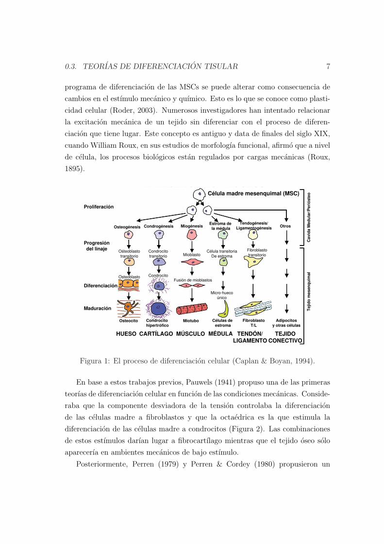
Una celula que es vital para esos cambios es la celula madre mesenquimal
(MSCs). A lo largo de su diferenciacion, las MSCs se dividen en “celulas hijas”,
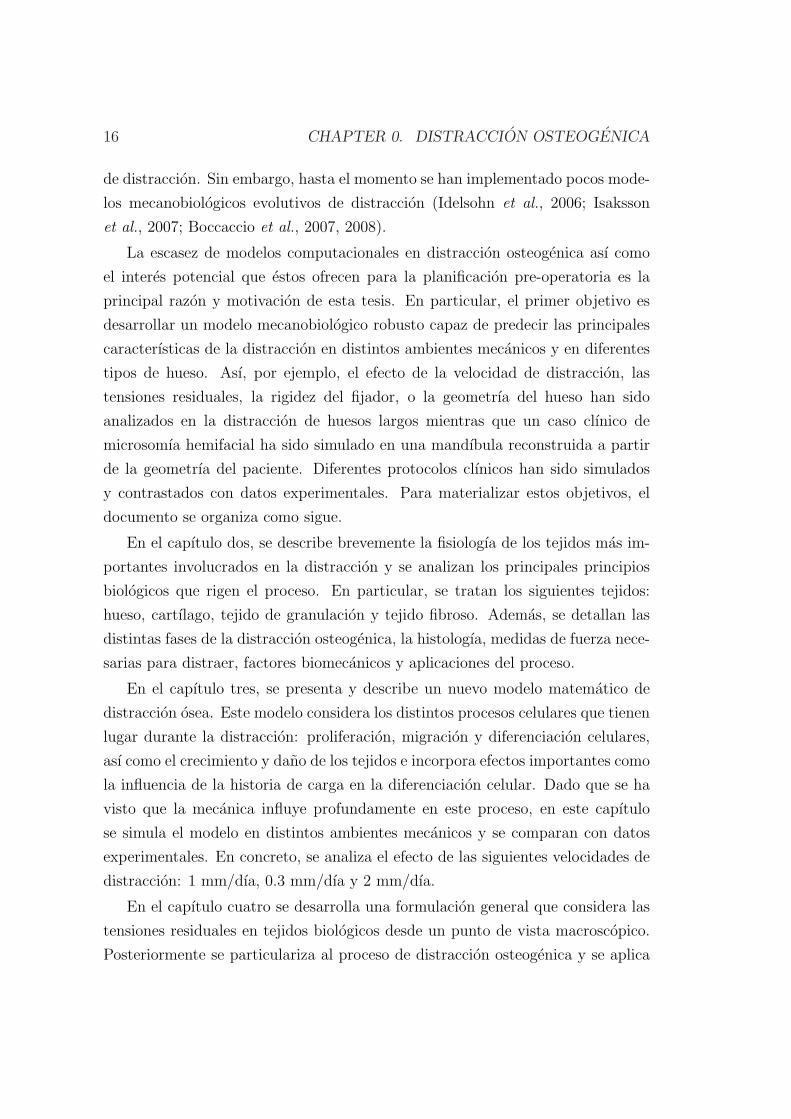
que tras sufrir una serie de cambios en su fenotipo terminan en la fabricacion de
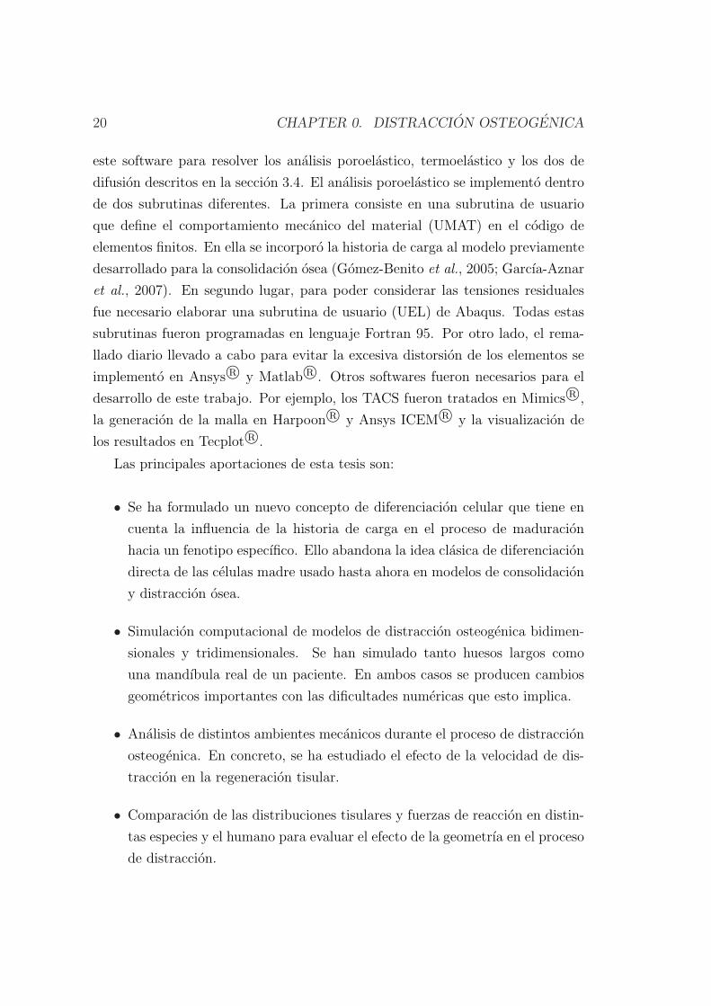
un unico tipo de tejido, ver Figura 1 (Caplan & Boyan, 1994). Sin embargo, el
0.3. TEORIAS DE DIFERENCIACION TISULAR 7
programa de diferenciacion de las MSCs se puede alterar como consecuencia de
cambios en el estımulo mecanico y quımico. Esto es lo que se conoce como plasti-
cidad celular (Roder, 2003). Numerosos investigadores han intentado relacionar
la excitacion mecanica de un tejido sin diferenciar con el proceso de diferen-
ciacion que tiene lugar. Este concepto es antiguo y data de finales del siglo XIX,
cuando William Roux, en sus estudios de morfologıa funcional, afirmo que a nivel
de celula, los procesos biologicos estan regulados por cargas mecanicas (Roux,
1895).
Célula madre mesenquimal (MSC)
HUESO CARTÍLAGO TENDÓN/LIGAMENTO
MÚSCULO MÉDULA TEJIDOCONECTIVO
Osteogénesis CondrogénesisTendogénesis/
LigamentogénesisMiogénesisEstroma de la médula Otros
Proliferación
Progresióndel linaje
Diferenciación
Maduración
Osteocito Condrocitohipertrófico
FibroblastoT/L
Miotubo Células deestroma
Adipocitosy otras células
Osteoblasto Condrocito
Fusión de mioblastos
Micro-hueco
único
Célula transitoria
De estromaMioblasto
Fibroblasto
transitorioCondrocito
transitorio
Osteoblasto
transitorio
Tej
ido
mes
enq
uim
alC
avid
aM
edu
lar/
Per
ióst
eo
Figura 1: El proceso de diferenciacion celular (Caplan & Boyan, 1994).
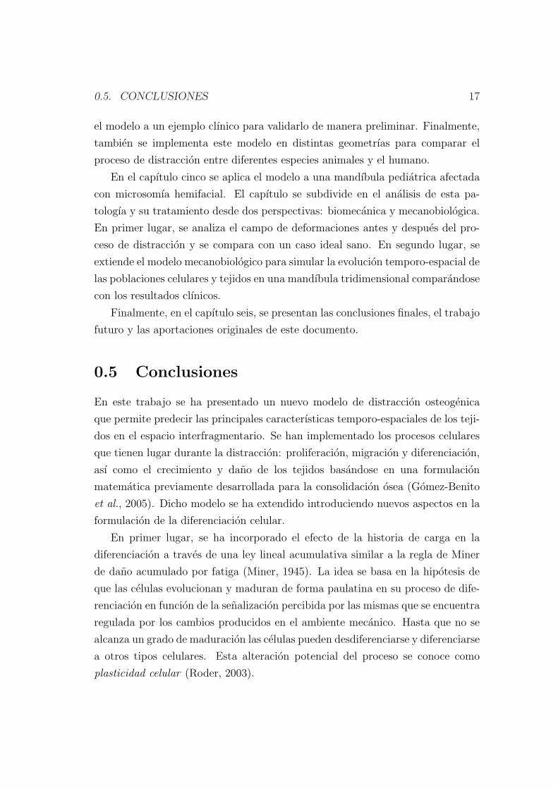
En base a estos trabajos previos, Pauwels (1941) propuso una de las primeras
teorıas de diferenciacion celular en funcion de las condiciones mecanicas. Conside-
raba que la componente desviadora de la tension controlaba la diferenciacion
de las celulas madre a fibroblastos y que la octaedrica es la que estimula la
diferenciacion de las celulas madre a condrocitos (Figura 2). Las combinaciones
de estos estımulos darıan lugar a fibrocartılago mientras que el tejido oseo solo
aparecerıa en ambientes mecanicos de bajo estımulo.
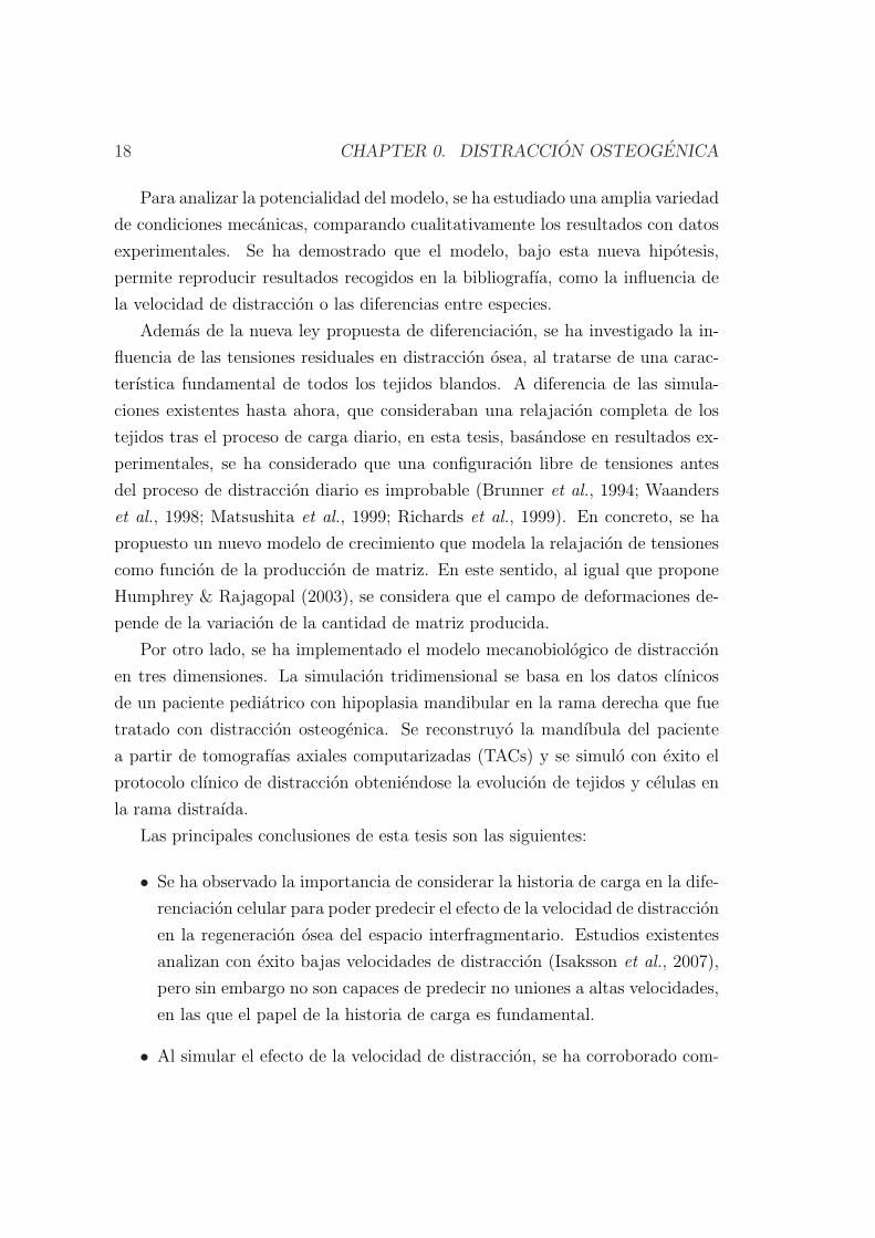
Posteriormente, Perren (1979) y Perren & Cordey (1980) propusieron un
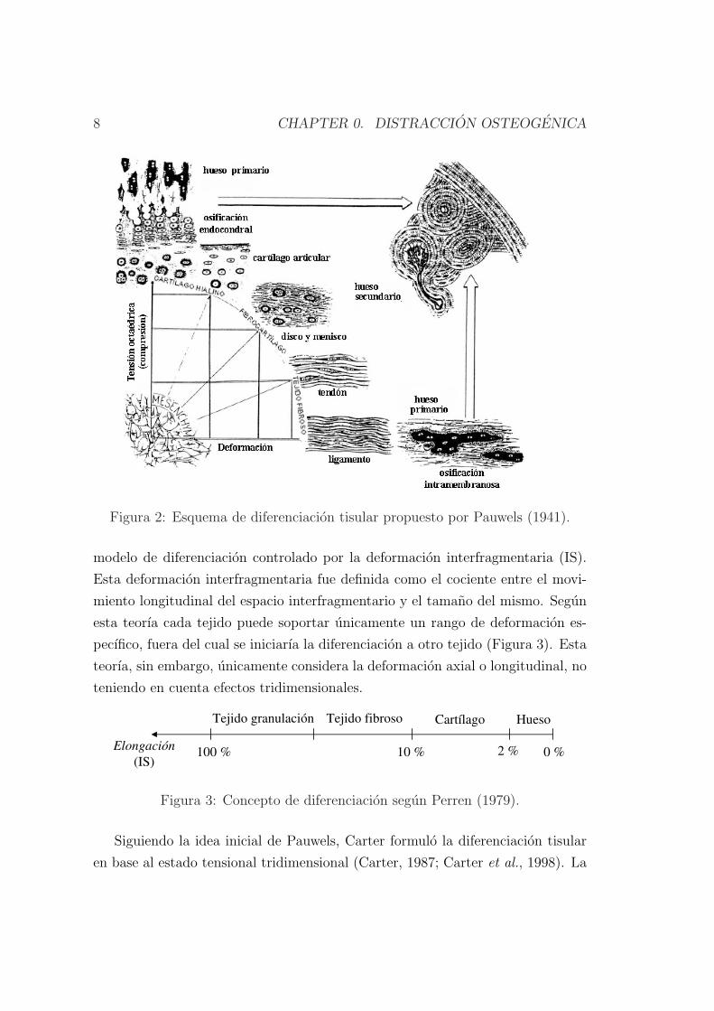
8 CHAPTER 0. DISTRACCION OSTEOGENICA
Figura 2: Esquema de diferenciacion tisular propuesto por Pauwels (1941).
modelo de diferenciacion controlado por la deformacion interfragmentaria (IS).
Esta deformacion interfragmentaria fue definida como el cociente entre el movi-
miento longitudinal del espacio interfragmentario y el tamano del mismo. Segun
esta teorıa cada tejido puede soportar unicamente un rango de deformacion es-
pecıfico, fuera del cual se iniciarıa la diferenciacion a otro tejido (Figura 3). Esta
teorıa, sin embargo, unicamente considera la deformacion axial o longitudinal, no
teniendo en cuenta efectos tridimensionales.
HuesoCartílagoTejido fibrosoTejido granulación
Elongación
(IS)100 % 10 % 2 % 0 %
Figura 3: Concepto de diferenciacion segun Perren (1979).
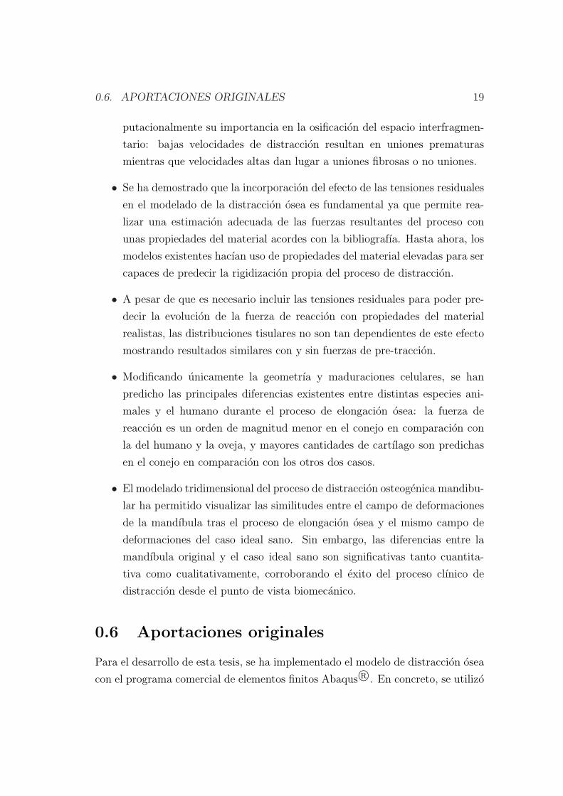
Siguiendo la idea inicial de Pauwels, Carter formulo la diferenciacion tisular
en base al estado tensional tridimensional (Carter, 1987; Carter et al., 1998). La
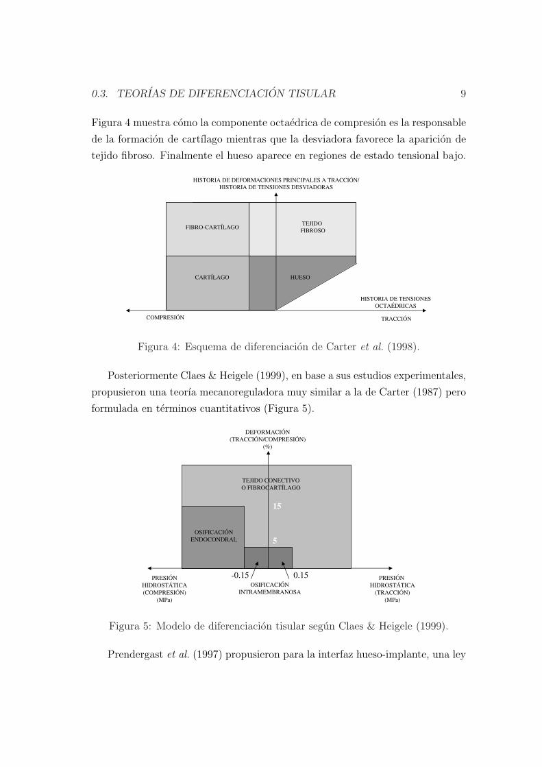
0.3. TEORIAS DE DIFERENCIACION TISULAR 9
Figura 4 muestra como la componente octaedrica de compresion es la responsable
de la formacion de cartılago mientras que la desviadora favorece la aparicion de
tejido fibroso. Finalmente el hueso aparece en regiones de estado tensional bajo.
-5
TRACCIÓNCOMPRESIÓN
HISTORIA DE TENSIONES
OCTAÉDRICAS
HUESOCARTÍLAGO
FIBRO-CARTÍLAGOTEJIDO
FIBROSO
HISTORIA DE DEFORMACIONES PRINCIPALES A TRACCIÓN/
HISTORIA DE TENSIONES DESVIADORAS
Figura 4: Esquema de diferenciacion de Carter et al. (1998).
Posteriormente Claes & Heigele (1999), en base a sus estudios experimentales,
propusieron una teorıa mecanoreguladora muy similar a la de Carter (1987) pero
formulada en terminos cuantitativos (Figura 5).
-0.85-5
OSIFICACIÓN
ENDOCONDRAL
OSIFICACIÓN
INTRAMEMBRANOSA
PRESIÓN
HIDROSTÁTICA
(COMPRESIÓN)
(MPa)
PRESIÓN
HIDROSTÁTICA
(TRACCIÓN)
(MPa)
DEFORMACIÓN
(TRACCIÓN/COMPRESIÓN)
(%)
TEJIDO CONECTIVO
O FIBROCARTÍLAGO
-0.15 0.15
5
15
Figura 5: Modelo de diferenciacion tisular segun Claes & Heigele (1999).
Prendergast et al. (1997) propusieron para la interfaz hueso-implante, una ley
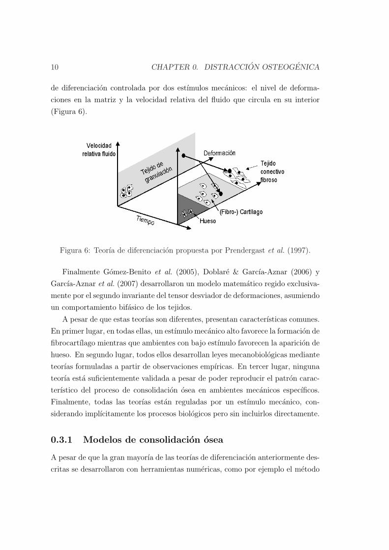
10 CHAPTER 0. DISTRACCION OSTEOGENICA
de diferenciacion controlada por dos estımulos mecanicos: el nivel de deforma-
ciones en la matriz y la velocidad relativa del fluido que circula en su interior
(Figura 6).
Figura 6: Teorıa de diferenciacion propuesta por Prendergast et al. (1997).
Finalmente Gomez-Benito et al. (2005), Doblare & Garcıa-Aznar (2006) y
Garcıa-Aznar et al. (2007) desarrollaron un modelo matematico regido exclusiva-
mente por el segundo invariante del tensor desviador de deformaciones, asumiendo
un comportamiento bifasico de los tejidos.
A pesar de que estas teorıas son diferentes, presentan caracterısticas comunes.
En primer lugar, en todas ellas, un estımulo mecanico alto favorece la formacion de
fibrocartılago mientras que ambientes con bajo estımulo favorecen la aparicion de
hueso. En segundo lugar, todos ellos desarrollan leyes mecanobiologicas mediante
teorıas formuladas a partir de observaciones empıricas. En tercer lugar, ninguna
teorıa esta suficientemente validada a pesar de poder reproducir el patron carac-
terıstico del proceso de consolidacion osea en ambientes mecanicos especıficos.
Finalmente, todas las teorıas estan reguladas por un estımulo mecanico, con-
siderando implıcitamente los procesos biologicos pero sin incluirlos directamente.
0.3.1 Modelos de consolidacion osea
A pesar de que la gran mayorıa de las teorıas de diferenciacion anteriormente des-
critas se desarrollaron con herramientas numericas, como por ejemplo el metodo
0.3. TEORIAS DE DIFERENCIACION TISULAR 11
de los elementos finitos (MEF), las mas antiguas se iniciaron con la aparicion de
estas herramientas. Ası, por ejemplo, Cheal et al. (1991) retomaron la hipotesis
de la deformacion interfragmentaria propuesta por Perren (1979). Compararon
la histologıa del callo de fractura con la deformacion del mismo usando el MEF
para ası poder determinar computacionalmente el campo de deformaciones en
el callo en la primera etapa del proceso de consolidacion. Ademas, aunque no
demostraron el dano existente en los tejidos, sı que encontraron una correlacion
entre reabsorcion osea con altos niveles de deformacion, ası como, formacion osea
con bajos niveles de deformacion.
Ament & Hofer (1996, 2000) propusieron un modelo biomecanico basado en
la logica difusa para describir la diferenciacion tisular durante la consolidacion.
Ademas del estımulo mecanico introdujeron un factor biologico, la vasculari-
zacion, para ası poder distinguir entre osificacion intramembranosa y endocon-
dral. El estımulo mecanico era la densidad energıa de deformacion. Predijeron con
exito la formacion de cartılago, el crecimiento del callo, y la posterior reabsorcion
del mismo tras la osificacion del espacio interfragmentario. Esta formulacion ha
sido retomada recientemente por Simon et al. (2003) y Shefelbine et al. (2005).
Los autores simularon con el MEF y la logica difusa, el proceso de consolidacion
osea, basandose en la teorıa de diferenciacion de Claes & Heigele (1999).
Bailon-Plaza & van der Meulen (2001) plantearon el primer modelo mecano-
biologico bidimensional que incluıa los factores de crecimiento. Este modelo se
modifico posteriormente para incorporar el efecto del estımulo mecanico en la
diferenciacion celular (Bailon-Plaza & van der Meulen, 2003). Recientemente
Geris et al. (2006, 2008) extendieron este modelo introduciendo aspectos claves
de la consolidacion osea, como la vascularizacion y compararon los resultados con
datos experimentales.
Lacroix et al. (2002) propusieron un modelo de consolidacion osea basado
en la teorıa de diferenciacion celular propuesta anteriormente por Prendergast
et al. (1997). Este modelo ha sido utilizado posteriormente por Andreykiv et al.
(2007) para incluir los procesos de difusion, proliferacion y diferenciacion de las
poblaciones celulares (MSCs, fibroblastos, condrocitos y osteoblastos). Isaksson
et al. (2008) propusieron un modelo similar para desarrollar una formulacion
mecanica de la diferenciacion tisular durante la consolidacion osea, relacionando
12 CHAPTER 0. DISTRACCION OSTEOGENICA
mecanismos celulares con el estımulo mecanico.
Finalmente, Gomez-Benito et al. (2005), Doblare & Garcıa-Aznar (2006) y
Garcıa-Aznar et al. (2007) reprodujeron con exito los principales eventos que
ocurren durante la consolidacion osea: la proliferacion, migracion y diferenciacion
celular, ası como el dano de los tejidos y la vascularizacion. Ademas, mejoraron
los modelos numericos existentes de consolidacion (Ament & Hofer, 2000; Bailon-
Plaza & van der Meulen, 2001; Lacroix & Prendergast, 2002a; Bailon-Plaza &
van der Meulen, 2003) con la incorporacion de una formulacion matematica que
describıa el crecimiento del callo.
0.3.2 Modelos de distraccion osteogenica
El fenomeno biologico que tiene lugar en la distraccion es muy similar al de la
consolidacion osea (Lammens et al., 1998; Jensen, 2002) por lo que la mayorıa de
los modelos de distraccion osea parten de esquemas de diferenciacion tisular ya
propuestos para la consolidacion.
Hasta el momento se han implementado pocos modelos para el caso de dis-
traccion, comparado con la gran cantidad de modelos de consolidacion osea. La
mayorıa de estos modelos analizan como la geometrıa, propiedades del material y
carga afectan al ambiente mecanico del espacio interfragmentario en uno o varios
instantes del proceso de distraccion (Carter et al., 1998; Samchukov et al., 1998;
Loboa et al., 2005; Kofod et al., 2005; Cattaneo et al., 2005; Boccaccio et al.,
2006; Morgan et al., 2006). Estos son los llamados modelos biomecanicos.
Por ejemplo, Samchukov et al. (1998) evaluaron desde el punto de vista
biomecanico la orientacion de distractores lineales con un modelo bidimensional
de una mandıbula humana. Concluyeron que estos dispositivos deben estar orien-
tados paralelos al eje de distraccion.
Carter y sus colaboradores (Carter et al., 1998; Morgan et al., 2006) carac-
terizaron el ambiente biofısico del espacio interfragmentario durante la distraccion.
En primer lugar, Carter et al. (1998) obtuvieron en dos instantes concretos de la
distraccion los campos de deformacion principal maxima y de tension hidrostatica.
Posteriormente, Morgan et al. (2006) cuantificaron computacionalmente la dis-
tribucion espacial y temporal de cuatro estımulos mecanicos para la diferen-
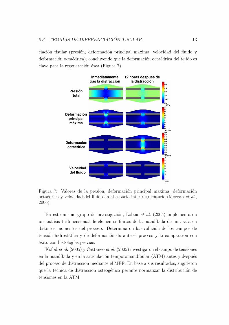
0.3. TEORIAS DE DIFERENCIACION TISULAR 13
ciacion tisular (presion, deformacion principal maxima, velocidad del fluido y
deformacion octaedrica), concluyendo que la deformacion octaedrica del tejido es
clave para la regeneracion osea (Figura 7).
Presión total
Deformaciónprincipalmáxima
Deformaciónoctaédrica
Velocidaddel fluido
Inmediatamentetras la distracción
12 horas después dela distracción
Figura 7: Valores de la presion, deformacion principal maxima, deformacionoctaedrica y velocidad del fluido en el espacio interfragmentario (Morgan et al.,2006).
En este mismo grupo de investigacion, Loboa et al. (2005) implementaron
un analisis tridimensional de elementos finitos de la mandıbula de una rata en
distintos momentos del proceso. Determinaron la evolucion de los campos de
tension hidrostatica y de deformacion durante el proceso y lo compararon con
exito con histologıas previas.
Kofod et al. (2005) y Cattaneo et al. (2005) investigaron el campo de tensiones
en la mandıbula y en la articulacion temporomandibular (ATM) antes y despues
del proceso de distraccion mediante el MEF. En base a sus resultados, sugirieron
que la tecnica de distraccion osteogenica permite normalizar la distribucion de
tensiones en la ATM.
14 CHAPTER 0. DISTRACCION OSTEOGENICA
Boccaccio et al. (2006) estudiaron la respuesta mecanica de una mandıbula hu-
mana con distractores comparando los campos de desplazamientos y de tensiones
en una mandıbula sana y en otra con una osteotomıa. En concreto, analizaron el
efecto de la masticacion en la mandıbula no distraıda, el efecto de una expansion
progresiva del distractor y la velocidad de distraccion (0.6 y 1.2 mm/dıa). Con-
cluyeron que las respuestas mecanicas de la mandıbula sana y distraıda son muy
distintas y que una velocidad de 1.2 mm/dıa reproduce mejor el campo de des-
plazamientos impuesto por el distractor.
Sin embargo, los modelos evolutivos proporcionan mejores aproximaciones de
la diferenciacion tisular como funcion del ambiente mecanico a lo largo de todo el
periodo de distraccion. Hasta ahora, existen pocos modelos capaces de predecir la
evolucion temporo-espacial de los distintos tejidos en el espacio interfragmentario
(Idelsohn et al., 2006; Isaksson et al., 2007; Boccaccio et al., 2007, 2008). Todos
ellos hacen uso del esquema de diferenciacion propuesto por Prendergast et al.
(1997) (vease Figura 6). Idelsohn et al. (2006) simularon las tres fases de la dis-
traccion en la mandıbula de un conejo. Analizaron la influencia de la frecuencia
de distraccion recomendando bajas frecuencias en la primera etapa del proceso.
Isaksson et al. (2007) simularon la regeneracion osea en la tibia de una oveja
durante todo el proceso de distraccion osteogenica. Estos autores predijeron con
exito la distribucion tisular con distintas frecuencias y velocidades de distraccion
pero no ası la evolucion de la fuerza necesaria para producir la distraccion. Boc-
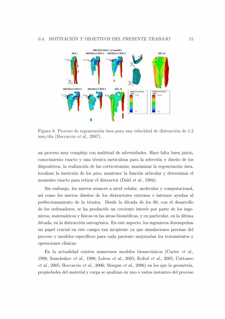
caccio et al. (2007, 2008) analizaron la influencia de la velocidad de distraccion
y la duracion del periodo de latencia en el callo de fractura de una mandıbula
humana sometida a distraccion en la zona sinfisaria (Figura 8). En este trabajo
se determino un periodo maximo de latencia de 1 semana para evitar uniones
prematuras y una velocidad optima de distraccion de 1.2 mm/dıa.
0.4 Motivacion y objetivos del presente trabajo
El proceso de distraccion osteogenica ha ido ganando popularidad debido su
numero elevado de aplicaciones. Sin embargo, hoy en dıa, la mayorıa de los
cirujanos son autodidactas dadas las instrucciones tan limitadas de las que dispo-
nen. Ademas, a pesar de la reduccion en el numero de complicaciones, se trata de
0.4. MOTIVACION Y OBJETIVOS DEL PRESENTE TRABAJO 15
PROTOCOLO- 1.2 mm/DÍA
DÍA 1 DISTRACCIÓN 2 DÍA 43
DÍA 23DISTRACCIÓN 4 DISTRACCIÓN 5
DISTRACCIÓN 3
MÓDULO YOUNG
(MPa)
MÓDULO YOUNG
(MPa)
5.285
0.2 0.2
95.857
Figura 8: Proceso de regeneracion osea para una velocidad de distraccion de 1.2mm/dıa (Boccaccio et al., 2007).
un proceso muy complejo con multitud de adversidades. Hace falta buen juicio,
conocimiento exacto y una tecnica meticulosa para la seleccion y diseno de los
dispositivos, la realizacion de las corticotomıas, maximizar la regeneracion osea,
localizar la insercion de los pins, mantener la funcion articular y determinar el
momento exacto para retirar el distractor (Dahl et al., 1994).
Sin embargo, los nuevos avances a nivel celular, molecular y computacional,
ası como los nuevos disenos de los distractores externos e internos ayudan al
perfeccionamiento de la tecnica. Desde la decada de los 80, con el desarrollo
de los ordenadores, se ha producido un creciente interes por parte de los inge-
nieros, matematicos y fısicos en las areas biomedicas, y en particular, en la ultima
decada, en la distraccion osteogenica. En este aspecto, los ingenieros desempenan
un papel crucial en este campo tan incipiente ya que simulaciones precisas del
proceso y modelos especıficos para cada paciente mejorarıan los tratamientos y
operaciones clınicas.
En la actualidad existen numerosos modelos biomecanicos (Carter et al.,
1998; Samchukov et al., 1998; Loboa et al., 2005; Kofod et al., 2005; Cattaneo
et al., 2005; Boccaccio et al., 2006; Morgan et al., 2006) en los que la geometrıa,
propiedades del material y carga se analizan en uno o varios instantes del proceso
16 CHAPTER 0. DISTRACCION OSTEOGENICA
de distraccion. Sin embargo, hasta el momento se han implementado pocos mode-
los mecanobiologicos evolutivos de distraccion (Idelsohn et al., 2006; Isaksson
et al., 2007; Boccaccio et al., 2007, 2008).
La escasez de modelos computacionales en distraccion osteogenica ası como
el interes potencial que estos ofrecen para la planificacion pre-operatoria es la
principal razon y motivacion de esta tesis. En particular, el primer objetivo es
desarrollar un modelo mecanobiologico robusto capaz de predecir las principales
caracterısticas de la distraccion en distintos ambientes mecanicos y en diferentes
tipos de hueso. Ası, por ejemplo, el efecto de la velocidad de distraccion, las
tensiones residuales, la rigidez del fijador, o la geometrıa del hueso han sido
analizados en la distraccion de huesos largos mientras que un caso clınico de
microsomıa hemifacial ha sido simulado en una mandıbula reconstruida a partir
de la geometrıa del paciente. Diferentes protocolos clınicos han sido simulados
y contrastados con datos experimentales. Para materializar estos objetivos, el
documento se organiza como sigue.
En el capıtulo dos, se describe brevemente la fisiologıa de los tejidos mas im-
portantes involucrados en la distraccion y se analizan los principales principios
biologicos que rigen el proceso. En particular, se tratan los siguientes tejidos:
hueso, cartılago, tejido de granulacion y tejido fibroso. Ademas, se detallan las
distintas fases de la distraccion osteogenica, la histologıa, medidas de fuerza nece-
sarias para distraer, factores biomecanicos y aplicaciones del proceso.
En el capıtulo tres, se presenta y describe un nuevo modelo matematico de
distraccion osea. Este modelo considera los distintos procesos celulares que tienen
lugar durante la distraccion: proliferacion, migracion y diferenciacion celulares,
ası como el crecimiento y dano de los tejidos e incorpora efectos importantes como
la influencia de la historia de carga en la diferenciacion celular. Dado que se ha
visto que la mecanica influye profundamente en este proceso, en este capıtulo
se simula el modelo en distintos ambientes mecanicos y se comparan con datos
experimentales. En concreto, se analiza el efecto de las siguientes velocidades de
distraccion: 1 mm/dıa, 0.3 mm/dıa y 2 mm/dıa.
En el capıtulo cuatro se desarrolla una formulacion general que considera las
tensiones residuales en tejidos biologicos desde un punto de vista macroscopico.
Posteriormente se particulariza al proceso de distraccion osteogenica y se aplica
0.5. CONCLUSIONES 17
el modelo a un ejemplo clınico para validarlo de manera preliminar. Finalmente,
tambien se implementa este modelo en distintas geometrıas para comparar el
proceso de distraccion entre diferentes especies animales y el humano.
En el capıtulo cinco se aplica el modelo a una mandıbula pediatrica afectada
con microsomıa hemifacial. El capıtulo se subdivide en el analisis de esta pa-
tologıa y su tratamiento desde dos perspectivas: biomecanica y mecanobiologica.
En primer lugar, se analiza el campo de deformaciones antes y despues del pro-
ceso de distraccion y se compara con un caso ideal sano. En segundo lugar, se
extiende el modelo mecanobiologico para simular la evolucion temporo-espacial de
las poblaciones celulares y tejidos en una mandıbula tridimensional comparandose
con los resultados clınicos.
Finalmente, en el capıtulo seis, se presentan las conclusiones finales, el trabajo
futuro y las aportaciones originales de este documento.
0.5 Conclusiones
En este trabajo se ha presentado un nuevo modelo de distraccion osteogenica
que permite predecir las principales caracterısticas temporo-espaciales de los teji-
dos en el espacio interfragmentario. Se han implementado los procesos celulares
que tienen lugar durante la distraccion: proliferacion, migracion y diferenciacion,
ası como el crecimiento y dano de los tejidos basandose en una formulacion
matematica previamente desarrollada para la consolidacion osea (Gomez-Benito
et al., 2005). Dicho modelo se ha extendido introduciendo nuevos aspectos en la
formulacion de la diferenciacion celular.
En primer lugar, se ha incorporado el efecto de la historia de carga en la
diferenciacion a traves de una ley lineal acumulativa similar a la regla de Miner
de dano acumulado por fatiga (Miner, 1945). La idea se basa en la hipotesis de
que las celulas evolucionan y maduran de forma paulatina en su proceso de dife-
renciacion en funcion de la senalizacion percibida por las mismas que se encuentra
regulada por los cambios producidos en el ambiente mecanico. Hasta que no se
alcanza un grado de maduracion las celulas pueden desdiferenciarse y diferenciarse
a otros tipos celulares. Esta alteracion potencial del proceso se conoce como
plasticidad celular (Roder, 2003).
18 CHAPTER 0. DISTRACCION OSTEOGENICA
Para analizar la potencialidad del modelo, se ha estudiado una amplia variedad
de condiciones mecanicas, comparando cualitativamente los resultados con datos
experimentales. Se ha demostrado que el modelo, bajo esta nueva hipotesis,
permite reproducir resultados recogidos en la bibliografıa, como la influencia de
la velocidad de distraccion o las diferencias entre especies.
Ademas de la nueva ley propuesta de diferenciacion, se ha investigado la in-
fluencia de las tensiones residuales en distraccion osea, al tratarse de una carac-
terıstica fundamental de todos los tejidos blandos. A diferencia de las simula-
ciones existentes hasta ahora, que consideraban una relajacion completa de los
tejidos tras el proceso de carga diario, en esta tesis, basandose en resultados ex-
perimentales, se ha considerado que una configuracion libre de tensiones antes
del proceso de distraccion diario es improbable (Brunner et al., 1994; Waanders
et al., 1998; Matsushita et al., 1999; Richards et al., 1999). En concreto, se ha
propuesto un nuevo modelo de crecimiento que modela la relajacion de tensiones
como funcion de la produccion de matriz. En este sentido, al igual que propone
Humphrey & Rajagopal (2003), se considera que el campo de deformaciones de-
pende de la variacion de la cantidad de matriz producida.
Por otro lado, se ha implementado el modelo mecanobiologico de distraccion
en tres dimensiones. La simulacion tridimensional se basa en los datos clınicos
de un paciente pediatrico con hipoplasia mandibular en la rama derecha que fue
tratado con distraccion osteogenica. Se reconstruyo la mandıbula del paciente
a partir de tomografıas axiales computarizadas (TACs) y se simulo con exito el
protocolo clınico de distraccion obteniendose la evolucion de tejidos y celulas en
la rama distraıda.
Las principales conclusiones de esta tesis son las siguientes:
• Se ha observado la importancia de considerar la historia de carga en la dife-
renciacion celular para poder predecir el efecto de la velocidad de distraccion
en la regeneracion osea del espacio interfragmentario. Estudios existentes
analizan con exito bajas velocidades de distraccion (Isaksson et al., 2007),
pero sin embargo no son capaces de predecir no uniones a altas velocidades,
en las que el papel de la historia de carga es fundamental.
• Al simular el efecto de la velocidad de distraccion, se ha corroborado com-
0.6. APORTACIONES ORIGINALES 19
putacionalmente su importancia en la osificacion del espacio interfragmen-
tario: bajas velocidades de distraccion resultan en uniones prematuras
mientras que velocidades altas dan lugar a uniones fibrosas o no uniones.
• Se ha demostrado que la incorporacion del efecto de las tensiones residuales
en el modelado de la distraccion osea es fundamental ya que permite rea-
lizar una estimacion adecuada de las fuerzas resultantes del proceso con
unas propiedades del material acordes con la bibliografıa. Hasta ahora, los
modelos existentes hacıan uso de propiedades del material elevadas para ser
capaces de predecir la rigidizacion propia del proceso de distraccion.
• A pesar de que es necesario incluir las tensiones residuales para poder pre-
decir la evolucion de la fuerza de reaccion con propiedades del material
realistas, las distribuciones tisulares no son tan dependientes de este efecto
mostrando resultados similares con y sin fuerzas de pre-traccion.
• Modificando unicamente la geometrıa y maduraciones celulares, se han
predicho las principales diferencias existentes entre distintas especies ani-
males y el humano durante el proceso de elongacion osea: la fuerza de
reaccion es un orden de magnitud menor en el conejo en comparacion con
la del humano y la oveja, y mayores cantidades de cartılago son predichas
en el conejo en comparacion con los otros dos casos.
• El modelado tridimensional del proceso de distraccion osteogenica mandibu-
lar ha permitido visualizar las similitudes entre el campo de deformaciones
de la mandıbula tras el proceso de elongacion osea y el mismo campo de
deformaciones del caso ideal sano. Sin embargo, las diferencias entre la
mandıbula original y el caso ideal sano son significativas tanto cuantita-
tiva como cualitativamente, corroborando el exito del proceso clınico de
distraccion desde el punto de vista biomecanico.
0.6 Aportaciones originales
Para el desarrollo de esta tesis, se ha implementado el modelo de distraccion osea
con el programa comercial de elementos finitos Abaqus R©. En concreto, se utilizo
20 CHAPTER 0. DISTRACCION OSTEOGENICA
este software para resolver los analisis poroelastico, termoelastico y los dos de
difusion descritos en la seccion 3.4. El analisis poroelastico se implemento dentro
de dos subrutinas diferentes. La primera consiste en una subrutina de usuario
que define el comportamiento mecanico del material (UMAT) en el codigo de
elementos finitos. En ella se incorporo la historia de carga al modelo previamente
desarrollado para la consolidacion osea (Gomez-Benito et al., 2005; Garcıa-Aznar
et al., 2007). En segundo lugar, para poder considerar las tensiones residuales
fue necesario elaborar una subrutina de usuario (UEL) de Abaqus. Todas estas
subrutinas fueron programadas en lenguaje Fortran 95. Por otro lado, el rema-
llado diario llevado a cabo para evitar la excesiva distorsion de los elementos se
implemento en Ansys R© y Matlab R©. Otros softwares fueron necesarios para el
desarrollo de este trabajo. Por ejemplo, los TACS fueron tratados en Mimics R©,
la generacion de la malla en Harpoon R© y Ansys ICEM R© y la visualizacion de
los resultados en Tecplot R©.
Las principales aportaciones de esta tesis son:
• Se ha formulado un nuevo concepto de diferenciacion celular que tiene en
cuenta la influencia de la historia de carga en el proceso de maduracion
hacia un fenotipo especıfico. Ello abandona la idea clasica de diferenciacion
directa de las celulas madre usado hasta ahora en modelos de consolidacion
y distraccion osea.
• Simulacion computacional de modelos de distraccion osteogenica bidimen-
sionales y tridimensionales. Se han simulado tanto huesos largos como
una mandıbula real de un paciente. En ambos casos se producen cambios
geometricos importantes con las dificultades numericas que esto implica.
• Analisis de distintos ambientes mecanicos durante el proceso de distraccion
osteogenica. En concreto, se ha estudiado el efecto de la velocidad de dis-
traccion en la regeneracion tisular.
• Comparacion de las distribuciones tisulares y fuerzas de reaccion en distin-
tas especies y el humano para evaluar el efecto de la geometrıa en el proceso
de distraccion.
0.7. PUBLICACIONES 21
• Formulacion de un modelo que incluye las tensiones de pre-traccion en dis-
traccion osteogenica. Este modelo se simulo en casos de elongacion de
huesos largos asumiendo un estado de tensiones no nulo antes del proceso
de carga diario.
0.7 Publicaciones
Fruto de esta tesis doctoral se han publicado los siguientes trabajos de investi-
gacion en revistas cientıficas y conferencias:
0.7.1 Revistas
• Reina-Romo E., Gomez-Benito M.J., Garcıa-Aznar J.M., Domınguez J.,
Doblare, M. (2009). Modeling Distraction Osteogenesis: Analysis of the
distraction rate. Biomechanics and Modeling in Mechanobiology. 8: 323-
35.
• Reina-Romo E., Gomez-Benito M.J., Garcıa-Aznar J.M., Domınguez J.,
Doblare, M. Growth mixture model of distraction osteogenesis: effect of
pre-traction stresses. Biomechanics and Modeling in Mechanobiology. In
Press, DOI: 10.1007/s10237-009-0162-5.
• Reina-Romo E., Gomez-Benito M.J., Garcıa-Aznar J.M., Domınguez J.,
Doblare, M. An interspecies computational study on limb lengthening. En-
viado.
• Reina-Romo E., Sampietro-Fuentes A., Gomez-Benito M.J., Garcıa-Aznar
J.M., Domınguez J., Doblare, M. Biomechanical response of a mandible in
a patient affected with hemifacial microsomia before and after distraction
osteogenesis. Enviado.
• Reina-Romo E., Sampietro-Fuentes A., Gomez-Benito M.J., Garcıa-Aznar
J.M., Domınguez J., Doblare, M. Three-dimensional simulation of mandibu-
lar distraction osteogenesis: mechanobiological analysis. En preparacion.

22 CHAPTER 0. DISTRACCION OSTEOGENICA
0.7.2 Conferencias
• Reina E., Gomez-Benito M.J., Garcıa-Aznar J.M., Domınguez J., Doblare,
M. Modelo computacional de distraccion osea. CMNE/CILAMCE, Semni.
Oporto, Portugal, Junio, 2007.
• Reina E., Gomez-Benito M.J., Garcıa-Aznar J.M., Domınguez J., Doblare,
M. Influence of distraction rate on the outcome of distraction osteogenesis:
computational simulation. European Society of Biomechanichs Workshop
2007. Dublın, Irlanda, Agosto, 2007.
• Reina E., Gomez-Benito M.J., Garcıa-Aznar J.M., Domınguez J., Doblare,
M. Influencia de la velocidad de distraccion en la regeneracion osea. Mode-
lo computacional. 8o Congreso Iberoamericano de Ingenierıa Mecanica.
Cusco, Peru, Octubre, 2007.
• Reina-Romo E., Gomez-Benito M.J., Garcıa-Aznar J.M., Domınguez J.,
Doblare, M. Simulating limb lengthening in an interspecies’ analysis. Biome-
chanics and Biology of Bone Healing. Berlın, Alemania, Mayo 2008.
• Reina-Romo E., Gomez-Benito M.J., Garcıa-Aznar J.M., Domınguez J.,
Doblare, M. Different animal models of bone distraction. 5th European
Congress on Computational Methods in Applied Sciences and Engineeering
(ECCOMAS 2008). Venecia, Italia, Julio 2008.
• Reina-Romo E., Gomez-Benito M.J., Garcıa-Aznar J.M., Domınguez J.,
Doblare, M. Limb lengthening: Influence of the load history. 16th Congress
European Society of Biomechanics. Lucerna, Suiza, Julio 2008.
• A. Sampietro Fuentes, E. Reina-Romo, M Ferrer Molina. Analisis biomeca-
nico de la distraccion osea en mandıbula: comparativa clınico-experimental.
55 Reunion de la Sociedad Espanola de Ortodoncia. Valencia, Espana,
Junio 2009.
• Reina-Romo E., Sampietro-Fuentes A., Gomez-Benito M.J., Garcıa-Aznar
J.M., Domınguez J., Doblare, M. Estudio tensional antes y despues de la
0.8. LINEAS DE TRABAJO FUTURO 23
distraccion osteogenica mandibular en una caso de microsomıa hemifacial.
Semni. Barcelona, Espana, Julio 2009.
• Reina-Romo E., Sampietro-Fuentes A., Gomez-Benito M.J., Garcıa-Aznar
J.M., Domınguez J., Doblare, M. Simulacion numerica del proceso de dis-
traccion osteogenica mandibular en un caso de microsomıa hemifacial. 9o
Congreso Iberoamericano de Ingenierıa Mecanica, Las Palmas de Gran Ca-
naria, Espana, Noviembre 2009.
0.8 Lıneas de trabajo futuro
El proceso de distraccion osteogenica constituye un campo muy activo que aun
sigue siendo objeto de intensa investigacion cientıfica. De hecho, es uno de los
fenomenos mas desconocidos de la biologıa osea. Ademas, los cirujanos carecen
hoy en dıa de instrucciones establecidas que definan el protocolo mas adecuado
de distraccion para cada paciente.
Por lo tanto, las posibles mejoras y desarrollo de este campo son innumerables,
tanto desde el punto de vista computacional como experimental. En concreto, se
han planificado algunas extensiones del modelo incorporando factores no conside-
rados ası como nuevas aplicaciones. Se resume como sigue:
1. Desarrollo futuro en la parte computacional:
• Simular las fases de latencia y de remodelacion en detalle.
• El proceso de distraccion osteogenica es claramente un problema de
grandes deformaciones. Sin embargo, la falta de datos experimentales
acerca del comportamiento real de los tejidos durante el proceso de
distraccion osea limita sus aplicaciones numericas. Por lo tanto, en un
futuro se debe caracterizar el comportamiento mecanico de los tejidos
del espacio interfragmentario en ambientes de grandes deformaciones.
• Simular el proceso de elongacion osea en geometrıas mas complejas y
desarrollar modelos especıficos para cada paciente. De hecho, las simu-
laciones de elementos finitos del proceso de distraccion osteogenica de-
berıan desarrollarse en base a funciones que representen la geometrıa
24 CHAPTER 0. DISTRACCION OSTEOGENICA
exacta del modelo (analisis isogeometrico, NURBS). Estos analisis
tambien se podrıan extender y adaptar al proceso de distraccion osea.
La malla podrıa adaptarse a los cambios geometricos que tienen lugar
a lo largo del proceso de distraccion evitando por lo tanto la inclusion
del remallado.
• Otro aspecto que podrıa ser susceptible de mejora es la migracion
celular, que aquı ha sido simulada con una ecuacion estandar de di-
fusion. Sin embargo, es bien conocido que el movimiento de las celulas
no es aleatorio o adireccional sino que contituye un proceso mucho
mas complejo. Por ejemplo, recientemente se ha demostrado que el
movimiento celular se guıa por la rigidez y deformacion del sustrato
(Lo et al., 2000; Wong et al., 2003; Schwarz & Bischofs, 2005; Moreo
et al., 2008; Sanz-Herrera et al., 2009). Estos aspectos deberıan estu-
diarse en un futuro puesto que la migracion celular es fundamental en
el proceso de distraccion osteogenica.
• Se ha supuesto que las tensiones residuales estan reguladas por la pro-
duccion de matriz. Sin embargo, estudios futuros deberıan tambien
incluir un termino adicional de relajacion de tensiones debido al creci-
miento volumetrico.
• Se ha simulado el cremiento como funcion de la proliferacion de las
MSCs y de la hipertrofia de los condrocitos (Gomez-Benito et al.,
2005). Sin embargo, el crecimiento volumetrico debido a la produccion
de matriz no es despreciable y deberıa ser incluido en modelos futuros
para ası obtener resultados mas realistas.
• En relacion con los aspectos anteriores, se podrıa extender el mode-
lo con un planteamiento micro-macro y ası reducir el numero de para-
metros. Se podrıan simular los procesos de diferenciacion, proliferacion
y migracion celular en el nivel micro y despues homogeneizar las varia-
bles y pasarlas al nivel macro.
• Ademas se quiere extender el modelo para estudiar teorıas de diferen-
ciacion asimetricas. Hoy en dıa existe un intenso debate acerca de si
las celulas de cartılago aparecen o no en ambientes a traccion como
0.8. LINEAS DE TRABAJO FUTURO 25
la distraccion osea. Numerosos estudios demuestran que solo existe
osificacion intramembranosa en el espacio interfragmentario durante
la distraccion (Ilizarov, 1989a,b; Aronson et al., 1989; Delloye et al.,
1990; Shearer et al., 1992; Ganey et al., 1994; Schenck & Gatchter,
1994). Pero casi todos los modelos mecanobiologicos proponen reglas
simetricas de diferenciacion respecto del tipo de carga (Prendergast
et al., 1997; Gomez-Benito et al., 2005) y por lo tanto consideran la for-
macion de cartılago tanto a compresion como a traccion. El modelo de
Claes & Heigele (1999), en cambio, incluye esta asimetrıa formandose
cartılago solo a compresion. En el apendice B se ha aplicado esta teorıa
de diferenciacion y se ha extendido al caso de distraccion osea para
comprobar si formulaciones asimetricas ya existentes de diferenciacion
celular son capaces de predecir el proceso de distraccion osteogenica de
manera mas realista. El modelo se ha validado de manera preliminar
analizando el efecto de la rigidez del fijador durante la etapa de con-
solidacion osea. Sin embargo, este estudio requiere mas analisis para
validar completamente el modelo.
2. Desarrollo futuro en la parte experimental:
• La insuficiente validacion de los modelos de distraccion osteogenica es
una de las principales limitaciones de los mismos. Existen bastantes
estudios experimentales de distraccion en la bibliografıa pero presentan
una gran variabilidad en los resultados. Por lo tanto, se pretende llevar
a cabo en un futuro cercano experimentos de distraccion osea para
comprobar las hipotesis mas relevantes del modelo, ası como realizar
una estimacion de los parametros del mismo. Para ello, es preciso en
un futuro:
– Definir y preparar los experimentos en animales, centrandose en
la eleccion del tipo de especie, el procedimiento de distraccion
a realizar, el protocolo de distraccion ası como los parametros a
controlar durante el ensayo entre otros. Por ejemplo, se podrıan
medir las fuerzas producidas por el distractor sobre el hueso cada
26 CHAPTER 0. DISTRACCION OSTEOGENICA
vez que se produce un desplazamiento en el distractor, ası como
las tensiones residuales que mantiene el hueso sobre el distractor
al final de cada dıa, y antes del siguiente paso de distraccion.
– Diseno y fabricacion del distractor. Se debe disenar el distractor
para asegurar la estabilidad del espacio interfragmentario ası como
unas condiciones clınicas optimas.
– Desarrollo de la instrumentacion electronica necesaria para medir
los parametros de interes, como por ejemplo la carga.
En el marco de la validacion experimental de los modelos se pone de manifiesto
el caracter interdisciplinar de este proceso, ya que deben considerarse aspectos
mecanicos, biologicos y medicos.
Con estos desarrollos futuros se contribuira a la mejora de los tratamientos
clınicos. Por ejemplo, hoy en dıa, se usan radiografıas para determinar el momento
de retirada del distractor. Sin embargo, la correlacion entre la densidad osea de
la radiografıa y la integridad biomecanica del nuevo hueso formado es muy pobre.
Por lo tanto, son necesarios modelos fiables que permitan determinar cualitativa
y cuantitativamente el protocolo optimo de distraccion.
Chapter 1
Introduction
1.1 Introduction
The Latin etymology of distraction, distrahere (from dis, apart, and trahere, to
draw) means pulling in various directions (Burrill, 1998) and was introduced by
G. A. Ilizarov to the field of orthopedics in 1951 to describe the induction of
new-bone formation between two bone segments that are separated by gradual
traction. The deep interest of Ilizarov in the fundamental role played by local
mechanical parameters on biological processes has lead to his well known “Law
of Tension-Stress” which states that gradual traction of living tissues creates
stresses that can stimulate and maintain the regeneration and active growth of
certain tissue structures. Therefore, in distraction osteogenesis, mechanical forces
play a major role in the development of tissues within the distracted gap. As in
distraction osteogenesis, a wide variety of physical phenomena are induced by
mechanical stimuli (e.g. bone healing, osteoporosis and tissue remodeling). In
fact, recent advances in cell and molecular biology take into account the central
role of mechanical forces on tissue differentiation, development and remodeling.
However, the identification of the mechanical parameters of importance and their
mechanisms of action are unresolved and continue to be investigated.
These relationships between physical forces and the morphology of living
things is not new and dates from Galileo. He hypothesized in 1638 that gravi-
ty and mechanical forces are limiting factors on the growth and architecture
27
28 CHAPTER 1. INTRODUCTION
of living organs. Over the last 150 years, Charles Darwin (1859), Karl Culmann
(1864), G. Hermann von Meyer (1867), Julius Wolff (1892), Wilhelm Roux (1895),
Gebhardt (1901), D’Arcy Thompson (1917), Friedrich Pauwels (1941), and Harrol
Frost (1963) have recognized the importance of mechanical conditions in skeletal
development and evolution.
This concept of mechanical regulation of biological processes is the main
premise of mechanobiology, a research field introduced in the 20th century and
that has been developed in the 1990s. In contrast to biomechanics (mechanics
applied to biosciences), this research field focuses on how the mechanical en-
vironment regulates the cell behavior in different biological processes, such as,
development, adaptation, growth, remodeling, repair, regeneration and tissue
differentiation pathways of biological tissues. It includes experimental and ana-
lytical models that help to understand the skeletal response to mechanical factors
(van der Meulen & Huiskes, 2002), being usually divided into:
• Experimental Mechanobiology : it has been used to examine both tissue dif-
ferentiation and adaptation to altered loading, with the majority of experi-
ments examining tissue remodeling in response to mechanical stimuli. The
most common experimental design is a device that isolates or controls the
mechanical stimuli and then examines the tissues that form (Soballe et al.,
1992; Goodman et al., 1994; Guldberg et al., 1997; Tagil & Aspenberg, 1999;
Altman et al., 2002; Ng et al., 2006).
• Computational Mechanobiology : its purpose is to determine the quantitative
rules that govern the effects of mechanical loading on tissue differentiation,
growth, adaptation and maintenance. A potential rule is hypothesized and
the outcome of this hypothesis is modeled and compared against real tissue
structures and morphologies (Claes & Heigele, 1999). If the results of this
trial-and-error method correspond well, there might be an explanation for
the mechanism being modeled.
The potential of mechanobiology to contribute to clinical progress is very
promising. Mechanically based pathologies, such as, osteoporosis, neochondro-
genesis, tissue differentiation at implant interfaces, bone healing or distraction
1.1. INTRODUCTION 29
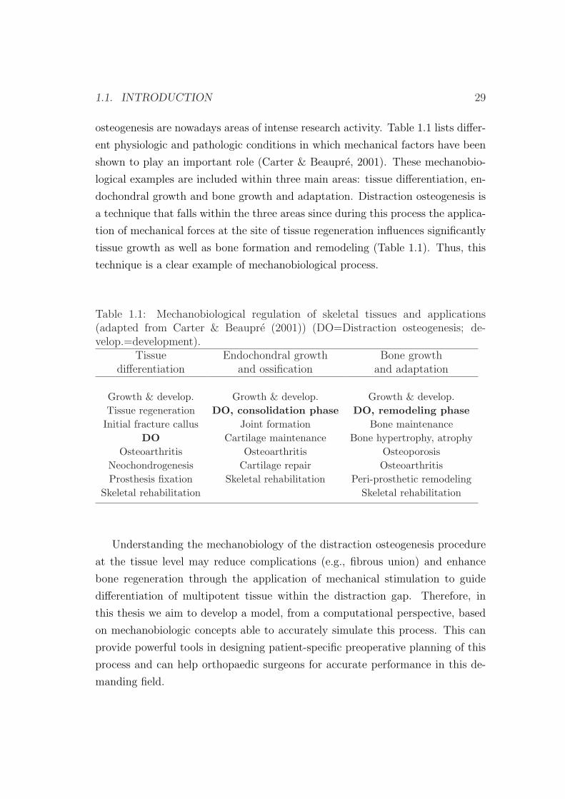
osteogenesis are nowadays areas of intense research activity. Table 1.1 lists differ-
ent physiologic and pathologic conditions in which mechanical factors have been
shown to play an important role (Carter & Beaupre, 2001). These mechanobio-
logical examples are included within three main areas: tissue differentiation, en-
dochondral growth and bone growth and adaptation. Distraction osteogenesis is
a technique that falls within the three areas since during this process the applica-
tion of mechanical forces at the site of tissue regeneration influences significantly
tissue growth as well as bone formation and remodeling (Table 1.1). Thus, this
technique is a clear example of mechanobiological process.
Table 1.1: Mechanobiological regulation of skeletal tissues and applications(adapted from Carter & Beaupre (2001)) (DO=Distraction osteogenesis; de-velop.=development).
Tissue Endochondral growth Bone growthdifferentiation and ossification and adaptation
Growth & develop. Growth & develop. Growth & develop.Tissue regeneration DO, consolidation phase DO, remodeling phaseInitial fracture callus Joint formation Bone maintenance
DO Cartilage maintenance Bone hypertrophy, atrophyOsteoarthritis Osteoarthritis Osteoporosis
Neochondrogenesis Cartilage repair OsteoarthritisProsthesis fixation Skeletal rehabilitation Peri-prosthetic remodeling
Skeletal rehabilitation Skeletal rehabilitation
Understanding the mechanobiology of the distraction osteogenesis procedure
at the tissue level may reduce complications (e.g., fibrous union) and enhance
bone regeneration through the application of mechanical stimulation to guide
differentiation of multipotent tissue within the distraction gap. Therefore, in
this thesis we aim to develop a model, from a computational perspective, based
on mechanobiologic concepts able to accurately simulate this process. This can
provide powerful tools in designing patient-specific preoperative planning of this
process and can help orthopaedic surgeons for accurate performance in this de-
manding field.
30 CHAPTER 1. INTRODUCTION
1.2 Distraction osteogenesis
Distraction osteogenesis is a unique biologic process of new bone formation be-
tween the surfaces of bone segments that are gradually separated by incremental
traction. It is used to correct severe bone injuries and to lengthen bones. Tradi-
tional treatments for severe bone injuries have evolved through major stages that
include high level amputation, shoe augmentation, orthotics and bone grafting.
Shoe augmentation and orthotics, are clearly visible and are, therefore, mostly
refused because they tarnish the external appearance (Leung et al., 2006). Bone
grafting, which is classified into autogenous or allogeneic bone grafting, exhibit
limitations and have failure rates from 22.5% to 38% (Ilizarov & Ledyaev, 1992).
In autogenous bone grafting, tissue is provided by the individual him/herself and
in allogeneic bone grafting tissue is taken from a donor. The former heals quick-
est and more reliably but is limited in quantity and involves donor site morbidity
whilst the latter could elicit an immunological response due to genetic differences
and the risk of inducing transmissible diseases (Glowacki & Mulliken, 1985; Buck
et al., 1989). Xenografts, or bone grafts obtained from different species are also a
poor option due to the danger of disease transmission or immunological rejection.
In light of these limitations, particular attention is paid to surgical techniques
to lengthen the extremities or to bridge bone defects. In this respect, the con-
tribution made by G. A. Ilizarov is undisputed (Ilizarov & Soybelman, 1969;
Ilizarov, 1988, 1989a,b). Through systematic basic research and extensive clinical
application he introduced to the field of orthopaedics in 1951 what he referred as
distraction osteogenesis.
Distraction osteogenesis takes the advantage of the body’s natural ability to
regenerate bone and other tissues and therefore offers some distinct advantages
over traditional methods. It requires much less operative time than bone grafts,
allows the distraction of any bone type, hospitalization is rarely more than 24
hours, there is no donor site morbidity, blood transfusions are not necessary and
it lengthens the associated skin, muscle and subcutaneous tissues, eliminating
potentially deforming mechanisms from contracted soft tissues and abnormally
directed muscle forces (Fonseca, 2000). Besides medical benefits, patients are
also able to maintain a close to normal life style while under treatment, with
1.2. DISTRACTION OSTEOGENESIS 31
many patients fully ambulatory and able to work during the entire length of
the treatment (Heller, 1998). It has also been shown to contribute to savings of
approximately $30,000 per patient (Cierny & Zorn, 1994) when compared with
conventional methods of treatment and to savings of approximately $345,000 per
patient when compared to the costs of amputation due to the lower cost of pros-
thetic care for the remaining life of patients (Lieberman & Friedlaender, 2005).
The disadvantages of this method include the long duration of treatment, the
necessity of continual monitoring of the treatment device, the need for frequent
medication and the continual radiographic monitoring to assess the progress of
correction (Kirienko et al., 2003).
Potential complications of the surgical method are comparable to those elicited
by other surgical procedures. They include muscle contracture, joint luxation, pin
site problems, axial deviation, neurologic injury, vascular injury, premature con-
solidation, delayed consolidation, nonunion and hardware failure (Paley, 1990).
These complications can be minimized with meticulous technique and careful
monitoring and can be considered acceptable in light of the potential benefits of
this surgical procedure.
Due to the huge benefits of distraction osteogenesis over conventional meth-
ods, this technique has been successfully applied to some of the most challenging
conditions in the orthopedic surgery such as limb lengthening, bone transport,
treatment of nonunions and deformities (Paley et al., 1989; Hyodo et al., 1996;
Aronson, 1997; Paley et al., 1997). Furthermore, over the last 20 years this tech-
nique has also been introduced to the rest of the organism such as the craniofacial
region, opening up new possibilities in the correction of severe craniofacial defor-
mities as well as some facial injuries resulting from trauma. It is also applied to
complex foot deformities for which other treatment options do not exist (Grant
et al., 1992; Paley, 1993; de la Huerta, 1994), to create new ligaments (Aston
et al., 1992), correct soft tissue deformities (e.g. chronic knee and elbow contrac-
ture) (Calhoun et al., 1992a; Haggland et al., 1993; Herzenberg et al., 1994a) or
flat bone such as vertebrae (Lieberman & Friedlaender, 2005).
Some of the pathologies well accepted for treatment of distraction osteoge-
nesis are very common in the current population. For example, 23% of the
general population has a leg length discrepancy of 1 cm and approximately 1
32 CHAPTER 1. INTRODUCTION
in 1000 requires a corrective device (Rozbruch & Ilizarov, 2006). Affected peo-
ple often find that the associated aesthetic problem is just as debilitating as the
functional limitations, which affect statically and dynamically the entire postu-
ral and musculoskeletal system. The causes of such differences in limb length
can be either congenital or acquired. Congenital conditions or birth defects
are the commonest causes of one side limb shortening such as proximal focal
femoral deficiency, hemimelias or congenital pseudoarthrosis. Acquired patholo-
gies with extensive loss of bone and soft tissue are also frequent and can be due
to tumor resection tissue, to high energy trauma or malunited fractures. For
instance, in the United States 5-10 % (250,000 to 500,000) of fractures go onto
nonunion or delayed union (Rockwood et al., 2006). Most of this large num-
ber of mal-united fractures lead to limb shortening. Additionally, craniofacial
defects amenable to treatment with distraction osteogenesis are very common.
For example, approximately 10% of the population has significant dental overjet
(http://emedicine.medscape.com/article/844837-overview).
1.2.1 Tissue differentiation theories
Distraction osteogenesis, fracture healing, adaptation to skeletal implants, bone
development and regeneration are skeletal tissue differentiation processes, which
involve many cell and tissue types. During these processes, tissues are continually
changing due to growth and response to the tissue environment, including the
physical, chemical and mechanical environment.
One cell that is vital for these changes is the stem cell. There are two general
types of stem cells: the embryonic stem cells (ESC) and the somatic tissue stem
cells (TSC), which differ in their properties. ESC are pluripotent in nature, i.e.,
they are able to give rise to all tissues of an embryo, whilst TSC are multipo-
tent, i.e., they have a differentiation potential which is restricted to the different
lineages of a pre-specified tissue (Roder, 2003). The focus of this thesis is the
influence of the differentiation of TSC (which will be called mesenchymal stem
cells, MSCs) on the process of distraction osteogenesis.
During their differentiation, MSCs divide, and their “daughter cells” become
committed to a specific and distinctive phenotypic pathway, a lineage with dis-
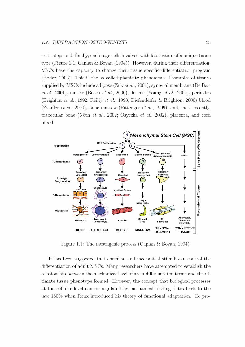
1.2. DISTRACTION OSTEOGENESIS 33
crete steps and, finally, end-stage cells involved with fabrication of a unique tissue
type (Figure 1.1, Caplan & Boyan (1994)). However, during their differentiation,
MSCs have the capacity to change their tissue specific differentiation program
(Roder, 2003). This is the so called plasticity phenomena. Examples of tissues
supplied by MSCs include adipose (Zuk et al., 2001), synovial membrane (De Bari
et al., 2001), muscle (Bosch et al., 2000), dermis (Young et al., 2001), pericytes
(Brighton et al., 1992; Reilly et al., 1998; Diefenderfer & Brighton, 2000) blood
(Zvaifler et al., 2000), bone marrow (Pittenger et al., 1999), and, most recently,
trabecular bone (Noth et al., 2002; Osyczka et al., 2002), placenta, and cord
blood.
Tendogenesis/
LigamentogenesisMarrow Stroma
Transitory
FibroblastTransitory
Stromal Cell
Osteogenesis Chondrogenesis Myogenesis
MSC Proliferation
Transitory
Osteoblast
Transitory
Chondrocyte Myoblast
Mesenchymal Stem Cell (MSC)
Myoblast Fusion
Unique
Micro-niche
ChondrocyteOsteoblast
Other
Bo
ne
Ma
rro
w/P
eri
os
teu
mM
es
en
ch
ym
al
Tis
su
e
Proliferation
Commitment
Lineage
Progression
Differentiation
Maturation
OsteocyteHypertrophic
ChondrocyteMyotube
Stromal
Cells
T/L
Fibroblast
Adipocytes,
Dermal and
Other Cells
BONE CARTILAGE MUSCLE MARROWTENDON/
LIGAMENT
CONNECTIVE
TISSUE
THE MESENGENIC PROCESS
Figure 1.1: The mesengenic process (Caplan & Boyan, 1994).
It has been suggested that chemical and mechanical stimuli can control the
differentiation of adult MSCs. Many researchers have attempted to establish the
relationship between the mechanical level of an undifferentiated tissue and the ul-
timate tissue phenotype formed. However, the concept that biological processes
at the cellular level can be regulated by mechanical loading dates back to the
late 1800s when Roux introduced his theory of functional adaptation. He pro-

34 CHAPTER 1. INTRODUCTION
posed that the mechanical environment of “irritations” actually stimulated the
formation of particular types of connective tissue (Roux, 1895). In particular,
he postulated that compression stimulated the formation of bone, tension for
connective tissue, and relative displacement in combination with compression or
tension for cartilage.
Roux’s hypothesis took some time before been taken up in orthopedics. It
was only in the 1920s that his work was seriously considered again in relation
to fracture healing. Pauwels (1941) proposed a more rigorous mechanoregulation
theory based on continuum mechanics. His studies were largely based on clinical
observation and logic. He hypothesized that the invariants of the strain and stress
tensors guided the differentiation pathway, whereby deviatoric stresses stimulate
the formation of fibrous connective tissue and hydrostatic, compressive stresses
stimulate cartilage formation. No specific stimulus exists in this theory for the
differentiation of bony tissue (Figure 1.2).
Later, a simpler idea, strain-based, was proposed by Perren (1979) and Perren
& Cordey (1980) to predict the evolution of tissues in a bone fracture gap. They
developed the concept of “interfragmentary strain (IFS)”:
IFS =∆L
L(1.1)
where L is the width of the fracture gap and ∆L is the change of the fracture
gap after loading. Perren & Cordey (1980) believed that tissue differentiation
was a result of tissue disruption. Therefore, if IFS exceeds the tissue strength or
tissue elongation, the tissue resulted in rupture and would change its phenotype
such that tissue failure would not occur. As observed in Figure 1.3, the strain
tolerance is greatest for granulation tissue, intermediate for cartilage, and least
for bone.
Based also on the ideas of Pauwels, Carter proposed a combination of octa-
hedral shear stress and hydrostatic stress for his differentiation theory (Carter,
1987; Carter et al., 1998). They postulated that the compressive hydrostatic
stress history guides the formation of cartilage, whereas the tensile strain history
guides the synthesis of fibrous connective tissue and bone is formed in regions
without significant levels of both (Figure 1.4). Unlike Pauwels, they recognized
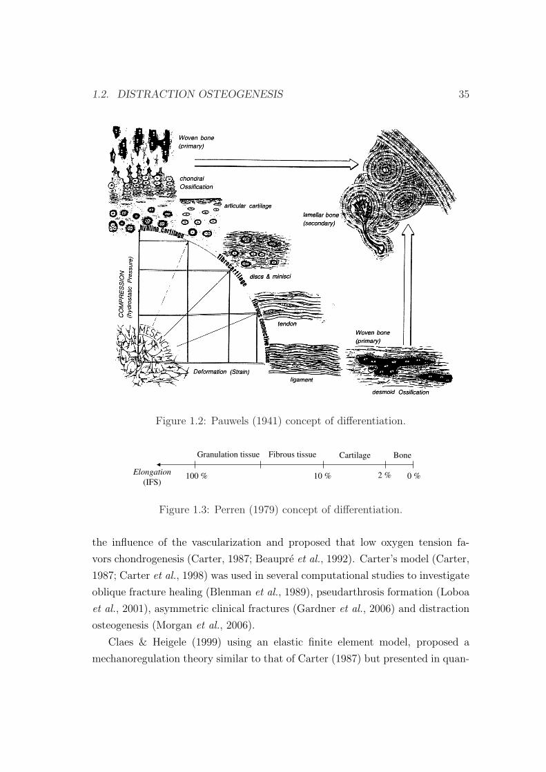
1.2. DISTRACTION OSTEOGENESIS 35
Figure 1.2: Pauwels (1941) concept of differentiation.
BoneCartilageFibrous tissueGranulation tissue
Elongation
(IFS)100 % 10 % 2 % 0 %
Figure 1.3: Perren (1979) concept of differentiation.
the influence of the vascularization and proposed that low oxygen tension fa-
vors chondrogenesis (Carter, 1987; Beaupre et al., 1992). Carter’s model (Carter,
1987; Carter et al., 1998) was used in several computational studies to investigate
oblique fracture healing (Blenman et al., 1989), pseudarthrosis formation (Loboa
et al., 2001), asymmetric clinical fractures (Gardner et al., 2006) and distraction
osteogenesis (Morgan et al., 2006).
Claes & Heigele (1999) using an elastic finite element model, proposed a
mechanoregulation theory similar to that of Carter (1987) but presented in quan-
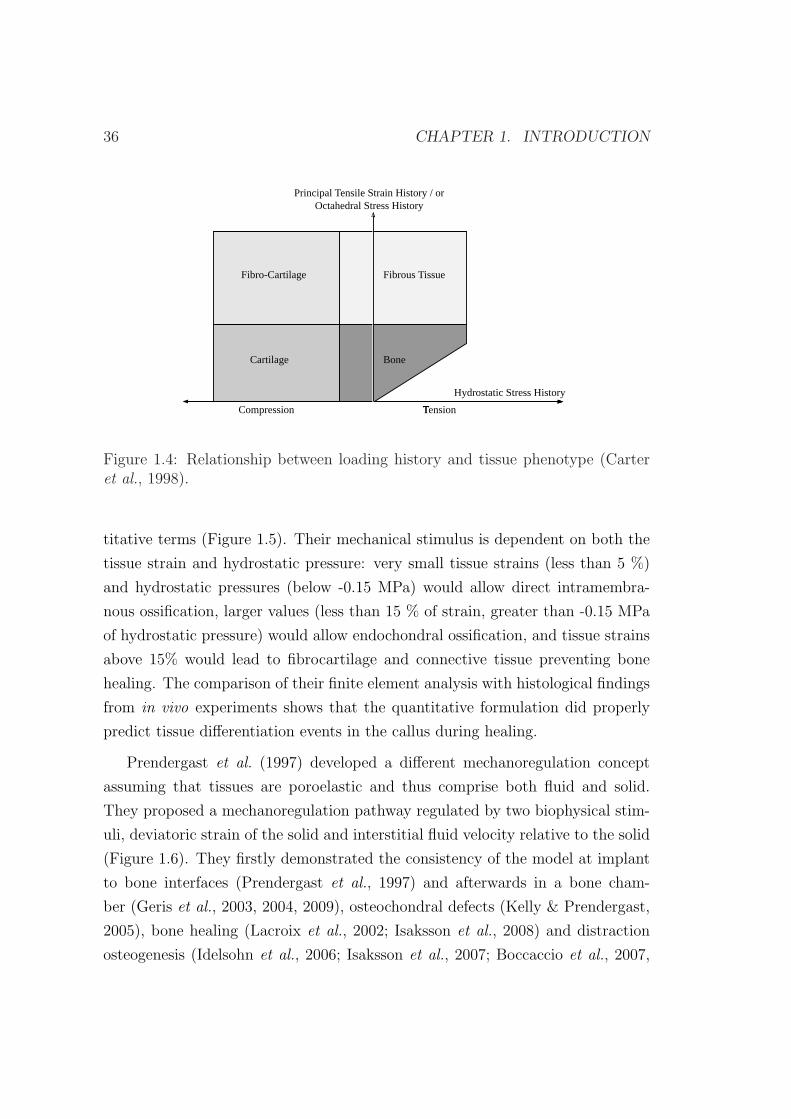
36 CHAPTER 1. INTRODUCTION
Fibro-Cartilage Fibrous Tissue
Cartilage Bone
Hydrostatic Stress History
Principal Tensile Strain History / orOctahedral Stress History
TensionCompression
Figure 1.4: Relationship between loading history and tissue phenotype (Carteret al., 1998).
titative terms (Figure 1.5). Their mechanical stimulus is dependent on both the
tissue strain and hydrostatic pressure: very small tissue strains (less than 5 %)
and hydrostatic pressures (below -0.15 MPa) would allow direct intramembra-
nous ossification, larger values (less than 15 % of strain, greater than -0.15 MPa
of hydrostatic pressure) would allow endochondral ossification, and tissue strains
above 15% would lead to fibrocartilage and connective tissue preventing bone
healing. The comparison of their finite element analysis with histological findings
from in vivo experiments shows that the quantitative formulation did properly
predict tissue differentiation events in the callus during healing.
Prendergast et al. (1997) developed a different mechanoregulation concept
assuming that tissues are poroelastic and thus comprise both fluid and solid.
They proposed a mechanoregulation pathway regulated by two biophysical stim-
uli, deviatoric strain of the solid and interstitial fluid velocity relative to the solid
(Figure 1.6). They firstly demonstrated the consistency of the model at implant
to bone interfaces (Prendergast et al., 1997) and afterwards in a bone cham-
ber (Geris et al., 2003, 2004, 2009), osteochondral defects (Kelly & Prendergast,
2005), bone healing (Lacroix et al., 2002; Isaksson et al., 2008) and distraction
osteogenesis (Idelsohn et al., 2006; Isaksson et al., 2007; Boccaccio et al., 2007,
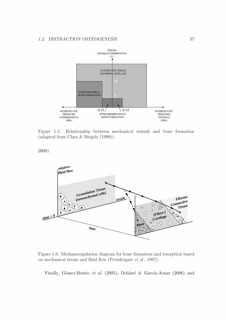
1.2. DISTRACTION OSTEOGENESIS 37
-0.85-5
ENDOCHONDRAL
BONE FORMATION
INTRAMEMBRANOUS
BONE FORMATION
HYDROSTATIC
PRESSURE
(COMPRESSIVE)
(MPa)
HYDROSTATIC
PRESSURE
(TENSILE)
(MPa)
STRAIN
(TENSILE/COMPRESSIVE)
(%)
CONNECTIVE TISSUE
OR FIBROCARTILAGE
-0.15 0.15
5
15
Figure 1.5: Relationship between mechanical stimuli and bone formation(adapted from Claes & Heigele (1999)).
2008).
time = 0
relative
fluid flow
strainGranulation Tissue
(mesenchymal cells)
Fibrous
Connective
Tissue
(Fibro-)
Cartilage
timeBone
Figure 1.6: Mechanoregulation diagram for bone formation and resorption basedon mechanical strain and fluid flow (Prendergast et al., 1997).
Finally, Gomez-Benito et al. (2005), Doblare & Garcıa-Aznar (2006) and
38 CHAPTER 1. INTRODUCTION
Garcıa-Aznar et al. (2007) proposed a mathematical model driven exclusively
by the second invariant of the deviatoric strain tensor, assuming that tissues are
poroelastic.
Although these theories are different in details, they share some characteris-
tics. Firstly, they all propose that high mechanical stimulation favors the for-
mation of fibrocartilage tissue, while non stimulated environments favor bone
formation. Secondly, they all develop phenomenologic rules, with theories de-
rived from empirical observations. Thirdly, they are not sufficiently validated
despite being able to successfully reproduce the main patterns of fracture healing
in specific mechanical environments. And finally, all these tissue differentiation
theories are obviously related to mechanical stimuli, which is definitely executed
by cells whose biological sensing and signaling activities are implicitly assumed
but not directly considered.
Models of bone healing
Although most of the previous differentiation theories were developed within nu-
merical frames, such as the finite element analysis (FEA), the older ones were
taken up when these new tools emerged. For example, Cheal et al. (1991) took
up the “interfragmentary strain hypothesis” proposed by Perren (1979). They
compared the histology of fracture callus with magnitudes of strain using the
FEA to determine computationally the strain distribution in the callus at the
initial stage of healing. Although they did not demonstrate tissue damage, they
found an association of high strain levels with bone resorption and low strain
levels with bone formation.
Ament & Hofer (1996, 2000) proposed a biomechanical model based on a set
of fuzzy logic rules to describe the tissue transformation during healing. They
introduced a biological factor in addition to the mechanical stimulus. The bi-
ological factor was an osteogenic factor that accounted for the vascularization
and therefore allowed the differentiation between intramembranous and chondral
ossification. The mechanical stimulus was the strain energy density. They suc-
ceed in predicting bridging of the bone ends through cartilage, followed by the
growth of a callus cuff, and finally, the resorption of callus after ossification of the
interfragmentary gap. This approach has been taken up more recently by Simon
1.2. DISTRACTION OSTEOGENESIS 39
et al. (2003) and Shefelbine et al. (2005), who simulated, using finite element
analysis and the fuzzy logic, fracture healing, based on local mechanical factors,
as described by Claes & Heigele (1999), and the local vascularity.
Bailon-Plaza & van der Meulen (2001) presented the first two-dimensional
temporo-spatial mathematical model of the bone healing process that considers
the effect of the growth factors. This model was later modified to incorporate the
effects of mechanical stimulation on cell differentiation (Bailon-Plaza & van der
Meulen, 2003). More recently, Geris et al. (2006, 2008) developed this model
further by including key aspects of healing, such as angiogenesis and directed
cell migration and compared the simulation results with the experimental ob-
servations. They also demonstrated the potential therapeutical value of bone
regeneration models (Geris et al., 2008).
Lacroix et al. (2002) have developed a bone healing model based on the
mechanoregulation theory early formulated by Prendergast et al. (1997). This
model has been taken up by Andreykiv et al. (2007) to include diffusion, prolifer-
ation and differentiation of cell populations (mesenchymal stem cells, fibroblasts,
chondrocytes and osteoblasts). A similar model was proposed by Isaksson et al.
(2008). They develop a mechanistic model of tissue differentiation, which directly
couples cellular mechanisms to mechanical stimuli during bone healing.
Finally, Gomez-Benito et al. (2005), Doblare & Garcıa-Aznar (2006) and
Garcıa-Aznar et al. (2007) succeed in simulating the main processes that oc-
cur during fracture healing, namely proliferation, migration and differentiation
as well as tissue damage and vascularization. Moreover, they improved on ex-
isting numerical models of fracture healing (Ament & Hofer, 2000; Bailon-Plaza
& van der Meulen, 2001; Lacroix & Prendergast, 2002a; Bailon-Plaza & van der
Meulen, 2003) by providing a mathematical formulation of callus growth.
Models of distraction osteogenesis
Fracture and distraction repair proceed by the same cellular healing process (Lam-
mens et al., 1998; Jensen, 2002), and therefore, most existing models of distraction
osteogenesis are based on existing models of fracture healing.
In fact, compared to the huge amount of bone healing models, only a small
number of computational works have been developed in bone distraction. Most
40 CHAPTER 1. INTRODUCTION
of these previous computational studies are based on biomechanical models, ana-
lyzing how the geometry, material properties and loading conditions at a specific
time point affect the mechanical environment around the osteotomy (Carter et al.,
1998; Samchukov et al., 1998; Loboa et al., 2005; Kofod et al., 2005; Cattaneo
et al., 2005; Boccaccio et al., 2006; Morgan et al., 2006).
For example, Samchukov et al. (1998) evaluated the biomechanical effects of
the orientation of linear distractors with a two-dimensional model of a human
mandible and concluded that distraction appliances must be oriented parallel to
the axis of distraction.
Carter and its coworkers (Carter et al., 1998; Morgan et al., 2006) character-
ized the local bio-physical environment created within the osteotomy gap during
long bone distraction osteogenesis. Firstly, Carter et al. (1998) predicted the
maximum principal tensile strain and hydrostatic stress patterns at two stages
of distraction osteogenesis. Afterwards, Morgan et al. (2006) quantified compu-
tationally the spatial and temporal profiles of four mechanical stimuli for tissue
differentiation (pressure, tensile strain, fluid flow and tissue dilatation) and con-
cluded that tissue dilatation might be a key stimulus for bone regeneration (Figure
1.7).
In the same research group, Loboa et al. (2005) performed a three dimensional
finite element analysis at different time points during mandibular distraction
in a rat model. They determined the changes in hydrostatic stress and tensile
strain fields throughout distraction and compared them successfully with previous
histological findings.
Kofod et al. (2005) and Cattaneo et al. (2005) investigated the stress dis-
tribution in the mandible and the temporomandibular joint (TMJ) before and
after skeletal correction by intraoral unilateral vertical mandibular ramus distrac-
tion, using a finite element model. Their results suggested that correction of the
mandibular deformity by distraction osteogenesis tends to normalize the stress
patterns in the TMJ.
Boccaccio et al. (2006) studied the mechanical response of a human mandible
when distraction orthodontic devices are used by comparing the displacement
field and the stress distribution in an osteotomized and healthy mandible. In
particular, they analyzed the effect of mastication in the undistracted mandible,
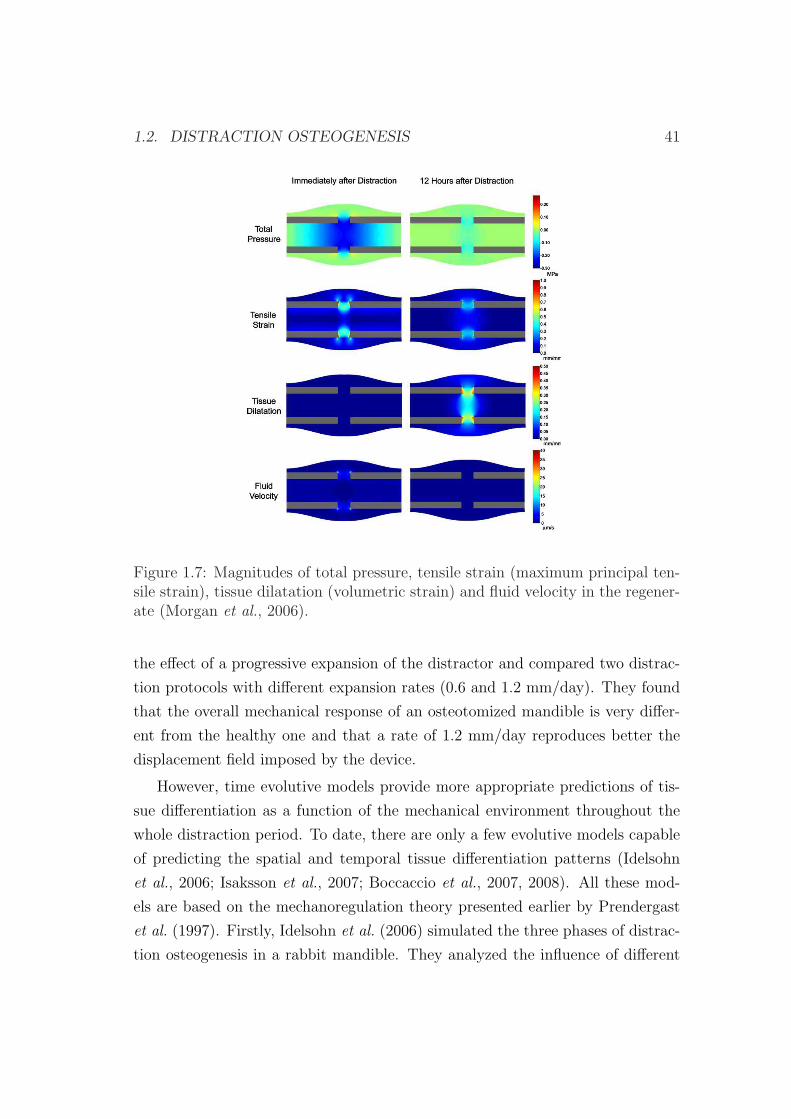
1.2. DISTRACTION OSTEOGENESIS 41
Figure 1.7: Magnitudes of total pressure, tensile strain (maximum principal ten-sile strain), tissue dilatation (volumetric strain) and fluid velocity in the regener-ate (Morgan et al., 2006).
the effect of a progressive expansion of the distractor and compared two distrac-
tion protocols with different expansion rates (0.6 and 1.2 mm/day). They found
that the overall mechanical response of an osteotomized mandible is very differ-
ent from the healthy one and that a rate of 1.2 mm/day reproduces better the
displacement field imposed by the device.
However, time evolutive models provide more appropriate predictions of tis-
sue differentiation as a function of the mechanical environment throughout the
whole distraction period. To date, there are only a few evolutive models capable
of predicting the spatial and temporal tissue differentiation patterns (Idelsohn
et al., 2006; Isaksson et al., 2007; Boccaccio et al., 2007, 2008). All these mod-
els are based on the mechanoregulation theory presented earlier by Prendergast
et al. (1997). Firstly, Idelsohn et al. (2006) simulated the three phases of distrac-
tion osteogenesis in a rabbit mandible. They analyzed the influence of different
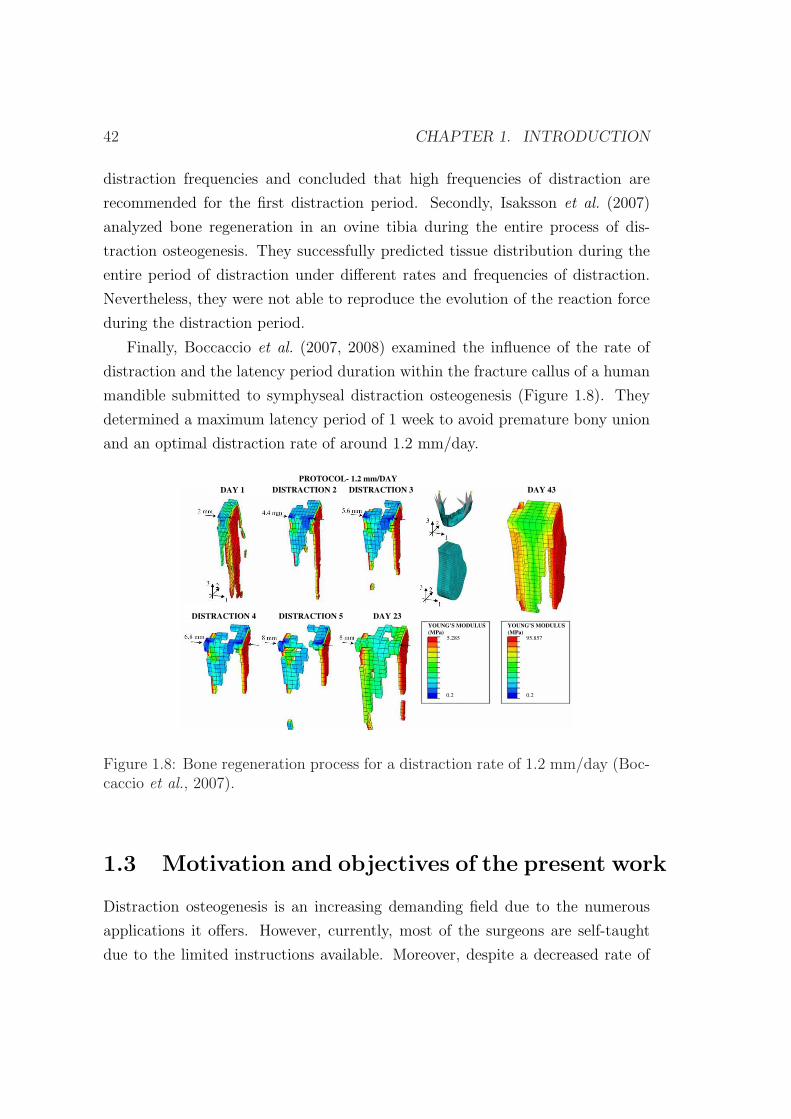
42 CHAPTER 1. INTRODUCTION
distraction frequencies and concluded that high frequencies of distraction are
recommended for the first distraction period. Secondly, Isaksson et al. (2007)
analyzed bone regeneration in an ovine tibia during the entire process of dis-
traction osteogenesis. They successfully predicted tissue distribution during the
entire period of distraction under different rates and frequencies of distraction.
Nevertheless, they were not able to reproduce the evolution of the reaction force
during the distraction period.
Finally, Boccaccio et al. (2007, 2008) examined the influence of the rate of
distraction and the latency period duration within the fracture callus of a human
mandible submitted to symphyseal distraction osteogenesis (Figure 1.8). They
determined a maximum latency period of 1 week to avoid premature bony union
and an optimal distraction rate of around 1.2 mm/day.
PROTOCOL- 1.2 mm/DAY
DAY 1 DISTRACTION 2 DAY 43
DAY 23DISTRACTION 4 DISTRACTION 5
DISTRACTION 3
YOUNG’S MODULUS
(MPa)
YOUNG’S MODULUS
(MPa)
5.285
0.2 0.2
95.857
Figure 1.8: Bone regeneration process for a distraction rate of 1.2 mm/day (Boc-caccio et al., 2007).
1.3 Motivation and objectives of the present work
Distraction osteogenesis is an increasing demanding field due to the numerous
applications it offers. However, currently, most of the surgeons are self-taught
due to the limited instructions available. Moreover, despite a decreased rate of
1.3. MOTIVATION AND OBJECTIVES OF THE PRESENT WORK 43
complications, limb lengthening is a very complex process with numerous adversi-
ties. Good judgment, accurate knowledge and meticulous technique are necessary
to select and design devices, perform corticotomies, maximize bone regeneration,
manage pin sites, maintain articular function and time fixator removal (Dahl
et al., 1994).
The new developments in cellular, molecular and computational technologies,
as well as the new designs of internal and external devices will help to improve the
treatment of distraction osteogenesis. Since the late 80s, with the development of
computers, there has been an increasing interest of engineers on biomedical fields,
and in particular, in the last decade, in distraction osteogenesis. We believe that
engineers play a crucial role in this emerging field since accurate simulations of
the process and patient specific models can help the surgeon for a more precise
performance.
Most of the existing models analyze specific instants of time (Carter et al.,
1998; Samchukov et al., 1998; Loboa et al., 2005; Kofod et al., 2005; Cattaneo
et al., 2005; Boccaccio et al., 2006; Morgan et al., 2006). However, the temporo-
spatial prediction of the process could be much valuable for the orthopaedic sur-
geons in terms of the distraction process planning. To date, there are only a few
evolutive models capable of predicting the spatial and temporal tissue differen-
tiation patterns from a qualitative point of view (Idelsohn et al., 2006; Isaksson
et al., 2007; Boccaccio et al., 2007, 2008).
This lack of mechanobiological models in bone distraction and its potential
interest to surgeons is the main motivation of this work. Within this purpose,
the first aim of this thesis is to develop a robust mechanobiological model able
to predict the main features of distraction osteogenesis under different mechan-
ical environments and within different types of bone. For example, the effect of
the distraction rate, residual stresses, fixator stiffness, or geometry of the bone
have been analyzed in long bone lengthening whilst a clinical case of hemifacial
microsomia has been simulated in a mandible reconstructed from the patient ge-
ometry. Different clinical settings have been simulated and compared against
experimental results. To perform these objectives, the manuscript is organized
as follows.
In chapter two, the physiology of the most important tissues involved in dis-
44 CHAPTER 1. INTRODUCTION
traction osteogenesis is briefly described and the biological principles behind dis-
traction are analyzed. In particular, the following tissues are described: bone,
cartilage, granulation tissue and fibrous tissue. Moreover, the phases of distrac-
tion osteogenesis, the histology, the load measurements, the biomechanical factors
and the main applications of this process are presented.
In chapter three, a new mathematical model of distraction osteogenesis is
described. This model considers the main cellular events underlying distraction
osteogenesis: cell proliferation, migration and differentiation as well as tissue
growth and damage and incorporates important effects such as the influence of
the load history on tissue differentiation. Since mechanical loading has profound
influences on distraction osteogenesis, in this chapter the model is applied to
different mechanical environments, comparing the results to experimental setups
found in the literature. In particular, the effect of different distraction rates is
analyzed: 1 mm/day, 0.3 mm/day and 2 mm/day.
In chapter four a general macroscopic formulation is presented, which is able
to consider the effect of residual stresses in living tissues. Then, the model is
particularized to the process of distraction osteogenesis and afterwards applied
to a clinical example in order to investigate the influence of residual stresses on
the outcome of limb lengthening. Finally, the pattern of limb lengthening is
compared in different animal species and a human case.
In chapter five the model is applied to a pediatric mandible of a patient with
hemifacial microsomia. This chapter is divided into the analysis of two different
applications: biomechanical and mechanobiological. First, the pattern of stresses
and strains is analyzed before and after the process of distraction and compared
with a healthy idealized case. And secondly, a temporo-spatial analysis of the
whole process of distraction is developed and the final outcome compared against
actual clinical results.
Finally, in chapter six, the final conclusions, the future work as well as the
main original contributions of this work are presented.
Chapter 2
Biological background of bone
distraction
2.1 Introduction
Distraction osteogenesis is a unique biologic process of new bone formation be-
tween the surfaces of bone segments that are gradually separated. Under the
influence of the tensional stress, the soft callus is maintained at the center of the
distraction gap while routine fracture healing occurs at the periphery of the re-
generate (Samchukov et al., 2001). Many tissues besides bone have been observed
to form under tension stress, including mucosa, skin, muscle, tendon, cartilage,
blood vessels, and peripheral nerves (Ilizarov, 1989a,b; Cope et al., 1999). There-
fore, distraction osteogenesis involves a process of continuum tissue formation.
In the following sections, we review the tissue physiology of the connective
tissues with a special emphasis on the most commonly found in distraction os-
teogenesis. Moreover, the process of distraction osteogenesis is described from a
biological and mechanical perspective, detailing the main phases of the process
as well as the mechanobiological factors involved. Finally, the main applications
of this technique are discussed.
45
46 CHAPTER 2. BIOLOGICAL BACKGROUND
2.2 Connective tissue physiology
Connective tissues share a common origin from undifferentiated mesenchymal
cells (Figure 1.1) and encompass the major structural constituents of the body.
The different types of connective tissues are responsible of providing and main-
taining form in the body. Functioning mechanically, they provide a matrix that
connects and binds the cells and organs and ultimately give support to the body.
Its structure is composed by ground substance, cells and fibers. Unlike the other
tissues (epithelial, muscle an nerve), which are formed mainly by cells, the major
constituent of the connective tissue is the extracellular matrix. Extracellular ma-
trices consist of different combinations of protein fibers (collagen, reticular and
elastic), most of which are collagen fibers and ground substance (Junqueira &
Carneiro, 2005). Of the more than 20 types of collagen thus far identified, types
I to III are found mainly in connective tissues (see Table 2.1).
Connective tissues include cartilage, tendons, ligaments, bone and the adipose
tissues as well as skin, blood and lymph (Cowin, 1999). Here, we review the main
tissue types that appear in the distracted gap, i.e., bone tissue, cartilage tissue,
fibrous tissue and granulation tissue. The composition and the structure of the
tissues that develop within the distracted gap is presented.
2.2.1 Bone tissue
Bone is a metabolically active tissue capable of adapting its structure to mechan-
ical stimuli and repairing structural damage through the process of remodeling
(Robling et al., 2006). It has the capability of forming new osseous tissue at
locations that are damaged or missing, such as in fracture healing, distraction os-
teogenesis or bone implants interface or removing bone matrix in case of disuse.
This calcified, vascular connective tissue has many functions, including support,
protection, mineral storage, blood cell production (hematopoiesis) and locomo-
tion through the attachment of muscles.
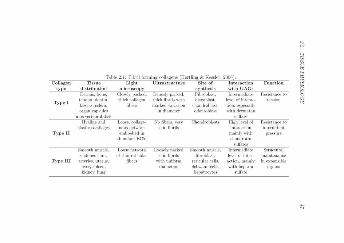
2.2.T
ISSU
EP
HY
SIO
LO
GY
47
Table 2.1: Fibril forming collagens (Hertling & Kessler, 2006).Collagen Tissue Light Ultrastructure Site of Interaction Function
type distribution microscopy synthesis with GAGs
Type I
Dermis, bone, Closely packed, Densely packed, Fibroblast, Intermediate Resistance totendon, dentin, thick collagen thick fibrils with osteoblast, level of interac- tensionfascias, sclera, fibers marked variation chondroblast, tion, especiallyorgan capsules in diameter odontoblast with dermatan
intervertebral disk sulfate
Type II
Hyaline and Loose, collage- No fibers, very Chondroblasts High level of Resistance toelastic cartilages nous network thin fibrils interaction intermitent
embbebed in mainly with pressureabundant ECM chondrotin
sulfates
Type III
Smooth muscle, Loose network Loosely packed Smooth muscle, Intermediate Structuralendoneurium, of thin reticular thin fibrils fibroblast, level of inter- maintenance
arteries, uterus, fibers with uniform reticular cells, action, mainly in expansibleliver, spleen, diameters Schwann cells, with heparin organskidney, lung hepatocytes sulfate
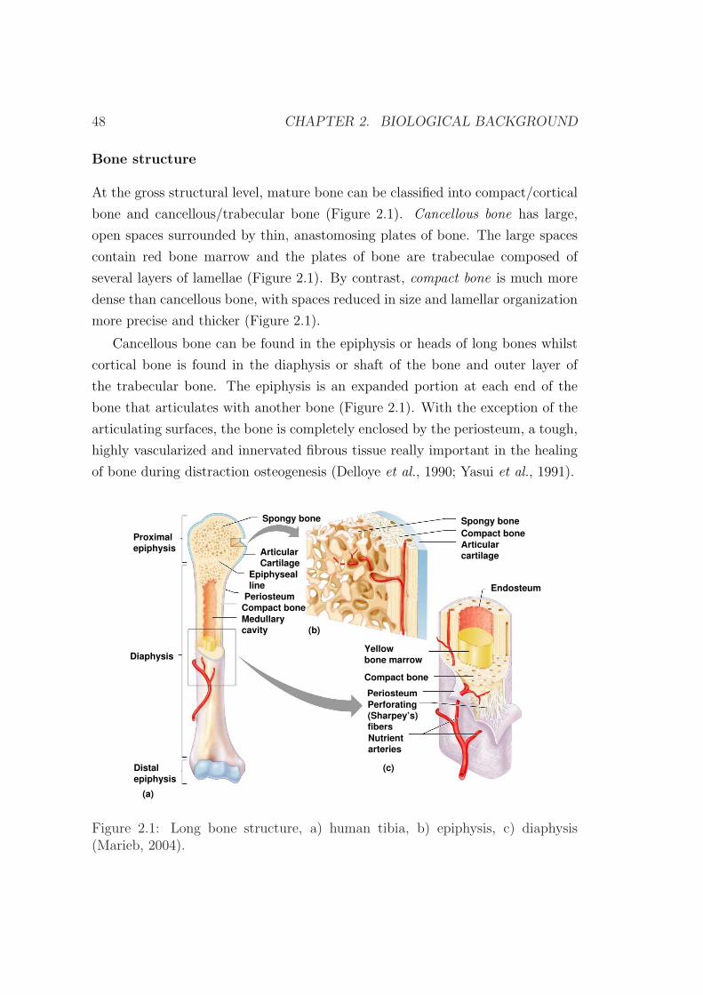
48 CHAPTER 2. BIOLOGICAL BACKGROUND
Bone structure
At the gross structural level, mature bone can be classified into compact/cortical
bone and cancellous/trabecular bone (Figure 2.1). Cancellous bone has large,
open spaces surrounded by thin, anastomosing plates of bone. The large spaces
contain red bone marrow and the plates of bone are trabeculae composed of
several layers of lamellae (Figure 2.1). By contrast, compact bone is much more
dense than cancellous bone, with spaces reduced in size and lamellar organization
more precise and thicker (Figure 2.1).
Cancellous bone can be found in the epiphysis or heads of long bones whilst
cortical bone is found in the diaphysis or shaft of the bone and outer layer of
the trabecular bone. The epiphysis is an expanded portion at each end of the
bone that articulates with another bone (Figure 2.1). With the exception of the
articulating surfaces, the bone is completely enclosed by the periosteum, a tough,
highly vascularized and innervated fibrous tissue really important in the healing
of bone during distraction osteogenesis (Delloye et al., 1990; Yasui et al., 1991).
Proximalepiphysis
Diaphysis
Distalepiphysis
Spongy bone
Medullarycavity
Articularcartilage
Compact bone
Endosteum
Yellowbone marrow
Compact bone
PeriosteumPerforating(Sharpey’s)fibersNutrientarteries
(a)
(b)
(c)
Spongy bone
Compact bonePeriosteum
Epiphysealline
ArticularCartilage
Figure 2.1: Long bone structure, a) human tibia, b) epiphysis, c) diaphysis(Marieb, 2004).
2.2. TISSUE PHYSIOLOGY 49
At the tissue level, bone may be divided into three wide categories:
• Woven bone: This type of bone is laid down rapidly as a disorganized
arrangement of collagen fibers and osteocytes. The disorganized pattern
and generally lower proportions of noncollagenous proteins decrease the
mechanical strength of woven bone compared with the primary or secondary
bone. The cell to bone volume ratio is high, confirming its role in providing
temporary, rapid mechanical support, such as following traumatic injury.
This type of bone is unique because it can be deposited without a preexisting
membrane, bone or cartilaginous model (Martin et al., 1998).
In adult skeleton, this young regenerated bone can be found in a fracture
callus, during distraction osteogenesis and in areas undergoing active endo-
chondral ossification.
Chemical analysis of this bone type has revealed constituents consistent
with normal bone. The water (15%), lipid (5%), calcium (25%), phosphorus
(12%), and collagen (24%) contents have been measured and compared
favorably to normal bone specimen (Lieberman & Friedlaender, 2005).
• Primary bone or lamellar bone can exist in cortical and trabecular bone.
Unlike woven bone, primary bone must replace a preexisting structure,
either a cartilaginous model or previously deposited woven bone.
• Secondary bone is deposited only during remodeling and replaces primary
cortical or trabecular bone. Differences between the developmental process
of primary and secondary bone imply that a different controlling mech-
anism may be responsible for the endosteal and periosteal deposition of
primary bone versus the intracortical deposition of secondary bone during
remodeling.
Bone cells
Three main types of cell populations may be distinguished within the bone tissue:
• Osteoblasts are mononuclear bone cells of mesenchymal origin that secrete
unmineralized bone matrix (osteoid), which eventually mineralizes to yield
50 CHAPTER 2. BIOLOGICAL BACKGROUND
mature bone. These are the most abundant bone cells that develop dur-
ing the early stages of distraction osteogenesis. There are two variants of
osteoblasts: mesenchymal osteoblasts or bone lining cells (Shapiro, 1988).
The former are poorly differentiated cells that originate from the MSCs
and synthesize woven matrix by secreting collagen fibrils circumferentially.
These are crucial in the distraction osteogenesis procedure. The latter are
essentially inactive osteoblasts. They array themselves in a well-polarized
fashion along the woven bone surface and secrete fibrils in a parallel or
lamellar orientation.
• Osteocytes are terminally differentiated osteoblasts that are completely sur-
rounded by the mineralized collagen matrix. These cells are the most abun-
dant cells in bone, can be in woven or lamellar bone and may act as sensors
for the mechanical and chemical signals (Cowin et al., 1991; Lanyon, 1993;
Burger, 2001). They are distributed throughout the bone tissue volume and
have the ability to communicate with other bone cells through an exten-
sive network of cellular processes connected at gap junctions. Osteocytes
response to mechanical stimuli includes changes in strain itself and strain
generated changes in their fluid environment (Ehrlich & Lanyon, 2002).
They then transduce the mechanical signals derived from mechanical load-
ing into cues that eventually result in reduced bone loss or enhanced bone
gain (Robling et al., 2006).
• Osteoclasts are multinucleate cells derived from fusion of mononuclear hae-
mopoietic precursors that resorb bone by secretion of acid and proteases.
Bone development
Normal bone develops via intramembranous or endochondral ossification. The
former arises in a richly vascularized mesenchymal membrane where mesenchymal
cells differentiate into osteoblasts without the mediation of a cartilage phase.
The latter describes the synthesis of bone on a mineralized cartilage scaffold.
Both types of bone formation occur within the regenerate during distraction
osteogenesis and bone healing.
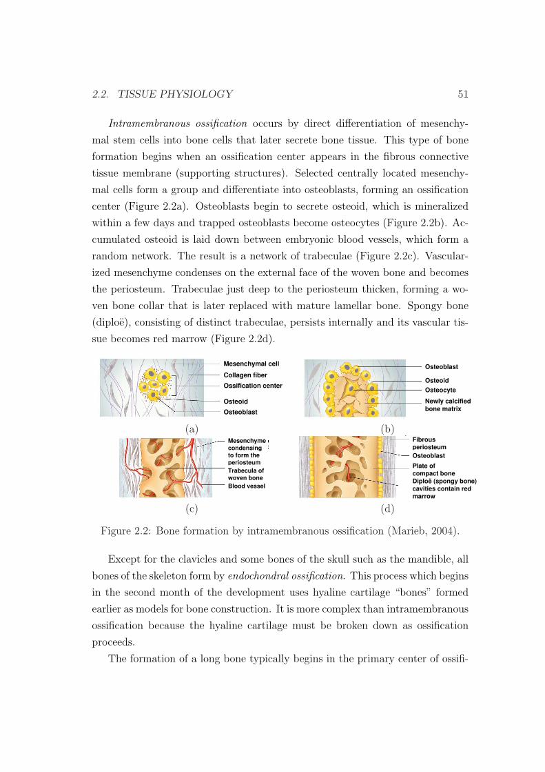
2.2. TISSUE PHYSIOLOGY 51
Intramembranous ossification occurs by direct differentiation of mesenchy-
mal stem cells into bone cells that later secrete bone tissue. This type of bone
formation begins when an ossification center appears in the fibrous connective
tissue membrane (supporting structures). Selected centrally located mesenchy-
mal cells form a group and differentiate into osteoblasts, forming an ossification
center (Figure 2.2a). Osteoblasts begin to secrete osteoid, which is mineralized
within a few days and trapped osteoblasts become osteocytes (Figure 2.2b). Ac-
cumulated osteoid is laid down between embryonic blood vessels, which form a
random network. The result is a network of trabeculae (Figure 2.2c). Vascular-
ized mesenchyme condenses on the external face of the woven bone and becomes
the periosteum. Trabeculae just deep to the periosteum thicken, forming a wo-
ven bone collar that is later replaced with mature lamellar bone. Spongy bone
(diploe), consisting of distinct trabeculae, persists internally and its vascular tis-
sue becomes red marrow (Figure 2.2d).
Mesenchymal cell
Collagen fiber
Ossification center
Osteoid
Osteoblast
Osteoblast
Osteoid
Osteocyte
Newly calcifiedbone matrix
(a) (b)Mesenchymecondensingto form theperiosteumTrabecula ofwoven boneBlood vessel
FibrousperiosteumOsteoblast
Diploë (spongy bone)cavities contain redmarrow
Plate ofcompact bone
(c) (d)
Figure 2.2: Bone formation by intramembranous ossification (Marieb, 2004).
Except for the clavicles and some bones of the skull such as the mandible, all
bones of the skeleton form by endochondral ossification. This process which begins
in the second month of the development uses hyaline cartilage “bones” formed
earlier as models for bone construction. It is more complex than intramembranous
ossification because the hyaline cartilage must be broken down as ossification
proceeds.
The formation of a long bone typically begins in the primary center of ossifi-
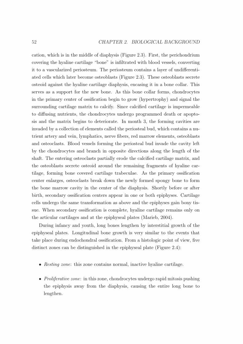
52 CHAPTER 2. BIOLOGICAL BACKGROUND
cation, which is in the middle of diaphysis (Figure 2.3). First, the perichondrium
covering the hyaline cartilage “bone” is infiltrated with blood vessels, converting
it to a vascularized periosteum. The periosteum contains a layer of undifferenti-
ated cells which later become osteoblasts (Figure 2.3). These osteoblasts secrete
osteoid against the hyaline cartilage diaphysis, encasing it in a bone collar. This
serves as a support for the new bone. As this bone collar forms, chondrocytes
in the primary center of ossification begin to grow (hypertrophy) and signal the
surrounding cartilage matrix to calcify. Since calcified cartilage is impermeable
to diffusing nutrients, the chondrocytes undergo programmed death or apopto-
sis and the matrix begins to deteriorate. In month 3, the forming cavities are
invaded by a collection of elements called the periosteal bud, which contains a nu-
trient artery and vein, lymphatics, nerve fibers, red marrow elements, osteoblasts
and osteoclasts. Blood vessels forming the periosteal bud invade the cavity left
by the chondrocytes and branch in opposite directions along the length of the
shaft. The entering osteoclasts partially erode the calcified cartilage matrix, and
the osteoblasts secrete osteoid around the remaining fragments of hyaline car-
tilage, forming bone covered cartilage trabeculae. As the primary ossification
center enlarges, osteoclasts break down the newly formed spongy bone to form
the bone marrow cavity in the center of the diaphysis. Shortly before or after
birth, secondary ossification centers appear in one or both epiphyses. Cartilage
cells undergo the same transformation as above and the epiphyses gain bony tis-
sue. When secondary ossification is complete, hyaline cartilage remains only on
the articular cartilages and at the epiphyseal plates (Marieb, 2004).
During infancy and youth, long bones lengthen by interstitial growth of the
epiphyseal plates. Longitudinal bone growth is very similar to the events that
take place during endochondral ossification. From a histologic point of view, five
distinct zones can be distinguished in the epiphyseal plate (Figure 2.4):
• Resting zone: this zone contains normal, inactive hyaline cartilage.
• Proliferative zone: in this zone, chondrocytes undergo rapid mitosis pushing
the epiphysis away from the diaphysis, causing the entire long bone to
lengthen.
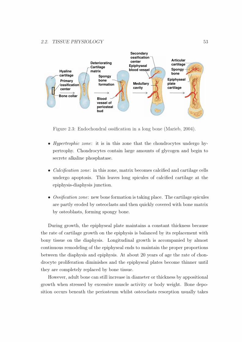
2.2. TISSUE PHYSIOLOGY 53
Hyalinecartilage
Bone collar
DeterioratingCartilagematrix
Spongyboneformation
Primaryossificationcenter
Bloodvessel ofperiostealbud
Secondaryossificationcenter
Epiphysealblood vessel
Medullarycavity
Articularcartilage
Spongybone
Epiphysealplatecartilage
Figure 2.3: Endochondral ossification in a long bone (Marieb, 2004).
• Hypertrophic zone: it is in this zone that the chondrocytes undergo hy-
pertrophy. Chondrocytes contain large amounts of glycogen and begin to
secrete alkaline phosphatase.
• Calcification zone: in this zone, matrix becomes calcified and cartilage cells
undergo apoptosis. This leaves long spicules of calcified cartilage at the
epiphysis-diaphysis junction.
• Ossification zone: new bone formation is taking place. The cartilage spicules
are partly eroded by osteoclasts and then quickly covered with bone matrix
by osteoblasts, forming spongy bone.
During growth, the epiphyseal plate maintains a constant thickness because
the rate of cartilage growth on the epiphysis is balanced by its replacement with
bony tissue on the diaphysis. Longitudinal growth is accompanied by almost
continuous remodeling of the epiphyseal ends to maintain the proper proportions
between the diaphysis and epiphysis. At about 20 years of age the rate of chon-
drocyte proliferation diminishes and the epiphyseal plates become thinner until
they are completely replaced by bone tissue.
However, adult bone can still increase in diameter or thickness by appositional
growth when stressed by excessive muscle activity or body weight. Bone depo-
sition occurs beneath the periosteum whilst osteoclasts resorption usually takes
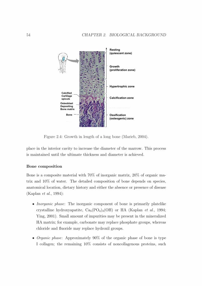
54 CHAPTER 2. BIOLOGICAL BACKGROUND
Resting
(quiescent zone)(quiescent zone)
GrowthGrowth
(proliferation zone)
Hypertrophic zone
Calcified
Calcification zoneCartilage
spicule
Osteoblast
Depositing
Ossification
(osteogenic) zone
Bone
Bone matrix
Figure 2.4: Growth in length of a long bone (Marieb, 2004).
place in the interior cavity to increase the diameter of the marrow. This process
is maintained until the ultimate thickness and diameter is achieved.
Bone composition
Bone is a composite material with 70% of inorganic matrix, 20% of organic ma-
trix and 10% of water. The detailed composition of bone depends on species,
anatomical location, dietary history and either the absence or presence of disease
(Kaplan et al., 1994):
• Inorganic phase: The inorganic component of bone is primarily platelike
crystalline hydroxyapatite, Ca5(PO4)3(OH) or HA (Kaplan et al., 1994;
Ying, 2001). Small amount of impurities may be present in the mineralized
HA matrix; for example, carbonate may replace phosphate groups, whereas
chloride and fluoride may replace hydroxil groups.
• Organic phase: Approximately 90% of the organic phase of bone is type
I collagen; the remaining 10% consists of noncollagenous proteins, such
2.2. TISSUE PHYSIOLOGY 55
as lipids and other macromolecules, i.e., growth factors, cytokines, and
adhesive proteins (Fung, 1993; Kaplan et al., 1994; Ying, 2001). Growth
factors and cytokines (such as insulinlike growth factors), proteins contained
in serum, bone-inductive proteins (such as osteonectin, osteopontin and
osteocalcin) and extracellular matrix compounds (such as bone sialoprotein,
bone proteoglycans, and other phosphoproteins as well as proteolipids) are
present in the mineralized matrix and may mediate bone cell function such
as formation of new bone by osteoblasts and bone resorption by osteoclasts
(Kaplan et al., 1994; Ying, 2001).
The presence of crystals gives bone its rigidity and compressive strength,
whereas collagen fibers confer tensile strength and toughness (Adams et al., 2006).
The water binding properties of proteoglycans enable them to “capture space” in
developing tissue (Adams et al., 2006).
2.2.2 Cartilage tissue
Cartilage is a type of connective tissue that stands up to both tension and com-
pression and has qualities intermediate between dense connective tissue and bone.
It is tough but flexible, providing resilient rigidity to the structures it supports.
Cartilage lacks nerve fibers and unlike other connective tissues is avascular. It
receives by diffusion from the blood vessels located in the connective tissue mem-
brane surrounding it (Marieb & Hoehn, 2007). Thus, compared to other connec-
tive tissues, cartilage grows and repairs more slowly.
It is composed of specialized cells called chondrocytes and chondroblasts that
produce a large amount of extracellular matrix composed of collagen fibers, abun-
dant ground substance rich in proteoglycan, and elastin fibers.
Cartilage is classified in three types:
• Hyaline cartilage is the most abundant cartilage type in the body. It is
a rather hard, translucent material rich in collagen and proteoglycan. It
covers the end of bones to form the smooth articular surface of joints. It is
also found in the nose, the larynx, between the ribs and the sternum and in
the processes of bone healing and distraction osteogenesis. Bones grow via a
56 CHAPTER 2. BIOLOGICAL BACKGROUND
hyaline cartilage intermediate through the endochondral ossification during
normal skeletal development and usually during distraction osteogenesis.
• Elastic cartilage is similar in appearance to hyaline cartilage, except for the
presence of numerous branching elastic fibers within its matrix. It is stiff
yet elastic, and is important to prevent tubular structures from collapsing.
Elastic cartilage is found in the pinna of the ear, in tubular structures such
as the auditory tubes and in the epiglottis.
• Fibrocartilage is characterized by large amounts of irregular and dense bun-
dles of coarse collagen fibers in its matrix. In contrast to hyaline and elastic
cartilage, fibrocartilage consists of alternating layers of cartilage matrix and
thick dense layers of type I collagen fibers. It is a white, very tough material
that provides high tensile strength and support. It contains more collagen
and less proteoglycan than hyaline cartilage. Thus, its properties are closer
to those of tendons than hyaline cartilage. It is present in areas most sub-
jected to frequent stress like intervertebral discs, the symphysis pubis and
the attachments of certain tendons and ligaments.
As hyaline cartilage is the type of cartilage which appears in the distracted
callus, we are here mainly interested in this type of connective tissue. Its organic
matrix is composed of a dense network of fine collagen fibrils (mostly type II
collagen, with minor amounts of types V, VI, IX and XI) that are enmeshed in a
concentrated solution of proteoglycans (PGs) (Bateman et al., 1996). In normal
articular cartilage the collagen content ranges from 15 to 22% by wet weight and
the PG content from 4 to 7% by wet weight. The remaining 60 to 85% is water,
inorganic salts and small amounts of other matrix proteins, glycoproteins and
lipids (Mow & Ratcliffe, 1997). Collagen fibrils and PGs, each being capable of
forming structural networks of significant strength (Kempson et al., 1976; Broom
& Silyn-Roberts, 1990), are the structural components supporting the internal
mechanical stresses that result from loads being applied to the articular carti-
lage. Moreover, these structural components, together with water determine the
mechanical behavior of this tissue (Mow & Ateshian, 1997).

2.2. TISSUE PHYSIOLOGY 57
2.2.3 Fibrous tissue
Fibrous connective tissue is a type of connective tissue which has relatively high
tensile strength and great elasticity, due to a relatively high concentration of
collagenous or elastic fibers. These fibers are embedded in a matrix which consists
primarily on water, polysaccharides and proteins.
The cells of fibrous connective tissue are mostly fibroblasts, irregular, branch-
ing cells that secrete strong fibrous proteins as an extracellular matrix. There are
several categories of fibrous connective tissue:
• Loose connective tissue (Figure 2.5) supports most epithelia and many or-
gans that are required to expand like the lungs, arteries, and bladder. It
also surrounds blood vessels and nerves and is found between muscles and
in the distracted gap during the latency phase of the distraction process
(Pietrzak, 2008). There are three subclasses: areolar, adipose and reticular
(Marieb & Hoehn, 2007).
Fat cellsFibroblasts
Mast cell
Elastic fiber
Capillary
Nerve fiber
Fiber
Collagen bundle
NeutrophilReticular fiber
MacrophageLymphocyte
Fibrocyte
Plasma cell
Figure 2.5: Loose connective tissue with its predominant cells and fibers(Eroschenko & di Fiore, 2007).
– The functions of areolar connective tissue, shared by some but not all
connective tissues, include supporting and binding other tissues, hold-
ing body fluids, defending against infection and storing nutrients as
58 CHAPTER 2. BIOLOGICAL BACKGROUND
fat. Fibroblast predominate, but macrophages, fat cells and occasional
mast cells are also seen. The most obvious structural feature of this
tissue is the loose arrangement of its fibers. Because of its loose nature,
areolar connective tissue provides a reservoir of water and salts for sur-
rounding body tissues. Areolar connective tissue is the most widely
distributed connective tissue in the body and it serves as a kind of
universal packing material between other tissues. It binds body parts
together while allowing them to move freely, wraps small blood ves-
sels and nerves, surrounds glands, forms the subcutaneous tissue and
is present in all mucous membranes. This type of tissue is also the
predominate type involved in wound inflammation and wound healing
and during the latency phase of distraction osteogenesis (Bucci, 1995).
– Adipose connective tissue is similar to areolar tissue in structure and
function but its nutrient-storing ability is much greater. Consequently,
adipocytes (fat cells) predominate and account for 90 % of this tissue
mass. This tissue is highly vascularized indicating its high metabolic
activity and is very abundant since it constitutes 18% of an average
person body weight.
– Reticular connective tissue resembles areolar connective tissue but the
only fibers in its matrix are reticular fibers, which form a network
along which fibroblasts called reticular cells lie scattered. This tissue
forms supporting structures for many organs, such as the spleen and
thymus.
• Dense connective tissue has collagen fibers as its main matrix element.
There are two subclasses: regular or irregular.
Dense regular connective tissue contains closely packed bundles of collagen
fibers forming a uniaxial fiber network and thus providing a great tensile
strength. Unlike areolar connective tissue, this tissue has few cells other
than fibroblasts and is poorly vascularized. Dense regular tissue forms
tendons (which attach muscles to bones) and flat, sheets like tendons called
aponeuroses (which attach muscles to other muscles or to bones). It also
forms fascia and ligaments.
2.2. TISSUE PHYSIOLOGY 59
Irregular connective tissue has the same structural elements as the regular
variety. However, the bundles of collagen fibers are much thicker and they
are arranged irregularly. This type of tissue forms sheets in areas where
tension is exerted from many different directions. It is found in the skin
and it forms fibrous joint capsules and the fibrous covering that surrounds
some organs (kidneys, bone, cartilages, muscles and nerves).
When a non-union or pseudoarthrosis1 takes place in distraction osteogenesis,
two different fibrous tissues may appear in the distracted gap, according to the
type of non-union (Ilizarov & Gracheva, 1971). When the pseudoarthrosis is stiff,
the tissue between bone ends is dense fibrous or fibrocartilagenous tissue whereas
in mobile pseudoarthrosis it is loose connective tissue (Khaleel & Pool, 2003).
2.2.4 Granulation tissue
Granulation tissue is a loosely organized connective tissue that replaces the fibrin
clot during the latency phase in distraction osteogenesis or during the inflam-
matory phase in fracture healing and in wound healing. It is composed largely
of MSCs, proliferating fibroblasts, macrophages, newly formed blood vessels and
ground substance that includes collagen, glycoproteins and hyaluronic acid (a
component of the cartilage) (Mulder et al., 2002). The blood vessels need to be
established as soon as possible to provide the growing tissue with nutrients, to
take away cellular wastes, and transport new leukocytes to the area. Proliferating
fibroblasts produce growth factors as well as new collagen fibers to bridge the gap.
Some of these fibroblasts have contractile properties that pull the margins of the
wound together (Marieb & Hoehn, 2007). The ground substance consists initially
of a network of type III collagen, a weaker form of the structural protein that
can be produced rapidly. This is later replaced by the stronger, long-stranded
type I collagen. Granulation tissue has generally considerable numbers of active
immune cells. The main ones are macrophages and neutrophils, although other
leukocytes are also present. These work to phagocytize old or damaged tissue,
1Pseudarthrosis (or “non-union”) is the formation of a false joint caused by the failure ofthe bones to fuse. This most commonly occurs when the bones do not heal properly after afracture.
60 CHAPTER 2. BIOLOGICAL BACKGROUND
and protect the healing tissue from pathogenic insult. This is necessary both to
aid the healing process and to protect against invading pathogens.
As explained above, experimentally, granulation tissue consists of many cell
types, ground substance and blood vessels. In the initial phase of the distraction
process, these cells are very difficult to distinguish within the distraction gap. In
this thesis, when referring to this type of tissue, we will only consider one of the
associated cells, as representative of all initial precursor cells: the mesenchymal
stem cells. To avoid misunderstanding with the fibrous tissue created in non-
unions, the loose fibrous connective tissue that appears in the latency phase of
the distraction process will also be called in this thesis granulation tissue since
they are very similar in composition and structure.
2.3 Biological basis of bone formation in dis-
traction osteogenesis
Distraction osteogenesis is a surgical technique aimed to produce large amounts
of bony tissue. Depending on the anatomical site where the tensional stress is
induced, distraction osteogenesis techniques can be divided into callotasis (dis-
traction of the fracture callus) or physeal distraction (distraction of the growth
plate). Here, we focus on the former which consists on the gradual stretching
of a reparative callus formed around bone segments surgically interrupted by an
osteotomy (Murray, 1996). This method has been utilized as the predominant
technique of distraction osteogenesis in experimental models and clinical applica-
tions due to the many complications associated to physeal distraction (Pietrzak,
2008).
2.3.1 Phases of distraction osteogenesis
In the distraction process, there are five fundamental sequential phases in which
different biologic phenomena are produced (Figure 2.6):
• Osteotomy. In this phase the bone is surgically divided into two segments,
resulting in a loss of continuity and mechanical integrity. Bone fragments
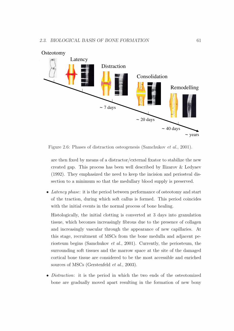
2.3. BIOLOGICAL BASIS OF BONE FORMATION 61
Latency
Distraction
Consolidation
Remodelling
~ 7 days
~ 20 days
~ 40 days
~ years
Osteotomy
Figure 2.6: Phases of distraction osteogenesis (Samchukov et al., 2001).
are then fixed by means of a distractor/external fixator to stabilize the new
created gap. This process has been well described by Ilizarov & Ledyaev
(1992). They emphasized the need to keep the incision and periosteal dis-
section to a minimum so that the medullary blood supply is preserved.
• Latency phase: it is the period between performance of osteotomy and start
of the traction, during which soft callus is formed. This period coincides
with the initial events in the normal process of bone healing.
Histologically, the initial clotting is converted at 3 days into granulation
tissue, which becomes increasingly fibrous due to the presence of collagen
and increasingly vascular through the appearance of new capillaries. At
this stage, recruitment of MSCs from the bone medulla and adjacent pe-
riosteum begins (Samchukov et al., 2001). Currently, the periosteum, the
surrounding soft tissues and the marrow space at the site of the damaged
cortical bone tissue are considered to be the most accessible and enriched
sources of MSCs (Gerstenfeld et al., 2003).
• Distraction: it is the period in which the two ends of the osteotomized
bone are gradually moved apart resulting in the formation of new bony
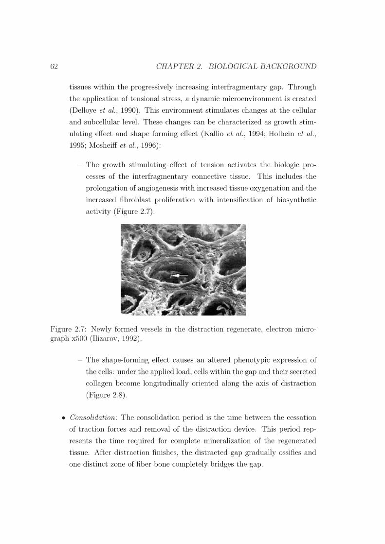
62 CHAPTER 2. BIOLOGICAL BACKGROUND
tissues within the progressively increasing interfragmentary gap. Through
the application of tensional stress, a dynamic microenvironment is created
(Delloye et al., 1990). This environment stimulates changes at the cellular
and subcellular level. These changes can be characterized as growth stim-
ulating effect and shape forming effect (Kallio et al., 1994; Holbein et al.,
1995; Mosheiff et al., 1996):
– The growth stimulating effect of tension activates the biologic pro-
cesses of the interfragmentary connective tissue. This includes the
prolongation of angiogenesis with increased tissue oxygenation and the
increased fibroblast proliferation with intensification of biosynthetic
activity (Figure 2.7).
Figure 2.7: Newly formed vessels in the distraction regenerate, electron micro-graph x500 (Ilizarov, 1992).
– The shape-forming effect causes an altered phenotypic expression of
the cells: under the applied load, cells within the gap and their secreted
collagen become longitudinally oriented along the axis of distraction
(Figure 2.8).
• Consolidation: The consolidation period is the time between the cessation
of traction forces and removal of the distraction device. This period rep-
resents the time required for complete mineralization of the regenerated
tissue. After distraction finishes, the distracted gap gradually ossifies and
one distinct zone of fiber bone completely bridges the gap.
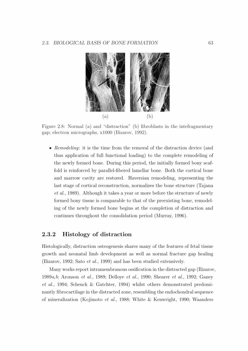
2.3. BIOLOGICAL BASIS OF BONE FORMATION 63
(a) (b)
Figure 2.8: Normal (a) and “distraction” (b) fibroblasts in the intefragmentarygap; electron micrographs, x1000 (Ilizarov, 1992).
• Remodeling : it is the time from the removal of the distraction device (and
thus application of full functional loading) to the complete remodeling of
the newly formed bone. During this period, the initially formed bony scaf-
fold is reinforced by parallel-fibered lamellar bone. Both the cortical bone
and marrow cavity are restored. Haversian remodeling, representing the
last stage of cortical reconstruction, normalizes the bone structure (Tajana
et al., 1989). Although it takes a year or more before the structure of newly
formed bony tissue is comparable to that of the preexisting bone, remodel-
ing of the newly formed bone begins at the completion of distraction and
continues throughout the consolidation period (Murray, 1996).
2.3.2 Histology of distraction
Histologically, distraction osteogenesis shares many of the features of fetal tissue
growth and neonatal limb development as well as normal fracture gap healing
(Ilizarov, 1992; Sato et al., 1999) and has been studied extensively.
Many works report intramembranous ossification in the distracted gap (Ilizarov,
1989a,b; Aronson et al., 1989; Delloye et al., 1990; Shearer et al., 1992; Ganey
et al., 1994; Schenck & Gatchter, 1994) whilst others demonstrated predomi-
nantly fibrocartilage in the distracted zone, resembling the endochondral sequence
of mineralization (Kojimoto et al., 1988; White & Kenwright, 1990; Waanders
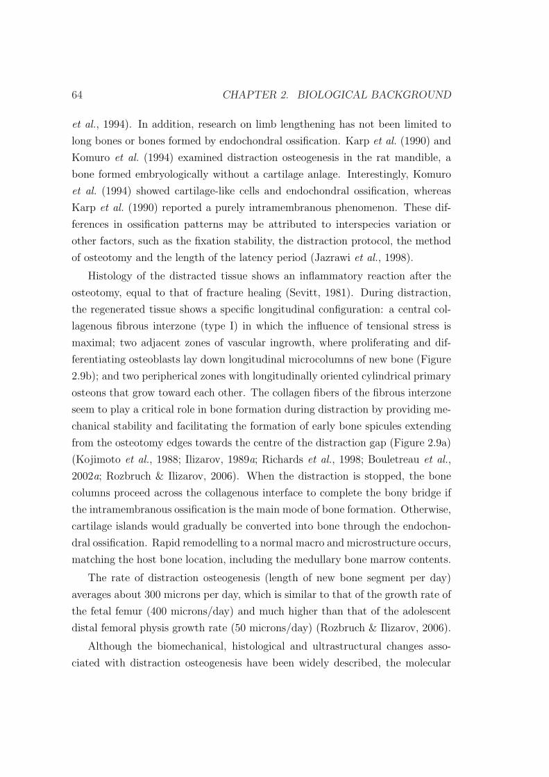
64 CHAPTER 2. BIOLOGICAL BACKGROUND
et al., 1994). In addition, research on limb lengthening has not been limited to
long bones or bones formed by endochondral ossification. Karp et al. (1990) and
Komuro et al. (1994) examined distraction osteogenesis in the rat mandible, a
bone formed embryologically without a cartilage anlage. Interestingly, Komuro
et al. (1994) showed cartilage-like cells and endochondral ossification, whereas
Karp et al. (1990) reported a purely intramembranous phenomenon. These dif-
ferences in ossification patterns may be attributed to interspecies variation or
other factors, such as the fixation stability, the distraction protocol, the method
of osteotomy and the length of the latency period (Jazrawi et al., 1998).
Histology of the distracted tissue shows an inflammatory reaction after the
osteotomy, equal to that of fracture healing (Sevitt, 1981). During distraction,
the regenerated tissue shows a specific longitudinal configuration: a central col-
lagenous fibrous interzone (type I) in which the influence of tensional stress is
maximal; two adjacent zones of vascular ingrowth, where proliferating and dif-
ferentiating osteoblasts lay down longitudinal microcolumns of new bone (Figure
2.9b); and two peripherical zones with longitudinally oriented cylindrical primary
osteons that grow toward each other. The collagen fibers of the fibrous interzone
seem to play a critical role in bone formation during distraction by providing me-
chanical stability and facilitating the formation of early bone spicules extending
from the osteotomy edges towards the centre of the distraction gap (Figure 2.9a)
(Kojimoto et al., 1988; Ilizarov, 1989a; Richards et al., 1998; Bouletreau et al.,
2002a; Rozbruch & Ilizarov, 2006). When the distraction is stopped, the bone
columns proceed across the collagenous interface to complete the bony bridge if
the intramembranous ossification is the main mode of bone formation. Otherwise,
cartilage islands would gradually be converted into bone through the endochon-
dral ossification. Rapid remodelling to a normal macro and microstructure occurs,
matching the host bone location, including the medullary bone marrow contents.
The rate of distraction osteogenesis (length of new bone segment per day)
averages about 300 microns per day, which is similar to that of the growth rate of
the fetal femur (400 microns/day) and much higher than that of the adolescent
distal femoral physis growth rate (50 microns/day) (Rozbruch & Ilizarov, 2006).
Although the biomechanical, histological and ultrastructural changes asso-
ciated with distraction osteogenesis have been widely described, the molecular
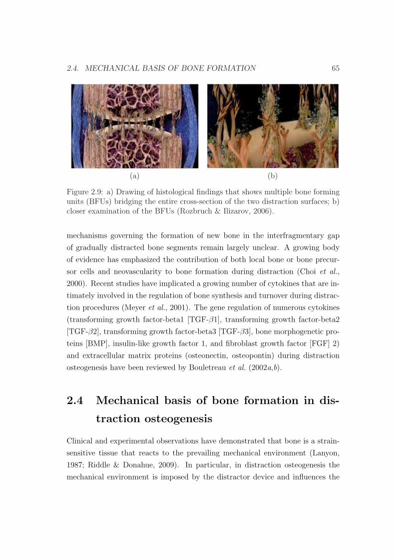
2.4. MECHANICAL BASIS OF BONE FORMATION 65
(a) (b)
Figure 2.9: a) Drawing of histological findings that shows multiple bone formingunits (BFUs) bridging the entire cross-section of the two distraction surfaces; b)closer examination of the BFUs (Rozbruch & Ilizarov, 2006).
mechanisms governing the formation of new bone in the interfragmentary gap
of gradually distracted bone segments remain largely unclear. A growing body
of evidence has emphasized the contribution of both local bone or bone precur-
sor cells and neovascularity to bone formation during distraction (Choi et al.,
2000). Recent studies have implicated a growing number of cytokines that are in-
timately involved in the regulation of bone synthesis and turnover during distrac-
tion procedures (Meyer et al., 2001). The gene regulation of numerous cytokines
(transforming growth factor-beta1 [TGF-β1], transforming growth factor-beta2
[TGF-β2], transforming growth factor-beta3 [TGF-β3], bone morphogenetic pro-
teins [BMP], insulin-like growth factor 1, and fibroblast growth factor [FGF] 2)
and extracellular matrix proteins (osteonectin, osteopontin) during distraction
osteogenesis have been reviewed by Bouletreau et al. (2002a,b).
2.4 Mechanical basis of bone formation in dis-
traction osteogenesis
Clinical and experimental observations have demonstrated that bone is a strain-
sensitive tissue that reacts to the prevailing mechanical environment (Lanyon,
1987; Riddle & Donahue, 2009). In particular, in distraction osteogenesis the
mechanical environment is imposed by the distractor device and influences the
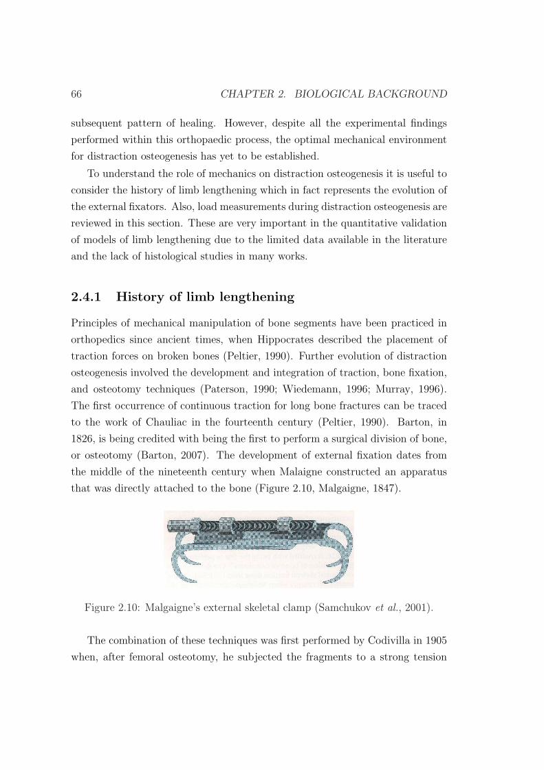
66 CHAPTER 2. BIOLOGICAL BACKGROUND
subsequent pattern of healing. However, despite all the experimental findings
performed within this orthopaedic process, the optimal mechanical environment
for distraction osteogenesis has yet to be established.
To understand the role of mechanics on distraction osteogenesis it is useful to
consider the history of limb lengthening which in fact represents the evolution of
the external fixators. Also, load measurements during distraction osteogenesis are
reviewed in this section. These are very important in the quantitative validation
of models of limb lengthening due to the limited data available in the literature
and the lack of histological studies in many works.
2.4.1 History of limb lengthening
Principles of mechanical manipulation of bone segments have been practiced in
orthopedics since ancient times, when Hippocrates described the placement of
traction forces on broken bones (Peltier, 1990). Further evolution of distraction
osteogenesis involved the development and integration of traction, bone fixation,
and osteotomy techniques (Paterson, 1990; Wiedemann, 1996; Murray, 1996).
The first occurrence of continuous traction for long bone fractures can be traced
to the work of Chauliac in the fourteenth century (Peltier, 1990). Barton, in
1826, is being credited with being the first to perform a surgical division of bone,
or osteotomy (Barton, 2007). The development of external fixation dates from
the middle of the nineteenth century when Malaigne constructed an apparatus
that was directly attached to the bone (Figure 2.10, Malgaigne, 1847).
Figure 2.10: Malgaigne’s external skeletal clamp (Samchukov et al., 2001).
The combination of these techniques was first performed by Codivilla in 1905
when, after femoral osteotomy, he subjected the fragments to a strong tension
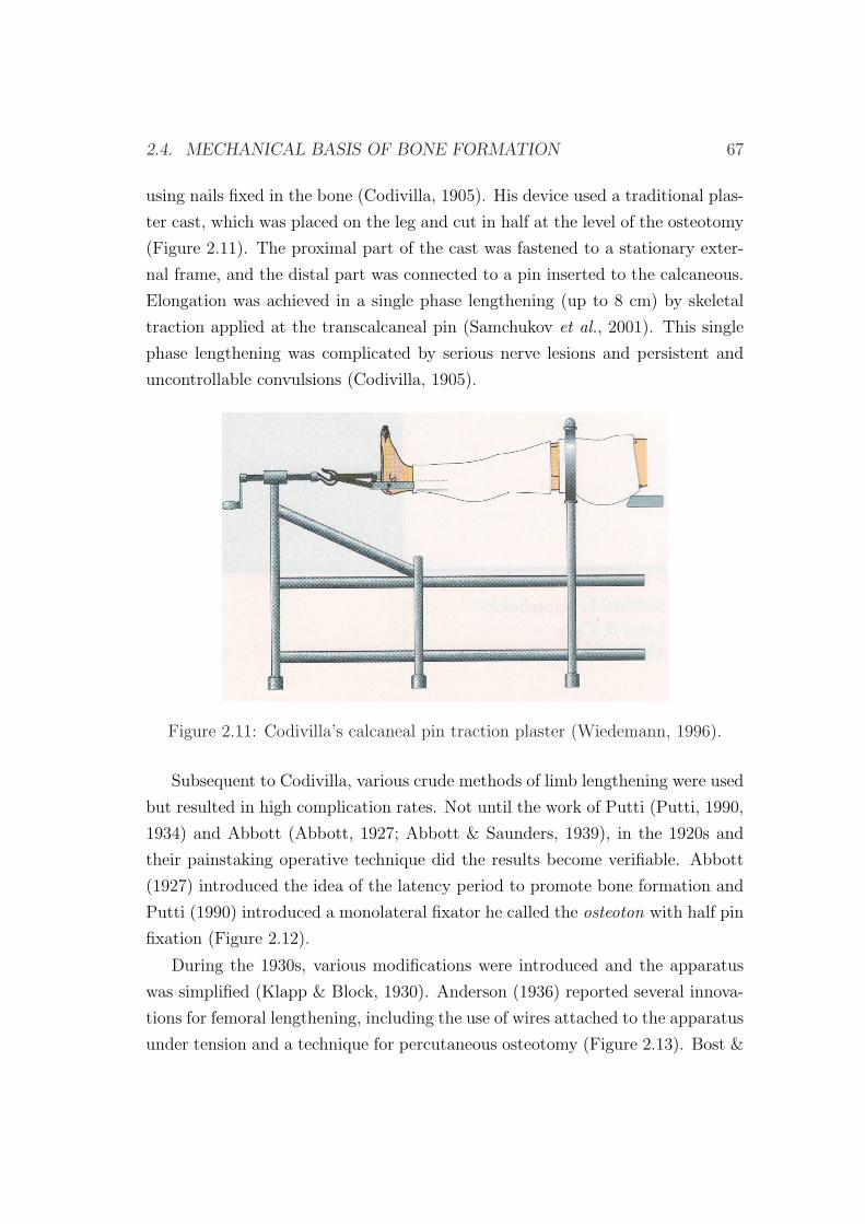
2.4. MECHANICAL BASIS OF BONE FORMATION 67
using nails fixed in the bone (Codivilla, 1905). His device used a traditional plas-
ter cast, which was placed on the leg and cut in half at the level of the osteotomy
(Figure 2.11). The proximal part of the cast was fastened to a stationary exter-
nal frame, and the distal part was connected to a pin inserted to the calcaneous.
Elongation was achieved in a single phase lengthening (up to 8 cm) by skeletal
traction applied at the transcalcaneal pin (Samchukov et al., 2001). This single
phase lengthening was complicated by serious nerve lesions and persistent and
uncontrollable convulsions (Codivilla, 1905).
Figure 2.11: Codivilla’s calcaneal pin traction plaster (Wiedemann, 1996).
Subsequent to Codivilla, various crude methods of limb lengthening were used
but resulted in high complication rates. Not until the work of Putti (Putti, 1990,
1934) and Abbott (Abbott, 1927; Abbott & Saunders, 1939), in the 1920s and
their painstaking operative technique did the results become verifiable. Abbott
(1927) introduced the idea of the latency period to promote bone formation and
Putti (1990) introduced a monolateral fixator he called the osteoton with half pin
fixation (Figure 2.12).
During the 1930s, various modifications were introduced and the apparatus
was simplified (Klapp & Block, 1930). Anderson (1936) reported several innova-
tions for femoral lengthening, including the use of wires attached to the apparatus
under tension and a technique for percutaneous osteotomy (Figure 2.13). Bost &
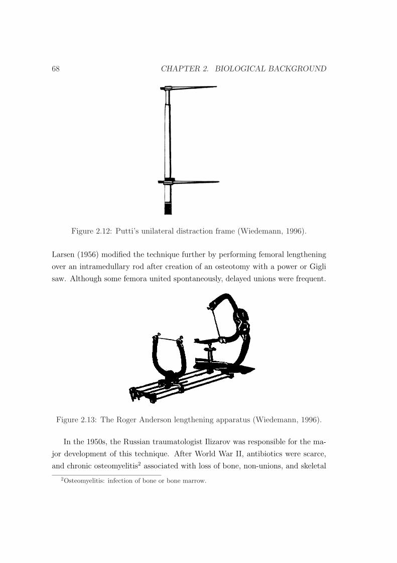
68 CHAPTER 2. BIOLOGICAL BACKGROUND
Figure 2.12: Putti’s unilateral distraction frame (Wiedemann, 1996).
Larsen (1956) modified the technique further by performing femoral lengthening
over an intramedullary rod after creation of an osteotomy with a power or Gigli
saw. Although some femora united spontaneously, delayed unions were frequent.
Figure 2.13: The Roger Anderson lengthening apparatus (Wiedemann, 1996).
In the 1950s, the Russian traumatologist Ilizarov was responsible for the ma-
jor development of this technique. After World War II, antibiotics were scarce,
and chronic osteomyelitis2 associated with loss of bone, non-unions, and skeletal
2Osteomyelitis: infection of bone or bone marrow.
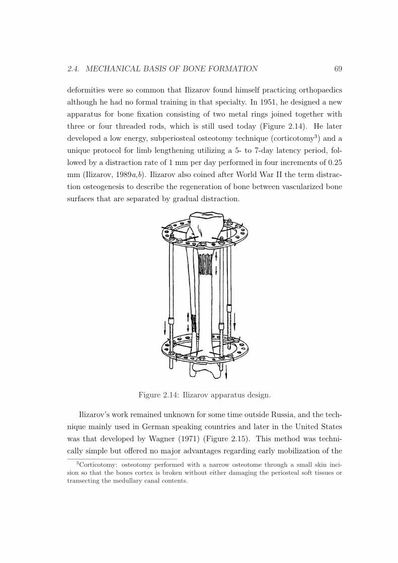
2.4. MECHANICAL BASIS OF BONE FORMATION 69
deformities were so common that Ilizarov found himself practicing orthopaedics
although he had no formal training in that specialty. In 1951, he designed a new
apparatus for bone fixation consisting of two metal rings joined together with
three or four threaded rods, which is still used today (Figure 2.14). He later
developed a low energy, subperiosteal osteotomy technique (corticotomy3) and a
unique protocol for limb lengthening utilizing a 5- to 7-day latency period, fol-
lowed by a distraction rate of 1 mm per day performed in four increments of 0.25
mm (Ilizarov, 1989a,b). Ilizarov also coined after World War II the term distrac-
tion osteogenesis to describe the regeneration of bone between vascularized bone
surfaces that are separated by gradual distraction.
Figure 2.14: Ilizarov apparatus design.
Ilizarov’s work remained unknown for some time outside Russia, and the tech-
nique mainly used in German speaking countries and later in the United States
was that developed by Wagner (1971) (Figure 2.15). This method was techni-
cally simple but offered no major advantages regarding early mobilization of the
3Corticotomy: osteotomy performed with a narrow osteotome through a small skin inci-sion so that the bones cortex is broken without either damaging the periosteal soft tissues ortransecting the medullary canal contents.
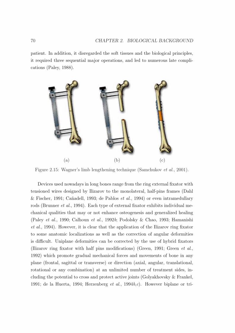
70 CHAPTER 2. BIOLOGICAL BACKGROUND
patient. In addition, it disregarded the soft tissues and the biological principles,
it required three sequential major operations, and led to numerous late compli-
cations (Paley, 1988).
(a) (b) (c)
Figure 2.15: Wagner’s limb lengthening technique (Samchukov et al., 2001).
Devices used nowadays in long bones range from the ring external fixator with
tensioned wires designed by Ilizarov to the monolateral, half-pins frames (Dahl
& Fischer, 1991; Canadell, 1993; de Pablos et al., 1994) or even intramedullary
rods (Brunner et al., 1994). Each type of external fixator exhibits individual me-
chanical qualities that may or not enhance osteogenesis and generalized healing
(Paley et al., 1990; Calhoun et al., 1992b; Podolsky & Chao, 1993; Hamanishi
et al., 1994). However, it is clear that the application of the Ilizarov ring fixator
to some anatomic localizations as well as the correction of angular deformities
is difficult. Uniplane deformities can be corrected by the use of hybrid fixators
(Ilizarov ring fixator with half pins modifications) (Green, 1991; Green et al.,
1992) which promote gradual mechanical forces and movements of bone in any
plane (frontal, sagittal or transverse) or direction (axial, angular, translational,
rotational or any combination) at an unlimited number of treatment sides, in-
cluding the potential to cross and protect active joints (Golyakhovsky & Frankel,
1991; de la Huerta, 1994; Herzenberg et al., 1994b,c). However biplane or tri-
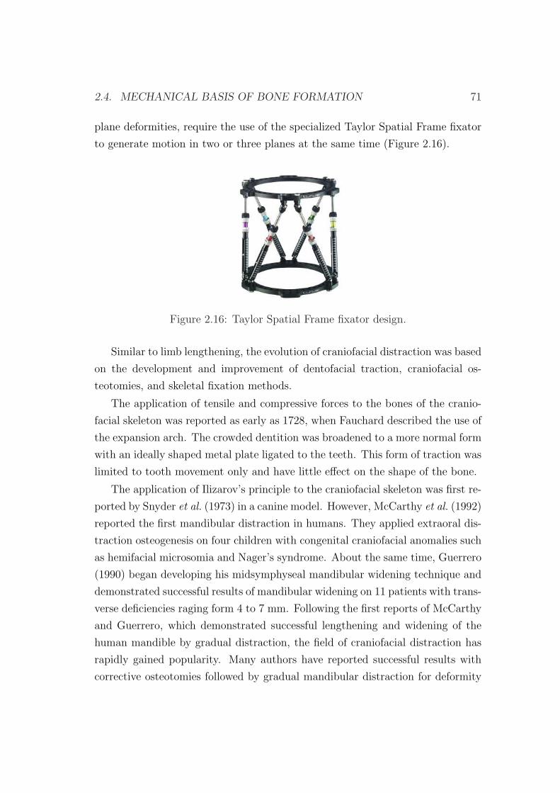
2.4. MECHANICAL BASIS OF BONE FORMATION 71
plane deformities, require the use of the specialized Taylor Spatial Frame fixator
to generate motion in two or three planes at the same time (Figure 2.16).
Figure 2.16: Taylor Spatial Frame fixator design.
Similar to limb lengthening, the evolution of craniofacial distraction was based
on the development and improvement of dentofacial traction, craniofacial os-
teotomies, and skeletal fixation methods.
The application of tensile and compressive forces to the bones of the cranio-
facial skeleton was reported as early as 1728, when Fauchard described the use of
the expansion arch. The crowded dentition was broadened to a more normal form
with an ideally shaped metal plate ligated to the teeth. This form of traction was
limited to tooth movement only and have little effect on the shape of the bone.
The application of Ilizarov’s principle to the craniofacial skeleton was first re-
ported by Snyder et al. (1973) in a canine model. However, McCarthy et al. (1992)
reported the first mandibular distraction in humans. They applied extraoral dis-
traction osteogenesis on four children with congenital craniofacial anomalies such
as hemifacial microsomia and Nager’s syndrome. About the same time, Guerrero
(1990) began developing his midsymphyseal mandibular widening technique and
demonstrated successful results of mandibular widening on 11 patients with trans-
verse deficiencies raging form 4 to 7 mm. Following the first reports of McCarthy
and Guerrero, which demonstrated successful lengthening and widening of the
human mandible by gradual distraction, the field of craniofacial distraction has
rapidly gained popularity. Many authors have reported successful results with
corrective osteotomies followed by gradual mandibular distraction for deformity
72 CHAPTER 2. BIOLOGICAL BACKGROUND
correction, lengthening, widening, bone transport and alveolar ridge augmenta-
tion (Block et al., 1993; Habal, 1994; Havlik & Bartlett, 1994; Moore et al., 1994;
Block et al., 1995; Chin & Toth, 1996; Weil et al., 1997; Yen, 1997).
Different distraction devices are now available for oral and maxillofacial appli-
cation, including mandibular, maxillary, midfacial, cranial, and alveolar distrac-
tors. They can all be classified in two types: external and internal. The external
devices are attached to the bone by percutaneous pins connected externally to
fixation clamps. The fixation clamps, in turn, are joined together by a distraction
rod that, when activated, effectively pushes the clamps and the attached bone
segments apart, generating new bone in its path. Relative to the direction of
lengthening, they are divided into unidirectional, bidirectional, and multidirec-
tional devices. The internal devices are located either subcutaneously or within
the oral cavity (intraorally). The intraoral devices can be placed above (extra-
mucosal) or below (submucosal) the soft tissue. These devices are attached to
the bone (bone-borne), to the teeth (tooth-borne) or simultaneously to the teeth
and bone (hybrid) (Samchukov et al., 2001).
2.4.2 Load measurements during distraction
In vivo load measurements show that forces required to distract increase with
time because gap tissues become gradually stiffer and therefore are indicative of
the distraction process outcome (Figure 2.17) (Leong et al., 1979; Jones et al.,
1989; White & Kenwright, 1990; Kenwright et al., 1990; Wolfson et al., 1990;
Brunner et al., 1994; Younger et al., 1994; Simpson et al., 1996; Forriol et al.,
1997; Waanders et al., 1998; Matsushita et al., 1999; Aarnes et al., 2002; Singare
et al., 2006). Initially, the distracted bone surfaces are joined by a collagenous
bridge that becomes progressively more mineralized and therefore stiffer as dis-
traction proceeds. Most of the resistance is thus concentrated in shorter lengths
of collagen, giving rise to higher loads over time. Therefore, the actual load
measured during distraction correlates directly to the cross sectional area of this
bridge and inversely to the length of the unmineralized portion (Figure 2.9a).
Forces involved in limb lengthening have been reported in animal (White
& Kenwright, 1990; Brunner et al., 1994; Forriol et al., 1997; Waanders et al.,
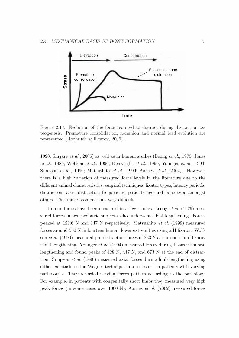
2.4. MECHANICAL BASIS OF BONE FORMATION 73
Str
ess
Time
Non-union
Premature
consolidation
Successful bone
distraction
Distraction Consolidation
Figure 2.17: Evolution of the force required to distract during distraction os-teogenesis. Premature consolidation, nonunion and normal load evolution arerepresented (Rozbruch & Ilizarov, 2006).
1998; Singare et al., 2006) as well as in human studies (Leong et al., 1979; Jones
et al., 1989; Wolfson et al., 1990; Kenwright et al., 1990; Younger et al., 1994;
Simpson et al., 1996; Matsushita et al., 1999; Aarnes et al., 2002). However,
there is a high variation of measured force levels in the literature due to the
different animal characteristics, surgical techniques, fixator types, latency periods,
distraction rates, distraction frequencies, patients age and bone type amongst
others. This makes comparisons very difficult.
Human forces have been measured in a few studies. Leong et al. (1979) mea-
sured forces in two pediatric subjects who underwent tibial lengthening. Forces
peaked at 122.6 N and 147 N respectively. Matsushita et al. (1999) measured
forces around 500 N in fourteen human lower extremities using a Hifixator. Wolf-
son et al. (1990) measured pre-distraction forces of 233 N at the end of an Ilizarov
tibial lengthening. Younger et al. (1994) measured forces during Ilizarov femoral
lengthening and found peaks of 428 N, 447 N, and 673 N at the end of distrac-
tion. Simpson et al. (1996) measured axial forces during limb lengthening using
either callotasis or the Wagner technique in a series of ten patients with varying
pathologies. They recorded varying forces pattern according to the pathology.
For example, in patients with congenitally short limbs they measured very high
peak forces (in some cases over 1000 N). Aarnes et al. (2002) measured forces
74 CHAPTER 2. BIOLOGICAL BACKGROUND
between 431 and 542 N in four short statured patients undergoing tibial length-
ening. Physeal lengthening required greater forces of 569 N to 804 N (Jones et al.,
1989; Kenwright et al., 1990).
Distraction forces measured in sheep tibias are similar to human ones. For
example, Brunner et al. (1994) measured forces of 350 N in sheep tibias at the
end of transport and Younger (1997) recorded peak forces at an average of 285
N.
Lower forces are required to distract lamb and rabbit tibias. In a study on
lambs the maximum force attained was between 80 and 100 N (Forriol et al.,
1997). In rabbit tibias, Waanders et al. (1998) measured an averaged distraction
force on each day of distraction ranging from 5 to 24 N. Singare et al. (2006)
showed that the latency period had a strong effect on the increase of the distrac-
tion force. In the immediate distraction group (0 day latency) the postdistraction
force registered was 28.71 N, whereas in the 4-day delay distraction group, the
tensile force was 30.51 N. In the 7-day delay distraction group, the tensile load
was 39.86 N. These results are similar to those found by White & Kenwright
(1990). The tension obtained at the end of distraction in the immediate distrac-
tion group was about 30 N, and in the 7-day delay distraction group was more
than 50 N. These increasing loads in prolonged latency phases are due to the
advanced mineralization of the bridge (Figure 2.9b).
In all cases, the force required to maintain a given tissue length decreases
with time due to the relaxation effect: peak forces each day occur immediately
after distraction, and are reduced progressively during the next 24 hours (Leong
et al., 1979; Brunner et al., 1994; Forriol et al., 1997; Waanders et al., 1998; Mat-
sushita et al., 1999). Some studies reveal that the force obtained after the applied
displacement decays exponentially during the 24 hours after distraction (Aarnes
et al., 2002). However, this relaxation is not complete and leads to a daily force
accumulation due to three main effects: the mechanical elongation of the gap, the
intrinsic viscoelastic nature of soft tissues in the interfragmentary gap (Simpson
et al., 1996; Nakamura et al., 1997; Matsushita et al., 1999; Richards et al., 1999;
Aarnes et al., 2002; Leong & Morgan, 2008) and the tissue growth/differentiation
inside the gap. Quantitative estimations of stress accumulation due to residual
stresses during the process of distraction can be found in the literature (Brunner
2.5. BIOMECHANICAL FACTORS 75
et al., 1994; Waanders et al., 1998; Matsushita et al., 1999; Richards et al., 1999).
2.5 Biomechanical factors
The optimal mechanical environment in which bone formation occurs clinically
has not been fully determined yet. In fact, there are multiple mechanical and
biological factors that affect to the quality and quantity of the regenerated bone.
The basic parameters include:
• Vascular supply : Many studies have suggested that blood supply has a
significant influence on the shape and mass of the resulting bone (Trueta
& Trias, 1961; Ilizarov, 1989a; Aronson, 1994). If blood supply is inade-
quate to support normal or increased mechanical loading, then the bone
cannot respond favorably, leading to atrophic or degenerative changes. By
contrast, if blood supply is adequate to support increased mechanical load-
ing, the bone will demonstrate compensatory hypertrophic changes. Ilizarov
demonstrated that the periosteum, the bone marrow and the nutrient artery
are equally important for new bone formation (Ilizarov, 1971; Ilizarov et al.,
1983; Ilizarov, 1989a) although many authors have indicated that the pe-
riosteum is the major contributor to osteogenesis during distraction (Delloye
et al., 1990; Yasui et al., 1991; Cara del Rosal, 1992). Therefore, methods
of bone separation that disrupt the periosteum, such as widely displaced
corticotomies or osteotomies, can result in decreased osteogenesis (Frierson
et al., 1994).
• Latency period. It is generally agreed that a period of latency subsequent to
a corticotomy enhances the formation of bone (White & Kenwright, 1991;
Gil-Albarova et al., 1992; Aronson, 1994; Aronson & Shen, 1994). The
duration of the latency period in most clinical reports (Paley, 1990; Price
& Mann, 1991; Dahl & Fischer, 1991; Bonnard et al., 1993; Kenwright
& White, 1993; Aronson, 1994; Fischgrund et al., 1994) has ranged from
three to ten days, with the shorter periods used with the classic Ilizarov
corticotomy at metaphyseal locations and the longer periods needed for
more traditional osteotomy techniques performed with an oscillating saw,
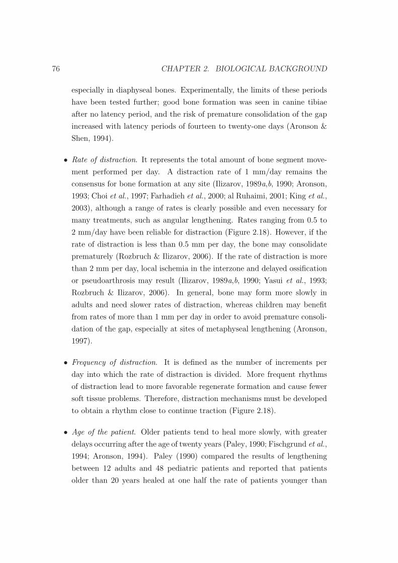
76 CHAPTER 2. BIOLOGICAL BACKGROUND
especially in diaphyseal bones. Experimentally, the limits of these periods
have been tested further; good bone formation was seen in canine tibiae
after no latency period, and the risk of premature consolidation of the gap
increased with latency periods of fourteen to twenty-one days (Aronson &
Shen, 1994).
• Rate of distraction. It represents the total amount of bone segment move-
ment performed per day. A distraction rate of 1 mm/day remains the
consensus for bone formation at any site (Ilizarov, 1989a,b, 1990; Aronson,
1993; Choi et al., 1997; Farhadieh et al., 2000; al Ruhaimi, 2001; King et al.,
2003), although a range of rates is clearly possible and even necessary for
many treatments, such as angular lengthening. Rates ranging from 0.5 to
2 mm/day have been reliable for distraction (Figure 2.18). However, if the
rate of distraction is less than 0.5 mm per day, the bone may consolidate
prematurely (Rozbruch & Ilizarov, 2006). If the rate of distraction is more
than 2 mm per day, local ischemia in the interzone and delayed ossification
or pseudoarthrosis may result (Ilizarov, 1989a,b, 1990; Yasui et al., 1993;
Rozbruch & Ilizarov, 2006). In general, bone may form more slowly in
adults and need slower rates of distraction, whereas children may benefit
from rates of more than 1 mm per day in order to avoid premature consoli-
dation of the gap, especially at sites of metaphyseal lengthening (Aronson,
1997).
• Frequency of distraction. It is defined as the number of increments per
day into which the rate of distraction is divided. More frequent rhythms
of distraction lead to more favorable regenerate formation and cause fewer
soft tissue problems. Therefore, distraction mechanisms must be developed
to obtain a rhythm close to continue traction (Figure 2.18).
• Age of the patient. Older patients tend to heal more slowly, with greater
delays occurring after the age of twenty years (Paley, 1990; Fischgrund et al.,
1994; Aronson, 1994). Paley (1990) compared the results of lengthening
between 12 adults and 48 pediatric patients and reported that patients
older than 20 years healed at one half the rate of patients younger than
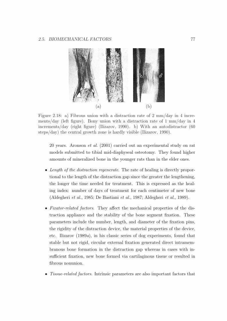
2.5. BIOMECHANICAL FACTORS 77
(a) (b)
Figure 2.18: a) Fibrous union with a distraction rate of 2 mm/day in 4 incre-ments/day (left figure). Bony union with a distraction rate of 1 mm/day in 4increments/day (right figure) (Ilizarov, 1990). b) With an autodistractor (60steps/day) the central growth zone is hardly visible (Ilizarov, 1990).
20 years. Aronson et al. (2001) carried out an experimental study on rat
models submitted to tibial mid-diaphyseal osteotomy. They found higher
amounts of mineralized bone in the younger rats than in the elder ones.
• Length of the distraction regenerate. The rate of healing is directly propor-
tional to the length of the distraction gap since the greater the lengthening,
the longer the time needed for treatment. This is expressed as the heal-
ing index: number of days of treatment for each centimeter of new bone
(Aldegheri et al., 1985; De Bastiani et al., 1987; Aldegheri et al., 1989).
• Fixator-related factors. They affect the mechanical properties of the dis-
traction appliance and the stability of the bone segment fixation. These
parameters include the number, length, and diameter of the fixation pins,
the rigidity of the distraction device, the material properties of the device,
etc. Ilizarov (1989a), in his classic series of dog experiments, found that
stable but not rigid, circular external fixation generated direct intramem-
branous bone formation in the distraction gap whereas in cases with in-
sufficient fixation, new bone formed via cartilaginous tissue or resulted in
fibrous nonunion.
• Tissue-related factors. Intrinsic parameters are also important factors that
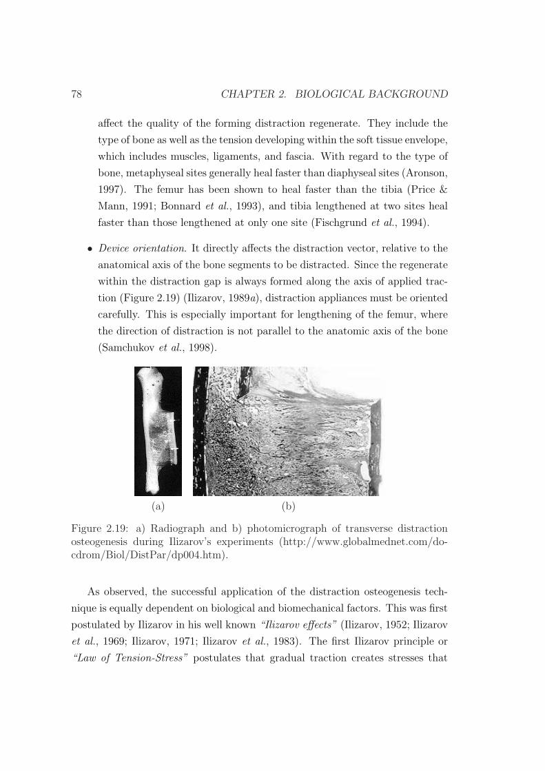
78 CHAPTER 2. BIOLOGICAL BACKGROUND
affect the quality of the forming distraction regenerate. They include the
type of bone as well as the tension developing within the soft tissue envelope,
which includes muscles, ligaments, and fascia. With regard to the type of
bone, metaphyseal sites generally heal faster than diaphyseal sites (Aronson,
1997). The femur has been shown to heal faster than the tibia (Price &
Mann, 1991; Bonnard et al., 1993), and tibia lengthened at two sites heal
faster than those lengthened at only one site (Fischgrund et al., 1994).
• Device orientation. It directly affects the distraction vector, relative to the
anatomical axis of the bone segments to be distracted. Since the regenerate
within the distraction gap is always formed along the axis of applied trac-
tion (Figure 2.19) (Ilizarov, 1989a), distraction appliances must be oriented
carefully. This is especially important for lengthening of the femur, where
the direction of distraction is not parallel to the anatomic axis of the bone
(Samchukov et al., 1998).
(a) (b)
Figure 2.19: a) Radiograph and b) photomicrograph of transverse distractionosteogenesis during Ilizarov’s experiments (http://www.globalmednet.com/do-cdrom/Biol/DistPar/dp004.htm).
As observed, the successful application of the distraction osteogenesis tech-
nique is equally dependent on biological and biomechanical factors. This was first
postulated by Ilizarov in his well known “Ilizarov effects” (Ilizarov, 1952; Ilizarov
et al., 1969; Ilizarov, 1971; Ilizarov et al., 1983). The first Ilizarov principle or
“Law of Tension-Stress” postulates that gradual traction creates stresses that

2.6. CLINICAL APPLICATIONS 79
can stimulate and maintain regeneration of living tissues. The second Ilizarov
principle theorized that the shape and mass of bones and joints are dependent
on an interaction between mechanical loading and blood supply.
2.6 Clinical applications
Since Ilizarov’s reintroduction of distraction in the orthopaedic therapy, new ap-
plications have emerged in the rest of the organism. One of the sites where this
technique has also been introduced and is under investigation is the craniofacial
skeleton. But perhaps one of the most exciting potential areas for future research
is the application of distraction forces at different rates to regenerate both liga-
ments (Aston et al., 1992) and articular cartilage (Lieberman & Friedlaender,
2005). Next, we summarize the main applications in long bones and mandibular
distraction. Long bone distraction osteogenesis applications are:
• Bone transport. It was first introduced by Ilizarov for treating long bone de-
fects that resulted from trauma, oncologic resection, or congenital anoma-
lies (Ilizarov, 1971, 1988). The concept includes resection of pathologic
bone followed by gradual transport of an osteotomized healthy bone seg-
ment (transport disk) via distraction device across the area of defect. After
the transport disk reaches the opposite host bone segment, the intervening
fibrous tissue is removed followed by application of compression between
the transport and host bone segments at the docking site. Several bone
transport techniques have been developed. According to Ilizarov, the tech-
niques are divided into three groups based on the numbers of distraction-
compression sites: monofocal, bifocal and trifocal.
Congenital pseudoarthrosis of the tibia is ideally treated using the bone
transport method of Ilizarov with open resection of the pseudoarthrosis
and intramedullary fixation (Paley et al., 1992).
• Limb lengthening (Figure 2.20). Congenital anomalies (birth defects) with
limb reduction deficiencies like radial hemimelia4, ulnar hemimelia, congen-
4Hemimelia: developmental anomaly characterized by the absence or gross shortening of thelower portion of one or more of the limbs.
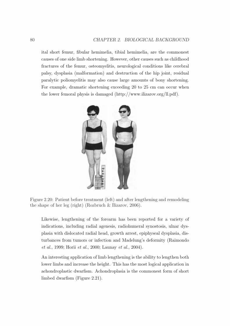
80 CHAPTER 2. BIOLOGICAL BACKGROUND
ital short femur, fibular hemimelia, tibial hemimelia, are the commonest
causes of one side limb shortening. However, other causes such as childhood
fractures of the femur, osteomyelitis, neurological conditions like cerebral
palsy, dysplasia (malformation) and destruction of the hip joint, residual
paralytic poliomyelitis may also cause large amounts of bony shortening.
For example, dramatic shortening exceeding 20 to 25 cm can occur when
the lower femoral physis is damaged (http://www.ilizarov.org/ll.pdf).
Figure 2.20: Patient before treatment (left) and after lengthening and remodelingthe shape of her leg (right) (Rozbruch & Ilizarov, 2006).
Likewise, lengthening of the forearm has been reported for a variety of
indications, including radial agenesis, radiohumeral synostosis, ulnar dys-
plasia with dislocated radial head, growth arrest, epiphyseal dysplasia, dis-
turbances from tumors or infection and Madelung’s deformity (Raimondo
et al., 1999; Horii et al., 2000; Launay et al., 2004).
An interesting application of limb lengthening is the ability to lengthen both
lower limbs and increase the height. This has the most logical application in
achondroplastic dwarfism. Achondroplasia is the commonest form of short
limbed dwarfism (Figure 2.21).
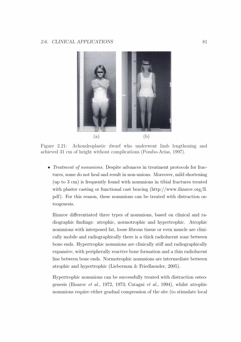
2.6. CLINICAL APPLICATIONS 81
(a) (b)
Figure 2.21: Achondroplastic dwarf who underwent limb lengthening andachieved 31 cm of height without complications (Pombo-Arias, 1997).
• Treatment of nonunions. Despite advances in treatment protocols for frac-
tures, some do not heal and result in non-unions. Moreover, mild shortening
(up to 3 cm) is frequently found with nonunions in tibial fractures treated
with plaster casting or functional cast bracing (http://www.ilizarov.org/ll.
pdf). For this reason, these nonunions can be treated with distraction os-
teogenesis.
Ilizarov differentiated three types of nonunions, based on clinical and ra-
diographic findings: atrophic, normotrophic and hypertrophic. Atrophic
nonunions with interposed fat, loose fibrous tissue or even muscle are clini-
cally mobile and radiographically there is a thick radiolucent zone between
bone ends. Hypertrophic nonunions are clinically stiff and radiographically
expansive, with peripherally reactive bone formation and a thin radiolucent
line between bone ends. Normotrophic nonunions are intermediate between
atrophic and hypertrophic (Lieberman & Friedlaender, 2005).
Hypertrophic nonunions can be successfully treated with distraction osteo-
genesis (Ilizarov et al., 1972, 1973; Catagni et al., 1994), whilst atrophic
nonunions require either gradual compression of the site (to stimulate local
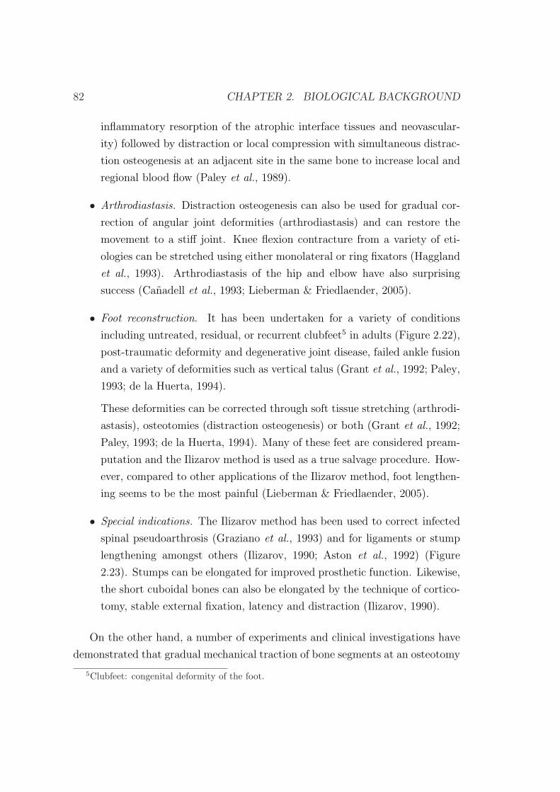
82 CHAPTER 2. BIOLOGICAL BACKGROUND
inflammatory resorption of the atrophic interface tissues and neovascular-
ity) followed by distraction or local compression with simultaneous distrac-
tion osteogenesis at an adjacent site in the same bone to increase local and
regional blood flow (Paley et al., 1989).
• Arthrodiastasis. Distraction osteogenesis can also be used for gradual cor-
rection of angular joint deformities (arthrodiastasis) and can restore the
movement to a stiff joint. Knee flexion contracture from a variety of eti-
ologies can be stretched using either monolateral or ring fixators (Haggland
et al., 1993). Arthrodiastasis of the hip and elbow have also surprising
success (Canadell et al., 1993; Lieberman & Friedlaender, 2005).
• Foot reconstruction. It has been undertaken for a variety of conditions
including untreated, residual, or recurrent clubfeet5 in adults (Figure 2.22),
post-traumatic deformity and degenerative joint disease, failed ankle fusion
and a variety of deformities such as vertical talus (Grant et al., 1992; Paley,
1993; de la Huerta, 1994).
These deformities can be corrected through soft tissue stretching (arthrodi-
astasis), osteotomies (distraction osteogenesis) or both (Grant et al., 1992;
Paley, 1993; de la Huerta, 1994). Many of these feet are considered pream-
putation and the Ilizarov method is used as a true salvage procedure. How-
ever, compared to other applications of the Ilizarov method, foot lengthen-
ing seems to be the most painful (Lieberman & Friedlaender, 2005).
• Special indications. The Ilizarov method has been used to correct infected
spinal pseudoarthrosis (Graziano et al., 1993) and for ligaments or stump
lengthening amongst others (Ilizarov, 1990; Aston et al., 1992) (Figure
2.23). Stumps can be elongated for improved prosthetic function. Likewise,
the short cuboidal bones can also be elongated by the technique of cortico-
tomy, stable external fixation, latency and distraction (Ilizarov, 1990).
On the other hand, a number of experiments and clinical investigations have
demonstrated that gradual mechanical traction of bone segments at an osteotomy
5Clubfeet: congenital deformity of the foot.
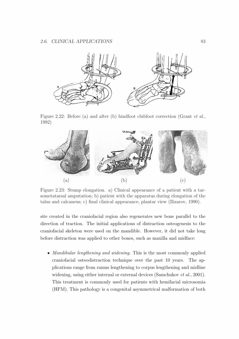
2.6. CLINICAL APPLICATIONS 83
Figure 2.22: Before (a) and after (b) hindfoot clubfoot correction (Grant et al.,1992)
(a) (b) (c)
Figure 2.23: Stump elongation. a) Clinical appearance of a patient with a tar-sometatarsal amputation; b) patient with the apparatus during elongation of thetalus and calcaneus; c) final clinical appearance, plantar view (Ilizarov, 1990).
site created in the craniofacial region also regenerates new bone parallel to the
direction of traction. The initial applications of distraction osteogenesis to the
craniofacial skeleton were used on the mandible. However, it did not take long
before distraction was applied to other bones, such as maxilla and midface:
• Mandibular lengthening and widening. This is the most commonly applied
craniofacial osteodistraction technique over the past 10 years. The ap-
plications range from ramus lengthening to corpus lengthening and midline
widening, using either internal or external devices (Samchukov et al., 2001).
This treatment is commonly used for patients with hemifacial microsomia
(HFM). This pathology is a congenital asymmetrical malformation of both
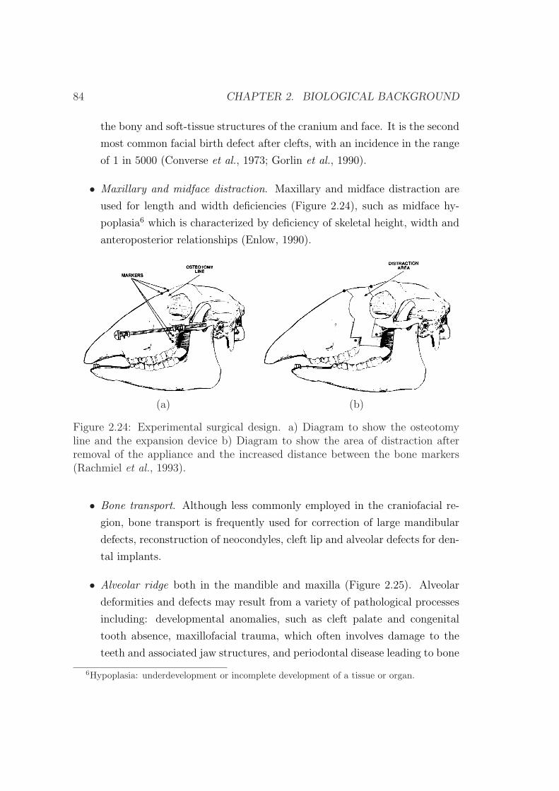
84 CHAPTER 2. BIOLOGICAL BACKGROUND
the bony and soft-tissue structures of the cranium and face. It is the second
most common facial birth defect after clefts, with an incidence in the range
of 1 in 5000 (Converse et al., 1973; Gorlin et al., 1990).
• Maxillary and midface distraction. Maxillary and midface distraction are
used for length and width deficiencies (Figure 2.24), such as midface hy-
poplasia6 which is characterized by deficiency of skeletal height, width and
anteroposterior relationships (Enlow, 1990).
(a) (b)
Figure 2.24: Experimental surgical design. a) Diagram to show the osteotomyline and the expansion device b) Diagram to show the area of distraction afterremoval of the appliance and the increased distance between the bone markers(Rachmiel et al., 1993).
• Bone transport. Although less commonly employed in the craniofacial re-
gion, bone transport is frequently used for correction of large mandibular
defects, reconstruction of neocondyles, cleft lip and alveolar defects for den-
tal implants.
• Alveolar ridge both in the mandible and maxilla (Figure 2.25). Alveolar
deformities and defects may result from a variety of pathological processes
including: developmental anomalies, such as cleft palate and congenital
tooth absence, maxillofacial trauma, which often involves damage to the
teeth and associated jaw structures, and periodontal disease leading to bone
6Hypoplasia: underdevelopment or incomplete development of a tissue or organ.
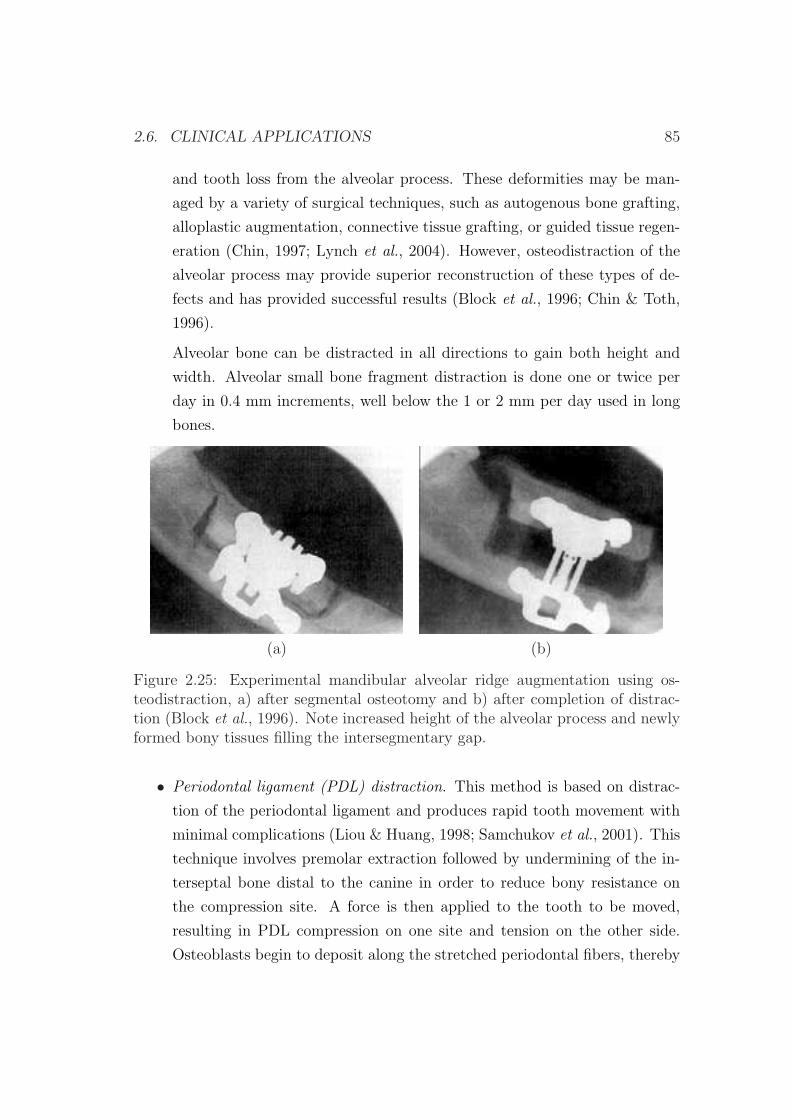
2.6. CLINICAL APPLICATIONS 85
and tooth loss from the alveolar process. These deformities may be man-
aged by a variety of surgical techniques, such as autogenous bone grafting,
alloplastic augmentation, connective tissue grafting, or guided tissue regen-
eration (Chin, 1997; Lynch et al., 2004). However, osteodistraction of the
alveolar process may provide superior reconstruction of these types of de-
fects and has provided successful results (Block et al., 1996; Chin & Toth,
1996).
Alveolar bone can be distracted in all directions to gain both height and
width. Alveolar small bone fragment distraction is done one or twice per
day in 0.4 mm increments, well below the 1 or 2 mm per day used in long
bones.
(a) (b)
Figure 2.25: Experimental mandibular alveolar ridge augmentation using os-teodistraction, a) after segmental osteotomy and b) after completion of distrac-tion (Block et al., 1996). Note increased height of the alveolar process and newlyformed bony tissues filling the intersegmentary gap.
• Periodontal ligament (PDL) distraction. This method is based on distrac-
tion of the periodontal ligament and produces rapid tooth movement with
minimal complications (Liou & Huang, 1998; Samchukov et al., 2001). This
technique involves premolar extraction followed by undermining of the in-
terseptal bone distal to the canine in order to reduce bony resistance on
the compression site. A force is then applied to the tooth to be moved,
resulting in PDL compression on one site and tension on the other side.
Osteoblasts begin to deposit along the stretched periodontal fibers, thereby
86 CHAPTER 2. BIOLOGICAL BACKGROUND
forming long bony trabeculae horizontally and parallel to the path of tooth
movement. This process is different from tooth movement into regenerate
bone. The former involves movement of both tooth and bone as new bone is
generated whilst the latter involves remodelling of bone as a tooth is moved
into new bone.
• Cranial distraction. Cranial bones respond to tensional stresses in a simi-
lar manner as long bones, and are characterized by formation of a typical
distraction regenerate (Barone et al., 1993; Losken et al., 1998; Samchukov
et al., 2001). Based on the results of experimental studies, several distrac-
tion osteogenesis techniques have now been applied clinically for reconstruc-
tion of cranial deformities and cranial vault defects.
Chapter 3
Numerical simulation of long
bone distraction osteogenesis
3.1 Introduction
In chapter 1 we have seen several different models to simulate bone distraction.
All these models are based on existing ones proposed for bone healing due to the
similarities between these two processes (Lammens et al., 1998; Jensen, 2002). In
fact, distraction osteogenesis has been considered as a particular form of fracture
healing, since a high rate of osteogenesis occurs and a high amount of callus forms
during this procedure (Ilizarov, 1983, 1989a).
In this chapter, we present a general formulation of living tissues, which is
based on a mathematical model previously proposed for bone fracture healing
(Gomez-Benito et al., 2005, 2006; Garcıa-Aznar et al., 2007). This model has
been extended since it was not able to simulate some mechanical conditions dur-
ing distraction osteogenesis, such as the effect of the distraction rate. In par-
ticular, the cellular maturation stage has been considered in the process of cell
differentiation. In the first part of this chapter, the mathematical model is de-
scribed. In the second part, an example of application is performed in order to
test the reliability of the model under different mechanical environments: the
effect of the distraction rate on the regenerate during long bone lengthening.
87
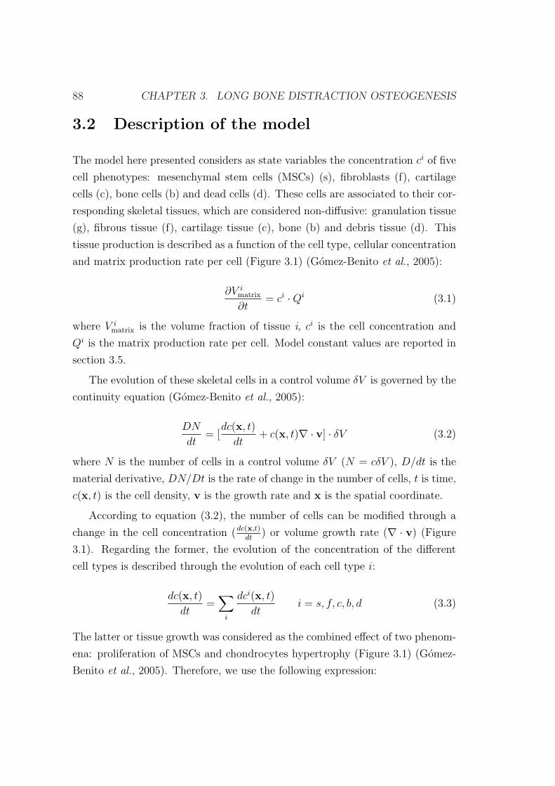
88 CHAPTER 3. LONG BONE DISTRACTION OSTEOGENESIS
3.2 Description of the model
The model here presented considers as state variables the concentration ci of five
cell phenotypes: mesenchymal stem cells (MSCs) (s), fibroblasts (f), cartilage
cells (c), bone cells (b) and dead cells (d). These cells are associated to their cor-
responding skeletal tissues, which are considered non-diffusive: granulation tissue
(g), fibrous tissue (f), cartilage tissue (c), bone (b) and debris tissue (d). This
tissue production is described as a function of the cell type, cellular concentration
and matrix production rate per cell (Figure 3.1) (Gomez-Benito et al., 2005):
∂V imatrix
∂t= ci ·Qi (3.1)
where V imatrix is the volume fraction of tissue i, ci is the cell concentration and
Qi is the matrix production rate per cell. Model constant values are reported in
section 3.5.
The evolution of these skeletal cells in a control volume δV is governed by the
continuity equation (Gomez-Benito et al., 2005):
DN
dt= [
dc(x, t)
dt+ c(x, t)∇ · v] · δV (3.2)
where N is the number of cells in a control volume δV (N = cδV ), D/dt is the
material derivative, DN/Dt is the rate of change in the number of cells, t is time,
c(x, t) is the cell density, v is the growth rate and x is the spatial coordinate.
According to equation (3.2), the number of cells can be modified through a
change in the cell concentration (dc(x,t)dt
) or volume growth rate (∇ · v) (Figure
3.1). Regarding the former, the evolution of the concentration of the different
cell types is described through the evolution of each cell type i:
dc(x, t)
dt=
∑i
dci(x, t)
dti = s, f, c, b, d (3.3)
The latter or tissue growth was considered as the combined effect of two phenom-
ena: proliferation of MSCs and chondrocytes hypertrophy (Figure 3.1) (Gomez-
Benito et al., 2005). Therefore, we use the following expression:
3.2. DESCRIPTION OF THE MODEL 89
Proliferation
Differentiation
Callussize
Callusstiffness
OsteoblastsFibroblasts Chondrocytes
Cartilagetissue
Fibroustissue
Bonetissue
Endochondral
ossiffication
Intramembranous
ossiffication
MSCs
Maturation state
MECHANICALSTIMULUS
Granulationtissue
Debristissue
Deadcells
Migration
Figure 3.1: Scheme of the main events in the mechanobiological model (cell pro-liferation, migration, differentiation and tissue growth), guided by the mechanicalstimulus.
∇ · v = gυendochondral(Ψ, t) + fυ
proliferation(cs, Ψ) (3.4)
where gυendochondral(Ψ, t) represents the callus growth produced during endochon-
dral ossification and fυproliferation(c
s, Ψ) is due to MSCs proliferation.
All events are assumed to be controlled by a single mechanical stimulus (Figure
3.1) identified here with the second invariant of the deviatoric strain tensor (Ψ)
(Gomez-Benito et al., 2005; Garcıa-Aznar et al., 2007):
Ψ(x, t) = J2 =√
(εI − ε)2 + (εII − ε)2 + (εIII − ε)2 (3.5)
where εI , εII and εIII are principal strains, and ε = (εI + εII + εIII) is the
hydrostatic strain.
Next, the rules that govern the cellular evolution of each cell phenotype as
90 CHAPTER 3. LONG BONE DISTRACTION OSTEOGENESIS
well as tissue growth are going to be described.
3.2.1 Cell balance
Mesenchymal stem cells
MSCs concentration (cs(x, t)) was assumed to change by proliferation, migration
and differentiation (Figure 3.1) (Gomez-Benito et al., 2005):
dcs(x, t)
dt= f s
proliferation(cs, Ψ) + f s
migration(cs, hi)− f s
differentiation(Ψ, t) (3.6)
being f sproliferation, f s
migration and f sdifferentiation the functions that define the rate of
variation of cs due to proliferation, migration and differentiation respectively, Ψ
the mechanical stimulus, hi the microcrack volume fraction in specie i per unit
volume and x the spatial coordinate.
The first term in equation (3.6) (f sproliferation) controls MSCs proliferation. It
is modeled as a function of its concentration (cs) and the mechanical stimulus
Ψ(x,t) (equation (3.7)): stem cells are assumed to proliferate by mitosis and this
proliferation is considered to increase with mechanical stimulus. Proliferation
function could have been chosen constant although there are some experimen-
tal works suggesting that mechanical strain increases cell proliferation (Smith
& Roberts, 1980; Li et al., 1997; Song et al., 2007). In fact, proliferation dur-
ing distraction osteogenesis exceeds that in nondistracted fracture healing as the
stimulus is much higher (Aronson et al., 1997a). We have chosen a saturation
function to take into account that proliferation increases with the mechanical
stimulus, but with a limit (αproliferation) (Gomez-Benito et al., 2005):
f sproliferation =
αproliferation ·Ψ(x, t)
Ψ(x, t) + Ψproliferation
· cs (3.7)
with αproliferation and Ψproliferation model constants (section 3.5).
With respect to the second term of equation (3.6) (f smigration), in this work, we
have considered as a first approach, cell migration as random, nondirected, and
following a standard diffusion equation known as Fick’s law:
3.2. DESCRIPTION OF THE MODEL 91
f smigration = −∇ · (D(hi) · ∇cs) (3.8)
where D is the diffusion coefficient (section 3.5).
And finally, the third term in equation (3.6) (f sdifferentiation) accounts for the
MSCs differentiation process. In this manuscript, differentiation is assumed to
be dependent on the daily average value of the mechanical stimulus and time
(Cullinane et al., 2003),
f sdifferentiation =
hintramembranous if mb = 1
gdifferentiation if mc = 1
f fdifferentiation if mf = 1
−cs if Ψ > Ψdeath
0 otherwise
(3.9)
where hintramembranous, gdifferentiation and f fdifferentiation are the expressions that define
the evolution to osteoblasts, chondrocytes and fibroblasts, respectively.
The dependence of the previous expressions on time and stimulus is defined
through what is called the maturation state of the cells (mi). It is biologically
plausible to assume that MCSs will differentiate only if they have been subjected
to a specific mechanical environment for a period of time (Roder, 2003). Once this
state has been reached, it is said that the cell is fully matured (mi=1). Whilst fully
matured cells follow an irreversible differentiation pathway resulting in stable cell
phenotypes, incomplete mature cells (mi<1) can reverse their differentiation (cell
plasticity) (Pacifici et al., 1990; Ishizeki et al., 1992; Asahina et al., 1993; Nakase
et al., 1994). In order to evaluate the temporal evolution of the maturation state
of the cell type i (mi), different approaches can be used. In this case, the number
of days a cell needs to mature fully at a constant stimulus level (Figure 3.2) is
defined by Ni = AiΨbi , where Ai and bi are constants dependent on the cell
phenotype (Table 3.1). Both constants Ai and bi have been adjusted according
to the maturation times proposed in previous parametric studies (Gomez-Benito
et al., 2005) and different experimental evidences (Roberts et al., 1982; Turner
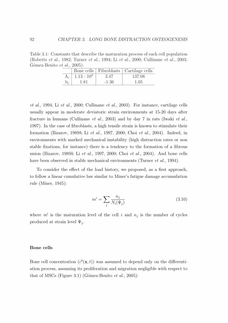
92 CHAPTER 3. LONG BONE DISTRACTION OSTEOGENESIS
Table 3.1: Constants that describe the maturation process of each cell population(Roberts et al., 1982; Turner et al., 1994; Li et al., 2000; Cullinane et al., 2003;Gomez-Benito et al., 2005).
Bone cells Fibroblasts Cartilage cellsAi 1.13 · 103 3.47 137.08bi 1.81 -1.36 1.05
et al., 1994; Li et al., 2000; Cullinane et al., 2003). For instance, cartilage cells
usually appear in moderate deviatoric strain environments at 15-20 days after
fracture in humans (Cullinane et al., 2003) and by day 7 in rats (Iwaki et al.,
1997). In the case of fibroblasts, a high tensile strain is known to stimulate their
formation (Ilizarov, 1989b; Li et al., 1997, 2000; Choi et al., 2004). Indeed, in
environments with marked mechanical instability (high distraction rates or non
stable fixations, for instance) there is a tendency to the formation of a fibrous
union (Ilizarov, 1989b; Li et al., 1997, 2000; Choi et al., 2004). And bone cells
have been observed in stable mechanical environments (Turner et al., 1994).
To consider the effect of the load history, we proposed, as a first approach,
to follow a linear cumulative law similar to Miner’s fatigue damage accumulation
rule (Miner, 1945):
mi =∑
j
nj
Ni(Ψj)(3.10)
where mi is the maturation level of the cell i and nj is the number of cycles
produced at strain level Ψj.
Bone cells
Bone cell concentration (cb(x, t)) was assumed to depend only on the differenti-
ation process, assuming its proliferation and migration negligible with respect to
that of MSCs (Figure 3.1) (Gomez-Benito et al., 2005):
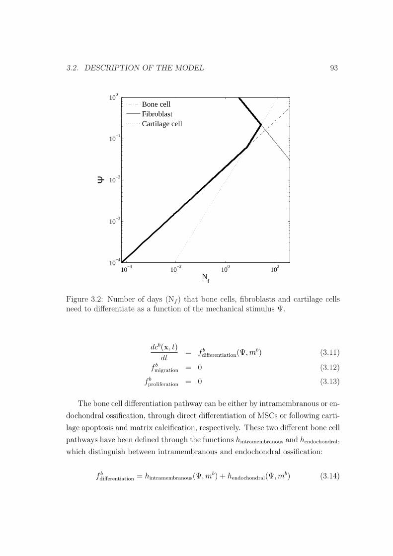
3.2. DESCRIPTION OF THE MODEL 93
10−4
10−2
100
102
10−4
10−3
10−2
10−1
100
Ψ
Nf
Bone cellFibroblastCartilage cell
Figure 3.2: Number of days (Nf ) that bone cells, fibroblasts and cartilage cellsneed to differentiate as a function of the mechanical stimulus Ψ.
dcb(x, t)
dt= f b
differentiation(Ψ, mb) (3.11)
f bmigration = 0 (3.12)
f bproliferation = 0 (3.13)
The bone cell differentiation pathway can be either by intramembranous or en-
dochondral ossification, through direct differentiation of MSCs or following carti-
lage apoptosis and matrix calcification, respectively. These two different bone cell
pathways have been defined through the functions hintramembranous and hendochondral,
which distinguish between intramembranous and endochondral ossification:
f bdifferentiation = hintramembranous(Ψ,mb) + hendochondral(Ψ,mb) (3.14)
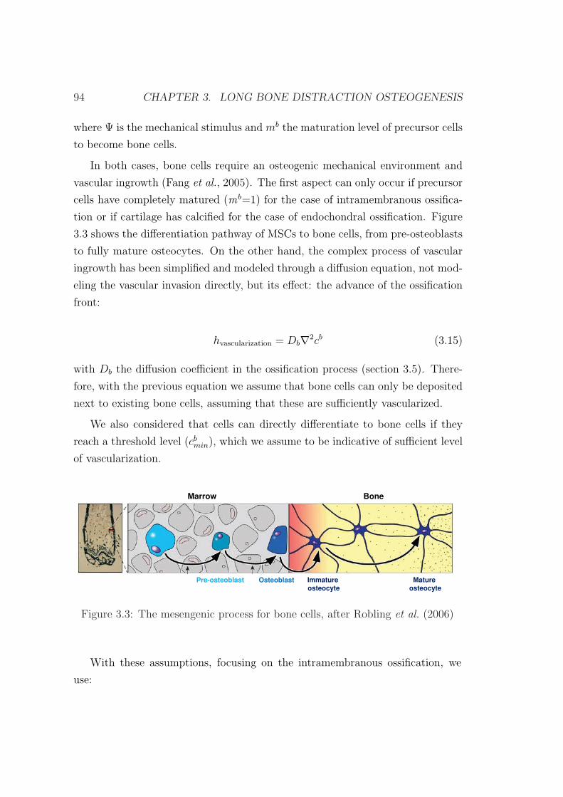
94 CHAPTER 3. LONG BONE DISTRACTION OSTEOGENESIS
where Ψ is the mechanical stimulus and mb the maturation level of precursor cells
to become bone cells.
In both cases, bone cells require an osteogenic mechanical environment and
vascular ingrowth (Fang et al., 2005). The first aspect can only occur if precursor
cells have completely matured (mb=1) for the case of intramembranous ossifica-
tion or if cartilage has calcified for the case of endochondral ossification. Figure
3.3 shows the differentiation pathway of MSCs to bone cells, from pre-osteoblasts
to fully mature osteocytes. On the other hand, the complex process of vascular
ingrowth has been simplified and modeled through a diffusion equation, not mod-
eling the vascular invasion directly, but its effect: the advance of the ossification
front:
hvascularization = Db∇2cb (3.15)
with Db the diffusion coefficient in the ossification process (section 3.5). There-
fore, with the previous equation we assume that bone cells can only be deposited
next to existing bone cells, assuming that these are sufficiently vascularized.
We also considered that cells can directly differentiate to bone cells if they
reach a threshold level (cbmin), which we assume to be indicative of sufficient level
of vascularization.
Pre-osteoblast Osteoblast Immatureosteocyte
Matureosteocyte
Marrow Bone
Figure 3.3: The mesengenic process for bone cells, after Robling et al. (2006)
With these assumptions, focusing on the intramembranous ossification, we
use:
3.2. DESCRIPTION OF THE MODEL 95
hintramembranous =
hvascularization if [(cb < cbmin)&(mb = 1)]
cs if [(cb > cbmin)&(mb = 1)]
0 otherwise
(3.16)
where mb is the normalized maturation state of MSCs to bone cells and ci the
cell concentration.
Endochondral ossification has been modeled analogously:
hendochondral =
hvascularization if [(mb = 1)&(cb < cbmin)]
cc if [(mb = 1)&(cb > cbmin)]
0 otherwise
(3.17)
Cartilage cells
Cartilage cell concentration (cc(x, t)) was also assumed to change only by the
differentiation process (Figure 3.1) (Gomez-Benito et al., 2005). Its concentration
increases by MSCs differentiation into this cell phenotype and decreases through
the endochondral ossification:
dcc(x, t)
dt= f c
differentiation(Ψ, t) = gdifferentiation − hendochondral (3.18)
f cmigration = 0 (3.19)
f cproliferation = 0 (3.20)
The endochondral ossification has been modeled with equation (3.17) whilst
the direct differentiation of MSCs to chondrocytes follows the following rule:
gdifferentiation =
cs if (mc = 1)
0 otherwise(3.21)
96 CHAPTER 3. LONG BONE DISTRACTION OSTEOGENESIS
Fibroblasts
Similarly, fibroblast concentration (cf (x, t)) was only dependent on differentiation
rules, assuming their proliferation and migration negligible:
dcf (x, t)
dt= f f
differentiation(Ψ, t) (3.22)
f fmigration = 0 (3.23)
f fproliferation = 0 (3.24)
Differentiation of MSCs to fibroblasts has been modeled:
f fdifferentiation =
cs if (mf = 1)
0 otherwise(3.25)
Dead cells
Finally, if the mechanical stimulus reaches a limit value MSCs can also die:
if Ψ > Ψdeath,dcd
dt= cs (3.26)
where Ψdeath is the stimulus level above which MSCs will die (section 3.5).
3.2.2 Callus growth
Tissue growth is developed, as a first approximation, under the small deformation
assumption. We are aware that distraction in the first days is a large deformation
process since interfragmentary movements represent as much as 100% of the size
of the gap in these first days. However, after 5 days of distraction, strains are
reduced up to 20%. On the basis of this hypothesis and following equation (3.4),
the total tissue growth is assumed to be computed as the sum of the proliferation
of MSCs and chondrocytes hypertrophy (equation (3.4)) (Gomez-Benito et al.,
2005).
Regarding the former, it is assumed that the concentration of mesenchymal
cells can increase due to proliferation, from zero to a maximum or saturation cell
3.3. MATERIAL PROPERTIES 97
density (csmax) without having to increase the callus size. Once this concentration
is reached, the only way cells have to proliferate further is by increasing the callus
size at a constant level of cell concentration (equation (3.4)):
fυproliferation(c
s, Ψ) =
0 if (cs < cs
max)fsproliferation
csmax
if (cs = csmax)
(3.27)
with f sproliferation the proliferation function defined in equation (3.7) and cs
max the
normalized saturation value of stem cell density (section 3.5).
The second growth mode is assumed to be due to the hypertrophy of chon-
drocytes. These cells undergo an increase of volume before calcification and
programmed cell death to allow osseous tissue to develop (endochondral ossifica-
tion). Growth due to chondrocytes hypertrophy (equation (3.4)) is described by
the following expression (Gomez-Benito et al., 2005):
gυendochondral(c
c, Ψ) =−1
cc(x, t)· ∂c(x, t)
∂t= − ggrowth
cc(x, t)(3.28)
where ggrowth is:
ggrowth =
Ψ−Ψcalcified
Ψbone −Ψcalcified
khyper if (Ψ < Ψcalcified)&(cc > ccmin)
0 otherwise(3.29)
with Ψcalcified, khyper and ccmin constants of the model (section 3.5).
3.3 Material properties
The different tissues (granulation tissue, fibrous tissue, cartilage, calcified carti-
lage and bone tissue) govern the mechanical properties of the distraction gap and
hence the associated gap stiffness. Tissues are assumed to be poroelastic and
isotropic, each one with a constant proportion of the main components (Gomez-
Benito et al., 2005): collagen type I (cI), II (cII), and III (cIII), water, ground
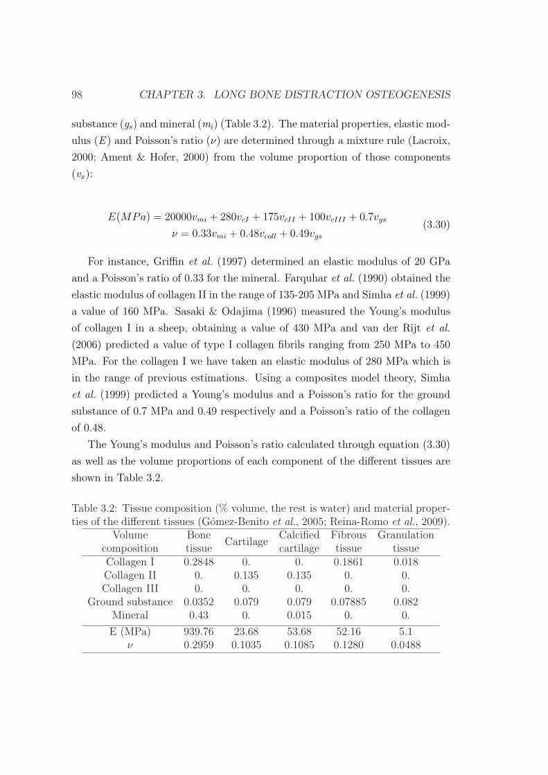
98 CHAPTER 3. LONG BONE DISTRACTION OSTEOGENESIS
substance (gs) and mineral (mi) (Table 3.2). The material properties, elastic mod-
ulus (E ) and Poisson’s ratio (ν) are determined through a mixture rule (Lacroix,
2000; Ament & Hofer, 2000) from the volume proportion of those components
(vx):
E(MPa) = 20000vmi + 280vcI + 175vcII + 100vcIII + 0.7vgs
ν = 0.33vmi + 0.48vcoll + 0.49vgs
(3.30)
For instance, Griffin et al. (1997) determined an elastic modulus of 20 GPa
and a Poisson’s ratio of 0.33 for the mineral. Farquhar et al. (1990) obtained the
elastic modulus of collagen II in the range of 135-205 MPa and Simha et al. (1999)
a value of 160 MPa. Sasaki & Odajima (1996) measured the Young’s modulus
of collagen I in a sheep, obtaining a value of 430 MPa and van der Rijt et al.
(2006) predicted a value of type I collagen fibrils ranging from 250 MPa to 450
MPa. For the collagen I we have taken an elastic modulus of 280 MPa which is
in the range of previous estimations. Using a composites model theory, Simha
et al. (1999) predicted a Young’s modulus and a Poisson’s ratio for the ground
substance of 0.7 MPa and 0.49 respectively and a Poisson’s ratio of the collagen
of 0.48.
The Young’s modulus and Poisson’s ratio calculated through equation (3.30)
as well as the volume proportions of each component of the different tissues are
shown in Table 3.2.
Table 3.2: Tissue composition (% volume, the rest is water) and material proper-ties of the different tissues (Gomez-Benito et al., 2005; Reina-Romo et al., 2009).
Volume BoneCartilage
Calcified Fibrous Granulationcomposition tissue cartilage tissue tissueCollagen I 0.2848 0. 0. 0.1861 0.018Collagen II 0. 0.135 0.135 0. 0.Collagen III 0. 0. 0. 0. 0.
Ground substance 0.0352 0.079 0.079 0.07885 0.082Mineral 0.43 0. 0.015 0. 0.
E (MPa) 939.76 23.68 53.68 52.16 5.1ν 0.2959 0.1035 0.1085 0.1280 0.0488
3.3. MATERIAL PROPERTIES 99
The values of the permeability are different for each tissue type. For hard
tissues, we assume a constant permeability distinguishing between cortical bone,
woven bone and calcified cartilage, with values of 7·10−15, 7·10−11 and 3.5·10−12
mm2. In soft tissues (granulation tissue, fibrous tissue, cartilage tissue and debris
tissue) permeability is calculated from composition and porosity, following the
model proposed by Levick (1987). The main aspects of these relationships are
summarized in appendix A.
3.3.1 Tissue damage
Damage is incorporated in the model through the variable di. This variable
quantifies the macroscopic mechanical degradation and is related to the density
of internal microcracks (hi). In general, the relation between both variables can
be expressed as (Doblare & Garcıa-Aznar, 2006):
f(di) = hi. (3.31)
The continuum damage variable di is normalized between [0,1] where 0 rep-
resents an intact matrix and 1 a completely disrupted matrix. Although damage
could affect all tissues, we assume that it only occurs in the granulation and debris
tissues due to their relative low resistant properties. We assume that granulation
or debris tissues are locally disrupted when the maximum value of the mechan-
ical stimulus in their corresponding tissues reaches a limit stimulus Ψdamage. In
this case, we assume that the disrupted volume fraction is 0.95, that is, only a
small residual stiffness is considered for these tissues in mechanically demanding
environments (Gomez-Benito et al., 2005):
di =
0 if Ψ < Ψdamage
0.95 otherwise (3.32)
The rigidity reduction of the granulation tissue as a result of the damage is given
by:
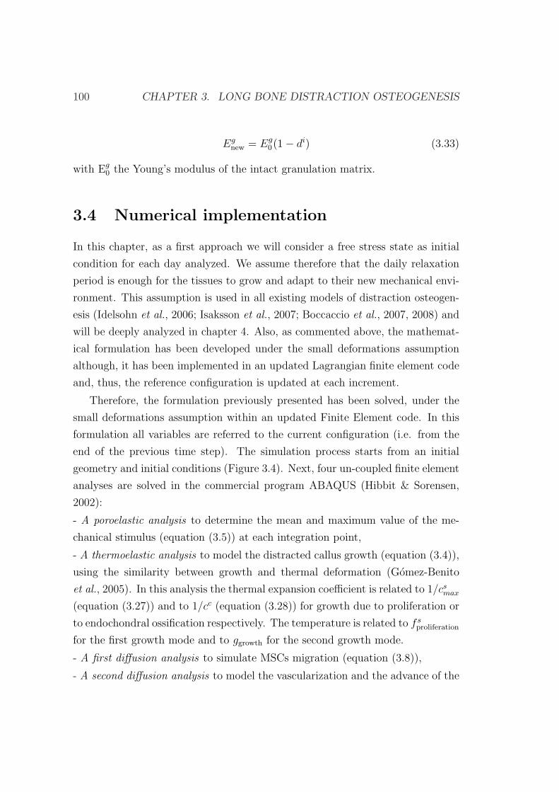
100 CHAPTER 3. LONG BONE DISTRACTION OSTEOGENESIS
Egnew = Eg
0(1− di) (3.33)
with Eg0 the Young’s modulus of the intact granulation matrix.
3.4 Numerical implementation
In this chapter, as a first approach we will consider a free stress state as initial
condition for each day analyzed. We assume therefore that the daily relaxation
period is enough for the tissues to grow and adapt to their new mechanical envi-
ronment. This assumption is used in all existing models of distraction osteogen-
esis (Idelsohn et al., 2006; Isaksson et al., 2007; Boccaccio et al., 2007, 2008) and
will be deeply analyzed in chapter 4. Also, as commented above, the mathemat-
ical formulation has been developed under the small deformations assumption
although, it has been implemented in an updated Lagrangian finite element code
and, thus, the reference configuration is updated at each increment.
Therefore, the formulation previously presented has been solved, under the
small deformations assumption within an updated Finite Element code. In this
formulation all variables are referred to the current configuration (i.e. from the
end of the previous time step). The simulation process starts from an initial
geometry and initial conditions (Figure 3.4). Next, four un-coupled finite element
analyses are solved in the commercial program ABAQUS (Hibbit & Sorensen,
2002):
- A poroelastic analysis to determine the mean and maximum value of the me-
chanical stimulus (equation (3.5)) at each integration point,
- A thermoelastic analysis to model the distracted callus growth (equation (3.4)),
using the similarity between growth and thermal deformation (Gomez-Benito
et al., 2005). In this analysis the thermal expansion coefficient is related to 1/csmax
(equation (3.27)) and to 1/cc (equation (3.28)) for growth due to proliferation or
to endochondral ossification respectively. The temperature is related to f sproliferation
for the first growth mode and to ggrowth for the second growth mode.
- A first diffusion analysis to simulate MSCs migration (equation (3.8)),
- A second diffusion analysis to model the vascularization and the advance of the
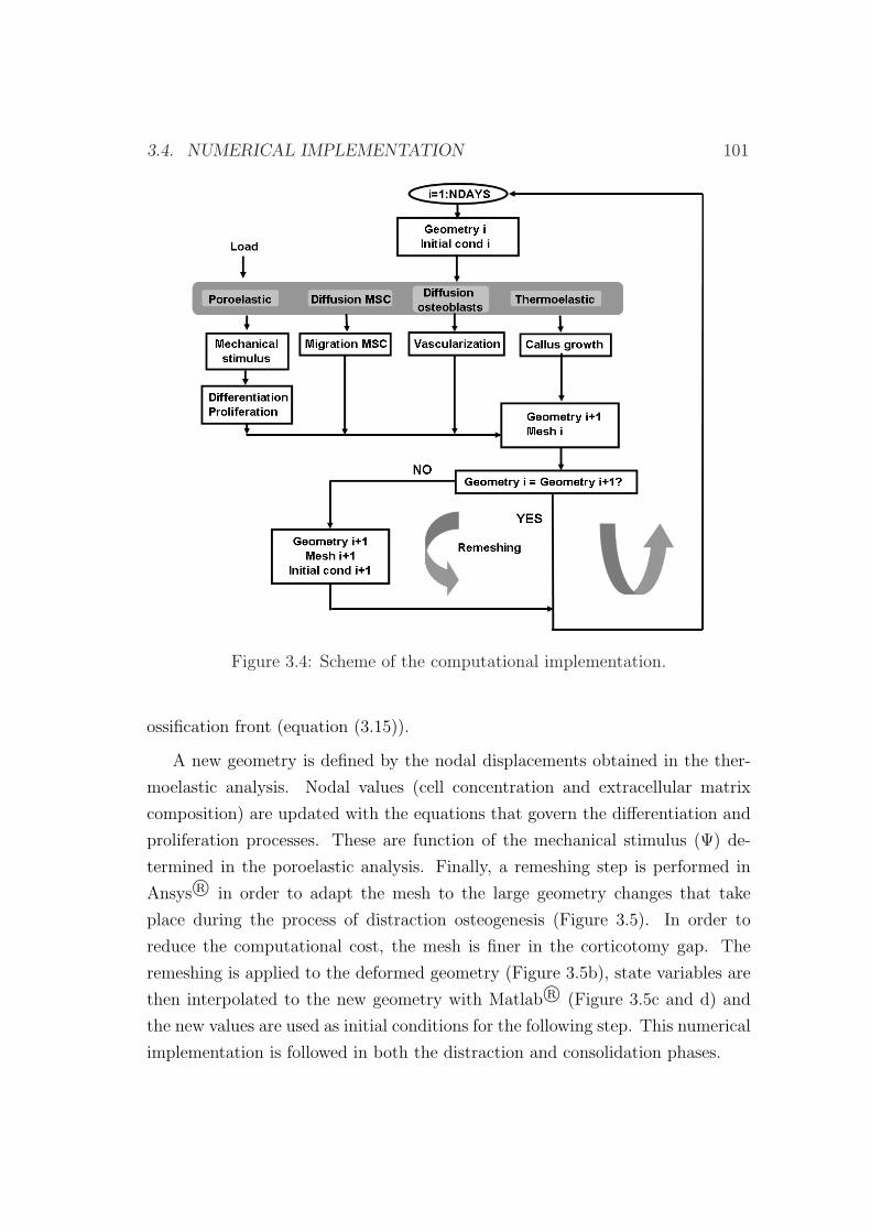
3.4. NUMERICAL IMPLEMENTATION 101
Figure 3.4: Scheme of the computational implementation.
ossification front (equation (3.15)).
A new geometry is defined by the nodal displacements obtained in the ther-
moelastic analysis. Nodal values (cell concentration and extracellular matrix
composition) are updated with the equations that govern the differentiation and
proliferation processes. These are function of the mechanical stimulus (Ψ) de-
termined in the poroelastic analysis. Finally, a remeshing step is performed in
Ansys R© in order to adapt the mesh to the large geometry changes that take
place during the process of distraction osteogenesis (Figure 3.5). In order to
reduce the computational cost, the mesh is finer in the corticotomy gap. The
remeshing is applied to the deformed geometry (Figure 3.5b), state variables are
then interpolated to the new geometry with Matlab R© (Figure 3.5c and d) and
the new values are used as initial conditions for the following step. This numerical
implementation is followed in both the distraction and consolidation phases.
102 CHAPTER 3. LONG BONE DISTRACTION OSTEOGENESIS
(a) (b) (c) (d)
Figure 3.5: Remeshing implementation. a) Old mesh integration points beforethe loading process; b) old mesh nodes after the loading process; c) new meshnodes; d) new mesh integration points. Old elements are drawn with dashed linesand new elements are drawn with solid lines.
3.5 Model parameters
All the parameters used in the simulations have been estimated from the literature
and have been tested in sensitivity analyses:
• Ψbone=0.03 is the stimulus level below which bone tissue may be formed
through the endochondral ossification.
• Ψdeath=1 is the stimulus level above which MSCs will die (Claes et al., 1997;
Gomez-Benito et al., 2005).
• Ψdamage=0.6 is the stimulus level above which disruption of granulation
tissue takes place.
• Ψcalcified=0.06 is the stimulus level below which cartilage begins to calcify
before endochondral ossification occurs.
• αproliferation=0.6 day−1 and Ψproliferation=0.2 are the parameters that define
the stem cell proliferation
• csmax=1 is the normalized saturation value of stem cell density (Wilsman
et al., 1996; Gomez-Benito et al., 2005).
• khyper=0.01 second−1 is the parameter that controls the volume increase pro-
duced during normalized cartilage cell calcification (Wilsman et al., 1996;
Gomez-Benito et al., 2005).
3.6. EXAMPLE OF APPLICATION 103
• Qs=0.3 mm3/(stem cell·day), Qb=0.3 mm3/(osteoblast·day), Qc=0.2 mm3/
(chondrocyte·day), Qf=0.5 mm3/(fibroblast·day) is the amount of matrix
synthesized per stem cell, osteoblast, chondrocyte or fibroblast and unit
time.
• cbmin=0.2 is the minimum concentration of bone cells that indicates when
blood supply is completed at the ossification front and osteoblasts can dif-
ferentiate directly from stem cells.
• ccmin=0.6 is the equilibrium value of normalized cartilage cell concentration
(Wilsman et al., 1996; Gomez-Benito et al., 2005).
• D=1 mm2/day is the diffusion coefficient that controls stem cell migration.
• Db=4 mm2/day is the constant that defines the diffusion coefficient in the
ossification process.
3.6 Example of application
As explained in chapter 2, mechanical factors, such as axial alignment, stabil-
ity and distraction rate affect both the quality and quantity of the regenerated
bone (Ilizarov, 1989a). For example, nonunions may occur when the bone ends
move too much (Ilizarov, 1989a; Tajana et al., 1989; Fischgrund et al., 1994), the
distraction rate is higher than the optimal (Ilizarov, 1989b; Tajana et al., 1989;
White & Kenwright, 1990; Choi et al., 2004), the frequency of distraction is not
adequate (Ilizarov, 1989b), there is no latency phase (Ilizarov, 1989a,b; White &
Kenwright, 1990) or due to damage of the bone marrow and periosteal soft tissues
(Ilizarov, 1989a).
Therefore, in this section, the mechanobiological model is applied to different
mechanical environments in order to elucidate if mechanics may be an important
factor that determines the main features of distraction osteogenesis. In particular,
we analyze the effect of different distraction rates.
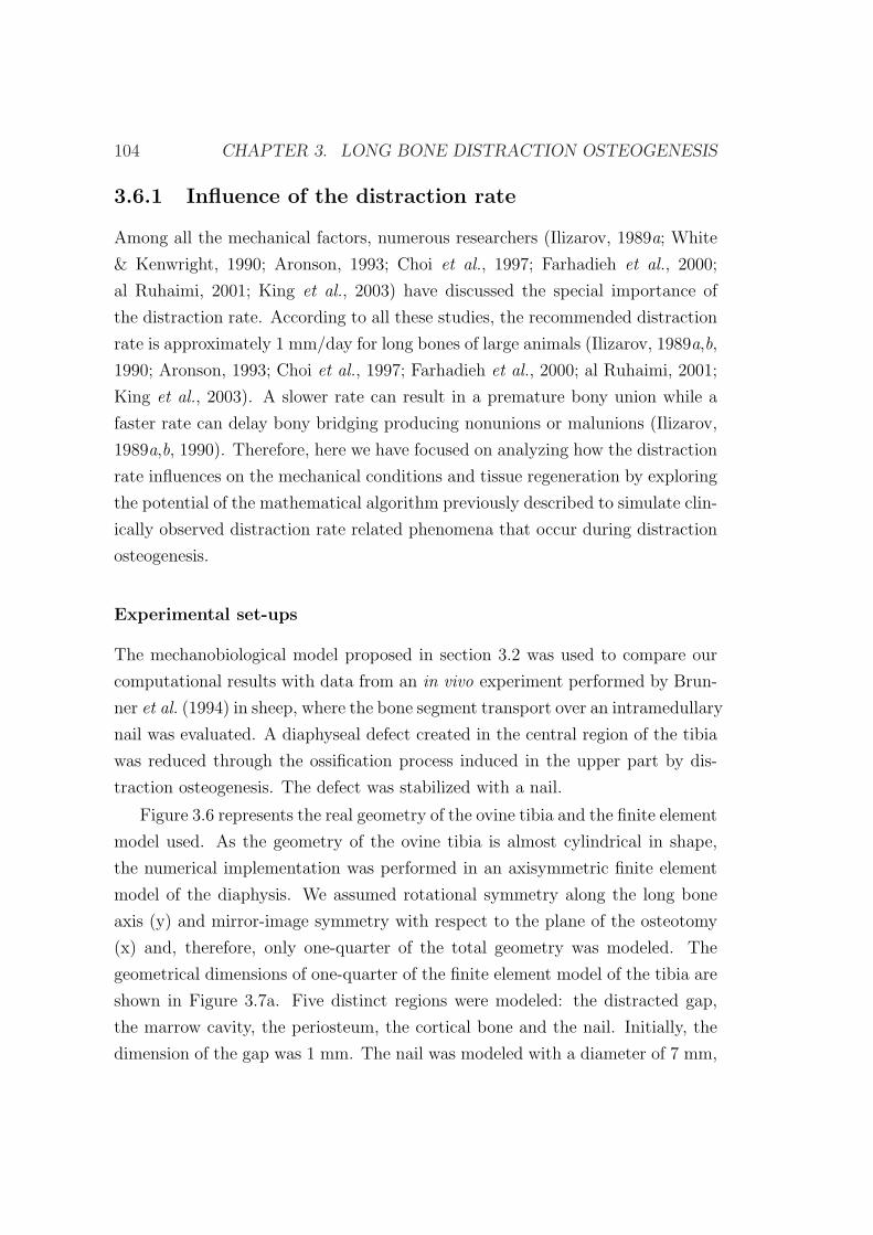
104 CHAPTER 3. LONG BONE DISTRACTION OSTEOGENESIS
3.6.1 Influence of the distraction rate
Among all the mechanical factors, numerous researchers (Ilizarov, 1989a; White
& Kenwright, 1990; Aronson, 1993; Choi et al., 1997; Farhadieh et al., 2000;
al Ruhaimi, 2001; King et al., 2003) have discussed the special importance of
the distraction rate. According to all these studies, the recommended distraction
rate is approximately 1 mm/day for long bones of large animals (Ilizarov, 1989a,b,
1990; Aronson, 1993; Choi et al., 1997; Farhadieh et al., 2000; al Ruhaimi, 2001;
King et al., 2003). A slower rate can result in a premature bony union while a
faster rate can delay bony bridging producing nonunions or malunions (Ilizarov,
1989a,b, 1990). Therefore, here we have focused on analyzing how the distraction
rate influences on the mechanical conditions and tissue regeneration by exploring
the potential of the mathematical algorithm previously described to simulate clin-
ically observed distraction rate related phenomena that occur during distraction
osteogenesis.
Experimental set-ups
The mechanobiological model proposed in section 3.2 was used to compare our
computational results with data from an in vivo experiment performed by Brun-
ner et al. (1994) in sheep, where the bone segment transport over an intramedullary
nail was evaluated. A diaphyseal defect created in the central region of the tibia
was reduced through the ossification process induced in the upper part by dis-
traction osteogenesis. The defect was stabilized with a nail.
Figure 3.6 represents the real geometry of the ovine tibia and the finite element
model used. As the geometry of the ovine tibia is almost cylindrical in shape,
the numerical implementation was performed in an axisymmetric finite element
model of the diaphysis. We assumed rotational symmetry along the long bone
axis (y) and mirror-image symmetry with respect to the plane of the osteotomy
(x) and, therefore, only one-quarter of the total geometry was modeled. The
geometrical dimensions of one-quarter of the finite element model of the tibia are
shown in Figure 3.7a. Five distinct regions were modeled: the distracted gap,
the marrow cavity, the periosteum, the cortical bone and the nail. Initially, the
dimension of the gap was 1 mm. The nail was modeled with a diameter of 7 mm,
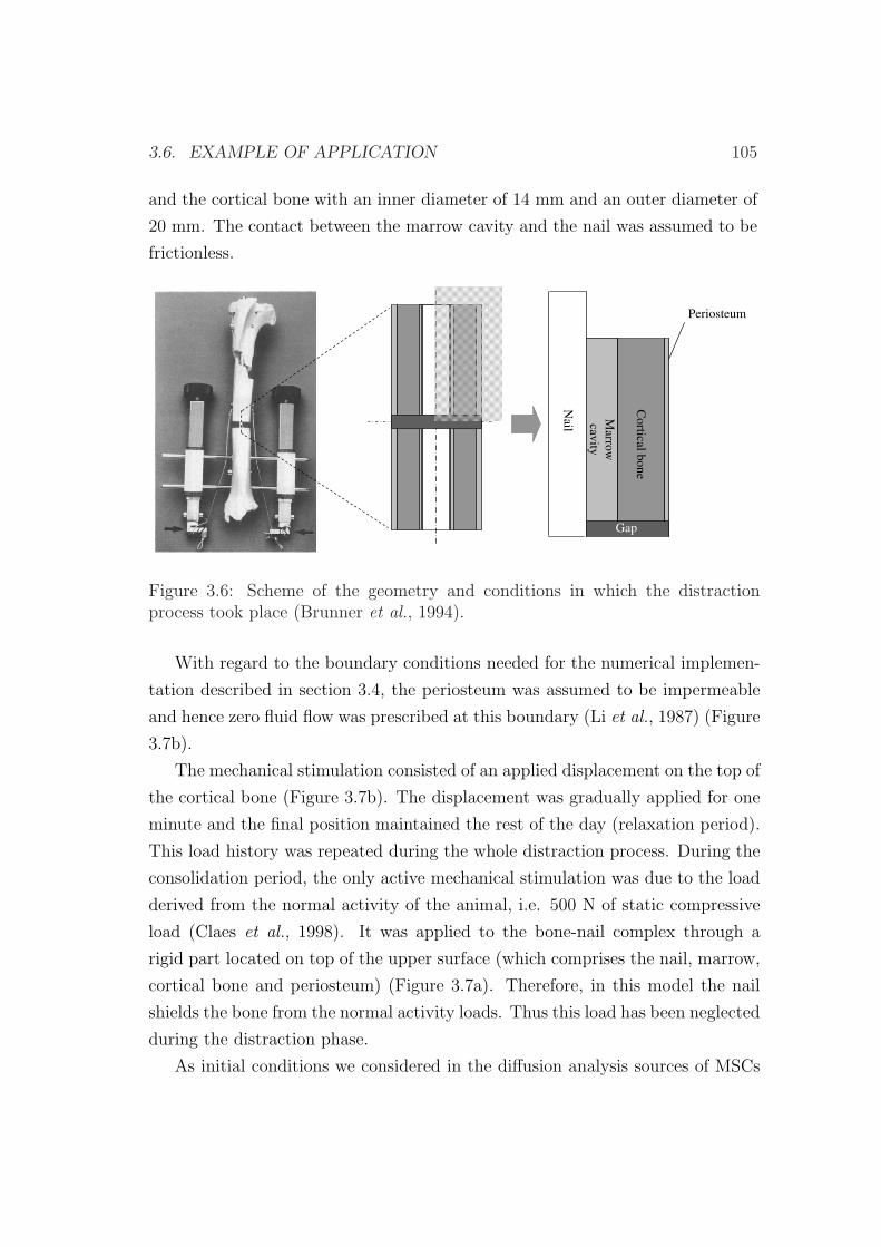
3.6. EXAMPLE OF APPLICATION 105
and the cortical bone with an inner diameter of 14 mm and an outer diameter of
20 mm. The contact between the marrow cavity and the nail was assumed to be
frictionless.M
arrow
cavity
Co
rtical bo
ne
Gap
Nail
Periosteum
Figure 3.6: Scheme of the geometry and conditions in which the distractionprocess took place (Brunner et al., 1994).
With regard to the boundary conditions needed for the numerical implemen-
tation described in section 3.4, the periosteum was assumed to be impermeable
and hence zero fluid flow was prescribed at this boundary (Li et al., 1987) (Figure
3.7b).
The mechanical stimulation consisted of an applied displacement on the top of
the cortical bone (Figure 3.7b). The displacement was gradually applied for one
minute and the final position maintained the rest of the day (relaxation period).
This load history was repeated during the whole distraction process. During the
consolidation period, the only active mechanical stimulation was due to the load
derived from the normal activity of the animal, i.e. 500 N of static compressive
load (Claes et al., 1998). It was applied to the bone-nail complex through a
rigid part located on top of the upper surface (which comprises the nail, marrow,
cortical bone and periosteum) (Figure 3.7a). Therefore, in this model the nail
shields the bone from the normal activity loads. Thus this load has been neglected
during the distraction phase.
As initial conditions we considered in the diffusion analysis sources of MSCs
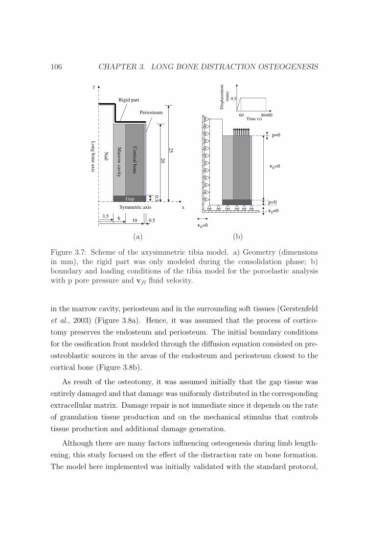
106 CHAPTER 3. LONG BONE DISTRACTION OSTEOGENESIS
10 0.563.5
Co
rtical bo
ne
Gap
20
25N
ail
Periosteum
Lo
ng
bo
ne
axis
Symmetric axis
y
x
Marro
wcav
ity
Rigid part
0.5
vfl=0
Dis
pla
cem
ent
(mm
)
0.5
Time (s)60 86400
p=0
vfl=0
vfl=0
p=0
(a) (b)
Figure 3.7: Scheme of the axysimmetric tibia model. a) Geometry (dimensionsin mm), the rigid part was only modeled during the consolidation phase; b)boundary and loading conditions of the tibia model for the poroelastic analysiswith p pore pressure and vfl fluid velocity.
in the marrow cavity, periosteum and in the surrounding soft tissues (Gerstenfeld
et al., 2003) (Figure 3.8a). Hence, it was assumed that the process of cortico-
tomy preserves the endosteum and periosteum. The initial boundary conditions
for the ossification front modeled through the diffusion equation consisted on pre-
osteoblastic sources in the areas of the endosteum and periosteum closest to the
cortical bone (Figure 3.8b).
As result of the osteotomy, it was assumed initially that the gap tissue was
entirely damaged and that damage was uniformly distributed in the corresponding
extracellular matrix. Damage repair is not immediate since it depends on the rate
of granulation tissue production and on the mechanical stimulus that controls
tissue production and additional damage generation.
Although there are many factors influencing osteogenesis during limb length-
ening, this study focused on the effect of the distraction rate on bone formation.
The model here implemented was initially validated with the standard protocol,
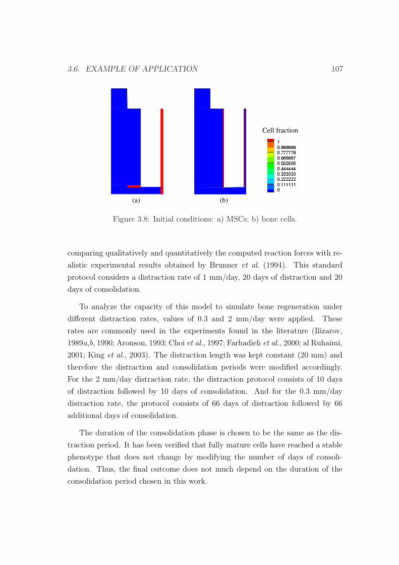
3.6. EXAMPLE OF APPLICATION 107
Cell fraction
(a) (b)
Figure 3.8: Initial conditions: a) MSCs; b) bone cells.
comparing qualitatively and quantitatively the computed reaction forces with re-
alistic experimental results obtained by Brunner et al. (1994). This standard
protocol considers a distraction rate of 1 mm/day, 20 days of distraction and 20
days of consolidation.
To analyze the capacity of this model to simulate bone regeneration under
different distraction rates, values of 0.3 and 2 mm/day were applied. These
rates are commonly used in the experiments found in the literature (Ilizarov,
1989a,b, 1990; Aronson, 1993; Choi et al., 1997; Farhadieh et al., 2000; al Ruhaimi,
2001; King et al., 2003). The distraction length was kept constant (20 mm) and
therefore the distraction and consolidation periods were modified accordingly.
For the 2 mm/day distraction rate, the distraction protocol consists of 10 days
of distraction followed by 10 days of consolidation. And for the 0.3 mm/day
distraction rate, the protocol consists of 66 days of distraction followed by 66
additional days of consolidation.
The duration of the consolidation phase is chosen to be the same as the dis-
traction period. It has been verified that fully mature cells have reached a stable
phenotype that does not change by modifying the number of days of consoli-
dation. Thus, the final outcome does not much depend on the duration of the
consolidation period chosen in this work.
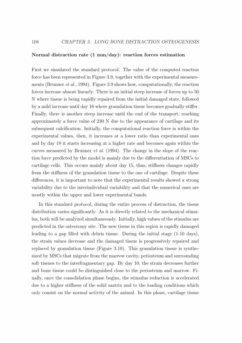
108 CHAPTER 3. LONG BONE DISTRACTION OSTEOGENESIS
Normal distraction rate (1 mm/day): reaction forces estimation
First we simulated the standard protocol. The value of the computed reaction
force has been represented in Figure 3.9, together with the experimental measure-
ments (Brunner et al., 1994). Figure 3.9 shows how, computationally, the reaction
forces increase almost linearly. There is an initial steep increase of forces up to 50
N where tissue is being rapidly repaired from the initial damaged state, followed
by a mild increase until day 16 where granulation tissue becomes gradually stiffer.
Finally, there is another steep increase until the end of the transport, reaching
approximately a force value of 230 N due to the appearance of cartilage and its
subsequent calcification. Initially, the computational reaction force is within the
experimental values, then, it increases at a lower ratio than experimental ones
and by day 18 it starts increasing at a higher rate and becomes again within the
curves measured by Brunner et al. (1994). The change in the slope of the reac-
tion force predicted by the model is mainly due to the differentiation of MSCs to
cartilage cells. This occurs mainly about day 15, thus, stiffness changes rapidly
from the stiffness of the granulation tissue to the one of cartilage. Despite these
differences, it is important to note that the experimental results showed a strong
variability due to the interindividual variability and that the numerical ones are
mostly within the upper and lower experimental bands.
In this standard protocol, during the entire process of distraction, the tissue
distribution varies significantly. As it is directly related to the mechanical stimu-
lus, both will be analyzed simultaneously. Initially, high values of the stimulus are
predicted in the osteotomy site. The new tissue in this region is rapidly damaged
leading to a gap filled with debris tissue. During the initial stage (1-10 days),
the strain values decrease and the damaged tissue is progressively repaired and
replaced by granulation tissue (Figure 3.10). This granulation tissue is synthe-
sized by MSCs that migrate from the marrow cavity, periosteum and surrounding
soft tissues to the interfragmentary gap. By day 10, the strain decreases further
and bone tissue could be distinguished close to the periosteum and marrow. Fi-
nally, once the consolidation phase begins, the stimulus reduction is accelerated
due to a higher stiffness of the solid matrix and to the loading conditions which
only consist on the normal activity of the animal. In this phase, cartilage tissue
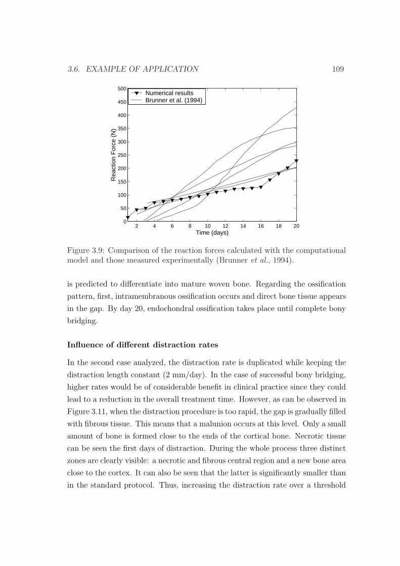
3.6. EXAMPLE OF APPLICATION 109
2 4 6 8 10 12 14 16 18 200
50
100
150
200
250
300
350
400
450
500
Time (days)
Rea
ctio
n F
orce
(N
)
Numerical resultsBrunner et al. (1994)
Figure 3.9: Comparison of the reaction forces calculated with the computationalmodel and those measured experimentally (Brunner et al., 1994).
is predicted to differentiate into mature woven bone. Regarding the ossification
pattern, first, intramembranous ossification occurs and direct bone tissue appears
in the gap. By day 20, endochondral ossification takes place until complete bony
bridging.
Influence of different distraction rates
In the second case analyzed, the distraction rate is duplicated while keeping the
distraction length constant (2 mm/day). In the case of successful bony bridging,
higher rates would be of considerable benefit in clinical practice since they could
lead to a reduction in the overall treatment time. However, as can be observed in
Figure 3.11, when the distraction procedure is too rapid, the gap is gradually filled
with fibrous tissue. This means that a malunion occurs at this level. Only a small
amount of bone is formed close to the ends of the cortical bone. Necrotic tissue
can be seen the first days of distraction. During the whole process three distinct
zones are clearly visible: a necrotic and fibrous central region and a new bone area
close to the cortex. It can also be seen that the latter is significantly smaller than
in the standard protocol. Thus, increasing the distraction rate over a threshold
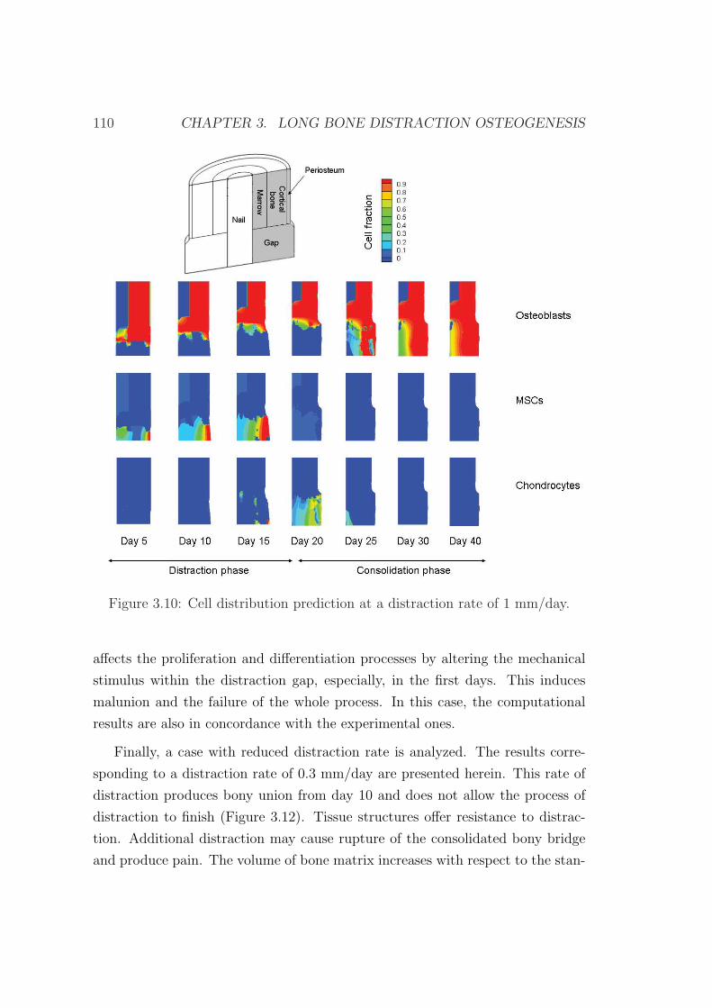
110 CHAPTER 3. LONG BONE DISTRACTION OSTEOGENESIS
Figure 3.10: Cell distribution prediction at a distraction rate of 1 mm/day.
affects the proliferation and differentiation processes by altering the mechanical
stimulus within the distraction gap, especially, in the first days. This induces
malunion and the failure of the whole process. In this case, the computational
results are also in concordance with the experimental ones.
Finally, a case with reduced distraction rate is analyzed. The results corre-
sponding to a distraction rate of 0.3 mm/day are presented herein. This rate of
distraction produces bony union from day 10 and does not allow the process of
distraction to finish (Figure 3.12). Tissue structures offer resistance to distrac-
tion. Additional distraction may cause rupture of the consolidated bony bridge
and produce pain. The volume of bone matrix increases with respect to the stan-
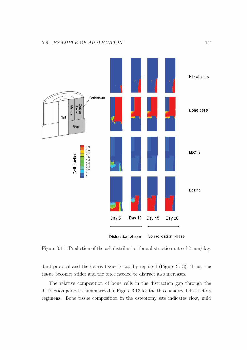
3.6. EXAMPLE OF APPLICATION 111
Figure 3.11: Prediction of the cell distribution for a distraction rate of 2 mm/day.
dard protocol and the debris tissue is rapidly repaired (Figure 3.13). Thus, the
tissue becomes stiffer and the force needed to distract also increases.
The relative composition of bone cells in the distraction gap through the
distraction period is summarized in Figure 3.13 for the three analyzed distraction
regimens. Bone tissue composition in the osteotomy site indicates slow, mild
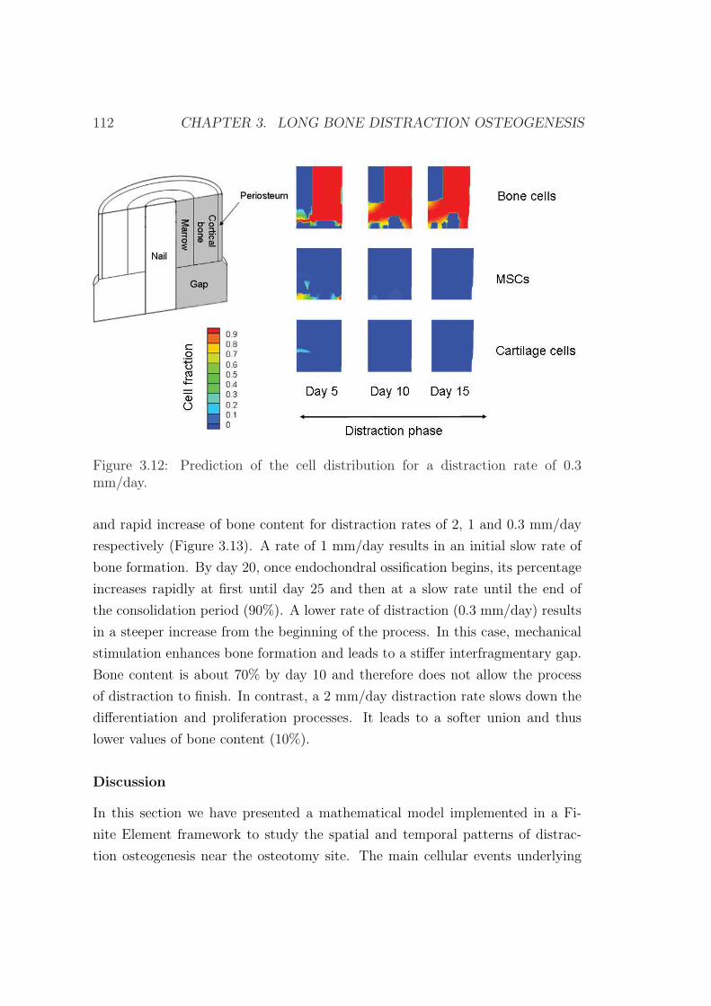
112 CHAPTER 3. LONG BONE DISTRACTION OSTEOGENESIS
Figure 3.12: Prediction of the cell distribution for a distraction rate of 0.3mm/day.
and rapid increase of bone content for distraction rates of 2, 1 and 0.3 mm/day
respectively (Figure 3.13). A rate of 1 mm/day results in an initial slow rate of
bone formation. By day 20, once endochondral ossification begins, its percentage
increases rapidly at first until day 25 and then at a slow rate until the end of
the consolidation period (90%). A lower rate of distraction (0.3 mm/day) results
in a steeper increase from the beginning of the process. In this case, mechanical
stimulation enhances bone formation and leads to a stiffer interfragmentary gap.
Bone content is about 70% by day 10 and therefore does not allow the process
of distraction to finish. In contrast, a 2 mm/day distraction rate slows down the
differentiation and proliferation processes. It leads to a softer union and thus
lower values of bone content (10%).
Discussion
In this section we have presented a mathematical model implemented in a Fi-
nite Element framework to study the spatial and temporal patterns of distrac-
tion osteogenesis near the osteotomy site. The main cellular events underlying

3.6. EXAMPLE OF APPLICATION 113
0 5 10 15 20 25 30 35 400
10
20
30
40
50
60
70
80
90
100
Time (days)
Bon
e ce
ll pe
rcen
tage
(%
)
v=2 mm/dayv=1 mm/dayv=0.3 mm/day
Figure 3.13: Bone volume fraction evolution in the gap throughout the distractionperiod for the different distraction rates analyzed.
in distraction osteogenesis have been implemented: proliferation, migration and
differentiation as well as tissue growth and damage.
A mathematical model formulated earlier for fracture healing is basically used
(Gomez-Benito et al., 2005, 2006; Garcıa-Aznar et al., 2007). Therefore, we as-
sume that fracture healing and distraction osteogenesis share similar biological
processes and strain-related bone tissue reactions. We have used this model and
others based on different mechanoregulatory differentiation rules (Prendergast
et al., 1997; Claes & Heigele, 1999; Gomez-Benito et al., 2005) to simulate the
influence of different distraction rates. They were able to successfully predict
the distraction osteogenesis process for distraction rates of 0.3 mm/day and 1
mm/day but not for 2 mm/day one. To improve those models, we have added
the effect of the load history on the process of differentiation in the model by tak-
ing into account the maturation cell level, thus considering cell plasticity (Roder,
2003). We have also checked in different examples of fracture healing that this new
extended model is also able to predict this regenerative process (Gomez-Benito
et al., 2005, 2006; Garcıa-Aznar et al., 2007).
The results of this extended model have been compared with those reported
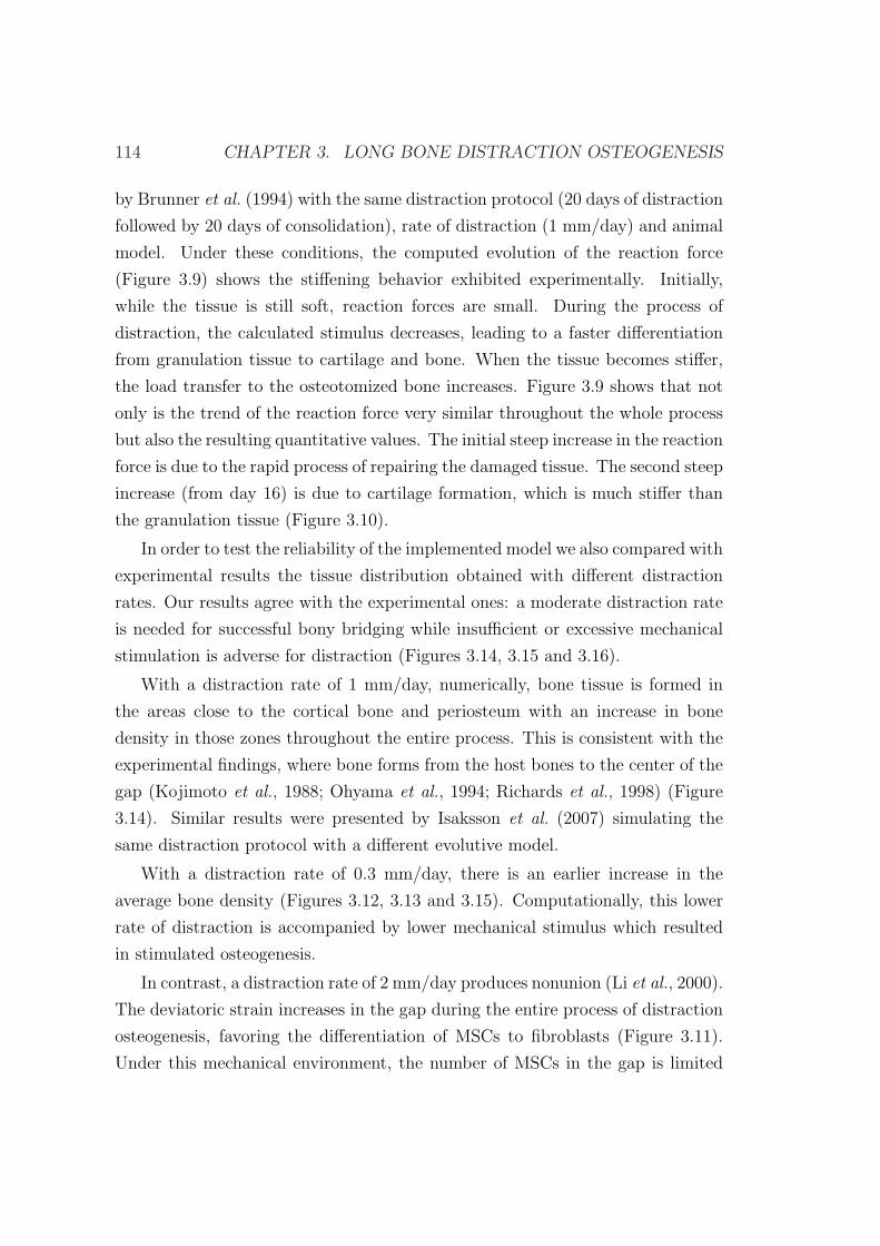
114 CHAPTER 3. LONG BONE DISTRACTION OSTEOGENESIS
by Brunner et al. (1994) with the same distraction protocol (20 days of distraction
followed by 20 days of consolidation), rate of distraction (1 mm/day) and animal
model. Under these conditions, the computed evolution of the reaction force
(Figure 3.9) shows the stiffening behavior exhibited experimentally. Initially,
while the tissue is still soft, reaction forces are small. During the process of
distraction, the calculated stimulus decreases, leading to a faster differentiation
from granulation tissue to cartilage and bone. When the tissue becomes stiffer,
the load transfer to the osteotomized bone increases. Figure 3.9 shows that not
only is the trend of the reaction force very similar throughout the whole process
but also the resulting quantitative values. The initial steep increase in the reaction
force is due to the rapid process of repairing the damaged tissue. The second steep
increase (from day 16) is due to cartilage formation, which is much stiffer than
the granulation tissue (Figure 3.10).
In order to test the reliability of the implemented model we also compared with
experimental results the tissue distribution obtained with different distraction
rates. Our results agree with the experimental ones: a moderate distraction rate
is needed for successful bony bridging while insufficient or excessive mechanical
stimulation is adverse for distraction (Figures 3.14, 3.15 and 3.16).
With a distraction rate of 1 mm/day, numerically, bone tissue is formed in
the areas close to the cortical bone and periosteum with an increase in bone
density in those zones throughout the entire process. This is consistent with the
experimental findings, where bone forms from the host bones to the center of the
gap (Kojimoto et al., 1988; Ohyama et al., 1994; Richards et al., 1998) (Figure
3.14). Similar results were presented by Isaksson et al. (2007) simulating the
same distraction protocol with a different evolutive model.
With a distraction rate of 0.3 mm/day, there is an earlier increase in the
average bone density (Figures 3.12, 3.13 and 3.15). Computationally, this lower
rate of distraction is accompanied by lower mechanical stimulus which resulted
in stimulated osteogenesis.
In contrast, a distraction rate of 2 mm/day produces nonunion (Li et al., 2000).
The deviatoric strain increases in the gap during the entire process of distraction
osteogenesis, favoring the differentiation of MSCs to fibroblasts (Figure 3.11).
Under this mechanical environment, the number of MSCs in the gap is limited
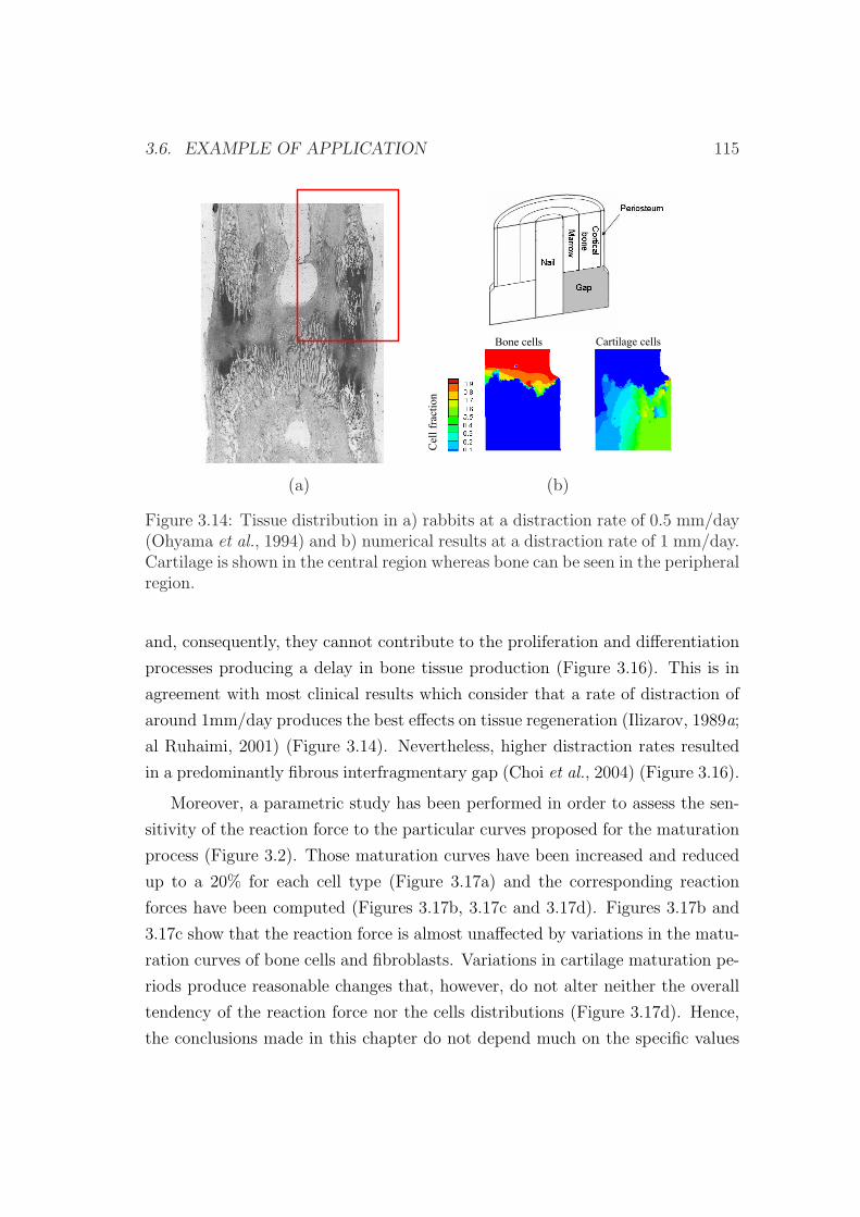
3.6. EXAMPLE OF APPLICATION 115
Bone cells Cartilage cells
action
Cellfra
(a) (b)
Figure 3.14: Tissue distribution in a) rabbits at a distraction rate of 0.5 mm/day(Ohyama et al., 1994) and b) numerical results at a distraction rate of 1 mm/day.Cartilage is shown in the central region whereas bone can be seen in the peripheralregion.
and, consequently, they cannot contribute to the proliferation and differentiation
processes producing a delay in bone tissue production (Figure 3.16). This is in
agreement with most clinical results which consider that a rate of distraction of
around 1mm/day produces the best effects on tissue regeneration (Ilizarov, 1989a;
al Ruhaimi, 2001) (Figure 3.14). Nevertheless, higher distraction rates resulted
in a predominantly fibrous interfragmentary gap (Choi et al., 2004) (Figure 3.16).
Moreover, a parametric study has been performed in order to assess the sen-
sitivity of the reaction force to the particular curves proposed for the maturation
process (Figure 3.2). Those maturation curves have been increased and reduced
up to a 20% for each cell type (Figure 3.17a) and the corresponding reaction
forces have been computed (Figures 3.17b, 3.17c and 3.17d). Figures 3.17b and
3.17c show that the reaction force is almost unaffected by variations in the matu-
ration curves of bone cells and fibroblasts. Variations in cartilage maturation pe-
riods produce reasonable changes that, however, do not alter neither the overall
tendency of the reaction force nor the cells distributions (Figure 3.17d). Hence,
the conclusions made in this chapter do not depend much on the specific values
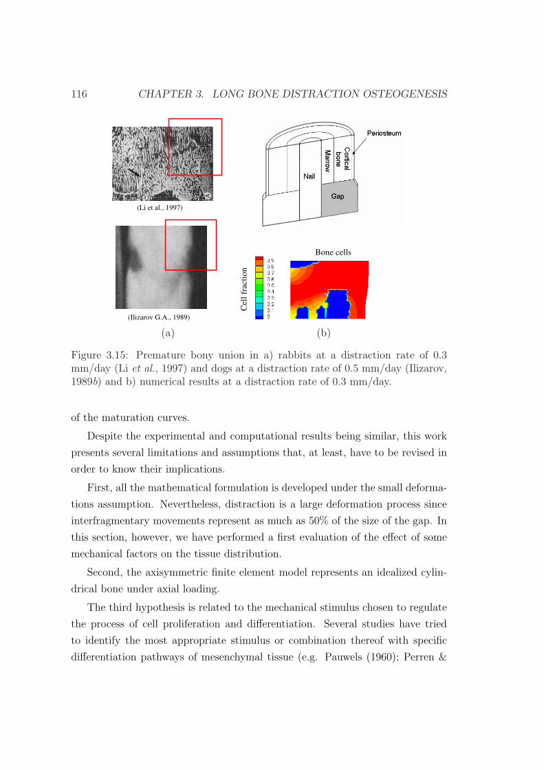
116 CHAPTER 3. LONG BONE DISTRACTION OSTEOGENESIS
(Li et al., 1997)
(Ilizarov G.A., 1989)
Cel
lfr
acti
on
Bone cells
(a) (b)
Figure 3.15: Premature bony union in a) rabbits at a distraction rate of 0.3mm/day (Li et al., 1997) and dogs at a distraction rate of 0.5 mm/day (Ilizarov,1989b) and b) numerical results at a distraction rate of 0.3 mm/day.
of the maturation curves.
Despite the experimental and computational results being similar, this work
presents several limitations and assumptions that, at least, have to be revised in
order to know their implications.
First, all the mathematical formulation is developed under the small deforma-
tions assumption. Nevertheless, distraction is a large deformation process since
interfragmentary movements represent as much as 50% of the size of the gap. In
this section, however, we have performed a first evaluation of the effect of some
mechanical factors on the tissue distribution.
Second, the axisymmetric finite element model represents an idealized cylin-
drical bone under axial loading.
The third hypothesis is related to the mechanical stimulus chosen to regulate
the process of cell proliferation and differentiation. Several studies have tried
to identify the most appropriate stimulus or combination thereof with specific
differentiation pathways of mesenchymal tissue (e.g. Pauwels (1960); Perren &
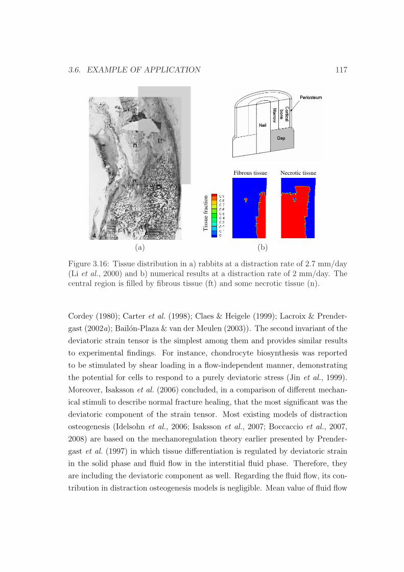
3.6. EXAMPLE OF APPLICATION 117
Fibrous tissue Necrotic tissue
Tis
sue
frac
tio
n
(a) (b)
Figure 3.16: Tissue distribution in a) rabbits at a distraction rate of 2.7 mm/day(Li et al., 2000) and b) numerical results at a distraction rate of 2 mm/day. Thecentral region is filled by fibrous tissue (ft) and some necrotic tissue (n).
Cordey (1980); Carter et al. (1998); Claes & Heigele (1999); Lacroix & Prender-
gast (2002a); Bailon-Plaza & van der Meulen (2003)). The second invariant of the
deviatoric strain tensor is the simplest among them and provides similar results
to experimental findings. For instance, chondrocyte biosynthesis was reported
to be stimulated by shear loading in a flow-independent manner, demonstrating
the potential for cells to respond to a purely deviatoric stress (Jin et al., 1999).
Moreover, Isaksson et al. (2006) concluded, in a comparison of different mechan-
ical stimuli to describe normal fracture healing, that the most significant was the
deviatoric component of the strain tensor. Most existing models of distraction
osteogenesis (Idelsohn et al., 2006; Isaksson et al., 2007; Boccaccio et al., 2007,
2008) are based on the mechanoregulation theory earlier presented by Prender-
gast et al. (1997) in which tissue differentiation is regulated by deviatoric strain
in the solid phase and fluid flow in the interstitial fluid phase. Therefore, they
are including the deviatoric component as well. Regarding the fluid flow, its con-
tribution in distraction osteogenesis models is negligible. Mean value of fluid flow
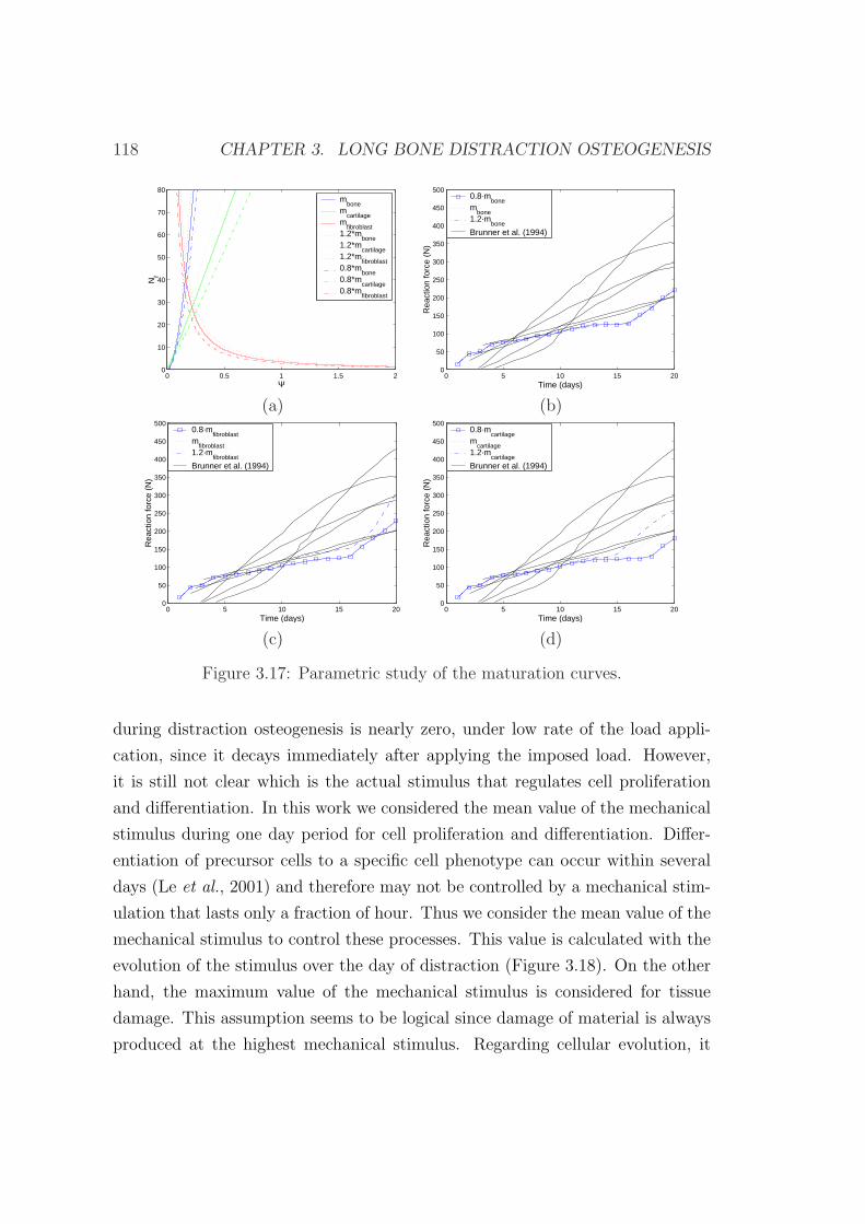
118 CHAPTER 3. LONG BONE DISTRACTION OSTEOGENESIS
0 0.5 1 1.5 20
10
20
30
40
50
60
70
80
Ψ
Nf
mbone
mcartilage
mfibroblast
1.2*mbone
1.2*mcartilage
1.2*mfibroblast
0.8*mbone
0.8*mcartilage
0.8*mfibroblast
0 5 10 15 200
50
100
150
200
250
300
350
400
450
500
Time (days)
Rea
ctio
n fo
rce
(N)
0.8·mbone
mbone
1.2·mbone
Brunner et al. (1994)
(a) (b)
0 5 10 15 200
50
100
150
200
250
300
350
400
450
500
Time (days)
Rea
ctio
n fo
rce
(N)
0.8·mfibroblast
mfibroblast
1.2·mfibroblast
Brunner et al. (1994)
0 5 10 15 200
50
100
150
200
250
300
350
400
450
500R
eact
ion
forc
e (N
)
Time (days)
0.8·mcartilage
mcartilage
1.2·mcartilage
Brunner et al. (1994)
(c) (d)
Figure 3.17: Parametric study of the maturation curves.
during distraction osteogenesis is nearly zero, under low rate of the load appli-
cation, since it decays immediately after applying the imposed load. However,
it is still not clear which is the actual stimulus that regulates cell proliferation
and differentiation. In this work we considered the mean value of the mechanical
stimulus during one day period for cell proliferation and differentiation. Differ-
entiation of precursor cells to a specific cell phenotype can occur within several
days (Le et al., 2001) and therefore may not be controlled by a mechanical stim-
ulation that lasts only a fraction of hour. Thus we consider the mean value of the
mechanical stimulus to control these processes. This value is calculated with the
evolution of the stimulus over the day of distraction (Figure 3.18). On the other
hand, the maximum value of the mechanical stimulus is considered for tissue
damage. This assumption seems to be logical since damage of material is always
produced at the highest mechanical stimulus. Regarding cellular evolution, it
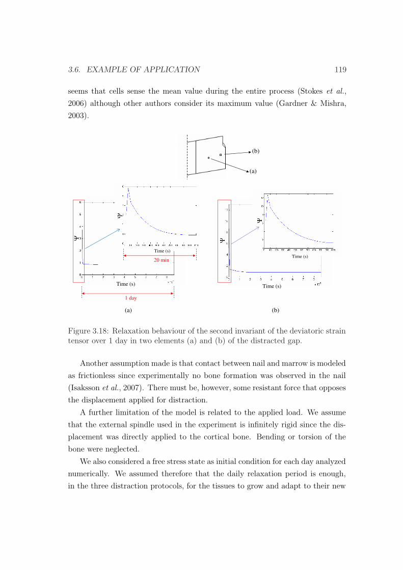
3.6. EXAMPLE OF APPLICATION 119
seems that cells sense the mean value during the entire process (Stokes et al.,
2006) although other authors consider its maximum value (Gardner & Mishra,
2003).
(a)
(b)
1 day
20 min
(a) (b)
Time (s) Time (s)
Time (s)
Time (s)
Figure 3.18: Relaxation behaviour of the second invariant of the deviatoric straintensor over 1 day in two elements (a) and (b) of the distracted gap.
Another assumption made is that contact between nail and marrow is modeled
as frictionless since experimentally no bone formation was observed in the nail
(Isaksson et al., 2007). There must be, however, some resistant force that opposes
the displacement applied for distraction.
A further limitation of the model is related to the applied load. We assume
that the external spindle used in the experiment is infinitely rigid since the dis-
placement was directly applied to the cortical bone. Bending or torsion of the
bone were neglected.
We also considered a free stress state as initial condition for each day analyzed
numerically. We assumed therefore that the daily relaxation period is enough,
in the three distraction protocols, for the tissues to grow and adapt to their new
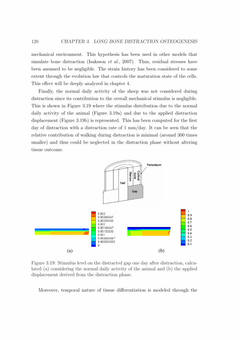
120 CHAPTER 3. LONG BONE DISTRACTION OSTEOGENESIS
mechanical environment. This hypothesis has been used in other models that
simulate bone distraction (Isaksson et al., 2007). Thus, residual stresses have
been assumed to be negligible. The strain history has been considered to some
extent through the evolution law that controls the maturation state of the cells.
This effect will be deeply analyzed in chapter 4.
Finally, the normal daily activity of the sheep was not considered during
distraction since its contribution to the overall mechanical stimulus is negligible.
This is shown in Figure 3.19 where the stimulus distribution due to the normal
daily activity of the animal (Figure 3.19a) and due to the applied distraction
displacement (Figure 3.19b) is represented. This has been computed for the first
day of distraction with a distraction rate of 1 mm/day. It can be seen that the
relative contribution of walking during distraction is minimal (around 300 times
smaller) and thus could be neglected in the distraction phase without altering
tissue outcome.
(b)(a)
Figure 3.19: Stimulus level on the distracted gap one day after distraction, calcu-lated (a) considering the normal daily activity of the animal and (b) the applieddisplacement derived from the distraction phase.
Moreover, temporal nature of tissue differentiation is modeled through the
3.6. EXAMPLE OF APPLICATION 121
maturation state variable since matrix production, and therefore stiffness of the
distracted gap, are dependent on the maturation time of the corresponding cells.
Nevertheless, reaction forces calculated with our computational model showed a
change of the slope by day 16 approximately that did not match with experimen-
tal results (see Figure 3.9). This may be due to some factors in the real model
that are not truly simulated. For instance, during the distraction process, the col-
lagen fibers, which are the main component of the granulation tissue extracellular
matrix (Bouletreau et al., 2002a), are stretched out and consequently loose their
normal wavy structure to get a rectilinear appearance oriented parallel to the dis-
traction vector (Figure 2.8b) (Ilizarov, 1989a). These fibers provide, temporarily,
mechanical resistance to the distracted gap and therefore may contribute to the
increasing stiffness observed experimentally. This effect has not been included in
our model yet.
As far as we know, this model is the first to examine nonunions computa-
tionally in distraction osteogenesis due to the application of different distraction
rates. Current differentiation rules (Prendergast et al., 1997; Claes & Heigele,
1999; Gomez-Benito et al., 2005) are not able to predict delays in bony union
when the distraction rate is very high (2 mm/day). Another advance over previ-
ous simulations is that it takes into account the influence of the strain history on
the maturation state of the cells, as other authors have shown in previous works
(Schriefer et al., 2005). Further improvements of the model to include other as-
pects of cell biology as well as the extension of the model to other geometries will
greatly enhance our understanding of the regulatory mechanisms involved in the
distraction process. Chapter 4 will explore these aspects.

122 CHAPTER 3. LONG BONE DISTRACTION OSTEOGENESIS
Chapter 4
Growth mixture model of
distraction osteogenesis: effect of
pre-traction stresses
4.1 Introduction
Until the early 80’s, it was believed that biological organs were free of stress when
all external loads were removed and hence considered that these tissues were not
residually stressed (Gregersen et al., 2000). However, nowadays, residual stresses
have been widely investigated in the tissues of a number of organ systems and are
thought to be a consequence of nonuniform growth, resorption and remodeling
(Skalak, 1981; Skalak et al., 1982; Fung, 1990a; Taber & Humphrey, 2001). The
presence of residual stresses has been established, for example, in the cardiovas-
cular system (see, e.g., Vaishnav & Vossoughi (1983); Fung (1984, 1985); Chuong
& Fung (1986); Vaishnav & Vossoughi (1987); Liu & Fung (1988); Han & Fung
(1996)), the gastrointestinal tract (see, e.g., Gregersen et al. (2000)) and the mus-
culoskeletal system (see, e.g., Bertram et al. (1998); Popowics et al. (2002)). It
has also been proposed that residual stresses may influence not only the biome-
chanical behavior of tissues, but also their local cell biology (e.g. Gregersen et al.
(2000)).
Quantitative estimations of stress accumulation due to residual stresses during
123
124 CHAPTER 4. RESIDUAL STRESSES IN BONE DISTRACTION
the process of distraction can be found in the literature (Brunner et al., 1994;
Waanders et al., 1998; Matsushita et al., 1999; Richards et al., 1999). During the
process of distraction osteogenesis, stress accumulation is modulated by three
effects: the mechanical elongation of the gap, the intrinsic viscoelastic nature of
soft tissues in the interfragmentary gap (Leong et al., 1979; Simpson et al., 1996;
Nakamura et al., 1997; Matsushita et al., 1999; Richards et al., 1999; Aarnes
et al., 2002) and the tissue growth/differentiation inside the gap.
The notion of locally differential growth giving rise to residual stresses was
suggested early by Skalak (1981) and then later by Chuong & Fung (1986) as an
important feature of soft tissue growth. Since then, numerous studies have devel-
oped continuum growth models for single constituents (see, e.g., Huang (1994);
Taber (1998); Chen & Hoger (2000); Epstein & Maugin (2000); Klisch et al.
(2001); DiCarlo & Quiligotti (2002); Lubarda & Hoger (2002); Kuhl & P. (2003);
Volokh (2004); Lappa (2005); Menzel (2005); Alastrue et al. (2007)) or mixtures
(see, e.g., Preziosi & Farina (2002); Humphrey & Rajagopal (2003); Breward
et al. (2003); Klisch et al. (2003); Garikipati et al. (2004)). In these models,
growth has been defined either relative to a stress-free configuration (see, e.g.,
Rodriguez et al. (1994); Taber & Eggers (1996); Taber (1998); Garikipati et al.
(2004); Ramasubramanian & Taber (2008)) or to a stressed configuration (for
example, Klisch et al. (2001, 2003)). However, the inclusion of the effect of resid-
ual stresses in models of limb lengthening has not been considered yet. Existing
mechanobiological models have used a zero pre-traction stress configuration as
the daily reference state, assuming therefore no stress accumulation after each
load step (Isaksson et al., 2007; Boccaccio et al., 2007, 2008).
Thus, the aim of this chapter is to develop a general macroscopic growth
mixture formulation able to consider pre-traction stresses (stress level in the gap
tissue before each distraction step) in bone distraction osteogenesis. First, we
establish the typical governing equations (kinematics, constitutive relations and
mass balance), then we particularize the model to the process of bone distraction
osteogenesis and afterwards we apply the model to a clinical example in order to
investigate the influence of pre-traction stresses and tissue growth on the outcome
of limb lengthening. Finally, to analyze the potential of the new model proposed,
we compare the pattern of limb lengthening in different animal species and a
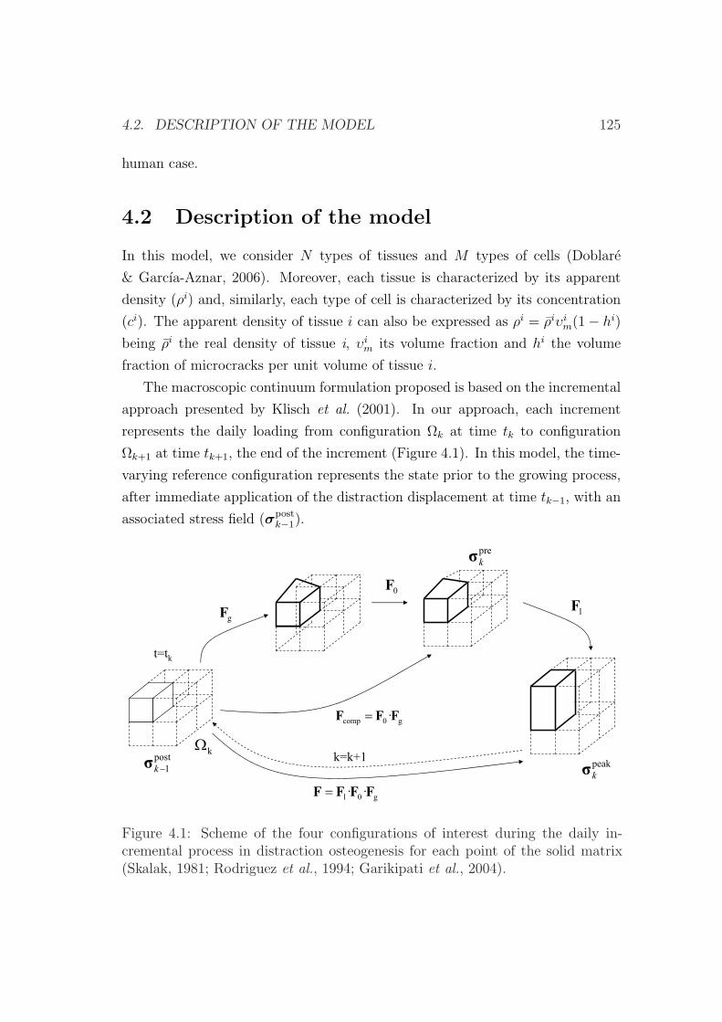
4.2. DESCRIPTION OF THE MODEL 125
human case.
4.2 Description of the model
In this model, we consider N types of tissues and M types of cells (Doblare
& Garcıa-Aznar, 2006). Moreover, each tissue is characterized by its apparent
density (ρi) and, similarly, each type of cell is characterized by its concentration
(ci). The apparent density of tissue i can also be expressed as ρi = ρiυim(1− hi)
being ρi the real density of tissue i, υim its volume fraction and hi the volume
fraction of microcracks per unit volume of tissue i.
The macroscopic continuum formulation proposed is based on the incremental
approach presented by Klisch et al. (2001). In our approach, each increment
represents the daily loading from configuration Ωk at time tk to configuration
Ωk+1 at time tk+1, the end of the increment (Figure 4.1). In this model, the time-
varying reference configuration represents the state prior to the growing process,
after immediate application of the distraction displacement at time tk−1, with an
associated stress field (σpostk−1).
g0l ·· FFFF
0F
g0comp ·FFF
gFlF
t=tk
post
1k
kk=k+1
peak
k
pre
k
Figure 4.1: Scheme of the four configurations of interest during the daily in-cremental process in distraction osteogenesis for each point of the solid matrix(Skalak, 1981; Rodriguez et al., 1994; Garikipati et al., 2004).
126 CHAPTER 4. RESIDUAL STRESSES IN BONE DISTRACTION
The multiplicative decomposition of the deformation gradient tensor, advo-
cated for growth theories by Rodriguez et al. (1994) and further elaborated in
different works (see, e.g. Taber & Eggers (1996); Hoger (1997); Chen & Hoger
(2000); Taber & Perucchio (2000); Klisch et al. (2001); DiCarlo & Quiligotti
(2002); Quiligotti (2002); Klisch et al. (2003); Himpel et al. (2005)) is here used
(Figure 4.1). On the basis of previous studies (Garikipati et al., 2004; Davol
et al., 2008) and according to this hypothesis, the total deformation gradient is
assumed to be composed of the elastic deformation associated to the external
loads and that related to tissue growth or differentiation. From tk to tk+1, the
incremental tensor associated to growth (Fg) accounts for the change in size and
shape due to volumetric growth and for the new tissue produced or differentiated
during the incremental growth process (Rodriguez et al., 1994; Taber & Eggers,
1996; Taber, 1998; Garikipati et al., 2004; Ramasubramanian & Taber, 2008).
The tensor Fg is, in general, incompatible, while the total gradient F has to be
compatible. Therefore, an auxiliary tensor (F0) is needed to reach a compatible
configuration (Fcomp). Finally, the elastic strain associated to the loading process
is additionally stored during the last configuration (Fl). Thus, the total defor-
mation is described by the deformation gradients Fg, F0 and Fl (see Figure 4.1),
and the total composition of these tensors:
F = Fl · F0 · Fg. (4.1)
In order to compute the stress tensor, we assume tissues to be modeled as a
mixture of a porous solid phase (s) and a mobile interstitial fluid (f). The solid
phase corresponds to a mixture of the different tissues existing in the represen-
tative volume element under consideration. Employing the rule of mixtures, the
total Cauchy stress σ results from the contribution of the hydrostatic pressure
due to the fluid and a contribution of the solid constituents (as a first approach,
isotropic behavior is assumed for the whole mixture). Then, the constitutive re-
lation for the stress is formulated according to Humphrey & Rajagopal (2003),
as a function of the response of the different tissues and their time-varying mass
production. Mathematically, we have for all time t :
4.2. DESCRIPTION OF THE MODEL 127
σ = σfl + σeff , (4.2)
σfl = −p1, (4.3)
σeff =N∑
i=1
υim0
σik +
N∑i=1
1
ρi
1
det Fk
∫ tk
0
πi(τ)σi(Fk, τ)detFkdτ, (4.4)
where σeff is the Cauchy stress tensor corresponding to the solid phase, σfl is the
Cauchy stress tensor corresponding to the fluid phase, p represents the hydrostatic
pressure field of the fluid, 1 the identity second order tensor, N is the number
of tissues, υim0
is the initial volume fraction of tissue i, σik is the stress for each
tissue i at time tk, σi is the stress response for tissue i evaluated at time tk with
respect to the time τ ∈ [0, tk] in which the tissue was created, ρi its apparent
mass density, πi is the new matrix produced of tissue i per unit volume and time
at time τ ; τ is a dummy variable of integration over time and Fk is the total
deformation gradient tensor calculated with respect to the reference state at time
tk.
The standard mass balance is posed for each tissue type i (Doblare & Garcıa-
Aznar, 2006). A sufficient amount of constituents (i.e. collagen) is considered
to be available for tissue synthesis locally and their transport is neglected. Tis-
sue components and tissues themselves are considered to be non-diffusive. Mass
balance reads,
dρi
dt+ ρi∇ · v =
dρi
dtυi
m(1− hi)+
+ ρi dυim
dt(1− hi) + ρiυi
m(−d(hi)
dt)+
+ ρi∇ · v = πi i = 1, . . . , N, (4.5)
where v is the macroscopic velocity vector of the solid skeleton, ρi is the real
density of tissue i, υim is the volume fraction of tissue i, ρi its apparent mass
density and πi is the new volume produced of tissue i per unit volume and time.
Moreover, we consider, as a first approach, that the total tissue production (πi) is
128 CHAPTER 4. RESIDUAL STRESSES IN BONE DISTRACTION
the sum of the production of individual cells. Since we also consider that cells can
remove other tissues, the net matrix production of tissue i per unit time can be
written as the difference between its production and removal rates, both of which
are positive by definition because of the continuous turnover in vivo (Doblare &
Garcıa-Aznar, 2006):
πi = (ciβipr −
N∑
j=1,j 6=i
cjβij)ρ
i, (4.6)
where βipr is the volumetric production rate of tissue i by the cell type i, βi
j is
the volume rate of tissue i removed by cells type j per unit time. Note that
tissue production is indirectly controlled by the mechanical stimulus, since cel-
lular differentiation and proliferation processes are regulated by this mechanical
stimulus.
In a similar way, the cell balance (evolution of the number of cells per unit
volume) for each cell type may be written as:
dci
dt+ ci∇ · v = πi
c −∇ ·mic i = 1, ..., M (4.7)
being v the macroscopic velocity vector of the solid skeleton, ci the concentration
of the cell type i, mic the mass flux of cell type i with respect to the solid,
and πic the net production of such cell type, which can have different origins:
proliferation or differentiation. Differentiation can be either from different cells
to this cell phenotype or from this type of cell to other types (including dead cells
as a specific cell type and consequently considering the possibility of necrosis and
apoptosis). Therefore, the net production of cells per unit time can be written
as (Doblare & Garcıa-Aznar, 2006):
πic = ciαi
pr +M∑
k=1,k 6=i
ckαik −
M∑
k=1,k 6=i
ciαki (4.8)
4.2. DESCRIPTION OF THE MODEL 129
where M is the number of cell types, αipr is the production of cells type i due to
mitosis per unit time and cell and αik is the production of cells type i from the
differentiation of cells type k per unit time and cell.
4.2.1 Kinematics of growth
As in chapter 3, the mathematical formulation has been developed under the
small deformations assumption at each time step. If the deformation gradient
tensor is written in terms of the displacement gradient tensor L as F=1+L, then
equation (4.1) can be expanded to:
F = (1 + Ll)(1 + L0)(1 + Lg) (4.9)
F = 1 + Ll + L0 + Lg + LlL0 + LlLg + L0Lg + LlL0Lg (4.10)
where the displacement gradient tensor L = ε + ω is the sum of the linearized
deformation and rotation tensors (0 means compatible, g growth and l elastic,
see Figure 4.1). Under the small deformation assumption, equation (4.10) can be
simplified as:
F ' 1 + Ll + L0 + Lg (4.11)
Linearization of the multiplicative decomposition of the deformation gradient
tensor (equation 4.11) leads to:
ε =1
2(F− 1) + (F− 1)T = εl + ε0 + εg (4.12)
where F is the deformation gradient tensor (equation 4.11), 1 the second or-
der identity tensor, T is the transpose operator and εl, ε0, εg are the elastic,
compatible and growth infinitesimal strain tensors respectively.
130 CHAPTER 4. RESIDUAL STRESSES IN BONE DISTRACTION
4.3 Constitutive equation
The model here proposed has been incorporated to the mechanobiological model
described in section 3.2, considering the simplifications given by the kinematics
of growth of section 4.2.1. Therefore the same state variables as in section 3.2
(concentration of the cell phenotypes, concentration of the skeletal tissues and the
cellular maturation levels) as well as the same continuity equation of the skeletal
tissues (equation (3.2)) are incorporated in this model. Further, in this model, it
is assumed that the real density of the different tissues (ρi) does not change over
time:
∂ρi
∂t= 0, i= g, f, c, b, d tissues, (4.13)
Following the previous description and considering these simplifications, the
constitutive relation (4.2) for the stress can now be written as:
σ = −p1 +N∑
i=1
υim0
σik +
N∑i=1
1
ρi
∫ tk
0
πi(τ)σidτ, (4.14)
where σi = σi(ε− επi) is the stress response of tissue i evaluated at time tk with
respect to the time τ ∈ [0, tk] in which the tissue was deposited with ε, the total
linearized strain tensor at time tk, and επi is the strain level when the new matrix
(πi) was deposited at time τ (υim0
, σik as in equation (4.4)).
According to (4.14) the stress response depends on the deformation expe-
rienced by each tissue type during the loading configuration evaluated at time
tk, on the strains generated during the growth process and on the new tissue
produced at time τ .
The mass balance equation is now simplified as:
4.4. NUMERICAL IMPLEMENTATION 131
dρi
dt+ ρi∇ · v = ρi dυi
m
dt(1− hi) + ρiυi
m(−d(hi)
dt) + ρi∇ · v = πi
i= g, d tissues (4.15)
and
dρi
dt+ ρi∇ · v = ρi dυi
m
dt+ ρi∇ · v = πi i= c, b, f tissues (4.16)
where hi is evaluated with equations (3.31) and (3.32) and πi with equation (4.6).
4.4 Numerical implementation
The formulation presented above has been solved in an updated Lagrangian fi-
nite element code. These equations are implemented at each load step k of the
distraction process under the small deformation assumption considering bound-
ary, initial and loading conditions. Next, we present the steps that have been
numerically implemented in one increment (k to k + 1) of the process equivalent
to one day of distraction (see Figure 4.1):
1. Initialization: initially no growth is assumed and we impose the first dis-
traction displacement in a poroelastic analysis to evaluate initial strains
(ε(t0)) and post-traction stresses (σ0).
2. A remeshing process is employed to avoid the excessive distortion of the
finite element mesh during the distraction process.
3. Growth analysis: once determined the strains (ε(tk)) and the corresponding
stresses (σpostk−1) for this step (k to k+1) that includes poroelastic relaxation,
new tissue is created and a compatibility analysis is performed to evaluate
the new stress level (σprek ) that occurs as a consequence of tissue growth,
differentiation and adaptation. In fact, given the mechanical stimulus com-
puted from the poroelastic analysis, the matrix production rate πi(tk) is
132 CHAPTER 4. RESIDUAL STRESSES IN BONE DISTRACTION
updated through (4.6). Both strain level (εi(tk) = ε(tn)) for the new tissue
i formed and the matrix production (πi(tk)) are stored as state variables
for each tissue i.
4. Update of the geometry: the new geometry is updated as well as the state
variables at each nodal point according to the differentiation, proliferation
and matrix production rules.
5. Two diffusion analyses are then performed in Abaqus (Hibbit & Sorensen,
2002): one to simulate MSCs migration and other to model vascularization
(∇mic in (4.7)) (Gomez-Benito et al., 2005).
6. A new poroelastic analysis is implemented to determine the mean and maxi-
mum value of the mechanical stimulus at each nodal point. Equation (4.14)
is solved with a user element subroutine in Abaqus (Hibbit & Sorensen,
2002) under the small deformations assumption.
Assuming a linear elastic behavior of the solid matrix, the stresses can be
computed as:
σ(tk) = −p1 +N∑
i=1
υim0
σik +
N∑i=1
1
ρi
n=k−1∑n=1
πinCi : [ε(tk)− εi(tn)]∆tn (4.17)
where p represents the hydrostatic pressure field of the fluid, N is the num-
ber of tissues, υim0
is the initial volume fraction of tissue i, σik is the stress
for each tissue i at time tk, Ci is the elasticity tensor associated to tissue i,
ε is the total strain tensor, n is the number of time increments from t = 0
to tk, and πin is the new tissue produced per unit time during the time
increment n (if negative it means resorption).
Note that in (4.17), when k = n and πik=n 6= 0, εi(tn) = ε(tk) and, there-
fore, a null stress is associated to such tissue fraction. This is in agree-
ment with the assumption that new tissue is deposited in an incremental
unstressed state. Thus, only previously existing tissue will contribute to
support stresses.
4.5. EXAMPLES OF APPLICATION 133
7. Go to step (2).
4.5 Examples of application
4.5.1 Validation of the model
Example of application
The same example of application as in section 3.6.1 is presented in order to
compare the numerical results. Brunner et al. (1994) evaluated the bone segment
transport over an intramedullary nail in 12 sheep. A diaphyseal defect created in
the central region of the tibia was reduced through the ossification process induced
in the upper part by distraction osteogenesis. The defect was stabilized with a
nail. They measured the tensile force during limb lengthening, showing a daily
incomplete relaxation of tissues within the distracted gap. In this experimental
study, lengthening was started just after the osteotomy at a rate of 1 mm per day.
The distraction protocol followed by Brunner et al. (1994) consisted of 20 days of
distraction, immediately after the osteotomy, followed by 20 days of consolidation.
Considering an idealized cylindrical tibia, we represent its anatomy by an
axisymmetric finite element model, and, therefore, only one-quarter of the actual
geometry is modelled. The dimensions are shown in Figure 3.7a. The parameters
required to model the diaphysis of the tibia are the diameter of the diaphysis,
thickness of the periosteum and bone marrow, radius of the nail and size of
the osteotomy gap. The initial size of the gap was 1 mm. The cortical bone
was modeled with an inner radius of 6 mm and an outer radius of 10 mm, the
thickness of the periosteum was set to 0.5 mm and the radius of the nail was 3.5
mm (Figure 3.7a) (Brunner et al., 1994).
Boundary conditions of the axisymmetrical model consisted on rotational sym-
metry along the long bone axis and mirror-image symmetry with respect to the
plane of the osteotomy (Figure 3.7b). Null fluid flow was prescribed at the pe-
riosteum, assuming therefore this boundary to be impermeable (Li et al., 1987)
(Figure 3.7b). Initial conditions consisted on a gap initially filled with debris
tissue and on maximal tissue damage in that region to simulate the lack of the
latency phase. The loading conditions during the distraction phase consisted of a
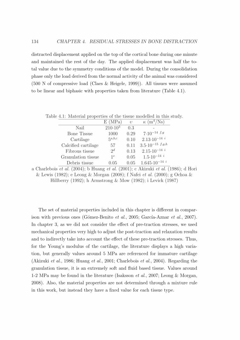
134 CHAPTER 4. RESIDUAL STRESSES IN BONE DISTRACTION
distracted displacement applied on the top of the cortical bone during one minute
and maintained the rest of the day. The applied displacement was half the to-
tal value due to the symmetry conditions of the model. During the consolidation
phase only the load derived from the normal activity of the animal was considered
(500 N of compressive load (Claes & Heigele, 1999)). All tissues were assumed
to be linear and biphasic with properties taken from literature (Table 4.1).
Table 4.1: Material properties of the tissue modelled in this study.E (MPa) υ κ (m4/Ns)
Nail 210·103 0.3 -Bone Tissue 1000 0.29 7·10−14 f,g
Cartilage 5a,b,c 0.10 2.13·10−14 i
Calcified cartilage 57 0.11 3.5·10−15 f,g,h
Fibrous tissue 2d 0.13 2.15·10−14 i
Granulation tissue 1e 0.05 1.5·10−14 i
Debris tissue 0.05 0.05 1.645·10−14 i
a Charlebois et al. (2004); b Huang et al. (2001); c Akizuki et al. (1986); d Hori& Lewis (1982); e Leong & Morgan (2008); f Nafei et al. (2000); g Ochoa &
Hillberry (1992); h Armstrong & Mow (1982); i Levick (1987)
The set of material properties included in this chapter is different in compar-
ison with previous ones (Gomez-Benito et al., 2005; Garcıa-Aznar et al., 2007).
In chapter 3, as we did not consider the effect of pre-traction stresses, we used
mechanical properties very high to adjust the post-traction and relaxation results
and to indirectly take into account the effect of these pre-traction stresses. Thus,
for the Young’s modulus of the cartilage, the literature displays a high varia-
tion, but generally values around 5 MPa are referenced for immature cartilage
(Akizuki et al., 1986; Huang et al., 2001; Charlebois et al., 2004). Regarding the
granulation tissue, it is an extremely soft and fluid based tissue. Values around
1-2 MPa may be found in the literature (Isaksson et al., 2007; Leong & Morgan,
2008). Also, the material properties are not determined through a mixture rule
in this work, but instead they have a fixed value for each tissue type.
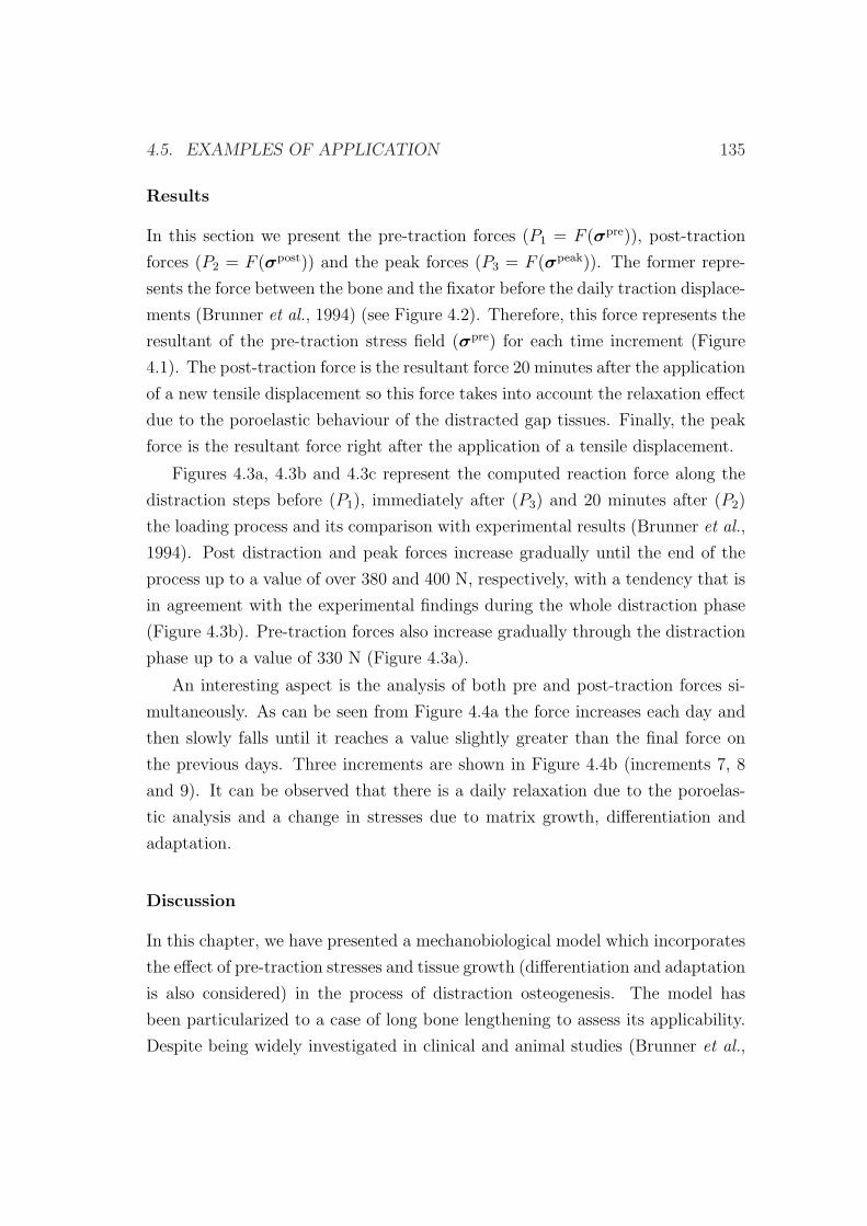
4.5. EXAMPLES OF APPLICATION 135
Results
In this section we present the pre-traction forces (P1 = F (σpre)), post-traction
forces (P2 = F (σpost)) and the peak forces (P3 = F (σpeak)). The former repre-
sents the force between the bone and the fixator before the daily traction displace-
ments (Brunner et al., 1994) (see Figure 4.2). Therefore, this force represents the
resultant of the pre-traction stress field (σpre) for each time increment (Figure
4.1). The post-traction force is the resultant force 20 minutes after the application
of a new tensile displacement so this force takes into account the relaxation effect
due to the poroelastic behaviour of the distracted gap tissues. Finally, the peak
force is the resultant force right after the application of a tensile displacement.
Figures 4.3a, 4.3b and 4.3c represent the computed reaction force along the
distraction steps before (P1), immediately after (P3) and 20 minutes after (P2)
the loading process and its comparison with experimental results (Brunner et al.,
1994). Post distraction and peak forces increase gradually until the end of the
process up to a value of over 380 and 400 N, respectively, with a tendency that is
in agreement with the experimental findings during the whole distraction phase
(Figure 4.3b). Pre-traction forces also increase gradually through the distraction
phase up to a value of 330 N (Figure 4.3a).
An interesting aspect is the analysis of both pre and post-traction forces si-
multaneously. As can be seen from Figure 4.4a the force increases each day and
then slowly falls until it reaches a value slightly greater than the final force on
the previous days. Three increments are shown in Figure 4.4b (increments 7, 8
and 9). It can be observed that there is a daily relaxation due to the poroelas-
tic analysis and a change in stresses due to matrix growth, differentiation and
adaptation.
Discussion
In this chapter, we have presented a mechanobiological model which incorporates
the effect of pre-traction stresses and tissue growth (differentiation and adaptation
is also considered) in the process of distraction osteogenesis. The model has
been particularized to a case of long bone lengthening to assess its applicability.
Despite being widely investigated in clinical and animal studies (Brunner et al.,
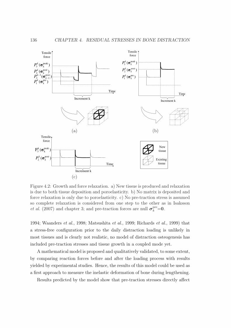
136 CHAPTER 4. RESIDUAL STRESSES IN BONE DISTRACTION
Tensile
force
Time
)( peak
3 k
kP
Increment k
)( post
2 k
kP
)( post
1
1
2 k
kP
)( pre
1 k
kP
Tensile
force
Time
)(
)(
pre
1
ost
2
k
k
p
k
k
P
P
)( peak
3 k
kP
Increment k
(a) (b)Tensile
force
Time
)( post
2 k
kP
)(P peak
k
k
3
Increment k
New
tissue
Existing
tissuetissue
(c)
Figure 4.2: Growth and force relaxation. a) New tissue is produced and relaxationis due to both tissue deposition and poroelasticity. b) No matrix is deposited andforce relaxation is only due to poroelasticity. c) No pre-traction stress is assumedso complete relaxation is considered from one step to the other as in Isakssonet al. (2007) and chapter 3; and pre-traction forces are null σpre
k =0.
1994; Waanders et al., 1998; Matsushita et al., 1999; Richards et al., 1999) that
a stress-free configuration prior to the daily distraction loading is unlikely in
most tissues and is clearly not realistic, no model of distraction osteogenesis has
included pre-traction stresses and tissue growth in a coupled mode yet.
A mathematical model is proposed and qualitatively validated, to some extent,
by comparing reaction forces before and after the loading process with results
yielded by experimental studies. Hence, the results of this model could be used as
a first approach to measure the inelastic deformation of bone during lengthening.
Results predicted by the model show that pre-traction stresses directly affect
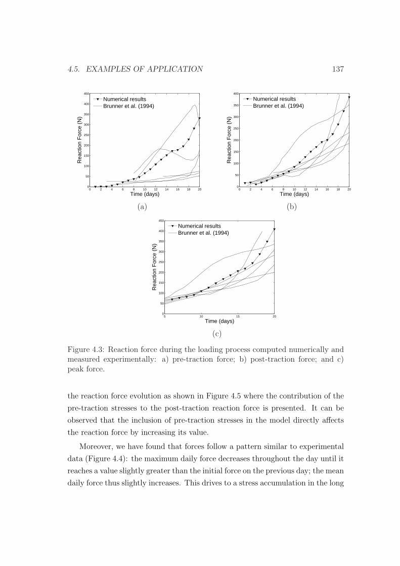
4.5. EXAMPLES OF APPLICATION 137
0 2 4 6 8 10 12 14 16 18 200
50
100
150
200
250
300
350
400
450
Time (days)
Rea
ctio
n F
orce
(N
)
Numerical resultsBrunner et al. (1994)
0 2 4 6 8 10 12 14 16 18 200
50
100
150
200
250
300
350
400
Time (days)
Rea
ctio
n F
orce
(N
)
Numerical resultsBrunner et al. (1994)
(a) (b)
5 10 15 200
50
100
150
200
250
300
350
400
450
Time (days)
Rea
ctio
n F
orce
(N
)
Numerical resultsBrunner et al. (1994)
(c)
Figure 4.3: Reaction force during the loading process computed numerically andmeasured experimentally: a) pre-traction force; b) post-traction force; and c)peak force.
the reaction force evolution as shown in Figure 4.5 where the contribution of the
pre-traction stresses to the post-traction reaction force is presented. It can be
observed that the inclusion of pre-traction stresses in the model directly affects
the reaction force by increasing its value.
Moreover, we have found that forces follow a pattern similar to experimental
data (Figure 4.4): the maximum daily force decreases throughout the day until it
reaches a value slightly greater than the initial force on the previous day; the mean
daily force thus slightly increases. This drives to a stress accumulation in the long
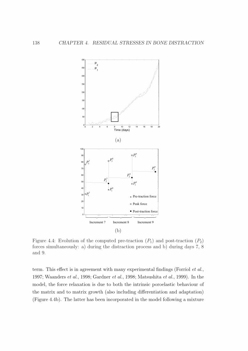
138 CHAPTER 4. RESIDUAL STRESSES IN BONE DISTRACTION
350
400
P2
P
300
N
P1
200
250
N
100
150
t
0
50
0 2 4 6 8 10 12 14 16 18 200
Time (days)
(a)
90
100
8P
9
3P
70
80
N
7
3P
3P
8
9
2P
40
50
60
N
8
9
1P
8
2P
7
2P
20
30
40c
Pre-traction force
7
1P
8
1P
0 0 5 1 1 5 2 2 50
10
20
Peak force
Post-traction force
0 0.5 1 1.5 2 2.5
x 105
Increment 7 Increment 8 Increment 9
(b)
Figure 4.4: Evolution of the computed pre-traction (P1) and post-traction (P2)forces simultaneously: a) during the distraction process and b) during days 7, 8and 9.
term. This effect is in agreement with many experimental findings (Forriol et al.,
1997; Waanders et al., 1998; Gardner et al., 1998; Matsushita et al., 1999). In the
model, the force relaxation is due to both the intrinsic poroelastic behaviour of
the matrix and to matrix growth (also including differentiation and adaptation)
(Figure 4.4b). The latter has been incorporated in the model following a mixture
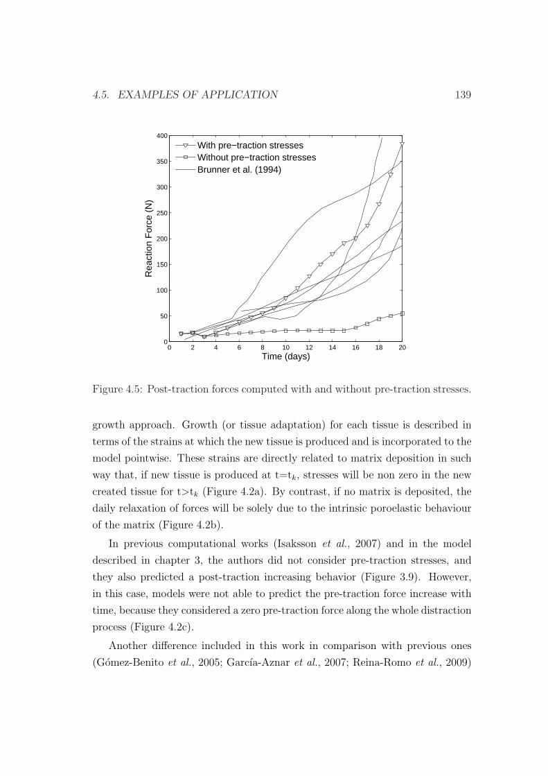
4.5. EXAMPLES OF APPLICATION 139
0 2 4 6 8 10 12 14 16 18 200
50
100
150
200
250
300
350
400
Time (days)
Rea
ctio
n F
orce
(N
)
With pre−traction stressesWithout pre−traction stressesBrunner et al. (1994)
Figure 4.5: Post-traction forces computed with and without pre-traction stresses.
growth approach. Growth (or tissue adaptation) for each tissue is described in
terms of the strains at which the new tissue is produced and is incorporated to the
model pointwise. These strains are directly related to matrix deposition in such
way that, if new tissue is produced at t=tk, stresses will be non zero in the new
created tissue for t>tk (Figure 4.2a). By contrast, if no matrix is deposited, the
daily relaxation of forces will be solely due to the intrinsic poroelastic behaviour
of the matrix (Figure 4.2b).
In previous computational works (Isaksson et al., 2007) and in the model
described in chapter 3, the authors did not consider pre-traction stresses, and
they also predicted a post-traction increasing behavior (Figure 3.9). However,
in this case, models were not able to predict the pre-traction force increase with
time, because they considered a zero pre-traction force along the whole distraction
process (Figure 4.2c).
Another difference included in this work in comparison with previous ones
(Gomez-Benito et al., 2005; Garcıa-Aznar et al., 2007; Reina-Romo et al., 2009)
140 CHAPTER 4. RESIDUAL STRESSES IN BONE DISTRACTION
is the set of material properties chosen. If the material properties of this study
(lower than those used in chapter 3 for some tissues) are used to simulate the
model without pre-traction stresses, the reaction forces show values that are out
of the experimental bands (Figure 4.5). This indicates that the influence of pre-
traction stresses on the force prediction is crucial.
On the other hand, pre-traction stresses may have additional important impli-
cations (i.e. in tissue distribution), since they increase the mechanical stimulus
that controls all the processes and consequently may affect to tissue damage,
differentiation and tissue growth. Figure 4.6 shows the spatial distribution of
the mechanical stimulus at days 5 and 10 of the distraction process considering
pre-traction stresses (Figure 4.6a) and neglecting them (Figure 4.6b). As ob-
served, the mechanical stimulus (second invariant of the deviatoric strain tensor)
is higher when considering the pre-traction stresses (Figure 4.6a). Thus, tissue
damage, which we assume to only depend on the maximum value of the mechan-
ical stimulus, increases. Regarding differences in the differentiation processes,
similar tissue outcomes are observed when considering pre-traction stresses and
when neglecting them: there is an initial stage in which the gap was gradually
filled with MSCs and a small amount of bone appeared next to the old bone ma-
trix; a second period in which these precursor cells differentiated into cartilage
cells, and a final stage in which further ossification took place and bony bridging
occurred.
This model presents several limitations that need to be addressed. Firstly, it
is clear that the fundamental aspect of this work is to assume that the relaxation
stress that occurs in the pre-traction force is regulated by two combined effects:
the poroelastic behaviour of tissue matrix and tissue growth (also considering
differentiation and adaptation). This fact is consistent with the formulation pro-
posed by Humphrey & Rajagopal (2003). Secondly, the mathematical formulation
has been implemented under the small deformation assumption, although large
strains are sometimes generated during distraction osteogenesis, specially during
the first days. However, the mathematical formulation has been implemented
in an updated Lagrangian code, so all variables are referred to the current (i.e.
from the end of the previous increment) configuration of the system. Using this
approach, this limitation is not very restrictive. In fact, taking into account that
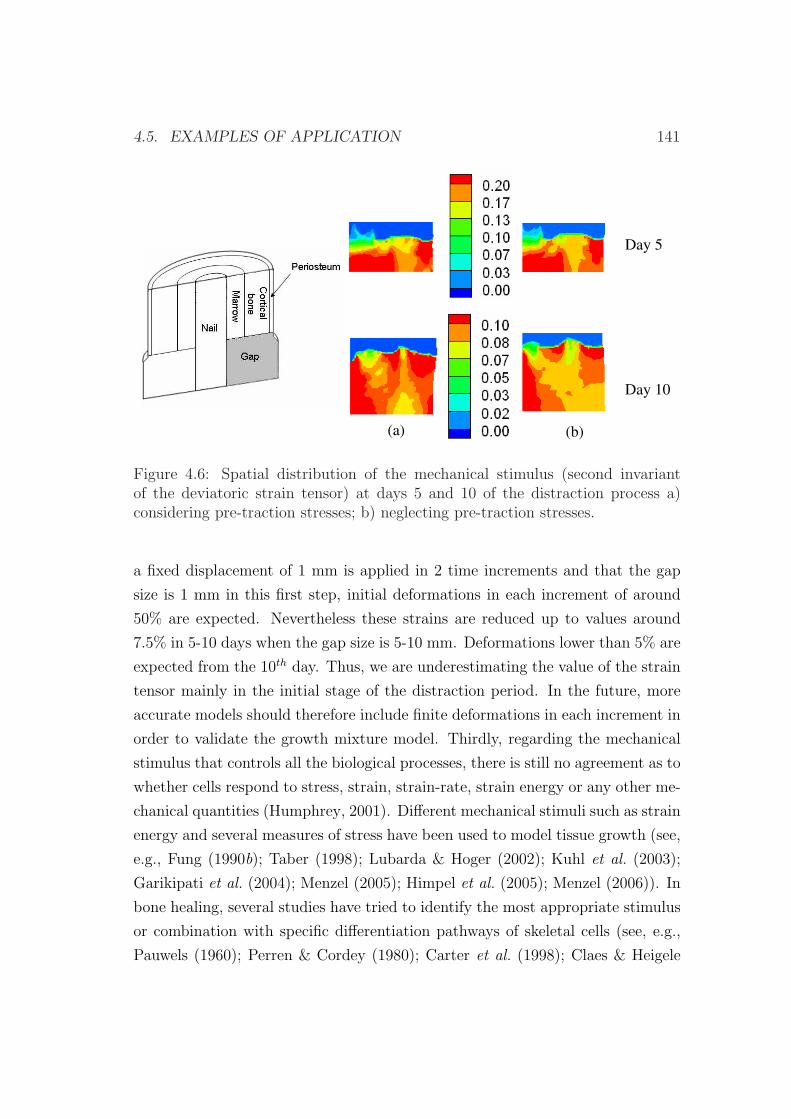
4.5. EXAMPLES OF APPLICATION 141
Day 5
Day 10
(a) (b)
Figure 4.6: Spatial distribution of the mechanical stimulus (second invariantof the deviatoric strain tensor) at days 5 and 10 of the distraction process a)considering pre-traction stresses; b) neglecting pre-traction stresses.
a fixed displacement of 1 mm is applied in 2 time increments and that the gap
size is 1 mm in this first step, initial deformations in each increment of around
50% are expected. Nevertheless these strains are reduced up to values around
7.5% in 5-10 days when the gap size is 5-10 mm. Deformations lower than 5% are
expected from the 10th day. Thus, we are underestimating the value of the strain
tensor mainly in the initial stage of the distraction period. In the future, more
accurate models should therefore include finite deformations in each increment in
order to validate the growth mixture model. Thirdly, regarding the mechanical
stimulus that controls all the biological processes, there is still no agreement as to
whether cells respond to stress, strain, strain-rate, strain energy or any other me-
chanical quantities (Humphrey, 2001). Different mechanical stimuli such as strain
energy and several measures of stress have been used to model tissue growth (see,
e.g., Fung (1990b); Taber (1998); Lubarda & Hoger (2002); Kuhl et al. (2003);
Garikipati et al. (2004); Menzel (2005); Himpel et al. (2005); Menzel (2006)). In
bone healing, several studies have tried to identify the most appropriate stimulus
or combination with specific differentiation pathways of skeletal cells (see, e.g.,
Pauwels (1960); Perren & Cordey (1980); Carter et al. (1998); Claes & Heigele
142 CHAPTER 4. RESIDUAL STRESSES IN BONE DISTRACTION
(1999); Lacroix & Prendergast (2002a); Bailon-Plaza & van der Meulen (2003)).
The second invariant of the deviatoric strain tensor is the simplest among them
and provides similar results to experimental findings (Garcıa-Aznar et al., 2007).
Moreover, Isaksson et al. (2006) concluded, in a comparison of different mechan-
ical stimuli to describe normal fracture healing, that the most significant was
the deviatoric component of the strain tensor. Fourthly, volumetric growth due
to internal matrix production and external bone remodeling has been neglected
and could be incorporated in future works. Fifthly, the solid matrix has been
considered to be elastic. With a viscoelastic behavior of the matrix, force relax-
ation predicted by the model would be slightly higher. Future analysis should be
done in this aspect to study the most appropriate matrix behavior. In addition,
the solid matrix has been assumed to be isotropic and independent of the type
of loading. Future work should be done to incorporate the tension-compression
asymmetry in the material properties as well as the anisotropic behaviour. Fur-
ther, quantitative validation of the results predicted by this model is limited since
no additional studies have measured pre- and post-traction forces in sheep dur-
ing distraction osteogenesis. Thus, in this work we have tried to perform a first
semi-quantitative evaluation of the effect of the pre-traction stresses and tissue
growth.
4.5.2 An interspecies computational study on limb length-
ening
There is no ideal animal model for the study of all aspects involved in distraction
osteogenesis. Rabbits are used in approximately 35% of musculoskeletal research
studies (Neyt et al., 1998). This is in part due to ease to house and manipu-
late, size, low cost and faster skeletal changes amongst others (Liebschner, 2004).
However, they show fewer similarities with humans than dogs and sheep. Adult
sheep offer the advantage of a body weight similar to that of humans and long
bone dimensions suitable for the implantation of distractors. Also the amount of
surrounding soft tissue in sheep is comparable to long bones in humans (Augat
et al., 1997). From a biological point of view, dogs are more suitable as a model
for human bones (Gong et al., 1964; Aerssens et al., 1998), although they are less
4.5. EXAMPLES OF APPLICATION 143
acceptable due to increasing ethical issues (Pearce et al., 2007).
Regarding the study of limb lengthening, many animal species have been
used as experimental models such as rabbits (Kojimoto et al., 1988; Waanders
et al., 1998), rats (Aronson et al., 1997b; Yasui et al., 1997), mice (Choi et al.,
2004), dogs (Ilizarov, 1989a,b, 1990; Aronson et al., 1990) and sheep (Brunner
et al., 1994), amongst others. Some of these studies have provided quantitative
estimations of stress accumulation due to residual stresses during the process of
distraction (Brunner et al., 1994; Waanders et al., 1998; Matsushita et al., 1999;
Richards et al., 1999). The substantial level of the stresses accumulated in the
interfragmentary gap during the distraction process suggests that they should
produce a large effect on the bone growth process during this technique.
There are still few computational studies in the field of bone distraction. Dis-
traction of long bones has been numerically simulated in sheep (Isaksson et al.,
2007), humans (Morgan et al., 2006), mice (Carter et al., 1998) and rabbits
(Richards et al., 1998). In craniofacial distraction, models of mandibles of rats
(Loboa et al., 2005), humans (Samchukov et al., 1998; Kofod et al., 2005; Boc-
caccio et al., 2007, 2008) and rabbits (Idelsohn et al., 2006) have been developed.
However, only the study performed in the previous section has included the effect
of the pre-traction stresses in a single specie.
The aim of the present study is to evaluate the potential of the previously
developed evolutive model described in section 4.2 by comparing the tissue pat-
tern of limb lengthening in different animal species and the human case. In this
sense, we explore if this model is able to qualitatively explain the differences
in the lengthening patterns of tissue distributions found in animals of different
size. This comparison was performed by simulating the spatial and temporal tis-
sue changes in the distracted gap across species, computing their corresponding
reaction forces and comparing the overall results with experimental findings.
We have assumed that the only parameter that depends on the type of specie
is the cellular maturation period, according to experimental evidences (Table
4.2). It is well known that small animals, such as rabbits, have faster skeletal
changes and bone turnover than larger animals (Newman et al., 1995; Castaneda
et al., 2006). For instance, chondrocytes usually appear 15-20 days after frac-
ture in humans (Cullinane et al., 2003) and by day 7 in rats (Iwaki et al., 1997).
144 CHAPTER 4. RESIDUAL STRESSES IN BONE DISTRACTION
Thus, maturation times of the rabbit were scaled by three to represent the faster
progression of tissue development in the rabbit as compared to the sheep and
human (Bailon-Plaza & van der Meulen, 2003; Roberts, 1988). The rest of pa-
rameters were considered specie-independent and were taken from previous works
(Gomez-Benito et al., 2005).
Experimental set-ups
To compare the process of distraction in different animals, different in vivo experi-
ments were simulated. Firstly, the experiment carried out in sheep by Brunner
et al. (1994), which has been simulated in the previous section to compute reaction
forces. Here it will be extended further by analyzing tissue distributions.
Secondly, we simulated a rabbit tibia model. The numerical results were
compared with those reported by Waanders et al. (1998). They measured the in
vivo fixator forces in rabbit tibias. After a 6-day latency period, the rabbit tibia
was distracted at a rate of 0.25 mm every 8 hours during 12 days.
Finally, a human tibia was analyzed and compared against the tensile force
recorded by Matsushita et al. (1999). In this case, the lengthening process was
started two weeks postoperatively at a rate of 0.5 mm every 12 hours during 20
days.
The latency phase was simulated by means of the initial conditions and di-
rectly affects to the actual Young’s modulus of the gap (E). We assumed that,
initially, tissue damage was totally repaired in the distraction gap (E=1 MPa)
and that it was partially filled by mesenchymal stem cells when the latency phase
occurs. In the sheep model, as no latency phase was employed, we assumed that
the gap was initially filled with necrotic tissue and also that tissue damage was
maximal in that region (d=0.95 and therefore E=0.05 MPa).
Other initial conditions consisted, in the diffusion analysis, of sources of MSCs
in the marrow cavity, periosteum and in the surrounding soft tissues (Gerstenfeld
et al., 2003) (Figure 3.8a). The initial boundary conditions for the ossification
front modeled through the diffusion equation consisted on preosteoblastic sources
in the areas of the endosteum and periosteum closest to the cortical bone (Figure
3.8b).
A cylindrical geometry for the diaphysis of the tibia was assumed in all cases,
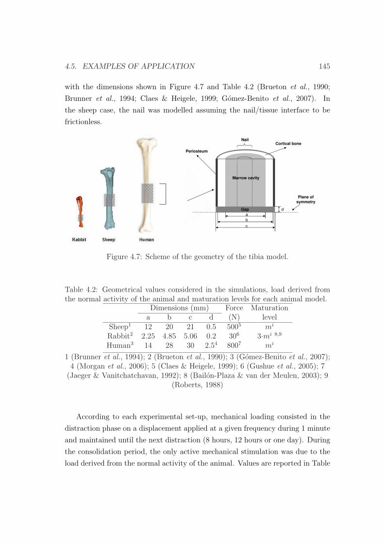
4.5. EXAMPLES OF APPLICATION 145
with the dimensions shown in Figure 4.7 and Table 4.2 (Brueton et al., 1990;
Brunner et al., 1994; Claes & Heigele, 1999; Gomez-Benito et al., 2007). In
the sheep case, the nail was modelled assuming the nail/tissue interface to be
frictionless.
Marrow cavityMarrow cavity
Cortical bone
Periosteum
Gap
c
b
a
d
Nail
Plane ofsymmetry
Figure 4.7: Scheme of the geometry of the tibia model.
Table 4.2: Geometrical values considered in the simulations, load derived fromthe normal activity of the animal and maturation levels for each animal model.
Dimensions (mm) Force Maturationa b c d (N) level
Sheep1 12 20 21 0.5 5005 mi
Rabbit2 2.25 4.85 5.06 0.2 306 3·mi 8,9
Human3 14 28 30 2.54 8007 mi
1 (Brunner et al., 1994); 2 (Brueton et al., 1990); 3 (Gomez-Benito et al., 2007);4 (Morgan et al., 2006); 5 (Claes & Heigele, 1999); 6 (Gushue et al., 2005); 7
(Jaeger & Vanitchatchavan, 1992); 8 (Bailon-Plaza & van der Meulen, 2003); 9(Roberts, 1988)
According to each experimental set-up, mechanical loading consisted in the
distraction phase on a displacement applied at a given frequency during 1 minute
and maintained until the next distraction (8 hours, 12 hours or one day). During
the consolidation period, the only active mechanical stimulation was due to the
load derived from the normal activity of the animal. Values are reported in Table
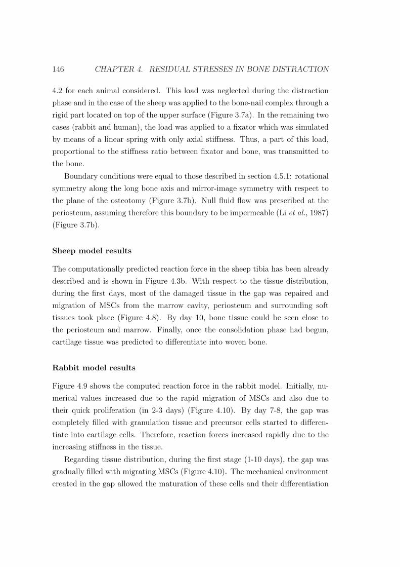
146 CHAPTER 4. RESIDUAL STRESSES IN BONE DISTRACTION
4.2 for each animal considered. This load was neglected during the distraction
phase and in the case of the sheep was applied to the bone-nail complex through a
rigid part located on top of the upper surface (Figure 3.7a). In the remaining two
cases (rabbit and human), the load was applied to a fixator which was simulated
by means of a linear spring with only axial stiffness. Thus, a part of this load,
proportional to the stiffness ratio between fixator and bone, was transmitted to
the bone.
Boundary conditions were equal to those described in section 4.5.1: rotational
symmetry along the long bone axis and mirror-image symmetry with respect to
the plane of the osteotomy (Figure 3.7b). Null fluid flow was prescribed at the
periosteum, assuming therefore this boundary to be impermeable (Li et al., 1987)
(Figure 3.7b).
Sheep model results
The computationally predicted reaction force in the sheep tibia has been already
described and is shown in Figure 4.3b. With respect to the tissue distribution,
during the first days, most of the damaged tissue in the gap was repaired and
migration of MSCs from the marrow cavity, periosteum and surrounding soft
tissues took place (Figure 4.8). By day 10, bone tissue could be seen close to
the periosteum and marrow. Finally, once the consolidation phase had begun,
cartilage tissue was predicted to differentiate into woven bone.
Rabbit model results
Figure 4.9 shows the computed reaction force in the rabbit model. Initially, nu-
merical values increased due to the rapid migration of MSCs and also due to
their quick proliferation (in 2-3 days) (Figure 4.10). By day 7-8, the gap was
completely filled with granulation tissue and precursor cells started to differen-
tiate into cartilage cells. Therefore, reaction forces increased rapidly due to the
increasing stiffness in the tissue.
Regarding tissue distribution, during the first stage (1-10 days), the gap was
gradually filled with migrating MSCs (Figure 4.10). The mechanical environment
created in the gap allowed the maturation of these cells and their differentiation
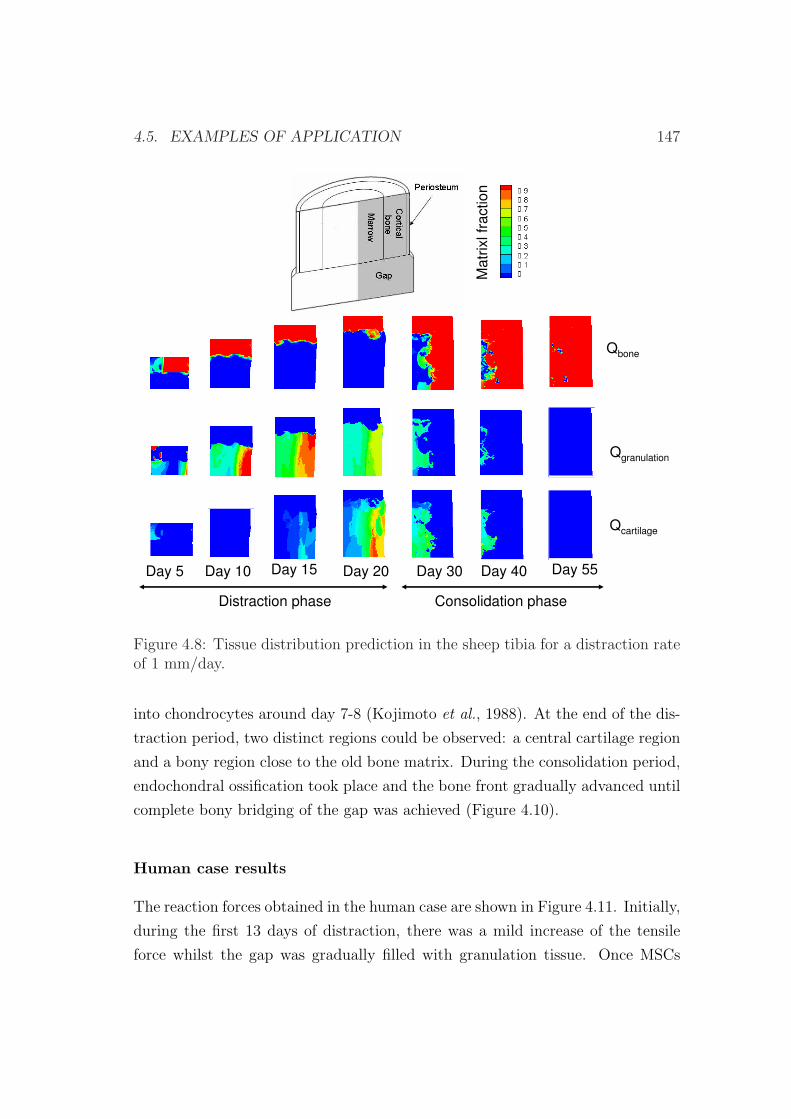
4.5. EXAMPLES OF APPLICATION 147
Qbone
Qgranulation
Qcartilage
Day 5 Day 10 Day 15 Day 20
Distraction phase Consolidation phase
Day 30 Day 40
Ma
trix
lfr
actio
n
Day 55
Figure 4.8: Tissue distribution prediction in the sheep tibia for a distraction rateof 1 mm/day.
into chondrocytes around day 7-8 (Kojimoto et al., 1988). At the end of the dis-
traction period, two distinct regions could be observed: a central cartilage region
and a bony region close to the old bone matrix. During the consolidation period,
endochondral ossification took place and the bone front gradually advanced until
complete bony bridging of the gap was achieved (Figure 4.10).
Human case results
The reaction forces obtained in the human case are shown in Figure 4.11. Initially,
during the first 13 days of distraction, there was a mild increase of the tensile
force whilst the gap was gradually filled with granulation tissue. Once MSCs
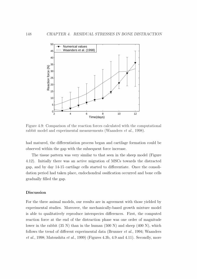
148 CHAPTER 4. RESIDUAL STRESSES IN BONE DISTRACTION
2 4 6 8 10 120
5
10
15
20
25
30
35
40
45
50
Rea
ctio
n fo
rce
(N)
Time(days)
Numerical valuesWaanders et al. (1998)
Figure 4.9: Comparison of the reaction forces calculated with the computationalrabbit model and experimental measurements (Waanders et al., 1998).
had matured, the differentiation process began and cartilage formation could be
observed within the gap with the subsequent force increase.
The tissue pattern was very similar to that seen in the sheep model (Figure
4.12). Initially there was an active migration of MSCs towards the distracted
gap, and by day 14-15 cartilage cells started to differentiate. Once the consoli-
dation period had taken place, endochondral ossification occurred and bone cells
gradually filled the gap.
Discussion
For the three animal models, our results are in agreement with those yielded by
experimental studies. Moreover, the mechanically-based growth mixture model
is able to qualitatively reproduce interspecies differences. First, the computed
reaction force at the end of the distraction phase was one order of magnitude
lower in the rabbit (35 N) than in the human (500 N) and sheep (400 N), which
follows the trend of different experimental data (Brunner et al., 1994; Waanders
et al., 1998; Matsushita et al., 1999) (Figures 4.3b, 4.9 and 4.11). Secondly, more
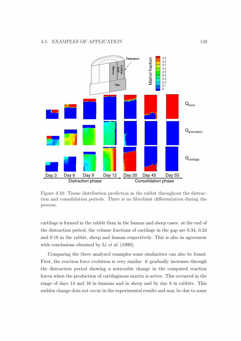
4.5. EXAMPLES OF APPLICATION 149
Qbone
Qgranulation
Qcartilage
Day 3 Day 6 Day 9 Day 12 Day 20
Distraction phase Consolidation phase
Day 45 Day 55
Ma
trix
lfr
actio
n
Figure 4.10: Tissue distribution prediction in the rabbit throughout the distrac-tion and consolidation periods. There is no fibroblast differentiation during theprocess.
cartilage is formed in the rabbit than in the human and sheep cases: at the end of
the distraction period, the volume fractions of cartilage in the gap are 0.34, 0.24
and 0.18 in the rabbit, sheep and human respectively. This is also in agreement
with conclusions obtained by Li et al. (1999).
Comparing the three analyzed examples some similarities can also be found.
First, the reaction force evolution is very similar: it gradually increases through
the distraction period showing a noticeable change in the computed reaction
forces when the production of cartilaginous matrix is active. This occurred in the
range of days 14 and 16 in humans and in sheep and by day 8 in rabbits. This
sudden change does not occur in the experimental results and may be due to some
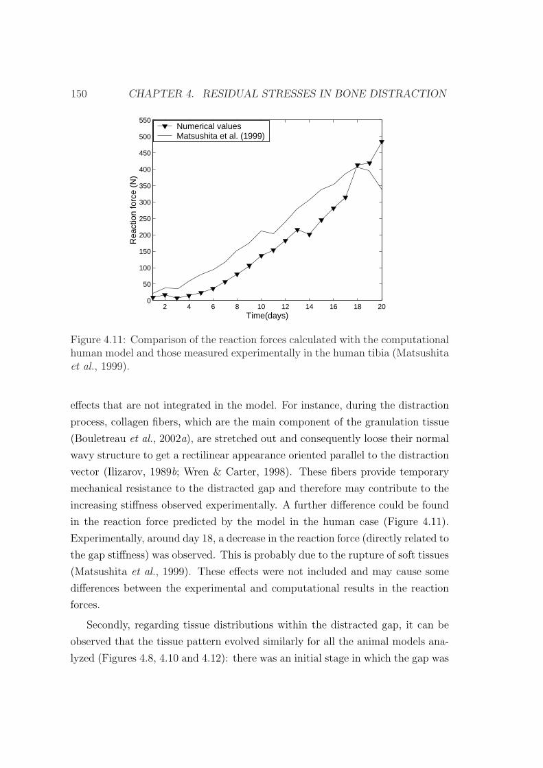
150 CHAPTER 4. RESIDUAL STRESSES IN BONE DISTRACTION
2 4 6 8 10 12 14 16 18 200
50
100
150
200
250
300
350
400
450
500
550
Rea
ctio
n fo
rce
(N)
Time(days)
Numerical valuesMatsushita et al. (1999)
Figure 4.11: Comparison of the reaction forces calculated with the computationalhuman model and those measured experimentally in the human tibia (Matsushitaet al., 1999).
effects that are not integrated in the model. For instance, during the distraction
process, collagen fibers, which are the main component of the granulation tissue
(Bouletreau et al., 2002a), are stretched out and consequently loose their normal
wavy structure to get a rectilinear appearance oriented parallel to the distraction
vector (Ilizarov, 1989b; Wren & Carter, 1998). These fibers provide temporary
mechanical resistance to the distracted gap and therefore may contribute to the
increasing stiffness observed experimentally. A further difference could be found
in the reaction force predicted by the model in the human case (Figure 4.11).
Experimentally, around day 18, a decrease in the reaction force (directly related to
the gap stiffness) was observed. This is probably due to the rupture of soft tissues
(Matsushita et al., 1999). These effects were not included and may cause some
differences between the experimental and computational results in the reaction
forces.
Secondly, regarding tissue distributions within the distracted gap, it can be
observed that the tissue pattern evolved similarly for all the animal models ana-
lyzed (Figures 4.8, 4.10 and 4.12): there was an initial stage in which the gap was
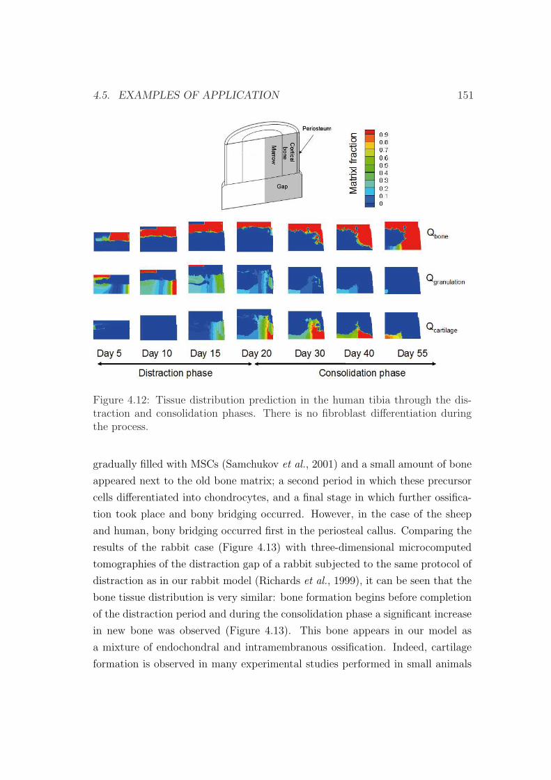
4.5. EXAMPLES OF APPLICATION 151
Figure 4.12: Tissue distribution prediction in the human tibia through the dis-traction and consolidation phases. There is no fibroblast differentiation duringthe process.
gradually filled with MSCs (Samchukov et al., 2001) and a small amount of bone
appeared next to the old bone matrix; a second period in which these precursor
cells differentiated into chondrocytes, and a final stage in which further ossifica-
tion took place and bony bridging occurred. However, in the case of the sheep
and human, bony bridging occurred first in the periosteal callus. Comparing the
results of the rabbit case (Figure 4.13) with three-dimensional microcomputed
tomographies of the distraction gap of a rabbit subjected to the same protocol of
distraction as in our rabbit model (Richards et al., 1999), it can be seen that the
bone tissue distribution is very similar: bone formation begins before completion
of the distraction period and during the consolidation phase a significant increase
in new bone was observed (Figure 4.13). This bone appears in our model as
a mixture of endochondral and intramembranous ossification. Indeed, cartilage
formation is observed in many experimental studies performed in small animals

152 CHAPTER 4. RESIDUAL STRESSES IN BONE DISTRACTION
(Ohyama et al., 1994; Yasui et al., 1997; Jazrawi et al., 1998; Li et al., 1999) as
well as in larger ones (Peltonen et al., 1992; de Pablos et al., 1994; Fink et al.,
2003). This is also in agreement with existing computational models (Isaksson
et al., 2007; Boccaccio et al., 2007, 2008). In the human case, comparison with
experimental data has been very difficult since most available data only consist
on bone measurements.
(a) (b)
(c) (d)
Figure 4.13: Comparison of bone turnover of the numerical results with three-dimensional microcomputed tomographies in the rabbit model (Richards et al.,1999) at a) day 12; b) day 18; c) day 30; d) day 55 after the latency period.
In this study, the effect of the pre-traction stresses has been considered. How-
ever, comparing Figures 3.10 and 4.8, where the same experimental set-up has
been modeled but with different mathematical models, it can be appreciated that
tissue distributions are not affected significantly by the residual stresses. By con-
trast, considering residual stresses is crucial for a correct reaction force prediction
and material properties adjust.
There are several limitations in the present study. The first one regards the
mathematical formulation, which is developed under the small deformations as-
4.5. EXAMPLES OF APPLICATION 153
sumption. Nevertheless, distraction is a large deformation process since inter-
fragmentary movements may represent as much as 100% of the size of the gap.
However, after 5 days of distraction, strains are reduced up to 20%. Secondly,
the latency phase is modelled by means of the initial conditions. An additional
limitation is that we have only considered one cell type (MSC) as representative
of all initial precursor cells and therefore a single tissue type (granulation tissue)
as representative of the initial callus tissue in order to have a workable model
with a limited number of tissues. Moreover, the named fibrous tissue represents
in our model a final irreversible differentiated tissue that cannot evolve to other
tissue types and that appears in cases of nonunion. The inclusion of additional
tissue types would not alter significantly the overall results of this study and may
only affect slightly to the mechanical properties of the distracted gap. Further,
the same material properties have been considered for the three analyzed models.
The interspecies tissue properties differences have been assumed comparable to
that available in the literature for a single specie. Regarding the differences in
cell-processes between species, we have assumed that the only parameter depen-
dent on the type of specie is the maturation stage of the cells. However, other
causes such as differences in inflammatory phases, proliferation rates, matrix pro-
duction, surgical techniques that were applied or type of fixators amongst others
may also contribute to the differentiation process.
As far as we know, no computational study has been performed yet analyzing
the mechanical environment within the distraction gap for different animal mod-
els. In this section, a growth mixture model that includes pre-traction stresses
was for the first time used in this study to compare tissue distribution as well as
reaction forces in the human and the two animal species obtaining results that are
in agreement with experimental studies. Hence, the ability of the model to pre-
dict different results corresponding to the two animal models and the human case
indicates that interspecies differences can be predicted by a model that includes
the effect of residual stresses. However, further studies are needed to completely
corroborate the model because there is a lack of experimental measurements that
allow to understand the main characteristics of bone healing in each specie.

154 CHAPTER 4. RESIDUAL STRESSES IN BONE DISTRACTION
Chapter 5
Numerical simulation of
mandibular distraction
osteogenesis
5.1 Introduction
Distraction osteogenesis is an effective way to grow new bone and has been widely
used in the last decades to correct bone deformities, either congenital or acquired,
bone length discrepancies and bony defects. Its application to the craniofacial
skeleton has gained wide acceptance, since its clinical introduction by McCarthy
et al. (1992), due to the huge possibilities this process offers.
In fact, the craniofacial skeleton is more amenable to the distraction tech-
nique than long bones. The bones of the craniofacial skeleton are much thinner
than the long bones and the associated blood supply is richer. This is why the
craniofacial skeleton with its rich blood supply can tolerate more liberal elevation
of the periosteum as well as complete osteotomy which disrupts the endosteum
(Aronson, 1994).
However, mandibular distraction osteogenesis (MDO) is often a more complex
procedure than long bone lengthening (Gateno et al., 2000). Bones must often be
moved in three dimensions (Figure 5.1), as opposed to just one, as in a limb, and
scarring must be kept to a minimum for aesthetic reasons. Also, the mandible is a
155
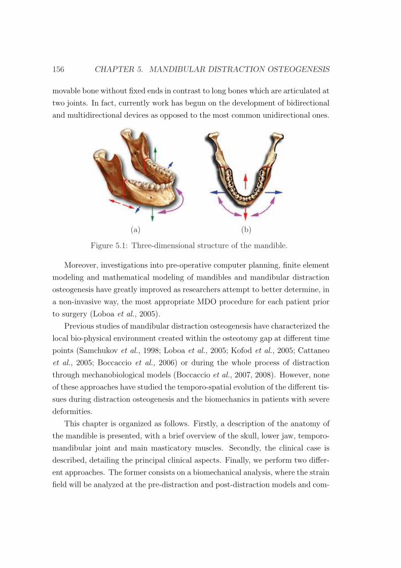
156 CHAPTER 5. MANDIBULAR DISTRACTION OSTEOGENESIS
movable bone without fixed ends in contrast to long bones which are articulated at
two joints. In fact, currently work has begun on the development of bidirectional
and multidirectional devices as opposed to the most common unidirectional ones.
(a) (b)
Figure 5.1: Three-dimensional structure of the mandible.
Moreover, investigations into pre-operative computer planning, finite element
modeling and mathematical modeling of mandibles and mandibular distraction
osteogenesis have greatly improved as researchers attempt to better determine, in
a non-invasive way, the most appropriate MDO procedure for each patient prior
to surgery (Loboa et al., 2005).
Previous studies of mandibular distraction osteogenesis have characterized the
local bio-physical environment created within the osteotomy gap at different time
points (Samchukov et al., 1998; Loboa et al., 2005; Kofod et al., 2005; Cattaneo
et al., 2005; Boccaccio et al., 2006) or during the whole process of distraction
through mechanobiological models (Boccaccio et al., 2007, 2008). However, none
of these approaches have studied the temporo-spatial evolution of the different tis-
sues during distraction osteogenesis and the biomechanics in patients with severe
deformities.
This chapter is organized as follows. Firstly, a description of the anatomy of
the mandible is presented, with a brief overview of the skull, lower jaw, temporo-
mandibular joint and main masticatory muscles. Secondly, the clinical case is
described, detailing the principal clinical aspects. Finally, we perform two differ-
ent approaches. The former consists on a biomechanical analysis, where the strain
field will be analyzed at the pre-distraction and post-distraction models and com-
5.2. ANATOMY OF THE MANDIBLE 157
pared with an idealized healthy case. The latter, consists of a temporo-spatial
prediction of the main processes that occur during distraction osteogenesis of a
mandible with severe hypoplasia of one of the ramus. In this case only the tissue
distribution will be computed. In chapter 4, tissue distribution has been shown
to not vary significantly with the inclusion of residual stresses and therefore the
much simpler model described in chapter 3 will be implemented.
5.2 Anatomy of the mandible
In this section the mandible is briefly described, as well as the muscles and bones
involved in the masticatory process.
This description will serve to posteriorly create the finite element model of the
mandible. It is very important to correctly define the different muscle insertions
as well as the boundary conditions of the mandible. Thus, the movements of the
temporomandibular joint must be known.
To accomplish these objectives, firstly, we describe the main bones of the
skull, that will serve as attachment for masticatory muscles. Secondly, we fo-
cus on the lower jaw of the mandible and afterwards a brief description of the
temporomandibular joint is presented. Finally the main muscles involved in the
masticatory processes are detailed.
5.2.1 The skull
The skull is the body’s most complex bony structure, formed by cranial and facial
bones, being 22 in all. The cranial bones, or cranium, enclose and protect the
fragile brain and furnish attachments sited for head and neck muscles. The facial
bones form the framework of the face, contain cavities for the special sense organs
of sight, taste, and smell, provide openings for air and food passage, secure the
teeth, and anchor the facial muscles of expression.
The cranial bones include the paired parietal and temporal bones and the
unpaired frontal, occipital, sphenoid and ethmoid bones (Figure 5.2). The facial
skeleton is made of 14 bones of which only the mandible and the vomer are
unpaired. The maxillae, zygomatics, nasals, lacrimals, palatines, and inferior
158 CHAPTER 5. MANDIBULAR DISTRACTION OSTEOGENESIS
conchae are paired bones (Figure 5.2). Through not really part of the skull, the
hyoid bone, lies just inferior to the mandible in the anterior neck. This bone is
unique in that it is the only bone of the body that does not articulate directly
with any other bone. Instead, it is anchored by the narrow stylohyoid ligaments
to the styloid processes of the temporal bones. The hyoid bone acts as a movable
base for the tongue and serves as attachment points for neck muscles.
Most skull bones are flat bones. Except for the mandible, which is connected
to the rest of the skull by a freely movable joint (the temporomandibular joint),
all bones of the adult skull are firmly united by interlocking joints called sutures.
The major skull sutures, the coronal, sagittal, squamous, and lamboid sutures
connect cranial bones (Figure 5.2) whilst the remaining ones connect facial bones
and are named according to the specific bones they connect. These suture lines
have a saw-toothed or serrated appearance.
5.2.2 The mandible
The mandible (lower jaw) is the largest and strongest bone of the face. It has
a body, which forms the chin, and two upright rami (Figure 5.3). Each ramus
meets the body posteriorly at a mandibular angle. At the superior margin of
each ramus are two processes separated by the mandibular notch. The anterior
coronoid process is an insertion point for the large temporalis muscle that elevates
the lower jaw during chewing. The posterior mandible condyle articulates with
the mandibular fossa of the temporal bone, forming the temporomandibular joint
on the same side.
The mandibular body serves for the reception of the lower teeth. Its superior
border, called the alveolar margin contains the sockets in which the teeth are
embedded. In the midline of the mandibular body there is a slight depression, the
mandibular symphysis indicating where the two mandibular bones fused during
infancy.
Large mandibular foramina, one of the medial surface of each ramus, permits
the nerves (responsible for tooth sensation) to pass to the teeth in the lower jaw.
Dentists inject lidocaine into these foramina to prevent pain while working on
the lower teeth. The mental foramina, openings on the lateral aspects of the
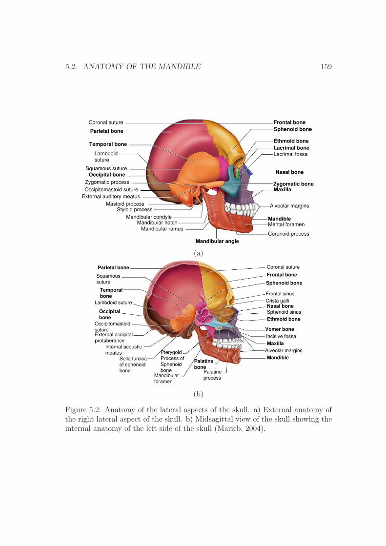
5.2. ANATOMY OF THE MANDIBLE 159
Frontal boneSphenoid bone
Ethmoid boneLacrimal boneLacrimal fossa
Nasal bone
Zygomatic boneMaxilla
Alveolar margins
MandibleMental foramen
Coronoid process
Mandibular angle
Mandibular ramus
Mandibular notch
Mandibular condyle
Styloid process
Mastoid process
External auditory meatus
Occipitomastoid suture
Zygomatic process
Occipital bone
Lambdoid
suture
Squamous suture
Temporal bone
Parietal bone
Coronal suture
(a)
Coronal suture
Frontal bone
Sphenoid bone
Frontal sinus
Crista galli
Nasal boneSphenoid sinus
Ethmoid bone
Vomer boneIncisive fossa
MaxillaAlveolar margins
Mandible
Palatine
process
Palatinebone
Mandibular
foramen
Pterygoid
Process of
Sphenoid
bone
Sella turcica
of sphenoid
bone
Internal acoustic
meatus
External occipital
protuberance
Occipitomastoid
suture
Occipitalbone
Lambdoid suture
Temporalbone
Squamous
suture
Parietal bone
(b)
Figure 5.2: Anatomy of the lateral aspects of the skull. a) External anatomy ofthe right lateral aspect of the skull. b) Midsagittal view of the skull showing theinternal anatomy of the left side of the skull (Marieb, 2004).
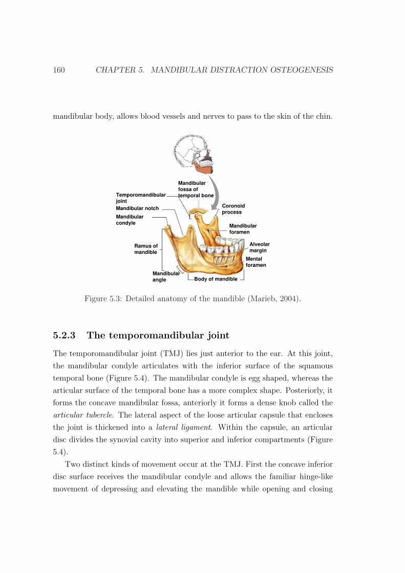
160 CHAPTER 5. MANDIBULAR DISTRACTION OSTEOGENESIS
mandibular body, allows blood vessels and nerves to pass to the skin of the chin.
Mandibularforamen
Coronoidprocess
Alveolarmargin
Mentalforamen
Body of mandibleMandibularangle
Ramus ofmandible
Mandibularcondyle
Mandibular notch
Temporomandibularjoint
Mandibularfossa oftemporal bone
Figure 5.3: Detailed anatomy of the mandible (Marieb, 2004).
5.2.3 The temporomandibular joint
The temporomandibular joint (TMJ) lies just anterior to the ear. At this joint,
the mandibular condyle articulates with the inferior surface of the squamous
temporal bone (Figure 5.4). The mandibular condyle is egg shaped, whereas the
articular surface of the temporal bone has a more complex shape. Posteriorly, it
forms the concave mandibular fossa, anteriorly it forms a dense knob called the
articular tubercle. The lateral aspect of the loose articular capsule that encloses
the joint is thickened into a lateral ligament. Within the capsule, an articular
disc divides the synovial cavity into superior and inferior compartments (Figure
5.4).
Two distinct kinds of movement occur at the TMJ. First the concave inferior
disc surface receives the mandibular condyle and allows the familiar hinge-like
movement of depressing and elevating the mandible while opening and closing
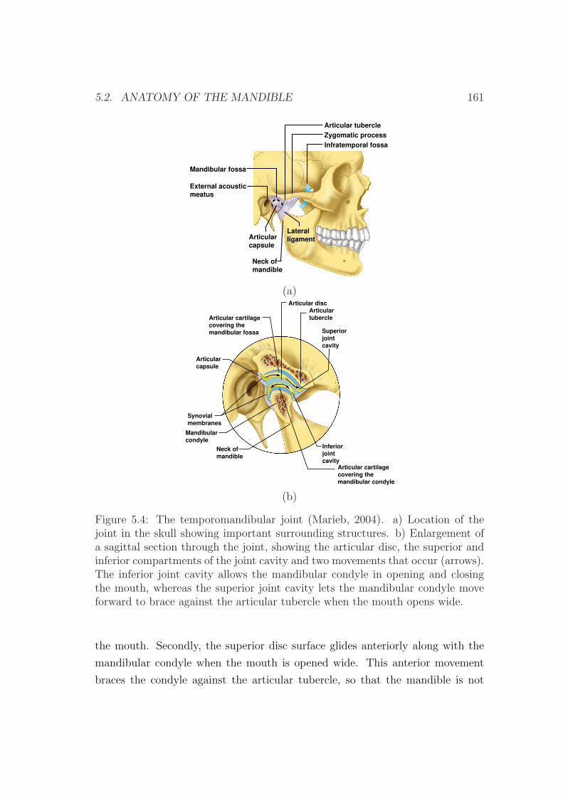
5.2. ANATOMY OF THE MANDIBLE 161
(a)
Zygomatic process
Mandibular fossa
Articular tubercle
Infratemporal fossa
External acousticmeatus
LateralligamentArticular
capsule
Neck of mandible
(a)
Articularcapsule
Articular cartilage covering the mandibular fossa
Articular discArticulartubercle
Superiorjointcavity
Inferiorjointcavity
Mandibularcondyle
Neck of mandible
Synovialmembranes
Articular cartilage covering the mandibular condyle
(b)
Figure 5.4: The temporomandibular joint (Marieb, 2004). a) Location of thejoint in the skull showing important surrounding structures. b) Enlargement ofa sagittal section through the joint, showing the articular disc, the superior andinferior compartments of the joint cavity and two movements that occur (arrows).The inferior joint cavity allows the mandibular condyle in opening and closingthe mouth, whereas the superior joint cavity lets the mandibular condyle moveforward to brace against the articular tubercle when the mouth opens wide.
the mouth. Secondly, the superior disc surface glides anteriorly along with the
mandibular condyle when the mouth is opened wide. This anterior movement
braces the condyle against the articular tubercle, so that the mandible is not
162 CHAPTER 5. MANDIBULAR DISTRACTION OSTEOGENESIS
forced through the thin roof of the mandibular fossa when one bites hard foods.
The superior compartment also allows this joint to glide from side to side. As
the posterior teeth are drawn into occlusion during grinding, the mandible moves
with a side to side movement called lateral excursion. This lateral jaw movement
is unique to mammals.
5.2.4 The masticatory muscles
Four pairs of muscles are involved in mastication activities (chewing and biting),
and all are innervated by the mandibular branch of cranial nerve V (see Table
5.1). The prime movers of jaw closure (and biting) are the powerful masseter and
temporalis muscles (Figure 5.5). Grinding movements are brought about by the
pterygoid muscles. The buccinator muscle also plays a role in chewing (Table 5.1
and Figure 5.5). Normally gravity is sufficient to depress the mandible, but if
there is resistance to jaw opening, neck muscles such as the digastric and milohy-
oid are activated. Table 5.1 describes masticatory’s muscle shape, their location
relative to other muscles, origin and insertion, primary actions and innervations.
Forces developed by masticatory muscles
The approximate magnitude of the force developed by a muscle (Fi) during a
given masticatory activity results as the product of the cross-sectional area of the
muscle (Xi), a constant for skeletal muscles (K) and a scaled value of the muscle
contraction relative to its maximum response for any task (EMGi) (Korioth et al.,
1992):
Fi = EMGi · (Xi ·K) (5.1)
where K=40 N/cm2 (Weijs & Hillen, 1984; Reina et al., 2007).
5.3 Clinical case description
This study was based on data from a 6-year-old male patient with unilateral
mandibular hypoplasia of the right mandibular ramus, corresponding with a grade
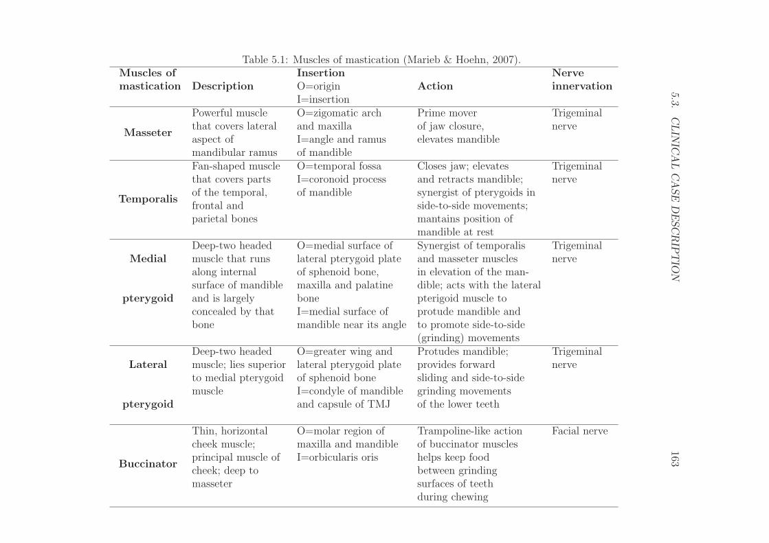
5.3.C
LIN
ICA
LC
ASE
DE
SC
RIP
TIO
N163
Table 5.1: Muscles of mastication (Marieb & Hoehn, 2007).Muscles of
DescriptionInsertion
ActionNerve
mastication O=origin innervationI=insertion
Masseter
Powerful muscle O=zigomatic arch Prime mover Trigeminalthat covers lateral and maxilla of jaw closure, nerveaspect of I=angle and ramus elevates mandiblemandibular ramus of mandible
Temporalis
Fan-shaped muscle O=temporal fossa Closes jaw; elevates Trigeminalthat covers parts I=coronoid process and retracts mandible; nerveof the temporal, of mandible synergist of pterygoids infrontal and side-to-side movements;parietal bones mantains position of
mandible at rest
MedialDeep-two headed O=medial surface of Synergist of temporalis Trigeminalmuscle that runs lateral pterygoid plate and masseter muscles nervealong internal of sphenoid bone, in elevation of the man-
pterygoidsurface of mandible maxilla and palatine dible; acts with the lateraland is largely bone pterigoid muscle toconcealed by that I=medial surface of protude mandible andbone mandible near its angle to promote side-to-side
(grinding) movements
LateralDeep-two headed O=greater wing and Protudes mandible; Trigeminalmuscle; lies superior lateral pterygoid plate provides forward nerveto medial pterygoid of sphenoid bone sliding and side-to-side
pterygoidmuscle I=condyle of mandible grinding movements
and capsule of TMJ of the lower teeth
Buccinator
Thin, horizontal O=molar region of Trampoline-like action Facial nervecheek muscle; maxilla and mandible of buccinator musclesprincipal muscle of I=orbicularis oris helps keep foodcheek; deep to between grindingmasseter surfaces of teeth
during chewing
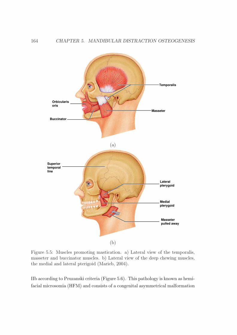
164 CHAPTER 5. MANDIBULAR DISTRACTION OSTEOGENESIS
Temporalis
Masseter
Orbicularisoris
Buccinator
(a)
Lateralpterygoid
Medialpterygoid
Masseterpulled away
Superiortemporalline
(b)
Figure 5.5: Muscles promoting mastication. a) Lateral view of the temporalis,masseter and buccinator muscles. b) Lateral view of the deep chewing muscles,the medial and lateral pterigoid (Marieb, 2004).
IIb according to Pruzanski criteria (Figure 5.6). This pathology is known as hemi-
facial microsomia (HFM) and consists of a congenital asymmetrical malformation
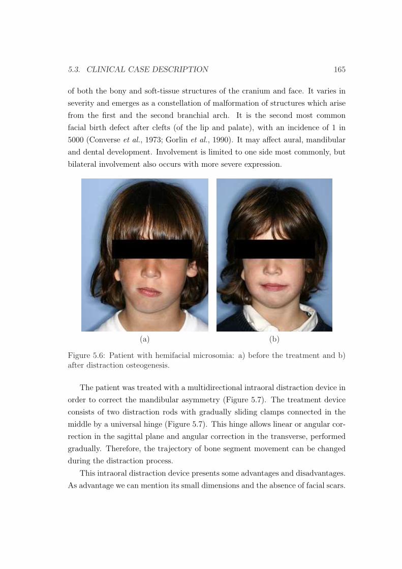
5.3. CLINICAL CASE DESCRIPTION 165
of both the bony and soft-tissue structures of the cranium and face. It varies in
severity and emerges as a constellation of malformation of structures which arise
from the first and the second branchial arch. It is the second most common
facial birth defect after clefts (of the lip and palate), with an incidence of 1 in
5000 (Converse et al., 1973; Gorlin et al., 1990). It may affect aural, mandibular
and dental development. Involvement is limited to one side most commonly, but
bilateral involvement also occurs with more severe expression.
(a) (b)
Figure 5.6: Patient with hemifacial microsomia: a) before the treatment and b)after distraction osteogenesis.
The patient was treated with a multidirectional intraoral distraction device in
order to correct the mandibular asymmetry (Figure 5.7). The treatment device
consists of two distraction rods with gradually sliding clamps connected in the
middle by a universal hinge (Figure 5.7). This hinge allows linear or angular cor-
rection in the sagittal plane and angular correction in the transverse, performed
gradually. Therefore, the trajectory of bone segment movement can be changed
during the distraction process.
This intraoral distraction device presents some advantages and disadvantages.
As advantage we can mention its small dimensions and the absence of facial scars.
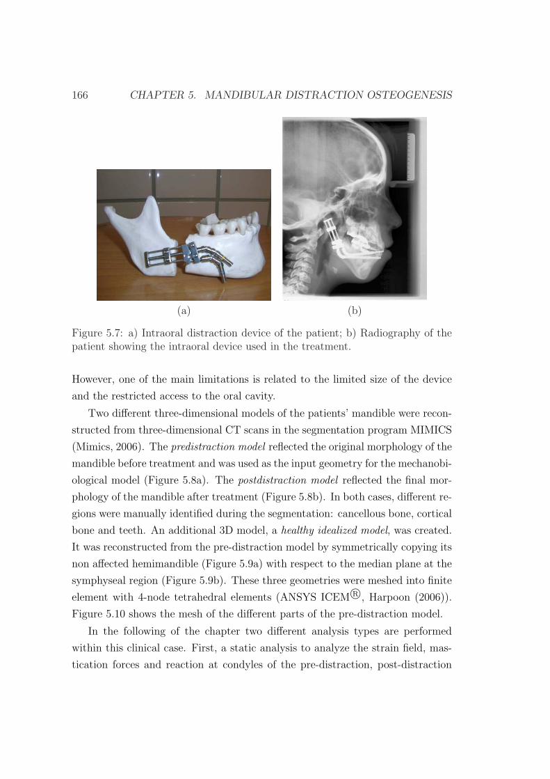
166 CHAPTER 5. MANDIBULAR DISTRACTION OSTEOGENESIS
(a) (b)
Figure 5.7: a) Intraoral distraction device of the patient; b) Radiography of thepatient showing the intraoral device used in the treatment.
However, one of the main limitations is related to the limited size of the device
and the restricted access to the oral cavity.
Two different three-dimensional models of the patients’ mandible were recon-
structed from three-dimensional CT scans in the segmentation program MIMICS
(Mimics, 2006). The predistraction model reflected the original morphology of the
mandible before treatment and was used as the input geometry for the mechanobi-
ological model (Figure 5.8a). The postdistraction model reflected the final mor-
phology of the mandible after treatment (Figure 5.8b). In both cases, different re-
gions were manually identified during the segmentation: cancellous bone, cortical
bone and teeth. An additional 3D model, a healthy idealized model, was created.
It was reconstructed from the pre-distraction model by symmetrically copying its
non affected hemimandible (Figure 5.9a) with respect to the median plane at the
symphyseal region (Figure 5.9b). These three geometries were meshed into finite
element with 4-node tetrahedral elements (ANSYS ICEM R©, Harpoon (2006)).
Figure 5.10 shows the mesh of the different parts of the pre-distraction model.
In the following of the chapter two different analysis types are performed
within this clinical case. First, a static analysis to analyze the strain field, mas-
tication forces and reaction at condyles of the pre-distraction, post-distraction
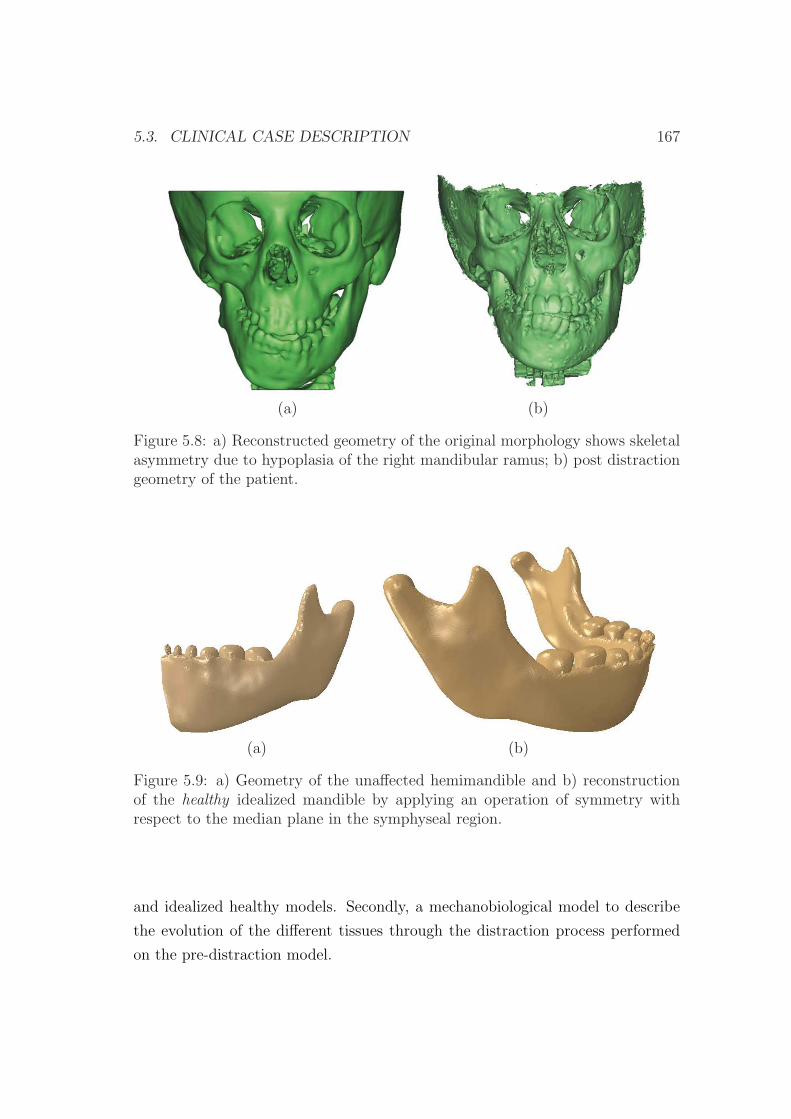
5.3. CLINICAL CASE DESCRIPTION 167
(a) (b)
Figure 5.8: a) Reconstructed geometry of the original morphology shows skeletalasymmetry due to hypoplasia of the right mandibular ramus; b) post distractiongeometry of the patient.
(a) (b)
Figure 5.9: a) Geometry of the unaffected hemimandible and b) reconstructionof the healthy idealized mandible by applying an operation of symmetry withrespect to the median plane in the symphyseal region.
and idealized healthy models. Secondly, a mechanobiological model to describe
the evolution of the different tissues through the distraction process performed
on the pre-distraction model.
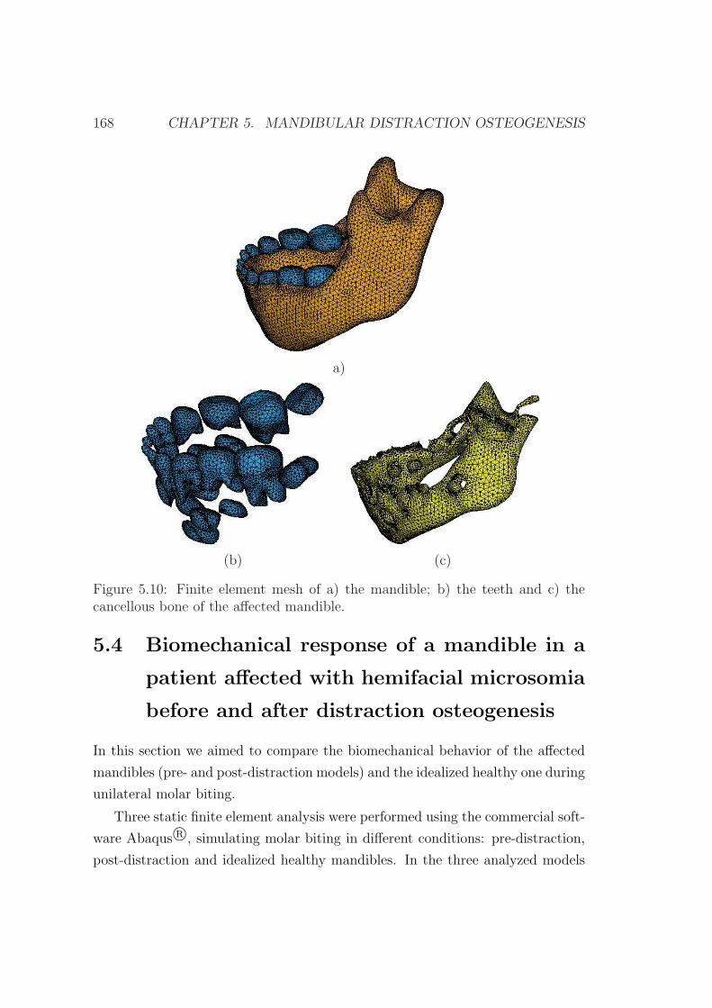
168 CHAPTER 5. MANDIBULAR DISTRACTION OSTEOGENESIS
a)
(b) (c)
Figure 5.10: Finite element mesh of a) the mandible; b) the teeth and c) thecancellous bone of the affected mandible.
5.4 Biomechanical response of a mandible in a
patient affected with hemifacial microsomia
before and after distraction osteogenesis
In this section we aimed to compare the biomechanical behavior of the affected
mandibles (pre- and post-distraction models) and the idealized healthy one during
unilateral molar biting.
Three static finite element analysis were performed using the commercial soft-
ware Abaqus R©, simulating molar biting in different conditions: pre-distraction,
post-distraction and idealized healthy mandibles. In the three analyzed models
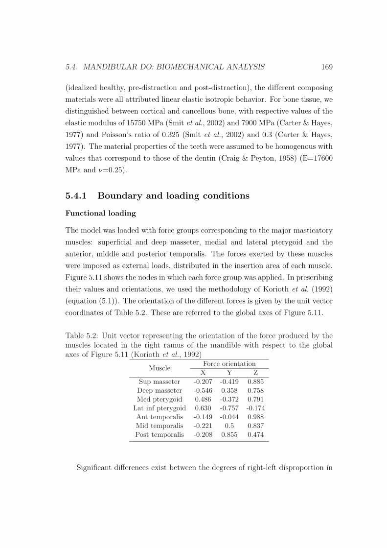
5.4. MANDIBULAR DO: BIOMECHANICAL ANALYSIS 169
(idealized healthy, pre-distraction and post-distraction), the different composing
materials were all attributed linear elastic isotropic behavior. For bone tissue, we
distinguished between cortical and cancellous bone, with respective values of the
elastic modulus of 15750 MPa (Smit et al., 2002) and 7900 MPa (Carter & Hayes,
1977) and Poisson’s ratio of 0.325 (Smit et al., 2002) and 0.3 (Carter & Hayes,
1977). The material properties of the teeth were assumed to be homogenous with
values that correspond to those of the dentin (Craig & Peyton, 1958) (E=17600
MPa and ν=0.25).
5.4.1 Boundary and loading conditions
Functional loading
The model was loaded with force groups corresponding to the major masticatory
muscles: superficial and deep masseter, medial and lateral pterygoid and the
anterior, middle and posterior temporalis. The forces exerted by these muscles
were imposed as external loads, distributed in the insertion area of each muscle.
Figure 5.11 shows the nodes in which each force group was applied. In prescribing
their values and orientations, we used the methodology of Korioth et al. (1992)
(equation (5.1)). The orientation of the different forces is given by the unit vector
coordinates of Table 5.2. These are referred to the global axes of Figure 5.11.
Table 5.2: Unit vector representing the orientation of the force produced by themuscles located in the right ramus of the mandible with respect to the globalaxes of Figure 5.11 (Korioth et al., 1992)
MuscleForce orientation
X Y ZSup masseter -0.207 -0.419 0.885Deep masseter -0.546 0.358 0.758Med pterygoid 0.486 -0.372 0.791
Lat inf pterygoid 0.630 -0.757 -0.174Ant temporalis -0.149 -0.044 0.988Mid temporalis -0.221 0.5 0.837Post temporalis -0.208 0.855 0.474
Significant differences exist between the degrees of right-left disproportion in
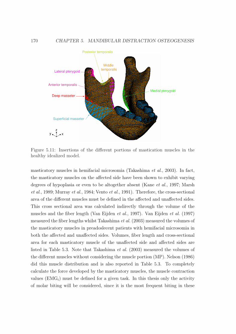
170 CHAPTER 5. MANDIBULAR DISTRACTION OSTEOGENESIS
Superficial masseter
Deep masseter
Lateral pterygoid
Posterior temporalis
Middle
temporalis
Anterior temporalis
Medial pterygoid
x
z
y
Figure 5.11: Insertions of the different portions of mastication muscles in thehealthy idealized model.
masticatory muscles in hemifacial microsomia (Takashima et al., 2003). In fact,
the masticatory muscles on the affected side have been shown to exhibit varying
degrees of hypoplasia or even to be altogether absent (Kane et al., 1997; Marsh
et al., 1989; Murray et al., 1984; Vento et al., 1991). Therefore, the cross-sectional
area of the different muscles must be defined in the affected and unaffected sides.
This cross sectional area was calculated indirectly through the volume of the
muscles and the fiber length (Van Eijden et al., 1997). Van Eijden et al. (1997)
measured the fiber lengths whilst Takashima et al. (2003) measured the volumes of
the masticatory muscles in preadoslecent patients with hemifacial microsomia in
both the affected and unaffected sides. Volumes, fiber length and cross-sectional
area for each masticatory muscle of the unaffected side and affected sides are
listed in Table 5.3. Note that Takashima et al. (2003) measured the volumes of
the different muscles without considering the muscle portion (MP). Nelson (1986)
did this muscle distribution and is also reported in Table 5.3. To completely
calculate the force developed by the masticatory muscles, the muscle contraction
values (EMGi) must be defined for a given task. In this thesis only the activity
of molar biting will be considered, since it is the most frequent biting in these
5.4. MANDIBULAR DO: BIOMECHANICAL ANALYSIS 171
patients with anterior open bite. Values are reported in Table 5.3 for the ipsila-
teral and contralateral sides. Final forces values are summarized in Table 5.3 for
the unaffected (U) and affected (A) sides in the case of molar biting.
Boundary conditions
Boundary conditions were imposed on the occlusal face of the molars and on
the joint surface of the condyles. The former corresponded to a unilateral molar
biting on the side in which the mastication takes place (right or left) and was
simulated by simply restraining the vertical displacement of the molars that come
in contact with the food. The latter aimed to reflect the mandibular fossa/condyle
restriction and was simulated by fully restraining the movement along the normal
direction of the top of the condyle. This was performed by creating a contact
surface that simulates the mandibular fossa of temporal bone. Patients with
grade IIb do not have any articular disc and thus the movement of the affected
condyle was not restrained in both pre and post-distraction models. By contrast,
in the ideal healthy model, both condyles are assumed to articulate and therefore
their normal movement was also restrained.
5.4.2 Results
In this section we aim to compare the mandible strain field and deformed shape as
well as the masticatory and reaction forces at the condyles for the three aforemen-
tioned cases: the affected mandibles (pre- and post-distraction) and the idealized
healthy one during unilateral molar biting.
Before describing the results for the three different models, it suits to clarify
that in the unilateral molar biting the term ipsilateral (working side) and con-
tralateral (balancing side) refer to the side in which the food is situated and the
opposite side, respectively.
Figure 5.12a shows the deformed and undeformed shape of the three analyzed
mandibles for a molar biting on the right side. Viewed frontally, the mandible
was rotated in a clockwise manner around the occlusal restraint in the pre and
post-distraction models and in an anticlockwise direction in the healthy model.
In the occlusal view, however, the displacement appears to be clockwise in the
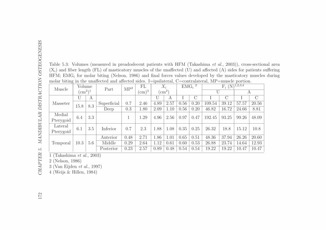
172
CH
AP
TE
R5.
MA
ND
IBU
LA
RD
IST
RA
CT
ION
OST
EO
GE
NE
SIS
Table 5.3: Volumes (measured in preadoslecent patients with HFM (Takashima et al., 2003)), cross-sectional area(Xi) and fiber length (FL) of masticatory muscles of the unaffected (U) and affected (A) sides for patients sufferingHFM; EMGi for molar biting (Nelson, 1986) and final forces values developed by the masticatory muscles duringmolar biting in the unaffected and affected sides. I=ipsilateral, C=contralateral, MP=muscle portion.
MuscleVolume
Part MP2 FL Xi EMGi2 Fi (N)1,2,3,4
(cm3)1 (cm)3 (cm2) U AU A U A I C I C I C
Masseter15.8 8.3
Superficial 0.7 2.46 4.89 2.57 0.56 0.20 109.54 39.12 57.57 20.56Deep 0.3 1.80 2.09 1.10 0.56 0.20 46.82 16.72 24.66 8.81
Medial6.4 3.3 1 1.29 4.96 2.56 0.97 0.47 192.45 93.25 99.26 48.09
PterygoidLateral
6.1 3.5 Inferior 0.7 2.3 1.88 1.08 0.35 0.25 26.32 18.8 15.12 10.8Pterygoid
Temporal 10.3 5.6Anterior 0.48 2.71 1.86 1.01 0.65 0.51 48.36 37.94 26.26 20.60Middle 0.29 2.64 1.12 0.61 0.60 0.53 26.88 23.74 14.64 12.93
Posterior 0.23 2.57 0.89 0.48 0.54 0.54 19.22 19.22 10.47 10.47
1 (Takashima et al., 2003)2 (Nelson, 1986)3 (Van Eijden et al., 1997)4 (Weijs & Hillen, 1984)
5.4. MANDIBULAR DO: BIOMECHANICAL ANALYSIS 173
healthy model and anticlockwise in the two remaining models (Figure 5.12a).
The distribution of principal strains is shown in Figure 5.12b for the three
models. Regions experiencing high magnitudes of tensile strains include the area
around the occlusal restraint and the condyle of the working side in the healthy
model (around 400 microstrains) and the condyle of the healthy ramus in the two
other models.
In the healthy model, compressive strain was most severe (around -500 micros-
trains) around the occlusal bite point of the lingual border, the mandibular notch,
the mandibular ramus of the working side and both condyles (Figure 5.12b).
By contrast, in the pre and post-distraction models, the articulated ramus
of the mandible was subjected to higher magnitudes of tensile and compressive
strains (around 3000 microstrains). Also, the lingual border experienced high
values of compressive strain, mainly in the pre-distraction model.
Finally the total reaction forces found at the occlusal restraint are 255.1 N,
236 N and 362.7 N for the pre-distraction, post-distraction and idealized healthy
models, respectively.
With regard to the molar biting with the left molar, for the affected mod-
els, results are not symmetrical with respect to those produced during the right
molar biting, in contrast to the idealized healthy model (due to the symmetry
in the geometry and boundary conditions). Viewed frontally, the pre-distraction
mandible was rotated in a clockwise manner around the occlusal restraint and
in an occlusal view in an anticlockwise manner as in the first load case. The
post-distraction model also moves in the same directions in both perspectives.
In addition, both tensile and compressive strains show higher strain magnitudes
than the first load case. The symphyseal region experienced higher magnitudes of
tensile strain on the labial surface than on the lingual side. Compressive strain,
however, was found to be higher in magnitude in the lingual side than in the
labial one. In this case, the mastication force resulted of 419.9 N, 303.9 N and
362.7 N for the pre-distraction, post-distraction and idealized healthy models,
respectively. Figures are not shown due to their similarity to the first loading
case.
174 CHAPTER 5. MANDIBULAR DISTRACTION OSTEOGENESIS
Pre-distraction model Post-distraction model Idealized healthy model(1) (2) (3)
x1 x1x1
x1 x1 x1
(a)
max
principal0.0 2.5·10-4 5·10-4 7.5·10-4 10-3
-10-3 -7.5·10-4 -5·10-4 -2.5·10-4 0.0
min
principal
(b)
Figure 5.12: a) Frontal and occlusal (dorsal) views of the pre-distraction, post-distraction and idealized healthy mandibles in their undeformed state (light gray)and in their deformed state (dark gray) (magnified by a factor of 100 in thehealthy model); b) Maximum (tensile) (εmax
pr ) and minimum (compressive) (εminpr )
principal strains of the hemimandibles in the pre-distraction, post-distraction andidealized healthy mandibles. Molar biting in the right side (which is the mostcommon in this patient).
5.4. MANDIBULAR DO: BIOMECHANICAL ANALYSIS 175
5.4.3 Discussion
In this study the distributions of tensile and compressive strains as well as the
mastication forces and displacements were calculated in a mandible affected with
HFM. Analysis of the principal strains in the healthy and affected mandibles
reveals larger strains in the affected cases, compared to the healthy one. The
distribution of strain is also much more symmetrical in the healthy case than
in the affected models, both in tension and compression. However, from Figure
5.12b, it can be appreciated that strain distribution in the post-distraction model
is qualitatively and quantitatively much more similar to the healthy model than
the pre-distraction one. This reveals, to some extent, the success of the clinical
procedure. In all cases strain magnitudes were lower than 3000 microstrains,
which is within the physiological range measured experimentally. In vivo bone
strains have been directly measured on the external surface of bones, obtaining
values in the range of approximately 50−4000 microstrains for most activities for
various animals (Rubin & Lanyon, 1984), and up to 2500 microstrains in humans
(Burr et al., 1996; Frost, 1998).
The displacement field is very similar in the pre and post-distraction models
for both load cases. By contrast, this deformed shape is not comparable to that of
the healthy model, being similar to that computed by Korioth et al. (1992). The
differences between the three models are mainly due to the different boundary
conditions and forces exerted by the muscles. Unlike the healthy model, the
affected TMJ of the post-distraction model was considered to not recover and
hence to not articulate with the mandibular fossa of temporal bone, allowing
rotations as a rigid body with high amplitudes. This is probably the critical
point with regard to the deformed shape of the mandible.
In order to compare the different results, Table 5.4 summarizes the mandibu-
lar condylar forces in the balancing and working sides as well as the forces of
mastication in all the analyzed cases. As observed, these results indicate a mag-
nitude of the force transmitted through the healthy condyle of the same order
for all the load cases and geometries analyzed. Many in vivo tests have mea-
sured mandibular condylar forces during jaw function. Breul et al. (1999), using
magnetic resonance imaging (MRI) scans of the TMJ, show that the TMJ was
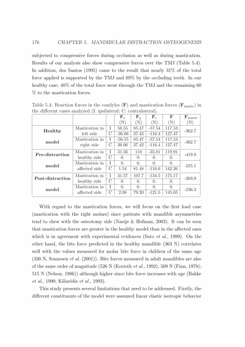
176 CHAPTER 5. MANDIBULAR DISTRACTION OSTEOGENESIS
subjected to compressive forces during occlusion as well as during mastication.
Results of our analysis also show compressive forces over the TMJ (Table 5.4).
In addition, dos Santos (1995) came to the result that nearly 31% of the total
force applied is supported by the TMJ and 69% by the occluding teeth. In our
healthy case, 40% of the total force went through the TMJ and the remaining 60
% to the mastication forces.
Table 5.4: Reaction forces in the condyles (F) and mastication forces (Fmastic) inthe different cases analyzed (I: ipsilateral; C: contralateral).
Fx Fy Fz F Fmastic
(N) (N) (N) (N) (N)
HealthyMastication in I 56.55 85.47 -57.54 117.53
-362.7left side C -36.06 37.42 -116.4 127.47
modelMastication in I -56.55 85.47 -57.54 117.53
-362.7right side C 36.06 37.42 -116.4 127.47
Pre-distractionMastication in I 31.56 110 -35.81 119.91
-419.9healthy side C 0. 0. 0. 0.
modelMastication in I 0. 0. 0. 0.
-255.1affected side C 1.54 81.48 -116.6 142.26
Post-distractionMastication in I 31.57 107.7 -134.5 175.17
-303.9healthy side C 0. 0. 0. 0.
modelMastication in I 0. 0. 0. 0.
-236.3affected side C 2.08 79.20 -121.5 145.05
With regard to the mastication forces, we will focus on the first load case
(mastication with the right molars) since patients with mandible asymmetries
tend to chew with the osteotomy side (Naeije & Hofman, 2003). It can be seen
that mastication forces are greater in the healthy model than in the affected ones
which is in agreement with experimental evidences (Sato et al., 1999). On the
other hand, the bite force predicted in the healthy mandible (363 N) correlates
well with the values measured for molar bite force in children of the same age
(330 N, Sonnesen et al. (2001)). Bite forces measured in adult mandibles are also
of the same order of magnitude (526 N (Korioth et al., 1992); 569 N (Finn, 1978);
515 N (Nelson, 1986)) although higher since bite force increases with age (Bakke
et al., 1990; Kiliaridis et al., 1993).
This study presents several limitations that need to be addressed. Firstly, the
different constituents of the model were assumed linear elastic isotropic behavior
5.5. MANDIBULAR DO: MECHANOBIOLOGICAL ANALYSIS 177
although mandibular bone should have been modeled as orthotropic. However,
for a mandible loaded by occlusal forces, the orthotropic model is just 10 %
more accurate than the much simpler isotropic model (Boccaccio et al., 2006).
Also, the teeth have been assigned one single material property being aware that
they are composed of different materials (enamel, dentin, pulp and cementum).
Secondly, only the main masticatory muscles have been included in this model.
Others, such as neck muscles (digastric and milohyoid) also contribute to the
masticatory process and should be considered in future works. Moreover, the
possible strengthening of the muscles after distraction has not been included
in the post-distraction model. Further, the cross sectional area of the muscles
considered in this study has been taken from literature data. More accurate
values could have been measured through MRI although this has not been done
for ethical reasons. Finally, future work should model more precisely the TMJ.
In this study we have performed a biomechanical analysis in both healthy and
altered conditions of a subject-specific mandible. It was found that the overall
mechanical response of the pre-distraction model is very different from the healthy
one and that the strain distribution of the post-distraction and healthy models
was similar. This shows the success of the DO process from a biomechanical
point of view. Also, the comparison of the different magnitudes measured in
the different cases show that this model is a useful tool to understand the normal
function and to predict changes due to alterations, such as those produced in cases
of HFM. However, further works are needed in order to be able to pre-clinically
test the mechanical consequences of a planned DO procedure.
5.5 Three dimensional simulation of mandibu-
lar distraction osteogenesis: mechanobiolog-
ical analysis
The aim of this section is to apply the previously developed model of distrac-
tion osteogenesis (chapter 3) to investigate its ability to predict the main tissue
patterns during the course of the three dimensional lengthening procedure of the
mandible ramus. Considering the irregular shape of the mandible, it might be
178 CHAPTER 5. MANDIBULAR DISTRACTION OSTEOGENESIS
questionable whether two-dimensional models adequately capture the structural
characteristics of the bone.
5.5.1 Model description
This study was based on the same patient as in section 5.4. The three-dimensional
model of the mandible corresponded with the original morphology of the mandible
before treatment, i.e., predistraction model of section 5.3. Also, the same seg-
mentation procedure was followed although, in this case, an additional region was
identified: the gap. The right ramus of the predistraction model was virtually
cut simulating the osteotomy at the location indicated by the surgeon (Figure
5.13). Four different regions were therefore identified during the segmentation
procedure of this model: gap, cancellous bone, cortical bone and teeth (Figure
5.13).
With regard to the clinical distraction protocol, the full process includes a
7-day latency period and a phase of distraction of 20 days, followed by a con-
solidation period of 4 months. During the distraction phase, the mandible was
distracted at a rate of 0.5 mm every 12 hours during 8 days, and to avoid pain,
at a rate of 0.25 mm every 6 hours during the following 12 days. Changes in
the angulation of the device were performed, at days 15, 17, 22 and 29 after the
beginning of distraction. Thus, four angular changes of 7 degrees were done, with
a total angular deformation of 28 degrees at the end of the distraction process.
5.5.2 Numerical implementation
The numerical implementation of the model includes four uncoupled finite ele-
ment analyses combined with a remeshing process. The mathematical model ap-
plied is that described in Chapter 3, and therefore the numerical implementation
is similar to that explained in section 3.4 although the remeshing process differs
slightly. It consists on the following steps:
1. Finite element analyses : four un-coupled finite element analyses are im-
plemented for each time step in the commercial programm Abaqus R©: a
poroelastic analysis to compute the mechanical stimulus, a thermoelastic
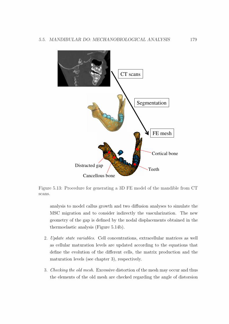
5.5. MANDIBULAR DO: MECHANOBIOLOGICAL ANALYSIS 179
Cortical bone
Distracted gapTeeth
FE mesh
CT scans
Segmentation
Cancellous bone
Figure 5.13: Procedure for generating a 3D FE model of the mandible from CTscans.
analysis to model callus growth and two diffusion analyses to simulate the
MSC migration and to consider indirectly the vascularization. The new
geometry of the gap is defined by the nodal displacements obtained in the
thermoelastic analysis (Figure 5.14b).
2. Update state variables. Cell concentrations, extracellular matrices as well
as cellular maturation levels are updated according to the equations that
define the evolution of the different cells, the matrix production and the
maturation levels (see chapter 3), respectively.
3. Checking the old mesh. Excessive distortion of the mesh may occur and thus
the elements of the old mesh are checked regarding the angle of distorsion
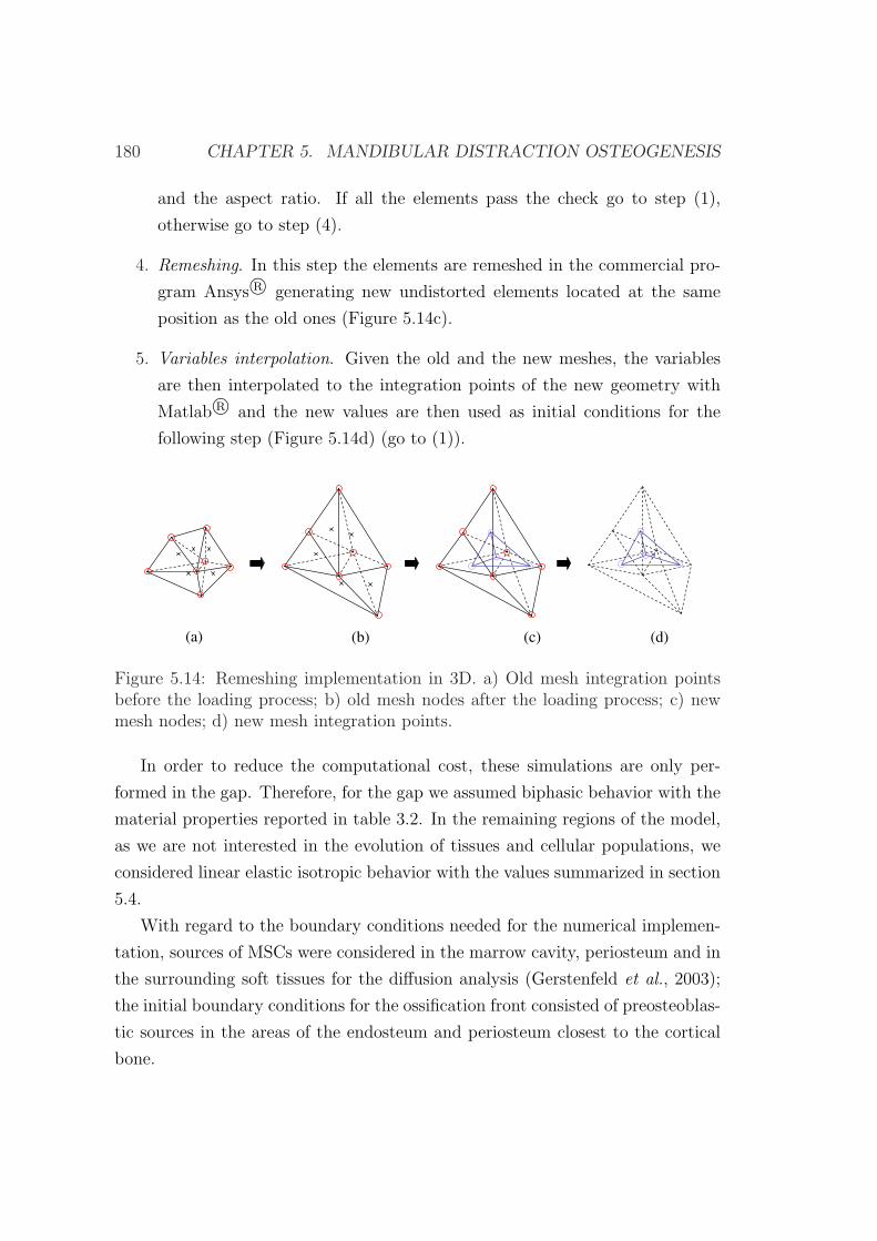
180 CHAPTER 5. MANDIBULAR DISTRACTION OSTEOGENESIS
and the aspect ratio. If all the elements pass the check go to step (1),
otherwise go to step (4).
4. Remeshing. In this step the elements are remeshed in the commercial pro-
gram Ansys R© generating new undistorted elements located at the same
position as the old ones (Figure 5.14c).
5. Variables interpolation. Given the old and the new meshes, the variables
are then interpolated to the integration points of the new geometry with
Matlab R© and the new values are then used as initial conditions for the
following step (Figure 5.14d) (go to (1)).
(a) (b) (c) (d)
Figure 5.14: Remeshing implementation in 3D. a) Old mesh integration pointsbefore the loading process; b) old mesh nodes after the loading process; c) newmesh nodes; d) new mesh integration points.
In order to reduce the computational cost, these simulations are only per-
formed in the gap. Therefore, for the gap we assumed biphasic behavior with the
material properties reported in table 3.2. In the remaining regions of the model,
as we are not interested in the evolution of tissues and cellular populations, we
considered linear elastic isotropic behavior with the values summarized in section
5.4.
With regard to the boundary conditions needed for the numerical implemen-
tation, sources of MSCs were considered in the marrow cavity, periosteum and in
the surrounding soft tissues for the diffusion analysis (Gerstenfeld et al., 2003);
the initial boundary conditions for the ossification front consisted of preosteoblas-
tic sources in the areas of the endosteum and periosteum closest to the cortical
bone.
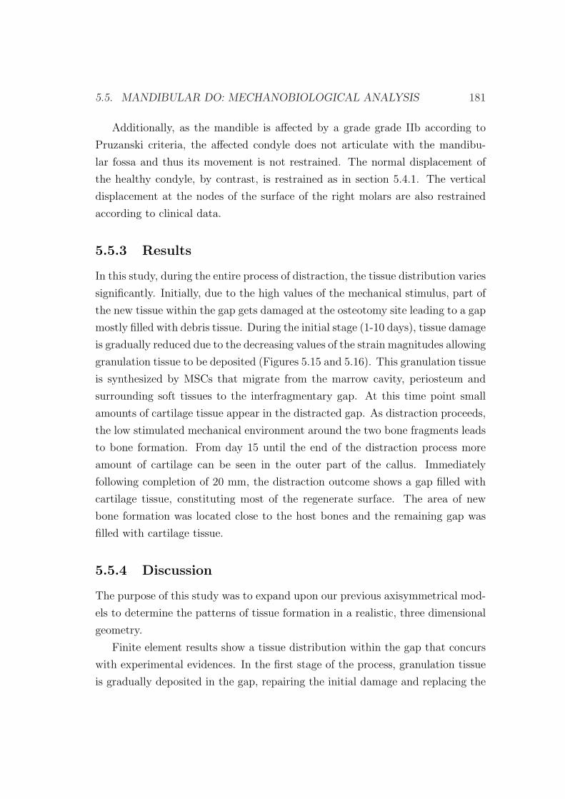
5.5. MANDIBULAR DO: MECHANOBIOLOGICAL ANALYSIS 181
Additionally, as the mandible is affected by a grade grade IIb according to
Pruzanski criteria, the affected condyle does not articulate with the mandibu-
lar fossa and thus its movement is not restrained. The normal displacement of
the healthy condyle, by contrast, is restrained as in section 5.4.1. The vertical
displacement at the nodes of the surface of the right molars are also restrained
according to clinical data.
5.5.3 Results
In this study, during the entire process of distraction, the tissue distribution varies
significantly. Initially, due to the high values of the mechanical stimulus, part of
the new tissue within the gap gets damaged at the osteotomy site leading to a gap
mostly filled with debris tissue. During the initial stage (1-10 days), tissue damage
is gradually reduced due to the decreasing values of the strain magnitudes allowing
granulation tissue to be deposited (Figures 5.15 and 5.16). This granulation tissue
is synthesized by MSCs that migrate from the marrow cavity, periosteum and
surrounding soft tissues to the interfragmentary gap. At this time point small
amounts of cartilage tissue appear in the distracted gap. As distraction proceeds,
the low stimulated mechanical environment around the two bone fragments leads
to bone formation. From day 15 until the end of the distraction process more
amount of cartilage can be seen in the outer part of the callus. Immediately
following completion of 20 mm, the distraction outcome shows a gap filled with
cartilage tissue, constituting most of the regenerate surface. The area of new
bone formation was located close to the host bones and the remaining gap was
filled with cartilage tissue.
5.5.4 Discussion
The purpose of this study was to expand upon our previous axisymmetrical mod-
els to determine the patterns of tissue formation in a realistic, three dimensional
geometry.
Finite element results show a tissue distribution within the gap that concurs
with experimental evidences. In the first stage of the process, granulation tissue
is gradually deposited in the gap, repairing the initial damage and replacing the
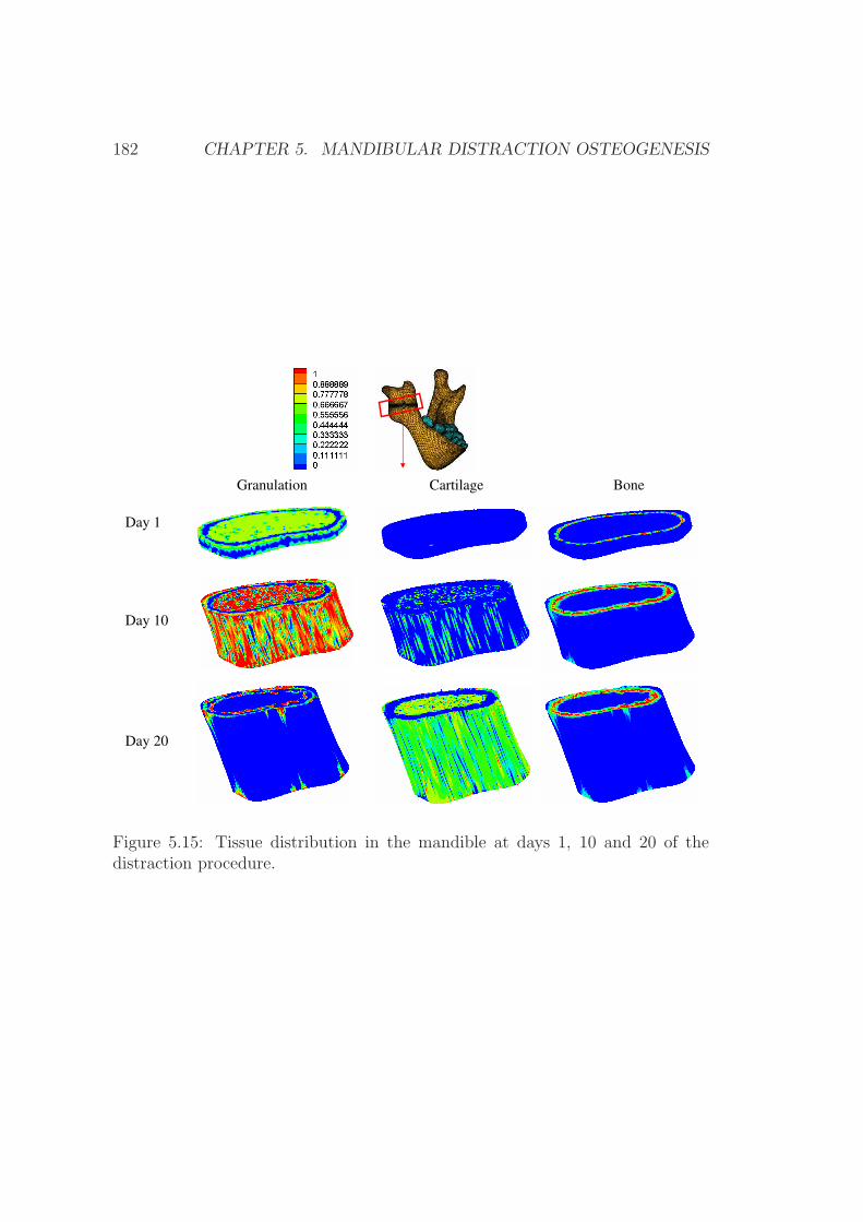
182 CHAPTER 5. MANDIBULAR DISTRACTION OSTEOGENESIS
BoneGranulation Cartilage
Day 1
Day 10
Day 20
Figure 5.15: Tissue distribution in the mandible at days 1, 10 and 20 of thedistraction procedure.
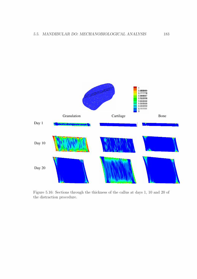
5.5. MANDIBULAR DO: MECHANOBIOLOGICAL ANALYSIS 183
Day 1
Day 10
Day 20
BoneGranulation Cartilage
Figure 5.16: Sections through the thickness of the callus at days 1, 10 and 20 ofthe distraction procedure.
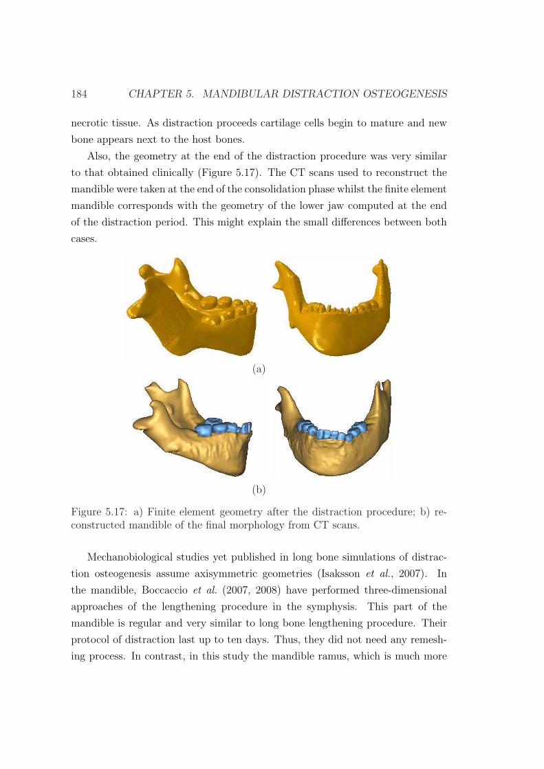
184 CHAPTER 5. MANDIBULAR DISTRACTION OSTEOGENESIS
necrotic tissue. As distraction proceeds cartilage cells begin to mature and new
bone appears next to the host bones.
Also, the geometry at the end of the distraction procedure was very similar
to that obtained clinically (Figure 5.17). The CT scans used to reconstruct the
mandible were taken at the end of the consolidation phase whilst the finite element
mandible corresponds with the geometry of the lower jaw computed at the end
of the distraction period. This might explain the small differences between both
cases.
(a)
(b)
Figure 5.17: a) Finite element geometry after the distraction procedure; b) re-constructed mandible of the final morphology from CT scans.
Mechanobiological studies yet published in long bone simulations of distrac-
tion osteogenesis assume axisymmetric geometries (Isaksson et al., 2007). In
the mandible, Boccaccio et al. (2007, 2008) have performed three-dimensional
approaches of the lengthening procedure in the symphysis. This part of the
mandible is regular and very similar to long bone lengthening procedure. Their
protocol of distraction last up to ten days. Thus, they did not need any remesh-
ing process. In contrast, in this study the mandible ramus, which is much more
5.5. MANDIBULAR DO: MECHANOBIOLOGICAL ANALYSIS 185
irregular in shape will be lengthened for 20 days a total of 20 mm. Therefore,
we have improved on existing three dimensional numerical models of distraction
osteogenesis by including the remeshing procedure.
This model presents several limitations that need to be discussed. Firstly, as
already discussed in Chapter 3, all the mathematical formulation is developed
under the small deformations assumption and a free stress state is assumed as
initial condition for each day analyzed numerically. Secondly, the distraction
orthodontic device has not been modelled, since the main goal of this study was
to evaluate the tissue distribution outcome within the gap. Instead, the distracted
displacement was directly applied on the top of the cortical bone. However, this
simplification does not affect significantly the finite element prediction. Thirdly,
only the distraction phase was simulated. Further studies should also consider the
consolidation and latency periods. Fourthly, mastication loads were neglected,
assuming them to be much smaller than the distracted loads.
This model presents a preliminar three dimensional approach of distraction
osteogenesis from a computational perspective. Although it should be further
extended in the future, it shows the enormous potential it offers. It could be used
to study different aspects of the distraction procedure such as the effect of the
distraction rate, the best placement of the corticotomy or the time of the device
removal amongst others.

186 CHAPTER 5. MANDIBULAR DISTRACTION OSTEOGENESIS
Chapter 6
Closure
6.1 Summary
This document presents a new model of distraction osteogenesis that predicts the
spatial and temporal features of the process around the osteotomy site. The cel-
lular events underlying distraction osteogenesis, namely proliferation, migration
and differentiation as well as tissue growth and tissue damage have been imple-
mented with a mathematical model formulated previously for fracture healing
(Gomez-Benito et al., 2005). This model has been extended further by intro-
ducing two new perspectives in the formulation of the differentiation processes.
Firstly, the load history has been considered in the differentiation through a lin-
ear cumulative law similar to Miner’s fatigue damage accumulation rule (Miner,
1945). This concept is based on the assumption that cells are able to change
their differentiation pathway depending on the influences of the local mechanical
environment. This potential reversibility is denoted as tissue plasticity (Roder,
2003). To validate the model, simulations have been performed in a wide variety
of mechanical environments and have been compared to different experimental
settings. It has been demonstrated that the model is able to explain classic re-
sults, such as the observed influence of the distraction rate on tissue outcome or
the main interspecies differences.
Additionally to the above described new differentiation approach, another im-
portant feature of soft tissues, namely residual stresses is investigated in the field
187
188 CHAPTER 6. CLOSURE
of bone lengthening. In contrast to the previous simulations that consider a com-
plete relaxation of the tissue during the daily loading process, here we assume
that a stress free configuration prior to the daily loading is unlikely in most tis-
sues and not realistic as observed in clinical and animal studies (Brunner et al.,
1994; Waanders et al., 1998; Matsushita et al., 1999; Richards et al., 1999). In
particular, we propose a new growth mixture model which assumes that stress
relaxation is regulated by matrix production. In this sense, the formulation pro-
posed considers that the strain response is regulated by the time varying matrix
production, which is consistent with the formulation proposed by Humphrey &
Rajagopal (2003).
Besides, computational simulations have also been implemented in three di-
mensional models. These studies are based on data from a young male patient
with unilateral mandibular hypoplasia of the right mandibular ramus which was
treated with distraction osteogenesis. The 3D model of the patients’ mandible
was reconstructed from three-dimensional CT and the process was successfully
simulated following the clinical protocol of distraction.
6.2 Conclusions
The major conclusions of this thesis can be formulated as follows:
• The load history during cell differentiation has been shown to be crucial
when predicting the effect of the distraction rate on the process of bone
formation within the distraction gap. Previous studies have successfully
simulated low distraction rates (Isaksson et al., 2007) but have failed in
predicting nonunions at high distraction rates, where the load history plays
a decisive role.
• The rate of distraction was predicted to have an important effect on the out-
come of distraction osteogenesis. Low distraction rates resulted in prema-
ture bony union, whereas a fast rate resulted in a fibrous union or nonunion.
• It has been shown that the inclusion of the pre-traction stresses in distrac-
tion osteogenesis models is necessary for a correct prediction of the force
6.3. ORIGINAL CONTRIBUTIONS 189
required to distract with material properties in agreement with the liter-
ature. Existing models used high values of the material properties to be
able to reproduce the stiffening behavior observed experimentally during
the lengthening procedure.
• Although accurate force predictions during distraction osteogenesis with
realistic material properties need the inclusion of pre-traction stresses, tissue
distributions are not so much dependent on that showing similar results with
and without residual stresses.
• The model consistently predicts tissue pattern in different animal species
and a human case: the computed reaction force at the end of the distraction
phase is one order of magnitude lower in the rabbit than in the human and
sheep, and more cartilage is formed in the rabbit than in the human and
sheep cases.
• The three dimensional simulation of the mandibular distraction osteogene-
sis process in a case of hemifacial microsomia has shown that the strain dis-
tribution in the post-distraction model is qualitatively and quantitatively
much more similar to the healthy model than the pre-distraction one. This
reveals, to some extent, the success of the clinical procedure from a biome-
chanical point of view.
6.3 Original contributions
For the development of this dissertation, the model of distraction osteogenesis
has been developed in the commercial finite element software Abaqus R©. In
particular, this software was used to solve the poroelastic, thermoelastic and the
two diffusive analyses explained in section 3.4. The poroelastic analysis has been
implemented within two different subroutines. The former was coded to account
for the load history in the differentiation process in a subroutine that defines the
material’s mechanical behavior (UMAT). The latter included the growth mixture
model that considers the residual stresses in a User element subroutine (UEL)
of Abaqus. All these subroutines were performed using Fortran 95. Besides, the
190 CHAPTER 6. CLOSURE
daily remeshing performed to avoid an excessive distorsion of the elements was
implemented in Ansys R© and Matlab R©. Moreover, other softwares have been
employed during this research. The management of CT scans has been made in
Mimics R©, the generation of meshes in Harpoon R© and Ansys ICEM R© and the
visualization of results in Tecplot R©.
The main contributions of this thesis are listed in the following points:
• A new approach to model cell differentiation was used through the load
history. It abandons the classical view of a direct differentiation of stem
cells commonly used in mechanobiological models of fracture healing and
distraction osteogenesis.
• Computational simulation of distraction osteogenesis in bidimensional and
three dimensional models. Both long bones and mandibles have been simu-
lated. In both cases important geometric changes take place during the
simulation and a remeshing is needed.
• Analysis of different mechanical environments in the process of distraction
osteogenesis. In particular, the effect of the distraction rate on the outcome
of the distraction procedure was evaluated.
• Interspecies analysis to assess the effect of different geometrical environ-
ments on bone regeneration during limb lengthening. Reaction forces and
tissue distributions were computed in different animal species and the hu-
man case.
• Formulation of a growth mixture model that includes the pre-traction stresses
in distraction osteogenesis. The model simulates the process of long bone
lengthening assuming a non-free state prior to the daily loading process.
6.4 Publications
The main results of this work have been partially published in the following
journals and conferences or are in preparation:
6.4. PUBLICATIONS 191
6.4.1 Journals
• Reina-Romo E., Gomez-Benito M.J., Garcıa-Aznar J.M., Domınguez J.,
Doblare, M. (2009). Modeling Distraction Osteogenesis: Analysis of the
distraction rate. Biomechanics and Modeling in Mechanobiology. 8: 323-
35.
• Reina-Romo E., Gomez-Benito M.J., Garcıa-Aznar J.M., Domınguez J.,
Doblare, M. Growth mixture model of distraction osteogenesis: effect of
pre-traction stresses. Biomechanics and Modeling in Mechanobiology. In
Press, DOI: 10.1007/s10237-009-0162-5.
• Reina-Romo E., Gomez-Benito M.J., Garcıa-Aznar J.M., Domınguez J.,
Doblare, M. An interspecies computational study on limb lengthening.
Manuscript submitted for publication.
• Reina-Romo E., Sampietro-Fuentes A., Gomez-Benito M.J., Garcıa-Aznar
J.M., Domınguez J., Doblare, M. Biomechanical response of a mandible in
a patient affected with hemifacial microsomia before and after distraction
osteogenesis. Manuscript submitted for publication.
• Reina-Romo E., Sampietro-Fuentes A., Gomez-Benito M.J., Garcıa-Aznar
J.M., Domınguez J., Doblare, M. Three-dimensional simulation of mandibu-
lar distraction osteogenesis: mechanobiological analysis. In preparation.
6.4.2 Conferences
• Reina E., Gomez-Benito M.J., Garcıa-Aznar J.M., Domınguez J., Doblare,
M. Modelo computacional de distraccion osea. CMNE/CILAMCE, Semni.
Oporto, Portugal, June, 2007.
• Reina E., Gomez-Benito M.J., Garcıa-Aznar J.M., Domınguez J., Doblare,
M. Influence of distraction rate on the outcome of distraction osteogenesis:
computational simulation. European Society of Biomechanichs Workshop
2007. Dublin, Ireland, August, 2007.
192 CHAPTER 6. CLOSURE
• Reina E., Gomez-Benito M.J., Garcıa-Aznar J.M., Domınguez J., Doblare,
M. Influencia de la velocidad de distraccion en la regeneracion osea. Mode-
lo computacional. 8o Congreso Iberoamericano de Ingenierıa Mecanica.
Cusco, Peru, October, 2007.
• Reina-Romo E., Gomez-Benito M.J., Garcıa-Aznar J.M., Domınguez J.,
Doblare, M. Simulating limb lengthening in an interspecies’ analysis. Biome-
chanics and Biology of Bone Healing. Berlin, Germany, May 2008.
• Reina-Romo E., Gomez-Benito M.J., Garcıa-Aznar J.M., Domınguez J.,
Doblare, M. Different animal models of bone distraction. 5th European
Congress on Computational Methods in Applied Sciences and Engineeering
(ECCOMAS 2008). Venice, Italy, July 2008.
• Reina-Romo E., Gomez-Benito M.J., Garcıa-Aznar J.M., Domınguez J.,
Doblare, M. Limb lengthening: Influence of the load history. 16th Congress
European Society of Biomechanics. Lucerne, Switzerland, July 2008.
• A. Sampietro Fuentes, E. Reina-Romo, M Ferrer Molina. Analisis biomeca-
nico de la distraccion osea en mandıbula: comparativa clınico-experimental.
55 Reunion de la Sociedad Espanola de Ortodoncia. Valencia, Spain, June
2009.
• Reina-Romo E., Sampietro-Fuentes A., Gomez-Benito M.J., Garcıa-Aznar
J.M., Domınguez J., Doblare, M. Estudio tensional antes y despues de la
distraccion osteogenica mandibular en una caso de microsomıa hemifacial.
Semni. Barcelona, Spain, July 2009.
• Reina-Romo E., Sampietro-Fuentes A., Gomez-Benito M.J., Garcıa-Aznar
J.M., Domınguez J., Doblare, M. Simulacion numerica del proceso de dis-
traccion osteogenica mandibular en un caso de microsomıa hemifacial. 9o
Congreso Iberoamericano de Ingenierıa Mecanica, Las Palmas de Gran Ca-
naria, Spain, November 2009.
6.5. FUTURE WORK 193
6.5 Future work
Distraction osteogenesis is an active field which is continuously under investiga-
tion. In fact it still remains one of the most unknown phenomena of bone biology.
Moreover, surgeons lack of established instructions to correctly define the specific
patient planning of the process.
Therefore, the possible improvements in this field are innumerable, in both
experimental and computational perspectives. In particular, several extensions
of the model are planned for the future. These are summarized as follows:
1. Future work in the computational perspective:
• Modeling the latency and remodeling phases.
• Distraction osteogenesis is a clear example of large deformations. How-
ever, the lack of data about the real behavior of tissues involved in the
regenerated gap under large deformations limits its current numerical
application. Therefore, future work should focus on characterizing the
mechanical behavior of these tissues under large deformations.
• Simulating long bone lengthening in complex geometries and perform
patient specific models. In particular, finite element simulations of
bone distraction may be developed based on high order shape functions
that properly represent the geometry (isogeometric analysis, NURBS).
Also, these analyses can be extended and adapted to the the process
of distraction, where a growing geometry takes place. In this case, the
mesh could adapt to the changes of geometry that take place during
the clinical procedure and therefore the remeshing could be avoided.
• Another point to be improved regards cell migration, which has been
simulated following a standard diffusion equation. However, it is well
known that cell movement is not random and nondirected, but a much
more complex phenomenon. For example, recently, cell motion has
been found to be guided by the substrate compliance and prestrain
(Lo et al., 2000; Wong et al., 2003; Schwarz & Bischofs, 2005). These
aspects should be included in future works since cell migration plays
a central role in distraction osteogenesis.
194 CHAPTER 6. CLOSURE
• Residual stresses have been assumed to be regulated by matrix produc-
tion. However, future studies should also include an additional force
relaxation due to volumetric growth.
• The growth process is assumed in our model to be solely due to prolif-
eration of MSCs and chondrocytes hypertrophy (Gomez-Benito et al.,
2005). However, volumetric growth due to matrix production is not
negligible and should be included in future models to achieve more
realistic results.
• Related to the previous points, a micro-macro approach could be per-
formed in order to introduce a higher magnification scale and thus re-
duce the number of parameters. Events such as cellular differentiation,
proliferation and migration could be simulated at the microstructural
level and later homogenized to the macro level.
• Moreover, we should further extend the model to study asymmetri-
cal rules in the differentiation theory. There is currently an active
discussion on whether cartilage forms in tensile environments such as
distraction osteogenesis. Many studies report intramembranous ossi-
fication in the distracted gap (Ilizarov, 1989a,b; Aronson et al., 1989;
Delloye et al., 1990; Shearer et al., 1992; Ganey et al., 1994; Schenck
& Gatchter, 1994). However, almost all the existing mechanobiolog-
ical models propose differentiation rules that are symmetrical with
respect to the type of loading (Prendergast et al., 1997; Gomez-Benito
et al., 2005) and therefore consider cartilage formation under tensile
and compressive environments. In contrast, the tissue differentiation
diagram proposed by Claes & Heigele (1999) includes this asymmetry
and cartilage is only deposited in compressive environments. There-
fore in Appendix B this differentiation theory has been applied and
extended to the case of distraction osteogenesis to analyze whether
existing asymmetrical mechanobiological rules are able to predict pat-
terns in distraction osteogenesis that may be more realistic. The model
has been validated to some extent, by simulating the effect of the fixa-
tor stiffness on the young regenerate bone after distraction osteogenesis
6.5. FUTURE WORK 195
although further work is needed in order to fully validate the model.
2. Future work in the experimental perspective:
• The validation issue is of main concern in models of distraction osteo-
genesis. The bibliography displays a large amount of data but with
high variability. Therefore, in a close future, experiments of distraction
osteogenesis must be performed in order to check the validity of all the
assumptions and parameters chosen. Within this purpose, future work
must be focused on:
– Defining and preparing the animal experiments to be carried out,
focusing on the type of specie, the distraction procedure aimed
to perform, the different distraction protocols of interest and the
parameters to be recorded through the process amongst others.
For example, the force between the distracted gap and the fixator
after pulling could be measured as well as the residual stresses
stored in the bone after each daily lengthening procedure.
– Distractor design and manufacturing. The optimum design must
be carefully developed to ensure stability of the regenerate, as well
as optimum clinical conditions.
– Electronic instrumentation development to measure different mag-
nitudes, such as load.
These future developments of the model reveal the interdisciplinary character
of this process, since mechanical, biological as well as medical aspects need to
be considered all together. The accomplishment of these goals would contribute
to optimize the current treatment strategies. Presently, noninvasive procedures
such as plain radiography have been used clinically to determine when the re-
generate bone is capable of functional loading. However, the correlation between
radiographic density and the biomechanical integrity of newly formed bone is
poor. Therefore, more reliable quantitative and qualitative approaches need to
be developed in order to determine the optimal protocol of distraction.

196 CHAPTER 6. CLOSURE
Appendix A
Permeability theory
A.1 Soft tissues permeability
The permeability (k) in soft tissues was computed from their composition, mainly
the permeability of collagen fibrils (kcol) and ground substance (kgs) (Levick,
1987):
k =1
(1/kcol) + (1/kgs)(A.1)
The permeability of collagen fibers is determined as a function of the fiber
radius, the volume they occupy and also the Kozeny coefficient which accounts for
the effect of the friction between fluid and fibers. The permeability of the ground
substance is a function of its content in glycosaminoglycans and proteoglycans.
The permeability of these components is determined via the medium length of
the fibers which form it. All these relations are correlated following the work of
Levick (1987).
Permeability of collagen fibers is determined by:
kcol =(1− V h
col)3 · r2
col
4 ·Ghb · (V hcol)
2(A.2)
where rcol is the collagen fiber ratio which varies between 20, 30 and 50 nm
according to the type of tissue, granulation, fibrous and cartilage (Levick, 1987);
V hcol is the effective volume occupied by the collagen fibers including interstitial
197
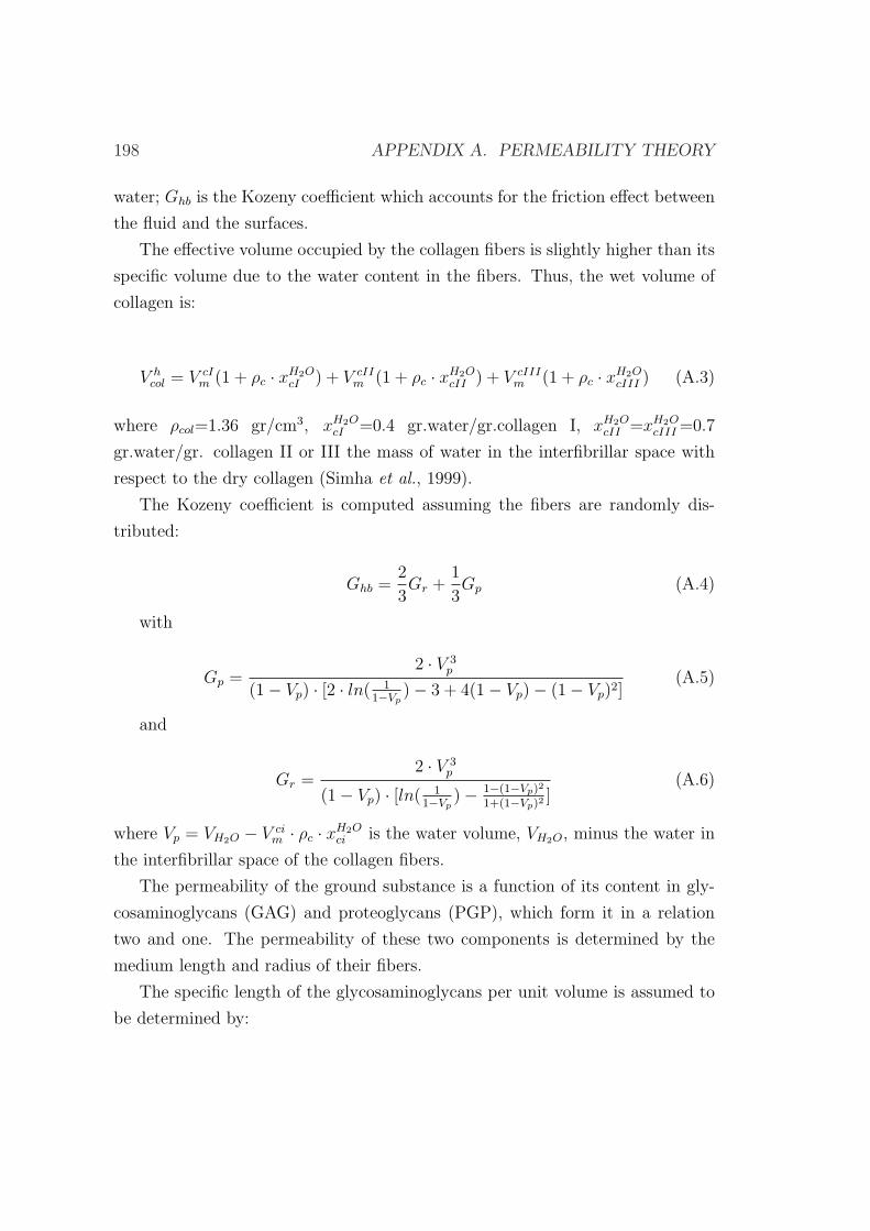
198 APPENDIX A. PERMEABILITY THEORY
water; Ghb is the Kozeny coefficient which accounts for the friction effect between
the fluid and the surfaces.
The effective volume occupied by the collagen fibers is slightly higher than its
specific volume due to the water content in the fibers. Thus, the wet volume of
collagen is:
V hcol = V cI
m (1 + ρc · xH2OcI ) + V cII
m (1 + ρc · xH2OcII ) + V cIII
m (1 + ρc · xH2OcIII ) (A.3)
where ρcol=1.36 gr/cm3, xH2OcI =0.4 gr.water/gr.collagen I, xH2O
cII =xH2OcIII =0.7
gr.water/gr. collagen II or III the mass of water in the interfibrillar space with
respect to the dry collagen (Simha et al., 1999).
The Kozeny coefficient is computed assuming the fibers are randomly dis-
tributed:
Ghb =2
3Gr +
1
3Gp (A.4)
with
Gp =2 · V 3
p
(1− Vp) · [2 · ln( 11−Vp
)− 3 + 4(1− Vp)− (1− Vp)2](A.5)
and
Gr =2 · V 3
p
(1− Vp) · [ln( 11−Vp
)− 1−(1−Vp)2
1+(1−Vp)2]
(A.6)
where Vp = VH2O − V cim · ρc · xH2O
ci is the water volume, VH2O, minus the water in
the interfibrillar space of the collagen fibers.
The permeability of the ground substance is a function of its content in gly-
cosaminoglycans (GAG) and proteoglycans (PGP), which form it in a relation
two and one. The permeability of these two components is determined by the
medium length and radius of their fibers.
The specific length of the glycosaminoglycans per unit volume is assumed to
be determined by:
A.1. SOFT TISSUES PERMEABILITY 199
lgag =Vgag/r
2gag
(Vgag/r2gag) + (Vpgp/r2
pgp)(A.7)
where rgag=0.5nm and rpgp=1.0nm are average radii of the fibers of glycosamino-
glycans and proteoglycans respectively (Levick, 1987).
The specific length of the proteoglycans fibers is determined by:
lpgp = 1− lgag (A.8)
The permeability due to the glycosaminoglycans is obtained through the ex-
pression:
kgag = a(Vgag · ρgag)b (A.9)
with a=1.3410−11 and b=-1.485 constants determined experimentally (Levick,
1987), ρgs= 1.54 gr/cm3 glycosaminoglycans density.
The permeability associated to proteoglycans is:
kpgp =(1− Vpgp)
3 · r2pgp
4 ·Ghb · V 2pgp
(A.10)
being the resultant permeability of the ground substance:
kgs =1
(lgag/kgag) + (lpgp/kpgp)· (1− V h
col) · ξ (A.11)
with ξ=0.7 the tortuosity.

200 APPENDIX A. PERMEABILITY THEORY
Appendix B
Asymmetrical differentiation
theories
B.1 Introduction
The role of chondrocytes in distraction osteogenesis is still controversial and ob-
jective of many experimental works. Whereas some studies report that the bone
forms by intramembranous ossification and no endochondral ossification takes
place (Ilizarov, 1989a,b; Aronson et al., 1989; Delloye et al., 1990; Shearer et al.,
1992; Ganey et al., 1994; Schenck & Gatchter, 1994), others observe cartilage
formation from the central fibrous tissue of the regenerate (Kojimoto et al., 1988;
White & Kenwright, 1990; Waanders et al., 1994).
In the numerical model developed in this thesis, we have assumed that carti-
lage can be deposited in both tensile and compressive environments. This sym-
metry concept is also shared by other mechanobiological rules (Pauwels, 1941;
Prendergast et al., 1997; Gomez-Benito et al., 2005). However, in order to ana-
lyze the effect of the asymmetry in the differentiation rules with respect to the
type of loading (compression or tension), the model proposed by Claes & Heigele
(1999) is used herein. This asymmetrical quantitative model has been developed
to describe fracture healing patterns (compression loading) and successfully cor-
relates new tissue formation with the local mechanical stimuli (Claes & Heigele,
1999; Shefelbine et al., 2005). As explained in Chapter 1, this mechanical stimulus
201
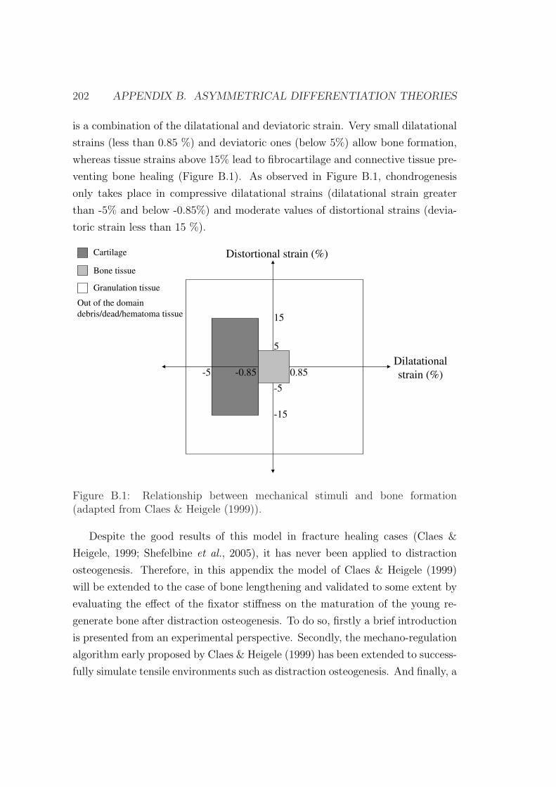
202 APPENDIX B. ASYMMETRICAL DIFFERENTIATION THEORIES
is a combination of the dilatational and deviatoric strain. Very small dilatational
strains (less than 0.85 %) and deviatoric ones (below 5%) allow bone formation,
whereas tissue strains above 15% lead to fibrocartilage and connective tissue pre-
venting bone healing (Figure B.1). As observed in Figure B.1, chondrogenesis
only takes place in compressive dilatational strains (dilatational strain greater
than -5% and below -0.85%) and moderate values of distortional strains (devia-
toric strain less than 15 %).
-5 0.85
5
Distortional strain (%)
Dilatational
strain (%)-0.85
15
Cartilage
Bone tissue
Granulation tissue
Out of the domain
debris/dead/hematoma tissue
-15
-5
Figure B.1: Relationship between mechanical stimuli and bone formation(adapted from Claes & Heigele (1999)).
Despite the good results of this model in fracture healing cases (Claes &
Heigele, 1999; Shefelbine et al., 2005), it has never been applied to distraction
osteogenesis. Therefore, in this appendix the model of Claes & Heigele (1999)
will be extended to the case of bone lengthening and validated to some extent by
evaluating the effect of the fixator stiffness on the maturation of the young re-
generate bone after distraction osteogenesis. To do so, firstly a brief introduction
is presented from an experimental perspective. Secondly, the mechano-regulation
algorithm early proposed by Claes & Heigele (1999) has been extended to success-
fully simulate tensile environments such as distraction osteogenesis. And finally, a
B.2. EFFECT OF THE FIXATOR STIFFNESS 203
sheep tibia model is implemented, using the finite element framework and results
are compared against in vivo experimental data (Claes et al., 2000).
B.2 Effect of the fixator stiffness on the young
regenerate bone after distraction osteogen-
esis
Clinical and experimental studies have shown that several mechanical factors
influence the course of bone healing. During limb lengthening, the mechanical
behaviour of the distractor device is of particular importance since most of the
load is transmitted through it. It directly affects the magnitude of the inter-
fragmentary movement and callus size (Goodship & Kenwright, 1985; Goodship
et al., 1993; Claes et al., 1997; Schell et al., 2005). A stiff fixation minimizes
interfragmentary movements and results in limited stimulation of callus forma-
tion. A flexible fixation can enhance the callus formation, thus improving the
healing process, whereas an unstable fixation can lead to a nonunion (Kenwrigh
& Goodship, 1989; Claes et al., 1995). The specific range of movements which ef-
fectively stimulates young distraction callus is unknown (Claes et al., 2000). The
movement which occurs normally in this tissue during the maturation phase can
be estimated from in vitro or in vivo measurements of fixators used in distraction
osteogenesis (Schneider et al., 1992; Podolsky & Chao, 1993; Claes et al., 2000;
Duda et al., 2003).
Choosing the appropriate external fixator and design is as important as the
actual execution of frame application. Although Ilizarov often attributed special
biological effects to the ring external fixator with tensioned wires, distraction
osteogenesis and even bone transportation can be successfully accomplished using
monolateral, half-pins frames (Dahl & Fischer, 1991; Canadell, 1993; de Pablos
et al., 1994) or even intramedullary rods (Brunner et al., 1994). The choice of
an external fixator is determined by the surgeon’s experience and preference, the
complexity of the problem, the patient’s ability and tolerance, and the number
of sites requiring treatment (Price & Mann, 1991; Saxby & Nunley, 1992). Each
type of external fixator exhibits individual mechanical qualities that may or not
204 APPENDIX B. ASYMMETRICAL DIFFERENTIATION THEORIES
enhance osteogenesis and generalized healing (Paley et al., 1990; Calhoun et al.,
1992b; Podolsky & Chao, 1993; Hamanishi et al., 1994). For example, monolateral
fixators are stable enough to distract the osteogenic zone but are limited by an
inherent cantilever design that imparts eccentric loads to the bone and may result
in undesirable angulation of the lengthened segment (Figure B.2b). Also, the
application of the Ilizarov ring fixator to some anatomic localizations as well as
the correction of angular deformities is difficult. In this sense, the Ilizarov ring
fixator with half pins modifications (Green, 1991; Green et al., 1992) is more
versatile. This system promotes gradual mechanical forces and movements of
bone in any plane (frontal, sagittal or transverse) or direction (axial, angular,
translational, rotational or any combination) at an unlimited number of treatment
sides, including the potential to cross and protect active joints (Golyakhovsky &
Frankel, 1991; de la Huerta, 1994; Herzenberg et al., 1994b,c). However, biplane
or triplane deformities cannot be corrected with these hybrid fixators and require
the use of the specialized Taylor Spatial Frame fixator to generate motion in two
or three planes at the same time.
(a) (b)
Figure B.2: a) Ilizarov external fixator; b) Monolateral external fixator.
Numerous experimental studies (Goodship & Kenwright, 1985; Goodship
et al., 1993; Claes et al., 1997; Schell et al., 2005) as well as computational ones
(Lacroix & Prendergast, 2002b; Isaksson et al., 2006; Gomez-Benito et al., 2006;
Garcıa-Aznar et al., 2007) have demonstrated the close link between interfrag-
B.3. DESCRIPTION OF THE MODEL 205
mentary movement and bone consolidation during fracture healing. Far less re-
search has been performed experimentally in distraction osteogenesis (Ilizarov,
1989a). And, as far as the authors know, no computational study has yet simu-
lated the effect of the fixator stiffness on distraction osteogenesis. Therefore, this
appendix aims to evaluate the effect of the stiffness of the fixator device on the
interfragmentary movements and tissue outcome during the consolidation phase.
B.3 Description of the model
The model proposed by Claes & Heigele (1999) will be extended herein to simu-
late clinically observed fixator stiffness related phenomena that occur during dis-
traction osteogenesis. Improvements have been performed on the original model
(Claes & Heigele, 1999) (Figure B.1) in order to take into account the asym-
metry in both distortional and dilatational strains. In fact, the model does not
consider differences under tensile and compression distortional strains (Figure
B.1). Nevertheless, it has been observed in the literature that bone formation is
faster in distraction osteogenesis (tensile environment) than in fracture healing
(compressive environment) (Aronson, 1991). Also, blood supply, which is closely
related to osteogenesis, is much greater in distraction osteogenesis than fracture
healing (Aronson, 1993). The tissue differentiation diagram of Claes & Heigele
(1999) was adapted to determine tissue differentiation in tensile mechanical en-
vironments (Figure B.1). Four main areas can be distinguished on the modified
diagram (Figure B.3). Firstly, a tissue destruction area, when the dilatational
(Ψdil) or deviatoric strain (Ψdev) is too high (usually out of the physiological
range) (-0.3>Ψdil >0.3, -0.3>Ψdev >0.3). Secondly, a cartilage area, with rel-
atively high-dilatational compressive strain (-0.05< Ψdil <-0.0085, -0.15< Ψdev
<0.15). Thirdly, a bony area, with small amounts of dilatational and deviatoric
strain. This is the area modified with respect to the original model. According to
in vitro studies on osteoblasts, cell culture osteoblasts try to avoid surface strains
larger than 4% by turning away from the principal strain axis (Neidlinger Wilke
et al., 1994). Thus, the bone formation area in compressive environments is:
-0.0085< Ψdil <0, -0.05< Ψdev <0 (Figure B.1) (Claes & Heigele, 1999). However,
in highly stimulated tensile environments such as distraction osteogenesis bony
206 APPENDIX B. ASYMMETRICAL DIFFERENTIATION THEORIES
tissue is also deposited under higher mechanical stimulus. During the distraction
process, bone columns increase in length and diameter so that the central soft
interzone keeps the same length, around 4 mm long (Aronson et al., 1990). Thus,
tissue level strains produced within the 4 mm distracted gap when a displacement
of 1 mm is applied is around 25 %. Therefore, in tensile environments such as
distraction osteogenesis, much larger strains may activate bone cells. Our bony
region in this case is: 0< Ψdil <0.034, 0< Ψdev <0.2 (Figure B.1). In the remain-
ing zones of the diagram, granulation tissue is expected to be deposited under
physiological mechanical loads (-0.3<Ψdil <0.3, -0.3<Ψdev <0.3).
-5 30
-5
Distortional strain (%)
Dilatational
strain (%)-0.85
30
-30 3.4
20
-30
-15
15
Cartilage
Bone tissue
Granulation tissue
Out of the domain
debris/dead/hematoma tissue
Figure B.3: Modified model of Claes & Heigele (1999) used in this study.
The numeric values for the regions were chosen based on previous in vivo mea-
surements, and modelling simulations (Claes & Heigele, 1999; Shefelbine et al.,
2005). Note that the diagram distinguishes between bone formation under ten-
sile environments and compressive ones. In fact, tissues do not behave similarly
under tensile or compressive loads.
The remaining cellular events underlying distraction osteogenesis (cell prolif-
eration, migration and tissue growth) were formulated and numerically imple-
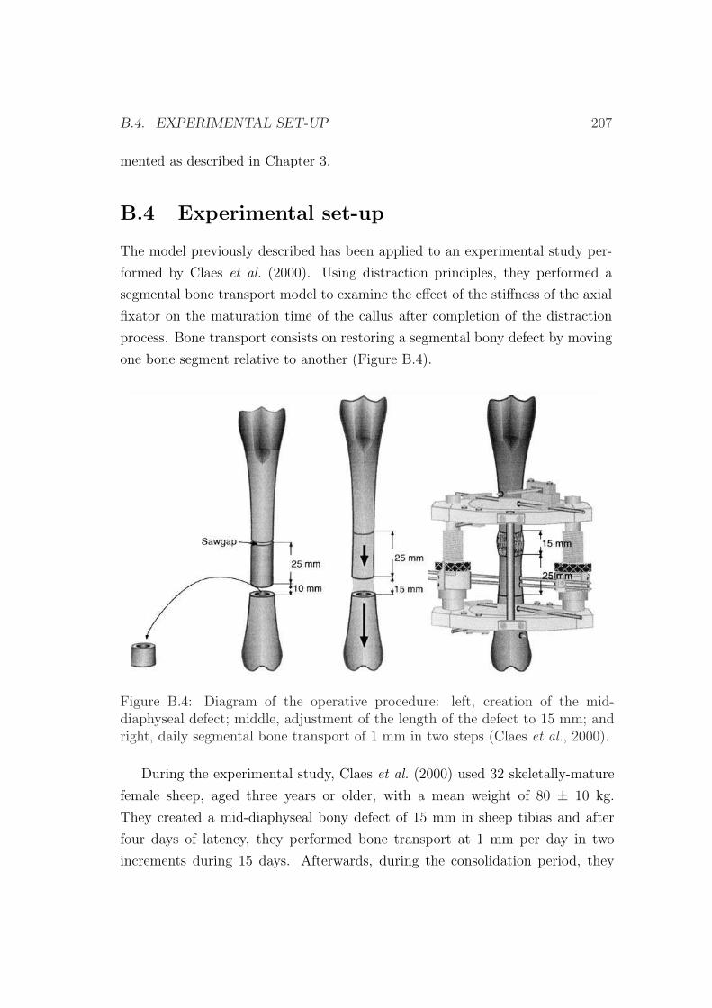
B.4. EXPERIMENTAL SET-UP 207
mented as described in Chapter 3.
B.4 Experimental set-up
The model previously described has been applied to an experimental study per-
formed by Claes et al. (2000). Using distraction principles, they performed a
segmental bone transport model to examine the effect of the stiffness of the axial
fixator on the maturation time of the callus after completion of the distraction
process. Bone transport consists on restoring a segmental bony defect by moving
one bone segment relative to another (Figure B.4).
Figure B.4: Diagram of the operative procedure: left, creation of the mid-diaphyseal defect; middle, adjustment of the length of the defect to 15 mm; andright, daily segmental bone transport of 1 mm in two steps (Claes et al., 2000).
During the experimental study, Claes et al. (2000) used 32 skeletally-mature
female sheep, aged three years or older, with a mean weight of 80 ± 10 kg.
They created a mid-diaphyseal bony defect of 15 mm in sheep tibias and after
four days of latency, they performed bone transport at 1 mm per day in two
increments during 15 days. Afterwards, during the consolidation period, they
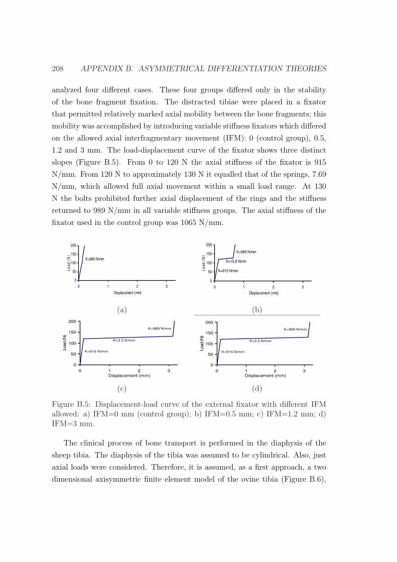
208 APPENDIX B. ASYMMETRICAL DIFFERENTIATION THEORIES
analyzed four different cases. These four groups differed only in the stability
of the bone fragment fixation. The distracted tibiae were placed in a fixator
that permitted relatively marked axial mobility between the bone fragments; this
mobility was accomplished by introducing variable stiffness fixators which differed
on the allowed axial interfragmentary movement (IFM): 0 (control group), 0.5,
1.2 and 3 mm. The load-displacement curve of the fixator shows three distinct
slopes (Figure B.5). From 0 to 120 N the axial stiffness of the fixator is 915
N/mm. From 120 N to approximately 130 N it equalled that of the springs, 7.69
N/mm, which allowed full axial movement within a small load range. At 130
N the bolts prohibited further axial displacement of the rings and the stiffness
returned to 989 N/mm in all variable stiffness groups. The axial stiffness of the
fixator used in the control group was 1065 N/mm.
0
50
100
150
200
0 1 2 3
Displacement (mm)
Lo
ad
(N
)
K=989 N/mm
0
50
100
150
200
0 1 2 3
Displacement (mm)
Lo
ad
(N
)
K=15,8 N/mm
K=915 N/mm
K=989 N/mm
(a) (b)
0
50
100
150
200
0 1 2 3
Displacement (mm)
Load (N
)
K=3.3 N/mm
K=915 N/mm
K=989 N/mm
0
50
100
150
200
0 1 2 3
Displacement (mm)
Load (N
)
K=3.3 N/mm
K=915 N/mm
K=989 N/mm
(c) (d)
Figure B.5: Displacement-load curve of the external fixator with different IFMallowed: a) IFM=0 mm (control group); b) IFM=0.5 mm; c) IFM=1.2 mm; d)IFM=3 mm.
The clinical process of bone transport is performed in the diaphysis of the
sheep tibia. The diaphysis of the tibia was assumed to be cylindrical. Also, just
axial loads were considered. Therefore, it is assumed, as a first approach, a two
dimensional axisymmetric finite element model of the ovine tibia (Figure B.6),
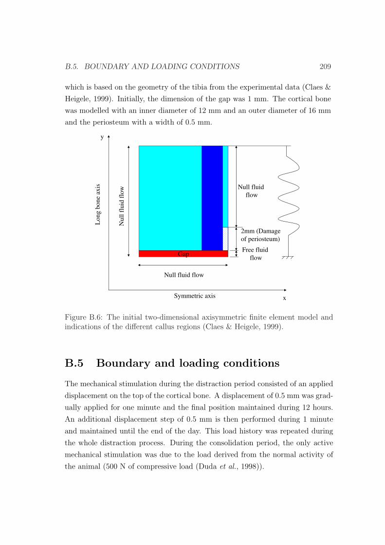
B.5. BOUNDARY AND LOADING CONDITIONS 209
which is based on the geometry of the tibia from the experimental data (Claes &
Heigele, 1999). Initially, the dimension of the gap was 1 mm. The cortical bone
was modelled with an inner diameter of 12 mm and an outer diameter of 16 mm
and the periosteum with a width of 0.5 mm.
Long
bone
axis
Symmetric axis x
y
2mm (Damage
of periosteum)
Null fluid flow
Null fluid
flow
Null
fluid
flo
w
GapFree fluid
flow
Figure B.6: The initial two-dimensional axisymmetric finite element model andindications of the different callus regions (Claes & Heigele, 1999).
B.5 Boundary and loading conditions
The mechanical stimulation during the distraction period consisted of an applied
displacement on the top of the cortical bone. A displacement of 0.5 mm was grad-
ually applied for one minute and the final position maintained during 12 hours.
An additional displacement step of 0.5 mm is then performed during 1 minute
and maintained until the end of the day. This load history was repeated during
the whole distraction process. During the consolidation period, the only active
mechanical stimulation was due to the load derived from the normal activity of
the animal (500 N of compressive load (Duda et al., 1998)).
210 APPENDIX B. ASYMMETRICAL DIFFERENTIATION THEORIES
With regard to the boundary conditions, the periosteum was assumed to be
impermeable and hence zero fluid flow was prescribed at this boundary (Li et al.,
1987). In the diffusion analysis we considered sources of MSCs in the marrow
cavity and the surrounding soft tissues (Gerstenfeld et al., 2003). Consequently, it
was assumed that the process of corticotomy preserves the endosteum. However,
it did not preserve the periosteum and therefore we assumed it to not contribute
to MSCs source and to be damaged for 2 mm around the plane site of the os-
teotomy (Figure B.6) (Claes et al., 2000). The initial boundary conditions for
the ossification front modeled through the diffusion equation consisted on pre-
osteoblastic sources in the areas of the endosteum and periosteum closest to the
cortical bone.
Also, the tissue in the interfragmentary gap was assumed to be totally dam-
aged at the beginning of the distraction period since, according to experimental
data, the four days of latency were not enough for recruitment of MSCs and
reparation of the tissue. As observed in Figure B.6, the fixator was simulated by
means of a variable stiffness linear spring with only axial stiffness.
B.6 Results
In this part of the appendix, we have determined first the tissue distribution
during the distraction phase, assuming the fixator to be infinitely rigid. After-
wards, the evolution of the interframentary movement as well as the distribution
of tissues is computed during the consolidation phase for the four types of fixator
simulated.
The tissue distribution during the distraction period is very similar to that
described in the previous examples although no cartilage formation takes place
(Figure B.7). During the initial stage of the distraction phase, the initial damaged
tissue is gradually repaired by the migrating MSCs. At the end of the distraction
period two clearly distinct zones can be distinguished: a central soft tissue area
and a peripherical bone tissue. This bone has been formed through intramem-
branous ossification close to the existing host bone. Also, during the distraction
period, as the distraction gap increased, bone front advanced while the soft tissue
interzone remained almost constant, about 3 mm long. This is in concordance
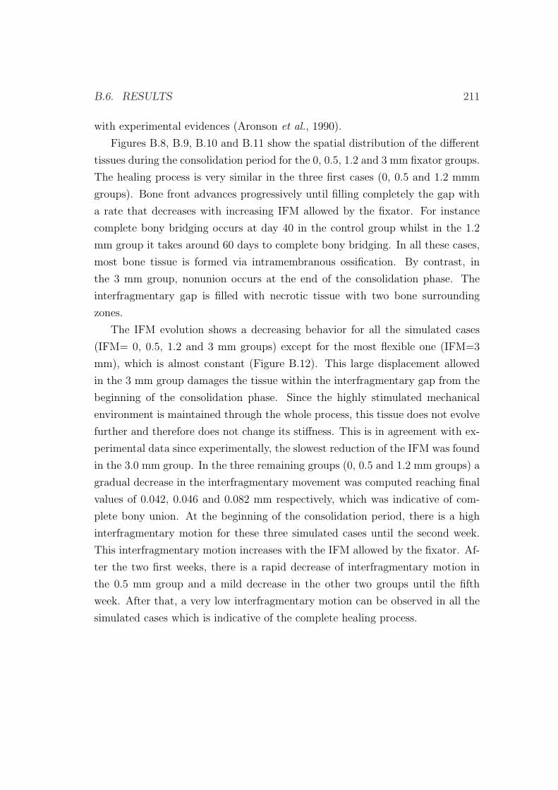
B.6. RESULTS 211
with experimental evidences (Aronson et al., 1990).
Figures B.8, B.9, B.10 and B.11 show the spatial distribution of the different
tissues during the consolidation period for the 0, 0.5, 1.2 and 3 mm fixator groups.
The healing process is very similar in the three first cases (0, 0.5 and 1.2 mmm
groups). Bone front advances progressively until filling completely the gap with
a rate that decreases with increasing IFM allowed by the fixator. For instance
complete bony bridging occurs at day 40 in the control group whilst in the 1.2
mm group it takes around 60 days to complete bony bridging. In all these cases,
most bone tissue is formed via intramembranous ossification. By contrast, in
the 3 mm group, nonunion occurs at the end of the consolidation phase. The
interfragmentary gap is filled with necrotic tissue with two bone surrounding
zones.
The IFM evolution shows a decreasing behavior for all the simulated cases
(IFM= 0, 0.5, 1.2 and 3 mm groups) except for the most flexible one (IFM=3
mm), which is almost constant (Figure B.12). This large displacement allowed
in the 3 mm group damages the tissue within the interfragmentary gap from the
beginning of the consolidation phase. Since the highly stimulated mechanical
environment is maintained through the whole process, this tissue does not evolve
further and therefore does not change its stiffness. This is in agreement with ex-
perimental data since experimentally, the slowest reduction of the IFM was found
in the 3.0 mm group. In the three remaining groups (0, 0.5 and 1.2 mm groups) a
gradual decrease in the interfragmentary movement was computed reaching final
values of 0.042, 0.046 and 0.082 mm respectively, which was indicative of com-
plete bony union. At the beginning of the consolidation period, there is a high
interfragmentary motion for these three simulated cases until the second week.
This interfragmentary motion increases with the IFM allowed by the fixator. Af-
ter the two first weeks, there is a rapid decrease of interfragmentary motion in
the 0.5 mm group and a mild decrease in the other two groups until the fifth
week. After that, a very low interfragmentary motion can be observed in all the
simulated cases which is indicative of the complete healing process.
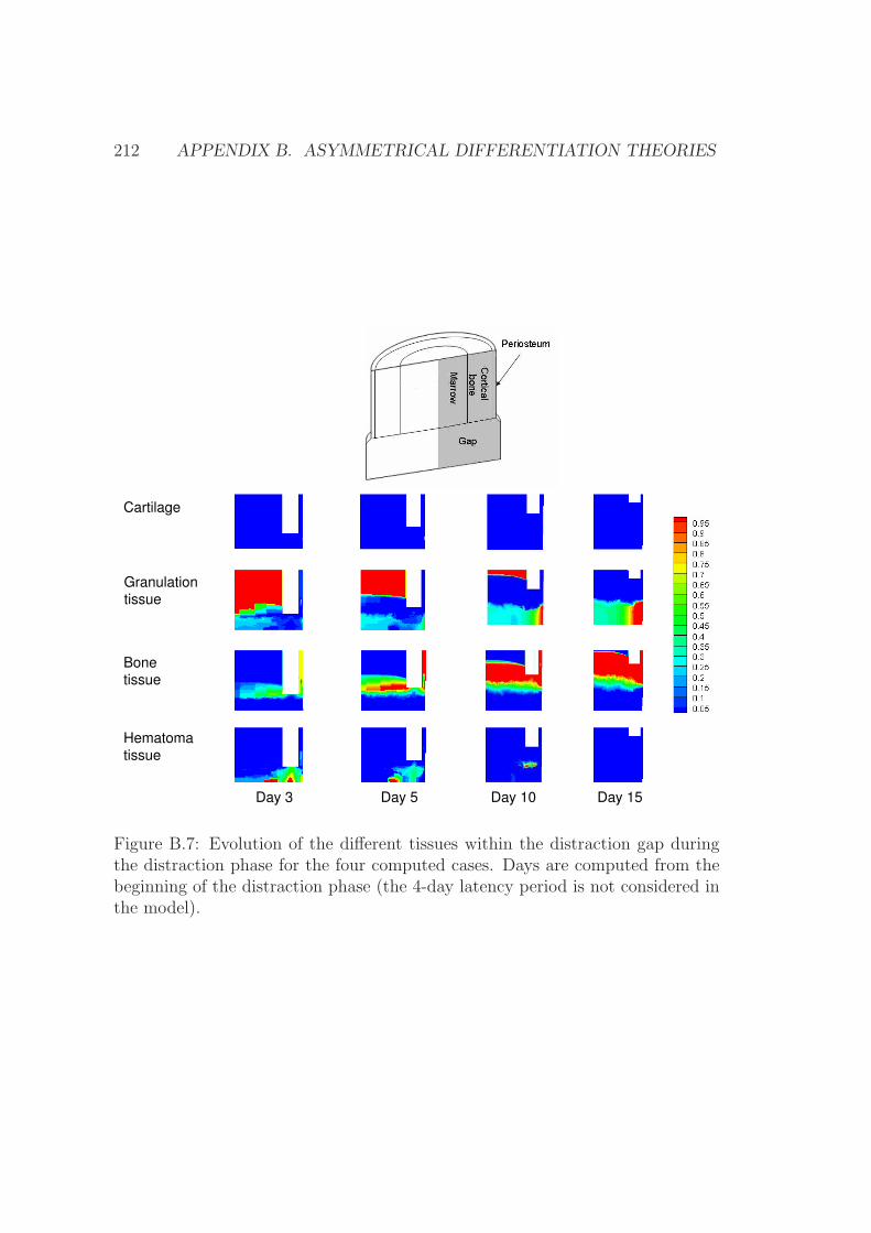
212 APPENDIX B. ASYMMETRICAL DIFFERENTIATION THEORIES
Bone
tissue
Day 3 Day 5 Day 10
Cartilage
Day 15
Hematoma
tissue
Granulation
tissue
Figure B.7: Evolution of the different tissues within the distraction gap duringthe distraction phase for the four computed cases. Days are computed from thebeginning of the distraction phase (the 4-day latency period is not considered inthe model).
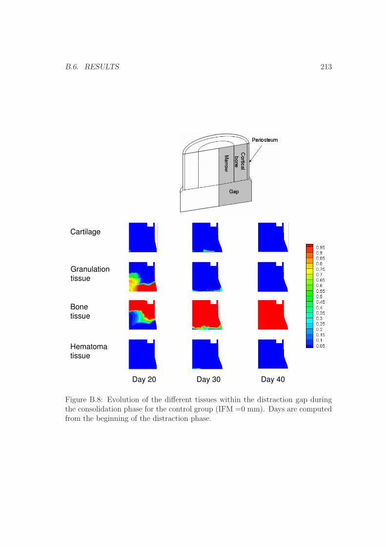
B.6. RESULTS 213
Day 20 Day 30 Day 40
Bone
tissue
Cartilage
Hematoma
tissue
Granulation
tissue
Figure B.8: Evolution of the different tissues within the distraction gap duringthe consolidation phase for the control group (IFM =0 mm). Days are computedfrom the beginning of the distraction phase.
214 APPENDIX B. ASYMMETRICAL DIFFERENTIATION THEORIES
Day 20 Day 30 Day 40
Bone
tissue
Hematoma
tissue
Cartilage
Day 55
Granulation
tissue
Figure B.9: Evolution of the different tissues within the distraction gap duringthe consolidation phase for the 0.5 mm group. Days are computed from thebeginning of the distraction phase.
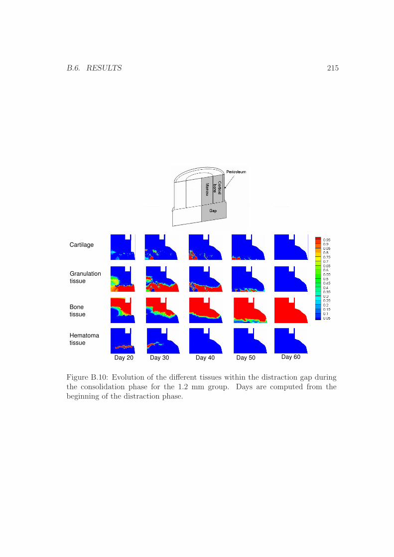
B.6. RESULTS 215
Bone
tissue
Cartilage
Day 20 Day 30 Day 40 Day 50 Day 60
Hematoma
tissue
Granulation
tissue
Figure B.10: Evolution of the different tissues within the distraction gap duringthe consolidation phase for the 1.2 mm group. Days are computed from thebeginning of the distraction phase.

216 APPENDIX B. ASYMMETRICAL DIFFERENTIATION THEORIES
Bone
tissue
Hematoma
tissue
Cartilage
Day 20 Day 30 Day 35
Granulation
tissue
Figure B.11: Evolution of the different tissues within the distraction gap dur-ing the consolidation phase for the 3 mm group. Days are computed from thebeginning of the distraction phase.
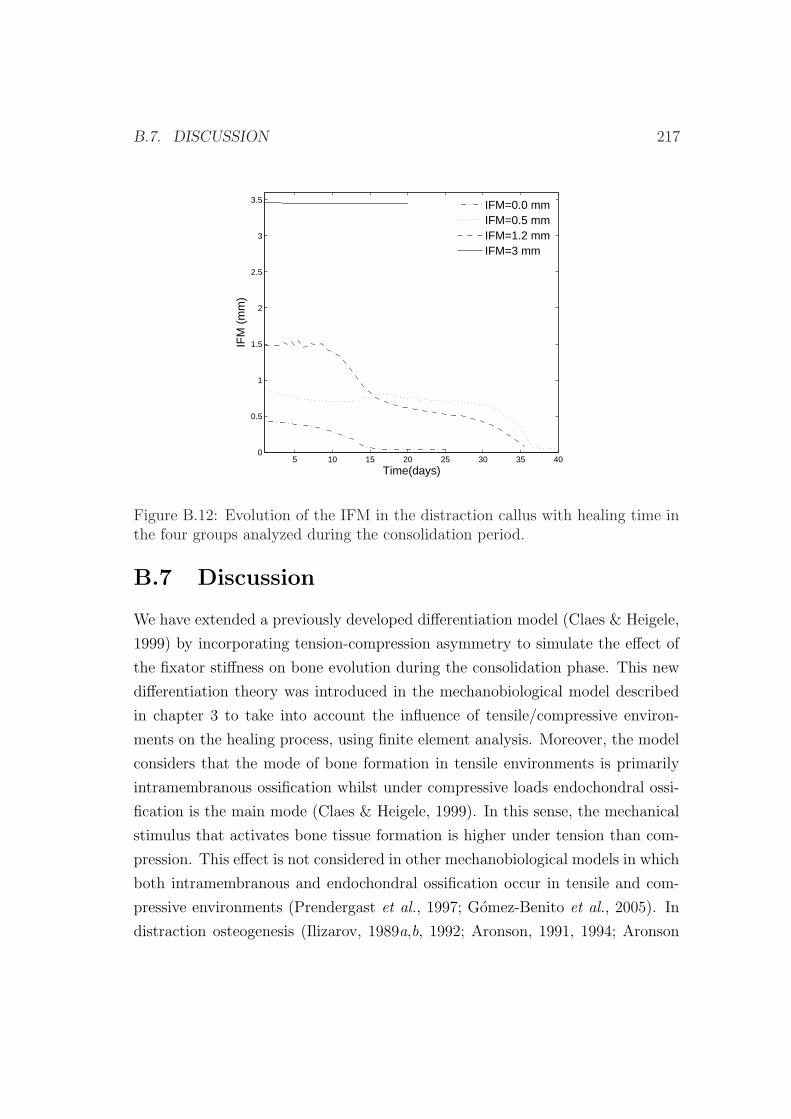
B.7. DISCUSSION 217
5 10 15 20 25 30 35 400
0.5
1
1.5
2
2.5
3
3.5
Time(days)
IFM
(m
m)
IFM=0.0 mmIFM=0.5 mmIFM=1.2 mmIFM=3 mm
Figure B.12: Evolution of the IFM in the distraction callus with healing time inthe four groups analyzed during the consolidation period.
B.7 Discussion
We have extended a previously developed differentiation model (Claes & Heigele,
1999) by incorporating tension-compression asymmetry to simulate the effect of
the fixator stiffness on bone evolution during the consolidation phase. This new
differentiation theory was introduced in the mechanobiological model described
in chapter 3 to take into account the influence of tensile/compressive environ-
ments on the healing process, using finite element analysis. Moreover, the model
considers that the mode of bone formation in tensile environments is primarily
intramembranous ossification whilst under compressive loads endochondral ossi-
fication is the main mode (Claes & Heigele, 1999). In this sense, the mechanical
stimulus that activates bone tissue formation is higher under tension than com-
pression. This effect is not considered in other mechanobiological models in which
both intramembranous and endochondral ossification occur in tensile and com-
pressive environments (Prendergast et al., 1997; Gomez-Benito et al., 2005). In
distraction osteogenesis (Ilizarov, 1989a,b, 1992; Aronson, 1991, 1994; Aronson
218 APPENDIX B. ASYMMETRICAL DIFFERENTIATION THEORIES
et al., 1990) or at implant interfaces (Geris et al., 2004), where shear loads pre-
dominate, many experimental studies demonstrate the direct differentiation of
mesenchymal stem cells into bone tissue through intramembranous ossification.
In order to test the reliability of the new extended model, four different fixators
were simulated during the consolidation phase of a common distraction process.
For the four analyzed cases, our results are in agreement with experimental ones:
a stiff fixator promotes bone formation while the excessive motion induced by very
flexible fixators is adverse for bony bridging. Also, decreasing the stiffness of the
fixator increased callus size until the critical stiffness that leads to nonunion.
Figure B.13 shows a comparison of the computed IFM with the experimental
values measured by Claes et al. (2000). Experimental IFM values at the beginning
and end of the consolidation period are similar to those computed numerically.
These results show that the qualitative trend of the IFM values is predicted, with
a much larger IFM in the 3 mm group than in the control group. In the 3 mm
group , the distraction gap was mostly filled with poorly differentiated tissue
(necrotic) whilst in the control group, which had much less motion between the
bone ends, there was substantially more osteogenic activity in the distraction
space. At the end of the consolidation period, a non union or pseudoarthrosis
is predicted in the 3 mm group as compared to the complete bony union of the
control group.
Moreover, the extended model is able to qualitatively reproduce tissue dis-
tributions within the gap in the four cases (Figures B.8, B.9, B.10 and B.11).
During the bone transport procedure, bone tissue forms in the areas close to the
cortical bone and periosteum. This bone front advances trough the consolidation
period with a rate that increases as the fixator stiffness decreases. However, in
the case with most mobility between the bone ends (3 mm group) osteogenic
activity is least and nonunion occurs. This is in concordance with experimental
findings. Figure B.14a shows the histology of the interfragmentary gap at the
end of the consolidation phase in the 3 mm group. It can be observed that tis-
sue distribution is very similar to the computed numerically (Figure B.14b). In
this case, nonunion occurs and the interfragmentary gap is filled with a central
necrotic tissue that does not evolve further. However, some amount of bone is
close to the original one. Computationally, this lower stiffness of the fixator is
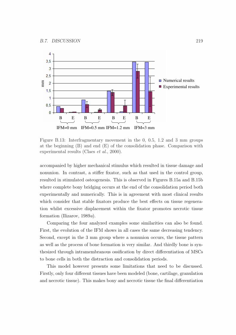
B.7. DISCUSSION 219
Numerical results
Experimental results
IFM=0 mm IFM=0.5 mm IFM=1.2 mm IFM=3 mm
mm
B E EB B E B E
Figure B.13: Interfragmentary movement in the 0, 0.5, 1.2 and 3 mm groupsat the beginning (B) and end (E) of the consolidation phase. Comparison withexperimental results (Claes et al., 2000).
accompanied by higher mechanical stimulus which resulted in tissue damage and
nonunion. In contrast, a stiffer fixator, such as that used in the control group,
resulted in stimulated osteogenesis. This is observed in Figures B.15a and B.15b
where complete bony bridging occurs at the end of the consolidation period both
experimentally and numerically. This is in agreement with most clinical results
which consider that stable fixators produce the best effects on tissue regenera-
tion whilst excessive displacement within the fixator promotes necrotic tissue
formation (Ilizarov, 1989a).
Comparing the four analyzed examples some similarities can also be found.
First, the evolution of the IFM shows in all cases the same decreasing tendency.
Second, except in the 3 mm group where a nonunion occurs, the tissue pattern
as well as the process of bone formation is very similar. And thirdly bone is syn-
thesized through intramembranous ossification by direct differentiation of MSCs
to bone cells in both the distraction and consolidation periods.
This model however presents some limitations that need to be discussed.
Firstly, only four different tissues have been modeled (bone, cartilage, granulation
and necrotic tissue). This makes bony and necrotic tissue the final differentiation
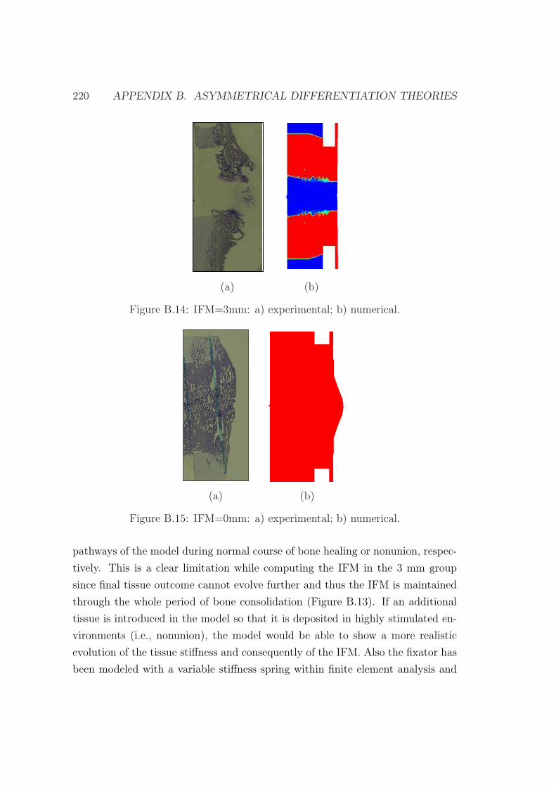
220 APPENDIX B. ASYMMETRICAL DIFFERENTIATION THEORIES
(a) (b)
Figure B.14: IFM=3mm: a) experimental; b) numerical.
(a) (b)
Figure B.15: IFM=0mm: a) experimental; b) numerical.
pathways of the model during normal course of bone healing or nonunion, respec-
tively. This is a clear limitation while computing the IFM in the 3 mm group
since final tissue outcome cannot evolve further and thus the IFM is maintained
through the whole period of bone consolidation (Figure B.13). If an additional
tissue is introduced in the model so that it is deposited in highly stimulated en-
vironments (i.e., nonunion), the model would be able to show a more realistic
evolution of the tissue stiffness and consequently of the IFM. Also the fixator has
been modeled with a variable stiffness spring within finite element analysis and
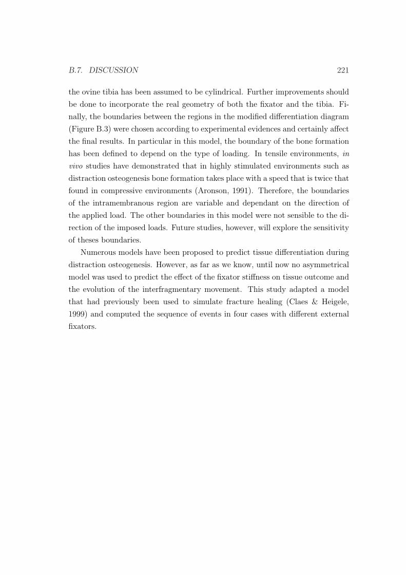
B.7. DISCUSSION 221
the ovine tibia has been assumed to be cylindrical. Further improvements should
be done to incorporate the real geometry of both the fixator and the tibia. Fi-
nally, the boundaries between the regions in the modified differentiation diagram
(Figure B.3) were chosen according to experimental evidences and certainly affect
the final results. In particular in this model, the boundary of the bone formation
has been defined to depend on the type of loading. In tensile environments, in
vivo studies have demonstrated that in highly stimulated environments such as
distraction osteogenesis bone formation takes place with a speed that is twice that
found in compressive environments (Aronson, 1991). Therefore, the boundaries
of the intramembranous region are variable and dependant on the direction of
the applied load. The other boundaries in this model were not sensible to the di-
rection of the imposed loads. Future studies, however, will explore the sensitivity
of theses boundaries.
Numerous models have been proposed to predict tissue differentiation during
distraction osteogenesis. However, as far as we know, until now no asymmetrical
model was used to predict the effect of the fixator stiffness on tissue outcome and
the evolution of the interfragmentary movement. This study adapted a model
that had previously been used to simulate fracture healing (Claes & Heigele,
1999) and computed the sequence of events in four cases with different external
fixators.

222 APPENDIX B. ASYMMETRICAL DIFFERENTIATION THEORIES
Bibliography
Aarnes, G. T., Steen, H., Kristiansen, L. P., Ludvigsen, P. & Reikeras, O. (2002).
Tissue response during monofocal and bifocal leg lengthening in patients. J
Orthop Res. 20, 137–41.
Abbott, L. C. (1927). The operative lengthening of the tibia and fibula. J Bone
Joint Surg. 9, 128–152.
Abbott, L. C. & Saunders, J. B. (1939). The operative lengthening of the tibia
and fibula. A preliminary report on the further development of the principles
and technique. Ann Surg. 110, 961–991.
Adams, M. A., Burton, K., Bogduk, N. & Dolan, P. (2006). The Biomechanics
of Back Pain. Elsevier Health Sciences, ISBN 0443100683.
Aerssens, J., Boonen, S., Lowet, G. & Dequeker, J. (1998). Interspecies differences
in bone composition, density, and quality: potential implications for in vivo
bone research. Endocrinology. 139, 663–70.
Akizuki, S., Mow, V. C., Muller, F., Pita, J. C., Howell, D. S. & Manicourt, D. H.
(1986). Tensile properties of human knee joint cartilage: I. Influence of ionic
conditions, weight bearing, and fibrillation on the tensile modulus. J Orthop
Res. 4, 379–9.
al Ruhaimi, K. A. (2001). Comparison of different distraction rates in the
mandible: an experimental investigation. Int J Oral Maxillofac Surg. 30, 220–
227.
223
224 BIBLIOGRAPHY
Alastrue, V., Pena, E., Martınez, M. A. & Doblare, M. (2007). Assessing the use
of the “opening angle method” to enforce residual stresses in patient-specific
arteries. Ann Biomed Eng. 35, 1821–37.
Aldegheri, R., DeBastiani, G. & Renzi-Brivio, L. (1985). Allungamento diafisario
dell’arto inferiore. Chir Ozgani Mov. 70, 111.
Aldegheri, R., Trivella, G. & Lavini, F. (1989). Epiphyseal distraction. Hemi-
chondrodiatasis. Clin Orthop Relat Res. 241, 128–36.
Altman, G. H., Horan, R. L., Martin, I., Farhadi, J., Stark, P. R., Volloch,
V., Richmond, J. C., Vunjak-Novakovic, G. & Kaplan, D. L. (2002). Cell
differentiation by mechanical stress. FASEB J. 16, 270–2.
Ament, C. & Hofer, E. P. (1996). On the importance of the osteogenic and
vasculative factors in callus healing. In Proceedings of the 5th Meeting of the
International Society for Fracture Repair.
Ament, C. & Hofer, E. P. (2000). A fuzzy logic model of fracture healing. J
Biomech. 33, 961–8.
Anderson, R. (1936). Femoral bone lengthening. Am. J. Surg. 31, 479–483.
Andreykiv, A., van Keulen, F. & Prendergast, P. J. (2007). Simulation of fracture
healing incorporating mechanoregulation of tissue differentiation and disper-
sal/proliferation of cells. Biomech Model Mechanobiol, 7, 443–461.
Armstrong, C. G. & Mow, V. C. (1982). Variations in the intrinsic mechani-
cal properties of human articular cartilage with age, degeneration, and water
content. J Bone Joint Surg Am. 64, 88–94.
Aronson, J. (1991). The biology of distraction osteogenesis. In: Maiocchi
AB, Aronson J, editors, Operative Principles of Ilizarov. Fracture Treat-
ment, Nonunion, Osteomyelitis, Lengthening, Deformity Correction. Balti-
more, Williams and Wilkins.
Aronson, J. (1993). Temporal and spatial increases in blood flow during distrac-
tion osteogenesis. Clin Orthop Relat Res. 301, 124–131.

BIBLIOGRAPHY 225
Aronson, J. (1994). Experimental and clinical experience with distraction osteo-
genesis. Cleft Palate Craniofac J. 31, 473–81.
Aronson, J. (1997). Limb-lengthening, skeletal reconstruction, and bone transport
with the Ilizarov method. J Bone Joint Surg Am. 79, 1243–58.
Aronson, J., Gao, G. G., Shen, X. C., McLaren, S. G., Skinner, R. A., Bad-
ger, T. M. & Lumpkin, C. K. J. (2001). The effect of aging on distraction
osteogenesis in the rat. J Orthop Res. 19, 421–7.
Aronson, J., Good, B., Stewart, C., Harrison, B. & Harp, J. (1990). Preliminary
studies of mineralization during distraction osteogenesis. Clin Orthop Relat
Res. 250, 43–9.
Aronson, J., Harrison, B., Stewart, C. & Harp, J. (1989). The histology of
distraction osteogenesis using different external fixators. Clin Orthop Relat
Res. 241, 106–16.
Aronson, J. & Shen, X. (1994). Experimental healing of distraction osteogenesis
comparing metaphyseal and diaphyseal sites. Clin Orthop Rel Res. 301, 25–30.
Aronson, J., Shen, X. C., Gao, G. G., Miller, F., Quattlebaum, T., Skinner,
R. A., Badger, T. M. & Lumpkin, C. K. J. (1997a). Sustained proliferation
accompanies distraction osteogenesis in the rat. J Orthop Res. 15, 563–9.
Aronson, J., Shen, X. C., Skinner, R. A., Hogue, W. R., Badger, T. M. & Lump-
kin, C. K. J. (1997b). Rat model of distraction osteogenesis. J Orthop Res.
15(2), 221–6.
Asahina, I., Sampath, T. K., Nishimura, I. & Hauschka, P. V. (1993). Human os-
teogenic protein-1 induces both chondroblastic and osteoblastic differentiation
of osteoprogenitor cells derived from newborn rat calvaria. J Cell Biol. 123,
921–33.
Aston, J. W. J., Williams, S. A., Allard, R. N., Sawamura, S. & Carollo, J. J.
(1992). A new canine cruciate ligament formed through distraction histogenesis.
Report of a pilot study. Clin Orthop Relat Res. 280, 30–6.
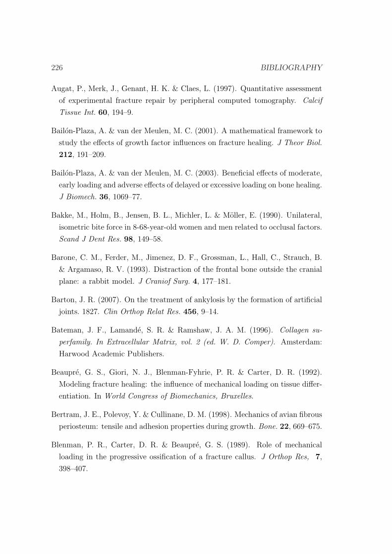
226 BIBLIOGRAPHY
Augat, P., Merk, J., Genant, H. K. & Claes, L. (1997). Quantitative assessment
of experimental fracture repair by peripheral computed tomography. Calcif
Tissue Int. 60, 194–9.
Bailon-Plaza, A. & van der Meulen, M. C. (2001). A mathematical framework to
study the effects of growth factor influences on fracture healing. J Theor Biol.
212, 191–209.
Bailon-Plaza, A. & van der Meulen, M. C. (2003). Beneficial effects of moderate,
early loading and adverse effects of delayed or excessive loading on bone healing.
J Biomech. 36, 1069–77.
Bakke, M., Holm, B., Jensen, B. L., Michler, L. & Moller, E. (1990). Unilateral,
isometric bite force in 8-68-year-old women and men related to occlusal factors.
Scand J Dent Res. 98, 149–58.
Barone, C. M., Ferder, M., Jimenez, D. F., Grossman, L., Hall, C., Strauch, B.
& Argamaso, R. V. (1993). Distraction of the frontal bone outside the cranial
plane: a rabbit model. J Craniof Surg. 4, 177–181.
Barton, J. R. (2007). On the treatment of ankylosis by the formation of artificial
joints. 1827. Clin Orthop Relat Res. 456, 9–14.
Bateman, J. F., Lamande, S. R. & Ramshaw, J. A. M. (1996). Collagen su-
perfamily. In Extracellular Matrix, vol. 2 (ed. W. D. Comper). Amsterdam:
Harwood Academic Publishers.
Beaupre, G. S., Giori, N. J., Blenman-Fyhrie, P. R. & Carter, D. R. (1992).
Modeling fracture healing: the influence of mechanical loading on tissue differ-
entiation. In World Congress of Biomechanics, Bruxelles.
Bertram, J. E., Polevoy, Y. & Cullinane, D. M. (1998). Mechanics of avian fibrous
periosteum: tensile and adhesion properties during growth. Bone. 22, 669–675.
Blenman, P. R., Carter, D. R. & Beaupre, G. S. (1989). Role of mechanical
loading in the progressive ossification of a fracture callus. J Orthop Res, 7,
398–407.
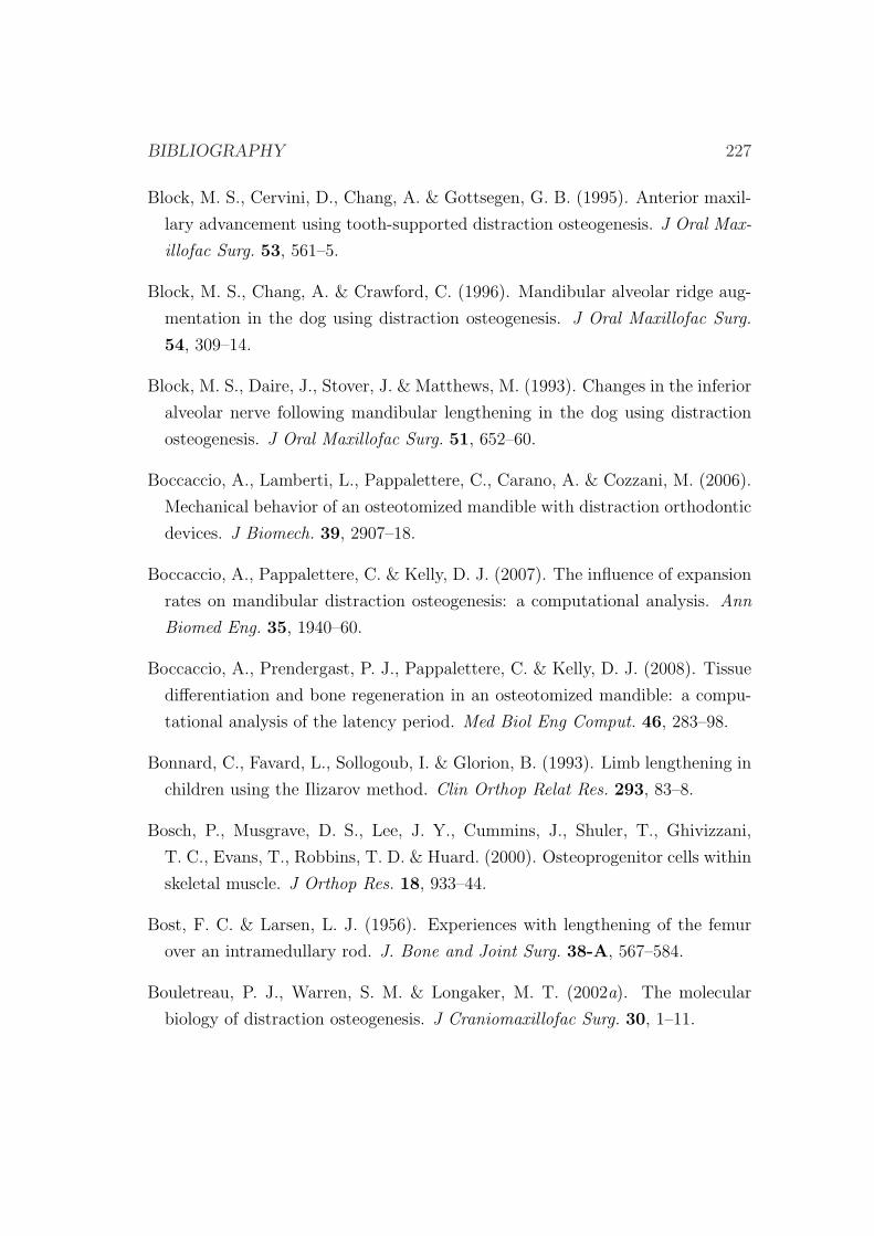
BIBLIOGRAPHY 227
Block, M. S., Cervini, D., Chang, A. & Gottsegen, G. B. (1995). Anterior maxil-
lary advancement using tooth-supported distraction osteogenesis. J Oral Max-
illofac Surg. 53, 561–5.
Block, M. S., Chang, A. & Crawford, C. (1996). Mandibular alveolar ridge aug-
mentation in the dog using distraction osteogenesis. J Oral Maxillofac Surg.
54, 309–14.
Block, M. S., Daire, J., Stover, J. & Matthews, M. (1993). Changes in the inferior
alveolar nerve following mandibular lengthening in the dog using distraction
osteogenesis. J Oral Maxillofac Surg. 51, 652–60.
Boccaccio, A., Lamberti, L., Pappalettere, C., Carano, A. & Cozzani, M. (2006).
Mechanical behavior of an osteotomized mandible with distraction orthodontic
devices. J Biomech. 39, 2907–18.
Boccaccio, A., Pappalettere, C. & Kelly, D. J. (2007). The influence of expansion
rates on mandibular distraction osteogenesis: a computational analysis. Ann
Biomed Eng. 35, 1940–60.
Boccaccio, A., Prendergast, P. J., Pappalettere, C. & Kelly, D. J. (2008). Tissue
differentiation and bone regeneration in an osteotomized mandible: a compu-
tational analysis of the latency period. Med Biol Eng Comput. 46, 283–98.
Bonnard, C., Favard, L., Sollogoub, I. & Glorion, B. (1993). Limb lengthening in
children using the Ilizarov method. Clin Orthop Relat Res. 293, 83–8.
Bosch, P., Musgrave, D. S., Lee, J. Y., Cummins, J., Shuler, T., Ghivizzani,
T. C., Evans, T., Robbins, T. D. & Huard. (2000). Osteoprogenitor cells within
skeletal muscle. J Orthop Res. 18, 933–44.
Bost, F. C. & Larsen, L. J. (1956). Experiences with lengthening of the femur
over an intramedullary rod. J. Bone and Joint Surg. 38-A, 567–584.
Bouletreau, P. J., Warren, S. M. & Longaker, M. T. (2002a). The molecular
biology of distraction osteogenesis. J Craniomaxillofac Surg. 30, 1–11.
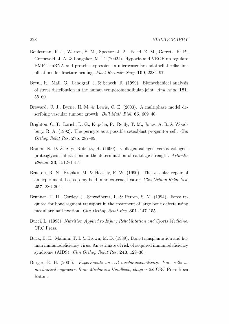
228 BIBLIOGRAPHY
Bouletreau, P. J., Warren, S. M., Spector, J. A., Peled, Z. M., Gerrets, R. P.,
Greenwald, J. A. & Longaker, M. T. (2002b). Hypoxia and VEGF up-regulate
BMP-2 mRNA and protein expression in microvascular endothelial cells: im-
plications for fracture healing. Plast Reconstr Surg. 109, 2384–97.
Breul, R., Mall, G., Landgraf, J. & Scheck, R. (1999). Biomechanical analysis
of stress distribution in the human temporomandibular-joint. Ann Anat. 181,
55–60.
Breward, C. J., Byrne, H. M. & Lewis, C. E. (2003). A multiphase model de-
scribing vascular tumour growth. Bull Math Biol. 65, 609–40.
Brighton, C. T., Lorich, D. G., Kupcha, R., Reilly, T. M., Jones, A. R. & Wood-
bury, R. A. (1992). The pericyte as a possible osteoblast progenitor cell. Clin
Orthop Relat Res. 275, 287–99.
Broom, N. D. & Silyn-Roberts, H. (1990). Collagen-collagen versus collagen-
proteoglycan interactions in the determination of cartilage strength. Arthritis
Rheum. 33, 1512–1517.
Brueton, R. N., Brookes, M. & Heatley, F. W. (1990). The vascular repair of
an experimental osteotomy held in an external fixator. Clin Orthop Relat Res.
257, 286–304.
Brunner, U. H., Cordey, J., Schweiberer, L. & Perren, S. M. (1994). Force re-
quired for bone segment transport in the treatment of large bone defects using
medullary nail fixation. Clin Orthop Relat Res. 301, 147–155.
Bucci, L. (1995). Nutrition Applied to Injury Rehabilitation and Sports Medicine.
CRC Press.
Buck, B. E., Malinin, T. I. & Brown, M. D. (1989). Bone transplantation and hu-
man immunodeficiency virus. An estimate of risk of acquired immunodeficiency
syndrome (AIDS). Clin Orthop Relat Res. 240, 129–36.
Burger, E. H. (2001). Experiments on cell mechanosensitivity: bone cells as
mechanical engineers. Bone Mechanics Handbook, chapter 28. CRC Press Boca
Raton.
BIBLIOGRAPHY 229
Burr, D. B., Milgrom, C., Fyhrie, D., Forwood, M., Nyska, M., Finestone, A.,
Hoshaw, S., Saiag, E. & Simkin, A. (1996). In vivo measurement of human
tibial strains during vigorous activity. Bone. 18, 405–10.
Burrill, A. M. (1998). A New Law Dictionary and Glossary. The Lawbook
Exchange.
Calhoun, J. H., Evans, E. B. & Herndon, D. N. (1992a). Techniques for the
management of burn contractures with the Ilizarov fixator. Clin Orthop Relat
Res. 280, 117–24.
Calhoun, J. H., Li, F., Ledbetter, B. R. & Gill, C. A. (1992b). Biomechanics of
the Ilizarov fixator for fracture fixation. Clin Orthop Relat Res. 280, 15–22.
Canadell, J. (1993). Bone lengthening: experimental results. J Pediatr Orthop
B. 2, 8–10.
Canadell, J., Gonzales, F., Barrios, R. H. & Amillo, S. (1993). Arthrodiastasis
for stiff hips in young patients. Int Orthop. 17, 254–8.
Caplan, A. I. & Boyan, B. D. (1994). Bone volume 8, mechanisms of bone develop-
ment and growth, Chapter: Endochondral bone formation: the lineage cascade.
CRC, Press.
Cara del Rosal, J. A. (1992). Influencia de la vascularizacion sobre el callo de
elongacion. PhD thesis, Universidad de Navarra.
Carter, D. R. (1987). Mechanical loading history and skeletal biology. J Biomech.
20, 1095–109.
Carter, D. R. & Beaupre, G. S. (2001). Skeletal Function and Form: Mechanobi-
ology of Skeletal Development Aging, and Regeneration. Cambridge University
Press, ISBN 052179000X.
Carter, D. R., Beaupre, G. S., Giori, N. J. & Helms, J. A. (1998). Mechanobiology
of skeletal regeneration. Clin Orthop Relat Res. 355S, S41–S55.
Carter, D. R. & Hayes, W. C. (1977). The compressive behavior of bone as a
two-phase porous structure. J Bone Joint Surg Am. 59, 954–62.
230 BIBLIOGRAPHY
Castaneda, S., Largo, R., Calvo, E., Rodrıguez-Salvanes, F., Marcos, M. E., Dıaz-
Curiel, M. & Herrero-Beaumont, G. (2006). Bone mineral measurements of
subchondral and trabecular bone in healthy and osteoporotic rabbits. Skeletal
Radiol. 35, 34–41.
Catagni, M. A., Guerreschi, F., Holman, J. A. & Cattaneo, R. (1994). Distraction
osteogenesis in the treatment of stiff hypertrophic nonunions using the Ilizarov
apparatus. Clin Orthop Relat Res. 301, 159–63.
Cattaneo, P. M., Kofod, T., Dalstra, M. & Melsen, B. (2005). Using the Finite
Element Method to model the biomechanics of the asymmetric mandible be-
fore, during and after skeletal correction by distraction osteogenesis. Comput
Methods Biomech Biomed Engin. 8, 157–65.
Charlebois, M., Mckee, M. D. & Buschmann, M. D. (2004). Nonlinear tensile
properties of bovine articular cartilage and their variation with age and depth.
J Biomech Eng. 126, 129–137.
Cheal, E. J., Mansmann, K. A., DiGioia, A. M., Hayes, W. C. & Perren, S. M.
(1991). Role of interfragmentary strain in fracture healing: ovine model of a
healing osteotomy. J Orthop Res. 9, 131–42.
Chen, Y. & Hoger, A. (2000). Constitutive functions for elastic materials in finite
growth and deformation. J Elast. 59, 175–193.
Chin, M. (1997). Alveolar process reconstruction using distraction osteogenesis.
In International congress on Cranial and Facial Bone Distraction Processes,
Paris, France.
Chin, M. & Toth, B. A. (1996). Distraction osteogenesis in maxillofacial surgery
using internal devices: review of five cases. J Oral Maxillofac Surg. 54, 45–53.
Choi, I. H., Ahn, J. H., Chung, C. Y. & Cho, T. J. (2000). Vascular prolifer-
ation and blood supply during distraction osteogenesis: a scanning electron
microscopic observation. J Orthop Res. 18, 698–705.
BIBLIOGRAPHY 231
Choi, I. H., Shim, J. S., Seong, S. C., Lee, M. C., Song, K. Y., Park, S. C.,
Chung, C. Y., Cho, T. J. & Lee, D. Y. (1997). Effect of the distraction rate on
the activity of the osteoblast lineage in distraction osteogenesis of rat’s tibia.
Immunostaining study of the proliferating cell nuclear antigen, osteocalcin, and
transglutaminase C. Bull Hosp Jt Dis. 56, 34–40.
Choi, P., Ogilvie, C., Thompson, T., Miclau, T. & Helms, J. H. (2004). Cellular
and molecular characterization of a murine non-union model. J Orthop Res.
22, 1100–1107.
Chuong, C. J. & Fung, Y. C. (1986). On residual stresses in arteries. J Biomech
Eng. 108, 189–92.
Cierny, G. r. & Zorn, K. E. (1994). Segmental tibial defects. comparing conven-
tional and Ilizarov methodologies. Clin Orthop Relat Res. 301, 118–23.
Claes, L., Augat, P., Suger, G. & Wilke, H. J. (1997). Influence of size and
stability of the osteotomy gap on the success of fracture healing. Orthop Res.
15, 577–84.
Claes, L., Laule, J., Wenger, K., Suger, G., Liener, U. & Kinzl, L. (2000). The
influence of stiffness of the fixator on maturation of callus after segmental
transport. J Bone Joint Surg Br. 82, 142–8.
Claes, L. E. & Heigele, C. A. (1999). Magnitudes of local stress and strain along
bony surfaces predict the course and type of fracture healing. J Biomech. 32,
255–266.
Claes, L. E., Heigele, C. A., Neidlinger-Wilke, C., Kaspar, D., Seidl, W., Margevi-
cius, K. J. & Augat, P. (1998). Effects of mechanical factors on the fracture
healing process. Clin Orthop Relat Res. 355S, S132–S147.
Claes, L. E., Wilke, H. J., Augat, P., Rubenacker, S. & Margevicius, K. J. (1995).
Effect of dynamization on gap healing of diaphyseal fractures under external
fixation. Clin Biomech. 10, 227–234.
Codivilla, A. (1905). On the means of lengthening, in the lower limbs, the muscles
and tissues which are shortened through deformity. Am J Orthop Surg. 2, 353.
232 BIBLIOGRAPHY
Converse, J. M., Coccaro, P. J., Becker, M. & Wood-Smith, D. (1973). On
hemifacial microsomia. The first and second branchial arch syndrome. Plast
Reconstr Surg. 51, 268–79.
Cope, J. B., Samchukov, M. L. & Cherkashin, A. M. (1999). Mandibular distrac-
tion osteogenesis: a historic perspective and future directions. Am J Orthod
Dentofac Orthop. 115, 448–60.
Cowin, S. C. (1999). Structural changes in living tissues. Meccanica. 34, 379–98.
Cowin, S. C., Moss-Salentijn, L. & Moss, M. L. (1991). Candidates for the
mechanosensory system in bone. J Biomech Eng. 113, 191–7.
Craig, R. G. & Peyton, F. A. (1958). Elastic and mechanical properties of human
dentin. J Dent Res. 37, 710–718.
Cullinane, D. M., Salisbury, K. T., Alkhiary, Y. & Eisenberg, S. (2003). Effects
of the local mechanical environment on vertebrate tissue differentiation during
repair: does repair recapitulate development. J Exp Biol, 206, 2459–2471.
Culmann, K. (1864). Die Graphische Statik. Verlag von Meyer & Zeller, Zurich.
Dahl, M. T. & Fischer, D. A. (1991). Lower extremity lengthening by Wagner’s
method and by callus distraction. Orthop Clin North Am. 22, 643–9.
Dahl, M. T., Gulli, B. & Berg, T. (1994). Complications of limb lengthening. A
learning curve. Clin Orthop Relat Res. 301, 10–8.
Darwin, C. (1859). The origin of species. John Murray.
Davol, A., Bingham, M. S., Sah, R. L. & Klisch, S. M. (2008). A nonlinear finite
element model of cartilage growth. Biomech Model Mechanobiol. 7, 295–307.
De Bari, C., DellAccio, F., Tylzanowski, P. & Luyten, F. P. (2001). Multipo-
tent mesenchymal stem cells from adult human synovial membrane. Arthritis
Rheum. 44, 1928–1942.
De Bastiani, G., Aldegheri, R., Renzi-Brivio, L. & Trivella, G. (1987). Limb
lengthening by callus distraction (callotasis). J Pediatr Orthop. 7, 129–34.
BIBLIOGRAPHY 233
de la Huerta, F. (1994). Correction of the neglected clubfoot by the Ilizarov
method. Clin Orthop Relat Res. 301, 89–93.
de Pablos, J., Barrios, C., Alfaro, C. & Canadell, J. (1994). Large experimen-
tal segmental bone defects treated by bone transportation with monolateral
external distractors. Clin Orthop Relat Res. 298, 259–65.
Delloye, C., Delefortrie, G., Coutelier, L. & Vincent, A. (1990). Bone regenerate
formation in cortical bone during distraction lengthening: an experimental
study. Clin Orthop. 250, 34–42.
DiCarlo, A. & Quiligotti, S. (2002). Growth and balance. Mech Res Commun.
29, 449–456.
Diefenderfer, D. L. & Brighton, C. T. (2000). Microvascular pericytes express ag-
grecan message which is regulated by BMP-2. Biochem Biophys Res Commun.
269, 172–178.
Doblare, M. & Garcıa-Aznar, J. M. (2006). On numerical modelling of growth,
differentiation and damage in structural living tissues. Arch Comput Methods
Eng. 13, 471–513.
dos Santos, J. J. (1995). Supportive conservative therapies for temporomandibu-
lar disorders. Dent Clin North Am, 39, 459–77.
Duda, G., Eckert-Hubner, K., Sokiranski, R., Kreutner, A., Miller, R. & Claes, L.
(1998). Analysis of inter-fragmentary movement as a function of musculoskele-
tal loading conditions in sheep. J Biomech. 31, 201–210.
Duda, G. N., Sporrer, S., Sollmann, M., Hoffmann, J. E., Kassi, J. P., Kho-
dadadyan, C. & Raschke, M. (2003). Interfragmentary movements in the early
phase of healing in distraction and correction osteotomies stabilized with ring
fixators. Langenbecks Arch Surg, 387, 433–40.
Ehrlich, P. J. & Lanyon, L. E. (2002). Mechanical strain and bone cell function:
a review. Osteoporos Int, 13, 688–700.
Enlow, D. H. (1990). Facial growth. Ed 3, Philadelphia, WB Saunders.
234 BIBLIOGRAPHY
Epstein, M. & Maugin, G. A. (2000). Thermomechanics of volumetric growth in
uniform bodies. Int J Plast. 16, 951–978.
Eroschenko, V. P. & di Fiore, M. S. H. (2007). DiFiore’s Atlas of Histology with
Functional Correlations. Lippincott Williams & Wilkins, ISBN 0781770572.
Fang, T. D., Salim, A., Xia, W., Nacamuli, R. P., Guccione, S., Song, H. M.,
Carano, R. A., Filvaroff, E. H., Bednarski, M. D., Giaccia, A. J. & Longaker,
M. T. (2005). Angiogenesis is required for successful bone induction during
distraction osteogenesis. J Bone Miner Res. 20, 1114–24.
Farhadieh, R. H., Gianoutsos, M. P., Dickinson, R. & Walsh, W. R. (2000). Effect
of distraction rate on biomechanical , mineralization, and histologic properties
of an ovine mandible model. Plast Reconstr Surg. 105, 889–895.
Farquhar, T., Dawson, P. R. & Torzilli, P. A. (1990). A microstructural model
for the anisotropic drained stiffness of articular cartilage. J. Biomech. Eng.
112, 414–425.
Fink, B., Pollnau, C., Vogel, M., Skripitz, R. & Enderle, A. (2003). Histomor-
phometry of distraction osteogenesis during experimental tibial lengthening. J
Orthop Trauma. 17, 113–8.
Finn, R. A. (1978). Relationship of vertical maxillary dysplasias, bite force, and
integrated EMG. In Abstracts of Conference on Craniofacial Research. Center
for human Growth and Development. University of Michigan, Ann Arbor.
Fischgrund, J., Paley, D. & Suter, C. (1994). Variables affecting time to bone
healing during limb lengthening. Clin Orthop Relat Res. 301, 31–7.
Fonseca, R. J. (2000). Oral and maxillofacial surgery. Elsevier Health Sciences,
ISBN 0721696317.
Forriol, F., Goenaga, I., Mora, G., Vinolas, J. & Canadell, J. (1997). Measurement
of bone lengthening forces; an experimental model in the lamb. Clin Biomech.
12, 17–21.
BIBLIOGRAPHY 235
Frierson, M., Ibrahim, K., Boles, M., Bote, H. & Ganey, T. (1994). Distraction
osteogenesis: a comparison of corticotomy techniques. Clin Orthop. 301, 19–24.
Frost, H. M. (1963). Bone remodeling dynamics. Charles C. Thomas, Springfield,
IL.
Frost, H. M. (1998). A brief review for orthopedic surgeons: fatigue damage
(microdamage) in bone (its determinants and clinical implications). J Orthop
Sci. 3, 272–81.
Fung, Y. C. (1984). Biodynamics: Circulation. New York: Springer-Verlag.
Fung, Y. C. (1985). What principle governs the stress distribution in living or-
gans? in Fung YC, Fukada E, Wang JJ (eds): Biomechanics in China, Japan,
and USA. Beijing, China, Science press.
Fung, Y. C. (1990a). Biomechanics: Motion, Flow, Stress, and Growth. New
York: Springer-Verlag.
Fung, Y. C. (1990b). Biomechanics: Mechanical Properties of Living Tissues.
Springer, Berlin.
Fung, Y. C. (1993). Biomechanics: Mechanical Properties of Living Tissues,
Second edition. Springer Verlag, New York.
Ganey, T. M., Klotch, D. W., Sasse, J., Ogden, J. A. & Garcia, T. (1994).
Basement membrane of blood vessels during distraction osteogenesis. Clin
Orthop Relat Res. 301, 132–8.
Garcıa-Aznar, J. M., Kuiper, J. H., Gomez-Benito, M. J., Doblare, M. & Richard-
son, J. B. (2007). Computational simulation of fracture healing: influence of
interfragmentary movement on the callus growth. J Biomech. 40, 1467–1476.
Gardner, M. J., van der Meulen, M. C., Demetrakopoulos, D., Wright, T. M.,
Myers, E. R. & Bostrom, M. P. (2006). In vivo cyclic axial compression affects
bone healing in the mouse tibia. J Orthop Res, 24, 1679–1686.

236 BIBLIOGRAPHY
Gardner, T. N., Evans, M., Simpson, H. & Kenwright, J. (1998). Force-
displacement behaviour of biological tissue during distraction osteogenesis. Med
Eng Phys. 20, 708–15.
Gardner, T. N. & Mishra, S. (2003). The biomechanical environment of a bone
fracture and its influence upon the morphology of healing. Med Eng Phys. 25,
455–464.
Garikipati, K., Arruda, E. M., Grosh, K., Narayanan, H. & Calve, S. (2004).
A continuum treatment of growth in biological tissue: the coupling of mass
transport and mechanics. J Mech Phys Solids. 52, 1595–1625.
Gateno, J., Teichgraeber, J. F. & Aguilar, E. (2000). Computer planning for
distraction osteogenesis. Plast Reconstr Surg. 105, 873–82.
Gebhardt, W. (1901). lber funktionell wichtige Anordnungsweisen der groberen
und feineren Bauelemente des Wirbeltierknochens. I, Allgemeiner Teil. Wilhelm
Roux’ Arch Entwickl Mech Org, 11, 383–498.
Geris, L., Andreykiv, A., Van Oosterwyck, H., Vander Sloten, J., van Keulen,
F., Duyck, J. & Naert, I. (2004). Numerical simulation of tissue differentiation
around loaded titanium implants in a bone chamber. J Biomech. 37, 763–769.
Geris, L., Gerisch, A., Maes, C., Carmeliet, G., Weiner, R., Vander Sloten, J.
& Van Oosterwyck, H. (2006). Mathematical modeling of fracture healing in
mice: comparison between experimental data and numerical simulation results.
Med Biol Eng Comput, 44, 280–9.
Geris, L., Gerisch, A., Sloten, J. V., Weiner, R. & Oosterwyck, H. V. (2008).
Angiogenesis in bone fracture healing: a bioregulatory model. J Theor Biol,
251, 137–58.
Geris, L., Van Oosterwyck, H., Vander Sloten, J., Duyck, J. & Naert, I. (2003).
Assessment of mechanobiological models for the numerical simulation of tissue
differentiation around immediately loaded implants. Comput Methods Biomech
Biomed Engin, 6, 277–88.
BIBLIOGRAPHY 237
Geris, L., Vandamme, K., Naert, I., Vander Sloten, J., Duyck, J. & Van Ooster-
wyck, H. (2009). Numerical simulation of bone regeneration in a bone chamber.
J Dent Res, 88, 158–63.
Geris, L., Vander Sloten, J. & Van Oosterwyck, H. (2008). Mathematical mod-
elling of bone regeneration including angiogenesis: design of treatment strate-
gies for atrophic nonunions. In Transactions of the 54th Annual Meeting of the
Orthopaedic Research Society, New Orleans.
Gerstenfeld, L. C., Culliname, D. M., Barnes, G. L., Graves, D. T. & Einhorn,
T. A. (2003). Fracture healing as a post-natal development process: molecular,
spatial, and temporal aspects of its regulation. J Cell Biochem. 88, 873–884.
Gil-Albarova, J., de Pablos, J., Franzeb, M. & Canadell, J. (1992). Delayed
distraction in bone lengthening. Improved healing in lambs. Acta Orthop Scand.
63, 604–6.
Glowacki, J. & Mulliken, J. B. (1985). Demineralized bone implants. Clin Plast
Surg. 12, 233–41.
Golyakhovsky, V. & Frankel, V. H. (1991). Ilizarov bone transport in large bone
loss and in severe osteomyelitis. Bull Hosp Jt Dis Orthop Inst. 51, 63–73.
Gomez-Benito, M. J., Fornells, P., Garcıa-Aznar, J. M., Seral, B., Seral-Inigo, F.
& Doblare, M. (2007). Computational comparison of reamed versus unreamed
intramedullary tibial nails. J Orthop Res. 25, 191–200.
Gomez-Benito, M. J., Garcıa-Aznar, J. M., Kuiper, J. H. & Doblare, M. (2005).
Influence of fracture gap size on the pattern of long bone healing: a computa-
tional study. J Theor Biol. 235, 105–119.
Gomez-Benito, M. J., Garcıa-Aznar, J. M., Kuiper, J. H. & Doblare, M. (2006).
A 3D computational simulation of fracture callus formation: influence of the
stiffness of the external fixator. J Biomech Eng. 128, 290–299.
Gong, J. K., Arnold, J. S. & Cohn, S. H. (1964). Composition of trabecular and
cortical bone. Anat Rec. 149, 325–31.
238 BIBLIOGRAPHY
Goodman, S., Song, Y., Doshi, A. & Aspenberg, P. (1994). Cessation of strain
facilitates bone formation in the micromotion chamber implanted in the rabbit
tibia. Biomaterials, 15, 889–893.
Goodship, A. E. & Kenwright, J. (1985). The influence of induced micromovement
upon the healing of experimental tibial fractures. J Bone Joint Surg Br. 67,
650–5.
Goodship, A. E., Watkins, P. E., Rigby, H. S. & Kenwright, J. (1993). The role
of fixator frame stiffness in the control of fracture healing. An experimental
study. J Biomech. 26, 1027–35.
Gorlin, R. J., Cohen, M. M. J. & Levin, L. S. (1990). Syndromes of the head and
neck. New York: Oxford University Press.
Grant, A. D., Atar, D. & Lehman, W. B. (1992). The Ilizarov technique in
correction of complex foot deformities. Clin Orthop Relat Res. 280, 94–103.
Graziano, G. P., Herzenberg, J. E. & Hensinger, R. N. (1993). The halo-Ilizarov
distraction cast for correction of cervical deformity. Report of six cases. J Bone
Joint Surg Am. 75, 996–1003.
Green, S. A. (1991). The Ilizarov method: Rancho technique. Orthop Clin North
Am. 22, 677–88.
Green, S. A., Harris, N. L., Wall, D. M., Ishkanian, J. & Marinow, H. (1992).
The Rancho mounting technique for the Ilizarov method. A preliminary report.
Clin Orthop Relat Res. 280, 104–16.
Gregersen, H., Kassab, G. S. & Fung, Y. C. (2000). The zero stress state of the
gastrointestinal tract: biomechanical and functional implications. Dig Dis Sci.
45, 2271–2281.
Griffin, L. V., Gibeling, J. C., Martin, R. B., Gibson, V. A. & Stover, S. M.
(1997). Model of flexural fatigue damage accumulation for cortical bone. J
Orthop Res. 15(4), 607–614.
BIBLIOGRAPHY 239
Guerrero, C. (1990). Expansion mandibular quirurgica. Rev Venez Ortod. 48,
1–2.
Guldberg, R. E., Caldwell, N. J., Guo, X. W., Goulet, R. W., Hollister, S. J. &
Goldstein, S. A. (1997). Mechanical stimulation of tissue repair in the hydraulic
bone chamber. J Bone Miner Res. 12, 1295–302.
Gushue, D. L., Houck, J. & Lerner, A. L. (2005). Rabbit knee joint biomechanics:
motion analysis and modeling of forces during hopping. J Orthop Res. 23, 735–
42.
Habal, M. B. (1994). New bone formation by biological rhythmic distraction. J
Craniofac Surg. 5, 344–7.
Haggland, G., Rydholm, U. & Sunden, G. (1993). Ilizarov technique in the
correction of knee flexion contracture: report of four cases. J Pediatr Orthop
B. 2, 170–172.
Hamanishi, C., Yoshii, T., Totani, Y. & Tanaka, S. (1994). Lengthened callus
activated by axial shortening. Histological and cytomorphometrical analysis.
Clin Orthop Relat Res. 307, 250–4.
Han, H. C. & Fung, Y. C. (1996). Direct measurement of transverse residual
strains in aorta. Am J Physiol. 270, H750–H759.
Harpoon (2006). Sharc Lt. Richard Bardwell. Empress Business Centre. Manch-
ester, UK.
Havlik, R. J. & Bartlett, S. P. (1994). Mandibular distraction lengthening in
the severely hypoplastic mandible: a problematic case with tongue aplasia. J
Craniofac Surg. 5, 305–10.
Heller, O. (1998). Management of Medical Technology: Theory, Practice, and
Cases. Springer, ISBN 0792380541.
Hertling, D. & Kessler, R. M. (2006). Management of Common Musculoskeletal
Disorders: Physical Therapy Principles and Methods. Lippincott Williams &
Wilkins.
240 BIBLIOGRAPHY
Herzenberg, J. E., Davis, J. R., Paley, D. & Bhave, A. (1994a). Mechanical
distraction for treatment of severe knee flexion contractures. Clin Orthop Relat
Res. 301, 80–8.
Herzenberg, J. E., Scheufele, L. L., Paley, D., Bechtel, R. & Tepper, S. (1994b).
Knee range of motion in isolated femoral lengthening. Clin Orthop Relat Res.
301, 49–54.
Herzenberg, J. E., Smith, J. D. & Paley, D. (1994c). Correcting torsional defor-
mities with Ilizarov’s apparatus. Clin Orthop Relat Res. 302, 36–41.
Hibbit, K. & Sorensen, I. (2002). Theory Manual, v. 6.3. HKS inc. Pawtucket,
RI, USA.
Himpel, G., Kuhl, E., Menzel, A. & Steinmann, P. (2005). Computational mod-
elling of isotropic multiplicative growth. Comput Model Eng Sci. 8, 119–134.
Hoger, A. (1997). Virtual configurations and constitutive equations for residually
stressed bodies with material symmetry. J Elast. 48, 125–144.
Holbein, O., Neidlinger-Wilke, C., Suger, G., Kinzl, L. & Claes, L. (1995). Ilizarov
callus distraction produces systemic bone cell mitogens. J Orthop Res. 13, 629–
38.
Hori, R. Y. & Lewis, J. L. (1982). Mechanical properties of the fibrous tissue
found at the bone-cement interface following total joint replacement. J Biomed
Mater Res. 16, 911–27.
Horii, E., Nakamura, R., Nakao, E., Kato, H. & Yajima, H. (2000). Distraction
lengthening of the forearm for congenital and developmental problems. J Hand
Surg [Br]. 25, 15–21.
Huang, C. Y., Mow, V. C. & Ateshian, G. A. (2001). The role of flow-independent
viscoelasticity in the biphasic tensile and compressive responses of articular
cartilage. J Biomech Eng. 123, 410–7.
BIBLIOGRAPHY 241
Huang, Z. (1994). The equilibrium equations and constitutive equations of the
growing deformable body in the framework of continuum theory. Int J Non-
Linear Mech. 39, 951–962.
Humphrey, J. D. (2001). Stress, strain, and mechanotransduction in cells. J
Biomech Eng. 123, 638–641.
Humphrey, J. D. & Rajagopal, K. R. (2003). A constrained mixture model for
arterial adaptations to a sustained step change in blood flow. Biomech Model
Mechanobiol. 2, 109–26.
Hyodo, A., Kotschi, H., Kambic, H. & Muschler, G. (1996). Bone transport using
intramedullary fixation and a single flexible traction cable. Clin Orthop Relat
Res. 325, 256–68.
Idelsohn, S., Planell, J. A., Gil, F. J. & Lacroix, D. (2006). Development of
a dynamic mechano-regulation model based on shear strain and fluid flow to
optimize distraction osteogenesis. J Biomech. 39S, S1–S684.
Ilizarov, G. A. (1952). A method of uniting bones in fractures and an apparatus
to implement this method. In USSR Authorship Certificate 9847 1.
Ilizarov, G. A. (1971). Basic principles of transosseous compression and distrac-
tion osteosynthesis. Ortop Travmatol Protez. 32, 7–15.
Ilizarov, G. A. (1983). Experimental theoretical and clinical aspects of tran-
sosseous osteosynthesis. In Abstracts of the First International Symposium on
Transosseous Osteosynthesis. Medi Surgical Video, Milan, Italy, pp. 17.
Ilizarov, G. A. (1988). The principles of the Ilizarov method. Bull Hosp Jt Dis
Orthop Inst. 48, 1.
Ilizarov, G. A. (1989a). The tension-stress effect on the genesis and growth of
tissues. Part I: the influence of stability of fixation and soft-tissue preservation.
Clin Orthop. 238, 249–81.
242 BIBLIOGRAPHY
Ilizarov, G. A. (1989b). The tension-stress effect on the genesis and growth of
tissues. Part II: the influence of the rate and frequency of distraction. Clin
Orthop. 239, 263–85.
Ilizarov, G. A. (1990). Clinical application of the tension-stress effect for limb
lengthening. Clin Orthop Relat Res. 250, 8–26.
Ilizarov, G. A. (1992). Transosseous Osteosynthesis. Heidelberg: Springer-Verlag.
Ilizarov, G. A. & Gracheva, V. I. (1971). Bloodless treatment of congenital
pseudoarthrosis of the crus with simultaneous elimination of shortening using
dosed distraction. Orthop Traumatol Protez. 32, 42–6.
Ilizarov, G. A., Kaplunov, A. G., Degtiarev, V. E. & Lediaev, V. I. (1972). Treat-
ment of pseudarthroses and ununited fractures, complicated by purulent infec-
tion, by the method of compression-distraction osteosynthesis. Ortop Travmatol
Protez. 33, 10–4.
Ilizarov, G. A., Lediaev, V. I. & Degtiarev, V. E. (1973). Operative and bloodless
methods of repairing defects of the long tubular bones in osteomyelitis. Vestn
Khir Im I I Grek. 110, 55–9.
Ilizarov, G. A., Lediaev, V. I. & Shitin, V. P. (1969). The course of compact bone
reparative regeneration in distraction osteosynthesis under different conditions
of bone fragment fixation (experimental study). Eksp Khir Anesteziol. 14,
3–12.
Ilizarov, G. A. & Ledyaev, V. I. (1992). The replacement of long tubular bone
defects by lengthening distraction osteotomy of one of the fragments. 1969.
Clin Orthop Relat Res. 280, 7–10.
Ilizarov, G. A., Schreiner, A. A., Imerlishvili, I. A., Bakhlykov, Y. N., Onirkova,
A. M. & Marterl, I. I. (1983). On the problem of improving osteogenesis
conditions in limb lengthening. In Abstracts of First International Symposium
on Experimental and Clinical Aspects of Transosseous Osteosynthesis, USSR,
20-22.
BIBLIOGRAPHY 243
Ilizarov, G. A. & Soybelman, L. M. (1969). Some clinical and experimental data
concerning lengthening of lower extremities. Exp Khir Arrestar. 14, 27.
Isaksson, H., Comas, O., Van Donkelaar, C. C., Mediavilla, J., Wilson, W.,
Huiskes, R. & Ito, K. (2007). Bone regeneration during distraction osteogenesis:
mechano-regulation by shear strain and fluid velocity. J Biomech. 40, 2002–11.
Isaksson, H., van Donkelaar, C. C., Huiskes, R. & Ito, K. (2008). A mechano-
regulatory bone-healing model incorporating cell-phenotype specific activity. J
Theor Biol. 252, 230–46.
Isaksson, H., Wilson, W., van Donkelaar, C. C., Huiskes, R. & Ito, K. (2006).
Comparison of biophysical stimuli for mechano-regulation of tissue differentia-
tion during fracture healing. J Biomech. 39, 1507–16.
Ishizeki, K., Kuroda, N. & Nawa, T. (1992). Morphological characteristics of
the life cycle of resting cartilage cells in mouse rib investigated in intrasplenic
isografts. Anat Embryol (Berl). 185, 421–30.
Iwaki, A., Jingushi, S., Oda, Y., Izumi, T., Shida, J. I., Tsuneyoshi, M. & Su-
gioka, Y. (1997). Localization and quantification of proliferating cells during
rat fracture repair: detection of proliferating cell nuclear antigen by immuno-
chemistry. J Bone Miner Res. 12, 96–102.
Jaeger, R. J. & Vanitchatchavan, P. (1992). Ground reaction forces during ter-
mination of human gait. J Biomech. 25, 1233–6.
Jazrawi, L. M., Majeska, R. J., Klein, M. L., Kagel, E., Stromberg, L. & Ein-
horn, T. A. (1998). Bone and cartilage formation in an experimental model of
distraction osteogenesis. J Orthop Trauma. 12, 111–6.
Jensen, O. T. (2002). Alveolar Distraction Osteogenesis. Quintessence Pub. Co.,
ISBN 0867154144.
Jin, M., Levenston, M., Frank, E. & Grodzinsky, A. (1999). Regulation of carti-
lage matrix metabolism by dynamic tissue shear strain. Trans Orthop Res Soc.
24, 169.
244 BIBLIOGRAPHY
Jones, C. B., Dewar, M. E., Aichroth, P. M., Crawfurd, E. J. & Emery, R. (1989).
Epiphyseal distraction monitored by strain gauges. Results in seven children.
J Bone Joint Surg Br. 250, 61–72.
Junqueira, L. C. & Carneiro, J. (2005). Basic histology: Text & Atlas. McGraw-
Hill Professional, ISBN 0071440917.
Kallio, T. J., Vauhkonen, M. V., Peltonen, J. I. & Karaharju, E. O. (1994). Early
bone matrix formation during distraction. A biochemical study in sheep. Acta
Orthop Scand. 65, 467–71.
Kane, A. A., Lo, L. J., Christensen, G. E., Vannier, M. W. & Marsh, J. L.
(1997). Relationship between bone and muscles of mastication in hemifacial
microsomia. Plast Reconstr Surg. 99, 990–7.
Kaplan, F. S., Hayes, W. C., Keaveny, T. M., A., B., Einhorn, T. A. & Iannotti,
J. P. (1994). Form and function of bone, in “Orthopaedic Basic Science”.
American Academy of Orthopaedic Surgeons, Columbus, Ohio.
Karp, N. S., Thorne, C. H. M., McCarthy, J. & Sissons, H. (1990). Bone length-
ening in the craniofacial skeleton. Ann Plast Surg. 24, 231–237.
Kelly, D. J. & Prendergast, P. J. (2005). Mechano-regulation of stem cell dif-
ferentiation and tissue regeneration in osteochondral defects. J Biomech. 38,
1413–22.
Kempson, G. E., Tuke, M. A., Dingle, J. T., Barrett, A. J. & Horsfield, P. H.
(1976). The effects of proteolytic enzymes on the mechanical properties of adult
human articular cartilage. Biochim Biophys Acta. 428, 741–760.
Kenwrigh, J. & Goodship, A. E. (1989). Controlled mechanical stimulation in
the treatment of tibial fractures. Clin Orthop Relat Res. 241, 36–47.
Kenwright, J., Spriggins, A. J. & Cunningham, J. L. (1990). Response of the
growth plate to distraction close to skeletal maturity. Is fracture necessary?
Clin Orthop Relat Res. 250, 61–72.

BIBLIOGRAPHY 245
Kenwright, J. & White, S. H. (1993). A historical review of limb lengthening and
bone transport. Injury. 24, S9–19.
Khaleel, A. & Pool, R. D. (2003). (i) Congenital pseudoarthrosis and lengthening.
Curr Orthop. 17, 411–417.
Kiliaridis, S., Kjellberg, H., Wenneberg, B. & Engstrom, C. (1993). The relation-
ship between maximal bite force, bite force endurance, and facial morphology
during growth. A cross-sectional study. Acta Odontol Scand. 51, 323–31.
King, N. S., Liu, Z. J., Wang, L. L., Chiu, I. Y., Whelan, M. F. & Huang, G. J.
(2003). Effect of distraction rate and consolidation period on bone density
following mandibular osteodistraction in rats. Arch Oral Biol. 48, 299–308.
Kirienko, A., Villa, A. & Calhoun, J. H. (2003). Ilizarov Technique for Complex
Foot and Ankle Deformities. Informa Health Care, ISBN 0824747895.
Klapp, R. & Block, W. (1930). Die Knochenbruchbehandlung mit Drahtzugen.
Stuttgart, Ferd Elnke.
Klisch, S. M., Chen, S. S., Sah, R. L. & Hoger, A. (2003). A growth mixture
theory for cartilage with application to growth-related experiments on cartilage
explants. J Biomech Eng. 125, 169–179.
Klisch, S. M., Van Dyke, T. J. & Hoger, A. (2001). A theory of volumetric growth
for compressible elastic biological materials. Math Mech Solids. 6, 551–575.
Kofod, T., Cattaneo, P. M. & Melsen, B. (2005). Three-dimensional finite element
analysis of the mandible and temporomandibular joint on simulated occlusal
forces before and after vertical ramus elongation by distraction osteogenesis. J
Craniofac Surg. 16, 421–9.
Kojimoto, H., Yasui, N., Goto, T., Matsuda, S. & Shimomura, Y. (1988). Bone
lengthening in rabbits by callus distraction. J Bone Joint Surgery Br. 70-B,
543–9.
246 BIBLIOGRAPHY
Komuro, Y., Takato, T., Harii, K. & Yonemara, Y. (1994). The histologic analysis
of distraction osteogenesis of the mandible in rabbits. Plast Reconstr Surg. 94,
152–9.
Korioth, T. W. P., Romilly, D. P. & Hannam, A. G. (1992). Three-dimensional
finite element stress analysis of the dentate human mandible. Am J Phys
Anthropol. 88, 69–96.
Kuhl, E., Menzel, A. & Steinmann, P. (2003). Computational modeling of growth.
Comput Mech. 32, 71–88.
Kuhl, E. & P., S. (2003). Mass- and volumetric-specific views on thermodynamics
for open systems. Proc R Soc London, 459A, 2547–2568.
Lacroix, D. (2000). Simulation of tissue differentiation during fracture healing.
PhD thesis, University of Dublin.
Lacroix, D. & Prendergast, P. J. (2002a). A mechano-regulation model for tissue
differentiation during fracture healing: analysis of gap size and loading. J
Biomech. 35, 1163–1171.
Lacroix, D. & Prendergast, P. J. (2002b). Three-dimensional simulation of frac-
ture repair in the human tibia. Comput Methods Biomech Biomed Eng. 5,
369–76.
Lacroix, D., Prendergast, P. J., Li, G. & Marsh, D. (2002). Biomechanical model
to simulate tissue differentiation and bone regeneration: application to fracture
healing. Med Biol Eng Comput. 40, 14–21.
Lammens, J., Liu, Z., Aerssens, J., Dequeker, J. & Fabry, G. (1998). Distraction
bone healing versus osteotomy healing: a comparative biochemical analysis. J
Bone Miner Res. 13, 279–86.
Lanyon, L. E. (1987). Functional strain in bone tissue as an objective, and
controlling stimulus for adaptive bone remodelling. J Biomech. 20, 1083–93.
Lanyon, L. E. (1993). Osteocytes, strain detection, bone modeling and remodel-
ing. Calcif Tissue Int. 53, S102–6.
BIBLIOGRAPHY 247
Lappa, M. (2005). A CFD level-set method for soft tissue growth: theory and
fundamental equations. J Biomech. 38, 185–90.
Launay, F., Jouve, J. L., Viehweger, E., Guillaume, J. M., Jacquemier, M. &
Bollini, G. (2004). Progressive forearm lengthening with an intramedullary
guidewire in children: report of 10 cases. J Pediatr Orthop. 24, 21–5.
Le, A. X., Miclau, T., Hu, D. & Helms, J. A. (2001). Molecular aspects of healing
in stabilized and non-stabilized fractures. J Orthop Res. 19, 78–84.
Leong, J. C., Ma, R. Y., Clark, J. A., Cornish, L. S. & Yau, A. C. (1979).
Viscoelastic behavior of tissue in leg lengthening by distraction. Clin Orthop
Relat Res. 139, 102–9.
Leong, P. L. & Morgan, E. F. (2008). Measurement of fracture callus material
properties via nanoindentation. Acta Biomater. 4, 1569–75.
Leung, K. S., Taglang, G. & Schnettler, R. (2006). Practice of Intramedullary
Locked Nails: New Developments in Techniques and Applications. Birkhuser,
ISBN 3540253491.
Levick, J. R. (1987). Flow through interstitium and other fibrous matrices. Q.
J. Exp. Physiol. 72, 409–438.
Li, G., Bronk, J. T., An, K. N. & Kelly, P. J. (1987). Permeability of cortical
bone of canine tibiae. Microvascular Res. 34, 302–310.
Li, G., Simpson, A. H. & Triffitt, J. T. (1999). The role of chondrocytes in
intramembranous and endochondral ossification during distraction osteogenesis
in the rabbit. Calcif Tissue Int. 64, 310–7.
Li, G., Simpson, H. R. W., Kenwright, J. & Triffitt, J. T. (1997). Assessment of
cell proliferation in regenerating bone during distraction osteogenesis at differ-
ent distraction rates. J Orthop Res. 15, 765–772.
Li, G., Simpson, H. R. W., Kenwright, J. & Triffitt, J. T. (2000). Tissues formed
during distraction osteogenesis in the rabbit are determined by the distraction

248 BIBLIOGRAPHY
rate: localization of the cells that express the mRNAs and the distribution of
types I and II collagens. Cell Biol Int. 24, 25–33.
Lieberman, J. R. & Friedlaender, G. E. (2005). Bone Regeneration and Repair:
Biology and Clinical Applications. Humana Press, ISBN 0896038475.
Liebschner, M. A. (2004). Biomechanical considerations of animal models used
in tissue engineering of bone. Biomaterials. 25, 1697–714.
Liou, E. J. & Huang, C. S. (1998). Rapid canine retraction through distraction
of the periodontal ligament. Am J Orthod Dentofacial Orthop. 114, 372–82.
Liu, S. Q. & Fung, Y. C. (1988). Zero-stress states of arteries. J Biomech Eng.
110, 82–4.
Lo, C. M., Wang, H. B., Dembo, M. & Wang, Y. L. (2000). Cell movement is
guided by the rigidity of the substrate. Biophys J, 79, 144–152.
Loboa, E. G., Beaupre, G. S. & Carter, D. R. (2001). Mechanobiology of initial
pseudarthrosis formation with oblique fractures. J Orthop Res, 19, 1067–1072.
Loboa, E. G., Fang, T. D., Parker, D. W., Warren, S. M., Fong, K. D., Longaker,
M. T. & Carter, D. R. (2005). Mechanobiology of mandibular distraction
osteogenesis: finite element analyses with a rat model. J Orthop Res. 23,
663–70.
Losken, H. W., Mooney, M. P., Zoldos, J., Tschakaloff, A., Burrows, A. M., Smith,
T. D., Cooper, G. M., Kapucu, M. R. & Siegel, M. I. (1998). Internal calvarial
bone distraction in rabbits with delayed-onset coronal suture synostosis. Plast
Reconstr Surg. 102, 1109–19.
Lubarda, V. A. & Hoger, A. (2002). On the mechanics of solids with a growing
mass. Int J Solids Struct. 39, 4627–4664.
Lynch, S. E., Genco, R. J. & Marx, R. E. (2004). Tissue Engineering: Applica-
tions in Maxillofacial Surgery and Periodontics. Quintessence Pub. Co., ISBN
0867153466.
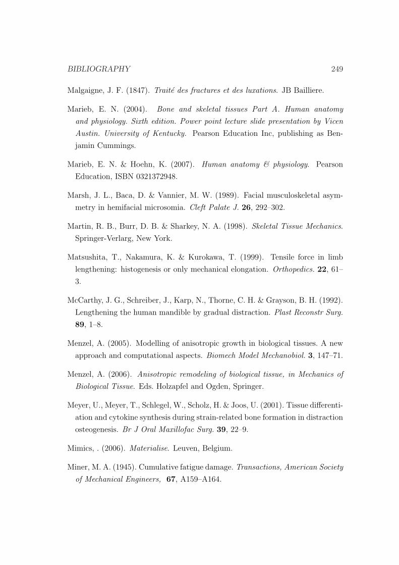
BIBLIOGRAPHY 249
Malgaigne, J. F. (1847). Traite des fractures et des luxations. JB Bailliere.
Marieb, E. N. (2004). Bone and skeletal tissues Part A. Human anatomy
and physiology. Sixth edition. Power point lecture slide presentation by Vicen
Austin. University of Kentucky. Pearson Education Inc, publishing as Ben-
jamin Cummings.
Marieb, E. N. & Hoehn, K. (2007). Human anatomy & physiology. Pearson
Education, ISBN 0321372948.
Marsh, J. L., Baca, D. & Vannier, M. W. (1989). Facial musculoskeletal asym-
metry in hemifacial microsomia. Cleft Palate J. 26, 292–302.
Martin, R. B., Burr, D. B. & Sharkey, N. A. (1998). Skeletal Tissue Mechanics.
Springer-Verlarg, New York.
Matsushita, T., Nakamura, K. & Kurokawa, T. (1999). Tensile force in limb
lengthening: histogenesis or only mechanical elongation. Orthopedics. 22, 61–
3.
McCarthy, J. G., Schreiber, J., Karp, N., Thorne, C. H. & Grayson, B. H. (1992).
Lengthening the human mandible by gradual distraction. Plast Reconstr Surg.
89, 1–8.
Menzel, A. (2005). Modelling of anisotropic growth in biological tissues. A new
approach and computational aspects. Biomech Model Mechanobiol. 3, 147–71.
Menzel, A. (2006). Anisotropic remodeling of biological tissue, in Mechanics of
Biological Tissue. Eds. Holzapfel and Ogden, Springer.
Meyer, U., Meyer, T., Schlegel, W., Scholz, H. & Joos, U. (2001). Tissue differenti-
ation and cytokine synthesis during strain-related bone formation in distraction
osteogenesis. Br J Oral Maxillofac Surg. 39, 22–9.
Mimics, . (2006). Materialise. Leuven, Belgium.
Miner, M. A. (1945). Cumulative fatigue damage. Transactions, American Society
of Mechanical Engineers, 67, A159–A164.
250 BIBLIOGRAPHY
Moore, M. H., Guzman-Stein, G., Proudman, T. W., Abbott, A. H., Netherway,
D. J. & David, D. J. (1994). Mandibular lengthening by distraction for airway
obstruction in treacher-collins syndrome. J Craniofac Surg. 5, 22–5.
Moreo, P., Garcıa-Aznar, J. M. & Doblare, M. (2008). Modeling mechanosens-
ing and its effect on the migration and proliferation of adherent cells. Acta
Biomater, 4, 613–21.
Morgan, E. F., Longaker, M. T. & Carter, D. R. (2006). Relationships between
tissue dilatation and differentiation in distraction osteogenesis. Matrix Biol.
25, 94–103.
Mosheiff, R., Cordey, J., Rahn, B. A., Perren, S. M. & Stein, H. (1996). The
vascular supply to bone in distraction osteoneogenesis: an experimental study.
J Bone Joint Surg Br. 78, 497–8.
Mow, V. C. & Ateshian, G. A. (1997). Friction, Lubrication, and Wear of Di-
arthrodial Joints. In: Basic Orthopaedic Biomechanics, V.C. Mow and W.C.
Hayes (eds). Raven Press, New York, 2nd ed.
Mow, V. C. & Ratcliffe, A. (1997). Structure and function of articular cartilage
and meniscus. In: Mow VC, Hayes WC (eds) Basic orthopaedic biomechanics.
Lippincott-Raven, New York.
Mulder, M., Small, N., Botma, Y., MacKenzie, J. & Ziady, L. (2002). Basic
Principles of Wound Care. Pearson South Africa, ISBN 1868911365.
Murray, J. E., Kaban, L. B. & Mulliken, J. B. (1984). Analysis and treatment of
hemifacial microsomia. Plast Reconstr Surg. 74, 186–99.
Murray, J. H. (1996). Distraction histiogenesis: principles and indications. J Am
Acad Orthop Surg. 4, 317–327.
Naeije, M. & Hofman, N. (2003). Biomechanics of the human temporomandibular
joint during chewing. J Dent Res. 82, 528–31.
BIBLIOGRAPHY 251
Nafei, A., Danielsen, C. C., Linde, F. & Hvid, I. (2000). Properties of growing
trabecular ovine bone. Part I: mechanical and physical properties. J Bone Joint
Surg Br. 82, 910–20.
Nakamura, K., Matsushita, T., Okazaki, H. & Kurokawa, T. (1997). Soft tissue
responses to limb lengthening. J Orthop Sci. 2, 191–197.
Nakase, T., Takaoka, K., Hirakawa, K., Hirota, S., Takemura, T., Onoue, H.,
Takebayashi, K., Kitamura, Y. & Nomura, S. (1994). Alterations in the ex-
pression of osteonectin, osteopontin and osteocalcin mRNAs during the devel-
opment of skeletal tissues in vivo. Bone Miner. 26, 109–22.
Neidlinger Wilke, C., Holbein, O., Grood, E., Morike, M. & Claes, L. (1994).
Effects of cyclic strain on proliferation, metabolic activity and alignment of
human osteoblasts and fibroblasts. In Abstract Book, 40th Annual Meeting,
ORS.
Nelson, G. J. (1986). Three dimensional computer modeling of human mandibular
biomechanics. PhD thesis, University of British Columbia.
Newman, E., Turner, A. S. & Wark, J. D. (1995). The potential of sheep for the
study of osteopenia: current status and comparison with other animal models.
Bone. 16, 277S–284S.
Neyt, J. G., Buckwalter, J. A. & Carroll, N. C. (1998). Use of animal models in
musculoskeletal research. Iowa Orthop J, 18, 118–23.
Ng, K. W., Mauck, R. L., Statman, L. Y., Lin, E. Y., Ateshian, G. A. & Hung,
C. T. (2006). Dynamic deformational loading results in selective application
of mechanical stimulation in a layered, tissue-engineered cartilage construct.
Biorheology. 43, 497–507.
Noth, U., Osyczka, A. M., Tuli, R., Hickok, N. J., Danielson, K. G. & Tuan,
R. S. (2002). Multilineage mesenchymal differentiation potential of human
trabecular bone-derived cells. J Orthop Res. 20, 1060–9.
Ochoa, J. A. & Hillberry, B. M. (1992). Permeability of bovine cancellous bone.
In Transactions of the 38th ORS, Washinton DC.
252 BIBLIOGRAPHY
Ohyama, M., Miyasaka, Y., Sakurai, M., Yokobori, A. J. & Sasaki, S. (1994).
The mechanical behavior and morphological structure of callus in experimental
callotasis. Biomed Mater Eng. 4, 273–81.
Osyczka, A. M., Noth, U., Danielson, K. G. & Tuan, R. S. (2002). Different
osteochondral potential of clonal cell lines derived from adult human trabecular
bone. Ann N Y Acad Sci. 961, 73–77.
Pacifici, M., Golden, E. B., Oshima, O., Shapiro, I. M., Leboy, P. S. & Adams,
S. L. (1990). Hypertrophic chondrocytes. The terminal stage of differentiation
in the chondrogenic cell lineage? Ann N Y Acad Sci. 599, 45–57.
Paley, D. (1988). Current techniques of limb lengthening. J Pediatr Orthop. 8,
73–92.
Paley, D. (1990). Problems, obstacles, and complications of limb lengthening by
the Ilizarov technique. Clin Orthop Relat Res. 250, 81–104.
Paley, D. (1993). The correction of complex foot deformities using Ilizarov’s
distraction osteotomies. Clin Orthop Relat Res. 293, 97–111.
Paley, D., Catagni, M., Argnani, F., Prevot, J., Bell, D. & Armstrong, P. (1992).
Treatment of congenital pseudoarthrosis of the tibia using the Ilizarov tech-
nique. Clin Orthop Relat Res. 280, 81–93.
Paley, D., Catagni, M. A., Argnani, F., Villa, A., Benedetti, G. B. & Cattaneo,
R. (1989). Ilizarov treatment of tibial nonunions with bone loss. Clin Orthop
Relat Res. 241, 146–65.
Paley, D., Fleming, B., Catagni, M., Kristiansen, T. & Pope, M. (1990). Me-
chanical evaluation of external fixators used in limb lengthening. Clin Orthop
Relat Res. 250, 50–7.
Paley, D., Herzenberg, J. E., Paremain, G. & Bhave, A. (1997). Femoral length-
ening over an intramedullary nail. A matched-case comparison with Ilizarov
femoral lengthening. J Bone Joint Surg Am. 79, 1464–80.
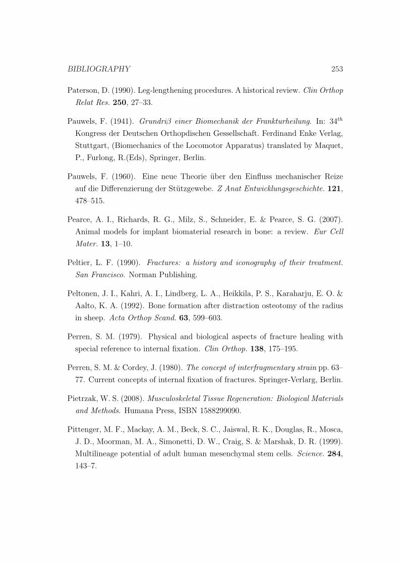
BIBLIOGRAPHY 253
Paterson, D. (1990). Leg-lengthening procedures. A historical review. Clin Orthop
Relat Res. 250, 27–33.
Pauwels, F. (1941). Grundriβ einer Biomechanik der Frankturheilung. In: 34th
Kongress der Deutschen Orthopdischen Gessellschaft. Ferdinand Enke Verlag,
Stuttgart, (Biomechanics of the Locomotor Apparatus) translated by Maquet,
P., Furlong, R.(Eds), Springer, Berlin.
Pauwels, F. (1960). Eine neue Theorie uber den Einfluss mechanischer Reize
auf die Differenzierung der Stutzgewebe. Z Anat Entwicklungsgeschichte. 121,
478–515.
Pearce, A. I., Richards, R. G., Milz, S., Schneider, E. & Pearce, S. G. (2007).
Animal models for implant biomaterial research in bone: a review. Eur Cell
Mater. 13, 1–10.
Peltier, L. F. (1990). Fractures: a history and iconography of their treatment.
San Francisco. Norman Publishing.
Peltonen, J. I., Kahri, A. I., Lindberg, L. A., Heikkila, P. S., Karaharju, E. O. &
Aalto, K. A. (1992). Bone formation after distraction osteotomy of the radius
in sheep. Acta Orthop Scand. 63, 599–603.
Perren, S. M. (1979). Physical and biological aspects of fracture healing with
special reference to internal fixation. Clin Orthop. 138, 175–195.
Perren, S. M. & Cordey, J. (1980). The concept of interfragmentary strain pp. 63–
77. Current concepts of internal fixation of fractures. Springer-Verlarg, Berlin.
Pietrzak, W. S. (2008). Musculoskeletal Tissue Regeneration: Biological Materials
and Methods. Humana Press, ISBN 1588299090.
Pittenger, M. F., Mackay, A. M., Beck, S. C., Jaiswal, R. K., Douglas, R., Mosca,
J. D., Moorman, M. A., Simonetti, D. W., Craig, S. & Marshak, D. R. (1999).
Multilineage potential of adult human mesenchymal stem cells. Science. 284,
143–7.
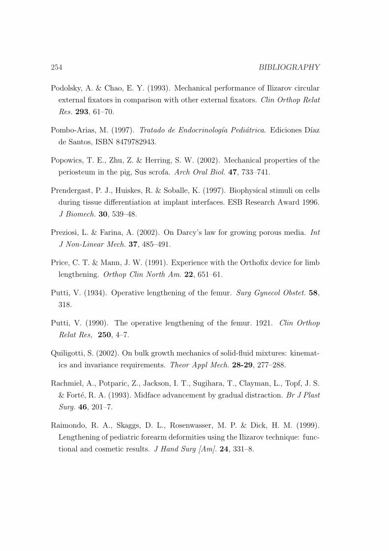
254 BIBLIOGRAPHY
Podolsky, A. & Chao, E. Y. (1993). Mechanical performance of Ilizarov circular
external fixators in comparison with other external fixators. Clin Orthop Relat
Res. 293, 61–70.
Pombo-Arias, M. (1997). Tratado de Endocrinologıa Pediatrica. Ediciones Dıaz
de Santos, ISBN 8479782943.
Popowics, T. E., Zhu, Z. & Herring, S. W. (2002). Mechanical properties of the
periosteum in the pig, Sus scrofa. Arch Oral Biol. 47, 733–741.
Prendergast, P. J., Huiskes, R. & Soballe, K. (1997). Biophysical stimuli on cells
during tissue differentiation at implant interfaces. ESB Research Award 1996.
J Biomech. 30, 539–48.
Preziosi, L. & Farina, A. (2002). On Darcy’s law for growing porous media. Int
J Non-Linear Mech. 37, 485–491.
Price, C. T. & Mann, J. W. (1991). Experience with the Orthofix device for limb
lengthening. Orthop Clin North Am. 22, 651–61.
Putti, V. (1934). Operative lengthening of the femur. Surg Gynecol Obstet. 58,
318.
Putti, V. (1990). The operative lengthening of the femur. 1921. Clin Orthop
Relat Res, 250, 4–7.
Quiligotti, S. (2002). On bulk growth mechanics of solid-fluid mixtures: kinemat-
ics and invariance requirements. Theor Appl Mech. 28-29, 277–288.
Rachmiel, A., Potparic, Z., Jackson, I. T., Sugihara, T., Clayman, L., Topf, J. S.
& Forte, R. A. (1993). Midface advancement by gradual distraction. Br J Plast
Surg. 46, 201–7.
Raimondo, R. A., Skaggs, D. L., Rosenwasser, M. P. & Dick, H. M. (1999).
Lengthening of pediatric forearm deformities using the Ilizarov technique: func-
tional and cosmetic results. J Hand Surg [Am]. 24, 331–8.
BIBLIOGRAPHY 255
Ramasubramanian, A. & Taber, L. A. (2008). Computational modeling of mor-
phogenesis regulated by mechanical feedback. Biomech Model Mechanobiol. 7,
77–91.
Reilly, T. M., Seldes, R., Luchetti, W. & Brighton, C. T. (1998). Similarities
in the phenotypic expression of pericytes and bone cells. Clin Orthop. 346,
95–103.
Reina, J. M., Garcıa-Aznar, J. M., Domınguez, J. & Doblare, M. (2007). Numer-
ical estimation of bone density and elastic constants distribution in a human
mandible. J. Biomech. 40, 828–836.
Reina-Romo, E., Gomez-Benito, M. J., Garcıa-Aznar, J. M., Domınguez, J. &
Doblare, M. (2009). Modeling distraction osteogenesis: analysis of the distrac-
tion rate. Biomech Model Mechanobiol. 8, 323–35.
Richards, M., Goulet, J. A., Schaffler, M. B. & Goldstein, S. A. (1999). Temporal
and spatial characterization of regenerate bone in the lengthened rabbit tibia.
J Bone Miner Res. 14, 1978–86.
Richards, M., Goulet, J. A., Weiss, J. A., Waanders, N. A., Schaffler, M. B. &
Goldstein, S. A. (1998). Bone regeneration and fracture healing: experience
with distraction osteogenesis model. Clin Orthop Relat Res. 355S, S191–S204.
Riddle, R. C. & Donahue, H. J. (2009). From streaming-potentials to shear stress:
25 years of bone cell mechanotransduction. J Orthop Res. 27, 143–9.
Roberts, W. E. (1988). Bone tissue interface. J Dent Educ. 52, 804–9.
Roberts, W. E., Mozsary, P. G. & Klingler, E. (1982). Nuclear size as a cell-kinetic
marker for osteoblast differentiation. Am J Anat. 165, 373–84.
Robling, A. G., Castillo, A. B. & Turner, C. H. (2006). Biomechanical and
molecular regulation of bone remodeling. Annu Rev Biomed Eng. 8, 455–98.
Rockwood, C. A., Green, D. P., Bucholz, R. W., Heckman, J. D., Court-Brown,
C. M., Koval, K. J. & Tornetta, P. (2006). Rockwood and Green’s Fractures
256 BIBLIOGRAPHY
in Adults: Rockwood, Green, and Wilkins’ Fractures. Lippincott Williams &
Wilkins, ISBN 0781746361.
Roder, I. (2003). Dynamical Modeling of Hematopoietic Stem Cell Organization.
PhD thesis, Leipzig.
Rodriguez, E. K., Hoger, A. & McCulloch, A. D. (1994). Stress-dependent finite
growth in soft elastic tissues. J Biomech. 27, 455–67.
Roux, W. (1895). Gesammelte abhandlungen uber entwicklungsmechanik der or-
ganismen. Wilhelm Engelmann, Leipzig.
Rozbruch, S. R. & Ilizarov, S. (2006). Limb Lengthening and Reconstruction
Surgery. CRC Press, ISBN 0849340519, 9780849340512.
Rubin, C. T. & Lanyon, L. E. (1984). Dynamic strain similarity in vertebrates;
an alternative to allometric limb bone scaling. J Theor Biol, 107, 321–7.
Samchukov, M. L., Cope, J. B. & Cherkashin Mosby, A. M. (2001). Craniofacial
Distraction Osteogenesis. Heidelberg: Springer-Verlag. Inc. St. Louis. 22-23.
Samchukov, M. L., Cope, J. B., Harper, R. P. & Ross, J. D. (1998). Biomechanical
considerations of mandibular lengthening and widening by gradual distraction
using a computer model. J Oral Maxillofac Surg. 56, 51–9.
Sanz-Herrera, J. A., Moreo, P., Garcıa-Aznar, J. M. & Doblare, M. (2009). On
the effect of substrate curvature on cell mechanics. Biomaterials, In press.
Sasaki, N. & Odajima, S. (1996). Elongation mechanism of collagen fibrils and
force-strain relations of tendon at each level of structural hierarchy. J Biomech.
29, 1131–1136.
Sato, M., Ochi, T., Nakase, T., Hirota, S., Kitamura, Y., Nomura, S. & Yasui,
N. (1999). Mechanical tension-stress induces expression of bone morphogenetic
protein (BMP)-2 and BMP-4, but not BMP-6, BMP-7, and GDF-5 mRNA,
during distraction osteogenesis. J Bone Miner Res. 14, 1084–95.
Saxby, T. & Nunley, J. A. (1992). Metatarsal lengthening by distraction osteo-
genesis: a report of two cases. Foot Ankle. 13, 536–9.
BIBLIOGRAPHY 257
Schell, H., Epari, D. R., Kassi, J. P., Bragulla, H., Bail, H. J. & Duda, G. N.
(2005). The course of bone healing is influenced by the initial shear fixation
stability. J Orthop Res. 23, 1022–8.
Schenck, R. K. & Gatchter, A. (1994). Bone Formation and Repair, Chapter
27. (Brighton C.T., Friedlaender G.E., Lane J.M.), American Academy of
Orthopaedic Surgeons.
Schneider, E., Sasse, S., Schmidt, H. G. & Schmann, U. (1992). Biomechanics
of the ring fixator–contributions of individual structural elements. Spine. 95,
580–7.
Schriefer, J. L., Warden, S. J., Saxon, L. K., Robling, A. G. & Turner, C. H.
(2005). Cellular accommodation and the response of bone to mechanical load-
ing. J Biomech. 38, 1838–1845.
Schwarz, U. S. & Bischofs, I. B. (2005). Physical determinants of cell organization
in soft media. Med Eng Phys. 27, 763–72.
Sevitt, S. (1981). Bone repair and fracture healing in man. London: Churchill
Livingstone.
Shapiro, F. (1988). Cortical bone repair. The relationship of the lacunar-
canalicular system and intercellular gap junctions to the repair process. J
Bone Joint Surg Am. 70, 1067–1081.
Shearer, J. R., Roach, H. I. & Parsons, S. W. (1992). Histology of a lengthened
human tibia. J Bone Joint Surg Br. 74, 39–44.
Shefelbine, S. J., Augat, P., Claes, L. & Simon, U. (2005). Trabecular bone
fracture healing simulation with finite element analysis and fuzzy logic. J
Biomech. 38, 2440–50.
Simha, N. K., Fedewa, M., Leo, P. H., Lewis, J. L. & Oegema, T. (1999). A com-
posites theory predicts the dependence of stiffness of cartilage culture tissues
on collagen volume fraction. J Biomech. 32, 503–509.
258 BIBLIOGRAPHY
Simon, U., Augat, P., Utz, M. & Claes, L. (2003). Simulation of tissue develop-
ment and vascularization in the callus healing process. In Transactions of the
49th Annual Meeting of the Orthopaedic Research Society, New Orleans.
Simpson, A. H., Cunningham, J. L. & Kenwright, J. (1996). The forces which
develop in the tissues during leg lengthening. A clinical study. J Bone Joint
Surg Br. 78, 979–83.
Singare, S., Li, D., Liu, Y., Wu, Z. & Wang, J. (2006). The effect of latency on
bone lengthening force and bone mineralization: an investigation using strain
gauge mounted on internal distractor device. Biomed Eng Online. 5, 18.
Skalak, R. (1981). Growth as a finite displacement field. In Proc. IUTAM Sym.
on Finite Elasticity, ed. DE Carlson, RT Shield.
Skalak, R., Dasgupta, G., Moss, M., Otten, E., Dullumeijer, P. & Vilmann, H.
(1982). Analytical description of growth. J Theor Biol. 94, 555–77.
Smit, T. H., Huyghe, J. M. & Cowin, S. C. (2002). Estimation of the poroelastic
parameters of cortical bone. J Biomech, 35, 829–835.
Smith, R. K. & Roberts, W. E. (1980). Cell kinetics of the initial response to
orthodontically induced osteogenesis in rat molar periodontal ligament. Calcif
Tissue Int. 30, 51–6.
Snyder, C. C., Levine, G. A., Swanson, H. M. & Browne, E. Z. J. (1973).
Mandibular lengthening by gradual distraction. Preliminary report. Plast Re-
constr Surg. 51, 506–8.
Soballe, K., Hansen, E. S., B-Rasmussen, H., Jorgensen, P. H. & Bunger, C.
(1992). Tissue ingrowth into titanium and hydroxyapatite coated implants
during stable and unstable mechanical conditions. J Orthop Res. 10, 285–299.
Song, G., Ju, Y., Soyama, H., Ohashi, T. & Sato, M. (2007). Regulation of
cyclic longitudinal mechanical stretch on proliferation of human bone marrow
mesenchymal stem cells. Mol Cell Biomech. 4, 201–10.
BIBLIOGRAPHY 259
Sonnesen, L., Bakke, M. & Solow, B. (2001). Bite force in pre-orthodontic children
with unilateral crossbite. Eur J Orthod. 23, 741–9.
Stokes, I. A., Aronsson, D. D., Dimock, A. N., Cortright, V. & Beck, S. (2006).
Endochondral growth in growth plates of three species at two anatomical lo-
cations modulated by mechanical compression and tension. J Orthop Res. 24,
1327–1334.
Taber, L. A. (1998). A model for aortic growth based on fluid shear and fiber
stresses. J Biomech Eng. 120, 348–54.
Taber, L. A. & Eggers, D. W. (1996). Theoretical study of stress-modulated
growth in the aorta. J Theor Biol. 180, 343–357.
Taber, L. A. & Humphrey, J. D. (2001). Stress-modulated growth, residual stress,
and vascular heterogeneity. J Biomech Eng. 123, 528–35.
Taber, L. A. & Perucchio, R. (2000). Modeling heart development. J Elast. 61,
165–197.
Tagil, M. & Aspenberg, P. (1999). Cartilage induction by controlled mechanical
stimulation in vivo. J Orthop Res. 17, 200–204.
Tajana, G. F., Morandi, M. & M., Z. M. (1989). The structure and development
of osteogenic repair tissue according to Ilizarov technique in man. Characteri-
zation of extracellular matrix. Orthopedics. 12, 515–23.
Takashima, M., Kitai, N., Murakami, S., Furukawa, S., Kreiborg, S. & Takada, K.
(2003). Volume and shape of masticatory muscles in patients with hemifacial
microsomia. Cleft Palate Craniofac J. 40, 6–12.
Thompson, D. W. (1917). On growth and form. Cambridge University Press,
London.
Trueta, J. & Trias, A. (1961). The vascular contribution to osteogenesis. IV. The
effect of pressure upon the epiphysial cartilage of the rabbit. J Bone Joint Surg
Br. 43-B, 800–13.
260 BIBLIOGRAPHY
Turner, C. H., Forwood, M., Rho, J. Y. & Yoshikawa, T. (1994). Mechanical
loading thresholds for lamellar and woven bone formation. J. Bone Miner.
Res. 9, 87–97.
Vaishnav, R. N. & Vossoughi, J. (1983). Estimation of residual strain in aortic
segments. In Biomedical engineering II: recent development: proceedings of the
Second Southern Biomedical Engineering Conference. Oxford: Pergamon Press.
Vaishnav, R. N. & Vossoughi, J. (1987). Residual stress and strain in aortic
segments. J Biomech. 20, 235–9.
van der Meulen, M. C. & Huiskes, R. (2002). Why mechanobiology? A survey
article. J Biomech. 35, 401–14.
van der Rijt, J. A., van der Werf, K. O., Bennink, M. L., Dijkstra, P. J. & Feijen,
J. (2006). Micromechanical testing of individual collagen fibrils. Macromol
Biosci, 6, 697–702.
Van Eijden, T. M., Korfage, J. A. & Brugman, P. (1997). Architecture of the
human jaw-closing and jaw-opening muscles. Anat Rec. 248, 464–74.
Vento, A. R., LaBrie, R. A. & Mulliken, J. B. (1991). The O.M.E.N.S. classifica-
tion of hemifacial microsomia. Cleft Palate Craniofac J. 28, 68–76.
Volokh, K. Y. (2004). A simple phenomenological theory of tissue growth. Mech
Chem Biosyst. 1, 147–60.
von Meyer, G. H. (1867). Die architekter die spongiosa. Arch Anat Physiol Wiss
Med, 34, 615–628.
Waanders, N. A., Richards, M., Steen, H., Kuhn, J. L., Goldstein, S. A. & Goulet,
J. A. (1998). Evaluation of the mechanical environment during distraction
osteogenesis. Clin Orthop Relat Res. 349, 225–34.
Waanders, N. A., Senunas, L. E., Steen, H., Goulet, J. A., Bonadio, J. & Gold-
stein, S. A. (1994). Bone formation in distraction osteogenesis: histologic and
immunohistochemical findings. Trans Orthop Res Soc. 40, 231.
BIBLIOGRAPHY 261
Wagner, H. (1971). Operative beinverlangerung. Chirurg. 42, 260.
Weijs, W. A. & Hillen, B. (1984). Relationship between the physiological cross-
section of the human jaw muscles and their cross-sectional area in computer
tomograms. Acta Anat. 118, 129–38.
Weil, T. S., Van Sickels, J. E. & Payne, C. J. (1997). Distraction osteogenesis for
correction of transverse mandibular deficiency: a preliminary report. J Oral
Maxillofac Surg. 55, 953–60.
White, S. H. & Kenwright, J. (1990). The timing of distraction of an osteotomy.
J Bone Joint Surg Br. 72, 356–61.
White, S. H. & Kenwright, J. (1991). The importance of delay in distraction of
osteotomies. Orthop Clin North Am. 22, 569–79.
Wiedemann, M. (1996). Callus distraction: a new method? A historical review
of limb lengthening. Clin Orthop. 327, 291.
Wilsman, N. J., Farnum, C. E., Leiferman, E. M., Fry, M. & Barreto, C. (1996).
Differential growth by growth plates as a function of multiple parameters of
chondrocytic kinetics. J Orthop Res. 14, 927–36.
Wolff, J. (1892). The Law of Bone Remodelling. Das Gesetz derTransformation
der Knochen, Kirschwald. Translated by Maquet, P., Furlong, R.
Wolfson, N., Hearn, T. C., Thomason, J. J. & Armstrong, P. F. (1990). Force
and stiffness changes during Ilizarov leg lengthening. Clin Orthop Relat Res.
250, 58–60.
Wong, J. Y., Velasco, A., Rajagopalan, P. & Pham, Q. (2003). Directed movement
of vascular smooth muscle cells on gradient-compliant hydrogels. Langmuir. 19,
1908–13.
Wren, T. A. & Carter, D. (1998). A microstructural model for the tensile consti-
tutive and failure behavior of soft skeletal connective tissues. J Biomech Eng.
120, 55–61.
262 BIBLIOGRAPHY
Yasui, N., Kojimoto, H., Shimizu, H. & Shimomura, Y. (1991). The effect of
distraction upon bone, muscle and periosteum. Orthop Clin North Am. 22,
563–567.
Yasui, N., Kojimoto, H. Sasaki, K., Kitada, A., Shimizu, H. & Shimomura, Y.
(1993). Factors affecting callus distraction in limb lengthening. Clin Orthop
Relat Res. 293, 55–60.
Yasui, N., Sato, M., Ochi, T., Kimura, T., Kawahata, H., Kitamura, Y. & No-
mura, S. (1997). Three modes of ossification during distraction osteogenesis in
the rat. J Bone Joint Surg Br. 79, 824–30.
Yen, S. L. (1997). Distraction osteogenesis: application to dentofacial orthope-
dics. Semin Orthod. 3, 275–83.
Ying, J. Y. (2001). Nanostructured Materials: Applications to Sensors, Electron-
ics, and Passivation Coatings. Academic Press, ISBN 0127444513.
Young, H. E., Steele, T. A., Bray, R. A., Hudson, J., Floyd, J. A., Hawkins, K.,
Thomas, K., Austin, T., Edwards, C., Cuzzourt, J., Duenzl, M., Lucas, P. A.
& Black, A. C. J. (2001). Human reserve pluripotent mesenchymal stem cells
are present in the connective tissues of skeletal muscle and dermis derived from
fetal, adult, and geriatric donors. Anat Rec. 264, 51–62.
Younger, A. S. (1997). The biomechanical properties of distraction callus created
during Ilizarov tibial lengthening in sheep. PhD thesis, Aberdeen (Scotland):
Aberdeen University.
Younger, A. S., Mackenzie, W. G. & Morrison, J. B. (1994). Femoral forces during
limb lengthening in children. Clin Orthop Relat Res. 301, 55–63.
Zuk, P. A., Zhu, M., Mizuno, H., Huang, J., Futrell, J. W., Katz, A. J., Benhaim,
P., Lorenz, H. P. & Hedrick, M. H. (2001). Multilineage cells from human
adipose tissue: implications for cell-based therapies. Tissue Eng. 7, 211–28.
Zvaifler, N. J., Marinova-Mutafchieva, L., Adams, G., Edwards, C. J., Moss, J.,
Burger, J. A. & Maini, R. N. (2000). Mesenchymal precursor cells in the blood
of normal individuals. Arthritis Res. 2, 477–88.