digital notes - applied mechanics - mrcet.ac.in
TRANSCRIPT
i
DIGITAL NOTES
APPLIED MECHANICS R20A2102
B.Tech –II Year – I Semester
DEPARTMENT OF AERONAUTICAL ENGINEERING
MALLA REDDY COLLEGE OF ENGINEERING & TECHNOLOGY
(An Autonomous Institution – UGC, Govt.of India) Recognizes under 2(f) and 12(B) of UGC ACT 1956
(Affiliated to JNTUH, Hyderabad, Approved by AICTE –Accredited by NBA & NAAC-“A” Grade-ISO 9001:2015 Certified)
APPLIED MECHANICS
ii
MALLAREDDY COLLEGE OF ENGINEERING AND TECHNOLOGY II Year B. Tech MECH-I Sem L T/P/D C
3 3
((R18A0302) Applied Mechanics
Course objectives:
The Student is to develop the capacity to predict the effects of force
andmotion while carrying out the creative design functions of
engineering.
To help the student develop this ability to visualize, which is so vital to problem formulation.
Maximum progress is when the principles and heir limitations are learned together within the context of engineering applications.
Unit – I Introduction Resultants of Force System Parallelogram law –Forces and components- Resultant of coplanar Concurrent Forces Moment of Force-problems.
Equilibrium of Force Systems: Free Body Diagrams, Equations of Equilibrium - Equilibrium
of planar Systems
Unit – II Analysis of Pin-Jointed Plane Frames : Determination of Forces in members of plane, pin jointed, perfect trusses by (i) method of joints and (ii) method of sections. Analysis of various types of cantilever & simply– supported trusses-by method of joints, method of sections
Centroids and Centers of Gravity: Introduction – Centroids and Centre of gravity of simple figures (from basic principles ) – Centroids of Composite Figures - Theorem of Pappus – Center of gravity of bodies and centroids of volumes.
Unit – III
Moments of Inertia: Definition – Perpendicular and parallel axes theorems, Polar Moment of Inertia –Radius of
gyration - Transfer formula for moment of inertia - Moments of Inertia for Composite areas Mass Moment of
Inertia: Moment of Inertia of Masses- Transfer Formula for Mass Moments of Inertia
Unit – IV
Kinematics: Motion of a particle – Rectilinear motion – motion curves – Rectangular components of curvilinear
motion. Kinetics of particles: D’Alemberts principle for plane motion and connected bodies.
iii
Unit – V Introduction to structural members: Introduction to different beams with end conditions and loadings with
applications in aircraft (Theory only), columns with different end conditions with applications in aircraft (Theory
only), Introduction to truss and frames, joints-pin, hinge etc, (Theory only) degrees of freedom for different
structures (Theory only).
TEXT BOOKS:
1. Engineering Mechanics/ S. Timoshenko and D.H. Young, Mc Graw Hill Book Company. 2. Engineering Mechanics - Statics and Dynamics by Vijaya Kumar Reddy K , Suresh Kumar J.BS Publications
REFERENCES: 1. Engineering Mechanics / S.S. Bhavikati & K.G. Rajasekharappa 2. A text of Engineering
Mechanics / YVD Rao / K. Govinda Rajulu/ M. Manzoor Hussain, Academic Publishing Company
3. Engg. Mechanics / M.V. Seshagiri Rao & D Rama Durgaiah/ Universities Press
4. Engineering Mechanics, Umesh Regl / Tayal.
5. Engineering Mechanics / KL Kumar / Tata McGraw Hill.
6. Engineering Mechanics / Irving Shames / Prentice Hall
Course Outcomes:
1. Understand and Apply the concept of drawing free body diagram for various machine components.
2. Evaluate forces in various frames of structural members and estimate the location of center of gravity
theoretically.
3. Calculate the moment of inertia in various sectional components and apply this to real life structures.
4. Understand the importance of kinetics and kinematics in mechanics and apply the principles to various frames.
5. Distinguish between various structural members according to their load carrying capacity.
iv
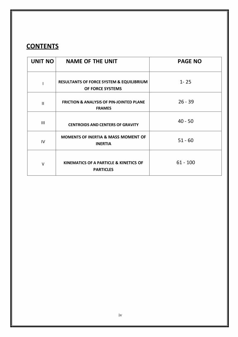
CONTENTS
UNIT NO NAME OF THE UNIT PAGE NO
I
RESULTANTS OF FORCE SYSTEM & EQUILIBRIUM
OF FORCE SYSTEMS
1- 25
II
FRICTION & ANALYSIS OF PIN-JOINTED PLANE
FRAMES
26 - 39
III
CENTROIDS AND CENTERS OF GRAVITY
40 - 50
IV
MOMENTS OF INERTIA & MASS MOMENT OF
INERTIA
51 - 60
V
KINEMATICS OF A PARTICLE & KINETICS OF
PARTICLES
61 - 100
v
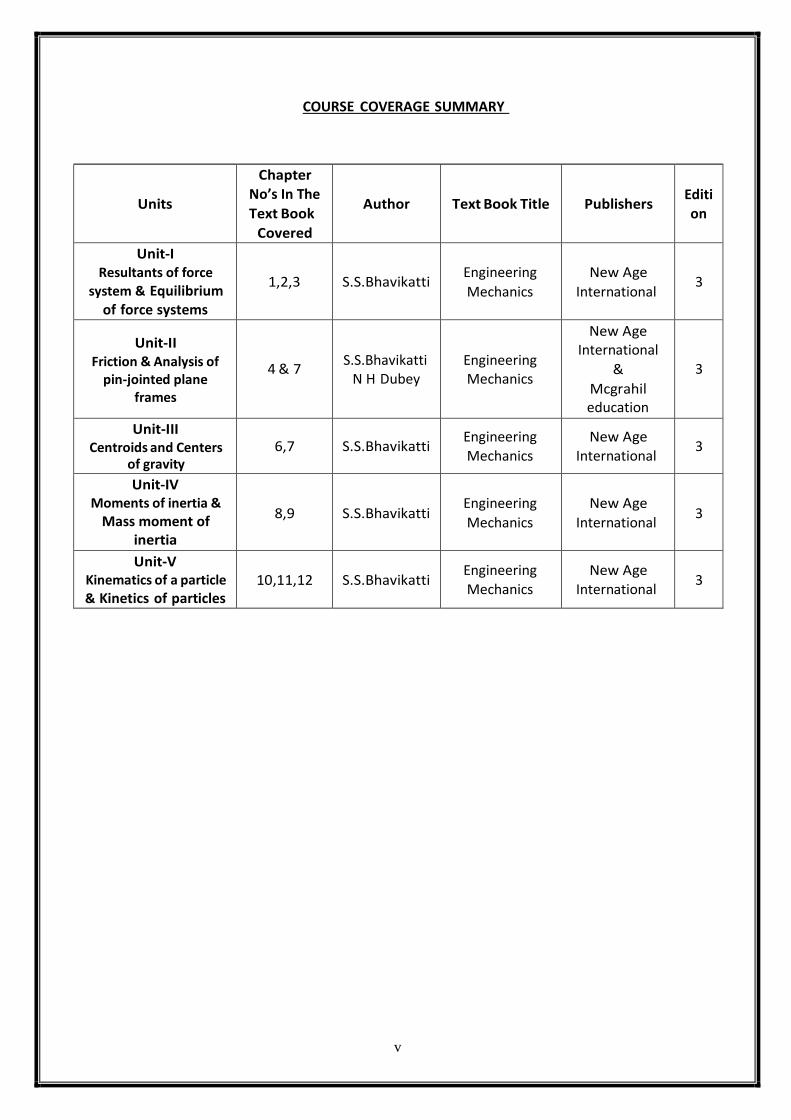
COURSE COVERAGE SUMMARY
Units
Chapter
No’s In The
Text Book
Covered
Author
Text Book Title
Publishers
Editi
on
Unit-I Resultants of force
system & Equilibrium of force systems
1,2,3
S.S.Bhavikatti
Engineering
Mechanics
New Age
International
3
Unit-II Friction & Analysis of
pin-jointed plane frames
4 & 7
S.S.Bhavikatti N H Dubey
Engineering Mechanics
New Age International
&
Mcgrahil education
3
Unit-III Centroids and Centers
of gravity
6,7
S.S.Bhavikatti
Engineering
Mechanics
New Age
International
3
Unit-IV Moments of inertia &
Mass moment of inertia
8,9
S.S.Bhavikatti
Engineering
Mechanics
New Age
International
3
Unit-V Kinematics of a particle
& Kinetics of particles
10,11,12
S.S.Bhavikatti
Engineering Mechanics
New Age International
3
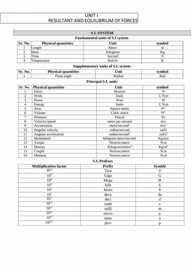
UNIT I RESULTANT AND EQUILIBRIUM OF FORCES
Fundamental units of S.I system
Sr. No. Physical quantities Unit symbol
1 Length Metre m
2 Mass Kilogram Kg
3 Time Second S
4 Temperature Kelvin K
Supplementary units of S.I. system
Sr. No. Physical quantities Unit symbol
1 Plane angle Radian Rad
Principal S.I. units
Sr. No. Physical quantities Unit symbol 1 Force Newton N
2 Work Joule J, N.m
3 Power Watt W
4 Energy Joule J, N.m
5 Area Square metre m2
6 Volume Cubic metre m3
7 Pressure Pascal Pa
8 Velocity/speed metre per second m/s
9 Acceleration metre/second2 m/s2
10 Angular velocity radian/second rad/s
11 Angular acceleration radian/second2 rad/s2
12 Momentum kilogram metre/second Kg.m/s
13 Torque Newton metre N.m
14 Density Kilogram/metre3 Kg/m3
15 Couple Newton.metre N.m
16 Moment Newton.metre N.m
S.I. Prefixes
Multiplication factor Prefix Symble 1012
Tera T
109 Giga G
106 Mega M
103 kilo k
102 hecto h
101 deca da 10-1
deci d 10-2
centi c 10-3
milli m 10-6
micro µ 10-9
nano n 10-12
pico p
S.I. SYSTEM
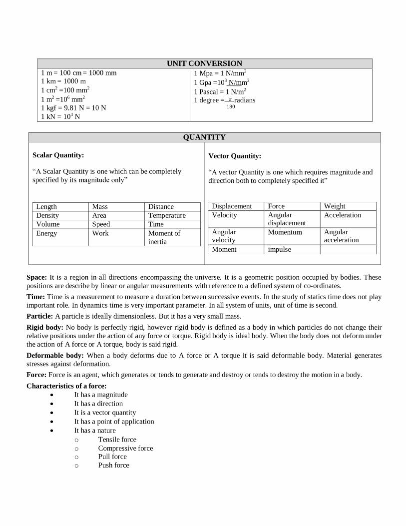
UNIT CONVERSION
1 m = 100 cm = 1000 mm 1 km = 1000 m
1 cm2 =100 mm2
1 m2 =106 mm2
1 kgf = 9.81 N = 10 N
1 kN = 103 N
1 Mpa = 1 N/mm2
1 Gpa =103 N/mm2
1 Pascal = 1 N/m2 1 degree = 𝜋 radians
180
QUANTITY
Scalar Quantity:
“A Scalar Quantity is one which can be completely
specified by its magnitude only”
Length Mass Distance
Density Area Temperature
Volume Speed Time
Energy Work Moment of
inertia
Vector Quantity:
“A vector Quantity is one which requires magnitude and
direction both to completely specified it”
Space: It is a region in all directions encompassing the universe. It is a geometric position occupied by bodies. These
positions are describe by linear or angular measurements with reference to a defined system of co-ordinates.
Time: Time is a measurement to measure a duration between successive events. In the study of statics time does not play
important role. In dynamics time is very important parameter. In all system of units, unit of time is second.
Particle: A particle is ideally dimensionless. But it has a very small mass.
Rigid body: No body is perfectly rigid, however rigid body is defined as a body in which particles do not change their
relative positions under the action of any force or torque. Rigid body is ideal body. When the body does not deform under
the action of A force or A torque, body is said rigid.
Deformable body: When a body deforms due to A force or A torque it is said deformable body. Material generates
stresses against deformation.
Force: Force is an agent, which generates or tends to generate and destroy or tends to destroy the motion in a body.
Characteristics of a force:
It has a magnitude
It has a direction
It is a vector quantity
It has a point of application
It has a nature
o Tensile force
o Compressive force o Pull force
o Push force
Displacement Force Weight
Velocity Angular displacement
Acceleration
Angular velocity
Momentum Angular acceleration
Moment impulse
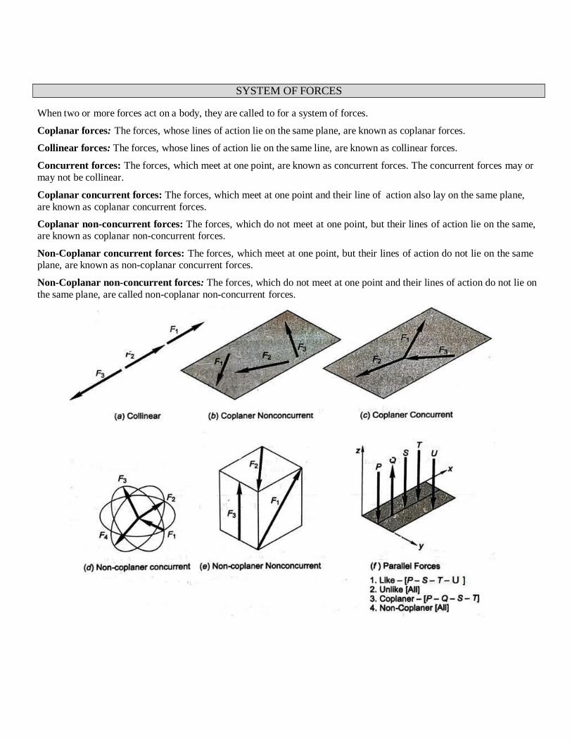
When two or more forces act on a body, they are called to for a system of forces.
Coplanar forces: The forces, whose lines of action lie on the same plane, are known as coplanar forces.
Collinear forces: The forces, whose lines of action lie on the same line, are known as collinear forces.
Concurrent forces: The forces, which meet at one point, are known as concurrent forces. The concurrent forces may or
may not be collinear.
Coplanar concurrent forces: The forces, which meet at one point and their line of action also lay on the same plane,
are known as coplanar concurrent forces.
Coplanar non-concurrent forces: The forces, which do not meet at one point, but their lines of action lie on the same, are known as coplanar non-concurrent forces.
Non-Coplanar concurrent forces: The forces, which meet at one point, but their lines of action do not lie on the same plane, are known as non-coplanar concurrent forces.
Non-Coplanar non-concurrent forces: The forces, which do not meet at one point and their lines of action do not lie on
the same plane, are called non-coplanar non-concurrent forces.
SYSTEM OF FORCES
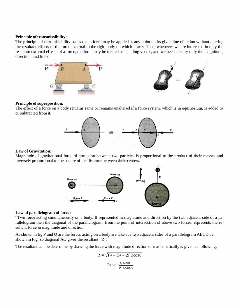
Principle of transmissibility:
The principle of transmissibility states that a force may be applied at any point on its given line of action without altering
the resultant effects of the force external to the rigid body on which it acts. Thus, whenever we are interested in only the
resultant external effects of a force, the force may be treated as a sliding vector, and we need specify only the magnitude, direction, and line of
Principle of superposition:
The effect of a force on a body remains same or remains unaltered if a force system, which is in equilibrium, is added to
or subtracted from it.
Law of Gravitation: Magnitude of gravitational force of attraction between two particles is proportional to the product of their masses and inversely proportional to the square of the distance between their centers.
Law of parallelogram of force:
“Two force acting simultaneously on a body. If represented in magnitude and direction by the two adjacent side of a pa-
rallelogram then the diagonal of the parallelogram, from the point of intersection of above two forces, represents the re-
sultant force in magnitude and direction”
As shown in fig P and Q are the forces acting on a body are taken as two adjacent sides of a parallelogram ABCD as
shown in Fig. so diagonal AC gives the resultant ”R”.
The resultant can be determine by drawing the force with magnitude direction or mathematically is given as following:
R = √P2 + Q2 + 2PQcosθ
Tanα = Q SIN θ
P+QCOS θ
Force:
“An agent which produces or tends to produce, destroys or tends to destroy motion of body is called force”
Unit: N, kN, Kg etc. Quantity : Vector
Characteristics of Force:
1) Magnitude: Magnitude of force indicates the amount of force (expressed as N or kN) that will be ex-
erted on another body
2) Direction: The direction in which it acts
3) Nature: The nature of force may be tensile or compressive
4) Point of Application: The point at which the force acts on the body is called point of application
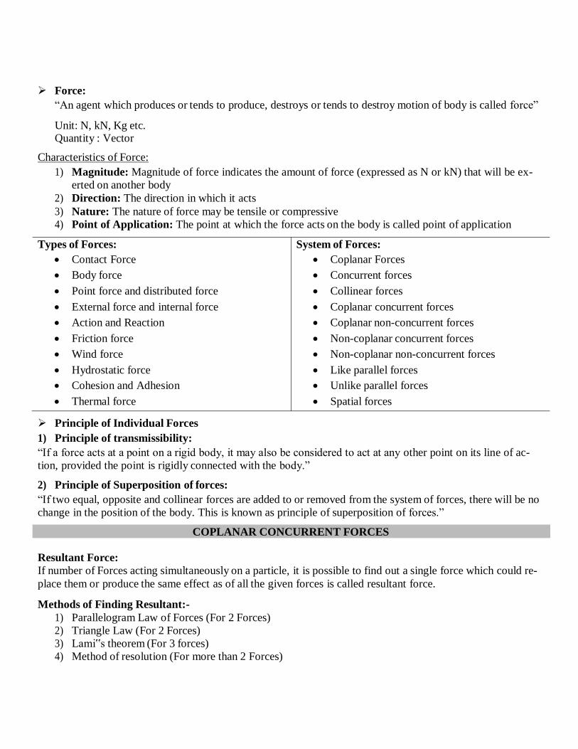
Types of Forces:
Contact Force
Body force
Point force and distributed force
External force and internal force
Action and Reaction
Friction force
Wind force
Hydrostatic force
Cohesion and Adhesion
Thermal force
Principle of Individual Forces
1) Principle of transmissibility:
System of Forces:
Coplanar Forces
Concurrent forces
Collinear forces
Coplanar concurrent forces
Coplanar non-concurrent forces
Non-coplanar concurrent forces
Non-coplanar non-concurrent forces
Like parallel forces
Unlike parallel forces
Spatial forces
“If a force acts at a point on a rigid body, it may also be considered to act at any other point on its line of ac-
tion, provided the point is rigidly connected with the body.”
2) Principle of Superposition of forces:
“If two equal, opposite and collinear forces are added to or removed from the system of forces, there will be no
change in the position of the body. This is known as principle of superposition of forces.”
COPLANAR CONCURRENT FORCES
Resultant Force:
If number of Forces acting simultaneously on a particle, it is possible to find out a single force which could re-
place them or produce the same effect as of all the given forces is called resultant force.
Methods of Finding Resultant:-
1) Parallelogram Law of Forces (For 2 Forces)
2) Triangle Law (For 2 Forces)
3) Lami‟s theorem (For 3 forces)
4) Method of resolution (For more than 2 Forces)
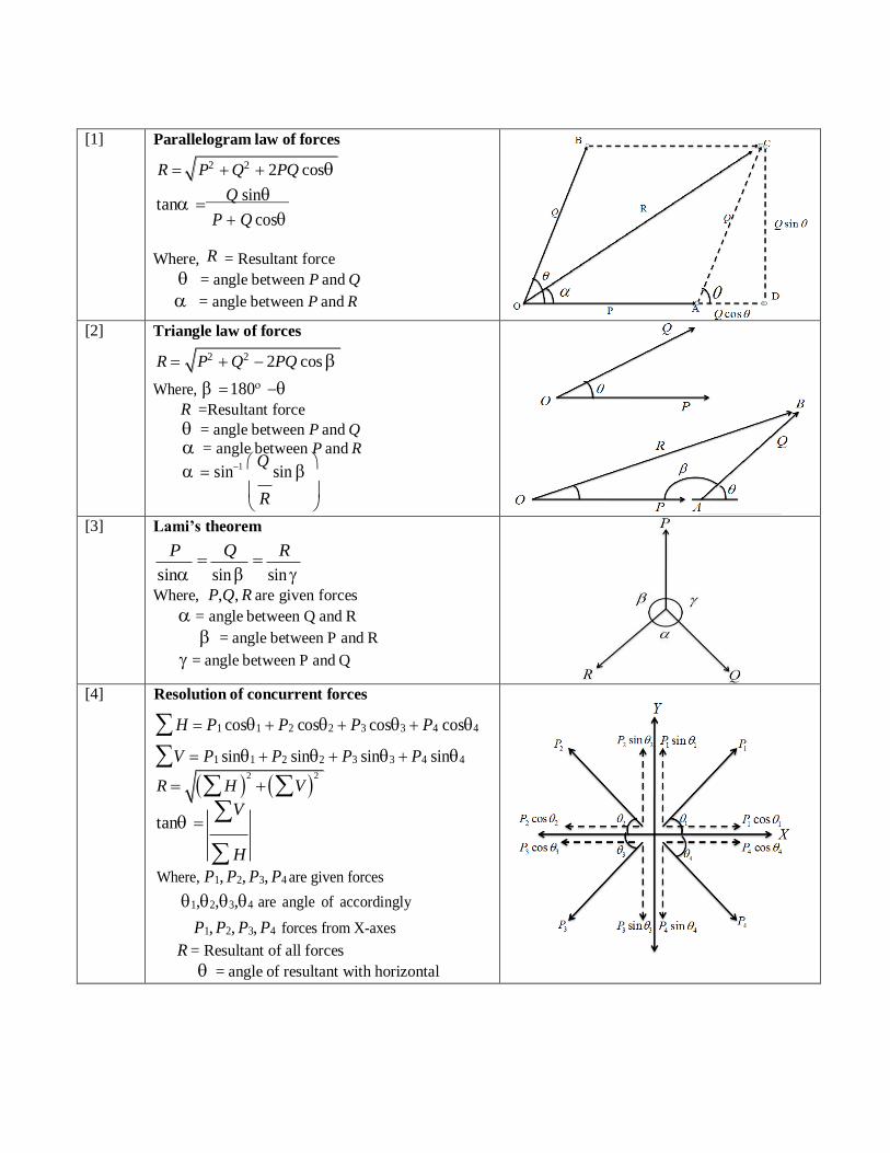
[1] Parallelogram law of forces
R P2 Q2 2PQ cos
tan Q sin
P Q cos
Where, R = Resultant force
= angle between P and Q
= angle between P and R
[2] Triangle law of forces
R P2 Q2 2PQ cos
Where, 180 R =Resultant force
= angle between P and Q
= angle between P and R
sin1 Q
sin
R
[3] Lami’s theorem
P
Q
R
sin sin sin Where, P,Q, R are given forces
= angle between Q and R
= angle between P and R
= angle between P and Q
[4] Resolution of concurrent forces
H P1 cos1 P2 cos2 P3 cos3 P4 cos4
V P1 sin1 P2 sin2 P3 sin3 P4 sin4
R H 2
V 2
tan V
H
Where, P1, P2, P3, P4 are given forces
1,2,3,4 are angle of accordingly
P1, P2, P3, P4 forces from X-axes
R = Resultant of all forces
= angle of resultant with horizontal
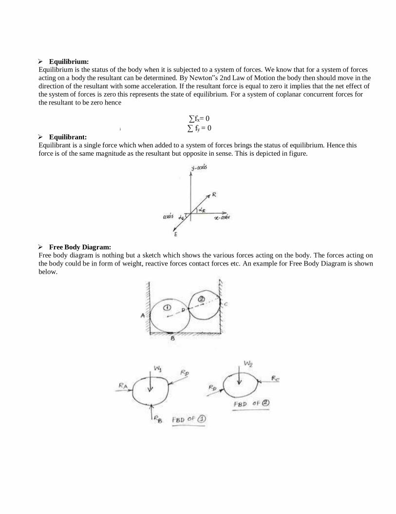
Equilibrium: Equilibrium is the status of the body when it is subjected to a system of forces. We know that for a system of forces
acting on a body the resultant can be determined. By Newton‟s 2nd Law of Motion the body then should move in the
direction of the resultant with some acceleration. If the resultant force is equal to zero it implies that the net effect of the system of forces is zero this represents the state of equilibrium. For a system of coplanar concurrent forces for
the resultant to be zero hence
i
Equilibrant:
∑fx= 0
∑ fy = 0
Equilibrant is a single force which when added to a system of forces brings the status of equilibrium. Hence this
force is of the same magnitude as the resultant but opposite in sense. This is depicted in figure.
Free Body Diagram:
Free body diagram is nothing but a sketch which shows the various forces acting on the body. The forces acting on
the body could be in form of weight, reactive forces contact forces etc. An example for Free Body Diagram is shown
below.
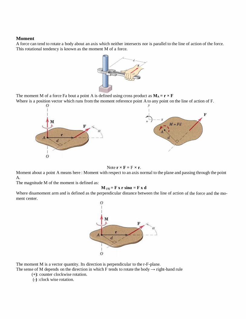
Moment A force can tend to rotate a body about an axis which neither intersects nor is parallel to the line of action of the force.
This rotational tendency is known as the moment M of a force.
The moment M of a force Fa bout a point A is defined using cross product as MA = r × F Where is a position vector which runs from the moment reference point A to any point on the line of action of F.
Note r × F = F × r.
Moment about a point A means here : Moment with respect to an axis normal to the plane and passing through the point A.
The magnitude M of the moment is defined as: M (A) = F x r sinα = F x d
Where disamoment arm and is defined as the perpendicular distance between the line of action of the force and the mo-
ment center.
The moment M is a vector quantity. Its direction is perpendicular to the r-F-plane. The sense of M depends on the direction in which F tends to rotate the body → right-hand rule
(+): counter clockwise rotation.
(-) :clock wise rotation.
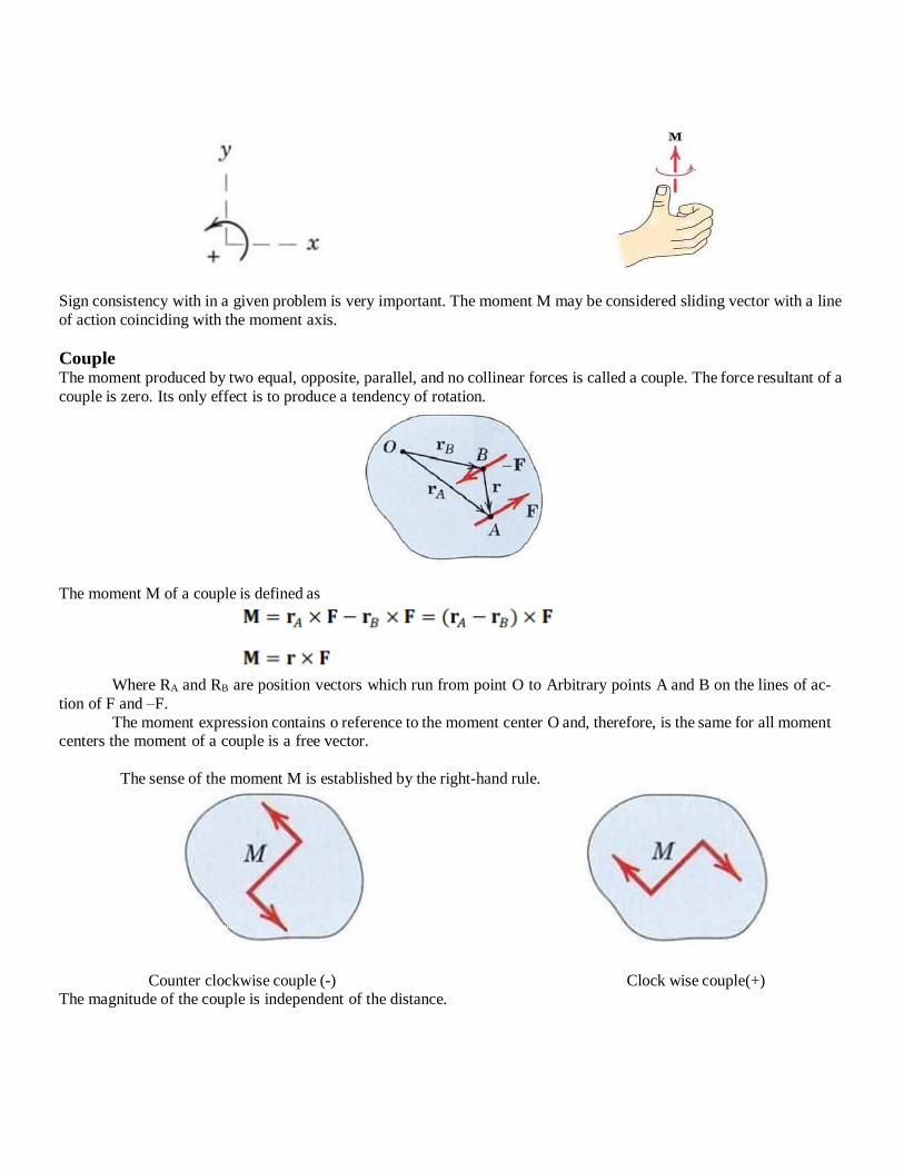
Sign consistency with in a given problem is very important. The moment M may be considered sliding vector with a line
of action coinciding with the moment axis.
Couple The moment produced by two equal, opposite, parallel, and no collinear forces is called a couple. The force resultant of a
couple is zero. Its only effect is to produce a tendency of rotation.
The moment M of a couple is defined as
Where RA and RB are position vectors which run from point O to Arbitrary points A and B on the lines of ac-
tion of F and –F.
The moment expression contains o reference to the moment center O and, therefore, is the same for all moment centers the moment of a couple is a free vector.
The sense of the moment M is established by the right-hand rule.
Counter clockwise couple (-) Clock wise couple(+) The magnitude of the couple is independent of the distance.
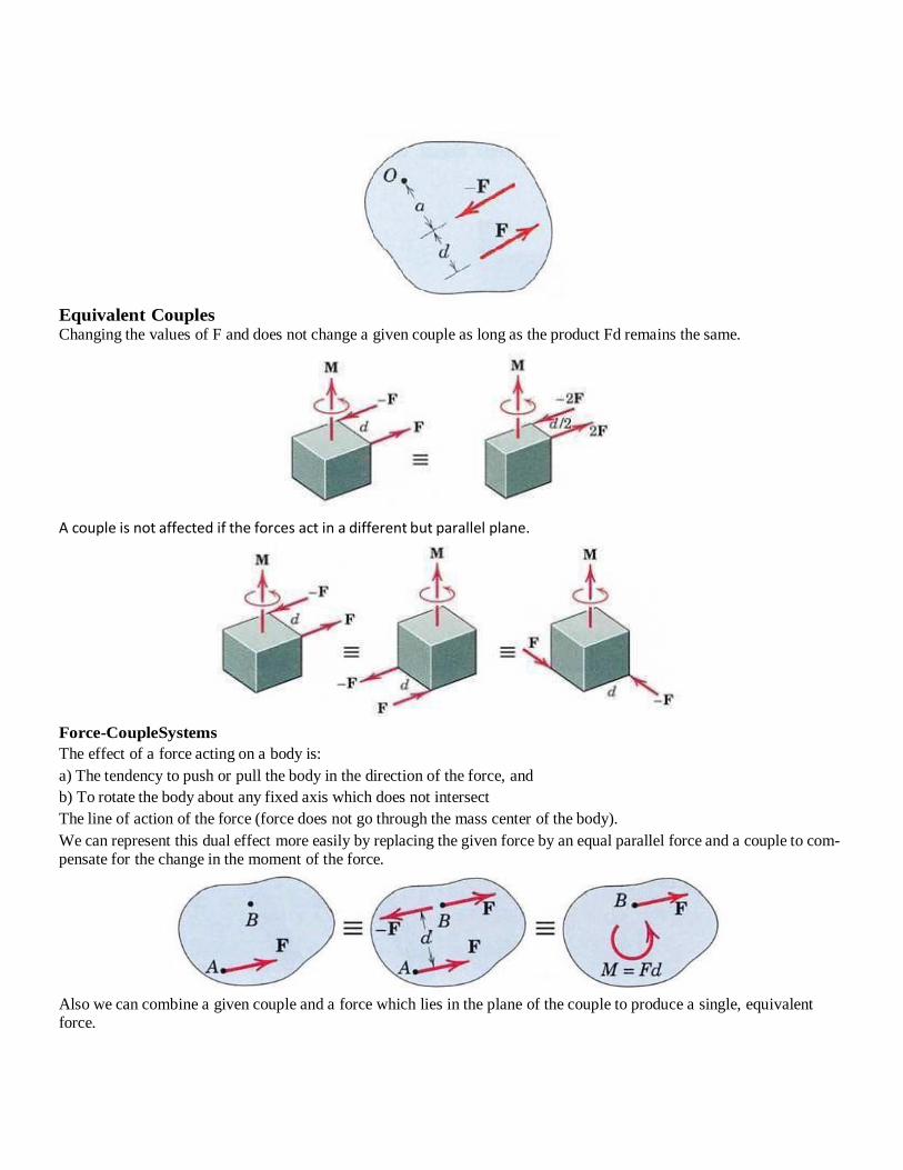
Equivalent Couples Changing the values of F and does not change a given couple as long as the product Fd remains the same.
A couple is not affected if the forces act in a different but parallel plane.
Force-CoupleSystems
The effect of a force acting on a body is:
a) The tendency to push or pull the body in the direction of the force, and
b) To rotate the body about any fixed axis which does not intersect
The line of action of the force (force does not go through the mass center of the body).
We can represent this dual effect more easily by replacing the given force by an equal parallel force and a couple to com- pensate for the change in the moment of the force.
Also we can combine a given couple and a force which lies in the plane of the couple to produce a single, equivalent force.
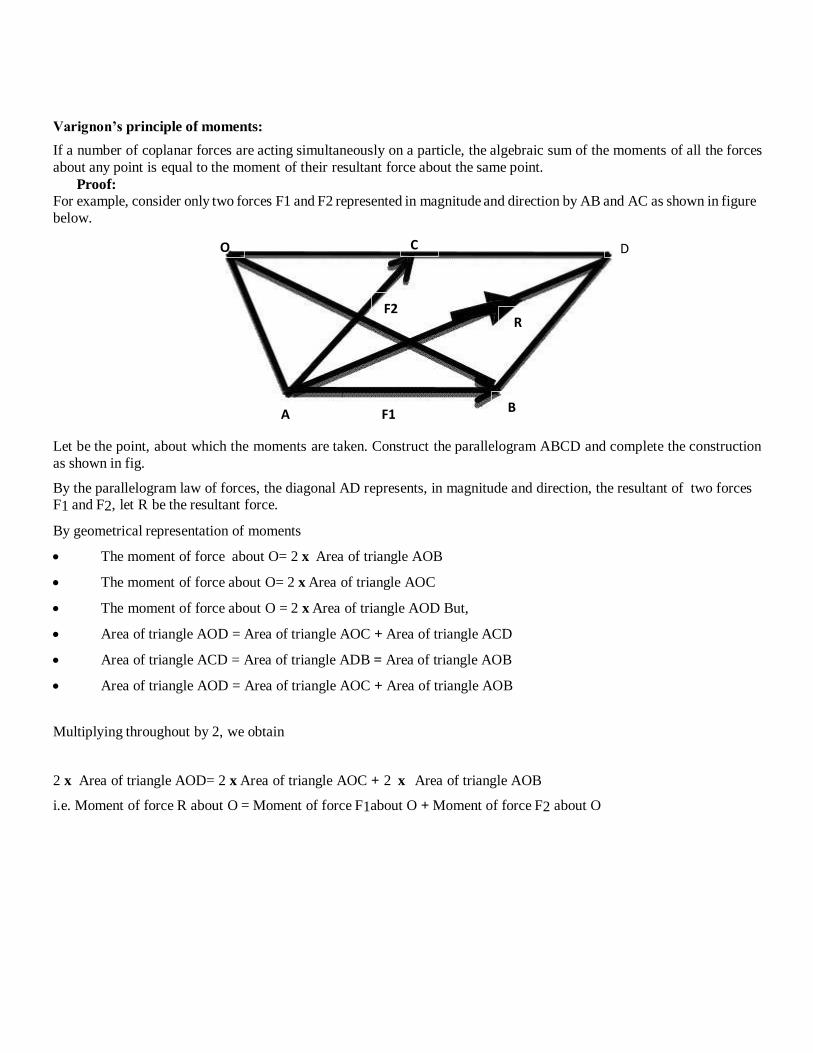
Varignon’s principle of moments:
If a number of coplanar forces are acting simultaneously on a particle, the algebraic sum of the moments of all the forces
about any point is equal to the moment of their resultant force about the same point.
Proof:
For example, consider only two forces F1 and F2 represented in magnitude and direction by AB and AC as shown in figure
below.
Let be the point, about which the moments are taken. Construct the parallelogram ABCD and complete the construction
as shown in fig.
By the parallelogram law of forces, the diagonal AD represents, in magnitude and direction, the resultant of two forces F1 and F2, let R be the resultant force.
By geometrical representation of moments
The moment of force about O= 2 x Area of triangle AOB
The moment of force about O= 2 x Area of triangle AOC
The moment of force about O = 2 x Area of triangle AOD But,
Area of triangle AOD = Area of triangle AOC + Area of triangle ACD
Area of triangle ACD = Area of triangle ADB = Area of triangle AOB
Area of triangle AOD = Area of triangle AOC + Area of triangle AOB
Multiplying throughout by 2, we obtain
2 x Area of triangle AOD= 2 x Area of triangle AOC + 2 x Area of triangle AOB
i.e. Moment of force R about O = Moment of force F1about O + Moment of force F2 about O
O C D
F2 R
A F1 B
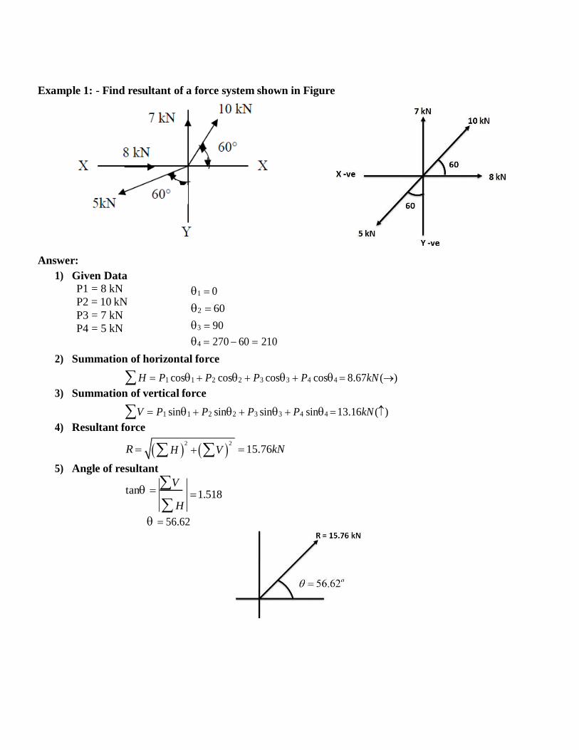
Example 1: - Find resultant of a force system shown in Figure
Answer:
1) Given Data
P1 = 8 kN
P2 = 10 kN
P3 = 7 kN
P4 = 5 kN
1 0
2 60
3 90
4 270 60 210
2) Summation of horizontal force
H P1 cos1 P2 cos2 P3 cos3 P4 cos4 8.67kN ()
3) Summation of vertical force
V P1 sin1 P2 sin2 P3 sin3 P4 sin4 13.16kN ()
4) Resultant force
R
5) Angle of resultant
tan V
H
1.518
15.76kN
56.62
H 2
V 2
H 2
V 2
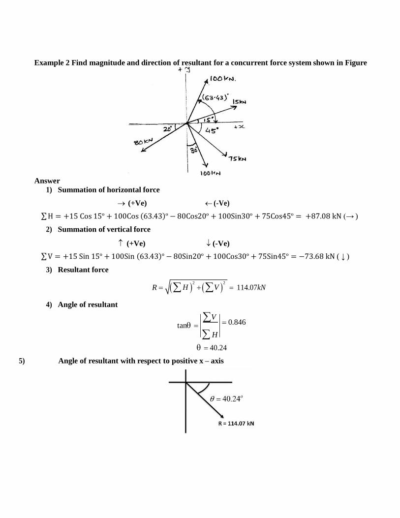
Example 2 Find magnitude and direction of resultant for a concurrent force system shown in Figure
Answer
1) Summation of horizontal force
(+Ve) (-Ve)
∑ H = +15 Cos 15º + 100Cos (63.43)º − 80Cos20º + 100Sin30º + 75Cos45º = +87.08 kN (→ )
2) Summation of vertical force
(+Ve) (-Ve)
∑ V = +15 Sin 15º + 100Sin (63.43)º − 80Sin20º + 100Cos30º + 75Sin45º = −73.68 kN ( ↓ )
3) Resultant force
4) Angle of resultant
R 114.07kN
tan V
0.846
H
40.24
5) Angle of resultant with respect to positive x – axis
H 2
V 2
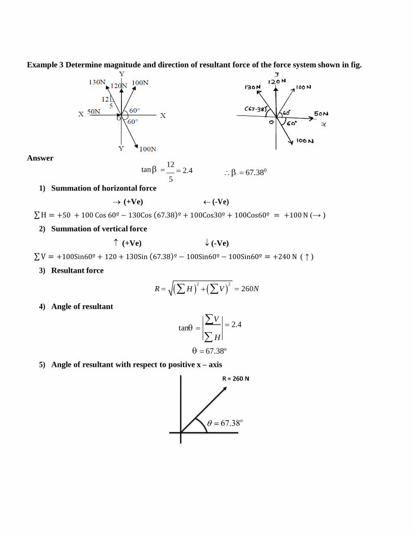
Example 3 Determine magnitude and direction of resultant force of the force system shown in fig.
Answer
tan 12
5
2.4
67.380
1) Summation of horizontal force
(+Ve) (-Ve)
∑ H = +50 + 100 Cos 60º − 130Cos (67.38)º + 100Cos30º + 100Cos60º = +100 N (→ )
2) Summation of vertical force
(+Ve) (-Ve)
∑ V = +100Sin60º + 120 + 130Sin (67.38)º − 100Sin60º − 100Sin60º = +240 N ( ↑ )
3) Resultant force
R 260N
4) Angle of resultant
tan V
2.4
H
67.38º
5) Angle of resultant with respect to positive x – axis
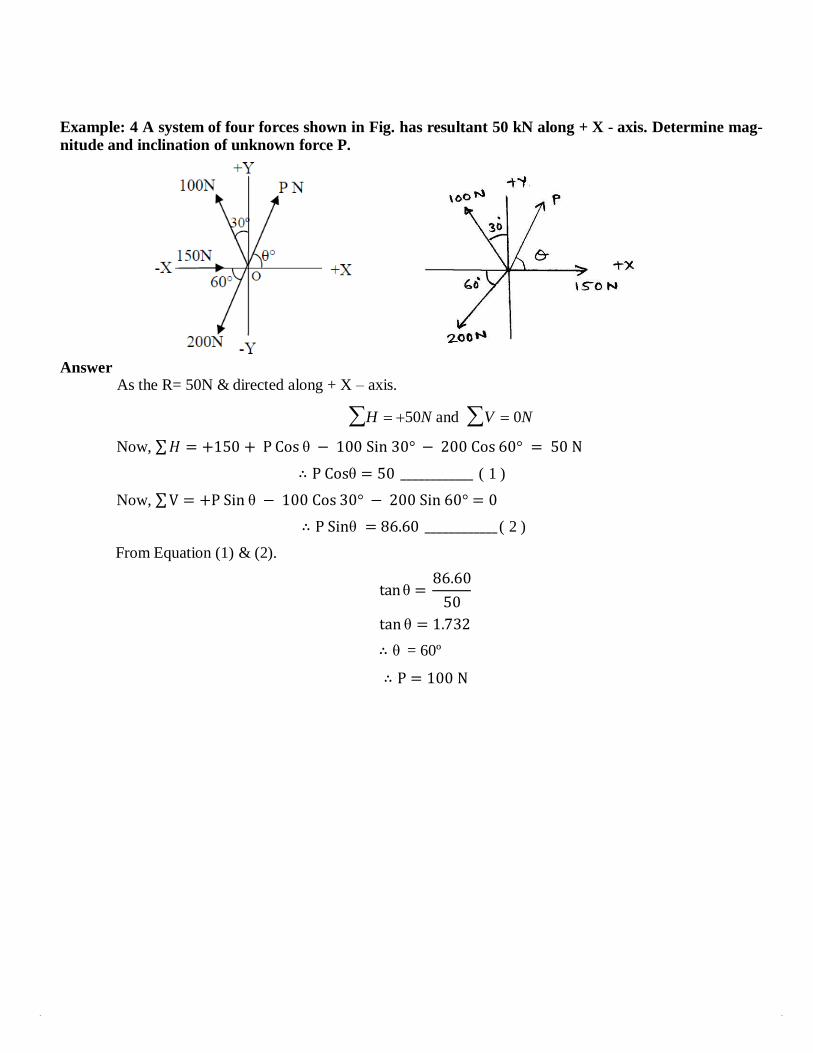
Example: 4 A system of four forces shown in Fig. has resultant 50 kN along + X - axis. Determine mag-
nitude and inclination of unknown force P.
Answer As the R= 50N & directed along + X – axis.
H 50N and V 0N
Now, ∑ 𝐻 = +150 + P Cos θ − 100 Sin 30° − 200 Cos 60° = 50 N
∴ P Cosθ = 50 ____________ ( 1 )
Now, ∑ V = +P Sin θ − 100 Cos 30° − 200 Sin 60° = 0
∴ P Sinθ = 86.60 ____________ ( 2 )
From Equation (1) & (2).
tan θ =
86.60
50
tan θ = 1.732
∴ θ = 60º
∴ P = 100 N
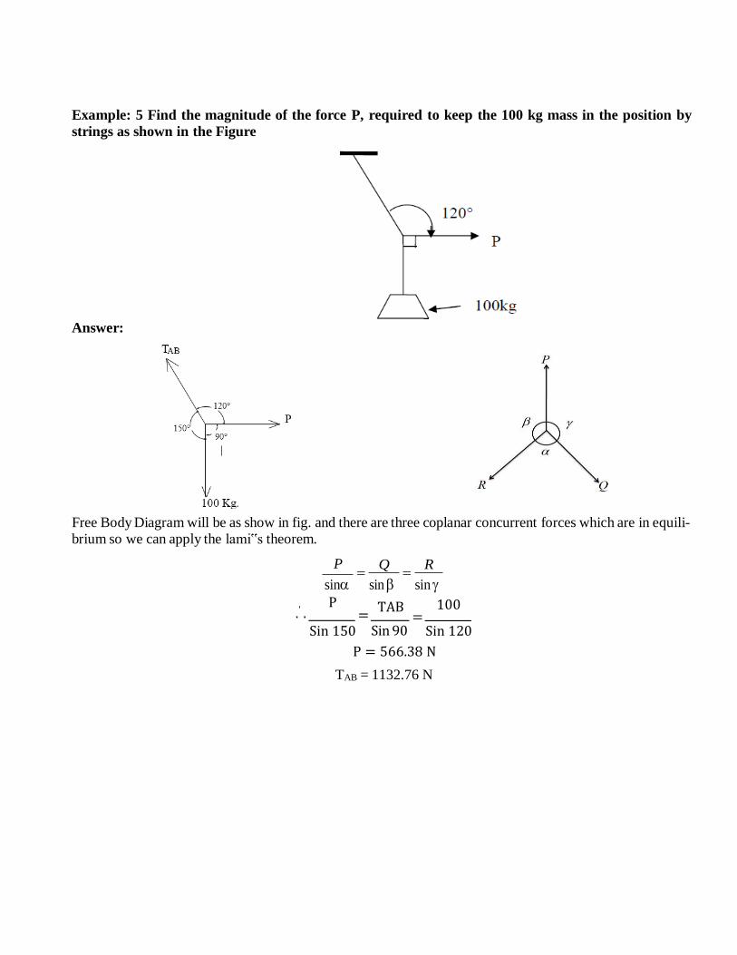
Example: 5 Find the magnitude of the force P, required to keep the 100 kg mass in the position by
strings as shown in the Figure
Answer:
Free Body Diagram will be as show in fig. and there are three coplanar concurrent forces which are in equili-
brium so we can apply the lami‟s theorem.
P
sin
Q
sin
R
sin
.′ . P
= Sin 150
TAB
Sin 90
100 =
Sin 120
P = 566.38 N
TAB = 1132.76 N
P2 Q2 2PQ cos
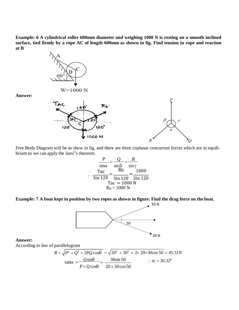
Example: 6 A cylindrical roller 600mm diameter and weighing 1000 N is resting on a smooth inclined
surface, tied firmly by a rope AC of length 600mm as shown in fig. Find tension in rope and reaction
at B
Answer:
Free Body Diagram will be as show in fig. and there are three coplanar concurrent forces which are in equili-
brium so we can apply the lami‟s theorem.
P
sin
Q
sin
R
sin
.′ . Tac
= Sin 120
Rb =
Sin 120
1000
Sin 120 Tac = 1000 N
RB = 1000 N
Example: 7 A boat kept in position by two ropes as shown in figure. Find the drag force on the boat.
Answer:
According to law of parallelogram
R
tan Q sin
30sin 50
P Q cos 20 30 cos 50
45.51N
30.320
202 302 2 2030cos 50
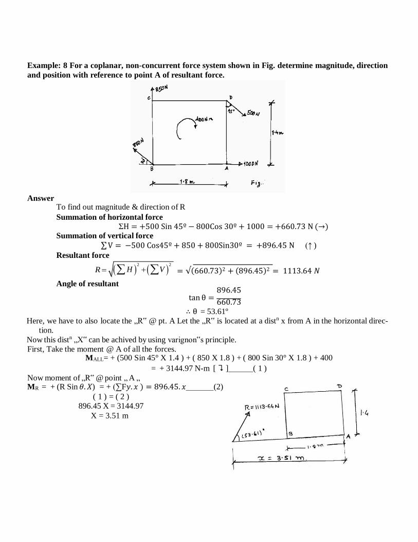
Example: 8 For a coplanar, non-concurrent force system shown in Fig. determine magnitude, direction
and position with reference to point A of resultant force.
Answer
To find out magnitude & direction of R
Summation of horizontal force
ΣH = +500 Sin 45º − 800Cos 30º + 1000 = +660.73 N (→) Summation of vertical force
∑ V = −500 Cos45º + 850 + 800Sin30º = +896.45 N (↑ )
Resultant force
R
Angle of resultant
= √(660.73)2 + (896.45)2 = 1113.64 𝑁
896.45 tan θ =
660.73 ∴ θ = 53.61º
Here, we have to also locate the „R‟ @ pt. A Let the „R‟ is located at a distn x from A in the horizontal direc-
tion.
Now this distn „X‟ can be achived by using varignon‟s principle.
First, Take the moment @ A of all the forces. MALL= + (500 Sin 45° X 1.4 ) + ( 850 X 1.8 ) + ( 800 Sin 30° X 1.8 ) + 400
= + 3144.97 N-m [ ⮧ ] ( 1 )
Now moment of „R‟ @ point „ A „ MR = + (R Sin 𝜃. 𝑋) = + (∑F𝑦. 𝑥 ) = 896.45. 𝑥 (2)
( 1 ) = ( 2 )
896.45 X = 3144.97
X = 3.51 m
H 2
V 2
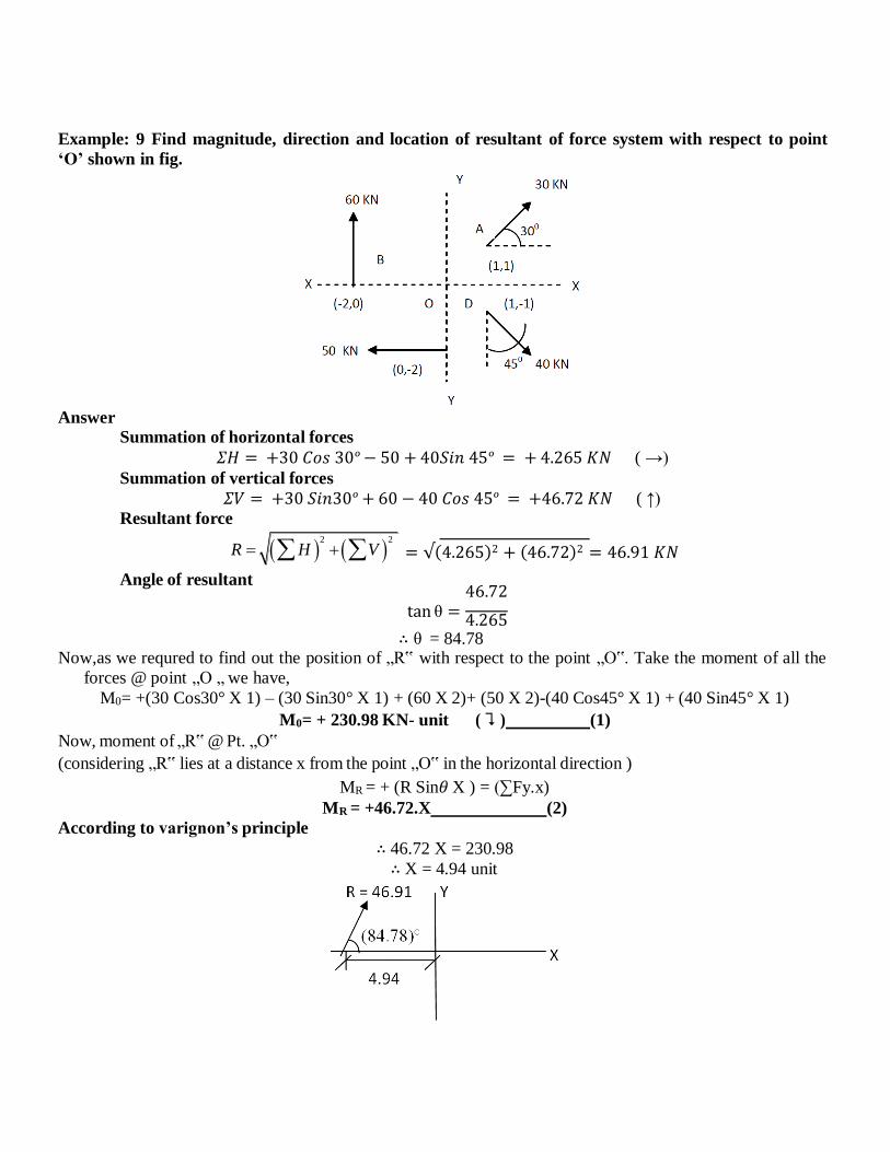
Example: 9 Find magnitude, direction and location of resultant of force system with respect to point
‘O’ shown in fig.
Answer Summation of horizontal forces
𝛴𝐻 = +30 𝐶𝑜𝑠 30º − 50 + 40𝑆𝑖𝑛 45º = + 4.265 𝐾𝑁 ( →)
Summation of vertical forces
𝛴𝑉 = +30 𝑆𝑖𝑛30º + 60 − 40 𝐶𝑜𝑠 45º = +46.72 𝐾𝑁 ( ↑)
Resultant force
R
Angle of resultant
= √(4.265)2 + (46.72)2 = 46.91 𝐾𝑁
46.72 tan θ = 4.265
∴ θ = 84.78 Now,as we requred to find out the position of „R‟ with respect to the point „O‟. Take the moment of all the
forces @ point „O „ we have,
M0= +(30 Cos30° X 1) – (30 Sin30° X 1) + (60 X 2)+ (50 X 2)-(40 Cos45° X 1) + (40 Sin45° X 1)
M0= + 230.98 KN- unit ( ⮧ ) (1)
Now, moment of „R‟ @ Pt. „O‟
(considering „R‟ lies at a distance x from the point „O‟ in the horizontal direction )
MR = + (R Sin𝜃 X ) = (∑Fy.x) MR = +46.72.X (2)
According to varignon’s principle
∴ 46.72 X = 230.98
∴ X = 4.94 unit
H 2
V 2
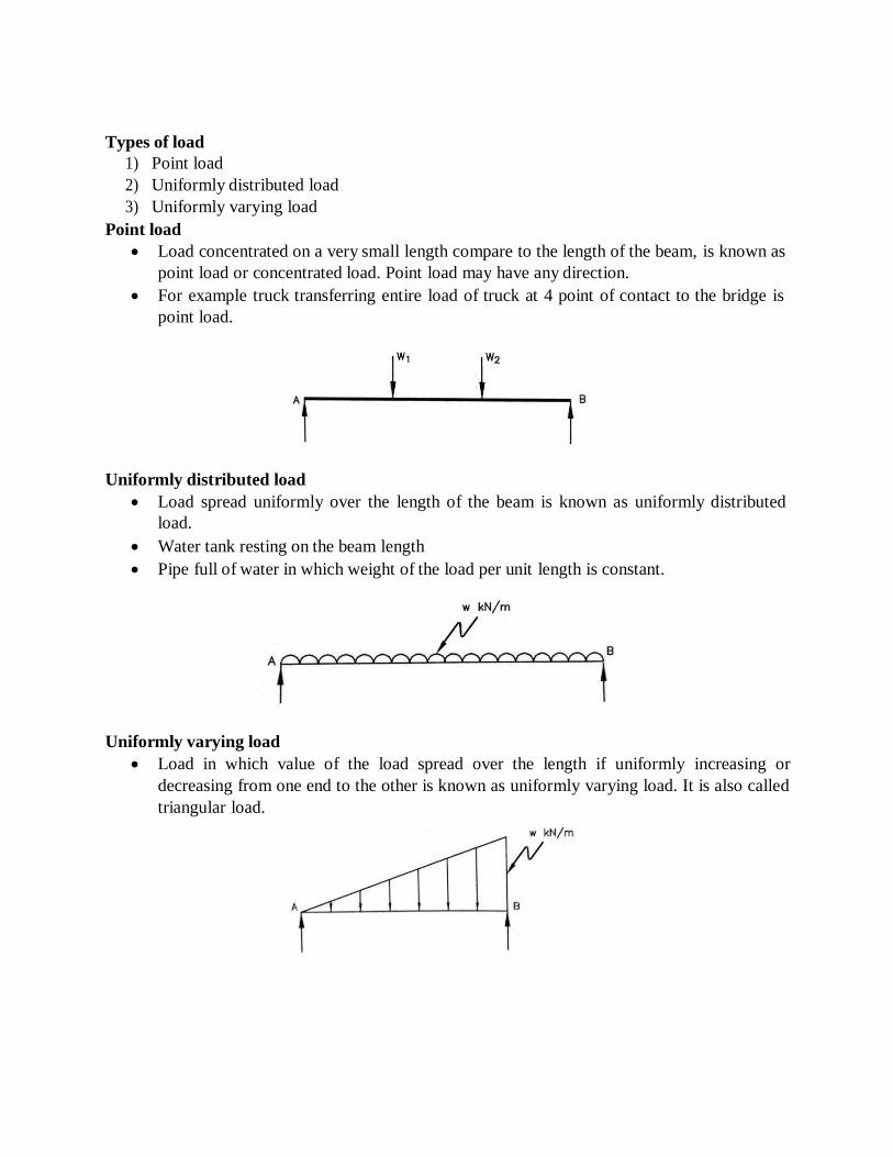
Types of load
1) Point load
2) Uniformly distributed load
3) Uniformly varying load
Point load
Load concentrated on a very small length compare to the length of the beam, is known as
point load or concentrated load. Point load may have any direction.
For example truck transferring entire load of truck at 4 point of contact to the bridge is
point load.
Uniformly distributed load
Load spread uniformly over the length of the beam is known as uniformly distributed
load.
Water tank resting on the beam length
Pipe full of water in which weight of the load per unit length is constant.
Uniformly varying load
Load in which value of the load spread over the length if uniformly increasing or
decreasing from one end to the other is known as uniformly varying load. It is also called
triangular load.
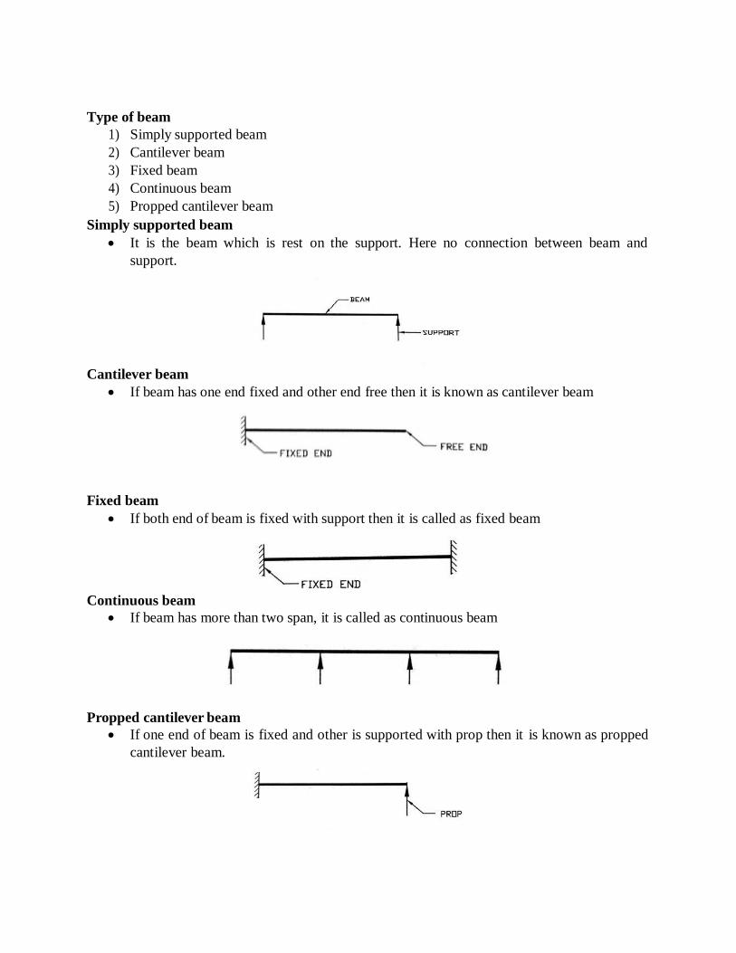
Type of beam
1) Simply supported beam
2) Cantilever beam
3) Fixed beam
4) Continuous beam
5) Propped cantilever beam
Simply supported beam
It is the beam which is rest on the support. Here no connection between beam and
support.
Cantilever beam
If beam has one end fixed and other end free then it is known as cantilever beam
Fixed beam
If both end of beam is fixed with support then it is called as fixed beam
Continuous beam
If beam has more than two span, it is called as continuous beam
Propped cantilever beam
If one end of beam is fixed and other is supported with prop then it is known as propped
cantilever beam.
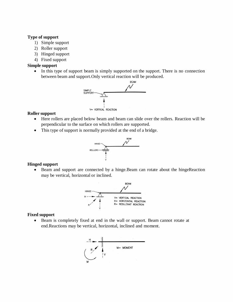
Type of support
1) Simple support
2) Roller support
3) Hinged support
4) Fixed support
Simple support
In this type of support beam is simply supported on the support. There is no connection
between beam and support.Only vertical reaction will be produced.
Roller support
Here rollers are placed below beam and beam can slide over the rollers. Reaction will be
perpendicular to the surface on which rollers are supported.
This type of support is normally provided at the end of a bridge.
Hinged support
Beam and support are connected by a hinge.Beam can rotate about the hingeReaction
may be vertical, horizontal or inclined.
Fixed support
Beam is completely fixed at end in the wall or support. Beam cannot rotate at
end.Reactions may be vertical, horizontal, inclined and moment.
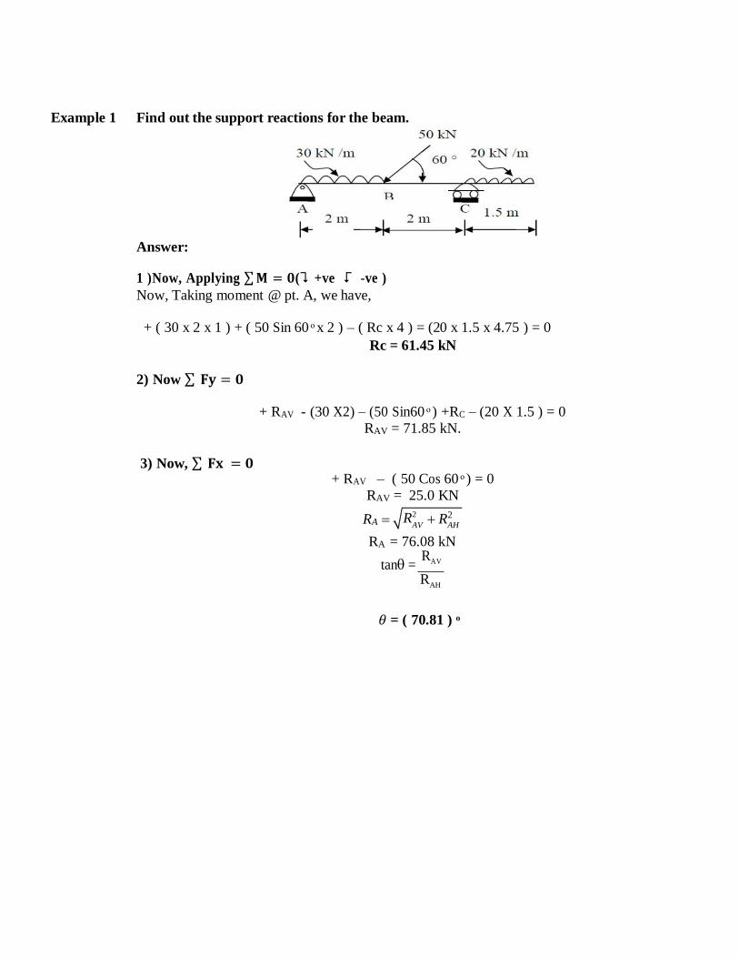
Example 1 Find out the support reactions for the beam.
Answer:
1 )Now, Applying ∑ 𝐌 = 𝟎(⮧ +ve ⮦ -ve )
Now, Taking moment @ pt. A, we have,
+ ( 30 x 2 x 1 ) + ( 50 Sin 60 ͦ x 2 ) – ( Rc x 4 ) = (20 x 1.5 x 4.75 ) = 0
Rc = 61.45 kN
2) Now ∑ 𝐅𝐲 = 𝟎
+ RAV - (30 X2) – (50 Sin60 ͦ ) +RC – (20 X 1.5 ) = 0
RAV = 71.85 kN.
3) Now, ∑ 𝐅𝐱 = 𝟎 + RAV – ( 50 Cos 60 ͦ ) = 0
RAV = 25.0 KN
RA
RA = 76.08 kN
tan = RAV
RAH
𝜃 = ( 70.81 ) ͦ
R2
AV AH R2

R2
AV AH R2
Example- 2 Determine the reactions at support A and B for the beam loaded as shown in figure
Answer:
The F.B.D. of the beam is shown below
1 )Applying ∑ 𝐌 = 𝟎 ⮧ + ve ⮦ -ve
Take the moment @ pt. A, we have,
+ ( 30 X 2 ) – (30) – (RB X 6 ) + (15 X 6 X 5) + ( 60 Sin 30 ̊ ) = 0
RAV – 30 – ( 15 X 6 ) + RB – (60 Sin30̊ ) = 0 RB = 120 kN
2) ∑ Fy = 0
∴ RAV = 30 kN
3) ΣFy = 0
RAH – 60 Cos 30 ̊ = 0
∴ RAH = +51.96 kN
Now, RA = 60 kN
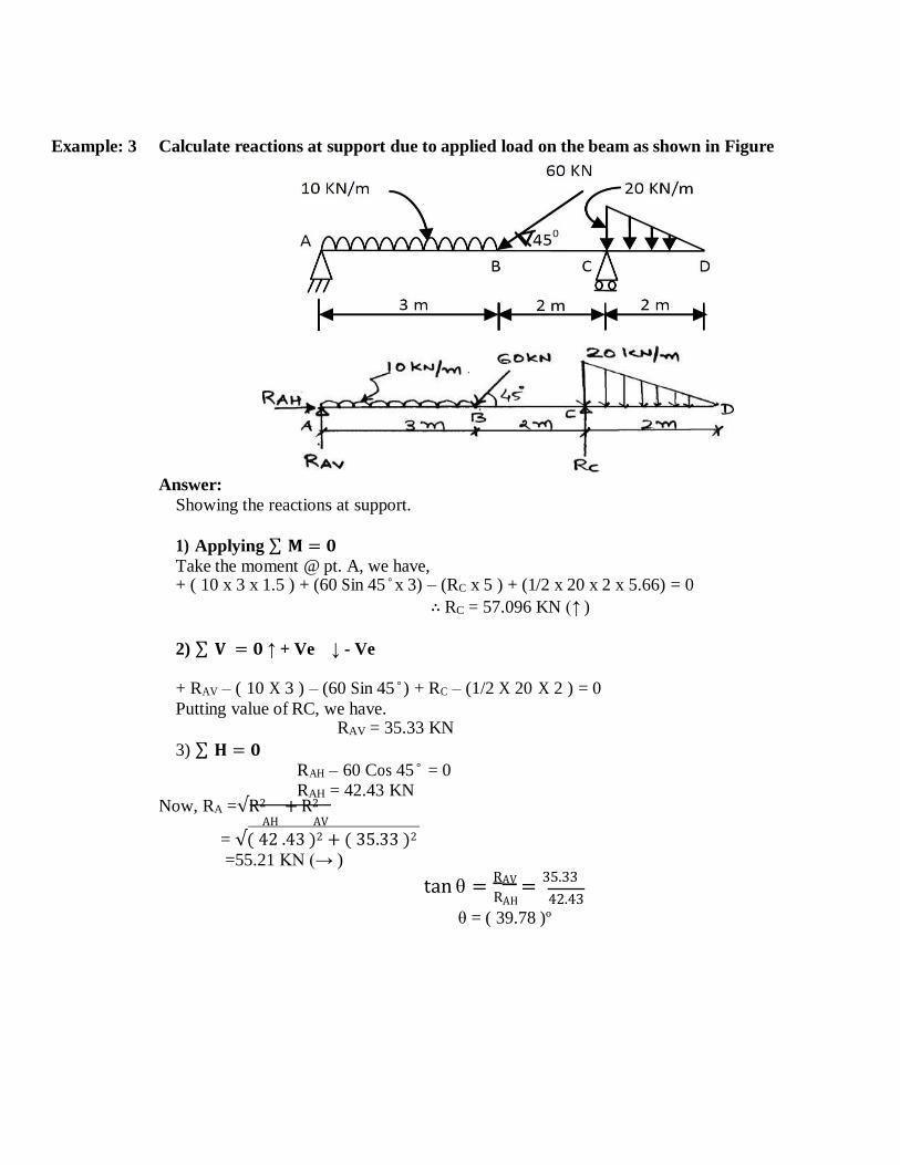
Example: 3 Calculate reactions at support due to applied load on the beam as shown in Figure
Answer:
Showing the reactions at support.
1) Applying ∑ 𝐌 = 𝟎 Take the moment @ pt. A, we have, + ( 10 x 3 x 1.5 ) + (60 Sin 45 ̊ x 3) – (RC x 5 ) + (1/2 x 20 x 2 x 5.66) = 0
∴ RC = 57.096 KN (↑ )
2) ∑ 𝐕 = 𝟎 ↑ + Ve ↓ - Ve
+ RAV – ( 10 X 3 ) – (60 Sin 45 ̊ ) + RC – (1/2 X 20 X 2 ) = 0 Putting value of RC, we have.
RAV = 35.33 KN
3) ∑ 𝐇 = 𝟎 RAH – 60 Cos 45 ̊ = 0
RAH = 42.43 KN Now, RA =√R2 + R2
AH AV
= √( 42 .43 )2 + ( 35.33 )2
=55.21 KN (→ )
tan θ =
RAV = 35.33
RAH 42.43
θ = ( 39.78 )º
1
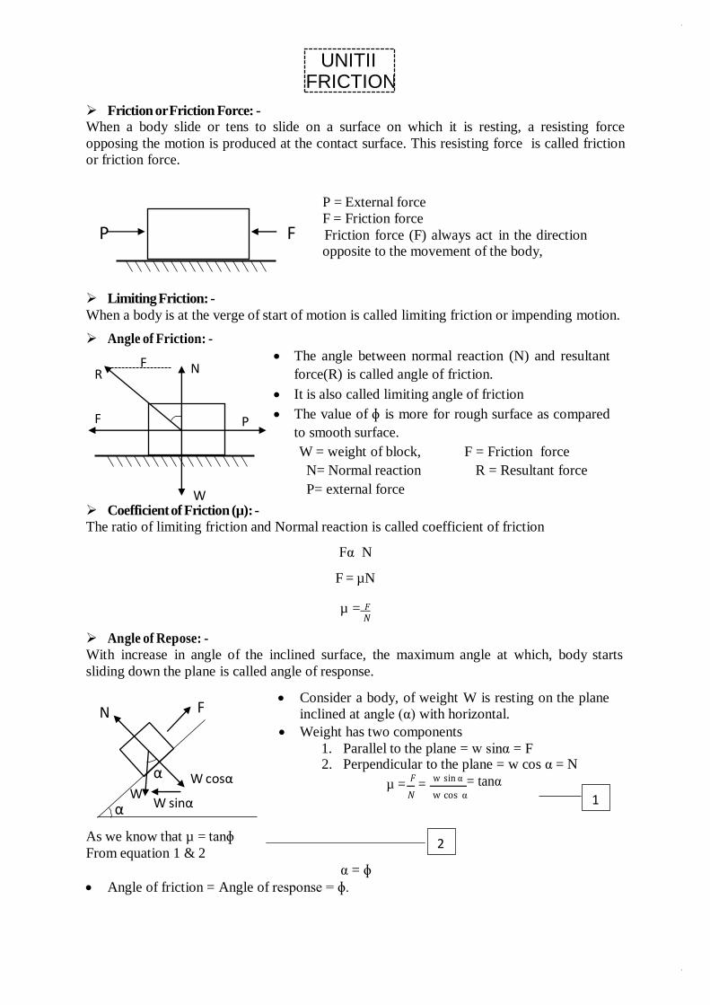
Friction or Friction Force: -
When a body slide or tens to slide on a surface on which it is resting, a resisting force
opposing the motion is produced at the contact surface. This resisting force is called friction
or friction force.
P = External force
F = Friction force
Friction force (F) always act in the direction opposite to the movement of the body,
Limiting Friction: -
When a body is at the verge of start of motion is called limiting friction or impending motion.
Angle of Friction: -
Coefficient of Friction (µ): -
The angle between normal reaction (N) and resultant
force(R) is called angle of friction.
It is also called limiting angle of friction
The value of ɸ is more for rough surface as compared
to smooth surface.
W = weight of block, F = Friction force
N= Normal reaction R = Resultant force
P= external force
The ratio of limiting friction and Normal reaction is called coefficient of friction
Fα N
F = µN
µ = 𝐹 𝑁
Angle of Repose: -
With increase in angle of the inclined surface, the maximum angle at which, body starts
sliding down the plane is called angle of response.
Consider a body, of weight W is resting on the plane
inclined at angle (α) with horizontal.
Weight has two components
1. Parallel to the plane = w sinα = F 2. Perpendicular to the plane = w cos α = N
µ = 𝐹
= w sin α = tanα
𝑁 w cos α
As we know that µ = tanɸ
From equation 1 & 2
α = ɸ
Angle of friction = Angle of response = ɸ.
P F
2
R F N
F P
W
N F
α W cosα W
α W sinα
UNITII FRICTION
Law of static friction: -
1. The friction force always acts in a direction, opposite to that in which the body tends
to move.
2. The magnitude of friction force is equal to the external force.
3. The ratio of limiting friction (F) & normal reaction (N) is constant.
4. The friction force does not depend upon the area of contact between the two surfaces.
5. The friction force depends upon the roughness of the surfaces.
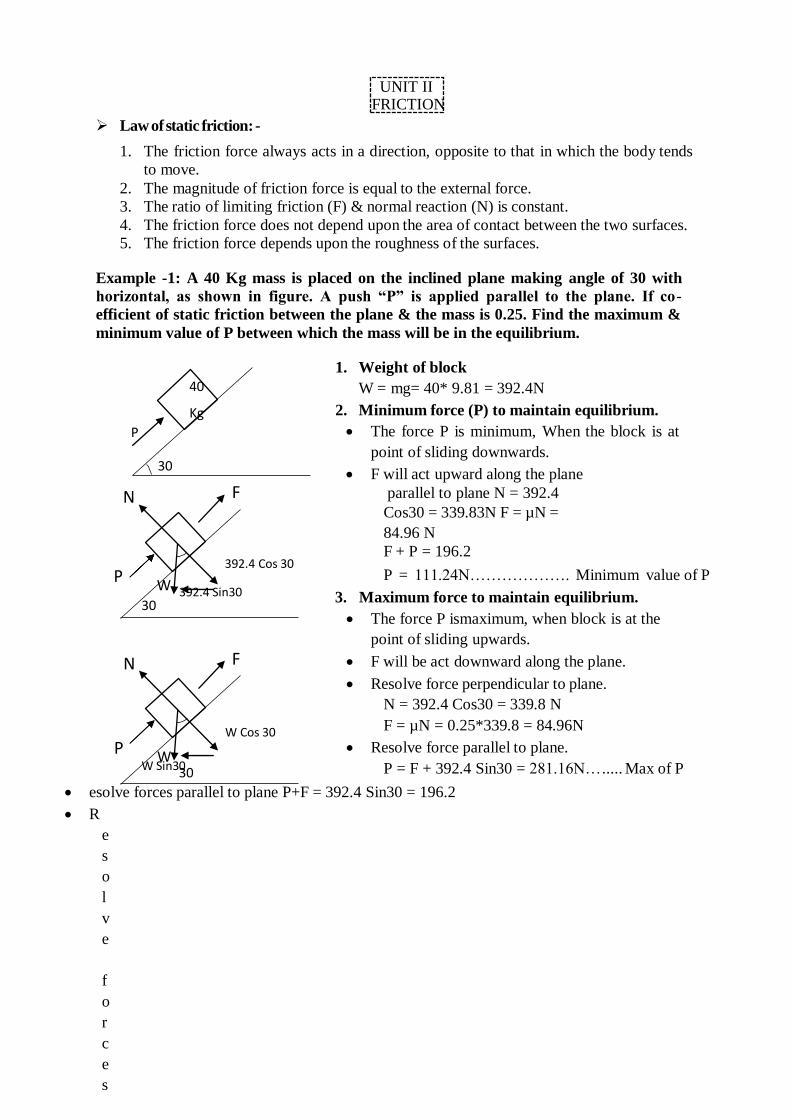
Example -1: A 40 Kg mass is placed on the inclined plane making angle of 30 with
horizontal, as shown in figure. A push “P” is applied parallel to the plane. If co-
efficient of static friction between the plane & the mass is 0.25. Find the maximum &
minimum value of P between which the mass will be in the equilibrium.
1. Weight of block
W = mg= 40* 9.81 = 392.4N
2. Minimum force (P) to maintain equilibrium.
The force P is minimum, When the block is at
point of sliding downwards.
F will act upward along the plane
N F parallel to plane N = 392.4
Cos30 = 339.83N F = µN =
84.96 N
F + P = 196.2 392.4 Cos 30
P W 392.4 Sin30
30
N F
W Cos 30
P W W Sin3030
P = 111.24N………………. Minimum value of P
3. Maximum force to maintain equilibrium.
The force P ismaximum, when block is at the
point of sliding upwards.
F will be act downward along the plane.
Resolve force perpendicular to plane.
N = 392.4 Cos30 = 339.8 N
F = µN = 0.25*339.8 = 84.96N
Resolve force parallel to plane.
P = F + 392.4 Sin30 = 281.16N… ..... Max of P
esolve forces parallel to plane P+F = 392.4 Sin30 = 196.2
R
e
s
o
l
v
e
f
o
r
c
e
s
UNIT II FRICTION
40
Kg
P
30
550 N
230 N
θ A
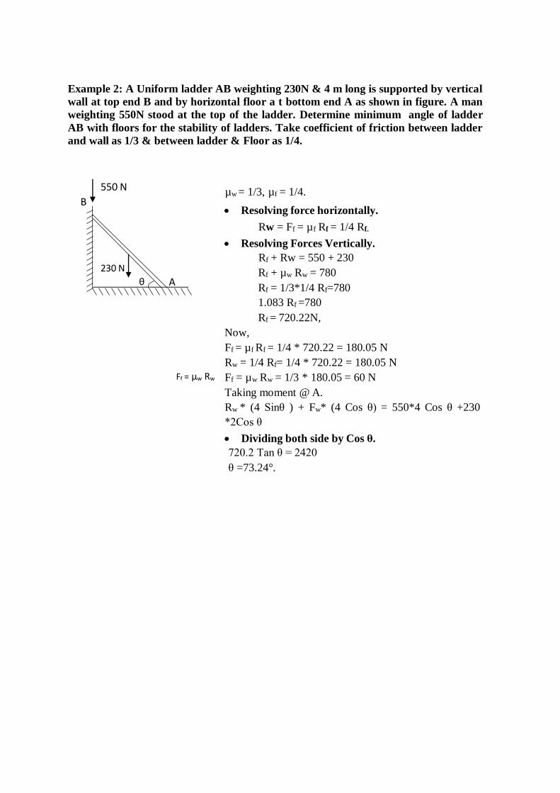
Example 2: A Uniform ladder AB weighting 230N & 4 m long is supported by vertical
wall at top end B and by horizontal floor a t bottom end A as shown in figure. A man
weighting 550N stood at the top of the ladder. Determine minimum angle of ladder
AB with floors for the stability of ladders. Take coefficient of friction between ladder
and wall as 1/3 & between ladder & Floor as 1/4.
µw = 1/3, µf = 1/4. B
Resolving force horizontally.
Rw = Ff = µf Rf = 1/4 Rf.
Resolving Forces Vertically.
Rf + Rw = 550 + 230
Rf + µw Rw = 780
Rf = 1/3*1/4 Rf=780
1.083 Rf =780
Rf = 720.22N,
Ff = µw Rw
Now,
Ff = µf Rf = 1/4 * 720.22 = 180.05 N
Rw = 1/4 Rf= 1/4 * 720.22 = 180.05 N
Ff = µw Rw = 1/3 * 180.05 = 60 N
Taking moment @ A.
Rw * (4 Sinθ ) + Fw* (4 Cos θ) = 550*4 Cos θ +230
*2Cos θ
Dividing both side by Cos θ.
720.2 Tan θ = 2420
θ =73.24°.
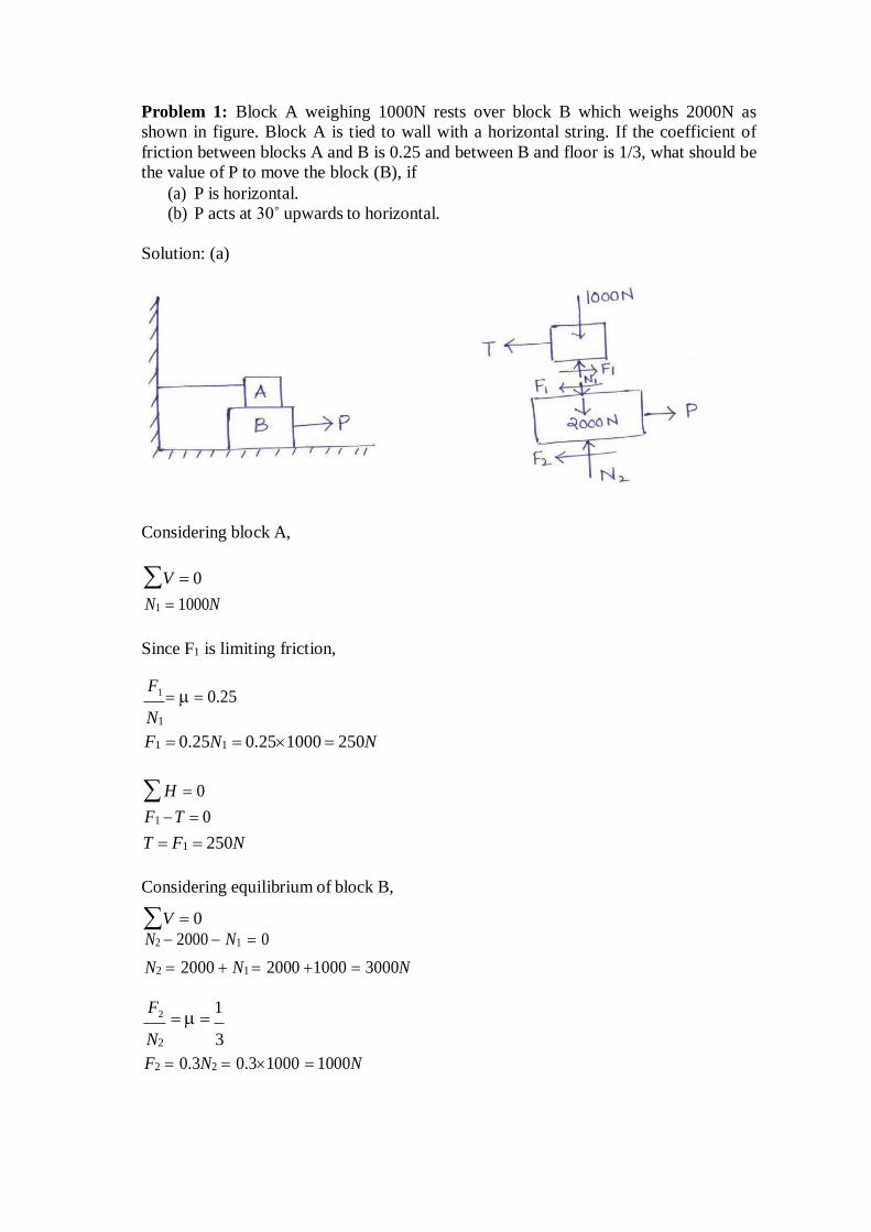
Problem 1: Block A weighing 1000N rests over block B which weighs 2000N as
shown in figure. Block A is tied to wall with a horizontal string. If the coefficient of
friction between blocks A and B is 0.25 and between B and floor is 1/3, what should be
the value of P to move the block (B), if
(a) P is horizontal.
(b) P acts at 30˚ upwards to horizontal.
Solution: (a)
Considering block A,
V 0
N1 1000N
Since F1 is limiting friction,
F1 0.25
N1
F1 0.25N1 0.251000 250N
H 0
F1 T 0
T F1 250N
Considering equilibrium of block B,
V 0
N2 2000 N1 0
N2 2000 N1 2000 1000 3000N
F2 1
N2 3
F2 0.3N2 0.31000 1000N
H 0
P F1 F2 250 1000 1250N
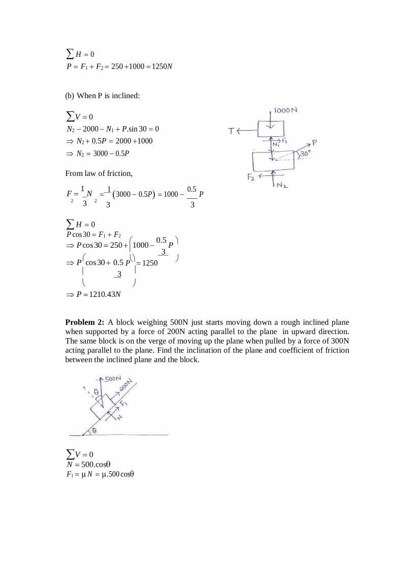
(b) When P is inclined:
V 0
N2 2000 N1 P.sin 30 0
N2 0.5P 2000 1000
N2 3000 0.5P
From law of friction,
F 1 N
2 3
2
H 0
1 3000 0.5P 1000
0.5 P
3 3
P cos 30 F1 F2
P cos 30 250 1000
0.5 P
3
P cos 30 0.5
P 1250
3
P 1210.43N
Problem 2: A block weighing 500N just starts moving down a rough inclined plane
when supported by a force of 200N acting parallel to the plane in upward direction.
The same block is on the verge of moving up the plane when pulled by a force of 300N
acting parallel to the plane. Find the inclination of the plane and coefficient of friction
between the inclined plane and the block.
V 0
N 500.cosF1 N .500 cos
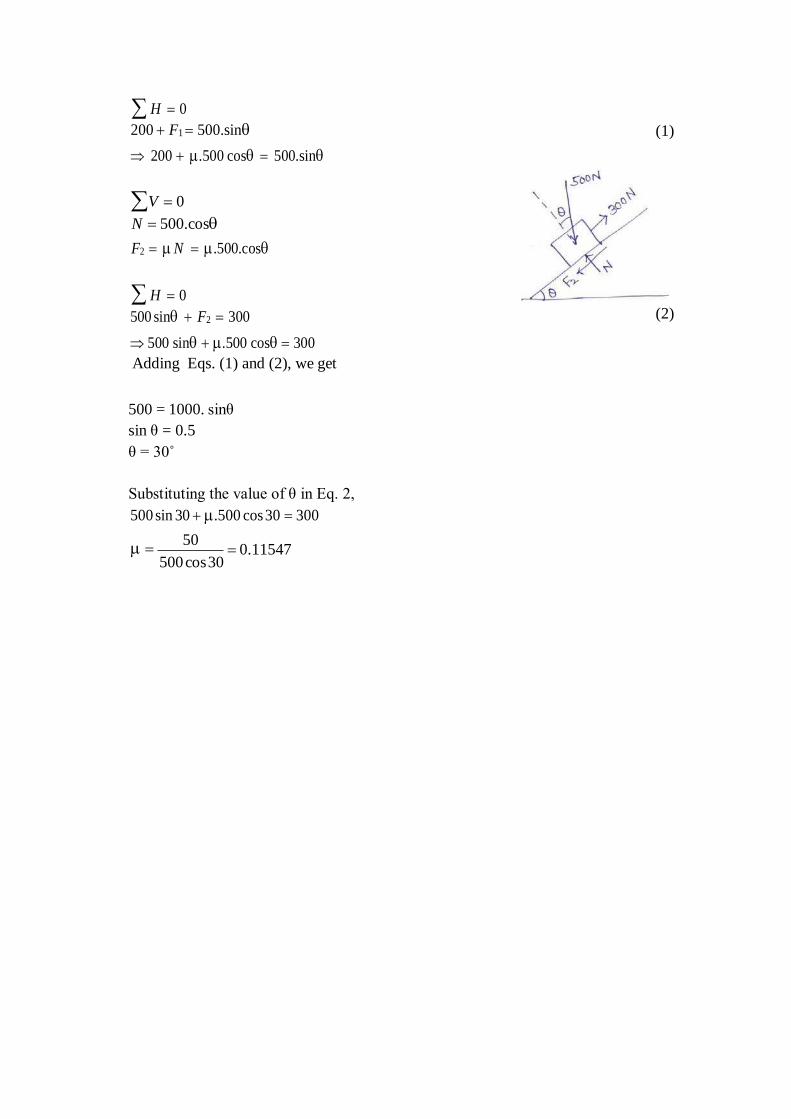
H 0
200 F1 500.sin
200 .500 cos 500.sin
V 0
N 500.cos
F2 N .500.cos
H 0
500 sin F2 300
500 sin .500 cos 300
Adding Eqs. (1) and (2), we get
500 = 1000. sinθ
sin θ = 0.5
θ = 30˚
Substituting the value of θ in Eq. 2,
500 sin 30 .500 cos 30 300
(1)
(2)
50
500 cos 30 0.11547
Truss/ Frame: A pin jointed frame is a structure made of slender (cross-sectional dimensions quite small compared to length) members pin connected at ends and
capable of taking load at joints.
Such frames are used as roof trusses to support sloping roofs and as bridge trusses to
support deck.
Plane frame: A frame in which all members lie in a single plane is called plane frame.
They are designed to resist the forces acting in the plane of frame. Roof trusses and
bridge trusses are the example of plane frames.
Space frame: If all the members of frame do not lie in a single plane, they are called
as space frame. Tripod, transmission towers are the examples of space frames.
Perfect frame: A pin jointed frame which has got just sufficient number of members
to resist the loads without undergoing appreciable deformation in shape is called a
perfect frame. Triangular frame is the simplest perfect frame and it has 03 joints and
03 members.
It may be observed that to increase one joint in a perfect frame, two more members are
required. Hence, the following expression may be written as the relationship between
number of joint j, and the number of members m in a perfect frame.
m = 2j – 3
(a) When LHS = RHS, Perfect frame. (b) When LHS<RHS, Deficient frame.
(c) When LHS>RHS, Redundant frame.
Assumptions
The following assumptions are made in the analysis of pin jointed trusses:
1. The ends of the members are pin jointed (hinged).
2. The loads act only at the joints.
3. Self weight of the members is negligible.
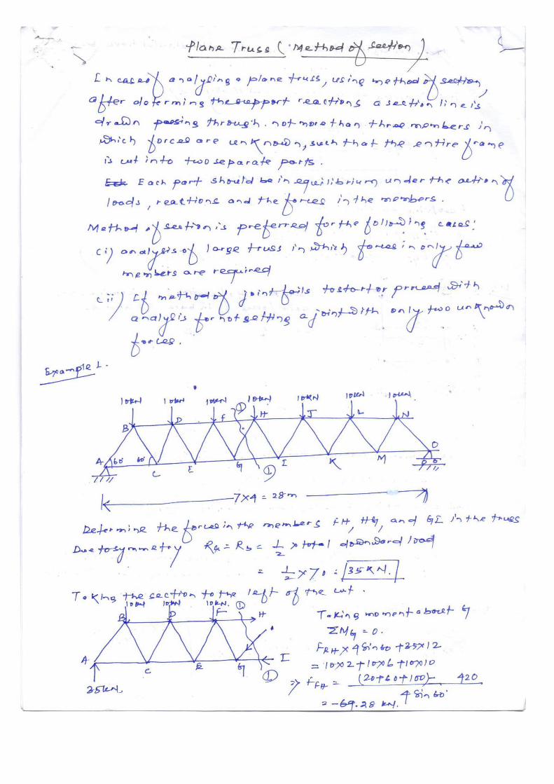
Methods of analysis
1. Method of joint
2. Method of section
ANALYSIS OF PLANE
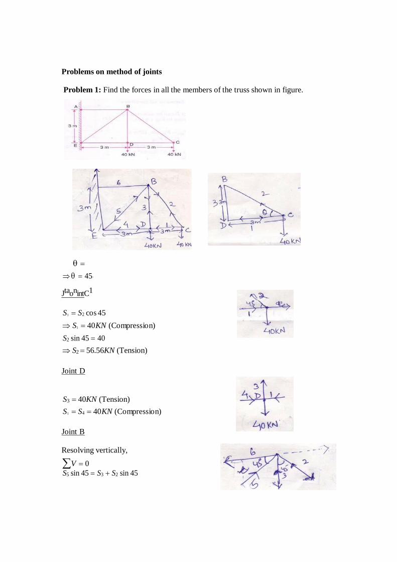
Problems on method of joints
Problem 1: Find the forces in all the members of the truss shown in figure.
45∘
JtaonintC1
S1 S2 cos 45
S1 40KN (Compression)
S2 sin 45 40
S2 56.56KN (Tension)
Joint D
S3 40KN (Tension)
S1 S4 40KN (Compression)
Joint B
Resolving vertically,
V 0
S5 sin 45 S3 S2 sin 45
S5 113.137KN (Compression)
Resolving horizontally,
H 0
S6 S5 cos 45 S2 cos 45
S6 113.137 cos 45 56.56 cos 45
S6 120KN (Tension)
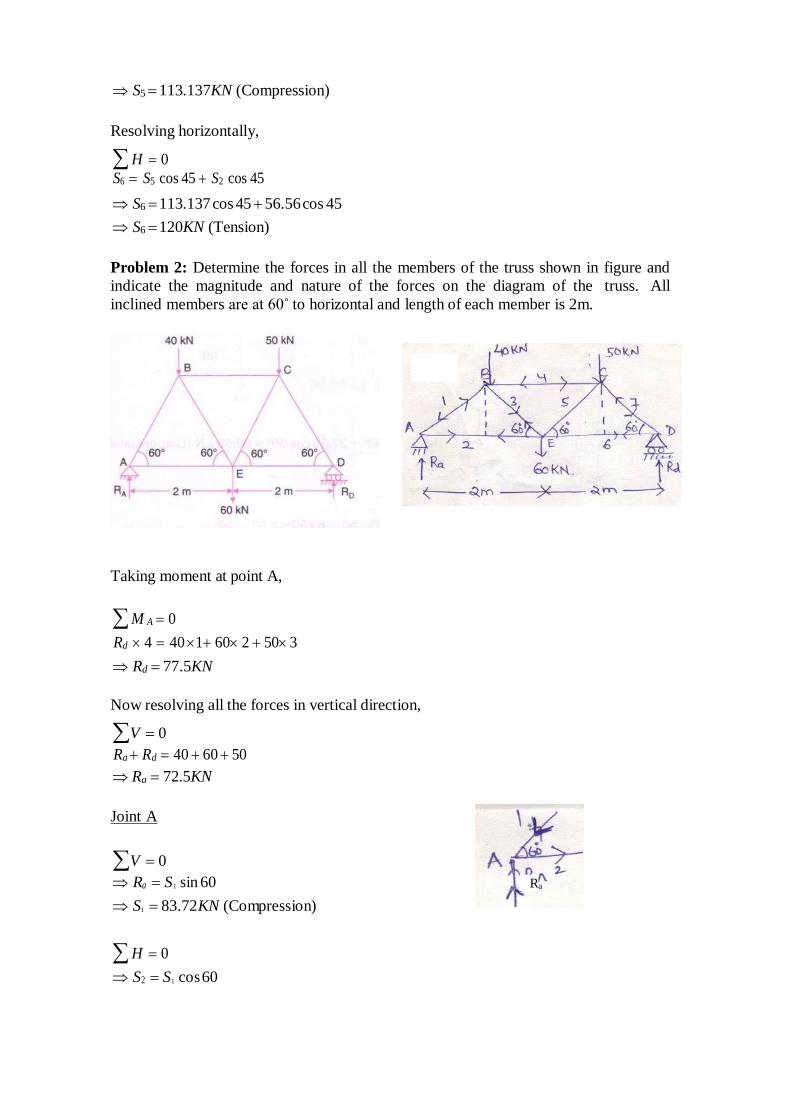
Problem 2: Determine the forces in all the members of the truss shown in figure and
indicate the magnitude and nature of the forces on the diagram of the truss. All
inclined members are at 60˚ to horizontal and length of each member is 2m.
Taking moment at point A,
M A 0
Rd 4 40 1 60 2 50 3
Rd 77.5KN
Now resolving all the forces in vertical direction,
V 0
Ra Rd 40 60 50
Ra 72.5KN
Joint A
V 0
Ra S1 sin 60
S1 83.72KN (Compression)
H 0
S2 S1 cos 60
Ra
S1 41.86KN (Tension)
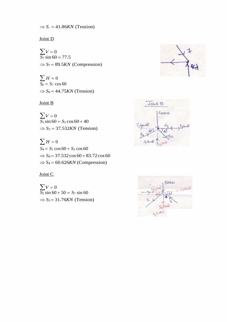
Joint D
V 0
S7 sin 60 77.5
S7 89.5KN (Compression)
H 0
S6 S7 cos 60
S6 44.75KN (Tension)
Joint B
V 0
S1 sin 60 S3 cos 60 40
S3 37.532KN (Tension)
H 0
S4 S1 cos 60 S3 cos 60
S4 37.532 cos 60 83.72 cos 60
S4 60.626KN (Compression)
Joint C
V 0
S5 sin 60 50 S7 sin 60
S5 31.76KN (Tension)
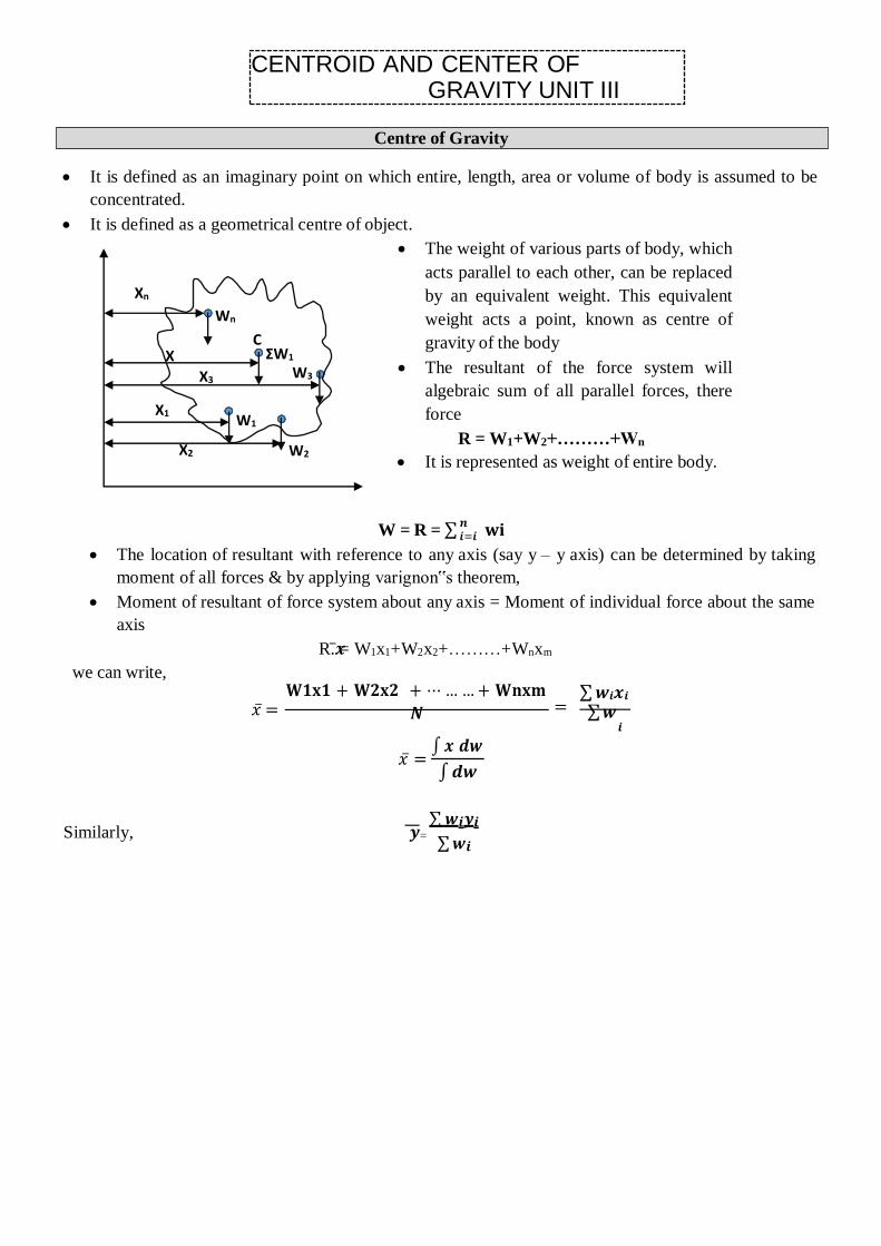
It is defined as an imaginary point on which entire, length, area or volume of body is assumed to be
concentrated.
It is defined as a geometrical centre of object.
The weight of various parts of body, which
acts parallel to each other, can be replaced
by an equivalent weight. This equivalent
weight acts a point, known as centre of
gravity of the body
The resultant of the force system will
algebraic sum of all parallel forces, there
force
R = W1+W2+………+Wn
It is represented as weight of entire body.
𝒏 𝒊=𝒊 𝐰𝐢
The location of resultant with reference to any axis (say y – y axis) can be determined by taking
moment of all forces & by applying varignon‟s theorem,
Moment of resultant of force system about any axis = Moment of individual force about the same
axis
we can write,
R.𝒙̅ = W1x1+W2x2+………+Wnxm
𝐖𝟏𝐱𝟏 + 𝐖𝟐𝐱𝟐 + ⋯ … … + 𝐖𝐧𝐱𝐦
𝑥̅ = 𝑵 =
∑ 𝒘𝒊𝒙𝒊
∑ 𝒘
𝑥 ̅=
Similarly, 𝒚=
𝒊
∫ 𝒙 𝒅𝒘
∫ 𝒅𝒘
∑ 𝒘𝒊𝒚𝒊
∑ 𝒘𝒊
CENTROID AND CENTER OF GRAVITY UNIT III
Xn
Wn
C X
X3
ΣW1
W3
X1 W1
X2 W2
W = R = ∑
Centre of Gravity
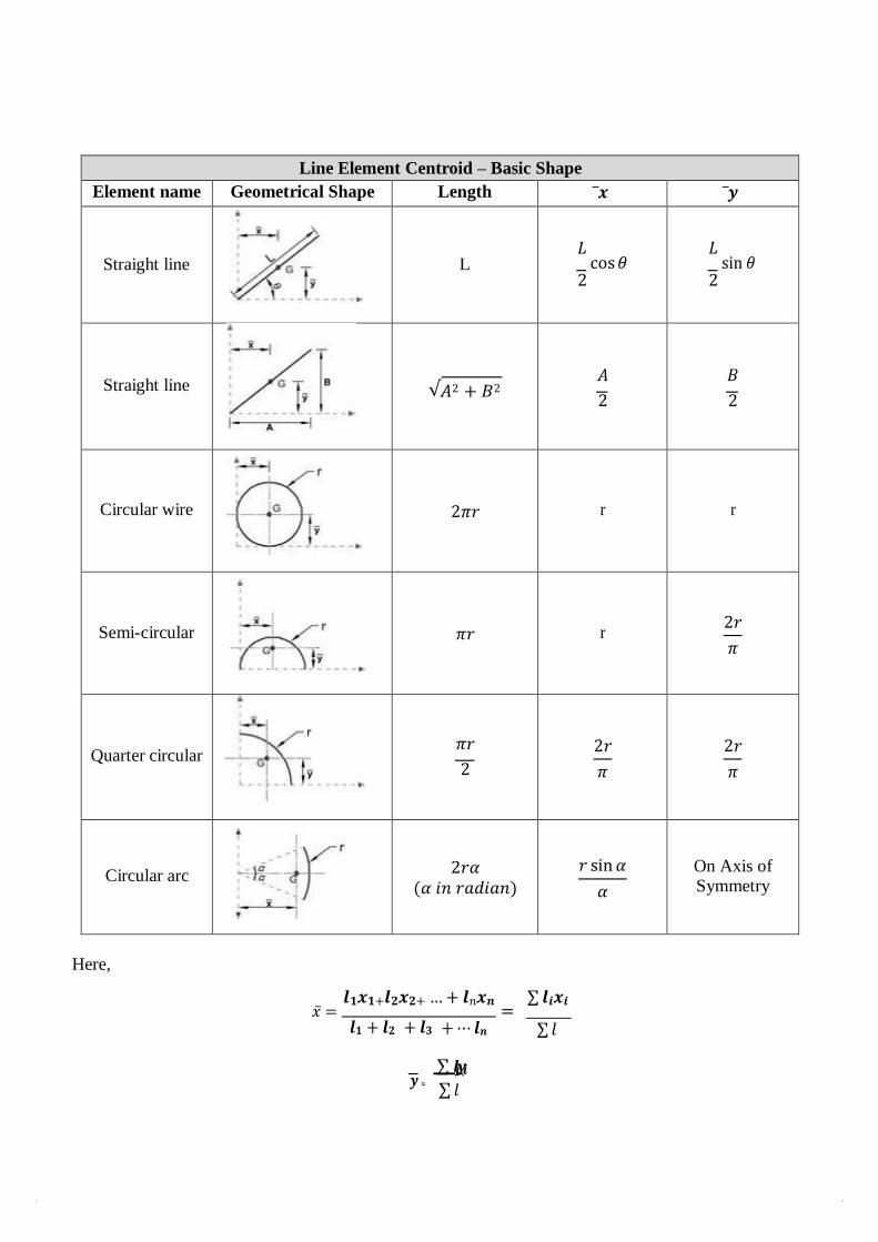
Line Element Centroid – Basic Shape
Element name Geometrical Shape Length 𝒙̅ �̅�
Straight line
L
𝐿 cos 𝜃
2
𝐿 sin 𝜃
2
Straight line
√𝐴2 + 𝐵2
𝐴
2
𝐵
2
Circular wire
2𝜋𝑟
r
r
Semi-circular
𝜋𝑟
r
2𝑟
𝜋
Quarter circular
𝜋𝑟
2
2𝑟
𝜋
2𝑟
𝜋
Circular arc
2𝑟𝛼 (𝛼 𝑖𝑛 𝑟𝑎𝑑𝑖𝑎𝑛)
𝑟 sin 𝛼
𝛼
On Axis of Symmetry
Here,
�̅� =
𝒍𝟏𝒙𝟏+𝒍𝟐𝒙𝟐+ … + 𝒍𝑛𝒙𝒏 ∑ 𝒍𝒊𝒙𝒊
= 𝒍𝟏 + 𝒍𝟐 + 𝒍𝟑 + ⋯ 𝒍𝒏 ∑ 𝑙
𝒚 =
∑ 𝒍𝒊𝒚𝒊
∑ 𝑙
𝟎
𝟎
X
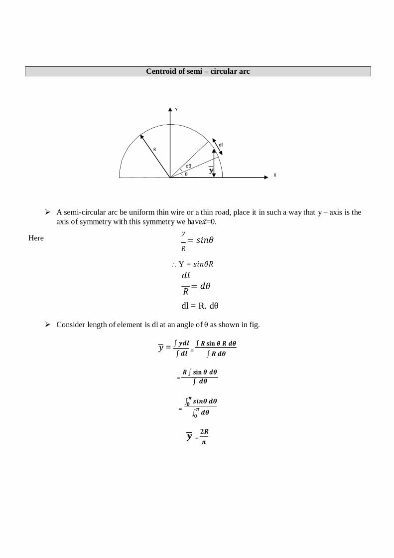
A semi-circular arc be uniform thin wire or a thin road, place it in such a way that y – axis is the
axis of symmetry with this symmetry we have𝑥=̅ 0.
Here 𝑦
= 𝑠𝑖𝑛𝜃 𝑅
Y = 𝑠𝑖𝑛𝜃𝑅
𝑑𝑙
𝑅 = 𝑑𝜃
dl = R. dθ
Consider length of element is dl at an angle of θ as shown in fig.
𝑦 = ∫ 𝒚𝒅𝒍
∫ 𝒅𝒍
∫ 𝑹 𝐬𝐢𝐧 𝜽 𝑹 𝒅𝜽
∫ 𝑹 𝒅𝜽
𝑹 ∫ 𝐬𝐢𝐧 𝜽 𝒅𝜽 =
∫ 𝒅𝜽
∫𝝅
𝒔𝒊𝒏𝜽 𝒅𝜽 =
∫𝝅
𝒅𝜽
𝒚 = 𝟐𝑹
𝝅
Centroid of semi – circular arc
Y
dl R
dθ
θ 𝒚
=
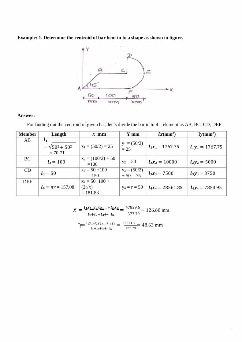
Example: 1. Determine the centroid of bar bent in to a shape as shown in figure.
Answer:
For finding out the centroid of given bar, let‟s divide the bar in to 4 – element as AB, BC, CD, DEF
Member Length 𝒙 𝐦𝐦 Y mm 𝒍𝒙(mm2) l𝒚(mm2)
AB 𝒍𝟏
= √502 + 502
= 70.71
x1 = (50/2) = 25
y1 = (50/2)
= 25
𝒍𝟏𝒙𝟏 = 1767.75
𝒍𝟏𝒚𝟏 = 1767.75
BC 𝒍𝟐 = 100
x2 = (100/2) + 50 =100
y2 = 50 𝒍𝟐𝒙𝟐 = 10000 𝒍𝟐𝒚𝟐 = 5000
CD 𝒍𝟑 = 50
x3 = 50 +100 = 150
y3 = (50/2) + 50 = 75
𝒍3𝒙𝟑 = 7500 𝒍𝟑𝒚3 = 3750
DEF
𝒍𝟒 = 𝜋𝑟 = 157.08
x4 = 50+100 +
(2r/π)
= 181.83
y4 = r = 50
𝒍𝟒𝒙4 = 28561.85
𝒍4𝒚4 = 7853.95
𝑥 ̅ = 𝒍𝟏𝒙𝟏+𝒍𝟐𝒙𝟐+…+𝒍𝑛 𝒙𝒏 =
47829.6 = 126.60 mm
𝒍𝟏+𝒍𝟐+𝒍𝟑+⋯𝒍𝒏 377.79
y̅ = l 1 y 1+l 2 y 2+…+ln yn = 18371 .7 = 48.63 mm l1 +l2 +l3+⋯ln 377 .79
2 m B A
G
D
X = 3.5 m
L
m
C
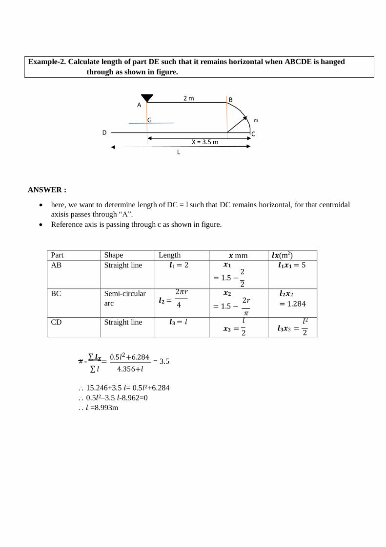
ANSWER :
here, we want to determine length of DC = l such that DC remains horizontal, for that centroidal
axisis passes through “A”.
Reference axis is passing through c as shown in figure.
Part Shape Length 𝒙 mm 𝒍𝒙(m2)
AB Straight line 𝒍1 = 2 𝒙𝟏
2 = 1.5 −
2
𝒍𝟏𝒙𝟏 = 5
BC Semi-circular
arc
2𝜋𝑟 𝒍𝟐 =
4 𝒙𝟐
2𝑟 = 1.5 −
𝜋
𝒍𝟐𝒙2
= 1.284
CD Straight line 𝒍𝟑 = 𝑙 𝑙 𝒙𝟑 =
2 𝑙2
𝒍𝟑𝒙3 = 2
𝒙 = ∑ 𝒍𝒙=
0.5𝑙2 +6.284 = 3.5
∑ 𝑙 4.356+𝑙
... 15.246+3.5 𝑙= 0.5𝑙2+6.284
... 0.5𝑙2–3.5 𝑙-8.962=0
... 𝑙 =8.993m
Example-2. Calculate length of part DE such that it remains horizontal when ABCDE is hanged
through as shown in figure.
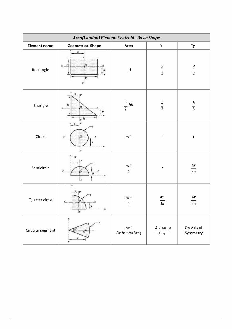
Area(Lamina) Element Centroid– Basic Shape
Element name Geometrical Shape Area ̅𝒙 𝒚̅
Rectangle
bd
𝑏
2
𝑑
2
Triangle
1 𝑏ℎ
2
𝑏
3
ℎ
3
Circle
𝜋𝑟2
r
r
Semicircle
𝜋𝑟2
2
r
4𝑟
3𝜋
Quarter circle
𝜋𝑟2
4
4𝑟
3𝜋
4𝑟
3𝜋
Circular segment
𝛼𝑟2
(𝛼 𝑖𝑛 𝑟𝑎𝑑𝑖𝑎𝑛)
2 𝑟 sin 𝛼
3 𝛼
On Axis of Symmetry
)
P Q dy h
y
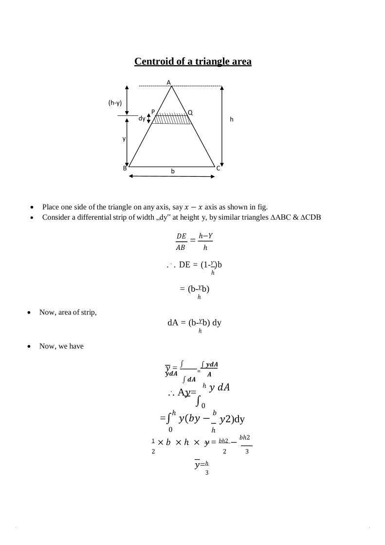
Centroid of a triangle area
A
(h-y
B b C
Place one side of the triangle on any axis, say 𝑥 − 𝑥 axis as shown in fig.
Consider a differential strip of width „dy‟ at height y, by similar triangles ∆ABC & ∆CDB
𝐷𝐸
𝐴𝐵 =
ℎ−𝑌
ℎ
. . . DE = (1-𝑌)b ℎ
Now, area of strip,
Now, we have
= (b-𝑌b) ℎ
dA = (b-𝑌b) dy
ℎ
𝑦 = ∫
𝒚𝒅𝑨 ∫ 𝒅𝑨
... A𝑦=
∫ 𝒚𝒅𝑨
𝑨
ℎ 𝑦 𝑑𝐴
∫0
=∫ℎ
𝑦(𝑏𝑦 − 𝑏
𝑦2)dy 0 ℎ
1 × 𝑏 × ℎ × 𝑦 = 𝑏ℎ2 − 𝑏ℎ2
2 2 3
𝑦=ℎ 3
=
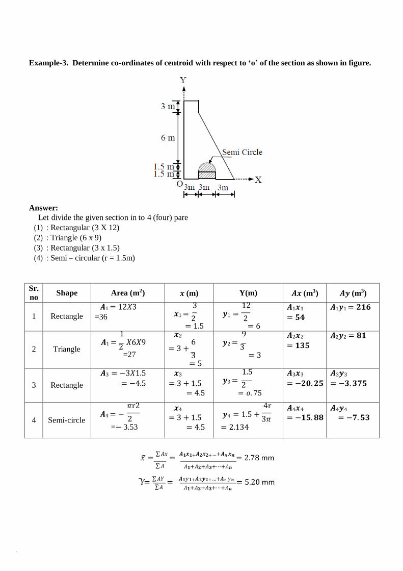
Example-3. Determine co-ordinates of centroid with respect to ‘o’ of the section as shown in figure.
Answer:
Let divide the given section in to 4 (four) pare
(1) : Rectangular (3 X 12)
(2) : Triangle (6 x 9)
(3) : Rectangular (3 x 1.5)
(4) : Semi – circular (r = 1.5m)
Sr. no
Shape Area (m2) 𝒙 (m) Y(m) 𝑨𝒙 (m3) 𝑨𝒚 (m3)
1
Rectangle
𝑨1 = 12𝑋3 =36
3 𝒙1 =
2
= 1.5
12 𝒚1 =
2
= 6
𝑨1𝒙1
= 𝟓𝟒
𝑨1𝒚1 = 𝟐𝟏𝟔
2
Triangle
1 𝑨1 =
2 𝑋6𝑋9
=27
𝒙2
6 = 3 +
3 = 5
9 𝒚2 =
3
= 3
𝑨2𝒙2
= 𝟏𝟑𝟓 𝑨2𝒚2 = 𝟖𝟏
3
Rectangle
𝑨3 = −3𝑋1.5 = −4.5
𝒙3
= 3 + 1.5 = 4.5
1.5 𝒚3 =
2
= 𝑜. 75
𝑨3𝒙3
= −𝟐𝟎. 𝟐𝟓
𝑨3𝒚3
= −𝟑. 𝟑𝟕𝟓
4
Semi-circle
𝜋r2 𝑨4 = −
2
=− 3.53
𝒙4
= 3 + 1.5 = 4.5
4r 𝒚4 = 1.5 +
3𝜋
= 2.134
𝑨4𝒙4
= −𝟏𝟓. 𝟖𝟖 𝑨4𝒚4
= −𝟕. 𝟓𝟑
𝑥̅ = ∑ 𝐴𝑥
= 𝑨𝟏𝒙𝟏+𝑨𝟐𝒙𝟐+…+𝑨𝑛 𝒙𝒏 = 2.78 mm
∑ 𝐴 𝐴𝟏+𝐴𝟐+𝐴𝟑+⋯+𝐴𝒏
�̅� = ∑ 𝐴𝑌
= 𝑨𝟏𝑦 𝟏+𝑨𝟐𝒚𝟐+…+𝑨𝑛 𝑦 𝒏 = 5.20 mm
∑ 𝐴 𝐴𝟏+𝐴𝟐+𝐴𝟑+⋯+𝐴𝒏
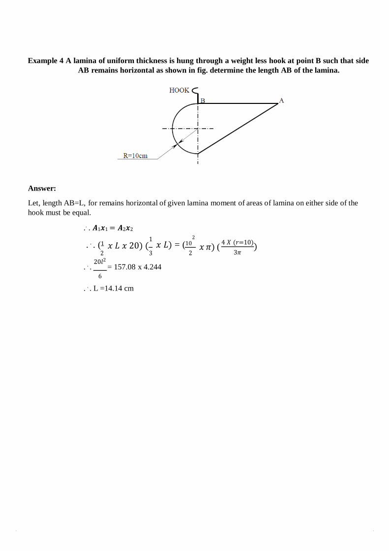
Example 4 A lamina of uniform thickness is hung through a weight less hook at point B such that side
AB remains horizontal as shown in fig. determine the length AB of the lamina.
Answer:
Let, length AB=L, for remains horizontal of given lamina moment of areas of lamina on either side of the
hook must be equal.
.. . 𝑨1𝒙1 = 𝑨2𝒙2
. . . (1
2
1 𝑥 𝐿 𝑥 20) (
3
2
𝑥 𝐿) = (10
2
𝑥 𝜋) ( 4 𝑋 (𝑟=10)
)
3𝜋
. . . 20𝑙2
= 157.08 x 4.244 6
. . . L =14.14 cm
dl B
A Y
Y
dA
C Y
Y
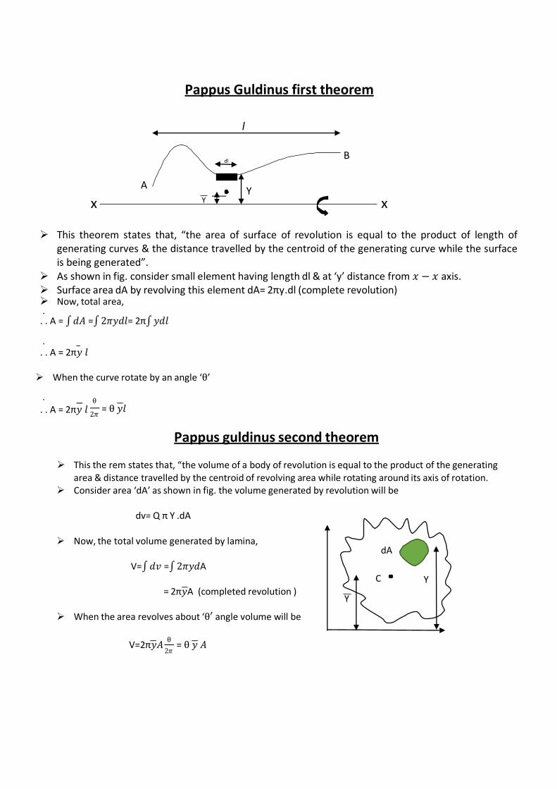
Pappus Guldinus first theorem
l
x x
This theorem states that, “the area of surface of revolution is equal to the product of length of generating curves & the distance travelled by the centroid of the generating curve while the surface is being generated”.
As shown in fig. consider small element having length dl & at ‘y’ distance from 𝑥 − 𝑥 axis. Surface area dA by revolving this element dA= 2πy.dl (complete revolution) Now, total area, .
. . A = ∫ 𝑑𝐴 =∫ 2𝜋𝑦𝑑𝑙= 2π∫ 𝑦𝑑𝑙
. . . A = 2π𝑦 𝑙
When the curve rotate by an angle ‘θ’
. θ
. . A = 2π𝑦 𝑙 2𝜋
= θ 𝑦𝑙
Pappus guldinus second theorem
This the rem states that, “the volume of a body of revolution is equal to the product of the generating area & distance travelled by the centroid of revolving area while rotating around its axis of rotation.
Consider area ‘dA’ as shown in fig. the volume generated by revolution will be
dv= Q π Y .dA
Now, the total volume generated by lamina,
V=∫ 𝑑𝑣 =∫ 2𝜋𝑦𝑑A
= 2π𝑦A (completed revolution )
When the area revolves about ‘θ′ angle volume will be
V=2π𝑦𝐴 θ
2𝜋 = θ 𝑦 𝐴
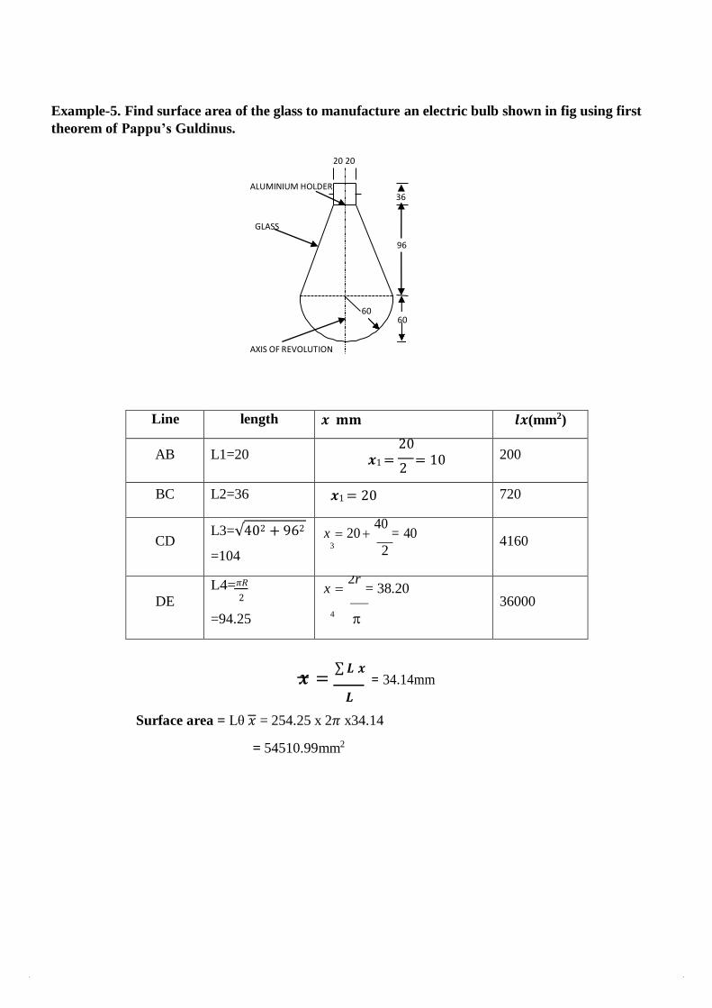
Example-5. Find surface area of the glass to manufacture an electric bulb shown in fig using first
theorem of Pappu’s Guldinus.
20 20
Line length 𝒙 𝐦𝐦 𝒍𝒙(mm2)
AB L1=20 20
𝒙1 = 2
= 10 200
BC L2=36 𝒙1 = 20 720
CD
L3=√402 + 962
=104
x 20 40
= 40
3 2
4160
DE
L4=𝜋𝑅 2
=94.25
x 2r
= 38.20
4
36000
𝒙 = ∑ 𝑳 𝒙
= 34.14mm
𝑳
Surface area = Lθ 𝑥 = 254.25 x 2𝜋 x34.14
= 54510.99mm2
ALUMINIUM HOLDER 36
GLASS
96
60 60
AXIS OF REVOLUTION
The moment of force about any point is defined as product of force and perpendicular
distance between direction of force and point under consideration. It is also called as
first moment of force.
In fact, moment does not necessary involve force term, a moment of any other
physical term can also be determined simply by multiplying magnitude of physical
quantity and perpendicular distance. Moment of areas about reference axis has been
taken to determine the location of centroid. Mathematically it was defined as,
Moment = area x perpendicular distance.
M = (A x y)
If the moment of moment is taken about same reference axis, it is known as moment
of inertia in terms of area, which is defined as,
Moment of inertia = moment x perpendicular distance.
IA =(M x y) = A.y x y = A y2
Where IA is area moment of inertia, A is area and ‘y’ is the distance been centroid of
area and reference axis. On similar notes, moment of inertia is also determined in
terms of mass, which is defined as,
Im = mr2
Where ‘m’ is mass of body, ‘r’ is distance between center of mass of body and
reference axis and Im is mass of moment of inertia about reference axis. It must be
noted here that for same area or mass moment of inertia will be change with change
in location of reference axis.
MOMENT OF INERTIA UNIT IV
Introduction
Y
C h
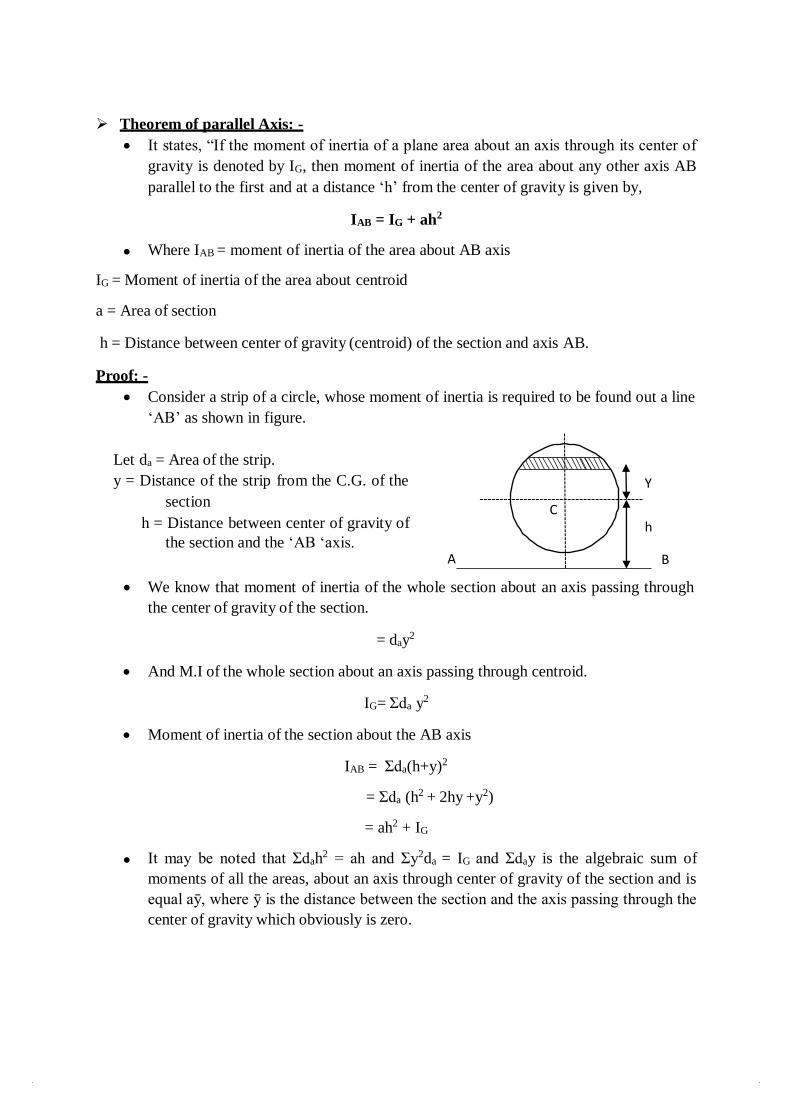
Theorem of parallel Axis: -
It states, “If the moment of inertia of a plane area about an axis through its center of
gravity is denoted by IG, then moment of inertia of the area about any other axis AB
parallel to the first and at a distance ‘h’ from the center of gravity is given by,
IAB = IG + ah2
Where IAB = moment of inertia of the area about AB axis
IG = Moment of inertia of the area about centroid
a = Area of section
h = Distance between center of gravity (centroid) of the section and axis AB.
Proof: -
Consider a strip of a circle, whose moment of inertia is required to be found out a line
‘AB’ as shown in figure.
Let da = Area of the strip.
y = Distance of the strip from the C.G. of the
section
h = Distance between center of gravity of
the section and the ‘AB ‘axis. A B
We know that moment of inertia of the whole section about an axis passing through
the center of gravity of the section.
= day2
And M.I of the whole section about an axis passing through centroid.
IG= Σda y2
Moment of inertia of the section about the AB axis
IAB = Σda(h+y)2
= Σda (h2 + 2hy +y2)
= ah2 + IG
It may be noted that Σdah2 = ah and Σy2da = IG and Σday is the algebraic sum of
moments of all the areas, about an axis through center of gravity of the section and is
equal aȳ, where ȳ is the distance between the section and the axis passing through the
center of gravity which obviously is zero.
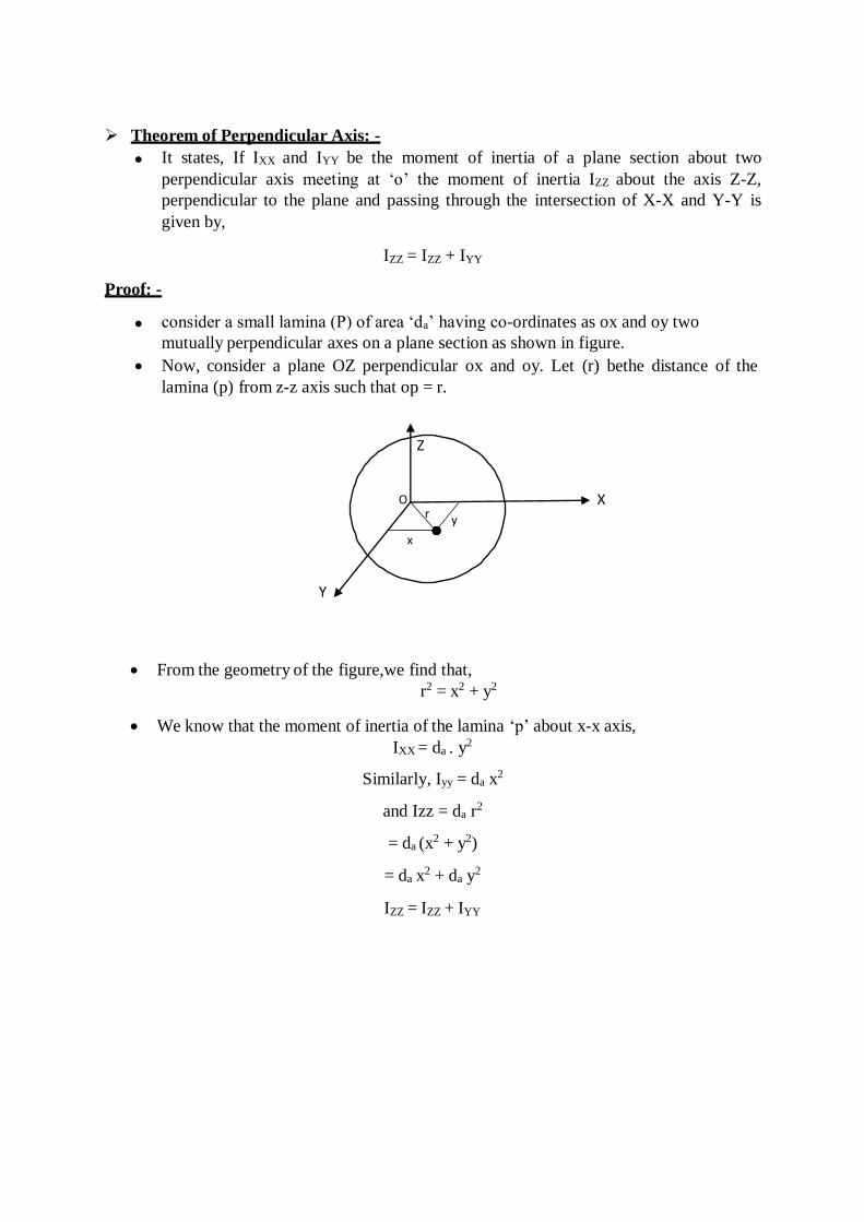
Theorem of Perpendicular Axis: -
It states, If IXX and IYY be the moment of inertia of a plane section about two
perpendicular axis meeting at ‘o’ the moment of inertia IZZ about the axis Z-Z,
perpendicular to the plane and passing through the intersection of X-X and Y-Y is
given by,
IZZ = IZZ + IYY
Proof: -
consider a small lamina (P) of area ‘da’ having co-ordinates as ox and oy two
mutually perpendicular axes on a plane section as shown in figure.
Now, consider a plane OZ perpendicular ox and oy. Let (r) bethe distance of the
lamina (p) from z-z axis such that op = r.
X
Y
From the geometry of the figure,we find that,
r2 = x2 + y2
We know that the moment of inertia of the lamina ‘p’ about x-x axis,
IXX = da . y2
Similarly, Iyy = da x2
and Izz = da r2
= da (x2 + y2)
= da x2 + da y
2
IZZ = IZZ + IYY
Z
O r y
x
Y A B
d
p q Y dx
D C Y b
∫
∫
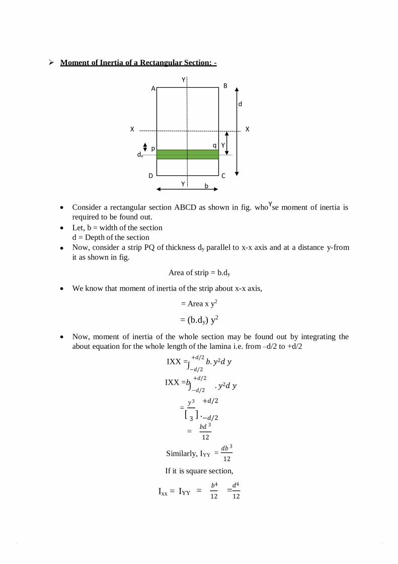
Moment of Inertia of a Rectangular Section: -
X X
Consider a rectangular section ABCD as shown in fig. whoYse moment of inertia is
required to be found out.
Let, b = width of the section
d = Depth of the section
Now, consider a strip PQ of thickness dy parallel to x-x axis and at a distance y-from
it as shown in fig.
Area of strip = b.dy
We know that moment of inertia of the strip about x-x axis,
= Area x y2
= (b.dy) y2
Now, moment of inertia of the whole section may be found out by integrating the
about equation for the whole length of the lamina i.e. from –d/2 to +d/2
IXX = +𝑑/2
𝑏. 𝑦2𝑑 𝑦 −𝑑/2
IXX =𝑏 +𝑑/2
−𝑑/2
. 𝑦2𝑑 𝑦
= 𝑦 3 +𝑑/2
[ 3
] .−𝑑/2
= 𝑏𝑑 3
12
Similarly, IYY = 𝑑𝑏 3
12
If it is square section,
Ixx
= IYY = 𝑏4
12 =
𝑑4
12
x P Q
dx
2
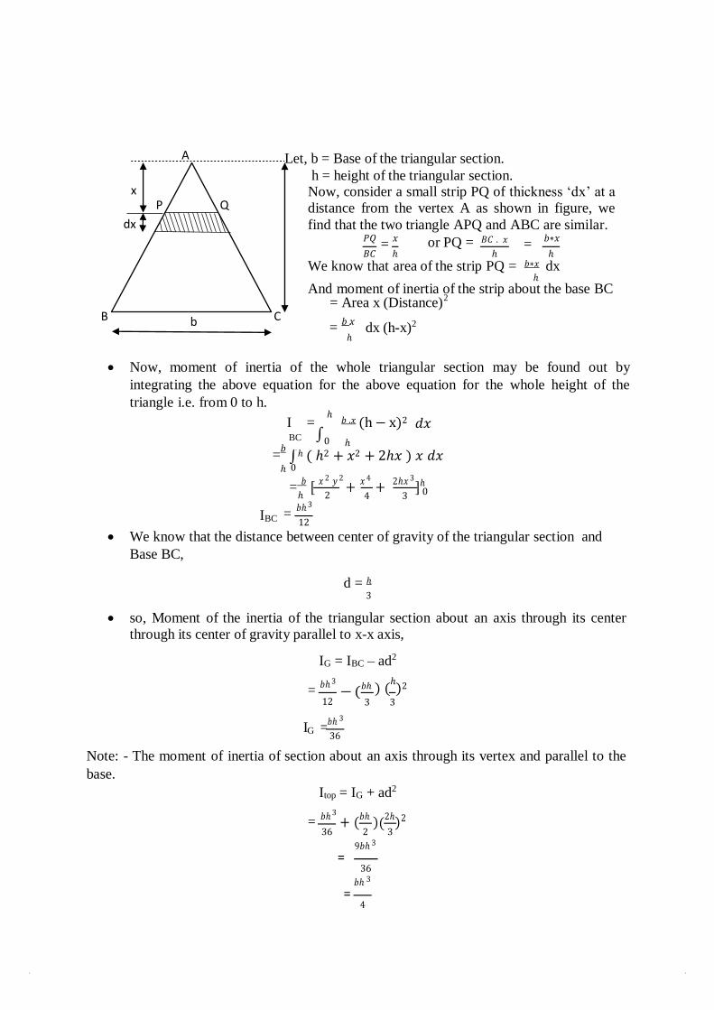
A Let, b = Base of the triangular section.
h = height of the triangular section. Now, consider a small strip PQ of thickness ‘dx’ at a
distance from the vertex A as shown in figure, we
find that the two triangle APQ and ABC are similar. 𝑃𝑄
= 𝑥 or PQ = 𝐵𝐶 . 𝑥 =
𝑏∗𝑥
𝐵𝐶 ℎ ℎ ℎ
We know that area of the strip PQ = 𝑏∗𝑥 dx ℎ
And moment of inertia of the strip about the base BC = Area x (Distance)
B b C =
𝑏 .𝑥
ℎ dx (h-x)2
Now, moment of inertia of the whole triangular section may be found out by
integrating the above equation for the above equation for the whole height of the
triangle i.e. from 0 to h.
I = ℎ
𝑏 .𝑥 (h − x)2 𝑑𝑥 BC ∫0 ℎ
=𝑏
ℎ ( ℎ2 + 𝑥2 + 2ℎ𝑥 ) 𝑥 𝑑𝑥 ℎ 0
= 𝑏 [ 𝑥 2 𝑦 2
+ 𝑥 4
+ 2ℎ𝑥 3
]ℎ
IBC
ℎ 2
= 𝑏ℎ 3
12
4 3 0
We know that the distance between center of gravity of the triangular section and
Base BC,
d = ℎ 3
so, Moment of the inertia of the triangular section about an axis through its center
through its center of gravity parallel to x-x axis,
IG = IBC – ad2
= 𝑏ℎ 3 𝑏ℎ ) (
ℎ)2
12 3 3
I =𝑏ℎ 3
G 36
Note: - The moment of inertia of section about an axis through its vertex and parallel to the
base.
Itop = IG + ad2
= 𝑏ℎ 3
+ (𝑏ℎ )(2ℎ)2
36 2 3
9𝑏ℎ 3
= 36
𝑏ℎ 3
= 4
∫
− (
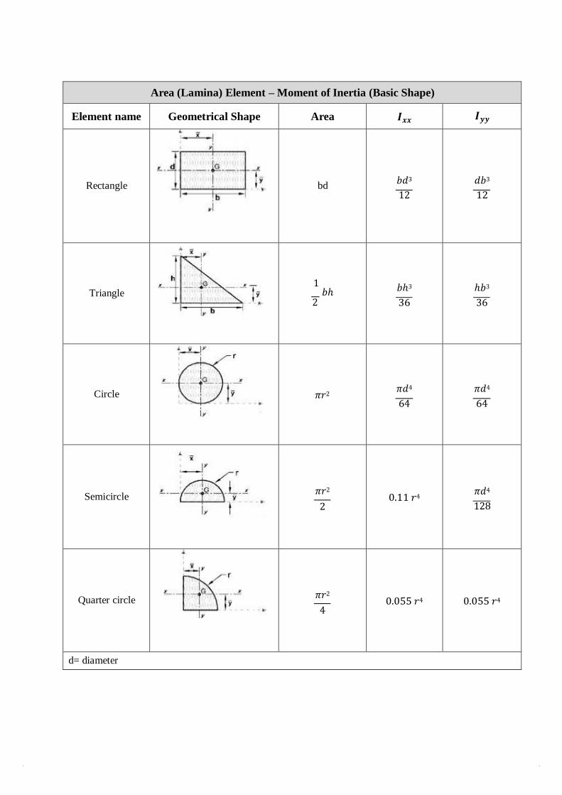
Area (Lamina) Element – Moment of Inertia (Basic Shape)
Element name Geometrical Shape Area 𝑰𝒙𝒙 𝑰𝒚𝒚
Rectangle
bd
𝑏𝑑3
12
𝑑𝑏3
12
Triangle
1 𝑏ℎ
2
𝑏ℎ3
36
ℎ𝑏3
36
Circle
𝜋𝑟2
𝜋𝑑4
64
𝜋𝑑4
64
Semicircle
𝜋𝑟2
2
0.11 𝑟4
𝜋𝑑4
128
Quarter circle
𝜋𝑟2
4
0.055 𝑟4
0.055 𝑟4
d= diameter
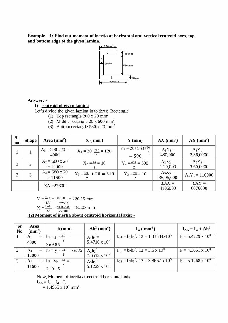
Example – 1: Find out moment of inertia at horizontal and vertical centroid axes, top
and bottom edge of the given lamina.
Answer: -
1) centroid of given lamina
Let’s divide the given lamina in to three Rectangle (1) Top rectangle 200 x 20 mm2
(2) Middle rectangle 20 x 600 mm2
(3) Bottom rectangle 580 x 20 mm2
Sr no
Shape Area (mm2) X ( mm ) Y (mm) AX (mm2) AY (mm2)
1 1 A1 = 200 x20 =
4000 X1 = 20+200 = 120
2
Y1 = 20+560+20 2
= 590
A1X1= 480,000
A1Y1 = 2,36,0000
2 2 A2 = 600 x 20
= 12000 X2 =
20 = 10 2
Y2 = 600 = 300
2
A2X2 = 1,20,000
A2Y2 = 3,60,0000
3 3 A3 = 580 x 20
= 11600 X3 = 580 + 20 = 310
2 Y3 =
20 = 10 2
A3X3 = 35,96,000
A3Y3 = 116000
ΣA =27600
ΣAX = 4196000
ΣAY = 6076000
Ӯ = ΣAY = 6076000 = 220.15 mm
ΣA
Ẍ = ΣAX
ΣA
27600
= 4196000 = 152.03 mm 27600
(2) Moment of inertia about centroid horizontal axis: -
Sr No
Area (mm2)
h (mm) Ah2 (mm4) IG ( mm4 ) IXX = IG + Ah2
1 A1 = h1 = yt - 𝑑1 = 2
A1h1 = 5.4716 x 10⁸
IG1 = b1h13/ 12 = 1.33334x10⁵
I1 = 5.4729 x 10⁸
4000 2
369.85
2 A2 = 12000
h2 = yt - 𝑑2 = 79.85 2
2
A2h2 = 7.6512 x 10⁷
IG2 = b2h23/ 12 = 3.6 x 10⁸
I2 = 4.3651 x 10⁸
3 A3 = h3= yb - 𝑑3 = 2
A3h3 = 5.1229 x 10⁸
IG3 = b3h33/ 12 = 3.8667 x 10⁵
I3 = 5.1268 x 10⁸
11600 2
210.15
Now, Moment of inertia at centroid horizontal axis
IXX = I1 + I2 + I3
= 1.4965 x 109 mm4
220 mm
20 mm
20 mm 560 mm
20mm
600 mm
3
2
1
(3) Moment of inertia about centroid verticalaxis: -
Shape
No
Area
(mm2)
h (mm) Ah2 (mm4) IG ( mm4 ) Iyy = IG + Ah2
1 A1 = 4000
h1 = Xl – X1
= 32.03
A1h = 4.1036 x 10 1
IG1 = d1b13/12
= 1.33334 x 10⁷ I1 = 1.7437 x 10⁷
2 A2 = 12000
h1 = Xl – X2
= 142.03
A2h 2 = 2.4207 x 10⁸
2 IG2 = d2b2
3/ 12 = 4 x 10⁵
I2 = 2.4247 x 10⁸
3 A3 = 11600
h1 = X3 – Xl
= 310
A3h 2 = 1.1148 x 10⁹
3 IG3 = d3b33/ 12 =
3.2519 x 10⁸
I3 = 1.4399 x 10⁹
Now, Moment of inertia at centroidal axis
Iyy = I1 + I2 + I3
= 1.6998 x 109 mm4
(4) Moment of inertia about top edge of horizontal axis: -
Shape
no
Area
(mm2) h (mm) Ah2 (mm4) IG ( mm4 ) Itt = IG + Ah2
1 A1 = 4000
h1 = 𝑑 1 = 10 2
A1h 2 = 4 x 10⁵
1
IG1 = b1d13/ 12 =
1.33334 x 10⁵ I1 = 5.3334 x 10⁵
2 A2 = 12000
h2 = 𝑑 2 = 300 2
A2h 2 = 1.08 x 10⁹
2
IG2 = b2d23/ 12 =
3.6 x 10⁹ I2 = 1.44 x 10⁹
3 A3 = 11600
h3 = 𝑑 3 = 590 2
A3h 2 = 4.038 x 10⁹
3
IG3 = b3d33/ 12 =
3.8667 x 10⁵ I3 = 4.0384 x 10⁹
Now, Moment of inertia at top edge of horizontal axis
Itt = I1 + I2 + I3
= 5.4789 x 109 mm4
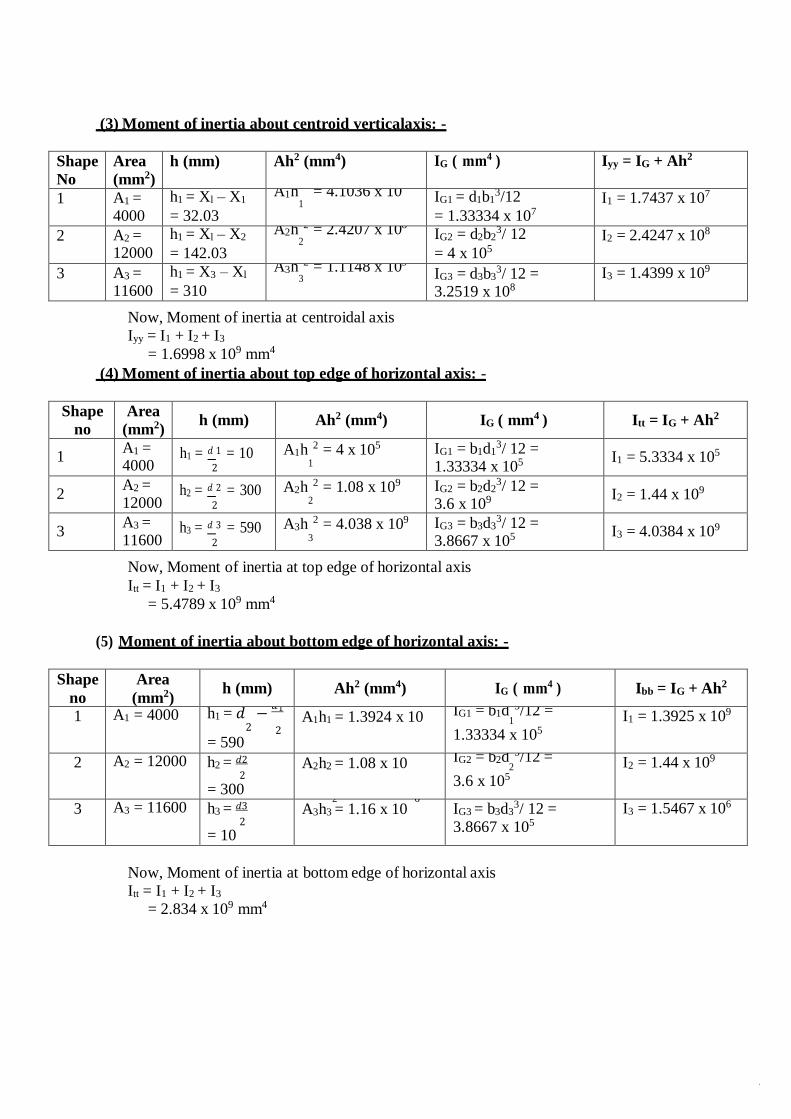
(5) Moment of inertia about bottom edge of horizontal axis: -
Shape
no
Area
(mm2) h (mm) Ah2 (mm4) IG ( mm4 ) Ibb = IG + Ah2
1 A1 = 4000 h1 = 𝑑 − 𝑑1
2 2
= 590
A1h1 = 1.3924 x 10 IG1 = b1d 3/12 =
1
1.33334 x 10⁵
I1 = 1.3925 x 10⁹
2 A2 = 12000 h2 = 𝑑2 2
= 300
A2h2 = 1.08 x 10 IG2 = b2d 3/12 =
2
3.6 x 10⁵
I2 = 1.44 x 10⁹
3 A3 = 11600 h3 = 𝑑3 2
= 10
2 6
A3h3 = 1.16 x 10 IG3 = b3d33/ 12 =
3.8667 x 10⁵
I3 = 1.5467 x 10⁶
Now, Moment of inertia at bottom edge of horizontal axis
Itt = I1 + I2 + I3
= 2.834 x 109 mm4
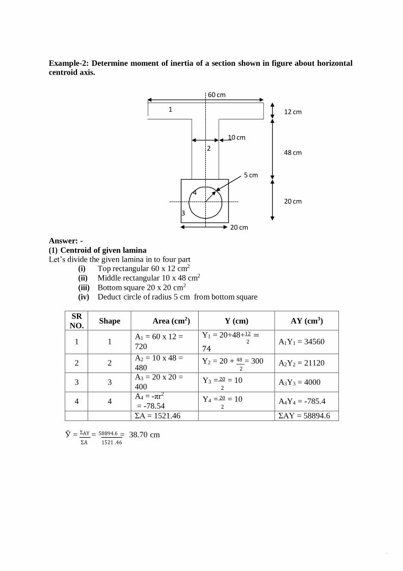
Example-2: Determine moment of inertia of a section shown in figure about horizontal
centroid axis.
12 cm
48 cm
20 cm
Answer: -
(1) Centroid of given lamina
Let’s divide the given lamina in to four part (i) Top rectangular 60 x 12 cm2
(ii) Middle rectangular 10 x 48 cm2
(iii) Bottom square 20 x 20 cm2
(iv) Deduct circle of radius 5 cm from bottom square
SR
NO. Shape Area (cm2) Y (cm) AY (cm3)
1 1 A1 = 60 x 12 =
720
Y1 = 20+48+12 = 2
74 A1Y1 = 34560
2 2 A2 = 10 x 48 = 480
Y2 = 20 + 48 = 300 2
A2Y2 = 21120
3 3 A3 = 20 x 20 = 400
Y3 = 20 = 10
2 A3Y3 = 4000
4 4 A4 = -πr2
= -78.54
Y4 = 20 = 10
2 A4Y4 = -785.4
ΣA = 1521.46 ΣAY = 58894.6
Ӯ = ΣAY = 58894.6 = 38.70 cm ΣA 1521 .46
60 cm
1
10 cm
2
5 cm
4
3
20 cm
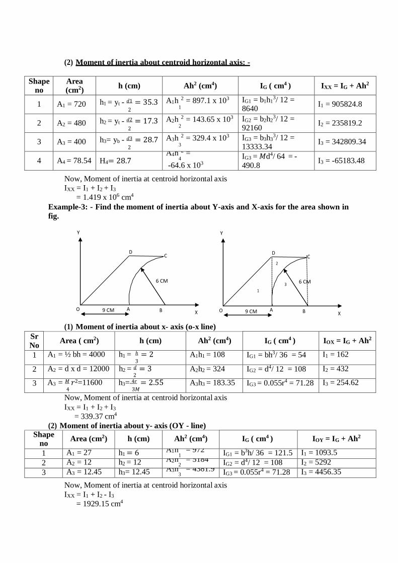
(2) Moment of inertia about centroid horizontal axis: -
Shape no
Area (cm2)
h (cm) Ah2 (cm4) IG ( cm4 ) IXX = IG + Ah2
1 A1 = 720 h1 = yt - 𝑑1 = 35.3 2
A1h 2 = 897.1 x 10³
1
IG1 = b1h13/ 12 =
8640 I1 = 905824.8
2 A2 = 480 h2 = yt - 𝑑2 = 17.3 2
A2h 2 = 143.65 x 10³
2
IG2 = b2h23/ 12 =
92160 I2 = 235819.2
3 A3 = 400 h3= yb - 𝑑3 = 28.7 2
A3h 2 = 329.4 x 10³
3
IG3 = b3h33/ 12 =
13333.34 I3 = 342809.34
4 A4 = 78.54 H4= 28.7 A4h 2 =
4
-64.6 x 10³ IG3 = 𝑀d4/ 64 = -
490.8 I3 = -65183.48
Now, Moment of inertia at centroid horizontal axis
IXX = I1 + I2 + I3
= 1.419 x 106 cm4
Example-3: - Find the moment of inertia about Y-axis and X-axis for the area shown in
fig.
Y Y
(1) Moment of inertia about x- axis (o-x line)
Sr
No Area ( cm2) h (cm) Ah2 (cm4) IG ( cm4 ) IOX = IG + Ah2
1 A1 = ½ bh = 4000 h1 = ℎ = 2 3
A1h1 = 108 IG1 = bh3/ 36 = 54 I1 = 162
2 A2 = d x d = 12000 h2 = 𝑑 = 3 2
A2h2 = 324 IG2 = d4/ 12 = 108 I2 = 432
3 A3 = 𝑀 𝑟2=11600 4
h3= 4𝑟 = 2.55 3𝑀
A3h3 = 183.35 IG3 = 0.055r4 = 71.28 I3 = 254.62
Now, Moment of inertia at centroid horizontal axis
IXX = I1 + I2 + I3
= 339.37 cm4
(2) Moment of inertia about y- axis (OY - line) Shape
no Area (cm2) h (cm) Ah2 (cm4) IG ( cm4 ) IOY = IG + Ah2
1 A1 = 27 h1 = 6 A1h = 972 1 IG1 = b3h/ 36 = 121.5 I1 = 1093.5
2 A2 = 12 h2 = 12 A2h = 5184 2 IG2 = d4/ 12 = 108 I2 = 5292
3 A3 = 12.45 h3= 12.45 A3h = 4381.9
3 IG3 = 0.055r4 = 71.28 I3 = 4456.35
Now, Moment of inertia at centroid horizontal axis
IXX = I1 + I2 - I3
= 1929.15 cm4
D C
2
3 6 CM
1
O 9 CM A B X
D C
6 CM
O 9 CM A B X
CONCEPT OF MOTION
A body is said to be in motion if it changes its position with respect to its surroundings . The nature of path of displacement of various particles of a body determines the type of motion. The motion may be of the following types :
1. Rectilinear translation
2. Curvilinear translation
3. Rotary or circular motion.
Rectilinear translation is also known as straight line motion. Here particles of a body move in straight parallel paths. Rectilinear means forming straight lines and translation means behaviour. Rectilinear translation will mean behaviour by which straight lines are formed. Thus, when a body moves such that its particles form parallel straight paths the body is said to have rectilinear translation.
In a curvilinear translation the particles of a body move along circular arcs or curved paths.
Rotary or circular motion is a special case of curvilinear motion where particles of a body move along concentric circles and the displacement is measured in terms of angle in radians or revolutions.
DEFINITIONS
1. Displacement. If a particle has rectilinear motion with respect to some point which is assumed to be fixed, its displacement is its total change of position during any interval of time. The point of reference usually assumed is one which is at rest with respect to the surfaces of the earth.
The unit of displacement is same as that of distance or length. In M.K.S. or S.I. system it is one metre.
2. Rest and motion. A body is said to be at rest at an instant (means a small interval of time) if its position with respect to the surrounding objects remains unchanged during that instant.
A body is said to be in motion at an instant if it changes its position with respect to its surrounding objects during that instant.
Actually, nothing is absolutely at rest or absolutely in motion : all rest or all motion is relative only.
3. Speed. The speed of body is defined as its rate of change of its position with respect to its surroundings irrespective of direction. It is a scalar quantity. It is measured by distance covered per unit time.
UNIT V KINEMATICS AND

Mathematically, speed
= Distance covered S Time taken t
Its units are m/sec or km/ hour.
4. Velocity. The velocity of a body is its rate of change of its position with respect to its surroundings in a particular direction. It is a vector quantity. It is measured by the distance covered in a particular direction per unit time.
i.e., Velocity = Distance covered (in a particular direction)
Time taken
v = S
. t
Its units are same as that of speed i.e., m/sec or km/hour.
5. Uniform velocity. If a body travels equal distances in equal intervals of time in the same direction it is said to be moving with a uniform or constant velocity. If a car moves 50 metres with a constant velocity in 5 seconds, its velocity will be equal to,
50 = 10 m/s.
5
6. Variable velocity. If a body travels unequal distances in equal intervals of time, in the same direction, then it is said to be moving with a variable velocity or if it is changes either its speed or its direction or both shall again be said to be moving with a variable velocity.
7. Average velocity. The average or mean velocity of a body is the velocity with which the distance travelled by the body in the same interval of time, is the same as that with the variable velocity.
If u = initial velocity of the body
v = final velocity of the body
t = time taken
S = distance covered by the body
Then average velocity = u v
and S = F u vI
t
H 2 K 8. Acceleration. The rate of change of velocity of a body is called its acceleration. When the
velocity is increasing the acceleration is reckoned as positive, when decreasing as negative. It is represented by a or f.
If u = initial velocity of a body in m/sec
v = final velocity of the body in m/sec
t = time interval in seconds, during which the change has occurred,
Then acceleration, a = v u m/sec
t sec
or a = v u
m/sec2
t
From above, it is obvious that if velocity of the body remains constant, its acceleration will be zero.
9. Uniform acceleration. If the velocity of abody changes by equal amounts in equal intervals of time, the body is said to move with uniform acceleration.
10. Variable acceleration. If the velocity of a body changes by unequal amount in equal intervals of time, the body is said to move with variable acceleration.
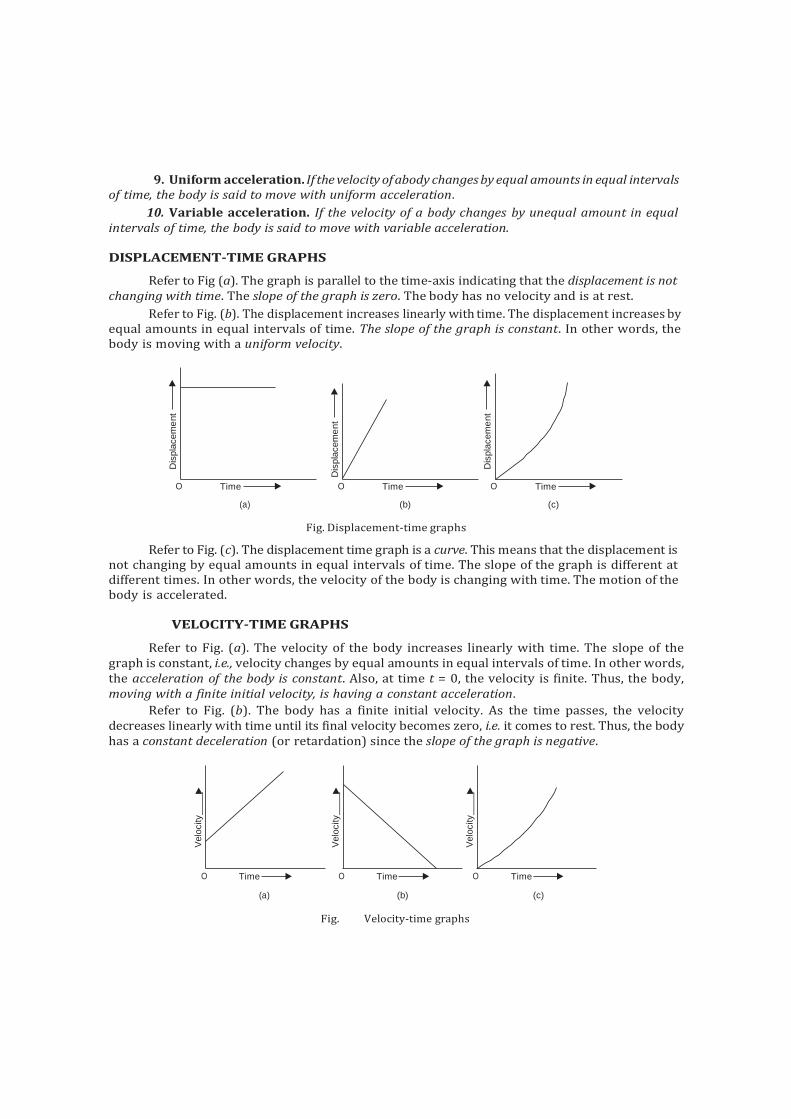
DISPLACEMENT-TIME GRAPHS
Refer to Fig (a). The graph is parallel to the time-axis indicating that the displacement is not changing with time. The slope of the graph is zero. The body has no velocity and is at rest.
Refer to Fig. (b). The displacement increases linearly with time. The displacement increases by equal amounts in equal intervals of time. The slope of the graph is constant. In other words, the body is moving with a uniform velocity.
(a) (b)
Fig. Displacement-time graphs
(c)
Refer to Fig. (c). The displacement time graph is a curve. This means that the displacement is not changing by equal amounts in equal intervals of time. The slope of the graph is different at different times. In other words, the velocity of the body is changing with time. The motion of the body is accelerated.
VELOCITY-TIME GRAPHS
Refer to Fig. (a). The velocity of the body increases linearly with time. The slope of the graph is constant, i.e., velocity changes by equal amounts in equal intervals of time. In other words, the acceleration of the body is constant. Also, at time t = 0, the velocity is finite. Thus, the body, moving with a finite initial velocity, is having a constant acceleration.
Refer to Fig. (b). The body has a finite initial velocity. As the time passes, the velocity decreases linearly with time until its final velocity becomes zero, i.e. it comes to rest. Thus, the body has a constant deceleration (or retardation) since the slope of the graph is negative.
(a) (b)
Fig. Velocity-time graphs
(c)
O Time O Time O Time
O Time O Time O Time
Dis
pla
cem
ent
Velo
city
Velo
city
Dis
pla
cem
ent
Velo
city
Dis
pla
cem
ent
F I
F I
F I
I
F I
F
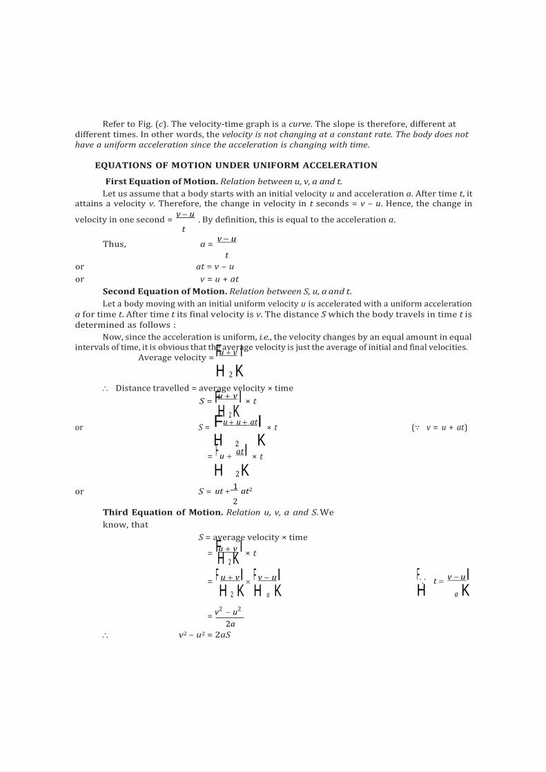
Refer to Fig. (c). The velocity-time graph is a curve. The slope is therefore, different at different times. In other words, the velocity is not changing at a constant rate. The body does not have a uniform acceleration since the acceleration is changing with time.
EQUATIONS OF MOTION UNDER UNIFORM ACCELERATION
First Equation of Motion. Relation between u, v, a and t.
Let us assume that a body starts with an initial velocity u and acceleration a. After time t, it attains a velocity v. Therefore, the change in velocity in t seconds = v – u. Hence, the change in
velocity in one second = v u
. By definition, this is equal to the acceleration a. t
Thus, a = v u
t
or at = v – u
or v = u + at
Second Equation of Motion. Relation between S, u, a and t.
Let a body moving with an initial uniform velocity u is accelerated with a uniform acceleration a for time t. After time t its final velocity is v. The distance S which the body travels in time t is determined as follows :
Now, since the acceleration is uniform, i.e., the velocity changes by an equal amount in equal intervals of time, it is obvious that the average velocity is just the average of initial and final velocities.
Average velocity = u v
H 2 K Distance travelled = average velocity × time
S = u v
× t
H 2 K or S =
u u at × t (∵ v = u + at)
H 2 K = u
at × t
H 2 K or S = ut
1 at2
2
Third Equation of Motion. Relation u, v, a and S. We
know, that
S = average velocity × time
= u v
× t
H 2 K = F u vI F v u I F∵ t
v uI H 2 K H a K H a K
= v2 u2
2a
v2 – u2 = 2aS
F I F I H K H
2
= un an u (n 1) a (n 2n 1)
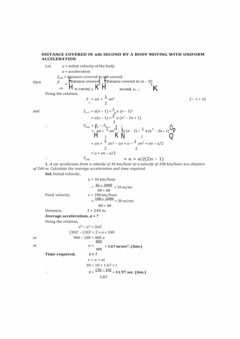
DISTANCE COVERED IN nth SECOND BY A BODY MOVING WITH UNIFORM ACCELERATION
Let u = initial velocity of the body
a = acceleration
Snth = distance covered in nth second
then S = G distance coveredJ G distance covered in (n 1)J nth in n second, sn second, sn 1 K
Using the relation,
S = un + 1
an2 (∵ t = n) n 2
and Sn–1 = u(n – 1) + 1
a (n – 1)2
= u(n – 1) + 1
a (n2 – 2n + 1)
Snth = SF n
2 – Sn
1–1
2 I LM 1 2 OP
Snth
H 2 K N 2 Q = un +
1 an2 – un + u –
1 an2 + an – a/2
2 2 = u + an – a/2
= u + a/2(2n – 1) 1. A car accelerates from a velocity of 36 km/hour to a velocity of 108 km/hour in a distance
of 240 m. Calculate the average acceleration and time required.
Sol. Initial velocity,
u = 36 km/hour
= 36 1000
60 60 = 10 m/sec
Final velocity, v = 108 km/hour
= 108 1000
= 30 m/sec 60 60
Distance, S = 240 m.
Average acceleration, a = ?
Using the relation,
v2 – u2 = 2aS
(30)2 – (10)2 = 2 × a × 240
or 900 – 100 = 480 a 800
or a = 480
= 1.67 m/sec2. (Ans.)
Time required, t = ?
v = u + at
30 = 10 + 1.67 × t
t = (30 10)
= 11.97 sec. (Ans.) 1.67
2. A body has an initial velocity of 16 m/sec and an acceleration of 6 m/sec 2. Determine its speed after it has moved 120 metres distance. Also calculate the distance the body moves during 10th second.
Sol. Initial velocity, u = 16 m/sec
Acceleration, a = 6 m/sec2
Distance, S = 120 metres
Speed, v = ?
Using the relation,
v2 – u2 = 2aS
v2 – (16)2 = 2 × 6 × 120
or v2 = (16)2 + 2 × 6 × 120
= 256 + 1440 = 1696
v = 41.18 m/sec. (Ans.)
Distance travelled in 10th sec ; S10th = ?
Using the relation,
Snth
S10th
= u + a
(2n – 1) 2
= 16 + 6
(2 × 10 – 1) = 16 + 3 (20 – 1) 2
= 73 m. (Ans.)
3. On turning a corner, a motorist rushing at 15 m/sec, finds a child on the road40 m ahead. He instantly stops the engine and applies brakes, so as to stop the car within 5 m of the child, calculate : (i) retardation, and (ii) time required to stop the car.
Sol. Initial velocity, u = 15 m/sec
Final velocity, v = 0
Distance, S = 40 – 5 = 35 m.
(i) Retardation, a = ?
Using the relation,
v2 – u2 = 2aS
02 – 152 = 2 × a × 35
a = – 3.21 m/sec2. (Ans.)
[– ve sign indicates that the acceleration is negative, i.e., retardation]
(ii) Time required to stop the car, t = ?
Using the relation,
v = u + at
0 = 15 – 3.21 × t (∵ a = – 3.21 m/sec2)
t = 15
= 4.67 s. (Ans.) 3.21
4. A burglar’s car had a start with an acceleration 2 m/sec 2. A police vigilant party came after 5 seconds and continued to chase the burglar’s car with a uniform velocity of 20 m/sec. Find the time taken, in which the police will overtake the car.
Sol. Let the police party overtake the burglar’s car in t seconds, after the instant of reaching the spot.
Distance travelled by the burglar’s car in t seconds, S1 :
Initial velocity, u = 0
Acceleration, a = 2 m/sec2
Time, t = (5 + t) sec.
Using the relation,
S = ut + 1
at2
2
S = 0 + 1
× 2 × (5 + t)2
1 2
= (5 + t)2 ...(i)
equal.
Distance travelled by the police party, S2 :
Uniform velocity, v = 20 m/sec.
Let t = time taken to overtake the burglar’s car
Distance travelled by the party,
S2 = v × t = 20t ...(ii)
For the police party to overtake the burglar’s car, the two distances S1 and S2 should be
i.e., S1 = S2
(5 + t)2 = 20t
25 + t2 + 10t = 20t
t2 – 10t + 25 = 0
t = 10 100 100
2
or t = 5 sec. (Ans.)
5. A car starts from rest and accelerates uniformly to a speed of 80 km/hour over a distance of
500 metres. Calculate the acceleration and time taken.
If a further acceleration raises the speed to 96 km/hour in 10 seconds, find the acceleration and
further distance moved.
The brakes are now applied and the car comes to rest under uniform retardation in 5 seconds.
Find the distance travelled during braking.
Sol. Considering the first period of motion :
Initial velocity, u = 0
Velocity attained, v = 80 1000
60 60
Distance covered, S = 500 m
= 22.22 m/sec.
If a is the acceleration and t is the time taken,
Using the relation :
v2 – u2 = 2aS
(22.22)2 – 02 = 2 × a × 500
a = (22.22)2
2 500
Also, v = u + at
= 0.494 m/sec2. (Ans.)
22.22 = 0 + 0.494 × t
t = 22.22
0.494 = 45 sec. (Ans.)
Now considering the second period of motion,
Using the relation,
v = u + at
where v = 96 km/hour = 96 1000
60 60
= 26.66 m/sec
u = 80 km/hour = 22.22 m/sec
t = 10 sec
26.66 = 22.22 + a × 10
a = 26.66 22.22
= 0.444 m/sec2. (Ans.) 10
To calculate distance covered, using the relation
S = ut + 1
at2
2
= 22.22 × 10 + 1
× 0.444 × 102 2
= 222.2 + 22.2 = 244.4
S = 244.4 m. (Ans.)
During the period when brakes are applied :
Initial velocity, u = 96 km/hour = 26.66 m/sec
Final velocity, v = 0
Time taken, t = 5 sec.
Using the relation,
v = u + at
0 = 26.66 + a × 5
a = 26.66
= – 5.33 m/sec2. 5
(–ve sign indicates that acceleration is negative i.e., retardation)
Now using the relation,
v2 – u2 = 2aS
02 – (26.66)2 = 2 × – 5.33 × S
S = 26.662
= 66.67 m. 2 5.33
Distance travelled during braking = 66.67 m. (Ans.)
F I
6. Two trains A and B moving in opposite directions pass one another. Theirlengths are 100 m and 75 m respectively. At the instant when they begin to pass, A is moving at 8.5 m/sec with a constant acceleration of 0.1 m/sec time the trains take to pass.
Sol. Length of train A = 100 m
Length of train B = 75 m
Total distance to be covered
2 and B has a uniform speed of 6.5 m/sec. Find the
= 100 + 75 = 175 m
Imposing on the two trains A and B, a velocity equal and opposite to that of B.
Velocity of train A = (8.5 + 6.5) = 15.0 m/sec
and velocity of train B = 6.5 – 6.5 = 0.
Hence the train A has to cover the distance of 175 m with an acceleration of 0.1 m/sec2 and an initial velocity of 15.0 m/sec.
Using the relation,
S = ut + 1
at2
2
175 = 15t + 1
× 0.1 × t2
2 3500 = 300t + t2
or t2 + 300t – 3500 = 0
t = 300 90000 14000
300 322.49
2 2 = 11.24 sec.
Hence the trains take 11.24 seconds to pass one another. (Ans.)
7. The distance between two stations is 2.6 km. A locomotive starting from one station, gives the train an acceleration (reaching a speed of 40 km/h in 0.5 minutes) until the speedreaches 48 km/hour. This speed is maintained until brakes are applied2.anFdintdratihneistimbreoutagkhetntotorepsteraftotrhme this jsoeucorndeys. tation under a negative acceleration of 0.9 m/sec
Sol. Considering the motion of the locomotive starting from the first station.
Initial velocity u = 0
Final velocity v = 40 km/hour
= 40 1000
60 60 = 11.11 m/sec.
Time taken, t = 0.5 min or 30 sec.
Let ‘a’ be the resulting acceleration.
Using the relation,
v = u + at
11.11 = 0 + 30a
a = 11.11 = 0.37 m/sec2. 30
Let t1 = time taken to attain the speed of 48 km/hour
G 48 1000 13.33 m/sec.J
H 60 60 K
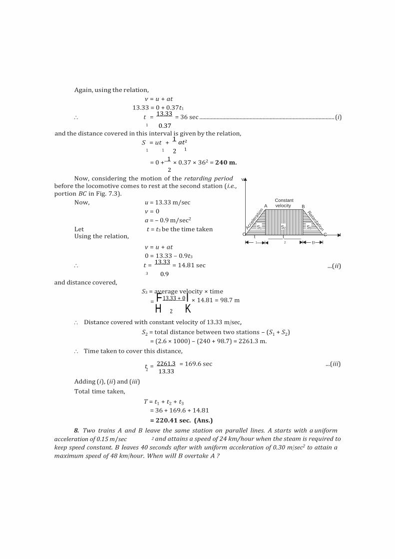
F I
Again, using the relation,
v = u + at
13.33 = 0 + 0.37t1
t = 13.33
= 36 sec .............................................................................................. (i) 1 0.37
and the distance covered in this interval is given by the relation,
S = ut + 1
at2
1 1 2 1
= 0 + 1
× 0.37 × 362 = 240 m. 2
Now, considering the motion of the retarding period v
before the locomotive comes to rest at the second station (i.e., portion BC in Fig. 7.3).
Now, u = 13.33 m/sec
v = 0
a = – 0.9 m/sec2
Let t = t3 be the time taken
Constant
A velocity B
S1 S2 S3
Using the relation, O t t C t
v = u + at
0 = 13.33 – 0.9t3
t = 13.33
= 14.81 sec
1 2 t3
...(ii)
3 0.9
and distance covered,
S3 = average velocity × time
= 13.33 + 0 × 14.81 = 98.7 m
H 2 K Distance covered with constant velocity of 13.33 m/sec,
S2 = total distance between two stations – (S1 + S2)
= (2.6 × 1000) – (240 + 98.7) = 2261.3 m.
Time taken to cover this distance,
t = 2261.3 = 169.6 sec ...(iii)
2
Adding (i), (ii) and (iii)
Total time taken,
13.33
T = t1 + t2 + t3
= 36 + 169.6 + 14.81
= 220.41 sec. (Ans.)
8. Two trains A and B leave the same station on parallel lines. A starts with a uniform
acceleration of 0.15 m/sec 2 and attains a speed of 24 km/hour when the steam is required to
keep speed constant. B leaves 40 seconds after with uniform acceleration of 0.30 m/sec2 to attain a
maximum speed of 48 km/hour. When will B overtake A ?
Sol. Motion of train A :
Uniform acceleration, a1 = 0.15 m/sec2
Initial velocity, u1 = 0
Final velocity, v1 = 24 km/hour
= 24 1000
20 m/sec. 60 60 3
Let t1 be the time taken to attain this velocity (in seconds).
Using the relation,
v = u + at 20
= 0 + 0.15t
3 1
t = 20
= 44.4 sec. 1 3 0.15
Also, distance travelled during this interval,
S = ut
+ 1 at2
1 1 2 1
Motion of train B :
= 0 + 1
× 0.15 × 44.42
2
= 148 m.
Initial velocity, u2 = 0
Acceleration, a2 = 0.3 m/sec2
Final velocity, v2 = 48 km/hr
= 48 1000 40 m/sec.
60 60 3
Let t2 be the time taken to travel this distance, say S2.
Using the relation,
v = u + at 40 = 0 + 0.3t 3
2
t = 40
= 44.4 sec 2 3 0.3
and S2 = u2t2
+ 1 a t2
2 2 2
= 0 + 1
× 0.3 × (44.4)2
2
= 296 m.
Let the train B overtake the train A when they have covered a distance S from the start. And let the train B take t seconds to cover the distance.
Thus, time taken by the train A = (t + 40) sec.
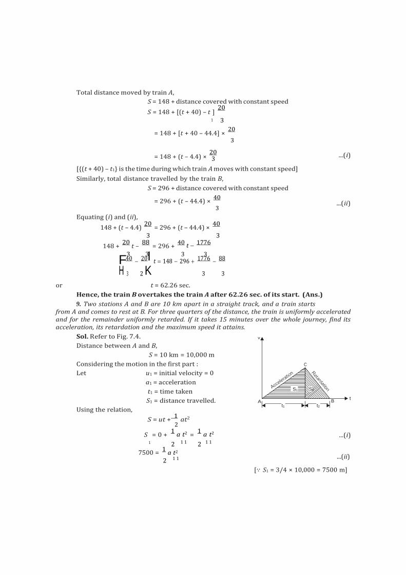
C
S1 S2
B
t1 t2
3
F3 3 3 3
Total distance moved by train A,
S = 148 + distance covered with constant speed
S = 148 + [(t + 40) – t ] 20
1 3
= 148 + [t + 40 – 44.4] × 20
3
= 148 + (t – 4.4) × 20
[{(t + 40) – t1} is the time during which train A moves with constant speed]
Similarly, total distance travelled by the train B,
S = 296 + distance covered with constant speed
= 296 + (t – 44.4) × 40
3
...(i)
...(ii)
Equating (i) and (ii),
148 + (t – 4.4) 20
= 296 + (t – 44.4) × 40
3 3
148 + 20
t – 88
= 296 + 40 t
1776
40 20I t 148 296 1776 88
H 3 2 K 3 3
or t = 62.26 sec.
Hence, the train B overtakes the train A after 62.26 sec. of its start. (Ans.)
9. Two stations A and B are 10 km apart in a straight track, and a train starts
from A and comes to rest at B. For three quarters of the distance, the train is uniformly accelerated and for the remainder uniformly retarded. If it takes 15 minutes over the whole journey, find its acceleration, its retardation and the maximum speed it attains.
Sol. Refer to Fig. 7.4. v
Distance between A and B,
S = 10 km = 10,000 m
Considering the motion in the first part :
Let u1 = initial velocity = 0
a1 = acceleration
t1 = time taken
Using the relation,
S1 = distance travelled. A t
S = ut + 1
at2 2
S = 0 + 1
a t2 = 1
a t2 ...(i) 1 2 1 1 2 1 1
7500 = 1
a t2
2 1 1 ...(ii)
[∵ S1 = 3/4 × 10,000 = 7500 m]
F I
2 2
Also, for the second retarding part
u2 = initial velocity
= final velocity at the end of first interval
= 0 + a1t1 = a1t1
Hence v2 = final velocity at the end of second part
= u2 – a2t2
= a1t1 – a2t2
= 0, because the train comes to rest
a1t1 = a2t2
or a1 t2 ...(iii)
a2 t1
Also, S2 = distance travelled in the second part = average velocity × time
= G a1t1 0 J × t
H 2 K 2
= a1t1 . t ...(iv) 2 2
Adding (i) and (iv), a t2 a t
S1 + S2 = 1 1 1 1 . t2
= a1t1 (t + t )
2 1 2
or S1 + S2 =
a1t1 × 900 (∵ t 2 1 + t2 = 15 min. = 900 sec)
10,000 = a1t1
× 900 (∵ S + S = 10 km = 10,000 m)
2 1 2
or a t 1 1
= 20,000
200
900 9 But a1t1 = maximum velocity
Hence max. velocity = 200
9
= 22.22 m/sec (Ans.)
Also, from eqn. (ii)
7500 = 1
× 22.22 × t 2 1
or t = 7500 = 675 sec 1 11.11
t2 = 900 – 675 = 225 sec
Now from eqn. (iii),
a1 t2
225
1
a2 t1 675 3
3a1 = a2.
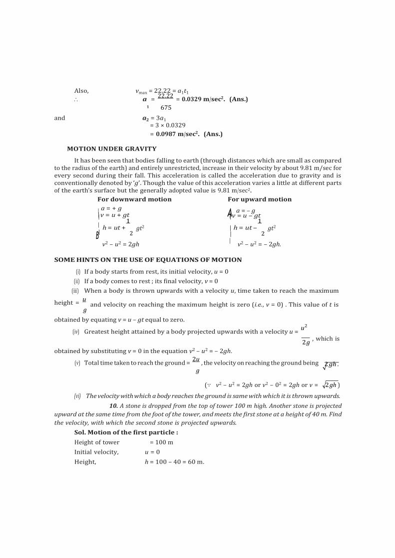
A
Also, vmax = 22.22 = a1t1
a = 22.22
= 0.0329 m/sec2. (Ans.) 1 675
and a2 = 3a1
= 3 × 0.0329
= 0.0987 m/sec2. (Ans.)
MOTION UNDER GRAVITY
It has been seen that bodies falling to earth (through distances which are small as compared to the radius of the earth) and entirely unrestricted, increase in their velocity by about 9.81 m/sec for every second during their fall. This acceleration is called the acceleration due to gravity and is conventionally denoted by ‘g’. Though the value of this acceleration varies a little at different parts of the earth’s surface but the generally adopted value is 9.81 m/sec2.
For downward motion For upward motion
a = + g
v = u + gt a = – g
v = u – gt 1
1
h = ut + gt2 h = ut – gt2
B 2 2
v2 – u2 = 2gh v2 – u2 = – 2gh.
SOME HINTS ON THE USE OF EQUATIONS OF MOTION
(i) If a body starts from rest, its initial velocity, u = 0
(ii) If a body comes to rest ; its final velocity, v = 0
(iii) When a body is thrown upwards with a velocity u, time taken to reach the maximum
height = u
g
and velocity on reaching the maximum height is zero (i.e., v = 0) . This value of t is
obtained by equating v = u – gt equal to zero.
(iv) Greatest height attained by a body projected upwards with a velocity u = u2
2 g , which is
obtained by substituting v = 0 in the equation v2 – u2 = – 2gh.
(v) Total time taken to reach the ground = 2u
, the velocity on reaching the ground being g
(∵ v2 – u2 = 2gh or v2 – 02 = 2gh or v = 2 gh )
(vi) The velocity with which a body reaches the ground is same with which it is thrown upwards.
10. A stone is dropped from the top of tower 100 m high. Another stone is projected
upward at the same time from the foot of the tower, and meets the first stone at a height of 40 m. Find
the velocity, with which the second stone is projected upwards.
Sol. Motion of the first particle :
Height of tower = 100 m
Initial velocity, u = 0
Height, h = 100 – 40 = 60 m.
2 gh .
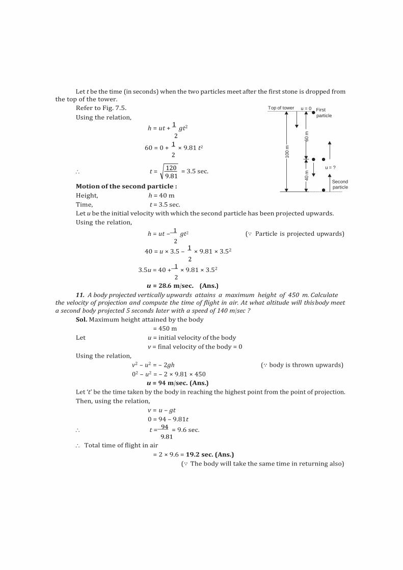
Let t be the time (in seconds) when the two particles meet after the first stone is dropped from the top of the tower.
Refer to Fig. 7.5.
Using the relation, h = ut +
1 gt2
2
60 = 0 + 1
× 9.81 t2 2
Top of tower u = 0 First
particle
t =
Motion of the second particle :
Height, h = 40 m
Time, t = 3.5 sec.
= 3.5 sec.
Let u be the initial velocity with which the second particle has been projected upwards.
Using the relation,
h = ut – 1
gt2 (∵ Particle is projected upwards) 2
40 = u × 3.5 – 1
× 9.81 × 3.52
2
3.5u = 40 + 1
× 9.81 × 3.52
2
u = 28.6 m/sec. (Ans.)
11. A body projected vertically upwards attains a maximum height of 450 m. Calculate the velocity of projection and compute the time of flight in air. At what altitude will this body meet a second body projected 5 seconds later with a speed of 140 m/sec ?
Sol. Maximum height attained by the body
= 450 m
Let u = initial velocity of the body
v = final velocity of the body = 0
Using the relation,
v2 – u2 = – 2gh (∵ body is thrown upwards)
02 – u2 = – 2 × 9.81 × 450
u = 94 m/sec. (Ans.)
Let ‘t’ be the time taken by the body in reaching the highest point from the point of projection.
Then, using the relation,
v = u – gt
0 = 94 – 9.81t
t = 94 = 9.6 sec. 9.81
Total time of flight in air
= 2 × 9.6 = 19.2 sec. (Ans.)
(∵ The body will take the same time in returning also)
120 9.81
u = ?
Second particle
100 m
40 m
60 m
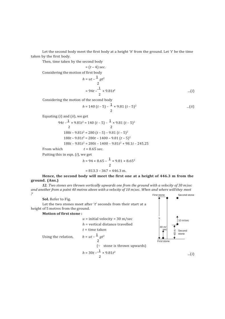
2
Let the second body meet the first body at a height ‘h’ from the ground. Let ‘t’ be the time
taken by the first body.
Then, time taken by the second body
= (t – 4) sec.
Considering the motion of first body
h = ut – 1
gt2
2 1
= 94t – × 9.81t ...(i) 2
Considering the motion of the second body
h = 140 (t – 5) – 1
× 9.81 (t – 5)2 ...(ii) 2
Equating (i) and (ii), we get
94t – 1
× 9.81t2 = 140 (t – 5) – 1
× 9.81 (t – 5)2
2 2
188t – 9.81t2 = 280 (t – 5) – 9.81 (t – 5)2
188t – 9.81t2 = 280t – 1400 – 9.81 (t – 5)2
188t – 9.81t2 = 280t – 1400 – 9.81t2 + 98.1t – 245.25
From which t = 8.65 sec.
Putting this in eqn. (i), we get
h = 94 × 8.65 – 1
× 9.81 × 8.652
2
= 813.3 – 367 = 446.3 m.
Hence, the second body will meet the first one at a height of 446.3 m from the ground. (Ans.)
12. Two stones are thrown vertically upwards one from the ground with a velocity of 30 m/sec and another from a point 40 metres above with a velocity of 10 m/sec. When and where willthey meet ?
Sol. Refer to Fig.
Let the two stones meet after ‘t’ seconds from their start at a
First stone Second stone
height of 5 metres from the ground.
Motion of first stone :
u = initial velocity = 30 m/sec
h = vertical distance travelled
t = time taken
Using the relation, h = ut – 1
gt2
2
(∵ stone is thrown upwards)
h = 30t – 1
× 9.81t2
2
First stone
...(i)
h 10 m/sec
30 m/ sec Second
stone 40 m
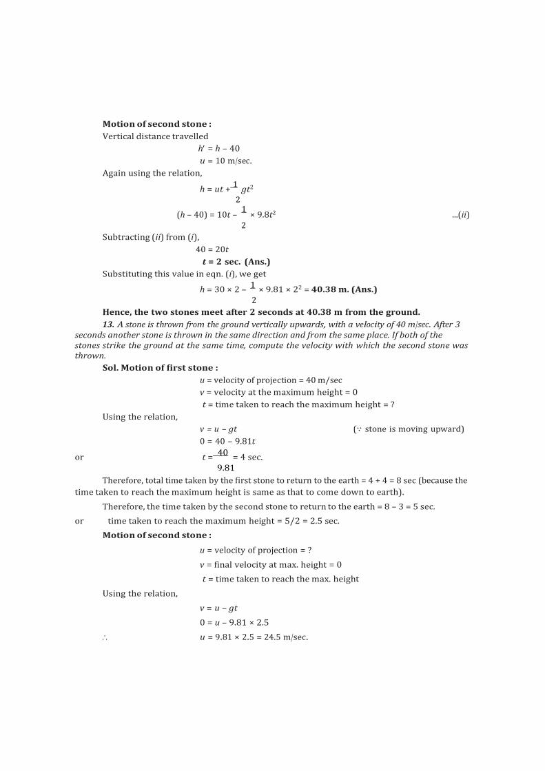
Motion of second stone :
Vertical distance travelled
h = h – 40
u = 10 m/sec.
Again using the relation,
h = ut + 1
gt2
2
(h – 40) = 10t – 1
× 9.8t2 ...(ii) 2
Subtracting (ii) from (i),
40 = 20t
t = 2 sec. (Ans.)
Substituting this value in eqn. (i), we get
h = 30 × 2 – 1
× 9.81 × 22 = 40.38 m. (Ans.) 2
Hence, the two stones meet after 2 seconds at 40.38 m from the ground.
13. A stone is thrown from the ground vertically upwards, with a velocity of 40 m/sec. After 3 seconds another stone is thrown in the same direction and from the same place. If both of the stones strike the ground at the same time, compute the velocity with which the second stone was thrown.
Sol. Motion of first stone :
u = velocity of projection = 40 m/sec
v = velocity at the maximum height = 0
t = time taken to reach the maximum height = ?
Using the relation,
v = u – gt (∵ stone is moving upward)
0 = 40 – 9.81t
or t = 40
= 4 sec. 9.81
Therefore, total time taken by the first stone to return to the earth = 4 + 4 = 8 sec (because the
time taken to reach the maximum height is same as that to come down to earth).
Therefore, the time taken by the second stone to return to the earth = 8 – 3 = 5 sec.
or time taken to reach the maximum height = 5/2 = 2.5 sec.
Motion of second stone :
u = velocity of projection = ?
v = final velocity at max. height = 0
t = time taken to reach the max. height
Using the relation,
v = u – gt
0 = u – 9.81 × 2.5
u = 9.81 × 2.5 = 24.5 m/sec.
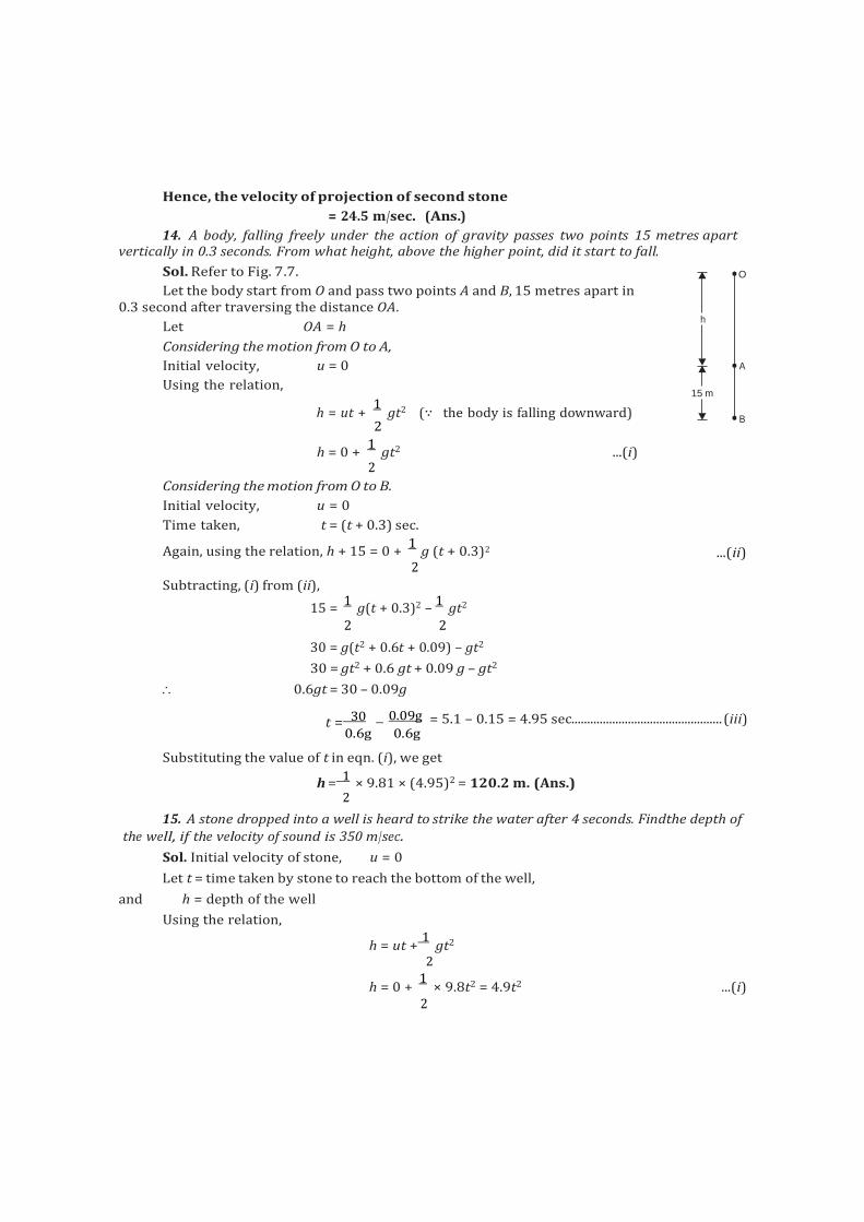
Hence, the velocity of projection of second stone
= 24.5 m/sec. (Ans.)
14. A body, falling freely under the action of gravity passes two points 15 metres apart vertically in 0.3 seconds. From what height, above the higher point, did it start to fall.
Sol. Refer to Fig. 7.7.
Let the body start from O and pass two points A and B, 15 metres apart in 0.3 second after traversing the distance OA.
Let OA = h
Considering the motion from O to A,
Initial velocity, u = 0
Using the relation,
h = ut + 1
gt2 (∵ the body is falling downward) 2
h = 0 + 1
gt2 ...(i) 2
Considering the motion from O to B.
Initial velocity, u = 0
Time taken, t = (t + 0.3) sec.
Again, using the relation, h + 15 = 0 + 1
g (t + 0.3)2 2
O
h
A
15 m
B
...(ii)
Subtracting, (i) from (ii),
15 = 1
g(t + 0.3)2 – 1
gt2
2 2
30 = g(t2 + 0.6t + 0.09) – gt2
30 = gt2 + 0.6 gt + 0.09 g – gt2
0.6gt = 30 – 0.09g
t = 30 0.09g = 5.1 – 0.15 = 4.95 sec................................................ (iii)
0.6g 0.6g
Substituting the value of t in eqn. (i), we get
h = 1
× 9.81 × (4.95)2 = 120.2 m. (Ans.) 2
15. A stone dropped into a well is heard to strike the water after 4 seconds. Findthe depth of the well, if the velocity of sound is 350 m/sec.
Sol. Initial velocity of stone, u = 0
Let t = time taken by stone to reach the bottom of the well,
and h = depth of the well
Using the relation,
h = ut + 1
gt2
2
h = 0 + 1
× 9.8t2 = 4.9t2 ...(i) 2
Also, the time taken by the sound to reach the top
= Depth of the well
Velocity of sound
= h 4.9t2
350 350
Total time taken = time taken by the stone to reach the bottom of the well
+ time taken by sound to reach the ground
= 4 seconds (given)
t + 4.9t2
= 4 350
or 4.9t2 + 350t – 1400 = 0
or t = 350 (350)2 4 4.9 1400
2 4.9
= 350 387.2
= 3.8 sec 9.8
t = 3.8 sec.
Substituting the value in eqn. (i), we get
h = 4.9 × (3.8)2 = 70.8 m
Hence, the depth of well = 70.8 m. (Ans.)
VARIABLE ACCELERATION
16. The equation of motion of a particle is S = – 6 – 5t 2 + t3
...(ii)
where S is in metres and t in seconds.
Calculate : (i) The displacement and the acceleration when the velocity is zero.
(ii) The displacement and the velocity when the acceleration is zero.
Sol. The equation of motion is
S = – 6 – 5t2 + t3 ...(given) ...(i)
Differentiating both sides, ds
or v = – 10t + 3t2
dt
v = – 10t + 3t2 ...(ii)
Again, differentiating both sides,
dv or a = – 10 + 6t
dt
a = – 10 + 6t ...(iii)
Now, (i) When the velocity is zero,
v = – 10t + 3t2 = 0
t(3t – 10) = 0
t = 10
= 3.33 sec. (ignoring t = 0 which means start) 3
Substituting this value in eqns. (i) and (iii),
S = displacement
= – 6 – 5 × 3.332 + 3.333
= – 6 – 55.44 + 36.92
= – 24.52 m. (Ans.)
The negative sign indicates that distance is travelled in the other direction.
Also, a = acceleration
= – 10 + 6 × 10
= 10 m/sec2. (Ans.) 3
(ii) When the acceleration is zero
a = – 10 + 6t = 0
6t = 10
or t = 10
5
= 1.67 sec. 6 3
Substituting this value in eqns. (i) and (ii), we get
S = displacement
= – 6 – 5t2 + t3 = – 6 – 5 × (1.67)2 + (1.67)3
= – 6 – 13.94 + 4.66 = – 15.28 m. (Ans.)
The –ve sign again means that the distance is travelled in the other direction.
Also, v = – 10t + 3t2
= – 10 × 1.67 + 3 × (1.67)2 = – 16.7 + 8.36
= – 8.34 m/sec. (Ans.)
17. If a body be moving in a straight line and its distance S in metres from a givenpoint in the
line after t seconds is given by the equation
S = 20t + 3t2 – 2t3.
Calculate : (a) The velocity and acceleration at the start.
(b) The time when the particle reaches its maximum velocity.
(c) The maximum velocity of the body.
Sol. The equation of motion is
S = 20t + 3t2 – 2t3 ...(i)
Differentiating both sides
dS = v = 20 + 6t – 6t2 ...(ii) dt
Again, differentiating
d2S
dv = a = 6 – 12t ...(iii)
dt2 dt
(a) At start, t = 0
Hence from eqns. (ii) and (iii),
v = 20 + 0 – 0 = 20 m/sec. (Ans.)
a = 6 – 12 × 0 = 6 m/sec. (Ans.)
(b) When the particle reaches its maximum velocity
a = 0
i.e., 6 – 12t = 0
t = 0.5 sec. (Ans.)
(b) The maximum velocity of the body
When t = 0.5 sec.
vmax = 20 + 6t – t2
= 20 + 6 × 0.5 – 6 × 0.52
= 20 + 3 – 1.5
= 21.5 m/sec. (Ans.)
SELECTED QUESTIONS EXAMINATION PAPERS
18. Two trains A and B leave the same station on parallel lines. A starts with uniform acceleration of 0.15 m/s 2 and attains a speed of 24 km/hour when the steam is reduced to keep the speed constant. B leaves 40 seconds after with a uniform acceleration of 0.30 m/s2 to attain a maximum speed of 48 km/hour. When will B overtake A ?
Sol. Motion of train A:
Uniform acceleration, a1 = 0.15 m/s2
Initial velocity, u1 = 0
Final velocity, v1 = 24 km/h
= 24 1000 = 20 m/sec 60 60 3
Let t1 be the time taken to attain this velocity (in seconds)
Using the relation:
v = u + at 20 = 0 + 0.15 × t 3 1
t = 20
= 44.4 sec 1 3 0.15
Also, distance travelled during this interval,
s = u t + 1
a t2
1 1 1 2 1 1
Motion of train B:
= 0 + 1
× 0.15 × 44.42 = 148 m 2
Initial velocity, u2 = 0
Acceleration, a2 = 0.3 m/sec2
Final velocity, v2 = 48 km/h
= 48 1000 40 m/sec
60 60 3
Let t2 be taken to travel this distance, say s2
Using the relation:
v = u + at
I
2
F
40 = 0 + 0.3 × t
3 2
t = 40
= 44.4 s 2 3 0.3
and s2 = u2t2 + 1
a2t2
2 2
= 0 + 1
× 0.3 × (44.4)2 = 296 m 2
Let the train B overtake the train A when they have covered a distance s from the start. And let the train B take t seconds to cover the distance.
Thus, time taken by the train A = (t + 40) sec.
Total distance moved by train A.
s = 148 + distance covered with constant speed
= 148 + [(t + 40) – t1] × 20/3
= 148 + [t + 40 – 44.4] × 20/3
= 148 + (t – 4.4) × 20/3 ...(i)
[{(t + 40) – t2} is the time during which train A moves with constant speed].
Similarly, total distance travelled by the train B,
s = 296 + distance covered with constant speed
= 296 + (t – 44.4) × 40/3 ...(ii)
Equating (i) and (ii)
148 + (t – 4.4) × 20/3 = 296 + (t – 44.4) × 40/3
148 20
t 88
= 296 40
t 1776
3 3 3 3 40 20 t = 148 296 1776 88
H 3 3 K 3 3
t = 62.26 s
Hence, train B, overtakes train A after 62.26 s of its start. (Ans.)
19. A cage descends a mine shaft with an acceleration of 1 m/s 2. After the cage has travelled 30 m, stone is dropped from the top of the shaft. Determine: (i) the time taken by the stone to hit the cage, and (ii) distance travelled by the cage before impact.
Sol. Acceleration of cage,
a = 1 m/s2
Distance travelled by the shaft before dropping of the stone = 30 m
(i) Time taken by the stone to hit the cage = ?
Considering motion of the stone.
Initial velocity, u = 0
Let t = time taken by the stone to hit the cage, and
h1 = vertical distance travelled by the stone before the impact.
Using the relation,
h = ut + 1
gt2
h = 0 + 1
× 9.8 t2 = 4.9 t2 ...(i) 1 2
2
Now let us consider motion of the cage for 30 m
Initial velocity, u = 0
Acceleration, a = 1.0 m/s2.
Let t = time taken by the shaft to travel 30 m
Using the relation,
s = ut + 1
at2
2
30 = 0 + 1
× 1 × (t)2
2
t = 7.75 s.
It means that cage has travelled for 7.75 s before the stone was dropped. Therefore total time
taken by the cage before impact = (7.75 + t).
Again using the relation:
s = ut + 1
at2
2
s = 0 + 1
× 1 × (7.75 + t)2 ...(ii) 1 2
In order that stone may hit the cage the two distances must be equal i.e., equating (i) and (ii).
4.9 t2 = 1
× (7.75 + t)2
2
4.9 = 0.5 (60 + t2 + 15.5 t)
or 9.8 = t2 + 15.5 t + 60
or t2 + 15.5 t – 50.2 = 0
t = 15.5 (15.5)2 4 50.2
2 = 15.5
2
441.05
= 15.5 21.0
2 = 2.75 s (neglecting –ve sign)
t = 2.75 s. (Ans.)
(ii) Distance travelled by the cage before impact = ?
Let s2 = distance travelled by the cage before impact.
We know total time taken by the cage before impact.
= 7.75 + 2.75 = 10.5 s.
Now using the relation,
s = ut + 1
at2
2 2
1 = 0 + × 1 × (10.5) = 55.12 m
2
Hence distance travelled by the cage before impact = 55.12 m. (Ans.)
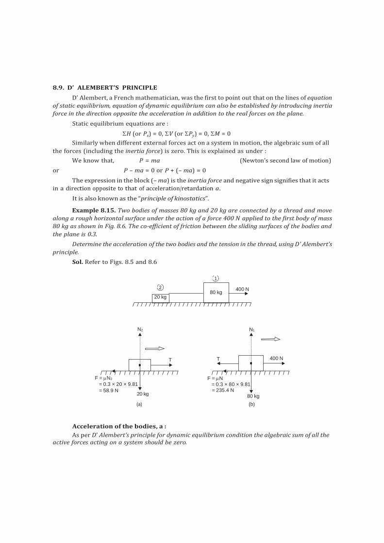
20 kg
8.9. D’ ALEMBERT’S PRINCIPLE
D’ Alembert, a French mathematician, was the first to point out that on the lines of equation
of static equilibrium, equation of dynamic equilibrium can also be established by introducing inertia
force in the direction opposite the acceleration in addition to the real forces on the plane.
Static equilibrium equations are :
H (or Px) = 0, V (or Py) = 0, M = 0
Similarly when different external forces act on a system in motion, the algebraic sum of all
the forces (including the inertia force) is zero. This is explained as under :
We know that, P = ma (Newton’s second law of motion)
or P – ma = 0 or P + (– ma) = 0
The expression in the block (– ma) is the inertia force and negative sign signifies that it acts
in a direction opposite to that of acceleration/retardation a.
It is also known as the “principle of kinostatics”.
Example 8.15. Two bodies of masses 80 kg and 20 kg are connected by a thread and move
along a rough horizontal surface under the action of a force 400 N applied to the first body of mass
80 kg as shown in Fig. 8.6. The co-efficient of friction between the sliding surfaces of the bodies and
the plane is 0.3.
Determine the acceleration of the two bodies and the tension in the thread, using D’ Alembert’s
principle.
Sol. Refer to Figs. 8.5 and 8.6
N2 N1
T T 400 N
F = N2
= 0.3 × 20 × 9.81 F = N
= 0.3 × 80 × 9.81
= 58.9 N = 235.4 N 80 kg
(a) (b)
Acceleration of the bodies, a :
As per D’ Alembert’s principle for dynamic equilibrium condition the algebraic sum of all the active forces acting on a system should be zero.
2
1
400 N
20 kg
80 kg
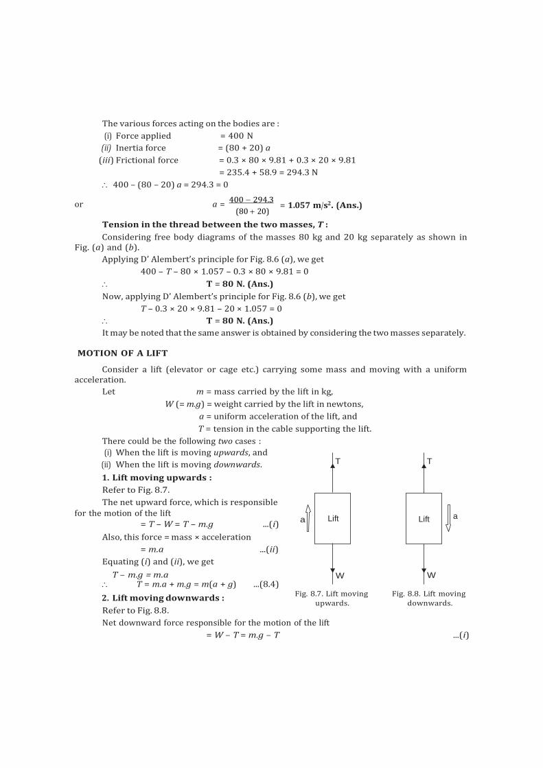
Lift
Lift
The various forces acting on the bodies are :
(i) Force applied = 400 N
(ii) Inertia force = (80 + 20) a
(iii) Frictional force = 0.3 × 80 × 9.81 + 0.3 × 20 × 9.81
= 235.4 + 58.9 = 294.3 N
400 – (80 – 20) a = 294.3 = 0
or a = 400 294.3
(80 20)
= 1.057 m/s2. (Ans.)
Tension in the thread between the two masses, T :
Considering free body diagrams of the masses 80 kg and 20 kg separately as shown in Fig. (a) and (b).
Applying D’ Alembert’s principle for Fig. 8.6 (a), we get
400 – T – 80 × 1.057 – 0.3 × 80 × 9.81 = 0
T = 80 N. (Ans.)
Now, applying D’ Alembert’s principle for Fig. 8.6 (b), we get
T – 0.3 × 20 × 9.81 – 20 × 1.057 = 0
T = 80 N. (Ans.)
It may be noted that the same answer is obtained by considering the two masses separately.
MOTION OF A LIFT
Consider a lift (elevator or cage etc.) carrying some mass and moving with a uniform acceleration.
Let m = mass carried by the lift in kg,
W (= m.g) = weight carried by the lift in newtons,
a = uniform acceleration of the lift, and
T = tension in the cable supporting the lift.
There could be the following two cases :
(i) When the lift is moving upwards, and
(ii) When the lift is moving downwards. T T
1. Lift moving upwards :
Refer to Fig. 8.7.
The net upward force, which is responsible for the motion of the lift a
= T – W = T – m.g ...(i) a
Also, this force = mass × acceleration
= m.a ...(ii)
Equating (i) and (ii), we get
T – m.g = m.a W W T = m.a + m.g = m(a + g) ...(8.4)
2. Lift moving downwards :
Refer to Fig. 8.8.
Fig. 8.7. Lift moving upwards.
Fig. 8.8. Lift moving downwards.
Net downward force responsible for the motion of the lift
= W – T = m.g – T ...(i)
Also, this force = mass × acceleration
= m.a ...(ii)
Equating (i) and (ii), we get
m.g – T = m.a
T = m.g – m.a = m (g – a)
16. An elevator cage of mass 900 kg when empty is lifted or lowered vertically by means of a
wire rope. A man of mass 72.5 kg is standing in it. Find :
(a) The tension in the rope,
(b) The reaction of the cage on the man, and
(c) The force exerted by the man on the cage, for the following two conditions :
(i) when the cage is moving up with an acceleration of 3 m/s2 and
(ii) when the cage is moving down with a uniform velocity of 3 m/s.
Sol. Mass of the cage, M = 900 kg
Mass of the man, m = 72.5 kg.
(i) Upward acceleration, a = 3 m/s2
(a) Let T be the tension in the rope in newtons
The various forces acting on the cage are :
1. Tension, T of the rope acting vertically upwards.
2. Total mass = M + m, of the cage and the man acting vertically downwards.
As the cage moves upwards, T > (M + m) g
Net accelerating force = T – (M + m) g = (m + m) a
T – (M + m) g = (M + m) a ...(i)
Substituting the given values, we get
T – (900 + 72.5) 9.81 = (900 + 72.5) × 3
T = 12458 N. (Ans.)
(b) Let ‘R’ be the reaction of the cage on the man in newtons.
Considering the various forces, the equation of motion is
R – mg = m.a ...(ii)
or R = mg + ma = m (g + a)
= 72.5 (9.81 + 3) = 928.7 N. (Ans.)
(c) The force exerted by the man on the cage must be equal to the force exerted by the cage
on the man (Newton’s third law of motion).
Force exerted by the man on the cage = 928.7 N. (Ans.)
(ii) When the cage moves with a uniform velocity 3 m/s :
When the cages moves with a uniform velocity, acceleration is equal to zero.
(a) Tension in the rope, T :
Putting a = 0 in eqn. (i), we get
T – (M + m) g = (M + m) × 0 = 0
T = (M + m) g
= (900 + 72.5) × 9.81 = 9540 N. (Ans.)
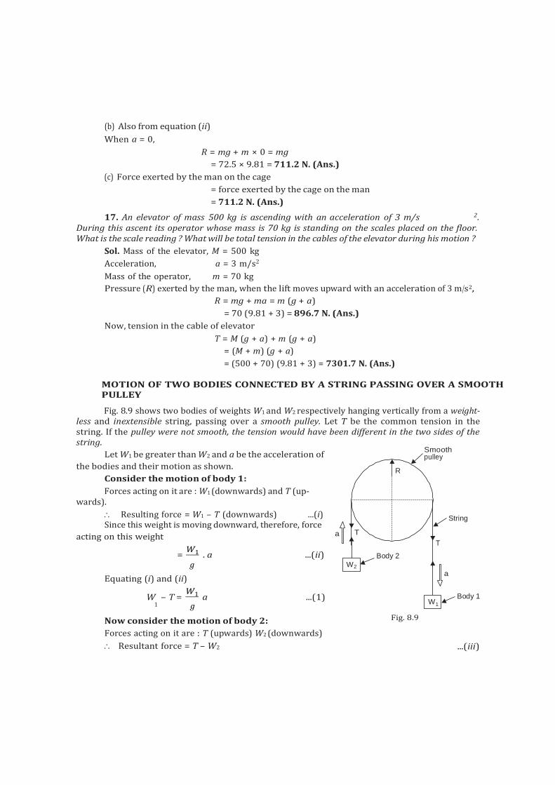
pulley
(b) Also from equation (ii)
When a = 0,
R = mg + m × 0 = mg
= 72.5 × 9.81 = 711.2 N. (Ans.)
(c) Force exerted by the man on the cage
= force exerted by the cage on the man
= 711.2 N. (Ans.)
17. An elevator of mass 500 kg is ascending with an acceleration of 3 m/s 2. During this ascent its operator whose mass is 70 kg is standing on the scales placed on the floor. What is the scale reading ? What will be total tension in the cables of the elevator during his motion ?
Sol. Mass of the elevator, M = 500 kg
Acceleration, a = 3 m/s2
Mass of the operator, m = 70 kg
Pressure (R) exerted by the man, when the lift moves upward with an acceleration of 3 m/s2,
R = mg + ma = m (g + a)
= 70 (9.81 + 3) = 896.7 N. (Ans.)
Now, tension in the cable of elevator
T = M (g + a) + m (g + a)
= (M + m) (g + a)
= (500 + 70) (9.81 + 3) = 7301.7 N. (Ans.)
MOTION OF TWO BODIES CONNECTED BY A STRING PASSING OVER A SMOOTH PULLEY
Fig. 8.9 shows two bodies of weights W1 and W2 respectively hanging vertically from a weight- less and inextensible string, passing over a smooth pulley. Let T be the common tension in the string. If the pulley were not smooth, the tension would have been different in the two sides of the string.
Let W1 be greater than W2 and a be the acceleration of Smooth
the bodies and their motion as shown.
Consider the motion of body 1:
Forces acting on it are : W1 (downwards) and T (up- wards).
Resulting force = W1 – T (downwards) ...(i) Since this weight is moving downward, therefore, force
acting on this weight a T
= W1 . a ...(ii)
R
Body 2
String
T
g W2
Equating (i) and (ii) a
W – T = W1 a ...(1)
1 g
Now consider the motion of body 2:
Forces acting on it are : T (upwards) W2 (downwards)
Resultant force = T – W2
W1
Fig. 8.9
Body 1
...(iii)
F I
1
LAWS OF MOTION 231
Since the body is moving upwards therefore force acting on the body
= W2 . a ............................................................................................................ (iv)
g
Equating (iii) and (iv)
T – W2 =
W2 . a ...(2) g
Now adding eqns. (1) and (2), we get W1 W2
W1 – W2 = GH g JK a
F W1 W2 I from which, a =
From equation (2),
HGW W KJ .g
T – W2
= W2 a
g F I
T = W + W2 a W2 G 1
a J 2 g H g K
Substituting the value of ‘a’ from equation (8.6), we get
T = W LM1
FG W1 W2 IJ . g OP 2 MN H W1 W2 K g PQ
from which, T = 2 W1 W2
W1 W2
Reaction of the pulley,
R = T + T = 2T
= 4W1 W2
W1 W2
Example 8.18. Two bodies weighing 45 N and 60 N are hung to the ends of a rope, passing
over a frictionless pulley. With what acceleration the heavier weight comes down ? What is the
tension in the string ?
Sol. Weight of heavier body, W1 = 60 N
Weight of lighter body, W2 = 45 N
Acceleration of the system, a = ?
Using the relation,
a = g (W1 W2)
(W1 W2) Tension in the string, T = ?
Using the relation,
= 9.81 (60 45)
= 1.4 m/s2. (Ans.) (60 45)
T = 2 W1 W2 2 60 45 = 51.42 N. (Ans.)
W1 W2 (60 45)
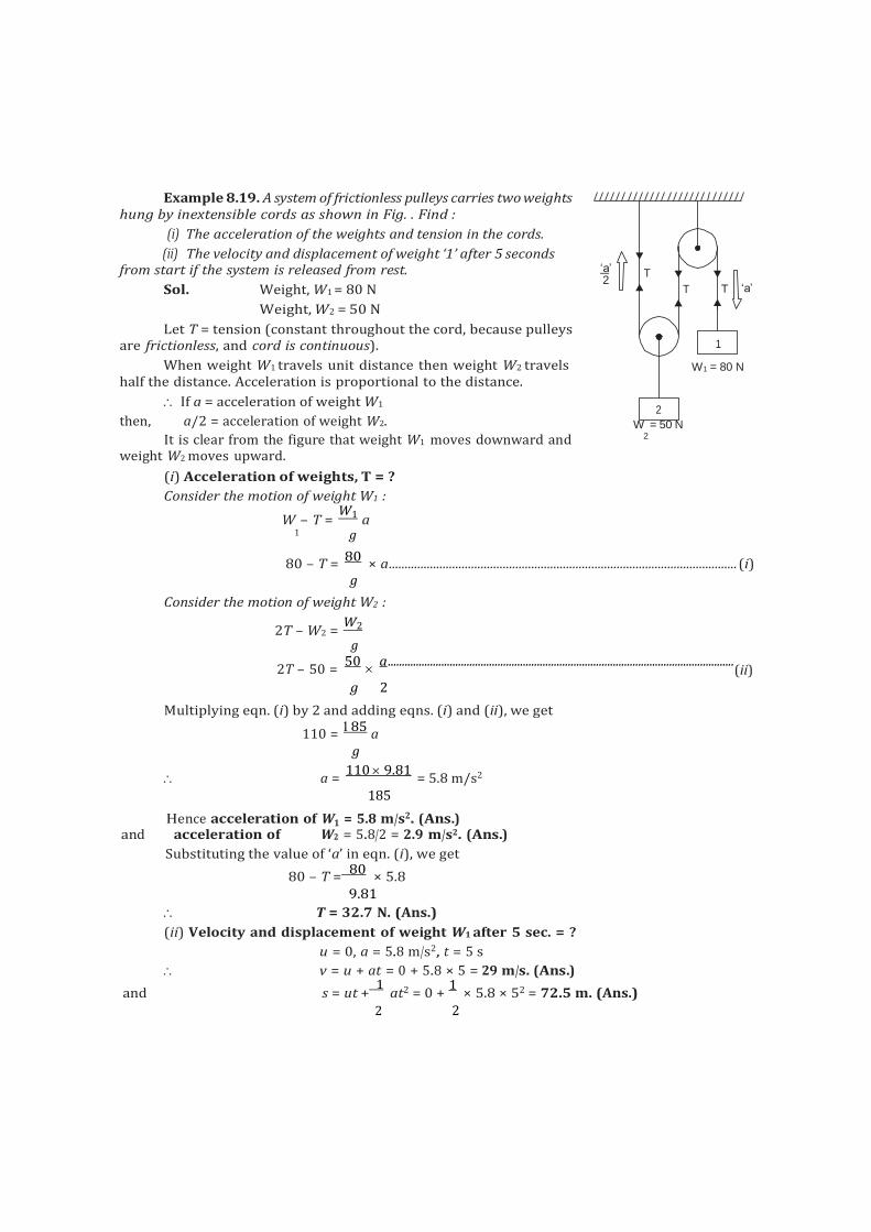
‘a’ 2
T
T T ‘a’
W1 = 80 N
2
1
Example 8.19. A system of frictionless pulleys carries two weights hung by inextensible cords as shown in Fig. . Find :
(i) The acceleration of the weights and tension in the cords.
(ii) The velocity and displacement of weight ‘1’ after 5 seconds from start if the system is released from rest.
Sol. Weight, W1 = 80 N
Weight, W2 = 50 N
Let T = tension (constant throughout the cord, because pulleys are frictionless, and cord is continuous).
When weight W1 travels unit distance then weight W2 travels half the distance. Acceleration is proportional to the distance.
If a = acceleration of weight W1
then, a/2 = acceleration of weight W2. W = 50 N
It is clear from the figure that weight W1 moves downward and 2 weight W2 moves upward.
(i) Acceleration of weights, T = ?
Consider the motion of weight W1 :
W – T = W1 a
1 g
80 – T = 80
× a .............................................................................................................. (i) g
Consider the motion of weight W2 :
2T – W2 = W2
g
2T – 50 = 50
a ...........................................................................................................................
(ii) g 2
Multiplying eqn. (i) by 2 and adding eqns. (i) and (ii), we get
110 = 85
a g
a = 110 9.81
= 5.8 m/s2
185
Hence acceleration of W1 = 5.8 m/s2. (Ans.) and acceleration of W2 = 5.8/2 = 2.9 m/s2. (Ans.)
Substituting the value of ‘a’ in eqn. (i), we get
80 – T = 80
× 5.8 9.81
T = 32.7 N. (Ans.)
(ii) Velocity and displacement of weight W1 after 5 sec. = ?
u = 0, a = 5.8 m/s2, t = 5 s
v = u + at = 0 + 5.8 × 5 = 29 m/s. (Ans.)
and s = ut + 1
at2 = 0 + 1
× 5.8 × 52 = 72.5 m. (Ans.) 2 2
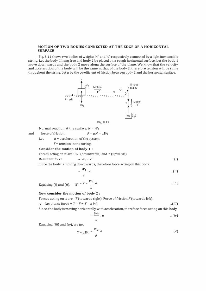
MOTION OF TWO BODIES CONNECTED AT THE EDGE OF A HORIZONTAL SURFACE
Fig. 8.11 shows two bodies of weights W1 and W2 respectively connected by a light inextensible string. Let the body 1 hang free and body 2 be placed on a rough horizontal surface. Let the body 1 move downwards and the body 2 move along the surface of the plane. We know that the velocity and acceleration of the body will be the same as that of the body 2, therefore tension will be same throughout the string. Let be the co-efficient of friction between body 2 and the horizontal surface.
Fig. 8.11
Normal reaction at the surface, N = W2
and force of friction, F = N = W2
Let a = acceleration of the system
T = tension in the string.
Consider the motion of body 1 :
Forces acting on it are : W1 (downwards) and T (upwards)
Resultant force = W1 – T ...(i)
Since the body is moving downwards, therefore force acting on this body
= W1 . a ...(ii)
g
Equating (i) and (ii), W1
– T = W1 a ...(1)
g
Now consider the motion of body 2 :
Forces acting on it are : T (towards right), Force of friction F (towards left).
Resultant force = T – F = T – W2 ...(iii)
Since, the body is moving horizontally with acceleration, therefore force acting on this body
= W2 . a ...(iv)
g
Equating (iii) and (iv), we get
T – W2
=
W2 a ...(2) g
N
2 Motion Smooth
pulley ‘a’
F= N
W2 T
Motion ‘a’
W1 1
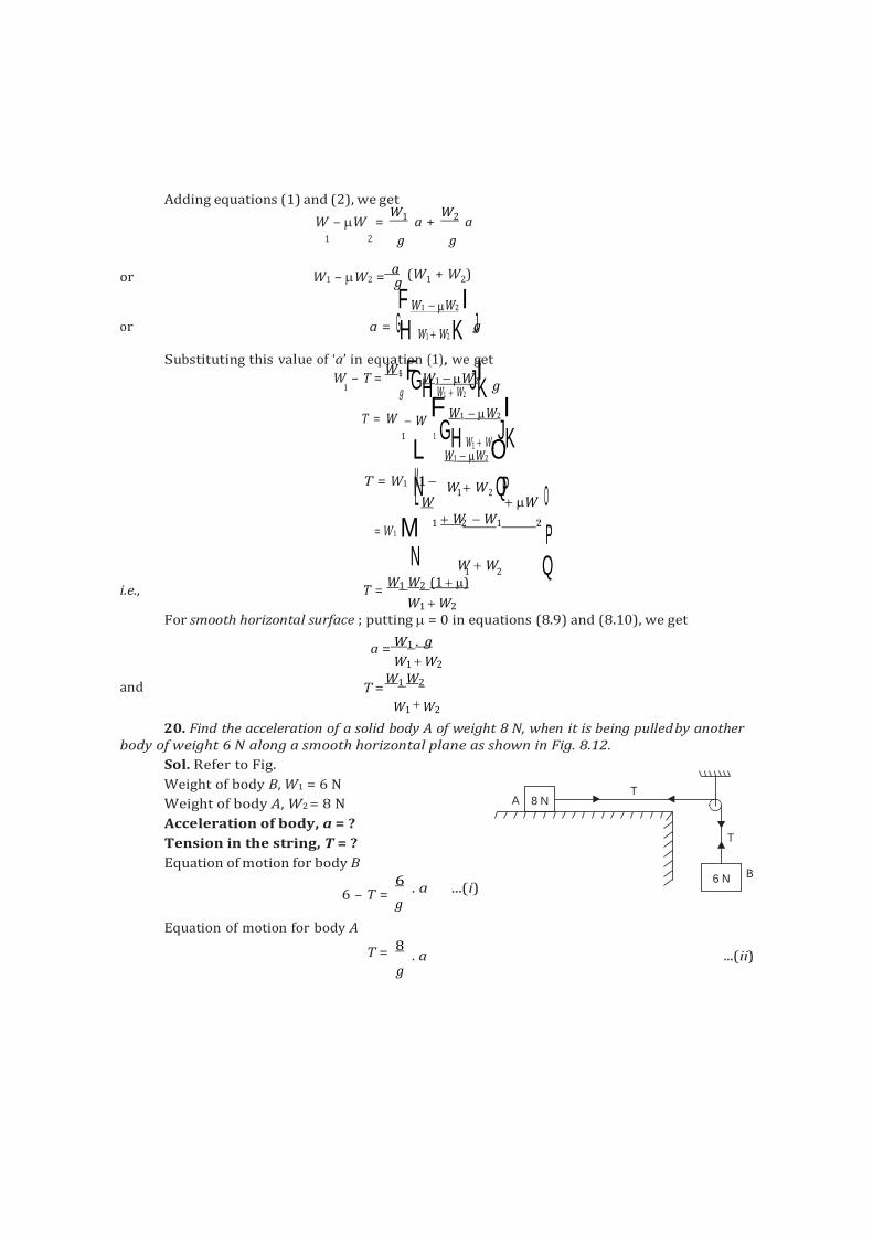
8 N
g
T =
Adding equations (1) and (2), we get
W – W = W1 a +
W2 a 1 2 g g
or W1 – W2 = a (W1 + W2)
F W1 W2 I or a = GH W1 W2 K gJ
Substituting this value of ‘a’ in equatiFon (1), we g
Iet
W – T = W1
W1 W2 g
1 g
GH W1 W2 JK
T = W W F W1 W2 I
1 1 GH W1 W2 JK L W1 W2 O
T = W1 M1 P NL W W1 W2 Q
W O
= W1 M N
1 W2 W1 2
P W
1 W
2 Q i.e., T =
W1 W2 (1 )
W1 W2
For smooth horizontal surface ; putting = 0 in equations (8.9) and (8.10), we get
a = W1 . g
W1 W2
and W1 W2
W1 W2
20. Find the acceleration of a solid body A of weight 8 N, when it is being pulled by another body of weight 6 N along a smooth horizontal plane as shown in Fig. 8.12.
Sol. Refer to Fig.
Weight of body B, W1 = 6 N
Weight of body A, W2 = 8 N
Acceleration of body, a = ?
Tension in the string, T = ?
Equation of motion for body B
6 – T =
Equation of motion for body A
A
6
. a ...(i) g
T = 8 . a ...(ii)
g
T
T
6 N B
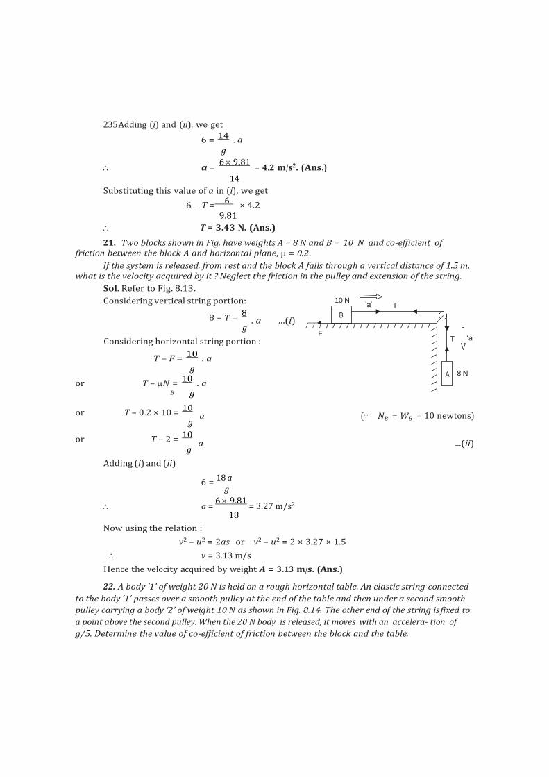
F
A
B
235 Adding (i) and (ii), we get
6 = 14 . a g
a = 6 9.81
= 4.2 m/s2. (Ans.) 14
Substituting this value of a in (i), we get
6 – T = 6
× 4.2 9.81
T = 3.43 N. (Ans.)
21. Two blocks shown in Fig. have weights A = 8 N and B = 10 N and co-efficient of friction between the block A and horizontal plane, = 0.2.
If the system is released, from rest and the block A falls through a vertical distance of 1.5 m, what is the velocity acquired by it ? Neglect the friction in the pulley and extension of the string.
Sol. Refer to Fig. 8.13.
Considering vertical string portion:
8 – T = 8
g
. a ...(i)
10 N ‘a’ T
Considering horizontal string portion :
T – F = 10
. a g
or T – N = 10
. a
T ‘a’
8 N
B g
or T – 0.2 × 10 = 10
g
a (∵ NB
= WB
= 10 newtons)
or T – 2 = 10
g
a ...(ii)
Adding (i) and (ii)
6 = 18 a
g
a = 6 9.81
= 3.27 m/s2
18
Now using the relation :
v2 – u2 = 2as or v2 – u2 = 2 × 3.27 × 1.5
v = 3.13 m/s
Hence the velocity acquired by weight A = 3.13 m/s. (Ans.)
22. A body ‘1’ of weight 20 N is held on a rough horizontal table. An elastic string connected
to the body ‘1’ passes over a smooth pulley at the end of the table and then under a second smooth
pulley carrying a body ‘2’ of weight 10 N as shown in Fig. 8.14. The other end of the string is fixed to
a point above the second pulley. When the 20 N body is released, it moves with an accelera- tion of
g/5. Determine the value of co-efficient of friction between the block and the table.
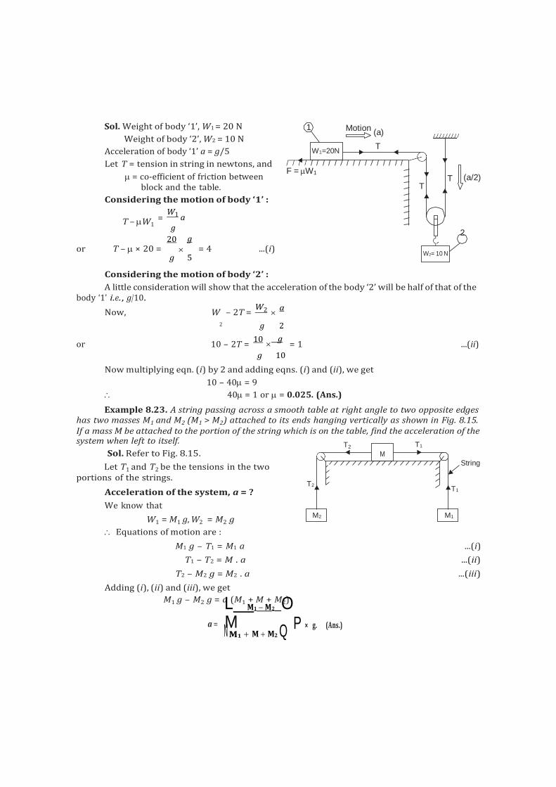
T2 T1
T1
M1 M2
M
N
Sol. Weight of body ‘1’, W1 = 20 N
Weight of body ‘2’, W2 = 10 N
Acceleration of body ‘1’ a = g/5
Let T = tension in string in newtons, and
= co-efficient of friction between block and the table.
Considering the motion of body ‘1’ :
T – W1
= W1 a
g
20 g or T – × 20 = = 4 ...(i)
g 5
Considering the motion of body ‘2’ :
A little consideration will show that the acceleration of the body ‘2’ will be half of that of the body ‘1’ i.e., g/10.
Now, W – 2T = W2
a
2 g 2
or 10 – 2T = 10
g
= 1 ...(ii) g 10
Now multiplying eqn. (i) by 2 and adding eqns. (i) and (ii), we get
10 – 40 = 9
40 = 1 or = 0.025. (Ans.)
Example 8.23. A string passing across a smooth table at right angle to two opposite edges has two masses M1 and M2 (M1 > M2) attached to its ends hanging vertically as shown in Fig. 8.15. If a mass M be attached to the portion of the string which is on the table, find the acceleration of the system when left to itself.
Sol. Refer to Fig. 8.15.
Let T1 and T2 be the tensions in the two portions of the strings.
T2
Acceleration of the system, a = ?
We know that
String
W1 = M1 g, W2 = M2 g
Equations of motion are :
M1 g – T1 = M1 a ...(i)
T1 – T2 = M . a ...(ii)
T2 – M2 g = M2 . a ...(iii)
Adding (i), (ii) and (iii), we get
M1 g – M2 g = a (M1 + M + M2) L M1 M2 O
a = M M1 M M2 Q P × g. (Ans.)
1 Motion (a)
T
F = W1 T (a/2)
T
2
W1=20N
W2= 10 N
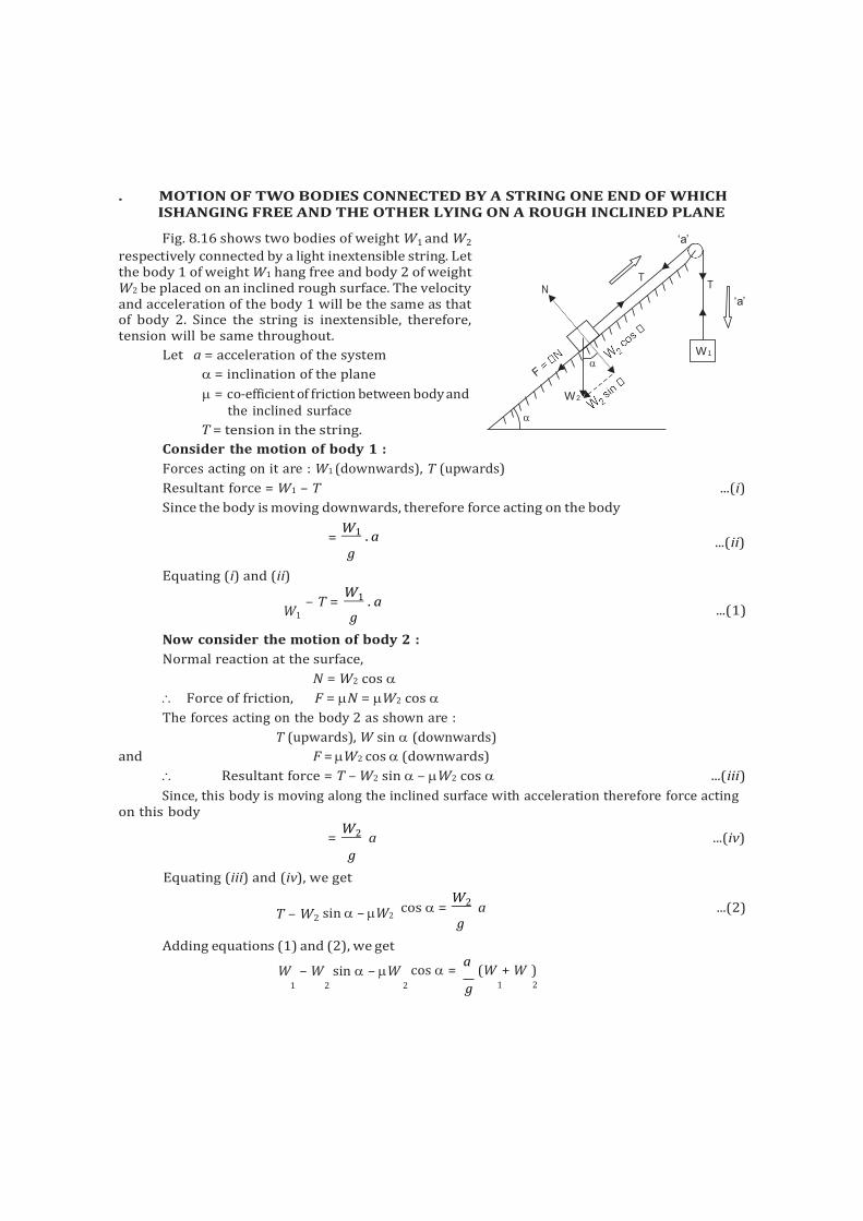
. MOTION OF TWO BODIES CONNECTED BY A STRING ONE END OF WHICH ISHANGING FREE AND THE OTHER LYING ON A ROUGH INCLINED PLANE
Fig. 8.16 shows two bodies of weight W1 and W2
respectively connected by a light inextensible string. Let the body 1 of weight W1 hang free and body 2 of weight W2 be placed on an inclined rough surface. The velocity and acceleration of the body 1 will be the same as that of body 2. Since the string is inextensible, therefore, tension will be same throughout.
Let a = acceleration of the system
= inclination of the plane
= co-efficient of friction between body and the inclined surface
T = tension in the string.
Consider the motion of body 1 :
Forces acting on it are : W1 (downwards), T (upwards)
‘a’ ‘a’
Resultant force = W1 – T ...(i)
Since the body is moving downwards, therefore force acting on the body
Equating (i) and (ii)
W1
= W1 . a
g
– T = W1 . a
g
...(ii)
...(1)
Now consider the motion of body 2 :
Normal reaction at the surface,
N = W2 cos
Force of friction, F = N = W2 cos
The forces acting on the body 2 as shown are :
T (upwards), W sin (downwards)
and F = W2 cos (downwards)
Resultant force = T – W2 sin – W2 cos ...(iii)
Since, this body is moving along the inclined surface with acceleration therefore force acting on this body
= W2 a ...(iv)
g
Equating (iii) and (iv), we get
T – W2
sin – W2
cos = W2 a ...(2) g
Adding equations (1) and (2), we get
W – W sin – W cos = a
(W + W ) 1 2 2 g 1 2
T N T
W1
W2
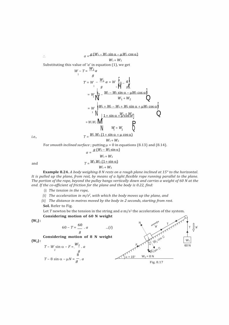
1 1 H K
O N L
a = g (W1 W2 sin W2 cos )
W1 W2
Substituting this value of ‘a’ in equation (1), we get
W – T = W1 a
1 g
T = W – W1 a = W FG 1
a IJ g g
= W ML1 W1 W2 sin W2 cos OP 1 N W1 W2 Q
= W MLW1 W2 W1 W2 sin W2 cos OP 1
W1 W2 Q 1 sin cos
= W1W2 M P N W
1 W
2 Q
i.e., T = W1 W2 (1 sin cos )
W1 W2
For smooth inclined surface ; putting = 0 in equations (8.13) and (8.14). g (W1 W2 sin )
a = W1 W2
and T = W1 W2 (1 sin )
W1 W2
Example 8.24. A body weighing 8 N rests on a rough plane inclined at 15° to the horizontal. It is pulled up the plane, from rest, by means of a light flexible rope running parallel to the plane. The portion of the rope, beyond the pulley hangs vertically down and carries a weight of 60 N at the end. If the co-efficient of friction for the plane and the body is 0.22, find:
(i) The tension in the rope,
(ii) The acceleration in m/s2, with which the body moves up the plane, and
(iii) The distance in metres moved by the body in 2 seconds, starting from rest.
Sol. Refer to Fig.
Let T newton be the tension in the string and a m/s2 the acceleration of the system.
Considering motion of 60 N weight (W1) :
(W2) :
60 – T = 60
. a ...(i) g
Considering motion of 8 N weight
T – W sin – F = W2 . a
2 g
‘a’
8 T – 8 sin – N =
g . a
Fig. 8.17
N
‘a’ T
T
F
W1
60 N
= 15° W2 = 8 N
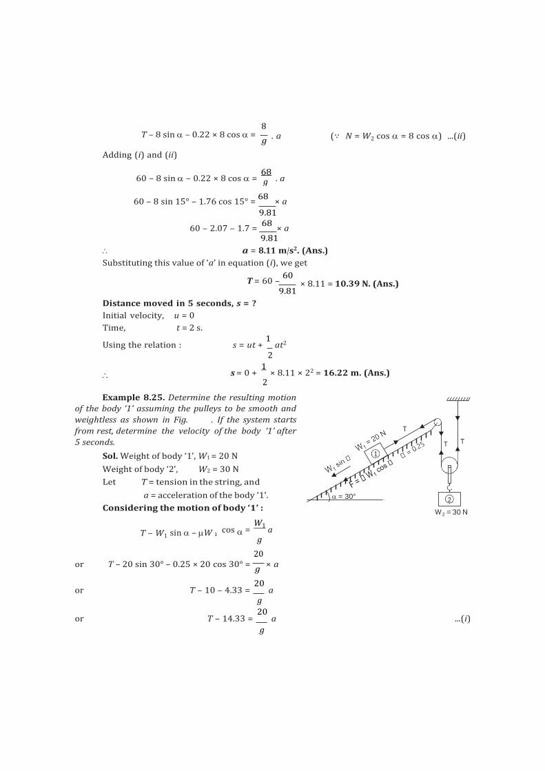
g
T – 8 sin – 0.22 × 8 cos =
Adding (i) and (ii)
8
g . a (∵ N = W2 cos = 8 cos ) ...(ii)
60 – 8 sin – 0.22 × 8 cos = 68
. a
60 – 8 sin 15° – 1.76 cos 15° = 68
× a
9.81
60 – 2.07 – 1.7 = 68
× a 9.81
a = 8.11 m/s2. (Ans.)
Substituting this value of ‘a’ in equation (i), we get
T = 60 – 60
9.81
× 8.11 = 10.39 N. (Ans.)
Distance moved in 5 seconds, s = ?
Initial velocity, u = 0
Time, t = 2 s.
Using the relation : s = ut + 1
at2
2
s = 0 + 1
× 8.11 × 22 = 16.22 m. (Ans.) 2
Example 8.25. Determine the resulting motion of the body ‘1’ assuming the pulleys to be smooth and
weightless as shown in Fig. . If the system starts
from rest, determine the velocity of the body ‘1’ after
5 seconds.
Sol. Weight of body ‘1’, W1 = 20 N
Weight of body ‘2’, W2 = 30 N
Let T = tension in the string, and
a = acceleration of the body ‘1’.
Considering the motion of body ‘1’ : 2
= 30 N
T – W1
sin – W 1
cos = W1
a g
20 or T – 20 sin 30° – 0.25 × 20 cos 30° =
g × a
or T – 10 – 4.33 = 20
a g
or T – 14.33 = 20
a ...(i)
g
T
T T
1
= 30° 2
W
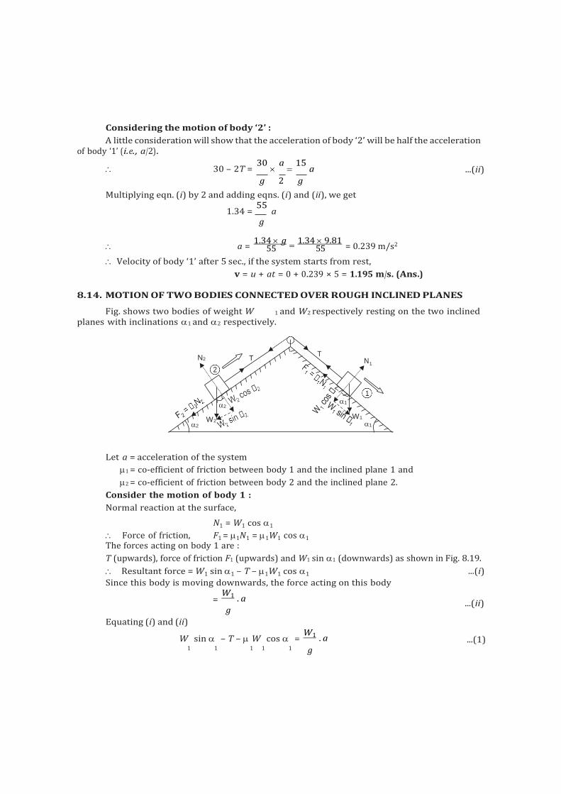
55 55
Considering the motion of body ‘2’ :
A little consideration will show that the acceleration of body ‘2’ will be half the acceleration of body ‘1’ (i.e., a/2).
30 – 2T = 30
a
15 a ...(ii)
g 2 g
Multiplying eqn. (i) by 2 and adding eqns. (i) and (ii), we get
1.34 = 55
a g
a = 1.34 g
1.34 9.81
= 0.239 m/s2
Velocity of body ‘1’ after 5 sec., if the system starts from rest,
v = u + at = 0 + 0.239 × 5 = 1.195 m/s. (Ans.)
8.14. MOTION OF TWO BODIES CONNECTED OVER ROUGH INCLINED PLANES
Fig. shows two bodies of weight W 1 and W2 respectively resting on the two inclined planes with inclinations 1 and 2 respectively.
Let a = acceleration of the system
1 = co-efficient of friction between body 1 and the inclined plane 1 and
2 = co-efficient of friction between body 2 and the inclined plane 2.
Consider the motion of body 1 :
Normal reaction at the surface,
N1 = W1 cos 1
Force of friction, F1 = 1N1 = 1W1 cos 1
The forces acting on body 1 are :
T (upwards), force of friction F1 (upwards) and W1 sin 1 (downwards) as shown in Fig. 8.19.
Resultant force = W1 sin 1 – T – 1W1 cos 1 ...(i)
Since this body is moving downwards, the force acting on this body
Equating (i) and (ii)
= W1 . a
g
...(ii)
W sin – T – W cos = W1 . a ...(1)
1 1 1 1 1 g
N2 T T
N 1
2
1
2 1
2 W2
W1 1
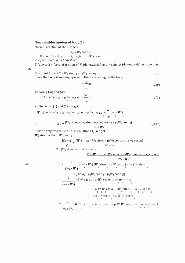
Fig.
Now consider motion of body 2 :
Normal reaction at the surface,
N2 = W2 cos 2
Force of friction, F2 = 2N2 = 2W2 cos 2
The forces acting on body 2 are :
T (upwards), force of friction of F2 (downwards) and W2 sin 2 (downwards) as shown in
Resultant force = T – W2 sin 2 – 2W2 cos 2 ...(iii)
Since the body is moving upwards, the force acting on the body
Equating (iii) and (iv)
= W2 a g
...(iv)
T – W sin – W cos = W2 a ...(2)
2 2 2 2 2 g
Adding eqns. (1) and (2), we get
W sin – W sin
– W
cos
– W
cos = a
(W + W )
1 1 2 2 1 1 1 2 2 2 g 1 2
a = g (W1 sin 1 W2 sin 2 1W1 cos 1 2W2 cos 2)
W1 W2
Substituting this value of ‘a’ in equation (1), we get
W1 sin 1 – T – 1W1 cos 1
...(8.17)
= W1 g
g
× (W1 sin 1 W2 sin 2 1W1 cos 1 2 W2 cos 2)
W1 W2
T = (W1 sin 1 – 1 W1 cos 1)
– W1 (W1 sin 1 W2 sin 2 1W1 cos 1 2W2 cos 2)
W1 W2
or T = 1
[(W + W ) (W sin – W cos ) – W (W sin
(W1 W2) 1 2 1 1 1 1 1 1 1
– W2 sin 2 – 1W1 cos 1 – 2W2 cos 2)]
= 1
[W2 sin 1 W2 cos
+ W W
sin
(W1 W2) 1 1 1 1 1 2 1
– W W cos – W2 sin + W W sin 1 1 2 1 1 1 1 2 2
+ W2 cos + W W cos ] 1 1 1 2 1 2 2
= 1
(W W sin + W W sin – W W cos + W W cos )
W1 W2 1 2 1 1 2 2 1 1 2 1 2 1 2 2
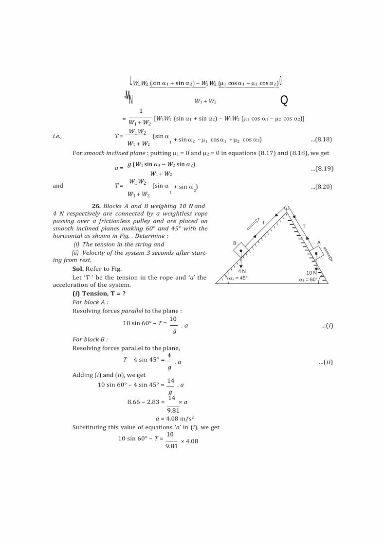
L W1 W2 (sin 1 sin 2 ) W1 W2 (1 cos 1 2 cos 2 ) O = MN
1
W1 W2 Q
= W1 W2
[W1W2 (sin 1 + sin 2) – W1W2 (1 cos 1 – 2 cos 2)]
i.e., T = W1 W2
(sin W1 W2 1
+ sin 2 – 1 cos 1 + 2 cos 2) ...(8.18)
For smooth inclined plane : putting 1 = 0 and 2 = 0 in equations (8.17) and (8.18), we get
g (W1 sin 1 W2 sin 2)
W1 W2 ...(8.19)
and T = W1 W2 (sin + sin ) ...(8.20) W1 W2
1
26. Blocks A and B weighing 10 N and 4 N respectively are connected by a weightless rope passing over a frictionless pulley and are placed on smooth inclined planes making 60° and 45° with the horizontal as shown in Fig. . Determine :
(i) The tension in the string and
(ii) Velocity of the system 3 seconds after start- ing from rest.
Sol. Refer to Fig.
Let ‘T ’ be the tension in the rope and ‘a’ the acceleration of the system.
(i) Tension, T = ?
For block A :
Resolving forces parallel to the plane :
For block B :
10 sin 60° – T = 10
g
. a ...(i)
Resolving forces parallel to the plane,
T – 4 sin 45° = 4
g
. a ...(ii)
Adding (i) and (ii), we get
10 sin 60° – 4 sin 45° = 14
. a g
8.66 – 2.83 = 14
× a
9.81
a = 4.08 m/s2
Substituting this value of equations ‘a’ in (i), we get
10 sin 60° – T = 10
9.81
× 4.08
T T
B A
4 N
2 = 45° 10 N
1 = 60°
a =
2
10 T = 10 sin 60° – × 4.08
9.81
= 8.66 – 4.16 = 4.5 N. (Ans.)
(ii) Velocity after 3 seconds, v = ?
Using the relation : v = u + at
= 0 + 4.08 × 3 (∵ u = 0)
= 12.24 m/s. (Ans.)
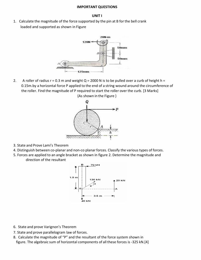
IMPORTANT QUESTIONS
UNIT I
1. Calculate the magnitude of the force supported by the pin at B for the bell crank
loaded and supported as shown in Figure
2. A roller of radius r = 0.3 m and weight Q = 2000 N is to be pulled over a curb of height h =
0.15m.by a horizontal force P applied to the end of a string wound around the circumference of
the roller. Find the magnitude of P required to start the roller over the curb. [3 Marks]
{As shown in the Figure }
3. State and Prove Lami’s Theorem 4. Distinguish between co-planar and non-co planar forces. Classify the various types of forces. 5. Forces are applied to an angle bracket as shown in figure 2. Determine the magnitude and
direction of the resultant
6. State and prove Varignon’s Theorem
7. State and prove parallelogram law of forces. 8. Calculate the magnitude of “P” and the resultant of the force system shown in
figure. The algebraic sum of horizontal components of all these forces is -325 kN.[4]
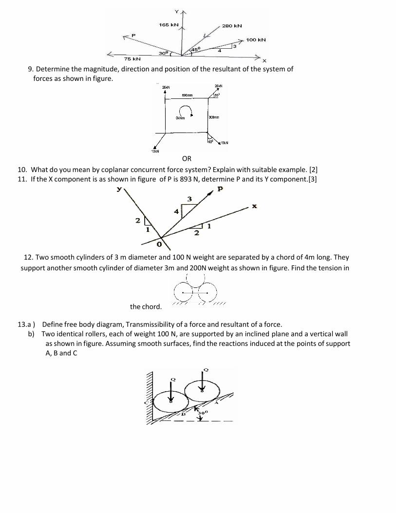
9. Determine the magnitude, direction and position of the resultant of the system of
forces as shown in figure.
OR
10. What do you mean by coplanar concurrent force system? Explain with suitable example. [2] 11. If the X component is as shown in figure of P is 893 N, determine P and its Y component.[3]
12. Two smooth cylinders of 3 m diameter and 100 N weight are separated by a chord of 4m long. They
support another smooth cylinder of diameter 3m and 200N weight as shown in figure. Find the tension in
the chord.
13.a ) Define free body diagram, Transmissibility of a force and resultant of a force. b) Two identical rollers, each of weight 100 N, are supported by an inclined plane and a vertical wall
as shown in figure. Assuming smooth surfaces, find the reactions induced at the points of support A, B and C
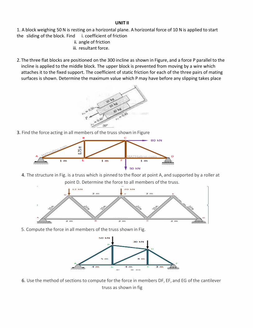
UNIT II
1. A block weighing 50 N is resting on a horizontal plane. A horizontal force of 10 N is applied to start the sliding of the block. Find i. coefficient of friction
ii. angle of friction iii. resultant force.
2. The three flat blocks are positioned on the 300 incline as shown in Figure, and a force P parallel to the
incline is applied to the middle block. The upper block is prevented from moving by a wire which attaches it to the fixed support. The coefficient of static friction for each of the three pairs of mating surfaces is shown. Determine the maximum value which P may have before any slipping takes place
3. Find the force acting in all members of the truss shown in Figure
4. The structure in Fig. is a truss which is pinned to the floor at point A, and supported by a roller at
point D. Determine the force to all members of the truss.
5. Compute the force in all members of the truss shown in Fig.
6. Use the method of sections to compute for the force in members DF, EF, and EG of the cantilever
truss as shown in fig
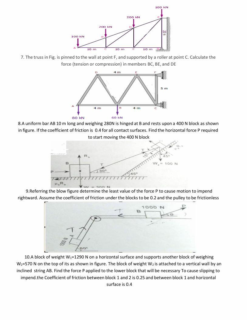
7. The truss in Fig. is pinned to the wall at point F, and supported by a roller at point C. Calculate the
force (tension or compression) in members BC, BE, and DE
8.A uniform bar AB 10 m long and weighing 280N is hinged at B and rests upon a 400 N block as shown
in figure. If the coefficient of friction is 0.4 for all contact surfaces. Find the horizontal force P required
to start moving the 400 N block
9.Referring the blow figure determine the least value of the force P to cause motion to impend
rightward. Assume the coefficient of friction under the blocks to be 0.2 and the pulley to be frictionless
10.A block of weight W1=1290 N on a horizontal surface and supports another block of weighing
W2=570 N on the top of its as shown in figure. The block of weight W2 is attached to a vertical wall by an
inclined string AB. Find the force P applied to the lower block that will be necessary To cause slipping to
impend.the Coefficient of friction between block 1 and 2 is 0.25 and between block 1 and horizontal
surface is 0.4
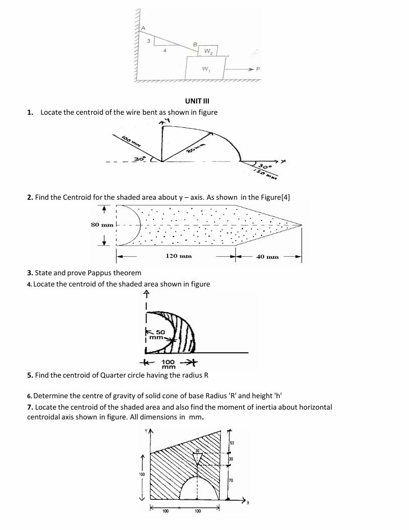
UNIT III
1. Locate the centroid of the wire bent as shown in figure
2. Find the Centroid for the shaded area about y – axis. As shown in the Figure[4]
3. State and prove Pappus theorem
4. Locate the centroid of the shaded area shown in figure
5. Find the centroid of Quarter circle having the radius R
6. Determine the centre of gravity of solid cone of base Radius 'R' and height 'h'
7. Locate the centroid of the shaded area and also find the moment of inertia about horizontal centroidal axis shown in figure. All dimensions in mm.
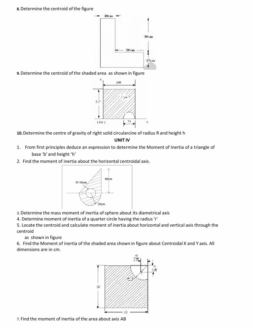
8. Determine the centroid of the figure
9. Determine the centroid of the shaded area as shown in figure
10. Determine the centre of gravity of right solid circularcine of radius R and height h
UNIT IV
1. From first principles deduce an expression to determine the Moment of Inertia of a triangle of
base ‘b’ and height ‘h’
2. Find the moment of inertia about the horizontal centroidal axis.
3. Determine the mass moment of inertia of sphere about its diametrical axis
4. Determine moment of inertia of a quarter circle having the radius 'r' 5. Locate the centroid and calculate moment of inertia about horizontal and vertical axis through the centroid
as shown in figure 6. Find the Moment of inertia of the shaded area shown in figure about Centroidal X and Y axis. All dimensions are in cm.
7. Find the moment of inertia of the area about axis AB
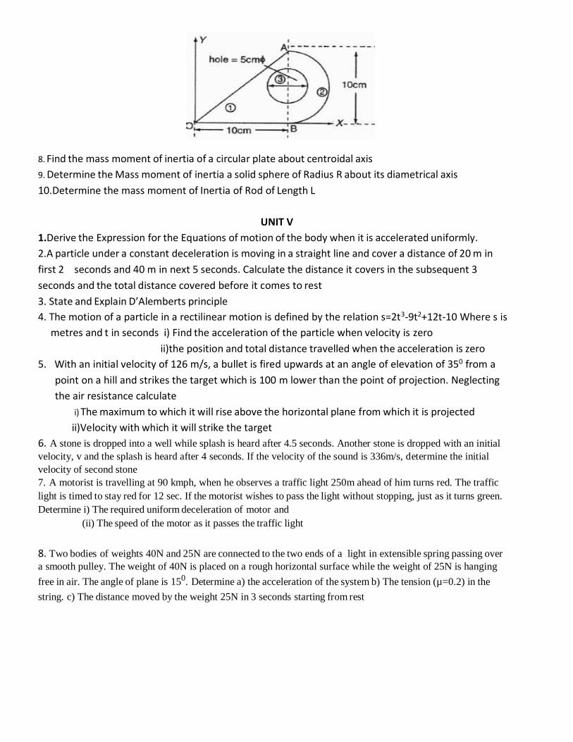
8. Find the mass moment of inertia of a circular plate about centroidal axis
9. Determine the Mass moment of inertia a solid sphere of Radius R about its diametrical axis
10.Determine the mass moment of Inertia of Rod of Length L
UNIT V
1.Derive the Expression for the Equations of motion of the body when it is accelerated uniformly.
2.A particle under a constant deceleration is moving in a straight line and cover a distance of 20 m in
first 2 seconds and 40 m in next 5 seconds. Calculate the distance it covers in the subsequent 3
seconds and the total distance covered before it comes to rest
3. State and Explain D’Alemberts principle
4. The motion of a particle in a rectilinear motion is defined by the relation s=2t3-9t2+12t-10 Where s is
metres and t in seconds i) Find the acceleration of the particle when velocity is zero
ii)the position and total distance travelled when the acceleration is zero
5. With an initial velocity of 126 m/s, a bullet is fired upwards at an angle of elevation of 350 from a
point on a hill and strikes the target which is 100 m lower than the point of projection. Neglecting
the air resistance calculate
i) The maximum to which it will rise above the horizontal plane from which it is projected
ii)Velocity with which it will strike the target
6. A stone is dropped into a well while splash is heard after 4.5 seconds. Another stone is dropped with an initial
velocity, v and the splash is heard after 4 seconds. If the velocity of the sound is 336m/s, determine the initial
velocity of second stone 7. A motorist is travelling at 90 kmph, when he observes a traffic light 250m ahead of him turns red. The traffic
light is timed to stay red for 12 sec. If the motorist wishes to pass the light without stopping, just as it turns green.
Determine i) The required uniform deceleration of motor and
(ii) The speed of the motor as it passes the traffic light
8. Two bodies of weights 40N and 25N are connected to the two ends of a light in extensible spring passing over
a smooth pulley. The weight of 40N is placed on a rough horizontal surface while the weight of 25N is hanging
free in air. The angle of plane is 150. Determine a) the acceleration of the system b) The tension (µ=0.2) in the
string. c) The distance moved by the weight 25N in 3 seconds starting from rest