dias smart adaptive remote diagnostic antitampering systems
TRANSCRIPT
DIAS
Smart Adaptive Remote Diagnostic Antitampering Systems
EUROPEAN COMMISSION HORIZON 2020
LC-MG-1-4-2018 Grant agreement ID: 814951
Deliverable No. D3.2
Deliverable Title Status quo of critical tampering techniques and proposal of required new OBD monitoring functions
Issue Date 23/12/2020
Dissemination level Public
Main Author(s) J.A. van den Meiracker (TNO) R. Vermeulen (TNO)
Version V1.0
Ref. Ares(2021)163218 - 08/01/2021
DIAS D3.2 – Status quo of critical tampering techniques, V1.0
23/12/2020 2
DIAS Consortium
This project has received funding from the European Union’s Horizon 2020 research and innovation programme under grant agreement No 814951.
This document reflects only the authors’ view and the Agency is not responsible for any use that may be made of the information it contains.
DIAS D3.2 – Status quo of critical tampering techniques, V1.0
23/12/2020 3
Document log
Version Description Distributed for Assigned to Date
V0.0 Draft versions TNO internal
content review
Reviewer: Ann Delahaye, Joep van de
Meiracker, Robin Vermeulen (each other’s
content)
July 2020 (during CG meetings)
V0.1 Draft content of
deliverable Content review
by LAT
Reviewers: Dimitrios Kontses, Pavlos Fragkiadoulakis
12/10/2020
V0.2-v0.7
Draft content of deliverable
General Assembly check
All partner managers 25/11/2020
V0.8 Final content of
deliverable (updated) - - 20/12/2020
V1.0 Final version - - 23/12/2020
Verification and approval of final version
Description Name Date
Verification of the “Final content of deliverable (V0.8)” by WP leader
Ann Delahaye (TNO) 20/12/2020
Check of the “First final version (v1.0)” before uploading by coordinator
Zissis Samaras (LAT/AUTh) 23/12/2020
DIAS D3.2 – Status quo of critical tampering techniques, V1.0
23/12/2020 4
Executive summary Pollutant emissions of road vehicles have reduced significantly thanks to the development and application of effective and often complex emissions control systems. Tampering of these systems leads to elevated tail-pipe emissions up to uncontrolled levels of vehicles of decades ago. Tampering poses a large environmental risk because a small share of tampering potentially can lead to a significant increase of the EU fleet average emissions. For the EU H2020 project DIAS, a market assessment has been conducted and reported (DIAS Deliverable 3.1) which included a risk assessment to determine which tampering poses the largest environmental risk. The result of this assessment is a matrix of vehicle tampering combinations to be tested which contains passenger cars, trucks and non-road mobile machinery with diesel engines and a passenger car with a petrol engine on one side and the different variants of tampering on the other side: emulators, ECU flashing, sensor modification and OBD deletion devices. The test programme is conducted to determine the working principles of tampering. Based on this, requirements are defined for measures that are to be developed to counter existing tampering attempts by prevention and detection. Detailed results of the test program, such as descriptions of how the tampering works, what vehicle signals are affected and how tampering can remain undetected are reported in a separate confidential report (D2.2). This report provides an overview of critical tampering techniques of the tampering evaluated so far in the testing programme and as made available from parallel and earlier tests not performed in the framework of DIAS. So far 34 pieces of tampering were purchased and evaluated in a desk test and a selection of three LDV, one HDV and one NRMM were tested so far in an on-road test applying various tampering types. This report also gives an update of the market assessment which is ongoing throughout the DIAS programme. At the time of publishing this report, the testing programme is still running, and new data will be available for analyses and will be reported to consortium partners and in an update to this report when the testing is finished. Based on the available test results and information, this report proposes the main directions for the development of required new functions which detect and prevent tampering, and which would ensure that the OBD will detect faulty components of the environmental protection system (EPS). The various tampering types tested were mostly meant for the second last generation of vehicles as regards the applicable EU emission standard. According to tamperers, it takes time to find tampering solutions to by-pass the latest control measures that are implemented on the newest vehicles. The tampering that was evaluated, showed mixed results. The results ranged from successful tampering to tampering that didn’t work at all. Also, tampering was tested were immediately or eventually, diagnostic trouble codes were stored, and malfunction indications popped up. Successful tampering was able to deactivate reagent dosing of the SCR system, deactivate EGR valve actuation, allowed removal of critical EPS components such as a DPF and allows to leave faulty components of the EPS on the vehicle while no diagnostic trouble codes were stored, no malfunction indication was lit or no power inducement was activated. Several tampering techniques were identified which exploit different vulnerabilities. Emulators, as mostly offered for HDV and NRMM, inject false sensor and actuator signals to the ECU as a kind of a man-in-the-middle attack. Another simpler form of an emulator can modify sensor signals to set a false condition of the EPS control logic that deactivates the reagent dosing or in the case of a lambda sensor bushing/catalyst modify the signal of the sensor to simulate the correct operation of the three-way catalyst. Emulators compromise the data integrity of sensors and actuators as either communicated using digital data communication protocols or as an analog signal.
DIAS D3.2 – Status quo of critical tampering techniques, V1.0
23/12/2020 5
ECU flashing compromises the data integrity of the OEM software, can serve various tampering goals and is offered for passenger cars, vans, trucks and mobile machinery. Possible goals are deactivating the EGR, deactivating reagent dosing of the SCR system, removal of components or even the whole EPS. Current techniques seem to exploit mainly the OBD port and applicable service protocols. For the ECU flashing that was tested, dedicated hardware tools are used to upload the malware. This malware needs to be developed by dedicated ECU tuning companies who reverse engineer parts of the software. It is still unclear how exactly the current security features of ECUs are by-passed. Examples of possibilities are the side-channel attack, sniffing or other security breaches for instance involving leakage of confidential company information. OBD DTC erasers have not been evaluated in the testing programme so far but certain types of SCR emulators have this OBD DTC deletion feature integrated to enable the tampering which means that this is a vulnerability that needs to be addressed. Depending on the components affected, the tampering of the SCR and/or EGR system generally results in a large increase of the NOx tail-pipe emission and when a DPF is removed, in a large increase of the particulate emissions. In the case the tampering is applied to avoid repair, i.e. a malfunctioning component remains on the vehicle, the increase of the emissions can be lower as the EPS may still work partially. Based on the observed tampering techniques and vulnerabilities exploited, several general requirements are defined which shall be used as guidelines for the development of new functions for the detection or prevention of tampering and which would ensure that the OBD will detect faulty components of the environmental protection system (EPS). For DIAS level 1 these general requirements are:
• Assuring the data integrity of the signals of sensors and actuators that take part in the control of the EPS and the on-board diagnostics system.
o For digital signals, an option is to detect or prevent the injection of false signals by authentication of digital signals.
o The integrity of analog and digital signals can be checked using advanced data rationality checks.
• Assuring the data integrity of the ECU. An option is to detect or prevent unauthorized flashing of ECUs by advanced security features
• Detection or prevention of malicious erasing of the fault code memory of the on-board diagnostics system
It should be further investigated what options fulfil the requirements regarding the DIAS goal to detect or prevent tampering, especially taking account of the user requirements. Since current OBD does not foresee in functionality to detect and report tampering it is advised to consider requirements for continuous tampering diagnostics with tampering probability monitoring and reporting. It is also recommended to consider tampering checks for periodic inspections. The tampering diagnostics could assist enforcement of proper use of the EPS at regular periodic inspections, roadside inspections or for monitoring of tampering in the fleet through the cloud. The feature could be a part of an integrated environmental performance monitoring system which not only monitors tampering but also performs other monitoring jobs such as monitoring the emissions performance (OBM) and fuel consumption (OBFCM). It is recommended to continue monitoring the market developments for the introduction of new tampering techniques throughout the DIAS project and continue to investigate in the DIAS project how current security features for ECUs are by-passed.
DIAS D3.2 – Status quo of critical tampering techniques, V1.0
23/12/2020 6
Contents
Executive summary ...................................................................................................................... 4
List of Abbreviations .................................................................................................................... 8
Definitions ................................................................................................................................. 10
List of Figures ............................................................................................................................. 13
List of Tables .............................................................................................................................. 14
Introduction ....................................................................................................................... 15
Background ........................................................................................................................... 15
Objectives.............................................................................................................................. 16
Approach ............................................................................................................................... 17
Document structure .............................................................................................................. 17
Deviations from original DoW ............................................................................................... 17
Updates and status quo of the market assessment .............................................................. 19
ECU flashing .......................................................................................................................... 19
Emulators .............................................................................................................................. 22
Modifiers ............................................................................................................................... 23
OBD Suppressors ................................................................................................................... 23
Update of tampering types ................................................................................................... 24
Motivation for tampering ..................................................................................................... 24
Methodology: test matrix and test programme ................................................................... 27
Scope of work........................................................................................................................ 27
Sources .................................................................................................................................. 27
Key performance indicators .................................................................................................. 27
Procedure .............................................................................................................................. 28
Test matrix ............................................................................................................................ 29
Vehicle list ............................................................................................................................. 30
Tampering list ....................................................................................................................... 31
Vehicle configuration ............................................................................................................ 32
Test equipment ..................................................................................................................... 32
Test route .............................................................................................................................. 36
Reliability and validity ........................................................................................................... 39
Results of the test programme ............................................................................................ 40
Introduction .......................................................................................................................... 40
LD1: diesel - ECU flashing using ECU pins connection .......................................................... 40
DIAS D3.2 – Status quo of critical tampering techniques, V1.0
23/12/2020 7
LD2: petrol – TWC spacer/catalyst ........................................................................................ 41
LD3: diesel – Temperature spacers (T5) ............................................................................... 42
HD1: diesel ............................................................................................................................ 43
NRMM2: diesel – SCR emulator ............................................................................................ 49
Results overview: KPI matrix ................................................................................................. 51
Results from tests performed outside the DIAS framework................................................. 52
Tampering working principles and vulnerabilities ................................................................ 55
Updated overview of tampering types ................................................................................. 55
Working principles ................................................................................................................ 55
Vulnerabilities ....................................................................................................................... 57
Overview of vulnerabilities and tampering methods ........................................................... 58
Directions for tampering prevention or detection and proposal for monitoring functions ..... 60
ECU data integrity. ................................................................................................................ 60
Sensor and actuator data integrity ....................................................................................... 60
Detection or prevention of malicious DTC deletion ............................................................. 60
Overall tampering diagnostic: tampering probability monitoring and reporting ................. 61
Overview of requirements for tampering detection or prevention ..................................... 61
Conclusions ........................................................................................................................ 62
Bibliography ....................................................................................................................... 64
DIAS D3.2 – Status quo of critical tampering techniques, V1.0
23/12/2020 8
List of Abbreviations ACEA European Automobile Manufacturers Association AMOC Ammonia Oxidation Catalyst ACM Aftertreatment Control Module BDM Background Debug Mode BTX Benzene, Toluene and Xylene CI Combustion Ignition CO Carbon Monoxide CO2 Carbon Dioxide CoC Certificate of Conformity CoP Conformity of Production CRT Continuously Regenerating Trap DCU DEF
Dosing Control Unit Diesel Exhaust Fluid (AdBlue/urea solution)
DIAS Smart Adaptive Remote Diagnostic Antitampering Systems DOC Diesel Oxidation Catalyst DoW Description of Work DPF Diesel Particle Filter DTC Diagnostic Trouble Code DVSA Driver & Vehicle Standards Agency EC Elemental Carbon EC European Commission ECE Economic Commission for Europe ECU Electronic Control Unit EEV EFTA
Enhanced Environmentally Friendly Vehicle European Free Trade Association
EGR Exhaust Gas Recirculation EPA United States Environmental Protection Agency EPS EU
Environmental Protection System European Union
EU-28 European Union and all present member states as of October 2019 EU-33 European Union and all present member states as of October 2019 together with
Iceland, Liechtenstein, Norway, Switzerland and Turkey EVAP Evaporative Emission Control System GDI Gasoline Direct Injection GPF Gasoline Particle Filter GWP Global Warming Potential H2O Water HC Hydrocarbons HD(V) Heavy-Duty (Vehicle) HDDF Heavy-Duty Dual Fuel HEGO Heated Exhaust Gas Oxygen sensor I/M test Vehicle Inspection and Maintenance Test JTAG Joint Test Action Group LA Light Aldehydes (formaldehyde, acetaldehyde, acrolein) LD(V) Light-Duty (Vehicle) LNT Lean NOx Trap MI(L) Malfunction Indicator (Light) N2 Nitrogen NOx Nitrogen Oxides
DIAS D3.2 – Status quo of critical tampering techniques, V1.0
23/12/2020 9
NMHC Non-Methane Hydrocarbon NMVOC Non-Methane Volatile Organic Compounds NRMM Non-Road Mobile Machinery NRSC Non-Road Stationary Cycle NRTC Non-Road Transient Cycle NTE Not-To-Exceed testing O2 Oxygen OBD On-board Diagnostics OC Organic Carbon OCE Off-Cycle Emission testing OEM Original Equipment Manufacturer OTL OBD Threshold Limit PAH Polycyclic Aromatic Hydrocarbons PEMS Portable Emissions Measurement System PM Particulate Matter PN Particulate Number PTI Periodic Technical Inspection RDE Real Driving Emissions RPM Rotations Per Minute (engine speed) SCR Selective Catalytic Reduction SI Spark Ignition SOx Sulphur oxides SO2 Sulphur dioxide SO4 Sulphate TWC Three-way catalyst UEGO Universal Exhaust Gas Oxygen sensor UNECE United Nations Economic Commission for Europe VAG Volkswagen, Audi Group or Volkswagen Group WHSC World Harmonized Stationary Cycle test WHTC World Harmonized Transient Cycle test WLTC Worldwide harmonized Light vehicles Test Cycle WLTP Worldwide harmonized Light vehicles Test Procedure WNTE World harmonized Not-To-Exceed cycle
DIAS D3.2 – Status quo of critical tampering techniques, V1.0
23/12/2020 10
Definitions Approval authority
The authority of a country or Member State with competence for all aspects of the approval of a type of vehicle, system, component, or separate technical unit or of the individual approval of a vehicle; for the authorisation process, for issuing and, if appropriate, withdrawing approval certificates; for acting as the contact point for the approval authorities of other Member States; for designating the technical services and for ensuring that the manufacturer meets his obligations regarding the conformity of production. As defined in directive 2007/46/EC.
Aftermarket parts
Replacement parts that are not made by the original manufacturer. Aftermarket parts are used to replace damaged parts in vehicles and other equipment. They are typically cheaper than OEM parts but are likely to have a similar effect.
Authority Person or body having the legal power to make and enforce the law. Concerning the legislation on vehicle emissions and environmental protection systems the following types of authorities are involved:
• Development of regulations and norms, like the UNECE. Typically, a global or international organisation.
• Enforcement of regulations and norms, like approval authorities such as the RDW or DVSA. Usually organised per country or Member State.
Branch organization
An organisation that takes an active role in improving, advising, informing or securing the automotive branch.
Customer A person who buys goods or services from a shop or business. Concerning environmental protection systems the distinction can be made between: Customer: a person who buys goods or services without the intention of tampering of the environmental protection systems. This includes the uninformed customer: who believes no tampering is involved while in fact, it is. Intentional customer: a person who buys goods or services intending to tamper with the environmental protection systems of the vehicle.
ECU Embedded system in automotive electronics that controls one or more of the electrical systems or subsystems in a vehicle.
Environmental protection system
System fitted to a vehicle that is designed to reduce any (pollutant) emissions of that vehicle, e.g. EGR, DPF and SCR.
Hacking Event Event organised within this project which allows hackers to tamper with (parts of) the environmental protection systems of vehicles to show and explain how they approach these systems.
Hacker A person who uses computers to gain unauthorised access to data. With regard to environmental protection systems a hacker typically is a computer expert or vehicle technician that can, using his technical knowledge, make (unauthorised) changes to (secure) automotive ECUs or sensor communication, with either good or bad intentions.
Heavy-Duty Vehicles that meet the requirements of vehicle categories M2, M3, N2 and N3 as defined in directive 2007/46/EC which involves:
• M2 and M3: Vehicles designed and constructed for the carriage of passengers, comprising more than eight seats in addition to the driver’s seat, and having a maximum mass not exceeding 5 tonnes for M2 and exceeding 5 tonnes for M3.
DIAS D3.2 – Status quo of critical tampering techniques, V1.0
23/12/2020 11
• N2 and N3: Vehicles designed and constructed for the carriage of goods and having a maximum mass exceeding 3,5 tonnes but not exceeding 12 tonnes for N2 and having a maximum mass exceeding 12 tonnes for N3.
Light-Duty Vehicles that meet the requirements of vehicle categories M1 and N1 as defined in directive 2007/46/EC which involves:
• M1: Vehicles designed and constructed for the carriage of passengers and comprising no more than eight seats in addition to the driver’s seat.
• N1: Vehicles designed and constructed for the carriage of goods and having a maximum mass not exceeding 3,5 tonnes.
Limp mode Limp mode is a security function integrated into a vehicle that reduces the power and limits the RPM of the engine to prevent any serious damage in case the electronic control unit detects a vehicle system failure.
Manufacturer Person or body that makes goods for sale. With regard to vehicle manufacturing and especially environmental protection systems the distinction can be made between: Manufacturer: a person or body who is responsible to the approval authority for all aspects of the type-approval or authorisation process and for ensuring conformity of production. The person or body doesn't have to be directly involved in all stages of the construction of the vehicle, system, component or separate technical unit, which is the subject of the approval process, as defined in directive 2007/46/EC. Tampering manufacturer: person or body that constructs a tampering device.
NRMM Non Road Mobile Machinery. Any self-propelled vehicle which is designed and constructed specifically to perform work, which, because of its construction characteristics, is not suitable for carrying passengers or for transporting goods, as defined in directive 2007/46/EC. Machinery mounted on a motor vehicle chassis shall not be considered as mobile machinery.
Supplier Person or body that provides something needed such as a product or service. With regard to environmental protection systems the following distinction can be made for suppliers: Supplier: Vendors or workshops/repair shops that provide a product or service regarding all stages of the construction of a vehicle, system, component or separate technical unit in a vehicle without involvement in any tampering related device or service. Tampering supplier: Vendors or workshops/repair shops that provide tampering devices, tools and/or the service to tamper with environmental protection systems.
Tamperer A person who for whatever reason deliberately tampers with the environmental protection systems of any vehicle.
To tamper Interfere with something to cause damage or make unauthorised alterations.
Tampering Device
Also known as a cheating device. A systems, component or separate technical unit that, when fitted to a vehicle, actively or passively tampers with an environmental protection system of a vehicle with the purpose to (partly) deactivate or bypass it. This typically includes the removal or deactivation of systems in a vehicle that monitor the status of those environmental protection systems and give feedback about malfunctions, i.e. the OBD system of the vehicle.
Tampering Service
A service provided by a supplier or tamperer to make changes to an environmental protection system or ECU with the purpose to (partly) deactivate or bypass it. This typically includes the removal or deactivation of systems in a vehicle that monitor
DIAS D3.2 – Status quo of critical tampering techniques, V1.0
23/12/2020 12
the status of those environmental protection systems and give feedback about malfunctions.
Tuner Workshop, dealership or any other company that provides hardware for or the service to make changes to the performance of any vehicle. Also known as ‘chip’ tuner.
Type-approval The procedure whereby a Member State certifies that a type of vehicle, system, component or separate technical unit satisfies the relevant administrative provisions and technical requirements as defined in directive 2007/46/EC.
(Motor) Vehicle Any power-driven vehicle which is moved by its means, having at least four wheels, being completed i.e. type-approved, with a maximum design speed exceeding 25 km/h.
DIAS D3.2 – Status quo of critical tampering techniques, V1.0
23/12/2020 13
List of Figures Figure 2.1: Dimsport Detailed ECU application list: source dimsport.it ............................................... 19 Figure 2.2: Dimsport MyGenius, source Dimsport ............................................................................... 20 Figure 2.3: Forum discussion on the DPF removal of a VW Passat, source mhhauto.com, visited 12-11-2020. ................................................................................................................................................ 21 Figure 2.4: DPF emulator for Toyota, source dpf-toyota.com .............................................................. 22 Figure 2.5: Lambda sensor spacer including catalytic element, source aliexpress.com ...................... 23 Figure 2.6: Spacer for K-type exhaust gas temperature sensor, source aliexpress.com ...................... 23 Figure 2.7: OBD DTC eraser, source truckdiag.com .............................................................................. 24 Figure 3.1: Desk test of an emulator ..................................................................................................... 28 Figure 3.2: On-road test with a truck .................................................................................................... 28 Figure 3.3: SEMS data logger ................................................................................................................ 33 Figure 3.4: SEMS installation on the LD1, the exhaust sensors were placed in an extension pipe supported on the back of the vehicle. .................................................................................................. 33 Figure 3.5: Typical SEMS installation, schematic overview .................................................................. 33 Figure 3.6: Pegasor Soot Sensor measuring unit .................................................................................. 34 Figure 3.7: Overview of LD1 exhaust set-up with PPS sampling (before and after the DPF). .............. 34 Figure 3.8: Left: break-out box and ECU, right: ETAS ........................................................................... 35 Figure 3.9: Schematic overview of SEMS installation in the truck ........................................................ 35 Figure 3.10: Custom exhaust end-piece ............................................................................................... 36 Figure 3.11: Top: real driving route (RDE-compliant) consisted of urban, rural and motorway parts, Bottom: vehicle speed and altitude for RDE profile. ............................................................................ 37 Figure 3.12: Long route layout .............................................................................................................. 38 Figure 3.13: Short route layout ............................................................................................................. 39 Figure 4.1: TWC lambda sensor spacers: #1 simple spacer, #2 spacer with metallic catalyst, #3 spacer with Euro 4 catalyst, #4 spacer with ceramic catalyst .......................................................................... 42 Figure 4.2: Temperature sensor (T5) spacers ....................................................................................... 43 Figure 4.3: Ford Euro VI SCR emulator, connected to OBD port, from NKAAY .................................... 45 Figure 4.4: Ford Euro VI SCR Emulator, connected to the CAN-bus, from CAN-BUS emulator ............ 45 Figure 4.5: EPS unit with highlighted EGT sensors: EGT1 (before DOC), EGT2 (after DOC, before DPF) and EGT3 (before SCR, after DPF) ......................................................................................................... 47 Figure 4.6: EGT3 custom sensor spacer ................................................................................................ 48 Figure 4.7: Truck AAT sensor located behind the grill .......................................................................... 49
Figure 4.8: Tampered AAT sensor at -21°C ........................................................................................... 49 Figure 4.9: SCR emulator Deutz-Fahr .................................................................................................... 50 Figure 4.10: Two of the tested SCR emulators by ACEA ....................................................................... 53 Figure 4.11: Type 1 SCR emulator tested by Bosch .............................................................................. 54 Figure 4.12: Type 2 SCR emulator tested by Bosch .............................................................................. 54
DIAS D3.2 – Status quo of critical tampering techniques, V1.0
23/12/2020 14
List of Tables Table 1 updated overview of environmental protection systems affected by tampering and the main motivations to tamper. ......................................................................................................................... 25 Table 3.1: Test matrix. The vehicle - tampering combinations are presented per vehicle and consortium partner. The tests that have been finalised and that are included in the test results are indicated by a ✓. ................................................................................................................................... 29 Table 3.2: List of the selected vehicles for the testing programme. .................................................... 30 Table 3.3: Tampering list: the columns received, desk and road indicate if the device has been received after purchase if the desk test is performed and if the road test is performed, no (N), yes (Y), planned (P), not applicable (N.A.) or to be determined (T.B.D.) respectively. ............................... 31 Table 3.4: Truck, trailer and combined test mass ................................................................................. 32 Table 3.5: Characteristics of RDE-compliant route ............................................................................... 37 Table 3.6: Long route specification ....................................................................................................... 38 Table 3.7: Short route specification ...................................................................................................... 38 Table 4.1: LD1 ECU flashing. Comparison of basic RDE statistics ......................................................... 41 Table 4.2: Depth of the temperature sensor (T5) reaching in the exhaust for the corresponding spacers. ................................................................................................................................................. 43 Table 4.3: Average emission results baseline vs. ECU tampering (long route)..................................... 44 Table 4.4: Average emission results baseline vs. SCR emulator CAN + analog signals (long route) ..... 46 Table 4.5: Average emission results baseline vs. NOx sensor emulator (short route) ......................... 46 Table 4.6: Average emission results baseline vs. ETG3 tampering (short route) ................................. 47 Table 4.7: Average emission results baseline vs. EGT3 spacer (short route) ....................................... 48 Table 4.8: Average emission results baseline vs. AAT tampering (long route) ..................................... 49 Table 4.9: KPI matrix ............................................................................................................................. 51 Table 10: An overview of system vulnerabilities, attack surfaces and tampering methods. This overview does not include the vulnerabilities related to remote OTA (over the air) communication which is part of the assessment for the DIAS level 2 prototype. .......................................................... 59
DIAS D3.2 – Status quo of critical tampering techniques, V1.0
23/12/2020 15
Introduction
Background With the EU emissions standards for vehicles becoming increasingly stringent, manufacturers have managed to introduce state-of-the-art environmental protection systems that have brought significant reductions to the actual emission levels. However, there is increasing evidence of illegal manipulation of environmental protection systems by vehicle owners and widespread usage is observed in the market [1, 2]. These manipulations, also known as tampering, can substantially affect the emissions of the tampered vehicles by bringing them back to uncontrolled or partially controlled conditions and therefore may constitute a significant threat to the efforts to regulate the emissions and improve air quality. In early 2017, it was discovered that the SCR systems of up to 20% of eastern European heavy-duty vehicles on German roads are suspect of being manipulated [3]. These were mainly trucks with Euro V certified engines. Again in 2017 reports by Swiss authorities [4] indicate that in Switzerland vehicles have been caught, with hardware manipulations (mostly SCR emulators and simple built-in potentiometers that stop the dosing of the reagent which is needed for the operation of an SCR system to reduce diesel engine NOx emissions). In January 2018 the British government reported that 8% of heavy-duty vehicles were found to have a cheat device [5]. Next to these examples, several news sources [6, 7, 8] can be found that report about environmental protection systems, like the DPF and EGR being tampered with on a large scale and that this tampering is hardly detected by the authorities. After initial suspicion, actual tampering is difficult to prove without an extensive inspection of the vehicle. The European Commission is currently tackling the above situation by exploring possible measures, legislative and technical solutions to strengthen the anti-tampering with the exhaust emission control system enforcement within the roadworthiness framework. It is stressed that these discussions take place in parallel with the discussion on mileage fraud and solutions that are being considered in one case can be of interest to the other. The European Commission set up the project DIAS: Smart Adaptive Remote Diagnostic Anti-tampering Systems to tackle the problem of tampering, by exploring possible measures, legal and technical solutions to strengthen the anti-tampering with the exhaust environmental protection system. This project is funded by the EU Research and Innovation program Horizon 2020. It started in September 2019 and runs for three consecutive years until August 2022. The primary target of DIAS is to harden vehicle environmental protection systems against tampering. This means that any changes in environmental protection system hardware and software that degrade the performance of the system will be prevented or detected. DIAS will develop innovative protection and security measures to increase the level of prevention. In case of detection, information about the tampering attempt is available and is used to introduce counter-measures e.g. the activation of the driver inducement systems. As a participant in the consortium assigned to DIAS, TNO has a leading role in assessing the current market involved in tampering of the emission reduction systems in the vehicle. This task is one of the main objectives of DIAS and is included in work package 3 (WP3). For task 3.1 of DIAS, a market assessment was conducted to determine the market of tampering in terms of size, appearance and involved players, to reveal the motivations for tampering and to identify the different types of tampering offered. The exercise has led to a matrix of vehicle – tampering combinations that pose the largest environmental risk and which were tested in a next phase of the project to determine the current vulnerabilities and exploits of vehicles that need to be addressed by the DIAS concept.
DIAS D3.2 – Status quo of critical tampering techniques, V1.0
23/12/2020 16
DIAS deliverable D3.2 reports the results of the testing, lists the critical tampering techniques, describes the working principles, vulnerabilities of current EPS (and OBD) and gives directions for new functions to prevent and detect tampering. Details about how the tampering works and can remain undetected by on-board diagnostics are reported in a confidential report D2.2 so as not to disclose the tampering techniques to a large public.
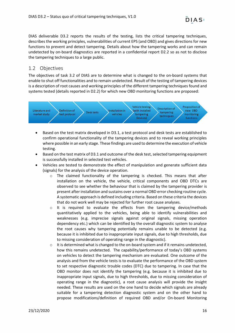
Objectives The objectives of task 3.2 of DIAS are to determine what is changed to the on-board systems that enable to shut off functionalities and to remain undetected. Result of the testing of tampering devices is a description of root causes and working principles of the different tampering techniques found and systems tested (details reported in D2.2) for which new OBD monitoring functions are proposed:
• Based on the test matrix developed in D3.1, a test protocol and desk tests are established to confirm operational functionality of the tampering devices and to reveal working principles where possible in an early stage. These findings are used to determine the execution of vehicle testing.
• Based on the test matrix of D3.1 and outcome of the desk test, selected tampering equipment is successfully installed in selected test vehicles.
• Vehicles are tested to demonstrate the effect of manipulation and generate sufficient data (signals) for the analysis of the device operation.
o The claimed functionality of the tampering is checked. This means that after installation on the vehicle, the vehicle, critical components and OBD DTCs are observed to see whether the behaviour that is claimed by the tampering provider is present after installation and sustains over a normal OBD error checking routine cycle. A systematic approach is defined including criteria. Based on these criteria the devices that do not work well may be rejected for further root cause analyses.
o It is required to evaluate the effects from the tampering device/methods quantitatively applied to the vehicles, being able to identify vulnerabilities and weaknesses (e.g. imprecise signals against original signals, missing operation dependency etc.) which can be identified by the overall diagnostic system to analyse the root causes why tampering potentially remains unable to be detected (e.g. because it is inhibited due to inappropriate input signals, due to high thresholds, due to missing consideration of operating range in the diagnostic).
o It is determined what is changed to the on-board system and if it remains undetected, how this remains undetected. The capability/performance of today’s OBD systems on vehicles to detect the tampering mechanism are evaluated. One outcome of the analysis and from the vehicle tests is to evaluate the performance of the OBD system to set respective diagnostic trouble codes (DTC) due to tampering. In case that the OBD monitor does not identify the tampering (e.g. because it is inhibited due to inappropriate input signals, due to high thresholds, due to missing consideration of operating range in the diagnostic), a root cause analysis will provide the insight needed. These results are used on the one hand to decide which signals are already suitable for a tampering detection diagnostic system and on the other hand to propose modifications/definition of required OBD and/or On-board Monitoring
DIAS D3.2 – Status quo of critical tampering techniques, V1.0
23/12/2020 17
functions to detect tampering (e.g. longer observation times, lowered threshold, a combination of signals).
• The desktop testing and vehicle testing results in a description of the tampering techniques, clustered according to their working principles: how each type of tampering works, what signals are affected, what software and hardware of the board systems are involved and affected.
Based on the results of testing, suitable (OBD-) monitors and signals that can be incorporated in the overall DIAS diagnostic system for a tampering detection will be identified. A proposal will be done for modifications/definitions of required OBD and/or On-board Monitoring functions for prevention and detection of tampering by the DIAS concept D3.2 also directly provides information for the identification and implementation of detection methods and countermeasures to be developed in WP4 and WP5 and for setting up guidelines and recommendations for future legislation for the introduction of future safe monitoring systems in WP6.
Approach In achieving the objectives, for task 3.2 the selected tampering device/methods and vehicles that are proposed in the matrix of D3.1 are tested to understand their working principles and their impact on the system and signals:
1. in a desktop test rig and 2. applied and tested on vehicles, driving the vehicles on the road or a testbed.
The test matrix proposes combinations of tampering types and vehicle types to be tested according to a test plan that is aimed at obtaining in a structured way the test data that is needed to understand the working principles of the tampering and to determine the KPI of the tampering. KPI include a check of the functionality claim (does it work as promised), costs, ease of installation, reliability/robustness and impact on the vehicle control systems, emissions and other possible impacts.
Document structure Chapter 1 presents the background, purpose, approach and structure of the current document and deviations from the DoW (Description of Work). Chapter 2 gives an update of the ongoing market assessment. New findings and tampering found since the publication of D3.1 are discussed in this chapter. Chapter 3 described the methodology used for testing various forms of tampering. In chapter 4 all the results from the test programme are presented. Chapter 5 discusses the tampering general working principles and vulnerabilities and Chapter 6 gives directions for tampering prevention or detection. Finally, Chapter 7 presents the conclusions on this document.
Deviations from original DoW
Description of work related to deliverable as given in DoW Status quo of critical tampering techniques and proposal of required new OBD monitoring functions: Results of the testing of tampering devices with a description of root causes and working principles of the different tampering techniques found and systems tested and proposal for new OBD monitoring functions.
Time deviations from original DoW There has been a delay of 1 month since the scheduled delivery date.
DIAS D3.2 – Status quo of critical tampering techniques, V1.0
23/12/2020 18
Content deviations from original DoW It was decided to report the details about how the tampering works and can remain undetected by on-board diagnostics in a confidential report, deliverable D2.2 of DIAS, so as not to disclose the tampering techniques to a large public. This report gives only a part of the test results because not all vehicles and tampering has been tested at the time of publishing this report.
DIAS D3.2 – Status quo of critical tampering techniques, V1.0
23/12/2020 19
Updates and status quo of the market assessment In report DIAS D3.1 an overview is given of the tampering market and the different tampering devices and services available in that market. During the DIAS project, the market is analysed continuously by scanning websites and by having interviews with involved companies such as tuning workshops. In this chapter, the new findings are reported that were obtained after the publication of D3.1. New types of tampering are found, more insight was obtained into how certain types of tampering are marketed but also more information was obtained about the motivations for tampering.
ECU flashing Tampering in the form of ECU flashing, with the purpose to alter or deactivate EPS, is together with emulators the largest form of tampering offered for LD vehicles. This form of tampering also has a large market share for HD and NRMM. This form of tampering is widely offered by tuning companies as a service, as a DIY kit with hardware tools to facilitate the flashing but also widely discussed on forums where self-taught experts and hobbyists share information and experiences on forums such as how-to-do’s with clear step-by-step instructions and workshop manuals.
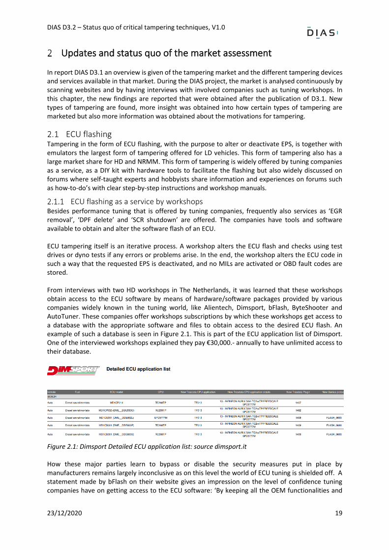
ECU flashing as a service by workshops Besides performance tuning that is offered by tuning companies, frequently also services as ‘EGR removal’, ‘DPF delete’ and ‘SCR shutdown’ are offered. The companies have tools and software available to obtain and alter the software flash of an ECU. ECU tampering itself is an iterative process. A workshop alters the ECU flash and checks using test drives or dyno tests if any errors or problems arise. In the end, the workshop alters the ECU code in such a way that the requested EPS is deactivated, and no MILs are activated or OBD fault codes are stored. From interviews with two HD workshops in The Netherlands, it was learned that these workshops obtain access to the ECU software by means of hardware/software packages provided by various companies widely known in the tuning world, like Alientech, Dimsport, bFlash, ByteShooter and AutoTuner. These companies offer workshops subscriptions by which these workshops get access to a database with the appropriate software and files to obtain access to the desired ECU flash. An example of such a database is seen in Figure 2.1. This is part of the ECU application list of Dimsport. One of the interviewed workshops explained they pay €30,000.- annually to have unlimited access to their database.
Figure 2.1: Dimsport Detailed ECU application list: source dimsport.it How these major parties learn to bypass or disable the security measures put in place by manufacturers remains largely inconclusive as on this level the world of ECU tuning is shielded off. A statement made by bFlash on their website gives an impression on the level of confidence tuning companies have on getting access to the ECU software: ‘By keeping all the OEM functionalities and
DIAS D3.2 – Status quo of critical tampering techniques, V1.0
23/12/2020 20
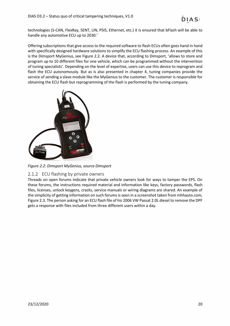
technologies (S-CAN, FlexRay, SENT, LIN, PSI5, Ethernet, etc.) it is ensured that bFlash will be able to handle any automotive ECU up to 2030.’ Offering subscriptions that give access to the required software to flash ECUs often goes hand in hand with specifically designed hardware solutions to simplify the ECU flashing process. An example of this is the Dimsport MyGenius, see Figure 2.2. A device that, according to Dimsport, ‘allows to store and program up to 10 different files for one vehicle, which can be programmed without the intervention of tuning specialists’. Depending on the level of expertise, users can use this device to reprogram and flash the ECU autonomously. But as is also presented in chapter 4, tuning companies provide the service of sending a slave module like the MyGenius to the customer. The customer is responsible for obtaining the ECU flash but reprogramming of the flash is performed by the tuning company.
Figure 2.2: Dimsport MyGenius, source Dimsport
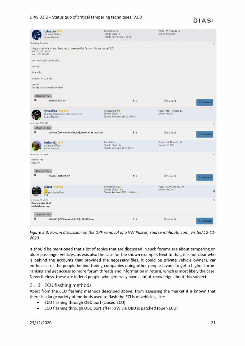
ECU flashing by private owners Threads on open forums indicate that private vehicle owners look for ways to tamper the EPS. On these forums, the instructions required material and information like keys, factory passwords, flash files, licenses, unlock keygens, cracks, service manuals or wiring diagrams are shared. An example of the simplicity of getting information on such forums is seen in a screenshot taken from mhhauto.com, Figure 2.3. The person asking for an ECU flash file of his 2006 VW Passat 2.0L diesel to remove the DPF gets a response with files included from three different users within a day.
DIAS D3.2 – Status quo of critical tampering techniques, V1.0
23/12/2020 21
Figure 2.3: Forum discussion on the DPF removal of a VW Passat, source mhhauto.com, visited 12-11-2020. It should be mentioned that a lot of topics that are discussed in such forums are about tampering on older passenger vehicles, as was also the case for the shown example. Next to that, it is not clear who is behind the accounts that provided the necessary files. It could be private vehicle owners, car enthusiast or the people behind tuning companies doing other people favour to get a higher forum ranking and get access to more forum threads and information in return, which is most likely the case. Nevertheless, these are indeed people who generally have a lot of knowledge about this subject.
ECU flashing methods Apart from the ECU flashing methods described above, from assessing the market it is known that there is a large variety of methods used to flash the ECUs of vehicles, like:
• ECU flashing through OBD port (closed ECU)
• ECU flashing through OBD port after R/W via OBD is patched (open ECU)
DIAS D3.2 – Status quo of critical tampering techniques, V1.0
23/12/2020 22
• ECU flashing through boot flash i.e. R/W via boot (open ECU)
• ECU flashing through boot flash (open ECU) after the password is obtained via OBD Detailed information on how these methods work is however difficult to find since the ECU flashing market is shielded off from outsiders. ECUs and software updates are secured by digital signatures and passwords that can be generated using keys. It remains unclear how these keys are obtained or reversed engineered. An engineer with experience in this field explained that ‘it is certainly not inconceivable that this information might come through back doors from the manufacturers’. This cannot be checked.
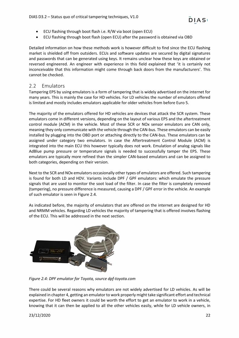
Emulators Tampering EPS by using emulators is a form of tampering that is widely advertised on the internet for many years. This is mainly the case for HD vehicles. For LD vehicles the number of emulators offered is limited and mostly includes emulators applicable for older vehicles from before Euro 5. The majority of the emulators offered for HD vehicles are devices that attack the SCR system. These emulators come in different versions, depending on the layout of various EPS and the aftertreatment control module (ACM) in the vehicle. Most of these SCR or NOx sensor emulators are CAN only, meaning they only communicate with the vehicle through the CAN-bus. These emulators can be easily installed by plugging into the OBD port or attaching directly to the CAN-bus. These emulators can be assigned under category two emulators. In case the Aftertreatment Control Module (ACM) is integrated into the main ECU this however typically does not work. Emulation of analog signals like AdBlue pump pressure or temperature signals is needed to successfully tamper the EPS. These emulators are typically more refined than the simpler CAN-based emulators and can be assigned to both categories, depending on their version. Next to the SCR and NOx emulators occasionally other types of emulators are offered. Such tampering is found for both LD and HDV. Variants include DPF / GPF emulators: which emulate the pressure signals that are used to monitor the soot load of the filter. In case the filter is completely removed (tampering), no pressure difference is measured, causing a DPF / GPF error in the vehicle. An example of such emulator is seen in Figure 2.4. As indicated before, the majority of emulators that are offered on the internet are designed for HD and NRMM vehicles. Regarding LD vehicles the majority of tampering that is offered involves flashing of the ECU. This will be addressed in the next section.
Figure 2.4: DPF emulator for Toyota, source dpf-toyota.com There could be several reasons why emulators are not widely advertised for LD vehicles. As will be explained in chapter 4, getting an emulator to work properly might take significant effort and technical expertise. For HD fleet owners it could be worth the effort to get an emulator to work in a vehicle, knowing that it can then be applied to all the other vehicles easily, while for LD vehicle owners, in
DIAS D3.2 – Status quo of critical tampering techniques, V1.0
23/12/2020 23
particular private owners, it is much easier to go to a tuning company and let the ECU be flashed. Next to that the available truck makes and models are much more limited compared to the passenger car market. This wide range of makes and models LD vehicles also require a large variety of emulators, of which the efforts for development by tamperers could be less profitable compare to ECU flashing.
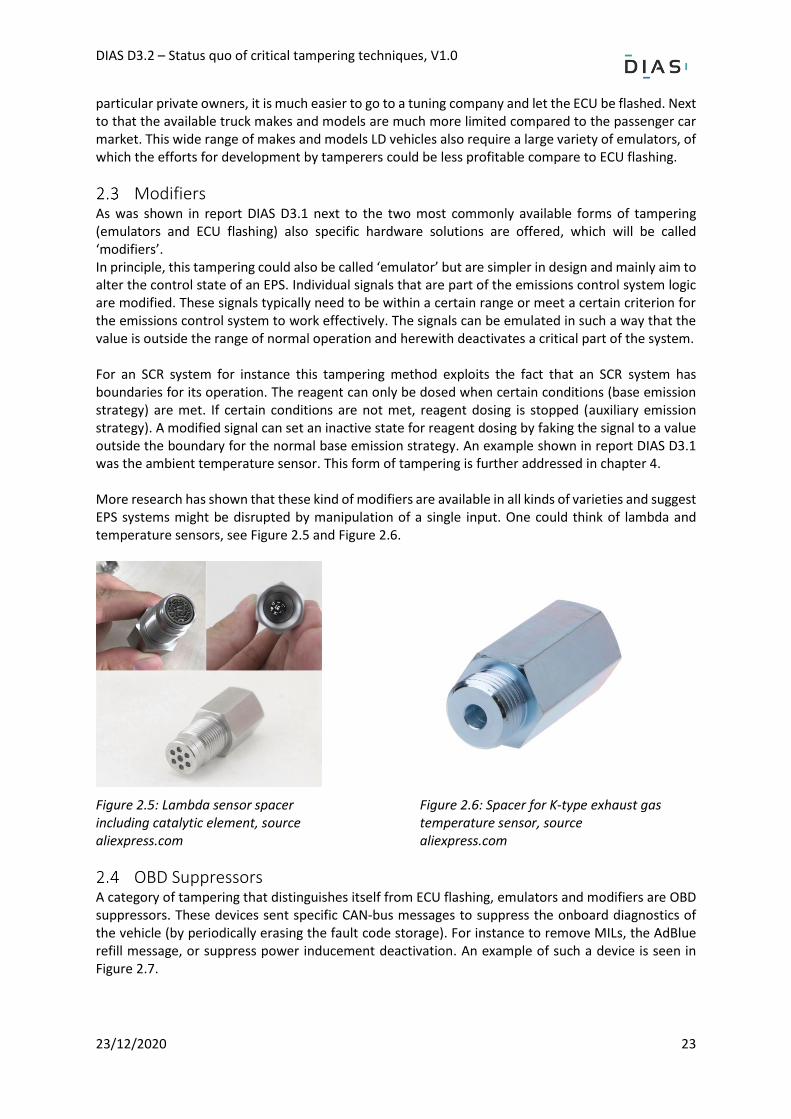
Modifiers As was shown in report DIAS D3.1 next to the two most commonly available forms of tampering (emulators and ECU flashing) also specific hardware solutions are offered, which will be called ‘modifiers’. In principle, this tampering could also be called ‘emulator’ but are simpler in design and mainly aim to alter the control state of an EPS. Individual signals that are part of the emissions control system logic are modified. These signals typically need to be within a certain range or meet a certain criterion for the emissions control system to work effectively. The signals can be emulated in such a way that the value is outside the range of normal operation and herewith deactivates a critical part of the system. For an SCR system for instance this tampering method exploits the fact that an SCR system has boundaries for its operation. The reagent can only be dosed when certain conditions (base emission strategy) are met. If certain conditions are not met, reagent dosing is stopped (auxiliary emission strategy). A modified signal can set an inactive state for reagent dosing by faking the signal to a value outside the boundary for the normal base emission strategy. An example shown in report DIAS D3.1 was the ambient temperature sensor. This form of tampering is further addressed in chapter 4. More research has shown that these kind of modifiers are available in all kinds of varieties and suggest EPS systems might be disrupted by manipulation of a single input. One could think of lambda and temperature sensors, see Figure 2.5 and Figure 2.6.
Figure 2.5: Lambda sensor spacer including catalytic element, source aliexpress.com
Figure 2.6: Spacer for K-type exhaust gas temperature sensor, source aliexpress.com
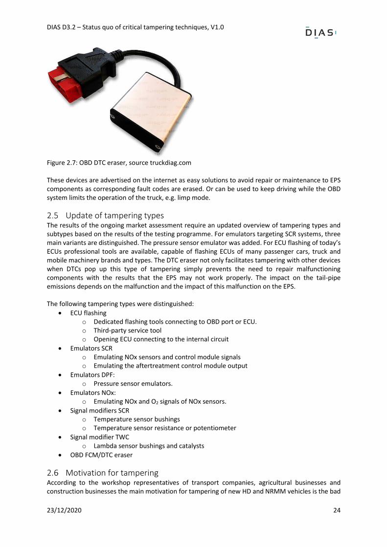
OBD Suppressors A category of tampering that distinguishes itself from ECU flashing, emulators and modifiers are OBD suppressors. These devices sent specific CAN-bus messages to suppress the onboard diagnostics of the vehicle (by periodically erasing the fault code storage). For instance to remove MILs, the AdBlue refill message, or suppress power inducement deactivation. An example of such a device is seen in Figure 2.7.
DIAS D3.2 – Status quo of critical tampering techniques, V1.0
23/12/2020 24
Figure 2.7: OBD DTC eraser, source truckdiag.com These devices are advertised on the internet as easy solutions to avoid repair or maintenance to EPS components as corresponding fault codes are erased. Or can be used to keep driving while the OBD system limits the operation of the truck, e.g. limp mode.
Update of tampering types The results of the ongoing market assessment require an updated overview of tampering types and subtypes based on the results of the testing programme. For emulators targeting SCR systems, three main variants are distinguished. The pressure sensor emulator was added. For ECU flashing of today’s ECUs professional tools are available, capable of flashing ECUs of many passenger cars, truck and mobile machinery brands and types. The DTC eraser not only facilitates tampering with other devices when DTCs pop up this type of tampering simply prevents the need to repair malfunctioning components with the results that the EPS may not work properly. The impact on the tail-pipe emissions depends on the malfunction and the impact of this malfunction on the EPS. The following tampering types were distinguished:
• ECU flashing o Dedicated flashing tools connecting to OBD port or ECU. o Third-party service tool o Opening ECU connecting to the internal circuit
• Emulators SCR o Emulating NOx sensors and control module signals o Emulating the aftertreatment control module output
• Emulators DPF: o Pressure sensor emulators.
• Emulators NOx: o Emulating NOx and O2 signals of NOx sensors.
• Signal modifiers SCR o Temperature sensor bushings o Temperature sensor resistance or potentiometer
• Signal modifier TWC o Lambda sensor bushings and catalysts
• OBD FCM/DTC eraser
Motivation for tampering According to the workshop representatives of transport companies, agricultural businesses and construction businesses the main motivation for tampering of new HD and NRMM vehicles is the bad
DIAS D3.2 – Status quo of critical tampering techniques, V1.0
23/12/2020 25
experience with the EPS of the older generations of the vehicle(s) previously owned, where problems with the EPS led to downtime and high costs. This not only holds for single vehicles but even whole fleets of vehicles. The reason for the bad experience of HD vehicle owners is the insufficient knowledge and interest for the EPS equipped in their vehicles. According to workshops the overall reliability of the first generation of EPS like DPF and SCR for HD was not in line with the general understanding of vehicle reliability by their owners. As a result, these systems where maintained insufficiently and broke down, resulting in high repair cost. For example, a new DPF for truck applications costs around 1000 to 4000 euros, while DPF cleaning costs around 300 euros. In particular, for owners of NRMM, an important motivation for tampering is an increase of power and a decrease in fuel consumption for their vehicles. The application and use of these kinds of vehicles usually are highly specialised. Owners, therefore, tend to customise and alter their vehicles specifically to those needs. In combination with a general lack of inspection by authorities, this does not prevent owners from tampering with the EPS. Another motive for tampering that is known is the use of tampering devices and services to avoid necessary maintenance and repairs. An example of this could be a NOx sensor emulator that emulates the NOx sensors which thereby do not need to be replaced in case they break down. From interviews with several transport companies in the Netherlands, it was also understood that the social acceptance towards tampering is decreasing as green technologies and sustainable transport become more and more the standard. It is said that tampering occurs more frequently in Eastern Europe countries as the economic situation might be less positive or social acceptance towards tampering is higher.
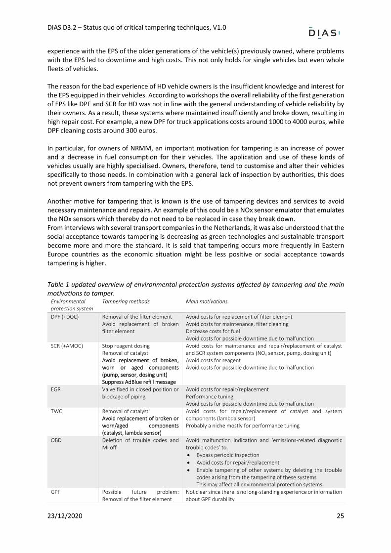
Table 1 updated overview of environmental protection systems affected by tampering and the main motivations to tamper.
Environmental protection system
Tampering methods Main motivations
DPF (+DOC) Removal of the filter element Avoid replacement of broken filter element
- Avoid costs for replacement of filter element - Avoid costs for maintenance, filter cleaning - Decrease costs for fuel - Avoid costs for possible downtime due to malfunction
SCR (+AMOC) Stop reagent dosing Removal of catalyst Avoid replacement of broken, worn or aged components (pump, sensor, dosing unit) Suppress AdBlue refill message
- Avoid costs for maintenance and repair/replacement of catalyst and SCR system components (NOx sensor, pump, dosing unit)
- Avoid costs for reagent - Avoid costs for possible downtime due to malfunction
EGR Valve fixed in closed position or blockage of piping
- Avoid costs for repair/replacement - Performance tuning - Avoid costs for possible downtime due to malfunction
TWC Removal of catalyst Avoid replacement of broken or worn/aged components (catalyst, lambda sensor)
- Avoid costs for repair/replacement of catalyst and system components (lambda sensor)
- Probably a niche mostly for performance tuning
OBD Deletion of trouble codes and MI off
Avoid malfunction indication and ‘emissions-related diagnostic trouble codes’ to:
• Bypass periodic inspection
• Avoid costs for repair/replacement
• Enable tampering of other systems by deleting the trouble codes arising from the tampering of these systems This may affect all environmental protection systems
GPF Possible future problem: Removal of the filter element
Not clear since there is no long-standing experience or information about GPF durability
DIAS D3.2 – Status quo of critical tampering techniques, V1.0
23/12/2020 26
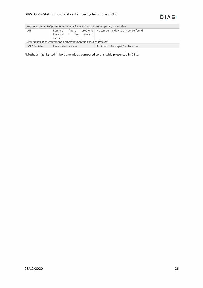
New environmental protection systems for which so far, no tampering is reported
LNT Possible future problem: Removal of the catalytic element
No tampering device or service found.
Other types of environmental protection systems possibly affected
EVAP Canister Removal of canister - Avoid costs for repair/replacement
*Methods highlighted in bold are added compared to this table presented in D3.1.
DIAS D3.2 – Status quo of critical tampering techniques, V1.0
23/12/2020 27
Methodology: test matrix and test programme
Scope of work In this chapter, the test matrix and the test methodology are presented. The main objectives of the testing programme are:
• to determine the key performance indicators of the currently available tampering
• to determine how the tampering works and can remain undetected by on-board diagnostics. This information would indicate what vulnerabilities are exploited to develop the tampering. For emulators that connect to the CAN-bus, it means that it is for instance necessary to determine what CAN signals and other signals are affected, how the signals values look and behave. The test programme aims to measure those signals without and with tampering installed so that the signals in both situations can be compared. A test matrix has been defined with the vehicle – tampering combinations to be tested. This test matrix is an updated version of the version presented in the report DIAS D3.1 Table 4.1, taking into account the latest findings of the ongoing market assessment from the previous chapter. It should be noted that, since the testing programme continues beyond the issue date of this report the test matrix and test programme described here mainly reflect on the outcomes of the testing programme presented in this version. It can be found in section 3.5.
Sources Report DIAS D2.1 and DIAS D3.1 and the ongoing market assessment (Chapter 2) acted as the main source of information as these reports laid the basis for this testing programme.
Key performance indicators For each form of tampering that has been tested their specifications, characteristics and performance was expressed by means of Key Performance Indicators (KPI). An overview of the KPIs for which the tampering was tested is listed below. Depending on the type of tampering some KPIs were not applicable.
• Appearance - Construction/build quality - Physical connections/in- and outputs
• Functionality - General working principle - Affected vehicle signals/communication
• Installation - Instructions/manuals available - Workshop tools required - Hard- and software required - The effort for installation required - Skills required
• Reliability, robustness - Claims made by the provider - Reliability of tampering
• Impact - Effectiveness of tampering - Change in emissions - Vehicle response
DIAS D3.2 – Status quo of critical tampering techniques, V1.0
23/12/2020 28
- OBD response
• Tampering cost
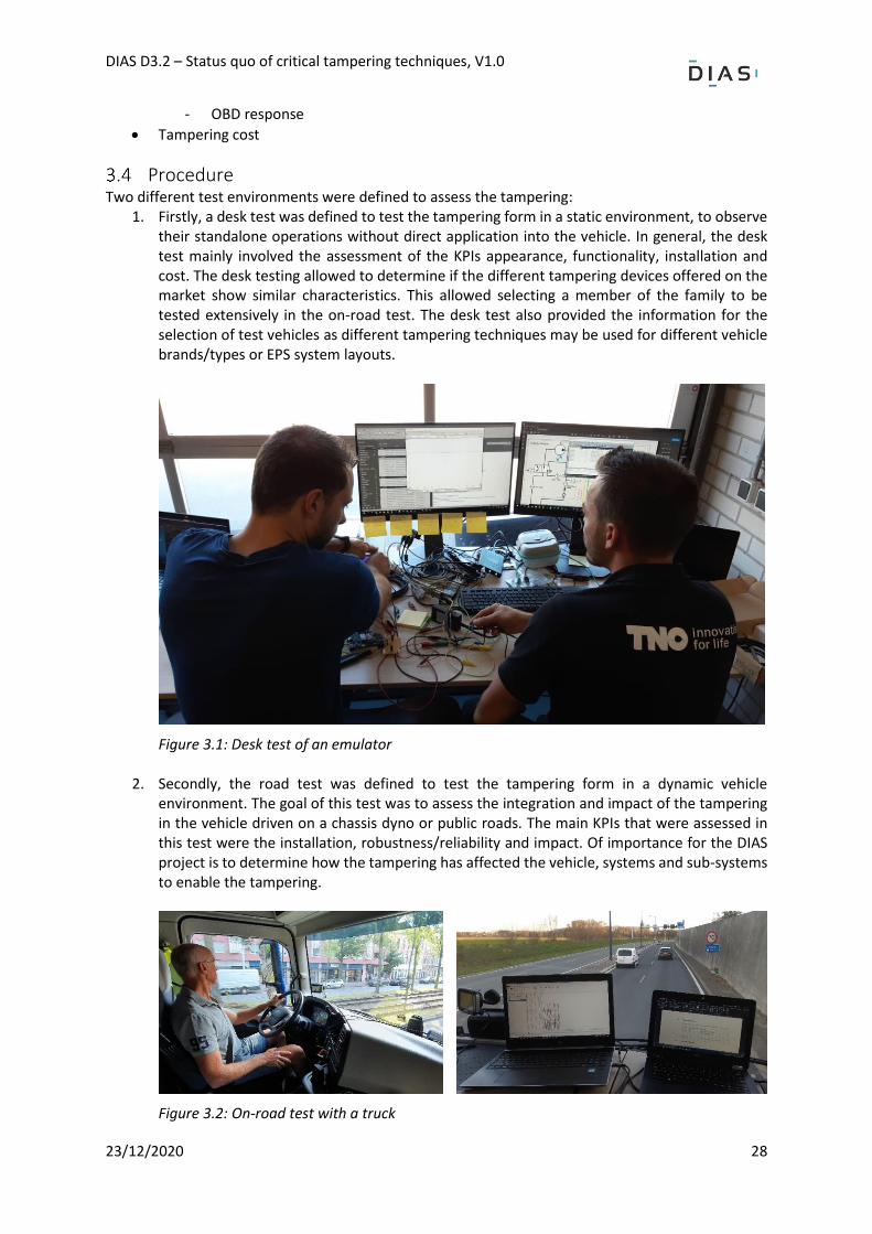
Procedure Two different test environments were defined to assess the tampering:
1. Firstly, a desk test was defined to test the tampering form in a static environment, to observe their standalone operations without direct application into the vehicle. In general, the desk test mainly involved the assessment of the KPIs appearance, functionality, installation and cost. The desk testing allowed to determine if the different tampering devices offered on the market show similar characteristics. This allowed selecting a member of the family to be tested extensively in the on-road test. The desk test also provided the information for the selection of test vehicles as different tampering techniques may be used for different vehicle brands/types or EPS system layouts.
Figure 3.1: Desk test of an emulator
2. Secondly, the road test was defined to test the tampering form in a dynamic vehicle environment. The goal of this test was to assess the integration and impact of the tampering in the vehicle driven on a chassis dyno or public roads. The main KPIs that were assessed in this test were the installation, robustness/reliability and impact. Of importance for the DIAS project is to determine how the tampering has affected the vehicle, systems and sub-systems to enable the tampering.
Figure 3.2: On-road test with a truck
DIAS D3.2 – Status quo of critical tampering techniques, V1.0
23/12/2020 29
Depending on the particular form of tampering the testing procedure was different. Emulators were desk tested first to determine the hardware used and to check if the emulator could be applied to the corresponding test vehicle. In case of for example signal emulation in the form of exhaust sensor spacers, no desk test was performed as these devices are passive parts and/or are difficult to test outside the vehicle. In case of ECU flashing the execution of a desk test highly depended on the type of ECU flashing, i.e. was it purchased as a service or did it require DIY flashing interaction. The following procedure was followed for the preparation, the testing programme and data processing:
1. Finalise test procedure and test matrix: The concept test procedure and test matrix were finalised based on the latest information gathered in the ongoing market assessment and the availability of tampering devices/services.
2. Distribute test tasks: The test tasks were distributed among the consortium partners in the project. The distribution depended on the expertise of each partner and their ease of access to test vehicles. A subdivision of tests among the partners is seen in the test matrix Table 3.1
3. Source and acquire tampering: Tampering devices/services were sourced and purchased by the consortium partners in the preparation of the test programme. This process ran following the sourcing of the test vehicles.
4. Source and acquire test vehicles: In conjunction with the acquired tampering devices/services a vehicle selection was made, and the vehicles were sourced. The first HD diesel was sourced within the project consortium.
5. Acquire necessary testing equipment, tools and knowledge: Specialised testing equipment, tools and vehicle parts were sourced in preparation of testing.
6. Instrumentation of test facility and vehicle: The test facilities and vehicles were instrumented in preparation of the testing.
7. Performing of tests: After all preparations were made the tests were performed. As explained a desk and/or road test was performed depending on the form of tampering investigated.
8. Archive and analysis of raw data: The test data was archived and analysed on the one hand to verify if the tests were performed correctly and the data was collected properly. On the other hand, the data was analysed to obtain preliminary results.
9. Evaluate and summarise road test results: As a final step of the test procedure the tests were evaluated, and the results were documented in test reports and distributed to the other partners. Note that general finding and conclusions are presented in this report. More detailed and potentially confidential results are presented in DIAS D2.2.
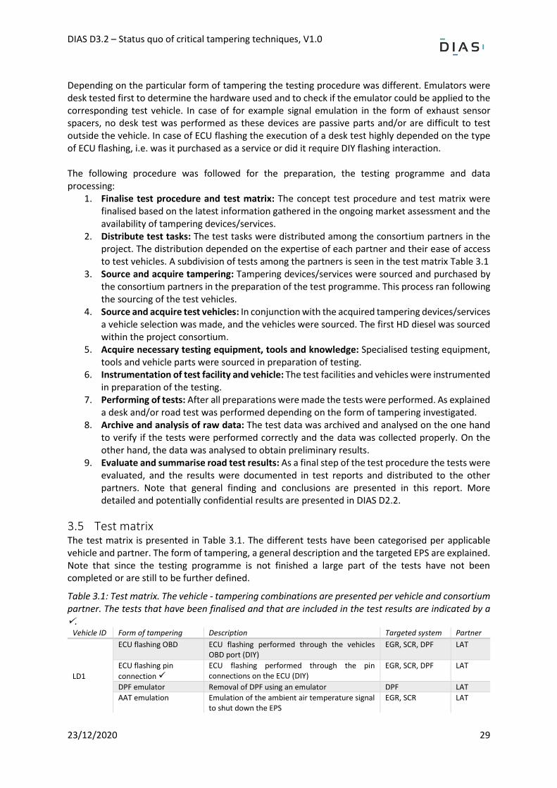
Test matrix The test matrix is presented in Table 3.1. The different tests have been categorised per applicable vehicle and partner. The form of tampering, a general description and the targeted EPS are explained. Note that since the testing programme is not finished a large part of the tests have not been completed or are still to be further defined.
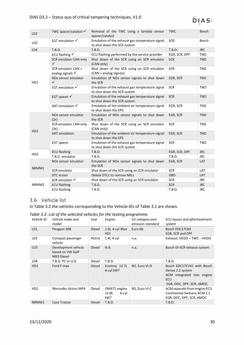
Table 3.1: Test matrix. The vehicle - tampering combinations are presented per vehicle and consortium partner. The tests that have been finalised and that are included in the test results are indicated by a ✓.
Vehicle ID Form of tampering Description Targeted system Partner
LD1
ECU flashing OBD ECU flashing performed through the vehicles OBD port (DIY)
EGR, SCR, DPF LAT
ECU flashing pin
connection ✓
ECU flashing performed through the pin connections on the ECU (DIY)
EGR, SCR, DPF LAT
DPF emulator Removal of DPF using an emulator DPF LAT
AAT emulation Emulation of the ambient air temperature signal to shut down the EPS
EGR, SCR LAT
DIAS D3.2 – Status quo of critical tampering techniques, V1.0
23/12/2020 30
LD2 TWC spacer/catalyst ✓ Removal of the TWC using a lambda sensor
spacer/catalyst TWC Bosch
LD3 EGT emulation ✓ Emulation of the exhaust gas temperature signal
to shut down the SCR system SCR Bosch
LD4 T.B.D. T.B.D. T.B.D. JRC
HD1
ECU flashing ✓ ECU flashing performed by the service provider EGR, SCR, DPF TNO
SCR emulator CAN-only
✓
Shut down of the SCR using an SCR emulator (CAN-only)
SCR TNO
SCR emulator CAN +
analog signals ✓
Shut down of the SCR using an SCR emulator (CAN + analog signals)
SCR TNO
NOx sensor emulator
✓
Emulation of NOx sensor signals to shut down the SCR
EGR, SCR TNO
EGT emulation ✓ Emulation of the exhaust gas temperature signal to shut down the SCR system
SCR TNO
EGT spacer ✓ Emulation of the exhaust gas temperature signal to shut down the SCR system
SCR TNO
AAT emulation ✓ Emulation of the ambient air temperature signal to shut down the EPS
EGR, SCR TNO
HD2
NOx sensor emulator (2x)
Emulation of NOx sensor signals to shut down the SCR
EGR, SCR TNO
SCR emulator CAN-only (3x)
Shut down of the SCR using an SCR emulator (CAN-only)
SCR TNO
AAT emulation Emulation of the ambient air temperature signal to shut down the EPS
EGR, SCR TNO
EGT spacer Emulation of the exhaust gas temperature signal to shut down the SCR system
SCR TNO
HD3 ECU flashing T.B.D. EGR, SCR, DPF JRC
T.B.D. emulator T.B.D. T.B.D. JRC
NRMM1
NOx sensor emulator Emulation of NOx sensor signals to shut down the SCR
EGR, SCR LAT
SCR emulator Shut down of the SCR using an SCR emulator SCR LAT
DTC eraser Delete DTCs to remove MILs OBD LAT
NRMM2
SCR emulator ✓ Shut down of the SCR using an SCR emulator SCR JRC
ECU flashing T.B.D. SCR JRC
ECU flashing T.B.D. T.B.D. JRC
Vehicle list In Table 3.2 the vehicles corresponding to the Vehicle IDs of Table 3.1 are shown.
Table 3.2: List of the selected vehicles for the testing programme. Vehicle ID Vehicle make and
model Fuel Engine EU category and
emission standard ECU layout and aftertreatment system
LD1 Peugeot 308 Diesel 1.6L 4-cyl Blue HDI
Euro 6b Bosch EDC17C60 EGR, SCR and DPF
LD2 Compact passenger vehicle
Petrol 1.4L 4-cyl n.a. Exhaust: UEGO – TWC – HEGO
LD3 Development vehicle based on VW Golf MK3 Diesel
Diesel N.A. n.a. Bosch DI-SCR exhaust system
LD4 T.B.D. PC or LCV Diesel T.B.D. T.B.D.
HD1 Ford F-max Diesel Ecotorq 12.7L 6-cyl kW?
N3, Euro VI-D Bosch EDC17CV41 with Bosch Denox 2.2 system ACM integrated into engine ECU EGR, DOC, DPF, SCR, AMOC.
HD2 Mercedes Actros MP4 Diesel OM471 engine 12.8L 6-cyl kW?
N3, Euro VI-C ACM separate from engine ECU Continental-Siemens ACM 2.1 EGR, DOC, DPF, SCR, AMOC
NRMM1 Case Tractor Diesel T.B.D. T.B.D.
DIAS D3.2 – Status quo of critical tampering techniques, V1.0
23/12/2020 31
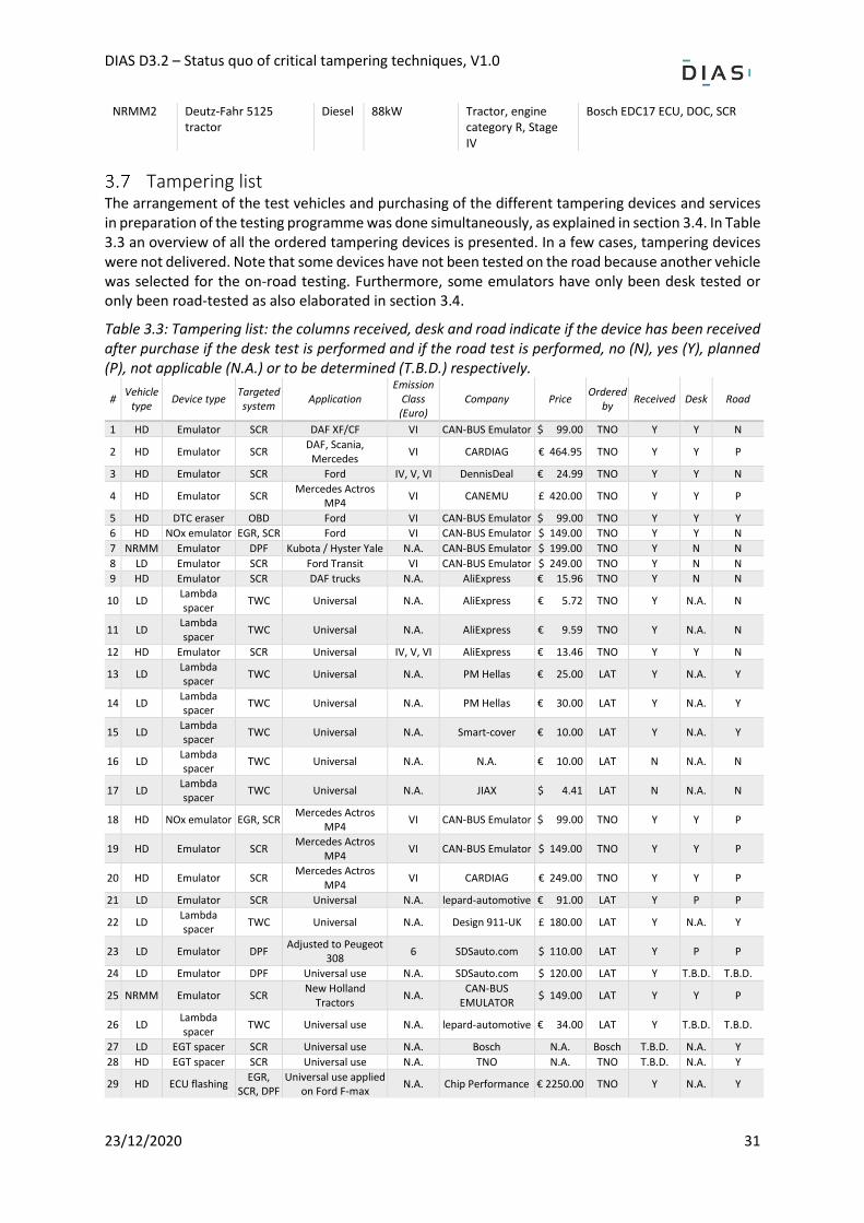
NRMM2 Deutz-Fahr 5125 tractor
Diesel 88kW Tractor, engine category R, Stage IV
Bosch EDC17 ECU, DOC, SCR
Tampering list The arrangement of the test vehicles and purchasing of the different tampering devices and services in preparation of the testing programme was done simultaneously, as explained in section 3.4. In Table 3.3 an overview of all the ordered tampering devices is presented. In a few cases, tampering devices were not delivered. Note that some devices have not been tested on the road because another vehicle was selected for the on-road testing. Furthermore, some emulators have only been desk tested or only been road-tested as also elaborated in section 3.4.
Table 3.3: Tampering list: the columns received, desk and road indicate if the device has been received after purchase if the desk test is performed and if the road test is performed, no (N), yes (Y), planned (P), not applicable (N.A.) or to be determined (T.B.D.) respectively.
# Vehicle
type Device type
Targeted system
Application Emission
Class (Euro)
Company Price Ordered
by Received Desk Road
1 HD Emulator SCR DAF XF/CF VI CAN-BUS Emulator $ 99.00 TNO Y Y N
2 HD Emulator SCR DAF, Scania,
Mercedes VI CARDIAG € 464.95 TNO Y Y P
3 HD Emulator SCR Ford IV, V, VI DennisDeal € 24.99 TNO Y Y N
4 HD Emulator SCR Mercedes Actros
MP4 VI CANEMU £ 420.00 TNO Y Y P
5 HD DTC eraser OBD Ford VI CAN-BUS Emulator $ 99.00 TNO Y Y Y
6 HD NOx emulator EGR, SCR Ford VI CAN-BUS Emulator $ 149.00 TNO Y Y N
7 NRMM Emulator DPF Kubota / Hyster Yale N.A. CAN-BUS Emulator $ 199.00 TNO Y N N
8 LD Emulator SCR Ford Transit VI CAN-BUS Emulator $ 249.00 TNO Y N N
9 HD Emulator SCR DAF trucks N.A. AliExpress € 15.96 TNO Y N N
10 LD Lambda spacer
TWC Universal N.A. AliExpress € 5.72 TNO Y N.A. N
11 LD Lambda spacer
TWC Universal N.A. AliExpress € 9.59 TNO Y N.A. N
12 HD Emulator SCR Universal IV, V, VI AliExpress € 13.46 TNO Y Y N
13 LD Lambda spacer
TWC Universal N.A. PM Hellas € 25.00 LAT Y N.A. Y
14 LD Lambda spacer
TWC Universal N.A. PM Hellas € 30.00 LAT Y N.A. Y
15 LD Lambda spacer
TWC Universal N.A. Smart-cover € 10.00 LAT Y N.A. Y
16 LD Lambda spacer
TWC Universal N.A. N.A. € 10.00 LAT N N.A. N
17 LD Lambda spacer
TWC Universal N.A. JIAX $ 4.41 LAT N N.A. N
18 HD NOx emulator EGR, SCR Mercedes Actros
MP4 VI CAN-BUS Emulator $ 99.00 TNO Y Y P
19 HD Emulator SCR Mercedes Actros
MP4 VI CAN-BUS Emulator $ 149.00 TNO Y Y P
20 HD Emulator SCR Mercedes Actros
MP4 VI CARDIAG € 249.00 TNO Y Y P
21 LD Emulator SCR Universal N.A. lepard-automotive € 91.00 LAT Y P P
22 LD Lambda spacer
TWC Universal N.A. Design 911-UK £ 180.00 LAT Y N.A. Y
23 LD Emulator DPF Adjusted to Peugeot
308 6 SDSauto.com $ 110.00 LAT Y P P
24 LD Emulator DPF Universal use N.A. SDSauto.com $ 120.00 LAT Y T.B.D. T.B.D.
25 NRMM Emulator SCR New Holland
Tractors N.A.
CAN-BUS EMULATOR
$ 149.00 LAT Y Y P
26 LD Lambda spacer
TWC Universal use N.A. lepard-automotive € 34.00 LAT Y T.B.D. T.B.D.
27 LD EGT spacer SCR Universal use N.A. Bosch N.A. Bosch T.B.D. N.A. Y
28 HD EGT spacer SCR Universal use N.A. TNO N.A. TNO T.B.D. N.A. Y
29 HD ECU flashing EGR,
SCR, DPF Universal use applied
on Ford F-max N.A. Chip Performance € 2250.00 TNO Y N.A. Y
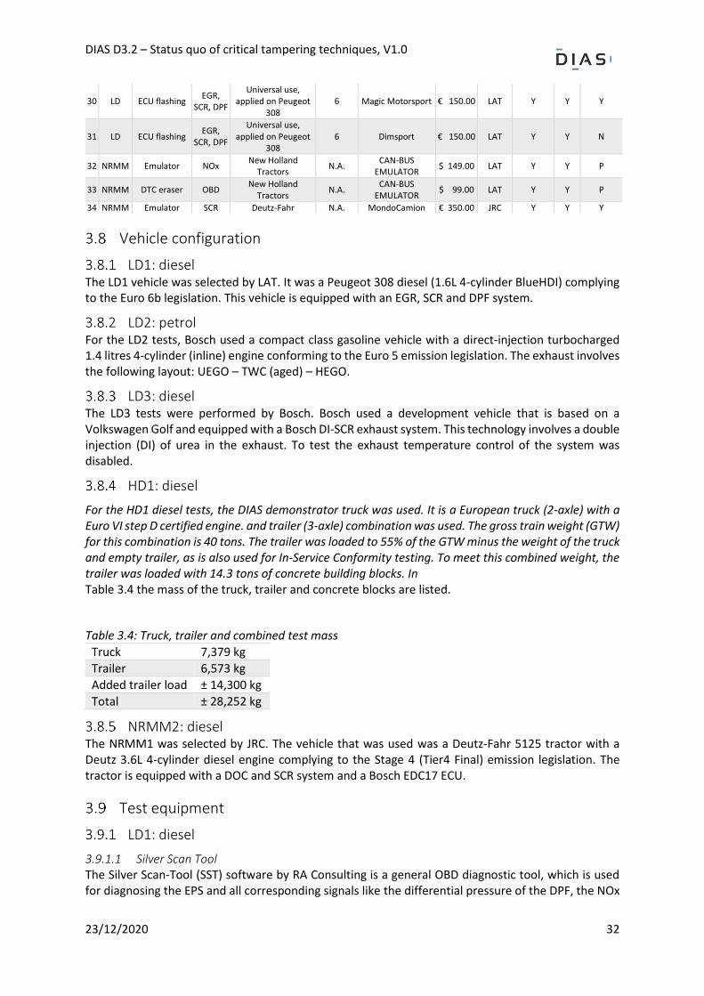
DIAS D3.2 – Status quo of critical tampering techniques, V1.0
23/12/2020 32
30 LD ECU flashing EGR,
SCR, DPF
Universal use, applied on Peugeot
308 6 Magic Motorsport € 150.00 LAT Y Y Y
31 LD ECU flashing EGR,
SCR, DPF
Universal use, applied on Peugeot
308 6 Dimsport € 150.00 LAT Y Y N
32 NRMM Emulator NOx New Holland
Tractors N.A.
CAN-BUS EMULATOR
$ 149.00 LAT Y Y P
33 NRMM DTC eraser OBD New Holland
Tractors N.A.
CAN-BUS EMULATOR
$ 99.00 LAT Y Y P
34 NRMM Emulator SCR Deutz-Fahr N.A. MondoCamion € 350.00 JRC Y Y Y
Vehicle configuration
LD1: diesel The LD1 vehicle was selected by LAT. It was a Peugeot 308 diesel (1.6L 4-cylinder BlueHDI) complying to the Euro 6b legislation. This vehicle is equipped with an EGR, SCR and DPF system.
LD2: petrol For the LD2 tests, Bosch used a compact class gasoline vehicle with a direct-injection turbocharged 1.4 litres 4-cylinder (inline) engine conforming to the Euro 5 emission legislation. The exhaust involves the following layout: UEGO – TWC (aged) – HEGO.
LD3: diesel The LD3 tests were performed by Bosch. Bosch used a development vehicle that is based on a Volkswagen Golf and equipped with a Bosch DI-SCR exhaust system. This technology involves a double injection (DI) of urea in the exhaust. To test the exhaust temperature control of the system was disabled.
HD1: diesel
For the HD1 diesel tests, the DIAS demonstrator truck was used. It is a European truck (2-axle) with a Euro VI step D certified engine. and trailer (3-axle) combination was used. The gross train weight (GTW) for this combination is 40 tons. The trailer was loaded to 55% of the GTW minus the weight of the truck and empty trailer, as is also used for In-Service Conformity testing. To meet this combined weight, the trailer was loaded with 14.3 tons of concrete building blocks. In Table 3.4 the mass of the truck, trailer and concrete blocks are listed.
Table 3.4: Truck, trailer and combined test mass
Truck 7,379 kg
Trailer 6,573 kg
Added trailer load ± 14,300 kg
Total ± 28,252 kg
NRMM2: diesel The NRMM1 was selected by JRC. The vehicle that was used was a Deutz-Fahr 5125 tractor with a Deutz 3.6L 4-cylinder diesel engine complying to the Stage 4 (Tier4 Final) emission legislation. The tractor is equipped with a DOC and SCR system and a Bosch EDC17 ECU.
Test equipment
LD1: diesel
3.9.1.1 Silver Scan Tool The Silver Scan-Tool (SST) software by RA Consulting is a general OBD diagnostic tool, which is used for diagnosing the EPS and all corresponding signals like the differential pressure of the DPF, the NOx
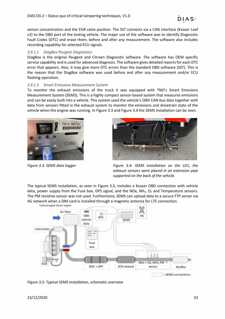
DIAS D3.2 – Status quo of critical tampering techniques, V1.0
23/12/2020 33
sensor concentration and the EGR valve position. The SST connects via a CAN interface (Kvaser Leaf v2) to the OBD port of the testing vehicle. The major use of the software was to identify Diagnostic Fault Codes (DTC) and erase them, before and after any measurement. The software also includes recording capability for selected ECU signals.
3.9.1.2 DiagBox Peugeot Diagnostics DiagBox is the original Peugeot and Citroen Diagnostic software. The software has OEM specific service capability and is used for advanced diagnosis. The software gives detailed reports for each DTC error that appears. Also, it may give more DTC errors than the standard OBD software (SST). This is the reason that the DiagBox software was used before and after any measurement and/or ECU flashing operation.
3.9.1.3 Smart Emissions Measurement System To monitor the exhaust emissions of the truck it was equipped with TNO’s Smart Emissions Measurement System (SEMS). This is a highly compact sensor-based system that measures emissions and can be easily built into a vehicle. This system used the vehicle’s OBD CAN-bus data together with data from sensors fitted in the exhaust system to monitor the emissions and drivetrain state of the vehicle when the engine was running. In Figure 3.3 and Figure 3.4 the SEMS installation can be seen.
Figure 3.3: SEMS data logger
Figure 3.4: SEMS installation on the LD1, the exhaust sensors were placed in an extension pipe supported on the back of the vehicle.
The typical SEMS installation, as seen in Figure 3.5, includes a Kvaser OBD connection with vehicle data, power supply from the Fuse box, GPS signal, and the NOx, NH3, O2 and Temperature sensors. The PM resistive sensor was not used. Furthermore, SEMS can upload data to a secure FTP server via 4G network when a SIM-card is installed through a magnetic antenna for LTE connection.
Figure 3.5: Typical SEMS installation, schematic overview
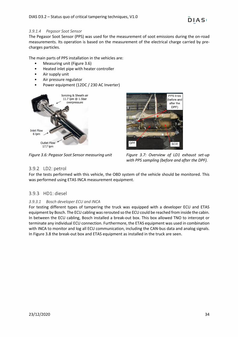
DIAS D3.2 – Status quo of critical tampering techniques, V1.0
23/12/2020 34
3.9.1.4 Pegasor Soot Sensor The Pegasor Soot Sensor (PPS) was used for the measurement of soot emissions during the on-road measurements. Its operation is based on the measurement of the electrical charge carried by pre-charges particles. The main parts of PPS installation in the vehicles are:
• Measuring unit (Figure 3.6) • Heated inlet pipe with heater controller • Air supply unit • Air pressure regulator • Power equipment (12DC / 230 AC Inverter)
Figure 3.6: Pegasor Soot Sensor measuring unit
Figure 3.7: Overview of LD1 exhaust set-up with PPS sampling (before and after the DPF).
LD2: petrol For the tests performed with this vehicle, the OBD system of the vehicle should be monitored. This was performed using ETAS INCA measurement equipment.
HD1: diesel
3.9.3.1 Bosch developer ECU and INCA For testing different types of tampering the truck was equipped with a developer ECU and ETAS equipment by Bosch. The ECU cabling was rerouted so the ECU could be reached from inside the cabin. In between the ECU cabling, Bosch installed a break-out box. This box allowed TNO to intercept or terminate any individual ECU connection. Furthermore, the ETAS equipment was used in combination with INCA to monitor and log all ECU communication, including the CAN-bus data and analog signals. In Figure 3.8 the break-out box and ETAS equipment as installed in the truck are seen.
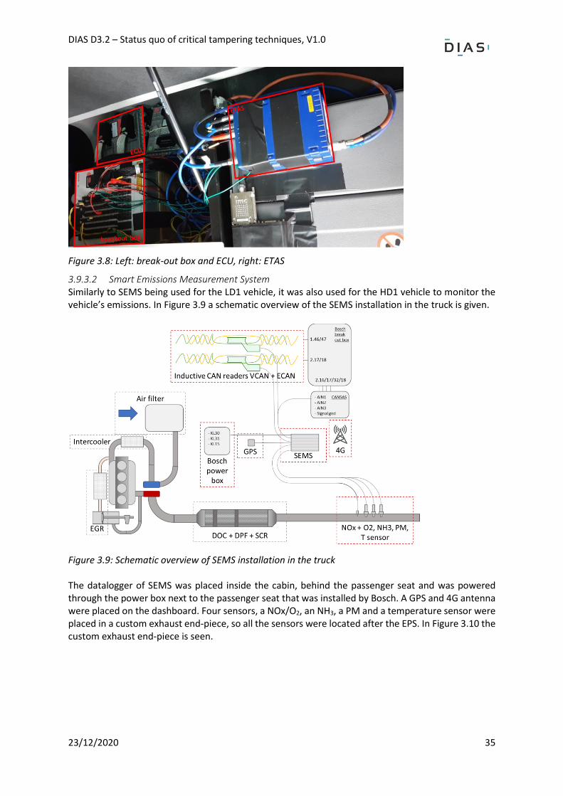
DIAS D3.2 – Status quo of critical tampering techniques, V1.0
23/12/2020 35
Figure 3.8: Left: break-out box and ECU, right: ETAS
3.9.3.2 Smart Emissions Measurement System Similarly to SEMS being used for the LD1 vehicle, it was also used for the HD1 vehicle to monitor the vehicle’s emissions. In Figure 3.9 a schematic overview of the SEMS installation in the truck is given.
Figure 3.9: Schematic overview of SEMS installation in the truck The datalogger of SEMS was placed inside the cabin, behind the passenger seat and was powered through the power box next to the passenger seat that was installed by Bosch. A GPS and 4G antenna were placed on the dashboard. Four sensors, a NOx/O2, an NH3, a PM and a temperature sensor were placed in a custom exhaust end-piece, so all the sensors were located after the EPS. In Figure 3.10 the custom exhaust end-piece is seen.
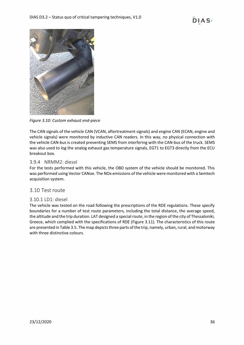
DIAS D3.2 – Status quo of critical tampering techniques, V1.0
23/12/2020 36
Figure 3.10: Custom exhaust end-piece The CAN signals of the vehicle CAN (VCAN, aftertreatment signals) and engine CAN (ECAN, engine and vehicle signals) were monitored by inductive CAN readers. In this way, no physical connection with the vehicle CAN-bus is created preventing SEMS from interfering with the CAN-bus of the truck. SEMS was also used to log the analog exhaust gas temperature signals, EGT1 to EGT3 directly from the ECU breakout box.
NRMM2: diesel For the tests performed with this vehicle, the OBD system of the vehicle should be monitored. This was performed using Vector CANoe. The NOx emissions of the vehicle were monitored with a Semtech acquisition system.
Test route
LD1: diesel The vehicle was tested on the road following the prescriptions of the RDE regulations. These specify boundaries for a number of test route parameters, including the total distance, the average speed, the altitude and the trip duration. LAT designed a special route, in the region of the city of Thessaloniki, Greece, which complied with the specifications of RDE (Figure 3.11). The characteristics of this route are presented in Table 3.5. The map depicts three parts of the trip, namely, urban, rural, and motorway with three distinctive colours.
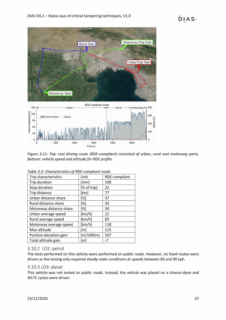
DIAS D3.2 – Status quo of critical tampering techniques, V1.0
23/12/2020 37
Figure 3.11: Top: real driving route (RDE-compliant) consisted of urban, rural and motorway parts, Bottom: vehicle speed and altitude for RDE profile.
Table 3.5: Characteristics of RDE-compliant route
Trip characteristics Unit RDE-compliant
Trip duration [min] 100
Stop duration [% of trip] 22
Trip distance [km] 77
Urban distance share [%] 37
Rural distance share [%] 33
Motorway distance share [%] 30
Urban average speed [km/h] 21
Rural average speed [km/h] 83
Motorway average speed [km/h] 118
Max altitude [m] 115
Positive elevation gain [m/100km] 507
Total altitude gain [m] -7
LD2: petrol The tests performed on this vehicle were performed on public roads. However, no fixed routes were driven as the testing only required steady-state conditions at speeds between 60 and 90 kph.
LD3: diesel This vehicle was not tested on public roads. Instead, the vehicle was placed on a chassis-dyno and WLTC cycles were driven.
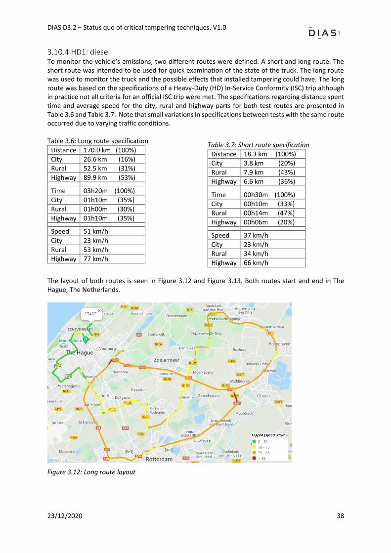
DIAS D3.2 – Status quo of critical tampering techniques, V1.0
23/12/2020 38
HD1: diesel To monitor the vehicle’s emissions, two different routes were defined. A short and long route. The short route was intended to be used for quick examination of the state of the truck. The long route was used to monitor the truck and the possible effects that installed tampering could have. The long route was based on the specifications of a Heavy-Duty (HD) In-Service Conformity (ISC) trip although in practice not all criteria for an official ISC trip were met. The specifications regarding distance spent time and average speed for the city, rural and highway parts for both test routes are presented in Table 3.6 and Table 3.7. Note that small variations in specifications between tests with the same route occurred due to varying traffic conditions. Table 3.6: Long route specification
Distance 170.0 km (100%)
City 26.6 km (16%)
Rural 52.5 km (31%)
Highway 89.9 km (53%)
Time 03h20m (100%)
City 01h10m (35%)
Rural 01h00m (30%)
Highway 01h10m (35%)
Speed 51 km/h
City 23 km/h
Rural 53 km/h
Highway 77 km/h
Table 3.7: Short route specification
Distance 18.3 km (100%)
City 3.8 km (20%)
Rural 7.9 km (43%)
Highway 6.6 km (36%)
Time 00h30m (100%)
City 00h10m (33%)
Rural 00h14m (47%)
Highway 00h06m (20%)
Speed 37 km/h
City 23 km/h
Rural 34 km/h
Highway 66 km/h
The layout of both routes is seen in Figure 3.12 and Figure 3.13. Both routes start and end in The Hague, The Netherlands.
Figure 3.12: Long route layout
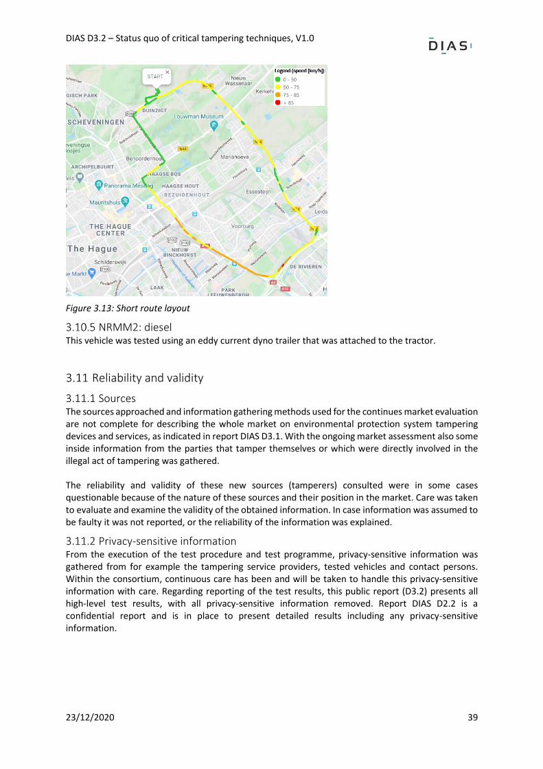
DIAS D3.2 – Status quo of critical tampering techniques, V1.0
23/12/2020 39
Figure 3.13: Short route layout
NRMM2: diesel This vehicle was tested using an eddy current dyno trailer that was attached to the tractor.
Reliability and validity
Sources The sources approached and information gathering methods used for the continues market evaluation are not complete for describing the whole market on environmental protection system tampering devices and services, as indicated in report DIAS D3.1. With the ongoing market assessment also some inside information from the parties that tamper themselves or which were directly involved in the illegal act of tampering was gathered. The reliability and validity of these new sources (tamperers) consulted were in some cases questionable because of the nature of these sources and their position in the market. Care was taken to evaluate and examine the validity of the obtained information. In case information was assumed to be faulty it was not reported, or the reliability of the information was explained.
Privacy-sensitive information From the execution of the test procedure and test programme, privacy-sensitive information was gathered from for example the tampering service providers, tested vehicles and contact persons. Within the consortium, continuous care has been and will be taken to handle this privacy-sensitive information with care. Regarding reporting of the test results, this public report (D3.2) presents all high-level test results, with all privacy-sensitive information removed. Report DIAS D2.2 is a confidential report and is in place to present detailed results including any privacy-sensitive information.
DIAS D3.2 – Status quo of critical tampering techniques, V1.0
23/12/2020 40
Results of the test programme
Introduction The results of the test programme of all the tested vehicles are presented in this chapter. As mentioned in Chapter 3 the results are expressed by means of the predefined KPIs and tampering is categorised based on main working principles. The full table of results of all tests specified per KPI can be found in section 0. This chapter acts as a summary and additional explanation for that table. For a detailed description of the more detailed results and finding reference is made to the confidential report DIAS D2.2.
LD1: diesel - ECU flashing using ECU pins connection For the LD1 vehicle, the flashing of the ECU using the ECU pins connection was investigated. The goal was to incrementally add ECU modifications that should alter the ECU behaviour. The ECU flashing was attempted for the Bosch ECU EDC17C60 used in the LD1 vehicle. The OBD system should not report any DTC error (MIL) and neither should any diagnostic tool (including a generic and an OEM-specific). According to the tamperer, the modification of the DPF, SCR and EGR systems were possible via the following combined modifications: DPF (for the DPF modification), DPF/EGR (for the SCR modification, using the original DPF), and DPF/EGR/SCR (for the EGR modification). Additionally, the DPF removal procedure required the additional removal of the DPF canister.
Testing preparations and procedure For the tampering operation, the FLEX ECU Programming Software Tool was used by Magic Motorsport. The software was combined with a customized CAN interface named FlexBox (also by Magic Motorsport), which was used for ECU hardware access. The ECU flashing procedure required a high level of experience and knowledge regarding vehicles and aftertreatment systems, as well as specialized equipment. As a result, the procedure must be carried out by highly experienced mechanic specialists. Taking the above into consideration, LAT visited a local tamperer who claimed to program ECUs for the last 20 years. The tamperer had access to thousands of “ECU image files”, which contained altered data for a variety of vehicle components and for a variety of brands. Additionally, the tamperer was equipped with the necessary specialized equipment. The tamperer received assistance from another tamperer during the process (someone from the Magic Motorsport company), although this was not transparently communicated with LAT.
Results and conclusion Initially, after the ECU flashing was performed, it was found that (only) the OEM diagnostic tool reported errors, which were not permanent. Permanent errors should not appear in order for the tampering attempt to be considered as successful. The urea dosing module was not deactivated; it was rather modified via some internal maps of the ECU: ultimately, the NOx emissions were found to be significantly raised after the tampering attempt implying that the DeNOx system was modified within the ECU. The main statistics comparison for both the baseline and complete DPF/SCR/EGR ECU flashing RDE tests is found in Table 4.1. As a conclusion, the tampering attempt proved to work without any external additional mechanical intervention. Possibly, the EGR socket should be removed to verify the EGR programming, but this was not checked, because the tamperer claimed that this was not needed.
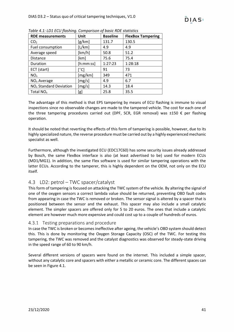
DIAS D3.2 – Status quo of critical tampering techniques, V1.0
23/12/2020 41
Table 4.1: LD1 ECU flashing. Comparison of basic RDE statistics
RDE measurements Unit Baseline FlexBox Tampering
CO2 [g/km] 131.7 130.5
Fuel consumption [L/km] 4.9 4.9
Average speed [km/h] 50.8 51.2
Distance [km] 75.6 75.4
Duration [h:mm:ss] 1:27:23 1:28:18
ECT (start) [°C] 91 73
NOx [mg/km] 349 471
NOx Average [mg/s] 4.9 6.7
NOx Standard Deviation [mg/s] 14.3 18.4
Total NOx [g] 25.8 35.5
The advantage of this method is that EPS tampering by means of ECU flashing is immune to visual inspections since no observable changes are made to the tampered vehicle. The cost for each one of the three tampering procedures carried out (DPF, SCR, EGR removal) was ±150 € per flashing operation. It should be noted that reverting the effects of this form of tampering is possible, however, due to its highly specialized nature, the reverse procedure must be carried out by a highly experienced mechanic specialist as well. Furthermore, although the investigated ECU (EDC17C60) has some security issues already addressed by Bosch, the same FlexBox interface is also (at least advertised to be) used for modern ECUs (MD1/MG1). In addition, the same Flex software is used for similar tampering operations with the latter ECUs. According to the tamperer, this is highly dependent on the OEM, not only on the ECU itself.
LD2: petrol – TWC spacer/catalyst This form of tampering is focused on attacking the TWC system of the vehicle. By altering the signal of one of the oxygen sensors a correct lambda value should be returned, preventing OBD fault codes from appearing in case the TWC is removed or broken. The sensor signal is altered by a spacer that is positioned between the sensor and the exhaust. This spacer may also include a small catalytic element. The simpler spacers are offered only for 5 to 20 euros. The ones that include a catalytic element are however much more expensive and could cost up to a couple of hundreds of euros.
Testing preparations and procedure In case the TWC is broken or becomes ineffective after ageing, the vehicle’s OBD system should detect this. This is done by monitoring the Oxygen Storage Capacity (OSC) of the TWC. For testing this tampering, the TWC was removed and the catalyst diagnostics was observed for steady-state driving in the speed range of 60 to 90 km/h. Several different versions of spacers were found on the internet. This included a simple spacer, without any catalytic core and spacers with either a metallic or ceramic core. The different spaces can be seen in Figure 4.1.
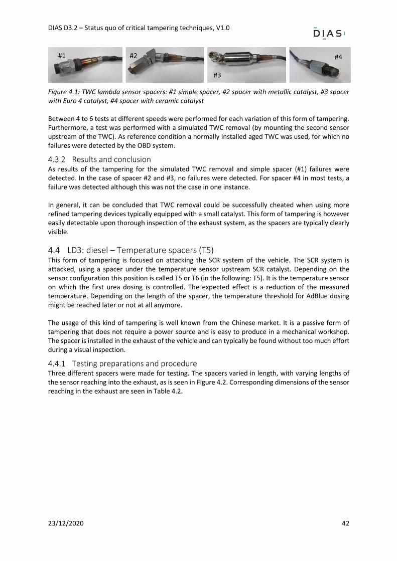
DIAS D3.2 – Status quo of critical tampering techniques, V1.0
23/12/2020 42
Figure 4.1: TWC lambda sensor spacers: #1 simple spacer, #2 spacer with metallic catalyst, #3 spacer with Euro 4 catalyst, #4 spacer with ceramic catalyst Between 4 to 6 tests at different speeds were performed for each variation of this form of tampering. Furthermore, a test was performed with a simulated TWC removal (by mounting the second sensor upstream of the TWC). As reference condition a normally installed aged TWC was used, for which no failures were detected by the OBD system.
Results and conclusion As results of the tampering for the simulated TWC removal and simple spacer (#1) failures were detected. In the case of spacer #2 and #3, no failures were detected. For spacer #4 in most tests, a failure was detected although this was not the case in one instance. In general, it can be concluded that TWC removal could be successfully cheated when using more refined tampering devices typically equipped with a small catalyst. This form of tampering is however easily detectable upon thorough inspection of the exhaust system, as the spacers are typically clearly visible.
LD3: diesel – Temperature spacers (T5) This form of tampering is focused on attacking the SCR system of the vehicle. The SCR system is attacked, using a spacer under the temperature sensor upstream SCR catalyst. Depending on the sensor configuration this position is called T5 or T6 (in the following: T5). It is the temperature sensor on which the first urea dosing is controlled. The expected effect is a reduction of the measured temperature. Depending on the length of the spacer, the temperature threshold for AdBlue dosing might be reached later or not at all anymore. The usage of this kind of tampering is well known from the Chinese market. It is a passive form of tampering that does not require a power source and is easy to produce in a mechanical workshop. The spacer is installed in the exhaust of the vehicle and can typically be found without too much effort during a visual inspection.
Testing preparations and procedure Three different spacers were made for testing. The spacers varied in length, with varying lengths of the sensor reaching into the exhaust, as is seen in Figure 4.2. Corresponding dimensions of the sensor reaching in the exhaust are seen in Table 4.2.
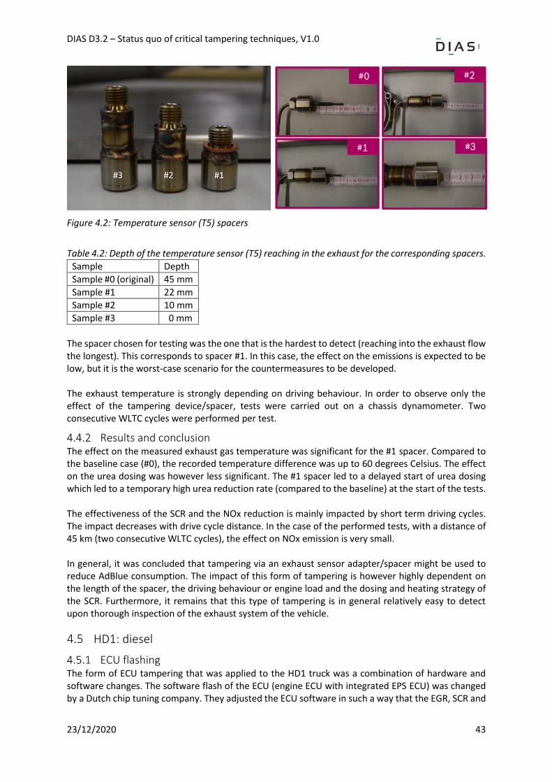
DIAS D3.2 – Status quo of critical tampering techniques, V1.0
23/12/2020 43
Figure 4.2: Temperature sensor (T5) spacers
Table 4.2: Depth of the temperature sensor (T5) reaching in the exhaust for the corresponding spacers.
Sample Depth
Sample #0 (original) 45 mm
Sample #1 22 mm
Sample #2 10 mm
Sample #3 0 mm
The spacer chosen for testing was the one that is the hardest to detect (reaching into the exhaust flow the longest). This corresponds to spacer #1. In this case, the effect on the emissions is expected to be low, but it is the worst-case scenario for the countermeasures to be developed. The exhaust temperature is strongly depending on driving behaviour. In order to observe only the effect of the tampering device/spacer, tests were carried out on a chassis dynamometer. Two consecutive WLTC cycles were performed per test.
Results and conclusion The effect on the measured exhaust gas temperature was significant for the #1 spacer. Compared to the baseline case (#0), the recorded temperature difference was up to 60 degrees Celsius. The effect on the urea dosing was however less significant. The #1 spacer led to a delayed start of urea dosing which led to a temporary high urea reduction rate (compared to the baseline) at the start of the tests. The effectiveness of the SCR and the NOx reduction is mainly impacted by short term driving cycles. The impact decreases with drive cycle distance. In the case of the performed tests, with a distance of 45 km (two consecutive WLTC cycles), the effect on NOx emission is very small. In general, it was concluded that tampering via an exhaust sensor adapter/spacer might be used to reduce AdBlue consumption. The impact of this form of tampering is however highly dependent on the length of the spacer, the driving behaviour or engine load and the dosing and heating strategy of the SCR. Furthermore, it remains that this type of tampering is in general relatively easy to detect upon thorough inspection of the exhaust system of the vehicle.
HD1: diesel
ECU flashing The form of ECU tampering that was applied to the HD1 truck was a combination of hardware and software changes. The software flash of the ECU (engine ECU with integrated EPS ECU) was changed by a Dutch chip tuning company. They adjusted the ECU software in such a way that the EGR, SCR and
DIAS D3.2 – Status quo of critical tampering techniques, V1.0
23/12/2020 44
DPF systems would be deactivated, without any errors, fault codes or MILs arising while driving. For this service, a total of €2250,- was charged. As a result of the software changes to the ECU, the EGR valve had to be disconnected and the DPF filter had to be removed. Several road tests were performed with the truck and the tampered ECU. It turned out several iterations were needed for the chip tuning company to make the correct changes to the ECU flash. Nevertheless also for the final test done with the tampered ECU, it turned out the tampering was not applied completely successful to the truck, as OBD errors arose. This was not the case for the short test route, however during the long test route several OBD errors raised. It turned out these errors were related to the turbocharger. The powertrain went in reduced power mode. The tuning company instructed to physically block the EGR as most likely the cause of the errors was some exhaust gas leaking through the EGR valve. A final test of about 2.5 hours in city, rural and highway environment was performed by Bosch with the physically blocked EGR. The ECU tampering turned out to be successful as no OBD fault codes or MILs were raised. As the DPF filter was removed from the truck, no soot was filtered from the exhaust gas. Stationary measurements with a particle counter from HORIBA showed that the number of particles in the exhaust gas increased from several hundreds of particles per square cm to several millions of particles per square cm, which are typical values for a DPF removal of a truck. In Table 4.3 the average emission results are shown of the baseline and ECU tampering final test. Although the average speed and average power requested from the engine are slightly higher for the ECU tampering final test, the NOx emissions are severely higher (> 100 times).
Table 4.3: Average emission results baseline vs. ECU tampering (long route)
Baseline ECU tampering Unit
Velocity 50.6 52.3 km/h
CO2 817 923 g/km
NOx 0.22 14.4 g/kWh
NOx 0.144 20.3 g/km
NH3 5.37 0.93 ppm
Engine power 68.1 73.7 kW
Emulators For the HD diesel, various emulators were sourced, as can be seen in the test matrix. This includes emulators based on CAN-only, but also emulators that not only emulate CAN signals but also analog sensor signals. The results and findings of the emulator tests for the HD diesel are summarised below.
4.5.2.1 SCR emulator CAN only Several SCR emulators were purchased for this truck. As this model is relatively new in the market no emulators were advertised as being specially designed for this truck. However several SCR emulators claiming to be suitable for Ford Euro VI trucks were being offered online for 100 to 250 euros, see Figure 4.3 and Figure 4.4. The emulator from Figure 4.3 is inserted in the OBD port of the truck and should emulate the AdBlue and NOx CAN signals so that the SCR system is paralysed. The emulator from Figure 4.4 is connected directly to the CAN-bus of the vehicle and claims to disable the SCR system and NOx sensors and also the DPF system.
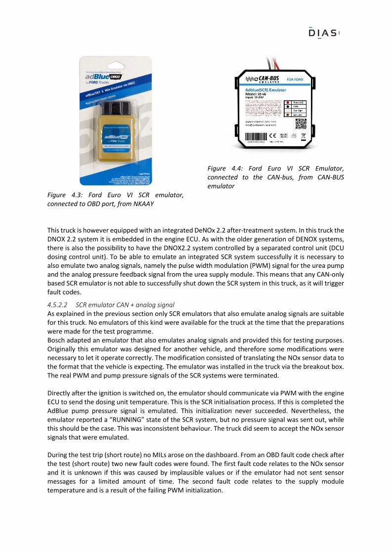
Figure 4.3: Ford Euro VI SCR emulator, connected to OBD port, from NKAAY
Figure 4.4: Ford Euro VI SCR Emulator, connected to the CAN-bus, from CAN-BUS emulator
This truck is however equipped with an integrated DeNOx 2.2 after-treatment system. In this truck the DNOX 2.2 system it is embedded in the engine ECU. As with the older generation of DENOX systems, there is also the possibility to have the DNOX2.2 system controlled by a separated control unit (DCU dosing control unit). To be able to emulate an integrated SCR system successfully it is necessary to also emulate two analog signals, namely the pulse width modulation (PWM) signal for the urea pump and the analog pressure feedback signal from the urea supply module. This means that any CAN-only based SCR emulator is not able to successfully shut down the SCR system in this truck, as it will trigger fault codes.
4.5.2.2 SCR emulator CAN + analog signal As explained in the previous section only SCR emulators that also emulate analog signals are suitable for this truck. No emulators of this kind were available for the truck at the time that the preparations were made for the test programme. Bosch adapted an emulator that also emulates analog signals and provided this for testing purposes. Originally this emulator was designed for another vehicle, and therefore some modifications were necessary to let it operate correctly. The modification consisted of translating the NOx sensor data to the format that the vehicle is expecting. The emulator was installed in the truck via the breakout box. The real PWM and pump pressure signals of the SCR systems were terminated. Directly after the ignition is switched on, the emulator should communicate via PWM with the engine ECU to send the dosing unit temperature. This is the SCR initialisation process. If this is completed the AdBlue pump pressure signal is emulated. This initialization never succeeded. Nevertheless, the emulator reported a “RUNNING” state of the SCR system, but no pressure signal was sent out, while this should be the case. This was inconsistent behaviour. The truck did seem to accept the NOx sensor signals that were emulated. During the test trip (short route) no MILs arose on the dashboard. From an OBD fault code check after the test (short route) two new fault codes were found. The first fault code relates to the NOx sensor and it is unknown if this was caused by implausible values or if the emulator had not sent sensor messages for a limited amount of time. The second fault code relates to the supply module temperature and is a result of the failing PWM initialization.
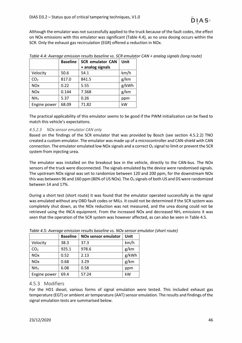
DIAS D3.2 – Status quo of critical tampering techniques, V1.0
23/12/2020 46
Although the emulator was not successfully applied to the truck because of the fault codes, the effect on NOx emissions with this emulator was significant (Table 4.4), as no urea dosing occurs within the SCR. Only the exhaust gas recirculation (EGR) offered a reduction in NOx.
Table 4.4: Average emission results baseline vs. SCR emulator CAN + analog signals (long route)
Baseline SCR emulator CAN + analog signals
Unit
Velocity 50.6 54.1 km/h
CO2 817.0 841.5 g/km
NOx 0.22 5.55 g/kWh
NOx 0.144 7.368 g/km
NH3 5.37 0.26 ppm
Engine power 68.09 71.82 kW
The practical applicability of this emulator seems to be good if the PWM initialization can be fixed to match this vehicle’s expectations.
4.5.2.3 NOx sensor emulator CAN only Based on the findings of the SCR emulator that was provided by Bosch (see section 4.5.2.2) TNO created a custom emulator. The emulator was made up of a microcontroller and CAN-shield with CAN connection. The emulator emulated low NOx signals and a correct O2 signal to limit or prevent the SCR system from injecting urea. The emulator was installed on the breakout box in the vehicle, directly to the CAN-bus. The NOx sensors of the truck were disconnected. The signals emulated by the device were randomised signals. The upstream NOx signal was set to randomize between 120 and 200 ppm, for the downstream NOx this was between 96 and 160 ppm (80% of US NOx). The O2 signals of both US and DS were randomized between 14 and 17%. During a short test (short route) it was found that the emulator operated successfully as the signal was emulated without any OBD fault codes or MILs. It could not be determined if the SCR system was completely shut down, as the NOx reduction was not measured, and the urea dosing could not be retrieved using the INCA equipment. From the increased NOx and decreased NH3 emissions it was seen that the operation of the SCR system was however affected, as can also be seen in Table 4.5.
Table 4.5: Average emission results baseline vs. NOx sensor emulator (short route)
Baseline NOx sensor emulator Unit
Velocity 38.3 37.3 km/h
CO2 925.1 978.6 g/km
NOx 0.52 2.13 g/kWh
NOx 0.68 3.29 g/km
NH3 6.08 0.58 ppm
Engine power 69.4 57.24 kW
Modifiers For the HD1 diesel, various forms of signal emulation were tested. This included exhaust gas temperature (EGT) or ambient air temperature (AAT) sensor emulation. The results and findings of the signal emulation tests are summarised below.
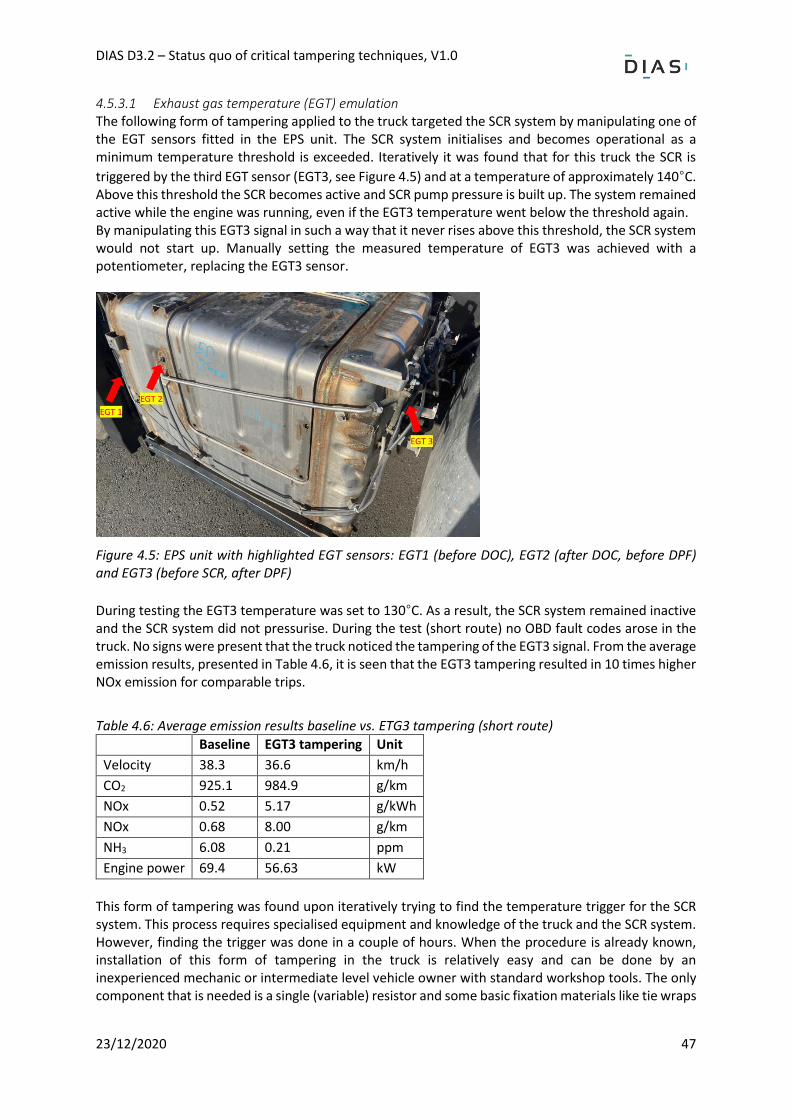
DIAS D3.2 – Status quo of critical tampering techniques, V1.0
23/12/2020 47
4.5.3.1 Exhaust gas temperature (EGT) emulation The following form of tampering applied to the truck targeted the SCR system by manipulating one of the EGT sensors fitted in the EPS unit. The SCR system initialises and becomes operational as a minimum temperature threshold is exceeded. Iteratively it was found that for this truck the SCR is
triggered by the third EGT sensor (EGT3, see Figure 4.5) and at a temperature of approximately 140°C. Above this threshold the SCR becomes active and SCR pump pressure is built up. The system remained active while the engine was running, even if the EGT3 temperature went below the threshold again. By manipulating this EGT3 signal in such a way that it never rises above this threshold, the SCR system would not start up. Manually setting the measured temperature of EGT3 was achieved with a potentiometer, replacing the EGT3 sensor.
Figure 4.5: EPS unit with highlighted EGT sensors: EGT1 (before DOC), EGT2 (after DOC, before DPF) and EGT3 (before SCR, after DPF)
During testing the EGT3 temperature was set to 130°C. As a result, the SCR system remained inactive and the SCR system did not pressurise. During the test (short route) no OBD fault codes arose in the truck. No signs were present that the truck noticed the tampering of the EGT3 signal. From the average emission results, presented in Table 4.6, it is seen that the EGT3 tampering resulted in 10 times higher NOx emission for comparable trips.
Table 4.6: Average emission results baseline vs. ETG3 tampering (short route)
Baseline EGT3 tampering Unit
Velocity 38.3 36.6 km/h
CO2 925.1 984.9 g/km
NOx 0.52 5.17 g/kWh
NOx 0.68 8.00 g/km
NH3 6.08 0.21 ppm
Engine power 69.4 56.63 kW
This form of tampering was found upon iteratively trying to find the temperature trigger for the SCR system. This process requires specialised equipment and knowledge of the truck and the SCR system. However, finding the trigger was done in a couple of hours. When the procedure is already known, installation of this form of tampering in the truck is relatively easy and can be done by an inexperienced mechanic or intermediate level vehicle owner with standard workshop tools. The only component that is needed is a single (variable) resistor and some basic fixation materials like tie wraps
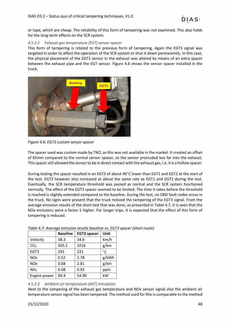
DIAS D3.2 – Status quo of critical tampering techniques, V1.0
23/12/2020 48
or tape, which are cheap. The reliability of this form of tampering was not examined. This also holds for the long-term effects on the SCR system.
4.5.3.2 Exhaust gas temperature (EGT) sensor spacer This form of tampering is related to the previous form of tampering. Again the EGT3 signal was targeted in order to affect the operation of the SCR system or shut it down permanently. In this case, the physical placement of the EGT3 sensor in the exhaust was altered by means of an extra spacer between the exhaust pipe and the EGT sensor. Figure 4.6 shows the sensor spacer installed in the truck.
Figure 4.6: EGT3 custom sensor spacer The spacer used was custom made by TNO, as this was not available in the market. It created an offset of 65mm compared to the normal sensor spacer, so the sensor protruded less far into the exhaust. This spacer still allowed the sensor to be in direct contact with the exhaust gas, i.e. it is a hollow spacer.
During testing the spacer resulted in an EGT3 of about 40°C lower than EGT1 and EGT2 at the start of the test. EGT3 however also increased at about the same rate as EGT1 and EGT2 during the test. Eventually, the SCR temperature threshold was passed as normal and the SCR system functioned normally. The effect of the EGT3 spacer seemed to be limited. The time it takes before the threshold is reached is slightly extended compared to the baseline. During the test, no OBD fault codes arose in the truck. No signs were present that the truck noticed the tampering of the EGT3 signal. From the average emission results of the short test that was done, as presented in Table 4.7, it is seen that the NOx emissions were a factor 5 higher. For longer trips, it is expected that the effect of this form of tampering is reduced.
Table 4.7: Average emission results baseline vs. EGT3 spacer (short route)
Baseline EGT3 spacer Unit
Velocity 38.3 34.6 km/h
CO2 925.1 1016 g/km
EGT3 241 221 °C
NOx 0.52 1.78 g/kWh
NOx 0.68 2.81 g/km
NH3 6.08 0.93 ppm
Engine power 69.4 54.90 kW
4.5.3.3 Ambient air temperature (AAT) emulation Next to the tampering of the exhaust gas temperature and NOx sensor signal also the ambient air temperature sensor signal has been tampered. The method used for this is comparable to the method
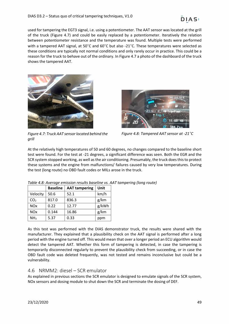
DIAS D3.2 – Status quo of critical tampering techniques, V1.0
23/12/2020 49
used for tampering the EGT3 signal, i.e. using a potentiometer. The AAT sensor was located at the grill of the truck (Figure 4.7) and could be easily replaced by a potentiometer. Iteratively the relation between potentiometer resistance and the temperature was found. Multiple tests were performed
with a tampered AAT signal, at 50°C and 60°C but also -21°C. These temperatures were selected as these conditions are typically not normal conditions and only rarely occur in practice. This could be a reason for the truck to behave out of the ordinary. In Figure 4.7 a photo of the dashboard of the truck shows the tampered AAT.
Figure 4.7: Truck AAT sensor located behind the grill
Figure 4.8: Tampered AAT sensor at -21°C
At the relatively high temperatures of 50 and 60 degrees, no changes compared to the baseline short test were found. For the test at -21 degrees, a significant difference was seen. Both the EGR and the SCR system stopped working, as well as the air conditioning. Presumably, the truck does this to protect these systems and the engine from malfunctions/ failures caused by very low temperatures. During the test (long route) no OBD fault codes or MILs arose in the truck.
Table 4.8: Average emission results baseline vs. AAT tampering (long route)
Baseline AAT tampering Unit
Velocity 50.6 52.1 km/h
CO2 817.0 836.3 g/km
NOx 0.22 12.77 g/kWh
NOx 0.144 16.86 g/km
NH3 5.37 0.33 ppm
As this test was performed with the DIAS demonstrator truck, the results were shared with the manufacturer. They explained that a plausibility check on the AAT signal is performed after a long period with the engine turned off. This would mean that over a longer period an ECU algorithm would detect the tampered AAT. Whether this form of tampering is detected, in case the tampering is temporarily disconnected regularly to prevent the plausibility check from succeeding, or in case the OBD fault code was deleted frequently, was not tested and remains inconclusive but could be a vulnerability.
NRMM2: diesel – SCR emulator As explained in previous sections the SCR emulator is designed to emulate signals of the SCR system, NOx sensors and dosing module to shut down the SCR and terminate the dosing of DEF.
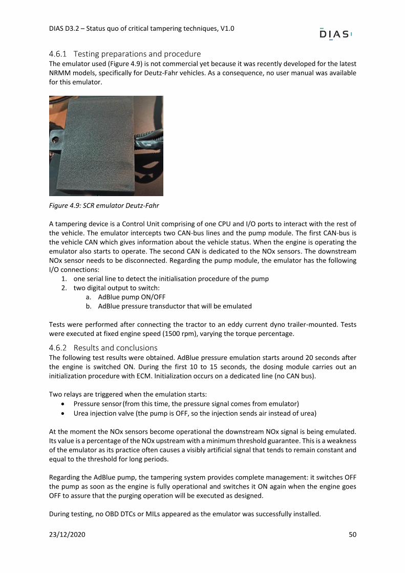
DIAS D3.2 – Status quo of critical tampering techniques, V1.0
23/12/2020 50
Testing preparations and procedure The emulator used (Figure 4.9) is not commercial yet because it was recently developed for the latest NRMM models, specifically for Deutz-Fahr vehicles. As a consequence, no user manual was available for this emulator.
Figure 4.9: SCR emulator Deutz-Fahr A tampering device is a Control Unit comprising of one CPU and I/O ports to interact with the rest of the vehicle. The emulator intercepts two CAN-bus lines and the pump module. The first CAN-bus is the vehicle CAN which gives information about the vehicle status. When the engine is operating the emulator also starts to operate. The second CAN is dedicated to the NOx sensors. The downstream NOx sensor needs to be disconnected. Regarding the pump module, the emulator has the following I/O connections:
1. one serial line to detect the initialisation procedure of the pump 2. two digital output to switch:
a. AdBlue pump ON/OFF b. AdBlue pressure transductor that will be emulated
Tests were performed after connecting the tractor to an eddy current dyno trailer-mounted. Tests were executed at fixed engine speed (1500 rpm), varying the torque percentage.
Results and conclusions The following test results were obtained. AdBlue pressure emulation starts around 20 seconds after the engine is switched ON. During the first 10 to 15 seconds, the dosing module carries out an initialization procedure with ECM. Initialization occurs on a dedicated line (no CAN bus). Two relays are triggered when the emulation starts:
• Pressure sensor (from this time, the pressure signal comes from emulator)
• Urea injection valve (the pump is OFF, so the injection sends air instead of urea) At the moment the NOx sensors become operational the downstream NOx signal is being emulated. Its value is a percentage of the NOx upstream with a minimum threshold guarantee. This is a weakness of the emulator as its practice often causes a visibly artificial signal that tends to remain constant and equal to the threshold for long periods. Regarding the AdBlue pump, the tampering system provides complete management: it switches OFF the pump as soon as the engine is fully operational and switches it ON again when the engine goes OFF to assure that the purging operation will be executed as designed. During testing, no OBD DTCs or MILs appeared as the emulator was successfully installed.
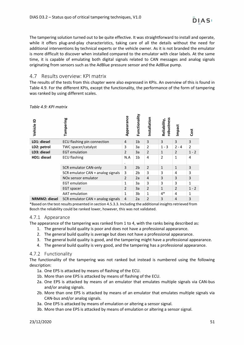
DIAS D3.2 – Status quo of critical tampering techniques, V1.0
23/12/2020 51
The tampering solution turned out to be quite effective. It was straightforward to install and operate, while it offers plug-and-play characteristics, taking care of all the details without the need for additional interventions by technical experts or the vehicle owner. As it is not branded the emulator is more difficult to discover when installed compared to the emulator with clear labels. At the same time, it is capable of emulating both digital signals related to CAN messages and analog signals originating from sensors such as the AdBlue pressure sensor and the AdBlue pump.
Results overview: KPI matrix The results of the tests from this chapter were also expressed in KPIs. An overview of this is found in Table 4.9. For the different KPIs, except the functionality, the performance of the form of tampering was ranked by using different scales.
Table 4.9: KPI matrix
Ve
hic
le ID
Tam
pe
rin
g
Ap
pe
aran
ce
Fun
ctio
nal
ity
Inst
alla
tio
n
Re
liab
ility
,
rob
ust
ne
ss
Imp
act
Co
st
LD1: diesel ECU flashing pin connection 4 1b 3 3 3 3
LD2: petrol TWC spacer/catalyst 3 3a 2 1 - 3 2 - 4 2
LD3: diesel EGT emulation 2 3a 2 1 2 1 - 2
HD1: diesel ECU flashing N.A.
1b 4 2 1 4
SCR emulator CAN-only 3 2b 2 1 1 3
SCR emulator CAN + analog signals 3 2b 3 3 4 3
NOx sensor emulator 2 2a 4 3 3 3
EGT emulation 1 3a 3 3 3 1
EGT spacer 2 3a 2 1 2 1 - 2
AAT emulation 1 3b 1 4* 4 1
NRMM2: diesel SCR emulator CAN + analog signals 4 2a 2 3 4 3
*Based on the test results presented in section 4.5.3.3. Including the additional insights retrieved from Bosch the reliability could be ranked lower, however, this was not validated.
Appearance The appearance of the tampering was ranked from 1 to 4, with the ranks being described as:
1. The general build quality is poor and does not have a professional appearance. 2. The general build quality is average but does not have a professional appearance. 3. The general build quality is good, and the tampering might have a professional appearance. 4. The general build quality is very good, and the tampering has a professional appearance.
Functionality The functionality of the tampering was not ranked but instead is numbered using the following description:
1a. One EPS is attacked by means of flashing of the ECU. 1b. More than one EPS is attacked by means of flashing of the ECU. 2a. One EPS is attacked by means of an emulator that emulates multiple signals via CAN-bus
and/or analog signals. 2b. More than one EPS is attacked by means of an emulator that emulates multiple signals via
CAN-bus and/or analog signals. 3a. One EPS is attacked by means of emulation or altering a sensor signal. 3b. More than one EPS is attacked by means of emulation or altering a sensor signal.
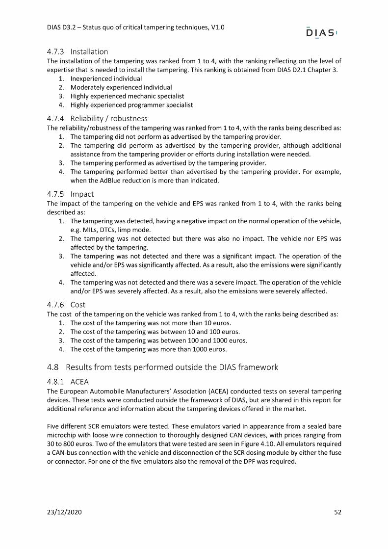
DIAS D3.2 – Status quo of critical tampering techniques, V1.0
23/12/2020 52
Installation The installation of the tampering was ranked from 1 to 4, with the ranking reflecting on the level of expertise that is needed to install the tampering. This ranking is obtained from DIAS D2.1 Chapter 3.
1. Inexperienced individual 2. Moderately experienced individual 3. Highly experienced mechanic specialist 4. Highly experienced programmer specialist
Reliability / robustness The reliability/robustness of the tampering was ranked from 1 to 4, with the ranks being described as:
1. The tampering did not perform as advertised by the tampering provider. 2. The tampering did perform as advertised by the tampering provider, although additional
assistance from the tampering provider or efforts during installation were needed. 3. The tampering performed as advertised by the tampering provider. 4. The tampering performed better than advertised by the tampering provider. For example,
when the AdBlue reduction is more than indicated.
Impact The impact of the tampering on the vehicle and EPS was ranked from 1 to 4, with the ranks being described as:
1. The tampering was detected, having a negative impact on the normal operation of the vehicle, e.g. MILs, DTCs, limp mode.
2. The tampering was not detected but there was also no impact. The vehicle nor EPS was affected by the tampering.
3. The tampering was not detected and there was a significant impact. The operation of the vehicle and/or EPS was significantly affected. As a result, also the emissions were significantly affected.
4. The tampering was not detected and there was a severe impact. The operation of the vehicle and/or EPS was severely affected. As a result, also the emissions were severely affected.
Cost The cost of the tampering on the vehicle was ranked from 1 to 4, with the ranks being described as:
1. The cost of the tampering was not more than 10 euros. 2. The cost of the tampering was between 10 and 100 euros. 3. The cost of the tampering was between 100 and 1000 euros. 4. The cost of the tampering was more than 1000 euros.
Results from tests performed outside the DIAS framework
ACEA The European Automobile Manufacturers’ Association (ACEA) conducted tests on several tampering devices. These tests were conducted outside the framework of DIAS, but are shared in this report for additional reference and information about the tampering devices offered in the market. Five different SCR emulators were tested. These emulators varied in appearance from a sealed bare microchip with loose wire connection to thoroughly designed CAN devices, with prices ranging from 30 to 800 euros. Two of the emulators that were tested are seen in Figure 4.10. All emulators required a CAN-bus connection with the vehicle and disconnection of the SCR dosing module by either the fuse or connector. For one of the five emulators also the removal of the DPF was required.

DIAS D3.2 – Status quo of critical tampering techniques, V1.0
23/12/2020 53
Figure 4.10: Two of the tested SCR emulators by ACEA Four of the five SCR emulators showed the successful emulation of the SCR dosing module and prevented the dosing of AdBlue, without the EDC being able to detect the emulator, meaning no MILs or fault codes. One of the devices transmitted a fault memory clear command each time the EDC started up. An important result of the tests performed by ACEA is that most of the tested emulators were, in the end, detectable using sophisticated OBD diagnostic scan tools. Due to the missing or repetitive OBD data of the aftertreatment controller some emulators were recognised.
Bosch Before the DIAS project was started Bosch conducted desk tests outside the DIAS framework on two SCR emulators. These results were shared within the consortium and are therefore also presented here. The two SCR emulators that were tested by Bosch are each of a different type.
‘Type 1’ is meant for a system with an integrated ECU and dosing control. The emulator connects to the CAN bus and the urea pump.
‘Type 2’ is meant for a system with a separate dosing control unit. The emulator connects to the ECU via the CAN bus. The separate dosing control unit is disconnected. This distinction was previously explained in section 4.5.2.1.
4.8.2.1 Type 1: SCR emulator CAN + analog signal This type of emulator (example in Figure 4.11) is connected with the vehicle via the CAN-bus and the dosing module directly. The emulator deactivates and emulates sensors/actuators through both ways (CAN-bus and directly) and sends out a fault code memory clear message upon start-up of the EDC. Disconnection of fuses and the interruption of signal lines are required. This type of emulator was also tested in the demonstrator truck. As a result of the emulator, the urea dosing is terminated without OBD faults detected. Also, any activation of inducement systems (e.g. limp mode/power derating) did not occur. Bosch indicated that the emulator could have a possible influence on the component durability for example the dosing valve could be running dry. Similar to the findings of ACEA also this emulator caused a different response from an OBD scanning tool, as the DCU and data stream could not be looked into.
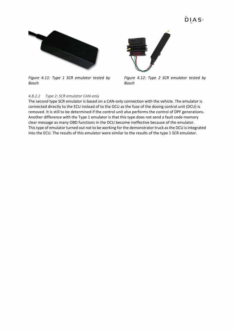
Figure 4.11: Type 1 SCR emulator tested by Bosch
Figure 4.12: Type 2 SCR emulator tested by Bosch
4.8.2.2 Type 2: SCR emulator CAN-only The second type SCR emulator is based on a CAN-only connection with the vehicle. The emulator is connected directly to the ECU instead of to the DCU as the fuse of the dosing control unit (DCU) is removed. It is still to be determined if the control unit also performs the control of DPF generations. Another difference with the Type 1 emulator is that this type does not send a fault code memory clear message as many OBD functions in the DCU become ineffective because of the emulator. This type of emulator turned out not to be working for the demonstrator truck as the DCU is integrated into the ECU. The results of this emulator were similar to the results of the type 1 SCR emulator.
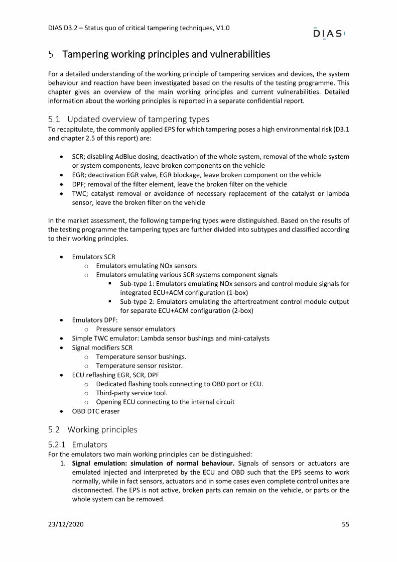
DIAS D3.2 – Status quo of critical tampering techniques, V1.0
23/12/2020 55
Tampering working principles and vulnerabilities For a detailed understanding of the working principle of tampering services and devices, the system behaviour and reaction have been investigated based on the results of the testing programme. This chapter gives an overview of the main working principles and current vulnerabilities. Detailed information about the working principles is reported in a separate confidential report.
Updated overview of tampering types To recapitulate, the commonly applied EPS for which tampering poses a high environmental risk (D3.1 and chapter 2.5 of this report) are:
• SCR; disabling AdBlue dosing, deactivation of the whole system, removal of the whole system or system components, leave broken components on the vehicle
• EGR; deactivation EGR valve, EGR blockage, leave broken component on the vehicle
• DPF; removal of the filter element, leave the broken filter on the vehicle
• TWC; catalyst removal or avoidance of necessary replacement of the catalyst or lambda sensor, leave the broken filter on the vehicle
In the market assessment, the following tampering types were distinguished. Based on the results of the testing programme the tampering types are further divided into subtypes and classified according to their working principles.
• Emulators SCR o Emulators emulating NOx sensors o Emulators emulating various SCR systems component signals
▪ Sub-type 1: Emulators emulating NOx sensors and control module signals for integrated ECU+ACM configuration (1-box)
▪ Sub-type 2: Emulators emulating the aftertreatment control module output for separate ECU+ACM configuration (2-box)
• Emulators DPF: o Pressure sensor emulators
• Simple TWC emulator: Lambda sensor bushings and mini-catalysts
• Signal modifiers SCR o Temperature sensor bushings. o Temperature sensor resistor.
• ECU reflashing EGR, SCR, DPF o Dedicated flashing tools connecting to OBD port or ECU. o Third-party service tool. o Opening ECU connecting to the internal circuit
• OBD DTC eraser
Working principles
Emulators For the emulators two main working principles can be distinguished:
1. Signal emulation: simulation of normal behaviour. Signals of sensors or actuators are emulated injected and interpreted by the ECU and OBD such that the EPS seems to work normally, while in fact sensors, actuators and in some cases even complete control unites are disconnected. The EPS is not active, broken parts can remain on the vehicle, or parts or the whole system can be removed.
DIAS D3.2 – Status quo of critical tampering techniques, V1.0
23/12/2020 56
2. Signal modification: control state modification. Signals of sensors are emulated but, in this case, also modified to simulate conditions under which the emission control system officially doesn’t have to work. By simulating these false conditions the EPS is brought in an inactive state.
Ad.1 Signal emulation Signals of separate digital sensors, of analog sensors or actuators, are emulated and injected on the CAN bus, as SENT, as PWM or as analog signal to the ECU. Original components such as modules or sensors are to be disconnected, e.g. a NOx sensor, a reagent dosing pump, or a whole aftertreatment control module. The emulator broadcasts emulated signals of these components, replacing the signals of the disconnected components (man in the middle/replay attack). Relevant signals are NOx/O2 sensors, the dosing pump initialisation, reagent pump pressure sensor, reagent level sensor, delta pressure sensor (DPF). The ECU, which reads and checks these signals, detects these signals as if the disconnected component is normally active. In this way several types of tampering motivations can be addressed:
• the reagent dosing pump can be deactivated to avoid reagent dosing.
• The ACM can be disconnected to avoid dosing and allow removal of a complete aftertreatment system (SCR and/or DPF).
• A malfunctioning NOx sensor or dosing pump can stay unrepaired at the vehicle.
• A cracked DPF can stay in the vehicle or be removed because the correct pressure differential is broadcasted.
• Lambda sensor: the bushing or catalyst delays the response of the upstream and downstream lambda sensor O2 signals such that the TWC appears to store and release oxygen as if the TWC is working properly. Not all tested devices were able to achieve this and lead to diagnostic trouble codes. This type does not alter the control state of the EPS but prevents detection of incorrect functioning of the TWC such that the broken catalyst can stay in the vehicle without MI or DTCs stored in FCM preventing necessary replacement.
Generally, this type of emulator uses a simple microcontroller platform with I/O to broadcast the emulated signals to the ECU (CAN, PWM, analog). Certain types frequently, e.g. after each start, communicate via CAN the service commands to clear the fault code memory (erase DTCs).
Ad. 2 Signal modification In principle could also be called ‘emulator’ but this type is simpler in design and mainly aims to alter the control state of an EPS by modifying one or more sensor signals. This type is applied to deactivate reagent dosing for an SCR system. This tampering method exploits the fact that an SCR system has boundaries for its operation. The reagent can only be dosed when certain release conditions (base emission strategy) are met. If certain conditions are not met, reagent dosing is stopped (auxiliary emission strategy). A modified signal can set an inactive state for reagent dosing by faking the signal to a value outside the boundary for the normal base emission strategy. The SCR signal modifiers have shown to work on older generations of heavy-duty vehicles and have been found on vehicles in-use at roadside inspections by the police. Vehicles with Euro VI certified engines tested in the testing programme have shown to detect a number of the modified signals because the plausibility of the values is checked. In a few cases, the modified signals were not detected by the ECUs algorithms. These signals are known to be part of the reagent dosing control logic and when not checked for plausibility and interpreted as a correct value can deactivate reagent dosing:
• Ambient temperature: at low ambient temperatures standard AdBlue freezes, hence reagent is not dosed. Also, EGR can be set inactive to prevent system fouling at low ambient temperatures.
DIAS D3.2 – Status quo of critical tampering techniques, V1.0
23/12/2020 57
• Ambient temperature: at high temperatures, higher than the requirements for off-cycle emissions manufacturers may request to use an auxiliary strategy.
• Reagent temperature: at low reagent temperatures standard AdBlue freezes, hence reagent is not to be injected.
• Exhaust gas/SCR temperatures: at low catalyst and exhaust gas temperatures thermolysis and hydrolysis of the injected reagent can be incomplete leading to clogging of nozzles and system fouling and at low temperatures the SCR reactions in the catalyst don’t take place. Hence reagent is not to be injected at these temperatures.
• Engine coolant temperature: At low engine coolant temperatures the auxiliary emission strategy is active. The reagent isn’t injected and EGR remains inactive.
ECU reflashing ECU reflashing is flashing modified software in the memory of the ECU. The modification depends on the specific tampering goal: the deactivation of reagent dosing, deactivation of the EGR valve, removal of DPF or of the whole aftertreatment unit. Another typical tampering motivation is to increase the power rating of the engine (performance tuning). A reflash with unauthorised modified software isn’t easy. OEM software is digitally signed, and ECUs are password protected. So far two different ECU reflash methods were tested. The working principles of ECU reflashing are not fully clear. Several methods are mentioned. ECU flashing is a high-risk method offered widely on the internet and by tuning workshops uses professional tools which can flash ECU specific software to many ECU types.
Vulnerabilities The tampering is possible due to the following vulnerabilities:
Emulators/modifiers Signal emulation
• Injection of false messages on the CAN bus
• Replay attack/man in the middle attack: Emulation/modification/falsification of digital (CAN/SENT) and analog signals of sensors and actuators.
- Analog sensors - Digital sensors (CAN/SENT) and sensor control units. - Actuators (analog, PWM)
• No or limited detection of falsified messages, sensor and actuator values by the OBD and ECU. If the signal is simulated well, OBD doesn’t detect a signal with a false value.
• An ECU can’t identify and check the source of a CAN message.
• A CAN message is identified by a CAN ID which can be spoofed. Signal modification
• Auxiliary emission strategies: Boundary conditions of SCR system outside which no reagent is to be injected. Boundary conditions of the EGR system outside which EGR valve is not to be actuated.
• The digital and analog signals part of the control logic of the emission strategy and used for measuring the conditions.
- Analog sensors. E.g. NTC temperature sensors. Thermocouples. - Digital sensors.
• No or limited detection of false or modified sensor values by the OBD. If signal(s) is (are) simulated well OBD doesn’t detect the signal(s) with a false value.
• An ECU can’t identify and check the source of a CAN message.
• A CAN message is identified by a CAN ID which can be spoofed.
DIAS D3.2 – Status quo of critical tampering techniques, V1.0
23/12/2020 58
ECU reflashing Reflashing of an ECU is necessary when software needs to be updated. Usually, this is done through a service tester. Today SOTA, software over the air is also possible (Wi-Fi, Bluetooth, mobile networks) For the ECU reflashing the following components, services and protocols are potentially vulnerable and used for the malicious ECU reflashing. So far it is not clear what hacking techniques are used to by-pass the security measures that are already in place.
• OBD interface. Many tampering tools use the OBD port as the interface for ECU reflashing.
• Some tampering tools are connected directly to the ECU interface/connector or even to IC pins on ECU board
• UDS protocol (Diagnostic communication protocol). Various services are providing access to the ECU to perform diagnostic jobs, reading stored fault codes, erasing fault codes and software upgrading. For communication between the service tester and the ECU, the UDS protocol is generally used. The UDS protocol specifies a number of services to facilitate communication. This communication can be exploited for attacking an ECU. Example of UDS commands involved in ECU reflashing:
o Diagnostic session control o Security access o Routine control o Request download o Transfer data o Request transfer exit o Checksum
• CAN bus: the communication bus for communication between ECUs, SCUs, CCUs etc.
• SOTA. Software over the air (Wi-Fi, mobile network, Bluetooth, etc.) and USB is considered potentially vulnerable and needs to be investigated for level 2.
• Reverse engineering. ARM. Analyses of calibration data. Software with GUI is used to display and find dependencies in hex/a2s files to determine which ECU map needs to be altered for the specific tampering target.
• Modification of calibration data in ECU maps.
• Running unauthorised modified software,
• Data integrity checks, software version, checksum.
• No or limited detection of altered behaviour: some functions are checked mandatory. It seems that tampering developers use trial and error method to determine how function checks can be bypassed. For instance, EGR valve flow control.
In theory, also Sensor Control Units (SCU) could be re-flashed and allow tampering. Nevertheless, so far, no cases have been found aimed at reflashing. Nevertheless, it is advised to consider the security of SCU as well.
OBD DTC eraser Using regular UDC communication protocol DTC stored in fault memory can be deleted. In the case, a MI is present it is deactivated once the DTC is erased. To clear DTCs is a user requirement because any workshop should be able to reset or delete the diagnostic trouble codes after a repair.
Overview of vulnerabilities and tampering methods The following table gives an overview of the vulnerabilities, attack surfaces and the tampering methods
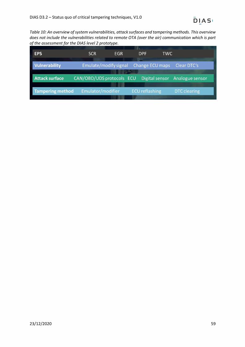
DIAS D3.2 – Status quo of critical tampering techniques, V1.0
23/12/2020 59
Table 10: An overview of system vulnerabilities, attack surfaces and tampering methods. This overview does not include the vulnerabilities related to remote OTA (over the air) communication which is part of the assessment for the DIAS level 2 prototype.
DIAS D3.2 – Status quo of critical tampering techniques, V1.0
23/12/2020 60
Directions for tampering prevention or detection and proposal for monitoring functions
In this chapter directions and requirements are proposed for the development of measures for DIAS level 1 to detect and prevent tampering of EPS that was classified as potentially high risk considering the environmental impact. The requirements are determined based on the market assessment, the results of the test programme obtained until the publication of this report and the results of external testing of tampering devices. Since at the time of publication the DIAS test programme task 3.2 is still running and the market assessment is ongoing, new test results will become available. These new results may lead to additional directions for detection or prevention of tampering of EPS. This chapter does not provide the detailed information for proposed tampering measures as this is reported in confidential report Deliverable D2.2 of DIAS.
ECU data integrity. Current security techniques have proven not to be sufficient to prevent unauthorised flashing of an ECU. The data integrity is compromised. The unauthorised flashing of malicious software to the memory of the ECU should therefore be detected and prevented. The challenge will be to prevent tampering and maintain the possibility to perform authorised flashing because this is needed to update the software/firmware of the ECU as part of the normal service of a vehicle and as regards the RMI regulation. To prevent tampering, improved security through encryption with secure key generation and storage, intrusion detection, code signing, authentication and data integrity checks should be considered. It is however not clear how the current security measures are bypassed and thus what kind of security would prevent the tampering. It is therefore recommended to further investigate the vulnerabilities that currently allow ECU reflashing.
Sensor and actuator data integrity Emulators can inject false digital signals via the CAN or via SENT protocol to the ECU (replay attack man in the middle attack). The data integrity of digital and analog sensors is compromised. For digital signals, it is recommended to consider secure communication e.g. through message authentication. Secure communication on the CAN between sensors, xCUs and the ECU is important because CAN is one of the most widely used protocols for this communication. Sensor and actuator signals currently can be emulated to simulate normal behaviour of removed or deactivated components or be modified to set a condition under which an EPS does not have to work, e.g. reagent dosing is not to be activated under certain conditions. To prevent tampering of sensor and actuator signals for the DIAS level 1 advanced algorithms should be developed to check the integrity of the signals. Analog sensor signals can’t be protected by authentication. This means that these signals need to be checked by an advance integrity/plausibility/rationality check. Checking the presence of these algorithms and demonstrating their functionality could be considered to be part of the certification process.
Detection or prevention of malicious DTC deletion Tampering abuses the vulnerability of the simple diagnostic service commands by which the OBD fault code memory with diagnostic trouble codes can be erased. After a repair, it is necessary to clear the DTCs and should remain possible for workshops. Aside from the check for DTCs, for periodic
DIAS D3.2 – Status quo of critical tampering techniques, V1.0
23/12/2020 61
inspection, the readiness test shall be completed. This can only be achieved if tampering does not lead to faults or is deactivated and a complete OBD cycle is performed to check the OBD monitors. Still, it is therefore recommended to develop a function that aims to specifically detect and prevent only the malicious DTC deletion. Several options could be considered such as setting a permanent fault or checking or limiting the frequency of a DTC reset.
Overall tampering diagnostic: tampering probability monitoring and reporting
Since current OBD does not foresee in functionality to detect and report tampering it is advised to consider requirements for dedicated tampering checks to be performed and reported at (periodic) inspections. For DIAS level 2 this could be assisted by a system for intrusion detection that determines the probability of tampering based on the available data. If the probability exceeds a certain threshold this should be reported. Various concepts for reporting can be considered. A tampering probability indicator could assist the regulator to enforce correct usage of the EPS using regular inspections. Either roadside, periodic or continuous. This requires completely new functions which can’t be implemented in level 1 but it is suggested to consider this for DIAS level 2. This diagnostic feature should be tamper-evident by itself. The feature could be a part of an integrated environmental performance monitoring system which not only monitors tampering but also other monitoring jobs such as monitoring the emissions performance (OBM) and fuel consumption (OBFCM).
Overview of requirements for tampering detection or prevention Based on the observed tampering techniques and vulnerabilities exploited, many general requirements are defined which shall be used as guidelines for the development of new functions for the detection or prevention of tampering and which would ensure that the OBD will detect faulty components of the environmental protection system (EPS). For DIAS level 1 these general requirements are:
• Assuring the data integrity of the signals of sensors and actuators that take part in the control of the EPS and the on-board diagnostics system.
o For digital signals, an option is to detect or prevent the injection of false signals by authentication of digital signals.
o For both digital and analog signals the integrity can also be tested by means of advanced data rationality checks.
• Assuring the data integrity of the ECU. An option is to detect or prevent of unauthorized flashing of ECUs by advanced security features.
• Detection or prevention of malicious erasing of the fault code memory of the on-board diagnostics system.
It should be further investigated what options fulfil the requirements regarding detection or prevention of tampering, especially taking account of the user requirements. For DIAS level 2, it is recommended to consider an overall tampering diagnostic with tampering probability monitoring and reporting.
DIAS D3.2 – Status quo of critical tampering techniques, V1.0
23/12/2020 62
Conclusions Based on the available results from the testing programme and information received from testing activity not performed in the framework of DIAS, the following can be concluded:
• Tampering for the latest generation of vehicles (e.g. Euro VI step D or Euro 6d temp) is not or hardly available as the development of new tampering to by-pass the latest control features of modern EPS probably takes some time.
• For the second last generation tampering which is freely available on the market can successfully deactivate environmental protection systems, enable removal of environmental protection systems or prevent necessary repair of components essential for the correct operation of environmental protection systems.
• The quality of the tampering is mixed. Several devices did work without any DTCs, malfunction indication or driver inducement. Initially, the ECU reflash lead to diagnostic trouble codes stored in fault code memory of the on-board diagnostic system while after a few iterations, i.e. improvements provided by the tampering provider, it works without fault codes. Several devices (emulators, TWC bushings, temperature sensor mods) lead to DTCs or hardly work (temperature sensor bushings) and some other devices didn’t work at all (emulators, TWC bushings).
• Different working principles of the tampering have been identified.
• SCR and NOx sensor emulators are mostly offered for HDV and NRMM and inject false sensor and actuator signals to the ECU via the CAN and/or SENT protocol or as an analog signal. The data integrity of digital, analog sensors and actuators is compromised. In some cases, the tampering is assisted by fault code clear commands to erase the fault code memory.
• In the case of a separate aftertreatment control module, SCR tampering constitutes deactivation of this control module and emulation of the signals of the module. Since the deactivation of the module also deactivates DPF regeneration the DPF needs to be removed because without regeneration the DPF will clog. Several HDV manufacturers use this dual system setup with a separate ECU and aftertreatment control module.
• For passenger cars, few emulators are seen on the market and seem to mainly target the DPF enabling removal of the DPF or let a cracked DPF unrepaired under the vehicle. One was tested and lead to diagnostic trouble codes.
• Another form of an emulator is a simple device which modifies a single or multiple sensor signals to set a condition that leads to the deactivation of the EPS. Also in this case the data integrity of signals is compromised. This tampering exploits the presence of auxiliary emission strategies for temporal and conditional deactivation of the EPS which are allowed to protect the engine or critical components.
• Another major tampering technique is that of ECU flashing which is widely offered for passenger cars, vans, trucks and mobile machinery. The CU data integrity is compromised by the ECU flash which can serve various goals, from deactivating an EGR, reagent dosing of the SCR system to removal of components or even the whole EPS. ECU is also flashed to increase the power rating of the engine. Current techniques seem to exploit mainly the OBD port and applicable service protocols. For the tested ECU flashing dedicated hardware, tools are used to upload the malware.
• For ECU reflashing it is not clear how the current security measures are bypassed and thus what kind of security could prevent the tampering. It is therefore recommended to further investigate the vulnerabilities that currently allow ECU reflashing.
• OBD DTC erasers have not been tested so far. It is assumed that these devices abuse the universal diagnostic service protocol that has commands for clearing DTCs. This function is unprotected to allow third parties, such as white brand workshops and vehicle owners can erase DTCs after a repair.
DIAS D3.2 – Status quo of critical tampering techniques, V1.0
23/12/2020 63
• EPS tampering allows compromising the hardware and its functionality, namely, to unplug, deactivate or remove critical parts of the EPS or leave faulty components on the vehicle.
• Depending on the components affected, the tampering of the SCR and/or EGR system generally results in a large increase of the NOx tail-pipe emission and when a DPF is removed, in a large increase of the particulate emissions. In the case the tampering is applied to avoid repair, i.e. a malfunctioning component remains on the vehicle, the increase of the emissions can be lower as the EPS may still work partially.
• Based on the observed tampering techniques and vulnerabilities exploited, a number of general requirements are defined which shall be used as guidelines for the development of new functions for the detection or prevention of tampering and which would ensure that the OBD will detect faulty components of the environmental protection system (EPS). For DIAS level 1 these general requirements are:
o Assuring the data integrity of the signals of sensors and actuators that take part in the control of the EPS and the on-board diagnostics system.
▪ For digital signals, an option is to detect or prevent the injection of false signals by authentication of digital signals.
▪ The integrity of both analog and digital signals can be checked by means of advanced data rationality checks.
o Assuring the data integrity of the ECU. An option is to detect or prevent of unauthorized flashing of ECUs by advanced security features
o Detection or prevention of malicious erasing of the fault code memory of the on-board diagnostics system
• It should be further investigated what options fulfil the requirements regarding detection or prevention of tampering, especially taking account of the user requirements.
• Since current OBD does not foresee in functionality to detect and report tampering it is advised to consider requirements for continuous tampering diagnostics with tampering probability monitoring and reporting. It is also recommended to consider tampering checks for periodic inspections. The tampering diagnostics could assist enforcement of proper use of the EPS for at regular periodic inspections, roadside inspections or for monitoring of tampering in the fleet through the cloud.
DIAS D3.2 – Status quo of critical tampering techniques, V1.0
23/12/2020 64
Bibliography
[1] Transport & Environment, “New truck diesel scandal in Europe twice the size of 'VW diesel gate' in US,” Transport & Environment, 20 February 2017. [Online]. Available: https://www.transporten-vironment.org/news/new-truck-diesel-scandal-europe-twice-size-%E2%80%-98vw-dieselgate%E2%80%99-us. [Accessed November 2019].
[2] J. Gallagher, “Thousands of motorists are breaking the law by driving diesel cars without pollution filters.,” BBC, 29 October 2017. [Online]. Available: https://www.bbc.com/news/uk-41761864. [Accessed November 2019].
[3] D. Pöhler, T. Adler, C. Krufczik, M. Horbanski, J. Lampel and U. Platt, “Real Driving NOx Emissions of European Trucks and Detection of Manipulated Emission Systems,” 19th EGU General Assembly, p. 13991, 2017.
[4] Representative of Switzerland, “Manipulation on EURO IV, EURO V and EURO VI trucks by supression of AdBlue injection - Detection of manipulated trucks - situation mid of September 2017,” UNECE, 2017.
[5] Driver and Vehicle Standards Agency & Traffic Commissioners for Great Britain, “More than 100 lorry operators caught deliberately damaging air quality,” Government of the United Kingdom, 12 January 2018. [Online]. Available: https://www.gov.uk/government/news/more-than-100-lorry-operators-caught-deliberately-damaging-air-quality. [Accessed November 2019].
[6] DieselNet, “EU truck manufacturers call for action to prevent tampering of emission controls,” DieselNet, 24 February 2017. [Online]. Available: https://www.dieselnet.com/news/2017/02acea.php. [Accessed November 2019].
[7] VRT news, “Keuring merkt grootschalige roetfilterfraude niet op,” VRT, 02 July 2017. [Online]. Available: https://www.vrt.be/vrtnws/nl/2017/07/02/keuring_merkt_grootschaligeroetfilterfraudenietop-1-3014602/. [Accessed December 2019].
[8] Comms Assistant, “How to tackle the illegal diesel filter removal 'industry' in Belgium and beyond,” Transport & Environment, 3 July 2017. [Online]. Available: https://www.transportenvironment.org/news/how-tackle-illegal-diesel-filter-removal-industry-belgium-and-beyond. [Accessed November 2019].
[9] J. van den Meiracker and R. Vermeulen, “The market of cheating devices and testing matrix with a priotization for testing of vehicle tampering technique combinations,” 31 March 2020.