development of task-oriented ros-based autonomous ugv
TRANSCRIPT
Development of task-oriented ROS-based Autonomous UGV with 3DObject Detection
Rajesh Raveendran1∗, Siva Ariram1∗, Antti Tikanmaki1 and Juha Roning1
Abstract— In a scenario where fire accidents takes place thepriority is always human safety and acting swiftly to containthe fire from further spreading. The modern autonomoussystems can promise both human safety and can performactions rapidly. One such scenario which is motivated by urbanfirefighting was designed in challenge 3 of MBZIRC 2020competition. In this challenge the UAV’s and UGV collaborateautonomously to detect the fire and quench the flames withwater. So, in this project we have developed Robot OperatingSystem (ROS)-based autonomous system to solve the challengefor UGV criteria by detecting targeted objects in real-time,in our case its simulated fire and red colored softballs. Thenfinally localize those targets as markers in the map andnavigate autonomously to all those targets. This work has twosections, in the first section mapping and localizing the fire andsoftballs in highly cluttered environment and then reachingthose targets autonomously. Robustly mapping the area withadequate sensors and detection of targets with optimally trainedCNN based network is the key to localizing of the targetedobjects in a highly cluttered environments.
Keywords: ROS, architecture, mapping, autonomous nav-
igation, object detection, CNN, dataset
I. INTRODUCTION
Autonomous mobile systems have received more attention
in recent days and slowly is integrating into daily activities
of human life. Especially in disaster prone situation these
systems can be deployed rapidly and contain the disaster.
Recently in China, autonomous mobile robots were used
to provide medicines to COVID-19 affected patients. Au-
tonomous drones were used to monitor the people crowd
and announcing awareness regarding COVID-19 in densely
populated countries such as India and China, also in UAE.
The unprecedented situation can be further contained if we
have online shopping where last mile robots can deliver
daily needs to our door steps, this can avoid further human
contacts. In order to deploy autonomous systems in these
scenarios we need very robust autonomous systems which
can navigate in any cluttered environments safely and ro-
bustly. In robotics world there are many competitions that are
conducted around the world to enhance the overall system ro-
bustness and accuracy of autonomous systems and they have
to collaborate with each other. One such event is MBZIRC
2020 Challenge[5] which contains three challenges, collab-
orative UAVs to grab softballs with 11cm in diameter in
highly dynamic environment, collaborative UAVs and UGV
1Biomimetics and Intelligent Systems Group(BISG), University ofOulu, 90570 Oulu, Finland. [email protected]@oulu.fi
∗Rajesh Raveendran and Siva Ariram have equally contributed to thiswork as first authors
FSB Dataset - https://github.com/sivaariram/Fire-and-Ball-Dataset
for construction and finally urban firefighting scenario. In
this work we have focused on the UGV’s criteria for third
scenario to localize simulated fire and navigate autonomously
in a highly cluttered environment.The designed autonomous
navigation system includes real-time path planning, mapping,
obstacle avoidance and default recovery phase. We trained
a Convolution Neural Network with training data-set using
Darknet detection algorithm. Achieving the accuracy in
object detection with data-set from different scenarios and
training the network for highly optimized weights was one
of the most challenging part.
II. BACKGROUND
In the development of any Simultaneous Localization
and Mapping (SLAM) based autonomously navigating mo-
bile systems, deciding the choice of representation of the
environment is a critical design decision. Fundamentally,
the environment can be represented in two ways based on
features in the environment and dense representation such
as occupancy grid ma. And based on the choices SLAM’s
can be classified into two approaches, namely grid-based and
feature-based approaches. In the feature-based approach, the
features contain both semantic and metric information. It
provides semantic features such as point, line and plane and
metric features such as range and orientation [6]. And based
on these features, a feature map is incrementally built and
using this feature map the mobile system is simultaneously
localized in the environment. Feature based maps are highly
preferred in structured environment with open space with
predefined landmarks [6] [7] and this also depends on
what type of features some line based feature extractors
provide optimum results in indoor with concrete wall and
pillars. And feature-based approach is computationally less
expensive compared to dense grid-based approach. Typical
indoor environment using Rao-Blackwellized particle filters
(RBPFs) are a high-performance solution, and has been
integrated into open source software such as Gmapping
[7] [8]. The data association step can fail if there are
uncertainties arising from the scan data which in turn can
lead to incorrect feature extraction [9] [10]. Hence, accuracy
of scan data plays a vital role in feature extraction and
grid mapping. Also, any type of sensor uncertainties has a
probability to propagate into mapping and navigation stack.
In this work we have chosen Hector Map [11] and OctoMap
[12] which is chosen based on the base controller mode
of operation. Most of the localization algorithms utilizes
the extended Kalman filter (EKF), unscented Kalman filter
(UKF) or Adaptive Monte-Carlo Localization (AMCL) par-
ticle filters. The Kalman Filter is based on Bayesian method
and it computes recursively the optimal parameter estimation
from its posterior density. The object dynamic function and
posterior density are Gaussian distribution in Kalman filter
and the process and measurement functions are linear. In
EKF, the process function linearization is performed with
Taylor series approximation and in UKF the approximation
is based on sigma point sampling. In this project cascading
EKF with different modalities has been implemented using
robot localization [14] package.
In order to achieve the high accuracy in object detection
at different scales, the recent studies applied multiple layer
architecture. At the same time the low-level feature in
superficial layers may not perform the detection with high
accuracy [4]. Most of the object detection algorithm is totally
depend on training data-set and training parameters which
helps to prevent the network over trained or under trained.
Hence, we decided to collect enough data-sets under different
scenarios and depends on number of classes we configured
the training parameters. The other important factor is that
the detection should not affect the system performance since
most of the detection network occupies the GPU memory[1],
so we implemented the network based on system perfor-
mance.
III. SYSTEM DESCRIPTION
The UGV platform, Morri, is an evolutionary version of
the high-performance platform that was first used ten years
ago in Elrob 2008. Since then, the platform has undergone
several development cycles, especially on sensors and com-
puters, but the core features of powerful 5 kW motors, narrow
body and large footprint relative to weight has remained the
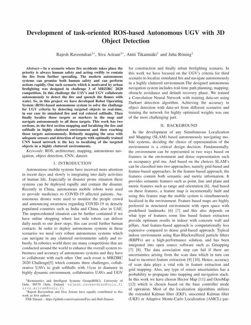
same. Figure 1 shows the sensors and cameras attached to
the Morri.
Morri is equipped with custom made battery modules.
Each module has 5Ah 24V capacity with integrated monitor
and charger. Robust CAN bus is used to control each
battery module (on/off, charging, etc.) and to read its status
(how much charge left, temperature etc.). Operation time of
Morri per one battery module is highly depending on the
mass of payload, demanded speeds and accelerations, and
environmental factors such as ground softness and slope. As
a rough approximation, with one battery module Morri can
travel 2km on hard surface. The number of batteries can
be tuned according to each scenario’s parameters so that
”enough” batteries are attached to Morri. Currently, Morri
has space for up to 12 battery modules. Morri has internal
onboard computer Zotac with NVIDIA Geforce 1070 GPU
enabling high performance CUDA processing. The complete
navigation stack with obstacle avoidance and 3D model
reconstruction are performed using this on-board computer
so Morri can operate independently without external connec-
tion. Two different options for inter-process communication
are available, the commonly used ROS interfaces and a
proprietary high performance binary protocol tailored for
real time control. Each ROS node utilizes messages from
common msgs stack in-order to avoid circular dependencies
Fig. 1: Morri UGV
with multiple stack. The system network is configured to use
multiple machine with single ROS master. The Operator PC
can be used to monitor the heartbeat of all the sensors and
receive the messages.
IV. SYSTEM ARCHITECTURE
Morri runs in meta-operating system called ROS. The
main reasons for opting ROS is easy construction of dis-
tributed computing systems, extensive tool-sets for debug-
ging, visualization, logging, introspecting and saving the data
in a bag format, has capability to provides libraries from
low level system integration to control and perception of
mobile systems and manipulators, it is supported by large
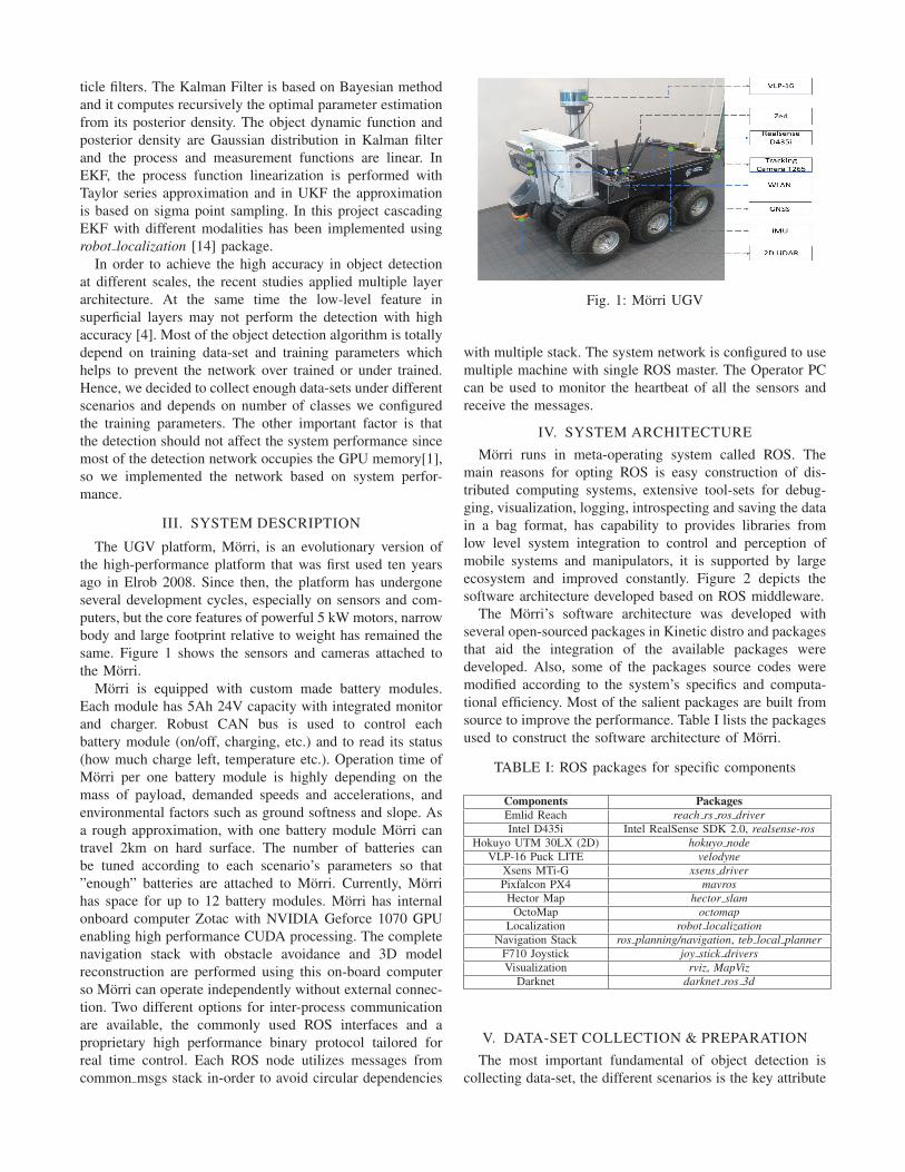
ecosystem and improved constantly. Figure 2 depicts the
software architecture developed based on ROS middleware.
The Morri’s software architecture was developed with
several open-sourced packages in Kinetic distro and packages
that aid the integration of the available packages were
developed. Also, some of the packages source codes were
modified according to the system’s specifics and computa-
tional efficiency. Most of the salient packages are built from
source to improve the performance. Table I lists the packages
used to construct the software architecture of Morri.
TABLE I: ROS packages for specific components
Components PackagesEmlid Reach reach rs ros driverIntel D435i Intel RealSense SDK 2.0, realsense-ros
Hokuyo UTM 30LX (2D) hokuyo nodeVLP-16 Puck LITE velodyne
Xsens MTi-G xsens driverPixfalcon PX4 mavros
Hector Map hector slamOctoMap octomap
Localization robot localizationNavigation Stack ros planning/navigation, teb local planner
F710 Joystick joy stick driversVisualization rviz, MapViz
Darknet darknet ros 3d
V. DATA-SET COLLECTION & PREPARATION
The most important fundamental of object detection is
collecting data-set, the different scenarios is the key attribute
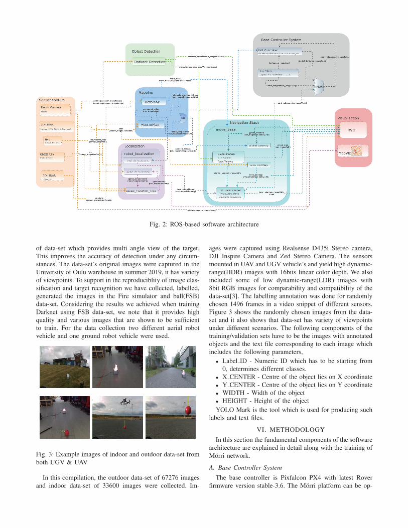
Fig. 2: ROS-based software architecture
of data-set which provides multi angle view of the target.
This improves the accuracy of detection under any circum-
stances. The data-set’s original images were captured in the
University of Oulu warehouse in summer 2019, it has variety
of viewpoints. To support in the reproduciblity of image clas-
sification and target recognition we have collected, labelled,
generated the images in the Fire simulator and ball(FSB)
data-set. Considering the results we achieved when training
Darknet using FSB data-set, we note that it provides high
quality and various images that are shown to be sufficient
to train. For the data collection two different aerial robot
vehicle and one ground robot vehicle were used.
Fig. 3: Example images of indoor and outdoor data-set from
both UGV & UAV
In this compilation, the outdoor data-set of 67276 images
and indoor data-set of 33600 images were collected. Im-
ages were captured using Realsense D435i Stereo camera,
DJI Inspire Camera and Zed Stereo Camera. The sensors
mounted in UAV and UGV vehicle’s and yield high dynamic-
range(HDR) images with 16bits linear color depth. We also
included some of low dynamic-range(LDR) images with
8bit RGB images for comparability and compatibility of the
data-set[3]. The labelling annotation was done for randomly
chosen 1496 frames in a video snippet of different sensors.
Figure 3 shows the randomly chosen images from the data-
set and it also shows that data-set has variety of viewpoints
under different scenarios. The following components of the
training/validation sets have to be the images with annotated
objects and the text file corresponding to each image which
includes the following parameters,
• Label ID - Numeric ID which has to be starting from
0, determines different classes.
• X CENTER - Centre of the object lies on X coordinate
• Y CENTER - Centre of the object lies on Y coordinate
• WIDTH - Width of the object
• HEIGHT - Height of the object
YOLO Mark is the tool which is used for producing such
labels and text files.
VI. METHODOLOGY
In this section the fundamental components of the software
architecture are explained in detail along with the training of
Morri network.
A. Base Controller System
The base controller is Pixfalcon PX4 with latest Rover
firmware version stable-3.6. The Morri platform can be op-
erated in three different modes manual, manual with collisionavoidance and autonomous with obstacle avoidance, the
corresponding modes in PX4 are MANUAL which allows
RC, MANUAL with RC override which allows joystick drive
and GUIDED. The PX4 controller uses vision based position
and orientation rather than its internal filtered IMU which is
not suitable in indoor as heading has sporadic errors. The
PX4 uses odometry from the 2D LiDAR scan match when
RC messages are overrided by joy stick during manual with
collision avoidance. And in the case of GUIDED mode the
odometry is similar to the odometry used in local planner or
SLAM which is either based on OctoMap or Hector map
selection. In upcoming Mapping section this is explained
with further details.
B. Localization
One of the essential methods for position estimation of
an autonomous system is odometry/dead reckoning. In ROS,
odometry message comprises of position, orientation and
twist (linear and angular velocity). The message represents
the transformation of the base link frame of the mobile
system viewed from the odometry frame. The odometry
message is published in odometry frame (odom) as the
message itself the transformation of the base link observed
from odometry frame. However, the odometry has gradual
error accumulation when the robot moves over the time.
This gradual drift in odometry is compensated as a transform
message from map to odometry frame and most of the SLAM
techniques based on feature or grid-based will provide this
transform.
In this architecture the state estimation of the UGV is
based on cascading the odometry locally and globally from
different modalities. The scan-match odometry from 2D
LiDAR scan data at 40Hz and filtered IMU data from xsens
is fused with local ekf localization node which provides
robust local state estimation of UGV at local frame. Finally
this odometry message is used by local planner in navi-
gation stack. The navsat transform node provides odometry
message which takes heading of the UGV from IMU and
fused odometry message from global ekf localization node.
It finally provides odometry message which is cascaded
with global ekf localization along with GNSS and odometry
message from local ekf localization node. The resultant state
estimation from global ekf localization node is published in
consistent with UGV’s world frame is highly accurate state
of the UGV in world frame.
C. Mapping
SLAM is a technique used to localize the mobile system
and generate a physical map of the environment simultane-
ously. And this is always considered to be a complex problem
because for mapping the environment a good estimate of the
robot’s location is needed and to localize a robot, a consistent
map of the environment is required. Hence, there is mutual
dependency between the estimates about the pose of the
robot and the map of the environment. As the task does not
require dense model of the environment, we have adopted
occupancy grid method rather dense 3D SLAM approaches.
In this architecture there are two mapping capabilities. The
OctoMaps were used to generate 3D occupancy grid which is
more computationally efficient to generate rather graph based
RGBD-SLAM such RTAB-Map which is GPU intensive and
computationally its not efficient for the given task and storage
consumes more space. The OctoMaps are generated from the
3D scan data from velodyne and the projected grid map is
used for global and local path planning.
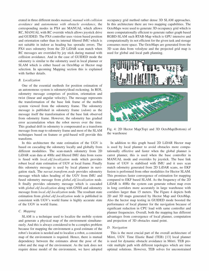
Fig. 4: 2D Hector Map(Top) and 3D OctoMap(Bottom) of
the warehouse
In addition to this graph based 2D LiDAR Hector map
is used by local planner to avoid obstacles more compu-
tationally effective and faster when the global planner is
carrot planner, this is used when the base controller in
MANUAL mode and overrides by joystick. The base link
frame of UGV is stabilised with IMU and it uses scan
match odometry generated from 2D LiDAR scans, no EKF
fusion is performed from other modalities for Hector SLAM.
This promises faster convergence of estimation for mapping
compared to EKF based SLAM. As the frequency of the 2D
LiDAR is 40Hz the system can generate robust map even
in long corridors more accurately in large warehouse with
corridors larger than 15 meters. The Figure 4 depicts both
2D and 3D maps generated by Hector Map and OctoMap.
Also the hector map testing in GUIDED mode boosted the
performance of local planner for the navigation because of
significant reduction in CPU load with same controller and
planner frequencies. Overall, both the mapping has different
advantages from convergence of local planner, computation
and projection of 3D obstacles stand point.
D. Navigation
This is the most crucial part of the overall architecture of
Morri, UGV. Time Elastic Band (TEB) [13] local planner
is used for dynamic obstacle avoidance in Morri. TEB pro-
vide multiple path with different topologies which are time
optimal solutions. However, TEB solves for unconstrained
optimization problem which is much faster than constrained
optimization problems, the performance of TEB is based on
size of the map, size of the obstacle (polygon or circle)
and computational power. In this system the parameters
are tuned for optimal results considering the computation
power with maximum CPU load of other packages and
achieving maximum speed for completing the task faster.
The maximum velocity achieved was 0.7m/sec - 1.2m/sec
along x-axis without compensating the performance of the
controller’s stability. Figure 8 show the local and global path
generated by planners in different scenarios. Navigating in
tight corners is much easier with circular footprint as most
of the unconstrained problem is now convex optimization
problem with smooth costmaps.
E. Object Detection
To perform object detection, we use the data-sets that
provides information about the fire simulator through the
camera. The objects are detected using the information from
the Realsense D435i camera, then they are classified and the
distance of the object relative to the Morri is measured. The
object detection is attained using the integration of feature
based and appearance based modeling. As compared to other
sensors the images from the camera have more information
that can be used to identify objects.
There are plenty of convolutional neural network(CNN)
architectures that performs object detection method using
feature extractor which are performed better than other
methods, this shows development in object detection. During
the training process CNN learns the features in object and it
can also generalize the object feature.Here, we used existing
method which is Darknet object detection and it uses a
hierarchical dimension of object classification[1]. Using this
method we trained Morri Object detection network that can
detect targeted objects in real-time. Figure 5 shows the real-
time detection from Morri view with the bounding boxes. To
find the depth of the object we used depth frame in realsense
D435i, we overlapped the bounding box parameters from
RGB frame to depth frame to find the depth parameter of
the targeted object.
Fig. 5: Trained Morri network can detect fire simulator and
soft ball(Morri Camera View)
F. Training Network
To analyse the quality and other attributes of FSB data-
set, we utilized widely used open source neural network
framework Darknet. The darknet model is trained with high
resolution images and shown promising results in object
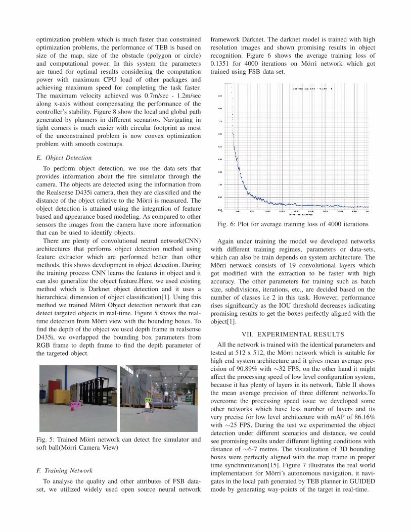
recognition. Figure 6 shows the average training loss of
0.1351 for 4000 iterations on Morri network which got
trained using FSB data-set.
Fig. 6: Plot for average training loss of 4000 iterations
Again under training the model we developed networks
with different training regimes, parameters or data-sets,
which can also be train depends on system architecture. The
Morri network consists of 19 convolutional layers which
got modified with the extraction to be faster with high
accuracy. The other parameters for training such as batch
size, subdivisions, iterations, etc., are decided based on the
number of classes i.e 2 in this task. However, performance
rises significantly as the IOU threshold decreases indicating
promising results to get the boxes perfectly aligned with the
object[1].
VII. EXPERIMENTAL RESULTS
All the network is trained with the identical parameters and
tested at 512 x 512, the Morri network which is suitable for
high end system architecture and it gives mean average pre-
cision of 90.89% with ∼32 FPS, on the other hand it might
affect the processing speed of low level configuration system,
because it has plenty of layers in its network, Table II shows
the mean average precision of three different networks.To
overcome the processing speed issue we developed some
other networks which have less number of layers and its
very precise for low level architecture with mAP of 86.16%
with ∼25 FPS. During the test we experimented the object
detection under different scenarios and distance, we could
see promising results under different lighting conditions with
distance of ∼6-7 metres. The visualization of 3D bounding
boxes were perfectly aligned with the map frame in proper
time synchronization[15]. Figure 7 illustrates the real world
implementation for Morri’s autonomous navigation, it navi-
gates in the local path generated by TEB planner in GUIDED
mode by generating way-points of the target in real-time.
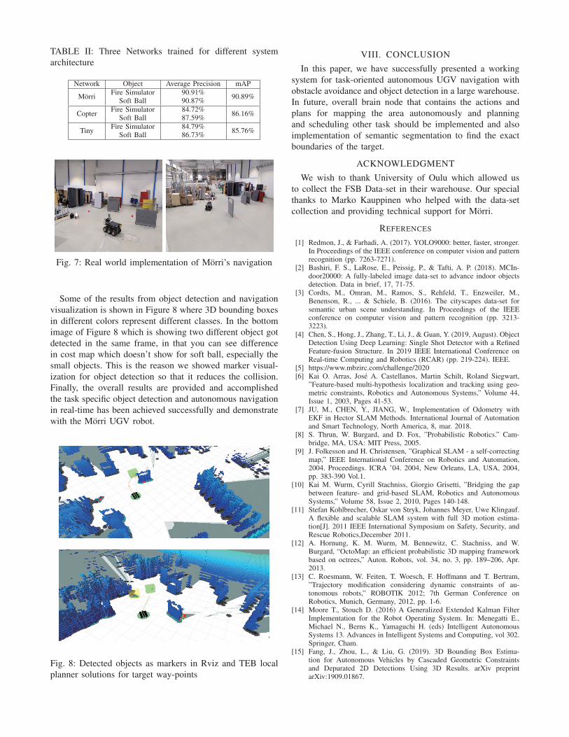
TABLE II: Three Networks trained for different system
architecture
Network Object Average Precision mAP
MorriFire Simulator 90.91%
90.89%Soft Ball 90.87%
CopterFire Simulator 84.72%
86.16%Soft Ball 87.59%
TinyFire Simulator 84.79%
85.76%Soft Ball 86.73%
Fig. 7: Real world implementation of Morri’s navigation
Some of the results from object detection and navigation
visualization is shown in Figure 8 where 3D bounding boxes
in different colors represent different classes. In the bottom
image of Figure 8 which is showing two different object got
detected in the same frame, in that you can see difference
in cost map which doesn’t show for soft ball, especially the
small objects. This is the reason we showed marker visual-
ization for object detection so that it reduces the collision.
Finally, the overall results are provided and accomplished
the task specific object detection and autonomous navigation
in real-time has been achieved successfully and demonstrate
with the Morri UGV robot.
Fig. 8: Detected objects as markers in Rviz and TEB local
planner solutions for target way-points
VIII. CONCLUSION
In this paper, we have successfully presented a working
system for task-oriented autonomous UGV navigation with
obstacle avoidance and object detection in a large warehouse.
In future, overall brain node that contains the actions and
plans for mapping the area autonomously and planning
and scheduling other task should be implemented and also
implementation of semantic segmentation to find the exact
boundaries of the target.
ACKNOWLEDGMENT
We wish to thank University of Oulu which allowed us
to collect the FSB Data-set in their warehouse. Our special
thanks to Marko Kauppinen who helped with the data-set
collection and providing technical support for Morri.
REFERENCES
[1] Redmon, J., & Farhadi, A. (2017). YOLO9000: better, faster, stronger.In Proceedings of the IEEE conference on computer vision and patternrecognition (pp. 7263-7271).
[2] Bashiri, F. S., LaRose, E., Peissig, P., & Tafti, A. P. (2018). MCIn-door20000: A fully-labeled image data-set to advance indoor objectsdetection. Data in brief, 17, 71-75.
[3] Cordts, M., Omran, M., Ramos, S., Rehfeld, T., Enzweiler, M.,Benenson, R., ... & Schiele, B. (2016). The cityscapes data-set forsemantic urban scene understanding. In Proceedings of the IEEEconference on computer vision and pattern recognition (pp. 3213-3223).
[4] Chen, S., Hong, J., Zhang, T., Li, J., & Guan, Y. (2019, August). ObjectDetection Using Deep Learning: Single Shot Detector with a RefinedFeature-fusion Structure. In 2019 IEEE International Conference onReal-time Computing and Robotics (RCAR) (pp. 219-224). IEEE.
[5] https://www.mbzirc.com/challenge/2020[6] Kai O. Arras, Jose A. Castellanos, Martin Schilt, Roland Siegwart,
”Feature-based multi-hypothesis localization and tracking using geo-metric constraints, Robotics and Autonomous Systems,” Volume 44,Issue 1, 2003, Pages 41-53.
[7] JU, M., CHEN, Y., JIANG, W., Implementation of Odometry withEKF in Hector SLAM Methods. International Journal of Automationand Smart Technology, North America, 8, mar. 2018.
[8] S. Thrun, W. Burgard, and D. Fox, ”Probabilistic Robotics.” Cam-bridge, MA, USA: MIT Press, 2005.
[9] J. Folkesson and H. Christensen, ”Graphical SLAM - a self-correctingmap,” IEEE International Conference on Robotics and Automation,2004. Proceedings. ICRA ’04. 2004, New Orleans, LA, USA, 2004,pp. 383-390 Vol.1.
[10] Kai M. Wurm, Cyrill Stachniss, Giorgio Grisetti, ”Bridging the gapbetween feature- and grid-based SLAM, Robotics and AutonomousSystems,” Volume 58, Issue 2, 2010, Pages 140-148.
[11] Stefan Kohlbrecher, Oskar von Stryk, Johannes Meyer, Uwe Klingauf.A flexible and scalable SLAM system with full 3D motion estima-tion[J]. 2011 IEEE International Symposium on Safety, Security, andRescue Robotics,December 2011.
[12] A. Hornung, K. M. Wurm, M. Bennewitz, C. Stachniss, and W.Burgard, “OctoMap: an efficient probabilistic 3D mapping frameworkbased on octrees,” Auton. Robots, vol. 34, no. 3, pp. 189–206, Apr.2013.
[13] C. Roesmann, W. Feiten, T. Woesch, F. Hoffmann and T. Bertram,”Trajectory modification considering dynamic constraints of au-tonomous robots,” ROBOTIK 2012; 7th German Conference onRobotics, Munich, Germany, 2012, pp. 1-6.
[14] Moore T., Stouch D. (2016) A Generalized Extended Kalman FilterImplementation for the Robot Operating System. In: Menegatti E.,Michael N., Berns K., Yamaguchi H. (eds) Intelligent AutonomousSystems 13. Advances in Intelligent Systems and Computing, vol 302.Springer, Cham.
[15] Fang, J., Zhou, L., & Liu, G. (2019). 3D Bounding Box Estima-tion for Autonomous Vehicles by Cascaded Geometric Constraintsand Depurated 2D Detections Using 3D Results. arXiv preprintarXiv:1909.01867.