atp: autonomous transport protocol
TRANSCRIPT

ATP: Autonomous Transport Protocol
Tamer Elsayed, Mohamed Hussein, Moustafa Youssef, Tamer Nadeem, Adel Youssef, Liviu IftodeDepartment of Computer Science and UMIACS
University of MarylandCollege Park, Maryland 20742ftelsayed,mhussein,moustafa,nadeem,adel,[email protected]
UMIACS-TR-2003-52 and CS-TR-4483May 19, 2003
Abstract
In this report we present the design of the Autonomous Transport Protocol (ATP). The basic service providedby ATP is a reliable transport connection between two endpoints (identified by content identifiers) independent oftheir physical location. Autonomy allows dynamic endpoints relocation ondifferent end hosts without disruptingthe transport connection between them. ATP depends on the existence of an underlying Instance-Based Network(IBN) to achieve its goals.
An IBN provides the flexibility of having different instances of the same content. It is up to the user of theIBN network to define the relation between these instances. An IBN allows its user to to map a content to aparticular node. Application endpoints can send messages to other content-identified endpoints. Routing in theIBN is instance-based; the IBN can route a message to a specific content instance or to the nearest instance, ifno exact match is found for the destination content instance. Moreover, the IBN replicates the stored contents inorder to provide fault tolerance and IBN nodes along the query path can cache a content to provide fast answersto future queries.
The ATP layer in the intermediate nodes between the source and destination endpoints can actively participatein the connection, for example, to buffer data for the destination endpoints during periods of unavailability. Data istransferred by a combination of active and passive operations, where the ATP layer of a node can decide whetherto actively push the data to the destination or to passively wait for the destination endpoint to pull the data. Thedecision to whether to use the active or passive modes can be taken by a local policy on the node running the ATPprotocol.
Keywords: Content-based networks, instance-based networks, mobility management, transport protocols, ubiq-uitous computing
1 Introduction
Advances in wireless networking, device miniaturization,and mobile computing have made ubiquitous com-puting possible more than ever before. The ubiquitous computing era will challenge our way of thinking andcomputing for more than the PC revolution did in the past. Users want to move everywhere and seamlessly accessservices and resources located in the environment. For thisto happen, user applications need to migrate from onemachine to another and the user network connections should be maintained during these migrations.
1

In a true ubiquitous environment, users should be allowed tochange networks and hosts seamlessly and com-munication should continue even if the user is not availablefor a short period of time. Current Internet architectureoffers a limited support for ubiquitous communication. In traditional TCP/IP, the connection is identified by theIP address of the end hosts and the user is bound to the same host during the connection lifetime. Although themobile IP protocol [5] provides a solution to the host mobility between different networks, a user is bound to asingle host during the lifetime of a connection. As ubiquitous computing emerges, the user should become thefocus of communication and not the end hosts.
To achieve this goal, connections should be carried betweenusers, independent from the host on which the useris located. Peer-to-peer lookup services provide a mechanism to map a content into a specific host and to querythe location of this content in a peer-to-peer (P2P) network. Considering a user’s endpoint as a content, a transportlayer protocol over a P2P network uses the lookup service mechanism to locate the end hosts. The challenge ishow to maintain a reliable connection between the users’ endpoints as they roam in the environment moving fromone host to another leading to a dynamic change of the user ID (content) to host mapping. In such an environment,data for the same connection can be produced at different hosts and consumed at multiple locations depending onthe location of the user endpoint. In TCP , this mapping is static during the lifetime of the connection.
In this report, we introduce the Autonomous Transport Protocol (ATP). In ATP, autonomy allows dynamicendpoint relocation on different end hosts without disrupting the transport connection between them. The ATP hasthe following features:� It does not enforce any naming scheme on the user application. The application is responsible for uniquely
identifying the endpoint.� The endpoints of a transport connection are defined as contents in the P2P network. This decouples theconnection from the physical host where the user endpoint islocated, and hence ensures autonomy.� Mobility of the endpoints is handled via the P2P network by dynamically changing the mapping betweenthe endpoint and the host. The ATP layer is responsible for moving segments to the destination and theacknowledgment to the source regardless of their current mapping in the P2P network.� Since a P2P network is built as an overlay network, the ATP layer in the intermediate nodes between thesource and destination endpoints can actively participatein the connection, for example, to buffer data forthe destination endpoints during periods of unavailability.� Data is transfered by a combination ofactiveandpassiveoperations, where the ATP layer of a node candecide whether to actively push the data to the destination or to passively wait for the destination endpointto pull the data. The decision to whether to use the active or passive modes can be taken by a local policyon the node running the ATP protocol.
This report is organized as follows. In Section 2 we introduce an example scenario to illustrate the problem weare trying to solve and motivate the ATP protocol. Section 3 describes the system architecture. We introduce anextension to the current P2P lookup services, the Instance-Based Network (IBN), in Section 4. Section 5 introducesthe ATP protocol. In Section 6, we present different applications that can benefit from the ATP protocol. Wesurvey related work in Section 7. Section 8 gives a discussion about the ATP design. Finally, Section 9 presentsthe conclusions and the extension to the current work.
2 Example
Figure 1 shows an application scenario for the ATP. A set of wireless nodes, represented by small black circles,are distributed over an area. An observerSrcgenerates statistical data about the environment as it moves around.This data is transmitted reliably to an analyzerDst.
2

Src
2
1
Dst
3
4
3. Source Migration
2. D
estin
ation
Migr
ation
1. Connection Establishment
Node vicinity
Figure 1. A typical ATP application scenario
3

The observer triggers the tracking application of the nearest node to become active (Node 1 in Figure 1) inwhich it records and transmits the collected data to the analyzer (Node 3) using the ATP layer. During the observermovement, it can become out of the vicinity of any tracking node. For example, while the observer moves fromnode 1 to node 2 (source migration) as in Figure 1, temporally it does not come in the vicinity ofany node. Oncethe observer becomes out the vicinity of Node 1, the trackingapplication stops tracking and the ATP layer on node1 handles the established connection to continue reliably transmitting the packets it has to the analyzer. When theobserver approaches node 2, it triggers the tracking application on that node to collect the data and to transmitthem to the analyzer using the ATP layer of node 2. Meanwhile,ATP layer at Node 1 may still be transmitting therest of the data it has to the observer.
Similarly, The analyzer changes the monitoring node from Node 3 to Node 4 (destination migration) as in thefigure. As analyzer moves from node 3 to node 4, the ATP layer atnode 3 continues the connection on behalf ofhim. When the analyzer connects to node 4, the connection is updated to forward the data to the new physicallocation of the analyzer. ATP layers at node 3 and 4 are responsible for transferring the data from node 3, which isnot shown yet to the analyzer, to node 4. Due to the spatial locality of nodes 3 and 4, transferring the data betweenthose two nodes has lower overhead than transferring the data from the observer. In this scenario, the observer andthe analyzer do not need to be aware of the physical location of each other and the roaming handling should betransparent to both.
3 System Architecture
Figure 2 shows the system architecture for an ATP environment. The ATP protocol stack consists of four layers:
1. The underlying-network layer
2. The IBN layer
3. The ATP layer
4. The application layer
In the following subsections, we introduce each layer.
3.1 Underlying Network Layer
This layer presents the communication infrastructure for our system. This can be an IP infrastructure (such asthe case in the Internet), an ad-hoc network (such as the casein MANET [1]), or any other underlying network.
3.2 Instance-Based Network (IBN) Layer
We define content-based network (CBN) as a network of endpoint entities calledcontentswhere each content isaddressed or located by its name, properties or attributes,independent of its physical location. The content couldbe a user, an application service, a document, a network node, a network connection or any other object. UnlikeIP networks where the IP address is not just a unique ID but also a locator, CBN addressing is decoupled fromthe location of contents. Contents can actively communicate with each other by sending or receiving messages, orperforming a lookup for other contents. Other content types, such as a document, can be passively stored in thenetwork.
The CBN layer extends the functionality provided by the current peer-to-peer lookup services (such as CAN [6],Chord [10], Pastry [7], and Tapestry [14]). Peer-to-peer lookup services provide a mechanism to map a key to some
4

Underlying Network
Application
Autonomous Trasnport Protocol
Instance-Based Network
P2P Lookup Service
Figure 2. System architecture
node in network specified by the lookup service, and allows the users to query for these keys. The CBN, however,maps a content to aspecificnode in the network and routes messages to this node.
We developed an enhanced content-based network named as theinstant-based network (IBN). The IBN has theunique feature of allowing different instances of the same content to be stored in the network (and hence the nameIBN). Details of the IBN layer are discussed in Section 4.
3.3 Autonomous Transport Protocol (ATP) Layer
The main goal of the Autonomous Transport Protocol is to offer a reliable transport protocol over the IBN.Migration of endpoints should be transparent to each other;that is, the protocol should be able to maintain theconnection during the migration of endpoints. The protocolshould maintain established connections seamlesslyand independent from intermediate node availability. In other words, our proposed protocol should have the samefunctionality of TCP in static networks while confronting the dynamics of the IBN environment. The details ofthe ATP protocol are discussed in Section 5.
3.4 Application Layer
ATP-aware applications communicate with the ATP layer to perform migration of the endpoints. The ATP layeris responsible for migrating the open connection state to the new node, while the application is responsible formigrating the application state. To minimize the required changes of the existing applications to be ATP-aware,the interface between the ATP layer and the application layer is similar to the TCP socket interface with theaddition of two functions:migrateandland. An application that wants to migrate calls the “migrate” API functionto inform the ATP layer of its intention to migrate. When the application migration is done, the application needsto call the “land” API function to notify the ATP layer on the new node to restore the open connections. TheATP-Application layer interface is described in Appendix A.
4 The Instance-Based Network
In this section, we propose a new Instance-Based Network (IBN). The proposed network provides the flexibilityof having different instances of the same content. It is up tothe user of the IBN network to define the relation
5

between these instances. For example, a file archiving system can use the new IBN to store different versions ofthe same file. Here, the file name represents the common content and the different versions represent the differentinstances of the same file. A user of this file archiving systemmay want to query for a particular version of the file(instance) or ask for the latest version of the file. This feature is unique in the proposed IBN compared to any P2Plookup service.
In the balance of this section, we introduce the features of the proposed IBN and then present its addressing androuting schemes required to achieve these features.
4.1 Features/Goals
The proposed IBN enhances the content-based network that extends the functionality of the current peer-to-peerlookup services [6, 10, 7, 14], which provides a mechanism tomap a content identifier to a specific node. IBNsupport the following functionalities:� Content-node mapping: The IBN user can ask the IBN to map a content to a particular node (through a
publish operation). All mapping are leased, that is, if the user does not refresh the lease before it expires,the content is removed from the IBN.� Content communication: Application endpoints, defined by contents, can send messages to other content-identified endpoints.� Instance-based routing: The IBN can route a message to a specific content instance or to the nearest instance(the neighborhood metric is defined below) if no exact match is found for the destination content instance.� Replication: The IBN replicates the stored contents in order to provide fault tolerance.� Caching: Nodes along the query path can cache a content to provide fast answers to future queries.
Figure 3 illustartes the architecture of an IBN node model showing its main components.
4.2 Addressing
A content of the new IBN is addressed using a nameX and an instance identifier(i1; i2; :::; in), wherei1; :::; inaren integer numbers (Figure 4). We use the notation(X : i1; :::; in) to refer to an instance of a contentX. Thesemantics and dimensionality (n) of the instant identifier tuple is assigned by the user of theIBN network. Thesesemantics include the ordering relation between differentinstances. For example, in a file archiving system, a filename can be represented as(logfile : 1; 0; 1) to represent the version 1.01 of the filelogfile. These semantics areassigned by the file archiving system.
The user of the IBN network maps a content instance to a particular node. The next subsection describes howthe routing is performed in the proposed IBN.
4.3 Routing
The routing in the proposed IBN network is instance-based. Amessage destined to content(X : i1; :::; in) isrouted to the nearest published instance of the same contentX to the destination instance. The routing algorithmof the IBN is illustrated in Algorithm 1. The functionClosestin the algorithm represents one possible orderingrelation between different relations. This is the comparison function used by the ATP protocol.
The proposed IBN extends the routing techniques of the current P2P lookup services. Appendix B showsthe API that the CBN network exports to upper layers. Appendix C presents a possible implementation for theproposed CBN.
6

P2P Lookup Service
Content Communication
Handler
Instance Publishing
Instance Routing
User Application
Transport Protocol
File System
IBN Node
IBN Node
IBN Node
IBN Node
Contents
Figure 3. IBN node architecture
7B82A319
Name/ID Instance Identifier
2 0 3 ……... 6
X i 1 ……... i 2 i 3 i n
Figure 4. Instance-Based Naming
7

Alg. 1. IBN Route ( Msg, (X : i1; :::; in))1: if Content is published in the IBN networkthen2: if (X : i1; :::; in) is published in the network on nodeN then3: RouteMsg to nodeN .4: else5: Msg is routed to(j1; :::; jn)= Closest(i1; :::; in) whereClosestis defined as:
Closest(i1; :::; in) = 8>>>><>>>>: (j1; :::; jn) : n > 1and(j1; :::; jn�1) = Closest(i1; :::; in�1) and: (jn is the maximum number� in such that: (j1; :::; jn) is a prefix of the indices of an existing instance)a : n = 1 anda is the maximum number� i1such that: j1 appears as a first index of an existing instance)6: end if7: else8: Msg is dropped.9: end if
5 Autonomous Transport Protocol
The main goal of ATP protocol is to decouple the operation of the endpoints and maintain a reliable communi-cation between them. In this section, we introduce the details of the ATP protocol.
5.1 Overview
A connection in the ATP protocol is established between two endpoints which are identified bycontent ID’s.Endpoints could migrate or temporarily disappear from the network, and the datasegmentsandacknowledgmentsshould continue to flow between them. For the sake of simplicity of presentation, we assume that all connectionsare simplex. Extension to the full-duplex case is straight forward.
A typical communication scenario is shown in Figure 11. A source endpoint (Src), with content IDS, establishesa connection with a destination endpoint (Dst), with content IDD (Step 1). When the destination endpointmigrates to a new node (Step 2), the ATP layer on the old node spawns anagentthat acts, at the ATP layer, onbehalf of the destination to buffer any received data and to send acknowledgments. The ATP layer on the newand old nodes cooperate to make the migration transparent tothe source endpoint. Similarly, when the sourceendpoint migrates (Step 3), the ATP layer on the old node spawns an agent to take care of sending any data inthe buffer and to receive acknowledgments. The ATP layers onthe new and old nodes cooperate to make themigration transparent to the destination endpoint. The migration step can be performed multiple times and therecan be multiple agents working for the same endpoint at any time.
The ATP layer of the source endpoint, whether it is in the original node or any other agent, can take the decisionto participate actively in the connection or to wait passively for the destination to pull the data. In the former case,the node publishes itself asASwhile in the latter the node publishes itself asPS. Since the operations of the sourceand destination are decoupled, the default mode of the agents acting on behalf of the source is to be in the activemode. Agents acting on behalf of the destination in receiving data should buffer this data until the destinationappears on the new node. Therefore, these agents should be inthe passive mode until the destination reappears
1For simplicity of illustration, we assume that an application message fits an ATP segment. Moreover, we assume that the ATPacknowledges a segment number whereas in the actual implementation it acknowledges an octet number.
8

Src Dst
Node 1
Node 2
ATP_Connect (S, D)
IBN_Publish (AS:0)
IBN_Publish (D)
IBN_Send (D,Syn(S, S_Port))
ATP_Accept (S, S_Port, D, D_Port)
IBN_Publish (D)
IBN_Send (AS:0,Syn(D, D_Port))
Figure 5. ATP connection establishment phase
and request the buffered data. A sender in the passive mode can arbitrarily choose the length of the data to be sentbefore waiting for another pull or the requester can determine the desired length (or its limit) in the pull message.
Each agent has a unique name composed of the original contentID plus the starting sequence number of the datait is responsible for. For example,AS:4denotes an agent for the source endpoint in the active mode responsiblefor the segment starting with sequence number 4. This namingof the agents is supported by the underlying IBNwhere different instances (agents) of the same contentS are identified by the sequence number of the startingsegment the agent is responsible for. The following subsection describes the operations of the ATP protocol inmore details.
5.2 Connection Establishment
Figure 5 shows the steps involved in the connection establishment phase of the ATP protocol. We assumethat Dst has already registered itself with the IBN by calling “IBN PUBLISH(D, [], Node2)”, otherwise, theconnection establishment will fail returning “Destination Unreachable”. The connection establishment phasestarts bySrc calling “ATP Connect(S, SPort, D)” where S Port is a unique port number for each connectionin which S is involved 2. The ATP layer spawns an agent (ATP Agent1) which becomes responsible for theconnection that is being established. The agent calls “IBN PUBLISH(AS:03,[], Node1)” indicating its presenceon Node1 and that it will be in the active mode starting from sequence number 04. Following that,ATP Agent1sends a connection establishment message toDst by calling “IBN SEND(D, Syn(S, SPort))”. The IBN routes thismessage to Node2 whereDst is currently located. WhenDst receives this message, it extracts theS andS Portfields and calls “ATP ACCEPT(S, SPort, D, D Port)”. This function make the ATP layer at Node2 spawn an agent(ATP Agent2). This agent publishesD by calling “IBN PUBLISH(D,[],Node2)”. Following that,ATP Agent2 calls
2This can be implemented as a counter maintained by the ATP layer which is incremented for each connection thatS is involved in.3The published identifier should be AS:SPort:0, but we drop the port number part here for simplicity of illustration.4the starting sequence number can be chosen arbitrary
9

Src Dst
Node 1 Node 2
IBN_Send (D,Data 1 )
IBN_Send (D,Data 2 )
IBN_Send (AS:1,Ack 1 )
IBN_Send (AS:2,Ack 2 )
.
.
. . . .
Figure 6. ATP basic mode
“ IBN SEND(AS:0, Syn(D, DPort))” so thatSrccan know about the port thatDst is using for this connection.Src,Dst, ATP Agent1, andATP Agent2 store the connection identifier “<S, SPort, D, D Port>” that uniquely identifiesthe connection for later use5.
5.3 Basic Mode
Figure 6 shows the operation of the ATP protocol in the basic mode. In this mode, neitherSrcnorDst migrates.Operation in this mode is very similar to the operation of theTCP protocol over the IP networks. Segmentsgenerated bySrcare sent byATP Agent1 with destination addressD. An acknowledgment fromATP Agent2 forsequence numberk is sent toAS:k. The ATP layer uses the underlying IBN to route the acknowledgment messageto the node responsible for the nearest instance toAS:k. In Figure 6, this node isNode1 which is responsible forAS:0.
5.4 Source Migration
Figure 7 shows the operation of the ATP protocol when the source migrates fromNode1 to Node3.Before migration: SrcinformsATP Agent1 of its intention to migrate by invoking the ATP function “ATP MIGRATE()”.
Upon the invocation of this function,ATP Agent1 stores the current status of all connections, involvingSrcas oneof the endpoints, in the IBN.6. The status contains the last sequence number buffered in the ATP layer byDst onNode1.
During migration : The contentAS:0 is still published in the IBN and attached toATP Agent1 at Node1.ATP Agent1 is responsible for transmitting the remaining data in the ATP sending buffer, accepting acknowledg-ments from the destination, managing the transmission window and retransmitting segments if necessary.
Upon landing: When SRC lands onNode3, it invokes the ATP functionATP LAND(S). A new ATP agentis spawned to be responsible for the connection on the new node. Let’s call the newly spawned ATP agent
5The connection establishment uses a two-way handshake as itprovides a simplex connection. For the case of two-way communication,three-way handshaking should be used.
6What is the ID of the stored status? One proposed ID isAS:-1 and when the new ATP agent is spawned, it will get the storedconnections status, unpublishAS:-1and publishes it again.
10

Src Dst
Node 1 Node 2
IBN_Publish (D)
IBN_Publish (AS:0)
1
2
3
IBN_Send (D, Data 1 )
IBN_Send (D, Data 2 )
IBN_Send (AS:1,Ack 1 )
IBN_Send (AS:2,Ack 2 )
IBN_Send (D,Data 3 ) Src
Node 3
IBN_Send (AS:3,Ack 3 )
IBN_Send (D,Data 4 )
IBN_Send (D,Data 5 )
IBN_Send (AS:4,Ack 4 )
IBN_Send (AS:5,Ack 5 )
ATP_Land (S)
IBN_Publish (AS:4)
4
5
Data received from the endpoint
.
.
. . . .
ATP_Migrate()
Figure 7. ATP source migration
11

ATP Agent3. ATP Agent3 starts by restoring the status of all connections thatSrc is involved in (only one connec-tion in Figure 7 for simplicity) from the IBN. At that point, knowing its starting sequence number,ATP Agent3publishes a new content in the IBN with IDAS:j, wherej is the sequence number obtained from the stored status(j = 4 in Figure 7), and attach this content toNode3 by calling “IBN PUBLISH(AS:j, [], Node3)”.
After landing : Srcstarts sending data. A cumulative acknowledgment7 from ATP Agent2 for segmentk is sentwith destination addressAS:k. If k is less thanj, the acknowledgment is routed toATP Agent1 (using the instance-based routing feature of the underlying IBN). Similarly, ifk is greater than or equal toj, the acknowledgment isrouted toATP Agent3.5.4.1 Multiple migrations
Figure 8 shows the operation of the ATP protocol when the source makes multiple migrations fromNode1 toNode3 and finally toNode4. This is a direct extension to the case described above.
5.5 Acknowledgment
The cumulative acknowledgment used in TCP is adequate for the communication model assumed in IP networksin which we have a single source and a single destination for each connection. Due to the flexibility of endpointsmigration in the ATP protocol, we might end up having interaction between many source and destination agents,as explained in the next subsections. For this model of communication, the cumulative acknowledgment is nolonger suitable. Figure 9 shows an example of why cumulativeacknowledgment alone is not adequate. In theexample, the source sends segment 1 and then migrates toNode2 where it sends segment 2. The acknowledgmentfor segment 1 is lost and even if the agent atNode1 retransmits segment 1, all acknowledgments will be sentto Node2. The agent atNode1 will retransmit until its lifetime8 is over, even though the segment reached thedestination successfully leading to a significant loss of bandwidth.
ATP solves this problem by requiring that any duplicate segment to be acknowledged separately. In this case,the acknowledgment reaches the correct node. If an acknowledgment for segmentk is lost and the original segmentis retransmitted, a cumulative acknowledgment of thelast segment received is with destination addressAS:k. Thisis consistent with TCP behavior except that the acknowledgment is sent to the node responsible for the duplicatesegment and not to the node responsible for the last sequencenumber.
Therefore, sending of acknowledgments is triggered by either:� expiration of a timer (or alternatively, reception of a certain amount of data): in this case, the ATP protocolsends a cumulative acknowledgment for the segments it received.� reception of a duplicate segment: in this case, the ATP protocol sends a cumulative acknowledgment for thenode responsible for the duplicate segment.
For the remaining of the report, we use the acknowledgment policy described in this section. Other acknowl-edgment policies, mainly for range acknowledgments, are discussed in Appendix D.
5.6 Destination Migration
Figure 10 shows the operation of the ATP protocol when the destination migrates fromNode2 to Node3. TheATP protocol works as follows:
Before migration: Dst informsATP Agent2 of its intention to migrate by callingATP MIGRATE(). In response,ATP Agent2 does two things:
7ATP acknowledgments are discussed in Section 5.58We discuss agents’ lifetime in Section 5.7.
12

Src Ds t
Node 1 Node 2
IBN_Publish (D)
IBN_Publish (AS:0)
1
2
IBN_Send (D, Data 1 )
IBN_Send (D, Data 2 )
IBN_Send (AS:1,Ack 1 ) ) Src
Node 3
ATP_Land (S)
IBN_Publish (AS:2)
.
.
.
ATP_Migrate()
IBN_Send (D, Data 3 )
IBN_Send (AS:3,Ack 3 ) )
.
.
.
3
4
Src
Node 4
ATP_Land (S)
IBN_Publish (AS:4)
ATP_Migrate()
Data received from the endpoint
IBN_Send (D, Data 4 )
IBN_Send (AS:4,Ack 4 ) )
Figure 8. Multiple source migrations
13

Src Dst
Node 1 Node 2
IBN_Publish (D)
IBN_Publish (AS:0)
1
2
IBN_Send (D, Data 1 )
IBN_Send (D, Data 2 )
IBN_Send (AS:1,Ack 1 ) )
Src
Node 3
ATP_Land (S)
IBN_Publish (AS:2)
.
.
.
ATP_Migrate()
IBN_Send (AS:2,Ack 2 ) )
IBN_Send (D, Data 1 )
IBN_Send (AS:2,Ack 2 ) )
.
.
.
Dropped segment
Data received from the endpoint
Figure 9. Inadequacy of cumulative acknowledgment in ATP
14

ATP_Land (D)
Dst
Node 1
Node 3
IBN_Publish (AS:0)
IBN_Publish (D)
IBN_Send (D, Data 1 )
IBN_Send(D, Data 2 )
IBN_Send(AS:1, Ack 1 )
IBN_Send(AS:2, Ack 2 ) ATP_Migrate()
1
2
5
4
IBN_Send(D, Data 3 )
IBN_Send(AS:3, Ack 3 )
IBN_Send(PS:1,Pull(1))
Node 2
3
IBN_Publish (PS:1)
IBN_Republish (D)
2
1
IBN_Send(D, Pull-Data 1 )
IBN_Send(D, Data 4 )
3
IBN_Send(PS:2,Pull(2))
IBN_Send(D, Pull-Data 2 )
IBN_Send(AS:4, Ack 4 )
Src Dst
IBN_Send(PS:3,Pull(3))
IBN_Send(D, Pull-Data 3 )
4
IBN_Send(PS:3,Pull-Ack(3))
.
.
.
.
.
.
Data consumed by the endpoint
Data received from the endpoint
Figure 10. ATP destination migration
15
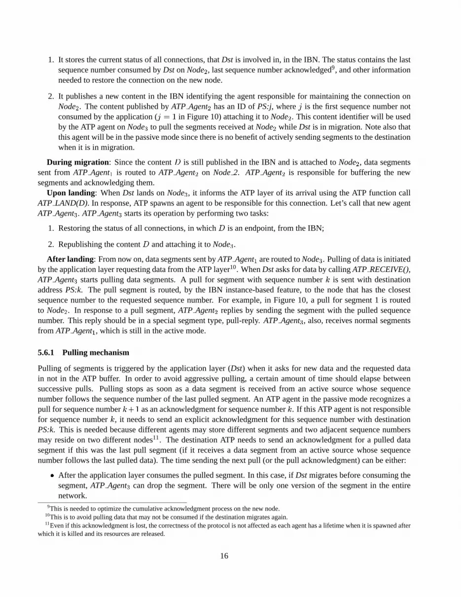
1. It stores the current status of all connections, thatDst is involved in, in the IBN. The status contains the lastsequence number consumed byDst onNode2, last sequence number acknowledged9, and other informationneeded to restore the connection on the new node.
2. It publishes a new content in the IBN identifying the agentresponsible for maintaining the connection onNode2. The content published byATP Agent2 has an ID ofPS:j, wherej is the first sequence number notconsumed by the application (j = 1 in Figure 10) attaching it toNode2. This content identifier will be usedby the ATP agent onNode3 to pull the segments received atNode2 while Dst is in migration. Note also thatthis agent will be in the passive mode since there is no benefitof actively sending segments to the destinationwhen it is in migration.
During migration : Since the contentD is still published in the IBN and is attached toNode2, data segmentssent fromATP Agent1 is routed toATP Agent2 on Node2. ATP Agent2 is responsible for buffering the newsegments and acknowledging them.
Upon landing: WhenDst lands onNode3, it informs the ATP layer of its arrival using the ATP function callATP LAND(D). In response, ATP spawns an agent to be responsible for this connection. Let’s call that new agentATP Agent3. ATP Agent3 starts its operation by performing two tasks:
1. Restoring the status of all connections, in whichD is an endpoint, from the IBN;
2. Republishing the contentD and attaching it toNode3.After landing : From now on, data segments sent byATP Agent1 are routed toNode3. Pulling of data is initiated
by the application layer requesting data from the ATP layer10. WhenDstasks for data by callingATP RECEIVE(),ATP Agent3 starts pulling data segments. A pull for segment with sequence numberk is sent with destinationaddressPS:k. The pull segment is routed, by the IBN instance-based feature, to the node that has the closestsequence number to the requested sequence number. For example, in Figure 10, a pull for segment 1 is routedto Node2. In response to a pull segment,ATP Agent2 replies by sending the segment with the pulled sequencenumber. This reply should be in a special segment type, pull-reply. ATP Agent3, also, receives normal segmentsfrom ATP Agent1, which is still in the active mode.
5.6.1 Pulling mechanism
Pulling of segments is triggered by the application layer (Dst) when it asks for new data and the requested datain not in the ATP buffer. In order to avoid aggressive pulling, a certain amount of time should elapse betweensuccessive pulls. Pulling stops as soon as a data segment is received from an active source whose sequencenumber follows the sequence number of the last pulled segment. An ATP agent in the passive mode recognizes apull for sequence numberk+1 as an acknowledgment for sequence numberk. If this ATP agent is not responsiblefor sequence numberk, it needs to send an explicit acknowledgment for this sequence number with destinationPS:k. This is needed because different agents may store different segments and two adjacent sequence numbersmay reside on two different nodes11. The destination ATP needs to send an acknowledgment for a pulled datasegment if this was the last pull segment (if it receives a data segment from an active source whose sequencenumber follows the last pulled data). The time sending the next pull (or the pull acknowledgment) can be either:� After the application layer consumes the pulled segment. Inthis case, ifDst migrates before consuming the
segment,ATP Agent3 can drop the segment. There will be only one version of the segment in the entirenetwork.
9This is needed to optimize the cumulative acknowledgment process on the new node.10This is to avoid pulling data that may not be consumed if the destination migrates again.11Even if this acknowledgment is lost, the correctness of the protocol is not affected as each agent has a lifetime when it isspawned after
which it is killed and its resources are released.
16

� As soon as the ATP layer receives the pulled data (beforeDst consumes it). In this case, ifDst migratesbefore consuming the segment,ATP Agent3 has to maintain it in its buffer since there is no guarantee thatATP Agent2 would maintain it after receiving an acknowledgment for thelast pull). There may be differentcopies of the same segment in the network since acknowledgments can be lost in the network.
5.6.2 Multiple Migrations
Figure 11 shows the operation of the ATP protocol when the destination makes multiple migrations fromNode2 toNode3 and finally toNode4. This is a direct extension to the case described in the previous section. It is importantto notice two things here:
1. The ATP layer inNode3, when it received the pull for segment 2, created a pull acknowledgment for segment1. This is consistent with our pull policy, as described in Section 5.6.1,Node3 is not responsible for segment1.
2. The ATP layer inNode4, when it received the pulled segment 2, created a pull acknowledgment for it. Again,this is consistent with our active mode policy as segment 3 was received using the active mode.
5.7 Reclaiming Network Resources
Since the ATP protocol uses the IBN to map content ID’s to nodes and to store the status of the connectionduring migration, it becomes important to reclaim the network resources used by ATP when they are not needed.The leasing feature of the IBN means that if an endpoint of theconnection or an agent is crashed (or does notappear for an extended period of time) all its resources willbe deleted from the IBN as they will not be refreshed.
ATP also need to free resources that are used by agents in the nodes (e.g., the sending buffers). When an agentreceives acknowledgement for all of its buffered segments,it can release the maintained buffer and die safely.Also, each agent has a lifetime assigned to it when it is created. If the lifetime of an agent elapses before receivingacknowledgment for all the segments in its buffer, the agentdies immediately.
6 Applications
The ATP protocol is essential to applications requiring reliable communication with endpoints migration. Ex-amples include surveillance applications in sensor networks where a target is tracked using cameras on energyconstrained sensors. To conserve energy, it is important totrack the target using only one camera and to changethe active camera as the target moves. It is also critical notto lose any data as the active camera changes. ATPbecomes handy in such an environment. An ATP-aware application can be run on the node controlling the activecamera. This application is responsible for sending the captured video frames to the command center. When theactive camera changes, the ATP-aware application migratesto the new node. No data is lost during migration asthe ATP provides a reliable connection between the source endpoint (sensor node) and the destination endpoint(command center). In such an
Another possible application is parallel download of largefiles. A destination endpoint representing the file canbuffer a part of the file on one node and migrates to another node where it buffers another part. This buffering-migration cycles continues until the entire file is bufferedat different nodes. The ATP agent at each node isresponsible for transferring the part of the file in its buffer.
Future applications, e.g. the CarNet [] project can also benefit from the service provided by the ATP layer. (Dr.Liviu, please complete this part and add any other relevant application).
17

Src Dst
Node 2 Node 1
IBN_Publish (D)
IBN_Publish (AS:0)
1
2
IBN_Send (D, Data 1 )
IBN_Send (D, Data 2 )
IBN_Send (AS:1,Ack 1 ) )
Node 3
ATP_Land (S)
IBN_Publish (D)
ATP_Migrate()
IBN_Send (D, Data 3 )
IBN_Send (AS:2,Ack 2 ) )
.
.
.
3 Node 4 ATP_Land (S)
IBN_Publish (D)
ATP_Migrate()
IBN_Publish (PS:1)
Dst
IBN_Publish (PS:2)
Dst
IBN_Send (AS:3,Ack 3 ) )
IBN_Send(PS:1,Pull(1))
IBN_Send(D, Pull-Data 1 )
IBN_Send(PS:2,Pull(2))
IBN_Send(D, Pull-Data 2 )
IBN_Send(PS:2,Pull-Ack(2))
IBN_Send(PS:1,Pull-Ack(1))
2
1
3
Data consumed by the endpoint
Data received from the endpoint
Figure 11. Multiple destination migrations
18
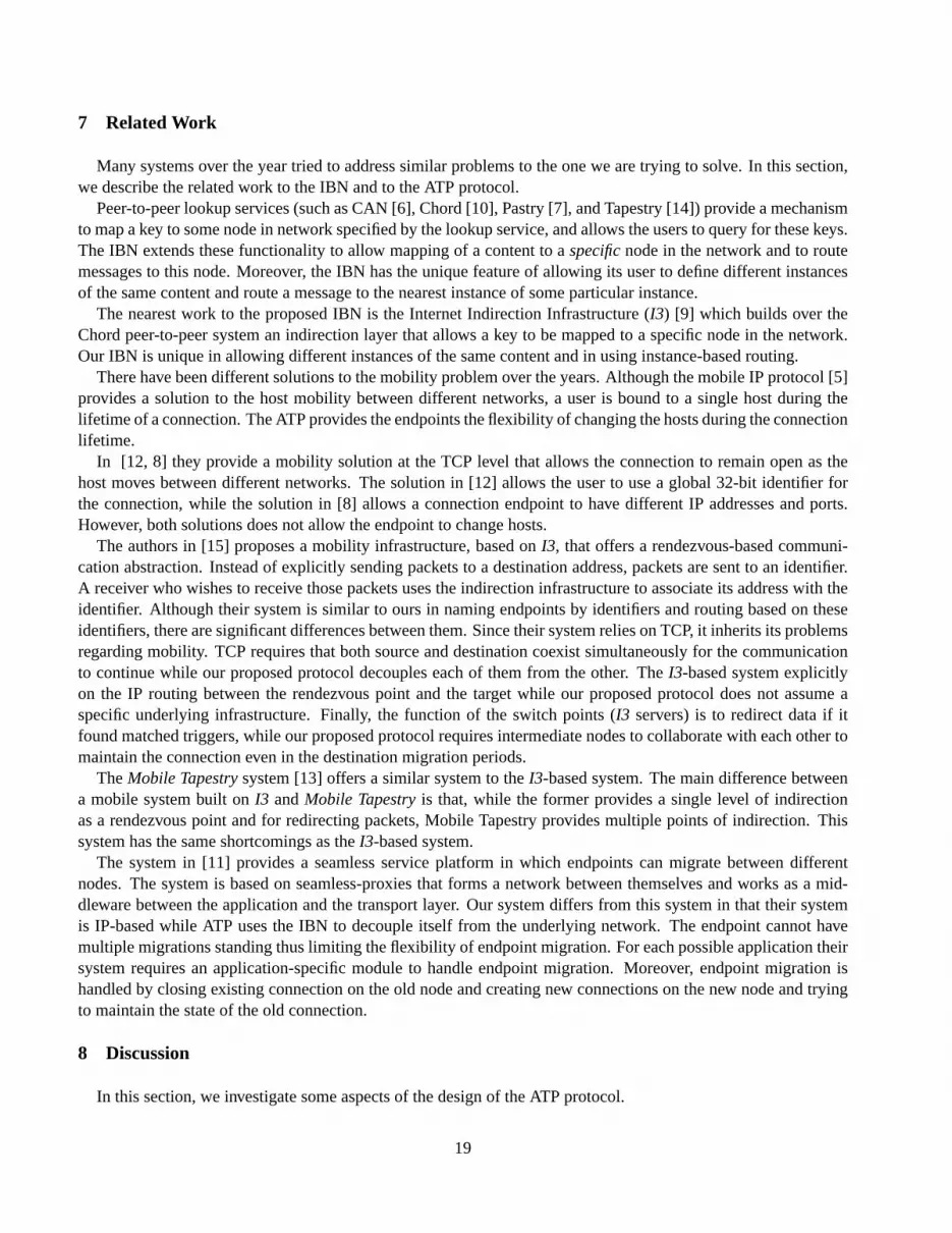
7 Related Work
Many systems over the year tried to address similar problemsto the one we are trying to solve. In this section,we describe the related work to the IBN and to the ATP protocol.
Peer-to-peer lookup services (such as CAN [6], Chord [10], Pastry [7], and Tapestry [14]) provide a mechanismto map a key to some node in network specified by the lookup service, and allows the users to query for these keys.The IBN extends these functionality to allow mapping of a content to aspecificnode in the network and to routemessages to this node. Moreover, the IBN has the unique feature of allowing its user to define different instancesof the same content and route a message to the nearest instance of some particular instance.
The nearest work to the proposed IBN is the Internet Indirection Infrastructure (I3) [9] which builds over theChord peer-to-peer system an indirection layer that allowsa key to be mapped to a specific node in the network.Our IBN is unique in allowing different instances of the samecontent and in using instance-based routing.
There have been different solutions to the mobility problemover the years. Although the mobile IP protocol [5]provides a solution to the host mobility between different networks, a user is bound to a single host during thelifetime of a connection. The ATP provides the endpoints theflexibility of changing the hosts during the connectionlifetime.
In [12, 8] they provide a mobility solution at the TCP level that allows the connection to remain open as thehost moves between different networks. The solution in [12]allows the user to use a global 32-bit identifier forthe connection, while the solution in [8] allows a connection endpoint to have different IP addresses and ports.However, both solutions does not allow the endpoint to change hosts.
The authors in [15] proposes a mobility infrastructure, based onI3, that offers a rendezvous-based communi-cation abstraction. Instead of explicitly sending packetsto a destination address, packets are sent to an identifier.A receiver who wishes to receive those packets uses the indirection infrastructure to associate its address with theidentifier. Although their system is similar to ours in naming endpoints by identifiers and routing based on theseidentifiers, there are significant differences between them. Since their system relies on TCP, it inherits its problemsregarding mobility. TCP requires that both source and destination coexist simultaneously for the communicationto continue while our proposed protocol decouples each of them from the other. TheI3-based system explicitlyon the IP routing between the rendezvous point and the targetwhile our proposed protocol does not assume aspecific underlying infrastructure. Finally, the functionof the switch points (I3 servers) is to redirect data if itfound matched triggers, while our proposed protocol requires intermediate nodes to collaborate with each other tomaintain the connection even in the destination migration periods.
TheMobile Tapestrysystem [13] offers a similar system to theI3-based system. The main difference betweena mobile system built onI3 andMobile Tapestryis that, while the former provides a single level of indirectionas a rendezvous point and for redirecting packets, Mobile Tapestry provides multiple points of indirection. Thissystem has the same shortcomings as theI3-based system.
The system in [11] provides a seamless service platform in which endpoints can migrate between differentnodes. The system is based on seamless-proxies that forms a network between themselves and works as a mid-dleware between the application and the transport layer. Our system differs from this system in that their systemis IP-based while ATP uses the IBN to decouple itself from theunderlying network. The endpoint cannot havemultiple migrations standing thus limiting the flexibilityof endpoint migration. For each possible application theirsystem requires an application-specific module to handle endpoint migration. Moreover, endpoint migration ishandled by closing existing connection on the old node and creating new connections on the new node and tryingto maintain the state of the old connection.
8 Discussion
In this section, we investigate some aspects of the design ofthe ATP protocol.
19

8.1 Fault Tolerance
In a dynamic network environment, maintaining a reliable communication is a great challenge. We have twotypes of faults: node failure and link failure.
ATP can rely on the IBN route discovery service to alleviate the link-failure problem. The node-failure problemmanifests itself in three situations. First, the failed node could be responsible for a set of mapped contents.Second, the node could be the host node for an agent responsible for some segments. Third, that node could bethe destination endpoint for a stream of network segments.
To solve the first subproblem, ATP can rely on the underlying IBN replication mechanisms to transparentlyprovide backup nodes for each mapped content. To solve the second subproblem, the ATP should rely on its ownreplication mechanism. This issue is still open. One possible solution is to make the ATP state (including buffers)stored in the IBN network and depend on the IBN replication mechanism. The third subproblem is a catastrophiccase as it may lead to the destruction of the application state. If the node failure affects only the networkingstack and not the application layer, then we can apply the solution of subproblem 2 to this subproblem. The IBNmay need to do a remapping of all content ID’s that were published at the failed node to a new default node sothat segments sent during the recovery period are buffered and the source can continue its operations withoutinterruption of service.
8.2 Active/Passive Policy
Any sending ATP agent can take the decision to dynamically switch between the active and passive modesaccording to a certain policy. One possible policy is to consider the current state of network resources (e.g. bufferlength, CPU load, available bandwidth, or remaining energy) locally or even globally (which requires the neighbornodes to cooperate is someway). The decision could also be left to the application and can be negotiated duringthe connection establishment. The challenge is to determine who, when, and how to take the switching decision.This needs to be tested experimentally.
It is natural for the source agents to be in the active mode, while it is more appropriate for the destination agentsthat buffer data from the source to be in the passive mode waiting for data to be pulled from them as discussedbefore.
Note that when we allow destination agents to be in the activemode, there may be more than an active sourceresponsible for the same data segments. This may lead to deleting a data segment from the network without beingconsumed by the destination. This is because acknowledgments from the past may be delayed for any arbitraryperiod in the network and arrive at a wrong destination. Figure 12 shows an example for such a scenario. Wesuggest to different solutions to this problem:
1. send the acknowledgment to the source that generated the segment. This solution has the disadvantageof making the destination keep track of the source of each segment, reducing the decoupling between thesource and the destination.
2. use epoch numbers protect from aging acknowledgments.
8.3 Security
Allowing ATP to act on behalf of the source or the destinationopens many interesting security issues. We planto investigate these issues thoroughly after setting up theinitial design.
Security is an important issue is distributed systems like ATP. The security problem is three-fold: privacy,authenticity and trust. One solution to privacy is to apply public-key cryptography, such as the Diffe-Hellman key-exchange technology [3], to communications between endpoints. Moreover, the platform’s security is no weakerthan that of any other distributed platform.
20

ATP_Land (D)
Ds t
Node 1
Node 3
IBN_Publish (AS:0)
IBN_Publish (D)
IBN_Send (D, Data 1 )
IBN_Send(D, Data 2 )
IBN_Send(AS:1, Ack 1 )
IBN_Send(AS:2, Ack 2 )
ATP_Migrate()
1
2
IBN_Send(PS:1,Pull(1))
Node 2
IBN_Publish (PS:1)
IBN_Republish (D)
IBN_Send(D, Pull-Data 1 )
Src Dst
Data received from the endpoint
IBN_Publish (AS:2) Switch to active
mode
Ack delayed in the network
IBN_Send(AS:2, Ack 2 )
Segment 2 removed from ATP buffer
Segment 2 removed from ATP buffer
Segment 2 retransmitted
Figure 12. A delayed acknowledgment in the network can lead deleting a data segment from thenetwork without being consumed by the endpoint
21

Authentication is difficult in a dynamic network environment because the presence of reliable and always avail-able certificate authorities (CAs) cannot be assumed. Although there is a tradeoff between the decentralizationof a CA [2] and the CA’s effectiveness, this does place a limiton the level of security possible with our system.However, there are some easy solutions to the authentication of nodes on the user side; e.g., by inserting secure ICcards or communicating directly with each other through IrDA ports, nodes can be identified with certainty andkeys can then be safely exchanged.
There have been some initial proposals for distributed trust systems [4]. These solutions can be directly incor-porated into our system providing a solution to the trust issue.
8.4 End-to-End Semantics
In ATP, agents act on behalf of both source and destination endpoints to guarantee the delivery of the segmentsincluding control segments, e.g. close connection request. In traditional reliable transport protocols, e.g. TCP,the source has to wait until it receives an acknowledgment for the close connection request after successfullytransmitting all the data segments. In addition to coping with this traditional end-to-end semantic, ATP could shiftthe burden of waiting for such acknowledgment from the source to the ATP agents. Eliminating such waiting time,which is signified by the migration of the endpoints, allows the source to terminate earlier while the destinationis still in the middle of the connection. Although this feature violates the traditional end-to-end semantics of thereliable connection, it could be very useful for certain application types.
9 Conclusions
In this report, we presented the design of theAutonomous Transport Protocol. ATP provides a reliable streambetween two endpoints regardless of their physical location in the network. We also introduced theInstance-BasedNetworkingas an extension to the currentpeer-to-peerlookup services.
In an instance-based network, the network provides the flexibility of having different instances of the samecontent. It is up to the user of the IBN network to define the relation between these instances. An IBN provides itsuser with the ability to map a content to a particular node. Application endpoints, defined by contents, can sendmessages to other content-identified endpoints. Routing inthe IBN is instance-based; the IBN can route a messageto a specific content instance or to the nearest instance, if no exact match is found for the destination contentinstance. The semantics of different instances and the relation between them are assigned by the application usingthe IBN. Moreover, the IBN replicates the stored contents inorder to provide fault tolerance and IBN nodes alongthe query path can cache a content to provide fast answers to future queries.
The ATP protocol allows the endpoints to migrate between different hosts. At each node that an endpoint hasdata, the ATP spawns an agent that becomes responsible for the connection on this node. Each instance is treatedas an instance of the same content endpoint. ATP uses the underlying IBN to route the data and acknowledgmentto the correct agent.
Data is transfered by a combination ofactiveandpassiveoperations, where the ATP layer of a node can decidewhether to actively push the data to the destination or to passively wait for the destination endpoint to pull the data.The decision to whether to use the active or passive modes canbe taken by a local policy on the node running theATP protocol. This decision may be based on the current stateof network resources (e.g. buffer length, CPU load,available bandwidth, or remaining energy). The decision could also be left to the application and can be negotiatedduring the connection establishment.
The ATP protocol is essential to applications requiring reliable communication with endpoints migration. Cur-rent applications can be made ATP-aware with minor modification to their code. We believe that the ATP protocolis a corner stone for ubiquitous computing to become a reality.
22

References
[1] Mobile Ad Hoc Networking (MANET): Routing Protocol PerformanceIssues and Evaluation Considerations.RFC2501, January 1999.
[2] R. Canetti, S. Halevi, and A. Herzberg. Maintaining authenticated communication in the presence of break-ins.Journalof Cryptology, 13:61–105, 2000.
[3] W. Diffe and M. Hellman. New Direction in Cryptography.IEEE Transaction on Information Theory, IT-22(6):644–654, 1976.
[4] S. Lee, R. Sherwood, and B. Bhattacharje. Cooperative Peer Groups in NICE. InProceedings of IEEE Infocom 2003,2003.
[5] C. Perkins. IP Mobility Support.RFC 2002, October 1996.[6] S. Ratnasamy, P. Francis, M. Handley, R. Karp, and S. Shenker. A Scalable Content-Addressable Network. InPro-
ceedings of ACM SIGCOMM 2001, 2001.[7] A. Rowstron and P. Druschel. Pastry: Scalable, distributed Object Location and Routing for Large-Scale Peer-to-Peer
Systems. InProceedings of IFIP/ACM International Conference on Distributed Systems Platforms (Middleware), pages329–350, Heidelberg, Germany, November 2001.
[8] A. C. Snoeren and H. Balakrishnan. TCP Connection Migration.Internet Draft, November 2000.[9] I. Stoica, D. Adkins, S. Zhaung, S. Shenker, and S. Surana. Internet Indirection Infrastructure. InProceedings of ACM
SIGCOMM 2002, pages 73–86, Pittsburgh, PA, August 2002.[10] I. Stoica, R. Morris, D. Karger, M. F. Kaashoek, and H. Balakrishnan. Chord: A Scalable Peer-to-peer Lookup Service
for Internet Applications. InProceedings of ACM SIGCOMM 2001, San Diego, September 2001.[11] K. Takasugi, M. Nakamura, S. Tanaka, and M. Kubota. Seamless Service Platform for Following a User s Movement in
a Dynamic Network Environment. InProceedings of the First IEEE International Conference on PervasiveComputingand Communications (PerCom 03), March 2003.
[12] B. Zhang, B. Zhang, and I. Wu. ETCP: Extended TCP for Mobile IP Support.Internet Draft, 1998.[13] B. Y. Zhao, A. D. Joseph, and J. D. Kubiatowicz. Supporting rapid mobility via locality in an overlay network. Technical
Report UCB/CSD-02-1216, UC Berkeley, November 2002.[14] B. Y. Zhao, J. D. Kubiatowicz, and A. D. Joseph. Tapestry: An infrastructure for fault-tolerant wide-area location and
routing. Technical Report UCB/CSD-01-1141, UC Berkeley, April 2001.[15] S. Zhuang, K. Lai, I. Stoica, R. Katz, and S. Shenker. Host Mobility Using an Internet Indirection Infrastructure. In
Proceedings of MobiSys 2003, 2003.
Appendix A: ATP-Application Interface
The ATP interface to the application layer adds two functioncalls to the TCP socket-programming interface(“Migrate” and “Land”) besides minor changes to the other calls. Here, we briefly review those calls. For thefollowing functions, the ”Address” structure has two fields: contentandport, both are given and arbitrarily selectedby the application. Thecontentis equivalent to the IP address in the current IP networks andthe port is equivalentto the current port.� SOCKET(Type): Creates a new socket and returns the socket file descriptor.The argumentTypespecifies
the socket type; which could be one of two: streams, and datagrams. In our initial design, we are concernedonly with streams.� BIND(Socket, Addr): BindsSocketto the port specified in the address structureAddr.� CLOSE(Socket): Shutdowns the communication from the caller side specifiedby Socket.� CONNECT(Socket, DstAddr): Connects theSocketto the remote socket bound to the addressDst Addr.� SEND(Socket, Msg): Sends the messageMsgthrough the connection specified bySocket.� RECEIVE(Socket, Buffer, Length): Requests ATP to deliver data of length at mostLengthsent toSocket.
23

� LISTEN(Socket): Causes the incoming ATP connection request to socketSocketto be handled and thenqueued for acceptance by the program.� ACCEPT(Socket, SrcAddr): Dequeues the next connection on the queue forSocket.� MIGRATE(): Informs ATP that the application decided to migrate requiring ATP to maintain all associatedsocket connections.� LAND(Content): Restores all sockets that were bound toContentname before migration. This function iscalled when the migrating application land on a new physicalnode.
Appendix B: IBN Interface with Upper Layers
An IBN should provide the following API’s12:� PUBLISH(ContentID, ContentData, NodeID): Publishes (or announces) a content to the IBN network.Con-tentID is the unique identifier of the content to be published.ContentDatais the data, corresponding to thatcontent, which will be stored in the network.NodeIDis the identifier of a particular node in the IBN to holdthe content. NodeID can be omitted; in that case, the IBN is free to store the content in any node (this is thefunction provided by the current peer-to-peer lookup services).� REPUBLISH(ContentID, NodeID): Republishes the content whoseID is ContentIDby changing its locationin the IBN to the node whoseID is NodeID.� REMOVE(ContentID): Removes a content that the user has previously published inthe IBN.� SEND(Message, ContentID): Informs the IBN to send a segmentMessageto a contentContentIDpublishedto the IBN.� RETRIEVE(ContentID): Retrieves a copy of the data corresponding to a previously published content whoseID is ContentID.� DELIVER (SrcContentID, DstContentID, Message): Acts as an up call from the IBN to the upper layer tonotify the user of the arrival of a messageMessagedestined to it.SrcContentIDandDstCOntentIDare theID of source and destination contents respectively.
Appendix C: IBN Implementation
We propose an implementation that extends the current peer-to-peer lookup services. When the user asks theIBN to publish the content instance(X : i1; :::; in) on a certain nodeA, the IBN uses the underlying peer-to-peerlookup service to find the nodeB where the contentX should be mapped to. The IBN layer uses the nodeB tostore a mapping between the instance(X : i1; :::; in) and the nodeA in a data structureD . Note that nodeB willbe responsible for all instances of the same contentX.
If an application wants to send a message to an instance(X : j1; :::; jn), the IBN routes the message usingthe underlying peer-to-peer network to the nodeB. The IBN layer on nodeB checks the data structureD to findthe nearest instance to the destination instance identifier(j1; :::; jn) and the nodeC where this instance is stored(using the routing algorithm is Section 4. The IBN finally forwards the message to nodeC. Other API functionsdescribed in Appendix B can be obtained in a way similar to theabove two operations.
The proposed implementation has the following features:12We useContentIDhere to refer to the full name of the content instance
24

A
E
D
C
B
R.T. … ... … ...
M:1,3 E M:3,2 H
P .C . … … ...
R.T. … ... … …
P .C . M:1,3
… ...
R.T. … ... … ... … ...
P .C . … ...
Z:1,5 ...
1
2
3
P .C . …
R.T . …
IBN Node Message
Routing Direction
Routing Table Published Contents
Figure 13. IBN routing: a message from Z : 1; 5 destined to M : 2; 3 is routed to M : 1; 3� A single node is responsible for all instances of a particular content. This allows for efficient algorithms forfinding the nearest instance to a given instance while routing a message.� Different contents are mapped to different nodes based on the algorithm used by the underlying peer-to-peerlookup service. In general, peer-to-peer lookup services assigns keys (content IDs) to nodes uniformly sothat no node becomes overloaded and there are techniques to differ the number of keys on each node basedon its actual load.� The proposed implementation is independent of the underlying peer-to-peer lookup services. The imple-menter can choose from different peer-to-peer lookup services, for example, based on the efficiency of thelookup operation (some peer-to-peer lookup services, suchas Pastry [7], takes network locality into theirrouting algorithm.)
Figure 13 shows an example for the routing in the IBN. A message fromZ : 1; 5 destined toM : 2; 3 is routedtoM : 1; 3. The message is first routed toD (the node responsible for the mapping of the instances ofM ) usingthe underlying peer-to-peer routing mechanism (steps 1 and2). When the messages reaches nodeD, it checks itsforwarding table and redirects it to the node responsible for the closest instance (NodeE).
Appendix D: Range Acknowledgment
In this appendix, we describe a technique for range acknowledgment that can enhance the performance of theATP protocol. Performance evaluation experiments need to be conducted to assess the benefit of this technique.
25

D.1 Overview
A range acknowledgment acknowledges a range of sequence numbers. It is identified by two sequence numbers,the starting sequence number of the acknowledged range and the ending sequence number of the acknowledgedrange.
Let ACK(i:j) be a range acknowledgment fromi to j. ACK(i:j) is sent with a destination addressAS:j. IfATP Agent2 receives all data segments in sequence, it sends backACK(1:k), where 1 is the first sequence numberreceived andk is the last sequence number received. IfATP Agent2 receives segments out of sequence, we canhave different acknowledgment policies:
1. Sending multiple acknowledgment for the multiple ranges. For example, ifATP Agent2 has sequence num-ber rangesi1 to i2, i3 to i4, i5 to i6, it sendsACK(i1 : i2), ACK(i3 : i4), andACK(i5 : i6). Each of theseacknowledgments is sent to a different destination addressdepending on its range:ACK(i1 : i2) is sent toAS:i2, ACK(i3 : i4) is sent toAS:i4, while ACK(i5 : i6) is sent toAS:i6.
2. Sending acknowledgment for the first range only with a possibility of retransmission of the segments wealready received. This is equivalent to the cumulative acknowledgment mechanism.
3. Sending acknowledgment for each segment we receive. In this case we do not need the range (or cumulative)acknowledgment mechanism.
4. Sending acknowledgment for the range that the last received segment falls in.
5. Sending two range acknowledgments. One for the first range(corresponding to cumulative acknowledg-ment) and the second is for the range in which the last segmentwas received. The first range acknowledg-ment is sent to trigger the fast retransmission mechanism (imported from TCP).
These different policies do not affect the correctness of the ATP protocol. In all cases, the source will time out,retransmit the segment, and dies if it does not receive any acknowledgment for a certain period of time. The mainfactors affecting the choice of the acknowledgment policy are:� avoiding retransmission of already received segments.� avoiding sending unnecessary acknowledgments.
Sending of acknowledgments is triggered by either:� expiration of a timer (or alternatively, reception of a certain amount of data): in this case, the ATP protocolsends a range acknowledgment for the first consecutive rangethat it is responsible for (similar to cumulativeacknowledgment).� reception of a segment out of order: in this case, the ATP protocol can choose one of the above policies. Forthe rest of this appendix, we will stick to option 4 (acknowledging the range that the last received segmentfalls in).� reception of a duplicate segment: in this case, the ATP protocol sends an acknowledgment for this duplicatesegment.
26

IBN_Send (D, Data 4 )
Src
Ds t
Node 1 Node 2
ATP_Land (S)
IBN_Publish (AS:0) IBN_Publish (D)
IBN_Send (D, Data 1 )
IBN_Send(AS:1, Ack(1:1))
IBN_Send(AS:2, Ack(1:2))
Node 3
ATP_Migrate()
1
2
4
3
IBN_Publish (AS:6)
IBN_Send(AS:3, Ack(1:3))
6
7
IBN_Send(D, Data 6 )
IBN_Send(D, Data 7 )
IBN_Send (AS:7, Ack(1:7)*)
IBN_Send(D, Data 5 )
IBN_Send (AS:5, Ack(1:5)*)
8
9
IBN_Send(D, Data 8 )
IBN_Send (D, Data 9 )
IBN_Send(AS:9, Ack(1:9))
IBN_Send(AS:6, Ack(6:6))
IBN_Send(AS:7, Ack(6:7))
Src
IBN_Send (D, Data 2 )
IBN_Send (D, Data 3 )
5
IBN_Send(AS:4, Ack(1:4))
Data consumed by the endpoint
Data received from the endpoint
Packet 5 fills the gap
Figure 14. ATP range acknowledgment27

D.2 Forward Acknowledgment Flag
Since we may have different agents acting on behalf of the source, a range acknowledgment may cover differentnodes. However, a single acknowledgment will be routed to a single node. Therefore, we need a mechanism bywhich a single range acknowledgment sent by the destinationcould reach all the nodes covered by it. We proposethe Forward Acknowledgment Flag(FAF) as a solution to this problem. Figure 14 shows an example of thetechnique (FAF indicated by * in the acknowledgment). When the destinationreceives a segment with a sequencenumber that fills the gap between two ranges (segment 5 in the figure), it sets theFAF in the corresponding rangeacknowledgment. When a sending agent receives an acknowledgment with theFAF set, it checks whether a newrange acknowledgment should be generated with a new range that is not covered by the current agent. If a newacknowledgment is generated, itsFAF is set and the process is repeated.
D.3 Multiple Destination Migration
In this section, we discuss the multiple destination migration case when we have the range acknowledgmentmechanism. The problem of destination migration becomes more difficult whenDst migrates another time beforefinishing the pulling process for the first migration. In thiscase,Dst may leave behind some segments in thereceiving buffer ofATP Agent2 and some other segments inATP Agent3. Because of the time of instability in theIBN, after republishing an old content or publishing a new content, the segments buffered in both agents may notbe in sequence.
For example, consider the scenario depicted in Figure 15. Let the ATP agents responsible for this connectionon Node2, Node3, andNode4 beATP Agent2, ATP Agent3, andATP Agent4 respectively. Because of the loss ofsegment 3 (step A), it does not reachATP Agent2. WhenATP Agent1 retransmits segment 3 (step B),ATP Agent3has republished the contentD and attached it toNode3 (step C), therefore segment 3 is routed toATP Agent3instead ofATP Agent213. On the other hand, segment 4 reachesATP Agent2 successfully and is acknowledged(step D), therefore, it is not retransmitted byATP Agent1. ATP Agent3 starts pulling segments fromATP Agent2.It pulls segments 1 and 2 successfully (steps E and F). WhenDst migrates fromNode3 to Node4 (step G) afterconsuming segment 1 but before consuming segment 2. Therefore, ATP Agent3 acknowledges segment 1 anddrops segment 2. To this point,ATP Agent2 is buffering segments 1, 2, and 4; andATP Agent22 is bufferingsegments 3 and 5. Upon the second migration ofDst, ATP Agent22 publishesPS:3(step H).
WhenATP Agent4 restores the connection status, it knows that the next sequence number to be consumed byDstis 2. Therefore, uponDst’s request of new data,ATP Agent4 pulls segment 2 (step I). This pull segment reachesATP Agent2, which responds by sending a pull-reply with the required segment (step J). Similarly, segment 3is pulled. The difference is that the pull segment in this case reachesATP Agent3 instead ofATP Agent2 sinceATP Agent3 publishedPS:3(step K). The problem occurs whenATP Agent4 pulls segment 4. The pull segmentfor segment 4 hasPS:4as its destination address, and hence reachesATP Agent3 (step L) , which does not haveit! Actually, a pull segment for segment 4 will never reachATP Agent2.
As a solution to this problem, we propose thatATP Agent3 when receiving a pull for segment 4, it removes thecontentPS:3from the IBN and publishes, instead, contentPS:5, where 5 is the next sequence number it has (stepM). ATP Agent3 should also forward the pull segment. Doing so,ATP Agent4 will be able to pull segments 4 and5 correctly. Publishing contentPS:5instead ofPS:3is not performed before receiving pull-acknowledgment forsegment 3.
Another problem occurs if segment 4 arrives atATP Agent3 after publishingPS:5 instead ofPS:3? That canhappen since segment 4 might have been in its route toATP Agent3 when the latter received the pull for it. Becauseof the high dynamics in our environment, we have to take precautions for such intricate situations. In this situation,
13Note that this cannot happen in the case of cumulative acknowledgment as segments will always be in sequence
28

A
ATP_Land (S)
ATP_Migrate()
Node 1
Node 3
IBN_Publish (AS:0)
IBN_Publish (D)
IBN_Send (D, Data 1 )
IBN_Send (AS:2, Ack(1:2))
Node 4
ATP_Migrate()
1
2
5
3
IBN_Send(D, Data 3 )
IBN_Send(AS:3, Ack(3:3)) IBN_Send(PS:1, Pull(1))
Node 2
IBN_Send (D, Data 3 )
4 IBN_Publish (PS:1)
IBN_Republish (D)
IBN_Send(D,Pull-Data 1 )
IBN_Send (D, Data 5 )) 1
IBN_Send(AS:5, Ack(5:5))
Dst
IBN_Publish (PS:3)
ATP_Land (S) IBN_Send (D, Data 5 )
2
IBN_Republish (D)
IBN_Unpublish (S:3) IBN_Publish (PS:5)
IBN_Send(AS:5, Ack(5:5))
Src
IBN_Send(AS:4, Ack(4:4))
Dst
IBN_Send (D, Data 2 )
IBN_Send (D, Data 4 )
Dst
IBN_Send(PS:2, Pull(2))
IBN_Send(D,Pull-Data 2 )
Pull not acknowledged
IBN_Send(S:2, Pull-Ack(2))
IBN_Send(D,Pull-Data 2 )
IBN_Send(PS:3, Pull(3))
IBN_Send(D,Pull-Data 3 )
3
IBN_Send(PS:4, Pull(4))
IBN_Send(PS:4, Pull(4))
IBN_Send(D,Pull-Data 4 )
4
IBN_Send(PS:4, Pull-Ack(4))
B
C
D
E
F
G
IBN_Send(PS:2, Pull(2)) I
J
K
L
M
Dropped segment
Data consumed by the endpoint
Data received from the endpoint
H
Figure 15. Multiple migration with range acknowledgment29

we propose thatATP Agent3 has to remove the contentPS:5and publishPS:4, instead. If another agent is alreadyresponsible for segment 4 (i.e if the IBN rejects the publishing operation) then segment 4 can be safely ignored.
To summarize, an agent receiving a pull segment for a sequence number not in its buffer should unpublish itscurrent ID and republishes an ID containing the next sequence number, in the agent buffer, after the one in the pullsegment. It should also retransmit the received pull segment. If an agent receives a segment with sequence numberbefore the sequence number in its current published ID, it should try to change its published ID to contain thesequence number in the received segment. If the publishing operation fails, the agent can safely drop the receivedsegment.
D.4 Closing Remarks
The range acknowledgment mechanism has the advantage of reducing the retransmission of already receivedsegments. However, it may produce unnecessary acknowledgments. Another problem is that when a range ac-knowledgment with theFAF is lost, this acknowledgment will not be reproduced again (as its range has alreadybeen filled). Moreover, handling the case of multiple destination migrations may involve publishing and unpub-lishing operations. We believe that range acknowledgment is still an effective mechanism to enhance performanceas acknowledgment are smaller in size than data segments andthe problematic cases occurs with low probability.However, we need to verify that by experimentation.
30