detailed design study of north java corridor
TRANSCRIPT

JAPAN INTERNATIONAL COOPERATION AGENCY (JICA)
MINISTRY OF PUBLIC WORKS REPUBLIC OF INDONESIA
KATAHIRA & ENGINEERS INTERNATIONAL
DECEMBER 2006
DETAILED DESIGN STUDY OF
NORTH JAVA CORRIDOR FLYOVER PROJECT IN THE REPUBLIC OF INDONESIA
BIDDING DOCUMENT
PACKAGE I MERAK FLYOVER
BALARAJA FLYOVER
VOLUME III
SECTION VI - TECHNICAL SPECIFICATION
NO.
SDCR(5)06-090
NORTH JAVA CORRIDOR FLYOVER PROJECT
BIDDING DOCUMENTS
VOLUME III
TECHNICAL SPECIFICATIONS
The Technical Specifications describe in detail the work to be executed, the character and quality of materials and workmanship and the specific responsibilities of the Contractor that are not covered by the Conditions of Contract. The Technical Specification shall be read in conjunction with the plans and other contract documents. The Technical Specification is contained in Volume III of the Bidding Documents that compromise of the following parts:
INDONESIAN STANDARD GENERAL SPECIFICATIONS (SPESIFIKASI)
TECHNICAL SPECIFICATIONS Pertinent notes appearing in the Contract Plans or Drawings shall also be considered as part and parcel of the Technical Specifications. Such notes shall take precedence over the Indonesian Standard General Specifications. Any further amendments to the Technical Specifications and to any other Bid Document, if necessary, will be furnished to pre-qualified bidders, by means of Addenda. The “Technical Specifications”, Volume III of the Bidding Documents is composed of nine (9) Divisions, Division 1 thru 9 with each division providing the specifications of work items belonging to a particular type of work or work grouping as follows: DIVISION 1 - General
DIVISION 2 Drainage
DIVISION 3 Earthworks
DIVISION 4 Pavement and Widening of Shoulders
DIVISION 5 Granular Pavement
DIVISION 6 Asphalt Pavement
DIVISION 7 Structures
DIVISION 8 Miscellaneous
DIVISION 9 Facilities
Division 1 – General - stipulates the general requirements of the Contract, Engineer’s Facilities, Mobilization and Demobilization of Contractor’s Equipment and Facilities, and Maintenance and Protection of Traffic, (Temporary works or facilities) for the proper prosecution and completion of the project that do not necessarily become as integral part of the completed project.

Division 2 to Division 7 provides the specifications of permanent works with each part covering the items belonging to the particular type of work that it represents. The specifications for permanent work items are generally presented under five (5) distinct sections as follows:
1. Description of Work;
2. Material Requirements;
3. Construction Requirements;
4. Method of Measurement and
5. Basis of Payment
Division 8 - Miscellaneous provides the specification of permanent works regarding structures pertinent to highways, and bridges that can not be properly classified as belonging to any particular type of work as represented in Division 1 to Division 7 the Technical Specifications. Division 9 – Facilities provide the work relative to installation of facilities such as street lighting including installation of appurtenances necessary to satisfy the lighting requirements of the Project. The Section Number of the Special Work item is distinguished by placing the symbol “SS” before its designated Arabic Number. For Specifications of other special items of work not included in Volume III of the Technical Specifications of this project, the corresponding standard specification shall be deemed to apply:
• AASHTO Standard Specifications for Highway Bridges, Sixteenth Edition, 1996
• ASTM Standard Specifications • JIS Standards • JRA Specifications
Section VI Technical Specifications
TTAABBLLEE OOFF CCOONNTTEENNTTSS
Page
DIVISION 1 - GENERAL SSEECCTTIIOONN 1.1 GGEENNEERRAALL .................................................................................................................................................................. DD11-- 11
SSEECCTTIIOONN 11..22 MMOOBBIILLIIZZAATTIIOONN AANNDD DDEEMMOOBBIILLIIZZAATTIIOONN
1.2.1 General...................................................................................... D1- 4 1.2.2 Mobilization Programme............................................................ D1 - 5 1.2.3 Additional Soil Investigation....................................................... D1 - 6 1.2.4 Measurement and Payment ...................................................... D1 - 6
SSEECCTTIIOONN 11..33 EENNGGIINNEEEERR’’SS FFAACCIILLIITTIIEESS 1.3.1 General...................................................................................... D1 - 8 1.3.2 Office Furniture, Equipment and Supplies................................. D1 - 8 1.3.3 Laboratory Equipment and Apparatus....................................... D1 - 9 1.3.4 Service Vehicles for the Engineer ............................................. D1 - 9 1.3.5 Communication Equipment ....................................................... D1 - 10 1.3.6 Security and Safety of the Engineer’s Facilities ........................ D1 - 10 1.3.7 Staffing for the Engineer’s Facilities .......................................... D1 - 11 1.3.8 Photographs .............................................................................. D1 - 11 1.3.9 Measurement and Payment ...................................................... D1 - 12
SSEECCTTIIOONN 11..88 MMAAIINNTTEENNAANNCCEE AANNDD PPRROOTTEECCTTIIOONN OOFF TTRRAAFFFFIICC 1.8.1 General...................................................................................... D1 - 13 1.8.2 Protection of Works Against Traffic Damage............................. D1 - 13 1.8.3 Temporary Road or Bridge Works............................................. D1 - 13 1.8.4 Temporary Traffic Control.......................................................... D1 - 14 1.8.5 Maintenance for Traffic Safety................................................... D1 - 15 1.8.6 Basis of Payment....................................................................... D1 - 15
DIVISION 2 - DRAINAGE
SSEECCTTIIOONN 22..11 DDIITTCCHHEESS AANNDD WWAATTEERRWWAAYYSS 2.1.1 General...................................................................................... D2 - 1 2.1.2 Materials and Quality Assurance............................................... D2 - 3 2.1.3 Execution................................................................................... D2 - 3 2.1.4 Measurement and Payment ...................................................... D2 - 4
SSEECCTTIIOONN 22..22 MMOORRTTAARREEDD SSTTOONNEEWWOORRKK 2.2.1 General ....................................................................................... D2 - 6 2.2.2 Materials...................................................................................... D2 - 8 2.2.3 Construction of Mortared Stonework........................................... D2 - 9 2.2.4 Measurement and Payment ........................................................ D2 - 10
SSEECCTTIIOONN 22..33 RRCC PPIIPPEE CCUULLVVEERRTTSS,, DDIITTCCHHEESS,, MMAANNHHOOLLEESS,, CCAATTCCHH BBAASSIINNSS,, AANNDD CCOONNCCRREETTEE DDRRAAIINNSS
2.3.1 General ....................................................................................... D2 - 12 2.3.2 Sequence of Work....................................................................... D2 - 12 2.3.3 Drainage Pipes............................................................................ D2 - 13 2.3.4 U-Ditch, Manholes, Catch Basin and Headwalls......................... D2 - 14 2.3.5 Measurement and Payment ........................................................ D2 - 19
DIVISION 3 – EARTHWORKS
SSEECCTTIIOONN 33..11 CCLLEEAARRIINNGG AANNDD GGRRUUBBBBIINNGG
3.1.1 Description................................................................................. D3 - 1 3.1.2 Construction .............................................................................. D3 - 1 3.1.3 Method of Measurement............................................................ D3 - 2 3.1.4 Basis of Payment....................................................................... D3 - 3
SSEECCTTIIOONN 33..22((11)) EEXXCCAAVVAATTIIOONN 3.2(1).1 Description................................................................................. D3 - 4 3.2(1).2 Excavation Procedure ............................................................... D3 - 4 3.2(1).3 Use of Excavation Material........................................................ D3 - 5 3.2(1).4 Removal and Disposal of Unsuitable Material ........................... D3 - 5 3.2(1).5 Soft Rock ................................................................................... D3 - 5 3.2(1).6 Method of Measurement............................................................ D3 - 5 3.2(1).7 Basis of Payment....................................................................... D3 - 6
SSEECCTTIIOONN 33..22 SSTTRRUUCCTTUURREE EEXXCCAAVVAATTIIOONN
3.2.1 Description................................................................................. D3 - 7 3.2.2 Classification ............................................................................. D3 - 7 3.2.3 Groundwater.............................................................................. D3 - 7 3.2.4 Excavation ................................................................................. D3 - 8 3.2.5 Backfill and Embankment of Structures..................................... D3 - 9 3.2.6 Method of Measurement............................................................ D3 - 10 3.2.7 Basis of Payment....................................................................... D3 - 11
SSEECCTTIIOONN 33..33((11)) BBOORRRROOWW MMAATTEERRIIAALL AANNDD CCOOMMMMOONN BBAACCKKFFIILLLL
3.3(1).1 Description................................................................................. D3 - 12 3.3(1).2 Materials .................................................................................... D3 - 12 3.3(1).3 Use of Borrow Pits..................................................................... D3 - 12 3.3(1).4 Placing and Compaction............................................................ D3 - 12 3.3(1).5 Payment to Others..................................................................... D3 - 13
3.3(1).6 Method of Measurement............................................................ D3 - 13 3.3(1).7 Basis of Payment....................................................................... D3 - 13
SSEECCTTIIOONN 33..33((11))aa FFOORRMMAATTIIOONN OOFF EEMMBBAANNKKMMEENNTT AANNDD AARREEAASS OOFF FFIILLLL
3.3(1)a.1 Description................................................................................. D3 - 14 3.3(1)a.2 Sources and Use of Material ..................................................... D3 - 14 3.3(1)a.3 Construction .............................................................................. D3 - 14 3.3(1)a.4 Method of Measurement............................................................ D3 - 19 3.3(1)a.5 Basis of Payment....................................................................... D3 - 19
SSEECCTTIIOONN 33..33((11))bb WWAASSTTEE
3.3(1)b.1 Description................................................................................. D3 - 20 3.3(1)b.2 Waste Material........................................................................... D3 - 20 3.3(1)b.3 Work Requirement..................................................................... D3 - 20
SSEECCTTIIOONN 33..33((22)) SSTTRRUUCCTTUURRAALL BBAACCKKFFIILLLL 3.3(2).1 Description................................................................................. D3 - 21 3.3(2).2 Materials .................................................................................... D3 - 21 3.3(2).3 Construction .............................................................................. D3 - 21 3.3(2).4 Method of Measurement............................................................ D3 - 21 3.3(2).5 Basis of Payment....................................................................... D3 - 21
SSEECCTTIIOONN 33..33((33)) PPEERRMMEEAABBLLEE BBAACCKKFFIILLLL
3.3(3).1 Description................................................................................. D3 - 22 3.3(3).2 Materials .................................................................................... D3 - 22 3.3(3).3 Construction .............................................................................. D3 - 22 3.3(3).4 Method of Measurement............................................................ D3 - 22 3.3(3).5 Basis of Payment....................................................................... D3 - 22
SSEECCTTIIOONN SSSS 33..33((33)) SSOOIILL CCEEMMEENNTT IIMMPPRROOVVEEMMEENNTT
SS 3.3(3).1 Description................................................................................. D3 - 23 SS 3.3(3).2 Materials .................................................................................... D3 - 23 SS 3.3(3).3 Construction .............................................................................. D3 - 24 SS 3.3(3).4 Method of Measurement............................................................ D3 - 24 SS 3.3(3).5 Basis of Payment....................................................................... D3 - 24
SSEECCTTIIOONN 33..33((44)) LLIIGGHHTTWWEEIIGGHHTT EEMMBBAANNKKMMEENNTT ((EEPPSS--BBLLOOCCKKSS))
3.3(4).1 Description................................................................................. D3 - 25 3.3(4).2 Materials .................................................................................... D3 - 25 3.3(4).3 Submittals.................................................................................. D3 - 25 3.3(4).4 Quality Control Requirements ................................................... D3 - 26 3.3(4).5 Product Manufacturing Quality Assurance ................................ D3 - 27 3.3(4).6 Handling and Storing of EPS-Blocks ......................................... D3 - 28 3.3(4).7 Product Manufacturing Quality Assurance: Phase II ................. D3 - 29 3.3(4).8 Construction .............................................................................. D3 - 30 3.3(4).9 Method of Measurement............................................................ D3 - 32 3.3(4).10 Basis of Payment....................................................................... D3 - 32
SSEECCTTIIOONN 33..44((11)) SSUUBBGGRRAADDEE PPRREEPPAARRAATTIIOONN
3.4(1).1 Description................................................................................. D3 - 33 3.4(1).2 Material Requirements .............................................................. D3 - 33
3.4(1).3 Construction .............................................................................. D3 - 33 3.4(1).4 Method of Measurement............................................................ D3 - 34 3.4(1).5 Basis of Payment....................................................................... D3 - 35
SSEECCTTIIOONN SSSS 33..55((11)) MMEECCHHAANNIICCAALLLLYY SSTTAABBIILLIIZZEEDD EEAARRTTHHWWAALLLL
SS 3.5.1 Description................................................................................. D3 - 36 SS 3.5.2 Materials .................................................................................... D3 - 36 SS 3.5.3 Construction Requirements ....................................................... D3 - 39 SS 3.5.4 Method of Measurement............................................................ D3 - 41 SS 3.5.5 Basis of Payment....................................................................... D3 - 41
DIVISION 4 - PAVEMENT WIDENING AND SHOULDERS
SSEECCTTIIOONN 44..22 AAGGGGRREEGGAATTEE SSUUBBBBAASSEE
4.2.1 Description................................................................................. D4 - 1 4.2.2 Materials .................................................................................... D4 - 1 4.2.3 Construction .............................................................................. D4 - 4 4.2.4 Method of Measurement............................................................ D4 - 4 4.2.5 Basis of Payment....................................................................... D4 - 5
DIVISION 5 - GRANULAR PAVEMENT SSEECCTTIIOONN 55..11 AAGGGGRREEGGAATTEE SSUUBBBBAASSEE
5.1.1 General..................................................................................... . D5 - 1 5.1.2 Basis of Payment....................................................................... D5 - 1
DIVISION 6 - ASPHALT PAVEMENT SSEECCTTIIOONN 66..11((11)) PPRRIIMMEE CCOOAATT
6.1(1).1 Description................................................................................. D6 - 1 6.1(1).2 Materials .................................................................................... D6 - 1 6.1(1).3 Construction .............................................................................. D6 - 1 6.1(1).4 Method of Measurement............................................................ D6 - 2 6.1(1).5 Basis of Payment....................................................................... D6 - 2
SSEECCTTIIOONN 66..11((22)) TTAACCKK CCOOAATT
6.1(2).1 Description................................................................................. D6 - 3 6.1(2).2 Materials .................................................................................... D6 - 3 6.1(2).3 Construction .............................................................................. D6 - 3 6.1(2).4 Method of Measurement............................................................ D6 - 4 6.1(2).5 Basis of Payment....................................................................... D6 - 4
SSEECCTTIIOONN 66..33 BBIITTUUMMIINNOOUUSS CCOONNCCRREETTEE SSUURRFFAACCEE CCOOUURRSSEE
6.3.1 Description .................................................................................. D6 - 5 6.3.2 Materials...................................................................................... D6 - 5 6.3.3 Construction ................................................................................ D6 - 8
6.3.4 Method of Measurement ............................................................. D6 - 8 6.3.5 Basis of Payment ........................................................................ D6 - 9
DIVISION 7 - STRUCTURES SSEECCTTIIOONN 77..11 SSTTRRUUCCTTUURRAALL CCOONNCCRREETTEE
7.1.1 Description................................................................................. D7 - 1 7.1.2 Materials .................................................................................... D7 - 3 7.1.3 Mixing and Batching.................................................................... D7 - 5 7.1.4 Placement.................................................................................. D7 - 14 7.1.5 Finishing Works ......................................................................... D7 - 21 7.1.6 Field Quality Control .................................................................. D7 - 23 7.1.7 Measurement and Payment ...................................................... D7 - 26
SSEECCTTIIOONN SSSS 77..11((99)) WWAATTEERRPPRROOOOFFIINNGG OONN DDEECCKK 7.1(9).1 Description................................................................................. D7 - 28 7.1(9).2 Materials .................................................................................... D7 - 28 7.1(9).3 Submittals................................................................................... D7 - 28 7.1(9).4 Application/Construction............................................................ D7 - 28 7.1(9).5 Measurement and Payment ...................................................... D7 - 29
SSEECCTTIIOONN 77..22((99)) PPRREESSTTRREESSSSEEDD CCOONNCCRREETTEE
7.2(9).1 Description................................................................................. D7 - 30 7.2(9).2 Materials .................................................................................... D7 - 31 7.2(9).3 Construction and Quality Control............................................... D7 - 36 7.2(9).4 Pre-Tensioning Method ............................................................. D7 - 40 7.2(9).5 Post-tensioning Method............................................................. D7 - 43 7.2(9).6 Post Tensioned Segmental Construction .................................. D7 - 48 7.2(9).7 Method of Measurement............................................................ D7 - 49 7.2(9).8 Basis of Payment....................................................................... D7 - 49
SSEECCTTIIOONN 77..33 RREEIINNFFOORRCCIINNGG SSTTEEEELL 7.3.1 General...................................................................................... D7 - 51 7.3.2 Materials .................................................................................... D7 - 51 7.3.3 Construction .............................................................................. D7 - 52 7.3.4 Measurement and Payment ....................................................... D7 - 55
SSEECCTTIIOONN 77..55 SSTTRRUUCCTTUURRAALL SSTTEEEELL WWOORRKKSS
7.5.1 General...................................................................................... D7 - 57
7.5.1.1 Description.................................................................. D7 - 57 7.5.1.2 Standards Included in the Specifications.................... D7 - 57 7.5.1.3 Materials ..................................................................... D7 - 57 7.5.1.4 Tolerances .................................................................. D7 - 59
7.5.2 Submittal.................................................................................... D7 - 59
7.5.2.1 Erection Procedures ................................................... D7 - 60 7.5.2.2 Proof of Compliance with the Specifications for Materials......................................... D7 - 60 7.5.2.3 Manufacturer’s Literature............................................ D7 - 61
7.5.2.4 Inspection Report........................................................ D7 - 61
7.5.3 Construction Requirements ....................................................... D7 - 61
7.5.3.1 Organization ............................................................... D7 - 61 7.5.3.2 Handling and storing Materials ................................... D7 - 62 7.5.3.3 Qualification ................................................................ D7 - 62 7.5.3.4 Welding....................................................................... D7 - 63 7.5.3.5 Fabrication .................................................................. D7 - 64 7.5.3.6 Fabrication Tolerances ............................................... D7 - 68 7.5.3.7 Inspection and Test of Welding .................................. D7 - 70 7.5.3.8 Delivery to Site............................................................ D7 - 73 7.5.3.9 Site Erection ............................................................... D7 - 73
7.5.4 Protective Coating ..................................................................... D7 - 77
7.5.4.1 General ....................................................................... D7 - 77 7.5.4.2 Zinc and Aluminum Coating........................................ D7 - 78
7.5.5 Construction Requirements ....................................................... D7 - 86 7.5.6 Measurement and Payment ...................................................... D7 - 88
7.5.6.1 General ....................................................................... D7 - 88 7.5.6.2 Unit Basis.................................................................... D7 - 88
7.5.7 Basis of Payment....................................................................... D7 - 89 SSEECCTTIIOONN 77..66 PPIILLIINNGG
7.6.1 Description................................................................................. D7 - 91 7.6.2 Working Drawings ..................................................................... D7 - 91 7.6.3 Materials .................................................................................... D7 - 92
7.6.3.1 Concrete Piles ............................................................ D7 - 92
7.6.4 Construction .............................................................................. D7 - 92
7.6.4.1 Cast In Place Concrete Piles ...................................... D7 - 92 7.6.4.2 Reinforcing Steel Cage Construction.......................... D7 - 95 7.6.4.3 Concrete Placement, Curing and Protection .............. D7 - 95 7.6.4.4 Construction Tolerances............................................. D7 - 96 7.6.4.5 Bored Pile Records..................................................... D7 - 96
7.6.5 Measurement and Payment ...................................................... D7 - 98 SSEECCTTIIOONN 77..66((2277)) PPIILLEE IINNTTEEGGRRIITTYY TTEESSTTIINNGG
7.6(27).1 Description................................................................................. D7 - 99 7.6(27).2 Report........................................................................................ D7 - 99 7.6(27).3 Final Integrity Evaluation ........................................................... D7 - 99 7.6(27).4 Method of Measurement............................................................ D7 - 99 7.6(27).5 Basis of Payment....................................................................... D7 - 99
SSEECCTTIIOONN SSSS 77..66((2288)) PPIILLEE DDYYNNAAMMIICC AANNAALLYYSSIISS
7.6(28).1 Description................................................................................. D7 - 101 7.6(28).2 Equipment and Material Requirements ..................................... D7 - 101 7.6(28).3 Dynamic Testing Firm................................................................ D7 - 102 7.6(28).4 Reporting Results ...................................................................... D7 - 102 7.6(28).5 Method of Measurement............................................................ D7 - 103 7.6(28).6 Basis of Payment....................................................................... D7 - 103
SSEECCTTIIOONN SSSS 77..66((3300)) FFOOUUNNDDAATTIIOONN IINNVVEESSTTIIGGAATTIIOONN 7.6(30).1 Description................................................................................. D7 - 104 7.6(30).2 Scope ........................................................................................ D7 - 104 7.6(30).3 Location and Depth of Boreholes .............................................. D7 - 104 7.6(30).4 Schedule.................................................................................... D7 - 104 7.6(30).5 General Requirements .............................................................. D7 - 104 7.6(30).6 Interval of SPT and Disturbed Sampling ................................... D7 - 105 7.6(30).7 Laboratory Testing..................................................................... D7 - 105 7.6(30).8 Soils Report ............................................................................... D7 - 105 7.6(30).9 Method of Measurement............................................................ D7 - 105 7.6(30).10 Basis of Payment..................................................................... D7 - 106
SSEECCTTIIOONN 77..99((11)) SSTTOONNEE MMAASSOONNRRYY
7.9(1).1 Description................................................................................. D7 - 107 7.9(1).2 Materials .................................................................................... D7 - 107 7.9(1).3 Construction .............................................................................. D7 - 107 7.9(1).4 Method of Measurement............................................................ D7 - 109 7.9(1).5 Basis of Payment....................................................................... D7 - 109
SSEECCTTIIOONN 77..99((22)) BBLLIINNDDIINNGG SSTTOONNEE
7.9(2).1 Description................................................................................. D7 - 110 7.9(2).2 Materials .................................................................................... D7 - 110 7.9(2).3 Construction .............................................................................. D7 - 110 7.9(2).4 Method of Measurement............................................................ D7 - 110 7.9(2).5 Basis of Payment....................................................................... D7 - 110
SSEECCTTIIOONN 77..99 EEXXPPAANNSSIIOONN JJOOIINNTTSS
7.9.1 Description................................................................................. D7 - 111 7.9.2 Submittals.................................................................................. D7 - 111 7.9.3 Expansion Joint Types .............................................................. D7 - 111 7.9.4 Materials .................................................................................... D7 - 111 7.9.5 Construction .............................................................................. D7 - 113 7.9.6 Method of Measurement............................................................ D7 - 114 7.9.7 Basis of Payment....................................................................... D7 - 114
SSEECCTTIIOONN SSSS 77..1111 BBRRIIDDGGEE FFAALLLLIINNGG PPRREEVVEENNTTIIOONN DDEEVVIICCEE ((RREESSTTRRAAIINNEERR))
7.11.3(1) Description ............................................................................... . D7 - 116 7.11.3(2) Submittal.................................................................................... D7 - 116 7.11.3(3) Material Requirements .............................................................. D7 - 116 7.11.3(4) Corrosion Protection.................................................................. D7 - 116 7.11.3(5) Method of Measurement............................................................ D7 - 116 7.11.3(6) Basis of Payment....................................................................... D7 - 117
SSEECCTTIIOONN 77..1122 EELLAASSTTOOMMEERRIICC BBEEAARRIINNGG PPAADD
7.12.1 Description................................................................................. D7 - 118
7.12.1.1 Scope.......................................................................... D7 - 118 7.12.1.2 Code and Standard..................................................... D7 - 118
7.12.2 General...................................................................................... D7 - 118 7.12.3 Materials .................................................................................... D7 - 118 7.12.4 Workmanship............................................................................. D7 - 121
7.12.4.1 Storage ....................................................................... D7 - 121 7.12.4.2 Marking and Bearings................................................. D7 - 121 7.12.4.3 Corrosion Protection ................................................... D7 - 122 7.12.4.4 Grouting ...................................................................... D7 - 122 7.12.4.5 Installation................................................................... D7 - 122 7.12.4.6 Tolerances .................................................................. D7 - 122
7.12.5 Inspection and Testing .............................................................. D7 - 123 7.12.6 Method of Measurement............................................................ D7 - 123 7.12.7 Basis of Payment....................................................................... D7 - 123
SSEECCTTIIOONN 77..1122((22)) BBRRIIDDGGEE BBEEAARRIINNGG FFOORR SSTTEEEELL GGIIRRDDEERR 7.12(2).1 Description................................................................................. D7 - 124 7.12(2).2 Materials .................................................................................... D7 - 124 7.12(2).3 Storage ...................................................................................... D7 - 125 7.12(2).4 Marking of Bearings................................................................... D7 - 126 7.12(2).5 Corrosion Protection.................................................................. D7 - 126 7.12(2).6 Grouting..................................................................................... D7 - 126 7.12(2).7 Installation ................................................................................. D7 - 126 7.12(2).8 Tolerances................................................................................. D7 - 126 7.12(2).9 Inspection and Testing .............................................................. D7 - 127 7.12(2).10 Construction .............................................................................. D7 - 127 7.12(2).11 Method of Measurement............................................................ D7 - 128 7.12(2).12 Basis of Payment....................................................................... D7 - 128
SSEECCTTIIOONN 77..1133 SSTTEEEELL BBRRIIDDGGEE RRAAIILLIINNGGSS
7.13.1 Description................................................................................. D7 - 129 7.13.2 Materials .................................................................................... D7 - 129 7.13.3 Construction .............................................................................. D7 - 129 7.13.4 Method of Measurement............................................................ D7 - 130 7.13.5 Basis of Payment........................................................................ D7 - 130
SSEECCTTIIOONN 77..1144 BBRRIIDDGGEE NNAAMMEE PPLLAATTEE
7.14.1 Description................................................................................. D7 - 131 7.14.2 Materials .................................................................................... D7 - 131 7.14.3 Construction Requirements ....................................................... D7 - 131 7.14.4 Method of Measurement............................................................ D7 - 131 7.14.5 Basis of Payment........................................................................ D7 - 132
SSEECCTTIIOONN 77..1155 DDEEMMOOLLIITTIIOONN OOFF EEXXIISSTTIINNGG SSTTRRUUCCTTUURREESS
7.15.1 Description................................................................................. D7 - 133 7.15.2 Work Requirement..................................................................... D7 - 133 7.15.3 Method of Measurement............................................................ D7 - 134 7.15.4 Basis of Payment....................................................................... D7 - 135
SSEECCTTIIOONN 77..1166((22)) RRIIGGIIDD PPAAVVEEMMEENNTT 7.16.1 Description................................................................................. D7 - 136 7.16.2 Materials .................................................................................... D7 - 136 7.16.3 Proportioning, Consistency and Strength of Concrete .............. D7 - 138 7.16.4 Construction Requirements ....................................................... D7 - 138
7.16.4.1 Quality Control of Concrete ........................................ D7 - 138
7.16.5 Equipment ................................................................................. D7 - 139
7.16.6 Joints ......................................................................................... D7 - 140 7.16.7 Construction .............................................................................. D7 - 141 7.16.8 Protection of Pavement ............................................................. D7 - 142 7.16.9 Opening to Traffic ...................................................................... D7 - 143 7.16.10 Method of Measurement............................................................ D7 - 143 7.16.11 Basis of Payment....................................................................... D7 - 143
SSEECCTTIIOONN 77..1177 LLEEAANN CCOONNCCRREETTEE 7.17.1 Description................................................................................. D7 - 144 7.17.2 Underlying Course..................................................................... D7 - 144 7.17.3 Sand bedding ............................................................................ D7 - 144 7.17.4 Materials .................................................................................... D7 - 144
7.17.4.1 Mix Proportion............................................................. D7 - 144 7.17.4.2 Formwork.................................................................... D7 - 144 7.17.4.3 Joints .......................................................................... D7 - 145 7.17.4.4 Mixing, Transportation, Laying & Consolidation ......... D7 - 145 7.17.4.5 Finishing ..................................................................... D7 - 145 7.17.4.6 Curing ......................................................................... D7 - 145 7.17.4.7 Testing for Strength .................................................... D7 - 145 7.17.4.8 Crushing Strength Requirements ............................... D7 - 145 7.17.4.9 Causes for Rejection .................................................. D7 - 146 7.17.4.10 Surface Smoothness ................................................. D7 - 146 7.17.4.11 Maintenance .............................................................. D7 - 146
7.17.5 Method of Measurement............................................................ D7 - 146 7.17.6 Basis of Payment....................................................................... D7 - 147
SECTION 7.18(1) RETROFITTING OF EXISTING BRIDGE 7.18(1).1 Description................................................................................. D7 - 148 7.18(1).2 Submittals.................................................................................. D7 - 148 7.18(1).1 References ................................................................................ D7 - 148 7.18(1).2 Manufacturer’s Technical Assistant........................................... D7 - 148 7.18(1).3 Materials .................................................................................... D7 - 149 7.18(1).4 Delivery and Storage of Materials ............................................. D7 - 150 7.17(1).5 Construction Requirements ....................................................... D7 - 150
7.18(1).1 Submittals ................................................................... D7 – 150 7.18(1).2 Concrete Repair.......................................................... D7 – 150 7.18(1).3 Steel Continuity........................................................... D7 – 151 7.18(1).4 Galvanic Jacket Anode Installation............................. D7 – 151 7.18(1).5 Overlay Placement ..................................................... D7 – 151
7.17(1).6 Method of Measurement and Basis of Payment........................ D7 - 152 SECTION 7.18(2) WIDENING OF EXISTING BRIDGE
7.18(2).1 Description................................................................................. D7 - 153 7.18(2).2 Specification References........................................................... D7 - 153 7.18(2).3 Shop Drawings .......................................................................... D7 - 153 7.18(2).4 Materials .................................................................................... D7 – 153 7.18(2).5 Construction Requirements ....................................................... D7 - 154
7.18(2).5.1 Concrete Removal .................................................. D7 – 154 7.18(2).5.2 Refinishing Exposed Areas of Deck........................ D7 – 154 7.18(2).5.3 Attachment to Existing Deck ................................... D7 – 154 7.18(2).5.4 Reinforcement......................................................... D7 – 155
7.18(2).6 Method of Measurement and Basis of Payment........................ D7 - 155
DIVISION 8 - MISCELLANEOUS SSEECCTTIIOONN 88..11 SSOODDDDIINNGG
8.1.1 Description................................................................................. D8 - 1 8.1.2 Materials .................................................................................... D8 - 1 8.1.3 Construction .............................................................................. D8 - 1 8.1.4 Method of Measurement............................................................ D8 - 2 8.1.5 Basis of Payment....................................................................... D8 - 2
SSEECCTTIIOONN 88..33 GGUUAARRDDRRAAIILL AANNDD FFEENNCCEE 8.3(1).1 Description................................................................................. D8 - 3 8.3(1).2 Materials .................................................................................... D8 - 3 8.3(1).3 Construction .............................................................................. D8 - 3 8.3(1).4 Method of Measurement............................................................ D8 - 4 8.3(1).5 Basic of Payment....................................................................... D8 - 4
SSEECCTTIIOONN 88..44 TTRRAAFFFFIICC SSIIGGNNSS ((WWAARRNNIINNGG AANNDD RREEGGUULLAATTOORRYY)) 8.4(1).1 Description................................................................................. D8 - 5 8.4(1).2 Materials .................................................................................... D8 - 5 8.4(1).3 Construction .............................................................................. D8 - 5 8.4(1).4 Method of Measurement............................................................ D8 - 6 8.4(1).5 Basic of Payment....................................................................... D8 - 6
SSEECCTTIIOONN 88..55 OOVVEERRHHEEAADD SSIIGGNN 8.5.1 Description................................................................................. D8 - 7 8.5.2 Materials .................................................................................... D8 - 7
8.5.2.1 Reflective Sheeting..................................................... D8 - 8 8.5.2.2 Post and Frames ........................................................ D8 - 8
8.5.3 Construction .............................................................................. D8 - 9 8.5.4 Method of Measurement............................................................ D8 - 9 8.5.5 Basic of Payment....................................................................... D8 - 9
SSEECCTTIIOONN 88..66((66)) RREEFFLLEECCTTOORRIIZZEEDD TTHHEERRMMOOPPLLAASSTTIICC PPAAVVEEMMEENNTT MMAARRKKIINNGGSS 8.6(6).1 Description................................................................................. D8 - 10 8.6(6).2 Materials .................................................................................... D8 - 10 8.6(6).3 Construction Requirements ....................................................... D8 - 10
8.6(6).3.1 Preparation of Road Surface..................................... D8 - 10 8.6(6).3.2 Preparation of Thermoplastic Material ...................... D8 - 11
8.6(6).4 Laying ........................................................................................ D8 - 11 8.6(6).5 Re-use of Thermoplastic Materials............................................ D8 - 11 8.6(6).6 Defective Materials or Workmanship......................................... D8 - 11 8.6(6).7 Method of Measurement............................................................ D8 - 12 8.6(6).8 Basis of Payment....................................................................... D8 - 12
SSEECCTTIIOONN 88..88 PPRREECCAASSTT CCOONNCCRREETTEE CCUURRBB 8.8.1 Description................................................................................. D8 - 13 8.8.2 Materials .................................................................................... D8 - 13 8.8.3 Construction Requirements ....................................................... D8 - 13 8.8.4 Method of Measurement............................................................ D8 - 14 8.8.5 Basis of Payment....................................................................... D8 - 14
SSEECCTTIIOONN 88..99((11)) CCOONNCCRREETTEE MMEEDDIIAANN
8.9(1).1 Description................................................................................. D8 - 15 8.9(1).2 Materials .................................................................................... D8 - 15 8.9(1).3 Equipment and Tools................................................................. D8 - 16 8.9(1).4 Construction .............................................................................. D8 - 16 8.9(1).5 Erecting ..................................................................................... D8 - 18 8.9(1).6 Method of Measurement............................................................ D8 - 19 8.9(1).7 Basis of Payment....................................................................... D8 - 19
SSEECCTTIIOONN 88..99 CCOONNCCRREETTEE SSIIDDEEWWAALLKK
8.9.1 Description................................................................................. D8 - 20 8.9.2 Materials .................................................................................... D8 - 20 8.9.3 Construction Requirements ....................................................... D8 - 20 8.9.4 Method of Measurement............................................................ D8 - 21 8.9.5 Basis of Payment....................................................................... D8 - 21
DIVISION 9 - FACILITIES
SSEECCTTIIOONN 99..11 SSTTRREEEETT LLIIGGHHTTIINNGG,, PPAANNEELL,, TTRRAAFFFFIICC SSIIGGNNAALL 9.1.1 General...................................................................................... D9 - 1 9.1.2 Scope of Work ........................................................................... D9 - 1 9.1.3 Quality Assurance ..................................................................... D9 - 1 9.1.4 Drawings and Documents ......................................................... D9 - 2 9.1.5 Standards and Regulations ....................................................... D9 - 3 9.1.6 Lighting ...................................................................................... D9 - 3 9.1.7 Lighting Panels .......................................................................... D9 - 5 9.1.8 Poles and Masts ........................................................................ D9 - 8 9.1.9 Cable, Grounding, Splices and Conduit .................................... D9 - 13 9.1.10 Traffic Signals and Flashing Lights............................................ D9 - 15 9.1.11 Modification of Existing Systems ............................................... D9 - 16 9.1.12 Construction .............................................................................. D9 - 17 9.1.13 Method of Measurement............................................................ D9 - 22 9.1.14 Basis of Payment....................................................................... D9 - 23
D1-1
DIVISION 1 -GENERAL
SECTION 1.1 GENERAL
1. Abbreviations In addition to the definitions stated in the Conditions of Contract, the following
abbreviations are also used in the General Specifications and they shall be interpreted as follows:
C.B.R - California Bearing Ratio
cm - Centimeters Cov. Pl - Cover Plate cu.m or m3 - cubic meter
dia. or Ø - diameter diaph. - Diaphragm Drg. or Dwg - Drawing ea. - Each Guss. - Gusset Hp - Horsepower(s) Kg - Kilogram(s) l.m or m - Linear meter lt - liter(s) Max. - Maximum Min. - Minimum mm - Millimeter(s) No. - Number P.C. - Prestressed Concrete R.C - Reinforced Concrete Rp. - Rupiah sht. - Sheet Spl. - Splice Sq.cm / cm2 - Square centimeter Sq.m / m2 - Square meter Ton - Tonne Wt. - Weight
2. Materials
Unless otherwise specifically provided in this Contract, all items incorporated in the completed work, such as equipment, materials and other articles, are to be new and the most suitable grade for the purpose intended. Unless otherwise specifically provided in this Contract, reference to any equipment, material, article, or patented process, by trade name, make, or catalogue number, shall be regarded as establishing a standard or quality and shall not be construed as limiting, competition, and the Contractor may, at his option, use any equipment, material, article, or process which, in the judgment of the Engineer is equal to that named.
Unless otherwise specified or instructed, all proprietary materials shall be
used in accordance with the Manufacturer’s instructions.
D1-2
When required by the Engineer, the Contractor, before placing any order for
materials or manufactured articles to be incorporated in the Permanent Works, shall submit for approval a complete description of such items, the names of the firms from whom he proposes to obtain them, and a list of such of the items that he proposes the firms should supply. When so directed, the Contractor shall submit samples and certificates for approval.
3. Storage of Materials
Materials shall be stored so as ensure preservation of their specified quality and fitness for the work. They shall be placed on a hard, clean surface and, when required, they shall be placed under cover. Stored materials shall be located so as to facilitate prompt inspection. Private property shall not be used for storage purposes without written permission of the owner and lessee and payment to them, if necessary.
The stockpile site shall be prepared by clearing and leveling as directed by
the Engineer.
The centre of all aggregate stockpile areas shall be raised and sloped to the sides as required so as to provide proper drainage of excess moisture. The material shall be stored in such manner as to prevent segregation and coning and to ensure proper gradation and moisture content. Coarse aggregate storage piles shall be built up and removed in layers not exceeding one meter. The height of such stockpiles shall be limited to five meters.
4. Royalties
The Contractor shall be responsible for all compensation and royalties due in
respect of quarried materials. No separate payment will be made for the compensation of royalties, but all such coast shall be included in the applicable unit price and total of the Bid Schedule.
5. Right-Of-Way
The right-of way is the land to be acquired for the project. The right-of-way
widths shown on the Drawings are approximate only the effective width shall be established by the Engineer.
6. Working Area
The Contractor shall make all arrangements, inclusive of payment, if
necessary, for the use of any land required for working areas outside the right-of-way, and the Employer will not accept any liability in connection with the use of such land. Any exception to this will be given in the Special Specifications or at the time of Bidding.
7. Site for Detours, Plan and Other Uses
The Contractor shall select, arrange for, and if necessary pay for the use of
sites for detours, for all central mixing plants for concrete and bituminous materials, for the storage of equipment, for his own office buildings, housing, or other uses necessary for the execution of the Work.
D1-3
Before any land belonging to the Government or to a private landowner is used for any purposes in connection with the execution of the Work, the Engineer’s approval shall be obtained.
If any utility for water, electricity, drainage, etc,. passing through the
temporary site will be affected by the Works, the Contractor at his own expense, shall provide a satisfactory alternative in full working order to the satisfaction of the owner of the utility and the Engineer, before the cutting or removal of the existing utility.
On completion of the Contract, or earlier if so directed by the Engineer, all plant and any other encumbrances shall be removed, the site properly cleaned, all damage made good, and , if necessary, the land-owner paid for the use of the land.
8. Items under Division 1 – General are as follows:
• Section 1.2 - Mobilization and Demobilization • Section 1.3 - Engineer’s Facilities • Section 1.8 - Maintenance and Protection of Traffic
D1-4
SECTION 1.2 - MOBILIZATION AND DEMOBILIZATION
1.2.1 General
(1) Description
The extent of mobilization activities required for this Contract will be dependent upon the type and volume of work to be performed, as specified elsewhere in the Contract Documents, and in general will conform to the following :
(a) Mobilization Requirements for all Contracts:
(i) Land purchase or rental for the Contractor’s base camp and for the construction activities.
(ii) Mobilization of the General Superintendent conforms to the quality assurance (certification) of the scope of Works (new construction, or road betterment / bridge replacement, or periodic maintenance).
(iii) Mobilization of all construction supervisory staff and labour required for the execution and completion of the contracted works.
(iv) Mobilization and installation of Construction Plant from their existing locations to the sites where they are to be used under this Contract.
(v) Provision and maintenance of the Contractor’s base camp, including as necessary, site offices, living quarter, workshops and stores, etc.
(vi) Strengthening of Existing Bridges for Transportation of Construction Equipment.
(b) Mobilization Requirements for Field Offices and Facilities for Engineer
These requirements will be provided in a separate pay item.
(c) Mobilization Requirements for Quality Control Facilities The provision and maintenance of the laboratory requirements specified under Section 1.3 of these Specifications together with the field laboratory equipment are listed in Appendix to Bid of Section VIII of the Bid Documents. The laboratory building and equipment, when supplied under this Contract, shall remain the property of the Contractor at the completion of the project.
When the provision of field laboratory and laboratory equipment are not specifically nominated in the scope of work of this Contract as specified in Contract Data, quality control facilities, including as necessary, such laboratory facilities and

D1-5
services as is required to meet the quality control provisions of these Specifications, shall be supplied by the approved Laboratory Testing Services.
(d) Demobilization Requirements for all Contracts
Demobilization of the Site by the Contractor at the end of the Construction period, including the removal of all installation, Construction Plant and equipment from Government owned land, and the restitution of the Site of its original condition prior to the Commencement of the Works.
(2) Related Requirements Specified Elsewhere (a) General Conditions of Contract : relevant Clauses (b) Engineer’s Facilities : Section 1.3 (c) Ditches and Waterways : Section 2.1 (d) Culverts and Concrete Drains : Section 2.3
(3) Mobilization Period
The mobilization of all items listed in Appendix 6 and 6A of Volume V of the Bidding Documents shall be completed within period of 90 days from the Commencement Date of Works except that the quality control facilities or services shall be installed and operational within 45 days.
If the Contractor failed to complete the mobilization of quality control facilities and services as above specified, Contractor will liable to deducting of an amount as specified in Appendices 6 and 6A, and he will also be charged with the full actual cost plus 10% (ten percent) for all quality control facilities and services which to be carried out by the Engineer or other parties as directed by the Engineer.
(4) Submittals
The Contractor shall submit to the Engineer a Mobilization Programme to the detail and timing specified in these Specifications.
Where the strengthening of existing structures of the construction of temporary bridges or embankments on roads adjacent to the project site is required to facilitate the movement of the Contractor’s equipment, plant or materials, details of such temporary works shall also be submitted concurrently with the Mobilization Programme.
1.2.2 Mobilization Programme
(1) Within 14 days after receipt of Notice to Proceed, the Contractor shall perform a Pre Construction Meeting attended by the Employer, Engineer, Engineer Representative (if any), and Contractor to discuss all technical and non technical matters for the project.
(2) After this discussion, within 14 days the Contractor shall submit to the Engineer for his approval a mobilization programme (including bridge strengthening programme, if any).
D1-6
(3) The Mobilization Programme shall specify the timing of all applicable mobilization activities listed in Clause 1.2.1(1) and shall incorporate the following additional information:
(a) Location of Contractor's base camp with a general location plan and detailed site plan showing the locations of the Contractor's office, workshop, stores, laboratory and major construction equipment, together with the laboratory when such facilities are included in the Scope of the Contract.
(b) Equipment delivery schedule indicating the current location of all equipment listed in the schedules submitted with the Bid, together with the proposed means of transport and scheduled arrival dates at site.
(c) Any changes in the equipment and staffing schedules submitted with the Bid for which the Contractor needs the approval of the Engineer.
(d) A detailed list indicating the structures which require strengthening for safe passage of construction traffic, the proposed execution methodology and the scheduled starting and finishing dates for strengthening of each structure.
(e) A mobilization progress schedule in the format of a bar chart showing each of the major mobilization activities and a progress curve measured in terms of percentage completion of mobilization.
1.2.3 Additional Soil Investigation
The geological and geotechnical data issued or made available to the Contractor by the Employer before submission of the Contractor’s bid has been given in good faith. The Employer does not warrant that such data fully covers the range of existing conditions on the Site or that designation of rock or other naturally occurring materials shown on any Drawings or in reports, maps, geotechnical or other similar information made available to the Contractor for bidding purposes are correct.
Should the Contractor consider it necessary he shall conduct additional soil investigations and/or carry out tests for whatever purpose (for example, for confirmation of the suitability of construction methodologies).
1.2.4 Measurement and Payment
(1) Measurement
Measurement of mobilization progress will be assessed by the Engineer against the approved overall progress schedule for mobilization listed in Appendices 6 and 6A of Volume V of the Bidding documents.
D1-7
(2) Basis of Payment
Mobilization shall be paid for on a proportional lump sum basis according to the schedule given below, which payments shall constitute full compensation for furnishing and placing all equipment, and for all labour, materials, tools and incidentals necessary to complete the work required of these Specifications. However, the Engineer may, along the Contract Period, order the Contractor to add laboratory equipments as necessary.
50 % (fifty percent) when mobilization is 50 % complete and the laboratory testing facilities have been fully mobilized.
30 % (thirty percent) when all major items of equipment are on site and accepted by the Engineer.
20 % (twenty percent) on completion of demobilization.
In the event that the Contractor does not complete mobilization in accordance with either of the two limits specified in the applicable Appendices to Bid of Volume V of the Bidding documents, the amount to be certified by the Engineer for payment will be the full percentage installments of the Lump Sum price for Mobilization and Demobilization less an amount 0.001 (one per thousand) of the value of the installment for each day’s delay in completion up to a maximum of 50 (fifty) days.
Pay Item No. Description Unit of Measurement
1.2 Mobilization and Demobilization Lump Sum

D1-8
SECTION 1.3 - ENGINEER’S FACILITIES
1.3.1 General
(1) Description
Under this Section, the Contractor shall provide and maintain until final completion and acceptance of the project a site office and laboratory space for the exclusive use of the Engineer in a rented building of not less than 100sq.m floor area, with parking space, security, two (2) telephone lines, necessary electricity, potable water, sewer and drainage services for 24 hours a day, all conforming to the satisfaction of the Engineer. All facilities provided by the Contractor shall conform to the best standard of the required types. The site office shall be provided with parking area for at least 6 vehicles and a satisfactory access road to the parking area. Outside lighting around the building and parking area shall be installed to the satisfaction of the Engineer and shall be maintained at all times during the implementation of the Contract. Appropriate signs shall also be erected to inform the public of the purpose of the facilities.
(2) Operation and Maintenance of the Engineer’s facilities
The Contractor is required to maintain the Engineer’s site office and all utilities therein in good condition throughout the whole period for which the facility is required and to repair and/or replace broken items that become defective in any way. Should the Contractor fail to maintain, repair or replace any item when such is required or fail to supply any material, article or thing necessary within the times specified by the Engineer, the Engineer may deal with the matter himself and whatever he considers most appropriate, and all costs thereby incurred by the Engineer shall be recoverable from the Contractor. The Contractor shall provide and pay for all connection charges in respect of electricity, water, telephones and other communication facilities. Electricity and water consumption costs and the cost of the telephone services and calls shall be paid for by the Contractor. The Contractor shall provide emergency generators or power generating units with enough capacity to supply the power needed. For potable water requirement, the Contractor shall provide drinking water dispenser with purifier, including daily supply of loaded mineral water container, to the satisfaction of the Engineer.
1.3.2 Office Furniture, Equipment and Supplies
The Contractor shall within 30 days after receipt of the Notice to Proceed, furnish the site office with sufficient furniture and fixings, equipment and necessary office supplies as specified in the Appendix 7 to Bid of the Bid Documents, all to the satisfaction of the Engineer.
All furniture, fixtures, appliance and equipment specified in Appendix 7 to Bid shall be brand new when initially furnished and shall conform with those indicated on the
D1-9
plans and/or Specifications as to the kind, type and size or as determined by the Engineer. The Contractor shall ensure that the furniture, fixtures, appliance and equipment therein are properly maintained and, if any problems arise, shall rectify the matter himself and shall not wait for the occupants of the property to take action if it is obvious that a delay in dealing with the matter would otherwise occur. All costs in connection with providing adequate maintenance shall be borne by the Contractor.
1.3.3 Laboratory Equipment and Apparatus
The laboratory testing equipment and apparatus to be provided as specified in Appendix to Bid shall be brand new and complete with accessories and supplies necessary to carry out the specified tests. The laboratory equipment and apparatus shall be maintained by the Contractor in serviceable condition and all measuring and control of equipment shall be checked and calibrated from time to time as required by the Engineer, and immediately corrected or replaced if found to be inaccurate.
1.3.4 Service Vehicles for the Engineer
(1) Provision of service vehicles on rental basis
Immediately after commencement date, the Contractor shall provide and deliver to the site the following new vehicles on rental basis for the temporary and exclusive use of the Engineer working on the site:
2 units - 2 wheel drive station wagon type or equivalent, 2200cc, diesel engine with factory installed air-conditioner All vehicles shall be fitted, as a minimum, with tools, equipment and accessories as normally provided by the supplier. They shall also be supplied with seat belts, first aid kits, fire extinguishers, detachable magnetic warning lights, accident warning triangles and any other accessories as may be prescribed under the law. In case the Contractors fails to provide the aforesaid vehicles on the date required, the Engineer shall take such action as he deemed necessary, to acquire the usage of such vehicle and charge all relevant expenses to the Contractor.
The vehicles may be used by the Engineer on and off the site and outside the project area, both for business purposes during working hours and all reasonable recreational purposes. The vehicles shall be registered in the name of the Contractor and ownership shall vest in the Contractor except where such vehicles are rented from a third party. Accordingly, when the assignments of the Engineer’s and Employer’s personnel in connection with the execution of the Works have been completed, the vehicles shall be returned to the Contractor. The Contractor shall also provide the vehicles with the necessary fuel and lubricants for all running, and shall maintain the vehicles in good condition at all times, all at his own expense. He shall also undertake, entirely at his own expense, all servicing and maintenance requirements for the vehicles,
D1-10
including regularly cleaning inside and out and providing all such replacement parts as may from time to time become necessary. When any vehicle is not available due to breakdown, servicing, maintenance, repairs or other requirements, the Contractor shall, at his own expense, provide a replacement vehicle in line with the requirements set out herein. Should the Contractor fail to maintain, repair or replace any vehicle when such is required, the Engineer may deal with the matter himself in whatever manner he considers most appropriate, and all cost thereby incurred by the Engineer shall be recoverable from the Contractor and may be deducted from any money which is due or which may become due to the Contractor. The Contractor shall be solely responsible for all activities related to the procurement of the vehicles and for the registration of the vehicles, their annual road license/taxes and the provision of passes, access stickers and the like, as well as for providing fully comprehensive insurance until and including the date of issue the Taking-over Certificate; all costs thereof being at the Contractor’s expense. The vehicles shall comply in all respect, with all relevant Indonesian national or local laws, statutes and regulations.
(2) Driver for the service vehicles for the Engineer
Each vehicle shall be driven by a competent, qualified and experienced driver recruited and paid by the Contractor, including overtime payments and the like. All such drivers shall be under the direct full-time control of the Engineer. All drivers shall be properly licensed, with demonstrable previous experience in driving in and under conditions prevailing on a major civil engineering construction site. The Contractor shall manage and monitor the performance of the drivers to ensure provision and maintenance of drivers with high level of skill and demonstrated ability to drive efficiently and safely. Drivers not meeting these criteria shall be promptly replace by the Contractor when so directed by the Engineer.
1.3.5 Communication Equipment
The Contractor shall provide upon commencement of the works and maintain for the duration of the contract two (2) telephone lines for the use of the Engineer.
1.3.6 Security and Safety of the Engineer’s Facilities
The Contractor shall be responsible for the protection and security of all Engineers’ facilities to be provided during the duration of the Contract. The Contractor shall provide the Engineer’s compound adequate security on a 24-hour basis to the approval of the Engineer. The Contractor shall provide protective clothing, waterproof clothing, safety shoes and safety helmets for the laboratory and site staff.

D1-11
1.3.7 Staffing for the Engineer’s facilities
All staff for the Engineer’s site office, laboratory and living quarters, such as janitors, maintenance personnel, security personnel, service drivers and support staff shall be provided at the expense of the Contractor. The Contractor shall also provide laboratory personnel to provide assistance to the Engineer. The personnel appointed by the Contractor shall be well-experienced in the type of the work to be undertaken and shall be subject to the approval of the Engineer. They shall work full-time and shall be responsible to the Engineer’s material supervisor for all work carried-out in the laboratory.
1.3.8 Photographs
The Contractor shall provide photographic record of the construction work. Such photographs shall be taken when and where as directed by the Engineer or under the following occasions or events:
1. When a portion of the work is difficult or impossible to inspect at the time of a particular operation, where a portion will be covered by backfill, or filling materials after completion and acceptance of the work by the Engineer.
2. When or where special or unusual features of the work or latent
conditions on the site are present.
When taking photographs, the Contractor is required to observe that:
1. An indicator such as scale, pole or similar item shall be placed thereon to signify or illustrate the relative dimensions of the pictures.
2. Each picture shall be captioned and identified as to the date, location,
description of the work in progress or completed operation or activity or presence of unusual features.
3. Each picture shall be properly referenced.
4. The picture shall be clearly discernible in color having a dimension of
not less than 12.5cm x 9cm. All photographs shall be submitted at intervals of not more than one (1) month or as required, taken selectively by the Engineer, which represents the progress of the works. The photographs selected by the Engineer, which shall have his signature with copies furnished by the Contractor, shall be compiled in albums provided by the Contractor for the purpose and shall be so arranged in consecutive order in accordance with the construction program submitted to and approved by the Engineer. Each album shall show the name of the Project on the cover and shall contain a location map of the construction site. A set of photographs shall consist of at least ten (10) photographs taken per month.

D1-12
1.3.9 Measurement and Payment
The work item shall be measured for payment in lump sum amount. The measurement for lump sum shall be broken down into the following:
a) Provisions of the Engineer’s site office including operation and maintenance shall be measured for payment on a monthly basis on the contract amount provided in Appendix 7 to Bid. Operation and maintenance of the site office and laboratory building for the Engineer will be paid for from the time the Engineer occupies the building.
b) Provision for furnishing furniture, fixtures, appliance and equipment for the Engineer’s site office and laboratory building shall be made on the number provided and based on the amount specified in the Appendix 7 to Bid.
c) Provision for stationary and communication equipment shall be made on a monthly basis at the contract unit price shown in the Appendix 7 to Bid.
d) Provision of vehicles for the Engineer including operation and maintenance of the vehicles will be paid for during the time when the Engineer is supplied with each type of vehicles until the completion of the project. The unit of measurement to be paid shall be per vehicle per month.
e) The quantities for Progress Photographs shall be measured by the number of photographs selected and provided as progress photographs. The unit of measure is each at the contract unit price shown in the Appendix 7 to Bid.
Pay Item No. Description Unit of Measurement
1.2(1).b Engineer’s Facilities Lump Sum
D1-13
SSEECCTTIIOONN 11..88
MMAAIINNTTEENNAANNCCEE AANNDD PPRROOTTEECCTTIIOONN OOFF TTRRAAFFFFIICC
1.8.1 General
(1) Description
(a) It is the intent of the Articles in this Section to ensure that during the performance of the Works all existing roads are kept open for traffic and are maintained in a safe and usable condition, and that residents along and adjacent to the Works are provided with safe, convenient access to their properties.
(b) In particular circumstances the Contractor may reroute traffic over temporary road works. This requires the Engineer's approval and conformance to Clause 1.8.2 below.
(c) The word “traffic” in this Section often connoted as any kind of vehicles, however, the traffic shall mean all vehicles and pedestrians.
(2) Related Work Specified Elsewhere
(a) General Conditions of Contract : relevant Clauses
1.8.2 Protection Of Works Against Traffic Damage
(a) The Contractor shall carry out his work in a manner to protect the works against damage from public and construction traffic.
(b) Traffic control and traffic diversions shall be used as necessary to protect the works.
(c) At all times, particular attention shall be given to the control of traffic in adverse weather conditions, at times of high traffic flows and during periods where the constructed works are especially susceptible to damage.
1.8.3 Temporary Road or Bridge Works
(1) General
The Contractor shall furnish, maintain and remove on completion of the Works, all temporary road works, bridges, access ramps and the like that are required for providing access for the Contractor or the public.
Such temporary works shall be constructed to the satisfaction of the Engineer, but the Contractor shall nevertheless be responsible for any damage done to or caused by such temporary road works.
(2) Land Required
Before constructing temporary road or bridge works, the Contractor shall make all necessary arrangements, including payment if required to any landowners concerned, for the use of the land and, shall obtain the approval of the responsible authority and the Engineer. Upon completion of the Works,

D1-14
the Contractor shall clean and restore the land to its original condition to the satisfaction of the Engineer and the landowner concerned.
(3) Passage of Contractor's Plant
The Contractor shall make all necessary arrangements in order that the Construction Works can be safely passed by equipment, materials and employees belonging to other Contractors engaged in the construction of adjacent works. For this purpose the Contractor and the other Contractors concerned in the construction of the adjacent works, shall with at least 15 (fifteen) days notice, submit to the Engineer for his approval, a schedule for such transportation.
(4) Temporary Diversions or Detours
Temporary diversions or detours of traffic shall be constructed as appropriate for the prevailing traffic conditions with regard to safety requirements and structural strength. All such diversions shall not be open to public traffic until the alignment, construction, drainage and erection of temporary traffic signs has been approved by the Engineer. Throughout the public use of the diversion the Contractor shall maintain the construction, drainage and signs to the satisfaction of the Engineer.
(5) Temporary Traffic Ramps
The Contractor shall construct and maintain temporary bridges and traffic ramps for public access to the road at all points where vehicle access was available before the Works commenced and at other places where necessary or as required by the Engineer.
1.8.4 Temporary Traffic Control
(1) Safety Management of Railway
The Contractor shall make the necessary close coordination with concerned P.T. KAI authorities to ensure proper safety planning of the railway passage during construction. Well trained watchmen with flags and necessary materials must be arranged to ensure public safety during construction. Daily monitoring of the schedules of the arrivals of the trains must be monitored and recorded.
(2) Signs and Barriers
In order to protect the Works, to ensure the safety of the public and to facilitate the free traffic flow through or around the Works the Contractor shall erect and maintain traffic signs, barriers, and other like facilities at any place, where construction operations interfere with the use of the road by traffic. All signs and barricades shall include reflective strips or an alternative means enabling then to be observed after dark.
(3) Flagmen
The Contractor shall also provide and station competent flagmen to all places where the construction operations interfere with the flow of traffic. Their sole
D1-15
duties shall consist of directing and controlling movement of traffic through or around the Works.
1.8.5 Maintenance for Traffic Safety
(1) Temporary Road Works and Traffic Control
All temporary road works and traffic control installations provided by the Contractor shall at all times during the performance of the Works be maintained in a safe and serviceable condition to the requirements and satisfaction of the Engineer, to ensure the safety of traffic and of the public using the road.
(2) Clearance of Obstructions
At all times during the performance of the Works, the Contractor shall ensure that the pavement, shoulders and adjacent areas within the right-of-way shall be maintained free of construction material, debris or other such loose objects that may obstruct or endanger the free and safe passage of traffic. The Works shall also be maintained free of any unauthorized parking or street trading activity except in areas designated for such purposes.
1.8.6 Basis of Payment
Payment will be made for traffic maintenance operations executed in accordance with this Section of Specifications. The cost of this work shall be deemed full compensation for furnishing all materials, labour, equipment, tools and other incidental necessary for the erection and maintenance of all temporary installation, for traffic control during the performance of the works, for the removal of traffic controls upon completion of the work and for clearance of any obstruction.
If the Contractor failed to carry out the traffic maintenance operations as specified in this Section of these Specifications, he will be charged with the full actual cost plus 10% (ten percent) for all traffic maintenance operations which is to be carried out by the Engineer or other parties as directed by the Engineer.
Pay Item No. Description Unit of Measurement
1.8 Maintenance and Protection of Traffic
Lump Sum
D2-1
DIVISION 2 - DRAINAGE
SSEECCTTIIOONN 22..11
DDIITTCCHHEESS AANNDD WWAATTEERRWWAAYYSS
2.1.1 General
(1) Description
(a) This work shall consist of constructing new unlined or lined ditches and of regarding existing unlined ditches, in accordance with this Specification, and the lines, levels and details shown on the Drawings, or as directed by the Engineer. Lined ditches shall be constructed using mortared stonework or as shown on the Drawings.
(b) The work also includes relocation or preservation of existing streams, irrigation canals or other waterways which unavoidably must be disturbed, temporarily or permanently, in the course of satisfactorily completing the work of this Contract.
(2) Issue of Construction Details
Construction details of lined and unlined ditch works not included in the Contract Documents at the time of Bid will be issued by the Engineer.
(3) Related Work Specified Elsewhere
(a) Mobilization and Demobilization : Section 1.2 (b) Mortared Stonework : Section 2.2 (c) Culverts and Concrete Drains : Section 2.3 (d) Excavation : Section 3.2 (e) Fill : Section 3.3
(4) Dimension Tolerances
(a) Finished grades on ditch inverts shall not vary from those specified or approved by more than 1 cm at any point, and shall be sufficiently smooth and uniform to ensure the free flow of water without ponding at low-flow period.
(b) Finished ditch alignments and cross-section profiles shall not vary from those specified or approved by more than 5 cm at any point.
(5) Submittals
(a) Samples of materials to be used for ditch lining shall be submitted as specified in Clause 2.2.1(5) of these Specifications.
(b) The Contractor shall notify the Engineer of his completion of all ditch formations and no lining material shall be placed until the Engineer has approved the formation.
D2-2
(6) Work Scheduling
(a) The Contractor shall at all times ensure adequate drainage of the work by so scheduling ditch construction that the drainage is operative before work is begun on the embankment and pavement structure.
(b) Ditches shall first be trimmed short of the approved cross-sections, and final trimming, including the repair of any damage that may have been done during the construction work, shall be carried out after the completion of all immediately adjacent or interfacing other work.
(7) Work Site Conditions
The Contractor shall continuously maintaining a dry work site and ensuring that adequate sanitation facilities are available for the workmen.
(8) Rectification of Unsatisfactory Work
(a) Survey work defining existing or constructed surface profiles shall be repeated as necessary to obtain an accurate record of the physical conditions, to the satisfaction of the Engineer.
(b) Ditch construction work which does not meet the tolerance criteria given in Clause 2.1.1(4) above, or is otherwise not acceptable to the Engineer, shall be rectified by the Contractor as directed by the Engineer.
The rectification work may include:
(i) further excavation or filling, including if necessary first backfilling the new work and re-excavating to the specified lines;
(ii) repair or replacement of defective mortared stonework in accordance with the provisions of Clause 2.2.1(8) of these Specifications;
(c) Unsatisfactory Fill Work shall be rectified in accordance with the provisions of Clause 3.3(1)a.3 of these Specifications.
(9) Maintenance of Accepted Work
Not withstanding the Contractor’s obligation to carry out rectification of unsatisfactory or failed work as specified in Clause 2.1.1(8) above, the Contractor shall also be responsible for routine maintenance of all completed and accepted lined and unlined ditches throughout the remaining Contract Period, including the Defect Liability Period.
(10) Use and Disposal of Excavated Materials
The provisions specified for Excavation in Section 3.2(1) shall apply.
D2-3
(11) Site Restitution and Disposal of Temporary Works
Unless otherwise directed by the Engineer, all temporary works shall be removed by the Contractor after completion of the permanent structure. Removal of temporary works shall not disturb or damage the finished structure or formation.
Materials recovered from temporary works shall remain the property of the Contractor or may, if approved as suitable materials by the Engineer, be incorporated into the permanent works and paid for under the relevant pay items of these Specifications.
Any excavated materials temporarily allowed to be placed within a waterway shall be disposed of finally in such a manner as not to obstruct the waterway.
2.1.2 Materials and Quality Assurance
(1) Fill
Fill used shall conform to the requirements for material properties, placing, compacting and quality assurance specified in Section 3.3(1) of these Specifications.
(2) Mortared Stonework
Mortared stone ditch lining shall conform to the requirements of material properties, placing, and quality assurance specified in Section 2.2 of these Specifications.
2.1.3 Execution
(1) Setting Out of Ditches
The required locations, lengths, direction of fall and grades of all ditches to be regraded or excavated or lined, and the location of all associated catch pits and ditch out-falls shall be set out by the Contractor strictly in accordance with the Drawings or construction details furnished by the Engineer under Clause 2.1.1.(2) of these Specifications.
(2) Construction of Ditches
(a) Excavation, filling and trimming shall be carried out as required to regrade both existing and new ditches to the grades shown on the construction drawings and to the profiles shown on the typical Ditch Type in Drawing, or as otherwise directed by the Engineer.
(b) Following approval of the prepared ditch formations by the Engineer, mortared stone lining shall be constructed as specified in Section 2.2 of these Specifications,
(c) All materials from ditch excavations shall be disposed of and leveled by Contractor in such a manner to prevent any environmental impacts, at the locations indicated by Engineer.
D2-4
(3) Preservation of Existing Waterways
(a) Natural streams or channels adjacent to the works of this Contract shall not be disturbed without the approval of the Engineer.
(b) If any excavation or dredging in the stream bed is unavoidable for the proper execution of the works, the Contractor shall, after the works are constructed, backfill all such excavations to the original ground surface or stream bed with material approved by the Engineer.
(c) Material deposited within the stream area from foundation or other excavations, or from the placing of cofferdams, shall be removed completely following construction.
(4) Relocation of Waterways
(a) Where embankment stabilization or other permanent works of the Contract will unavoidably block, or partially block, any existing waterway, the waterway shall be relocated to ensure unrestricted flow past the works at all usual levels of flood. Such relocation shall be approved by the Engineer.
(b) Such waterway relocations shall preserve the existing channel invert gradient and shall be so aligned that no detrimental scour will be caused in either the works or adjacent properties.
2.1.4 Measurement and Payment
(1) Measurement for Excavation
Excavation for drainage ditches and waterways shall be measured for payment as the volume of material actually removed and accepted by the Engineer, to be necessary to satisfactorily form or reform the ditches and waterways to the correct lines, levels and profiles as shown on the Drawings or as directed by the Engineer. Excavation in excess of that shown on the Drawings or directed by the Engineer shall not be measured or paid for.
(2) Measurement and Payment of Fill
Fill used for drainage ditches and waterways will be measured and paid for as fill under Section 3.3(1) of these Specifications.
(3) Measurement and Payment of Ditch Lining
Ditch lining for drainage ditches and waterways will be measured and paid for as Mortared Stonework under Section 2.2 of these Specifications.
(4) Basis of Payment
The quantities of excavation, determined as provided above, shall be paid for at the Contract Price per unit of measurement for the Pay Item listed below and shown in Bill of Quantities, which price and payment shall be full compensation for furnishing all labor, tools and equipment for the excavation of drainage ditches and waterways, for all necessary formation or foundation

D2-5
preparation for ditch linings, and for all other work or costs necessary for the proper completion of the work prescribed in this Section.
Pay Item. Description Unit of No. Measurement
2.1(1) Common Excavation for Drainage Cubic Meter Ditches and Waterways
D2-6
SSEECCTTIIOONN 22..22
MMOORRTTAARREEDD SSTTOONNEEWWOORRKK
2.2.1 General
(1) Description
(a) This work shall consist of lining the sides or bottom of ditches and waterways, and of constructing aprons, entry pits and other similar small waterway structures with mortar cemented stone constructed on a prepared bed in accordance with these Specifications and conformity with the lines, grades, and dimensions shown on the Drawings or as directed by the Engineer,
(b) The work also involves the construction of weep holes, including the supply and installation of weep hole forms or pipes.
(c) In some instances, where stone quality and shape are suitable and the quality of workmanship high, the Engineer may direct that Mortared Stonework be used in place of Stone Masonry for larger load-bearing structures such as slab culverts, culvert headwalls and retaining walls.
(d) For projects on which Soil Cement Base has been specified, the Engineer may approve the use of brick instead of stone for the lining work described in this Section, provided the proposed brick is sound and is not to be incorporated in any load-bearing structure.
(2) Issue of Construction Details
Construction details of lined and unlined ditch works not included in the Contract Documents at the time of Bid will be issued by the Engineer.
(3) Related Work Specified Elsewhere
(i) Ditches and Waterways : Section 2.1 (ii) Culverts and Concrete Drains : Section 2.3 (iii) Concrete : Section 7.1 (iv) Stone Masonry : Section 7.9(1)
(4) Dimension Tolerances
(a) The face surface of each facing stone shall not vary from the average surface profile of the surrounding stonework by more than 10 mm.
(b) For ditch and waterway linings, the average surface profile formed by placed stonework shall not vary from the specified or approved channel invert profile by more than 20 mm, nor from
D2-7
the specified or approved cross section profile be more than 50 mm.
(c) The minimum thickness of any Mortared Stonework lining shall be 100 mm.
(d) The finished profiles for minor, non-load bearing structures such as catchpits and spillway aprons shall not vary from the specified or approved profiles by more than 20 mm.
(5) Submittals and Approvals
(a) Prior to the intended date of first using any stone material proposed for use in Mortared Stonework, the Contractor shall submit to the Engineer two representative samples of 50 kg weight each of the stone. One of these samples will be retained by the Engineer for reference throughout the Contract Period. Only stone approved by the Engineer shall be used in the work.
(b) No Mortared Stonework shall be commenced until the Engineer has approved the prepared formation on which the work is to be placed for lining.
(6) Work Scheduling
(a) The extent of Mortared Stonework carried out at any one time shall be limited in accordance with the rate of placing to ensure that all stones are placed only in fresh mortar.
(b) Where Mortared Stonework lining is to be constructed on slopes or as ditch lining, the formation shall in the first instance be prepared as if there were no lining. The final shaping to the required lines shall only be made immediately prior to the placing of the stonework.
(7) Work Site Conditions
The Contractor shall continuously maintaining a dry work site and ensuring that adequate sanitation facilities are available for the workmen.
(8) Rectification of Unsatisfactory or Failed Work
(a) Mortared stonework which does not meet the tolerances given in Clause 2.2.1(4) above shall be rectified by the Contractor at his own expense, in the manner directed by the Engineer.
(b) The Contractor shall be responsible for the stability and integrity of all finished work and shall replace at his own expense any portions that become damaged or displaced due, in the opinion of the Engineer, to carelessness or neglect on the part of the Contractor. However, the Contractor shall not be held responsible for damage arising from such natural causes as storms or from unavoidable movement of the natural ground upon which the Work is placed, provided the works so
D2-8
damaged had previously been accepted in writing as satisfactory and complete by the Engineer.
(9) Maintenance of Accepted Work
Not withstanding the Contractor’s obligation to carry out rectification of unsatisfactory or failed work as specified in Clause 2.2.1(8) above, the Contractor shall also be responsible for routine maintenance of all completed and accepted mortared stonework construction for drainage works throughout the remaining Contract Period, including the Warranty Period.
2.2.2 Materials
(1) Stone
(a) Stone shall consist of field stone or rough unhewn quarry stone which is sound, tough, durable, dense, resistant to the action of air and water, and suitable in all respects for the purpose intended.
(b) Quality and dimension of stone shall be approved by the Engineer prior to use. Stone for lining ditches and waterways shall be as nearly rectangular in shape as is practical.
(c) Unless otherwise provided by the Drawings or Specifications all stones used for Mortared Stone work shall be retained on a 100 mm sq aperture sieve
(2) Mortar
Mortar shall be in accordance with Section 7.3 “Cement Mortar” of the Indonesian Standard Technical Specifications (Teknikal Spesifikasi).
D2-9
2.2.3 Construction of Mortared Stonework
(1) Preparation of Formations or Foundations
(a) Formations for Mortared Stonework lining shall be prepared in accordance with the provisions of Section 2.1 Ditches and Waterways.
(b) Foundations or trenches for Mortared Stonework cut-off walls or Structures shall be prepared on accordance with the provisions of Section 3.2, Structure Excavation.
(c) Permeable bedding layers and filter pocket recesses shall be provided where specified in accordance with the provisions of these Specifications.
(2) Preparation of Stone
(a) The stones shall be cleaned of all defects that may impair the bond with the mortar,
(b) Prior to placement, stones shall be thoroughly wetted with ample time being allowed for the absorption of water to near saturation.
(3) Placing Stone
(a) A bedding of fresh mortar at least 30 mm thick shall be placed on the prepared formation. This mortar bedding shall be constructed progressively with the laying of surface stones in such a manner that the stones are always securely bedded in the mortar before it hardens.
(b) The stones shall be firmly bedded one close against another to provide the required thickness of lining measured perpendicular to the slope. Mortar shall be placed to completely fill all spaces between the stones and shall be finished almost flush with the surface of the lining but not covering the stones.
(c) The work shall be progressed from the bottom of slopes towards the top, and surfaces shall be finished immediately following the initial set of the mortar by sweeping with a stiff broom.
(d) Finished surfaces shall be cured in accordance with Clause 7.1.5(4) of these Specifications.
(e) Adjacent slopes and shoulders shall be trimmed and finished to ensure a tight smooth interface with the Mortared Stonework that will allow unobstructed drainage and prevent scour at the edges of the work.
D2-10
(4) Construction Mortared Stonework Structures
(a) Cut-off walls to be constructed in trenches, or other structures in which earth support or other formwork is provided, shall be constructed by filling the trench or forms with mortar to a depth of 60 percent of the maximum dimension of the stones and immediately thereafter placing stones in the unset mortar. Additional mortar shall than be added and the process repeated until the form is filled, Additional mortar shall than be added to the top so as to obtain a screened, level top surface.
(b) If the stone shape is such that a sufficiently strong interlock can be obtained and if a stiff mortar is used, Mortared Stonework may also be constructed without forms, in the manner prescribed for Stone Masonry in Section 7.9(1) of these Specifications.
(c) Exposed surfaces of Mortared Stonework structures shall be finished and cured as specified above for stone lining.
(d) Backfill around the finished, cured structure shall be placed in accordance with the provisions of Section 3.3(2), Structure Backfill.
2.2.4 Measurement and Payment
(1) Measurement for Payment
(a) Mortared stonework shall be measured for payment in cubic meters as the nominal volume of completed and accepted work.
(b) For Mortared Stonework used for lining ditches and waterways, or lining any other surfaces, the nominal volume shall be defined by the area of the exposed surface of the finished work and the nominal thickness of the lining. For payment purposes, the nominal lining thickness shall be taken as the least of the following:
(i) The specified or approved thickness as shown on the Drawings or directed by the Engineer.
(ii) The average actual thickness placed as determined by field measurements.
(c) For Mortared Stonework used in all other (non-lining) situations, the nominal volume for payment shall be calculated as the theoretical volume defined by the specified or approved lines and cross-sections.
(d) Any materials placed in excess of the approved or theoretical volume shall not be measured or paid for.
D2-11
(e) Excavation for drainage ditches that are to be lined with mortared stonework shall be measured for payment in accordance with Section 2.1 of these Specifications.
(f) No separate measurements or payment shall be made for the provision of permeable bedding or granular filter pocket material or installation of weep hole forms or pipes, nor for any other form work used.
(2) Basis of Payment
The quantities of Mortared Stonework, determined as provided above, shall be paid for at the Contract Price per unit of measurement for the Pay Item listed below and shown in the Bill of Quantities, which price and payment shall be full compensation for furnishing and placing all materials, for all necessary formation of foundation preparation, for construction of weep holes, for dewatering the works, for backfilling and furnishing and for all other work or costs necessary or usual for the proper completion of the work prescribed in this Section.
Pay Item Description Unit of No. Measurement 2.2(1) Mortared Stonework for Drainage Cubic Meter Channel
D2-12
SSEECCTTIIOONN 22..33
RRCC PPIIPPEE CCUULLVVEERRTTSS,, DDIITTCCHHEESS,, MMAANNHHOOLLEESS,, CCAATTCCHH BBAASSIINNSS,,
AANNDD CCOONNCCRREETTEE DDRRAAIINNSS
2.3.1 General
(1) Scope
(a) This work shall consist of construction of drainage pipes, culverts, U-ditches and other drainage facilities in accordance with the Specifications all in conformity with the lines, grades, dimensions as shown on the drawings or as instructed by the Engineer.
(b) The applicable provisions of Working in and dealing with Water Flows shall be read into and become part of this Section. The cost of working in or dealing with all ground water encountered in executing the work under this Section shall be deemed to be included in the unit price for the pay item being installed or constructed.
(c) All work shall be done in accordance with these Specifications and in conformity with the lines, grades, levels and dimensions shown on the Drawings or as directed by the Engineer.
(d) The Engineer shall inspect and test all pre-cast concrete items before their delivery to the site and at any time prior to installation of the said item into the work.
(2) Description
The types and characteristics of the drainage pipes and other drainage structures shown on the Drawings and their estimated total quantities entered in the Bill of Quantities are not to be taken as final. To assist the Engineer in his review of the Contract Drawings, the Contractor will undertake a survey of the site to determine the location, pipe or channel size, invert level and estimated discharge of all storm water or foul sewer flows entering the Site. On the basis of the results of this survey, the final types, lines, characteristics and quantities will be decided by the Engineer, who will inform the Contractor of such in writing in due time in relation to the approval of the schedule of work submitted by the Contractor. The responsibility for accurately locating all existing flows will rest with the Contractor and the cost of the survey is deemed to be included in the unit price for the various pay items under this Section.
2.3.2 Sequence of Work
The Contractor shall schedule the construction of the drainage works that the discharge of runoff from rain and other sources, both during and after construction, is properly provided for. To avoid damage to the works in the course off construction, the Contractor shall provide adequate means of protection, including all necessary temporary outlets for ditches and diversion channels or dams. Culverts or other drainage works for the discharge runoff water either during or after construction shall not be built until adequate facilities for the inflow and outflow of the water have been completed. The said facilities shall be kept shall be kept clear of all obstructions that might impede the flow of water. All culverts, ditches, and other drainage works shall
D2-13
be fully operational before work is begun on the construction of subgrade level, subbase course and shoulders. Construction of these items shall be discussed in other Sections accordingly.
2.3.3 Drainage Pipes
The work shall consist of reinforced concrete pipes furnished and installed in accordance with these Specifications and in conformity with the lines, levels, size, and other details indicated in the drawings or as decided by the Engineer as a result of the Contractors survey mentioned in Clause 2.3.1(2) above.
(1) Materials
All concrete and reinforcement shall comply with the relevant requirement of Division 7 of these Specifications. Pipe details shall be as shown on the Drawings. The Contractor will submit full details of his proposed arrangement for the manufacture, curing and handling of the reinforced concrete pipes to the Engineer for approval. Formwork used in the manufacture shall be steel and of rigid construction.
In the areas of setting culverts in deep underground, excavation could be replaced by other methods, such as jacking method, and etc. All materials to be used for other methods shall be approved first by the Engineer before orders are given to the suppliers or manufacturers.
Reinforced concrete culvert pipes shall be of precast reinforced concrete and shall conform with AASHTO Specification M170 - 89.
(2) Construction
(a) Excavation
Prior to excavation work, the Contractor shall take all necessary measures to keep the excavation free from surface water or surface water run-off.
In areas of fill, filling shall be completed to a depth of one pipe diameter above the top of the pipe. All excavation shall be carried-out so as to avoid or minimize damage to the existing surfaces.
The sides of the pits and trenches shall be adequately supported at all times. Except where otherwise described in the Contract, they shall not be battered. The supports shall be left in pits or trenches only where described in the Contract. Excavated materials not required for backfilling shall be dealt in accordance with Division 3 of this Specification.
Soft spots in the bottom of drainage excavation shall be removed and the resulting void shall be immediately backfilled with granular backfill. Cost of the additional treatment as instructed by the Engineer shall be paid for under the relevant clauses of this Specification. Where the Engineer considers that the soft spots are due to the Contractor’s failure to fulfill his obligations under any clause of these Specifications, the Contractor shall, at his own expense, undertake the additional excavation and backfill with granular materials to the satisfaction of
D2-14
the Engineer. In areas of setting culverts without excavation, all details of construction shall be in accordance with the approved working/shop drawings by the Engineer and the relevant clauses of these Specifications.
(b) Bedding, laying and surrounding of Pipes
All pipes shall be laid, using cradles if necessary, to the true line and level as directed by the Engineer. Joints shall be sealed with 1:2 cement mortar, except where otherwise specified, to prevent leakage. The inside jointing shall be protected for at least two days or as otherwise directed by the Engineer to prevent cracking.
After the Engineer has checked and approved the pipes and joints, the Contractor will complete the concrete bedding and hunching or surrounding as instructed by the Engineer. Concrete shall be placed thoroughly below and around the pipe to the dimensions shown on the Drawings. Special care should be taken to avoid dislodging the pipes or damaging the joints.
(c) Backfilling and Reinstatement
Backfilling shall not commence until in the opinion of the Engineer, the concrete has achieved sufficient strength. Backfilling shall be carried out in accordance with Section 3.3(2), except that the maximum thickness of loose materials shall not exceed 15cm. where insufficient suitable material is available from any particular pipe excavations, surplus material from any other excavation shall be used. On the completion of backfilling, the area excavated shall be reinstated to its original condition. The Engineer, however, may waive or modify this requirement if the area is to be overlaid or reconstructed under other sections of the contract.
2.3.4 U-Ditch, Manholes, Catch-Basin, and Headwalls
(1) Description
This item shall consist of all work in connection with the construction of ditches, inlets, pipe headwalls and catch basins where shown on the drawings or as directed by the Engineer. All works shall be done in accordance with these Specifications and in conformity with the lines, levels, grades and dimensions shown on the drawings or as directed by the Engineer.
(2) Material
(a) Materials shall be shown on the Drawings and shall comply with the relevant Sections of these Specifications. Details about units which require reinforcement will be as shown on the drawings.
(b) Grating materials shall conform to the requirement of JIS G 3101:
Rolled Steel for General Structures SS-400 and shall be galvanized unless otherwise specified.

D2-15
(c) Bedding
Granular material for bedding concrete drains, pipe culverts and other structures shall be in accordance with Section 3.3(2) of these Specifications.
(d) Concrete
Concrete used for all structural work described in this Section shall be in accordance with the requirements specified in Section 7.1 of these Specifications.
(e) Reinforcing Steel for Concrete
All reinforcing steel used in the works shall be in accordance with the requirements specified in Section 7.3 of these Specifications.
(f) Steel Gutter Screen
Steel Gutter shall conform to the requirement of JIS G 3101: Rolled Steel for General Structures SS-400 and shall be zinc plated (±77µm) and coated with nylon to a thickness of not less than 250µm, unless otherwise specified in the Drawings.
(g) Corrugated Metal Culvert Pipes
Corrugated metal culvert pipes shall be of zinc coated (galvanized) corrugated iron or steel and shall conform with AASHTO M36 - 90.
(h) Mortar
Mortar for pipe joints and collars shall be Cement Mortar conforming to the requirements specified in Section 7.3 of Pekerjaan Umum Standard Technical Specifications.
(i) Filter Material
Filter materials used in the work shall conform to the requirements specified in Section 2.4 of Pekerjaan Umum Standard Technical Specifications.
(j) Backfill
Fill material used in the works shall conform to the requirements specified in Section 3.3(2).
(3) Construction
(a) Site Preparation
Excavation and preparation of trenches and foundations for concrete drains and culverts shall be carried out in accordance with the provisions of Section 3.2.
D2-16
Bedding material shall be placed in accordance with the provisions of these Specifications.
(b) Foundation
The foundation shall be prepared in accordance with Section 7.9(2) of these Specifications. When Class E concrete is shown on the Drawings or instructed by the Engineer, this shall be in accordance with Section 7.1 of these Specifications.
(c) Layout
All works on U-ditches, inlets, pipe headwalls and catch basins shall be carefully set out and constructed with due consideration being taken to the fact that the upper surfaces must be incorporated exactly into curbs, footpaths, etc. The Engineer may reject any item of work under this section when the upper surfaces do not meet the tolerances for curb and footpath given elsewhere in these Specifications. Bottom surface of ditches shall be smoothly and neatly finished. Where the Engineer considers that ay ditch, inlet or catch basin is likely to carry foul sewage, he may instruct that the 150mm sand trap as shown on the drawings be replaced by benching formed in Class D concrete. All details regarding the shape of benching and the method of construction shall be in accordance with the instructions of the Engineer. Unless otherwise specified, joints of the precast blocks shall be carefully constructed using cement mortar of 1 part cement and 2 parts sand so as to prevent leakage. Hook of U-ditches along steep slopes shall be constructed so as to effectively resist sliding, by excavating the soil to the shape of the hook and placing the concrete without disturbing the surrounding soil. Cast-in-place concrete for waterways, drainage ditches, catch basins, manholes, pipe headwalls, inlet and outlet waterways shall be constructed in accordance with the requirements of Division 7 of these Specifications. Concrete structures shall be exactly as shown on the Drawings and or as directed by the Engineer. The top portions of the catch basins or inlets on which covers are to be placed shall be set exactly, carefully and smoothly finished. To ensure conformity in the horizontal and vertical alignment of the curb, the Engineer may instruct that work on the upper sections of inlets, catch basins and U-ditches are deferred and carried out immediately before or during work on the adjacent curb. Any additional expense incurred in complying with the Engineer’s instruction is deemed to be included in the unit price for this work.
(d) Culvert Head Walls and Inlet and Outlet Structures
Unless otherwise shown on the Drawings, spillway aprons and scour protection works associated with culvert work shall be constructed using Mortared Stone work as specified in Section 2.2. Generally, Mortared Stonework shall also be used for small culvert headwalls and other structures which are not to carry significant structural loads.

D2-17
Head walls for large culverts or beneath high embankments, or other load bearing structures associated with culvert work, shall be constructed using Stone Masonry rather than Mortared Stonework, or, if loadings are sufficiently high, using Reinforced Concrete. The material to be used shall be as directed by the Engineer, who shall take account of the quality and shape of the available stone for stone work and also the skill of the stone masons employed by the Contractor.
(e) Construction of Concrete Drains
Reinforced concrete drains and cover slabs shall be constructed in accordance with the lines, levels and other details shown in the Drawings, or as instructed by the Engineer, and in accordance with the provisions of Section 7.1, Concrete. The drains may be cast in situ or precast and installed in sections. The cover slabs shall be constructed as precast units.
For cast in-situ drains, the Engineer may permit the side of the excavation to be used in place of forms, in which case the thickness of wall and cover to the earth side reinforcement shall be increased by 25 millimeters without additional payment.
Weep holes shall be formed in the walls of the drains in accordance with the provisions these Specifications. Construction joints in cast in-situ drains shall be formed at intervals of 10 Meters or less. Such joints, as well as joints between butt jointed precast drain sections, shall be between 10 mm and 20 mm in width and shall be packed with mortar flush with the inside surface of the drains.
(f) Backfill and Reinstatement
Backfill shall be performed in accordance with the requirements of Section 3.3(2) of these Specifications. Backfill shall be carefully made so as to obtain a bearing capacity equal to the adjacent subgrade. In compacting subbase course and base course in contact with the drainage structures, rammers or small compactors shall be used and care must be taken to prevent damage to the adjacent structures. Backfill shall be carefully constructed so as to prevent erosion by overflow of drain water or rain. On completion of backfilling, the area excavated shall be reinstated to its original condition, but the Engineer may waive or modify this requirement if the area is to be overlaid or reconstructed under other sections of these Specifications.
D2-18
(4) Reference Standard
AASHTO : AASHTO M36- 90
: Zinc Coated (Galvanized) Corrugated Iron or Steel Culverts and Under drains.
AASHTO M170 - 89
: Reinforced Concrete Culvert, Storm Drain, and Sewer Pipe.
(5) Work Scheduling
(a) No culvert or concrete drain work shall be commenced until the Engineers written approval and scope of works has been issued.
(b) Satisfactory drainage shall be in operation and effective before any excavation or filling work is undertaken. In most cases, this will require culvert work to be substantially completed before embankment work can be commenced, unless adequate drainage is otherwise ensured by special temporary works installed by the Contractor.
(c) No subgrade preparation or pavement overlay work, either in the carriageway or the shoulder areas, shall be commenced until the culverts, head walls and other minor structures below subgrade level along that section of the project have been completed.
(6) Rectification of Unsatisfactory Work
All work and materials for the construction of culverts and concrete drain shall conform to the dimensional tolerances and to the various provisions for rectifying unsatisfactory work that are given in the Sections of these Specifications relevant to the work or material concerned.
(7) Use and Disposal of Excavated Materials
The provisions specified for Excavation in Section 3.2(1) shall apply
(8) Site Restitution and Disposal of Temporary Works
Unless otherwise directed by the Engineer, all temporary works shall be removed by the Contractor after completion of the permanent structure. Removal of temporary works shall not disturb or damage the finished structure or formation.
Materials recovered from temporary works shall remain the property of the Contractor or may, if approved as suitable materials by the Engineer, be incorporated into the permanent works and paid for under the relevant pay items of these Specifications.
Any excavated materials temporarily allowed to be placed within a waterway shall be disposed of finally in such a manner as not to obstruct the waterway.
D2-19
(9) Control of Traffic
Traffic control shall conform to the provisions of Section 1.8, Maintenance and Protection of Traffic.
2.3.5 Measurement and Payment
(1) Measurement for Payment
(a) The quantity of reinforced concrete drainage pipe to be paid for, shall be the number of linear meters measured along the e culverts, shall be the lengths of pipes between the outside faces of the headwalls, measured along the axis of the pipes as, installed in place, completed and accepted.
(b) The quantities to be measured for all other structures described in this section shall be the quantities of the various materials used, calculated as provided in other sections of these Specifications.
(c) The quantities of each type of ditch to be paid separately under Items 2.3(12) a 2.3(12)g, for precast concrete ditches, lined and unlined ditches, will be the number of linear meter measures along center line of the completed ditch.
(d) The quantities of catch basins, manholes, inlet and outlet of waterway and pipe headwalls to be measured for payment will be respectively the lump sum for each structure furnished and installed in place, completed and accepted in accordance with the Drawings and the Engineer’s instructions. The measurement for the pipe headwalls will be deemed to include the mortared rubble apron as detailed on the Drawings and no additional measurement will be made for this apron.
(e) The measurement for inlets, catch basins and precast concrete U-ditches will be independent of the depth and the unit price will be deemed to cover any depth within the range shown on the Drawings. No additional measurement will be made for joints between inlets, catch basin, precast concrete U-ditch and drainage pipes. Any additional costs involved in forming joints or junctions between any individual pay items, will be deemed to be included in the cost of the pay items.
(2) Basis for Payment
The quantities of Pipe Culvert measured as provided above, shall be paid for at the Contract Price per unit of measurement respectively for each of the Pay Items listed below and shown on Bill of Quantities, which price and payments shall be full compensation for furnishing and placing all materials and for all excavation and disposal of materials, compaction, form work, backfilling, weep holes, labour, equipment, tools and incidentals necessary to complete the works.
Inlets, catch basins, pipe headwalls, manholes, and precast U-ditches measured as provided above shall be paid at the contract unit price for each pay item as described below. The price and payment will be full compensation
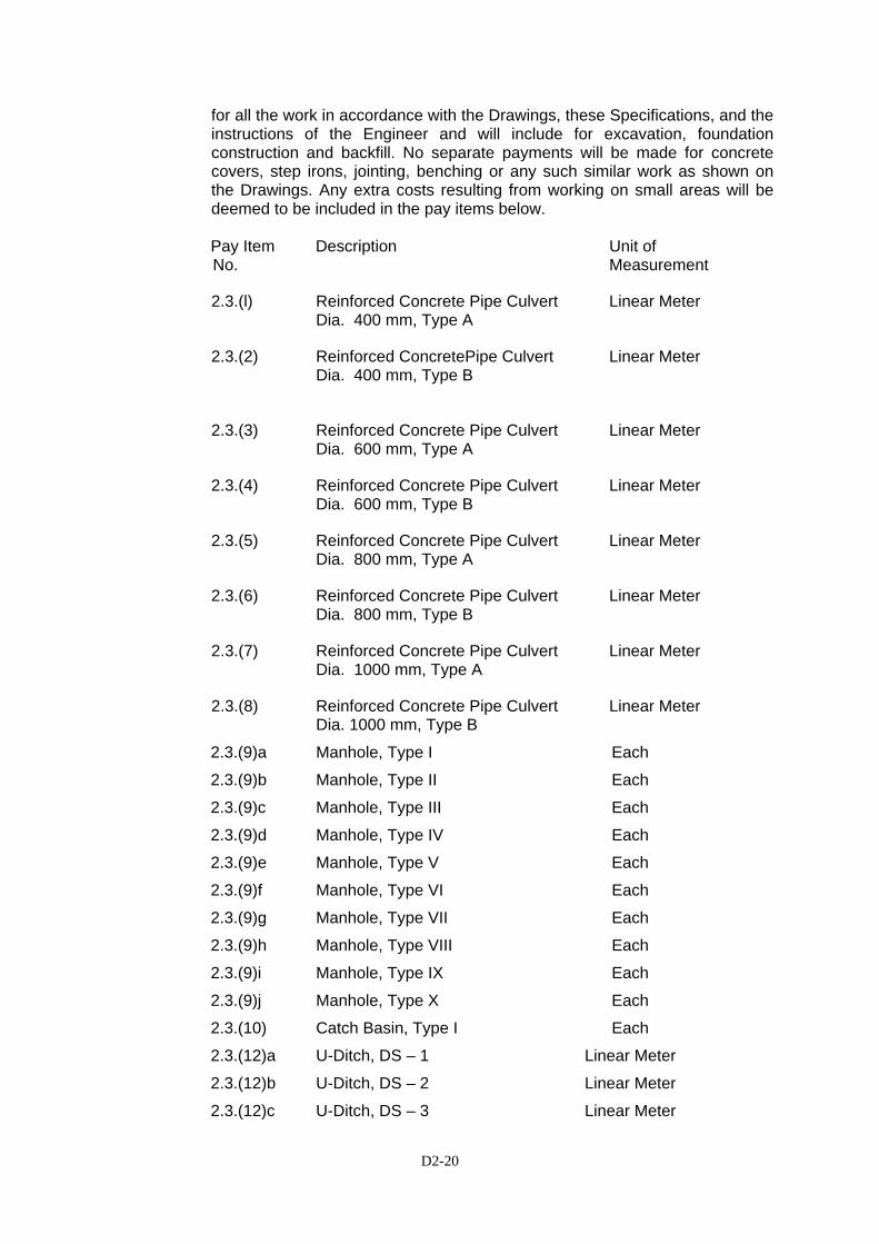
D2-20
for all the work in accordance with the Drawings, these Specifications, and the instructions of the Engineer and will include for excavation, foundation construction and backfill. No separate payments will be made for concrete covers, step irons, jointing, benching or any such similar work as shown on the Drawings. Any extra costs resulting from working on small areas will be deemed to be included in the pay items below. Pay Item Description Unit of No. Measurement
2.3.(l) Reinforced Concrete Pipe Culvert Linear Meter Dia. 400 mm, Type A
2.3.(2) Reinforced ConcretePipe Culvert Linear Meter Dia. 400 mm, Type B
2.3.(3) Reinforced Concrete Pipe Culvert Linear Meter Dia. 600 mm, Type A
2.3.(4) Reinforced Concrete Pipe Culvert Linear Meter Dia. 600 mm, Type B
2.3.(5) Reinforced Concrete Pipe Culvert Linear Meter Dia. 800 mm, Type A
2.3.(6) Reinforced Concrete Pipe Culvert Linear Meter Dia. 800 mm, Type B
2.3.(7) Reinforced Concrete Pipe Culvert Linear Meter Dia. 1000 mm, Type A
2.3.(8) Reinforced Concrete Pipe Culvert Linear Meter Dia. 1000 mm, Type B
2.3.(9)a Manhole, Type I Each
2.3.(9)b Manhole, Type II Each
2.3.(9)c Manhole, Type III Each
2.3.(9)d Manhole, Type IV Each
2.3.(9)e Manhole, Type V Each
2.3.(9)f Manhole, Type VI Each
2.3.(9)g Manhole, Type VII Each
2.3.(9)h Manhole, Type VIII Each
2.3.(9)i Manhole, Type IX Each
2.3.(9)j Manhole, Type X Each
2.3.(10) Catch Basin, Type I Each
2.3.(12)a U-Ditch, DS – 1 Linear Meter
2.3.(12)b U-Ditch, DS – 2 Linear Meter
2.3.(12)c U-Ditch, DS – 3 Linear Meter
D2-21
2.3.(12)d U-Ditch, DS – 3A Linear Meter
2.3.(12)e U-Ditch, DS – 4 Linear Meter
2.3.(12)f U-Ditch, DS – 4A Linear Meter
2.3.(12)g U-Ditch, DS – 5 Linear Meter
2.3.(13) Drain Pipe, 150 mm diameter Linear Meter
2.3.(14) Drain Pipe, 200 mm diameter Linear Meter
2.3.(15) Drain Pipe, 250 mm diameter Linear Meter
2.3.(16) Deck Drain, Type I Each
2.3.(17) Deck Drain, Type II Each
2.3.(18) Steel Gutter Drain Screen Linear Meter
2.3.(19) Outer Ditch for Viaduct Linear Meter
2.3.(20) Box Culvert Linear Meter
2.3(21) Extension of existing Box Culvert Linear Meter
D3-1
DIVISION 3 - EARTHWORKS
SSEECCTTIIOONN 33..11 CCLLEEAARRIINNGG AANNDD GGRRUUBBBBIINNGG 3.1 1 Description This work shall consist of clearing, grubbing, removing of top soil, and removing and
disposing of all vegetation and debris within the limits except such objects as designated to remain in place or are to be removed in accordance with other Clauses of these Specifications.
This work shall also include the preservation from injury or defacement of all
vegetation and objects designated to remain. 3.1.2 Construction
(1) General
The Engineer will establish the limits of work and designated all trees, shrubs, plants and other things to remain. The Contractor shall preserve all items designated to remain.
(a) Clearing and Grubbing and Tree Removal
All surface objects and all trees, down timber, rotten wood, stumps, roots, snags, brush, other vegetation, rubbish, and other protruding obstructions, not designated to remain, shall be cleared and/or grubbed, including disposal as required. In areas under roadway embankments, from which top soil or unsuitable materials are to be removed or which are designated to be compacted, all stumps and roots shall be removed to a depth at least 50 cm below the original ground surface and at least 50 cm below the bottom of the lowest pavement layer. In roadway cut areas, all stumps and roots shall be removed to a depth of not less than 50 cm below the finished subgrade level. Clearing and grubbing of pits, channel changes, and ditches will be required only to the depth necessitated by the excavation within those areas. Voids left after removal of roots shall be filled with suitable compared material.
(b) Topsoil Stripping
In areas under roadway embankment or where designated by the Engineer, the Contractor shall remove the topsoil and dispose of it as directed by the Engineer.

D3-2
In general the removal of topsoil shall include only the removal of soil which is sufficiently fertile to encourage or sustain a growth of vegetation.
Removal of topsoil over any designated area shall be executed to the depth as directed by the Engineer, and the topsoil shall be kept separate from other excavated material. When the topsoil will be used for dressing of the slopes of the embankment or other areas as directed by the Engineer or as indicated on the drawings, the work of topsoil stripping will be deemed to include stockpiling the topsoil when necessary and removing there from and the placing and spreading of the topsoil in areas designated by the Engineer. After spreading, the topsoil shall be raked to form smooth surface free of weeds, roots, sods and large stones.
(c) Protection of Areas Designated to Remain In areas designated by the Engineer, the Contractor will be responsible for the protection and routine maintenance of existing shrubs, trees and grassed areas. On completion of the Works these areas will be returned to the Employer in the same condition as before and any damage due directly or indirectly to the Contractor’s operations shall be made good at his own expense.
(d) Disposal of Cleared Material
The Contractor shall have the right to use unsaleable timber (or
saleable timber when permission is granted in writing by the appropriate Government agency or authority) for his own purpose in connection with the Contract always provided that he has ascertained and complied with the requirement of the appropriate Government agency or authority.
Saleable timber shall be neatly stored in an approved accessible place
within or near the right-of-way as directed and shall be trimmed and stacked in accordance with the requirements of the appropriate Government agency.
All other timber, except timber to be used, and all brush, stumps, roots,
logs, and other refuse from the clearing and grubbing operation shall be disposed of at locations provided by the Contractor.
The roadway and adjacent areas shall be left with a neat and finished
appearance. No accumulation of debris shall remain on or adjacent to the right-of-way.
3.1.3 Method of Measurement
Measurement will be by one or more of the following alternative measurement methods: 1) Area Method. The work to be paid for shall be based on the total area
cleared and grubbed which is calculated in square meter within the limits
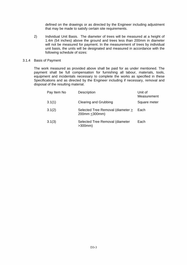
D3-3
defined on the drawings or as directed by the Engineer including adjustment that may be made to satisfy certain site requirements.
2) Individual Unit Basis. The diameter of trees will be measured at a height of
1.4m (54 inches) above the ground and trees less than 200mm in diameter will not be measured for payment. In the measurement of trees by individual unit basis, the units will be designated and measured in accordance with the following schedule of sizes:
3.1.4 Basis of Payment The work measured as provided above shall be paid for as under mentioned. The
payment shall be full compensation for furnishing all labour, materials, tools, equipment and incidentals necessary to complete the works as specified in these Specifications and as directed by the Engineer including if necessary, removal and disposal of the resulting material.
Pay Item No Description Unit of
Measurement
3.1(1) Clearing and Grubbing Square meter
3.1(2) Selected Tree Removal (diameter > 200mm <300mm)
Each
3.1(3) Selected Tree Removal (diameter >300mm)
Each
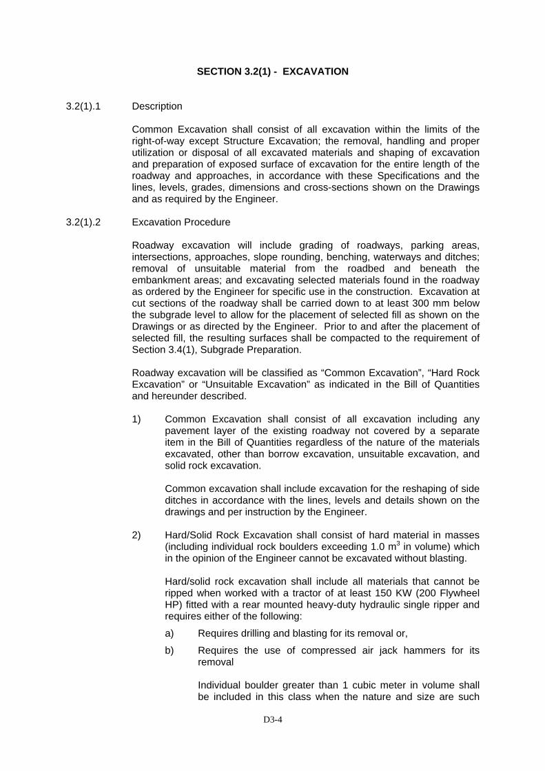
D3-4
SECTION 3.2(1) - EXCAVATION
3.2(1).1 Description
Common Excavation shall consist of all excavation within the limits of the right-of-way except Structure Excavation; the removal, handling and proper utilization or disposal of all excavated materials and shaping of excavation and preparation of exposed surface of excavation for the entire length of the roadway and approaches, in accordance with these Specifications and the lines, levels, grades, dimensions and cross-sections shown on the Drawings and as required by the Engineer.
3.2(1).2 Excavation Procedure
Roadway excavation will include grading of roadways, parking areas, intersections, approaches, slope rounding, benching, waterways and ditches; removal of unsuitable material from the roadbed and beneath the embankment areas; and excavating selected materials found in the roadway as ordered by the Engineer for specific use in the construction. Excavation at cut sections of the roadway shall be carried down to at least 300 mm below the subgrade level to allow for the placement of selected fill as shown on the Drawings or as directed by the Engineer. Prior to and after the placement of selected fill, the resulting surfaces shall be compacted to the requirement of Section 3.4(1), Subgrade Preparation. Roadway excavation will be classified as “Common Excavation”, “Hard Rock Excavation” or “Unsuitable Excavation” as indicated in the Bill of Quantities and hereunder described. 1) Common Excavation shall consist of all excavation including any
pavement layer of the existing roadway not covered by a separate item in the Bill of Quantities regardless of the nature of the materials excavated, other than borrow excavation, unsuitable excavation, and solid rock excavation.
Common excavation shall include excavation for the reshaping of side ditches in accordance with the lines, levels and details shown on the drawings and per instruction by the Engineer.
2) Hard/Solid Rock Excavation shall consist of hard material in masses
(including individual rock boulders exceeding 1.0 m3 in volume) which in the opinion of the Engineer cannot be excavated without blasting.
Hard/solid rock excavation shall include all materials that cannot be
ripped when worked with a tractor of at least 150 KW (200 Flywheel HP) fitted with a rear mounted heavy-duty hydraulic single ripper and requires either of the following:
a) Requires drilling and blasting for its removal or,
b) Requires the use of compressed air jack hammers for its removal
Individual boulder greater than 1 cubic meter in volume shall be included in this class when the nature and size are such
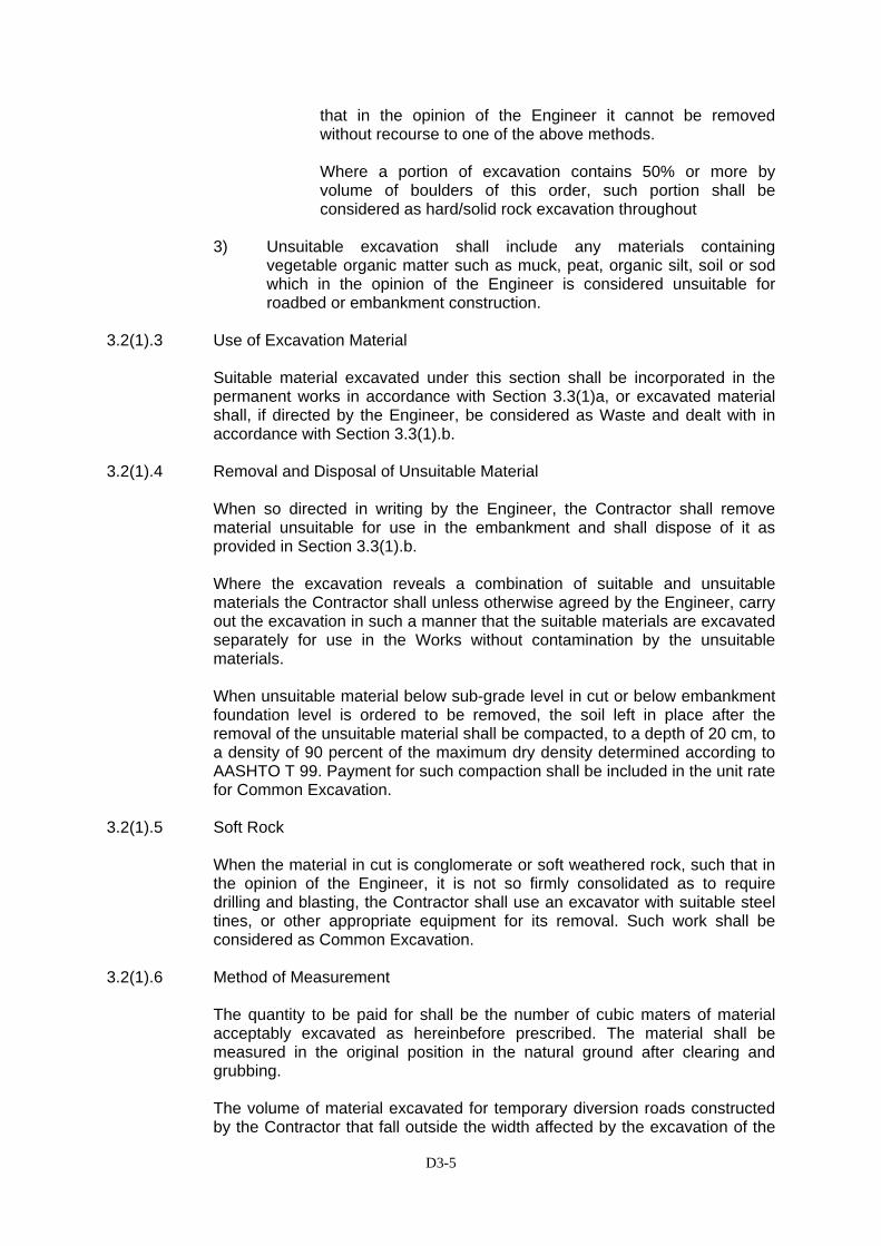
D3-5
that in the opinion of the Engineer it cannot be removed without recourse to one of the above methods. Where a portion of excavation contains 50% or more by volume of boulders of this order, such portion shall be considered as hard/solid rock excavation throughout
3) Unsuitable excavation shall include any materials containing
vegetable organic matter such as muck, peat, organic silt, soil or sod which in the opinion of the Engineer is considered unsuitable for roadbed or embankment construction.
3.2(1).3 Use of Excavation Material Suitable material excavated under this section shall be incorporated in the
permanent works in accordance with Section 3.3(1)a, or excavated material shall, if directed by the Engineer, be considered as Waste and dealt with in accordance with Section 3.3(1).b.
3.2(1).4 Removal and Disposal of Unsuitable Material When so directed in writing by the Engineer, the Contractor shall remove
material unsuitable for use in the embankment and shall dispose of it as provided in Section 3.3(1).b.
Where the excavation reveals a combination of suitable and unsuitable
materials the Contractor shall unless otherwise agreed by the Engineer, carry out the excavation in such a manner that the suitable materials are excavated separately for use in the Works without contamination by the unsuitable materials.
When unsuitable material below sub-grade level in cut or below embankment
foundation level is ordered to be removed, the soil left in place after the removal of the unsuitable material shall be compacted, to a depth of 20 cm, to a density of 90 percent of the maximum dry density determined according to AASHTO T 99. Payment for such compaction shall be included in the unit rate for Common Excavation.
3.2(1).5 Soft Rock When the material in cut is conglomerate or soft weathered rock, such that in
the opinion of the Engineer, it is not so firmly consolidated as to require drilling and blasting, the Contractor shall use an excavator with suitable steel tines, or other appropriate equipment for its removal. Such work shall be considered as Common Excavation.
3.2(1).6 Method of Measurement The quantity to be paid for shall be the number of cubic maters of material
acceptably excavated as hereinbefore prescribed. The material shall be measured in the original position in the natural ground after clearing and grubbing.
The volume of material excavated for temporary diversion roads constructed
by the Contractor that fall outside the width affected by the excavation of the
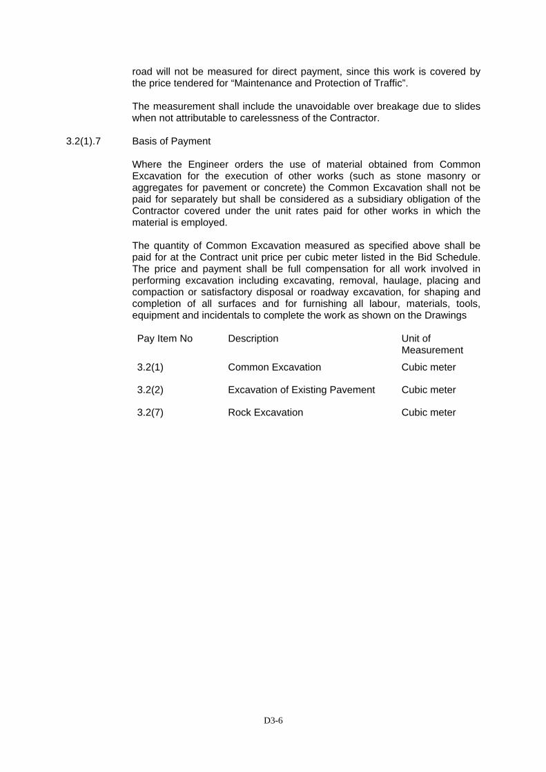
D3-6
road will not be measured for direct payment, since this work is covered by the price tendered for “Maintenance and Protection of Traffic”.
The measurement shall include the unavoidable over breakage due to slides
when not attributable to carelessness of the Contractor. 3.2(1).7 Basis of Payment Where the Engineer orders the use of material obtained from Common
Excavation for the execution of other works (such as stone masonry or aggregates for pavement or concrete) the Common Excavation shall not be paid for separately but shall be considered as a subsidiary obligation of the Contractor covered under the unit rates paid for other works in which the material is employed.
The quantity of Common Excavation measured as specified above shall be
paid for at the Contract unit price per cubic meter listed in the Bid Schedule. The price and payment shall be full compensation for all work involved in performing excavation including excavating, removal, haulage, placing and compaction or satisfactory disposal or roadway excavation, for shaping and completion of all surfaces and for furnishing all labour, materials, tools, equipment and incidentals to complete the work as shown on the Drawings
Pay Item No Description Unit of
Measurement
3.2(1) Common Excavation Cubic meter
3.2(2) Excavation of Existing Pavement Cubic meter
3.2(7) Rock Excavation Cubic meter

D3-7
SECTION 3.2 - STRUCTURE EXCAVATION
3.2.1 Description
Structure Excavation shall consist of excavation in earth, within the limits or the work as specified herein or as shown on the Drawings, that is made for structures. Any excavation which can be defined under any other Clause of this Specification shall not be considered to be Structure Excavation.
Structure Excavation shall be limited to excavation for the foundation of bridges or concrete retaining walls, box culverts, wing walls and other structures, unless otherwise noted in these Specifications. It shall include backfilling with suitable material accepted by the Engineer: incorporating surplus material in the fill areas as described in Section 3.3(1)a; disposing of waste material, and all necessary materials and equipment for keeping the excavation free of surface runoff and groundwater. Removal of free - surface water and river water shall not be paid for under this Section but will be considered to be covered by other pertinent Section of these Specifications.
3.2.2 Classification
Structure Excavation shall be classified for measurement and payment as:
(a) Structure excavation in earth; and
(b) Structure excavation executed at a depth greater than 20cm below the constant level to which the groundwater naturally rises in a foundation pit;
3.2.3 Groundwater
(a) Whenever groundwater is encountered during structure excavation the Contractor shall take such measures to ensure that the excavation and footing are kept free of water.
(b) When the excavation is taking place in or directly adjacent to free-surface water this will not be considered as groundwater and will be deemed to be covered by the Contractor's obligations under applicable Clause of these Specifications and therefore will not be measured for additional payment under this Section. The decision as to whether water is free-surface water or groundwater will be at the absolute discretion of the Engineer.
(c) Suitable and practically watertight cofferdams shall be used where water bearing strata are encountered above the elevation of the bottom of the excavation. Upon request, the Contractor shall submit shop drawings showing his proposed method of cofferdam construction to the Engineer for his approval.
Cofferdams or cribs for foundation construction shall, in general, be carried out well below the bottoms of the footings and shall be well braced and as nearly water-tight as practicable. In general, the interior dimensions of cofferdams shall be such as to give sufficient clearance for the construction of forms and the inspection or their exteriors, to permit pumping outside of the forms. Cofferdams or cribs which are tilted or moved laterally during the process of sinking shall be corrected or enlarged so as to provide the necessary clearance.
D3-8
When conditions are encountered which, as determined by the Engineer, render it impractical to dewater the foundation before placing the footing, the Engineer may require the construction of concrete foundation seal of such dimensions as he may consider necessary, and such seal shall be placed as shown on the Drawings or as directed by the Engineer. The foundation shall then be dewatered and the footing placed. When weighted cribs are employed and the weight is utilized to overcome partially the hydrostatic pressure acting against the bottom of the foundation seal, special anchorage such as dowels or keys shall be provided to transfer the entire weight of the crib to the foundation seal. When a foundation seal is placed under water, the cofferdam shall be vented or ported at low water level as directed.
Cofferdams shall be constructed so as to protect concrete against damage from sudden rising of the water and to prevent damage to the foundation by erosion. No timber or bracing shall be left in cofferdams or cribs without the approval of the Engineer.
Any pumping that may be permitted from the interior of any foundation enclosure shall be done in such a manner as to preclude the possibility of any portion of the concrete materials being carried away. Any pumping required during the placing of concrete, or for a period of at least 24 hours thereafter, shall be done from a suitable pump located outside the concrete forms. Pumping to dewater shall not commence until the seal has set sufficiently to withstand the hydrostatic pressure.
Unless otherwise provided, cofferdam or cribs, supports with all sheeting, bracing involved herewith, shall be removed by the Contractor after the completion of the substructure. Removal shall be effected in such a manner as not to disturb or damage any finished work.
(d) Preservation of Channel
Unless otherwise permitted, no excavation shall be made outside of cribs, cofferdams, and natural stream bed adjacent to the structure shall not be disturbed without the approval of the Engineer. If any excavation or dredging is made at the site of the structure before cribs, or cofferdams are sunk in place, the Contractor shall, after the foundation base is in place, back fill all such excavations to the original ground surface or stream bed with material satisfactory to the Engineer. Material deposited within the stream area from the foundation or other excavation or from the filling of cofferdams shall be removed and the stream area freed from obstruction.
3.2.4 Excavation
Prior to starting excavation operations in any area, the Contractor shall:
• take steps in cooperation with the Employer and the Engineer to regulate the natural drainage or the water flowing on the surface of the ground, to prevent flooding of excavations.
• ensure that all necessary Site Clearance and Demolition in that area has been performed in accordance with these Specifications.
• Notify the Engineer sufficiently in advance of the beginning of any excavation so that cross-sectional elevations and measurements can
D3-9
be taken of the undisturbed ground. The existing ground adjacent to the structures shall not be disturbed without the permission of the Engineer.
• determine the location and extent of any public utilities in the area. To that end, the Contractor shall dig trial pits at each location where he proposes to excavate for permanent works foundations.
Trenches or foundation pits for structures or structure footings shall be of sufficient size to permit the placing of structures or structure footings of the full width and length shown. The sides of trenches or pits shall be adequately supported at all times. The elevations of the bottoms of footings as shown on the Drawings shall be considered as approximate only and the Engineer may on the spot order in writing such changes in dimensions or elevations of footings as may be deemed necessary to secure a satisfactory foundation.
Boulders, logs, and any other unsuitable material encountered in excavation shall be removed from the site and shall not be used for backfilling purposes.
After each excavation is completed, the Contractor shall notify the Engineer to that effect, and no footing or bedding material shall be placed until the Engineer has approved the depth of excavation and the character of the foundation material.
All rock or other hard foundation material shall be cleaned of all loose material and cut to a firm surface, either level, stepped or serrated as directed by the Engineer. All seams or crevices shall be cleaned out and grouted. All loose and disintegrated rock and thin strata shall be removed.
When the footing is to rest on material other than rock, excavation to fine grade shall not be made until just before the footing is to be placed. Within the foundation material is soft or mucky or otherwise unsuitable, in the opinion of the Engineer, the Contractor shall remove the unsuitable material and replace it with granular backfill, as specified in Section 3.3(2). This foundation fill shall be placed and properly compacted in 15 cm layers up to the foundation elevation at the density required by the Engineer.
If, in the opinion of the Engineer, the foundation material is unsuitable solely because of the Contractor's failure to fulfill his obligations under Section 3.3(2) of this Specification, the Contractor may either:
• carry out at his own expense the removal and replacement described above: or
• suspend works in that excavation until such time as the foundation material becomes suitable.
The existing road or any adjacent facilities shall be protected during structure excavation by the placing of temporary steel sheet piles or other suitable works.
3.2.5 Backfill and Embankment of Structures
On completion of the structure, excavated areas if not to be backfilled in accordance with Section 3.3(2) or 3.3(3), shall be backfilled with approved material to the level of the finished ground surface. Unless otherwise approved by the Engineer, all backfill shall be carried out in accordance with the requirements of Section 3.3(2) of these Specifications.

D3-10
All material surplus to the requirement of this Section shall be utilized for the formation of areas of fill or shall, if instructed by the Engineer, be considered as waste and treated in accordance with Section 3.3(1)b.
3.2.6 Method of Measurement
The quantity of structure excavation to be paid for shall be the number of cubic meters of material measured in its original position and shall be computed as follows:
The volume of earth or rock to be measured for structure excavation shall consist of a prismoid bounded by the following planes:
• upper plane; the horizontal plane reproducing the perimeter of the base of the structural member and passing through the lowest point of the natural ground or excavated ground along the perimeter; above which plane excavation shall be considered as common excavation and shall be measured and paid for accordingly;
• lower plane; the horizontal plane at the base of the foundation which will be taken as the lower surface or the structural concrete, leveling concrete or blinding concrete as shown on the Drawings or instructed by the Engineer;
• the vertical planes coinciding with the perimeter of the base of the structural member. Any additional width of excavation necessary for the installation of blinding stone or class E leveling concrete or structural concrete exceeding area of lower plane will not be measured for payment and the cost of this excavation will be deemed to be included in the unit price for the measured quantity as described above.
Except as described previously in Clause 3.2.4 of these Specifications, measurement for structure excavation shall not include material removal below the footing grade and beyond the specified limits of the excavation
Structure excavation under railway shall include all temporary works such as support for the existing railway and temporary bridges, rails, etc. as shown in the drawings, to secure current transportation with suitable foundation. It also includes all the monitoring works of the existing railway to prevent the accident and failure of railway network.
Where the Engineer orders the excavation after the embankment has been placed, this extra excavation in the embankment will be measured for payment as Structure excavation as otherwise provided in these Specifications.
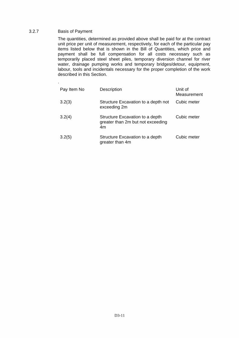
D3-11
3.2.7 Basis of Payment
The quantities, determined as provided above shall be paid for at the contract unit price per unit of measurement, respectively, for each of the particular pay items listed below that is shown in the Bill of Quantities, which price and payment shall be full compensation for all costs necessary such as temporarily placed steel sheet piles, temporary diversion channel for river water, drainage pumping works and temporary bridges/detour, equipment, labour, tools and incidentals necessary for the proper completion of the work described in this Section.
.
Pay Item No Description Unit of Measurement
3.2(3) Structure Excavation to a depth not exceeding 2m
Cubic meter
3.2(4) Structure Excavation to a depth greater than 2m but not exceeding 4m
Cubic meter
3.2(5) Structure Excavation to a depth greater than 4m
Cubic meter

D3-12
SECTION 3.3(1) - BORROW MATERIAL AND COMMON BACKFILL 3.3(1).1 Description This work shall consist of the clearing and stripping of borrow pits, the
excavating and hauling spreading and compacting of materials obtained from approved sources for constructing embankment, subgrade and other parts of the work as required by the Contract or by the Engineer.
3.3(1).2 Materials Borrow material shall be selected to meet the requirements and conditions of
the particular fill or embankment for which it is to be used. Materials shall be free from detrimental quantities of organic material such as leaves, grass, roots and sewage.
Any material classified by the Unified Soil Classification System as OL, OH or
PT shall not be used. Materials classified as GW, GP, GM, GC, SW, SP, SM and SC shall be
accepted as suitable provided that the material is shown to be sound and has no peculiar characteristics. Materials classified as CH or MH can be used as Embankment fill, unless otherwise indicated on the Contract Drawings or elsewhere, but not in the subgrade unless it is possible to obtain the minimum design C.B.R. value required when compacted as specified in Section 3.4(1).
3.3(1).3 Use of Borrow Pits Borrow material shall be obtained from approved private sources. Permission
to open borrow pits, including advice as to suitability, shall first be obtained in writing from the Engineer. Nevertheless, the total amount of surplus material from excavation, after deduction of the material declared unsuitable by the Engineer, shall be considered to be available for use in the embankment, and any borrow material resulting from the Contractor having used pit borrow in place of surplus material shall not be measured for payment under these Specifications.
The distance of borrow pits from the work site shall not be grounds for extra
payment or revision of the Contract Price. In making his Bid the Contractor shall visit the site and form his estimate of the haulage costs on the basis of his own survey of the possible nature and locations of the borrow pits.
Where suitable material for embankments is available adjacent to the
embankment the Engineer may order the excavation of drainage channels wider and deeper than normally required in which case such excavation will be measured and included in cross-sections as Common Excavation.
3.3(1).4 Placing and Compaction Suitable borrow material shall be incorporated in the permanent works in
accordance with the requirements of Section 3.3(1)a.
D3-13
3.3(1).5 Payment to Others The consent of the landowner and tenant for the digging and taking of
material for borrow shall be secured by the Contractor, who shall, if required, pay for such concession. The pit shall be left in a condition acceptable to the owner and to the Engineer.
Any fees payable for permission to cut or haul the borrow material will be at
the Contractor’s expense and will be deemed to be included in the unit price for this pay item.
3.3(1).6 Method of Measurement The quantity of borrow material to be measured and paid for shall be the
balance of the earthworks remaining after applying to the volume of embankment the quantity of all suitable material excavated within the site. The volume of embankment to be measured will be the net volume, after Site Clearing, of required and accepted embankment, actually constructed and completed to the lines, grades and cross section shown on the Drawing and as directed by Engineer. To calculate the balance of the earthwork it shall be assumed that the shrinkage factor for all suitable material excavated within the site is 0.90. This factor is fixed for all such material and claim on the basis of variation to this factor will be rejected. No allowance will be made for shrinkage in the borrow material between cutting at the borrow pit and incorporation in the permanent work.
3.3(1).7 Basis of Payment This work measured as provided above shall be paid for at the unit rate listed
below, which price and payment shall be full compensation for the cost of searching for and finding borrow pits, for acquiring the right to occupancy the sites and extract material for the cost of any negotiation right of access for the cost of establishing and maintaining access for any fees, licenses or royalties in connection with borrow pits for clearing, grubbing, sloping, draining and cleaning up of pits for furnishing, excavating, hauling, placing and compacting material from borrow pits and for providing all labor, equipment, tools and incidentals necessary to the works.
Pay Item No Description Unit of Measurement
3.3(1) Borrow Materials and Common Backfill
Cubic meter
D3-14
SECTION 3.3(1)a FORMATION OF EMBANKMENT AND AREAS OF FILL 3.3(1)a.1 Description This work shall consist of construction of embankment and backfill not
specified elsewhere by furnishing, placing, compacting and shaping suitable material of acceptable quality obtained from approved sources in accordance with these specification and to the lines, level, grades, dimension and cross-section shown on the Drawing and as required by the Engineer.
3.3(1)a.2 Sources and Use of Material Material for embankment shall consist of suitable material approved by the
Engineer excavated under any other Section of this Specification. Borrow material excavated however shall only be used under the provisions of Clause 3.3(1).3. Surplus of suitable material shall be disposed of in accordance with Clause 3.2(1).3 of these Specifications.
3.3(1)a.3 Construction
(a) Compaction of Foundation of Embankment
When ordered by the Engineer, the Contractor shall excavate turf, decayed vegetable matter, or other unsuitable matter to such depth as the Engineer may require. This work shall be considered as Clearing and Grubbing or Common Excavation and paid for as provided in Section 3.1 and 3.2(1). Before the start of construction of Embankment, the Contractor shall fill all holes, etc. within all the areas which have been cleared and grubbed, and grubbed, and such areas be suitable leveled at level resulting after the removal of the topsoil. Fill material shall be approved by the Engineer. This work shall not be paid for directly, but shall be considered a subsidiary obligation of the Contractor covered by the Contract price for other related item. Before the construction of the Embankment is begun, the Engineer may order the compaction of the cleared surface or that resulting after removal of the topsoil, in which case the density after compaction shall conform to the requirements of Sub-clause 3.3(1)a.3(d).
(b) Placing and Compaction
(i) Material for embankment obtained and approved as provided
above, shall be placed in horizontal layers of uniform thickness over a width determined by the Engineer and in conformity with the lines, grade, sections, and dimensions shown on the Drawings. The layer of loose material other than rock shall be not more than 20 cm thick, unless the compacting equipment used is capable of compacting a depth greater than 20 cm to a uniform density through the full depth which is acceptable to the Engineer, in which case the Contractor may place and compact the material other than rock, in layers of thickness
D3-15
approved by the Engineer. After adjustment of density, the loose material shall be compacted to the required density.
(ii) If the material deposited as fill subsequently reaches a
condition such that it cannot be compacted in accordance with the requirements of the Contract, the Contractor shall at his own expense either :
(a) make good by removing the material either to tip or
elsewhere until it is in a suitable physical condition for re-use and replace it with suitable material; or
(b) make good the material by mechanical or chemical
means; or
(c) cease work in the material until its physical condition is again such that it can be compacted as described in the Contract.
(iii) Where embankments are located on hillsides, or where new fill
is to be compacted against existing embankments or where fill is constructed on half width at a time, the original slope of the hillside of the old or of the first half width fill, shall be cut into a distance sufficient to accommodate the width of the compacting equipment as the new fill is placed in horizontal layers, and this material cut shall be incorporated and compacted with the new fill.
In the measurement of the work no allowance will be made for the volumes of material cut from the hillside or from the old or from the first half width fill to accommodate the compacting equipment, but will be calculated only on the net volume of fill placed against the original hillside, the old embankment or the first half width fill.
(iv) To avoid interference with the construction of bridge abutments,
wing walls and box culverts, the Contractor shall, at points to be determined by the Engineer, suspend work on embankment forming the approaches to any such structure until such time as the construction of the latter is sufficiently advanced to permit the completion of the approaches without the risk of interference or damage to the bridge works. The cost of suspension of work shall be included in the Contract unit prices for “Common Excavation’, and “Borrow Material”.
(v) Material for embankment at points inaccessible to normal
compacting equipment shall be placed in horizontal layers of loose material not more than 10cm thick and thoroughly compacted by the use of mechanical rammers.
(vi) In carrying embankments up to or over culverts and where
required in the Contract up to or over bridges, the Contractor shall bring the embankments up equally on both sides. If conditions require placing backfill or embankment appreciably higher on one side than on the opposite side, the additional
D3-16
material on the higher side shall not be placed until the structure has been in place 14 days, and permission has been given by the Engineer following tests made by the laboratory under the supervision of the Engineer to establish that the structure has attained sufficient strength to withstand any pressure created by the methods used and materials placed without damage or strain beyond a safe factor.
Where special materials for filling adjacent to structures are described in the Contract, filling may proceed over widths less than the full width of the embankment and in steps not exceeding the depth of the adjoining area of fill. In rock fill embankments the materials shall be carefully packed for such distance from the structure as is described in the Contract. Special care shall be taken to prevent any wedging action against the structure and all slopes bounding or within the areas to be filled shall be benched or serrated to prevent wedge action. The placing of embankment and the benching of slopes shall continue in such a manner that at all times there shall be a horizontal berm of thoroughly compacted material for a distance at least equal to the height of the abutment or wall to be backfilled against except in so far as undisturbed material intrudes upon the areas.
(c) Compaction Trials
Before starting the formation of the embankment the Contractor shall construct trial lengths for compacting as directed by the Engineer. The soils used in the trials shall be those encountered along the roadway and the compacting equipment shall be the same equipment that the Contractor will use for the main work accepted by the Engineer. The object of these trials will be to determine the optimum moisture content and the relationship between the number of passes of compacting equipment and density obtained for the soil types under trial. No separate payment will be made for this work, which will be regarded as a subsidiary obligation of the Contractor covered under the other sections of this Specification.
(d) Required Density
The required densities to which embankment layers shall be compacted are as follows:
(i) Layers more than 20 cm below subgrade level shall be
compacted to 95 percent of the maximum dry density determined according to AASHTO T 99. For all soils, except rock fill materials, containing more than 10 percent oversize material retained on a 19.0 mm (3/4 inch) sieve, the maximum dry density thus obtained shall be adjusted for such oversize material as directed by the Engineer.
D3-17
(ii) Layers of 20 cm or less below subgrade level shall be compacted to 100 percent of the maximum dry density determined according to AASHTO T 99
(e) Moisture Content
Embankment material that does not contain sufficient moisture to obtain the required compaction shall be given additional moisture by means of approved sprinkler and mixing. Material containing more than the amount of moisture necessary to obtain the required compaction may not without approval of the Engineer be incorporated in the embankment until it has been sufficiently dried out. The drying of wet material may be expedited by dishing or other methods approved by the Engineer. The compaction of the embankment shall be carried out at the optimum moisture content, In forming the embankment the Contractor shall take the steps to ensure that the work can be drained free of rain water and shall make due allowance in the height and width of the work for swelling or shrinkage.
(f) Rock Fill No rock fill shall be placed until after the Contractor has discussed his proposals for the work of cut and fill with the Engineer and secured the latter’s approval. In order to provide a suitable grade level material for covering the rock fill shall be reserved from the excavation of cut. Should such material be available and not be so reserved by the Contractor, so that borrow material has to be used for forming the grade level, such borrow shall be supplied and placed without extra payment to the Contractor. Rock fill shall be placed in loose layers not to exceed 60 cm in thickness and compacted as herein provided. The top of this fill shall be not less than 20 cm below the required finished subgrade and the interstices shall be thoroughly filled with clean small spalls, gravel or similar approved material and thoroughly compacted to the satisfaction of the Engineer. Rock in fill shall be considered as rock only when the earth or other finer material, when uniformly distributed throughout the mass, is considerably less than sufficient to fill the voids so that the rock particles shall be intimate contact and not so separated by earth or similar material. Otherwise the fill material shall be handled and considered as earth fill to be placed and compacted as specified in this specification or as directed by the Engineer. Where rock is to be incorporated in fill or portions of fill, composed largely of earth and friable rock material, the rock shall be reduced to a maximum size not exceeding 75 percent of the thickness of the layer being placed. A sufficient cover of earth over rock fill shall be used to produce a uniform grade level.

D3-18
(g) Mixed Material in Fill When material of widely divergent characteristics such as clay and chalk or sand drawn from different sources are to be used in the embankment they shall be deposited in alternate layers over the full width of the embankment to depth approved by the Engineer. When material used for fill is of variable quality, the Contractor shall schedule and execute his works so that the material designated as better quality by the Engineer is used in the upper layers of the fill. Rock, clay or other material shall be broken up and no accumulation of lumps or boulders at the toe of the embankment will be permitted.
(h) Leveling of Existing Embankment Before fill is placed and compacted on an existing roadway, the existing embankment and/or pavement may be leveled by cutting, rooting or scarifying with approved mechanical means to a level to be determined by the Engineer. The earth, old asphalt or other material obtained as a result of this operation will be declared by the Engineer to be either suitable or unsuitable for use in the adjacent embankment as directed by the Engineer subject to the provisions in Section 3.2(1) “Excavation”. In the second case the material shall be disposed of as provided in Section 3.3(1)b “Waste”.
(i) Finishing Roadbed (i) Final Grade Level - When an embankment requires the
addition of material to a depth of not more than 20 cm to bring it up to the required grade level, the top of the embankment shall be thoroughly scarified and re-compacted before the additional material is placed.
(ii) Slopes – Side sloped shall be neatly trimmed to the lines and
slopes shown on the Drawing or as directed by Engineer, and finished work shall be left in neat and acceptable condition.
(iii) Stability – The Contractor shall replace any portions of
embankment that have been damaged or displaced due, in the opinion of the Engineer, to carelessness or negligence on the part of the Contractor, or to such natural causes such as storms. The Contractor will not be responsible for damage cause by unavoidable movement of the natural ground upon which the embankment is made.
During construction, the roadway shall be kept shaped to drain at all times. When unsuitable material has been placed in the embankment by the Contractor, it shall be removed and replaced with suitable material without any extra payment therefor.

D3-19
3.3(1)a.4 Method of Measurement The performance of the work above shall be covered by the Contract Price of
the appropriate pay items under which the fill material is obtained and the work of this Section 3.3(1)a shall not be measured for the direct payment.
3.3(1)a.5 Basis of Payment Performance of this work under the Contract is not payable direct but shall be
considered as a subsidiary obligation of the Contractor covered under the Contract Price for performance of work under Section 3.2(1) “Excavation:” and Section 3.3(1) “Borrow Material and Common Backfill” of these Specifications.
D3-20
SECTION 3.3(1)b WASTE 3.3(1)b.1 Description This item shall consist of excavating, ripping, loading, hauling and spreading
in waste areas, soil material designated as waste. 3.3(1)b.2 Waste Material Material shall be known as “Waste” in the following cases:
(a) When the material resulting from the excavation made for the construction of the road is declared in writing by the Engineer to be unsuitable for use in the embankment or other work.
Normally, highly organic clays and silts, peat, soil containing large amounts of roots, grass and other vegetable matter, domestic or industrial waste are to unsuitable. Materials that are soft or unsuitable merely because they are too wet or dry are not to be classified as unsuitable unless otherwise directed by the Engineer.
(b) When the material resulting from the excavation made for the
construction of the road is surplus to the amount required for the construction of the embankment.
The material proposed for wasting shall not be wasted until approved
or directed in writing by the Engineer. 3.3(1)b.3 Work Requirement Unsuitable material shall be excavated below subgrade level in cut and below
embankment foundation level to the depth shown on the Drawings or directed by the Engineer. Where unsuitable material excavated below the normal subgrade level or below embankment foundation or for benching under embankment, the excavation shall be back filled with material and in a manner that conforms to Section 3.3(1)a.
Waste shall be removed and disposed of in waste areas provided by the
Contractor in such manner as to present a neat appearance and not to obstruct drainage to any highway nor to cause injury to highway works or property. If it becomes necessary for the Contractor to locate or relocate any waste area, they shall be approved by the Engineer prior to spreading any waste.
Waste areas shall be left in a smooth, neat and drainable condition, as directed by the Engineer, and all waste material shall be placed in such manner that adjacent property will not be damaged or endangered.
Soil slopes shall be steeper than 2(horizontal): 1(vertical), unless otherwise directed by the Engineer.
Performance of this work shall not be paid under this Section but shall be
considered as a subsidiary obligation of the Contractor covered under the unit rates of the appropriate pay item for excavation.
D3-21
SECTION 3.3(2) - STRUCTURAL BACKFILL 3.3(2).1 Description This item shall consist of furnishing, placing and compacting granular backfill
adjacent to structures. The area in which this material is to be placed is the “Influence Zone” of certain structures as shown on the Drawings.
3.3(2).2 Materials The material shall be well graded crushed or uncrushed gravel, stone, rockfill,
natural sand or a well mixed combination of any of these. Grading requirements for the material are as follows: Maximum size 10 cm Passing 4.75 mm sieve 25% to 90 % Passing 0.075 mm sieve 0% to 10 % Plasticity Index 10 max 3.3(2).3 Construction The granular backfill shall be placed in layers not exceeding 15 cm and
compacted to a density of 95% of the maximum dry density determined according to AASHTO T 180.
3.3(2).4 Method of Measurement The quantity of granular backfill to be measured and paid for will be the
number of cubic meters of suitable material supplied and compacted to the Engineer’s satisfaction and in accordance with this Specification. This material is required to be placed when filling within the influence zone of certain structures and any material placed outside the specified zone will not be measured for payment.
Any existing material within the influence zone which is removed because of
the Contractor’s method of working must be replaced by granular backfill at the Contractor’s expense. Where excavation within the Specifications, then the backfilling will be carried out with granular backfill and the work will be measured for payment under this Section.
3.3(2).5 Basis of Payment The accepted quantities of granular backfill, measured as provided above, will
be paid for at the Contract unit price for the pay item as below. The price and payment will be full compensation for the work described in this Section, including furnishing, hauling, placing and compacting the material.
Pay Item No Description Unit of
Measurement
3.3(2) Structure Backfill Cubic meter
D3-22
SECTION 3.3(3) - PERMEABLE BACKFILL 3.3(3).1 Description This work shall consist of supplying and installing selected backfill material
adjacent to structures in accordance with these Specifications and in the locations shown on the Drawings or instructed by the Engineer.
3.3(3).2 Materials Material shall be hard clean, crushed rock or gravel complying with the
following grading.
Sieve Size % Passing by Weight 63 mm
37.5 mm 19 mm 9.5 mm
100 85 – 100
0 – 20 0 - 5
3.3(3).3 Construction The method of construction will be at the discretion of the Contractor, but
details must be submitted for the Engineer’s approval before commencement of the work. All details of the permeable backfill shall be as shown on the Drawings and the degree of compaction shall be as instructed by the Engineer.
3.3(3).4 Method of Measurement Unless this material is specified as included in another pay item, the quantity
of permeable backfill to be measured and paid for will be the number of cubic meters of suitable material supplied, placed and compacted in accordance with the details shown on the Drawings. Any material placed beyond the dimensions shown on the Drawings will not be measured for payment.
3.3(3).5 Basis of Payment The work measured as provided above will be paid for at the Contract price
per unit of measurement for the item listed below, which price and payment will be full compensation for furnishing and placing all materials and for all labour, equipment, tools and other incidentals necessary to complete the work in accordance with the Drawings, Specifications and as directed by the Engineer.
Pay Item No Description Unit of
Measurement
3.3(3) Permeable Backfill Cubic meter

D3-23
SECTION SS 3.3(3) – SOIL CEMENT IMPROVEMENT SS 3.3(3).1 Description
This item shall consist of soil cement improvement by jet grouting method applied on areas in the project verified to have poor sub-soil. Prior to the commencement of the work, sub-soil investigation as directed by the Engineer shall be carried-out by the Contractor. The Contractor shall submit to the Engineer his proposed construction method for the Work. Shop drawings shall also be prepared and submitted by the Contractor for approval by the Engineer. No work shall be allowed to commence until the shop drawings and the work methodology submitted by the Contractor is approved by the Engineer. The work shall be carried-out in close conformity with the requirements established by the Engineer.
SS 3.3(3).2 Materials
• Cement Grout shall be mixture of cement and water. The quantity of cement shall be 150kg per cubic meter mixed with sufficient amount of water. Addition of additives to the cement grout shall not be permitted unless otherwise approved by the Engineer in writing.
• Cement shall be Portland cement of the type or other special type of
cement to be established by the Engineer.
• Water – water used in mixing, curing or designated application shall be reasonably clean and free from oil, salt, acid, alkali, grass or other substances injurious to the finished product. Water when required by the Engineer shall be tested in accordance with and shall meet the suggested requirements of AASHTO T 26.
The characteristic and composition of the grout mix shall be in conformity with the data provided in Table 1, Characteristic and composition of Grout and Table 2 – Characteristic of Jet Grouting
Table 1 – Characteristic and Composition of Grout
Composition of Grout Type
Characteristics Cement
(kg)
Liquid Additive
(kg)
Solid Additive
(kg)
Water
(ltr)
JG -1 High Strength 760 12.0 - 750 JG-2 Medium Strength 500 7.5 200 760 JG-3 Low Strength 300 4.5 400 750 JG-4 Organic Soil 760* 12.0 - 740 JG-5 High Fluidity 550* - 822
Note: * Special type of cement
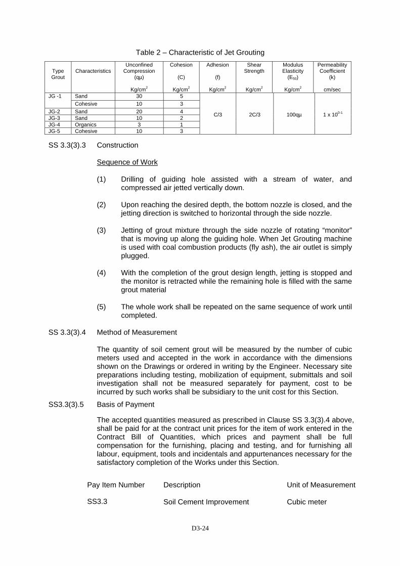
D3-24
Table 2 – Characteristic of Jet Grouting
SS 3.3(3).3 Construction
Sequence of Work (1) Drilling of guiding hole assisted with a stream of water, and
compressed air jetted vertically down. (2) Upon reaching the desired depth, the bottom nozzle is closed, and the
jetting direction is switched to horizontal through the side nozzle.
(3) Jetting of grout mixture through the side nozzle of rotating “monitor” that is moving up along the guiding hole. When Jet Grouting machine is used with coal combustion products (fly ash), the air outlet is simply plugged.
(4) With the completion of the grout design length, jetting is stopped and
the monitor is retracted while the remaining hole is filled with the same grout material
(5) The whole work shall be repeated on the same sequence of work until
completed. SS 3.3(3).4 Method of Measurement The quantity of soil cement grout will be measured by the number of cubic
meters used and accepted in the work in accordance with the dimensions shown on the Drawings or ordered in writing by the Engineer. Necessary site preparations including testing, mobilization of equipment, submittals and soil investigation shall not be measured separately for payment, cost to be incurred by such works shall be subsidiary to the unit cost for this Section.
SS3.3(3).5 Basis of Payment
The accepted quantities measured as prescribed in Clause SS 3.3(3).4 above, shall be paid for at the contract unit prices for the item of work entered in the Contract Bill of Quantities, which prices and payment shall be full compensation for the furnishing, placing and testing, and for furnishing all labour, equipment, tools and incidentals and appurtenances necessary for the satisfactory completion of the Works under this Section.
Type Grout
Characteristics
Unconfined Compression
(qµ)
Kg/cm2
Cohesion
(C)
Kg/cm2
Adhesion
(f)
Kg/cm2
Shear Strength
Kg/cm2
Modulus Elasticity
(E50)
Kg/cm2
PermeabilityCoefficient
(k)
cm/sec Sand 30 5 JG -1 Cohesive 10 3
JG-2 Sand 20 4 JG-3 Sand 10 2 JG-4 Organics 3 1 JG-5 Cohesive 10 3
C/3
2C/3
100qµ
1 x 100-1
Pay Item Number Description Unit of Measurement
SS3.3 Soil Cement Improvement
Cubic meter
D3-25
SECTION 3.3(4) - LIGHTWEIGHT EMBANKMENT (EPS-BLOCKS) 3.3(4).1 Description
This item shall consist of the construction of lightweight embankment in accordance with this Specification and in conformity with the lines, grades, and dimensions shown on the Drawings or established by the Engineer
3.3(4).2 Materials
Lightweight embankments shall be constructed of suitable materials in consonance with the following definitions: (1) Geofoam – a term referring to Expanded Polystyrene (EPS) a super
light weight soil substitute used for embankment, and related bridge approach fills on soft ground. The use of this type of material in embankment construction shall reduce the magnitude of ultimate settlement and save construction time.
The geofoam materials shall be in accordance with the following
ASTM Standards:
• C 578-95 Standard Specification for Rigid, Cellular Polystyrene Thermal Insulation
• C 303-98 – Standard Test Method for Dimensions and Density
of Preformed Block and Board Type-Thermal Insulation. (2) Concrete - Concrete shall be manufactured in accordance with
Section 7.1, Structural Concrete, of these Specifications for the applicable grade. The grade of concrete for each element of the works shall be as shown on the Drawings.
(3) Reinforcing Steel – Reinforcement shall conform to the requirements
of Section 7.3, Reinforcing Steel, of these Specifications.
(4) Structural Steel – Structural steel shall conform to the requirements of Section 7.5, Structural Steel Works of these Specifications.
3.3(4).3 Submittals
The Contractor shall submit shop drawings indicating the proposed location and lay out of all EPS blocks to be placed during construction. No work on this item shall be commenced until the shop drawings are approved by the Engineer. The Contractor shall submit the Material Quality Control (MQC) plan of the EPS block to the Engineer to ensure that all necessary checks and tests of the materials supplied by the molder are undertaken. The MQC submitted by the Contractor shall be approved first by the Engineer prior to the ordering of the materials.
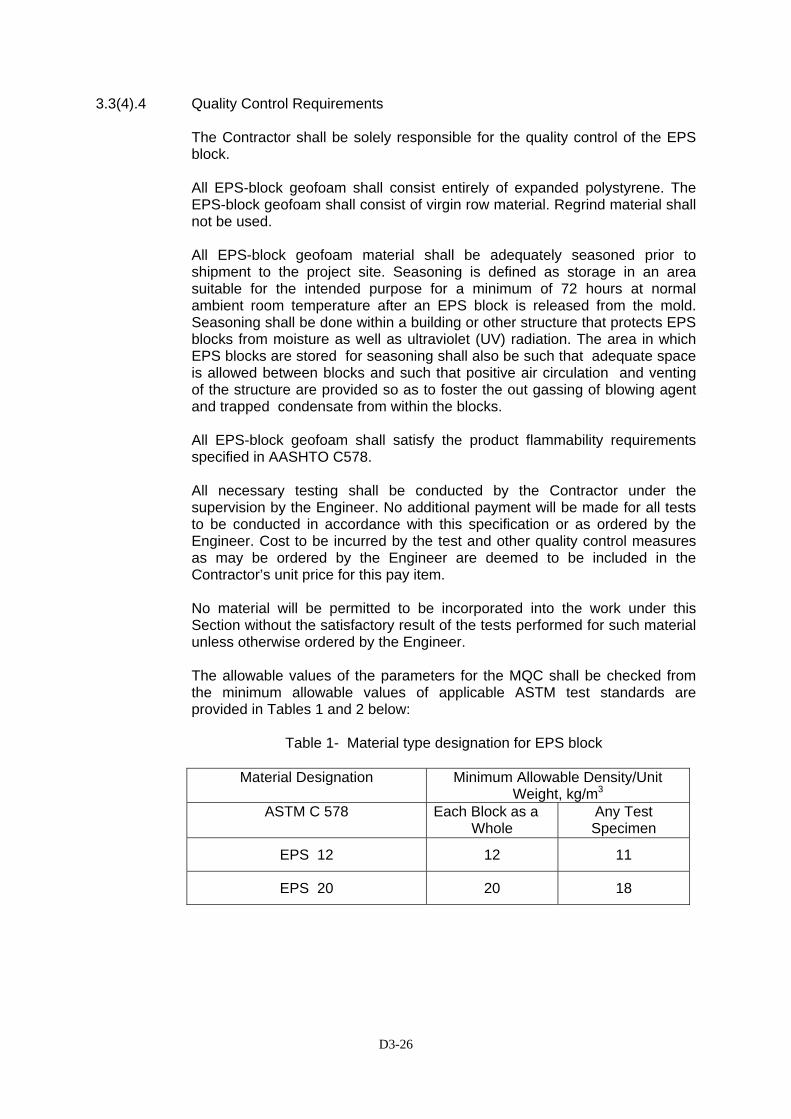
D3-26
3.3(4).4 Quality Control Requirements
The Contractor shall be solely responsible for the quality control of the EPS block. All EPS-block geofoam shall consist entirely of expanded polystyrene. The EPS-block geofoam shall consist of virgin row material. Regrind material shall not be used. All EPS-block geofoam material shall be adequately seasoned prior to shipment to the project site. Seasoning is defined as storage in an area suitable for the intended purpose for a minimum of 72 hours at normal ambient room temperature after an EPS block is released from the mold. Seasoning shall be done within a building or other structure that protects EPS blocks from moisture as well as ultraviolet (UV) radiation. The area in which EPS blocks are stored for seasoning shall also be such that adequate space is allowed between blocks and such that positive air circulation and venting of the structure are provided so as to foster the out gassing of blowing agent and trapped condensate from within the blocks. All EPS-block geofoam shall satisfy the product flammability requirements specified in AASHTO C578. All necessary testing shall be conducted by the Contractor under the supervision by the Engineer. No additional payment will be made for all tests to be conducted in accordance with this specification or as ordered by the Engineer. Cost to be incurred by the test and other quality control measures as may be ordered by the Engineer are deemed to be included in the Contractor’s unit price for this pay item. No material will be permitted to be incorporated into the work under this Section without the satisfactory result of the tests performed for such material unless otherwise ordered by the Engineer. The allowable values of the parameters for the MQC shall be checked from the minimum allowable values of applicable ASTM test standards are provided in Tables 1 and 2 below:
Table 1- Material type designation for EPS block
Material Designation Minimum Allowable Density/Unit Weight, kg/m3
ASTM C 578 Each Block as a Whole
Any Test Specimen
EPS 12 12 11
EPS 20 20 18

D3-27
Table 2 - Minimum allowable values of MQC/MQA parameters for individual test specimens
Material Designation
Dry
Density/ Unit
Weight kg/m3
Compressive
strength kPa
Flexural Strength,
kPa
Elastic Limit
Stress, kPa
Initial
Tangent Young’s Modulus
MPa
EPS 12 11 35 80 30 2
EPS 20 18 90 200 50 5
All test specimens shall be seasoned as specified in ASTM C578. Dry density unit weight, compressive strength and flexural strength shall be measured as specified in ASTM C578. The specimens used for compressive testing shall be cubic in shape with a 50 mm face width. The test specimens shall be prepared from samples taken from actual blocks produced for the Works. A strain rate of 10 percent per minutes shall be used for the compressive strength tests. Both the elastic limit stress and the initial tangent Young’s modulus shall be determined in the same test used to measure compressive strength. The elastic-limit stress is defined as the measured compressive normal stress at a compressive normal strain of 1 percent. The initial target Young’s modulus is defined as the average slope of the compressive stress versus compressive strain curve between 0-percent and 1- percent strain. The thickness, width, and length dimensions of an EPS block shall be perpendicular, forming an angle of 90 degrees. The deviation of any face of the block form a theoretical perpendicular plane shall not exceed 3 mm over a distance of 500 mm.
Any one face of a block shall not deviate from planarity by more than 5 mm when measured using a straightedge with a length of 3 meters.
3.3(4).5 Product Manufacturing Quality Assurance The manufacturing quality assurance (MQA) of the EPS-block geofoam product shall be conducted by the Contractor to verify the molder’s MQC procedure. MQA of the EPS-block geofoam shall consist of two phases. Phase I MQA consists of pre certification of the molder and shall be conducted prior to shipment of any EPS blocks to the project site. Phase II MQA shall be conducted as the EPS blocks are delivered to the project site. 1) MQA Phase I
No EPS blocks shall be shipped to the project site until such time as all parts of the Phase I MQA have been completed.
D3-28
The Contractor shall deliver a minimum of three (3) full-size EPS blocks for each EPS-block geofoam type to be used in the Works to the Engineer’s laboratory or other location as required by the Engineer. The blocks shall in all respects be the same as blocks to be supplied for the Works, including required seasoning. The Contractor, under the supervision of the Engineer, shall weigh measure, sample and test a random number of blocks to evaluate the ability of the molder to produce EPS-block geofoam of quality as specified in these Specifications. The shop drawings submitted by the Contractor shall be reviewed by the Engineer during MQA Phase I. The block layout shall be designed so that the following general design details are taken into account: a) The plane on which a given layer of blocks is placed must be parallel
to the longitudinal axis of the road alignment. b) There must be a minimum of two layers of blocks at all locations. c) Within a given layer of blocks, the longitudinal axis of all blocks must
be parallel to each other. d) Within a given layer of blocks, the vertical points between adjacent
blocks must be offset to the greatest extent practicable relative to blocks in adjacent rows.
e) The longitudinal axis of blocks for layers above and/or below a given layer must be perpendicular to the longitudinal axis of blocks within that given layer.
f) The longitudinal axis of the upper most layer of blocks must be perpendicular to the longitudinal axis of the road alignment.
Prior to the delivery of any EPS-block geofoam to the project site, a meeting shall be held between, at a minimum, the Engineer and the Contractor. The supplier and/or molder of the EPS-block geofoam may also attend at the Contractor’s discretion to answer any questions. The purpose of the meeting shall be to review the Phase I MQA results and discuss the Phase II MQA to ensure that all parties are familiar with the requirements of these Specifications. At the satisfactory conclusion of the meeting, the Contractor shall be allowed to begin on-site receipt, storage and placement of the EPS-block geofoam.
3.3(4).6 Handling and Storing of EPS –Blocks
Each EPS Block shall be properly stockpiled in a secured area at the project site until placement. The storage area shall be away from any heat source or construction activity that produces heat or flame. Personal tobacco smoking is not permitted in the storage area. EPS blocks in temporary on-site storage shall be secured with sandbags and similar soft-weight to prevent their being dislodged by wind. The block shall not be covered in any manner that might allow the build-up of heat beneath the cover.

D3-29
The blocks shall not be trafficked by any vehicle or equipment. Foot traffic by persons shall be kept to a minimum. Each EPS-block shall be labeled indicating the date the block was molded, the mass weight of the entire block in kilograms as measured after a satisfactory period of seasoning, the dimensions of the block in millimeters, and the actual dry density /unit weight in kilograms per cubic meter. Additional markings using alphanumeric characters, colors, and/or symbol shall be applied as necessary to indicate the location of each block relative to the shop drawings submitted by the Contractor. At all stages of manufacturing, shipment and construction, the EPS blocks shall be handled in a manner so as to minimize physical damage to the blocks. No method of lifting the blocks that creates dents or holes in the block surfaces or losses of portions of the block shall be allowed.
3.3(4).7 Product Manufacturing Quality Assurance: Phase II
Phase II MQA will be performed by the Engineer as the EPS blocks are delivered to the project site. Phase II MQA shall consist of four sub-phases (IIa through IId). The Contractor shall co-operate and assist the Engineer in implementing Phase II MQA. Phase IIa MQA shall consist of on-site visual inspection of each block delivered to the project site to check for damage and to visually verify the labeled information on each block. Any blocks with damage or not meeting the requirements of this Specification will be: a) rejected on the spot and placed in an area separate from those blocks
that are accepted, or b) marked “unacceptable” and returned to the supplier. Phase IIb MQA shall consist of on-site verification that the minimum block dry density, as well as the physical tolerances given in this Specification, are met. At least one truck load of EPS blocks shall be checked and additional blocks shall be checked if initial measurements indicate lack of compliance. The Contractor shall supply a scale on site with sufficient capacity and precision for weighing of EPS blocks. This scale shall have been recently calibrated and certification of such calibration shall be made available to the Engineer. Phase IIc MQA shall consist of sampling and testing specimen prepared from the EPS blocks. The laboratory tests shall check for compliance with the parameters shown in Table 2. The Contractor shall provide the necessary samples taken from locations on the EPS block as directed by the Engineer. The Contractor shall undertake all tests under the supervision of the Engineer. At least one EPS block will be selected for sampling and testing. If unsatisfactory test results are obtained, the Contractor may be directed to remove potentially defective EPS blocks and replace them with blocks of acceptable quality at no additional cost.
D3-30
Phase IId MQA shall consists of the preparation of as-built drawings, as well as additional record keeping to document the location of all EPS blocks placed in the works. The Contractor shall cooperate with and assist the Engineer with this phase.
3.3(4).8 Construction
(1) Site preparation
(a) If indicated on the Drawings or so ordered by the Engineer, the natural soil subgrade shall be cleared of vegetation and any large or sharp edges soil particles and be reasonably planed prior to placing a geotextile and / or sand bedding layer.
(b) If no sand bedding layer is used, the natural subgrade shall be
cleared such that there is no vegetation, or particles of soil or rock larger than coarse gravel, exposed at the surface.
(c) Regardless of the subgrade material (i.e., natural soil or sand
bed), the subgrade surface on which the EPS blocks will be placed shall be sufficiently planar (i.e., smooth) prior to the placement of the first block layer. The required smoothness is defined as a vertical deviation of no more than 10 mm over any 3 meter distance.
(d) There shall be no debris of any kind on the subgrade surface
when EPS block are placed.
(e) Unless directed otherwise by the Engineer, there shall be no standing water on the subgrade within the area where EPS blocks are placed at the time of block placement.
(2) Placing of EPS – Block
(a) EPS blocks shall be placed at the locations shown either on the Drawings or approved shop drawings submitted by the Contractor. Particular care shall be required EPS blocks of different density are to be used in the Works.
(b) EPS blocks shall be placed so that all vertical and horizontal
joints between the blocks are tight. (c) The surfaces of the EPS block shall be directly traversed by
any vehicle or construction equipment during or after placement of the blocks.
(d) With the exception of sand bags or similar soft weights used to
temporarily restrain EPS blocks against wind, no construction materials other than that shown on the drawings shall be placed or stockpiled on the EPS blocks.
(e) At no time shall heat or open flame be used near the EPS
blocks so as to cause melting or combustion of the blocks.
D3-31
(f) The final surface of the EPS blocks shall be covered as shown on the Drawings or as directed by the Engineer. Care shall be exercised during placement of the cover material so as not to cause any damage to the blocks.
(3) Pavement Construction
(a) No vehicles or construction equipment shall traverse directly on the EPS blocks or on any separation material placed between ESP blocks and the pavement system. Soil or aggregate for the pavement system layers shall be pushed onto the EPS blocks or separation layer using appropriate equipment such as a bulldozer or a front-end loader. A minimum of 300mm of soil or aggregate shall cover the top of the EPS blocks or separation layer before compaction commences.
(b) The pavement shall be placed above the EPS blocks after
completion of requisite works such subgrade preparation, subbase course, etc., within the limits of roadway including shoulders, as shown on the Drawings.
(c) The specifications covering the construction of pavement are
given in the applicable sections provided in these Specifications.
(4) Embankment
Embankment of common or selected materials indicated on the drawings or as ordered by the Engineer shall be in accordance with Section 3.3(1) of these Specifications.
(5) Retaining Wall
(a) Excavation and Foundation Works
Excavation for the base of the wall shall be in accordance with
the limits designated on the Drawings. The foundation for the structure shall be graded level for a
width equal to the total width plus 300mm or as shown on the Drawings. Prior to EPS construction the foundation shall be compacted with a smooth wheel vibratory roller. Any foundation soils found to be unsuitable shall be removed and replaced with structural backfill in accordance with Section 3.3(2).
When concrete panels are specified, lean concrete leveling
pad shall be cast accurately to line and level as detailed on the Drawings. The leveling pad shall be cast at least 12 hours before placement of walls panels.
D3-32
(6) Concreting
Concreting and other subsidiary works shall be in accordance with Section 7.1 of these Specifications.
(7) Reinforcing Steel
Reinforcement shall be in accordance with Section 7.3 of these Specifications.
3.3(4).9 Method of Measurement
The quantity of light weight embankment / EPS-Blocks construction to be paid for under this Section shall be the number of cubic meters (m3) of EPS blocks completed and accepted in accordance with the Drawings and this Specification or as otherwise required by the Engineer. The area of retaining wall for lightweight embankment to be paid for under this Section shall be the number of square meters (m2) completed and accepted in accordance with the Drawings and this Specification or as otherwise required by the Engineer. The quantity to be paid for intermediate concrete slab shall be the number of square meters of concrete slab placed and accepted in the completed work in conformity with the lines, dimensions and thickness as indicated on the Drawings and as directed by the Engineer.
3.3(4).10 Basis of Payment
The accepted quantities measured as prescribed in Clause 3.3(4).9 above, shall be paid for at the contract unit prices for each item of work, which prices and payment shall be full compensation for the furnishing, placing and compacting, testing, and for furnishing all labour, equipment, tools and incidentals and appurtenances necessary for the satisfactory completion of the Works under this Section.
Pay Item Number Description Unit of
Measurement
3.3(4) Lightweight Embankment (EPS-Blocks)
Cubic meter
3.3(6) Intermediate Concrete Slab
Square Meter
SS 3.5(2) Retaining Wall for Lightweight Embankment
Square Meter
D3-33
SECTION 3.4(1) - SUBGRADE PREPARATION 3.4(1).1 Description This item shall consist of the preparation of subgrade for the support of
overlaying structural layers. It shall extend to full width of the roadway. Unless authorized by the Engineer, subgrade preparation shall not be done unless the Contractor is able to start immediately the construction of pavement structure.
3.4(1).2 Material Requirements Unless otherwise stated in the contract and except when the subgrade is in
rock cut, all materials below subgrade level to a depth 150mm or to such greater depth as may be required by the Engineer shall be in accordance with relevant provisions in these Specifications.
3.4(1).3 Construction
(1) Prior works
Prior to commencing preparation of the subgrade, all culverts, cross-drains, ducts, and the like (including their fully compacted backfill), ditches, drains and drainage outlets shall be completed. Any work on the preparation of the subgrade shall not be started unless prior work described herein shall have been approved by the Engineer.
(2) Subgrade Level Tolerances
The finished compacted surface of the subgrade shall conform to the allowable tolerances as specified hereunder: Permitted variation from + 20mm Design LEVEL OF SURFACE - 30mm Permitted SURFACE IRREGULARITY MEASURED BY 3-m STRAIGHT EDGE 30mm Permitted variation from design CROSSFALL OR CAMBER + 0.5% Permitted variation from Design LONGITUDINAL GRADE over 25m length + 0.1%
(3) Subgrade in Common Excavation
Unless otherwise specified, all materials below subgrade level in earth cuts to a depth of 300 mm or other depth shown on the Plans or as directed by the Engineer shall be excavated. The material, if suitable, shall be set aside for future use or, if unsuitable, shall be disposed of in accordance with the requirements of Clause 3.2(1).4 of these Specifications.
Where material has been removed from below subgrade level, the resulting surface shall be compacted in accordance with Clause 3.2(1).4 and the requirements below.

D3-34
All materials within 300 mm below subgrade level in earth cuts shall be compacted in accordance with the requirements of Clause 3.3(1).4. Such materials shall be compacted to 95% of the maximum dry density, as determined by AASHTO T 180. The material shall have a soaked CBR value of 15. All materials within 300 mm below subgrade level in fill shall be compacted to 95% of the maximum dry density, as determined by AASHTO T 180. The material shall have a soaked CBR value of 25.
The roadbed material in cuts shall be moistened or dried to uniform moisture content within + or - 2% of optimum moisture and shall be thoroughly compacted.
• 100% of the maximum dry density as determined by AASHTO T 180, in case the roadbed will constitute the subbase of the new pavement
(4) Subgrade on Embankment
After the embankment has been completed, the full width shall be conditioned by removing any soft or other suitable material that is not compacted properly. The resulting areas and all other low sections, holes, or depressions shall be brought to grade with suitable material. The entire roadbed shall be shaped and compacted to the requirements of Clause 3.3(1).4. Scarifying, dragging, rolling, or of other methods of work shall be performed or used as necessary to provide thoroughly compacted roadbed shaped to the cross-sections as shown on the Drawings.
(5) Protection of Completed Work
The Contractor shall be required to protect and maintain at his own expense the entire work within the limits of his contract in good condition satisfactory to the Engineer from the time he first started work until all works have been completed. Maintenance shall include repairing and re-compacting ruts, ridges, soft spots and deteriorated sections of the subgrade caused by the traffic of the Contractor’s vehicle and equipment or that of the public.
3.4(1).4 Method of Measurement
The preparation of the subgrade at locations where unsuitable materials have been excavated and disposed shall be measured in square meters, which shall be calculated based on surveys carried out defining the limits as directed by the Engineer. Should a leveling course be necessary to correct the irregularities of the prepared subgrade or for non-compliance to the maximum allowable tolerances prescribed in Sub-clause 3.4(1).3(2), such course shall not be measured separately and shall be deemed to have been included in the pay item for embankment.
D3-35
3.4(1).5 Basis of Payment
The accepted quantities, measured as prescribed above, shall be paid for at the appropriate contract unit price for this section/pay item in the Bill of Quantities, in which price and payment shall be full compensation for the placing, or removal or disposal of all materials including all labour, equipment, tools, and incidentals necessary to complete the work prescribed in this section.
Pay Item Number Description Unit of Measurement
3.4(1) Subgrade Preparation Square Meter
D3-36
SECTION SS 3.5 (1) MECHANICALLY STABILIZED EARTHWALL
3.5.1. Description
The work shall consist of mechanically stabilized earthwall constructed in accordance with this Specification and in conformity with the lines, levels and details shown on the Drawings or as directed by the Engineer.
3.5.2. Materials
(1) Concrete Facing Panels
Concrete shall have a cylinder compressive strength at 28 days of 30 MPa with a minimum cement content of 335 kg/m3 and a maximum free water/cement ratio of 0.54. Coarse aggregate shall be in accordance with the grading requirement for Class B concrete shown in Table 7.1.2.(1) Aggregate Grading Requirements.
Unless notified otherwise, at least three test cylinders shall be made per production cycle and tested at 28 days.
(2) Cast-In-Elements
a) Tie-Strips
Tie strips shall be bolted (or clamped) in the position shown on the Drawings when pouring concrete. Tie strip plates separation shall not be less than 8 mm nor greater than 10mm unless noted otherwise.
b) Dowels
The dowels shall be rigid plastic bar with a diameter of 20mm (0+.-2mm). The dowel shall be cut in such a manner as to neither bend nor distort the dowel ends.
c) Tube
The tube shall be rigid plastic, with an internal diameter of 30mm (+/- 2mm).
d) Reinforcement
Where required for particular applications, reinforcement shall be placed in accordance with the Drawings.
e) Lifting Anchors
The lifting anchors shall not be displaced from their correct position and alignment when pouring concrete.
D3-37
f) Appearance
The exterior face of the concrete panels shall be uniform and must not show significant variations from one panel to other. Panels should be free of honeycombs, stains or deep cracks on the face. Cement, aggregate and release agent of the same type and from the same source, shall be used throughout the project.
g) Casting
Panels shall be cast with face down on a flat area, with the exterior face at the bottom of the mould and the tie strips facing upward.
h) Tolerances
All dimensions, unless noted otherwise, shall be within +/- 5mm except as follows: a) The height of panels shall be within +/- 3mm. b) The difference between the lengths of the diagonals shall not
exceed 10 mm. c) Twist or warp shall not exceed 5mm. d) Tie strip plate separation shall not be less than 8 mm nor more
than 10 mm e) Dowel straightness shall be within 2mm. f) Length of reinforcing strips shall be within +/- 75mm.
(3) Moulds
The panel dimension shown on the drawings shall be controlled. The Contractor shall ensure that the moulds as supplied will produce panels within the tolerance specified above.
The Contractor shall be responsible for any damage to the moulds apart from any expected reasonable wear and tear.
(4) Handling
Panels shall be handled so as to avoid chipping or cracking of the concrete, scratching of the front face and deformation of dowels and tie strips.
Panels shall be stored in the following manner as to prevent straining of the front face.
a) Not more than 6 panels are in any one stack.
b) Tie strips do not impinge on the face of the panel above or below.
c) Support points are one above the other through the stack.

D3-38
(5) Joint Filler (for concrete panels)
Filler for the vertical joints shall be flexible open cell polyurethane foam strips of 40mm square cross section. For the horizontal joints the filler shall be either (i) resin bonded cork filler board conforming to ASTM D 1752 or (ii) rubber pad with Shore “A” hardness 85±5.
(6) Reinforcement and Tie Strips
Steel reinforcement strips shall be hot dipped galvanized and shall comply generally with ISO 1460 and 1461. Reinforcement strips shall be ribbed flats of Grade 350 or as specified in the Drawings. Reinforcing strips shall be cut to length and holed in the specified locations. Reinforcement shall be inspected to ensure that it is free from defects that may impair its strength or durability. No plastic material shall be used as reinforcement for permanent structures.
(7) Bolts and Nuts
Bolts and nuts shall be strength Grade 8.8 as per BS 3692 or equivalent, metric size M 12 with hot dip galvanized or equivalent protective coating. The galvanization shall comply with ISO 1460 and 1461.
(8) Fill Material
The Fill materials to be used in the mechanically stabilized wall shall be free from any organic or other deleterious material, conforming to the physical, chemical limits as defined in this Specification or as shown on the Drawings.
(a) Physical The angle of internal friction of saturated soil specimen by shear box
test should not be less than 36 degrees. (b) Chemical i. PH Value
The pH value of the materials shall be in the range of 5 to 10. For pH value within the range of 4.5 to 5.0 the resistivity shall be greater than 5000 ohm cm.
ii. Soluble Salts
Where the resistivity of the material (see Sub-clause 3.5.2(9)) is in the range of 1000 to 5000 ohm-cm or the material is of industrial origin, the concentration of chloride (CI) and sulphate
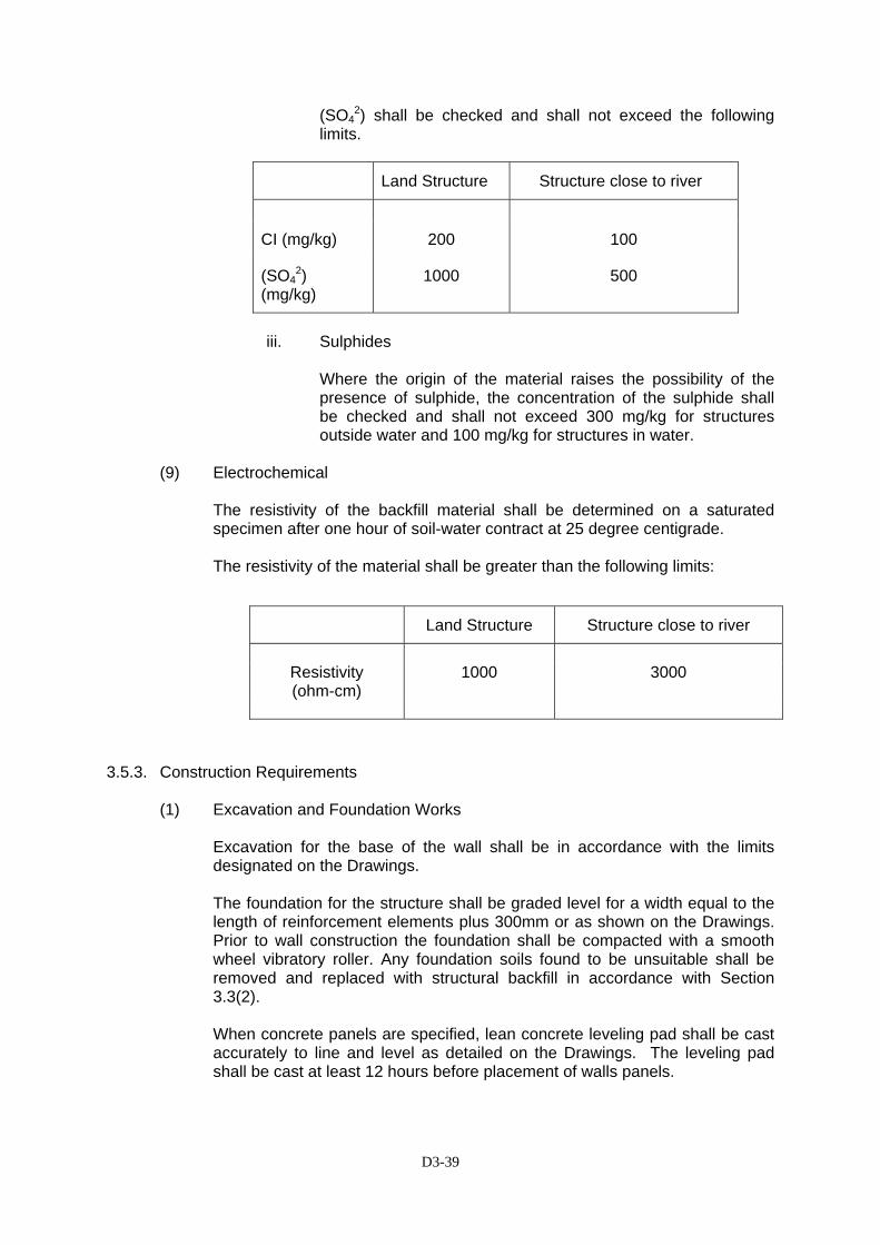
D3-39
(SO42) shall be checked and shall not exceed the following
limits.
Land Structure Structure close to river
CI (mg/kg) 200 100
(SO42)
(mg/kg) 1000 500
iii. Sulphides
Where the origin of the material raises the possibility of the presence of sulphide, the concentration of the sulphide shall be checked and shall not exceed 300 mg/kg for structures outside water and 100 mg/kg for structures in water.
(9) Electrochemical
The resistivity of the backfill material shall be determined on a saturated specimen after one hour of soil-water contract at 25 degree centigrade.
The resistivity of the material shall be greater than the following limits:
3.5.3. Construction Requirements
(1) Excavation and Foundation Works
Excavation for the base of the wall shall be in accordance with the limits designated on the Drawings. The foundation for the structure shall be graded level for a width equal to the length of reinforcement elements plus 300mm or as shown on the Drawings. Prior to wall construction the foundation shall be compacted with a smooth wheel vibratory roller. Any foundation soils found to be unsuitable shall be removed and replaced with structural backfill in accordance with Section 3.3(2). When concrete panels are specified, lean concrete leveling pad shall be cast accurately to line and level as detailed on the Drawings. The leveling pad shall be cast at least 12 hours before placement of walls panels.
Land Structure Structure close to river
Resistivity (ohm-cm)
1000 3000

D3-40
(2) Wall Erection Where a proprietary wall system is used, a field representative shall be available during the erection of the wall to assist the Contractor. Precast panels shall be placed so that their final position is vertical as shown on the Drawings. For erection, panels shall be handled by means of lifting devices connected to the upper edge of the panel. Panels shall be placed in successive horizontal lifts as backfill placement proceeds. As backfill material is placed behind the panels, the panels shall be maintained in position by means of temporary wedges, dowels or bracing according to the wall supplier’s recommendations. Reinforcement elements shall be placed normal to the face of the wall, unless otherwise shown on the Drawings. Prior to placement of the reinforcing elements, backfill shall be compacted in accordance with these Specifications.
(3) Filling and Compaction
Filling shall follow closely behind the wall facing panel erection. At each level of reinforcement, backfill shall be roughly leveled before placing and bolting reinforcement strips. The maximum thickness of each fill layer shall be 0.375 m or less as directed by the Engineer. During fill placement, trucks and heavy vehicles shall be kept back 1.5m from the rear face of the wall and crawler tracks shall not be directly in contract with the reinforcement. The fill within 1.5m behind the wall shall be compacted with hand-operated compacting machine with a weight not greater than 1 ton.
The compaction operation of mechanically stabilized wall shall be undertaken with the objective of preventing excessive ultimate settlement of the fill material. The fill shall be compacted to not less 95% standard proctor density and the minimum bulk density after compaction should not be less than 1800 Kg/m3. In general, 15-25 passes by 8 ton vibratory roller may sufficiently compact the granular backfill to the required specification of 95% standard proctor density.
(4) Tolerance
Differential settlement shall not exceed one percent along the wall after completion. Local variation of up to 30 mm or more measured by a 4.5 m straight edge along the wall face shall be allowed subject to the approval of the Engineer. Concrete facing vertical tolerances and horizontal alignment tolerances shall not exceed 20mm when measured with a 3m straight edge. During construction maximum allowable offset in any panel joint shall be 20mm. The completed wall shall have an overall vertical tolerance of the wall (top to bottom) that shall not exceed 13mm per 3m of wall height.

D3-41
(5) Drainage
(a) Subsoil Pipe
The subsoil pipe shall be half round perforated pipe, wrapped around with geo-textile cloth or equivalent with 4 numbers of 10 mm diameter staggered concentric holes, spaced longitudinally at 150 mm or as directed by the Engineer.
(b) Temporary Drainage
During construction of the mechanically stabilized earthwall, temporary drainage shall be constructed to divert any surface run-off away from the structure. At the end of each day any surplus backfill behind the structure shall be leveled-off at a gentle slope so that any surface run-off will flow into the temporary drainage.
3.5.4. Method of Measurement
The area of mechanically stabilized earth wall to be paid for under this Section shall be the number of square meters (m2) of earth wall completed and accepted in accordance with the Drawings and this Specification or as otherwise required by the Engineer. The volume of selected fill placed, compacted and accepted as called for on the Drawings and in accordance with this Specification or as otherwise required by the Engineer under this Item, shall be measured in cubic meters (m3).
3.5.5. Basis of Payment
The accepted quantities measured as prescribed in Clause 3.5.4 above, shall be paid for at the contract unit prices for each item of work, which prices and payment shall be full compensation for the furnishing, placing and compacting as necessary of all materials and appurtenances and for the furnishing of all labor, equipment, tools and incidents necessary to complete the item.
Price and payment for mechanically stabilized earth wall shall be deemed to include the cost of excavation, concrete foundation, pre-cast concrete panels, drainage work and incidental work items.
Payment shall be made under:
Pay Item Number Description Unit of
Measurement SS 3.5 (1) Mechanically Stabilized Earthwall Square Meter
D4-1
DIVISION 4 – PAVEMENT WIDENING AND SHOULDERS
SSEECCTTIIOONN 44..22 -- AAGGGGRREEGGAATTEE SSUUBBBBAASSEE
4.2.1 DDeessccrriippttiioonn
This work shall consist of supplying and placing of untreated crash stone materials between the subgrade and concrete slab or bituminous treated base, in accordance with these Specifications and in conformity with the lines, grades, thickness and typical cross-sections shown on the plans or established by the Engineer.
44..22..22 MMaatteerriiaallss
(1) Material Sources
Aggregate subbase materials shall be selected from approved sources.
(2) Classes of Aggregate Base
Two different qualities of base course are specified, Class A and Class B. Generally, Aggregate Base Class A is base course quality materials for use n layers immediately below bituminous surfacing. Aggregate Class B is for sub-base layers. Class B aggregate may also be used for unsealed shoulders.
(3) Coarse Aggregate Fraction
The coarse aggregate retained on the 4.75mm sieve shall consist of hard durable particles or fragments or rock and gravel. Materials which break up when alternately wetted and dried shall not be used.
(4) Fine Aggregate Fraction
Fine aggregate passing the 4.75mm sieve shall consist of natural or crushed sand and fine mineral particles.
(5) Required Material Properties
All aggregates shall be free from organic matter and lumps of clay or other deleterious matter and after compaction shall conform to the grading requirements given in Table (a) and (b) (using wet sieve testing).
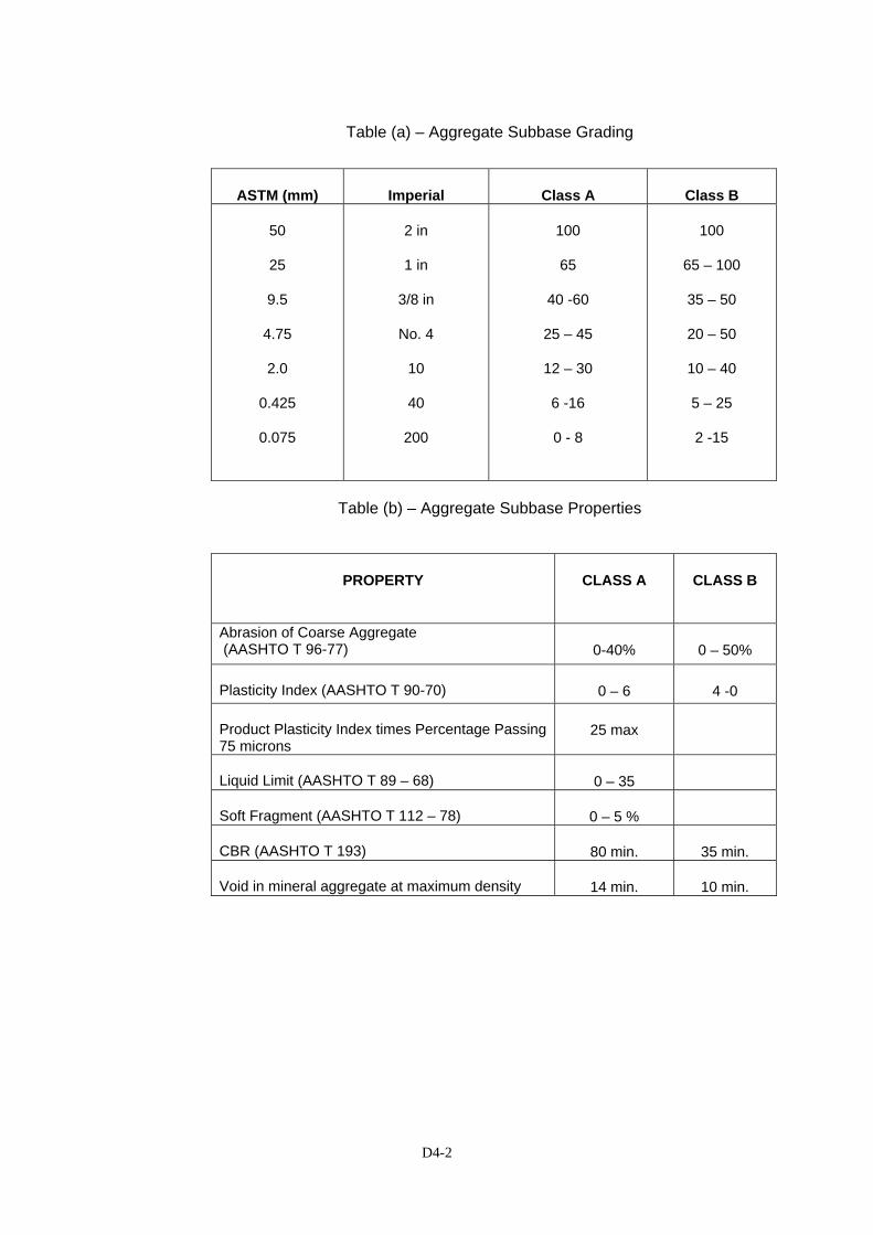
D4-2
Table (a) – Aggregate Subbase Grading
ASTM (mm) Imperial Class A Class B
50
25
9.5
4.75
2.0
0.425
0.075
2 in
1 in
3/8 in
No. 4
10
40
200
100
65
40 -60
25 – 45
12 – 30
6 -16
0 - 8
100
65 – 100
35 – 50
20 – 50
10 – 40
5 – 25
2 -15
Table (b) – Aggregate Subbase Properties
PROPERTY CLASS A CLASS B
Abrasion of Coarse Aggregate (AASHTO T 96-77) 0-40% 0 – 50% Plasticity Index (AASHTO T 90-70) 0 – 6 4 -0 Product Plasticity Index times Percentage Passing 75 microns
25 max
Liquid Limit (AASHTO T 89 – 68) 0 – 35 Soft Fragment (AASHTO T 112 – 78) 0 – 5 % CBR (AASHTO T 193) 80 min. 35 min. Void in mineral aggregate at maximum density 14 min. 10 min.

D4-3
(6) Dimensional Tolerances
(a) The finished surface levels shall comply with the Drawings and within the following tolerances:
Table (c) – Dimensional Tolerances
Aggregate Base Material and Layer Surface Level Tolerances
Aggregate Class B used as Subbase (Top surface of Subbase only)
+ 0cm
- 2 cm Aggregate Class A Surfaces for Prime Coat
+ 0cm
- 2 cm Unsealed Aggregate Class B shoulders (Top layer only) To comply with Article
4.2.1(3) of the Indonesian Standard Technical
Specification
(b) The surfaces of all construction Aggregate Base layers shall not have any irregularities which can hold moisture and the camber of all such surfaces shall comply with that shown on the Drawings.
(c) The minimum thickness of Aggregate base shall not be less than the required thickness less one centimeter.
Table(d) – Design Nominal Thickness of Asphaltic Mixtures
MIXTURE TYPE
SYMBOL
MINIMUM NOMINAL
THICKNESS (mm)
THICKNESS TOLERANCES
Sand sheet, Class A
SS-A
15
Sand sheet, Class B
SS-B
20
+ 2,0
Wearing Course
HRS-WC
30
Hot Rolled Sheet
Base Course
HRS-Base
35
+ 3,0
Wearing Course
AC-WC
40 + 3,0n
Binder Course
AC-BC
50 +4,0n
Asphalt Concrete
Base
AC-Base
60 + 5,0n

D4-4
(7) Blending of Aggregate Subbase Materials
Blending materials to meet the specified requirements shall be carried out in an approved mixing plant, using suitable calibrated mechanical feeders providing a continuous flow mix components in the correct proportions. Under no conditions shall site mixing be used.
44..22..33 CCoonnssttrruuccttiioonn
(1) Preparation of Subgrade
The subgrade shall be constructed, prepared, and finished as provided under pay item 3.4(1) of these Specifications before placing aggregate subbase course materials. The thickness of the subbase shall be as shown on the drawings or as instructed by the Engineer.
(2) Spreading
The Contractor’s method of spreading granular subbase shall be subject to the approval of the Engineer. If the Engineer is not satisfied with the Contractor’s method of spreading, he may require the use of spread box at no extra cost. Spreader boxes shall be self propelled wheel type or tracked vehicles and adjustable to place the material in layers of the specified thickness without undue disturbance to the prepared subgrade.
(3) Compaction
Immediately following final spreading and smoothing, each layer shall be compacted to full width by means of smooth wheel power rollers, pneumatic tired rollers or approved equipment. Rolling shall gradually progress from the low to high point of the cross-section, parallel to the centerline of the road, and shall continue until the entire surface has been rolled.
Any irregularities or depressions that developed shall be corrected by loosening the materials at these places and adding or removing materials until the surface is smooth and uniform. At all places not accessible by the roller, the materials shall be compacted thoroughly with approved tampers or compactors. The material shall be both bladed and rolled until a smooth and even surface has been obtained. Where the surfaces fail to meet the tolerance requirement, the Contractor shall remove and replace the subbase as directed by the Engineer with no additional cost.
Subbase materials shall be compacted to attain the required density through the full depth of each layer of at least 100% maximum density determined in accordance with AASHTO T180, Method D. In place field density determinations will be made in accordance with AASHTO T 191. The Engineer will make the measurements of test holes at random during progress of the work to confirm compliance with the specifications and to determine the depth of un-compacted layers required to obtain the designated nominal depth of the subbase.
Cutting the test holes and refilling with materials properly compacted shall be done by the Contractor under the supervision of the Engineer, at the Contractor’s expense.
44..22..44 MMeetthhoodd ooff MMeeaassuurreemmeenntt
The quantities t be paid for shall be the number of cubic meter of Subbase course laid in accordance with the drawings or instructed by the Engineer, compacted, tested and accepted by the Engineer. The quantity to be paid for will be based on the
D4-5
nominal dimensions and shape shown on the Drawings and the actual length measured along the centerline of survey. During the execution of the work, the thickness of each course shall be accurately controlled to attain the required thickness after compaction.
44..22..55 BBaassiiss ooff PPaayymmeenntt
The work measured as provided above shall be paid for, at the contract unit price per cubic meter for the type of subbase listed below. The payment shall be full compensation for furnishing materials, hauling, placing, compacting, sprinkling, rolling, finishing, shaping and for all labour, equipment, tools and incidentals necessary to complete the work specified herein. Pay Item Number
Description
Unit of Measurement
4.2(2)
Aggregate Subbase Class B
Cubic meter

D5-1
DDIIVVIISSIIOONN 55 –– GGRRAANNUULLAARR PPAAVVEEMMEENNTT
SSEECCTTIIOONN 55..11 -- AAGGGGRREEGGAATTEE SSUUBBBBAASSEE
5.1.1 General
This work shall consist of supplying, processing, hauling, spreading, watering and compacting crushed graded aggregate on a prepared and accepted surface in accordance with the details shown on the Drawings or as directed by the Engineer. Processing shall include, where necessary, crushing, screening, separation, blending, and any other operation necessary to produce a material conforming to the requirements prescribed in Section 4.2 of these Specifications.
5.1.2 Basis of Payment
The work measured as provided above shall be paid for, at the contract unit price per cubic meter for the type of subbase listed below. The payment shall be full compensation for furnishing materials, hauling, placing, compacting, sprinkling, rolling, finishing, shaping and for all labour, equipment, tools and incidentals necessary to complete the work specified herein.
Pay Item Number
Description
Unit of Measurement
5.1(1)
Aggregate Subbase Class A
Cubic meter
5.1(2)
Aggregate Subbase Class B
Cubic meter
D6-1
DIVISION 6 – ASPHALT PAVEMENT
SECTION 6.1(1) - PRIME COAT 6.1(1).1 Description
This work shall consist of furnishing and applying bituminous material to a previously prepared sub-grade, sub-base or base course surface in accordance with these Specifications and to the width shown on the typical cross sections or instructed by the Engineer.
6.1(1).2 Materials
(a) Bituminous Material
Bituminous material shall be of type and grade called for in the Drawings and shall conform to the requirements of the specifications listed below: Medium-curing cut back asphalt: AASHTO M 82 Rapid-curing cut back asphalt: AASHTO M 81 The grade (with temperatures of application in degrees C) shall be MC-70 (43 - 85 degrees) or RC-250 (60 - 100 degrees).
(b) Blotter Material
Blotter material shall be approved clean, dry sand or stone screenings free from any cohesive material. It shall contain no organic matter.
6.1(1).3 Construction
(a) Weather Limitations
Prime coat shall be applied only with the approval of the Engineer who will specify the grade to be used. The surface to be treated shall be dry or slightly damp, and the atmospheric temperature in the shade above 13 degrees Celsius and rising or above 15 degrees Celsius if falling.
(b) Equipment
The equipment shall meet the requirements of these Specifications and as directed by the Engineer.
(c) Preparation of Surface
Immediately before the application of the bituminous material, all loose dirt and other objectionable materials shall be removed from the surface with a power broom and/or blower as required. If the Engineer so orders, the surface shall be lightly bladed and rolled immediately prior to the application of bituminous material, in which case brooming
D6-2
or blowing will not be required. When so ordered by the Engineer a light application of water shall be made just before the application of bituminous material. The area to be treated shall be approved by the Engineer prior to application.
(d) Application of Bituminous Material
Bituminous material shall be applied to the width of the section to be primed by means of a bitumen distributor in a uniform, continuous spread. The rate of application will usually be in the range of 1.0 to 2.5 kg/sq.m and the Engineer will determine the rate and material grade to be used for each material being covered. Care shall be taken that the application of bituminous material at the junction of spreads is not in excess of the specified amount. Excess bituminous material shall be sponged from the surface. Skipped areas or deficiencies shall be corrected. Building paper shall be placed over the end of the previous applications and the joining application shall start on the building paper. Building paper used shall be removed and satisfactorily disposed of.
(e) Application of Blotter Material
In order to minimize possible damage by rain before the surface has completely dried, the Engineer may instruct that blotter material should be spread to cover any wet bituminous material. Blotter material shall be spread so that no wheels or tracks will travel on uncovered wet bituminous material.
6.1(1).4 Method of Measurement
The quantity of prime coat to be paid for shall be the number of kilograms of bituminous material, laid in accordance with this Specification and the Engineer's instructions.
6.1(1).5 Basis of Payment
The accepted quantities of prime coat, determined as provided above. will be paid for at the Contract price per liters for bituminous material which price and payment will be full compensation for the work of this Section, irrespective of the grade of material selected by the Engineer. Blotter material will not be payable directly but shall be considered as a subsidiary obligation of the Contractor covered under the Contract price for this Section. Pay Item Number
Description
Unit of Measurement
6.1(1)
Prime Coat
Liter

D6-3
SECTION 6.1(2) - TACK COAT 6.1(2).1 Description
This work shall consist of preparing and treating an existing bituminous or concrete surface with bituminous material in accordance with these Specifications and in conformity with the details shown on the Drawings or as established by the Engineer.
6.1(2).2 Materials
Bituminous material shall conform to the requirements of the specification listed below. Rapid-curing cut back asphalt : AASHTO M 81 The grade (with temperatures of application in degrees C) shall be RC-250 (60 - 100 degrees).
6.1(2).3 Construction
(a) Equipment
The equipment shall meet the requirements of specified in the Indonesian Standard Specification for this section and as ordered by the Engineer.
(b) Preparation of Surface to be Treated
The existing surface shall be patched and cleaned and shall be free of irregularities to provide a reasonably smooth and uniform surface to receive the treatment. Unstable, corrugated or damaged areas shall be removed and replaced or repaired as instructed by the Engineer. The edges of existing pavement; which are to be adjacent to new pavement, shall be cleaned to permit the adhesion of bituminous materials. The area to be treated shall be approved by the Engineer prior to application.
(c) Application of Bituminous Material
The bituminous material shall be uniformly applied with a pressure distributor within the 24 hours preceding placement of the covering course. The Engineer will specify the rate of the application which will usually be in the range of 0.4 to 0.8 kg/sq.m. Care shall be taken that the application of bituminous material at the junction of spreads is not in excess of the specified amount. Excess bituminous material shall be sponged from the surface. Skipped areas or deficiencies shall be corrected.
The surface shall be allowed to dry until it is in a proper condition of tackiness to receive the covering course. Tack coat shall be applied only so far in advance of covering course placement as is necessary to obtain this proper condition of tackiness. Until the covering course is placed, the Contractor shall protect the tack coat from damage.
D6-4
6.1(2).4 Method of Measurement
The quantity of tack coat to be paid for shall be the number of liters of bituminous material, laid in accordance with this Specification and the Engineer's instructions.
6.1(2).5 Basis of Payment
The accepted quantities of tack coat, determined as provided above, will be paid for at the Contract unit price per liters for bituminous material complete in place and accepted, which price and payment will be full compensation for the work of this Section.
Pay Item Number
Description
Unit of Measurement
6.1(2)
Tack Coat
Liter
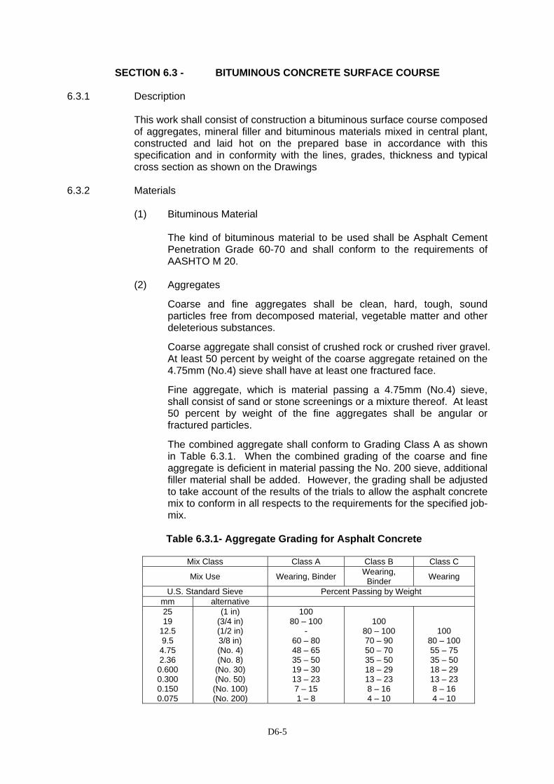
D6-5
SECTION 6.3 - BITUMINOUS CONCRETE SURFACE COURSE 6.3.1 Description
This work shall consist of construction a bituminous surface course composed of aggregates, mineral filler and bituminous materials mixed in central plant, constructed and laid hot on the prepared base in accordance with this specification and in conformity with the lines, grades, thickness and typical cross section as shown on the Drawings
6.3.2 Materials
(1) Bituminous Material
The kind of bituminous material to be used shall be Asphalt Cement Penetration Grade 60-70 and shall conform to the requirements of AASHTO M 20.
(2) Aggregates
Coarse and fine aggregates shall be clean, hard, tough, sound particles free from decomposed material, vegetable matter and other deleterious substances.
Coarse aggregate shall consist of crushed rock or crushed river gravel. At least 50 percent by weight of the coarse aggregate retained on the 4.75mm (No.4) sieve shall have at least one fractured face.
Fine aggregate, which is material passing a 4.75mm (No.4) sieve, shall consist of sand or stone screenings or a mixture thereof. At least 50 percent by weight of the fine aggregates shall be angular or fractured particles.
The combined aggregate shall conform to Grading Class A as shown in Table 6.3.1. When the combined grading of the coarse and fine aggregate is deficient in material passing the No. 200 sieve, additional filler material shall be added. However, the grading shall be adjusted to take account of the results of the trials to allow the asphalt concrete mix to conform in all respects to the requirements for the specified job-mix. Table 6.3.1- Aggregate Grading for Asphalt Concrete
Mix Class Class A Class B Class C
Mix Use Wearing, Binder Wearing, Binder Wearing
U.S. Standard Sieve Percent Passing by Weight mm alternative 25 19
12.5 9.5
4.75 2.36 0.600 0.300 0.150 0.075
(1 in) (3/4 in) (1/2 in) 3/8 in) (No. 4) (No. 8) (No. 30) (No. 50)
(No. 100) (No. 200)
100 80 – 100
- 60 – 80 48 – 65 35 – 50 19 – 30 13 – 23 7 – 15 1 – 8
100 80 – 100 70 – 90 50 – 70 35 – 50 18 – 29 13 – 23 8 – 16 4 – 10
100 80 – 100 55 – 75 35 – 50 18 – 29 13 – 23 8 – 16 4 – 10
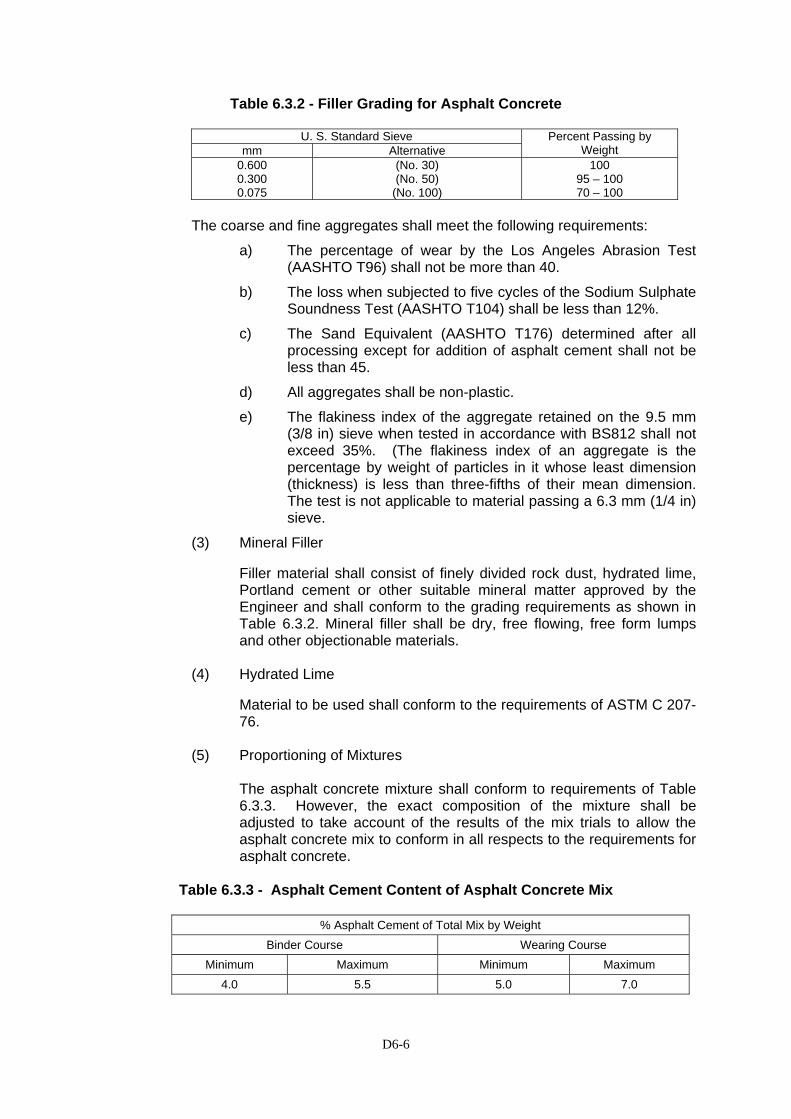
D6-6
Table 6.3.2 - Filler Grading for Asphalt Concrete
U. S. Standard Sieve mm Alternative
Percent Passing by Weight
0.600 0.300 0.075
(No. 30) (No. 50)
(No. 100)
100 95 – 100 70 – 100
The coarse and fine aggregates shall meet the following requirements:
a) The percentage of wear by the Los Angeles Abrasion Test (AASHTO T96) shall not be more than 40.
b) The loss when subjected to five cycles of the Sodium Sulphate Soundness Test (AASHTO T104) shall be less than 12%.
c) The Sand Equivalent (AASHTO T176) determined after all processing except for addition of asphalt cement shall not be less than 45.
d) All aggregates shall be non-plastic.
e) The flakiness index of the aggregate retained on the 9.5 mm (3/8 in) sieve when tested in accordance with BS812 shall not exceed 35%. (The flakiness index of an aggregate is the percentage by weight of particles in it whose least dimension (thickness) is less than three-fifths of their mean dimension. The test is not applicable to material passing a 6.3 mm (1/4 in) sieve.
(3) Mineral Filler
Filler material shall consist of finely divided rock dust, hydrated lime, Portland cement or other suitable mineral matter approved by the Engineer and shall conform to the grading requirements as shown in Table 6.3.2. Mineral filler shall be dry, free flowing, free form lumps and other objectionable materials.
(4) Hydrated Lime
Material to be used shall conform to the requirements of ASTM C 207-76.
(5) Proportioning of Mixtures
The asphalt concrete mixture shall conform to requirements of Table 6.3.3. However, the exact composition of the mixture shall be adjusted to take account of the results of the mix trials to allow the asphalt concrete mix to conform in all respects to the requirements for asphalt concrete.
Table 6.3.3 - Asphalt Cement Content of Asphalt Concrete Mix
% Asphalt Cement of Total Mix by Weight
Binder Course Wearing Course Minimum Maximum Minimum Maximum
4.0 5.5 5.0 7.0
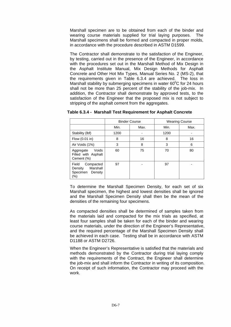
D6-7
Marshall specimen are to be obtained from each of the binder and wearing course materials supplied for trial laying purposes. The Marshall specimens shall be formed and compacted in proper molds, in accordance with the procedure described in ASTM D1599. The Contractor shall demonstrate to the satisfaction of the Engineer, by testing, carried out in the presence of the Engineer, in accordance with the procedures set out in the Marshall Method of Mix Design in the Asphalt Institute Manual, Mix Design Methods for Asphalt Concrete and Other Hot Mix Types, Manual Series No. 2 (MS-2), that the requirements given in Table 6.3.4 are achieved. The loss in Marshall stability by submerging specimens in water 600C for 24 hours shall not be more than 25 percent of the stability of the job-mix. In addition, the Contractor shall demonstrate by approved tests, to the satisfaction of the Engineer that the proposed mix is not subject to stripping of the asphalt cement from the aggregates.
Table 6.3.4 - Marshall Test Requirement for Asphalt Concrete
Binder Course Wearing Course Min. Max. Min. Max. Stability (lbf) 1200 - 1200 - Flow (0.01 in) 8 16 8 16 Air Voids (1%) 3 8 3 6 Aggregate Voids Filled with Asphalt Cement (%)
60 75 70 80
Field Compacted Density Marshall Specimen Density (%)
97 - 97 -
To determine the Marshall Specimen Density, for each set of six Marshall specimen, the highest and lowest densities shall be ignored and the Marshall Specimen Density shall then be the mean of the densities of the remaining four specimens. As compacted densities shall be determined of samples taken from the materials laid and compacted for the mix trials as specified, at least four samples shall be taken for each of the binder and wearing course materials, under the direction of the Engineer’s Representative, and the required percentage of the Marshall Specimen Density shall be achieved in each case. Testing shall be in accordance with ASTM D1188 or ASTM D2726.
When the Engineer’s Representative is satisfied that the materials and methods demonstrated by the Contractor during trial laying comply with the requirements of the Contract, the Engineer shall determine the job-mix and shall inform the Contractor in writing of its composition. On receipt of such information, the Contractor may proceed with the work.
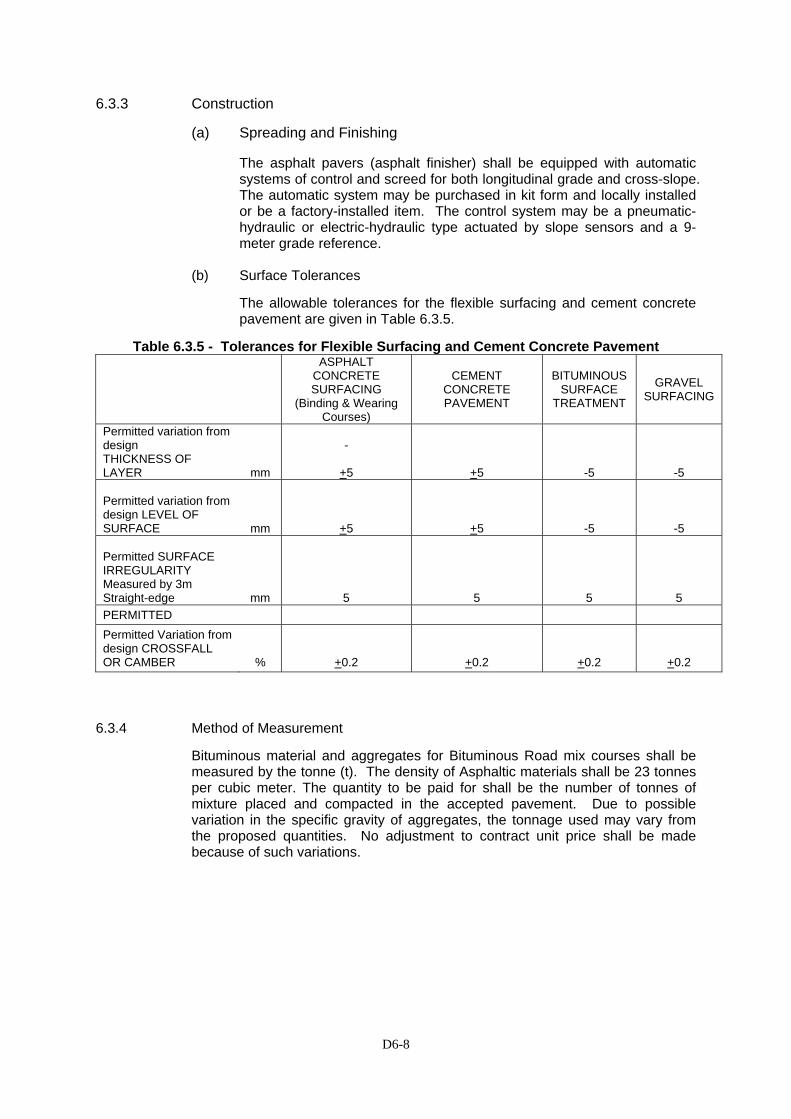
D6-8
6.3.3 Construction
(a) Spreading and Finishing
The asphalt pavers (asphalt finisher) shall be equipped with automatic systems of control and screed for both longitudinal grade and cross-slope. The automatic system may be purchased in kit form and locally installed or be a factory-installed item. The control system may be a pneumatic-hydraulic or electric-hydraulic type actuated by slope sensors and a 9-meter grade reference.
(b) Surface Tolerances
The allowable tolerances for the flexible surfacing and cement concrete pavement are given in Table 6.3.5.
Table 6.3.5 - Tolerances for Flexible Surfacing and Cement Concrete Pavement
ASPHALT CONCRETE SURFACING
(Binding & Wearing Courses)
CEMENT CONCRETE PAVEMENT
BITUMINOUS SURFACE
TREATMENT
GRAVEL SURFACING
Permitted variation from design THICKNESS OF LAYER mm
-
+5 +5 -5 -5 Permitted variation from design LEVEL OF SURFACE mm +5 +5 -5 -5 Permitted SURFACE IRREGULARITY Measured by 3m Straight-edge mm 5 5 5 5 PERMITTED Permitted Variation from design CROSSFALL OR CAMBER % +0.2 +0.2 +0.2 +0.2
6.3.4 Method of Measurement
Bituminous material and aggregates for Bituminous Road mix courses shall be measured by the tonne (t). The density of Asphaltic materials shall be 23 tonnes per cubic meter. The quantity to be paid for shall be the number of tonnes of mixture placed and compacted in the accepted pavement. Due to possible variation in the specific gravity of aggregates, the tonnage used may vary from the proposed quantities. No adjustment to contract unit price shall be made because of such variations.
D6-9
6.3.5 Basis of Payment
The accepted quantities of asphalt bituminous material, determined as above, will be paid for at the contract unit prices per units of measurement for each item shown below complete in place and accepted, which price will be full compensation for work in this section including any extra costs due to regulating or overlaying existing pavements. Pay Item Number
Description
Unit of Measurement
6.3 (1) Asphalt Concrete Wearing Course, (AC-WC) Tonne 6.3 (2) Asphalt Concrete Binder Course, (AC-BC) Tonne 6.3 (3) Asphalt Concrete Base, (AC-Base) Tonne
D7-1
DIVISION 7 – STRUCTURES
SECTION 7.1 STRUCTURAL CONCRETE 7.1.1 Description
(1) Scope
The work shall consist of furnishing, placing and finishing concrete in all reinforced and composite structures except pavements in accordance with this specification and conforming to the lines, levels, grades, and dimensions shown on the Drawings, or as required by the Engineer. Concrete shall consist of a mixture of Portland cement, fine aggregates, coarse aggregates, admixtures when specified, and water mixed in the proportions specified and approved by the Engineer.
(2) Classes and Uses of Concrete
Six (6) classes of concrete are provided for in this Section namely A, B, B-1, B-2, C and E (lean concrete). Each class shall be used in the specific part of the structure as described herein below and as called for on the Drawings. The classes and uses of concrete are as follows:
Class A - For PC double trapezoidal girder, diaphragm (PC
double trapezoidal girder), PC hollow slab, deck slab of steel trapezoidal girder, and as indicated on the Drawings.
Class B - For RC column, infill for composite column, abutments,
footings, pier head (coping), and where shown on the Drawings.
Class B-1 - For parapet, median barrier and where shown on the Drawings. Class B-2 - For bored piles, and where shown on the Drawings. Class C - For approach slab, reinforced concrete box culverts, headwalls, wingwalls, aprons, retaining walls, revetment works, and as shown on the Drawings. Class D - Where shown on the Drawings Class E (Lean Concrete) - For thin layers underneath footings and where shown
on the Drawings or as directed by the Engineer.
D7-2
(3) Submittals
(a) The Contractor shall submit samples of all the materials he intends to use together with test data confirming that all the material properties specified in Clause 7.1.2 of these Specifications are met.
(b) The Contractor shall submit his mix design for each type of concrete he proposes to use 30 days prior to the intended start of concrete placement.
(c) The Contractor shall submit in writing the results of all specified quality control tests promptly when they become available or are requested by the Engineer. In the case of compressive strength tests, this will involve submitting the 3-day strength, 7-day strength, 14-day strength and 28-day strength test results 3 days, 7 days, 14 days and 28 days respectively following the date of mixing.
(d) The Contractor shall submit detailed drawings of all false work to be used, and shall obtain the Engineer's approval before setting up any false work.
(e) The Contractor shall notify the Engineer in writing at least 24 hours before he intends commencing mixing or placing any concrete, as specified in Clause 7.1.4.(4) below.
(4) Storage and Protection of Cement
For storage of cement the Contractor shall provide a weatherproof shed that is airtight and has a raised wooden floor which is covered with polyethylene sheeting. At all times stacks of cement bags shall be kept covered with an envelope of polyethylene sheeting.
(5) Job Conditions
The Contractor shall maintain the temperature of all materials, particularly the coarse aggregate, at the lowest possible levels and shall maintain the temperature of the concrete below 30 ºC at the time of placement. In addition, the Contractor shall not place any concrete when:
(a) The rate of evaporation exceeds 1.0 kg/m2/hour.
(b) The relative humidity of the air is less than 40 %.
(c) Directed not to do so by the Engineer, during periods of rain or when the air is dust laden or otherwise polluted.
(6) Rectification of Unsatisfactory Concrete Work
(a) Rectification of concrete work which does not meet the tolerance criteria specified in Sub-clause 7.1.6.(4), or which does not have a satisfactory surface finish, or which does not meet the mix property requirements specified in Sub-clause 7.1.3.(3), shall be as directed by the Engineer and may include:
(i) Changes in the mix proportions for the remainder of the work.

D7-3
(ii) Additional curing on those portions of the structure represented by the test specimens which failed.
(iii) Strengthening or complete removal and replacement of those portions of the work which he deems to be unsatisfactory.
(b) In the event of a dispute regarding the quality of the concrete work or any doubt regarding the adequacy of the available test data, the Engineer may direct the Contractor to carry out additional testing to ensure that a fair judgement of the work quality can be made.
7.1.2 Materials
(1) Cement
(a) The cement used for Concrete Work shall be any type of Portland cement conforming to AASHTO M85 except type IA, IIA, IIIA and IV. Unless other-wise permitted by the Engineer, air-entraining admixtures shall not be used.
(b) Unless otherwise permitted by the Engineer, the product of only one mill of any one brand type of Portland cement shall be used on the project.
(2) Water
Water used in mixing, curing, or other designated applications shall be clean and free from harmful matter such as oil, salt, acid, alkali, sugar, or organic materials. Water will be tested in accordance with, and shall meet the requirements of AASHTO T26. Water known to be of potable quality may be used without being tested. When the proposed water quality is doubtful and the testing as above mentioned could not be carried out, comparison testing shall be carried out by using the cement mortar with the proposed water and with the distillated or drinking water. The proposed water could be used when the compressive strength at 7 days and 28 days of cement mortar with the proposed water is at least 90 % of cement mortar with the distillated or drinking water at the same curing period.
(3) Aggregate Grading Requirements
(a) The coarse and fine aggregate gradations shall conform with the requirements given in Table 7.1.2.(1) except that materials not meeting these grading requirements will not necessarily be rejected if the Contractor can demonstrate by testing that concrete meeting the mix property requirements specified in Sub-clause 7.1.3.(3) can be produced using them.
(b) The coarse aggregate shall be selected so that the maximum particle size is no greater than three quarters the minimum clear space between reinforcing bars or between the bars and the formwork or between any other restrictions in the space that the concrete must occupy in the work.
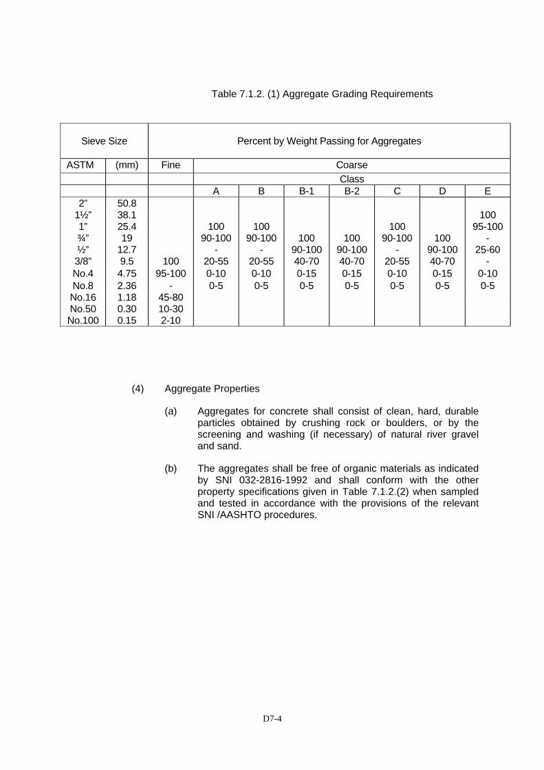
D7-4
Table 7.1.2. (1) Aggregate Grading Requirements
(4) Aggregate Properties
(a) Aggregates for concrete shall consist of clean, hard, durable particles obtained by crushing rock or boulders, or by the screening and washing (if necessary) of natural river gravel and sand.
(b) The aggregates shall be free of organic materials as indicated by SNI 032-2816-1992 and shall conform with the other property specifications given in Table 7.1.2.(2) when sampled and tested in accordance with the provisions of the relevant SNI /AASHTO procedures.
Sieve Size
Percent by Weight Passing for Aggregates
ASTM (mm) Fine Coarse Class A B B-1 B-2 C D E
2” 50.8 1½” 38.1 100 1” 25.4 100 100 100 95-100¾” 19 90-100 90-100 100 100 90-100 100 - ½” 12.7 - - 90-100 90-100 - 90-100 25-60 3/8” 9.5 100 20-55 20-55 40-70 40-70 20-55 40-70 - No.4 4.75 95-100 0-10 0-10 0-15 0-15 0-10 0-15 0-10 No.8 2.36 - 0-5 0-5 0-5 0-5 0-5 0-5 0-5 No.16 1.18 45-80 No.50 0.30 10-30 No.100 0.15 2-10
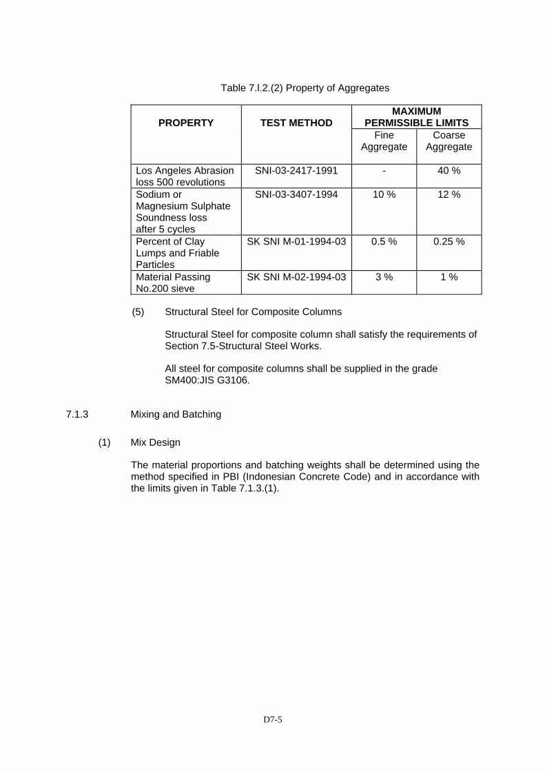
D7-5
Table 7.l.2.(2) Property of Aggregates
MAXIMUM PERMISSIBLE LIMITS
PROPERTY
TEST METHOD
Fine Aggregate
Coarse Aggregate
Los Angeles Abrasion loss 500 revolutions
SNI-03-2417-1991 - 40 %
Sodium or Magnesium Sulphate Soundness loss after 5 cycles
SNI-03-3407-1994 10 % 12 %
Percent of Clay Lumps and Friable Particles
SK SNI M-01-1994-03 0.5 % 0.25 %
Material Passing No.200 sieve
SK SNI M-02-1994-03 3 % 1 %
(5) Structural Steel for Composite Columns
Structural Steel for composite column shall satisfy the requirements of Section 7.5-Structural Steel Works.
All steel for composite columns shall be supplied in the grade SM400:JIS G3106.
7.1.3 Mixing and Batching
(1) Mix Design
The material proportions and batching weights shall be determined using the method specified in PBI (Indonesian Concrete Code) and in accordance with the limits given in Table 7.1.3.(1).
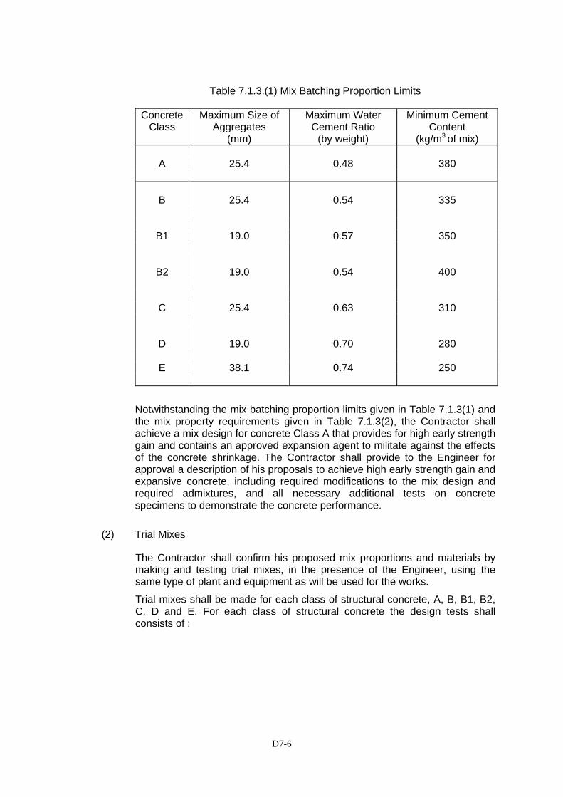
D7-6
Table 7.1.3.(1) Mix Batching Proportion Limits
Concrete Class
Maximum Size of Aggregates
(mm)
Maximum Water Cement Ratio
(by weight)
Minimum Cement Content
(kg/m3 of mix)
A 25.4 0.48 380
B 25.4 0.54 335
B1 19.0 0.57 350
B2 19.0 0.54 400
C 25.4 0.63 310
D 19.0 0.70 280
E 38.1 0.74 250
Notwithstanding the mix batching proportion limits given in Table 7.1.3(1) and the mix property requirements given in Table 7.1.3(2), the Contractor shall achieve a mix design for concrete Class A that provides for high early strength gain and contains an approved expansion agent to militate against the effects of the concrete shrinkage. The Contractor shall provide to the Engineer for approval a description of his proposals to achieve high early strength gain and expansive concrete, including required modifications to the mix design and required admixtures, and all necessary additional tests on concrete specimens to demonstrate the concrete performance.
(2) Trial Mixes
The Contractor shall confirm his proposed mix proportions and materials by making and testing trial mixes, in the presence of the Engineer, using the same type of plant and equipment as will be used for the works.
Trial mixes shall be made for each class of structural concrete, A, B, B1, B2, C, D and E. For each class of structural concrete the design tests shall consists of :
D7-7
Type of Test Age Number of Specimens
Tested
Compressive Strength 3 days 9
7 days 9
28 days 9
and workability control tests by measurement of the slump.
All tests shall be carried out in accordance with 7.1.3 (3)(a).
From the same mix as that from which the test specimens are made, the workability of the concrete shall be determined by slump test in accordance with AASHTO test specification T119 or other method approved by the Engineer.
Unless the results of trial mixes for a particular class have been approved by the Engineer, no concrete of the relevant class shall be placed in the works.
The trial mix shall be deemed acceptable provided it meets all the mix property requirements specified in Sub-clause 7.1.3(3) below.
(3) Mix Property Requirements
(a) All concrete used in the work shall meet the compressive strength and slump requirements specified in Table 7.1.3.(2), or approved by the Engineer, when sampled, cured and tested in accordance with SNI 03-1974-1990 (AASHTO T22), Pd M-16-1996-03 (AASHTO T23), SNI 03-2493-1991 (AASHTO T126), SNI 03-2458-1991 (AASHTO T141).
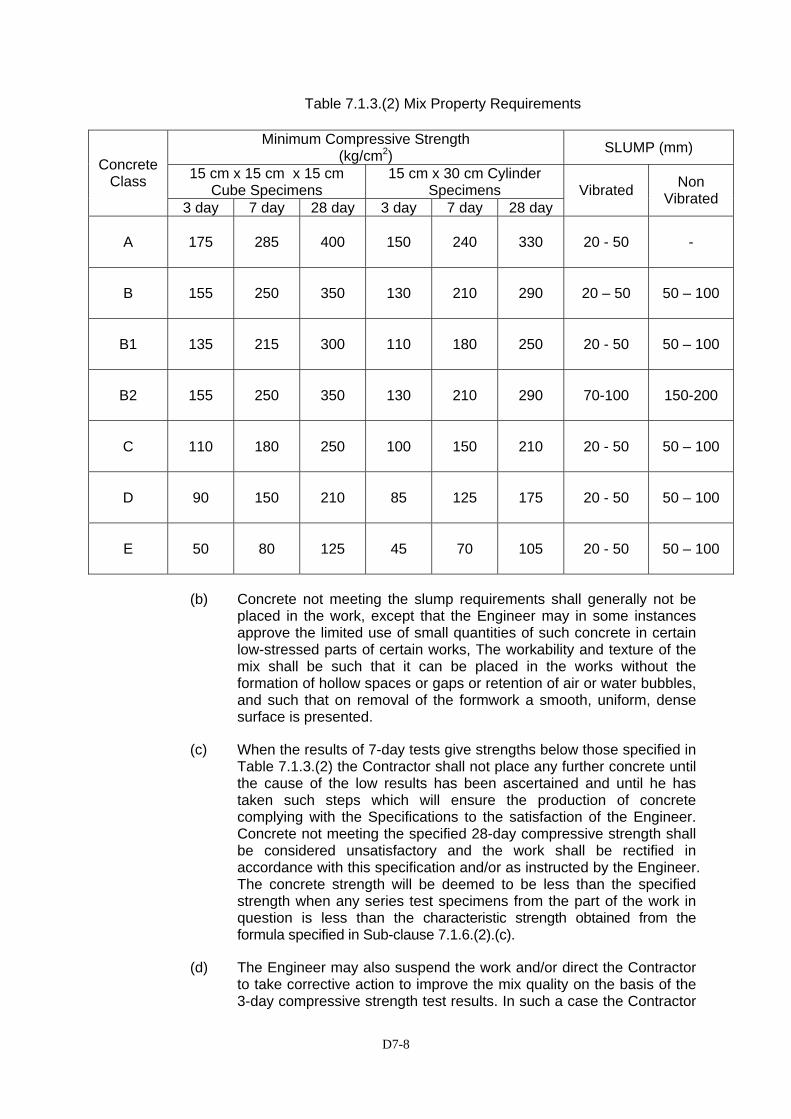
D7-8
Table 7.1.3.(2) Mix Property Requirements
(b) Concrete not meeting the slump requirements shall generally not be placed in the work, except that the Engineer may in some instances approve the limited use of small quantities of such concrete in certain low-stressed parts of certain works, The workability and texture of the mix shall be such that it can be placed in the works without the formation of hollow spaces or gaps or retention of air or water bubbles, and such that on removal of the formwork a smooth, uniform, dense surface is presented.
(c) When the results of 7-day tests give strengths below those specified in Table 7.1.3.(2) the Contractor shall not place any further concrete until the cause of the low results has been ascertained and until he has taken such steps which will ensure the production of concrete complying with the Specifications to the satisfaction of the Engineer. Concrete not meeting the specified 28-day compressive strength shall be considered unsatisfactory and the work shall be rectified in accordance with this specification and/or as instructed by the Engineer. The concrete strength will be deemed to be less than the specified strength when any series test specimens from the part of the work in question is less than the characteristic strength obtained from the formula specified in Sub-clause 7.1.6.(2).(c).
(d) The Engineer may also suspend the work and/or direct the Contractor to take corrective action to improve the mix quality on the basis of the 3-day compressive strength test results. In such a case the Contractor
Minimum Compressive Strength (kg/cm2) SLUMP (mm)
15 cm x 15 cm x 15 cm Cube Specimens
15 cm x 30 cm Cylinder Specimens
Concrete Class
3 day 7 day 28 day 3 day 7 day 28 day Vibrated Non
Vibrated
A
175 285 400 150 240 330 20 - 50 -
B
155 250 350 130 210 290 20 – 50 50 – 100
B1
135 215 300 110 180 250 20 - 50 50 – 100
B2
155 250 350 130 210 290 70-100 150-200
C
110 180 250 100 150 210 20 - 50 50 – 100
D
90 150 210 85 125 175 20 - 50 50 – 100
E
50 80 125 45 70 105 20 - 50 50 – 100
D7-9
shall immediately cease placing the concrete in question but may elect to wait until the results of the 7-day tests are available, before implementing corrective measures, at which time the Engineer will review both the 3-day and 7-day test results, and may direct immediate implementation of whatever corrective measures he judges as necessary.
(e) Rectification of unsatisfactory concrete work involving the complete removal and replacement of the concrete will not be based on the results of 3-day compressive strength tests alone unless the Contractor and Engineer mutually agree on the rectification.
(4) Mix Adjustments
(a) Adjusting Workability
If it is found impossible to obtain concrete of the desired placeability and workability with the proportions originally designated by the Engineer, the Contractor will make such changes in aggregate weights as are necessary, provided that in no case shall the cement content originally designated be changed, nor shall the water/cement ratio established by compressive strength testing as resulting in adequate strength be increased.
Re-tempering concrete already mixed by adding water or by other means will not be permitted. Admixtures for increasing the workability will be permitted only when specifically approved by the Engineer.
(b) Adjusting Strength
If the concrete does not come up to the specified or approval strength, the cement content shall be increased as directed by the Engineer.
(c) Adjustment for New Materials.
No change in the source or character of the materials shall be made without written notice to the Engineer and no new materials shall be used until the Engineer has accepted such material in writing and has designated new proportions based on tests on new trial mixes carried out by the Contractor.
(5) Batching plant and equipment
(a) General
All material in the mix shall be proportioned wholly by weight. Batching plants shall include bins, weighing hoppers, and scales for the fine aggregate and for each separated size of coarse aggregate. If cement is used in bulk, a bin, hopper and scales for the cement shall be included. Batch containers shall be watertight.
Provision satisfactory to the Engineer shall be made for batching other components of the mix, at the batching plant or at the mixer as may be necessary. The batching plant may be either of stationary or of mobile
D7-10
type. It shall be always properly levelled within the accuracy required for the proper operation of the weighing mechanisms.
(b) Bins and hoppers
Bins with adequate separate compartments for fine aggregate and for each required size of coarse aggregate shall be provided in the batching plant. Each compartment shall discharge efficiently and freely into the weighing hopper. Means of control shall be provided so that as the quantity desired in the weighing hopper is being approached, the material may be added slowly and shut off with precision. A port or other opening for removing an overload of the several materials from the hopper shall be provided.
Weighing hoppers shall be constructed so as to discharge fully.
(c) Scales
The scales for weighing aggregates and cement shall be of either the beam type or the springless-dial type. They shall be accurate within one-half of 1% under operating conditions throughout the range of use. Ten 25 kilogram weights shall be available for checking accuracy. All exposed fulcrums, crevices, and similar working parts of scales shall be kept clean. When beam-type scales are used, provision shall be made for indicating to the operator that the required load in the weighing hopper is being approached. The device shall indicate at least the last 100 kilograms of load and up to 25 kilograms overload. All weighing and indicating devices shall be in full view of the operator while charging the hopper and he shall have convenient access to all controls.
Cement may be measured by weight, or in standard sacks considered to weigh 50 kilograms net. When measured by weight a separate, satisfactory scale and hopper shall be provided together with a boot or other approved device to transfer the cement from the weighing hopper. Satisfactory methods of handling shall be employed.
Batching shall be so conducted as to result in the weights of material required, within tolerances of 1% for cement and 2% for aggregates.
(6) Mixing Equipment
(a) General
All concrete shall be mixed in batch mixers. It may be mixed at the site of construction, at a central plant, or in transit. Each mixer shall have attached to it in a prominent place a manufacturer's plate showing the capacity of the drum in terms of volume of mixed concrete and the speed of rotation of the mixing drum.
(b) Mixers at site of construction
Mixers at the site shall be approved drum-type capable of combining the aggregate, cement, and water into a thoroughly mixed and uniform mass within the specified mixing period and of discharging the mixture
D7-11
without segregation. The mixer shall be equipped with a suitable charging hopper, water storage, and a water measuring device, accurate within 1%. Controls shall be so arranged that the water can be applied only while the mixer is being charged. The discharge lever shall lock automatically until the batch has been mixed the required time after all materials are in the mixer. Suitable equipment for discharging the concrete into hoppers or buckets shall be provided. The mixer shall be cleaned at suitable intervals. The pickup and throw-over blades in the drum shall be replaced when they have lost 10% of their depth.
(c) Central Plant Mixers
These mixers shall be of approved drum type capable of combining the aggregate, cement, and water into a thoroughly mixed and uniform mass within the specified mixing period and of discharging the mixture without segregation. Central plant mixers shall be equipped with an acceptable timing device that will not permit the batch to be discharged until the specified mixing time has elapsed. The water system for a central mixer shall be either a calibrated measuring tank or a meter and shall not necessarily be an integral part of the mixer.
The mixers shall be cleaned at suitable intervals. They shall be examined daily for changes in interior condition. The pick up and throw-over blades in the drum shall be replaced when they have lost 10% of their depth.
(d) Truck or transit mixers
These shall be equipped with electrically actuated counters by which the number of revolutions of the drum or blades may readily be verified and the counters shall be actuated at the commencement of mixing operations at designated mixing speeds. The transit mixer shall have a watertight revolving drum suitably mounted and shall be capable of combining the ingredients of the concrete into a thoroughly mixed and uniform mass and of discharging the concrete with a satisfactory degree of uniformity and without segregation.
The volume of mixed concrete permitted in the drum shall not exceed the manufacturer’s rating nor exceed 80% the gross volume of the drum. The agitating speed of the drum shall not be less than two or more than six revolutions per minute.
The gross volume of agitator bodies expressed in cubic meters shall be supplied by the mixer manufacturer.
Upon approval by the Engineer, open-top, revolving-blade truck mixers may be used in lieu of agitating trucks for transportation of central plant mixed concrete.
Except when intended for use exclusively as agitators truck mixers shall be provided with a water measuring device to measure accurately the quantity of water for each batch. The delivered amount of water shall be within plus or minus 1% of the indicated amount.

D7-12
(7) Batching
(a) When packaged cement is used, the batch quantity shall be such that the quantity of cement required is equal to one or more whole sacks of cement. The aggregates shall be measured separately by weight. The size of each batch shall not exceed the rated capacity of the mixer.
(b) Prior to batching, the aggregates shall be saturated and maintained in a moist condition, at moisture content as close as possible to the saturated surface dry state, by periodic spraying of the aggregate stockpiles with water. The last such watering of the aggregates shall have been at least 12 hours prior to the time of batching to ensure adequate draining of the stockpiles.
(8) Mixing Concrete (a) Plant mixing at the site of construction - Job-site mixers shall be
operated at a drum speed of not less than 15 nor more than 20 revolutions per minute. The batched materials shall be so charged into the drum that a portion of the water shall enter in advance of the cement and aggregates and the water shall continue to flow into the drum for a minimum time of 5 seconds after all the cement and aggregates are in the drum. Mixing time shall be measured from the time all materials except water are in the drum and shall in the case of mixers having a capacity of 3/4 cubic meter or less not be less than 1.5 minutes and shall be increased 15 seconds for each additional 0.5 cubic meter.
In the case of dual drum mixers, the mixing time shall not include transfer time. The contents of an individual mixer drum shall be removed before a succeeding batch is emptied therein. Any concrete mixed less than the specified minimum time shall be discarded and disposed of by the Contractor at his own expense.
The volume of concrete mixed per batch shall not exceed the mixer's nominal capacity in cubic meters as shown on the manufacturer 's guaranteed capacity standard rating plate on the mixer.
Retempering concrete by adding water or by other means will not be permitted. Concrete which is not of the required consistency at the time of placement shall not be used.
The amount of admixture to be added, if any, shall be approved by the Engineer.
(b) Central plant mixing -. Mixing at central plant shall conform to the requirements for mixing at the site.
(c) Truck mixing -Truck mixers may be used for complete mixing at the batch plant and as truck agitators for delivery of concrete to job sites or they may be used for complete mixing of the concrete at the job site. They shall either be a closed watertight revolving drum or an open top revolving blade or paddle type.
D7-13
The amount of mixing shall be designated in number of revolutions of the mixer drum. When a truck mixer is used for complete mixing, each batch of concrete shall be mixed for not less than 70 nor more than 100 revolution of the drum or blades at the rate of rotation designated by the manufacturer of the equipment as the "mixing speed". Such designation shall appear on a metal plate attached to the mixer. If the batch is at least one cubic meter less than guaranteed capacity, the number of revolutions at mixing speed may be reduced to not less than 50. Mixing in excess of 100 revolutions shall be at the agitating speed. All materials, including the mixing water, shall be in the mixer drum before actuation of the revolution counter which will indicate the number of revolutions of the drum or blades.
When wash water (flush water) is used as a portion of the mixing water for the succeeding batch, it shall be accurately measured and taken into account in determining the amount of additional mixing water required. When wash water is carried on the truck mixer, it shall be carried in a compartment separate from the one used for carrying or measuring the mixing water. The Engineer will specify the amount of wash or flush water, when permitted, and may specify a “dry" drum if wash water is used without measurement or without supervision.
When a truck mixer is used for complete mixing at the batch plant, mixing operation shall begin within 30 minutes after the cement has been added to the aggregate. After mixing, the truck mixer shall be used as an agitator for transporting concrete at the speed designated by the manufacturer of the equipment as agitating speed. Concrete discharge shall be completed within 45 minutes after the addition of the cement to the aggregates. Each batch of concrete delivered at the job site shall be accompanied by a time slip issued at the batching plant, bearing the time of departure therefrom. When the truck mixer is used for the complete mixing of the concrete at the job site, the mixing operation shall begin within 30 minutes after the cement has been added to the aggregates.
The rate of discharge of the plastic concrete from the mixer drum shall be controlled by the speed of rotation of the drum in the discharge direction with the discharge gate fully open.
(d) Where it is not possible to employ mixing machines, the Engineer may approve mixing of concrete manually, as near as practicable to the point of placement. The use of hand mixing is to be restricted to non-structural concrete.
(9) Transporting Mixed Concrete
Mixed concrete may only be transported to the delivery point in truck agitators or truck mixers operating at the speed designated by the manufactures of the equipment as agitating speed, or in non-agitating hauling equipment, provided the consistency and workability of the mixed concrete upon discharge at the delivery point is suitable for adequate placement and consolidation in place.
Truck agitators shall be loaded not to exceed the manufacturer’s guaranteed capacity. They shall maintain the mixed concrete in a thoroughly mixed and uniform mass during hauling.
D7-14
No additional mixing water shall be incorporated into the concrete during hauling or after arrival at the delivery point.
The rate of discharge of mixed concrete from truck mixers or agitators shall be controlled by the speed of rotation of the drum in the discharge direction with the discharge gate fully open.
When a truck mixer or agitator is used for transporting concrete to the delivery point, discharge shall be completed within one hour, or before 250 revolutions of the drum or blades, whichever comes first, after the introduction of the cement to the aggregates. Under conditions contributing to quick stiffening of the concrete or when the temperature of the concrete is 30°C, or above, a time less than one hour will be required.
(10) Delivery of Mixed Concrete
The Contractor shall have sufficient plant capacity and transportation apparatus to insure continuous delivery at the rate required. The rate of delivery of concrete during concreting operations shall be such as to provide for the proper handling, placing and finishing of the concrete. The rate shall be such that the interval between batches shall not exceed 20 minutes. The methods of delivering and handling the concrete shall be such as will facilitate placing of the minimum handling.
7.1.4 Placement
(1) Preparation of Site
(a) The Contractor shall demolish existing structures that are to be replaced by the new Concrete Work or which must be removed to make way for the new Concrete Work. Such demolition work shall be carried out in accordance with Section 7.15 of these Specifications.
(b) The Contractor shall excavate or backfill the foundations or formation for the Concrete Work to the lines shown on the Drawings or as instructed by the Engineer in accordance with the provisions of Sections 3.2(1) and 3.2 of these Specifications, and shall clear and grub a sufficient area around the perimeter of the Concrete Works to ensure easy access to all sides of the work. Stable walkways shall also be provided if necessary to ensure that all sides of the work may be easily and safely inspected.
(c) All footings, foundations and excavations for Concrete Work shall be kept dry and concrete shall not be placed on earth containing mud, debris or other foreign material, or in water.
(d) Before the placing of concrete is commenced, all formwork, reinforcement and items to be encased in the concrete (such as pipes or ducts) shall be correctly positioned and securely fastened and supported against displacement by the concrete placement work.
(e) If specified or required by the Engineer, bedding material for the Concrete Work shall be laid in accordance with the provisions of Section 7.1 of these Specifications.
D7-15
(f) The Engineer will inspect all prepared excavation and foundations before approving the placement of form work or reinforcing steel or concrete and may request the Contractor to carry out deep probe penetration tests, density tests or other investigations to confirm adequate bearing capacity of the foundation sub soils. In the event that unsatisfactory conditions are found, the Contractor may be directed to alter the dimensions or depth of the foundation and to excavate and replace soft areas, compact the foundation soils or carry out other stabilization measures which may be directed by the Engineer.
(2) Formwork
(a) Earth formwork, where approved by the Engineer, shall be formed by excavation, the sides and bottom being trimmed by hand to the required dimensions. All loose dirt shall be removed prior to the placing of concrete.
(b) Fabricated formwork may be of wood or steel, with mortar-tight joints and shall be rigid enough to maintain the required position during placing, compacting and curing without deformation.
(c) Rough timber may be used for surfaces that will not be exposed in the finished structure, but dressed timber of uniform thickness shall be used for exposed concrete surfaces. Formwork shall provide chamfering of all sharp edges.
(d) Forms shall be constructed so that they can be removed without damaging the concrete.
(e) Forms for the construction of PC decks shall be steel.
(3) False Work
All false shall be designed and constructed to provide the necessary rigidity and to support the loads coming upon without significant settlement or deformation. The maximum allowable settlement in the falsework after placing all concrete shall be 15mm at the center of the span. The Contractor shall submit to the Engineer calculations and drawings related to the falsework, and shall not commence construction without the Engineer’s prior approval.
Falsework that cannot be founded on solid footings must be supported by ample falsework pilling which shall be spaced, driven, and removed in a manner approved by the Engineer.
Before concrete is placed the Engineer shall inspect all formwork, falsework and centering and no concrete shall be placed until the Engineer has inspected and approved such formwork, falsework and centering. Such approval shall not relieve the Contractor of any of his responsibility under the Contract for the successful completion of the structure.
The falsework used to support the PC decks shall be designed to ensure rapid erection, dismantling and transfer for each construction stage.

D7-16
The falseworks shall:
a) Be easily transferable from span to span
b) Feature articulated steel forms supported on collapsible falsework elements that can be locked off prior to concreting.
c) Feature jacks or other means of adjustments to facilitate the rising and lowering of the formwork to match the required longitudinal profile and cross-fall within each span.
d) Provide adequate working space and access to accommodate all construction activities including prestressing operations required at each construction stage.
The Contractor shall make reference to the falsework outline details provided in the Drawings when designing the falsework for use in constructing the PC decks.
(4) Placing of Concrete
(a) General
The Contractor shall inform the Engineer in writing at least 24 hours before he intends to commence the placing of concrete, or to continue the placing of concrete if operations have been suspended for more than a 24 hour period. The notification shall include the location of the work, the nature of the work, the class of concrete and the date and time of concrete mixing. The Engineer will acknowledge receipt of the notification and will inspect the formwork and reinforcement and may or may not issue an approval in writing for the work to commence as planned. The Contractor shall not place any concrete without having received the Engineer's written approval to proceed.
Notwithstanding the issue of an approval to proceed, no concrete shall be placed when the Engineer or his representative is not actually present to witness the mixing and placing operation in its entirety.
Immediately before concrete is placed, formwork shall be saturated with water or coated internally with a non-staining mineral oil.
No concrete shall be used which not placed in its final position in the form within 60 minutes after it has been mixed, or within such shorter time as may be directed by the Engineer on the basis of the observed setting characteristics of the cement being used, unless an additive approved by the Engineer has been added to retard the hardening process.
The placing of concrete shall be continued without stoppage up to an approved pre-arranged construction joint or until the work is completed.
Concrete shall be placed in a way which shall avoid the segregation of fine and coarse particles in the mix. Concrete shall be placed in the
D7-17
forms as near as practicable to its final position to avoid flowing and shall not be allowed to flow more than one meter after placement.
When placed into structures which have intricate formwork and dense steel reinforcement, concrete shall be deposited in horizontal layers not more than 150 mm thick. For concrete walls, this thickness may be 300 mm placed continuously along the entire length.
Concrete shall not be dropped freely into the form from heights greater than 1500 mm. Concrete shall not be deposited directly through water.
Where concrete is placed in water, pumping shall not be carried out until 48 hours after concreting, except if the concrete is placed using a tremie or drop-bottom-bucket methods, which form and type are especially used for that purpose and which have been approved by the Engineer.
The tremie shall be watertight and of sufficient size to enable the smooth flow of concrete. The tremie shall always be full during concreting. If the flow of concrete stops the tremie shall be withdrawn and refilled prior to further concreting.
Either Tremie or Drop-Bottom-Bucket shall flow the concrete mix under the concrete surface which has been previously placed.
Placing shall be performed at such a rate that already placed concrete which is being integrated with fresh concrete is still plastic.
Concrete surfaces which will be joined with new concrete shall be roughened, shall be free from loose and brittle materials, and shall be sprayed with water just prior to the new concrete being placed. Just prior to placing of the new concrete, the contact surface shall be spread with a cement mortar.
Water shall not be permitted to flow freely over or rise onto Concrete Work surface within 24 hours of placement.
(b) Concrete Columns
Concrete in columns or bents shall be placed in one continuous operation unless shown on the Drawings or permitted by the Engineer.
(c) Concrete Slab and Girder Spans – Slabs and Girders having spans of 10 meters or less shall be placed in continuous operation unless otherwise stated in the Drawings. Concrete preferably shall be deposited by beginning at the centre of the span working from the center towards the ends.
Concrete in slab spans shall be placed in one continuous operation and in one layer for each span unless otherwise indicated in the Drawings. Concrete girders spanning more than 10 meters may be placed in two (2) operations, the first operation being the placing of the concrete in the girder stems to the bottom of the slab haunches or the bottom of the slab whichever is applicable. A period of at least 24
D7-18
hours shall elapse between the completion of placing concrete in the girder and the commencement of placing concrete in slab.
The construction procedure for the concrete deck slab on steel trapezoidal girders shall be so arranged as to eliminate excessive stress in new or recently placed concrete.
Immediately before placing concrete, the top surface of the previously placed concrete shall be hammered with a sharp hand tool until the aggregate is exposed and cleaned. The Contractor shall check all falsework for shrinkage and settlement, and shall tighten all wedges to ensure minimum deflection of all formworks.
(d) Walls, Piers, etc. – Where walls, piers, columns, struts, posts and other such structural members, allow horizontal construction joints, concrete shall not be placed on top of other concrete which has not been allowed to set for 12 hours or more.
Work shall not be discontinued within 45cm of the top of any face, unless provision has been made for a coping less than 45 cm thick, in which case, if permitted by the Engineer, the construction joint may be at the underside of the coping.
(e) Culverts – the slabs of box culverts shall be placed for their full depth in one mass layer and allowed to set not less than 12 hours before any additional work on them is made.
Before concrete is placed in sidewalls, bottom slabs shall be cleaned of all shavings, sticks, sawdust and other extraneous materials.
The Contractor shall submit to the Engineer for approval his proposed method of pouring for culvert walls prior to the start of culvert construction. Concrete shall not be placed in layers more than one meter high relative to the concrete already placed. Deposition shall proceed in a systematic manner.
(f) Construction Joints –A concreting schedule shall be prepared for each proposed structure and the Engineer shall approve the location of construction joints on this schedule, or they shall be located as shown on the Drawings. Construction joints shall not be located at the junction of structural members unless otherwise specified.
Construction joints through wing walls shall be avoided. All construction joints shall be perpendicular to the principal lines of stress and in general shall be located at points of minimum shear.
Where vertical joints are necessary, reinforcing bars shall extend across the joint in such a manner as to make the structure monolithic. Special care shall be taken to avoid construction joints through paneled wing walls or other large surfaces which are to have an architectural finish. Necessary dowel, load-transfer devices and bonding devices shall be placed as shown on the Drawings or as directed by the Engineer.
D7-19
The Contractor shall provide additional labour and materials as necessary to make additional construction joints in case of any unplanned suspension of the work caused by rain or by breakdown in the concrete supply or by suspension of the work by the Engineer.
Subject to the Engineer’s approval, an additive may be used to bond the construction joints, which method shall be in accordance with the manufacturer’s instructions.
In salt water, construction joints will not be permitted between a depth of 750 mm under the lowest water level and 750 mm above the highest water level, unless otherwise shown on the Drawings.
(g) Expansion Joints – expansion joints shall be asphaltic joint filler, 20mm thick, and shall be located and formed as required on the Drawings.
Cutoff plate for water stops used for expansion joints shall be placed in accordance with the drawings.
The water stops shall be held firmly in place to prevent displacement during concreting. If after placing concrete, the water stops became materially out of position or shape, the surrounding concrete shall be removed, the water stop shall be reset, and the concrete shall be replaced, all at the Contractor’s expense.
Water stops shall be furnished full length for each straight portion of the joint, without field splices. Water stop shall be cut and spliced at cages in direction as may be necessary to avoid buckling or distortion. All field splices shall be performed by heat sealing the adjacent surfaces in accordance with the manufacturer’s recommendation to form watertight joints.
Open joints – open joints shall be constructed where shown on the Drawings by insertion and subsequent removal of a wooden strip, metal plate, or other approved material. The insertion and removal of the template shall be accomplished without chipping or breaking the corners of the concrete. Reinforcement shall not extend across an open joint unless otherwise specified in the Drawings.
(h) Steel Joints – the plates or other structural shapes shall be accurately shaped at the shop to conform to the section of the concrete floor. The fabrication and painting shall conform to the requirements of the specifications covering those items. When called for on the Drawings or in the Specifications, the material shall be galvanized in lieu of painting. Care shall be taken to ensure that the surface in the finished plane is true and free of warping. Positive methods shall be employed in placing the joints to keep them in correct position during the placing of concrete. The opening at expansion joints shall be that designated on the Drawings at normal temperature, and care shall be taken to avoid impairment of the clearance in any manner.
(i) Anchor Bolts – all necessary anchor bolts in piers or abutments shall be accurately set in holes formed while the concrete is being placed. Holes may be formed by inserting in the fresh concrete oiled wooden plugs, metal pipe sleeves, or other approved devices, and removing
D7-20
them after the concrete has partially set. Holes so formed shall be at least 10cm in diameter. Bolts shall be set accurately and fixed with grout completely filing the holes. The grout shall be non-shrink mortar of a type approved by the Engineer.
Anchor bolts used in connection with expansion shoes, rollers and rockers shall be located with due regard to the temperature at the time of erection. Care shall be taken that full and free movement of the superstructure at the moveable bearings is not restricted by improper setting or adjustment of bearings or anchor bolts and nuts.
(j) Shoes and Bearing Plates – bridge seat bearing areas shall preferably be finished high and ground to the level required. Shoes and bearing plates shall be set as indicated in the Drawings or as instructed by the Engineer.
(k) Piers and Abutments – no superstructure load shall be placed upon finished bents, piers, or abutments until the Engineer so directs, but the minimum time allowed for the hardening of concrete in the substructure before any load of the superstructure is placed thereon shall be 7 days when ordinary Portland cement is used.
(l) Drainage Holes and Weep holes – Drainage holes and weep holes shall be constructed in the manner and at the locations indicated on the Drawings or as instructed by the Engineer. Ports or vents for equalizing by hydrostatic pressure shall be placed below low water.
Form of weep holes through concrete shall be PVC pipe. Exposed surfaces of weep drain pipe shall be flushed with the concrete.
(m) Pipe, Conduits and Ducts – Pipes, conduits and ducts that are to be encased in concrete shall be installed by the Contractor before the concrete is placed. Unless otherwise indicated, pipe embedded in concrete shall be standard, light-weight, non-corrosive pipes. Pipes shall be held or braced rigidly during concrete placement in order to prevent displacement.
(5) Consolidation
(a) Concrete shall be consolidated with approved internal or external mechanical vibrators. When required, and when approved by the Engineer, vibrating shall be supplemented by hand rodding with suitable tools to assure proper and adequate consolidation. Vibrators shall not be used to transport concrete from point to point inside the forms.
(b) Care shall be taken during consolidation to ensure that all corners and spaces between and around reinforcing bars are properly filled without displacement of the reinforcing cage and that all voids and air bubbles are filled with concrete.
(c) Vibration shall be limited to the time necessary to produce satisfactory consolidation without causing segregation of aggregates.
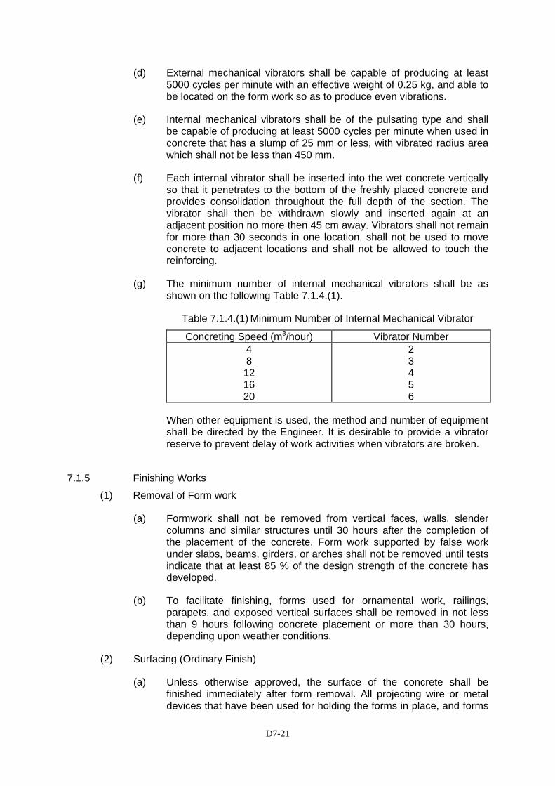
D7-21
(d) External mechanical vibrators shall be capable of producing at least 5000 cycles per minute with an effective weight of 0.25 kg, and able to be located on the form work so as to produce even vibrations.
(e) Internal mechanical vibrators shall be of the pulsating type and shall be capable of producing at least 5000 cycles per minute when used in concrete that has a slump of 25 mm or less, with vibrated radius area which shall not be less than 450 mm.
(f) Each internal vibrator shall be inserted into the wet concrete vertically so that it penetrates to the bottom of the freshly placed concrete and provides consolidation throughout the full depth of the section. The vibrator shall then be withdrawn slowly and inserted again at an adjacent position no more then 45 cm away. Vibrators shall not remain for more than 30 seconds in one location, shall not be used to move concrete to adjacent locations and shall not be allowed to touch the reinforcing.
(g) The minimum number of internal mechanical vibrators shall be as shown on the following Table 7.1.4.(1).
Table 7.1.4.(1) Minimum Number of Internal Mechanical Vibrator
Concreting Speed (m3/hour) Vibrator Number 4 8
12 16 20
2 3 4 5 6
When other equipment is used, the method and number of equipment shall be directed by the Engineer. It is desirable to provide a vibrator reserve to prevent delay of work activities when vibrators are broken.
7.1.5 Finishing Works
(1) Removal of Form work
(a) Formwork shall not be removed from vertical faces, walls, slender columns and similar structures until 30 hours after the completion of the placement of the concrete. Form work supported by false work under slabs, beams, girders, or arches shall not be removed until tests indicate that at least 85 % of the design strength of the concrete has developed.
(b) To facilitate finishing, forms used for ornamental work, railings, parapets, and exposed vertical surfaces shall be removed in not less than 9 hours following concrete placement or more than 30 hours, depending upon weather conditions.
(2) Surfacing (Ordinary Finish)
(a) Unless otherwise approved, the surface of the concrete shall be finished immediately after form removal. All projecting wire or metal devices that have been used for holding the forms in place, and forms

D7-22
which pass through the body of the concrete, shall be removed or cut back at least 25 mm beneath the surface of the concrete. Lips of mortar and all irregularities caused by form joints shall be removed.
(b) The Engineer shall inspect the concrete surfaces immediately upon removal of the forms and may direct the patching of minor imperfections which will not affect the structural or other functioning of the concrete work. The patching shall involve filling of small holes and depressions with cement mortar.
(c) If the Engineer approves the filling of large cavities of honeycombs, the work shall be chipped back to sound material, forming faces perpendicular to the work surface. The cavity shall be saturated with water and a thin layer of neat cement mortar (cement and water, without sand) shall be applied to the faces of the cavity. The cavity shall then be packed and rammed with stiff mortar composed of one part of Portland cement to two parts of sand, which shall be preshrunk by mixing it approximately 30 minutes before using.
(3) Surfacing (Special Finishes)
Exposed, usually visible surfaces shall be given further finishing work as follows or as directed by the Engineer:
(a) Tops of slabs, curbs, sidewalk surfaces and other horizontal surfaces as directed by the Engineer, shall be struck off with templates to provide the required levels or crowns immediately following placing of the concrete and shall be hand finished to smooth, even surfaces by both longitudinal and transverse movement of wooden floats, or by other suitable means, before the concrete has started to set.
(b) Float finished horizontal surfaces, which must not be slippery, such as for sidewalks, shall be slightly but uniformly roughened by brooming, or other methods directed by the Engineer, just as the concrete starts to set.
(c) Non-horizontal visible surfaces shall be rubbed with a medium coarse carborundum stone, using a small amount of mortar on the face. Immediately before starting this work the concrete shall be kept thoroughly saturated with water for a minimum period of three hours. The mortar shall be composed of cement and fine sand mixed in the proportions used in the concrete being finished. Rubbing shall be continued until all form marks projections and irregularities have been removed, all voids filled and a uniform surface has been obtained. The paste produced by this rubbing shall be left in place.
(4) Curing
(a) Immediately after placement concrete shall be protected from premature drying, excessively hot temperatures, and mechanical injury. Concrete shall be maintained with minimal moisture loss and a relatively constant temperature for a specified period to ensure proper hydration of the cement and hardening of the concrete.
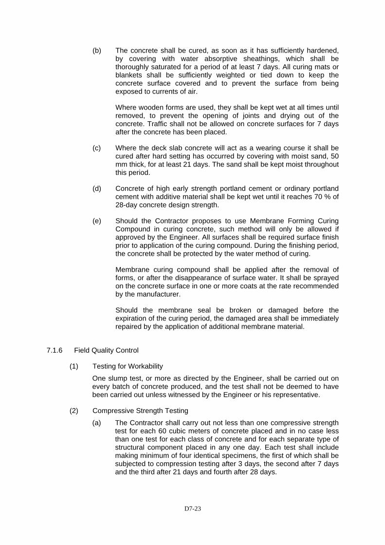
D7-23
(b) The concrete shall be cured, as soon as it has sufficiently hardened, by covering with water absorptive sheathings, which shall be thoroughly saturated for a period of at least 7 days. All curing mats or blankets shall be sufficiently weighted or tied down to keep the concrete surface covered and to prevent the surface from being exposed to currents of air.
Where wooden forms are used, they shall be kept wet at all times until removed, to prevent the opening of joints and drying out of the concrete. Traffic shall not be allowed on concrete surfaces for 7 days after the concrete has been placed.
(c) Where the deck slab concrete will act as a wearing course it shall be cured after hard setting has occurred by covering with moist sand, 50 mm thick, for at least 21 days. The sand shall be kept moist throughout this period.
(d) Concrete of high early strength portland cement or ordinary portland cement with additive material shall be kept wet until it reaches 70 % of 28-day concrete design strength.
(e) Should the Contractor proposes to use Membrane Forming Curing Compound in curing concrete, such method will only be allowed if approved by the Engineer. All surfaces shall be required surface finish prior to application of the curing compound. During the finishing period, the concrete shall be protected by the water method of curing.
Membrane curing compound shall be applied after the removal of forms, or after the disappearance of surface water. It shall be sprayed on the concrete surface in one or more coats at the rate recommended by the manufacturer.
Should the membrane seal be broken or damaged before the expiration of the curing period, the damaged area shall be immediately repaired by the application of additional membrane material.
7.1.6 Field Quality Control
(1) Testing for Workability
One slump test, or more as directed by the Engineer, shall be carried out on every batch of concrete produced, and the test shall not be deemed to have been carried out unless witnessed by the Engineer or his representative.
(2) Compressive Strength Testing
(a) The Contractor shall carry out not less than one compressive strength test for each 60 cubic meters of concrete placed and in no case less than one test for each class of concrete and for each separate type of structural component placed in any one day. Each test shall include making minimum of four identical specimens, the first of which shall be subjected to compression testing after 3 days, the second after 7 days and the third after 21 days and fourth after 28 days.
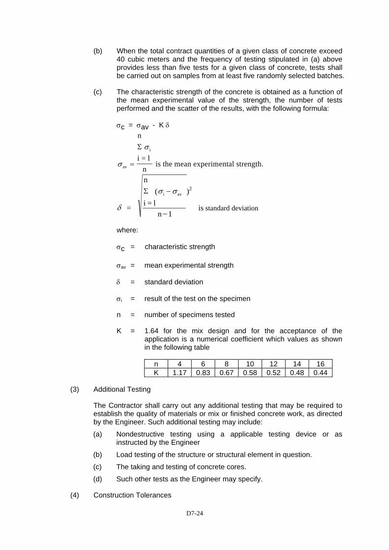
D7-24
(b) When the total contract quantities of a given class of concrete exceed 40 cubic meters and the frequency of testing stipulated in (a) above provides less than five tests for a given class of concrete, tests shall be carried out on samples from at least five randomly selected batches.
(c) The characteristic strength of the concrete is obtained as a function of the mean experimental value of the strength, the number of tests performed and the scatter of the results, with the following formula:
σc = σav - K δ
σ
σ
av
i
n
i = ln
is the mean experimental strength.=
Σ
δ
σ σ
=
n (
i = l n 1
is standard deviation
i avΣ −
−
)2
where:
σc = characteristic strength
σav = mean experimental strength
δ = standard deviation
σi = result of the test on the specimen
n = number of specimens tested
K = 1.64 for the mix design and for the acceptance of the application is a numerical coefficient which values as shown in the following table
n 4 6 8 10 12 14 16 K 1.17 0.83 0.67 0.58 0.52 0.48 0.44
(3) Additional Testing
The Contractor shall carry out any additional testing that may be required to establish the quality of materials or mix or finished concrete work, as directed by the Engineer. Such additional testing may include:
(a) Nondestructive testing using a applicable testing device or as instructed by the Engineer
(b) Load testing of the structure or structural element in question.
(c) The taking and testing of concrete cores.
(d) Such other tests as the Engineer may specify.
(4) Construction Tolerances

D7-25
The Construction tolerances for concrete works shall be as follows:
(a) Settling out
Spread footings, pile caps, pier columns and stems
± 10mm
Horizontal alignment of pier columns and stems
± 10mm
Bored piles 1/24 of pile dia. but not more than 75mm
(b) Dimensions
Length of concrete members (beams & slabs) overall length up to 6m overall length over 6m distance between beam, columns, walls, etc. width, depth and thickness (beams and slabs ) out –of-true
-0 and + 5mm -0 and + 5mm ± 10mm -0 and + 5mm deck slabs surfaces shall not have an out-of-true greater than 3mm under a 3m straight edge.
(c) Shape
Squareness (difference in diagonal Length) Straightness or bow (deviation of intended line) for length up to 3m for length from 3m to 5m for length over 5m
10mm 12mm 15mm 20mm
(d) Verticality
Bored piles vertical alignment 10mm per meter of depth
Vertical alignment for pier columns or stems , and walls
± 10mm
(e) Elevation
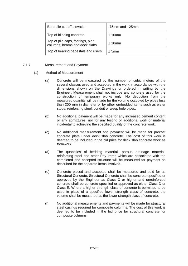
D7-26
Bore pile cut-off elevation -75mm and +25mm
Top of blinding concrete ± 10mm
Top of pile caps, footings, pier columns, beams and deck slabs ± 10mm
Top of bearing pedestals and risers ± 5mm
7.1.7 Measurement and Payment
(1) Method of Measurement
(a) Concrete will be measured by the number of cubic meters of the several classes used and accepted in the work in accordance with the dimensions shown on the Drawings or ordered in writing by the Engineer. Measurement shall not include any concrete used for the construction of temporary works only. No deduction from the measured quantity will be made for the volume occupied by pipes less than 200 mm in diameter or by other embedded items such as water stops, reinforcing steel, conduit or weep hole pipes.
(b) No additional payment will be made for any increased cement content or any admixtures, nor for any testing or additional work or material incidental to achieving the specified quality of the concrete work.
(c) No additional measurement and payment will be made for precast concrete plate under deck slab concrete. The cost of this work is deemed to be included in the bid price for deck slab concrete work as formwork.
(d) The quantities of bedding material, porous drainage material, reinforcing steel and other Pay Items which are associated with the completed and accepted structure will be measured for payment as described for the separate items involved.
(e) Concrete placed and accepted shall be measured and paid for as Structural Concrete. Structural Concrete shall be concrete specified or approved by the Engineer as Class C or higher and unreinforced concrete shall be concrete specified or approved as either Class D or Class E. Where a higher strength class of concrete is permitted to be used in place of a specified lower strength class of concrete, the volume shall be measured as the lower strength class of concrete.
(f) No additional measurements and payments will be made for structural steel casings required for composite columns. The cost of this work is deemed to be included in the bid price for structural concrete for composite columns.
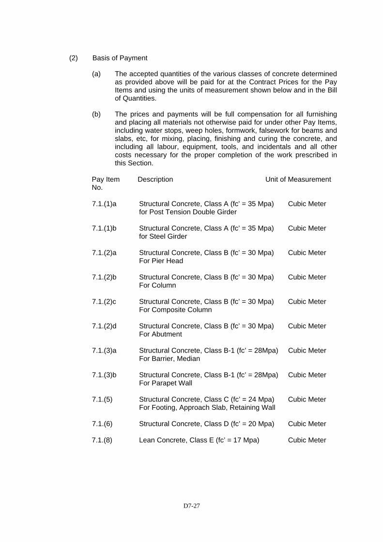
D7-27
(2) Basis of Payment
(a) The accepted quantities of the various classes of concrete determined as provided above will be paid for at the Contract Prices for the Pay Items and using the units of measurement shown below and in the Bill of Quantities.
(b) The prices and payments will be full compensation for all furnishing and placing all materials not otherwise paid for under other Pay Items, including water stops, weep holes, formwork, falsework for beams and slabs, etc, for mixing, placing, finishing and curing the concrete, and including all labour, equipment, tools, and incidentals and all other costs necessary for the proper completion of the work prescribed in this Section.
Pay Item Description Unit of Measurement No. 7.1.(1)a Structural Concrete, Class A (fc’ = 35 Mpa) Cubic Meter for Post Tension Double Girder 7.1.(1)b Structural Concrete, Class A (fc’ = 35 Mpa) Cubic Meter for Steel Girder 7.1.(2)a Structural Concrete, Class B (fc’ = 30 Mpa) Cubic Meter For Pier Head 7.1.(2)b Structural Concrete, Class B (fc’ = 30 Mpa) Cubic Meter For Column 7.1.(2)c Structural Concrete, Class B (fc’ = 30 Mpa) Cubic Meter For Composite Column 7.1.(2)d Structural Concrete, Class B (fc’ = 30 Mpa) Cubic Meter For Abutment 7.1.(3)a Structural Concrete, Class B-1 (fc’ = 28Mpa) Cubic Meter For Barrier, Median 7.1.(3)b Structural Concrete, Class B-1 (fc’ = 28Mpa) Cubic Meter For Parapet Wall 7.1.(5) Structural Concrete, Class C (fc’ = 24 Mpa) Cubic Meter For Footing, Approach Slab, Retaining Wall 7.1.(6) Structural Concrete, Class D (fc’ = 20 Mpa) Cubic Meter 7.1.(8) Lean Concrete, Class E (fc’ = 17 Mpa) Cubic Meter

D7-28
SECTION SS 7.1 (9) WATERPROOFING ON DECK
7.1(9).1 Description
This work shall consist of furnishing and applying of waterproofing on deck slab in accordance with this specification and as shown on the Drawings or as directed by the Engineer.
7.1(9).2 Materials
Waterproofing shall consist of polymer modified cementitious coating which is supplied in ready mix kits. The materials for waterproofing shall be formulated from selected cement graded hard-wearing aggregates and additives supplied in powder form together with a liquid component of polymers providing exceptional adhesion, resiliency, flexibility, toughness and durability.
Materials shall conform to the following requirements stated below:
Physical Properties Pot life at 30ºC 1 - 2 hrs Mixed Density 1.65 kg/m3 Adhesion to Substrate > 1 N/mm2 Shore hardness at 25º C 40 at 25ºC 7 days cured Tensile Strength (ASTM C-190 ) 5.0 N/mm2
Compressive Strength (ASTM C-190) 39.0 N/mm2 Flexural Strength (ASTM C – 348) 11.0 N/mm2 Bond Strength (ASTMC-321) 3.5 N/mm2 Shear Bond Strength ASTM C-190) 5.5 N/mm2 Abrasion resistance (ASTM 0241) 1.1 % weight lose Impact strength 16 lbs Water vapor transmission rate ¼” thick (ASTM E-96) 3.7 perms Freeze/thaw resistance cycles passed (ASTM C-291) 60.0 Flexibility 25 mm Mandrel Pass
7.1(9).3 Submittals
The Contractor shall submit working drawings of the waterproofing course to the Engineer for his review and approval. All working drawings shall show fully detailed dimensions and materials.
7.1(9).4 Application / Construction
The waterproofing course shall be constructed in accordance with the working drawing as approved by the Engineer.
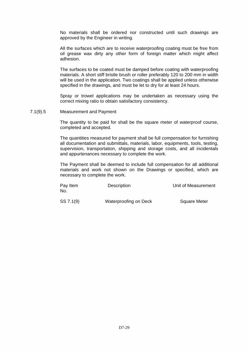
D7-29
No materials shall be ordered nor constructed until such drawings are approved by the Engineer in writing. All the surfaces which are to receive waterproofing coating must be free from oil grease wax dirty any other form of foreign matter which might affect adhesion.
The surfaces to be coated must be damped before coating with waterproofing materials. A short stiff bristle brush or roller preferably 120 to 200 mm in width will be used in the application. Two coatings shall be applied unless otherwise specified in the drawings, and must be let to dry for at least 24 hours. Spray or trowel applications may be undertaken as necessary using the correct mixing ratio to obtain satisfactory consistency.
7.1(9).5 Measurement and Payment
The quantity to be paid for shall be the square meter of waterproof course, completed and accepted. The quantities measured for payment shall be full compensation for furnishing all documentation and submittals, materials, labor, equipments, tools, testing, supervision, transportation, shipping and storage costs, and all incidentals and appurtenances necessary to complete the work. The Payment shall be deemed to include full compensation for all additional materials and work not shown on the Drawings or specified, which are necessary to complete the work.
Pay Item Description Unit of Measurement No.
SS 7.1(9) Waterproofing on Deck Square Meter
D7-30
SECTION 7.2(9) – PRESTRESSED CONCRETE
7.2(9).1 Description
(1) General
This work shall consist of prestressed concrete structures and prestressed concrete portions of composite structures, constructed in close conformity with the lines, grades, design and dimensions shown on the Drawings, or as established by the Engineer in accordance with this specification and other specification items involved. The work shall include the furnishing and installing of any appurtenant items necessary for the partial prestressing system to be used, including but not limited to the ducts, anchorage, assemblies and grout used for pressure grouting ducts. For cast-in-place prestressed concrete, the term “member” as used in this section shall be considered to mean the concrete which is to be prestressed.
(2) Definitions
Post-tensioning is defined as any method of prestressing concrete in which the tensioned reinforcement is tensioned after the concrete is placed. Pretensioning is defined as any method of prestressing in which the tensioned reinforcement is tensioned before the concrete is placed. Prestressing reinforcement is defined as any reinforcement to which prestress is applied by post-tensioning or pretensioning.
(3) Working Drawings
The Contractor shall prepare and submit to the Engineer working drawings of the prestressing system. Fabrication or installation of prestressing material shall not begin until the Engineer has approved the drawings. The working drawings shall show complete details and substantiating calculations of the method, materials and equipment, the Contractor proposes to use in the prestressing operations, including any additions or rearrangement of reinforcing steel and any revision in dimensions of the concrete structure or member to be pre-stressed, from that shown on the Drawings. Such details shall outline the method and sequence of stressing and shall include complete specifications and details of the prestressing steel and anchoring devices, working stresses, anchoring stresses, tendon elongation, type of ducts, and all other data pertaining to the prestressing operation, including the proposed arrangement of the prestressing steel in the members.
Whenever the Drawings do not include complete details for a prestressing system and its method of installation, or when complete details are provided in the Drawings and the Contractor wishes to propose any change, the Contractor shall include such details of the prestressing system proposed for use on the working drawings.
D7-31
Working drawings, shall be to scale and in sufficient detail to show the relative positions of all items that are to be embedded in the concrete, and their embedment depth, for the portions of the structure that are to be pre-stressed. Such embedded items include the prestressing duct, vents, anchorage reinforcement and hardware, reinforcing steel, anchor bolts, earthquake restrainers, deck joint seal assemblies, drainage system, utility conduits and other such items.
Such drawings shall be adequate to ensure that there will be no conflict between the planned positions of any embedded items and that concrete cover will be adequate. If during the preparation of such drawings conflicts are discovered, the Contractor shall revise his or her working drawing for one or more of the embedded items or propose changes in the dimensions of the work as necessary to eliminate the conflicts or to provide proper cover. Any such revisions shall be approved by the Engineer before work on any affected item, is started.
Working drawings shall be submitted sufficiently in advance of the start of the affected work to allow time for review by the Engineer and correction by the Contractor of the drawings without delaying the work.
All costs involved with the preparation of such drawings and with making the necessary modifications to the work resulting there from, shall be borne by the Contractor.
7.2(9).2 Materials
(1) General
All materials to be furnished and used which are not covered in this Section shall conform to the requirements stipulated in other applicable Sections/Clauses.
(2) Reinforcement – General
(a) Non-prestressing reinforcement shall conform to the requirements of Section 7.3, Reinforcing Steel, of these Specifications.
(b) Prestressing reinforcement shall be high tensile strength steel
wire, high tensile strength steel strand or high tensile strength steel bar.
(3) Prestressing Reinforcement
(a) High tensile strength steel wire shall be stress relieved and shall conform to the requirements of JIS G 3536 or AASHTO M 204.
(b) High tensile strand shall be weld free and stress relieved after
stranding and shall conform to the requirements of JIS G 3536 or AASHTO M 203.
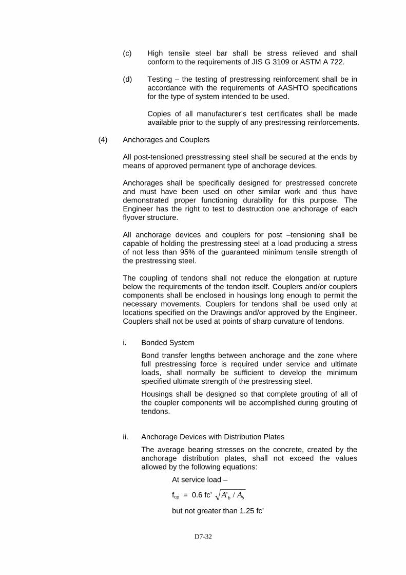
D7-32
(c) High tensile steel bar shall be stress relieved and shall conform to the requirements of JIS G 3109 or ASTM A 722.
(d) Testing – the testing of prestressing reinforcement shall be in
accordance with the requirements of AASHTO specifications for the type of system intended to be used.
Copies of all manufacturer’s test certificates shall be made available prior to the supply of any prestressing reinforcements.
(4) Anchorages and Couplers
All post-tensioned presstressing steel shall be secured at the ends by means of approved permanent type of anchorage devices. Anchorages shall be specifically designed for prestressed concrete and must have been used on other similar work and thus have demonstrated proper functioning durability for this purpose. The Engineer has the right to test to destruction one anchorage of each flyover structure. All anchorage devices and couplers for post –tensioning shall be capable of holding the prestressing steel at a load producing a stress of not less than 95% of the guaranteed minimum tensile strength of the prestressing steel. The coupling of tendons shall not reduce the elongation at rupture below the requirements of the tendon itself. Couplers and/or couplers components shall be enclosed in housings long enough to permit the necessary movements. Couplers for tendons shall be used only at locations specified on the Drawings and/or approved by the Engineer. Couplers shall not be used at points of sharp curvature of tendons.
i. Bonded System
Bond transfer lengths between anchorage and the zone where full prestressing force is required under service and ultimate loads, shall normally be sufficient to develop the minimum specified ultimate strength of the prestressing steel.
Housings shall be designed so that complete grouting of all of the coupler components will be accomplished during grouting of tendons.
ii. Anchorage Devices with Distribution Plates
The average bearing stresses on the concrete, created by the anchorage distribution plates, shall not exceed the values allowed by the following equations:
At service load –
fcp = 0.6 fc’ bb AA /'
but not greater than 1.25 fc’
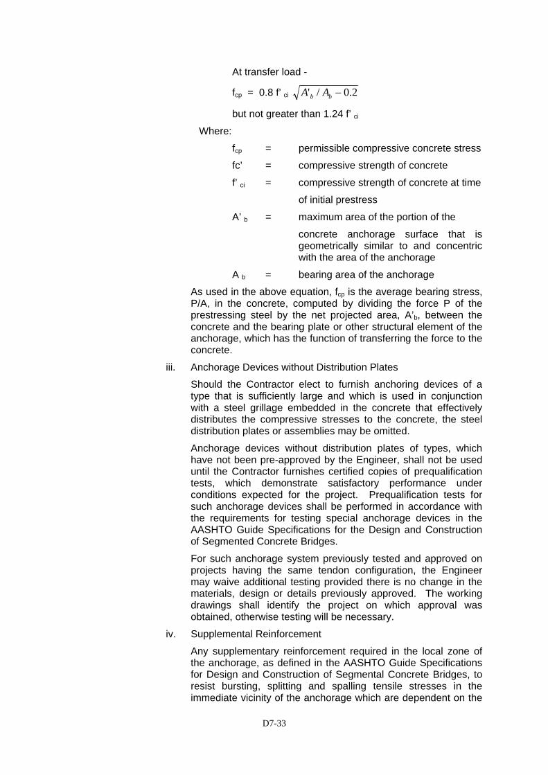
D7-33
At transfer load -
fcp = 0.8 f’ ci 2.0/' −bb AA
but not greater than 1.24 f’ ci
Where:
fcp = permissible compressive concrete stress
fc’ = compressive strength of concrete
f’ ci = compressive strength of concrete at time
of initial prestress
A’ b = maximum area of the portion of the
concrete anchorage surface that is geometrically similar to and concentric with the area of the anchorage
A b = bearing area of the anchorage
As used in the above equation, fcp is the average bearing stress, P/A, in the concrete, computed by dividing the force P of the prestressing steel by the net projected area, A’b, between the concrete and the bearing plate or other structural element of the anchorage, which has the function of transferring the force to the concrete.
iii. Anchorage Devices without Distribution Plates
Should the Contractor elect to furnish anchoring devices of a type that is sufficiently large and which is used in conjunction with a steel grillage embedded in the concrete that effectively distributes the compressive stresses to the concrete, the steel distribution plates or assemblies may be omitted.
Anchorage devices without distribution plates of types, which have not been pre-approved by the Engineer, shall not be used until the Contractor furnishes certified copies of prequalification tests, which demonstrate satisfactory performance under conditions expected for the project. Prequalification tests for such anchorage devices shall be performed in accordance with the requirements for testing special anchorage devices in the AASHTO Guide Specifications for the Design and Construction of Segmented Concrete Bridges.
For such anchorage system previously tested and approved on projects having the same tendon configuration, the Engineer may waive additional testing provided there is no change in the materials, design or details previously approved. The working drawings shall identify the project on which approval was obtained, otherwise testing will be necessary.
iv. Supplemental Reinforcement
Any supplementary reinforcement required in the local zone of the anchorage, as defined in the AASHTO Guide Specifications for Design and Construction of Segmental Concrete Bridges, to resist bursting, splitting and spalling tensile stresses in the immediate vicinity of the anchorage which are dependent on the
D7-34
configuration of the anchor device, shall be considered to be a part of the anchorage device. Such reinforcement shall be designated by the anchorage supplier and shall be furnished and placed as additional to the general zone reinforcement, which is shown on the Drawings.
(5) Corrosion Inhibitor
Corrosion inhibitor shall consist of a vapor phase inhibitor (VPI) powder conforming to the provisions of Federal Specification MIL-P3420 or as otherwise approved by the Engineer. When approved, water-soluble oil may be used on tendons as a corrosion inhibitor.
(6) Ducts
Ducts used to provide holes or voids in the concrete for the placement of the post-tensioning shall consists of rigid or semi-rigid metallic ducts and shall be mortar tight. Metal ducts shall be galvanized ferrous metal and shall be fabricated with either welded or interlocking seams. Galvanizing of welded seams will not be required. Rigid ducts shall have smooth inner walls and shall be capable of being curved to the proper configuration without crimping or flattening. Semi-rigid ducts shall be corrugated and their minimum wall thickness shall be : 26 gauge for ducts less than or equal to 66.7mm diameter and 24 gauge for ducts gauge for ducts greater than 66.7mm diameter. When bar tendons are pre-assembled with such ducts, the duct diameter shall not be less than 31 gauge. Adequate means, to the Engineer’s approval shall be employed to ensure that their locations are maintained exactly throughout the concreting operation. Ducting shall be flexible enough to allow it to conform to the curved lines of the prestressing tendons cables and yet rigid enough so that it does not sag or wobble between points of support in the formwork before and during the placement of concrete. The size of the ducts shall follow the manufacturer’s recommendation, but shall be a minimum of 6mm larger in internal diameter than the bar, cable, strand, or group of wires that they enclose. Ducts or anchorage assemblies shall be provided with pipes or other suitable connections at each end of the duct for the injection of grout under pressure, after the prestressing operations have been completed. Ducts shall be provided with ports for venting or grouting at high points and for draining at intermediate low points. Unless otherwise indicated on the Drawings 10mm diameter vent and drainage holes shall be provided at all high and low points on tendon profiles. The vents and
D7-35
drains shall be mortar tight, taped as necessary, and shall provide means for injection of grout through the vents and sealing to prevent leakage of grout.
(7) Concrete
Concrete shall be manufactured in accordance with Section 7.1 for the applicable grade. The grade of concrete for each type of unit shall be as shown on the Drawings.
(8) Formwork
Formwork for precast units shall conform with the requirements of Section 7.1 and to the particular requirements of this Section. Formwork shall be made of metal, or of timber lined with metal, or waterproof plywood, and shall be sufficiently strong such that it shall not deflect beyond the tolerance limits during casting. Seals shall be fitted to prevent loss of cement paste through joints in the formwork.
Chamfers shall be provided on all corners and shall be straight and true to shape and line.
Void formers shall have tightly fitting ends and shall be wrapped with adhesive tape sealant as required to prevent entry of slurry.
Formwork for hollow/ voided slab shall be winding pipe. Winding pipe shall be a suitable proprietary system approved by the Engineer. The material for the winding pipe shall be hot-dip galvanized and shall conform to JIS G-3302 (SGC). Sizes of winding pipe, pipe supports and holding down details are as shown on the Drawings.
(9) Grout
Unless otherwise directed by the Engineer as a result of grouting trials, the grout shall:
(a) consist of Portland Cement complying with all the requirements
of AASHTO M85 and water conforming to AASHTO T 26. (b) have a water/cement ratio as low as possible consistent with
adequate workability and under no circumstances exceeding 0.45.
(c) not be subject to bleeding that exceeds 2 percent of the volume 3 hours after mixing nor an overall maximum of 4 percent. Bleeding shall be measured at 30 degrees C in a glass cylinder of internal diameter about 100 mm and a height of grout of about 100 mm. The cylinder shall be covered during the test to prevent evaporation.
(d) be introduced by grouting equipment that shall be capable of completing continuous grouting of one duct in no more than 20 minutes.
Admixtures, if used, shall impart the properties of low-water content, good flow ability, minimum bleed, and expansion if desired. They
D7-36
shall contain no chemicals in quantities that may have harmful effect on the prestressing steel or cement. Admixtures, which, at the dosage used, contain chlorides in excess of 0.005 percent of the weight of the cement used or contain any fluorides, sulphites, and nitrates, shall not be used.
When a grout-expanding admixture is used as required or at the Contractor’s option, it shall be well dispersed through the other admixtures and shall produce a 2 to 6 percent unrestrained expansion of the grout.
Amount of admixture to obtain a desired amount of expansion shall be determined by tests. If the source of manufacture or brand of either admixture or cement changes after testing, new tests shall be conducted to determine proper proportions.
All admixtures shall be used in accordance with the instruction of the manufacturer and shall be subject to approval by the Engineer.
(10) Supply
High tensile steel wires or high tensile steel bars which will be used in prestressing shall be supplied in coils of sufficient diameter in order to maintain the properties and to be self-straightening. The material shall be in good condition, not kinked or bent.
The material shall be free of corrosion, dust, other loose materials, oil, lubricant, paint, mud or other unintended material, but shall not be polished.
(a) Marking
The wires shall be stored in groups based on size and length, shall be securely bound and tagged with a label identifying the size of the wire in the bundle.
(b) Storage
The materials for cable, wire, steel bars, anchorage, ducts shall be stored under a waterproof roof, placed clear of the ground surface and shall be protected from any potential damage.
7.2(9).3 Construction and Quality Control
(1) Sampling and Testing
All wire, strand, or bars to be shipped to the site, shall be assigned a lot number and tagged for identification purposes. Anchorage assemblies to be shipped shall be likewise identified.
Each lot of wire or bars and each reel of strand reinforcement shall be accompanied by a manufacturer’s certificate of compliance, a mill certificate, and a test report. The mill certificate and test report shall include the chemical composition (not required for strand), cross-sectional area, yield and ultimate strength, elongation at rupture,
D7-37
modules of elasticity, and the stress strain curve for the actual prestressing steel intended for use.
All values certified shall be based on test values and nominal sectional areas of the material being certified.
The Contractor shall furnish to the Engineer for verification testing, the samples described in the following sub-articles selected from each lot. If ordered by the Engineer, the selection of samples shall be made at the manufacturer’s plant by the Engineer or his representative.
All samples submitted shall be representative of the lot to be furnished and, in the case of wire or strand, shall be taken from the same master roll.
The actual strength of the prestressing steel shall not be less than specified by the applicable ASTM or JIS Standards, and shall be determined by tests of representative samples of the tendon materials in conformance with ASTM or JIS Standards.
All of the materials specified for testing shall be furnished free of cost and shall be delivered in time for tests to be made well in advance of anticipated time of use.
a) Pre-tensioning Method Tendons
For pretensioning strands, one (1) sample at least 2.0-meter long shall be furnished in accordance with the requirements of paragraph 9.1 of AASHTO M203 or length as specified in the equivalent JIS Standard.
b) Post-tensioning Method Tendons
The following lengths shall be furnished for each 20-ton, or portion thereof, lot material used in the work.
(i) For wires requiring heading - 1.5 meters.
(ii) For wires not requiring heading - sufficient length to make up one parallel-lay cable 1.5 meters long consisting of the same number of wires as the cable to be furnished.
(iii) For strand to be furnished with fitting - 1.5 meters between near ends of fittings.
(iv) For bars to be furnished with threaded ends and nuts - 1.5 meters between threads at ends.
D7-38
(c) Anchorage Assemblies and Couplers
Except for anchorage devices without distribution plates which are tested in accordance with paragraph 7.2(9).2.(4), the Contractor shall furnish for testing, two specimens of each size of prestressing tendon, including coupling, of the selected type, with end fittings and anchorage assembly attached for strength test only. These specimens shall be 1.5 meters in clear length, measured between ends of fittings.
If the results of the test indicate the necessity of check tests, additional specimens shall be furnished without cost.
For prestressing systems previously tested and approved on projects having the same tendon configuration, the Engineer may not require complete tendon samples provided there is no change in the material, design, or details previously approved. Shop drawings or prestressing details shall identify the project on which approval was obtained otherwise testing shall be conducted
(2) Prestressing Equipment
Tensioning equipment shall be approved by the Engineer prior to use and shall be calibrated as a complete unit by an approved laboratory every six months (or more often if directed by the Engineer) in order to give a correlation between the force applied to the tendon and the reading indicated by the pressure gauge. Tensioning equipment shall be provided with at least two pressure gauges with a face diameter not less than 150 mm, one to read initial sag pull-up and the second to read the loads during the final stressing operation. Pressure gauges shall be accurate to within approximately 1 % of their full capacity. Calibration certificates shall be kept in the works office at the casting yard and made available to the Engineer on demand.
(3) Assembling Tendons
Tendons shall be assembled in accordance with the instructions accompanying the manufacturer’s agreement certificate.
Prior to assembly, the surfaces of the prestressing steel shall be inspected for corrosion. Loose rust shall be removed by hand using burlap rags or soft steel wool and any lubricant shall be thoroughly removed using detergent. A light film of rust is not considered detrimental provided the steel is not visibly pitted.
Badly rusted or pitted steel shall be rejected and removed from site. Foreign matter adhering to steel shall be removed.
Prestressing steel installed in members prior to placing and curing of the concrete, or installed in the duct but not grouted within the time limit specified below, shall be continuously protected against rust or
D7-39
other corrosion by means of a corrosion inhibitor placed in the ducts or directly applied to the steel. The prestressing steel shall be so protected until grouted or encased in concrete. Prestressing steel installed and tensioned in members after placing and curing of the concrete and grouted within the time limit specified below will not require the use of a corrosion inhibitor described herein and rust, which may form during the interval between tendon installation and grouting will not be cause for rejection of the steel.
The permissible interval between tendon installation and grouting without use of a corrosion inhibitor for various exposure conditions shall be as follows:
After tendons are placed in ducts, the openings at the ends of the ducts shall be sealed to prevent entry of moisture. When steam curing is used, steel for post-tensioning shall not be installed until the steam curing is completed.
Whenever electric welding is performed on or near members containing prestressing steel, the welding ground shall be attached directly the steel being welded. All prestressing steel and hardware shall be protected from weld spatter or other damage.
Anchorages shall be assembled with tendons in a manner that shall prevent any shift in position, either during installation or concreting.
(4) Curing
Steam curing process may be used as an alternative to water curing. The casting bed for any unit cured with steam shall be completely enclosed to prevent steam escaping and simultaneously exclude outside atmosphere. Two to four hours after placing concrete and after the concrete has undergone initial setting, the first application of steam shall be made. If retarding admixtures have been used, the delay before application of the steam shall be increased to four to six hours. Water curing methods shall be used from the time the concrete is placed until steam is first applied. The steam shall be at 100% relative humidity to prevent loss of moisture and to provide moisture for proper hydration of the cement. Application of the steam shall not be directly on the concrete. During the application of the steam, the ambient air temperature shall increase at a rate not to exceed 22 degrees Celsius per hour until the maximum temperature is reached and shall be held until the concrete has reached the desired strength. In discontinuing the steam
Very Damp Atmosphere or over saltwater(Humidity > 70%)
7 days
Moderate Atmosphere (Humidity from 40% to 70%)
15 days
Very Dry Atmosphere (Humidity < 40%)
20 days
D7-40
application, the ambient air temperature shall not decrease at a rate to exceed 22 degrees Celsius per hour until a temperature has been reached 10 degrees Celsius above the temperature of the air to which the concrete will be exposed. The maximum curing temperature shall be from 60 degrees Celsius to 67 degrees Celsius. If the Contractor elects to cure by any other special method, the method and details shall be subject to the approval of the Engineer.
7.2(9).4 Pre-Tensioning Method
(1) Stressing Bed
The stressing bed for supporting prestressed forces during prestressing shall be designed and constructed to withstand the forces generated during the prestressing operation. The stressing bed shall be made in such a manner that if slippage occurs at the anchorage it will not be damaged. The stressing bed shall be of sufficient strength such that no deflection or damage will occur under concentrated or dead loads from the units being supported.
(2) Placing Tendon
The tendons shall be placed as shown on the Drawings and secured such that it shall not shift during concrete pouring. In placing the tendon, attention shall be given that the tendon will not touch the lubricating formwork. If the tendon touches the lubricant, it shall be cleaned immediately using kerosene or other suitable material. If possible, tendon stressing shall be carried out before lubricating the formwork. Anchorage shall be placed in the required position and shall not shift during concrete pouring. Distances from the forms shall be maintained by stays, blocks, ties or other approved supports. Blocks for holding units from contact with the forms shall be precast mortar blocks of approved shape and dimensions. Layers of units shall be separated by mortar blocks or other equally suitable devices. Wooden blocks shall not be used.
(3) Required Stressing Force
Unless otherwise stated on the Drawings, the force required is the force remaining in the tendons at the middle of each unit immediately after all tendons have been anchored to the abutments of the stressing bed and are in their final deflected position. The allowable variation of this force from its required value shall be 5 percent. The jacking force applied shall allow for any anticipated slip at the anchorage devices, wedge draw-in, and friction losses.
The method of tensioning tendons including the arrangement and layout of each line, calculations showing forces at anchorages and all deflection points, and estimated friction losses, shall be submitted to
D7-41
the Engineer for his approval before manufacture of members commences.
The Contractor shall carry out trial stressing operations to establish the frictional resistance offered by the hold-downs and also to confirm that the stated wedge draw-in is consistent with the type of jack and operator technique proposed.
Tendons shall be deflected, where shown on the Drawings, with devices strong enough to hold the tendons firmly in their proper positions, especially during concreting and vibrating operations. Unless otherwise directed by the Engineer hold-downs shall be located longitudinally within 200 mm and vertically within 5 mm of the locations shown on the Drawings.
Hold-downs shall be designed such that the deflector in contact with the strand shall have a diameter of not less than the tendon diameter or 15 mm whichever is the greater. The deflector shall be constructed from material no harder than AASHTO M183 (ASTM A36) grade 36 steel.
The Contractor shall submit calculations showing that the hold-downs have been designed and constructed to withstand concentrated loads resulting from the application of the tensioning force.
The method of tensioning shall ensure that the required force is produced in all tendons at the middle of all units, especially where more than one tendon or one unit is tensioned in the one operation.
Concrete shall not be cast later than 12 hours after tensioning. Should this time be exceeded, the Contractor shall check that the required tendon force has been maintained. Should re-stressing be required, tendon extensions shall be maintained by the use of shims without disturbing the bedded wedges.
Elongation measurement may be used only after the Engineer has examined the calculations and determined that the system meets the requirements. Jack pressure readings shall be used as a comparison with elongation measurements. If the jack pressure reading and the elongation measurement differ by more than 5%, the Engineer shall be informed prior to starting the concrete pour and, if considered necessary, the tendon shall be tested and the equipment shall be calibrated as directed by the Engineer.
(4) Prestressing Procedure
The tensioning operation shall be performed only by personnel trained and experienced in this type of work.
The prestressing elements shall be accurately held in position and stressed by jacks. A record shall be kept of the jacking force and the elongations produced thereby.
No bond stresses shall be transferred to the concrete, nor end anchorages released, until the concrete has attained a compressive
D7-42
strength, as shown by cylinder tests, of at least 28 MPa unless otherwise specified.
The elements shall be released in such an order that lateral eccentricity of prestress will be a minimum.
The tensioning force shall be applied and released at a uniform rate.
In order to remove slack and to lift tendons off the bed floor an initial force of 100 kg or as otherwise approved by the Engineer shall be applied to the tendons. Allowance shall be made for this force in calculating the required elongation.
Tendons shall be marked for measurement of elongation after the initial force has been applied. When required by the Engineer tendons shall be marked at both the jacking end and dead end of the stressing bed and at couplers (if used) so that slip and draw-in may be measured.
Should slip occur in any one of a group of tendons tensioned together, the tensioning of the whole group shall be relaxed, the tendons re-set, and the whole group tensioned again. Alternatively, if not more than two tendons have slipped the tensioning of the group may be completed with the loose tendons being tensioned after this.
The prestressing force shall be transferred from the tensioning jack to the abutment of the stressing bed immediately the required force (or elongation) has been reached in the tendons, and the pressure in the jack shall be relaxed before any other operation is commenced. Where deflected strands have been specified the Engineer may direct that elongation or strain gauge measurements be taken at various positions along the tendon to determine the force in the tendon at those positions. When ordered by the Engineer, prestressing steel in pretensioned member, if tensioned individually, shall be checked by the Contractor for loss of pre-stress not more than 3 hours prior to placing concrete for the member. The method and equipment for checking the loss of pre-stress shall be subject to approval by the Engineer. All prestressing steel that shows a loss of pre-stress in excess of 3 percent shall be pre-tensioned to the original completed jacking stress. Side and flange forms that restrain deflection shall be removed before release of pre-tensioning reinforcement. Except when otherwise shown on the Drawings, all prestressing steel shall be cut-off flush with the end of the member and the exposed ends of the steel and a 25 mm strip of adjoining concrete shall be cleaned and painted. Cleaning shall be by wire brushing or abrasive blast cleaning to remove all dirt and residue that is not firmly bonded to the metal or concrete surfaces. The surfaces shall be coated with one thick coat of zinc –rich paint.
D7-43
The paint shall be thoroughly mixed at the time of application, and shall be worked into any voids in the prestressing steel.
(5) Placing Concrete
Concrete shall not be deposited in the forms until the Engineer has inspected the placing of the reinforcement, anchorages and prestressing steel and given his approval thereof. The concrete shall be vibrated with care and in such a manner as to avoid displacement of reinforcement or wires.
7.2(9).5 Post-Tensioning Method
(1) Approval
Unless otherwise shown on the Drawings, the Contractor may determine the prestressing procedure, which procedure and work plan shall be submitted to the Engineer for approval prior to commencing any work on post-tensioned units.
(2) Placing Anchorage
Each anchorage shall be placed at right angles to the prestressed force work line, and secured such that it does not move during concrete pouring. If shown on the Drawings that steel plate is to be used as an anchorage, the concrete surface in contact with the steel plate shall be smooth and placed at right angles to the prestress force direction. The steel plate anchorage may be bedded on mortar as approved or directed by the Engineer. After finishing prestressing and grouting, the anchorage shall be encased with concrete with at least 30 mm cover.
(3) Placing Tendon
All steel elements shall be accurately placed in the position shown on the drawings and rigidly held during the placing and setting of the concrete. Distance from the forms shall be maintained by stays, blocks, ties, hangers or other approved supports. Blocks for holding units from contact with the forms shall be precast mortar blocks of approved shape and dimensions. Layer of units shall be separated by mortar blocks or other equally suitable devices. Wooden blocks shall not be used. Anchor holes shall be sealed to ensure that no mortar or other material enters the hole during pouring.
D7-44
Immediately before tensioning, the Contractor shall prove that all tendons are free to move between jacking points and that members are free to accommodate the horizontal and vertical movements due to the application of prestress.
(4) Placing Concrete
Concrete shall not be deposited in the forms until the Engineer has inspected the placing of the reinforcement, anchorages and prestressing steel and given his approval thereof. The concrete shall be vibrated with care and in such a manner as to avoid displacement of reinforcement or wires strands or the prestressing reinforcements.
(5) Required Concrete Strength
Prestressing shall not be carried out before the concrete has attained the required strength as shown on the Drawings, and shall not be less than 14 days after concrete pouring if wet curing is applied, or not less than 2 days after concrete pouring if steam curing is applied. Where units consist of jointed elements, the strength of the jointing material shall be at least equivalent to the specified transfer strength of the concrete in the unit.
(6) Required Prestressing Force
The measurement of prestressing force is carried out by directly measuring the jack compression or indirectly by measuring tendon elongation. Unless otherwise specified on the Drawings, the Engineer will decide which procedure is to be adopted after observation of the condition and accuracy which can be reached by the said procedures.
The Engineer shall determine the estimated elongation and jack compression.
The Contractor shall establish the datum point for measuring extension and jack pressure to the satisfaction of the Engineer.
The tensioning process shall be so conducted that the tension being applied and the elongation of the processing elements may be measured at all times.
Suitable shims or other approved devices shall be used to ensure that the specified anchor set loss is attained.
A record shall be kept on gauge pressure and elongation at all times and submitted to the Engineer for his approval.
The Contractor shall add to the forces required for prestress an allowance for anchorage friction and jack losses. The total forces and calculated extensions shall be approved by the Engineer before stressing is commenced.
D7-45
Immediately after anchoring, the stresses in the prestressing tendons shall not exceed 70 % of the specified tensile strength of tensioning steel. During stressing the value shall not exceed 80% of the specified tensile strength of prestressing steel.
The tendons shall be stressed at a gradual and steady rate. The force in the tendons shall be obtained from readings on two load cells or pressure gauges incorporated in the equipment. The extension of the tendons under approved total forces shall be within 5 % of the approved calculated extension. If the required elongation cannot be reached, the jacking force may be increased to 75 % of the specified tensile strength for the tendon. If the difference between the measured and calculated elongation is more than 5% however, no further tensioning shall be done until the calculations and the equipment are checked.
Stressing shall be from one end unless otherwise required in the Drawings or approved by the Engineer.
When stressing tendons with a stressing anchorage at both ends, the pull-in at the end remote from the jack shall be accurately measured and the appropriate allowance made in the measured extension at the jacking end.
When prestressing has been applied to the satisfaction of the Engineer, the tendons shall be anchored. The jack pressure shall then be released in such a way as to avoid shock to the anchorage or tendons.
If the pull-in of the tendons at completion of anchoring is greater than that approved by the Engineer, the load shall be released at a gradual and steady rate and the tensioning shall be repeated. The falsework under the bottom slab supporting the superstructure shall not be released until a minimum of 48 hours have elapsed after grouting of the post-tensioning tendons nor until all other conditions of the Specifications have been met. The supporting falsework shall be constructed in such a manner that the superstructure will be free to lift off the false work and shorten during post-tensioning.
(7) Grouting
(a) General
When the post-tensioning method is used, the prestressing steel shall be provided with permanent protection and shall be bonded to the concrete by completely filling the void space between the duct and the tendon with grout.
(b) Preparation of Ducts
All ducts shall be clean and free of deleterious materials that would impair bonding or interfere with grouting procedures.
D7-46
Ducts with concrete walls (cored ducts) shall be flushed to ensure that the concrete is thoroughly wetted. Metal ducts shall be flushed if necessary to remove deleterious material.
Water used for flushing ducts may contain slacked lime (calcium hydroxide) or quick-lime (calcium oxide) for 12 gram per liter.
After flushing, all water shall be blown out of the duct with oil-free compressed air.
(c) Equipment for Cement Grouting
The grouting equipment shall include a mixer capable of continuous mechanical mixing which will produce a grout free of lumps and undispersed cement, a grout pump and stand-by flushing equipment with water supply. The equipment shall be able to pump the mixed grout in a manner, which will comply with all requirements.
Accessory equipment, which will provide for accurate solid and liquid measure, shall be provided to batch all materials.
The pump shall be a positive displacement type and be able to produce an outlet pressure of at least 1.0 MPa. The pump should have seals adequate to prevent introduction of oil, air, or other foreign substance into the grout, and prevent loss of grout or water.
A pressure gauge having a full-scale reading of no greater than 2.0 MPa shall be placed at some point in the grout line between the pump outlet and the duct inlet.
The grouting equipment shall contain a screen having a clear opening of 3 mm maximum size, to screen the grout prior to its introduction into the grout pump. If grout with a thixotropic additive is used, a screen opening of 5 mm is satisfactory. This screen shall be easily accessible for inspection and cleaning.
The grouting equipment shall utilize gravity feed to the pump inlet from a hopper attached to and directly over it. The hopper must be kept at least partially full of grout at all times during the pumping operation to prevent air from being drawn into the duct.
Under normal conditions, the grouting equipment shall be capable of continuously grouting the largest tendon on the project in no more than 20 minutes.
(d) Mixing of Cement Grout
Water shall be added to the mixer first, followed by Portland cement and admixture, or as required by the admixture manufacturer.
Mixing shall be of such duration as to obtain a uniform, thoroughly blended grout, without excessive temperature increase or loss of expansive properties of the admixture. The grout shall be continuously agitated until it is pumped.
D7-47
Water shall be not added to increase grout flow ability, which has been decreased by delayed use of the grout.
Proportions of materials shall be based on tests made on the grout before grouting is begun, or may be selected based on prior documented experience with similar materials and equipment and under comparable field conditions (weather, temperature, etc.). The water content, shall be the minimum necessary for proper placement and when Type I or II cement is used shall not exceed a water cement ratio of 0.45 or approximately 5 gallons of water per sack 40 kilograms of cement.
The water content required for Type III cement shall be established for a particular brand based on tests.
The pump ability of the grout may be determined by the Engineer in accordance with the U.S. Corps of Engineers Methods CRD-C79. When this method is used, the efflux time of the grout sample immediately after mixing shall not be less than 11 seconds. The flow cone test does not apply to grout, which incorporates a thixotropic additive.
(e) Injection of Cement Grout
All grout and high point vent openings shall be open when grouting starts. Grout shall be allowed to flow from the first vent after the inlet pipe until any residual flushing water or entrapped air has been removed, at which time the vent should be capped or otherwise closed. Remaining vents shall be closed in sequence in the same manner.
The pumping pressure at the tendon inlet shall not exceed 1.75 MPa.
If the actual grouting pressure exceeds the maximum recommended pumping pressure, grout may be injected at any vent, which has been, or is ready to be capped as long as one-way flow of grout is maintained. If this procedure is used, the vent, which is to be used for injection shall be fitted with a positive shutoff.
When one-way flow of grout cannot be maintained, the grout shall be immediately flushed out of the duct with water.
Grout shall be pumped through the duct and continuously wasted at the outlet pipe until no visible slugs of water or air are ejected and the efflux time of the ejected grout, as measured by a flow cone test, if used, it not less than that of the injected grout. To ensure that the tendon remains filled with grout, the outlet shall then be closed and the pumping pressure allowed to build to a minimum of 0.5 MPa before the inlet vent is closed. Plugs, caps, or valves thus required shall not be removed or opened until the grout has set.
(f) Temperature Considerations
Grout shall not be above 32oC during mixing or pumping. If necessary, the mixing water shall be cooled.
D7-48
7 2(9).6 Post Tensioned Segmental Construction
(1) Description
This work consists of the assembling, joining and stressing of precast segments on Site. The units shall be manufactured in accordance with the requirements of this Section of these Specifications.
(2) Assembly of Precast Segments
The Contractor shall submit details of the falsework design and the method of erection and assembly to the Engineer for his approval at least four weeks prior to the proposed date for commencing assembly of the segments.
Segments shall be assembled on falsework or on bearers at ground level. The Contractor shall design the supporting system to carry all the loads that may be applied to it, and shall incorporate provision for adjusting the position of each segment during assembly.
The unit shall be assembled with minimum misalignment of ducts and outside surfaces and shall be within the allowed tolerances.
(3) Joint Concrete
Concrete for joints and associated diaphragms or other infill concrete involved in the assembly of segments for post-tensioned construction shall comply with the requirements of Section 7.1 of this Specification except where modified below.
The cement content shall be not less than 450 kg or greater than 500 kg per cubic meter of concrete.
Unless otherwise approved by the Engineer the effective maximum size shall be 10 mm.
Joint concrete will be subject to the same strength requirements prior to stressing as provided elsewhere in these Specifications.
Concrete materials shall be carefully selected and proportioned to produce joint concrete of the specified strength and of a similar color to that of the segments. If requested by the Engineer the Contractor shall supply cured samples of the proposed joint concrete for color comparison.
Joint concrete between segments shall be placed in forms which shall conform to the shape, lines and dimensions required in the finished work. Forms shall be rigid, watertight, and braced and tied together so that they will maintain position and shape during placing of concrete. The fit of the forms against the segments shall be such that a completely watertight joint, flush with adjacent surfaces is obtained.
Where necessary, temporary openings shall be provided in the formworks to enable adequate placing and compaction of concrete, especially around and underneath ducting and anchorages.

D7-49
The joints between segments shall be completely filled with compacted concrete of the required strength indicated on the Drawings. Surfaces against which concrete is to be placed shall be scabbled to a dense hard surface. Just prior to placing concrete, these surfaces shall be cleaned to remove all dirt and other foreign matter.
Joint concrete shall be placed in the presence of the Engineer and any joint concrete placed during his absence or not placed to his satisfaction shall be broken out by the Contractor and made good at no extra cost to the Employer.
Care shall be taken during placing and compaction of concrete to avoid damage to the ducting. Vibrators shall not come into direct contact with the ducting. If the ducting is damaged during concreting the whole or a portion of the concrete cast may be rejected by the Engineer.
After placing the concrete the top surface of the joint shall be screed flush with the tops of the adjacent segments and covered to prevent premature drying. Joint concrete shall be cured by one or more of the methods specified in this Specification for a minimum period of 7 days.
(4) Concreting of Anchorage Recesses
Concreting of anchorage recesses of the post tensioned segmental member shall be carried out as shown on the Drawings and in accordance with the requirements of these Specifications.
(5) Damage to Units
In the event of any unit, which has been manufactured or accepted by the Contractor, sustaining damage such as cracking, spalling or deformation of projecting reinforcement, the unit shall be set aside until it has been inspected by the Engineer, who will decide whether it shall be rejected and removed from the site of the works, or repaired by the Contractor. The cost of such repairs, or the removal of rejected units, and all costs of replacing these units at the site of the works shall be borne by the Contractor.
7.2(9).7 Method of Measurement
The quantity to be measured, for payment PC Strand and PC Bar shall be the number of kilograms installed in place, completed and accepted.
Units that have been rejected due to inadequate concrete, damage during handling, storage, transportation or erection, or for any other reason, shall not be measured for payment.
7.2(9).8 Basis of Payment
The work measured as provided above, shall be paid for at the unit price for the Pay Items as shown below and listed in the Bill of Quantities. The prices and payment shall be full compensation for furnishing and placing all materials including labour, equipment, tools and incidentals necessary to
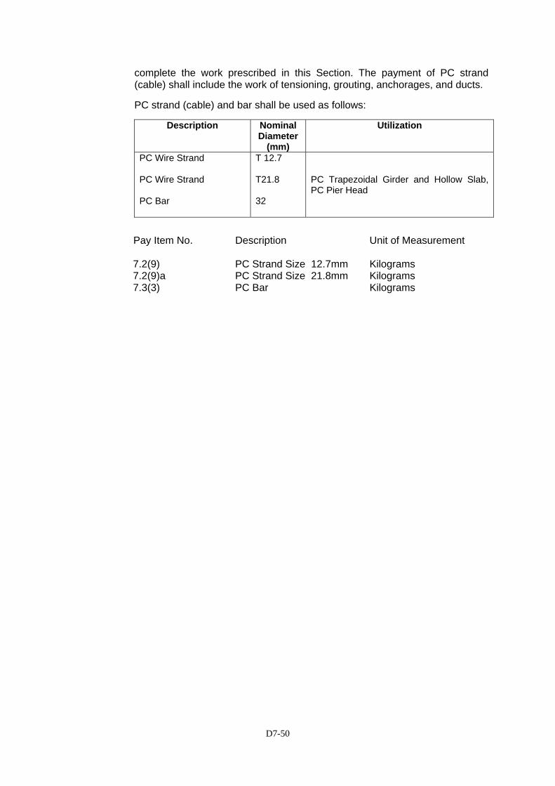
D7-50
complete the work prescribed in this Section. The payment of PC strand (cable) shall include the work of tensioning, grouting, anchorages, and ducts.
PC strand (cable) and bar shall be used as follows:
Description Nominal
Diameter(mm)
Utilization
PC Wire Strand PC Wire Strand PC Bar
T 12.7 T21.8 32
PC Trapezoidal Girder and Hollow Slab, PC Pier Head
Pay Item No. Description Unit of Measurement 7.2(9) PC Strand Size 12.7mm Kilograms 7.2(9)a PC Strand Size 21.8mm Kilograms 7.3(3) PC Bar Kilograms
D7-51
SSEECCTTIIOONN 77..33 -- RREEIINNFFOORRCCIINNGG SSTTEEEELL
7.3.1 General
(1) Description
This section covers furnishing, bending fabricating and placing reinforcing steel bars of the type and size provided in accordance these Specifications and in conformity with the requirements shown on with the Drawings, or as directed by the Engineer.
(2) Submittals
Before ordering material, all order lists and bending diagrams for each section of the works shall be furnished by the Contractor for the approval of the Engineer.
Before commencing Steel Reinforcing work the Contractor shall supply the Engineer with certified lists from the steel manufacturer or manufacturers giving the nominal unit weight in kilograms of every size and grade of reinforcing bar or welded steel mesh to be used in the work, and test certificates indicating the standards applying to each group of reinforcing.
The Contractor shall submit to the Engineer for approval, Shop Drawings indicating the bending, cutting, splicing and installation of all reinforcing bars.
The Shop Drawings shall be submitted sufficiently in advance of the start of the affected work to allow time for review by the Engineer and correction by the Contractor of the drawings without delaying the work.
7.3.2 Materials
Reinforcing steel shall conform to the requirements of the following specifications except that the weights of the standard bar sizes will be taken as provided in tables 7.3.1 and 7.3.2 below, irrespective of the specifications used in manufacture.
(1) References
The following reference standards are used to:
(a) Bar specified as being 9mm diameter or less: SII 0136 (Grade BJTP 24); or JIS G 3112 (Grade SR235); or AASHTO M 31 (Grade 40)
(b) Bar specified as being 10mm diameter or more:
SII 0136 (Grade BJTS 40); or JIS G 3112 (Grade SD 345 and SD 390); or AASHTO M 31 (Grade 60)
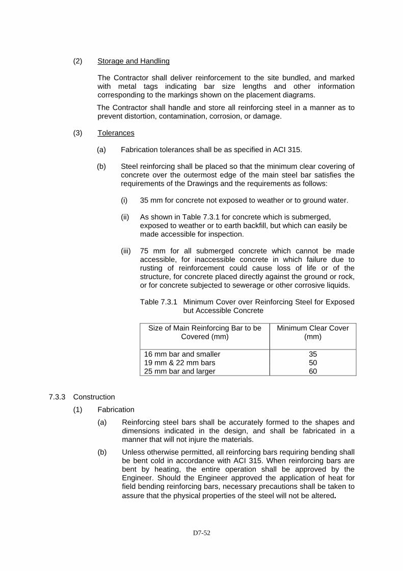
D7-52
(2) Storage and Handling
The Contractor shall deliver reinforcement to the site bundled, and marked with metal tags indicating bar size lengths and other information corresponding to the markings shown on the placement diagrams.
The Contractor shall handle and store all reinforcing steel in a manner as to prevent distortion, contamination, corrosion, or damage.
(3) Tolerances
(a) Fabrication tolerances shall be as specified in ACI 315.
(b) Steel reinforcing shall be placed so that the minimum clear covering of concrete over the outermost edge of the main steel bar satisfies the requirements of the Drawings and the requirements as follows:
(i) 35 mm for concrete not exposed to weather or to ground water.
(ii) As shown in Table 7.3.1 for concrete which is submerged, exposed to weather or to earth backfill, but which can easily be made accessible for inspection.
(iii) 75 mm for all submerged concrete which cannot be made accessible, for inaccessible concrete in which failure due to rusting of reinforcement could cause loss of life or of the structure, for concrete placed directly against the ground or rock, or for concrete subjected to sewerage or other corrosive liquids.
Table 7.3.1 Minimum Cover over Reinforcing Steel for Exposed but Accessible Concrete
Size of Main Reinforcing Bar to be
Covered (mm) Minimum Clear Cover
(mm)
16 mm bar and smaller 35 19 mm & 22 mm bars 50 25 mm bar and larger 60
7.3.3 Construction
(1) Fabrication
(a) Reinforcing steel bars shall be accurately formed to the shapes and dimensions indicated in the design, and shall be fabricated in a manner that will not injure the materials.
(b) Unless otherwise permitted, all reinforcing bars requiring bending shall be bent cold in accordance with ACI 315. When reinforcing bars are bent by heating, the entire operation shall be approved by the Engineer. Should the Engineer approved the application of heat for field bending reinforcing bars, necessary precautions shall be taken to assure that the physical properties of the steel will not be altered.
D7-53
(c) Reinforcing bars that cannot be straightened by means of fabrication shall not be used. Bars partially embedded in concrete shall not be bent except as shown on the Drawings or otherwise permitted.
(d) Qualified personnel shall be employed for cutting and bending, and proper appliances shall be provided for such work.
(e) If it is necessary for the Engineer to ascertain the quality of the steel bars, the Contractor shall test the reinforcing steel bars using the method prescribed by the Engineer.
(f) Bars of 2 cm diameter and greater shall be bent in a bending machine.
(2) Splicing
(a) When it is necessary to splice reinforcing steel bars at points other than shown on the Drawings, positions and methods of splicing shall be determined based on the strength calculations approved by the Engineer.
(b) In the lapped splices, the bars shall be lapped to the required length and wired together at several points by using annealed iron wire larger than 0.9mm.
(c) Exposed reinforcing bars intended for bonding with future extensions shall be effectively protected from injury and corrosion.
(d) Welding of reinforcing steel shall be done only if detailed on the Drawings or if authorized by the Engineer in writing.
(e) Substitution of different size bars will be permitted only if specifically authorized by the Engineer. If steel is substituted it shall be of equivalent to the cross sectional area to the design size, or larger.
(3) Ties for Reinforcement
Tie wire for fastening reinforcement shall be annealed steel wire conforming to AASHTO M32 - 90.
(4) Placing and Fastening
(a) Reinforcement shall be cleaned immediately prior to placement to remove dirt, mud, oil, paint, rust and mill scale, splashed mortar or other foreign coatings, which may reduce or destroy bonding with the concrete.
(b) Reinforcement shall be accurately positioned in accordance with the Drawings and or as directed by the Engineer.
(c) Reinforcing bars shall be securely fastened together using tie wire so that they cannot be displaced by the concrete placement operation. Crossing bars or stirrups shall not be welded to main tension reinforcement.
(d) All reinforcement shall be furnished in the full lengths shown on the Drawings. Except where shown on the Drawings, bars shall not be
D7-54
spliced without the written approval of the Engineer. Any splices that may be approved shall be staggered as far as possible and shall be located at points of minimum tensile stress.
(e) Where lapped splices are approved the lap length shall be at least 40 bar and as shown on the Drawings.
(f) Reinforcing steel shall not be welded unless detailed on the Drawings or specifically approved in writing by the Engineer. If the Engineer approves welding of splices, the splices of main reinforcement shall be full penetration butt welds conforming to the requirements of AWS D 2.0. Welds shall not be water quenched. Welded splices, if approved by the Engineer shall develop in tension at least 125% of the specified yield strength of the bars.
(g) The twisted ends of tie wire shall be directed away from concrete surfaces that will be exposed.
(h) Welded Wire fabric shall be installed in as long lengths as practicable, with adjoining pieces lapped at least one full mesh spacing. The fabric shall be cut to fit at curbs and openings, and shall be discontinuous at joints between slabs.
(i) When fixed reinforcement is to be left exposed for a delayed period of time, it shall be thoroughly cleaned and painted with neat cement grout.
(j) No part of the placed reinforcement shall be used to support concrete conveying equipment, access ways, working platforms or any other construction loads.
(5) Quality of Work and Rectification of Unsatisfactory Work
(a) Approval of order lists and bending diagrams will in no way relieve the Contractor of his responsibility for ascertaining the accuracy of such lists and diagrams. Revision of material furnished in accordance with such lists and diagrams to comply with the design drawings shall be at the expense of the Contractor.
(b) Reinforcing steel with any of the following defects will not be permitted in the work:
(i) Bar lengths, depths, and bends exceeding the fabrication tolerances specified in ACI 315.
(ii) Bends or kinks not indicated on the Drawings or final shop drawings.
(iii) Bars with reduced cross sectional area due to excessive rusting or any other cause.
(c) In the case of reinforcement fabrication errors, bars shall not be re-bent or straightened without the Engineer's approval or in a manner that will injure or weaken the material. Re-bending of bars shall be done cold unless otherwise approved by the Engineer. In no
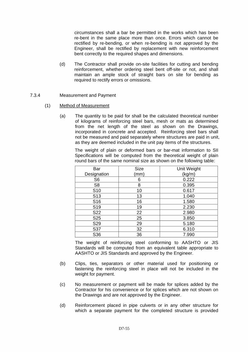
D7-55
circumstances shall a bar be permitted in the works which has been re-bent in the same place more than once. Errors which cannot be rectified by re-bending, or when re-bending is not approved by the Engineer, shall be rectified by replacement with new reinforcement bent correctly to the required shapes and dimensions.
(d) The Contractor shall provide on-site facilities for cutting and bending reinforcement, whether ordering steel bent off-site or not, and shall maintain an ample stock of straight bars on site for bending as required to rectify errors or omissions.
7.3.4 Measurement and Payment
(1) Method of Measurement
(a) The quantity to be paid for shall be the calculated theoretical number of kilograms of reinforcing steel bars, mesh or mats as determined from the net length of the steel as shown on the Drawings, incorporated in concrete and accepted. Reinforcing steel bars shall not be measured and paid separately where structures are paid in unit, as they are deemed included in the unit pay items of the structures.
The weight of plain or deformed bars or bar-mat information to SII Specifications will be computed from the theoretical weight of plain round bars of the same nominal size as shown on the following table:
Bar Designation
Size (mm)
Unit Weight (kg/m)
S6 6 0.222 S8 8 0.395
S10 10 0.617 S13 13 1.040 S16 16 1.580 S19 19 2.230 S22 22 2.980 S25 25 3.850 S29 29 5.180 S37 32 6.310 S36 36 7.990
The weight of reinforcing steel conforming to AASHTO or JIS Standards will be computed from an equivalent table appropriate to AASHTO or JIS Standards and approved by the Engineer.
(b) Clips, ties, separators or other material used for positioning or fastening the reinforcing steel in place will not be included in the weight for payment.
(c) No measurement or payment will be made for splices added by the Contractor for his convenience or for splices which are not shown on the Drawings and are not approved by the Engineer.
(d) Reinforcement placed in pipe culverts or in any other structure for which a separate payment for the completed structure is provided
D7-56
elsewhere in these Specifications shall not be measured for payment under this Section.
(2) Basis of Payment
The accepted quantities of reinforcing steel, determined as provided above, shall be paid for at the contract unit price per kilogram completed in place and accepted by the Engineer. Payment shall be full compensation for furnishing, fabricating, bending, assembling, erecting and if necessary gas welding reinforcing bar, for unloading at the specific location, storing, handling and placing the materials, including all labour, equipment, tools, testing, submittals and other work incidental to the satisfactory completion of the work.
Pay Item No. Description Unit of Measurement 7.3.(4) Reinforcing Steel Deformed
Bars Grade 40 Kilogram
D7-57
SECTION 7.5 –STRUCTURAL STEEL WORKS
7.5.1 General 7.5.1.1 Description
The work includes furnishing of all labor, materials and equipment required for performing all operations in the fabrication and installation of structural steel girders, steel coping and portal, bolts and other miscellaneous connection works as specified and shown on the Drawings.
7.5.1.2 Standards Included in the Specifications
The Publications listed below form part of these Specifications to the extent indicated by the reference thereto.
1) Japan Industrial Standards (JIS) Publication
2) Japan Road Association (JRA) Publication
3) Japan Steel Structural Association (JSS) Publication
4) AASHTO-American Association of State Highway and Transportation
Officials
5) ASTM - American Society for Testing and Materials
6) AWS - American Welding Society
7) SSPC - Steel Structures Painting Council (U.S.A)
7.5.1.3 Materials
(1) General
All materials shall be of new stock, free from surface imperfections and shall conform to the applicable JIS, standard or approved equal only. Unless otherwise specified, steel materials shall conform to JIS or JRA standards.
(2) Structural Steel
Materials shall conform to the requirements hereinafter specified. Connections in which details are not indicated shall be designed in accordance with the JIS or approved equal only, latest edition, and shall be welded or bolted, except as shown otherwise. Materials and parts necessary to complete each item, even though such work is not definitely shown or specified, shall be included. Miscellaneous bolts and anchors, supports, braces and connections necessary for completion of the works shall be provided. Structural steel shall be furnished according to the following specifications. The grades of steel to be furnished shall be as specified on the Drawings.
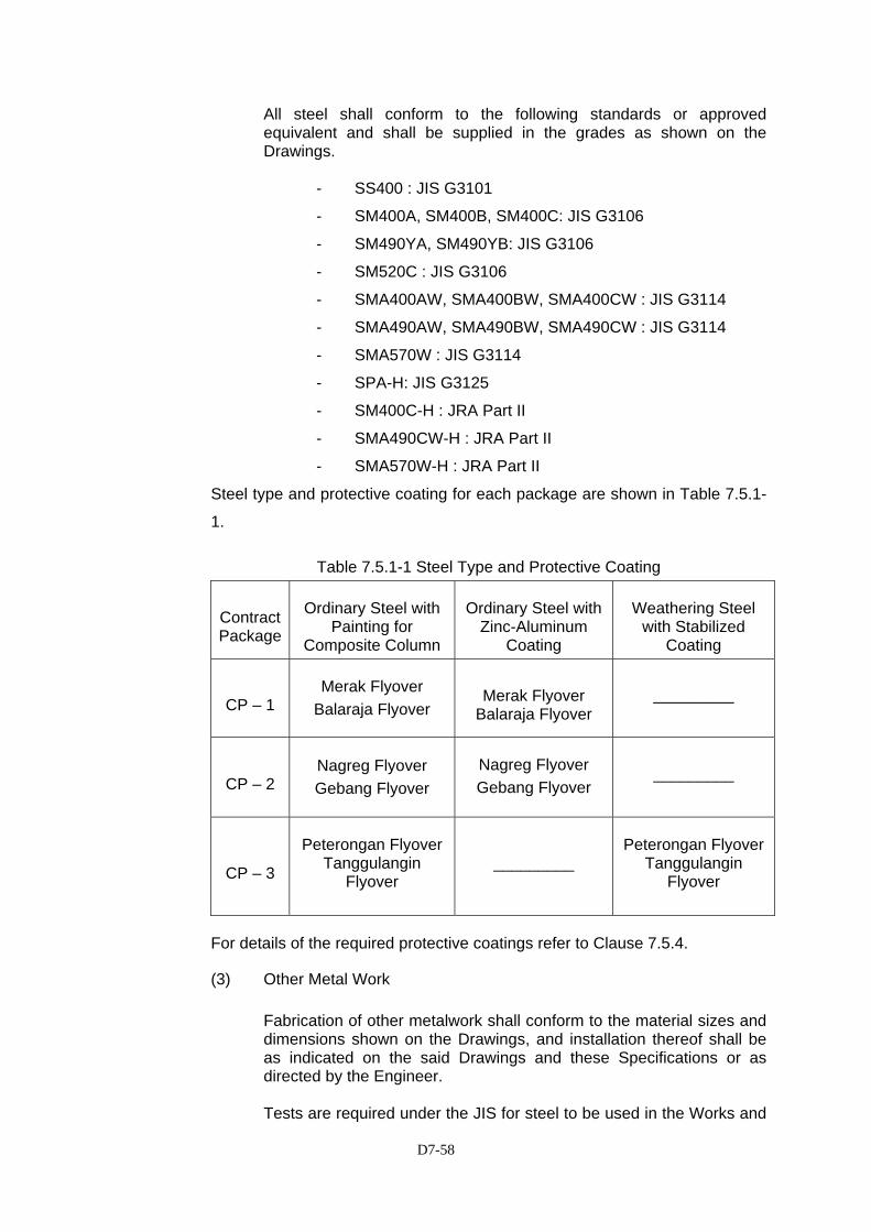
D7-58
All steel shall conform to the following standards or approved equivalent and shall be supplied in the grades as shown on the Drawings.
- SS400 : JIS G3101
- SM400A, SM400B, SM400C: JIS G3106
- SM490YA, SM490YB: JIS G3106
- SM520C : JIS G3106
- SMA400AW, SMA400BW, SMA400CW : JIS G3114
- SMA490AW, SMA490BW, SMA490CW : JIS G3114
- SMA570W : JIS G3114
- SPA-H: JIS G3125
- SM400C-H : JRA Part II
- SMA490CW-H : JRA Part II
- SMA570W-H : JRA Part II
Steel type and protective coating for each package are shown in Table 7.5.1-
1.
Table 7.5.1-1 Steel Type and Protective Coating
Contract Package
Ordinary Steel with Painting for
Composite Column
Ordinary Steel with Zinc-Aluminum
Coating
Weathering Steel with Stabilized
Coating
CP – 1 Merak Flyover
Balaraja Flyover
Merak Flyover Balaraja Flyover
_________
CP – 2 Nagreg Flyover Gebang Flyover
Nagreg Flyover Gebang Flyover
_________
CP – 3
Peterongan Flyover Tanggulangin
Flyover
_________
Peterongan Flyover Tanggulangin
Flyover
For details of the required protective coatings refer to Clause 7.5.4.
(3) Other Metal Work
Fabrication of other metalwork shall conform to the material sizes and dimensions shown on the Drawings, and installation thereof shall be as indicated on the said Drawings and these Specifications or as directed by the Engineer. Tests are required under the JIS for steel to be used in the Works and

D7-59
shall be carried out in the presence of the Engineer. At least 3-days notice in writing must be given to the Engineer of the dates proposed for such tests. a) High Strength Bolts High strength bolts for structural steel shall conform to JIS B
1186 and JRA Standard, Sets of Torque-Shear Type High Strength Hexagon Bolt, Hexagon Nut and Plain Washers for Friction Grip Joint or shall conform to JIS B1186 and JRA standard (corrosion resistant).
Sets of High Strength Bolt, Hexagon Bolt Hexagon Nut and
Plain Washers for Friction Grip Joint shall conform to JIS B 1186 (corrosion resistant).
b) Torque Control Bolts Torque control bolts for structural steel shall conform to JSS II
09-1981 and JRA. c) Shear Studs Steel grade, type, size and tolerance of shear studs shall
conform to JIS B 1198, Headed Stud or equivalent.
7.5.1.4 Tolerances
The Contractor shall, through appropriate planning and continuous measurements in the workshop and at the erection site ensure that the tolerances given in the Specifications are strictly observed. The Engineer will require any specific working procedure changed in case such procedure appears to have no sufficient security against exceeding the tolerances.
The Contractor shall be fully responsible for the calculation and provision of the necessary camber in the pre-assembled elements to obtain the correct levels in the completed bridge, duly considering the applied erection procedure and the sequence in the installation of the various dead load components.
7.5.2 Submittal
1) Working Drawings
The Contractor shall submit working drawings for the whole of the steelwork to the Engineer for his review. All working drawings shall show full detailed dimensions, sizes and cambers for all component parts of the structure. The size and extent of all welds shall be clearly shown on the shop drawings such that the work can be fabricated from these drawings without reference to the design drawings. The required grade of steel for each individual fabrication shall be clearly indicated. All working drawings shall also show method of construction, spacing of bolts, welding, sectional areas and other details necessary for the works. Bolted or welded construction may

D7-60
be employed subject to approval, soundness and neatness of design. Where welds are used, either at shop or on site, it shall wherever possible, be continuous around the joint to ensure that the joints are completely sealed against corrosion. The details of connections on working drawings shall be such as to minimize formation of pockets to hold condensation, water or dirt and a minimum gap between abutting angles and the like shall be provided wherever possible to eliminate any traps and facilitate maintenance painting.
No materials shall be ordered nor fabricated until such drawings are approved by the Engineer in writing. The Contractor shall be responsible for all errors of detailing, fabrications and correct fitting for all structural members.
7.5.2.1 Erection Procedures
The Contractor shall submit program of work and methodology to illustrate steel erection and temporary staying and bracing and to give clarification on data submitted. These submittals shall include details of storage and handling of steel materials, camber control, geometric control, site connections, cutting, welding, bolted connection, site assembly, test, erection equipment, crane way, temporary bent piers, assembling yard preparation, The Contractor shall also submit the details of welding equipment and welder’s license to approval of the Engineer. Whatever erection method is proposed the Contractor shall provide, for the prior approval of the Engineer, a detailed statement of his proposed methods for assembly, movement, and erection of girder units. The statement shall include but not limited to:
• Program for assembly of the girder units for Bridge • Details of the proposed assembly methods • Layout and details of the assembly yard and its equipment • Methods for fabricating, including temporary supports (or bracing) to
steelworks • Methods and equipment for storage of bridge girders • Methods for movement, load-out and transport of bridge girders to
erection position • Methods and equipment for lifting of girders into position • Methods for temporary support of girders prior to lowering into
permanent bearings • Details of temporary connections required to provide and maintain
accurate alignment at field splices prior to completion of permanent joint
7.5.2.2 Proof of Compliance with the Specifications for Materials
Manufacture’s certificates shall always be submitted to the Engineer for his approval. The Contractor shall also submit the following test results as a proof that the materials to be used will comply with the requirement of these
D7-61
Specifications.
1) Reports of Ladle Analysis for Steel
a) Mill test reports for main members b) Fabricator’s certificate for secondary members
2) Reports for Tensile Properties and Bend Tests for:
a) Steel shapes b) Steel bars c) Steel plates
3) Certificate of Conformance of:
a) Structural steel tubing b) Steel bar grating c) Filler metals for welding
4) Reports of Mechanical Properties of Shear Connectors
5) Reports of Mechanical Tests for High Strength Bolts and Standard Bolts.
7.5.2.3 Manufacturer’s Literature
The Contractor shall provide to the Engineer copies of manufacturer’s literature describing the structural steel and type of welding and/or arc shields used.
7.5.2.4 Inspection Report
The Contractor shall likewise submit the result of inspection tests specified in Clause 7.5.3, Construction.
7.5.3 Construction Requirements
7.5.3.1 Organization
To ensure consistent high quality the Contractor shall employ only qualified engineers and personnel experienced in the techniques of steel bridge construction to supervise these works. The Contractor shall submit to the Engineer full details of the experience and qualifications of the personnel he proposes to supervise these works together with description of their duties down to the level of foremen. The Contractor shall provide special practical training to his local staff prior to manufacture of units for the permanent works. This training shall be deemed part of the Contractor’s obligations under the contract and included in his price for the works. Expatriate operatives employed for steelworks assembly or erection shall be experienced in the
D7-62
construction of steel bridge works. The Engineer shall approve erection diagrams.
7.5.3.2 Handling and Storing Materials
Material to be stored at the job site shall be placed on skids above the ground. The underlying ground shall be kept and free from vegetation and shall be properly drained. The material shall be kept clean and shall be properly drained. Girders and beams shall be placed upright and shall be shored. The Contractor shall be responsible for the loss of any material, for which he has been paid, while it is in his care, or for any damage, resulting from his work. The loading, transporting and unloading of structural steelwork shall be so conducted that the steel will be kept free from injury and rough handling.
7.5.3.3 Qualification
1) Steel Fabricator Steel fabricator shall have an experience in fabrication of structural
steel for projects of similar type. A fabricator’s shop shall have a suitable space for temporary shop assembly. The Contractor shall submit a written description of fabrication capability including facilities, personnel and list of similar completed projects, including testing and quality control capability and specifically the type and extent of quality control procedure, which the fabricator intends to employ on this Project.
2) Steel Erector
Steel erector shall have experience in the erection of structural steel structure of similar size to the proposed structure. The Contractor shall submit a written description of structural steel erection capability including equipment, personnel, geometric control applications and a list of completed projects.
3) Qualified Welder and Welding Procedures
The Contractor shall submit for Engineer’s approval the welding procedure, welder’s qualification and the test results of each type of welding to be performed. Procedures shall be developed for welding all metals included in the work. The Contractor shall not start welding works until procedures, welders and trackers have been qualified as specified herein. The Contractor shall perform qualification testing by an approved testing laboratory, or by the Contractor’s laboratory if approved by the Engineer. Cost of such testing shall be borne by the Contractor. The Contractor shall qualify each welder and tracker assigned to work on this Project by test using equipment, positions, procedures, base metal and electrodes that will be encountered in his assignment. The Contractor shall furnish to the Engineer for approval a certification that each welder is qualified in accordance with the requirements JIS Z
D7-63
3801 and/or JIS Z3841 or approved standard. Welder shall have successful past experience with similar weld types or approved equal only.
7.5.3.4 Welding
1) General
Unless otherwise specified in this Specification, welded components shall comply with JRA Part II or approved equivalent.
Before the work is started, the welding procedure for each type of joint shall be approved by the Engineer. The welding procedure prepared by the Contractor shall include such trial welds and tests to satisfy the requirements of JRA Part II.
2) Welding Plan Prior to start of fabrication, a Welding Plan shall be prepared and
submitted to the Engineer for review. The plan shall be prepared, signed by a suitably qualified professional engineer, having significant past experience with similar projects, and shall include the following information:
• Procedures and program of welding sequence (for each
component and for welding components together). After approval of this submittal, welding procedures and sequences shall be followed without deviation.
• All information on welding detailed procedures, and additives
including any requirements for pre- and post-heating.
• Description of equipment to be used.
• Experience, qualification and licensing details for all welders to be employed. Successful past experience with similar weld types, plate thickness and plate material is required for all welders.
• Repair procedures or possible treatment of complete welds by
grinding with indication of grinding direction, etc.
• Fit-up requirements.
• Details on non-destructive testing methods to be used for specific typical joints.
• Precautions with regard to welding shrinkage. This plan shall be updated and maintained as required throughout the course of the project.
D7-64
3) Equipment
The welding machine shall be of modern type and with ample capacity to provide the required current to each welding point without appreciable fluctuations. Welding machine shall be used Carbon Gas Arc Semi-automatic Welding Machine, and Alternating Current Arc Welding Machine, or approved equal only. All shop/site welds shall be carried out by qualified welders under proper supervision. The work shall be properly prepared for welding and the correct sequence adhered at all times.
4) Welding Material
All arc-welding electrodes shall conform to be requirements of JIS Standards or approved equivalent.
5) Welding Construction
Welded connection shall be permitted only where indicated on the approved working drawings. Welded construction shall conform to the following: a) Surfaces to be welded shall be free from loose scale, slag, rust,
grease, paint and any other foreign materials except that mill scale that withstands vigorous wire brushing may remain. Joint surfaces shall be free from fins and tears. Preparation of edges by gas cutting shall, wherever practicable, be done by a mechanically guided torch.
b) The technique of welding employed, the appearance and
quality welds made, and the methods used in correcting defective work shall conform to JRA Part II or approved equivalent.
6) Tolerances
The tolerances concerning gap between parts to be welded, eccentricity and departure from theoretical alignment, dimensions of the cross section of grooved welded joints, etc. shall conform to JRA Part II or approved equivalent.
7.5.3.5 Fabrication
1) General
The Contractor shall fabricate the structural steel in the shop to the greatest extent possible for the appropriate transportation purpose taking into consideration the requirements in the Drawings. Bolted or welded connection shall be provided whether constructed on the shop or on the field as shown on the Drawings or as approved by the Engineer. High strength bolts for all bolted connections shall be used unless otherwise shown on the Drawings or approved by the Engineer.
D7-65
Connections shall be as shown on the Drawings or as approved by the Engineer. Holes except bolt holes shall be cut, drilled or punched at right angles to the surface of the metal and shall not be made or enlarged by burning. All sharp edges and corners shall be ground to a minimum radius of 1 mm and all sharp irregularities, burrs, slag and spatters on welds shall be removed. Bearing plates shall be provided under beams resting on concrete walls. Contact surface between bases of bearing and column or other elements bearing directly upon such plates shall be ground or milled as necessary for full effective bearing. Edges for welding shall likewise be properly prepared. An inspection shall be made to determine that the fabrication and the matching of the component parts are correct. Jigs shall be used for the assembly of units as much as possible to maintain appropriate position of mutual materials. Approval of the Engineer shall be required when drilling temporary bolt holes or welding temporary support to the assembled structure.
The tolerance shall not exceed those shown on the Drawings and each unit assembled shall be closely checked to ensure that all necessary clearances have been provided and that binding does not occur in any moving part. In order to maintain accurate finished dimensions and shape, appropriate reverse strain or restraints shall be provided as required. Assembly and disassembly work shall be performed in the presence of the Engineer, unless waived in writing by the Engineer. Any error or defect disclosed shall be immediately remedied by the Contractor.
Before disassembly for shipment, each piece of the structure shall be match-marked to facilitate erection in the field.
2) Templates
All templates, jigs and other equipment necessary for the accurate fabrication of the Work shall be provided by the Contractor at his own expense.
3) Cutting of Steel
Edges may be cut by machining, flame cutting or shearing, but edges to be welded shall nevertheless comply with the welding clauses of this Specification. Tolerances of cut edges of surface shall apply to following table. Defects exceeding following table shall be removed by machining or grinding. Correction to defects shall be faired to the surface less than following table requirements.
D7-66
Tolerances Table of Cut Edge Surfaces Defects Main Structure Secondary
Structure Burrs Less than 50 μm Ry Less than 100
μm Ry Notches No Notches Less than 1mm
Oxygen cutting of steel and weld metal shall be permitted provided a smooth and regular surface free from cracks and notches is secured, and provided that an accurate profile is secured by the use of a mechanical guide. In all oxygen cutting the cutting flame shall be so adjusted and manipulated as to avoid cutting inside the prescribed lines. The surface roughness of oxygen cut surfaces shall be equivalent to or better than the standard classes of replicas of flame cut surfaces as existing on JIS B 0601. Cut surfaces and edges shall be left free of adhering slag. Corrections of defects shall be faired to the oxygen cut surface with a slope not exceeding 1 in 10. Defects of oxygen cut edges shall not be repaired by welding except with the express approval of the Engineer for occasional notches or gouges. Such weld repair shall be made by suitably preparing the defect, welding with low hydrogen electrodes not exceeding 4 mm in diameter, observing the applicable requirements of the welding clauses of this specification, and grinding the completed weld smooth and flush with the adjacent surface to produce a workmanlike finish.
4) Straightening
All material before being assembled, shall be straightened or formed to the specified configuration by methods specified below.
Straightening or bending of either fabricated or un-fabricated steel, if necessary, shall be done by means of steady pressure applied by roll or press. Straightening and bending shall not be done by hammering or, unless the Engineer’s approval has been obtained by heating. If straightening by heating is allowed, the steel shall in no case be heated to a higher temperature than 9000C as measured by indicating crayons, liquids or bimetal thermometers. After heating, the metal shall be cooled slowly in air without any forced cooling.
5) Holes of Bolts
All holes shall be drilled. Punching of holes shall not be permitted. Reamed and fitted holes shall be sub-drilled 3 mm less in diameter than that of the finished holes and reamed to size. Reamed and fitted holes and drilled holes shall be made through steel templates or after assembly or by other approved means, to ensure complete matching between the plies of the joints.
D7-67
All steel templates shall have hardened steel bushings in holes accurately dimensioned from the center lines of the connection. The center lines shall be used to accurately locate the template. All finished holes shall be cylindrical and perpendicular to the member unless otherwise specified. All burrs and other defects shall be removed. The diameter of the completed hole shall be 2.5 mm larger than the nominal diameter of the bolt unless otherwise specified except that for the inner plies of a structural connection fastened by high-strength bolts the diameter of the hole shall not be larger than 2.5 mm larger than the nominal diameter of the bolt. All matching holes shall register with each other so that a gauge or drift 2 mm less in diameter than the hole shall pass freely through the assembled contact faces at right angles to them.
Burrs, fins and other defects shall be removed. Drifting to align holes shall be done in a manner that will not distort the metal or enlarge the hole.
6) Marking for Final Assembly
Each part shall be carefully marked to facilitate final erection. Such marking shall be durable but shall not injure the material. Such marks shall not be injured, defaced or removed by any person. The marking of components shall be in accordance with that shown on the workshop drawings submitted.
7) Shop Assembly
The Contractor shall carry out shop assemblage in his regular workshop.
Shop assemblage shall be understood as placing of prefabricated elements together to control the fit. The Contractor shall submit his proposal for shop assemblage for the approval of the Engineer. The shop assemblage shall verify that the individual elements have the shape to that the individual elements have the shape to fit exactly into adjoining elements. In addition, the shop assemblage shall verify that the camber aimed at, or prescribed, actually exists, and that the geometry is generally correct. The Contractor shall perform measurement of the structural members, and the results shall be recorded and submitted to the Engineer. The Contractor shall inform the Engineer that the shop assemblage of major components have been completed and measured, and the structure shall not be dismantled until the shop assemblage has been approved by the Engineer.

D7-68
7.5.3.6 Fabrication Tolerances
Dimensions shall be measured by means of an approved calibrated steel tape at the time of inspection. Unevenness of plate work shall not exceed the limitation of the standard mill practice as specified in JRA Part II or equivalent. Unless otherwise specified, the following tolerances shall apply:
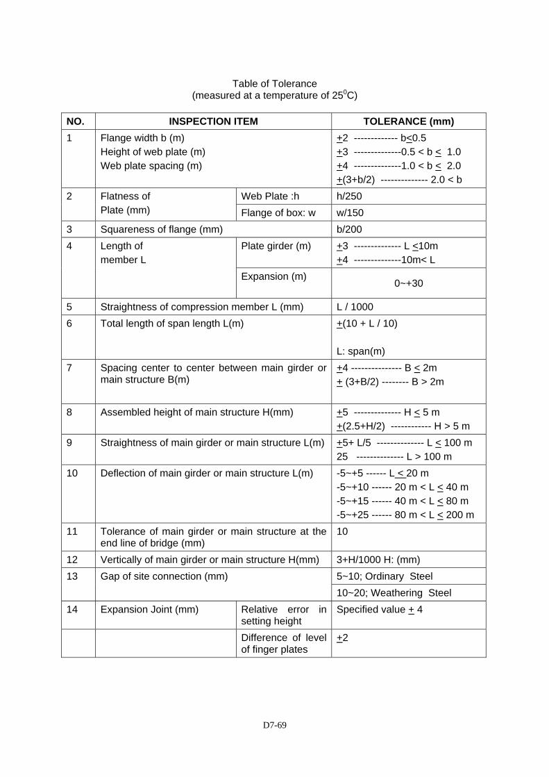
D7-69
Table of Tolerance
(measured at a temperature of 250C) NO. INSPECTION ITEM TOLERANCE (mm) 1 Flange width b (m)
Height of web plate (m) Web plate spacing (m)
+2 ------------- b<0.5 +3 --------------0.5 < b < 1.0 +4 --------------1.0 < b < 2.0 +(3+b/2) -------------- 2.0 < b
Web Plate :h h/250 2 Flatness of Plate (mm) Flange of box: w w/150
3 Squareness of flange (mm) b/200 Plate girder (m)
+3 -------------- L <10m +4 --------------10m< L
4 Length of member L
Expansion (m)
0~+30
5 Straightness of compression member L (mm) L / 1000 6 Total length of span length L(m) +(10 + L / 10)
L: span(m)
7 Spacing center to center between main girder or main structure B(m)
+4 --------------- B < 2m + (3+B/2) -------- B > 2m
8 Assembled height of main structure H(mm) +5 -------------- H < 5 m +(2.5+H/2) ------------ H > 5 m
9 Straightness of main girder or main structure L(m) +5+ L/5 -------------- L < 100 m 25 -------------- L > 100 m
10 Deflection of main girder or main structure L(m) -5~+5 ------ L < 20 m -5~+10 ------ 20 m < L < 40 m -5~+15 ------ 40 m < L < 80 m -5~+25 ------ 80 m < L < 200 m
11 Tolerance of main girder or main structure at the end line of bridge (mm)
10
12 Vertically of main girder or main structure H(mm) 3+H/1000 H: (mm) 5~10; Ordinary Steel 13 Gap of site connection (mm) 10~20; Weathering Steel
14 Expansion Joint (mm) Relative error in setting height
Specified value + 4
Difference of level of finger plates
+2
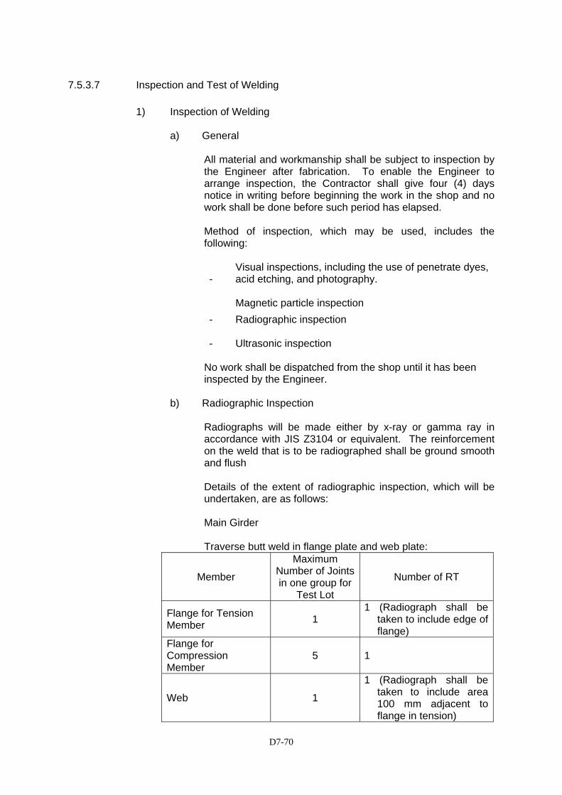
D7-70
7.5.3.7 Inspection and Test of Welding
1) Inspection of Welding
a) General
All material and workmanship shall be subject to inspection by the Engineer after fabrication. To enable the Engineer to arrange inspection, the Contractor shall give four (4) days notice in writing before beginning the work in the shop and no work shall be done before such period has elapsed. Method of inspection, which may be used, includes the following:
- Visual inspections, including the use of penetrate dyes, acid etching, and photography. Magnetic particle inspection
- Radiographic inspection - Ultrasonic inspection
No work shall be dispatched from the shop until it has been inspected by the Engineer.
b) Radiographic Inspection
Radiographs will be made either by x-ray or gamma ray in accordance with JIS Z3104 or equivalent. The reinforcement on the weld that is to be radiographed shall be ground smooth and flush Details of the extent of radiographic inspection, which will be undertaken, are as follows:
Main Girder
Traverse butt weld in flange plate and web plate:
Member
Maximum Number of Joints in one group for
Test Lot
Number of RT
Flange for Tension Member 1
1 (Radiograph shall be taken to include edge of flange)
Flange for Compression Member
5 1
Web 1
1 (Radiograph shall be taken to include area 100 mm adjacent to flange in tension)
D7-71
The result of the test shall satisfy the following:
i) The joint subject to tensile stress shall be equal or better
than class-2 as specified in JIS Z3104
ii) The joint subject to compressive stress shall be equal to or better than class-3.
iii) Ultrasonic inspection shall be carried out in accordance
with JIS Z3060 or equivalent.
Ultrasonic inspection shall be used on Flange/Flange welds, a part of full Flange/Web and in any other areas directed by the Engineer. Defects revealed by non-destructive tests will be compared with the standards for allowable porosity and fusion type defects set out herein. Where weld defects exceed the limits specified, the weld will be rejected. If approved by the Engineer, the Contractor shall carry out the corrective measure specified herein.
The Contractor shall program his work to the satisfaction of the Engineer in order to keep visits to a minimum. The cost of providing welding inspections, and equipment and operators for non-destructive testing will be borne by the Contractor. After the repair of any defective weld, further non-destructive tests of the corrected weld will be made at the Contractor’s expense. The cost of any further corrective measures and subsequent non-destructive testing of the weld will be borne by the Contractor. The Contractor shall provide the Engineer with an Inspection Plan, giving details of all items to be inspected before, during and after execution of welding for approval.
Inspection of welding shall be executed for the following work phases: a) Before Welding
Scum, angle of bevel, roof clearance, cleaning of surface to be welded, quality of end tab, drying of welding rod.
b) During Welding
Welding procedure, diameter of core and wire, type of flux, welding current and voltage, welding speed, welding rod position, length of arc, melting, cleaning of slag of each level under surface chapping, supervision of welding rod.
D7-72
c) After Execution of Welding
Assurance of bead surface, existence of harmful defects, treatment of crater, quality of slag removal, size of fillet, dimension of extra fill of butt welding, treatment of end tab.
2) Testing of Welding
The Contractor shall retain a suitably qualified and experienced independent Testing Agency, acceptable to the Engineer, to perform non-destructive testing of welds as described below. This Agency shall submit reports regularly to the Engineer, who may also arrange other independent tests of the Work. The test to be performed shall be as follows: a) All welds shall be visually inspected for size, contour and
general conformance with good welding practice. b) Only when there is suspension in visual inspection, Magnetic
Particle Testing shall be conducted.
c) The following percentage of randomly selected welds shall be subjected to Radiographic Inspection in accordance with the JIS Z3104 or Ultrasonic Inspection in accordance with JIS Z3060 or equivalent. The Contractor shall submit the Inspection method to the Engineer for approval.
d) The following welds shall be subjected to Ultrasonic Inspection in accordance with JIS Z3060 or equivalent:
Welds that fail to meet the requirements of these tests shall be repaired to the satisfaction of the Engineer, following which testing shall be repeated at the Contractor’s expense. If the welds cannot be repaired to the satisfaction of the Engineer, they shall be rejected and removed from the Work.
3) Corrections
In lieu of the rejection of an entire piece or member containing welding which is unsatisfactory or which indicates inferior workmanship, corrective measures may be permitted by the Engineer whose specific approval shall be obtained for making each correction. Defective or
- 100% of tension flange butt welds – shop - 20% of compressive flange butt welds – shop - 100% of each web butt weld, always including the 100 mm
adjacent to flange in tension – shop - 50% of other flange butt welds – shop.
- 100% of all flange butt welds – fields - 100% of all web but weld – fields - 100% of all fillet weld – field.
D7-73
unsound welds or base steel shall be corrected either by removing and replacing the entire weld, or as follows:
a) Excessive convexity or overlap shall be reduced by grinding. b) Undercut, lacking of weld shall be repaired with necessary
reinforcement of weld after removal of any foreign material such as slag, dust, oil, etc.
c) Any defects such as slag inclusion, incomplete fusion, or
inadequate joint penetration, shall be completely removed, cleaned and re-welded.
d) Cracks in weld or base steel, shall be removed to sound steel
throughout its length and 5 cm beyond each end of the crack, followed by welding. The extent of the crack, depth and length, shall be ascertained by the use of acid etching, magnetic particle inspection or other equally positive means.
The removal of welded steel shall be done by chipping, grinding, oxygen cutting, oxygen gouging, or air carbon arc gauging and in such a manner that the remaining welded steel or base steel is not nicked or undercut. Defective portions of the welding shall be removed without substantial removal of the base steel.
7.5.3.8 Delivery to Site
During delivery all component materials shall be adequately protected from damage and the Contractor shall be responsible for any damage, which may occur. In particular, the Contractor shall adequately strut the bottom flange of plate girders. All straps and chains used in lifting shall be adequately padded to prevent damage to the steelwork and its protective coating. No fabricated steel shall be placed in the Work without being inspected and passed by the Engineer after delivery.
7.5.3.9 Site Erection
1) Installation Program
Prior to executing steel fabrication, the Contractor shall prepare full calculation, detailed erection drawings and comprehensive installation program including engineering supervision organization, fabrication procedure, field installation procedure, application material, application machinery, inspection procedure, scope and standards of quality testing, and submit to the Engineer for approval. The erection drawings shall be signed by a suitably qualified professional engineer. Supporting calculations for all major items of work such as crane reach and capacity, temporary girder supports, temporary bearings, temporary bent piers and incidental and include full method statements for each stage of the erection shall accompany the erection drawings.

D7-74
Erection shall not commence until the Engineer has indicated that he has no further comments on the Contractor’s proposals. Steelwork shall be stored, clear of the ground and in such a way as to permit checking and to avoid excessive handling and damage to the steelwork or its protective coating. Unless otherwise directed by the Engineer, all surfaces to be brought together to form a joint or splice shall be free of paint or any other applied finish, oil, dirt, loose rust, loose scale, burrs and other defects which would prevents solid seating of the parts or would interfere with the development of friction between them.
2) Installation Requirements
a) Setting of Anchor Bolt and Others
Anchor bolt shall be set in accurate position by using template.
(i.) Setting method shall be proposed to the Engineer for his approval before setting starts.
(ii.) The thread of bolt shall be treated with appropriate
method against rust and/or from any damage before tightening.
(iii.) Non-shrink grout shall be placed under base plate, well
cured to obtain the sufficient strength before bearing loads are applied to base plate.
b) Shop Assembly
Structural units furnished shall be assembled in the shop. An inspection shall be made to determine the correctness of the fabrication and matching of the component parts. Assembly and disassembly work shall be performed in the presence of inspector, unless waived in writing by the Engineer, and any errors or defects disclosed shall be immediately remedied by the Contractor.
c) Adequacy of Temporary Connections
During erection, temporary connection work shall be securely made by bolting and/or welding for all dead load, wind and erection stresses.
d) Alignment
No permanent bolting or welding shall be done until the alignment of all parts with respect to each other shall be true within the respective tolerances required.
D7-75
e) Site Welding
(i) Any shop paint or surfaces adjacent to joints where field welding is to be executed shall be wire brushed to remove paint/primer.
(ii) Site welding shall conform to the requirements
specified herein before (7.5.3.4 & 7.5.3.7 etc.), except as approved by the Engineer.
f) Bolting
Bolts shall be driven accurately into the holes without damaging the thread. Bolt heads shall be protected from damage during driving. Bolt heads and nuts shall rest squarely against the metal. Where bolts are to be used on beveled surfaces having slopes greater than 1 in 20 with the plane normal to the bolt axis, beveled washers shall be provided to give full bearing to the head or nut. After having been finally tightened, nuts shall be locked. When bolts are tightened by torque method, tightening torque shall be adjusted so that tightening axial force is induced uniformly to each bolt.
Tightening axial force of bolts is shown in the following table:
Bolt tightening tools and measuring equipments shall be calibrated to check their accuracy on appropriate occasion.
g) Bolted Connection (High Strength Bolts/Torque Control Bolts)
High Strength Bolts/Torque Control Bolts with associated nuts and end washers shall comply with the Drawings and the latest edition of JRA standard and shall incorporated load indicating devices acceptable to the Engineer. High strength bolts/Torque Control Bolts shall be assembled with one hardened washer under the turned element (nut or bolt head). The washer shall be assembled with any convexity outwards. The inserting and tensioning of the high tensile bolts shall be so arranged that the close contacts established by the service bolts are maintained at all times. The tensioning of high tensile bolts shall not commence until the joint has been inspected by the Engineer.
Grade Size Axial Force of Bolt ( KN) M20
172~202
M22
212~249
F8T S10T S10TW F10T F10TW M24
247~290
D7-76
h) Correction of Errors
(i.) Correction of minor misfits by use of drift pins, and reaming, chipping or cutting will be permitted and shall be provided as part of erection work.
(ii) Any errors to be corrected or adjusted, preventing
proper assembly, shall be immediately reported to the Engineer, and such corrections or adjustment shall be made as necessary and approved by the Engineer.
(iii.) Cutting or alterations other than as approved will not be
permitted.
i) Erection (i.) The Contractor shall submit for approval full and
detailed description and shop drawings of his proposed procedure referred to the construction sequences as shown the Drawings and equipment, together with supporting calculations. The Engineer’s consent to of the Contractor’s erection procedure shall in no way affect the Contractor’s responsibility under the contract.
A full description of his proposed erection method shall
also include: - sequence of erection
- use of temporary or permanent stanchions, beams and bracing
- connection - erection camber diagrams to show the vertical
position of the structure at each stage of the erection process
- design calculation to cover the various stages in the erection process
- type of equipment to be sued during erection.
(ii.) The erection procedures shall be such that at the datum temperature, when the bridge is complete and with full permanent load applied, the profiles of the roadways shall correspond to those given on the drawings.
(iii.) Erection setting-out calculations shall take account of
the load relationships between deck and girder as well as geometric controls.
(iv.) Site workmanship, welding, and inspection during and
after erection shall comply with the appropriate requirements of the preceding clauses of these Specifications.
(v.) During erection the Contractor shall take special care to
D7-77
avoid permanent distortion, the locking-in of secondary stress and impairment of the fatigue resistance of the permanent works.
(vi.) Removal of temporary attachments by burning shall be
on the waste side with ample allowance for finishing by grinding, this requirement applies equally to exposed and subsequently embedded parts.
(vii.) The Contractor shall provide an adequate
communication system between strategic points during erection, which shall be maintained at all times to the satisfaction of the Engineer.
(viii.) The use of permanent fasteners as service fastenings
during assembly or erection will not be permitted where such use is liable to cause damage to the protective treatment provided to the fastener. Any fastening so damaged shall be replaced at the Contractor’s expenses.
(ix.) Each structural unit shall be accurately aligned by the
use of steel shims, or other approved methods so that no binding in any moving parts or distortion of any members occurs before it is finally fastened in place.
(x.) Operations, procedures of erection and bracing shall
not cause any damage to works previously placed nor produce overstressing to any of the building parts or components. Damaged parts caused by such operations shall be repaired as directed by the Engineer at no extra cost to the Employer.
3) Inspection
Inspection by the Engineer does not relieve the Contractor of his
responsibility to provide the necessary inspection of his own work, and that of his subcontractors, to ensure compliance with Drawings and these Specifications.
The fabrication and erection facilities, materials and quality of workmanship of the Contractor and his subcontractors shall be made available for inspection by the Engineer at all times during the progress of work. The Engineer shall have the right to reject work not satisfying the requirements of their governing references as mentioned herein before.
7.5.4 Protective Coating
7.5.4.1 General
Protective coating is required for both weathering steel components and ordinary steel components.
D7-78
The standard fabrication flowchart for weathering steel, including the required preparations, is given in Figure 7.5.4.1-1.
The standard fabrication flowchart of zinc-aluminum coating for ordinary steel is given in Figure 7.5.4.1-2.
A summary of classification and application of painting type based on JRA standards is presented in Figure 7.5.4.1.-3.
The type of protective coating to be applied to weathering steel is given in Figure 7.5.4.1-4.
The type of protective coating to be applied to ordinary steel is given in Figure 7.5.4.1-5.
The type of protective coating required for composite column steel work is presented in Table 7.5.4.1-1 to 7.5.4.1-3
7.5.4.2 Zinc and Aluminum coating
1) General
All mild steel parts exposed to weather shall be coated with zinc-aluminum after fabrication as shown on the Drawings or directed by the Engineer.
2) Preparation Prior to coating, the surface shall be cleaned of dirt, weld splatter,
grease, slag, oil or other deleterious matters. The steel surfaces shall be chemically desiccated and cleaned with abrasive blast or other suitable method as approved by the Engineer.
3) Coating
The zinc coating shall consist of uniform layer of commercially pure zinc free from abrasions, cracks, blisters, chemical spots or other imperfections, and shall adhere firmly to the surface of the steel. The weight of zinc coating per square meter of actual surface shall not be less than 550 grams. Any surface damaged shall be given 2 coats of approved zinc rich paints.
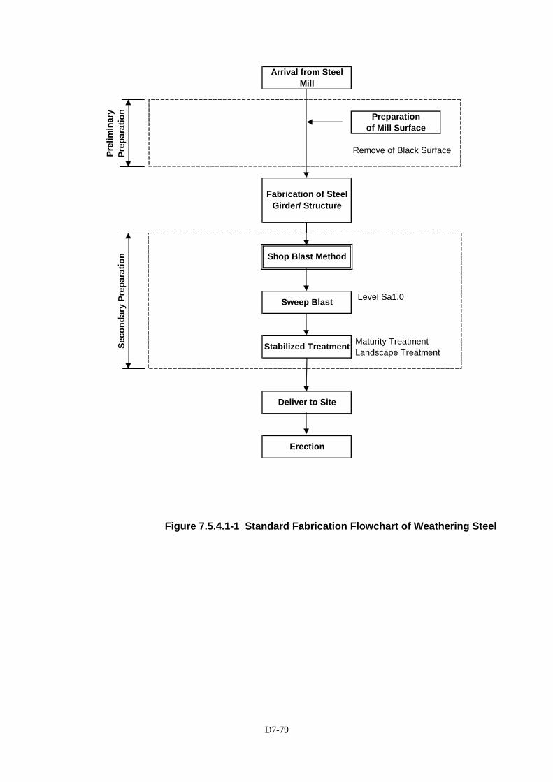
D7-79
Remove of Black Surface
Level Sa1.0
Maturity Treatment Landscape Treatment
Arrival from Steel Mill
Prel
imin
ary
Prep
arat
ion Preparation
of Mill Surface
Fabrication of Steel Girder/ Structure
Erection
Stabilized Treatment
Deliver to Site
Seco
ndar
y Pr
epar
atio
n Shop Blast Method
Sweep Blast
Figure 7.5.4.1-1 Standard Fabrication Flowchart of Weathering Steel
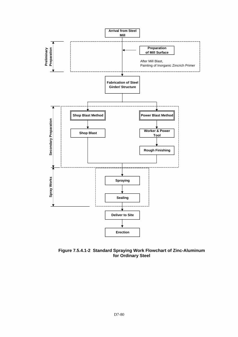
D7-80
After Mill Blast,Painting of Inorganic Zincrich Primer
Rough Finishing
Erection
Spra
y W
orks Spraying
Sealing
Deliver to Site
Arrival from Steel Mill
Prel
imin
ary
Prep
arat
ion Preparation
of Mill Surface
Fabrication of Steel Girder/ Structure
Seco
ndar
y Pr
epar
atio
n
Shop Blast Method Power Blast Method
Shop Blast Worker & Power Tool
Figure 7.5.4.1-2 Standard Spraying Work Flowchart of Zinc-Aluminum for Ordinary Steel
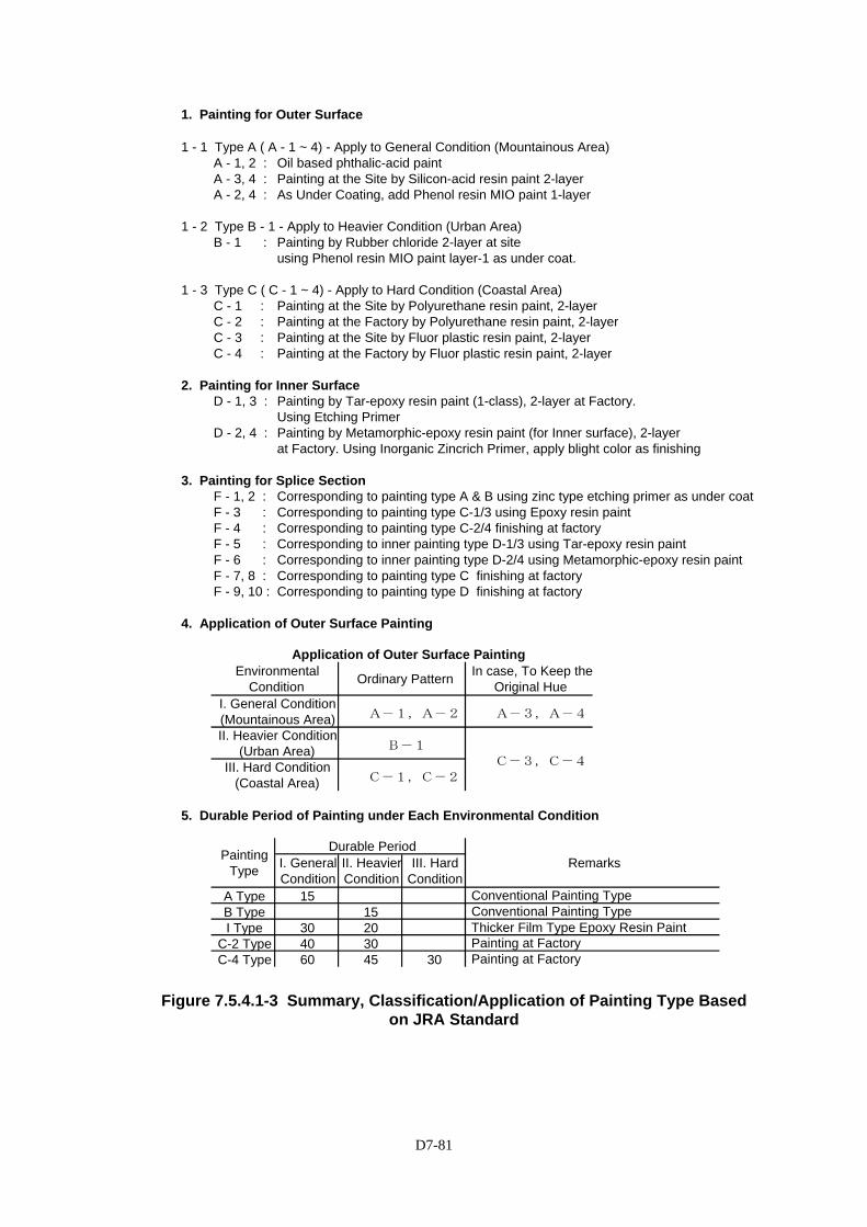
D7-81
Figure 7.5.4.1-3 Summary, Classification/Application of Painting Type Based on JRA Standard
1. Painting for Outer Surface
1 - 1 Type A ( A - 1 ~ 4) - Apply to General Condition (Mountainous Area)A - 1, 2 : Oil based phthalic-acid paintA - 3, 4 : Painting at the Site by Silicon-acid resin paint 2-layerA - 2, 4 : As Under Coating, add Phenol resin MIO paint 1-layer
1 - 2 Type B - 1 - Apply to Heavier Condition (Urban Area)B - 1 : Painting by Rubber chloride 2-layer at site
using Phenol resin MIO paint layer-1 as under coat.
1 - 3 Type C ( C - 1 ~ 4) - Apply to Hard Condition (Coastal Area)C - 1 : Painting at the Site by Polyurethane resin paint, 2-layerC - 2 : Painting at the Factory by Polyurethane resin paint, 2-layer C - 3 : Painting at the Site by Fluor plastic resin paint, 2-layerC - 4 : Painting at the Factory by Fluor plastic resin paint, 2-layer
2. Painting for Inner SurfaceD - 1, 3 : Painting by Tar-epoxy resin paint (1-class), 2-layer at Factory.
Using Etching PrimerD - 2, 4 : Painting by Metamorphic-epoxy resin paint (for Inner surface), 2-layer
at Factory. Using Inorganic Zincrich Primer, apply blight color as finishing
3. Painting for Splice SectionF - 1, 2 : Corresponding to painting type A & B using zinc type etching primer as under coatF - 3 : Corresponding to painting type C-1/3 using Epoxy resin paint F - 4 : Corresponding to painting type C-2/4 finishing at factoryF - 5 : Corresponding to inner painting type D-1/3 using Tar-epoxy resin paint F - 6 : Corresponding to inner painting type D-2/4 using Metamorphic-epoxy resin paintF - 7, 8 : Corresponding to painting type C finishing at factoryF - 9, 10 : Corresponding to painting type D finishing at factory
4. Application of Outer Surface Painting
5. Durable Period of Painting under Each Environmental Condition
A Type 15 B Type 15I Type 30 20
C-2 Type 40 30C-4 Type 60 45 30 Painting at Factory
Conventional Painting Type Conventional Painting Type Thicker Film Type Epoxy Resin Paint Painting at Factory
Remarks I. General Condition
II. Heavier Condition
III. Hard Condition
III. Hard Condition (Coastal Area) C-1,C-2
Painting Type
Durable Period
A-1,A-2 A-3,A-4
II. Heavier Condition (Urban Area) B-1
C-3,C-4
I. General Condition (Mountainous Area)
Application of Outer Surface PaintingEnvironmental
Condition Ordinary Pattern In case, To Keep the Original Hue
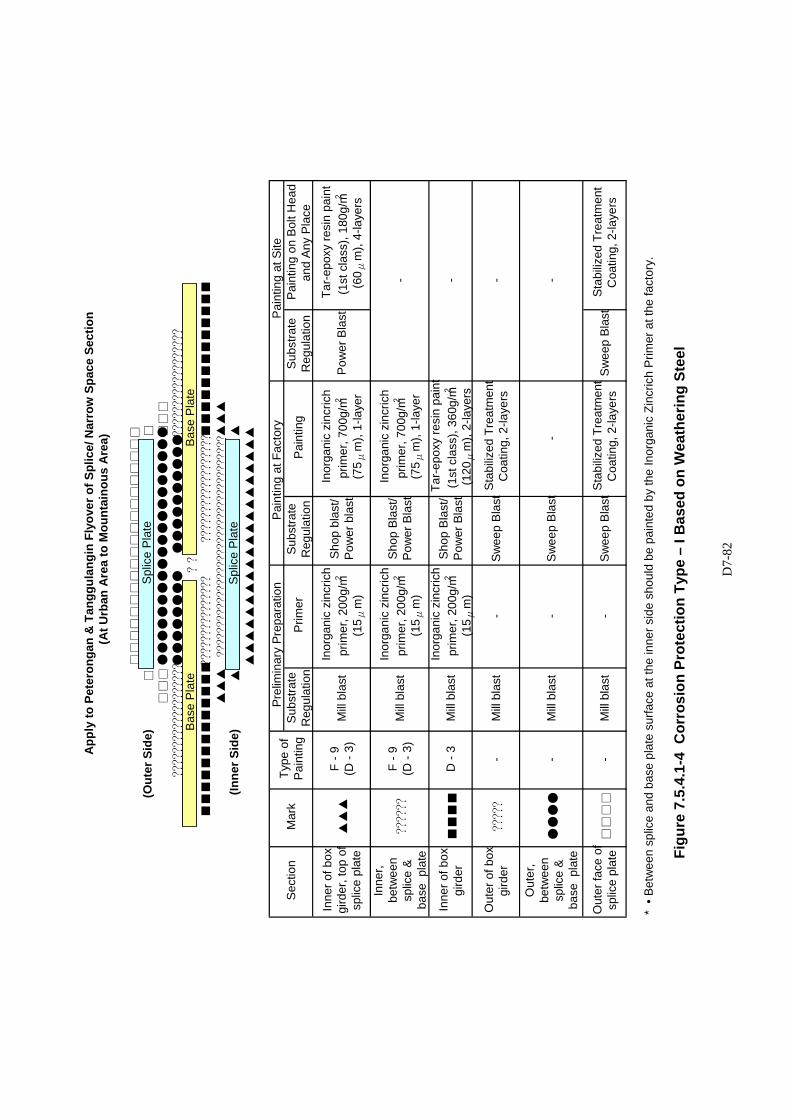
D7-
82
Figu
re 7
.5.4
.1-4
Cor
rosi
on P
rote
ctio
n Ty
pe –
I B
ased
on
Wea
ther
ing
Stee
l
(Out
er S
ide)
□□
□□□
□□□
???????????????????●
●●●●●●●
●●●●●●●●●●??????????????????
??
■■■■■■■■■■■■■???????????????
??????????????????■
■■■■■■■■■■■■
▲▲▲
▲▲▲
(Inne
r Sid
e)▲
▲▲▲▲▲▲▲▲▲▲▲▲▲▲▲▲▲▲▲▲▲
* •
Bet
wee
n sp
lice
and
base
pla
te s
urfa
ce a
t the
inne
r sid
e sh
ould
be
pain
ted
by th
e In
orga
nic
Zinc
rich
Prim
er a
t the
fact
ory.
App
ly to
Pet
eron
gan
& T
angg
ulan
gin
Flyo
ver o
f Spl
ice/
Nar
row
Spa
ce S
ectio
n(A
t Urb
an A
rea
to M
ount
aino
us A
rea)
□□□□□□□□□□□□□□□□□□□□
●●●●●●●●●●●●●●●●●●●●
?????????????????????????????????????
Sec
tion
Mar
k Ty
pe o
f P
aint
ing
Prel
imin
ary
Prep
arat
ion
Pai
ntin
g at
Fac
tory
Pai
ntin
g at
Site
Sub
stra
te
Reg
ulat
ion
Prim
erS
ubst
rate
R
egul
atio
n P
aint
ing
Sub
stra
te
Reg
ulat
ion
Pai
ntin
g on
Bol
t Hea
d an
d An
y Pl
ace
Sho
p bl
ast/
Pow
er b
last
In
orga
nic
zinc
rich
prim
er, 7
00g/
m2
(75 μ
m),
1-la
yer
Pow
er B
last
Inne
r of b
ox
gird
er, t
op o
f sp
lice
plat
e ▲▲▲
F
-9
(D -
3)M
ill bl
ast
Tar-e
poxy
resi
n pa
int
(1st
cla
ss),
180g
/m2
(60 μ
m),
4-la
yers
Inne
r, be
twee
n sp
lice
& ba
se p
late
??????
F -9
(D
- 3)
Mill
blas
tIn
orga
nic
zinc
rich
prim
er, 2
00g/
m2
(15 μ
m)
Sho
p B
last
/ P
ower
Bla
st
Inor
gani
c zi
ncric
h pr
imer
, 700
g/m2
(75 μ
m),
1-la
yer
-
Inor
gani
c zi
ncric
h pr
imer
, 200
g/m2
(15 μ
m)
Out
er o
f box
gi
rder
?????
-M
ill bl
ast
-S
wee
p B
last
Sta
biliz
ed T
reat
men
t C
oatin
g, 2
-laye
rs-
Inne
r of b
ox
gird
er
■■■■
D -
3M
ill bl
ast
Inor
gani
c zi
ncric
h pr
imer
, 200
g/m2
(15 μ
m)
Sho
p B
last
/ P
ower
Bla
st Ta
r-epo
xy re
sin
pain
t (1
st c
lass
), 36
0g/m2
(120
μm
), 2-
laye
rs-
Sta
biliz
ed T
reat
men
t C
oatin
g, 2
-laye
rs
●●●●
Out
er,
betw
een
splic
e &
base
pla
te
-M
ill bl
ast
-S
wee
p B
last
-
-
-S
wee
p B
last
Sta
biliz
ed T
reat
men
t C
oatin
g, 2
-laye
rsS
wee
p Bl
ast
Out
er fa
ce o
f sp
lice
plat
e □□□□
-M
ill bl
ast
Splic
e Pl
ate
Splic
e Pl
ate
Bas
e P
late
Bas
e P
late
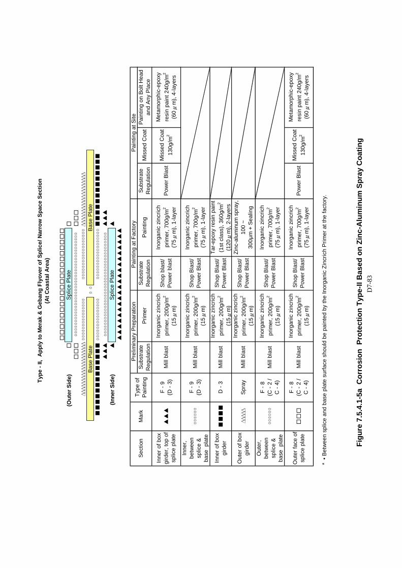
D7-
83
(Out
er S
ide)
□□
□□□
□□□
∆∆∆∆∆∆∆∆∆∆∆∆∆∆∆∆∆∆∆
☼☼☼☼☼☼☼☼☼☼☼☼☼☼☼
☼☼☼☼☼☼☼☼☼☼☼☼☼☼☼☼☼☼∆∆∆∆∆∆∆∆∆∆∆∆∆∆∆∆∆∆∆
☼☼
■■■■■■■
■■■■■■
☼☼☼☼☼☼☼☼☼☼☼☼☼☼☼
☼☼☼☼☼☼☼☼☼☼☼☼☼☼☼☼☼☼■■■■
■■■■■■■■■
▲▲▲
▲▲▲
(Inne
r Sid
e)▲
▲
▲▲▲▲▲▲▲▲▲▲▲▲▲
▲▲▲▲▲▲▲
* • B
etw
een
splic
e an
d ba
se p
late
sur
face
sho
uld
be p
aint
ed b
y th
e In
orga
nic
Zinc
rich
Prim
er a
t the
fact
ory.
Type
- II,
App
ly to
Mer
ak &
Geb
ang
Flyo
ver o
f Spl
ice/
Nar
row
Spa
ce S
ectio
n
Pain
ting
at S
ite
(At C
oast
al A
rea)
□□□□□□□□□□
□□□□□□□□□□
☼☼☼☼☼☼☼☼☼☼☼☼☼☼☼☼☼☼☼☼☼☼☼☼☼☼☼☼☼☼☼☼☼☼☼☼☼
☼☼☼☼☼☼☼☼☼☼☼☼☼☼☼☼☼☼☼☼☼☼☼☼☼☼☼☼☼☼☼☼☼☼☼☼☼
Sect
ion
Mar
kTy
pe o
f Pa
intin
g
Prel
imin
ary
Prep
arat
ion
Pain
ting
at F
acto
rySu
bstra
te
Reg
ulat
ion
Mis
sed
Coa
tPa
intin
g on
Bol
t Hea
d an
d An
y Pl
ace
Subs
trate
R
egul
atio
nPr
imer
Subs
trate
R
egul
atio
nPa
intin
g
Inne
r of b
ox
gird
er, t
op o
f sp
lice
plat
e▲▲▲
F - 9
(D -
3)M
ill b
last
Mis
sed
Coa
t 13
0g/m
2
Met
amor
phic
-epo
xy
resi
n pa
int 2
40g/
m2
(60 μ
m),
4-la
yers
Inor
gani
c zi
ncric
h pr
imer
, 200
g/m
2
(15 μ
m)
Shop
bla
st/
Pow
er b
last
Inor
gani
c zi
ncric
h pr
imer
, 700
g/m
2
(75 μ
m),
1-la
yer
Pow
er B
last
Inne
r,
betw
een
splic
e &
base
pla
te
☼☼☼☼☼☼
F - 9
(D -
3)M
ill b
last
Inor
gani
c zi
ncric
h pr
imer
, 200
g/m
2
(15 μ
m)
Shop
Bla
st/
Pow
er B
last
Inor
gani
c zi
ncric
h pr
imer
, 700
g/m
2
(75 μ
m),
1-la
yer
Out
er o
f box
gi
rder
∆∆∆∆∆
Spra
yM
ill b
last
Inor
gani
c zi
ncric
h pr
imer
, 200
g/m
2
(15 μ
m)
Shop
Bla
st/
Pow
er B
last
Zinc
-alu
min
um s
pray
, 10
0 ~
30
0μm
+ S
ealin
g
Inne
r of b
ox
gird
er■
■■■
D -
3M
ill b
last
Inor
gani
c zi
ncric
h pr
imer
, 200
g/m
2
(15 μ
m)
Shop
Bla
st/
Pow
er B
last
Tar-
epox
y re
sin
pain
t (1
st c
lass
), 36
0g/m
2
(120
μm
), 2-
laye
rs
Out
er,
be
twee
n sp
lice
& ba
se p
late
☼☼☼☼☼☼
F - 8
(C -
2 /
C
- 4)
Mill
bla
stIn
orga
nic
zinc
rich
prim
er, 2
00g/
m2
(15 μ
m)
Shop
Bla
st/
Pow
er B
last
Inor
gani
c zi
ncric
h pr
imer
, 700
g/m
2
(75 μ
m),
1-la
yer
Out
er fa
ce o
f sp
lice
plat
e□□□
F - 8
(C -
2 /
C
- 4)
Mill
bla
stM
isse
d C
oat
130g
/m2
Met
amor
phic
-epo
xy
resi
n pa
int 2
40g/
m2
(60 μ
m),
4-la
yers
Inor
gani
c zi
ncric
h pr
imer
, 200
g/m
2
(15 μ
m)
Shop
Bla
st/
Pow
er B
last
Inor
gani
c zi
ncric
h pr
imer
, 700
g/m
2
(75 μ
m),
1-la
yer
Pow
er B
last
Splic
e Pl
ate
Splic
e Pl
ate
Base
Pla
teBa
se P
late
Figu
re 7
.5.4
.1-5
a C
orro
sion
Pro
tect
ion
Type
-II B
ased
on
Zinc
-Alu
min
um S
pray
Coa
ting
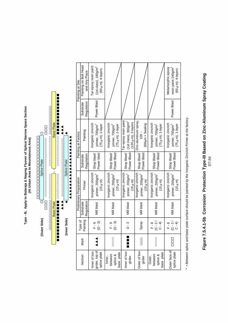
D7-
84
(Out
er S
ide)
□□
□□
□□
□□
∆∆∆∆∆∆∆∆∆∆∆∆∆∆∆∆∆∆∆☼☼☼☼☼☼☼☼☼☼☼☼☼☼☼☼
☼☼☼☼☼☼☼☼☼☼☼☼☼☼☼☼☼☼☼∆∆∆∆∆∆∆∆∆∆∆∆∆∆∆∆∆∆
☼☼
■■
■■
■■
■■
■■
■■
■☼☼☼☼☼☼☼☼☼☼☼☼☼☼☼☼
☼☼☼☼☼☼☼☼☼☼☼☼☼☼☼☼☼☼☼■
■■
■■
■■
■■
■■
■■
▲▲
▲▲
▲▲
(Inne
r Sid
e)▲
▲
▲▲
▲▲
▲▲
▲▲
▲▲
▲▲
▲▲
▲▲
▲▲
▲▲
* • B
etw
een
splic
e an
d ba
se p
late
sur
face
sho
uld
be p
aint
ed b
y th
e In
orga
nic
Zinc
rich
Prim
er a
t the
fact
ory.
☼☼☼☼☼☼☼☼☼☼☼☼☼☼☼☼☼☼☼☼☼☼☼☼☼☼☼☼☼☼☼☼☼☼☼☼☼
☼☼☼☼☼☼☼☼☼☼☼☼☼☼☼☼☼☼☼☼☼☼☼☼☼☼☼☼☼☼☼☼☼☼☼☼☼
Type
- III
, A
pply
to B
alar
aja
& N
agre
g Fl
yove
r of S
plic
e/ N
arro
w S
pace
Sec
tion
(At U
rban
Are
a to
Mou
ntai
nous
Are
a)
□□
□□
□□
□□
□□
□□
□□
□□
□□
□□
Sect
ion
Mar
kTy
pe o
f Pa
intin
g
Prel
imin
ary
Prep
arat
ion
Sub
stra
te
Reg
ulat
ion
Prim
er
Pain
ting
at F
acto
ryPa
intin
g at
Site
Subs
trate
R
egul
atio
nPa
intin
gSu
bstra
te
Reg
ulat
ion
Pain
ting
on B
olt H
ead
and
Any
Plac
e
Inne
r of b
ox
gird
er, t
op o
f sp
lice
plat
e▲
▲▲
F - 9
(D -
3)M
ill b
last
Tar-
epox
y re
sin
pain
t (1
st c
lass
), 18
0g/m
2
(60 μ
m),
4-la
yers
Inor
gani
c zi
ncric
h pr
imer
, 200
g/m
2
(15 μ
m)
Shop
bla
st/
Pow
er b
last
Inor
gani
c zi
ncric
h pr
imer
, 700
g/m
2
(75 μ
m),
1-la
yer
Pow
er B
last
Inor
gani
c zi
ncric
h pr
imer
, 200
g/m
2
(15 μ
m)
Shop
Bla
st/
Pow
er B
last
Inor
gani
c zi
ncric
h pr
imer
, 700
g/m
2
(75 μ
m),
1-la
yer
Inne
r,
betw
een
splic
e &
base
pla
te
☼☼☼☼☼☼
F - 9
(D -
3)M
ill b
last
Out
er o
f box
gi
rder
∆∆∆∆∆
Spra
yM
ill b
last
Inor
gani
c zi
ncric
h pr
imer
, 200
g/m
2
(15 μ
m)
Shop
Bla
st/
Pow
er B
last
Zinc
-alu
min
um s
pray
, 10
0 ~
30
0μm
+ S
ealin
g
Inne
r of b
ox
gird
er■
■■
■D
- 3
Mill
bla
stIn
orga
nic
zinc
rich
prim
er, 2
00g/
m2
(15 μ
m)
Shop
Bla
st/
Pow
er B
last
Tar-
epox
y re
sin
pain
t (1
st c
lass
), 36
0g/m
2
(120
μm
), 2-
laye
rs
Out
er,
be
twee
n sp
lice
& ba
se p
late
☼☼☼☼☼☼
F - 8
(C -
2 /
C
- 4)
Mill
bla
stIn
orga
nic
zinc
rich
prim
er, 2
00g/
m2
(15 μ
m)
Shop
Bla
st/
Pow
er B
last
Inor
gani
c zi
ncric
h pr
imer
, 700
g/m
2
(75 μ
m),
1-la
yer
Out
er fa
ce o
f sp
lice
plat
e□
□□
F - 8
(C -
2 /
C
- 4)
Mill
bla
stM
etam
orph
ic-e
poxy
re
sin
pain
t 240
g/m
2
(60 μ
m),
4-la
yers
Inor
gani
c zi
ncric
h pr
imer
, 200
g/m
2
(15 μ
m)
Shop
Bla
st/
Pow
er B
last
Inor
gani
c zi
ncric
h pr
imer
, 700
g/m
2
(75 μ
m),
1-la
yer
Pow
er B
last
Splic
e Pl
ate
Splic
e Pl
ate
Base
Pla
teBa
se P
late
Figu
re 7
.5.4
.1-5
b C
orro
sion
Pro
tect
ion
Type
-III B
ased
on
Zinc
-Alu
min
um S
pray
Coa
ting
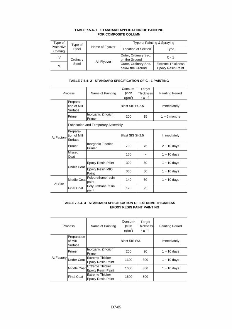
D7-85
At Factory
At SiteMiddle Coat Polyurethane resin
paintPolyurethane resin paintFinal Coat
Preparation of Mill Surface
Primer Inorganic Zincrich Primer
1 ~ 10 days
Final Coat Extreme Thicker Epoxy Resin Paint 1600 800
Middle Coat Extreme Thicker Epoxy Resin Paint 1600 800
Blast SIS St-2.5
TABLE 7.5.4- 3 STANDARD SPECIFICATION OF EXTREME THICKNESS EPOXY RESIN PAINT PAINTING
Process Name of PaintingConsum-
ption (g/m2)
Target Thickness
(μm)Painting Period
140
120 25
Immediately
1 ~ 6 months
2 ~ 10 days
1 ~ 10 days
Immediately
20
1 ~ 10 days
Blast SIS St3. Immediately
60 1 ~ 10 days
200
60
1 ~ 10 days
Under Coat
Painting Period
Extreme Thicker Epoxy Resin Paint 1600 800 1 ~ 10 days
30 1 ~ 10 days
Epoxy Resin Paint
160
300
Blast SIS St-2.5
15
75
-
TABLE 7.5.4- 1 STANDARD APPLICATION OF PAINTING FOR COMPOSITE COLUMN
Type of Protective Coating
Type of Steel Name of Flyover
Type of Painting & Spraying
Location of Section Type
V
Consum- ption (g/m2)
Target Thickness
(μm)Name of Painting
TABLE 7.5.4- 2 STANDARD SPECIFICATION OF C - 1 PAINTING
Process
Outer, Ordinary Sec. below the Ground
Ordinary Steel All Flyover
Outer, Ordinary Sec. on the Ground C - 1
At Factory
Under Coat Epoxy Resin MIO Paint 360
Prepara- tion of Mill Surface
Primer
IV
Missed Coat
Primer
Prepara- tion of Mill Surface
Extreme Thickness Epoxy Resin Paint
Fabrication and Temporary Assembly
Inorganic Zincrich Primer
Inorganic Zincrich Primer
200
700
D7-86
7.5.5 Construction Requirements (1) Weather Conditions
Paint shall be applied only on thoroughly dry surfaces. Painting will not be permitted when the atmospheric temperature of paint or the surface to be painted is at or below 50C or above 400C, or when metal surfaces are less than 50C above the dew point, or when the humidity exceeds 85 percent at the site of the work, or when freshly painted surfaces may become damaged by rain, fog, or dust, or when it can be anticipated that the atmospheric temperature will drop below 50C during the drying period, except as provided herein for painting in enclosures. Metal surfaces, which are hot enough to cause the paint to blister to produce a porous paint film, or to cause, the paint vehicle to separate from the pigment shall not be painted.
Subject to approval of the Engineer, the Contractor may provide a suitable enclosure to permit painting during inclement weather. Provisions shall be made to artificially control atmospheric conditions inside the enclosure within limits suitable for painting throughout the painting operation. Surfaces painted under cover in damp or cold weather shall remain under cover until the paint dries or weather conditions permit open exposure. Full compensation for providing and maintaining such enclosures shall be considered as included in the prices paid for the various contract items of work involving painting and no additional compensation will be allowed therefore.
(2) Surface Preparation
Before the application of any paint, the surfaces to be treated shall be thoroughly cleaned and freed from scale, loose paint, rust and other deleterious matters. Oil and grease shall be removed from the surface by washing with solvents or with a detergent solution before any blast cleaning operation. If any traces of oil or grease remain after blasting, they shall be removed by solvent cleaning and the area re-blasted. All welding areas shall be given special attention for removal of weld flux slag, weld metal splatter, weld head oxides, weld flux fumes, slivers and other foreign objects before blasting. If deemed necessary by the Engineer acid washing and subsequent washing with clean water shall be used.
Any rough welding seams have to be ground and must be inspected and approved by the Engineer before application of the coatings.
Structural steel which will be painted shall be cleaned by blast cleaning in accordance with SSPC (US Code)/ SIS (Swedish Code)/ SPSS (Japanese Code) Near-White Blast cleaning or equivalent. Mill scale, rust and foreign matter shall be removed to the extent that the only traces remaining are light stains in the form of spots or stripes. Finally, the surface is cleaned with vacuum cleaner or dry compressed air. The blast cleaning shall produce a surface roughness complying with the one specified by the paint manufacturer for the primer concerned.
D7-87
If cleaned surfaces rust or are contaminated with foreign material before painting is accomplished, they shall be re-cleaned by the Contractor at his expense.
The joint areas such as high strength bolts shall be protected by
masking at the time of the fabrication shop undercoats. Immediately prior to final erection, any rust in the joint area shall be removed by power wire brushing to a standard equivalent to SSPC-SP3/ SIS-Sa3/ SPSS-Sd3 or Sh3.
(3) Painting The execution of the painting works shall be carried out in the most
perfect and workmanlike manner by experienced labor to the satisfaction of the Engineer. Furthermore, the application of the paints shall be carried out in accordance with the manufacturer’s recommendations, if approved by the Engineer.
Planning and execution of the painting work shall be in conformity with
the supplier’s specifications in accordance with minimum and maximum intervals between the applications of the individual coats. If a coating material required the addition of a curing agent, the pot life under application conditions shall be clearly stated on the container label, and this pot life shall not be exceeded. When the pot life limit is reached, the spray equipment shall be emptied, remaining material discarded, the equipment cleaned and new material prepared.
Contractor shall calibrate the gauges for the thickness range to be
checked. Calibration shall generally be carried out on a ground and polished steel plate of a quality corresponding to the structural steel to be coated.
If dry film thickness is specified in thousands of an inch (mil), the
painting systems are the minimum according to the specification SSPC-PA 2, Measurement of Dry Paint Thickness with Magnetic Gauges.
When dry film thickness is less than specified, additional coats shall
be applied as required at no additional cost to the Contractor. Particular attention shall be paid to the film thickness on edges, welding, etc.
The final color will be selected by the Engineer from the
Manufacturer’s standard color range. Primer and intermediate coat color shall be selected to ensure proper coverage of the final coat with only a single application. Each coat shall be a different color to facilitate easy verification of coverage.
Areas adjacent to welded splices shall not be coated during fabrication
but shall be coated in the field after welding is complete using the same paint system described the above clauses.
For steel fabricated outside of the Indonesia, shop primer shall be
applied after initial fabrication and before shipping. The remaining coats shall be applied in the Indonesia fabrication shop after the
D7-88
necessary surface preparation. (4) Protection of Painting Work The Contractor shall provide protective measures as necessary to
prevent damage to the work and to other property or persons from all cleaning and painting operations. Paint or paint stains which results in an unsightly appearance on surfaces not designated to be painted shall be removed or obliterated by the Contractor at his expense. All painted surfaces that in the opinion of the Engineer are marred or damaged in any way, shall be repaired by the Contractor, at his expense, with materials to a condition equal to that of the coating specified herein. The Contractor’s proposal for re-treatment of areas damaged by flame cutting and welding operations should be clearly stated in the detailed painting plan to be submitted.
Upon completion of all painting operations and of any other work that
would cause dust, grease, or other foreign materials to be deposited upon the painted surfaces, the painted surfaces shall be completed, and the surfaces shall be undamaged and clean.
7.5.6 Measurement and Payment
7.5.6.1 General
Measurement and payment of steel girders in main bridge are divided into fabrication of materials and erection/installation of steel girders. These steel girders for payment includes the works of main girder, coping, portals, stiffeners, bolts, stud, weld and all incidental works for completion of structural steel components. The measurement of the steel girder works shall be made in terms of tonnes, completed and accepted.
7.5.6.2 Unit Basis
1) For pay items measured in mass of steel, the mass to be paid shall be computed based on the structural steel material only, including all plates, gussets and rolled sections. No reduction in mass shall be applied for bolt holes or weld preparation. The mass of welds, bolts, shear studs and any other miscellaneous items will not be considered for calculation of payment but shall be included in determining the unit rate quoted for the structural steel. For plates, the nominal thickness shall be used and the density assumed for steel in calculating the mass shall be 7850 kg/m3 (7.85 t/m3). For rolled sections, the nominal section mass shall be used.
2) The quantity to be paid under this section shall be calculated based on
the mass of the main structural steel girders, steel coping and portal including only those components that are not excluded under Sub-clause 7.5.6.2(1) above and are permanently bolted and/or welded to the girder assemblies.
3) The unit rates quoted for section/pay items 7.5(1) and 7.5(1)a shall be
full compensation for all equipment, tools, transportation, incidentals, labor, materials, overhead and profit relating to the furnishing and
D7-89
fabrication of the specified components including but not necessarily limited to: shop welds (including the welding plan, testing and all other requirements of welding as indicated elsewhere in this specification), bolts, shop drawing preparation and submission, surface preparation and shear studs and testing.
4) The unit rates quoted for pay items 7.5(3) and 7.5(4) shall be full
compensation for all equipment, tools, transportation, incidentals, labor, materials, overhead and profit relating to the erection of the specified components including but not necessarily limited to: field welds (including the welding plan, testing and all other requirements of Clause 7.5.3), temporary supports, cranes and rigging, preparation and submission of erection drawings, installation and adjustment of profile, geometry adjustment, repair of areas damaged during erection and built and removal of temporary works used for erection.
7.5.7 Basis of Payment
1) Furnish and Delivery of structural Steel Girders, Copings, Portals. For steel materials that are to be ‘Furnish and Delivery of structural
steel girders, copings and portals, the place designated for delivery shall be the project site. Payment for the item shall be deemed to be the full compensation for furnishing, fabricating and delivery of all the materials, equipment, tool, labor, welds, bolts, stud and scaffolding and any other incidental items of the works in accordance with the drawings and these Specifications.
The following list is included in the cost of ‘Structural steel girders, copings and portals, Furnish and Fabricate;
- Raw material cost in main and secondary steel girders with primer coating
- Associate materials costs, studs, bolts, restrainers, weld, tools, labor and equipment
- Shipping charge and marine transport cost
- Port charge, custom clearance, tax and duty
- Insurance
- Surface and or marine transport cost to fabrication shop
- Surface and or marine transport cost from fabrication shop to construction site
- Fabrication cost including pre-assembly, bolting, shop welds, shop coatings, equipment and facility costs in fabrication shop
- Administration and design/calculation costs
- Inspection and test costs
- Any other incidental cost

D7-90
2) Erection of Steel Girders, Copings and Portals
Payment for the item shall be deemed to be the full compensation for the Erection of Steel Girders, Copings and Portals, including all the materials, equipment, tools, labor, and any other incidental works such as weld, bolt, stud, temporary bearings, bent steel pier and falseworks, and any other incidental items such as geometric control to erect the steel bridge components in accordance with the drawings and these Specifications.
The following list is included in the cost of the Erection of Steel Girders, Copings and Portals’;
- Suitable crane cost for transport, assembling, dismantle,
operation and rent, etc. - Steel bent pier; costs for construction/dismantle including its
foundation, etc. - Site pre-assembling; cost for pre-assembling/dismantle of steel
members including preparation of base structure, unloading works, elevation adjustment work, welding, bolting, coating if any, and non-destructive test
- Girder erection works; costs for joint works of steel members
including bolting and field welding, temporary bearing works, temporary support bracing at each work stages girder erections
- Camber adjustment works - Geometric controls - Site welding and non-destructive tests - Site Painting if required - Installation/removal of scaffolding and safety net - Any other incidental cost
Payment will be made under the following pay items:
Pay Item No. Description Unit of Measurement
7.5(1) Furnish and Delivery of Steel Girder
Tonne
7.5(1)a Furnish and Delivery of Steel Coping and Portal Tonne
7.5(3) Erection of Steel Girder Tonne
7.5(4) Erection of Steel Coping and Portal Tonne
D7-91
SECTION 7.6 - PILING 7.6.1 Description This Item shall include construction of reinforced concrete piles cast in bored holes
drilled with the use of special equipment. It shall include the excavation and drilling of holes, furnishing and placing of temporary and/or permanent steel casing and other incidentals necessary for the execution of work. Pile construction shall be at locations, dimensions and lengths indicated in the Drawings and in accordance with these Specifications.
Prior to commencing any piling work the Contractor shall provide to the Engineer all data obtained from all necessary foundation investigation and all test data as prescribed in these Specifications. Following receipt of such data the Engineer will provide to the Contractor an itemized list showing the number, diameter and length of bored piles required at each foundation location. The Contractor shall not commence any piling work prior to receipt of the itemized list for the bored piles of each flyover.
7.6.2 Working Drawings
At least 2 weeks before work on bored piles is to begin the Contractor shall submit to the Engineer for review and approval, an installation plan for the construction of bored piles.
The submittal shall include the following:
a) List of proposed equipment to be used including cranes, drills, augers, bailing buckets, final cleaning equipment, desanding equipment,
slurry pumps, sampling equipment, tremies or concrete pumps, casings, etc. b) Details of overall construction operation sequence of bored pile
construction in groups or singly. c) Details of pile excavation method.
d) Details of permanent casing installation showing the means by which the
casing shall be placed in intimate contact with the surrounding earth following pile installation.
e) When slurry is required, details of the method, proposed mix, circulation and
design of slurry. f) Details of methods to clean the pile excavation. g) Details of reinforcement placement including support and centralization
methods. h) Details of concrete placement, curing and protection.
i) Details of any required Load Tests (if called for in the Drawings) and;
D7-92
j) Other information shown on the Drawings or requested by the Engineer.
The Contractor shall not start construction of bored pile for which working drawings are required until the Engineer has approved such drawings. Such approval will not relieve the Contractor of responsibility for results obtained by use of these drawings or any of this other responsibilities under the Contract.
7.6.3 Materials 7.6.3.1 Concrete Piles Concrete shall conform to the requirements of Section 7.1, Structural Concrete.
Concrete shall be Class “B2” unless otherwise specified in the drawings. The maximum size of aggregates shall not exceed 19mm.
Reinforcing steel shall conform to the requirements of Section 7.3, Reinforcing Steel. The use of appropriate additives to assure mix consistency shall be allowed provided
air entraining is not enhanced and with the Engineer’s approval. A retarder of proven adequacy and approved by the Engineer shall be used to ensure that early hardening of concrete during tremie operation will not occur.
Casings which are required to be incorporated as part of permanent work shall
conform to AASHTO M183 (ASTM A-36) or JIS A5525 (SKK 400). 7.6.4 Construction 7.6.4.1 Cast In Place Concrete Piles
1) Protection of Existing Structures
All reasonable precautions shall be taken to prevent damage to existing structures and utilities. The measures shall include but are not limited to, selecting construction methods and procedures that will prevent excessive caving of the bored hole, monitoring and controlling the vibrations from the driving of casing or sheeting or drilling of the pile.
2) General Methods and Equipment Excavation for bored piles shall be carried out by mechanical methods; blasting and compressed air method shall not be used unless permitted by the Engineer.
Excavation shall be performed through whatever materials are encountered to the dimensions and elevations shown on the Drawings or ordered by the Engineer. The methods and equipment shall be suitable for the intended purpose and materials encountered. Suitable casings shall be furnished and placed when required to prevent caving of the hole before concrete is placed. Mineral Slurry may be used in the drilling process to prevent caving during drilling of holes and the placement of concrete.
D7-93
a) Casings
The stability of excavations for bored piles shall be maintained where necessary by temporary or permanent casings. The casings, whether temporary or permanent shall be free from significant distortion, shall be free from internal projections, and encrusted concrete, which may prevent proper formation. The inside of casings shall be cleaned and all loose materials removed before placing concrete. Permanent steel casings, fabricated out of striped steel materials or equivalent, shall be prepared and installed as part of the composite bored piles. After installation is complete, the permanent casing shall be in intimate contact with the surrounding earth. This requirement precludes placement of permanent casing in an oversized hole or temporary casing outside the permanent casing below the top of the pile unless post-grouting of the exterior annular space is proposed by the Contractor and accepted by the Engineer. Temporary casing, if used in drilling operations, may be left in place as a permanent casing or removed from the hole as concrete is placed. The bottom of the casing shall be maintained to not more than 1.5m or less than 0.3m below the top of the concrete during withdrawal and placing operations unless otherwise permitted by the Engineer. Separation of the concrete during withdrawal operations shall be avoided by vibrating the casing.
Temporary casings which became bound or fouled during bored pile construction and cannot be practically removed shall constitute a defect in the bored pile. The Contractor shall be responsible to improve such defective piles to the satisfaction of the Engineer. All corrective measures including redesign of foundations caused by defective piles shall be done to the satisfaction of the Engineer by the Contractor without either compensation or an extension of the completion date of the Works. In addition, no compensation will be paid for casings remaining in place.
b) Excavations
The bottom elevation of the bored pile shown on the Drawings may be adjusted during construction if the Engineer determines that the foundation materials encountered during drilling is unsuitable or differs from what was assumed in the design of the drilled shaft. The Contractor shall take soil samples or rock cores when required by the specification or as directed by the Engineer to determine the character of the material directly below the shaft excavation. The Engineer will inspect the samples or cores to determine the final depth or required shaft exaction. Excavations shall not be carried out close to piles which have been executed but not concreted, or close to piles which have been cast
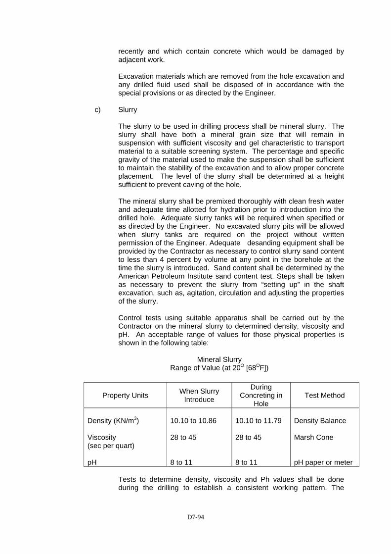
D7-94
recently and which contain concrete which would be damaged by adjacent work. Excavation materials which are removed from the hole excavation and any drilled fluid used shall be disposed of in accordance with the special provisions or as directed by the Engineer.
c) Slurry
The slurry to be used in drilling process shall be mineral slurry. The slurry shall have both a mineral grain size that will remain in suspension with sufficient viscosity and gel characteristic to transport material to a suitable screening system. The percentage and specific gravity of the material used to make the suspension shall be sufficient to maintain the stability of the excavation and to allow proper concrete placement. The level of the slurry shall be determined at a height sufficient to prevent caving of the hole. The mineral slurry shall be premixed thoroughly with clean fresh water and adequate time allotted for hydration prior to introduction into the drilled hole. Adequate slurry tanks will be required when specified or as directed by the Engineer. No excavated slurry pits will be allowed when slurry tanks are required on the project without written permission of the Engineer. Adequate desanding equipment shall be provided by the Contractor as necessary to control slurry sand content to less than 4 percent by volume at any point in the borehole at the time the slurry is introduced. Sand content shall be determined by the American Petroleum Institute sand content test. Steps shall be taken as necessary to prevent the slurry from “setting up” in the shaft excavation, such as, agitation, circulation and adjusting the properties of the slurry. Control tests using suitable apparatus shall be carried out by the Contractor on the mineral slurry to determined density, viscosity and pH. An acceptable range of values for those physical properties is shown in the following table:
Mineral Slurry Range of Value (at 20O [68OF])
Property Units When Slurry Introduce
During Concreting in
Hole Test Method
Density (KN/m3) Viscosity (sec per quart) pH
10.10 to 10.86 28 to 45 8 to 11
10.10 to 11.79 28 to 45 8 to 11
Density Balance Marsh Cone pH paper or meter
Tests to determine density, viscosity and Ph values shall be done during the drilling to establish a consistent working pattern. The
D7-95
number and frequency of such tests shall be as approved by the Engineer. Prior to placing concrete in the bored pile, slurry samples shall be taken from the bottom and at intervals not exceeding 3 meter for the full height of slurry. Any heavily contaminated slurry that has accumulated at the bottom of the shaft shall be eliminated. The mineral slurry shall be within specification requirements immediately before placement of bored pile concrete. Reports of all tests required above signed by an authorized representative of the Contractor, shall be furnished to the Engineer on completion of each bored pile.
d) Excavation Inspection
The Contractor shall provide equipment for checking the dimensions and alignment of each shaft excavation. The dimensions and alignment shall be determined by the Contactor under the direction of the Engineer. Final shaft depth shall be measured after final cleaning. The shaft excavation shall be cleaned so that a minimum of 50 percent of the base will have less than 1.25 cm of sediment. The maximum depth of sediment or any debris at any place on the base shall not exceed 3.80 cm. Shaft cleanliness will be determined by the Engineer.
7.6.4.2 Reinforcing Steel Cage Construction
The reinforcing steel cage as shown on the Drawings plus the cage stiffener bars, spacers, centralizer and other necessary appurtenance shall be completely prefabricated and placed as a unit immediately after the shaft excavation is inspected and accepted and prior to shaft concrete placement. Prefabricated reinforcement cages for piles shall be marked and fitted with spacers to ensure that the cage is correctly oriented and positioned within the pile. When concrete is placed by tremie methods, temporary hold down devices shall be used to prevent uplifting of the steel cage during concrete placement.
7.6.4.3 Concrete Placement, Curing and Protection
Concrete shall be place as soon as possible after the reinforcing steel cage has been installed and permission of the Engineer has been obtained. Concrete shall be placed without interruption until the complete pile is concreted. Placement shall continue after the shaft is full until good quality concrete is evident at the top of the shaft. Concrete shall be cast in place through a tremie or concrete pump. To prevent segregation, the concrete shall be carefully placed in a compact mass, in its final position, by means of a tremie, a bottom dump-bucket, or other approved means, and shall not be disturbed after being placed. The concrete mix shall be of such design that concrete remains in workable plastic state throughout the placement period.
D7-96
Temporary casings which are in contact with the bored pile concrete and which are not withdrawn before the initial set of the concrete has occurred shall be left in place. When the top pile elevation is above ground, the portion of the pile above ground shall be formed with a temporary or permanent casing when specified. For at least 48 hours after pile concrete has been placed, no construction operations that would cause soil movement adjacent to the shaft, other than mild vibration, shall be carried out unless permitted by the Engineer.
7.6.4.4 Construction Tolerances
The following construction tolerances shall be maintained in the construction of bored piles:
a) The bored pile shall be within a tolerance of 1/24 of pile diameter (but not more than 75mm) of the plan position in the horizontal plane at the plan elevation for the top of the shaft.
b) The vertical alignment of the drilled hole shall not vary from the plan alignment by more than 10 mm per meter.
c) After all the pile concrete is placed, the top of the reinforcing steel cage shall be no more than 150 mm above and no more than 75 mm below plan position.
d) The top elevation of the pile shall have a tolerance of plus 25 mm or minus 75mm from the plan top of pile elevation.
e) The cutting edges of the excavation equipment shall be normal to the vertical axis of the equipment within a tolerance of ±30mm per meter of diameter.
f) When casing is used, its outside diameter shall not be less than the shaft diameter shown on the Drawings. The diameter of cast in-site piles shall be at least 97% of the specified diameter.
7.6.4.5 Bored Pile Records
Bored pile records shall be kept by the Contractor and a signed copy handed to the Engineer at the end of each day of drilling. Pile records shall take the forms given in Table 7.6.4.5 below.
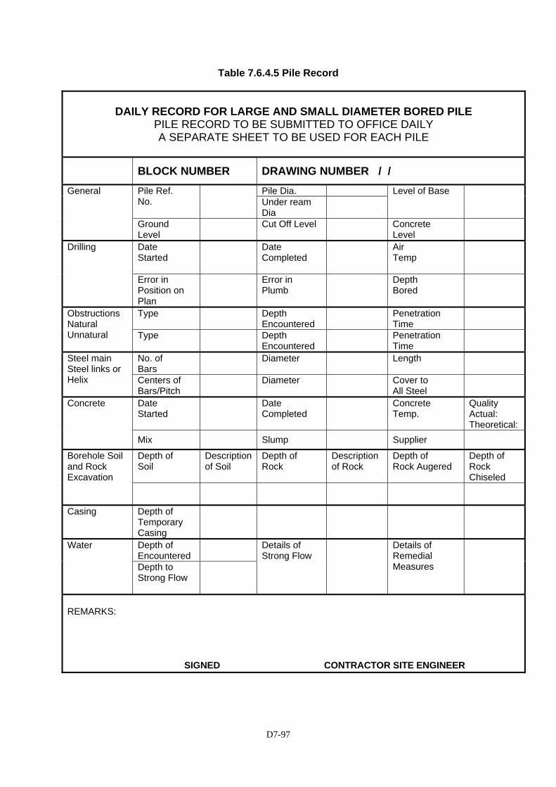
D7-97
Table 7.6.4.5 Pile Record
DAILY RECORD FOR LARGE AND SMALL DIAMETER BORED PILE
PILE RECORD TO BE SUBMITTED TO OFFICE DAILY A SEPARATE SHEET TO BE USED FOR EACH PILE
BLOCK NUMBER DRAWING NUMBER / /
Pile Dia. Pile Ref. No.
Under ream Dia
Level of Base General
Ground Level
Cut Off Level Concrete Level
Date Started
Date Completed
Air Temp
Drilling
Error in Position on Plan
Error in Plumb
Depth Bored
Type Depth Encountered
Penetration Time
Obstructions Natural Unnatural Type
Depth
Encountered Penetration
Time
No. of Bars
Diameter Length Steel main Steel links or Helix Centers of
Bars/Pitch Diameter Cover to
All Steel
Date Started
Date Completed
Concrete Temp.
Quality Actual: Theoretical:
Concrete
Mix Slump Supplier
Depth of Soil
Description of Soil
Depth of Rock
Description of Rock
Depth of Rock Augered
Depth of Rock Chiseled
Borehole Soil and Rock Excavation
Casing Depth of Temporary Casing
Depth of Encountered
Water
Depth to Strong Flow
Details of Strong Flow
Details of Remedial Measures
REMARKS:
SIGNED CONTRACTOR SITE ENGINEER

D7-98
7.6.5 Measurement and Payment
(1) Measurement
(a) The quantity of cast in-place concrete pile to be measured for payment will be the sum of the actual lengths in meters of piles cast and left in-place in the completed and accepted work. Measurements will be from the pile top to the bottom of the pile or as shown on the drawings. Portions of piles cast deeper than that required through over-drilling will not be measured for payment.
(b) The quantity of Structure Casing for bored pile (inner Ribbed Surface)
shall be measured on the actual weight in kilograms to the correct size, dimensions, type, etc as indicated in the drawings, of the materials only, furnished, delivered to Site and accepted by the Engineer for incorporation into the work.
(c) The quantity to be paid for under Structure Casing for Bored Pile
(Erected) shall be calculated based on the actual weight in kilograms of the structural casing erected permanently to the bored piles, including the full compensation for all labour, equipment, tools, submittals and incidentals, necessary to compete the work and accepted by the Engineer.
(2) Basis of Payment The accepted quantities, measured as prescribed in Sub-clause 7.6.5(1) shall be paid for at the contract unit price of each of the particular item listed below that is included in the Bill of Quantities, which price and payment shall be full compensation for furnishing and placing all materials including all labor, equipment tools, submittals and incidentals necessary to complete the work prescribed in this item.
Pay Item Number
Description
Unit of Measurement
7.6(22) Cast in-Place Concrete Bored Piles (1500mm diameter)
Linear Meter
7.6(23) Cast in-Place Concrete Bored Piles (1800 mm diameter)
Linear Meter
7.6(24) Cast in-Place Concrete Bored Piles (2500 mm diameter)
Linear Meter
SS.7.1(10) Structural Casing for Bored Pile (Inner Ribbed Surface, t = 13mm)
Kilogram
SS.7.1(11) Structural Casing for Bored Pile (Erected)
Kilogram
D7-99
SECTION 7.6(27) - PILE INTEGRITY TESTING 7.6(27).1 Description
The completed bored pile shall be subjected to non-destructive testing to determine the extent of any defects that may be present in the pile. Integrity-testing method to be adopted shall be low-strain, by either the Pulse Echo Method (PEM) or Transient Response Method (TRM) in accordance with ASTM D 5882, subject to the approval of the Engineer. The testing shall be carried out by the Contractor using an engineer with specialized experience in this field and shall be approved by the Engineer. Prior to integrity testing all apparatus shall be calibrated to ensure that precise and reliable data be obtained. Certificate of calibration shall be submitted unless otherwise waived by the Engineer.
7.6(27).2 Report
The Contractor shall submit a report on the integrity testing containing vital information necessary for the pile evaluation, prescribed in ASTM D5882. Such report shall be submitted within seven days after the completion of each test.
7.6(27).3 Final Integrity Evaluation
If and when necessary as determined after evaluation of the integrity of the pile subjected to the test, the Engineer may require further test or dictate pile repair or replacement, depending on the seriousness of the defect that may be established For piles that need to be repaired, the Contractor shall submit for the approval of the Engineer, remedial measures he intends to implement. For rejected piles, the Contractor shall make a proposal for review and approval of the Engineer. Such proposal shall include the necessary design calculations, the methodology he intends to implement, equipment and other items as may be necessary. Approval of these proposals however does not relieve the Contractor of contractual responsibilities for any defects as a result of the proposals. The cost of further tests required, remedial measures and replacement of rejected piles shall be borne by the Contractor.
7.6(27).4 Method of Measurement
The quantity to be paid for will be the number of piles tested and accepted. Any incidentals not otherwise described hereto are considered subsidiary to the work item and shall not be paid for separately.
7.6(27).5 Basis of Payment
The accepted quantity as provided in Clause 7.6(27).4 shall be paid at the contract price in the Bill of Quantities. The payment shall constitute full compensation of the cost of Integrity Pile Testing, including tools, apparatus, testing and reporting and all labor and incidentals necessary to complete the work prescribed in this section.

D7-100
Pay Item Number
Description
Unit of Measurement
7.6(27) Pile Integrity Testing Each
D7-101
SECTION SS7.6(28) - PILE DYNAMIC ANALYSIS
7.6(28).1 Description
High-strain Dynamic Testing is performed by obtaining and analyzing recorded shaft force and velocity under weights impact for evaluation of shaft load carrying capacity, structural integrity, and load-movement and shaft-soil load transfer relationships Testing of drilled and cast-in-place piles closely resembles testing of driven piles during re-strike. The following are specifications and instructions for high-stain dynamic testing of drilled and cast-in-place foundation piles. The work shall consist of furnishing all materials, equipment, and labor necessary for conducting high-strain dynamic tests on drilled and cast-in-placed piles (hereinafter each noted as test shaft). The Contractor shall not conduct the test himself but shall appoint an Independent Specialist to conduct all testing. The Contractor will be required to supply materials, equipment and labor as hereinafter specified including prior to, during, and after the load test. High-strain Dynamic Testing is a non-destructive quick test and it is intended that the test shaft be left in a condition suitable for use in production. Testing procedures shall conform to the ASTM D4945-89 specification unless as otherwise noted below. The shaft used for the test will be instrumented and tested by the Independent Specialist, as approved by the Engineer, meeting requirements outlined in the ASTM D4945-89 specification as well as those outlined below.
7.6(28).2 Equipment and Material Requirements
The Contractor shall supply all labor, materials and equipment required to prepare the test shaft, dynamically load the shaft, and return the shaft to a condition suitable for use in the finished structure. Equipment to be supplied by the Contractor required to perform the test includes but is not limited to:
1) If a permanent casing is not used to construct the shaft, then a shaft
top extension consisting of a thin walled casing or equivalent shall be used to extend the shaft by length at least equal to two and a half (2 ½) pile diameters such that the extended pile head is readily accessible by the testing engineer at the time of the test. If the shaft top is below grade, then the Contractor must have equipment available to remove surrounding soil (creating a safe working environment) so as to expose the concrete.
2) Means to ensure flat, level (axial to shaft) and sound concrete shaft
top. Concrete should be on level with, or above the casing. Prior to the test, four “windows” approximately size of 6 by 6 inches (150 by 150mm) shall be provided of at each quadrant of the casing
3) A drop weight in the range of one and half to two percent (1.5% to 2%)
of the anticipated pile capacity, or as determined by the Engineer. 4) A guide allowing variable drop heights typically between 2 to 3m, or as
determined by the Engineer.

D7-102
5) A shaft top cushion consisting of new sheets of plywood with total thickness between 2 to 6 inches (50 to 150 mm), or as determined by the Engineer.
6) A steel striker plate with a thickness of at least 2 inches (50 mm) and
an area between 70 to 90% of shaft top area but not less than the area of the impacting surface of the drop weight shall be placed on top of the plywood cushion.
7) If protruding reinforcing bars are present, the Contractor has the
option to incorporate the reinforcing steel in the test area. Upon successful completion of the dynamic test, the surrounding concrete can then be removed as to make the pile suitable for use in the structure. If the Contractor selects not to incorporate the steel in such a manner as described above 20% of the shaft cross sectional area shall be supplied with sufficient length such that the ram impact will not interface with the reinforcing bars. Steel striker plates and plywood cushion must also be sized so that they cover as much as the impact area as possible.
8) One (1) k of 200 Volt AC Power.
9) Surveyor’s transit, laser light or equivalent for measurement of pile set
under each impact. 7.6(28).3 Dynamic Testing Firm
Testing is to be performed by an accredited Independent Specialist from a firm with a minimum of four (4) year experience in dynamic load testing. The actual test shall be conducted and/or supervised by a practicing Geotechnical Engineer with at least five (5) years of dynamic testing experience or who has achieved basic or better level experience on the foundation QA examination as Provider of PDA Testing services. The firm selected by the Contractor must be approved by the Engineer. The Independent Specialist must supply the following testing instrumentation in addition to instrumentation outlined in ASTM specification D4945-89 Section 5: a) Pile Driving Analyzer (PDA)
b) Calibrated Strain Transducers
c) Calibrated Accelerometer
7.6(28).4 Reporting Results
The Independent Specialist appointed by the Contractor shall submit a timely report of the testing results to the Engineer for approval. The field results from at least one (CAPWAP) analysis (Case Pile Wave Analysis Program) shall be submitted. The CAPWAP analysis shall be performed by an engineer that has achieved an advanced or better level on the foundation QA examination as providers of PDA Testing Services. The report must also provide the following:

D7-103
a) Wave Equation analysis results obtained prior to testing
b) CAPWAP analysis result.
c) For each impact the maximum measured force, maximum calculated tension force, transferred energy to the gage location, corresponding stresses, and the Case Method bearing capacity.
d) Assessment of the test result with respect to both pile capacity and
integrity. 7.6(28).5 Method of Measurement
The quantity to be paid for shall be the number of bored piles tested and accepted. Any item indicated and not otherwise described hereto shall be considered subsidiary to the work item and shall not be paid for separately.
7.6(28).6 Basis of Payment
The accepted quality as provided in Clause 7.6(28).5 shall be paid at the contract price shown below. The payment shall constitute full compensation for the cost of Pile Dynamic Testing, the cost of appointing an Independent Specialist, all instrumentation, testing and testing equipment, analysis and reporting, tools, labor and all other incidentals necessary to complete the work prescribed in this Item.
Pay Item Number Description Unit of Measurement
SS7.6(28) Pile Dynamic Analysis (PDA) (Dia. 1500mm) Each SS7.6(29)a Pile Dynamic Analysis (PDA) (Dia. 1800mm) Each SS7.6(29)b Pile Dynamic Analysis (PDA) (Dia. 2500mm) Each

D7-104
SECTION SS 7.6(30) - FOUNDATION INVESTIGATION 7.6(30).1 Description
This work shall consist of conducting foundation investigation for flyover structures including all investigations, sampling and testing necessary to determine the bearing capacity of the soil and the depth of the piles as specified on the Drawings or in accordance with the requirements of the Engineer.
7.6(30).2 Scope The scope of this work shall consist of: 1) Machine drilling of boreholes with SPT’s and Disturbed Sampling 2) Daily Field Logs 3) Laboratory Testing 4) Soils Report
7.6(30).3 Location and Depth of Boreholes
For all flyovers, one (1) borehole located at each abutment and one (1) borehole located at each pier shall be conducted. The depth of each borehole shall extend of at least 5m below the base of the pile as shown on the Drawings at the respective location of the borehole.
7.6(30).4 Schedule
The foundation investigation shall be undertaken following the mobilization of the Contractor. The Contractor shall provide the Engineer with a schedule of the drilling, laboratory testing and reporting prior to commencing the investigation for approval.
7.6(30).5 General Requirements The following general requirements shall be satisfied by the Contractor:
(1) Daily field log
A daily field log shall be completed to include details of boring progress and soil sample description. The daily field logs shall be recorded by an experienced engineering geologist or geotechnical engineer employed by the Contractor. A copy of the daily field log shall be provided to the Engineer on the day following the completion of the log, together with surveyed location and existing ground level at each borehole.
(2) Storage of Soil Samples
All samples from machine drilling shall be stored in coreboxes in accordance with good engineering practice. Samples shall be bagged in

D7-105
suitable clear plastic bags with suitable tags giving borehole reference and depth of each sample.
(3) Photograph of Soil Sample, Drilling Progress and Laboratory Tests
Photographs shall be taken of all soil samples prior to bagging the sample, of drilling progress on site, and also of laboratory tests.
(4) Ground Water
The ground water level shall be established one day after the borehole is completed.
7.6(30).6 Interval of SPT and Disturbed Sampling Standard Penetration Tests (SPT’s) shall be conducted at an interval of 2m.
Disturbed samples shall be collected at every 2m intervals. Laboratory testing shall be undertaken on all disturbed samples.
7.6(30).7 Laboratory Testing Disturbed samples shall be subject to the following laboratory testings:
(1) Specific Gravity (ASTM D854-91) (2) Water Content (ASTM D4683-87) (3) Grain size Distribution (ASTM D422-63(90)) (4) Atterberg Limits (ASTM D4318-84) (5) Soil Classification
7.6(30).8 Soils Report
Three (3) copies of a soils report in English shall be submitted to the Engineer following the completion of the foundation investigation.
The report shall include:
(1) Field investigation methodology (2) Laboratory testing methodology (3) Summary of findings The report shall include details of (1) Location plans of boreholes (2) Soil Profile (3) Boreholes logs (4) Photographs of corebox samples, drilling progress and laboratory tests (5) Laboratory tests results of all samples tested (6) Grain size distribution curves
7.6(30).9 Method of Measurement The Foundation Investigation shall be measured on a lump sum basis.
D7-106
7.6(30).10 Basis of Payment
The accepted Foundation Investigation shall be paid at the lump sum price for each of the pay items listed in the Bill of Quantities , which price and payment shall be full compensation for all labour, materials tools, equipment and incidentals necessary to complete the investigation, including completing all borings, materials testing and reporting, all to the satisfaction of the Engineer. Payment shall be made under the following item: Pay Item No. Description Unit of Measurement
SS.7.6.(30) Foundation Lump Investigation Sum

D7-107
SECTION 7.9(1) – STONE MASONRY 7.9(1).1 Description
This work shall consist of stone masonry in retaining walls for both cut and embankment sections, in minor structures, and in other places where called for on the Drawings or ordered in writing by the Engineer. The stone masonry shall be constructed on the prepared foundation bed in accordance with these Specification and the specifications for other work items involved and in conformity with lines, grades, sections, and dimensions shown on the Drawings or required by the Engineer.
7.9(1).2 Materials
(1) The stone shall be sound, have sufficient strength, no seams, shall be of good quality, and shall be resistant to weathering. Quality of stone shall be approved by the Engineer prior to use. The stone shall be of the strength specified on the Drawings, and shall be wedged or convex shaped. The base surface shall be not less than 1/16 of the front surface, and the shorter length of the base surface shall be more than 1/10 of longer length. The standard number of stones per square meter shall be 14. However, if directed by the Engineer the number may differ from that specified.
(2) Mortar
Mortar shall be in accordance with Section 7.3 “Cement Mortar” of the Indonesian Standard Technical Specifications (Teknikal Spesifikasi).
(3) Concrete
Class E concrete for footings and backing shall be in accordance with the requirements of Section 7.1 of these Specifications.
(4) Filter Backfill
Permeable backfill shall be in accordance with Section 3.3(3) of these Specifications
7.9(1).3 Construction
(1) Excavation
Excavation shall be in strict accordance with the cross-sections, grades and lines shown on the Drawings after staking has been inspected and approved by the Engineer. When the excavation method and dimensions are not specified, the method shall be selected by the Contractor and approved by the Engineer. Excavation and backfill shall be made in accordance with the requirements of Sections 3.2 and 3.3(2) of these Specifications.
D7-108
(2) Foundation
Prior to placing the foundation, the soil shall be thoroughly compacted by mechanical or hand ramming. Blinding stone foundation in accordance with Section 7.9(2) shall then be placed and compacted as shown on the Drawings. A footing of Class E concrete shall then be formed to the dimensions as shown on the Drawings.
(3) Backfill and backing Concrete
Permeable backfill shall be provided as shown in the Drawings, Specifications or as directed by the Engineer. Class E concrete shall be placed and compacted on the permeable backfill material with consideration being given to the need to provide in advance, of the stonework only to such height as can be adequately compacted.
(4) Placing
Placing of stone masonry shall not begin until the finishing stakes set according to the design have been inspected and approved by the Engineer. Stones shall be washed with water before placing. Mortar bed shall be spread on the sides of adjacent stones before the next stone is laid. The thickness of the mortar shall be the minimum necessary to ensure that there is no direct contact between stones. Stones shall be thoroughly hammered into place and any stone whose face is deviating more than 20 mm from the true face or more than 30 mm from the face of adjacent stone, shall immediately be made good by lifting and relaying. Face joints between stones shall be flush-pointed as work proceeds.
(5) Weep holes
Walls of stone masonry shall be provided with weep holes. Unless otherwise shown on the Drawings or directed by the Engineer, the weep holes shall be spaced not more than 2 meters centre to centre and shall be 50 mm in diameter.
(6) Coping
Coping shall be as shown on the Drawings or directed by the Engineer. Where copings are not called for, the upper surface of masonry shall be mortared and finished smooth by wooden float.
(7) Joints
Expansions joints shall be formed at a maximum spacing of 20 meters. Joint shall be 30 mm in width and shall extend through the complete wall including the footing and backing concrete. Stones used for joint forming shall be selected so as to form a clean vertical joint of the dimensions specified above.
D7-109
(8) Curing
In hot or dry weather the masonry shall be satisfactorily protected from the sun and shall be kept wet for a period of at least three days after completion.
7.9(1).4 Method of Measurement
The quantities to be paid for shall be the number of cubic meters of stone masonry complete in place and accepted. In computing the quantity for payment, the dimensions used shall be those shown on the Drawings or ordered in writing by the Engineer. No deductions shall be made for weep holes, drain pipes, or other openings of less than 0.10 square meter in area, and no increase will be allowed for the concrete footing. Any coping provided shall be included in the measurement as though it were stone masonry.
7.9(1).5 Basis of Payment
The quantity of masonry, determined as provided above, shall be paid for at the contract unit price per cubic meter for stone masonry, which price and payment shall be full compensation for furnishing and placing all materials including concrete footing and coping and all other necessary work as specified for the proper completion of all the work as described in this Section. All excavation and backfill for these pay items will be deemed to be covered by and paid for under the work described in Section 3.2 and Section 3.3(2) of these Specifications. Any extra expense due to excavation, or due to provision of foundations or of special backfill will be considered to be included in the unit price for these pay items. Pay Item No. Description Unit of Measurement 7.9(1) Stone Masonry Cubic meter
D7-110
SECTION 7.9(2) – BLINDING STONE
7.9(2).1 Description
This item shall consist of furnishing, placing, shaping and compacting blinding stones used as foundation for structures in accordance with this specification to the lines, thickness, dimensions and locations as shown on the Drawings and as directed by the Engineer.
7.9(2).2 Materials The main component of blinding stone shall be approved cobble-stone or
crushed rock, of the maximum size compatible with the thickness of the blinding stone shown on the Drawings or as instructed by the Engineer.
7.9(2).3 Construction The minimum height of the stone shall be 7cm. Stone shall be closely packed
by hand placing, to the dimensions shown on the drawings, and then thoroughly rammed by mechanical rammer. Smaller stone pieces of minimum size of 3mm shall then be placed between the larger stones and upper surface brought by up to the finished level as shown on the drawings and or as instructed by the Engineer. The completed surface shall then be thoroughly compacted using a mechanical rammer or vibratory roller to the satisfaction of the Engineer.
The Contractor may propose an alternative method to the above process
based on the use of graded, crushed stone of maximum size or less than 5cm, with prior approval of the Engineer. The Engineer’s acceptance of this alternative method and the maximum thickness to be laid in one layer will be dependent on the proposed compacting plant and its suitability for the restricted working area available.
7.9(2).4 Method of Measurement
The volume of blinding stone measured for payment will be the number of cubic meters of blinding stone placed in accordance with these Specifications and calculated using the dimensions shown on the Drawings or instructed by the Engineer.
7.9(2).5 Basis of Payment
The quantity determined as provided above, shall be paid for at the contract unit price per cubic meter for blinding stone complete in place and accepted, which price and payment shall be full compensation for furnishing and placing all materials, equipment, tools and all other incidentals necessary for the proper completion of all the work as described in this Section. Pay Item No. Description Unit of Measurement 7.9(2) Blinding Stone Cubic meter

D7-111
SECTION 7.9- EXPANSION JOINTS
7.9.1 Description
This work shall consist of the supply and installation of expansion joints in accordance with lines, profiles, and types shown on the Drawings or as ordered by the Engineer in accordance with these Specifications.
7.9.2 Submittals
A sample of any expansion joint material that the Contractor proposes to use in the Works, together with a statement as to its source and test data giving its properties shall be submitted to the Engineer for approval before furnishing the joints. The Contractor shall submit an international certificate by the manufacturer to the Engineer for approval before furnishing the joints.
7.9.3 Expansion Joint Types
(1) Joint Seal Rubber Type
Joint seal rubber Type A and Type B expansion joints shall be for expansion amounts of 30 mm and 50 mm.
7.9.4 Materials (for reference data)
(1) Materials for joint seal rubber type A and type B shall comply with the following specification requirements:
(a) Flexible Epoxy Resin Mortar
The material used shall be of the following composition and specification:
(i) Composition (by weight)
Silica sand No.3 : 4.00 kg
(grain diameter 1.68 -- 1.19 mm)
Silica sand No.4 : 2.50 kg (grain diameter 1.19 – 0.59 mm)
Silica sand No.7 : 2.50 kg
(grain diameter 0.42 – 0.105 mm)
Silica : 1.00 kg powder
Epoxy binder : 1.00 kg
(ii) Specification
Specific Gravity : 2.20 + 0.10 Bending strength : >= 50kg /cm2 Compressive strength : >=150kg/cm2 Compression Young's : (0.5 – 2.0) x Modulus 10000 kg/cm2
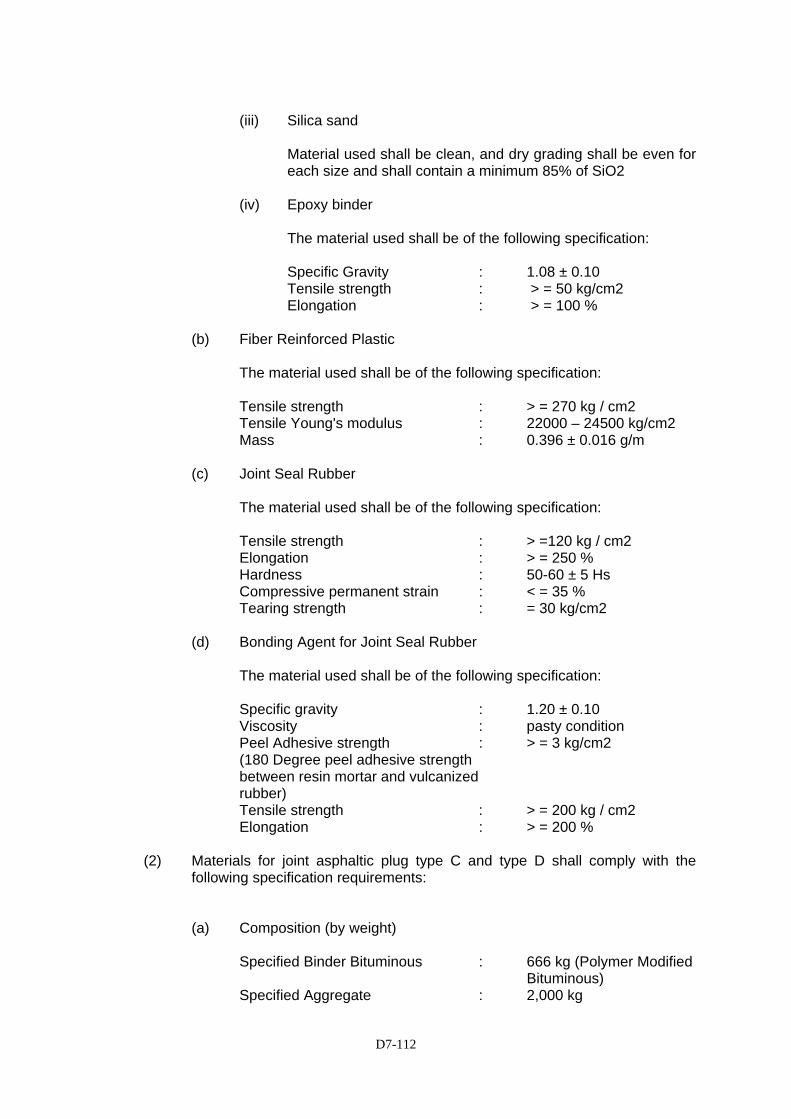
D7-112
(iii) Silica sand
Material used shall be clean, and dry grading shall be even for each size and shall contain a minimum 85% of SiO2
(iv) Epoxy binder
The material used shall be of the following specification:
Specific Gravity : 1.08 ± 0.10 Tensile strength : > = 50 kg/cm2 Elongation : > = 100 %
(b) Fiber Reinforced Plastic
The material used shall be of the following specification: Tensile strength : > = 270 kg / cm2 Tensile Young's modulus : 22000 – 24500 kg/cm2 Mass : 0.396 ± 0.016 g/m
(c) Joint Seal Rubber
The material used shall be of the following specification:
Tensile strength : > =120 kg / cm2 Elongation : > = 250 % Hardness : 50-60 ± 5 Hs Compressive permanent strain : < = 35 % Tearing strength : = 30 kg/cm2
(d) Bonding Agent for Joint Seal Rubber
The material used shall be of the following specification: Specific gravity : 1.20 ± 0.10 Viscosity : pasty condition Peel Adhesive strength : > = 3 kg/cm2 (180 Degree peel adhesive strength between resin mortar and vulcanized rubber) Tensile strength : > = 200 kg / cm2 Elongation : > = 200 %
(2) Materials for joint asphaltic plug type C and type D shall comply with the
following specification requirements:
(a) Composition (by weight)
Specified Binder Bituminous : 666 kg (Polymer Modified Bituminous)
Specified Aggregate : 2,000 kg
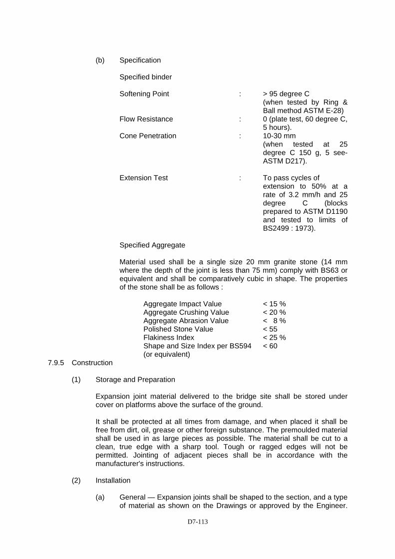
D7-113
(b) Specification
Specified binder
Softening Point : > 95 degree C (when tested by Ring & Ball method ASTM E-28)
Flow Resistance : 0 (plate test, 60 degree C, 5 hours).
Cone Penetration : 10-30 mm (when tested at 25 degree C 150 g, 5 see-ASTM D217).
Extension Test : To pass cycles of
extension to 50% at a rate of 3.2 mm/h and 25 degree C (blocks prepared to ASTM D1190 and tested to limits of BS2499 : 1973).
Specified Aggregate Material used shall be a single size 20 mm granite stone (14 mm where the depth of the joint is less than 75 mm) comply with BS63 or equivalent and shall be comparatively cubic in shape. The properties of the stone shall be as follows :
Aggregate Impact Value < 15 % Aggregate Crushing Value < 20 % Aggregate Abrasion Value < 8 % Polished Stone Value < 55 Flakiness Index < 25 % Shape and Size Index per BS594 < 60 (or equivalent)
7.9.5 Construction
(1) Storage and Preparation
Expansion joint material delivered to the bridge site shall be stored under cover on platforms above the surface of the ground. It shall be protected at all times from damage, and when placed it shall be free from dirt, oil, grease or other foreign substance. The premoulded material shall be used in as large pieces as possible. The material shall be cut to a clean, true edge with a sharp tool. Tough or ragged edges will not be permitted. Jointing of adjacent pieces shall be in accordance with the manufacturer's instructions.
(2) Installation
(a) General — Expansion joints shall be shaped to the section, and a type of material as shown on the Drawings or approved by the Engineer.
D7-114
The size of the gap shall be compatible with the mean bridge temperature at the time of installation. This temperature shall be determined in accordance with arrangement agreed with the Engineer.
The position of all bolts cast into concrete and all holes shall be accurately determined from templates. The mixing, application and curing of all proprietary materials shall comply with the manufacturer's requirements.
All joints shall be constructed according to physical details shown on the Drawings or as directed by the Engineer, and strictly in accordance with the manufacturer's recommendations.
(b) Placing of epoxy mortar — Placing of epoxy mortar for joint type A and B shall be executed in 2 (two) stages. Bottom-layer mortar shall be placed after a primer (epoxy binder) has been applied to the slab surface and side section of the pavement and the mortar compacted by means of a vibrator machine to a thickness of 2.0 cm from the pavement level. The top-layer of mortar shall be placed after embedding the Fiber Reinforced Plastic. The top layer shall be compacted with a vibrator to level with the surface pavement. Rough finishing shall be carried out with a wooden trowel and final finishing with a metallic trowel.
(c) Prevention of damage – During the placing and hardening of concrete or mortar under expansion joint components, relative movement shall be prevented between them and the supports to which they are being fixed.
When one half of the joint is being set, the other half shall be completely free from longitudinal restraint. In particular where strongbacks or templates are used to locate the two sides of a joint they shall not be fixed simultaneously to both sides. Screw threads shall be kept clean and free from rust. Ramps shall be provided and maintained to protect all expansion joints from vehicular loading. Vehicles shall cross the joints only by means of the ramps until the Engineer permits their removal.
(d) Time of installation – Setting of expansion joints shall be done after pavement works on the bridge are finished.
7.9.6 Method of Measurement
The quantities to be paid for shall be the actual number of linear meters of preformed expansion joints completed in place in accordance with the Drawings and accepted by the Engineer. Sealant and back up form of foamed polystyrene or similar material used in adjacent curbs and parapet walls will not be measured.
7.9.7 Basis of Payment
The quantities, measured as specified above, shall be paid for at the Contract price per unit of measurement, respectively, for each of the particular pay items listed
D7-115
below. The price and payment shall constitute full compensation for all cutting and excavation of pavement; formation of construction joint with existing concrete. The price will also include for cleaning of joint; expansion joint sealant for concrete barriers; and all labour and equipment, furnishing of materials including epoxy resin, epoxy mortar, fiber reinforced plastic, reinforcement and concrete; fabricating, transporting, painting. The setting costs of expansion joints will be deemed to include the cost of sealant used in adjacent works and parapets.
Pay Item No. Description Unit of Measurement
7.11(2) Expansion Joint, Type A Linear Meter 7.11(3) Expansion Joint, Type B Linear Meter
D7-116
SECTION SS 7.11 - BRIDGE FALLING PREVENTION DEVICE (RESTRAINER)
7.11.3(1) Description
This work shall consist of the supply and installation of all falling prevention devices complete with prestressing strand cables, anchorages, anti corrosion protection including oil and sheathing, and stopper conforming to the lines, dimensions and details shown on the Drawings or established by the Engineer, and all applicable requirements of all parts of these Specifications.
7.11.3(2) Submittal
The Contractor shall submit working drawings to the Engineer for his review. All working drawings shall show full detailed dimensions, sizes for all component parts of the structure. The required grade of steel for each individual fabrication shall be clearly indicated.
7.11.3(3) Material Requirements
All materials shall conform the details shown on the Drawings and to the standards below or approved equivalent and shall be supplied in the grades as shown on the Drawings. PC Cable : JIS G3536 (Hot-dipped Galvanized) Anchor and lock nut : JIS G4051 (Hot-dipped Galvanized) Spring : JIS G3560 (Polyester coated) Bearing Plate : JIS G3101 (Hot-dipped Galvanized) Shock absorbing Rubber : Chloroprene rubber Deviator : JIS K6748 Attachment bolt for deviator : JIS G4304 Connection Rod : JIS G3101 (Hot-dipped Galvanized) Anchorage cover for the under ground setting : JIS G3452 (Hot-dipped Galvanized) Anchorage cover : JIS G3131 (Hot-dipped Galvanized) Deviator setting in the Concrete structure : JIS G3141 (Hot-dipped Galvanized) Sheath : JIS K6741 Hole in the anchor : JIS G3101 (Hot-dipped Galvanized)
7.11.3(4) Corrosion Protection
Corrosion Protection shall conform to the requirements as shown on the Drawings.
7.11.3(5) Method of Measurement
The quantity to be measured shall be the actual number of falling prevention devices and stopper, of the various types identified, at the locations required, installed in place, completed and accepted by the Engineer.

D7-117
7.11.3(6) Basis of Payment
The amount of completed and accepted work, measured as provided above, will be the contract price for the several pay items which shall be full compensation for supplying materials, shipping, transporting, stockpiling, erection, for labor, equipment, tools and other items necessary for the proper completion of the work.
Payment shall be made under the following item:
Pay Item Number Description Unit of Measurement SS7.11.(4) Restrainer, Type - A
Set
SS7.11.(5) Restrainer, Type - B
Set
SS7.11.(6) Stopper for Steel Girder
Set
D7-118
SECTION 7.12 - ELASTOMERIC BEARING PAD
7.12.1 Description
7.12.1.1 Scope
This Section provides the requirements and procedures for the supply and installation of elastomeric bridge bearings as indicated on the Drawings, or as directed by the Engineer.
The Contractor may propose alternative bearing designs for review and approval by the Engineer. The bearing design loads, movement capacities and other design criteria shall be as shown on the Drawings.
7.12.1.2 Code and standard
Alternative bearing shall be designed and installed to a standard not less than that required in the JRA specifications.
7.12.2 General (a) Elastomeric bearings shall consist of laminated elastomeric pads or
assemblies of laminated elastomeric pads, steel base plates, steel shear keys, steel joint protectors and steel bolts as indicated on the Drawings and as specified herein.
(b) Steel bearing shall consist of upper shoe, lower shoe, glide plate,
rubber, side block, bolts, anchor bolts and stainless plate as indicated on the Drawings.
(c) The bond between the elastomer and the steel laminate shall be such
that, when a sample is tested for separation, failure shall occur within the elastomer and not between the elastomer and the steel.
7.12.3 Materials
The materials for the bridge bearings, including rubber bearings, steel components, bolts and other items, shall be as specified on the Drawings. The Contractor shall prepare comprehensive documentation on the bearings he proposes to use. The documentation on the bearing shall include the following minimum requirements to be submitted to the Engineer for acceptance:
i. Details of the type of bridge bearings, including materials, and the
name and address of the manufacturer, ii. Shop drawings and of any additional or revised reinforcement detail
drawing,
D7-119
iii. A certificate for each type of bridge bearing showing the manufacturer’s name, the date and place of manufacture, certification that the bridge bearings comply with the requirements stated in the Contract and results of tests carried out on the bearings,
iv. Details of fixings to superstructures and substructures, v. Details of protective coatings and protections of sliding surfaces
against dust etc., vi. Method of installation vii. Schedule of manufacture, testing and delivery, including name and
address of testing laboratory
All materials used in the manufacture of the bearing assemblies shall be new and unused with non-reclaimed material incorporated into the finished assembly. With regard to elastomeric bearing, all bonding of components shall be done under heat and pressure during the vulcanizing process. The bond shall be continuous throughout the plan area with no air spaces greater than 0.25mm within the bonding material. The bearing assemblies shall be furnished as complete units from one manufacturing source. The materials for the elastomeric bearings and assemblies shall comply with the following requirements:
1) Elastomeric Materials
The elastomeric materials of the compounds shall be 100% virgin natural rubber meeting the requirements of Table No.7.12-1
2) Internal Steel Laminates
The internal steel laminates for the laminated elastomeric bearing pads shall be rolled steel sheets complying with JIS G3101 or equivalent.
3) Laminated Elastomeric Bearing Pads
The characteristics of the elastomeric bearing pads shall be within the listed tolerances in Table 7.12-1.
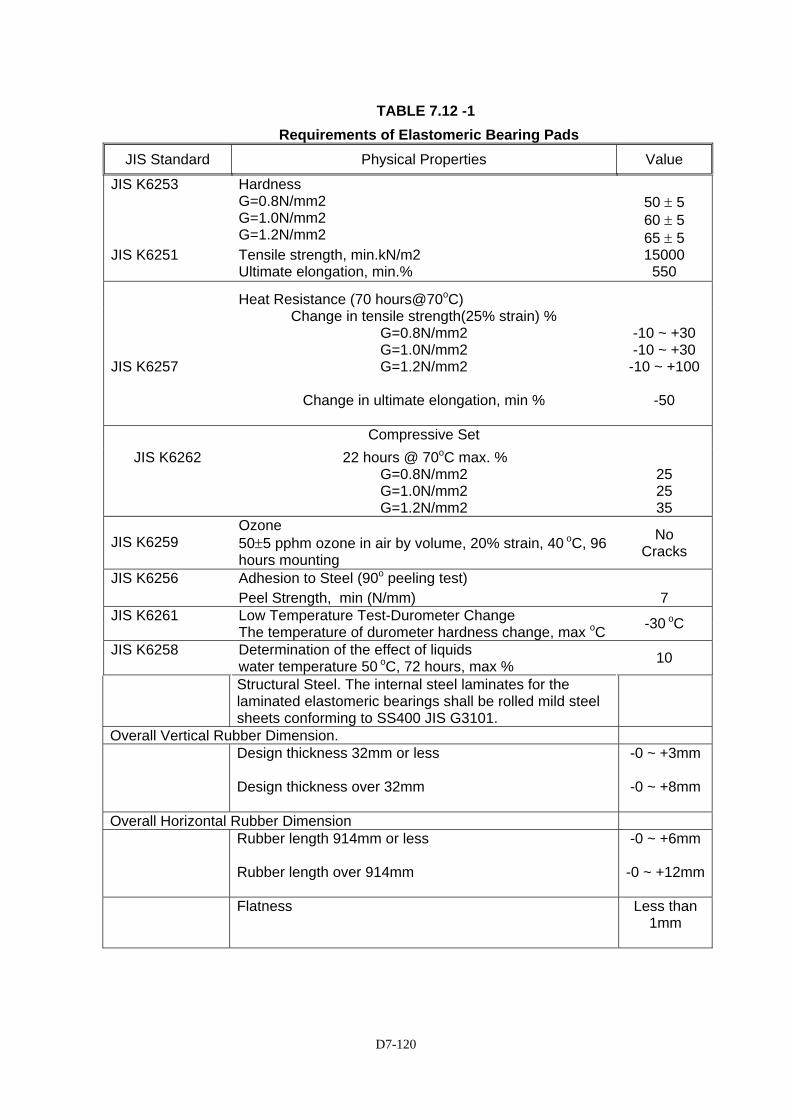
D7-120
TABLE 7.12 -1 Requirements of Elastomeric Bearing Pads
JIS Standard Physical Properties Value
JIS K6253 Hardness G=0.8N/mm2 G=1.0N/mm2 G=1.2N/mm2
50 ± 5 60 ± 5 65 ± 5
JIS K6251 Tensile strength, min.kN/m2 Ultimate elongation, min.%
15000 550
Heat Resistance (70 hours@70oC)
JIS K6257
Change in tensile strength(25% strain) % G=0.8N/mm2 G=1.0N/mm2 G=1.2N/mm2
Change in ultimate elongation, min %
-10 ~ +30 -10 ~ +30
-10 ~ +100
-50
Compressive Set JIS K6262 22 hours @ 70oC max. %
G=0.8N/mm2 G=1.0N/mm2 G=1.2N/mm2
25 25 35
JIS K6259
Ozone 50±5 pphm ozone in air by volume, 20% strain, 40 oC, 96 hours mounting
No Cracks
JIS K6256 Adhesion to Steel (90o peeling test) Peel Strength, min (N/mm) 7
Low Temperature Test-Durometer Change JIS K6261 The temperature of durometer hardness change, max oC -30 oC
Determination of the effect of liquids JIS K6258 water temperature 50 oC, 72 hours, max % 10
Structural Steel. The internal steel laminates for the laminated elastomeric bearings shall be rolled mild steel sheets conforming to SS400 JIS G3101.
Overall Vertical Rubber Dimension. Design thickness 32mm or less
Design thickness over 32mm
-0 ~ +3mm
-0 ~ +8mm
Overall Horizontal Rubber Dimension Rubber length 914mm or less
Rubber length over 914mm
-0 ~ +6mm
-0 ~ +12mm
Flatness Less than 1mm
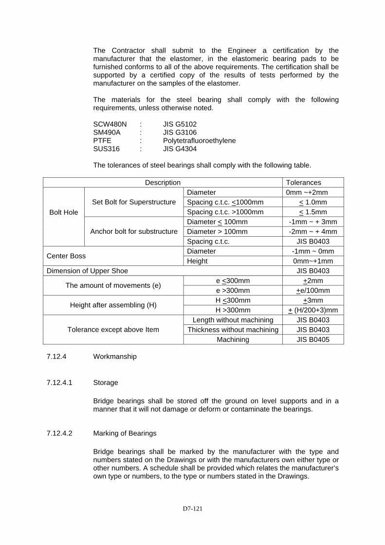
D7-121
The Contractor shall submit to the Engineer a certification by the manufacturer that the elastomer, in the elastomeric bearing pads to be furnished conforms to all of the above requirements. The certification shall be supported by a certified copy of the results of tests performed by the manufacturer on the samples of the elastomer. The materials for the steel bearing shall comply with the following requirements, unless otherwise noted.
SCW480N : JIS G5102 SM490A : JIS G3106 PTFE : Polytetrafluoroethylene SUS316 : JIS G4304
The tolerances of steel bearings shall comply with the following table.
Description Tolerances
Diameter 0mm ~+2mm Spacing c.t.c. <1000mm < 1.0mm Set Bolt for Superstructure Spacing c.t.c. >1000mm < 1.5mm Diameter < 100mm -1mm ~ + 3mm Diameter > 100mm -2mm ~ + 4mm
Bolt Hole
Anchor bolt for substructureSpacing c.t.c. JIS B0403 Diameter -1mm ~ 0mm
Center Boss Height 0mm~+1mm
Dimension of Upper Shoe JIS B0403 e <300mm +2mm
The amount of movements (e) e >300mm +e/100mm H <300mm +3mm
Height after assembling (H) H >300mm + (H/200+3)mm
Length without machining JIS B0403 Thickness without machining JIS B0403 Tolerance except above Item
Machining JIS B0405
7.12.4 Workmanship
7.12.4.1 Storage
Bridge bearings shall be stored off the ground on level supports and in a manner that it will not damage or deform or contaminate the bearings.
7.12.4.2 Marking of Bearings
Bridge bearings shall be marked by the manufacturer with the type and numbers stated on the Drawings or with the manufacturers own either type or other numbers. A schedule shall be provided which relates the manufacturer’s own type or numbers, to the type or numbers stated in the Drawings.
D7-122
The design movement, directions, magnitudes and the axes of bearing shall be marked on the upper faces of bridge bearings to facilitate checking of the installation. Movement indicators shall be provided for sliding bearings to permit checking of movements of the bearings before and after installation.
7.12.4.3 Corrosion Protection
Bearings shall be protected against corrosion by a protective coating selected by the Contractor to suit the environment of the Site. The Contractor shall provide evidence for acceptance by the Engineer for the satisfactory use of the proposed protective coating in a similar environment subject to similar use elsewhere.
7.12.4.4 Grouting
Grout for grouting base plates and holding down bolts shall be a proprietary non-shrink grout type. The grout shall not bleed or segregate. The suitability of the grout and grouting procedure proposed by the Contractor shall be verified by a test grouting in an arrangement where the dimensions and positions are the same as will be experienced in actual use. The test shall demonstrate an undisturbed grouting operation and a complete filling of the total bearing area.
7.12.4.5 Installation
Bridge bearings shall be installed as recommended by the manufacturer and bridge bearings, which have been pre-assembled, should not be dismantled. The levels of substructures stated in the Drawings on which bridge bearings are to be installed shall be adjusted to suit the thickness of the bearing, if alternative bearings are accepted, so that the superstructure is at the specified level after completion.
7.12.4.6 Tolerances
The centerline of bridge bearings shall be within 10 mm of the specified horizontal position. The level of bridge bearings shall be within 3 mm of the specified level. The relative levels for two bearings on the same pier shall be within 2 mm of the specified value. The inclination of bridge bearings shall be within 1 in 500 of the specified inclination. The horizontal axis of bridge bearings shall be within 0.002 radian of the specified alignment.
D7-123
7.12.5. Inspection and Testing
Inspection and testing of bearings shall be in accordance with the latest edition of the Bearing Design Standard, JRA.
7.12.6 Method of Measurement
The completed bridge bearings shall be paid per set basis, completed and accepted by the Engineer.
7.12.7 Basis of Payment
The quantities measured shall be paid for at the contract price for the several Pay Items which price and payment shall be full compensation for furnishing all documentation and submittals, materials, labor, equipment, tools, testing, supervision, transportation, shipping and storage costs, test assembly and incidentals necessary to complete the work. The payment shall be deemed to include full compensation for all additional materials and work not shown on the Drawings or specified, which are necessary to complete the installation. No special payment shall be made for special curb units, cover plates and transition strips.
Payment shall be made under the following item: Pay Item No. Description Unit
of Measurement 7.12(2) Elastomeric Bearing Pad, Type - A1 Set 7.12(2)a Elastomeric Bearing Pad, Type – A2 Set 7.12(2)b Elastomeric Bearing Pad, Type – A3 Set 7.12(2)c Elastomeric Bearing Pad, Type – A4 Set

D7-124
SECTION 7.12(2) - BRIDGE BEARING FOR STEEL GIRDER
7.12(2).1 Description
This work shall consist of furnishing and installing steel bearing, bearing shoes and pot bearings for bridge superstructures of the types and sizes as indicated on the Drawings or as directed by the Engineer.
7.12(2).2 Materials
The materials for the bridge bearings, including rubber pads, steel components, bolts and other items, shall be as specified on the Drawings. The Contractor shall prepare comprehensive documentation on the bearings he proposes to use. The documentation on the bearing shall include the following minimum requirements to be submitted to the Engineer for acceptance:
i. Details of the type of bridge bearings, including materials, and the name
and address of the manufacturer,
ii. Shop drawings and of any additional or revised reinforcement detail drawing,
iii. A certificate for each type of bridge bearing showing the manufacturer’s
name, the date and place of manufacture, certification that the bridge bearings comply with the requirements stated in the Contract and results of tests carried out on the bearings,
iv. Details of fixings to superstructures and substructures,
v. Details of protective coatings and protections of sliding surfaces against
dust etc.,
vi. Method of installation
vii. Schedule of manufacture, testing and delivery, including name and address of testing laboratory
All materials used in the manufacture of the bearing assemblies shall be new and unused with non-reclaimed material incorporated into the finished assembly.
(1) Bearing Shoes
Material for bearing shoes of general type shall conform to the following:
JIS G 3101 : Rolled Steel for General Structure - SS 400 JIS G 5101 : Carbon Steel Castings — SC 46 JISG 5102 : High Strength Brass Castings-HBsC3
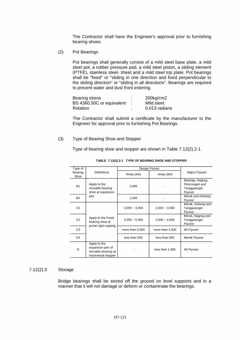
D7-125
C2
C3
C4
D
Apply to the movable bearing shoe at expansion pier
B1 2,000
C1
less than 500
Rmax (kN)
Type of Bearing
Shoe Hmax (kN)DefinitionsDesign Forces
-
B2 1,000 -
TABLE 7.12(2).2-1 TYPE OF BEARING SHOE AND STOPPER
- less than 1,560
2,000 ~ 3,000
less than 500
more than 4,500
3,000 ~ 4,500
2,000 ~ 3,000
3,000 ~ 5,000
more than 5,000
Apply to the expansion pier of movable bearing as transversal stopper
Object Flyover
Balaraja, Nagreg, Peterongan and Tanggulangin FlyoverMerak and Gebang Flyover
All Flyover
Merak, Gebang and Tanggulangin FlyoverMerak, Nagreg and Tanggulangin Flyover
Merak Flyover
All Flyover
Apply to the Fixed bearing shoe at portal rigid copping
The Contractor shall have the Engineer's approval prior to furnishing bearing shoes.
(2) Pot Bearings
Pot bearings shall generally consist of a mild steel base plate, a mild steel pot, a rubber pressure pad, a mild steel piston, a sliding element (PTFE), stainless steel- sheet and a mild steel top plate. Pot bearings shall be "fixed" or "sliding in one direction and fixed perpendicular to the sliding direction" or "sliding in all directions". Bearings are required to prevent water and dust front entering.
Bearing stress : 200kg/cm2 BS 4360.50C or equivalent : Mild steel. Rotation : 0.013 radians
The Contractor shall submit a certificate by the manufacturer to the Engineer for approval prior to furnishing Pot Bearings.
(3) Type of Bearing Shoe and Stopper Type of bearing shoe and stopper are shown in Table 7.12(2).2-1.
7.12(2).3 Storage
Bridge bearings shall be stored off the ground on level supports and in a manner that it will not damage or deform or contaminate the bearings.
D7-126
7.12(2).4 Marking of Bearings
Bridge bearings shall be marked by the manufacturer with the type and numbers stated on the Drawings or with the manufacturer’s own either type or other numbers. A schedule shall be provided which relates the manufacturer’s own type or numbers, to the type or numbers stated in the Drawings. The design movement, directions, magnitudes and the axes of bearing shall be marked on the upper faces of bridge bearings to facilitate checking of the installation. Movement indicators shall be provided for sliding bearings to permit checking of movements of the bearings before and after installation.
7.12(2).5 Corrosion Protection
Bearings shall be protected against corrosion by a protective coating selected by the Contractor to suit the environment of the Site. The Contractor shall provide evidence for acceptance by the Engineer for the satisfactory use of the proposed protective coating in a similar environment subject to similar use elsewhere.
7.12(2).6 Grouting
Grout for grouting base plates and holding down bolts shall be a proprietary non-shrink grout type. The grout shall not bleed or segregate. The suitability of the grout and grouting procedure proposed by the Contractor shall be verified by a test grouting in an arrangement where the dimensions and positions are the same as will be experienced in actual use. The test shall demonstrate an undisturbed grouting operation and a complete filling of the total bearing area.
7.12(2).7 Installation
Bridge bearings shall be installed as recommended by the manufacturer and bridge bearings, which have been pre-assembled, should not be dismantled. The levels of substructures stated in the Drawings on which bridge bearings are to be installed shall be adjusted to suit the thickness of the bearing, if alternative bearings are accepted, so that the superstructure is at the specified level after completion.
7.12(2).8 Tolerances
The centerline of bridge bearings shall be within 10 mm of the specified horizontal position. The level of bridge bearings shall be within 3 mm of the specified level. The relative levels for two bearings on the same pier shall be within 2 mm of the specified value.
D7-127
The inclination of bridge bearings shall be within 1 in 500 of the specified inclination. The horizontal axis of bridge bearings shall be within 0.002 radian of the specified alignment.
7.12(2).9 Inspection and Testing
Inspection and testing of bearings shall be in accordance with the latest edition of the Bearing Design Standard, JRA.
7.12(2).10 Construction
(1) Bearing Shoes
(a) Bearing shoes shall generally be accurately set in the specified position before construction of superstructure members. This setting work shall be carefully done with non-shrink mortar so that the bottom of bearing shoes will adhere tightly to the top of the pier of abutment.
When the Engineer has given approval and bearing shoes are set after construction of superstructure members, non-shrink mortar shall be thoroughly spread under the bottom of bearing shoes, and they shall completely adhere to the top of substructure.
(2) Pot Bearings
(a) Each Pot Bearings shall be accurately located using sufficiently rigid templates. The templates shall be immovably fixed to the form works. When the Engineer has given approval concrete of the pier heads and abutments may be placed.
(b) Bearings shall be installed accurately according to the manufacturer's instruction using non shrink adhesive mortar. When the Engineer has given approval non shrink adhesive mortar shall be packed below the base plates and in the holes of the anchor bolts.
D7-128
7.12(2).11 Method of Measurement
The quantities of bridge bearing for steel girder shall be measured as the set of each type completed in place and accepted by the Engineer.
7.12(2).12 Basis of Payment
The work measured as provided above will be paid for at the Contract unit price respectively. The payment shall consist of full compensation for furnishing, fabricating, transporting, painting and placing all materials including all labour, tools, equipment, and incidentals and necessary accessories as shown on the Drawings and includes anchor bars and caps, leveling mortar, steel mesh, spiral bar for anchor bars and reinforcement.
Pay Item No. Description Unit of
Measurement
7.12(7)a Bridge Bearing for Steel Girder, Type – B1 Set 7.12(7)b Bridge Bearing for Steel Girder, Type – B2 Set 7.12(7)c Bridge Bearing for Steel Girder, Type – C1 Set 7.12(7)d Bridge Bearing for Steel Girder, Type – C2 Set 7.12(7)e Bridge Bearing for Steel Girder, Type – C3 Set 7.12(7)f Bridge Bearing for Steel Girder, Type – C4 Set
D7-129
SECTION 7.13 – STEEL BRIDGE RAILINGS 7.13.1 Description
This work shall consist of furnishing, fabricating and erecting steel pipe railings, and incidental structures, as indicated on the Drawings and required by these Specifications and as directed by the Engineer.
7.13.2 Materials (1) Materials shall conform to the requirements of:
JIS G 3101 : Rolled Steel for General Structures JIS G 3452 : Carbon Steel Pipes for Ordinary Piping JIS G 3444 : Carbon Steel Tubes for General Structural
Purposes JIS G 3466 : Carbon Steel Square Pipes for General
Structural Purposes JIS G 3532 : Low Carbon Steel Wires JIS G 3552 : Chainlink Wire Netting JIS G 4040 : Aluminum and Aluminum Alloy Rods, Bars, Wires JIS G 4303 : Stainless Steel Bars
(2) Mortar and grout shall conform to the pertinent provisions of these Specifications.
(3) All steel railing, and fittings shall be galvanized unless otherwise
specified. All aluminum alloys shall be coated in accordance with the Specifications of JIS H 8601. Galvanized areas damaged by welding or other site works shall be cleaned and given 3 coats of approved zinc based paint, to the satisfaction of the Engineer.
(4) Where painting is required, it shall be in accordance with the
requirements of these Specifications. 7.13.3 Construction
(1) Pipe railings, fittings and incidental parts shall be carefully handled and stored on blocking, racks or platforms so as not to be in contact with the ground and shall be protected from corrosion. Materials shall be kept free from dirt, oil, grease and other foreign matter. Surfaces to be painted shall be carefully protected both in the shop and in the field. Threads shall be carefully protected from damage.
(2) Railings and fences shall be carefully constructed true to line and
grade as shown on the Drawings, and no construction shall be commenced before the inspection and approved by the Engineer, and before all centres, supports, and falsework or staging of bridge superstructure have been removed.
(3) The component parts of pipe railings shall be connected with threaded
screws unless otherwise specified on the Drawings. Fitting for railings on slopes shall be leveled to fit the required grades. Screw thread fittings shall be coated with red lead and oil, and the threads shall
D7-130
engage for a minimum length of 2 centimeters. Expansion shall be provided by omitting threads on one side of fittings at designated posts. Where the rails are continuous through two or more posts threads may be omitted between the rails and the fitting, but the rail must be pinned at each post. Where welding of component parts is permitted, the details must be in accordance with the Drawings or as approved by the Engineer.
(4) The Contractor shall provide for the erection of tubular railing by
suitable fabrication in the shop. Where railing is fitted between concrete posts, provision shall be made to allow the installation of same.
Railing and fence shall be fabricated and erected as indicated on the Drawings, and rails shall be parallel to the grade of the road. Posts shall be set truly vertical unless otherwise instructed by the Engineer.
All exposed surfaces shall be thoroughly cleaned in an approved manner as a final operation under this project.
(5) The Contractor shall furnish for the approval of the Engineer working
drawings for the particular type of railing and fence to be installed.
7.13.4 Method of Measurement
The quantities of metal railing to be paid for shall be the number of linear meters of railings satisfactorily completed and accepted in accordance with the Drawings, these Specifications, and as directed by the Engineer.
7.13.5 Basis of Payment
The work measured as provided above shall be paid for at the Contract unit price per linear meter of railings. The price and payment shall be full compensation for furnishing all railings, posts and fittings including delivery, erection and finishing, and for all labour, equipment, tools and incidentals necessary for the completion of the work.
Pay Item No. Description Unit of Measurement
7.13 Steel Bridge Railing Linear Meter
D7-131
SECTION 7.14 – BRIDGE NAME PLATE
7.14.1 Description
The Item shall consist of providing name plate on the bridge and shall include the furnishing of materials, labor and equipment required to supply, construct or install, or to complete all the works as shown on the Drawings and as approved by the Engineer. The wording and text for the bridge and monument name plates shall be submitted by shop drawing noting in full scale the wording and phrasing to be used. The Engineer, prior to plate fabrication, shall approve the submitted Drawing.
The following information shall at least be given on the plaque: • Name of the bridge, • Completion date, • Name of client, contractors, and consultants
7.14.2 Materials
Name plate of 1000 x 600mm shall be made from brass plates meeting the requirements of ASTM B36 with welded mold steel anchor bolt, wall, foundation and wording as directed by the Engineer. Prior to the installation of name plaque, the Contractor shall propose construction details to the Engineer for approval. The wall and foundations of the monuments shall be of class C concrete in accordance with the requirements of Section 7.1, Structural Concrete. Reinforcements shall be in accordance with the requirements of Section 7.3, Reinforcing Steel.
7.14.3 Construction Requirements
The Contractor shall furnish the name plate and install 2 sets on the bridge as directed by the Engineer. Concrete and reinforcement works shall follow the requirements prescribed in Section 7.1, Structural Concrete and Section 7.3, Reinforcing Steel respectively.
7.14.4 Method of Measurement
Bridge Name Plates shall be measured for payment based on the number of plates installed in accordance with the requirements shown on the Drawings and approved by the Engineer. Payment for bridge plate includes all the requirements such as plate, wall, and foundation; furnishing all materials, labor, tools, equipment and incidentals necessary to complete the work.

D7-132
7.14.5 Basis of Payment
The accepted quantity as provided in Clause 7.14.4, Method of Measurement shall be full compensation for furnishing all materials and for all preparation, erection, surface treatment and installation of these materials, and for all shop drawings, labor, equipment, tools, and incidentals to complete the Item to the satisfaction of the Engineer.
Pay Item No. Description Unit of Measurement
7.14 Bridge Name Plate Each
D7-133
SECTION 7.15 – DEMOLITION OF EXISTING STRUCTURES
7.15.1 Description This work shall consist of the removal, wholly or in part and satisfactory
disposal of blocks of masonry of an individual size greater than 1 cubic meter, of all buildings, hedges, fences, structures, old pavements, curbs, and any other obstructions which are not designated or permitted to remain, except for the obstruction to be removed and disposed of under other items in the Contract Documents. It shall also consist of the salvaging of designated materials and backfilling the resulting trenches, holes and pits.
7.15.2 Work Requirement
(1) General
The Contractor shall perform the above work, within and adjacent to the roadway, on the right-of-way, as shown on the Drawings or as directed by the Engineer. The Engineer may instruct that materials recovered from demolition shall remain the property of the Employer unless specifically provided otherwise in the Contract Documents. All designated saleable material shall be removed, without unnecessary damage, in sections or pieces that may be readily transported, and shall be stored by the Contractor at specified places on the project as directed by the Engineer. Basements or cavities left by structure removal shall be filled with acceptable material to the level of the surrounding ground and, if within the prism of construction, shall be compacted in accordance with Section 3.3(1).
Performance of these works under the Contract shall include salvage of materials removed, their custody, preservation, storage on the right-of-way or any other places as may be designated by the Engineer or the Employer, or disposal as provided herein.
(2) Removal of Bridges, Culverts, and other Structures
Bridges, culverts and other drainage structures in use by traffic shall not be removed until satisfactory arrangements have been made to accommodate traffic. Unless otherwise directed, the substructures of existing water structures shall be removed down to the natural stream bottom and those parts outside of a stream shall be removed to the extent necessary to avoid influence on new works. Where portions of the existing structures lie wholly or in part within the limits for a new structure, they shall be removed as necessary to accommodate the construction of the proposed structure. Where only a section of the existing structure is to be demolished, the Contractor shall execute this work in such away as to avoid damage to the section designated to remain. All details of the Contractor’s proposed working method shall be submitted to the Engineer for approval.

D7-134
Steel bridges and timber bridges, when specified by the Engineer to be salvaged, shall be carefully dismantled without damage. Steel members shall be match marked, unless such match marking is waived by the Engineer. All salvaged material shall be stored as requested by the Engineer. Unless waived in writing by the Engineer, all concrete removed that is of suitable size for riprap and not needed for such use on the Project, shall be stockpiled at locations designated by the Engineer, for use by the Employer.
(3) Removal of Curbs
Existing curbs designated for removal, including their bases, shall be broken into pieces and shall be removed and stockpiled at designated locations on the site for use of the Employer, or shall be otherwise disposed of as directed by the Engineer. Removal of existing curbs shall be undertaken in such a manner as to avoid damage to existing pavements and curbs which are designated to remain.
(4) Removal of Pavements, Footpaths, etc.
Irrespective of thickness all asphalt or concrete pavement. Footpaths or other hard surfaces designated for removal, shall be removed and stockpiled at designated location on the Site for use of Employer, or otherwise disposed of as directed by the Engineer. Removal of pavement shall be carefully undertaken to avoid damage to abutting sections of pavement or structures designated to remain. If removal of section of old pavement, footpaths or other hard surfaces of an individual size less than 10 cubic meters or excavation of ballast, gravel or similar sub base or base material is necessary, this work shall be considered as Common Excavation, and shall conform to the requirements of Section 3.2(1) of these Specifications, for construction, measurement and payment.
(5) Removal of Traffic Signs
Where directed, traffic signs including steel frames shall be carefully dismantled, removed and stored where directed by the Engineer. Concrete foundations shall be broken into pieces removed and stockpiled at designated locations on the site for use of the Employer or shall be otherwise disposed of as directed by the Engineer.
7.15.3 Method of Measurement The quantities to be paid for according to these Specifications or as directed
by the Engineer, shall be cubic meter or square meter or linear meter depending upon the nature of structure and obstructions demolished acceptably within the limits as directed by the Engineer.
D7-135
Demolition required for the Permanent works will be measured for payment, while demolition for haul roads, borrow areas and all the Temporary Works will not be measured for payment.
7.15.4 Basis of Payment The work measured as provided above shall be paid as under mentioned.
The payment shall be full compensation for furnishing all labour, materials, tools, equipment, and incidentals necessary to do the work and for doing all the demolition in the designated locations or areas as specified in these Specifications, including backfilling if necessary. The unit price for any work under this section will be deemed to include any precautions or special working methods necessary to avoid damage to abutting material designated to remain. Any such damage shall be rectified by the Contractor at his own expense. All work shall be as directed by the Engineer including the removal and disposal of all the resulting material.
Pay Item No. Description Unit of Measurement 7.15(1) Demolition of existing masonry structure Cubic meter 7.15(2) Demolition of existing concrete structure Cubic meter 7.15(10) Demolition of existing rigid pavement Square meter 7.15(11) Demolition of existing hedge or fence Linear meter 7.15(12) Demolition of existing concrete side walk Square meter 7.15(13) Demolition of existing concrete curb Linear meter
D7-136
SECTION 7.16(2) - RIGID PAVEMENT 7.16.1 Description
This work shall consist of construction of a pavement of Portland cement concrete constructed on a prepared base in accordance with this specification in conformity with the lines, grades, thickness and typical cross-sections as shown on the Drawings.
7.16.2 Materials
(1) Portland Cement The cement to be used shall be Portland cement Type I unless
otherwise provided. Different brands or the same brands from different mills shall not be mixed nor shall they be used alternately unless the mix is approved by the Engineer.
Cement which has for any reason become partially set or which
contains lumps of caked cement will be rejected. Cement salvaged from discarded or used bags will not be used.
Samples of cement shall be obtained in accordance with AASHTO T
127.
(2) Fine Aggregate It shall consist of natural sand, stone screenings or other inert
materials with similar characteristics, or combinations thereof, having hard or strong and durable particles. Fine aggregate from different sources of supply shall not be mixed or stored in the same pile nor used alternately in the same class of concrete without the approval of the Engineer.
It shall not contain more than 3 mass percent of materials passing the
0.075mm sieve by washing nor more than 1 mass percent each of clay lumps or shale. The use of beach sand will not be allowed without the approval of the Engineer.
If the fine aggregate is subjected to five cycles of the sodium sulfate
soundness test, the weighted loss shall not exceed ten mass percent. The fine aggregate shall be free from injurious amount s of organic
impurities. If subjected to colorimatic test for organic impurities and a color darker than the standard is produced, it shall be rejected. However, when tested for the effect of organic impurities of strength of mortar by AASHTO T 71, the fine aggregate may be used if the relative strength at 7 and 28 days is not less than 95 mass percent.
(3) Coarse Aggregate
It shall consist of crushed stone, gravel, blast furnace slag, or other approved inert materials of similar characteristics, or combination
D7-137
thereof, having hard, strong, durable pieces and free from any adherent coatings. It shall not contain more than 1 mass percent of materials passing the 0.075mm sieve, not more than 0.25 mass percent of clay lumps or nor more than 3,5 mass percent of soft fragments.
If the coarse aggregate is subjected to five cycles of the sodium sulfate soundness test, the weighted loss shall not exceed 12 mass percent.
It shall have a mass percent of wear not exceeding 25 when tested by
AASHTO T 96. (4) Reinforcing Steel
Reinforcing steel shall be in accordance with Section 7.3 of these Specifications and such further details are as shown on the Drawings.
(5) Water Water used in mixing, curing or other designated application shall be
reasonably clean and free of oil, salt, acid, alkali, grass or other substances injurious to the finished product. Water will be tested in accordance with the requirements of this specification. Water which is drinkable may be used without test. Where the source is shallow, the intake shall be so enclosed as to exclude silt, mud, grass or other foreign materials.
(6) Admixtures Chemical admixtures, if specified or permitted shall conform to the
requirements of AASHTO M 194.
(7) Curing Materials
Curing materials shall conform to the following requirements as specified or other materials as ordered by the Engineer: Liquid Membrane-Forming - AASHTO M 148 Compounds for Curing Concrete Type 2 White pigmented
(8) Calcium Chloride
It shall conform to AASHTO M 144, if specified or permitted by the Engineer.
(9) Slip Sheet Membrane
Membrane for waterproof underlay below the slab shall be polythene sheeting of 125 microns thick or as specified by the Engineer. When overlap of underlay materials is necessary, this shall be at least 300mm.

D7-138
7.16.3 Proportioning, Consistency and Strength of Concrete
The Contractor shall submit design mixes obtained from samples made in accordance with Standard Method of Making and Curing Concrete Compression and Flexure Tests Specimen in the Laboratory for each strength required, stating the proposed slump and the proportioning weights of cement, saturated surface aggregates and water. These mixes shall be proven by preliminary tests thirty (30) days before concreting and shall show a 28-day strength of fifteen (15%) percent higher than the ultimate strength required. No substitution shall be made in the materials or mix without additional tests to show that the quality of concrete is satisfactory. The proportion of aggregate to cement for concrete pavement shall be such that to produce a mixture which will work readily into the corners and around reinforcements, if any, with the method of placing concrete without permitting the materials to segregate or allow free water to collect on the surface. The combined aggregates shall be such compositions of sizes that when separated on the No.4 standard sieve, the weight passing the sieve (fine aggregate) shall not be less than thirty (30%) percent or greater than fifty (50%) percent of the total, except that these proportions do not necessarily apply to lightweight aggregates. The method of measuring concrete materials shall be such that the proportions can be accurately controlled and easily checked anytime during work.
Slump shall be in accordance with AASHTO T 119.
Aggregates shall be measured preferably by weight and to within one (1%) percent. Water shall be measured by weight or volume to within one and one-half (1 1/2%) percent. The water shall in no case, exceed 23 liters per bag (40 kg) of cement for all concrete with specified minimum flexural strength of 550 psi when tested by the third-point method or 650 psi by the mid-point method and a compressive strength of 3,500 psi for plain PCCP. Job mix adjustment of water content shall be allowed only on permission of the Engineer, provided that cement is also added to keep the original water-cement ratio of the design mix.
7.16.4 Construction Requirements 7.16.4.1 Quality Control of Concrete
The Contractor shall furnish the Engineer of a quality control of all materials during the handling, bending, ad mixing and placement operations. The Contractor shall furnish the Engineer of a Quality Control Plan detailing his production control procedures and the type and frequency of sampling and testing to insure that the concrete produces complies with the specifications. Experienced and qualified personnel shall perform all batching or mixing operations for the concrete mix, and shall be resent at the plat and job site to control the concrete productions whenever the plant is in operation.
D7-139
The Contractor shall perform all sampling, testing, and inspection necessary to assure the quality control of the component materials and the concrete. The Contractor shall be responsible for determining the gradation of fine and coarse aggregates and for testing the concrete mixture for slump, air content, water-cement ration and temperature. He shall conduct his operations so as to produce a mix conforming to the approved mix design. The Owner, his duly authorized representative or the Engineer shall have the right to order the test of any materials supplied by the Contractor entering into concrete pavement or reinforced concrete pavement whenever there is a reasonable doubt as to their suitability for the purpose. Such tests shall be in accordance with the standards of the ASTM, AASHTO or JIS for testing materials noted elsewhere in the Specifications. Copies or results of tests shall be furnished to the Owner promptly.
7.16.5 Equipment
Equipment and tools necessary for handling materials and performing all parts of the work shall be approved by the Engineer as to design, capacity and mechanical condition. The equipment shall be at the job site sufficiently ahead of the start of construction operation to be examined thoroughly and approved. (1) Batching Plant and Equipment
The Batching plant shall include bins, weighing hoppers, and scales for the fine aggregate and for each size of the coarse aggregate. If cement is used in bulk, a bin, hopper shall be properly sealed and vented to preclude dusting operation. The batch plant shall be equipped with suitable non-resettable batch counter which will correctly indicate the number of batch proportioned.
(2) Bins and Hoppers
Bin with adequate separate compartments for fine aggregate and for each size of the coarse aggregate shall be provided in the batching plant.
(3) Scales
Scales for weighing aggregates and cement shall be either in the beam type or the springless-dial type. They shall be accurate within one half percent throughout the range of use. Poises shall be designed to be locked in any position and to prevent unauthorized change.

D7-140
(4) Automatic weighing devices
Unless otherwise allowed on the contract, batching plants shall be equipped with automatic weighing devices of an approved type to proportion aggregates and bulk cement.
(5) Paving and Finishing Equipment
The concrete shall be placed with an approved paver designed to spread, consolidate, screed and float finish the freshly placed concrete in one complete pass of the machine in such a manner that the minimum of hand finishing will be necessary to provide a dense and homogenous pavement in conformance with the Drawings and specifications. The finishing machine shall be equipped with at least two oscillating type of transverse screeds or other compatible means of striking off concrete as required. Vibrators shall operate at a frequency of 8300 to 9600 impulses per minute under load at the maximum spacing of 60cm.
(6) Concrete saw
The Contractor shall provide sawing equipment in adequate number of units and power to complete the sawing with water-cooled diamond edge saw blade or an abrasive wheel to the required dimensions at the required rate. Ample supply of saw blades shall be maintained at the site during sawing operations. The Contractor shall provide adequate artificial lighting facilities for night sawing.
(7) Forms
Forms shall be of steel, of an approved section, and of depth equal to the thickness of the pavement at the edge. The base of the forms shall be sufficiently wide to provide necessary stability in all directions. The flange braces must extend outward on the base to not less than 2/3 the height of the form. All forms must be rigidly supported on a bed of thoroughly compacted material during the entire operation of placing and finishing the concrete. Form shall be provided with adequate devices to secure setting so that when in place, they will withstand, without visible spring or settlement, the impact and vibration of the consolidating and finishing pavement equipment.
7.16.6 Joints
Joint shall be constructed of the type and dimensions, at the locations required in the Drawings. All joints shall be protected from the intrusion of injurious foreign materials until sealed.
D7-141
7.16.7 Construction
(a) General
Before commencing the work on the concrete slab, all work on the subbase, ducts, and adjacent curb shall be completed to the satisfaction of the Engineer. All concrete shall be distributed uniformly, compacted and finished by machines.
(b) Form Setting
Forms shall be set sufficiently in advance of the point where concrete is being placed to permit the performance and approval of all operations required within and adjacent to the form lines. Forms shall be staked into place with no less than 3 pins for each 3m section. Pin shall be placed at each side of every joint. Form sections shall be tightly locked, free from play or any movement from any direction. The forms shall not deviate from true line by more than 5mm at any point. Forms shall be set so that they will withstand without visible spring or settlement, the impact and vibration of the consolidating and finishing equipment. Forms shall be cleaned and coated with a form release agent or oiled prior to the placing of concrete. The alignment and grade elevation of the forms shall be checked and corrections made by the Contractor immediately before placing the concrete. When any form has been disturbed or any grade has become unstable, the form shall be reset and rechecked.
(c) Mixing Concrete
If mixing, transporting and depositing of concrete are done other than the procedure prescribed under this sub-clause is allowed by the Engineer, the Contractor shall remain to be solely responsible to observe and produce concrete with the same quality required in the Specifications. No hand mixing shall be allowed during concreting operations except in emergency cases such as batching plant breakdown and shall stop at the first allowed construction joint. All concrete shall be machine mixed for at least 1½ minutes after all materials including water are in the mixing drum. The batching plant shall be of an approved capacity and type which will insure a uniform distribution of materials throughout the mass. It shall be equipped with a device for accurately measuring and controlling the amount of mixing water in each batch. The first batch of concrete materials placed in the mixer shall contain a sufficient excess of cement, sand and water to coat the inside of the drum without reducing the cement concrete of the mix to be discharged.
D7-142
(d) Placing Concrete
Placing of concrete with a free drop or fall of more than 1.5 meters shall not be allowed except when sheet metal conduits, pipes or elephant trunks are employed. When stoppages of concreting operations occur for any reason, construction joints shall be placed horizontally or as directed by the Engineer and be provided with shear keys and dowels to develop bond. Construction joints shall be approved by the Engineer. The Contractor shall provide forms that will produce the placed concrete in a correct and aligned manner. Metal or surfaced lumber forms shall be used for all exposed concrete surfaces. Plastering in general shall not be allowed so that extra care shall be exercised by the Contractor. Forms shall not be removed until the concrete has adequately set and stable enough to withstand the anticipated loadings, and in no case less than two (2) days after concreting. Removal of forms may be allowed earlier provided that test samples of concrete are taken and are shown to withstand safely dead and construction loads. Should any concrete materials fall into the surface of a completed slab, they shall be removed immediately by the approved methods.
(e) Placement of Reinforcement
Following the placing of the concrete, it shall be struck off to conform to the cross-section shown on the drawings. When reinforced concrete pavement is placed in two layers, the bottom layer shall be struck off and consolidated to such length and depth that the sheet of fabric or bar mat may be laid full length on the concrete in its final position without further manipulation. The reinforcement shall then be placed directly upon the concrete, after which the top layer of the concrete shall be placed, struck off and screeded. Any portion of the bottom layer of concrete which has been placed more than 30 minutes without being covered with the top layer shall be removed and replaced with freshly mixed concrete at the Contractor’s expense. At joints between mats of steel material reinforcement, the first wire of one mat shall lie within the complete mesh of the previous mat and the overlap shall not be less than 450mm. Reinforcing steel shall be free from dirt, oil, paint, grease, millscale, and loose or thick rust which could impair bond of the steel with the concrete.
7.16.8 Protection of Pavement
The Contractor shall protect the pavement and its appurtenances both against public traffic and traffic caused by its own construction equipments. This shall include watchmen to direct traffic, the erection of and maintenance of warning signs, lights, pavement bridges or crossovers, etc.
D7-143
Any damage to the pavement from the opening of traffic for public use until final acceptance shall be repaired or replaced by the Contractor without additional compensation.
7.16.9 Opening to Traffic
The Engineer will decide the opening of pavement to traffic after test specimens molded and cured in accordance with AASHTO T23 have attained the minimum strength requirements in of this specification. If such tests are not conducted prior to the specified age, the pavement shall not be opened to traffic until fourteen (14) days after the concrete was placed. Before opening to traffic, the pavement shall be cleaned thoroughly and all joints shall be sealed completely.
7.16.10 Method of Measurement
The area to be paid for under this Section shall be the number of square meters (m2) of concrete pavement placed and accepted in the completed pavement. The width for measurements will be the width from the outside edge to outside edge of completed pavement as placed in accordance with the Drawings or as otherwise required by the Engineer in writing. The length will be measured horizontally along the center line of each roadway. Any curb or gutter placed shall not be included in the area of concrete pavement measured.
7.16.11 Basis of Payment
The accepted quantity measured as specified in Clause 7.16(2).10, Method of Measurement shall be paid for at the contract unit prices for Cement Concrete Pavement, which price and payment shall constitute full compensation for furnishing all materials, for mixing, placing, finishing and curing all concrete, for furnishing and placing all joint materials, for sawing weakened plane joints, for fitting the prefabricated center metal joint, for facilitating and controlling traffic, and for furnishing all labor, equipment, tools and incidentals necessary to complete the Item.
Pay Item Number
Description
Unit of Measurement
7.16(2) Rigid Pavement (270mm thick)
Square Meter
D7-144
SECTION 7.17 - LEAN CONCRETE
7.17.1 Description
The work shall consist of furnishing all labour, equipment, supplies, materials, and of performing all operations in connection with construction of leveling course and pavement widening works with lean concrete including underlying course preparation, importing and preparation of aggregates, batching, mixing, transporting, placing consolidating, finishing, curing, maintenance and other incidental operations pertaining to the construction. All work shall be done in accordance with the plans and drawings, specifications, and as directed by the Engineer.
7.17.2 Underlying Course
Where wet lean concrete is specified for leveling course, prior to construction the underlying course shall be cleaned of dirt, mud, loose stone or other foreign matter and inspected by the Engineer to ensure compaction, finish and surface smoothness. Any areas failing to comply with the applicable specification requirements shall be removed, repaired or reconstructed as directed by the Engineer. No direct payment will be made for this removal, repair or reconstruction provided that the Contractor is held responsible therefor.
7.17.3 Sand Bedding
Where wet lean concrete is specified for pavement widening work, the lean concrete shall be laid on a prepared leveled bed comprising 4 cm of natural sand. Any natural sand with the bulk of its mass being retained on a No. 200 mesh sieve and its mortar fraction being non-plastic may be used. The sand at suitable moisture content shall be spread on the prepared approved sub-grade and leveled. The leveled bed shall be compacted with the largest roller that can be utilized in the excavation. Prior to placing wet lean concrete the sand bed shall be dampened with water.
7.17.4 Materials
The aggregates, cement and water shall conform to the requirements of applicable clauses of these Specifications. The maximum aggregate size, subject to the Engineer's approval, shall be selected by the Contractor with regard to the specific application of lean concrete.
7.17.4.1 Mix Proportion The mass ratio of cement to aggregate in the saturated surface dry condition shall be sufficient to achieve the crushing strength requirements of this Section, and to provide a satisfactory consistency of mixing, and shall not be less than 1 : 14.
7.17.4.2 Formwork Wet lean concrete for leveling course shall be placed between cut-off screeding forms of steel or timber set true to grade and elevation.
D7-145
7.17.4.3 Joints Longitudinal joints shall be offset by at least 20 cm from the longitudinal joint of the concrete pavement to be superimposed. Transverse construction joints shall be formed at the end of each days work and shall form a true transverse vertical surface.
7.17.4.4 Mixing, Transportation, Laying and Consolidation
Wet lean concrete shall be mixed, transported, placed, spread and compacted in accordance with the requirements of Section 7.1 of these Specifications.
7.17.4.5 Finishing
After consolidation and screeding to the correct plane and elevation the wet lean concrete shall be floated to a smooth finish the surface being free from depressions or projections. The surface shall then be regulated by at least two passes of a scraping straightedge with a blade not less than 1.8 m.
7.17.4.6 Curing
Wet lean concrete shall immediately on completion of finishing be cured for a period of not less than 7 days. Curing of the surface shall be achieved by one of the following methods: (1) Covering until the next pavement layer is laid with impermeable plastic
sheeting, adequately secured from being blown off the surface and with the joints overlapped at least 300 mm and set to prohibit egress of moisture.
(2) The entire surface sprayed uniformly with white pigmented curing
compound.
(3) Continual mist spraying covering the entire surface and maintaining a permanently moist condition for the full duration of the curing period. Intermittent wet curing will not be accepted.
7.17.4.7 Testing for Strength
Compressive strength test cylinders - 15 cm diameter by 30 cm high shall be prepared from the lean concrete delivered to site. One cylinder shall be prepared representing each 50 linear meter of wet• lean concrete being laid and not less than three (3) cylinders shall be prepared from each day's work.
7.17.4.8 Crushing Strength Requirements
The average crushing strength at 7 days of each group of' specimens representing each day's work shall not be less than 70 kg/cm2. If the average crushing strength of more than one group of any five consecutive groups falls below 70kg/cm2, the cement content shall be
D7-146
increased to such a value as may be approved by the Engineer, until it can be shown that a satisfactory result can be achieved with different mix proportions.
7.17.4.9 Causes for Rejection
Provided the crushing strength requirements are followed, low crushing strength values will not be cause for rejection. All loose, segregated or otherwise defective areas, along with areas not complying with the surface smoothness requirements, which cannot be corrected by grinding shall be delimited by the Engineer. The material shall be broken out to the full thickness of layer, removed and replaced with freshly mixed material complying with the Specification. Surface patching will not be permitted.
7.17.4.10 Surface Smoothness
Wet lean concrete shall be shaped and finished to the lines, grades and cross sections as shown on the drawings. The finished surface shall not deviate of more than 3 cm from the planned elevation. The finished surface shall not deviate more than 1 cm from a 3 m straightedge when applied parallel with and at right angles to the centerline of the roadway. Straightedge shall be applied by successively overlapping by 1/2 the length of the straightedge. The difference in deviations from the planned elevation of leveling course for concrete pavement between any two points within 20 m distance shall not exceed 1.5 cm.
7.17.4.11 Maintenance
Neither equipment nor traffic, including construction vehicles will be allowed on the finished surface during the initial 7 day's curing period. After the curing period such equipment and vehicles required for the continuation of works will be permitted to traffic on the wet lean concrete. Wet lean concrete shall be maintained in a proper condition prior to placing the next pavement layer. Any damage from any cause whatsoever shall be repaired by replacement of the area in question at the expense of the Contractor.
7.17.5 Method of Measurement
Lean concrete for leveling course shall be measured on the number of square meters of leveling course, completed and accepted in accordance with the plans, drawings, specifications and as directed by the Engineer. Sand bedding will not be measured separately. Wet lean concrete for applications other than leveling course to be measured for payment shall be the number of cubic meters of wet lean concrete accepted in place. In computing all quantities the dimensions used shall be those shown on the Drawings or ordered in writing by the Engineer. No pay allowance shall be
D7-147
made for any increased cement content or for variations in layer thickness where minimum thickness is specified.
7.17.6 Basis of Payment
The accepted quantities of wet lean concrete and sand bedding, determined as provided above, will be paid for at the Contract unit price for the item shown below. This payment shall be full compensation for furnishing all labour, equipment and materials necessary to complete the work, including underlying course preparation, sand bedding, mixing, preparation, transporting, laying, consolidation, finishing, curing, maintenance and all other incidental items of work in accordance with the plans, drawings, specifications, and as directed by the Engineer. Pay Item No. Description Unit of Measurement 7.17(1) Lean Concrete Square Meter for Rigid Pavement t= 100mm
D7-148
SECTION 7.18(1) – RETROFITTING OF EXISTING BRIDGE 7.18(1).1 Description
This work shall consist of the repair, strengthening and corrosion protection of reinforced concrete pier/ pile bent structures including preparation of concrete surfaces, application of strengthening and activated reinforced galvanic mesh overlay corrosion protection, and curing of applied treatment in accordance with the details shown on Drawings or as directed by the Engineer.
7.18(1).2 Submittals The Contractor shall submit certifications, material samples, test data, and other submittals as required in these Specifications. The Contractor shall be responsible for the accuracy of all submittals. Unless specified otherwise submittals shall include the original and 2 copies. Retrofitting of the existing bridges shall not be commenced until the submittals have been approved by the Engineer or as otherwise directed by the Engineer. Such approval shall not relieve the Contractor of any responsibility under the Contract for the successful completion of the work.
7.18(1).3 References (1) ACI/ ICRI 2003 Concrete Repair Manual (2) ACI 222R Corrosion of Metals in Concrete (3) ICRI Guideline No. 03730 Guide for Surface Preparation for the Repair of
Deteriorated Concrete resulting from Reinforcing Steel Corrosion (4) ICRI Guideline No. 03732 Guide for Selecting and Specifying Concrete
Surface Preparation for Sealers, Coating and Polymer Overlays. (5) ASTM B418-95a Standard Specification for Cast and Wrought Galvanic
Zinc Anodes (6) ASTM C 309 Curing Compounds for Concrete
7.18(1).4 Manufacturer’s Technical Assistant The Contractor shall enlist and pay for the services of a qualified technician supplied by the activated reinforced galvanic mesh overlay supplier to provide on-site technical assistance for the installation of the activated reinforced galvanic mesh overlay. The technician shall have verified experience in the installation and testing of embedded galvanic anode systems for corrosion protection of reinforcing steel in concrete structures. The Contractor shall coordinate his work with the designated technician to allow for site support during project start up, anode installations and final system commissioning. The technician shall provide the Contractor with training and support, verify continuity of embedded steel, perform system commissioning, verify and document initial system performance, and prepare and submit a report to the Contractor for transmission to the Engineer.
D7-149
7.18(1).5 Materials
(1) Cement Mortar for Concrete Repair
Portland cement mortar shall consist of Type I or Type II Portland cement to AASHTO M85, clean water, and clean, well-graded sand passing a 1.18-mm (No. 16) sieve. The resistivity of the concrete repair materials shall be less than 15000 ohm-cm to provide suitable electrical conductivity.
(2) Activated Galvanic Jacket System
The activated galvanic jacket system shall be a suitable approved proprietary activated reinforced galvanic mesh comprising an expanded zinc anode with a nominal weight of 2.45kg/m^2. Galvanic strip anodes and galvanic jacket system shall be from the same supplier to ensure compatibility and single source support. The overlay mortar shall be electrochemically active and specifically designed for use with galvanic protection systems with a pH of 14 or greater. The overlay mortar shall not contain any corrosive constituents detrimental to reinforcing steel. The Contractor shall submit the following information for approval: (a) Type and proven track record of the overlay mortar and
activated galvanic jacket technology showing satisfactory field performance with a minimum of two projects of similar size and application.
(b) Independent third party evaluation of the anode technology.
(3) Fiberglass Reinforced Polymer (FRP) Mesh FRP mesh shall be a suitable approved glass fiber grid specifically designed for strengthening reinforcement. The FRP shall consist of E glass fiber rovings with epoxy resin binder. The FRP mesh shall have a nominal 25mm by 25mm grid spacing. FRP mesh shall be supplied and installed as part of the galvanic protection system.
(4) Mechanical Fasteners Mechanical fasteners shall be suitable approved proprietary electroplated zinc coated fasteners, at least 4mm in diameter and 31mm in length.
(5) Other Materials
Other materials specified on the Drawings shall comply with the relevant Sections of these Specifications.
D7-150
7.18(1).6 Delivery and Storage of Materials
All materials shall be delivered, handled and stored in accordance with the manufacturer’s instructions.
7.18(1).7 Construction Requirements 7.18(1).7.1 Submittals
Before beginning any concrete repair or retrofit work, the Contractor shall submit a detailed list of the equipment, procedures, and materials the Contractor proposes to use to the Engineer for approval. The Contractor shall submit material samples, together with appropriate certification and test results for the Galvanic Jacket Anode system proposed.
7.18(1).7.2 Concrete Repair
All spalled and delaminated concrete surfaces shall be repaired prior to placement of the activated galvanic jacket system. All damaged, deteriorated, loosened, or un-bonded portions of existing concrete shall first be removed by water blasting, bush hammering, jackhammering, or any other approved method, with approved equipment, after which the surfaces of existing concrete shall be prepared by contained shot blasting, wet sandblasting, or water blasting to remove any micro-fractured surfaces resulting from the initial removal process. The surfaces shall then be cleaned and allowed to dry thoroughly, unless the specific repair technique requires application of materials to a saturated surface. Concrete removal processes involving the use of jack hammers in excess of 14 kilograms, dry sandblasting, or scrabblers shall not be used without approval by the Engineer. The use of acids for cleaning or preparing concrete surfaces for repair will not be permitted. The perimeters of repairs to concrete that involve concrete removal and subsequent materials replacement shall be saw cut perpendicular to the repair surface to a minimum depth of 25mm. Featheredge repairs to concrete shall not be used. All loose scale, rust, corrosion by-products, or concrete shall be removed from exposed reinforcing steel. Reinforcing steel exposed for more than one-third of its perimeter circumference shall be completely exposed to provide 25mm minimum clearance between the steel and the concrete. Damaged or deteriorated reinforcing steel shall be removed and replaced as directed by the Engineer. After damaged or defective concrete has been removed the surface on which mortar is to be placed shall be prepared by being thoroughly cleaned of all micro-fractured, loose, or deteriorated materials and surface-dried. Immediately prior to the application of the concrete repair, the surface shall be treated with an approved resin bond coat. Portland cement mortar shall be composed of Portland cement, sand, and water, all well mixed and brought to proper consistency. Mortar mixtures and
D7-151
application techniques shall be in accordance with the requirements of the ACI Concrete Repair Manual or as approved by the Engineer. All cement mortar repairs shall be water cured for 7 days following application. At no time during this initial curing period shall the mortar be allowed to dry. If drying occurs, the repair shall be removed and replaced. Following the satisfactory curing of the concrete repair, the surface to receive the activated galvanic jacket system shall be cleaned by removing bond-inhibiting materials to achieve a substrate profile that meets the International Concrete Repair Institute (ICRI) Concrete Surface Profile (CSP) 5.
7.18(1).7.3 Steel Continuity
The electrical continuity of the embedded reinforcing steel shall be verified by the Contractor. The maximum DC resistance between reinforcing shall be less than 1 ohm. Any discontinuous reinforcing steel shall have continuity re-established.
7.18(1).7.4 Galvanic Jacket Anode Installation The activated galvanic jacket system shall have a minimum of two rebar connections per zone. Steel connections shall be made with suitable approved rebar connectors. Reinforced galvanic jackets shall be attached to the concrete surface using mechanical fasteners with suitable sized galvanized washers at a maximum spacing of 300mm to allow little or no movement during and after overlay installation. After installation, reinforced galvanic jacket sheets shall be wired together using pre-installed connection wire as necessary. Anode to anode connections shall be sealed with epoxy or silicone.
7.18(1).7.5 Overlay Placement
The activated overlay mortar shall be mixed according to the manufacturer’s instructions. Immediately prior to application of the repair material, the concrete substrate shall be presoaked with clean water. The overlay material shall be applied with a suitable applicator that ensures that mortar is properly compacted into the concrete substrate and consolidation is achieved around the zinc anode with no voids. The total thickness of the activated overlay mortar shall be 16mm as measured from the concrete substrate. The overlay mortar shall be finished with a wood float and cured with two coats of a membrane-forming concrete curing compound meeting the requirements of ASTM C309. The Contractor shall protect the overlay mortar from exposure to running water during application until final set.
D7-152
7.18(1).8 Method of Measurement and Basis of Payment The retrofitting of existing bridge shall be measured on a lump sum basis. The accepted retrofitting of existing bridge shall be paid at the lump sum price for each of the pay items listed in the Bill of Quantities, which price and payment shall be full compensation for preparation of the area, mixing, placing, finishing and curing the concrete repair, furnishing, and delivery of all the materials, including the activated galvanic jacket system, all labour, equipment, tools, and incidentals and all other costs necessary for the proper completion of the work prescribed in this Section, all to the satisfaction of the Engineer.
Pay Item Number
Description
Unit of Measurement
7.18(1) Retrofitting of Existing Bridge Lump Sum

D7-153
SECTION 7.18(2) – WIDENING OF EXISTING BRIDGE 7.18(2).1 Description
This work shall consist of the demolition and removal of parts of the existing bridges, including such parts as the railing, RC wall, curb and gutter and other miscellaneous parts, and after such removal, the widening of each bridge all as indicated with the details shown on Drawings or as directed by the Engineer.
7.18(2).2 Specification References
American Concrete Institute: 345 Standard Practice for Concrete Highway Bridge Deck
Construction 345.2R Guide for Widening Highway Bridges 546.1R Guide for Repair of Concrete Bridge Superstructure
7.18(2).3 Shop Drawings The Contractor shall submit complete shop drawings of the bridge widening with assembly details to the Engineer for approval. Widening of the existing bridges shall not be commenced until the shop drawings have been approved by the Engineer. Such approval shall not relieve the Contractor of any responsibility under the Contract for the successful completion of the work.
7.18(2).4 Materials
(1) Structural Concrete
Structural concrete shall conform to the requirements of Section 7.1, Structural Concrete.
(2) Reinforcing Steel
Reinforcing steel shall conform to the requirements of Section 7.3, Reinforcing Steel.
(3) Piling
Piling shall conform to the requirements of Section 7.6, Piling. (4) Structural Steel Works
Structural steel works shall conform to the requirements of Section 7.5, Structural Steel Works. Rolled beams shall comply with the requirements of JIS G 3101 SS400.
D7-154
(5) Other Materials
Other materials specified on the Drawings shall comply with the relevant Sections of these Specifications.
7.18(2).5 Construction Requirements 7.18(2).5.1 Concrete Removal
Methods of removal that could damage the portions of the existing bridge to remain in place shall not be permitted. Special care shall be taken by the Contractor to avoid damaging any reinforcing steel that is to remain in place. Existing reinforcement that is to be incorporated into the new work shall be thoroughly cleaned of all adhering material before being embedded in new concrete. Before beginning concrete removal operations involving the removal of a portion of a concrete element, a saw cut shall be made, taking care to avoid the reinforcing steel, to a true line along the limits of removal on all faces of the element which is visible in the completed work. Reinforcing dowels and bars exposed during the railing, curb, or sidewalk removal, that are not to be embedded into the new work, shall be cut off below the finished surface and the recess filled with a non shrink grout to the satisfaction of the Engineer. When bars or dowels are in a patch or overlay area, they shall be cut off at the bottom of the overlay or patch area.
7.18(2).5.2 Refinishing Exposed Area of Deck
Concrete on the deck of the existing bridge exposed by the removal of portions of the existing bridge may be too rough to serve as a riding surface. Unless a concrete or bituminous overlay is to be placed, these areas must be refinished. The recommendations of ACI 546.1R shall be followed in refinishing the existing deck surface.
7.18(2).5.3 Attachment to Existing Bridge Structures with large deck overhangs shall have a sufficient width of concrete removed from the overhang to permit lap splicing of the original transverse deck reinforcing with that of the widening. Structures with small or no overhangs shall either be connected to the widening with dowels or have sufficient transverse reinforcement exposed to permit splicing by welding or mechanical connections. Double-row patterns of dowels should be used instead of single rows to the satisfaction of the Engineer. Dowels may be cement grouted or fixed with epoxy resin. Pre-sized encapsulated resin cartridges may be used to set the dowels. The preferred method of fixing dowels is by cement grouting, where non shrink cement shall be used as bonding agent. This method requires a hole sloped one vertical to three horizontal or steeper so that the fluid grout will not escape.
D7-155
The dowel holes shall be drilled by methods that do not shatter or damage the concrete adjacent to the holes. They shall be located at least 75mm from the edge of the concrete and be no more than 6mm larger than the diameter of the dowels or as recommended by the supplier. The holes shall be free of dust and drilling slurry and in a surface dry condition before placing the grout or epoxy. The holes shall then be filled with cement grout or epoxy resin before the dowels are inserted. As an alternative to inclined holes, horizontal holes about 19mm larger than the dowel may be drilled and the dowels bonded in place with non shrink cement grout. The dowel shall be centred in the hole and the grout injected so that filling is accomplished outward from the base of the hole. A gasket shall be used around the dowel at the face of the hole to retain grout while allowing the air to escape.
7.18(2).5.4 Reinforcement
During placement of concrete in the widening, reinforcing bars protruding from the new deck shall be kept free of contact with the existing concrete forms, or attachments thereto. The new and existing transverse reinforcing steel shall be securely connected together or to common longitudinal reinforcement. Reinforcing bars extending from the existing deck should be straight rather than hooked. Reinforcing bars extending from the existing deck that are too short to give sufficient lap length may be extended by approved mechanical connections or full strength welds. Welding may be used when the extension being welded is free from restraint during the welding process to permit shortening of the bar as the weld cools. The American Welding Society’s D1.4, Structural Welding Code for Reinforcing Steel shall be followed when welding reinforcing bars.
7.18(2).6 Method of Measurement and Basis of Payment
The widening of existing bridge shall be measured on a lump sum basis. The accepted widening of existing bridge shall be paid at the lump sum price for each of the pay items listed in the Bill of Quantities, which price and payment shall be full compensation for mixing, placing, finishing and curing the concrete, including formwork, falsework for beams and slabs, etc, furnishing, fabricating and delivery of all the materials, welds, bolts, studs, scaffolding, including all labour, equipment, tools, and incidentals and all other costs necessary for the proper completion of the work prescribed in this Section, all to the satisfaction of the Engineer.
Pay Item Number
Description
Unit of Measurement
7.18(2) Widening of Existing Bridge Lump Sum
D8-1
DIVISION 8 - MISCELLANEOUS
SSEECCTTIIOONN 88..11 –– SSOODDDDIINNGG
8.1.1 Description
This work shall consist of furnishing grass sods as required and planting them to give a healthy, stable covering of grass which will maintain its growth in any weather and prevent erosion of the material in which it is planted.
8.1.2 Materials
The species of grass shall be axonopus compressus (rumput paetan). It shall be-rapid spreading, free of disease and noxious weeds and shall be deep rooted. The Contractor shall notify the Engineer not less than 3 days before cutting of sods begins. The source of sods will be approved by the Engineer before cutting and delivery to the Project. Sods shall be planted with their root system substantially undamaged and cut into block with moist earth in which they have grown. Sods shall be laid within 5 days of cutting. Sod block shall be hauled and stored in such manner that they will be protected from direct sun rays, provided with air circulation, and prevented against drying.
8.1.3 Construction
Grass sodding shall not take place until tree planting in the area has been completed.
Surfaces on which sod blocks are to be placed shall be scarified and shaped after removing debris, gravel and weeds. All stones of more than 3 cm diameter shall be removed. The surface below the sods shall be made up as necessary with good quality topsoil so as to ensure that the sod and topsoil together from a finished thickness of not less than 20 cm consisting of 5 cm soil shall be implanted with lime or other approved materials approximately 3 cm to a depth of 20 cm and a final layer of topsoil 10 cm thick placed on top. The purpose of the lime is to neutralize any existing sour condition of the soil. The Contractor will be responsible for ensuring a healthy growth in sodded areas and necessary fertilizer used before or after sodding will be at the Contractor’s own expenses. Urea or NPK fertilizer shall be used. Sod block shall be placed so as to cover 50% of the surface by forming sod strips at the surface by forming sod strips at the interval of 30 cm (this will be called “Strip Sodding”), or to cover entire surfaces (which shall eb called “Solid Sodding”), as noted in the Drawings or directed by the Engineer. In strip sodding joints shall be staggered to form a broken bond. Joints between adjacent sod block shall not exceed 0.5 cm. Sod block shall be placed in smooth finish and compacted by a roller of 100 kg weight or by tamper plate. Sand shall be spread over the grass sods already laid and into the joints and the whole area shall be watered twice daily until the grass has taken firm root.

D8-2
Sufficient bamboo stakes shall be used to prevent the sod blocks slipping when sodding is provided on slopes. For at least six months after completion of sodding, the Contractor shall maintain watering and other incidental operations. Sodded areas will be subject to special checks, 2 and 12 months after they have been laid. Any areas in which sods are not maintaining a healthy growth shall be refurnished and resodded by the Contractor at his own expense. The Contractor will be responsible for cutting and keeping clean any sodded areas until completion of the Period of Warranty.
8.1.4 Method of Measurement
The quantities of sodding to be paid for shall be the number of square meters of treated surface measured on the slope including unsodded areas between strip sods, completed and accepted in accordance with the Drawings, Specifications and as directed by the Engineer.
8.1.5 Basis of the Payment
The quantities, determined as provided above, shall be paid for at the Contract price per unit of measurement for the pay items listed below, which price and payment shall be full compensation for furnishing all materials, labour, equipment, tolls including preparation of surface, sodding protection and maintenance, and other incidentals to complete the work in accordance with the Drawings and Specifications, and as directed by the Engineer.
Pay Item No. Description Unit of Measurement 8.1(1) Soil Sodding Square meter
D8-3
SECTION 8.3 – GUARDRAIL AND FENCE
8.3(1).1 Description This work shall consist of furnishing and installing the specified type of railing at locations indicated on the Drawings or as directed by the Engineer. The work shall include all required posts, rails, fixtures and fastenings beams and attachments as well as aligning, fabricating, erecting and painting of guardrail or fence, if required, and all the process necessary to complete the work as described in the Drawings and this Specification.
8.3(1).2 Materials Materials shall conform to the relevant requirements of : JIS G 3101 : Rolled Steel for General Structures JIS G 3452 : Carbon Steel pipes for Ordinary Piping JIS G 3444 : Carbon Steel Tubes for General Structures Purposes JIS G 3466 : Carbon Steel Square Pipes for General Structure Purposes
JIS G 3532 : low carbon Steel Wires JIS G 3552 : Chainlink Wire Netting
(a) Corrugated sheet steel beams for vehicle guardrail shall conform to
AASHTO M 180 – 174 Class A, Type 1
(b) All steel railing and fittings shall be galvanized unless otherwise specified. Where painting is required it shall also be in accordance with the requirements of these Specifications.
(c) All other materials shall be in accordance with the relevant clauses of
this Specification or as specified on the Drawings.
8.3(1).3 Construction General
(a) Pipe, railing and incidental parts shall be carefully handled and stored on blocking, racks or platforms so as not to be in contact with the ground and shall be protected from corrosion. Materials shall be kept free from dirt, oil, grease and other foreign matter. Threads shall be carefully protected from damage.
(b) Guardrail shall be constructed to the lines and grades, and in the
exact positions shown on the Drawings or as directed by the Engineer. (c) Steel shall not be heated or welded in the field unless with the prior
written approval of the Engineer. Field operation of drilling holes or cutting steel shall be carefully conducted so as to prevent damage to steel.
(d) Posts shall be firmly set after digging holes by means of auger or
other equipment approved by the Engineer. When handwork is
D8-4
required, care shall be exercised not to damage existing pavement. When posts are to be set in concrete or masonry, all details of preformed openings and the method of fixing the post therein shall be as shown on the Drawings.
Post holes in soil shall be backfilled using material approved by the Engineer or concrete according to the details on the Drawings. Backfill material shall be thoroughly compacted to the same degree of compaction as the reinstated to its original condition to the satisfaction of the Engineer.
(e) The component parts of pipe railing shall be connected with threaded
screws unless otherwise specified on the Drawings. Fitting or railing on slopes shall be leveled to fit the required grades. Screw thread fitting shall be coated with red lead and oil.
Expansion wire and provided by omitting screws on one side of fittings at designated posts. Where the rails are continuous through two or more posts screw may be omitted between the rails and the fitting.
Bared wire and chainlink netting shall be securely fixed to steel posts with suitable metal fittings including steel connecting plates at joints of steel angles, at corners and at ends of fence bolted as required, materials and workmanship to be approved by the Engineer.
Gates shall be supplied and fixed all in accordance with the drawings including hinges, locks, bolts and keepers and other ironmongery required, materials and workmanship to be approved by the Engineer.
Barbed wire shall be securely fixed to steel posts with suitable metal fittings, materials and workmanship to be approved by the Engineer.
8.3(1).4 Method of Measurement
The quantities to be paid for shall be the number of linear meters of each type of guardrail of fence, completed and accepted in accordance with the Drawings, Specifications, and as directed by the Engineer. Vehicle guardrail will be used for protection of bridge piers and between earthwork and bridge section and each complete unit will be measured for payment on lump sun basis.
8.3(1).5 Basis of Payment
The work measured as provided above shall be paid for at the Contract unit price for each type of guardrail or fence as designated below. The price and payment shall be full compensation for furnishing and installing all materials, including labour, equipment, tools and all incidentals necessary to complete the work as shown on the Drawings and described in his Specification.
Pay Item No. Description Unit of Measurement
8.3(1) Vehicle Guardrail, Type-A Linear meter 8.3(13) BRC Fence Linear meter
8.3(15) Guard Fence over Railway Linear meter
D8-5
SECTION 8.4 –TRAFFIC SIGNS (WARNING AND REGULATORY) 8.4(1).1 Description This work shall consist of furnishing, fabricating, hauling, and establishing the
specified types of traffic signs at locations indicated on the Drawings or as directed by the Engineer and as required by the Ministry of Transportation Decree No. PM/L/Phb-75. Procedures for installing, location and other Rules for Guide Signs for Roads and Highways and No. KM 170/L/Phb/75 of the Indonesian Traffic Signs.
8.4(1).2 Materials
(a) Materials shall conform to the requirements noted in the Drawings. Steel and aluminum materials shall be of durable quality and shall be approved by the Engineer.
Material for poles shall comply with the requirements of JIS G 3444. Bolts to be used for tightening sign boards shall be steel bolts, fully
galvanized, and free from deformation and bending. Each bolt shall be tightened with a galvanized nut and washer.
(b) Aluminum plates shall be degreased, etched, neutralized and
processed prior to use as traffic sign boards. Reflective sheeting shall conform to the requirements of AASHTO M
268 and shall be of the colour specified by the Engineer or as shown on the Drawings and shall include a precoated adhesive on the back capable of forming a durable bond, by vacuum or roller method, to aluminum plates.
(c) Steel poles for traffic signs shall either be processed for rust
prevention by phosphatic membrane or zinc galvanizing, or if approved by the Engineer, by means of a rust prevention painting process. Rust prevention paint and galvanizing shall conform to these Specifications and all details of materials and painting shall be approved in advance by the Engineer.
8.4(1).3 Construction
(a) The type, and location of traffic signs shall conform to the Drawings and the instruction of the Engineer. Traffic sign locations shall be established in the presence of the Engineer.
(b) Poles shall be set on a foundation as shown on the drawings after
digging holes by means of auger or other equipment approved by the Engineer. When handwork is required, care shall be exercised not to damage existing pavement.
(c) Poles shall be supported as necessary until the concrete has achieved
sufficient strength and the hole shall then be backfilled and thoroughly
D8-6
compacted with suitable material to the satisfaction of the Engineer. The adjacent surface shall be restored to its original condition as directed by the Engineer.
(d) When traffic signs are to be installed on an existing road extreme care
shall be exercised to prevent obstruction of traffic. Any damage portion shall be repaired to its original condition immediately after installation.
(e) Traffic sign shall carefully handled so as not to cause damage, and
the Contractor shall repair or replace signs at his own expense in the event of damage.
8.4(1).4 Method of Measurement
The quantities to be paid for shall be the actual number of permanent traffic sign poles furnished, placed and accepted in accordance with the Drawings, and as directed by the Engineer. Type A pole will include one pole and one sign, Type B pole will include one pole with two signs and Type C pole will include one pole with three signs.
8.4(1).5 Basis of Payment
The work measured as provided above shall be paid for at the Contract unit price for each type of traffic sign pole listed below.
The prices and payment shall be full compensation for furnishing and placing all materials including sign or signs as necessary, for all materials, for foundations, for all excavation, backfill and reinstatement, including labour, equipment, tools and incidentals necessary to complete the work as shown on the drawings or described herein. Pay Item No. Description Unit of Measurement 8.4(1) Regulatory and Warning Sign , Type A Each 8.4(2) Regulation and Warning Sign, Type B Each

D8-7
SECTION 8.5 – OVERHEAD SIGN
8.5.1 Description This work shall consist of furnishing, fabricating, hauling and installing the
specified types of road signs at locations indicated on the Drawings or as directed by the Engineer and as required by the Ministry of Transportation Decree No. PM/L/Phb-75. Procedures for installing, location and other Rules for Guide Signs for Roads and Highways and No. KM 170/L/Phb/75 of the Indonesian Traffic Signs.
8.5.2 Materials
(a) Unless otherwise noted in these Specifications, all materials shall conform to the requirements given on the drawings.
(b) The specification for steel and aluminum products and for reflective
sheeting as given in Section 8.4 of these Specifications shall also be applied to road signs.
(c) Sign Panels
The sign blanks shall be free from laminations, blisters, silvers, open seams, pits from heavy rolled in scales, ragged edges, holes turned-down corners, or other defects which may affect their appearance or use for the intended purpose. All blanks shall be as nearly uniform in thickness as is practicable and shall be commercially flat. All shearing, cutting and punching shall be done prior to preparation of the blanks for application of reflective materials or paint. The sheared edges of all signs blanks shall be straight and smooth, free from tears or raggedness. All corners shall be rounded unless otherwise shown on the Drawings. All punched or drilled holes shall be round, free from tears, raggedness or distortions of the metal.
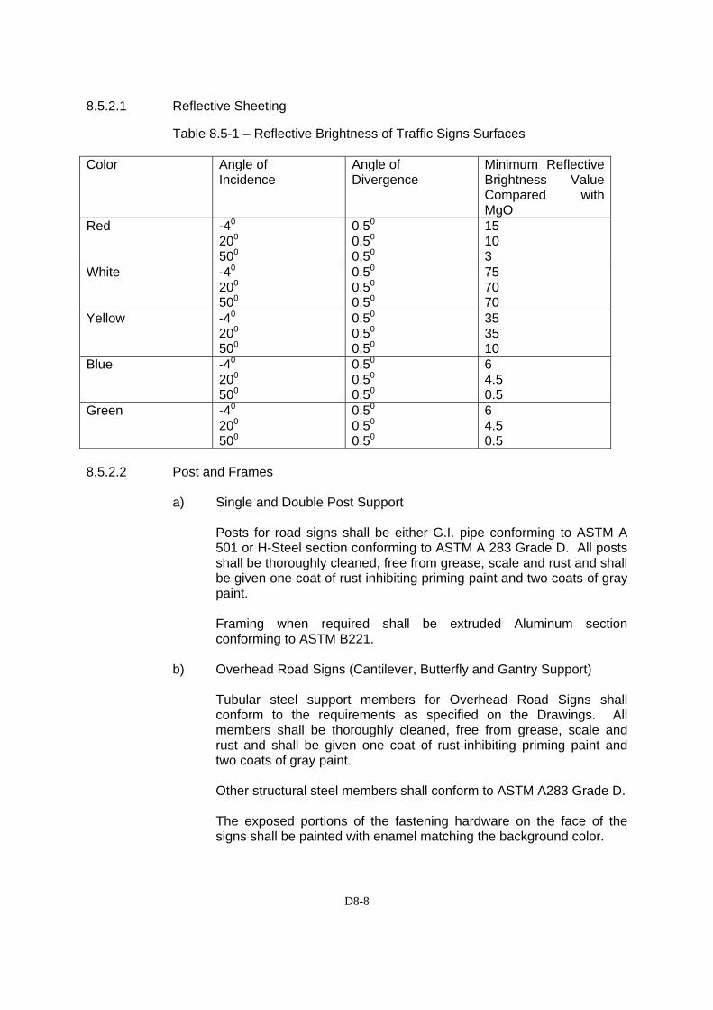
D8-8
8.5.2.1 Reflective Sheeting
Table 8.5-1 – Reflective Brightness of Traffic Signs Surfaces Color Angle of
Incidence Angle of Divergence
Minimum Reflective Brightness Value Compared with MgO
Red -40 200 500
0.50 0.50 0.50
15 10 3
White -40 200 500
0.50 0.50 0.50
75 70 70
Yellow -40 200 500
0.50 0.50 0.50
35 35 10
Blue -40 200 500
0.50 0.50 0.50
6 4.5 0.5
Green -40 200 500
0.50 0.50 0.50
6 4.5 0.5
8.5.2.2 Post and Frames
a) Single and Double Post Support
Posts for road signs shall be either G.I. pipe conforming to ASTM A 501 or H-Steel section conforming to ASTM A 283 Grade D. All posts shall be thoroughly cleaned, free from grease, scale and rust and shall be given one coat of rust inhibiting priming paint and two coats of gray paint. Framing when required shall be extruded Aluminum section conforming to ASTM B221.
b) Overhead Road Signs (Cantilever, Butterfly and Gantry Support)
Tubular steel support members for Overhead Road Signs shall conform to the requirements as specified on the Drawings. All members shall be thoroughly cleaned, free from grease, scale and rust and shall be given one coat of rust-inhibiting priming paint and two coats of gray paint. Other structural steel members shall conform to ASTM A283 Grade D. The exposed portions of the fastening hardware on the face of the signs shall be painted with enamel matching the background color.
D8-9
8.5.3 Construction
(a) The types and locations of all overhead signs shall be as shown on the Drawings or will be established by the Engineer before commencement of this work. When fixing the above, the Engineer will also instruct the lettering to be used on each sign.
(b) All details given in Section 8.4 regarding the fabrication and
installation of signs and poles shall also be applied to overhead signs. Foundation details shall be as shown on the Drawings.
(c) The signs and light units shall be carefully handled so as to avoid
damage, and the Contractor shall repair or replace these at his own expense in the event of any damage.
8.5.4 Method of Measurement
The quantities to be paid for shall be the actual number of overhead signs furnished, placed and accepted in accordance with the Drawings, and as directed by the Engineer. Payment will be made for each type of overhead sign as described in the Drawings.
8.5.5 Basis of Payment
The work measured as provided above shall be paid for at the Contract unit price for each type of overhead sign as listed below.
The prices and payment shall be full compensation for furnishing and placing all materials including signs lettered in accordance with the Engineer’s instructions, pole(s), jointing, for all sundry materials, for foundations, for all excavation, backfill and reinstatement, including labour, equipment, tools and incidentals necessary to complete the work. Pay Item No. Description Unit of Measurement 8.5(17) Overhead Sign, Type A Each 8.5(18) Overhead Sign, Type B Each 8.5(19) Overhead Sign, Type C Each
D8-10
SECTION 8.6(6) - REFLECTORIZED THERMOPLASTIC PAVEMENT MARKINGS 8.6(6).1 Description This standard specifies the requirement for reflectorized thermoplastic
pavement striping materials that is applied to the road surface in a molten state by mechanical means with surface application of glass beads at a rate not less than 350g/L of glass beads having a size range of drop-in type and will produce an adherent reflectorized stripe of specified thickness and width capable or resisting deformation by traffic.
8.6(6).2 Materials
1) Reflectorized thermoplastic pavement material shall be homogenously composed of pigment, filler, resins and glass reflectorizing spheres.
The thermoplastic material shall be available to both white and yellow.
2) Glass beads (pre-mix) shall be uncoated and shall comply with the following requirements:
Refractive index, min. : 1.50 Spheres, Percent, min. : 90 Gradation Sieve Mass percent passing (mm) 0.850 : 100 0.600 : 75-95 0.425 : - 0.300 : 15 – 35 0.180 : -
0.150 : 0 - 5 8.6(6).3 Construction Requirements 8.6(6).3.1 Preparation of Road Surface
The materials should be applied only on the surface which is clean and dry. It shall not be laid into loose detritus, mud or similar extraneous matter, or over an old paint marking, or over an old thermoplastic marking which is faulty. In the case of smooth, polished surface stones such as smooth concrete, old asphalt surfacing with smooth polished surface stones and/or where the method of application of the manufacturer of the thermoplastic materials shall be recommended the application of materials shall be with the approval of the Engineer.
D8-11
8.6(6).3.2 Preparation of Thermoplastic Materials
The materials shall be melted in accordance with the manufacturer’s instruction in a heater fitted with a mechanical stirrer to give a smooth consistency to the thermoplastic and such that the local overheating shall be avoided. The temperature of the mass shall be within the range specified by the manufacturer and shall on no account be allowed to exceed the maximum temperature stated by the manufacturer. The molten material shall be used as expeditiously as possible and for thermoplastics which have natural resin binders or otherwise sensitive to prolong heating the materials shall not be maintained in a molten condition for more than 4 hours.
8.6(6).4 Laying
Center lines, lane lines and edges shall be applied by approved mechanical means and shall be laid to regular alignment. Other markings may be applied by hand-screed, hand propelled machine or by self-propelled machine approved or directed by the Engineer. After transfer to the laying apparatus the materials shall be maintained within the temperature range specified by the manufacturer and stirred to maintain the right consistency for laying. In the case of screen application the material shall be laid to a thickness of not less than 3mm (approx. 1/8 inch) or more than 6mm (1/4 inch) unless specifically authorized by the Engineer when laid over an existing marking. In the case of sprayed application the material shall be laid to the thickness of not less than 1.5 mm unless specifically authorized by the Engineer. In all cases the surface produced shall be uniform and appreciably free from bubbles and streaks. Where the Contract Documents require or the Engineer directs that ballotini shall be applied to the surface of the markings, these shall be applied uniformly to the surface of hot thermoplastic immediately after laying such that the quality of ballotini firmly embedded and retained in the surface after completion. Road markings of a repetitive nature, other center lines, lane lines, etc. shall unless otherwise directed by the Engineer be set out with stencils which comply with the size and spacing requirements shown on the Drawings.
8.6(6).5 Re-use of Thermoplastic Materials
At the end of the day as much as possible, the remaining material in the heater and/or laying apparatus shall be removed. This may be broken and used again provided that the maximum heating temperature has not been exceeded and such re-using of material shall be approved by the Engineer.
8.6(6).6 Defective Materials or Workmanship
Materials which are defective shall be replaced by a new one, to the satisfaction and approval of the Engineer. If in case pavement marking has been applied in an unsatisfactory manner or in incorrect dimensions or in a wrong location, it shall be removed immediately and shall be corrected by the Contractor at his own expense. The road pavement shall be made good to the satisfaction and approval of the Engineer.
D8-12
8.6(6).7 Method of Measurement
The quantity of pavement markings to be paid for shall be area as shown on the Drawings of symbols, lettering, hatching and the like, completed and accepted.
8.6(6).8 Basis of Payment
The quantities measured as determined in Sub-clause 8.6(6).7, Method of Measurement, shall be paid for at the appropriate contract unit price for the Pay Items shown in the Bill of Quantities which price and payment shall constitute full compensation for furnishing and placing all materials, sampling and packing, for the preparation of the surface, and for all labor, equipment, tools and incidentals necessary to complete the Item.
Payment will be made under: Pay Item
Number Description Unit of Measurement
8.6(6) Reflectorized Thermoplastic
Pavement Marking
Square Metre

D8-13
SECTION 8.8 – PRECAST CONCRETE CURB
8.8.1 Description
This work shall consist of the construction of concrete curb of the various shapes and at the locations as shown on the Drawings or instructed by the Engineer.
8.8.2 Materials
Curbs may be cast-in-place or precast. The concrete for reinforced or precast curbs shall be Class C and any base or foundation shall be of concrete Class E blinding stone as shown on the Drawings. All concrete shall meet the requirements of Section 7.1 of the Specifications.
Preformed expansion joint fillers for curb joints shall consist of a bituminous mastic composition, formed and encased between two layers of bituminous felt, all in conformity with AASHTO M-33.
8.8.3 Construction Requirements
The construction requirements shall conform to Section 7.1 for concrete structures. Maximum joint spacing shall be 10 m before placing the exposed section of the curb all lines and levels shall be checked by the Engineer. Any junction between the concrete base and the Class C concrete shall be prepared and treated as a construction joint in accordance with Section 7.1 of these Specifications.
When at driveway entrance crossings or for other reasons, a transition section of curb is indicated on the Drawings or ordered by the Engineer, The Contractor shall furnish concrete curbs with the required modification.
Precast curbs shall be cast in mortar-tight metal moulds sufficiently rigid to prevent any delimitation of the curb. The precast curbs shall be removed from the moulds as soon as practicable and shall be kept damp for a period or at least 7 days. During this period they shall be protected from the sun and wind. Any curbs that show cracking or soft or damaged corners or surfaces shall be rejected.
Curbs shall be carefully handled, transported and off-loaded so as to avoid damage. Any curbs which become chipped, marred or cracked before or during placing shall be rejected.
Bedding and joint mortar for precast curbs shall comply with the requirements of the applicable specifications
Curb construction shall be carried out in accordance with the tolerances given in the Special Specifications.
On completion of curb the Contractor shall backfill and tidy up the work to the satisfaction of the Engineer.
The precast curbs shall be painted to surface of concrete based on local government specification. The Contractor shall submit specification of painting material to the Engineer for approval
D8-14
8.8.4 Method of Measurement
Concrete curb of the types as shown on the Drawings will be measured by the Linear meter along the face of the curb.
No additional allowance will be made for curbs constructed on curves. No deduction in length will be made for drainage structures installed in the curb section, but payment for these structures will be deemed to be full compensation for finishing the structures with painting to the same standard and tolerance as the adjacent curb and for providing expansion joints between the units and the adjacent curbs.
Reinforced concrete curbs provided as an integral part of non- drainage structures will net be measured for payment under this section, but will be dealt with under Section 7.1 of these Specifications.
8.8.5 Basis of Payment
The accepted quantities of concrete curbs determined as provided above, will be paid for at the contract unit price per linear meter of curbing completed in place. This price and payment shall be full compensation for the work on the types of curb as Shown in the Drawings, including excavation in any material, provision of base of foundation, expansion joint material, bedding, jointing of precast curbs, backfill and disposal or all surplus material, and all other materials, labour or equipment necessary to complete the work.
Pay Item No. Description Unit of Measurement
8.8.(1) Precast Concrete Curb, Type A Each
8.8.(2) Precast Concrete Curb, Type B Each

D8-15
SECTION 8.9(1) – CONCRETE MEDIAN 8.9(1).1 Description
This work shall consist of concrete median constructed and erected in close conformity with the dimensions, lines, grades design shown on the Drawings, or established by the Engineer in accordance with this and other specification items involved. It shall include the manufacture, transportation, and storage or precast concrete units, cast-in-situ concrete unit and railing members.
8.9(1).2 Materials
(a) General
All materials to be furnished and used which are not covered in this section shall conform to the requirements stipulated in other applicable Clauses.
(b) Reinforcement
Reinforcement steel bars shall conform to Section 7.3 of these Specifications.
(c) Concrete
Concrete shall conform to the requirements of Class B -1 concrete as in Section 7.1 of these Specifications and to the requirements specified below unless otherwise stated in the Drawings. The Contractor shall develop his own mix designs in compliance with Section 7.1 of these Specifications.
(d) Grout
Grout shall consist of Portland cement, potable water and retarder admixture approved by the Engineer. No admixture containing chlorides or nitrates shall be used. The Contractor shall submit the proportions of mixing for approval of the Engineer. The grout shall be mixed by mechanical mixing equipment of a type that will produce uniform and thoroughly mixed grout. Water shall be first added to the mixer followed by cement and admixture.
(e) Railing
Railing shall conform to the requirements of Section 7.13 of these Specifications and as shown on the Drawings.
D8-16
(f) Expansion Joint Filler
Expansion joint filler shall conform to the requirement of AASHTO M 33.
8.9(1).3 Equipment and Tools
Equipment and tools necessary for handling materials and performing the work shall be satisfactory to the Engineer as to design, capacity, mechanical condition and shall be at the site of the work before work is started. If any equipment as used by the Contractor proves inadequate to obtain the results prescribed, such equipment shall be improved or other satisfactory equipment substituted or added at the direction of the Engineer. (a) Concrete Batching Plant and Equipment
Concrete batching plant and equipment, concrete mixers, vibrators, tools and transportation shall conform to Section 7.1 of these Specifications.
(b) Forms
Forms shall be made or metal conforming to the shape, lines and dimensions of the members shown on the Drawings and be in accordance with the requirements of Section 7.1 of these Specifications. The number of forms to be provided by the Contractor shall be adequate for the casting schedule which shall be submitted by the Contractor for the Engineer's and approval. In the event that the rate of casting cannot maintain the approved schedule output, the Contractor shall provide additional forms, in such numbers as may be directed by the Engineer. Forms that deteriorate from reuse shall be replaced by the Contractor with new forms if so directed by the Engineer. Unless otherwise approved by the Engineer the form shall be so designed that the concrete median is cast in an inverted position.
8.9(1).4 Construction
(a) Precasting (In case of precast concrete units)
Concrete median shall be constructed using precast members manufactured in a casting yard of sufficient size, provided by the Contractor. The Contractor shall provide a casting yard superintendent having the necessary technical expertise and experience to supervise the work on a full time basis The Contractor shall prepare, check and submit to the Engineer complete Working Drawings and Schedules, showing:
D8-17
i) Details of the various precast units to be manufactured ii) Contractor's alternative designs if the submission of
alternatives is approved; iii) Details of forms: iv) Contractors details of proposed manufacture and construction: v) Sequence of operations proposed: and vi) Production schedule in relation to Construction Schedule and
Contract Period.
The Contractor shall not cast concrete prior to the Engineer's approval of the Contractor's Drawings and Schedules, the concrete mixture, formwork, sequence of operations, method of placing, curing, protecting, handling and erecting members. Any alternative to the design in the contract document shall be subject to the Engineer's approval before manufacture or construction. After all stipulated necessary approvals have been given the Contractor shall inform the Engineer, not less than three working days in advance, of the probable date of commencement of manufacture.
(b) Form Setting
Forms shall be erected, set, braced and supported in a manner satisfactory to the Engineer with the inverted base of the form truly level both longitudinally and transversely.
(c) Placing Steel
All reinforcing steel shall be accurately placed in the position shown on the Drawings and rigidly held during placing and setting of concrete. Distances from the forms shall be maintained by stay blocks, ties, hangers, or other approved support. The use of precast mortar blocks for holding units from contact with the forms is not recommended, and approval for their use will only be given if their design and dimensions are such that the contact area with the forms is minimal. The use of wooden blocks is prohibited.
(d) Placing Concrete Concrete shall be placed in accordance with the requirements of, Section 7.1 of these Specifications.
(e) Finishing Concrete
Immediately after placing concrete the upper exposed surface shall be struck off true to the forms and hand finished using wooden floats. On completion of floating all units cast shall be checked by means of a straight edge to ensure that no high spots exist.
D8-18
(f) Curing Concrete
Curing shall commence immediately on finishing operations and shall comply with the requirement Section 7.1 of these Specifications, Water curing shall be continuous for at least 7 days.
(g) Form Removal
Forms shall not be removal mail at least 2.1 hours alter finishing of the concrete.
(h) Surface Finish
The units east shall have a finish in accordance with Section 7.1 of these Specifications.
(i) Storage of Units
Units shall not be moved until the concrete has attained at least 70% of the specified minimum compressive strength. Unit shall be stored clear of the ground Stacking of units shall be permitted provided it is limited in double stacking but no concrete to concrete contact shall be permitted.
8.9(1).5 Erecting (In case of precast concrete units)
(a) Equipment
Unit shall be double slung from a gantry or crane of adequate capacity to facilitate case of handling and correct positioning. Lifting devices shall not damage or mark the concrete.
(b) Bedding
Cement grout bedding shall be spread to the thickness shown on the Drawings. The spreading of grout shall not be made far in advance or median placing as the grout shall still be plastic at the time of placing the barrier unit. Grout squeezed out from under the barrier shall be removed
(c) Alignment
The barrier shall be erected to the correct alignment following and providing the correct smooth curvature.
D8-19
(d) Railing
Railing shall be installed and constructed in accordance with Section 7.13 of these Specifications.
8.9(1).6 Method of Measurement
The quantity of concrete median to be measured for payment shall be the actual number of linear meters of precast or cast-in-situ concrete members, including reinforcement, asphaltic joint filler, and all fixings and attachments installed in place, completed and accepted. The length of any special units of non-standard dimensions shall be measured and used for calculative payment Concrete median shall include forming holes for bolts in concrete, bolting complete and making good concrete. Transaction blocks, lean concrete foundation and infill concrete foundation and infill concrete between the median and curb shall not be measured for payment. The work will be considered as subsidiary obligation of the Contractor under this section.
8.9(1).7 Basis of Payment
The work measured as provided above shall be paid for at the Contract unit price for the items listed below which appear in the Bill of Quantities. The prices and payment shall be full compensation for furnishing and placing all materials including all tools, equipment and incidentals necessary to complete the work prescribed this Section. Pay item No. Description Unit of Measurement
8.9(2) Concrete Median, Type A Linear meter 8.9(3) Concrete Median, Type B Linear meter

D8-20
SECTION 8.9 – CONCRETE SIDEWALK 8.9.1 Description
This work shall consist of construction of Portland cement concrete sidewalk in accordance with the specification and to the lines, grades, levels and dimensions shown on the drawings, or as required by the Engineer.
8.9.2 Materials
(a) Portland Cement Concrete
The concrete shall be class B-1 as specified Section 7.1 of these Specifications
(b) Expansion Joint Filler
Unless otherwise ordered, the preformed joint filler shall have a thickness of 5mm and shall conform to the requirements of Section 7.16(2), Rigid Pavement.
(c) Forms
Forms shall be of wood or metal as approved by the Engineer and shall extend to the full depth of the concrete. Al forms shall be straight, free form warps and adequate strength to resist distortion.
(d) Bed Course Materials
Bed course materials shall consist of cinders, sand, slag, gravel, crushed stone or other approved permeable granular materials of such grading that all particles shall pass a 12.5mm sieve.
8.9.3 Construction Requirements
Excavation shall be made to the depth and width required that will permit the installation and bracing of the forms. The foundation shall be shaped and compacted to a firm and even surface conforming to the section shown on the drawings.
All forms shall be staked securely in position at the correct line and level. Preformed filler shall be set in a position shown on the drawings before placing of concrete is started. The top of the joint filler shall be placed 5mm below the top surface of the finished sidewalk.
The mixing, placing, finishing and curing of concrete shall be as specified in Section 7.1 of these Specifications. The Portland cement concrete shall be placed to the total depth shown on the plans.
The surface shall be cut through to a depth of 10mm with trowel at intervals of 1m or were required, in straight lines perpendicular to the edge of the sidewalk.
The edges of the sidewalk and the traverse cuts shall be shaped with a suitable tool so formed as to round the edges to a radius of 15mm.
D8-21
8.9.4 Method of Measurement
The area to be paid for shall be the number of square meters of sidewalk measured, completed in place and accepted.
8.9.5 Basis of Payment
The quantity as determined above, shall be paid for all the contract unit price per square meter for sidewalk which price and payment shall constitute full compensation for furnishing and placing materials for concrete sidewalk, expansion joint material, for excavating and compacting the foundation bed, for furnishing and placing cinders, gravel or other permeable bed course materials, for forms, and for all labour, equipment, tools and incidentals necessary to complete the work under this Section\
Pay Item No. Description Unit of Measurement
8.9(5) Concrete Sidewalk Square meter
D9-1
DIVISION 9 - FACILITIES
SSEECCTTIIOONN 99..11 –– SSTTRREEEETT LLIIGGHHTTIINNGG,, PPAANNEELL,, TTRRAAFFFFIICC SSIIGGNNAALL
9.1.1 General
(a) This work shall consist of furnishing and installing all materials and equipment necessary to complete in place signals. highway lighting, and other electrical systems, and the modification of such existing systems when so specified, all in accordance with the Drawings, these Specifications, or as instructed by the Engineer.
(b) The location of signals, controllers, poles and appurtenances shown on the Drawings are approximate and the exact location will be established by the Engineer in the field.
(c) The electrical works for Guide Signs shall be executed in accordance with this Section. Payment under this Section for Guide Sign Cables will terminate at the junction board in the hand hole of the pole.
9.1.2 Scope of Work
The scope of work shall cover the supply, delivery to site, erection, test and commissioning of all material and equipment in connection with the Electrical Installation to the extend described and shown on the Drawings and includes but is not necessary limited to :
(a) Preparation and submission of Shop Drawings (b) Submission of detailed Material Supply Lists (c) All work associated with the removal of sections of the existing
systems and the incorporation of the remaining sections in the permanent works.
(d) Site measurements of ambient brightness of natural daylight at tunnel sections to assist the Engineer in his review of the lighting details shown on the Bidding Drawings.
(e) All other electrical equipment and services needed to complete a usable and operable facility in accordance with the pertinent electric codes and local regulations for Electrical Installation.
9.1.3 Quality assurance
(a) For the actual fabrication, installation, and testing of the work described in this Section, the Contractor shall use only thoroughly trained and experienced personnel who are completely familiar with the requirements for this work and with the installation recommendations of the manufactures of the specified items.
D9-2
- In acceptance or rejection of the installed electrical system.
no allowance will be made for lack of skill on the part of installers.
- Installers shall hold the relevant valid certificates complying with PLN and LOCAL GOVERMENT Jakarta Regulations.
(b) All work shall comply with the Drawings and this Specification, in addition to complying with the following codes and regulations:
- Requirements of local PLN exploitation units and local government authority;
- PULL, SPLN and local government standards
9.1.4 Drawings and Documents
(a) The Contractor shall refer to all relevant drawings to ascertain for
himself the location and routes of all other utility services so as to maintain adequate clearance between electrical and other services. The supplied drawings are to indicate generally the arrangement of the work. The Contractor is therefore required to provide working drawings showing the exact routes of all underground or overhead cables and ducts, the exact run off all conduits and trunking, the location of manholes, draw-in and junction boxes, the number and size of wires in each conduit or trunking. the final connection arrangements at street lighting panels, the detail of ducts and the method of fixing street lighting panels for the approval of the Engineer before commencing any portion of the works. All such working drawings shall be submitted in duplicate and within the periods stipulated below:
(i) Details of ducts and method of fixing street lighting panels
and entry into buildings: Working drawings shall be submitted within two months of handing over the site to the Contractor.
(ii) All other working drawings shall be submitted within a period of one month from the date of approval of the street lighting panels by the Engineer.
(iii) Should however the Contractor be obliged to install electrical conduits prior to this period then he shall submit the relevant working drawings at least four weeks prior to the proposed date for commencement of the work.
(iv) The Contractor shall submit a programme indicating the
dates on which concreting in different sections will take place, together with the submission of the working drawings.
D9-3
(b) On completion of testing, the Contractor shall make "as built”
drawings of plans and circuit diagrams, which clearly indicate any modifications which have been made to the original design.
(c) Upon completion of the work, as a condition of its acceptance, the Contractor shall supply to the Engineer three copies of a Manual for the maintenance and operation of all electrical installations and a parts list sufficient for the ordering of parts.
9.1.5 Standards and Regulations
(a) The work covered by this Contract shall be carried out in accordance with the regulations issued by the local Electricity Authority and with the applicable standards and codes of any of the following:
JIS : Japanese Industrial Standard JEC : Japanese Electrical Committee ICE : Institute of Electrical Engineers ASA : American Standards Association
ASTM : American Society for Testing Materials DIN : German Industry Standard
(Deutsche Industrie Normen) IEA : International Electrical Association NEC : National Electrical Code (U.S.A) NECA : National Electrical Contractors "Standard of Installation". (USA)
UL : Underwriters Laboratories, Inc. PIN : Indonesia Government Electric Company
(b) Before submitting his Bid, the Contractor must carefully examine at his own expense all of the Regulations issued by the local Electricity Authority and selected materials and method of installation shall be in accordance with these Regulations.
The Contractor shall include in his unit price for any changes or
modification of contract documents to ensure conformance with local regulation.
9.1.6 Lighting
(a) Lighting units as shown on the Drawings shall consists of lighting lanterns (lanterns), lamps, electrical control ballasts (ballasts), and mounting accessories.
The Contractor shall submit for approval, detailed street lighting panel diagrams for each type of lantern he proposes to install. Furthermore, calculations shall be submitted showing the horizontal illuminance in lux at roadway level and the luminance
D9-4
distribution in candela per sq.m for every 2 m in roadway direction and every 1.2 m across the roadway.
(b) Street Lighting Units (Pole Mounted)
Lamps for road lighting system shall be 180 watts low-pressure sodium type. For the arterial roads lamps shall be 400 watts high pressure sodium type.
All lanterns shall be of the type shown on the Drawings or equivalent as approved by the Engineer.
(c) Lighting Units for Under Bridges Lighting units Fixed to the ceiling/wall under Bridges or inside
Tunnels (Box Culverts) shall have 150 watts low-pressure sodium type lamps.
The layout of tunnel lighting units shown on the Drawings is
based on the estimated ambient brightness of natural daylight at the tunnel entrance. On completion of the box culvert and substantial pavement works, the Contractor shall undertake site measurements to check the actual ambient brightness. Based on these results, the Engineer may revise the layout of lighting units as shown on the Drawings.
Lanterns shall be surface mounted type with symmetrical light distribution and of the type shown on the Drawings or equivalent as approved by the Engineer.
(d) High Mast Lighting Units
The lanterns shall be floodlight type and shall be mounted on a high mast carrying 400 watts high pressure sodium lamps. The lantern shall comprise three main parts; a low-pressure die-cast aluminum housing; a toughened front glass, attached to the housing by two hinges and four clips of stainless steel; and a hot dip galvanized mounting bracket. The lantern shall be fitted with an asymmetrical optical system of special design, made of high purity aluminum which has been chemically polished and anodized.
The lantern shall incorporate a splash and dustproof type sealing
between the housing and the glass front cover. All exposed metal parts shall be made of non-corrosive materials. In its basic mounting position with the glass front cover in an absolute horizontal position the flood-light shall keep all distributed light below the horizontal plane, providing a cut-off light distribution with perfect glare limitation in accordance with C.I.E. recommendations. (C.I.E.: Commission International de 1' Éclair age).
D9-5
(e) Ballasts for Low Pressure Sodium Lamp
Ballasts for low pressure sodium lamps shall be designated to properly operate the lamps of the wattage as designated in the Drawings. Ballasts shall have the electrical characteristics of the high power factor type with voltage ratings as noted on the Drawings. The ballasts shall be remotely mounted and shall be set on the junction board located in the hand-hole of the lighting pole. Each ballast shall have a name plate permanently attached to the case listing all electrical data.
(f) Ballasts for High Pressure Sodium Lamp
Ballasts for high pressure sodium lamps shall be designed to properly operate the lamps of the wattage as designated in the Drawings. All ballasts shall be drip-proof, canned, polyester-filled and shall be equipped with terminal blocks for the electrical connections. Instructions for making the electrical connection shall be printed clearly on the can of the ballast. The power factor of a lamp combination shall have a higher value than 0.85 and shall be achieved by connecting parallel capacitors with sufficient capacitance across the mains. The capacitors used for the purpose shall be suitable to operate at a normal voltage of at least 220 V 50 Hz.
(g) Ballasts for high-Pressure Mercury Lamp Ballasts for high-pressure mercury lamps shall be designated to properly operate the lamps of the wattage as detailed in the Drawings. All ballasts shall be drip-proof nylon encapsulated orthocyclically wound units, of low power loss and rugged mechanical and electrical construction. The ballasts shall be equipped with terminal blocks for electrical connections. Instructions of the electrical connection shall have a name plate permanently attached to the case, listing all electrical data.
9.1.7 Lighting Panels
(a) General
The lighting panels shall be included as feeders of the power source fed to the circuits of the street and tunnel lighting, traffic
D9-6
signals and the guide signs. The panels shall be as shown on the Drawings or equivalent as approved by the Engineer. The panels shall be ventilated and shall be substantial, tree-standing structures on a concrete foundation a minimum of 40 cm above ground level. Panel house roofs shall be double pitched, the apex being central to the panel. The panel and door shall be made from fully-finished steel sheet not less than 3.2 millimeters in thickness with the necessary steel frames. The welding for all outside joints shall be smooth finished. The panel shall have a bottom design that will permit tack welding to channels that shall be set on the raised concrete foundation as shown on the Drawings. The panel shall be completely assembled and wired at the factory. Main and small wiring shall be easily accessible for maintenance and inspection, and small wiring shall be effectively isolated from the main wiring. The wiring diagram engraved or etched on an aluminum plate, shall be permanently fixed to the inner door of the panel. Each panel shall have one or more nameplates for identification. Nameplates shall be made of laminated plastic with white characters to show through a black top layer when cut or engraved.- Panel housings shall be fitted with a LOCAL GOVERNMENT/PLN master lock.
(b) Components of Lighting Panels
All lighting panels shall be as shown on the Drawings. The components shall be designed for 3-phase 4-wire, 50 Hertz operation at 380/220 volts.
The components shall be in accordance with the following items: (c) Circuit Breakers
The circuit breakers shall be moulded case, air break type, rated for 600-volt A.C. service. The circuit breakers shall have 3-poles unless otherwise noted.
The circuit breakers shall provide inverse time tripping for overloads and instantaneous action and overload ten times the normal rating. The circuit breakers shall be arc resisting contact type and be provided with trip-free lever handles and arc quenchers.
D9-7
The circuit breakers' interrupting capacity shall be 16,000 amperes based on IIS C 8370 standard duty cycles, except that breakers larger than 225 amperes shall have 25,000 amperes interrupting capacity, or as approved by the Engineer. The breakers for the main power feeders shall be provided with auxiliary contact that will close when the breaker is closed and 380 volts shunt trip coil. They shall be wired to prevent either breaker being closed while the other is closed.
(d) Knife Switch
Knife-switches shall have 3-blades and 200 amperes capacity based on ES C 8308, or as approved by the Engineer.
(e) Control Equipment
Multiple lighting circuits shall be controlled by timer switches.
(f) Timer Switch
Timer switch units shall have two control elements, one of which shall be for "on" control at evening and "off' at early morning, and the other which shall be for reduced cut-rent control at midnight for saving energy, all as shown on the Drawings. Both "on" and "off" time setting shall be available for any of the 24 hours, and the minimum setting increment shall be one minute. Timer switch shall be operated on 220 volts, 50 Hz. Timer switches installed in the street lighting panels shall have an emergency driving device for 48 hours or more when the incoming power source fails. M.B. panels and tunnel lighting panels shall be fitted with a manual switch-over circuit to by-pass the timing switch.
(g) Control Equipment for Tunnel Lighting
Additional control equipment for tunnel lighting panels comprises auto controller and photo sensor. The former is to be attached to the tunnel lighting panel and the latter is to be installed at the entrance of the tunnel. The auto controller shall be a panel mounted type provided with a built-in timer switch, display lamps, power switch and change-over switches for automatic or manual control. Power source requirement shall be AC 1 phase 220 V + 10% 50 Hz and 40 VA at maximum.

D9-8
Setting of timer for basic lighting shall be 100% turn on between 06:00 hours and 24:00 hours and 50% turn on between 24:00 hours and 06:00 hours. The timer switch shall have an emergency driving device for 48 hours or more when the incoming power source fails. The entrance zone lighting which shall be controlled by the photo sensor shall be arranged in two sets as follows :
− First set of entrance zone lights turns on at 5,000 lux of outside luminance;
− First set of entrance zone lights turns off at 2,500 lux of outside luminance;
− Second set of entrance zone lights turns on at 10,000 lux of outside luminance;
− Second set of entrance zone lights turns off at 5,000 lux of outside luminance.
The photo sensor shall consist of a light receiving window and cadmium sulphate detecting device and relay unit.
9.1.8 Poles and Masts
(a) Lighting Poles
Lighting poles shall be galvanized steel, in accordance with the details shown on the Drawings, as outlined herein. The Contractor may propose the use of spun prestressed concrete lighting poles as an alternative to the galvanized steel poles for the Engineer's approval construction drawings of the lighting poles, method of handling and transportation, erection and details of how the poles are fixed in the ground. All relevant clauses for steel lighting poles shall be applicable to spun prestressed concrete poles.
All materials shall be in natural colour and shall not be painted or coated with any other material. All pole items shall be galvanized steel and all hardware shall be galvanized steel. Scratches, marks, dents or other damages to poles and fittings will be cause for rejection. Any marks or stains resulting from wrapping materials shall be removed.
All poles and arms shall be individually spiral wrapped and, in addition, shall be packed for shipping in groups with suitable form fitting wood dunnage between all poles and completely around each group at a minimum of 4 locations, and held with suitable metal strapping. Arms shall be wrapped, packed and shipped to the job site with a minimum of reloading between points of origin
D9-9
and destination. Packing not in conformance with this provision shall be cause for rejection of poles and/or arms. All loading and unloading of poles and arms shall be under the supervision of the manufacturer and/or Contractor. All miscellaneous pole line hardware required to complete the project shall be standard material manufactured for pole line construction. All metal parts shall be hot dip galvanized. All poles supplied shall be of the anchor base type, and shall have a cast steel anchor base fitted over the shaft and secured with two circumferential welds.
The handhole and cover plate for the terminal connection shall be 2.0 meters above ground level. Identification plates shall be attached to each lighting pole.
For the Arterial Street only, each lighting pole shall be fitted with a standard Local Government "computer" identification plate.
(b) Foundations
Concrete for foundations for lighting poles and pedestals of cabinets shall be of Class C or as shown on the Drawings. All details of concrete and reinforcement for foundations shall conform to the applicable requirements of Division 7.
(c) High Masts
(i) The masts shall be made of steel folded in conical sections, automatically welded in one longitudinal seam. The sections shall be telescopic jointed or by means of bolts. If bolted joints are used, flanges shall not disturb the aesthetics of the silhouette of the mast and should preferably be positioned inside the mast. The steel parts of the mast shall be hot dip galvanized over their entire surface in accordance with the requirements of these Specifications. After installation of the mast, all exposed anchor bolts and securing nuts on the foundation shall be given one coat of an approved bituminous paint. All scratches and other damage of the finish occurring during transport or installation works shall be thoroughly cleaned and touched up.
(ii) The masts shall be bolted on a reinforced concrete foundation by means of steel bolts and nuts of adequate diameter and quantity. The foundation shall be made of concrete and rolled steel bars in accordance with the applicable requirements of Division 7.
The Contractor shall submit for the Engineer's approval, construction drawings of the foundations and calculations showing that the foundation and the anchor bolts will not move. Anchor bolts shall conform to the specifications of JIS B 1180 and B 1181 or equal, and each shall be
D9-10
provided with 2 nuts and 2 washers. Anchor bolts, nuts and washers shall be galvanized over their entire surface. The masts shall have a lockable access door at ground level.
(iii) The lamp accessories such as fuses, ballasts, ignitors and capacitors shall be mounted on a suitable frame and installed inside the mast at ground level. Provisions shall be made that no moisture, either from condensation or from entering rain water, will drip on the lamp accessories. Rising cables from the accessories to the lamps shall be bunched and fixed in the mast. Near the accessory frame inside the mast an earth terminal of at least M10 diameter shall be provided, directly welded to the mast. At the top of the mast a head frame shall be provided suitable to receive the lighting fittings in quantities and directions as shown on the drawings.
(iv) The mast shall have a harmonious silhouette and the Contractor shall submit for approval, full information on the shape and detailed dimensions of the proposed masts.
(v) Before manufacturing the masts, the Contractor shall provide calculations and obtain the Engineer's approval for detailed construction drawings of the mast. The calculations shall cover the complete structure, including head frame and lanterns, and shall show that:
- No parts of the assembly are submitted to stresses above acceptable limits;
- The deflection caused by dynamic forces does not exceed acceptable limits; and
- Calculation is in accordance with JIL-1001- 1962. (JIL: Japan Lighting Fixtures and Equipment Industry Association)
(d) Mobile Equipment for Floodlight Masts
(i) Mobile equipment shall consist of head frame assembly, mobile floodlight carriage, hoisting device, and electrical equipment.
(ii) Each mast will be provided with a mechanism which shall have three locks at the top of the structure capable of supporting a mobile floodlight suspension, etc., when the raising cables are slack. Head frame assemblies shall be fitted at the top of the mast, and one carriage for supporting a maximum of six floodlights shall be provided.
D9-11
(iii) Each mast structure shall be complete with three hoisting
cables, a six conductor minimum 10 mm2 electrical cable, circuit breaker box and hoist with removable common drive. The electrical cable shall be disconnected from the circuit breaker box and securely attached to the lowering cable when the floodlights are lowered. The electric cables shall be split within the flood-light carriage with a 5 ampere in-line fuse installed in each floodlight ballast supply line.
(iv) The head frame assembly shall be covered by a
removable cover and the carriage ring shall be supplied in semi-circles to facilitate shipping, mounting or dismounting after the High Mast pole has been erected.
(v) The ring shall be supplied with means of supporting six
floodlights equally spaced around the ring, and a plug to match the six pole socket outlet in the base shall be installed in the main power feeder for testing purposes when the ring is in the lower position.
(vi) Guides shall be provided on the head frame sleeve, to
ensure correct alignment of the carriage to the locking mechanism in the raised position. Rollers shall be provided on the inside of the carriage to aid in the final alignment of the carriage in the raising operation. The carriage shall be equipped with indicating flags to confirm that the carriage is in the fully locked position. This flag shall be clearly discernible from ground level.
The locking mechanisms shall be located at a maximum of 120 degrees to each other on the head frame assembly and shall be able to support the carriage, lanterns and ballast in the fully locked position. The hoisting cables shall not be under tension when the carriage is in the raised and locked position.
(vii) A winch shall be provided in the base of each mast shaft,
for raising and lowering the carriage by means of flexible steel hoisting cables. The winch shall be of the worm and gear type, having a gear ratio that will allow easy raising and lowering and prevent the free fall of the carriage in the event of an accidental release of the winch handle. A winch handle shall be provided for hand operation of the winch in an emergency.
(vi) A hinged door cover shall be provided over the access
opening in the mast shall. The opening shall be of sufficient size to permit the removal from the shaft of the equipment installed therein, for replacement or maintenance. The door shall be provided with facilities

D9-12
for padlocking. The access opening shall be suitably reinforced to ensure that there is no weakening of the structure in this area, also„it shall be ensured that the reinforcing is such that it does not interfere with the operation or access to equipment required therein.
(vii) In addition to the cable hoist, the masts shall be
provided with a grounding stud and nuts, and a code gauge epoxy-painted steel sheet metal box containing :
(a) One three-pole, 20 ampere moulded case circuit breaker (interrupting capacity of 30,000 amperes at 460 volts) for the area lighting luminaires.
(b) One single-pole, 15 ampere as in the above for the security lighting luminaire.
(c) One single-pole, 15 ampere circuit breaker, as in the above, for the lowering device drive outlet.
(d) One six-pole matching plug and socket outlet for the six conductor hanging cable.
(e) One neutral connecting strip to which the neutral circuit from the street lighting panels shown on the drawings and the mast socket outlets shall be connected.
One 265-volt, single phase socket outlet compatible with the lowering device drive plug shall be connected to the circuit breaker in (c) above.
The removable lowering and raising device drive motor (one only supplied) shall include a torque rated clutch with shaft connection for the lowering device drive. Mounting and bracing for the drive motor shall be provided. A water tight connection and control box shall be supplied with the drive motor which shall contain:
• One reversing motor starter with cable and plug to match the socket outlet in the circuit breaker box, plus a six meter length of control cable complete with a water tight reversing push button station.' The latter will allow the operator to stand back out of the possible danger zone during the "raising" and "lowering" of the luminaries mounting ring.
• Before placing an order for the motor, the Contractor shall submit the characteristics of the

D9-13
motor to be used to the Engineer to obtain his approval.
9.1.9 Cable, Grounding, Splices and Conduit
(a) Wiring for Lighting
All cables to be used for roadway lighting shall be of the type and size shown on the Drawings. Cables shall be pulled into a pole through pipes prepared in the foundation of the pole, and shall be connected to the terminals in the terminal box installed in the pole.
All poles shall include an approved miniature circuit breaker rated at IP-10 amperes, 240 volts, installed in the base of each pole and accessible through the hand hole of the pole. The fuse shall protect both pole cables and electrical control ballasts.
Cables installed in the pole shall have two conductors of 2.5 mm as prescribed in "Cable and Wire" herein. Cables shall be adequately attached to the lantern so that lantern terminals shall be free from carrying their weights.
Roadway lighting cables shall be four (4) cored through to the last pole.
(b) Cable and Wire
All cables shall be suitable for operation at the specified voltage in open, duct or conduit, under the condition of the maximum conductor operating temperature which at rated current shall be less than 70 degrees C.
Cable colours shall comply with Indonesian colour code standards.
Cables shall be delivered to the Site on substantial non- returnable wooden drums, each bearing a securely fixed label stating gross weight, serial number, length of cable and other description.
Covers shall be provided around the periphery of the drum in order to protect the cable in transit and the inner cable end shall be adequately protected by a metal guard or other approved means. Both ends of the cable shall be sealed by a suitable method to prevent the entrance of moisture. All cables inside of the lighting pole shall have two conductors per lantern. Cables shall be 600 volts grade "Polyvinyl Chloride Insulated and Sheathed Cable (NYY)" or shall be of the type approved by the Engineer.
D9-14
All cables for the roadway lighting system to be installed underground shall be PVC insulated, Galvanized Flat Steel wire armouring, and PVC sheeting type NYFGbY or equal approved by the Engineer. Conductors shall have a minimum cross-sectional area of 10 mm2 for use in underground installations. All cables to be used shall be tested and approved by Lembaga Masalah Kelistrikan (LMK) or PLN prior to the Engineer's approval.
(c) Grounding Conduit, steel poles and cabinets shall be made mechanically and electrically secure to form a continuous system, and shall be effectively grounded. Bonding and grounding jumpers shall be copper wire of the same cross-sectional area for all systems.
Bonding jumpers shall be used in all non-metallic boxes. Metallic boxes shall employ hubs of double lock nuts and bushes. The bonding of all conduits, lighting poles and panels to form a continuous ground system shall be in accordance with applicable code standards. If directed by the Engineer, each lighting pole shall be individually grounded.
Size of grounding wire shall be minimum of 6 mm2 Bare Copper Conductor (BCC) or as approved by the Engineer.
Ground rods shall be copper 10 dia. x 1,500 millimeter minimum, depth 1.2 meter below finished grade and thermo-welded or connected using connection hardware to the 6 mm2 grounding wire.
The Contractor shall investigate each site and measure the grounding resistance of the sites. After taking the data, the Contractor shall obtain the Engineer's approval before installation.
The grounding resistance shall be 5 ohms or less, or as approved by the Engineer.
Details of all grounding points shall be submitted to the Engineer for approval.
(d) Electrical Splice Materials
Splices and taps shall be made with pressure type solderless connectors to securely joint the wires, both mechanically and electrically. An epoxy resin, cast type insulation shall be formed in clear plastic moulds. The material used shall be compatible with the insulation specified in the Contract Drawings or these Specifications. Materials to be used for the work shall conform
D9-15
to the requirements of JIS C 2804. C 2805 and C 2806, or shall have the quality approved by the Engineer.
Insulating tape when specified for use in splice formation shall conform to JIS C 2336.
Unfused quick-disconnect connectors such as In-line connectors or Tee connectors shall be of quality approved by the Engineer.
(e) Conduit Pipe
Conduit to be installed below ground, above ground or on the surface of structures shall be medium weight galvanized steel pipe. Cable pipes installed below ground are termed as ducts and are dealt with in the applicable Section of these Specifications.
Exterior and interior surfaces of all steel conduit shall be uniformly and adequately zinc-coated by a hot-dip galvanizing process.
Conduit to be embedded in concrete shall be PVC in accordance with the requirement of JIS C 8430.
(f) Cable Trays
All details regarding material and installation of cable trays shall be as shown on the Drawings.
9.1.10 Traffic Signals and Flashing Lights
Each unit of traffic signals shall consist of a complete electrical mechanism for controlling the operations of traffic, including the following − Control equipment housing cabinet − timing mechanism; − Auxiliary equipment for timing control; and − Poles and signal heads consisting of optical units with brackets
and fittings. Signal head lamps shall be halogen and pedestrian crossing signal lamp faces shall incorporate "walking man"/"stationary man", "cross"/"do not cross", symbols. Poles shall be painted.
All details regarding the type and capacity of the controller and the supply and installation of Traffic Signals shall be in accordance with the pecification of DLLAJR (Dinas Lalu Lintas Angkutan Jalan Raya), and shall be to the satisfaction of the Engineer.
D9-16
Applicable standards from the specification for the installation of lighting shall also be applied to the installation of traffic signals.
Details of flashing lights shall be as shown on the Drawings and the source of manufacture shall be approved by the Engineer before any orders are placed.
9.1.11 Modification of Existing Systems
(a) Removing
The Contractor shall remove existing materials such as lighting and lanterns, lighting panels, traffic signals, etc. which will obstruct the construction of the works, in accordance with the Drawings and these Specifications, and/or as established by the Engineer.
A removal manual shall be submitted for the Engineer's approval prior to carrying out the removing works.
On completion of removal works, all holes shall be filled and the area left clean and tidy, all to the satisfaction of the Engineer.
All useless materials, removed, such as lighting fittings and ballasts, poles, traffic signals, cables, conduits, etc. shall be dumped or carried to a store as specified by the Engineer on the Contractor's responsibility.
(b) Relocation
Part of the existing materials removed shall be relocated in accordance with the Drawings and/or as established by the Engineer. All relocation shall be carried out by the same means of construction as additional furnished materials in the works as required in these Specifications. Prior to re-fixing any lighting pole or control panel, accessible surfaces shall be rubbed or brushed clean of all rust, etc. and painted with 3 coats of zinc based rust-preventing paint as specified by the Engineer.
If there are any dents or other damage to materials during the relocation, the material shall be replaced with the same kind, or repaired to the satisfaction of the Engineer.
D9-17
9.1.12 Construction
(a) General
All workmanship shall be complete and in accordance with the latest accepted standards of the industry, as determined by the Engineer. Installation of duct, construction of manholes, and excavation for cable or duct track shall be in accordance with applicable Section of these Specifications. .
(b) Excavating and Back
The excavation and backfilling required for the installation of foundations, poles and other appliances shall be performed in accordance with the requirements of applicable Section of these Specifications, but will not be measured for payment. The cost of such extra work will be deemed to be included in the unit price of the pay item being installed or removed.
(c) Foundations
Foundations shall be constructed of Portland cement concrete Class C, unless otherwise noted on the Drawings and all details shall meet the applicable requirements of Division 7 of the Specifications. The bottom of concrete foundations shall rest on firm ground. Foundations shall be poured in one pour where practicable. The exposed portions shall be formed to present a neat appearance. The footing shown on the Drawings shall be extended if conditions require additional depth, and such additional work, if ordered by the Engineer, will be paid for under the applicable provision of Division 3 of these Specifications.
Forms shall be true to line and grade. Tops of footings for poles, except special foundations, shall be finished to ground line or sidewalk grade unless otherwise noted on the Drawings or directed by the Engineer.
Forms shall be rigid and securely braced in place. Conduit ends and anchor bolts shall be placed in proper position and to proper height, and shall be held in place by means of a template until concrete sets. Plumbing of poles shall be accomplished by adjusting leveling nuts. Shims, or other similar devices for plumbing or raking will not be permitted. Both forms and ground which will be in contact with the concrete shall be thoroughly moistened before placing concrete. Forms shall not be removed until the concrete has set at least 3 days.
D9-18
A "rubbed surface finish" shall be applied to exposed surfaces of concrete in accordance with the requirements of Section 7.1
Where obstructions prevent construction of planned foundations, the Contractor shall construct an effective foundation, satisfactory to the Engineer.
(d) Conduit
Installation of conduit shall be performed in accordance with these Specifications and in reasonably close conformity with the locations as specified in the Drawings or as directed by the Engineer.
The size of conduit used shall be as shown on the Drawings. Conduits smaller than 25mm the electrical trade size shall not be used, unless otherwise specified. It shall be the option of the Contractor, at his own expense, to use larger size conduit if desired, and where larger size conduit is used, it shall be for the entire length of the run from outlet to outlet. No reducing couplings will be permitted. The ends of all conduits shall be well reamed to remove burrs and rough edges. Field cuts shall be made square and true so that the ends will butt or come together for the full circumference thereof. Slip joints or running threads will not be permitted for coupling conduit. When a standard coupling cannot be used, an approved threaded union coupling shall be used. The threads of all steel conduits shall be well painted with a good quality of lead or rust-preventative paint before couplings are made up. All steel couplings shall be screwed up until the ends of the conduits are brought together, so that a good electrical connection will be made throughout the entire length of the conduit run. Where coating on steel conduit has been damaged in handling or installing, such places shall be thoroughly painted with rust-preventative paint. All conduit ends shall be threaded and capped with standard conduit couplings capped with conduit push pennies until wiring is started. When couplings and push pennies are removed, the threaded ends shall be provided with approved conduit bushings. The use of any plugs, even though temporary, in lieu of the aforementioned conduit couplings and push pennies is expressly prohibited. Conduit stubs from bases shall extend at least 15 cm from the face of foundations and at least 80 cm below the top of foundations. Conduit bends, except factory bends, shall have a radius of not less than six times the inside diameter of the conduit. Where

D9-19
factory bends are not used, conduit shall be bent, using an approved conduit bending tool employing correctly sized dies, without crimping or flattening, using the longest radius practicable. All PVC conduit bends shall be preformed.
Conduit terminating in poles or pedestals shall extend approximately 15 cm above the foundation vertically and shall be sloped towards the hand hole opening.
Conduit entering through the bottom of a pull box shall be located near the end walls to leave the major portion of the box clear. At all outlets, conduit shall enter from the direction of the run, terminate 15 to 20 cm below the pull box lid and within 9 cm of the box wall nearest its entry location.
Suitable markers shall be set at the ends of conduits which are covered so that they may be easily located.
A galvanized pull wire shall be installed in all conduits which are to receive future conductors. At least 60 cm of pull wire shall be doubled back into the conduit at each termination.
Conduit of utility box shall cooperate to electric cables, telecom cables and water supply pipes located at grade beside of foot pass. This U-ditch with cover structure made by precast concrete product. The material shall be as shown on the Drawings or as directed by the Engineer.
(e) Pull Boxes
Pull boxes shall be installed at the locations shown on the Drawings, and at such additional points as ordered by the Engineer. The Contractor may install, at his own expense, such additional boxes as may be desired to facilitate the work.
(f) Wire
Wiring shall conform to appropriate code requirements. Wiring within cabinets, manholes, etc. shall be neatly arranged and within cabinets shall be laced.
Powdered soapstone, talc, or lubricant shall be used in placing conductors in conduit.
Splicing in conductors will be permitted only at manholes, transformer leads, in pole bases, or at control equipment. Sufficient signal light conductors shall be provided to perform the functional operation of the signal systems as shown. Spare conductors shall be provided when noted on the Drawings.
D9-20
(g) Service
Service points are located within or close to the Site, normally, but not necessarily always, at the PLN sub-station transformer house nearest the project main lighting panel designated on the drawings.
Unless otherwise noted on the Drawings, each service point shall include a meter base installed in accordance with serving utility requirements, a three wire service breaker of size noted on the Drawings, the necessary conduit risers and grounding assembly.
In general, all multiple lighting will be 220 volts, 50 Hz as noted on the Drawings.
The Contractor shall prepare all drawings required and all necessary documentation for the application tin the service connection which shall be submitted to the Engineer. The Engineer shall then, upon request of the Contractor, make arrangements with the serving utility to complete the service connections.
The serving utility connection costs, but not the electrical energy consumption, will be charged to the Contractor.
(h) Field Test
Prior to completion of the work, the Contractor shall cause the following tests to be made on all traffic signal and lighting circuits, in the presence of the Engineer.
(i) Test for continuity of each circuit.
(ii) Test for grounds in each circuit.
(iii) A megger test on each circuit between the conductor and ground with all switch boards, panel boards, fuse holders, switches, socket outlets and over current devices in place and all readings recorded. The Contractor shall furnish the Engineer with three copies of the test results identifying observed readings with their respective circuits. The insulation resistance between conductor and ground shall be not less than 8 megohms.
Any change in the above stated minimum readings must be approved by the Engineer. Such approval must be in writing, following written application by the Contractor.
(iv) A functional test in which it is demonstrated that each and every part of the system functions as specified or intended herein. Any fault in any material or in any part of the installation revealed by these tests shall be replaced or repaired by the Contractor in a manner approved by the
D9-21
Engineer, and the same test shall be repeated until no fault appears.
(i) Painting
Ail painting required shall be in conformance with applicable portions of applicable Section of these Specifications. If the enclosure of any electrical equipment (less signal heads) located above ground does not have an exterior surface of either aluminum or galvanizing, then it shall be finished with two coats of an approved zinc based paint, plus such finishing coat as the Engineer may direct. Controller cabinets shall be finished in accordance with the above requirements for electrical equipment. Galvanized steel or aluminum lighting poles and lighting lanterns shall not be painted.
(j) Lighting Poles
Lighting poles shall be handled in loading, unloading and erecting in such a manner that they will not be damaged. Any parts that are damaged due to the Contractor's operations shall be repaired or replaced at the Contractor's expense, to the satisfaction of the Engineer.
Lighting poles shall not be erected on concrete foundations until foundations have set at least 72 hours, and shall be raked sufficiently to be plumb after all load has been placed, or as otherwise directed by the Engineer.
(k) Control Equipment
Where specifically detailed on the Drawings, for service locations where two or more lighting circuits are operated from one time switch control device, the relays, service breakers and any other necessary control equipment shall be grouped together and installed in a suitable rain-tight enclosure of a sufficient size to accommodate all of the equipment installed therein.
Each electrical control ballast assembly shall be protected by moulded circuit breakers.
D9-22
(l) Signal Controllers All control cabinets and control equipment shall be factory wired ready for operation. Field work shall be limited to placing cabinets and equipment and connecting field wiring to field terminal strips.
(m) Signal Heads All signal heads shall be installed as shown on the Drawings. Signal heads shall not be installed at any intersection until all other signal equipment, including the controller, is in place and ready for operation at that intersection, except that the signal heads may be mounted if the faces are covered.
(n) "As-Built" Drawings
Upon completion of the work, the Contractor shall submit "As-Built" or corrected drawings, or any data therefore as required by the Engineer, showing in detail all construction changes, especially location and depth of conduit and completed schematic circuit diagram.
The drawings shall be on sheets conforming to the standard contract Drawings. Corrected drawings shall be made on full sized sheets and not on reduced size prints.
(o) Guarantee
The Contractor shall furnish to the Employer any guarantee or warranty required as a normal trade practice in connection with the purchase of any materials or items used in the construction of the illumination or traffic signal system or systems included in this Contract.
9.1.13 Method of Measurement
The quantity of each item paid for under this section will be the number of linear meters or individual items as detailed below which are furnished and installed in accordance with this specification, the Drawings and the instructions of the Engineer.
Ducts, manholes and excavation for cable or ducts will be measured for payment under applicable Section of these Specifications.
Cable within each pole or traffic signal will not be measured for payment, but will be considered to be included in the unit price for the pay item being installed. Measurement of external cable will be taken to the junction board located within the hand hole of the pole or to the first junction within the control panel.
D9-23
9.1.14 Basis of Payment,
The quantity measured as provided above, shall be paid at the Contract unit price for each pay item as described below. The price and payment will be full compensation for all the work shown on the Drawings or described in these Specifications. The scope of work included in each pole item shall be as shown on the Drawings or as described in these Specifications. The work of high mast lighting will include furnishing, assembly and erection of the mast, mast head, lanterns, wiring, electrical control gear. base plate and anchor bolts for the mast. One removable lowering and raising device drive motor unit shall be furnished and payment shall be full compensation for furnishing the drive motor and all its mounting and control equipment. Detailed drawings for the pile foundation and pile cap will be supplied by the Engineer and this work will be measured and paid for under Division 7 of these Specifications.
The payment for tunnel lighting panel will include furnishing and installing the remotely sited photo sensor.
The payment for bus stop shelter lighting shall include furnishing and installing the MCB box and all electrical items after this box.
The payment for cable will be full compensation for the furnishing, laying or pulling, and jointing cable, but excavation, protection and backfilling will be paid for under applicable Section of these Specifications.
Payment for installation, relocation or removal of any pole or panel will be deemed to include any excavation, demolition, backfilling and all materials necessary for the provision of a base as shown on the Drawings or described in these Specifications.
The payment for utility box will be full compensation for all the works, precast concrete U-ditch with cover, the furnishing, laying, for excavation, sand base, protections and backfilling. But installation of utilities will not include this pay item. Pay Item No. Description Unit of Measurement 9.1(1) Street Lighting Pole, Type A (11m) Each 9.1(10) Street Lighting Ceiling, Type A – Sont 150 watt Each 9.1(10)a Street Lighting Ceiling, Type B – Sont 250 watt Each 9.1(12)a Panel Type LP-PJU FO Each 9.1(12)b Panel Type LP-PJU 1 Each

D9-24
9.1(12)c Panel Type LP-PJU 2 Each 9.1(12)d Panel Type LP-PJU 3 Each 9.1(12)e Panel Type LP-PJU 4 Each 9.1(12)f Panel Type LP-PJU 5 Each 9.1(12)g Panel Type LP-PJU 6 Each 9.1(13) Traffic Signal Head, Type A Each 9.1(14) Traffic Signal Head, Type B Each 9.1(17) Traffic Signal Pole, Type I Each 9.1(18) Traffic Signal Pole, Type II Each 9.1(23) Cable Type-1 NYFGBY 2C – 2.5mm2) Linear meter 9.1(25) Cable Type-3 NYFGBY 4C – 10mm2) Linear meter 9.1(27) Cable Type-5 NYFGBY 4C – 25mm2) Linear meter 9.1(29) Cable Type-7 NYFGBY 4C – 50mm2) Each 9.1(40) Removal of Lighting Pole Each 9.1(41) Removal of Lighting Signal Each