desktop laptop practical session - itech computer education
TRANSCRIPT
INDEX Desktop
Sr. No. Particula rs Page No’s
1. Introduction to Computers 1 -30
2. Basic Electronics 31 - 59
3. BIOS 60 - 67
4. Partition & Formatting 68 - 73
5. Operating System & Installation 74 - 95
6. Software‘s 96 - 102
7. Input and Output Devices 103 - 108
8. Memory 109 - 121
9. Storage Devices 122 - 133
10. MSDOS 134 - 147
11. Micro Processor 148 - 161
12. Mother Boards 162 -178
13. Power Supply 179 – 195
14. Assem blin g of Computer 196 - 212
15. Virus & Antivirus 213 – 228
16. Troub lesh o otin g of computer 229 – 259
17. Computer Network 260 – 269
Laptop 18. History of Laptop 270 – 273
19. Laptop Memory 274 -279
20. Laptop Processor 280 -283
21. Motherboard 284 – 287
22. Power Supply 288 – 290
23. Storage Devices 291 – 297
24. Assem blin g of laptop 298 – 317
25. Laptop Troubleshooting 318 – 327
Practical Session
Sr. No. Practical Session Lecture No. Page No
1 Components Ident i fic at ion – I Lec. 1 To 4 329 – 331
2 Partition, Formatting & Installation – II Lec. 5 To 8 332 – 334
3 Input & Output – III Lec. 9 To 10 335 – 336
4 Memory – IV Lec. 11 To 15 337 – 337
5 Assem blin g of computer – V Lec. 20 338 – 339
6 Laptop Maintenance and Trouble sh oot ing – I Lec. 28 340 - 341
1
I-TECH Computer Education Computer Hardware (Desktop &Laptop)
Chapter – 1 Introduction to Computer Hardware
Objective of learning:
• Introduction to computer
• Application of computer, Advantage and disadv an ta ge of computer
• Different types of computers
• Identifying the different components of computers
• How to install the different components of computers
Introduction to computers Are you new to computers? Do you wonder w hat they do and wh y you wo uld want to use one? Welcome—you're in the right pl ace. This book w ill guide on different comput ers: what they are, the
different types, and what you can do with them.
What are computers?
Computers are m achines that perform tasks or calculations according to a set of instructions, or
programs. The fi rst fully electronic computers, introduced in the 1940s, we e huge machines that
required teams of peop le to o perate. Compared to those early machines, today's computers are
amazing. Not only are they thousands of times faster, they can fit on your desk, in your lap, or even in
your pocket.
Computers work through an int eraction of hard ware and software. Hardware refers to the parts of a
computer that you can see and touch, including the case and ev erything inside it. The most important
piece of h ardware is a t iny rectangular chip inside your computer called the central processing unit
(CPU), or microprocessor. It's the "brain" of your computer—the part that translates instructions and
performs calculations. Hardware items such as your monitor, ke yboard, mouse, printer, and other
items are often called hardware devices, or devices.
Software refers to the instructions, or programs, that tell the hardware what to do. A word process ing
program that you can use to write letters on your computer is a type of software. The operating system
(OS) is software that manages your computer and the devic es connected to it. Two well-kn own
operating systems are Windows and Macintosh o perating system. Your comp ter uses the W indows
operating system.
ENIAC
Introduced in 1946, EN IAC (Electronic Numerical Integrator and Computer) was the first general-
purpose electronic computer. It was built f or the United States military to calculate the paths of
artillery shells. Physically, ENIAC was enormous, weighing more than 27,000 kilograms (60,000
pounds) and filling a large room. To process data, ENIAC used about 18,000 vacuum tubes, each the
size of a small light bulb. The tubes burned out easily and had to be constant ly replaced.
Types of computers
Computers range in siz e and c apability. At one end of the scale are
supercomputers, very large computers with thousands of linked
microprocessors that per form extremely complex calculations. At the
other end are tin y computers embedded in cars, TVs, stereo s ystems,
2
I-TECH Computer Education Computer Hardware (Desktop &Laptop)
calculators, and appliances. These computers are built to perform a limited numer of tasks.
The personal computer, or PC, is designed to be used by one person at a t ime. This section describes
the various kinds of personal computers: desktops, laptops, handheld computers, and Tablet PCs.
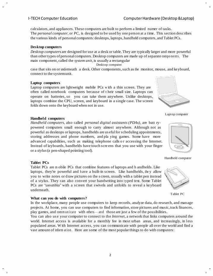
Desktop computers
Desktop computers are designed for use at a desk or table. They are typically larger and more powerful
than other types of personal computers. Desktop computers are made up of separate compo ne nts. The
main component, called the system unit, is usually a rectangular Desktop computer
case that sits on or underneath a desk. Other components, such as the monitor, mouse, and keyboard,
connect to the system unit.
Laptop computers
Laptop computers are lightweight mobile PCs w ith a thin screen. They are
often called notebook computers because of t heir small size. Laptops can
operate on batteries, so you can take them anywhere. Unlike desktops,
laptops combine the CPU, screen, and keyboard in a single case. The screen
folds down onto the keyboard when not in use.
Handheld computers Handheld computers, also called personal digital assistants (PDAs), are batt ry-
Laptop computer
powered computers small enough to carry almost anywhere. Although not as
powerful as desktops or laptops, handhelds are us eful for scheduling appointments,
storing addresses and phone numbers, and pla ying games. Some have more
advanced capabilities, such as making telephone calls o r accessing the Internet.
Instead of ke yboards, handhelds have touch scre ens that you use with your finger
or a stylus (a pen-shaped pointing tool).
Tablet PCs
Tablet PCs are m obile PCs that combine features of laptops and h andhelds. Like
laptops, they're powerful and h ave a built-in screen. Like handhelds, the y allow
you to write notes or d raw pictures on the s creen, usually with a tablet pen instead
of a stylus. They can also convert your handwriting into t yped text. Some Tablet
PCs are ―convertibles‖ with a screen that swivels and unfolds to reveal a keyboard
underneath.
What can you do with computers?
Handheld computer
Tablet PC
In the workplace, many people use computers to keep records, analyze data, do research, and manage
projects. At home, you can use computers to find information, store pictures and music, track finances,
play games, and comm un ica te with others— an d those are just a few of the possibilities.
You can also us e your computer to connect to the Internet, a network that links computers around the
world. Internet access is available for a monthly fee in most urban areas, and increasingly, in l ess
populated areas. W ith Internet access, you can communicate with people all over the world and find a
vast amount of inform at ion . Here are some of the most popular things to do with computers:
3
I-TECH Computer Education Computer Hardware (Desktop &Laptop)
The web
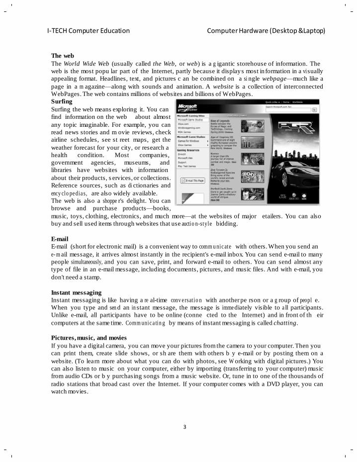
The World Wide Web (usually called the Web, or web) is a g igantic storehouse of information. The
web is the most popu lar part of the Internet, partly because it displays most in formation in a vi sually
appealing format. Headlines, text, and pictures c an be combined on a si ngle webpage—much like a
page in a m agazine—along with sounds and animation. A website is a collection of interconnected
WebPages. The web contains millions of websites and billions of WebPages.
Surfing
Surfing the web means exploring it. You can
find information on the web about almost
any topic imaginable. For example, you can
read news stories and m ovie reviews, check
airline schedules, see st reet maps, get the
weather forecast for your city, or research a
health condition. Most companies,
government agencies, museums, and
libraries have websites with information
about their products, s ervices, or collections.
Reference sources, such as di ctionaries and
ency clo pe dia s, are also widely available.
The web is also a shoppe r's delight. You can
browse and purchase products—books,
music, toys, clothing, electronics, and much more—at the websites of major
buy and sell used items through websites that use auctio n-style bidding.
etailers. You can also
E-mail (short for electronic mail) is a convenient way to comm u nic ate with others. When you send an
e- m ail message, it arrives almost instantly in the recipient's e-mail inbox. You can send e-mail to many
people simultaneously, and you can save, print, and forward e-mail to others. You can send almost any
type of file in an e-mail message, including documents, pictures, and music files. And with e-mail, you
don't need a stamp.
Instant messaging
Instant messaging is like having a re al-time conv e rsat io n with another pe rson or a g roup of peopl e.
When you type and sen d an in stant message, the message is imme diately visible to a ll participants.
Unlike e-mail, all participants have to be online (conne cted to the Internet) and in front of th eir
computers at the same time. Comm unic a tin g by means of instant messaging is called chatting.
Pictures, music, and movies
If you have a digital camera, you can move your pictures from the camera to your computer. Then you
can print them, create slide shows, or sh are them with others b y e-mail or by posting them on a
website. (To learn more about what you can do with photos, see W orking with digital pictures.) You
can also listen to music on your computer, either by importing (transferring to your computer) music
from audio CDs or b y purchasing songs from a music website. Or, tune in to one of the thousands of
radio stations that broad cast over the Internet. If your computer comes with a DVD player, you can
watch movies.
4
I-TECH Computer Education Computer Hardware (Desktop &Laptop)
Gaming
Do you like to play games? Thousands of computer games in every conceivable category are available
to entertain you. Get behind the wheel of a race car, battle fri ghtening creatures in a dungeon, or
control civilizations and empires! Many games allow you to compete w ith other pla yers around the
world through the Internet. Windows includes a variety of card games, puzzle games, and strategy
games.
Full form of computer abbriviation:
C – Commonly
O – Operated
M – Machine which
P – Process
U – Under
T – Technical &
E – Educational
R – Reports
Definition of Computer:
In Layman‘s language “A computer is a simple electronic machine that helps you to solve
problems.”
In Technical manner “A computer is a high speed electronic device which follows instruction & is
capable of performing arithmetical and logical operation.”
Advantage of Computer:
1) Speed: Computer can carry out any instruction in less than a millionth of a second. Naturally,
in any job, involving lots of calculation, computers are very useful. A computer can sort a s et
of thousand names in less than hundredth of a second.
2) Accuracy: This is the most important characteristic of computer. Computer can do cal culation
without errors and very accurately. Even when computer is making thousand calculations every
second, not a sing le one will g o wrong. If mistakes occur in an y calculation, they are due to
human mistakes.
3) Diligence: Computer is c apable of performing any task given to them r espectively. This
property of computer to do the g iven task obe diently without asking any question is called
diligence. If any calculation has been done a million time s, a computer will do so with sa me
accuracy and speed.
4) Storage capacity: Computer c an store large volume of data and information on mag netic
media. Computers also h ave enormous speed to retrieve this saved data. Computers can carry
out the given task using a small set of elementary instructions. These instructions are extremely
simple; e.g. add, subtract, compare, etc. and are collectively known as programs. It is not
nece ssa r y to have more than 100 distinct instructions even for a very powerful machine.
Limitation /Dis ad van ta g e of Computer:
(1) Lack of commonsense: Computer can work as human being s but it is o nly a tool. It cannot
think. It does not have common sense or intelligence as human being have. Computers are to
5
I-TECH Computer Education Computer Hardware (Desktop &Laptop)
be instructed for making them perform any task. So every time when we have to use computer
for a task, we need to first tell computer what to do.
(2) Inability to correct: when we give instruction to the computer we must give correct
instructions. A computer cannot p rompt for wrong instructions. If there is a mistake in giving
data to the computer, the end result is wrong. Popularly this is termed as Garbage In – Garbage
Out.
(3) Dependence on human instructions: Computers look as the y are very clever. Actually they
are only tools. They cannot do an ything unless a man instructs the m. A computer cannot
generate any information on its own. It can only do what it has been instructed or told to do.
(4) Dependence on Electricity: Computers depen d on electricit y for their functioning. Just
imagine the state of an organization using computers and not having power. Manpower will be
sitting idle without an y work. An or ganization will be totally crippled in case t here is no
power. A lot of pending work will be left for completion.
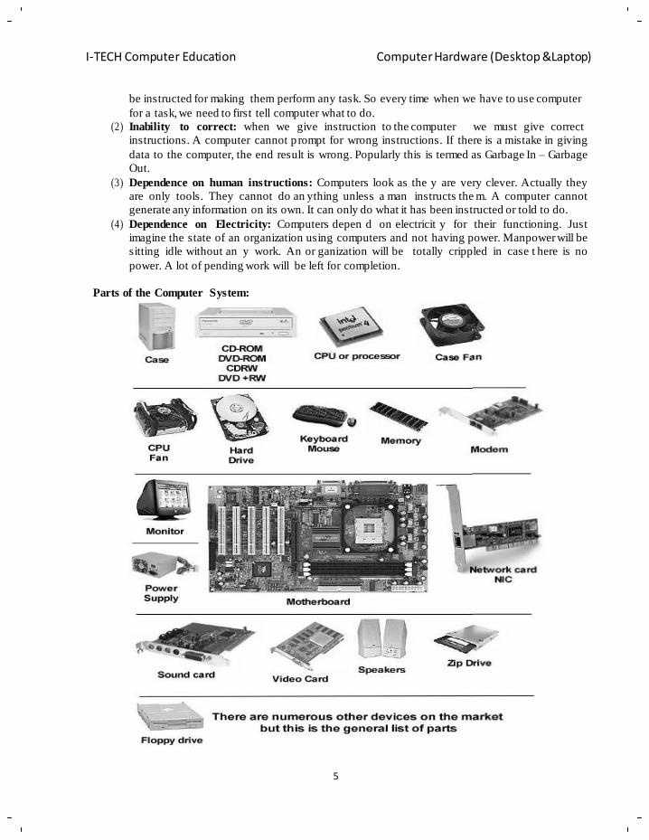
Parts of the Computer System:
6
I-TECH Computer Education Computer Hardware (Desktop &Laptop)
Different types of computer:
(1) Super Computer:
Speed: 64-128 bit
Use: Weather reports and defence.
Size: Building size
Example: Param 10000, Anand Param 2
(2) Mainfram e Computer:
Speed: 32-64 bit
Use: Big organiz at ion s like TATA, Railways etc.
Size: Room size
Example: IBM 360 series, Hone y w e ll ‘ s, PDP 88/860.
(3) Mini Computer:
Speed: 16-32 bit
Use: small organiz a tio ns, Branches, Offices, etc.
Size: Desk size
Example: RPG AS-400
(4) Micro Computer:
(i ) Desktop
(i i ) Portable Speed:
8-32 bit Use:
Personal use Size:
Desktop size
Example: Personal computers (P –I, P –II, P-III & P –IV etc.)
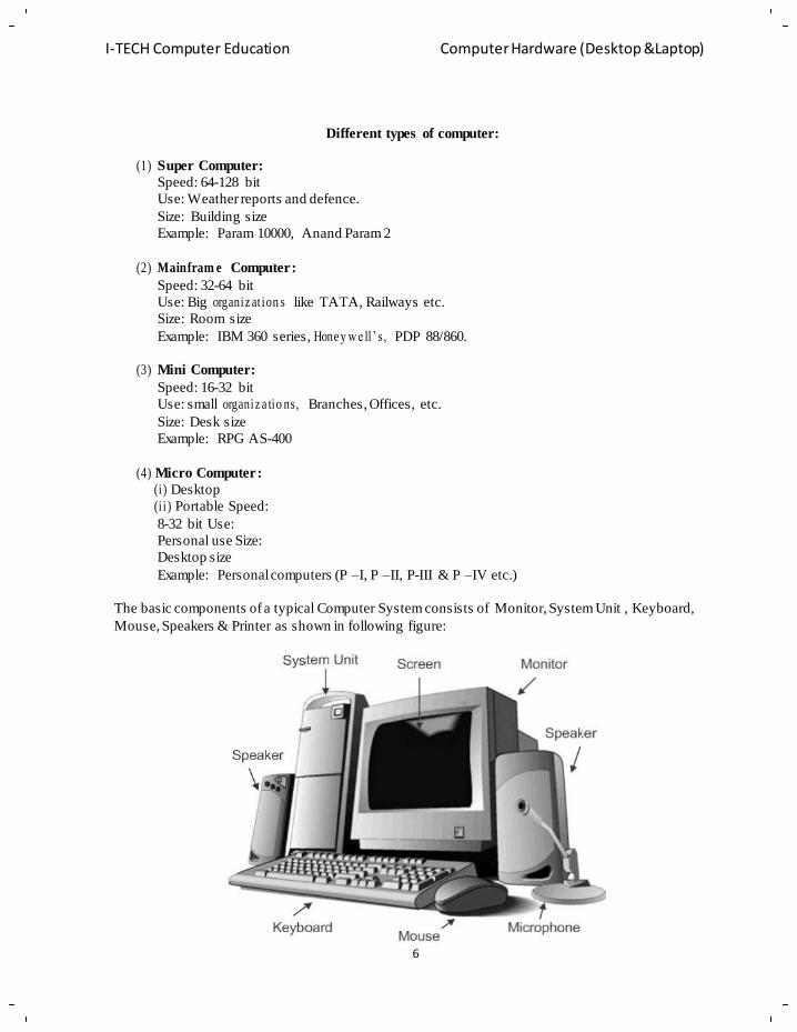
The basic components of a typical Computer System consists of Monitor, System Unit , Keyboard,
Mouse, Speakers & Printer as shown in following figure:
7
I-TECH Computer Education Computer Hardware (Desktop &Laptop)
m
Parts of Computers:
1. System unit / CPU (Central Processing Unit):
The system unit is the core of a com puter system. Usually it's a rec tangular box placed on or
underneath your desk. Inside this box are many electronic components that process information. The
most important of these compo nents is the central processing unit (CPU), or microprocessor, which
acts as the "brain" of your computer. Another component is random access emory (RAM), which
temporarily stores information that the CPU uses while the computer is on. The information stored in
RAM is erased when the computer is turned off.
Almost every other part of your computer connects to the s ystem unit us ing cables. The cables plug
into specific ports (openings), typically on the back of the system unit. Hardware that is not part of t he
system unit is sometimes called a peripheral device or device.
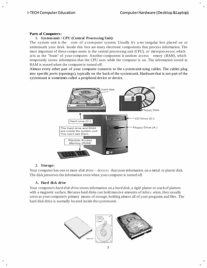
2. Storage:
Your computer has one or more disk drives — de vic e s that store information on a metal or plastic disk.
The disk preserves the information even when your computer is turned off.
A. Hard disk drive
Your computer's hard disk drive stores information on a hard disk , a rigid platter or stack of platters
with a magnetic surface. Because hard disks can hold massive amounts of infor ation, they usually
serve as your computer's primary means of storage, holding almost all of your programs and files. The
hard disk drive is normally located inside the system unit.
8
I-TECH Computer Education Computer Hardware (Desktop &Laptop)
A
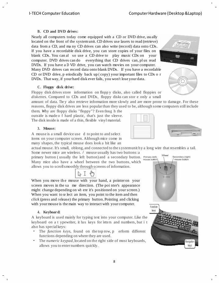
B. CD and DVD drives:
Nearly all computers today come equipped with a CD or DVD drive, usu ally
located on the front of the system unit. CD drives use lasers to read (retrieve)
data from a CD, and ma ny CD drives can also write (record) data onto CDs.
If you have a recordable disk drive, you can store copies of your files on
blank CDs. You can al so use
computer. DVD drives can do
a CD drive to play music CDs on your
everything that CD drives can, pl us read
DVDs. If you have a D VD drive, you can watch movies on your computer.
Many DVD drives can record data onto blank DVDs. If you have a recordable
CD or DVD drive, p eriodically back up ( copy) your important files to CDs o r
DVDs. That way, if your hard disk ever fails, you won't lose your data.
C. Floppy disk drive:
Floppy disk drives store information on flopp y disks , also called floppies or
diskettes. Compared to CDs and DVDs, floppy disks can stor e only a small
amount of data. The y also retrieve information more slowly and are more prone to damage. For these
reasons, floppy disk drives are less popular than they used to be, although some computers still include
them. Why are floppy disks "floppy"? Even thoug h the
outside is made o f hard plastic, that's just the sleeve.
The disk inside is made of a thin, flexible vinyl material.
3. Mouse:
A mouse is a small device use
d to point to and select
items on your computer screen. Although mice come in
many shapes, the typical mouse does look a bit like an
actual mouse. It's small, oblong, and connected to the s ystem unit by a long wire that resembles a tail.
Some newer mice are wireless. mouse usually has two buttons: a
primary button ( usually the left button) and a secondary button.
Many mice also have a wheel between the two buttons, which
allows you to scroll smoothly through screens of information.
When you move th e mouse with your hand, a pointer on your
screen moves in the sa me direction. (The poi nter's appearance
might change depending on wh ere it's positioned on your screen.)
When you want to se lect an item, you point to the item and then
click (press and r elease) the primary button. Pointing and clicking
with your mouse is the main way to interact with your computer.
4. Keyboard:
A keyboard is used mainly for typing text into your computer. Like the
keyboard on a t ypewriter, it ha s keys for lette rs and numbers, but i t
also has special keys: • The function keys, found on the top row, p erform different
functions depending on where they are used.
• The numeric keypad, located on the right side of most keyboards,
allows you to enter numbers quickly.
9
I-TECH Computer Education Computer Hardware (Desktop &Laptop)
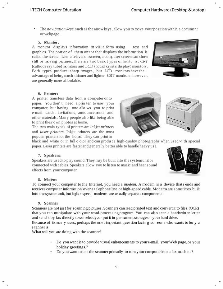
• The navigation keys, such as the arrow keys, allow you to move your position within a document
or webpage.
5. Monitor:
A monitor displays information in visual form, using text and
graphics. The portion of the m onitor that displays the information is
called the screen. Like a television screen, a computer screen can show
still or moving pictures.There are two basic t ypes of monito rs: CRT
(cathode ray tube) monitors and LCD (liquid crystal display) monitors.
Both types produce sharp images, but LCD monitors have the
advantage of being much thinner and lighter. CRT monitors, however,
are generally more affordable.
6. Printer:
A printer transfers data from a computer onto
paper. You don' t need a prin ter to use your
computer, but having one allo ws you to print
e-mail, cards, invitations, announcements, and
other materials. Many people also like being able
to print their own photos at home.
The two main types of printers are inkjet printers
and laser printers. Inkjet printers are the most
popular printers for the home. They can print in
black and white or in full c olor and can produ ce high-quality photographs when used wi th special
paper. Laser printers are faster and generally better able to handle heavy use.
7. Speakers:
Speakers are used to play sound. They may be built into the system unit or
connected with cables. Speakers allow you to listen to music and hear sound
effects from your computer.
8. Modem:
To connect your computer to t he Internet, you need a modem. A modem is a device that s ends and
receives computer information over a telephone line or high-speed cable. Modems are sometimes built
into the system unit, but highe r -sp e ed modems are usually separate components.
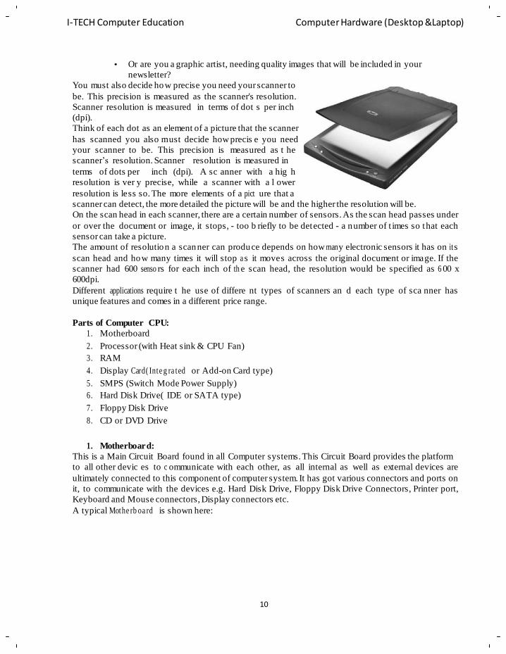
9. Scanner:
Scanners are not just for scanning pictures. Scanners can read printed text and convert it to files (OCR)
that you can manipulate with your word-processing program. You can also scan a handwritten letter
and send it by fax directly to somebody, or put it in permanent storage on your hard drive.
Because of its man y uses, perhaps the most important question facin g someone who wants to bu y a
scanner is:
What will you are doing with the scanner?
• Do you want it to provide visual enhancements to your e-mail, your Web page, or your
holiday greetings,?
• Do you want to use the scanner primarily to turn your computer into a fax machine?
10
I-TECH Computer Education Computer Hardware (Desktop &Laptop)
• Or are you a graphic artist, needing quality images that will be included in your
newsletter?
You must also decide how precise you need your scanner to
be. This precision is measured as the scanner's resolution.
Scanner resolution is measured
(dpi).
in terms of dot s per inch
Think of each dot as an element of a picture that the scanner
has scanned you also m ust decide how precis e you need
your scanner to be. This precision is measured as t he
scanner‘s resolution. Scanner resolution is measured in
terms of dots per inch (dpi). A sc anner with a hig h
resolution is ver y precise, while a scanner with a l ower
resolution is less so. The more elements of a pict ure that a
scanner can detect, the more detailed the picture will be and the higher the resolution will be.
On the scan head in each scanner, there are a certain number of sensors. As the scan head passes under
or over the document or image, it stops, - too b riefly to be detected - a number of t imes so that each
sensor can take a picture.
The amount of resolution a scanner can produce depends on how man y electronic sensors it has on it s
scan head and how many times it will stop a s it moves across the original document or image. If the
scanner had 600 senso rs for each inch of th e scan head, the resolution would be specified as 6 00 x
600dpi.
Different applications require t he use of differe nt types of scanners an d each type of sca nner has
unique features and comes in a different price range.
Parts of Computer CPU:
1. Motherboard
2. Processor (with Heat sink & CPU Fan)
3. RAM
4. Display Card( Inte g ra ted or Add-on Card type)
5. SMPS (Switch Mode Power Supply)
6. Hard Disk Drive( IDE or SATA type)
7. Floppy Disk Drive
8. CD or DVD Drive
1. Motherboard:
This is a Main Circuit Board found in all Computer systems. This Circuit Board provides the platform
to all other devic es to c ommunicate with each other, as all internal as well as external devices are
ultimately connected to this component of computer system. It has got various connectors and ports on
it, to communicate with the devices e.g. Hard Disk Drive, Floppy Disk Drive Connectors, Printer port,
Keyboard and Mouse connectors, Display connectors etc.
A typical Mothe rb oa rd is shown here:
11
I-TECH Computer Education Computer Hardware (Desktop &Laptop)
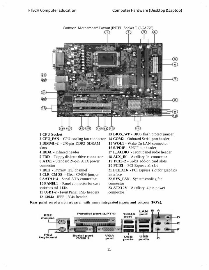
Common Motherboard Layout (INTEL Socket T (LGA775)
1 CPU Socket
2 CPU_FAN - CPU cooling fan connector
3 DIMM1~2 - 240-pin DDR2 SDRAM
slots
4 IRDA - Infrared header
5 FDD - Floppy diskette drive connector
6 ATX1 - Standard 24-pin ATX power
connector
7 IDE1 - Primary IDE channel
8 CLR_ CM OS - Clear CMOS jumper
9 SATA1~4 - Serial ATA connectors
10 PANEL1 - Panel connector for case
switches and LEDs
11 USB1-2 - Front Panel USB headers
12 1394a - IEEE 1394a header
13 BIOS_WP - BIOS flash protect jumper
14 COM2 - Onboard Serial port header
15 WOL1 - Wake On LAN connector
16 S/PDIF - SPDIF out header
17 F_AUDIO - Front panel audio header
18 AUX_IN - Auxiliary In connector
19 PCI1~2 - 32-bit add-on card slots
20 PCIE1 - PCI Express x1 slot
21 PCIEX16 - PCI Express slot for graphics
interface
22 SYS_FAN - System cooling fan
connector
23 ATX12V - Auxiliary 4-pin power
connector
Rear panel on of a motherboa rd with many integrated inputs and outputs (I/O's).
12
I-TECH Computer Education Computer Hardware (Desktop &Laptop)
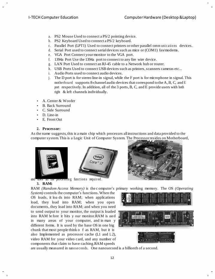
a. PS2 Mouse Used to connect a PS/2 pointing device.
b. PS2 Keyboard Used to connect a PS/2 keyboard.
c. Parallel Port (LPT1) Used to connect printers or other parallel comm unic a tio ns devices.
d. Serial Port used to connect serial devices such as mice or (COM1) fax/modems.
e. VGA Port Connect your monitor to the VGA port.
f. 1394a Port Use the 1394a port to connect to any fire wire device.
g. LAN Port Used to connect an RJ-45 cable to a Network hub or router.
h. USB Ports Used to connect USB devices such as printers, scanners cameras etc...
i . Audio Ports used to connect audio devices.
j . The D port is for stereo line-in signal, while the F port is for microphone in signal. This
mothe rb oa rd supports 8-channel audio devices that correspond to the A, B, C, and E
port respectively. In addition, all of the 3 ports, B, C, and E provide users with both
right & left channels individually.
• A. Center & Woofer
• B. Back Surround
• C. Side Surround
• D. Line-in
• E. Front Out
2. Processor:
As the name suggests, this is a main chip which processes all instructions and data provided to the
computer system. This is a Logic Unit of Computer System. The Processor resides on Motherboard,
and does all the proce ssin g funct ion s requir ed .
3. RAM:
RAM (Random Access Memory) is the c omputer‘s primary working memory. The OS (Operating
System) controls the computer‘s functions. When the
OS loads, it loa ds into RAM;
load, they load into RAM;
when applications
when you open
documents, they load into RAM; and when you need
to send output to your monitor, the output is loaded
into RAM be fore it hits y our monitor.RAM is use d
in many areas of your computer, and in man y
different forms. It is used by the base OS in one big
chunk that most people think o f as RAM, but it is
also Implemented as processor cache (L1 and L 2),
video RAM for your video card, and any number of
components that claim to have caching.RAM speeds
are usually measured in nano se c on ds. One nanosecond is a billionth of a second.
13
I-TECH Computer Education Computer Hardware (Desktop &Laptop)
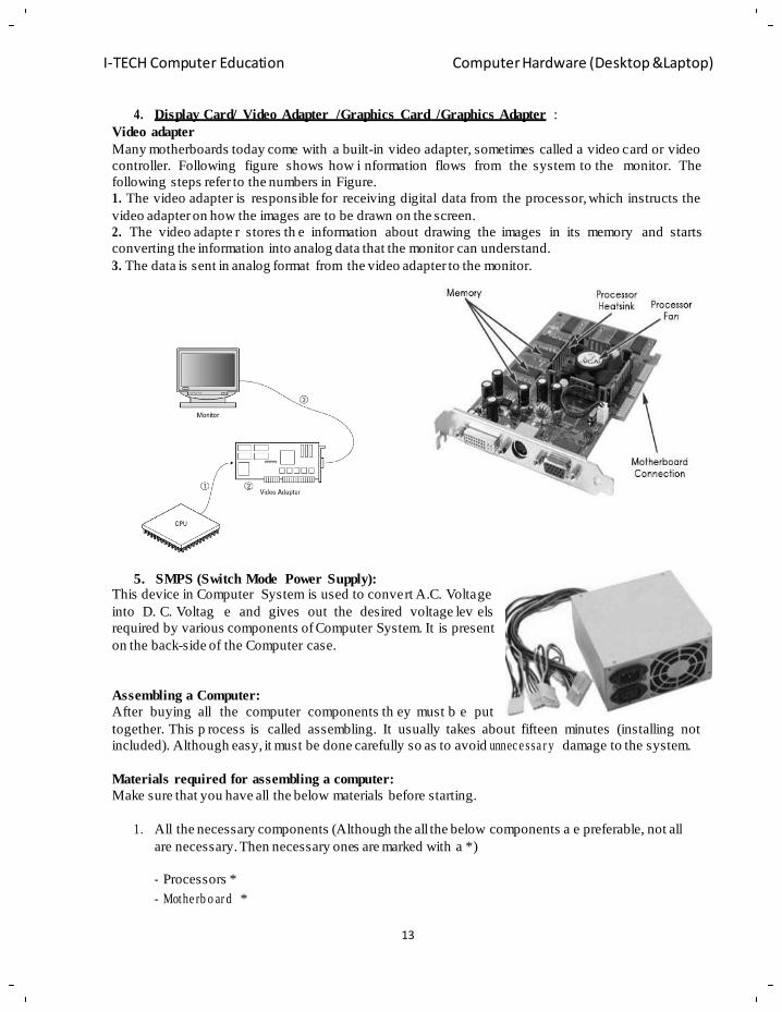
4. Display Card/ Video Adapter /Graphics Card /Graphics Adapter :
Video adapter
Many motherboards today come with a built-in video adapter, sometimes called a video card or video
controller. Following figure shows how i nformation flows from the system to the monitor. The
following steps refer to the numbers in Figure.
1. The video adapter is responsible for receiving digital data from the processor, which instructs the
video adapter on how the images are to be drawn on the screen.
2. The video adapte r stores th e information about drawing the images in its memory and starts
converting the information into analog data that the monitor can understand.
3. The data is sent in analog format from the video adapter to the monitor.
5. SMPS (Switch Mode Power Supply): This device in Computer System is used to convert A.C. Voltage
into D. C. Voltag e and gives out the desired voltage lev els
required by various components of Computer System. It is present
on the back-side of the Computer case.
Assembling a Computer:
After buying all the computer
components th ey must b e put
together. This p rocess is called assembling. It usually takes about fifteen minutes (installing not
included). Although easy, it must be done carefully so as to avoid unnec e ssa r y damage to the system.
Materials required for assembling a computer:
Make sure that you have all the below materials before starting.
1. All the necessary components (Although the all the below components a e preferable, not all
are necessary. Then necessary ones are marked with a *)
- Processors *
- Mothe rb o ar d *
14
I-TECH Computer Education Computer Hardware (Desktop &Laptop)
Computer Hardware (Desktop & Laptop)
- Hard disk *
- RAM *
- Cabinet *
- Floppy Drive *
- CD Drive *
- Cards
- Display Card (Not needed if On-board display is available on Motherboard)
- Sound Card (Not needed if On-board sound is available on Motherboard)
- Modem
- Other Cards(If Any)
- Monitors *
- Keyboard *
- Mouse *
- Speakers
- UPS
- Other Comp o ne nts( If Any)
- Also keep the cables that came with the comp on e nts close by
2. Philips head Screw d rive r( also known as Star Screwdriver)
3. Flat head Screwdriver
4. Forceps (for pulling out jumpers and screws)
5. Magnetized Screwdriver
6. Multi meter (Testing)
Required Environment for assembling PC:
Make sure that the following things are true of the room in which the computer is assembled/kept.
• Make sure that a flat sur face of a good area is available when the s ystem is assembled. Make
sure that the room has enough space to move.
• See that the place where the Computer is kept is dust free as dust can harm the system.
• Make sure that the room has good ventilation and won't be very hot.
• Check the grounding in the plug to make sure that earthing (Grou ndin g ) is done properly.
Precautions to be care while assembling the PC:
Before Starting the actual assembly of the PC S ystem, the following precautions would he lp you to
avoid any mishap during the assembly process:
• While the motherboard has to be fitted at a fixed place inside the PC cabinet, the locations of add-
on cards ( as and wh en used) and t he drivers (hard disk drive, flopp y disk drive, and CD-ROM
drive) within the dr ivers bay of the cabinet can be changed within certain limits. But it is be tter to
place them far away from each other. (The length of the cable provided for interconnections to the
motherboard has to be t aken into account, as the re must be some slack aft er these are installed and
connected.) This will impr ove the cooling and reduce the chance of electro-magnetic interference
between them.
• The motherboard contains sensitive components, which can be easily damaged by static electricity.
Therefore the motherbo ard should remain in it s original anti static e nvelope until required for
installation. The person taking it out should wear an anti static wrist strap that is properly grounded.
15
I-TECH Computer Education Computer Hardware (Desktop &Laptop)
In the abs ence of a proper wrist strap, you must make one on your own, using a peeled of multi-
stranded copper cable a nd ground it prope rly. Similar handling precautions are also required for
cards.
• Be sure to handle all the components with great care. If a small thing like a screw is dropped on the
MB, it can damage the delicate circuitry, rendering the Main Board useless.
Assembling the PC:
If you have purchased all the necessary hardware your are ready assemble your PC. Before unpacking
your components from its original anti-static bags you must put on your anti-static wrist strap, which
will discharge yourself. It is im portant that you discharge yourself or t here is a danger that you can
damage your components by anti-static shock by touching the components. If you don't have an anti-
static wrist strap you can discharge yourself by touching the metal edges of your ATX case, although
this is not recommended.
The first thing you should do is unpack your ATX case. T ake off the cover of your case so that you
can access the inside. Place the case on a desk s o that you are lookin g down towards the open c ase.
Your case should com e with motherboard mounting screws. If your ATX back plate it not already
fitted you can fit it b y placing your plate near the ATX b ack plate cut out and pushing the pl ate
outwards, it should clip on.
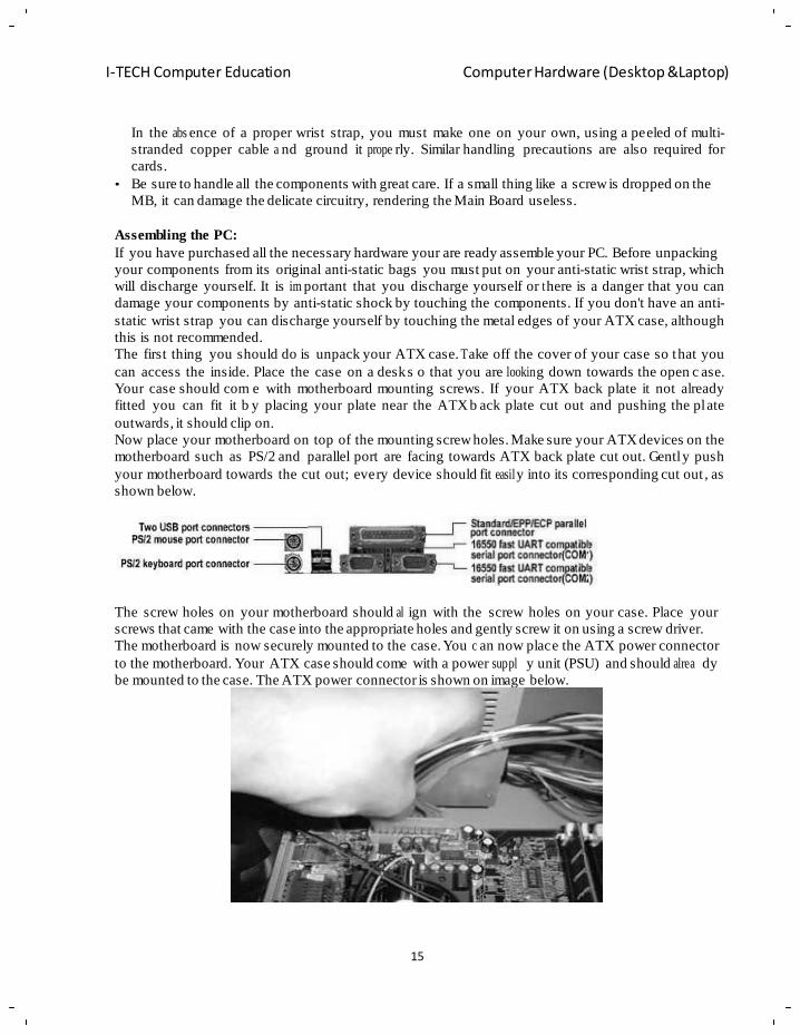
Now place your motherboard on top of the mounting screw holes. Make sure your ATX devices on the
motherboard such as PS/2 and parallel port are facing towards ATX back plate cut out. Gentl y push
your motherboard towards the cut out; every device should fit easil y into its corresponding cut out , as
shown below.
The screw holes on your motherboard should al ign with the screw holes on your case. Place your
screws that came with the case into the appropriate holes and gently screw it on using a screw driver.
The motherboard is now securely mounted to the case. You c an now place the ATX power connector
to the motherboard. Your ATX case should come with a power suppl y unit (PSU) and should alrea dy
be mounted to the case. The ATX power connector is shown on image below.
16
I-TECH Computer Education Computer Hardware (Desktop &Laptop)
Place the ATX power connector on top of the power socket on the mother board. Push down the power
connector and it should clip o nto the socket. If you try to f it the power connector the wrong way
round, it won't fit, it will only fit one way. So, if the power connector does not go in, it should go in the
other way round.
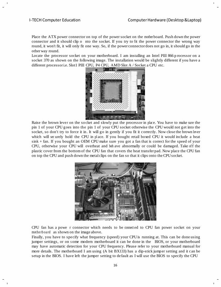
Locate the processor socket on your motherboard. I am installing an Intel PIII 866 p rocessor on a
socket 370 as shown on the following image. The installation would be slightly different if you have a
different processor i.e. Slot1 PIII CPU, P4 CPU, AMD Slot A / Socket a CPU etc.
Raise the brown lever on the socket and slowly put the processor in plac e. You have to make sur e the
pin 1 of your CPU goes into the pin 1 of your CPU socket otherwise the CPU would not get into the
socket, so don't try to force it in . It will go in gently if you fit it correctly. Now close the brown lev er
which will sec urely hold the CPU in pl ace. If you bought retail boxed CPU it would include a heat
sink + fan. If you bought an OEM CPU make sure you got a fan that is correct for the speed of your
CPU, otherwise your CPU will overheat and beh ave abnormally or could be damaged. Take of f the
plastic cover from the bottom of the CPU fan that covers the heat transfer pad. Now place the CPU fan
on top the CPU and push down the metal clips on the fan so that it clips onto the CPU socket.
CPU fan has a powe r connector which needs to be connect ed to CPU fan power socket on your
mothe rb oa rd as shown on the image above.
Finally, you have to specify what frequency (speed) your CPU is running at. This can be done using
jumper settings, or on s ome modern motherboard it can be done in the BIOS, or your motherboard
may have automatic detection for your CPU frequency. Please refer to your motherboard manual for
more details. The motherboard I am using (A bit BX133) has a dip-stick jumper setting and it can be
setup in the BIOS. I have left the jumper setting to default as I will use the BIOS to specify the CPU
17
I-TECH Computer Education Computer Hardware (Desktop &Laptop)
frequency. The CPU runs at the bus spe ed of 133 MHz therefore I will use the settings 133 *
6.5(m ul tipl ie r) under the BIOS, which will the run the CPU at 866 Mhz.
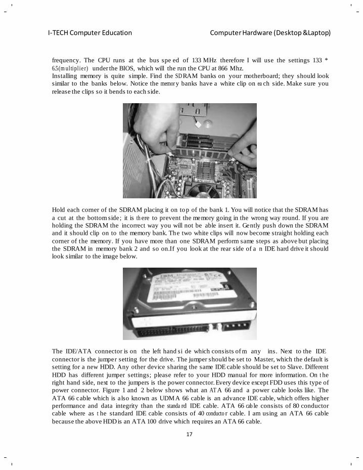
Installing memory is quite simple. Find the SD RAM banks on your motherboard; they should look
similar to the banks below. Notice the memor y banks have a white clip on ea ch side. Make sure you
release the clips so it bends to each side.
Hold each corner of the SDRAM placing it on top of the bank 1. You will notice that the SDRAM has
a cut at the bottom side; it is th ere to prevent the memory going in the wrong way round. If you are
holding the SDRAM the incorrect way you will not be able insert it. Gently push down the SDRAM
and it should clip on to the memory bank. The two white clips will now become straight holding each
corner of the memory. If you have more than one SDRAM perform same steps as above but placing
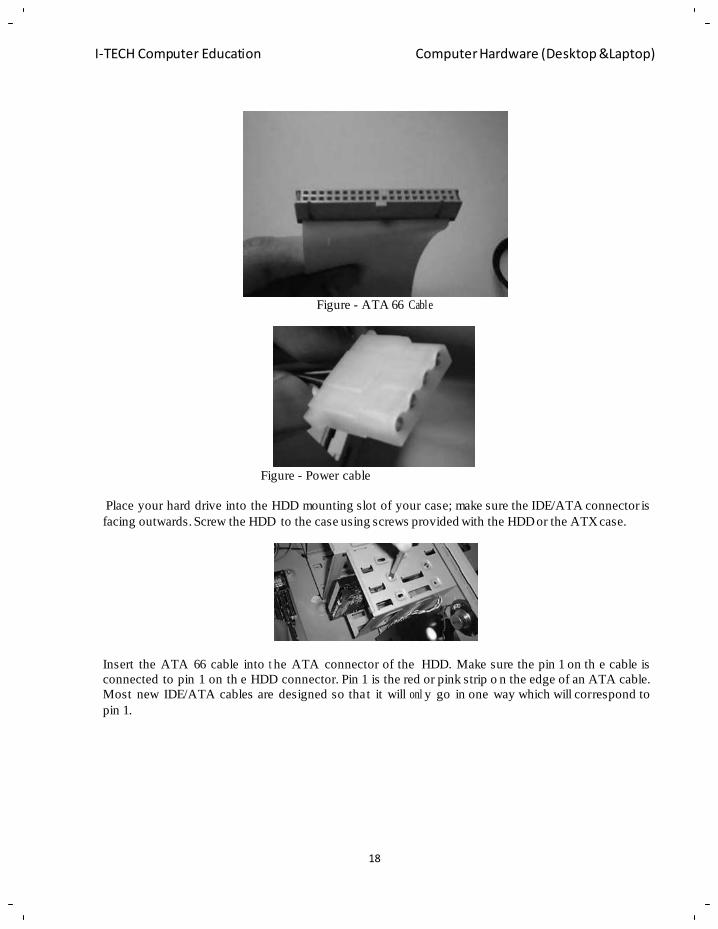
the SDRAM in memory bank 2 and so on.If you look at the rear side of a n IDE hard drive it should
look similar to the image below.
The IDE/ATA connector is on the left hand si de which consists of m any ins. Next to the IDE
connector is the jumper setting for the drive. The jumper should be set to Master, which the default is
setting for a new HDD. Any other device sharing the same IDE cable should be set to Slave. Different
HDD has different jumper settings; please refer to your HDD manual for more information. On t he
right hand side, next to the jumpers is the power connector. Every device except FDD uses this type of
power connector. Figure 1 and 2 below shows what an AT A 66 and a power cable looks like. The
ATA 66 cable which is also known as UDMA 66 cable is an advance IDE cable, which offers higher
performance and data integrity than the standa rd IDE cable. ATA 66 cab le consists of 80 conductor
cable where as t he standard IDE cable consists of 40 conducto r cable. I am using an ATA 66 cable
because the above HDD is an ATA 100 drive which requires an ATA 66 cable.
18
I-TECH Computer Education Computer Hardware (Desktop &Laptop)
Figure - ATA 66 Cable
Figure - Power cable
Place your hard drive into the HDD mounting slot of your case; make sure the IDE/ATA connector is
facing outwards. Screw the HDD to the case using screws provided with the HDD or the ATX case.
Insert the ATA 66 cable into t he ATA connector of the HDD. Make sure the pin 1 on th e cable is
connected to pin 1 on th e HDD connector. Pin 1 is the red or pink strip o n the edge of an ATA cable.
Most new IDE/ATA cables are designed so that it will onl y go in one way which will correspond to
pin 1.
I-TECH Computer Education Computer Hardware (Desktop &Laptop)
19
20
I-TECH Computer Education Computer Hardware (Desktop &Laptop)
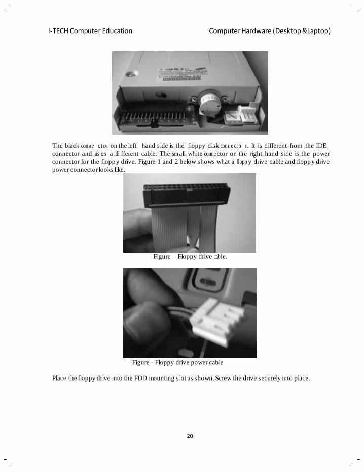
The black conne ctor on the left hand side is the floppy disk conne cto r. It is different from the IDE
connector and us es a di fferent cable. The sm all white conne ctor on th e right hand side is the power
connector for the floppy drive. Figure 1 and 2 below shows what a flopp y drive cable and floppy drive
power connector looks like.
Figure - Floppy drive cable .
Figure - Floppy drive power cable
Place the floppy drive into the FDD mounting slot as shown. Screw the drive securely into place.
21
I-TECH Computer Education Computer Hardware (Desktop &Laptop)
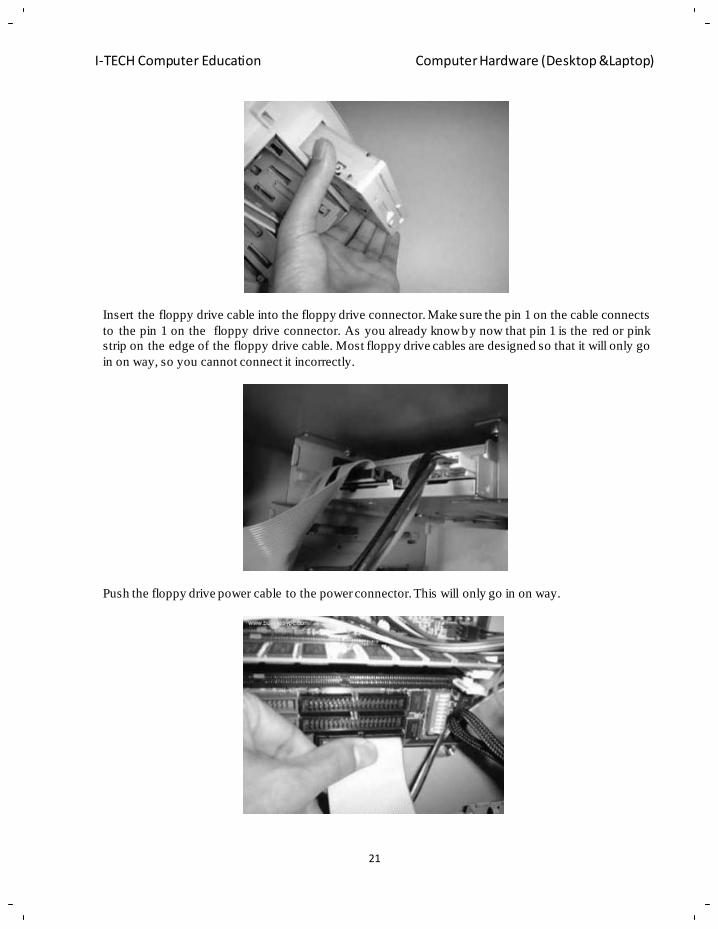
Insert the floppy drive cable into the floppy drive connector. Make sure the pin 1 on the cable connects
to the pin 1 on the floppy drive connector. As you already know by now that pin 1 is the red or pink
strip on the edge of the floppy drive cable. Most floppy drive cables are designed so that it will only go
in on way, so you cannot connect it incorrectly.
Push the floppy drive power cable to the power connector. This will only go in on way.
22
I-TECH Computer Education Computer Hardware (Desktop &Laptop)
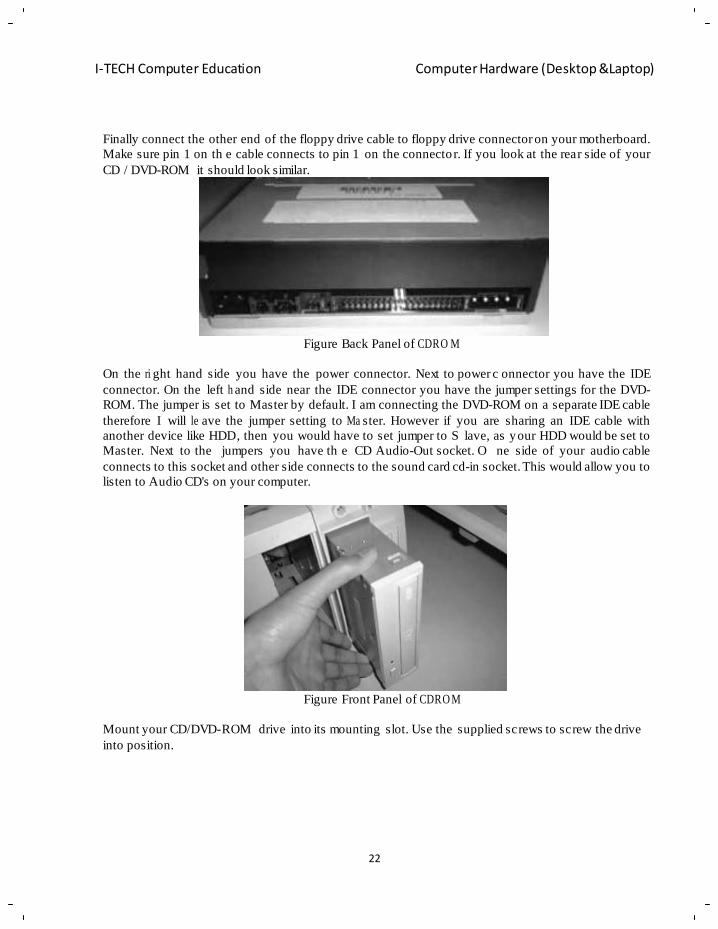
Finally connect the other end of the floppy drive cable to floppy drive connector on your motherboard.
Make sure pin 1 on th e cable connects to pin 1 on the connecto r. If you look at the rear side of your
CD / DVD-ROM it should look similar.
Figure Back Panel of CDRO M
On the ri ght hand side you have the power connector. Next to power c onnector you have the IDE
connector. On the left h and side near the IDE connector you have the jumper settings for the DVD-
ROM. The jumper is set to Master by default. I am connecting the DVD-ROM on a separate IDE cable
therefore I will le ave the jumper setting to Ma ster. However if you are sharing an IDE cable with
another device like HDD, then you would have to set jumper to S lave, as your HDD would be set to
Master. Next to the jumpers you have th e CD Audio-Out socket. O ne side of your audio cable
connects to this socket and other side connects to the sound card cd-in socket. This would allow you to
listen to Audio CD's on your computer.
Figure Front Panel of CDRO M
Mount your CD/DVD-ROM drive into its mounting slot. Use the supplied screws to screw the drive
into position.
23
I-TECH Computer Education Computer Hardware (Desktop &Laptop)
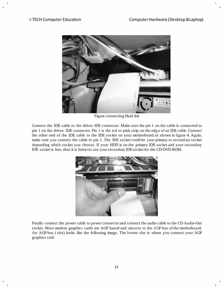
Figure connecting Hard disk
Connect the IDE cable to the drives IDE connector. Make sure the pin 1 on the cable is connected to
pin 1 on the drives IDE connector. Pin 1 is the re d or pink strip on the edg e of an IDE cable. Connect
the other end of the IDE cable to the IDE socket on your motherboard as shown in fi gure 4. Again,
make sure you connect the cable to pin 1. The IDE socket could be your primary or secondary socket
depending which socket you choose. If your HDD is on the primary IDE socket and your secondary
IDE socket is free, then it is better to use your secondary IDE socket for the CD/DVD-ROM.
Finally connect the power cable to power connector and connect the audio cable to the CD Audio-Out
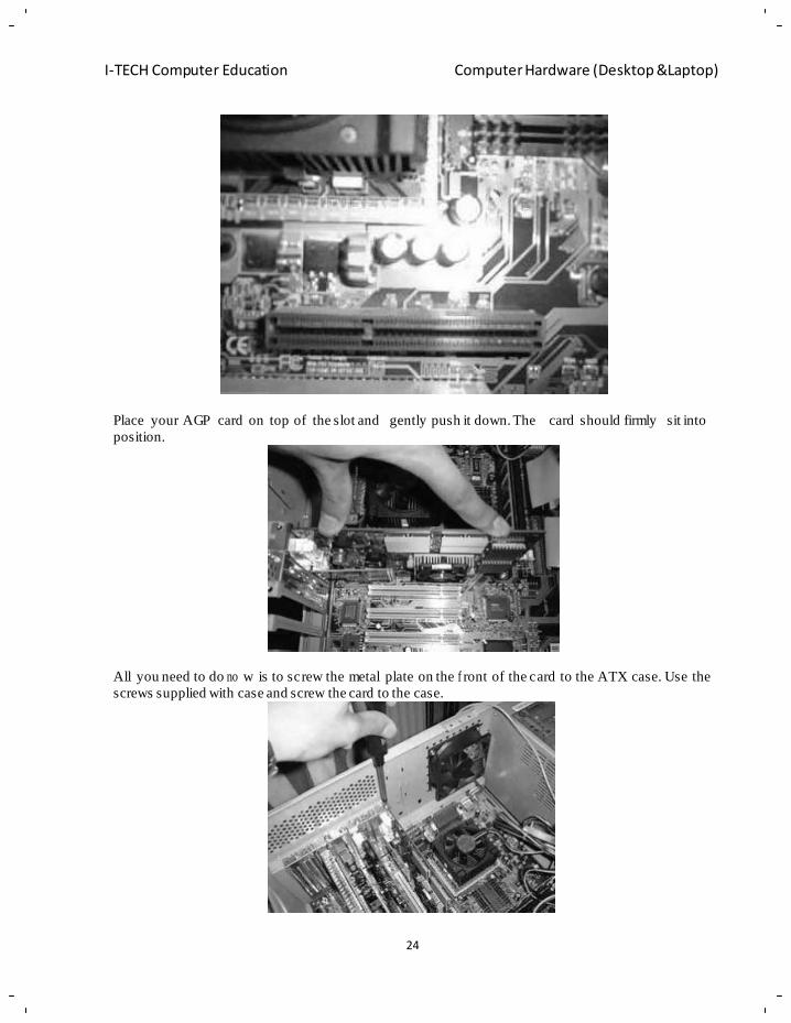
socket. Most modern graphics cards are AGP based and conn ects to the A GP bus of the motherboard.
An AGP bus ( slot) looks like the following image. The b rown slot is where you connect your AGP
graphics card.
24
I-TECH Computer Education Computer Hardware (Desktop &Laptop)
Place your AGP card on top of the slot and gently push it down. The card should firmly sit into
position.
All you need to do no w is to screw the metal plate on the f ront of the card to the ATX case. Use the
screws supplied with case and screw the card to the case.
25
I-TECH Computer Education Computer Hardware (Desktop &Laptop)
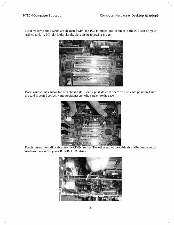
Most modern sound car ds are designed with the PCI interface and connect to the PC I slot of your
mothe rb oa rd . A PCI slot looks like the slots on the following image.
Place your sound card on top of a chosen slot. Gently push down the card so it sits into position. Once
the card is seated correctly into position, screw the card on to the case.
Finally insert the audio cable into the CD-IN socket. The other end of the cable should be connected to
Audio-out socket on your CD/D V D -R O M drive.
26
I-TECH Computer Education Computer Hardware (Desktop &Laptop)
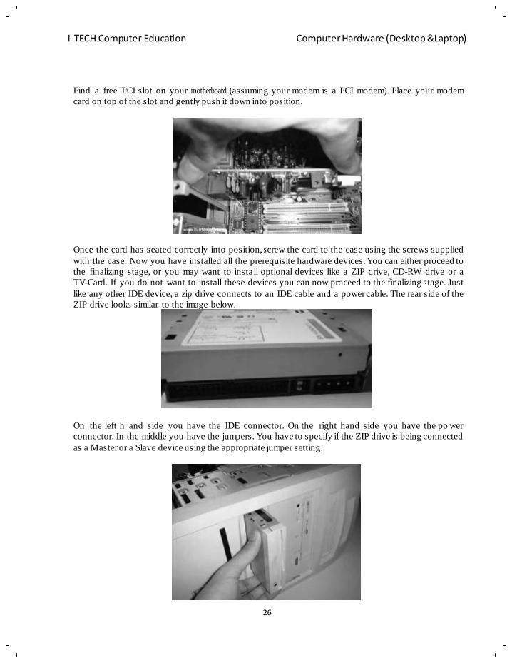
Find a free PCI slot on your motherboard (assuming your modem is a PCI modem). Place your modem
card on top of the slot and gently push it down into position.
Once the card has seated correctly into position, s crew the card to the case using the screws supplied
with the case. Now you have installed all the prerequisite hardware devices. You can either proceed to
the finalizing stage, or you may want to install optional devices like a ZIP drive, CD-RW drive or a
TV-Card. If you do not want to install these devices you can now proceed to the finalizing stage. Just
like any other IDE device, a zip drive connects to an IDE cable and a power cable. The rear side of the
ZIP drive looks similar to the image below.
On the left h and side you have the IDE connector. On the right hand side you have the po wer
connector. In the middle you have the jumpers. You have to specify if the ZIP drive is being connected
as a Master or a Slave device using the appropriate jumper setting.
27
I-TECH Computer Education Computer Hardware (Desktop &Laptop)
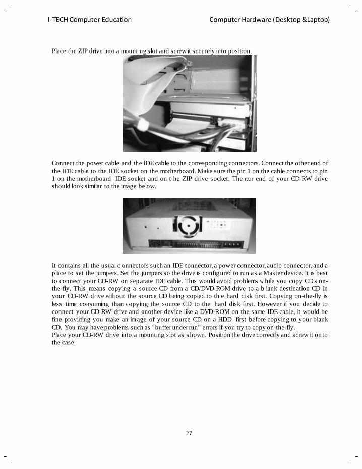
Place the ZIP drive into a mounting slot and screw it securely into position.
Connect the power cable and the IDE cable to the corresponding connectors. Connect the other end of
the IDE cable to the IDE socket on the motherboard. Make sure the pin 1 on the cable connects to pin
1 on the motherboard IDE socket and on t he ZIP drive socket. The rea r end of your CD-RW drive
should look similar to the image below.
It contains all the usual c onnectors such an IDE connector, a power connector, audio connector, and a
place to set the jumpers. Set the jumpers so the drive is configured to run as a Master device. It is best
to connect your CD-RW on separate IDE cable. This would avoid problems w hile you copy CD's on-
the-fly. This means copying a source CD from a CD/DVD-ROM drive to a b lank destination CD in
your CD-RW drive with out the source CD b eing copied to th e hard disk first. Copying on-the-fly is
less time consuming than c opying the source CD to the hard disk first. However if you decide to
connect your CD-RW drive and another device like a DVD-ROM on the same IDE cable, it would be
fine providing you make an im age of your source CD on a HDD first before copying to your blank
CD. You may have problems such as "buffer under run" errors if you try to copy on-the-fly.
Place your CD-RW drive into a mounting slot as s hown. Position the drive correctly and screw it on to
the case.
28
I-TECH Computer Education Computer Hardware (Desktop &Laptop)
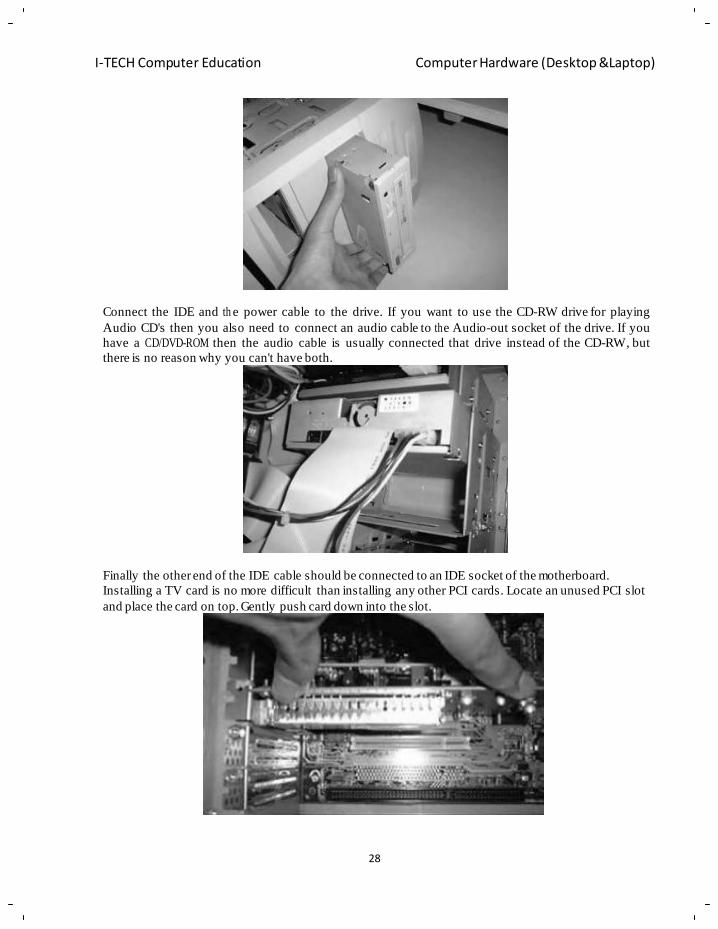
Connect the IDE and th e power cable to the drive. If you want to use the CD-RW drive for playing
Audio CD's then you also need to connect an audio cable to th e Audio-out socket of the drive. If you
have a CD/DVD-ROM then the audio cable is usually connected that drive instead of the CD-RW, but
there is no reason why you can't have both.
Finally the other end of the IDE cable should be connected to an IDE socket of the motherboard.
Installing a TV card is no more difficult than installing any other PCI cards. Locate an unused PCI slot
and place the card on top. Gently push card down into the slot.
29
I-TECH Computer Education Computer Hardware (Desktop &Laptop)
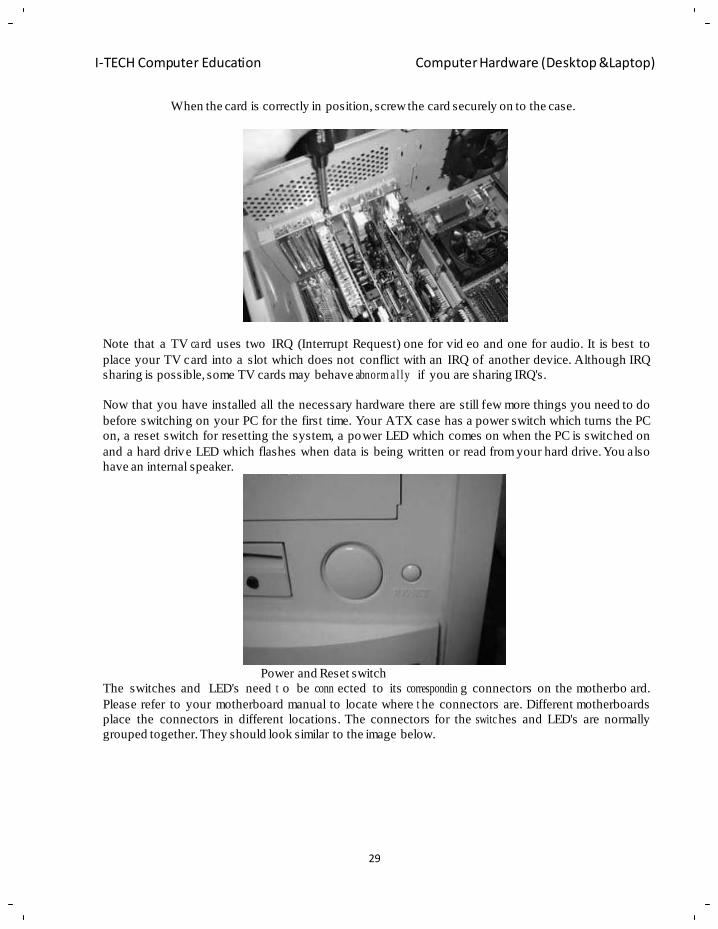
When the card is correctly in position, screw the card securely on to the case.
Note that a TV ca rd uses two IRQ (Interrupt Request) one for vid eo and one for audio. It is best to
place your TV card into a slot which does not conflict with an IRQ of another device. Although IRQ
sharing is possible, some TV cards may behave abnorm a l ly if you are sharing IRQ's.
Now that you have installed all the necessary hardware there are still few more things you need to do
before switching on your PC for the first time. Your ATX case has a power switch which turns the PC
on, a reset switch for resetting the system, a power LED which comes on when the PC is switched on
and a hard drive LED which flashes when data is being written or read from your hard drive. You also
have an internal speaker.
Power and Reset switch
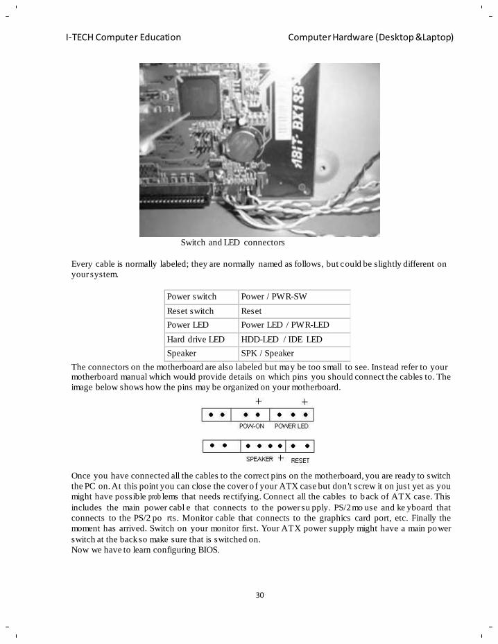
The switches and LED's need t o be conn ected to its correspondin g connectors on the motherbo ard.
Please refer to your motherboard manual to locate where t he connectors are. Different motherboards
place the connectors in different locations. The connectors for the switc hes and LED's are normally
grouped together. They should look similar to the image below.
30
I-TECH Computer Education Computer Hardware (Desktop &Laptop)
Switch and LED connectors
Every cable is normally labeled; they are normally named as follows, but could be slightly different on
your system.
Power switch Power / PWR-SW
Reset switch Reset
Power LED Power LED / PWR-LED
Hard drive LED HDD-LED / IDE LED
Speaker SPK / Speaker
The connectors on the motherboard are also labeled but may be too small to see. Instead refer to your motherboard manual which would provide details on which pins you should connect the cables to. The
image below shows how the pins may be organized on your motherboard.
Once you have connected all the cables to the correct pins on the motherboard, you are ready to switch
the PC on. At this point you can close the cover o f your ATX case but don 't screw it on just yet as you
might have possible prob lems that needs rectifying. Connect all the cables to back of ATX case. This
includes the main power cabl e that connects to the power su pply. PS/2 mo use and ke yboard that
connects to the PS/2 po rts. Monitor cable that connects to the graphics card port, etc. Finally the
moment has arrived. Switch on your monitor first. Your ATX power supply might have a main power
switch at the back so make sure that is switched on.
Now we have to learn configuring BIOS.
31
I-TECH Computer Education Computer Hardware (Desktop &Laptop)
Chapter- 2
Basic Electronic
Objective of Learning
Basics of electronics
Ohms law
Different electronics compo ne nts and its types
Tools required to work with electronics components
Micro pr oc e sso r and its architecture & block diagram of computer
In this fast developing societ y, electronics has come to stay as t he most important branch of
engineering. Electronic devices are bein g used in almost all the indus tries for qualit y control and
automation and they are fast replacing the present vast army of workers engaged in pro cessing and
assembling the fa ctories. Great stri des taken in the industr ial applications of electronics durin g the
recent years have d emonstrated that this versatile tool can be of great importance in increasi ng
production, efficie nc y and control.
The rapid g rowth of electronics technology offers a formidable challen ge to the beg inner, who may
be almost paralyzed by the mass of details. However, the mastery of fundamentals can simplify the
learning process to a great extent.
Electronics
The branch of en gineering which d eals with c urrent conduction through a v acuum or gas or
semiconductor is known as electronics. Electronics has gained much importance due to its numerou s
appl ic at io ns in industry. The electronics devices are capable of performing the following functions:
• Rectification
• Amplification
• Control
• Generation
• Conversion of light into electricity
• Conversion of electricity into light
Atomic Structure
According to the modern theory, matter is electrical in nature. All matter is comprised of molecules,
which in turn are comprised of atoms, which are again comprised of protons , neutrons and electrons.
A molecule is the smallest part of matter which can exist by itself and contains one or more atoms.
The word matter inclu des almost ever ything. It includes copper, wood, water, air....virtually
everything. If we were able to take a piece of matter such as a drop o f water, divided it b y two and
kept dividing by two u ntil it c ouldn't be divided any further while it wa s still wa ter we would
eventually have a molecule of water. A molecule, the smallest particle which can exist, of water
comprises two atoms of Hydrogen and one atom of Oxygen - H2O.
An atom is also divisibl e - into protons and ele ctrons. Both are electrical particles and neither is
divisible. Electrons are the smallest and lightest and are said to be negatively charged. Protons on the
other hand are about 1800 times the mass of electrons and are positively charged. The fact that
electrons repel electrons and protons r epel protons, but electrons and protons attract on e another
follows the basic law of physics: Like forces repel and unlike forces attract.
32
I-TECH Computer Education Computer Hardware (Desktop &Laptop)
When electrons are made to move, the result is dynamic electricity. "Dynamic" means movement. To
produce a movement of an electron it is nec essary to either have a negatively charged field "push it",
a positively charged field "pull it", or, as normally occurs in a n electric circuit, a negative and
positive charge (a pushing and pulling of forces).
Most atoms have a nucleus consistin g of all the protons of the atom and also one or more neutrons .
The remainder of the ele ctrons (always equal in number to the nuclear protons) is moving around the
nucleus in different layers K, LM, N...etc.
Some of the electrons in the outer orbit of atoms such as copper or silver can be easil y dislodged.
These electrons travel out into the wide open spaces bet ween the atoms and m olecules and m ay be
termed free electrons. It is the ability of these electrons to dr ift from atom to a tom which makes
electric current possible. Other electrons will resist dislod ge m e nt and are called bound electrons.
Basic Electronic Concepts Current
In electronics the current is defined as t he flow of electrical charge from one point to another. It is
measured in ampere.
We know that when a negatively charged body is touched to a positively charged body electrons flow
from the negative object to the positive object. Since electrons carry negative charge, this is an
example of electrical charges flowing. Before an electron can flow from one point to another it must
first be freed from the atom by gaining some energy.
Voltage
It is defined as "potential difference" between two ends of the circuit. It can be s een that a potential
difference is the result of the difference in the number of electrons between the terminals or ends of
any circuit. . It is measured in volt which can be defined as the pressure required forcing a current of
one ampere through a resistance of one ohm.
Resistance
In the topic cur rent we l earnt that cert ain materials such as copper have many free electrons. Other
materials have few er free electrons and substanc es such as g lass, rubber, mica have practicall y no
free electron movement therefore the are good insulators.
Technic al ly we can say the ability of a substance to oppose the flow of current is known as resistance.
It is measured in ohm.
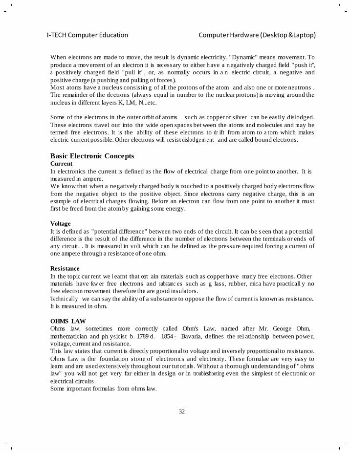
OHMS LAW
Ohms law, sometimes more correctly called Ohm's Law, named after Mr. George Ohm,
mathematician and ph ysicist b. 1789 d. 1854 - Bavaria, defines the rel ationship between powe r,
voltage, current and resistance.
This law states that current is directly proportional to voltage and inversely proportional to resistance.
Ohms Law is the foundation stone of electronics and electricity. These formulae are very easy to
learn and are used ex tensively throughout our tutorials. Without a thorough understanding of " ohms
law" you will not get very far either in design or in troubleshooting even the simplest of electronic or
electrical circuits.
Some important formulas from ohms law.
33
I-TECH Computer Education Computer Hardware (Desktop &Laptop)
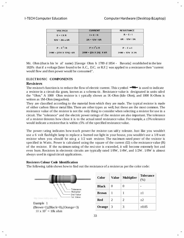
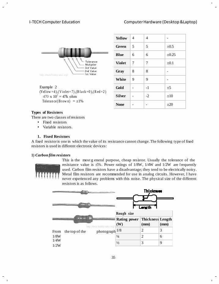
Color
Value
Multiplier Tolerance
(%)
Black 0 0 -
Brown 1 1 ±1
Red 2 2 ±2
Orange 3 3 ±0.05
Mr. Ohm (that is his 're al‘ name) [George Ohm b 1789 d 1854 - Bavaria] established in the late
1820's that if a voltage [later found to be A.C., D.C. or R.F.] was applied to a resistance then "current
would flow and then power would be consumed".
ELECT RO NI C COMPONENTS
Resisters The resistor's function is to reduce the flow of electric current. This s ymbol is used to indicate
a resistor in a circuit dia gram, known as a schema tic. Resistance value is designated in units calle d
the "Ohm." A 1000 Ohm resistor is t ypically shown as 1K -Ohm (kilo Ohm), and 1000 K-Ohms is
written as 1M-Ohm (megaohm).
They are classified according to the material from which they are made. The typical resistor is made
of either carbon film or metal film. There are other types as well, but these are the most common. The
resistance value of the resistor is not the only thing to consider when selecting a resistor for use in a
circuit. The "tolerance" and the electric power ratings of the resistor are also important. The tolerance
of a resistor denotes how close it is to the actual rated resistance value. For example, a ±5% tolerance
would indicate a resistor that is within ±5% of the specified resistance value.
The power r ating indicates how m uch power t he resistor can safel y tolerate. Just like you wouldn't
use a 6 volt flashlight lamp to replace a burned out light in your house, you wouldn't use a 1/8 watt
resistor when you should be usin g a 1/2 watt resistor. The max imum rated powe r of the r esistor is
specified in Watts. Power is calculated using the square of the current (I2) x the resistance value (R)
of the resistor. If the ma ximum rating of the resi stor is exceeded, it will become extremely hot a nd
even burn. Resistors in electronic circuits are typically rated 1/8W, 1/4W, and 1/2W . 1/8W is almost
always used in signal circuit applications.
Resisters Colour Code Identification
The following table shows how to find out the resistance of a resister as per the color code:
Example 1
(Brown=1),(Black=0),(Orange=3)
10 x 103
= 10k ohm
34
I-TECH Computer Education Computer Hardware (Desktop &Laptop)
Tolera nc e (G old) = ±5%
35
I-TECH Computer Education Computer Hardware (Desktop &Laptop)
Yellow 4 4 -
Green 5 5 ±0.5
Blue 6 6 ±0.25
Violet 7 7 ±0.1
Gray 8 8 -
White 9 9 -
Gold - -1 ±5
Silver - -2 ±10
None - - ±20
Rough size
Rating power
(W)
Thickness
(mm)
Length
(mm)
1/8 2 3
¼ 2 6
½ 3 9
Example 2
(Yel low =4 ),( V iolet= 7) ,(B la ck =0 ),( R ed =2 )
470 x 102
= 47k ohm
Tolera n ce ( Br ow n) = ±1%
Types of Resisters
There are two classes of resistors
• Fixed resistors
• Variable resistors.
1. Fixed Resistors
A fixed resistor is one in which the value of its resistance cannot change. The following type of fixed
resistors is used in different electronic devices:
1) Carbon film resistors
This is the most g eneral purpose, cheap resistor. Usually the tolerance of the
resistance value is ±5% . Power ratings of 1/8W, 1/4W and 1/2W are f requently
used. Carbon film resistors have a disadvantage; they tend to be electrically noisy.
Metal film resistors are recommended for use in analog circuits. However, I have
never experienced any problems with this noise. The physical size of the different
resistors is as follows.
From the top of the photograph
1/8W 1/4W
1/2W
35
I-TECH Computer Education Computer Hardware (Desktop &Laptop)
Rough size
Rating power
(W)
Thickness
(mm)
Length
(mm)
1/8 2 3
¼ 2 6
1 3.5 12
2 5 15
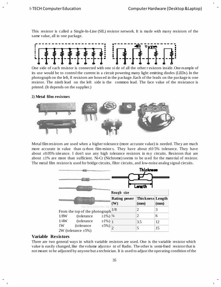
1/8W (tolerance ±1%)
1/4W (tolerance ±1%)
1W (tolerance ±5%)
This resistor is called a Single-In-Line (SIL) resistor network. It is made with many resistors of the
same value, all in one package.
One side of e ach resistor is connected with one si de of all the other r esistors inside. One ex ample of
its use would be to control the current in a circuit powering many light emitting diodes (LEDs). In the
photograph on the left, 8 resistors are hous ed in the package. Each of the leads on the package is one
resistor. The ninth lead on the left side is the common lead. The face value of the resistance is
printed. (It depends on the supplier.)
2) Metal film resistors
Metal film resistors are used when a higher tolerance (more accurate value) is needed. They are much
more accurate in value than ca rbon film resistor s. They have about ±0.0 5% tolerance. They have
about ±0.05% toler ance. I don't use any high tolerance resistors in m y circuits. Resistors that are
about ±1% are more than sufficient. Ni-Cr (Nichrome) seems to be us ed for the material of resistor.
The metal film resistor is used for bridge circuits, filter circuits, and low-noise analog signal circuits.
From the top of the photograph
2W (tolerance ±5%)
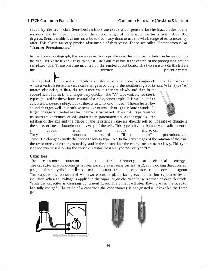
Variable Resistors There are two general ways in which variable resistors are used. One is the variable resistor which
value is easily changed, like the volume adjustm e nt of Radio. The other is semi-fixed resistor that is
not meant to be adjusted by anyone but a technician. It is used to adjust the operating condition of the
36
I-TECH Computer Education Computer Hardware (Desktop &Laptop)
circuit by the technician. Semi-fixed resistors are used t o compensate for t he inaccuracies of t he
resistors, and to fine-tune a circuit. The rotation angle of the va riable resistor is usuall y about 300
degrees. Some variable resistors must be turned many times to use the whole range of resistance they
offer. This a llows for very precise adjustments of their value. These are called "Potentiometers" or
"Trimmer Potentiometers."
In the above photograph, the variable r esistor typically used for volume controls can be se en on the
far right. Its value is ver y easy to adjust. The f our resistors at the center of the photog raph are t he
semi-fixed type. These ones are mounted on the printed circuit board. The two resistors on the left are
the trimmer potentiometers.
This symbol is used t o indicate a variable resistor in a circuit diagram.There is three ways in
which a variable resistor's value can change according to the rotation angle of its axis. When type "A"
rotates clockwise, at first, the resistance value changes slowly and then in the
second half of its ax is, it changes very quickly. The "A" type variable resistor is
typically used for the vo lume control of a radio, for ex ample. It is well suited t o
adjust a low sound subtly. It suits the char acteristics of the ear. The ear he ars low
sound changes well, but isn' t as sensitive to small chan ges in loud sounds. A
larger change is needed as t he volume is increased. These "A" type variable
resistors are sometimes called "audio taper" potentiometers. As for type "B", the
rotation of the axis and the chan ge of the resistance value are directly related. The rate of change is
the same, or linear, throughout the sweep of the axis. This type suits a resistance value adjustment in
a circuit, a bal ance circuit and so on.
They are sometimes called "linear taper" potentiometers.
Type "C" changes exactly the opposite way to type "A". In the early stages of the rotation of the axis,
the resistance value changes rapidly, and in the second half, the change occurs more slowly. This type
isn't too much used. As for the variable resistor, most are type "A" or type "B".
Capacitors
The capacitor's function is to store electricity, or electrical energy.
The capacitor also functions as a filter, passing alternating current (AC), and blocking direct current
(DC). This s ymbol is used to indicate a capacitor in a circuit diagram.
The capacitor is constructed with two electrode plates facing each other, but separated by an
insulator. When DC voltage is applied to the capacitor, an electric charge is stored on each electrode.
While the capacitor is charging up, cu rrent flows. The current will stop flowing when the cap acitor
has fully charged. The value of a capacitor (the capacitance), is designated in units c alled the Farad
(F).
37
I-TECH Computer Education Computer Hardware (Desktop &Laptop)
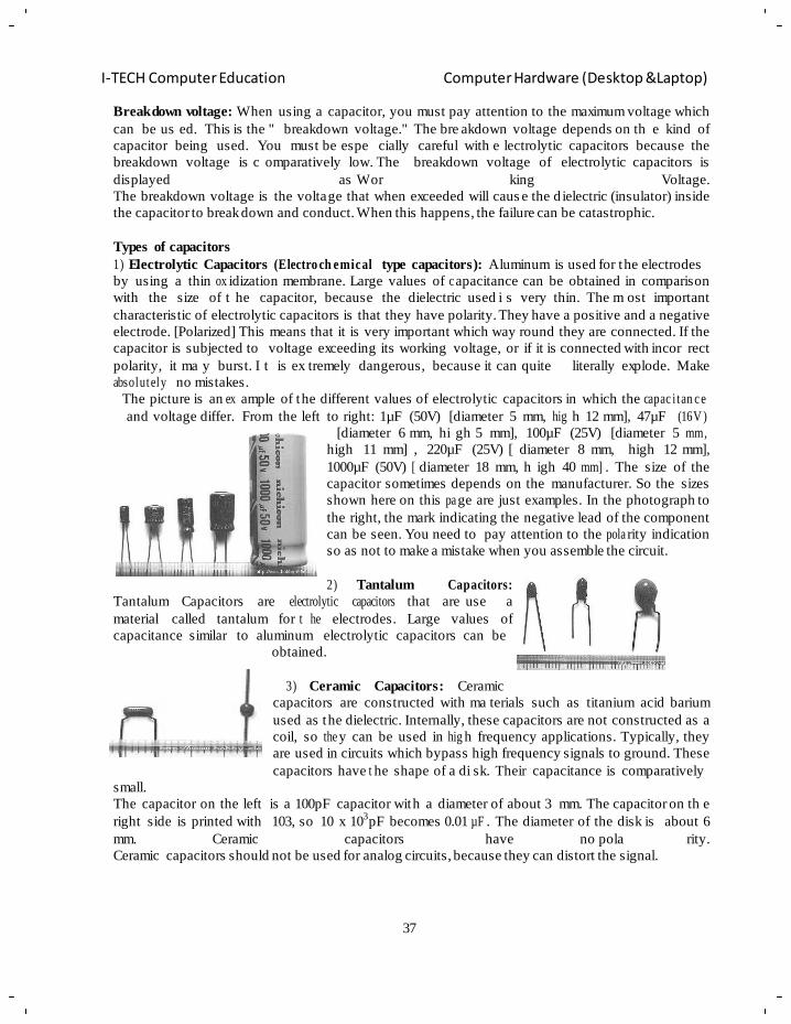
Breakdown voltage: When using a capacitor, you must pay attention to the maximum voltage which
can be us ed. This is the " breakdown voltage." The bre akdown voltage depends on th e kind of
capacitor being used. You must be espe cially careful with e lectrolytic capacitors because the
breakdown voltage is c omparatively low. The breakdown voltage of electrolytic capacitors is
displayed as Wor king Voltage.
The breakdown voltage is the voltage that when exceeded will caus e the d ielectric (insulator) inside
the capacitor to break down and conduct. When this happens, the failure can be catastrophic.
Types of capacitors
1) Electrolytic Capacitors (Electro ch emical type capacitors): Aluminum is used for the electrodes
by using a thin ox idization membrane. Large values of c apacitance can be obtained in comparison
with the size of t he capacitor, because the dielectric used i s very thin. The m ost important
characteristic of electrolytic capacitors is that they have polarity. They have a positive and a negative
electrode. [Polarized] This means that it is very important which way round they are connected. If the
capacitor is subjected to voltage exceeding its working voltage, or if it is connected with incor rect
polarity, it ma y burst. I t is ex tremely dangerous, because it can quite literally explode. Make
absolutely no mistakes.
The picture is an ex ample of the different values of electrolytic capacitors in which the capac i tan c e
and voltage differ. From the left to right: 1µF (50V) [diameter 5 mm, hig h 12 mm], 47µF (16V )
[diameter 6 mm, hi gh 5 mm], 100µF (25V) [diameter 5 mm,
high 11 mm] , 220µF (25V) [ diameter 8 mm, high 12 mm],
1000µF (50V) [ diameter 18 mm, h igh 40 mm] . The size of the
capacitor sometimes depends on the manufacturer. So the sizes
shown here on this pa ge are just examples. In the photograph to
the right, the mark indicating the negative lead of the component
can be seen. You need to pay attention to the pola rity indication
so as not to make a mistake when you assemble the circuit.
2) Tantalum Capacitors:
Tantalum Capacitors are electrolytic capacitors that are use a
material called tantalum for t he electrodes. Large values of
capacitance similar to aluminum electrolytic capacitors can be
obtained.
small.
3) Ceramic Capacitors: Ceramic
capacitors are constructed with ma terials such as titanium acid barium
used as the dielectric. Internally, these capacitors are not constructed as a
coil, so the y can be used in hig h frequency applications. Typically, they
are used in circuits which bypass high frequency signals to ground. These
capacitors have t he shape of a di sk. Their capacitance is comparatively
The capacitor on the left is a 100pF capacitor with a diameter of about 3 mm. The capacitor on th e
right side is printed with 103, so 10 x 103pF becomes 0.01 µF . The diameter of the disk is about 6
mm. Ceramic capacitors have no pola rity.
Ceramic capacitors should not be used for analog circuits, because they can distort the signal.
38
I-TECH Computer Education Computer Hardware (Desktop &Laptop)
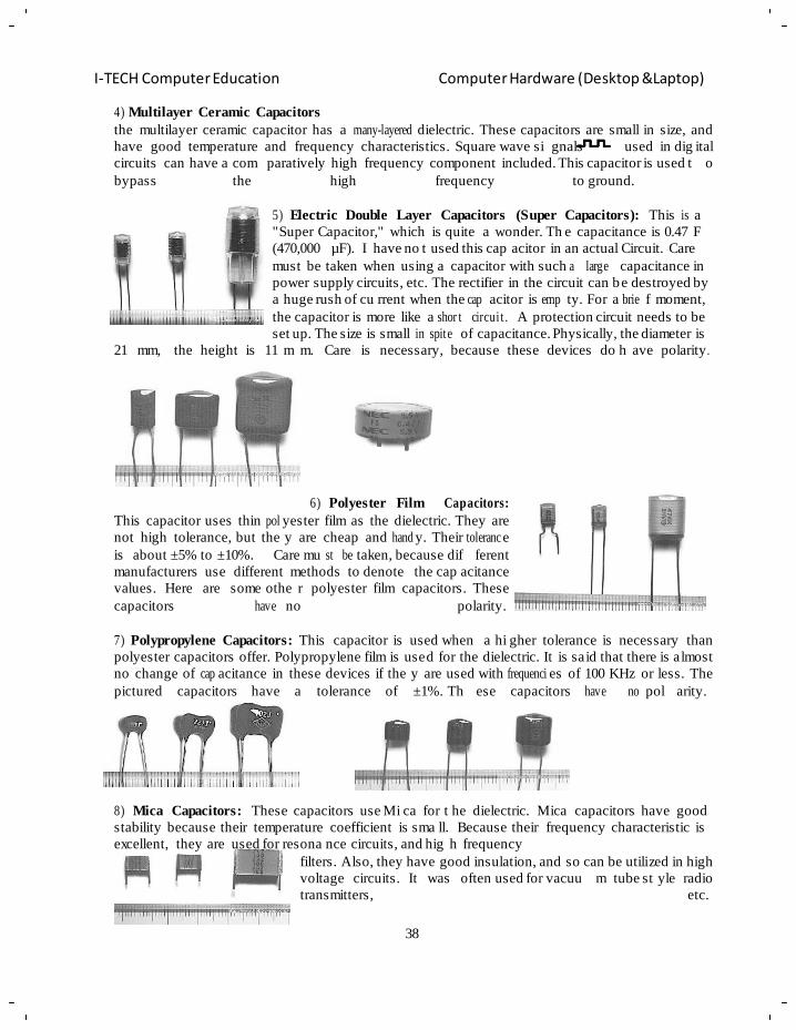
4) Multilayer Ceramic Capacitors
the multilayer ceramic capacitor has a many-layered dielectric. These capacitors are small in size, and
have good temperature and frequency characteristics. Square wave si gnals used in dig ital
circuits can have a com paratively high frequency component included. This capacitor is used t o
bypass the high frequency to ground.
5) Electric Double Layer Capacitors (Super Capacitors): This is a
"Super Capacitor," which is quite a wonder. Th e capacitance is 0.47 F
(470,000 µF). I have no t used this cap acitor in an actual Circuit. Care
must be taken when using a capacitor with such a large capacitance in
power supply circuits, etc. The rectifier in the circuit can be destroyed by
a huge rush of cu rrent when the cap acitor is emp ty. For a brie f moment,
the capacitor is more like a shor t circui t . A protection circuit needs to be
set up. The size is small in spite of capacitance. Physically, the diameter is
21 mm, the height is 11 m m. Care is necessary, because these devices do h ave polarity.
6) Polyester Film Capacitors:
This capacitor uses thin pol yester film as the dielectric. They are
not high tolerance, but the y are cheap and hand y. Their toleranc e
is about ±5% to ±10%. Care mu st be taken, because dif ferent
manufacturers use different methods to denote the cap acitance
values. Here are some othe r polyester film capacitors. These
capacitors have no polarity.
7) Polypropylene Capacitors: This capacitor is used when a hi gher tolerance is necessary than
polyester capacitors offer. Polypropylene film is used for the dielectric. It is said that there is almost
no change of cap acitance in these devices if the y are used with frequenci es of 100 KHz or less. The
pictured capacitors have a tolerance of ±1%. Th ese capacitors have no pol arity.
8) Mica Capacitors: These capacitors use Mi ca for t he dielectric. Mica capacitors have good
stability because their temperature coefficient is sma ll. Because their frequency characteristic is
excellent, they are used for resona nce circuits, and hig h frequency
filters. Also, they have good insulation, and so can be utilized in high
voltage circuits. It was often used for vacuu m tube st yle radio
transmitters, etc.
39
I-TECH Computer Education Computer Hardware (Desktop &Laptop)
Mica capacitors do not have high values of capacitance, and they can be relatively expensive. These
capacitors have no polarity.
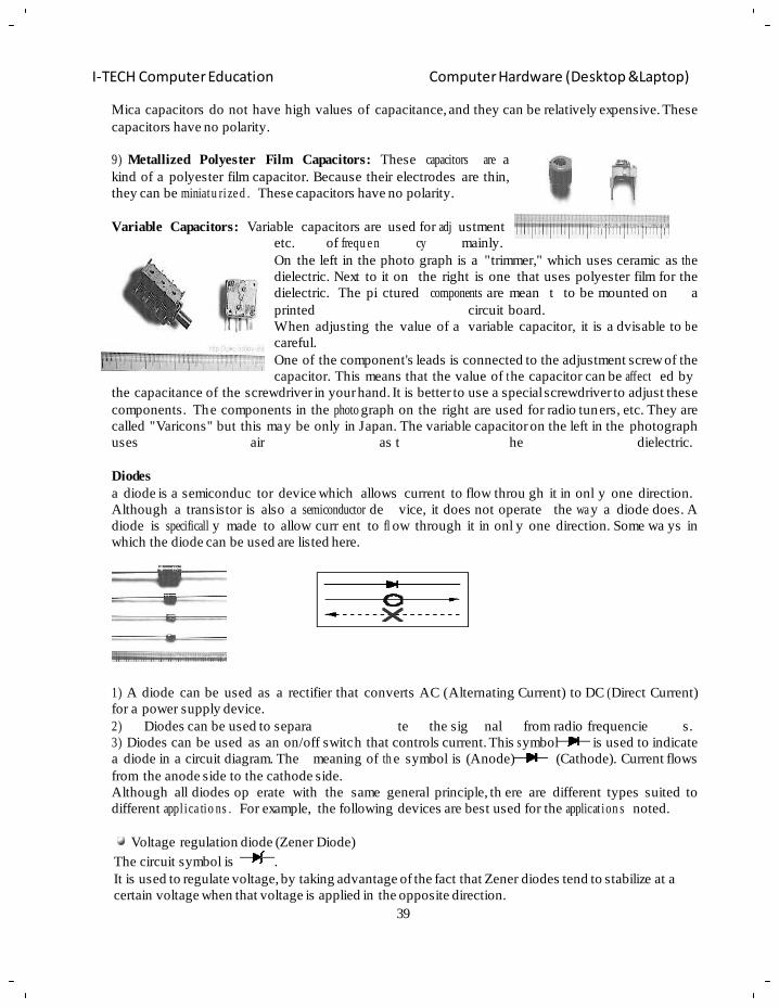
9) Metallized Polyester Film Capacitors: These capacitors are a
kind of a polyester film capacitor. Because their electrodes are thin,
they can be miniatu ri ze d . These capacitors have no polarity.
Variable Capacitors: Variable capacitors are used for adj ustment
etc. of frequ e n cy mainly.
On the left in the photo graph is a "trimmer," which uses ceramic as th e
dielectric. Next to it on the right is one that uses polyester film for the
dielectric. The pi ctured components are mean t to be mounted on a
printed circuit board.
When adjusting the value of a variable capacitor, it is a dvisable to b e
careful.
One of the component's leads is connected to the adjustment screw of the
capacitor. This means that the value of t he capacitor can be affect ed by
the capacitance of the screwdriver in your hand. It is better to use a special screwdriver to adjust these
components. The components in the photo graph on the right are used for radio tuners, etc. They are
called "Varicons" but this may be only in Japan. The variable capacitor on the left in the photograph
uses air as t he dielectric.
Diodes
a diode is a semiconduc tor device which allows current to flow throu gh it in onl y one direction.
Although a transistor is also a semiconductor de vice, it does not operate the wa y a diode does. A
diode is specificall y made to allow curr ent to fl ow through it in onl y one direction. Some wa ys in
which the diode can be used are listed here.
1) A diode can be used as a rectifier that converts AC (Alternating Current) to DC ( Direct Current)
for a power supply device.
2) Diodes can be used to separa te the sig nal from radio frequencie s.
3) Diodes can be used as an on/off switch that controls current. This s ymbol is used to indicate
a diode in a circuit diagram. The meaning of th e symbol is (Anode) (Cathode). Current flows
from the anode side to the cathode side.
Although all diodes op erate with the same general principle, th ere are different types suited to
different appl ica tio ns . For example, the following devices are best used for the applicat ion s noted.
Voltage regulation diode (Zener Diode)
The circuit symbol is .
It is used to regulate voltage, by taking advantage of the fact that Zener diodes tend to stabilize at a
certain voltage when that voltage is applied in the opposite direction.
40
I-TECH Computer Education Computer Hardware (Desktop &Laptop)
Light emitting diode
the circuit symbol is . This type of diode emits light when current flows through it in the
forward direction. (Forward biased.)
Variable capacitance diode the circuit symbol is .The current does not flow when applying
the voltage of the opposite direction to the diode. In this
condition, the diode has a capacitance like the capacitor. It is a
very small capa ci ta nc e . The capacitance of the diode changes
when changing voltage. With the change of this capa ci ta nc e , the
freque n c y of the oscillator can be changed.
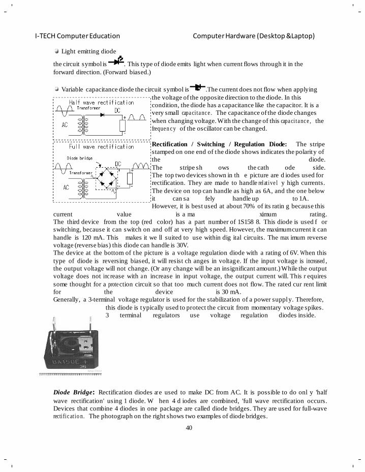
Rectification / Switching / Regulation Diode: The stripe
stamped on one end of the diode shows indicates the polarity of
the diode.
The stripe sh ows the cath ode side.
The top two devices shown in th e picture are d iodes used for
rectification. They are made to handle relat ive l y high currents.
The device on top can handle as high as 6A, and the one below
it can sa fely handle up to 1A.
However, it is best used at about 70% of its ratin g because this
current value is a ma ximum rating.
The third device from the top (red color) has a part number of 1S158 8. This diode is used f or
switching, because it can switch on and off at very high speed. However, the maximum current it can
handle is 120 mA. This makes it we ll suited to use within dig ital circuits. The max imum reverse
voltage (reverse bias) this diode can handle is 30V.
The device at the bottom of the picture is a voltage regulation diode with a rating of 6V. W hen this
type of diode is reversing biased, it will resist ch anges in voltage. If the input voltage is increased ,
the output voltage will not change. (Or any change will be an insignificant amount.) While the output
voltage does not inc rease with a n increase in input voltage, the output current will. This r equires
some thought for a prote ction circuit so that too much current does not flow. The rated cur rent limit
for the device is 30 mA.
Generally, a 3-terminal voltage regulator is used for the stabilization of a power suppl y. Therefore,
this diode is typically used to protect the circuit from momentary voltage spikes.
3 terminal regulators use voltage regulation diodes inside.
Diode Bridge: Rectification diodes ar e used to make DC from AC. It is possible to do onl y 'half
wave rectification' using 1 diode. W hen 4 d iodes are combined, 'full wave rectification occurs.
Devices that combine 4 diodes in one package are called diode bridges. They are used for full-wave
recti fi c at io n. The photograph on the right shows two examples of diode bridges.
41
I-TECH Computer Education Computer Hardware (Desktop &Laptop)
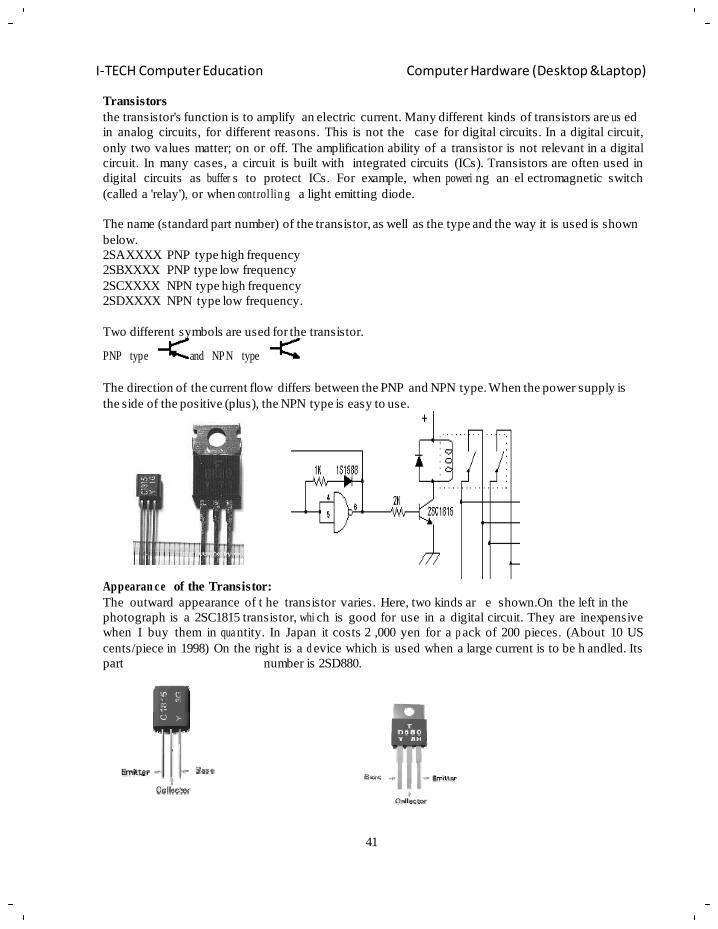
Transistors
the transistor's function is to amplify an electric current. Many different kinds of transistors are us ed
in analog circuits, for different reasons. This is not the case for digital circuits. In a digital circuit,
only two values matter; on or off. The amplification ability of a transistor is not relevant in a digital
circuit. In many cases, a circuit is built with integrated circuits (ICs). Transistors are often used in
digital circuits as buffer s to protect ICs. For example, when poweri ng an el ectromagnetic switch
(called a 'relay'), or when cont rol lin g a light emitting diode.
The name (standard part number) of the transistor, as well as the type and the way it is used is shown
below.
2SAXXXX PNP type high frequency
2SBXXXX PNP type low frequency
2SCXXXX NPN type high frequency
2SDXXXX NPN type low frequency.
Two different symbols are used for the transistor.
PNP type and NPN type
The direction of the current flow differs between the PNP and NPN type. When the power supply is
the side of the positive (plus), the NPN type is easy to use.
Appearan ce of the Transistor:
The outward appearance of t he transistor varies. Here, two kinds ar e shown.On the left in the
photograph is a 2SC1815 transistor, whi ch is good for use in a digital circuit. They are inexpensive
when I buy them in qua ntity. In Japan it costs 2 ,000 yen for a p ack of 200 pieces. (About 10 US
cents/piece in 1998) On the right is a d evice which is used when a large current is to be h andled. Its
part number is 2SD880.
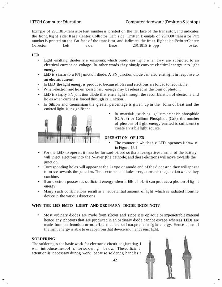
42
I-TECH Computer Education Computer Hardware (Desktop &Laptop)
Example of 2SC1815 transistor Part number is printed on the flat face o f the transistor, and indicates
the front. Rig ht side: B ase Center: Collector Left side: Emitter. E xample of 2SD880 transistor Part
number is printed on the flat face of the transistor, and indicates the front. Right side: Emitter Center:
Collector Left side: Base 2SC1815 is opp osite.
LED
• Light emitting diodes ar e components, which produ ces light when the y are subjected to an
electrical current or voltage. In other words they simply convert electrical energy into light
energy.
• LED is similar to a PN j unction diode. A PN junction diode can also emit lig ht in response to
an electric current.
• In LED the light energy is produced because holes and electrons are forced to recombine.
• When electron and holes reco m bine s, energy may be released in the form of photon.
• LED is simply PN junction diode that emits light through the recombination of electrons and
holes when current is forced through its junction.
• In Silicon and Germanium the greater percentage is g iven up in the form of heat and the
emitted light is insignificant.
• In materials, such as gallium arsenide phosphide
(GaAsP) or Gallium Phosphide (GaP), the number
of photons of li ght energy emitted is sufficient t o
create a visible light source.
OPERAT I O N OF LED
• The manner in which th e LED operates is show n
in Figure 15.1
• For the LED to operate it must be forward-biased so that the negative terminal of the battery
will inject electrons into the N-layer (the cathode) and these electrons will move towards the
junction.
• Corresponding holes will appear at the P-t ype or anode end o f the diode and they will appear
to move towards the junction. The electrons and holes merge towards the junction where they
combine.
• If an electron possesses s ufficient energy when it fills a hole, it can produce a photon of lig ht
energy.
• Many such combinations result in a substantial amount of lig ht which i s radiated from the
device in the various directions.
WHY THE LED EMITS LIGHT AND ORDI NA RY DIODE DOES NOT?
• Most ordinary diodes are made from silicon and since it is op aque or impenetrable material
hence any photons that are produced in an or dinary diode cannot escape whereas LEDs are
made from semiconductor materials that are semi-transpar ent to light energy. Hence some of
the light energy is able to escape from that device and hence emit light.
SOLDERING
The soldering is the basic work for electronic circuit engineering. I
will introduce the tool s for soldering below. The sufficient
attention is necessary during work, because soldering handles a
43
I-TECH Computer Education Computer Hardware (Desktop &Laptop)
high temperature. Pay attention to the handlin g of the soldering iron sufficiently, because it becomes
burn, fire more, carelessly.
• When you are about to make or rep air a fin e piece of El ectronic equipment which has bee n
carefully engineered, but it must be mad e or repaired with just a s much care if the unit is to
operate at the rated specifications.
• The most important factor in making or repairing equipment is Soldering. An electronic unit
will not work unless it is soldered properly.
• Proper soldering is most important to learn, since 90% of all service problems are due to bad
solder connections. If you are not experienced at soldering, a few minutes practice with some
odd lengths of wire on any PCB (Printed Circuit Board) will be helpful.
• The PCB has two sides- one plain or marked and the other a coppe r foil s ide. You have to fit
all the comp on en ts on the plain side and solder the leads on the copper foil side.
• A good solder connection will form an electri cal connection between the copper foil and the
component lead. Read the following instructions and study the pictorials of soldering.
RULES FOR GOOD SOLDERING
• Use the ri ght type of soldering iron. A small e fficient soldering iron ( about 10 to 25 W atts
with a 1/8‖ or 1/4‖ tip) is ideal for circuit board work. Pencil Bit soldering iron made by Sold
Ron works best. The soldering iron will reach its operating temperature within 3 to 5 minutes
after it is switched ‗ON‘ and should be left ‗ON‘ during the working period.
• Keep the hot tip of the soldering iron on a piece of metal so that excess heat is dissipated.
• Make sure that the connection to be soldered is clean. Wax frayed isolations and other foreign
substances cause poor connections. Clean the co mponent leads, wires, lug s, etc. with a blade
or a knife to remove the rust and dust before soldering.
• Use just enoug h solder to cover the lead a nd the copper foil ar ea of th e connection to be
soldered. Excess solder can bri dge across from one foil path to another and cause a short
circuit.
• Use sufficient heat. This is the essence of good soldering. Apply enough heat to the foil and
the lead to allow the solder to spread fre ely. You are not using enough heat, if the solder
barely melts and forms a round ball of rou gh flaky solder. A g ood soldered joint will look
smooth, shining and sol der spreader. The diff erence between good (sufficiently heated) and
poor soldering (insuf fici e nt ly heated) is just a few extra seconds with a lot iron applied firmly.
• Check the conn e ction. Compare it with the illust ration or with the solder joints made at the
factory. A well soldered joint should look smooth and brig ht and the solder should adhere
evenly to both the wire and the circuit board foil.
• Remember larger metal surfaces take longer time to heat.
Disorderin g wire
This is made of thin copper net wi re like a scr een cable in a co axial cable.
Like water inhales to cloth, the solder is absorbed to the net wire by a capillary tube phenomenon.
The usage is shown below. Apply the disordering wire to the part that wants to take solder. Apply the
soldering iron from the top a nd Melt the solder. The melted solder is absorbed to disor dering wire
with a capillary tube phenom en on . At this time you absorb solder while shifting disordering wire.
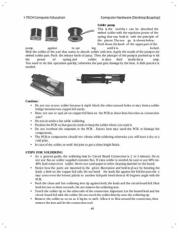
44
I-TECH Computer Education Computer Hardware (Desktop &Laptop)
Solder pump
This is the tool tha t can be absorbed the
melted solder with the repulsion power of the
spring that was built in with the principle of
the piston. The usa ge is shown below.
Push down the knob of the upper part of the
pump against to spr ing until it is locked.
Melt the solder of the p art that wants to absorb solder with iron. Apply the nozzle of the pump to th e
melted solder part. Push the release knob of pum p. Then the plunger of the pump is pushed up w ith
the power of spring and solder is abso rbed inside the p ump.
You need to do this operation quickly; otherwise the part gets damage by the heat. A little practice is
needed.
Cautions:
• Do not use ex cess solder because it mig ht block the other unused holes or ma y form a solder
bridge between two copper foil tracks.
• Does not use or spre ad on copper foil lines on the PCB as these lines fun ction as connection
wire?
• Do not sit under a fan while soldering.
• Position the PCB so that gravity tends to keep the solder where you want it.
• Do not overheat the components or the PCB . Excess heat may spoil the PCB or damage the
components.
• The PCB or components should not vibrate while soldering otherwise you will have a dry or a
cold joint.
• In case of dry solder, re-weld the joint to get a shiny bright finish.
STEPS FOR SOLDERING
• As a general guide, the soldering time fo r Circuit Board Connection is 2 to 3 minutes. Do es
not use flux as solder supplied contains flux. If extra solder is needed, be sure to use 60% tin-
40% lead compo sit ion solder. Never use sand paper or other cleaning material on the board.
• Notice how the parts are mounted in the given illustration and held in pl ace by bending the
leads a little on the copper foil side. Do not bend the leads flat against the foil because the y
may cross-over the b rown plastic to another foil-path bend them at 45 degrees angle with the
PCB.
• Push the clean and hot soldering iron tip against both, the leads and the circuit board foil. Heat
both for two or three seconds. Do not remove the soldering iron.
• Touch the solder tip to the other side of the connection. Important: Let the heated lead and the
circuit board foil melt the solder. Do not touch the solder directly onto the soldering tip.
• Remove the solder as so on as it beg ins to melt. Allow it to flow around the connection, then
remove the iron and let the connection cool.
45
I-TECH Computer Education Computer Hardware (Desktop &Laptop)
• After the solder has hardened clip off the wire close to the circuit board foil.
Electronic Instruments
Those instruments which employ electronic devices for measuring various electrical quantities (e.g.
voltage, current, resistance etc.) are known as electronic instruments.
There are a l arge number of electronic instruments available for completion of vari ous tests and
measurements. However, in this c hapter, we shall c onfine our attention to the following electronic
instruments:
(i) Multimeter (ii) Vacuum tube voltmeter (VTVM)
(i ii ) Cathode ray oscilloscope.
The knowledge of the manner in which e ach instrument is used plus an understandin g of t he
applications and limitations of each instrument will enable the reader to utilize such instruments
successfully.
Multimeter: A multimeter is a n electronic instrument which can measure resistances, currents and
voltages. It is an indispensable instrument and can be used fo r measuring d.c. as well as a.c. voltages
and currents. Multimeter is the most ine xpensive equipment and can make various electrical
measur e m en ts with reasonable accuracy.
Construction: A multimeter consists of an ordinary pivoted type of moving coil galvanometer. This
galvanometer consists of a coil pivoted on jew eled bearings between the poles of a p ermanent
magnet. The indicating needle is fastened to the coil. When electric current is passed through the coil,
mechanical force acts and the pointer moves over the scale.
Functions: A multimeter can measure voltages, currents and resistances to achieve this obje ctive.
Proper circuits are incorporated with the galvanometer. The galvanometer in a multimeteris always
of left zero type i.e. normally its needle rests in extreme left position as compared to center zero
position of ordinary galvanometers.
Applications of Multimeter
A multimeter is an extremely important electronic instrument and is exten sive ly used for carrying out
various tests and measure m e nts in electronic circuits. It is used:
(i ) For checking the circuit continuity. When the multime ter is e mployed as continuity
checking device, the ohmmeter scale is utilized and the equipment to be c hecked is shu t
off or discon ne c ted from the power mains.
(ii ) For measuring d.c. current flowing throu gh the cathode, plate, screen and other v acuum
tube circuits.
(ii i ) For measuring d.c. voltage across various resistors in electronic circuits.
(iv) For measuring a.c. voltages across power supply transformers.
(v) For asce rtain ing whether or not open or short circuit exists in the circuit under study.
Sensitivity of Multimeter
The resistance offered per volt of full sc ale deflection by the multimeter is known as multimeter
sensitivity.
Merits and Demerits of Multimeter
Although multimeter is widely used for manufacturing and servicing of electronics equipment, it h as
its own merits and demerits.
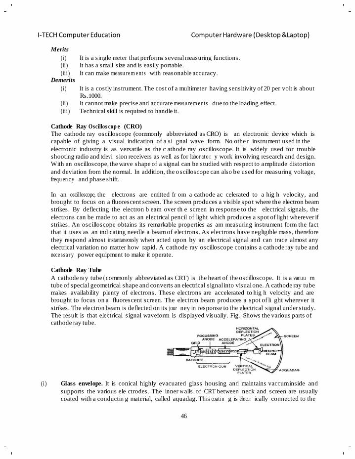
46
I-TECH Computer Education Computer Hardware (Desktop &Laptop)
Merits
(i ) It is a single meter that performs several measuring functions.
(ii ) It has a small size and is easily portable.
(ii i ) It can make measu re m e nts with reasonable accuracy. Demerits
(i ) It is a costly instrument. The cost of a multimeter having sensitivity of 20 per volt is about
Rs.1000.
(ii ) It cannot make precise and accurate measu re m e nts due to the loading effect.
(ii i ) Technical skill is required to handle it.
Cathode Ray Oscillos cop e (CRO)
The cathode ray oscilloscope (commonly abbreviated as CRO) is an electronic device which is
capable of giving a visual indication of a si gnal wave form. No othe r instrument used in the
electronic industry is as versatile as the c athode ray oscilloscope. It is widely used for trouble
shooting radio and televi sion receivers as well as for labor ato r y work involving research and design.
With an oscilloscope, the wave shape of a signal can be studied with respect to amplitude distortion
and deviation from the normal. In addition, the oscilloscope can also be used for measuring voltage,
frequ en c y and phase shift.
In an oscilloscope, the electrons are emitted fr om a cathode ac celerated to a hig h velocity, and
brought to focus on a fluorescent screen. The screen produces a visible spo t where the electron beam
strikes. By deflecting the electron b eam over th e screen in response to the electrical signals, the
electrons can be made to act as an electrical pencil of light which produces a spot of lig ht wherever if
strikes. An oscilloscope obtains its remarkable properties as am measuring instrument form the fact
that it uses as an indicating needle a beam of electrons. As electrons have negligible mass, therefore
they respond almost instantaneously when acted upon by an electrical signal and can trace almost any
electrical variation no matter how rapid. A cathode ray oscilloscope contains a cathode r ay tube and
nece ssa r y power equipment to make it operate.
Cathode Ray Tube
A cathode ra y tube ( commonly abbreviated as CRT) is the heart of the oscilloscope. It is a vacuu m
tube of special geometrical shape and converts an electrical signal into visual one. A cathode ray tube
makes availability plenty of electrons. These electrons are accelerated to hig h velocity and are
brought to focus on a fluorescent screen. The electron beam produces a spot of li ght wherever it
strikes. The electron beam is deflected on its jour ney in response to the electrical signal under study.
The result is that electrical signal waveform is displayed visually. Fig. Shows the various parts of
cathode ray tube.
(i ) Glass envelope. It is conical highly evacuated glass housing and maintains vaccum inside and
supports the various ele ctrodes. The inner w alls of CRT between neck and screen are usually
coated with a conductin g material, called aquadag. This coatin g is elect r ically connected to the
47
I-TECH Computer Education Computer Hardware (Desktop &Laptop)
accelerating anode so that electrons which accidentally strike the walls are returned to the anode.
This prevents the walls of the tube form charging to a high negative potential.
(ii ) Electron gun assembly. The a rrangement of electrod es which produce a focused beam of
electrons is called the electron gun. It essentially consists of an indire ctly heated cathode, a
control grid, a focusing anode and an accelerating anode. The control grid is held at neg ative
potential w.r.t. cathode whereas the two anodes are maintained at hi gh positive potential w.r.t.
cathode.
The cathode consists of a nickel cylinder coated with oxide coating and provides plent y of
electrons. The control grid encloses the cathode and consists of a metal c ylinder with a tin y
circular opening to keep the electron beam small in size. The focusing anode focuses the electron
beam into a sharp pin-point by controlling the positive potential on it. The positive potential
(about 10,000V) on the acc elerating anode is much hi gher than on the focusing anode. For this
reason, this anode accelerates the n arrow beam to high velocity. Therefore, the el ectron gun
assembly forms a narro w, accelerated beam of electrons which produces a spot of l ight when i t
strikes the screen.
(ii i ) Deflection plate assembly. The deflection of the beam is accomplished by two sets of deflecting
plates placed within the tube beyond the accelerating anode as shown in Fig. 24.17. One set is the
vertical deflection plates and the other set is the horizontal deflection plates.
The vertical deflection plates are mounted horiz ontally in the tube. By applying proper potential
to these plates, the electron beam can be made to move up and down vertically on the fluorescent
screen. The horizontal deflection plates are mounted in the v ertical plane. An appropriate
potential on t hese plate can caus e the electron beam to move right and l eft horizontally on t he
screen.
(iv) Screen. The scre en is the inside face of t he tube and i s coated with some fluorescent material
such as zinc orthosilicate, zinc oxide etc. When high velocity electron beam strikes the screen, a
spot of light is produced at the point of impact. The colour of the spot dep ends upon the nature of
fluorescent material. If zinc orthosilicate is used as t he fluorescent material, green light spot is
produced.
(v) Action of CRT. When the cathode is heated, it emits pl enty of el ectrons. These electrons pass
through control grid on their way to s creen. The control grid influences the amount of currents
flow as in standard vacuum tubes. If negative potential on the control grid is high, fewer electrons
will pass through it and the electron beam on striking the screen will produce a dim spot of light.
Reverse will happen if the negative potential on the control grid sis reduced. Thus, the intensity of
light spot on the screen c an be changed by changing the negative potential on the control g rid. As
the electron b eam leaves the control grid, it comes under the influ ences of fo cusing and
accelerating anode. As t he two anodes are maintained at hi gh positive p otential, therefore, they
produce a field which acts as an electrostatic lens to converge the electron beam at a point on the
screen.
ELECT RO NI C TOOLS
When you make an electronic circuit, the work which does the component lead of
parts straight or bends the lead or cuts the lead is needed. When handling a small
part, the tool tha t the tip is sha rp is ne eded. The following are some of the
example of freque nt ly used tools for repairing or making a electronics circuit.
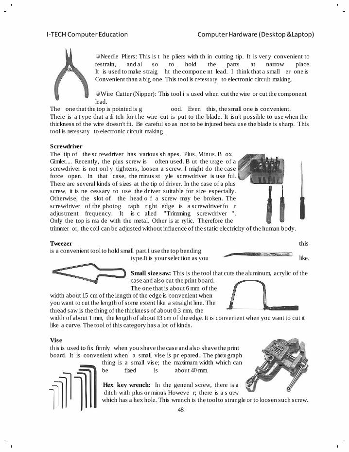
48
I-TECH Computer Education Computer Hardware (Desktop &Laptop)
Needle Pliers: This is t he pliers with th in cutting tip. It is ver y convenient to
restrain, and al so to hold the parts at narrow place.
It is used to make straig ht the compone nt lead. I think that a small er one is
Convenient than a big one. This tool is nece ssa ry to electronic circuit making.
Wire Cutter (Nipper): This tool i s used when cut the wire or cut the component
lead.
The one that the top is pointed is g ood. Even this, the small one is convenient.
There is a t ype that a di tch for t he wire cut is put to the blade. It isn't possible to use when the
thickness of the wire doesn't fit. Be careful so as not to be injured beca use the blade is sharp. This
tool is nece ssar y to electronic circuit making.
Screwdriver
The tip of the sc rewdriver has various sh apes. Plus, Minus, B ox,
Gimlet.... Recently, the plus screw is often used. B ut the usag e of a
screwdriver is not onl y tightens, loosen a screw. I might do the c ase
force open. In that case, the minus st yle screwdriver is use ful.
There are several kinds of sizes at the tip of driver. In the case of a plus
screw, it is ne cessary to use the dr iver suitable for size especially.
Otherwise, the slot of the head o f a screw may be broken. The
screwdriver of the photog raph right edge is a screwdriver fo r
adjustment frequency. It is c alled "Trimming screwdriver ".
Only the top is ma de with the metal. Other is ac rylic. Therefore the
trimmer or, the coil can be adjusted without influence of the static electricity of the human body.
Tweezer this
is a convenient tool to hold small part.I use the top bending
type.It is your selection as you like.
Small size saw: This is the tool that cuts the aluminum, acrylic of the
case and also cut the print board.
The one that is about 6 mm of the
width about 15 cm of the length of the edge is convenient when
you want to cut the length of some extent like a straight line. The
thread saw is the thing of the thickness of about 0.3 mm, the
width of about 1 mm, the length of about 13 cm of the edge. It is convenient when you want to cut it
like a curve. The tool of this category has a lot of kinds.
Vise
this is used to fix firmly when you shave the case and also shave the print
board. It is convenient when a small vise is pr epared. The photo graph
thing is a small vise; the maximum width which can
be fixed is about 40 mm.
Hex key wrench: In the general screw, there is a
ditch with plus or minus Howeve r; there is a s crew
which has a hex hole. This wrench is the tool to strangle or to loosen such screw.
49
I-TECH Computer Education Computer Hardware (Desktop &Laptop)
Picking-up tool: This tool is to pick up the part which had rolle d
on the narrow place. The four thin wires go out from the tip when
pushing the red knob.
When remove the power which pushes the knob, the wire returns to
the case with the spring and can grasp the part.
The crimp-style terminal press: This is the tool which connects the crimp-
style terminal and the wire. The tool which I am using can use the terminal
of 1.25 mm, 2.0 mm, 5.5 mm. The crimp-style terminal has the various kinds
according to the thickness of the wire, the size of hole of the terminal and so
on. The tool which I am using can do the cutting of the screw, the cut of the
wire cover as well as the press work of the crimp-style terminal.
DIGITAL ELECTRONICS
The branch of electronics which deals with dig ital circuits is c alled digital
electronics. When most of us he ar the term digital, we immediately think of ―digital calculator‖ or
―digital computer‖. This is a ttributed to the dramatic way the low-cost, powerful calculators and
computers have b ecome accessible to an ave rage person. Now di gital circuits are bein g used m any
electronics products su ch as video games, microwave ovens, and oscilloscopes. Digital techniques
have also replaced a lot of older ―analog circuits‖ used in consumer products such as radios, TV sets
and high-fidelity sound recording and playback equipment. In this ch apter, we shall discuss t he
funda m e ntal aspects of digital electronics.
ANALOG SIGNALS:
• There are two basic types of electronic signals and techniques, analog and digital.
• Analog signals are the most familiar type. An analog signal is an ac or dc voltage or current
that varies smoothly or continuously. It is one that does not change abruptly or changes in
steps.
• An analog signal can exist in a wi de variety of forms. Several types of analog signals are
shown in Figure 1.1.
• Figure 1.1a shows the most common type of analog signal, a sine wave. A significant number
of electronics signals are sinusoidal in nature. Radio sig nals and audio tones are examples of
such analog signals.
• A fixed dc voltage is also an analog signal. Figure 1.1b shows a constant positive dc voltage.
• Another type of analo g signal is a/ var ying dc voltage or cu rrent. A ch anging negative dc
voltage is illustrated in Figure1.1c.
• Any random but continuously varying waveform is considered to be analog signal. The signal
shown is F igure 1.1d is one o f an infinite va riety of such signals. Electronic circuits that
process these analog signals are called linear circuits.
DIGITAL SIGNALS:
• Digital signals are essentially a series of pulses o r rapidly changing voltage levels that vary in
discrete steps or increments.
• Digital signals are pulses of voltag e that usually switch between two fix ed levels. Figure 1.2
shows several types of digital signals. Notice how these signals switch between two distinct
voltage levels.
• In figure the two levels are 0 (ground) and +5 volts.
50
I-TECH Computer Education Computer Hardware (Desktop &Laptop)
WHY USE DIGITAL TECHNIQUES?
• The primary reason for use of digital techniques has been the availability of low cost, digital
integrated circuits (ICs).
• Advancement in integ rated circuit technolo gy has produced man y excellent low cost dig ital
circuits. Such circuits are small, inexp en sive and very reliable.
• Medium and Large scale (MSI AND LSI) integrated devices can replace entire circuits and
instruments. As a r esult electronic equipment designers have recognized the availability of
such devices and have begun to take advantage of them.
• Basically there are two t ypes of devices: bipolar and unipolar. Di gital ICs are f abricated by
employing either the bipolar or th e unipolar technologies and are accordingly referred to as
bipolar logic family or unipolar logic family.
INTEG RAT E D CIRCUITS (IC’s)
The circuits discussed s o far in the next consisted of s eparately manufactured components (e.g.
resistors, capacitors, diodes, transistors etc.) join ed by wires or plated conductors or printed boa rds.
Such circuits are known as discrete circuits because each component added to the circuit is discrete
distinct or sep arate) from the others. Discrete circuits have two main disadvantages, Firstly, in a
large circuit (e.g. TV circuits, computer circuits) there ma y be hundreds of components and
consequently discrete assembly would occup y a large space. Se condly, there will be hundreds of
soldered points posing a considerable problem of reliability. To me et these problems of space
conservation and reliability, engineers started a dr ive for miniaturized circuits. This le d to the
develo pm ent of micro- ele c t ronic s in the late 1950s.
Micro-electronics is the branch of electronics engineering which deals with micro-circuits. A micro-
circuit is simply a miniature assembly of elect ronic components. On e type of su ch circuit is t he
integrated circuit, generally abbreviated as IC. An integrated circuit has various components such as
resistors, diodes, tr ansistors etc. fabricated on a small semiconductor chip. How circuits containing
hundreds of components are fabricated on a s mall semiconductor chi p to produce an IC is a
fascinating feat of micro-electronics. This ha s not only fulfilled the ever-increasing demands of
industries for electronic equipment of smaller size, lighter weight and low power requirements, but it
has also resulted in high de gree of reliability. In this c hapter, we shall focus our attention on the
various aspects of integrated circuits.
Integrated Circuits
An integrated circuit is one in which circuit component such as transistor, diodes; resistor,
capacitors, etc. are automatically part of a semiconductor
chip.
An integrated circuits consist of a number of circuit
components (e.g. transistor, diodes, resistor etc.) and thei r
inter connections in a si gnal small package to perform a
complete electronic function. These compo ne nts are fo rmed
51
I-TECH Computer Education Computer Hardware (Desktop &Laptop)
and connected within a s mall chip of semi-conductor material. The following points are worth noting
about integrated circuits:
i . In an IC, the va rious components are automatic ally part of a small semi-conductor chip and
the individual components cannot be removed or replaced. This is in contrast to discrete
assembly in which individual comp on e nts can be removed or replaced if necessary.
ii . The size of an *IC is ex ternally small. In fact ICs are so sma ll that you normally need a
microscope to see the co nnections between the components. Fig. 25.1. Shows a t ypical semi-
conductor chip h aving dimensions 0.2 mm × 0.2 mm × 0.001 mm. It is possible to produce
circuits containing many transistors, diodes, resistors etc. on the surface of this small chip.
ii i . No components o f an IC are seen to project above the su rface of the chip. This is bec ause all
the compo ne nts are formed within the chip.
Advantage and Disadvanta ges of Integrated Circuits
Integrated circuits free the equipment designer from the need to c onstruct circuits with Individual
discrete components such as transistors, diodes, and resistors. W hich the exception of a f ew very
simple circuits, the available of a ch arge, number of low-cost integrated circuits has largely rendered
discrete circuitry obsolete. It is, therefore, desirable to mention the significant advantages of
integrated circuits over discrete circuits. However, integrated circuits have some disadvant ages and
continuous efforts are on to overcome them.
Advantages. Integrated circuits possess the following advantages over discrete circuits:
i . Increased reliabil i ty due to lesser number of connections.
ii . Extremely small size due to the fabrication of various circuit elements in a signal chip
of semi-c o nd uc tor material.
ii i . Lesser weight and **space requi re m e nt due to miniatu ri z e d circuit.
iv. Low power requirement.
v. Greater ability to operate at extreme values of temperature.
vi . Low cost because of simultaneous production of hundreds of alike circuits on a small
semi-c on du cto r wafer.
vi i . The circuit lay out is greatly simplified because integrated circuits are constrained to
use minimum number of external connections.
Disadvanta g es The disadv an tag e s of integrated circuits are :
i . If any component is an IC goes out of order, the whole IC has to be replaced by the
new one.
ii . In an IC, it is neither convenient nor econom ical to fabricate capacitances exceeding
30pF. Therefore, for high values o f capacitance, discrete components exterior to IC
chip are connected.
ii i . It is not possible to fabricate inductors and transformers on the surfa ce of semi-
conductor chip. Therefore, these components are connected exterior to IC chip are
connected.
iv. It is not possible to fabricate inductors and transformers on the surfa ce of semi-
conductors chip. Ther efore, these components are connected exterior to IC chip are
connected.
v. There is a lack of flexibility is a n IC i.e., it is ge nerally not possible to modify the
parameters within which an integrated circuit will operate.
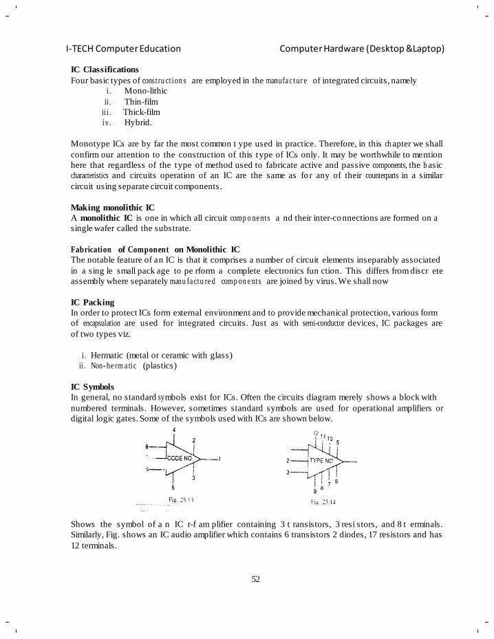
52
I-TECH Computer Education Computer Hardware (Desktop &Laptop)
IC Classifications
Four basic types of const ru ct ion s are employed in the manufa c tur e of integrated circuits, namely
i . Mono-lithic
ii . Thin-film
ii i . Thick-film
iv. Hybrid.
Monotype ICs are by far the most common t ype used in practice. Therefore, in this ch apter we shall
confirm our attention to the construction of this type of ICs only. It may be worthwhile to mention
here that regardless of the type of method used to fabricate active and passive components, the b asic
characteristics and circuits operation of an IC are the same as fo r any of their counterparts in a similar
circuit using separate circuit components.
Making monolithic IC
A monolithic IC is one in which all circuit comp o ne nts a nd their inter-connections are formed on a
single wafer called the substrate.
Fabrication of Component on Monolithic IC
The notable feature of an IC is that it comprises a number of circuit elements inseparably associated
in a sing le small pack age to pe rform a complete electronics fun ction. This differs from discr ete
assembly where separately manu fa ctu re d comp on e nts are joined by virus. We shall now
IC Packing
In order to protect ICs form external environment and to provide mechanical protection, various form
of encapsulation are used for integrated circuits. Just as with semi-conductor devices, IC packages are
of two types viz.
i . Hermatic (metal or ceramic with glass)
ii . Non- he rm a tic (plastics)
IC Symbols
In general, no standard sy mbols exist for ICs. Often the circuits diagram merely shows a block with
numbered terminals. However, sometimes standard symbols are used for operational amplifiers or
digital logic gates. Some of the symbols used with ICs are shown below.
Shows the symbol of a n IC r-f am plifier containing 3 t ransistors, 3 resi stors, and 8 t erminals.
Similarly, Fig. shows an IC audio amplifier which contains 6 transistors 2 diodes, 17 resistors and has
12 terminals.
53
I-TECH Computer Education Computer Hardware (Desktop &Laptop)
Scale of Integration
An IC chip may contain as large as 100,000 semiconductor device or other compo ne nts. The relative
number of th ese components within the chip is given by referring to it s scale o f integration. The
following terminolo g y is comm on ly used.
Scale of integration Abbreviation Number of components
Small
Medium
Large
Very large
Super large
*SSI
MSI
LSI
VLSI
SLSI
1 to 20
20 to 100
100 to 1000
1000 to 10,000
10,000 to 100,000
Microprocessors:
• A microprocessor is a multipurpose, programmable logic device that reads binary instructions from a
storage device called memory accepts binary data as input and pro cesses data a ccording to thos e
instructions and provides results as output.
• A typical programmable machine can be represented with thr ee components i.e. microprocessor,
memory and I/O. These three components work together or inter act with each other to perfo rm a
given task; thus, they comprise a system.
• The physical components of this system are called hardware.
• A set of instructions written for the microprocessor to perform a task is called a program, and a group
of programs is called software.
Binary Digits:
• The microp roc e sso r operates in binary digits, 0 and 1, also known as bits.
• Bit is an abbreviation for the term binary digit. These digits are represented in terms of electrical
voltages in the machine: generally, 0 represents low voltage level and 1 represents high voltage
level.
WHAT MICRO P R O CES S O R MEANS?
• Each micro pr oc e sso r recognizes and processes a group of bits called the word.
• The microprocessor is classified according to their word length. For example a processor with an
8-bit word is known as an 8-bit microprocessor and a processor with a 32-bit word is known as a
32-bit microprocessor.
A Microprocess o r as a Program mab le Device:
• The microprocessor is programmable means it can be instructed to perform given tasks within its
capability.
• A piano is a programmable machine i.e. it is capable of generating various kinds of tones based
on the number of ke ys it has. A musician sel ects keys depending upon the musical score printed
on a sheet.
• Similarly, today‘s microprocessor is desig ned to understand and execute many binary
instructions. It is a mult ipurpose machine i. e. it can be us ed to per form various sophisticated
comp ut ing functions, as well as simple tasks such as turning devices on or off.
• A programmer can select appropriates instructions and ask the mic roprocessor to perform various
task on a given set of data.
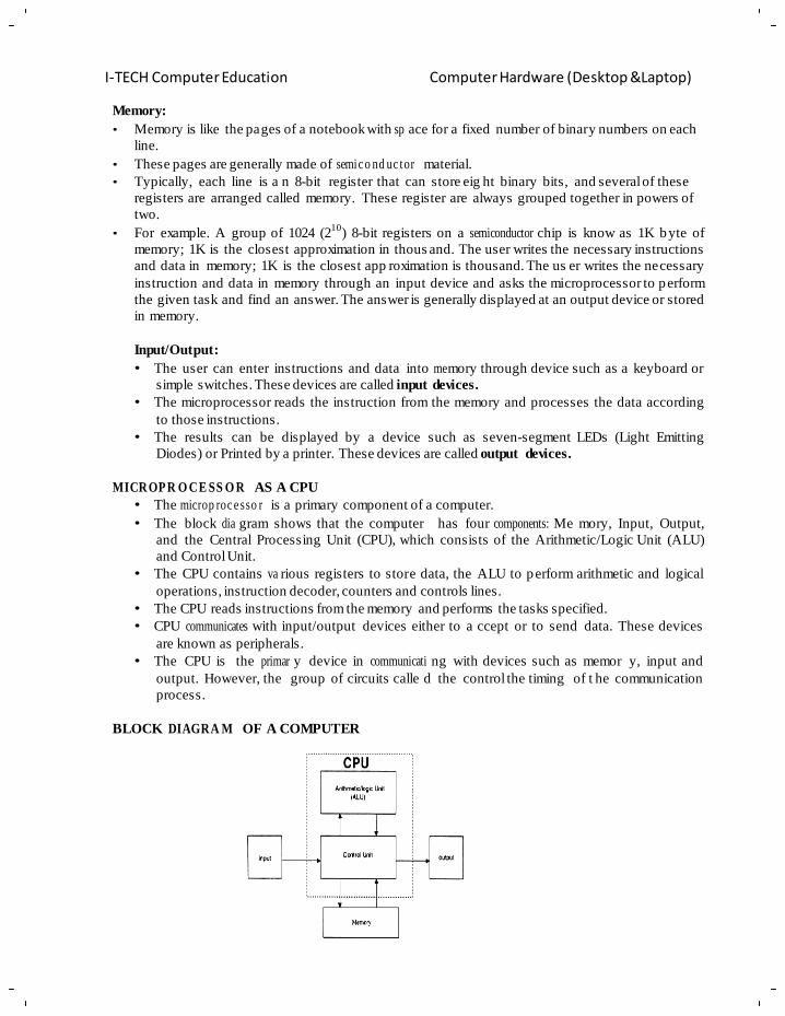
I-TECH Computer Education Computer Hardware (Desktop &Laptop)
54
Memory:
• Memory is like the pages of a notebook with sp ace for a fixed number of binary numbers on each
line.
• These pages are generally made of semic o nd uc tor material.
• Typically, each line is a n 8-bit register that can store eig ht binary bits, and several of these
registers are arranged called memory. These register are always grouped together in powers of
two.
• For example. A group of 1024 (210
) 8-bit registers on a semiconductor chip is know as 1K byte of
memory; 1K is the closest approximation in thous and. The user writes the necessary instructions
and data in memory; 1K is the closest app roximation is thousand. The us er writes the necessary
instruction and data in memory through an input device and asks the microprocessor to perform
the given task and find an answer. The answer is generally displayed at an output device or stored
in memory.
Input/Output:
• The user can enter instructions and data into me mory through device such as a keyboard or
simple switches. These devices are called input devices.
• The microprocessor reads the instruction from the memory and processes the data according
to those instructions.
• The results can be displayed by a device such as seven-segment LEDs (Light Emitting
Diodes) or Printed by a printer. These devices are called output devices.
MICROP R O CE SS O R AS A CPU
• The microp roc e sso r is a primary component of a computer.
• The block dia gram shows that the computer has four components: Me mory, Input, Output,
and the Central Processing Unit (CPU), which consists of the Arithmetic/Logic Unit (ALU)
and Control Unit.
• The CPU contains va rious registers to store data, the ALU to perform arithmetic and logical
operations, instruction decoder, counters and controls lines.
• The CPU reads instructions from the memory and performs the tasks specified.
• CPU communicates with input/output devices either to a ccept or to send data. These devices
are known as peripherals.
• The CPU is the primar y device in communicati ng with devices such as memor y, input and
output. However, the group of circuits calle d the control the timing of t he communication
process.
BLOCK DIAGRA M OF A COMPUTER
55
I-TECH Computer Education Computer Hardware (Desktop &Laptop)
BLOCK DIAGRA M OF A COMP UT E R WITH MICROPROCESSOR
MICROP R O CE SS O R INSTRUC TI O N SET AND COMP UT E R LANG UA GE S
• Micro pr oc e sso r recognizes and operates in binary numbers.
• Each micro pr oc e sso r has its own binary words, meanings and language.
• The words are formed by combining a number of bits for a given machine.
• WORD: is defined as t he number of bits the microprocessor recognizes and processes at a
time. The word length ranges from four bits f or small, microprocessor-based systems to 64
bits for high-speed large computers. Another term commonly used to express word length is
byte.
• BYTE: is defined as a g roup of 8 bits. F or e.g. a 16 bit m icroprocessor has a word leng th
equal to two bytes.
• NIBBLE: which stands for a group of 4 bits? A byte has two nibbles.
• Each machine has its o wn set of instructions based on the d esign of its CPU or of its
microprocessor. To com municate with the computer, one must give instructions in binar y
language (Machine language).
• It is difficult for most people to write programs in sets of 0s and 1s, computer manufacturers
have devised Englis h-l ike words to represent language programs, using these words.
• An assembly language is specific to a given machine; programs written in assembly language
are not tr ansferable from one machine to a nother. To ove rcome this limitation general-
purpose languages as BASIC and FORTRAN have been devised; a program written in these
languages can be machine indepe nd e nt . These languages are called high-level languages.
Machine Language:
The number of bits in a word for a g iven machine is fixed and words are formed throug h various combinations of these bits. For example, a machine with a word length of eight bits can have 256
(28) a combin at ion of eight bits-thus a l anguage of 256 words. However, not all of these words
need to be used in the machine. The microprocessor design engineer selects combinations of bit
patterns and gives a specific meaning to each combination by using electronic logic circuits; this
is called an instruction. Instructions are made up of one word or sev eral words. The set of
instructions designed into the machine makes up its ma chine language - a binary language
composed of 0s and 1s – that is specific to each computer.
56
I-TECH Computer Education Computer Hardware (Desktop &Laptop)
• Machine language and assembly language are micro pro c e ssor -sp e ci fic and both are conside re d as
low-level language.
• The machine language is in binary and the assembly language is in English-like words; however,
the microprocessor understands only the binary. Hence all the assembl y language mnemonics are to
be translated into the machine language or binary code.
• The mnemonics can be written electronically on a computer using a program called an editor in
the ASCII code and translated into a binary code by using the program called an assembler.
• The assembler is a program that translates the mnemonics entered by the ASCII keyboard into the
corresponding binary machine codes of the microproc essor. Each micr oprocessor has its own
assembler because the mnemonics and machine codes are specific to the microprocessor being used
and each assembler has rules that must be followed by the programmer.
High Level Languages:
• Progr a m m ing languages that are machine independent are called high level languages.
• These includes languages like FORTRAN, BASIC, PASCAL, C.C++ all of which have certain set of
rules, symbols and conve nt io ns from English.
• Instructions written in hi gh level languages are known as statements rather than mnemonics in th e
case of assembly language.
• Now the question arises is how the words in Eng lish is converted into bin ary languages of different
microp ro ce sso rs? The answer is through a program called as Interpreter or a Compiler.
• Interpreter or Compiler accepts English -lik e statements as their input called the source code.
• The compiler or inte rpreter then translates the s ource code into the machine language compatible
with the microprocessor being used in the system. This translation in the machine language is called
the object code.
• Each micro pr oc e sso r needs of its own compiler or an interpreter for each high level language.
• The primary difference between a compiler and a interpreter lies in the process of generating machine
code.
• The Compiler reads the entire program first and translated it into the object code that is executed by
the microprocessor.
• The interpreter reads one instruction at a time, pr oduces its object code a nd executes the instruction
before reading the next instruction.
• Compiler and Interpreters require large memory space because instruction in English requires several
machine codes to transl ate it into binar y. On the other h and, there is o ne to one correspondence
between the assembly language mnemonics and the machine code. Thus, assembly language
programs are compact and require less memory space. They are more efficient than the high level
language programs.
• The primary advantage of high-level languages is a trouble shooting part. It is much easier to fi nd
errors in a pr ogram written in hig h level language than to f ind them in a program written in an
assembly language.
MICROP R O CE SS O R ARCHI T E CT U RE AND ITS OPERATIONS
• The microprocessor is a programmable logic device, designed with register, flip-flops and timing
elements.
• The microprocessor has set of instructions, designed internally, to manipulate data and
comm unic a te with peripherals.
57
I-TECH Computer Education Computer Hardware (Desktop &Laptop)
• The process of d ata manipulation and communication is determined by the logic design of the
microp ro c ess or , called the architecture.
• The microprocessor can be programmed to perform functions on given data by selecting necessary
instruction from its set. These instructions are given to the microprocessor by writing them into its
memory.
• Writing instruction and data is done through an input device such as a keyboard.
• The microprocessor reads or transfers on instruction at a time, matches it with its instr uction set
and performs the data manip ulat ion indicated by the instruction.
• The result can be stored in memory or sent to such output devices as LEDs or a CRT terminal.
• In addition, the microprocessor can respond to external signals. It can be interrupted, reset or asked
to wait to synch ro niz e with slower peripherals.
• All the various functions performed by the microprocessor can be classified in three general
categories.
• Micro pr oc e ssor -init i ate d operations.
• Internal data operations.
• Peripheral (or externally initiated) operations.
• To perform the above functions the microprocessor requires a group of logic circuits and a set o f
signals called control signals.
• Early processors did not have the necessary circuitry on on e chip; the complete units were made
up of more than one chip. Therefor e, the term microprocessor unit (MPU) is defined here as a
group of d evices that c an perform these functions with the ne cessary set of control si gnals. This
term is similar to the term central processing unit (CPU).
• However, later microprocessor includes most of the necessary circuitry to per form these
operations on a single chip. Therefore, the terms MPU and micropro cessor are often us ed
synonymously.
MICROP R O CE SS O R INITIATE D OPERAT I O NS AND ITS BUS ORGANIATION
• The MPU performs primarily four operations:
1: Memory Read: Reads data (or instructions) from memory.
2: Memory Write: Writes data (or instructions) into memory.
3: I/O Read: Accepts data from input devices.
4: I/O Write: Sends data to output devices.
All these operations are part of the communications process betwe en the MPU and the
peripheral devices (including memory).
• To communicate with the peri pheral or a m emory location the MPU needs to perform the
following steps :
1: Identify the peripheral or the memory location (with its address)
2: Transfer data.
3: Provide timing or synchr oniz at io n signals.
• The 8085 MPU perform s the above functions usin g three sets of comm un ication lines called
buses: the address bus, the data bus and control bus.
Address Bus:
• The address bus is group of 16 lines generally identified as A0 to A 15. The addr ess bus is
unidirection al: bits flow in one direction – from the MPU to peripheral devices.
• The MPU uses the address bus to perform the first function : identifying a peripheral or a
memory locations.
58
I-TECH Computer Education Computer Hardware (Desktop &Laptop)
• In a computer system, each peripheral or memory location is identified by a binary number,
called an address, and the address bus is used to carry a 16-bit address.
• The number of address lines of the MPU determines its capacity to identify different memory
locations (or peripherals).
• The 8085 MPU with i ts 16 address lines is capable of addressin g 216
= 65,536 (g enerally
known as 64K) memory locations. (1K = 1024).
Data Bus:
• The data bus is a g roup of eig ht lines used for data flow. These lines are bidirectional data
flow in both directional between the MPU and memory and peripheral devices.
• The MPU uses the data bus to perform the second function i.e. transferring data
• The eight data lines enable the MPU to manipulate 8-bit data ranging from 00 to FF.
• The largest number that can appear on the data bus is 11111111.
• The 8085 is also known as 8-bit microprocessor.
• Microprocessor such as the Intel 8086, Zilog Z80 and Motorola 68000 have 16 data lines thus
they are known as 16-bit microprocessor and th e Intel 80386/486 have 32 data lines thus the y
are called as 32-bit microprocessor.
Control Bus:
• The control bus is comprised of various lines that carry synch ro niz at ion signals.
• The MPU uses such lines to perform the third function: providing timing signals.
• The MPU generates specific control signals for every operation (such as Memory Read or I/O
Write) it performs.
• Control signals are used to identify a device type with the MPU intends to communicate.
• To communicate with a memory – For example: To r ead an instruction from a me mory
location – the MPU places the 16-bit address on the address bus.
TYPES OF TRANS M ISS O N AND OTHER RELATE D TERMS
• A transmission format i s concerned with issues such as s ynchronization, direction of d ata
flow, speed errors, and medium of transmissi on (telephone lines for example). These topics
are described briefly below.
• Serial comm u nic at io n occurs either in Synch ro no u s or async hr on ou s format.
• In the synchronous format, a receiver and a tr ansmitter are synchronized; a block of
characters is transmitted along with the s ynchronization information. This format is generally
used for high speed transm ission (more than 20K bits/second).
• The asynchronous format is character-oriented.
• Each character carriers the information of the start and the stop bits.
• When no data are being transmitted, a receiver stays high at logic 1, called mark; logic 0 is
called space.
• Tran sm issio n begins with the one START bit.
• In the transmission of el even bits for an AS CII character in the as ynchronous format, there
will be one START bit, eight character bits and two STOP bits.
• The Asynchronous format is gener ally used in law speed transmission (less than 20 K
bits/second).
Simplex and Duplex Transmission:
Serial Comm u nic at ion is classified on the direction and simul ta ne o us flow of data.
Simplex Transmissio n: Data is transmitted only in one direction.
59
I-TECH Computer Education Computer Hardware (Desktop &Laptop)
Duplex Transmissio n: Data flows in both directions.
However if the transmission goes one way at a time it is c alled half duplex; however if it g oes both
ways simul ta ne ou sly it is called full duplex.
Parity check:
• During transmission, data bit ma y change (e.g. because of noise) and a wrong character may
be received by a receiver. The MSB bit in the ASCII code can be to check an error; this
process is called parity check.
• To check the Parity, the transmitter simply counts whether the number of 1s in a ch aracter is
odd or even, and transmits that information to the receiver as the MSB bit.
• The receiver checks the MSB bit and the number of 1s in the received character, if there is an
error, the receiver send back an error message to the transmitter.
• The parity check can be either odd or even, depending on the system.
• When the number of 1s is odd then the system has odd parity.
• When the number of 1s is even then the system has even parity.
• The parity check cannot detect multiple errors in a given character.
• The 8085/8080A microprocessor sets a parit y flag when the number of 1s in the accumulator
is even. This flag can be used for the parity check in the 8085/8 0 80 A system.
Baud:
• The rate at which the bits are transmitted in bits/second is called a baud in serial I/O.
• Technic al ly it is defined as the number of signal changes/second.
• Each equipment has its own baud rate.
• For example, a teletype generally runs on 110 baud.
COMM U NI C ATI O N DEVICE (MODEM)
• A Modem (Modulator/Demodulator) is a ci rcuit that translates dig ital data into audio tone
frequencies for transmission over t elephone and converts audio frequencies into dig ital data
for reception.
• The modulation technique g enerally used is ca lled frequency shift keying (FSK); it converts
logic 1 (MARK) and logic 0 (SPACE) in to audio tones around 1200 and 2200 Hz
frequencies.
• Computers can ex change information over tele phone lines b y using two modems – one on
each side.
• A calling computer (or a terminal) contacts a receiving computer thr ough a telephon e
number, and a communication link is established after control signals have been ex changed
between computers and modems.
• A typical process of comm u nica t ion is explained as :
• First a parallel word is converted into serial b its; is turn they generate two audio frequencies
according to logic 0 or 1 and these audio frequencies are transmitted over telephone lines.
• At the receiving end, audio frequencies are converted back into 0s and 1s, and the serial bits
are converted into a parallel word that can be read by the receiving computer.
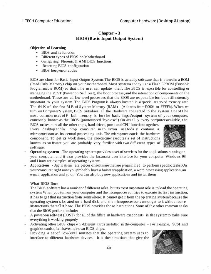
60
I-TECH Computer Education Computer Hardware (Desktop &Laptop)
O
n
p
u
m
w
o
p
e
Chapter - 3
BIOS (Basic Input Output System)
Objective of Learning
BIOS and its function
Different types of BIOS on Motherboard
Configu ring Phoenix & AMI BIOS functions
Resetting BIOS configuration
BIOS beep error codes
BIOS are short for Basic Input Output System. The BIOS is actually software that is stored in a ROM
(Read Only Memory) chip on your motherboard. Most systems today use a Flash EPROM (Erasable
Programmable ROM) so that t he user can update them. The BI OS is respons ible for controlling or
managing the POST (Power on Self Test), the boot process, and the interaction of components on the
motherboard. These are all low-level processes that the BI OS are responsible for, but still e xtremely
important to your system. The BIOS Program is always located in a sp ecial reserved memory area.
The 64 K of the first M B of S ystem Memory (RAM)—(Address from F 000h to FFFFh). When we
turn on Computer S ystem, BIOS initializes all the Hardware connected to the system. One of t he
most common uses of F lash memory is for t he basic input/output system of your computer,
commonly known as the BIOS (pronounced "bye-ose"). On virtua ll y every computer available, t he
BIOS makes sure all the other chips, hard drives, ports and CPU function t ogether.
Every desktop and la ptop computer in co mmon use toda y contains a
microprocessor as its central processing unit. The microprocessor is the hardware
component. To get its work done, the microprocessor executes a set of instructions
known as so ftware you are probably very familiar with two diff erent types of
software:
• Operating system - The operating system provides a set of services for the applications running on
your computer, and it also provides the fundamental user interface for your computer. Windows 98
and Linux are examples of operating systems.
• Applicat ions - Appl ic at ion s are pieces of software that are progra m m e d to perform specific tasks. On
your computer right now you probably have a browser application, a word processing application, an
e-mail application and so on. You can also buy new applications and install them.
What BIOS Does
The BIOS software has a number of different roles, but its most important role is to load the operating
system. When you turn on your computer and the microprocessor tries to execute its first instruction,
it has to get that instruction from somewhere. It cannot get it from the op erating system because the
operating system is loc ated on a hard disk, and the microprocessor cannot get to it without some
instructions that tell it how. The BIOS provides those instructions. Some of th e other common tasks
that the BIOS perform include:
• A power-on self-test (POST) for all of the differ e nt hardware comp on e nts in the system to make sure
everything is working properly
• Activating other BIOS chips o n different cards installed in the computer - F or example, SCSI and
graphics cards often have their own BIOS chips.
• Providing a set of low-level routines that the operating system uses to
interface to different hardware devices - It is these routines that give the
61
I-TECH Computer Education Computer Hardware (Desktop &Laptop)
BIOS its name. They manage things like the keyboard, the scre en, and the se rial and parallel por ts,
especially when the computer is booting.
• Managing a collection of settings for the hard disks, clock, etc.
BIOS use Flash memory, type of ROM.
The BIOS is special software that interfaces the major hardware comp on e nts of your computer with the
operating system. It is usually stored on a Flash memory chip on the mother bo a rd, but sometimes the
chip is another type of ROM.
When you turn on your computer, the BIOS do several things. This is its usual sequence:
1. Check the CMOS Setup for custom settings
2. Load the interrupt handlers and device drivers
3. Initialize registers and power management
4. Perform the power-on self-test (POST)
5. Display system settings
6. Determine which devices are bootable
7. Initiate the bootstrap sequence
The first thing the BIOS do is ch eck the information stored in a tiny (64 bytes) amount of RAM
located on a complementary metal oxide semiconductor (CMOS) chip. The CMOS Setup provides
detailed information particular to your system and can be altered as your system changes. The BIOS
uses this information to modify or supplement its default progr am min g as needed.
Interrupt handlers are small pieces of soft ware that act as t ranslators between the hardware
components and the op erating system. For example, when you press a key on your keyboard, the
signal is sent to the keyboard interrupt handler, which tells the CPU what it is and passes it on to the
operating system.
Device drivers are other pieces of software that identify the base hardware components such as
keyboard, mouse, hard drive and flopp y drive. Since the BIOS are constantly intercepting signals to
and from the hardware, it is usually copied, or shadowed, into RAM to run faster.
Booting the Computer
Whenever you turn on your computer, the first thing you see is the BIOS software doing its thing. On
many machines, the BIOS displays text describing things like the amount of memory installed in your
computer, the type of hard disk and so on. It turns out that, durin g this boot sequence, the BIOS are
doing a remarkable amount of work to g et your computer ready to run. This section briefl y describes
some of those activities for a typical PC.
After checking the CMOS Setup and loading the interrupt handlers, the BIOS determine whether the
video card is ope rational. Most vide o cards have a miniature BIOS of their own tha t initializes the
memory and graphics processor on the card. If they do not, there is usuall y video driver information
on another ROM on the mother bo a rd that the BIOS can load.
Next, the BIOS checks to see if this is a cold boot or a reboot. It does this by checking the value at
memory address 0000:0472. A value of 1234h indicates a r eboot, and the BIOS skip the r est of
POST. Anything else is considered a cold boot.
If it is a cold boot, the BIOS verify RAM by performing a read/write test of each memory address. It
checks the PS/2 ports or USB ports for a keyboard and a mouse. It looks for a peripheral component
interconnects (PCI) bus and, if it finds one, checks a ll the PCI cards. If the BI OS find an y errors
during the POST, it will notify you by a series of beeps or a text message displayed on the screen. An
error at this point is almost always a hardware problem.
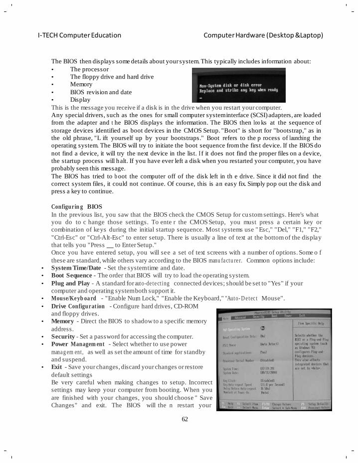
62
I-TECH Computer Education Computer Hardware (Desktop &Laptop)
d
o
n
g
o
B
m
m
d
c
m
k
c
m
The BIOS then displays some details about your system. This typically includes information about:
• The processor
• The floppy drive and hard drive
• Memory
• BIOS revision and date
• Display
This is the message you receive if a disk is in the drive when you restart your computer.
Any special drivers, such as the ones for small computer system interface (SCSI) adapters, are loaded
from the adapter and t he BIOS displays the information. The BIOS then loo ks at the sequence of
storage devices identified as boot devices in the CMOS Setup. "Boot" is short for "bootstrap," as in
the old phrase, "L ift yourself up by your bootstraps." Boot refers to the p rocess of launchin g the
operating system. The BIOS will try to initiate the boot sequence from the first device. If the BIOS do
not find a device, it will try the next device in the list. I f it does not find the proper files on a d evice,
the startup process will halt. If you have ever left a disk when you restarted your computer, you have
probably seen this message.
The BIOS has tried to b oot the computer off of the disk left in th e drive. Since it did not find the
correct system files, it could not continue. Of course, this is an easy fix. Simply pop out the disk and
press a key to continue.
Configurin g BIOS
In the previous list, you saw that the BIOS check the CMOS Setup for custom settings. Here's what
you do to c hange those settings. To ente r the CMOS Setup, you must press a certain key or
combination of keys during the initial startup sequence. Most s ystems use " Esc," "Del," "F1," "F2,"
"Ctrl-Esc" or "Ctrl-Alt-Esc" to enter setup. There is usually a line of text at the bottom of the display
that tells you "Press to Enter Setup."
Once you have entered setup, you will see a set of text screens with a number of options. Some o f
these are standard, while others vary according to the BIOS manu fa ctu re r. Common options include:
• System Time/Date - Set the system time and date.
• Boot Sequence - The order that BIOS will try to load the operating system.
• Plug and Play - A standard for auto-de te ct ing connected devices; should be set to "Yes" if your
computer and operating system both support it.
• Mouse/Keyb oa rd - "Enable Num Lock," "Enable the Keyboard," "Auto- D e tec t Mouse".
• Drive Configurat ion - Configure hard drives, CD-ROM
and floppy drives.
• Memory - Direct the BIOS to shadow to a specific memory
address.
• Security - Set a password for accessing the computer.
• Power Managem ent - Select whether to use power
mana g em ent , as well as set the amount of time for standby
and suspend.
• Exit - Save your changes, discard your changes or restore
default settings
Be very careful when making changes to setup. Incorrect
settings may keep your computer from booting. When you
are finished with your changes, you should choose " Save
Changes" and exit. The BIOS will the n restart your
63
I-TECH Computer Education Computer Hardware (Desktop &Laptop)
computer so that the new settings take effect.
The BIOS uses CMOS technology to sav e any changes made to the co mputer's settings. With t his
technology, a small lithium or Ni-Cad battery can supply enough power to keep the data fo r years.
In fact, some of the newer chips have a 10-year, tiny lithium battery built right into the CMOS chip.
Updating Your BIOS
Occasionally, a computer will ne ed to h ave its BIOS updated. This is especi ally true of older
machines. As new devic es and standards arise, the BIOS needs to chan ge in order to understand the
new hardware. Since the BIOS are stored in some form of R OM, changing it is a bi t harder t han
upgrading most other types of software.
To change the BIOS itself, you'll probably need a speci al program from the computer or B IOS
manufacturer. Look at the BI OS revision and date information displa yed on s ystem startup or check
with your computer ma nufacturer to find out w hat type of B IOS you have. Then go to the BIOS
manufacturer's Web site to se e if an upgrade is a vailable. Download the upgrade and the utility
program needed to insta ll it. Some times the utility and update are combined in a single file to
download. Copy the program, along with the BIOS update, onto a floppy disk. Restart your computer
with the floppy disk in the drive, and the progra m erases the old BI OS and writes the new one. You
can find a BIOS Wizard that will check your BIOS at BIOS Upgrades.
Flashing the BIOS
In modern PCs the BIOS is stored in rewritable memory, allowing the contents to be repl aced or
'rewritten'. This r ewriting of the cont ents is some times termed fl ashing. This is done b y a special
program, usually provided by the system's manufacturer. A file containing such contents is sometimes
termed 'a BIOS image'. BIOS might be reflashed in order to upgrade to a newer version to fix bugs or
provide improved per formance or to support ne wer hardware, or a reflashing operation might be
needed to fix a damaged BIOS. A Bios may also be "flashed" by putting the file on the root of a USB
drive and
EEPROM chips are advantageous because they can be easily updated by the user; hardware
manufacturers frequently issue BI OS updates to upgrade their products, i mprove compatibility and
remove bugs. However, this advanta ge had the risk that an improperl y executed or abort ed BIOS
update could render the computer or device unusable. To avoid these situations, more recent BIOSes
use a "boot block"; a portion of the BIOS which runs first and must be updated separately. This code
verifies if the rest o f the BIOS is intact (using hash checksums or other methods) before transferring
control to it. If the boot b lock detects any corruption in the main BIOS, it will typically warn the user
that a recovery process must be initiated by booting from removable media (floppy, CD or USB
memory) so the use r can try flashing the BIOS again. Some motherb oards have ba ckup BIOS
(sometimes referred to as Dual BIOS boards) to recover from BIOS corruptions.
Major BIOS manufacturers include:
• American Megatrends Inc. (AMI)
• Phoenix Technologies
• ALi
• Win bond
As with chan ges to the CMOS Setup, be car eful when upgrading your BIOS. Make sure you are
upgrading to a ve rsion that is compatible with your computer system. Otherwise, you could co rrupt
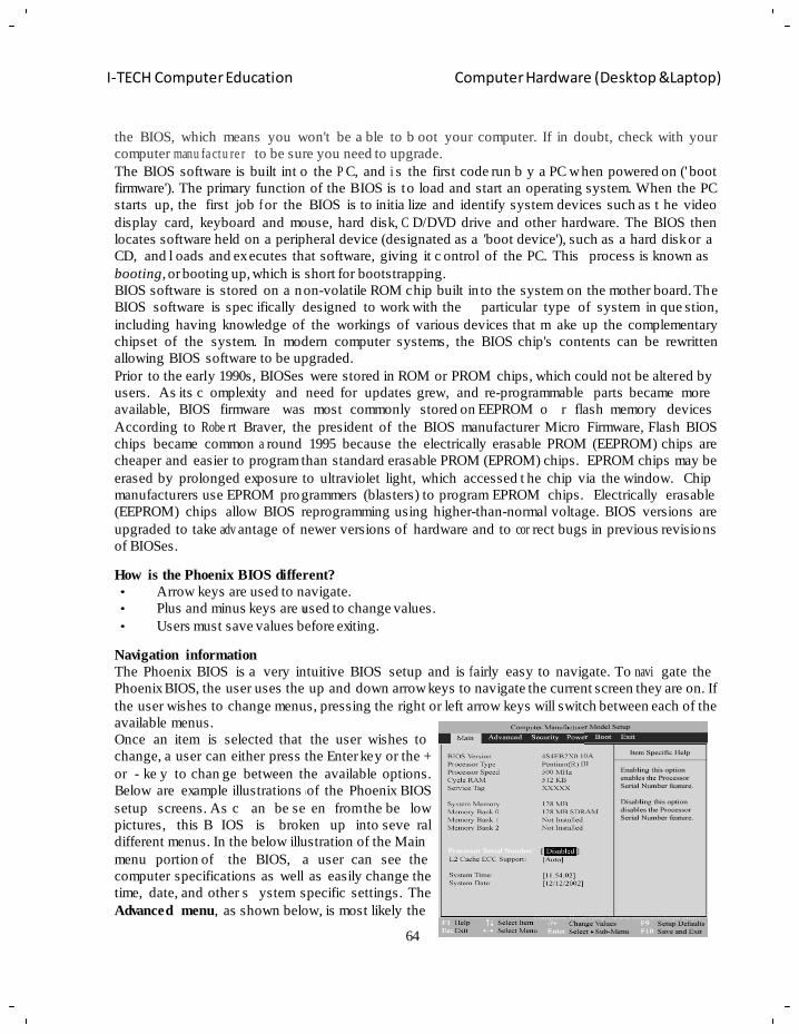
64
I-TECH Computer Education Computer Hardware (Desktop &Laptop)
u
o
u
g
the BIOS, which means you won't be a ble to b oot your computer. If in doubt, check with your
computer manu fa ctu re r to be sure you need to upgrade.
The BIOS software is built int o the P C, and i s the first code run b y a PC w hen powered on (' boot
firmware'). The primary function of the BIOS is to load and start an operating system. When the PC
starts up, the first job f or the BIOS is to initia lize and identify system devices such as t he video
display card, keyboard and mouse, hard disk, C D/DVD drive and other hardware. The BIOS then
locates software held on a peripheral device (designated as a 'boot device'), such as a hard disk or a
CD, and l oads and ex ecutes that software, giving it c ontrol of the PC. This
booting, or booting up, which is short for bootstrapping.
process is known as
BIOS software is stored on a non-volatile ROM chip built in to the system on the mother board. The
BIOS software is spec ifically designed to work with the particular type of system in que stion,
including having knowledge of the workings of various devices that m ake up the complementary
chipset of the system. In modern computer systems, the BIOS chip's contents can be rewritten
allowing BIOS software to be upgraded.
Prior to the early 1990s, BIOSes were stored in ROM or PROM chips, which could not be altered by
users. As its c omplexity and
available, BIOS firmware was
need for updates grew, and re-programmable parts became more
most commonly stored on EEPROM o r flash memory devices
According to Robe rt Braver, the president of the BIOS manufacturer Micro Firmware, Flash BIOS
chips became common a round 1995 because the electrically erasable PROM (EEPROM) chips are
cheaper and easier to program than standard erasable PROM (EPROM) chips. EPROM chips may be
erased by prolonged exposure to ultraviolet light, which accessed t he chip via the window. Chip
manufacturers use EPROM programmers (blasters) to program EPROM chips. Electrically erasable
(EEPROM) chips allow BIOS reprogramming using higher-than-normal voltage. BIOS versions are
upgraded to take adv antage of newer versions of hardware and to cor rect bugs in previous revisions
of BIOSes.
How is the Phoenix BIOS different?
• Arrow keys are used to navigate.
• Plus and minus keys are used to change values.
• Users must save values before exiting.
Navigation information
The Phoenix BIOS is a very intuitive BIOS setup and is f airly easy to navigate. To navi gate the
Phoenix BIOS, the user uses the up and down arrow keys to navigate the current screen they are on. If
the user wishes to change menus, pressing the right or left arrow keys will switch between each of the
available menus.
Once an item is selected that the user wishes to
change, a user can either press the Enter key or the +
or - ke y to chan ge between the available options.
Below are example illustrations of the Phoenix BIOS
setup screens. As c an be se en from the be low
pictures, this B IOS is broken up into seve ral
different menus. In the below illustration of the Main
menu portion of the BIOS, a user can see the
computer specifications as well as easily change the
time, date, and other s ystem specific settings. The
Advanced menu, as shown below, is most likely the
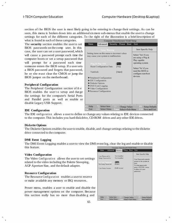
65
I-TECH Computer Education Computer Hardware (Desktop &Laptop)
e
u
a
d
b
e
b
section of t he BIOS the user is most likely going to be entering to change their settings. As can be
seen, this menu is broken down into an additional six more sub-menus that enable the user to change
settings for each of the different categories. To t he right of the illustration is a brief d escription of
what is found in each of these categories.
The security section enables the user t o set
BIOS passwords on the comp uter. In this
case, the user can set a user password, which
will cause a password prompt each time the
computer boots or set a setup password that
will prompt for a password each time
someone enters the BIOS setup. If a user sets
a BIOS password and forgets that password,
he or she m ust clear the CMOS or jump the
BIOS jumper on the motherboard.
Peripheral Configuration
The Peripheral Configuration section of th e
BIOS enables the user t o setup and chan ge
the settings for the computer's Serial Ports
and Parallel ports as well as enable or
disable Legacy USB Support.
IDE Configuration
The IDE configu rat io n allows a user to define or change any values relating to IDE devices connected
to the computer. This includes you hard disk drive, CD-ROM drives and any other IDE drives.
Diskette Options
The Diskette Options enables the user to enable, disable, and change settings relating to the diskette
drive connected to the computer.
DMI Event Logging
The DMI Event Logging enables a user to view the DMI event log, clear the log and enable or disable
this feature.
Video Configuration
The Video Configu rat io n allows the user to set settings
related to the video including the Palette Snooping,
AGP Aperture Size, and the default adapter.
Resource Configuration
The Resource Config ur at ion enables a user to reserve
or make available any memory or IRQ resources.
Power menu, enables a user to enable and disable the
power management options on the computer. Because
this section really has no more than disablin g and
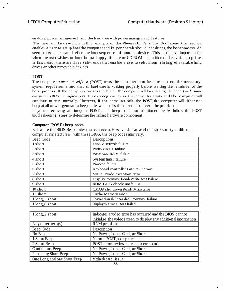
66
I-TECH Computer Education Computer Hardware (Desktop &Laptop)
enabling power mana ge m e nt and the hardware with power mana ge m e nt features.
The next and final sect ion in th is example of the Phoenix BI OS is the Boot menu; this section
enables a user to setup h ow the computer and its peripherals should load d uring the boot process. As
seen below, users can d efine the boot sequence of bootable devices. This section is important for
when the user wishes to boot from a floppy diskette or CD-ROM. In addition to the available options
in this menu, there are t hree sub-menus that ena ble a user to select from a listing of available ha rd
drives or other removable devices.
POST
The computer power-on self-test (POST) tests the computer to ma ke sure it me ets the necessary
system requirements and that all hardware is wo rking properly before starting the remainder of the
boot process. If the co mputer passes the POST the computer will have a sing le beep (with some
computer BIOS manufacturers it may beep twice) as the computer starts and t he computer will
continue to sta rt normally. However, if the computer fails the POST, th e computer will e ither not
beep at all or will generate a beep code, which tells the user the source of the problem.
If you're receiving an irregular POST or a beep code not me ntioned below follow the POST
trouble sh oot ing steps to determine the failing hardware component.
Computer POST / beep codes
Below are the BIOS Beep codes that can occur. However, because of the wide variety of different
computer manu fa ctu re rs with these BIOS, the beep codes may vary.
Beep Code Descriptions
1 short DRAM refresh failure
2 short Parity circuit failure
3 short Base 64K RAM failure
4 short System timer failure
5 short Process failure
6 short Keyboard controller Gate A20 error
7 short Virtual mode exception error
8 short Display memory Read/Write test failure
9 short ROM BIOS checksum failure
10 short CMOS shutdown Read/Write error
11 short Cache Memory error
1 long, 3 short Conve nt ion al /E xte n de d memory failure
1 long, 8 short Displa y/R etr ac e test failed
1 long, 2 short Indicates a video error has occurred and the BIOS cannot
initialize the video screen to display any additional information
Any other beep(s) RAM problem.
Beep Code Description
No Beeps No Power, Loose Card, or Short.
1 Short Beep Normal POST, computer is ok.
2 Short Beep POST error, review screen for error code.
Continuous Beep No Power, Loose Card, or Short.
Repeating Short Beep No Power, Loose Card, or Short.
One Long and one Short Beep Mothe rb o ar d issue.
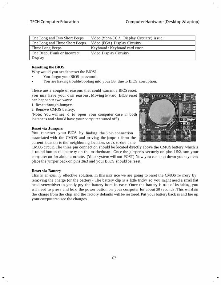
67
I-TECH Computer Education Computer Hardware (Desktop &Laptop)
One Long and Two Short Beeps Video (Mono/C G A Display Circuitry) issue.
One Long and Three Short Beeps. Video (EGA) Display Circuitry.
Three Long Beeps Keyboard / Keyboard card error.
One Beep, Blank or Incorrect
Display
Video Display Circuitry.
Resetting the BIOS
Why would you need to reset the BIOS?
You forgot your BIOS password.
You are having trouble booting into your OS, due to BIOS corruption.
These are a couple of reasons that could warrant a BIOS reset,
you may have your own reasons. Moving forw ard, BIOS reset
can happen in two ways:
1. Reset through Jumpers
2. Remove CMOS battery.
(Note: You will nee d to open your computer case in both
instances and should have your computer turned off.)
Reset via Jumpers You can reset your BIOS by
finding the 3 pin connection
associated with the CMOS and moving the jumpe r from the
current location to the neighboring location, so a s to shor t the
CMOS circuit. The three pin connection should be located directly above the CMOS battery, which is
a round button cell batte ry on the motherboard. Once the jumper is securely on pins 1&2, turn your
computer on for about a minute. (Your s ystem will not POST) Now you can shut down your system,
place the jumper back on pins 2&3 and your B IOS should be reset.
Reset via Battery
This is an equal ly effective solution. In this insta nce we are going to r eset the CMOS me mory by
removing the charge (or the battery). The battery clip is a little tricky so you might need a small flat
head screwdriver to gently pry the battery from its case. Once the battery is out of its holding , you
will need to p ress and hold the power button on your computer for about 30 seconds. This will drai n
the charge from the chip and the factory defaults will be restored. Put your battery back in and fire up
your computer to see the changes.
68
I-TECH Computer Education Computer Hardware (Desktop &Laptop)
Chapter - 4
Partition & Formatting of disk
Objective of learning
Introduction to Partition & Formatting
Different types of partitions
File system and its types
Features of different file system
Perfor min g partition and formatting in windows xp
In a computer, a partition is a logical division of a hard disk c reated so tha t you can have different
operating systems on the same hard disk or to create the appearance of having separate hard drives for file
management, multiple users, or other purposes. A pa rtition is c reated when you format the h ard disk.
Typically, a one-partition hard disk is la belled the "C:" drive ("A:" and "B:" are typically reserved for
diskette drives).A two-partition hard drive would typically contain "C:" and "D:" drives. (CD-ROM drives
typically are assigned the last letter in whatever sequence of letters have been used as a result of hard disk
formatting, or typically with a two-partition, the "E:" drive.). When you partition a hard drive, you make it
available to an operating system. Multiple partitions on a single hard drive appear as separate drives to the
operating system.
For example, when you install an operating system like Windows XP, pa rt of the process is to define a
partition on the hard driv e. This partition serves to define an are a of the hard drive that Windows XP can
use to install all of its files. In Windows operating systems, this primary partition is usually assigned the
drive letter of "C" Also Known As: disk partition.
Types of hard drive partitions
1. Primary Partition is a partition that is need ed to st ore and boot an operating system, though
applications and user data can reside there as well, and what‘s more, you can have a primary partition
without any operating system on it. The re can be up to a m aximum of four primary partitions on a
single hard disk, with only one of them set as active (see ―Active partition‖).
2. Active (boot) partition is a primary partition that has an operating system installed on it. It is used for
booting your machine. If you have a single primary partition, it is regarded as active. If you have more
than one primary partition, only one of them is marked active (in a given PC session).
3. Extended partition can be sub-divided into lo gical drives and is vi ewed as a container for logical
drives, where data proper is located. An extended partition is not formatted or assigned a drive letter.
The extended partition is used only for creating a desired number of logical partitions.
4. Logical drive is created within an extended partition. A logical partition is a wa y to extend the initial
limitation of four partitions. An e xtended partition can contain up to 24 logical partitions (you‘re
limited by the number of drive letters and the amount of hard drive space available for creating drives;
of course, it‘s senseless to use 24 partitions on a s ystem in most cases, because it will be a d ata
organization nightmare). Logical partitions are used for storing data mainly, they can be formatted and
assigned drive letters; their details are listed in the extended partition‘s table - EMBR (Extended
Master Boot Record).
69
I-TECH Computer Education Computer Hardware (Desktop &Laptop)
How to partition and format the hard disk using the Windows XP Setup program
You can use the Windows XP Se tup program to partition and format the hard disk. To do th is, use the
following steps:
Step 1: Partition the hard disk
a. Insert the Windows XP CD into your CD or DVD drive, or insert the first Windows XP Setup disk
into the flopp y disk drive, and then resta rt the computer to start the W indows XP Setup pro gram.
Note If you are using the Windows XP Setup di sks, insert each addi tio n al disk when you are prompted,
and then press ENTER to continue after you insert each disk.
b. If you are prompted, select any options that are required to start the computer from the CD or DVD
drive.
c. If your hard disk controller requires a third-pa rty original equipment manufacturer (OEM) driver,
press F6 to specif y the driver. For more inform ation about how to use F 6 to suppl y a third-pa rty OEM
device driver while the Windows Setup program is running, click the following article number to view the
article in the Microsoft Knowledge Base: Limited OEM driver suppo rt is available with F 6 during
Windows XP Setup.
d. At the Welcome to Setup page, press ENTER.
Note If you are using the Setup disks (si x bootable disks), the setup prompts you to insert the W indows
XP CD.
e. Press F8 to accept the Windows XP Licensing Agreement.
f. If an existing Windows XP installation is detec ted, you are prompted to repair it. To b ypass the
repair, press ESC.
g. All existing partitions a nd non-partitioned spaces are listed for each physical hard disk. Use t he
ARROW keys to select an existing partition, or create a new partition by selecting the non-partitioned
space where you want to create a new partition. You can also p ress C to create a new partition using
non-pa rt i tio ne d space.
Note If you want to create a partition where one or more partitions already exist, you must first delete
the existing partition or partitions, and then create the ne w partition. You can p ress D to delete an
existing partition, and then press L (or press ENTER, and then press L if it is the System partition) to
confirm that you want to delete the partition. Repeat this step for each existing partition that you want
to include in th e new partition. When all the partitions are deleted, select the remaining non-
partitioned space, and then press C to create the new partition.
h. To create the partition with the maximum size, press ENTER. To specify the partition size, type the
size in megabytes (MB) for the new partition, and then press ENTER.
i . If you want to create additional partitions, repeat steps g. and h.
j . To format the partition and install Windows XP, go to step 2.
Formatting
In order for storage media, such as a ha rd drive, to be reco gnized by your computer, it needs to be
formatted. Formatting a disk involves testing the disk and writing a new directory structure, or "a ddress
table," onto the disk. If you would like to erase or initialize a hard drive, you can use a disk utility program
70
I-TECH Computer Education Computer Hardware (Desktop &Laptop)
to reformat it. This will create a bl ank, empty disk for storing your files. While the disk appears to be
empty, most of the files on the disk are actually untouched by the formatting process. When you format a
disk, it creates a new address table, making the entire disk available for writing. However, the files are
still on the disk - the y just don't show up since are no l onger part of the director y structure. So if you
accidentally format a disk (which is pretty hard to do), you can still retrieve most of your files using an
advanced disk utility such as Norton Disk Doctor or Disk Warrior etc.
The term "format" can also be used t o describe the layout or style of text in a text document. When you
format the la yout, you choose the pa ge margins and the line spacing. When you format the text, you
choose the font, the siz e, and the st yles, such as bol d, italic, and underlin ed. If you do not want to install
Windows XP, press F3 two times to exit the Windows Setup program.
File System:
The method for storing and retrieving files on a disk. It is system software that takes commands from the
Operating system to rea d and write the disk cluste rs (groups of secto rs). The file s ystem manages a
folder/directory structure, which provides an index to the files, and it def ines the Syntax used to ac cess
them (how t he "path" to the file is coded). File systems dictate how files are named as well as the
maximum size of a fi le or vol ume. There ar e numerous file systems in use; for ex ample, FAT32 and
NTFS is Windows file Systems and HF S is us ed on Macs. Linux uses ext2, ext3 and F AT32. UNIX
systems use UFS, Ext2, ext3 and ZFS.
FAT32
The 32-bit version of the FAT file system. In wide use on PCs that run Windows 95/98, FAT32 Was
Introduced with the OEM Service Release 2 (OSR2) version of Windows 95 in 1996. It supports larger
disk Partitions and file sizes and has more safeguards than the earlier FAT (FAT16). In the event of disk
failure, FAT32 can r elocate the root director y on the disk and use the backup copy of the F AT table.
FAT32 also reduced cluster waste. Starting with Windows NT, FAT32 was superseded by NTFS.
Drive Size Default FAT16 Cluster Size Default FAT32 Cluster Size
260 MB–511 MB 8 KB Not supported
512 MB–1,023 MB 16 KB 4 KB 1,024 MB–2 GB 32 KB 4 KB
2 GB–8 GB Not supported 4 KB
8 GB–16 GB Not supported 8 KB
16 GB–32 GB Not supported 16 KB
> 32 GB Not supported 32 KB
There are additional differences between FAT32 and FAT16:
FAT32 allows finer allocation granula ri ty (app rox im ate ly 4 million allocation units per Volume).
FAT32 allows the root directory to grow (FAT16 holds a maximum of 512 entries and the limit can be
even lower due to the use of long file names in the root folder).
Advantages of FAT16
a. MS-DOS, Windows 95, Windows 98, Windows NT, Windows 2000, and some UNIX Operating
systems can use it.
b. There are many tools available to address problems and recover data.
c. If you have a startup failure, you can start the computer with an MS-DOS bootable floppy disk.
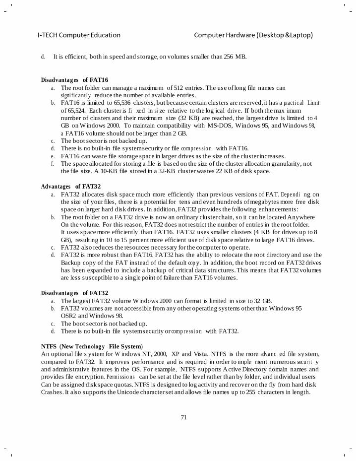
71
I-TECH Computer Education Computer Hardware (Desktop &Laptop)
d. It is efficient, both in speed and storage, on volumes smaller than 256 MB.
Disadvanta g es of FAT16
a. The root folder can manage a maximum of 512 entries. The use of long file names can
signi fic a nt ly reduce the number of available entries.
b. FAT16 is limited to 65,536 clusters, but because certain clusters are reserved, it has a pract ic al Limit
of 65,524. Each cluster is fi xed in si ze relative to the log ical drive. If both the max imum
number of clusters and their maximum size (32 KB) are reached, the largest drive is limited to 4
GB on W indows 2000. To maintain compatibility with MS-DOS, Windows 95, and Windows 98,
a FAT16 volume should not be larger than 2 GB.
c. The boot sector is not backed up.
d. There is no built-in file system security or file compr es sio n with FAT16.
e. FAT16 can waste file storage space in larger drives as the size of the cluster increases.
f. The space allocated for storing a file is based on the size of the cluster allocation granularity, not
the file size. A 10-KB file stored in a 32-KB cluster wastes 22 KB of disk space.
Advantages of FAT32
a. FAT32 allocates disk space much more efficiently than previous versions of FAT. Depe ndi ng on
the size of your files, there is a potential for tens and even hundreds of megabytes more free disk
space on larger hard disk drives. In addition, FAT32 provides the following enhancements:
b. The root folder on a FAT32 drive is now an ordinary cluster chain, so it can be located Anywhere
On the volume. For this reason, FAT32 does not restrict the number of entries in the root folder.
It uses space more efficiently than FAT16. FAT32 uses smaller clusters (4 KB for drives up to 8
GB), resulting in 10 to 15 percent more efficient use of disk space relative to large FAT16 drives.
c. FAT32 also reduces the resources necessary for the computer to operate.
d. FAT32 is more robust than FAT16. FAT32 has the ability to relocate the root directory and use the
Backup copy of the FAT instead of the default cop y. In addition, the boot record on FAT32 drives
has been expanded to include a backup of critical data structures. This means that FAT32 volumes
are less susceptible to a single point of failure than FAT16 volumes.
Disadvanta g es of FAT32
a. The largest FAT32 volume Windows 2000 can format is limited in size to 32 GB.
b. FAT32 volumes are not accessible from any other operating systems other than Windows 95
OSR2 and Windows 98.
c. The boot sector is not backed up.
d. There is no built-in file system security or comp re ssio n with FAT32.
NTFS (New Technolog y File System)
An optional file s ystem for W indows NT, 2000, XP and Vista. NTFS is the more adva nc ed file system,
compared to FAT32. It improves performance and is required in order to imple ment numerous securi t y
and administrative features in the OS. For example, NTFS supports Active Directory domain names and
provides file encryption. Permissio ns can be set at the file level rather than by folder, and individual users
Can be assigned disk space quotas. NTFS is designed to log activity and recover on the fly from hard disk
Crashes. It also supports the Unicode character set and allows file names up to 255 characters in length.
72
I-TECH Computer Education Computer Hardware (Desktop &Laptop)
Difference between FAT and NTFS
FAT
1) Fat stands for File Allocation Table
2) There are two categories in Fat File System
I) Fat 16
II) Fat 32
3) In Fat up To Folder Level Security is available
4) Comp re ssion Option is not available
5) Encryption Option is not available
6) Disk Quota Option is not available
7) FAT Supported By All of the Microsoft Based Operating System
NTFS
1) NTFS stands for New Tech no log y File System
2) There are three categories in NTFS file System
I) NTFS 4.0 - NT O/S
II) NTFS 5.0 - 2000 O/S
III) NTFS 6.0 - 2003O/S
3) In NTFS Up-to File Level Security is available
4) Comp re ssion Option is available
5) Encryption Option is available
6) Disk Quota Option is Available
7) NTFS Supported By only Limited Microsoft Based Operating System
Step 2: Format the hard disk and install Windows XP
a. Use the ARROW keys to select the partition where you want to install Windows XP, and then press
ENTER.
b. Select the format option that you want to use to format the partition. You can select from the
following options:
a. Format the partition by using the NTFS file system (Quick)
b. Format the partition by using the FAT file system (Quick)
c. Format the partition by using the NTFS file system
d. Format the partition by using the FAT file system
e. Leave the current file system intact (no changes)
Notes: f. If the selected partition is a new partition, the op tion to leave the curr ent file system intact
is not available.
g. If the selected partition is larger than 32 gigabytes (GB), the FAT file system option is not
available.
h. If the s elected partition is larger than 2 GB, the Windows Setup program uses the FAT32
file system (you must press ENTER to confirm).
i . If the partition is smaller than 2 GB , the Windows Setup prog ram uses the F AT16 file
system.
j . If you deleted and created a new System partition, but you are installing Windows XP on a
different partition, you are prompted to select a file system for both the System and Startup
partitions.
c. Press ENTER.
73
I-TECH Computer Education Computer Hardware (Desktop &Laptop)
d. After the Windows Setup program formats the partition, follow the instru ctions that appear on the
screen to install W indows XP. Aft er the Windows Setup pro gram is finished and you have
restarted the computer, you can use the Disk Management tools in Windows XP to create or format
more partitions. For additional information about how to use th e Windows XP Disk Mana gement
tools to partition and format your hard disk.
74
I-TECH Computer Education Computer Hardware (Desktop &Laptop)
Chapter – 5
Operating System
Objective of learning
Introd uc tio n to OS and it architecture
Basics function of an OS
Minimum hardware requir e m e nts for installing window 7
Performing Windows 7 installation & windows activation
Installing software application
An operating system (OS) is software, consisting of programs and data, that runs on computers and
manages computer hardware resources and pro vides common services for effi cient execution of
various application software.
For hardware functions s uch as input and output and memory allocation, the operating system acts as
an intermediary between application programs and the computer hardware, although the application
code is usually executed directly by the hardware and will frequently call the OS or be interrupted by
it. Operating systems are found on almost any device that contains a computer—from cellular phones
and video game consoles to superc o m pute r s and web servers.
Examples of popular modern oper ating systems for personal computers are (in alphab etical order):
GNU /Lin ux , Mac OS X, Microsoft Windows and UNIX.
Types of Operating Systems
1. Real-time Operating System: It is a multita sking operating system that aims at executing
real-time applications. Real-time operating systems often use specialized scheduling
algorithms so tha t they can achieve a deterministic nature of behavior. The main object of
real-time operating systems is their quick and predictable response to events. They either have
an event-driven or a t ime-sharing design. An event-driven system switches between tasks
based on the ir priorities while time-sharing operating systems switch tasks based on c lock
interrupts.
2. Multi-user and Single-user Operating Systems: The operating systems of this type allow a
multiple users to access a computer s ystem concurrently. Time-sharing system can be
classified as multi-user sy stems as the y enable a multiple user access to a computer throug h
the sharing of time. Si ngle-user operating systems, as oppos ed to a multi-user operating
system, are usable b y a single user at a time. Being able to h ave multiple accounts on a
Windows operating s ystem does not make it a multi-user system. Rather, only the netwo r k
administrator is the real user. But for a Unix-like operating system, it is possible for two users
to login at a time and this capability of the OS makes it a multi-user operating system.
3. Multi-tasking and Single-tasking Operating Systems: When a single program is allowed to
run at a time, the s ystem is grouped under a single -ta skin g system, while in case the operating
system allows the execution of multiple tasks at one time, it is c lassified as a multi-tasking
operating system. Multi-tasking can be of two types namely, pre-emptive or co-operative. In
pre-emptive mult ita skin g , the operating system slices the CPU time and dedicates one slot to
each of the pro grams. Unix-like operating systems such as S olaris and Linux support pre-
emptive multitasking. Coop e rat ive multitasking is achieved by relying on each process to give
75
I-TECH Computer Education Computer Hardware (Desktop &Laptop)
time to the other process es in a defined m anner. MS Windows prior to Windows 95 used to
support cooperative multitasking.
4. Distributed Operating System: An ope rating system that man ages a group of independ ent
computers and makes them appear to be a sing le computer is known as a d istributed operating
system. The development of networked computers that could be linked and communicate with
each other, gave rise to distributed computing. Distributed computations are ca rried out on
more than on e machine. When computers in a group work in coop eration, they make a
distributed system.
5. Embedded System: The operating systems designed for being used in e mbedded computer
systems are known as e mbedded operating systems. They are designed to operate on small
machines like PDAs with less autonom y. They are able to operat e with a limited number of
resources. They are very compact and ex tremely efficient by design. Windows CE and Minix
3 are some examples of embedded operating systems.
Components of Operating System:
The comp on e nts of an o perating system all ex ist in order to make the dif ferent parts of a comput er
work together. All sof tware—from financial databases to f ilm editors—needs to g o through the
operating system in order to use any of the hardware, whether it be as simple as a mouse or keyboard
or complex as an Internet connection.
The user interface: A screenshot of the Bourne Again Shell command line. Each command is typed out after the 'prompt',
and then its output appears below, working its way down the screen. The current command prompt is
at the bottom. A screenshot of the KDE graphical user interface. Programs take the form of images on
the screen, and the files, folders, and appl ica tio n s take the form of icons and symbols. A mouse is
used to navigate the computer.
Every computer that receives some sort of human input needs a user interface, which allows a person
to interact with the computer. While devices like keyboards, mice and t ouch screens make up the
hardware end of this ta sk, the user interface makes up the software for it. The two most c ommon
forms of a user i nterface have historically been the Command-line interface, where computer
commands are t yped out line-by-line, and the Graphical user i nterface, where a vi sual environment
(most comm on ly with windows, buttons, and icons) is present.
Graphical user interfaces Most of the modern co mputer systems support graphical user interfaces (GUI), and oft en include
them. In some computer systems, such as the original implementation of Mac OS, the GUI is
integrated into the kernel.
While technically a graphical user interface is not an operating system service, incorporating support
for one into the operatin g system kernel can allow the GUI to be more responsive b y reducing the
number of contex t switches required fo r the GU I to perform its output f unctions. Other operatin g
systems are modular, separating the graphics subsystem from the kernel and the Operating System. In
the 1980s UNIX, VMS and many others had operating systems that were built this way. GNU/Linux
and Mac OS X are also built this way. Modern releases of Microsoft Windows such as Windows
Vista implement a graphics subsystem that is mostly in use r-space; however the graphics drawing
76
I-TECH Computer Education Computer Hardware (Desktop &Laptop)
routines of v ersions between Windows NT 4.0 and Windows Server 2003 exist mostly in ke rnel
space. Windows 9x had very little distinction between the interface and the kernel.
Many computer operating systems allow the user to install or cr eate any user interface they desire.
The X W indow System in conjunction with GNOME or KDE is a com monly found setup on most
UNIX and UN IX-like (BSD, GNU/Linux, Solaris) systems. A number of W indows shell
replacements have be en released for Microsoft Windows, which offe r alternatives to the included
Windows shell, but the shell itself cannot be separated from Windows.
Numerous Unix-based GUIs have existed over time, most derived from X11. Competition among the
various vendors of UN IX (HP, IBM, and Sun) led to much fragmentation, though an effort to
standardize in the 1990s to COSE and CDE faile d for various reasons, and were eventually eclipsed
by the widespread adoption of GNOME and KDE. Prior to free software-based toolkits and d esktop
environments, Motif was the prevalent toolkit/d esktop combin at ion (and was the basis upon whi ch
CDE was developed).
Graphical user interfaces evolve ov er time. For example, Windows has modified its user inter face
almost every time a new major version of Wi ndows is released, and the Mac OS GU I changed
dram at ic al ly with the introd uc tio n of Mac OS X in 1999.
The kernel A kernel connects the application software to the hardware of a computer. With the aid of t he
firmware and device drivers, the operating system provides the most basic leve l of control over all of
the computer's hardware devices. It manages memory access for programs in the RAM, it determines
which programs get access to whic h hardware resources, it se ts up or resets the CPU's operating
states for optimal oper ation at all times, and it org anizes the d ata for long-term non-volatile storage
with file systems on such media as disks, tapes, flash memory, etc.
Program execution The operating system acts as an interface between an application and the hardware. The user interacts
with the hardware from "the other side". The op erating system is a set of services which simplifies
development of applications. Executing a program involves the creation of a process by the operating
system. The kernel creates a process by assigning memory and other resources, establishing a priority
for the process (in multi-tasking systems), loading program code into memory, and executing the
program. The p rogram then interacts with the user and/or othe r devices and performs its intended
function.
Interrupts Interrupts are central to operating systems, as they provide an efficient way for the operating system
to interact with and react to its environment. The alternative — having the operating system "watch"
the various sources of input for events (polling) that require action — can be found in older s ystems
with very small stacks (50 or 60 bytes) but a re unusual in mode rn systems with lar ge stacks.
Interrupt-based programming is directl y supported by most modern CPUs. Interrupts provide a
computer with a wa y of automatically saving local register contexts, and running specific code in
response to events. Ev en very basic computers support hardwa re interrupts, and allow the
progra m m e r to specify code which may be run when that event takes place.
When an interrupt is received, the computer's hardware automatically suspends whatever program is
currently running, saves its status, and runs computer code previousl y associated with the interrupt;
this is analogous to placi ng a bookmark in a boo k in response to a phon e call. In modern op erating
77
I-TECH Computer Education Computer Hardware (Desktop &Laptop)
systems, interrupts are handled by the operating system's kernel. Interrupts may come from either the
computer's hardware or from the running program.
When a hardware device triggers an interrupt, the operating system's kernel decides how to d eal with
this event, generally by running some processing code. The amount of code being run depends on the
priority of the interrupt (for example: a pe rson usually responds to a smoke detector alarm before
answering the phone). The processing of h ardware interrupts is a t ask that is usuall y delegated to
software called device driver, which may be ei ther part of the ope rating system's kernel, part of
another program, or both. Device drivers may then relay information to a running program by various
means.
A program may also trigger an interrupt to the ope rating system. If a program wishes to a ccess
hardware for example, it may interrupt the operating system's kernel, which causes control to be
passed back to the ke rnel. The kernel will the n process the r equest. If a program wishes additional
resources (or wishes to shed resources) such as memory, it will trigger an interrupt to get the kernel's
attention.
Modes Privilege rings for the x86 available in protected mode. Operating systems determine which processes
run in each mode.Moder n CPUs support mu ltiple modes of operation. CP Us with this capabilit y use
at least two modes: pro tected mode and supervisor mode. The sup ervisor mode is used b y the
operating system's kernel for low le vel tasks that need unrestricted access to ha rdware, such as
controlling how memory is written and erased, and communication with devices like graphics cards.
Protected mode, in contrast, is used for almost everything else. Applications operate within protected
mode, and can onl y use hardware by communicating with the kern el, which controls ever ything in
supervisor mode. CPUs might have other modes similar to protected mode as well, such as the virtual
modes in order to emulate older p rocessor types, such as 16-bit p rocessors on a 32 -bit one, or 32-bit
processors on a 64-bit one.
When a computer first starts up, it is automatically running in supervisor mode. Th e first few
programs to run on the computer, bein g the BIOS, boot load er and the oper ating system have
unlimited access to hardware - an d this is requi red because, by definition, initializing a protect ed
environment can only be done outside of one. However, wh en the operating system passes control to
another program, it can place the CPU into protected mode.
In protected mode, programs may have access to a more limited set of the CPU's instructions. A us er
program may leave protected mode only by triggering an interrupt, causing control to be passed bac k
to the kernel. In this way the operating system can maintain exclusive control over things like access
to hardware and memor y.The term "protected mode resource" generally refers to one or m ore CPU
registers, which contain information that the runni ng program isn't allowed to alter. Attempts to alter
these resources generally cause a switch to supervisor mode, wh ere the operating system can deal
with the illegal operation the program was attempting (for example, by killing the program).
Memory Management Among other things, a multipr og ra m m ing operating system kernel must be responsible for managing
all system memory which is c urrently in use by programs. This e nsures that a program does not
interfere with me mory already used by another program. Since programs time share, each program
must have indep en de nt access to memory.
Cooperative memory management, used by many early operating systems, assumes that all programs
make voluntary use of the kernel's memory manager, and do not exceed their allocated memory. This
system of memory management is a lmost never seen any more, since pr ograms often contain bu gs
78
I-TECH Computer Education Computer Hardware (Desktop &Laptop)
which can cause them to exceed their allocated memory. If a p rogram fails, it may cause memory
used by one or more other programs to be affected or overwritten. Malicious programs or viruses may
purposefully alter another program's memory, or may affect the oper ation of the operatin g system
itself. With cooperative memo r y management, it takes only one misbeh a ved program to crash the
system.
Memory protection enables the kernel to limit a process' access to the computer's memory. Various
methods of memor y protection exist, including memory segmentation and pa ging. All method s
require some lev el of hardware support (such as the 80286 MMU ), which doesn't exist in all
computers.
In both segmentation and paging, certain protected mode registers specify to the CPU what memory
address it should allow a running program to access. Attempts to access other addresses will trigger
an interrupt which will cause the CPU to re-enter supervisor mode, placing the kernel in charge. This
is called a segmentation violation or Se g-V for short, and since it is both difficult to assi gn a
meaningful result to such an operation, and because it is usually a sign of a misbehaving program, the
kernel will generally resort to termin at ing the offending program, and will report the error.
Windows 3.1-I had some level of memory protection, but programs could easily circumvent the need
to use it. A gener al protection fault would be produced indicating a segmentation violation had
occurred, however the system would often crash anyway.
Multitasking Mult i tas king refers to the running of multiple independent computer programs on the same computer;
giving the appearance that it is performing the tasks at the same time. Since most computers can do at
most one or two things at one time, th is is generally done via time-sh ari ng, which means that each
program uses a share of the computer's time to execute.
An operating system kernel contains a pi ece of s oftware called a sch eduler which determines how
much time each program will spend executing, and in which order execution control should be passed
to programs. Control is passed to a process b y the kernel, which allows the program ac cess to the
CPU and memory. Later, control is returned to the kernel through some mechanism, so that another
program may be allowe d to use the CPU. Thi s so-called passing of cont rol between the kern el and
appl ic at io ns is called a context switch.
An early model which governed the alloc ation of time to prog rams was called coope rative
multitasking. In this model, when control is passed to a program by the kernel, it may execute for as
long as it w ants before explicitly returning control to the kernel. This means that a malicious or
malfunctioning program may not onl y prevent any other programs from using the CPU, but it c an
hang the entire system if it enters an infinite loop.
Modern operating systems extend the concepts of application preemption to device drivers and kernel
code, so that the operating system has preemptive control over internal run-times as well.
The philosophy governing preemptive multitasking is tha t of ensuring that all programs are given
regular time on the CPU. This implies that all programs must be limited in how much time they are
allowed to spend on the CPU without being interrupted. To accomplish this, modern operating system
kernels make use of a timed interrupt. A protected mode timer is set by the kernel which triggers a
return to supervisor mode after the specified time has elapsed. (See above sections on Interrupts and
Dual Mode Operation.)
On many single user operating systems cooperative multitasking is per fectly adequate, as home
computers generally run a small number of well tested programs. Windows NT was the first version
of Microsoft W indows which enfo rced preemptive multitasking, but it didn' t reach the home u ser
market until Windows XP, (since Windows NT was targeted at professionals.)
79
I-TECH Computer Education Computer Hardware (Desktop &Laptop)
Disk access and file systems File systems allow users and programs to organize and sort files on a com puter, often through the use
of directories (or "folders"),Access to data stored on disks is a central feature of all operating systems.
Computers store data on disks using files, which are structured in specific ways in order to allow for
faster access, higher reliability, and to make better use out of the drive' s available space. The specific
way in which files are stored on a disk is c alled a file system, and enabl es files to have names an d
attributes. It also allows them to be st ored in a hierarchy of di rectories or fol ders arranged in a
directory tree.Early operating systems generally supported a single type of disk drive and only one kind of
fi le system. Early fi le systems were l imited in their capacity, speed, and in the kinds of fi le names and directory s tructures they could use. These l imitations often reflected l imitations in the operating systems they were designed for, making i t very di fficult for an operating system to support more than one file system.
While many simpler op erating systems support a limited range of opti ons for accessing storage
systems, operating systems like UNIX and GNU/Linux support a te chnology known as a virtual file
system or VFS. An operating system such as UNIX supports a wide array of storage devices,
regardless of t heir design or file systems, allowing them to be accessed through a common
application programming interface (API). This makes it unnecessa ry for programs to have a ny
knowledge about the de vice they are accessing. A VFS allows the op erating system to provid e
programs with a ccess to an unlimited number of devices with a n infinite variety of file systems
installed on them, through the use of specific device drivers and file system drivers.
A connected storage device, such as a hard dri ve, is accessed t hrough a devi ce driver. The dev ice
driver understands the s pecific language of the drive and is able to tra nslate that lan guage into a
standard language used by the operating system to a ccess all disk dr ives. On U NIX, this is the
language of block devices.
When the kernel has an appropriate device driver in place, it can then access the contents of the disk
drive in raw format, which may contain one or more file systems. A file system driver is used to
translate the commands used to access each specific file system into a standard set of commands that
the operating system can use to talk to all file systems. Programs can then deal with these files
systems on the basis of filenames, and directories/folders, contained within a hi erarchical structure.
They can create, delete, open, and close files, as well as gather various information about the m,
including access permission s, size, and free space, and creation and modific at io n dates.
Various differences between file s ystems make supporting all file sy stems difficult. Allowed
characters in file names, case sensitivity, and the presence of various kinds of file attributes makes the
implementation of a single interface for every file system a daunting task. Operating systems tend to
recommend using (and so support nativel y) file systems specifically designed for them; for ex ample,
NTFS in Windows and ext3 and ReiserFS in GNU/Linux. However, in practice, third party drives are
usually available to give support for the most wide ly used file s ystems in most g eneral-purpose
operating systems (for example, NTFS is availab le in GNU/Linux through NTFS-3g, and ext2/3 and
ReiserFS are available in Windows through FS-driver and rfstool).
Device drivers A device driver is a specific type of computer software developed to allow interaction with hardware
devices. Typically this constitutes an interface for communicating with the device, through the
specific computer bus o r communications subsystem that the hardware is connected to, providing
commands to and/or receiving data from the device, and on the other end, the requisite interfaces to
the operating system and software applications. It is a speci alized hardware-dependent computer
program which is also operating system specific that enables another pro gram, typically an operating
80
I-TECH Computer Education Computer Hardware (Desktop &Laptop)
system or applications s oftware package or com puter program running under the oper ating system
kernel, to interact transparently with a hardware device, and usually provides the requisite interrupt
handling nece ssa ry for any nece ssa ry async hr on ou s time- de pe n de nt hardware interfa c ing needs.
The key design goal of device drivers is abstraction. Every model o f hardware (even within the same
class of d evice) is dif ferent. Newer models also are released by manufacturers that provide more
reliable or b etter performance and th ese newer models are often controlled differently. Computers
and their operating systems cannot be expected to know how to control every device, both now and in
the future. To solve this pr oblem, operative systems essentially dictate how every type of device
should be controlled. The function o f the d evice driver is th en to tr anslate these op erative system
mandated function calls into device specific calls. In theory a ne w device, which is controlled in a
new manner, should function correctly if a suitable dr iver is av ailable. This new d river will ensure
that the device appears to operate as usual from the operating system's point of view.
Networking Currently most oper ating systems support a variety of netwo rking protocols, hardware, and
applications for usin g them. This means that computers running dissimilar oper ating systems can
participate in a common network for sharing resources such as computing, files, printers, and
scanners using either wired or wireless connections. Networks c an essentially allow a computer's
operating system to access the resou rces of a remote computer to support the sam e functions as it
could if those resources were connected directly to the local computer. This includes everything from
simple communication, to using networked file systems or even sharing another computer's graphics
or sound hardwa re. Some network servic es allow the resources of a computer to be acc essed
transparently, such as SSH which allows networked users direct access to a computer's command line
interface.
Client/server networking involves a program on a computer somewhere which connects via a network
to another computer, called a serv er. Servers offer (or host) v arious services to othe r network
computers and users. These services are usually provided through ports or numbered access points
beyond the s erver's network address each port number is usuall y associated with a max imum of one
running program, which is responsible fo r handling requests to that po rt. A da emon, being a user
program, can in turn access the local hardware resources of that computer by passing requests to the
operating system kernel.
Security A computer b eing secure depends on a number of technologies working properly. A mod ern
operating system provides access to a number of resources, which are available to software runni ng
on the system, and to external devices like networks via the kernel.
The operating system must be capable of distinguishing between requests which should be allowed to
be processed, and others which should not be processed. W hile some systems may simply distinguish
between "privileged" and "non-privileged", systems commonly have a form of r equester identity,
such as a user name. To establish identity there may be a process of authentication. Often a username
must be quoted, and each username ma y have a password. Other methods of authentication, such as
magnetic cards or biome tric data, might be used instead. In some cases, especially connections from
the network, resources may be accessed with n o authentication at all (such as reading files over a
network share). Also co vered by the concept of requester identity is a uthorization; the particular
services and resources accessible by the requester once logged into a s ystem are tied to either the
requester's user account or to the variously configured groups of users to which the requester belongs.
81
I-TECH Computer Education Computer Hardware (Desktop &Laptop)
In addition to the allow/disallow model of security, a system with a high level of security will also
offer auditing options. These would allow tracking of requests for access to resources (such as, "who
has been reading this file? "). Internal security, or security from an already running program is onl y
possible if all possibly harmful requests must be carried out through interrupts to the operating system
kernel. If programs can directly access hardware and resources, they cannot be secured.
External security involves a request from outside the computer, such as a login at a connected console
or some kind of network connection. External requests are often passed thr ough device drivers to the
operating system's kernel, where they can be passed onto application s, or ca rried out dir ectly.
Security of ope rating systems has long been a concern because of highl y sensitive data held on
computers, both o f a commercial and military nature. The United States Government Department of
Defense (DoD) created the Trusted Computer System Evaluation Criteria (TCSEC) which is a
standard that sets basic r equirements for ass essing the effectiveness of security. This became of vital
importance to operating system makers, because the TCSEC was used to evaluate, classify and select
computer systems being considered for the processing, storage and retrieval of sensitive or classified
information.Network services include offerings such as file sharing, print services, email, web sites,
and file trans fer protocols (FTP), most of which can have compromised security. At the front line of
security are hardware devices known as firewalls or intrusion det ection/prevention systems. At th e
operating system level, there are a number of software firewalls available, as well as intrusion
detection/prevention systems. Most modern oper ating systems include a software firewall, which is
enabled by default. A software firewall can be configured to allow or den y network traffic to or fro m
a service or application running on the operating system. Therefore, one can install and be running an
insecure service, such as Telnet or FTP, and not have to be threatened by a security breach because
the firewall would deny all traffic trying to connect to the service on that port.
An alternative strategy, and the only sandbox strategy available in systems that do not meet the Popek
and Goldberg virtualization requirements, is the operating system not running user programs as native
code, but instead either emulates a processor or provides a host for a p-c ode based s ystem such a s
Java.
Internal security is espe cially relevant for multi-user systems; it allows each use r of the s ystem to
have private files th at the other us ers cannot tamper with or read. Internal security is also vital if
auditing is to be of any use, since a program can potentially bypass the operating system, inclusive of
bypassing auditing.
In modern operating systems, there're many in-built security modules to prevent these malicio us
threats. As an example, with Microsoft W indows 7 OS, there is a program called Microsoft s ecurity
essentials to prevent all these security holes.
Windows 7 Installation step by step guide
The Windows 7 is finally here. It's released for beta testers a few years ago and I am here with a small
step by step picture guided tour through the installation process. It is available in x 86 (32bit) versions
which are 2.72 GB ISO. The x64 version is around 3.2 GB in size. The installation process was just
like vista setup and to my surprise completed in just around 20 minutes in my low end hardware. This
surely indicates the perfo rm a n c e impro ve m e nts Microsoft has put on this windows vista replacement.
Different Editions of Windows 7 OS.
1) Windows 7 home basic
2) Windows 7 home premium
3) Windows 7 premium
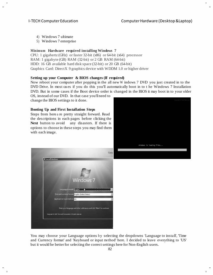
82
I-TECH Computer Education Computer Hardware (Desktop &Laptop)
2
4) Windows 7 ultimate
5) Windows 7 enterprise
Minimum Hardware required installing Windows 7
CPU: 1 gigahertz (GHz) or faster 32-bit (x86) or 64-bit (x64) processor
RAM: 1 gigabyte (GB) RAM (32-bit) or 2 GB RAM (64-bit)
HDD: 16 GB available hard disk space (32-bit) or 20 GB (64-bit)
Graphics Card: DirectX 9 graphics device with WDDM 1.0 or higher driver
Setting up your Computer & BIOS changes (If required)
Now reboot your computer after popping in the all new W indows 7 DVD you just created in to the
DVD Drive. In most cas es if you do this you'll automatically boot in to t he Windows 7 Installation
DVD. But in some cases if the Boot device order is changed in the BIOS it may boot in to your older
OS, instead of our DVD. In that case you'll need to
change the BIOS settings to it done.
Booting Up and First Installation Steps
Steps from here a re pretty straight forward. Read
the descriptions in each pages before clicking the
Next button to avoid any disasters. If there is
options to choose in these steps you may find them
with each image.
You may choose your Language options b y selecting the dropdowns 'Language to install', 'Time
and Currency format' and 'Keyboard or input me thod' here. I decided to leave everything to 'US'
but it would be better for selecting the correct settings here for Non-English users.
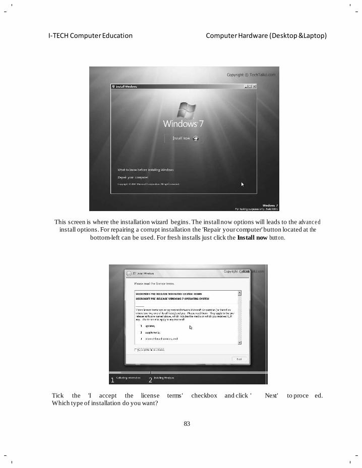
83
I-TECH Computer Education Computer Hardware (Desktop &Laptop)
This screen is where the installation wizard begins. The install now options will leads to the advanc e d
install options. For repairing a corrupt installation the 'Repair your computer' button located at the
bottom-left can be used. For fresh installs just click the Install now button.
Tick the 'I accept the license terms' checkbox and click ' Next' to proce ed.
Which type of installation do you want?
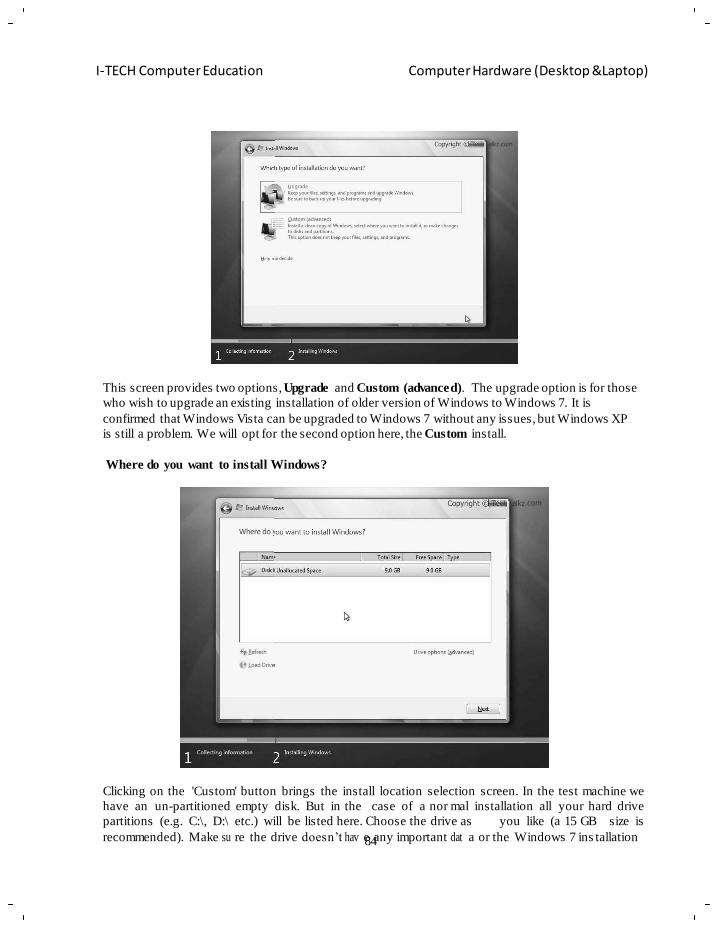
84
I-TECH Computer Education Computer Hardware (Desktop &Laptop)
This screen provides two options, Upgrade and Custom (advanced). The upgrade option is for those
who wish to upgrade an existing installation of older version of Windows to Windows 7. It is
confirmed that Windows Vista can be upgraded to Windows 7 without any issues, but Windows XP
is still a problem. We will opt for the second option here, the Custom install.
Where do you want to install Windows?
Clicking on the 'Custom' button brings the install location selection screen. In the test machine we
have an un-partitioned empty disk. But in the case of a nor mal installation all your hard drive
partitions (e.g. C:\, D:\ etc.) will be listed here. Choose the drive as you like (a 15 GB size is
recommended). Make su re the drive doesn‘t hav e any important dat a or the Windows 7 ins tallation
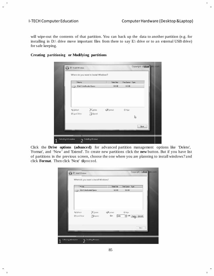
85
I-TECH Computer Education Computer Hardware (Desktop &Laptop)
will wipe-out the contents of that partition. You can back up the data to a nother partition (e.g. for
installing in D:\ drive move important files from there to say E:\ drive or to an external USB drive)
for safe keeping.
Creating partitioning or Modifying partitions
Click the Drive options (advanced) for advanced partition management options like 'Delete',
'Format', and ‗New‘ and 'Extend'. To create new partitions click the new button. But if you have list
of partitions in the previous screen, choose the one where you are planning to install windows7 and
click Format. Then click 'Next' tLoRproc e e d.
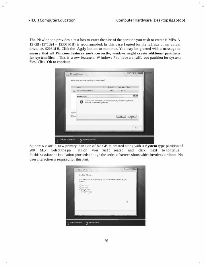
86
I-TECH Computer Education Computer Hardware (Desktop &Laptop)
The 'New' option provides a text box to enter the size of the partition you wish to create in MBs. A
15 GB (15*1024 = 15360 MB) is recommended. In this case I opted for the full size of my virtual
drive, i.e. 9216 M B. Click the Apply button to c ontinue. You may be greeted with a message to
ensure that all Windows features work correctly; windows might create additional partitions
for system files. . This is a ne w feature in W indows 7 to have a small b oot partition for system
files. Click Ok to continue.
So here w e are, a new primary partition of 8.8 GB is created along with a System type partition of
200 MB. Select the pa rtition you just c reated and click next to continue.
In this session the instillation proceeds though the series of screen shots which involves a reboot. No
user interaction is required for this Part.
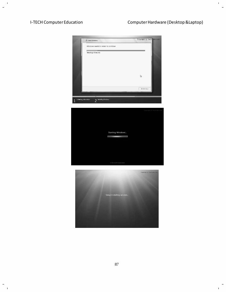
87
I-TECH Computer Education Computer Hardware (Desktop &Laptop)
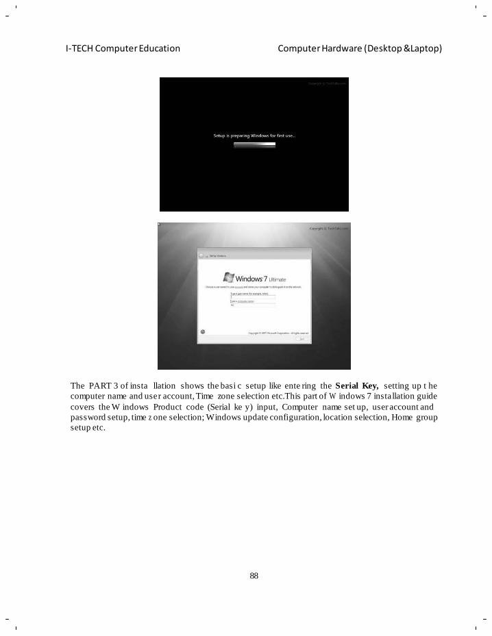
88
I-TECH Computer Education Computer Hardware (Desktop &Laptop)
The PART 3 of insta llation shows the basi c setup like ente ring the Serial Key, setting up t he
computer name and user account, Time zone selection etc.This part of W indows 7 installation guide
covers the W indows Product code (Serial ke y) input, Computer name set up, user account and
password setup, time z one selection; Windows update configuration, location selection, Home group
setup etc.
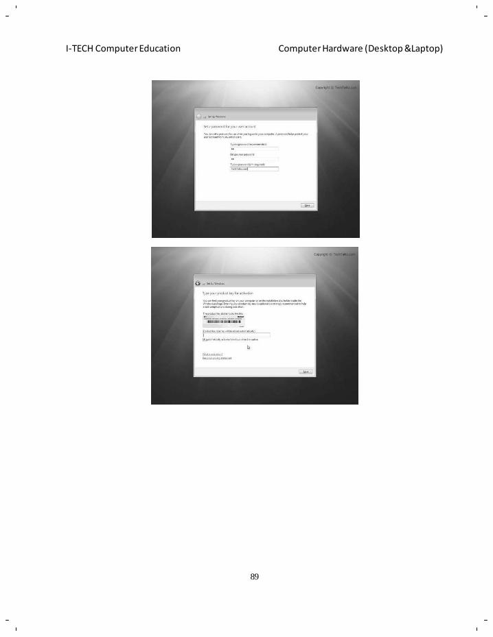
89
I-TECH Computer Education Computer Hardware (Desktop &Laptop)
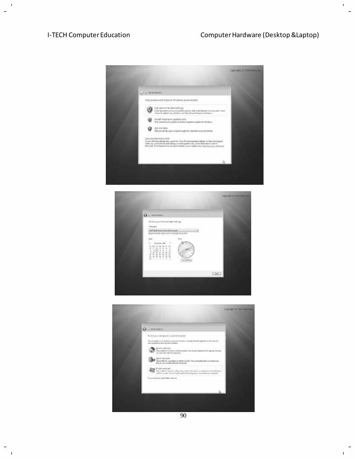
90
I-TECH Computer Education Computer Hardware (Desktop &Laptop)
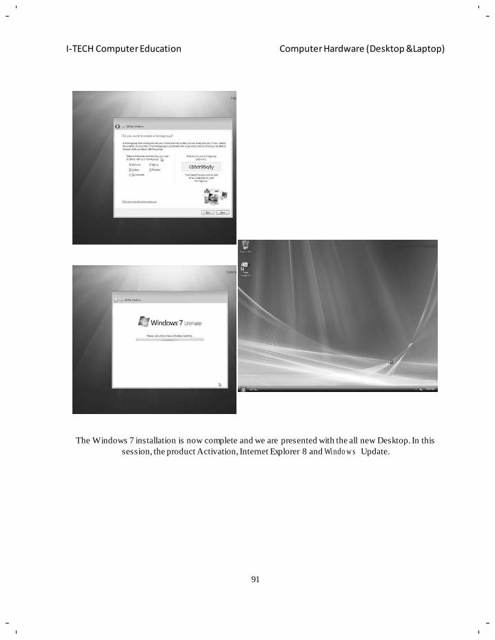
91
I-TECH Computer Education Computer Hardware (Desktop &Laptop)
The Windows 7 installation is now complete and we are presented with the all new Desktop. In this
session, the product Activation, Internet Explorer 8 and Windo w s Update.
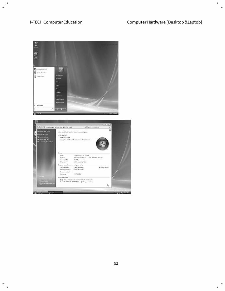
92
I-TECH Computer Education Computer Hardware (Desktop &Laptop)
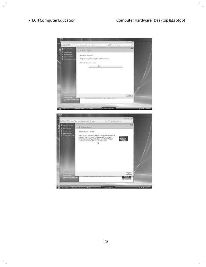
93
I-TECH Computer Education Computer Hardware (Desktop &Laptop)
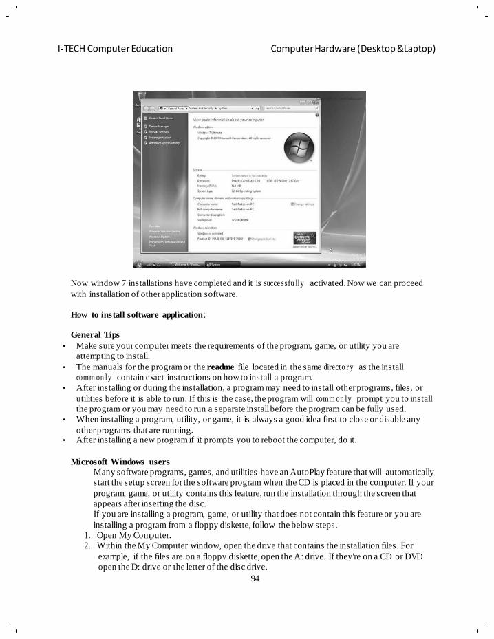
94
I-TECH Computer Education Computer Hardware (Desktop &Laptop)
c
o
a
Now window 7 installations have completed and it is succe ssfu lly activated. Now we can proceed
with installation of other application software.
How to install software application:
General Tips
• Make sure your computer meets the requirements of the program, game, or utility you are
attempting to install.
• The manuals for the program or the readme file located in the same directo r y as the install
comm on ly contain exact instructions on how to install a program.
• After installing or during the installation, a program may need to install other programs, files, or
utilities before it is able to run. If this is the case, the program will comm on ly prompt you to install
the program or you may need to run a separate install before the program can be fully used.
• When installing a program, utility, or game, it is always a good idea first to close or disable any
other programs that are running. • After installing a new program if it prompts you to reboot the computer, do it.
Microsoft Windows users
Many software programs, games, and utilities have an AutoPlay feature that will automatically
start the setup screen for the software program when the CD is placed in the computer. If your
program, game, or utility contains this feature, run the installation through the screen that
appears after inserting the disc.
If you are installing a program, game, or utility that does not contain this feature or you are
installing a program from a floppy diskette, follow the below steps.
1. Open My Computer.
2. Within the My Computer window, open the drive that contains the installation files. For
example, if the files are on a floppy diskette, open the A: drive. If they're on a CD or DVD
open the D: drive or the letter of the disc drive.
95
I-TECH Computer Education Computer Hardware (Desktop &Laptop)
3. Within the drive that contains your files, locate either a setup or install file. Double-clicking
on this file should start the installation for the program, game, or utility. If you see multiple
setups or install files, try to locate the Application file or double-click each of setup or install
files until you find the file that starts the installation. Many times the icons associated with the
installation files have the same name.
An alternate method of starting the installation in Microsoft Windows
1. Click Start and Run.
2. In the Run Window, type x:\setup or x:\install where x is the letter of the drive you wish to
start the installation from. For example, if you are attempting to install a program from the
floppy disk drive you would type a:\setup or a:\install.
96
I-TECH Computer Education Computer Hardware (Desktop &Laptop)
n
e
u
c
d
c
o
Objective of learning
Software – definition
Chapter – 6
Software
Interaction of software‘s with hardware
Different types of software‘s – System, application, device drivers etc.
Different storage media
Third party softw a r es ,a rc hiv e software
Software The software is the information that the computer uses to get the job done.
Software needs to be
accessed before it can be used. There are many terms used for process of accessing software including
running, executing, starting up, opening, and ot hers. Computer pro grams allow users to c omplete
tasks. A program can also be referred to as an application and the two words are used interchangeably.
Examples of soft ware programs or applications would be the Operating System (DOS, Windows,
UNIX, MacOS and vari ous others), Word processor (typing letters), Spreadsheet (financial info),
Database (inventory control and address book), Graphics program, Internet Browser, Email and many
others. As well any document that you create, graphic you design, sound you compose, file you make,
letter you write, email you send or anything that you create on your computer is referred to as
software. All software is stored in files.
Software is stored on a disk, card, tape or on e of the doz ens of other stora ge devices
available. There are millions of different pieces of software available for almost every
conceivable need. Software is available commercially through stores and mail order
and also available on t he Internet. Software is also available through an Open Source
license which allows anyone to use the Open Source software free of charge as long as
the license is ma intained. If you can't find the application that you need software development
companies can custom design software for you.
The three basic types of software are; commercial, shareware and open source software. Some
software is also released into the public domain without a license.
Commercial software comes prepackaged and is available from software stores and through the
Internet.
Shareware is software developed by individual and small companies that cannot afford to market their
software worldwide or by a company that wants to rele ase a demonstration version of their
commercial product. You will have an evaluation period in which you can decide whether to purchase
the product or not. Sharewar e software often is disabled in some wa y and has a not ice attached to
explain the legal requir e m e nts for using the product.
Open Source software is created by generous programmers and released into the public domain for
public use. There is usuall y a copyright notice that must r emain with th e software product. Ope n
Source software is not public domain in that the company or individual that develops the softw a re
retains ownership of the program but the software can be used f reely. Many popular Open Source
97
I-TECH Computer Education Computer Hardware (Desktop &Laptop)
applications are being developed and upgraded regularly by individuals and companies that believe in
the Open Source concept.
Operating Systems
All computers need some sort of Operating System (OS). The majority of modern home computers use
some form of Microsoft's operating systems. The original Microsoft operating system was called DOS
(Disk Operating System) though most computers use Windows. Windows comes in v arious versions
beginning with version 3.x then 95, 98, ME, XP, Vista and currently version 7. A few computers use
IBM's O/S2. Apple's Mac use their own operating system beginning with OS 1 though to OS 10. x. In
the past large companies and institutions would have an operating system design exclusively for them
but as the commercial operating systems become more sophisticated the benefits o f this pr actice is
becoming less apparent. Some computer p rofessionals, Internet Service Providers (ISP) and
mainframe computer users use an operating system such as UN IX (or a vari ant such as Linux),
Windows NT or 2000 (Win2k) or one of the other network or server based operating systems.
The operating system controls the input and outp ut or directs the flow of information to and from the
CPU. Much of this is done automatically by the system but it is possible to modify and control your
system if you need to.
Most computer users will run Microsoft W indows, Mac OS or Linux as their operating system. These
OS are G raphic User Interface (GUI) which allows the user t o control or run t he computer using a
Mouse and Icons. The user simply moves the mouse on a flat su rface, rolls the trackb all, or mo ves
their hand over the touchpad to control a pointer. They then choose the option they want by pressing a
button or touching the pad. Without a GU I the user controls the comp uter using the ke ys on the
keyboard. This is referred to as a Command Line Interface (CLI)
Disk and Storage
Disks and cards are used to store informat io n. All information on computers is stored in fi les. The size
of a file is measured in bytes. A byte is approximately one character (letter 'a', number '1', symbol '?'
etc....).A byte is mad e up of 8 bits. A bit is simp ly an on o r an off signal which p asses through the
computers circuitry. Every piece of so ftware can be broken down into a series of on or o ff signals or
its Binary Code.
• 4 bit equal to 1 Nibble
• 8 bit equal to 1 Byte
• 1024 bytes is a Kilobyte (Kb).
• 1024 kilobytes is a Megabyte (Mb).
• 1024 megabyte is a Gigabyte (Gb).
• 1024 gigabytes is a Terabyte (Tb)
• 1024 terabyte is a Perabyte (Pb)
• 1024 perabyte is a Exabyte (Eb)
Disk are a common way of transporting information such as bringing files home from work or sharing
files. Floppy disks have become less useful as f ile sizes increase and Compact disks ( CDs), Flash
drives and Digital Video Devices (DVDs) are becoming more popular. Most software is sold on a CD.
Internal Hard disks are the most common storage device.
Compact disks or CDs can store lar ge amounts of information. One disk will store 650 Mb. One ty pe
is a CD-ROM which stands for Compact Disk Read Only Memory. Another type is a CD-RW which
stands for Compact Disk - Read/Write. CD drives can copy information or burn information on to a
98
I-TECH Computer Education Computer Hardware (Desktop &Laptop)
e
o
G
g
n
o
blank CD. Common Re ad Only CD blanks can onl y be written to onc e though more expensive
Read/Write CD's can be used over and over again.
DVD disks can store 4.5 Gb on standard disk, 8 Gb on a dual layer disk and 16 Gb on a blue-ray disk.
Digital recorders allow you to store large files, such as movies, on a single disk.
Hard disks store th e majority of information on today's modern computer. Some of the first hard disk
stored 10 to 40 Mb. Today the standard hard disk stores 150 Gb or more (this number is constantly
increasing). Information can be stored and deleted as necessary. As files get larger the speed that hard
disks can read and write become more importa nt .F la sh drive or thumb drives range in size.
Floppy disk or diskette comes in two basic siz es; 5.25 inch and 3.5 inch. B oth have low and h igh
density versions though 3.5 in ch high density disks are the most com mon though many modern
computers are being sold without floppy disk drives.
Disk size
Amount of storage Appr ox im ate printed
8.5 x 11 inch pages
3.5 high density 1.44 Mb 720 pages
CD 650 Mb a small library
DVD 4.5 Gb a feature length movie
DVD dual layer 8 Gb a long feature length movie with extras
There are many other storage devices including tapes, Panasonic's LS120 3.5 inch diskettes, Iomega's
Zip & Jazz disks, VCR tape and many others. Innovation in storage technology is advancin g rapidly
and some technologies become obsolete. Information is stored in an electromagnetic form much like a
cassette or video tape.
Note:
Keep disks away from strong
electric or ma gnetic fields in cluding x-rays? Be aware of high
electromagnetic areas in the room such as televisions, speakers, hi gh tension wires, etc... Use disks
only at room temperature and keep them o ut of direct sunlig ht. If possible avoid passing
elect ro m a gn et ic storage devices through airport x-rays. In theory information stored on a disk will last
indefinitely but the ph ysical storage device will wear out with usag e and time so be sure to back up
(copy) your important files to a second storage device.
Computer software
Computer software, or just software, is a collection of computer programs and related data that provide
the instructions telling a computer what to do and how to do it. W e can also say software refers to one
or more computer programs and data held in the storage of the computer for some purposes. In other
words software is a set o f programs, procedures, algorithms and its docu mentation. Program software
performs the function of the program it implements, either by directly providing instructions to t he
computer hardware or b y serving as input to a nother piece of softwar e. The term was coi ned to
contrast to the old term hardw are (meaning physical devices). In contrast to hardware, software is
intangible, meaning it " cannot be touched‖. Software is also sometimes used i n a more narrow sense,
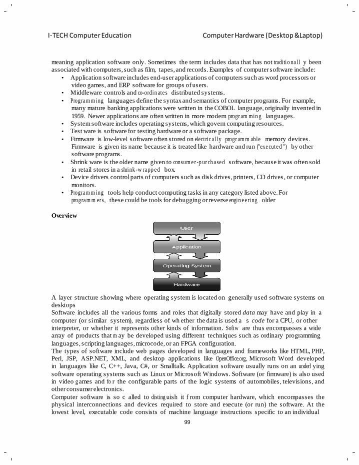
99
I-TECH Computer Education Computer Hardware (Desktop &Laptop)
meaning application software only. Sometimes the term includes data that has not tradi tio na l l y been
associated with computers, such as film, tapes, and records. Examples of computer software include:
• Application software includes end-user applications of computers such as word processors or
video games, and ERP software for groups of users.
• Middleware controls and co-ordin ate s distributed systems.
• Progra m m ing languages define the syntax and semantics of computer programs. For example,
many mature banking applications were written in the COBOL language, originally invented in
1959. Newer applications are often written in more modern progr am min g languages.
• System software includes operating systems, which govern computing resources.
• Test ware is software for testing hardware or a software package.
• Firmware is low-level software often stored on elect ric a l ly progr am m able memory devices.
Firmware is given its name because it is treated like hardware and run ("exe cute d ") by other
software programs.
• Shrink ware is the older name given to consum e r -p ur ch a se d software, because it was often sold
in retail stores in a shrink -w ra pp e d box.
• Device drivers control parts of computers such as disk drives, printers, CD drives, or computer
monitors.
• Progra m m ing tools help conduct computing tasks in any category listed above. For
progra m m er s, these could be tools for debugging or reverse engin e e ring older
Overview
A layer structure showing where operating system is located on generally used software systems on
desktops
Software includes all the various forms and roles that digitally stored data may have and play in a
computer (or si milar system), regardless of wh ether the data is used a s code for a CPU, or other
interpreter, or whether it represents other kinds of information. Softw are thus encompasses a wide
array of products that m ay be developed using different techniques such as ordinary programming
languages, scripting languages, microcode, or an FPGA configuration.
The types of software include web pages developed in languages and frameworks like HTML, PHP,
Perl, JSP, ASP.NET, XML, and desktop applications like OpenOffice.org, Microsoft Word developed
in languages like C, C++, Java, C#, or Smalltalk. Application software usually runs on an underl ying
software operating systems such as Linux or Microsoft Windows. Software (or firmware) is also used
in video g ames and fo r the configurable parts of the logic systems of automobiles, televisions, and
other consumer electronics.
Computer software is so c alled to disting uish it f rom computer hardware, which encompasses the
physical interconnections and devices required to store and execute (or run) the software. At the
lowest level, executable code consists of machine language instructions specific to an individual
100
I-TECH Computer Education Computer Hardware (Desktop &Laptop)
processor. A machine language consists of groups of binary values signifying processor instructions
that change the state of the computer from its preceding state. Programs are an ord ered sequence of
instructions for changing the sta te of the computer in a particular sequence. It is usua lly written in
high-level programming languages that are easier and more efficient for humans to use (closer to
natural language) than machine language. High-level languages are compiled or interpreted into
machine language object code. Software may also be written in an assembly language, essentially, a
mnemonic representation of a m achine language using a natural language alphabet. Assem bly
language must be assembled into object code via an assembler.
Types of software
1. System software
System software provides the basic functions for computer usage and helps run the computer hardware
and system. It includes a combin at ion of the following:
• Device drivers
• Operating systems
• Servers
• Utilities
• Window systems
System software is resp onsible for mana ging a variety of independ ent hardware components, so that
they can work together harmoniously. Its purpose is to unburden the applicati on software programmer
from the often complex details of the particular computer being used, including such accessories as
communications devices, printers, device readers, displays and keyboards, and also to pa rtition the
computer's resources such as memory and processor time in a safe and stable manner.
2. Program ming software
Progr a m m ing software usually provides tools to assist a program m er in writing computer programs,
and software using different progra m m in g languages in a more convenient way. The tools include:
• Compilers
• Debuggers
• Interpreters
• Linkers
• Text editors
An Integrated development environment (IDE) is a single application that attempts to manage all these
functions.
3. Application software
Application software is developed to aid in any task that b enefits from computation. It is a broad
category, and encompasses software of m any kinds, including the inter net browser being used to
display this page. This category includes:
• Business software
• Comp ute r- aid ed design
• Databases
• Decision making software
• Educ at ion al software
• Image editing
• Industrial automation
101
I-TECH Computer Education Computer Hardware (Desktop &Laptop)
• Math em at ic al software
• Medical software
• Molecular modeling software
• Quantum chem ist r y and solid state physics software
• Simulation software
• Spreadsheets
• Telec o m m un ica tio ns (i.e., the Internet and ever ything that flows on it)
• Video games
• Word processing
Users often s ee things differently than programmers. People who u se modern general purpose
computers (as opposed to embedded systems, analog computers and supercomputers) usually see three
layers of software performing a variety of tasks: platform, application, and user software.
• Platform software: Platform includes the firmware, device drivers, an operating system, and
typically a graphical user interface which, in total, allow a user to in teract with the computer
and its peripherals ( associated equipment). Platform software often comes bundled with the
computer. On a PC you will usually have the ability to change the platform software.
• Application software: Application software or Applications are what most people think of
when they think of so ftware. Typical examples include office suites and video g ames.
Application software is often purchased separately from computer hardware. Sometimes
applications are bundled with the computer, but th at does not chan ge the fact that they run as
independent applications. Applications are usually independent programs from the operating
system, though they are often tailored for specific platforms. Most users think of compilers,
databases, and other "system software" as applications.
The software's license gives the user the right to use the software in the licensed environment. Some
software comes with the license when purch ased off the shelf, or an OEM license when bundled with
hardware. Other software comes with a fr ee software license, granting the recipient the rights to
modify and redistribute the software. Software can also be in the form of freeware or shareware.
4. Third-part y Software
Third -p a rty software generally falls into the following somewhat overla ppin g groups.
• Commercial software products are developed, distributed and maintained under a licensing
agreement with a vendor or organ iza tio n, generally for a fee. Comm er cia l software products
are normally installed like the vendor supplied software, but in a separate directory.
• The author of software identified as shareware, would normally expect some payment for
down loa din g the software and accom p a n yin g docum e nta tio n. The payment is often voluntary
and made to a specified organization.
• According to the 'Free Software Foundat io n' , freeware is software that everyone is free to copy,
modify and redist rib ute . The word "free" pertains to freedom. It does not imply that it is free of
charge, so anyone can sell free software so long as they don't impose any new restrictions on its
redist rib utio n or use. GNU software is an example of the freeware. The right to redistribute the
software is legally bound with the condition that the distribution includes original code,
complete docum en tatio n including the changes made.
• Total absence of copy right protection is the chara cte rist ic of public domain software. Anyone
can copy, modify or use it in any way the wish. The author has no exclusive right and has no
legal respo nsibi l ity associated with the use of the software.
102
I-TECH Computer Education Computer Hardware (Desktop &Laptop)
5. Archive sites
Publically accessible software, including shareware and freeware, may be accessed via anonymous
FTP or the WWW from an archive site on the internet. A network search utility named archie may be
used to search databases of Anonymous FTP host directories and locate specific software.
Some well-known archive sites in U SA include the GNU archive site and UUNET. Popular bus y
archive sites often may have mirror sites which keep copies of spec ific directories or files to m ake
them quickly available to local users and to re duce the load on the original site. For example,
ftp.uwsg.indiana.edu/pub mirrors several popular software distributions including , gnu, linux, mosaic,
netscape, perl5, and sendmail.
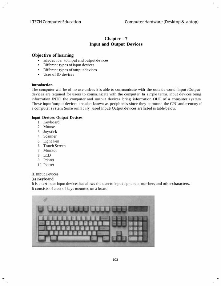
103
I-TECH Computer Education Computer Hardware (Desktop &Laptop)
Chapter - 7
Input and Output Devices
Objective of learning
Introd uc tio n to Input and output devices
Different types of input devices
Different types of output devices
Uses of IO devices
Introduction
The computer will be of no use unless it is able to communicate with the outside world. Input /Output
devices are required for users to communicate with the computer. In simple terms, input devices bring
information INTO the computer and output devices bring information OUT of a computer system.
These input/output devices are also known as peripherals since they surround the CPU and memory of
a computer system. Some comm o nly used Input/ Output devices are listed in table below.
Input Devices Output Devices
1. Keyboard
2. Mouse
3. Joystick
4. Scanner
5. Light Pen
6. Touch Screen
7. Monitor
8. LCD
9. Printer
10. Plotter
II. Input Devices
(a) Keyboard
It is a text base input device that allows the user to input alphabets, numbers and other characters.
It consists of a set of keys mounted on a board.
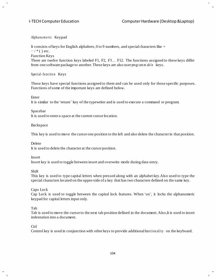
104
I-TECH Computer Education Computer Hardware (Desktop &Laptop)
Alpha nu m e ric Keypad
It consists of keys for English alphabets, 0 to 9 numbers, and special characters like +
− / * ( ) etc.
Function Keys
There are twelve function keys labeled F1, F2, F3… F12. The functions assigned to these keys differ
from one software package to another. These keys are also user progr am m ab le keys.
Special - fu nc tio n Keys
These keys have special functions assigned to them and can be used only for those specific purposes.
Functions of some of the important keys are defined below.
Enter
It is similar to the ‗return‘ key of the typewriter and is used to execute a command or program.
Spacebar
It is used to enter a space at the current cursor location.
Backspace
This key is used to move the cursor one position to the left and also delete the character in that position.
Delete
It is used to delete the character at the cursor position.
Insert
Insert key is used to toggle between insert and overwrite mode during data entry.
Shift
This key is used to type capital letters when pressed along with an alphabet key.Also used to type the
special characters located on the upper-side of a key that has two characters defined on the same key.
Caps Lock
Cap Lock is used to toggle between the capital lock features. When ‗on‘, it locks the alphanumeric
keypad for capital letters input only.
Tab
Tab is used to move the cursor to the next tab position defined in the document. Also,It is used to insert
indentation into a document.
Ctrl
Control key is used in conjunction with other keys to provide additional funct ion al i ty on the keyboard.
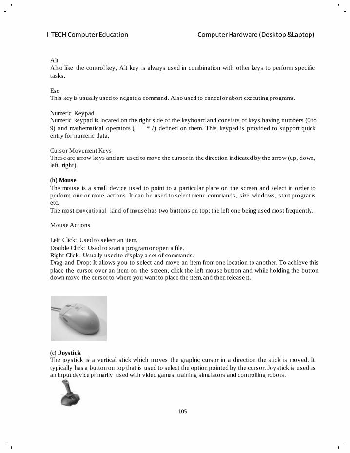
105
I-TECH Computer Education Computer Hardware (Desktop &Laptop)
Alt
Also like the control key, Alt key is always used in combination with other keys to perform specific
tasks.
Esc
This key is usually used to negate a command. Also used to cancel or abort executing programs.
Numeric Keypad
Numeric keypad is located on the right side of the keyboard and consists of keys having numbers (0 to
9) and mathematical operators (+ − * /) defined on them. This keypad is provided to support quick
entry for numeric data.
Cursor Movement Keys
These are arrow keys and are used to move the cursor in the direction indicated by the arrow (up, down,
left, right).
(b) Mouse
The mouse is a small device used to point to a particular place on the screen and select in order to
perform one or more actions. It can be used to select menu commands, size windows, start programs
etc.
The most conv en tio na l kind of mouse has two buttons on top: the left one being used most frequently.
Mouse Actions
Left Click: Used to select an item.
Double Click: Used to start a program or open a file.
Right Click: Usually used to display a set of commands.
Drag and Drop: It allows you to select and move an item from one location to another. To achieve this
place the cursor over an item on the screen, click the left mouse button and while holding the button
down move the cursor to where you want to place the item, and then release it.
(c) Joystick
The joystick is a vertical stick which moves the graphic cursor in a direction the stick is moved. It
typically has a button on top that is used to select the option pointed by the cursor. Joystick is used as
an input device primarily used with video games, training simulators and controlling robots.
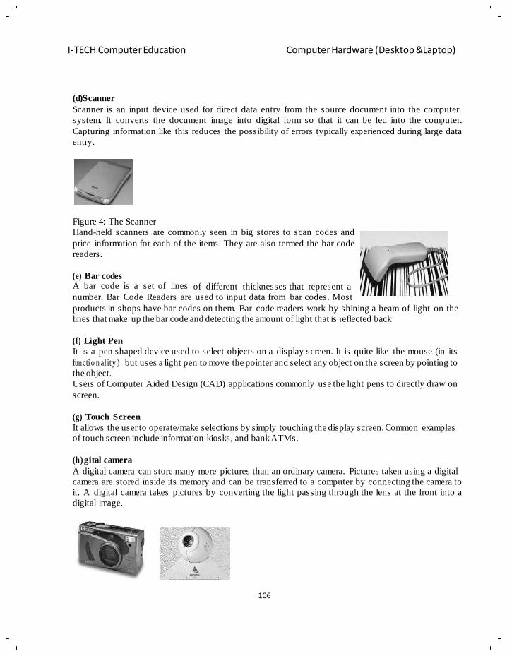
106
I-TECH Computer Education Computer Hardware (Desktop &Laptop)
(d)Scanner
Scanner is an input device used for direct data entry from the source document into the computer
system. It converts the document image into digital form so that it can be fed into the computer.
Capturing information like this reduces the possibility of errors typically experienced during large data
entry.
Figure 4: The Scanner
Hand-held scanners are commonly seen in big stores to scan codes and
price information for each of the items. They are also termed the bar code
readers.
(e) Bar codes A bar code is a set of lines
of different thicknesses that represent a
number. Bar Code Readers are used to input data from bar codes. Most
products in shops have bar codes on them. Bar code readers work by shining a beam of light on the
lines that make up the bar code and detecting the amount of light that is reflected back
(f) Light Pen
It is a pen shaped device used to select objects on a display screen. It is quite like the mouse (in its
functio n al ity ) but uses a light pen to move the pointer and select any object on the screen by pointing to
the object.
Users of Computer Aided Design (CAD) applications commonly use the light pens to directly draw on
screen.
(g) Touch Screen
It allows the user to operate/make selections by simply touching the display screen. Common examples
of touch screen include information kiosks, and bank ATMs.
(h)gital camera
A digital camera can store many more pictures than an ordinary camera. Pictures taken using a digital
camera are stored inside its memory and can be transferred to a computer by connecting the camera to
it. A digital camera takes pictures by converting the light passing through the lens at the front into a
digital image.
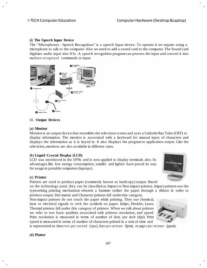
107
I-TECH Computer Education Computer Hardware (Desktop &Laptop)
(i) The Speech Input Device
The ―Microphones - Speech Recognition‖ is a speech Input device. To operate it we require using a
microphone to talk to the computer. Also we need to add a sound card to the computer. The Sound card
digitizes audio input into 0/1s .A speech recognition program can process the input and convert it into
machin e- re c og niz e d commands or input
III. Output Devices
(a) Monitor
Monitor is an output device that resembles the television screen and uses a Cathode Ray Tube (CRT) to
display information. The monitor is associated with a keyboard for manual input of characters and
displays the information as it is keyed in. It also displays the program or application output. Like the
television, monitors are also available in different sizes.
(b) Liquid Crystal Display (LCD)
LCD was introduced in the 1970s and is now applied to display terminals also. Its
advantages like low energy consumption, smaller and lighter have paved its way
for usage in portable computers (laptops).
(c) Printer
Printers are used to produce paper (commonly known as hardcopy) output. Based
on the technology used, they can be classified as Impact or Non-impact printers. Impact printers use the
typewriting printing mechanism wherein a hammer strikes the paper through a ribbon in order to
produce output. Dot-matrix and Character printers fall under this category.
Non-impact printers do not touch the paper while printing. They use chemical,
heat or electrical signals to etch the symbols on paper. Inkjet, DeskJet, Laser,
Thermal printers fall under this category of printers. When we talk about printers
we refer to two basic qualities associated with printers: resolution, and speed.
Print resolution is measured in terms of number of dots per inch (dpi). Print
speed is measured in terms of number of characters printed in a unit of time and
is represented as charac te rs- pe r- se co nd (cps), lines-p e r-m in ute (lpm), or page s-pe r -m inute (ppm).
(d) Plotter
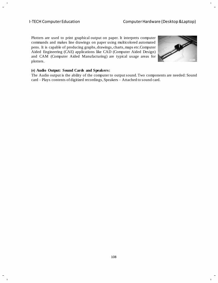
108
I-TECH Computer Education Computer Hardware (Desktop &Laptop)
Plotters are used to print graphical output on paper. It interprets computer
commands and makes line drawings on paper using multicolored automated
pens. It is capable of producing graphs, drawings, charts, maps etc.Computer
Aided Engineering (CAE) applications like CAD (Computer Aided Design)
and CAM (Computer Aided Manufacturing) are typical usage areas for
plotters.
(e) Audio Output: Sound Cards and Speakers:
The Audio output is the ability of the computer to output sound. Two components are needed: Sound
card – Plays contents of digitized recordings, Speakers – Attached to sound card.
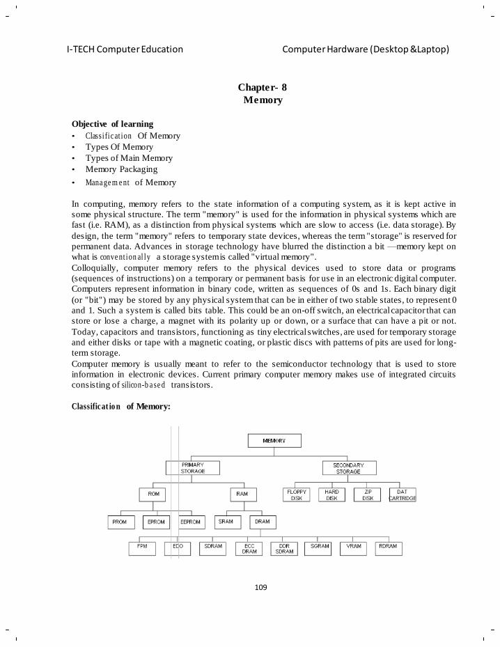
109
I-TECH Computer Education Computer Hardware (Desktop &Laptop)
Chapter- 8
Memory
Objective of learning
• Classi fic at ion Of Memory
• Types Of Memory
• Types of Main Memory
• Memory Packaging
• Mana ge m e nt of Memory
In computing, memory refers to the state information of a computing system, as it is kept active in
some physical structure. The term "memory" is used for the information in physical systems which are
fast (i.e. RAM), as a distinction from physical systems which are slow to access (i.e. data storage). By
design, the term "memory" refers to temporary state devices, whereas the term "storage" is reserved for
permanent data. Advances in storage technology have blurred the distinction a bit —memory kept on
what is conve nt ion al ly a storage system is called "virtual memory".
Colloquially, computer memory refers to the physical devices used to store data or programs
(sequences of instructions) on a temporary or permanent basis for use in an electronic digital computer.
Computers represent information in binary code, written as sequences of 0s and 1s. Each binary digit
(or "bit") may be stored by any physical system that can be in either of two stable states, to represent 0
and 1. Such a system is called bits table. This could be an on-off switch, an electrical capacitor that can
store or lose a charge, a magnet with its polarity up or down, or a surface that can have a pit or not.
Today, capacitors and transistors, functioning as tiny electrical switches, are used for temporary storage
and either disks or tape with a magnetic coating, or plastic discs with patterns of pits are used for long-
term storage.
Computer memory is usually meant to refer to the semiconductor technology that is used to store
information in electronic devices. Current primary computer memory makes use of integrated circuits
consisting of silicon-b a se d transistors.
Classificat io n of Memory:
110
I-TECH Computer Education Computer Hardware (Desktop &Laptop)
Primary Storage is further classified into two types i.e. ROM and RAM. Seco nd ar y storage contains the
different devices such as Floppy disk, Hard disk, Zip disk and DAT cartridge. Memory normally refers
to the amount of RAM installed in the computer. Leading companies which are the memory suppl ie rs
are Micron, Siemens etc.
Types of Memory:
Volatile memory: (RAM)
Volatile memory is computer memory that requires power to maintain the stored information. Most
modern semiconductor volatile memory is either Static RAM or dynamic RAM. SRAM retains its
contents as long as the power is connected and is easy to interface to but uses six transistors per bit.
Dynamic RAM is more complicated to interface to and control, and needs regular refresh cycles to
prevent its contents being lost. However, DRAM uses only one transistor and a capacitor per bit,
allowing it to reach much higher densities and, with more bits on a memory chip, be much cheaper per
bit. SRAM is not worthwhile for desktop system memory, where DRAM dominates, but is used for
their cache memories. SRAM is commonplace in small embedded systems, which might only need tens
of kilobytes or less. Upcoming volatile memory technologies that hope to replace or compete with
SRAM and DRAM include Z-RAM, TTRAM, A-RAM and ETA RAM.
Non-volatile memory: (ROM)
Non-volatile memory is computer memory that can retain the stored information even when not
powered. Examples of non-volatile memory include read-only memory, flash memory, most types of
magnetic computer storage devices (e.g. hard disks, floppy discs and magnetic tape), optical discs, and
early computer storage methods such as paper tape and punched cards. Upcoming non-volatile memory
technolo gie s include FeRAM, CBRAM, PRAM, SONOS, Racetrack memory, NRAM and Millipede.
Virtual memory:
Virtual memory is a system where all physical memory is controlled by the operating system. When a
program needs memory, it requests it from the operating system. The operating system then decides
what physical location to place the memory in. This offers several advantages. Computer programmers
no longer need to worry about where the memory is physically stored or whether the user's computer
will have enough memory. It also allows multiple types of memory to be used. For example, some
memory can be stored in physical RAM chips while other memory is stored on a hard drive. This
drastically increases the amount of memory available to programs. The operating system will place
actively used memory in physical RAM, which is much faster than hard disks. When the amount of
RAM is not sufficient to run all the current programs, it can result in a situation where the computer
spends more time moving memory from RAM to disk and back than it does accomplishing tasks; this is
known as thrashing. Virtual memory systems usually include protected memory, but this is not always
the case.
Protected memory
Protected memory is a system where each program is given an area of memory to use and is not
permitted to go outside that range. Use of protected memory greatly enhances both the reliability and
security of a computer system. Without protected memory, it is possible that a bug in one program will
alter the memory used by another program. This will cause that other program to run off of corrupted
memory with unpredictable results. If the operating system's memory is corrupted, the entire computer
111
I-TECH Computer Education Computer Hardware (Desktop &Laptop)
system may crash and need to be rebooted. At times programs intentionally alter the memory used by
other programs. This is done by viruses and malware to take over computers. Protected memory assigns
programs their own areas of memory. If the operating system detects that a program has tried to alter
memory that doesn't belong to it, the program is terminated. This way, only the offending program
crashes, and other programs are not affected by the error. Protected memory systems almost always
include virtual memory as well.
Types of Main Memory:
Volatile memory:
Volatile memory, also known as volatile storage, is computer memory that requires power to maintain
the stored information, unlike non-volatile memory which does not require a maintained power supply.
It has been less popularly known as temporary memory. Most forms of modern random access memory
(RAM) are volatile storage, including dynamic random access memory (DRAM) and static random
access memory (SRAM). Content addressable memory and dual-ported RAM are usually implemented
using volatile storage. Early volatile storage technologies include delay line memory and Williams‘s
tube.
Dynamic Random- Access Memory (DRAM):
Dynamic random-access memory (DRAM) is a type of random-access memory that stores each bit of
data in a separate capacitor within an integrated circuit. The capacitor can be either charged or
discharged. These two states are taken to represent the two values of a bit, conve nt ion al ly called 0 and
1. Since capacitors leak charge, the information eventually fades unless the capacitor charge is refreshed periodically. Because of this refresh requirement, it is a dynamic memory as opposed to
SRAM and other static memory.The main memory (the "RAM") in personal computers is Dynamic
RAM (DRAM), as is the "RAM" of home game consoles (PlayStation, Xbox 360), laptop, notebook
and workstation computers.The advantage of DRAM is its structural simplicity: only one transistor and
a capacitor are required per bit, compared to six transistors in SRAM. This allows DRAM to reach very
high densities. Unlike flash memory, DRAM is volatile memory, since it loses its data quickly when
power is removed. The transistors and capacitors used are extremely small; hundreds of billions can fit
on a single memory chip.DRAM is the most popular type of memory used in systems today. It is also
the most popular type of memory that computer users are adding to their computers for the purpose of
upgrading memory. Therefore, you must understand the different types of DRAM and what types of
DRAM outperform others.
• Types Of DRAM:
Standard DRAM
Memory is organized into rows and columns like a spreadsheet. The information is stored in the
different cells or blocks that make up these rows and columns. With standard RAM, the CPU requests
data by sending the address of the row and the address of the column for every block of data that needs
to be read. The memory controller then fetches the information from that memory location.
Fast Page Mode (FPM)
Fast Page Mode (FPM) improves on the performance of standard DRAM by not requiring a row
address for each request to memory, assuming that the next block of data is on the same row (which in
most cases will be true).
112
I-TECH Computer Education Computer Hardware (Desktop &Laptop)
Extended Data Output (EDO)
Extended Data Output (EDO) memory is about 10 to 15 percent faster than FPM memory and is
usually found on 66 MHz motherboards. With EDO memory, the memory controller can read data from
a memory block while listening for the next instruction. This capability increases performance, because
the memory controller does not have to wait for the next instruction after read ng a block of memory;
while it is reading one block of memory, it is receiving the next instruction With FPM RAM, the
reading of one memory block and listening for the next instruction would be done in multiple steps.
Burst Extended Data Output (BEDO)
Burst Extended Data Output (BEDO) is a bursting-type technology. The word burst refers to the fact
that when one memory address is requested and that address is retrieved, the system bursts into the next
couple of blocks and reads those as well. The theory behind BEDO is that the system has already gone
through the trouble of locating that block, and chances are that the next request will be for the next
block, so why not take it while we are there? If that extra block is the next requested block from the
CPU, the memory controller already has the data and can pass it to the CPU immediately.
BEDO is 50 percent faster than EDO. Because of lack of support from computer manufacturers,
however, BEDO has not been used in many systems. It seems that PC manufacturers are using SDRAM
instead.
Synchronous DRAM (SDRAM)
Synchronous DRAM (SDRAM) is memory synchronized at system speed. This synchronized speed
means that the data stored in memory is refreshed at the system speed and data is accessed in memory
at the system speed. SDRAM is the popular RAM in systems today. Because you are running at the
system speed, however, you must match the RAM with the motherboard speed. Thus, if you have a 100
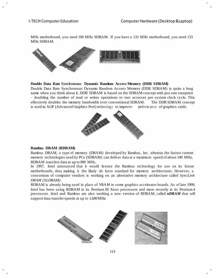
113
I-TECH Computer Education Computer Hardware (Desktop &Laptop)
MHz motherboard, you need 100 MHz SDRAM. If you have a 133 MHz motherboard, you need 133
MHz SDRAM.
Double Data Rate Synchronous Dynamic Random Access Memory (DDR SDRAM)
Double Data Rate Synchronous Dynamic Random Access Memory (DDR SDRAM) is quite a long
name when you think about it. DDR SDRAM is based on the SDRAM concept with just one exception
– doubling the number of read or writes operations to two accesses per system clock cycle. This
effectively doubles the memory bandwidth over conventional SDRAM. The DDR SDRAM concept
is used in AGP (Advanced Graphics Port) techno log y to improve perfo rm an c e of graphics cards.
Rambus DRAM (RDRAM)
Rambus DRAM, a type of memory (DRAM) developed by Rambus, Inc. whereas the fastest current
memory technologies used by PCs (SDRAM) can deliver data at a maximum speed of about 100 MHz,
RDRAM transfers data at up to 800 MHz. In 1997, Intel announced that it would license the Rambus technology for use on its future
motherboards, thus making it the likely de facto standard for memory architectures. However, a
consortium of computer vendors is working on an alternative memory architecture called SyncLink
DRAM (SLDRAM).
RDRAM is already being used in place of VRAM in some graphics accelerator boards. As of late 1999,
Intel has been using RDRAM in its Pentium III Xeon processors and more recently in its Pentium 4 processors. Intel and Rambus are also working a new version of RDRAM, called nDRAM that will
support data transfer speeds at up to 1,600 MHz

114
I-TECH Computer Education Computer Hardware (Desktop &Laptop)
Error Correction Code DRAM (ECC DRAM)
Many higher-end systems use a special type of RAM called Error Correction Code (ECC)
DRA M . N O N -E C C is normally used by the end users. ON-ECC RAM checks out for any error occurred
in parity bit but does not correct it, which is performed by ECC.ECC detects problems in RAM quite
well and can fix most of them on the fly.ECC RAM are costly as compared with NON -ECC
RAM.ECC DRAM memory requires special types of Mothe r bo ar ds that can support ECC DRAM.
Synchronous Graphics Random Access Memory (SGRAM)
It is streamlined to work with graphics cards. Enables fast read and write operation for the graphics
processor when working with the information in the Video frame buffer.
Video RAM(VRAM)
Memory that is optimized for Video Cards where each memory cell is dual ported. Video data can be
written to the RAM while the graphics adapter simulta n eo usly reads from it to refresh the display.
Static Random- Access Memory (SRAM):
Static random-access memory (SRAM) is a type of semiconductor memory where the word static
indicates that, unlike dynamic RAM (DRAM), it does not need to be periodically refreshed, as SRAM
uses bit table latching circuitry to store each bit. SRAM exhibits data remainence but is still volatile in
the conventional sense that data is eventually lost when the memory is not powered. It is also known as
Cache RAM.
• SRAM operation
An SRAM cell has three different states it can be in: standby where the circuit is idle, reading when
the data has been requested and writing when updating the contents. The SRAM to operate in read
mode and write mode should have "read ab il i ty" and "write stability" respectively.
• Applications and uses:
Static RAM exists primarily as:
Integrated on chip-
o As RAM or cache memory in micro-controllers (usually from around 32 bytes up to 128
kilobytes)
o As the primary caches in powerful microprocessors, such as the x86 family, and many
others (from 8 kB, up to several megabytes)
o To store the registers and parts of the state-machines used in some microprocessors on
application specific ICs, or ASICs (usually in the order of kilobytes)
o In FPGAs and CPLDs.
Embedded use
Many categories of industrial and scientific subsystems, automotive electronics, and similar, contain
static RAM. Some amount (kilobytes or less) is also embedded in practically all modern appliances,
toys, etc. that implement an electronic user interface. Several megabytes may be used in complex
products such as digital cameras, cell phones, synthe size r s, etc.
SRAM in its dual-ported form is sometimes used for real time digital signal proce ssin g circuits.
115
I-TECH Computer Education Computer Hardware (Desktop &Laptop)
In computers
SRAM is also used in personal computers, workstations, routers and peripheral equipment: internal
CPU caches and external burst mode SRAM caches, hard disk buffers, router buffers, etc. LCD screens
and printers also normally employ static RAM to hold the image displayed (or to be printed). Small
SRAM buffers are also found in CDROM and CDRW drives, usually 256 kb or more are used to buffer
track data, which is transferred in blocks instead of as single values. The same applies to cable modems
and similar equipment connected to computers.
Hobbyists
Hobbyists often prefer SRAM due to the ease of interfacing. It is much easier to work with than DRAM
as there are no refresh cycles and the address and data buses are directly accessible rather than
multiplexed. In addition to buses and power connections, SRAM usually require only three controls:
Chip Enable (CE), Write Enable (WE) and Output Enable (OE). In synchronous SRAM, Clock (CLK)
is also included.
• Types of SRAM
Non-volatile SRAM
Non-volatile SRAMs have standard SRAM functio n al ity , but they save the data when the power supply is lost, ensuring preservation of critical information. NVSRAMs are used in a wide range of
situations—networking, aerospace, and medical, among many others—where the preservation of data is
critical and where batteries are impractical.
Asynchrono us SRAM
Asynchronous SRAM are available from 4 Kb to 32 Mb. The fast access time of SRAM makes
asynchronous SRAM appropriate as main memory for small cache-less embedded processors used in
everything from industrial electronics and measurement systems to hard disks and networking
equipment, among many other applications. They are used in various applications like switches and
routers, IP-Phones, IC-Testers, DSLAM Cards, to Automotive Electronics.
Cache Memory
Cache memory is a relat ive ly small amount (norm al ly less than 1MB) of high speed memory that
resides very close to the CPU. Cache memory is designed to supply the CPU with the most frequently
requested data and instructions. Retrieving data from cache takes a fraction of the time that it takes to
access it from main memory. Having cache memory can save a lot of time.
Caches are organized into layers . The highest layer is closest to the device (such as the CPU) using it.
There are two levels of cache built right into the CPU. Any cache memory component is assigned a
"level" according to its proximi ty to the processor. The cache that is closest to the processor is called
Level 1 (L1) Cache. The next level of cache is numbered L2, then L3, and so on.
• Hit Rate
Whenever the CPU finds the data it needs in the cache then it is called a cache hit. When the CPU fails
to find the data it needs in the cache that is called a cache miss. The ratio of cache hits to cache misses
is called a cache hit ratio.
116
I-TECH Computer Education Computer Hardware (Desktop &Laptop)
• Level 1 (Primary) Cache
Level 1 or primary cache is the fastest memory on the PC. It is built directly into the processor itself.
It is very small, generally from 8 KB to 64 KB, but it is extre m ely fast and runs at the same speed as
the processor.
• Level 2 (Secondary) Cache
Level 2 caches is a secon d ar y cache to the level 1 cache, and is larger and slightly slower. Used to catch
recent accesses that are not caught by the level 1 cache, and is usually 64 KB to 2 MB in size. Usually
found either on the same package as the processor itself (though it isn't in the same circuit where the
processor and level 1 cache are) or on the mothe r bo a rd or as a daughter board that inserts into the
motherboard.
• Operation s in Cache
Write Through and Write Back:
When the CPU writes new data to the cache, the cache controller must update main memory with the
new data. By making sure that the information in the cache is the same as that in main memory. The
cache controller is said to maintain cache coherency. If the cache controller allows the data in the cache
to differ from data in main memory, the data is said to be stale. Every time the CPU updates the cache,
the data is automatically written through to the main memory. Which is called as Write Through Cache.
If the CPU needs to access the cache or main memory before the write through is completed, the CPU
must wait. This will slow the overall performance of the CPU. To prevent this problem the cache
controller update a small but fast buffer instead of directly updating the main memory. Because the
buffer can be faster than the main memory, the cache controller can make the cache available to the
CPU sooner. This method of updating the main memory is called a Buffered or posted write through.
The cache controller will keep track of which data is stale and only update the memory when it must,
not immediately required after every memory write. This technique is called write back or copy back.
The concept of buffering, or posting, the writes can also be applied to the write back cache to further
increase its performance as well.It results in the fastest cache.
Non-volatile memory:
Non-volatile memory, NVM or non-volatile storage, in the most basic sense, is computer memory that
can retain the stored information even when not powered. Examples of non-volatile memory include
read- on ly memory, flash memory, ferroelectric RAM, most types of magnetic computer storage devices
(e.g. hard disks, floppy disks, and magnetic tape), optical discs, and early computer storage methods
such as paper tape and punched cards. Non-volatile memory is typically used for the task of secondary
storage, or long-term persistent storage. The most widely used form of primary storage today is a
volatile form of random access memory (RAM), meaning that when the computer is shut down,
anything contained in RAM is lost. Unfortunately, most forms of non-volatile memory have limitations
that make them unsuitable for use as primary storage. Typically, non-volatile memory either costs more
or performs worse than volatile random access memory. Several companies are working on developing
non-volatile memory systems comparable in speed and capacity to volatile RAM. For instance, IBM is
currently developing MRAM (Magneto resistive RAM). Not only would such technology save energy,
but it would allow for computers that could be turned on and off almost instantly, bypassing the slow
start-up and shutdown sequence.
117
I-TECH Computer Education Computer Hardware (Desktop &Laptop)
Non-volatile data storage can be categorized in electrically addressed systems (read-only memory) and
mechanically addressed systems (hard disks, optical disc, magnetic tape, holographic memory, and
such). Electrically addressed systems are expensive, but fast, whereas mechanically addressed systems
have a low price per bit, but are slow. Non-volatile memory may one day eliminate the need for
comp a ra tiv e ly slow forms of secon da r y storage systems, which include hard disks.
• Types Of Non-Volatile Memory:
Mask-programmed ROM:
One of the earliest forms of non-volatile read-only memory, the mask-programmed ROM was prewired
at the design stage to contain specific data; once the mask was used to manufacture the integrated
circuits, the data was cast in stone (silicon, actually) and could not be changed. The mask ROM was
therefore useful only for large-volume production, such as for read-only memories containing the start
up code in early microcomputers. This program was often referred to as the "bootstrap", as in pulling
oneself up by one's own bootstraps. Due to the very high initial cost and inability to make revisions, the
mask ROM is rarely, if ever, used in new designs.
Program ma ble ROM
The next approach was to create a chip which was initially blank; the programmable ROM originally
contained silicon or metal fuses, which would be selectively "blown" or destroyed by a device
programmer or PROM programmer in order to change 0s to 1s. Once the bits were changed, there was
no way to restore them to their original condition. Non-volatile but still somewhat inflexible. Early
PAL programmable array logic chips used a similar programming approach to that used in the fuse-
based PROMs. Newer Anti fuse-based PROMs (which are also referred to as one-time-programmable
(OTP) memory) are widely used in consumer and automotive electronics, radio-frequency
identification devices (RFID), implantable medical devices, and high-definition multimedia interfaces
(HDMI) due to their small footprint, reliability, fast read speed, and long data retention rates.
Erasable PROMs
There are two classes of non-volatile memory chips based on EPROM technology.
• UV-erase EPROM
The original erasable non-volatile memories were EPROM's; these could be readily identified by the
distinctive quartz window in the center of the chip package. These operated by trapping an electrical
charge on the gate of a field-effect transistor in order to change a 1 to a 0 in memory. To remove the
charge, one would place the chip under an intense short-wavelength fluorescent ultraviolet lamp for 20–
30 minutes, returning the entire chip to its original blank (all ones) state.
• OTP (one-time programmable) EPROM
An OTP is electrically an EPROM, but with the quartz window physically missing. Like the fuse,
PROM it can be written once, but cannot be erased.
Electrica lly erasable PROM
Electrically erasable PROMs have the advantage of being able to selectively erase any part of the chip
without the need to erase the entire chip and without the need to remove the chip from the circuit.
While an erase and rewrite of a location appears nearly instantaneous to the user, the write process is
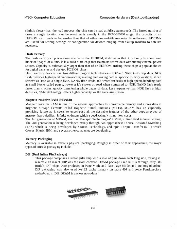
118
I-TECH Computer Education Computer Hardware (Desktop &Laptop)
slightly slower than the read process; the chip can be read at full system speeds. The limited number of
times a single location can be rewritten is usually in the 10000-100000 range; the capacity of an
EEPROM also tends to be smaller than that of other non-volatile memories. Nonetheless, EEPROMs
are useful for storing settings or configuration for devices ranging from dial-up modems to satellite
receivers.
Flash memory
The flash memory chip is a close relative to the EEPROM; it differs in that it can only be erased one
block or "page" at a time. It is a solid-state chip that maintains stored data without any external power
source. Capacity is substantially larger than that of an EEPROM, making these chips a popular choice
for digital cameras and desktop PC BIOS chips.
Flash memory devices use two different logical technologies—NOR and NAND—to map data. NOR
flash provides high-speed random access, reading and writing data in specific memory locations; it can
retrieve as little as a single byte. NAND flash reads and writes sequentially at high speed, handling data
in small blocks called pages, however it‘s slower on read when compared to NOR. NAND flash reads
faster than it writes, quickly transferring whole pages of data. Less expensive than NOR flash at high
densities, NAND techn olog y offers higher capacity for the same-size silicon.
Magneto resistive RAM (MRAM):
Magneto resistive RAM is one of the newest approaches to non-volatile memory and stores data in
magnetic storage elements called magnetic tunnel junctions (MTJ's). MRAM has an especially
promising future as it seeks to encompass all the desirable features of the other popular types of
memory (non-v olat il i ty, infinite endurance, high-speed readin g/w ri tin g, low cost).
The 1st generation of MRAM, such as Everspin Technologies' 4 Mbit, utilized field induced writing.
The 2nd generation is being developed mainly through two approaches: Thermal Assisted Switching
(TAS) which is being developed by Crocus Technology, and Spin Torque Transfer (STT) which
Crocus, Hynix, IBM, and several other companies are developing.
Memory Packaging
Memory is available in various physical packaging. Roughly in order of their appearance, the major
types of DRAM packaging include:
DIP (Dual Inline Pin Package)
This package comprises a rectangular chip with a row of pins down each long side, making it
resemble an insect. DIP was the most common DRAM package used in PCs through early 386
models. DIP chips were produced in Page Mode and Fast Page Mode, and are long obsolete.
DIP packaging was also used for L2 cache memory on most 486 and some Pentium-class
mothe rb oa rd s. DIP DRAM is useless nowadays.
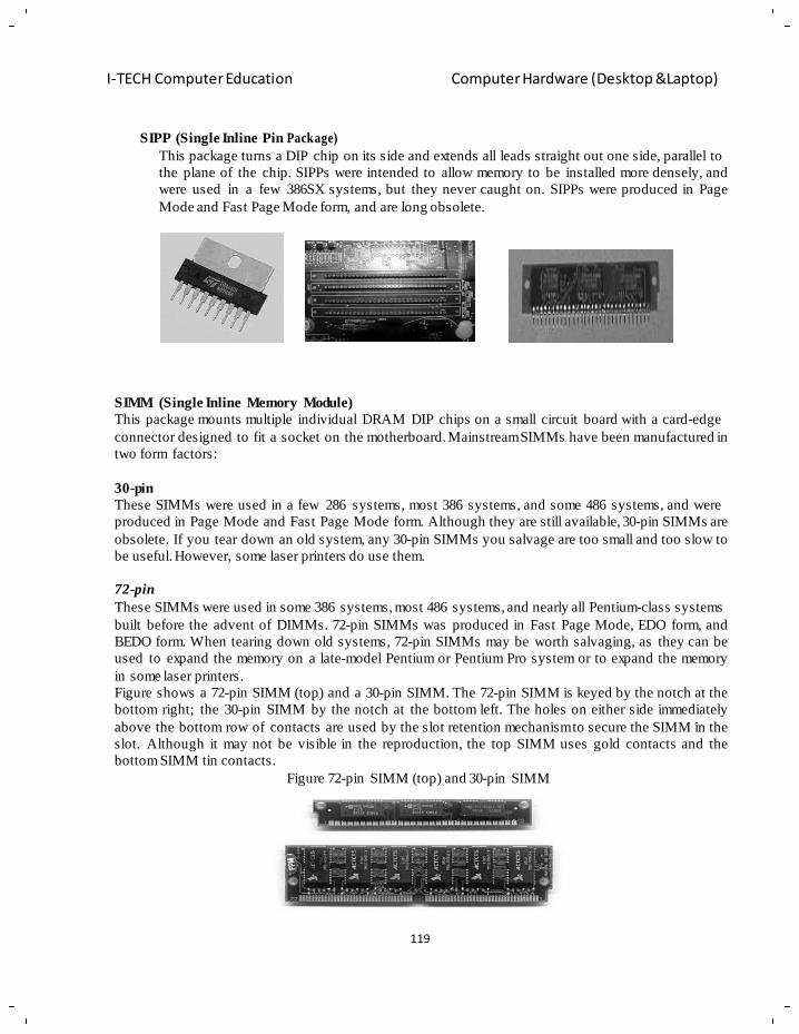
119
I-TECH Computer Education Computer Hardware (Desktop &Laptop)
SIPP (Single Inline Pin Package)
This package turns a DIP chip on its side and extends all leads straight out one side, parallel to
the plane of the chip. SIPPs were intended to allow memory to be installed more densely, and
were used in a few 386SX systems, but they never caught on. SIPPs were produced in Page
Mode and Fast Page Mode form, and are long obsolete.
SIMM (Single Inline Memory Module)
This package mounts multiple individual DRAM DIP chips on a small circuit board with a card-edge
connector designed to fit a socket on the motherboard. Mainstream SIMMs have been manufactured in
two form factors:
30-pin
These SIMMs were used in a few 286 systems, most 386 systems, and some 486 systems, and were
produced in Page Mode and Fast Page Mode form. Although they are still available, 30-pin SIMMs are
obsolete. If you tear down an old system, any 30-pin SIMMs you salvage are too small and too slow to
be useful. However, some laser printers do use them.
72-pin
These SIMMs were used in some 386 systems, most 486 systems, and nearly all Pentium-class systems
built before the advent of DIMMs. 72-pin SIMMs was produced in Fast Page Mode, EDO form, and
BEDO form. When tearing down old systems, 72-pin SIMMs may be worth salvaging, as they can be
used to expand the memory on a late-model Pentium or Pentium Pro system or to expand the memory
in some laser printers.
Figure shows a 72-pin SIMM (top) and a 30-pin SIMM. The 72-pin SIMM is keyed by the notch at the
bottom right; the 30-pin SIMM by the notch at the bottom left. The holes on either side immediately
above the bottom row of contacts are used by the slot retention mechanism to secure the SIMM in the
slot. Although it may not be visible in the reproduction, the top SIMM uses gold contacts and the
bottom SIMM tin contacts.
Figure 72-pin SIMM (top) and 30-pin SIMM
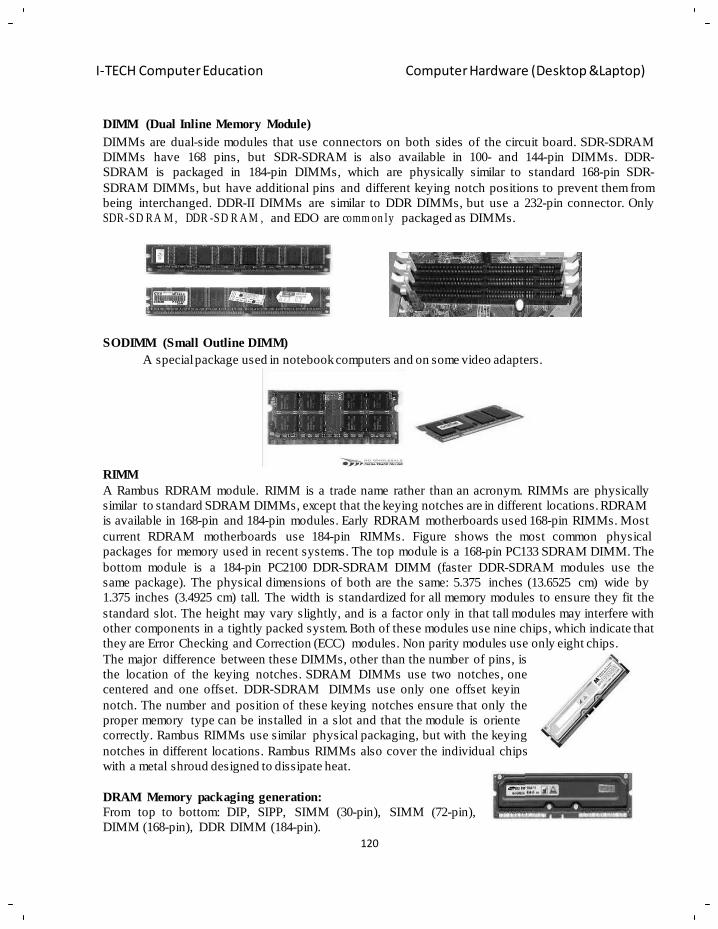
120
I-TECH Computer Education Computer Hardware (Desktop &Laptop)
DIMM (Dual Inline Memory Module)
DIMMs are dual-side modules that use connectors on both sides of the circuit board. SDR-SDRAM
DIMMs have 168 pins, but SDR-SDRAM is also available in 100- and 144-pin DIMMs. DDR-
SDRAM is packaged in 184-pin DIMMs, which are physically similar to standard 168-pin SDR-
SDRAM DIMMs, but have additional pins and different keying notch positions to prevent them from
being interchanged. DDR-II DIMMs are similar to DDR DIMMs, but use a 232-pin connector. Only
SDR-SD RA M , DDR -SD R A M , and EDO are comm on ly packaged as DIMMs.
SODIMM (Small Outline DIMM)
A special package used in notebook computers and on some video adapters.
RIMM
A Rambus RDRAM module. RIMM is a trade name rather than an acronym. RIMMs are physically
similar to standard SDRAM DIMMs, except that the keying notches are in different locations. RDRAM
is available in 168-pin and 184-pin modules. Early RDRAM motherboards used 168-pin RIMMs. Most
current RDRAM motherboards use 184-pin RIMMs. Figure shows the most common physical
packages for memory used in recent systems. The top module is a 168-pin PC133 SDRAM DIMM. The
bottom module is a 184-pin PC2100 DDR-SDRAM DIMM (faster DDR-SDRAM modules use the
same package). The physical dimensions of both are the same: 5.375 inches (13.6525 cm) wide by
1.375 inches (3.4925 cm) tall. The width is standardized for all memory modules to ensure they fit the
standard slot. The height may vary slightly, and is a factor only in that tall modules may interfere with
other components in a tightly packed system. Both of these modules use nine chips, which indicate that
they are Error Checking and Correction (ECC) modules. Non parity modules use only eight chips.
The major difference between these DIMMs, other than the number of pins, is
the location of the keying notches. SDRAM DIMMs use two notches, one
centered and one offset. DDR-SDRAM DIMMs use only one offset keyin
notch. The number and position of these keying notches ensure that only the
proper memory type can be installed in a slot and that the module is oriente
correctly. Rambus RIMMs use similar physical packaging, but with the keying
notches in different locations. Rambus RIMMs also cover the individual chips
with a metal shroud designed to dissipate heat.
DRAM Memory packaging generation:
From top to bottom: DIP, SIPP, SIMM (30-pin), SIMM (72-pin),
DIMM (168-pin), DDR DIMM (184-pin).
121
I-TECH Computer Education Computer Hardware (Desktop &Laptop)
Managem ent of Memory:
Proper management of memory is vital for a computer system to operate properly. Modern operating
systems have complex systems to properly manage memory. Failure to do so can lead to bugs, slow
performance, and at worst case, takeover by viruses and malicious software. Nearly everything a
computer programmer does requires him or her to consider how to manage memory. Even storing a
number in memory requires the programmer to specify how the memory should store it.
• Memory Management Bugs:
Improper mana ge m e nt of memory is a common cause of bugs.
In arithmetic overflow, a calculation results in a number larger than the allocated memory permits. For example, an 8-bit integer allows the numbers −127 to +127. If its value is 127 and
it is instructed to add one, the computer cannot store the number 128 in that space. Such a case
will result in undesired operation, such as changing the number's value to −128 instead of +128.
A memory leak occurs when a program requests memory from the operating system and never returns the memory when it's done with it. A program with this bug will gradually require more
and more memory until the program fails as it runs out.
A segmentation fault results when a program tries to access memory that it has no permission to access. Generally a program doing so will be terminated by the operating system.
Buffer overflow means that a program writes data to the end of its allocated space and then continues to write data to memory that belongs to other programs. This may result in erratic program behavior, including memory access errors, incorrect results, a crash, or a breach of
system security. They are thus the basis of many software vulnerabilities and can be maliciously
exploited.
• Early computer systems
In early computer systems, programs typically specified the location to write memory and what data to
put there. This location was a physical location on the actual memory hardware. The slow processing of
such computers didn't allow for the complex memory management systems used today. Also, as most
such systems were single-task, sophisticated systems weren't required as much. This approach has its
pitfalls. If the location specified is incorrect, this will cause the computer to write the data to some other
part of the program. The results of an error like this are unpredictable. In some cases, the incorrect data
might overwrite memory used by the operating system. Computer crackers can take advantage of this to
create viruses and malware.
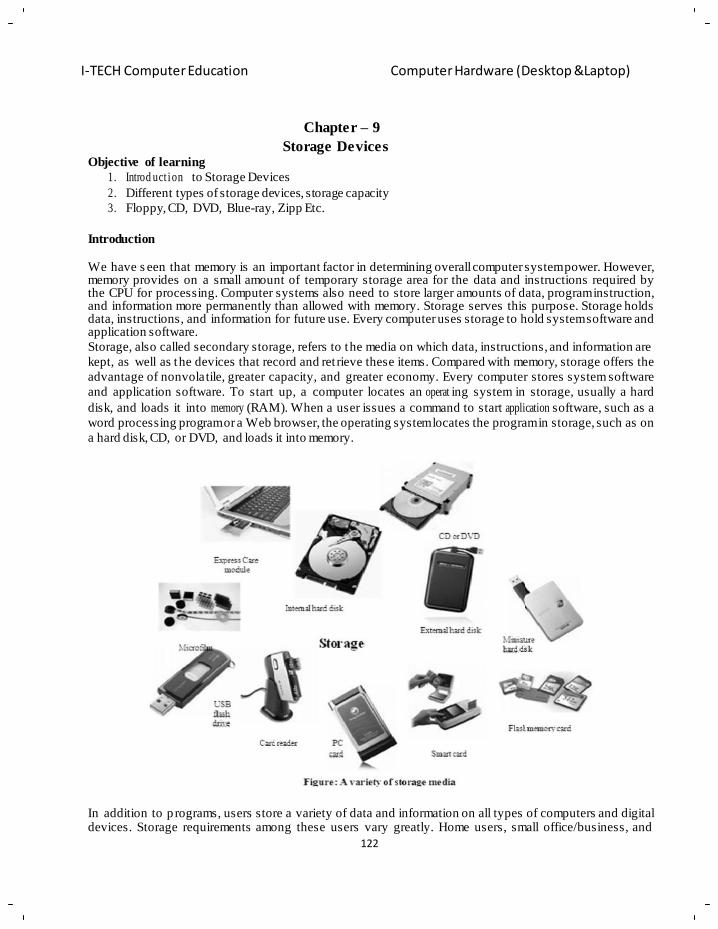
122
I-TECH Computer Education Computer Hardware (Desktop &Laptop)
Objective of learning
Chapter – 9
Storage Devices
1. Introd uct ion to Storage Devices
2. Different types of storage devices, storage capacity
3. Floppy, CD, DVD, Blue-ray, Zipp Etc.
Introduction
We have s een that memory is an important factor in determining overall computer system power. However, memory provides on a small amount of temporary storage area for the data and instructions required by the CPU for processing. Computer systems also need to store larger amounts of data, program instruction, and information more permanently than allowed with memory. Storage serves this purpose. Storage holds data, instructions, and information for future use. Every computer uses storage to hold system software and application software.
Storage, also called secondary storage, refers to the media on which data, instructions, and information are
kept, as well as the devices that record and ret rieve these items. Compared with memory, storage offers the
advantage of nonvolatile, greater capacity, and greater economy. Every computer stores system software
and application software. To start up, a computer locates an operat ing system in storage, usually a hard
disk, and loads it into memory (RAM). When a user issues a command to start application software, such as a
word processing program or a Web browser, the operating system locates the program in storage, such as on
a hard disk, CD, or DVD, and loads it into memory.
In addition to p rograms, users store a variety of data and information on all types of computers and digital devices. Storage requirements among these users vary greatly. Home users, small office/business, and
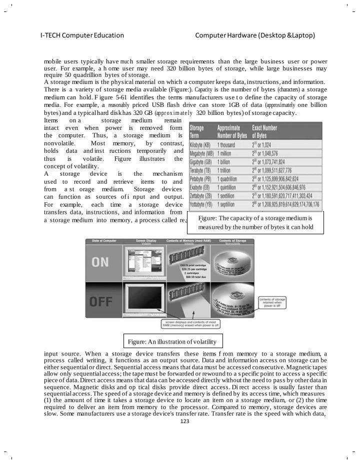
123
I-TECH Computer Education Computer Hardware (Desktop &Laptop)
u
ading it functions as an
mobile users typically have muc h smaller storage requirements than the large business user or power user. For example, a h ome user may need 320 billion bytes of storage, while large businesses may require 50 quadrillion bytes of storage. A storage medium is the physical material on which a computer keeps data, instructions, and information.
There is a variety of storage media available (Figure:). Capacity is the number of bytes (characters) a storage
medium can hold. F igure 5-61 identifies the terms manufacturers use t o define the capacity of storage
media. For example, a reasonably priced USB flash drive can store 1GB of data (approximately one billion
bytes) and a typical hard disk has 320 GB (appr ox im ate ly 320 billion bytes) of storage capacity.
Items on a storage medium remain
intact even when power is removed form
the computer. Thus, a storage medium is
nonvolatile. Most memory, by contrast,
holds data and inst ructions
thus is volatile. Figure
concept of volatility.
temporarily and
illustrates the
A storage device is the mechanism
used to record and retrieve items to and
from a st orage medium. Storage devices
can function as sources of i nput and output.
For example, each time a storage device
transfers data, instructions, and information from
a storage medium into memory, a process called re
F,igure: The capacity of a storage medium is
measured by the number of bytes it can hold
Figure: An illustration of volatility
input source. When a storage device transfers these items f rom memory to a storage medium, a process called writing, it functions as an output source. Data and information access on storage can be either sequential or direct. Sequential access means that data must be accessed consecutive. Magnetic tapes allow only sequential access; the tape must be forwarded or rewound to a s pecific point to access a specific piece of data. Direct access means that data can be accessed directly without the need to pass by other data in sequence. Magnetic disks and op tical disks provide direct access. Di rect access is usua lly faster than sequential access. The speed of a storage device and memory is defined by its access time, which measures (1) the amount of time it takes a storage device to locate an item on a storage medium, or (2 ) the time required to deliver an item from memory to the processor. Compared to memory, storage devices are slow. Some manufacturers use a s torage device's transfer rate. Transfer rate is the speed with which data,
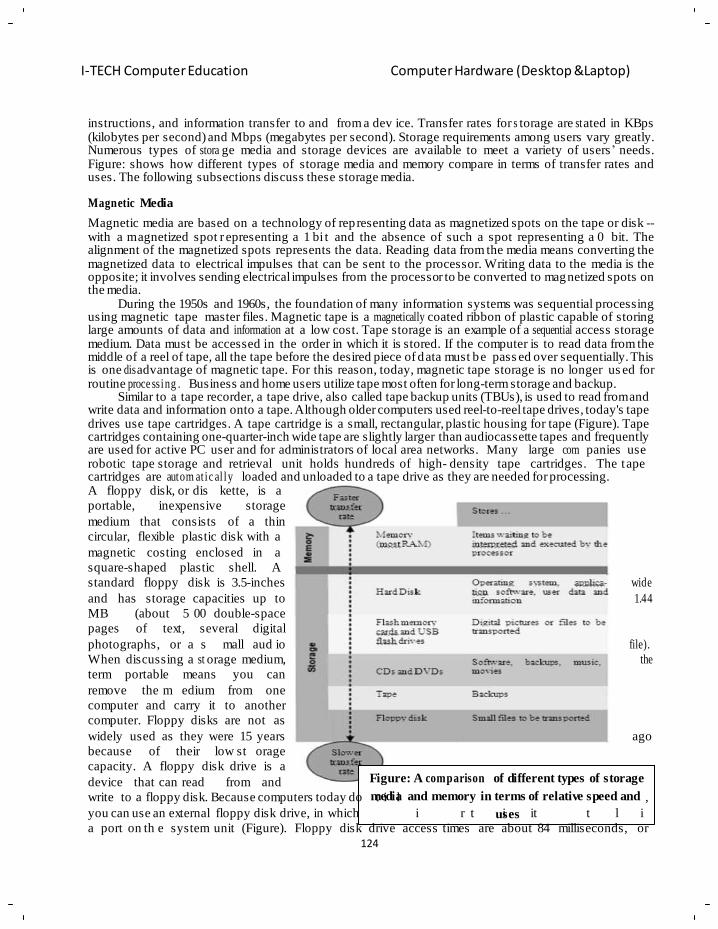
124
I-TECH Computer Education Computer Hardware (Desktop &Laptop)
no nc ude a floppy disk drive
the drive s a sepa a e dev ce
as standard equipment
w h a cable hat p ugs n
instructions, and information transfer to and from a dev ice. Transfer rates for s torage are st ated in KBps (kilobytes per second) and Mbps (megabytes per second). Storage requirements among users vary greatly. Numerous types of stora ge media and storage devices are available to meet a variety of users‘ needs. Figure: shows how different types of storage media and memory compare in terms of transfer rates and uses. The following subsections discuss these storage media.
Magnetic Media
Magnetic media are based on a technology of representing data as magnetized spots on the tape or disk -- with a m agnetized spot r epresenting a 1 bi t and the absence of such a spot representing a 0 bit. The alignment of the magnetized spots represents the data. Reading data from the media means converting the magnetized data to electrical impulses that can be sent to the processor. Writing data to the media is the opposite; it involves sending electrical impulses from the processor to be converted to magnetized spots on the media.
During the 1950s and 1960s, the foundation of many information systems was sequential processing using magnetic tape master files. Magnetic tape is a magnetically coated ribbon of plastic capable of storing large amounts of data and information at a low cost. Tape storage is an example of a sequential access storage medium. Data must be accessed in the order in which it is stored. If the computer is to read data from the middle of a reel of tape, all the tape before the desired piece of data must be pass ed over sequentially. This is one dis advantage of magnetic tape. For this reason, today, magnetic tape storage is no longer us ed for routine proce ssing . Business and home users utilize tape most often for long-term storage and backup.
Similar to a tape recorder, a tape drive, also called tape backup units (TBUs), is used to read from and write data and information onto a tape. Although older computers used reel-to-reel tape drives, today's tape drives use tape cartridges. A tape cartridge is a small, rectangular, plastic housing for tape (Figure). Tape cartridges containing one-quarter-inch wide tape are slightly larger than audiocassette tapes and frequently are used for active PC user and for administrators of local area networks. Many large com panies use robotic tape storage and retrieval unit holds hundreds of high- density tape cartridges. The tape cartridges are autom at ic al ly loaded and unloaded to a tape drive as they are needed for processing. A floppy disk, or dis kette, is a
portable, inexpensive storage
medium that consists of a thin
circular, flexible plastic disk with a
magnetic costing enclosed in a
square-shaped plastic shell. A
standard floppy disk is 3.5-inches
and has storage capacities up to
MB (about 5 00 double-space
pages of text, several digital
photographs, or a s mall aud io
When discussing a st orage medium,
term portable means you can
remove the m edium from one
computer and carry it to another
computer. Floppy disks are not as
widely used as they were 15 years
because of their low st orage
capacity. A floppy disk drive is a
device that can read from and
write to a floppy disk. Because computers today do
wide
1.44
file).
the
ago
Figure: A comparison of different types of storage
mteidial and memory in terms of relative speed and ,
you can use an external floppy disk drive, in which i r t uises it t l i
a port on th e system unit (Figure). Floppy disk drive access times are about 84 milliseconds, or
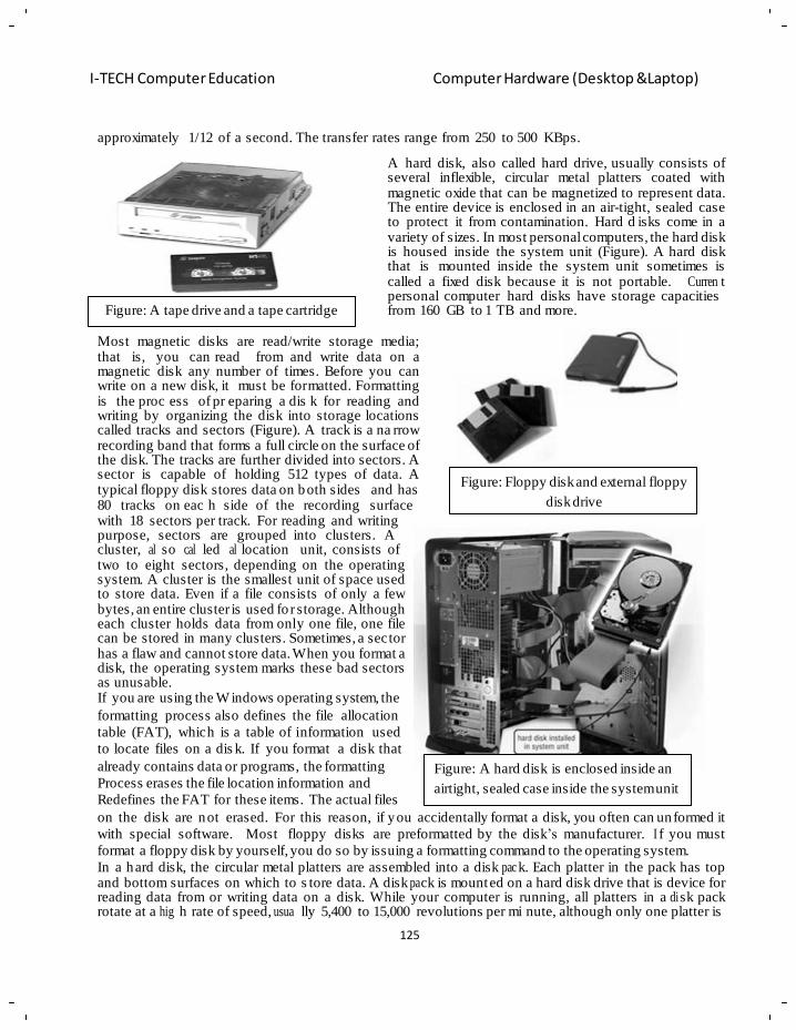
125
I-TECH Computer Education Computer Hardware (Desktop &Laptop)
approximately 1/12 of a second. The transfer rates range from 250 to 500 KBps.
A hard disk, also called hard drive, usually consists of several inflexible, circular metal platters coated with magnetic oxide that can be magnetized to represent data. The entire device is enclosed in an air-tight, sealed case to protect it from contamination. Hard d isks come in a variety of sizes. In most personal computers, the hard disk is housed inside the system unit (Figure). A hard disk that is mounted inside the system unit sometimes is called a fixed disk because it is not portable. Curren t personal computer hard disks have storage capacities
Figure: A tape drive and a tape cartridge from 160 GB to 1 TB and more.
Most magnetic disks are read/write storage media; that is, you can read from and write data on a magnetic disk any number of times. Before you can write on a new disk, it must be formatted. Formatting is the proc ess of pr eparing a dis k for reading and writing by organizing the disk into storage locations called tracks and sectors (Figure). A track is a na rrow recording band that forms a full circle on the surface of the disk. The tracks are further divided into sectors. A sector is capable of holding 512 types of data. A typical floppy disk stores data on both sides and has
Figure: Floppy disk and external floppy
80 tracks on eac h side of the recording surface disk drive
with 18 sectors per track. For reading and writing purpose, sectors are grouped into clusters. A cluster, al so cal led al location unit, consists of two to eight sectors, depending on the operating system. A cluster is the smallest unit of space used to store data. Even if a file consists of only a few bytes, an entire cluster is used fo r storage. Although each cluster holds data from only one file, one file can be stored in many clusters. Sometimes, a sector has a flaw and cannot store data. When you format a disk, the operating system marks these bad sectors as unusable. If you are using the W indows operating system, the
formatting process also defines the file allocation
table (FAT), which is a table of information used
to locate files on a dis k. If you format a disk that
already contains data or programs, the formatting
Process erases the file location information and
Redefines the FAT for these items. The actual files
Figure: A hard disk is enclosed inside an
airtight, sealed case inside the system unit
on the disk are not erased. For this reason, if you accidentally format a disk, you often can unformed it
with special software. Most floppy disks are preformatted by the disk‘s manufacturer. I f you must
format a floppy disk by yourself, you do so by issuing a formatting command to the operating system.
In a hard disk, the circular metal platters are assembled into a disk pac k. Each platter in the pack has top and bottom surfaces on which to s tore data. A disk pa ck is mounted on a hard disk drive that is device for reading data from or writing data on a disk. While your computer is running, all platters in a di sk pack rotate at a hig h rate of speed, usua lly 5,400 to 15,000 revolutions per mi nute, although only one platter is
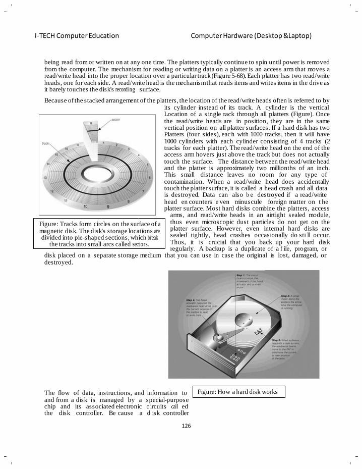
126
I-TECH Computer Education Computer Hardware (Desktop &Laptop)
being read from or written on at any one time. The platters typically continue to spin until power is removed from the computer. The mechanism for reading or writing data on a platter is an access arm that moves a read/write head into the proper location over a particular track (Figure 5-68). Each platter has two read/write heads, one for each side. A read/write head is the mechanism that reads items and writes items in the drive as it barely touches the disk's recording surface.
Because of the stacked arrangement of the platters, the location of the read/write heads often is referred to by its cylinder instead of its track. A cylinder is the vertical Location of a s ingle rack through all platters (Figure). Once the read/write heads are in position, they are in the same vertical position on all platter surfaces. If a hard disk has two Platters (four sides), each with 1000 tracks, then it will have 1000 cylinders with each cylinder consisting of 4 tracks (2 tracks for each platter). The r ead/write head on the end of the access arm hovers just above the track but does not actually touch the surface. The distance between the read/write head and the platter is approximately two millionths of an inch. This small distance leaves no room for any type of contamination. When a read/write head does accidentally touch the platter surface, it is called a head crash and all data is destroyed. Data can also b e destroyed if a read/write head en counters e ven minuscule foreign matter on t he
Figure: Tracks form circles on the surface of a magnetic disk. The disk's storage locations are divided into pie-shaped sections, which break
the tracks into small arcs called sectors.
platter surface. Most hard disks combine the platters, access arms, and read/write heads in an airtight sealed module, thus even microscopic dust particles do not get on the platter surface. However, even internal hard disks are sealed tightly, head crashes occasionally do sti ll occur. Thus, it is crucial that you back up your hard disk regularly. A backup is a duplicate of a f ile, program, or
disk placed on a separate storage medium that you can use in case the original is lost, damaged, or destroyed.
The flow of data, instructions, and information to Figure: How a hard disk works
and from a disk is managed by a special-purpose chip and its associated electronic c ircuits call ed the disk controller. Be cause a d isk controller
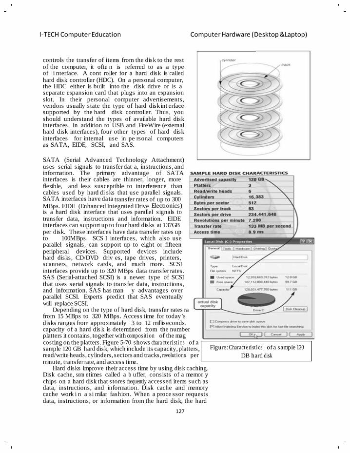
127
I-TECH Computer Education Computer Hardware (Desktop &Laptop)
nge hard The of
netic
controls the transfer of items from the disk to the rest of the computer, it ofte n is referred to as a type of i nterface. A cont roller for a hard disk is c alled hard disk controller (HDC). On a personal computer, the HDC either is built into the disk drive or is a separate expansion card that plugs into an expansion slot. In their personal computer advertisements, vendors usually state the type of hard disk int erface supported by the hard disk controller. Thus, you should understand the types of available hard disk interfaces. In addition to USB and FireWire (external hard disk interfaces), four other types of hard disk interfaces for internal use in pe rsonal computers as SATA, EIDE, SCSI, and SAS.
SATA (Serial Advanced Technology Attachment) uses serial signals to transfer dat a, instructions, and information. The primary advantage of SATA interfaces is their cables are thinner, longer, more flexible, and less susceptible to interference than cables used by hard di sks that use parallel signals. SATA interfaces have data transfer rates of up to 300 MBps. EIDE (Enhanced Integrated Drive Electronics) is a hard disk interface that uses parallel signals to transfer data, instructions and information. EIDE interfaces can support up to four hard disks at 137GB per disk. These interfaces have data transfer rates up to 100MBps. SCS I interfaces, which also use parallel signals, can support up to eight or fifteen peripheral devices. Supported devices include hard disks, CD/DVD driv es, tape drives, printers, scanners, network cards, and much more. SCSI interfaces provide up to 320 MBps data transfer rates. SAS (Serial-attached SCSI) is a newer type of SCSI that uses serial signals to transfer data, instructions, and information. SAS has man y advantages over parallel SCSI. Experts predict that SAS eventually will replace SCSI.
Depending on the type of hard disk, transfer rates ra from 15 MBps to 320 MBps. Access time for today‘s disks ranges from approximately 3 to 12 milliseconds. capacity of a hard dis k is determined from the number platters it contains, together with composit ion of the mag costing on the platters. Figure 5-70 shows chara cte rist ic s of a sample 120 GB hard disk, which include its capacity, platters, read/write heads, cylinders, sectors and tracks, revolut ions per minute, transfer rate, and access time.
Hard disks improve their access time by using disk caching. Disk cache, som etimes called a b uffer, consists of a memor y chips on a hard disk that stores frequently accessed items such as data, instructions, and information. Disk cache and memory cache work i n a si milar fashion. When a proce ssor requests data, instructions, or information from the hard disk, the hard
Figure: Characte rist ics of a sample 120
DB hard disk
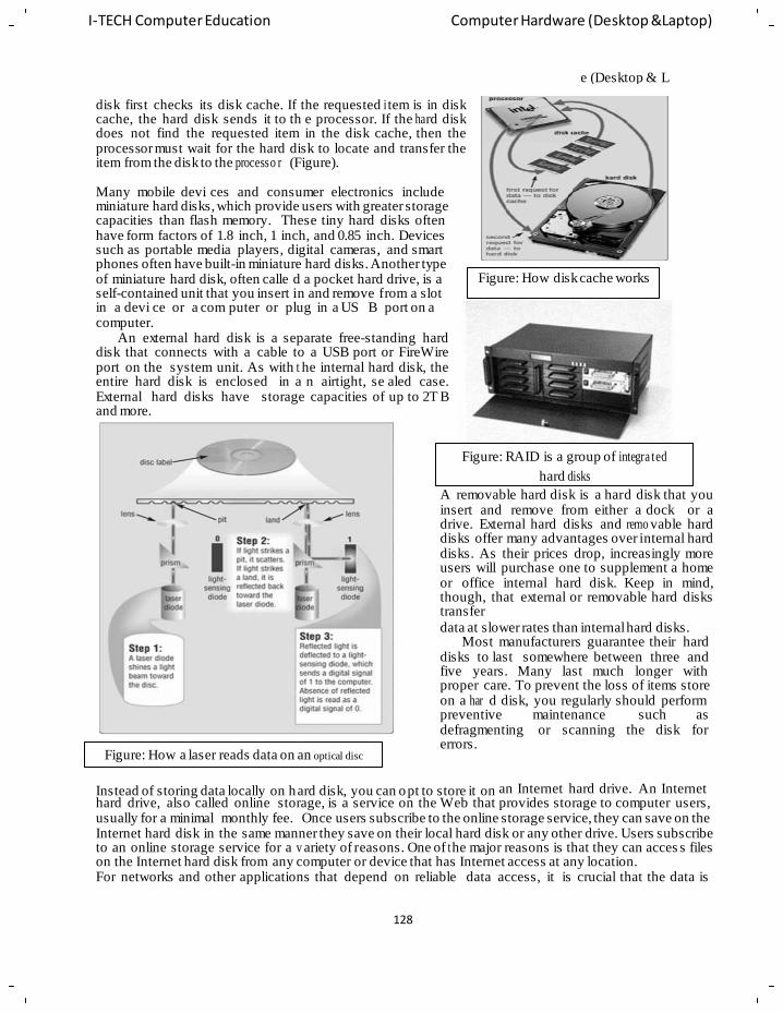
128
I-TECH Computer Education Computer Hardware (Desktop &Laptop)
e (Desktop & L
disk first checks its disk cache. If the requested i tem is in disk cache, the hard disk sends it to th e processor. If the ha rd disk does not find the requested item in the disk cache, then the processor must wait for the hard disk to locate and transfer the item from the disk to the processo r (Figure).
Many mobile devi ces and consumer electronics include miniature hard disks, which provide users with greater storage capacities than flash memory. These tiny hard disks often have form factors of 1.8 inch, 1 inch, and 0.85 inch. Devices such as portable media players, digital cameras, and smart phones often have built-in miniature hard disks. Another type of miniature hard disk, often calle d a pocket hard drive, is a self-contained unit that you insert in and remove from a slot in a devi ce or a com puter or plug in a US B port on a computer.
An external hard disk is a separate free-standing hard disk that connects with a cable to a USB port or FireWire port on the system unit. As with t he internal hard disk, the entire hard disk is enclosed in a n airtight, se aled case. External hard disks have storage capacities of up to 2T B and more.
Figure: How disk cache works
Figure: How a laser reads data on an optical disc
Figure: RAID is a group of integra ted
hard disks
A removable hard disk is a hard disk that you insert and remove from either a dock or a drive. External hard disks and remo vable hard disks offer many advantages over internal hard disks. As their prices drop, increasingly more users will purchase one to supplement a home or office internal hard disk. Keep in mind, though, that external or removable hard disks transfer
data at slower rates than internal hard disks. Most manufacturers guarantee their hard
disks to last somewhere between three and five years. Many last much longer with proper care. To prevent the loss of items store on a har d disk, you regularly should perform preventive maintenance such as defragmenting or scanning the disk for errors.
Instead of storing data locally on hard disk, you can opt to store it on an Internet hard drive. An Internet hard drive, also called online storage, is a service on the Web that provides storage to computer users, usually for a minimal monthly fee. Once users subscribe to the online storage service, they can save on the Internet hard disk in the same manner they save on their local hard disk or any other drive. Users subscribe to an online storage service for a v ariety of reasons. One of t he major reasons is that they can acces s files on the Internet hard disk from any computer or device that has Internet access at any location. For networks and other applications that depend on reliable data access, it is crucial that the data is
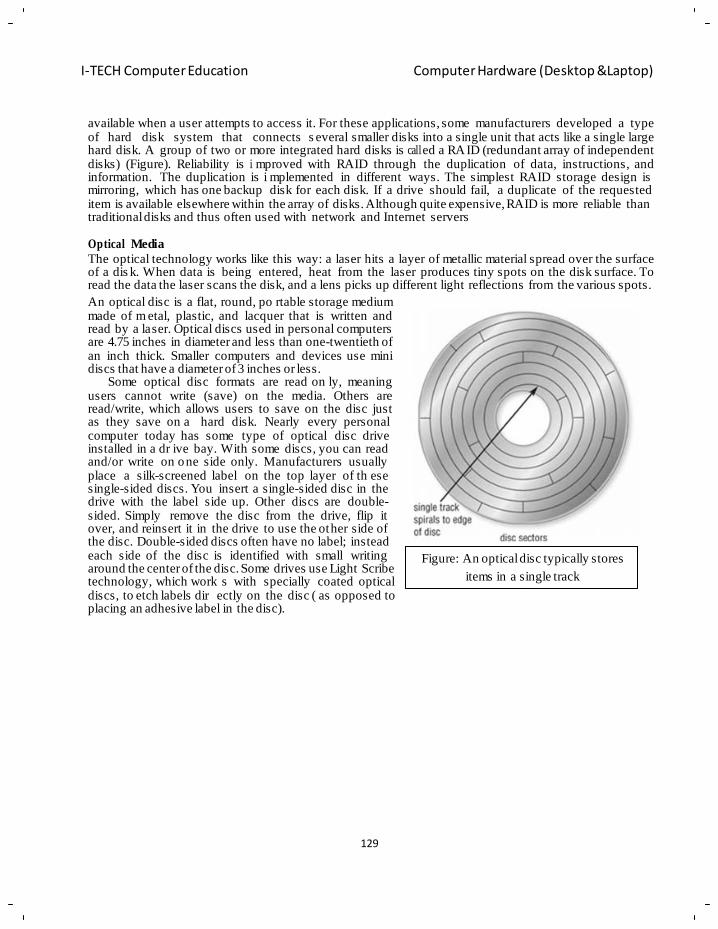
129
I-TECH Computer Education Computer Hardware (Desktop &Laptop)
available when a user attempts to access it. For these applications, some manufacturers developed a type of hard disk system that connects s everal smaller disks into a single unit that acts like a single large hard disk. A group of two or more integrated hard disks is call ed a RA ID (redundant array of independent disks) (Figure). Reliability is i mproved with RAID through the duplication of data, instructions, and information. The duplication is i mplemented in different ways. The simplest RAID storage design is mirroring, which has one backup disk for each disk. If a drive should fail, a duplicate of the requested item is available elsewhere within the array of disks. Although quite expensive, RAID is more reliable than traditional disks and thus often used with network and Internet servers
Optical Media
The optical technology works like this way: a laser hits a layer of metallic material spread over the surface of a dis k. When data is being entered, heat from the laser produces tiny spots on the disk surface. To read the data the laser scans the disk, and a lens picks up different light reflections from the various spots.
An optical disc is a flat, round, po rtable storage medium made of m etal, plastic, and lacquer that is written and read by a laser. Optical discs used in personal computers are 4.75 inches in diameter and less than one-twentieth of an inch thick. Smaller computers and devices use mini discs that have a diameter of 3 inches or less.
Some optical disc formats are read on ly, meaning users cannot write (save) on the media. Others are read/write, which allows users to save on the disc just as they save on a hard disk. Nearly every personal computer today has some type of optical disc drive installed in a dr ive bay. With some discs, you can read and/or write on o ne side only. Manufacturers usually place a silk-screened label on the top layer of th ese single-sided discs. You insert a single-sided disc in the drive with the label side up. Other discs are double- sided. Simply remove the disc from the drive, flip it over, and reinsert it in the drive to use the other side of the disc. Double-sided discs often have no label; instead each side of the disc is identified with small writing around the center of the disc. Some drives use Light Scribe technology, which work s with specially coated optical discs, to etch labels dir ectly on the disc ( as opposed to placing an adhesive label in the disc).
Figure: An optical disc typically stores
items in a single track
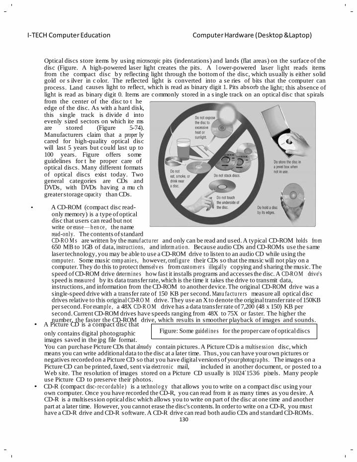
130
I-TECH Computer Education Computer Hardware (Desktop &Laptop)
Optical discs store items by using microscopic pits (indentations) and lands (flat areas) on the surface of the disc (Figure. A high-powered laser light creates the pits. A l ower-powered laser li ght reads items from the compact disc by reflecting light through the bottom of the disc, which usually is either solid gold or s ilver in c olor. The reflected light is converted into a se ries of bits that the computer can process. Land causes light to reflect, which is read as binary digit 1. Pits absorb the light; this absence of light is read as binary digit 0. Items are commonly stored in a s ingle track on an optical disc that spirals from the center of the disc to t he edge of the disc. As with a hard disk, this single track is divide d into evenly sized sectors on which ite ms are stored (Figure 5-74). Manufacturers claim that a proper ly cared for high-quality optical disc will last 5 years but could last up to 100 years. Figure offers some guidelines for t he proper care of optical discs. Many different formats of optical discs exist today. Two general categories are CDs and DVDs, with DVDs having a mu ch greater storage capacity than CDs.
• A CD-ROM (compact disc read-
only memory) is a type of optical disc that users can read but not write or erase — h en ce , the name read-only. The contents of standard CD-RO M s are written by the manuf actu rer and only can be read and used. A typical CD-ROM holds from 650 MB to 1GB of data, instruct ions, and inform a tio n. Because audio CDs and CD-ROMs use the same laser technology, you may be able to use a CD-ROM drive to listen to an audio CD while using the compute r. Some music comp anie s, however, configur e their CDs so that the music will not play on a computer. They do this to protect themselv es from custom er s illegal ly copying and sharing the music. The speed of CD-ROM drive determine s how fast it installs programs and accesses the disc. A CD-RO M drive' s speed is measure d by its data transfer rate, which is the time it takes the drive to transmit data, instructions, and information from the CD-ROM to another device. The original CD-ROM drive was a single-speed drive with a transfer rate of 150 KB per second. Manu fa ctu re rs measure all optical disc drives relative to this original CD-RO M drive. They use an X to denote the original transfer rate of 150KB per second. For example , a 48X CD-R O M drive has a data transfer rate of 7,200 (48 x 150) KB per second. Current CD-ROM drives have speeds ranging from 48X to 75X or faster. The higher the number, the faster the CD-ROM drive, which results in smoother playback of images and sounds.
• A Picture CD is a compact disc that
only contains digital photographic images saved in the jpg file format.
Figure: Some guidel ine s for the proper care of optical discs
You can purchase Picture CDs that already contain pictures. A Picture CD is a multise ssion disc, which means you can write additional data to the disc at a later time. Thus, you can have your own pictures or negatives recorded on a Picture CD so that you have digital versions of your photogra phs. The images on a Picture CD can be printed, faxed, sent via elect ronic mail, included in another document, or posted to a Web site. The resolution of images stored on a Picture CD usually is 1024´1536 pixels. Many people use Picture CD to preserve their photos.
• CD-R (compact disc- re c or da ble ) is a technolo g y that allows you to write on a compact disc using your own computer. Once you have recorded the CD-R, you can read from it as many times as you desire. A CD-R is a multisession optical disc which allows you to write on part of the disc at one time and another part at a later time. However, you cannot erase the disc's contents. In order to write on a CD-R, you must have a CD-R drive and CD-R software. A CD-R drive can read both audio CDs and standard CD-ROMs.
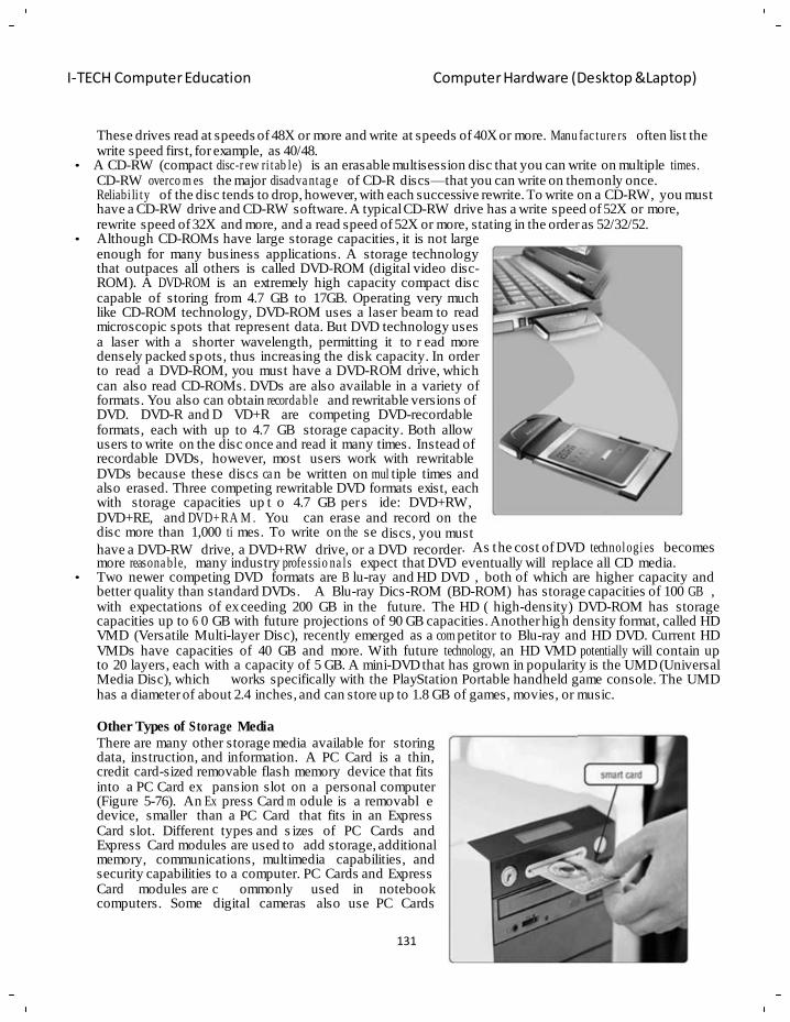
I-TECH Computer Education Computer Hardware (Desktop &Laptop)
These drives read at speeds of 48X or more and write at speeds of 40X or more. Manu fac ture rs often list the write speed first, for example, as 40/48.
• A CD-RW (compact disc-r ew ri tab le) is an erasable multisession disc that you can write on multiple times. CD-RW overco m es the major disadva ntag e of CD-R discs—that you can write on them only once. Reliabi li ty of the disc tends to drop, however, with each successive rewrite. To write on a CD-RW, you must have a CD-RW drive and CD-RW software. A typical CD-RW drive has a write speed of 52X or more, rewrite speed of 32X and more, and a read speed of 52X or more, stating in the order as 52/32/52.
• Although CD-ROMs have large storage capacities, it is not large enough for many business applications. A storage technology that outpaces all others is called DVD-ROM (digital video disc- ROM). A DVD-ROM is an extremely high capacity compact disc capable of storing from 4.7 GB to 17GB. Operating very much like CD-ROM technology, DVD-ROM uses a laser beam to read microscopic spots that represent data. But DVD technology uses a laser with a shorter wavelength, permitting it to r ead more densely packed spots, thus increasing the disk capacity. In order to read a DVD-ROM, you must have a DVD-ROM drive, which can also read CD-ROMs. DVDs are also available in a variety of formats. You also can obtain recorda ble and rewritable versions of DVD. DVD-R and D VD+R are competing DVD-recordable formats, each with up to 4.7 GB storage capacity. Both allow users to write on the disc once and read it many times. Instead of recordable DVDs, however, most users work with rewritable DVDs because these discs ca n be written on mul tiple times and also erased. Three competing rewritable DVD formats exist, each with storage capacities up t o 4.7 GB per s ide: DVD+RW, DVD+RE, and DVD+RA M . You can erase and record on the disc more than 1,000 ti mes. To write on the se discs, you must
have a DVD-RW drive, a DVD+RW drive, or a DVD recorder. As the cost of DVD technologies becomes more reasona ble, many industry profe ssio na ls expect that DVD eventually will replace all CD media.
• Two newer competing DVD formats are B lu-ray and HD DVD , both of which are higher capacity and better quality than standard DVDs. A Blu-ray Dics-ROM (BD-ROM) has storage capacities of 100 GB , with expectations of ex ceeding 200 GB in the future. The HD ( high-density) DVD-ROM has storage capacities up to 6 0 GB with future projections of 90 GB capacities. Another high density format, called HD VMD (Versatile Multi-layer Disc), recently emerged as a com petitor to Blu-ray and HD DVD. Current HD VMDs have capacities of 40 GB and more. With future technology, an HD VMD potentially will contain up to 20 layers, each with a capacity of 5 GB. A mini-DVD that has grown in popularity is the UMD (Universal Media Disc), which works specifically with the PlayStation Portable handheld game console. The UMD has a diameter of about 2.4 inches, and can store up to 1.8 GB of games, movies, or music.
Other Types of Storage Media
There are many other storage media available for storing data, instruction, and information. A PC Card is a thin, credit card-sized removable flash memory device that fits into a PC Card ex pansion slot on a personal computer (Figure 5-76). An Ex press Card m odule is a removabl e device, smaller than a PC Card that fits in an Express Card slot. Different types and s izes of PC Cards and Express Card modules are used to add storage, additional memory, communications, multimedia capabilities, and security capabilities to a computer. PC Cards and Express Card modules are c ommonly used in notebook computers. Some digital cameras also use PC Cards
131
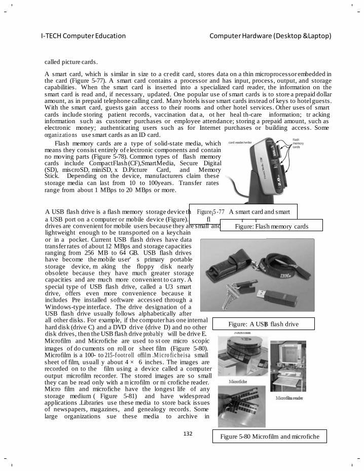
I-TECH Computer Education Computer Hardware (Desktop &Laptop)
at plugs n USB ash card eade
B
called picture cards.
A smart card, which is similar in size to a cr edit card, stores data on a thin microprocessor embedded in the card (Figure 5-77). A smart card contains a processor and has input, process, output, and storage capabilities. When the smart card is inserted into a specialized card reader, the information on the smart card is read and, if necessary, updated. One popular use of smart cards is to store a prepaid dollar amount, as in prepaid telephone calling card. Many hotels issue smart cards instead of keys to hotel guests. With the smart card, guests gain access to their rooms and other hotel services. Other uses of smart cards include storing patient records, vaccination dat a, ot her heal th-care information; tr acking information such as customer purchases or employee attendance; storing a prepaid amount, such as electronic money; authenticating users such as for Internet purchases or building access. Some organiz atio ns use smart cards as an ID card.
Flash memory cards are a type of solid-state media, which means they consist entirely of e lectronic components and contain no moving parts (Figure 5-78). Common types of flash memory cards include CompactFlash (CF),SmartMedia, Secure Digital (SD), miscroSD, miniSD, x D.Picture Card, and Memory Stick. Depending on the device, manufacturers claim these storage media can last from 10 to 100years. Transfer rates range from about 1 MBps to 20 MBps or more.
A USB flash drive is a flash memory storage device th Figurei5 -77 A smart card and smart
a USB port on a computer or mobile device (Figure). fl drives are convenient for mobile users because they are small and lightweight enough to be transported on a keychain or in a pocket. Current USB flash drives have data transfer rates of about 12 MBps and storage capacities ranging from 256 MB to 64 GB. USB flash drives
r r Figure: Flash memory cards
have become the mobile user' s primary portable storage device, m aking the floppy disk nearly obsolete because they have much greater storage capacities and are much more convenient to carry. A special type of USB flash drive, called a U3 smart drive, offers even more convenience because it includes Pre installed software accessed through a Windows-type interface. The drive designation of a USB flash drive usually follows alphabetically after all other disks. For example, if the computer has one internal hard disk (drive C) and a DVD drive (drive D) and no other disk drives, then the USB flash drive proba bly will be drive E. Microfilm and Microfiche are used to st ore micro scopic
Figure: A USB flash drive
images of do cuments on roll or sheet film (Figure 5-80). Microfilm is a 100- to 215-f oot r oll offilm .M ic ro fic he isa small sheet of film, usuall y about 4 × 6 inches. The images are recorded on to the film using a device called a computer output microfilm recorder. The stored images are so small they can be read only with a m icrofilm or mi crofiche reader. Micro film and microfiche have storage medium ( Figure 5-81)
the longest life of any and have widespread
applications .Libraries use these media to store back issues of newspapers, magazines, and large organizations sue these
genealogy records. Some media to archive in
132
Figure 5-80 Microfilm and microfiche
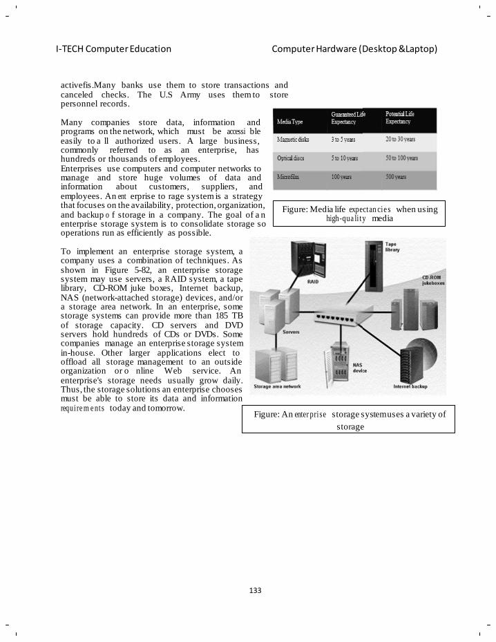
I-TECH Computer Education Computer Hardware (Desktop &Laptop)
activefis.Many banks use them to store transactions and canceled checks. The U.S Army uses them to store personnel records.
Many companies store data, programs on the network, which easily to a ll authorized users.
information and
must be accessi ble A large business,
commonly referred to as an enterprise, has hundreds or thousands of employees. Enterprises use computers and computer networks to manage and store huge volumes of data and information about customers, suppliers, and employees. An ent erprise to rage system is a strategy that focuses on the availability, protection, organization, and backup o f storage in a company. The goal of a n enterprise storage system is to consolidate storage so operations run as efficiently as possible.
To implement an enterprise storage system, a company uses a combination of techniques. As shown in Figure 5-82, an enterprise storage system may use servers, a R AID system, a tape library, CD-ROM juke boxes, Internet backup, NAS (network-attached storage) devices, and/or a storage area network. In an enterprise, some storage systems can provide more than 185 TB of storage capacity. CD servers and DVD servers hold hundreds of CDs or DVDs. Some companies manage an enterprise storage system in-house. Other larger applications elect to
Figure: Media life expectan cie s when using
high-qua li ty media
offload all storage management organization or o nline Web
to an outside service. An
enterprise's storage needs usually grow daily. Thus, the storage solutions an enterprise chooses must be able to store its data and information require m e nts today and tomorrow.
Figure: An enter prise storage system uses a variety of
storage
133
134
I-TECH Computer Education Computer Hardware (Desktop &Laptop)
Chapter - 10
MS DOS
Objective of learning
Brief unde rstan din g of DOS
Setup files of msdos & installing msdos
Concept of conve nt io na l , extended and paged memory
Working different internal dos and external dos commands
MS-DOS is the most well known ope rating system; the most commerc ialized version is that of
Microsoft, christened "MS-DOS". MS-DOS was created in 1981 when it was used on IBM computers.
DOS, as with an y operating system, controls computer activity. It manages operations such as data
flow, display, data entry amongst other various elements that make up a system.
The role of DOS is to inte rpret commands that the user enters via the keyboard.
These commands allow the following tasks to be executed:
• File and folder management
• Disk upgrades
• Hardware configuration
• Memory optimization
• Program execution
These commands are typed after the prompt, in the case of MS-DOS (Microsoft DOS, the most well
known): the drive letter followed by a backslash, for example: A:\ or C:\.
To execute a command type the command then hit ENTERS.
Files in MS DOS
In a computer data is stored in files. When you run a program, MS-DOS processes the data stored in
the file and passes it to t he system. In MS-DOS a file can be any size, however the file name is more
restricted, it can onl y have a max imum length of 8 characters plus 3 for the extension. Furthermore,
the files can only contain the following characters:
• Letters A to Z
• Numbers 0 to 9
• The following special characters: $~! # % & - ( ) @ ' _ ^
Thus filenames must not contain:
• Spaces
• Commas
• Backslash
• Dot (apart from the dot that separates the name and the extensio n) no r can they contain any of
the following list of reserved names:
• CLOCK$
• CON
• AUX
• COM1
• COM2
• COM3
• COM4
135
I-TECH Computer Education Computer Hardware (Desktop &Laptop)
• LPT1
• LPT2
• LPT3
• NUL
• PRN
Organizing files in directories or folders
Depending on its si ze a hard drive ma y contain several thousands of files. However, the more files
there are, the more difficult it is to ma nage them, this is when we need to store them in directories In
MS-DOS, directory names are also subject to the same name restrictions as files (8 characters for the
name, and an extension with 3 characters).
Installing MS-DOS
When installing MS-DOS, make sure that in the BIOS the boot disk is set to A: first, then the hard
drive (boot sequence: A:, C:) Then insert disk 1 in the A: drive, power up the computer, then follow
the on-screen instructions.
You must enter the following information:
• Time and date
• Country
• The media on which to install the operating system (make sure the drive is accessible and has
sufficient free disk space)
• The storage folder for MS-DOS files
• If the MS-DOS shell should appear on each start-up
• If MS-DOS should occupy a single partition taking up the entire hard drive
Creating a system boot disk
After MS-DOS has been installed you should create a system boot disk.
Once you have inserted a blank floppy disk into the drive enter the following command: Format a: /s
The /s switch means "copy system files".
This floppy disk can be used to boot the system by inserting it in the floppy disk drive and restarting
the computer.
Introduction to memory
Memory is an area where programs are stored and from where they can be executed. A PC compatible
computer has three types of memory:
• Conventional
• Extended
• Paged
The amount of memory present (and available) in a system can be found by running the following
command: "mem" (or "mem /c |more" for more detailed information).
Conventio na l memory
Conventional memory is that pa rt of memory where programs may load without an y specific
instructions. The amount of conve ntional memory varies from 256 K B to 640 KB (on all recent
computers: 386, 486, Pentium, etc.).
136
I-TECH Computer Education Computer Hardware (Desktop &Laptop)
The amount o f memory available is th e memory remaining after DOS has been loaded into memo ry
the operating system, device drivers and all commands loaded from the config.sys and
autoexec.bat).
Extended memory
Extended memory enables the system to access more memory. This type of memory is available on
computers equipped with an 80286 type processor or higher. Programs normally only recognise
conve nt io nal memory addresses, to access the storage area located beyond the 640 KB, programs need
specific instru ct ion s. A program that manages access to extended memory, for example it prevents two
programs from using the same area of memory at the same time. This program is called "extended
memory manager".
MS-DOS comes with the standard extended memory manager called HIM E M .S YS (it is also found in
Windows 98). It is loaded in the config.sys by adding the line:
DEVICE=path/himem.sys where path is the access path to the file.
Paged memory
Another method o f accessing memory beyond the first 640 KB is to use paged memory. Some
programs (few nowadays) are optimised to use this type of memory. As with extended memory, this
type of memory requires a program to manage it, it is c alled "paged memory manager". Programs
designed to use this type of memory cannot access it directly: the memory manager must copy sections
of 16 KB of memory (called pages) into an area (called frame segment) located in the high memory
area. This t ype of memory was developed before extended memory; this memory is thus slow er and
only allows utilisation of one limited portion of memory at any given time.
High memory
Many systems have 384 KB of high memory (HMA, High Memory Addresses), located directly after
the 640 KB of conventional memory. This area of memory can be used by hardware. Areas not us ed
by hardware are called "upper memory blocks" (UMB), they allow pr ograms to be run in pag ed
memory.
Various DOS Commands: Selecting and Copying Text from a command Prompt Window
1. Click the icon in the upper left-hand corner of the bar on top of the window, point to edit in the
menu that appears, and click Mark.
2. Click at the beginning of the text you want to copy.
3. Press and hold down the <SHIFT> key, and then click at the end of the text you want to copy.
4. Click the icon again, click Edit, and then click Copy.
5. Paste the text into a document by holding the <Ctrl> key and pressing <C>, or by selecting
Paste from the Edit menu. If you want to paste the text back into the command prompt
window, click the icon again, point to Edit, and click Paste.
Using Wildcard Characters Wildcard characters can be used when using Windows Search or Find, and to represent multiple files
or folders when using a command prompt. Wildcard characters are as follows:
Asterisk (*): Acts as a substitute for zero or more characters. For example, to search for or make a
change to any .txt file that starts with G, enter G*.txt. If you want any file that has an extension
starting with .tif, enter *.tif. For all files in a particular folder, enter *.*.
137
I-TECH Computer Education Computer Hardware (Desktop &Laptop)
1. ATTRIB
In Windows, files and folders ha ve certain properties (called attributes) that can be confi gured. If you
right-click on the file or folder' s icon, you'll see some check box es that allow you to chan ge these
attributes. The ATTRIB command allows you to do this when the Windows GUI is not available. The
possible attributes, which vary based on Windows version and other factors, are as follows:
Read only: When set, this allows the file to be opened and viewed, but not changed or deleted.
Archive: This attribute affe cts whether the file will be backed up in cer tain backup schemes using a
backup program, or whe ther running the XCOPY co mmand will cop y that particular file. F or more
inform at ion , see Windows Backup help files.
Hidden: Windows hides certain files b y default; however, an y file can be hidden or display ed by
changing this attribute. In 2000 and XP, when the user has enabled the showing of hidden files (in an y
Windows folder in Tool s > Folder Options > View tab), icons fo r hidden folders and files appear
translucent.
Use
ATTRIB uses the plus sign (+) to turn on an at tribute, and the minus sign (-) to turn off an at tribute.
To use ATTRIB, navigate to the folder where the desired file is located.
Parameters +r: Sets the read-only file attribute.
-r: Clears the read-only file attribute.
+a: Sets the archive file attribute.
-a: Clears the archive file attribute.
+s: Sets the system file attribute.
-s: Clears the system file attribute.
+h: Sets the hidden file attribute.
-h: Clears the hidden file attribute.
Examples To display the attributes of a file named chapte r0 7.d oc , navigate to the folder and enter: ATTRIB chapter07.doc
To assign the read-only attribute to the file, enter: ATTRIB +r chapter07.doc
To remove the read-only, hidden, and system attributes from all .reg files on the C: drive, including in
all subfolders, navigate to the C: drive and enter: ATTRIB -r -h -s *.reg /s.
2. CD or CHDIR
This refers to Change Directory, and is used to ch ange the current folder. When directions for another
command say, "navigate to the ABC folder," this is the command that you would use to do that.
Use
When narrowing down t o a subfolder within the current folder, t ype CD, followed b y the subfolder
name. For example, if the current folder is C:\ WINDOWS, and you want to na vigate to
C:\WI N D O W S\D E SK T O P, type:
CD Desktop
138
I-TECH Computer Education Computer Hardware (Desktop &Laptop)
To change the cu rrent folder to a root lev el (a drive letter without any additional folders) (e.g.,
C:\Documents and Settings to C :) , make sure to enter the ba ckslash (\) after the drive letter. For
example, if the prompt says C:\Documents and Settings> and you want to navigate to the C dr ive,
enter: CD C:\.
3. CHKDSK (present in all versions, useful in 2000 and XP only)
CHKDSK is a program used for checking the status of magnetic drives/disks, fixing certain errors, and
even recovering readable data from bad di sk sectors. It isn't particularly useful in 9x , except for
obtaining a r eport on fil es on the disk. To corre ct any disk errors on 9x , run Scandisk. In 2000, and
XP, CHKDSK replaces 9x's Scandisk. In 2000 and XP, it is easier to run CHKDSK from Windows, so
you might as well save the command-line version for when the computer is booted into Safe Mo de,
Command prompt only. When invoked with the /f and/or /r switches to run on a disk in use, CHKDSK
will prompt you to run at the next boot.
Use
Type CHKDSK followed by the drive letter and colon (:), followed by any switches (each switch must
be preceded by a space character). Switches
/c: Use with NTFS- for m at te d drives only. Skips folder structure cycle checking, resulting in a faster
completion.
/f: Fixes file system errors on the disk. If run on a disk currently in use, /f causes CHKDSK to be run
on the next boot.
/i: Use with NTFS-f or m at te d drives only. Performs a less exhaustive check of index entries, resulting
in a faster completion.
/r: Recovers readable information from bad disk sectors. If run on a disk currently in use, /r causes
CHKDSK to be run on the next boot. See the listing for the RECOVER command for another tool that
can recover lost data.
/v: Displays the name of each file in every folder as the disk is checked.
/x: Use with NTFS-f orm at te d drives only. Makes all necessary changes to any network -m a p pe d drives
in order for CHKDSK to work on them. /x also includes the funct io nal i ty of the /r switch.
4. CLS
CLS removes all text except the main heading and prompt from the command prompt window. CLS
stands for Clear Screen. Use
Type CLS.
5. CONVE RT (XP and 2000 only)
Converts hard drive p artitions formatted as F AT and FAT32 to NT FS. CONVERT cannot conv ert a
partition to any file system other than NTFS. Use
Type CONVERT followed by the drive letter and colon, and then /fs:ntfs followed by any switches. If
you were converting drive C to NTFS in the verbose mode (see the switch listings), you would type: CONVERT C: /fs:ntfs /v
And then press <Enter>. Switches /fs: ntfs: CONVERT won't work without this switch following the drive letter. fs means file system.

139
I-TECH Computer Education Computer Hardware (Desktop &Laptop)
f/nosecurity: Specifies that files and folders already on the drive are accessible to everyone who uses
the computer.
/v: Verbose mode. All possible information will be displayed while the conversion is taking place.
/x: Performs all changes to networ k-m ap pe d drives necess ar y for the conversion to take place.
6. COPY
Copies one or more files. XCOPY provides much more flexibi l ity than does COPY. Use Type COPY followed by general switches, then type the path of the file(s) to be copied followed by
any switches that apply to the source files, then the path of the destination, if desired, followed by any
switches that apply to the destination. The source can be a path to a drive, folder, or file. If it is a drive
or folder, it will copy all the files in that folder to the destination, but it will not copy subfolders or any
files within subfolders. W ildcards can be used in a source. Two or m ore files or folders can be
specified in the source by using the plus sign (+) followed by a space character before each file after
the first one listed, as in: COPY /v D:\Backup\*.dll + D:\Backup\Example.txt C:\Windows\System32
This example would copy all .dll files in the Backup folder on the D drive, but no files in subfolders of
Backup, plus the file Example.txt to the C:\Windows\System32 folder. The /v switch verifies that each
file is copied properly.
The destination can also be a path to a drive, folder, or file. If the destination is a path to a drive or
folder, the copy will keep the name of the original file. If the destination is a file with a name different
from the original, the copy will have the new filename. If the destination is not specified, the copy will
be placed in the current folder, as l ong as t he current folder isn't the same as the source folder; in
which case no copying will occur.
If two o r more source files are specified but only one destination file is spe cified, the files will be
combined into a single file, assuming the file formats are compatible with each other and can handle
such a change. Text files (.txt), for example, can be combined. Switches
/d: If any of the source files are encrypted, this switch removes the encryption attribute on the copies.
/n: Causes the filename to be converted to one that complies with the DOS 8.3 filename convention.
/v: Verifies that new files are copied correctly. It is advisable to use when copying critical files. It does
cause the copying to take more time than without /v.
/y: By default, Windows prompts you to confirm that you want to ov erwrite an existing destination
file of the same name in the same folder; /y stops these prompts.
/-y: Turns off the / y switch. Restores prompts to c onfirm that you want to ove rwrite an existing
destination file of the same name in the same folder.
/z: In case copies are being made over a network and the network connection is lost, or one of the
computers goes off line, /z sets the copy operation to automatically resume from where it left off after
the connection is reestablished.
7. DEL or ERASE
Deletes specified files.
Use Navigate to the folder that contains the file and type DEL or ERASE followed by the filename, and by
any desired switches. You can also enter the entire path at the pr ompt rather than navigating to the
folder. Multiple filenames can be entered separated by spaces, commas, or semicolons, or wildcards
140
I-TECH Computer Education Computer Hardware (Desktop &Laptop)
can be used. If only a folder name is entered, DEL or ERASE will de lete only the files in the root of
the folder. Subfolders and files within subfolders will not be affected unless the /s switch is used.
Switches
/f: Normally, files with the read-only attribute will not be deleted. /f overrides this and forces deletion.
/p: Prompts you to confirm that you want the file to be deleted.
/q: Prevents Windows from prompting you to confirm that you want the file to be deleted.
/s: Deletes specified files from the current folder and all subfolders. Displays each filename as the file
is deleted.
8. DIR
Displays a list of the subfolders and files in a f older or drive with some inf ormation such as total file
size, the last date and time each file was modified, and the amount of free disk space on the disk. Use
Navigate to the desired folder and type DIR followed by any desired switches. Does not show hidden
or system file unless you use the /a switch.
Switches /p: Displays one screen at a time. To continue, press any key on the keyboard.
/q: Displays the owner of each file, if applicable.
/a: Displays all files, including files with the hidden and system attributes.
/a followed by attributes codes: displays only files or other items with attributes you specify. Attribute Codes
a: Files ready for archiving only
d: Folders only
h: Hidden files and folders only
r: Read-only files only
s: System files and folders only
Each of t hese codes c an be i nversed by preceding it with a m inus sign (-). For ex ample, -r di splays
only files with the read -only attribute. In addition, using multiple attr ibute codes, W indows will
display only files with all of the attributes indicated by the codes. Don't leave a space between codes
when using multiple codes. For example, to display only files that are both read only and hidden, type: DIR /arh
/s: Lists every occurrence, in the specified folder and all its subfolders, of the specified filename.
/x: Displays both long filenames and 8.3 filenames.
9. DEL or ERASE
Deletes specified files.
Use
Navigate to the folder that contains the file and type DEL or ERASE followed by the filename, and by
any desired switches. You can also enter the entire path at the pr ompt rather than navigating to the
folder. Multiple filenames can be entered separated by spaces, commas, or semicolons, or wildcards
can be used. If only a folder name is entered, DEL or ERASE will de lete only the files in the root of
the folder. Subfolders and files within subfolders will not be affected unless the /s switch is used.
Switches
/f: Normally, files with the read-only attribute will not be deleted. /f overrides this and forces deletion.
/p: Prompts you to confirm that you want the file to be deleted.
/q: Prevents Windows from prompting you to confirm that you want the file to be deleted.
/s: Deletes specified files from the current folder and all subfolders. Displays each filename as the file
is deleted.
141
I-TECH Computer Education Computer Hardware (Desktop &Laptop)
10. DIR
Displays a list of the subfolders and files in a f older or drive with some inf ormation such as total file
size, the last date and time each file was modified, and the amount of free disk space on the disk.
Use
Navigate to the desired folder and type DIR followed by any desired switches. Does not show hidden
or system file unless you use the /a switch.
Switches
/p: Displays one screen at a time. To continue, press any key on the keyboard.
/q: Displays the owner of each file, if applicable.
/a: Displays all files, including files with the hidden and system attributes.
/a followed by attributes codes: displays only files or other items with attributes you specify.
Attribute Codes
a: Files ready for archiving only
d: Folders only
h: Hidden files and folders only
r: Read-only files only
s: System files and folders only
Each of t hese codes c an be i nversed by preceding it with a m inus sign (-). For ex ample, -r di splays
only files with the read -only attribute. In addition, using multiple attr ibute codes, W indows will
display only files with all of the attributes indicated by the codes. Don't leave a space between codes
when using multiple codes. For example, to display only files that are both read only and hidden, type:
DIR /arh
/s: Lists every occurrence, in the specified folder and all its subfolders, of the specified filename.
/x: Displays both long filenames and 8.3 filenames.
11. EDIT (limited use in 2000 and XP)
Starts the MS-DOS Editor, which creates and changes ASCII text files. EDIT is a n antiquated text
editor that works without benefit of a mouse. I t can be essential to use if you boot into DOS and need
to edit a text file such as autoexec.bat or config.sys. Access menu comman ds by pressing and holding
the <Alt> key while typing the first letter of the me nu and the highlighted letter of each command.
Once you have accessed a menu, the arrow keys can be used to navi gate the menus. Another way to
invoke a menu command is to highlight it by using the arrow keys, and then press <Enter>.
Use Type EDIT followed by the full path to the file you want to open or create, followed by any desired
switches.
12. EXIT
Closes a DOS prompt a nd many DOS pro grams. If you click the X to c lose the window in a DOS
program, you'll get a message indicating that closing the program this way will cause any unsaved data
to be lost. While you'll rarely have any unsaved data, it is pr obably easier to use this c ommand to
avoid the prompt.
Use
Type EXIT.
142
I-TECH Computer Education Computer Hardware (Desktop &Laptop)
13. FDISK (DOS and 9x only)
Opens a program that allows creation and deletion of partitions, and the viewing of pa rtition
information. Once the program is open, it is no longer a command-line program, but instead is m enu
based.
Use
While booted into DOS, t ype FDISK to open the program. Two s witches will also perform functions
without opening the menu -b a sed program.
Switches
/mbr: This will repla ce the master boot record (MBR). The MBR is the first sector on the hard disk.
There is a small progra m in the MB R that tells the system which part it ion is bootable. You cannot
boot without the MB R being intact. Us e this switch to replace a dama ged MBR. This can o ccur if
there is a boot-s ector virus, or for othe r reasons. Try using this if you can't boot and you can't
determine another cause. Using this switch does not open the menu-based program.
/status: This will display information about the partition. Using this switch does not open the m enu-
based program.
/x: Ignores extended disk partition support. If you receive a disk access or stack ove rflow error, use
this switch; /x can be used with /status, but if used by itself, the menu-based program does open.
14. FORMAT
Formats magnetic disks and partitions in specified file formats (FAT, FAT32, and NTFS). Works with
floppy and hard disks.
Use
Type FORMAT followed by the drive lette r and a col on, a space, the n /fs: and the name of the file
system (FAT, FAT32, or NTFS). For example, to format drive E: as FAT32, you would type:
FORMAT E: /fs:FAT32
Floppy disks can b e formatted only as FAT. F AT is the desig nation for FAT16. If you omit the /fs
switch, the system will use the default. Switches
/fs: followed by the desired file system: This s witch determines the file system, but if you leave it
out, Windows will use the default. For example, floppies will autom a tic a lly be formatted as FAT.
/q: Quick format. Skips a sector -b y-s ec tor surface scan of the disk. Use o nly with a disk known not to
have any bad sectors.
/c: Compress newly added files. Works only with NTFS partitions.
/s: (95, 98, and DOS only) Formats a floppy and copies the three DOS files (Command.com, IO.sys,
MSDOS.sys) onto it. Th is switch will work in 95 and 98, and an y time the computer is booted into
MS-DOS.
15. MD or MKDIR
Stands for "Make Directory." Creates a folder or subfolder.
Use
Type MD f ollowed by the full path of the new folder, including the name of the new folder.
Alternatively, you can navigate to the drive or fold er one level above that of the new folder, and ty pe
MD followed only by the desired name of the new folder.
143
I-TECH Computer Education Computer Hardware (Desktop &Laptop)
16. MOVE
Moves files or folders from one drive or folder to a nother. Similar to COPY, except that MOVE
deletes the source file.
Use
Type MOVE follow ed by a s witch, if desi r ed, then the source folder or files name, and then the
destination folder or file name. If moving more than one file, the destination must be a folder.
Switches
/y: Normally, you would be prompted to confi rm if you want to overwrite an existing destination file
or folder of the same name; /y turns off this prompt. It is not nec essary to use unless there actually is
such a destination file or folder and you want to suppress the prompt.
/-y: Turns on the prompt to confirm that you want to overwrite a destination file or folder of the same
name, if present.
17. PATH
Although "path" has a more general meaning, "the path" refers to the path to all of these commands . In
9x, some of these are in the root folder of the boot drive (usually C :\), some are in the Windows folder
(usually C:\Windows), and some a re in the Command folder (usually C:\Windows\Command). In
2000 and XP, commands can be found in the W indows folder (usually C:\Windows or C:\Winnt), and
in the S ystem32 folder (usually C:\Windows\System32). There also mig ht be a Command folder
(usually C:\Windows\Command or C: \Winnt\Command). The PAT H command sets the c omputer to
recognize the loc ations of these commands. That is how W indows can f ind each command simply
from the user entering commands at the command prompt or in the Run dialog. Run by itself, PATH
displays the current path.
Use
Type PATH followed by the path that contains commands. You can enter multiple command paths by
separating them with semicolons (;).
Parameter
; Separates the different paths that are to make up "the path." If you use this by itself, the existing
command path will be deleted.
Example
In 9x, if you find you don't have access to all commands that should be available, type:
PATH C:\;C:\Windows;C:\Windows\Command
18. REN or RENAME
Changes the name of a file or folder.
Use
Navigate to the folder that contains the file you want to rename, or to the parent folder of the subfolder
you want to rename. Type REN followed by the existing file or folder name, a space, and then the new
file or folder nam e. REN cannot be used to move files or folders, so you cannot enter a new path for
the file.
19. REPLACE
Replaces files in the destination folder with files in the source folder that have the same name. It also
can be used to add files to the destination folder that don't already exist there. For example, if you need
to make sure that all files on an optical disc have been copied to a folder on the hard drive, you could
use another method to c opy them again, and then get the prompt to ov erwrite existing files. Using
144
I-TECH Computer Education Computer Hardware (Desktop &Laptop)
REPLACE with the /a s witch automatically copies only files that don't exist on the destination folder
while ignoring those files that do exist there.
Use
To replace files or folders, type REPLACE followed by the path to the source files or folders, then the
destination files or folders, followed by any appropriate switches. You can also navigate to the source
folder before running the command. If you specify neither a source nor a destination folder, the current
folder is used.
Switches
/a: Adds only files to the destination folder that aren't there already; /a cannot be used at the same time
as the /s or /u switches.
/p: Prompts you for confi rm a tio n before replacing or adding a file or folder.
/r: Replaces read-only, hidden or s ystem files or folders. Files or folders in the destination folder with
these attributes normally would cause the operation to stop.
/w: Waits for you to ins ert a disk befor e searching for source files or fo lders. Without this switch,
REPLACE attempts to replace or add files immedia tely after the user presses <ENTER>.
/s: Includes subfolders of the destination folder (not the source folder); /s cannot be us ed at the s ame
time as the /a switch.
/u: Replaces only those files in the destination folder that are older than those with the same names in
the source fold er; /u can not be used at the same time as the /a switch; /u cannot be used to upd ate
hidden or system files. You'll have to remove these attributes first, using the ATTRIB command or the
Windows interface.
20. RD or RMDIR
Deletes a folder. RD stands for "Remove Directory."
Use
Type RD followed by the path to the folder you want to de lete, followed by any desired switches.
Make sure to enter the full path, starting with the drive letter. Do not na vigate first to the folder you
want to delete; RD won' t work if you do. Additionally, RD won 't work if the folder to be deleted i s a
subfolder of the current folder.
Switches
/s: Includes all subfolders and their contents.
/q: Quiet mode. Normally, a confirmation is g iven after the deletion is c omplete; /q tur ns off this
confirmation.
21. SHUTDOWN (XP only)
Allows you to shut down, restart, or log a user off the computer. Used without switches, SHUTDOWN
will log off the current user.
Use
Type SHUT D O W N followed by any desired switches. Switches
-s: Shuts down the computer.
-r: Reboots the computer.
-f: Forces any running programs to close.
-t followed by a space and a number of seconds: This se ts the timer for system shutdown in t he
specified number of seconds. The default is 20 seconds.
145
I-TECH Computer Education Computer Hardware (Desktop &Laptop)
-a: Aborts shutdown. If you run shutdown and then change your mind, during the timed interval
before the machine shuts down you can abort the shutdown by running SHUTD O W N -a.
22. SYSTEMI NF O (XP only)
Displays detailed configuration information abo ut a computer and W indows, including operating
system (OS) configuration, security information, and product ID, and hardware properties, such as
memory, disk space, and network adapters.
Use
Type SYSTEMINFO. If you want to confi gure the format of the output, use the /fo swi tch.
SYST E M IN FO is an ideal command to be accom p a nie d by the MORE command.
Switches
/fo followed by one of the three possibilities: TABLE, LIST, or C SV (Comma-Separated Values).
LIST is the default.
23. TASKKILL (XP only)
Terminates one or more programs or processes. Processes can be called by their process ID or by their
name. View running processes by using the TASKLIST command.
Use
Run TASKLIST or Windows' Task Manager (type <Ctrl> + <Alt> + <Delete>). Once you've
determined which processes to terminate, type TASKKILL followed by the appropriate switches and
parameters. Switches and Parameters
/pid followed by the process ID: Specifies the process ID of the process to be terminated.
/im followed by the process name: Specifies the process name (called image name) of the process to
be terminated. TASK K IL L will terminate all instances of a process.
/f: Terminates the process (es) by force, if necessary. Some processes will ordinarily not be terminated
without this switch. Mo st of thes e are crucial to the operation of Windows, so don' t be surprised if
Windows shuts down if you end the wrong process.
24. TASKLIST (XP only)
Displays a list of pro grams and pr ocesses with t heir Process ID (PID) for all tasks runnin g on the
computer. Useful to compile data for the TASK K I L L command.
Use
Type TASKLIST followed by any desired switches.
25. TYPE
Displays the text in a text file.
Use
Navigate to the text file's folder and type TYPE, or type TYPE followed by the path to the file or files
to view. To view multiple files, separate them with spaces.
26. VER
Displays the Windows version and number.
Use
Type VER.
146
I-TECH Computer Education Computer Hardware (Desktop &Laptop)
27. XCOP Y
Copies files, folders, and subfolders. XCOPY offers great flexibility over any other way to copy, be it
by command line or using the Windows graphical interface.
Use
Type XCOPY followed by the path to the source file or folder, then the destination file or folder, and
then any desired switches. Switches
/w: Prompts you to press a key before copying commences.
/p: Prompts you to confirm that you want to create each destination file.
/c: Continues copying regardless of errors.
/q: Quiet mode. XCOPY messages are not displayed.
/f: Displays filenames while copying.
/l: Displays the names of all the files that are set to be copied.
/g: Specifies that destination files not be encrypted (2000 and XP only).
XCOPY D:\*.doc c:\folder /d:03-05-2006
/u: Copies only those source files with the same names as those already in the destination folder.
/i: If you have specified a folder or a file name with wildcards as the source and the destination folder
doesn't already exist, /i causes XCOPY to create the new folder. The default is for XCOPY to prompt
you to specify whether the destination is a folder or file.
/s: Copies folders and subfolders as long as there are files inside them.
/e: Copies all subfolders, regardless of whether there are files inside them.
/t: Copies the entire folder tree, but none of the files. Add the /e switch to copy empty folders.
/k: (2000 and XP) Causes the copied files to retain the read-only attribute if the source files had it. By
default, copied files do not have the read-only attribute.
/k: (9x) Causes all attributes to be copied with the files.
/r: Copies files with the read -o nly attribute, but is not supposed to copy the attribute. However, it
might actually copy the attribute in some cases.
/h: Copies files with hidden and system attributes. The default is for system and hidden files not to be
copied.
/a: Copies only files with the archive attributes.
/m: Copies only files with the archive attributes, but removes the archive attribute from the source file.
/n: Applies 8.3 file and/or folder names to the copies. Necess ar y when copying files with long
filenames to systems that can handle only 8.3 filenames.
/y: Normally, XCOPY prompts you to confirm that you want to overwrite a destination file of the
same name as the one being copied; /y turns off this prompting.
/-y: Restores prompting to overwrite existing files of the same name as the one being copied.
/z: (2000 and XP only) If you are copying over a network and the network connection is lost for
whatever reason, if you used /z, copying can pick up where it left off once the connection is restored;
/z saves you from having to start over again; /z also displays the copying progress for each file.
28. DISKPART
Allows manag em ent of disk partitions.
Use
Type DISKP A R T followed by the appropriate switches and parameters. Run without switches and
parameters, DISKPART starts the Windows Setup partit ion ing program. You'll recognize the program
if you have installed NT 4.0, 2000 or XP.
147
I-TECH Computer Education Computer Hardware (Desktop &Laptop)
Switches and Parameters
/add followed by the device name and the desired size, in MB, of the partition: Creates a new
partition. For example, to add a 10-MB partition, type:
DISK P A R T /add \Devic e\H a r dD isk 0 10
Device name is defined after the /delete switch.
Deletion Examples
DISK PA R T /delete \Device\HardDisk0\Partition2
DISK P A R T /delete E:
29. FIXBOOT
Creates a new boot sector on the system partition. Useful if the boot sector has been damaged.
Use
Type FIXBOOT. This will create a new boot sector on the partition that you are logged on to. If you
want to create a boot sector on a different drive, enter the drive letter followed by a colon after
FIXBOOT and a space. For example, to create a new boot sector on the E: drive, type:
FIXBOOT E:
30. FIXMBR
Creates a new MBR on a hard drive. The MBR is the first sector on a hard drive. A small program on
the MBR contains information about the partitions, indicating which one is bootable, in case there are
more than one.
Use
Type FIXMBR. This will create a new MBR on the existing boot disk drive. To select another drive,
enter the device name after FIXMBR. Run the MAP command to find the device name. For example,
to replace the MBR on the first drive on the system, you can type:
FIXMBR \Device\HardDisk\0
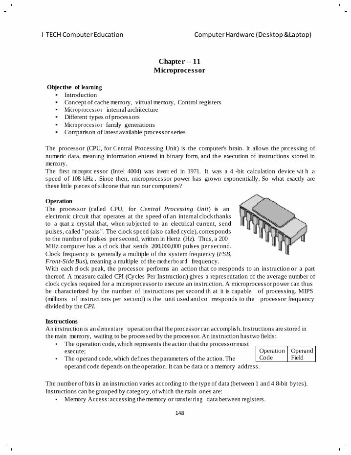
148
I-TECH Computer Education Computer Hardware (Desktop &Laptop)
Chapter – 11
Microprocessor
Objective of learning
Introduction
Concept of cache memory, virtual memory, Control registers
Micr op roc e sso r internal architecture
Different types of processors
Micro pr oc e sso r family generations
Comparison of latest available processor series
The processor (CPU, for C entral Processing Unit) is the computer's brain. It allows the proc essing of
numeric data, meaning information entered in binary form, and the execution of instructions stored in
memory.
The first microproc essor (Intel 4004) was invent ed in 1971. It was a 4 -bit calculation device wit h a
speed of 108 kHz . Since then, microprocessor power has grown exponentially. So what exactly are
these little pieces of silicone that run our computers?
Operation
The processor (called CPU, for Central Processing Unit) is an
electronic circuit that operates at the speed of an internal clock thanks
to a quart z crystal that, when su bjected to an electrical current, send
pulses, called "peaks". The clock speed (also called cycle), corresponds
to the number of pulses per second, written in Hertz (Hz). Thus, a 200
MHz computer has a cl ock that sends 200,000,000 pulses per second.
Clock frequency is generally a multiple of the system frequency (FSB,
Front-Side Bus), meaning a multiple of the mothe r bo ar d frequency.
With each cl ock peak, the processor performs an action that co rresponds to a n instruction or a part
thereof. A measure called CPI (Cycles Per Instruction) gives a representation of the average number of
clock cycles required for a microprocessor to execute an instruction. A microprocessor power can thus
be characterized by the number of instructions per second th at it is capable
(millions of instructions per second) is the unit used and co rresponds to the
divided by the CPI.
of processing. MIPS
processor frequency
Instructions
An instruction is an elem e nta ry operation that the processor can accomplish. Instructions are stored in
the main memory, waiting to be processed by the processor. An instruction has two fields:
• The operation code, which represents the action that the processor must
execute;
• The operand code, which defines the parameters of the action. The
Operation Code
Operand Field
operand code depends on the operation. It can be data or a memory address.
The number of bits in an instruction varies according to the type of data (between 1 and 4 8-bit bytes).
Instructions can be grouped by category, of which the main ones are:
• Memory Access: accessing the memory or transf er ring data between registers.
149
I-TECH Computer Education Computer Hardware (Desktop &Laptop)
• Arithmetic Operations : operations such as addition, subtraction, division or multiplication.
• Logic Operations : operations such as AND, OR, NOT, EXC LU SIV E NOT, etc.
• Control: sequence controls, conditional conne ct ion s, etc.
Registers
When the processor executes instructions, data is temporarily stored in s mall, local memory locations
of 8, 16, 32 or 64 bits called registers. Depending on th e type of pro cessor, the ov erall number of
registers can vary from about ten to many hundreds.
The main registers are:
• The accumulato r register (ACC), which stores the results of arithmetic and logical operations;
• The status register (PSW, Processor Status Word), which holds s ystem status indicators (carry
digits, overflow, etc.);
• The instruction register (RI), which contains the current instruction being processed;
• The ordinal counter (OC or PC for Program Counter), which contains the address of the nex t
instruction to process;
• The buffer register, which tempo ra ri ly stores data from the memory.
Cache Memory
Cache memory (also called buffer memory) is local memory that reduces waiting times for information
stored in the RAM (Ran dom Access Memory). In effect, the computer's main memory is slower than
that of t he processor. There ar e, however,
types of m emory that are much faster, but
which have a greatly increased cost. The
solution is the refore to i nclude this t ype of
local memory close to the processor and t o
temporarily store the primary data to be
processed in it. Rec ent model computers
have many different levels of ca che
memory:
• Level one cache memory (called L1 Cache, for Level 1 Cache) is d irectly integrated into the
processor. It is subdivided into two parts:
o The first part is the instruction cache, which contains instructions from the RAM tha t have
been decoded as they came across the pipelines.
o The second part is the d ata cache, which contains data from the RAM and data recently used
during processor operations.
Level 1 cache can be accessed very rapidly. Access waiting time approaches that of internal processor
registers.
• Level two cache memory (called L2 Cache, for Level 2 Cache) is located in the case along with
the processor (in the chip). The level two cache is an intermediary between the processor, with its
internal cache, and the RAM. It can be accessed more rapidly than the RAM, but less rapidly than
the level one cache.
• Level three cache memory (called L3 Cache, for Level 3 Cache) is located on the mothe rb oa rd .
All these levels of cache reduce the latency time of various memory types when proc essin g or
transf e rring information. While the processor works, the level one cache controller can interface with
the level two controllers to transfer information without impeding the processor. As well, the level two
150
I-TECH Computer Education Computer Hardware (Desktop &Laptop)
cache interfaces with the RAM (level three cache) to allow transfers without impeding normal
processor operation.
Control Signals
Control signals are electronic signals that orchestrate the various processor units participa tin g in the
execution of an instruction. Control signals are sent using an element called a sequencer. For example,
the Read / Write signal allows the memory to be told that the processor wants to read or write
information.
Functional Units The processor is made up of a group of interrelated units (or control units). Microp ro c ess or architecture
varies considerably from one de sign to another, but the main elements of a
follows:
microprocessor are as
• A control unit that links th e incoming data, decodes it, a nd sends it to the execution unit: Th e
control unit is made up of the following elements:
o Sequencer (or monitor and logic unit) that s ynchronizes instruction ex ecution with the clock
speed. It also sends control signals;
o ordinal counter that contains the address of the instruction currently being executed;
o Instruction register that contains the following instruction.
• An execution unit (or processing unit) that ac complishes tasks assig ned to it b y the instruction
unit. The execution unit is made of the following elements:
o The arithmetical and logic unit (written ALU). The ALU performs basic arithmetical
calculations and logic functions (AND, OR, EXC LU SI V E OR, etc.);
o The floating point unit (written FPU) that performs partial complex calculations which cannot be
done by the arithmetical and logic unit.
o The status register;
o The Accumula to r register.
• A bus management unit (or input-output unit) that manages the flow of incoming and outgoing
information and that interfaces with system RAM;
The diagram below gives a simplified repr es en tat ion of the elements that make up the processor (the
physical layout of the elements is different
than their actual layout):
Transistor
To process information, the mi
has a group of instructions,
croprocessor
called the
"instruction set", made possible by electronic
circuits. More precisely, the instruction set is
made with the help of semiconductors, little
"circuit switches" that use the transistor
effect, discovered in 1947 b y John Barden,
Walter H. Brattain and William Shockley who
received a Nobel Prize in 1956 for it.
A transistor (the contraction of transfer
resistor) is an el ectronic semi-conductor component that has three el ectrodes and is c apable of
modifying current passing through it using one o f its electrodes (called c ontrol electrode). These are
151
I-TECH Computer Education Computer Hardware (Desktop &Laptop)
referred to as "active comp on en ts", in contrast to "passive compon en ts", such as resistance or capacitors
which only have two electrodes (referred to as being "bipolar").
A MOS (metal, oxide, silicone) transistor is the most c ommon type of transistor used to d esign
integrated circuits. MOS transistors have two negatively charged areas, respectively called source
(which has an almost zero charge) and drain (which has a 5V ch arge), separated by a positively
charged region, and c alled a substrate). The substrate has a cont rol electrode overlaid, called a gate,
that allows a charge t o be appl ied to the
substrate.
When there is no charge on t he control
electrode, the positively charged substrate
acts as a bar rier and prevents electron
movement from the so urce to t he drain.
However, when a ch arge is applied to the
gate, the positive charges of the substrate
are repelled and a n egatively charged
communication channel is opened between
the source and the drain.
The transistor therefore acts as a progr am m ab le switch,
thanks to the control electrode. When a charge is applied
to the control electrode, it acts as a closed interrupter
and, when there is no charge, it acts as an open
interrupter.
Integrated Circuits
Once combined, transistors can make logic circuits, that,
when combined, form processors. The first integrated
circuit dates ba ck to 1 958 and
Instruments.MOS transistors are
was built b y Texas
therefore made of
slices of silicone (called wafers) obtained after multiple processes. These slices of silicone are cut into
rectangular elements to form a "circuit". Circuits are then placed in cases with input-output connectors
and the sum of these par ts makes an "integrated circuit". The minuteness of the engraving, written in
microns (micrometers, written µm) defines the number of transistors per surfa
millions of transistors on one single processor.
ce unit. There can be
Moore's Law, penned i n 1965 by Gordon E. Moore, cofounder of Intel, predicted that processor
performance (by extension of the number of transistors integrated in the silicone) would double ev ery
twelve months. This law was revised in 1975, bring ing the number of months to 18. Moore Law is still
being proven today.
Because the rectangular case contains input-output pins that resemble legs, the term "electronic flea" is
used in French to refer to integrated circuits.
Families
Each type of processor has its own instruction set. Processors are grouped into the following families,
according to their unique instruction sets:
• 80x86: the "x" represents the family. Mention is therefore made to 386, 486, 586, 686, etc.
• ARM
• IA-64
152
I-TECH Computer Education Computer Hardware (Desktop &Laptop)
• MIPS
• Motorola 6800
• PowerPC
• SPARC
This explains why a program produced for a certain type of processor can only work directly on a
system with another type of p rocessor if there is instruction translation, called emulation. The term
"emulato r" is used to refer to the program perfo rm in g this translation.
Instruction Set
An instruction set is the sum of basic operations that a processor can accom plish . A proce ssor
instruction set is a determining factor in its archi tecture, even though the same architecture can lead to
different imple m e ntat ion s by different manufacturers.
The processor works efficiently thanks to a limited number of instructions, hardwired to the electronic
circuits. Most operations can be performed usin g basic functions. Some ar chitecture does, how ever,
include advanced processor functions.
CISC Architecture
CISC (Complex Instruction Set Computer) architecture means hardw iring the processor with complex
instructions that are difficult to create using basic instructions.
CISC is especiall y popular in 80 x86 type processors. This type of ar chitecture has an elevat ed cost
because of advanced functions printed on the s ilicone. Instructions are of variable length and may
sometimes require more than one clock c ycle. Because CISC-based processors can onl y process one
instruction at a time, the proce ssing time is a function of the size of the instruction.
RISC Architecture
Processors with RISC (Reduced Instruction Set Computer) technology do not have hardwir ed,
advanced functions.
Programs must therefore be translated into simple instructions which complicates development and/or
requires a more powerful processor. Such architecture has a reduced production cost compared to CISC
processors. In addition, instructions, simple in n ature, are executed in just one clock c ycle, which
speeds up p rogram execution when compared to CISC processors. Finally, these processors can handle
multiple instructions simultan e ou sly by processing them in parallel.
Technolog ical Improvements
Throughout time, microp ro ce sso r manu fa ctu re rs (called founders) have developed a certain number of
improv em ents that optimize processor performance.
Parallel Processing
Parallel processing consists of simultaneously executing instructions from the same program on
different processors. This involves dividing a pr ogram into multiple pr ocesses handled in parall el in
order to reduce execution time.
This type of technolog y, however, requir es synchronization and commu nication between the var ious
processes, like the divisi on of tasks in a business : work is d ivided into small discrete processes which
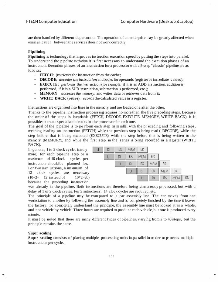
153
I-TECH Computer Education Computer Hardware (Desktop &Laptop)
are then handled by different departments. The operation of an enterprise may be greatly affected when
comm unic a tio n between the services does not work correctly.
Pipelining
Pipelining is technology that improves instruction execution speed by putting the steps into parallel.
To understand the pipeline mechanism, it is first necessary to understand the execution phases of an
instruction. Execution phases of an instruction for a processor with a 5-step "classic" pipeline are as
follows:
• FETCH: (retrieves the instruction from the cache;
• DECODE: decodes the instruction and looks for operands (register or immediate values);
• EXECUTE : performs the instruction (for example, if it is an ADD instruction, addition is
performed, if it is a SUB instruction, subtraction is performed, etc.);
• MEMO RY : accesses the memory, and writes data or retrieves data from it;
• WRITE BACK (retire): records the calculated value in a register.
Instructions are organized into lines in the memory and are loaded one after the other.
Thanks to the pipeline, instruction processing requires no more than the five preceding steps. Because
the order o f the steps is invariable (FETCH, DECODE, EXECUTE, MEMORY, WRITE BACK), it is
possible to create specialized circuits in the processor for each one.
The goal of the pipeline is to pe rform each step in pa rallel with the pr eceding and following steps,
meaning reading an instruction (FETCH) while t he previous step is being read ( DECODE), while the
step before that is being executed (EXECUTE), while the step before that is being written to the
memory (MEMORY), and while the first step in the series is be ing recorded in a re gister (WRITE
BACK).
In general, 1 to 2 clock cycles (rarely
more) for each pipeline step or a
maximum of 10 clock cycles
instruction should be planned
per
for.
For two instr uctions, a maximum of
12 clock cycles are necessary
(10+2= 12 instead of 10*2=20)
because the preceding instruction
was already in the pipeline. Both instructions are therefore being simultaneously processed, but with a
delay of 1 or 2 clock cycles. For 3 instru ct ion s, 14 clock cycles are required, etc.
The principle of a pipeline may be com pared to a car assembly line. The car moves from one
workstation to another b y following the assembly line and is completely finished by the time it leaves
the factory. To completely understand the principle, the assembly line must be looked at as a whole,
and not vehicle by vehicle. Three hours are required to produce each vehicle, but one is produced every
minute.
It must be noted that there are many different types of pipelines, v arying from 2 to 40 steps, but the
principle remains the same.
Super scaling
Super scaling consists of placing multiple processing units in pa rallel in or der to pr ocess multiple
instructions per cycle.
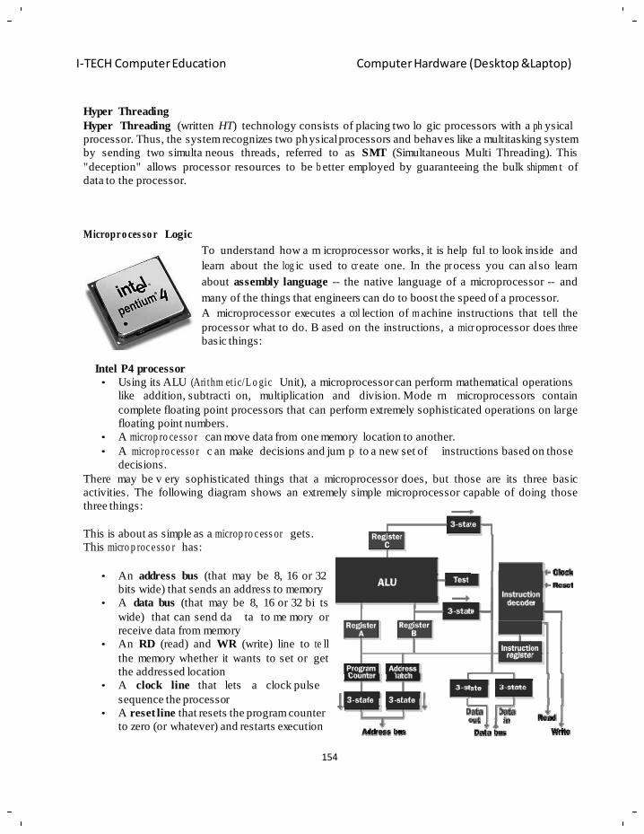
154
I-TECH Computer Education Computer Hardware (Desktop &Laptop)
Hyper Threading
Hyper Threading (written HT) technology consists of placing two lo gic processors with a ph ysical
processor. Thus, the system recognizes two physical processors and behaves like a multitasking system
by sending two simulta neous threads, referred to as SMT (Simultaneous Multi Threading). This
"deception" allows processor resources to be b etter employed by guaranteeing the bulk shipmen t of
data to the processor.
Micropro ces so r Logic To understand how a m icroprocessor works, it is help ful to look inside and
learn about the log ic used to cr eate one. In the pr ocess you can al so learn
about assembly language -- the native language of a microprocessor -- and
many of the things that engineers can do to boost the speed of a processor.
A microprocessor executes a col lection of m achine instructions that tell the
processor what to do. B ased on the instructions, a micr oprocessor does thre e
basic things:
Intel P4 processor
• Using its ALU (Ari thm et ic/L o gic Unit), a microprocessor can perform mathematical operations
like addition, subtracti on, multiplication and division. Mode rn microprocessors contain
complete floating point processors that can perform extremely sophisticated operations on large
floating point numbers.
• A microp ro ce sso r can move data from one memory location to another.
• A microp ro c esso r c an make decisions and jum p to a new set of instructions based on those
decisions.
There may be v ery sophisticated things that a microprocessor does, but those are its three basic
activities. The following diagram shows an extremely simple microprocessor capable of doing those
three things:
This is about as simple as a microp ro c ess or gets.
This micro p roc e sso r has:
• An address bus (that may be 8, 16 or 32
bits wide) that sends an address to memory
• A data bus (that may be 8, 16 or 32 bi ts
wide) that can send da ta to me mory or
receive data from memory
• An RD (read) and WR (write) line to te ll
the memory whether it wants to set or get
the addressed location
• A clock line that lets
sequence the processor
a clock pulse
• A reset line that resets the program counter
to zero (or whatever) and restarts execution
155
I-TECH Computer Education Computer Hardware (Desktop &Laptop)
Let's assume that both the address and data buses are 8 bits wide in this example.
Here are the components of this simple microprocessor:
• Registers A, B and C are simply latches made out of flip-flops.
• The address latch is just like registers A, B and C.
• The program counter is a latch with the extra ability to increment by 1 when told to do so, and also
to reset to zero when told to do so.
• The ALU could be as si mple as an 8- bit adder, or it might be able to add, subtract, multiply and
divide 8-bit values. Let's assume the latter here.
• The test register is a special latch that can hold values from comparisons performed in the ALU.
An ALU can normally compare two numbers and determine if they are equal, if one is greater than
the other, etc. The test register can also normally hold a carry bit from the last stage of the adder. It
stores these values in flip-flops and then the instruction decoder can use the values to ma ke
decisions.
• There are six boxes marked "3-State" in the diagram. These are tri-state buffers. A tri-state buffer
can pass a 1, a 0 or i t can essentially disconnect its output (ima gine a switch that totally
disconnects the output line from the wir e that the output is he ading toward). A tri-state buffer
allows multiple outputs to connect to a wire, but only one of them to actually drive a 1 or a 0 onto
the line.
• The instruction register and instruction decoder are responsible for controlling all of the other
components.
Although they are not shown in this diagram, there would be cont rol lines from the instruction decoder
that would:
• Tell the A register to latch the value currently on the data bus
• Tell the B register to latch the value currently on the data bus
• Tell the C register to latch the value currently output by the ALU
• Tell the program counter register to latch the value currently on the data bus
• Tell the address register to latch the value currently on the data bus
• Tell the instruction register to latch the value currently on the data bus
• Tell the program counter to increment
• Tell the program counter to reset to zero
• Activate any of the six tri-state buffers (six separate lines)
• Tell the ALU what operation to perform
• Tell the test register to latch the ALU's test bits
• Activate the RD line
• Activate the WR line
Coming into the instruction decoder are the bits from the test register and the clock line, as well as the
bits from the instruction register.
Micropro ces so r Memory
The previous section tal ked about the address and data buses, as wel l as the
RD and W R lines. These buses a nd lines connect either to RAM or ROM --
generally both. In our sample microprocessor, we have an address bus 8 bits
wide and a data bus 8 bits wide. That means that the microprocessor can
address (28) 256 b ytes of memory, and it ca n read or write 8 bits of the
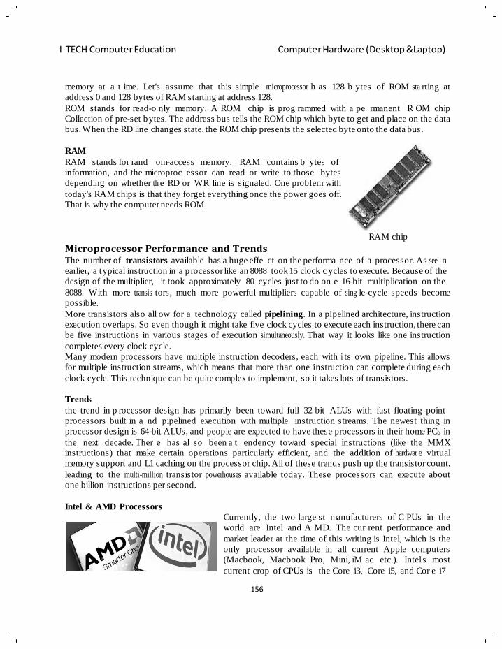
156
I-TECH Computer Education Computer Hardware (Desktop &Laptop)
R
memory at a t ime. Let's assume that this simple microprocessor h as 128 b ytes of ROM sta rting at
address 0 and 128 bytes of RAM starting at address 128.
ROM stands for read-o nly memory. A ROM chip is prog rammed with a pe rmanent R OM chip
Collection of pre-set bytes. The address bus tells the ROM chip which byte to get and place on the data
bus. When the RD line changes state, the ROM chip presents the selected byte onto the data bus.
RAM
RAM stands for rand om-access memory. RAM contains b ytes of
information, and the microproc essor can read or write to those bytes
depending on whether th e RD or WR line is signaled. One problem with
today's RAM chips is that they forget everything once the power goes off.
That is why the computer needs ROM.
Microprocessor Performance and Trends RAM chip
The number of transistors available has a huge effe ct on the performa nce of a processor. As see n
earlier, a typical instruction in a p rocessor like an 8088 took 15 clock c ycles to execute. Because of the
design of the multiplier, it took approximately 80 cycles just to do on e 16-bit multiplication on the
8088. With more transis tors, much more powerful multipliers capable of sing le-cycle speeds become
possible.
More transistors also all ow for a technology called pipelining. In a pipelined architecture, instruction
execution overlaps. So even though it might take five clock cycles to execute each instruction, there can
be five instructions in various stages of execution simultaneously. That way it looks like one instruction
completes every clock cycle.
Many modern processors have multiple instruction decoders, each with i ts own pipeline. This a llows
for multiple instruction streams, which means that more than one instruction can complete during each
clock cycle. This technique can be quite complex to implement, so it takes lots of transistors.
Trends
the trend in p rocessor design has primarily been toward full 32-bit ALUs with fast floating point
processors built in a nd pipelined execution with multiple instruction streams. The newest thing in
processor design is 64-bit ALUs, and people are expected to have these processors in their home PCs in
the next decade. Ther e has al so been a t endency toward special instructions (like the MMX
instructions) that make certain operations particularly efficient, and the addition of hardwar e virtual
memory support and L1 caching on the processor chip. All of these trends push up the transistor count,
leading to the multi-million transistor powerhouses available today. These processors can execute about
one billion instructions per second.
Intel & AMD Processors Currently, the two large st manufacturers of C PUs in the
world are Intel and A MD. The cur rent performance and
market leader at the time of this writing is Intel, which is the
only processor available in all current Apple computers
(Macbook, Macbook Pro, Mini, iM ac etc.). Intel's most
current crop of CPUs is the Core i3, Core i5, and Cor e i7
157
I-TECH Computer Education Computer Hardware (Desktop &Laptop)
g
h
h
P
while AMD's top off ering is the Phenom II. Though AMD is not the market leader, many of their
products are found in high performance, budget-oriented notebook and c ustom desktop builds as well
as low-cost enthusiast-oriented desktops. AMD's highest performance processors however, have not yet
been available for mobile platforms as Intel's Core iX series are at the time of this writing.
Beneath we provide a chart which compares the relative differences in performance between competing
product lines within Intel's and AMD's offerings. We also org anize these by the following classes:
high-end, mid-range and economy. It is impor tant to note that these comparisons give a quick visual
reference as to relative absolute performance across these three categories but does not ne cessarily
indicate absolute rankings between the Intel and AMD products within those categories (for instance,
the Core i7 is on the same row in as the Pheno m II series but of fers superior general performance).
Further, the Core iX Mobile series only indicate relative performance for notebook-oriented platforms
(they are the highest performance mobile CPUs to date); it is not use ful to compare them to a deskt op-
class processors such as the Intel Core i7 or the Phenom II series.
Intel Core i7 Intel Core i7 Mobile AMD Phenom II X6
As Intel's newest flagship Intel's Core i7 Mobile featur es AMD's Phenom II X6 represents the
processor, the i7 is a 64-bi t unparalleled performance on industry's first consumer class six -core
processor offering either 2, 4, notebooks, incor p ora tin g processor. The X6 offers the highest
or 6 cor es of the hi ghest levels significant power savings while levels of performance ideal for the most
of performance available. The implementing the same features intensive of tasks - bolstered by AMD's
i7 combines Hyper Thre a din g as the non-mobile i7, Hype r new Turbo Core technology, the X6 is
and Turbo B oost techn olo gie s Threading and Tu rbo Boost . able to optim ize performance in a
for the most demandi ng and The i7 Mobile is a vailable on variety of situations.
advanced of applications. notebooks with 2 or 4 cores;
currently the 4 co re version
offers higher performance in
some respects but he at and
battery life are concerns.
158
I-TECH Computer Education Computer Hardware (Desktop &Laptop)
m
o
e
h
p
w
n
X
a
n
Intel Core i5 Intel Core i5 Mobile AMD Phenom II X4
Based upon the same
architecture as the i7, the i5 is
The Intel Core i5 Mobile while AMD's latest generation of consumer
also featuring Hyper Threading class 4 core processors, the quad-core
also a 64-bit processor that
features 2 or 4 cores at a
and Turbo Boost possesses a
similar but lesser class of
Phenom II X4 chips are designed to
deliver perform an c e ideal for all kinds
similar class of perfor m a nc e of perfor m a nc e than the Core i7
the i7 processor at a lower cost. Mobile with less cache and
of multimedia as well as in the most
demanding of applications such as
The i5 features Turbo Boost
and Hyper-Threading
technolo g y but do not possess
as much cache memory as the
i7.
available in notebooks only
with 2 cores. The i5 Mobile is
a high perfor m a nc e processor
with low energy requirements.
virtualization.
Intel Core i3 Intel Core i3 Mobile AMD Phenom II X3 & X2
Derived from the same
architecture as the higher end
i5 and i7, the i3 is available
strictly as a dual core
The Intel Core i3 Mobile
descends similarly from the i3,
presenting a fast, 64-bit
computing experience with the
AMD's Phenom X3 and X2 processors
boast 3 or 2 cores that offer excellent
perfo rm a n ce value; great for all around
usage on a small budget all while
processor. Though Hyper intelligent architecture of the i5 utilizing AMD's latest architecture
Threading is available, it does
not feature TurboBoost. The
Core i3 processor presents
higher levels of performance
than the Core 2 at a smaller
cost.
Mobile and i7 Mobile. The i3
Mobile features 2 cores and
Hyper Threading but does not
include Turbo Boost
technology
technolo g y seen in the Phenom II X4
series
Intel Core 2 Quad
The Core 2 Quad features 4 processing cores to optimize gaming, video, and image processing. Built on the
same architecture as the Core 2 Duo, this processor excels on multi -ta skin g with perfo rm a nc e hungry
applications.
159
I-TECH Computer Education Computer Hardware (Desktop &Laptop)
o
o
C
C
e
a
m
Intel Core 2 Extreme
Available in both 2 and 4 core versions, distingu ishing features of the Extreme series include higher
bus speeds than the non-ex t re m e versions, and an unlocked clock multiplier for further customization
of your computing performance.
Intel Core 2 Duo AMD Phenom I X3 & Phenom I X4
Contains two processing cores to optimize gaming,
video, and image processing. Laptops with this chip
tend to be thinner and more energy-efficient.
AMD's first generation of consumer class processors
featuring quad and triple core performance found in
desktop builds. Features 64-bit computing
performance as well as AMD's Hyper Transport bus
technology.
Intel Pentium Dual Core AMD Turion II Ultra / AMD Turion II
Dual core processor based on the Core micro
architecture.
A class beneath the Core 2 Duo and Core Duo of
Intel's processor offerings, the Pentium Dual Core is
available in current desktops and laptops.
The Turion II and Turion II Ultra are AMD's
mainstream mobile processor platform; they provide
excellent all-around performance for multimedia
such as high definition video. As these are often
paired with AMD/ATI graphics, budget
configu ra tio ns containing these processors are also
sufficient for basic 3D graphics and gaming.
Intel Core Duo / Intel Core Solo AMD Athlon II X2
The Intel Core Duo and Core Solo are dual and
single core processors based on the Core micro
archi te ctu re . The Core Duo and Core Solo offers
modest perfo rm a n c e for office and limited
multimedia oriented tasks.
The AMD Athlon II X2 is a 2 core desktop processor
that is 80% faster than it's single core counterpart.
Great for multi t a skin g and multimedia consumption
on a budget.
160
I-TECH Computer Education Computer Hardware (Desktop &Laptop)
n
n
m
h
m
g
e
n
Intel Centrin o/Cent r ino Duo AMD Sempron
A mobile -o rie nte d processor based upon Pentium M The AMD Sempron is a budget class processor seen
or
Core Duo archi tec tur e s; the Centrino also integrates
in low cost notebooks and desktops and are
considered a class above notebo ok /ne tto p processors
wireless netw ork ing techno log y allowing for smaller such as the Intel Atom or the AMD Neo platforms.
sized laptops. Offers slight perfo rm an c e boost over
simply choosing a core duo and dell wireless card
(which is typically less expensive.)
Intel Atom AMD Athlon Neo / Neo X2
Primarily found in net books and net tops, this
processor
has been designed with price and power
consum ptio n in mind. As a result, it offers much
less processing power
than other current Intel altern at ive s. This processor
is available in 1 or 2 cores, with the single core
option being far more prevalent.
The Athlon Neo and Neo X2 are single and dual core
processors seen in ultra-m o bi le platforms such as net
book and net tops. They are featured with ATI
integrated graphics for reasonable multimedia
playback performance.
Intel Celeron
Intel's economy model processor. It is the most basic, and thus the slowest. It has less cache than other
Intel processors, so even if it has the same Ghz rating as another processor, it will be slower. We usually
do not recommend this processor because it offers the least in terms of longevity.
Intel Processor Series
Processor Year Bus width Descript io n
4004 1971 4 First microprocessor.
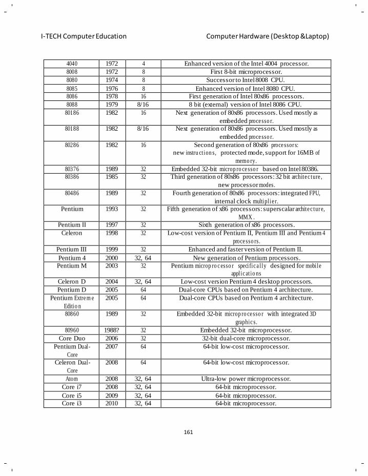
161
I-TECH Computer Education Computer Hardware (Desktop &Laptop)
4040 1972 4 Enhanced version of the Intel 4004 processor.
8008 1972 8 First 8-bit microprocessor.
8080 1974 8 Successor to Intel 8008 CPU.
8085 1976 8 Enhanced version of Intel 8080 CPU.
8086 1978 16 First generation of Intel 80x86 processors.
8088 1979 8/16 8 bit (external) version of Intel 8086 CPU.
80186 1982 16 Next generation of 80x86 processors. Used mostly as
embedded proce sso r.
80188 1982 8/16 Next generation of 80x86 processors. Used mostly as
embedded proce sso r.
80286 1982 16 Second generation of 80x86 proce ssor s:
new instru ct ion s, protected mode, support for 16MB of
memo ry.
80376 1989 32 Embedded 32-bit microp ro ce sso r based on Intel 80386.
80386 1985 32 Third generation of 80x86 processors: 32 bit archite c ture ,
new processor modes.
80486 1989 32 Fourth generation of 80x86 processors: integrated FPU,
internal clock multipl i e r.
Pentium 1993 32 Fifth generation of x86 processors: superscalar archite c tur e,
MMX .
Pentium II 1997 32 Sixth generation of x86 processors.
Celeron 1998 32 Low-cost version of Pentium II, Pentium III and Pentium 4
proce sso rs.
Pentium III 1999 32 Enhanced and faster version of Pentium II.
Pentium 4 2000 32, 64 New generation of Pentium processors.
Pentium M 2003 32 Pentium microp ro c esso r speci fic a l ly designed for mobi le
appl ic at io ns
Celeron D 2004 32, 64 Low-cost version Pentium 4 desktop processors.
Pentium D 2005 64 Dual-core CPUs based on Pentium 4 architecture.
Pentium Extre m e
Editio n
2005 64 Dual-core CPUs based on Pentium 4 architecture.
80860 1989 32 Embedded 32-bit microp ro ce sso r with integrated 3D
graphic s.
80960 1988? 32 Embedded 32-bit microprocessor.
Core Duo 2006 32 32-bit dual-core microprocessor.
Pentium Dual-
Core
2007 64 64-bit low-cost microprocessor.
Celeron Dual -
Core
2008 64 64-bit low-cost microprocessor.
Atom 2008 32, 64 Ultra-low power microprocessor.
Core i7 2008 32, 64 64-bit microprocessor.
Core i5 2009 32, 64 64-bit microprocessor.
Core i3 2010 32, 64 64-bit microprocessor.
162
I-TECH Computer Education Computer Hardware (Desktop &Laptop)
Chapter - 12
Motherboard
Objective of learning
Motherboard and its farm factor
History and evolution of motherboard
Different compo ne nts on motherboard
Different types of processor slot/sockets
Features of different MB
A motherboard is also known as a main board, sy stem board and lo gic board. A common abbrevi ation
is ‗mobo'. They can be found in a v ariety of electrical devices, ranging from a TV to a computer.
Generally, they will be referred to as a motherboard or a main board when associated with a complex
device such as a computer, which is what we shall look at. Put simpl y, it is the central circuit board of
your computer. All other components and peripherals plug into it, and the job of the motherboard i s to
relay information between them all. Despite the fact that a better motherboard will not add to the speed
of your PC, it is none-th e-less important to have one that is both s table and reliable, as its role is v ital.
A motherboard hous es the BIOS (Basic Input/Output System), which is the simple software run b y a
computer when initiall y turned on. Other compo nents attach directly to it, such as the memor y, CPU
(Central Proce ssing Unit), graphics card, sound card, hard-drive, disk drives, along with various
external ports and peripherals.
Difference between motherboards:
There are a lot of moth erboards on the market to choose from. The big question is, how do you go
about choosing which one is right for you? Different motherboards support different components, a nd
so it is vital you make a number of decisions con cerning general system specifications before you can
pick the right motherboard.
If you purchase your case before the rest of the components, the first factor to think about concerning
motherboards is the size, or form factor. A form factor is a standardized motherboard size. If you think
about fitting a mothe rboard in a case, there are a number of mountin g holes, slot locations and PSU
connectors. The most popular motherboard fo rm factor today is AT X, which evolved from it's
predecessor, the Baby AT, a smaller version of the AT (Advanced Technology) form factor. Generally
speaking, nowadays a standard computer will h ave an ATX f orm factor motherboard: only special
cases require different form factors.
So now you know whic h size you need, what c omes next? The following are all fa ctors you need to
consider.
The first important differential is which CPU the board supports. Two of the bigg est makes of CPUs at
the moment are Intel and AMD, yet you cannot buy motherboards that support the use of either: it will
support one or the other, due to physical differences in the connectors. This is often referred to as a type
of platform; for ex ample, an ‗ Intel platform motherboard' means a m otherboard with an Intel CPU.
Furthermore, you must choose a specific type of processor; for example, an AM D Athlon 64 or
Pentium 4. Therefore, you must choose which CPU you want before you can choose your motherboard.
Both Intel and AMD processors are capable of running the same applications, but there are differences in price and performance depending on which one you choose.
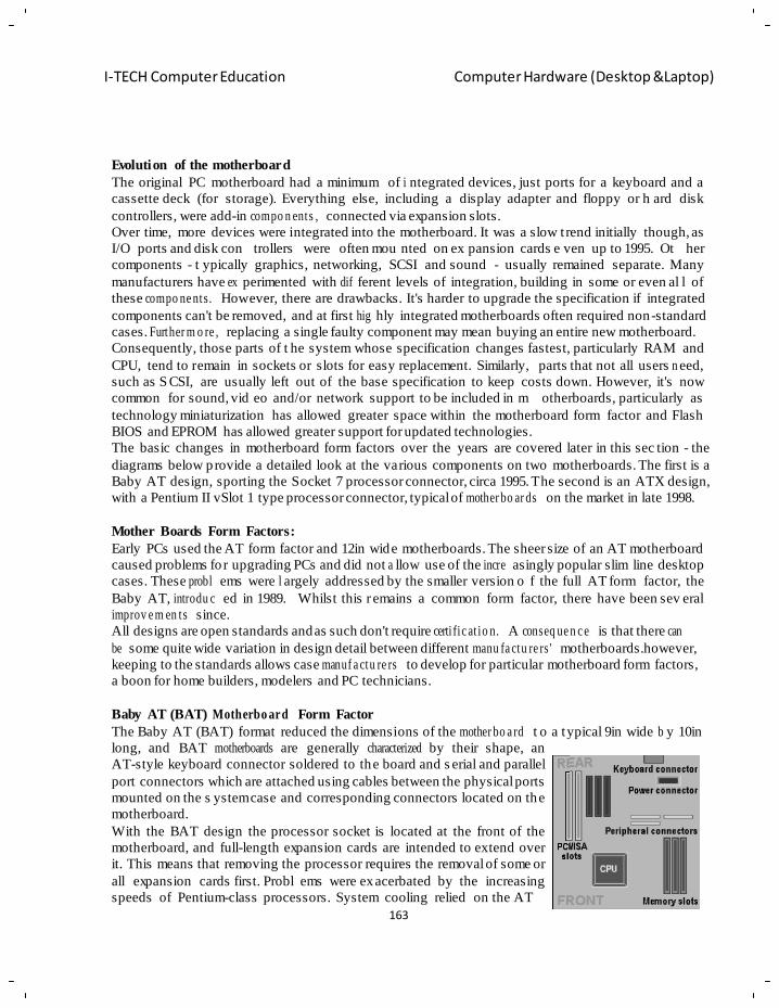
163
I-TECH Computer Education Computer Hardware (Desktop &Laptop)
Evolution of the motherboard
The original PC motherboard had a minimum of i ntegrated devices, just ports for a keyboard and a
cassette deck (for storage). Everything else, including a display adapter and floppy or h ard disk
controllers, were add-in compo n ents , connected via expansion slots.
Over time, more devices were integrated into the motherboard. It was a slow t rend initially though, as
I/O ports and disk con trollers were often mou nted on ex pansion cards e ven up to 1995. Ot her
components - t ypically graphics, networking, SCSI and sound - usually remained separate. Many
manufacturers have ex perimented with dif ferent levels of integration, building in some or even al l of
these compo ne nts. However, there are drawbacks. It's harder to upgrade the specification if integrated
components can't be removed, and at first hig hly integrated motherboards often required non-standard
cases. Further m o re , replacing a single faulty component may mean buying an entire new motherboard.
Consequently, those parts of t he system whose specification changes fastest, particularly RAM and
CPU, tend to remain in sockets or slots for easy replacement. Similarly, parts that not all users n eed,
such as S CSI, are usually left out of the base specification to keep costs down. However, it's now
common for sound, vid eo and/or network support to be included in m otherboards, particularly as
technology miniaturization has allowed greater space within the motherboard form factor and Flash
BIOS and EPROM has allowed greater support for updated technologies.
The basic changes in motherboard form factors over the years are covered later in this sec tion - the
diagrams below provide a detailed look at the various components on two motherboards. The first is a
Baby AT design, sporting the Socket 7 processor connector, circa 1995. The second is an ATX design,
with a Pentium II vSlot 1 type processor connector, typical of mother bo ar ds on the market in late 1998.
Mother Boards Form Factors:
Early PCs used the AT form factor and 12in wide motherboards. The sheer size of an AT motherboard
caused problems fo r upgrading PCs and did not a llow use of the incre asingly popular slim line desktop
cases. These probl ems were l argely addressed by the smaller version o f the full AT form factor, the
Baby AT, introdu c ed in 1989.
improv e m en ts since.
Whilst this r emains a common form factor, there have been sev eral
All designs are open standards and as such don't require certi fic at io n. A conseq ue n c e is that there can
be some quite wide variation in design detail between different manu fa ctu re rs ' motherboards.however,
keeping to the standards allows case manuf a ctu re rs to develop for particular motherboard form factors,
a boon for home builders, modelers and PC technicians.
Baby AT (BAT) Motherbo ard Form Factor
The Baby AT (BAT) format reduced the dimensions of the mother bo a rd t o a typical 9in wide b y 10in
long, and BAT motherboards are generally characterized by their shape, an
AT-style keyboard connector soldered to the board and s erial and parallel
port connectors which are attached using cables between the physical ports
mounted on the s ystem case and corresponding connectors located on the
motherboard.
With the BAT design the processor socket is located at the front of the
motherboard, and full-length expansion cards are intended to ex tend over
it. This means that removing the processor requires the removal of some or
all expansion cards first. Probl ems were ex acerbated by the increasing
speeds of Pentium-class processors. System cooling relied on the AT
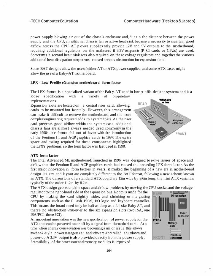
164
I-TECH Computer Education Computer Hardware (Desktop &Laptop)
power supply blowing air out of the chassis enclosure and, due t o the distance between the power
supply and the CPU, an additio nal chassis fan or act ive heat sink became a necessity to maintain good
airflow across the CPU. AT p ower supplies onl y provide 12V and 5V outputs to the motherboard,
requiring additional regulators on the motherboard if 3.3V components (P CI cards or CPUs) are used.
Sometimes a second hea t sink was also required on these voltage r egulators and together the v arious
additional heat dissipation compon e nts caused serious obstruction for expansion slots.
Some BAT designs allow the use of either AT or ATX power supplies, and some ATX cases might
allow the use of a Baby-AT motherboard.
LPX - Low Profile eXtension motherboard form factor
The LPX format is a specialized variant of the Bab y-AT used in low pr ofile desktop systems and is a
loose specification with
implementations.
Expansion slots are located on
a variety of proprietary
a central riser card, allowing
cards to be mounted hor izontally. However, this arrangement
can make it difficult to remove the motherboard, and the more
complex engineering required adds to system costs. As the riser
card prevents good airflow within the system case, additional
chassis fans are al most always needed.Used commonly in the
early 1990s, th e format fell out of favor with th e introduction
of the Pentium I I and AGP g raphics cards in 1997. The ex tra
space and cool ing required for these components highlighted
the LPX's problems, so the form factor was last used in 1998.
ATX form factor
The Intel Advanced/ML motherboard, launched in 1996, was designed to so lve issues of space and
airflow that the Pentium II and AGP graphics cards had caused the preceding LPX form factor. As the
first major innovation in form factors in years, it marked the beginning of a new era in motherboard
design. Its size and layout are completely different to the BAT format, following a new scheme known
as ATX. The dimensions of a standard ATX board are 12in wide by 9.6in long; the mini ATX variant is
typically of the order 11.2in by 8.2in.
The ATX design gets round the space and airflow problems by moving the CPU socket and the voltage
regulator to the right-hand side of the expansion bus. Room is made for the
CPU by making the card slightly wider, and shrinking or inte grating
components such as the F lash BIOS, I/O logic and keyboard controller.
This means the board need only be half as deep as a full size Baby AT, and
there's no obstruction whatsoev er to the six expansion slots (two I SA, one
ISA/PCI, three PCI).
An important innovation was the new speci fic at ion of power supply for the
ATX that can be powered on or off by a signal from the mothe rb oa rd . At a
time when energy conservation was becoming a major issue, this allows
noteb o ok -style power manag e m e nt and softw a re - c ontr olle d shutdown and
power-up.A 3.3V output is also provided directly from the power supply.
Acce ssib il i ty of the processor and memory modules is improved
165
I-TECH Computer Education Computer Hardware (Desktop &Laptop)
dram at ic al ly , and relocation of the peripheral connectors allows shorter cables to be used. This also
helps reduce elect ro m a gn e tic interf e re nc e . The ATX power supply has a side vent that blows air from
the outside directly across the processor and memory modules, allowing passive heat sinks to be used
in most cases, thereby reducing system noise.
NLX - New Low profile eXtended - form factor for motherboards:
Intel's NLX design, introduced in 1997, is an improvement
on the LPX design for low-profile systems, with an emphasis
on ease of maintenance. The NLX format is smaller,
typically 8.8in wide b y 13in long, so we ll suited for low-
profile desktop cases.All expansion slots, power cables and
peripheral connectors are located on an ed ge-mounted riser
card, allowing simple r emoval of the ma in motherboard,
which is mounted on r ails in the chassis. It uses a full-width
I/O shield to a llow for different combinations of rear-panel
I/O. The design allows for use of an A GP card, but the slot
must be on the mother board, which reduces the ease of
maintenance when such a card is implemented.
Micro ATX motherboa rd form factor:
Introduced in the late 1990s, the MicroATX is basic al l y a smaller version of Intel's ATX specification,
intended for compact, low-cost consumer systems with limited expansion potential.The maximum size
of the board is 9.6in s quare, and its de signed to f it into either a
standard ATX case or one of t he new micro-tower desktop designs.
The double-decker I/O shield is the same as t hat on t he ATX desi gn,
but there's only provision for up to four expansion slots as opposed to
the seven t hat ATX al lows. The microATX also allows use of a
smaller power suppl y, such as the SFX design, which is r educed in
both size and power output.
FlexATX motherboa rd form factor:
The FlexATX is a nat ural evolution of the Intel's microATX form
factor which was first unveiled in late 1999. The FlexATX addendum
to the microATX specification addresses the requirements of onl y the
motherboard and not the overall system solution. As such, it does not
detail the interfaces, memory or graphics technologies required to
develop a success ful product design. These are left to the implementer
and system designer. The choice of processor is, howe ver, limited to
socket-only designs.The principal difference between FlexATX and
microATX is tha t the new form factor reduces the size of t he
motherboard - to 9in x 7.5in. Not only does this result in lower overall
system costs, it also facilitates smaller system designs. The FlexATX
form factor is backwards compatible with both the ATX a nd micro-
ATX specifications - use of the same motherboard mounting holes as
both of its predec e sso rs avoids the need to retool existing chassis.
166
I-TECH Computer Education Computer Hardware (Desktop &Laptop)
Riser architectu res for motherboa rds :
In the late 1990s, the PC indu stry developed a need for a ri ser architecture that would contribut e
towards reduced overall system costs and at the same time increase the flexibility of the s ystem
manufacturing process. The A udio/Modem Riser AMR) specification, introd uced in the summer of
1998, was the be ginning of a new riser architecture approach. AMR had the capability to support b oth
audio and modem functi ons. However, it did hav e some shortcomings, which were identified after the
release of t he specification. These shortcomings included the lack of Plug and Play (PnP) suppor t, as
well as the consumption of a PCI connector location.Consequently, new riser architecture specifications
were defined which combine more functions onto a single card. These new riser architectures combine
audio, modem, broadband techn ologies, and LAN interfaces onto a single card. They continue to g ive
motherboard OEMs the flexibility to create a generic motherboard for a variety of customers. The riser
card allows OEMs and system integrators to provide a customised solution for each customer's needs.
Two of the most recent riser architecture speci fica t ion s include CNR and ACR.
CNR - Communicat io ns and Network in g Riser
Intel's CNR (Communication and Networking Riser)
specification defines a hardware scalable OEM motherboard
riser and interface that supports the audio, m odem, and
LAN interfaces of core logic chipsets. The ma in objective
of this spe cification is t to reduce the baseline
implementation cost of f eatures that are widely used in the
Connected PC, while also addressing specific functional
limitations of today's audio, modem, and LAN subsystems.
PC users' demand for feature-rich PCs, c ombined with the
industry's current trend towards lower cost, mandates higher
levels of integration at all levels of the P C platform.
Mothe rb o ar d integration of comm unic a tio n techn olo gies has
been problematic to date, for a variety of reasons, including FCC and international telecom certification
processes, mother bo a rd space, and other manu fa c tur er specific requirements.
Motherboard integration of the audio, modem, a nd LAN subsystems is also problematic, due to the
potential for i ncreased noise, which in-turn d egrades the performance of e ach system. The CNR
specifically addresses these problems by physically separating these noise-sensitive systems from the
noisy enviro nm en t of the motherboard.
With a standard riser solution, as defined in this specification, the system manufacturer is f ree to
implement the audio, modem, and/or LAN subsystems at a lower bill of materials (BOM) cost than
would be possible b y deploying the same functions in industr y-standard expansion slots or in a
proprietary method. With the added flexibility that hardware scalability brings, a system manufacturer
has several motherboard acceleration options available, all stemming from the baseline CNR interface.
The CNR Speci fic at ion supports the five interfaces:
• AC97 Interface - Supports audio and modem functions on the CNR card
• LAN Connect Interface (LCI) - Provides 10/100 LAN or Home Phone line Networking
capabilities for Intel chipset based solutions
• Media Independent Interface (MII) - Provides 10/100 LAN or Home Phone line Networking
capabilities for CNR platforms using the MII Interface
• Universal Serial Bus (USB) - Supports new or emerging technolo gie s such as xDSL or wireless
167
I-TECH Computer Education Computer Hardware (Desktop &Laptop)
• System Management Bus (SMBus) - Provides Plug and Play (PnP) functionality on the CNR
card.Each CNR card can utilize a maximum of four interfaces by choosing the specific LAN
interface to support.
ACR - Advanced Communica tions Riser
The rival ACR (Advanced Com munications Riser) speci fic at ion is supported b y an alliance of leading
computing and communi cation companies, whose founders include 3CO M, AMD, VIA Technologies
and Lucent Technologies. Like CNR, it defines a form factor and i nterfaces for multiple and varied
communications and audio sub system designs in desktop OEM personal computers. Building on f irst
generation PC mothe rb oa rd ri ser architecture, ACR expands the riser card definition beyond the
limitation of audio and modem codecs, while maintaining backward compatibility with le gacy riser
designs through an industry standard connector scheme. The ACR interface combines several existing
communications buses, and introduces new and advanced communications buses answering industry
demand for low-cost,
comm unic a tio ns peripherals.
high-performance
ACR supports modem, audio, LAN, and x DSL. Pins
are reserved for fut ure wireless bus support. Be yond
the limitations of first generation riser spe cifications,
the ACR specification enables riser-based broadband communications, networking peripheral and audio
subsystem designs. ACR accomplishes this in an open-
standards context.
Although the two specificatio ns both offer si milar
functionality, the way in which they are imple m e nte d are quite
dissimilar. In addition to the PCI
conne c tor/sh a re d slot issue, the principal differences are as follows:
• ACR is backwards compatible with AMR, CNR isn't
• ACR provides support xDSL technologies via its Integrated Packet Bus (IPB) technology; CNR
provides such support via the well-esta bl ishe d USB interface
• ACR provides fo r concurrent support for LCI (LAN Connect Interface) and M II (Media
Independent Interface) LAN interfaces; CNR supports either, but not both at the same time
• The ACR Specification has already reserved pins for a fut ure wireless interface; the CNR
specification has the pins available but will onl y define them when the wireless market has
become more mature.
Ultimately, motherboard manuf ac tur e rs are going to have to decide whether the ACR specification's
additional features are worth the extra cost.
Componen ts Of Motherboards:
When you look at the mother board inside your computer, you notice that there are a num ber of
different items connected to this board. The memory sockets are installed on this board; the CPU socket
is located on the motherboard, and the BIOS chip is also located on the motherboard. In this section, we
will identify the different system board components.
168
I-TECH Computer Education Computer Hardware (Desktop &Laptop)
Processor
One of the easiest items to recognize on the motherboard is the processor. The processor is usually the
largest chip on the system board and can be identified generally because it often has a heat sink or fan
located on top of it.
Classic Pentium motherboards typically have a socket 7 sl ot that the processor is inserted into. This
socket is implemented as a ZIF (zero insertion force) socket, which means that the processor chip can
be removed or added to the socket with ve ry little effort. ZIF sockets typically have a lever that you
pull to pop the processor out of the socket.
Pentium II system boards had to imple ment a different socket for the Pentium II chip because the
Pentium II chip was designed with a single edge connector and was inserted into the board standing up.
The processor socket for Pentium II chips is called slot 1.
SIMM/DI M M sockets
When you look at a s ystem board, one of the fir st items that shou ld stand out is the processor or its
socket; the next thing that you will usually take notice of are the memory slots that are used to install
RAM.There are typically two types of sockets to install memory: SIMM (Single InLine Memory
Module) sockets and D IMM (Dual Inline Memory Module) sock ets. Original Pentium s ystems
typically have either four 72-pin SIMM sockets, or two 168-pin DIMM sockets to install memory.
When installing SIMMs in Pentium motherboards, you have to install them in pairs, but when installing
DIMMs, you can install them individually. The reason for the difference in the installation pro cess is
that when installing memory, you must fill a m emory bank, which is the size of the processor‘s data
path. That is, if you install 72-pin (32-bit) SIMMs onto a Pentium (64-bit) motherboard, then you have
to install two modules to fill the 64-bit data path of the processor. DIMMs are 64-bit memory modules,
which is why you only have to install one at a time.
Cache memory
Cache memory increases performance by storing frequently used program code or data. Bec ause cache
memory is faster than RAM, the system can store information accessed from RAM in cache memory
when the data is accessed the first time. The processor can then retrieve the information from the faster
cache memory for subsequent calls. All the processors today have integrated cache memory, which is
known as level-1 cache. The types of cache are as follows:
L1 (level-1) cache: Cache that is integrated within the processor.
L2 (level-2) cache: Cache that is located outside the processor, like on the motherboard.
Older motherboards implemented cache memory as rows of DIP chips placed directly on the
motherboard. This area was sometimes even labeled ―cache.‖ Labels on a motherboard seem to be
something that you cannot always rely on though—if they are there, consider it an added bonus!
Newer systems have implemented the cache as a memory module, so you may see an empty slot on the
motherboard that looks l ike a place where you would install a S IMM, but it will reall y hold a cache
module. A lot of times this will be labeled as cache on the system board.
Expansion slot
Most mothe rb oa rd s have one or more expansion slots, which serve the purpose of adding functionality
to the computer. Even if, for example, your computer doesn‘t have sound capability right now, you can
install a sound card into the expansion slot to add that capability.
169
I-TECH Computer Education Computer Hardware (Desktop &Laptop)
Expansion slots come in different varieties on systems today, and it is e xtremely important to
understand the benefits of each type. If you look at the s ystem board, you can see a number of
expansion slots. There are probably some white narrow slots on the board, which are the PCI slots. You
may also see some larger black slots; these are ISA slots.
Communicat io n ports
Newer system boards have comm unic a tio n ports integrated directly into the board. The communication
ports are also known as the COM ports. T ypically, there are two COM p orts on each s ystem, COM1
and COM2.
COM ports are also known as s erial ports. The reason that they are called serial ports is because they
send data in a series—a single bit a t a time. If eight bits of data are being delivered to a device
connected to the COM ports, then the system is sending the eight bits of data, one at a time.
You usually connect an external modem, or a s erial mouse, to these ports. Each of these devices is used
for communication; a modem is used to allow your computer to talk to an other computer across phone
lines, while a serial mouse is a communication device that allows you to communicate with the system.
Serial ports on the back of the system board are one of two types:
DB9-male is a male serial port with 9 pins.
DB25-male is a male serial port with 25 pins.
Parallel port
Another type of connector that you will have on the back of the motherboard is the parallel port. The
parallel port is also known as the prin ter port, or LPT1. The parallel port gets its name by being able to
send information eight bits a t a time. Whereas serial ports only send one bit a t a time in single file,
parallel ports send can send eig ht bits in one operation—side-by-side rather than sing le file. The
parallel port is a fema le port located on the back of the s ystem board with 25 pins, which is know n as
DB25-female.
You connect the parallel port to a printer b y using a parallel cable that has a different type of connector
at each end. On one end of the cable is a DB 25 connector that attaches to the parallel port on the b ack
of the computer (that makes sense—a female DB25 port has a cable with a DB25 male connector on it).
On the other end of the cable (the end that connects to the printer) you will have a 36-pin Centronics
connector.
Keyboard /M ous e connector
Most mothe rb o ar ds toda y have mouse and keyboard connectors that are m ost likely PS2 style
connectors.Older motherboards may have an older DIN keyboard connector, which you can see on
baby AT motherboards. These systems may or may not have a mouse po rt on the s ystem board. If not,
the mouse connector was located on t he case t hat the system board w as inserted into; the mouse
connector would connect by wires to the system board.
Power connector
Located on the system board, you should see a type of connector that you can use to connect the power
supply to the mothe rb o ar d. All of these devices c onnected to the mothe rb oard need to get power from
somewhere, so the pow er supply is con nected to the motherboard, which supp lies power to the bo ard
and its comp on e nts. There a re power cables coming from the po wer supply to conne ct to the
motherboard with very unique connectors on the end, these may be labeled as P1 and P2, or on some
systems, P8 and P9.You have to be ex tremely careful to make sure that t hese connectors are inserted
170
I-TECH Computer Education Computer Hardware (Desktop &Laptop)
properly, or you could damage the mothe rboard. Often, the connectors are keyed (meaning that they
can only go in one way) so that you cannot put both of the connectors in the wrong way.
Video adapter
Many mother bo ar ds today come with a built-in video adapter, sometimes called a video card or video
controller.
Hard disk controller
A controller is a device that is r esponsible for controlling data flow, so a hard drive controller is
responsible for both of the following:
1. Receiving information from the processor and converting or interpreting the information into signals
that the hard disk can understand
2. Sending information back to the proc essor and converting the infor mation into sig nals that the
processor can understand.
Older drives implemented the controller as an expansion card installed into the system that connected
to the hard disk via a cable connection. Toda y, however, hard disk controllers are inte grated into t he
hard disks. You can also find either one o r two hard disk controllers on newer motherboards (for more
information, see the section titled ―EI DE/ATA-2‖). The controller on the motherboard has 40 pins and
connects to the drive using a 40-wire ribbon cable.
IDE/ATA
A number of h ard drive standards have been developed over the last number of years—the first major
standard being the IDE standard. The IDE (Integrated Drive Electronics) standard calls for an
integrated controller on the drive to manage information entering and leaving the hard disk.
IDE has been around since 1989. IDE drives attach to the mothe rboard by means of a 40-wire ribbon
cable. The IDE standard also allows two driv es to connect in a daisy -chain fashion, c reating a
master/slave relationship between devices. The master drive is responsible for sending and re ceiving
information in the chain. The IDE standard is also known as the ATA (Advanced Technology
Attac h m e nt) standard, which is sometimes known as the ATA-1 standard.
EIDE/ATA-2
The EIDE (Enhanced IDE) standard followed shortly after the IDE standard. The E IDE standard is a
specification that allows four dri ves to be connect ed to a dual channel controller. This is usu ally
implemented as a motherboard having two controllers, one bein g the pri mary controller and th e other
being the secondary controller. You would then connect two d rives off of each controller, making a
master/ slave chain off each controller; EIDE also supports larger hard disks; the typical size of an IDE
drive was about 504 MB. The EIDE standard is also known as ATA-2.
ATAPI
Typically, IDE devices are imple m e nte d as hard drives, but there has be en a new ATA spe cification
that has allowed other types of devices to exist on an ATA (or IDE) chain. This specification is known
as the ATA Packet Interface, which allows devices like CD-ROMs and tape drives to exist on an ATA
chain. Other types of ATAPI devices are CD writers, DVD devices, and zip drives.
ULTRA DMA
Ultra DMA drives have two major benefits over ATA drives:
171
I-TECH Computer Education Computer Hardware (Desktop &Laptop)
Speed: Ultra DMA devices function at double th e speed of regular IDE devices. IDE devices execute
commands at 16.6MB per second, wh ereas ultra DMA devices execute commands at 33.3MB per
second.
Reliability: Ultra DMA devices implement error corr ection, which provides for increas ed data
reliability compared with IDE, which does not implement error correction.
To take advant age of u ltra DMA technolo gy, you need an ultra DMA drive and an ultr a DMA
compatible BIOS. In addition, you need an ultr a DMA compatible driver loaded in the operating
system that uses the device.
It is important to note t hat ultra DMA technolo gy is backward compatible with IDE and E IDE. For
example, if you have a motherboard with ultra DMA support, you can still plug an IDE or EIDE device
into the controllers on the motherboard. You can also take a ultra DMA drive and install it on an EIDE
board.
Floppy disk controller
Located very close to the hard disk controllers, y ou should see a smalle r floppy drive controller that
connects the flopp y drive to the motherboard. This controller supports a 33-wire ribbon cable, w hich
connects the floppy drive to the motherboard. W hen connecting the floppy drive to the system, you will
notice that the ribbon cab le for the floppy drive has one end where the wires are twisted. This is the end
of the ribbon cable that must be conn ected to th e floppy drive. The opposite end is connected to the
controller on the motherboard.
SCSI controller
Some high-end machines, particularly those d esigned for use as serv ers, may have a cont roller on the
motherboard with 50 pins on it. This is the footprint of a SCSI (Small Computer System Interface)
controller on the mothe rboard. Because SCSI devices outperform IDE devices, SCSI controllers are
extremely popular for use in se rvers (which have greater hard-disk access and storage needs than
regular desktop computers).
The following list compares the various flavors of SCSI. Know them for the exam:
SCSI: SCSI is an example of a technology that has been out for many years and has progressed within
those years. The o riginal version of SCSI , also known as SCS I-1 was an 8-bit technolog y with a
transfer rate of 5 Mbps. One of the major benefits of SCSI is that you are not limited to two devices in a
chain like you are with IDE SCSI-1 allows you to have eight devices in the chain, with the controller
counting as one.
Fast SCSI-2: Fast SCSI-2 increases the performance of SCSI by doubling the transfer rate. Fast SCSI-
2 devices transfer information at 10 Mbps, as opposed to 5 MBPS (SCSI-1). Fast SCSI-2 is still an 8-bit
technology and supports eight devices in the chain.
Wide SCSI-2: Wide SCSI-2 takes the data path of SCSI (8-bit) and doub les it to 16 bits; because the
width of W ide SCSI-2 has been doubled the transfer rate is also 10 Mbps . The number o f devices in a
Wide SCSI-2 chain is 16.
Fast Wide SCSI-2: Fast Wide SCSI-2 is the combination of Fast SCSI-2 and W ide SCSI-2. The data
path of Fast Wide SCSI-2 is 16 bits, the transf er rate is 20 Mbps, and t he number o f devices that is
supported in the chain is 16.
Ultra SCSI: Ultra SCSI takes the transfer rate of 10 Mbps and doubles it again to 20 Mbps! With Ultra
SCSI, the bus width is only eight bits, and the number of devices that exist in the chain is eight.
172
I-TECH Computer Education Computer Hardware (Desktop &Laptop)
Ultra Wide SCSI: Ultra Wide SCSI is Ultr a SCSI with the bus width inc reased to 16 bits a nd the
number of devi ces in the chain is increased to 16! The t ransfer rate of Ultra Wide SCSI has been
increased to 40 Mbps.
LVD (Ultra2): Low Voltage Differential, also known as Ultra2 SCSI, has a bus width of 16 bits a nd
supports up to 16 devices. LVD gets its reputation from having a transfer rate of 80 Mbps.
BIOS chip
Locating the BIOS chip on the s ystem board is easy; it is usuall y rectangular in shap e and generally
features the manufacturer‘s name as a lab el on the chip. Some of the popular manufa cturers are AMI,
AWARD, and IBM. The Basic Input Output System (BIOS) is the low-level program code that allows
all the s ystem devices to communicate with one another. This low-level program code is stored in the
BIOS chip on the motherboard.
The BIOS chip is a ROM (read only memory) chip, which means that you can read information from
the chip, but you cannot write to th e chip under normal circumstances. Today‘s implementation of
BIOS chips is EEPROM (Electrically Erasable Programmable ROM), which means that you can get
special software from the manufa c ture r of the BIOS to write to the chip.
Why would you want to erase the B IOS? Suppose, for example, that your BIOS is progra m m e d to
support a hard disk up to 2GB in size, but that you want to install a new, lar ger hard disk instead. What
can you do about it? You can contact the BIOS manufacturer and get an update fo r your BIOS chip,
which is usua lly a software program today (in the past, you generally had to install a new c hip).
Running the software program writes new instructions to the BIOS to make it aware that there ar e hard
disks bigger than 2GB and provides instructions for dealing with them. But before new instructions can
be written, the old instructions need to be e rased. The BIOS chip also contains code that controls the
boot process fo r your system. It contains code th at will perform a power on self test (POST), wh ich
means that the computer goes through a number of tests, checking itself out and making sure that it is
okay. Once it has made it past the POST, the BIOS then locates a bootable partition and calls on the
master boot record, which will load an operating system.
Battery
The computer keeps tr ack of its inventory in what is known as Complementary Metal Oxide
Semiconductor (CMOS). CMOS is a listing of system components, such as the size of the hard disk that
is installed in the compu ter, the amount of RAM, a nd the resources (IRQs and IO addresses) used by
the serial and parallel ports. This inventory list is stor ed in what is known as CMOS RAM, whic h is a
bit of a problem b ecause RAM loses its content when the power is sh ut off. You don‘t want the
computer to forget that it has a hard disk or forget how much RAM it has installed. To prevent this sort
of problem, a small wat ch-like battery on th e system board maintains enough energy so tha t CMOS
RAM does not lose its charge. If CMOS RAM lose s its charge, it results in the CMOS content being
lost.
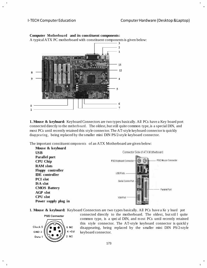
173
I-TECH Computer Education Computer Hardware (Desktop &Laptop)
Computer Motherboa rd and its constituent components:
A typical ATX PC motherboard with constituent components is given below:
1. Mouse & keyboard: Keyboard Connectors are two types basically. All PCs have a Key board port
connected directly to the mothe rb oa rd . The oldest, but still quite common type, is a special DIN, and
most PCs until recently retained this style connector. The AT-style keyboard connector is quickly
disap pe a ring , being replaced by the smaller mini DIN PS/2-style keyboard connector.
The important constituent compone nts of an ATX Motherboard are given below:
Mouse & keyboard
USB
Parallel port
CPU Chip
RAM slots
Floppy controller
IDE controller
PCI slot
ISA slot
CMOS Battery
AGP slot
CPU slot
Power supply plug in
1. Mouse & keyboard: Keyboard Connectors are two types basically. All PCs have a Ke y board port
connected directly to the motherboard. The oldest, but stil l quite
common type, is a speci al DIN, and m ost PCs until recently retained
this style connector. The AT-style keyboard connector is quickl y
disappearing, being replaced by the smaller mini DIN PS/2-style
keyboard connector.
174
I-TECH Computer Education Computer Hardware (Desktop &Laptop)
You can use an AT-st yle keyboard with a PS/2 -style socket (or the other wa y around) by using a
converter. Although the AT connector is unique in PC s, the PS/2-style mini-DIN is also used in m ore
modern PCs for the mo use. Fortunately , most PC s that use the mini-DI N for both the k eyboard and
mouse clearly mark each mini-DIN socket as t o its correct use. So me keyboards have a USB
connection, but thes e are fairly rare compared to th e PS/2 conne ction keyboards.
2. USB (Universal serial bus):
USB is the Gen eral-purpose connection for PC. You can find USB versions of many different devices,
such as mic e, keyboards, scanners, cameras, and even printers. a USB connector's distinctive
rectangular shape makes it easily recognizable.USB has a number of features that makes it particularly
popular on PCs. F irst, USB devices are hot s wappable. You can insert or remov e them without
restarting your system.
3. Parallel port: Most printers use a special connector called a parallel port. Parallel port carry data on
more than one wire, as opposed to the serial port, which uses only one wire. Parallel ports use a 25-pin
female DB connector. Parallel ports ar e directly supported b y the m otherboard through a direct
connection or through a dangle.
4. CPU Chip : The central processing unit, also called the microprocessor performs all the
calculations that take place inside a pc. C PUs come in Variety of shap es and sizes.
Modern CPUs gener ate a lot of heat and thus re quire a coolin g fan or h eat sink. The coolin g device
(such as a cooling fan) is removable, althoug h some C PU manufactures sell the C PU with a fan
perm a ne nt ly attached.
5. RAM slots: Random-Access Memory (RAM) stores programs and data currently being used by the
CPU. RAM is me asured in units c alled bytes. RAM has been packaged in many different ways. The
most current package is called a 168-pin DIMM (Dual Inline Memory module).
6. Floppy controller: The floppy drive connects to the computer via a 34-pin ribbon cable, which in
turn connects to the motherb oa rd . A floppy controller is one that is used to control the floppy drive.
7. IDE controller: Industry standards define t wo common types of h ard drives: E IDE and S CSI.
Majority of the PCs use E IDE drives. SCSI drives show up in high end PCs such as network serve rs or
graphical workstations. The EIDE drive connects to the hard drive vi a a 2-inch-wide, 40-pin rib bon
cable, which in turn connects to the motherboard. IDE controller is responsible for controlling the hard
drive.
8. PCI slot: Intel introduced the Peripheral component interconnect bus protocol. The PC I bus is used
to connect I/O devices (such as NIC or RAID controllers) to the main logic of the computer. PCI bus
has replaced the ISA bus.
9. ISA slot: (Industry Standard Architecture) It is the standard architecture of the Ex pansion bus.
Mothe rb o ar d may contain some slots to connect ISA compatible cards.
10. CMOS Battery: To provide CMOS with the power when the computer is turned off all
mothe rb oa rd s comes with a battery. These batteries mount on the motherb oa rd in one of three ways: the
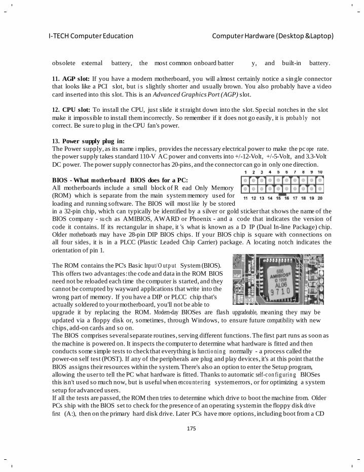
175
I-TECH Computer Education Computer Hardware (Desktop &Laptop)
obsolete external battery, the most common onboard batter y, and built-in battery.
11. AGP slot: If you have a modern motherboard, you will almost certainly notice a single connector
that looks like a PCI slot, but i s slightly shorter and usually brown. You also probably have a vi deo
card inserted into this slot. This is an Advanced Graphics Port (AGP) slot.
12. CPU slot: To install the CPU, just slide it st raight down into the slot. Special notches in the slot
make it impossible to install them incorrectly. So remember if it does not go easily, it is proba b ly not
correct. Be sure to plug in the CPU fan's power.
13. Power supply plug in:
The Power supply, as its name i mplies, provides the necessary electrical power to make the pc ope rate.
the power supply takes standard 110-V AC power and converts into +/-12-Volt, +/-5-Volt, and 3.3-Volt
DC power. The power supply connector has 20-pins, and the connector can go in only one direction.
BIOS - What motherboa rd BIOS does for a PC:
All motherboards include a small block of R ead Only Memory
(ROM) which is separate from the main system memory used for
loading and running software. The BIOS will most like ly be stored
in a 32-pin chip, which can typically be identified by a silver or gold sticker that shows the name of the
BIOS company - su ch as AMIBIOS, AWARD or Phoenix - and a code that indicates the version of
code it contains. If its rectangular in shape, it 's what is known as a D IP (Dual In-line Package) chip.
Older motherboards may have 28-pin DIP BIOS chips. If your BIOS chip is square with connections on
all four sides, it is in a PLCC (Plastic Leaded Chip Carrier) package. A locating notch indicates the
orientation of pin 1.
The ROM contains the PC's Basic Input/O utp ut System (BIOS).
This offers two advantages: the code and data in the ROM BIOS
need not be reloaded each time the computer is started, and they
cannot be corrupted by wayward applications that write into the
wrong part of memory. If you have a DIP or PLCC chip that's
actually soldered to your motherboard, you'll not be able to
upgrade it by replacing the ROM. Modern-day BIOSes are flash upgradeable, meaning they may be
updated via a floppy disk or, sometimes, through Windows, to ensure future compatibility with new
chips, add-on cards and so on.
The BIOS comprises several separate routines, serving different functions. The first part runs as soon as
the machine is powered on. It inspects the computer to determine what hardware is fitted and then
conducts some simple tests to check that everything is functio nin g normally - a process called the
power-on self test (POST). If any of the peripherals are plug and play devices, it's at this point that the
BIOS assigns their resources within the system. There's also an option to enter the Setup program,
allowing the user to tell the PC what hardware is fitted. Thanks to automatic self-c on fig urin g BIOSes
this isn't used so much now, but is useful when encou nte ring system errors, or for optimizing a system
setup for advanced users.
If all the tests are passed, the ROM then tries to determine which drive to boot the machine from. Older
PCs ship with the BIOS set to check for the presence of an operating system in the floppy disk drive
first (A:), then on the primary hard disk drive. Later PCs have more options, including boot from a CD
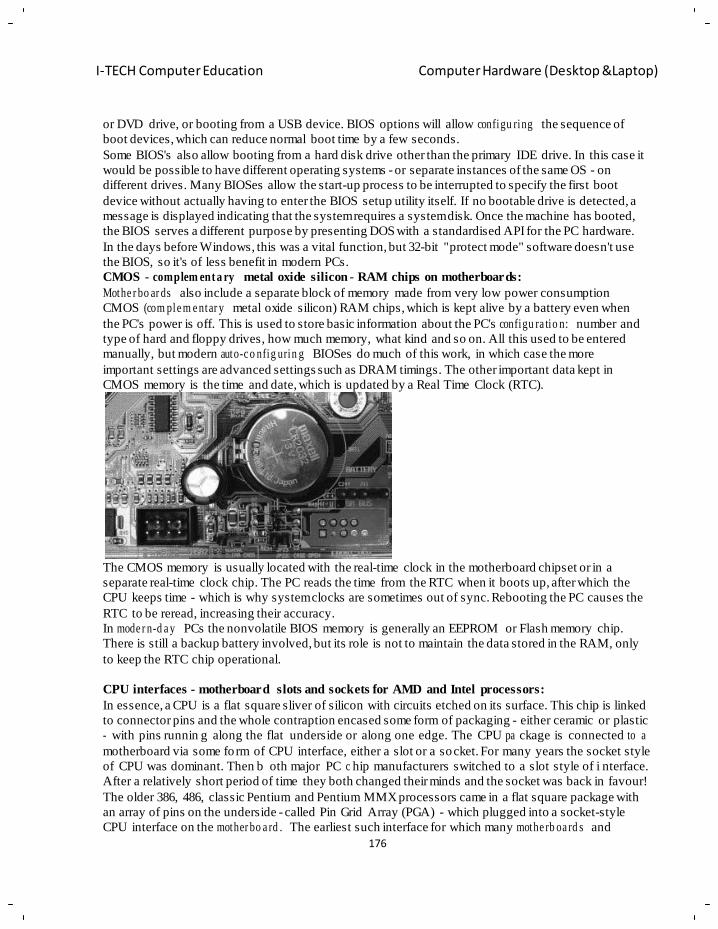
176
I-TECH Computer Education Computer Hardware (Desktop &Laptop)
or DVD drive, or booting from a USB device. BIOS options will allow configu ring the sequence of
boot devices, which can reduce normal boot time by a few seconds.
Some BIOS's also allow booting from a hard disk drive other than the primary IDE drive. In this case it
would be possible to have different operating systems - or separate instances of the same OS - on
different drives. Many BIOSes allow the start-up process to be interrupted to specify the first boot
device without actually having to enter the BIOS setup utility itself. If no bootable drive is detected, a
message is displayed indicating that the system requires a system disk. Once the machine has booted,
the BIOS serves a different purpose by presenting DOS with a standardised API for the PC hardware.
In the days before Windows, this was a vital function, but 32-bit "protect mode" software doesn't use
the BIOS, so it's of less benefit in modern PCs.
CMOS - complem ent a ry metal oxide silicon - RAM chips on motherboards:
Mothe r bo ar ds also include a separate block of memory made from very low power consumption
CMOS (com ple m e ntar y metal oxide silicon) RAM chips, which is kept alive by a battery even when
the PC's power is off. This is used to store basic information about the PC's configu ra tio n: number and
type of hard and floppy drives, how much memory, what kind and so on. All this used to be entered
manually, but modern auto-c o nfig urin g BIOSes do much of this work, in which case the more
important settings are advanced settings such as DRAM timings. The other important data kept in
CMOS memory is the time and date, which is updated by a Real Time Clock (RTC).
The CMOS memory is usually located with the real-time clock in the motherboard chipset or in a
separate real-time clock chip. The PC reads the time from the RTC when it boots up, after which the
CPU keeps time - which is why system clocks are sometimes out of sync. Rebooting the PC causes the
RTC to be reread, increasing their accuracy.
In mode r n-d a y PCs the nonvolatile BIOS memory is generally an EEPROM or Flash memory chip.
There is still a backup battery involved, but its role is not to maintain the data stored in the RAM, only
to keep the RTC chip operational.
CPU interfaces - motherboard slots and sockets for AMD and Intel processors:
In essence, a CPU is a flat square sliver of silicon with circuits etched on its surface. This chip is linked
to connector pins and the whole contraption encased some form of packaging - either ceramic or plastic
- with pins runnin g along the flat underside or along one edge. The CPU pa ckage is connected to a
motherboard via some fo rm of CPU interface, either a slot or a socket. For many years the socket style
of CPU was dominant. Then b oth major PC c hip manufacturers switched to a slot style of i nterface.
After a relatively short period of time they both changed their minds and the socket was back in favour!
The older 386, 486, classic Pentium and Pentium MMX processors came in a flat square package with
an array of pins on the underside - called Pin Grid Array (PGA) - which plugged into a socket-style
CPU interface on the mother bo a rd . The earliest such interface for which many mothe rb oa rd s and
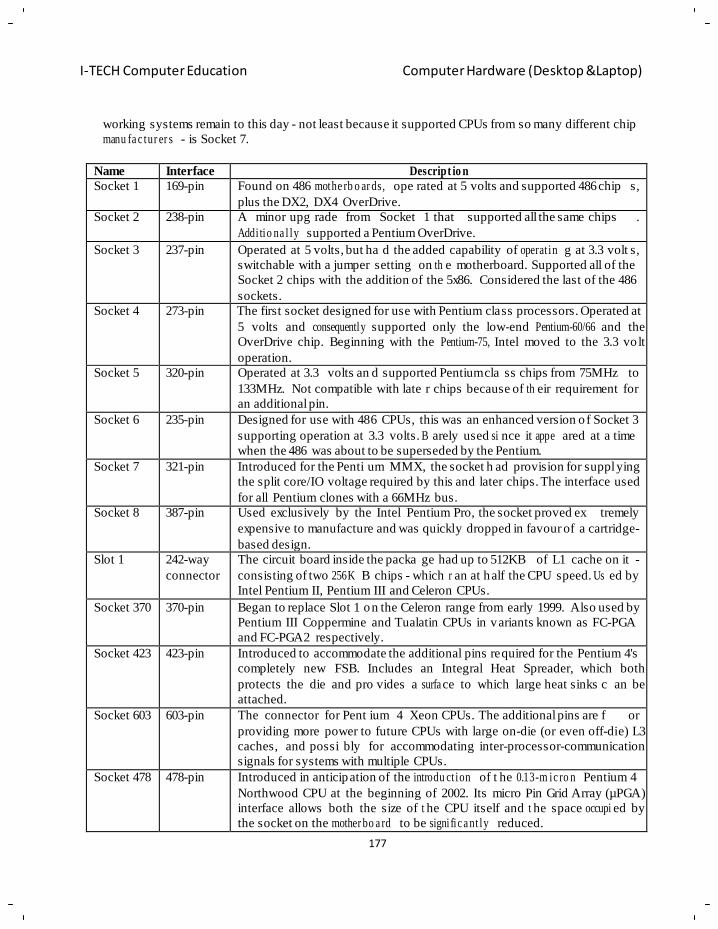
177
I-TECH Computer Education Computer Hardware (Desktop &Laptop)
working systems remain to this day - not least because it supported CPUs from so many different chip
manu fa c tur er s - is Socket 7.
Name Interface Descript io n
Socket 1 169-pin Found on 486 mothe rb o ar ds, ope rated at 5 volts and supported 486 chip s,
plus the DX2, DX4 OverDrive.
Socket 2 238-pin A minor upg rade from Socket 1 that supported all the same chips .
Addi tio na l ly supported a Pentium OverDrive.
Socket 3 237-pin Operated at 5 volts, but ha d the added capability of operat in g at 3.3 volt s,
switchable with a jumper setting on th e motherboard. Supported all of the
Socket 2 chips with the addition of the 5x86. Considered the last of the 486
sockets.
Socket 4 273-pin The first socket designed for use with Pentium class processors. Operated at
5 volts and consequently supported only the low-end Pentium-60/66 and the
OverDrive chip. Beginning with the Pentium-75, Intel moved to the 3.3 vo lt
operation.
Socket 5 320-pin Operated at 3.3 volts an d supported Pentium cla ss chips from 75MHz to
133MHz. Not compatible with late r chips because of th eir requirement for
an additional pin.
Socket 6 235-pin Designed for use with 486 CPUs, this was an enhanced version o f Socket 3
supporting operation at 3.3 volts. B arely used si nce it appe ared at a time
when the 486 was about to be superseded by the Pentium.
Socket 7 321-pin Introduced for the Penti um MMX, the socket h ad provision for suppl ying
the split core/IO voltage required by this and later chips. The interface used
for all Pentium clones with a 66MHz bus.
Socket 8 387-pin Used exclusively by the Intel Pentium Pro, the socket proved ex tremely
expensive to manufacture and was quickly dropped in favour of a cartridge-
based design.
Slot 1 242-way
connector
The circuit board inside the packa ge had up to 512KB of L1 cache on it -
consisting of two 256K B chips - which r an at half the CPU speed. Us ed by
Intel Pentium II, Pentium III and Celeron CPUs.
Socket 370 370-pin Began to replace Slot 1 on the Celeron range from early 1999. Also used by
Pentium III Coppermine and Tualatin CPUs in variants known as FC-PGA
and FC-PGA2 respectively.
Socket 423 423-pin Introduced to accommodate the additional pins required for the Pentium 4's
completely new FSB. Includes an Integral Heat Spreader, which both
protects the die and pro vides a surfa ce to which large heat sinks c an be
attached.
Socket 603 603-pin The connector for Pent ium 4 Xeon CPUs. The additional pins are f or
providing more power to future CPUs with large on-die (or even off-die) L3
caches, and possi bly for accommodating inter-processor-communication
signals for systems with multiple CPUs.
Socket 478 478-pin Introduced in anticipation of the introdu ct ion of t he 0.13-m ic ro n Pentium 4
Northwood CPU at the beginning of 2002. Its micro Pin Grid Array (µPGA)
interface allows both the size of t he CPU itself and t he space occupi ed by
the socket on the mother bo a rd to be signi fic a nt ly reduced.
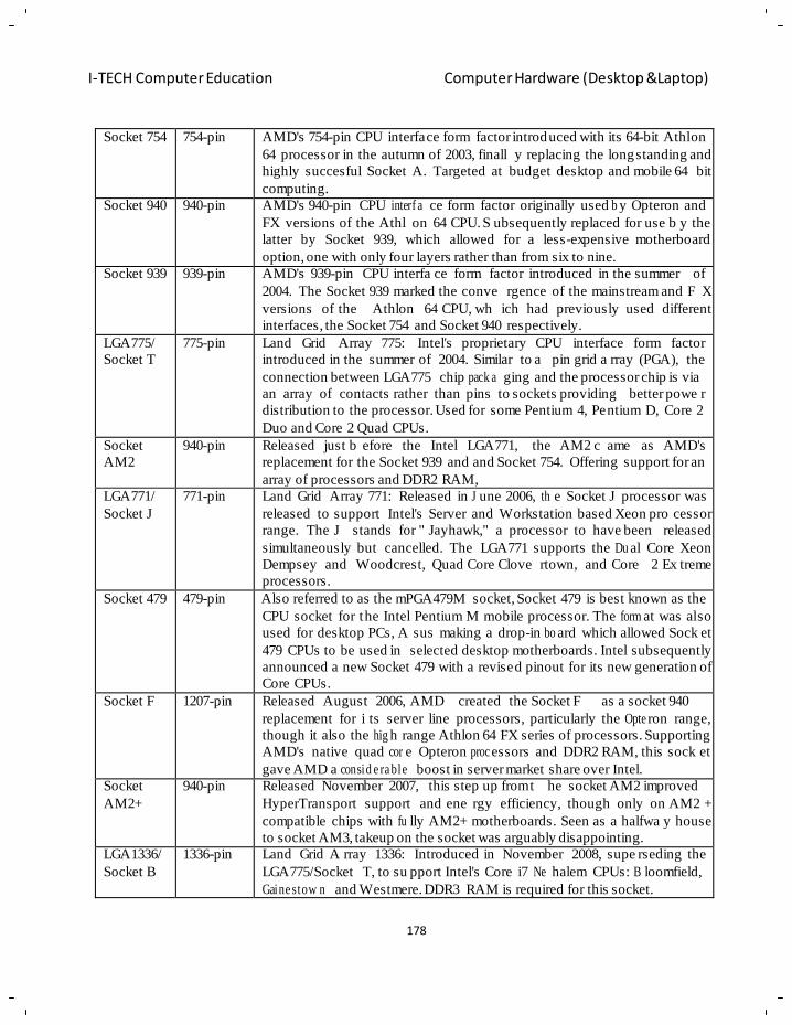
178
I-TECH Computer Education Computer Hardware (Desktop &Laptop)
Socket 754 754-pin AMD's 754-pin CPU interface form factor introduced with its 64-bit Athlon
64 processor in the autumn of 2003, finall y replacing the longstanding and
highly succesful Socket A. Targeted at budget desktop and mobile 64 bit
computing.
Socket 940 940-pin AMD's 940-pin CPU interf a ce form factor originally used b y Opteron and
FX versions of the Athl on 64 CPU. S ubsequently replaced for use b y the
latter by Socket 939, which allowed for a less-expensive motherboard
option, one with only four layers rather than from six to nine.
Socket 939 939-pin AMD's 939-pin CPU interfa ce form factor introduced in the summer of
2004. The Socket 939 marked the conve rgence of the mainstream and F X
versions of the Athlon 64 CPU, wh ich had previously used different
interfaces, the Socket 754 and Socket 940 respectively.
LGA775/
Socket T
775-pin Land Grid Array 775: Intel's proprietary CPU interface form factor
introduced in the summer of 2004. Similar to a pin grid a rray (PGA), the
connection between LGA775 chip pack a ging and the processor chip is via
an array of contacts rather than pins to sockets providing better powe r
distribution to the processor. Used for some Pentium 4, Pentium D, Core 2
Duo and Core 2 Quad CPUs.
Socket
AM2
940-pin Released just b efore the Intel LGA771, the AM2 c ame as AMD's
replacement for the Socket 939 and and Socket 754. Offering support for an
array of processors and DDR2 RAM,
LGA771/
Socket J
771-pin Land Grid Array 771: Released in J une 2006, th e Socket J processor was
released to support Intel's Server and Workstation based Xeon pro cessor
range. The J stands for " Jayhawk," a processor to have been released
simultaneously but cancelled. The LGA771 supports the Du al Core Xeon
Dempsey and Woodcrest, Quad Core Clove rtown, and Core 2 Ex treme
processors.
Socket 479 479-pin Also referred to as the mPGA479M socket, Socket 479 is best known as the
CPU socket for the Intel Pentium M mobile processor. The form at was also
used for desktop PCs, A sus making a drop-in bo ard which allowed Sock et
479 CPUs to be used in selected desktop motherboards. Intel subsequently
announced a new Socket 479 with a revised pinout for its new generation of
Core CPUs.
Socket F 1207-pin Released August 2006, AMD created the Socket F as a socket 940
replacement for i ts server line processors, particularly the Opte ron range,
though it also the hig h range Athlon 64 FX series of processors. Supporting
AMD's native quad cor e Opteron proc essors and DDR2 RAM, this sock et
gave AMD a consid e ra ble boost in server market share over Intel.
Socket
AM2+
940-pin Released November 2007, this step up from t he socket AM2 improved
HyperTransport support and ene rgy efficiency, though only on AM2 +
compatible chips with fu lly AM2+ motherboards. Seen as a halfwa y house
to socket AM3, takeup on the socket was arguably disappointing.
LGA1336/
Socket B
1336-pin Land Grid A rray 1336: Introduced in November 2008, supe rseding the
LGA775/Socket T, to su pport Intel's Core i7 Ne halem CPUs: B loomfield,
Gaine stow n and Westmere. DDR3 RAM is required for this socket.
179
I-TECH Computer Education Computer Hardware (Desktop &Laptop)
Chapter - 13
Power supply unit (SMPS)
Objectives of learning • Power Rating and Efficiency
• Appe a r an c e of Power Supply
• Various connectors from a computer PSU
• AT vs. ATX
• Working Of SMPS
• Failure modes
• Precautions & Applications
• Terms And Facts Related To Power Supply
• Uninte rru pte d power supply(UPS)
A power supply unit (PSU) supplies DC power to the other components in a computer. It converts
general-purpose alternating current (AC) electric power from the mains (110V to 120V at 60Hz [115V
nominal] in North America, parts of South America, Japan, and Taiwan; 220V to 240V at 50Hz [230V
nominal] in most of the rest of the world) to low-voltage (for a desktop computer: 12V, 5V, 5VSB,
3V3, -5V, and -12V) direct current (DC) power for the internal components of the computer. Some
power supplies have a switch to select either 230 V or 115 V. Other models are able to accept any
voltage and frequency between those limits and some models only operate from one of the two mains
supply standards. Most modern desktop computer power supplies conform to the ATX form factor.
ATX power supplies are turned on and off by a signal from the motherboard. They also provide a
signal to the motherboard to indicate when the DC power lines are correct so that the computer is able
to boot-up. While an ATX power supply is connected to the mains supply it provides a 5V stand-by
(5VSB) line so that the standby functions on the computer and certain peripherals are powered. The
most recent ATX PSU standard is version 2.31 of mid-2008.
Power Rating and Efficiency:
Computer power supplies are rated based on their maximum output power. Typical power ranges are
from 500 W to lower than 300 W for small form factor systems intended as ordinary home computers,
the use of which is limited to web-surfing and burning and playing DVDs. Power supplies used by
gamers and enthusiasts mostly range from 450 W to 1400 W. Typical gaming PCs feature power
supplies in the range of 500-800 W, with higher-end PCs demanding 800-1400 W supplies. The
highest-end units are up to 2 kW strong and are intended mainly for servers and, to a lesser degree,
extreme performance computers with multiple processors, several hard disks and multiple graphics
cards. The power rating of a PC power supply is not officially certified and is self-claimed by each
manufacturer. A common way to reach the power figure for PC PSUs is by adding the power available
on each rail, which will not give a true power figure. Therefore it is possible to overload a PSU on one
rail without having to use the maximum rated power.
This may mean that if:
• PSU A has a peak rating of 550 watts at 25°C, with 25 amps (300 W) on the 12 volt line, and
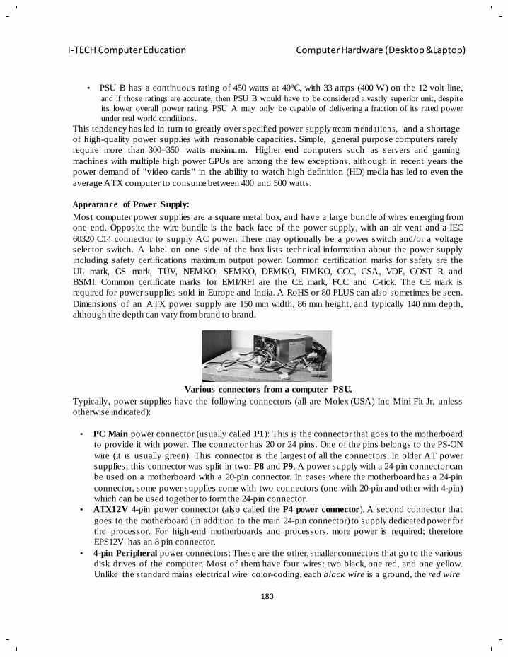
180
I-TECH Computer Education Computer Hardware (Desktop &Laptop)
• PSU B has a continuous rating of 450 watts at 40°C, with 33 amps (400 W) on the 12 volt line,
and if those ratings are accurate, then PSU B would have to be considered a vastly superior unit, despite
its lower overall power rating. PSU A may only be capable of delivering a fraction of its rated power
under real world conditions.
This tendency has led in turn to greatly over specified power supply recom m e nda t ion s, and a shortage
of high-quality power supplies with reasonable capacities. Simple, general purpose computers rarely
require more than 300–350 watts maximum. Higher end computers such as servers and gaming
machines with multiple high power GPUs are among the few exceptions, although in recent years the
power demand of "video cards" in the ability to watch high definition (HD) media has led to even the
average ATX computer to consume between 400 and 500 watts.
Appearan ce of Power Supply:
Most computer power supplies are a square metal box, and have a large bundle of wires emerging from
one end. Opposite the wire bundle is the back face of the power supply, with an air vent and a IEC
60320 C14 connector to supply AC power. There may optionally be a power switch and/or a voltage
selector switch. A label on one side of the box lists technical information about the power supply
including safety certifications maximum output power. Common certification marks for safety are the
UL mark, GS mark, TÜV, NEMKO, SEMKO, DEMKO, FIMKO, CCC, CSA, VDE, GOST R and
BSMI. Common certificate marks for EMI/RFI are the CE mark, FCC and C-tick. The CE mark is
required for power supplies sold in Europe and India. A RoHS or 80 PLUS can also sometimes be seen.
Dimensions of an ATX power supply are 150 mm width, 86 mm height, and typically 140 mm depth,
although the depth can vary from brand to brand.
Various connectors from a computer PSU.
Typically, power supplies have the following connectors (all are Molex (USA) Inc Mini-Fit Jr, unless
otherwise indicated):
• PC Main power connector (usually called P1): This is the connector that goes to the motherboard
to provide it with power. The connector has 20 or 24 pins. One of the pins belongs to the PS-ON
wire (it is usually green). This connector is the largest of all the connectors. In older AT power
supplies; this connector was split in two: P8 and P9. A power supply with a 24-pin connector can
be used on a motherboard with a 20-pin connector. In cases where the motherboard has a 24-pin
connector, some power supplies come with two connectors (one with 20-pin and other with 4-pin)
which can be used together to form the 24-pin connector.
• ATX12V 4-pin power connector (also called the P4 power connector). A second connector that
goes to the motherboard (in addition to the main 24-pin connector) to supply dedicated power for
the processor. For high-end motherboards and processors, more power is required; therefore
EPS12V has an 8 pin connector.
• 4-pin Peripheral power connectors: These are the other, smaller connectors that go to the various
disk drives of the computer. Most of them have four wires: two black, one red, and one yellow.
Unlike the standard mains electrical wire color-coding, each black wire is a ground, the red wire
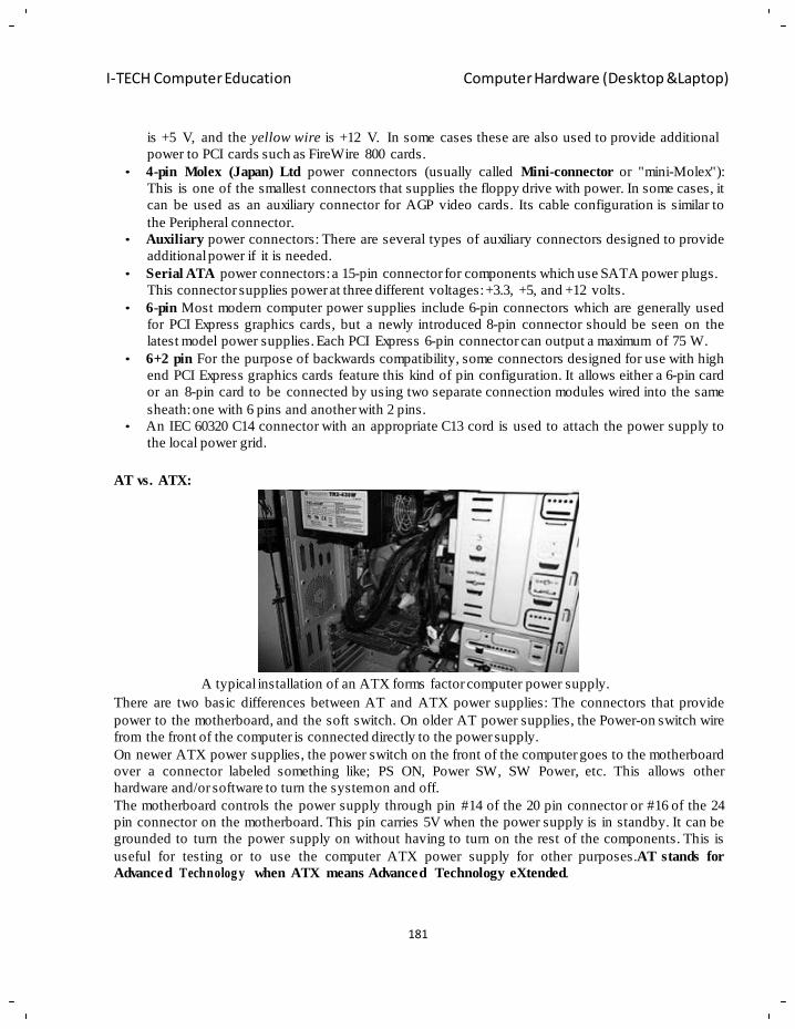
181
I-TECH Computer Education Computer Hardware (Desktop &Laptop)
is +5 V, and the yellow wire is +12 V. In some cases these are also used to provide additional
power to PCI cards such as FireWire 800 cards.
• 4-pin Molex (Japan) Ltd power connectors (usually called Mini-connector or "mini-Molex"):
This is one of the smallest connectors that supplies the floppy drive with power. In some cases, it
can be used as an auxiliary connector for AGP video cards. Its cable configuration is similar to
the Peripheral connector.
• Auxiliary power connectors: There are several types of auxiliary connectors designed to provide
additional power if it is needed.
• Serial ATA power connectors: a 15-pin connector for components which use SATA power plugs.
This connector supplies power at three different voltages: +3.3, +5, and +12 volts.
• 6-pin Most modern computer power supplies include 6-pin connectors which are generally used
for PCI Express graphics cards, but a newly introduced 8-pin connector should be seen on the
latest model power supplies. Each PCI Express 6-pin connector can output a maximum of 75 W.
• 6+2 pin For the purpose of backwards compatibility, some connectors designed for use with high
end PCI Express graphics cards feature this kind of pin configuration. It allows either a 6-pin card
or an 8-pin card to be connected by using two separate connection modules wired into the same
sheath: one with 6 pins and another with 2 pins.
• An IEC 60320 C14 connector with an appropriate C13 cord is used to attach the power supply to
the local power grid.
AT vs. ATX:
A typical installation of an ATX forms factor computer power supply.
There are two basic differences between AT and ATX power supplies: The connectors that provide
power to the motherboard, and the soft switch. On older AT power supplies, the Power-on switch wire
from the front of the computer is connected directly to the power supply.
On newer ATX power supplies, the power switch on the front of the computer goes to the motherboard
over a connector labeled something like; PS ON, Power SW, SW Power, etc. This allows other
hardware and/or software to turn the system on and off.
The motherboard controls the power supply through pin #14 of the 20 pin connector or #16 of the 24
pin connector on the motherboard. This pin carries 5V when the power supply is in standby. It can be
grounded to turn the power supply on without having to turn on the rest of the components. This is
useful for testing or to use the computer ATX power supply for other purposes.AT stands for
Advanced Technolog y when ATX means Advanced Technology eXtended.
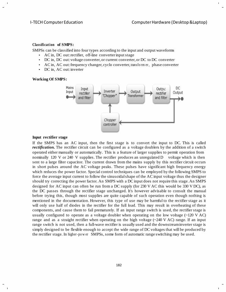
182
I-TECH Computer Education Computer Hardware (Desktop &Laptop)
Classificat ion of SMPS:
SMPSs can be classified into four types according to the input and output waveforms
• AC in, DC out: rectifier, off-line converter input stage
• DC in, DC out: voltage converter, or current converter, or DC to DC converter
• AC in, AC out: frequency changer, cyclo converter, transfo rm er , phase converter
• DC in, AC out: inverter
Working Of SMPS:
Input rectifier stage
If the SMPS has an AC input, then the first stage is to convert the input to DC. This is called rectification. The rectifier circuit can be configured as a voltage doublers by the addition of a switch
operated either manually or automatically. This is a feature of larger supplies to permit operation from
nominally 120 V or 240 V supplies. The rectifier produces an unregulated D voltage which is then
sent to a large filter capacitor. The current drawn from the mains supply by this rectifier circuit occurs
in short pulses around the AC voltage peaks. These pulses have significant high frequency energy
which reduces the power factor. Special control techniques can be employed by the following SMPS to
force the average input current to follow the sinusoidal shape of the AC input voltage thus the designer
should try correcting the power factor. An SMPS with a DC input does not require this stage. An SMPS
designed for AC input can often be run from a DC supply (for 230 V AC this would be 330 V DC), as
the DC passes through the rectifier stage unchanged. It's however advisable to consult the manual
before trying this, though most supplies are quite capable of such operation even though nothing is
mentioned in the documentation. However, this type of use may be harmful to the rectifier stage as it
will only use half of diodes in the rectifier for the full load. This may result in overheating of these
components, and cause them to fail prematurely. If an input range switch is used, the rectifier stage is
usually configured to operate as a voltage doubler when operating on the low voltage (~120 V AC)
range and as a straight rectifier when operating on the high voltage (~240 V AC) range. If an input
range switch is not used, then a full-wave rectifier is usually used and the downstream inverter stage is
simply designed to be flexible enough to accept the wide range of DC voltages that will be produced by
the rectifier stage. In higher -po w er SMPSs, some form of automatic range switching may be used.
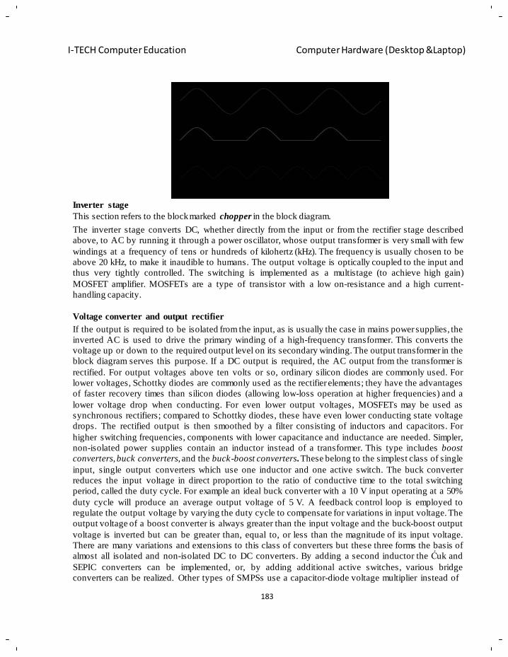
183
I-TECH Computer Education Computer Hardware (Desktop &Laptop)
Inverter stage
This section refers to the block marked chopper in the block diagram.
The inverter stage converts DC, whether directly from the input or from the rectifier stage described
above, to AC by running it through a power oscillator, whose output transformer is very small with few
windings at a frequency of tens or hundreds of kilohertz (kHz). The frequency is usually chosen to be
above 20 kHz, to make it inaudible to humans. The output voltage is optically coupled to the input and
thus very tightly controlled. The switching is implemented as a multistage (to achieve high gain)
MOSFET amplifier. MOSFETs are a type of transistor with a low on-resistance and a high current-
handling capacity.
Voltage converter and output rectifier
If the output is required to be isolated from the input, as is usually the case in mains power supplies, the
inverted AC is used to drive the primary winding of a high-frequency transformer. This converts the
voltage up or down to the required output level on its secondary winding. The output transformer in the
block diagram serves this purpose. If a DC output is required, the AC output from the transformer is
rectified. For output voltages above ten volts or so, ordinary silicon diodes are commonly used. For
lower voltages, Schottky diodes are commonly used as the rectifier elements; they have the advantages
of faster recovery times than silicon diodes (allowing low-loss operation at higher frequencies) and a
lower voltage drop when conducting. For even lower output voltages, MOSFETs may be used as
synchronous rectifiers; compared to Schottky diodes, these have even lower conducting state voltage
drops. The rectified output is then smoothed by a filter consisting of inductors and capacitors. For
higher switching frequencies, components with lower capacitance and inductance are needed. Simpler,
non-isolated power supplies contain an inductor instead of a transformer. This type includes boost
converters, buck converters, and the buck-boost converters. These belong to the simplest class of single
input, single output converters which use one inductor and one active switch. The buck converter
reduces the input voltage in direct proportion to the ratio of conductive time to the total switching
period, called the duty cycle. For example an ideal buck converter with a 10 V input operating at a 50%
duty cycle will produce an average output voltage of 5 V. A feedback control loop is employed to
regulate the output voltage by varying the duty cycle to compensate for variations in input voltage. The
output voltage of a boost converter is always greater than the input voltage and the buck-boost output
voltage is inverted but can be greater than, equal to, or less than the magnitude of its input voltage.
There are many variations and extensions to this class of converters but these three forms the basis of
almost all isolated and non-isolated DC to DC converters. By adding a second inductor the Ćuk and
SEPIC converters can be implemented, or, by adding additional active switches, various bridge
converters can be realized. Other types of SMPSs use a capacitor-diode voltage multiplier instead of
184
I-TECH Computer Education Computer Hardware (Desktop &Laptop)
inductors and transformers. These are mostly used for generating high voltages at low currents
(Cock c rof t -W al to n generator). The low voltage variant is called charge pump.
Regulation
A feedback circuit monitors the output voltage and compares it with a reference voltage, which shown
in the block diagram serves this purpose. Depending on design/safety requirements, the controller may
contain an isolation mechanism (such as opto-couplers) to isolate it from the DC output. Switching
supplies in computers, TVs and VCRs have these opto-c o uple r s to tightly control the output voltage.
Open-loop regulators do not have a feedback circuit. Instead, they rely on feeding a constant voltage to
the input of the transformer or inductor, and assume that the output will be correct. Regulated designs
compensate for the impedance of the transformer or coil. Mono polar designs also compensate for the
magnetic hysteresis of the core. The feedback circuit needs power to run before it can generate power,
so an additional non-sw i tc hing power -su pp ly for stand-by is added.
Transform er design:
SMPS transformers run at high frequency. Most of the cost savings (and space savings) in off-line
power supplies come from the fact that a high frequency transformer is much smaller than the 50/60 Hz
transformers formerly used. There are additional design tradeoffs.
Transform er size
The higher the switching frequency, the lesser the amount of energy that needs to be stored
intermediately during the time of a single switching cycle. Because this energy is stored in form of
magnetic energy in the transformer core material (like ferrite), less of such material is needed.
However, higher frequency also means more energy lost during transitions of the switching
semiconductor. Furthermore, much more attention to the physical layout of the circuit board is
required, and the amount of elect ro m a g ne tic interf er e nc e will be more pronounced.
Core loss
There are several differences in the design of transformers for 50 Hz vs 500 kHz. Firstly a low
frequency transformer usually transfers energy through its core (soft iron), while the (usually ferrite)
core of a high frequency transformer limits leakage.
Copper loss
At low frequencies (such as the line frequency of 50 or 60 Hz), designers can usually ignore the skin
effect. At line frequencies, the skin effect becomes important when the conductors have a diameter
larger than about 0.3 inches (7.6 mm).Switching power supplies must pay more attention to the skin
effect because it is a source of power loss. At 500 kHz, the skin depth is about 0.003 inches (0.076 mm)
– a dimension smaller than the typical wires used in a power supply. The skin effect is exacerbated by
the harmonics present in the switching waveforms. The appropriate skin depth is not just the depth at
the fundamental, but also the skin depths at the harmonics. Since the wave forms in a SMPS are
generally high speed (PWM square waves), the wiring must be capable of supporting high harmonics of
the base frequency due to effect. In addition to the skin effect, there is also a proximity effect, which is
another source of power loss.
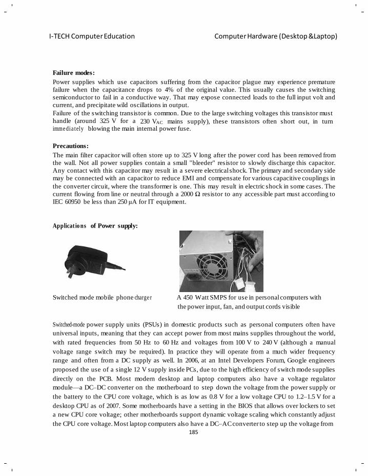
185
I-TECH Computer Education Computer Hardware (Desktop &Laptop)
Failure modes:
Power supplies which use capacitors suffering from the capacitor plague may experience premature
failure when the capacitance drops to 4% of the original value. This usually causes the switching
semiconductor to fail in a conductive way. That may expose connected loads to the full input volt and
current, and precipitate wild oscillations in output.
Failure of the switching transistor is common. Due to the large switching voltages this transistor must
handle (around 325 V for a 230 VAC mains supply), these transistors often short out, in turn imme dia tely blowing the main internal power fuse.
Precautions:
The main filter capacitor will often store up to 325 V long after the power cord has been removed from
the wall. Not all power supplies contain a small "bleeder" resistor to slowly discharge this capacitor.
Any contact with this capacitor may result in a severe electrical shock. The primary and secondary side
may be connected with an capacitor to reduce EMI and compensate for various capacitive couplings in
the converter circuit, where the transformer is one. This may result in electric shock in some cases. The
current flowing from line or neutral through a 2000 Ω resistor to any accessible part must according to
IEC 60950 be less than 250 μA for IT equipment.
Applicat io ns of Power supply:
Switched mode mobile phone charge r A 450 Watt SMPS for use in personal computers with
the power input, fan, and output cords visible
Switched-mode power supply units (PSUs) in domestic products such as personal computers often have
universal inputs, meaning that they can accept power from most mains supplies throughout the world,
with rated frequencies from 50 Hz to 60 Hz and voltages from 100 V to 240 V (although a manual
voltage range switch may be required). In practice they will operate from a much wider frequency
range and often from a DC supply as well. In 2006, at an Intel Developers Forum, Google engineers
proposed the use of a single 12 V supply inside PCs, due to the high efficiency of switch mode supplies
directly on the PCB. Most modern desktop and laptop computers also have a voltage regulator
module—a DC–DC converter on the motherboard to step down the voltage from the power supply or
the battery to the CPU core voltage, which is as low as 0.8 V for a low voltage CPU to 1.2–1.5 V for a
desktop CPU as of 2007. Some motherboards have a setting in the BIOS that allows over lockers to set
a new CPU core voltage; other motherboards support dynamic voltage scaling which constantly adjust
the CPU core voltage. Most laptop computers also have a DC–AC converter to step up the voltage from
186
I-TECH Computer Education Computer Hardware (Desktop &Laptop)
the battery to drive a CCFL backlight in the flat-screen monitor, which typically requires around
1 kVRMS. Due to their high volumes mobile phone chargers have always been particularly cost
sensitive. The first chargers were linear power supplies but they quickly moved to the cost effective
ringing choke converter (RCC) SMPS topology, when new levels of efficiency were required. Recently
the demand for even lower no load power requirements in the application has meant that fly back
topology is being used more widely; primary side sensing fly back controllers are also helping to cut
the bill of materials (BOM) by removing secondary-side sensing components such as opt
couplers.Where integration of capacitors for stabilization and batteries as a energy storage or hum and
interference needs to be avoided in the power distribution, SMPS may be essential for efficient
conversion of electric DC energy. For AC applications where frequency and voltage can't be produced
by the primary source an SMPS may be essential as well. Applications may be found in the automobile
industry where ordinary trucks uses nominal 24 VDC but may need 12 VDC. Ordinary cars use nominal
12 VDC and may need to convert this to drive equipment. In industrial settings, DC supply is sometimes
chosen to avoid hum and interference and ease the integration of capacitors and batteries used to buffer
the voltage that makes SMPS essential. In the case of TV sets, for example, an excellent regulation of
the power supply can be shown by using a variac. For example, in some TV-models made by Philips,
the power supply starts when the voltage reaches around 90 V. From there, one can change the voltage
with the variac, and go as low as 40 V and as high as 260 V (a peak voltage of 260× alterations.
Laptops
Most portable computers have power supplies that provide 25 to 200 watts. In portable computers (such
as laptops) there is usually an external power supply (sometimes referred to as a "power brick" due to
its similarity, in size, shape and weight, to a real brick) which converts AC power to one DC voltage
(most commonly 19 V), and further DC-DC conversion occurs within the laptop to supply the various
DC voltages required by the other components of the portable computer.
Servers
Some web servers use a single-voltage 12 volt power supply. All other voltages are generated by
voltage regulator modules on the motherboard.
Energy efficiency:
Computer power supplies are
generally about 70–75% efficient. That means in order for a 75%
efficient power supply to produce 75 W of DC output it would require 100 W of AC input and dissipate
the remaining 25 W in heat. Higher-quality power supplies can be over 80% efficient; higher energy
efficient PSU's waste less energy in heat, and requires less airflow to cool and as a result will be
quieter. Google's server power supplies are more than 90% efficient. HP's server power supplies have
reached 94% efficiency. Standard PSUs sold for server workstations have around 90% efficiency, as of
2010.It important to match the capacity of a power supply to the power needs of the computer. The
energy efficiency of power supplies drops significantly at low loads. Efficiency generally peaks at
about 50-75% load. The curve varies from model to model (examples of how this curve looks can be
seen on test reports of energy efficient models found on the 80 PLUS website). As a rule of thumb for
standard power supplies it is usually appropriate to buy a supply such that the calculated typical
consumption of one's computer is about 60% of the rated capacity of the supply provided that the
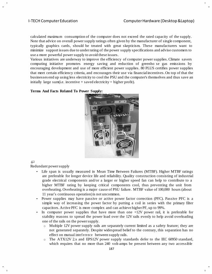
187
I-TECH Computer Education Computer Hardware (Desktop &Laptop)
calculated maximum consumption of the computer does not exceed the rated capacity of the supply.
Note that advice on overall power supply ratings often given by the manufacturer of single component,
typically graphics cards, should be treated with great skepticism. These manufacturers want to
minimize support issues due to under rating of the power supply specifications and advise customers to
use a more powerful power supply to avoid these issues.
Various initiatives are underway to improve the efficiency of computer power supplies. Climate savers
computing initiative promotes energy saving and reduction of greenho se gas emissions by
encouraging development and use of more efficient power supplies. 80 PLUS certifies power supplies
that meet certain efficiency criteria, and encourages their use via financial incentives. On top of that the
businesses end up using less electricity to cool the PSU and the computer's themselves and thus save an
initially large sum(i.e. incentive + saved electricity = higher profit).
Terms And Facts Related To Power Supply:
Redundant power supply
• Life span is usually measured in Mean Time Between Failures (MTBF). Higher MTBF ratings
are preferable for longer device life and reliability. Quality construction consisting of industrial
grade electrical components and/or a larger or higher speed fan can help to contribute to a
higher MTBF rating by keeping critical components cool, thus preventing the unit from
overheating. Overheating is a major cause of PSU failure. MTBF value of 100,000 hours (about
11 year‘s continuous operation) is not uncommon.
• Power supplies may have passive or active power factor correction (PFC). Passive PFC is a
simple way of increasing the power factor by putting a coil in series with the primary filter
capacitors. Active PFC is more complex and can achieve higher PF, up to 99%.
• In computer power supplies that have more than one +12V power rail, it is preferable for
stability reasons to spread the power load over the 12V rails evenly to help avoid overloading
one of the rails on the power supply.
o Multiple 12V power supply rails are separately current limited as a safety feature; they are
not generated separately. Despite widespread belief to the contrary, this separation has no
effect on mutual interf e re nc e between supply rails.
o The ATX12V 2.x and EPS12V power supply standards defer to the IEC 60950 standard,
which requires that no more than 240 volt-amps be present between any two accessible
188
I-TECH Computer Education Computer Hardware (Desktop &Laptop)
points. Thus, each wire must be current-limited to no more than 20 A; typical supplies
guarantee 18 A without triggering the current limit. Power supplies capable of delivering
more than 18 A at 12 V connect wires in groups to two or more current sensors which will
shut down the supply if excess current flows. Unlike a fuse or circuit breaker, these limits
reset as soon as the overload is removed.
o Because of the above standards, almost all high-power supplies claim to implement
separate rails, however this claim is often false; many omit the necessary current-limit
circuitry, both for cost reasons and because it is an irritation to customers. (The lack is
sometimes advertised as a feature under names like "rail fusion" or "current sharing".)
• When the computer is powered down but the power supply is still on, it can be started remotely
via Wake-on-LAN and Wake-on-Ring or locally via Keyboard Power ON (KBPO) if the
mothe rb oa rd supports it.
• Early PSUs used a conventional (heavy) step-down transformer, but most modern computer
power supplies are a type of switched-mode power supply (SMPS) with a ferrite-cored High
Freque n c y transformer.
• Computer power supplies may have short circuit protection; overpower (overload) protection,
overvoltage protection, under voltage protection, over current protection, and over temperature
protection.
• Some power supplies come with sleeved cables, which is aesthetically nicer, makes wiring
easier and cleaner and have less detrimental effect on airflow.
• There is a popular misconception that a greater power capacity (watt output capacity) is always
better. Since supplies are self-certified, a manufacturer's claims may be double or more what is
actually provided. Although a too-large power supply will have an extra margin of safety as far
as not over-loading, a larger unit is often less efficient at lower loads (under 20% of its total
capability) and therefore will waste more electricity than a more appropriately sized unit.
Additionally, computer power supplies generally do not function properly if they are too lightly
loaded. (less than about 15% of the total load.) Under no-load conditions they may shut down or
malfun ct io n. For this reason the no-load protection was introduced in some power supplies.
• Another popular misconception is that the greater the total watt capacity is, the more suitable
the power supply becomes for higher-end graphics cards. The most important factor for judging
PSUs suitability for certain graphics cards is the PSUs total 12V output, as it is that voltage on
which modern graphics cards operate. If the total 12V output stated on the PSU is higher than
the suggested minimum of the card, then that PSU can fully supply the card. It is however
recommended that a PSU should not just cover the graphics cards' demands, as there are other
components in the PC that depend on the 12V output, including the CPU , disk drives and
optical drives.
• Power supplies can feature magnetic amplifiers or double - fo rw a r d converter circuit design.
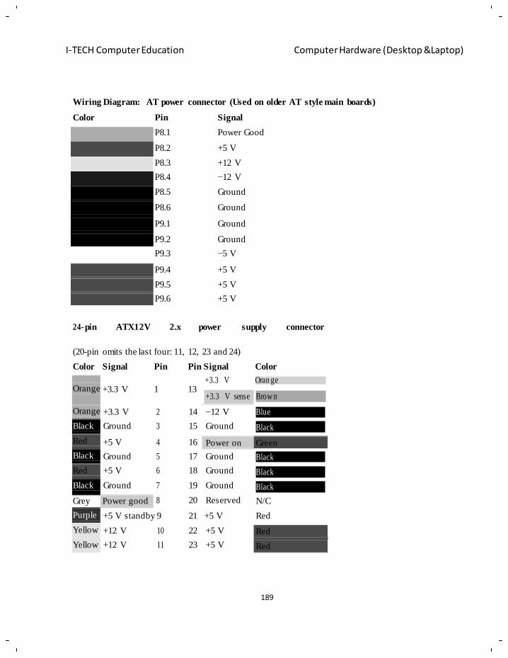
189
I-TECH Computer Education Computer Hardware (Desktop &Laptop)
Orange
Orange
Black
Red
Black
Red
Black
Grey Power good
Purple
Yellow
Yellow
Wiring Diagram: AT power connector (Used on older AT style main boards)
Color Pin Signal
P8.1 Power Good
P8.2 +5 V
P8.3 +12 V
P8.4 −12 V
P8.5 Ground
P8.6 Ground
P9.1 Ground
P9.2 Ground
P9.3 −5 V
P9.4 +5 V
P9.5 +5 V
P9.6 +5 V
24-pin ATX12V 2.x power supply connector
(20-pin omits the last four: 11, 12, 23 and 24)
Color Signal Pin Pin Signal Color
+3.3 V Oran ge +3.3 V 1 13
+3.3 V sense Brow n
+3.3 V 2 14 −12 V Blue
Ground 3 15 Ground Black
+5 V 4 16 Power on Green
Ground 5 17 Ground Black
+5 V 6 18 Ground Black
Ground 7 19 Ground Black
8 20 Reserved N/C
+5 V standby 9 21 +5 V Red
+12 V 10 22 +5 V Red
+12 V 11 23 +5 V Red
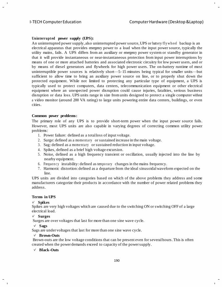
190
I-TECH Computer Education Computer Hardware (Desktop &Laptop)
Uninterrupt ed power supply (UPS):
An uninterrupted power supply, also uninterrupted power source, UPS or battery/ fly w h e el backup is an
electrical apparatus that provides emergency power to a load when the input power source, typically the
utility mains, fails. A UPS differs from an auxiliary or emergency power system or standby generator in
that it will provide instantaneous or near-instantaneous protection from input power interruptions by
means of one or more attached batteries and associated electronic circuitry for low power users, and or
by means of diesel generators and flywheels for high power users. The on-battery runtime of most
uninterruptible power sources is relatively short—5–15 minutes being typical for smaller units—but
sufficient to allow time to bring an auxiliary power source on line, or to properly shut down the
protected equipment. While not limited to protecting any particular type of equipment, a UPS is
typically used to protect computers, data centers, telecommunication equipment or other electrical
equipment where an unexpected power disruption could cause injuries, fatalities, serious business
disruption or data loss. UPS units range in size from units designed to protect a single computer without
a video monitor (around 200 VA rating) to large units powering entire data centers, buildings, or even
cities.
Common power problems:
The primary role of any UPS is to provide short-term power when the input power source fails.
However, most UPS units are also capable in varying degrees of correcting common utility power
problems:
1. Power failure: defined as a total loss of input voltage.
2. Surge: defined as a mome nta ry or sustained increase in the main voltage.
3. Sag: defined as a mome nta ry or sustained reduction in input voltage.
4. Spikes, defined as a brief high voltage excursion.
5. Noise, defined as a high frequency transient or oscillation, usually injected into the line by
nearby equipment.
6. Freque n c y instability: defined as tempo ra ry changes in the mains frequency.
7. Harmonic distortion: defined as a departure from the ideal sinusoidal waveform expected on the
line.
UPS units are divided into categories based on which of the above problems they address and some
manufacturers categorize their products in accordance with the number of power related problems they
address.
Terms in UPS
Spikes Spikes are very high voltages which are caused due to the switching ON or switching OFF of a large
electrical load.
Surges Surges are over voltages that last for more than one sine wave cycle.
Sags Sags are under voltages that last for more than one sine wave cycle.
Brown-Outs Brown-outs are the low voltage conditions that can be present even for several hours. This is often
created when the power demands exceed to capacity of the power supply.
Black-Outs
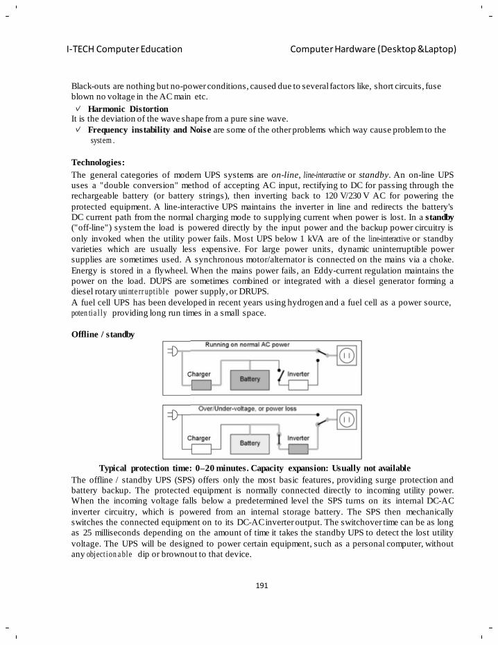
191
I-TECH Computer Education Computer Hardware (Desktop &Laptop)
Black-outs are nothing but no-power conditions, caused due to several factors like, short circuits, fuse
blown no voltage in the AC main etc.
Harmonic Distortion It is the deviation of the wave shape from a pure sine wave.
Frequency instability and Noise are some of the other problems which way cause problem to the
system .
Technologies:
The general categories of modern UPS systems are on-line, line-interactive or standby. An on-line UPS
uses a "double conversion" method of accepting AC input, rectifying to DC for passing through the
rechargeable battery (or battery strings), then inverting back to 120 V/230 V AC for powering the
protected equipment. A line-interactive UPS maintains the inverter in line and redirects the battery's
DC current path from the normal charging mode to supplying current when power is lost. In a standby
("off-line") system the load is powered directly by the input power and the backup power circuitry is
only invoked when the utility power fails. Most UPS below 1 kVA are of the line-interactive or standby
varieties which are usually less expensive. For large power units, dynamic uninterruptible power
supplies are sometimes used. A synchronous motor/alternator is connected on the mains via a choke.
Energy is stored in a flywheel. When the mains power fails, an Eddy-current regulation maintains the
power on the load. DUPS are sometimes combined or integrated with a diesel generator forming a
diesel rotary uninte rr upt ible power supply, or DRUPS.
A fuel cell UPS has been developed in recent years using hydrogen and a fuel cell as a power source,
poten tia l ly providing long run times in a small space.
Offline / standby
Typical protection time: 0–20 minutes. Capacity expansion: Usually not available
The offline / standby UPS (SPS) offers only the most basic features, providing surge protection and
battery backup. The protected equipment is normally connected directly to incoming utility power.
When the incoming voltage falls below a predetermined level the SPS turns on its internal DC-AC
inverter circuitry, which is powered from an internal storage battery. The SPS then mechanically
switches the connected equipment on to its DC-AC inverter output. The switchover time can be as long
as 25 milliseconds depending on the amount of time it takes the standby UPS to detect the lost utility
voltage. The UPS will be designed to power certain equipment, such as a personal computer, without
any object ion a ble dip or brownout to that device.
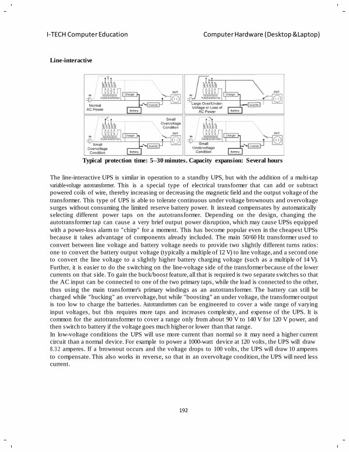
192
I-TECH Computer Education Computer Hardware (Desktop &Laptop)
Line-interactive
Typical protection time: 5–30 minutes. Capacity expansion: Several hours
The line-interactive UPS is similar in operation to a standby UPS, but with the addition of a multi-tap
variable-voltage autotransformer. This is a special type of electrical transformer that can add or subtract
powered coils of wire, thereby increasing or decreasing the magnetic field and the output voltage of the
transformer. This type of UPS is able to tolerate continuous under voltage brownouts and overvoltage
surges without consuming the limited reserve battery power. It instead compensates by automatically
selecting different power taps on the autotransformer. Depending on the design, changing the
autotransformer tap can cause a very brief output power disruption, which may cause UPSs equipped
with a power-loss alarm to "chirp" for a moment. This has become popular even in the cheapest UPSs
because it takes advantage of components already included. The main 50/60 Hz transformer used to
convert between line voltage and battery voltage needs to provide two slightly different turns ratios:
one to convert the battery output voltage (typically a multiple of 12 V) to line voltage, and a second one
to convert the line voltage to a slightly higher battery charging voltage (such as a multiple of 14 V).
Further, it is easier to do the switching on the line-voltage side of the transformer because of the lower
currents on that side. To gain the buck/boost feature, all that is required is two separate switches so that
the AC input can be connected to one of the two primary taps, while the load is connected to the other,
thus using the main transformer's primary windings as an autotransformer. The battery can still be
charged while "bucking" an overvoltage, but while "boosting" an under voltage, the transformer output
is too low to charge the batteries. Autotransformers can be engineered to cover a wide range of varying
input voltages, but this requires more taps and increases complexity, and expense of the UPS. It is
common for the autotransformer to cover a range only from about 90 V to 140 V for 120 V power, and
then switch to battery if the voltage goes much higher or lower than that range.
In low-voltage conditions the UPS will use more current than normal so it may need a higher current
circuit than a normal device. For example to power a 1000-watt device at 120 volts, the UPS will draw
8.3 2 amperes. If a brownout occurs and the voltage drops to 100 volts, the UPS will draw 10 amperes
to compensate. This also works in reverse, so that in an overvoltage condition, the UPS will need less
current.
193
I-TECH Computer Education Computer Hardware (Desktop &Laptop)
Double-con vers io n / online:
Typical protection time: 5–30 minutes. Capacity expansion: Several hours, the online UPS is ideal for
environments where electrical isolation is necessary or for equipment that is very sensitive to power
fluctuations. Although once previously reserved for very large installations of 10 kW or more, advances
in technology have now permitted it to be available as a common consumer device, supplying 500
watts or less. The initial cost of the online UPS may be slightly higher, but its total cost of ownership is
generally lower due to longer battery life. The online UPS may be necessary when the power
environment is "noisy", when utility power sags, outages and other anomalies are frequent, when
protection of sensitive IT equipment loads is required, or when operation from an extended-run backup
generator is necessary. The basic technology of the online UPS is the same as in a standby or line-
interactive UPS. However it typically costs much more, due to it having a much greater current AC-to-
DC battery-charger/rectifier, and with the rectifier and inverter designed to run continuously with
improved cooling systems. It is called a double-conversion UPS due to the rectifier directly driving the
inverter, even when powered from normal AC current. In an online UPS, the batteries are always
connected to the inverter, so that no power transfer switches are necessary. When power loss occurs,
the rectifier simply drops out of the circuit and the batteries keep the power steady and unchanged.
When power is restored, the rectifier resumes carrying most of the load and begins charging the
batteries, though the charging current may be limited to prevent the high-power rectifier from
overh ea tin g the batteries and boiling off the electrolyte.
The main advantage to the on-line UPS is its ability to provide an electrical firewall between the
incoming utility power and sensitive electronic equipment. While the standby and line-interactive UPS
merely filter the input utility power, the double-conversion UPS provides a layer of insulation from
power quality problems. It allows control of output voltage and frequency regardless of input voltage
and frequency.
Hybrid topology / double conversion on demand
These hybrid designs do not have an official designation, although one name used by HP and Eaton is double conversion on demand. This style of UPS is targeted towards high efficiency applications while
still maintainin g the features and protection level offered by double conversion.
A hybrid (double conversion on demand) UPS operates as an off-line/standby UPS when power
conditions are within a certain preset window. This allows the UPS to achieve very high efficiency
ratings. When the power conditions fluctuate outside of the predefined windows, the UPS switches to
online/double conversion operation. In double conversion mode the UPS can adjust for voltage
variations without having to use battery power, can filter out line noise and control frequency.
Examples of this hybrid/double conversion on demand UPS design are the HP R8000, HP R12000, HP
RP12000/3 and the Eaton Blade UPS.
Ferro-resonant:
Typical protection time: 5 – 15 minutes. Capacity expansion: Several Hours
Ferro-resonant units operate in the same way as a standby UPS unit; however, they are online with the
exception that a ferro-resonant transformer is used to filter the output. This transformer is designed to
194
I-TECH Computer Education Computer Hardware (Desktop &Laptop)
hold energy long enough to cover the time between switching from line power to battery power and
effectively eliminates the transfer time. Many ferro-resonant UPSs are 82–88% efficient (AC/DC-AC)
and offer excellent isolation.The transformer has three windings, one for ordinary mains power, the
second for rectified battery power, and the third for output AC power to the load.
This once was the dominant type of UPS and is limited to around the 150 kVA range. These units are
still mainly used in some industrial settings (oil and gas, petrochemical, chemical, utility, and heavy
industry markets) due to the robust nature of the UPS. Many ferro-resonant UPSs utilizing controlled
ferro techn olo g y may not interact with powe r -fa c tor -c or re ct in g equipment.
DC power
Typical protection time: Several hours. Capacity expansion: Yes
A UPS designed for powering DC equipment is very similar to an online UPS, except that it does not
need an output inverter, and often the powered device does not need a power supply. Rather than
converting AC to DC to charge batteries, then DC to AC to power the external device, and then back to
DC inside the powered device, some equipment accepts DC power directly and allows one or more
conversion steps to be eliminated. This equipment is more commonly known as a rectifier. Many
systems used in telecommunications use 48 V DC power, because it is not considered a high-voltage by
most electrical codes and is exempt from many safety regulations, such as being installed in conduit
and junction boxes. DC has typically been the dominant power source for telecommunications, and AC
has typically been the dominant source for computers and servers. There has been much
experimentation with 48 V DC power for computer servers, in the hope of reducing the likelihood of
failure and the cost of equipment. However, to supply the same amount of power, the current must be
same.
Applications of UPS:
N+1
In large business environments where reliabi li ty is of great importance, a single huge UPS can also be a single point of failure that can disrupt many other systems. To provide greater reliability, multiple
smaller UPS modules and batteries can be integrated together to provide redundant power protection
equivalent to one very large UPS. "N+1" means that if the load can be supplied by N modules, the
installation will contain N+ 1 module. In this way, failure of one module will not impact system
operation.
Multiple redundancy
Many computer servers offer the option of redundant power supplies, so that in the event of one power supply failing, one or more other power supplies are able to power the load. This is a critical point –
each power supply must be able to power the entire server by itself. Redundancy is further enhanced by
plugging each power supply into a different circuit (i.e. to a different circuit breaker).Redundant
protection can be extended further yet by connecting each power supply to its own UPS. This provides
double protection from both a power supply failure and a UPS failure, so that continued operation is
assured. This configuration is also referred to as 2N redundancy. If the budget does not allow for two
identical UPS units then it is common practice to plug one power supply into mains power and the
other into the UPS.
195
I-TECH Computer Education Computer Hardware (Desktop &Laptop)
Outdoor use
When a UPS system is placed outdoors, it should have some specific features that guarantee that it can tolerate weather with a 'minimal to none' effect on performance. Factors such as temperature, humidity,
rain, and snow among others should be considered by the manufacturer when designing an outdoor
UPS system. Operating temperature ranges for outdoor UPS systems could be around −40 °C to
+55 °C.Outdoor UPS systems can be pole, ground (pedestal), or host mounted. Outdoor environment
could mean extreme cold, in which case the outdoor UPS system should include a battery heater mat, or
extreme heat, in which case the outdoor UPS system should include a fan system or an air conditioning
system.
Internal systems
UPS systems can be designed to be placed inside a computer chassis. There are two types of internal UPS. The first type is a miniaturized regular UPS that is made small enough to fit into a 5.25-inch CD-
ROM slot bay of a regular computer chassis. The other type are re-engineered switching power supplies
that utilize dual power sources of AC and/or DC as power inputs and have an AC/DC built-in switching
mana g em en t control units.
Common Specificat io ns of UPS
General
–UPS Type
– Load Rating
Input Specification – Input Voltage
– Nominal Frequency
– Input Connection
Output Specification – Output Voltage
– Output Waveform Type
– Transfer Time
Battery Specification
– Battery Type – Battery Capacity
– Typical Battery Life
– Typical Run Time at Full Load
– Time at Half Load
– Typical Recharge Time
– Battery Expansion
• Other
– Indicators and Alarms
– Control and Monito ring Hardware and Software
– Cert i fic at ion s
196
I-TECH Computer Education Computer Hardware (Desktop &Laptop)
Chapter - 14
Assembling of the Computer
Objective of learning
Why assembling to be done
Comp on e nts required for assembling
Steps of assembling
Precautions to be take for assembling
Assem blin g trouble sho ot ing tips
Building a computer c an be a ver y rewarding experience. Since you‘re reading this, you‘re probably
thinking about building your next computer instead of buying one p re-built. This is a ve ry viable option
these days and can bring many benefits; you can learn a lot about comput er hardware by building one,
you get a totally personalized computer, you can choose better components and you may be able to save
some money and have fun. Additionally, if you are the sort of p erson who wants to understand how
things work, if you take broken stuf f apart just to see how it a ll fits together, if you have a dra wer
somewhere full of ―parts‖ you think ma y come in handy someday, then you just may be in th e right
place
The first step to building a computer is acquiring the parts. This guide will start with a quick explanation
of essential parts and elaborate on them further on.
A computer is made up of a case (or chassis) which houses s everal important internal components, and
provides places to connect the external compo ne n ts, including non-peripherals.
Inside the case go the following internal parts:
• Power Supply/PSU – power supply unit, converts outlet power, whi ch is alternating current
(AC), to direct current (DC) which is requi red by internal components, as well as p roviding
appropriate voltages and currents for these internal components.
• Motherboard/Main board – As t he name indicates, this is the electronic centerpiece of t he
computer, everything else connects to the motherboard.
• Processor/CPU – central processing unit, the "brain" of the computer, most actual computation
takes place here.
• RAM – random access memory, the "short-term memory" of a computer, used by the CPU to
store program instructions and data upon which it is currentl y operating. Data in RAM is los t
when the computer is powered off, thus necessi tat in g a hard drive.
• Hard Drive/Hard Disk – the "long-term memory" of the computer, used for persistent storage –
i.e. the things stored on it remain even when the computer is powered down. Th e operating
system, and all your programs and data are stored here.
• Optical Drive – device for reading/writing optical disks. May read CDs, DVDs, or other optical
media, depending on the type. It is essential for installing many operating systems and programs.
It may be able to write some of these discs, as well. Some people like to have two such drives for
copying disks.
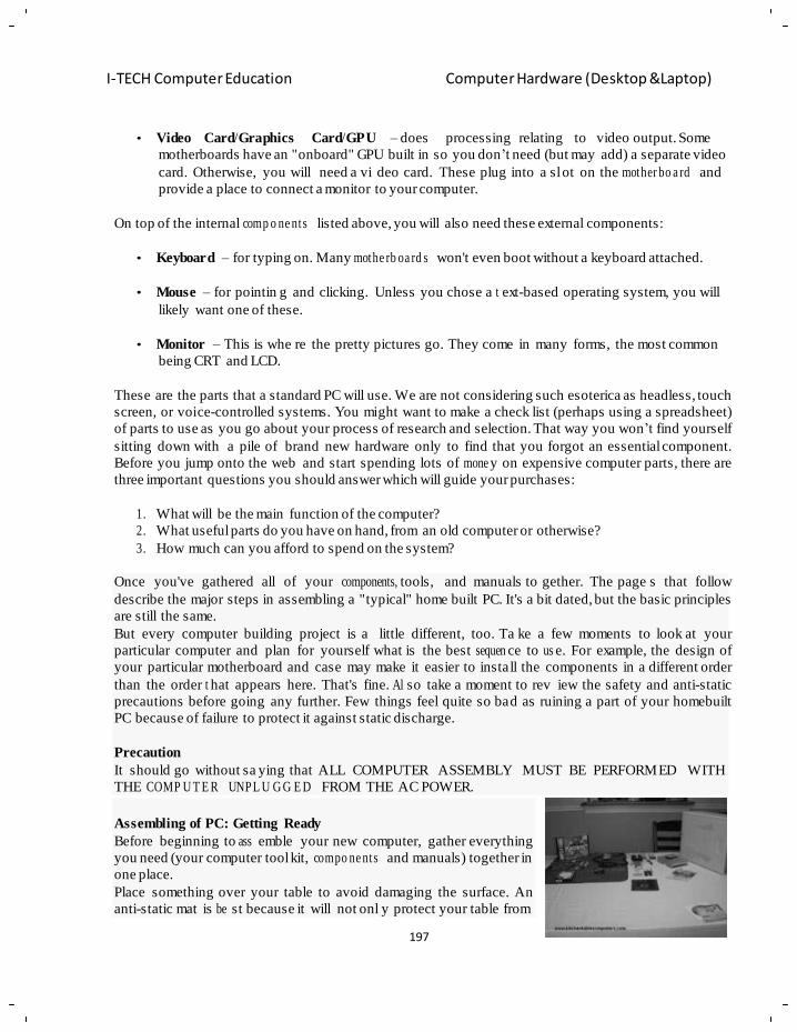
197
I-TECH Computer Education Computer Hardware (Desktop &Laptop)
m
a
E
• Video Card/Graphics Card/GPU – does processing relating to video output. Some
motherboards have an "onboard" GPU built in so you don‘t need (but may add) a separate video
card. Otherwise, you will need a vi deo card. These plug into a sl ot on the mother bo a rd and
provide a place to connect a monitor to your computer.
On top of the internal comp o ne nts listed above, you will also need these external components:
• Keyboard – for typing on. Many mothe rb oa rd s won't even boot without a keyboard attached.
• Mouse – for pointin g and clicking. Unless you chose a t ext-based operating system, you will
likely want one of these.
• Monitor – This is whe re the pretty pictures go. They come in many forms, the most common
being CRT and LCD.
These are the parts that a standard PC will use. We are not considering such esoterica as headless, touch
screen, or voice-controlled systems. You might want to make a check list (perhaps using a spreadsheet)
of parts to use as you go about your process of research and selection. That way you won‘t find yourself
sitting down with a pile of brand new hardware only to find that you forgot an essential component.
Before you jump onto the web and start spending lots of mone y on expensive computer parts, there are
three important questions you should answer which will guide your purchases:
1. What will be the main function of the computer?
2. What useful parts do you have on hand, from an old computer or otherwise?
3. How much can you afford to spend on the system?
Once you've gathered all of your components, tools, and manuals to gether. The page s that follow
describe the major steps in assembling a "typical" home built PC. It's a bit dated, but the basic principles
are still the same.
But every computer building project is a little different, too. Ta ke a few moments to look at your
particular computer and plan for yourself what is the best sequen ce to us e. For example, the design of
your particular motherboard and case may make it easier to install the components in a different order
than the order t hat appears here. That's fine. Al so take a moment to rev iew the safety and anti-static
precautions before going any further. Few things feel quite so bad as ruining a part of your homebuilt
PC because of failure to protect it against static discharge.
Precaution
It should go without sa ying that ALL COMPUTER ASSEMBLY MUST BE PERFORMED WITH
THE COMP U T E R UNPL U G G E D FROM THE AC POWER.
Assembling of PC: Getting Ready
Before beginning to ass emble your new computer, gather everything
you need (your computer tool kit, compo ne nts and manuals) together in
one place.
Place something over your table to avoid damaging the surface. An
anti-static mat is be st because it will not onl y protect your table from
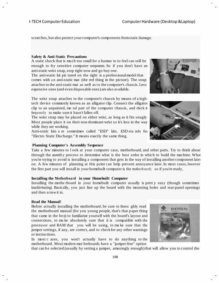
198
I-TECH Computer Education Computer Hardware (Desktop &Laptop)
n
n
n
l
y
g
o
y y
o
u
y
w
h
b
scratches, but also protect your computer's components from static damage.
Safety & Anti-Static Precautions A static shock that is much too small for a human to to feel can still be
enough to fry sensitive computer components. So if you don't have an
anti-static wrist strap, stop right now and go buy one.
The anti-static kit pic tured on the right is a professional model that
comes with a n anti-static mat (the red thing in the picture). The strap
attaches to the anti-static mat as well as to the computer's chassis. Less
expensive ones (and even disposable ones) are also available.
The wrist strap attaches to the computer's chassis by means of a hi gh-
tech device commonly known as an alligator clip. Connect the alligator
clip to an unpainted, me tal part of the computer chassis, and che ck it
frequ en tly to make sure it hasn't fallen off.
The wrist strap may be placed on either wrist, as long as it fits snugly.
Most people place it on their non-dominant wrist so it's less in the way
while they are working.
Anti-static kits a re sometimes called "ESD" kits. ESD sta nds for
"Electro Static Discharge." It means exactly the same thing.
Planning Computer's Assembly Sequence
Take a few minutes to l ook at your computer case, motherboard, and other parts. Try to think ahead
through the assembl y process to determine what is the best order in which to build the machine. What
you're trying to avoid is installing a component that gets in the way of installing another component later
on. A few minutes of planning at this point c an help prevent annoyance later. In most cases, how ever,
the first part you will install in your homebuilt computer is the mothe rb oa rd; so if you're ready,
Installing the Motherboa rd in your Homebuilt Computer
Installing the mothe rboard in your homebuilt computer usually is prett y easy (though sometimes
knuckle-busting). Basically, you just line up the board with the mounting holes and rear-panel openings,
and then screw it in.
Read the Manual!
Before actually installing the motherboard, be sure to thorou ghly read
the motherboard manual (for you young people, that's that paper thing
that came in the box) to familiarize yourself with the board's layout and
connections, to ma ke absolutely sure that it is compatible with the
processor and RAM that you will be using, to ma ke sure that the
jumper settings, if any, are correct, and to check for any other warnings
or instructions.
In most c ases, you won't actually have to do anything to the
motherboard. Most modern mot herboards have a "jumper-free" option
that can be selected (usually by setting a jumper, amusingly enough) that will allow you to control the
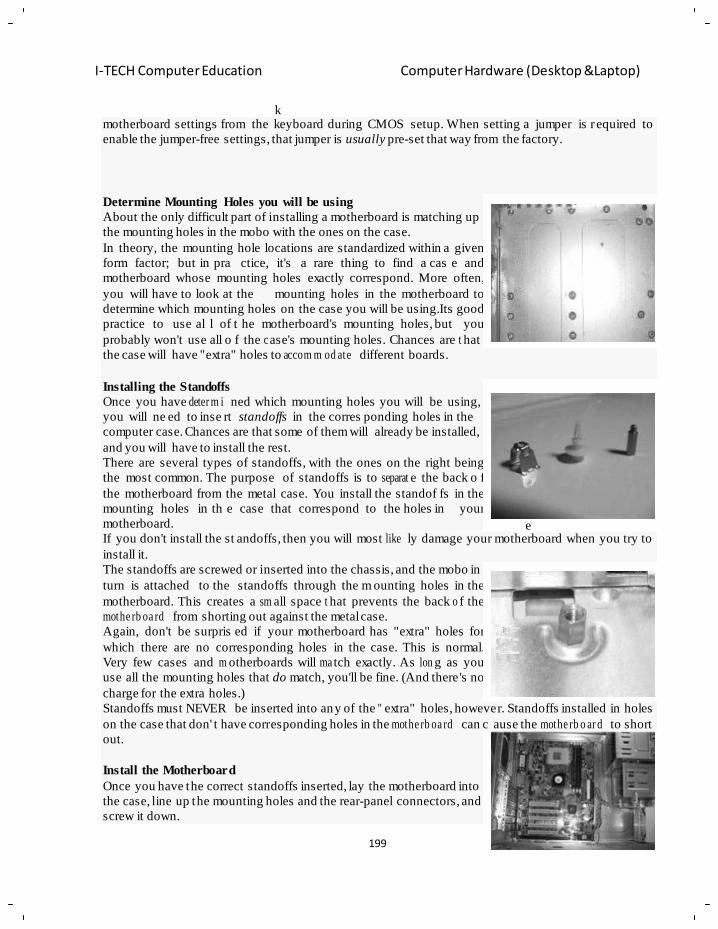
199
I-TECH Computer Education Computer Hardware (Desktop &Laptop)
k
u
n w
m
f
a
o
e
motherboard settings from the keyboard during CMOS setup. When setting a jumper is r equired to
enable the jumper-free settings, that jumper is usually pre-set that way from the factory.
Determine Mounting Holes you will be using
About the only difficult part of installing a motherboard is matching up
the mounting holes in the mobo with the ones on the case.
In theory, the mounting hole locations are standardized within a given
form factor; but in pra ctice, it's a rare thing to find a cas e and
motherboard whose mounting holes exactly correspond. More often,
you will have to look at the mounting holes in the motherboard to
determine which mounting holes on the case you will be using.Its good
practice to use al l of t he motherboard's mounting holes, but you
probably won't use all o f the c ase's mounting holes. Chances are t hat
the case will have "extra" holes to accom m od ate different boards.
Installing the Standoffs
Once you have deter m i ned which mounting holes you will be using,
you will ne ed to inse rt standoffs in the corres ponding holes in the
computer case. Chances are that some of them will already be installed,
and you will have to install the rest.
There are several types of standoffs, with the ones on the right being
the most common. The purpose of standoffs is to separat e the back o f
the motherboard from the metal case. You install the standof fs in the
mounting holes in th e case that correspond to the holes in your
motherboard.
If you don't install the st andoffs, then you will most like ly damage your motherboard when you try to
install it.
The standoffs are screwed or inserted into the chassis, and the mobo in
turn is attached to the standoffs through the m ounting holes in the
motherboard. This creates a sm all space t hat prevents the back o f the
mothe rb oa rd from shorting out against the metal case.
Again, don't be surpris ed if your motherboard has "extra" holes for
which there are no corresponding holes in the case. This is normal.
Very few cases and m otherboards will ma tch exactly. As lon g as you
use all the mounting holes that do match, you'll be fine. (And there 's no
charge for the extra holes.)
Standoffs must NEVER be inserted into any of the " extra" holes, however. Standoffs installed in holes
on the case that don' t have corresponding holes in the mothe rb oa rd can c ause the mothe rb o ar d to short
out.
Install the Motherboard
Once you have the correct standoffs inserted, lay the motherboard into
the case, line up the mounting holes and the rear-panel connectors, and
screw it down.
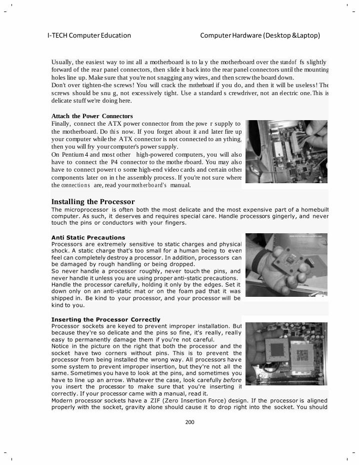
200
I-TECH Computer Education Computer Hardware (Desktop &Laptop)
e
m
o s
s
,
m r
h
m
b e
o
h
Usually, the easiest way to inst all a motherboard is to la y the motherboard over the standof fs slightly
forward of the rear panel connectors, then slide it back into the rear panel connectors until the mounting
holes line up. Make sure that you're not snagging any wires, and then screw the board down.
Don't over tighten-the screws! You will crack the motherboard if you do, and then it will be useless! The
screws should be snu g, not excessively tight. Use a standard s crewdriver, not an el ectric one. Th is is
delicate stuff we're doing here.
Attach the Power Connectors
Finally, connect the ATX power connector from the powe r supply to
the motherboard. Do thi s now. If you forget about it a nd later fire up
your computer while the ATX connector is not connected to an ything,
then you will fry your computer's power supply.
On Pentium 4 and most other high-powered computers, you will also
have to connect the P4 connector to the mothe rboard. You may also
have to connect power t o some high-end video cards and certain other
components later on in t he assembly process. If you're not sure where
the connec tio n s are, read your moth er bo a rd' s manual.
Installing the Processor The microprocessor is often both the most delicate and the most expensive part of a homebuilt computer. As such, it deserves and requires special care. Handle processors gingerly, and never touch the pins or conductors with your fingers.
Anti Static Precautions Processors are extremely sensitive to static charges and physical shock. A static charge that's too small for a human being to even
feel can completely destroy a processor. In addition, processors can be damaged by rough handling or being dropped.
So never handle a processor roughly, never touch the pins, and
never handle it unless you are using proper anti-static precautions. Handle the processor carefully, holding it only by the edges. Set it down only on an anti-static mat or on the foam pad that it was
shipped in. Be kind to your processor, and your processor will be
kind to you.
Inserting the Processor Correctly Processor sockets are keyed to prevent improper installation. But because they're so delicate and the pins so fine, it's really, really
easy to permanently damage them if you're not careful. Notice in the picture on the right that both the processor and the
socket have two corners without pins. This is to prevent the processor from being installed the wrong way. All processors have
some system to prevent improper insertion, but they're not all the same. Sometimes you have to look at the pins, and sometimes you
have to line up an arrow. Whatever the case, look carefully before you insert the processor to make sure that you're inserting it
correctly. If your processor came with a manual, read it.
Modern processor sockets have a ZIF (Zero Insertion Force) design. If the processor is aligned properly with the socket, gravity alone should cause it to drop right into the socket. You should
201
I-TECH Computer Education Computer Hardware (Desktop &Laptop)
e
s
o
s
h
e
o
t
w
o
h
o m
n
a
e
o
a
m
never need to use force greater than a gentle nudge with a single finger (and the pinky finger, at
that) to insert a modern processor. Never, never, never. Some processors have no pins. Instead, they have little bumps that make contact with the CPU
socket. They look like pimples and dimples. This design makes it nearly impossible to break the chip while installing it, but it does sometimes cause problems if dust, hair, or other debris finds its
way to the socket. Canned air solves the problem.
Most processors are secured by a bail mounted alongside the socket. Once you've lined up the pins and allowed the processor to drop into the socket, check to make sure that the processor is fully
inserted and not sitting crookedly.Once you are absolutely certain that the processor is seated properly, gently close the bail to secure
the processor. If you encounter too much resistance, stop and check again to
make sure that the processor is lined up correctly. If you close the bail while the processor is not seated properly, you probably will
ruin both the motherboard and the processor.
Finished? Congratulations! Now take a breather and a swig of your favorite beverage and prepare for the next step: Installing the CPU Cooler.
Installing the CPU Cooler
Today's fast processors generate a tremendous amount of he at. Without a CPU cooler, a pro cessor
would burn out in mere seconds.
Inadequate cooling also can result in da ta errors, performance problems, and reduced processor life.
CPU manufacturers t ypically provide lists of " approved" coolers for their chips. These cool ers may or
may not be any better than other coolers, but using a non -approved cooler might void the CPU' s
warranty.
To extend your homebuilt computer's life and m aximize its performance while not running the risk of
voiding the CPU w arranty, I recommend that you use the b est cooler you can find that has been
manu fa c tur er -a pp ro ve d for your particular processor. The processor cooler is not a place to skimp.
Parts of a CPU Cooler
Most CPU coolers are composed of three parts: A fan, a heat sink, and
a mounting device that attaches the cooler assembly to the motherboard
directly over the processor. A fourth element of the cooling system is
something called "heat sink compound" or "thermal jelly," which is
applied between the heat sink a nd the die of the processor to improve
heat transfer from the processor to the heat sink.
Many heat sinks come with a patch of heat sink compound pre-applied
to the heat sink itself. The act ual compound is covered with a little
plastic tab during shipping. If you are using a heat sink with pre -
applied heat sink compound, then you need to peel the protective tab off the heat sink prior to installing
the cooler. Forgetting this simp le step can cause serious damage to your processor. If your heat sink
doesn't have pre-applied compound, you will need to appl y a thin coa ting of heat sink comp ound
directly to the processor die. This also applies if, for some reason, you have removed and are replacing
the heat sink.
The old compound mus t be c ompletely are carefully removed and new compound applied b efore
replacing the cooler. Don't use steel wool or abr asives of any sort! Just wipe the jelly off the processor
and the heat sink with a clean, lint-free cloth or paper towel.
202
I-TECH Computer Education Computer Hardware (Desktop &Laptop)
p
g
w
d
o
a
v
d
m
I suggest you use a hig h-quality thermal jelly. Arctic Silver is m y personal favorite. The di fference in
price is trivial, and high- qu al i ty thermal jelly will help keep your processor cool and comfy.
Mounting the CPU Cooler
The CPU cooler assembly is positioned over the processor and is
usually secured to the motherboard by metal clips tha t hold the heat
sink down tightly against the processor.
Notice that on bai l-type sockets, both the socket and t he heat sink are
offset from center a little to a ccommodate the bail. Make sure you
install the cooler with it s offset on the same side as t he offset on t he
socket.
Use a slotted scr ewdriver too gently, but firmly, hook the retaining
clips under the tabs on the processor socket. Be very careful not to let the screwdriver slip. If it scratches
the surface of the motherboard, the mobo could be ruined .So m e cooling assemblies use plastic clips that
simply slide strai ght down over the processor and snap i nto place. These types of assemblies us ually
don't require any tools to install.
Don't forget to plug in the fan! In most cases, it will plug into a three-
pin connector on the mother board that is (appropriatel y enough)
labeled "CPU Fan" in te ensy-weensy letters. This is to a llow the
computer to control the fan speed based upon how hard the processor is
working.
If you want, you can "hotwire" the fan using an adaptor that directly
connects it to the power supply, which causes it to spin at full speed all
the time. I don't recommend this for most users. It creates a lot of noise,
uses more power, and causes the fan to wear out sooner. Some people
also believe you can "overcool" the CPU by running the fan at full speed all the time. I personally don't
think that's possible unless you're using the computer outdoors in Antarctica, but some people disagree.
In most cases, you also can disable the fan speed control in CMOS setup, which has the same effect as
hotwiring the fan, and which I also don't recommend.
Chipset Coolers
Most modern mothe rb oa rd s als o have a chi pset cooler, at least on t he Northbridge chipset. These are
almost always factory-installed and are adequate for all but the most intensive use. Just blow the fan out
with canned air once in a while, and replace it if it stops spinning or starts making noises.
If you do find it necessar y to replace or up grade the factory-installed chipset cooler, the proc ess is
basically the same as installing a CPU cooler. The m ain difference is that chipset coolers usually are
fastened to the motherboard using spring fasteners or plastic retainers rather than a metal clip. You may
need to have access to the back of the motherboard to remove the fasteners, and you may have to install
new fasteners if the old ones can't be removed without breaking them
Liquid CPU Cooling Systems
Water cooling is not a new idea. Liquid cooling systems have been around since the earliest days of
mainframe computing, when every IT department had a plumber on call. Nowadays, liquid CPU cooling
systems are popular mainly among PC builders who use their computers for gaming or other pro cessor-
intensive applications.
203
I-TECH Computer Education Computer Hardware (Desktop &Laptop)
a
A
A M
M
c
p
m
h
n
h
e
Not being much of a gamer myself (although I do love Microsoft Flight Simulator), my cooling needs
tend not to be very intense. And frankly, I really haven't come across a s ystem that worked so hard that a
good fan-type cooler w asn't enough. Also, I'm a little sk ittish about mi xing water and el ectronics; so
most of the time I use good, old-fash ion ed air cooling.
But if you plan to over clock (also something I frown upon) or otherwise push your CPU to the edge,
then liquid cooling can buy you a few critical degrees of extra cooling. That can make a difference while
you are, for example, in the heat of battle, saving the world from invaders from outer space.
Okay, now that we've installed the cooler, let's move on to the next step: Installing RAM.
Installing the RAM (Memory) Modules
Anti-Static Precautions
Like processors, RAM modules are extremely sensitive to sta tic
charges and should be handled very carefully. Never touch the metal
conductors, and onl y handle RAM modules b y their edges. Nothing
feels quite as bad as destroying a perfectly good stick of RAM.
You can learn more about anti-static precautions here.
Before actually installing the RAM modules in your computer, check
again to make sure that the RAM you have is of the correct type and
speed for your motherboard. Most computers nowadays use DDR-II or
DDR-III memory modules, but double -c h ec k to make sure.
Proper Insertion of the RAM Modules
RAM modules are keyed with little notches that fit over corresponding
tabs in the RAM slots. We've circled them in the picture on t he right
(click the picture for a close-up).
Before inserting the RAM module, make sure that the notches and tabs
are correctly lined up. If there are more notches than there are tabs (or
vice-versa), then you have the wrong RAM f or your motherboard.
Same thing goes for if the notches and tabs don 't match up. You have
the wrong RAM, and all the force in the world won't make it the right
RAM.
Once you're sure you have the right RAM, to actually insert it, simply push it firmly, straight down into
the slot, and push the retainer clips inward. That's it.
Which Slots to Use
If you are using SDRAM or single -c h an n el DDR - SD R A M , then it usually doesn't matter which modules
go into whic h slots. B ut a few motherboards require that you start with the first slot a nd fill them in
order, so you may as well do it that way.
If you are using DDR memory in dual-channel configuration, however, then you must fill the first slot of
each of the two RAM banks with an identical stick of RAM; and you must do the same with the s econd
slots of each bank, i f you are us ing them. The RAM sticks in each bank must be identical to each other.
In addition, although it is not required, I recommend that the two banks also be identical.
204
I-TECH Computer Education Computer Hardware (Desktop &Laptop)
In other words, a mother board that supports dual- channel DDR will usuall y have two (or more ) RAM
banks, which usuall y are identified b y different color slots. Each bank ha s two slots, and both slo ts in
each bank must have identical RAM. So if you put a 1 GB stick of PC2-5300 667MHz DDR2 in the first
slot, then you must also put a 1 GB stick of PC2-5300 667MHz DDR2 in the second slot in order to use
the dual -c ha n ne l configuration.
If you choose to use the additional banks, then t he same rule applies. Ea ch stick in the bank mus t be
identical, but the banks need not be identical to each other. In practice, however, I usually just fill all the
slots with identical RAM sticks. Makes life easier, and I find I get far fewer conflicts this way.
When using SDRAM or DDR-SDRAM, an y unused RAM slots are si mply left empty. But if you are
using RAMBUS RIMM modules, then you will have to install "continuit y modules" in a ny unused
RIMM slots. Remember: RAMBUS modules must be installed in identical pairs.
Manufactu rers and Speeds
In theory, it shouldn' t matter if th e RAM mo dules installed in a computer are made by different
manufacturers, as long as the type and speed are the same. There are standards for this sort of things, so
memory from different manufacturers should be compatible. But sometimes subtle differences between
manufacturers can cause problems; so I recommend that you purchase RAM made by the same
manu fa c tur er , if possible.
Also in theory, when different speed RAM modules are used, all of the R AM should clock to the speed
of the slowest module. But in realit y, I've found that mi xing RAM speeds sometimes causes sy stem
instability. I've had plenty of cases where RAM sticks that tested just fine alone wouldn't play well
together. So I strongly recommend that the entire RAM installed in your computer be of the same speed.
In fact, in pr actice, I just use all identical sticks in any given computer. Whenever possible, I'll even
remove perfectly good RAM when doing an up grade, just so all the st icks I install are identical. ( And
again, you must use RAM pairs of identical s ize and sp eed when usi ng RAMBUS or dual-c hannel
DDR.)Now that you've installed your computer's RAM, le t's move on to the next step: Installing
Expansion Cards.
Installing Expansion Cards
Depending on the moth erboard you have purchased, you may need to i nstall one or more expansion
cards. Many new motherboards have audio, video, and network "cards" built right into them. But if not
(or if you don't want to use the integ rated cards), then you will need to install ex pansion cards. If your
board has inte grated cards that you don't plan to use, you should disable them in BI OS, both to avoid
possible conflicts and to avoid wasting resources on a component that's not being used.
Precautions
Like any other component in your homebuilt co mputer, you should mak e sure that the cards you are
about to install ar e compatible with your motherboard and with the operating system you plan on
installing.
Compatibility becomes especially important when selecting AGP video cards, because the voltages for
the different AGP standards are different. So be especially careful that your motherboard is capable of
supporting the video card you have selected before you attempt to install it, and check to see if there are
any mothe rbo a rd jumpers you have to set for the card you are installing.
205
I-TECH Computer Education Computer Hardware (Desktop &Laptop)
h
P
m
h
m o
o
d
In addition, always be sure to observe anti-static precautions when handling expansion cards. Nothing is
quite as depressing as totally destroying an ex pensive card b ecause you forgot to ta ke anti-static
precautions.
Proper Insertion of Expansion Cards
Like RAM, expansion cards and slots a re keyed. They have little
notches with corresponding tabs in the slot that are designed to prevent
you from installing the wrong card.
So if the card doesn 't seem to fit, check t hose notches and t abs. Don't
break out a hammer and try to pound it in. You probably are trying to
insert the wron g kind o f card (or insert the c ard in the wron g kind of
slot).
Notice in the picture on t he right that the AGP video slot is set back
from the rest o f the slo ts and is of a diff erent size. In addition, the
various ridges, tabs, and so fort h on the card and t he slot are intended to he lp prevent incorrect insertion
or incompatible cards. You should read the documentation for your motherboard and cards to make sure
they are compatible.
The card shown in this picture is a network card that fits into the PCI
slot. Notice that it is keyed to the slot. (Also no te that the card is onl y
slanted to make it easier for you to see the slot. Expansion cards, like
RAM, are pushed straight down into their slots, like in the next picture
down.)
It usually doesn't matter which PCI cards are installed in whic h slots.
But sometimes it does, depending on how a particular motherboard and
OS manage shared resources. So before installing PCI cards, check the
motherboard and expansion card manuals for any recom m e nd at ion s for
slot assignments; and if one of more of your cards don't work (or if the y cause system instability), try
changing the slots before you trash the cards. Sometimes that's all it takes.
Once you have determined which cards will be installed in which slots,
actually installing them is simple. Place the computer on its side so the
slots on the motherbo ard face up, align the card in the slot
perpendicular to the motherboard (that is, straig ht up, bec ause the
computer is on its side), and p ush down until you feel the card "pop"
into place.
You may have to use some oo mph here. If the c ard doesn't seat itself
using fingertip pressure, place your palm over the card and push down
firmly and evenly until you feel the card pop into place. But first check
the slots, notches, and tabs to make sure you're not trying to install the card in the wrong slot.
Finally, secure the card into place by screwing the card's metal bracket
into the screw hole over the expansion slot opening on the b ack of the
case. Some cases don't use screws, and instead have some sort of metal
or plastic clip that holds the card (or all of them, some times) in the
motherboard. Usually this is ob vious, but checks t he manual that came
with the case if you're confused.It's a good idea to save the slot covers
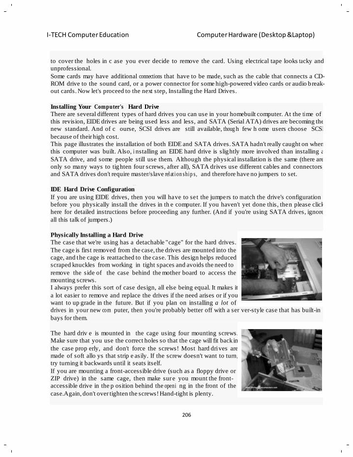
206
I-TECH Computer Education Computer Hardware (Desktop &Laptop)
e
a
S
n
r
h
d
e
o
to cover the holes in c ase you ever decide to remove the card. Using electrical tape looks ta cky and
unprofessional.
Some cards may have additional connections that have to be made, such as the cable that connects a CD-
ROM drive to the sound card, or a power connector for some high-powered video cards or audio b reak-
out cards. Now let's proceed to the next step, Installing the Hard Drives.
Installing Your Computer's Hard Drive
There are several different types of hard drives you can use in your homebuilt computer. At the ti me of
this revision, EIDE drives are being used less and less, and SATA (Serial ATA) drives are becoming the
new standard. And of c ourse, SCSI drives are still available, thoug h few h ome users choose SCSI
because of their high cost.
This page illustrates the installation of both EIDE and SATA drives. SATA hadn't really caught on when
this computer was built. Also, i nstalling an EIDE hard drive is slightly more involved than installing a
SATA drive, and some people still use them. Although the physical installation is the same (there are
only so many ways to tighten four screws, after all), SATA drives use different cables and connectors,
and SATA drives don't require master/slave relat ion ship s, and therefore have no jumpers to set.
IDE Hard Drive Configuration
If you are using EIDE drives, then you will have to set the jumpers to m atch the drive's configuration
before you physically install the drives in th e computer. If you haven't yet done this, then please click
here for detailed instructions before proceeding any further. (And if you're using SATA drives, ignore
all this talk of jumpers.)
Physically Installing a Hard Drive
The case that we're using has a detachable "cage" for the hard drives.
The cage is first removed from the case, the drives are mounted into the
cage, and the cage is reattached to the case. This design helps reduced
scraped knuckles from working in tight spaces and avoids the need to
remove the side of the case behind the mother board to access the
mounting screws.
I always prefer this sort of case design, all else being equal. It makes it
a lot easier to remove and replace the drives if the need arises or if you
want to up grade in the future. But if you plan on installing a lot of
drives in your new com puter, then you're probably better off with a ser ver-style case that has built-in
bays for them.
The hard driv e is mounted in the cage using four mounting screws.
Make sure that you use the correct holes so that the cage will fit back in
the case prop erly, and don't force the screws! Most hard dri ves are
made of soft allo ys that strip e asily. If the screw doesn't want to turn,
try turning it backwards until it seats itself.
If you are mounting a front-accessible drive (such as a floppy drive or
ZIP drive) in the same cage, then make sur e you mount the front-
accessible drive in the p osition behind the openi ng in the front of the
case.Again, don't over tighten the screws! Hand-tight is plenty.
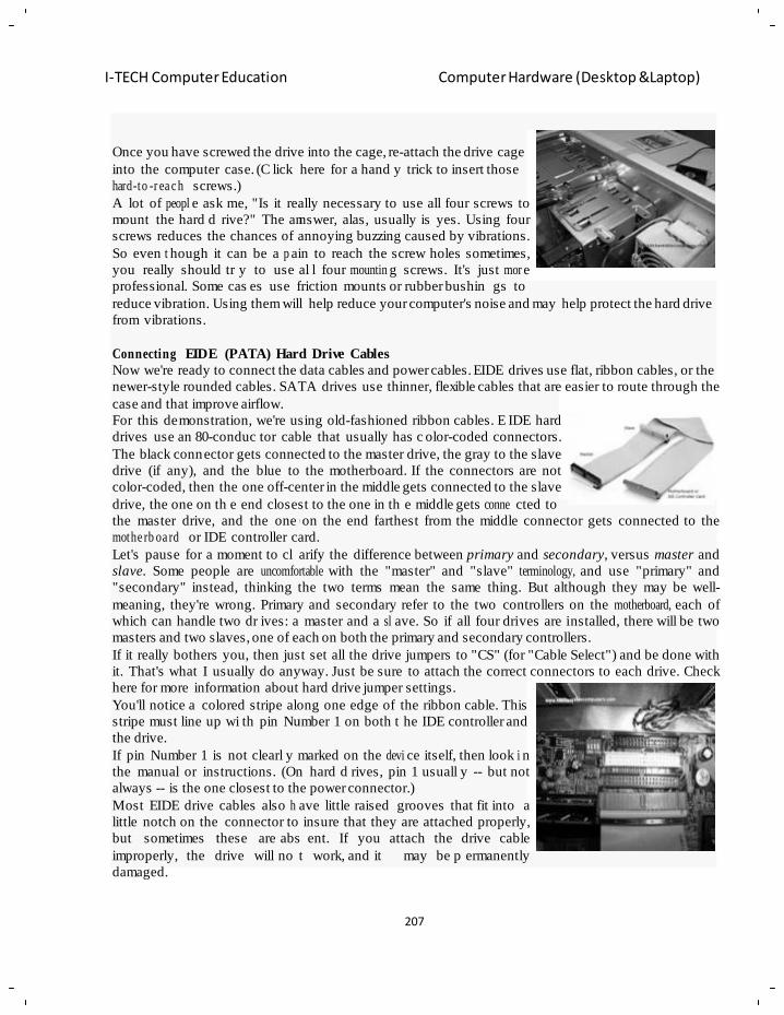
207
I-TECH Computer Education Computer Hardware (Desktop &Laptop)
a
n
d
o
w
m
y
Once you have screwed the drive into the cage, re-attach the drive cage
into the computer case. (C lick here for a hand y trick to insert those
hard-to -r ea c h screws.)
A lot of peopl e ask me, "Is it really necessary to use all four screws to
mount the hard d rive?" The annswer, alas, usually is yes. Using four
screws reduces the chances of annoying buzzing caused by vibrations.
So even t hough it can be a p ain to reach the screw holes sometimes,
you really should tr y to use al l four mountin g screws. It's just mor e
professional. Some cas es use friction mounts or rubber bushin gs to
reduce vibration. Using them will help reduce your computer's noise and may help protect the hard drive
from vibrations.
Connecting EIDE (PATA) Hard Drive Cables
Now we're ready to connect the data cables and power cables. EIDE drives use flat, ribbon cables, or the
newer-style rounded cables. SATA drives use thinner, flexible cables that are easier to route through the
case and that improve airflow.
For this demonstration, we're using old-fashioned ribbon cables. E IDE hard
drives use an 80-conduc tor cable that usually has c olor-coded connectors.
The black connector gets connected to the master drive, the gray to the slave
drive (if any), and the blue to the motherboard. If the connectors are not
color-coded, then the one off-center in the middle gets connected to the slave
drive, the one on th e end closest to the one in th e middle gets conne cted to
the master drive, and the one on the end farthest from the middle connector gets connected to the
mothe rb oa rd or IDE controller card.
Let's pause for a moment to cl arify the difference between primary and secondary, versus master and
slave. Some people are uncomfortable with the "master" and "slave" terminology, and use "primary" and
"secondary" instead, thinking the two terms mean the same thing. But although they may be well-
meaning, they're wrong. Primary and secondary refer to the two controllers on the motherboard, each of
which can handle two dr ives: a master and a sl ave. So if all four drives are installed, there will be two
masters and two slaves, one of each on both the primary and secondary controllers.
If it really bothers you, then just set all the drive jumpers to "CS" (for "Cable Select") and be done with
it. That's what I usually do anyway. Just be sure to attach the correct connectors to each drive. Check
here for more information about hard drive jumper settings.
You'll notice a colored stripe along one edge of the ribbon cable. This
stripe must line up wi th pin Number 1 on both t he IDE controller and
the drive.
If pin Number 1 is not clearl y marked on the devi ce itself, then look i n
the manual or instructions. (On hard d rives, pin 1 usuall y -- but not
always -- is the one closest to the power connector.)
Most EIDE drive cables also h ave little raised grooves that fit into a
little notch on the connector to insure that they are attached properly,
but sometimes these are abs ent. If you attach the drive cable
improperly, the drive will no t work, and it may be p ermanently
damaged.
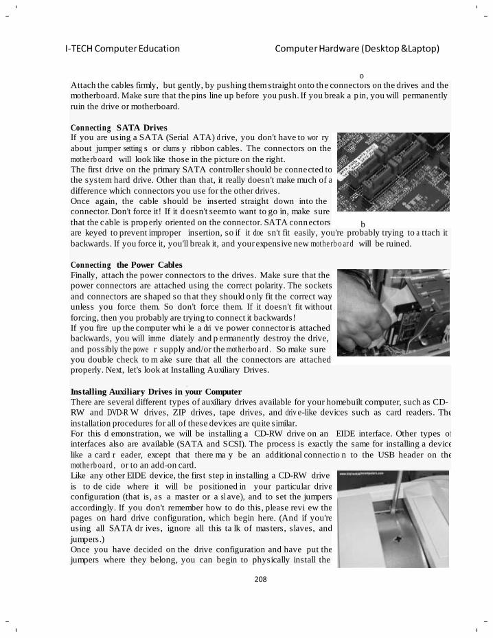
208
I-TECH Computer Education Computer Hardware (Desktop &Laptop)
A
n
c
y
e
y
o
b
w
n
Attach the cables firmly, but gently, by pushing them straight onto the connectors on the drives and the
motherboard. Make sure that the pins line up before you push. If you break a p in, you will permanently
ruin the drive or motherboard.
Connecting SATA Drives If you are using a SATA (Serial ATA) d rive, you don't have to wor ry
about jumper setting s or clums y ribbon cables. The connectors on the
mothe rb oa rd will look like those in the picture on the right.
The first drive on the primary SATA controller should be connected to
the system hard drive. Other than that, it really doesn't make much of a
difference which connectors you use for the other drives.
Once again, the cable should be inserted straight down into the
connector. Don't force it! If it doesn't seem to want to go in, make sure
that the cable is properly oriented on the connector. SATA connectors
are keyed to prevent improper insertion, so if it doe sn't fit easily, you're probably trying to a ttach it
backwards. If you force it, you'll break it, and your expensive new mothe rb o ar d will be ruined.
Connecting the Power Cables
Finally, attach the power connectors to the drives. Make sure that the
power connectors are attached using the correct polarity. The sockets
and connectors are shaped so that they should only fit the correct way
unless you force them. So don't force them. If it doesn't fit without
forcing, then you probably are trying to connect it backwards!
If you fire up the computer whi le a dri ve power connector is attached
backwards, you will imme diately and p ermanently destroy the drive,
and possibly the powe r supply and/or the mothe rbo a rd . So make sure
you double check to m ake sure that all the connectors are attached
properly. Next, let's look at Installing Auxiliary Drives.
Installing Auxiliary Drives in your Computer
There are several different types of auxiliary drives available for your homebuilt computer, such as CD-
RW and DVD-R W drives, ZIP drives, tape drives, and driv e-like devices such as card readers. The
installation procedures for all of these devices are quite similar.
For this d emonstration, we will be installing a CD-RW drive on an EIDE interface. Other types of
interfaces also are available (SATA and SCSI). The process is exactly the same for installing a device
like a card r eader, except that there ma y be an additional connectio n to the USB header on the
mothe rb oa rd , or to an add-on card.
Like any other EIDE device, the first step in installing a CD-RW drive
is to de cide where it will be positioned in your particular drive
configuration (that is, a s a master or a sl ave), and to set the jumpers
accordingly. If you don't remember how to do this, please revi ew the
pages on hard drive configuration, which begin here. (And if you're
using all SATA dr ives, ignore all this ta lk of masters, slaves, and
jumpers.)
Once you have decided on the drive configuration and have put the
jumpers where they belong, you can begin to physically install the
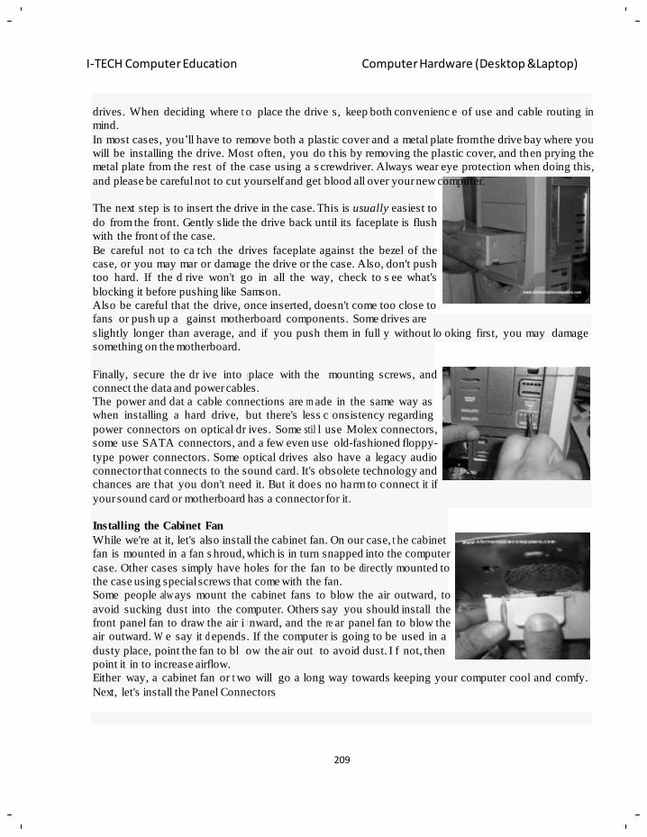
209
I-TECH Computer Education Computer Hardware (Desktop &Laptop)
c
v
n
p
b
w
m n
o
o
drives. When deciding where t o place the drive s, keep both convenienc e of use and cable routing in
mind.
In most cases, you‘ll have to remove both a plastic cover and a metal plate from the drive bay where you
will be installing the drive. Most often, you do this by removing the plastic cover, and then prying the
metal plate from the rest of the case using a s crewdriver. Always wear eye protection when doing this,
and please be careful not to cut yourself and get blood all over your new computer.
The next step is to insert the drive in the case. This is usually easiest to
do from the front. Gently slide the drive back until its faceplate is flush
with the front of the case.
Be careful not to ca tch the drives faceplate against the bezel of the
case, or you may mar or damage the drive or the case. Also, don't push
too hard. If the d rive won't go in all the way, check to s ee what's
blocking it before pushing like Samson.
Also be careful that the drive, once inserted, doesn't come too close to
fans or push up a gainst motherboard components. Some drives are
slightly longer than average, and if you push them in full y without lo oking first, you may damage
something on the motherboard.
Finally, secure the dr ive into place with the mounting screws, and
connect the data and power cables.
The power and dat a cable connections are m ade in the same way as
when installing a hard drive, but there's less c onsistency regarding
power connectors on optical dr ives. Some stil l use Molex connectors,
some use SATA connectors, and a few even use old-fashioned floppy-
type power connectors. Some optical drives also have a legacy audio
connector that connects to the sound card. It's obsolete technology and
chances are that you don't need it. But it does no harm to connect it if
your sound card or motherboard has a connector for it.
Installing the Cabinet Fan
While we're at it, let's also install the cabinet fan. On our case, t he cabinet
fan is mounted in a fan s hroud, which is in turn snapped into the computer
case. Other cases simply have holes for the fan to be dir ectly mounted to
the case using special screws that come with the fan.
Some people alw ays mount the cabinet fans to blow the air outward, to
avoid sucking dust into the computer. Others say you should install the
front panel fan to draw the air i nward, and the re ar panel fan to blow the
air outward. W e say it d epends. If the computer is going to be used in a
dusty place, point the fan to bl
point it in to increase airflow.
ow the air out to avoid dust. I f not, then
Either way, a cabinet fan or t wo will go a long way towards keeping your computer cool and comfy.
Next, let's install the Panel Connectors
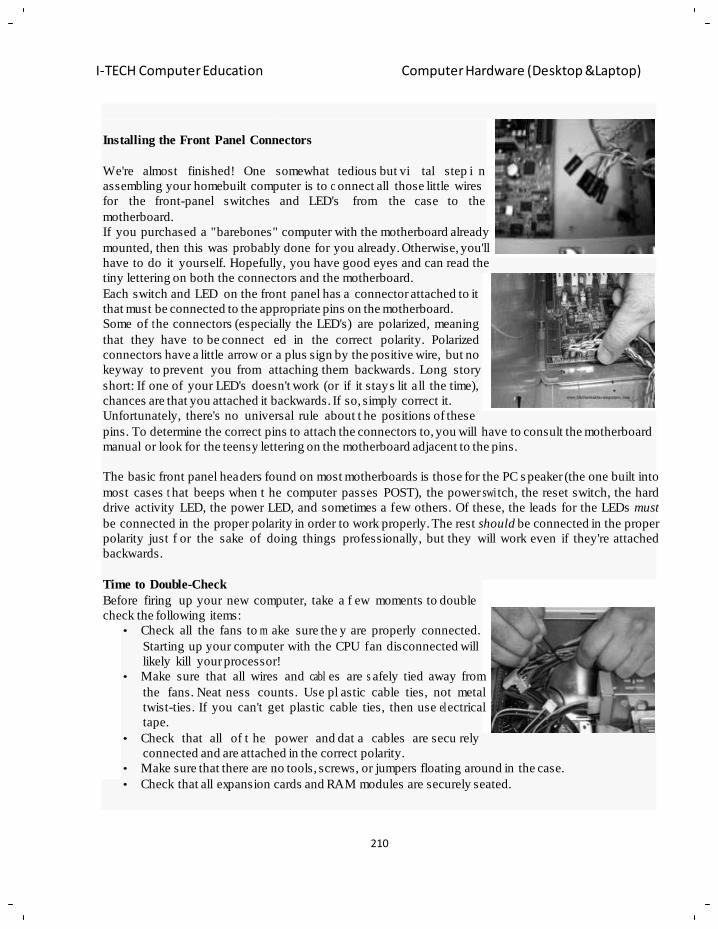
210
I-TECH Computer Education Computer Hardware (Desktop &Laptop)
n
E
e
n
h
Installing the Front Panel Connectors
We're almost finished! One somewhat tedious but vi tal step i n
assembling your homebuilt computer is to c onnect all those little wires
for the front-panel switches
motherboard.
and LED's from the case to the
If you purchased a "barebones" computer with the motherboard already
mounted, then this was probably done for you already. Otherwise, you'll
have to do it yourself. Hopefully, you have good eyes and can read the
tiny lettering on both the connectors and the motherboard.
Each switch and LED on the front panel has a connector attached to it
that must be connected to the appropriate pins on the motherboard.
Some of t he connectors (especially the LED's) are polarized, meaning
that they have to be connect ed in the correct polarity. Polarized
connectors have a little arrow or a plus sign by the positive wire, but no
keyway to prevent you from attaching them backwards. Long story
short: If one of your LED's doesn't work (or if it stays lit a ll the time),
chances are that you attached it backwards. If so, simply correct it.
Unfortunately, there's no universal rule about t he positions of these
pins. To determine the correct pins to attach the connectors to, you will have to consult the motherboard
manual or look for the teensy lettering on the motherboard adjacent to the pins.
The basic front panel headers found on most motherboards is those for the PC s peaker (the one built into
most cases t hat beeps when t he computer passes POST), the power swi tch, the reset switch, the hard
drive activity LED, the power LED, and sometimes a few others. Of these, the leads for the LEDs must
be connected in the proper polarity in order to work properly. The rest should be connected in the proper
polarity just f or the sake of doing things professionally, but they will work even if they're attached
backwards.
Time to Double-Check
Before firing up your new computer, take a f ew moments to double
check the following items:
• Check all the fans to m ake sure the y are properly connected.
Starting up your computer with the CPU fan disconnected will
likely kill your processor!
• Make sure that all wires and cabl es are s afely tied away from
the fans. Neat ness counts. Use pl astic cable ties, not metal
twist-ties. If you can't get plastic cable ties, then use el ectrical
tape.
• Check that all of t he power and dat a cables are secu rely
connected and are attached in the correct polarity.
• Make sure that there are no tools, screws, or jumpers floating around in the case.
• Check that all expansion cards and RAM modules are securely seated.
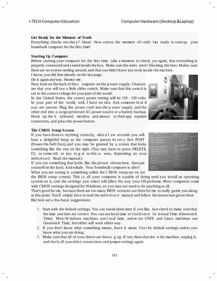
211
I-TECH Computer Education Computer Hardware (Desktop &Laptop)
T
G
o
h
b
m g
e
n
Get Ready for the Moment of Truth
Everything checks out oka y? Great! Now com es the moment of t ruth: Get ready to start up your
homebuilt computer for the first time!
Starting Up Computer
Before starting your computer for the first time, take a moment to check, yet again, that everything is
properly connected and s eated inside the box. Make sure the wires aren't blocking the fans. Makes sure
there are no screws rattling around, and that you didn't leave any tools inside the machine.
I know, you did that already on the last page.
Do it again anyway. Humor me.
Now look on the back of the c omputer on the p ower supply. Chances
are that you will see a little slider switch. Make sure that this switch is
set to the correct voltage for your part of the world.
In the United States, the correct power setting will be 110 - 120 volts.
In your part of the world, well, I have no ide a. Ask someone loc al if
you are unsure. Plug the power cord into the p ower supply, and the
other end into a su rge-protected AC power source or a battery backup.
Hook up the k eyboard, monitor, and mouse to their app ropriate
connectors, and press the power button.
The CMOS Setup Screen
If you have done ev erything correctly, after a f ew seconds you will
hear a delightful beep as the computer passes its ver y first POST
(Power-On-Self-Test), and you may be greeted by a screen that looks
something like the one on the right. (You may have to press DELETE,
F2, or some oth er key to g et to this sc reen, depending on your
mothe rb oa rd . Read the manual.)
If you see something that looks like the picture shown here, then pat
yourself on the back. And exhale. Your homebuilt computer is alive!
What you are seeing is something called the C MOS setup scre en (or
the BIOS setup screen). This i s all your computer is ca pable of doing until you install an operating
system on it, and the settings you select will affect the way your OS performs. Most computers come
with CMOS settings designed for Windows, so you may not need to do anything at all.
That's good for me, because there are too many BIOS versions out there for me to really guide you along
at this point. You'll simply have to read the mothe rb oa r d manual and follow the instruction given there
But here are a few basic suggestions:
1. Start with the default settings. You can tweak them later if you like. Just check to make sure that
the time and date are correct. You can use local time or Coordin ate d Un iversal Time (Greenwich
Time). Most W indows machines use l ocal time, and m ost UNIX and Linux machines use
Greenwich Time; but either will work either way.
2. If you don't know what something means, leave it alone. Use t he default settings unless you
know what you are doing.
3. Make sure that all of your drives are showin g up. If not, then shut dow n the machine, unplug it,
and check all your drive connections and jumper settings again.
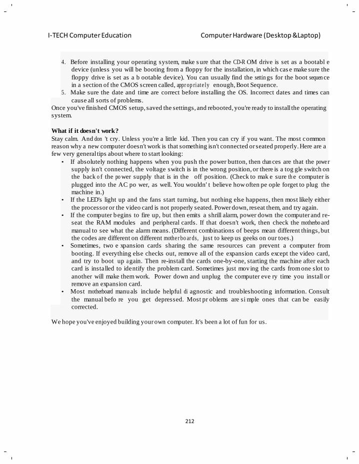
212
I-TECH Computer Education Computer Hardware (Desktop &Laptop)
4. Before installing your operating system, make s ure that the CD-R OM drive is set as a bootabl e
device (unless you will be booting from a floppy for the installation, in which cas e make sure the
floppy drive is set as a b ootable device). You can usually find the settin gs for the boot sequen ce
in a section of the CMOS screen called, appr op riate ly enough, Boot Sequence.
5. Make sure the date and time are correct before installing the OS. Incorrect dates and times can
cause all sorts of problems.
Once you've finished CMOS setup, saved the settings, and rebooted, you're ready to install the operating
system.
What if it doesn't work?
Stay calm. And don 't cry. Unless you're a little kid. Then you can cry if you want. The most common
reason why a new computer doesn't work is that something isn't connected or seated properly. Here are a
few very general tips about where to start looking:
• If absolutely nothing happens when you push the power button, then chan ces are that the powe r
supply isn't connected, the voltage switch is in the wrong position, or there is a tog gle switch on
the back o f the po wer supply that is in the off position. (Check to mak e sure th e computer is
plugged into the AC po wer, as well. You wouldn' t believe how often pe ople forget to plug the
machine in.)
• If the LED's light up and the fans start turning, but nothing else happens, then most likely either
the processor or the video card is not properly seated. Power down, reseat them, and try again.
• If the computer begins to fire up, but then emits a shrill alarm, power down the computer and re-
seat the RAM modules and peripheral cards. If that doesn't work, then check the motherbo ard
manual to see what the alarm means. (Different combinations of beeps mean different things, but
the codes are different on different mothe r bo ar ds, just to keep us geeks on our toes.)
• Sometimes, two e xpansion cards sharing the same resources can prevent a computer from
booting. If everything else checks out, remove all of the expansion cards except the video card,
and try to boot up a gain. Then re-install the cards one-by-one, starting the machine after each
card is installed to identify the problem card. Sometimes just moving the cards from one slot to
another will make them work. Power down and unplug the computer eve ry time you install or
remove an expansion card.
• Most motherboard manuals include helpful di agnostic and troubleshooting information. Consult
the manual befo re you get depressed. Most pr oblems are si mple ones that can be easily
corrected.
We hope you've enjoyed building your own computer. It's been a lot of fun for us.
213
I-TECH Computer Education Computer Hardware (Desktop &Laptop)
Chapter - 15
Computer Virus
Objectives of learning:
What is Computer Virus:
What Does A Virus Do:
How Does A Virus Spread:
Infection strategies:
Virus Example
Anti Virus Technologies:
Recovery methods
Types Of Viruses:
Tips to protect your PC from viruses:
Introduction
A computer virus is a computer program that can copy itself and infect a computer. The term "virus" is
also commonly but erroneously used to refer to other types of malware, including but not limited to
adware and sp yware programs that do not have the rep roductive ability. VIRUS stands for Vital
Information of Resources Under Siege true virus can spread from one computer to another (in some
form of executable code) when its host is taken to the target computer; for instance because a us er sent
it over a network or the Internet, or carried it on a removable medium such as a floppy disk, CD, DVD,
or drive. Viruses can i ncrease their chances of sprea di ng to other computers by infecting files on a
network file system or a f ile system that is ac cessed by another computer. As stated above, the term
"computer virus" is some times used as a catch-all phrase to inc lude all types of malware, even those
that do not have the reprod u ct ive abilit y. Malware includes computer viruses, computer worms, Trojan
horses, most root kit s, spyware, dishonest ad ware and other malicio us and unwanted software ,
including true viruses. Viruses are sometimes confused with wor ms and Tr ojan horses, which a re
technically different. A worm can exploit security vulnerabilities to spread itself automatically to other
computers through networks, while a Trojan horse is a program that appears harmless but hi des
malicious functions. W orms and Trojan ho rses, like viruses, may harm a computer system's data or
performance. Some viru ses and othe r malware have symptoms noticeable to the computer user, but
many are surreptitious or simply do nothing to call attention to them. Some viruses do nothing beyond
repro du cin g themselves.
Virus programs:
The Creeper virus was first detect ed on ARPANET, the forerunne r of the Internet, in the earl y 1970s.
Creeper was an experimental self-replicating program written by Bob Thomas at BBN Technologies in
1971. Creeper used the ARPANET to infect DEC PDP-10 computers ru nning the TENEX ope rating
system. Creeper gained access via the ARPANET and copi ed itself to the remote system where the
message, "I'm the creeper, catch m e if you can!" was displa yed. The Reaper program was created to
delete Creeper.
A program called "Elk Cloner" was the first computer virus to appear "in the wild" — that is, outside
the single computer or lab where it was created. Written in 1981 by Richard Skrenta, it attached itself to
the Apple DOS 3.3 operating system and spread via floppy disk. This virus, created as a practical joke
214
I-TECH Computer Education Computer Hardware (Desktop &Laptop)
when Skrenta was still in high school, was injected in a game on a floppy disk. On its 50th use the Elk
Cloner virus would be a ctivated, infecting the com puter and displa ying a short poem beg inning "Elk
Cloner: The program with a personality."
Before computer networks became widespread, most viruses spread on rem ovable media, particularly
floppy disks. In the early days of the personal computer, many users regularly exchanged information
and programs on floppies. Some viruses spread by infecting programs stored on these disks, while
others installed thems elv es into the disk boot se ctor, ensuring that they would be run when the user
booted the computer from the disk, usually inadvertently. PCs of th e era would attempt to boot f irst
from a floppy if one had be en left in the drive. Until floppy disks f ell out of use, this was the most
successful infection strategy and boot sector viruses were the most common in the wild for many years.
Traditional computer viruses emerged in the 1980s, driven by the spread of personal computers and the
resultant increase in BBS, mode m use, and software sharing. Bulletin board-driven software sharing
contributed directly to the spread of Trojan horse programs, and viruses were written to infect popularly
traded software. Shareware and bootleg software were equally common vectors for viruses on BBS's.
Macro viruses have become common since the mid-1990s. Most of the se viruses are written in the
scripting languages for Microsoft programs such as Word and Excel and spread throughout Microsoft
Office by infecting documents and sprea ds he et s. Since Word and E xcel were also available for Mac
OS, most could also sp read to Macintosh computers. Although most of these virus es did not h ave the
ability to se nd infected email messages, those viruses which did t ake advantage of the Mic rosoft
Outlook COM interface.
Some old versions of Microsoft W ord allow macros to replicate themselves with additional blank lines.
If two ma cro viruses simultaneously infect a document, the combination of the two, if also self-
replicating, can appear as a "mating" of the two and would likely be detected as a virus unique from the
"parents".
A virus ma y also send a web address link as an instant message to a ll the contacts on an infected
machine. If the recipient, thinking the link is f rom a friend (a trusted source) follows the link to the
website, the virus hosted at the site may be able to infect this new computer and continue propagating.
Viruses that spread using cross-site scriptin g were first repo rted in 2002, and were ac ademically
demonstrated in 2005.There have been multiple instances of the cross-site scripting viruses in the wi ld,
exploiting websites such as MySpace and Yahoo.
What Does a Virus Do?
The task of a virus is not always destructive like deleting files that may be important or something like
causing your hard drive to crash. Many viruses these days are more interested in harvesting information
from your computer and or using it as a zombie for their intentions like spam or other illegal purposes.
In times past it wa s often the intention of a virus to do da mage just f or the sake of destruction and
maybe bragging rights among peers but almost a ll viruses today that are widespread have at their root
some economic agenda.
How Does a Virus Spread?
One of the intents of all types of computer viruses that get installed on your computer will be to spread
itself. This ha ppens in a fashion that is not a ll that different from what happens with a virus in the
human population. It is through exposure that the virus spreads when the computers defenses are down
or nonexistent. Also like their biological counterpart the computer virus can be spread rapidly and are
not very easy to get rid of.
215
I-TECH Computer Education Computer Hardware (Desktop &Laptop)
Because the way a virus operates is to b e stealthy, coupled with the rapid communications that happen
between today‘s computers, it is easy to dramatically increase the speed at which a vi rus that is
targeting a newly discovered vulnerability can move around the w eb and around th e world.
A virus that targets a network of computers can even more easily spread since so many computers are
connected and most likel y will have the same vulnerability and e asy access to one another. O ften
viruses will spr ead via shared folders, email or over other media that is of ten exposed to other
computers via removable media like cds and fl ash drives.
Because there are so many types of computer viruses, a vi rus can infect another computer
unintentionally anytime that program is run and the virus is activated. Something like opening a email
attachment or downloading a file off the internet or giving or receiving a copy of a program or file from
a co-workers thumb drive c an expose you and others to a compute r virus.
Literally the gamut of these t ypes of computer viruses can ex pose you whenever you have a
downloaded file or a external drive attached to your pc. The most common way they spread is via email
attachments or with the use or transfer of files via instant messaging.
Infection strategies:
In order to r eplicate itself, a virus must be permitted to e xecute code and write to me mory. For this
reason, many viruses attach themselves to executable files that may be part of legitimate programs. If a
user attempts to launch an infected program, the virus' code may be executed simultaneously. Viruses
can be divided into two types based on their b ehavior when they are executed. Nonresident viruses
immediately search for other hosts that can be infected, infect those targets, and finally transfer control
to the application program they infected. Resident viruses do not search for hosts when they are started.
Instead, a resident virus loads itself into memory on ex ecution and transfe rs control to the host
program. The virus stays active in the background and infects new hosts when those files are accessed
by other programs or the operating system itself.
Nonresid ent viruses
Nonresident viruses can be thought of as consisting of a finder module and a replication module. The
finder module is responsible for finding new files to infect. For each ne w executable file the fin der
module encounters, it calls the replication module to infect that file.
Resident viruses
Resident viruses contain a replica tion module that is similar to the one that is employed by nonresident
viruses. This module, however, is not called by a finder module. The virus loads the replication module
into memory when it is ex ecuted instead and ensures that this module is ex ecuted each time the
operating system is call ed to perfo rm a c ertain operation. The replication module can be called, for
example, each time the operating system executes a file . In this cas e the virus infects ev ery suitable
program that is executed on the computer.
Resident viruses a re sometimes subdivided into a c ategory of fast infectors and a category of slow
infectors. Fast infectors are desi gned to infect as m any files as possi ble. A fast infector, for i nstance,
can infect every potential host file that is accessed. This poses a special problem when using anti-virus
software, since a virus scanner will access every potential host file on a computer when it performs a
system-wide scan. If the virus scanner fails to no tice that such a virus is present in memory the virus
can "piggy-back" on the vir us scanner and in this way infect all files that are scanned? Fast infectors
rely on their f ast infection rate to spread. The disa dvantage of this method is that infecting many files
216
I-TECH Computer Education Computer Hardware (Desktop &Laptop)
may make detection more likely, because the virus may slow down a computer or p erform many
suspicious actions that can be noticed b y anti-virus software. Slow infe ctors, on the other hand, are
designed to infect hosts infrequently. Some slow infectors, for instance, only infect files when they are
copied. Slow infectors are designed to avoid detection by limiting their actions: they are less likely to
slow down a computer noticeably and will, at most, in frequently trigger anti-virus software that detects
suspicious behavior by programs. The slow infector approach, however, does not seem very successful.
Vectors and hosts
Viruses have targeted various types of transm issio n media or hosts. This list is not exhaustive:
• Binary executable files (such as COM f iles and EXE f iles in MS- DOS, Portable Executable
files in Microsoft Windows, the Mach-O format in OSX, and ELF files in Linux)
• Volume Boot Records of floppy disks and hard disk partitions
• The master boot record (MBR) of a hard disk
• General-purpose script files (such as batch files in MS-DOS a nd Microsoft Windows, VBScript
files, and shell script files on Unix-like platforms).
• Appl ica tio n -spe c i fic script files (such as Telix-scripts)
• System specific auto run script files (such as Autorun.inf file needed by Windows to
autom at ica l ly run software stored on USB Memory Storage Devices).
• Documents that can contain macros (such as Microsoft Word documents, Microsoft Excel
sprea dsh e ets, AmiPro documents, and Microsoft Access database files)
• Cross-site scripting vulner abi l it i e s in web applications (see XSS Worm)
• Arbitrary computer files. An exploitable buffer overflow, format string , race condition or other
exploitable bug in a program which reads the file could be used to trigger the execution of code
hidden within it. Most bugs of this t ype can be made more difficult to e xploit in computer
architectures with protection features such as an execute disable bit and/or address space layout
randomization.
PDFs, like HTML, may link to malicious code. PDFs can also be infected with malicious code.
In operating systems that use file extensions to determine program associations (such as Mi crosoft
Windows), the ex tensions may be hidden f rom the user by default. This makes it possible to create a
file that is of a di fferent type than it appears to the user. For example, an executable may be c reated
named "picture.png.exe", in which the user sees only "picture.png" and therefore assumes that this file
is an image and most likely is safe, yet when opened runs the executable on the client machine.
An additional method is to generate the virus code from parts o f existing operating system files by
using the CRC16/CRC32 data. The initial code can be quite small (tens of bytes) and unpack a fairly
large virus. This is a nalogous to a biological "prion" in the way it works but is vulnerable to signature
based detection. This attack has not yet been seen "in the wild".
Methods to avoid detection
In order to avoid d etection by users, some viru ses employ different kinds of dec eption. Some old
viruses, especially on the MS-DOS platform, make sure that the "last modified" date of a host file stays
the same when the file is inf ected by the virus. This a pproach does not fool anti-virus software;
however, especia l ly those which maintain and date cyclic redun da n c y checks on file changes.
Some viruses can infect f iles without increasing their sizes or damaging the files. They accomplish this
by overwriting unused areas of executable files. These are called cavity viruses. For example, the CIH
217
I-TECH Computer Education Computer Hardware (Desktop &Laptop)
virus, or Chernobyl Virus, infects Portable Executable files. Because those files have many empty gaps,
the virus, which was 1 KB in length, did not add to the size of the file.
Some viruses try to avoid detection by killing the tasks associated with antivirus software before it can
detect them.
As computers and operating systems grow larger and more complex, old hiding techniques need to be
updated or r eplaced. Defending a compute r against viruses may demand that a file s ystem migrate
towards detailed and explicit permission for every kind of file access.
Avoiding bait files and other undesirable hosts
A virus needs to infect hosts in order to spread further. In some cases, it might be a bad idea to infect a
host program. For example, many anti-virus programs perform an inte grity check of th eir own c ode.
Infecting such programs will therefore increase the likelihood that the virus is detected. F or this reason,
some viruses are programmed not to inf ect programs that are known to be part of anti-virus software.
Another type of host that viruses sometimes avoid are bait files. Bait files (or goat files) are files that
are specially created by anti-virus software, or by anti-virus professionals themselves, to be infected by
a virus. These files can be created for various reasons, all of whi ch are related to the detection of the
virus:
• Anti-virus professionals can use bait files to take a sample of a virus (i.e. a cop y of a pro gram
file that is infected by the virus). It is more practical to store and exchange a small, infected bait
file, than to exchange a large application program that has been infected by the virus.
• Anti-virus professionals can use bait files to study the behavior of a virus and evaluate detection
methods. This is especially useful when the virus is pol ymorphic. In this case, the virus can be
made to infect a large number of bait files. The infected files can be used to test whether a virus
scanner detects all versions of the virus.
• Some anti-virus software employs bait files that are accessed regularly. When these files are
modified, the anti-virus software warns the user that a virus is probably active on the system.
Since bait files are us ed to detect the virus, or to make detection possible, a virus can ben efit from not
infecting them. Viruses typically do this b y avoiding suspicious programs, such as small program files
or programs that contain certain patterns of 'garbage instructions'.
A related strategy to make baiting difficult is sparse infection. Sometimes, sparse infectors do not infect
a host file that would be a suitabl e candidate for infection in other circumstances. For example, a virus
can decide on a random basis whethe r to infe ct a file or not, or a virus can only infect host file s on
particular days of the week.
Stealth
Some viruses try to trick antivirus software by intercepting its requests to the operating system. A virus
can hide itself by intercepting the antivirus software‘s request to read the file and passing the request to
the virus, instead of the OS. The virus can then return an uninfected version of the file to the antivirus
software, so that it seems that the file is "clean". Modern antivirus software employs various techniques
to counter stealth mech anisms of viruses. The o nly completely reliable method to avoid stealth is to
boot from a medium that is known to be clean.
Self-modification
Most modern antivirus p rograms try to find virus -patterns inside ordinary programs by scanning them
for so-called virus signatures. A signature is a characteristic byte-pattern that is part of a cert ain virus
218
I-TECH Computer Education Computer Hardware (Desktop &Laptop)
or family of viruses. If a virus scanner finds such a pattern in a file, it notifies the user that the file is
infected. The user can then delete, or (in some cases) "clean" or "heal" the infected file. Some viruses
employ techniques that make det ection by means of si gnatures difficult but probabl y not impossible.
These viruses modify their code on each infection. That is, each infected file contains a different variant
of the virus.
Encryption with a variable key
A more advanced method is the use of simple encryption to encipher the virus. In this case, the virus
consists of a small decrypting module and an encrypted copy of the virus code. If the virus is encrypted
with a di fferent key for each i nfected file, the only part of t he virus that remains constant is the
decrypting module, whic h would (for ex ample) be a ppended to the end. In this case, a virus scanner
cannot directly detect the virus using signatures, but it can still detect the decrypt in g module, which still
makes indirect detection of the virus pos sible. Since these would be s ymmetric keys, stored on the
infected host, it is in f act entirely possible to decrypt the final virus, but this is pr obably not required,
since self-m o di f ying code is such a rarity that it may be reason for virus scanners to at least flag the file
as suspicious.
An old, but compact, encr yption involves XORing each byte in a virus with a constant, so that the
exclusive-or operation had onl y to be repeated for decryption. It is susp icious for a code to modif y
itself, so the code to do the encryption/decryption may be part of the signature in ma ny virus
definitions.
Polymorph ic code
Polymorphic code was the first t echnique that posed a serious threat to virus scanners. Just like regular
encrypted viruses, a polymorphic virus infects files with an encrypted copy of itself, which is decoded
by a decryption module. In the case of polymorphic viruses, however, this decryption module is a lso
modified on each infect ion. A well -w rit te n pol ymorphic virus theref or e has no parts which remain
identical between in fections, making it ver y difficult to de tect directly using signatures. Antivirus
software can detect it by decrypting the viruses using an emulator, or by statistical pattern analysis of
the encrypted virus bod y. To enable pol ymorphic code, the virus has to have a pol ymorphic engine
(also called mutating engine or mutation engine) somewhere in its e ncrypted body. See Polymorphic
code for technical detail on how such engines operate.
Some viruses employ polymorphic code in a way that constrains the mutation rate of the virus
significantly. For example, a virus can be programmed to mutate only slightly over time, or it c an be
programmed to refrain from mutating when it infects a file on a computer that already contains copies
of the virus. The advant age of using such slow p olymorphic code is that it makes it more difficult for
antivirus professionals to obtain representative samples of the virus, because bait files that are infected
in one run will typically contain identical or similar samples of the virus. This will make it more likely
that the detection by the virus scanner will be unreliable, and that some instances of the virus may be
able to avoid detection.
Metamorp hic code
To avoid being detected by emulation, some viruses rewrite themselves completely each time they are
to infect new executables. Viruses that utilize this technique are said to be metamorphic. To e nable
metamorphism, a metamorphic engine is ne eded. A me tamorphic virus is usua lly very large and
219
I-TECH Computer Education Computer Hardware (Desktop &Laptop)
complex. For example, W32/Simile consisted of over 14000 lines of Assembly language code, 90% of
which is part of the meta m or phic engine.
Virus Examples:
I LOVE YOU Virus
– The virus only targets users running Microsoft Windows operating system, attacking the Outlook e-
mail program and the Internet Explorer browser, both of which are made by Microsoft.
– Victim activates the virus by opening the e-mail, then clicking on the attachment inside.
– Best defense, is to simply leave any unusual or unknown attach m e nts unopened.
Code Red
– Worms use up computer time and network bandwidth when they are replicating, and the worm called
Code Red made huge headlines in 2001.
– Code Red worm slowed down Internet traffic when it began to replicate itself and each cop y of the
worm scanned the Internet for
Windows NT or Windows 2000 servers that do not have the
Microsoft security patch installed.
– The memory resident worm, once active on a system, first attempts to spread itself by creat ing a
sequence of random IP addresses to infect unprotected web servers.
W95.CIH
– CIH virus, also known as Chernobyl, was first discovered in June 1998 in Taiwan.
– CIH is a destructive virus with a payload that destroys data and on
April 26, 1999, the payload triggered for the first time, causing many computer users to lose their data.
– CIH is a virus that infects the 32-bit Windows 95/98/NT executable files, but can function only under
Windows 95/98 and ME.
W32.Blaster.Worm
– W32. Bla ster .W o rm is a worm that exploits the DCOM RPC vulne ra bi li ty (first described in
Microsoft Security Bulletin MS03- 026) using TCP port 135.
– Worm also attempts to perform a Denial of Service (DoS) on the Microsoft Windows Update Web
server (windowsupdate.com).
– Systems Affected are Windows 2000, Windows NT, Windows
Server 2003, Windows XP
Vulnerab ility and countermeasu res: The vulne ra bi l ity of operating systems to viruses:
Just as g enetic diversity in a population dec reases the ch ance of a single disease wiping out a
population, the diversity of software s ystems on a network similarly limits the destructive potential of
viruses. This bec ame a particular concern in the 1990s, when Micr oso ft gained market dominance in
desktop operating systems and office suites. Th e users of Micr oso ft software (especially networking
software such as Micro s oft Outlook and Internet Explorer) are esp ecially vulnerable to the spre ad of
viruses. Microsoft softw are is tar geted by virus writers due to the ir desktop dominance, and is often
criticized for including many errors and holes for virus writers to exploit. Integrated and non-integrated
Microsoft appl ic at ion s (such as Microsoft Office) and applications with scripting languages with access
220
I-TECH Computer Education Computer Hardware (Desktop &Laptop)
to the file system (for example Visual Basic Script (VBS), and applications with networking features)
are also part icula r ly vulnerable.
Although Windows is by far the most popular t arget operating system for virus writers, viruses also
exist on other platforms. Any operating system that allows third-party programs to run can theoretically
run viruses. Some operat ing systems are mo re secure than othe rs. Unix-based operating systems (and
NTFS-aware applications on Windows NT based platforms) only allow their users to run ex ecutables
within their own protected memory space.
An Internet based experiment revealed that there were cases when people willingly pressed a particular
button to download a vi rus. Security analyst Didier Stevens ran a hal f year advertising campaign on
Google Ad W ords which said "Is your PC virus-free? Get it infected here!". The result was 409 clicks.
As of 2006, there are relatively few security exploits targeting Mac OS X (with a Unix-based file
system and kern el).The number of viruses for th e older Apple oper ating systems, known as Mac OS
Classic, varies greatly from source to source, with Apple stating that there are only four known viruses,
and independent sources stating there are as many as 63 viruses. Many Mac OS Classic viruses targeted
the HyperCard authoring environment. The difference in vir us vulnerability between Macs and
Windows is a chief selli ng point, one that Apple uses in their Get a Mac advertising. In January 2009,
Symantec announced the discover y of a Troj an that targets Macs. This discovery did not gain much
coverage until April 2009.
The role of software development
Because software is often designed with security features to prevent unauthorized use of s ystem
resources, many viruses must e xploit software bug s in a s ystem or ap plication to spread. Soft ware
development strategies that produce lar ge numbers of bug s will g enerally also produce poten tial
exploits.
Anti-virus software and other preventive measures:
Many users install anti-virus software that can de tect and eliminate known viru ses after the computer
downloads or runs the executable. There are two common methods that an anti-virus soft ware
application uses to detec t viruses. The first, and by far the most common method of virus detection is
using a list of virus signature definitions. This wor ks by examining the content of the computer's
memory (its RAM, and boot sectors) and the files stored on fixed or removable drives (hard drives,
floppy drives), and co mparing those files a gainst a database of known virus " signatures". The
disadvantage of this dete ction method is that user s are only protected from viruses that pr e-date their
last virus definition update. The second method is to use a heuristic alg orithm to find viruses based on
common behaviors. This method has the abilit y to de tect novel viruses t hat anti-virus security firms
have yet to create a signature for.
Some anti-virus programs are able to scan opened files in addition to sent and received email messages
"on the fly" in a similar manner. This p ractice is known as "on-access scanning". Anti-virus so ftware
does not change the underlying capability of host software to transmit viruses. Users must update their
software regularly to patch security holes. Anti-virus software also needs to be regularly updated in
order to recognize the latest threats.
One may also minimiz e the damag e done b y viruses by making regular backups of data (and the
operating systems) on d ifferent media, that are either kept unconnected to the system (most of the
time), read-only or not a ccessible for other reasons, such as usin g different file s ystems. This way, if
data is lost through a virus, one can start again using the backup (which should prefera bly be recent).
221
I-TECH Computer Education Computer Hardware (Desktop &Laptop)
If a backup session on optical media like C D and DVD is closed, it be comes read-only and can no
longer be affected by a virus (so l ong as a virus or infected file was not copied onto the CD/DVD).
Likewise, an operating system on a bootable CD can be used to start the compute r if the insta lled
operating systems become unusable. Backups on removable media must be carefully inspected before
restoration. The Gammima virus, for example, propagates via removable flash drives.
Anti Virus Technologies:
Anti Virus solutions have devised a variety of techniques to detect, cure and immunize against viruses.
These technologies are c onstantly being modified and refined to be effective against the new viruses
that are contin uo usly being written which are as follows:
– Virus detection using Signatures
– Virus detection using TSR Guards
– Virus detection using Checksums
What to look for in an Anti-virus Software:
• Does the anti-virus p ackage come with a DOS boot disk and does it ask you to create an emergency
repair disk during installation?
• Does the anti-virus p ackage offer option for scanning the boot reco rd and a complete file scan
imme dia tely after pre-install scan?
• Does the application check for file integrity?
How often can the user download virus signature updates?
• Does the anti-virus software have the option of perfor m ing a heuristic analysis?
• Is the anti-virus package capable of analyzing and disinfecting compressed archives such as .ZIP and
. A RJ files, as well as disinfe ct ing files within the archive?
Recovery methods:
Once a com puter has be en compromised by a virus, it is usually unsafe to c ontinue using the same
computer without completel y reinstalling the o perating system. However, there are a numbe r of
recovery options that exist after a computer has a virus. These actions depend on severity of the type of
virus.
Virus removal
One possibility on W indows Me, W indows XP, Windows Vista and Wi ndows 7 is a tool known as
System Restore, which restores the registry and critical system files to a p revious checkpoint. Often a
virus will cause a system to hang, and a subsequent hard reboot will render a s ystem restore point from
the same day corrupt. Restore points from previous days should work provided the virus is not designed
to corrupt the r estore files or also exists in pr evious restore points. Som e viruses, however, disable
System Restore and other important tools such as Task Manager and Command Prompt. An example of
a virus that does this is CiaDoor. Howev er, many such virus es can b e removed b y rebooting the
computer, entering Windows safe mode, and then using system tools.
Administrators have the option to disa ble such tools f rom limited users for various reasons (for
example, to reduce potential damage from and the spread of viruses). A virus can modify the registry to
do the same even if the Administ r ator is c ontrolling the computer; it bl ocks all users including the
administrator from accessing the tools. The message "Task Manager has been disabled b y your
administ ra tor" may be displayed, even to the administrator.
222
I-TECH Computer Education Computer Hardware (Desktop &Laptop)
Users running a Microsoft operating system can access Microsoft's website to run a free scan, provided
they have their 20-di git registration number. Man y websites run by anti-virus software companies
provide free online virus scanning, with limite d cleaning facilities (the purpose of the sites is to sell
anti-virus products). So me websites a llow a single suspicious file to be checked by many antivirus
programs in one operation.
Operating system reinstallation
Reinstalling the operating system is another approach to virus removal. It involves either reformat ting
the computer's hard drive and installing the OS and a ll programs from original media, or restoring the
entire partition with a clean backup image. User data can be restored by booting from a Live CD, or
putting the hard drive into another computer and booting from its operating system with g reat care not
to infect the second com puter by executing any infected programs on the original drive; and onc e the
system has been restored precautions must be taken to avoid reinfection from a restored executable file.
These methods are simple to do, ma y be faster than disinfecting a computer, and are guaranteed to
remove any malware. If the operating system and programs must be reinstalled from scratch, the time
and effort to reinstall, reconfigure, and restor e user pref erences must be t aken into account. Restorin g
from an image is muc h faster, totally safe, and restores the exact configuration to the state it was in
when the image was made, with no further trouble.
Types of Viruses:
Not all computer viruses behave, replicate, or infect the same way. There are several different
categories of viruses and malware. Below I list and discuss some of the most common t ypes of
computer viruses
Trojan Horse:
A Trojan hors e program has the app earance of having a useful and desired function. W hile it
may advertise its ac tivity after launching, this inf ormation is not appa rent to the user
beforehand. Secretly the program per forms other, undesired functions. A Trojan horse neithe r
replicates nor copies itse lf, but causes damage or compromises the security of the computer. A
Trojan horse must be s ent by someone o r carried by another program and may arrive in the
form of a joke program or software of some sort. The malicious functionality of a Trojan horse
may be anything undesirable for a computer user, including data destruction or compromising a
system by providing a means for another computer to gain access, thus bypassing normal access
controls.
Worms:
A worm is a program that makes and facilitates the distribution of copies of itself; for example,
from one disk drive to another, or b y copying itself using email or another transport
mechanism. The worm may do d amage and compromise the security of the computer. It may
arrive via exploitation of system vulnerability or by clicking on an infected e-mail.
Boot sector Virus:
A virus which attaches itself to the first pa rt of the hard disk that is r ead by the computer upon
boot up. These are normally spread by floppy disks.
223
I-TECH Computer Education Computer Hardware (Desktop &Laptop)
Macro Virus:
Macro viruses are viruses that use another application's macro programming language to
distribute themselves. They infect documents such as MS Word or MS Excel and are typically
spread to other similar documents.
Memory Resident Viruses:
Memory Resident Viruses reside in a computers volatile memory (RAM). They are initiated
from a virus which runs on the computer and they stay in memory after its initiating program
closes.
Root kit Virus:
A root kit virus is an undetectable virus which attempts to allow someone to gain control of a
computer system. The t erm root kit comes from the Linux administ rato r root user. Th ese
viruses are usu ally installed by Trojans and ar e normally disguised as operating system files.
Polymorph ic Viruses:
A polymorphic virus not only replicates itself by creating multiple files of it, but it also changes
its digital signature every time it replic ates. This makes it difficult f or less sophisticated
antivirus software to detect.
Logic Bombs/Tim e Bombs:
These are viruses which are programmed to initiate at a specific date or when a specific event
occurs. Some examples are a virus which deletes your photos on Halloween, or a virus which
deletes a database table if a certain employee gets fired.
Tips to protect your PC from viruses:
The single most important wa y to protect a gainst infection is to ke ep your software up-to date,
including your Operating System. Check regularly for updates or set up automatic updates.
Use quality Antivirus software f rom a well- known manufacturer. Check the manufacture r's
recommendations for information such as set-up and config uration.
Avoid questio na ble sites, such as sites that o ffer commercial software (software that you would
have to pay for normally) to download for free.
Avoid sites that offer software hacks and cr acks. Hacks and cracks are us ually a small patch or
software file that circumvents copy protection or usage restrictions.
Never open e-mail from unknown sources. If you have any doubts about an e-mail, it is better to
err on the side of caution and delete it.
224
I-TECH Computer Education Computer Hardware (Desktop &Laptop)
Tips to detect computer virus:
Your first step to detect a com puter virus is when your computer starts to run slower th an
usual.
Your computer crashes and/or restarts on it's own.
Your computer stops responding and/or freezes up.
Your applic at io ns on your computer aren't working correctly.
Your disk drives are inaccessible.
Unusual error messages pops up on your screen.
Abnormal dialog boxes or a menu pops up on your screen.
Browser does not Load Fast
Strange files in Registry
Install and Configure Symantec Anti-Virus Software:
Before You Begin
To use Symantec Antivirus for Windows, you need the following:
• a machine running Windows 98, ME, NT, 2000, or XP/7
• 128 MB of available hard drive space for Windows 98, ME, NT, 2000 and XP (Note: This figure
includes space used for tempo ra r y Windows files, the actual application may require less space.)
• an active Internet connection (if you plan to use the product's auto-update function), including:
o An installed Ethernet card and Category 5 Ethernet cable, if conne ct in g with UTNet,
Resnet, wired Public Network, or other Ethernet connection.
o A modem that works with your operating system, if dialing in.
Before you install Symantec Antivirus software:
• Close all open programs on your machine, so you won't lose work when you restart the machine
during this installa tio n .
• (Windows NT/20 00 /X P /7) Log in as Administrat o r , or as a user with administ r at ive privileges.
Task 1 - Install Symantec Antivirus for Windows
IMPORT ANT ! If you want to update your software or schedule auto-u p da te s, this application requires
Internet connectivity. If you begin installation when you are not connected, the program may attempt to
make a connection to complete the installation process.
For this product to install correctly, you need to uninstall or disable any existing anti-virus applications
and restart your machine. Then, you should tempor a rily disable any firewall appl ic at ion s that are
running.
1. Doub le- cl ic k on the installer. Double - cl ick the Symantec Antivirus folder, and follow the steps
below.
2. Click Install to begin installation.
3. Click next when the installer screen appears.
4. Read the license agreement screen, and if you agree to it, select I accept the terms of the
license agreement and click next.
5. Click next to install all components using the default installation path, or click Custom to
specify comp on e nts and installation path.
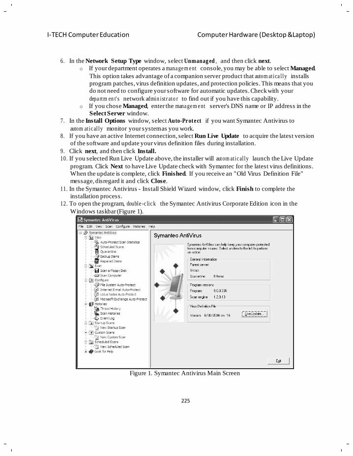
225
I-TECH Computer Education Computer Hardware (Desktop &Laptop)
6. In the Network Setup Type window, select Unmanag ed , and then click next.
o If your department operates a mana ge m e nt console, you may be able to select Managed.
This option takes advantage of a companion server product that autom at ica l ly installs
program patches, virus definition updates, and protection policies. This means that you
do not need to configure your software for automatic updates. Check with your
depa rtm en t' s network admin ist r ato r to find out if you have this capability.
o If you chose Managed, enter the mana ge m e nt server's DNS name or IP address in the
Select Server window.
7. In the Install Options window, select Auto-Prot ect if you want Symantec Antivirus to
autom at ic al ly monitor your system as you work.
8. If you have an active Internet connection, select Run Live Update to acquire the latest version
of the software and update your virus definition files during installation.
9. Click next, and then click Install.
10. If you selected Run Live Update above, the installer will autom at ic al ly launch the Live Update
program. Click Next to have Live Update check with Symantec for the latest virus definitions.
When the update is complete, click Finished. If you receive an "Old Virus Definition File"
message, disregard it and click Close.
11. In the Symantec Antivirus - Install Shield Wizard window, click Finish to complete the
installation process.
12. To open the program, double -c lic k the Symantec Antivirus Corporate Edition icon in the
Windows taskbar (Figure 1).
Figure 1. Symantec Antivirus Main Screen
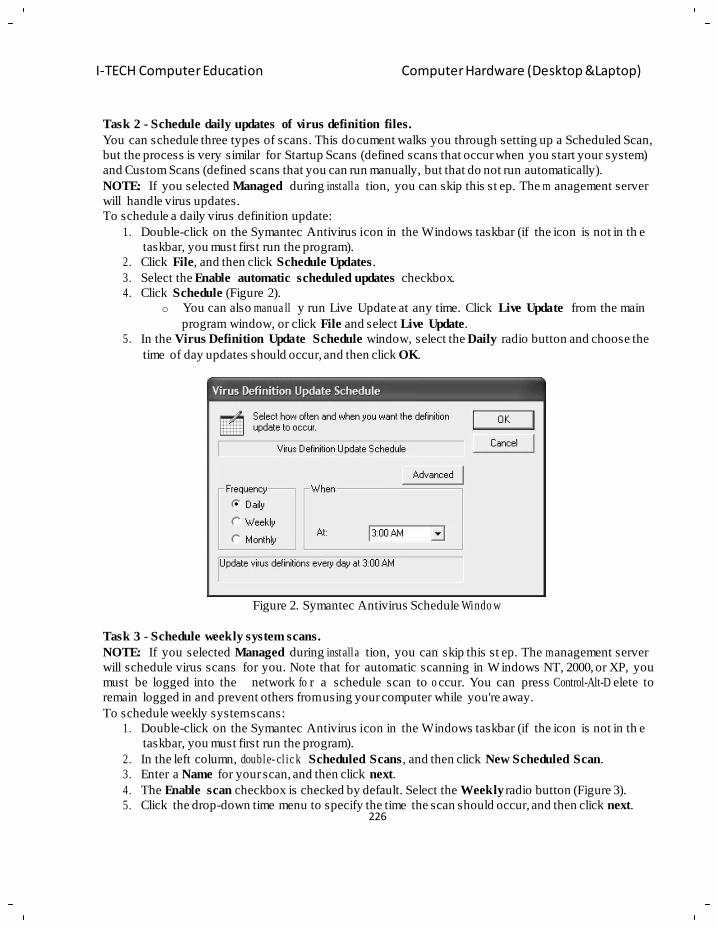
226
I-TECH Computer Education Computer Hardware (Desktop &Laptop)
Task 2 - Schedule daily updates of virus definition files.
You can schedule three types of scans. This document walks you through setting up a Scheduled Scan,
but the process is very similar for Startup Scans (defined scans that occur when you start your system)
and Custom Scans (defined scans that you can run manually, but that do not run automatically).
NOTE: If you selected Managed during installa tion, you can skip this st ep. The m anagement server
will handle virus updates.
To schedule a daily virus definition update:
1. Double-click on the Symantec Antivirus icon in the Windows taskbar (if the icon is not in th e
taskbar, you must first run the program).
2. Click File, and then click Schedule Updates.
3. Select the Enable automatic scheduled updates checkbox.
4. Click Schedule (Figure 2).
o You can also manua ll y run Live Update at any time. Click Live Update from the main
program window, or click File and select Live Update.
5. In the Virus Definition Update Schedule window, select the Daily radio button and choose the
time of day updates should occur, and then click OK.
Figure 2. Symantec Antivirus Schedule Windo w
Task 3 - Schedule weekly system scans.
NOTE: If you selected Managed during installa tion, you can skip this st ep. The m anagement server
will schedule virus scans for you. Note that for automatic scanning in W indows NT, 2000, or XP, you
must be logged into the network fo r a schedule scan to o ccur. You can press Control-Alt-D elete to
remain logged in and prevent others from using your computer while you're away.
To schedule weekly system scans:
1. Double-click on the Symantec Antivirus icon in the Windows taskbar (if the icon is not in th e
taskbar, you must first run the program).
2. In the left column, double- cl ic k Scheduled Scans, and then click New Scheduled Scan.
3. Enter a Name for your scan, and then click next.
4. The Enable scan checkbox is checked by default. Select the Weekly radio button (Figure 3).
5. Click the drop-down time menu to specify the time the scan should occur, and then click next.
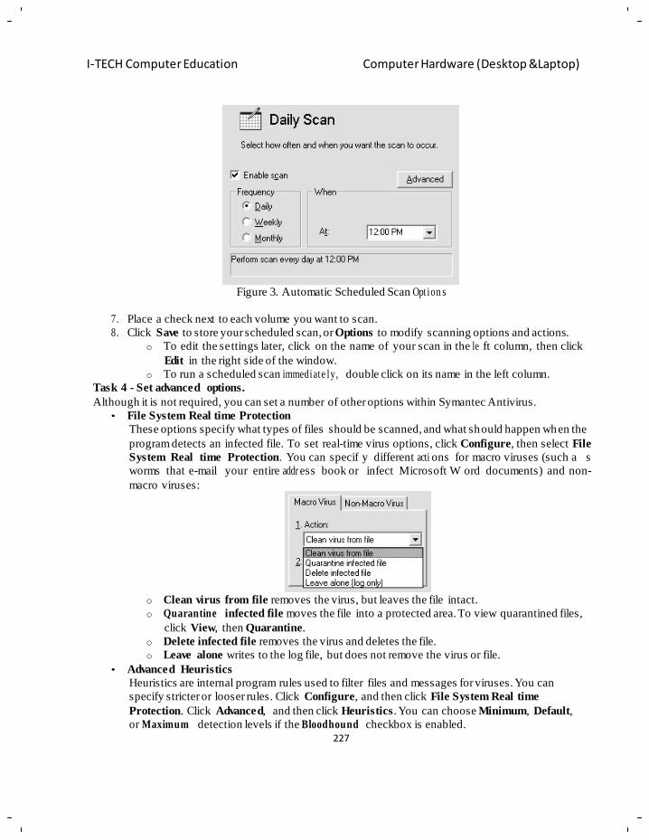
227
I-TECH Computer Education Computer Hardware (Desktop &Laptop)
Figure 3. Automatic Scheduled Scan Opt ion s
7. Place a check next to each volume you want to scan.
8. Click Save to store your scheduled scan, or Options to modify scanning options and actions.
o To edit the settings later, click on the name of your scan in the le ft column, then click
Edit in the right side of the window.
o To run a scheduled scan immediate ly, double click on its name in the left column.
Task 4 - Set advanced options.
Although it is not required, you can set a number of other options within Symantec Antivirus.
• File System Real time Protection
These options specify what types of files should be scanned, and what should happen when the
program detects an infected file. To set real-time virus options, click Configure, then select File
System Real time Protection. You can specif y different acti ons for macro viruses (such a s
worms that e-mail your entire addr ess book or infect Microsoft W ord documents) and non-
macro viruses:
o Clean virus from file removes the virus, but leaves the file intact.
o Quarantine infected file moves the file into a protected area. To view quarantined files,
click View, then Quarantine.
o Delete infected file removes the virus and deletes the file.
o Leave alone writes to the log file, but does not remove the virus or file.
• Advanced Heuristics
Heuristics are internal program rules used to filter files and messages for viruses. You can
specify stricter or looser rules. Click Configure, and then click File System Real time
Protection. Click Advanced, and then click Heuristics. You can choose Minimum, Default,
or Maximum detection levels if the Bloodhound checkbox is enabled.
228
I-TECH Computer Education Computer Hardware (Desktop &Laptop)
• Microsoft Exchange Real time Protection
you can configure the scan to autom a tic a lly send a customized message to any person who
sends you an infected e-mail. To set real-time Exchange options, click Configure, then select
Microsoft Exchange Real-time Protection.
• History Logs
Click History to view virus, scan, and event history logs. These files track the results of all
scans, updates, detected viruses, and actions taken by the program.
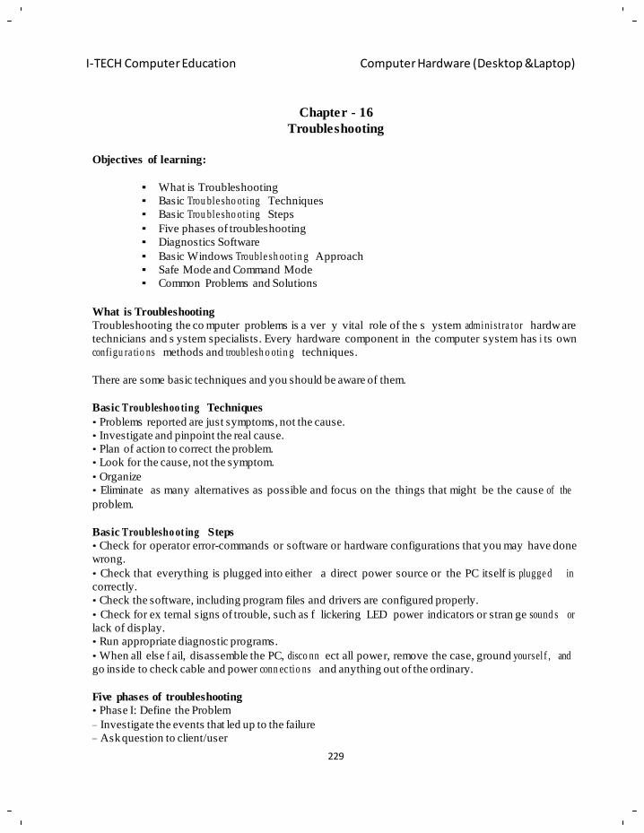
229
I-TECH Computer Education Computer Hardware (Desktop &Laptop)
Chapter - 16
Troubleshooting
Objectives of learning:
What is Troubleshooting
Basic Trou ble sho ot ing Techniques
Basic Trou ble sho ot ing Steps
Five phases of troubleshooting
Diagnostics Software
Basic Windows Trouble sh oot in g Approach
Safe Mode and Command Mode
Common Problems and Solutions
What is Troubleshooting
Troubleshooting the co mputer problems is a ver y vital role of the s ystem administ ra tor hardw are
technicians and s ystem specialists. Every hardware component in the computer system has i ts own
configu ra tio ns methods and troublesh o otin g techniques.
There are some basic techniques and you should be aware of them.
Basic Troubleshoo ting Techniques
• Problems reported are just symptoms, not the cause.
• Investigate and pinpoint the real cause.
• Plan of action to correct the problem.
• Look for the cause, not the symptom.
• Organize
• Eliminate as many alternatives as possible and focus on the things that might be the cause of the
problem.
Basic Troublesho ot ing Steps
• Check for operator error-commands or software or hardware configurations that you may have done
wrong.
• Check that everything is plugged into either a direct power source or the PC itself is plugge d in
correctly.
• Check the software, including program files and drivers are configured properly.
• Check for ex ternal signs of trouble, such as f lickering LED power indicators or stran ge sound s or
lack of display.
• Run appropriate diagnostic programs.
• When all else f ail, disassemble the PC, disco nn ect all power, remove the case, ground yoursel f , and
go inside to check cable and power conn ec tio ns and anything out of the ordinary.
Five phases of troubleshooting
• Phase I: Define the Problem
– Investigate the events that led up to the failure
– Ask question to client/user
230
I-TECH Computer Education Computer Hardware (Desktop &Laptop)
• Phase II: Zero in on the Cause
– For a totally random, intermittent problem, always suspect the power supply.
• Phase III: Conduct the Repair
– Make a Plan
– Follow the Plan from Beginning to End
– Repair or Replace
• Phase IV: Confirm the Results
– Conform Problem no longer exists
• Phase V: Document the Results
Diagnostics Software
• This software, some of which is included with the system when purchased, assists users in
identifying many problems that can occur with a computer's components.
• All versions of Windows from Windows 98 on include a set of diagnostic system tools (acce sse d via
Start > Programs >
Acce sso ries > System Tools) that can help you track down many types of system problems.
E.g. Scandisk, Disk Defra gm en ter , System Inform a tio n Tool, Dr.Watson Logging tool,
System File Checker.
Basic Windows Troubleshoot in g Approach
• Gather Information
– Start with the user's complaint.
– Find out about the configu rat ion – H/W & S/W
– Locate backups, emerg e nc y repair disk (ERD), or other external diagnostic or recovery tools.
– What was going on when the system failed?
– Hardware problem, that must be resolved before any work on the operating system proceeds.
– To ident i f y a p roblem and pinpoint a r esolution you can employ a technique known as di fferential
diagnosis.
– One by one rule out the possible causes of failure by diagno sin g suspected components.
– If there is, and fixing it makes the underlying problem disappear, then you have empirical proof that
your diagnosis was correct. If not, you must proceed with the process of elimination.
• Differential diagnosis on operating system problems
• Break the cycle into three components.
• System startup (operating system starts to load and it ends when control is turned over to the user)
• The operating phase (the user and the operating system can use the environment.)
• System shutdown - a shutdown command is given—or occurs unexpectedly.
Safe Mode and Command Mode
• Both Windows 98 and Windows 2000 offer safe mode.
• Safe mode loads the OS with minimal set of drivers
• If the hard disk is still functional, you may attempt to start the system in command mode.
• Press F8 just after the POST to get in to menu where you can get different option to boot the system
• Safe mode offers access to a wider variety of tools to help isolate and repair problems.
231
I-TECH Computer Education Computer Hardware (Desktop &Laptop)
Common Problems and Solutions
PROBL E M: The computer locks up and/or is acting weird:
Solution1: If the comp uter is frozen and will not re spond to an y commands, it may be necessary to
press Ctrl + Alt + Del (all three keys at the same time) to bring up the Task List. Select any program
that says "Not responding" and click the End Task button. Repeat until all tasks are ended. If this
does not work, turn the computer off, w ait several seconds, turn the com puter back on, and let the
computer run the Scandisk.
Solution2: Reboot it. A majority of problems that oc cur while you are using your computer can be
fixed by rebooting. Applications sometimes do n‘t release memory like they should when they are
finished. The end result is your computer locks up or acts r eally weird. When you reboot, memory
registers are cleared and most everythin g is reset. This fixes a lot of problems.
PROBL E M: The computer seems to be running slow.
Solution 1: Make sure t hat the s ystem is runnin g in Turbo Mode. Is the turbo led lit ? Turbo Mode
allows the computer to process information at its full potential, 33 MHz for a 33 MHz machine, and so
forth. If you are NOT in turbo mode, your system may only be running in 16MHz (which is very slow
- snail's pace by today's standards). Are the proper video drivers installed?
Solution 2: Try to cleanup your computer. Kill all TEMP f iles, clear CACHE on your web browser,
and get rid of the garba ge (if you know it is for su re garbage and how to s afely do it). Then DEFRAG
your hard drive. You really don't ever want to allow your system to become more than 2% fragmented,
as it can really slow your system down.
Solution 3: Another trick, make more memory available to th e system by using memory managers
intelligently and/or removing unnecessary TSR's, (Terminate and Stay Resident Programs) which
remain in memor y even though you don't really know the pro grams are running in the ba ck ground.
Pressing Ctrl/Alt/Delete in W in95 will display a list of most of the prog rams and non-driver files that
is currently loading your systems memory. Are the drivers installed? Is the printer cable attached to
both the printer port on the back of the c omputer AND to th e printer? Is the ca ble a parallel
connection? If no, you will need to setup the seria l parameters. If yes, then restart the s ystem in DOS
mode and t ype AUTOEXEC.BAT >PRN and pr ess the enter key. Most printers will then print... though
lasers and some ink jets will NOT automatically eject the paper, so you will need to press the page feed
button on the front of the printer.
PROBLEM: The system will not come up at all, the display is blank and the computer does not make any beep sounds from the speaker.
Solution 1: Check the power conn ectors to the c ase, the monitor... and to the wall and on the Mother
Board. Are any lights coming on at th e monitor, cas e? If not, then you may have popped circuit
breaker in your house or office. T ry plugging in a different electrical device or multi-meter to check
the power... it should be between 115 and 120, over
125 can easily FRY a computer and other electrical devices. If the lights are on, and the power seems
to be fin e then you need to dete rmine if the fan in the po wer supply coming on? Is the monitor
powered on? Is the mon itor's video cable plu gged into the video card ? Double check the bri ghtness
232
I-TECH Computer Education Computer Hardware (Desktop &Laptop)
and contrast settings. Plug the monitor into another computer if possible to verify the monitor isn't the
Problem.
Solution 2: Are any of the drive lig hts on - flo ppy, hard disk, or CD R OM drives? Did the y flash
during power on? If yes, then it's probably not the hard drive or cabling... if they are staying on, there a
definite problem. Check the BIOS settings. Maybe the battery is dea d or too low. If the BIOS are
correct, trace the cables and double check all of the connections and jumpers. Make sure that it did not
miss any of the pins when it was installed. Also, make sure that the power connecto r is on properl y;
remember "red towards power" on most drives.
Solution 3: If the monitor is working fine, and all of the rest of the stuff checks out, chances are - short
on the motherboard, bad power supply, or PC speaker connected wrong. If the PC sp eaker is wrong, you
wouldn't hear the beep codes.
Solution 4: Verify that all of the expansion cards are fully seated in the slots. A partially inserted card
can cause the s ystem not to boot - power suppl y fan may be on, but the monitor is black (blank)
without any messages.
Solution 5: Try unplugging and disconne cting everything except the motherboard, PC speake r, and
video card... if it doesn 't power up h ere, then check the RAM, video card, motherboard, and power
supply.
Solution 6: Try a different power supply - this is a very common problem. Today's power supplies are
designed to give up their lives to protect (save) the rest of your computer. Also, most of the new power
supplies being sold today we tested do NOT pass the basic tests, and use many short cuts to reduce the
cost.
Solution 7: Replace the system RAM, or move them to different slots.
Solution 8: If all else has failed, replace the Mother Board itself. This is a very rare problem, but does
occur in once of one-h un dr e d plus boards.
Solution 9: Try a different CPU - also extremel y rare... in 20 years, I have only seen this twice on a
system that was previou sly working.
PROBL E M: The keyboard doesn't work
Solution1. Press Ctrl + Alt + Del (all three keys at the same time) to bring up the Task List. Select
any program that says "Not respondin g " and click the End Task button. Repeat until all tasks are
ended. Check periodic a lly to see if the keyboard will work.
Solution2. Check to make sure the keyboard is still properly connected to the computer. If the
keyboard has been disconnected, you may have to reboot your computer.
Solution3. If all else fails, then turn the power off. Wait a couple of minutes before turning the
computer back on.
PROBL E M: The computer displays a disk error or non-system disk message?
Solution1: You may have left a disk in the A drive. Remove it and press any key on the keyboard to
reboot the computer.
Solution2: If you don‘t have a disk in the A drive and the message is acco m p a nie d by a "clunking"
sound, turn the computer off and send for a technician.
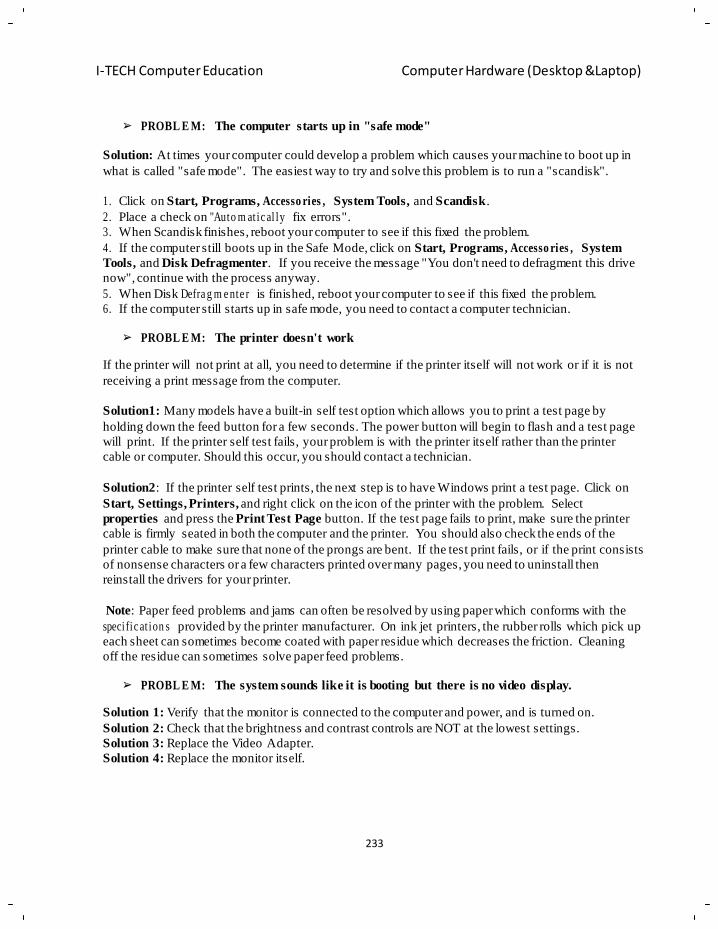
233
I-TECH Computer Education Computer Hardware (Desktop &Laptop)
PROBL E M: The computer starts up in "safe mode"
Solution: At times your computer could develop a problem which causes your machine to boot up in
what is called "safe mode". The easiest way to try and solve this problem is to run a "scandisk".
1. Click on Start, Programs, Accesso ries , System Tools, and Scandisk.
2. Place a check on "Auto m at ic al ly fix errors".
3. When Scandisk finishes, reboot your computer to see if this fixed the problem.
4. If the computer still boots up in the Safe Mode, click on Start, Programs, Accesso ries , System
Tools, and Disk Defragmenter. If you receive the message "You don't need to defragment this drive
now", continue with the process anyway.
5. When Disk Defra g m e nte r is finished, reboot your computer to see if this fixed the problem.
6. If the computer still starts up in safe mode, you need to contact a computer technician.
PROBL E M: The printer doesn't work
If the printer will not print at all, you need to determine if the printer itself will not work or if it is not
receiving a print message from the computer.
Solution1: Many models have a built-in self test option which allows you to print a test page by
holding down the feed button for a few seconds. The power button will begin to flash and a test page
will print. If the printer self test fails, your problem is with the printer itself rather than the printer
cable or computer. Should this occur, you should contact a technician.
Solution2: If the printer self test prints, the next step is to have Windows print a test page. Click on
Start, Settings, Printers, and right click on the icon of the printer with the problem. Select
properties and press the Print Test Page button. If the test page fails to print, make sure the printer
cable is firmly seated in both the computer and the printer. You should also check the ends of the
printer cable to make sure that none of the prongs are bent. If the test print fails, or if the print consists
of nonsense characters or a few characters printed over many pages, you need to uninstall then
reinstall the drivers for your printer.
Note: Paper feed problems and jams can often be resolved by using paper which conforms with the
speci fic at ion s provided by the printer manufacturer. On ink jet printers, the rubber rolls which pick up
each sheet can sometimes become coated with paper residue which decreases the friction. Cleaning
off the residue can sometimes solve paper feed problems.
PROBL E M: The system sounds like it is booting but there is no video display.
Solution 1: Verify that the monitor is connected to the computer and power, and is turned on.
Solution 2: Check that the brightness and contrast controls are NOT at the lowest settings.
Solution 3: Replace the Video Adapter.
Solution 4: Replace the monitor itself.
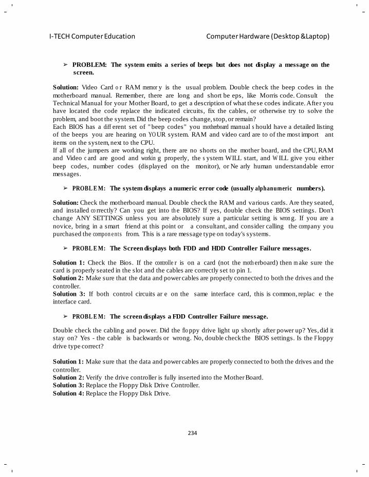
234
I-TECH Computer Education Computer Hardware (Desktop &Laptop)
PROBLEM: The system emits a series of beeps but does not display a message on the
screen.
Solution: Video Card o r RAM memor y is the usual problem. Double check the beep codes in the
motherboard manual. Remember, there are long and short be eps, like Morris code. Consult the
Technical Manual for your Mother Board, to get a description of what these codes indicate. After you
have located the code replace the indicated circuits, fix the cables, or otherwise try to solve the
problem, and boot the system. Did the beep codes change, stop, or remain?
Each BIOS has a diff erent set of " beep codes" you motherboard manual s hould have a detailed listing
of the beeps you are hearing on YO UR system. RAM and video card are to of the most import ant
items on the system, next to the CPU.
If all of the jumpers are working right, there are no shorts on the mother board, and the CPU, RAM
and Video c ard are good and workin g properly, the s ystem WILL start, and W ILL give you either
beep codes, number codes (displayed on the monitor), or Ne arly human understandable error
messages.
PROBL E M: The system displays a numeric error code (usually alphanumeric numbers).
Solution: Check the motherboard manual. Double check the RAM and various cards. Are they seated,
and installed co rrectly? Can you get into th e BIOS? If yes, double check the BIOS settings. Don't
change ANY SETTINGS unless you are absolutely sure a particular setting is wron g. If you are a
novice, bring in a smart friend at this point or a consultant, and consider calling the comp any you
purchased the compon e nts from. This is a rare message type on today's systems.
PROBL E M: The Screen displays both FDD and HDD Controller Failure messages.
Solution 1: Check the Bios. If the controlle r is on a card (not the moth erboard) then m ake sure the
card is properly seated in the slot and the cables are correctly set to pin 1.
Solution 2: Make sure that the data and power cables are properly connected to both the drives and the
controller.
Solution 3: If both control circuits ar e on the same interface card, this is common, replac e the
interface card.
PROBL E M: The screen displays a FDD Controller Failure message.
Double check the cabling and power. Did the flo ppy drive light up shortly after power up? Yes, did it
stay on? Yes - the cable is backwards or wrong. No, double check the BIOS settings. Is the F loppy
drive type correct?
Solution 1: Make sure that the data and power cables are properly connected to both the drives and the
controller.
Solution 2: Verify the drive controller is fully inserted into the Mother Board.
Solution 3: Replace the Floppy Disk Drive Controller.
Solution 4: Replace the Floppy Disk Drive.
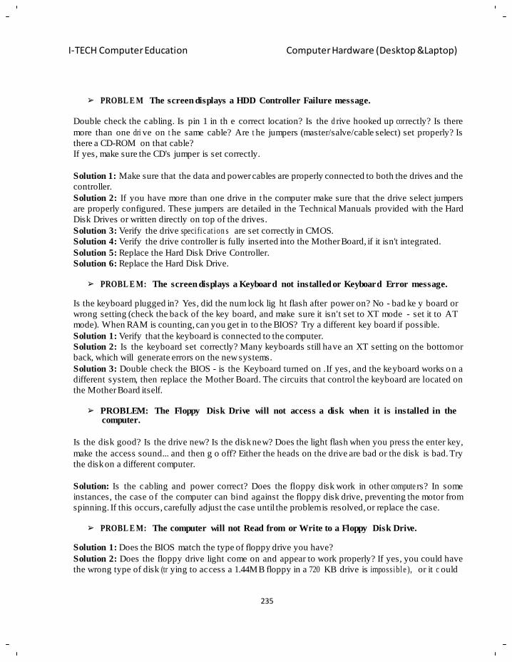
235
I-TECH Computer Education Computer Hardware (Desktop &Laptop)
PROBL E M The screen displays a HDD Controller Failure message.
Double check the cabling. Is pin 1 in th e correct location? Is the d rive hooked up cor rectly? Is there
more than one dri ve on t he same cable? Are t he jumpers (master/salve/cable select) set properly? Is
there a CD-ROM on that cable?
If yes, make sure the CD's jumper is set correctly.
Solution 1: Make sure that the data and power cables are properly connected to both the drives and the
controller.
Solution 2: If you have more than one drive in the computer make sure that the drive select jumpers
are properly configured. These jumpers are detailed in the Technical Manuals provided with the Hard
Disk Drives or written directly on top of the drives.
Solution 3: Verify the drive speci fic at ion s are set correctly in CMOS.
Solution 4: Verify the drive controller is fully inserted into the Mother Board, if it isn't integrated.
Solution 5: Replace the Hard Disk Drive Controller.
Solution 6: Replace the Hard Disk Drive.
PROBL E M: The screen displays a Keyboard not installed or Keyboard Error message.
Is the keyboard plugged in? Yes, did the num lock lig ht flash after power on? No - bad ke y board or
wrong setting (check the back of the key board, and make sure it isn't set to XT mode - set it to AT
mode). When RAM is counting, can you get in to the BIOS? Try a different key board if possible.
Solution 1: Verify that the keyboard is connected to the computer.
Solution 2: Is the keyboard set correctly? Many keyboards still have an XT setting on the bottom or
back, which will generate errors on the new systems.
Solution 3: Double check the BIOS - is the Keyboard turned on .If yes, and the keyboard works on a
different system, then replace the Mother Board. The circuits that control the keyboard are located on
the Mother Board itself.
PROBLEM: The Floppy Disk Drive will not access a disk when it is installed in the computer.
Is the disk good? Is the drive new? Is the disk new? Does the light flash when you press the enter key,
make the access sound... and then g o off? Either the heads on the drive are bad or the disk is bad. Try
the disk on a different computer.
Solution: Is the cabling and power correct? Does the floppy disk work in other compute rs? In some
instances, the case o f the computer can bind against the floppy disk drive, preventing the motor from
spinning. If this occurs, carefully adjust the case until the problem is resolved, or replace the case.
PROBL E M: The computer will not Read from or Write to a Floppy Disk Drive.
Solution 1: Does the BIOS match the type of floppy drive you have?
Solution 2: Does the floppy drive light come on and appear to work properly? If yes, you could have
the wrong type of disk (tr ying to access a 1.44MB floppy in a 720 KB drive is impossible ), or it c ould
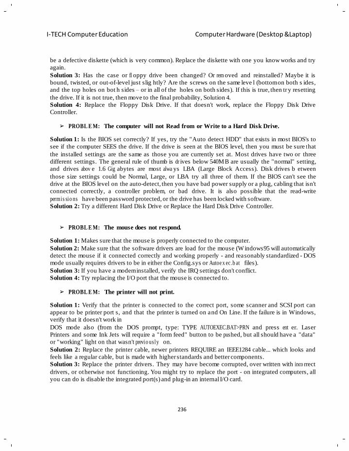
236
I-TECH Computer Education Computer Hardware (Desktop &Laptop)
be a defective diskette (which is very common). Replace the diskette with one you know works and try
again.
Solution 3: Has the case or fl oppy drive been changed? Or rem oved and reinstalled? Maybe it is
bound, twisted, or out-of-level just slig htly? Are the screws on the same leve l (bottom on both s ides,
and the top holes on bot h sides – or in all of the holes on both sides). If this is true, then tr y resetting
the drive. If it is not true, then move to the final probability, Solution 4.
Solution 4: Replace the Floppy Disk Drive. If that doesn't work, replace the Floppy Disk Drive
Controller.
PROBL E M: The computer will not Read from or Write to a Hard Disk Drive.
Solution 1: Is the BIOS set correctly? If yes, try the "Auto detect HDD" that exists in most BIOS's to
see if the computer SEES the drive. If the drive is seen at the BIOS level, then you must be sure t hat
the installed settings are the same as those you are currently set at. Most drives have two or three
different settings. The general rule of thumb is dr ives below 540MB are usually the "normal" setting,
and drives abov e 1.6 Gig abytes are most alwa ys LBA (Large Block Access). Disk drives b etween
those size settings could be Normal, Large, or LBA try all three of them. If the BIOS can't see the
drive at the BIOS level on the auto-detect, then you have bad power supply or a plug, cabling that isn't
connected correctly, a controller problem, or bad drive. It is also possible that the read-write
permis sio ns have been password protected, or the drive has been locked with software.
Solution 2: Try a different Hard Disk Drive or Replace the Hard Disk Drive Controller.
PROBL E M: The mouse does not respond.
Solution 1: Makes sure that the mouse is properly connected to the computer.
Solution 2: Make sure that the software drivers are load for the mouse (W indows95 will automatically
detect the mouse if it connected correctly and working properly - and reasonably standardized - DOS
mode usually requires drivers to be in either the Config.sys or Autoe x ec .b at files).
Solution 3: If you have a modem installed, verify the IRQ settings don't conflict.
Solution 4: Try replacing the I/O port that the mouse is connected to.
PROBL E M: The printer will not print.
Solution 1: Verify that the printer is connected to the correct port, some scanner and SCSI port can
appear to be printer port s, and that the printer is turned on and On Line. If the failure is in Windows,
verify that it doesn't work in
DOS mode also (from the DOS prompt, type: TYPE AUTOEXEC.BAT>PRN and press ent er. Laser
Printers and some Ink Jets will require a "form feed" button to be pus hed, but all should have a "data"
or "working" light on that wasn't previo usly on.
Solution 2: Replace the printer cable, newer printers REQUIRE an IEEE1284 cable... which looks and
feels like a regular cable, but is made with higher standards and better components.
Solution 3: Replace the printer drivers. They may have become corrupted, over written with inco rrect
drivers, or otherwise not functioning. You might try to replace the port - on integrated computers, all
you can do is disable the integrated port(s) and plug-in an internal I/O card.
237
I-TECH Computer Education Computer Hardware (Desktop &Laptop)
Solution 4: Replace the printer itself. It is rare that a printer itself has a p roblem of this na ture, but it
does occur.
Troubleshooting
You have either just finished assembling a computer or you have been using it for some time, and you
encounter problems that make you focus on your motherboard‘s functionality; this is because your PC
either doesn‘t boot succe ssfully (locks in the mid dle of the boot process or posts error messa ges) – or
doesn‘t power up or boo t at all. Moreover, it cou ld be that your system has simply become unstable,
exhibiting frequent crashes. Other peripherals of your PC may come into play as well, but you want to
rule out your mothe rb oa rd as a culprit – here‘s wh at to do.
Before moving on, you need to have an accurate picture of your computer‘s con figuration.
• In order to identify your motherboard.
• In order to gather additional information about your installed compo nents and their respe ctive
drivers.
CAUTION
Please discharge yourself of any static electricity before attempting anything on your motherboard and
while you are working. Electrostatic Discharge (ESD), which is a bit annoying but for sure harmless to
humans, is c ertainly lethal to se nsitive electronics. (For example, a few steps on a vinyl floor will
produce 12,000V of stat ic electricity - man y times the destruction threshold of a t ypical electronic
comp o ne nt .) You will be generating static electricity whenever for example:
• You open a common plastic bag.
• You remove adhesive tape from a container.
• You slide a circuit board on a work bench.
• You walk across a floor.
As you can see, rather common actions can potentially have catastrophic consequences. Electrical
fields can penetrate electronic devices. ESD is no t selective and can damage components directly and
indirectly. In order to be on the sa fe side, the best idea is to use a ntistatic wristbands (which are also
called ESD wrist straps) - especially when handling the processor and the memory chips. You can see
an antistatic wristband pictured below. The wr ist strap is connected t o ground through a coi led
retractable cable and 1 megaohm resistor, which allows hig h-voltage charges to leak throu gh but
prevents a shock hazard when working with low- voltage parts. If you are willing to
invest in an ESD wrist strap, then please do not buy a very cheap one; because typically
these do not have conductive fabr ic and instead use the fabr ic to hold th e metal plate
against the skin, whic h can result in r educed ESD protection over time as the metal
corrodes. When using an ESD wrist band, then do not forget to attach its allig ator clip
to a bare metal part of your computer, workbench or other grounded connection.
If you do not have any ESD wrist straps, then please touch a metallic object to let the static discharge,
before you start h andling your motherboard. However, while handling the motherboard, avoid
touching any metal leads or connectors. If you will need to walk and then continue working on your
238
I-TECH Computer Education Computer Hardware (Desktop &Laptop)
motherboard, touch a gain briefly an unpainted metal part of your computer casing, before resuming
work.
CAUTION
Here are some general best-practice guidelines when working with your motherboard and its
components:
• When you intend to remove the motherboard from the computer's case, first turn everything off and
unplug the po wer cord before continuing. When working on portabl e computers, also r emove all
batteries, PCMCIA cards and disconnect all peripherals.
• Before unplugging the power connector(s) of th e motherboard, verify first that the power suppl y is
switched off.
• Do not use magnetic tools (like screw driv e rs etc).
• Prior to installing any electronic component, keep it on top of an antistatic pad or inside an antistatic
bag (formally called an electrostatic shielding container).
• Do not a llow screws or other metallic parts to come in c ontact with th e motherboard circuit or its
components. Moreover, always weed out screws or metallic objects that may have been left inside the
computer casing .
• Make sure you place all screws you remove, in a sa fe place out of the wa y. Moreover, if the scr ews
you have r emoved appear to be of various sizes, then keep t hem in separate spots and take notes
regarding where they were remo ve d from.
• Do not remove any of the stickers on th e motherboard, because this can void your warranty.
• Have all the relevant do cumentation handy, and study it before acting .
NOTE Please keep in m ind that this is a generic troubleshooting guide for the average user. There is
always a chance you might be facing issues that are not covered by the procedure laid out here
(especially if you have a motherboard that is ver y complex/advanced, very old or with a reco rd of
extreme incidents). In any case, and particularly if you are evaluating the possibility of discarding your
motherboard, please consult the TSF experts at the Motherboards, Bios & CPU sub forum. If you have
questions or do not un derstand a term or method described here, please do not hesitat e to ask.
A. You press the Power button on your PC and no message is posted on the screen.
You may be seeing absolutely no indications that your system powers up or you may see only the CPU
fan turning. Or you may have positive indications that your system powers up, nevertheless it does not
post anything and you are hearing beeping sounds. Another case is your system does power up bu t
shuts down within a cou ple of seconds. The following is a step-by-step procedure to troubleshoot t his
kind of incidents to the wider scope possible.
1. Confirm that the computer and the monitor are properly plugged in an outlet or a functioning UPS.
(UPS stands for ―Uninterrupted Power Supply‖ and is a devic e described and ex plained in step 5 of
Confirm that the power switch at the back of your computer (if pr esent) is on ( I=ON, O=OFF).
Confirm that the voltage selector (if present) is set correctly for your area.
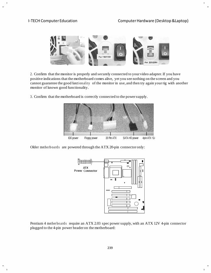
239
I-TECH Computer Education Computer Hardware (Desktop &Laptop)
2. Confirm that the monitor is properly and securely connected to your video adapter. If you have
positive indications that the motherboard comes alive, yet you see nothing on the screen and you
cannot guarantee the good funct ion al i ty of the monitor in use, and then try again your rig with another
monitor of known good functionality.
3. Confirm that the motherboard is correctly connected to the power supply.
Older mothe rb oa rd s are powered through the ATX 20-pin connector only:
Pentium 4 mother bo a rd s require an ATX 2.03 spec power supply, with an ATX 12V 4-pin connector
plugged to the 4-pin power header on the motherboard:
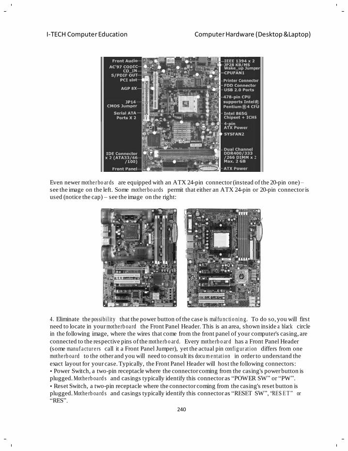
240
I-TECH Computer Education Computer Hardware (Desktop &Laptop)
Even newer mothe r bo ar ds are equipped with an ATX 24-pin connector (instead of the 20-pin one) –
see the image on the left. Some mother bo a rds permit that either an ATX 24-pin or 20-pin connector is
used (notice the cap) – see the image on the right:
4. Eliminate the possibi l ity that the power button of the case is malfu nc tio nin g. To do so, you will first
need to locate in your mothe rb oa rd the Front Panel Header. This is an area, shown inside a black circle
in the following image, where the wires that come from the front panel of your computer's casing, are
connected to the respective pins of the mothe rb o ar d. Every mothe rb o ar d has a Front Panel Header
(some manuf a ctur e rs call it a Front Panel Jumper), yet the actual pin config ur at ion differs from one
mothe rb oa rd to the other and you will need to consult its docu m e ntat ion in order to understand the
exact layout for your case. Typically, the Front Panel Header will host the following connectors:
• Power Switch, a two-pin receptacle where the connector coming from the casing's power button is
plugged. Mothe rb oa rd s and casings typically identify this connector as ―POWER SW‖ or ―PW‖.
• Reset Switch, a two-pin receptacle where the connector coming from the casing's reset button is
plugged. Mothe rb oa rd s and casings typically identify this connector as ―RESET SW‖, ―RES E T ‖ or
―RES‖.
241
I-TECH Computer Education Computer Hardware (Desktop &Laptop)
• Hard Disc LED, a two-pin receptacle where the connector coming from the casing's LED that
signifies the Hard Disc is active, is plugged. Mothe rb oa r ds and casings typically identify this
connector as ―HDD LED‖, ―HDD‖ or ―HD‖.
• Power/Message/Sleep LED, a two-pin receptacle where the connector coming from the casing's LED
that signifies the computer is powered on, is plugged. Motherboards and casings typically identify this
connector as ―POWER LED‖ or ―PWR_LED‖.
• Speaker, a four-pin receptacle where the connector coming from the computer's speaker is plugged.
Mothe rb o ar ds and casings typically identify this connector as ―SPEA K E R ‖ or ―SPEAK‖.
So, first use the mother bo a rd' s docu m e nta tio n and then inspect visually, in order to locate the pins that
correspond to the Power Switch. Remove the power switch connector from the respective pins, and
then short those two pins with a small screwdriver (as shown in the picture below). If your computer
now posts successfully, your problem was caused by a faulty power button.
5. Verify that the CMOS jumper is set at the ―Keep Data‖ position (pins 1-2):
242
I-TECH Computer Education Computer Hardware (Desktop &Laptop)
6. Verify that your power supply has enough wattage to support your system. Use TSF‘s exceptional
Power Supply Information and Selection advisory – where you will also find a great PSU calculator
you can use to see if you are severely underpowered. A word of caution: aforementioned TSF advisory
is the greatest tutorial on how t o select the best P SU for your system; so, do n ot take it lightly or for
granted that you are covered power-wise simply because your system finally boots up. Havin g a
computer on the ed ge of being adequately supplied with power can and will lead you to endl ess
problems and issues which may eventually hurt almost all your components (and, m ainly, your
computer‘s functionality and your own m ental balance). Buying the b est PSU for your computer
actually buys you peace of mind.
7. Verify that your power supply is oper ative. Find another one of known fun ctionality and equal or
higher wattage, and try powering your computer with it. Also, keep in mind that a mere statement of
the wattage is not e nough. For a power supply to be operative, th e voltage will have to be within
acceptable limits, and the delivered amperes will need to be adequate for the specific rig. Please, take
the comment from the previous step into serious consideration and, if you haven‘t already done so,
study carefully the PSU selection advisory mentioned therein.
8. Verify that the CPU that you intend to use i s indeed supported b y your motherboard. Visit the
website of your motherboard‘s manufacturer and find the C PU support l ist that corre spo nd s to your
motherboard. If you see in this list and the rele vant support docum en tat ion that your motherboard
supports your CPU onl y via a BIOS update, then download that ne wer BIOS version and the
respective Flash utility, and follow the instructions that accompany the Flash utility in order to update
your BIOS. Beware, though! If you are required to ultima tely flash your BIOS then, before moving
any further, please read now all the precautions you will need to take, which are explained in step 14
of this process.
9. Verify that the graphics card that you intend to use is wor king OK a nd is well seated. If your
motherboard has onboard video, retest it with th e graphics card removed. If it does not have onboard
video, then retest this time using another compatible graphics card of known functionality. If you are
using an AGP graphics card, these are typically keyed as shown in the image below, in ord er to
prevent an inadvertent installation on a non-supp orting motherboard. However, be advised that th is is
not adequate prevention for you! There is onl y one way to know fo r sure if your graphics card is
243
I-TECH Computer Education Computer Hardware (Desktop &Laptop)
supported or not; and t his is to know its ex act type and then check it out in your motherboard‘s
documentation. Why is this ? Because there are two versions of the AGP physical interface, for 3.3 V
and 1.5 V cards respecti vely. The 1.5 V version has a key further away from the ex ternal connector,
while the 3.3 V version is the opposite. Ho wever, some poorly designed older 3.3V cards incorrectly
have the 1.5V key, which may result in a burnt motherboard if installed in a AGP 4X/8X slot. So, be
very, very careful!
AGP cards are backward and forward compatible within limits. 1.5V-only keyed cards will not go into
3.3V slots and vice ve rsa (but rememb er what we‘ve just told re garding a s ad yet catastrophic
exception to this rule), though ―Universal‖ slots exist which accept either type of card. AGP Pro cards
(rarely used) will not fit into standard slots, but st andard AGP cards will typically work in a Pr o slot.
Some newer cards like nVidia's GeForce 6-series or ATI's X800-series only have keys for 1.5V to
prevent them from bein g installed in older mother boards without 1.5V support. The graphic co res can
only handle 0.8V for AGP8x and 1.5V for AGP4x and will be damaged by 3.3V slots. Some of the last
modern cards with 3.3 V support wer e the nV IDIA GeForce FX5000-series and the ATI Radeon
9500/9700/9800(R350) – but not 9600/9800(R360). Additionally, moving cards between computers of
various CPU ar chitectures may not work due to firmware issues.
10. Verify that your memory specifications are supported by your motherboard and th at you have
placed the m emory modules correctly (well seated in the ri ght slots). Yo u will need to consult your
motherboard‘s documentation because not all memory/slot configurations are functional; in the image
below you can see a relevant excerpt from a specific motherboard‘s manual (this is just an illustrative
example – your own mothe r bo ar d may be different):
244
I-TECH Computer Education Computer Hardware (Desktop &Laptop)
NB: Version 2.0 of this article will contain here a compreh ens iv e guide on confirming the proper
seating of DIMM memory modules. Please check again.
An important note if the memory you are using is SIMM: When installing SIMMs, it is impor tant to
remember that most s ystems (Pentium and newer), require two S IMM modules to make a sing le bank
of memory. Because of this, you need to fill the two slots in a bank with identical modules. However,
each bank can hold different size modules. For example, bank 1 (slots 1 and 2 ) may have two 32MB
modules, while bank 2 ( slots 3 and 4) may have two 16MB modules. The larger modules must be in
the first bank (slots 1 and 2). For most 486-based systems, a memory bank can be single SIMM. Early
486-based systems may require four 30-pins SIMMs to make a s ingle memory bank.
An important note if the memory you are using is 184-pin Rambus R IMMs: These require that all
empty memory slots contain a ― Continuity Module‖ (C-RIMM), so you will need to confirm these are
also properly in place. In this case, all memory slots are filled (with either a RIMM or a C-RIMM).
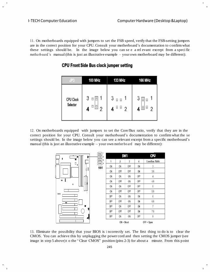
245
I-TECH Computer Education Computer Hardware (Desktop &Laptop)
11. On motherboards equipped with jumpers to set the FSB speed, verify that the FSB-setting jumpers
are in the correct position for your CPU. Consult your motherboard‘s documentation to confirm what
these settings should be. In the image below you can se e a rel evant excerpt from a speci fic
mothe rb oa rd ‘s manual (this is just an illustrative example – your own motherboard may be different):
12. On motherboards equipped with jumpers to set the Core/Bus ratio, verify that they are in the
correct position for your CPU. Consult your motherboard‘s documentation to confirm what the se
settings should be. In the image below you can see a relevant excerpt from a specific motherboard‘s
manual (this is just an illustrative example – your own mother bo a rd may be different):
13. Eliminate the possibility that your BIOS is i ncorrectly set. The first thing to do is to clear the
CMOS. You can achieve this by unplugging the power cord and then setting the CMOS jumper (see
image in step 5 above) t o the ― Clear CMOS‖ position (pins 2-3) for about a minute. From this point
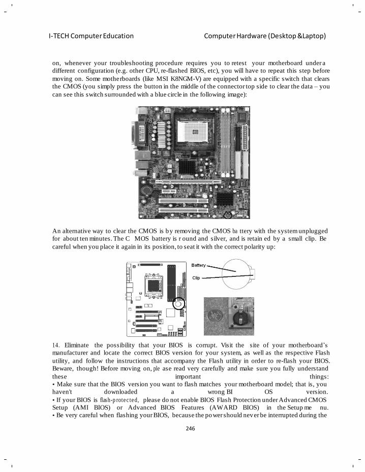
246
I-TECH Computer Education Computer Hardware (Desktop &Laptop)
on, whenever your troubleshooting procedure requires you to retest your motherboard under a
different configuration (e.g. other CPU, re-flashed BIOS, etc), you will have to repeat this step before
moving on. Some motherboards (like MSI K8NGM-V) are equipped with a specific switch that clears
the CMOS (you simply press the button in the middle of the connector top side to clear the data – you
can see this switch surrounded with a blue circle in the following image):
An alternative way to clear the CMOS is by removing the CMOS ba ttery with the system unplugged
for about ten minutes. The C MOS battery is r ound and silver, and is retain ed by a small clip. Be
careful when you place it again in its position, to seat it with the correct polarity up:
14. Eliminate the possibility that your BIOS is corrupt. Visit the site of your motherboard‘s
manufacturer and locate the correct BIOS version for your system, as well as the respective Flash
utility, and follow the instructions that accompany the Flash utility in order to re-flash your BIOS.
Beware, though! Before moving on, ple ase read very carefully and make sure you fully understand
these important things:
• Make sure that the BIOS version you want to flash matches your motherboard model; that is, you
haven't downloaded a wrong BI OS version.
• If your BIOS is flash-p rote c te d, please do not enable BIOS Flash Protection under Advanced CMOS
Setup (AMI BIOS) or Advanced BIOS Features (AWARD BIOS) in the Setup me nu.
• Be very careful when flashing your BIOS, because the power should never be interrupted during the
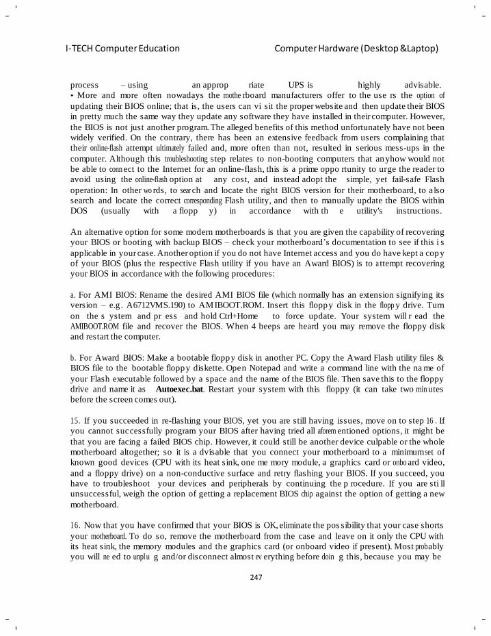
247
I-TECH Computer Education Computer Hardware (Desktop &Laptop)
process – using an approp riate UPS is highly advisable.
• More and more often nowadays the mothe rboard manufacturers offer to the use rs the option of
updating their BIOS online; that is, the users can vi sit the proper website and then update their BIOS
in pretty much the same way they update any software they have installed in their computer. However,
the BIOS is not just another program. The alleged benefits of this method unfortunately have not been
widely verified. On the contrary, there has been an extensive feedback from users complaining that
their online-flash attempt ultimately failed and, more often than not, resulted in serious mess-ups in the
computer. Although this troubleshooting step relates to non-booting computers that anyhow would not
be able to conn ect to the Internet for an online-flash, this is a prime oppo rtunity to urge the reader to
avoid using the online-flash option at any cost, and instead adopt the simple, yet fail-safe Flash
operation: In other wo rds, to sear ch and locate the right BIOS version for their motherboard, to also
search and locate the correct corresponding Flash utility, and then to manually update the BIOS within
DOS (usually with a flopp y) in accordance with th e utility's instructions.
An alternative option for some modern motherboards is that you are given the capability of recovering
your BIOS or booting with backup BIOS – check your motherboard‘s documentation to see if this i s
applicable in your case. Another option if you do not have Internet access and you do have kept a copy
of your BIOS (plus the respective Flash utility if you have an Award BIOS) is to a ttempt recovering
your BIOS in accordance with the following procedures:
a. For AMI BIOS: Rename the desired AMI BIOS file (which normally has an extension signifying its
version – e.g . A6712VMS.190) to AMIBOOT.ROM. Insert this floppy disk in the flopp y drive. Turn
on the s ystem and pr ess and hold Ctrl+Home to force update. Your system will r ead the
AMIBOOT.ROM file and recover the BIOS. When 4 beeps are heard you may remove the floppy disk
and restart the computer.
b. For Award BIOS: Make a bootable floppy disk in another PC. Copy the Award Flash utility files &
BIOS file to the bootable floppy diskette. Open Notepad and write a command line with the na me of
your Flash executable followed by a space and the name of the BIOS file. Then save this to the floppy
drive and name it as Autoexec.bat. Restart your system with this floppy (it can take two min utes
before the screen comes out).
15. If you succeeded in re-flashing your BIOS, yet you are still having issues, move on to step 16 . If
you cannot successfully program your BIOS after having tried all aforem entioned options, it might be
that you are facing a failed BIOS chip. However, it could still be another device culpable or the whole
motherboard altogether; so it is a dvisable that you connect your motherboard to a minimum se t of
known good devices (CPU with its heat sink, one me mory module, a graphics card or onbo ard video,
and a floppy drive) on a non-conductive surface and retry flashing your BIOS. If you succeed, you
have to troubleshoot your devices and peripherals by continuing the p rocedure. If you are sti ll
unsuccessful, weigh the option of getting a replacement BIOS chip against the option of getting a new
motherboard.
16. Now that you have confirmed that your BIOS is OK, eliminate the pos sibility that your case shorts
your motherboard. To do so, remove the motherboard from the case and leave on it only the CPU with
its heat sink, the memory modules and the graphics card (or onboard video if present). Most prob ably
you will ne ed to unplu g and/or disconnect almost ev erything before doin g this, because you may be
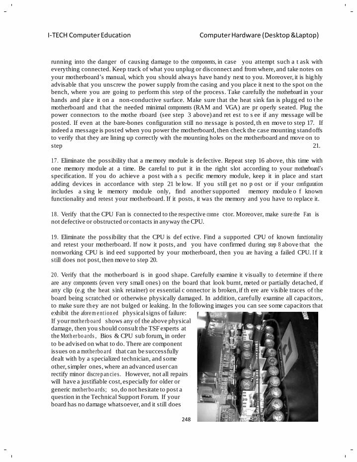
248
I-TECH Computer Education Computer Hardware (Desktop &Laptop)
running into the danger of causing damage to the components, in case you attempt such a t ask with
everything connected. Keep track of what you unplug or disconnect and from where, and take notes on
your motherboard‘s manual, which you should always have handy next to you. Moreover, it is highly
advisable that you unscrew the power supply from the casing and you place it next to the spot on the
bench, where you are going to perform this step of the process. Take carefully the motherboard in your
hands and plac e it on a non-conductive surface. Make sure t hat the heat sink fan is plugg ed to t he
motherboard and that the needed minimal components (RAM and VGA) are pr operly seated. Plug the
power connectors to the mothe rboard (see step 3 above) and ret est to s ee if any message will be
posted. If even at the bare-bones configuration still no me ssage is posted, th en move to step 17. If
indeed a message is posted when you power the motherboard, then check the case mounting standoffs
to verify that they are lining up correctly with the mounting holes on the motherboard and move on to
step 21.
17. Eliminate the possibility that a memory module is defective. Repeat step 16 above, this time with
one memory module at a time. Be careful to put it in the right slot according to your motherboard‘s
specification. If you do achieve a post with a s pecific memory module, keep it in place and start
adding devices in accordance with step 21 be low. If you still g et no p ost or if your configuration
includes a sing le memory module only, find another supported memory module o f known
functionality and retest your motherboard. If it posts, it was the memory and you have to r eplace it.
18. Verify that the CPU Fan is connected to the respective conne ctor. Moreover, make sure the Fan is
not defective or obstructed or contacts in anyway the CPU.
19. Eliminate the possibility that the CPU is def ective. Find a supported CPU of known functionality
and retest your motherboard. If now it posts, and you have confirmed during step 8 above that the
nonworking CPU is ind eed supported by your motherboard, then you are having a failed CPU. I f it
still does not post, then move to step 20.
20. Verify that the motherboard is in good shape. Carefully examine it visually to d etermine if there
are any components (even very small ones) on the board that look burnt, meted or partially detached, if
any clip (e.g the heat sink retainer) or essential c onnector is broken, if th ere are visible traces of t he
board being scratched or otherwise physically damaged. In addition, carefully examine all capacitors,
to make sure they are not bulged or leaking. In the following images you can see some capacitors that
exhibit the afore m e nt ion ed physical signs of failure:
If your mothe rb oa rd shows any of the above physical
damage, then you should consult the TSF experts at
the Moth er bo a rds , Bios & CPU sub forum, in order
to be advised on what to do. There are component
issues on a mothe rbo a rd that can be successfully
dealt with by a specialized technician, and some
other, simpler ones, where an advanced user can
rectify minor discre p an cie s. However, not all repairs
will have a justifiable cost, especially for older or
generic mother bo a rds; so, do not hesitate to post a
question in the Technical Support Forum. If your
board has no damage whatsoever, and it still does
249
I-TECH Computer Education Computer Hardware (Desktop &Laptop)
not post even after the preceding 20 steps, then you are most probably facing a dead motherboard
issue.
21. Eliminate the possibi li ty that the issue is caused by a device. Place the mothe rb o ar d in
afore m e nt ion e d bare-bones configu ra tio n (step 16 above) back in the case (do not connect any other
peripherals yet) and retest it. If it does not post anything, then it is a short for sure and you have to
check the mountings as said above. If it posts again like when it was on the bench, then it is a
peripheral issue. So, now you have to find the culpable device. Start conn ec t ing one peripheral at a
time, with this sequence:
a. Keyboard. If yours is a USB one, you may need to enable it through the System Setup utility. If you
have a PS/2 unit and your mothe rbo a rd supports it, try your set-up with this one first until the
trouble sh oot ing procedure is succe ssful ly concluded. If, however, your only option is a USB keyboard
and you intend, after having concluded this trouble sho otin g procedure, to use this USB keyboard for a
Windows XP installation, then be advised that you can face severe problems, as is explained in this
article: Universal serial bus (USB) input devices may not work when unsigned drivers are being
installed during Windows Setup
b. VGA card (if you have been testing so far with the onboard video). Do not forget to disable onboard
video through the System Setup utility before moving on. Also, keep in mind the compat ibi l ity
concerns mentioned in step 9 above.
c. Floppy disc drive. When you start adding drives, do not forget to connect them to the power supply
and the appropriate data bus. If your floppy cable has a twist, connect your drive to the connector after
that twist. If the floppy drive is not working when you attempt booting and its busy light comes on and
stays on, then unplug its connector and insert its cable reversely. If the only floppy drive available is a
USB one, you may need to enable it through the System Setup utility. However, beware! If you intend,
after having concluded this troubles ho otin g procedure, to use this USB floppy drive for a Windows
XP installation, then be advised that the drives which can be used in this case are very specific ones
and can be found in this article: A connected USB floppy disk drive does not work when you press F6
to install mass storage drivers during the Windows XP installation process
d. Hard disc drive. Apart from the power connector, do not forget to set its jumpers
(Single/M a ste r/S lav e ) correctly to Single (the image below is for illustrative purposes only – consult
your HDD‘s docu m e ntat io n) . If you‘re HDD supports IDE connect it there, even if you intend
ultimately to use it in a SATA /R A ID configu ra tio n . Even for an IDE drive, you might still need to
detect it through BIOS. If it is a SATA -o nly HDD, then you may need to enable the respective SATA
controller through the System Setup utility before moving on.
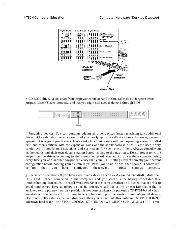
250
I-TECH Computer Education Computer Hardware (Desktop &Laptop)
e. CD-ROM drive. Again, apart from the power connector and the bus cable, do not forget to set its
jumpers (Maste r/S lav e ) correctly, and that you might still need to detect it through BIOS.
f. Remaining devices. You can continue adding all other devices (mouse , remaining fans, additional
drives, PCI cards, etc) one at a time, until you finally spot the malfunctioning one. However, generally
speaking it is a good practice to achieve a fully functioning state with your operating system installed
first, and then continue with the expansion cards and the additional ha rd discs. Please keep a v ery
careful eye on insta llation instructions and r estrictions for e ach one o f them. Always consult y our
motherboards and their own documentation before moving to the nex t step. Do not f orget to se t the
jumpers in the drives according to the current setup each time and t o power them correctly. Also,
every time you add another component verify that your BIOS settings reflect correctly your current
configuration before booting your system. If you move your hard disc to a S ATA/RAID controller,
confirm that you have configured the relevant BIOS settings correctly.
g. Special considerations. If you have a rem ovable device such as a M agneto-Optical (MO) disk or a
USB Card Reader connected to the computer and you intend, after having concluded this
troubleshooting procedure, to i nstall Windows XP in this computer, then be a dvised that in ord er to
avoid trouble you have to follow a speci fic procedure l aid out in this article: Drive letter that is
assigned to the primary hard disk partition is not correct when you perform a CD-ROM-based clean
installation of W indows XP. If you have an Iomega Zip drive on th e same integrated device
electronics (IDE) cable as the hard disk drive, then you can run into this problem: "STOP: C0000221
unknown hard er ror" or "STOP: C0000221 ST ATU S_ IM A G E _C H E C K SU M _M ISM A T CH " error
251
I-TECH Computer Education Computer Hardware (Desktop &Laptop)
message occurs. Also, avoid having the Iomega Zip drive connected during a Windows XP
installation.
B. You are hearing beeps when you power on your motherboard.
Regardless of error messages that might be posted on your screen, you might also be h earing beeps
coming from your motherboard. Th e beeps correspond to specifi c error codes which, if you
successfully decipher, can help you limit the scope of your troubleshooting endeavour to a na rrower
spectrum of potentiall y culpable components. Beware, though! The error beep code that your
motherboard is e mitting, could be linked to a cause deeper than the one a ctually identified by the
beeps themselves – so, resist the temptation of shortcut-fixes and perform thorough troubleshooting if
necessary. For example, it could be that you are getting a component er ror, but the real culprit is an
insufficient power supply; in such a case, replacing the component will not relieve you from the actual
problem.
1. High/Low tone (siren sound)
This means that your CPU is overheating. Immediately check and verify that the CPU heat sink is
properly installed and correctly connected to the power supply.
2. AMI Beep Codes
With AMI BIOS, your computer will give you one short be ep when the system boots su ccessfully.
Apart from beep code 8, all other error codes are fatal.
Beeps - Error message
1 short: System RAM refreshes failure
2 short: Memory parity circuit error
3 short: Base 64KB memory failure
4 short: System timer failure
5 short: CPU failure
6 short: 8042 - Gate A20 (keyboard) failure
7 short: Processor exception interrupts error
8 short: Display memory read/write failure
9 short: BIOS ROM checksum error
252
I-TECH Computer Education Computer Hardware (Desktop &Laptop)
10 short: CMOS shutdown register read/write error
11 short: Cache memory error
1 long - 3 short: Conve nt io nal /E xte n de d memory test failure
1 long - 8 short: Displa y/R etr ac e test failure
3. Award Beep Codes
With Award BIOS, your computer will give you one short beep when the system boots successfully.
Beware of the fact that the Award BIOS typically is customized by the motherboard manufacturer, so
it may very well be that the generic beep codes cited below either do not e xist in your own
motherboard, or you are hearing an error code that cannot be found here. It is always highly advisable
to consult your specific documentation.
Beeps - Error message
2 short: CMOS setting error
1 long, 1 short: DRAM or Motherboard error
1 long, 2 short: Monitor or display card error
1 long, 3 short: Keyboard error
1 long, 9 short: BIOS ROM error
Continuous long beeps: DRAM error
Continuous short beeps: Power error
4. IBM Beep Codes
In the original/standard IBM set of error codes, your computer will give you one short beep when the
system starts the self-test, followed b y a Normal Post that indica tes it boots suc cessfully.
Beeps - Error message
2 short: Initialization error
1 long, 1 short: System board error
1 long, 2 short: Video adapter error (MDA, CGA)
1 long, 3 short: EGA/VGA Graphics adapter error
3 long: 3270 keyboard adapter error
Repeating short: Power supply or system board problem
Cont in uo us: Power supply, system board, or keyboard problem
None: Power supply or system board problem
5. Compaq Beep Codes
Your computer will g ive you one short beep when the sy stem boots successf ully.
Beeps - Error message
2 short: General error
1 long, 1 short: BIOS ROM checksum error
1 long, 2 short: Video adapter error
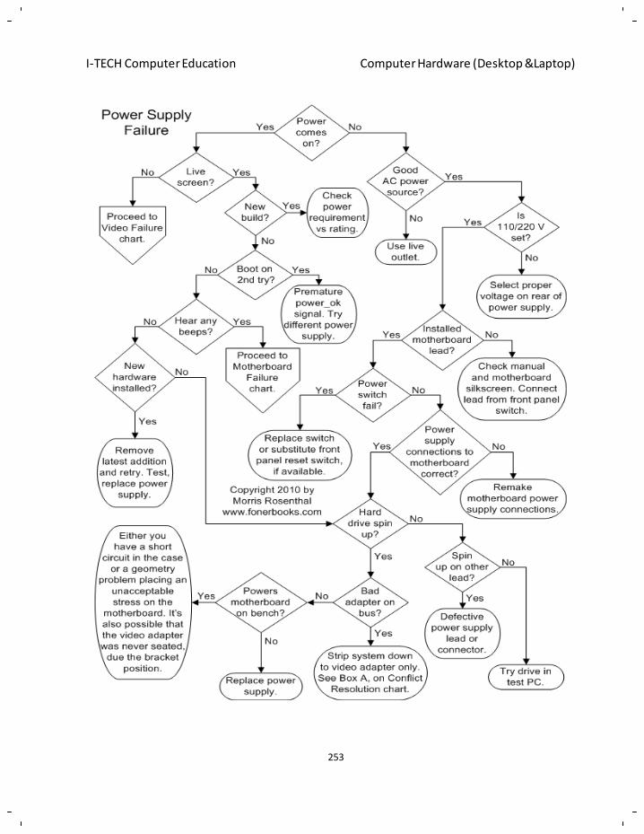
253
I-TECH Computer Education Computer Hardware (Desktop &Laptop)
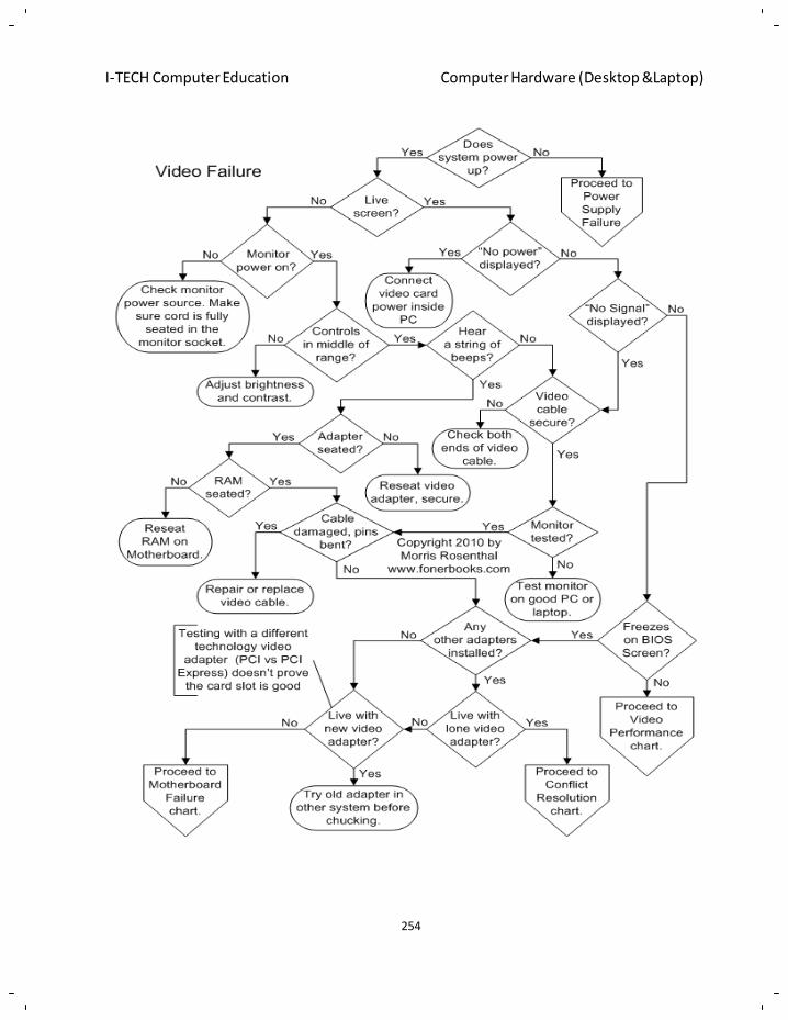
254
I-TECH Computer Education Computer Hardware (Desktop &Laptop)
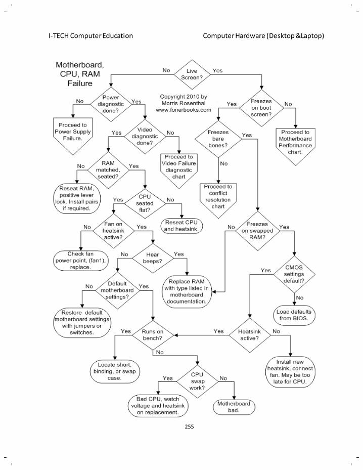
255
I-TECH Computer Education Computer Hardware (Desktop &Laptop)
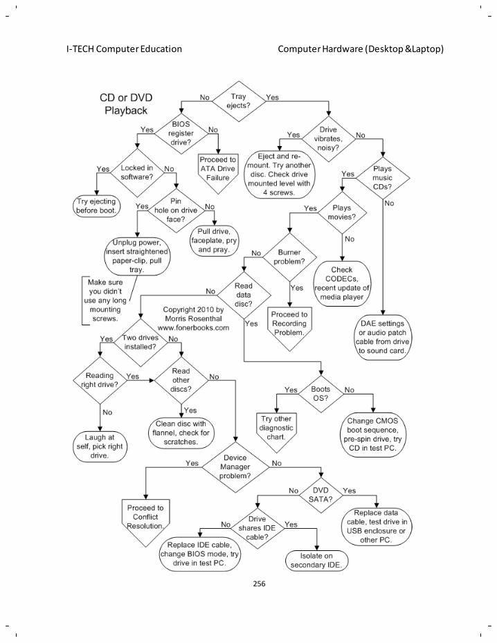
256
I-TECH Computer Education Computer Hardware (Desktop &Laptop)
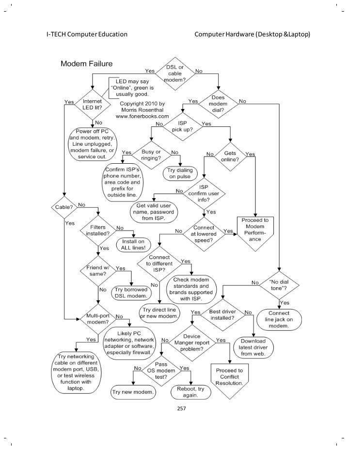
257
I-TECH Computer Education Computer Hardware (Desktop &Laptop)
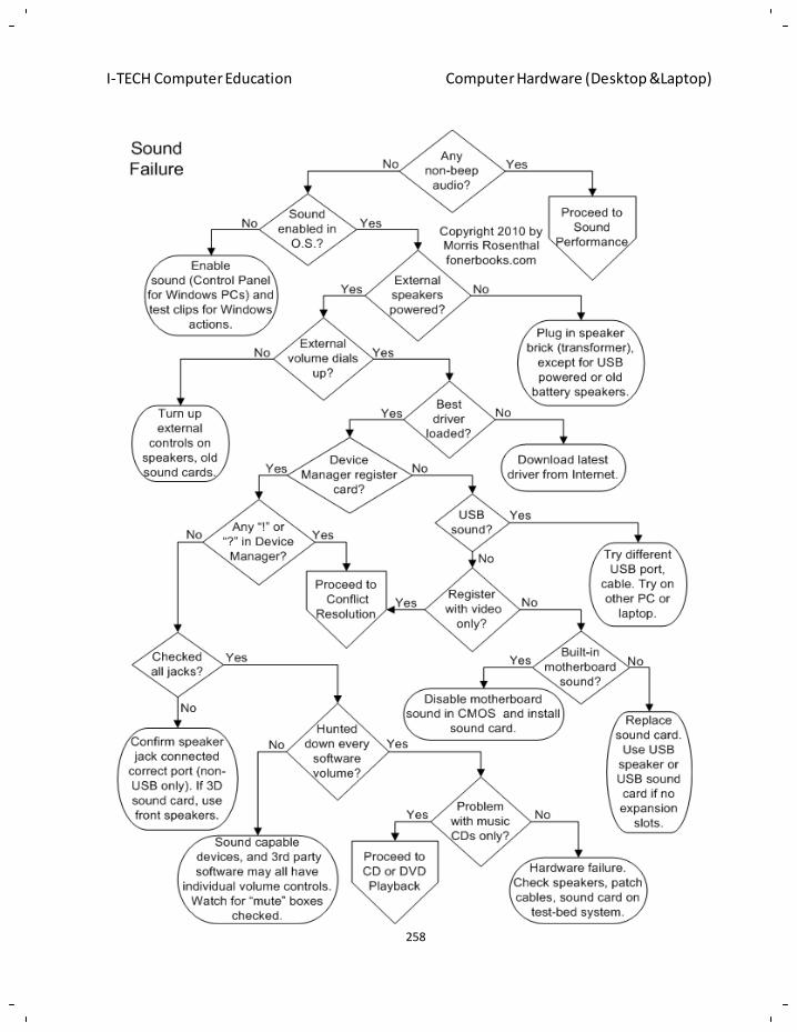
258
I-TECH Computer Education Computer Hardware (Desktop &Laptop)
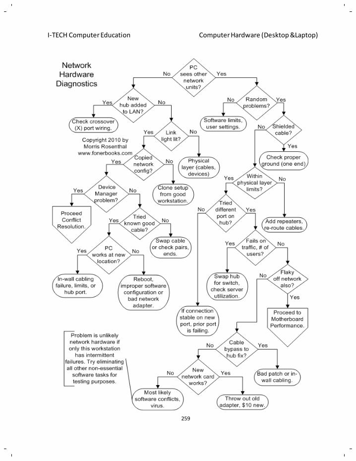
259
I-TECH Computer Education Computer Hardware (Desktop &Laptop)
260
I-TECH Computer Education Computer Hardware (Desktop &Laptop)
Chapter - 17
Computer Network
A computer network, o ften simply referred to as a network, is a colle ction of computers and devi ces
interconnected by communications channels that facilitate communications and allows sharing of
resources and inform ation among interconnected devices. Computer networking or Data
communications (Datacom) is the engineering discipline conc erned with the computer networks.
Computer networking is some times considered a sub-discipline of electrical engineering,
telecommunications, computer science, information technology and/or computer engineering since i t
relies heavily upon the theoretical and practic al application of these scie ntific and eng ineering
disciplines.
The three types of n etworks are: the Internet, the intranet, and t he extranet. Examples of di fferent
network methods are:
• Local area network (LAN), which is usually a small network constrained to a small geographic
area. An example of a LAN would be a computer network within a building.
• Metropolitan area network (MAN), which is used for medium size area. examples for a city or a
state.
• Wide area network (WAN) that is usually a larger network that covers a large geographic area.
• Wireless LANs and WANs (WLAN & WWAN) are the wireless equivalent of th e LAN and
WAN.
Networks may be classified according to a wide va riety of characteristics such as topology, connection
method and scale.
All networks are interconnected to allow communication with a variety of dif ferent kinds o f media,
including twisted-pair copper wire cable, coaxial cable, optical fiber, power lines and various wireless
technologies. The devices can be s eparated by a few meters (e.g. via Bluetooth) or n early unlimited
distances (e.g. via the i nterconnections of the Internet). Networking, routers, routing protocols, and
netwo rkin g over the public Internet have their speci fica tio n s defined in documents called RFCs
Purpose
Computer networks can be used for a variety of purposes:
Faci l it a tin g communications
Using a net work, people can com municate efficiently and easily via email, instant messaging, chat
rooms, telephone, video telephone calls, and video conferencing.
Sharing hardware
In a networked environment, each computer on a network may access and use hardw are resources on
the network, such as printing a document on a shared network printer.
261
I-TECH Computer Education Computer Hardware (Desktop &Laptop)
Sharing files, data, and information
In a network environment, authorized user may access data and information stored on other computers
on the network. The capability of providing access to data and information on shared storage devices is
an important feature of many networks.
Sharing software
Users connected to a network may run application programs on remote computers.
Network Classificat io n Categories:
The following list presents categories used for classifying networks.
Connection method
Computer networks can be classified according to the hardware and software technology that is us ed to
interconnect the individual devices in the network, such as optical fiber, Ethernet, wireless LAN, Home
PNA, power line communication or G.hn.Eth ernet as it is de fined by IEEE 802 utilizes various
standards and mediums that enable communication between devices. Frequently deployed devices
include hubs, switches, bridges, or routers. Wireless LAN technology is designed to conne ct devices
without wiring. These devices use radio waves or infrared signals as a transm ission medium. ITU-T
G.hn technology uses e xisting home wiring (coaxial cable, phone lines and power lines) to cre ate a
high-speed (up to 1 Gigabit/s) local area network.
Wired technologies
• Twisted pair wire is the most widely used medium for telec om m un ica tio n. Twisted-pair cabling
consist of copper wires that are twisted into pairs. Ordinar y telephone wires consist of two
insulated copper wires twisted into pairs. Comput er networking cabling consist of 4 pairs of
copper cabling that can be utilized for both voice and data transmission. The use of two wires
twisted together helps to reduce crosstalk and electromagnetic induction. The transmission
speed ranges from 2 million bits per second to 100 million bits per second. Twisted pair cabling
comes in two forms which are Unshielded Twisted Pair (UTP) and Shielded twisted-pair (STP)
which are rated in categories which are manufactured in different increments for v arious
scenarios.
• Coaxial cable is widely used for cable television systems, office buildings, and other work-sites
for local area networks. The cables consist of c opper or aluminum wire wrapped with insulating
layer typically of a flexible material with a high dielectric constant, all of which are surrounded
by a conductive layer. The layers of insu lation help minimize inte rference and distortion.
Tran sm issio n speed range from 200 million to more than 500 million bits per second.
• Optical fiber cable consists of one or more filaments of glass fiber wrapped in protective layers
that carries a data by means of pulses of light. It transmits light which can travel over extended
distances. Fiber-optic cables are not affected by electromagnetic radiation. Transmission speed
may reach trillions of bi ts per se cond. The t ransmission speed of fibe r optics is hundreds of
times faster than fo r coaxial cables and thousan ds of times faster than a twiste d-p ai r wi re.A
262
I-TECH Computer Education Computer Hardware (Desktop &Laptop)
recent innovation in fiber-optic cable is the use o f colored light.Instead of carrying one message
in a stream of white light impulses, this technolo gy can carry multiple signals in a single strand.
• Terrestrial Terrestrial microwaves use Earth-based transmitter and receiver. The equipment
looks similar to satellite dishes . Terrestrial microwaves use lo w-gigahertz range, which limits
all communications to line-of-sight. Path between relay stations spaced approx, 30 miles apart.
Microwave antennas are usually placed on top of buildings, towers, hills, and mountain peaks.
• Communications satellite– The satellites use microwave radio as their telecommunications
medium which are not deflected by the Earth's atmosphere. The satellites are stationed in space,.
These Earth -o rbi tin g systems are capable of receiving and relaying voice, data, and TV signals.
• Cellular and PCS systems– Use sever al radio c ommunications technologies. The s ystems are
divided to dif ferent geographic areas. Each area has a low-power transmitter or radio relay
antenna device to relay calls from one area to the next area.
• Wireless LANs– Wireless local area network use a hi gh-frequency radio technology similar to
digital cellular and a low-frequency radio technology. Wireless LANs use spread sp ectrum
technology to enable communication between multiple devices in a limited area. An example of
open- sta n da rd s wireless radio-wave techn olo gy is IEEE.
• Infrared communication , whic h can transmit signals between devices within small distances
not more than 10 m eters peer to peer or ( face to fac e ) without an y body in the line o f
transmitting.
Scale
Networks are often classified as local area network (LAN), wide area network (WAN), metropolitan
area network (MAN), personal area network (PAN), virtual private network (VPN), campus area
network (CAN), storage area network (SAN), and others, depending on their scale, s cope and purpose,
e.g., controller area network (CAN) usage, trust level, and access right often differ between these types
of networks. LANs tend to be desig ned for intern al use b y an organization's internal systems and
employees in individual ph ysical locations, such as a building , while WANs may connect physically
separate parts of an organiz at io n and may include conne ct io ns to third parties.
Network topology
Computer networks ma y be classified acco rding to the network topology upon which the network is
based, such as bus network, star network, rin g network, mesh n etwork. Network topolog y is the
coordination by which devices in the network are arranged in the ir logical relations to on e another,
independent of ph ysical arrangement. Even if ne tworked computers are physically placed in a linear
arrangement and are connected to a hub, the network has a star topology, rather than a bus topology. In
this regard the visual and ope rational characteristics of a network are distinct. Networks may be
classified based on the method of data us ed to convey the data, th ese include digital and analog
networks.
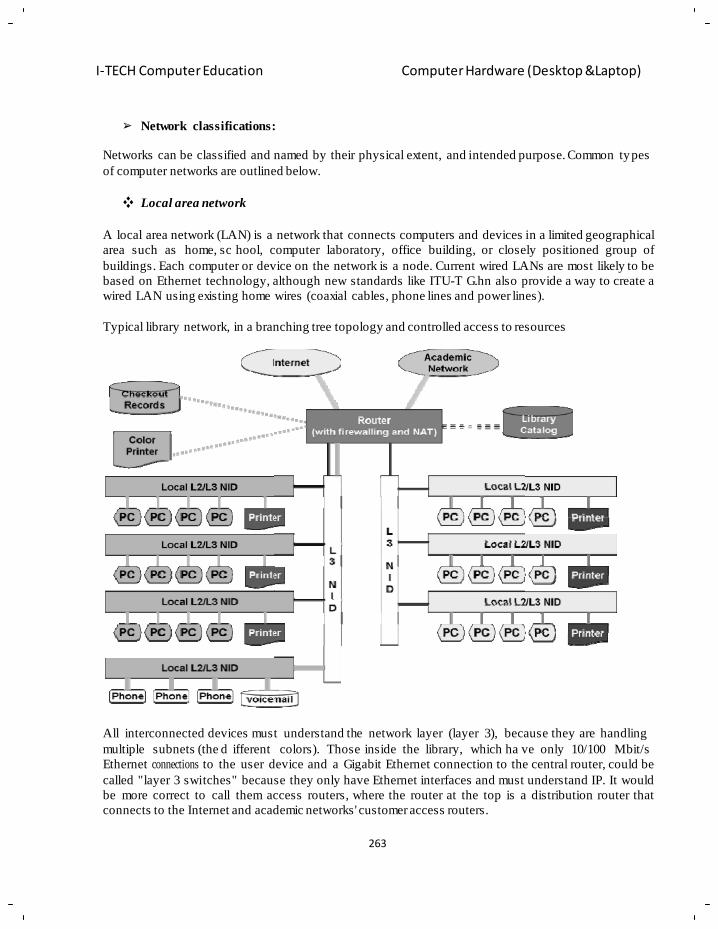
263
I-TECH Computer Education Computer Hardware (Desktop &Laptop)
Network classifications:
Networks can be classified and named by their physical extent, and intended purpose. Common types
of computer networks are outlined below.
Local area network
A local area network (LAN) is a network that connects computers and devices in a limited geographical
area such as home, sc hool, computer laboratory, office building, or closely positioned group of
buildings. Each computer or device on the network is a node. Current wired LANs are most likely to be
based on Ethernet technology, although new standards like ITU-T G.hn also provide a way to create a
wired LAN using existing home wires (coaxial cables, phone lines and power lines).
Typical library network, in a branching tree topology and controlled access to resources
All interconnected devices must understand the network layer (layer 3), because they are handling
multiple subnets (the d ifferent colors). Those inside the library, which ha ve only 10/100 Mbit/s
Ethernet connections to the user device and a Gigabit Ethernet connection to the central router, could be
called "layer 3 switches" because they only have Ethernet interfaces and must understand IP. It would
be more correct to call them access routers, where the router at the top is a distribution router that
connects to the Internet and academic networks' customer access routers.
264
I-TECH Computer Education Computer Hardware (Desktop &Laptop)
The defining characteristics of LANs, in contrast to WANs (Wide Area Networks), include their higher
data transfer rates, smaller geographic range, and no need for leased telecommunication lines. Current
Ethernet or other IEEE 802.3 LAN technologies operate at speeds up to 10 Gbit/s. This is the d ata
transfer rate. IEEE has projects investig at in g the standa rdiz a tio n of 40 and 100 Gbit/s.
Personal area network
A personal area network (PAN) is a computer netw ork used for communication among computer and
different information tec hnological devices close to one person. Some examples of devices that are
used in a PAN are p ersonal computers, printers, fax machines, telephones, PDAs, scanners, and even
video game consoles. A PAN may include wir ed and wireless devices. The rea ch of a PAN t ypically
extends to 10 meters. A wired PAN is usuall y constructed with US B and Firewire connections while
technolo gie s such as Bluetooth and infrared comm u nic at ion typically form a wireless PAN.
Home area network
A home area netwo rk (HAN) is a residential LAN which is used for c ommunication between dig ital
devices typically deployed in the home, usually a small number of personal computers and accessories,
such as printers and mobile computing devices. An important function is the sharing of Internet access,
often a broadband service through a CATV o r Digital Subscriber Line (DSL) provider. It can also be
referred to as an office area network (OAN).
Wide area network
A wide area network (WAN) is a computer network that covers a large geographic area such as a city,
country, or spans even in tercontinental distances, using a communications channel that combines man y
types of media such as telephone lines, cables, and air waves. A WAN often uses transmission facilities
provided by common ca rriers, such as telephone companies. WAN technologies generally function at
the lower three layers of the OSI reference model: the physical layer, the data link lay er, and the
network layer.
Campus network
A campus network is a computer network made up of an interconnection of local area networks (LANs)
within a limited geographical area. The networking equipment (switches, routers) and transmission
media (optical fiber, copper plant, Cat5 cabling etc.) are almost entirely owned (by the campus tenant /
owner: an ent erprise, university, government etc.).In the c ase of a univ ersity campus-based campus
network, the network is likely to link a variety of campus buildings including, for ex ample, academic
colleges or depa rtm e nts, the university library, and student residence halls.
Metropolit an area network
A Metropolitan area network (MAN) is a large computer network that usually spans a city or a large
campus.
265
I-TECH Computer Education Computer Hardware (Desktop &Laptop)
Enterprise private network
An enterprise private n etwork is a network buil d by an enterprise to in terconnect various comp any
sites, e.g., production sites, head offices, remote offices, shops, in order to share computer resources.
Internetwork
An internetwork is the connection of two or more private computer networks via a common routing
technology (OSI Layer 3) using routers. The Internet is an aggregation of many internetworks; hence its
name was shortened to Internet.
Backbone network
A Backbone network or network backbone is part o f a computer network infrastructure that
interconnects various pieces of n etwork, providing a path for the exchange of information between
different LANs or sub networks. A backbone can tie together diverse networks in the same build ing, in
different buildings in a campus environment, or ove r wide areas. Normally, the backbone's capacity is
greater than the networks connected to it. A la rge corporation that has many locations may have a
backbone network that t ies all of th e locations t ogether, for example, if a server cluster needs to be
accessed by different departments of a company that are located at different geographical locations. The
pieces of the network connections (for example: Ethernet, wireless) that bring these departments
together is often mentioned as network backbone. Network congestion is often taken into consideration
while designing backbones. Backbone networks should not be confused with the Internet backbone.
Global area network
A global area network (GAN) is a netwo rk used for supporting mobile comm un ica tio ns acros s an
arbitrary number of wireless LANs, satellite coverage areas, etc. The key challenge in mobile
communications is handing off the use r communications from one local c overage area to the nex t. In
IEEE Project 802, this involves a succession of terrestrial wireless LANs.[11]
Internet
The Internet is a g lobal system of i nterconnected governmental, academic, corporate, public, and
private computer networks. It is based on the networking technologies of the Internet Protocol Suite. It
is the successor of the Advanced Research Projects Agency Network (ARPANET) d eveloped by
DARPA of t he United States Department of Defense. The Internet is also the communications
backbone underlying the World Wide Web (WWW).Participants in the Internet use a diverse array of
methods of several hundred documented, and often standardized, protocols compatible with the Internet
Protocol Suite and an addressing system (IP addresses) administered by the Internet Assigned Numbers
Authority and address registries. Service providers and large enterprises exchange information about
the reach ability of thei r address spa ces through the Border Gateway Protocol (BGP), forming a
redundant worldwide mesh of transm issio n paths.
Intranets and extranets
Intranets and extranets are parts or extensions of a computer network, usua lly a local area network. An
intranet is a set of networks, using the Internet Protocol and IP-based tools such as web bro wsers and
file transfer applications that are under the cont rol of a sing le administrative entity. That administrat ive
entity closes the intranet to all but specific, authorized users. Most commonly, an intranet is the internal

266
I-TECH Computer Education Computer Hardware (Desktop &Laptop)
network of an organization. A large intranet will typically have at least one web server to provide users
with organizational information. An e xtranet is a network that is li mited in scope to a single
organization or entit y and also has limited connections to the netwo rks of one or more other usually,
but not necessarily, trusted organizations or e ntities—a company's customers may be given access to
some part of its intranet—while at the same time the customers may not be considered trusted from a
security standpoint. Technically, an extranet may also be categorized as a C AN, MAN, W AN, or other
type of n etwork, although an extranet cannot consist of a sin gle LAN; it must have at least one
connection with an external network.
Overlay network
An overlay network is a virtual computer network that is built on top of another network. Nodes i n the
overlay are connected by virtual or logical links, each of which corresponds to a path, perhaps through
many physical links, in the underlying network.
A sample overlay network: IP over SONET over Optical
For example, many peer-to-peer networks are overlay networks because they are organized as nodes of
a virtual s ystem of links run on top of the Internet. The Internet was initially built as an overlay on the
telephone network . Overlay networks have been around since the inv ention of n etworking when
computer systems were connected over telephone lines using modem, before any data network existed.
Nowadays the Internet is the basis for many overlaid networks that can be constructed to permit routing
of messages to destinations specified by an IP address. For example, distributed hash tables can be used
to route messages to a n ode having a specific logical address, whose IP address is known in advance.
Overlay networks have also been proposed as a way to improve Internet routing, such as through
quality of service guarantees to achieve hi gher-quality streaming media. Previous proposals such as
267
I-TECH Computer Education Computer Hardware (Desktop &Laptop)
IntServ, DiffServ, and IP Multicast have not seen wide acceptance largely because they require
modification of all routers in the network. On the other hand, an ov erlay network can be incrementally
deployed on end-hosts running the overlay protocol software, without cooperation from Internet service
providers. The overlay has no control ove r how packets are routed in the underlying network between
two overlay nodes, but it can control, for example, the sequence of overlay nodes a message traverses
before reaching its d estination. For example, Akamai Technologies manages an overlay network that
provides reliable, efficient content delivery (a kind of multicast). Academic research includes End
System Multicast and Overcast for multicast; RON ( Resilient Overlay Network) for resilient routing;
and OverQoS for quality of service guarantees, among others
Basic hardware components
All networks are made up of basic hardwar e building blocks to interconnect network nodes, suc h as
Network Interface Cards (NICs), Bridges, Hubs, Switches, and Routers. In addition, some method of
connecting these building blocks is required, us ually in the form of g alvanic cable (most commonl y
Category 5 c able). Less common are microwav e links (as in I EEE 802.12) or optical cable ( "optical
fiber").
Network interface cards
A network card, network adapter, or NIC (network interface card) is a piece of computer hardware
designed to allow computers to communicate over a computer network. It provides physical access to a
networking medium and often p rovides a low-level addressing system through the us e of addresses.
Each network interface card has its unique id. This is written on a chip which is mounted on the card.
Repeaters
A repeater is an electronic device that receives a signal, cleans it o f unnecessary noise, regenerates it,
and retransmits it at a hig her power level, or to the other side of an obstr uction, so that the sig nal can
cover longer distances without degradation. In most twisted pair Ethernet conf igurations, repeaters are
required for cable that runs longer than 100 meters. A repeater with multiple ports is known as a hub.
Repeaters work on the Physical Layer of the OSI model. Repeaters require a small amount of tim e to
regenerate the si gnal. This can c ause a propagation delay which can af fect network communication
when there are several repeaters in a r ow. Many network architectures limit the number of r epeaters
that can be used in a row (e.g. Ethernet's 5-4-3 rule).
Bridges
A network bridge connects multiple network segments at the data link layer (layer 2) of the OSI model.
Bridges broadcast to all ports except the port on which the broadcast was received. However, bridges
do not promiscuousl y copy traffic to all ports , as hubs do, but lea rn which MAC addr esses are
reachable through specific ports. Once t he bridge associates a port and an address, i t will send t raffic
for that address to that port onl y. Bridges learn the association of ports and addresses by examining the
source address of frames that it sees on va rious ports. Once a frame arrives through a po rt, its source
address is stored and the bridge assumes that MAC address is associated with that port. The first time
268
I-TECH Computer Education Computer Hardware (Desktop &Laptop)
that a p reviously unknown destination add ress is seen, the bridge will f orward the frame to all ports
other than the one on which the frame arrived.
Bridges come in three basic types:
• Local bridges: Directly connect local area networks (LANs)
• Remote bridges: Can be used to c reate a wide area network (WAN) link betwe en LANs.
Remote bridges, where the connecting link is slower than the end networks, largely have been
replaced with routers.
• Wireless bridges: Can be used to join LANs or connect remote stations to LANs.
Switches
A network switch is a device that forwards and filters OSI layer 2 data grams (chunks of data
communication) between ports (conn ected cables) based on t he MAC addresses i n the packets. A
switch is distinct from a hub in that it onl y forwards the fr ames to the ports involved in the
communication rather than all ports connected. A switch breaks the collision domain but repres ents
itself as a broadcast domain. Switches make forwarding decisions of fr ames on the basis of M AC
addresses. A switch no rmally has numerous p orts, facilitating a sta r topology for devices, and
cascading additional switches. Some switches are capable of routing based on Layer 3 add ressing or
additional logical levels; these are called multi-layer switches. The term switch is used loosel y in
marketing to encompass devices including routers and bri dges, as wel l as devi ces that may distribute
traffic on load or by application content (e.g., a Web URL identifier).
Views of networks
Users and network administrators typically have different views of their networks. Users can share
printers and some serv ers from a work group, which usually means the y are in the same geographic
location and a re on the same LAN, whereas a Network Administrator is responsible to k eep that
network up and running . A community of interest has less o f a connection of being in a local area, and
should be thought of as a set of a rbitrarily located users who shar e a s et of servers, and possibl y also
comm unic a te via peer-to -p e e r technologies.
Network administrators can see netwo rks from both physical and l ogical perspectives. The ph ysical
perspective involves geographic locations, physical cabling, and the net work elements (e.g., routers,
bridges and application layer gateways that interconnect the physical media. Logical networks, called,
in the TCP/ IP architecture, subnets, map o nto one or more physical media. For example, a com mon
practice in a cam pus of buildings is to make a set of L AN cables in each bui lding appear to be a
common subnet, using virtual LAN (VLAN) technology. Both users and administrators will be aware,
to varying extents, of the trust and scope char acteristics of a network. A gain using TCP/IP architectural
terminology, an intran et is a communit y of i nterest under privat e administration usually by an
enterprise, and is onl y accessible by authorized users (e.g. employees). Intranets do not have to be
connected to the Internet, but g enerally have a limited connection. An ex tranet is an ex tension of an
intranet that allows secure communications to use rs outside of the intranet (e.g. business partners,
customers).
269
I-TECH Computer Education Computer Hardware (Desktop &Laptop)
Unofficially, the Internet is the set of users, enterprises, and content providers that are interconnected
by Internet Service Providers (ISP). From an engineering viewpoint, the Internet is the set of subnets,
and aggregates of subnets, which share the registered IP address space and exchange information about
the reach ability of those IP addresses using the Border Gateway Protocol. Typically, the human-
readable names of serv ers are t ranslated to IP addresses, t ransparently to users, via the directory
function of the Domain Name System (DNS).
Over the Internet, there can be business-to-business (B2B), business-to-consumer (B2C) and consumer-
to-consumer (C2C) communications. Especially when money or sensitive information is e xchanged,
the communications are apt to be secured by some form of c ommunications security mechanism.
Intranets and extranets can be securely superimposed onto the Internet, without any access by general
Internet users and administ r ato rs, using secure Virtual Private Network (VPN) technology
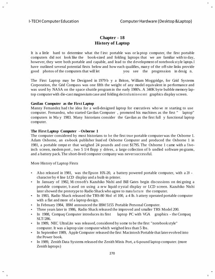
270
I-TECH Computer Education Computer Hardware (Desktop &Laptop)
Chapter - 18
History of Laptop
It is a little hard to determine what the f irst portable was or la ptop computer, the first portable
computers did not look like the book-sized and folding laptops that we are familiar with to day,
however, they were both portable and capable, and lead to the development of notebook style laptops. I
have outlined several potential firsts below and how each qualifies, many of the off-site links provide
good photos of the computers that will let you see the progression in desig n.
The First Laptop may be Designed in 1979 b y a Briton, William Moggridge, for Grid Systems
Corporation, the Grid Compass was one fifth the weight of any model equivalent in performance and
was used by NASA on the space shuttle program in the early 1980's. A 340K byte bubble memory lap-
top computer with die-cast magnesium case and folding elect rolu min e sc en t graphics display screen.
Gavilan Computer as the First Laptop
Manny Fernandez had t he idea for a well-designed laptop for executives who we re starting to use
computer. Fernandez, who started Gavilan Computer , promoted his machines as the first " laptop"
computers in Ma y 1983. Many historians consider the Gavilan as the first full y functional laptop
computer.
The First Laptop Computer - Osborne 1
The computer considered by most historians to b e the first true portable computer was the Osborne 1.
Adam Osborne, an ex-book publisher found ed Osborne Computer and produced the Osborne 1 in
1981, a portable comput er that weighed 24 pounds and cost $1795. The Osborne 1 came with a f ive-
inch screen, modem port , two 5 1/4 flopp y drives, a large collection of b undled software pro grams,
and a battery pack. The short-lived computer company was never successful.
More History of Laptop Firsts
• Also released in 1981, was the Epson HX-20, a battery powered portable computer, with a 20 -
character by 4 line LCD display and a built-in printer.
• In January of 1982, Mi crosoft's Kazuhiko Nishi and Bill Gates begin discussions on desi gning a
portable computer, b ased on using a ne w liquid cr ystal display or LCD screen. Kazuhiko Nishi
later showed the prototype to Radio Shack who agree to manu fa ctu re the computer.
• In 1983, Radio Shack released the TRS-80 Mod el 100, a 4 lb. b attery operated portable computer
with a flat and more of a laptop design.
• In February 1984, IBM announced the IBM 5155 Portable Personal Computer.
• Three years later in 1986, Radio Shack released the improved and smaller TRS Model 200.
• In 1988, Compaq Computer introduces its first laptop PC with VGA graphics - the Compaq
SLT/286.
• In 1989, NEC UltraLite was released, considered by some to be the first "notebook style"
computer. It was a laptop size computer which weighed less than 5 lbs.
• In September 1989, Apple Computer released the first Macintosh Portable that later evolved into
the Power book.
• In 1989, Zenith Data Systems released the Zenith Minis Port, a 6-pound laptop computer. (more
Zenith laptops)
271
I-TECH Computer Education Computer Hardware (Desktop &Laptop)
• In October 1989, Compaq Computer released its first notebook PC, the Compaq LTE.
• In March 1991, Microsoft released the Microsoft BallPoint Mouse that used both mouse and
trackball technolo g y in a pointing device designed for laptop computers.
• In October 1991, Apple Computers released the Macintosh PowerBook 100, 140, and 170 - all
notebook style laptops.
• In October 1992, IBM released its ThinkPad 700 laptop computer.
• In 1992, Intel and Microsoft release APM or the Advanced Power Mana ge m e nt speci fic at io n for
laptop computers.
• In 1993, the first PDAs or Personal Digital Assistants are released. PDAs are pen-based hand-held
computers.
• Who Invented It?
The laptop computer was invented by Adam Osborne in 1981. It was called the "Osborne 1" and
cost $1795. It came bundled with $1500 worth of programs. It had a tiny computer screen built
into it.
• What is a laptop computer?
A laptop is a computer that can be folded up and carried around.
• When was the laptop invented?
The laptop was invented in 1981.
• Where was it invented?
It was invented by Osborne Computers, a book company that sold books to McGraw-Hill.
• How was invented?
It was invented by taking computer techn olo gy from that time and scaling it down to make a
smaller, more portable computer
Definition of Laptop:
A laptop computer, o r simply laptop (also kno wn as notebook computer, notebook, notepad, and
incorrectly laptop ;), is a small portable comput er having its main compone nts (Processor, screen,
keyboard) built into a single unit capable of batter y powered operation, which usually weighs 2-18
pounds (approximately 1 to 8 kgs), depending on dimensions, mate rials, and other variables.
It is debatable what the first notebook or laptop computer was. The first laptops did not look like the
clamshell designs that are known to us today. However the first designs could still be carried with you
and be used on a lap which has lead to the advancement of notebook style laptops. Outlined below are
some computers that are classified as the first portable
The First Laptop Computer 1981: Osborne 1
computer (laptop).
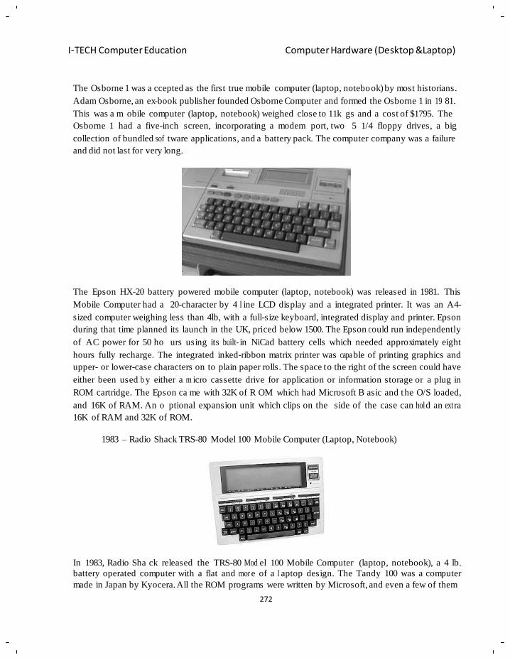
272
I-TECH Computer Education Computer Hardware (Desktop &Laptop)
The Osborne 1 was a ccepted as the first true mobile computer (laptop, notebook) by most historians.
Adam Osborne, an ex-book publisher founded Osborne Computer and formed the Osborne 1 in 19 81.
This was a m obile computer (laptop, notebook) weighed close to 11k gs and a cost of $1795. The
Osborne 1 had a five-inch screen, incorporating a modem port, two 5 1/4 floppy drives, a big
collection of bundled sof tware applications, and a battery pack. The computer company was a failure
and did not last for very long.
The Epson HX-20 battery powered mobile computer (laptop, notebook) was released in 1981. This
Mobile Computer had a 20-character by 4 l ine LCD display and a integrated printer. It was an A4-
sized computer weighing less than 4lb, with a full-size keyboard, integrated display and printer. Epson
during that time planned its launch in the UK, priced below 1500. The Epson c ould run independently
of AC power for 50 ho urs using its built- in NiCad battery cells which needed approximately eight
hours fully recharge. The integrated inked-ribbon matrix printer was capa ble of printing graphics and
upper- or lower-case characters on to plain paper rolls. The space to the right of the screen could have
either been used b y either a m icro cassette drive for application or information storage or a plug in
ROM cartridge. The Epson ca me with 32K of R OM which had Microsoft B asic and the O/S loaded,
and 16K of RAM. An o ptional expansion unit which clips on the side of the case can hol d an ext ra
16K of RAM and 32K of ROM.
1983 – Radio Shack TRS-80 Model 100 Mobile Computer (Laptop, Notebook)
In 1983, Radio Sha ck released the TRS-80 Mod el 100 Mobile Computer (laptop, notebook), a 4 lb.
battery operated computer with a flat and mor e of a l aptop design. The Tandy 100 was a computer
made in Japan by Kyocera. All the ROM programs were written by Microsoft, and even a few of them
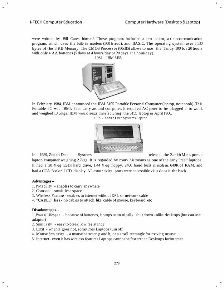
273
I-TECH Computer Education Computer Hardware (Desktop &Laptop)
were written by Bill Gates himself. These programs included a text editor, a t elecommunication
program, which uses the built- in modem (300 b aud), and BASIC. The operating system uses 3 130
bytes of the 8 KB Memory. The CMOS Processor (80c85) allows to use the Tandy 100 fo r 20 hours
with only 4 AA batteries (5 days at 4 hours/day or 20 days at 1 hour/day).
1984 - IBM 5155
In February 1984, IBM announced the IBM 5155 Portable Personal Computer (laptop, notebook). This
Portable PC was IBM's first carry around computer. It required AC powe r to be plugged in to wo rk
and weighed 13.6Kgs. IBM would seize manu fa c turin g the 5155 laptop in April 1986.
1989 - Zenith Data Systems Laptop
In 1989, Zenith Data Systems released the Zenith Minis port, a
laptop computer weighing 2.7kgs. It is regarded by many historians as one of the early "real" laptops.
It had a 20 M eg ESDI hard drive, 1.44 M eg floppy, 2400 baud built in mode m, 640K of RAM, and
had a CGA "color" LCD display. All conne c tivi ty ports were accessible via a door in the back.
Advantages--
1. Porta bil i ty - enables to carry anywhere
2. Compact - small, less space
3. Wireless Feature - enables to internet without DSL or network cable
4. "CABLE‖ less - no cables to attach, like cable of mouse, keyboard, etc
Disadvantages--
1. Powe r/L ife sp an - because of batteries, laptops autom at ic al ly shut down unlike desktops (but can use
adapter)
2. Sensi tiv ity - easy to break, low resistance
3. Limit - when it goes hot, sometimes Laptops turn off.
4. Mouse Sensi tivi ty - a mouse between g and h, or a small rectangle for moving mouse.
5. Internet - even it has wireless features Laptops cannot be faster than Desktops for internet
274
I-TECH Computer Education Computer Hardware (Desktop &Laptop)
Types of Memory
Chapter - 19
LAPTOP MEMORY
The ability to process information that requires a attention, storage
and retrieval. Or the circuitry in a computer that stores information.
Following is the types of memory used in laptop:
1) 204-pin SODIMM
2) 200-pin SODIMM
3) 144-pin SODIMM
4) 144-pin MicroDIMM
204-pin SODIMM
Approximately 2.6 in. b y 1.75 in. (66 mm
by 44.45 mm) cru cial 204-pin
are used in DDR3 memory
computers.
SODIMMs
for laptop
In short, 204-pin small outline dual inline
memory modules (SOD IMMs) are the form
factor used to provide DD R3 memory
modules for notebook compute rs and other
small form factor computing platforms. 204-
pin SODIMMs are currently available in PC3-8500 (DDR3 1066MHz) speeds. To use DDR3 memory,
your system must have both a 204-pin SODIMM slot and a chipset tha t supports DDR3 memory. A
DDR3 SODIMM will not fit into DDR2 or DDR memory sockets. SODIMMs are smaller and thinner
than regular DIMMs, and the 204-pin SODIMM PCBs are al ways ~2.6 i nches long and are usually
around 1.75 inches hig h (though the heights can vary slightly). They consist of a number of memor y
components (usually black) that are attached to a printed circuit board (usually green). The number of
memory components on a 204-pin SODIMM's printed circuit board (PCB) can vary, but the PCB will
always have 102 pins on the front and the b ack both, for a total of 204 pins. The gold pins on the
bottom of the SODIMM provide the connection between the memory module and the memory socket.
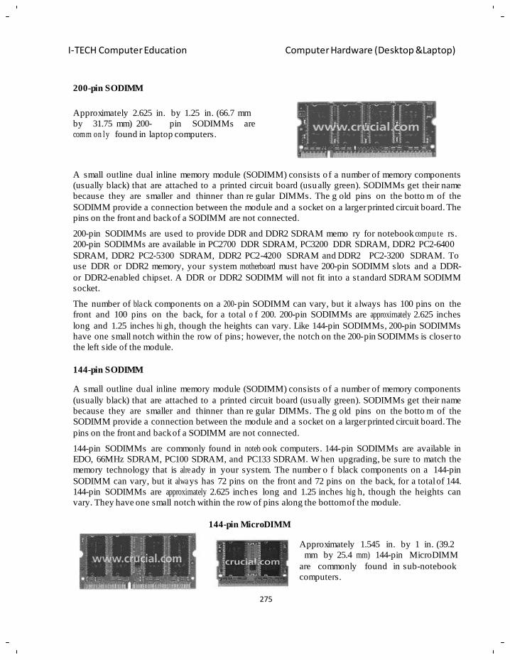
275
I-TECH Computer Education Computer Hardware (Desktop &Laptop)
200-pin SODIMM
Approximately 2.625 in. by 1.25 in. (66.7 mm
by 31.75 mm) 200- pin SODIMMs are
comm on ly found in laptop computers.
A small outline dual inline memory module (SODIMM) consists o f a number of memory components
(usually black) that are attached to a printed circuit board (usually green). SODIMMs get their name
because they are smaller and thinner than re gular DIMMs. The g old pins on the botto m of the
SODIMM provide a connection between the module and a socket on a larger printed circuit board. The
pins on the front and back of a SODIMM are not connected.
200-pin SODIMMs are used to provide DDR and DDR2 SDRAM memo ry for notebook compu te rs.
200-pin SODIMMs are available in PC2700 DDR SDRAM, PC3200 DDR SDRAM, DDR2 PC2-6400
SDRAM, DDR2 PC2-5300 SDRAM, DDR2 PC2-4200 SDRAM and DDR2 PC2-3200 SDRAM. To
use DDR or DDR2 memory, your system motherboard must have 200-pin SODIMM slots and a DDR-
or DDR2-enabled chipset. A DDR or DDR2 SODIMM will not fit into a standard SDRAM SODIMM
socket.
The number of bla ck components on a 200- pin SODIMM can vary, but it a lways has 100 pins on the
front and 100 pins on the back, for a total o f 200. 200-pin SODIMMs are approximately 2.625 inches
long and 1.25 inches hi gh, though the heights can vary. Like 144-pin SODIMMs, 200-pin SODIMMs
have one small notch within the row of pins; however, the notch on the 200-pin SODIMMs is closer to
the left side of the module.
144-pin SODIMM
A small outline dual inline memory module (SODIMM) consists o f a number of memory components
(usually black) that are attached to a printed circuit board (usually green). SODIMMs get their name
because they are smaller and thinner than re gular DIMMs. The g old pins on the botto m of the
SODIMM provide a connection between the module and a socket on a larger printed circuit board. The
pins on the front and back of a SODIMM are not connected.
144-pin SODIMMs are commonly found in noteb ook computers. 144-pin SODIMMs are available in
EDO, 66MHz SDRAM, PC100 SDRAM, and PC133 SDRAM. W hen upgrading, be sure to match the
memory technology that is alre ady in your system. The number o f black components on a 144-pin
SODIMM can vary, but it alwa ys has 72 pins on the front and 72 pins on the back, for a total of 144.
144-pin SODIMMs are approximately 2.625 inches long and 1.25 inches hig h, though the heights can
vary. They have one small notch within the row of pins along the bottom of the module.
144-pin MicroDIMM Approximately 1.545 in. by 1 in. (39.2
mm by 25.4 mm) 144-pin MicroDIMM
are commonly found in sub-notebook
computers.
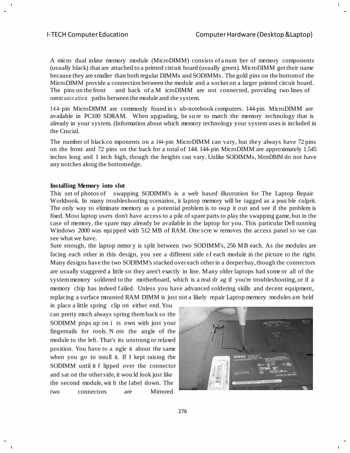
276
I-TECH Computer Education Computer Hardware (Desktop &Laptop)
A micro dual inline memory module (MicroDIMM) consists of a num ber of memory components
(usually black) that are attached to a printed circuit board (usually green). MicroDIMM get their name
because they are smaller than both regular DIMMs and SODIMMs. The gold pins on the bottom of the
MicroDIMM provide a connection between the module and a socket on a larger printed circuit board.
The pins on the front and back of a M icroDIMM are not connected, providing two lines of
comm unic a tio n paths between the module and the system.
14 4- pin MicroDIMM are commonly found in s ub-notebook computers. 144-pin MicroDIMM are
available in PC100 SDRAM. When upgrading, be su re to match the memory technology that is
already in your system. (Information about which memory technology your system uses is included in
the Crucial.
The number of black co mponents on a 144- pin MicroDIMM can vary, but they always have 72 pins
on the front and 72 pins on the back for a total of 144. 144-pin MicroDIMM are approximately 1.545
inches long and 1 inch high, though the heights can vary. Unlike SODIMMs, MicroDIMM do not have
any notches along the bottom edge.
Installing Memory into slot
This set of photos of swapping SODIMM's is a web based illustration for The Laptop Repair
Workbook. In many troubleshooting scenarios, it laptop memory will be tagged as a possi ble culprit.
The only way to eliminate memory as a potential problem is to swa p it out and see if the problem is
fixed. Most laptop users don't have access to a pile of spare parts to play the swapping game, but in the
case of memory, the spare may already be available in the laptop for you. This particular Dell running
Windows 2000 was equi pped with 512 MB of RAM. One scre w removes the access panel so we can
see what we have.
Sure enough, the laptop memor y is split between two SODIMM's, 256 MB each. As the modules are
facing each other in this design, you see a different side o f each module in t he picture to the right.
Many designs have the two SODIMM's stacked over each other in a deeper bay, though the connectors
are usually staggered a little so they aren't exactly in line. Many older laptops had some or all of the
system memory soldered to the motherboard, which is a real dr ag if you're troubleshooting, or if a
memory chip has indeed f ailed. Unless you have advanced soldering skills and decent equipment,
replacing a surface mounted RAM DIMM is just not a likely repair Laptop memory modules are held
in place a little spring clip on either end. You
can pretty much always spring them back so the
SODIMM pops up on i ts own with just your
fingernails for tools. N ote the angle of the
module to the left. That's its unstrung or relaxed
position. You have to a ngle it about the same
when you go to insta ll it. If I kept raising the
SODIMM until it f lipped over the connector
and sat on the other side, it wou ld look just like
the second module, wit h the l abel down. The
two connectors are Mirrored
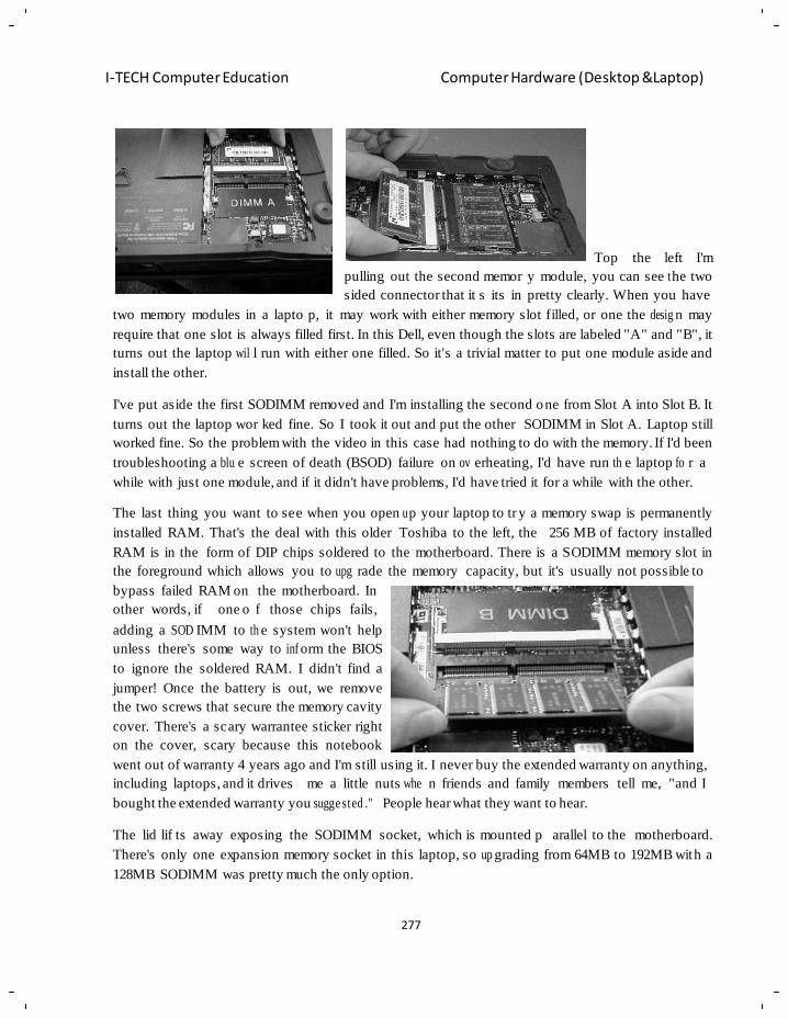
277
I-TECH Computer Education Computer Hardware (Desktop &Laptop)
Top the left I'm
pulling out the second memor y module, you can see t he two
sided connector that it s its in pretty clearly. When you have
two memory modules in a lapto p, it may work with either memory slot filled, or one the desig n may
require that one slot is always filled first. In this Dell, even though the slots are labeled "A" and "B", it
turns out the laptop wil l run with either one filled. So it's a trivial matter to put one module aside and
install the other.
I've put aside the first SODIMM removed and I'm installing the second one from Slot A into Slot B. It
turns out the laptop wor ked fine. So I took it out and put the other SODIMM in Slot A. Laptop still
worked fine. So the problem with the video in this case had nothing to do with the memory. If I'd been
troubleshooting a blu e screen of death (BSOD) failure on ov erheating, I'd have run th e laptop fo r a
while with just one module, and if it didn't have problems, I'd have tried it for a while with the other.
The last thing you want to see when you open u p your laptop to tr y a memory swap is permanently
installed RAM. That's the deal with this older Toshiba to the left, the 256 MB of factory installed
RAM is in the form of DIP chips soldered to the motherboard. There is a SODIMM memory slot in
the foreground which allows you to upg rade the memory capacity, but it's usually not possible to
bypass failed RAM on the motherboard. In
other words, if one o f those chips fails,
adding a SOD IMM to th e system won't help
unless there's some way to inf orm the BIOS
to ignore the soldered RAM. I didn't find a
jumper! Once the battery is out, we remove
the two screws that secure the memory cavity
cover. There's a scary warrantee sticker right
on the cover, scary because this notebook
went out of warranty 4 years ago and I'm still using it. I never buy the extended warranty on anything,
including laptops, and it drives me a little nuts whe n friends and family members tell me, "and I
bought the extended warranty you sugge sted ." People hear what they want to hear.
The lid lif ts away exposing the SODIMM socket, which is mounted p arallel to the motherboard.
There's only one expansion memory socket in this laptop, so up grading from 64MB to 192MB with a
128MB SODIMM was pretty much the only option.
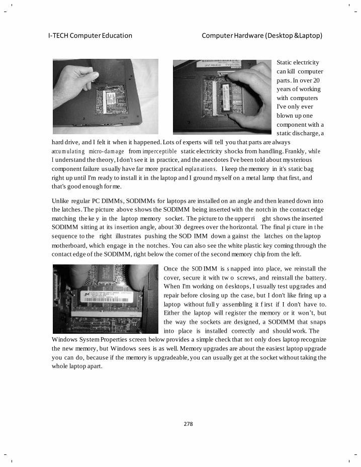
278
I-TECH Computer Education Computer Hardware (Desktop &Laptop)
Static electricity
can kill computer
parts. In over 20
years of working
with computers
I've only ever
blown up one
component with a
static discharge, a
hard drive, and I felt it when it happened. Lots of experts will tell you that parts are always
accu m ula tin g micro- da m a ge from impe rc e pt ible static electricity shocks from handling. Frankly, while
I understand the theory, I don't see it in practice, and the anecdotes I've been told about mysterious
component failure usually have far more practical expla n at ion s. I keep the memory in it's static bag
right up until I'm ready to install it in the laptop and I ground myself on a metal lamp that first, and
that's good enough for me.
Unlike regular PC DIMMs, SODIMMs for laptops are installed on an angle and then leaned down into
the latches. The picture above shows the SODIMM being inserted with the notch in the contact edge
matching the ke y in the laptop memory socket. The picture to the upper ri ght shows the inserted
SODIMM sitting at its i nsertion angle, about 30 degrees over the horizontal. The final pi cture in t he
sequence to the right illustrates pushing the SOD IMM down a gainst the latches on the laptop
motherboard, which engage in the notches. You can also see the white plastic key coming through the
contact edge of the SODIMM, right below the corner of the second memory chip from the left.
Once the SOD IMM is s napped into place, we reinstall the
cover, secure it with tw o screws, and reinstall the battery.
When I'm working on d esktops, I usually test upgrades and
repair before closing up the case, but I don't like firing up a
laptop without full y assembling it f irst if I don't have to.
Either the laptop will r egister the memory or it won‘t, but
the way the sockets are designed, a SODIMM that snaps
into place is installed correctly and should work. The
Windows System Properties screen below provides a simple check that no t only does laptop recognize
the new memory, but Windows sees is as well. Memory upgrades are about the easiest laptop upgrade
you can do, because if the memory is upgradeable, you can usually get at the socket without taking the
whole laptop apart.
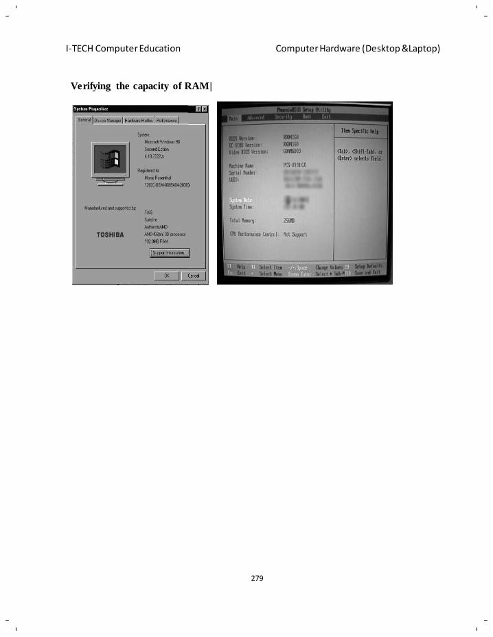
279
I-TECH Computer Education Computer Hardware (Desktop &Laptop)
Verifying the capacity of RAM|
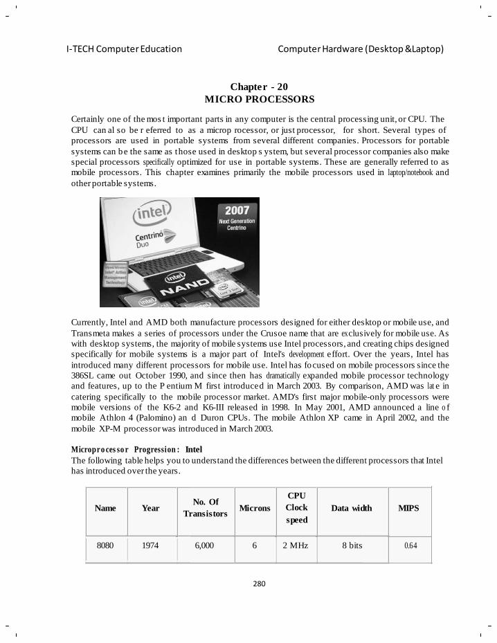
280
I-TECH Computer Education Computer Hardware (Desktop &Laptop)
r
d
Chapter - 20
MICRO PROCESSORS
Certainly one of the mos t important parts in any computer is the central processing unit, or CPU. The
CPU can al so be r eferred to as a microp rocessor, or just processor, for short. Several types of
processors are used in portable systems from several different companies. Processors for portable
systems can be the same as those used in desktop s ystem, but several processor companies also make
special processors specifically optimized for use in portable systems. These are generally referred to as
mobile processors. This chapter examines primarily the mobile processors used in laptop/notebook and
other portable systems.
Currently, Intel and AMD both manufacture processors designed for either desktop or mobile use, and
Transmeta makes a series of processors under the Crusoe name that are ex clusively for mobile use. As
with desktop systems, the majority of mobile systems use Intel processors, and creating chips designed
specifically for mobile systems is a major part of Intel's development effort. Over the years, Intel has
introduced many different processors for mobile use. Intel has focused on mobile processors since the
386SL came out October 1990, and since then has dramatically expanded mobile processor technology
and features, up to the P entium M first introduced in March 2003. By comparison, AMD was lat e in
catering specifically to the mobile processor market. AMD's first major mobile-only processors were
mobile versions of the K6-2 and K6-III released in 1998. In May 2001, AMD announced a line o f
mobile Athlon 4 (Palomino) an d Duron CPUs. The mobile Athlon XP came in April 2002, and the
mobile XP-M processor was introduced in March 2003.
Micropro ces so r Progression : Intel
The following table helps you to understand the differences between the different processors that Intel
has introduced over the years.
Name Year
No. Of
Transistors
Microns
CPU
Clock
speed
Data width MIPS
8080 1974 6,000 6 2 MHz 8 bits 0.64
281
I-TECH Computer Education Computer Hardware (Desktop &Laptop)
8088
1979
29,000
3
5 MHz 16 bits
0.33 8-bit bus
80286 1982 134,000 1.5 6 MHz 16 bits 1
80386 1985 275,000 1.5 16 MHz 32 bits 5
80486
1989
1,200,000
1
25 MHz
32 bits
20
Pentium
1993
3,100,000
0.8
60 MHz 32 bits
64-bit bus
100
Pentium 1997
II
7,500,000
0.35 233 MHz 32 bits
~300 64-bit bus
Pentium
III 1999
9,500,000
0.25 450 MHz 32 bits
~510 64-bit bus
Pentium
4 2000
42,000,000
0.18
32 bits
1.5 GHz 64-bit bus
~1,70 0
Pentium 4
"Prescott"
2004 125,000,000 0.09 3.6 GHz 32 bits
~7,00 0 64-bit bus
LAPTOP PROCESSOR
Installing a laptop CPU rarely makes sense and is often impossible. Laptops are engineered products,
with limited clearance and few exchangeable parts. If your laptop CPU works, but you think the laptop
is slow, add memory or defrag the hard drive. Even if the CPU is socketed rather than surface mounted
(soldered to the motherboard) there will be a very limited range of choices for upgrades, if any at all
are available. The upgrade CPU must be explicitly supported by the motherboard or you're wasting
your time, not to mention potentially damaging the motherboard. Even if it's possible to install a CPU
that's 20% faster, it won't make your laptop 20% faster, and in most applications, you probably won't
see any noticeable increase in performance at all.
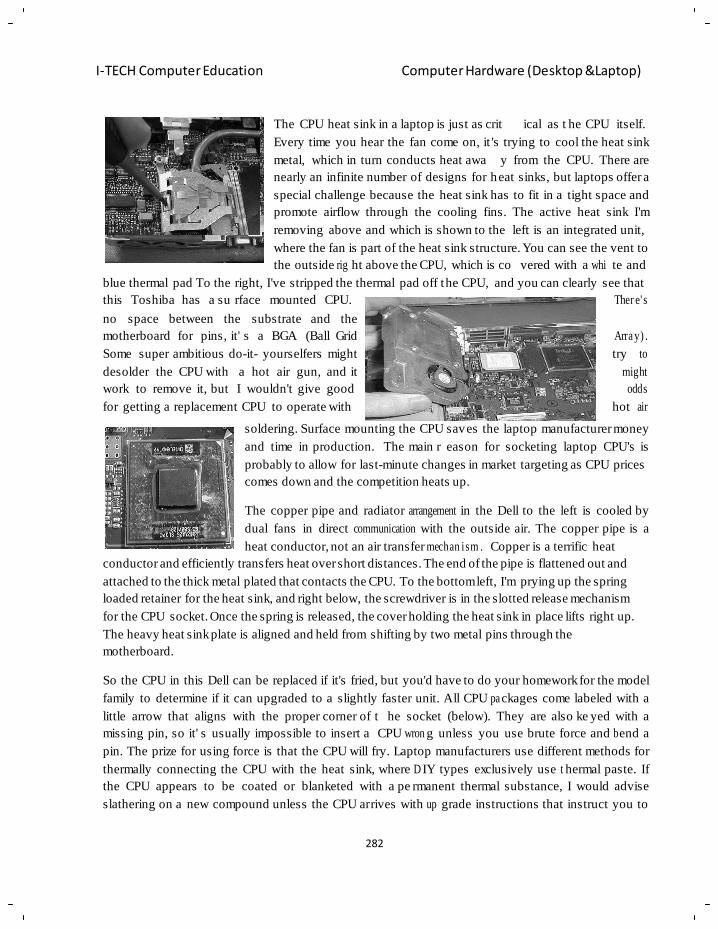
282
I-TECH Computer Education Computer Hardware (Desktop &Laptop)
The CPU heat sink in a laptop is just as crit ical as t he CPU itself.
Every time you hear the fan come on, it 's trying to cool the heat sink
metal, which in turn conducts heat awa y from the CPU. There are
nearly an infinite number of designs for heat sinks, but laptops offer a
special challenge because the heat sink has to fit in a tight space and
promote airflow through the cooling fins. The active heat sink I'm
removing above and which is shown to the left is an integrated unit,
where the fan is part of the heat sink structure. You can see the vent to
the outside rig ht above the CPU, which is co vered with a whi te and
blue thermal pad To the right, I've stripped the thermal pad off the CPU, and you can clearly see that
this Toshiba has a su rface mounted CPU. Ther e' s
no space between the substrate and the
motherboard for pins, it' s a BGA (Ball Grid
Some super ambitious do-it- yourselfers might
desolder the CPU with a hot air gun, and it
work to remove it, but I wouldn't give good
for getting a replacement CPU to operate with
Arra y) .
try to
might
odds
hot air
soldering. Surface mounting the CPU saves the laptop manufacturer money
and time in production. The main r eason for socketing laptop CPU's is
probably to allow for last-minute changes in market targeting as CPU prices
comes down and the competition heats up.
The copper pipe and radiator arrangement in the Dell to the left is cooled by
dual fans in direct communication with the outside air. The copper pipe is a
heat conductor, not an air transfer mechan ism . Copper is a terrific heat
conductor and efficiently transfers heat over short distances. The end of the pipe is flattened out and
attached to the thick metal plated that contacts the CPU. To the bottom left, I'm prying up the spring
loaded retainer for the heat sink, and right below, the screwdriver is in the slotted release mechanism
for the CPU socket. Once the spring is released, the cover holding the heat sink in place lifts right up.
The heavy heat sink plate is aligned and held from shifting by two metal pins through the
motherboard.
So the CPU in this Dell can be replaced if it's fried, but you'd have to do your homework for the model
family to determine if it can upgraded to a slightly faster unit. All CPU pa ckages come labeled with a
little arrow that aligns with the proper corner of t he socket (below). They are also ke yed with a
missing pin, so it' s usually impossible to insert a CPU wron g unless you use brute force and b end a
pin. The prize for using force is that the CPU will fry. Laptop manufacturers use different methods for
thermally connecting the CPU with the heat sink, where D IY types exclusively use t hermal paste. If
the CPU appears to be coated or blanketed with a pe rmanent thermal substance, I would advise
slathering on a new compound unless the CPU arrives with up grade instructions that instruct you to
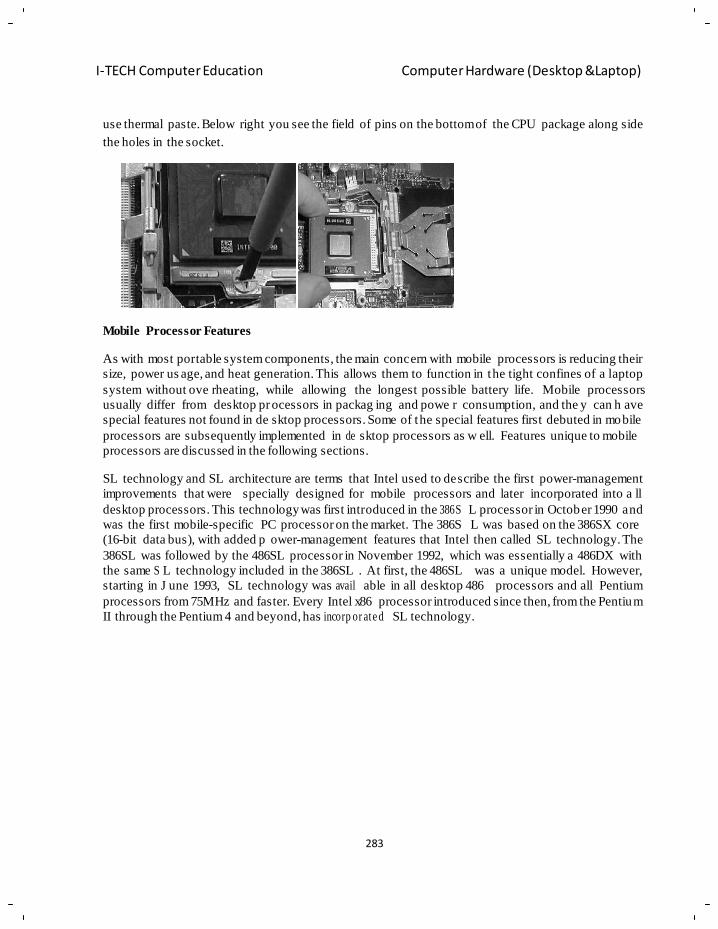
283
I-TECH Computer Education Computer Hardware (Desktop &Laptop)
use thermal paste. Below right you see the field of pins on the bottom of the CPU package along side
the holes in the socket.
Mobile Processor Features
As with most portable system components, the main concern with mobile processors is reducing their
size, power us age, and heat generation. This allows them to function in the tight confines of a laptop
system without ove rheating, while allowing the longest possible battery life. Mobile processors
usually differ from desktop pr ocessors in packag ing and powe r consumption, and the y can h ave
special features not found in de sktop processors. Some of the special features first debuted in mobile
processors are subsequently implemented in de sktop processors as w ell. Features unique to mobile
processors are discussed in the following sections.
SL technology and SL architecture are terms that Intel used to describe the first power-management
improvements that were specially designed for mobile processors and later incorporated into a ll
desktop processors. This technology was first introduced in the 386S L processor in October 1990 and
was the first mobile-specific PC processor on the market. The 386S L was based on the 386SX core
(16-bit data bus), with added p ower-management features that Intel then called SL technology. The
386SL was followed by the 486SL processor in November 1992, which was essentially a 486DX with
the same S L technology included in the 386SL . At first, the 486SL was a unique model. However,
starting in J une 1993, SL technology was avail able in all desktop 486 processors and all Pentium
processors from 75MHz and faster. Every Intel x86 processor introduced since then, from the Pentium
II through the Pentium 4 and beyond, has incorp or ate d SL technology.
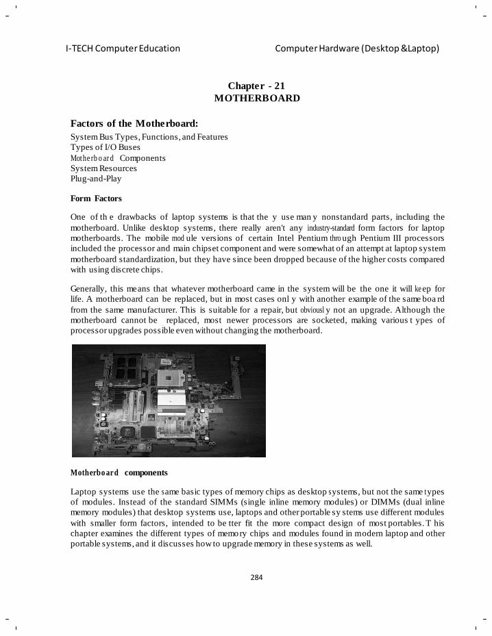
284
I-TECH Computer Education Computer Hardware (Desktop &Laptop)
Chapter - 21
MOTHERBOARD
Factors of the Motherboard:
System Bus Types, Functions, and Features
Types of I/O Buses
Mothe rb o ar d Components
System Resources
Plug-and-Play
Form Factors
One of th e drawbacks of laptop systems is that the y use man y nonstandard parts, including the
motherboard. Unlike desktop systems, there really aren't any industry-standard form factors for laptop
motherboards. The mobile mod ule versions of certain Intel Pentium thro ugh Pentium III processors
included the processor and main chipset component and were somewhat of an attempt at laptop system
motherboard standardization, but they have since been dropped because of the higher costs compared
with using discrete chips.
Generally, this means that whatever motherboard came in the system will be the one it will ke ep for
life. A motherboard can be replaced, but in most cases onl y with another example of the same boa rd
from the same manufacturer. This is suitable for a repair, but obviousl y not an upgrade. Although the
motherboard cannot be replaced, most newer processors are socketed, making various t ypes of
processor upgrades possible even without changing the motherboard.
Motherbo ard components
Laptop systems use the s ame basic types of memory chips as desktop s ystems, but not the same t ypes
of modules. Instead of the standard SIMMs (single inline memory modules) or DIMMs (dual inline
memory modules) that desktop systems use, laptops and other portable sy stems use different modules
with smaller form factors, intended to be tter fit the more compact design of most portables. T his
chapter examines the different types of memory chips and modules found in m odern laptop and other
portable systems, and it discusses how to upgrade memory in these systems as well.
285
I-TECH Computer Education Computer Hardware (Desktop &Laptop)
Memory Standards
Older portables often used proprietary memory modules, meaning that they were custom designed by
the system manufacturer and normally could be purchased only from that manufacturer. That not only
meant that replacing or upgrading memory was expensive, it was also ha rder to find, because in many
cases the memory could only be purchased from the original manufacturer. Some of the first l aptop
systems in late 80s and earl y 90s used propriet ary memory cartridges that looked like modern PC
Cards but plugg ed into a dedicated PCMC IA (Personal Computer Memory Card International
Association) memory socket inside the system. Gradually, most of the manufacturers shifted their
designs to using industry-standard memory modules, which are interchangeable, much easier to find,
and much l ess expensive overall. Most mod ern systems now use industry-standard memory modules
that are specifically designed for smaller or portable systems. Most of these industry-standard memory
chip and module designs are created by the JEDEC (Joint Electron Device Engineering Council) Solid
State Tech nolo g y Association.
JEDEC
JEDEC (Joint Electron Device Engineering Council) is the semiconductor engineering standardization
body of the Electronic Industries Alliance (E IA), a tr ade association that represents all areas of the
electronics industry. JEDEC was o riginally created in 1960 and governs the standa rdization of all
types of semiconductor devices, integrated circuits, and modules. J EDEC has about 300 member
companies, including memory, chipset, and pr ocessor manufacturers as wel l as pract ically any
company involved in manu fa ctu ring computer equipment using indust ry- stan da r d components.
The idea behind J EDEC is simple: If one company were to create a prop rietary memory technology,
for example, then other companies who wi shed to manufacture components compliant with that
memory would ha ve to pay license fees, assuming the company who owned it wa s interested in
licensing at all! Parts would be more proprietary in nature, causing problems with interchangeability or
sourcing reasonably priced replacements. In addition, those companies licensing the technology would
have no control over future changes made by the owner company. The idea behind J EDEC is to
prevent that type of scenario for items such as memory, by getting all the memory manufacturers to
work together creating shared industry standards covering memory chips and modules. JEDEC-
approved standards for memory could then be freely shared by all the member companies, and no one
single company would have control over a given standard, or an y of the companies produc ing
compliant components. FPM, SDRAM, DDR SDRA M, and DDR2 SDR AM are examples of JEDEC
memory standards used in PCs, whereas EDO and RDRAM ar e proprietary examples. You can find
out more about JEDEC standards for memory and other semic on d ucto r technology.
This chapter covers power for portable systems. Normally laptop or portable systems have options for
several sources of pow er, including AC ( alternating current; found i n the wall sock ets of most
buildings), power sockets in a utomobiles and airplanes, and several types of batteries. This chapter
examines all the power sources found in a modern portable system and also fo cuses on po wer
mana g em en t for portables.
AC/DC Power Supplies
All portable systems at one time or another must de pend on a n external power source either for
operation, to recharge their batteries, or both. The most comm on ly used external power sources are:
286
I-TECH Computer Education Computer Hardware (Desktop &Laptop)
• 120V 60Hz AC wall current (USA)
• 240V 50Hz AC wall current (Europe)
• 12V DC current (auto/airplane)
Expansion Buses
In an effort to give notebook computers the kind of expa nd ab il i ty users have grown used to in desk top
systems, the Personal Computer Memory Card International Association (PCMCIA) has established
several standards for credit card–size expansion boards that fit into small slots found in laptop and
notebook computers. PCMCIA was founded in 1 989 as a non-profit trade association with more than
85 member companies worldwide, to establish technical standards for PC Card technolo gy. The
development and evolution of the PCMCIA's PC Card interface standard has proven to be a successful
feat of engin e erin g in a market full of proprie tar y designs.
The words "Memory Card" in the PCMCIA name allude to the original 1.0 specification it released in
September 1990, which was for memor y cards only. The 2.0 release that came in September 199 1
added support for I/O (input/output) cards as well. Subsequent releases have enhanced the stand ard
further, adding higher performance modes, lower power consumption, and greater compatibility. The
current PC Card Standar d (Release 8.0) h as added many capabilities, features, and functions, and has
grown well beyond its simple memory card origins.
PC Cards (PCMCIA)
Although they were originally called PCMCIA Cards, after the se cond release of the specific ation in
1991, these cards are more accurately (and officially) called PC Cards inst ead. Still, to this da y many
people (including myself) often call them PCMCIA Cards, even t hough that is no l onger technically
correct.
Modern PC Cards suppo rt a v ariety of applications; the functionalit y that can b e added to a system
through PC Card technolog y is enormous. Virtuall y any type of interface or adapter that can be add ed
to a desktop s ystem via ISA (industry standard architecture) or P CI (peripheral component
interc on ne c t ) bus cards can also be added to a laptop or notebook system via PC Cards.
Graphics and Sound
Modern laptop computers feature in tegrated graphics and sound. Some recent laptops feature powerful
3D graphics acceleration and high-quality sound. However, in general, the graphics and sound features
found in laptop compute rs lags behind the features available with the b est add-on graphics and sound
cards available for their desktop siblings.
In this chapte r, you'll learn about the basic graphics and sound technolog ies as the y apply to laptop
computers and how to look for laptops that have th e graphics and sound f eatures you need. You w ill
also learn how to improve onboard graphics and onboard sound through internal and external upgrades
and how to troublesh oo t problems you might encounter.
287
I-TECH Computer Education Computer Hardware (Desktop &Laptop)
Video Display System
The video subsystem of a modern laptop/n ote bo o k system consists of two main components:
• Video display— An LCD panel in most laptop/no teb oo k systems
• Video adapter (also called the video chip or graphics adapter) — Built in to the mother bo ar d in
virtually every laptop/n ote bo ok systems. Some laptops integrate the graphics as part of the
mothe rbo a rd chipset, but some high-end and gaming optimized models use a discrete graphics
chip with its own video memory.
Portable System Accessories
A great many add-on devices are available for use with portable s ystems, providing functions that
cannot practically or economically be include d inside a s ystem itself. Indeed, many of the most
common uses for portable systems might require additional hardware, either because of the computer's
location or the requi re m e nts of the function.
Note that when i t comes to laptop accessories, the range of available options may actually exceed
those available for desktops. Consider that l aptop owners can choose not only from a wide array of
desktop accessories, they can also take advantage of a large group of accessories that are meant for use
exclusively by portable systems. The only desktop accessories not available to laptops a re internal
expansion cards and sto rage drives—and in so me cases even these components can be installed in
certain laptop confi gurations. The following sections discuss some of the most common peripherals
used with portable systems.
Carrying Cases
Perhaps the most popula r accessory for laptops i s the ca rrying case—and for good reason. Anyone
who takes an ex pensive laptop computer out in to the real world wants to be sure it wi ll survive
undamaged. People can and do carry their laptops in briefcases, backpacks, and p robably everything
short of a paper grocery bag, but for real protection, laptops should be carried in cases specifically
designed for that purpos e, with special cushioni ng to limit an y damage from accidental knocks and
drops.
Over the years, several different types of cushioning have been employed in laptop carrying cases. The
simplest and most common form of cushioning is a layer of foam rubb er. A handful of cases h ave
enhanced this type of cushioning by suspending the laptop in an elastic sling . A small number of oth er
carrying cases used inflatable cushions. The inflatable cases provided a good degree of cushioning but
often required partial deflation in order to remove the laptop.
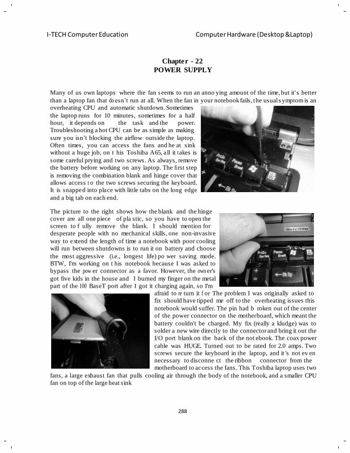
288
I-TECH Computer Education Computer Hardware (Desktop &Laptop)
Chapter - 22
POWER SUPPLY
Many of us own laptops where the fan s eems to run an anno ying amount of the time, but it' s better
than a laptop fan that do esn‘t run at all. When the fan in your notebook fails, the usual s ymptom is an
overheating CPU and automatic shutdown. Sometimes
the laptop runs for 10 minutes, sometimes for a half
hour, it depends on the task and the power.
Troubleshooting a hot CPU can be as simple as making
sure you isn‘t blocking the airflow outside the laptop.
Often times, you can access the fans and he at sink
without a huge job, on t his Toshiba A65, all it t akes is
some careful prying and two screws. As always, remove
the battery before working on any laptop. The fi rst step
is removing the combination blank and hinge cover that
allows access t o the two screws securing the keyboard.
It is snapped into place with little tabs on the long edge
and a big tab on each end.
The picture to the right shows how the blank and the hinge
cover are all one piece of pla stic, so you have to open the
screen to f ully remove the blank. I should mention for
desperate people with no mechanical skills, one non-invasive
way to extend the length of time a notebook with poor cooling
will run between shutdowns is to run it on battery and choose
the most aggressive (i.e., longest life) po wer saving mode.
BTW, I'm working on t his notebook because I was asked to
bypass the pow er connector as a favor. However, the own er's
got five kids in the house and I burned my finger on the metal
part of the 100 BaseT port after I got it charging again, so I'm
afraid to re turn it f or The problem I was originally asked to
fix should have tipped me off to the overheating issues this
notebook would suffer. The pin had b roken out of the center
of the power connector on the motherboard, which meant the
battery couldn't be charged. My fix (really a kludge) was to
solder a new wire directly to the connector and bring it out the
I/O port blank on the back of the not ebook. The coax power
cable was HUGE. Turned out to be rated for 2.0 amps. Two
screws secure the keyboard in the laptop, and it 's not ev en
necessary to disconne ct the ribbon connector from the
motherboard to access the fans. This Toshiba laptop uses two
fans, a large exhaust fan that pulls cooling air through the body of the notebook, and a smaller CPU
fan on top of the large heat sink
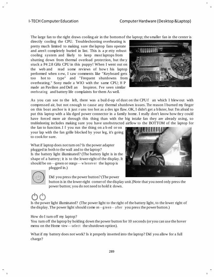
289
I-TECH Computer Education Computer Hardware (Desktop &Laptop)
The large fan to the right draws cooling air in the bottom of the laptop; the smaller fan in the center is
directly cooling the CPU. Troubleshooting overheating is
pretty much limited to making sure the laptop fans operate
and aren't completely buried in lint. This is a pr etty robust
cooling system and likely to keep most laptops from
shutting down from thermal overload protection, but the y
stuck a P4 2.8 GHz CPU in this puppy! When I went out on
the web and read some reviews of how t his laptop
performed when n ew, I saw comments like "Keyboard gets
too hot to type" and "Frequent shutdowns from
overheating." Sony made a WIO with the same CPU; H P
made an Pavilion and Dell an Inspiron. I've seen similar
overh e at ing and battery life complaints for them As well.
As you can see to the left, there was a buil d-up of dust on the CPU f an which I blew out with
compressed air, but not e nough to cause any thermal shutdown issues. Th e reason I burned my finger
on this boat anchor is it just r uns too hot as a des ign flaw. OK, I didn't get a b lister, but I'm afraid to
put this laptop with a klu dged power connector in a family home. I really don't know how the y could
have forced more air through this thing than with the big intake fan they are already using, so
troubleshooting includes making sure you have unobstructed airflow to the BOTTOM of the laptop for
the fan to function. I f you run the thing on a b ed or on
your lap with the fan grille blocked by your leg, it's going
to cook for sure.
What if laptop does not turn on? Is the power adapter
plugged in both to the wall and to the laptop?
Is the battery light illuminated? (The battery light is in the
shape of a battery; it is to the lower-right of the display. It
should be on—green or orange — w he n ev e r the laptop is
plugged in.)
Did you press the power button? (The power
button is in the lower-right corner of the display unit.)Note that you need only press the
power button; you do not need to hold it down.
Is the power light illuminated? (The power light to the right of the battery light, to the lower right of
the display. The power light should come on—g re e n— a fte r you press the power button.)
How do I turn off my laptop?
You turn off the laptop by holding down the power button for 10 seconds (or you can use the hover
menu on the Home view — sele c t the shutdown option).
What if my battery does not work? Is it properly inserted into the laptop? Did you allow for a full
charge?
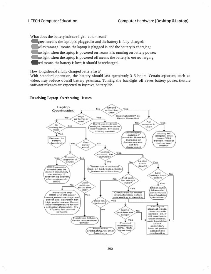
290
I-TECH Computer Education Computer Hardware (Desktop &Laptop)
What does the battery indicato r-l igh t color mean?
green means the laptop is plugged in and the battery is fully charged;
yellow /o ra ng e means the laptop is plugged in and the battery is charging;
no light when the laptop is powered on means it is running on battery power;
no light when the laptop is powered off means the battery is not recharging;
red means the battery is low; it should be recharged.
How long should a fully charged battery last?
With standard operation, the battery should last approximately 3–5 hours. Certain applications, such as
video, may reduce overall battery performance. Turning the backlight off saves battery power. (Future
software releases are expected to improve battery life.
Resolving Laptop Overheat ing Issues
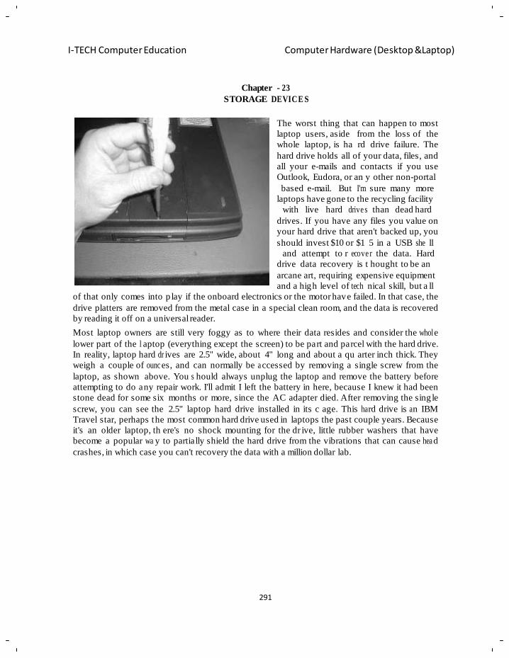
291
I-TECH Computer Education Computer Hardware (Desktop &Laptop)
Chapter - 23
STORAGE DEVICE S
The worst thing that can happen to most
laptop users, aside from the loss of the
whole laptop, is ha rd drive failure. The
hard drive holds all of your data, files, and
all your e-mails and contacts if you use
Outlook, Eudora, or an y other non-portal
based e-mail. But I'm sure many more
laptops have gone to the recycling facility
with live hard drive s than dead hard
drives. If you have any files you value on
your hard drive that aren't backed up, you
should invest $10 or $1 5 in a USB she ll
and attempt to r ecove r the data. Hard
drive data recovery is t hought to be an
arcane art, requiring expensive equipment
and a high level of tech nical skill, but a ll
of that only comes into p lay if the onboard electronics or the motor have failed. In that case, the
drive platters are removed from the metal case in a special clean room, and the data is recovered
by reading it off on a universal reader.
Most laptop owners are still very foggy as to where their data resides and consider the whol e
lower part of the l aptop (everything except the screen) to be part and parcel with the hard drive.
In reality, laptop hard dr ives are 2.5" wide, about 4" long and about a qu arter inch thick. They
weigh a couple of ounc es, and can normally be a ccessed by removing a single screw from the
laptop, as shown above. You s hould always unplug the laptop and remove the battery before
attempting to do any repair work. I'll admit I left the battery in here, because I knew it had been
stone dead for some six months or more, since the AC adapter died. After removing the sing le
screw, you can see the 2.5" laptop hard drive installed in its c age. This ha rd drive is a n IBM
Travel star, perhaps the most common hard drive used in laptops the past couple years. Because
it's an older laptop, th ere's no shock mounting for the dr ive, little rubber washers that have
become a popular wa y to partially shield the hard drive from the vibrations that can cause hea d
crashes, in which case you can't recovery the data with a million dollar lab.
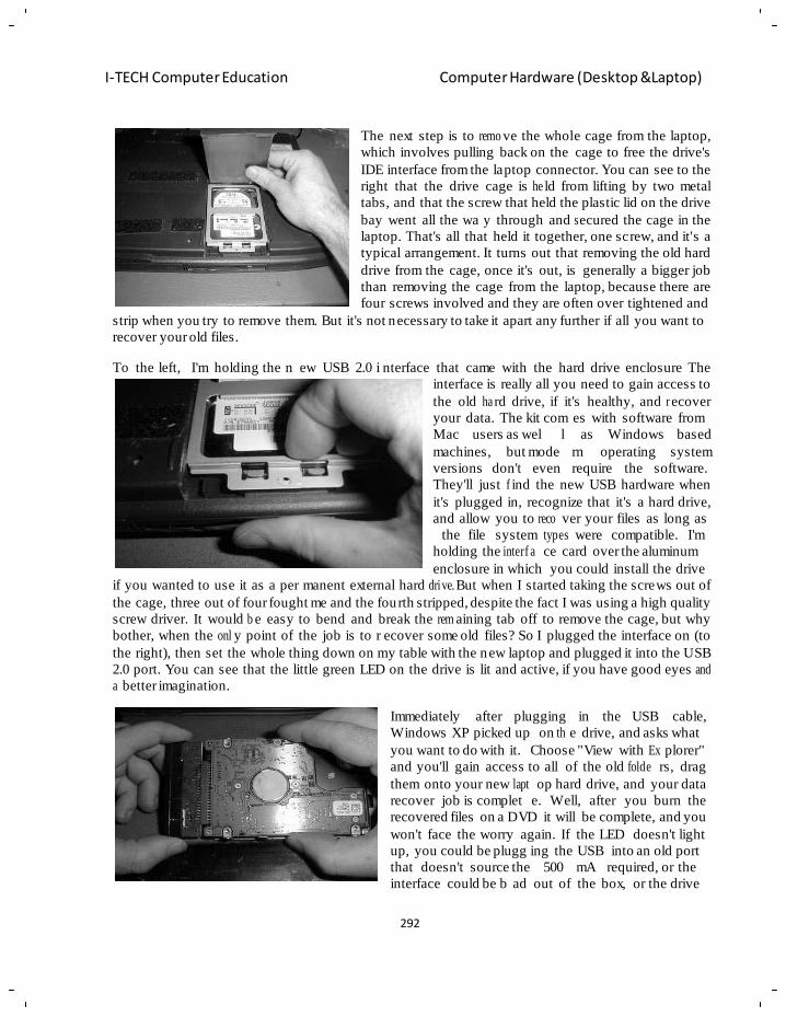
292
I-TECH Computer Education Computer Hardware (Desktop &Laptop)
The next step is to remo ve the whole cage from the laptop,
which involves pulling back on the cage to free the drive's
IDE interface from the laptop connector. You can see to the
right that the drive cage is he ld from lifting by two metal
tabs, and that the screw that held the plastic lid on the drive
bay went all the wa y through and s ecured the cage in the
laptop. That's all that held it together, one screw, and it's a
typical arrangement. It turns out that removing the old hard
drive from the cage, once it's out, is generally a bigger job
than removing the cage from the laptop, because there are
four screws involved and they are often over tightened and
strip when you try to remove them. But it's not necessary to take it apart any further if all you want to
recover your old files.
To the left, I'm holding the n ew USB 2.0 i nterface that came with the hard drive enclosure The
interface is really all you need to gain access to
the old ha rd drive, if it's healthy, and r ecover
your data. The kit com es with software from
Mac users as wel l
machines, but mode
versions don't even
as Windows based
rn operating system
require the software.
They'll just f ind the new USB hardware when
it's plugged in, recognize that it's a hard drive,
and allow you to reco ver your files as long as
the file system types were compatible. I'm
holding the interf a ce card over the aluminum
enclosure in which you could install the drive
if you wanted to use it as a per manent external hard drive. But when I started taking the screws out of
the cage, three out of four fought me and the fourth stripped, despite the fact I was using a high quality
screw driver. It would b e easy to bend and break the rem aining tab off to remove the cage, but why
bother, when the onl y point of the job is to r ecover some old files? So I plugged the interface on (to
the right), then set the whole thing down on my table with the new laptop and plugged it into the USB
2.0 port. You can see that the little green LED on the drive is lit and active, if you have good eyes and
a better imagination.
Immediately after plugging in the USB cable,
Windows XP picked up on th e drive, and asks what
you want to do with it. Choose "View with Ex plorer"
and you'll gain access to all of the old folde rs, drag
them onto your new lapt op hard drive, and your data
recover job is complet e. Well, after you burn the
recovered files on a DVD it will be complete, and you
won't face the worry again. If the LED doesn't light
up, you could be plugg ing the USB into an old port
that doesn't source the 500 mA required, or the
interface could be b ad out of the box, or the drive
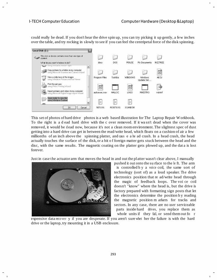
293
I-TECH Computer Education Computer Hardware (Desktop &Laptop)
could really be dead. If you don't hear the drive spin up, you can try picking it up gently, a few inches
over the table, and try rocking in slowly to see if you can feel the centripetal force of the disk spinning.
This set of photos of hard drive photos is a web based illustration for The Laptop Repair W orkbook.
To the right is a d ead hard drive with the c over removed. If it wa sn't dead when the cover was
removed, it would be d ead now, because it's not a clean room environment. The slightest spec of dust
getting into a hard drive can get in between the read/write head, which floats on a cushion of air a few
millionths of an inch above the spinning platter, and caus e a he ad crash. In a head crash, the head
actually touches the surface of the disk, or a bit o f foreign matter gets stuck between the head and the
disc, with the same results. The magnetic coating on the platter gets plowed up, and the dat a is lost
forever.
Just in case the actuator arm that moves the head in and out the pl atter wasn't clear above, I manually
pushed it out onto the su rface to the le ft. The arm is controlled b y a voice coil, the same sort of
technology (sort of) as a loud speaker. Th e drive
electronics position that re ad/write head through
the magic of feedback loops. The voi ce coil
doesn't "know" where the head is, but the drive is
factory prepared with formatting sign posts that let
the electronics determine the position b y reading
the magnetic position m arkers for tracks and
sectors. In any case, there are no us er serviceable
parts inside hard drives,
whole units if they fail,
you replace them as
or send them out fo r
expensive data reco ve r y if you are desperate. If you aren't sure whet her the failure is with the hard
drive or the laptop, try mounting it in a USB enclosure.
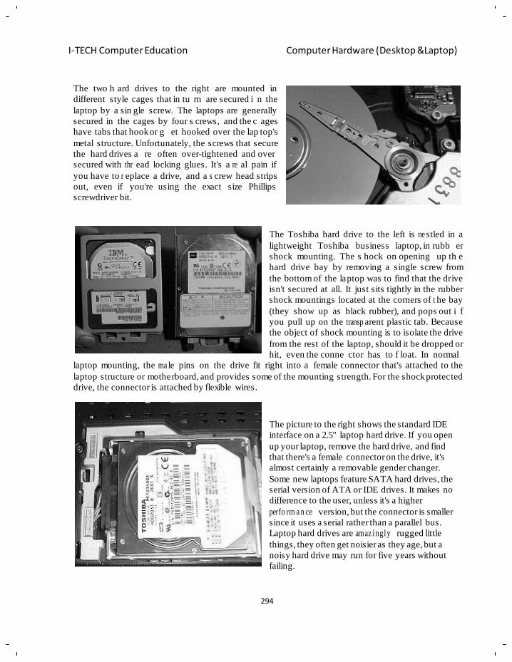
294
I-TECH Computer Education Computer Hardware (Desktop &Laptop)
The two h ard drives to the right are mounted in
different style cages that in tu rn are secured i n the
laptop by a sin gle screw. The laptops are generally
secured in the cages by four s crews, and the c ages
have tabs that hook or g et hooked over the lap top's
metal structure. Unfortunately, the screws that secure
the hard drives a re often over-tightened and over
secured with thr ead locking glues. It's a re al pain if
you have to r eplace a drive, and a s crew head strips
out, even if you're using the exact size Phillips
screwdriver bit.
The Toshiba hard drive to the left is ne stled in a
lightweight Toshiba business laptop, in rubb er
shock mounting. The s hock on opening up th e
hard drive bay by removing a single screw from
the bottom of the laptop was to find that the drive
isn't secured at all. It just sits tightly in the rubber
shock mountings located at the corners of t he bay
(they show up as black rubber), and pops out i f
you pull up on the transp arent plastic tab. Because
the object of shock mounting is to isolate the drive
from the rest of the laptop, should it be dropped or
hit, even the conne ctor has to f loat. In normal
laptop mounting, the ma le pins on the drive fit right into a female connector that's attached to the
laptop structure or motherboard, and provides some of the mounting strength. For the shock protected
drive, the connector is attached by flexible wires.
The picture to the right shows the standard IDE
interface on a 2.5" laptop hard drive. If you open
up your laptop, remove the hard drive, and find
that there's a female connector on the drive, it's
almost certainly a removable gender changer.
Some new laptops feature SATA hard drives, the
serial version of ATA or IDE drives. It makes no
difference to the user, unless it's a higher
perfo rm a n ce version, but the connector is smaller
since it uses a serial rather than a parallel bus.
Laptop hard drives are amaz ingly rugged little
things, they often get noisier as they age, but a
noisy hard drive may run for five years without
failing.
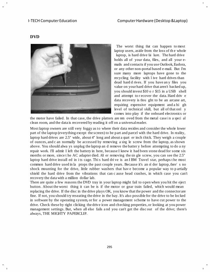
295
I-TECH Computer Education Computer Hardware (Desktop &Laptop)
DVD
The worst thing that can happen to most
laptop users, aside from the loss of th e whole
laptop, is hard drive fai lure. The hard drive
holds all of your data, files, and all your e-
mails and contacts if you use Outlook, Eudora,
or any other non-portal based e-mail. But I'm
sure many more laptops have gone to the
recycling facility with l ive hard drives than
dead hard d rives. If you have an y files you
value on your hard drive that aren't backed up,
you should invest $10 o r $15 in a USB shell
and attempt to r ecover the data. Hard driv e
data recovery is thou ght to be an arcane art,
requiring expensive equipment and a hi gh
level of technical skill, but all of that onl y
comes into play if the onboard electronics or
the motor have failed. In that case, the drive platters are rem oved from the metal case i n a speci al
clean room, and the data is recovered by reading it off on a universal reader.
Most laptop owners are still very foggy as to where their data resides and consider the whole lower
part of the laptop (everything except the screen) to be part and parcel with the hard drive. In reality,
laptop hard drives are 2.5" wide, about 4" long and about a quart er inch thick. They weigh a couple
of ounces, and c an normally be accessed by removing a sing le screw from the laptop, as shown
above. You should alwa ys unplug the laptop an d remove the batter y before attempting to do a ny
repair work. I'll admit I left the battery in here, because I knew it had been stone dead for some six
months or more, since t he AC adapter died. Aft er removing the sin gle screw, you can see the 2.5"
laptop hard drive install ed in i ts cage. Thi s hard dri ve is an I BM Travel star, perhaps t he most
common hard drive used in la ptops the past couple years. Because it's an ol der laptop, there' s no
shock mounting for the drive, little rubber washers that hav e become a popular way to p artially
shield the hard drive from the vibrations that can c ause head crashes, in which case you can't
recovery the data with a million dollar lab.
There are quite a few reasons the DVD tray in your laptop might fail to open when you hit the eject
button. About the worst thing it can be is if the motor or gear train failed, which would mean
replacing the drive. If the disc in the drive plays OK, you know that the power and the connector are
fine. If not, you should t ry reseating the drive in the bay. It's also possible for the drive to be locked
in software by the operating system, or for a power management scheme to have cut power to the
drive. Check these by right clicking the drive icon and checking properties, or looking at you power
management settings. But, when all else fails a nd you can't get the disc out
always, THE MIGHTY PAPERCLIP.
of the drive; there's
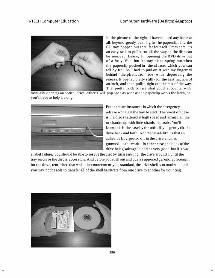
296
I-TECH Computer Education Computer Hardware (Desktop &Laptop)
In the picture to the right, I haven't used any force at
all, beyond gently pushing in t he paperclip, and the
CD tray popped out that far b y itself. From here, it's
an easy task to pull it ou t all the way so the disc can
be removed. Below, I'm opening the D VD drive out
of a Son y Vaio, but th e tray didn't spring out w hen
the paperclip pushed in the rel ease, which you can
tell by feel. So I had to pull on it with my fingernail
behind the plastic fac ade while depressing the
release. It opened pretty stiffly for the first fraction of
an inch, and then pulled right out the rest of the way.
That pretty much covers what you'll encounter with
manually opening an optical drive, either it will pop open as soon as the paperclip works the latch, or
you'll have to help it along.
But there are instances in which the emergency
release won't get the tray to eject. The worst of these
is if a disc shattered at high speed and jammed all the
mechanics up with little shards of plastic. You'll
know this is the case by the noise if you gently tilt the
drive back and forth. Another possibi l ity is that an
adhesive label peeled off in the drive and has
gummed up the works. In either case, the odds of the
drive being salvageable aren't very good, but if it was
a label failure, you should be able to rescue the disc by disass em b lin g the drive around it until the
tray ejects or the disc is accessible. And before you rush out and buy a supposed generic replacement
for the drive, remember that while the connector may be standard, the drive shell is custo m ize d , and
you may not be able to transfer all of the shell hardware from one drive to another for mounting.
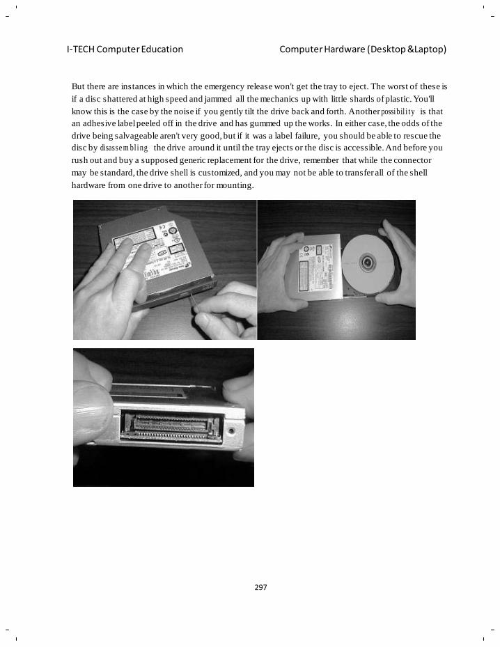
297
I-TECH Computer Education Computer Hardware (Desktop &Laptop)
But there are instances in which the emergency release won't get the tray to eject. The worst of these is
if a disc shattered at high speed and jammed all the mechanics up with little shards of plastic. You'll
know this is the case by the noise if you gently tilt the drive back and forth. Another possibil i ty is that
an adhesive label peeled off in the drive and has gummed up the works. In either case, the odds of the
drive being salvageable aren't very good, but if it was a label failure, you should be able to rescue the
disc by disasse m bl ing the drive around it until the tray ejects or the disc is accessible. And before you
rush out and buy a supposed generic replacement for the drive, remember that while the connector
may be standard, the drive shell is customized, and you may not be able to transfer all of the shell
hardware from one drive to another for mounting.
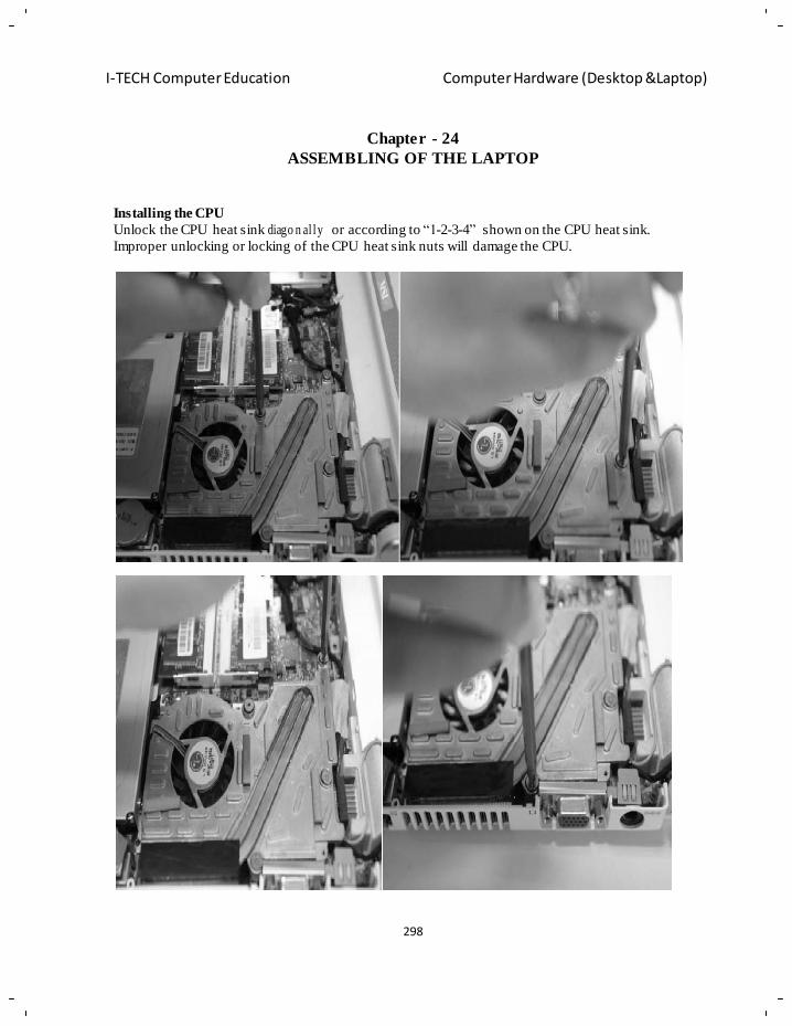
298
I-TECH Computer Education Computer Hardware (Desktop &Laptop)
Chapter - 24
ASSEMBLING OF THE LAPTOP
Installing the CPU
Unlock the CPU heat sink diago n al ly or according to ―1-2-3-4‖ shown on the CPU heat sink.
Improper unlocking or locking of the CPU heat sink nuts will damage the CPU.
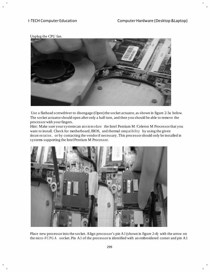
299
I-TECH Computer Education Computer Hardware (Desktop &Laptop)
Unplug the CPU fan.
Use a flathead screwdriver to disengage (Open) the socket actuator, as shown in figure 2-3a below.
The socket actuator should open after only a half turn, and then you should be able to remove the
processor with your fingers.
Hint: Make sure your system can acco m m o da te the Intel Pentium M /Celeron M Processor that you
want to install. Check for motherboard, BIOS, and thermal comp at ibi li ty by using the given
docum en tat ion , or by contacting the vendor if necessary. This processor should only be installed in
systems supporting the Intel Pentium M Processor.
Place new processor into the socket. Align processor‘s pin A1 (shown in figure 2-4) with the arrow on
the micro -FC PG A socket. Pin A1 of the processor is identified with an embroidered corner and pin A1
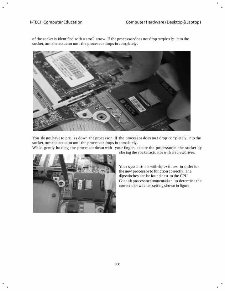
300
I-TECH Computer Education Computer Hardware (Desktop &Laptop)
of the socket is identified with a small arrow. If the processor does not drop complete ly into the
socket, turn the actuator until the processor drops in completely.
You do not have to pre ss down the processor. If the processor does no t drop completely into the
socket, turn the actuator until the processor drops in completely.
While gently holding the processor down with your finger, secure the processor in the socket by
closing the socket actuator with a screwdriver.
Your system is set with dip-sw i tc he s in order for
the new processor to function correctly. The
dipswitches can be found next to the CPU.
Consult processor docum e ntat io n to determine the
correct dipswitches setting shown in figure
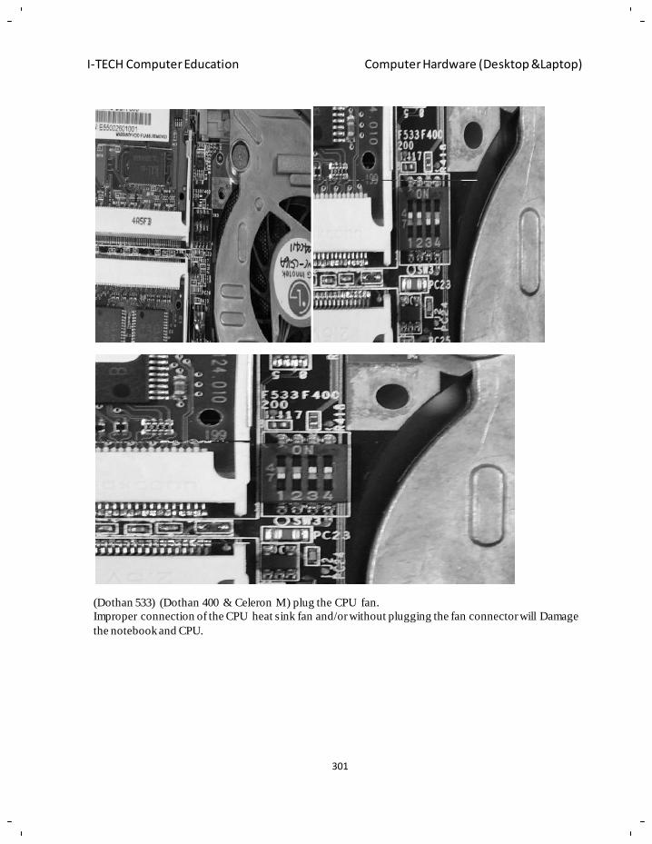
301
I-TECH Computer Education Computer Hardware (Desktop &Laptop)
(Dothan 533) (Dothan 400 & Celeron M) plug the CPU fan.
Improper connection of the CPU heat sink fan and/or without plugging the fan connector will Damage
the notebook and CPU.
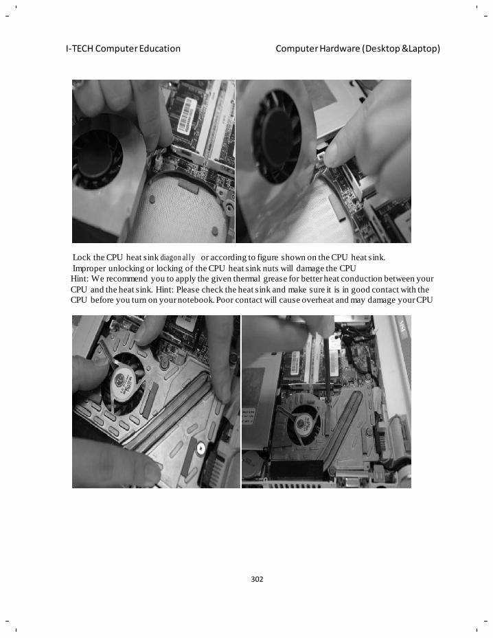
302
I-TECH Computer Education Computer Hardware (Desktop &Laptop)
Lock the CPU heat sink diagon al ly or according to figure shown on the CPU heat sink.
Improper unlocking or locking of the CPU heat sink nuts will damage the CPU
Hint: We recommend you to apply the given thermal grease for better heat conduction between your
CPU and the heat sink. Hint: Please check the heat sink and make sure it is in good contact with the
CPU before you turn on your notebook. Poor contact will cause overheat and may damage your CPU
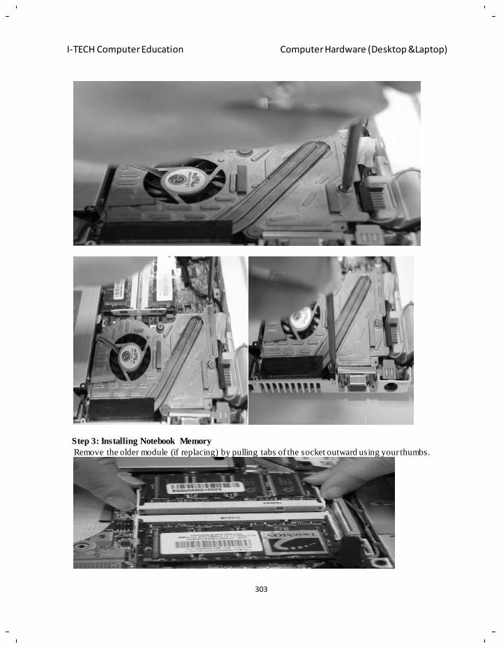
303
I-TECH Computer Education Computer Hardware (Desktop &Laptop)
Step 3: Installing Notebook Memory
Remove the older module (if replacing) by pulling tabs of the socket outward using your thumbs.
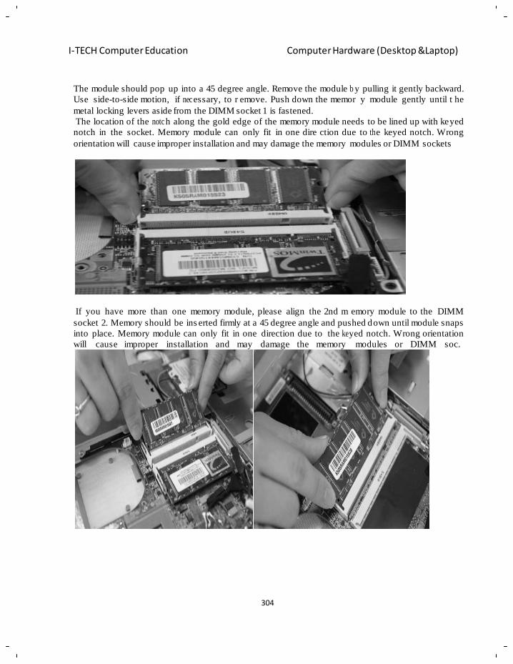
304
I-TECH Computer Education Computer Hardware (Desktop &Laptop)
The module should pop up into a 45 degree angle. Remove the module b y pulling it gently backward.
Use side-to-side motion, if nec essary, to r emove. Push down the memor y module gently until t he
metal locking levers aside from the DIMM socket 1 is fastened.
The location of the notc h along the gold edge of the memory module needs to be lined up with keyed
notch in the socket. Memory module can only fit in one dire ction due to th e keyed notch. Wrong
orientation will cause improper installation and may damage the memory modules or DIMM sockets
If you have more than one memory module, please align the 2nd m emory module to the DIMM
socket 2. Memory should be ins erted firmly at a 45 degree angle and pushed down until module snaps
into place. Memory module can only fit in one direction due to the ke yed notch. Wrong orientation
will cause improper installation and may damage the memory modules or DIMM soc.
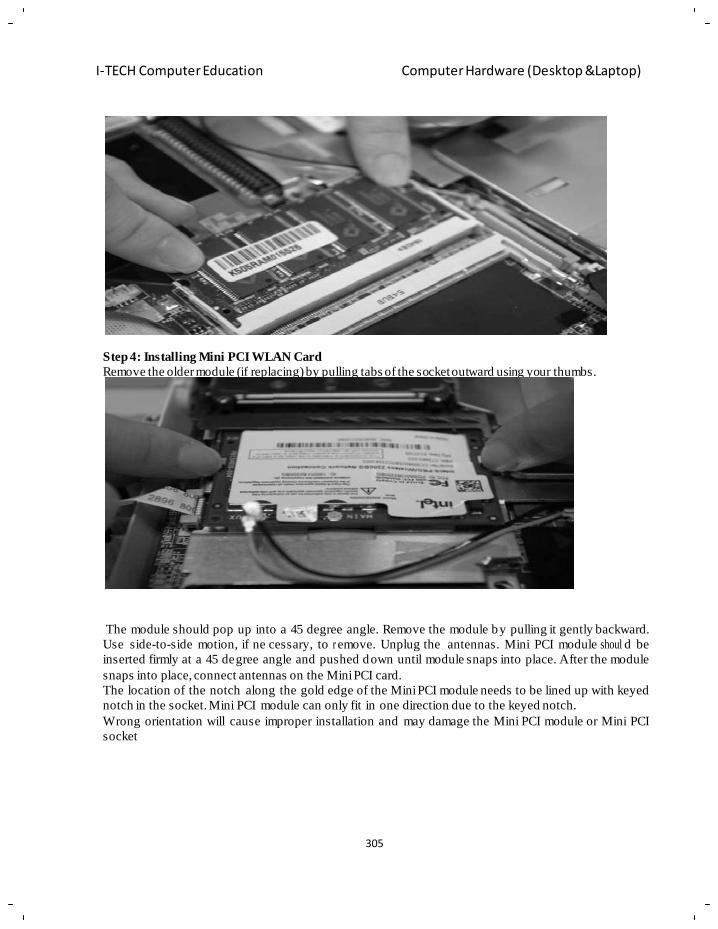
305
I-TECH Computer Education Computer Hardware (Desktop &Laptop)
Step 4: Installing Mini PCI WLAN Card
Remove the older module (if replacing) by pulling tabs of the socket outward using your thumbs.
The module should pop up into a 45 degree angle. Remove the module by pulling it gently backward.
Use side-to-side motion, if ne cessary, to r emove. Unplug the antennas. Mini PCI module shoul d be
inserted firmly at a 45 degree angle and pushed down until module snaps into place. After the module
snaps into place, connect antennas on the Mini PCI card.
The location of the notch along the gold edge of the Mini PCI module needs to be lined up with keyed
notch in the socket. Mini PCI module can only fit in one direction due to the keyed notch.
Wrong orientation will cause improper installation and may damage the Mini PCI module or Mini PCI
socket
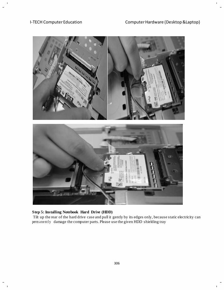
306
I-TECH Computer Education Computer Hardware (Desktop &Laptop)
Step 5: Installing Notebook Hard Drive (HDD)
Tilt up the rear of the hard drive case and pull it gently by its edges only, because static electricity can
perm a ne nt ly damage the computer parts. Please use the given HDD shielding tray
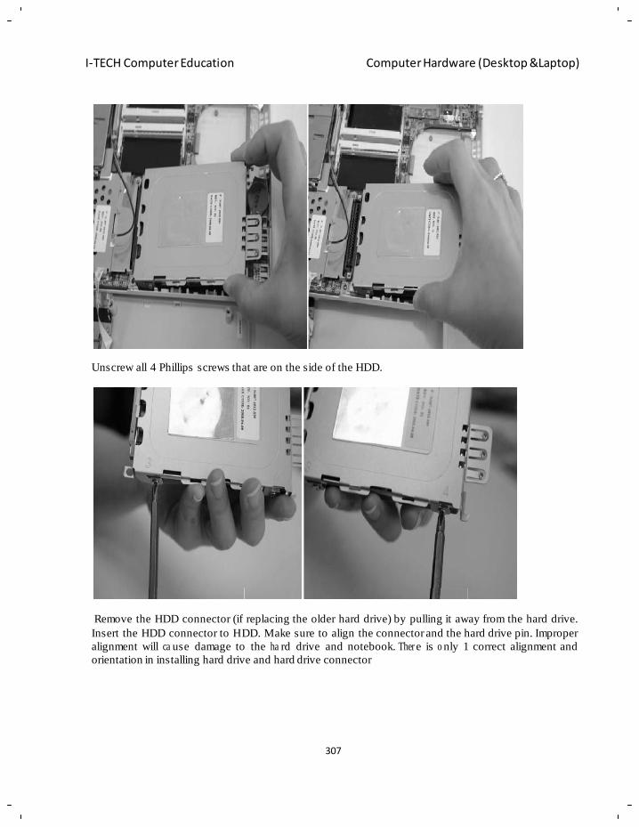
307
I-TECH Computer Education Computer Hardware (Desktop &Laptop)
Unscrew all 4 Phillips screws that are on the side of the HDD.
Remove the HDD connector (if replacing the older hard drive) by pulling it away from the hard drive.
Insert the HDD connector to HDD. Make sure to align the connector and the hard drive pin. Improper
alignment will ca use damage to the ha rd drive and notebook. Ther e is o nly 1 correct alignment and
orientation in installing hard drive and hard drive connector
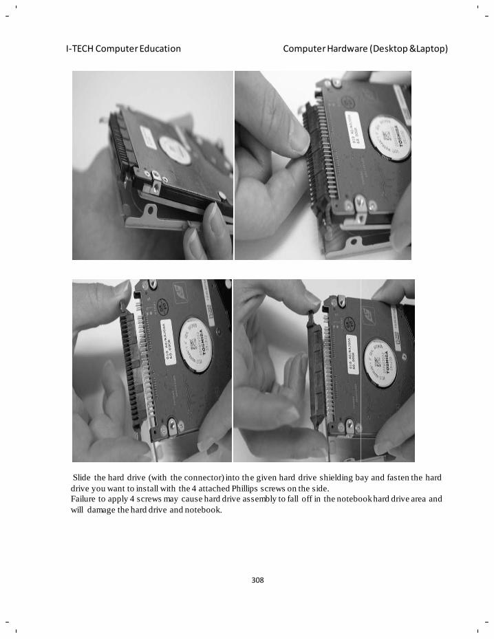
308
I-TECH Computer Education Computer Hardware (Desktop &Laptop)
Slide the hard drive (with the connector) into the given hard drive shielding bay and fasten the hard
drive you want to install with the 4 attached Phillips screws on the side.
Failure to apply 4 screws may cause hard drive assembly to fall off in the notebook hard drive area and
will damage the hard drive and notebook.
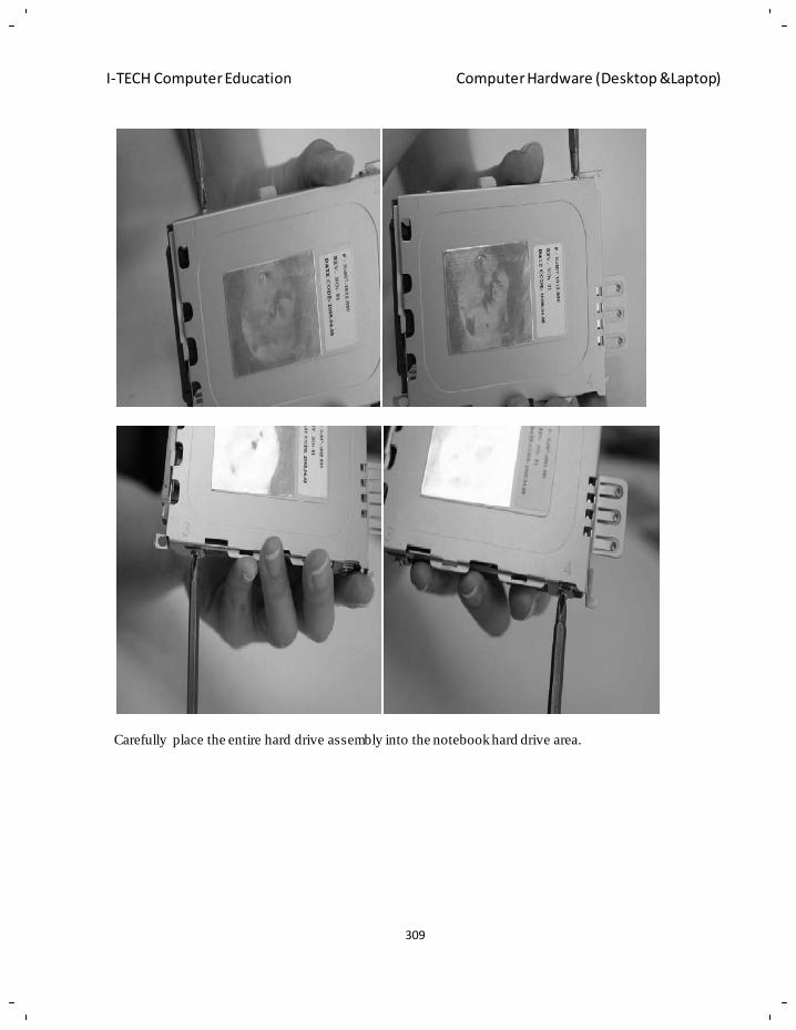
309
I-TECH Computer Education Computer Hardware (Desktop &Laptop)
Carefully place the entire hard drive assembly into the notebook hard drive area.
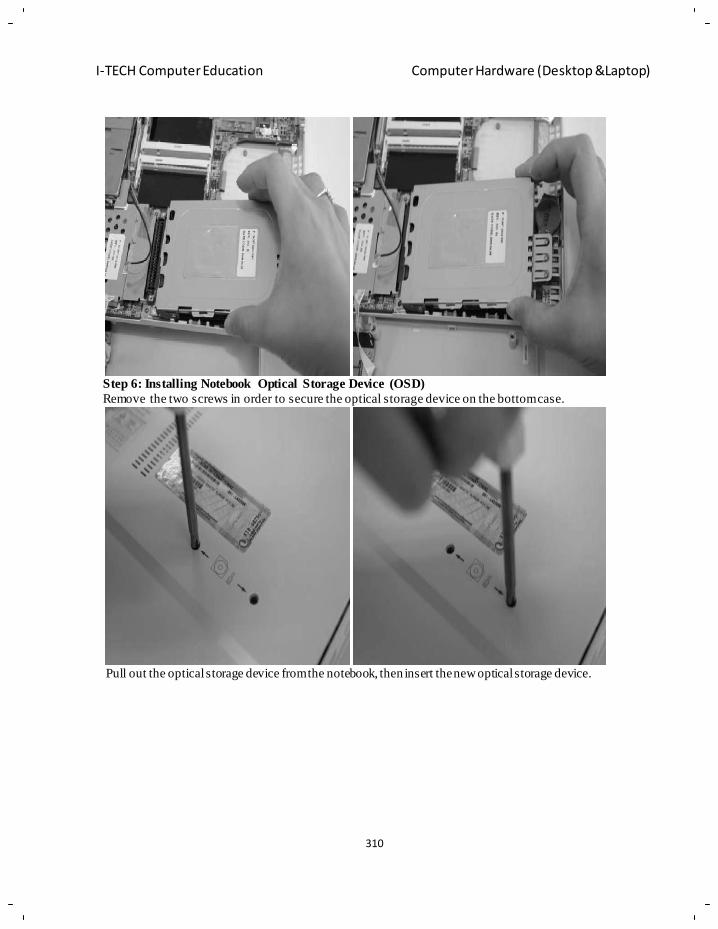
310
I-TECH Computer Education Computer Hardware (Desktop &Laptop)
Step 6: Installing Notebook Optical Storage Device (OSD)
Remove the two screws in order to secure the optical storage device on the bottom case.
Pull out the optical storage device from the notebook, then insert the new optical storage device.
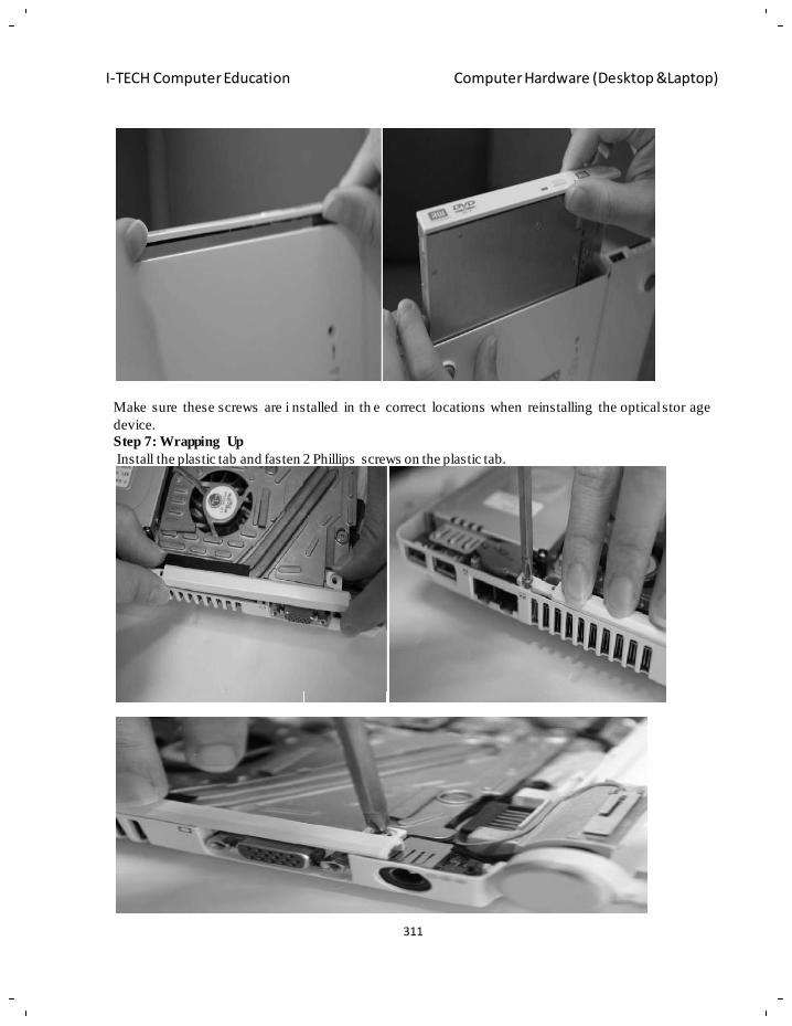
311
I-TECH Computer Education Computer Hardware (Desktop &Laptop)
Make sure these screws are i nstalled in th e correct locations when reinstalling the optical stor age
device.
Step 7: Wrapping Up
Install the plastic tab and fasten 2 Phillips screws on the plastic tab.
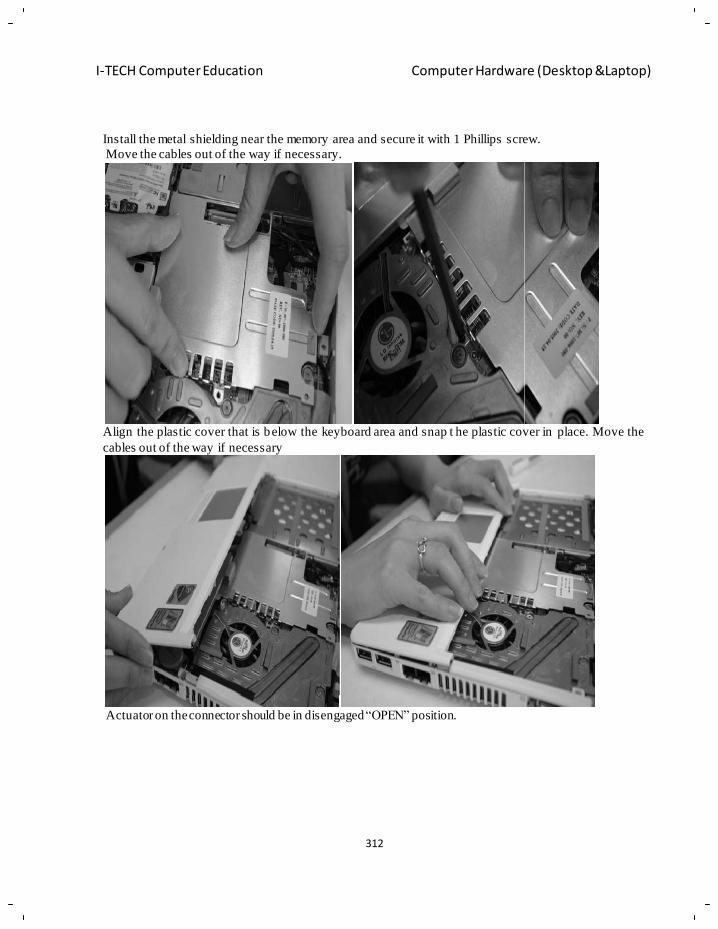
312
I-TECH Computer Education Computer Hardware (Desktop &Laptop)
Install the metal shielding near the memory area and secure it with 1 Phillips screw.
Move the cables out of the way if necessary.
Align the plastic cover that is below the keyboard area and snap t he plastic cover in place. Move the
cables out of the way if necessary
Actuator on the connector should be in disengaged ―OPEN‖ position.
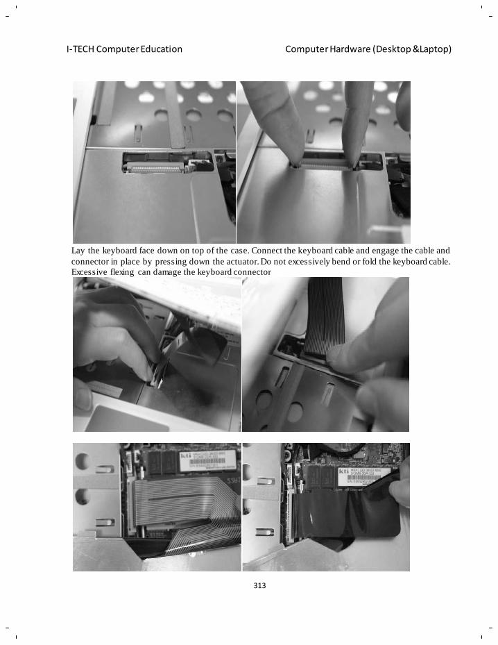
313
I-TECH Computer Education Computer Hardware (Desktop &Laptop)
Lay the keyboard face down on top of the case. Connect the keyboard cable and engage the cable and
connector in place by pressing down the actuator. Do not excessively bend or fold the keyboard cable.
Excessive flexing can damage the keyboard connector
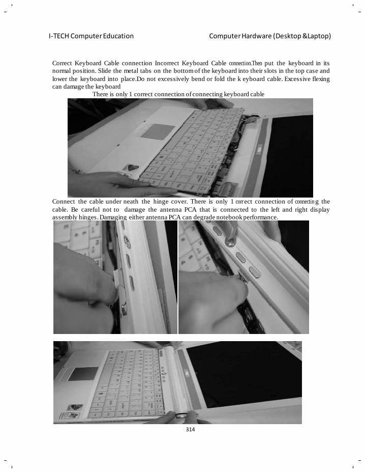
314
I-TECH Computer Education Computer Hardware (Desktop &Laptop)
Correct Keyboard Cable connection Incorrect Keyboard Cable connection.Then put the keyboard in its
normal position. Slide the metal tabs on the bottom of the keyboard into their slots in the top case and
lower the keyboard into place.Do not excessively bend or fold the k eyboard cable. Excessive flexing
can damage the keyboard
There is only 1 correct connection of connecting keyboard cable
Connect the cable under neath the hinge cover. There is only 1 corr ect connection of connectin g the
cable. Be careful not to damage the antenna PCA that is connected to the left and right display
assembly hinges. Damaging either antenna PCA can degrade notebook performance.
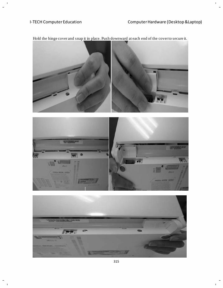
315
I-TECH Computer Education Computer Hardware (Desktop &Laptop)
Hold the hinge cover and snap it in place. Push downward at each end of the cover to secure it.
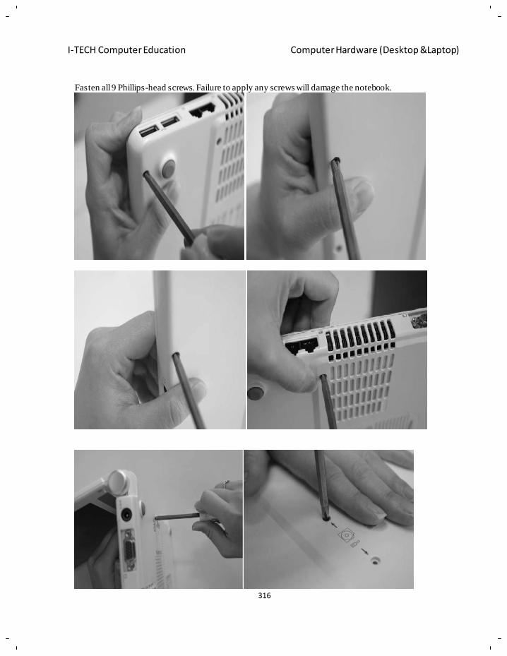
316
I-TECH Computer Education Computer Hardware (Desktop &Laptop)
Fasten all 9 Phillips-head screws. Failure to apply any screws will damage the notebook.
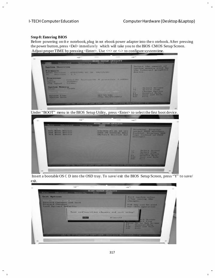
317
I-TECH Computer Education Computer Hardware (Desktop &Laptop)
Step 8: Entering BIOS
Before powering on th e notebook, plug in not ebook power adapter into the n otebook. After pressing
the power button, press <Del> immedia te ly which will take you to the BIOS CMOS Setup Screen.
Adjust proper TIME by pressing <Enter>. Use <+> or <-> to configure system time.
Under ―BOOT‖ menu in the BIOS Setup Utility, press <Enter> to select the first boot device.
Insert a bootable OS C D into the OSD tray. To save/ exit the BIOS Setup Screen, press ―Y‖ to save/
exit.
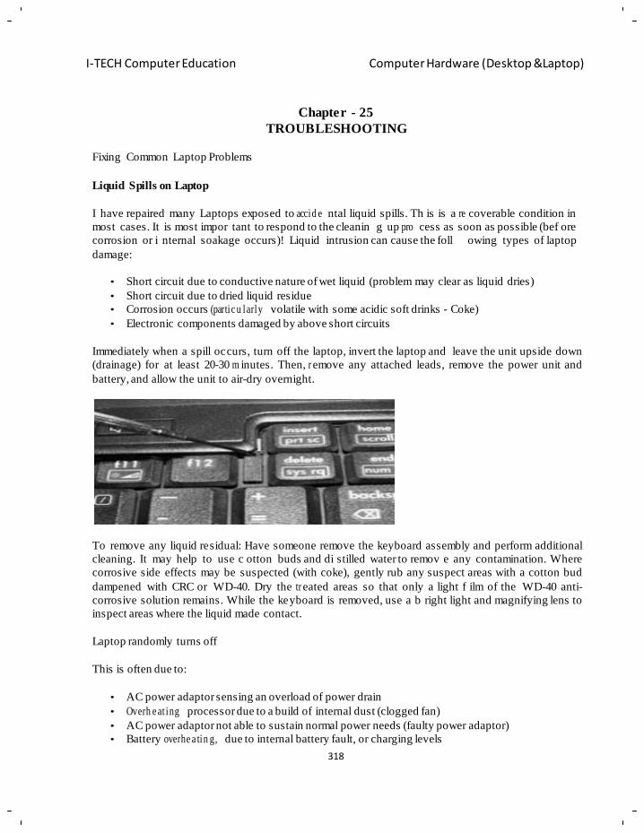
318
I-TECH Computer Education Computer Hardware (Desktop &Laptop)
Chapter - 25
TROUBLESHOOTING
Fixing Common Laptop Problems
Liquid Spills on Laptop
I have repaired many Laptops exposed to accid e ntal liquid spills. Th is is a re coverable condition in
most cases. It is most impor tant to respond to the cleanin g up pro cess as soon as possible (bef ore
corrosion or i nternal soakage
damage:
occurs)! Liquid intrusion can cause the foll owing types of laptop
• Short circuit due to conductive nature of wet liquid (problem may clear as liquid dries)
• Short circuit due to dried liquid residue
• Corrosion occurs (partic u larly volatile with some acidic soft drinks - Coke)
• Electronic components damaged by above short circuits
Immediately when a spill occurs, turn off the laptop, invert the laptop and leave the unit upside down
(drainage) for at least 20-30 m inutes. Then, r emove any attached leads, remove the power unit and
battery, and allow the unit to air-dry overnight.
To remove any liquid residual: Have someone remove the keyboard assembly and perform additional
cleaning. It may help to use c otton buds and di stilled water to remov e any contamination. Where
corrosive side effects may be suspected (with coke), gently rub any suspect areas with a cotton bud
dampened with CRC or WD-40. Dry the tr eated areas so that only a light f ilm of the WD-40 anti-
corrosive solution remains. While the keyboard is removed, use a b right light and magnifying lens to
inspect areas where the liquid made contact.
Laptop randomly turns off
This is often due to:
• AC power adaptor sensing an overload of power drain
• Overh e at ing processor due to a build of internal dust (clogged fan)
• AC power adaptor not able to sustain normal power needs (faulty power adaptor)
• Battery overhe a tin g, due to internal battery fault, or charging levels
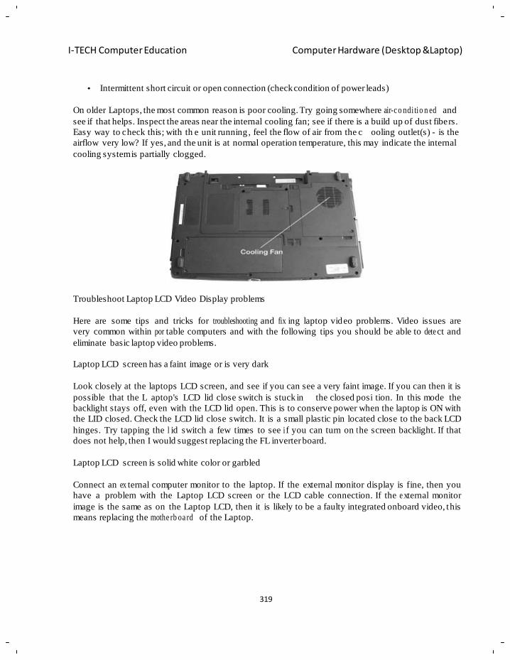
319
I-TECH Computer Education Computer Hardware (Desktop &Laptop)
• Intermittent short circuit or open connection (check condition of power leads)
On older Laptops, the most common reason is poor cooling. Try going somewhere air-c o ndi tio n ed and
see if that helps. Inspect the areas near the internal cooling fan; see if there is a build up of dust fibers.
Easy way to check this; with th e unit running , feel the flow of air from the c ooling outlet(s) - is the
airflow very low? If yes, and the unit is at normal operation temperature, this may indicate the internal
cooling system is partially clogged.
Troubleshoot Laptop LCD Video Display problems
Here are some tips and tricks for troubleshooting and fix ing laptop video problems. Video issues are
very common within por table computers and with the following tips you should be able to dete ct and
eliminate basic laptop video problems.
Laptop LCD screen has a faint image or is very dark
Look closely at the laptops LCD screen, and see if you can see a very faint image. If you can then it is
possible that the L aptop's LCD lid close switch is stuck in the closed posi tion. In this mode the
backlight stays off, even with the LCD lid open. This is to conserve power when the laptop is ON with
the LID closed. Check the LCD lid close switch. It is a small plastic pin located close to the back LCD
hinges. Try tapping the l id switch a few times to see i f you can turn on t he screen backlight. If that
does not help, then I would suggest replacing the FL inverter board.
Laptop LCD screen is solid white color or garbled
Connect an ex ternal computer monitor to the laptop. If the external monitor display is fine, then you
have a problem with the Laptop LCD screen or the LCD cable connection. If the e xternal monitor
image is the same as on the Laptop LCD, then it is likely to be a faulty integrated onboard video, this
means replacing the mothe rb oa rd of the Laptop.
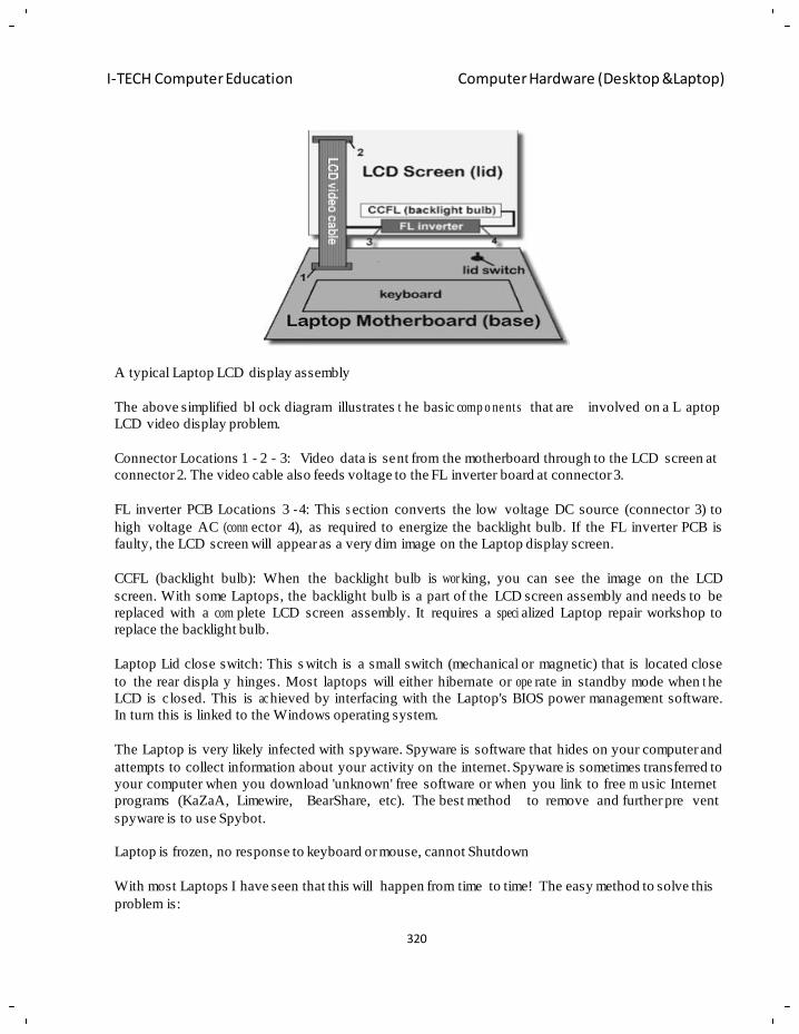
320
I-TECH Computer Education Computer Hardware (Desktop &Laptop)
A typical Laptop LCD display assembly
The above simplified bl ock diagram illustrates t he basic comp o ne nts that are
LCD video display problem.
involved on a L aptop
Connector Locations 1 - 2 - 3: Video data is sent from the motherboard through to the LCD screen at
connector 2. The video cable also feeds voltage to the FL inverter board at connector 3.
FL inverter PCB Locations 3 - 4: This s ection converts the low voltage DC source (connector 3) to
high voltage AC (conn ector 4), as required to energize the backlight bulb. If the FL inverter PCB is
faulty, the LCD screen will appear as a very dim image on the Laptop display screen.
CCFL (backlight bulb): When the backlight bulb is wor king, you can see the image on the LCD
screen. With some Laptops, the backlight bulb is a part of the LCD screen assembly and needs to be
replaced with a com plete LCD screen assembly. It requires a speci alized Laptop repair workshop to
replace the backlight bulb.
Laptop Lid close switch: This s witch is a small switch (mechanical or magnetic) that is located close
to the rear displa y hinges. Most laptops will either hibernate or ope rate in standby mode when t he
LCD is closed. This is ac hieved by interfacing with the Laptop's BIOS power management software.
In turn this is linked to the Windows operating system.
The Laptop is very likely infected with spyware. Spyware is software that hides on your computer and
attempts to collect information about your activity on the internet. Spyware is sometimes transferred to
your computer when you download 'unknown' free software or when you link to free m usic Internet
programs (KaZaA, Limewire,
spyware is to use Spybot.
BearShare, etc). The best method to remove and further pre vent
Laptop is frozen, no response to keyboard or mouse, cannot Shutdown
With most Laptops I have seen that this will happen from time to time! The easy method to solve this
problem is:
321
I-TECH Computer Education Computer Hardware (Desktop &Laptop)
1. Disconnect the laptop power cord
2. Remove the battery from the laptop
3. Wait a short while (10 seconds)
4. Replace the Laptop battery into the unit
5. Reconnect the Laptop Power cord
6. Turn the Laptop on
The Laptop will start normally and be fully operational. If you were working on a Microsoft Word or
Excel document at the time of the problem, then you may find that the data has been auto-recovered
for you. In this case, you will be auto matically prompted to view the last document you worked on
when you open the Microsoft program.
Troub lesh o ot Laptop Hibernate and Standby problems
Power management options on la ptops sometimes to c ause problems. Hibernate and Standby modes
are power saving modes of operations to battery powered laptops.
Hiber na tio n is a procedure by which the working state (contents) of your work is stored to disk before
the computer goes into hibernation or standby. When the Laptop is woken up, you are restored to the
exact place you were before. Standby and Hiber na tio n use a low power consum pt io n mode, with
enough power to preserve the content of such memory. This means that Laptop computer can wake up
without a full restart and loss of work.
Laptop does not wake up from Standby or Hibernation
Here are my tested suggestions:
• Give it time - some older Laptops may take up to 30 seconds to wake up - fully
• Some Laptops have special keys or buttons for 'Wake Up' - read the manual
• Press and hold the Laptops power button for five seconds or more. Some Laptops are
configured to Suspend or Hibernate with a press of the power button. Holding the power button
for 5+ seconds will usually reset and reboot the Laptop
• As a last resort, remove the laptop battery and t he power co rd, wait 30 seconds, replac e the
batteries and reconnect the power cord
Now that the Laptop is operational, you should research the underlying problem. Typically, such
problems arise from a disagr ee m e nt either between the power management features of the Laptops
BIOS and Windows.
Laptop display
A conflict with the Laptops BIOS power mana g e m e nt and Windows power mana ge m e nt is the most
common cause of such wake-up failure. Try different settings in the BIOS to see if that might solve the
problem. Look to see if the Laptops BIOS is configured to suspend the computer, and how it compares
with the value configured in Windows. In most cases let Windows control the power management.ve
been looking for an easy way to test for live laptop inverters for a couple years and I finally found a
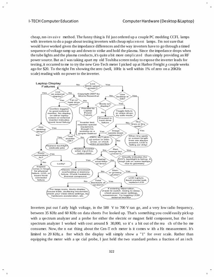
322
I-TECH Computer Education Computer Hardware (Desktop &Laptop)
cheap, non-inv a siv e method. The funny thing is I'd just ordered up a couple PC modding CCFL lamps
with inverters to do a page about testing inverters with cheap repla c e m e nt lamps. I'm not sure that
would have worked given the impedance differences and the way inverters have to go through a timed
sequence of voltage ramp up and down to strike and hold the plasma. Since the impedance drops when
the tube lights and the plasma conducts, it's quite a bit more compl ic ate d than simply providing an RF
power source. But as I was taking apart my old Toshiba screen today to expose the inverter leads for
testing, it occurred to me to try the new Cen-Tech meter I picked up at Harbor Freight a couple weeks
ago for $20. To the right I'm showing the zero (well, 10Hz is well within 1% of zero on a 20KHz
scale) reading with no power to the inverter.
Inverters put out f airly high voltage, in the 500 V to 700 V ran ge, and a very low r adio frequency,
between 35 KHz and 60 KHz on data sheets I've looked up. That's something you could easily pick up
with a spe ctrum analyzer and a probe for either the electric or magnet field component, but the l ast
spectrum analyzer I worked with cost around $ 30,000, so it' s a bit out of the rea ch of the ho me
consumer. Now, the n eat thing about the Cen-T ech meter is it comes w ith a Hz measurement. It's
limited to 20 KHz, a fter which the display will simply show a "1" for over scale. Rather than
equipping the meter with a spe cial probe, I just held the two standard probes a fraction of an i nch
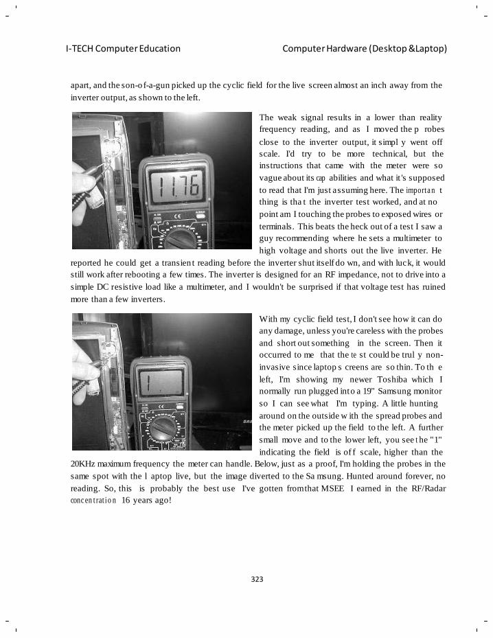
323
I-TECH Computer Education Computer Hardware (Desktop &Laptop)
apart, and the son-o f-a-gun picked up the cyclic field for the live screen almost an inch away from the
inverter output, as shown to the left.
The weak signal results in a lower than reality
frequency reading, and as I moved the p robes
close to the inverter output, it simpl y went off
scale. I'd try to be more technical, but the
instructions that came with the meter were so
vague about its cap abilities and what it 's supposed
to read that I'm just assuming here. The importa n t
thing is tha t the inverter test worked, and at no
point am I touching the probes to exposed wires or
terminals. This beats the heck out of a test I saw a
guy recommending where he sets a multimeter to
high voltage and shorts out the live inverter. He
reported he could get a transien t reading before the inverter shut itself do wn, and with luck, it would
still work after rebooting a few times. The inverter is designed for an RF impedance, not to drive into a
simple DC resistive load like a multimeter, and I wouldn't be surprised if that voltage test has ruined
more than a few inverters.
With my cyclic field test, I don't see how it can do
any damage, unless you're careless with the probes
and short out something in the screen. Then it
occurred to me that the te st could be trul y non-
invasive since laptop s creens are so thin. To th e
left, I'm showing my newer Toshiba which I
normally run plugged into a 19" Samsung monitor
so I can see what I'm typing. A little hunting
around on the outside w ith the spread probes and
the meter picked up the field to the left. A further
small move and to the lower left, you see t he "1"
indicating the field is of f scale, higher than the
20KHz maximum frequency the meter can handle. Below, just as a proof, I'm holding the probes in the
same spot with the l aptop live, but the image diverted to the Sa msung. Hunted around forever, no
reading. So, this is probably the best use I've gotten from that MSEE I earned in the RF/Radar
conc en t rat io n 16 years ago!
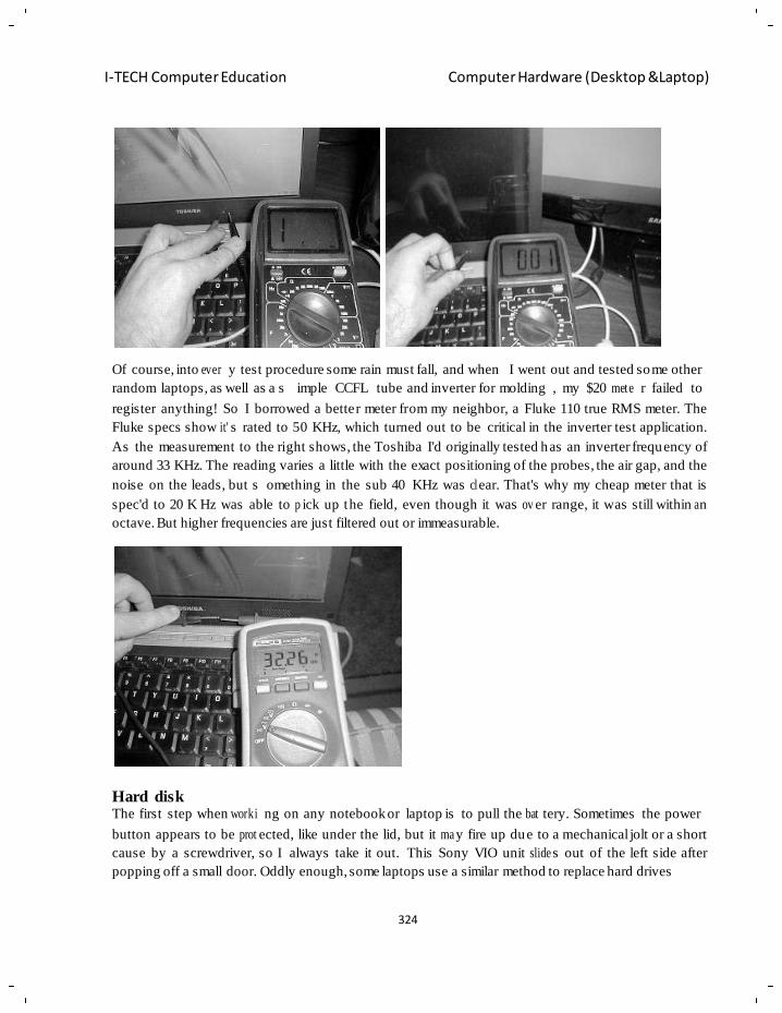
324
I-TECH Computer Education Computer Hardware (Desktop &Laptop)
Of course, into ever y test procedure some rain must fall, and when I went out and tested some other
random laptops, as well as a s imple CCFL tube and inverter for molding , my $20 mete r failed to
register anything! So I borrowed a better meter from my neighbor, a Fluke 110 true RMS meter. The
Fluke specs show it' s rated to 50 KHz, which turned out to be critical in the inverter test application.
As the measurement to the right shows, the Toshiba I'd originally tested has an inverter frequency of
around 33 KHz. The reading varies a little with the exact positioning of the probes, the air gap, and the
noise on the leads, but s omething in the sub 40 KHz was cl ear. That's why my cheap meter that is
spec'd to 20 K Hz was able to p ick up the field, even though it was ov er range, it was still within a n
octave. But higher frequencies are just filtered out or immeasurable.
Hard disk The first step when worki ng on any notebook or laptop is to pull the bat tery. Sometimes the power
button appears to be prot ected, like under the lid, but it ma y fire up due to a mechanical jolt or a short
cause by a screwdriver, so I always take it out. This Sony VIO unit slide s out of the left side after
popping off a small door. Oddly enough, some laptops use a similar method to replace hard drives
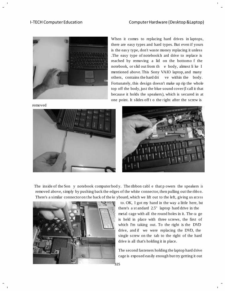
325
I-TECH Computer Education Computer Hardware (Desktop &Laptop)
When it comes to replacing hard drives in laptops,
there are easy types and hard types. But even if yours
is the eas y type, don't waste money replacing it unless
.The easy type of notebook h ard drive to replace is
reached by removing a lid
notebook, or slid out from th
on the bottom o f the
e body, almost li ke I
mentioned above. This Sony VAIO laptop, and many
others, contains the hard dri ve within the body.
removed
Fortunately, this design doesn't make up rip the whole
top off the body, just the blue sound cover (I call it that
because it holds the speakers), which is secured in at
one point. It slides off t o the r ight after the screw is
The inside of the Son y notebook computer bod y. The ribbon cabl e that p owers the speakers is
removed above, simply by pushing back the edges of the white connector, then pulling out the ribbo n .
There's a similar connector on the back of the ke yboard, which we lift out to the left, giving us acce ss
to. OK, I got my hand in the way a little here, but
there's a st andard 2.5" laptop hard drive in the
metal cage with all the round holes in it. The ca ge
is held in place with three screws, the first of
which I'm taking out. To the right is the DVD
drive, and if we were replacing the DVD, the
single screw on the tab to the right of the hard
drive is all that's holding it in place.
The second fasteners holding the laptop hard d rive
cage is exposed easily enough but try getting it out
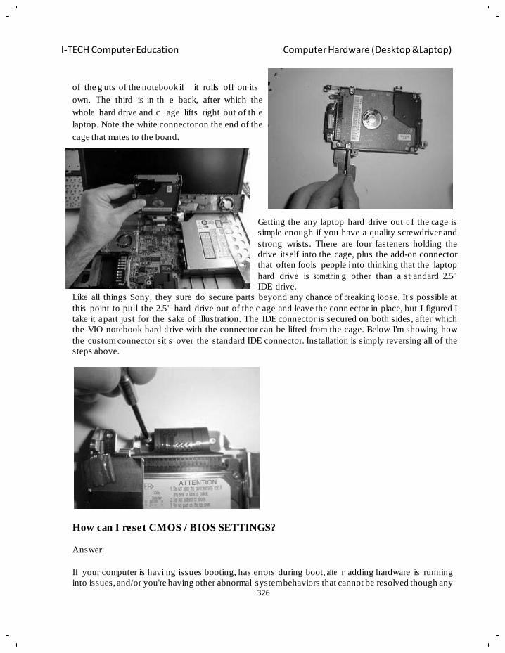
326
I-TECH Computer Education Computer Hardware (Desktop &Laptop)
of the g uts of the notebook if it rolls off on its
own. The third is in th e back, after which the
whole hard drive and c age lifts right out of th e
laptop. Note the white connector on the end of the
cage that mates to the board.
Getting the any laptop hard drive out o f the c age is
simple enough if you have a quality screwdriver and
strong wrists. There are four fasteners holding the
drive itself into the cage, plus the add-on connector
that often fools people i nto thinking that the laptop
hard drive is somethin g other than a st andard 2.5"
IDE drive.
Like all things Sony, they sure do secure parts beyond any chance of br eaking loose. It's possible at
this point to pull the 2.5" hard drive out of the c age and leave the conn ector in place, but I figured I
take it apart just for the sake of illustration. The IDE connector is secured on both sides, after which
the VIO notebook hard d rive with the connector c an be lifted from the cage. Below I'm showing how
the custom connector sit s over the standard IDE connector. Installation is simply reversing all of the
steps above.
How can I reset CMOS / BIOS SETTINGS?
Answer:
If your computer is havi ng issues booting, has errors during boot, afte r adding hardware is running
into issues, and/or you're having other abnormal system behaviors that cannot be resolved though any
327
I-TECH Computer Education Computer Hardware (Desktop &Laptop)
other method it ma y be necessary to reset the CMOS settings and/or l oad the d efault or fail-safe
defaults. To do this follow the below steps.
Load / Reset defaults
1. Enter CMOS setup, ad ditional information ab out entering CMOS setup can be found on
document CH000192.
2. In CMOS setup look for an option to reset the C MOS values to the default setting or an option
to load the fail-safe defaults. With many CMOS setup screens there will be a function key to
do this; for example, the F6, F11, or F12 key. Other setups may actually list an option that you
can arrow over to using the arrow keys and press Enter.
3. When found and s elected you'll likely be asked if you're sure you wish to load the de faults
press Y for yes or arrow to the yes option.
Reset Configu ra tio n Data
In addition to r estoring the system defaults if you've recently added new hardware or resetting the
default values did not h elp resolve your boot issues you may also want to reset the configuration data.
Below are some examples of how this can be done. Keep in mind that unfortunately all CMOS screens
are different and these instructions may not be exact steps for your CMOS.
Under advanced
If you're working on a computer with a Phoenix BIOS that has Main - Advanced - Security - .... across
the top of the screen you can get to this setting by using the right arrow to move over to Advanced and
under Advanced arrow down to Reset Configuration Data and changing the value from Disabled or No
to Enabled or Yes.
Once the above has been done press the F10 key and save and exit CMOS setup.
In PnP/PCI Configurations
If you're working with a Phoenix BIOS that has several different options and one of them is PnP/PC I
Configuration move the cursor down to this option and press Enter. Within the PnP/PCI
Configurations change th e Reset Config uration Data from Disabled to Enabled. Once the above has
been done press the F10 key and save and exit CMOS setup.
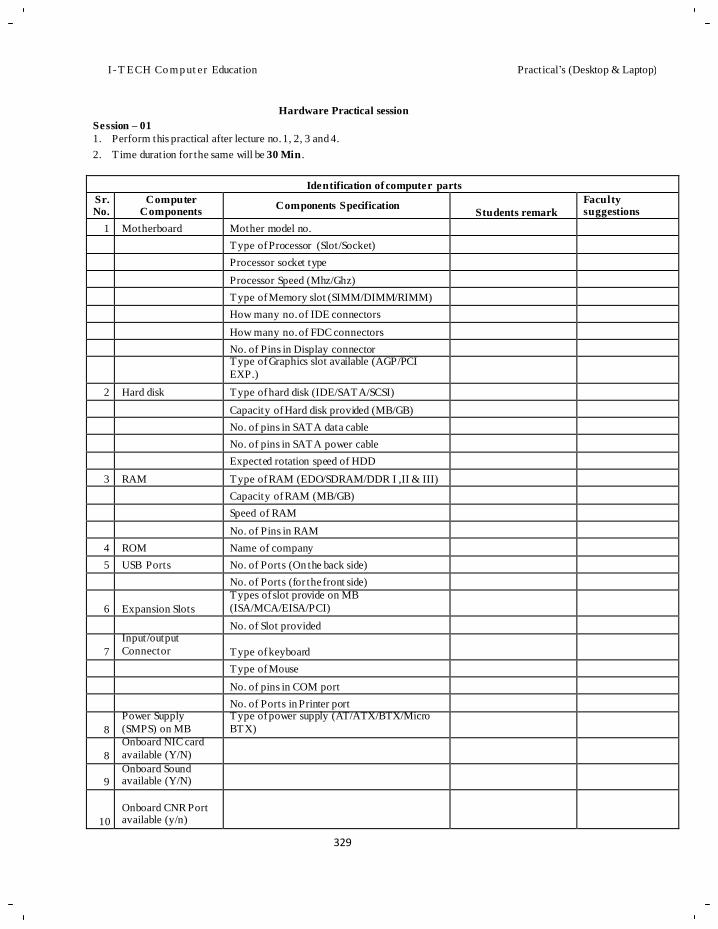
I -T ECH Co m p ut er Education Practical‘s (Desktop & Laptop)
Session – 01
Hardware Practical session
1. Perform this practical after lecture no. 1, 2, 3 and 4.
2. Time duration for the same will be 30 Min .
Identification of computer parts
Sr. No.
Computer Components
Components Specification
Students remark
Faculty suggestions
1 Motherboard Mother model no. Type of Processor (Slot/Socket) Processor socket type Processor Speed (Mhz/Ghz) Type of Memory slot (SIMM/DIMM/RIMM) How many no. of IDE connectors How many no. of FDC connectors No. of Pins in Display connector Type of Graphics slot available (AGP/PCI
EXP.)
2 Hard disk Type of hard disk (IDE/SATA/SCSI) Capacity of Hard disk provided (MB/GB) No. of pins in SATA data cable No. of pins in SATA power cable Expected rotation speed of HDD
3 RAM Type of RAM (EDO/SDRAM/DDR I ,II & III) Capacity of RAM (MB/GB) Speed of RAM No. of Pins in RAM
4 ROM Name of company 5 USB Ports No. of Ports (On the back side)
No. of Ports (for the front side)
6
Expansion Slots
Types of slot provide on MB
(ISA/MCA/EISA/PCI)
No. of Slot provided
7
Input/output
Connector
Type of keyboard
Type of Mouse No. of pins in COM port No. of Ports in Printer port
8
Power Supply
(SMPS) on MB
Type of power supply (AT/ATX/BTX/Micro
BTX)
8
Onboard NIC card
available (Y/N)
9
Onboard Sound available (Y/N)
10
Onboard CNR Port available (y/n)
329
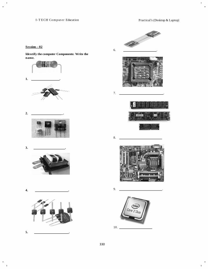
I -T ECH Co m p ut er Education
Practical‘s (Desktop & Laptop)
330
Session – 02
Identify the computer Components: Write the
name.
1. .
2. _.
3. .
6. .
7. .
8.
4. . 9. .
5. .
10.
331
I -T ECH Co m p ut er Education
Practical‘s (Desktop & Laptop)
3. Test Your Knowledge.
a. To make changes in CMOS setting, which
password you should know?
Ans:
b. Which details are stored in a standard CMOS setup?
Ans:
c. You made some changes to CMOS, and now some options are not working properly which were running before
you made changes. Which option would you use?
Ans:
Prepare the checklist:
Sr. No.
Activity Results
1. Write down main menus available in main window. 2. Note down the IDE devices attached to your PC. 3. List the size of RAM and the cache memory 4. Set and change user password.
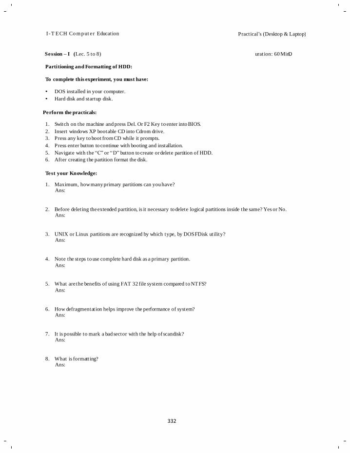
I -T ECH Co m p ut er Education
Practical‘s (Desktop & Laptop)
332
Session – I (Lec. 5 to 8) uration: 60 MinD.
Partitioning and Formatting of HDD:
To complete this experiment, you must have:
• DOS installed in your computer.
• Hard disk and startup disk.
Perform the practicals:
1. Switch on the machine and press Del. Or F2 Key to enter into BIOS.
2. Insert windows XP bootable CD into Cdrom drive.
3. Press any key to boot from CD while it prompts.
4. Press enter button to continue with booting and installation.
5. Navigate with the ―C‖ or ―D‖ button to create or delete partition of HDD.
6. After creating the partition format the disk.
Test your Knowledge:
1. Maximum, how many primary partitions can you have?
Ans:
2. Before deleting the extended partition, is it necessary to delete logical partitions inside the same? Yes or No. Ans:
3. UNIX or Linux partitions are recognized by which type, by DOS FDisk utility? Ans:
4. Note the steps to use complete hard disk as a primary partition.
Ans:
5. What are the benefits of using FAT 32 file system compared to NTFS?
Ans:
6. How defragmentation helps improve the performance of system? Ans:
7. It is possible to mark a bad sector with the help of scandisk? Ans:
8. What is formatting? Ans:
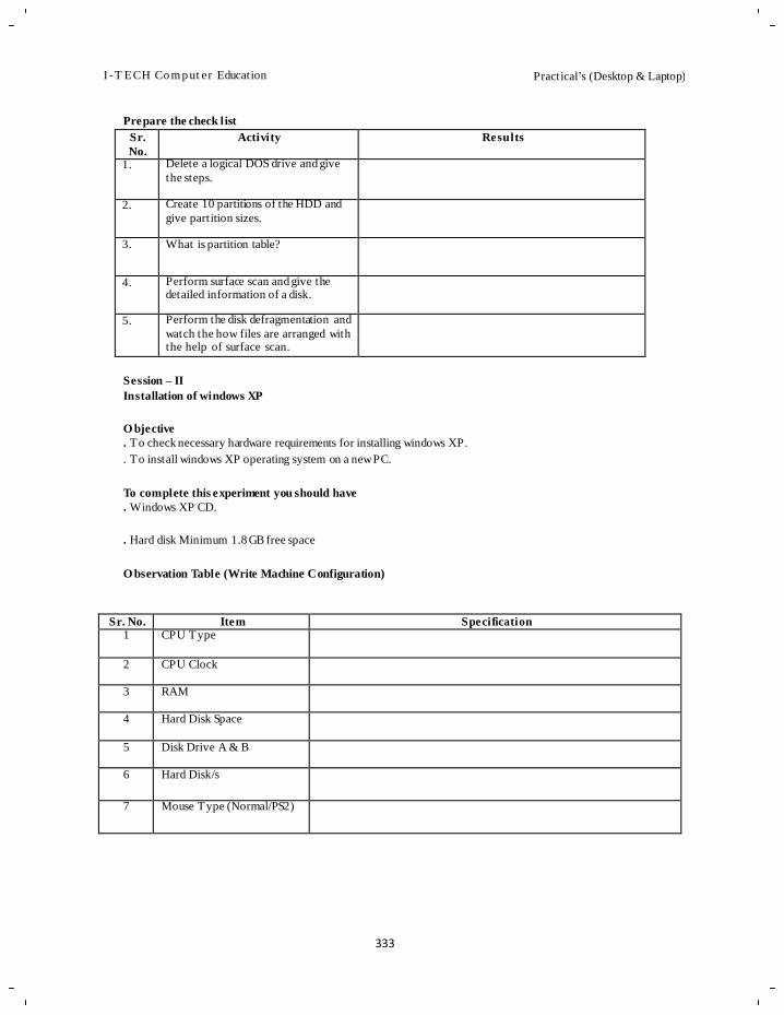
I -T ECH Co m p ut er Education
Practical‘s (Desktop & Laptop)
333
Prepare the check list
Sr.
No.
Activity Results
1. Delete a logical DOS drive and give
the steps.
2. Create 10 partitions of the HDD and
give partition sizes.
3. What is partition table?
4. Perform surface scan and give the detailed information of a disk.
5. Perform the disk defragmentation and
watch the how files are arranged with the help of surface scan.
Session – II
Installation of windows XP
O bjective
. To check necessary hardware requirements for installing windows XP.
. To install windows XP operating system on a new PC.
To complete this experiment you should have
. Windows XP CD.
. Hard disk Minimum 1.8 GB free space
O bservation Table (Write Machine Configuration)
Sr. No. Item Specification
1 CPU Type
2 CPU Clock
3 RAM
4 Hard Disk Space
5 Disk Drive A & B
6 Hard Disk/s
7 Mouse Type (Normal/PS2)
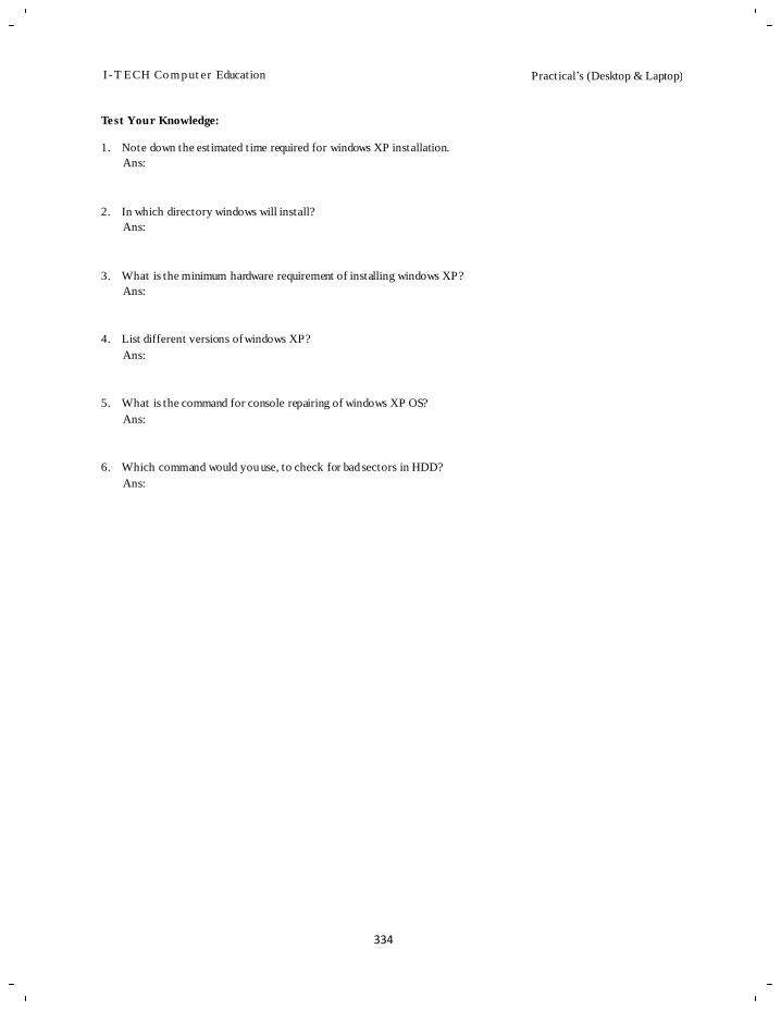
I -T ECH Co m p ut er Education
Practical‘s (Desktop & Laptop)
334
Test Your Knowledge:
1. Note down the estimated time required for windows XP installation.
Ans:
2. In which directory windows will install?
Ans:
3. What is the minimum hardware requirement of installing windows XP?
Ans:
4. List different versions of windows XP?
Ans:
5. What is the command for console repairing of windows XP OS?
Ans:
6. Which command would you use, to check for bad sectors in HDD?
Ans:
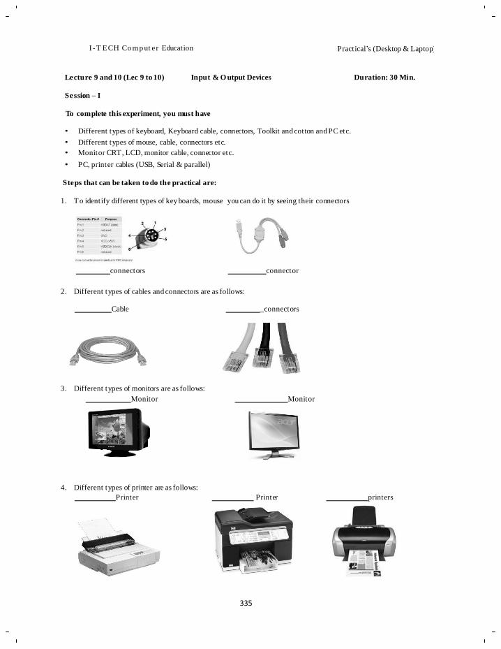
335
I -T ECH Co m p ut er Education
Practical‘s (Desktop & Laptop)
Lecture 9 and 10 (Lec 9 to 10)
Session – I
Input & O utput Devices Duration: 30 Min.
To complete this experiment, you must have
• Different types of keyboard, Keyboard cable, connectors, Toolkit and cotton and PC etc.
• Different types of mouse, cable, connectors etc.
• Monitor CRT, LCD, monitor cable, connector etc.
• PC, printer cables (USB, Serial & parallel)
Steps that can be taken to do the practical are:
1. To identify different types of key boards, mouse you can do it by seeing their connectors
connectors connector
2. Different types of cables and connectors are as follows:
Cable
3. Different types of monitors are as follows:
Monitor
4. Different types of printer are as follows:
Printer
_connectors
Monitor
Printer printers
336
I -T ECH Co m p ut er Education
Practical‘s (Desktop & Laptop)
Test your knowledge:
1. What are the different types of keyboard?
Ans:
2. Why you require cleaning of keyboard?
Ans:
3. Tea/Coffee has been spilled on a keyboard. What will you do?
Ans:
4. Can you connect an external keyboard to laptop?
Ans:
5. What is the function of ‗Sleep‘ key?
Ans:
6. What is the unit of measurement of resolution of a mouse?
Ans:
7. How does mouse pad work?
Ans:
8. What type of LED is used in optical mouse?
Ans:
9. What is spooling in printers?
Ans:
10. Explain the printing in laser printer.
Ans:
Prepare the check list:
Sr. No. Activity Results
1 Identification of keyboard type
2 Keyboard connector type
3 Keyboard cleaning
4 Troubleshooting of keyboard
5 Connection of mouse to PC
6 Study of mouse button
7. Cleaning of mouse
8. Troubleshooting of mouse
337
I -T ECH Co m p ut er Education
Practical‘s (Desktop & Laptop)
Test your knowledge (Lecture 11 -15) Memory Duration: 15 Min.
1. What is cache memory?
Ans:
2. Differentiate between RAM and ROM?
Ans:
3. SCSI port (pronounced skuzzy) stands for
Ans:
4. How many pins on a standard DDR RAM DIMM?
Ans:
5. What is Virtual Memory?
Ans:
6. is a command used to switch directories in MS-DOS
7. is used to copy the system files from one drive to another drive allowing that drive to be bootable
8. allows the user to delete and or create partitions on the hard disk drive.
9. is a command which allows the user to clear the complete contents of the screen and leave only a
prompt.
10. allows you to create your own directories in DOS.
11. allows you to list all the files in a directory.
338
I -T ECH Co m p ut er Education
Practical‘s (Desktop & Laptop)
Session – I (Till Lec 20) Assembling of Computers Duration: 30 Min.
To complete this experiment, you must have
• PC cabinet with SMPS,Motherboard,RAM,Floppy drive,CD/DVD ROM,HDD,Cable set, Keyboard, Mouse, Monitor
& screws .
• Windows installer CD/DVD
• Screw Driver set.
List the different hardware components required for assembling.
Sr.
No.
Components Required
Brand name, Type and Capacity
Use of components/Function of components
Faculty Remark
2 3 4 5 6 7 8 9
10 11 12 13 14 15 16 17 18
Perform the following procedure to assemble the machine:
1. Fix the SMPS in the cabinet.
2. Prepare the motherboard.
a. Install the processor on the motherboard and fix the processor fan on the same.
b. Install RAM in the memory slot of motherboard.
3. Fix the motherboard in the cabinet and check the screw fitt ings.
4. Connect the 20 -4 pin power connector to the motherboard.
5. Fix the HDD, FDD & CD/DVD drive in slot provided.
6. Connect the data cable and power connector to the HDD, FDD and CD/DVD.
7. Connect the other end of data cables to the motherboard.
8. Install AGP/PCI Express graphics card if required.
9. Connect the front panel connection on the motherboard. (On/off, Reset, HDD Led & power led).
10. Connect Front panel USB connector.
11. Connect the input and output peripheral.
339
I -T ECH Co m p ut er Education
Practical‘s (Desktop & Laptop)
Test your knowledge:
1. What are the types of PGA sockets, for installing the processor?
Ans:
2. Twisted cable of floppy drive cable is connected on which side either on back of floppy drive device or on the
motherboard?
Ans:
3. How will you distinguish between hard disk cable and floppy drive cable?
Ans:
4. How many pins are there in SATA data cable?
Ans:
5. How to select a SMPS for assembling a PC?
Ans:
I -T ECH Co m p ut er Education
Practical‘s (Desktop & Laptop)
340
Session 1: Laptop Maintenance and Troubleshooting (Lec 28) Duration: 25 min.
Objective: To physically study the different parts of the Laptop.
To perform this experiments the student must have the following requirements:
1. A completely dead laptop.
2. Tool kit to physically open the laptop.
Steps to perform the above objective:
1. First take a dead laptop and physically open the laptop from the back side by un-winding the screws. There will be a
sliding lock you can slide it to remove the battery of the laptop. The battery looks like this
2. In one small box you can see the RAM of the laptop and it‘s two small slots to attach it. It looks like this
3. Besides that slot normally in most of the laptops you can see the HARD DISK of the laptop. It looks like this
4. If you see the front panel of the laptop then you can see how he laptop screen and keyboards are connected to the
laptop motherboard.
5. Further if you see inside the board then you can see the small components same as in our normal one viz. capacitors,
transistors, diodes, IC‘s, etc
I -T ECH Co m p ut er Education
Practical‘s (Desktop & Laptop)
341
Test your knowledge:
1. Describe some advantages of laptop?
Ans:
2. What is cache memory?
Ans:
3. Where the laptop battery is exactly situated? And can it be changed?
Ans:
Check List:
Sr. No. Activity Result 1 Dead laptop is available
2 A toolkit is available 3 The laptops screws un-winded properly
Session 2:
Objective: Troubleshooting various problems in laptop.
To perform this experiment the students must have the following requirements:
1. A laptop which is facing some problem.
Steps to be performed to achieve the objective:-
Normally now a days the new laptops does not face much problem but then too there are some common problems that can
be solved easily.
1. If there is continuous beep sound without display while you turn on your laptop then you can just open the panel of
RAM from the back side of the laptop and just clean RAM and just attach it again to the same slot.
2. If the laptop turns down frequently even after the battery is fully charged then you can just have a watch on the
battery of the laptop. You can also change the battery of the laptop and then
3. See its performance.
4. During the windows installation if the setup is unable to take you to the partitioning and formatting step then you can
just check out with the hard disk.
Test your knowledge:
1. What is the first step that is to be performed when the display of laptop does not come?
Ans:
2. What is troubleshooting?
Ans:
Check List:
Sr. No. Activity Result 1. RAM cleaned due to display problem and attached to the same slot 2. Battery changed due to frequent shut down of laptop even if the battery
is fully charged
I -T ECH Co m p ut er Education
I-TECH Computer Education COURSE WARE FEEDBACK FORM
Course Name :- Name of Faculty :- Subject Start Date :- Subject End Date :- Date of Feedback :-
I. Content
1. Is the depth of coverage in the book enough for the course requirements?
Yes
No
Average If you have ticked ‗Average‘, please list topics to be added. If the depth of coverage is in excess, please list
topics to be removed.
(Please tick the appropriate answer)
2. Is the material in the chapters relevant to the course?
Relevant
Not Relevant
If you have ticked ' Average ', please list topics to be Covered in mo r e detail. If t h e d ep th of coverage
is excessive , please list topics to be covered to a lesser
depth. (Please tick the appropriate answer)
II. Organization
1. Is the material in the book organize d well?
Organiz ed Well Not Organize d
Well If you have ticked 'Not Relevant', please list the topics That is irrelevant.
(Please tick the appropriate answer)
2. What is your opinion about the layout and design of the book?
Excellent
Good
Average If you have ticked ‗Average‘, please give your Suggestions on how the layout and design has to be
improved.
(Please tick the appropriate answer)
I -T ECH Co m p ut er Education
3. Are the figures and illustrations informativ e and useful?
Useful
Not Useful If you have ticked 'Not Useful', please list the items that are not useful.
(Please tick the appropriate answer)
III. Readability
1. Is the language used in the book simple?
Simple
Too Complicated If you have ticked 'Too Complicated', please list the chapters where the language needs simplification.
(Please tick the appropriate answer)
2. Is the use of example s / progra ms in the book adequate?
Too Many
Adequate
Too Few If you have ticked 'Too Many' or 'Too Few', please indicate the topics where this is applicable.
(Please tick the appropriate answer)
[Note: Please tear off this perforated sheet and send it to the Head Office]
dw

NOTES

NOTES