paper desktop model - nasa
TRANSCRIPT
1
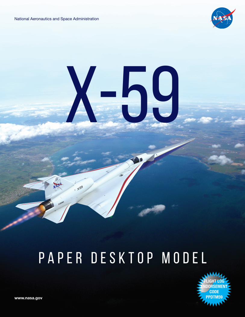
X-59National Aeronautics and Space Administration
www.nasa.gov
P A P E R D E S K T O P M O D E LFLIGHT LOG
ENDORSEMENT CODE
PPDTM59
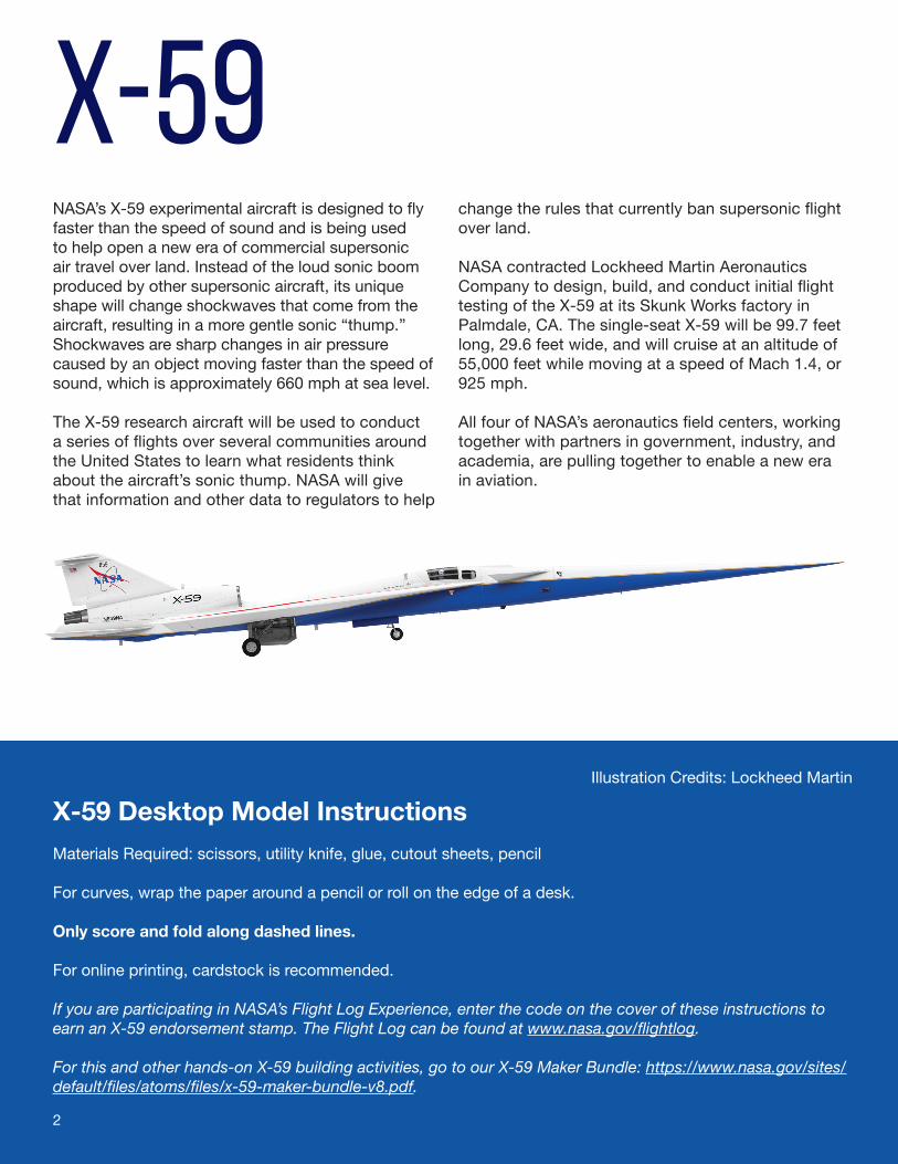
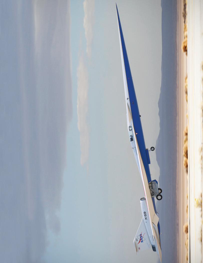
X-59NASA’s X-59 experimental aircraft is designed to fly faster than the speed of sound and is being used to help open a new era of commercial supersonic air travel over land. Instead of the loud sonic boom produced by other supersonic aircraft, its unique shape will change shockwaves that come from the aircraft, resulting in a more gentle sonic “thump.” Shockwaves are sharp changes in air pressure caused by an object moving faster than the speed of sound, which is approximately 660 mph at sea level.
The X-59 research aircraft will be used to conduct a series of flights over several communities around the United States to learn what residents think about the aircraft’s sonic thump. NASA will give that information and other data to regulators to help
change the rules that currently ban supersonic flight over land.
NASA contracted Lockheed Martin Aeronautics Company to design, build, and conduct initial flight testing of the X-59 at its Skunk Works factory in Palmdale, CA. The single-seat X-59 will be 99.7 feet long, 29.6 feet wide, and will cruise at an altitude of 55,000 feet while moving at a speed of Mach 1.4, or 925 mph.
All four of NASA’s aeronautics field centers, working together with partners in government, industry, and academia, are pulling together to enable a new era in aviation.
X-59 Desktop Model InstructionsMaterials Required: scissors, utility knife, glue, cutout sheets, pencil
For curves, wrap the paper around a pencil or roll on the edge of a desk. Only score and fold along dashed lines.
For online printing, cardstock is recommended.
If you are participating in NASA’s Flight Log Experience, enter the code on the cover of these instructions to earn an X-59 endorsement stamp. The Flight Log can be found at www.nasa.gov/flightlog.
For this and other hands-on X-59 building activities, go to our X-59 Maker Bundle: https://www.nasa.gov/sites/default/files/atoms/files/x-59-maker-bundle-v8.pdf.
2
Illustration Credits: Lockheed Martin
3
© DiskArt™ 1988
© DiskArt™ 1988
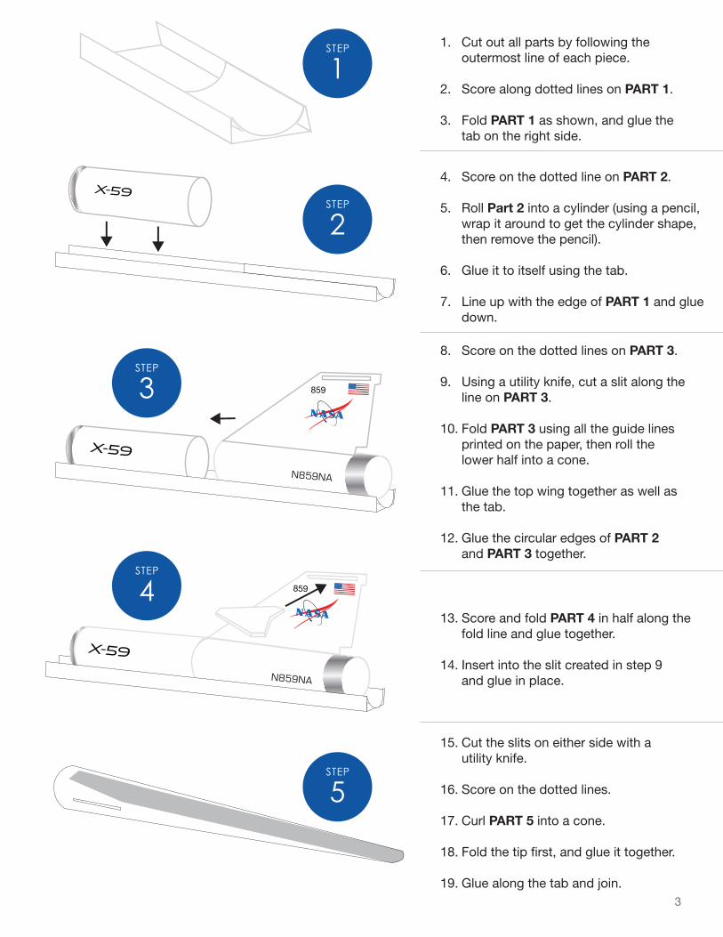
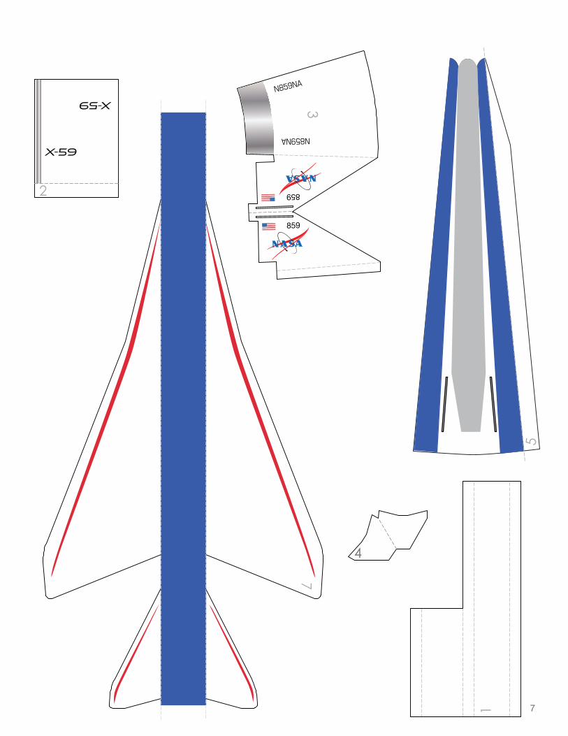
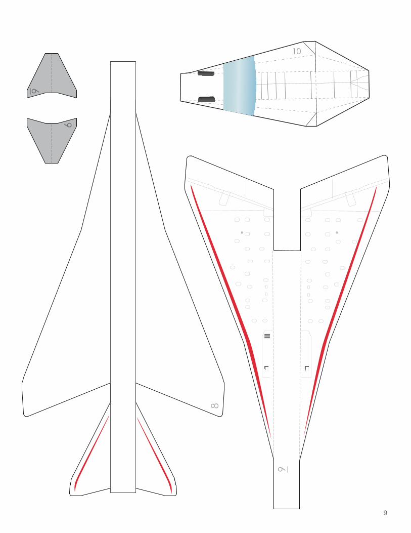
1. Cut out all parts by following the outermost line of each piece.
2. Score along dotted lines on PART 1.
3. Fold PART 1 as shown, and glue the tab on the right side.
4. Score on the dotted line on PART 2.
5. Roll Part 2 into a cylinder (using a pencil, wrap it around to get the cylinder shape, then remove the pencil).
6. Glue it to itself using the tab.
7. Line up with the edge of PART 1 and glue down.
8. Score on the dotted lines on PART 3.
9. Using a utility knife, cut a slit along the line on PART 3.
10. Fold PART 3 using all the guide lines printed on the paper, then roll the lower half into a cone.
11. Glue the top wing together as well as the tab.
12. Glue the circular edges of PART 2 and PART 3 together.
13. Score and fold PART 4 in half along the fold line and glue together.
14. Insert into the slit created in step 9 and glue in place.
15. Cut the slits on either side with a utility knife.
16. Score on the dotted lines.
17. Curl PART 5 into a cone.
18. Fold the tip first, and glue it together.
19. Glue along the tab and join.
1STEP
5STEP
2STEP
3STEP
4STEP
4
© DiskArt™ 1988
6STEP
7STEP
8STEP
10STEP
9STEP
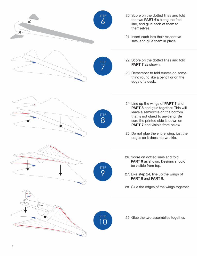
20. Score on the dotted lines and fold the two PART 6’s along the fold line, and glue each of them to themselves.
21. Insert each into their respective slits, and glue them in place.
22. Score on the dotted lines and fold PART 7 as shown.
23. Remember to fold curves on some-thing round like a pencil or on the edge of a desk.
24. Line up the wings of PART 7 and PART 8 and glue together. This will leave a semicircle on the bottom that is not glued to anything. Be sure the printed side is down on PART 7 and visible from below.
25. Do not glue the entire wing, just the edges so it does not wrinkle.
26. Score on dotted lines and fold PART 9 as shown. Designs should be visible from top.
27. Like step 24, line up the wings of PART 8 and PART 9.
28. Glue the edges of the wings together.
29. Glue the two assemblies together.
5
10
© DiskArt™ 1988
© DiskArt™ 1988
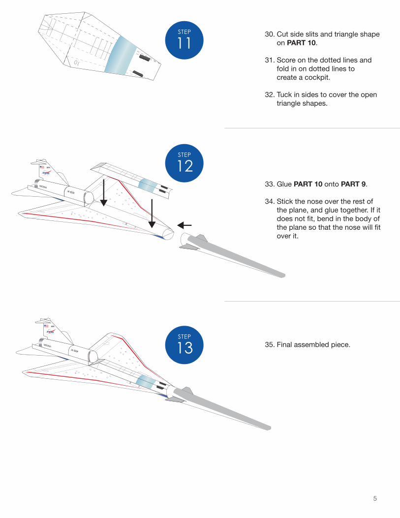
11STEP
12STEP
13STEP
30. Cut side slits and triangle shape on PART 10.
31. Score on the dotted lines and fold in on dotted lines to create a cockpit.
32. Tuck in sides to cover the open triangle shapes.
33. Glue PART 10 onto PART 9.
34. Stick the nose over the rest of the plane, and glue together. If it does not fit, bend in the body of the plane so that the nose will fit over it.
35. Final assembled piece.
6
7
859
859
© DiskArt™ 1988
© DiskArt™ 1988

8
Page intentionally left blank
9
10

10
Page intentionally left blank

11

NP-2021-11-3001-HQ
National Aeronautics and Space AdministrationHeadquarters300 E. Street, SWWashington, DC 20546