desktop injection moulding machine
TRANSCRIPT

MT/HNDMECH/04/41 Page - 1 -
1. Introduction to Plastic Forming Process
Figure 1.1 Spectrum of Forming Process for Thermoplastic Materials
The above spectrum reveals about thermoplastic forming process. Even all these techniques are
available today, due to the time limitation and such factors, only little headings will be introduce on
this article.
Blow molding: a process of forming hollow articles by blowing hot polymer against internal
surfaces of a split mold. Usually, a tube of heated polymer is extruded down the center of the closed
mold. Air is then injected, and the heated polymer expands in a fairly uniform thickness to form the
desired shape. This is the process used to make plastic bottles and containers. It is fast and typically
used only on thermoplastic materials.
blow molding
calendering
sheet materials
injection molding
rotational molding
solid phase
forming
thermo forming free form
fabrication
film blowing
casting
extrusion

MT/HNDMECH/04/41 Page - 2 -
Calendaring: the process of forming thermoplastic or thermosetting sheet or film by passing the
material through series of heated rolls. The gap between the last pair of heated rolls determines the
sheet thickness. The material usually is blended and plasticated on separate equipment. Elastomer
sheets, gaskets, and vinyl flooring tiles often are formed with this process.
Injection molding: A process in which granular polymer-usually, thermoplastic- is fed from a
hopper into a heated barrel where it is melted, after which a screw or ram forces the material into a
mold. Pressure is maintained until the part has solidified. The mold is opened, and the part is ejected
by some mechanism. This is by far the most important techniques for mass production. The major
disadvantages of the process are that not all polymers can be processed (some thermosets cannot)
and the metal molds are very expensive.
This basic process is also used for coinjection molding of two different polymers. There are two
extrusion barrels and injection systems. A shot is made with one polymer, and a second shot with a
second polymer can be used to surround or surface the part made in the first shot. Co-injection is
often done to achieve a cosmetic effect or to alter properties use properties. For an example, a
thermoplastic elastomer (TPE) can be injection molded just on the grip area of a plastic drill body
after the rigid plastic body is molded.
Another variation of injection molding is structural foam molding. The mold is only partially filled,
and the injected plastic expands to fill the mold to produce a part that is lightweight because of the
entrapped porosity, but with an integral skin. Foamed polymers have lower weight (and cost) than
their non-foamed counterparts, and the mechanical properties are often comparable. This process
frequently is used on polyphenylene oxide, olefins, vinyls, nylons, and thermoplastic elastomers.
Figure 1.2: Blow molding (recycledplastic 2014)

MT/HNDMECH/04/41 Page - 3 -
Rotational molding: this process is usually used for manufacture larger hollow containers such as
fuel tanks, water tanks, floats...etc. a pre measured quantity of thermoplastic pellet is charged into a
closed metal mold. The mold is clamped closed and put into a device capable of rotating the mold
about two axes. The rotating mold is heated to melt the charge. The molten polymer forms a skin
against the mold wall to make the part. Mold heating is stopped, and the mold is air or water cooled
to allow part removal. A significant advantages of this process is that it uses relatively low-cost
tooling, compared with injection molding and other capital intensive process.
Solid-phase forming: a process employed with thermoplastic materials in which a sheet or similar
pre-form is heated to the softening process, but below the melting point, and forged into a drawing
ring by a heated die set; the still-worm perform is transferred in the draw ring into a cooled draw
die, and plug draws the part to the finished shape. A lubricant is applied to both sides of the perform
to assist the draw. Depth-of-draw ratios can be 1:5 or higher, and the forming in the solid phase is
said to enhance strength over parts formed by melting technique.
Simpler shapes can be made by heating and stamping a sheet to make a form such as an arch
support for a shoe. Filled or reinforced thermoplastics, called sheet or bulk molding compounds,
can also be formed by press shaping of the preheated material.
Extrusion: the process of forming continuous shapes by forcing a molten polymer through a metal
die. Extrusion is used to make structural forms such as channels, bars, rounds, angles, tracks, hose,
and countless other forms. It is very fast and usually applied only to thermoplastics. With special
techniques, two different polymers or different colours of the same polymer can be coextruded, and
plastic also can be foamed during the extrusion process. This process is often used to make
specially shaped weather stripping. A variation (blowing) is used to make plastic bags.
Figure 1.4: polymer extrusion (avplastic 2014)

MT/HNDMECH/04/41 Page - 4 -
As above processing techniques review thermoplastic forming process thermosetting plastic also
important under this heading. Because, thermosetting is important same as thermoplastic. For more
knowledge access British plastic federation-2015
Compression molding: the molding material, usually preheated and premeasured, is placed in an
open mold cavity, the mold is closed with a cover half or plug, and heat and pressure are applied
and maintained until the material has filled the cavity and curves. This is the most widely used
process for thermosetting materials. Because, curing of thermosetting polymer is a time-dependent
reaction, cycle times usually are much longer than those in injection molding.
Foam processing: various techniques are used to produce molded plastic parts with dense skins and
high porosity in the core. The simplest process involves charging a metal mold with resins that
foam and expand during reaction. The expansion of the foaming resin causes the mold to be filled.
A variety of similar process are used for large parts, with the exception that the polymer is injected
into the cavity rather than charged into the mold. Standard injection molding machine can be
adapted to produce foamed parts by adding equipment to inject a metered amount of gas or a
chemical blowing agent into the polymer near to exit end of the extruder barrel of the injection
molding machine.
Reaction injection molding machine: in this process the polymer reactance are pumped under
high pressure into a mixing chamber and then flow into a mold at atmospheric pressure. The
chemical expand to fill the mold and to foam the polymer. The foaming action of the reactant
produces the pressure for the application of mold details (~207kPa) , and the reaction heat speeds
the polymer cure. A schematic of the reaction injection molding is shown in FIGURE () this
thermoset forming process
compression molding
foam processing
reaction injection molding
injection molding
Transfer molding
Casting Sintering Vulcanization

MT/HNDMECH/04/41 Page - 5 -
process is most often applied to large parts (over 1kg), and polyurethane foams are the most popular
molding material. Many large auto parts such as bezel, dashboards, and fenders are made with this
process. Fillers can be added to the reactants to improve the mechanical properties of the molded
parts.
Casting: this manufacturing process forms solid or hollow shapes from molten polymer or from
catalyzed resins by pouring the liquid material into a mold, without significant pressure, followed
by solidification or curing. The mold is usually open at the top. The polymer casting process is
widely used on polyurethane and silicone elastomers to make roll covers die springs, sheets and like
that. It is also suitable for making jigs and fixtures from filled epoxy or resins.
Sintering: used on some of the fluorocarbons and polyamides, and similar high temperature plastics,
sintering is the bonding of adjacent surfaces of powder particles. Some of the high-temperature
polymers are made into shapes by compressing polymer particles, as in compression molding, and
heating them until the particles join by coalescence. They do not melt and flow as in normal
compression and transfer molding
Able see some polymer processing methods on above paragraphs. More knowledge can be gained
on plasticindustry.com (2015) under the heading polymer processing methods. This research
reduced the heading of this project. Because its not the plot of this project Let’s move onto the next
chapter
2. History and Revolution of Injection Molding Machines.
The website avplastic.co.uk says as plastic or plastic revolution starts 1847 by Jons Jacob Berzelius
as producing first condensation polymer to the world. Later 1861 another Britain scientist
Alexander Parkes invented first man-made commercial plastic. Even the Parkes invented 1861 the
plastic, he describes the creation 1862 International exhibition in London. He called this plastic with
Figure 1.5: reaction injection molding process (avplastic 2014)

MT/HNDMECH/04/41 Page - 6 -
the name “Parksine”. It was expensive to produce, flammable, and brittle. But it was able to heated,
molded and retain its shape once cooled.
American inventor John Wesley Hyatt 1868 developed celluloid by combining cellulose nitrate and
camphor as a substitute for ivory in billiard balls. He improves on Parkes’ invention so that it could
be processed into finished form. Around 1872 John Wesley Hyatt, take his brother’s help to
produce first injection molding machine as shown in figure 2.1. It was like a hypordermic needle. In
that machine, working substance melted through heaters and press onto a die by a plunger to take
desired part.
With a small break, around 1909 Belgium inventor Leo Hendrik Baekeland introduced
phenolformaldehyde plastic. He called it as Bakelite, because of, it is his own creation. 1930s Saw
the initial development of major vinyl thermoplastics still used widely today: polystyrene, PVC
(polyvinyl chloride) and the polyolefins. During this period, the ICI laboratories produce Perspex
(polymethyl methacrylate).
In 1938, now days widely using polystyrene invented by Dow and a very good demand created by
the World War II on following Dow inventions. During the 1945-1955 periods, several materials
Polyethylene, polystyrene including metals, leather, woods…etc. also produced cheaply. The help
of American inventor James Watson Hendry on this time duration, should not be forget at this
moment. He replaced a screw to plunger and created fully deviated John Wesley Hyatt machine.
Therefore, customers were able to access colourful plastic. Further, the frictional force producing by
Figure 2.1: Patent application of Hyatt's injection moulding
machine. (avplastic 2014)

MT/HNDMECH/04/41 Page - 7 -
the screw creates some amount of heat. Therefore, the requirement of heater band on machine
reduces and increase efficiency of the machine.
At 1955 to 1965 one decade time period, several more useful plastic introduced, HDPE, LDPE,
ABS are such plastics to remember at this moment. The creation of reciprocating screw is so
important to remember on this 1 decade period. It was able to moves backwards and forwards
during the mold cycle. After mixing, the screw stops turning and the entire screw pushes forward,
acting like a plunger for injecting material into a mold. During plastication, the screw moves
backward against the hydraulic back pressure.
At the year of 1970, a big revolution had created by James Watson Hendry by adding gas-assisted
injection molding process. The process helped to cooled down the hollow and complex work-pieces
quickly. It changed flexibility as well as the strength and finish of manufactured parts while
reducing production time, cost, weight and waste.
Due to the heavy demand for plastic, robots introduced at the year of 1972 and plastic overtakes
steel industry at the year of 1979. At the year of 1985, Japanese firm produced all electric molding
machines. At last on 1990, aluminum molds introduced for this industries. Therefore low cost
molds were able to produce.
(A)
(B)
Figure 2.2: A-patent drawing for the Hendry injection molding machine B- Drawings for the Willert
reciprocating injection molding machine (avplastic 2014)

MT/HNDMECH/04/41 Page - 8 -
3. Modern Day Injection Molding Machine
Previous chapter described the history of injection molding machine. Even there are several
revolutions occurred for injection molding machine from 1847, the machine can be broadly
classified as clamping unit, and injection unit. These two units are similar to trailer and engine set
of a container. There are no limitations to set trailer and engine. Any engine part satisfies to any
trailer set. Likewise, same case occurs at these machines. But small limitation such as shot size and
injection unit capacity determines their combination. The aim of those clamping and injection unit
can be view below
3.1. Injection Unit:
The injection unit performs several duties to the machine. It contains several components as heating
cylinder, hopper, injection screw, nozzle…etc. due to, these components are important: small
description are given on coming paragraphs.
3.1.1. Heating cylinder
Heating cylinders or the barrel is the heart of the machine. Here the only area the solidified plastics
turn to liquid or semi-solidified phase. There are several failures occurred for injection screw by the
improperly working heating cylinders. Normally the barrels are constructed by the two different
materials. Inside wall of the material is by a small layer of chromium content material for with stand
high abrasive nature of the injection process. Meanwhile, the external wall or entire barrel made
with inexpensive material.
Electrical heater bands are strapped for external wall of the barrel as covering the entire barrel as
shown in figure 3.1. The heaters are divided for three zones as rear, center and front. The each three
zone are control separately by separate temperature controllers. There are sensors and thermo
couples as the machine requirements to sense the zone temperature as one thermocouple covering
one zone.
3.1.2. Hopper
This is the place machine store its working material for around two hour time period. Normally the
hopper is vertically mounted to insert plastic by the gravity to the machine in the shape of cylinder.
The size of the hopper determines by the normal cycles and average part size the machine can be
produced.
The pallets which introduced to the barrel are not so pure. It may contain small metal particles itself
by the blades of a plastic granulator used to produce regrind or the metal mixing components used

MT/HNDMECH/04/41 Page - 9 -
in the manufacture of the raw plastic pellets. Metal particles can ruin the sleeve of the injection
barrel or the surface of the screw. Therefore, a magnet could see at the bottom of the hopper.
Magnet drawer also could see on some machines. The selection of the magnet or drawer is limited
by the machine size and purpose of the machine.
3.1.3. Injection Screw
Injection screw or lead screw is the next important part of modern day injection molding machine.
It designed in the shape of auger and placed inside the heating barrel. It plays 2 major to the
machine as, auger fresh material from the hopper area into the heating area of the barrel.
Meanwhile, mixing and homogeneously maintain temperature of the molten plastic. Other than this,
screw generates some amount of heat by the friction inside of the barrel. So, it increases the life
time of heater and machine efficiency by decreasing electrical power requirement. The friction is
created because there is just a slight clearance between the surface of the screw flights and the
inside wall of the barrel, usually only 0.008 to 0.013cm. As the material is brought forward along
the screw flights, the plastic is squeezed tighter and tighter. The friction of squeezing generates
heat.
According to the requirements the screws designed with various factors as, shapes of flights,
distances between flights, amounts of shearing action, screw tip geometries, and methods of shutoff.
Below figure 3.1 shows some screws used in injection molding machine.
Figure 2.2: injection molding machine lead screw

MT/HNDMECH/04/41 Page - 10 -
3.2. Clamping Unit
Clamping unit is for produce required force to keep mold close when injection process is carried-
out. Normally tons or kilo newton used to denote clamping force. According to the viscosity of
molten plastic the clamping force varies from 5 to 20 molten flow indexes. Normally the index
range 5 to 10 is low flow, 10 to 15 are average flow and 15 to 20 are high flow.
It is not as important to remember a specific flow number as it is to know in what range a material
falls: high flow, average flow, or low flow. Then, since more injection pressure is needed to inject a
low-flow material than a high-flow material, it is understood that a low-flow material will require
much more clamp force to keep the mold closed against that higher injection pressure. Simply the
clamping force can be calculate by following equation
The depth of the mold also need to be calculated with projected area if the depth D greater than 1
inch. Normally clamp factor varied . A general purpose value is 68950
𝑝𝑟𝑜𝑗𝑒𝑐𝑡𝑒𝑑 𝑎𝑟𝑒𝑎 6 6 6𝑐𝑚2
𝐹𝑐𝑙𝑎𝑚𝑝 6 6 9 6 𝑘𝑁
𝑖𝑓 𝑡 𝑒 𝑠𝑎𝑓𝑒𝑡𝑦 𝑓𝑎𝑐𝑡𝑜𝑟 𝑖𝑠 : 𝑡 𝑒 𝑐𝑙𝑎𝑚𝑝 𝑓𝑜𝑟𝑐𝑒 . 6 6
𝑡 𝑒 𝑓𝑖𝑛𝑎𝑙 𝐹𝑐𝑙𝑎𝑚𝑝 94 6𝑘𝑁
Example question:
Find-out the clamping force for the below figure. The dimensions are l=16cm, w=16cm
and d=0.5cm. given clamp factor=68950
The machine with the closest rating for this product would be a 20000kN or machine.
MT/HNDMECH/04/41 Page - 11 -
The effects that could be arise by improper calculation of clamping force can be point on following
bullets
By low clamp force
Mold will not be stay close when injection process is carried-out
Final product could get flash or non-filled.
Flush creates a secondary operation and increase product cost.
By higher clamp force
Can damage the mold or press.
Molds are so cost. Therefore, it increases product price
Clamping mechanisms can damage
There are several mechanisms available for clamping unit. Hydraulic and mechanical (toggle)
systems are the famous systems for clamping unit.
3.2.1. Hydraulic Clamping System.
This system work by the force induced in hydraulic motor. Therefore, a very good efficiency and
work-force can gain from this system. Beyond this, this system allows to regulate the clamp
pressure over a wide range. Therefore, this system not only save money, but also machine and the
mold from catastrophic failures.
As there are advantages with hydraulic system, disadvantage also should be pointed. The limitation
of this system is, tonnage requirements approach the maximum rating, extreme injection pressures
may overcome the clamp force and blow the mold open. This results in flash, short shots, and
possible cycle interruption.
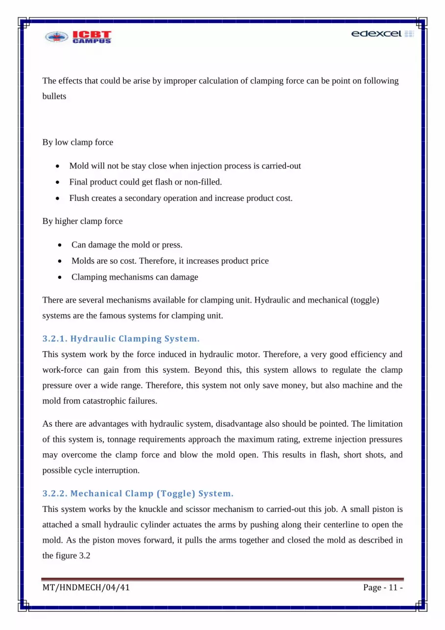
3.2.2. Mechanical Clamp (Toggle) System.
This system works by the knuckle and scissor mechanism to carried-out this job. A small piston is
attached a small hydraulic cylinder actuates the arms by pushing along their centerline to open the
mold. As the piston moves forward, it pulls the arms together and closed the mold as described in
the figure 3.2
MT/HNDMECH/04/41 Page - 12 -
The principal advantage of the mechanical system is that once it is locked in place, it is virtually
impossible to blow the mold open even if injection pressures are beyond those required. Of course,
there are limits to the pressure it can sustain, and eventually machine damage will occur if the
injection pressures are held beyond requirements for extended periods. But once the system locks,
there is no doubt that full tonnage force is available. Meanwhile, the knuckle linkages and bushes
need to replace regularly due to wear. Even if reduced this failure by proper lubrications, another
limitation is, impossible to regulate clamp pressure. For more knowledge under this heading access
sinothech-2014
4. Demonstrate a Simple Machine.
All most all the larger machinery is constructed according to small and simple principle. Similarly
this injection molding also can be manufactured through the above statement. Figure 4.1 describe a
simplified version of modern injection molding machines.
Figure 3.2: Toggle system (avplastic.com)

MT/HNDMECH/04/41 Page - 13 -
It is not so cost as modern day injection molding machine. Therefore, this machine worth for small
entrepreneurs, colleges…etc. further; this machine does not need larger ground area. It is just70cm,
50cm, and 35cm in length, width and height respectively. Further, low noise, low power
requirements also to be pointed when talk about this machine. Beyond all of this, cost of the
machine is the main point to denote at this moment. Cost of the machine for fabricate given on the
below Table 1
Income(LKR) Expenditure (LKR)
capital 22,000
Material 7000
Machine hire cost 10,000
Other wages 5000
Table 1: Cost for fabricate desktop injection molding machine(DIMM)
Further, the accessibility to 200oC temperature, customers are let to use several types of plastic such
as HDPE, LDPE, PP, ABS,…etc. except nylon ,Teflon…etc. therefore, the machine can used to
produce bottle lids, toys, small household items….etc.
As well as this machine for home uses, laboratories also can use this machine for find-out some
experiments such as melt flow index. So, it helps to determine flow behavior of material. A melt
flow index machine could see in figure 4.1 below
Figure 4.1: Simplified Desktop Injection Molding Machine

MT/HNDMECH/04/41 Page - 14 -
Due to the very less moving parts, customer not needs to pay attention as maintenances. When use
for long time, then only customer need to replace a rack and pinion. It can reduce if pasted
lubrication oils as it needed. Moreover, the nearby places of heater might get corrosion due to the
high heat. Other than that, paint pasted at the initial stage is so enough.
By the side of consumer, need to pay small safety attention. The machine is almost fully fabricated
with metal. So electric shock may affect consumer. So, users requested to wear sleepers or insulator
when work. The below figure 4.2 describes path of electric shock.
Figure 4.2: electric shock path
5. Engineering behind DIMM
Engineering is essential for construct a successful machine. Even technician fabricate, a part there
to engineers to select proper materials, correct nut and bolts, welding….etc. therefore, engineering
of this machine describe on coming several topics.
Figure 4.1: Melt flow index machine
MT/HNDMECH/04/41 Page - 15 -
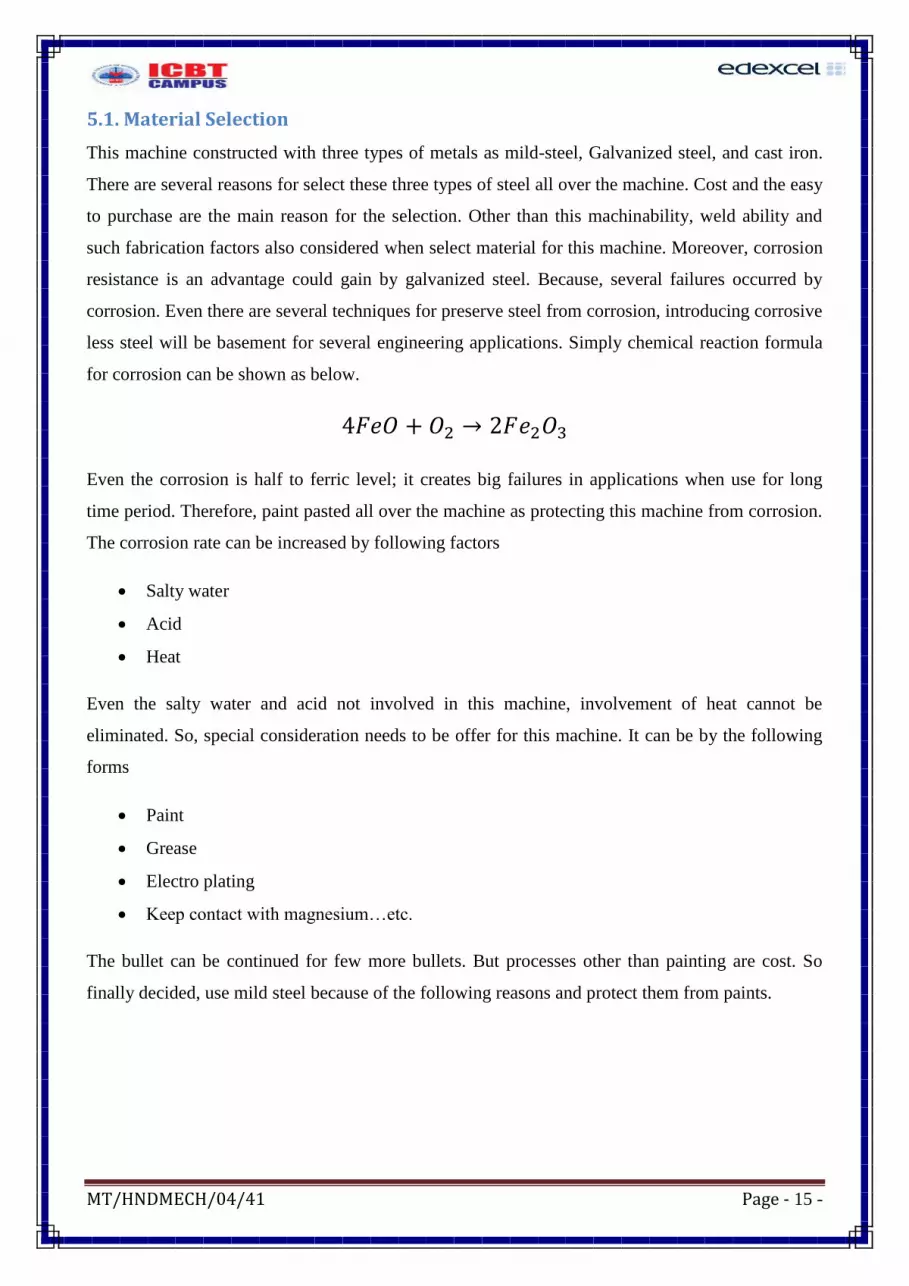
5.1. Material Selection
This machine constructed with three types of metals as mild-steel, Galvanized steel, and cast iron.
There are several reasons for select these three types of steel all over the machine. Cost and the easy
to purchase are the main reason for the selection. Other than this machinability, weld ability and
such fabrication factors also considered when select material for this machine. Moreover, corrosion
resistance is an advantage could gain by galvanized steel. Because, several failures occurred by
corrosion. Even there are several techniques for preserve steel from corrosion, introducing corrosive
less steel will be basement for several engineering applications. Simply chemical reaction formula
for corrosion can be shown as below.
4 2 2
Even the corrosion is half to ferric level; it creates big failures in applications when use for long
time period. Therefore, paint pasted all over the machine as protecting this machine from corrosion.
The corrosion rate can be increased by following factors
Salty water
Acid
Heat
Even the salty water and acid not involved in this machine, involvement of heat cannot be
eliminated. So, special consideration needs to be offer for this machine. It can be by the following
forms
Paint
Grease
Electro plating
Keep contact with magnesium…etc.
The bullet can be continued for few more bullets. But processes other than painting are cost. So
finally decided, use mild steel because of the following reasons and protect them from paints.

MT/HNDMECH/04/41 Page - 16 -
Through the table 2, the properties needed for this machine is so suit with mild-steel. High carbon
steel is over design and low carbon steel not very low qualities. Therefore, mild-steel selected to
construct this machine.
5.2. Fabrication Techniques
Steels are available in the form of tubes, sheets…etc. have to shape by using machineries or
blacksmithy works to requirements shapes. Lathe, milling, drilling, shaping are the famous
machineries for this operations. Other than this, CNC, ECM machines are some more machinery
available for larger production rate. So, lathe and milling operations will be discuss on coming
chapters.
Table 2: Mechanical Properties for High, Low and Mild steels (azom.com-2015)
Properties
metric
Low carbon
steel
Mild-steel High carbon
steel
Hardness, Brinell 126 163 187
Hardness, Knoop 145 184 209
Hardness, Rockwell B 71 84 90
Hardness, Vickers 131 170 196
Tensile Strength, Ultimate 440MPa 540 MPa 635MPa
Tensile Strength, Yield 370MPa 415 MPa 490MPa
Elongation at Break 15% 10% 10%
Reduction of Area 40% 35% 45%
Modulus of Elasticity 205GPa 200 GPa 212GPa
Bulk Modulus 140GPa 140 GPa 140GPa
Poisson's Ratio 0.290 0.29 0.27-0.3
Machinability 70% 160% 60%
Shear Modulus 80GPa 80 GPa 80GPa

MT/HNDMECH/04/41 Page - 17 -
5.2.1. Lathe Machine
The operation carried-out by the lathe machine called as turning operations. The job is performed
by rotating the work-piece against a sharp tool. A lathe machine consist headstock, tailstock, and
carriage. Following figure 5.1 describes a lathe machine.
Headstock of a lathe is the power source for machine tool. The prime mover (motor) is usually
fitted at the bottom side and is connected to the spindle of lathe using flat or V-belt on stepped
pulleys. In modern lathes, gears are also used to get large speed variations. The spindle carrying the
work revolves inside heavy duty bearings in the headstock.
Meanwhile, the right end of the work is supported by a stationery center called tailstock. The main
function of a tailstock is to hold the dead center which supports one end of the work. Its position
can be adjusted and clamped and the bed. Figure 5.2 describes cross section of a tailstock.
Figure 5.1: lathe machine (baby lathe)

MT/HNDMECH/04/41 Page - 18 -
Likewise, carriage also pointed at this moment. It placed on the bed in between the headstock and
tailstock supports guides and controls the movement of the cutting tool. It consists of several sets of
parts like apron, saddle, cross slide, compound rest and tool post.
Apron:- it is the lower vertical portion of the carriage hanging on the saddle and contains the
controls for the tool movements and carriage movements. Apron contains gears and clutches for
transmitting motion from the feed rod to the carriage. The split nut mechanism which engages with
the lead screw, gives the movement of tool for thread cutting.
Saddle:- this is an “H” shaped cast frame which is resting flat over the bed. This part slides directly
over the guide-ways. The apron is hanging from the front edge of it. The cross-slide, the compound
rest and the tool post are fitted over this. Figure 5.3 gives the layout of the arrangement.
Cross-slide:- the cross-slide mounted over the saddle enables the cross movement to the tool post.
In order to move the cross-slide forward and backward, the screw fitted below it, is turned by
rotating the handle provided at the end of it. When the screw rotates, it moves through a nut which
is fitted below the cross-slide, resulting the cross movement.
Figure 5.3. Saddle of lathe
Figure 5.2: tailstock (south bend 9inch)

MT/HNDMECH/04/41 Page - 19 -
Compound rest:- the compound rest is fitted over the cross slide. This has a circular base to obtain
angular movements. The compound slide has a screw and nut arrangement to get forward and
backward movements for short lengths.
Tool post:- the tool post mounted on the top of the compound rest. The tool is fixed on the tool post
for cutting action. There are different types of tool post available in market. They may be
Single screw tool post
Four screw tool post
Open side tool post
Four way tool post
Below figure 5.4 describes a single screw tool post.
There are several tools can be used in lathe machine. Mostly used tools when fabricating DIMM are
pointed below.
Cylindrical turning tool
Facing tool
Grooving tool
Parting off tool
Forming tool
External thread cutting tool
Drilling tool
Boring tool
Figure 5.4; single screw tool post (cnc.info)

MT/HNDMECH/04/41 Page - 20 -
Emery paper
A common problem faced when work with this tools is tool sharpening. The tool bland can be
occurring by improper lubricants and incorrect cutting speed. Any liquid can be used for lubricant
purpose. But it should not be reacted with work-piece and inflammable. Because of the possibility
for fire accident is high due to generating heat on tool and work-piece by cutting process. Other
factor cutting speed of machine can be calculated through following way.
The cutting velocity of work-piece is selected by the following factors.
1. The physical property of the working material likes hardness, brittleness, ductility…etc.
2. The material property of cutting tool.
3. The feed and depth of cut
4. The rigidity and capacity of the machine tool to resist the cutting forces.
A calculation method of finding the approximate cutting speed, feed and depth of turning is given
as:
( ) 2
A table could see in lathe shop is given below for easy regarding lathe operators to find C and V
Working material V(m/min) C
Mild steel 20-28 24
High carbon steel 12-18 13
Cast iron 18-25 18
brass 45-90 48
Bronze 15-21 21
Table 3: suggested values for V and C with high speed steel cutting tool

MT/HNDMECH/04/41 Page - 21 -
5.2.2. Drilling Operation
Drilling operation is carried-out by drill machine. There are several types of drill machines
available today market, most of the workshop use bench type drill machine and portable drill
machines. Similarly, number of drilling tools available today. Twist drill as shown below figure 5.5
is the widely using tool. Other than this, reamers, taps, counter boring, centering, spot facing are
some more operations can be done by drilling machine.
The related calculations for drilling operations are similar to lathe operations. But, the parameters
are varies. Therefore, the equations are repeated
( )
( )
Figure 5.5: drilling job

MT/HNDMECH/04/41 Page - 22 -
( )
. (9
)
Correct parameters selected by using above equations when drilling operations carried-out for
DIMM. They are given below
Tool material : high speed steel (HSS)
Point angle : 1080
Spindle speed : selected according to the drill bit diameter by the
range of 3000rpm to 4200rpm
Type of bits : twist drill
Type of drill machine : bench and portable
5.2.3. Milling Operation
Milling operation for construct DIMM is very less. Mill machine is used only for fix rack of the
gear on to the shaft. Important points of milling operations are pointed as shown below.
Type of machine : horizontal milling machine
Cutting tool : end mill cutter
Tool material : HSS
Work holding method : machine vice and V-clamp

MT/HNDMECH/04/41 Page - 23 -
5.2.4. Arc Welding
Welding job was carried-out for several parts as joining two different individually fabricated. Arm
and the barrel, main column and base plate are some example for welded job carried-out parts.
Below symbols reveal the reasons for arc welding used for joining purposes.
Cost is low.
Wide material range (several materials can be welded).
Easy to find transformers and related accessories.
Strong when compare with other welding techniques.
As well as arc welding contains this uniqueness; the bad effect also should be pointed. Coming
bullets reveals some bad effects of arc welding.
Possibility for eye blindness is high.
High heated chips can cause some wounds.
Electric shock hazard can arise.
Following safety precautions should be taken for safe-full and successful works to eliminate the
accidents of welding.
Face shield.
Safety goggles.
Apron.
Hand gloves.
Meanwhile, K.C.Johan (p 89, 2010) reveals welding procedure on his book. He says 15 steps as
welding procedure
Figure 5.6: milling job

MT/HNDMECH/04/41 Page - 24 -
1. Read the given drawing
2. Carry-out edge preparation.
3. Select correct weld electrode.
4. Select the size of the weld electrode suitable to the thickness and type of weld.
5. Find the approximate length of run per electrode or the speed of travel.
6. Finalize the sequence.
7. Join the parts to be welded by C-clamp or by vices.
8. Connect the neutral or negative terminal and close the loop.
9. Select the correct current and voltages.
10. Make sure the system is ready for welding works by test on a testing material as grip. Use
hand screen from this moment on every coming steps.
11. Make tacks on certain time periods.
12. Check the alignment of the pieces of the pieces, after the tack weld.
13. Start to welding work from one end.
14. Remove the slag using the chipping hammer.
15. Inspect the defect for successful welding
5.2.5. Blacksmithy Works
Blacksmithy is a shaping method for steels and such harder materials. Any harder material get soft
when it is heated for red hot level is the basic concept for blacksmithy works. Smithy is used to
shape relatively small jobs by hand hammering. Medium and larger components are shaped using
machine forging process. In both cases the metal is heated to red hot temperature to make it soft and
plastic. In smithing the heating is done in open fire or hearth while for machine forging the metal is
heated in closed furnace. In hand forging, hand tools and hammers are used to shape metal. The
Figure 5.7: blacksmithy work

MT/HNDMECH/04/41 Page - 25 -
skill of the operator is the primary part to produce the required shape and dimensions. A good
producer keeps the following tools with him
1. Work supporting tools
Anvil
2. Hammers
Swage block
Bick iron

MT/HNDMECH/04/41 Page - 26 -
Vanier caliper
3. Tongs
4. Metal shaping tools
5. Measuring tools
Not only tools enough for blacksmithy works. When give adequate heat for work-piece, then only
the job become easy. For smithing the temperature of steel estimated by the color of the heated
zone. Dark red colour is obtained about 7000C and cherry red at 900
0C. The colour becomes orange
at 11000C and white hot at 1300
0C.
Heating of steel improves softness and reduces tensile strength resulting its plasticity and
malleability. Proper heating gives easiness for shaping and good surface finish. If the metal is
Micro-meter
Steel ruler
Figure 5.8: blacksmith tools
MT/HNDMECH/04/41 Page - 27 -
overheated and kept for long time in a furnace, burning due to oxidation may occur resulting cracks
on surface melting of the heat-effected zone.
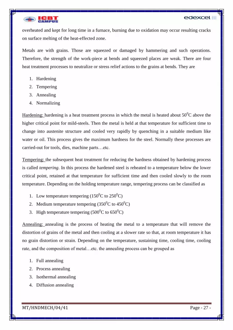
Metals are with grains. Those are squeezed or damaged by hammering and such operations.
Therefore, the strength of the work-piece at bends and squeezed places are weak. There are four
heat treatment processes to neutralize or stress relief actions to the grains at bends. They are
1. Hardening
2. Tempering
3. Annealing
4. Normalizing
Hardening: hardening is a heat treatment process in which the metal is heated about 500C above the
higher critical point for mild-steels. Then the metal is held at that temperature for sufficient time to
change into austenite structure and cooled very rapidly by quenching in a suitable medium like
water or oil. This process gives the maximum hardness for the steel. Normally these processes are
carried-out for tools, dies, machine parts…etc.
Tempering: the subsequent heat treatment for reducing the hardness obtained by hardening process
is called tempering. In this process the hardened steel is reheated to a temperature below the lower
critical point, retained at that temperature for sufficient time and then cooled slowly to the room
temperature. Depending on the holding temperature range, tempering process can be classified as
1. Low temperature tempering (1500C to 250
0C)
2. Medium temperature tempering (3500C to 450
0C)
3. High temperature tempering (5000C to 650
0C)
Annealing: annealing is the process of heating the metal to a temperature that will remove the
distortion of grains of the metal and then cooling at a slower rate so that, at room temperature it has
no grain distortion or strain. Depending on the temperature, sustaining time, cooling time, cooling
rate, and the composition of metal…etc. the annealing process can be grouped as
1. Full annealing
2. Process annealing
3. Isothermal annealing
4. Diffusion annealing

MT/HNDMECH/04/41 Page - 28 -
Normalizing: the normalizing process consists of heating the work-piece about 500C above its upper
critical temperature and then cooling in still air at room temperature. If necessary, the metal may be
held at the elevated temperature for a short period. Normalizing differs from annealing in the sense
that the holding time at the elevated temperature is very short or zero and the cooling rate is rapid
for the process. The normalizing process removes the internal stresses, refines the grains to smaller
size and improves the mechanical properties such as impact strength, yield point, ultimate tensile
strength…etc.
Through above stress relief processes, hardening was selected. Because it is
Speed than other process.
Process is easy.
Gives maximum hardness.
5.2.6. Grinding Process
Grinding process is a metal removing process for sharpen the cutting tools and blind or chamfering
the work-piece. Here also several grinding machines developed with several techniques. Pedestal
grinding, portable grinding, center-less grinding are some example for grinding operations. Below
Figure 5.9 describes some of the grinding operation.
Grinding machines use two types of cutting tools as sand papers and grinding wheels. Mostly
portable grinders are with sand papers and other grinding operation such as pedestal, center-less is
with grinding wheels. Grinding wheels are point by following method
Xx D 150 P YY M ZZ 3
Figure 5.9: Grinding Operation

MT/HNDMECH/04/41 Page - 29 -
Where:
Xx :- manufactures symbol for abrasive
D:- abrasive type (diamond or cubic boron nitride)
150:- grain size (coarse, ,medium, fine, very fine)
P:- grader scale from A to Z( A soft M medium and Z hard)
YY:- concentration(manufactures designation)
M:- Bond type (B=resin, M=metal, V=vetrified)
ZZ:- bond modification
3:- depth of abrasive in mm.
But, these details cannot be finding in every grinding wheel. Shop dealers gives grinding wheels
when customer request as hard or soft grinding wheels. So, DIMM grinding works were done
medium level grinding wheels with varying hand pressure.
5. Conclusion and Recommendation
Several inventors’ initial projects were total fail. But this little project DIMM cannot say totally
failed. It means little success is hidden behind this machine. Melting plastic pallet and ejecting it to
the mold is the big goal of injection molding. The DIMM had passed the melting part, remaining
part was the big issue for this machine. It means, DIMM might be succeeded if pressed the plunger
by hand other than gear box. Due to the high compressive of plunger, at a certain level the gear get
gets slip. So this is the big issue of this machine.
Even this machined failed little amount, it helped to gain several experiences in the way of
blacksmith works, lathe works and more over designing experience. It’s the most important point
for mechanical engineers. Because, several projects could see, as over design sometimes no
engineering behind those projects may be sometimes safety not there. When compare those factors
with this DIMM, even not say 100%, just able to say around 75%. Because, DIMM had passed
following factors successfully
Proper material selection
Easiest raw material feeding
Safety ensure by separated electrical control box.
Comfortable width, height and lengths
Very good aesthetic approach as covering customer….etc.

MT/HNDMECH/04/41 Page - 30 -
Reference and bibliography
British plastic federation (2015). available at:
http://www.bpf.co.uk/plastipedia/processes/Default.aspx [accessed : 25th
april 2015]
Plasticindustry (2015). Available at: http://www.plasticsindustry.com/plastic-processing-
methods.asp [accessed: 20th
april 2015]
Avplastic. Available at: http://www.avplastics.co.uk/njection-moulding-history [accessed:
29th
of april 2015]
Azom.com(2000-15). Available at: http://www.azom.com/article.aspx?ArticleID=6115
[accessed: 17th
of may 2015]
K.C. John (2010) mechanical workshop practice. 2nd
edn. India; PHI learning (pvt) ltd.