definisi pengajaran musik
TRANSCRIPT
ORIGINAL ARTICLE
Label-free super-resolution imaging of adenoviruses bysubmerged microsphere optical nanoscopyLin Li1, Wei Guo1, Yinzhou Yan1, Seoungjun Lee1 and Tao Wang2
Because of the small sizes of most viruses (typically 5–150 nm), standard optical microscopes, which have an optical diffraction limitof 200 nm, are not generally suitable for their direct observation. Electron microscopes usually require specimens to be placed undervacuum conditions, thus making them unsuitable for imaging live biologicalspecimens in liquid environments. Indirect opticalimaging of viruses has been made possible by the use of fluorescence optical microscopy that relies on the stimulated emission oflight from the fluorescing specimens when they are excited with light of a specific wavelength, a process known as labeling orself-fluorescent emissions from certain organic materials. In this paper, we describe direct white-light optical imaging of 75-nmadenoviruses by submerged microsphere opticalnanoscopy (SMON) without the use of fluorescent labeling or staining.Themechanism involved in the imaging is presented. Theoretical calculations of the imaging planes and the magnification factors havebeen verified by experimental results, with good agreement between theory and experiment.Light: Science & Applications (2013) 2, e104; doi:10.1038/lsa.2013.60; published online 27 September 2013
Keywords:imaging; microscope; optical; super-resolution; virus
INTRODUCTIONOpticalmicroscopic imaging resolution hasa theoreticallimitofapproximately 200 nm within the visible light spectrum due to thefar-field diffraction limit,which prevents the technique from beingused for direct observation of live viruses (typically 5–150 nm,withsome up to 300 nm).Progress in medicalscience and treatment ofdisease would benefit significantly from the availability of an instru-ment that enables direct optical imaging with a high resolution beyondtheopticaldiffraction limit.Transmission electron microscopy(TEM) and scanning electron microscopy (SEM) are often used toimage specially prepared dead virus structures at very high resolutions(,10 nm) in vacuum,but they are unsuitable for the study of liveviruses or virus/cell interactions. Fluorescence optical microscopy is arecently established method for the imaging ofcellular structures,bacteria and viruses beyond the opticaldiffraction limit,down to aresolution of 6 nm.1–4This technique is based on the detection of lightemitted by the fluorescing specimen when it is excited by light of aspecific wavelength. Structured illumination, such as stimulated emis-sion depletion and saturated structured illumination microscopy,which activate florescent light emission from a group of moleculessimultaneously, are typically used.5,6To enhance the imaging resolu-tion, statistical reconstruction of the florescent light emission of singlemolecules at different times, such as statistical optical reconstructionmicroscopy and photo-activated localization microscopy have beendeveloped,7,8whereby an optically blurred image is sharpened througha deconvolution process,i.e.,by digitally locating the peak ofan
optical profile or by using a point-spread function. The above fluor-escent optical imaging techniques are confronted with the challenge ofphotobleaching, which limits the maximum time of light exposure totens of seconds.9 In addition, fluorescent optical imaging techniquesoften require the conjugation of florescent molecules with the proteinsof the target material, thus making such techniques somewhat intru-sive,and only one type of stained protein can be imaged at a time,whereas there are over 10 000 types of proteins in each cell. Scanningnear-field optical microscopy, which is based on point-by-point scan-ning of a nano-scale optical tip very close (within a few nanometers) tothe target surface to illuminate the targets using the evanescent effectof the optical near-field, has demonstrated an imaging resolution of60–100 nm.10One of the drawbacks of the scanning near-field opticalmicroscopy technique is the long time required to acquire the fullimage,thus making itdifficultto study the dynamic behavior ofviruses and cells. Imaging using a negative refractive index metama-terial has been shown to provide super-resolution capability down to60 nm.11–13The technique has, however, not yet been applied to cell/virus imaging.The high levelof light attenuation is one of the keybarriers to the practical application of superlens techniques for super-resolution biomedical imaging. A recent study using an X-ray femto-second laser has shown super-resolution (subnanometer) imaging ofvirus particles just before their destruction.14Super-oscillatory lensopticalmicroscopyisanotherrecentlyreported subwavelengthimaging technique, and is based on a binary nano-structured mask.15
The imaging resolution so far is 105 nm (l/6),and it is suitable for1Laser Processing Research Centre, School of Mechanical, Aerospace and Civil Engineering, and Photon Science Institute, The University of Manchester, Manchester M13 9PL,UK and2Faculty of Medical and Human Sciences, The University of Manchester, Manchester M13 9PL, UKCorrespondence: Professor L Li, Laser Processing Research Centre, Schoolof Mechanical, Aerospace and Civil Engineering, and Photon Science Institute,The University ofManchester, Manchester M13 9PL, UK.E-mail: [email protected] 29 August 2012; revised 24 June 2013; accepted 25 June 2013
Light: Science & Applications (2013) 2, e104; doi:10.1038/lsa.2013.60ß 2013 CIOMP. All rights reserved 2047-7538/13www.nature.com/lsa
imaging an opaque target with transparent nano-structures. In 2011, amicrosphere-coupled optical nanoscope was reported by some of theauthors of this paper to have demonstrated an optical resolution of50 nm using a SiO2microsphere (with a diameter of 2–5 mm) in air forthe imaging of inorganic materials.16Untilnow,there has been noreportdemonstrating white lightdirectopticalimaging ofvirusesbelow 100 nm in size.In this paper, we report the use of submerged microsphere optical
nanoscopy (SMON) for the direct imaging of an adenovirus with adiameter of 75 nm at a resolution beyond the optical diffraction limit.Large-diameter (100 mm) BaTiO3 spheres were used for this sub-merged optical imaging. The mechanisms involved in the dual-lightlarge-microsphere submerged optical imaging are described.
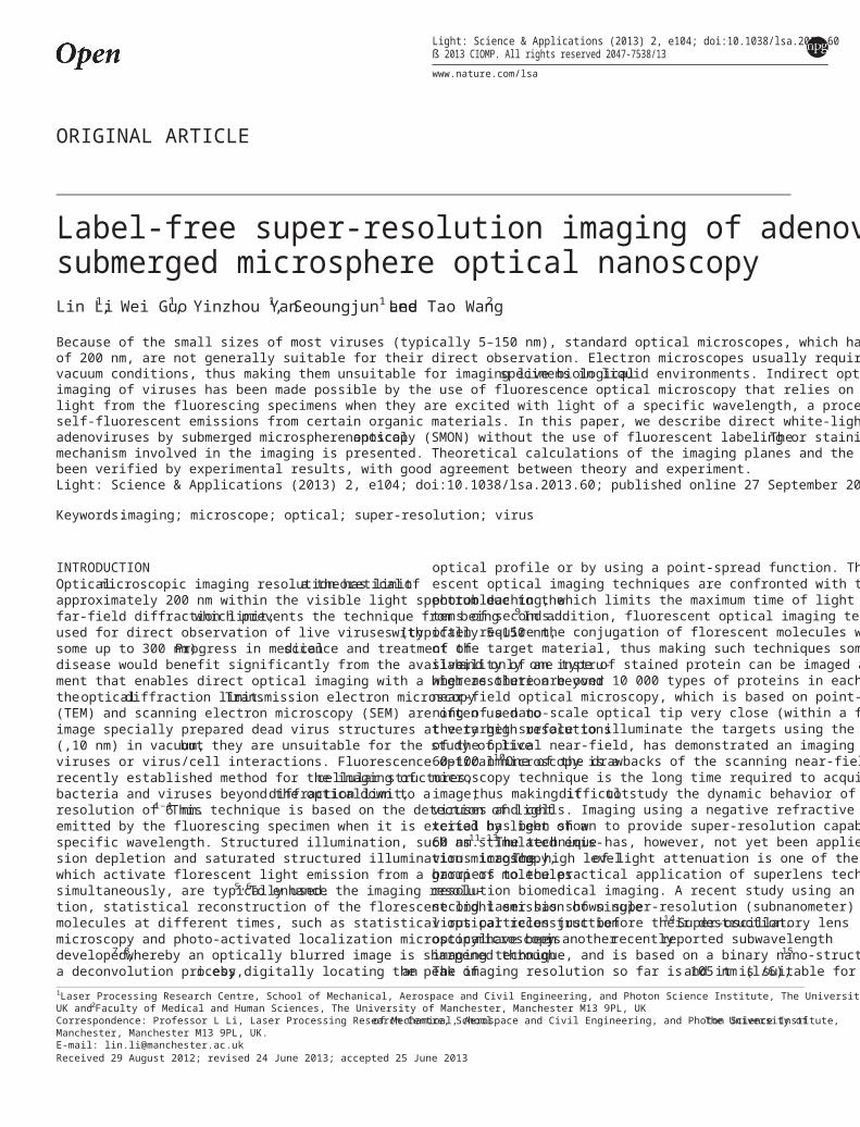
MATERIALS AND METHODSImaging set-upOptically transparentmicrospheresofBaTiO3 with diametersof100 mm (supplied by Cospheric LLC;California,USA) were placedover the test specimen. Deionized water was deposited between the testspecimen and the microscope lens. The optical microscope was used inboth the reflection and transmission modes (Figure 1).
Adenovirus slide preparationReplication-disabled adenoviruses of type 5 with deletions of the E1and E3 genes were used.Adenovirus stock (109 MOI mL 21) wasdiluted 10 timesin distilled H2O. Forvirusimaging using theBaTiO3 microsphere,the glass cover slide was first coated with a 5-nm-thick layer of gold to enable both optical and SEM imaging. Onemicroliter of diluted adenovirus stock was then spread onto the gold-coated microscope slide and air-dried.The viruses were then fixedwith one drop of 4% paraformaldehyde for 20 min, washed with tapwater and then air-dried.
TEM imaging sample preparationFor TEM imaging, diluted adenoviruses were loaded onto a carbon-coated TEM grid, which was negative stained using uranyl acetate.
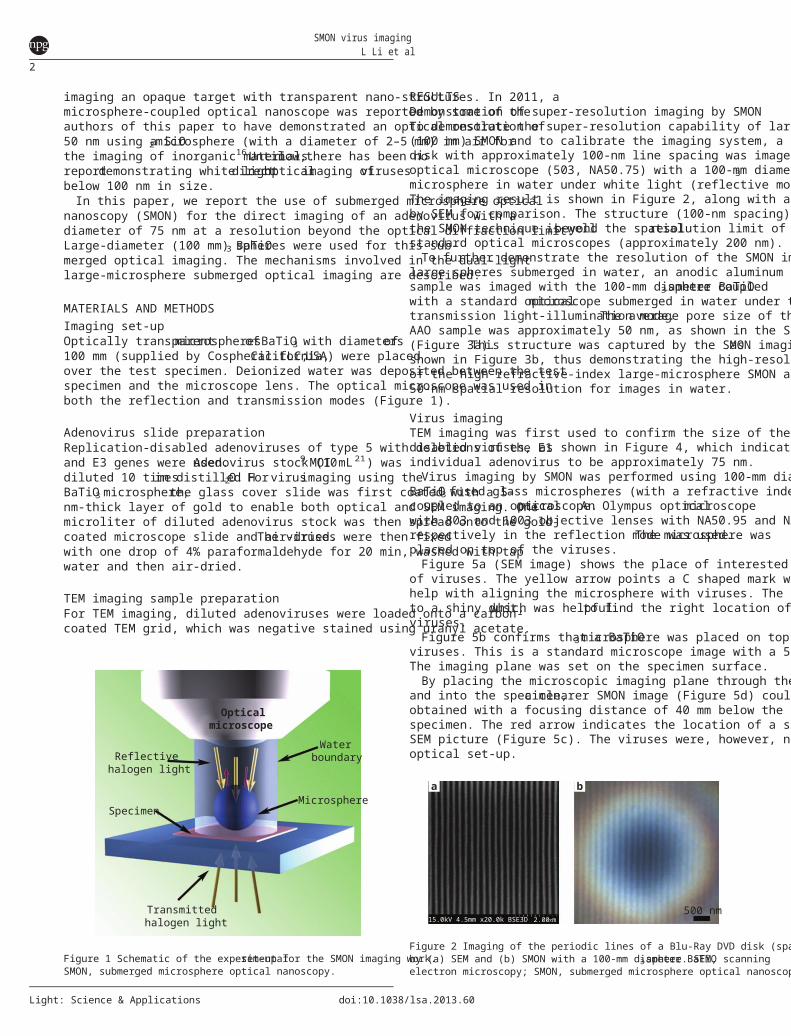
RESULTSDemonstration of super-resolution imaging by SMONTo demonstrate the super-resolution capability of large-microsphere(100 mm) SMON and to calibrate the imaging system, a Blu-Ray DVDdisk with approximately 100-nm line spacing was imaged using anoptical microscope (503, NA50.75) with a 100-mm diameter BaTiO3microsphere in water under white light (reflective mode) illumination.The imaging result is shown in Figure 2, along with an image obtainedby SEM for comparison. The structure (100-nm spacing) observed bythe SMON technique is wellbeyond the spatialresolution limit ofstandard optical microscopes (approximately 200 nm).To further demonstrate the resolution of the SMON imaging using
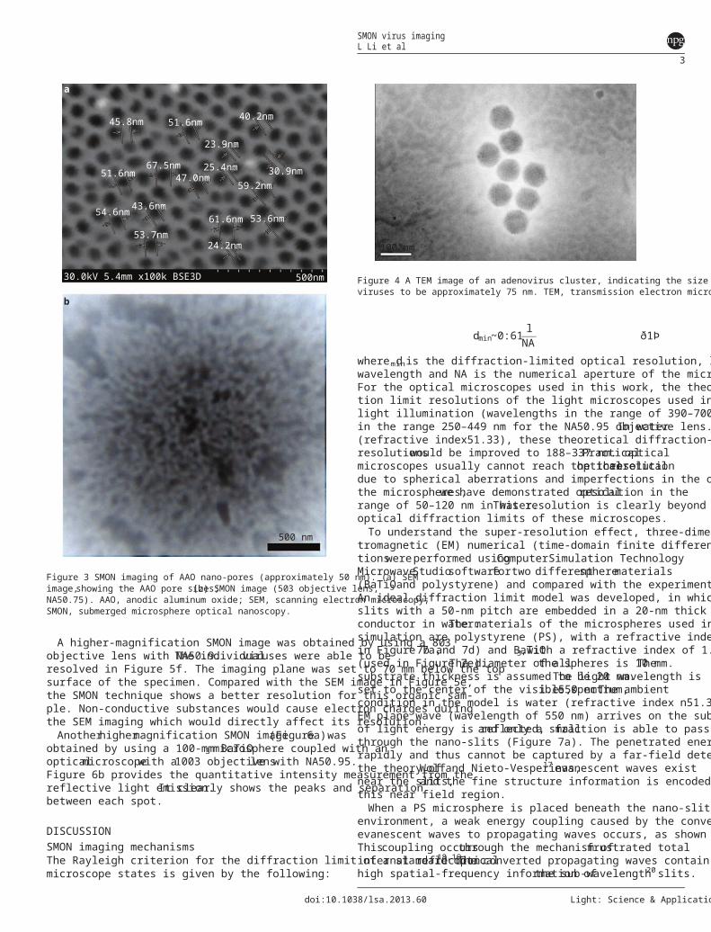
large spheres submerged in water, an anodic aluminum oxide (AAO)sample was imaged with the 100-mm diameter BaTiO3sphere coupledwith a standard opticalmicroscope submerged in water under thetransmission light-illumination mode.The average pore size of theAAO sample was approximately 50 nm, as shown in the SEM image(Figure 3a).This structure was captured by the SMON imaging,asshown in Figure 3b, thus demonstrating the high-resolution imagingof the high refractive-index large-microsphere SMON approach with a50-nm spatial resolution for images in water.
Virus imagingTEM imaging was first used to confirm the size of the replication-disabled viruses, as shown in Figure 4, which indicates the size of anindividual adenovirus to be approximately 75 nm.Virus imaging by SMON was performed using 100-mm diameter
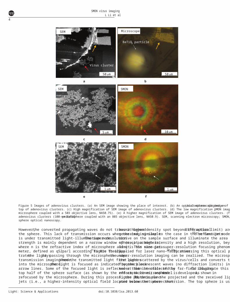
BaTiO3 fused glass microspheres (with a refractive index of n51.9)coupled to an opticalmicroscope.An Olympus opticalmicroscopewith 803 and 1003 objective lenses with NA50.95 and NA50.9respectively in the reflection mode was used.The microsphere wasplaced on top of the viruses.Figure 5a (SEM image) shows the place of interested with a cluster
of viruses. The yellow arrow points a C shaped mark which was used tohelp with aligning the microsphere with viruses. The red arrow pointsto a shiny dust,which was helpfulto find the right location of theviruses.Figure 5b confirms that a BaTiO3microsphere was placed on top of
viruses. This is a standard microscope image with a 503 objective lens.The imaging plane was set on the specimen surface.By placing the microscopic imaging plane through the microsphere
and into the specimen,a clearer SMON image (Figure 5d) could beobtained with a focusing distance of 40 mm below the top surface of thespecimen. The red arrow indicates the location of a shiny dust in theSEM picture (Figure 5c). The viruses were, however, not seen with thisoptical set-up.Reflective
halogen light
Specimen
Transmittedhalogen light
Microsphere
Waterboundary
Opticalmicroscope
Figure 1 Schematic of the experimentalset-up for the SMON imaging work.SMON, submerged microsphere optical nanoscopy.
a b
500 nm15.0kV 4.5mm x20.0k BSE3D 2.00 µm
Figure 2 Imaging of the periodic lines of a Blu-Ray DVD disk (spacing of a 100 nm)by (a) SEM and (b) SMON with a 100-mm diameter BaTiO3sphere. SEM, scanningelectron microscopy; SMON, submerged microsphere optical nanoscopy.
SMON virus imagingL Li et al
2
Light: Science & Applications doi:10.1038/lsa.2013.60
A higher-magnification SMON image was obtained by using a 803objective lens with NA50.9.The individualviruses were able to beresolved in Figure 5f. The imaging plane was set to 70 mm below the topsurface of the specimen. Compared with the SEM image in Figure 5e,the SMON technique shows a better resolution for this organic sam-ple. Non-conductive substances would cause electron charges duringthe SEM imaging which would directly affect its resolution.Anotherhighermagnification SMON image(Figure6a)was
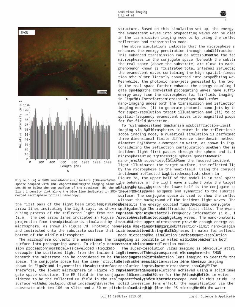
obtained by using a 100-mm BaTiO3 microsphere coupled with anopticalmicroscopewith a1003 objectivelenswith NA50.95.Figure 6b provides the quantitative intensity measurement from thereflective light emission.It clearly shows the peaks and separationbetween each spot.
DISCUSSIONSMON imaging mechanismsThe Rayleigh criterion for the diffraction limit of a standard opticalmicroscope states is given by the following:
dmin~0:61 lNA ð1Þ
where dminis the diffraction-limited optical resolution, l is the opticalwavelength and NA is the numerical aperture of the microscope lens.For the optical microscopes used in this work, the theoretical diffrac-tion limit resolutions of the light microscopes used in air for whitelight illumination (wavelengths in the range of 390–700 nm) would bein the range 250–449 nm for the NA50.95 objective lens.In water(refractive index51.33), these theoretical diffraction-limited imagingresolutionswould be improved to 188–337 nm.Practicalopticalmicroscopes usually cannot reach the theoreticalopticalresolutiondue to spherical aberrations and imperfections in the optics. By usingthe microspheres,we have demonstrated opticalresolution in therange of 50–120 nm in water.This resolution is clearly beyond theoptical diffraction limits of these microscopes.To understand the super-resolution effect, three-dimensional elec-
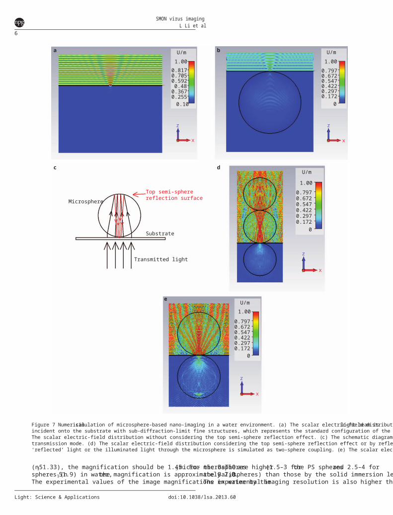
tromagnetic (EM) numerical (time-domain finite difference) simula-tionswereperformed usingComputerSimulation TechnologyMicrowaveStudiosoftwarefortwo differentspherematerials(BaTiO3and polystyrene) and compared with the experimental data.An ideal diffraction limit model was developed, in which two 100-nmslits with a 50-nm pitch are embedded in a 20-nm thick perfect electricconductor in water.The materials of the microspheres used in thesimulation are polystyrene (PS), with a refractive index of 1.59 (usedin Figure 7a,7b and 7d) and BaTiO3,with a refractive index of 1.9(used in Figure 7e).The diameter of allthe spheres is 10 mm.Thesubstrate thickness is assumed to be 20 nm.The light wavelength isset to the center of the visible spectrum,i.e.,550 nm.The ambientcondition in the model is water (refractive index n51.33). When anEM plane wave (wavelength of 550 nm) arrives on the substrate, mostof light energy is reflected,and only a smallfraction is able to passthrough the nano-slits (Figure 7a). The penetrated energy decays veryrapidly and thus cannot be captured by a far-field detector. Based onthe theory ofWolfand Nieto-Vesperinas,17 evanescent waves existnear the slits,and the fine structure information is encoded withinthis near field region.When a PS microsphere is placed beneath the nano-slits in the water
environment, a weak energy coupling caused by the conversion of theevanescent waves to propagating waves occurs, as shown in Figure 7b.Thiscoupling occursthrough the mechanism offrustrated totalinternal reflection.18,19The converted propagating waves contain thehigh spatial-frequency information ofthe sub-wavelength slits.20
a
b
500 nm
45.8nm 51.6nm
23.9nm
40.2nm
30.9nm59.2nm
53.6nm61.6nm
24.2nm53.7nm
30.0kV 5.4mm x100k BSE3D 500nm
43.6nm54.6nm
51.6nm67.5nm
47.0nm25.4nm
Figure 3 SMON imaging of AAO nano-pores (approximately 50 nm). (a) SEMimage,showing the AAO pore sizes;(b) SMON image (503 objective lens,NA50.75). AAO, anodic aluminum oxide; SEM, scanning electron microscopy;SMON, submerged microsphere optical nanoscopy.
100 nm
Figure 4 A TEM image of an adenovirus cluster, indicating the size of individualviruses to be approximately 75 nm. TEM, transmission electron microscopy.
SMON virus imagingL Li et al
3
doi:10.1038/lsa.2013.60 Light: Science & Applications
However,the converted propagating waves do not transmit beyondthe sphere. This lack of transmission occurs when the imaging sampleis under transmitted light-illumination mode.The super-resolutionstrength is mainly dependent on a narrow window of (n,q) parameters,where n is the refractive index of microsphere and q is the size para-meter, defined as q52pa/l according to Mie theory.21Figure 7c illus-tratesthe lightrayspassing through the microsphere underthetransmission imaging mode.When the transmitted light first passesinto the microsphere,the light is focused as indicated by the blackarrow lines. Some of the focused light is reflected at the interface of thetop half of the sphere surface (as shown by the red arrow lines) and isrefocused by the microsphere. During this process, the photonic nano-jets (i.e., a higher-intensity optical field located below the sphere that
has a higher density spot beyond the opticaldiffraction limit) aregenerated, similar to the case in the reflection mode.16The nano-jetsarrive on the sample surface and illuminate the area below the micro-sphere at a high intensity and a high resolution, beyond the diffractionlimit. This nano-jet super-resolution focusing phenomenon has beenapplied for laser nano-fabrication.22–24By reversing this optical path,super-resolution imaging can be realized. The microsphere re-collectsthe light scattered by the virus/cells and converts the high spatial-frequency evanescent waves (no diffraction limits) into propagatingwaves thatcan be collected by far-field imaging.To illustrate thiseffect,a three-microspheremodel isdeveloped,as shown inFigure 7d,to decouple the projected and the received light throughpure evanescent wave conversion. The top sphere is used to simulate
1 mm
SMON
SMON
Microscope
BaTiO3 particle
Virus cluster
SEM
SEM
SEM
dc
ba
fe
1 mm
5 mm 10 mm
50 mm50 mm
Figure 5 Images of adenovirus clusters. (a) An SEM image showing the place of interest. (b) An optical microscope image of a 100-mm BaTiO3microsphere aligned ontop of adenovirus clusters. (c) High magnification of SEM image of adenovirus clusters. (d) The low magnification SMON image of adenovirus clusters (100-mm BaTiO3microsphere coupled with a 503 objective lens, NA50.75). (e) A higher magnification of SEM image of adenovirus clusters. (f) A higher magnification SMON image ofadenovirus clusters (100-mm BaTiO3 microsphere coupled with an 803 objective lens, NA50.9). SEM, scanning electron microscopy; SMON, submerged micro-sphere optical nanoscopy.
SMON virus imagingL Li et al
4
Light: Science & Applications doi:10.1038/lsa.2013.60
the first pass of the light beam into the microsphere,i.e.,the blackarrow lines indicating the light rays, as shown in Figure 7c. The refo-cusing process of the reflected light from the top semi-sphere surface(i.e., the red arrow lines indicated in Figure 7c) or the reflected lightprojection from the opticalmicroscope is simulated by the middlemicrosphere, as shown in Figure 7d. Photonic nano-jets are generatedand redirected onto the substrate surface that is in contact with thebottom of the middle microsphere.The microsphere converts the evanescentwaves from the target
surface into propagating waves. To clearly demonstrate this conver-sion process,a conjugatemodelwas developed (Figure7d)todecouple the scattered light from the incident light waves. The spacebeneath the substrate can be considered to be the conjugate ‘virtual’space. The conjugate space has the same ‘structure’ as the real spaceshown in Figure7c and issymmetricto thesubstratesurface.Therefore, the lowest microsphere in Figure 7d represents the conju-gate space structure. The EM field in the conjugate space can be con-sidered to be the collected EM field in the real space from the substratesurface withoutthe background ofthe incidentlightwaves.Thesubstrate with two 100-nm slits and a 50-nm pitch is used as the fine
structure. Based on this simulation set-up, the energy coupling fromthe evanescent waves into propagating waves can be clearly displayedin the transmission imaging mode or by using the reflection and dualreflection and transmission mode.The above simulations indicate that the microsphere significantly
enhances the energy penetration through subdiffraction-limitslits.This enhanced transmission can be attributed to the factthatthemicrospheres in the conjugate space (beneath the substrate) and inthe real space (above the substrate) are close to each other. Hence, aphenomenon known as frustrated total internal reflection occurs, andthe evanescent waves containing the high spatial-frequency informa-tion ofthe slitsare linearly converted into propagating waves.18
Meanwhile, the photonic nano-jets generated by the two microspheresin the real space further enhance the energy coupling into the conju-gate space;thus,the converted propagating waves have sufficientenergy away from the microsphere for far-field imaging (as shownin Figure7d).Therefore,themicrosphereplaysa dual-rolefornano-imaging under both the transmission and reflection microscopeimaging modes: (i) to generate photonic nano-jets by the top spherefor super-resolution target illumination and (ii) to convert the highspatial-frequency evanescent waves into magnified propagating wavesfor far-field detection.To furtherunderstand themechanism ofsubdiffraction-limit
imaging via BaTiO3 microspheres in water in the reflection micro-scope imaging mode, a numerical simulation is performed using thethree-dimensional finite-difference time-domain method for a 10-mmdiameter BaTiO3 sphere submerged in water, as shown in Figure 7e.Considering the reflection configuration used in the imaging,theincident light first passes through the sphere and is focused by themicrosphere.During thisprocess,the sphere generates‘photonicnano-jets’with super-resolution.19,21–23When the focused incidentlight illuminates the target surface, the reflected light can be recollectedby the microsphere in the near-field. Using the conjugate model, theincidentand reflected lightwavesaredecoupled.As shown inFigure 7e, the upper half of the model is in real space, which describesthe behavior of the light wave incident onto the target surface via themicrosphere, whereas the lower half is the conjugate space, of whichthe ‘structure’is same as realspace and symmetric to the substratesurface. The conjugate space is used to show the reflected light wavewithout the background of the incident light waves. The microspheretransmits the energy coupled from the realspace to the conjugatespace through the subdiffraction-limit slits. The evanescent waves thatcontain the high spatial-frequency information (i.e., fine structures)are converted into propagating waves. The nano-photonic jets genera-ted via the upper microsphere provide enough energy coupling toenable far-field imaging.Hence,subdiffraction-limit nano-imagingcan be achieved using BaTiO3 microspheres in water for reflectionmode microscopy.The simulation indicatesthatsuper-resolutionimaging is possible in water with the aid ofmicrospheres in bothtransmission and reflection modes.The super-resolution virus imaging is obviously attributed to the
existence of the transparent microspheres.We compare the SMONwith super-solid immersion lens imaging to identify the differences.Based on the solid immersion lens theory,the maximum imagingresolution improvementby a microsphere should be n0/n1.25 Themaximum imaging resolutions achieved using a solid immersion lensare 163 nm and 137 nm for the PS and BaTiO3microspheres in water,respectively, for the microscope used in this study. Based on the supersolid immersion lens effect, the magnification via the microsphere canbe calculated as (n1/n0)2. For the PS microspheres (n151.60) in water
00
100908070605040302010
110
12001000800600Length (nm)
400200
Rela
tive i
ntensi
ty (a.
u.)
1400
SMON
b
a
500nm
Figure 6 (a) A SMON image ofadenovirus clusters (100-mm BaTiO3 micro-sphere coupled with 1003 objective lens,NA50.95);the imaging plane wasset 80 mm below the top surface of the specimen; (b) the quantitative contrastlight intensity plot along the blue line indicated in SMON image. SMON, sub-merged microsphere optical nanoscopy.
SMON virus imagingL Li et al
5
doi:10.1038/lsa.2013.60 Light: Science & Applications
(n151.33), the magnification should be 1.45. For the BaTiO3 micro-spheres (n151.9) in water,the magnification is approximately 2.0.The experimental values of the image magnifications in water by the
microspheresare higher(1.5–3 forthe PS spheresand 2.5–4 forthe BaTiO3 spheres) than those by the solid immersion lens effect.The experimental imaging resolution is also higher than the theoretical
Transmitted light
Substrate
MicrosphereTop semi-spherereflection surface
a b
c d
e
U/m
1.00
0
z
x
z
x
0.172
0.6720.5470.4220.297
0.797
U/m1.00
00.172
0.6720.5470.4220.297
0.797
U/m1.00
0
z
x
0.172
0.6720.5470.4220.297
0.797
U/m1.00
0.10
z
x
0.255
0.7050.5920.480.367
0.817
Figure 7 Numericalsimulation of microsphere-based nano-imaging in a water environment. (a) The scalar electric-field distribution when a parallellight beam isincident onto the substrate with sub-diffraction-limit fine structures, which represents the standard configuration of the microscope under the transmission mode. (b)The scalar electric-field distribution without considering the top semi-sphere reflection effect. (c) The schematic diagram of the top semi-sphere reflection in thetransmission mode. (d) The scalar electric-field distribution considering the top semi-sphere reflection effect or by reflective mode light illumination, where the‘reflected’ light or the illuminated light through the microsphere is simulated as two-sphere coupling. (e) The scalar electric-field distribution under the reflection mode.
SMON virus imagingL Li et al
6
Light: Science & Applications doi:10.1038/lsa.2013.60
limit of the solid immersion lens. Therefore, the microsphere plays animportant role in transforming the high-resolution evanescent wavesin the near field into far-field propagating waves.Because there is no diffraction limit for evanescent waves, the only
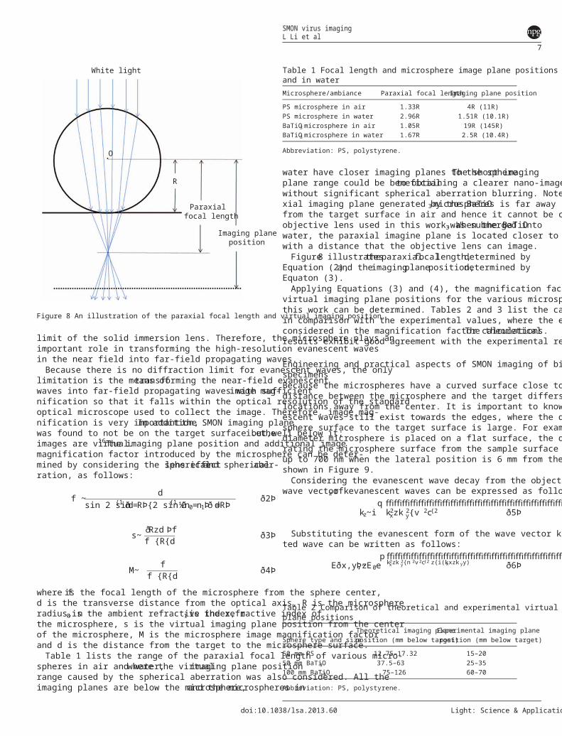
limitation is the means oftransforming the near-field evanescentwaves into far-field propagating waves with sufficientimage mag-nification so that it falls within the optical resolution of the standardoptical microscope used to collect the image. Therefore, image mag-nification is very important.In addition,the SMON imaging planewas found to not be on the target surface but well below it;i.e.,theimages are virtual.16The imaging plane position and additional imagemagnification factor introduced by the microsphere can be deter-mined by considering the sphericallens effectand sphericalaber-ration, as follows:
f ~ dsin 2 sin{1 d=Rð Þ{2 sin{1 n0=n1ð Þ d=Rð Þ½ ð2Þ
s~ Rzdð Þff {R{d ð3Þ
M~ ff {R{d ð4Þ
where fis the focal length of the microsphere from the sphere center,d is the transverse distance from the optical axis, R is the microsphereradius, n0is the ambient refractive index, n1is the refractive index ofthe microsphere, s is the virtual imaging plane position from the centerof the microsphere, M is the microsphere image magnification factorand d is the distance from the target to the microsphere surface.Table 1 lists the range of the paraxial focal length of various micro-
spheres in air and water,where the virtualimaging plane positionrange caused by the spherical aberration was also considered. All theimaging planes are below the microsphere,and the microspheres in
water have closer imaging planes to the sphere.The short imagingplane range could be beneficialto obtaining a clearer nano-imagewithout significant spherical aberration blurring. Note that the para-xial imaging plane generated by the BaTiO3microspheres is far awayfrom the target surface in air and hence it cannot be captured by theobjective lens used in this work. When the BaTiO3was submerged intowater, the paraxial imagine plane is located closer to the microsphere,with a distance that the objective lens can image.Figure8 illustratestheparaxialfocallength,determined by
Equation (2),and theimagingplaneposition,determined byEquaton (3).Applying Equations (3) and (4), the magnification factors and the
virtual imaging plane positions for the various microspheres used inthis work can be determined. Tables 2 and 3 list the calculated resultsin comparison with the experimental values, where the effect of d wasconsidered in the magnification factor calculations.The theoreticalresults exhibit good agreement with the experimental results.
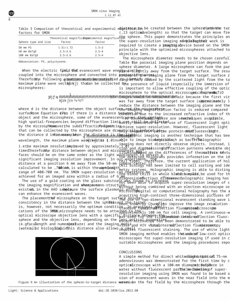
Engineering and practical aspects of SMON imaging of biomedicalspecimensBecause the microspheres have a curved surface close to the target, thedistance between the microsphere and the target differs at differentlocations away from the center. It is important to know whether evan-escent waves still exist towards the edges, where the distance from thesphere surface to the target surface is large. For example, when a 50-mmdiameter microsphere is placed on a flat surface, the distance, x, sepa-rating the microsphere surface from the sample surface is increased toup to 700 nm when the lateral position is 6 mm from the central axis, asshown in Figure 9.Considering the evanescent wave decay from the object surface, the
wave vector kzof evanescent waves can be expressed as follows:
kz~iffiffiffiffiffiffiffiffiffiffiffiffiffiffiffiffiffiffiffiffiffiffiffiffiffiffiffiffiffiffiffik2xzk 2
y{v 2c{2q
ð5Þ
Substituting the evanescent form of the wave vector k, the transmit-ted wave can be written as follows:
E x,y,zð Þ~E0effiffiffiffiffiffiffiffiffiffiffiffiffiffiffiffiffiffiffiffiffiffiffiffiffiffik2xzk 2y{n 2v 2c{2
pz{i(kxxzk yy) ð6Þ
White light
O
R
Paraxialfocal length
Imaging planeposition
Figure 8 An illustration of the paraxial focal length and virtual imaging position.
Table 1 Focal length and microsphere image plane positions in airand in waterMicrosphere/ambiance Paraxial focal lengthImaging plane position
PS microsphere in air 1.33R 4R (11R)PS microsphere in water 2.96R 1.51R (10.1R)BaTiO3 microsphere in air 1.05R 19R (145R)BaTiO3 microsphere in water 1.67R 2.5R (10.4R)
Abbreviation: PS, polystyrene.
Table 2 Comparison of theoretical and experimental virtual imagingplane positions
Sphere type and sizeTheoretical imaging planeposition (mm below target)
Experimental imaging planeposition (mm below target)
50 mm PS 12.75–17.32 15–2050 mm BaTiO3 37.5–63 25–35100 mm BaTiO3 75–126 60–70
Abbreviation: PS, polystyrene.
SMON virus imagingL Li et al
7
doi:10.1038/lsa.2013.60 Light: Science & Applications
When the electric field EoE0/e, the evanescent wave energy can becoupled into the microsphere and converted into propagating waves.Therefore,the following equation must be satisfied to identify themaximum plane wave vector (
ffiffiffiffiffiffiffiffiffiffiffiffiffiffik2xzk 2
yq
) thatcan be collected bymicrospheres:
dj jƒ 1ffiffiffiffiffiffiffiffiffiffiffiffiffiffiffiffiffiffiffiffiffiffiffiffiffiffiffiffiffiffiffiffiffiffiffiffik2xzk 2
y{n 2v2c{2q ð7Þ
where d is the distance between the object surface and the microspheresurface.From Equation (7),even if there is a distance between theobject and the microsphere, some of the evanescent waves that containhigh spatial-frequencies beyond diffraction limit can still be collectedby the microsphere.However,the subdiffraction-limitfrequenciesthat can be collected by the microsphere are dramatically reduced asthe distance d increases.For example,when the distance is the lightwavelength, the maximum plane wave vector (
ffiffiffiffiffiffiffiffiffiffiffiffiffiffik2xzk 2
yq
) is 1.01nv/c,i.e.,the maximum resolution isimproved by approximately 1.01times.Therefore,the distance between object and microsphere sur-faces should be on the same order as the light wavelength to obtain asignificant imaging resolution improvement. In our experiment, thedistance at a position 6 mm away from the 50-mm sphere center iscalculated to be ,700 nm,which is within the opticalwavelengthrange of 400–700 nm. The SMON super-resolution can therefore beachieved for an imaged area within a radius of 6 mm.The use of a gold coating on the glass substrate was found to increase
the imaging magnification and sharpnesswhen a nano-structureexisted,as in the AAO sample,because the surface plasmonic effectcan enhance the evanescent waves.The placement ofthe microsphere on the target surface ensures
consistency in the distance between the sphere and the target.Thisis, however, not necessarily the optimum condition. In practical appli-cations of the SMON,the microsphere needs to be attached to theoptical microscope objective lens with a specific distance between thesphere and the objective lens, depending on the lens optical properties(e.g.,focallength and numericalaperture) and the imaging media(water,oilor biologicalliquid).This distance also allows a small
distance to be created between the sphere and the targetdistance(,13 opticalwavelength) so that the target can move freely belowthe sphere. This paper demonstrates the principles and feasibility ofthe super-resolution imaging of biologicalsamples.Further work isrequired to create a practicalimaging device based on the SMONprinciple with the optimized microspheres attached to the microscopeobjective lens.The microsphere diameter needs to be chosen carefully. As listed in
Table 1,the paraxial imaging plane position depends on the micro-sphere diameter. A large microsphere can form the paraxial-imagingplane slightly away from the target surface. The resulting small sepa-ration of the imaging plane from the target surface reduces the blur-ring effect caused by the scattered light from the target surface.The presence of liquid (especially the immersion of the objective lens)
is important to allow effective coupling of the optical images from themicrosphere to the optical microscope. For a BaTiO3 microsphere,noimages could be obtained in air because the first virtual imaging planewas far away from the target surface (approximately 18R).Water canreduce the distance between the imaging plane and the surface; however,the imaging magnification factor is reduced compared with the drycondition due to the increased refractive index of the medium.For biomedicalimaging,there are severaltechniques available,pri-
marily dominated by the use of fluorescent light optical microscopy, toachieve super-resolution. However, fluorescent light optical microscopyonly imagescertain partsofthe protein thatemitfluorescentlight.Holographic imaging is another technique that has been reported to beable to image biologicalmaterials,such as bacteria.24,26Holographicimaging does not directly observe objects. Instead, it relies on the detec-tion and digitalprocessing ofdiffraction patterns when the objectisilluminated.Based on the differences of the surface texture,analysis ofthe detected holograms provides information on the identities of differentcell types. Therefore, the current application of holographic imaging incell biology has been limited to cell sorting and identification, i.e., cyto-metry systems. Holographic imaging is able to distinguish bacteria fromred blood cells in whole blood samples,which could be used for thediagnosis ofinfectious diseases.26 However,holographic imaging hasnot been able to acquire super-resolution images of cellular structureswithout being combined with an electron microscope or an atomic forcemicroscope.Digital or computational holography has the advantage ofacquiring high-contrast three-dimensional pictures of un-labeled cells.27
The use of two-dimensional evanescent standing wave illumination hasbeen shown by Chung etal.27 to improve the image resolution ofastandard totalinternalreflection fluorescentopticalmicroscopetoapproximately 100 nm for cell imaging. A continuous-wave 532-nm laserwas used for the illumination.Standard totalinternalreflection fluor-escent microscopy has been demonstrated to be able to image sindbisvirus and HIV virus.Totalinternalreflection fluorescentmicroscopyrequires fluorescent staining. The use of white light illumination in theSMON imaging method enables the use ofstandard low-cost opticalmicroscopes for super-resolution imaging if used in conjunction withsuitable microspheres and the imaging procedures reported in this paper.
CONCLUSIONSA simple method for direct white-light opticalobservation of 75-nmadenoviruses was demonstrated for the first time by coupling a standardopticalmicroscope with a 100-mm diameter BaTiO3 microsphere inwater without fluorescent particle labeling.The mechanism of super-resolution imaging using SMON was found to be based on the conver-sion of evanescent waves in the near field into the magnified prorogatingwaves in the far field by the microsphere through the mechanism of
Table 3 Comparison of theoretical and experimental magnificationfactors for SMON
Sphere type and sizeTheoretical magnification
factorExperimental magnification
factor
50 mm PS 1.51–1.72 1.5–350 mm BaTiO3 2.5–3.6 2.5–4100 mm BaTiO3 2.5–3.6 2.5–4
Abbreviation: PS, polystyrene.
6 µmx
rr
Figure 9 An illustration of the sphere-to-target distance variation.
SMON virus imagingL Li et al
8
Light: Science & Applications doi:10.1038/lsa.2013.60

frustrated total internal reflection. Nano-jet formation through focusingof light by the microsphere plays an important role in enhancing theimage contrastby delivering the converted propagating wave to thespace outside the sphere.Because evanescent waves do not have a dif-fraction limit, the transformation of the evanescent wave to a magnifiedpropagating wave within the opticalresolution limitofa standardoptical microscope is important.In other words,the resolution of themicrosphere-based optical imaging, although theoretically unlimited, islimited in practice by the magnification factor of the microsphere inconverting the evanescent wave to the propagating wave.Qualitativerelationships to determine the imaging plane location (normally wellbelow the microspheres) and the microsphere-induced magnificationfactors for the SMON were derived and compared to the experiments,with close agreement. This work opens new opportunities for the studyof virus/cell/bacteria/drug interactions to better understand the causes ofvarious deceases; super-resolution direct optical SMON imaging has thepotentialto become an alternative and complimentary technique tofluorescent optical microscopy and electron microscopy.
AUTHOR CONTRIBUTIONSLL conceived the concept,led the research,participated in the virusimaging experiments and prepared the manuscript.TW prepared allthe biologicalimaging samples,performed the TEM imaging oftheviruses, participated in the optical imaging experiments and contributedto the manuscript preparation. WG performed the virus imaging experi-ment and contributed to the manuscript writing. YY performed the theor-eticalsimulation work and contributed to the manuscript preparation,particularly on the Discussion section.SL performed the Blu-Ray andAAO imaging experiments, participated in the SMON biological sampleimaging experiments and contributed to the manuscript preparation.
ACKNOWLEDGMENTSWe thank Dr Peter March for his help in using microscopes in the Bio-imagingFacility,Dr Aleksandr Mironov for his help with the electron microscopeFacility in the Faculty of Life Sciences, the University of Manchester, and DrZengbo Wang for technical discussions during the early stages of the work.
1 Hell SW. Far-field optical nanoscopy. Science 2007; 316: 1153–1158.2 Huang B, Wang W, Bates M, Zhuang X. Three-dimensional super-resolution imaging by
stochastic optical reconstruction microscopy. Science 2008; 319: 810–813.3 Stone MD, Mihalusova M, O’Connor CM, Prathapam R, Collins K et al. Stepwise
protein-mediated RNA folding directs assembly of telomerase ribonucleoprotein.Nature 2007; 446: 458–461.
4 Huang B, Babcock H, Zhuang X. Breaking the diffraction barrier: super-resolutionimaging of cells. Cell 2010; 143: 1047–1058.
5 HellSW, Wichmann J.Breaking the diffraction resolution limitby stimulatedemission: stimulated-emission-depletion fluorescence microscopy. Opt Lett 1994;19: 780–782.
6 Heintzmann R, Jovin TM, Cremer C. Saturated patterned excitation microscopy—aconcept for optical resolution improvement. J Opt Soc Am A Opt Image Sci Vis 2002;19: 1599–1609.
7 Rust MJ, Bates M, Zhuang X. Sub-diffraction-limit imaging by stochastic opticalreconstruction microscopy (STORM). Nat Methods 2006; 3: 793–795.
8 Betzig E,Patterson GH,SougratR, LindwasserOW, Olenych S etal.Imagingintracellularfluorescent proteins atnanometerresolution.Science 2006;313:1642–1645.
9 Renn A, Seelig J, Sandoghdar V. Oxygen-dependent photochemistry of fluorescentdyes studied at the single molecule level. Mol Phys 2006; 104: 409–414.
10 Du¨ rig U, Pohl DW, Rohner F. Near-field optical-scanning microscopy. J Appl Phys1986; 59: 3318–3327.
11 Pendry JB. Negative refraction makes a perfect lens. Phys Rev Lett 2000; 85: 3966–3969.
12 Fang N, Lee H, Sun C, Zhang X. Sub-diffraction-limited optical imaging with a silversuperlens. Science 2005; 308: 534–537.
13 Smolyaninov II, Davis CC, Elliott J, Wurtz GA, Zayats AV. Super-resolution opticalmicroscopy based on photonic crystal materials. Phys Rev B 2005;72: 085442.
14 Chapman HN, Fromme P, Barty A, White TA, Kirian RA et al. Femtosecond X-rayprotein nanocrystallography. Nature 2011; 470: 73–78.
15 Roger ET, Lindberg J, Roy T, Savo S, Chad JE et al. A super-oscillatory lens opticalmicroscope for subwavelength imaging. Nat Mater 2012; 11: 432–435.
16 Wang Z, Guo W, Li L, Luk’yanchuk B, Khan A et al. Optical virtual imaging at 50 nmlateral resolution with a white-light nanoscope. Nat Commun 2011; 2: 218.
17 Richards B, Wolf E. Electromagnetic diffraction in optical systems. II. Structure of theimage field in an aplanatic system. Proc R Soc Lond A 1959; 253: 358–379.
18 Courjon D, Bainier C. Near field microscopy and near field optics. Rep Prog Phys1994; 57: 989–1028.
19 Li L, Guo W, Wang ZB, Liu Z, Whitehead D et al. Large area laser nano-texturing withuser-defined patterns. J Micromech Microeng 2009; 19: 064002.
20 Webb RH. Confocal optical microscopy. Rep Prog Phys 1996; 59: 427–471.21 Wang Z, Joseph N, Li L, Luk’yanchuk BS. A review of optical near-fields in particle/tip-
assisted laser nanofabrication. Proc IMechE Part C 2010; 224: 1113–1127.22 Guo W, Wang ZB,LiL,Liu Z,Luk’yanchuk B.Chemical-assisted laserparallel
nanostructuring ofsilicon in opticalnearfields.Nanotechnology 2008;19:455302.
23 Li L, Hong M, Schmidt M, Zhong M, Mashe M et al. Laser nano-manufacturing—stateof the art and challenges (Keynote at 61stCIRP General Assembly, 21–27 AugustBudapest 2011). CIRP Ann 2011; 60: 735–755.
24 Seo S, Su TW, Tseng D, Erlinger A, Izcan A. Lens-free holographic imaging for on-chipcytometry and dianostics. Lab Chip 2009; 9: 777–787.
25 Serrels KA, Ramsay E, Dalgarno PA, Gerardot BD, O’Connor JA et al. Solid immersionlens applications for nanophotonic devices. J Nanophoton 2008; 2: 021854.
26 Moon I, Daneshpanah M, Anand A, Javidi B. Cell identification with computational 3Dholographic microscopy. Opt Photon News 2011; 22: 18–23.
27 Chung E, Kim D, Cui Y, Kim YH, So PT. Two-dimensional standing wave total internalreflection fluorescence microscopy: superresolution imaging of single molecular andbiological specimens. Biophys J 2007; 93: 1747–1757.
This work is licensed under a Creative Commons Attribution-NonCommercial-NoDerivs Works 3.0 Unported license. To view a copy of
this license, visit http://creativecommons.org/licenses/by-nc-nd/3.0
SMON virus imagingL Li et al
9
doi:10.1038/lsa.2013.60 Light: Science & Applications