decentralized cooperative control - a multivehicle platform for research in networked embedded...
TRANSCRIPT

Recent advances in communication, computa-tion, and embedded technologies support thedevelopment of cooperative multivehicle sys-tems [1]. For the purposes of this article, weadopt the following definition of cooperative
behavior [2]: “Given some task specified by a designer, amultiple-robot system displays cooperative behavior if,due to some underlying mechanism, for instance, the‘mechanism of cooperation,’ there is an increase in thetotal utility of the system.” The development of coopera-tive multivehicle systems is motivated by the recognitionthat, by distributing computer power and other
resources, teams of mobile agents can perform manytasks more efficiently and robustly than an individualrobot. For example, teams of robots can complete taskssuch as multipoint surveillance, distributed localizationand mapping, and cooperative transport.
To facilitate the development of cooperative control sys-tems and mobile sensor networks, we have created a coop-erative multivehicle testbed (COMET) for research andexperimentation. The objective of this platform is to imple-ment and validate new cooperative control techniques.This article provides an overview of COMET. Specifically,we discuss the hardware and software components of theplatform and show how the components are integrated tomaximize flexibility and expandability. We provide exam-ples to illustrate the types of applications that can beexplored using this platform.
COMET consists of a team of ten mobile sensoragents as shown in Figure 1. Each agent is
equipped with an onboard embeddedcomputer that interfaces with sensors
and actuators on the robot. This
A MULTIVEHICLE PLATFORM FOR RESEARCH IN NETWORKED EMBEDDED SYSTEMS
DANIEL CRUZ, JAMES McCLINTOCK, BRENT PERTEET,
OMAR A.A. ORQUEDA, YUAN CAO, and RAFAEL FIERRO
58 IEEE CONTROL SYSTEMS MAGAZINE » JUNE 2007 1066-033X/07/$25.00©2007IEEE

onboard computer supports wireless network access so thatthe robots can be queried and controlled from the Internetor a local area network. In addition, we have developedmodels for simulating the rigid body dynamics on an open-source simulator. The availability of a tightly coupled simu-lation environment allows researchers and developers topreview the functionality of their algorithms, which helpsto minimize testing and development time.
COMET is designed to be scalable, accommodatingexperiments with an arbitrary number of vehicles.Depending on the application, new sensors can be addedon the fly to the sensor pool available for each agent. Aswe discuss later, each vehicle is itself a network of sensors.Thus, COMET is a collection of small, dynamic networks.This architecture enables COMET to serve as a testbed forstudying decentralized, dynamic, real-time sensor net-works as well as networked control and cooperative con-trol algorithms. Additionally, the platform offers a uniqueeducational opportunity. While working with these robots,students gain first-hand experience with technologies suchas networked control systems, embedded computing sys-tems, and controller area networks (CANs). Videos ofCOMET performing several of the cooperative controltasks described in this article are available online [3].
The remainder of this article is organized as follows. Inthe related work section, we discuss similar work beingdone at other universities and research facilities. The sec-ond section presents a vehicle description, discussing themain hardware and embedded sensing components of theplatform. Next, the software architecture, vision library,and graphical user interface (GUI) are presented. In theremaining sections, we discuss several control techniquesthat are implemented on the platform. We begin by show-ing a suite of basic control behaviors, such as obstacleavoidance (OA). Next, control techniques that are moreadvanced are described. In the final section, we draw con-clusions and suggest future work.
RELATED MULTIVEHICLE PLATFORMSIn the last few years, multivehicle platforms have beendeveloped at several universities and research labs. Someof the platforms involve hovercraft vehicles such as theCaltech multivehicle wireless testbed [4] and the Universi-ty of Illinois HoTDeC [5]. Other testbeds featureunmanned ground vehicles and unmanned aerial vehi-cles, such as MIT’s multivehicle testbed [6] and the Uni-versity of Pennsylvania’s multiple autonomous robots(MARS) testbed [7], [8]. The MARS platform uses groundvehicles based on the Tamiya TXT-1 chassis, which we usein COMET. Cornell University’s RoboFlag testbed [9]includes several small robots with local control loops thatwork cooperatively to achieve a common goal. Theserobots, designed for indoor experiments, use an overheadcamera for localization. Each vehicle carries a simplemicrocontroller unit, which is in charge of commanding
the actuators on the robot. High-level control is accom-plished using a remote workstation. Researchers atBrigham Young University use a multivehicle testbed [10]for cooperative robotics research in their MAGICC lab.Their initial system consisted of five nonholonomicrobots, with an onboard Pentium-based computer andwireless communications.
In this article, we discuss several coordinated controlalgorithms that are implemented on COMET. Ourapproach is to design low-level robotic behaviors and com-bine them to generate high-level controllers, as suggestedin [11]. Recently, several authors have approached theproblem of behavior-based control using techniques fromhybrid systems. For example, [12] provides an overview ofmultimodal behavior-based control with an emphasis onusing low-level behaviors to describe a high-level task ascompactly as possible. The behaviors that we use are basedon potential-field control (PFC), a technique used exten-sively by robotics researchers [13]. Although most of thework focuses on fully actuated planar robots, some resultsdiscuss the more difficult problem of using PFC for nonho-lonomic robots. For example, [14] approaches this problemby generating a trajectory for a holonomic robot and thenusing nonholonomic trajectory tracking.
Although our platform has some similarities with thoselisted above, COMET provides a combination of featuresthat cannot be found elsewhere. For example, to facilitateexperimental use, COMET supports online sensor recon-figuration. We use PC-104 computers on the robots to max-imize compactness and modularity. Most of our onboardsensors communicate with the computers using a locallydesigned CANBot board [15]. Additionally, our platformoffers a system for vision-based multivehicle coordinationby combining inexpensive Web cams with a NameTag
FIGURE 1 Multivehicle platform at Oklahoma State University. Theplatform consists of ten wirelessly networked robots based on theTXT-1 monster truck from Tamiya, Inc. Each robot is provided witha control board, odometry, various hot-swappable sensors, and anonboard embedded computer.
JUNE 2007 « IEEE CONTROL SYSTEMS MAGAZINE 59

system. Finally, we make extensive use of open-sourcesoftware, including Linux and Player [16].
VEHICLE DESCRIPTIONCOMET consists of ten robots based on the TXT-1, a one-tenth scale radio-controlled (R/C) monster truck fromTamiya, Inc. Each truck is modified to be part of anadaptable team of networked mobile agents. The vehiclesare small enough to operate in a laboratory environmentyet sturdy enough to negotiate rough outdoor terrain.The robot can support a load of 3.7 kg, allowing it tocarry an assortment of computers, sensors, and otherobjects. A list of COMET’s major components and theirrespective vendors is provided in “COMET Componentsand Vendors.”
The system allows users to configure each vehicle withvarious sensors depending on the application require-ments. Figure 2(a) illustrates the sensors that are currentlyavailable for use. The mechanical specifications of the plat-form are shown in Table 1.
The CAN is used to communicate with onboard sensorsbecause of its low latency time and high speed (up to 1Mb/s) [17]. Each device or sensor attached to the vehicle isaccompanied by a small board that serves as a communica-tion interface to the CANBus. These boards use PIC18Fseries microcontrollers to process sensor data. Since CANuses a message-based protocol, addresses are not required.The CANBus system allows sensors and actuators to beadded and removed from the system without reconfiguringthe high-level control structure. When a module is connectedto the bus, the low-level software configures the device tomake its information available to the higher-level software.This plug-and-play capability allows large sensor networksto be built without the need to reconfigure the entire system.
Mechanical ModificationsTo convert an off-the-shelf Tamiya R/C truck into amobile robot for research in networked embedded sys-tems, several modifications are required. The remainderof this section describes the changes and additions that wemake to each vehicle.
To provide odometry for each robot, the front wheels,which can rotate independently, are equipped with sepa-rate 400-counts-per-revolution quadrature opticalencoders. By using two encoders, the vehicle’s translation-al and rotational speeds can be calculated. The encoderboards and code wheels are installed as shown in Figure 3.
Since the plastic truck body that comes with the TXT-1 isnot conducive to mounting sensors, a precision-milled alu-minum plate is attached to each robot as shown in Figure 4.This plate is designed to be lightweight but sturdy enoughto support computers and sensors.
Finally, the suspension system on the chassis isimproved through the addition of one shock absorber perwheel. This upgrade increases the maximum load that thevehicle can carry without leaning while raising the chassisslightly higher off the ground.
The CANBot Control BoardThe CANBot control board is designed to provide a simpleinterface between sensors connected to the CANBus andthe vehicle’s onboard computer. A functional block dia-gram of this board is shown in Figure 2(b). The three mainfeatures of this board include device management, vehiclecontrol, and pulse-width-modulated (PWM) signal genera-tion. These features are described in more detail below.
Device ManagementThe CANBot board performs active bus monitoring torelieve the high-level controller of this task. The device
COMET Components and VendorsITEM: CHASSIS
Model: Tamiya TXT-1
Vendor: Tower Hobbies (http://www.towerhobbies.com)
ITEM: PC-104 (EMBEDDED COMPUTER)
Model: ADL855PC
Vendor: Advanced Digital-Logic (http://www.adlogic-
pc104.com)
ITEM: SENSORS (IR, LRF, ULTRASONIC RANGER)
Model: Sharp GP2Y0A02YK, Hokuyo URG-04LX, Devan-
tech SRF08
Vendor: Acroname (http://www.acroname.com)
ITEM: IEEE-1394 STEREO CAMERA
Model: Bumblebee
Vendor: Point Grey Inc. (www.ptgrey.com)
ITEM: PC-CAN INTERFACE
Model: USBcan, LAPcan
Vendor: KVASER (http://www.kvaser.com)
ITEM: GPS
Model: GPS18 5Hz
Vendor: Garmin (http://www.garmin.com)
ITEM: IMU
Model: 3DM-GX1
Vendor: MicroStrain Inc. (http://www.microstrain.com)
60 IEEE CONTROL SYSTEMS MAGAZINE » JUNE 2007
TABLE 1 Platform mechanical specifications. Each vehiclecan carry sensors and a payload. Agents are small enoughto be used indoors but robust enough to perform outdoors.
Dimensions Length 498 mmWidth 375 mmHeight 240 mm
Weight Loaded 8.2 kgUnloaded 5.2 kg
Maximum Speed 1.60 m/sCarry Capacity 3.7 kgMinimal Turning Radius 1359 mm

FIGURE 2 (a) In-vehicle controller area network (CAN). (b) CANBot unit block diagram. Vehicle sensors are networked using the CANBus.The CANBot control board hosts the CANBus and provides an interface between sensors and the robot’s onboard computer. The cameraand laser range finder are connected directly to the computer because of their bandwidth requirements.
Camera Odometer Motor Controller
Servo Controller(Pulse Width Modulation)
Servos
8 SignalLines
Infrared Module Global Positioning System Module
Inertial Measurement Unit Module
Device Manager
Low Level (CAN Bus)
CAN Interface
ServerAccess Point
WirelessCommunication
High Level (PC)
PC-104
MARHES CANBot Control Module
Speed Controller (ν, ω)
Laser Range Finder
WiFi
PIDVehicle Control Loop
(v,ω)
PIC 18F458
Device Managing
PIC 18F258
Pulse Width ModulationServo Control
PIC 18F258
Hard ResetLines
8 ServoPorts
WheelEncoders
MARHES CAN Control Unit (CANBot)
CANBus
(a)
(b)
JUNE 2007 « IEEE CONTROL SYSTEMS MAGAZINE 61

manager broadcasts a data packet with information aboutwhich devices are connected and active at any moment inthe CANBus. When a device stops transmitting informa-tion, the device manager attempts to reset the device inorder to bring it back into operation. If no response isreceived, the device manager signals the high-level con-troller that the sensor is no longer present.
Vehicle ControlThe CANBot control unit provides the high-level con-troller with a simple interface for adjusting the robot’stranslational and rotational velocities. To complete thistask, the unit uses two proportional-integral differential(PID) controllers that run on a single microcontroller.More details on speed control are provided in the follow-ing subsection.
PWM Signal GenerationPWM signal generation is an important capability of theCANBot control unit, since the servo motors use PWM for
input commands. All of the servos on the platform, includ-ing the motor drive, steering servo, and camera pan servo,are controlled using commands sent over the CANBus.The CANBot board can simultaneously control eight ser-vos through its PWM-generation chip. A typical servo con-nected to this unit has a resolution of 0.043° per control bit.
Optical encoders are extremely insensitive to noise.However, electrical noise on the signal lines can degradethe accuracy of the odometry system, for instance, byadding counts. Since PWM uses high-frequency signals,care must be taken to avoid coupling noise into sensitivesystems. Standard noise-reduction practices are followedwhen designing the CANBot control board and wiring thesignal lines from the board to the servos.
Vehicle Kinematics and PID TuningConsidering the monster truck chassis, a kinematicdescription of COMET is given by the car-like model [18]
xi = vi cos θi, (1)
yi = vi sin θi, (2)
θi = vi
ltan φi, (3)
where (xi, yi) and θi are the position and orientation ofrobot i; vi and φi represent the robot’s translational velocityand front wheel steering angle, respectively; and l is thedistance between the robot’s front and rear wheels. Notethat (3) can simply be written as
θi = ωi, (4)
where ωi is the angular velocity of the vehicle.To facilitate high-level control design, COMET’s low-
level speed controller is set up to accept velocitycommands uc
i = [vci ωc
i ]T . The CANBot control board
FIGURE 3 (a) E7MS encoder placement in platform wheel. (b) Codewheel. Each of the vehicle’s front wheels is equipped with a minia-ture encoder from USDigital. By measuring wheel rotation, thesesensors are used to determine the translational and rotationalspeeds of the vehicle.
(a) (b)
FIGURE 4 Three-dimensional simulation model and assembled vehicle. Sensors are mounted on a plate designed using SolidWorks 2004 andmilled using a Haas computer-controlled milling machine. Additional modifications include the installation of an electric speed controller(Novak Super Rooster), foam inserts for the wheels to increase traction, stabilizer bar clamps, and center skid plates to protect the gearbox.
62 IEEE CONTROL SYSTEMS MAGAZINE » JUNE 2007

provides this feature by using a PID controller to maintainthe robot’s translational and rotational speeds at desiredvalues. This low-level controller guarantees that, after ashort period of time,
∥∥uci − ui
∥∥ < ε,
where ui = [vi ωi]T is the ith robot’s speed vector and ε isa small positive constant. The controller requires measuredvalues of the translational speed vi and rotational speed ωias feedback. These speeds are estimated by the CANBotcontrol unit using the front wheel encoders. Encodercounts are read from the CANBus using a sampling timeT = 20 ms. Each time the encoders are read, the previouscount is subtracted from the current count to determinethe number of ticks that occurred in that 20-ms interval.The counter rolls over to zero once it reaches about 64,000ticks; however, the subtraction routine automaticallyaccounts for turnover unless the truck travels more thanabout 10 m in any 20-ms interval, which is impossible.Because the encoders have 400 lines and are quadrature,their effective resolution is 1,600 ticks per revolution, thatis, 0.225°. Using this value together with the wheel diame-ter of 6 in, the encoder distance factor is approximatelyζ = 0.3 mm/tick. This calculation has been verified experi-mentally on flat, even terrain. Since random wheel slip-page can occur [19], the odometry is calibrated todetermine an average distance factor for a given type ofsurface. Using the distance factor together with the vehiclewidth W = 37.5 cm, the translational velocity vi and rota-tional velocity ωi are estimated as
vi = (dR + dL)ζ
2T, (5)
ωi = (dR − dL)ζ
WT, (6)
where dR and dL are the number of ticks in one samplinginterval by the robot’s right and left encoders, respectively.
To maintain the robot’s translational and rotationalvelocities, the CANBot board uses a PID controller ofthe form
Vi(n) = Kpei(n) + Ki
n∑
k =0
ei(k) + Kd[ei(n) − ei(n − 1)],
where Vi(n) = [VDrivei VSteer
i ]T are the PID controller out-puts that drive the robot’s motors and steering servos,respectively, ei(n) = [vc
i − vi ωci − ωi]T is the difference
between the commanded and measured translationaland rotational speeds, and Kp = diag(Kpv, Kpω) ,Ki = diag(Kiv, Kiω), and Kd = diag(Kdv, Kdω) are controllergains. This PID controller runs on a PIC microcontrollerfrom Microchip Technology. To calculate the error signal,the microcontroller estimates vi and ωi using (5) and (6).
The commanded translational speed vci and rotational
speed ωci are provided by the high-level control program
running on the PC-104. The values VDrivei ∈ [−2048, 2047]
and VSteeri ∈ [−2048, 2047] are discrete controller outputs.
After the PID controller executes, VDrivei is converted to a
PWM signal, which is sent to the dc motor drive. VSteeri is
also converted to a PWM signal, which controls the steer-ing servo.
The controller gains Kd , Ki , and Kp are hand tunedusing the dynamic model
mivi = −ηvi + K1VDrivei ,
Jiωi = −σωi + K2VDrivei VSteer
i ,
where mi is the mass of the ith robot, Ji is the robot’smoment of inertia, η and σ are damping factors, K1 is aconstant with units of force, and K2 is a constant with unitsof torque. Since these values are highly dependent on themotors and servos, they are not listed here. This dynamicmodel is used for PID tuning because it accounts for thecoupling between the translational and rotational speeds.Once the performance of the controller is satisfactory, thecontroller gains are set in the CANBot firmware. The gainsthat we use are
Kpv = 0.80 s/m, Kdv = 1.00 s/m, Kiv = 0.02 s/m,
Kpω = 0.40 s, Kdω = 0.01 s, Kiω = 0.10 s.
Figure 5 shows the controller performance on even terrain.
Onboard ComputingAn Advanced Digital-Logic PC-104 computer hosts thelocal control software on each vehicle. The PC-104 sys-tem, which has the same capabilities as a desktop sys-tem, has a reduced size that fits on COMET. The PC-104is equipped with a 40-GB hard drive, FireWire, KvaserCAN card, WiFi support, and a Pentium M processor.The system features the RedHat Fedora operating sys-tem and runs the Linux kernel version 2.6. The onboardcomputer, which runs high-level control tasks, inter-faces with the vehicle through the CANBot ControlUnit. The CANBot Control Unit is the only CAN devicethat is mandatory for each vehicle.
Sensor SuiteThis section describes the suite of sensors available for useon the platform. Each sensor features CAN connectivitybased on the PIC18F258/248 microcontroller.
Infrared SensorsThe trucks carry infrared (IR) arrays based on the Sharp2Y0A02 infrared long-distance measuring sensor. EachSharp sensor outputs an analog voltage proportional toobject distance over a range of 0.2–1.5 m. The IR arrayconsists of three IR sensors mounted at a 45° offset. An
JUNE 2007 « IEEE CONTROL SYSTEMS MAGAZINE 63

IR/CAN control-board interface for the IR array trans-mits the measured distances through the CANBus at a 25-Hz sampling rate.
Global Positioning SystemThe global positioning system (GPS)/CAN control boardcan support any GPS receiver that outputs standard NMEA0183 sentences. A Garmin GPS 18 receiver (the 5-Hz ver-sion) is used on the platform. This device, which is accessedusing RS-232, provides data on longitude, latitude, altitude,heading, speed, satellites detected, and dilution of precision(which indicates GPS error based on the positions of thesatellites relative to the GPS receiver). The GPS featureswide area augmentation system technology to enhance itsaccuracy using a network of ground stations and satellites.When this feature is enabled, the position accuracy isapproximately 3 m. The sensor has an adjustable updaterate of up to 5 Hz.
When a GPS receiver is connected to a vehicle, its posi-tion data are considered as truth. If present, the inertialmeasurement unit (discussed below) and encoders areused as part of the positioning system to provide higherresolution over short distances. However, the output of thepositioning system is reset to the GPS position if the differ-ence between odometry measurements and the GPS posi-tion is greater than the GPS resolution.
Inertial Measurement UnitThe inertial measurement unit (IMU) is the Microstrain3DM-G. This IMU provides temperature-compensatedtriaxial orientation information in pitch (θ ), roll (φ), andyaw (ψ ) by integrating data from nine sensors (threegyros, three accelerometers, and three magnetometers)and measuring against a local coordinate system. This
information is updated at a rate of 75 Hz. Gyro-enhancedodometry is more accurate than encoder-based odome-try, particularly in determining the heading of the vehi-cle, since this angle is provided by the IMU instead ofdifferences in wheel rotation.
While two-dimensional (2D) gyro-enhanced odometry isautomatically provided when the IMU is connected to thesystem, the user can alternatively request three-dimensional(3D) position, which makes more comprehensive use of thesensor. The interface board, which samples data from theIMU using the RS-232 data port, has the same design andlayout as the GPS interface board. The only differencebetween the two is the firmware loaded into the microcon-troller’s flash memory. Since both the GPS and IMU operateby reading low-power electromagnetic signals, their perfor-mance is affected by electromagnetic interference producedby the vehicle itself and the environment. For this reason, thesensors are mounted as far away from the onboard comput-er as possible. Also, large metal objects in the environment oron board can degrade the accuracy of the magnetometers.
Laser Range FinderThe most recent addition to COMET’s sensor suite is aHokuyo URG-04LX laser range finder (LRF). Mounted ontop of the PC-104 enclosure, the LRF is connected to thecomputer by USB. The device uses a spinning laser cou-pled with advanced detection circuitry to create a 2D mapof the distance to nearby objects. This sensor has a rangeof 5 m and offers a wide viewing angle of 240°. The LRFhas a scanning rate of 10 Hz, an angular resolution of0.36°, and accuracy of ±10 mm, which makes it an excel-lent tool for autonomous vehicles exploring an unknownenvironment. Experimental applications of a LRF includeOA and contour following.
64 IEEE CONTROL SYSTEMS MAGAZINE » JUNE 2007
FIGURE 5 (a) Translational speed profile tracking. (b) Rotational speed profile tracking. The gains (Kp, Ki , Kd) are adjusted to reach thecommanded velocity vector uc(t) in minimal time with the smallest possible overshoot. The translational speed gains are (0.8 s/m, 1.0s/m, 0.02 s/m), while the rotational speed gains are (0.4 s, 0.01 s, 0.1 s).
10 20 30 40 50−2,000
−1,500
−1,000
−500
0
500
1,000
1,500
Time [s]
Line
ar S
peed
[mm
/s]
0 20 40 60 80 100 120−400
−300
−200
−100
0
100
200
300
400
Time [s]
Ang
ular
Spe
ed [m
rad/
s]
(a) (b)

VisionA video camera is available for use on the robots. Due to thelarge volume of data generated by the camera, the sensordoes not connect to the CAN network. Instead, we use aFireWire camera connected directly to the onboard comput-er. Currently, our vision library works with BumbleBeestereo cameras from Point Grey as well as Fire-i digital cam-eras from Unibrain [20]. More details about the visionlibrary are provided below.
Power SystemThe vehicle electronics, including the onboard computerand all of the sensors, are powered by a Powerizer 11.1 V,5,500 mAh, lithium ion battery. Lithium ion batteries arelightweight, storing more energy per unit mass (110–160W-h/kg) than batteries using heavier metals such as nick-el metal hydride (30–80 W-h/kg). On a full charge, thePowerizer battery can keep the electronics running forapproximately three hours. Additionally, a Datel UHE-5/5000 dc/dc converter provides the 5-V input requiredby several of the components.
A second battery is used for the motors because thecurrent draw surges when the motors spin up causingvoltage fluctuations, which are problematic for the sensi-tive electronics. Also, the lithium ion battery cannot sup-ply the current needed by the motors. Instead, we use asix-cell, 7.2-V, 3300-mAh, nickelmetal hydride battery. This batteryconnects directly to the speed con-troller and, depending on usage,lasts for several hours on a charge.
Vehicle Operation andMaintenanceOverall, the robots are robust, requir-ing little maintenance for everydayoperation. For attaching and recon-figuring sensors, each robot’s alu-minum plate is drilled and tappedwith approximately 100 mountingholes. An aluminum case houses theonboard computer to provide protec-tion, with a removable cover for easyaccess. Everyday maintenance of therobot includes cleaning after outdooruse and recharging motor and com-puter batteries.
To keep the vehicles in workingorder, some routine maintenance isrequired. For example, the batteriesare replaced as they wear out, usual-ly after about 50 chargings. Also, thedampers in the suspension systemlose a small amount of oil over timeso they must be checked and refilled
periodically. On rare occasions mechanical componentssuch as the lower plastic supports for the shield that holdsthe steering servos, as well as the gears inside the servos, aredamaged and must be replaced.
TXT SOFTWARE LIBRARIESIn this section, we elaborate on the higher-level softwaredeveloped for COMET (see Figure 6). This software is writ-ten using C++ and Playerlib to interface with Player. Thissection describes the Player driver that interfaces with thein-vehicle CAN network, the vision library, and the controlfunctions available to developers.
The Player/Stage/Gazebo ProjectThe Player/Stage/Gazebo [16] project is an ongoingopen source software development effort that offers asuite of tools for research in robotics. The source code,which is available for free download from sourceforge.net,is protected by the GNU General Public License. Sincethe source code is available for download and is open tomodifications, researchers and developers often con-tribute drivers for new sensors and mobile robots. Thesoftware can run on several platforms such as Solaris,Linux, and Mac OSX.
The project comprises three components that can beused individually or together. Player is an application that
FIGURE 6 Vehicle software architecture. This block diagram shows how the onboard sensornetwork interacts with the local embedded computer using the CAN. Player runs on the localcomputer and allows local or remote applications to access the system. A compatible simula-tion environment is also available.
PlayerSensor Server
CANLIB
USB andFireWire
WiFi802.11g
TXT Software Libraries
MRVisionRobot Control
Software
Embedded ComputerFC Linux 2.6.xx
Gazebo3D WorldSimulator
High-Level Control(Remote)
Laser Range FinderCamera
CANBus Sensor Suite
—Control Unit (Odometry)—Infrared—Inertial Measurement
Unit—Global Positioning System
TXT-Robot
TXT CANPlayer Driver
JUNE 2007 « IEEE CONTROL SYSTEMS MAGAZINE 65

provides a network interface for sensors and actuators onthe robot. Additionally, since Player allows multiple con-nections, more than one client can access each robot’sresources at the same time. This feature is useful in multi-vehicle control and coordination applications. Player sup-ports hardware such as LRFs, cameras, GPSs, and mostMobileRobots (previously ActivMedia) robots. Stage andGazebo are 2D and 3D world simulators, respectively. Bothof these applications can simulate populations of agents,sensors, objects, and environments.
Each vehicle executes Player using its onboard PC-104computer. Once Player is running, the vehicle is control-lable through the network. A control program might runon the local machine or on a remote computer. SinceCOMET uses several communication networks, systematicand non-systematic delays can affect the performance ofthe controllers. The lower level controller deals with theCANBus network delays and latency. These delays aregenerally insignificant and can be disregarded. The higherlevel control assumes information is readily available ateach sampling interval. However, when the controlleroperates using the local area network, delays can be signif-icant and affect the performance of the system [21]. Weplan to model these delays and their effects on perfor-mance of the testbed in future work.
A Gazebo model that supports the same sensors as ourtrucks is used to simulate COMET. Since Gazebo has astandard Player network interface, high-level control pro-grams can connect to virtual robots to read sensor valuesand execute control commands. In fact, from the stand-point of a high-level control program, virtual and realrobots are identical. Without any changes, a program thatcan run on the PC-104 to control a real robot can run on adesktop and control a virtual robot in Gazebo. An exampleof a Gazebo simulation is shown in Figure 7(a).
The TXT CAN Player DriverThe TXT Player driver is a bridge between Player and theCAN sensor network. A PCMCIA-CAN card or USB-CANconnector is used as the interfacing hardware, which isfacilitated by the Kvaser CANLib library of functions. Thecurrently supported CAN-enabled devices include theGarmin GPS, CANBot control unit, MicroStrain IMU, andIR distance sensors. Player includes the camera1394 driverto interface with FireWire cameras. The TXT Player driverupdates information from every sensor connected to theCANBus at 1 kHz. This speed exceeds the update rates ofour current sensors, and thus can facilitate integration offaster sensors in the future.
Mobile Robot VisionWhen a group of mobile agents attempts to perform a coor-dinated behavior such as flocking [22], leader-following[23], or a cooperative operation [24], each agent in thegroup must identify its neighbor agents and estimate theirpositions and orientations. One way to obtain this informa-tion is through an onboard vision sensor [25], [26]. Toaccomplish robot identification and localization, COMETuses markers or visual tags arranged on the back of eachrobot on a 3D-truncated octagonal-shaped structure, asshown in Figure 4. Each face of this visual tag has a codethat provides the vehicle’s ID as well as the position of theface in the 3D-visual marker. This information allows avision sensor to identify the vehicle and estimate its poserelative to the sensor coordinate system. The ink pattern isblack and white to reduce lighting and camera sensitivities.
The vision library analyzes an image using a five-stepprocess. During video capture and transformation, imagesfrom the camera are captured and converted intoOpenCV’s RGB format. The second step is filtering andthresholding, in which the image is converted to grayscale
FIGURE 7 (a) A Gazebo simulation of the platform. (b) Real vehicles. This figure shows the similarities between the simulated platform inGazebo and the physical robots. In fact, software written for the simulated vehicles can run on the robots without modification.
ControlsGuicam [MARHES]
Time 0.440 0.000
(a) (b)
66 IEEE CONTROL SYSTEMS MAGAZINE » JUNE 2007
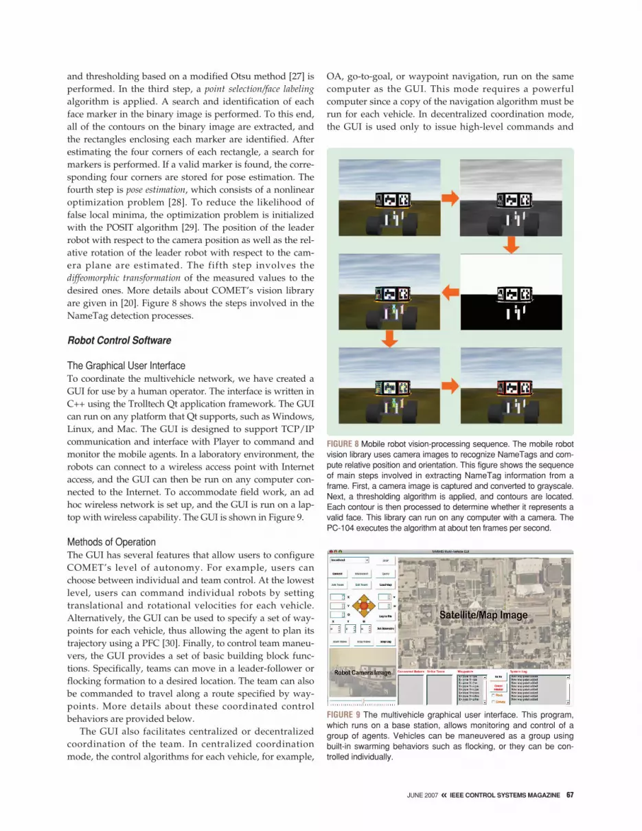
and thresholding based on a modified Otsu method [27] isperformed. In the third step, a point selection/face labelingalgorithm is applied. A search and identification of eachface marker in the binary image is performed. To this end,all of the contours on the binary image are extracted, andthe rectangles enclosing each marker are identified. Afterestimating the four corners of each rectangle, a search formarkers is performed. If a valid marker is found, the corre-sponding four corners are stored for pose estimation. Thefourth step is pose estimation, which consists of a nonlinearoptimization problem [28]. To reduce the likelihood offalse local minima, the optimization problem is initializedwith the POSIT algorithm [29]. The position of the leaderrobot with respect to the camera position as well as the rel-ative rotation of the leader robot with respect to the cam-era plane are estimated. The fifth step involves thediffeomorphic transformation of the measured values to thedesired ones. More details about COMET’s vision libraryare given in [20]. Figure 8 shows the steps involved in theNameTag detection processes.
Robot Control Software
The Graphical User InterfaceTo coordinate the multivehicle network, we have created aGUI for use by a human operator. The interface is written inC++ using the Trolltech Qt application framework. The GUIcan run on any platform that Qt supports, such as Windows,Linux, and Mac. The GUI is designed to support TCP/IPcommunication and interface with Player to command andmonitor the mobile agents. In a laboratory environment, therobots can connect to a wireless access point with Internetaccess, and the GUI can then be run on any computer con-nected to the Internet. To accommodate field work, an adhoc wireless network is set up, and the GUI is run on a lap-top with wireless capability. The GUI is shown in Figure 9.
Methods of OperationThe GUI has several features that allow users to configureCOMET’s level of autonomy. For example, users canchoose between individual and team control. At the lowestlevel, users can command individual robots by settingtranslational and rotational velocities for each vehicle.Alternatively, the GUI can be used to specify a set of way-points for each vehicle, thus allowing the agent to plan itstrajectory using a PFC [30]. Finally, to control team maneu-vers, the GUI provides a set of basic building block func-tions. Specifically, teams can move in a leader-follower orflocking formation to a desired location. The team can alsobe commanded to travel along a route specified by way-points. More details about these coordinated controlbehaviors are provided below.
The GUI also facilitates centralized or decentralizedcoordination of the team. In centralized coordinationmode, the control algorithms for each vehicle, for example,
OA, go-to-goal, or waypoint navigation, run on the samecomputer as the GUI. This mode requires a powerfulcomputer since a copy of the navigation algorithm must berun for each vehicle. In decentralized coordination mode,the GUI is used only to issue high-level commands and
FIGURE 8 Mobile robot vision-processing sequence. The mobile robotvision library uses camera images to recognize NameTags and com-pute relative position and orientation. This figure shows the sequenceof main steps involved in extracting NameTag information from aframe. First, a camera image is captured and converted to grayscale.Next, a thresholding algorithm is applied, and contours are located.Each contour is then processed to determine whether it represents avalid face. This library can run on any computer with a camera. ThePC-104 executes the algorithm at about ten frames per second.
FIGURE 9 The multivehicle graphical user interface. This program,which runs on a base station, allows monitoring and control of agroup of agents. Vehicles can be maneuvered as a group usingbuilt-in swarming behaviors such as flocking, or they can be con-trolled individually.
JUNE 2007 « IEEE CONTROL SYSTEMS MAGAZINE 67

monitor the state of the multivehicle system. Each vehiclecomputes and executes its own controller based on themission at hand. Navigation and OA are also executedlocally on the agent’s onboard computer. Instead of send-ing a large amount of real-time control data, the GUI com-municates only waypoints to the vehicles.
Finally, the GUI provides the user with advancedmonitoring capabilities. When a map of the environmentis supplied, the interface shows the location of eachrobot as well as the robot’s proximity to obstacles. Whena robot moves in the real world, the interface shows amoving icon on the map. The GUI can display moredetailed information about any individual agent, includ-ing its position, orientation, and velocity. To supportreconnaissance missions, live video from any agentequipped with a camera can be viewed. Users can panthe camera to view objects that are not directly in frontof the vehicle. However, the video transfer makes heavyuse of the network.
Levels of AutonomyAs mentioned above, the level of autonomy of COMETdepends on how the team is configured by the GUI tooperate. For example, to run in centralized coordinationmode, the robots must stay in contact with the GUI. Indecentralized mode, however, the GUI might disconnectafter uploading a mission to the robots. Also, when teammaneuvers are requested, the robots exercise greaterautonomy than when the user specifies waypoints foreach vehicle. The tradeoffs relate to the amount of userinput and scope of operation. When the robots actautonomously, the user has less finely tuned controlover their actions, although entering control commandsis less of a burden. On the other hand, commandingeach robot is time consuming but allows for precise con-trol. Also, when the robots act autonomously, they cancarry out missions in areas where communication is lim-ited. The major disadvantage is that the user loses theadvanced monitoring capabilities of the GUI.
BASIC CONTROL BEHAVIORSThis section describes basic control behaviors that areimplemented on COMET. These behaviors can be com-bined in parallel or sequentially to create more complexswarming behaviors. The algorithms are implementedwith C++ control functions and run in Linux on the PC-104 computers. Player is used to interface with the vehi-cle’s hardware. Thus, the behavior implementations aresubject to the networking delays and sampling timerestrictions of the CANBus as well as the sensors andactuators described above.
Go-To-GoalThe go-to-goal behavior is based on a PFC algorithm.PFCs use an attractive potential, which allows the
agents to move to a specific location. A PFC can be usedfor feature tracking, leader-following, waypoint track-ing, or any other application in which a vehicle needs toreach a designated goal. The artificial potential Pa(xi, yi)
is given by [30]
Pa(xi, yi) = 12ε[(xi − xg)
2 + (yi − yg)2],
where (xi, yi) is the position of agent i, ε is a positive con-stant, and (xg, yg) is the position of the goal. The attractiveforce, Fa(xi, yi), can be expressed as
Fa(xi, yi) = −∇Pa(xi, yi) = −[ ∂Pa
∂xi∂Pa∂yi
],
which yields
Fa(xi, yi) = ε
[xg − xiyg − yi
]
[Fa,xi
Fa,yi
]. (7)
Based on the two values calculated in (7), the desired ori-entation angle
θi,d = arctan 2(Fa,yi, Fa,xi) (8)
can be determined, where arctan 2(·) in (8) represents thefour-quadrant inverse tangent of Fa,xi and Fa,yi . This func-tion uses the signs of these two values to remove the two-solution ambiguity normally associated with the inversetangent of Fa,yi/Fa,xi .
After the orientation relative to the goal is calculated,the proportional controller
ωi = ±k (θi,d − θi),
where k = (ωmax/2π) s−1 and ωmax = 0.4 rad/s, is used toalign the vehicle with the desired heading. The transla-tional speed of the vehicle while executing the PFC mayvary. In some applications such as feature detection, thisspeed can be held constant. In other applications such asgoal seeking, the speed of the vehicle depends on thedistance to the goal. In leader-follower applications, thespeed of the leader is used as a feedforward term toincrease system robustness.
This behavior has several limitations that must beconsidered. When using the PFC together with a nonho-lonomic vehicle, the robot may begin to circle aroundits goal position. This behavior occurs because noise inthe odometry can cause the robot’s position estimate toshift laterally, and thus the robot must circle around tocorrect the error. This problem can be solved by includ-ing a threshold in the potential Pa such that the robot
68 IEEE CONTROL SYSTEMS MAGAZINE » JUNE 2007

does not move when Pa is below a cer-tain value. Additionally, since the go-to-goal behavior does not considerobstructions in the environment, colli-sions can occur. Go-to-goal behavior canbe coupled with OA to overcome thisproblem as described in the followingsubsections.
Obstacle AvoidanceOA is a basic building block ofautonomous robotic systems [31]. The OAbehavior can be seen as part of a hierar-chical hybrid system [32], which com-bines both continuous and discrete states.A common technique is to define OA as adiscrete control state. When the robotdetects an object that iscloser than a thresholdvalue, the OA state isused. The hybrid automa-ton shown in Figure 10illustrates this idea. OAmakes operating the robotsafer by using sonar or IRsensors to detect andavoid obstacles. In ourimplementation of OA, theagent uses two CAN-enabled IR arrays locatedat the front of the vehiclebody. Since each CAN-enabled IR array has threeIR sensors, six IR sensorsare available. These sen-sors are numbered from 0to 5 as shown in Figure 11.Much like the PFC, thisalgorithm begins by com-puting a set of virtualforces. In this case, the vir-tual right and left forcesare repulsive and are cal-culated based on four IR sensor readings as
Fr =2∑
n=1
λn
dn,
Fl =4∑
n=3
λn
dn,
where dn is the distance to the obstacle reported by thenth sensor and λn is a scaling factor applied to each IRsensor’s distance measurement. In other words, λn deter-mines the weight of each sensor in controlling the robot.
After extensive experimental testing, we chose the valueλn = [0.7, 0.9, 1.0, 0.7], which weighs the repulsive force infavor of objects directly in front of the robot.
The OA controller is a hybrid controller with twodiscrete states. The algorithm tracks the contour of anobstacle if the obstacle is in the way of the designatedgoal, but not directly in front of the vehicle. In this con-tour tracking state, OA uses the proportional controller
ωci =
kp(d5 − Dsafe), if the obstacle is on the left,kp(Dsafe − d0), if the obstacle is on the right,
FIGURE 11 (a) Top-front view of vehicle. (b) Infrared sensor coverage diagram. Infrared sensors are usedfor OA and contour following. Two infrared arrays are mounted at the front of each robot. Each arrayprovides distance-to-obstacle information straight ahead, at a 45° angle, and at a 90° angle.
0 1
2
Stereo C
amera
5
3
4
GPS
IR-Left
IR-Right
d5
d3
d4
d2
d1
d0
(a) (b)
FIGURE 10 OA behavior in a hybrid system. In this system, OA is used when an obsta-cle is detected nearer to the robot than a threshold value. Otherwise, the behaviorsthat comprise the robot’s current task are run.
Task Components
Behavior Behavior
Robot Task
ObstacleDetected == True
Obstacle Avoidance
ContourFollowing
CollisionAvoidance
ObstacleDetected == False
Obstacle at Side
Obstacle Straight Ahead
Behavior
JUNE 2007 « IEEE CONTROL SYSTEMS MAGAZINE 69

where kp is constant gain and Dsafe is the constant distanceat which the perimeter of the obstacle is tracked. This dis-tance is set to 0.2 m. The contour tracking speed isvOA = 0.6 m/s. When an obstacle is directly in front andmust be avoided, the OA controller enters a collision-avoidance state and calculates the translational and rota-tional velocities as
vci = vOA − kvp
4∑
n=1
λn
dn,
ωci = kωp(Fl − Fr),
where kvp and kωp are control constants, and vOA is areduced contour tracking velocity. Once the obstacle is nolonger directly in front, the controller switches to contourtracking, and the obstacle’s perimeter is tracked as before.The vehicle continues tracking the contour of the obstacleuntil the obstacle no longer obstructs the path to the goal.This condition is verified when the distance to the obstaclereported by sensors 1 or 4 (see Figure 11) are d1 ≥ ρ ord4 ≥ ρ , where ρ = 0.25 m. Once the obstacle is negotiated,the higher-level control continues operation.
Goal SeekingGoal seeking emerges from a combination of OA and go-to-goal behaviors using the hybrid architecture shown inFigure 10. The objective of this emergent behavior is todrive the agent to a designated waypoint without collidingwith obstacles. This behavior is useful since it enables thevehicle to travel autonomously. Goal seeking is includedas a fundamental block of the GUI. Figure 12 shows amobile agent at its initial position in a goal-seeking experi-
ment along with the trajectory that the agent follows whiletraveling to its goal.
Figure 13(a) shows the goal-seeking controller’s perfor-mance. Since the controller is hybrid, it switches betweenthe obstacle-avoidance states discussed above based on theproximity of obstacles in the environment. Figure 13(b)depicts the transition of the controller between the PFC,collision avoidance, and obstacle contour-tracking states.
MOTION-COORDINATION ALGORITHMSIn this section, we discuss several motion-coordinationalgorithms used on COMET. Some mathematical prelimi-naries are required. A multivehicle system can be consid-ered as a dynamic network in which each node representsa mobile agent (vehicle, mobile sensor, robot) with com-munication, sensing, and control capabilities. We considera dynamic network composed of N mobile agents thatshare a configuration space Q. Specifically, following [33],[34], a dynamic network of mobile agents is a tuple(I,A,Gc,Gs,H), where I = 1, . . . , N is the set of uniqueidentifiers representing agents in the network,A = (Xi, Ui, X0, fi)i∈I is a set of control systems (physicalagents), Gc = V, Ec is an undirected communicationgraph, where V is the set of nodes and Ec is the communi-cation edge map, and Gs = V, Es is a directed sensinggraph, where Es is the sensing edge map. Finally,H = V, Eh is a directed control graph with the set ofnodes V and the control edge map Eh.
Several graphs are needed to capture the interactionsof the agents within the network and environment. Insome cases, agents can hear but not see each other. Thedesign of the control graph H involves the assignmentof control policies for each agent. The set Eh is related to
70 IEEE CONTROL SYSTEMS MAGAZINE » JUNE 2007
FIGURE 12 (a) Starting position for a goal-seeking experiment. (b) Agent trajectory to goal. The designated goal is located at (11 m, 5.5 m) aroundthe corner in the hallway. As soon as the goal-seeking behavior starts, the potential field controller begins aligning the vehicle toward the goal.
0 2 4 6 8 10 120
1
2
3
4
5
6
X [m]
Y [m
]
(a) (b)

the communication Ec and sensing Es graphs. An edgebetween two nodes in the control graph can be createdonly if a communication edge or sensing edge exists.Moreover, agents can be modeled as hierarchical hybridsystems [32] that can exchange data that affect theircontinuous-time motions at discrete-time instants. Fig-ure 14 illustrates how the notation above can describe adynamic network of vehicles executing a formationcontrol task.
For a dynamic network performing a cooperativetask, a motion-coordination algorithm is the control, sens-ing, and communication law that accomplishes the giventask. In the discussion that follows, we assume that allrobots are modeled using the model (1), (2), and (4). Thismodel defines Xi, Ui, and fi for each agent i in the set A.Several motion-coordination algorithms that are imple-mented on COMET are described.
Formation ControlMany natural systems such as swarms, schools, and flocksexhibit stable formation behaviors [35]. In these systems,individuals follow distant leaders without colliding withneighbors. In some application domains, a group of agentsneed to move as a rigid structure. Also, in practical situationssuch as cooperative manipulation, a target formation mustbe established for a given task or environment. In thesecases, reconfiguration of agents in formation is required [24].
Formation control is useful when a network of mobileagents is required to follow a prescribed trajectory g(t)while achieving and maintaining a desired formationshape F d [36], [37]. A formation shape F is described bythe relative positions of the agents with respect to a refer-ence coordinate frame. Let the Euclidean distance
ij(t) ∈ [0,∞) and the bearing ψij(t) ∈ (−π, π] betweenagents i and j be defined as
ij(t) :=√
(xi − xj)2 + (yi − yj)
2, (9)
ψij(t) := π + ζij(t) − θi(t), (10)
with ζij(t) = arctan 2(yi − yj, xi − xj), as shown in Figure 15.The following definition is based on [38].
Definition: A formation is a network of N vehicles interconnected by means of a collection S = sij of nodespecifications
sij(t) := [ij(t) ψij(t)]T,
where i, j ∈ I , and ij and ψij are the separation distanceand bearing angle between vehicles i and j, respectively.
FIGURE 13 (a) Goal-seeking experiment vehicle speed plot. (b) State plot. The goal-seeking behavior uses a hybrid controller that switchesbetween potential-field control, contour tracking, and collision avoidance states as obstacles are encountered and negotiated. During thegoal-seeking experiment, the vehicle’s speed fluctuates as the controller switches between states while the robot travels toward its goal.
0 10 20 30 40−0.5
0
0.5
1
Time [s]
Tran
slat
iona
l Spe
ed [m
/s]
SetpointRobot Speed
0 10 20 30 40
PFC
CT
CA
Time [s]
Sta
te
(a) (b)
FIGURE 14 A dynamic network for formation control. Eachvehicle, which is assigned a unique identifier in the set I ,serves as a node V in the communication Gc, sensing Gs, andcontrol H graphs. For simplicity, only the directed control graphH = V, Eh is shown. To complete the definition of , the set ofcontrol systems A must be specified.
35
4
1
2
6
JUNE 2007 « IEEE CONTROL SYSTEMS MAGAZINE 71

An element sij(t) ∈ S indicates the relative position vectorthat follower agent j maintains with respect to its leaderagent i. The interconnections between agents are modeledas edges in the directed control graph H described aboveand shown in Figure 14.
Note that a desired formation shape F d is mapped intoa collection Sd = sd
ij of node specifications, where sdij
defines a desired separation dij and bearing ψ d
ij for followeragent j with respect to its leader agent i. Both communica-tion-based and vision-based formation control techniqueshave been implemented on COMET. These algorithms arediscussed below.
Vision-Based Formation ControlLet us consider a vehicle formation in which a leadvehicle is teleoperated or is required to follow a giventrajectory. To implement a formation controller, eachrobot with the possible exception of the lead robot musthave information about the relative location of at leastone of its neighbors. This information can either begathered through communication, if an edge exists inGc, or sensing, if an edge exists in Gs. Here, we assumethat intervehicle communication is disabled and thusno edges exist in the communication graph Gc. Howev-er, an edge exists in the sensing graph Gs from nodes ito j whenever agent i recognizes the NameTag of robotj. COMET uses a decentralized vision-based formation-control strategy that requires knowledge of only leader-follower relative distances and bearing angles. Thesedata are estimated based on measurements from thepan-controlled cameras on board each vehicle. Theremainder of this subsection gives an overview of theformation control strategy.
Let the node specification sij(t) ∈ R × (−π, π] of agent jbe given by (11). Differentiating sij using (9) and (10), therelative kinematic model becomes
ij = vj cos γ − vi cos ψij,
ψij = vi sin ψij − vj sin γ
ij− ωi,
γ = ψij + θi − θj,
where vi and ωi are the leader’s translational and rotation-al velocities, respectively. Similarly, the follower’s transla-tional and rotational velocities are denoted by vj and ωj,respectively. The value γ is an auxiliary relative angle, andthe values ij, ψij, θi, θj are defined in Figure 15. In matrixform, we have
sij =[
ijψij
]=
[cos γ 0− sin γ
ij0
]uj +
[− cos ψij 0sin ψij
ij−1
]ui.
The objective is to design a control lawuj(t) = [vj ωj]T that allows agent j to track agent i witha desired specification sd
ij(t), assuming that agent i is sta-bly tracking a desired trajectory g(t) with smooth,bounded inputs ui(t) = [vi ωi]T . To solve this problem,a high-gain observer is used to estimate the derivativesof the vehicles’ relative positions [39].
Communication-Based Formation ControlIn communication-based formation control, vehicles followeach other based on their position relative to a commonworld frame. This behavior requires that each vehicle com-municate its position to its neighbors. A robot in the for-mation is designated as the lead vehicle. The lead vehiclecan be driven by a high-level controller or teleoperatedthrough the GUI. Each one of the other robots is pro-grammed to follow the location communicated by a prese-lected neighboring robot. This technique requires that anedge be maintained in the communication graph Gc
between two robots in a leader-follower configuration.Sensing is not used,and thus no edgesexist in Gs. Communi-cation-based follow-ing is useful in urbanenvironments, wherethe leader agentmight not be visibleat all times. The suc-cess of the techniquedepends on the accu-racy of the position-estimation system.Additionally, thevehicles must sharean absolute positionreference frame. Fig-ure 16 depicts agroup of TXT vehicles
FIGURE 15 (a) Formation geometry diagram. (b) A leader-follower experiment. Each agent calculates the posi-tion of the vehicle directly in front of it and follows that vehicle in formation. The controller specification for robotj indicates the separation distance ij and bearing angle ψij to be maintained with respect to its leader vehicle i .The lead agent is teleoperated.
XE
YE
Agent j
Agent i
θj
(a) (b)
ψij
θi
ij
ζij
72 IEEE CONTROL SYSTEMS MAGAZINE » JUNE 2007

changing from a convoy formation to a V-like formationand returning to a convoy formation.
FlockingThe mechanisms through which natural systems movetogether in a decentralized, coordinated manner is aresearch topic in biology, mathematics, and controls.Flocking is a collective behavior that emerges when a largenumber of mobile agents with a common goal [22] interactwith each other to reach a consensus state in their headingangles and intervehicle separation distances [40]. A simpleflocking model is discussed in [41], where several agentstravel at the same speed. Each agent aligns its headingbased on the average of its heading and the heading of itssurrounding neighbors. Despite the absence of a central-ized coordination algorithm, the group aligns itself in thesame direction, and flocking behavior emerges. A theoreti-cal explanation for this behavior is presented in [42].
The model described in [41] is implemented onCOMET, where each agent is aware of the heading ofits neighboring peers. A local PI controller enforcesthe neighboring rule that aligns the agent’s headingaccording to
θi(t + 1) = 11 + ni(t)
θi(t) +
∑j∈Ni(t)
θj(t)
, (11)
where θi is the heading of agent i, and ni(t) is the number ofneighbors that can be heard or seen by agent i at time t. Also,all of the vehicles are commanded to maintain the sametranslational speed vc
I(t). Although OA is active, the imple-mentation is tested in an obstacle-free environment. Figure17 shows a five-agent team in which one of the robots fol-lows a set of waypoints to provide direction for the flock.The remaining robots use the alignment rule (11) to success-fully navigate together through the desired waypoints.
Perimeter Detection and TrackingWe now describe a decentralized coordination algorithmthat allows a mobile sensor network to find and track adynamic perimeter. A perimeter can be a chemical substancespill, building, or landmark. We assume that each agent isequipped with an appropriate sensor to detect the perimeter.As before, we consider a network of N mobile agents, eachmodeled with the unicycle model with control inputuc
i = [vci ωc
i ]T ∈ U, where U is a bounded, convex set.
FIGURE 16 (a) Communication-based formation control experiment. (b) Vehicle paths. In this experiment, the vehicles change formationswhile traveling to a goal. The red triangles in (b) represent the vehicles’ starting positions in a convoy formation. Later they assume a V-likeformation as shown in (a) and by the blue triangles in (b). Finally, the robots return to a convoy formation. The maneuver is based on odom-etry and intervehicle communications.
(b)(a)
4
3
2
1
0
−1
−2
−3
−4
Y [m
]
0 5 10 15 20 25 30 35
X [m]
JUNE 2007 « IEEE CONTROL SYSTEMS MAGAZINE 73
When a group of mobile agents attempts to perform a coordinated behavior,
each agent in the group must identify its neighbor agents and estimate
their positions and orientations.

We define a convex polygonal searching area S ⊂ R2
with boundary ∂S containing a target region ⊂ Swith perimeter ∂. The robots are initially placed in theenvironment at random locations (xi, yi) ∈ S \ , asshown in Figure 18(a). Also, agents can communicatewith other members of the team at discrete t imeinstants. Finally, we assume that each agent has a limit-ed field of view and limited communication range.Now we state the perimeter-detection and trackingproblem as follows.
Perimeter Detection and Tracking ProblemGiven a dynamic network of N mobile sensors random-ly distributed in a planar polygonal environment S ,determine a motion-coordination algorithm such that theteam detects and tracks a perimeter ∂ defined by a targetregion while avoiding intervehicle collisions.
To solve this problem, we implement a motion-coordi-nation algorithm composed of a random-coverage con-troller to start the search for the perimeter, a PFC(discussed above) to attract agents to a known perimeter
74 IEEE CONTROL SYSTEMS MAGAZINE » JUNE 2007
FIGURE 18 (a) Perimeter-detection experiment. (b) Agent paths. The random-coverage controller commands the agents in a spiral searchpath looking for the perimeter. A blobfinder, part of the vision library, uses the onboard camera to detect and track the perimeter. Once anagent finds the perimeter, the blobfinder-based tracking controller tracks it.
∂
∂Ω
Ω
2 3 4 5 6 7 8 9 100
1
2
3
4
5
6
7
8
9
X [m]
Y [m
]
R1R2R3
(a) (b)
Perimeter
Boundary
FIGURE 17 (a) Flocking experiment. (b) Agent paths. This figure shows a flocking experiment with five robots. The triangles in (b) representthe robots’ starting positions. In pure flocking, each agent runs the same controller and calculates its speed based on the speeds of neigh-boring agents. During this modified flocking experiment, one of the agents (red path) follows a set of waypoints to provide direction for theflock. The remaining robots use the flocking controller presented in this article, and the team successfully travels together through thedesired waypoints.
(a) (b)
14
12
10
8
6
4
2
0
−2
Y [m
]
2 4 6 8 10 12 14 16 18 20
X [m]

boundary point, and a tracking controller to track theperimeter. The agents coordinate their efforts to locate theperimeter. Once an agent finds the perimeter containingthe target region, the agent broadcasts its position to allrobots within range. As each robot receives the message, itstarts the PFC to reach the perimeter location and retrans-mits the received message, creating a communicationrelay. Additionally, OA is active in the backgroundthroughout the execution of the algorithm to prevent colli-sions. The goal of this algorithm is to use a multiroboticsystem to estimate a dynamic perimeter as it evolves.Once an estimate of the perimeter is known, cooperationcan be used to uniformly surround the target region [43].Figure 18 shows the algorithm in operation.
A TARGET-ASSESSMENT CASE STUDYThis section demonstrates how COMET might be used inthe real world for surveillance or target assessment. Theexperiment uses basic behaviors, motion-coordinationalgorithms, and the GUI described previously. Figure 19shows the site where the experiment is conducted.
The three phases that comprise the mission includesecuring the path, driving to the target, and encircling thetarget. These steps illustrate the modes of operation andlevels of autonomy discussed in the Robot Control Soft-ware section above.
Securing the PathFor the convoy to travel safely, the path must be secured.When the mission begins, two scout agents position them-selves at tactical locations to survey the path. Figure 19shows those locations, which are labeled as the surveil-
lance points. Each scout is commanded to its surveillancepoint using a series of waypoints. Figure 20(a) shows thefirst scout robot traveling to its surveillance points. Oncethe surveillance point is reached, the scout agent pans itscamera to provide a panoramic view as shown in Figure20(b). The user determines whether the path is safe basedon this video feedback. Graphs showing the first scoutagent’s trajectory, speed, and state as it travels are provid-ed in Figure 21.
After the first scout reaches the first surveillance loca-tion, the second scout drives farther into the preselectedconvoy path. Like the first scout, its function is to monitorthe area and provide video surveillance feedback.
JUNE 2007 « IEEE CONTROL SYSTEMS MAGAZINE 75
FIGURE 20 (a) Scout 1 in operation. (b) Graphical user interface control of Scout 1. The multivehicle graphical user interface is used to con-trol the surveillance operation. This task is accomplished by sending waypoints to the vehicles. Using the camera view in the lower left handcorner of (b), the user verifies that the path is safe.
(a)
(b)
Clark
Connect
Join Team
Disconnect Query
Stop
Load MapExit Team
X
X Y θ
Y
θ
v
w
Log to File
Set Odometry
Stop LogStop VideoStart Video
Clark Clark
Connected Robots Strike Team Waypoints System Log
New Map LoadedVideo Feed StoppedVideo Feed StoppedNew Way Point AddedNew Way Point AddedNew Way Point AddedNew Way Point Added
Go To
CancelMission
Flock
Convoy
X = 26 m Y = 3 mX = 24 m Y = 1 mX = 24 m Y = 0 mX = 22 m Y = −1 m
MARHES Multi-Vehicle GUI
o o o
FIGURE 19 A target-assessment mission. A team of six robotsis commanded to approach a target and relay camera imagesthat allow the user to assess the target’s condition. Initially,two scout robots inspect the path to ensure its safety. The fourremaining robots then proceed in formation to the target andsend back images.
Target
SurveillancePoint #2
SurveillancePoint #1
Convoy Route
Convoy
Scout#2
Scout#1

Driving to the TargetOnce the path is known to be safe, the convoy is com-manded to go to the target location. The convoy is com-posed of one leader agent and three followers, as shownin Figure 22. The first agent in the convoy is providedwith a series of waypoints to reach the target. The remain-ing agents follow the leader, executing a communication-based leader-follower operation.
Encircling the TargetOnce the convoy has reached the vicinity of the target, eachvehicle is commanded to a new location. This operation isbased on a series of preselected waypoints that guide the robotto a particular location near the target as shown in Figure 23(a).The objective of this rearrangement is to provide the user witha diverse view of the target. The user can now, by means ofremote video [see Figure 23(b)], assess the target condition.
CONCLUSIONSA scalable multivehicle platform has been developed todemonstrate cooperative control systems and sensor net-works. Major features of this platform include high flexi-bility to varying sensor configurations, with a pool ofhot-swappable sensors that can be added or removed onthe fly, and a modular framework for integrating sensingand control capabilities. The platform is compatible withPlayer and Gazebo, which makes it easily accessible andoffers the benefit of a simulation environment with fullsensor support. The software library gives developers abasic set of building blocks for more complex algorithms.
Currently, we are adding motion-coordination algorithmsto the library of team controllers. These algorithms includedeployment, rendezvous [44], perimeter estimation and pat-tern formation [45], and dynamic target tracking [46]. We arealso exploring alternative methods, such as machine learning[47] and optimal formation shape changes [48], to improvethe performance of existing motion-coordination algorithms.
76 IEEE CONTROL SYSTEMS MAGAZINE » JUNE 2007
FIGURE 22 The convoy proceeds. The lead robot travels autonomous-ly through the preassigned waypoints. Using communication, theother robots follow the leader in a line. Each follower attempts to driveat a safe distance from its preassigned leader. The robots safely tra-verse the path in formation.
FIGURE 21 (a) Scout 1 position plot. (b) Scout 1 translational velocity and state plots. The first scout vehicle encounters an obstacle in thepath, avoids it successfully, and positions itself at the surveillance point. The commanded and actual translational speeds are shown. Thestate diagram shows when the system switches from goal seeking to OA.
0 2 4 6 8 100
2
4
6
8
10
X [m]
Y [m
]
Obstacle
0 10 20 30 40 50
−0.2−0.1
00.10.20.30.4
Spe
ed [m
/s]
Time [s]
Time [s]0 10 20 30 40 50
−0.5
0
0.5
1
1.5
Sta
te
PFOA
(a) (b)

Additionally, new sensing devices and drivers are beingadded to the suite of onboard, hot-swappable embedded sen-sors. These devices include NorthStar localization systemsfrom Evolution Robotics, environmental wireless sensorsfrom Moteiv, and fisheye lens cameras.
COMET provides a comprehensive research and educa-tional tool, allowing students to learn hardware and soft-ware design for embedded computer systems and becomefamiliar with cutting-edge computer-controlled design andmanufacturing technology. Additionally, COMET pro-vides researchers in cooperative and distributed controlwith an interdisciplinary environment to integrate embed-ded sensing, hybrid control, and communication networks.
ACKNOWLEDGMENTSThe authors would like to thank the anonymous reviewersfor providing useful comments and suggestions thatimproved the presentation of this paper. We also thank
Justin Clark for his work in perimeter detection, Rahul Bud-dhisagar for his effort assisting in the development of thegraphical user interface, Chris Flesher for his work in com-puter vision, and Colby Toland and Kyle Hutchins for theirefforts in tuning the PID controllers. This work is supportedin part by NSF grants #0311460 and CAREER #0348637 andby the U.S. Army Research Office under grant DAAD19-03-1-0142 (through the University of Oklahoma).
REFERENCES[1] D. Hristu-Varsakelis and W.S. Levine, Eds., Handbook of Networked andEmbedded Control Systems (Control Engineering series). Cambridge, MA:Birkhäuser, 2005.[2] Y. Cao, S. Fukunga, and A. Kahng, “Cooperative mobile robotics:Antecedents and directions,” Autonomous Robots, vol. 4, no. 1, pp. 1–23, 1997.[3] Marhes multimedia, Jan. 2007 [Online]. Available: http://marhes.okstate.edu/multimedia.htm[4] Z. Jin, S. Waydo, E.B. Wildanger, M. Lammers, H. Scholze, P. Foley, D.Held, and R.M. Murray, “MVWT-II: The second generation caltech multi-vehicle wireless testbed,” in Proc. American Control Conf., Boston, MA, June2004, vol. 6, pp. 5321–5326.[5] V. Vladimerou, A. Stubbs, J. Rubel, A. Fulford, and G. Dullerud, “Multi-vehicle systems control over networks,” IEEE Control Syst. Mag., vol. 26, no.3, pp. 56–69, June 2006.[6] E. King, Y. Kuwata, M. Alighanbari, L. Bertuccelli, and J. How, “Coordi-nation and control experiments on a multi-vehicle testbed,” in Proc. AmericanControl Conf., Boston, MA, June 2004, vol. 6, pp. 5315–5320.[7] L. Chaimowicz, B. Grocholsky, J.F. Keller, V. Kumar, and C.J. Taylor,“Experiments in multirobot air-ground coordination,” in Proc. IEEE Int. Conf.Robotics Automation, New Orleans, LA, Apr. 2004, vol. 4, pp. 4053–4058.[8] B. Grocholsky, J. Keller, V. Kumar, and G. Pappas, “Cooperative air andground surveillance,” IEEE Robot. Automat. Mag., vol. 13, no. 3, pp. 16–26,Sept. 2006.[9] R. D'Andrea and M. Babish, “The RoboFlag testbed,” in Proc. AmericanControl Conf., Boston, MA, June 2004, vol. 1, pp. 656–660.[10] T.W. McLain and R.W. Beard, “Unmanned air vehicle testbed for coop-erative control experiments,” in Proc. American Control Conf., Boston, MA,June 2004, vol. 6, pp. 5327–5331.[11] T. Balch and R. Arkin, “Behavior-based formation control for multirobotteams,” IEEE Trans. Robot. Automat., vol. 14, no. 46, pp. 926–939, Dec. 1998.[12] M. Egerstedt, Control of Autonomous Mobile Robots (Control Engineeringseries), D. Hristu-Varsakelis and W. Levine, Eds. Cambridge, MA:Birkhäuser, 2005.[13] P. Ögren, E. Fiorelli, and N.E. Leonard, “Cooperative control of mobilesensor networks: Adaptive gradient climbing in a distributed environment,”IEEE Trans. Automat. Contr., vol. 49, no. 8, pp. 1292–1302, Aug. 2004.[14] K. Kyriakopoulos, P. Kakambouras, and N. Krikelis, “Navigation ofnonholonomic vehicles in complex environments with potential fields andtracking,” in Proc. IEEE Int. Conf. Robotics Automation, Minneapolis, MN,Apr. 1996, pp. 2968–2973.[15] J. Sanchez and K. Walling. MARHES TXT-1 CAN bus control unit, July2004 [Online]. Available: http://marhes.okstate.edu/CAN\_control\_unit.htm[16] B. Gerkey, R.T. Vaughn, and A. Howard, “The Player/Stage project:Tools for multi-robot and distributed sensor systems,” in Proc. 11th Int. Conf.Advanced Robotics, Coimbra, Portugal, June 2003, pp. 317–323.[17] K. Etschberger, Controller Area Network: Basics, Protocols, Chips and Appli-cations. Weingarten, Germany: IXXAT Press, 2001.[18] A. De Luca, G. Oriolo, and C. Samson, “Feedback control of a nonholo-nomic car-like robot,” in Robot Motion Planning and Control, J.-P. Laumond,Ed. London, U.K.: Springer-Verlag, 1998, pp. 171–253.[19] L. Ojeda, D. Cruz, G. Reina, and J. Borenstein, “Current-based slippagedetection and odometry correction for mobile robots and planetary rovers,”IEEE Trans. Robot. Automat., vol. 22, no. 2, pp. 366–378, Apr. 2006.[20] O. Orqueda, “Vision-based control of multi-agent systems,” Ph.D. dis-sertation, Oklahoma State Univ., Stillwater, OK, Dec. 2006 [Online]. Avail-able: http://marhes.okstate.edu/dissertations/orqueda_06.pdf[21] L. Mirkin and Z.J. Palmor, “Control issues in systems with loop delays,”in Handbook of Networked and Embedded Control Systems, D. Hristu-Varsakelisand W. S. Levine, Eds. Cambridge, MA: Birkhäuser, 2005, pp. 627–649.
JUNE 2007 « IEEE CONTROL SYSTEMS MAGAZINE 77
FIGURE 23 (a) Trajectory of the team of mobile agents. (b) Target-assessment pictures. Following the paths shown, the team success-fully assumes positions around the target. Images from the cameraon each agent are shown. The user’s target assessment is basedon these images.
−10 0 10 20 30 40−10
−8
−6
−4
−2
0
2
4
6
8
10
X [m]
Y [m
]
(a)
(b)

[22] R. Olfati-Saber, “Flocking for multi-agent dynamic systems: Algorithms andtheory,” IEEE Trans. Automat. Control, vol. 51, no. 3, pp. 401–420, Mar. 2006.[23] R. Fierro, A. Das, V. Kumar, and J.P. Ostrowski, “Hybrid control of for-mations of robots,” in Proc. IEEE Int. Conf. Robotics Automation, Seoul, Korea,May 2001, pp. 157–162.[24] R. Fierro, L. Chaimowicz, and V. Kumar, “Multi-robot cooperation,” inAutonomous Mobile Robots: Sensing, Control, Decision Making and Applications(Control Engineering series), S.S. Ge and F.L. Lewis, Eds. New York: Taylor& Francis, 2006, ch. 11, pp. 417–459.[25] D. Terzopoulos and R. Szeliski, “Tracking with Kalman Snakes” inActive Vision. Cambridge, MA: MIT Press, 1992, pp. 3–20.[26] P. Renaud, E. Cervera, and P. Martinet, “Towards a reliable vision-based mobile robot formation control,” in Proc. IEEE/RSJ Int. Conf. IntelligentRobots Systems, vol. 4, 2004, pp. 3176–3181.[27] N. Otsu, “A threshold selection method from gray-level histograms,”IEEE Trans. Syst., Man, Cybern., vol. 9, no. 1, pp. 62–66, 1979.[28] D. Lowe, “Fitting parameterized three-dimensional models to images,”IEEE Trans. Pattern Anal. Machine Intell., vol. 13, no. 5, pp. 441–450, 1991.[29] D. Oberkampf, D. DeMenthon, and L. Davis, “Iterative pose estimationusing coplanar feature points,” Comput. Vis. Image Understanding, vol. 63,no. 3, pp. 495–511, May 1996.[30] J.C. Latombe, Robot Motion Planning. Norwell, MA: Kluwer, 1991.[31] J. Borenstein and U. Raschke, “Real-time obstacle avoidance for non-point mobile robots,” SME Trans. Robot. Res., vol. 2, pp. 2.1–2.10, Sept. 1992.[32] R. Alur, T. Dang, J. Esposito, R. Fierro, Y. Hur, F. Ivancic, V. Kumar, I.Lee, P. Mishra, G. Pappas, and O. Sokolsky, “Hierarchical hybrid modelingof embedded systems,” in Embedded Software, (LNCS series 2211), T. Hen-zinger and C. Kirsch, Eds. New York: Springer-Verlag, 2001, pp. 14–31.[33] S. Martínez, F. Bullo, J. Cortés, and E. Frazzoli, “On synchronous robot-ic networks. Part I: Models, tasks and complexity notions,” in Proc. IEEEConf. Decision Control, European Control Conf., Seville, Spain, 12–15 Dec. 2005,pp. 2847–2852.[34] N.A. Lynch, Distributed Algorithms. San Mateo, CA: Morgan Kaufmann,1997.[35] J. Toner and Y. Tu, “Flocks, herds and schools: A quantitative theory offlocking,” Phys. Rev. E, vol. 58, no. 4, pp. 4828–4858, 1998.[36] G. Lafferriere, A. Williams, J. Caughman, and J. Veerman, “Decentral-ized control of vehicle formations,” Syst. Contr. Lett., vol. 54, no. 9, pp.899–910, Sept. 2005.[37] A.K. Das, R. Fierro, V. Kumar, J.P. Ostrowski, J. Spletzer, and C.J.Taylor, “A vision-based formation control framework,” IEEE Trans. Robot.Automat., vol. 18, no. 5, pp. 813–825, Oct. 2002.[38] H. Tanner, V. Kumar, and G. Pappas, “Leader-to-formation stability,”IEEE Trans. Robot. Automat., vol. 20, no. 3, pp. 443–455, June 2004.[39] O.A. Orqueda and R. Fierro, “Robust vision-based nonlinear formationcontrol,” in Proc. American Control Conf., Minneapolis, MN, 14–16 June 2006,pp. 1422–1427.[40] N. Moshtagh, A. Jadbabaie, and K. Daniilidis, “Distributed geodesiccontrol laws for flocking of nonholonomic agents,” in Proc. IEEE Conf. Deci-sion Control European Control Conf. (CDC-ECC'05), Seville, Spain, Dec. 2005,pp. 2835–2840.[41] T. Vicsek, A. Czirok, E.B. Jacob, I. Cohen, and O. Schochet, “Novel typeof phase transitions in a system of self-driven particles,” Phys. Rev. Lett., vol.75, pp. 1226–1229, 1995.[42] J.L.A. Jadbabaie and A.S. Morse, “Coordination of groups of mobileautonomous agents using nearest neighbor rules,” IEEE Trans. Automat.Contr., pp. 988–1001, 2003.[43] J. Clark and R. Fierro, “Cooperative hybrid control of robotic sensors forperimeter detection and tracking,” in Proc. American Control Conf., Portland,OR, 8–10 June 2005, pp. 3500–3505.[44] A. Ganguli, S. Susca, S. Martínez, F. Bullo, and J. Cortés, “On collectivemotion in sensor networks: sample problems and distributed algorithms,” inProc. IEEE Conf. Decision Control, Seville, Spain, Dec. 2005, pp. 4239–4244.[45] M.A. Hsieh and V. Kumar, “Pattern generation with multiple robots,” inProc. IEEE Int. Conf. Robotics Automation, Orlando FL, 15–19 May 2006, pp. 2442–2447.[46] T.H. Chung, J.W. Burdick, and R.M. Murray, “A decentralized motioncoordination strategy for dynamic target tracking,” in Proc. IEEE Int. Conf.Robotics Automation, Orlando, FL, May 2006, pp. 2416–2422.[47] M. Lomas, P. Vernaza, D. Lee, and V. Kumar, “Hill-climbing for poten-tial field based cooperative navigation,” in Proc. IEEE Int. Conf. RoboticsAutomation, Orlando, FL, May 2006, pp. 4318–4320.[48] J. Spletzer and R. Fierro, “Optimal position strategies for shape changes
in robot teams,” in Proc. IEEE Int. Conf. Robotics Automation, Barcelona,Spain, 18–22 Apr. 2005, pp. 754–759.
AUTHOR INFORMATIONDaniel Cruz received a B.S. degree in electronics engineer-ing from the Pontificia Javeriana University, Colombia in2001. He worked at the University of Michigan as aresearch investigator for two years and received a master’sdegree in electrical and computer engineering at Okla-homa State University, Stillwater in 2006. His areas ofinterest include positioning systems, mobile robot naviga-tion, and hardware integration.
James McClintock received a B.S. degree in electricalengineering from Oklahoma State University, Stillwaterin 2006. His research interests include cooperative controlof robotic systems and development of advanced robot-human interfaces. In 2004, he was awarded a NASA Okla-homa Space Grant Consortium research fellowship todevelop a robot-human interface for the Evolution Robot-ics Scorpion Robot. He is currently pursing a master’sdegree in electrical engineering at OSU.
Brent Perteet received a B.S. degree in electrical engi-neering from Oklahoma State University in 2005, where heis currently pursuing the M.S. degree in electrical engi-neering. His research interests include cooperative controlof robotic agents, strategies for pursuit-evasion and targettracking, embedded systems, and software engineering
Omar A.A. Orqueda received a B.S. degree in electronicsengineering from the Universidad Nacional del Sur, BahíaBlanca, Argentina. He received the Ph.D. in electrical engineer-ing from the School of Electrical and Computer Engineering,Oklahoma State University, Stillwater. His research interestsinclude distributed coordination of autonomous systems, arti-ficial vision, nonlinear control theory, and motion planning.
Yuan Cao received B.Eng. and M.S. degrees from Zhejiang University, Hangzhou, China. He is currentlypursuing a Ph.D. at the School of Electrical and ComputerEngineering, Oklahoma State University, Stillwater. Hisresearch interests include cooperative control of unmannedvehicles, estimation theory, and hybrid systems.
Rafael Fierro ([email protected]) received a M.Sc.degree in control engineering from the University of Bradford, England and a Ph.D. degree in electrical engineer-ing from the University of Texas at Arlington in 1990 and1997, respectively. From 1999 to 2001, he held a postdoctoralresearch appointment with the GRASP Lab, University ofPennsylvania. He is currently an assistant professor in theSchool of Electrical and Computer Engineering at OklahomaState University. His research interests include hierarchicalhybrid and embedded systems, optimization-based coopera-tive control, and robotics. He is the recipient of a FulbrightScholarship and a 2004 National Science FoundationCAREER Award. He can be contacted at the School of Electri-cal and Computer Engineering, Oklahoma State University,202 Engineering South, Stillwater, OK 74078-5032 USA.
78 IEEE CONTROL SYSTEMS MAGAZINE » JUNE 2007