darkening low-earth orbit satellite constellations: a review
TRANSCRIPT
Received January 31, 2022, accepted February 23, 2022, date of publication February 28, 2022, date of current version March 9, 2022.
Digital Object Identifier 10.1109/ACCESS.2022.3155193
Darkening Low-Earth Orbit SatelliteConstellations: A ReviewALI LALBAKHSH 1,2, (Member, IEEE), ANDREW PITCAIRN 3,KAUSHIK MANDAL 4, (Senior Member, IEEE),MOHAMMAD ALIBAKHSHIKENARI 5, (Member, IEEE),KARU P. ESSELLE 2, (Fellow, IEEE), AND SAM REISENFELD 1, (Life Member, IEEE)1School of Engineering, Macquarie University, Sydney, NSW 2119, Australia2School of Electrical and Data Engineering, University of Technology Sydney (UTS), Sydney, NSW 2007, Australia3Macquarie University College, Macquarie University, Sydney, NSW 2119, Australia4Institute of Radio Physics and Electronics, University of Calcutta, Kolkata 700073, India5Department of Signal Theory and Communications, Universidad Carlos III de Madrid, Leganés, 28911 Madrid, Spain
Corresponding author: Ali Lalbakhsh ([email protected])
This work was supported in part by Macquarie University; in part by the Australian Research Council Discovery Grants Scheme; and inpart by the Faculty of Engineering and Information Technology, University of Technology Sydney, Seed Grant.
ABSTRACT The proliferation of low-earth orbit (LEO) satellites and the LEO satellite internet will bea game-changer for the low-latency high-speed global internet. While this new generation of the satelliteinternet in conjunction with fifth generation network (5G) and sixth generation network (6G) enabledemerging technologies, such as precision farming and smart cities, it will bring new challenges, such assatellite collision, limited satellite lifespan, security concerns, and satellite brightness. This article discussesthe satellite brightness caused by LEO constellations that potentially affect the ongoing astronomical studies.It reviews the underlying contributors to the satellite brightness as well as the state-of-the-art technologiesproposed to mitigate this emerging challenge.
INDEX TERMS Low earth orbit satellites, satellite brightness, satellite internet, phased array antenna,brightness magnitude, satellite communication, SATCOM.
NOMENCLATUREAbbreviation Meaning5G 5th Generation mobile network.5G 5th Generation mobile network.LEO Low Earth Orbit.MEO Medium Earth Orbit.GEO Geosynchronous equatorial orbit.GPS Global positioning satellite.O3b Other 3 Billion.SES Société Européenne des Satellites.NOIR Lab National Optical Infrared
Astronomy Research Laboratory.m Meters.M Magnitued.ms Millisecond.Mbps Megabits per second.Gbps Gigabits per second.PSo Particle swarm optimisations.
The associate editor coordinating the review of this manuscript and
approving it for publication was Haipeng Yao .
I. INTRODUCTIONIn recent years, satellite internet has moved into the low earthorbit (LEO) arena, reducing latency, and increasing networkspeeds. Using several satellites in LEO, space players createconstellations of internet satellites to cover the earth fully.SpaceX’s Starlink network is the most developed of thesewith 1560 active satellites, as of 24 February 2022. Oth-ers include Telesat LEO, Amazon’s Project Kuiper, IridiumNEXT, Globalstar and OrbComm [1].
A constellation of satellites in LEO comes with manybenefits. Having a very high coverage percentage of theentire earth will help provide internet to remote areas toimprove education and communication where traditionalinternet access is very limited and unreliable. Reducedlatency will improve real-time communication speeds com-pared to traditional geosynchronous equatorial orbit (GEO)satellite internet. Running costs will be reduced due tothe minimal ground-based infrastructure required as futuresatellites will be fitted with optical inter-satellite links forcommunication between the satellites without using groundstations, further increasing data transfer speed [2], [3]. Such
VOLUME 10, 2022 This work is licensed under a Creative Commons Attribution 4.0 License. For more information, see https://creativecommons.org/licenses/by/4.0/ 24383
A. Lalbakhsh et al.: Darkening Low-Earth Orbit Satellite Constellations: A Review
TABLE 1. Speeds from different orbital heights.
constellations will play an essential role in emergency com-munications in regional areas and oceans where conventionalsatellite communications and other terrestrial technologiesare minimal [4], [5].
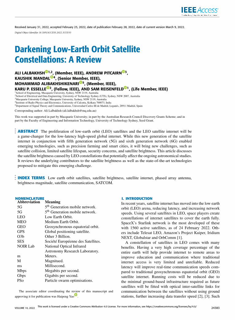
LEO satellite constellations can provide low latency, highbandwidth internet from an orbital height of 550 kilometers(km), significantly better than GEO internet satellites whichare stationed in a 35,786 km orbit [6], [7] to stay constantlyaligned with specific areas of the earth and have a muchhigher latency as well as lower bandwidth [8]. Table 1 showsa comparison of coverage and distance of GEO,medium earthorbit (MEO) and LEO Satellites.
Additionally, the LEO satellites can be de-orbited afterthey reach the end of life, another advantage over GEOtechnology. This helps in reducing the amount of space junkin orbit earth. Traditional GEO satellites are positioned intoa graveyard orbit when they retire, which is more efficientthan trying to deorbit it from its operating height [9]. Collisionavoidance is an important aspect of LEO satellite constella-tions. The orbital space around earth is becoming increasinglybusy with space junk, satellites, and other objects. Anothermajor concern is that too many satellites may induce theKessler effect, a cascading collision leading to a debris beltaround the earth, limiting our capabilities to launch rocketsinto orbit and beyond [10], [11]. As stated in [12], there areover 120 conjunctions in a 30-day period that cross the thresh-old for the current collision avoidance regulations as well as53 that cross the maneuver planning threshold that is used tocontrol the current density of LEO space. For this reason, acollision-avoidance system has been implemented ont o thesatellites to maneuver the satellite. Another key feature is tomake de-orbiting the satellites part of the satellite mission.When they reach their end of life, they complete a de-orbitburn, eventually burning up in the Earth’s atmosphere, furtherreducing the amount of space debris in orbit [13]–[15].
However, the LEO constellations require significantlymore satellites to provide the same coverage amount com-pared to a GEO constellation as shown in Fig. 1, [6], [16].
This increases the number of objects in the orbit, and withit brings new challenges, such as orbital collusion, limitedsatellite lifespan, security concerns associated with tens ofthousands of satellites, and satellite brightness. This reviewwill systematically discuss the underlying factors of LEOsatellite constellation brightness and the most recent tech-nologies developed to mitigate this emerging challenge.
II. DEVELOPMENT OF LEO SATELLITESTraditionally, internet satellites were in GEO, but in 2013Société Européenne des Satellites (SES) launched four satel-
lites, the start of its ‘Other 3 Billion’ (O3b) constellation intoMEO to provide internet access to many countries around theworld. The O3b constellation currently has 20 satellites inMEO, supporting many customers [17], [18]. In MEO, thesatellites have a 100-120 millisecond (ms) latency, which isfar better than GEO, but not as low as a LEO satellite con-stellation. Ob3mPOWER is their newest satellite design, cur-rently in production to increase bandwidth from 50 megabitsper second (Mbps) to 1+ gigabits per second (Gbps) [19].SinceO3b’s success in providingMEO satellite internet, LEOsatellite constellations have been developed to compete withbroadband and fiber internet on the ground as well as provideinternet to rural areas without compromise.
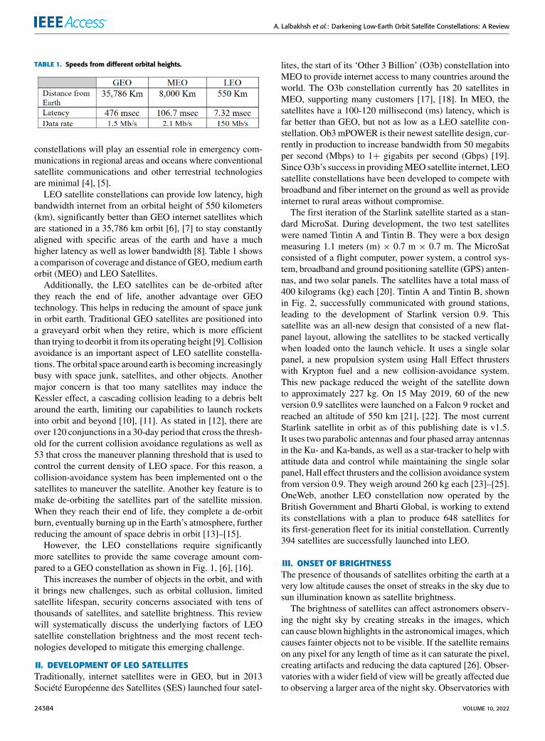
The first iteration of the Starlink satellite started as a stan-dard MicroSat. During development, the two test satelliteswere named Tintin A and Tintin B. They were a box designmeasuring 1.1 meters (m) × 0.7 m × 0.7 m. The MicroSatconsisted of a flight computer, power system, a control sys-tem, broadband and ground positioning satellite (GPS) anten-nas, and two solar panels. The satellites have a total mass of400 kilograms (kg) each [20]. Tintin A and Tintin B, shownin Fig. 2, successfully communicated with ground stations,leading to the development of Starlink version 0.9. Thissatellite was an all-new design that consisted of a new flat-panel layout, allowing the satellites to be stacked verticallywhen loaded onto the launch vehicle. It uses a single solarpanel, a new propulsion system using Hall Effect thrusterswith Krypton fuel and a new collision-avoidance system.This new package reduced the weight of the satellite downto approximately 227 kg. On 15 May 2019, 60 of the newversion 0.9 satellites were launched on a Falcon 9 rocket andreached an altitude of 550 km [21], [22]. The most currentStarlink satellite in orbit as of this publishing date is v1.5.It uses two parabolic antennas and four phased array antennasin the Ku- and Ka-bands, as well as a star-tracker to help withattitude data and control while maintaining the single solarpanel, Hall effect thrusters and the collision avoidance systemfrom version 0.9. They weigh around 260 kg each [23]–[25].OneWeb, another LEO constellation now operated by theBritish Government and Bharti Global, is working to extendits constellations with a plan to produce 648 satellites forits first-generation fleet for its initial constellation. Currently394 satellites are successfully launched into LEO.
III. ONSET OF BRIGHTNESSThe presence of thousands of satellites orbiting the earth at avery low altitude causes the onset of streaks in the sky due tosun illumination known as satellite brightness.
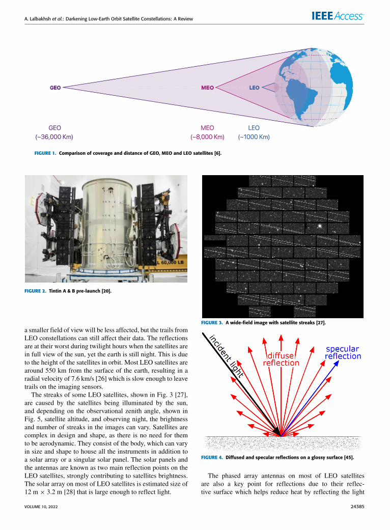
The brightness of satellites can affect astronomers observ-ing the night sky by creating streaks in the images, whichcan cause blown highlights in the astronomical images, whichcauses fainter objects not to be visible. If the satellite remainson any pixel for any length of time as it can saturate the pixel,creating artifacts and reducing the data captured [26]. Obser-vatories with a wider field of viewwill be greatly affected dueto observing a larger area of the night sky. Observatories with
24384 VOLUME 10, 2022
A. Lalbakhsh et al.: Darkening Low-Earth Orbit Satellite Constellations: A Review
FIGURE 1. Comparison of coverage and distance of GEO, MEO and LEO satellites [6].
FIGURE 2. Tintin A & B pre-launch [20].
a smaller field of view will be less affected, but the trails fromLEO constellations can still affect their data. The reflectionsare at their worst during twilight hours when the satellites arein full view of the sun, yet the earth is still night. This is dueto the height of the satellites in orbit. Most LEO satellites arearound 550 km from the surface of the earth, resulting in aradial velocity of 7.6 km/s [26] which is slow enough to leavetrails on the imaging sensors.
The streaks of some LEO satellites, shown in Fig. 3 [27],are caused by the satellites being illuminated by the sun,and depending on the observational zenith angle, shown inFig. 5, satellite altitude, and observing night, the brightnessand number of streaks in the images can vary. Satellites arecomplex in design and shape, as there is no need for themto be aerodynamic. They consist of the body, which can varyin size and shape to house all the instruments in addition toa solar array or a singular solar panel. The solar panels andthe antennas are known as two main reflection points on theLEO satellites, strongly contributing to satellites brightness.The solar array on most of LEO satellites is estimated size of12 m × 3.2 m [28] that is large enough to reflect light.
FIGURE 3. A wide-field image with satellite streaks [27].
FIGURE 4. Diffused and specular reflections on a glossy surface [45].
The phased array antennas on most of LEO satellitesare also a key point for reflections due to their reflec-tive surface which helps reduce heat by reflecting the light
VOLUME 10, 2022 24385
A. Lalbakhsh et al.: Darkening Low-Earth Orbit Satellite Constellations: A Review
FIGURE 5. Observer aspect of the satellite [46].
away. These antennas are essential to LEO satellites asthey are responsible for providing internet communicationson the V and Ku- bands, as well as connecting to theground stations for tracking and system monitoring on theV and Ka- bands [23]. Apart from phase array technology,a new beam steering mechanism has recently been pro-posed based on near-field transformation, contributing tolow-cost manufacturing [29]–[36]. This technique does notrequire expensive active phase shifters and can be imple-mented by all-dielectric substances [29]–[31], all-metal struc-tures [32], [33], or hybrid materials [34]–[36]. Additionally,there are other antenna reconfiguring techniques that poten-tially can be adopted for such purposes [37]–[43].
Phased array antennas electronically steer the highly-directive beam of the antenna using several microwave phaseshifters. The main beam can be oriented in any directionby fixing the arrangement of elements and changing thephase of each element accordingly. Despite their excellentperformance, this class of antenna is susceptible to heat,where their radiation patterns, and particularly the antennagain, are varied slightly as the heat increases. Because ofthis, reflective radiators are designed and placed on top ofthe antenna to minimize heat-driven variation in the antennaradiation patterns [44]. These radiators along with relativelylarge solar panels, reflect sunlight during sunrise and sunsetas the satellites orbit the earth, producing both specular anddiffused reflections [46].
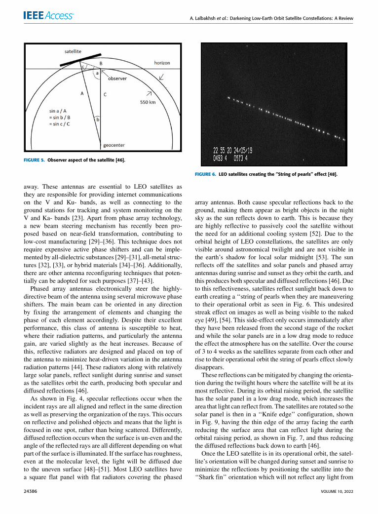
As shown in Fig. 4, specular reflections occur when theincident rays are all aligned and reflect in the same directionas well as preserving the organization of the rays. This occurson reflective and polished objects and means that the light isfocused in one spot, rather than being scattered. Differently,diffused reflection occurs when the surface is un-even and theangle of the reflected rays are all different depending on whatpart of the surface is illuminated. If the surface has roughness,even at the molecular level, the light will be diffused dueto the uneven surface [48]–[51]. Most LEO satellites havea square flat panel with flat radiators covering the phased
FIGURE 6. LEO satellites creating the ‘‘String of pearls’’ effect [48].
array antennas. Both cause specular reflections back to theground, making them appear as bright objects in the nightsky as the sun reflects down to earth. This is because theyare highly reflective to passively cool the satellite withoutthe need for an additional cooling system [52]. Due to theorbital height of LEO constellations, the satellites are onlyvisible around astronomical twilight and are not visible inthe earth’s shadow for local solar midnight [53]. The sunreflects off the satellites and solar panels and phased arrayantennas during sunrise and sunset as they orbit the earth, andthis produces both specular and diffused reflections [46]. Dueto this reflectiveness, satellites reflect sunlight back down toearth creating a ‘‘string of pearls when they are maneuveringto their operational orbit as seen in Fig. 6. This undesiredstreak effect on images as well as being visible to the nakedeye [49], [54]. This side-effect only occurs immediately afterthey have been released from the second stage of the rocketand while the solar panels are in a low drag mode to reducethe effect the atmosphere has on the satellite. Over the courseof 3 to 4 weeks as the satellites separate from each other andrise to their operational orbit the string of pearls effect slowlydisappears.
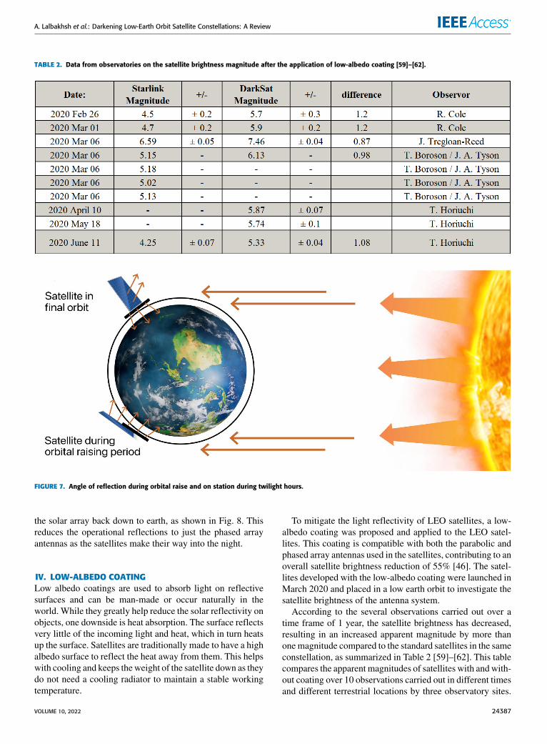
These reflections can be mitigated by changing the orienta-tion during the twilight hours where the satellite will be at itsmost reflective. During its orbital raising period, the satellitehas the solar panel in a low drag mode, which increases thearea that light can reflect from. The satellites are rotated so thesolar panel is then in a ‘‘Knife edge’’ configuration, shownin Fig. 9, having the thin edge of the array facing the earthreducing the surface area that can reflect light during theorbital raising period, as shown in Fig. 7, and thus reducingthe diffused reflections back down to earth [46].
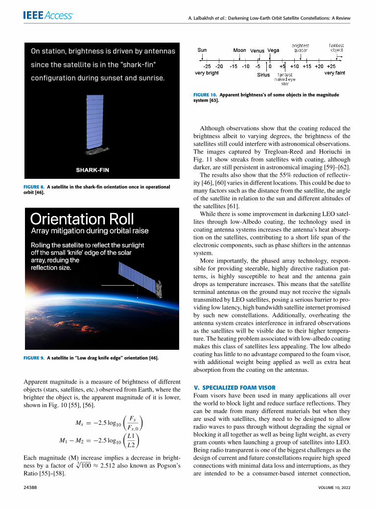
Once the LEO satellite is in its operational orbit, the satel-lite’s orientation will be changed during sunset and sunrise tominimize the reflections by positioning the satellite into the‘‘Shark fin’’ orientation which will not reflect any light from
24386 VOLUME 10, 2022
A. Lalbakhsh et al.: Darkening Low-Earth Orbit Satellite Constellations: A Review
TABLE 2. Data from observatories on the satellite brightness magnitude after the application of low-albedo coating [59]–[62].
FIGURE 7. Angle of reflection during orbital raise and on station during twilight hours.
the solar array back down to earth, as shown in Fig. 8. Thisreduces the operational reflections to just the phased arrayantennas as the satellites make their way into the night.
IV. LOW-ALBEDO COATINGLow albedo coatings are used to absorb light on reflectivesurfaces and can be man-made or occur naturally in theworld. While they greatly help reduce the solar reflectivity onobjects, one downside is heat absorption. The surface reflectsvery little of the incoming light and heat, which in turn heatsup the surface. Satellites are traditionally made to have a highalbedo surface to reflect the heat away from them. This helpswith cooling and keeps theweight of the satellite down as theydo not need a cooling radiator to maintain a stable workingtemperature.
To mitigate the light reflectivity of LEO satellites, a low-albedo coating was proposed and applied to the LEO satel-lites. This coating is compatible with both the parabolic andphased array antennas used in the satellites, contributing to anoverall satellite brightness reduction of 55% [46]. The satel-lites developed with the low-albedo coating were launched inMarch 2020 and placed in a low earth orbit to investigate thesatellite brightness of the antenna system.
According to the several observations carried out over atime frame of 1 year, the satellite brightness has decreased,resulting in an increased apparent magnitude by more thanonemagnitude compared to the standard satellites in the sameconstellation, as summarized in Table 2 [59]–[62]. This tablecompares the apparent magnitudes of satellites with andwith-out coating over 10 observations carried out in different timesand different terrestrial locations by three observatory sites.
VOLUME 10, 2022 24387
A. Lalbakhsh et al.: Darkening Low-Earth Orbit Satellite Constellations: A Review
FIGURE 8. A satellite in the shark-fin orientation once in operationalorbit [46].
FIGURE 9. A satellite in ‘‘Low drag knife edge’’ orientation [46].
Apparent magnitude is a measure of brightness of differentobjects (stars, satellites, etc.) observed from Earth, where thebrighter the object is, the apparent magnitude of it is lower,shown in Fig. 10 [55], [56].
Mx = −2.5 log10
(FxFx,0
)M1 −M2 = −2.5 log10
(L1L2
)Each magnitude (M) increase implies a decrease in bright-ness by a factor of 5
√100 ≈ 2.512 also known as Pogson’s
Ratio [55]–[58].
FIGURE 10. Apparent brightness’s of some objects in the magnitudesystem [63].
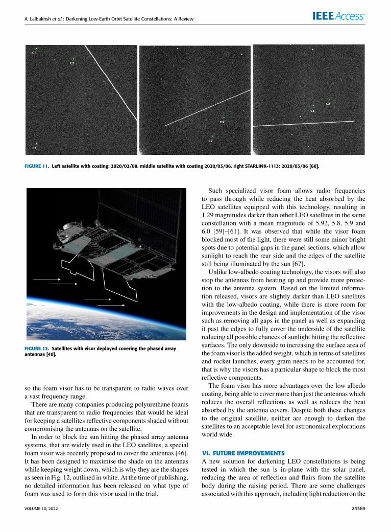
Although observations show that the coating reduced thebrightness albeit to varying degrees, the brightness of thesatellites still could interfere with astronomical observations.The images captured by Tregloan-Reed and Horiuchi inFig. 11 show streaks from satellites with coating, althoughdarker, are still persistent in astronomical imaging [59]–[62].
The results also show that the 55% reduction of reflectiv-ity [46], [60] varies in different locations. This could be due tomany factors such as the distance from the satellite, the angleof the satellite in relation to the sun and different altitudes ofthe satellites [61].
While there is some improvement in darkening LEO satel-lites through low-Albedo coating, the technology used incoating antenna systems increases the antenna’s heat absorp-tion on the satellites, contributing to a short life span of theelectronic components, such as phase shifters in the antennassystem.
More importantly, the phased array technology, respon-sible for providing steerable, highly directive radiation pat-terns, is highly susceptible to heat and the antenna gaindrops as temperature increases. This means that the satelliteterminal antennas on the ground may not receive the signalstransmitted by LEO satellites, posing a serious barrier to pro-viding low latency, high bandwidth satellite internet promisedby such new constellations. Additionally, overheating theantenna system creates interference in infrared observationsas the satellites will be visible due to their higher tempera-ture. The heating problem associated with low-albedo coatingmakes this class of satellites less appealing. The low albedocoating has little to no advantage compared to the foam visor,with additional weight being applied as well as extra heatabsorption from the coating on the antennas.
V. SPECIALIZED FOAM VISORFoam visors have been used in many applications all overthe world to block light and reduce surface reflections. Theycan be made from many different materials but when theyare used with satellites, they need to be designed to allowradio waves to pass through without degrading the signal orblocking it all together as well as being light weight, as everygram counts when launching a group of satellites into LEO.Being radio transparent is one of the biggest challenges as thedesign of current and future constellations require high speedconnections with minimal data loss and interruptions, as theyare intended to be a consumer-based internet connection,
24388 VOLUME 10, 2022
A. Lalbakhsh et al.: Darkening Low-Earth Orbit Satellite Constellations: A Review
FIGURE 11. Left satellite with coating: 2020/02/08. middle satellite with coating 2020/03/06. right STARLINK-1113: 2020/03/06 [60].
FIGURE 12. Satellites with visor deployed covering the phased arrayantennas [40].
so the foam visor has to be transparent to radio waves overa vast frequency range.
There are many companies producing polyurethane foamsthat are transparent to radio frequencies that would be idealfor keeping a satellites reflective components shaded withoutcompromising the antennas on the satellite.
In order to block the sun hitting the phased array antennasystems, that are widely used in the LEO satellites, a specialfoam visor was recently proposed to cover the antennas [46].It has been designed to maximise the shade on the antennaswhile keeping weight down, which is why they are the shapesas seen in Fig. 12, outlined in white. At the time of publishing,no detailed information has been released on what type offoam was used to form this visor used in the trial.
Such specialized visor foam allows radio frequenciesto pass through while reducing the heat absorbed by theLEO satellites equipped with this technology, resulting in1.29 magnitudes darker than other LEO satellites in the sameconstellation with a mean magnitude of 5.92, 5.8, 5.9 and6.0 [59]–[61]. It was observed that while the visor foamblocked most of the light, there were still some minor brightspots due to potential gaps in the panel sections, which allowsunlight to reach the rear side and the edges of the satellitestill being illuminated by the sun [67].
Unlike low-albedo coating technology, the visors will alsostop the antennas from heating up and provide more protec-tion to the antenna system. Based on the limited informa-tion released, visors are slightly darker than LEO satelliteswith the low-albedo coating, while there is more room forimprovements in the design and implementation of the visorsuch as removing all gaps in the panel as well as expandingit past the edges to fully cover the underside of the satellitereducing all possible chances of sunlight hitting the reflectivesurfaces. The only downside to increasing the surface area ofthe foam visor is the addedweight, which in terms of satellitesand rocket launches, every gram needs to be accounted for,that is why the visors has a particular shape to block the mostreflective components.
The foam visor has more advantages over the low albedocoating, being able to cover more than just the antennas whichreduces the overall reflections as well as reduces the heatabsorbed by the antenna covers. Despite both these changesto the original satellite, neither are enough to darken thesatellites to an acceptable level for astronomical explorationsworld wide.
VI. FUTURE IMPROVEMENTSA new solution for darkening LEO constellations is beingtested in which the sun is in-plane with the solar panel,reducing the area of reflection and flairs from the satellitebody during the raising period. There are some challengesassociatedwith this approach, including light reduction on the
VOLUME 10, 2022 24389
A. Lalbakhsh et al.: Darkening Low-Earth Orbit Satellite Constellations: A Review
solar panels, which would reduce the operating power, reduc-tion in antenna contact time, as the antenna facing earth for ashorter period of time, and satellite lifespan reduction due tohigher fuel consumption [46], [68]. Along with the satelliteorientation is to place the satellites closer to their final orbiton launch reducing the time spent in their raising period toreach the operational orbital height, reducing the amount oftime in their most reflective position. The challenge with thisis that it would be more expensive to raise the second stage ofthe rocket up higher by using the first stage for longer [69].
A report by C Walker at National Optical-Infrared Astron-omy Research Laboratory (NOIR Lab) in 2020 suggestsdeveloping a software application to identify, model andmaskthe satellite trails to predict the satellite interference in astron-omy imaging [53].
For example, an artifact detection and masking algorithmwas proposed in [70] which relies on 1- a dataset containingseveral visits to the same part of the sky, 2- detailed model-ing of the position variable point spread function (PSF) onsingle epoch images, 3- the production of PSF homogenizedartifact-less images, 4- the image’s model fitting catalogs,5- the construction of position variable PSF convolved sim-ulated images utilizing PSF models and the model fittingcatalogs. Such methods can be adapted to detect objects thatleave streaks using an algorithm to remove these streaks andartifacts. Using multiple images and interpolation to create animage that has no artifacts, this method can be applied to anysurvey that images the same section of the sky multiple times.This could be implemented and developed further to workwith specific observatories to reduce the impact of brightnessas more satellites enter orbit [71]. There are other algorithmsthat can be used alongside thismethod to improve the trackingand detection rate covering more potential objects that couldleave streaks and artifacts in the imaging [62], [72], [73].
Another method for brightness mitigation is to developsoftware that plans and predicts the time and projection ofthe satellites’ transit over the observatory so they can takeimages of the night sky when there are no satellites in transitin their desired area of the night sky for the duration of theexposure [53], [74]. This seems more promising as observa-tories can then see when they will have clear skies overheadto image the night sky. In addition to knowing when theyhave clear skies, it also depends on what type of imaging theobservatory is performing and the required time to take theimage. If a minimum timeframe for the exposure can be iden-tified, the orbital spacing can be defined to ensure that thereis a minimum window of time between each satellite pass-ing through these selected orbital zones. However, having aminimum operating window would prevent longer exposuresoccurring without interference from these constellations.
Interruption of the observations can be another approach tobrightness mitigation. If observations are required in the sameregion of the sky where the satellites are illuminated the exacttime they cross the field of view, this can be computed, andthe shutter can be closed during that time while the satellitepasses over and then reopened to continue capturing data and
won’t appear in the final image. However, this approach is notpractical for all observatories. For example, there would betoo many interruptions for a large field of view telescope, dueto the large area of the night sky it is imaging, more satelliteswould cross this zone, causing it to close its shutter morefrequently, which in turn reduces its exposure time, reducingthe amount of data collected in each image, making thisapproach less effective [47]. There are other measures suchas satellite number minimization based on particle swarmoptimizations (PSO) as reported in [16]. More informationon the implementation of a PSO algorithm can be foundin [75], [76]. Apart from PSO, other nature-based algorithmssuch as grey wolf optimization [77]–[79], ant colony opti-mization [80], [81], artificial neural networks [82]–[89], andgenetic algorithms [90] can be adopted for the same purpose.
In summary, operators need to do their best to avoid spec-ular reflections in the direction of observatories [48]. Thisis critical particularly for the observatories with larger fieldof view and can be implemented by adjusting the satellitesto reduce specular reflections while transiting over obser-vational areas. However, it will cost the satellite fuel everytime it passes over to rotate the satellite to an angle to reducethe reflections and then return to its normal position, furtherreducing the satellite’s lifespan.
Every day,more andmore satellites are being put into LEO,as such, observation times will slowly decrease as the sky fillsup with bright satellites. At this current time, there is little tono information on the reduction of observable time due tothese satellites and it being a new emerging technology.
VII. CONCLUSIONOne of the critical emerging challenges associated with theLEO satellite constellations is the unwanted brightness ofthese constellations visible from earth in the night sky. Suchbrightness interferes with astronomical viewing in manyways, potentially disrupting the observatories’ function. Theurgency for the LEO constellations brightness rectificationwas understood recently, and several technologies have beenproposed and tested to mitigate this issue.
The future improvements have some promising methodsthat will also need improvement over time as new methodsand technology are created to help with this new problem.Adjusting the satellite to have the satellite in-plane with thesunwould be the easiest method to help reduce the reflectivityof the solar panel. The downside to this is that this uses upmore fuel than normal [46], reducing the satellite lifespan andreducing the time the solar panel will be in direct sunlightand will change the orientation of the antenna, reducing thecontact area with the ground stations.
Masking the trails, satellite planning, and imaging inter-ruption will make moving the satellites to be in-plane withthe sun unnecessary.
These two methods will help imaging directly, reducingthe streaks and artifacts in both scenarios. The downside tomasking the trails, is there will be more images required tocover the viewing area, making sure the combined images
24390 VOLUME 10, 2022
A. Lalbakhsh et al.: Darkening Low-Earth Orbit Satellite Constellations: A Review
have no overlap of streaks that can be removed [53]. As wellas this, these methods could lose valuable scientific datafrom losing data due to streak removal, or not being able tooperate at specific times due to satellites flying overhead [74].Satellite planning will dictate when the observatories canview the night sky and they might miss key events due to thesatellites blocking the view. A way to mitigate this is to planand work with the constellation companies to create a gap inthe constellation for these events [74].
Interruption of the imaging process will be more viablefor small field of view observatories as there will be lesssatellites crossing its viewing area compared to wide fieldof view observatories. As with the other two methods, thereis a potential to lose data when interrupting the imagingand would lose more data compared to the other methodsabove as well as taking longer from all these interruptionsand additional processing.
Apart from all modifications proposed or implemented onthe satellite’s configuration, mathematical modeling highlytailored for each major observatory to predict the bright-ness caused by each LEO constellation is another promisingavenue to rectify this existing challenge.
REFERENCES[1] I. del Portillo, B. G. Cameron, and E. F. Crawley, ‘‘A technical comparison
of three low earth orbit satellite constellation systems to provide globalbroadband,’’ Acta Astronautica, vol. 159, pp. 123–135, Jun. 2019.
[2] Application for Approval for Orbital Deployment and Operating Authorityfor the SpaceX Gen2 NGSO Satellite System, Federal Commun. Commis-sion, Washington, DC, USA, 2020.
[3] Y. Lee and J. P. Choi, ‘‘Connectivity analysis ofmega-constellation satellitenetworks with optical intersatellite links,’’ IEEE Trans. Aerosp. Electron.Syst., vol. 57, no. 6, pp. 4213–4226, Dec. 2021.
[4] N. Pierdicca, L. Pulvirenti, M. Chini, L. Guerriero, and L. Candela,‘‘Observing floods from space: Experience gained from COSMO-SkyMedobservations,’’ Acta Astronautica, vol. 84, pp. 122–133, Mar. 2013.
[5] R. Yn, ‘‘Fundamentals of the route theory for satellite constellation designfor earth discontinuous coverage. Part 1: Analytic emulation of the earthcoverage,’’ Acta Astronautica, vol. 128, pp. 722–740, May 2016.
[6] Satellite Today. (2020). Schematic of Orbital Altitudes and Cover-age Areas. [Online]. Available: https://www.satellitetoday.com/content-collection/ses-hub-geo-meo-and-leo
[7] European Space Agency. (Mar. 30, 2020). ESA int. Accessed:Mar. 18, 2021. [Online]. Available: https://www.esa.int/Enabling_Support/Space_Transportation/Types_of_orbits#GEO
[8] D. Infra. (Dec. 2, 2020). Elon Musk’s Starlink and Satellite Broadband.Accessed: Mar. 19, 2021. [Online]. Available: https://dgtlinfra.com/elon-musk-starlink-and-satellite-broadband/
[9] Orbital Debris Mitigation Standard Practices, U.S Government,Washington, DC, USA, 2019.
[10] J. Drmola and T. Hubik, ‘‘Kessler syndrome: System dynamicsmodel,’’ Space Policy, pp. 44–45, pp. 29–39, Apr. 2018, doi:10.1016/j.spacepol.2018.03.003.
[11] D. J. Kessler and B. G. Cour-Palais, ‘‘Collision frequency of artificialsatellites: The creation of a debris belt,’’ J. Geophys. Res., vol. 83,pp. 2637–2646, Apr. 1978.
[12] T. J. Muelhaupt, M. E. Sorge, J. Morin, and R. S. Wilson, ‘‘Space trafficmanagement in the new space era,’’ J. Space Saf. Eng., vol. 6, no. 2,pp. 80–87, Jun. 2019, doi: 10.1016/j.jsse.2019.05.007.
[13] J. Radtke, C. Kebschull, and E. Stoll, ‘‘Interactions of the space debrisenvironment with mega constellations—Using the example of the OneWebconstellation,’’ Acta Astronautica, vol. 131, pp. 55–68, Feb. 2017, doi:10.1016/j.actaastro.2016.11.021.
[14] R. Lucken and D. Giolito, ‘‘Collision risk prediction for constellationdesign,’’ Acta Astronautica, vol. 161, pp. 492–501, Aug. 2019, doi:10.1016/j.actaastro.2019.04.003.
[15] S. Le May, S. Gehly, B. A. Carter, and S. Flegel, ‘‘Space debris collisionprobability analysis for proposed global broadband constellations,’’ ActaAstronautica, vol. 151, pp. 445–455, Oct. 2018.
[16] R. Deng, B. Di, H. Zhang, L. Kuang, and L. Song, ‘‘Ultra-dense LEOsatellite constellations: How many LEO satellites do we need?’’ IEEETrans. Wireless Commun., vol. 20, no. 8, pp. 4843–4857, Aug. 2021.
[17] (2020). O3b MEO—Our Coverage. Accessed: Jun. 9, 2021. [Online].Available: https://www.ses.com/our-coverage/o3b-meo
[18] N. Yo. (2021). Satellite Tracking. Accessed: Jun. 9, 2021. [Online]. Avail-able: https://www.n2yo.com/satellites/?c=43
[19] Boeing. Boeing to Build four Additional 702X Satellites for SES’sO3b mPOWER Fleet. Accessed: Jun. 9, 2021. [Online]. Available:https://boeing.mediaroom.com/2020-08-07-Boeing-to-Build-Four-Additional-702X-Satellites-for-SES
[20] G. Krebs. (June 2018). MicroSat 2A, 2b (Tintin A, B). Accessed:Mar. 18, 2021. [Online]. Available: https://space.skyrocket.de/doc_sdat/microsat-2.htm
[21] SpaceX. (May 15, 2019). Starlink Mission Press Kit. Accessed:Mar. 18, 2021. [Online]. Available: https://web.archive.org/web/20190515091900/https://www.spacex.com/sites/spacex/files/starlink_press_kit.pdf
[22] G. Krebs. (2019). Starlink Block V0.9. Accessed: Mar. 18, 2021. [Online].Available: https://space.skyrocket.de/doc_sdat/starlink-v0-9.htm.
[23] S. Persona. (May 22, 2019). Starlink Compendium. Accessed:Mar. 18, 2021. [Online]. Available: https://www.elonx.net/starlink-compendium/
[24] T. Sesnic. (Mar. 14, 2021). Starlink 22. Accessed: Mar. 18, 2021. [Online].Available: https://everydayastronaut.com/starlink-22/
[25] G. Krebs. (2019). Starlink Block V1.0. Accessed: Mar. 18, 2021. [Online].Available: https://space.skyrocket.de/doc_sdat/starlink-v1-0.htm
[26] S. Gallozzi, D. Paris, M. Maris, M. Scardia, and D. Roma, ‘‘Concernsabout ground based astronomical observations: Quantifying satellites’constellations damages,’’ Instrum. Methods Astrophys., Oct. 2020, doi:10.48550/arXiv.2003.05472.
[27] C. J. Clara, ‘‘A wide-field image (2.2 degrees across) from the dark energycamera on the blanco 4 m telescope,’’ Nat. Opt.-Infrared Astron. Res.Lab., Cerro Tololo Inter-Amer. Observatory, Tech. Rep., 2019. [Online].Available: https://noirlab.edu/public/images/iotw1946a/
[28] Damir. (Apr. 27, 2020). Space Related Ideas. Accessed: Mar. 25, 2021.[Online]. Available: https://lilibots.blogspot.com/2020/04/starlink-satellite-dimension-estimates.html
[29] M. Afzal, L. Matekovit, K. Esselle, and A. Lalbakhsh, ‘‘Beam-scanningantenna based on near-electric field phase transformation and refraction ofelectromagnetic wave through dielectric structures,’’ IEEE Access, vol. 8,pp. 199242–199253, 2020.
[30] A. Lalbakhsh, M. U. Afzal, K. P. Esselle, and S. L. Smith, ‘‘Wide-band near-field correction of a Fabry–Perot resonator antenna,’’ IEEETrans. Antennas Propag., vol. 67, no. 3, pp. 1975–1980, Mar. 2019, doi:10.1109/TAP.2019.2891230.
[31] T. Hayat, M. U. Afzal, A. Lalbakhsh, and K. P. Esselle, ‘‘Additively man-ufactured perforated superstrate to improve directive radiation characteris-tics of electromagnetic source,’’ IEEE Access, vol. 7, pp. 153445–153452,2019.
[32] A. Lalbakhsh, M. U. Afzal, T. Hayat, K. P. Esselle, and K. Mandal, ‘‘All-metal wideband metasurface for near-field transformation of medium-to-high gain electromagnetic sources,’’ Sci. Rep., vol. 11, no. 1, pp. 1–9,Dec. 2021.
[33] A. Lalbakhsh, M. U. Afzal, K. P. Esselle, and S. L. Smith, ‘‘All-metalwideband frequency-selective surface bandpass filter for TE and TMpolar-izations,’’ IEEE Trans. Antennas Propag., early access, Jan. 10, 2022, doi:10.1109/TAP.2021.3138256.
[34] M. U. Afzal, A. Lalbakhsh, and K. P. Esselle, ‘‘Method to enhance direc-tional propagation of circularly polarized antennas by making near-electricfield phase more uniform,’’ IEEE Trans. Antennas Propag., vol. 69, no. 8,pp. 4447–4456, Aug. 2021.
[35] A. Lalbakhsh, M. U. Afzal, K. P. Esselle, and S. L. Smith, ‘‘A high-gainwideband EBG resonator antenna for 60 GHz unlicenced frequency band,’’in Proc. 12th Eur. Conf. Antennas Propag. (EuCAP ), London, U.K., 2018,pp. 1–3.
[36] M. U. Afzal, K. P. Esselle, and A. Lalbakhsh, ‘‘A metasurface to focusantenna beam at offset angle,’’ in Proc. 2nd URSI Atlantic Radio Sci.Meeting (AT-RASC), May 2018, pp. 1–4.
[37] A. Iqbal, M. I. Waly, A. Smida, and N. K. Mallat, ‘‘Dielectric resonatorantenna with reconfigurable polarization states,’’ IET Microw., AntennasPropag., vol. 15, no. 7, pp. 683–690, Jun. 2021.
VOLUME 10, 2022 24391
A. Lalbakhsh et al.: Darkening Low-Earth Orbit Satellite Constellations: A Review
[38] W. A. Awan, S. I. Naqvi, W. A. E. Ali, N. Hussain, A. Iqbal, H. H. Tran,M. Alibakhshikenari, and E. Limiti, ‘‘Design and realization of a frequencyreconfigurable antenna with wide, dual, and single-band operations forcompact sized wireless applications,’’ Electronics, vol. 10, no. 11, p. 1321,May 2021.
[39] A. Lalbakhsh, M. U. Afzal, K. P. Esselle, and S. L. Smith, ‘‘Low-costnonuniform metallic lattice for rectifying aperture near-field of electro-magnetic bandgap resonator antennas,’’ IEEE Trans. Antennas Propag.,vol. 68, no. 5, pp. 3328–3335,May 2020, doi: 10.1109/TAP.2020.2969888.
[40] Y. Torabi, G. Dadashzadeh, A. Lalbakhsh, and H. Oraizi, ‘‘High-gainand low-profile dielectric-image-line leaky-wave-antenna for wide-anglebeam scanning at sub-THz frequencies,’’ Opt. Laser Technol., vol. 150,Jun. 2022, Art. no. 107968.
[41] P. Das, K. Mandal, and A. Lalbakhsh, ‘‘Single-layer polarization-insensitive frequency selective surface for beam reconfigurability ofmonopole antennas,’’ J. Electromagn. Waves Appl., vol. 34, no. 1,pp. 86–102, Jan. 2020.
[42] A. Iqbal, S. Ullah, U. Naeem,A. Basir, andU.Ali, ‘‘Design, fabrication andmeasurement of a compact, frequency reconfigurable, modified T-shapeplanar antenna for portable applications,’’ J. Elec. Eng. Tech., vol. 12, no. 4,2017, pp. 1611–1618.
[43] M. Hadei, G. Dadashzadeh, Y. Torabi, and A. Lalbakhsh, ‘‘Terahertzbeamforming network with non-uniform contour,’’ Appl. Opt., vol. 61,no. 4, pp. 1087–1097, 2022.
[44] Y. Wang, C. Wang, P. Lian, S. Xue, J. Liu, W. Gao, Y. Shi, Z. Wang, K. Yu,X. Peng, B. Du, and S. Xiao, ‘‘Effect of temperature on electromagneticperformance of active phased array antenna,’’ Electronics, vol. 9, no. 8,p. 1211, Jul. 2020.
[45] T. Jeffrey Phased-Array Radar Design Application of Radar Fundamen-tals. Raleigh, NC, USA: SciTech, 2009.
[46] SpaceX. (Apr. 28, 2020). Starlink Update. Accessed: Mar. 19, 2021.[Online]. Available: https://www.spacex.com/updates/starlink-update-04-28-2020/
[47] O. Hainaut and A. Williams, ‘‘Impact of satellite constellations on astro-nomical observations with ESO telescopes in the visible and infrareddomains,’’ Astron. Astrophys., vol. 636, p. A121, Oct. 2020.
[48] R. T. Tan. (Feb. 5, 2016). Specularity, Specular Reflectance.Accessed: Mar. 19, 2021. [Online]. Available: https://link.springer.com/referenceworkentry/10.1007/978-0-387-31439-6_538
[49] P. J. Marlow, J. Kim, and B. L. Anderson, ‘‘The perception and misper-ception of specular surface reflectance,’’ Current Biol., vol. 22, no. 20,pp. 1909–1913, Oct. 2012.
[50] H. Partanen, N. Sharmin, J. Tervo, and J. Turunen, ‘‘Specular and anti-specular light beams,’’ Opt. Exp., vol. 23, no. 22, pp. 28718–28727, 2015.
[51] GianniG46. (Oct. 27, 2010). Diffuse reflection. Accessed: Mar. 19, 2021.[Online]. Available: https://en.wikipedia.org/wiki/File: Lambert2.gif
[52] A. Mallama, ‘‘A flat-panel brightness model for the starlink satellitesand measurement of their absolute visual magnitude,’’ Instrum. MethodsAstrophys., Mar. 2020, doi: 10.48550/arXiv.2003.07805.
[53] C. Walker and J. Hall, ‘‘Impact of satellite constellations on optical astron-omy and recommendations toward mitigations,’’ Bull. Amer. AstronomicalSoc., vol. 52, no. 2, pp. 1–22, 2020.
[54] M. Langbroek, Starlink Satellite Train. Leiden, The Netherlands: Sat-TrackCam, 2019.
[55] A. Mallama and J. L. Hilton, ‘‘Computing apparent planetary magni-tudes for the astronomical almanac,’’ Astron. Comput., vol. 25, pp. 10–24,Oct. 2018.
[56] Y. Wang, X. Du, J. Zhao, and R. Gou, ‘‘Apparent magnitude calculationmethod for complex shaped space objects,’’ Adv. Space Res., vol. 62,no. 11, pp. 2988–2997, Dec. 2018.
[57] E. Schulman and C. V. Cox, ‘‘Misconceptions about astronomical magni-tudes,’’ Amer. J. Phys., vol. 65, no. 10, pp. 1003–1007, Oct. 1997.
[58] J. B. Hearnshaw, ‘‘An analysis of almagest magnitudes for the studyof stellar evolution,’’ New Astron. Rev., vol. 43, nos. 6–7, pp. 403–410,Sep. 1999.
[59] R. E. Cole, ‘‘Measurement of the brightness of the starlink spacecraftnamed ‘DARKSA,’’’ Res. Notes AAS, vol. 4, no. 3, p. 42, Mar. 2020.
[60] J. Tregloan-Reed, A. Otarola, E. Ortiz, V. Molina, J. Anais, R. Gonzalez,J. Colque, and da-Sanzana, ‘‘First observations and magnitude measure-ment of Starlink’s Darksat,’’ Astron. Astrophys., vol. 637, p. L1, May 2020.
[61] T. Horiuchi, H. Hanayama, and M. Ohishi, ‘‘Simultaneous multicolorobservations of Starlink’s darksat by the murikabushi telescope with MIT-SuME,’’ Astrophys. J., vol. 905, no. 1, p. 3, Dec. 2020.
[62] J. A. Tyson, Ž. Iveziá, A. Bradshaw, M. L. Rawls, B. Xin, P. Yoachim,J. Parejko, J. Greene, M. Sholl, T. M. C. Abbott, and D. Polin, ‘‘Mitigationof LEO satellite brightness and trail effects on the rubin observatoryLSST,’’ Astronomical J., vol. 160, no. 5, p. 226, Oct. 2020.
[63] N. Strobel. (Nov. 2, 201). Magnitude System. Accessed: Mar. 20, 2021.[Online]. Available: https://www.astronomynotes.com/starprop/s4.htm
[64] A. Mallama, ‘‘A flat-panel brightness model for the starlink satel-lites and measurement of their absolute visual magnitude,’’ 2020,arXiv:2003.07805.
[65] A. Mallama, ‘‘The brightness of visorsat-design starlink satellites,’’ 2021,arXiv:2101.00374.
[66] R. E. Cole, A Sky Brightness Model for the Starlink ‘VisorSat’ Spacecraft.Washington, DC, USA: American Astronomical Society, 2020.
[67] R. le, ‘‘A sky brightness model for the starlink ‘visorsat’ spacecraft,’’ 2021,arXiv:2107.06026.
[68] SpaceX. (May 2019). Starlink Mission Press Kit. Accessed:May 18, 2021. [Online]. Available: https://web.archive.org/web/20190515091900/https://www.spacex.com/sites/spacex/files/starlink_press_kit.pdf
[69] How Much Does it Cost to Launch a Reused Falcon 9. Accessed:Aug. 12, 2021. [Online]. Available: https://www.elonx.net/how-much-does-it-cost-to-launch-a-reused-falcon-9-elon-musk-explains-why-reusability-is-worth-it/
[70] S. Desai, J. Mohr, E. Bertin, M. Kümmel, and M. Wetzstein, ‘‘Detectionand removal of artifacts in astronomical images,’’ Astronomy Comput.,vol. 16, no. 2, pp. 67–78, 2016, doi: 10.1016/j.ascom.2016.04.002.
[71] S. Desai, J. J. Mohr, E. Bertin, M. Kummel, and M. Wetzstein, ‘‘Detectionand removal of artifacts in astronomical images,’’ Astron. Comput., vol. 16,pp. 67–78, Oct. 2016.
[72] H. Ali, C. H. Lampert, and T. M. Breuel, ‘‘Satellite tracks removal inastronomical images,’’ in Progress in Pattern Recognition, Image Analysisand Applications (Lecture Notes in Computer Science), vol. 4225, J.F. Martínez-Trinidad, J. A. Carrasco Ochoa, and J. Kittler, Eds. Berlin,Germany: Springer, 2006, doi: 10.1007/11892755_92.
[73] G. Nir, B. Zackay, and E. O. Ofek, ‘‘Optimal and efficient streak detec-tion in astronomical images,’’ Astronomical J., vol. 156, no. 5, p. 229,Oct. 2018.
[74] M. Levesque, ‘‘Automatic reacquisition of satellite positions by detectingtheir expected streaks in astronomical images,’’ in Proc. Adv. Maui Opt.Space Surveill. Technol. Conf., Held Waileas, Maui, HI, USA, Sep. 2009,p. 81.
[75] A. Lalbakhsh, U. M. Afzal, P. K. Esselle, and S. Smith, ‘‘Design of anartificial magnetic conductor surface using an evolutionary algorithm,’’in Proc. 19th Int. Conf. Electromagn. Adv. Appl. (ICEAA), Verona, Italy,Sep. 2017, pp. 885–887.
[76] J. Kennedy and R. Eberhart, ‘‘Particle swarm optimization,’’ in Proc. Int.Conf. Neural Netw., vol. 4, 1995, pp. 1942–1948.
[77] A. Karami, G. Roshani, E. Nazemi, and S. Roshani, ‘‘Enhancing theperformance of a dual-energy gamma ray based three-phase flow meterwith the help of grey wolf optimization algorithm,’’ Flow Meas. Instrum.,vol. 64, pp. 164–172, Feb. 2018.
[78] G. Roshani, E. Nazemi, and M. Roshani, ‘‘Usage of two trans-mitted detectors with optimized orientation in order to three phaseflow metering,’’ Measurement, vol. 100, pp. 122–130, Jan. 2017, doi:10.1016/j.measurement.2016.12.055.
[79] E. Nazemi, ‘‘Optimization of a method for identifying the flow regimeand measuring void fraction in a broad beam gamma-ray attenua-tion technique,’’ Int. J. Hydrogen Energy, vol. 41, pp. 7438–7444,Feb. 2016.
[80] P. Lalbakhsh, B. Zaeri, A. Lalbakhsh, and M. N. Fesharaki, ‘‘AntNet withreward-penalty reinforcement learning,’’ in Proc. 2nd Int. Conf. Comput.Intell., Commun. Syst. Netw., Jul. 2010, pp. 17–21.
[81] P. Lalbakhsh, B. Zaeri, and A. Lalbakhsh, ‘‘An improved model of antcolony optimization using a novel pheromone update strategy,’’ IEICETrans. Inf. Syst., vol. E96-D, no. 11, pp. 2309–2318, Nov. 2013, doi:10.1587/transinf.E96.D.2309.
[82] M. Roshani, G. Phan, G. Roshani, R. Hanus, B. Nazemi, E. Corniani,and E. Nazemi, ‘‘Combination of X-ray tube and GMDH neural networkas a non-destructive and potential technique for measuring characteristicsof gas-oil-water three phase flows,’’ Measurement, vol. 168, Feb. 2021,Art. no. 108427, doi: 10.1016/j.measurement.2020.108427.
[83] M. Sattari, G. Roshani, R. Hanus, and E. Nazemi, ‘‘Applicabil-ity of time-domain feature extraction methods and artificial intel-ligence in two-phase flow meters based on gamma-ray absorptiontechnique,’’ Measurement, vol. 168, Oct. 2021, Art. no. 108474, doi:10.1016/j.measurement.2020.108474.
24392 VOLUME 10, 2022
A. Lalbakhsh et al.: Darkening Low-Earth Orbit Satellite Constellations: A Review
[84] G. H. Roshani, S. A. H. Feghhi, A. Mahmoudi-Aznaveh, E. Nazemi, andA. Adineh-Vand, ‘‘Precise volume fraction prediction in oil–water–gasmultiphase flows by means of gamma-ray attenuation and artificial neuralnetworks using one detector,’’Measurement, vol. 51, pp. 34–41,May 2014.
[85] G. Roshani and E. Nazemi, ‘‘Intelligent densitometry of petroleum prod-ucts in stratified regime of two-phase flows using gamma ray and neu-ral network,’’ Flow Meas. Instrum., vol. 58, pp. 6–11, Feb. 2017, doi:10.1016/j.flowmeasinst.2017.09.007.
[86] G. H. Roshani, E. Nazemi, and S. A. H. Feghhi, ‘‘Investigation of using60Co source and one detector for determining the flow regime and voidfraction in gas–liquid two-phase flows,’’ Flow Meas. Instrum., vol. 50,pp. 73–79, Oct. 2016.
[87] G. H. Roshani, E. Nazemi, S. A. H. Feghhi, and S. Setayeshi, ‘‘Flow regimeidentification and void fraction prediction in two-phase flows based ongamma ray attenuation,’’Measurement, vol. 62, pp. 25–32, Feb. 2015.
[88] M. Roshani, G. Phan, P. Ali, G. Roshani, R. Hanus, T. Duong, E. Corniani,E. Nazemi, and E. Kalmoun, ‘‘Evaluation of flow pattern recognition andvoid fraction measurement in two phase flow independent of oil pipeline’sscale layer thickness,’’ Alex. Eng. J., vol. 60, pp. 1955–1966, May 2021,doi: 10.1016/j.aej.2020.11.043.
[89] M. Roshani, G. Phan, R. Faraj, N. Phan, G. Roshani, B. Nazemi,E. Corniani, and E. Nazemi, ‘‘Proposing a gamma radiation basedintelligent system for simultaneous analysing and detecting type andamount of petroleum by-products,’’ Nucl. Eng. Technol., vol. 53, no. 4,pp. 1277–1283, Apr. 2020, doi: 10.1016/j.net.2020.09.015.
[90] B.M.Karambasti,M.Ghodrat, G. Ghorbani, A. Lalbakhsh, andM.Behnia,‘‘Design methodology and multi-objective optimization of small-scalepower-water production based on integration of stirling engine and multi-effect evaporation desalination system,’’Desalination, vol. 526,Mar. 2022,Art. no. 115542.
ALI LALBAKHSH (Member, IEEE) received theMaster of Research (H.D.) and Ph.D. degrees inelectronics engineering from Macquarie Univer-sity, Australia, in 2015 and 2020, respectively.He holds an academic position (Research Fellow-ship) withMacquarie University. He has publishedover 110 peer-reviewed journal and conferencepapers. His research interests include high-gainand flexible antennas, metasurfaces, evolution-ary optimization methods, and passive microwave
components. He received several prestigious awards, including full schol-arships for his master’s and Ph.D. degrees, the Commonwealth Scientificand Industrial Research Organization (CSIRO) Grants on Astronomy andSpace Exploration, the Macquarie University Postgraduate Research Fund(PGRF), and the WiMed Travel Support Grants. He was a recipient ofthe 2016 ICEAA–IEEE APWC Cash Prize and the Macquarie UniversityDeputy Vice-Chancellor Commendation, in 2017. He is the only Researcherat the IEEE Region 10 (Asia–Pacific) who received the Most PrestigiousBest Paper Contest of the IEEE Region 10 more than once (2016, 2018, and2019). He was the highly commended finalist in the Excellence in HigherDegree Research Award in Science, Technology, Engineering, Mathematicsand Medicine (STEMM), Macquarie University, in 2019 and 2021. In 2020,he was announced as an Outstanding Reviewer of IEEE TRANSACTIONS ON
ANTENNAS AND PROPAGATION and received the Research Excellence Award ofthe Faculty of Science and Engineering, Macquarie University. In 2021,he received the Faculty Early Career Research Excellence Award and wasnamed one of the Fresh Scientists of New South Wales, Australia. He wasalso the highly commended finalist at the Macquarie University Vice-Chancellor’s Learning and Teaching Award. He serves as an Associate Editorfor the AEU-International Journal of Electronics and Communications andElectronics (MDPI).
ANDREW PITCAIRN was born in London, Eng-land. He moved to Australia, in 2003. He is cur-rently pursuing the bachelor’s degree in engineer-ing with Macquarie University College.
KAUSHIK MANDAL (Senior Member, IEEE)received the B.Sc. degree in physics (H) and theB.Tech. and M.Tech. degrees in radio physics andelectronics from the University of Calcutta, WestBengal, India, in 2001, 2004, and 2006, respec-tively, and the Ph.D. (Tech.) degree from the Uni-versity of Kalyani, in July 2014.
Since 2016, he has been working as an Assis-tant Professor with the Institute of Radio Physicsand Electronics, University of Calcutta. He has
authored or coauthored 44 internationally refereed journal articles. His cur-rent research interests include the design of the high-gain wideband compactmicrostrip patch antennas, antennas for UWB communication, multi-bandantennas for wireless devices, CP antennas, characterization and applicationof DGS, SIW-integrated microstrip antenna, and performance enhancementof microstrip antennas using frequency-selective surface (FSS). He wasa co-recipient of the IEEE TENCON 2017 Best Paper Award (in thetrack ‘Antenna’). He is the Treasurer of IEEE AP-MTT Chapter, KolkataSection. He is an Active Reviewer of IEEE TRANSACTIONS ON ANTENNAS AND
PROPAGATION, IEEE Antennas and Propagation Magazine, IET Microwaves,Antennas and Propagation, and Progress in Electromagnetics Research(PIER).
MOHAMMAD ALIBAKHSHIKENARI (Mem-ber, IEEE) was born in Mazandaran, Iran,in February 1988. He received the Ph.D. degree(Hons.) with an European Label in electronicengineering from the University of Rome ‘‘TorVergata,’’ Italy, in February 2020. He was a Ph.D.Visiting Researcher with the Chalmers Universityof Technology, Sweden, in 2018. His trainingduring the Ph.D. included a research stage in theSwedish company Gap Waves AB. He is currently
with the Department of Signal Theory and Communications, UniversidadCarlos III de Madrid, Spain, as a Principal Investigator of the CONEX-PlusTalent Training Program andMarie Sklodowska-Curie Actions. His researchinterests include antennas and wave-propagations, metamaterials and meta-surfaces, synthetic aperture radars (SARs), multiple-input multiple-output(MIMO) systems, RFID tag antennas, substrate-integrated waveguides(SIWs), impedance matching circuits, microwave components, millimeter-waves and terahertz-integrated circuits, gap waveguide technology, beam-forming matrices, and electromagnetic systems. The above research lineshave produced more than 140 publications on international journals, pre-sentations within international conferences, and book chapters with a totalnumber of the citations more than 2500 and an H-index of 35. He was a recip-ient of the three-year research grant funded by the Universidad Carlos III deMadrid and the European Union’s Horizon 2020 Research and InnovationProgram under the Marie Sklodowska-Curie Grant 801538 started in July2021, the two-year research grant funded by the University of Rome ‘‘TorVergata’’ started in November 2019, the three-year Ph.D. Scholarship fundedby the University of Rome ‘‘Tor Vergata’’ started in November 2016, andthe two Young Engineer Awards of the 47th and 48th European MicrowaveConference held in Nuremberg, Germany, in 2017, and in Madrid, Spain,in 2018, respectively. His research article titled ‘‘High-Gain Metasurfacein Polyimide On-Chip Antenna Based on CRLH-TL for Sub TerahertzIntegrated Circuits’’ published in Scientific Reports was awarded as the BestMonth Paper at the University of Bradford, in April 2020. He is serving as anAssociate Editor for IET Journal of Engineering and International Journalof Antennas and Propagation. He also acts as a referee in several highlyreputed journals and international conferences.
VOLUME 10, 2022 24393
A. Lalbakhsh et al.: Darkening Low-Earth Orbit Satellite Constellations: A Review
KARU P. ESSELLE (Fellow, IEEE) received theB.Sc. degree (Hons.) in electronic and telecom-munication engineering from the University ofMoratuwa, Sri Lanka, and the M.A.Sc. and Ph.D.degrees with near-perfect GPA in electrical engi-neering from the University of Ottawa, Canada.
Previously, he was the Director of the WiMedResearch Centre and an Associate Dean—HigherDegree Research (HDR) of the Division of Infor-mation and Communication Sciences and directed
the Centre for Collaboration in Electromagnetic and Antenna Engineering,Macquarie University, Sydney. He has also served as a member of the Dean’sAdvisory Council and the Division Executive and as the Head of the Depart-ment several times. He is currently a Director of Innovations for HumanityPty, Ltd., the Distinguished Professor in electromagnetic and antenna engi-neering at the University of Technology Sydney, and a Visiting Professorat Macquarie University. According to the Special Report on Researchpublished by The Australian national newspaper, he is the 2019 NationalResearch Field Leader in Australia in both microelectronics and electro-magnetisms fields. He has authored over 600 research publications and hispapers have been cited ∼12,000 times. In 2021, his publications receivedover 1,400 citations. His H-index is 52 and i-10 is 204. He is in the world’stop 100,000 most-cited scientists list by Mendeley Data. Since 2002, hisresearch team has been involved with research grants, contracts, and Ph.D.scholarships worth over 21 million dollars, including 15 Australian ResearchCouncil grants, without counting the 245 million-dollar SmartSat Corpo-rative Research Centre, which started in 2019. His research has been sup-ported bymany national and international organizations including AustralianResearch Council, Intel, U.S. Air Force, Cisco Systems, Hewlett-Packard,Australian Department of Defence, Australian Department of industry, NSWChief Scientist & Engineer Office, and German and Indian governments.He has provided expert assistance to more than a dozen companies includingIntel, Hewlett Packard Laboratory (USA), Cisco Systems (USA), Audacy(USA), Cochlear, Optus, ResMed, and Katherine-Werke (Germany). Histeam designed the high-gain antenna system for the world’s first entirelyKa-band CubeSat made by Audacy, USA, and launched to space by SpaceXin December 2018. This is believed to be the first Australian-designed high-gain antenna system launched to space, since CSIRO-designed antennas inAustralia’s own FedSat launched in 2002.
Dr. Esselle is a fellow of the Royal Society of New South Walesand Engineers Australia. His awards include Excellence Award—the mostprestigious—2021 Australian Defence Industry Awards, the 2021 Academicof the Year Award, Finalist for 2021 Australian National Eureka Prize forOutstanding Mentor of Young Researchers, Runner-Up to the same prize in2020, the 2019 Motohisa Kanda Award (from IEEE USA) for the most citedpaper in IEEE TRANSACTIONS ON ELECTROMAGNETIC COMPATIBILITY in the pastfive years, the 2021 IEEE Region 10 (Asia–Pacific) Outstanding VolunteerAward, the 2020 IEEE NSW Outstanding Volunteer Award, the 2019 Mac-quarie University Research Excellence Award for Innovative Technologies,the 2019 ARC Discovery International Award, the 2017 Excellence inResearchAward from the Faculty of Science and Engineering, the 2017 Engi-neering Excellence Award for Best Innovation, the 2017 Highly CommendedResearch Excellence Award fromMacquarie University, the 2017 Certificateof Recognition from IEEE Region 10, the 2016 and 2012 EngineeringExcellence Awards for Best Published Paper from IESL NSW Chapter,the 2011 Outstanding Branch Counsellor Award from IEEE headquarters(USA), the 2009 Vice Chancellor’s Award for Excellence in Higher DegreeResearch Supervision, and the 2004 Innovation Award for best inventiondisclosure. His mentees have been awarded many fellowships, awards, andprizes for their research achievements. Fifty-five international experts whoexamined the theses of his Ph.D. graduates ranked them in the top 5% or10%. Two of his students were awarded Ph.D. with the highest honor at Mac-quarie University—the Vice Chancellor’s Commendation, and one receivedUniversity Medal for Master of Research. From 2018 to 2020, he chairedthe prestigious Distinguished Lecturer Program Committee of the IEEEAntennas and Propagation (AP) Society—the premier global learned societydedicated for antennas and propagation—which has close to 10,000membersworldwide. After two stages in the selection process, he was also selectedby this society as one of two candidates in the ballot for the 2019 President
of the Society. Only three people from Asia or Pacific apparently havereceived this honor in the 68-year history of this society. He is one of thethree Distinguished Lecturers (DL) selected by the society in 2016. He is theonly Australian to chair the AP DL Program ever, the only Australian APDL in almost two decades, and second Australian AP DL ever (after UTSDistinguished Visiting Professor Trevor Bird). He has served the IEEE APSociety Administrative Committee in several elected or ex-officio positions2015–2020. He is a Track Chair of IEEE AP-S 2021 Singapore and AP-S2020 Montreal, Technical Program Committee Co-Chair of ISAP 2015,APMC 2011 and TENCON 2013, and the Publicity Chair of ICEAA/IEEEAPWC 2016, IWAT 2014, and APMC 2000. He is also the Chair of theBoard of management of Australian Antenna Measurement Facility, andwas the elected Chair of both IEEE New South Wales (NSW) and IEEENSW AP/MTT Chapter, in 2016 and 2017. He is in the College of ExpertReviewers of the European Science Foundation (2019–2022) and he has beeninvited to serve as an international expert/research grant assessor by severalother research funding bodies as well, including the European ResearchCouncil and funding agencies in Norway, Belgium, the Netherlands, Canada,Finland, Hong Kong, Georgia, South Africa, and Chile. He has beeninvited by the Vice-Chancellors of Australian and overseas universities toassess applications for promotion to professorial levels. He has also beeninvited to assess grant applications submitted to Australia’s most presti-gious schemes such as Australian Federation Fellowships and AustralianLaureate Fellowships. In addition to the large number of invited conferencespeeches he has given, he has been an invited plenary/extended/keynotespeaker of several IEEE and other conferences and workshops includingGSENN2022, Copenhagen, Denmark; EuCAP 2020 Copenhagen, Denmark;EEEMEET 2022, Dubai; URSI’19, Seville, Spain; and 23rd ICECOM2019, Dubrovnik, Croatia. He has served or is serving as an AssociateEditor of IEEE TRANSACTIONS ON ANTENNAS PROPAGATION, IEEE Anten-nas and Propagation Magazine, and IEEE ACCESS. His research activi-ties are posted in the web at http://web.science.mq.edu.au/∼esselle/ andhttps://www.uts.edu.au/staff/karu.esselle.
SAM REISENFELD (Life Member, IEEE)received the B.S. degree in information engineer-ing from the University of Illinois, in 1969, andthe M.S. and Ph.D. degrees in communicationsystems engineering from UCLA, in 1972 and1979, respectively.
From 1969 until 1988, he was a Space Commu-nication System Engineer at the Hughes Air-CraftCompany, Space and Communications Group,El Segundo, CA, USA. From 1988 until 2009,
he was an Associate Professor of telecommunications engineering at theUniversity of Technology Sydney, Australia. From 1988 until 1992, he was aResearcher in satellite communication technology at the Overseas Telecom-munications Commission, Sydney. He was the Organizer of the IEEEGLOBECOM’98, Sydney. From 1997 until 2005, he was the ResearchLeader for Ka-band satellite technology at the Australian CooperativeResearch Center for Satellite Systems. In 2009, he joined the School ofEngineering at Macquarie University, where he currently is an AssociateProfessor of telecommunications engineering. His research interests includesatellite communication systems, cognitive radio networks, digital signalprocessing, software defined radio, frequency estimation, direction of arrivalestimation, and artificial intelligence.
24394 VOLUME 10, 2022