d 'zst'l&s' - university of surrey
TRANSCRIPT
MODELLING DRY PROCESS CEMENT KILNS USING ACID/ALKALI MIXING TECHNIQUE
by
Melahat Tosunoglu, M.Sc.
D 'ZST'l&S'
Presented for the Degree of Doctor of Philosophy at the University of Surrey, Department of Chemical and Process Engineering, Guildford, England.
May 1984
1 FT - TD - 15
ProQuest Number: 10804603
All rights reserved
INFORMATION TO ALL USERS The quality of this reproduction is dependent upon the quality of the copy submitted.
In the unlikely event that the author did not send a com p le te manuscript and there are missing pages, these will be noted. Also, if material had to be removed,
a note will indicate the deletion.
uestProQuest 10804603
Published by ProQuest LLC(2018). Copyright of the Dissertation is held by the Author.
All rights reserved.This work is protected against unauthorized copying under Title 17, United States C ode
Microform Edition © ProQuest LLC.
ProQuest LLC.789 East Eisenhower Parkway
P.O. Box 1346 Ann Arbor, Ml 48106- 1346

ANNEME VE BABAMA (To my parents)
SUMMARY
At present, the main cost items associated with cement manufacture are due to the fuel and the electric energy consumed. Reducing the fuel cost can be achieved either by reducing the specific consumption or by using lower grade cheap fuels in the process.
One of the simplest and most important methods of reducing the specific consumption is the flame control, which, in addition to saving energy also results in better quality product and steadier kiln operation.
By changing the process from wet to suspension preheater dry system, the industry can reduce its fuel consumption up to 50%. Application of precalcining system to these dry process suspension kilns can even further improve the heat transfer conditions in the kiln and the preheater. Precalcining can be achieved either by introducing some proportion of the total heat input into the riser duct connecting the kiln to the preheater or by adding another stage of separate calciner chamber.
The advantages obtained by precalcining are several, some of the important ones being increase in production capacity for a given kiln unit, improved kiln lining life, steadier operation, better heat transfer conditions in suspension state for the decarbonation of the material, and the possibility of utilizing lower grade fuels in the secondary firing unit in the calciners.
In order to achieve the aim of energy saving, it is
essential to have a very good understanding and investigation of the aerodynamics of the furnace, and the effects of the modifications introduced to the system for energy saving purposes, like auxiliary burners. Modelling techniques prove to be very useful in such cases.
In this present work, the technique of physical modelling has been chosen and the acid/alkali mixing method has been applied for flow visualization.
By comparing the model results concerning the length and behaviour of the flame under different kiln operating conditions with the results of the experiments carried out on the prototype itself by earlier workers, the reliability of the technique and its usefulness in flame studies have been proved.
By applying the same technique and flow visualization methods to a 1 :40th scale down geometric model of a suspension preheater kiln with auxiliary firing arrangement, the optimum operating conditions for such systems in case of secondary firing have been determined.
It has been established that for the auxiliary firing systems in four-stage cyclone preheaters with combustion air being supplied through the kiln, the proportion of the fuel supplied at the back-end of the kiln in the riser duct should not exceed 30% of the total heat input, the optimum value being 27%. In designing auxiliary burners for such systems, it has also been found that the stream to jet velocity ratios (p) should be in the range 0.62 < p < 0.83 for burners 30° inclined to the horizontal, and 0.41 < p < 0.49

for the burners perpendicular to the stream flow in the riser duct for purpose of having an axisymmetric flame in the riser duct.
ACKNOWLEDGEMENTS
The author wishes to express her profound gratitude and indebtedness to her supervisor Mr. F.D. Moles for his valuable advice, help and encouragement throughout the course of this work.
She is also grateful to Dr. B.G. Jenkins for all the technical advice and information regarding certain aspects of the work.
Thanks are also due to all members of the Fuels and Energy Research Group of the University of Surrey (FERGUS) for their help and advice.
The help of the technical staff of the Department of Chemical and Process Engineering, especially of Mr. G.Shurlock in constructing the equipment is very much appreciated.
She would also like to thank the Audio-Visual Aids Groupof the University, namely to Mr. S. Heritage and Mr. J. Darbey for the photographic work.
In addition, thanks are also due to the Rugby Cement PLCfor financing the project, and to Nuh Cement (Turkey) forproviding the necessary design drawings and operational data.
And to Miss Jeanne Claessen, she is also grateful for typing the thesis.
Finally, she owes many thanks to her parents Mr. and Mrs. A. Tosunoglu for all the encouragement, support and generosity during the years of her studies.
TABLE OF CONTENTSPage
1. ENERGY AND THE CEMENT INDUSTRY1.1 Energy Problem in the Cement Industry 11.2 Cement Manufacture 2
1.2.1 Raw materials 21.2.2 Unit operations and chemical conversions 31.2.3 Manufacturing processes 61.2.4 Energy consumption 71.2.5 Fuels in the cement industry 91.2.6 Kiln firing systems 13
1.3 Energy Saving in. Cement Industry , 18
2. DRY PROCESS CEMENT MANUFACTURE WITH SPECIAL EMPHASIS ON PRECALCINATION2.1 The Raw Mix Suspension Preheaters 25
2.1.1 The Humboldt cyclone preheater 272.1.1.1 Particle size and separation 272.1.1.2 Particle size and heating time 292.1.1.3 Heat transfer in cyclone pre
heaters 302.1.1.4 Specific heat consumption and
heat balance 31. 2.1.2 Two and five stage cyclone preheaters 322.1.3 Various preheater systems 35
2.1.3.1 Dopol preheater of Polysius 352.1.3.2 Gepol preheater of Polysius 362.1.3.3 Buhler-Miag raw mix preheater 372.1.3.4 The ZAB raw mix suspension
preheater 382.1.3.5 Prerov counter-current suspen
sion preheater 382.1.3.6 The Krupp counter-current
suspension preheater 40
Page2.1.3.7 Fives-Cail Babcock 4-stage
cyclone preheater system E.V.S. 422.1.4 The preheater bypass system-alkali
recirculation 432.2 Precalcination 47
2.2.1 Introduction 472.2.2 Theoretical considerations of precalci
ning 492.2.3 Description and comparison of types of
precalcining processes 562.2.4 Advantages and disadvantages of pre
calcining 652.2.5 Precalcining in existing plants 70
2.2.5.1 The Humboldt cyclone preheater-conventional 4-stage suspension preheaters 71
2.2.5.2 Polysius Dopol kiln secondaryfiring arrangements 80
2.2.5.3 Polysius Gepol kiln secondaryfiring 83
2.2.5.4 The Buhler-Miag raw mix preheater with auxiliary firing 84
2.2.5.;5 Calcining by means of secondaryfiring in ZAB suspension preheater 85
2.2.5.6 Precalcining method for Wedagpreheaters 87
2.2.6 Converted plants with precalcining 892.2.7 Modern commercial precalcining plants
with suspension preheaters 892.2.7.1 Humboldt, Wedag Pyroclon -
precalciner 902.2.7.2 The Polysius precalcining process 9 42.2.7.3 F.L. Smidth precalciner process 9 72.2.7.4 The Fives-Cail Babcock approach
to precalcining 1012.2.7.5 The SF-suspension preheater
of the I.H'l. 102
2.2.7.6 The RSP-suspension preheater 1042.2.7.7 The KSV-precalciner of the
Kawasaki Heavy Industries 1072.2.7.8 The MFC suspension preheater
systems 1092.2.7.9 Other precalcining systems 110
MODELLING TURBULENT DIFFUSION FLAMES USING ACID/ALKALI MIXING TECHNIQUES3.1 Review of Physical Modelling 111
3.1.1 General introduction 1113.1.2 Choice of working fluid in model 1133.1.3 Similarity conditions and modelling
procedure 1143.1.4 Flow visualization techniques 115
3.2 Review of the Considerations Involved inModelling of Turbulent Diffusion Flames 124 i3.2.1 Turbulent jets 124
3.2.1.1 Free jet theory 1253.2.1.2 The similarity of free jets 1273.2.1.3 The enclosed jet 1303.2.1.4 Similarity of confined jets 1323.2.1'.5 A jet influenced by cross-flow 138
3.2.2 Flames and flame length 1453.2.2.1 Turbulent diffusion flames 1473.2.2.2 Aerodynamic mixing and the length
of the turbulent diffusion flames :1523.2.3 Flames in cement manufacturing processes 156
I THEORETICAL TREATMENT OF JETS IN CROSS FLOW 175
DESCRIPTION OF1THE HYDRAULIC SYSTEM AND THE ACID/ALKALI MODELLING EXPERIMENTS5.1 Preliminary experiments - Barnstone model 192
5.1.1. Operating fluid 195
Page5.1.2 Flow visualization 1955.1.3 Design and construction of the apparatus 1965.1.4 Video recording 1985.1.5 Model operating conditions 1995.1.6 Procedure for model operation 2025.1.7 Operational difficulties 205
5.2 Suspension Preheater Dry Process Kiln Model forthe Main Part of the Experimental Work 2065.2.1 Description of the hydraulic system 2065.2.2 Design and construction of the apparatus 211
5.2.2.1 Fluid delivery * 2285.2.3 Video recording 2305.2.4 Model operating conditions . 2315.2.5 Procedure for model operation 235
6. RESULTS6.1 Preliminary Results with the Barnstone Model 238
6.1.1 Operating conditions tested 2386.1.2 Analysis of the results 239
6.2 Suspension Preheater Model Results 2496.2.1 Object of the experiments and the ope
rating conditions tested 2496.2.2 Analysis of the Results 257
6.3 Experiments for Determination of the Path ofthe Auxiliary Flame 260
6.4 The Effect of the Burner Position on theAuxiliary Flame 2 64
7. DISCUSSION OF THE RESULTS7.1 Discussion of the Preliminary Results 278
7.1.1 Effect of varying kiln conditions onthe flame length 278
7.1.2 Comparison of the model predictions with the kiln measurements and the theoretical flame lengths 280
Page7.2 Discussion of the suspension preheater model
results 282
8. CONCLUSIONS AND RECOMMENDATIONS FOR FURTHER WORK 289
NOMENCLATURE 292
REFERENCES 293
APPENDICES 312
CHAPTER 1
ENERGY AND THE CEMENT INDUSTRY
1.1 Energy Problem in the Cement Industry
The cement industry is affected to a great extent by the problems arising in the energy market, being one of the most energy intensive industries (Stevens, 1979). It consumes about1.6 percent of the world's annual fuel supply, or the equivalent of about 75 million tons of oil. The electricity consumption accounts for about 2% of the world electricity production, which is about 75 billion kWh (Enkegaard, 1982).
Up until 1973's Oil Crisis, the cement plants' efficiencies were measured against labour consumption. Although the industry's big appetite for energy existed then, it was considered as a secondary factor. High energy consumption could be offset by other factors such as ease of mixing of the raw materials, ease of making low alkali cements, and other factors, as energy was cheap and plentiful. Cost of labour was the most significant factor influencing the manufacturing costs of cement.
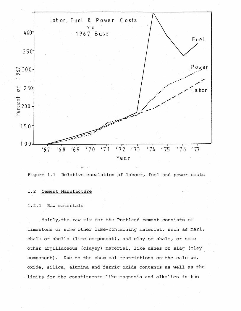
With the 1973 Arab oil embargo, however, the situation has changed quickly. The sharp increases in fuel prices made the energy costs just as significant as the costs of labourin fact, during the following couple of years, with even higher fuel prices, the cost of energy has overtaken labour as the main cost factor in the cement manufacture, as illustrated in Figure 1.1 (Strauss, 1977? Somes, 1979).
Per
cent
of
1
967
400“
300 -
2 50 L a b o r
200
0 ' 71 ' 7 2 ' 7 3 7 74 7 75 7 7 6 77/98 i ti t
Year
Figure 1.1 Relative escalation of labour, fuel and power costs
1.2 Cement Manufacture
1.2.1 Raw materials
Mainly, the raw mix for the Portland cement consists of limestone or some other lime-containing material, such as marl, chalk or shells (lime component), and clay or shale, or some other argillaceous (clayey) material, like ashes or slag (clay component). Due to the chemical restrictions on the calcium, oxide, silica, alumina and ferric oxide contents as well as the limits for the constituents like magnesia and alkalies in the
raw material, usually a careful choice of raw materials mixed in required quantities is necessary.
1.2.2 Unit operations and chemical conversions
In general, cement manufacture consists of four distinct stages:
(i) Preparation of the raw materials in the necessary proportions and in the proper physical state of fineness and intimate contact for the required chemical reactions to occur during the burning process. The preparation starts with the quarrying of the bulk of the constituents of the raw mix from the plant quarry, and is followed by the crushing stage, resulting in a product of about 10-25 mm top size. Argillaceous silicas and ferrious raw mix components (clay component) are added separately to the crusher product using weigh feeders or volumetric measurements at the grinding mills. Ball mills are used for wet and dry processes to grind the material to a fineness such that 15-30% wt. is retained on a 200 mesh sieve. Depending on the type of process, the raw materials are either ground with water and then filtered or dried by other devices before entering the kiln, or they are ground in closed circuit ball mills with air separators, utilizing the exit gas from the preheater to dry the material in suspension.
(ii) Pyroprocessing to heat the mixture to drive off the water, CC^, and to form the fluidized clinker takes place in the kiln system. The pyroprocessing unit, the rotary kiln, is the same in all different types of proceses (dry, semi-wet or wet). It is a highly refractory-lined cylindrical shell
(3-8 metres diameter, 50-230 metres length), equipped with an electrical drive to rotate at 1-3 rpm. The rotary kiln is a counter-current heat exchanger, slightly inclined to the horizontal to enable the raw material fed into the higher end to travel slowly by gravity towards the cooler end.
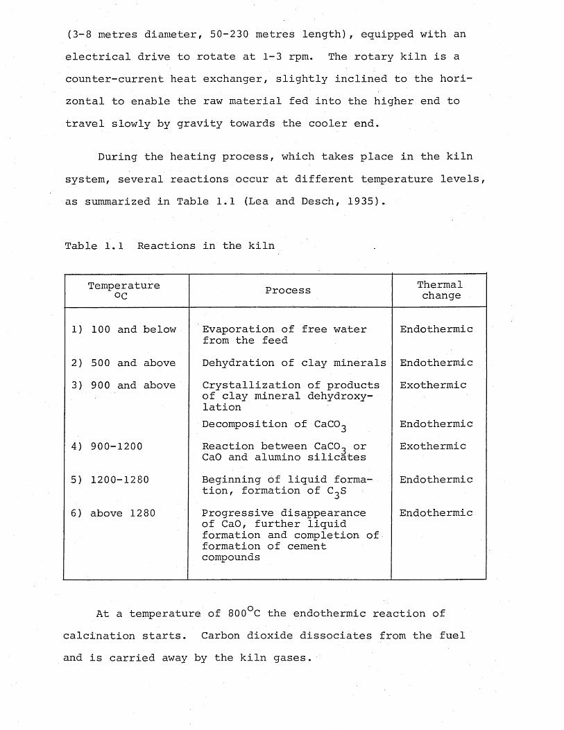
During the heating process, which takes place in the kiln system, several reactions occur at different temperature levels, as summarized in Table 1.1 (Lea and Desch, 1935).
Table 1.1 Reactions in the kiln
Temperatureoc Process Thermal
change
1) 100 and below Evaporation of free water from the feed
Endothermic
2) 500 and above Dehydration of clay minerals Endothermic3) 900 and above Crystallization of products
of clay mineral dehydroxy- lation
Exothermic
Decomposition of CaCO^ Endothermic4) 900-1200 Reaction between CaCO^ or
CaO and alumino silicatesExothermic
5) 1200-1280 Beginning of liquid formation, formation of C^S
Endothermic
6) above 1280 Progressive disappearance of CaO, further liquid formation and completion of formation of cement compounds
Endothermic
At a temperature of 800°C the endothermic reaction of calcination starts. Carbon dioxide dissociates from the fuel and is carried away by the kiln gases.
CaCO (high calcium limestone) + Heat Z CaO (high calcium quick lime) + <X>2 CaCO MgCO (dolomite limestone) + Heat CaO-MgO (dolomite quicklime)| +|2C0
It is necessary for the calcinations of the kiln feed to be completed before entering the burning zone in order to ensure the proper burning of the clinker, and to avoid upset kiln conditions.
In the burning zone, the lime-rich mixture containing silica, aluminium and ferric oxide, with small percentages of other oxides, is heated up to the sintering temperature and becomes viscous. This is called the clinkerizing process, and is manifested by the liquefying of the clinker constituents.At the temperature of 1250°C the formation of the most important compound, C^S, starts, and it continues until the temperature of 1370-1450°C is reached, which means • more lime combining with silica till all the lime present disappears. This temperature is the required temperature for burning a good quality clinker.
(iii) Cooling of the clinker: Just before the discharge end of the kiln, still in the burning zone, cooling of the clinker starts. The clinker at a temperature of approximately 1000°C at the discharge end is cooled to about 60°C in a coolerof some design before being discharged on to a conveyor.Clinker cooling is necessary and important for reasons, such as providing ease of handling, grinding, improved clinker quality, as well as waste heat recovery.
Modern coolers accomplish rapid quenching with air, andthe heat recovered from the cooling of the clinker provides
preheat temperatures of up to 850°C for the air passing through them, which is fed to the kiln as secondary air.
There are mainly four different types of clinker coolers, these being the grate, rotary, satellite and shaft coolers.
(iv) Grinding the cooled product with a small amount (3-5%) of gypsum (CaSO^ . 2^0) to control the setting time, to a fineness required for the chemical reactions to take place when the product is wetted.
1.2.3 Manufacturing processes
Depending on the moisture content of the raw meal, the cement manufacturing processes could be divided into two main groups:
(i) Wet process: The raw meal is in the form of a slurry with a water content of 32-42% when it is introduced to the feed end of the long wet process kiln. Because large quantities of water must be evaporated, most wet process kilns are equipped with heat exchanging devices, such as chains in the dehydration zone. The device chain systems also serve to break up the slurry into nodules that can flow readily down the kiln without forming mud rings. Two main advantages of the wet process are that wet grinding and blending of raw materials give better uniformity in the kiln feed compositions, and the pellets form in the chain section which are less likely to be carried off in the gas stream as they advance through the kiln.
(ii) Dry process: The dry process utilizes a dry kiln
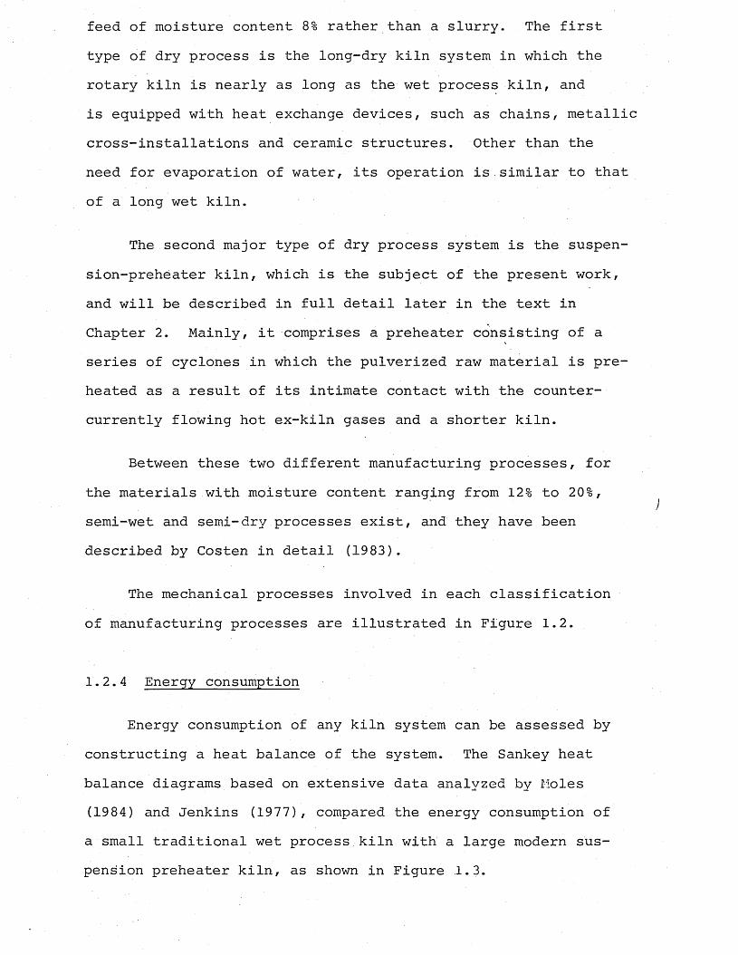
feed of moisture content 8% rather than a slurry. The first type of dry process is the long-dry kiln system in which the rotary kiln is nearly as long as the wet process kiln, and is equipped with heat exchange devices, such as chains, metallic cross-installations and ceramic structures. Other than the need for evaporation of water, its operation is similar to that of a long wet kiln.
The second major type of dry process system is the suspen- sion-preheater kiln, which is the subject of the present work, and will be described in full detail later in the text in Chapter 2. Mainly, it comprises a preheater consisting of a series of cyclones in which the pulverized raw material is preheated as a result of its intimate contact with the counter- currently flowing hot ex-kiln gases and a shorter kiln.
Between these two different manufacturing processes, for the materials with moisture content ranging from 12% to 20%, semi-wet and semi-dry processes exist, and they have been described by Costen in detail (1983).
The mechanical processes involved in each classification of manufacturing processes are illustrated in Figure 1.2.
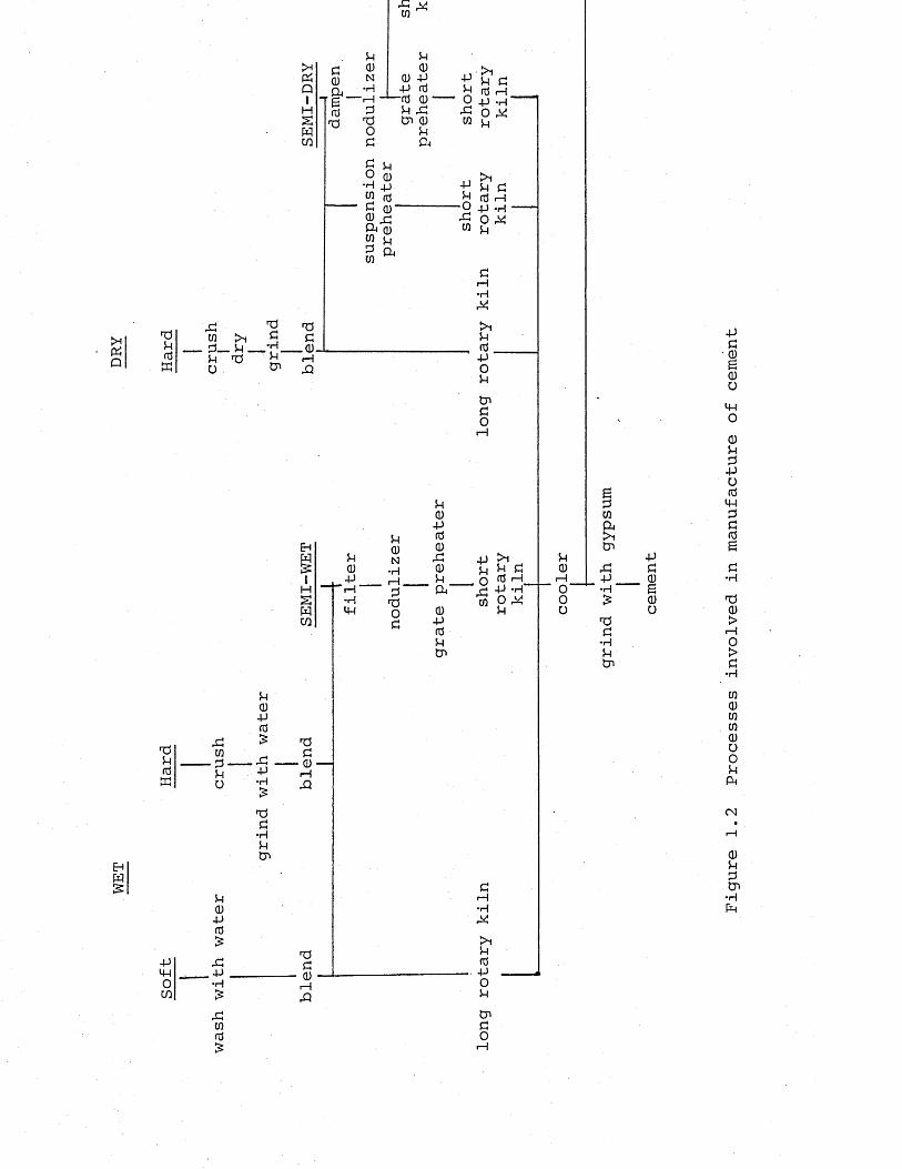
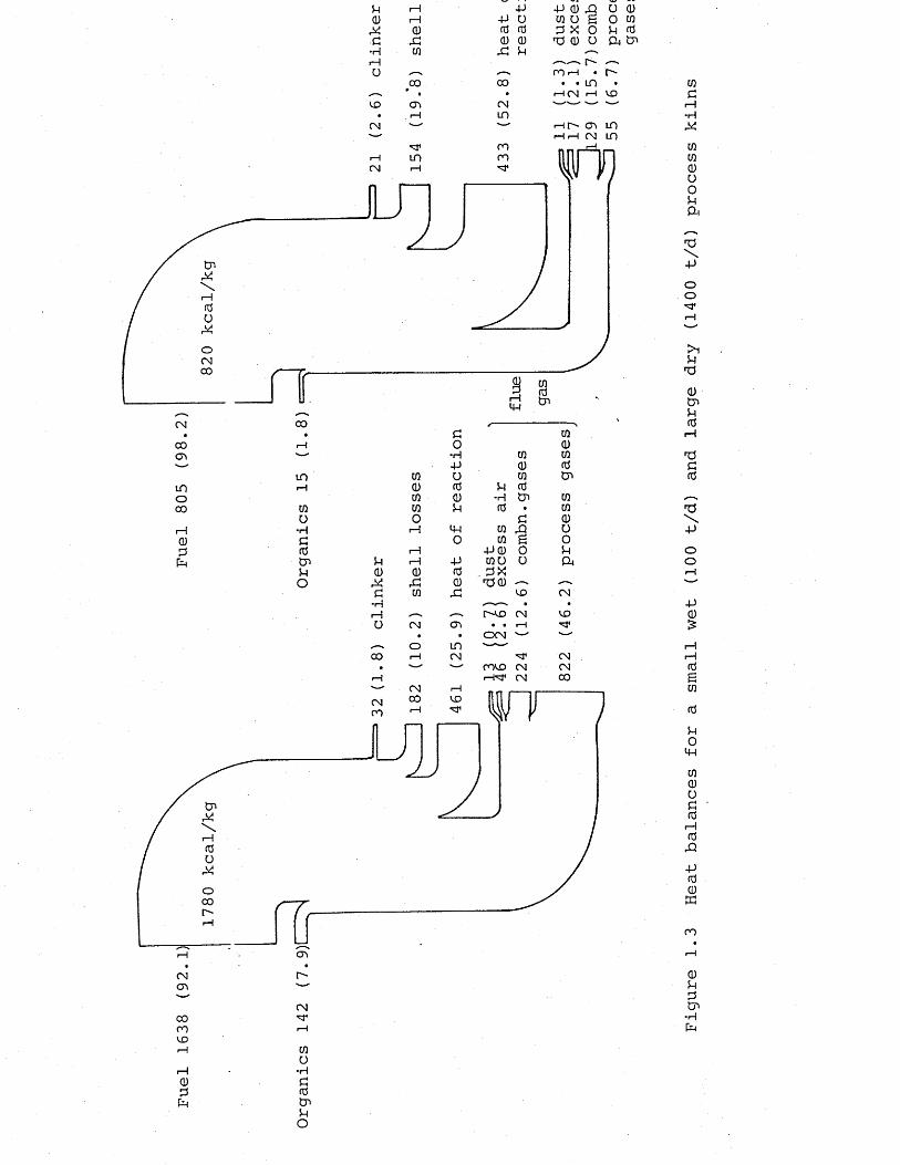
1.2.4 Energy consumption
Energy consumption of any kiln system can be assessed by constructing a heat balance of the system. The Sankey heat balance diagrams based on extensive data analyzed by Moles (1984) and Jenkins (1977), compared the energy consumption of a small traditional wet process kiln with a large modern suspension preheater kiln, as shown in Figure 1.3.
>HPhQ
EhW£
0 -P -P fd i—i fd 0P u T5 tn 0•H
+»
•H
i—I
i—i
•H
rH
-P4HOm i—itn
epU)Q*>itn
u -P0 CI—1 -P 00 •H “ g0 £ 0oc"Hptn
O
Figure
1.2
Processes
involved
in manufacture
of cement
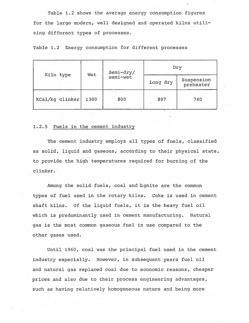
Table 1.2 shows the average energy consumption figures for the large modern, well designed and operated kilns utilizing different types of processes.
Table 1.2 Energy consumption for different processes
Kiln type Wet Semi-dry/Dry
semi-wetLong dry Suspension
preheater
KCal/kg clinker 1300 800 897 740
1.2.5 Fuels in the cement industry
The cement industry employs all types of fuels, classified as solid, liquid and gaseous, according to their physical state, to provide the high temperatures required for burning of the clinker.
Among the solid fuels, coal and lignite are the common types of fuel used in the rotary kilns. Coke is used in cement shaft kilns. Of the liquid fuels, it is the heavy fuel oil which is predominantly used in cement manufacturing. Natural gas is the most common gaseous fuel in use compared to the other gases used.
Until 1960, coal was the principal fuel used in the cement industry especially. However, in subsequent years fuel oil and natural gas replaced coal due to economic reasons, cheaper prices and also due to their process engineering advantages, such as having relatively homogeneous nature and being more
Fuel
1638
(92. 1)
X Fuel
805
(98.2)
1780 kcal/kg
\ 820
kcal/kg
p i—1 -P0) i—1 -P oM Q) fd id£ X <D <D•H Ui X pi— 1u -—, <—-
CO 00’ • •m cn CM• r—i inCM - —'— mrH m mCM rH "3*
-p o) ja u Q)ui o s o tnP x o u ^ (U u Cu tnrorH • r- . . m •i-H CM rH KD
Hh. CTv in pH h cm in17}
Z
rrCO
inCOo
■rH£fdtnPO
cno u
r m cm
mm cm
CM■sTUiO
■rH£fdtnPO
Figure
1.3
Heat balances for
a
small
wet
(100
t/d) and
large
dry
(1400
t/d) process
kilns
convenient to handle. Then, with the 1973 Oil Crisis, all this changed abruptly, leading to a general return to coal (and lignite). As the oil prices rose more, the coal prices became increasingly competitive. Since the coal reserves (world) are far greater than those of oil and natural gas, interest in coal was re-awakened and the future importance was recognized.
The figures for the present coal consumption by the cement industry and the forecasts for the cement industry’s usage of the three basic fuels - gas, oil and coal - in the developed countries like the U.K. (Rooney, 1982)/ U.S.A. (Garrett, 19 82) and Germany (Hochdal, 1982*, Tiggesbaumker et al., 19 82) illustrate the dominance of coal as the fuel for the cement industry.
Coal is the ideal, natural fuel for cement making. Some industries must either burn low sulphur coal (clean fuel) or install expensive tall chimneys to disperse the products of combustion. Therefore, high sulphur coal is not often economically competitive because of the prohibitive costs of meeting local environmental laws. Cement making, however, does not require a clean fuel; there, the coal burns cleanly because the waste products, including ash and most sulphur dioxide, are absorbed into the cement clinker, increasing the yield as well as eliminating the problem of ash disposal.In other words, due to the singular nature of the process and the process materials, the cement industry possesses the ability to sell fuel ash as the marketable end-product, cement. Other properties of cement processing, like not necessitating
short, high intensity flames and having the combustion in a large space which is free of internal fittings (rotary kiln), make coal favourable and a suitable fuel for this industry. Besides, it has been proved by Jenkins and Moles (1978a) that coal firing produces a more efficient cement making flame than either oil or gas, causing a reduction in specific fuel consumption of 150 kcal/kg clinker.
Uniformity of the various constituents of coal (ash, sulphur, chlorine and inherent moisture) are the demands of the cement manufacturer. The permissible ash content of the coal is governed by the raw material, more particularly by limestone due to its effect of lowering the lime standard of the raw mix quite considerably (Hochdal, 1982).
Of primary importance in connection with the preparation of coal is its volatile matter content. Coal with a volatile content above 32% will generally tend to undergo self-ignition on entering non-inert atmospherical conditions. The volatile content is moreover important for the pulverized coal flame itself. The higher the content, the more readily the ignition will occur. According to Gumz (1953) , the influencing factors are the volatile constituents, the ambient temperature, and the possibility of heat transfer to the fuel, i.e. the fineness of the fuel ,-particles and the magnitude of the fuel/air ratio.
The moisture content of the fuel has to comply with the requirements of cement burning too. The coal has to be dried in order to avoid any loss of calorific value, but a residual moisture content of 1-2% of coal, and 5-10% of lignite has
the advantage of somewhat reducing the explosion hazard; so such moisture percentages have to be tolerated, at the expense of calorific value (Tiggesbaumker, Kreft and Beyer, 1982).
The lowest limit for the calorific value of the fuel that can be utilized in the main burner is around 4000 kcal/kg.
Today, with the development of the new suspension preheaters with precalciners or auxiliary firing systems, which will be described in detail later in the text (Chapter 2), it is possible to utilize lower grade "junk" fuels, mud coal, other coal and coke wastes, granulated blast furnace slag, old motor tyres, rubber waste and other industrial and household wastes, to supply 15-30% of the heat requirement of the cement process.
1.2.6 Kiln firing systems
The fuel burner pipe which is normally a plain cylindrical nozzle, is positioned in the centre of the rotary kiln's cross-section, aligned either parallel to the kiln's longitudinal axis, or to the burner floor. The preheated secondary air is supplied co-axially to the burner pipe from the clinker cooler.
In the case of coal firing, the installations for preparing, feeding and firing of the fuel demand considerable adaptability due to variations in its composition. First, the coal has to be dried to the required moisture content in order to avoid any losses of calorific value.
Exit gas from the kiln system should be used for coal
drying, if possible, for fuel economy reasons. Coal drying is almost invariably effected simultaneously with grinding,i.e. comminuting the coal to produce pulverized coal for firing.
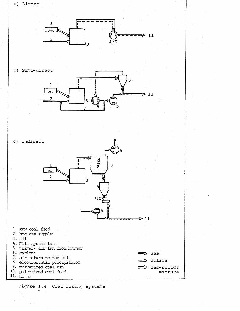
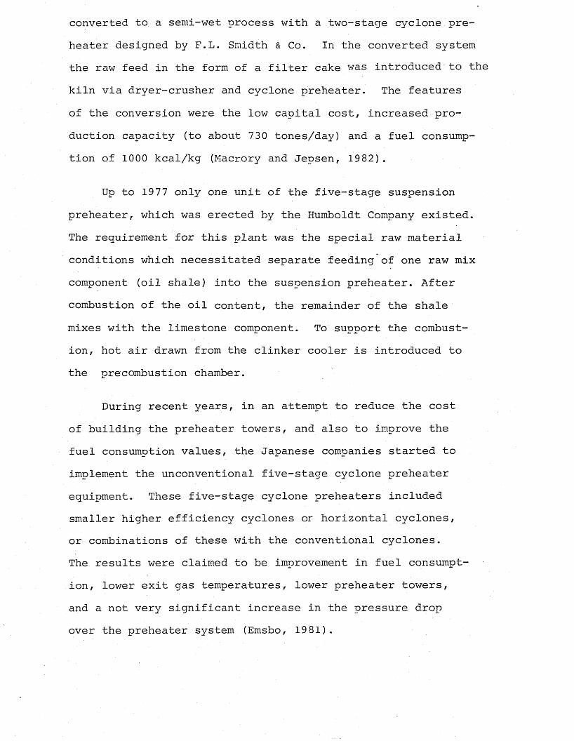
According to the path along which the exhaust gases from coal drying are routed, three different systems exist,as shown in Figure 1.4 (Tiggesbaumker, Kreft and Beyer, 1982).
(i) Direct firing system: The simplest solution is provided by the direct system in which the moist exhaust gas from the drying-grinding plant is fed directly to the burner system as primary air.
The disadvantages of the system are the limited gas exit velocity from the burner nozzle and the control of the rate of firing by the raw coal feed to the mill. The former of these means that not always sufficient kinetic energy for effective mixing with the secondary air is available, which in turn results in poor burn-out of the fuel. The latter means that with variations in moisture content and grindability, the rate of fuel feed to the burner - and therefore the rate of heat input into the kiln - likewise varies.
The system has the advantages of technical simplicity and less maintenance requirement. The kiln and the mill operate in combination, so if the mill develops a fault and has to stop, the kiln must also stop.
(ii) Semi-direct firing system: In order to reduce the amount of primary air, i.e. the amount of mill exhaust gas to be discharged through the burner, a portion of the gas utilized for drying the coal in the mill can be recycled to the mill
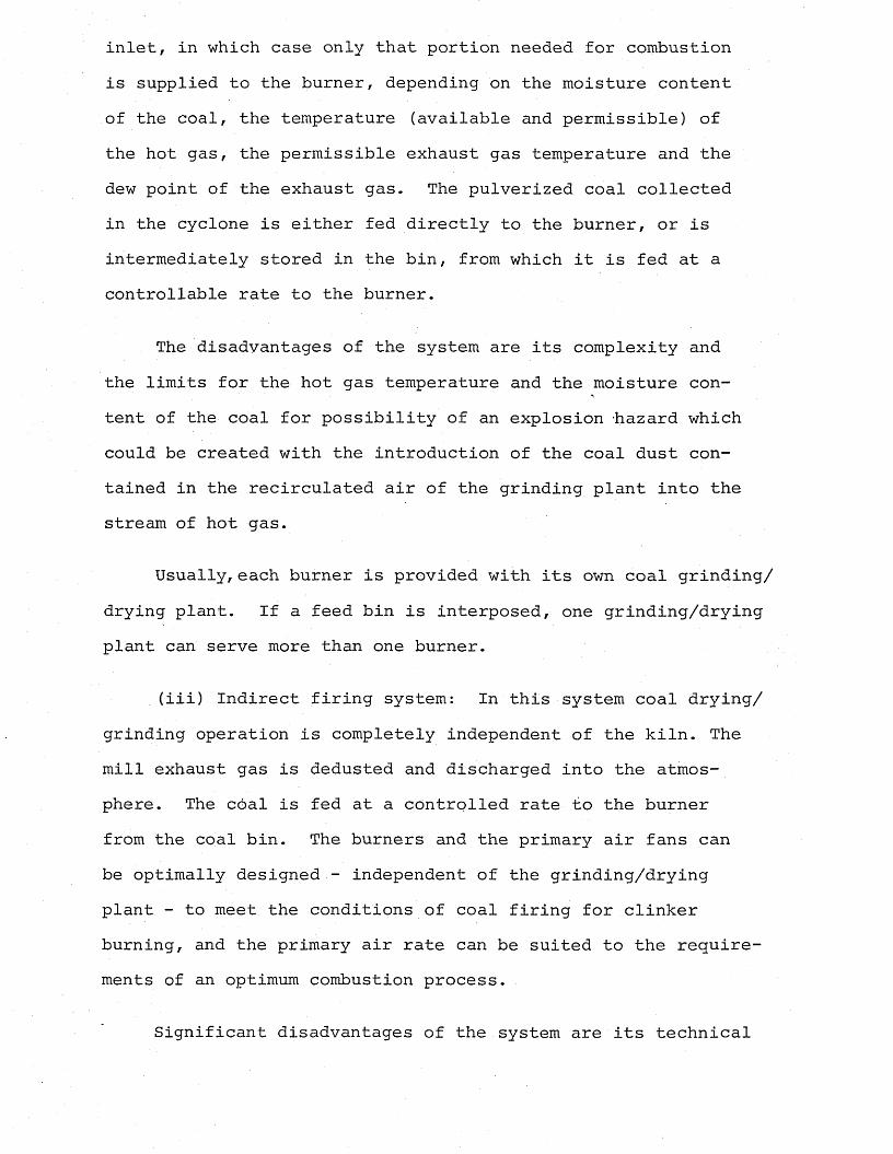
inlet, in which case only that portion needed for combustion is supplied to the burner, depending on the moisture content of the coal, the temperature (available and permissible) of the hot gas, the permissible exhaust gas temperature and the dew point of the exhaust gas. The pulverized coal collected in the cyclone is either fed directly to the burner, or is intermediately stored in the bin, from which it is fed at a controllable rate to the burner.
The disadvantages of the system are its complexity and the limits for the hot gas temperature and the moisture content of the coal for possibility of an explosion 'hazard which could be created with the introduction of the coal dust contained in the recirculated air of the grinding plant into the stream of hot gas.
Usually, each burner is provided with its own coal grinding/ drying plant. If a feed bin is interposed, one grinding/drying plant can serve more than one burner.
(iii) Indirect firing system: In this system coal drying/grinding operation is completely independent of the kiln. The mill exhaust gas is dedusted and discharged into the atmosphere. The coal is fed at a controlled rate to the burner from the coal bin. The burners and the primary air fans can be optimally designed - independent of the grinding/drying plant - to meet the conditions of coal firing for clinker burning, and the primary air rate can be suited to the requirements of an optimum combustion process.
Significant disadvantages of the system are its technical
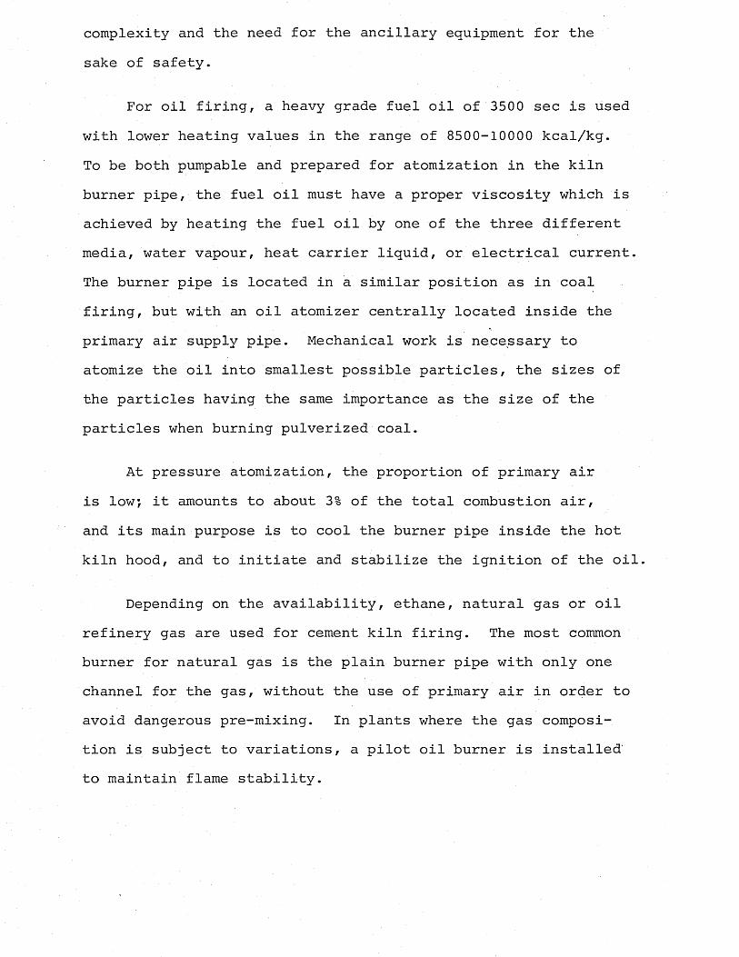
complexity and the need for the ancillary equipment for the sake of safety.
For oil firing, a heavy grade fuel oil of 3500 sec is used with lower heating values in the range of 8500-10000 kcal/kg.To be both pumpable and prepared for atomization in the kiln burner pipe, the fuel oil must have a proper viscosity which is achieved by heating the fuel oil by one of the three different media, water vapour, heat carrier liquid, or electrical current. The burner pipe is located in a similar position as in coal firing, but with an oil atomizer centrally located inside the primary air supply pipe. Mechanical work is necessary to atomize the oil into smallest possible particles, the sizes of the particles having the same importance as the size of the particles when burning pulverized coal.
At pressure atomization, the proportion of primary air is lowj it amounts to about 3% of the total combustion air, and its main purpose is to cool the burner pipe inside the hot kiln hood, and to initiate and stabilize the ignition of the oil.
Depending on the availability, ethane, natural gas or oil refinery gas are used for cement kiln firing. The most common burner for natural gas is the plain burner pipe with only one channel for the gas, without the use of primary air in order to avoid dangerous pre-mixing. In plants where the gas composition is subject to variations, a pilot oil burner is installed' to maintain flame stability.
a) Direct
4/5
b) Semi-direct
c) Indirect
r "
11
1. raw coal feed2. hot gas supply3. mill4. mill system fan5. primary air fan from burner6. cyclone7. air return to the mill 8* electrostatic precipitator9. pulverized coal bin10* pulverized coal feed H * burner
1
GasSolidsGas-solids
mixture
Figure 1.4 Coal firing systems
1.3 Energy Saving in the Cement Industry
Among the research and development activities of the cement industry are the efforts of reducing the specific labour input,chiefly by automation and operating with larger production capacities in order to offset the increased costs due to wages and salaries. Also, by using larger capacity plants, the capital investment costs are lowered.
However, the main cost items associated with cement manufacture, at present, are due to the fuel and electric energy consumed,as mentioned earlier. Reducing the fuel costs may be achieved either by reducing the specific consumption or by using low-grade cheap fuels in the process by which the industry contributes to the world’s general energy conservation plan.
The cement industry can reduce the specific energy consumption by the following methods:
1) To change the process or modify the present one.:2) To reduce the shell heat losses by use of improved refract
ories, or by lowering the temperatures in the burning zone to promote coating inside the refractories.
3) To recover waste heat if possible from the clinker cooling process, or from the flue gases by using it either for material or for coal drying.
4) Flame Control.
A comparison of the specific energy consumption figures (Table 1.2) shows very clearly the potential for energy saving by change of the process type from wet to dry, provided that the raw materials are suitable. In cases of difficult raw
materials, the conversion to semi-wet Lepol grate process may be the solution. In this case, the feed enters the kiln after it has passed through a filter press.
In both cases, conversion is possible, provided that there is sufficient capital available. If the necessary capital is not available, the moisture content of the slurry feed should be reduced by additives. Every 1% reduction in feed moisture content produces a 1.1% fuel saving in a wet process kiln (Moles, 1984).
In dry process suspension preheater kilns, which were thought to be the best system from the heat economy point of view when invented, the heat transfer can be improved even more by applying the precalcining technique. Precalcining can be achieved by either introducing some proportion of the total fuel requirement at the back end of the kiln through an auxiliary firing unit in the riser duct between the kiln and the preheater, or by introducing a separate calciner chamber between the kiln and the fourth stage cyclone of the preheater. The proportion of the fuel fired through the secondary firing unit can be increased up to 60%, which is the amount required for the decarbonation'^reaction.
The advantages obtained by this method are several, but the important ones from the energy conservation point of view are better heat transfer conditions in suspension state for the decarbonation of the material, improvement of the refractory life due to decrease in the thermal load of the burning zone, resulting in longer periods between the shutdowns for brick replacements which means savings in the shot-firing costs.
Also, with this technique the dimensions of the kiln can be reduced, which in turn results in less shell heat losses.
Of the four methods of energy saving in the cement industry mentioned above, the second important one is the flame control. In the conventional processes, the different temperature zones in the kiln (kiln and preheater in dry process) for internal processes of drying, decarbonating and clinkering are maintained by the precise control of the single energy input -flame. Maintaining these three zones is necessary for the reactions in the production of good quality cement clinker. More precise flame control in rotary cement kilns is essential to effect substantial savings in fuel, operating and maintenance costs in the cement industry, for three reasons:
1) Kilns would operate at optimum combustion efficiency conditions (max. 1.0% and 0.1% CO in the flue gases) for longer periods,resulting in lower fuel costs.
2) By moving the flame in a more precise fashion to melt nascent clinker rings, some clinker ring formation could be avoided. Therefore a saving in either down-time or shot- firing costs can be achieved.
3) Flame impingement on the kiln lining could be avoided because the Works Manager could be advised on what type of combustion system to avoid altogether, and the kiln burner could be shown how to alter the flame to avoid impingement.This would save money by increasing the life of the kiln linings.
By using a correlation enabling the flame characteristics
in any rotary kiln system to be predicted from a knowledge of the fuel/air input variables and kiln entrance geometry, the flame length can be optimized by varying the operating conditions to the desired values. An understanding of the aerodynamic aspect of the flames is important in controlling the shape of the flame, achieving good mixing and recirculation, which are essential in preventing a poor flame.
In precalcining suspension preheater kilns, the control of the flame in the kiln is even more essential in maintaining the required sintering temperature with an intense flame, in spite of the modified operating conditions consisting of less than half of the usual rate and very high excess air level especially in the system where the air for the secondary firing is supplied through the kiln. The burning length and the mixing behaviour of the auxiliary fuel are also the main factors to be controlled in the attempts to save fuel.
Energy losses can occur due to incomplete combustion, which manifests itself as a presence of CO in exhaust gases as a result of poor mixing conditions for air and fuel, as well as of long flames. A uniform distribution of. heat is essential for better heat transfer between the suspended particles and the hot gas.
Suspension preheaters with precalcining also provide energy saving by utilizing the lower grade cheap fuels, thereby both reducing the cost of the energy, as well as saving the high grade expensive fuels for the main burner only.Due to the lower temperatures required for the decarbonation reaction, the heat required for this reaction, which is 60%
of the total heat input, can be supplied by burning low grade fuels, domestic or industrial refuse, old motor tyres and others.
In order to achieve the aim of energy saving by one or more of the methods described above, it is essential to have a very good understanding and investigation of the aerodynamics of the furnace, the effects of the modifications introduced to the system for energy saving purposes (such as auxiliary firing) and their influence especially on aerodynamic flow within the kiln unit, the effects of the kiln input variables on the flame length and behaviour, and the heat transfer to charge.
This sort of information, which is unique to the system itself, can be gathered either by experimental work carried out on the prorotype, or by modelling techniques. In most cases, however, carrying out experiments in a real kiln is quite expensive and time-consuming, and still, it may not be possible to observe directly the effect of each input variable on the kiln operation and flame individually) also, the choice of the variables with the ranges within which they can be changed, may be limited. Most significantly, the results obtained may be applicable only to the system tested.
In such cases, the technique of modelling is applied. Satisfactory model experiments are those which are cheap and quick to perform, or which permit the desired observations to be made with greater precision or leisure, correspondingly.
The term "modelling" used here implies the practice of predicting the likely results of one experiment by way of
the interpretation of the results of another experiment; provided that the technique is a reliable one, only the second experiment needs to be performed, which is called the "model" experiment. The first experiment, which is of main interest, is referred to as the "prototype" or the "original".
The practices which fall under the above definition are of many kinds. Included among them, the most common are the geometric scale physical flow models, the mathematical models in which the experiments take place in the mind of the analyst, and the analogues in which the physical and chemical processes are quite different from those of the prototype.
Appropriate, well-proven modelling methods have proved to be useful tools which aid assessment and realization of energy saving ideas in practice, and as such are a valuable resource in improving fuel utilization.
The modelling technique chosen for the purpose of this research is one of physical modelling with the acid alkali method employed for flow visualization.
In the first part of the research, by using model experiments, the effect of the kiln input variables on the flame length are investigated and the model results are compared with the actual kiln trial results (Moles et al., 1974) to find a link between the prototype and the model which will enable interpretation of other model results in terms of kiln variables. At the same time, it is aimed to assess the reliability of the modelling technique chosen for the work.
The second part of the research concerns the auxiliary firing of the suspension preheater dry process kilns, the study of the changes brought about by the introduction of the auxiliary firing system with special emphasis on the aerodynamics affecting the flame behaviour, mixing length for the fuel and air. By using the model experiments, the performances of the kiln-preheater system under different conditions are investigated, with the aim of optimizing these conditions to achieve energy efficiency and savings.
CHAPTER 2
DRY PROCESS CEMENT MANUFACTURE WITH SPECIAL EMPHASIS ON PRECALCINATION
2.1 The Raw Mix Suspension Preheaters
One of the most important developments in the heat economy of cement dry production process is surely the invention of the cyclone suspension preheater in which the dry feed is preheated and partly calcined in a battery of heat exchanger vessels before it enters the rotary kiln. The heat exchange between the gas and the material in the vessels takes place while both are in suspension.
The first patent concerning the raw mix suspension preheater was applied for by Mr. M. Vogel-Jorgensen, an engineer of the construction firm F.L. Smidth Co., Copenhagen. The application was submitted to the Patent Office of the Czechoslovak Republic in Prague on June 1, 1932, under the name, "Method and arrangement for feeding a rotary kiln with fine dispersed material". The invention was patented on July 25, 19 34. The patent description contained the theoretical considerations underlying the design of this heat exchanger system consisting of four stages of cyclone arrangements for preheating the raw mix in suspension for the manufacture of cement by the dry process. Also included in the description was the utilization of the preheater exit gases for raw material drying (Duda,1977).
It was, however, not until 19 years later that a functionally reliable installation of this kind, with a capacity of 300 tons/day,was put into actual practice. On 12 May 1953,
the first rotary cement kiln equipped with a cyclone preheater for raw meal was commissioned at the cement works of Bomke and Bleckmann, Beckum in West Germany. It was built by Klockner-Humboldt-Deutz (KHD) as a result of particularly Franz Muller's work in modifying the process and demonstrating the technical feasibility of this process with its great future potential, and in utilizing it in industrial practice (Bomke, 1978).
During the years following 1953, suspension preheater, kilns were accepted as the best solution for drying and preheating the cement raw meal, and continued to replace the conventional long dry and wet rotary kiln processes in Europe, Japan, and more recently in the U.S.A. Today there are well over 500 suspension preheater systems which have been operated since the 1950's (Garrett, 1982).
The major factor for the overwhelming acceptance of this process by the cement industry is of course the fuel efficiency which is revealed clearly in Table 1.2 by comparison of the figures for energy consumption of the different rotary kiln systems. With the suspension preheaters, it is possible to obtain very low exhaust gas temperatures of about 329°C.
Although there are many different designs of preheater kilns available from many manufacturers, the most widely used one is .the Humboldt with over 100 plants already installed all around the world, and these will be dealt with in more detail in the subsequent section, being the type of the process chosen for the subject of this present work.
2.1.1 The Humboldt cyclone preheater
The Humboldt preheater kiln divides the burning process into two phases: the conventional burning cylinder, rotary kiln is considerably shortened, and the preheating and partial calcining of the raw mix by the hot kiln exit gases is performed in the cyclone raw mix suspension preheater.
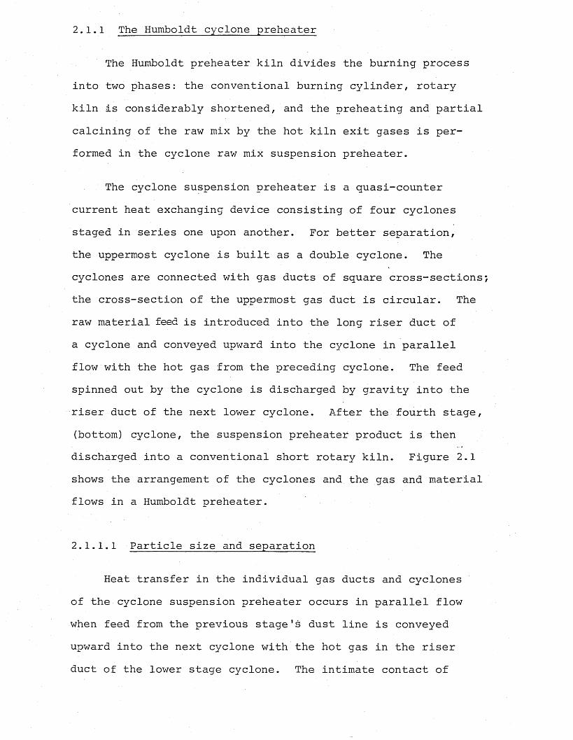
The cyclone suspension preheater is a quasi-counter current heat exchanging device consisting of four cyclones staged in series one upon another. For better separation, the uppermost cyclone is built as a double cyclone. The cyclones are connected with gas ducts of square cross-sections the cross-section of the uppermost gas duct is circular. The raw material feed is introduced into the long riser duct of a cyclone and conveyed upward into the cyclone in parallel flow with the hot gas from the preceding cyclone. The feed spinned out by the cyclone is discharged by gravity into the riser duct of the next lower cyclone. After the fourth stage, (bottom) cyclone, the suspension preheater product is then discharged into a conventional short rotary kiln. Figure 2.1 shows the arrangement of the cyclones and the gas and material flows in a Humboldt preheater.
2.1.1.1 Particle size and separation
Heat transfer in the individual gas ducts and cyclones of the cyclone suspension preheater occurs in parallel flow when feed from the previous stage's dust line is conveyed upward into the next cyclone with the hot gas in the riser duct of the lower stage cyclone. The intimate contact of
► gas♦raw material •
Figure 2.1 Humboldt preheater
feed particles with hot gases results in rapid heat exchange. However, when considered as a whole, the cyclone suspension preheater operates in gradual counter-current. The heat transfer between the gas and the raw mix takes effect in a state of suspension. If the raw meal is very well dispersed in the gas stream, spontaneous equalization of heat between the material and the gas occurs within the period of time that it takes for the material to be entrained in the gas stream and carried with it into the next cyclone. Each preheater stage is considered as an equilibrium unit in which temperature equalization takes place already in the riser duct to the cyclone.
The only function that a cyclone has to perform is to
separate the meal from the gas so that multiple feed of a meal and therefore multiple heat exchange can be accomplished. The feed spinned out by each cyclone is discharged by gravity to the riser duct of the next lower cyclone for repeated parallel flow heat exchange with successively hotter gases.
The separation time of raw mix particles in the preheater cyclones is proportional to the square of the particle diameter which is assumed to be of spherical shape. For proper separation in the cyclones, the particles are required to be of equal size.
2.1.1.2 Particle size and heating time
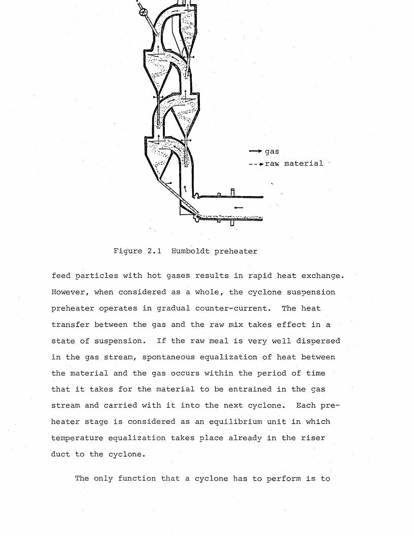
The time required to heat the raw mix particles by the gas in a state of suspension is relatively short. The effect of particle size on the heating time is shown in Figure 2.2, which indicates the periods of time required for heating of limestone particles of different sizes.
o 100
w O.
o o
0.05Seconds
Figure 2.2 Heating time of limestone particles of various sizes suspended in a stream of gas (Duda, 1977)
From the figure above, it is seen that larger particles require longer time for heating. Larger particles are separated in the cyclone before acquiring the temperature of the surrounding gas, resulting in a reduction in heat transfer intensity. By employing a series of cylones, this effect is eliminated. Heat transfer is intensified by feeding the raw meal from one stage to the other in higher and higher gas temperatures, and bringing it to the kiln inlet temperature that way.
2.1.1.3 Heat transfer in cyclone preheaters *
As already mentioned in section 2.1.1.1, the main part of the heat transfer occurs during the parallel flow of gas and raw mix in the riser duct. It has been proved by a Soviet worker, Spassky, as a result of his thermo-technical studies on a four stage cyclone preheater, that 80% of the heat transfer occurs in the riser ducts, whereas only 20% of the total heat transfer is carried out in the cyclones (Duda, 1977) .
The heat content of the exit gases, which have a usual temperature of 330°C in the four-stage suspension preheaters, can be economically utilized in drying of the raw material with up to 8.5% moisture content. The retention time of the raw material particle in a four-stage cyclone preheater of 50 metres height from the feed-point down to the rotary kiln entrance is approximately 25 seconds. During this period of time, the raw mix is preheated from 50°C to 800°C, whereas the ascending kiln gases are cooled from 1100°C to 330°C. At this temperature of 800°C on entry to the kiln,
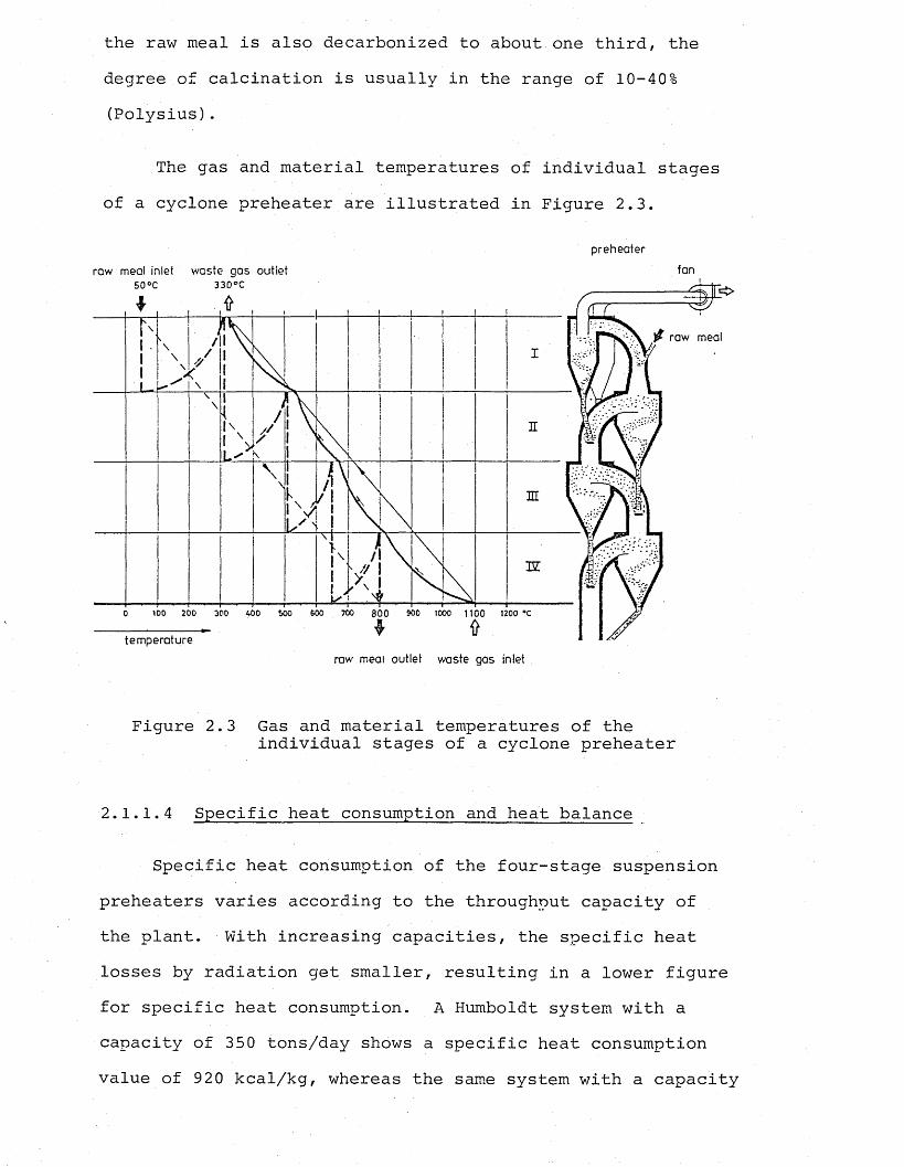
the raw meal is also decarbonized to about one third, the degree of calcination is usually in the range of 10-40% (Polysius).
The gas and material temperatures of individual stages of a cyclone preheater are illustrated in Figure 2.3.
preheaterraw meal inlet waste gas outlet fan
raw meal
3Z
100 200 400 600 700 8 0 0 900 1000 1100 1200 ®C300 500
temperatureraw meal outlet waste gas inlet .
Figure 2.3 Gas and material temperatures of theindividual stages of a cyclone preheater
2.1.1.4 Specific heat consumption and heat balance
Specific heat consumption of the four-stage suspension preheaters varies according to the throughput capacity of the plant. With increasing capacities, the specific heat losses by radiation get smaller, resulting in a lower figure for specific heat consumption. A Humboldt system with a capacity of 350 tons/day shows a specific heat consumption value of 920 kcal/kg, whereas the same system with a capacity
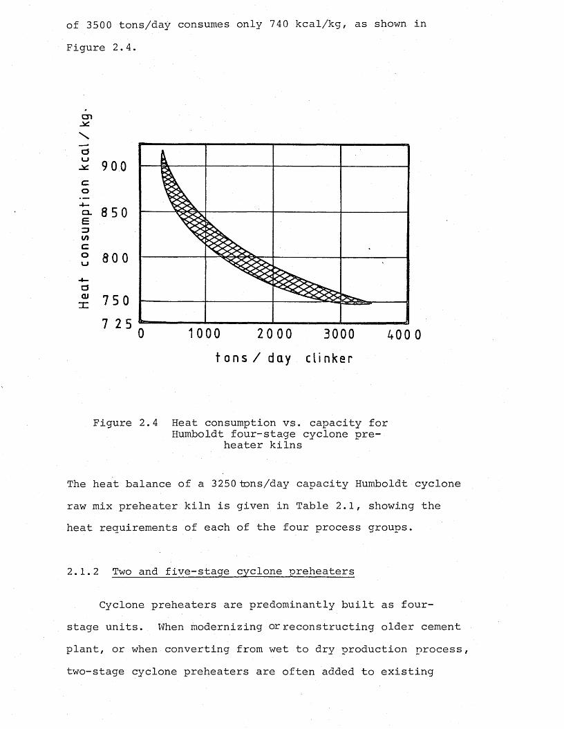
of 3500 tons/day consumes only 740 kcal/kg, as shown in Figure 2.4.
cn
au
ao
eZJI/)co
<3OJnz
9 00
0
02 C <22=1
0 400 0t o n s / da y c l i n k e r
Figure 2.4 Heat consumption vs. capacity for Humboldt four-stage cyclone pre
heater kilns
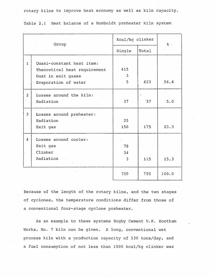
The heat balance of a 3250 tons/day capacity Humboldt cyclone raw mix preheater kiln is given in Table 2.1, showing the heat requirements of each of the four process groups.
2.1.2 Two and five-stage cyclone preheaters
Cyclone preheaters are predominantly built as four- stage units. When modernizing or reconstructing older cement plant, or when converting from wet to dry production process, two-stage cyclone preheaters are often added to existing
rotary kilns to improve heat economy as well as kiln capacity.
Table 2.1 Heat balance of a Humboldt preheater kiln system
GroupKcal/kg clinker
9 - -
Single Total
1 Quasi-constant heat item: Theoretical heat requirement Dust in exit gases Evaporation of water
41535 423 56.4
2 Losses around the kiln: Radiation 37 '37 5.0
3 Losses around preheater:RadiationExit gas
25150 175 23.3
4 Losses around cooler:Exit gasClinkerRadiation
78343 115 15.3
750 750 100.0
Because of the length of the rotary kilns, and the two stages of cyclones, the temperature conditions differ from those of a conventional four-stage cyclone preheater.
As an example to these systems Rugby Cement U.K. Southam Works, No. 7 kiln can be given. A long, conventional wet process kiln with a production capacity of 530 tons/day, and a fuel consumption of not less than 1500 kcal/kg clinker was
converted to a semi-wet process with a two-stage cyclone preheater designed by F.L. Smidth & Co. In the converted system the raw feed in the form of a filter cake was introduced to the kiln via dryer-crusher and cyclone preheater. The features of the conversion were the low capital cost, increased production capacity (to about 730 tones/day) and a fuel consumption of 1000 kcal/kg (Macrory and Jepsen, 1982).
Up to 1977 only one unit of the five-stage suspension preheater, which was erected by the Humboldt Company existed. The requirement for this plant was the special raw material conditions which necessitated separate feeding of one raw mix component (oil shale) into the suspension preheater. After combustion of the oil content, the remainder of the shale mixes with the limestone component. To support the combustion, hot air drawn from the clinker cooler is introduced to the precombustion chamber.
During recent years, in an attempt to reduce the cost of building the preheater towers, and also to improve the fuel consumption values, the Japanese companies started to implement the unconventional five-stage cyclone preheater equipment. These five-stage cyclone preheaters included smaller higher efficiency cyclones or horizontal cyclones, or combinations of these with the conventional cyclones.The results were claimed to be improvement in fuel consumption, lower exit gas temperatures, lower preheater towers, and a not very significant increase in the pressure drop over the preheater system (Emsbo, 1981).
2.1.3 Various preheater systems
2.1.3.1 Dopol preheater of the Polysius Company
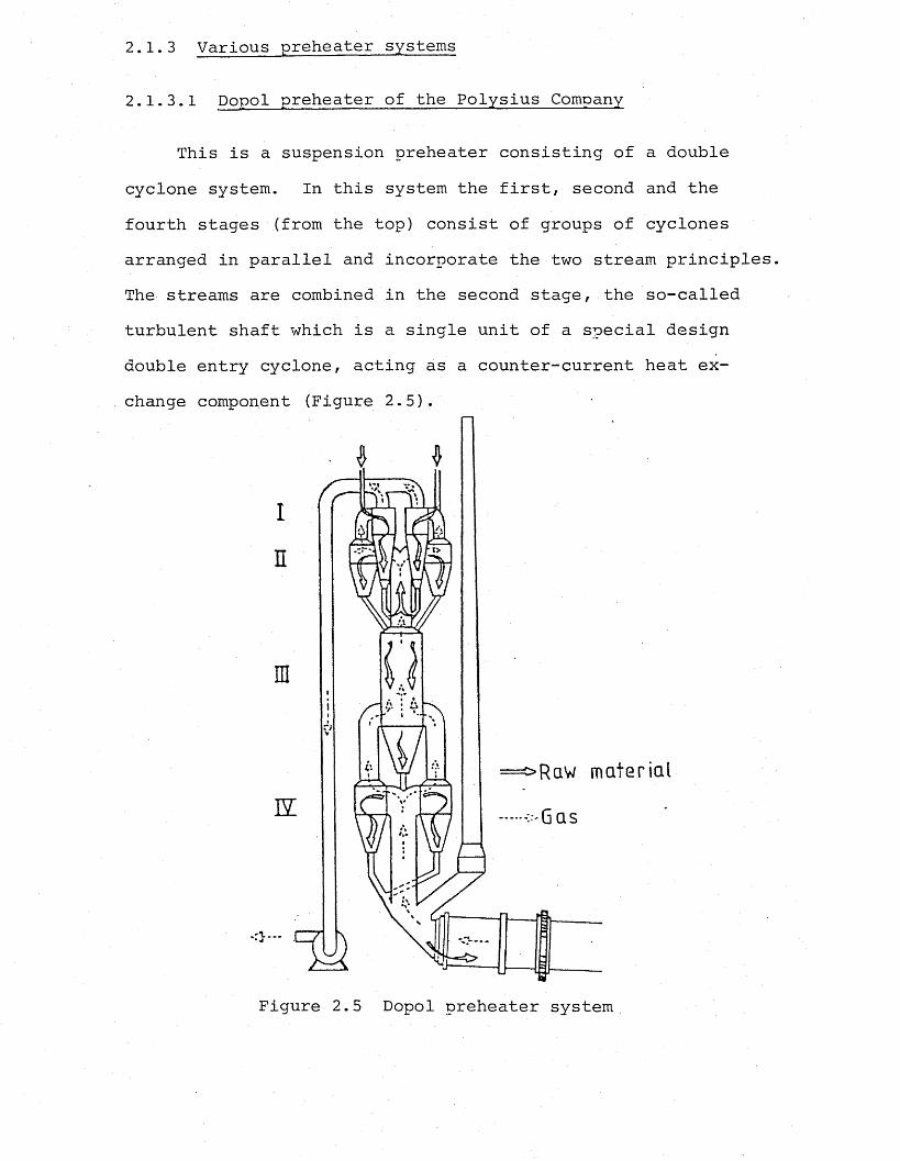
This is a suspension preheater consisting of a double cyclone system. In this system the first, second and the fourth stages (from the top) consist of groups of cyclones arranged in parallel and incorporate the two stream principles The streams are combined in the second stage, the so-called turbulent shaft which is a single unit of a special design double entry cyclone, acting as a counter-current heat exchange component (Figure 2.5).
=>Rqw material
Gas
Figure 2.5 Dopol preheater system
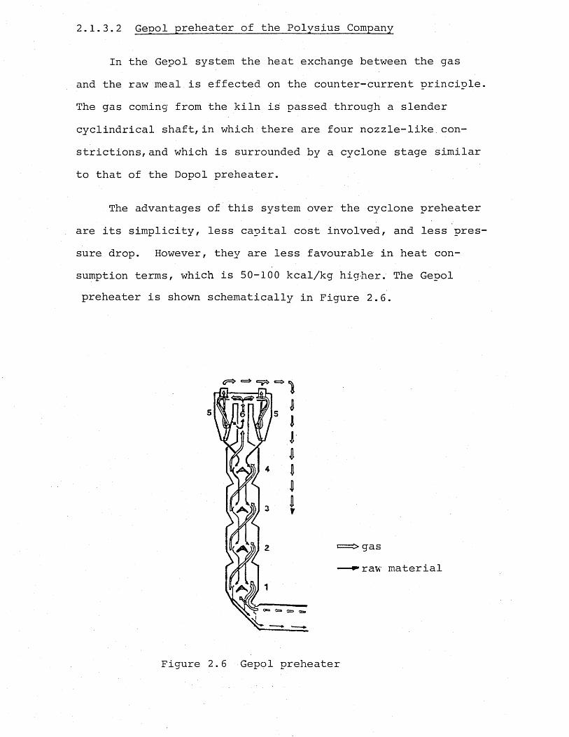
2.1.3.2 Gepol preheater of the Polysius Company
In the Gepol system the heat exchange between the gas and the raw meal is effected on the counter-current principle. The gas coming from the kiln is passed through a slender cyclindrical shaft,in which there are four nozzle-like constrictions, and which is surrounded by a cyclone stage similar to that of the Dopol preheater.
The advantages of this system over the cyclone preheater are its simplicity, less capital cost involved, and less pressure drop. However, they are less favourable in heat consumption terms, which is 50-100 kcal/kg higher. The Gepol preheater is shown schematically in Figure 2.6.
Figure 2.6 Gepol preheater
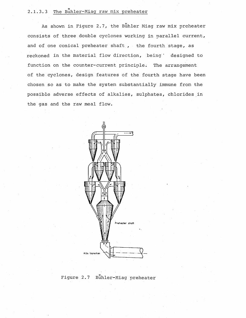
II2.1.3.3 The Buhler-Miag raw mix preheater
As shown in Figure 2.7, the Buhler Miag raw mix preheater consists of three double cyclones working in parallel current, and of one conical preheater shaft , the fourth stage, as reckoned in the material flow direction, being ' designed to function on the counter-current principle. The arrangement of the cyclones, design features of the fourth stage have been chosen so as to make the system substantially immune from the possible adverse effects of alkalies, sulphates, chlorides in the gas and the raw meal flow.
Figure 2.7 Buhler-Miag preheater
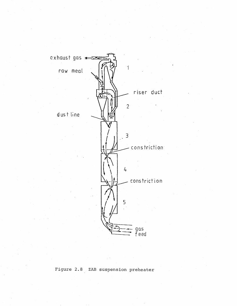
2.1.3.4 The ZAB raw mix suspension preheater
This five-stage suspension preheater, which was introduced in the 1970’s as a result of many years' research and model work, consists of three shaft stages and two groups of cyclones placed before it. The shaft stages are charac-: terized by their oval cross-section, and by the fact that their vertical axes are arranged in a staggered way to each other, as shown in Figure 2.8. These preheaters are characterized by simple design and reliable operation. Heat consumption value is low, 760 kcal/kg.
✓
2.1.3.5 The Prerov counter-current suspension preheater
The Prerov raw meal preheater, shown in Figure 2.9, is also of very simple design, and belongs to the category of shaft-type preheaters. The gas stream from the kiln is introduced tangentially into the lower end of the shaft.The gases perform a rotary motion all the way up the shaft and achieve intensive heat transfer to the raw meal on the counter-current principle. The raw meal is fed into the top part of the shaft, and is carried along by the gases into the concentrating system surmounting it. This system consists substantially of a concentrating cyclone and a battery of dust collecting cyclones.
e xh au s t gas
r i s e r duc t
d u s t l ine
c o n s t r i c t i o n
c o n s t r i c t i o n
Figure 2.8 ZAB suspension preheater
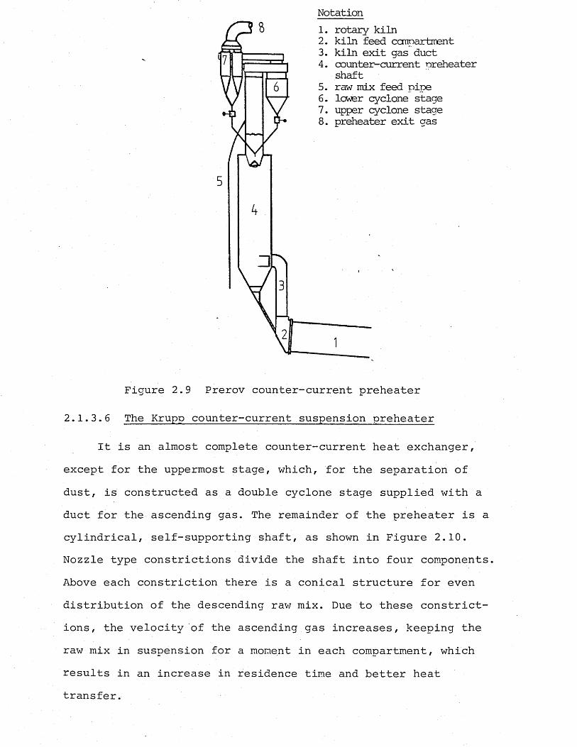
Notation1. rotary kiln2. kiln feed compartment3. kiln exit gas duct4. counter-current preheater
shaft5. raw mix feed pipe6. lower cyclone stage7. upper cyclone stage8. preheater exit gas
Figure 2.9 Prerov counter-current preheater
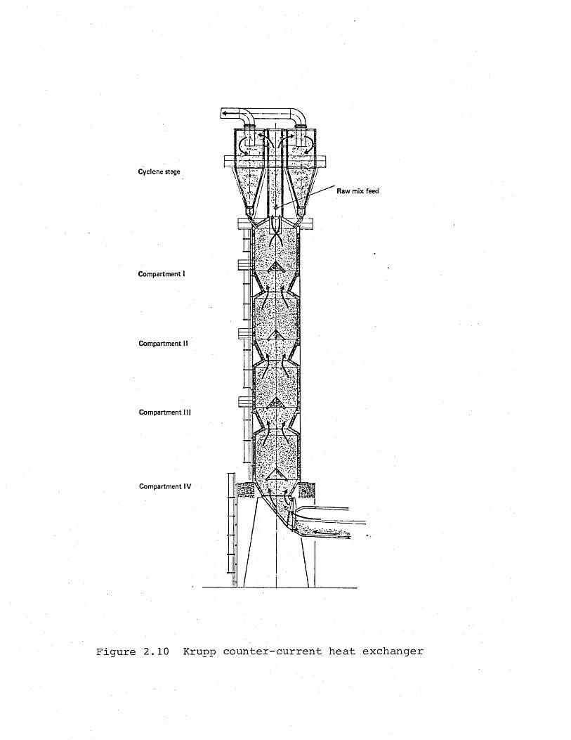
2.1.3.6 The Krupp counter-current suspension preheater
It is an almost complete counter-current heat exchanger, except for the uppermost stage, which, for the separation of dust, is constructed as a double cyclone stage supplied with a duct for the ascending gas. The remainder of the preheater is a cylindrical, self-supporting shaft, as shown in Figure 2.10. Nozzle type constrictions divide the shaft into four components, Above each constriction there is a conical structure for even distribution of the descending raw mix. Due to these constrictions, the velocity of the ascending gas increases, keeping the raw mix in suspension for a moment in each compartment, which results in an increase in residence time and better heat transfer.
Cyclone stage
Compartment I
Compartment II
Compartment III
Compartment IV
.V r
Raw mix feed
Figure 2.10 Krupp counter-current heat exchanger
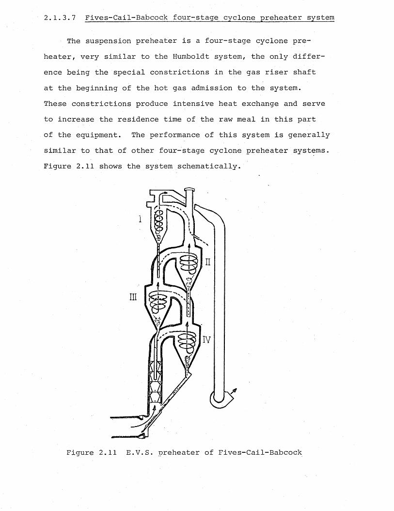
2.1.3.7 Fives-Cail-Babcock four-stage cyclone preheater system
The suspension preheater is a four-stage cyclone preheater, very similar to the Humboldt system, the only difference being the special constrictions in the gas riser shaft at the beginning of the hot gas admission to the system.These constrictions produce intensive heat exchange and serve to increase the residence time of the raw meal in this part of the equipment. The performance of this system is generally similar to that of other four-stage cyclone preheater systems. Figure 2.11 shows the system schematically.
Figure 2.11 E.V.S. preheater of Fives-Cail-Babcock
2.1.4 The preheater by—pass system; Alkali recirculation
It was first realized in the United States in 1935 that destruction of concrete takes effect, caused by a reaction between the cement's alkalies and the aggregates, especially if the aggregates contain about 0.25%-5% of components harmful to concretes like quartz, feldspar, clay shale, sandstone, granite rocks, rock mixtures consisting of quartz, chalcedony and opal, tridymite, cristobalite, zeolite, and volcanic glass.
It was found that the maximum admissible alkali content in cement was 0.60% whereby the alkalies are expressed as their molecular equivalent of sodium oxide.
In suspension preheater kilns morej alkalis i remain for the time of burning in the kiln system, thus in the clinker, than in other kiln systems. During the burning process, alkali|s! in the amount of 0.6-2.2% I^O and 0.1-0.7% Na20 coming from the clay component of the raw mix and from the fuel are transferred into the clinker.
Above approximately 800°C, the alkaliJs' in the kiln start to vaporize. However, part of the alkali]s; > the most temperature resistant ones, remain in the clinker and appear
in the clinker minerals ^ 2 3 S12' N<~8 A3,K< 8 A3' K2 ^ 4 ancNa2 SO^. The volatilized alkalis condense on the colder sections of the kiln system, especially on the kiln feed, which happens in preheater kilns in the third and fourth stage cyclones. The rate of condensation of especially
in the preheater is quite high (81-9 7%) , whereas Na2<~) condenses at a lower rate. This means that only a small proportion of the alkalies' (19—3%) leave the preheater kiln,
making the exhaust gas alkali content low, which can be returned into the kiln.
The condensed alkali]s| arrive with the preheated raw material mix along the material path in the kiln zones with higher temperatures where they again volatilize, causing the internal alkali cycle. This is in contrast to the external alkali cycle, which is produced by returning the alkali ladenexit gas into the kiln with the raw mix.
The alkali circuit can be lowered in order to reduce the alkali content in the clinker by a special by-pass arrangement for some proportion of the kiln gases. This is achieved
usually by diverting some of the gases through a by-pass valve in the lowest part of the stage four cyclone. However, thealkali laden kiln dust diverted through the by-pass, cannotbe returned back to the kiln. Due to the investment cost of the by-pass arrangement, and also the increase in heat consumption, as well as power requirement caused by the bypass, not more than 25% of the kiln exit volume is diverted through a by-pass valve. By more than 25% by-pass volume, only relatively low alkali reduction is achieved. In most cases the volume of 3-10% is usually found sufficient.
The increase in the heat consumption for 1% by-pass volume is about 4.5 kcal/kg clinker, and the increase in the energy consumption is about 2Kwh/ton clinker, independent of the by-pass volume. The material loss by turning, aside of the kiln dust through the by-pass valve amounts to 1% referred to the weight of the raw mix for 10% by-pass volume.
As a result of experimental work carried out by Sprung (1964), the parameters affecting the alkali cycle most were determined and the following conclusions were drawn.
a) The volatility of alkalis' increases with temperature and retention time in the burning zone.
! jb) The volatility of the alkali s depend on the SO^-content
of the raw meal. Increasing S03~content in the raw mix and SC^-content in the exit gases causes a decrease of the volatility of the raw mix alkalis | , as well as of the circulating alkalies.
c) In the sequence of the alkali carriers in the raw mix, i.e. illite, mica, orthoclase, the volatility of the raw mix alkalies decreases.
The volatility of the alkalies also increases with the increase of the amount of Cl contained in the raw mix, as well as in the kiln gases, and the water vapour in the kiln gases. Above all, it is the Cl which increases the volatility of the circulating alkalis „ For this purpose, Cl is added in the form of calcium chloride in various ways:
(i) to the raw mix in the grinding mill(ii) to the raw mix before feeding the kiln(iii) injecting Of 30% CaC^-solution underneath the
burner pipe into the rotarytkiln(iv) injecting of CaC^-dust to the secondary air.
The method of addition of calcium chloride to the raw mix for alkali reduction was first practised in America by Dr. L.T. Brownmiller in 1937 (Duda, 1977).
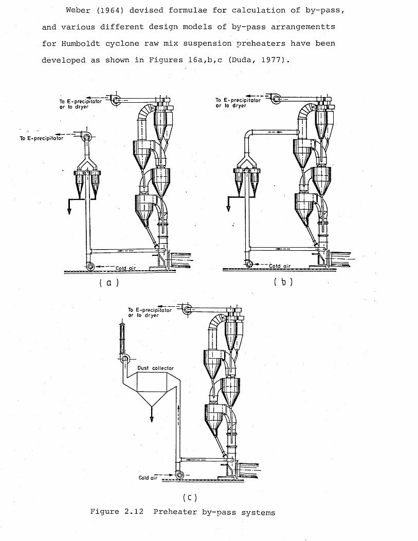
Weber (1964) devised formulae for calculation of by-pass, and various different design models of by-pass arrangementts for Humboldt cyclone raw mix suspension preheaters have been developed as shown in Figures 16a,b,c (Duda, 1977).
To E-precipitator or to dryer
To E-precipitator
Cold air
a
To E-precipitator or to dryer
Cold air
To E-precipitator or to dryer
Dust collector
Cold air
( c )
Figure 2.12 Preheater by-pass systems
2.2 Precalcination
2.2.1 Introduction
During the past fifteen years precalcination has been one of the most important topics in the cement industry. Although the basic concept of calcining, i.e. dividing the input of fuel between the kiln and the preheater, dates back in principle to ideas patented by A. Andrews in 1930, its practical realization came about only with the development of the dry process towards large kiln units with high' capacities and the problems to which these gave rise (Gerstner, Schleger, Schwerdtfeger, 1979).
Precalcining was born more or less at the same time in two different parts of the world, but for two entirely different reasons. In Japan, the boom in cement consumption and the geographical situation of the plants pushed the cement equipment manufacturers to design production lines with very large outputs. To achieve these capacities the dimensions of the kiln had to become excessively large. These larger size kilns became uneconomical, particularly in terms of fabrication requirements, shipping difficulties, susceptibility of large diameter kilns to loss of coating due to periodic flexing and reduced refractory life as a result of increased heat flux density in the burning zone. These problems, especially the shorter kiln lining life,resulting from reduction in the strength of the structural brick ring and increase in the thermal load with increasing kiln diameter, led to the most promising approach of burning cement in two stages, as a solution at least to reduce the difficulties.
In the 1960's, the firm of Onada Cement developed the first calciner from the so-called quicklime process. In that process the rotary kiln was fed with pre-burned limestone mixed with clay, as a result of which the output of the kiln was increased two to threefold. The relatively high heat consumption of that process prompted designers to undertake further development, jointly with Kawasaki Heavy Industries, to evolve the so-called R SP process.The development of precalcining process was intensified later in the 1970's (Steinbiss> 1979).
In Germany, a relatively small plant by today's standards, in Dotternhausen, forced the problem of using bituminous shale as a raw material with a heat value of about 900 kcal/kg. This bituminous material had to be introduced at such a location in the preheater kiln system that an efficient and economical operation was guaranteed (Ritzmann and Buech, 1977). In this process, known as the Rohrbach process, available oil shale is economically utilized by supplying it as a portion of the fuel to a firing unit in the preheater.
In 1968, the plant started the operation of using bituminous material in a preheater kiln system. As the development activities of the cement industry to achieve lower capital cost per tonne by installing larger capacity kilns, and also to reduce the operating costs by increasing the efficiency of these large plants with the aim of offsetting the increasing costs due to wages and salaries, continued, the industry, with the 1973 Oil Crisis, faced an even more serious problem. With the rapid rise of the prices of the
fuels, especially oil, the cost of the fuel and the electric energy consumed, have become the main cost factor in cement manufacture. In order to reduce the fuel and energy costs, it was not merely enough to find ways to economize, but also use of low grade cheap fuel was necessary. With these factors, precalcination process developments were intensified in the late 1970's, even more due to the feature of the process to utilize low grade fuels for calcination, which requires lower temperatures.
2.2.2 Theoretical considerations of precalcining
The decomposition reaction which takes place when the raw meal (mainly calcium carbonate) is heated, is called "calcining" or "decarbonation":
CaC03 % CaO + C02
Thermodynamically, the course of this reaction can be characterized by reaction enthalpy, temperature, and carbon dioxide equilibrium pressure. All the quantities are interrelated and are affected by the type of limestone, the impurities and the lattice structure of the calcite. For each type of limestone there is a particular reaction enthalpy and equilibrium pressure/temperature function, so that in the industrial process different conditions exist, i.e. temperatures and heat requirements for decarbonation, for different raw materials. The reaction steps in the decomposition of a limestone particle are as follows (Tigges- baumker and Rother, 1980):
1) supply of heat from the environment to the particle, mainly by convection and radiation;
2) thermal conduction inwards through the layer that has already decomposed;
3) chemical reaction: splitting-off of CC>2, formation and growth of nuclei, recrystallization of CaO, and reaction with the acidic jconstituents of the raw meal;
4) diffusion of C02 through the newly formed layer;
5) transfer of matter to the environment.
If the raw meal is fed in a fine-grained condition, and uniformly distributed in the hot gas, the reactions 1,2,4 and 5 take place with extreme rapidity, and the overall reaction time is determined virtually by the rate of reaction 3. The reaction time may vary from 2 to 12 seconds, bearing in mind that the rate of decomposition, after a short induction period, is very high and then diminishes as decarbonation proceeds, i.e. partial decarbonation up to about 90% takes place extremely quickly (1 to 4 seconds' duration), depending on the particle size, the C02 partial pressure of the environment, and the temperature of the material in the reaction space (Steinbiss, 1979).
According to Furnas (1931), a microscopic level calcination proceeds only from the outside of the particle inwards over a very narrow zone, practically a line. Assumptions are made for a constant linear rate (measured in centimetres per hour) for the penetration of the line of calcination and for the rate's being independent of size and shape of particle, degree of calcination or amount of previous heating. According
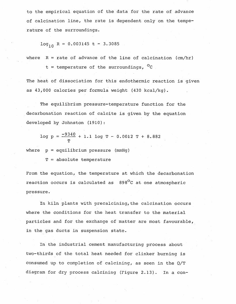
to the empirical equation of the data for the rate of advance of calcination line, the rate is dependent only on the temperature of the surroundings.
log1Q R = 0.003145 t - 3.3085
where R = rate of advance of the line of calcination (cm/hr) t = temperature of the surroundings, °C
The heat of dissociation for this endothermic reaction is given as 43,000 calories per formula weight (430 kcal/kg).
The equilibrium pressure-temperature function for the decarbonation reaction of calcite is given by the equation developed by Johnston (1910):
- 9 3 4 0log p = -■■■ ■ -- + 1.1 log T - 0.0012 T + 8.882T
where p = equilibrium pressure (mmHg)T = absolute temperature
From the equation, the temperature at which the decarbonation reaction occurs is calculated as 89 8°C at one atmospheric pressure.
In kiln plants with precalcining,the calcination occurs where the conditions for the heat transfer to the material particles and for the exchange of matter are most favourable, in the gas ducts in suspension state.
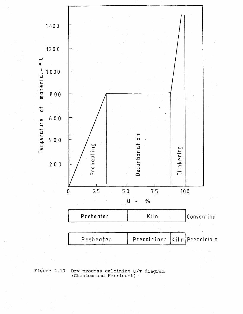
In the industrial cement manufacturing process about two-thirds of the total heat needed for clinker burning is consumed up to completion of calcining, as seen in the Q/T diagram for dry process calcining (Figure 2.13). In a con-
Tem
pera
ture
of
m
ate
ria
l
V _ J
o
1 400
0
cncnc
-O QJGJ0 v _ >cu
QQ.
25 5 0 75Q - %
P r e h e a t e r K i l n
P r e h e a t e r P r e c a l c i n e r K i l n
Convent i on
Pr e c a l c i n i n
Figure 2.13 Dry process calcining Q/T diagram (Ghestem and Herriquet)
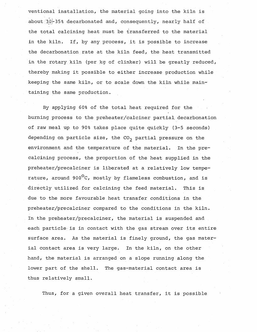
ventional installation, the material going into the kiln is about' 30,-35% decarbonated and, consequently, nearly half of the total calcining heat must be transferred to the material in the kiln. If, by any process, it is possible to increase the decarbonation rate at the kiln feed, the heat transmitted in the rotary kiln (per kg of clinker) will be greatly reduced, thereby making it possible to either increase production while keeping the same kiln, or to scale down the kiln while maintaining the same production.
By applying 60% of the total heat required for the burning process to the preheater/calciner partial, decarbonation of raw meal up to 90% takes place quite quickly (3-5 seconds) depending on particle size, the CC>2 partial pressure on the environment and the temperature of the material. In the precalcining process, the proportion of the heat supplied in the preheater/precalciner is liberated at a relatively low temperature, around 900°C, mostly by ftameless combustion, and is directly utilized for calcining the feed material. This is due to the more favourable heat transfer conditions in the preheater/precalciner compared to the conditions in the kiln.In the preheater/precalciner, the material is suspended and each particle- is in contact with the gas stream over its entire surface area. As the material is finely ground, the gas material contact area is very large. In the kiln, on the other hand, the material is arranged on a slope running along the lower part of the shell. The gas-material contact area is thus relatively small.
Thus, for a given overall heat transfer, it is possible
to replace the eliminated kiln volume by much smaller cal- ciner volume. The economic advantage is evident because it is always desirable to replace rotary components by static components, wherever possible.
According to Vosteeen (1974), for complete calcination of a raw meal of normal fineness the reaction time at temperatures of 900-1000°C is in the range of 2-12 seconds. However, it is desirable to avoid complete calcination, for in that case the temperature of the feed material would undergo an abrupt rise already before entry to the kiln, and would cause objectionable deposits to form in the calciner. A reaction time of about 1 to 4 seconds will suffice to achieve 90% calcination, and if this is achieved in the precalcining system, the heat requirement of the rotary kiln itself is reduced to about 40%. This remaining heat demand in the kiln is sufficient for sintering the material and compensating for the heat loss from the kiln.
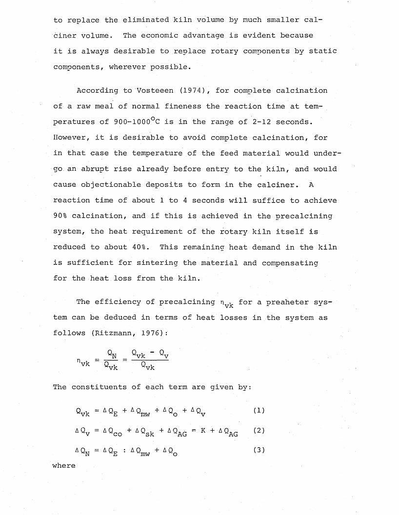
The efficiency of precalcining n ^ for a preaheter system can be deduced in terms of heat losses in the system as follows (Ritzmann, 1976):
nQ , - Q N vk v
vk Qvk Qvk
The constituents of each term are given by:
Qvk = A Q E + A Qmw + AQo + AQv (1)
*Qv = AQCO + AQsk + AQAG “ K + AQAG (2)AQ.7 = AQ„ : AQ + AQ (3)N E mw o
where
Qvk - heat supplied to the preheaterQ = heat recovered for calcining the raw meal EQ = heat contained in the raw meal emergincr from the ^mw ■ .
preheaterQq = heat contained in the kiln exit gas entering the
preheaterQv = heat loss from the preheater
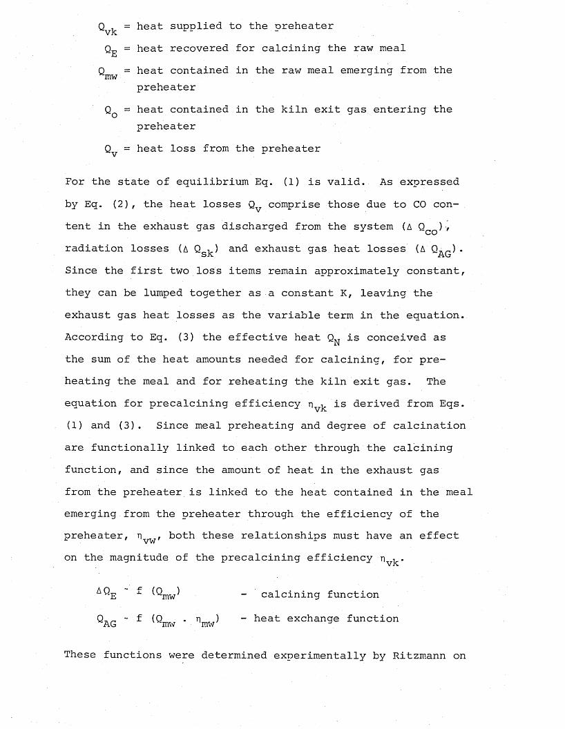
For the state of equilibrium Eq. (1) is valid. As expressed by Eq. (2), the heat losses Qv comprise those due to CO content in the exhaust gas discharged from the system (A Q ) ■/ radiation losses (a Qs]) an^ exhaust gas heat losses (A QAq ) • Since the first two loss items remain approximately constant, they can be lumped together as a constant K, leaving the exhaust gas heat losses as the variable term in the equation. According to Eq. (3) the effective heat QN is conceived as the sum of the heat amounts needed for calcining, for preheating the meal and for reheating the kiln exit gas. The equation for precalcining efficiency is derived from Eqs.(1) and (3). Since meal preheating and degree of calcination are functionally linked to each other through the calcining function, and since the amount of heat in the exhaust gas from the preheater is linked to the heat contained in the meal emerging from the preheater through the efficiency of the preheater, both these relationships must have an effecton the magnitude of the precalcining efficiency
AQe -1- " calcining function
Qag ~ f (Qmw * nmw^ ” heat exchange function
These functions were determined experimentally by Ritzmann on
three different rotary kiln/preheater systems with precalcining and the relationships between the degree of calcination and the raw meal temperature, exhaust gas temperature,and the number of cyclone stages (heat transfer effect), precalcining and heat losses, are obtained and presented in the forms of curves (Ritzmann, 1976).
2.2.3 Description and comparison of types of precalciningprocesses
The main principle of the precalcining process is the supply of a certain part of the fuel required for the complete process to a calciner, or secondary firing system, outside the rotary kiln. In the combustion chamber of the calciner, the fuel is fired in an atmosphere comprising combustion air mixed with kiln exit gas and meal, so that the meal undergoes a substantial degree of precalcination before it enters the kiln. Among other factors, the degree of precalcination is governed by the proportions of the fuel energy supplied to the calciner and to the kiln burner by the supply of combustion air. The hot air from the clinker cooler is utilized as the secondary air,and depending on the method of supplying combustion air (tertiary air) to the calciner or the secondary firing unit, the precalcination processes can be divided into two groups, which are:
1) precalcining process without tertiary air duct or air through the kiln system;
2) precalcining with tertiary air duct or air separate system.
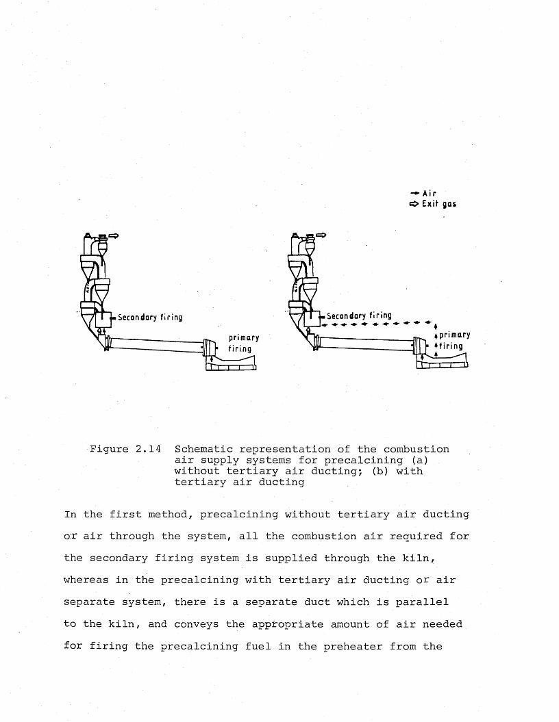
These two methods of supplying the combustion air from the clinker cooler to the calciner are shown schematically in Figure 2.14.
- ♦ A i r ci> E x it gas
Secondary f i r i n g
4 p r i m a r y
♦ f i r i n g
Secondary f i r i n g
p r i m a r y
Figure 2.14 Schematic representation of the combustion air supply systems for precalcining (a) without tertiary air ducting; (b) with tertiary air ducting
In the first method, precalcining without tertiary air ducting o:r air through the system, all the combustion air required for the secondary firing system is supplied through the kiln, whereas in the precalcining with tertiary air ducting or air separate system, there is a separate duct which is parallel to the kiln, and conveys the appropriate amount of air needed for firing the precalcining fuel in the preheater from the
clinker cooler to the preheater. With the air separate system it is also possible to have transitional arrangements, in that only a certain proportion of the precalcining combustion air is supplied through the duct, the rest being passed as excess air through the kiln (Ritzmann, 1978).
When the process engineering differences between the air through and the air separate systems are considered, the excess air factor should be particularly noted. With the system having separate air ducting, the combustion process in the • rotary kiln takes place with the normal air excess (generally corresponding to 2% C>2 in the kiln exit gas) , whereas with the air through the system, the combustion is effected with a higher air excess in the kiln (giving up to 10% C>2 in the exit gas).
Combustion with different air excess factors has certain consequences regarding the flame length, flame temperature and the presence of CO in the exit gas. With the high air excess factor in the air through systems, the ample supply of oxygen causes combustion to take place more rapidly and completely than with the low factor. With the low excess air percentage, there is a possibility of tracing CO in the exit gas from the kiln due to incomplete combustion. With a large air excess factor, however, the fuel is burnt rapidly and completely, giving a short flame. This, with the effect of large amount of excess air in lowering the flame temperature causes a reduction in the coating formation in the kiln due to the lower temperature obtained at the kiln inlet. Operating experience with the kilns without air ducting-air through have confirmed this result even with a relatively small amount of fuel fired
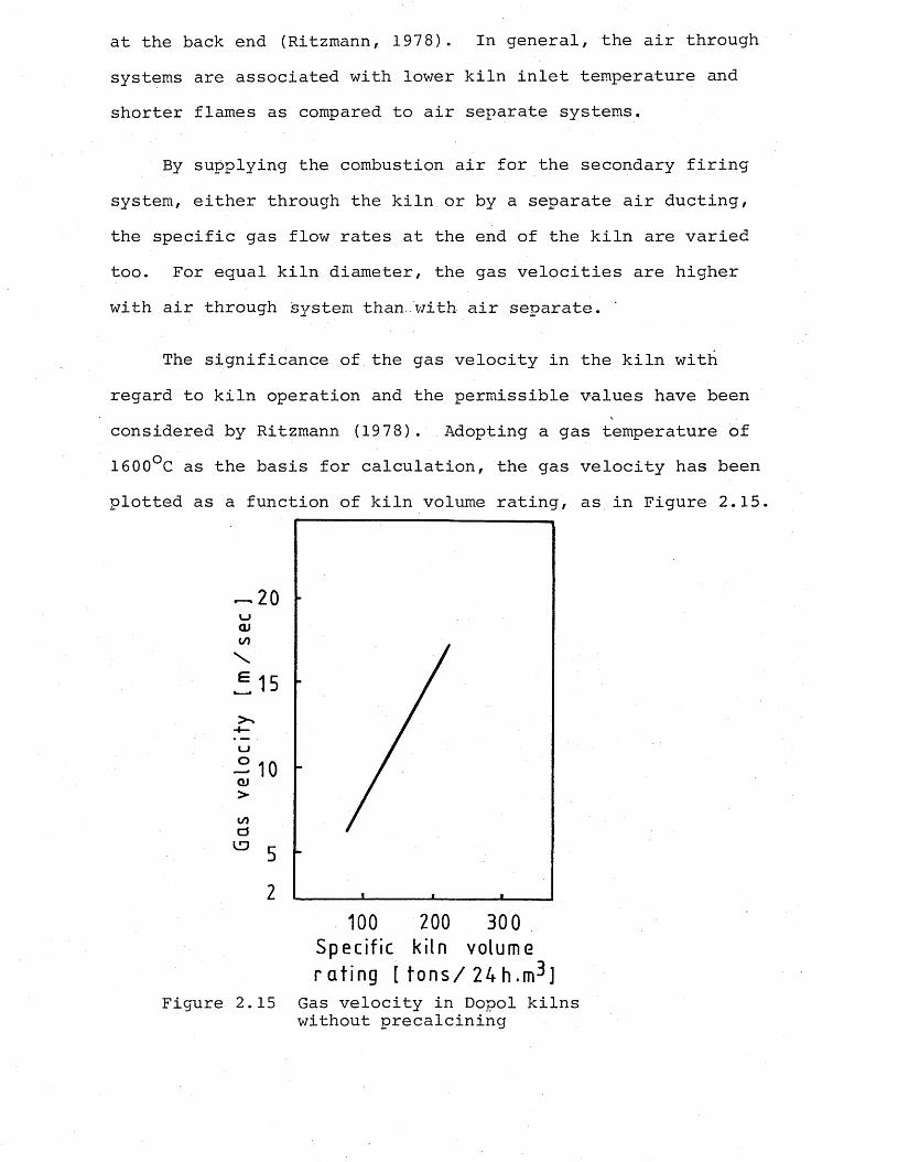
at the back end (Ritzmann, 1978). In general, the air through systems are associated with lower kiln inlet temperature and shorter flames as compared to air separate systems.
By supplying the combustion air for the secondary firing system, either through the kiln or by a separate air ducting, the specific gas flow rates at the end of the kiln are varied too. For equal kiln diameter, the gas velocities are higher with air through isystem than.with air separate.
The significance of the gas velocity in the kiln with regard to kiln operation and the permissible values have been considered by Ritzmann (1978). Adopting a gas temperature of 1600°C as the basis for calculation, the gas velocity has been plotted as a function of kiln volume rating, as in Figure 2.15.
20CL)CO
15
co
2100 200 300
Specif ic kiln volume r a t i n g [ t o n s / 2 4 h . m 3 ]
Figure 2.15 Gas velocity in Dopol kilns without precalcining
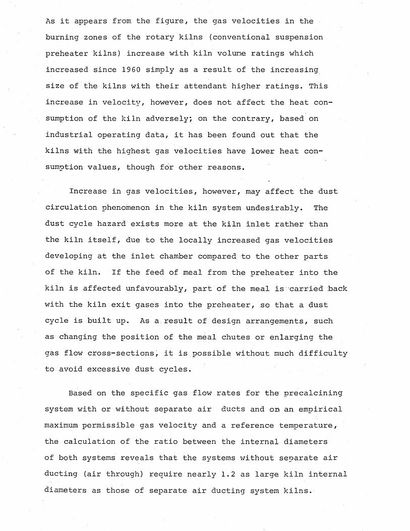
As it appears from the figure, the gas velocities in the burning zones of the rotary kilns (conventional suspension preheater kilns) increase with kiln volume ratings which increased since 1960 simply as a result of the increasing size of the kilns with their attendant higher ratings. This increase in velocity, however, does not affect the heat consumption of the kiln adversely; on the contrary, based on industrial operating data, it has been found out that the kilns with the highest gas velocities have lower heat consumption values, though for other reasons.
Increase in gas velocities, however, may affect the dust circulation phenomenon in the kiln system undesirably. The dust cycle hazard exists more at the kiln inlet rather than the kiln itself, due to the locally increased gas velocities developing at the inlet chamber compared to the other parts of the kiln. If the feed of meal from the preheater into the kiln is affected unfavourably, part of the meal is carried back with the kiln exit gases into the preheater, so that a dust cycle is built up. As a result of design arrangements, such as changing the position of the meal chutes or enlarging the gas flow cross-sections, it is possible without much difficulty to avoid excessive dust cycles.
Based on the specific gas flow rates for the precalcining system with or without separate air ducts and o p an empirical maximum permissible gas velocity and a reference temperature, the calculation of the ratio between the internal diameters of both systems reveals that the systems without separate air ducting (air through) require nearly 1.2 as large kiln internal diameters as those of separate air ducting system kilns.
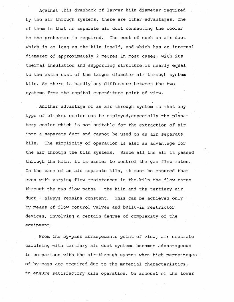
Against this drawback of larger kiln diameter required by the air through systems, there are other advantages. One of them is that no separate air duct connecting the cooler to the preheater is required. The cost of such an air duct which is as long as the kiln itself, and which has an internal diameter of approximately 2 metres in most cases, with its thermal insulation and supporting structure,is nearly equal to the extra cost of the larger diameter air through system kiln. So there is hardly any difference between the two systems from the capital expenditure point of view.
Another advantage of an air through system is that any type of clinker cooler can be employed,especially the plana- tery cooler which is not suitable for the extraction of air into a separate duct and cannot be used on an air separate kiln. The simplicity of operation is also an advantage for the air through the kiln systems.. Since all the air is passed through the kiln, it is easier to control the gas flow rates.In the case of an air separate kiln, it must be ensured that even with varying flow resistances in the kiln the flow rates through the two flow paths - the kiln and the tertiary air duct - always remains constant. This can be achieved only by means of flow control valves and built-in restrictor devices, involving a certain degree of complexity of the equipment.
From the by-pass arrangements point of view, air separate calcining with tertiary air duct systems becomes advantageous in comparison with the air-through system when high percentages of by-pass are required due to the material characteristics, to ensure satisfactory kiln operation. On account of the lower
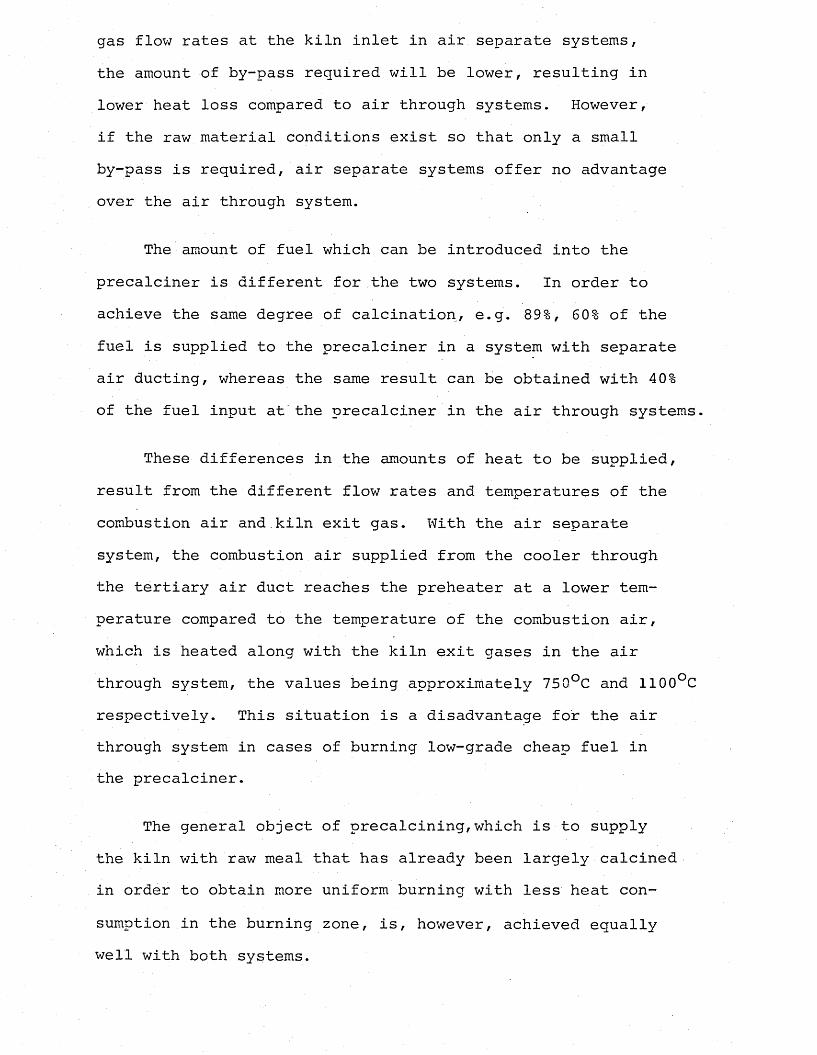
gas flow rates at the kiln inlet in air separate systems, the amount of by-pass required will be lower, resulting in lower heat loss compared to air through systems. However, if the raw material conditions exist so that only a small by-pass is required, air separate systems offer no advantage over the air through system.
The amount of fuel which can be introduced into the precalciner is different for the two systems. In order to achieve the same degree of calcination, e.g. 89%, 60% of the fuel is supplied to the precalciner in a system with separate air ducting, whereas the same result can be obtained with 40% of the fuel input at the precalciner in the air through systems.
These differences in the amounts of heat to be supplied, result from the different flow rates and temperatures of the combustion air and.kiln exit gas. With the air separate system, the combustion air supplied from the cooler through the tertiary air duct reaches the preheater at a lower temperature compared to the temperature of the combustion air, which is heated along with the kiln exit gases in the air through system, the values being approximately 750°C and 1100°C respectively. This situation is a disadvantage for the air through system in cases of burning low-grade cheap fuel in the precalciner.
The general object of precalcining,which is to supply the kiln with raw meal that has already been largely calcined in order to obtain more uniform burning with less heat consumption in the burning zone, is, however, achieved equally well with both systems.
The thermal ratings for the two systems, calcining with and without separate air ducting, have been calculated with regard to the relationships between kiln diameter and output on the basis of 90% calcination/ which requires 40% and 60% of the fuel supplied to the precalciner for the air through and air separate ducting systems respectively.(Ritzmann, 1978). The results have shown that the difference in the thermal ratings was only about 10% in favour of the air separate system, which is in fact too small to create any differences in the specific rates of refractory lining consumption.
In general, the heat consumption of precalcining kilns in comparison with that of conventional cyclone preheater kilns is affected by the higher exit gas temperature and in the altered radiation loss from the kiln. Regarding the exit gas, temperature, radiation losses from the preheater and the CO content of the gas, there is no difference between the two methods. For both cases, exit gas temperature rises with increasing calcination of the kiln feed material.
With regard to radiation losses from the kiln plant, there is hardly any difference between the air through and air separate system plants. Although the larger diameter air through system kiln is associated with correspondingly higher radiation loss compared to the smaller diameter air separate system kiln, the extra radiation from the tertiary air duct of the latter accounts for the difference between the radiation losses from the two kilns.
The NO emission values for the two kiln systems have also been found the same due to the counter effect of the
factors of temperature and the excess air level.
In addition to the assessments and comparisons based on experimental and theoretical data, the two precalcining processes of with and without tertiary air ducting, respectively, have also been compared with each other in terms of heat technology by using a mathematical model developed by Frisch, Jescher and Gardeik (1982). The calculations confirmed the experience gained in the industrial plant, namely that with tertiary air ducting the fuel energy flow into the calciner is greater than without it. The calculation also showed with precalcining using a tertiary air duct the kiln can be shortened by about 20-30% in comparison with the conventional kiln without precalcining. On the other hand, due to the very high temperatures at the kiln inlet, in the kiln systems without tertiary air ducting, it was not thought to be appropriate to shorten the kiln. The effect of clinker dust return to the calciner on the exit gas temperature and on the proportion of the fuel fired in the calciner has also been analyzed by ".using the model. It was found that with increasing dust loading of the kiln exit gas the temperature of the exit gas rises more in the system with tertiary air ducting, at the same time causing the proportion of the fuel energy supplied to the kiln to be increased. Therefore, with very high dust loadings, the difference in the exit gas temperature between the two systems diminishes.
From the point of view of heat technology, the precalcining process with tertiary air ducting offers advantages, because it is sometimes possible, if cheaper fuels are fired in the calciner, to lower the cost of fuel energy, while the coating
formation tendency in the kiln inlet due to undesirable sintering reactions is less because of lower gas temperatures.
2.2.4 Advantages and disadvantages of precalcining
Based on the theory, process descriptions and the existing plant data of calcining, the advantages which could be claimed for the system with precalcining could be summarized as follows:
(i) Increase of capacity: According to the type of theprocess, type of calciner chamber chosen and decarbonation rates reached, the production of a conventional dry-process kiln can be multiplied by 1.3 to 2.5.
Also, as a result of reduced dimensions required, it is possible to consider very high capacity installations (8000tons/ day) without involving the mechanical and refractorylining problems.
The reduced dimensions for a given capacity result in substantial savings in capital investment, and solves many of the problems associated with excessive dimensions, such as shipping difficulties, fabrication requirements, reduced refractory life due to structural reasons.
(ii) Kiln operation: By applying up to 60% of the totalheat required for the burning process to the preheater/pre- calciner, partial decarbonation of raw meal up to 90% takes place extremely quickly due to the favourable heat transfer conditions created by the suspension state of the particles.
When the kiln feed is 90% calcined, it enters the kiln at a constant temperature. As a result, more uniform raw
meal transport in the kiln is achieved, and no flash of material occurs. This ensures a very stable kiln operation and a formation of a uniform and stable coating. These factors together result in longer service life of the refractory lining.
With the precalciner systems, the clinkerization and the kiln operation have been made simpler and the kiln can be controlled with greater precision.
Due to the behaviour of the precalcined meal, there is less risk of objectionable caking on incrustation in the preheater and kiln. Also, precalcining relieves the thermal condition in the burning zone, and this together.with all other factors results in a higher availability of the kiln, affecting the kiln life again,and the operating costs favourably.
(iii) By-pass operation: The precalcining processwith separate air ducting is especially advantageous for theburning of cement raw materials with high alkali and chloridecontent. Since only a fraction of the total fuel input tothe plant is fired in the rotary kiln itself, and the feedmaterial is already largely calcined on entering the kiln,the specific exit quantity at the kiln inlet is lowered by60-70%. Volatilization of the alkalies and chloride is not
*affected; hence their concentration is about three times as high as in the conventional process. Accordingly, with bypass operation of the kiln system, the proportion to be bypassed - and therefore the heat and dust losses - is correspondingly smaller, for equal effectiveness of by-passing.This will also involve a much smaller capital investment for
the by-pass system.
(iv) Use of substitute fuels: An important advantageof the precalcining process is that it can utilize fuels with a high content of inert material (ballast) and low calorific value. This is because high-flame temperatures are not necessary.
The flameless combustion in the calciner does not impose any lower limit for calorific value, since the ignition of the fuel is ensured by the high meal and gas temperatures'of 700-900°C. The heat liberated in flameless combustion is utilized directly, without significant rise in temperature for calcining the feed material. It is thus possible to save high-grade fuels and to make use of combustible waste materials with high ballast content.
It should be noted, however, that the fuel ash (when using high ash content coal on bituminous material) will mix with the raw meal first in the lowest cyclone of the preheater, and then in the kiln. Therefore, based on the fuel ash analysis, the raw meal composition might need correction to meet the required clinker standard.
Among the lower grade, cheap fuels utilized in the pre- heater/precalciners is the oil shale which was first used in the five-stage preheater at Dotterhausen. The oil shale used at that cement works had a calorific value of about 930 kcal/kg, and it offered the additional advantage of producing an ash which consists of substances resembling cement raw meal.
In South Korea, a carbonaceous shale has been used simi-
larly, both as fuel and as clay component in one of the Prepol plants. The coal shale used had a calorific value of 200kcal/ kg, and ignition point above 600°C (Steinbiss, 1979).
In Germany, pulverized lignite has been used in the cement industry with success. It has been used in ZAB preheaters as the secondary fuel providing up to 25% of the total heat requirement of the plant (Huckauf, Gleichmar and Morgen- stern , 1982).
In Turkey, coarse coal - bituminous, lignite or mixture of the two -has been used recently in a number of suspension preheater kiln systems as the fuel for the secondary firing system (private communication - Nuh Cement, 1981).
Pioneering work in the field of old motor tyre burning in the secondary firing systems of the suspension preheater kilns has been done by the firm Dyckerhoff of West Germany in their Neuwied and Amoneburg cement works (Naredi, 1983).
The calorific values of the old tyres varied, depending on their type, but the average value was accepted as 7000kcal/kg.
In Britain, Associated Portland Cement Manufacturers Ltd. have developed and industrially introduced a process for the firing of pulverized domestic and industrial refuse in rotary cement kilns, together with the conventional fuels in a long- wet process kiln at Northfleet Works (Pennel, Giles and Hansen, 1977).
A process developed by Mannessmann-Veba-Umwelttechnik produces household refuse briquettes, called Eco-Briq, which have been used quite successfully in a suspension preheater
kiln in West Germany.
Other waste fuels which are used in the secondary firing systems of the suspension preheater kilns include charcoal, fuller's earth,acid sludge, which are introduced at or near the kiln inlet in conventional plants with cyclone-type or grate type preheater equipment. In such cases, the heat from these substitute fuels is, particularly in cyclone preheater plant, also largely utilized to precalcine the feed material. However, the proportion of these fuels is limited to 15-30% of the total heat consumption, because they cause an increase in the carbon monoxide concentration of : the exit gas if they are used in high proportions.
During the tests with these alternative fuels, it has also been confirmed that the content of nitrogen oxides in the exit gas is reduced by operating a secondary firing system due to the combustion at low temperatures.
After so many advantages, the disadvantages of the precalcining process must not be overlooked. Chief among these is the higher heat consumption. If a certain degree of calcining is to be attained in the calciner, the temperature in the equilibrium pressure/temperature function of the raw meal will have to be appropriately raised, so that the temperature profile in the preheater rises, involving the exit gas temperature, with the result of increased exit gas heat losses. Slight heat losses may occur if the exit gas still contains combustible matter, carbon monoxide. On account of the lower radiation from the kiln with calciner, there is, on the other hand, a slight heat saving to offset a portion of the exit gas losses.
The fuel energy consumption and fuel apportionment in the precalcining process have also been investigated by use of a mathematical model (Gardeik and Rosemann, 1981), and the calculated values compared well with the actual plant operating data. The model has been found suitable for estimating the effect of various influences upon kiln operation and fuel energy consumption, like the proportion of the fuel supplied to the secondary firing unit, the by-pass proportion, and the use of lower grade fuels. The results of the calculations showed that the fuel energy consumption increased with increasing proportion of the fuel supplied to the secondary firing (precalcining system), with diversion of the kiln gas (by-pass), and with utilization of lower grade fuels, which all agree with the data from the operating experience.
2.2.5 Precalcining in existing plants ■
Precalcining is applied in the existing kiln plants equipped with conventional suspension preheaters'by introducing the fuel for precalcining - certain amount to supply some proportion of the total heat requirement - in the riser duct above the kiln end housing. All the precalcining combustion air is drawn through the kiln itself. Because of the absence of a combustion chamber, however, the fuel can in most cases not undergo complete combustion, so that carbon monoxide occurs in the exit gas if the proportion of fuel fired in the secondary firing system exceeds 3 0%.
Generally speaking, the main objective of this technique is to benefit from one or more of the advantages offered by the plants with precalcining process, and not so much to in-
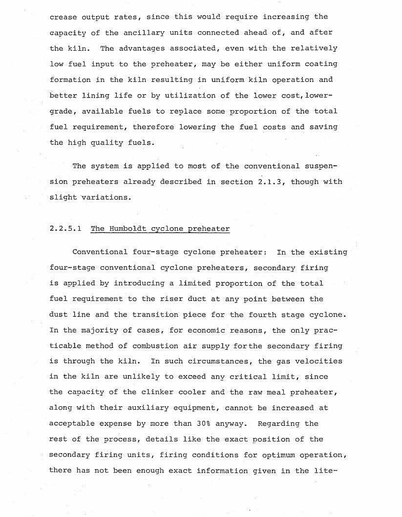
crease output rates, since this would require increasing the capacity of the ancillary units connected ahead of, and after the kiln. The advantages associated, even with the relatively low fuel input to the preheater, may be either uniform coating formation in the kiln resulting in uniform kiln operation and better lining life or by utilization of the lower cost, lower- grade, available fuels to replace some proportion of the total fuel requirement, therefore lowering the fuel costs and saving the high quality fuels.
The system is applied to most of the conventional suspension preheaters already described in section 2.1.3, though with slight variations.
2.2.5.1 The Humboldt cyclone preheater
Conventional four-stage cyclone preheater: In the existingfour-stage conventional cyclone preheaters, secondary firing is applied by introducing a limited proportion of the total fuel requirement to the riser duct at any point between the dust line and the transition piece for the fourth stage cyclone. In the majority of cases, for economic reasons, the only practicable method of combustion air supply for the secondary firing is through the kiln. In such circumstances, the gas velocities in the kiln are unlikely to exceed any critical limit, since the capacity of the clinker cooler and the raw meal preheater, along with their auxiliary equipment, cannot be increased at acceptable expense by more than 3 0% anyway. Regarding the rest of the process, details like the exact position of the secondary firing units, firing conditions for optimum operation, there has not been enough exact information given in the lite-
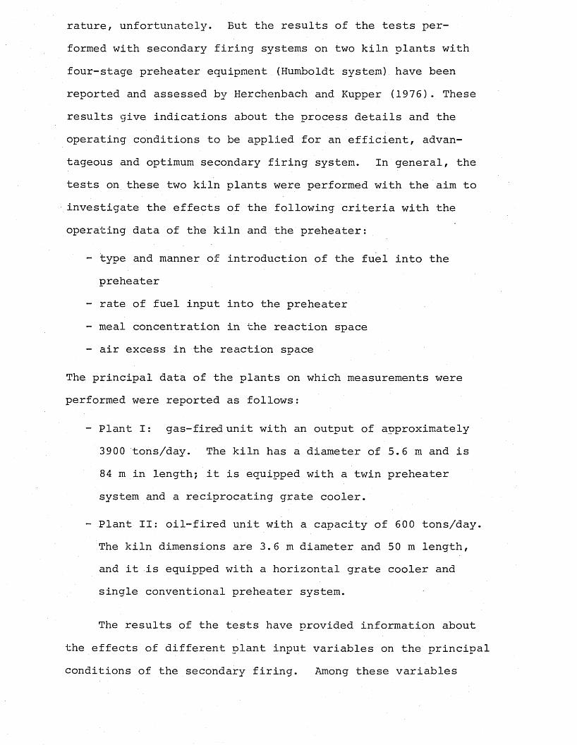
rature, unfortunately. But the results of the tests performed with secondary firing systems on two kiln plants with four-stage preheater equipment (Humboldt system) have been reported and assessed by Herchenbach and Kupper (1976). These results give indications about the process details and the operating conditions to be applied for an efficient, advantageous and optimum secondary firing system. In general, the tests on these two kiln plants were performed with the aim to investigate the effects of the following criteria with the operating data of the kiln and the preheater:
- type and manner of introduction of the fuel into the preheater
- rate of fuel input into the preheater- meal concentration in the reaction space- air excess in the reaction space
The principal data of the plants on which measurements were performed were reported as follows:
- Plant I: gas-fired unit with an output of approximately 3900 tons/day. The kiln has a diameter of 5.6 m and is 84 m in length; it is equipped with a twin preheater system and a reciprocating grate cooler.
- Plant II: oil-fired unit with a capacity of 600 tons/day. The kiln dimensions are 3.6 m diameter and 50 m length, and it is equipped with a horizontal grate cooler and single conventional preheater system.
The results of the tests have provided information about the effects of different plant input variables on the principal conditions of the secondary firing. Among these variables
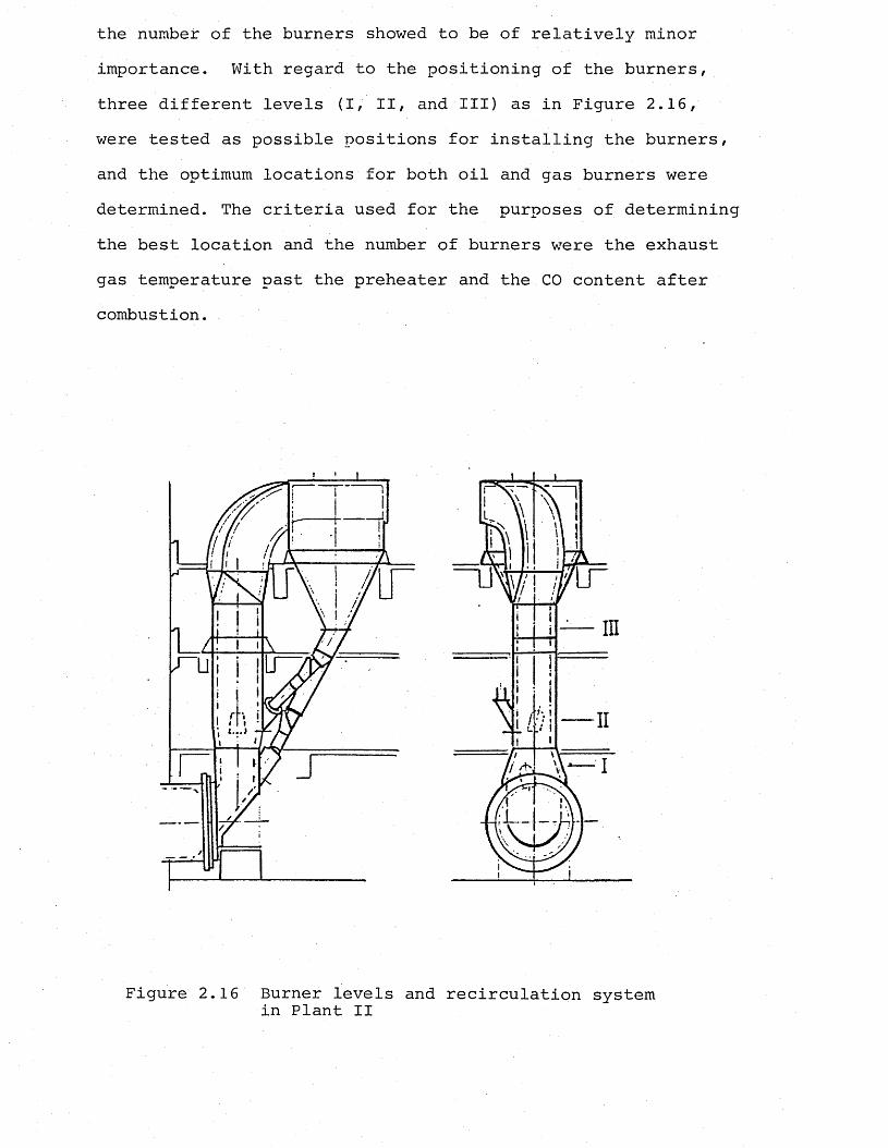
the number of the burners showed to be of relatively minor importance. With regard to the positioning of the burners, three different levels (I, II, and III) as in Figure 2.16, were tested as possible positions for installing the burners, and the optimum locations for both oil and gas burners were determined. The criteria used for the purposes of determining the best location and the number of burners were the exhaust gas temperature past the preheater and the CO content after combustion. .
f,
Figure 2.16 Burner levels and recirculation system in Plant II
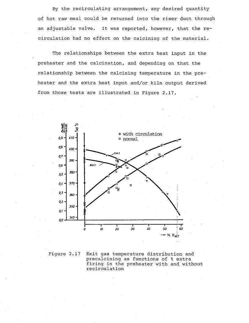
By the recirculating arrangement, any desired quantity of hot raw meal could be returned into the riser duct through an adjustable valve. It was reported, however, that the recirculation had no effect on the calcining of the material.
The relationships between the extra heat input in the preheater and the calcination, and depending on that the relationship between the calcining temperature in the preheater and the extra heat input and/or kiln output derived from those tests are illustrated in Figure 2.17.
o with circulation d normal
0,7 “
390 -
0.6 -
0.5 "
0.3 ~360 -
0.2 ~
3 5 0 -
30
Figure 2.17 Exit gas temperature distribution and precalcining as functions of % extra firing in the preheater with and without recirculation
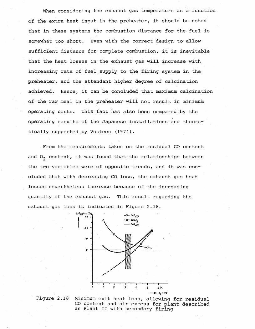
When considering the exhaust gas temperature as a function of the extra heat input in the preheater, it should be noted that in these systems the combustion distance for the fuel is somewhat too short. Even with the correct design to allow sufficient distance for complete combustion, it is inevitable that the heat losses in the exhaust gas will increase with increasing rate of fuel supply to the firing system in the preheater, and the attendant higher degree of calcination achieved. Hence, it can be concluded that maximum calcination of the raw meal in the preheater will not result in minimum operating costs. This fact has also been compared by the operating results of the Japanese installations and theoretically supported by Vosteen (1974).
From the measurements taken on the residual CO content and O2 content, it was found that the relationships between the two variables were of opposite trends, and it was concluded that with decreasing CO loss, the exhaust gas heat losses nevertheless increase because of the increasing quantity of the exhaust gas. This result regarding the exhaust gas loss is indicated in Figure 2.18.
20
0 1 2 3 6 V.5
► 02nWT
Figure 2.18 Minimum exit heat loss, allowing for residual CO content and air excess for plant described as Plant II with secondary firing
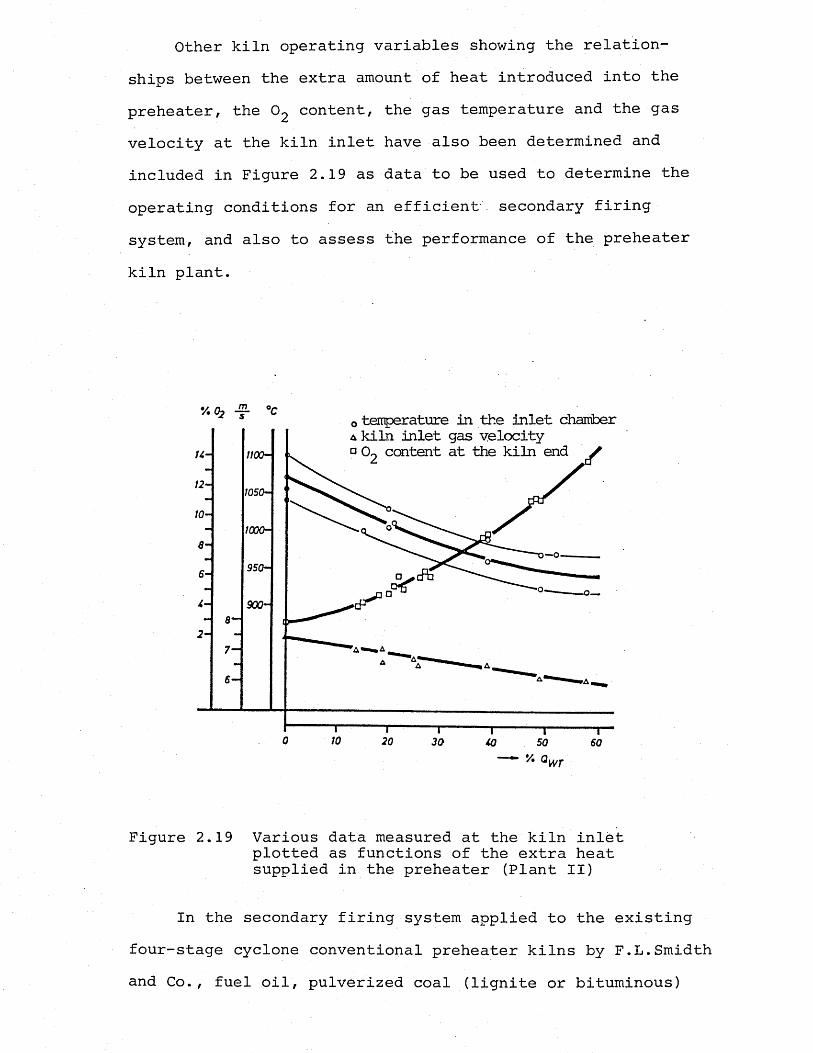
Other kiln operating variables showing the relationships between the extra amount of heat introduced into the preheater, the 02 content, the gas temperature and the gas velocity at the kiln inlet have also been determined and included in Figure 2.19 as data to be used to determine the operating conditions for an efficient secondary firing system, and also to assess the performance of the preheater kiln plant.
o temperature in the inlet chamber a kiln inlet gas velocity ° 02 content at the kiln end ^u-
12-
10-
i— O
4-
2 -
7-
0 10 20 30 SO 60V. QWT
Figure 2.19 Various data measured at the kiln inlet plotted as functions of the extra heat supplied in the preheater (Plant II)
In the secondary firing system applied to the existing four-stage cyclone conventional preheater kilns by F.L.Smidth and Co., fuel oil, pulverized coal (lignite or bituminous)
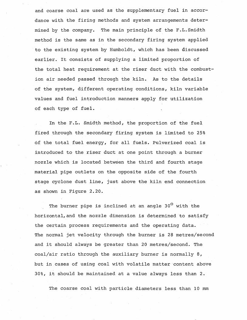
and coarse coal are used as the supplementary fuel in accordance with the firing methods and system arrangements determined by the company. The main principle of the F.L.Smidth method is the same as in the secondary firing system applied to the existing system by Humboldt, which has been discussed earlier. It consists of supplying a limited proportion of the total heat requirement at the riser duct with the combustion air needed passed through the kiln. As to the details of the system, different operating conditions, kiln variable values and fuel introduction manners apply for utilization of each type of fuel.
In the F.L. Smidth method, the proportion of the fuel fired through the secondary firing system is limited to 25% of the total fuel energy, for all fuels. Pulverized coal is introduced to the riser duct at one point through a burner nozzle which is located between the third and fourth stage material pipe outlets on the opposite side of the fourth stage cyclone dust line, just above the kiln end connection as shown in Figure 2.20.
The burner pipe is inclined at an angle 30° with the horizontal, and the nozzle dimension is determined to satisfy the certain process requirements and the operating data.The normal jet velocity through the burner is 28 metres/second and it should always be greater than 20 metres/second. The coal/air ratio through the auxiliary burner is normally 8, but in cases of using coal with volatile matter content above 30%, it should be maintained at a value always less than 2.
The coarse coal with particle diameters less than 10 mm
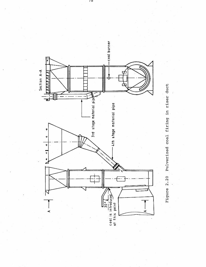
Sect
ion
A-A
/ o
OJcl_3J3
»-> O
Figure
2.20
Pulverized
coal
firing
in riser
duct
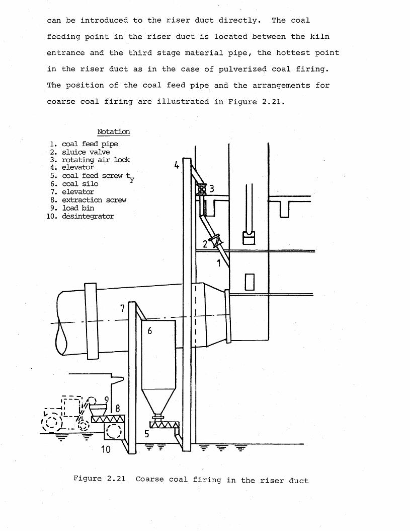
can be introduced to the riser duct directly. The coal feeding point in the riser duct is located between the kiln entrance and the third stage material pipe, the hottest point in the riser duct as in the case of pulverized coal firing. The position of the coal feed pipe and the arrangements for coarse coal firing are illustrated in Figure 2.21.
1.2.3.4..5.6.7.8. 9.10.
Notationcoal feed pipe sluice valve rotating air lock elevatorcoal feed screw t coal silo elevatorextraction screw load bin desintegrator u
n
ior
Figure 2.21 Coarse coal firing in the riser duct
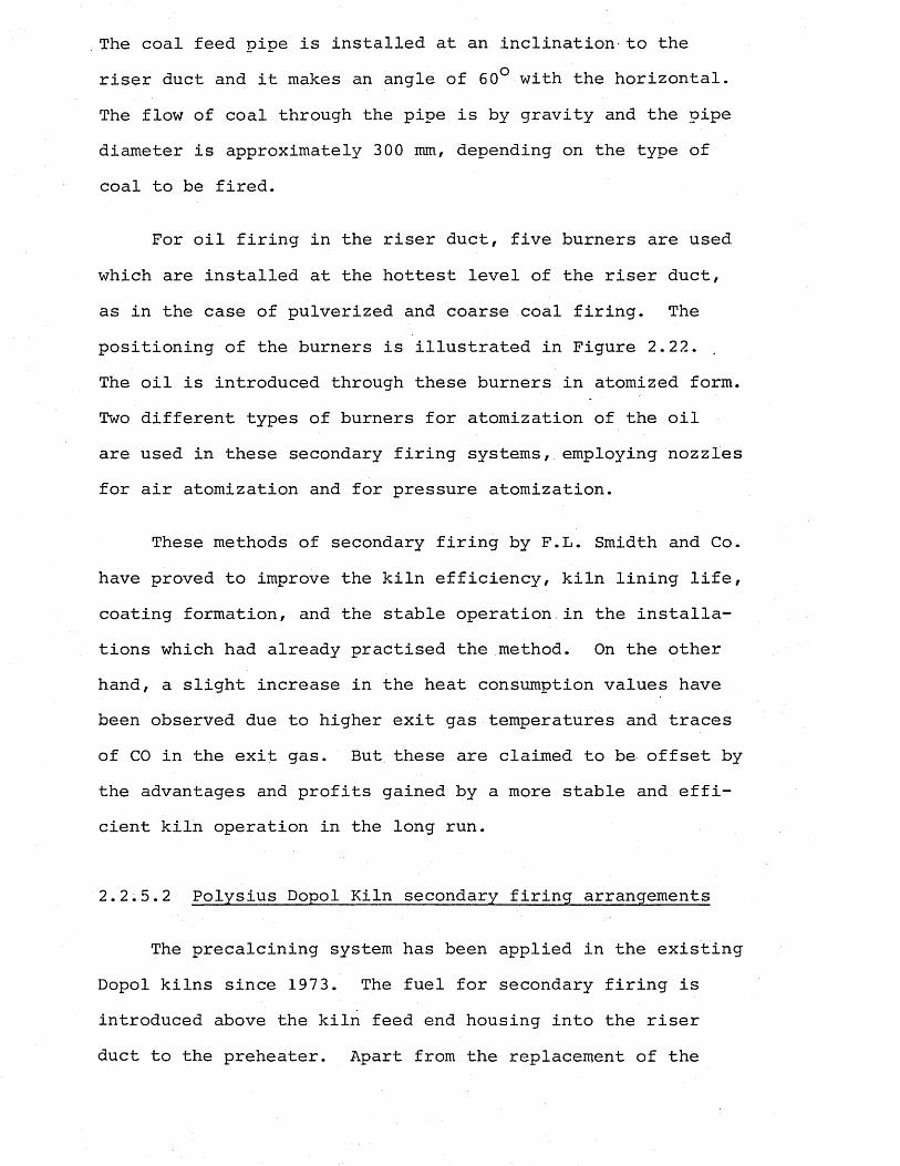
The coal feed pipe is installed at an inclination-to the riser duct and it makes an angle of 60° with the horizontal. The flow of coal through the pipe is by gravity and the pipe diameter is approximately 300 mm, depending on the type of coal to be fired.
For oil firing in the riser duct, five burners are used which are installed at the hottest level of the riser duct, as in the case of pulverized and coarse coal firing. The positioning of the burners is illustrated in Figure 2.22.The oil is introduced through these burners in atomized form. Two different types of burners for atomization of the oil are used in these secondary firing systems, employing nozzles for air atomization and for pressure atomization.
These methods of secondary firing by F.L. Smidth and Co. have proved to improve the kiln efficiency, kiln lining life, coating formation, and the stable operation.in the installations which had already practised the method. On the other hand, a slight increase in the heat consumption values have been observed due to higher exit gas temperatures and traces of CO in the exit gas. But these are claimed to be offset by the advantages and profits gained by a more stable and efficient kiln operation in the long run.
2.2.5.2 Polysius Dopol Kiln secondary firing arrangements
The precalcining system has been applied in the existing Dopol kilns since 1973. The fuel for secondary firing is introduced above the kiln feed end housing into the riser duct to the preheater. Apart from the replacement of the
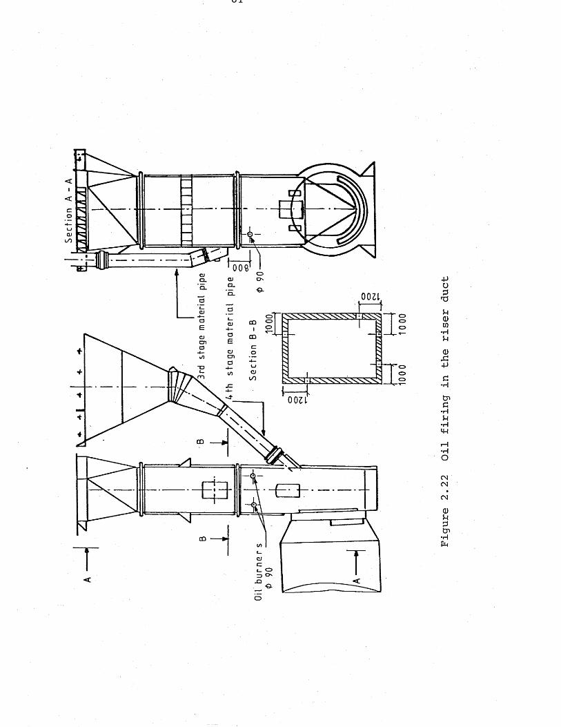
KJ JL
a
100?CJ Q.C L
CLQJq l
OOZlom o o
CD
cn
rn tNNNl
C D
CD
CJ
<O
Figure
2.22
Oil
firing
in the
riser
duct
distributor bridge, originally of brickwork, by a rotatable metal plate, no alterations are made to the preheater. In these systems, broadly speaking, 15-20% of the total heat input is introduced into the preheater, and the air required for the combustion of the fuel through secondary firing system is supplied through the kiln. The burners, usually more than one, in case of oil firing two, are arranged in the riser duct as shown in Figure 2.23.
b - b
BurnerA-A
- E 3 -
Figure 2.23 Secondary firing and burner arrangementsin a Dopol kiln
Other fuels used in this system include pulverized lignite, fuller's earth and old motor tyres (Ritzmann, 1976? Tiggesbaum- ker, Rother, 1980).
In case of pulverized lignite, the fuel is blown directly into the riser duct. Since the velocity in this duct in
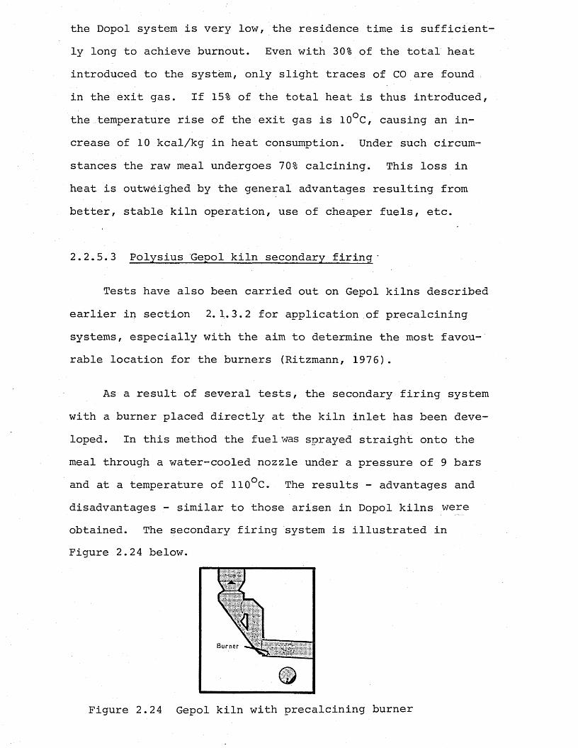
the Dopol system is very low, the residence time is sufficiently long to achieve burnout. Even with 30% of the total heat introduced to the system, only slight traces of CO are found in the exit gas. If 15% of the total heat is thus introduced, the temperature rise of the exit gas is 10°C, causing an increase of 10 kcal/kg in heat consumption. Under such circumstances the raw meal undergoes 70% calcining. This loss in heat is outweighed by the general advantages resulting from better, stable kiln operation, use of cheaper fuels, etc.
2.2.5.3 Polysius Gepol kiln secondary firing -
Tests have also been carried out on Gepol kilns described earlier in section 2.1.3.2 for application of precalcining systems, especially with the aim to determine the most favourable location for the burners (Ritzmann, 1976).
As a result of several tests, the secondary firing system with a burner placed directly at the kiln inlet has been developed. In this method the fuel was sprayed straight onto the meal through a water-cooled nozzle under a pressure of 9 bars and at a temperature of 110°C. The results - advantages and disadvantages - similar to those arisen in Dopol kilns were obtained. The secondary firing system is illustrated in Figure 2.24 below.
Burner
Figure 2.24 Gepol kiln with precalcining burner
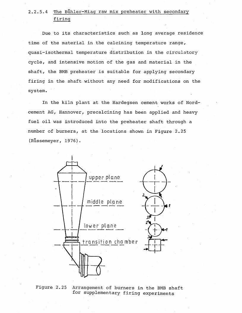
2.2.5.4 The Buhler-Miag raw mix preheater with secondaryfiring
Due to its characteristics such as long average residence time of the material in the calcining temperature range, quasi-isothermal temperature distribution in the circulatory cycle, and intensive motion of the gas and material in the shaft, the BMB preheater is suitable for applying secondary firing in the shaft without any need for modifications on the system.
In the kiln plant at the Hardegsen cement works of Nord- cement AG, Hannover, precalcining has been applied and heavy fuel oil was introduced into the preheater shaft through a number of burners, at the locations shown in Figure 2.25 (Russemeyer, 1976).
f
Figure 2.25 Arrangement of burners in the BMB shaft for supplementary firing experiments
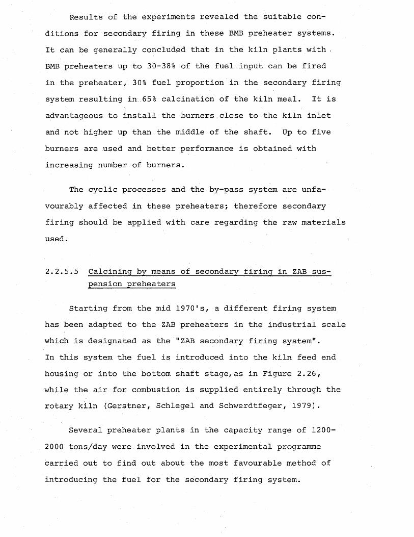
Results of the experiments revealed the suitable conditions for secondary firing in these BMB preheater systems.It can be generally concluded that in the kiln plants with :BMB preheaters up to 30-38% of the fuel input can be fired in the preheater, 30% fuel proportion in the secondary firing system resulting in..65% calcination of the kiln meal. It is advantageous to install the burners close to the kiln inlet and not higher up than the middle of the shaft. Up to five burners are used and better performance is obtained with increasing number of burners.
The cyclic processes and the by-pass system are unfavourably affected in these preheaters; therefore secondary firing should be applied with care regarding the raw materials used.
2.2.5.5 Calcining by means of secondary firing in ZAB suspension preheaters
Starting from the mid 1970's, a different firing system has been adapted to the ZAB preheaters in the industrial scale which is designated as the "ZAB secondary firing system".In this system the fuel is introduced into the kiln feed end housing or into the bottom shaft stage,as in Figure 2.26, while the air for combustion is supplied entirely through the rotary kiln (Gerstner, Schlegel and Schwerdtfeger, 1979).
Several preheater plants in the capacity range of 1200- 2000 tons/day were involved in the experimental programme carried out to find out about the most favourable method of introducing the fuel for the secondary firing system.
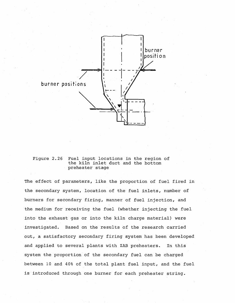
burner positi on
burner positions
Figure 2.26 Fuel input locations in the region of the kiln inlet duct and the bottom preheater stage
The effect of parameters, like the proportion of fuel fired in the secondary system, location of the fuel inlets, number of burners for secondary firing, manner of fuel injection, and the medium for receiving the fuel (whether injecting the fuel into the exhaust gas or into the kiln charge material) were investigated. Based on the results of the research carried out, a satisfactory secondary firing system has been developed and applied to several plants with ZAB preheaters. In this system the proportion of the secondary fuel can be charged between 10 and 40% of the total plant fuel input, and the fuel is introduced through one burner for each preheater string.
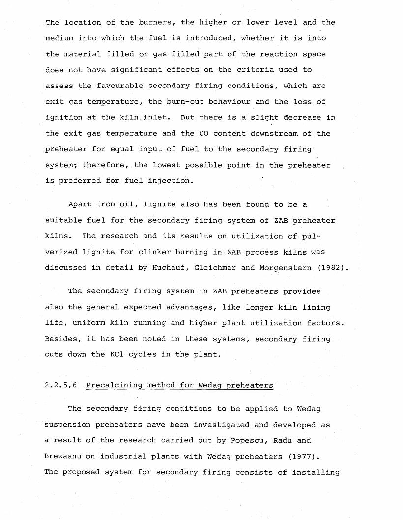
The location of the burners, the higher or lower level and the medium into which the fuel is introduced, whether it is into the material filled or gas filled part of the reaction space does not have significant effects on the criteria used to assess the favourable secondary firing conditions, which are exit gas temperature, the burn-out behaviour and the loss of ignition at the kiln inlet. But there is a slight decrease in the exit gas temperature and the CO content downstream of the preheater for equal input of fuel to the secondary firing system*, therefore, the lowest possible point in the preheater is preferred for fuel injection.
Apart from oil, lignite also has been found to be a suitable fuel for the secondary firing system of ZAB preheater kilns. The research and its results on utilization of pulverized lignite for clinker burning in ZAB process kilns was discussed in detail by Huchauf, Gleichmar and Morgenstern (1982).
The secondary firing system in ZAB preheaters provides also the general expected advantages, like longer kiln lining life, uniform kiln running and higher plant utilization factors. Besides, it has been noted in these systems, secondary firing cuts down the KC1 cycles in the plant.
2.2.5.6 Precalcining method for Wedag preheaters
The secondary fifing conditions to be applied to Wedag suspension preheaters have been investigated and developed as a result of the research carried out by Popescu, Radu and Brezaanu on industrial plants with Wedag preheaters (1977).The proposed system for secondary firing consists of installing
six burners for burning natural gas in the duct connecting the kiln to the preheater at a location shown in Figure 2.27.
Figure 2.27 Position for additional burners forsecondary firing in a Wedag preheater
For oil firing, according to the results of the experiments performed, it is suggested to install the two oil burners at a lower level than in the case of gas firing. This method enabled 60% of the total heat input to be fired at the backend of the kiln.
2.2.6 Converted plants with precalcining
If it is desired, besides the advantages associated with the precalcining also to increase the output of the plant, the capacity of the equipment upstream and downstream of the kiln should be accordingly increased. More particularly, special attention should be given to the gas throughput ofthe preheater. In order to increase the gas flow capacityof the preheater without causing' excessive gas velocities, one of the methods of either modifying the cross-sections and increasing the fan capacity or installing a parallel preheater string should be accomplished. These methods have already been applied to some of the existing Humboldt (Pyroclonespecially) and Dopol kilns (Herchenbach and Weber, 1979)Tiggesbaumker and Rother, 1980). These conversions are recommended only in exceptional cases, such as limited time availability for shutdown to carry out the modifications. Otherwise, it is always better to have the plant conversion for precalcining by adopting one of the modern commercial precalcining processes by adding a calciner chamber just ahead of the rotary kiln between the third and fourth cyclone stages.
2.2.7 Modern commercial precalcining plants with suspension preheaters
The basic concept of all the precalcining processes available today is the addition of a separate combustion chamber just ahead of the rotary kiln. The raw meal is fed and progresses through the cyclones as in the conventional suspension preheater system. However, the third stage product
is discharged into a separate furnace into which the fuel providing 60% of the total heat input of the plant is supplied. The combustion air required in this chamber is supplied from the clinker cooler either separately or together with the kiln exhaust gases. Burners are positioned either in the chamber or in the air inlet ducts. Nearly completely calcined (up to 95%) meal is then carried in the gas stream from the furnace to the fourth stage cyclone, where it is spun out for discharge into the kiln.
The advantages and disadvantages associated with precalcining as described earlier in section 2.2.4 apply to nearly all of the commercial precalcining plants of different process descriptions to more or less the same extent
2.2.7.1 Humboldt-Wedag Pyroclon-precalciner ' . ■
The Pyroclon system developed by Humboldt-Wedag consists of a four-stage cyclone suspension preheater (conventional) with a secondary firing system, designated as Pyroclon reactor which is basically the extended riser duct. For secondary firing rates of 55 to 65%, to reduce the gas temperaturewhich typically increases to a value of 365°C, preheaters with five stages are installed for fuel saving purposes. Although the conventional rotary kilns with length to diameter ratios of 13.5 to 14.5 are mostly used with the Pyroclon systems, for secondary firing rates above 50% the raw meal up to 99% calcined requires shorter kiln length. To avoid installation of wasteful kiln length, the shorter Pyrorapid kilns with length to diameter ratio of 10 are used in those cases of higher secondary firing rates.
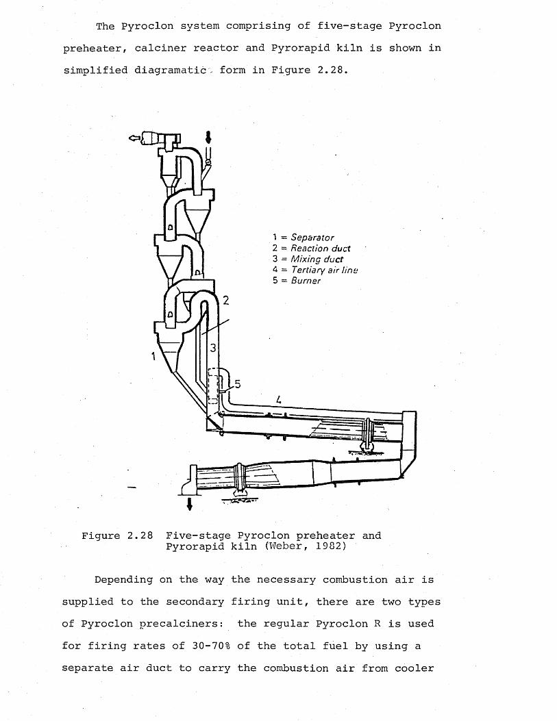
The Pyroclon system comprising of five-stage Pyroclon preheater, calciner reactor and Pyrorapid kiln is shown in simplified diagramatic'; form in Figure 2.28.
<5=»i
1 = Separator2 = Reaction duct3 = Mixing duct4 = Tertiary air line5 = Burner
Figure 2.2 8 Five-stage Pyroclon preheater and Pyrorapid kiln (Weber, 1982)
Depending on the way the necessary combustion air is supplied to the secondary firing unit, there are two types of Pyroclon precalciners: the regular Pyroclon R is usedfor firing rates of 30-70% of the total fuel by using a separate air duct to carry the combustion air from cooler
06
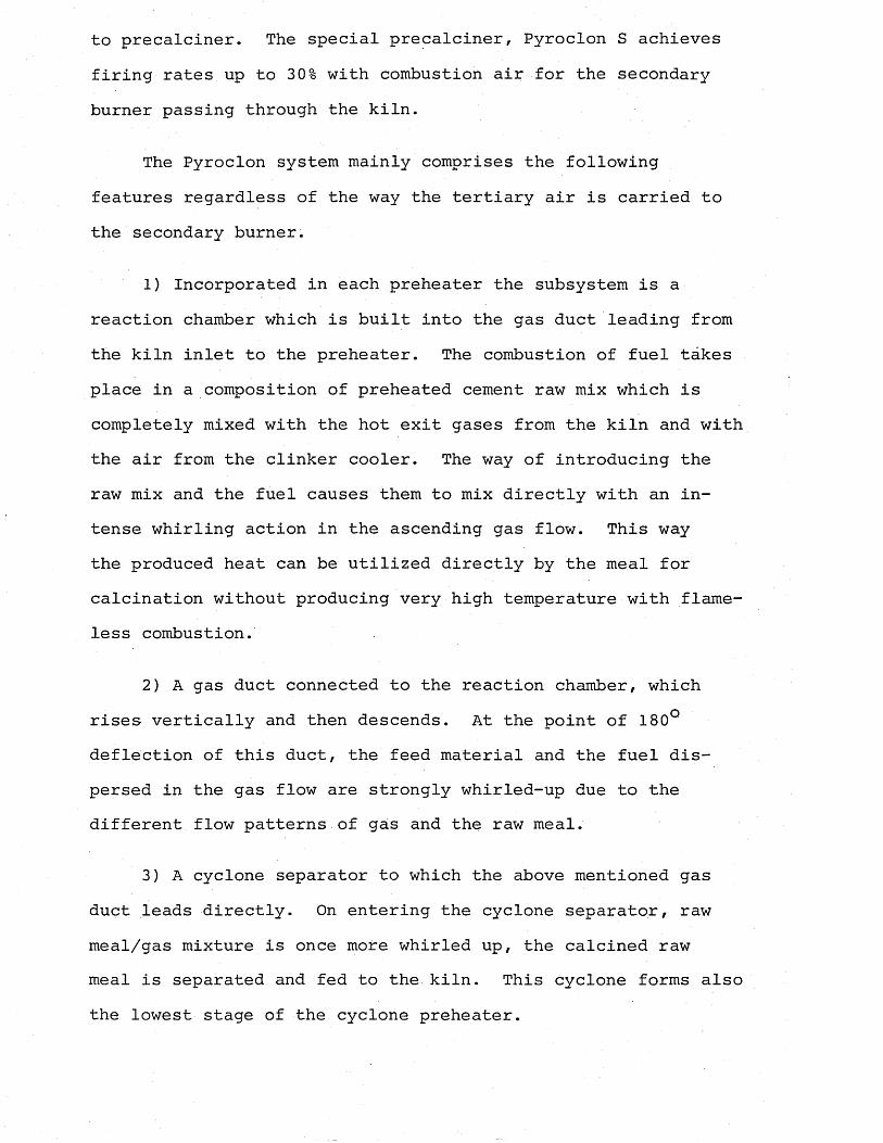
to precalciner. The special precalciner, Pyroclon S achieves firing rates up to 30% with combustion air for the secondary burner passing through the kiln.
The Pyroclon system mainly comprises the following features regardless of the way the tertiary air is carried to the secondary burner.
1) Incorporated in each preheater the subsystem is a reaction chamber which is built into the gas duct leading from the kiln inlet to the preheater. The combustion of fuel takes place in a composition of preheated cement raw mix which is completely mixed with the hot exit gases from the kiln and with the air from the clinker cooler. The way of introducing the raw mix and the fuel causes them to mix directly with an intense whirling action in the ascending gas flow. This waythe produced heat can be utilized directly by the meal for calcination without producing very high temperature with flame- less combustion.
2) A gas duct connected to the reaction chamber, which rises vertically and then descends. At the point of 180° deflection of this duct, the feed material and the fuel dispersed in the gas flow are strongly whirled-up due to the different flow patterns of gas and the raw meal.
3) A cyclone separator to which the above mentioned gas duct leads directly. On entering the cyclone separator, raw meal/gas mixture is once more whirled up, the calcined raw meal is separated and fed to the kiln. This cyclone forms also the lowest stage of the cyclone preheater.
The flows and points where these whirling actions take place are indicated in Figure 2.29.
Fuel *=£> Meal vzfo Kiln waste oas
Cooler tertiary airKiln and calciner waste gas
Figure 2.29 Humboldt-Wedag Pyroclon precalciner flow patterns (Herchenbach, 1983)
Claimed advantages over other systems are its simple design and operation, special configuration of the inlets for raw meal, fuel and gases containing oxygen, ensuring good mixing to be achieved in a vertical reaction path under optimum conditions. The length of the path can be adjusted according to the combustion characteristics of the fuel, and therefore the system is suitable for any type of fuel. Other advantages
also include low pressure loss, reduced dust circuit formation between the kiln and the Pyroclon system and lower N0V and SO emissions. It is also claimed that the system offersXa very efficient partial gas extraction compared to the other preheater systems (Herchenbach, 1983).
2.2.7.2 The Polysius precalcining process
When developing its own precalcining process, the Polysius Company applied two different methods of combustion air supply for the secondary firing unit. These two different systems are called Prepol AS and Prepol AT referring to methods of precalcining with and without tertiary air duct, respectively.
In both systems, the riser duct connecting the kiln end to the fourth stage cyclones is extended to the length to provide the approximate reaction time required for calcination at certain gas velocities. The fuel is supplied through one or more burners to this extended riser duct, which is called the calciner. The raw meal from the Dopol-turbulence shaft passes the ascending calcining duct where it is highly calcined due to the heat from the fuel supplied through several burners. After separation in the lowest cyclone stage, the raw mix enters the kiln feed hood, 90-95% calcined.
Figure 2.30 illustrates a kiln plant with a Prepol AT precalcining system schematically. The inclined position of the calciner gives rise to material circulation in this part of the system. The air needed for the calcining burners which is drawn through the kiln and heated to the kiln exit temperature, enters the calciner with a high content of heat. The heat
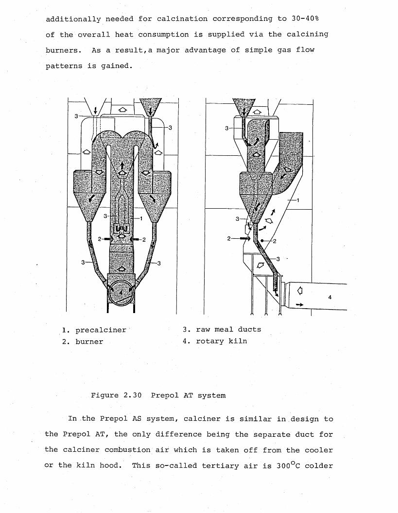
additionally needed for calcination corresponding to 30-40% of the overall heat consumption is supplied via the calcining burners. As a result,a major advantage of simple gas flow patterns is gained.
SUP
1. precalciner 3. raw meal ducts2. burner 4. rotary kiln
Figure 2.30 Prepol AT system
In the Prepol AS system, calciner is similar in design to the Prepol AT, the only difference being the separate duct for the calciner combustion air which is taken off from the cooler or the kiln hood. This so-called tertiary air is 300°C colder
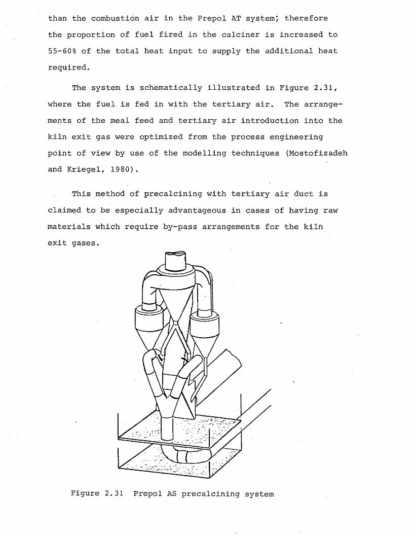
than the combustion air in the Prepol AT system*, therefore the proportion of fuel fired in the calciner is increased to 55-60% of the total heat input to supply the additional heat required.
The system is schematically illustrated in Figure 2.31, where the fuel is fed in with the tertiary air. The arrangements of the meal feed and tertiary air introduction into the kiln exit gas were optimized from the process engineering point of view by use of the modelling techniques (Mostofizadeh and Kriegel, 1980).
This method of precalcining with tertiary air duct is claimed to be especially advantageous in cases of having raw materials which require by-pass arrangements for the kiln exit gases.
Figure 2.31 Prepol AS precalcining system
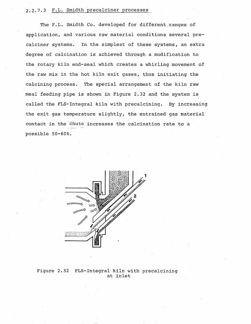
2.2.7.3 F.L. Smidth precalciner processes
The F.L. Smidth Co. developed for different ranges of application, and various raw material conditions several precalciner systems. In the simplest of these systems, an extra degree of calcination is achieved through a modification to the rotary kiln end-seal which creates a whirling movement of the raw mix in the hot kiln exit gases, thus initiating the calcining process. The special arrangement of the kiln raw meal feeding pipe is shown in Figure 2.32 and the system is called the FLS-Integral kiln with precalcining. By increasing the exit gas temperature slightly, the entrained gas material contact in the chute increases the calcination rate to a possible 50-60%.
Figure 2.32 FLS-Integral kiln with precalciningat inlet
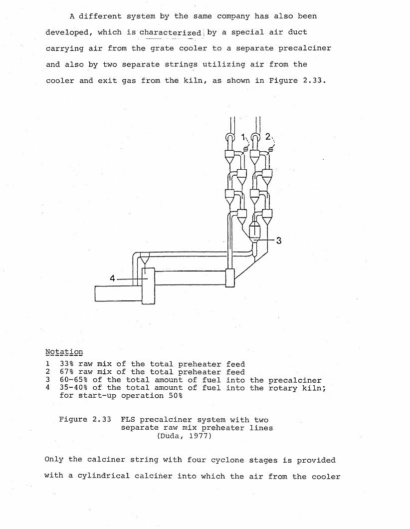
A different system by the same company has also been developed, which is characterized 1 by a special air duct carrying air from the grate cooler to a separate precalciner and also by two separate strings utilizing air from the cooler and exit gas from the kiln, as shown in Figure 2.33.
Notation1 33% raw mix of the total preheater feed2 67% raw mix of the total preheater feed3 60-65% of the total amount of fuel into the precalciner4 35-40% of the total amount of fuel into the rotary kiln*,
for start-up operation 50%
Figure 2.33 FLS precalciner system with two separate raw mix preheater lines
(Duda, 1977)
Only the calciner string with four cyclone stages is provided with a cylindrical calciner into which the air from the cooler
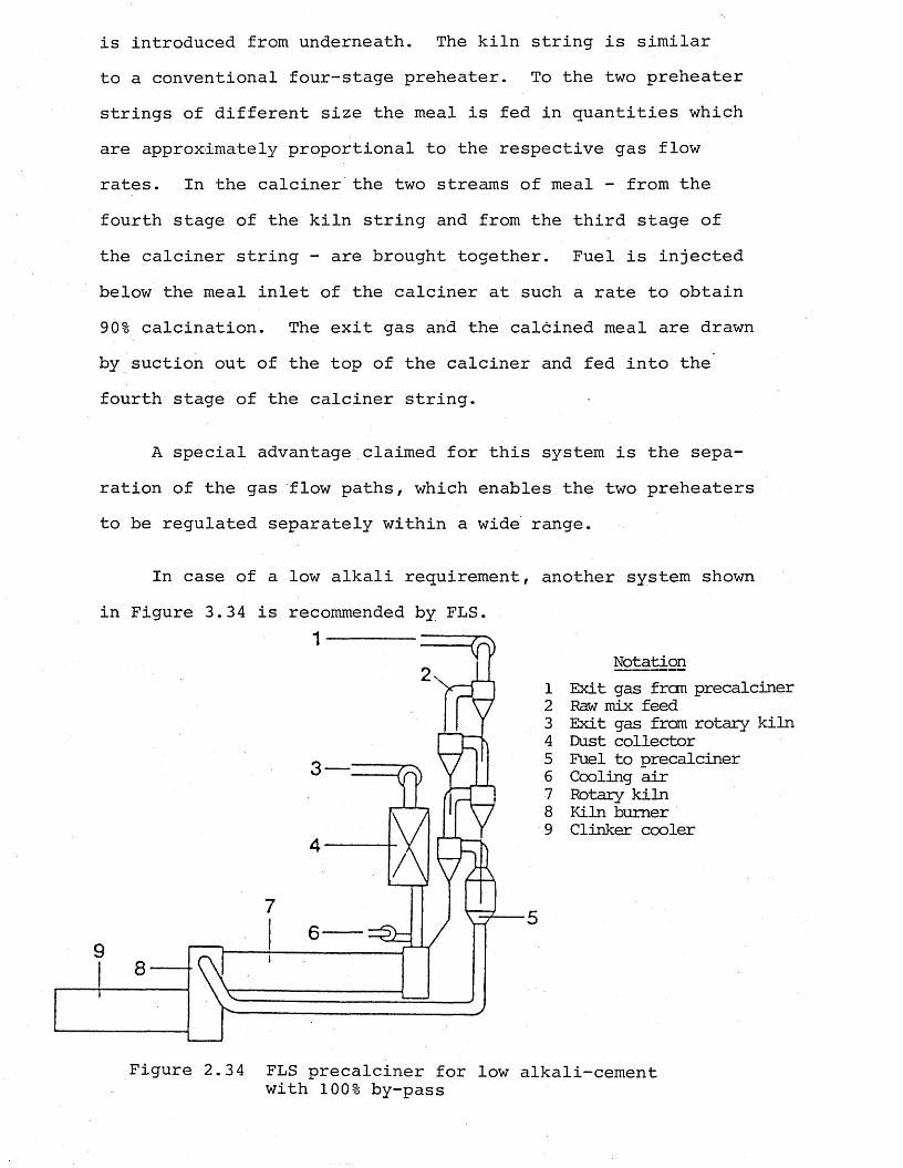
is introduced from underneath. The kiln string is similar to a conventional four-stage preheater. To the two preheater strings of different size the meal is fed in quantities which are approximately proportional to the respective gas flow rates. In the calciner the two streams of meal - from the fourth stage of the kiln string and from the third stage of the calciner string - are brought together. Fuel is injected below the meal inlet of the calciner at such a rate to obtain 90% calcination. The exit gas and the calcined meal are drawn by suction out of the top of the calciner and fed into the fourth stage of the calciner string.
A special advantage claimed for this system is the separation of the gas flow paths, which enables the two preheaters to be regulated separately within a wide range.
In case of a low alkali requirement, another system shown in Figure 3.34 is recommended by FLS.
Notation1 Exit gas from precalciner2 Raw mix feed3 Exit gas from rotary kiln4 Dust collector5 Fuel to precalciner6 Cooling air7 Rotary kiln8 Kiln burner9 Clinker cooler
rv3 — :
Figure 2.34 FLS precalciner for low alkali-cement with 100% by-pass
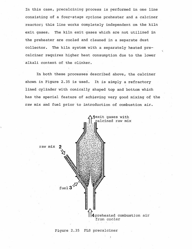
In this case, precalcining process is performed in one line consisting of a four-stage cyclone preheater and a calciner reactor; this line works completely independent on the kiln exit gases. The kiln exit gases which are not utilized in the preheater are cooled and cleaned in a separate dust collector. The kiln system with a separately heated precalciner requires higher heat consumption due to the lower alkali content of the clinker.
In both these processes described above, the calciner shown in Figure 2.35 is used. It is simply a refractory lined cylinder with conically shaped top and bottom which has the special feature of achieving very good mixing of the raw mix and fuel prior to introduction of combustion air.
*|exit gases with calcined raw mix
f rI |4preheated combustion air from cooler
Figure 2.35 FLS precalciner
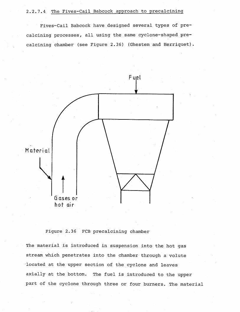
2.2.7.4 The Fives-Cail Babcock approach to precalcining
Fives-Cail Babcock have designed several types of precalcining processes, all using the same cyclone-shaped precalcining chamber (see Figure 2.36) (Ghestem and Herriquet).
Fuel
Gases or
Figure 2.36 FCB precalcining chamber
The material is introduced in suspension into the hot gas stream which penetrates into the chamber through a volute located at the upper section of the cyclone and leaves axially at the bottom. The fuel is introduced to the upper part of the cyclone through three or four burners. The material
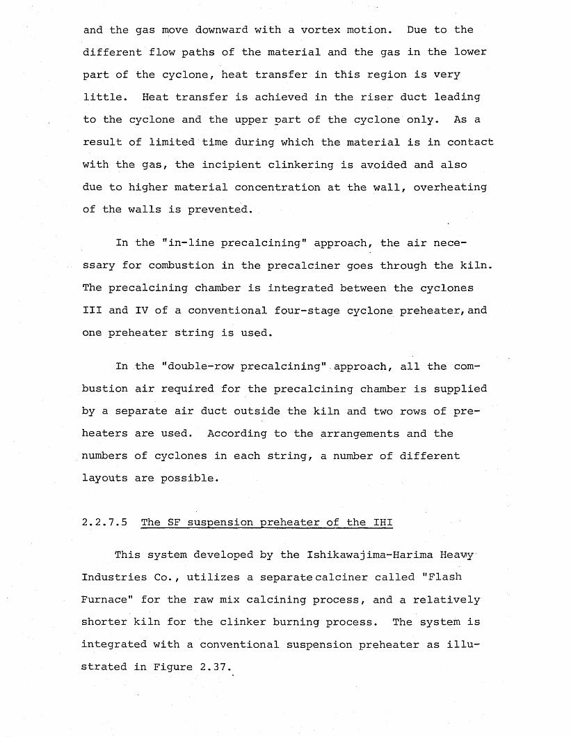
and the gas move downward with a vortex motion. Due to the different flow paths of the material and the gas in the lower part of the cyclone, heat transfer in this region is very little. Heat transfer is achieved in the riser duct leading to the cyclone and the upper part of the cyclone only. As a result of limited time during which the material is in contact with the gas, the incipient clinkering is avoided and also due to higher material concentration at the wall, overheating of the walls is prevented.
In the "in-line precalcining" approach, the air necessary for combustion in the precalciner goes through the kiln. The precalcining chamber is integrated between the cyclones III and IV of a conventional four-stage cyclone preheater,and one preheater string is used.
In the "double-row precalcining" approach, all the combustion air required for the precalcining chamber is supplied by a separate air duct outside the kiln and two rows of preheaters are used. According to the arrangements and the numbers of cyclones in each string, a number of different layouts are possible.
2.2.7.5 The SF suspension preheater of the IHI
This system developed by the Ishikawajima-Harima Heavy Industries Co., utilizes a separatecalciner called "Flash Furnace" for the raw mix calcining process, and a relatively shorter kiln for the clinker burning process. The system is integrated with a conventional suspension preheater as illustrated in Figure 2.37.
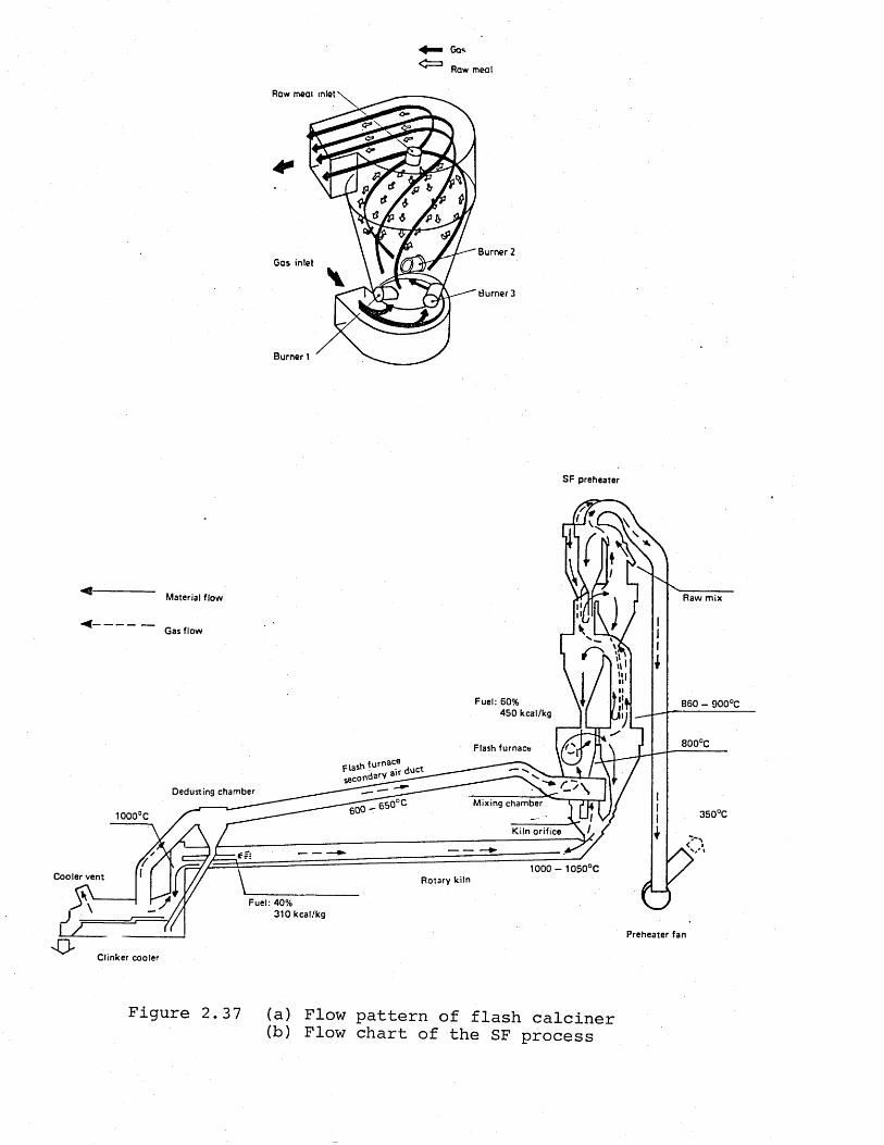
G a sR a w m e a l
R a w m e a l i n l e t
<?*
B u r n e r 2G a s i n l e t
Burner 3
B u r n e r 1
SF preheater
Material flow Raw m ix
Gas flow
Fuel: 60%45 0 kcal/kg
86 0 - 900°C
800°C
Dedusting chamberMixing chamber
350°C
Kiln orifice
1000 - 1050°CCooler vent Rotary kiln
Fuel: 40%310 kcal/kg
Preheater fanLZZT-_ZOClinker cooler
Figure 2.37 (a) Flow pattern of flash calciner(b) Flow chart of the SF process
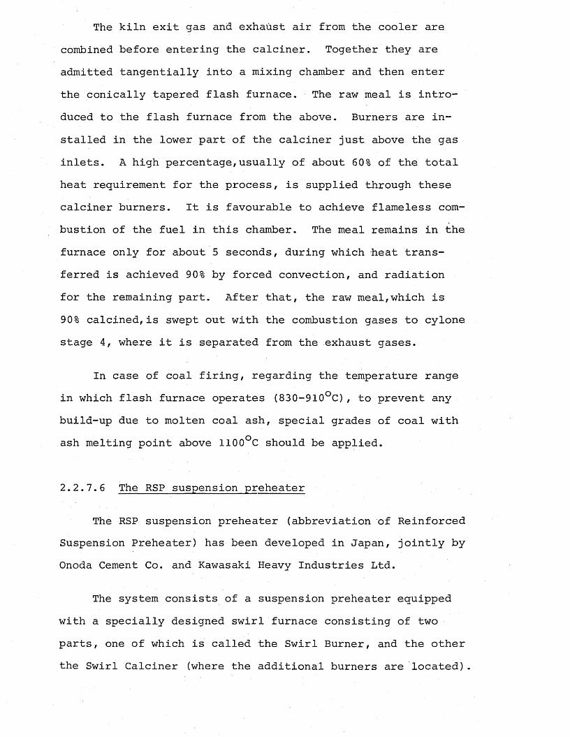
The kiln exit gas and exhaust air from the cooler are combined before entering the calciner. Together they are admitted tangentially into a mixing chamber and then enter the conically tapered flash furnace. The raw meal is introduced to the flash furnace from the above. Burners are installed in the lower part of the calciner just above the gas inlets. A high percentage,usually of about 60% of the total heat requirement for the process, is supplied through these calciner burners. It is favourable to achieve flameless combustion of the fuel in this chamber. The meal remains in the furnace only for about 5 seconds, during which heat transferred is achieved 90% by forced convection, and radiation for the remaining part. After that, the raw meal,which is 90% calcined,is swept out with the combustion gases to cylone stage 4, where it is separated from the exhaust gases.
In case of coal firing, regarding the temperature range in which flash furnace operates (830-910°C), to prevent any build-up due to molten coal ash, special grades of coal with ash melting point above 1100°C should be applied.
2.2.7. 6 The RSP suspension preheater
The RSP suspension preheater (abbreviation of Reinforced Suspension Preheater) has been developed in Japan, jointly by Onoda Cement Co. and Kawasaki Heavy Industries Ltd.
The system consists of a suspension preheater equipped with a specially designed swirl furnace consisting of two parts, one of which is called the Swirl Burner, and the other the Swirl Calciner (where the additional burners are located).
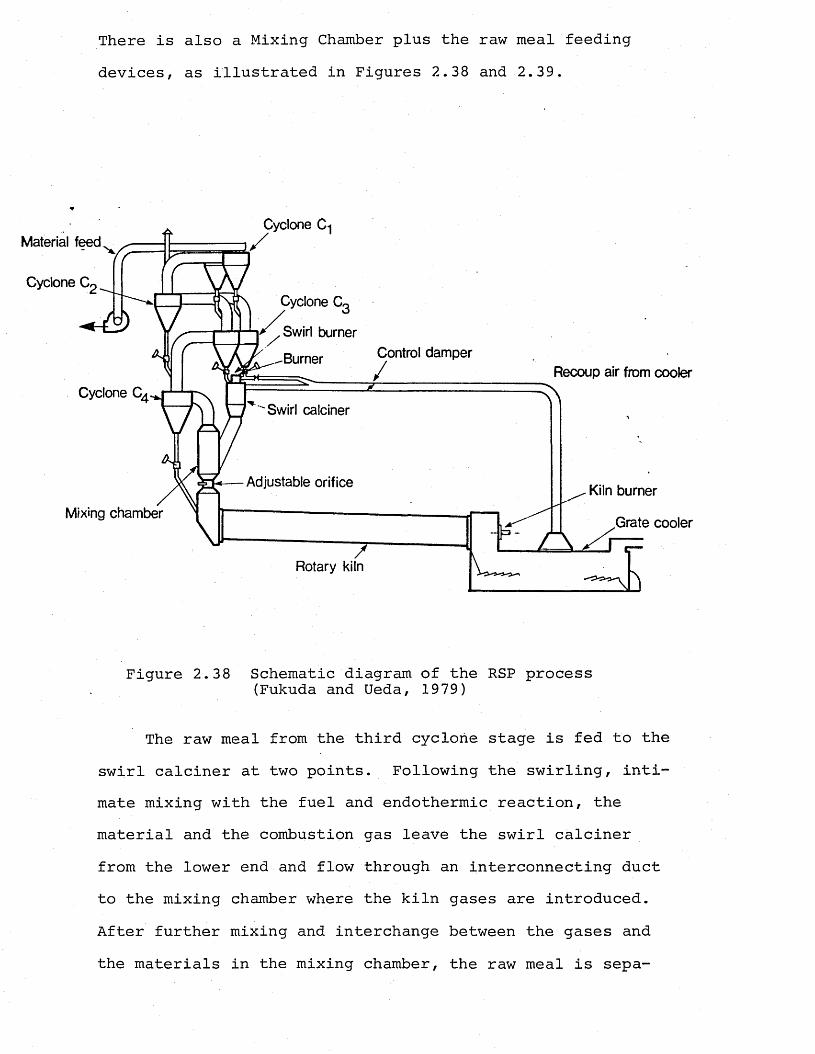
There is also a Mixing Chamber plus the raw meal feeding devices, as illustrated in Figures 2.38 and 2.39.
Cyclone C-jMaterial feed
Cyclone C,Cyclone CQ
.Swirl burnerControl damper.-Burner
Recoup air from coolerCyclone Q
"Swirl calciner
Adjustable orifice Kiln burner
Mixing chamber.Grate cooler
Rotary kiln
Figure 2.38 Schematic diagram of the RSP process (Fukuda and Ueda, 1979)
The raw meal from the third cyclone stage is fed to the swirl calciner at two points. Following the swirling, intimate mixing with the fuel and endothermic reaction, the material and the combustion gas leave the swirl calciner from the lower end and flow through an interconnecting duct to the mixing chamber where the kiln gases are introduced. After further mixing and interchange between the gases and the materials in the mixing chamber, the raw meal is sepa-
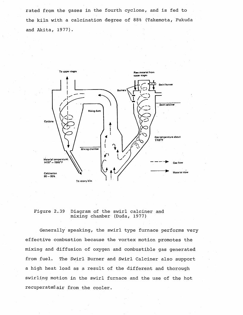
rated from the gases in the fourth cyclone, and is fed to the kiln with a calcination degree of 88% (Takemota, Fukuda and Akita, 1977).
T o upper stages Rgvv material fromupper stages
Burners
Swirl calciner
Rising duct
Cyclone
Gas temperature about 1705°F
Material temperature: 1475° — 1565°F Gas flow
Material tlowCalcination8 0 - 9 5 %
To rotary kiln
Figure 2.39 Diagram of the swirl calciner and mixing chamber (Duda, 1977)
Generally speaking, the swirl type furnace performs very effective combustion because the vortex motion promotes the mixing and diffusion of oxygen and combustible gas generated from fuel. The Swirl Burner and Swirl Calciner also support a high heat load as a result of the different and thorough swirling motion in the swirl furnace and the use of the hot recuperated air from the cooler.
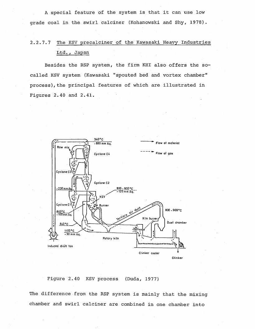
A special feature of the system is that it can use low grade coal in the swirl calciner (Kohanowski and Shy, 1978).
2.2.7.7 The KSV precalciner of the Kawasaki Heavy Industries Ltd., Japan
Besides the RSP system, the firm KHI also offers the so- called KSV system (Kawasaki "spouted bed and vortex chamber" process), the principal features of which are illustrated in Figures 2.40 and 2.41.
Flow of m aterial-8 8 0 mm Aq.Raw mi:
Flow of gasCyclone C4
Cyclone C3
Cyclone C2
Burner
800 - 900 °C
Kiln burner.
iioo°c-3 0 m m A q .
Rotary kiln
Induced draft fan
C linker cooler
Clinker
Figure 2.40 KSV process (Duda, 1977)
The difference from the RSP system is mainly that the mixing chamber and swirl calciner are combined in one chamber into
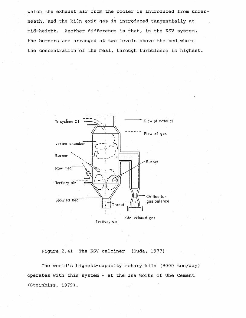
which the exhaust air from the cooler is introduced from underneath, and the kiln exit gas is introduced tangentially at mid-height. Another difference is that, in the KSV system, the burners are arranged at two levels above the bed where the concentration of the meal, through turbulence is highest.
Flow o‘ mctericlTo cyclone Cl
Flow of gas
vortex cnamber
Burner Ns-\ N,
Tertiary air
y Orifice tor \ gas balanceSpouted bed
jj Throat
Kiln exhaust gasTertiary air
Figure 2.41 The KSV calciner (Duda, 1977)
The world's highest-capacity rotary kiln (9000 ton/day) operates with this system - at the Isa Works of Ube Cement (Steinbiss, 1979).
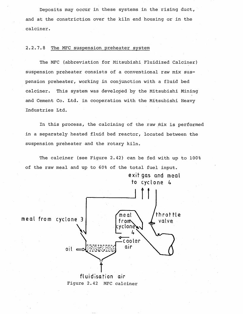
Deposits may occur in these systems in the rising duct, and at the constriction over the kiln end housing or in the calciner.
2.2.7.8 The MFC suspension preheater system
The MFC (abbreviation for Mitsubishi Fluidized Calciner) suspension preheater consists of a conventional raw mix suspension preheater, working in conjunction with a fluid bed calciner. This system was developed by the Mitsubishi Mining and Cement Co. Ltd. in cooperation with the Mitsubishi Heavy Industries Ltd.
In this process, the calcining of the raw mix is performed in a separately heated fluid bed reactor, located between the suspension preheater and the rotary kiln.
The calciner (see Figure 2.42) can be fed with up to 100% of the raw meal and up to 60% of the total fuel input.
ex i t gas and meal to cyclone 4
Iflmeal from cyclon
oil
fronts.cycloney
if lu id isaf ion air
Figure 2.42 MFC calciner
The entire stream of the raw meal from the cyclone stage 3 is fed to the calciner. The air for combustion which is the exhaust air from the cooler enters the fluidized bed tangen- tially above the fluidized bed. The calcination of the meal undergoes in the fluidized bed in about 5 minutes; after that it is swept along with the combustion gases out of the calciner to the fourth stage cyclone for precipitation.
Generally, this type of plant operates without any major problems, and it is not affected by deposits or coatings.
2.2.1.9 Other precalcining systems
In addition to the precalcining processes described so far, there are many other systems which are variations on the basic suspension preheater systems, most being designed and built according to the operational requirements. However, the underlying basic principle of all precalcining systems is the same - enhancing the intimate content of the raw meal with higher heat content gases through the aid of a vortex chamber, fluidized bed, vertical reaction chamber.
Examples are C-SF (Chichibu type flash furnace kiln),C-FF (Chichibu type modified flash furnace), N KSV (New Kawasaki spouted bed and vortex chamber process), etc. (Kawai eh al.,1982; Kohanowski and Shy, 1978).
CHAPTER 3
MODELLING TURBULENT DIFFUSION FLAMES USING ACID/ALKALI MIXING TECHNIQUES
3.1 Review of Physical Modelling
3.1.1 General introduction
Various techniques for the study of flowing systems have been developed and modified during the last few decades. Towards the end of the last century, Hele Shaw (1898) reported experiments on the two dimensional flow of water and following that, in the 1920's, a considerable amount of pioneering work was carried out on flow visualization and model techniques in connection with the flight of aircraft. In this field rapid advances were made, and wind tunnel techniques were used widely in the 1930's. In these cases, however, the research was primarily concerned with the flow around objects not through them, and it is the latter which is of main interest to the industry in general.
The first attempts of applying similar techniques to the development of industrial equipment involving the flow of gases dates back to 1923, to the work of Groume-Grjimailo who used water to simulate combustion air and coloured kerosene to represent fuel gas.
During the years following World War II, rapid advances were made in the utilization of these modelling techniques for studying the flows in industrial equipment mainly due to two factors: One of these was the realization of the practical
gas turbine engine, in which the utmost efficiency of every component is vital, and the other was the recognition of the economic necessity for improving fuel utilization in all kinds of industrial processes, such as steel, cement making.
More recently, the modelling techniques have been seriously applied to the solution of industrial flow problems, and today many workers in various technical fields in which combustion or gas flow is important appreciate the advantages of using models and of studying the flow of their systems in order to improve performance and rationalize design.
In most of the practical continuous combustion systems, mixing of the fuel and air is the main factor controlling the combustion process. The mixing process may be broadly described in terms of flow patterns, to which the consequent concentration, flame and radiation patterns are related. It is due to this fact that the usefulness of studying flow phenomenon in combustion equipment is accepted without any doubt by the workers in this field. Unfortunately, a worthwhile study of flow in the presence of combustion is very difficult to achieve, although it is technically possible. On the other hand, cold flows (isothermal) can be studied very easily; it has already been established by Chesters (1954) and Winter (1960) that in typical practical combustion systems of practical interest the flow pattern without combustion is very closely related to that occurring under normal operating conditions.
Cold model studies can be made by means of scale models more readily than hot studies, because of the absence of the fuel factors, which offer advantages like being cheap and easy
to handle. Besides, a choice of working fluid is then possible. The cold flow can be visualized directly by using transparent models, an idea pioneered by Groume-Grjimailo (1923) who described work on furnace models with plane glass side walls through which the flow of water could be viewed. Recent work has been carried out with plastic materials such as "perspex" which allow exact three-dimensional reproduction to be made of components with complicated shapes by simple moulding methods.
Apart from complete three-dimensional models, simpler two-dimensional models can be used for non-rotating fluid systems to give some idea of the principal features of the flow system and effects of major changes in the system.
3.1.2 Choice of working fluid in model
As the study of flow under cold, or more currently, isothermal conditions allow a choice to be made of the operatingfluid, air or water may be used depending on the type ofsystem under study, and the aims of the particular investigation in hand.
In general, air models are employed when quantitative results are expected, whereas water models are used for qualitative or semi-qualitative results.
Although there is a fundamental difference between the compressibilities of water and air, this does not invalidate the use of water for simulating air flow in the majority of combustion systems, because of low Mach numbers for the flow in these systems make the effect of compressibility insignificant.
The kinematic viscosity of hot furnace gases is about 12 times that of cold air and 120 times that of cold water. So if for the purposes of dynamic similarity, equal Reynolds numbers-are to be maintained in the model and in the prototype a 1 : 12 scale air model will require the same gas velocity as the prototype, whereas the same size water model will require only one tenth of that velocity (Lain, 1972). This fact is one of the most important advantages for water models, since at low velocities flow visualization is easier and better. Winter and Deterding (1956) summarized the advantages and disadvantages of the water flow method for the gas flow simulation, and the two model systems (water and air) were compared by Costen (1983).
3.1.3 Similarity conditions and modelling procedure
The success of modelling depends largely on ensuring that there is similarity between the processes investigated in the model and in the prototype.
Geometrical similarity requires a constant scale factor to be maintained for every linear dimension in the model and the prototype. Mechanical similarity may be static, kinematic or dynamic. Static similarity requires that model and the prototype undergo similar elastic or plastic deformations when corresponding stress systems are applied. Kinematic similarity means that there is a velocity scale ratio which is maintained constant between corresponding points of model and prototype. Dynamic similarity requires that the force ratios causing acceleration of masses in the corresponding systems are maintained
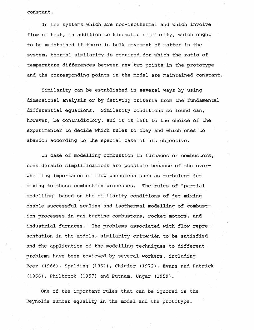
constant.
In the systems which are non-isothermal and which involve flow of heat, in addition to kinematic similarity, which ought to be maintained if there is bulk movement of matter in the system, thermal similarity is required for which the ratio of temperature differences between any two points in the prototype and the corresponding points in the model are maintained constant.
Similarity can be established in several ways by using dimensional analysis or by deriving criteria from the fundamental differential equations. Similarity conditions so found can, however, be contradictory, and it is left to the choice of the experimenter to decide which rules to obey and which ones to abandon according to the special case of his objective.
In case of modelling combustion in furnaces or combustors, considerable simplifications are possible because of the overwhelming importance of flow phenomena such as turbulent jet mixing to these combustion processes. The rules of "partial modelling" based on the similarity conditions of jet mixing enable successful scaling and isothermal modelling of combustion processes in gas turbine combustors, rocket motors, and industrial furnaces. The problems associated with flow representation in the models, similarity criterion to be satisfied and the application of the modelling techniques to different problems have been reviewed by several workers, including Beer (1966), Spalding (1962), Chigier (1972), Evans and Patrick (1966), Philbrook (1957) and Putnam, Ungar (1959).
One of the important rules that can be ignored is the Reynolds number equality in the model and the prototype.
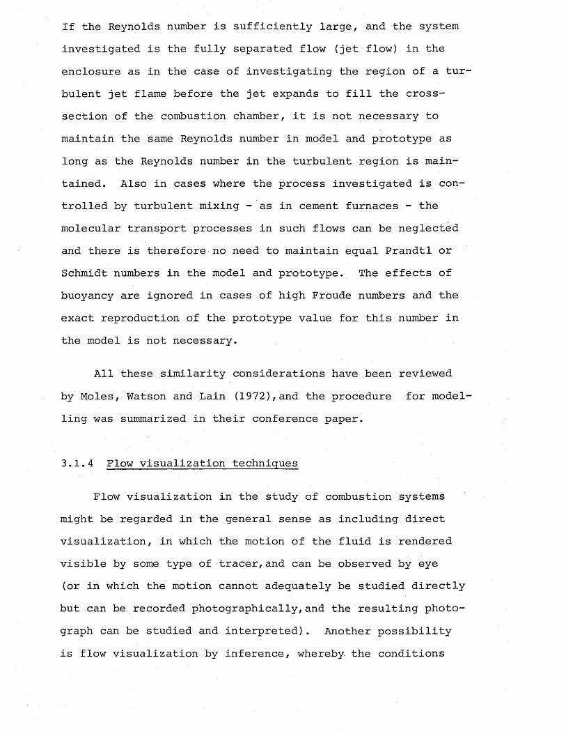
If the Reynolds number is sufficiently large, and the system investigated is the fully separated flow (jet flow) in the enclosure as in the case of investigating the region of a tur bulent jet flame before the jet expands to fill the cross- section of the combustion chamber, it is not necessary to maintain the same Reynolds number in model and prototype as long as the Reynolds number in the turbulent region is maintained. Also in cases where the process investigated is controlled by turbulent mixing - as in cement furnaces - the molecular transport processes in such flows can be neglected and there is therefore no need to maintain equal Prandtl or Schmidt numbers in the model and prototype. The effects of buoyancy are ignored in cases of high Froude numbers and the exact reproduction of the prototype value for this number in the model is not necessary.
All these similarity considerations have been reviewed by Moles, Watson and Lain (1972),and the procedure for model ling was summarized in their conference paper.
3.1.4 Flow visualization techniques
Flow visualization in the study of combustion systems might be regarded in the general sense as including direct visualization, in which the motion of the fluid is rendered visible by some type of tracer,and can be observed by eye (or in which the motion cannot adequately be studied directly but can be recorded photographically,and the resulting photograph can be studied and interpreted). Another possibility is flow visualization by inference, whereby the conditions
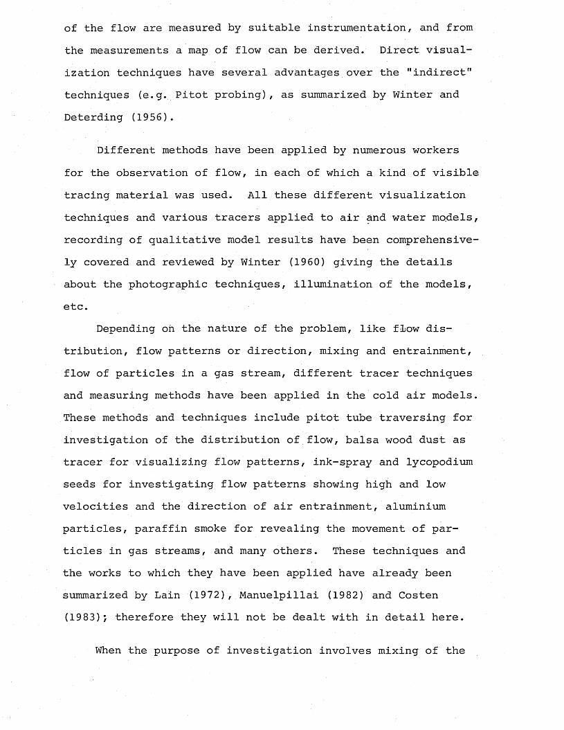
of the flow are measured by suitable instrumentation, and from the measurements a map of flow can be derived. Direct visualization techniques have several advantages over the "indirect" techniques (e.g. Pitot probing), as summarized by Winter and Deterding (1956).
Different methods have been applied by numerous workers for the observation of flow, in each of which a kind of visible tracing material was used. All these different visualization techniques and various tracers applied to air and water models, recording of qualitative model results have been comprehensively covered and reviewed by Winter (1960) giving the details about the photographic techniques, illumination of the models, etc.
Depending oh the nature of the problem, like flow distribution, flow patterns or direction, mixing and entrainment, flow of particles in a gas stream, different tracer techniques and measuring methods have been applied in the cold air models. These methods and techniques include pitot tube traversing for investigation of the distribution of flow, balsa wood dust as tracer for visualizing flow patterns, ink-spray and lycopodium seeds for investigating flow patterns showing high and low velocities and the direction of air entrainment, aluminium particles, paraffin smoke for revealing the movement of particles in gas streams, and many others. These techniques and the works to which they have been applied have already been summarized by Lain (1972), Manuelpillai (1982) and Costen (1983); therefore they will not be dealt with in detail here.
When the purpose of investigation involves mixing of the
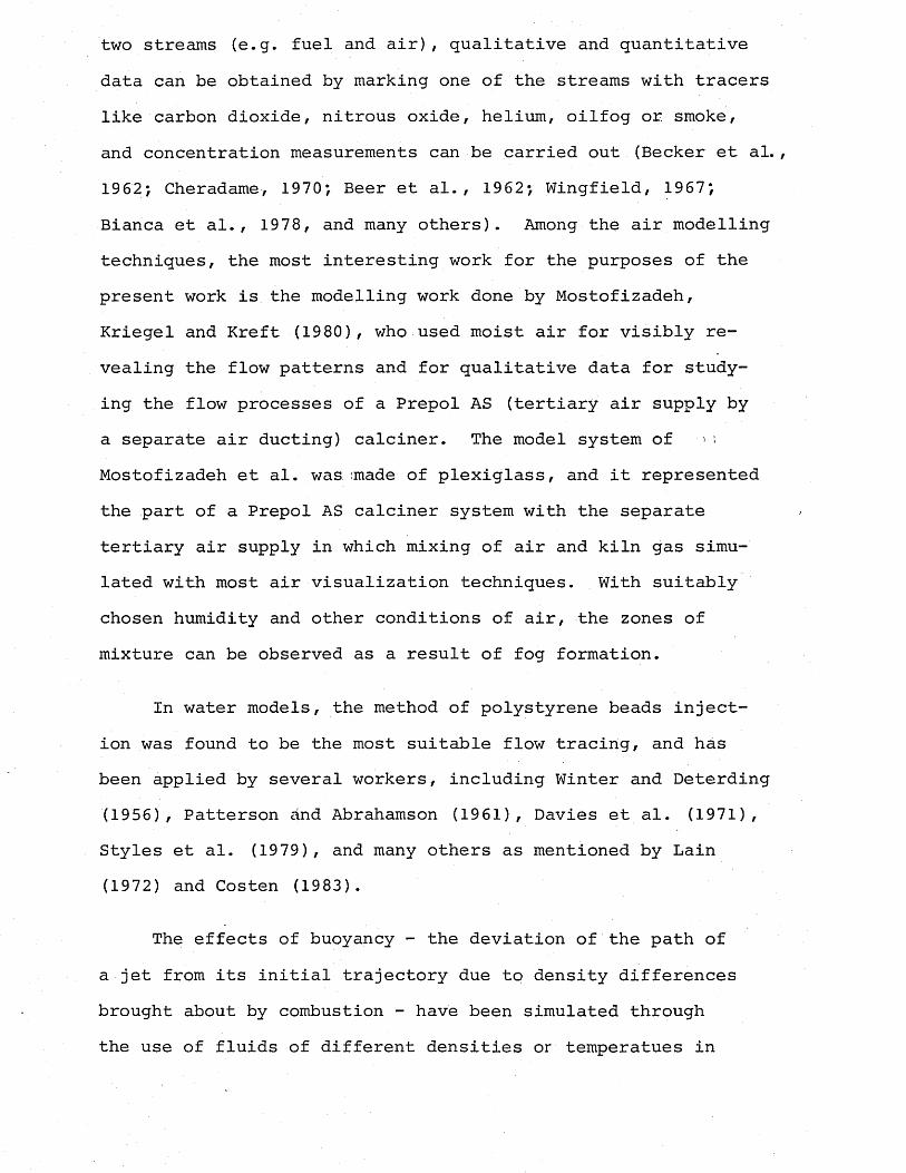
two streams (e.g. fuel and air), qualitative and quantitative data can be obtained by marking one of the streams with tracers like carbon dioxide, nitrous oxide, helium, oilfog or smoke, and concentration measurements can be carried out (Becker et al. , 1962; Cheradame, 1970; Beer et al., 1962; Wingfield, 1967;Bianca et al., 1978, and many others). Among the air modelling techniques, the most interesting work for the purposes of the present work is the modelling work done by Mostofizadeh,Kriegel and Kreft (1980), who used moist air for visibly revealing the flow patterns and for qualitative data for studying the flow processes of a Prepol AS (tertiary air supply by a separate air ducting) calciner. The model system of ■ > ; Mostofizadeh et al. was .made of plexiglass, and it represented the part of a Prepol AS calciner system with the separate tertiary air supply in which mixing of air and kiln gas simulated with most air visualization techniques. With suitably chosen humidity and other conditions of air, the zones of mixture can be observed as a result of fog formation.
In water models, the method of polystyrene beads injection was found to be the most suitable flow tracing, and has been applied by several workers, including Winter and Deterding (1956), Patterson and Abrahamson (1961), Davies et al. (1971), Styles et al. (1979), and many others as mentioned by Lain (1972) and Costen (1983).
The effects of buoyancy - the deviation of the path of a jet from its initial trajectory due to density differences brought about by combustion - have been simulated through the use of fluids of different densities or temperatues in
a scale model. These methods include use of magnetite slurry, coloured kerosine, salt briquettes, sodium chloride with water, and the works involving these methods have been described and summarized by Lain (1972) and Costen (1983).
For the studies'of flame jets and the entrainment and mixing of air as in the case of the present work, many techniques exist for labelling one or other of the streams.
Two-dimensional water models were used by Curtis and Johnson (1959) to observe the mixing and recirculation phenomena in the furnaces. By adding dye to the water simulating the recirculated gas and observing its diffusion as it passed through the furnace, the effectiveness of mixing and the recirculated gas in the furnace was indicated.
Kristmanson and Danckwerts (1961) used a photographic method to determine the concentration distribution of jet- fluid when a circular turbulent jet of liquid mixes with an unlimited liquid environment. The experimental technique used for the simulation of the jet system had originally been developed for use in an apparatus made of galvanized iron, in which it was impossible to use strong acid or strong alkali as the main fluid because of corrosion effects. A dilute solution of borax had therefore been used as the alkali and a solution of hydrochloric acid as the acid. The jet- fluid was alkaline and the indicator used was bromocresol green which changes from yellow to blue as the pH changes from 3.8 to 5.4, a range which renders it suitable for use with borax and hydrochloric acid. High contrast filters were used for the photographic work to enable the blue colour
of the indicator in the mixing zone to be observed.
The chemical tracer technique was also used by Clarke, Gerrard and Holliday (19 62) in the water models of the gas turbine combustion chambers in order to study the mixing processes quantitatively. In the chamber investigated the chemical used was acidified ammonium ferrous sulphate, in solution with the water which simulated the "fuel" flow.The tests were on a sheet metal chamber fitted with an injector. The fuel was injected at a certain air/fuel ratio,, and then samples from the primary zone and the exhaust section respectively were extracted. The iron content of the samples was thus measured quantitatively by adding thio-glycollic acid to give a purple coloration, which was assessed quantitatively using a Spekker absorptiometer. The results were then expressed in terms of equivalent air/fuel ratios.
Fallows (1966) developed a method which permits visual observation of two successive compositions as mixing proceeds. The method depends on the colour changes occurring in a mixed pH indicator where a solution containing phosphoric acid and its sodium salt is mixed with a solution of caustic soda. Distinctive colour changes occur at two mixture compositions, and these compositions may be chosen independently. The relative densities of the two solutions may be varied within limits.
Street and Twamley (1967) used the method of labelling gases by injecting into them trace concentrations of acids and alkalis, and noting the colour changes when a filter paper or muslin, impregnated with chemical indicator solution is
positioned downstream from the injector. The advantages of the technique were its simplicity and its ability to give both qualitative and quantitative data. In the experiments hydrogen chloride and ammonia gases were used to label the fluids. For qualitative investigations hydrogen chloride was generated using solid ammonium chloride and concentrated sulphuric acid and injected into the secondary air stream. Ammonia was used as a second label. In quantitative measurements the tracer flow had to be monitored. By using the filter-paper probes the concentration changes in narrow slices of a particular cross-sectional area could be- measured or indicated.
A simple technique for measuring flame shape and length is the representation of the mixing controlled combustion reaction by the neutralization reaction of acid and alkali. Hawthorne (1939) pioneered this technique and was able to accurately model the burning reaction by using acid-alkali neutralization reaction. A jet of caustic soda solution coloured with phenolphthalein was arranged to discharge into a weak acid, caustic sodairepresentingthe fuel, and the acid simulating the air. The comparison.of the photographs of caustic soda jet showed great similarity with the flame shape. Although Weddel . (1942) modified this flame model later, it was still not applied to any specific industrial process. During the period 1936-1941, a programme of study was conducted at M.I.T. to establish the similarity of turbulent jet flames to cold-jet mixing involving concentration traverses, radial and axial, of acid-alkali flame jet models and corresponding measurements on a wide variety of burning
fuel jets, including hydrogen, city gas, hydrogen-air, propane and others. The acid-alkali jet length to disappearance of colour was noted to change with the changes of normalities of the solutions or the flow rates (Hottel, 1953).
Very closely related to the subject of this thesis is the work of Ruhland (1967) who for the first time applied the acid-alkali technique to an industrial process, to represent the enclosed turbulent jet diffusion flame in the cement rotary kiln. Ruhland used dilute hydrochloric acid to simulate air, and sodium hydroxide solution to simulate the fuel-primary air, the nozzle fluid. Thymolphthalein was used as the indicator to give a blue colour to the jet fluid. The part of the solution which was of blue colour represented the unburnt fuel in the flame. By using photographic methods the flame lengths were measured for different operating conditions. These measured values were used as data for some part of the work for the development of the flame length formula.
Inman (1969) also used a very similar technique to Ruhland's, and by using both phenolphthalein and thymol*- phthalein as indicators, he was able to compare the application of these two. Although psychologically the red coloration of the phenolphthalein to represent flames had better impact for demonstrations, the blue colour of thymolphthalein was found to be more stable. The technique was used for the effect of changes in running conditions, including design alterations, on the glass furnace flames. Geometric similarity was obtained by constructing a 1/24 scale down model of
the glass tank and Reynolds number equality was modified for any number in the turbulent region. Stoichiometric conditions are represented in the model by adjusting the relative acid and alkali concentrations. The flame lengths measured did not exactly agree with the flame lengths measured in the actual plant, but qualitatively their response to changes in the operating conditions were the same.
The flame length measurements in the glass melting furnace models by use of acid-alkali technique were also carried out by Fricker, Page and Chew (1978). A distorted model with nozzles designed according to Thring-Newby criteria was used with flow rates maintaining a reduced Reynolds number in the turbulent region. By using photographic methods simulated flames were recorded. It was concluded that, although the visual simulation of the flame was excellent,and the ■ U effects of burner angle and position, excess air on the flame could be produced in the model, quantitative measurements were not found to be very precise.
The most recent research in this field was the work carried out by Midland Research Station of British Gas in which the acid-alkali technique was utilized for developing filing systems for glass melting tanks. The reliability and the accuracy of the technique were assessed by comparison of the model predictions for flame length with the actual plant measurements. The similarity criteria, and the details about the model and the experimental procedures were given in detail in the report by Khan and Macfadyen (1980), and the results of their experiments confirmed the ability of the technique to simulate the effect on flame length of
varying furnace conditions, and the flame lengths were predicted within - 10% error.
It is also reported by Cheradame (1970) that flow visualization by use of coloured tracers in the hydraulic models was used in the small-scale models at the International Flame Research Foundation. The method of mixing of the slightly basic water with the yellow acidified tracer resulting in a visible violet tint at a certain pH was used for the study of mixing patterns.
Other tracing techniques and the modelling work done at the University of Surrey by the previous members of the Fuels and Energy Research Group (FERGUS) have already been described by Costen (1983), and will therefore not be mentioned here.
3.2 Review of the Considerations Involved in Modelling ofTurbulent Diffusion Flames
3.2.1 Turbulent jets
The flames encountered in cement manufacturing processes are of the turbulent diffusion type. In order to study the properties of such flames, the rules and methods of isothermal modelling of the turbulent jet systems can be applied to these systems. Therefore the rotary kiln flame can be described in such terms as being a long enclosed turbulent jet passing into a turbulent co-flowing stream constrained by a circular duct, whereby the flame of the auxiliary firing system as applied in the present work is a short impinging semi-free turbulent jet in cross flow. An understanding of such jet systems and modelling procedures is necessary for the true representation
of the cement making flames in such terms. Such an understanding starts with the simplest form, that of the free jet.
3.2.1.1 Free jet theory
A turbulent free jet is formed when a high velocity stream of fluid passes from a relatively small opening into a large unconfined space in which the surrounding fluid is either at rest or moving relatively slowly. If the opening is a narrow slot, a plane free jet is formed; if it is a circular aperture a round free jet is produced. Such a stream has sufficient momentum to preserve its initial flow direction for some distance from the orifice, until all the kinetic energy due to its initial velocity is dispersed into turbulent mixing regions of the jet by the fluid entrainment.
Throughout the jet the pressure is. nearly the same as it exists in the surrounding fluid, but the jet stream is separated from its surroundings by a surface of discontinuity (Prandtl, 1952). This boundary generally is well-defined, apart from local instabilities and in entraining the surrounding fluid, it reduces the jet stream velocity.
The jet spreads in such a way that the fluid mass increases directly proportional to the distance from the sources, whereas the pressure and the momentum remain constant. This behaviour is manifested by the shape of a solid semi-cone of defined angle.
The free jet contains three main regions which can be clearly defined. The first of these regions is the potential core of the jet which extends to a distance of about 4-5
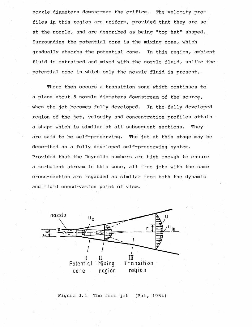
nozzle diameters downstream the orifice. The velocity profiles in this region are uniform, provided that they are so at the nozzle, and are described as being "top-hat" shaped. Surrounding the potential core is the mixing zone, which gradually absorbs the potential cone. In this region, ambient fluid is entrained and mixed with the nozzle fluid, unlike the potential cone in which only the nozzle fluid is present.
There then occurs a transition zone which continues to a plane about 8 nozzle diameters downstream of the source, when the jet becomes fully developed. In the fully developed region of the jet, velocity and concentration profiles attain a shape which is similar at all subsequent sections. They are said to be self-preserving. The jet at this stage may be described as a fully developed self-preserving system.Provided that the Reynolds numbers are high enough to ensure a turbulent stream in this zone, all free jets with the same cross-section are regarded as similar from both the dynamic and fluid conservation point of view.
nozzle
inPotential Mixing I ransi t ion
core region region
Figure 3.1 The free jet (Pai, 1954)
3.2.1.2 The similarity of free jets
In free jet mixing the length scale factor is the nozzle diameter dQ (or radius 'r ), and the time scale factor is determined by the Reynolds number of the flow at any chosen point. However, beyond about 8 nozzle diameters downstream the orifice and with Reynolds numbers above a certain minimum ensuring adequate turbulence, all free jets are dynamically similar, except for microscale phenomena, even though the ratio of r to some characteristic length x of the system is different (Thring and Newby, 1953). This permits the use of um/u0 • x/r0 and Cm x/rQ as dimensionless variables. The equations for the decay of the fluid velocity and the concentration profile derived are based on the following three assumptions:
1) Radial spread functions, concentration and the velocity profiles respectively,
C£- = f, (r/x) (3.1)o
u^ = f2 (r/x) (3.2)o
are dependent only on the Reynolds number at a characteristic point where r is the radial distance from the axis and for large values of x,
constant , 0= ....... (3.3)m x
2) Momentum is conserved. From the conservation of momentum equation,
oo
I = 2 7T p u2 r dr (3.4)
where p = density of the fluidr = radial distance from the axis u = mean fluid velocity
the momenta-:', at the nozzle unit (initial momentum) and at adistance far enough from the nozzle, where p = Pa of thesurroundings are defined, respectively, as
I = n p u 2 r 2...................... .......... (3.5)0 0 o
I = 2tt p u 2 x2 ......... (3.6)a m
and (3.5) is equal to (3.6).
3) The nozzle fluid is conserved. From the second assumption, the equation for velocity decay,
U- f po 1%I r/x (3.7)-2 = k u u o pa i °
is developed.
In the same manner, by using assumption 3, the concentration profile equation can be developed (Stambuleanu, 1976).
C , m = kCo a p rQ/x (3.8)
aThe above derived equations reveal that at each point along the fully developed free jet axis, the axial velocity and concentration of the injected stream depend on the distance to the nozzle, x.
Ricou and Spalding (1961) concentrated on one property of the jet: the mass flow rate across a section at right angles to the jet axis, denoted by m, where:
m = 2it pur dr .......... (3.9)o
By developing a technique for measuring the axial mass flow rate in the turbulent jet formed by the injection of gas or air into a reservoir of stagnant air at uniform pressure, they determined the values of the constants for different isothermal jet fluids in the mass entrainment equation:
m— = k — for isothermal cases ........... (3.10)*o 2 r°
In the cases of non-isothermal jets, an "equivalent nozzleradius" for the injector is introduced in order to calculate and establish velocity and concentration profiles. This new term is defined as the dimension through which the fluid mass rate and momentum values are those of the original jet, while the density of the fluid is equal to that of the new temperature. Thus the equivalent nozzle radius, r ', is defined (Thring,1962):
mr ' = .....2.. (3.11)O / — \ (IT Pf Ic )
where I - original momentumrri = mass flow rate o
- the flame or hot jet density
Introducing this "equivalent nozzle radius" term into the equation developed by Hinze and Van der Hegge-Zijnen (1949) for axially symmetric jets,
*0* = k - 5 _ ™o 2 ro
P1a 1 2 .......... (3.12)
». Pq )
where m refers to mass flow rate in each cross-section ofX
the jet, the non-isothermal velocity and concentration equations are obtained:
(3.13)
c p£m ~ f IP j
(3.14)
3.2.1.3 The enclosed jet
When a jet is placed in an enclosed space, as is often the case in furnace systems, it undergoes some basic changes. The flow in such cases is constrained, and as a result the pressure gradients prevent the existence of an undisturbed surrounding stream,and velocity is everywhere dependent upon position.
The flow pattern is governed by the chamber geometry and the input of mass and momentum. The turbulent jet entrains fluid as is required to satisfy its entrained capacity. In cases when the entrainment capacity of the jet exceeds the amount of fluid available for entrainment, the phenomenon of recirculation takes place as fluid is caused to flow in a reverse direction around the downstream periphery of the jet to a point nearer the source, where it is entrained. The concept of a "jet" becomes very arbitrary.
The enclosed jet, like the submerged free jet, can be divided into three regions, as shown in Figure 3.2. The first part consists of the primary potential cone and the discontinuity layer as in the case of a free jet. However, additional high shear zone near the jet boundaries is initiated
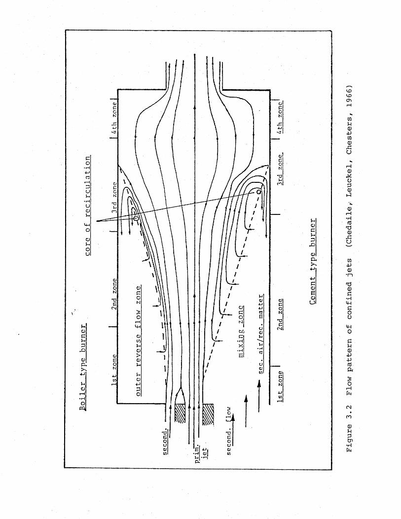
co•rH
r3
U5-•pHuCJ5 -
U-1ooou
y->ocy-Dx>CL)CuXUorH
• Ho
X)CM
GG)GGGJ2>Q)CXX+->4->GO£oo
Figure
3.2
Flow
pattern
of confined
jets
(Chedaile,;
Leuckel, Chesters,
1966)
by the confinement, and as the flow develops shear forces increase.
By the start of the mixing zone this enlarged shear layer has consumed the potential core, and it continues to grow with the boundary layer until either merges or all the surrounding fluid is consumed. It is in this region that the recirculation phenomenon occurs. In order to satisfy the jet entrainment capacity, the fluid from downstream is returned to the source, giving rise to the differnces between the free and enclosed jets.
The presence of recirculation can affect the prediction of the jet performance as normal free jet expansion has been interfered with, impinging at some point with the surrounding walls and changing its characteristics completely.
In the third region, the jet is described as fully developed. Although its original momentum is eventuallyconverted into static pressure and uniform mixed velocity,vthe pressure within the jet increases with distance from the nozzle.
3.2.1.4 Similarity of confined jets
The fully turbulent constant density jets in infinite stagnant atmospheres are aerodynamically similar, except in the region surrounding the jet source. But the same situation does not apply to the confined jets as the walls interfere with the expansion of the jet and other additional parameters, which result from the resulting difference between a confined and a free jet are introduced.
1 J J
Several theoretical relationships have been developed to enable the prediction of enclosed jet performance and recirculation for a universal set of systems. Three of these to be widely used in the study of combustion will be considered in this section, which are the theories of Craya-Curtet, Thring-Newby and Becker, with special emphasis on the Craya- Curtet parameter which has been used for the modelling of the turbulent diffusion flames in the present work.
Craya-Curtet (1955) have introduced a rigorous analysis for the performance of an enclosed jet and determined a parameter of similarity for confined jets which is based on the theory of the free turbulent jet and upon a calculation model which is illustrated in Figure 3.3.
The approximate theory of enclosed jets allows for the wall effect of the enclosing duct, when the jet is supplied with a co-flowing stream. Both two-dimensional and axisymme-tric conditions are considered.
v'The approach used was the employment of the mean values
of the Navier-Stokes equations, which were simplified and integrated in conjunction with the continuity equation. From these manipulations similarity equations were produced for both two-dimensional and axisymmetric enclosed jet systems.
For the axisymmetric system, which is most similar to the kiln system, the similarity parameter, m, for determining the onset of recirculation in a duct is given by:
m - -3/2 R2 + R + K R2 /(rQ/L)2 (3.15)
where R is the discharge ratio q/Q,q = ,(uc - ua) rQJQ = 7TU (L - 6 *)2 + qaK = a factor relating to the shape of the velocity
profileu , u = velocities of the jet and the surrounding fluid,resp. o a J
8* - boundary layer displacement thickness
The boundary layer displacement thickness, 6*, is related to flow such that,
-V8* - 1.74 Re 2 (Coulson and Richardson, 1965) ...(3.16)
Considering the Reynolds numbers associated with the fully turbulent kiln systems, in which Re > 105, the value of boundary thickness becomes so small that it is unlikely to affect the similarity parameter, therefore it is neglected.
A further simplification can be made referring to Patrick's (1965) conclusions, which suggest that, as the jet has a "top- hat" profile at the nozzle, its shape factor, K, can be assumed to be equal to one.
The value of m varies between zero and infinity, recirculation starting when the value is greater than 1.5, and increasing with increase of m.
The similarity parameter developed by Thring and Newby (1953) was based mainly on the free jet theory and designated usually as 0, where,
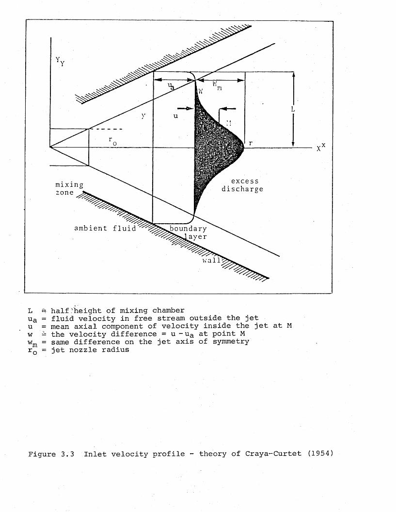
excessdischargemixing
zone j
ambient fluid boundary^^sjsyer
wall
L == half .'height of mixing ehamberua = fluid velocity in free stream outside the jet u = mean axial component of velocity inside the jet at M w = the velocity difference = u -ua at point M wm = same difference on the jet axis of symmetry rQ = jet nozzle radius
Figure 3.3 Inlet velocity profile - theory of Craya-Curtet (1954)
where mQ = primary (jet) mass flowma = secondary mass flowr0* = equivalent nozzle radiusL = half diameter of constraining tube
C ' = mass concentration of the nozzle fluid in the jet 00
of combustible mixture after complete mixing
The equivalent nozzle radius being defined as,
ro pf(3.18)
where r = nozzle radius opQ = nozzle fluid density
= density of the fluid after complete mixing (flame)
This approach of Thring-Newby which allows for the temperature effect of combustion, by using the equivalent nozzle radius, rQ', is not generally applicable if r0'/b > 0.05 owing to excessive distortion in the nozzle region.
A,'further similarity parameter for enclosed jets developed by Becker (19 72) is similar to that of Craya-Curtet, the main difference being that the Craya-Curtet parameter, m, lies between zero and infinity, whereas the Becker throttle factor is between zero and 1. Becker has shown that the Craya-Curtet parameter, m, is in fact a function of the ratio of kinematic to dynamic mean velocities, u^/u^, and that the pattern of a confined turbulent jet differs profoundly from that of a free jet. The latter conclusion is more apparent in a system like a cement kiln where the secondary air flow is too low to satisfy the entrainment capacity of the jet fluid, therefore recirculation occurs.
In his derivation, Becker treated the enclosed jet as a point source, and simplified the relationships for the kinematic and dynamic mean velocities in the following forms respectively:
mu, ~ + u (3.19)k — 2ttI j p O
I + h Iu, = - ........... (3.20)d 7T P L2a
where I and I are momenta, p^ and p are densities for the o a o Kajet and the surrounding fluid, respectively.
Becker has defined the similarity parameter, called the Becker throttle factor as,
1 ukT, = — (3.21)h V 2 ud
Moles, Watson and Lain (1972) have compiled a survey of 53 wet process cement kilns, and from the data they have evaluated the range of operation in terms of excess air, size ratio, and similarity parameters. The survey revealed that the Thring-Newby criteria do not apply to the rotary kiln system due to range of ro'/L values being far too high compared to the limiting highest value of 0.05. They concluded that the Craya-Curtet and Becker parameters are suitable provided that the value of m must be greater than 1.5 for recirculation to occur. Similarly, recirculation occurs only when Becker throttle number T^ is less than 0.4. The ranges applicable to the rotary kilns have shown that they are of medium to low recirculatory intensity.
3.2.1.5 A jet influenced by cross-flow
The simple jet flows, like free jets, jets mixing with parallel streams, and jets mixing with streams in enclosures of various shapes have been studied rigorously by use of similarity and turbulent jet mixing theories in an attempt to understand the physics of industrial flames and to improve the combustion efficiency of those industrial heating systems which employ turbulent jets to promote mixing which is a rate controlling step in combustion processes. Other jet systems, like a system where high velocity jets are injected into a transverse main stream, however, have been less studied.
The problem of mixing of turbulent jets with a mainstream at some angle is relevant to many industrial applications, such as burners, gas turbine combustors, flare stacks, exhausting of gases from chimneys into a cross-wind, and injection of secondary air over fuel beds.
The transverse jet is an example of a free turbulent shear flow, like the free jet, but is much more complex.With a free jet the turbulent motion at the mixing boundary causes the entrainment of surrounding fluid into the flow.The jet spreads and the axial velocity falls. The solution of the flow pattern is possible by a simple mathematical analysis, and by use of an experimentally determined constant. It is assumed that the pressure is constant throughout the jet,and the profiles of velocity downstream of the nozzle at successive sections are similar to each other.
When the free jet encounters a cross-flowing stream, though, this single picture of free jet development changes.
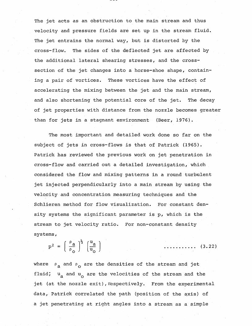
The jet acts as an obstruction to the main stream and thus velocity and pressure fields are set up in the stream fluid.The jet entrains the normal way, but is distorted by the cross-flow. The sides of the deflected jet are affected by the additional lateral shearing stresses, and the cross- section of the jet changes into a horse-shoe shape, containing a pair of vortices. These vortices have the effect of accelerating the mixing between the jet and the main stream, and also shortening the potential core of the jet. The decay of jet properties with distance from the nozzle becomes greater than for jets in a stagnant environment (Beer, 1976).
The most important and detailed work done so far on the subject of jets in cross-flows is that of Patrick (1965). Patrick has reviewed the previous work on jet penetration in cross-flow and carried out a detailed investigation, which considered the flow and mixing patterns in a round turbulent jet injected perpendicularly into a main stream by using the velocity and concentration measuring techniques and the Schlieren method for flow visualization. For constant density systems the significant parameter is p, which is the stream to jet velocity ratio. For non-constant density systems,
r p ih ( U 'ia ap u o ; o ;
where Pa and pQ are the densities of the stream and jetfluid; u and u are the velocities of the stream and the a ojet (at the nozzle exit),respectively. From the experimental data, Patrick correlated the path (position of the axis) of a jet penetrating at right angles into a stream as a simple
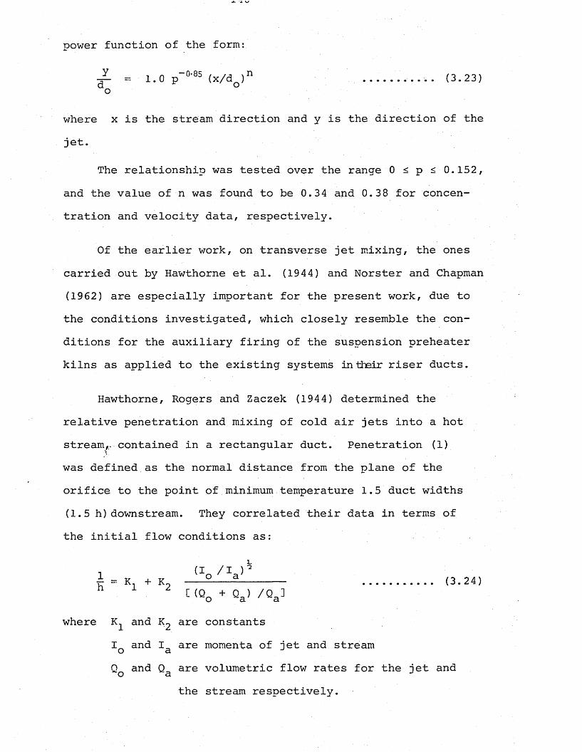
power function of the form
y (3.23)do
where x is the stream direction and y is the direction of the jet.
The relationship was tested over the range 0 < p < 0.152, and the value of n was found to be 0.34 and 0.38 for concentration and velocity data, respectively.
Of the earlier work, on transverse jet mixing, the ones carried out by Hawthorne et al. (1944) and Norster and Chapman (1962) are especially important for the present work, due to the conditions investigated, which closely resemble the conditions for the auxiliary firing of the suspension preheater kilns as applied to the existing systems in their riser ducts.
Hawthorne, Rogers and Zaczek (1944) determined the relative penetration and mixing of cold air jets into a hot stream,- contained in a rectangular duct. Penetration (1) was defined as the normal distance from the plane of the orifice to the point of minimum temperature 1.5 duct widths (1.5 h) downstream. They correlated their data in terms of the initial flow conditions as:
where and are constantsI and I are momenta of jet and stream o aQ and Q„ are volumetric flow rates for the jet ando a J
(3.24)
the stream respectively.
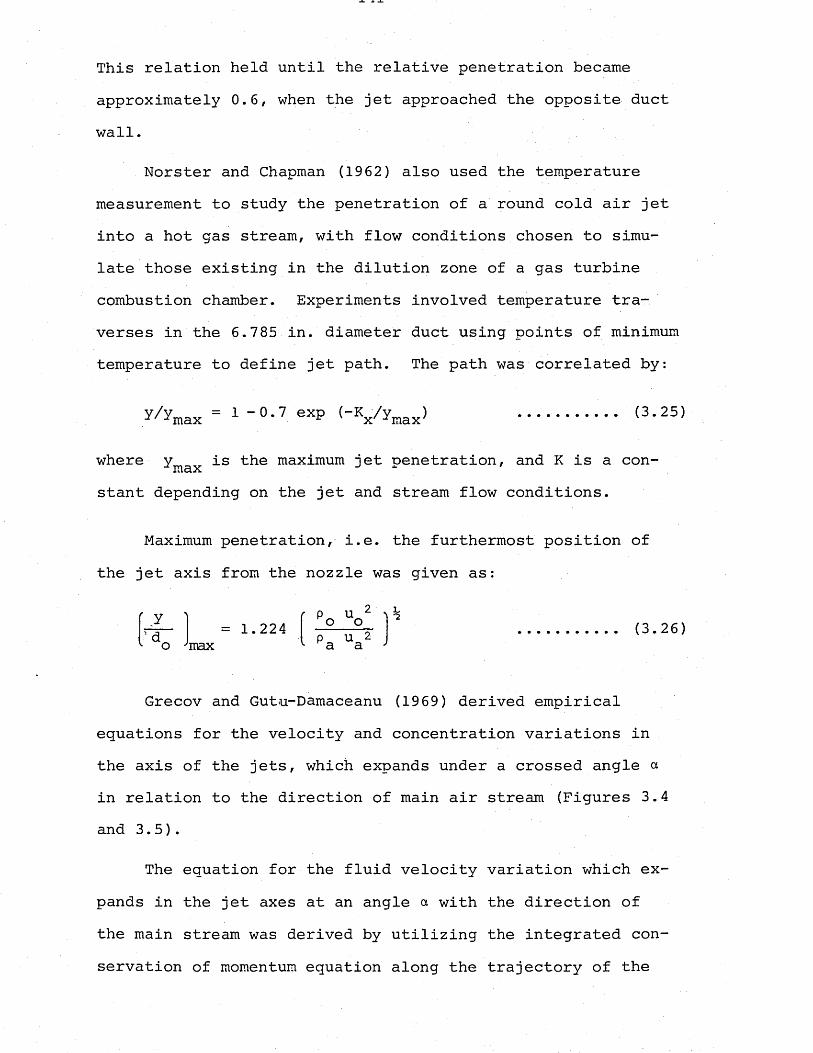
This relation held until the relative penetration became approximately 0.6, when the jet approached the opposite duct wall.
Norster and Chapman (1962) also used the temperature measurement to study the penetration of a round cold air jet into a hot gas stream, with flow conditions chosen to simulate those existing in the dilution zone of a gas turbine combustion chamber. Experiments involved temperature traverses in the 6.785 in. diameter duct using points of minimum temperature to define jet path. The path was correlated by:
y / W = 1 ~ 0-7 eXp ("Vyinax) .......... (3.25)
where y is the maximum jet penetration, and K is a con- Jmaxstant depending on the jet and stream flow conditions.
Maximum penetration, i.e. the furthermost position of the jet axis from the nozzle was given as:
( v c P uy - . Ko o= 1.224 max p u 2 a a
(3.26)
Grecov and Gutu-Damaceanu (1969) derived empirical equations for the velocity and concentration variations in the axis of the jets, which expands under a crossed angle a in relation to the direction of main air stream (Figures 3.4 and 3.5).
The equation for the fluid velocity variation which expands in the jet axes at an angle a with the direction of the main stream was derived by utilizing the integrated conservation of momentum equation along the trajectory of the
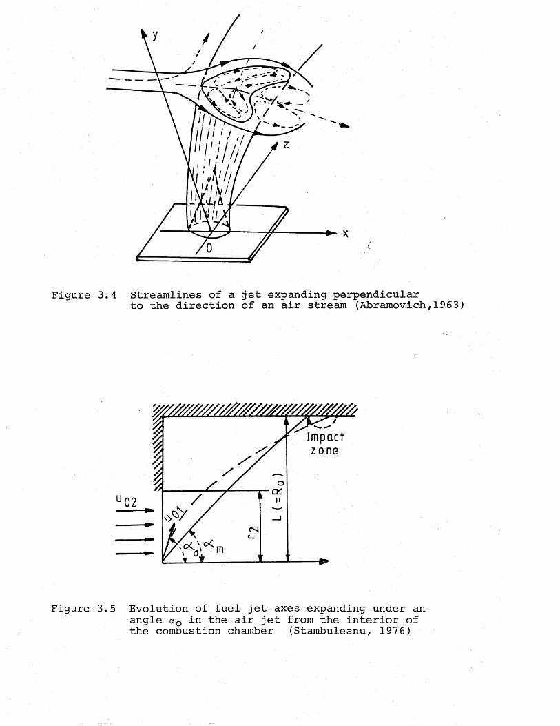
Figure 3.
Figure 3.
4 Streamlines of a jet expanding perpendicularto the direction of an air stream (Abramovich,1963)
^ Impact
5 Evolution of fuel jet axes expanding under an angle aQ in the air jet from the interior of the combustion chamber (Stambuleanu, 1976)
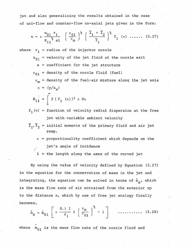
jet and also generalizing the results obtained in the case of uni-flow and counter-flow co-axial jets given in the form:
U01 rlk
K1101m
f1 (n) ...... (3.27)
where r^ = radius of the injector nozzleu01 velocity of the jet fluid at the nozzle exita = coefficient for the jet structure
poi = density of the nozzle fluid (fuel)P m = density of the fuel-air mixture along the jet axis n = (y/ax)
K11 2 [ f x ( n ) ] 2 n dn
f1 (n)
XV x2
£ =
1 =
function of velocity radial dispersion at the freejet with variable ambient velocityinitial moments of the primary fluid and air jet resp.proportionality coefficient which depends on the jet's angle of incidencethe length along the axes of the curved jet
By using the value of velocity defined by Equation (3.27) in the equation for the conservation of mass in the jet and integrating, the equation can be solved in terms of ni , whichais the mass flow rate of air entrained from the exterior up to the distance x, which by use of free jet analogy finally becomes,
ma = m010 . 1 1 r
£ ----- iY* Im
I P01- 1 (3.28)
where m^^ is the mass flow rate of the nozzle fluid and
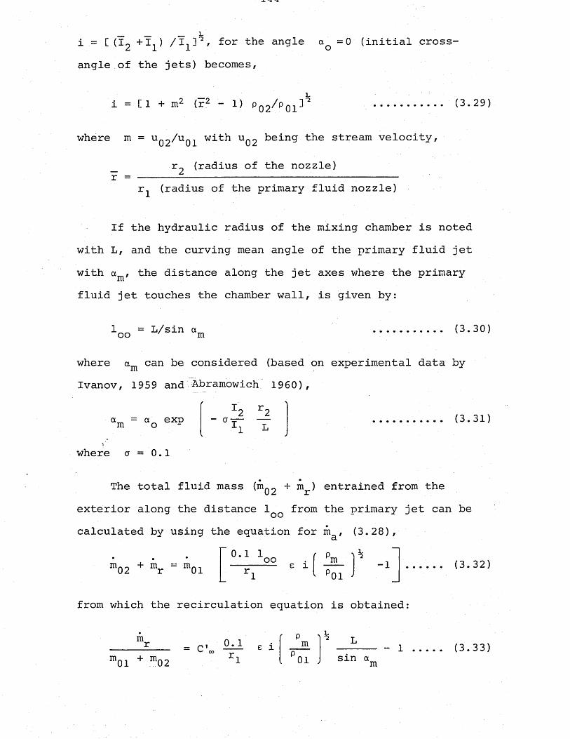
_ _ — Vi = [ (I2 + 1 ) /I-^ 2 / f°r the angle aQ =0 (initialangle of the jets) becomes,
cross-
i = [ 1 + m2 (r2 - 1) pq2^p01 2 (3.29)
where m = uq2//u01 with Uq2 being the stream velocity,
r =r2 (radius of the nozzle)
r^ (radius of the primary fluid nozzle)
If the hydraulic radius of the mixing chamber is noted with L, and the curving mean angle of the primary fluid jet with a , the distance along the jet axes where the primary fluid jet touches the chamber wall, is given by:
1 ^ = L/sin a oo m (3.30)
where am can be considered (based on experimental data by Ivanov, 1959 and Abramowich 1960),
a = a exp - CTI2 r2 (3.31)
where a = 0.1
The total fluid mass (hIq2 + m ) entrained from theexterior along the distance 1Q from the primary jet can becalculated by using the equation for m , (3.28),a
m02 + mr “ m010.1 1oo e l m
01-1 (3.32)
from which the recirculation equation is obtained:
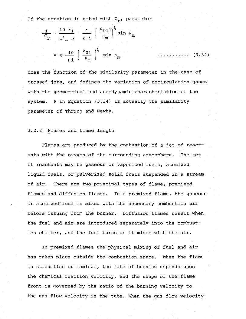
If the equation is noted with .C , parameter
^r C1 L e i001 _ . 1 0 r l . _ 1
m
„ 10 f P01 0 --- sin am . (3.34)e i Pm
does the function of the similarity parameter in the case ofcrossed jets, and defines the variation of recirculation gases with the geometrical and aerodynamic characteristics of the system. 0 in Equation (3.34) is actually the similarity parameter of Thring and Newby.
3.2.2 Flames and flame length
Flames are produced by the combustion of a jet of reactants with the oxygen of the surrounding atmosphere. The jet of reactants may be gaseous or vaporized fuels, atomized liquid fuels, or pulverized solid fuels suspended in a stream of air. There are two principal types of flame, premixed flames' and diffusion flames. In a premixed flame, the gaseous or atomized fuel is mixed with the necessary combustion air before issuing from the burner. Diffusion flames result when the fuel and air are introduced separately into the combustion chamber, and the fuel burns as it mixes with the air.
In premixed flames the physical mixing of fuel and air has taken place outside the combustion space. When the flame is streamline or laminar, the rate of burning depends upon the chemical reaction velocity, and the shape of the flame front is governed by the ratio of the burning velocity to the gas flow velocity in the tube. When the gas-flow velocity
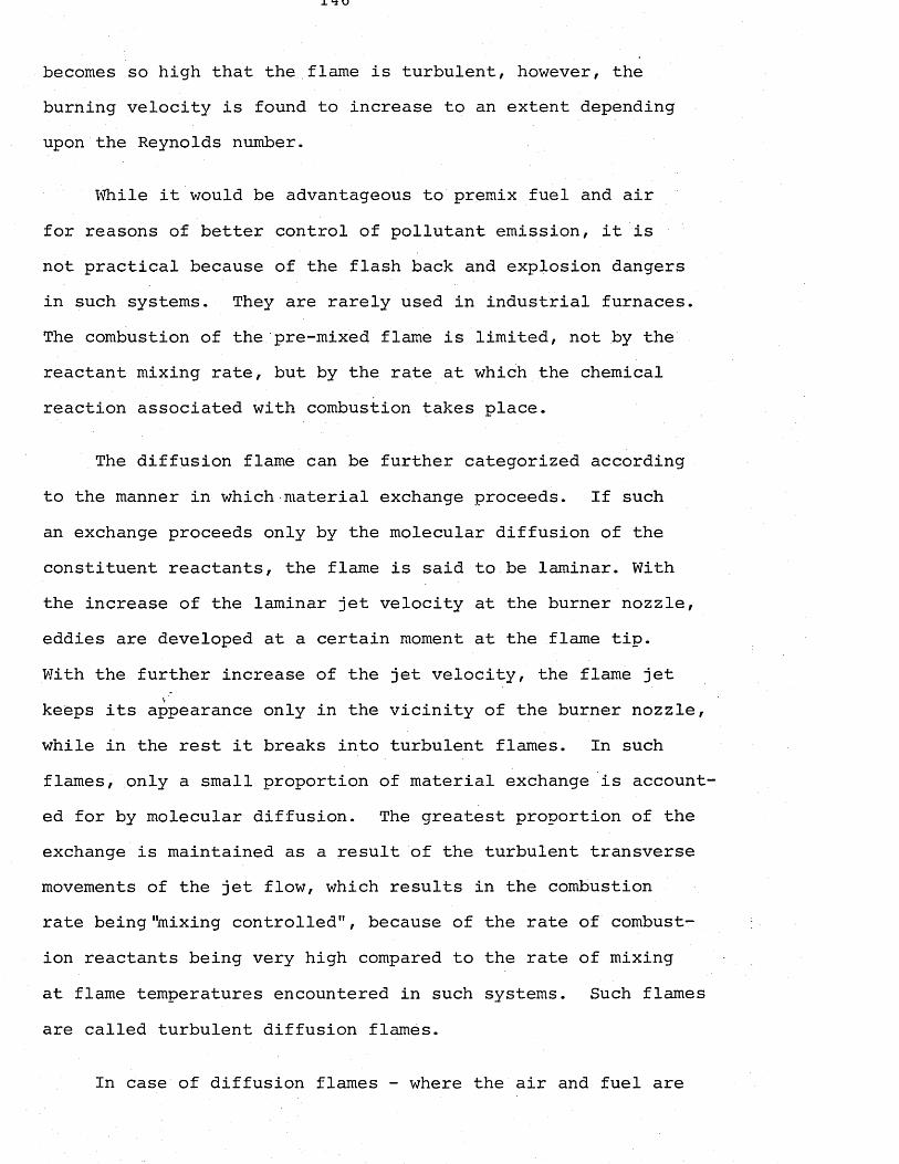
becomes so high that the flame is turbulent, however, the burning velocity is found to increase to an extent depending upon the Reynolds number.
While it would be advantageous to premix fuel and air for reasons of better control of pollutant emission, it is not practical because of the flash back and explosion dangers in such systems. They are rarely used in industrial furnaces. The combustion of the pre-mixed flame is limited, not by the reactant mixing rate, but by the rate at which the chemical reaction associated with combustion takes place.
The diffusion flame can be further categorized according to the manner in which-material exchange proceeds. If such an exchange proceeds only by the molecular diffusion of the constituent reactants, the flame is said to be laminar. With the increase of the laminar jet velocity at the burner nozzle, eddies are developed at a certain moment at the flame tip.With the further increase of the jet velocity, the flame jet keeps its appearance only in the vicinity of the burner nozzle, while in the rest it breaks into turbulent flames. In such flames, only a small proportion of material exchange is accounted for by molecular diffusion. The greatest proportion of the exchange is maintained as a result of the turbulent transverse movements of the jet flow, which results in the combustion rate being"mixing controlled", because of the rate of combustion reactants being very high compared to the rate of mixing at flame temperatures encountered in such systems. Such flames are called turbulent diffusion flames.
In case of diffusion flames - where the air and fuel are
introduced separately, the significant flame parameters, such as flame length, flame contour, stability and combustion intensity, radiant heat transfer from the flame, and also the emission of pollutants depend upon the way in which fuel and air are mixed. Most industrial flames are of the turbulent diffusion type.
3.2.2.1 Turbulent diffusion flames
The types of flames which are most commonly encountered in the industrial applications are the turbulent diffusion flames, that is, a flame projected centrally along a combustion chamber without direct impingement on the walls. The air for the combustion is supplied at the burner end at a low velocity so that the mixing between fuel and air is by turbulent diffusion and is governed by the fuel jet momentum, or burner reaction thrust.
The turbulent diffusion flames of gases, liquid and pulverized fuels have been compared by Hubbard (1958) with particular emphasis on the physical processes governing mixing.The soot formation and the attendant increase in flame emissi- vity, combustion and heat transfer associated with each type of fuel have also been discussed. Of these, the most important factor affecting the combustion rate and flame length of high temperature diffusion flames is the aerodynamic mixing of the reactant and oxidiser, and this topic will be explained in detail in the following sub-section.
At high temperatures above about 1100°C, the chemical reaction rates between the combustible gases and oxygen are
so fast, compared with the physical mixing of a turbulent jet diffusion flame, that the latter is the rate controlling process. This means that the rate of combustion of these gases closely follows the rate of mixing. The same argument applies to the liquid fuels which are atomized into fine spray producing hydrocarbon gases by evaporation. Under certain conditions thermal cracking occurs with the production of soot which has a diameter of less than 0.5 microns.
Rates of mixing and combustion along the axes of typical gas and oil flames have been compared (Hubbard, 1958), and the data reveal that in the case of a gas flame the rate of combustion is the same as the rate of mixing until about 80% of the fuel has burned, whereas with the oil flame the rate of combustion is about 4% slower than the rate of mixing.The case of pulverized fuel, on the other hand, is different in the sense that from the combustion mechanism point of view, coal can be considered as being composed of two parts, these being the volatile matter which is evolved on heating, and the carbon residues in 'the form of cenospheres. The evolution of the volatile matter depends on the time taken to ignite and to consume the volatiles, which means that it depends on the radiation which the coal receives from the walls of the furnace, indirectly on the heat transfer processes between the flame and the charge. Once the volatiles are evolved, they behave exactly like the hydrocarbon gases of the oil and gas flames. The combustion residue, however, is controlled by the rate at which the surface/gas reactions occur and also by the molecular diffusion of oxygen to, and combustion products away from the surface.
Another important aspect of the heat transfer from the flames is related to the flame emissivity. The emissivity can hardly be changed in the flames of the gaseous fuels (coke oven or town gas), but the situation differs in the case of liquid fuel flames, depending on the soot formation. The flame emissivity increases by the presence of soot particles and the formation of these soot particles is affected by such factors as type of fuel, rate of heating of the liquid droplets, rate of mixing of fuel with its surroundings the composition of the surroundings. The most important fact or affecting the soot formation in liquid fuel flames is the carbon/ hydrogen ratio of the fuel.
The distribution of soot particles within the flame is similar to the distribution of concentration of the burner fluid in liquid fuel flames, and there exists a constant relationship between the luminous emissivity of a turbulent jet diffusion liquid fuel flame and the axial soot concentration.
In the case of the pulverized fuel flame, the concentration of the particles can be very high compared to the corresponding liquid fuel flame (up to 100 times), and therefore, flame emissivity is higher and remains higher even after the combustion has finished due to the presence of ash particles. The volatile matter contains hydrocarbon gases which behave like those of an oil flame, cracking and forming soot under certain conditions.
In order for the heat content of the fuel to be utilized it has to be released first. In the case of an oil flame the
proportion of heat released is almost the same as the proportion of fuel burned, but in the gas flames the proportion of heat released is somewhat less than that of fuel burned.
Although for the pulverized fuel not very many data are available, the heat release can be increased by arranging the mixing conditions in order to increase the rate of combustion of the solid residue.
Flames pass their heat to the environment mainly by radiation, and the effect of convection can be ignored. The heat transfer from the flame to its surroundings by radiation per unit projected area can be expressed as:
Qr = e a (T1l( - T^).................... ......... (3.35)
where e is the flame emissivity. When AT is high, as inthe case of cold surroundings, the heat transfer can be increased either by increasing e or T .
/In cases of flame impinging on the charge, there is also heat transfer by convection, which is given by Q, which is the heat transfer by convection per unit area of the receiver.
Qc = h V0’8 (T1 - T2) ......... (3.36)
In this case, it is necessary to increase either AT or the velocity for increased rates of heat transfer.
The flame temperature at any point is determined by the algebraic equation:
Heat received by radiation from the surroundings+
Sensible heat carried into the flame by the combustion air and the recirculated gases
+Heat liberated by combustion
Heat radiated to the surroundings
Heat lost by convection to any surface
Sensible heat of the flame gases
Considering the characteristics of the flames of solid, liquid and gaseous fuels, in general, those flames which have low emissivity (gas flames) radiate less, therefore have higher flame temperatures.
Liquid fuel flames are the most flexible of the three, since' it is possible to alter the emissivity. But any increase in emissivity results in decrease in temperature.In cement rotary kilns, long, lazy, luminous flames are used.
Pulverized fuel flames due to the presence of the ash particles are not suitable for directing them onto the surface in order to pick up heat by convection, but this case is not a problem in the cement industry where a certain amount of coal ash can be tolerated in the clinker.
3.2.2.2 Aerodynamic mixing and the length of turbulent diffusion flames
When the velocity of a fuel jet from a given burner is increased and it reaches a certain value, so that the flow becomes turbulent, the flame length remains constant as the fuel ratio is increased further. This property of turbulent diffusion flames may be explained by the fact that mixing the fuel jet with the ambient oxygen, the process is faster and consequently is more intense as the velocity of the fuel at the burner's nozzle is greater, which causes the distance along which the flame is produced, to remain almost the same (Stambuleanu, 1976).
The combustion length of a turbulent diffusion flame depends on the length required for mixing of the air and fuel streams; in other words, it is the physical processes of mixing which govern the combustion length.
Wohl, Gazley and Kapp (1951) determined the heights of the turbulent diffusion flames rising vertically in free still air, which were produced by city gas (pure) and a mixture of city gas (50%) with air (50%). From the graphs wherein the ratio of flame height to tube diameter is plotted as a function of average gas velocity in the tube, they observed that the ratio was nearly constant for the turbulent flow region, except for the region of low velocities where it decreased slightly.
From their work they developed the empirical equations corresponding to the gaseous fuels, city gas (100%) and a mixture of city gas (50%) with air respectively.
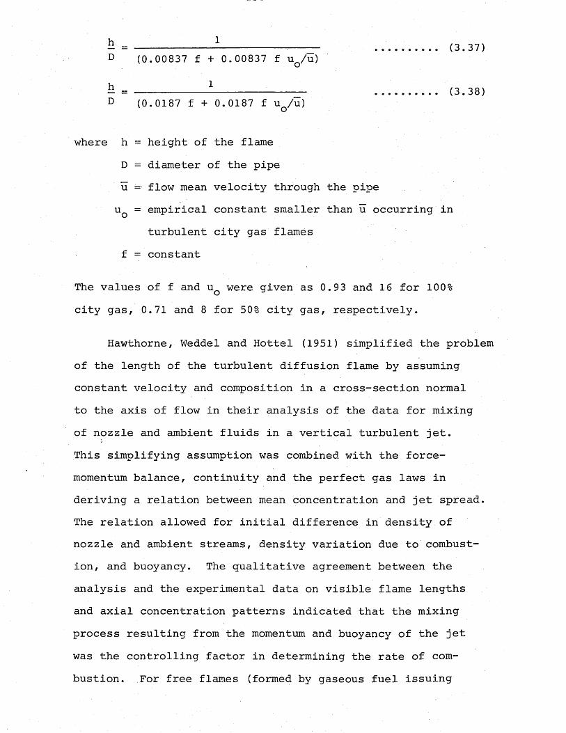
h = ____________1 _________D (0.00837 f + 0.00837 f u q / u )
h = 1__________D (0.0187 f +0.0187 f uq/u )
where h = height of the flame D = diameter of the pipe u - flow mean velocity through the pipeuQ = empirical constant smaller than u occurring in
turbulent city gas flames f = constant
The values of f and uQ were given as 0.93 and 16 for 100% city gas, 0.71 and 8 for 50% city gas, respectively.
Hawthorne, Weddel and Hottel (1951) simplified the problem of the length of the turbulent diffusion flame by assuming constant velocity and composition in a cross-section normal to the axis of flow in their analysis of the data for mixing of nozzle and ambient fluids in a vertical turbulent jet.This simplifying assumption was combined with the force- momentum balance, continuity and the perfect gas laws in deriving a relation between mean concentration and jet spread.The relation allowed for initial difference in density ofnozzle and ambient streams, density variation due to combustion, and buoyancy. The qualitative agreement between the analysis and the experimental data on visible flame lengths and axial concentration patterns indicated that the mixing process resulting from the momentum and buoyancy of the jet was the controlling factor in determining the rate of combustion. For free flames (formed by gaseous fuel issuing
(3.37)
(3.38)
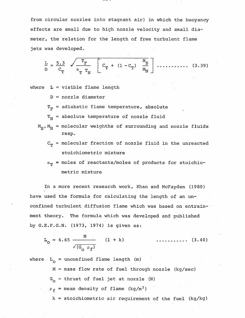
from circular nozzles into stagnant air) in which the buoyancy effects are small due to high nozzle velocity and small diameter, the relation for the length of free turbulent flame jets was developed.
L 5.3 / TFD C_ a m T T N
MSCT + t1 - V (3.39)
where L = visible flame lengthD = nozzle diameterTF = adiabatic flame temperature, absoluteTn = absolute temperature of nozzle fluid
MS,MN = m°lecular weighths of surrounding and nozzle fluids resp.
CT = molecular fraction of nozzle fluid in the unreacted stoichiometric mixture
aT = moles of reactants/moles of products for stoichiometric mixture
In a more recent research work, Khan and McFayden (1980) have used the formula for calculating the length of an unconfined turbulent diffusion flame which was based on entrain- ment theory. The formula which was developed and published by G.E.F.G.N. (1973, 1974) is given as:
MLq = 6.65----------- (1 + k) (3.40)*'<Go
where Lq = unconfined flame length (m)M = mass flow rate of fuel through nozzle (kg/sec)Gq = thrust of fuel jet at nozzle (N) p£ = mean density of flame (kg/m3) k = stoichiometric air requirement of the fuel (kg/kg)
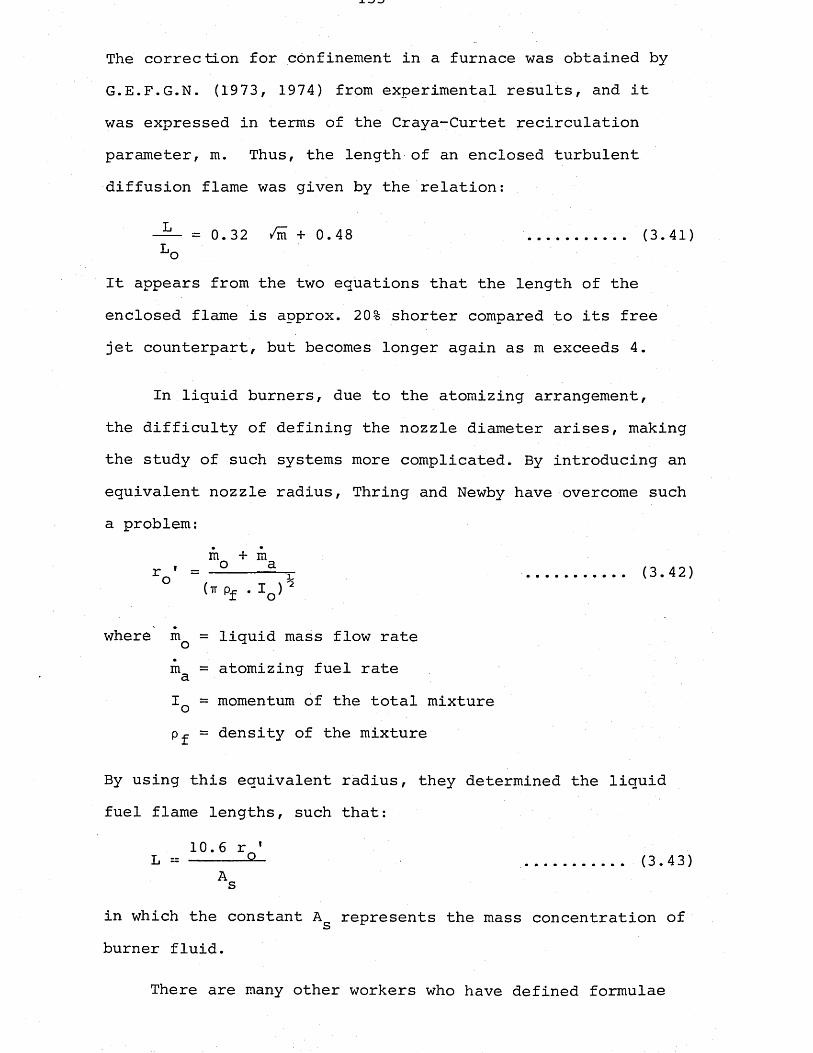
The correction for confinement in a furnace was obtained by- G.E.F.G.N. (1973, 1974) from experimental results, and it was expressed in terms of the Craya-Curtet recirculation parameter, m. Thus, the length of an enclosed turbulent diffusion flame was given by the relation:
= 0.32 /i + 0.48 (3.41)Lo
It appears from the two equations that the length of the enclosed flame is approx. 20% shorter compared to its free jet counterpart, but becomes longer again as m exceeds 4.
In liquid burners, due to the atomizing arrangement, the difficulty of defining the nozzle diameter arises, making the study of such systems more complicated. By introducing an equivalent nozzle radius, Thring and Newby have overcome such a problem:
m + mv = — H : <3-42>
(* pf • iQ ) 2
where mQ = liquid mass flow rate m& = atomizing fuel rate I = momentum of the total mixture Pf = density of the mixture
By using this equivalent radius, they determined the liquid fuel flame lengths, such that:
10.6 r *L = ------Q_ (3.43)As
in which the constant Ag represents the mass concentration of burner fluid.
There are many other workers who have defined formulae
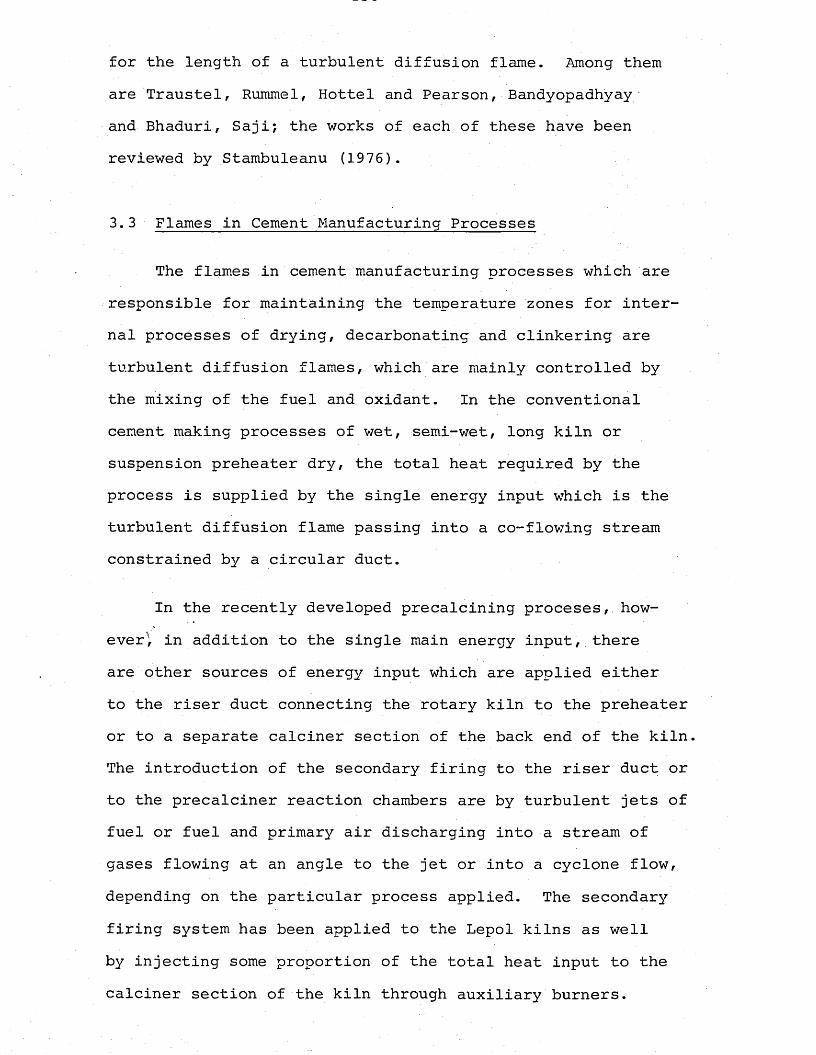
for the length of a turbulent diffusion flame. Among them are Traustel, Rummel, Hottel and Pearson, Bandyopadhyay and Bhaduri, Saji; the works of each of these have been reviewed by Stambuleanu (1976).
3.3 Flames in Cement Manufacturing Processes
The flames in cement manufacturing processes which are responsible for maintaining the temperature zones for internal processes of drying, decarbonating and clinkering are turbulent diffusion flames, which are mainly controlled by the mixing of the fuel and oxidant. In the conventional cement making processes of wet, semi-wet, long kiln or suspension preheater dry, the total heat required by the process is supplied by the single energy input wThich is the turbulent diffusion flame passing into a co-flowing stream constrained by a circular duct.
In the recently developed precalcining proceses, however^ in addition to the single main energy input, there are other sources of energy input which are applied either to the riser duct connecting the rotary kiln to the preheater or to a separate calciner section of the back end of the kiln. The introduction of the secondary firing to the riser duct or to the precalciner reaction chambers are by turbulent jets of fuel or fuel and primary air discharging into a stream of gases flowing at an angle to the jet or into a cyclone flow, depending on the particular process applied. The secondary firing system has been applied to the Lepol kilns as well by injecting some proportion of the total heat input to the calciner section of the kiln through auxiliary burners.
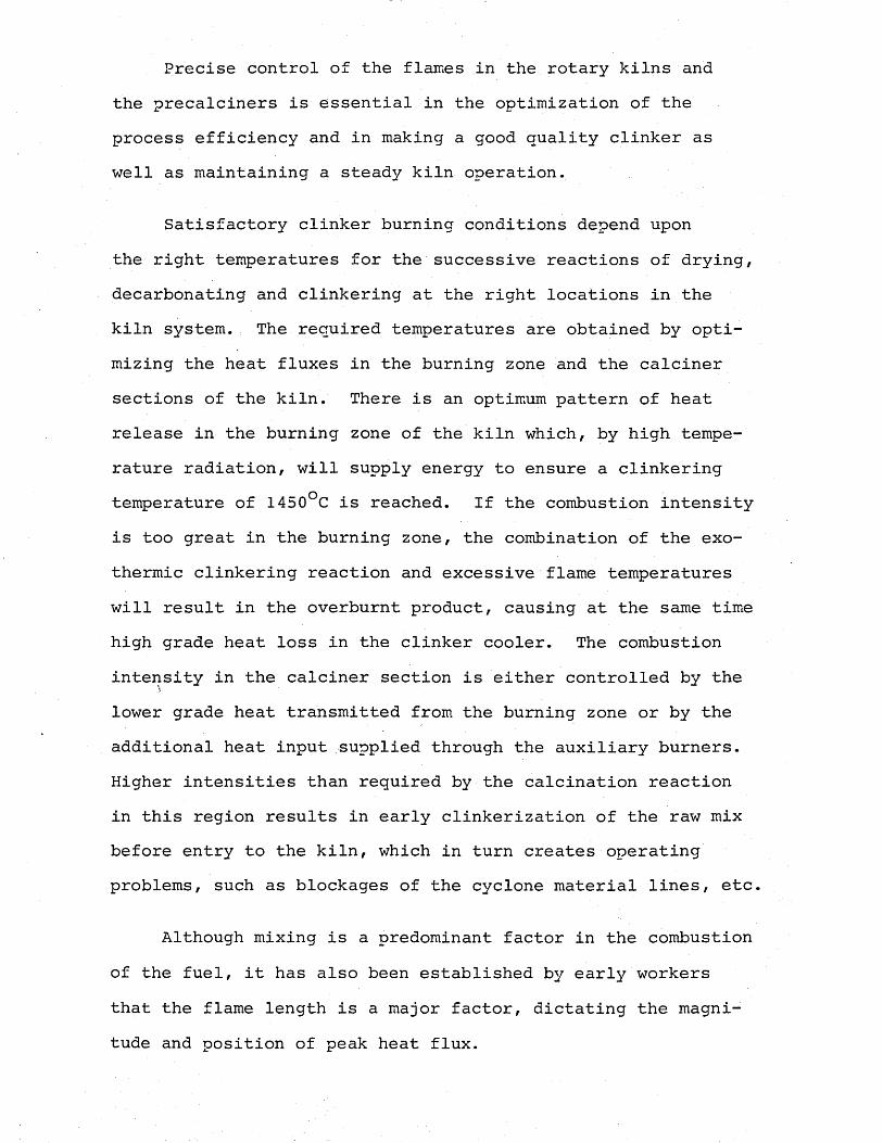
Precise control of the flames in the rotary kilns and the precalciners is essential in the optimization of the process efficiency and in making a good quality clinker as well as maintaining a steady kiln operation.
Satisfactory clinker burning conditions depend upon the right temperatures for the successive reactions of drying, decarbonating and clinkering at the right locations in the kiln system. The required temperatures are obtained by optimizing the heat fluxes in the burning zone and the calciner sections of the kiln. There is an optimum pattern of heat release in the burning zone of the kiln which, by high temperature radiation, will supply energy to ensure a clinkering temperature of 1450°C is reached. If the combustion intensity is too great in the burning zone, the combination of the exothermic clinkering reaction and excessive flame temperatures will result in the overburnt product, causing at the same time high grade heat loss in the clinker cooler. The combustion intensity in the calciner section is either controlled by the lower grade heat transmitted from the burning zone or by the additional heat input supplied through the auxiliary burners. Higher intensities than required by the calcination reaction in this region results in early clinkerization of the raw mix before entry to the kiln, which in turn creates operating problems, such as blockages of the cyclone material lines, etc.
Although mixing is a predominant factor in the combustion of the fuel, it has also been established by early workers that the flame length is a major factor, dictating the magnitude and position of peak heat flux.
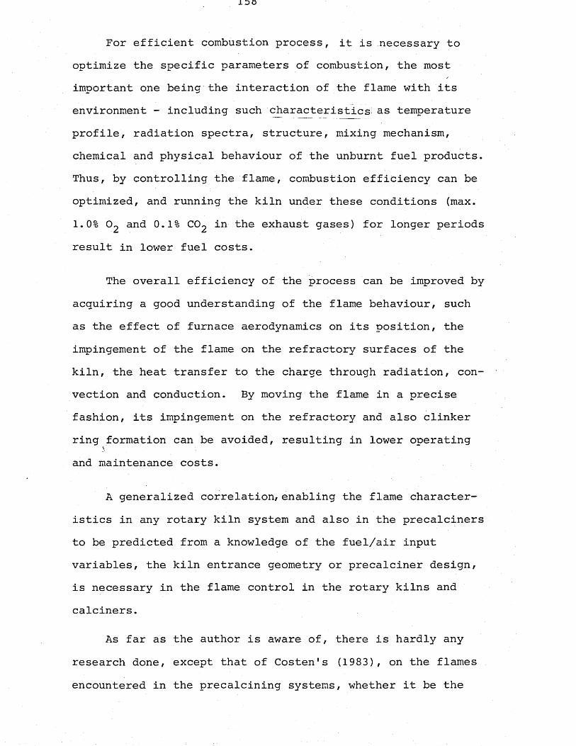
For efficient combustion process, it is necessary to optimize the specific parameters of combustion, the most important one being the interaction of the flame with its environment - including such characteristics^ as temperature profile, radiation spectra, structure, mixing mechanism, chemical and physical behaviour of the unburnt fuel products. Thus, by controlling the flame, combustion efficiency can be optimized, and running the kiln under these conditions (max. 1.0% C>2 and 0.1% CC>2 in the exhaust gases) for longer periods result in lower fuel costs.
The overall efficiency of the process can be improved by acquiring a good understanding of the flame behaviour, such as the effect of furnace aerodynamics on its position, the impingement of the flame on the refractory surfaces of the kiln, the heat transfer to the charge through radiation, convection and conduction. By moving the flame in a precise fashion, its impingement on the refractory and also clinkerring formation can be avoided, resulting in lower operatingv ~and maintenance costs.
A generalized correlation, enabling the flame characteristics in any rotary kiln system and also in the precalciners to be predicted from a knowledge of the fuel/air input variables, the kiln entrance geometry or precalciner design, is necessary in the flame control in the rotary kilns and calciners.
As far as the author is aware of, there is hardly any research done, except that of Costen's (1983), on the flames encountered in the precalcining systems, whether it be the
application to the existing kiln systems or new plants.All information available for these systems consists Of general performance data for the plants with precalciners or auxiliary firing arrangements, mainly data on the effects of some of the kiln variables, like proportion of the heat supplied through secondary firing system and excess air level on the process heat consumption figures,and the production rates for different geometries of the precalciners or the burner systems.
The change of the aerodynamics of the calciner section of a Lepol kiln by the introduction of a turbulent jet flame into the section has been analyzed by Costen (1983) through water model experiments and plant trials. But there still has not been a correlation developed for the characteristics of the flames and for the effects of process input variables on these flames of different characteristics according to the system of precalcining employed.
The coal flame in the burning zone of the rotary kiln (turbulent diffusion flame discharging into a co-flowing stream), however, has been investigated by Ruhland (1967) and later by Moles et al. (1974) with more advanced and detailed experimental techniques.
The research work on the rotary kiln flames was initiated by Ruhland (1967) with the aim of determining the effects of various kiln input variables on the length of the coal flame. Most of Ruhland's work was based on acid-alkali mixing model experiments to produce an equation governing the flame length in a rotary kiln and he had only a limited number of results
obtained from the real kiln system. These kiln measurements consisted of the analysis of the gas samples drawn through fourteen holes provided on the kiln shell by using a specially developed water-cooled gas sampling probe. The content of
°2' C02 ana C0 t*10 9as was determined, and from the CO concentration the flame shape and length were investigated. Those points in the kiln where the appearance of CO had just stopped, indicated the contour of the flame. By comparing the model results with the actual kiln results the effect of the change of volume of the substances caused by the combustion and the heat resulting therefrom on the flame length was determined. Although the model and prototype results agreed in their behaviour qualitatively, by showing the same dependence on the kiln input parameters tested, the difference between the flame lengths obtained from the model and the prototype revealed the effect of this volume change of the substances in the hot prototype.
A .non-dimensional parameter, K, was devised to take into account these density differences, normally between the primary air plus coal and secondary air at the kiln inlet,and the exit gas at the end of the flame on the other hand. By including the parameter K in the mathematical correlation between the length of the flame,and the input variables acting upon the simulated flame, which was deducted from the model experimental results, the required equation for the flame length was developed. In its final form, this universal kiln equation of Ruhland1s is given as:
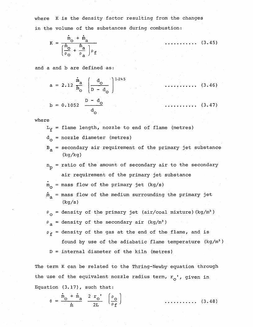
where K is the density factor resulting from the changes in the volume of the substances during combustion:
m + mK = — — =-2........ (3.45)
mo j maP o P a pf
and a and b are defined as:
maa = 2.12 ^ mo
d ) 1 . 2 , 5
(3.46)
D - db = 0. 1052 (3. 47)
dowhere
= flame length, nozzle to end of flame (metres)dQ = nozzle diameter (metres)
= secondary air requirement of the primary jet substance (kg/kg)
n^ = ratio of the amount of secondary air to the secondary air requirement of the primary jet substance
mQ = mass flow of the primary jet (kg/s),ma = mass flow of the medium surrounding the primary jet
(kg/s)P ■= density of the primary jet (air/coal mixture)(kg/m3)Pa = density of the secondary air (kg/m3)
= density of the gas at the end of the flame, and isfound by use of the adiabatic flame temperature (kg/m3)
D = internal diameter of the kiln (metres)
The term K can be related to the Thring-Newby equation through the use of the equivalent nozzle radius term, r 1, given in Equation (3.17), such that:
At a sufficient distance from the nozzle, p = p , therefore,O 3
However, Ruhland's work has its limitations. First of all, most of the work is based on the acid-alkali model results, and there is insufficient number of results relating to a production size kiln to derive a correlation. Analysis of the results in terms of similarity parameters also shows that the results cover an extremely wide range of conditions, probably to be certain of all kiln systems, which is an approach that could lead to over-generalized equation exponents when applied to a particular kiln system.
In view of these limitations, a more thorough investigation was carried out by Moles et al. (1974), mainly on a production size kiln. In order to find a correlation for the flame length and to determine the effects of different kiln input variables on flame length, Moles et al. carried out several experiments in such a way as to demonstrate a particular effect in each one. The No. 2 kiln at the Barnstone works of A.P.C.M. Ltd., which was designed to produce Portland cement using the wet process method with a 33% moisture feedstock, was used as the prototype for the kiln experiments.
The kiln was fired with pulverized coal produced by an attritor, and the output averaged 4.5 tonnes cement clinker per
(3.49)
Combining the two Equations (3.44) and (3.49)
0 [3.21 (2/3 + B ) + 3. 862 (1/n -1)• P0Mb2 e (a+b)
(3.50)
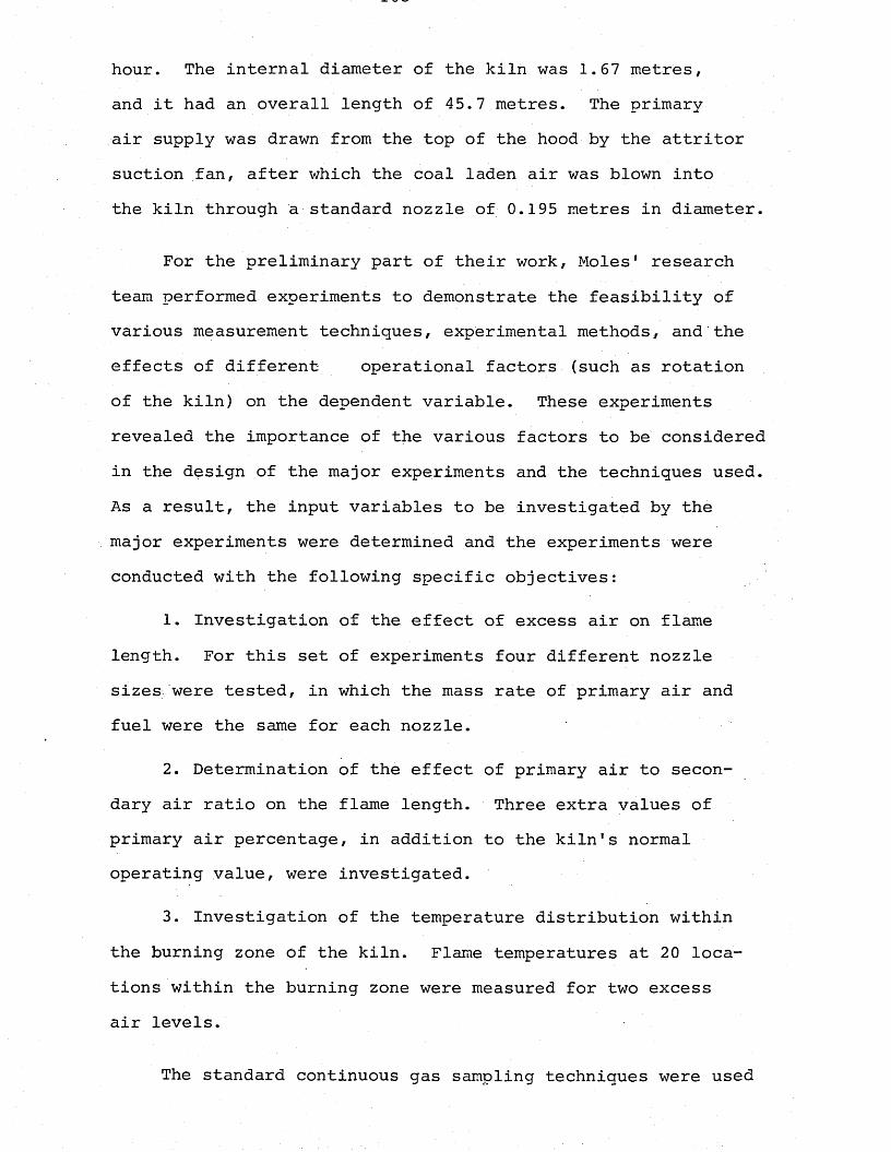
hour. The internal diameter of the kiln was 1.67 metres, and it had an overall length of 45.7 metres. The primary air supply was drawn from the top of the hood by the attritor suction fan, after which the coal laden air was blown into the kiln through a standard nozzle of 0.195 metres in diameter.
For the preliminary part of their work, Moles' research team performed experiments to demonstrate the feasibility of various measurement techniques, experimental methods, and the effects of different operational factors (such as rotation of the kiln) on the dependent variable. These experiments revealed the importance of the various factors to be considered in the design of the major experiments and the techniques used. As a result, the input variables to be investigated by the major experiments were determined and the experiments were conducted with the following specific objectives:
1. Investigation of the effect of excess air on flame length. For this set of experiments four different nozzle sizes were tested, in which the mass rate of primary air and fuel were the same for each nozzle.
2. Determination of the effect of primary air to secondary air ratio on the flame length. Three extra values of primary air percentage, in addition to the kiln's normal operating value, were investigated.
3. Investigation of the temperature distribution within the burning zone of the kiln. Flame temperatures at 20 locations within the burning zone were measured for two excess air levels.
The standard continuous gas sampling techniques were used
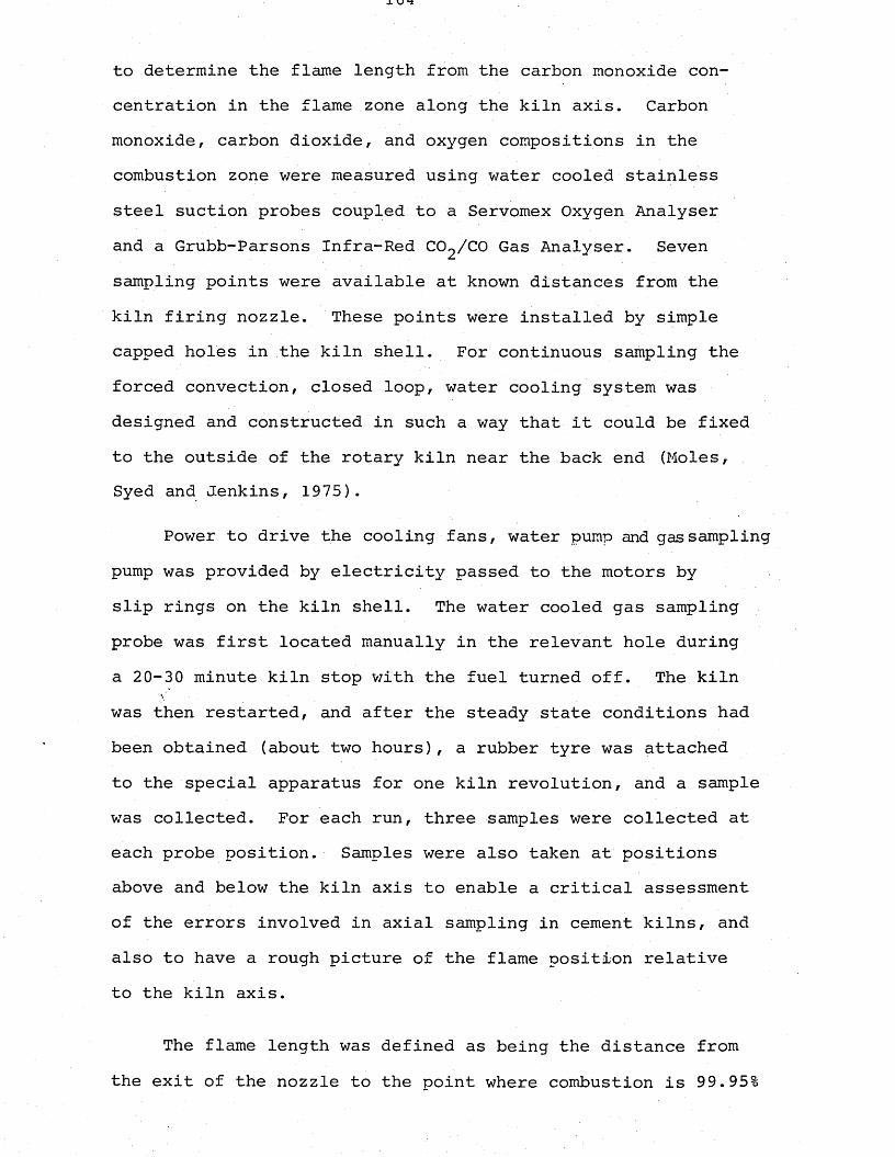
to determine the flame length from the carbon monoxide concentration in the flame zone along the kiln axis. Carbon monoxide, carbon dioxide, and oxygen compositions in the combustion zone were measured using water cooled stainless steel suction probes coupled to a Servomex Oxygen Analyser and a Grubb-Parsons Infra-Red CC^/CO Gas Analyser. Seven sampling points were available at known distances from the kiln firing nozzle. These points were installed by simple capped holes in the kiln shell. For continuous sampling the forced convection, closed loop, water cooling system was designed and constructed in such a way that it could be fixed to the outside of the rotary kiln near the back end (Moles,Syed and Jenkins, 1975).
Power to drive the cooling fans, water pump and gas sampling pump was provided by electricity passed to the motors by slip rings on the kiln shell. The water cooled gas sampling probe was first located manually in the relevant hole during a 20-30 minute kiln stop with the fuel turned off. The kiln was then restarted, and after the steady state conditions had been obtained (about two hours), a rubber tyre was attached to the special apparatus for one kiln revolution, and a sample was collected. For each run, three samples were collected at each probe position. Samples were also taken at positions above and below the kiln axis to enable a critical assessment of the errors involved in axial sampling in cement kilns, and also to have a rough picture of the flame position relative to the kiln axis.
The flame length was defined as being the distance from the exit of the nozzle to the point where combustion is 99.95%
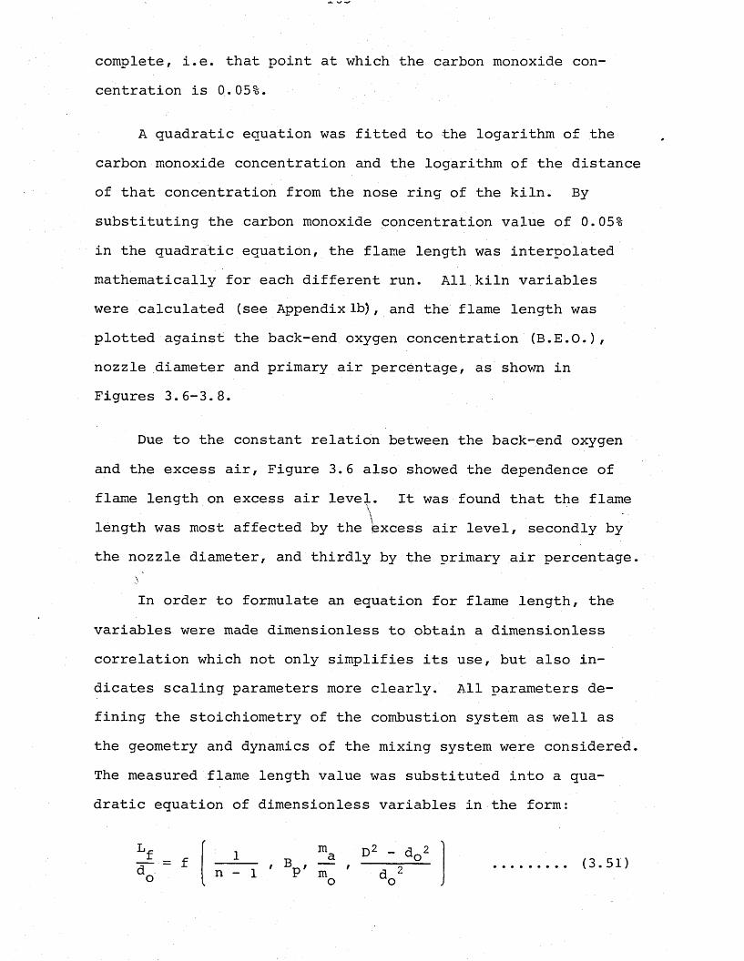
complete, i.e. that point at which the carbon monoxide concentration is 0.05%.
A quadratic equation was fitted to the logarithm of the carbon monoxide concentration and the logarithm of the distance of that concentration from the nose ring of the kiln. By substituting the carbon monoxide concentration value of 0.05% in the quadratic equation, the flame length was interpolated mathematically for each different run. All kiln variables were calculated (see Appendix lb) , and the flame length was plotted against the back-end oxygen concentration (B.E.O.), nozzle diameter and primary air percentage, as shown in Figures 3.6-3.8.
Due to the constant relation between the back-end oxygen and the excess air, Figure 3.6 also showed the dependence offlame length on excess air level. It was found that the flame\ _length was most affected by the kxcess air level, secondly by the nozzle diameter, and thirdly by the primary air percentage.
In order to formulate an equation for flame length, the variables were made dimensionless to obtain a dimensionless correlation which not only simplifies its use, but also indicates scaling parameters more clearly. All parameters defining the stoichiometry of the combustion system as well as the geometry and dynamics of the mixing system were considered. The measured flame length value was substituted into a quadratic equation of dimensionless variables in the form:
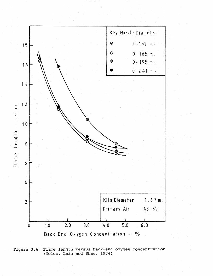
Flam
e Le
ngth
-
me
tre
s
Key Nozzle Diameter
0 2 41 m
1 4
Kiln Diameter
Primary Air
6.02.0 4.0 5.03.01.00Back End Oxygen Concentrat ion - %
Figure 3.6 Flame length versus back-end oxygen concentration(Moles, Lain and Shaw, 1974)
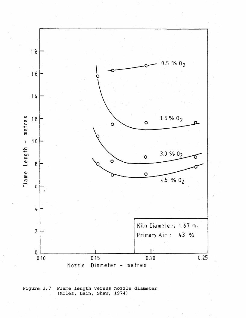
Flam
e Le
ngth
-
met
res
1 a0.5 % o 2
1 6
14
1.5 % 012
10
3.0 % 02
8
4-5 % 02
Kiln Diameter: 1.67 m.
Primary Air : 43 %2
0.250.200.150.10Nozzle Diameter - met res
Figure 3.7 Flame length versus nozzle diameter(Moles, Lain, Shaw, 1974)
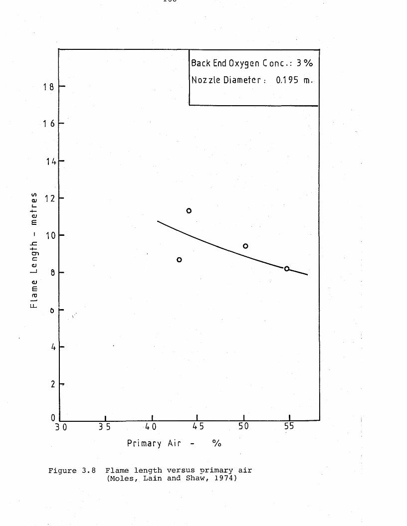
Flam
e Le
ng
th
- m
etre
s
x v
Back End Oxygen C one.: 3 %
Nozzle Diameter: 0.195 m.
Primary Air
Figure 3.8 Flame length versus primary air(Moles, Lain and Shaw, 1974)
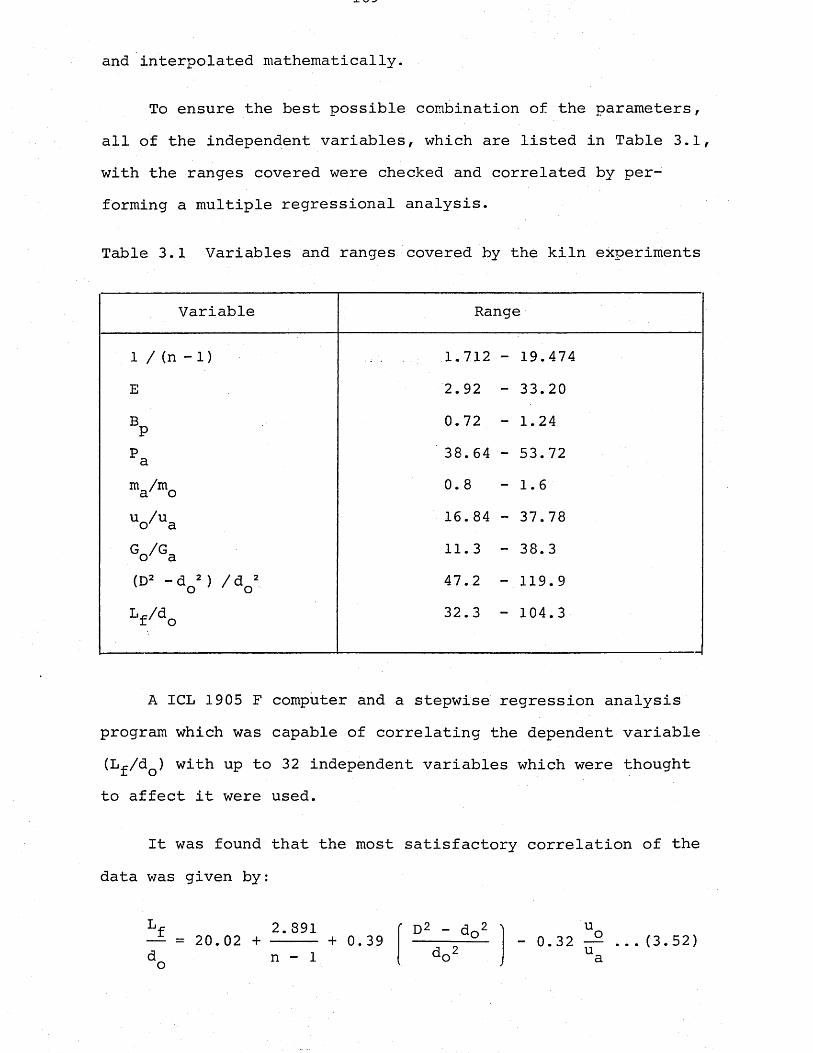
and interpolated mathematically.
To ensure the best possible combination of the parameters, all of the independent variables, which are listed in Table 3.1, with the ranges covered were checked and correlated by performing a multiple regressional analysis.
Table 3.1 Variables and ranges covered by the kiln experiments
Variable Range
1 / (n - 1) 1.712 - 19.474E 2.92 - 33.20BP 0.72 - 1.24Pa 38.64 - 53.72m /m a' o 0.8 - 1.6u_/u o' a 16. 84 - 37.78
< V Ga 11. 3 - 38.3(D> -dG») /do’ 47.2 - 119. 9
V do 32.3 — 104.3
A ICL 1905 F computer and a stepwise regression analysis program which was capable of correlating the dependent variable (L^/dQ) with up to 32 independent variables which were thought to affect it were used.
It was found that the most satisfactory correlation of the data was given by:
Lf 2.891— = 20. 02 + ----- + 0.39d_ n - 1
D2 - d02 Ido2
u0. 32 — ... (3.52) ua
Comparison of the experimentally measured values of L^/dQ and the calculated values showed that 80% of the data were correlated ±15% with the equation developed, and all the data lay within the range ±25%, as shown in Figure 3.9.
From the relationship between the flame length and the nozzle diameter, it was recommended that burner nozzles for kilns to be designed on the criterion defining the minimum point on the versus dQ curve, and a chart enabling the rapid determination of the flame length and nozzle diameter was prepared, as shown in Figure 3.10.
Having established the correlation for flame length by use of the extensive kiln data, the same research group worked on modelling of the kiln system in order to verify the kiln results with the model experiments. A 1 : 21 scale down geometric model of the same kiln (Barnstone No. 2) was designed by a member,;B.G. Jenkins, of Moles' research team, and was constructed by using perspex as the material! by Stanley' ! _ _ 'Plastics Company... Initial modelling principles and procedures were determined and preliminary experiments were conducted by B.G. Jenkins of the same Group (Moles and Jenkins, 1975) in order to confirm the plant trial results and the applicability of the correlation.
Although these preliminary experiments indicated the suitability of the modelling technique and the accuracy of the plant trials, it was not until the present work that a detailed, accurate, experimental programme was carried out on the model of the kiln . The objectives were assessing the accuracy and suitability of the acid-alkali technique to study
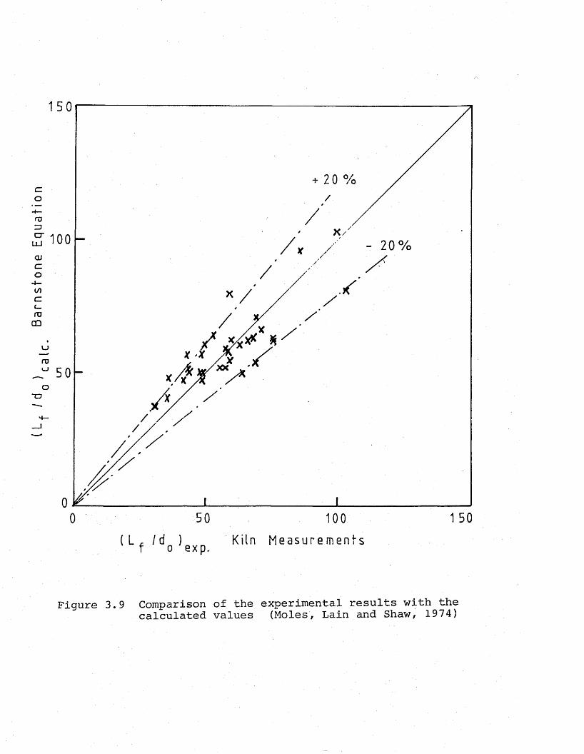
Bar
nst
on
e E
qu
atio
n
150
+ 2 0 %
f V
( L r i d ) f o exp.
50 100
Kiln Measurements
1 50
Figure 3.9 Comparison of the experimental results with the calculated values (Moles, Lain and Shaw, 1974)
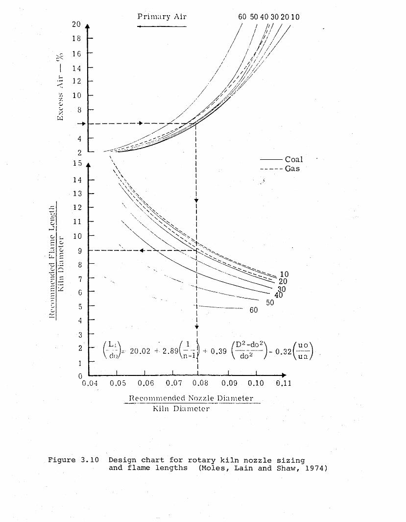
Krf
Pin
nion
clcd
Fl
ame
Len
gth
Kiln
I)
iam
eter
E
xces
s'
Air
P rim a ry A ir 60 50 40 30 20 10
j
14
12
10
8
4
215
\\
14
13
12
11
10
9
8
7
6
D4
3/ D 2 - d o 2
°-39uo2
n-1 ua100.04 0.05 0.06 0.07 0.08 0.09 0.10 0.11
Re c om m e n d e d Nozzle D i a m e t e r Kiln D i a m e t e r
Figure 3.10 Design chart for rotary kiln nozzle sizingand flame lengths (Moles, Lain and Shaw, 1974)
the flame behaviour in the rotary kilns and the effect of each kiln input variable on the length of the flame, as well as confirming the plant results,and developing a factor to be used as a tie-up between the actual kiln and the isothermal model results.
In a more recent publication, Lowes, Layne and Watson (1977) reported a correlation for the effective flame length (1.0% CO), which was derived from the experimental data of Moles et al. obtained from the Barnstone kilns trials. The effective flame length correlation is given as follows:
Lf (1.0% CO) ■ Kido *o 1
100 - PAE
D- K~E + K0 — 2 3 ao
mixing air require- excess externallength ment of jet air recirculation
Physically controlled chemically controlledmixing process reaction of combustibles
(3.53)where
D = kiln internal diameter oE = excess air percentages
= experimentally determined constant= flame length
L . = theoretical mixing lengthmix ■ *■’ JPA = primary air percentage dQ = firing pipe diameter
It was stated that for normal levels of primary and excess air, the two terms appearing in the correlation the excess air and the air requirement of the jet terms - were relatively small. Therefore, from the correlation it was concluded that the flame length was controlled essentially by the mixing length

and external recirculation terms, both of which depend on the design of the fuel injector.
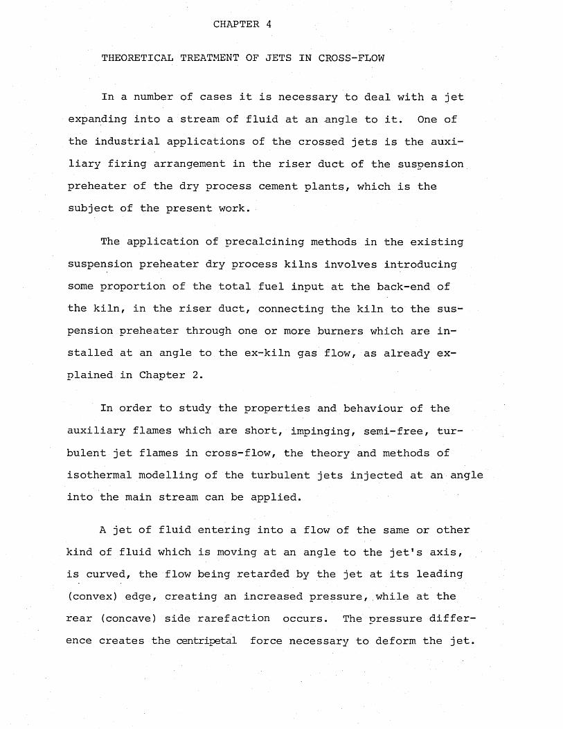
CHAPTER 4
THEORETICAL TREATMENT OF JETS IN CROSS-FLOW
In a number of cases it is necessary to deal with a jet expanding into a stream of fluid at an angle to it. One of the industrial applications of the crossed jets is the auxiliary firing arrangement in the riser duct of the suspension preheater of the dry process cement plants, which is the subject of the present work.
The application of precalcining methods in the existing suspension preheater dry process kilns involves introducing some proportion of the total fuel input at the back-end of the kiln, in the riser duct, connecting the kiln to the suspension preheater through one or more burners which are installed at an angle to the ex-kiln gas flow, as already explained in Chapter 2.
In order to study the properties and behaviour of the auxiliary flames which are short, impinging, semi-free, turbulent jet flames in cross-flow, the theory and methods of isothermal modelling of the turbulent jets injected at an angle into the main stream can be applied.
A jet of fluid entering into a flow of the same or other kind of fluid which is moving at an angle to the jet's axis, is curved, the flow being retarded by the jet at its leading (convex) edge, creating an increased pressure, while at the rear (concave) side rarefaction occurs. The pressure difference creates the centripetal force necessary to deform the jet.
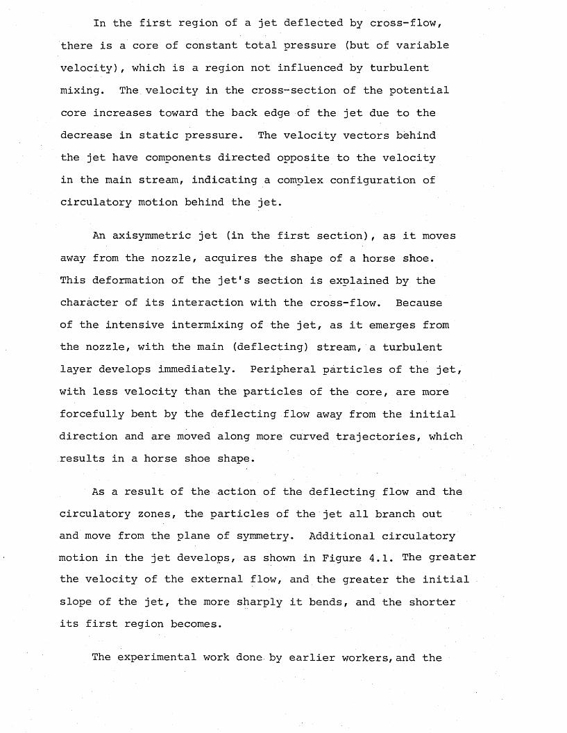
In the first region of a jet deflected by cross-flow, there is a core of constant total pressure (but of variable velocity), which is a region not influenced by turbulent mixing. The velocity in the cross-section of the potential core increases toward the back edge of the jet due to the decrease in static pressure. The velocity vectors behind the jet have components directed opposite to the velocity in the main stream, indicating a complex configuration of circulatory motion behind the jet.
An axisymmetric jet (in the first section), as it moves away from the nozzle, acquires the shape of a horse shoe.This deformation of the jet's section is explained by the character of its interaction with the cross-flow. Because of the intensive intermixing of the jet, as it emerges from the nozzle, with the main (deflecting) stream, a turbulent layer develops immediately. Peripheral particles of the jet, with less velocity than the particles of the core, are more forcefully bent by the deflecting flow away from the initial direction and are moved along more curved trajectories, which results in a horse shoe shape.
As a result of the action of the deflecting flow and the circulatory zones, the particles of the jet all branch out and move from the plane of symmetry. Additional circulatory motion in the jet develops, as shown in Figure 4.1. The greater the velocity of the external flow, and the greater the initial slope of the jet, the more sharply it bends, and the shorter its first region becomes.
The experimental work done by earlier workers, and the
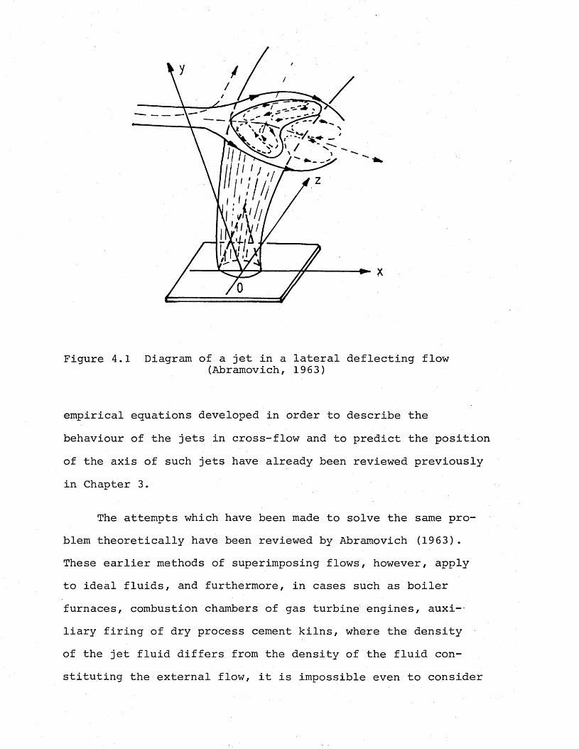
Figure 4.1 Diagram of a jet in a lateral deflecting flow(Abramovich, 1963)
empirical equations developed in order to describe the behaviour of the jets in cross-flow and to predict the position of the axis of such jets have already been reviewed previously in Chapter 3.
The attempts which have been made to solve the same problem theoretically have been reviewed by Abramovich (19 63) . These earlier methods of superimposing flows, however, apply to ideal fluids, and furthermore, in cases such as boiler furnaces, combustion chambers of gas turbine engines, auxi-~ liary firing of dry process cement kilns, where the density of the jet fluid differs from the density of the fluid constituting the external flow, it is impossible even to consider
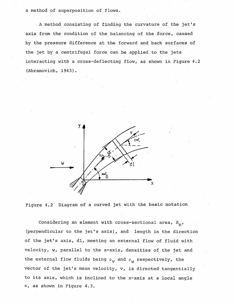
a method of superposition of flows.
A method consisting of finding the curvature of the jet's axis from the condition of the balancing of the force, caused by the pressure difference at the forward and back surfaces of the jet by a centrifugal force can be applied to the jets interacting with a cross-deflecting flow, as shown in Figure 4.2 (Abramovich, 1963).
c<
Figure 4.2 Diagram of a curved jet with the basic notation
Considering an element with cross-sectional area, sn^(perpendicular to the jet's axis), and length in the directionof the jet's axis, dl, meeting an external flow of fluid withvelocity, w, parallel to the x-axis, densities of the jet andthe external flow fluids being pTy and p respectively, thev wvector of the jet's mean velocity, v, is directed tangentiallyto its axis, which is inclined to the x-axis at a local angle a, as shown in Figure 4.3.
dyy 1 - — = tan a . ... (4.1)dx
Figure 4.3 Element of a curved jet
As the first approximation, a jet being deflected by a cross-flow can be compared to an arrow wing with a curved axis It is also assumed that the jet is divided by plane sections into elementary parts, and the density, velocity of the flow are constant over the length dl. From the investigation on arrow wings, if the axis of the wing forms some angle a with the direction of the velocity of the external flow, w, then the aerodynamic force acting on the wing is proportional tothe dynamic pressure due to the component of the stream velo-
/
city which is normal to the axis of the wing.
(w sin a)2N = C F pTT --------— (4.2n n w 2Cn = force coefficient depending on the shape of the wing
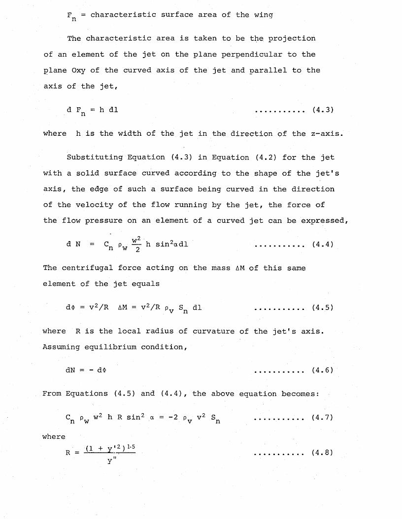
Fn = characteristic surface area of the wing
The characteristic area is taken to be the projection of an element of the jet on the plane perpendicular to the plane Oxy of the curved axis of the jet and parallel to the axis of the jet,
d Fr ■ = h dl .......... (4.3)
where h is the width of the jet in the direction of the z-axis.
Substituting Equation (4.3) in Equation (4.2) for the jet with a solid surface curved according to the shape of the jet's axis, the edge of such a surface being curved in the direction of the velocity of the flow running by the jet, the force of the flow pressure on an element of a curved jet can be expressed,
2 .
d N = Cn pw h sin2adl ........... (4.4)
The centrifugal force acting on the mass AM of this sameelement of the jet equals
d$ = v 2/ R AM = v 2/ R pv Sn dl ... ....... (4.5)
where R is the local radius of curvature of the jet's axis. Assuming equilibrium condition,
dN = - d$ .......... (4.6)
From Equations (4.5) and (4.4), the above equation becomes:
C p w2 h R sin2 a = -2 p v2 S . (4.7)n w v n vwhere
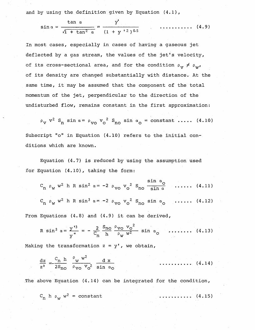
and by using the definition given by Equation (4.1),tan a y1
sin a = .-.......— = (4.9)A + tan2 a (1 + y 1 2 ) °*5
In most cases, especially in cases of having a gaseous jet deflected by a gas stream, the values of the jet's velocity, of its cross-sectional area, and for the condition p / p ,
V vv
of its density are changed substantially with distance. At the same time, it may be assumed that the component of the total momentum of the jet, perpendicular to the direction of the undisturbed flow, remains constant in the first approximation:
P„ v2 sin <x= p„_ v 2 sin a - constant (4.10)v n vo o no o
Subscript "o" in Equation (4.10) refers to the initial conditions which are known.
Equation (4.7) is reduced by using the assumption used for Equation (4.10), taking the form:
sin aC p w2 h R sin2 a= -2 p v 2 --:... (4.11)n ~w vo o no s m a
Cn pw w2 h R sin3 ““ "2 pvo V Sno sln ao ..... (4'12)
From Equations (4.8) and (4.9) it can be derived,
. y '3 2 sno p vo vo2 . ' , A , n xr s m a= = - — _ - 2 s m « (4.13)y n 11 w
Making the transformation z = y1, we obtain,
j C h p w2 ,=_ n n _w d x (4.14)z3 2Sno Pvo VQ2 sin aG
The above Equation (4.14) can be integrated for the condition,
C h p w2 ~ constant ...........(4.15)ri w
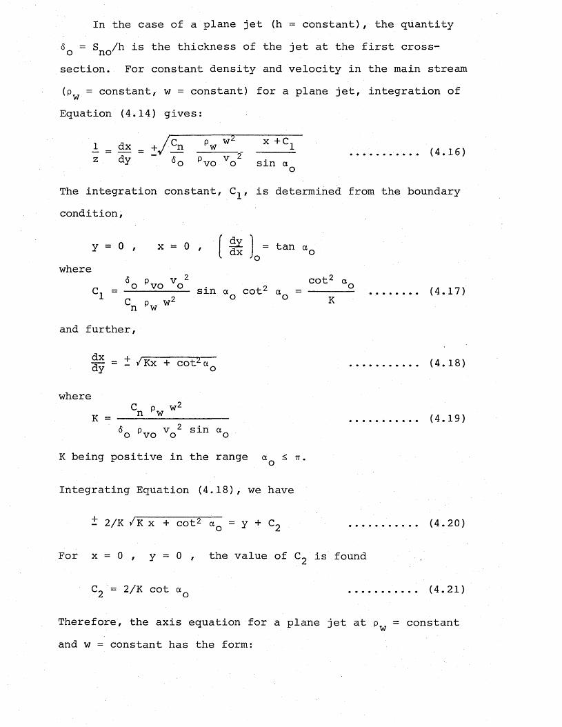
In the case of a plane jet (h = constant), the quantity6 = S /h is the thickness of the jet at the first cross- o no' Jsection. For constant density and velocity in the main stream(p = constant, w = constant) for a plane jet, integration of wEquation (4.14) gives:
i j /c P w2 x +C,A = A* = +/hl J!*--- -----1 ........... (4.16)z dY 5o pvo vo sin ao
The integration constant, , is determined from the boundary condition,
y = 0 , x = 0 ,where
dydx = tan aQ
o6 v^2 cot2 a_
C. = ---------- sin a cot2 a = ...... (4.17)n pw w K
and further,
^ = t /Kx + cot2aQ (4.18)
whereC p w2
K = ----— ......... (4.19)6o pvo vo2 sin “o
K being positive in the range aQ < tt .
Integrating Equation (4.18), we have
t 2/K /K x + cot2 aQ = y + C2 (4.20)
For x = 0 , y = 0 , the value of C2 is found
C2 = 2/K cot aQ (4.21)
Therefore, the axis equation for a plane jet at 'p = constant and w = constant has the form:
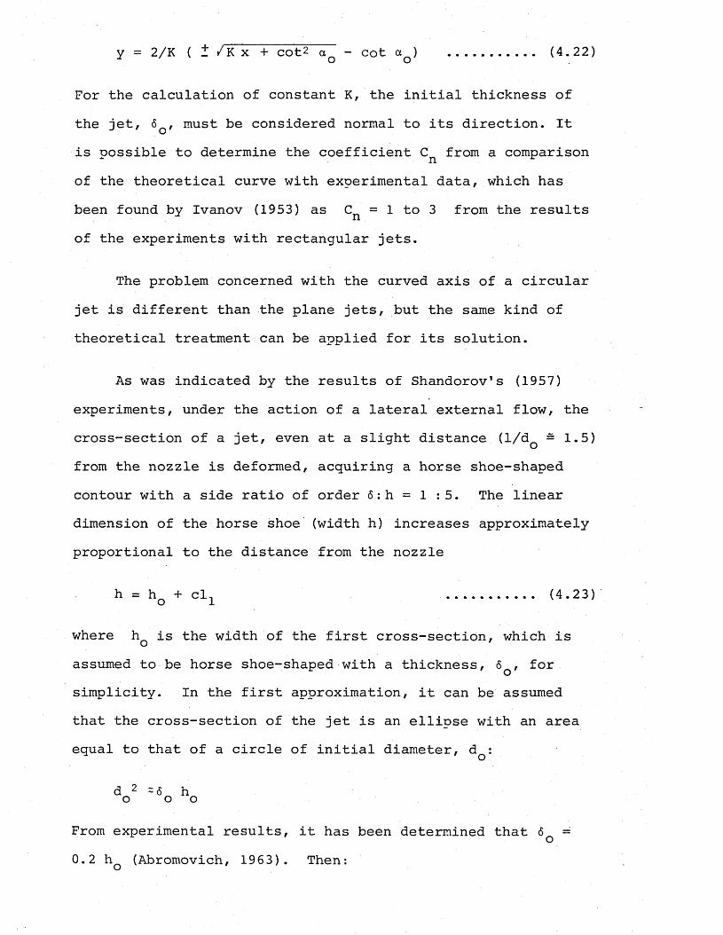
y = 2/K ( it /Kx + cot2 aQ - cot a ) (4.22)
For the calculation of constant K, the initial thickness of the jet, 6 , must be considered normal to its direction. It is possible to determine the coefficient Cn from a comparison of the theoretical curve with experimental data, which has been found by Ivanov (1953) as CR = 1 to 3 from the results of the experiments with rectangular jets.
The problem concerned with the curved axis of a circular jet is different than the plane jets, but the same kind of theoretical treatment can be applied for its solution.
As was indicated by the results of Shandorov's (1957) experiments, under the action of a lateral external flow, the cross-section of a jet, even at a slight distance (l/dQ - 1.5)from the nozzle is deformed, acquiring a horse shoe-shapedcontour with a side ratio of order 6: h = 1 : 5. The linear dimension of the horse shoe (width h) increases approximately proportional to the distance from the nozzle
h = hQ + clx (4.23)
where hQ is the width of the first cross-section, which is assumed to be horse shoe-shaped with a thickness, 6q, for simplicity. In the first approximation, it can be assumed that the cross-section of the jet is an ellipse with an area equal to that of a circle of initial diameter, dQ:
From experimental results, it has been determined that SQ = 0.2 hQ (Abromovich, 1963). Then:
6 = 0.45 d , h ~ 2.25 d .......... (4.24)o o o owhere upon
S = ....... . (4.25)no 4
In addition, assuming the rate of expansion of a curved jet of a horseshoe-shaped cross-section to be the same as that in a rectangular jet (c = 0.22),
h = 2.25 d - +0.22 1 (4.26)
Substituting Equations (4.25) and (4.26) into Equation (4.13), we obtain for a jet of circular section,
-IQ ~ TT d 2 p V 2y d _ 2 o vo o .**-- = - — 0— s m a ..... (4.27)y" Cn 9 dQ + 0.88 1 pw w °
Substituting for the length of a curve 1, x
1 = [ /I + y12 ~dx (4.28)
y"3 = _ 1.57 1 pvo vp2 sin a (4.29)Y" cn ^ 9° pw w2 °
JTTJ'Z d (x/ao)
The solution of Equation (4.29) can be obtained by the method of successive approximations. However, first the integral for the value of 1 (Eq. 4.28) has to be solved. By using the equation for the plane jet (Eq. 4.18) for dy/dx,
2 1 y'2 = (dy/dx) = z2 =Kx + cot2 ao
and substituting it in Equation (4.28), the integral for 1 is solved,
_____/l + Kx + cot2 a/ ---------------2 dxKx + cot2 ao
1 =
/(l + Kx + cot2 .a ) (Kx + cot2 a ) - /(I + cot2 a ) cot2 dQ
/l + Kx + cot2 a + /Kx + cot2 a In -- 2 2 (4.30)
/l + cot2 a + /cot2 ao o
Substituting Equation (4.30) into (4.27), a refined value of the quantity y 1 and with that value, the value 1 (x) from Equation (4.28) can be obtained. By substituting this new value of the function l(x) in Equation (4.27), it is possible to define more accurately the contour of the curved axis for a circular jet. Regarding the complexity of the function 1 (x), a rougher approximation may be obtained by proceeding from the assumption that the width of the horseshoe-shaped cross-section of a sharply bent jet is proportional to x (instead of 1); then Equation (4.26) can be written as:
h = 2.25 dQ + 0.22 x (4.31)
and Equation (4.27) is changed as:
»3 o tt d 2 p v 2Y 2 o vo o . fA on \* = - — ------------- -----o— s m a ....... (4.32)y " Cn 9 dQ + 0.88 x Pw w °
Taking into account Equations (4.19) and (4.24), and making the transformation z - y1,
— = ---— — (5 6„ + 0.22 x) dx (4.33)Z 3 5 TT 6 o
is obtained, in which K has the same value as in the case of a plane jet (at 6Q = 0.45 dQ). When Equation (4.33) is inte-
grated, the following expression is found:
1 = dx = + /~4K z dy it
^ 0.022 21X + — 5 X Z0O+ C. (4.34)
The integration constant, = cot2 aQ is found with the aidof the boundary condition cot = (dx/dy)x_Q. Substitutingthis value in Equation (4.34), we obtain:
= + y.dy - V4K
TT+cot2 a (4.35)
At y > 0, the integration of Equation (4.35) givesdx
J — ■=— Kx2 + 4 / i t Kx + cot2 a7T 6 (o
from which,
tt 6y + c 2 = 0.88 K
In 0.088 Kit 6
4K „ 0.088 KX T —— — — — —TT TT 6
x2 + cot2 a ,0.176 K , 4K +---5--- x + —7T 0 _ TT(4.36)
Based on the boundary condition y = 0, x = 0,
it 6C2 =
o0.088K
In 2 / 0.088 K ---;--- cot a + 1.27 K—
TT 6 00 ;(4.37)
Hence, the approximate equation for the axis of a jet with a circular initial cross-section has the following form:
y = /35.7 ^ xJ\
35.7 61.27 Kx +— .— 5 x2 + cot2 a
x InK
35. 7 6o
35. 78 6
cot aQ + 1.27 K
+ 2 K35.78 6
x +1.27K
(4.38)
Using the equations for K (4.19) and for <5q (4.24),
—X— / 39 a Indo
10 + #- +/ do d + 20 -=- + 7 a cot2 a
do °10 + /7a cot a
(4.39)
wherePa = —— ---- sin aC p w2 °n w K 6
(4.40)
At aQ = tt/2, Equation (4.39) is simplified:
= 14.4 /a lgo
1 + 0.1 x/d 1 + /l + 20 d /x o
(4.41)
The equations derived so far apply to cases where jet flows into an infinite deflecting flow of fluid.
In combustion chambers and in a series of other cases, like the calciners or auxiliary firing chambers of cement plants, jets enter a flow bounded by walls. In this case the curvature of the jet is intensified when the same ratio of dynamic pressure exists in the jet and in the flow. The simple method for calculating the influence of the finite dimensions of a channel on the curvature of a jet consists of substituting in the equation presented above for the jets in unbounded space, the average velocity obtained from the mixing of the jet with the flow of gas instead of the velocity of the passing flow.
G1 + G2 Wc F. (4.42)
where and G2 are the weight flow rates of the gas in theexternal flow, and in the jet, respectively. F is the areaof the channel cross-section; Y -- p g is the specific weightc c
of the mixture for the temperature and the pressure of the mixture.
In the empirical equations proposed by Shandorov (1957) and Ivanov (1952), respectively, which have the following forms respectively at aQ = tt/2
and q^2 being the dynamic pressures in the deflecting flow and in the jet's initial cross-section, respectively. qc is used instead of q. , where
The formulae obtained above for the curvature of a jet by a lateral flow requires a knowledge of the initial values of the jet's velocity and slope. If the jet flows out of a nozzle, then the initial velocity is known and the initial angle of the jet is equal to the angle of the nozzle apparatus. However, for example, in combustion chambers the jet of air pours into a flow of combustion gases from an annular channel, which envelops the hot*tube, through apertures in its thin wall. For these cases neither the initial velocity nor the angle of the jet are known beforehand, and these values should be determined theoretically. Shandorov (1957) developed
1,3 3
where *3 01 = P1 t t
q02 p 2 2
a method for determining these values.
The direction and value of a jet's velocity are approximately determined by means of the geometric addition of the vertical component of velocity, calculated in terms of the drop in static pressure under which discharge occurs, and of the velocity of the air in the channel. For the calculation of the first component, the velocity is found in terms of pressure drops for different parts of the wall in front of an aperture.
V 2 y = / | M ............ (4.43)
The effective component of the discharge velocity v2y normal to the wall, due to the ejecting action of the deflecting flow is larger than v'2y anc may determined from,
v2y = = v' 2y <4'44)
the value y*/y = /AP/ P* is determined graphically. The second component of the discharge velocity is the velocity v2X averaged over the mass flow rate in the channel in front of the aperture. Consequently, the initial velocity of the jet is
v2 = ^ v2y2 + v2x2 (4;45)
and the discharge angle of the jet is
a = arc tan ■ (4.46)v2x
The actual initial section of the jet is less than the area of the discharging aperture.
From the formula y = e / 1 + 1/m2, where m = /AP/q2 = v2y/v2x which combines the rate coefficient y with the concentration coefficient of the jet e in the absence of a deflecting flow, it follows:
e = ysin ay
Taking into account the influence of the deflecting flow, we obtain,
e* = y* sin a * (4.47)
Introducing the effective discharge area F0 equal to the area of the cross-section of the jet normal to its axis, it may be written:
F0 = e* Fq (4.48)
where Fq is the discharge area of the aperture.
The first section of the air jet which pours into the flow from the circular aperture in the thin wall differs somewhat from a circle; however, this may be neglected. Then, from Equations (4.47) and (4.48) we have:
d = d^ / y*sin a * (4.49)0 o y
where de is the diameter of the equivalent jet discharging from the nozzle at an angle a^*, and having an axis which coincides with the axis of the real jet discharging from the aperture in the thin wall of the channel.
Equations (4.45), (4.46) and (4.49) enable the use ofEquations (4.39) and Shandorov's empirical equation:

q 0 l 2-55x/d = --- (y/d) + y/dq
1 +o2
l01[02
cot a
for the axis of the jet discharging from the aperture in the channel.
CHAPTER 5
DESCRIPTION OF THE HYDRAULIC SYSTEM AND THE ACID/ALKALI MODELLING EXPERIMENTS
5.1 Preliminary Experiments - The Barnstone Model
Before building the suspension preheater kiln model, it was thought useful to do experiments with a water model already existing in the Department of Chemical Engineering, with the following objectives:
1) To get familiar with the modelling technique to be used for the main experiments, and to improve the accuracy of the technique.
2) To assess the reliability of the predictions obtained from isothermal mixing model experiments.
3) To find a parameter, a tie-up between the cold isothermal model and the prototype to be used in the interpretationof the model results in terms of kiln operating conditions, by comparing the model results with the results of the experiments already done on the prototype (Moles, Lain and Shaw, 1974).
The apparatus used for the preliminary part of the work with the above mentioned aims, is a perspex water model of the No. 2 kiln at the Barnstone works of A.P.C.M. Ltd., an overall view of which is shown in Plate 5.1.
Plate 5.2 is a line flow diagram illustrating the arrangement of the two different flow systems for the primary and secondary fluid flow, which are independent of each other.
0TSOCDtiO4->WcMrdPQ0X■Pmo£>
I—I I—Icdu0>orHLO0 +J 0 i— IfV
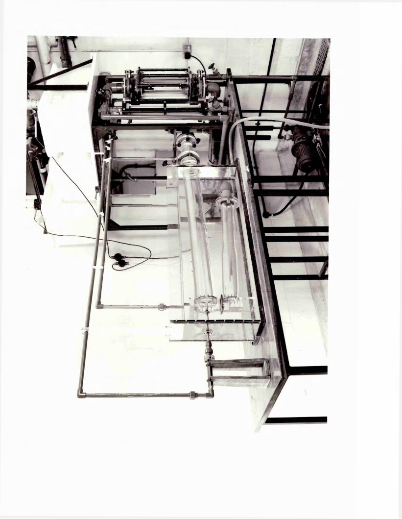

Audio Visual Aids Unit University of Surrey

r—\CDTJO£0£O-PCO£P03W0,£-PPOip
P03•HT)so
r— IP)0£•HPiCNin0 -P 0 i— IQa
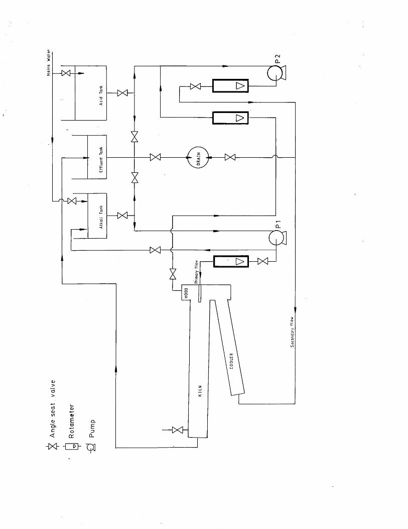
Angle
seat
valve
Cl
[>1—IX]—
Q.
The primary (jet) fluid contained in tank T1 is pumped to the model through the nozzle and the secondary fluid from tank T3 is passed to the kiln tube through the cooler by use of a centrifugal pump, P2. The closed loop for the kiln hood off-take flow supplying fluid to the input side of the Pump 2 was not used for the experiments of this work.
The effluent solution leaving the model is passed into a tank before being discharged into the drain, through a valve which is used to collect samples of the effluent solution.
5.1.1 Operating fluid
Water was chosen to simulate both air and fuel streams in the model. By using water as the operating fluid, the dynamic similarity between the model and the prototype could be obtained at very much reduced velocities compared to the velocities in a gas for a given size of model, due to viscosity characteristics. Such reduced velocities enabled simultaneous visual observation of the whole field of flow and easier recording of the qualitative results at the time the flow pattern existed.
5.1.2 Flow visualization
For visual simulation of the flame behaviour and flow and mixing processes in the model, the acid-alkali technique was used which utilizes mixing controlled neutralization reaction of an acid and an alkali to represent the combustion reaction.
Hydrochloric acid and sodium hydroxide were used as
reactants for the neutralization reaction. The part of water passed to the kiln tube through the cooler section of the model to represent the secondary air in the real kiln was made slightly acidic, while the rest of the water which was supplied to the model through the nozzle to represent the burner nozzle fluid in the real system (primary air and fuel) was made alka- ;.i line. With the addition of the indicator phenolphthalein to the nozzle fluid, the progress of neutralization in the model could be made visible. The pink coloured region so produced resembled the flame "unburnt fuel" and the regions where the mixing had been complete revealed by the disappearance of the pink colour when the "nozzle fluid" (alkali) had entrained the stoichiometric concentration of "air" (acid).
5.1.3, Design and construction of the apparatus
The model, originally designed by B.G.Jenkins .(Moles & Jenkins 1975), was a 1 : 21st geometric scale of a wet process kiln with a rotary cooler located under the kiln and parallel to it. The kiln had the dimensions of 1.67 metres internal diameter and 45.7 metres of length. 13mm thick clear perspex was used for the construction of the model with glued and screwed joints where necessary.
The burner was turned from a; %"o.d. stainless steel tube with the firing end being detachable to allow the use of different internal diameter nozzles which were 1 :21st geometric scales of the burners used in the prototype kiln as well.
The model consisting of the kiln and the rotary cooler tubes was immersed in water contained in a rectangular tank
made of perspex in order to avoid possible distortion of the simulated flows by refraction.
A centimetre scale was drawn along the tube to facilitate the measurement of the flame lengths. Two polythene tanks supplied acid and alkali solutions to the model. The tank with a capacity of 143 litres was used as the hydrochloric acid tank, and the second tank was calibrated to a level to hold 36 litres of alkali solution. Both tanks were equipped with stirrers to obtain uniform solution concentration. These tanks, together with a third tank to be used as the effluent tank, were mounted above the end of the model tube kiln on a frame-work of height 2 m approximately with the purposes of maximizing the available laboratory floor space as well as providing an adequate head for the pumps.
All piping used was the "Le Bas" UPVC with V diameter for all the lines from the tanks to the drain and the model with glued joints. The effluent, ex-kiln flow was conducted through a thick-walled 2" diameter PVC piping suitable for threading to be used with the associated PVC filters. A 1" diameter PVC pipe line was provided for draining the model when necessary. UPVC angle seat valves were used to direct and control all the flows in the system as shown in Plate 5.2.The measurements of the kiln delivery flows were achieved by using rotameters supplied and calibrated by G.E.C. Elliot Ltd. , types 65XK and 24S for acid and alkali flow, respectively.
The system for supplying water to the model consisted of two pumps labelled PI and P2 on the line diagram in Plate 5.2. Pump PI injected alkali and indicator through the burner nozzle
and pump P2 was used as the acid pump delivering secondary fluid through the cooler to the kiln tube. The characteristics of the two pumps were as follows:
PI : Monopump, Type CGH131R3Flow , 2.5 m3/hr at 3.5 bar
0.4 m3/hr at 0 bar0.75 h.p. - 1750 rpm.
P2 : Little Giant Comp., Magnet driven chemical pump,Type 3MD
Flow , 0.8 m3/hr to i4.9 m centrifugal
5.1.4 Video recording
Referring to the experience gained and reported by earlier workers on photographic techniques used for recording flow in similar models (Costen, 1983 and Khan and McFadyen, 1980), the technique, of video recording was found to be the most advantageous and satisfactory for permanent recording or analyzing the model runs.
For recording of the time behaviour of the flame and flow mixing, on VHS format video film, no special lighting arrangements were required, and the results obtained by the video technique, especially for the measurement of the flame lengths, were found to depend on the indicator concentration. For achieving better contrast between the flame envelope and the surroundings, the use of a green filter with the camera was quite successful.
The video system consisted of a "Link" camera, JVC video
tape recorder and a "Sanyo" video monitor. The video camera was specifically adapted by the manufacturer to suit FERGUS' requirements for all isothermal work, exhibiting high resolution and contrast under adverse lighting conditions. The results were recorded and replayed on the high resolution monitor incorporating a standard, slow and still frame facility.
The video recording technique has several advantages over other techniques:
1) permanent recording of time behaviour of the system; this feature is especially useful in measuring the lengths of the simulated flames in acid-alkali models allowing by play-back the time mean average length to be calculated from the number of single frame measurements;
2) instantaneous erasure, playback, recording;
3) instantaneous focus, aperture and exposure correction;
4) still, slow and fast motion playback;
5) voice-over recording for necessary comments;
6) running costs.
The video system is shown in Plate 5.3 in operation.
5.1.5 Model operating conditions
The model operating conditions were based on the actual kiln data obtained during the plant trials achieved on the prototype Barnstone kiln by Moles et al. (1974). The model experimental plan covered the simulation of the operating conditions produced in the kiln during these plant experiments for investigation of the effect of each different input variable

-pcQ)-H3w.a)o(D•H>CO
LD0-Prd
i—iO4
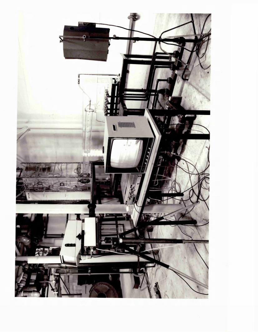
of the kiln on the flame length as well as the kiln's standard operating conditions. The data for the kiln's normal operating conditions and the calculated data for the kiln variables, such as primary air, secondary air, fuel flow rates, secondary air and jet velocities, similarity parameter (Craya-Curtet in this case) for each trial are given in Appendix 1.
As it had already been established by previous workers on the subject (Moles et al., 1972* Khan and McFadyen, 1980; Inman, 1969; and Beer, 1966), the exact reproduction of the full scale Reynolds numbers was not required for dynamic similarity as long as the conditions in both the furnace and the model were fully turbulent. Besides, bearing in mind the disadvantages of having high flow velocities and excessive amounts of acid, alkali and indicator consumption by the
— reproduction of the exact kiln Reynolds numbers in the model, the acid and alkali tank capacities were used as the limiting factor for the determination of the flow rates in the model.
A flow rate for hydrochloric acid solution was chosen such that a Reynolds number in the turbulent region would be maintained for a running period of 10 minutes. From the chosen flow rate, the velocity of the secondary fluid for the model was determined. The effects of recirculation in the kiln were simulated by keeping the similarity parameter, Craya-Curtet being the most suitable, the same for the model and the kiln. The jet velocity, sodium hydroxide solution representing the fuel and the primary air in the model, were calculated so that the Craya-Curtet parameter would be the same as in the prototype kiln for each experimental condition.
From the calculated jet velocity, the flow rate of the alkali solution was determined. Once the flow rates were set, the normalities of the acid and alkali solutions were adjusted to represent the stoichiometric conditions so that the indicator becomes transparent when the "fuel and primary air" (alkali) jet has entrained stoichiometric concentration of "secondary air" (acid). In other words, the product of alkali normality and alkali flow rate is equal to the product of the acid normality and stoichiometric acid rate. For each run, acid normality was kept constant at 0.025 N,and alkali normality was evaluated to simulate the flow conditions in the kiln. Sample calculations for the determination of the model operating conditions are given in Appendix 2.
Table 1 gives the standard operating conditions of the Barnstone No. 2 kiln, which were simulated in the model. The model operating conditions, based on the same data and calculated as explained earlier, are given in Table 5.2. For the conditions other than standard, changed according to the objectives of certain experiments and their simulations in the model work, are tabulated in Appendix 2.
5.1.6 Procedure for model operation
Prior to starting each run, the solutions required for 10 minutes of operation were prepared. The hydrochloric acid solution with constant normality of 0.025 g.moles/litre for all experiments was prepared by adding 244 mis of 36% HC1 to 143 litres of water, and the solution was stirred for about 20 minutes to obtain a uniform concentration. To make the sodium hydroxide solution anhydrous NaOH pellets of required
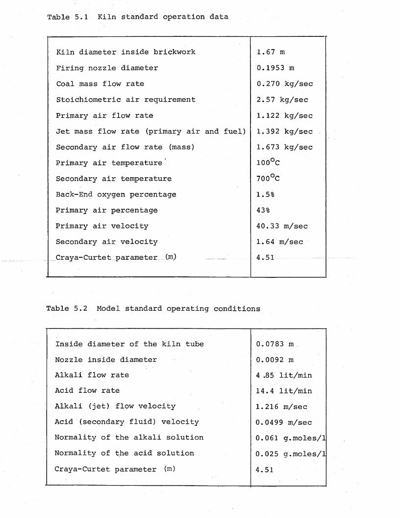
Table 5.1 Kiln standard operation data
Kiln diameter inside brickwork 1.67 mFiring nozzle diameter 0.1953 mCoal mass flow rate 0.270 kg/secStoichiometric air requirement 2.57 kg/secPrimary air flow rate 1.122 kg/secJet mass flow rate (primary air and fuel) 1.392 kg/secSecondary air flow rate (mass) 1.673 kg/secPrimary air temperature 100°CSecondary air temperature 700°CBack-End oxygen percentage 1.5%Primary air percentage 43%Primary air velocity 40.33 m/secSecondary air velocity 1.64 m/secCraya-Curtet parameter(m) ________ 4.51
Table 5.2 Model standard operating conditions
Inside diameter of the kiln tube 0.0783 mNozzle inside diameter 0.0092 mAlkali flow rate 4 .85 lit/minAcid flow rate 14.4 lit/minAlkali (jet) flow velocity 1.216 m/secAcid (secondary fluid) velocity 0.0499 m/secNormality of the alkali solution 0.061 g.moles/1Normality of the acid solution 0.025 g.moles/1Craya-Curtet parameter (m) 4.51
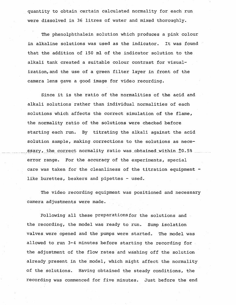
quantity to obtain certain calculated normality for each run were dissolved in 36 litres of water and mixed thoroughly.
The phenolphthalein solution which produces a pink colour in alkaline solutions was used as the indicator. It was found that the addition of 150 ml of the indicator solution to the alkali tank created a suitable colour contrast for visualization, and the use of a green filter layer in front of the camera lens gave a good image for video recording.
Since it is the ratio of the normalities of the acid and alkali solutions rather than individual normalities of each solutions which affects the correct simulation of the flame, the normality ratio of the solutions were checked before starting each run. By titrating the alkali against the acid solution sample, making corrections to the solutions as necessary , the correct normality ratio was obtained within ±0.5% error range. For the accuracy of the experiments, special care was taken for the cleanliness of the titration equipment - like burettes, beakers and pipettes - used.
The video recording equipment was positioned and necessary camera adjustments were made.
Following all these preparations for the solutions and the recording, the model was ready to run. Sump isolation valves were opened and the pumps were started. The model was allowed to run 3-4 minutes before starting the recording for the adjustment of the flow rates and washing off the solution already present in the model, which might affect the normality of the solutions. Having obtained the steady conditions, the recording was commenced for five minutes. Just before the end
of each run, the drain valve for the effluent tank was closed and a sample of the effluent solution was collected. A method analogous to flue gas analysis was used to check the accuracy of the flow metering to the model, to determine the excess acid percentage in the effluent by titrating the sample solution against the sodium hydroxide solution used for the run. The details of this procedure are given in Appendix 3.
5.1.7 Operational difficulties
One of the problems encountered during the preliminary experiments was the accurate metering of the solution flow rates, which was revealed by the checks made by effluent solution titrations at the end of each run. The operation period for each run due to the tank capacities was not long enough for the effluent solution analysis to be-made during the run, so that the corrections could be made on the flow rates to obtain accurate excess acid level. It was decided to consider this aspect for the calculation of the suspension preheater kiln model operating conditions. The capacity of the tanks and the flow rates of the solutions were thought to be arranged to give a model run period of at least 15 minutes, which would allow necessary analysis to be carried out
The other operational difficulty arose from the inconvenient way of collecting sample solutions from the three tanks which were placed on a frame-work of ± 2 m height.This gave the idea of constructing separate sample collection lines with valves for each flow for the suspension preheater kiln model.
5.2 Suspension Preheater Dry Process Kiln Model for theMain Part of the Experimental Work
5.2.1 Description of the hydraulic system
An overall view of the apparatus which was designed and constructed for the main purpose of the work is illustrated in Plates 5.4-5.6. It is a perspex water model of the No. 2 kiln at the Nuh Cement Works in Hereke, Turkey, which is a dry process kiln integrated with a four stage cyclone suspension preheater and a grate type cooler system.
Plate 5.7 represents the line flow diagram of the model system, showing the three independent circuits for the primary, secondary and auxiliary flows. The secondary fluid flow to the kiln tube is maintained by gravity through the cooler and the hood, and the primary fluid representing primary air and fuel is pumped through the model burner nozzle.
For auxiliary firing, the fluid representing some proportion of the total fuel requirement of the kiln is supplied by a pump through a nozzle into the inlet chamber of the kiln, the vertical riser duct connecting the kiln to the preheater system.
The total flow through the preheater system representing the exhaust gases was passed to the effluent system by the suction of the pump at the1 outlet of the top stage cyclones.
Three circuits comprised a different sample test lines, each of which was a direct piping system from the tanks to the drain with appropriate valve arrangement designed to enable collecting samples from the tanks without any wastage of tank fluid and also without any difficulty.

Plate 5.4 Overall view of the suspension preheater kiln model

Plate 5.5 Overall view and piping system for the suspension preheater kiln model
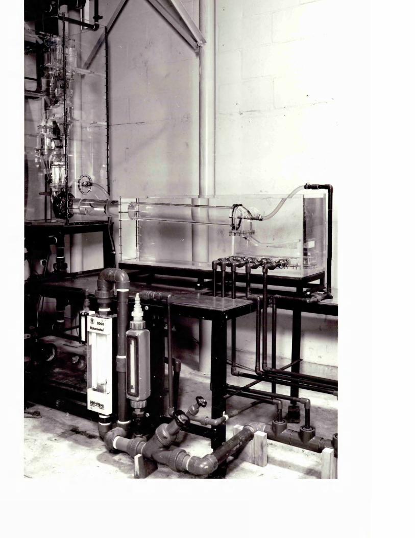

Plate 5.6 Suspension preheater with auxiliary firing arrangement
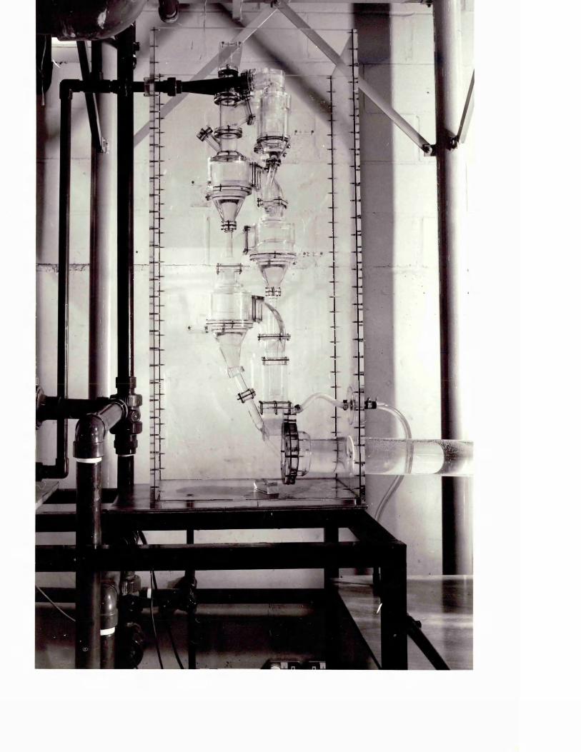
'
_L
Plate
5.7
Line
flow
diagram
for
the
suspension preheater
kiln model
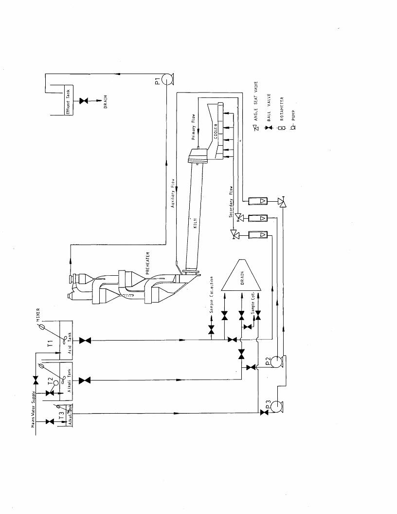
Mai
ns
Wat
er
Sup
ply
CM,
C M
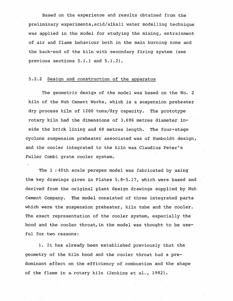
Based on the experience and results obtained from the preliminary experiments,acid/alkali water modelling technique was applied in the model for studying the mixing, entrainment of air and flame behaviour both in the main burning zone and the back-end of the kiln with secondary firing system (see previous sections 5.1.1 and 5.1.2).
5.2.2 Design and construction of the apparatus
The geometric design of the model was based on the No. 2 kiln of the Nuh Cement Works, which is a suspension preheater dry process kiln of 1200 tons/dry capacity. The prototype rotary kiln had the dimensions of 3.696 metres diameter inside the brick lining and 60 metres length. The four-stage
cyclone suspension preheater associated was of Humboldt design, and the cooler integrated to the kiln was Claudius Peter's Fuller Combi grate cooler system.
The 1 : 40th scale perspex model was fabricated by using the key drawings given in Plates 5.8-5.17, which were based and derived from the original plant design drawings supplied by Nuh Cement Company. The model consisted of three integrated parts which were the suspension preheater, kiln tube and the cooler. The exact representation of the cooler system, especially the hood and the cooler throat,in the model was thought to be useful for two reasons:
1. It has already been established previously that the geometry of the kiln hood and the cooler throat had a predominant effect on the efficiency of combustion and the shape of the flame in a-rotary kiln (Jenkins et al., 1982) .

Plate 5.8 Suspension preheater
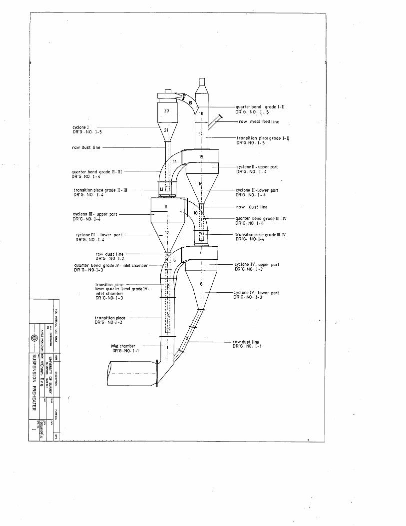
SU
SP
EN
SIO
N
PR
EH
EA
TE
R
83§3e?bS
quarte r bend grade I - I I DR' G- NO - 1 - 5i
— ra w m e a l feed lin ecyclone I •—DR'G - NO- 1 -5
tra n s it io n piece g ra d e I - I I DR'G -NO • I - 5
ra w dust line
cyc loneII - upper part D R 'G -N O - 1 -4q u a rte r bend grade II - I I I
D R 'G -N O - 1 -4
trans ition piece grade II - III DR'G- NO- 1-4
cyclone I I - lo w e r part DR'G- NO- 1 - 4
-ra w d u s t line
cyclone III - upper part D R 'G -N O . 1-4 quarte r bend grade III - IV
DR'G - NO- 1 -4
transition piece grade III- IV DR'G- N O -1-4
cyclone III - low er part DR'G - NO - 1 -4
raw dust line --------------------D R 'G - NO- 1 -2
q u a rte r bend grade IV - inlet chamber D R 'G - N O -1 -3
cyclone IV , upper part D R'G -N O - 1 -3
transition piece ----------------------lower quarter bend grade IV - in let cham ber D R 'G -N O -1 -3
cyclone I V - lo w er part D R 'G -N O - 1 -3
tra n s it io n piece DR'G- N O - I -2
r a w dust line D R 'G . NO. 1-1inlet chamber
D R 'G -N O -1 -1
15>§S

<T>LO
plate
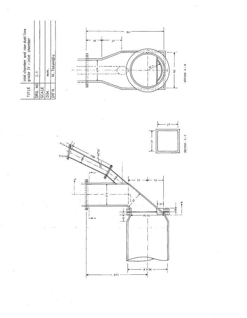
ZJ G> •u -O
>
cnO
LU
OCJ>CO Q□
3L I
ri“
I* zv
9 '0 6

or— I
IT)
Plate
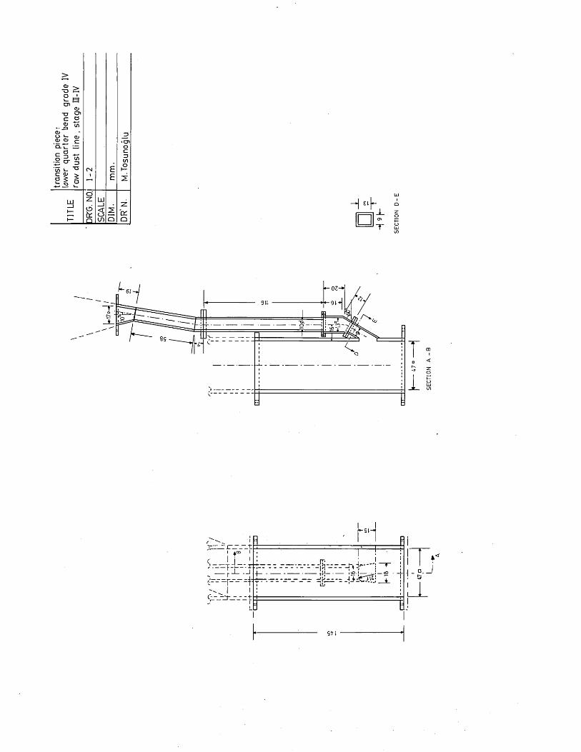
>
c w
<s>Q□
H ef
911
T□r-.
i
1 l 1-a .
'l
_l__________________ rq______ ________ !
1J

mPlate
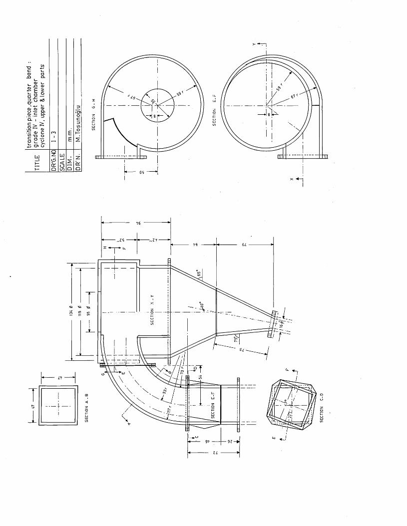
X
=>oo>3O'
>
OC_>CO
Ll_UJ
oLllin
05
i
SEC
TIO
N

CNLOCD■pftfrHCM
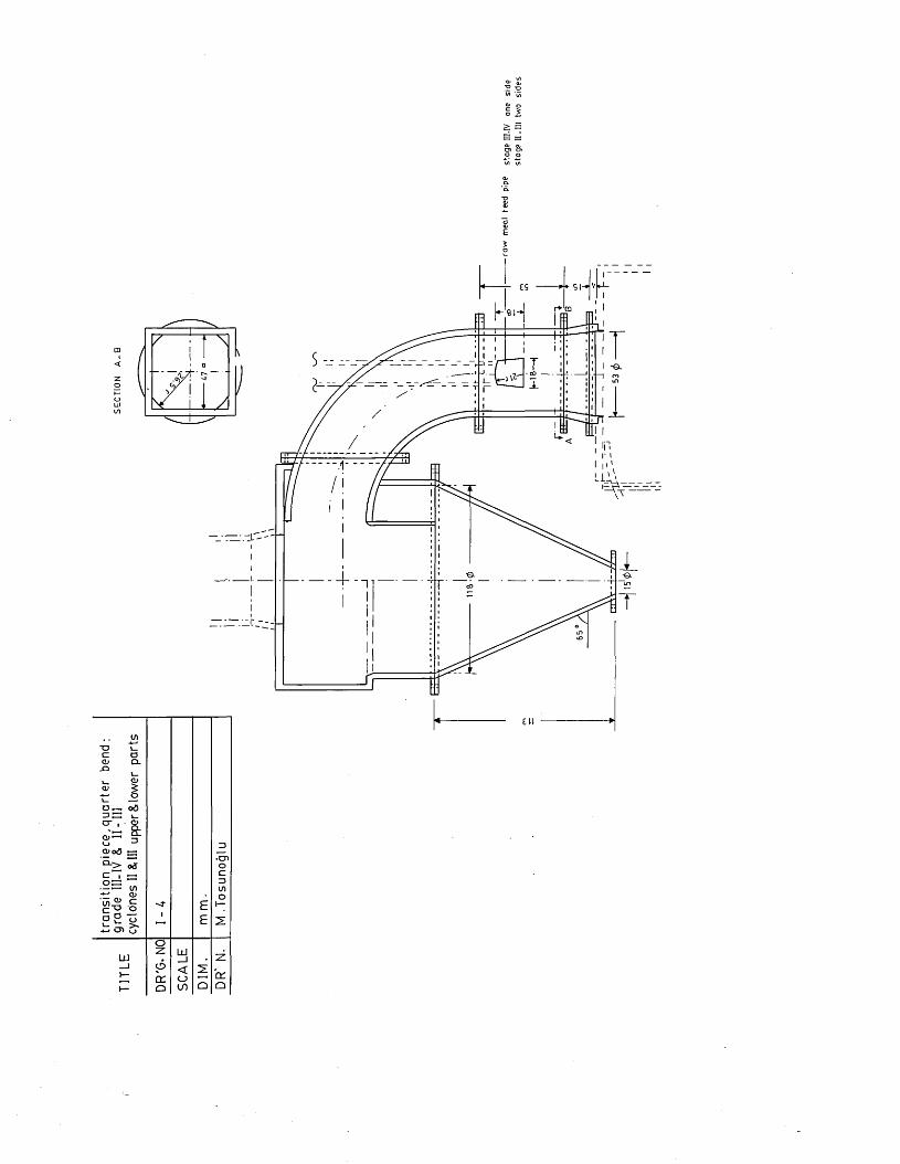
O> ©o ^ £ =CJ1 O'o a
E5o
^ 9l7ft^a m i j = * i
oO
1x1 O O □O

rorH
LO
Plate
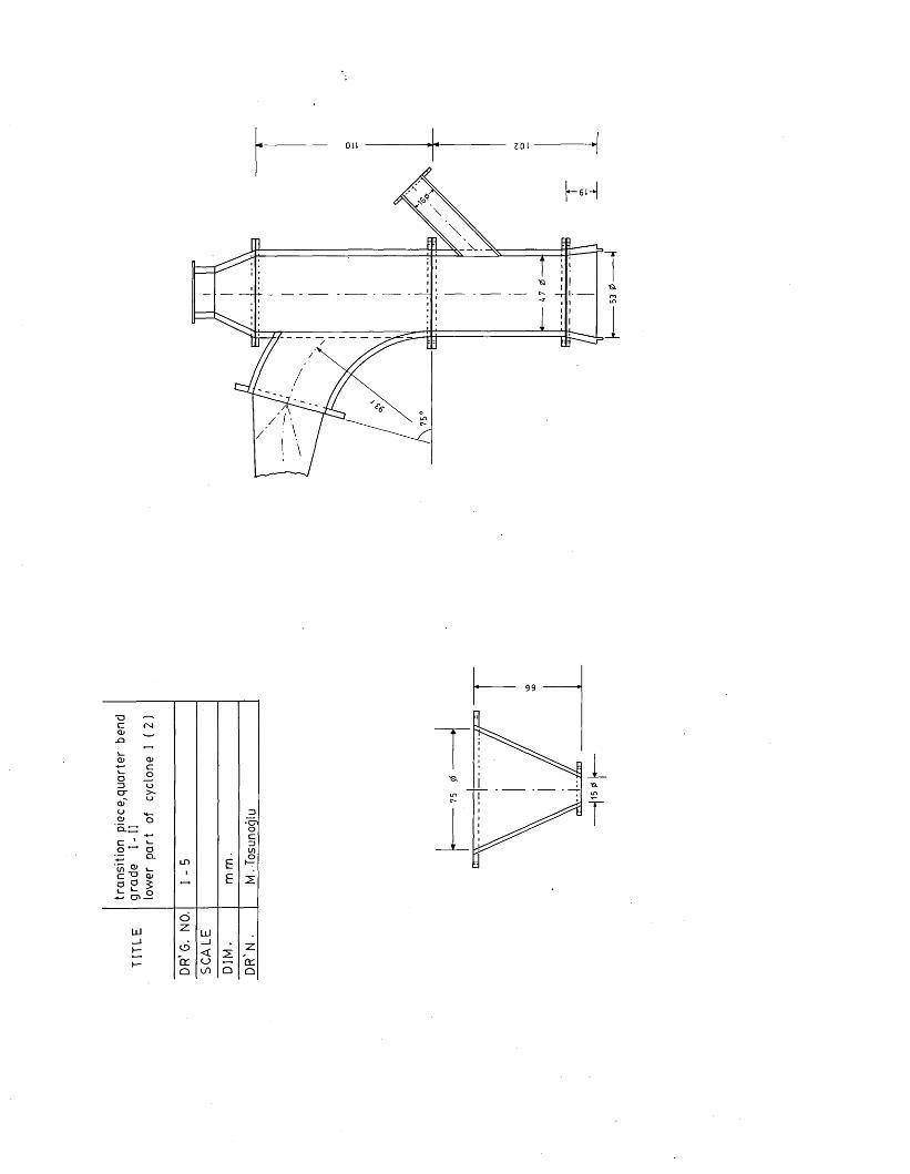
Oil
99

in
Plate
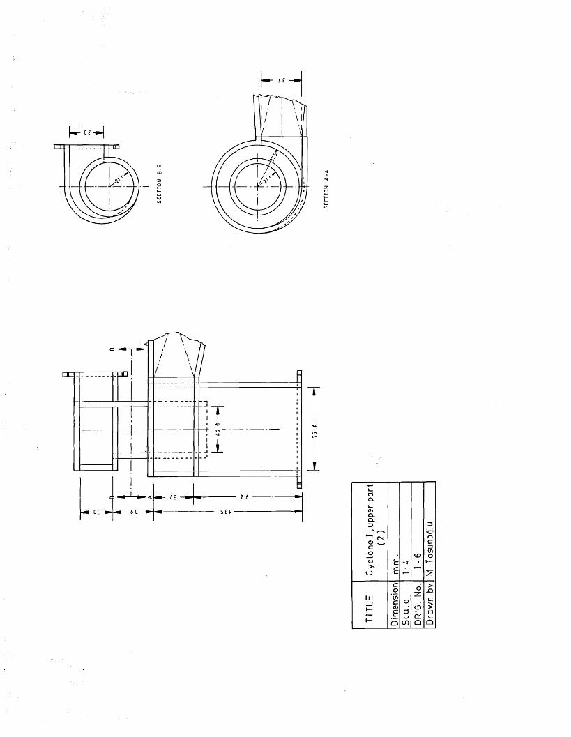
-pm
Cycl
one
I ,up
per
part
(2)
££
'■TCDi
M .T
osun
oglu
c >o nLU Ifl_J cCD CD
CO ££ o<_) t r aV-1— Q in a Q

LOLOCD+)fd
rHPL,
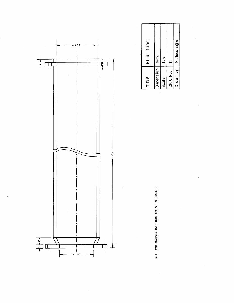
15*LU 3CD3I—Z
E
•O'oc3V)oI—
E - Z
TITL
E
Dim
ensi
on
Sca
le
ozotrQ D
raw
n by
<* 9 06
0 LSL

LO
CD■Pfdi—iP-i
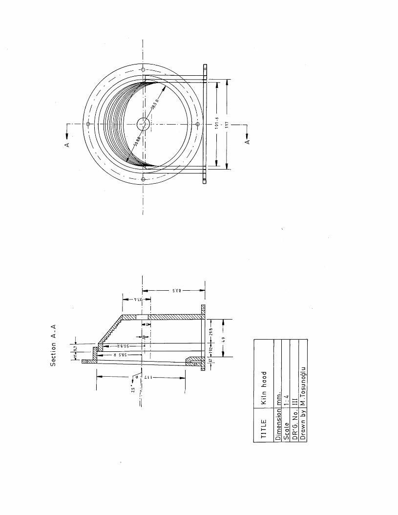
Section
r4=
■w i
3IDO oO oJO Dino o
£ ~4- i—5 e 2
o >No o X3Ixl_J
V)co G>Zo' C
£1— £ O<_> cr a1— Q in o Q

I-"UO0)-prdi—lP-i
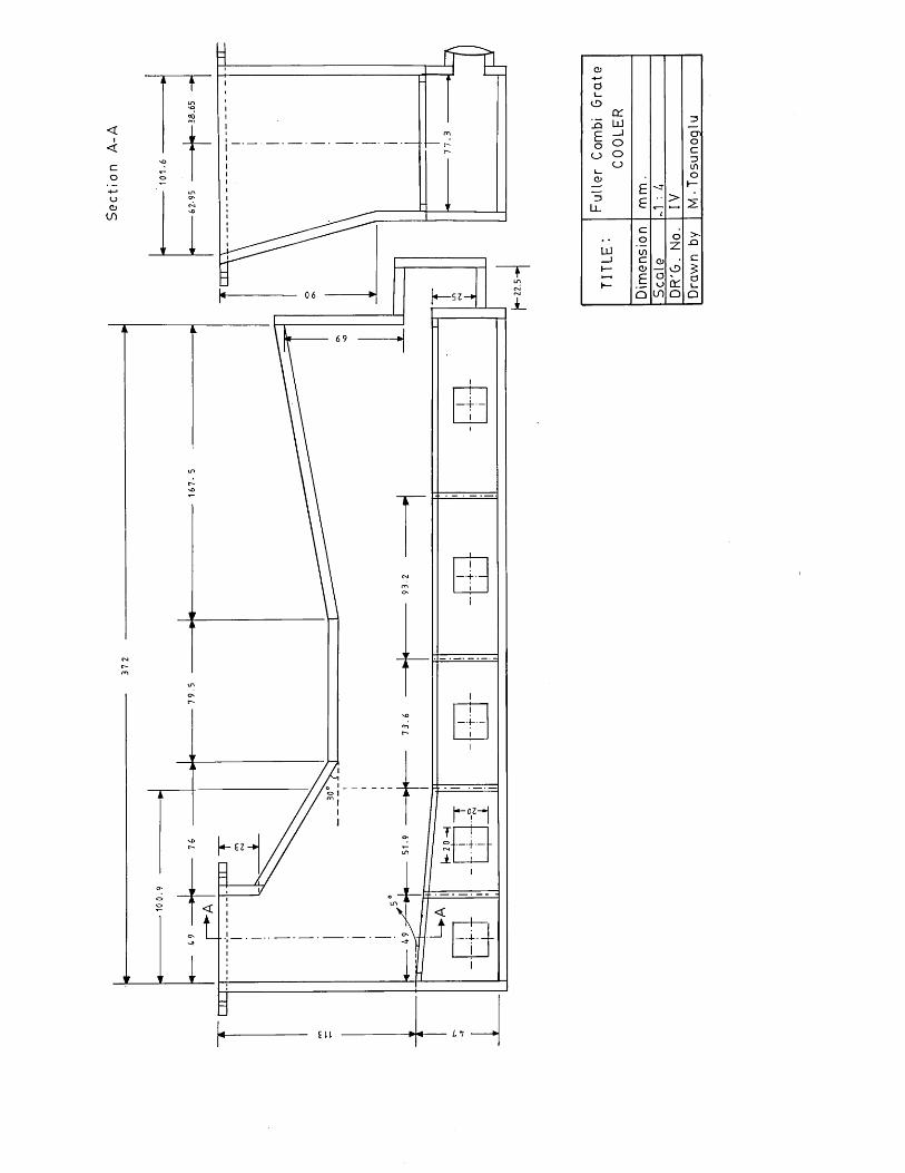
Section
A-A
|< S3
— 4-.
Fuller Co
mbi
Grat
e CO
OLER
EE
i
IV M•Tos
unog
lu
L U
c01 f) No
. > -. O
c 0) Cl-r d> o <
E Uo O S CS
Q o □
2. For future possible research purposes. Construction of the model was carried out by using a 13 mm thick perspex for most of the parts of the system, including kiln tube, cooler, inlet chamber. The dust lines of the cyclone pre- heater were fabricated by using perspex tubes with wall thickness of 6 mm. The same wall thickness (6 mm) was used for the construction of the 4th, 3rd and 2nd stage cyclones, whereas the 1st stage cyclones were made of thicker material, namely 10 mm. Glued or screwed joints for the perspex material were used where necessary.
Plates 5.18 to 5.21 illustrate the perspex construction of the preheater, cooler and the general views of the system.
A V o.d. stainless steel tube was used to make the main burner with the firing end being threaded to accept nozzles of different inside diameters made of steel too. The .size of the model nozzle diameter was determined by scaling down of the prototype burner diameter geometrically.
The auxiliary firing burner was constructed by drilling a hole of required diameter rin the wall of the inletchamber and screwing the perspex piece with a hole of the same diameter at a certain angle, as shown in Plate 5.22.
The preheater tower and the cooler with that part of the kiln tube resembling the burning zone were contained in two rectangular perspex tanks filled with water to prevent optical distortion when being viewed.

Plate 5.18 Perspex construction of the suspension preheater-kiln-grate cooler

0Og0-p
oco•H-PU2U■PC/1aOuX0a0u0to0Xi-pM-lo
■H>i—I-+I0U0>o<Tiin0 -P 0 I—Ito

Plate 5.20 Suspension preheatet - perspex construction

Plate 5.21 Grate cooler - perspex construction

+Jo3TJpCDCfl•HP(U-Pc-H-pcCD
£(dpurdp<u£p£>1pfdi—Ix£
OJC N•mcu-prdi—iPi
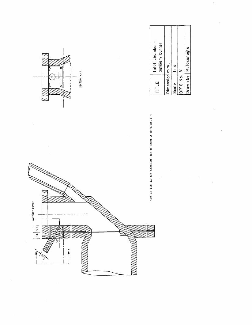
Au
xilia
ry
bu
rne
r
5.2.2.1 Fluid delivery
The flow scheme illustrated in Plate 5.7 was fabricated by using materials which satisfied the requirements of corrosion resistance and operational flexibility.
The rigid conduit in the system was constructed by using 11 Le Bas" UPVC piping with different diameters for each section varying from 3/8". to 4" size. For assembly all 2" pipes were threaded and the rest of the pipes other than 2" size were glued due to their thinner wall thickness.
The acid solution to be used as the secondary fluid was conveyed in 2" piping and fed to the cooler through five cooler chambers with inlets of V diameter each. The flow in the 2" pipe was split into five channels of diameter each by a manifold. For alkali flow to the main burner, 2" piping was used for the line between the tank and the pump.The ex-pump flow was through a 1" pipe which later reduced to k" after the rotameter.
The sample collection lines provided for the secondary and primary flow systems for quick and easy analysis of the acid and alkali solutions were constructed by using h" diameter piping.
For ex-preheater flow which was delivered from two 1" diameter outlets of the first stage cyclone, the draining of the acid and the primary alkali tanks, and ex-effluent tank delivery, the conduit system consisted of 2" piping.
Ducting of 3/8" diameter was used for the auxiliary firingsystem, except for the connection of the rigid conduit to the
auxiliary burners, where the flexible polythene tubing was used.
The sump isolator, kiln delivery, drainage and sample collection valves were all ball valves of suitable dimension,2", V 1 or 3/8" ,• as required. The fine control of the flows in three circuits, primary, secondary and auxiliary lines, were achieved by using V', 2" and 3/8" angle seat valves respectively, in connection with the rotameters of 24, 65,9.5mm diameter to display the quantitative measurements.The rotameters were supplied and calibrated by G.E. C. Elliot Ltd. and Gap Flowmeters.
The fluid delivery system consisted of three centrifugal pumps, labelled PI, P2 and P3 on the line diagram, shown in Plate 5.7. The primary (alkali), fluid is pumped to the system through the main burner by pump P2, and pump P3 was used for the auxiliary firing system, injecting auxiliary fuel (alkali) fluid into the vertical riser duct of the preheater through a nozzle. The secondary flow of the kiln (acid) was supplied by the gravitational force,and the pump PI was used to create suction at the preheater delivering total liquid flow through the system to the effluent tank, serving the same function as the exhaust gas fan in the prototype system.
The three pumps used for delivery of the fluid had the following characteristics:
PI : Totton Electrical Products - type EMP 100/8Max. flow : 100 lit/min Max. head : up to 8 m0.18 KW - 2800/3380 rev/min
P2 : Little Giant Comp., Magnet driven chemical pump,Type : 3 MDFlow : 13.3 lit/minMax. head : 4.9 m.
P3 : Totton Electrical Products - Type DP 35/3Max. 'flow : 35 lit/minMax. head :3m.
Three sumps, each fabricated from polythene to reduce corrosion supplied acid and alkali solutions to the system.The three tanks, labelled Tl, T2, T3 on the line diagram in Plate 5.7 were equipped with mixers to maintain uniform solution concentrations, and they had the following dimensions:
Tl : Acid tank - capacity: 1343 litresT2 : Alkali tank (main burner) - capacity: 1343 litresT3 : Alkali tank (auxiliary firing) - capacity: 78 litres.
The sumps were placed 3.2 metres above the laboratory floor on a specially constructed platform with access ladder, to maximize the utilisation of the available laboratory space and to provide adequate heads for the pumps and acid flow to‘ the system by gravity.
A fourth tank in Plate 5.7 was used as the effluent solution tank, which was placed on a small platform below the main platform for the other tanks. The effluent tank was also made from polythene, and it had a capacity of 79 litres.
5.2.3 Video recording
The equipment and techniques for recording of the model
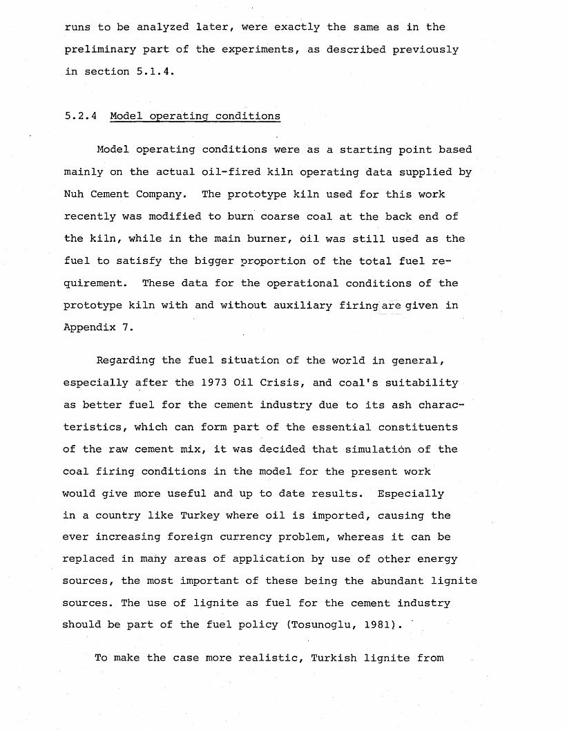
runs to be analyzed later, were exactly the same as in the preliminary part of the experiments, as described previously in section 5.1.4.
5.2.4 Model operating conditions
Model operating conditions were as a starting point based mainly on the actual oil-fired kiln operating data supplied by Nuh Cement Company. The prototype kiln used for this work recently was modified to burn coarse coal at the back end of the kiln, while in the main burner, oil was still used as the fuel to satisfy the bigger proportion of the total fuel requirement. These data for the operational conditions of the prototype kiln with and without auxiliary firing] are given in Appendix 7.
Regarding the fuel situation of the world in general, especially after the 1973 Oil Crisis, and coal's suitability as better fuel for the cement industry due to its ash characteristics, which can form part of the essential constituents of the raw cement mix, it was decided that simulation of the coal firing conditions in the model for the present work would give more useful and up to date results. Especially in a country like Turkey where oil is imported, causing the ever increasing foreign currency problem, whereas it can be replaced in many areas of application by use of other energy sources, the most important of these being the abundant lignite sources. The use of lignite as fuel for the cement industry should be part of the fuel policy (Tosunoglu, 1981).
To make the case more realistic, Turkish lignite from
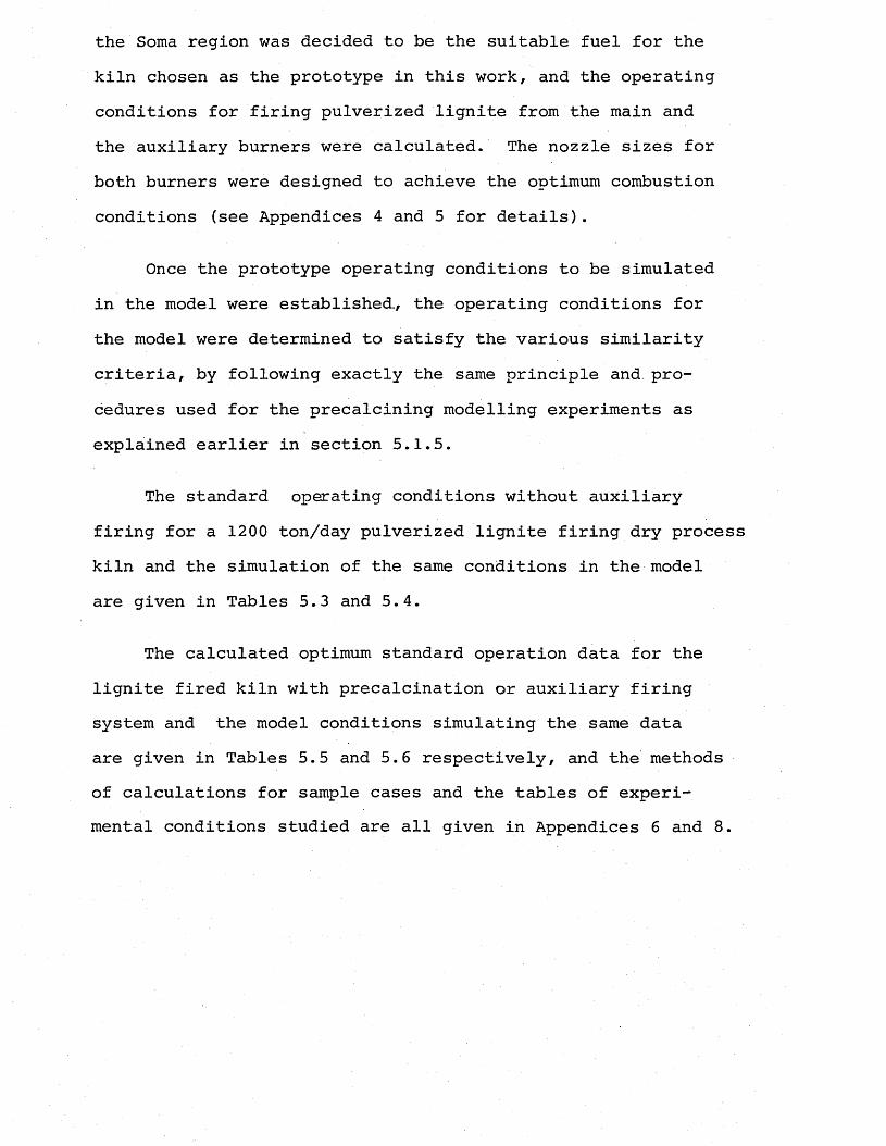
the Soma region was decided to be the suitable fuel for the kiln chosen as the prototype in this work, and the operating conditions for firing pulverized lignite from the main and the auxiliary burners were calculated. The nozzle sizes for both burners were designed to achieve the optimum combustion conditions (see Appendices 4 and 5 for details).
Once the prototype operating conditions to be simulated in the model were established., the operating conditions for the model were determined to satisfy the various similarity criteria, by following exactly the same principle and. procedures used for the precalcining modelling experiments as explained earlier in section 5.1.5.
The standard operating conditions without auxiliary firing for a 1200 ton/day pulverized lignite firing dry process kiln and the simulation of the same conditions in the model are given in Tables 5.3 and 5.4.
The calculated optimum standard operation data for the lignite fired kiln with precalcination or auxiliary firing system and the model conditions simulating the same data are given in Tables 5.5 and 5.6 respectively, and the methods of calculations for sample cases and the tables of experimental conditions studied are all given in Appendices 6 and 8.
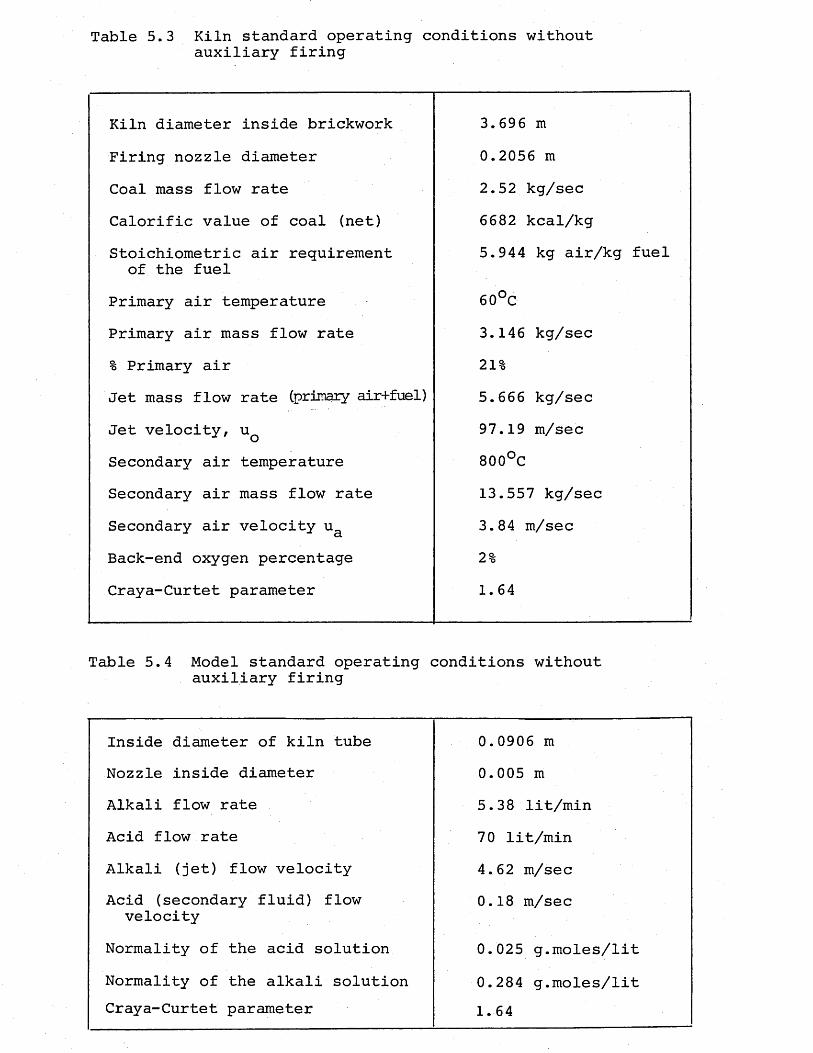
Table 5.3 Kiln standard operating conditions withoutauxiliary firing
Kiln diameter inside brickwork 3.696mFiring nozzle diameter 0.2056 mCoal mass flow rate 2.52 kg/secCalorific value of coal (net) 6682 kcal/kgStoichiometric air requirement of the fuel
5.944 kg air/kg fuel
Primary air temperature 60°CPrimary air mass flow rate 3.146 kg/sec% Primary air 21%Jet mass flow rate (primary air+fuel) 5.666 kg/secJet velocity, uQ 97.19 m/secSecondary air temperature 800°CSecondary air mass flow rate 13.557 kg/secSecondary air velocity ua 3.84 m/secBack-end oxygen percentage 2%Craya-Curtet parameter 1.64
Table 5.4 Model standard operating conditions without auxiliary firing
Inside diameter of kiln tube 0.0906mNozzle inside diameter 0.005 mAlkali flow rate 5.38 lit/minAcid flow rate 70 lit/minAlkali (jet) flow velocity 4,62 m/secAcid (secondary fluid) flow
velocity0.18 m/sec
Normality of the acid solution 0.025 g.moles/litNormality of the alkali solution 0.284 g.moles/litCraya-Curtet parameter 1.64
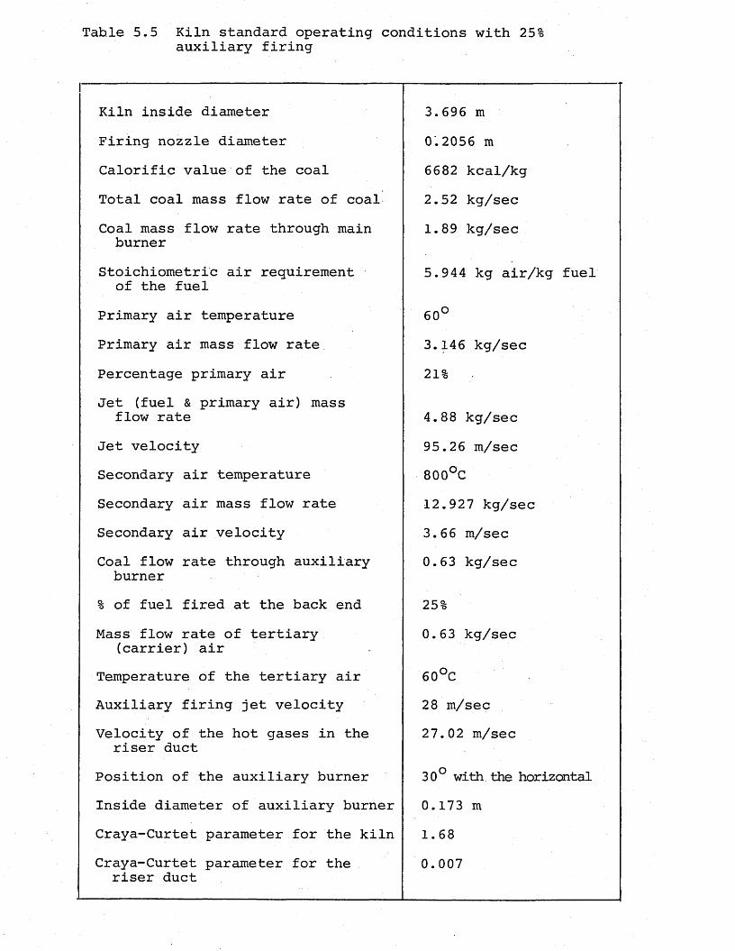
Tahle 5.5 Kiln standard operating conditions with 25%auxiliary firing
Kiln inside diameter 3.696 mFiring nozzle diameter 0.2056mCalorific value of the coal 6682 kcal/kgTotal coal mass flow rate of coal 2.52 kg/secCoal mass flow rate through main burner
1.89 kg/sec
Stoichiometric air requirement of the fuel
5.944 kg air/kg fuel
Primary air temperature0oVO
Primary air mass flow rate 3.146 kg/secPercentage primary air 21%Jet (fuel & primary air) mass
flow rate 4.88 kg/secJet velocity 95.26 m/secSecondary air temperature 800°CSecondary air mass flow rate 12.927 kg/secSecondary air velocity 3.66 m/secCoal flow rate through auxiliary burner
0.63 kg/sec
% of fuel fired at the back end 25%Mass flow rate of tertiary
(carrier) air0.63 kg/sec
Temperature of the tertiary air 60°CAuxiliary firing jet velocity 28 m/secVelocity of the hot gases in the
riser duct27.02 m/sec
Position of the auxiliary burner 30° with the horizontalInside diameter of auxiliary burner 0.173 mCraya-Curtet parameter for the kiln 1.68Craya-Curtet parameter for the riser duct
0.007
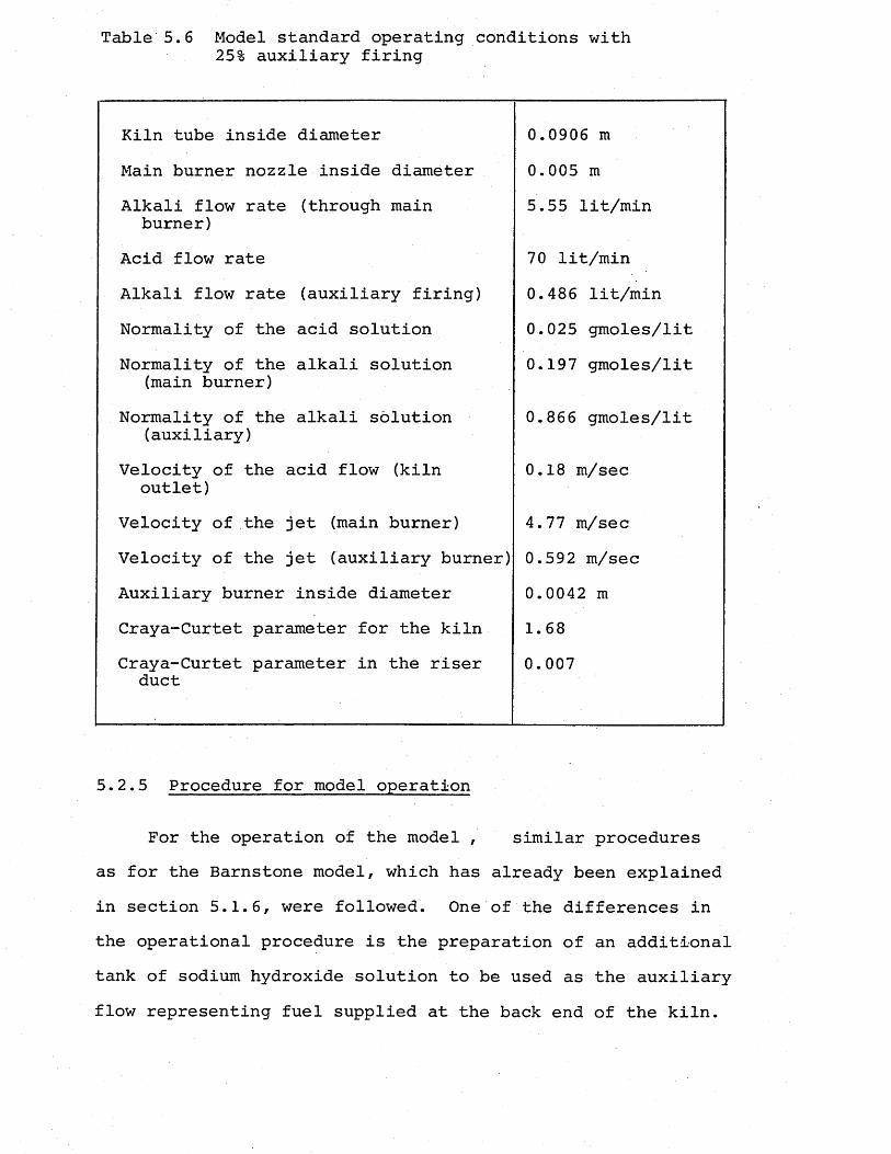
Table 5.6 Model standard operating conditions with25% auxiliary firing
Kiln tube inside diameter 0.0906 mMain burner nozzle inside diameter 0.005 mAlkali flow rate (through main burner)
5.55 lit/min
Acid flow rate 70 lit/minAlkali flow rate (auxiliary firing) 0.486 lit/minNormality of the acid solution 0.025 gmoles/litNormality of the alkali solution
(main burner)0.197 gmoles/lit
Normality of the alkali solution (auxiliary)
0.866 gmoles/lit
Velocity of the acid flow (kiln outlet)
0.18 m/sec
Velocity of the jet (main burner) 4.77 m/secVelocity of the jet (auxiliary burner) 0.592 m/secAuxiliary burner inside diameter 0.0042 mCraya-Curtet parameter for the kiln 1.68Craya-Curtet parameter in the riser duct
0.007
5.2.5 Procedure for model operation
For the operation of the model , similar procedures as for the Barnstone model, which has already been explained in section 5.1.6, were followed. One of the differences in the operational procedure is the preparation of an additional tank of sodium hydroxide solution to be used as the auxiliary flow representing fuel supplied at the back end of the kiln.
The period for one model run in this case was increased to about 15 minutes to allow some time for checking and correcting the flow metering before the ejqperimental data recording to avoid the necessity of any corrections on the results later, and to improve the accuracy of the experiments, and also to allow enough time for measurements and recordings of two flames, the main burner and auxiliary burner. For the start-up of the model operation, first the acid flow is supplied to the model by simply opening the valves,and the flow rate is adjusted by opening the angle seat valve gradually. Care was taken not to load the model suddenly with pressure. The pump for suction of the model total flow was started as soon as the model was filled,and a balance was obtained between the pump suction and the acid flow to avoid any pressure build-up in the system.
Then the primary alkali pump was started? after 2-3 minutes of operation the effluent solution was checked for correct concentration,and corrections on the flow rates were made when necessary. Once correct metering of the primary alkali and acid flows was maintained, the auxiliary firing line valves were opened and the associated pump was started. The effluent solution concentration was checked again this time to regulate the auxiliary fluid flow rate. When all flow rates were correctly set, the recording was started which commenced for nearly 10 minutes.
In order to speed up the effluent solution checks and save time in adjusting the correct solution normality for each experiment, in this part of the work a pH meter Gallen- kamp combined electrode was used for concentration measure-

merits instead of time-consuming and tiresome titration technique. Normality ratios of the acid and alkali solutions were double-checked with the titration method at the same time.
CHAPTER 6
RESULTS
6.1 Preliminary Results with the Barnstone Model
6.1.1 Operating conditions tested
Three groups of experiments were carried out for this part of the experimental work. Each part of the experiments were planned in advance and model operating conditions were calculated in such a way to simulate the conditions tested during the plant trials carried out by Moles et al. (1974) . on the Barnstone kiln, each of which aimed to demonstrate a particular effect.
For designing the nozzles tested, geometric similarity with the prototype nozzles used during kiln trials was obtained.
Part 1: Part 1 experiments were intended to investigate theeffect of excess air level on flame length. The nozzle size tested was the one representing the full scale nozzle with a diameter of 0.1651 metres, and the primary air level was kept at a value to simulate 43% on the real plant. Flow conditions in the model were varied for the four runs in order to simulate the back-end oxygen percentages of 0.5, 1.5, 3.0 and 4.5.
Part 2: These experiments were designed to examine the effectof nozzle size on the flame length. Four different nozzle sizes tested were designed to simulate the flames produced by the full-scale nozzles of 0.1524, 0.1651, 0.1953 and 0.2413 metres diameters.
For each different size nozzle, flow conditions were set so as j to simulate the plant conditions with back-end oxygen level varying between 0.5 and 4.5, whereby the primary air percentage was kept at 43%.
Part 3: In this part, the effect of primary air percentage onthe flame length was investigated. The model operating conditions were determined to represent the full-scale plant conditions of 3.0% back-end oxygen level with primary air percentages varying between 54% and 43%. The nozzle used for these experiments was the geometric scale model of the kiln's standard nozzle of 0.1953 metres diameter.
For each test condition, the model was run for a period of approximately 5 minutes, and the flame behaviour was recorded on the video tape.
Flame length recordings were taken from 36 video frames, selected randomly during 3 minutes of each run.
6.1.2 Analysis of the Results
Based on these 36 video frame recordings, the values for the mean and standard deviation were calculated. Maximum standard deviation value was found to be 10.2%, whereas the typical value varied in the range 2-3%.
The actual excess air levels tested were calculated based on the effluent solution normality values as explained in Appendix 3.
Mean flame length values were plotted against the back-
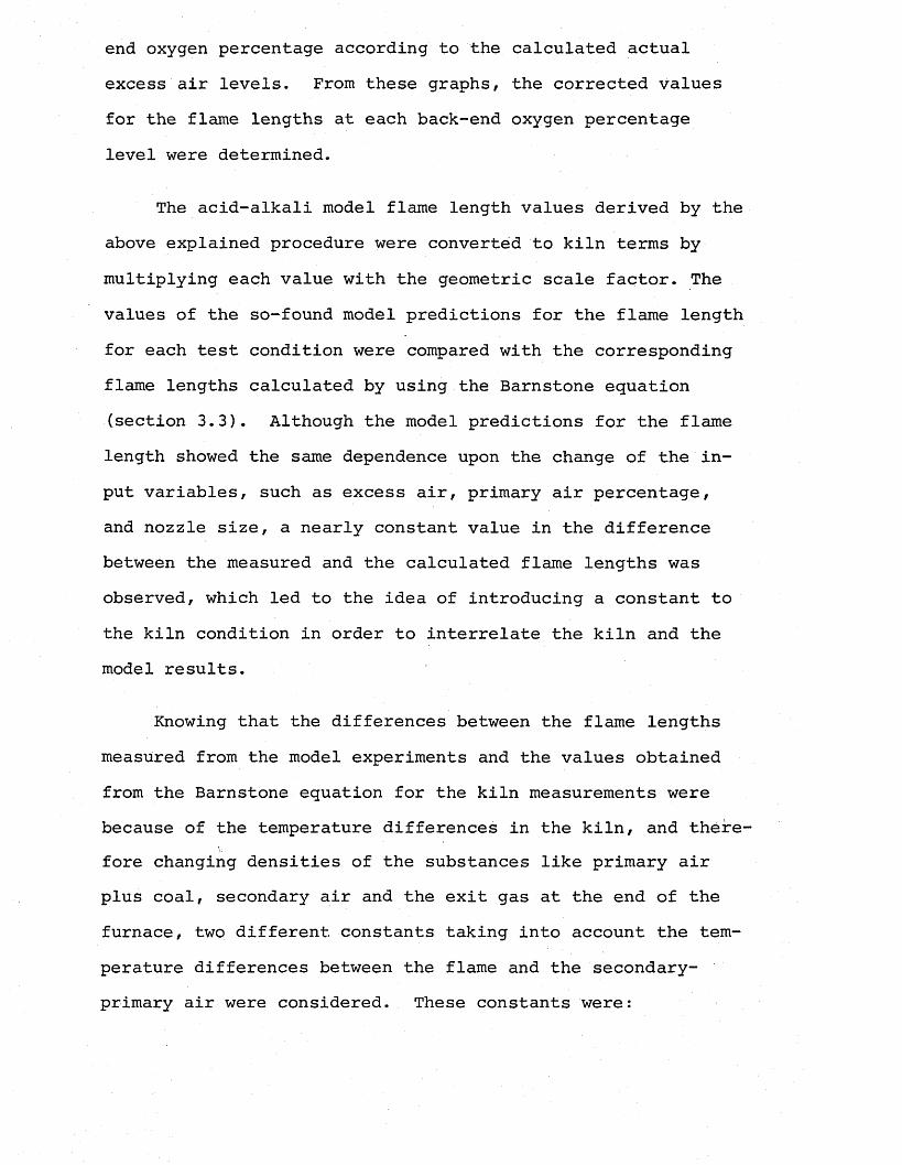
end oxygen percentage according to the calculated actual excess air levels. From these graphs, the corrected values for the flame lengths at each back-end oxygen percentage level were determined.
The acid-alkali model flame length values derived by the above explained procedure were converted to kiln terms by multiplying each value with the geometric scale factor. The values of the so-found model predictions for the flame length for each test condition were compared with the corresponding flame lengths calculated by using the Barnstone equation (section 3.3). Although the model predictions for the flame length showed the same dependence upon the change of the input variables, such as excess air, primary air percentage, and nozzle size, a nearly constant value in the difference between the measured and the calculated flame lengths was observed, which led to the idea of introducing a constant to the kiln condition in order to interrelate the kiln and the model results.
Knowing that the differences between the flame lengths measured from the model experiments and the values obtained from the Barnstone equation for the kiln measurements were because of the temperature differences in the kiln, and therefore changing densities of the substances like primary air plus coal, secondary air and the exit gas at the end of the furnace, two different constants taking into account the temperature differences between the flame and the secondary- primary air were considered. These constants were:
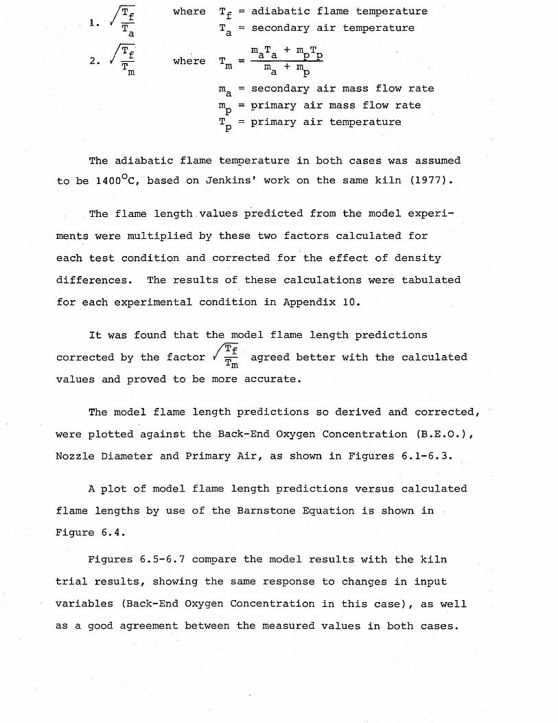
1 .
rT^ where T^ = adiabatic flame temperatureTa = secondary air temperature
/ t7 m T + rn T2. / — where T =-------— — ET m m + mm a p
ma = secondary air mass flow rate m = primary air mass flow rate Tp - primary air temperature
The adiabatic flame temperature in both cases was assumed to be 1400°C, based on Jenkins1 work on the same kiln (1977).
The flame length values predicted from the model experiments were multiplied by these two factors calculated for each test condition and corrected for the effect of density differences. The results of these calculations were tabulated for each experimental condition in Appendix 10.
It was found that the model flame length predictionscorrected by the factor /*£■ agreed better with the calculated-•-mvalues and proved to be more accurate.
The model flame length predictions so derived and corrected, were plotted against the Back-End Oxygen Concentration (B.E.O.), Nozzle Diameter and Primary Air, as shown in Figures 6.1-6.3.
A plot of model flame length predictions versus calculated flame lengths by use of the Barnstone Equation is shown in Figure 6.4.
Figures 6.5-6.7 compare the model results with the kiln trial results, showing the same response to changes in input variables (Back-End Oxygen Concentration in this case) , as well as a good agreement between the measured values in both cases.
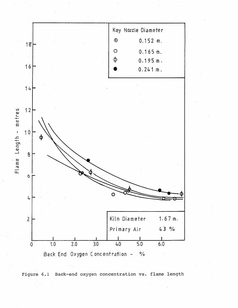
Flam
e Le
ngth
-
met
res
Key Nozzle Diameter
© 0.152 m.
0 .165 m.
0 .1 9 5 m .
0.241 m.
Kiln Diameter
Primary Air 4 3 %
5.0 6.03.01.0 2.00Back End Oxygen Concentration - %
Figure 6.1 Back-end oxygen concentration vs. flame length
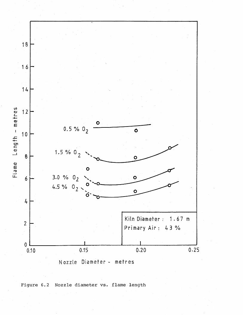
Flam
e Le
ngth
-
met
res
18
1 6
14
12
10
8
64 . 5 % 0 2 x 0
'o '-o -4
Kiln Diameter : 1 . 6 7 m
Primary Air : 4 3 %2
0
0.250.15 0.200.10
Nozzle Diameter - metres
Figure 6.2 Nozzle diameter vs. flame length
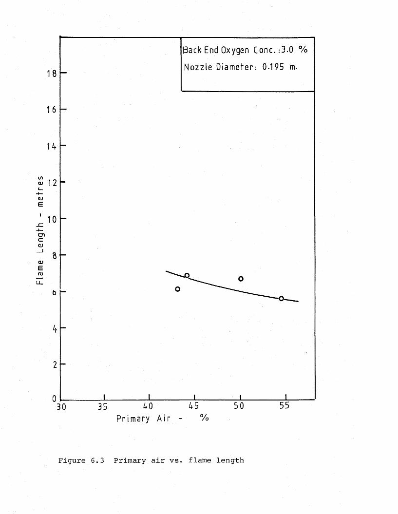
Flam
e Le
ngth
-
met
res
Back End Oxygen Conc.:3.0 %
Nozzle Diameter: 0.195 m.
8 -
%Primary Air
Figure 6.3 Primary air vs. flame length
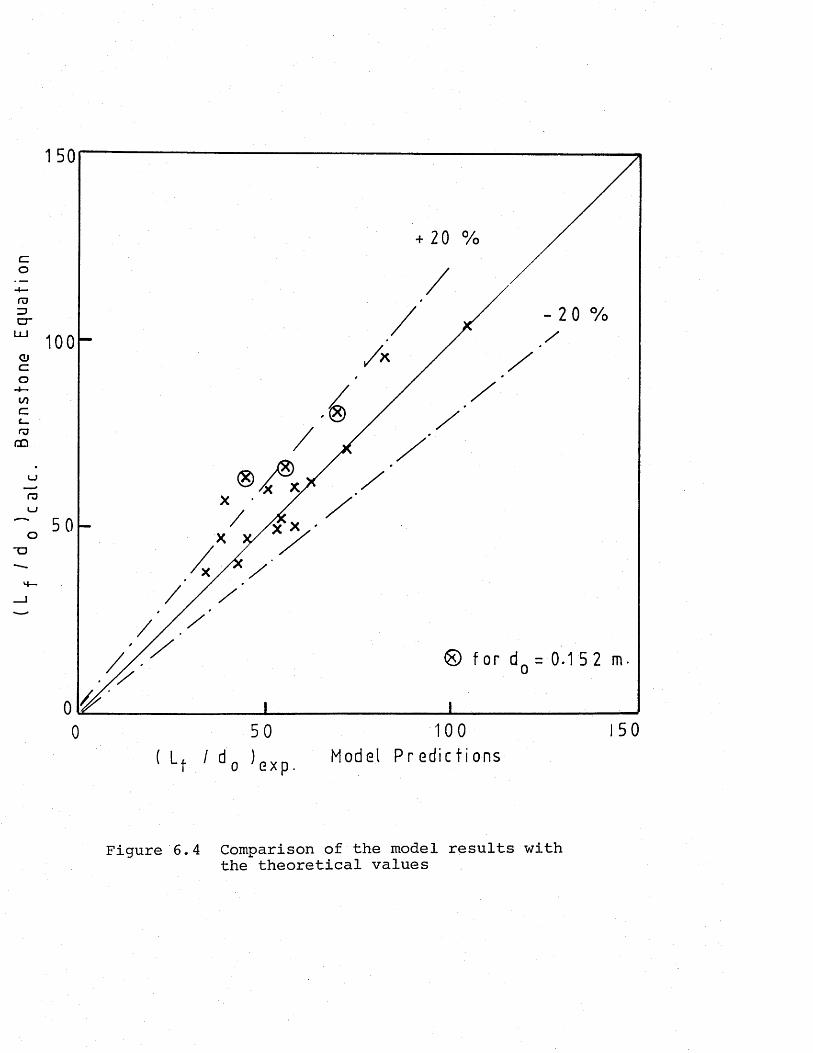
Bar
nsto
ne
Equ
ati
on
150
+ 20 %
0 50 100 150( Lj. / d Q ) QXp Model Predict ions
Figure 6.4 Comparison of the model results with the theoretical values
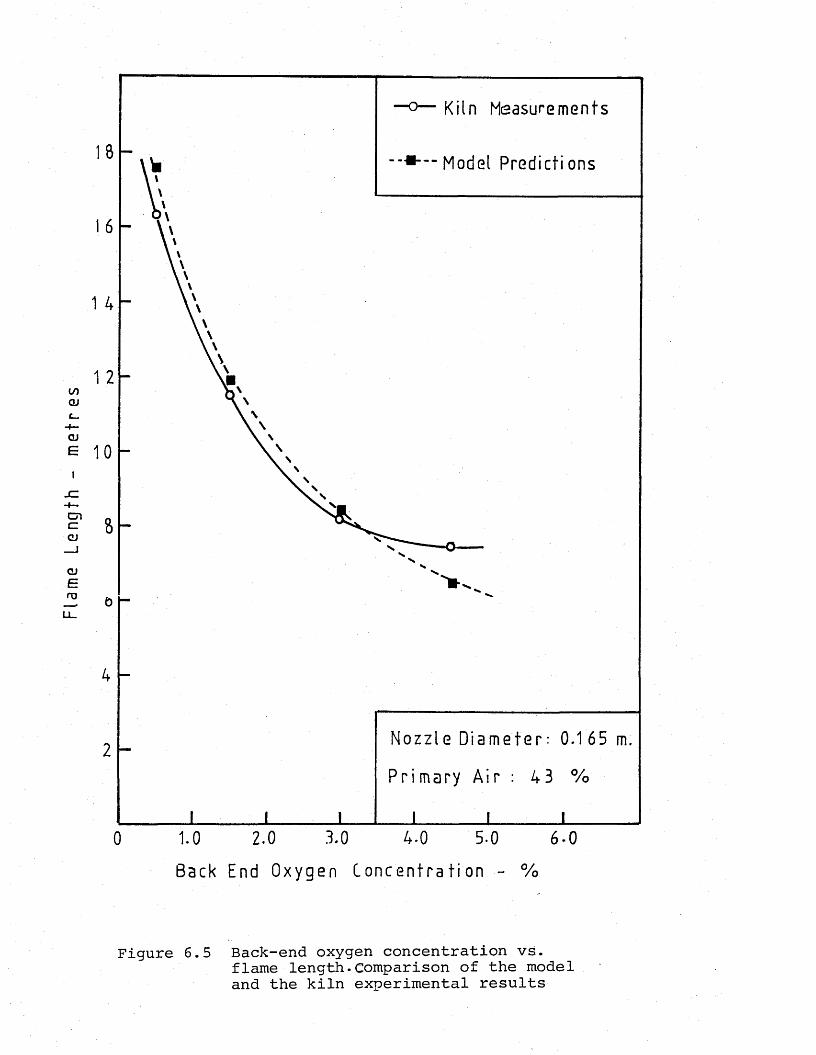
Flam
e Le
ngth
-
me
tre
s
Kiln Measurements
18 Model Predictions
16
1 4
1 2
10
8
o
4
2
0 1.0 2.0 3.0 4-0 5-0 6-0
Back End Oxygen Concentrat ion - %
Figure 6.5 Back-end oxygen concentration vs.flame length.Comparison of the modeland the kiln experimental results
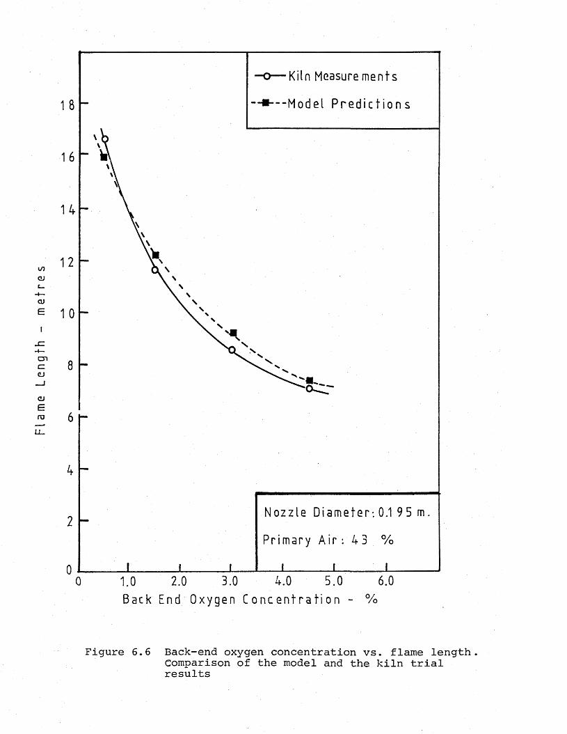
Flam
e Le
ngth
-
me
tre
s
Kiln Measure ments
- - - - - - M o d e l P r e d ic t io n s
10 -
Nozzle Diameter-. 0.1 95 m.
Primary A i r : 43 %
6.05.03.0 4.02.01.00Back End Oxygen C o n c e n t r a t io n - %
Figure 6.6 Back-end oxygen concentration vs. flame length.Comparison of the model and the kiln trialresults
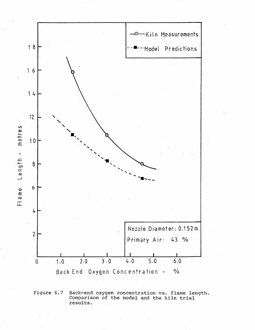
Fi a
me
Leng
th
- m
etre
s
Ki ln Measurements
“ 'Model Predictions
4 -
Nozzle Diameter: 0.152m.
43 %
6.04.0 5.03-02.01.00Back End Oxygen Co n c e n t r a t i o n - %
Figure 6.7 Back-end oxygen concentration vs. flame length.Comparison of the model and the kiln trialresults.
6.2 Suspension Preheater Model Results
6.2.1 Object of the experiments and the operating conditions tested
The primary object of this part of the experimental work was to determine the effects of the secondary firing upon a variety of plant parameters with a view to drawing conclusions for optimizing the operating conditions of the plant, especially in terms of energy consumption.
Among the parameters of secondary firing, the proportion of the total fuel quantity - supplied as extra heat to the preheater was found to be the most important factor affecting the kiln operating conditions, and especially the flames of the main and the auxiliary burner.
The characteristics of the secondary firing adopted to the suspension preheater model for the present work were determined based on the survey of the secondary firing systems in the existing suspension preheater kilns,and also the reports of the operating experiences with these kiln systems. These characteristics of the auxiliary firing arrangement included having one burner, positioned in the riser duct between the third and the fourth stage cyclone dust lines, which was inclined, making a 30° angle with the horizontal.
The operating conditions for the plant for five different levels of auxiliary firing proportions were calculated, and these conditions were tested by the model experiments. The calculation of the plant operating conditions with auxiliary firing and also the determination of the model operating conditions to simulate these calculated prototype conditions are
given in Appendices 4-8.
For determination of the effect of the percentage of the total heat input applied to the preheater and also for deciding upon the optimum conditions, the following chief criteria were adopted:
1. The length of the combustion region in the riser duct -height of the flame;
2. The length of the flame in the rotary kiln (main flame);3. Uniform heat distribution in the riser duct by an axisymmetrie
non-impinging flame;4. The carbon monoxide concentration in the exhaust gases.
The effect of excess air level was excluded in this part of the experiments, having already been investigated in the preliminary part of the work. A constant 2% back-end oxygen level, which is the usual level encountered in most of the suspension preheater kilns was simulated in the model.
The auxiliary firing proportions tested included 0, 20,25, 30 and 35%.
The model was run for approximately 15 minutes/, during which the flames on both ends - main and auxiliary burners - were recorded (as seen in Plates 6.1 and 6.2), and samples of the effluent solution were collected.
The flame length readings were taken from 40 video frame readings for each flame - auxiliary and main. For the auxiliary flame, the height to which the flame rises in the riser duct and the upper stage of the fourth stage cyclone was measured, and its position was noted. The flame simulations are shown

Plate 6.1 Simulation of the main burner flame at 30% auxiliary firing conditions
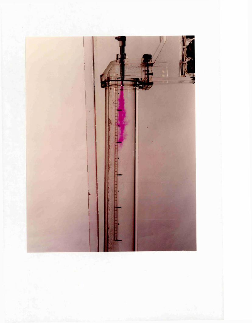

Plate 6.2 Simulation of the flame in the riser duct optimum auxiliary firing conditions of 30
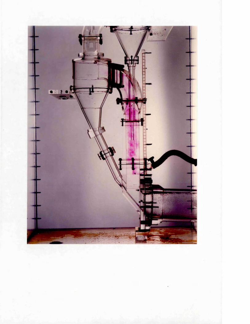

Plate 6.3 Simulation of the flame in the riser duct at 20% auxiliary firing conditions
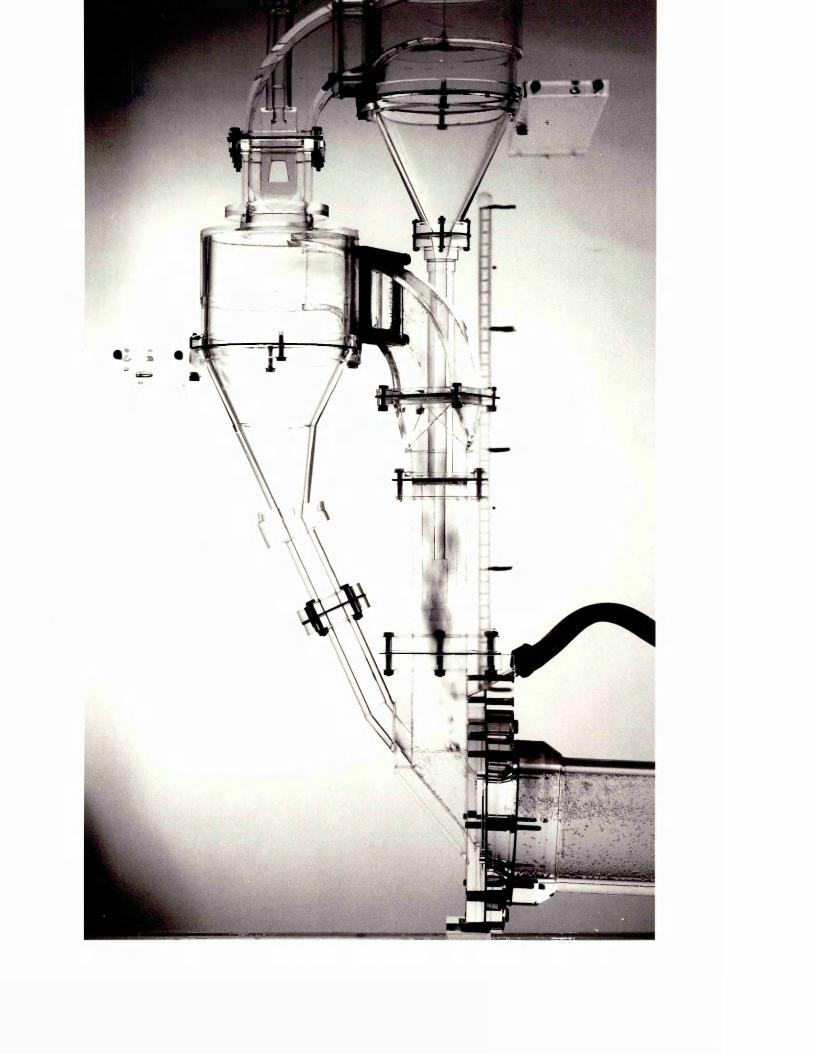

Plate 6.4 Simulation of the flame in the riser duct at 25% auxiliary firing conditions
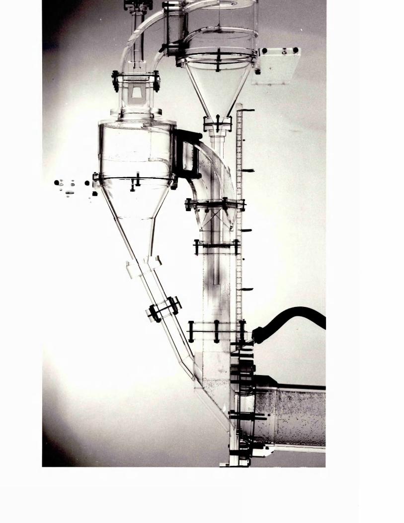

Plate 6.5 Simulation of the flame in the riser duct at 30% auxiliary firing conditions
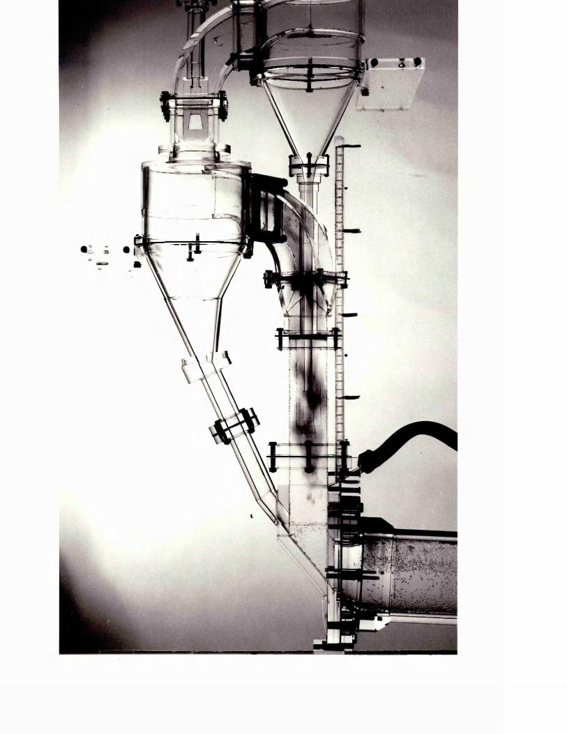

Plate 6.6 Simulation of the flame in the riser duct at 35% auxiliary firing conditions
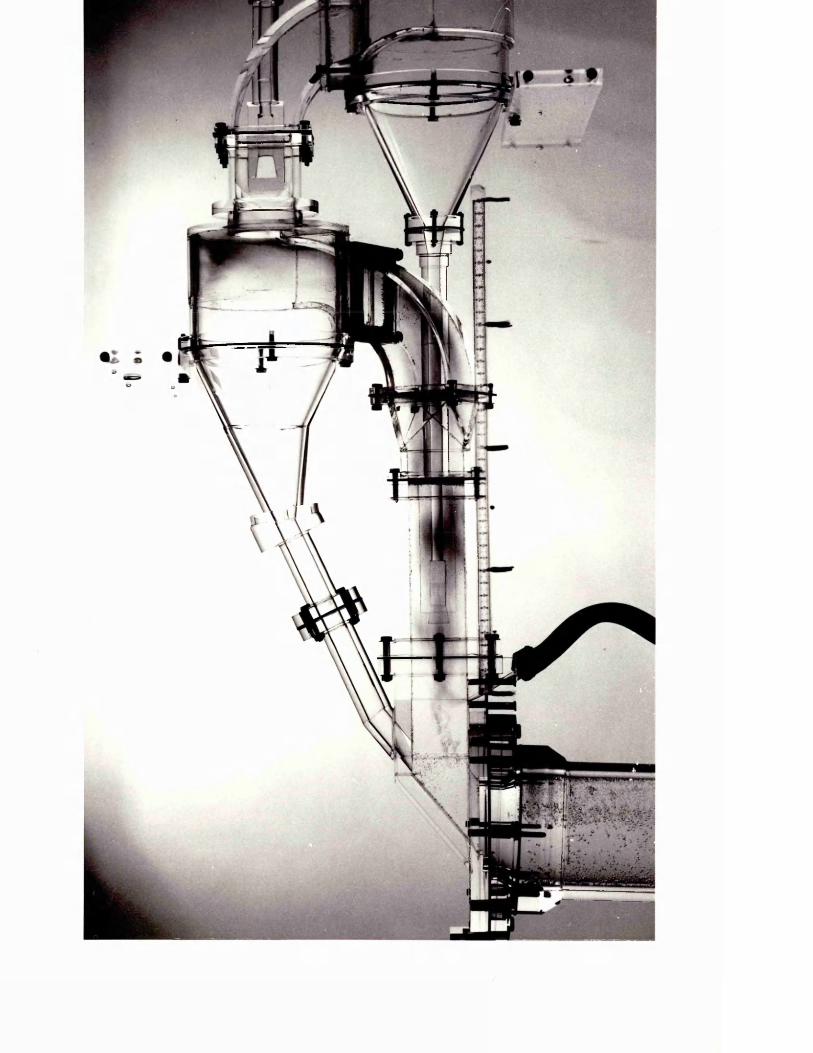
V -V*i
in Plates 6.3-6.6.
Effluent solution samples were tested for their pH values, any increase of pH value from the base value (pH of the effluent solution for 0% auxiliary firing), indicating degree of un- mixedness, therefore presence of CO in the exhaust gas in terms of kiln conditions.
6.2.2 Analysis of the results
Based on the readings taken from 40 video frames for each flame length separately, the mean for the flame length or height and the standard deviation were calculated. As already explained in section 6.1.2, these model measurements were converted into kiln terms by multiplying them with the geometric scale factor.In order to get the final value for the model predictions for the flame lengths, the effect of density differences between the nozzle plane, and the end of the flame had to be taken into account. Since previous analysis of the Barnstone model resultsrevealed that the fact< rather than proved to givemore accurate results, ..as accepted as the only and right
J -m
factor for density corrections of the model results.
The mean adiabatic temperatures for the main and the auxiliary flames were determined theoretically since no plant data were available in this case. For the main flame, the theoretical flame temperatures for each experimental condition of varying auxiliary firing proportion, which means increasing excess air level in air through secondary firing systems, were calculated and plotted against percentage excess air level for each case. From the graph, the variation of flame temperature
with excess air level was revealed.
Although theoretical flame temperatures can be calculated, these values are never obtained in the real kiln systems due to kiln shell losses and heat transfer to the charge. It has been established, however, that a new adiabatic flame temperature of 1600°C is common in most of the cement kiln (Jenkins, 1984). Based on this fact, the average flame temperature for the kiln's normal operating conditions was assumed to be 1600°C and for other conditions of high excess air levels (increasing secondary firing proportion) assumptions were made according to the relationship between the flame temperature and the excess air level,as in Figure A9.1. Using these average flame temperature values
Hrfand the calculated prototype operating conditions, M 7=— values1mfor each experimental condition were calculated and the flame length predictions were corrected for density differences (Appendix 11). The so determined flame lengths were plotted against the secondary firing heat input percentage, as shown in Figure 6.8.
For the auxiliary flame, almost the same procedure was followed. The assumptions for the mean adiabatic flame temperatures for each condition of different secondary firing proportion were based on the theoretical flame temperature calculations. The inlet chamber temperatures were based on the experimental data given by Herchenbach and Kupper (1976) for the secondary firing systems in four-stage cyclone preheaters. When calculating the values of T , it was found that the mass flow rate of the tertiary air was so little compared with the secondary mass flow rate, therefore it was neglected, resulting in the assumption of T^ ='T . The calculated density
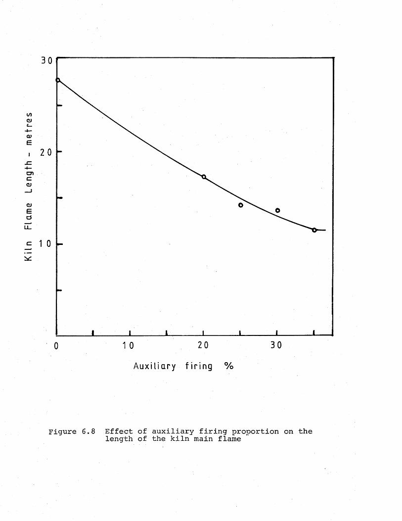
Kil
n Fl
ame
Leng
th
- m
etr
es
20
3020
Au x i l i a r y f i r i n g %
Figure 6.8 Effect of auxiliary firing proportion on the length of the kiln main flame
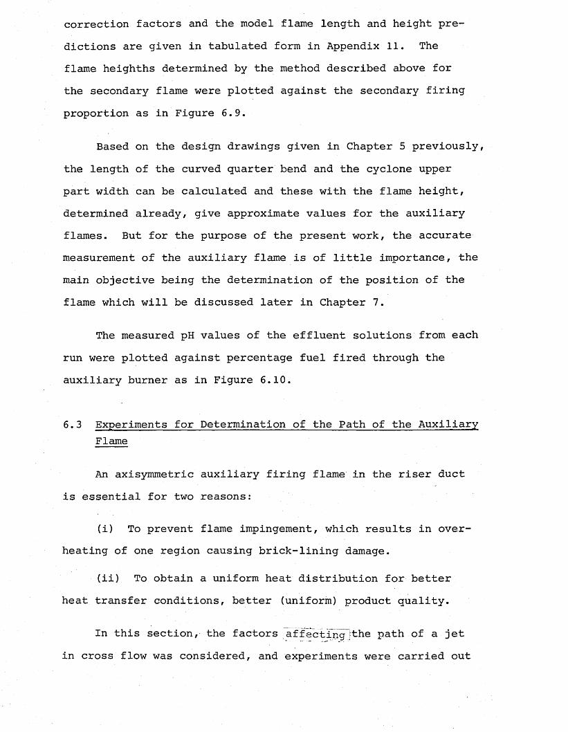
correction factors and the model flame length and height predictions are given in tabulated form in Appendix 11. The flame heighths determined by the method described above for the secondary flame were plotted against the secondary firing proportion as in Figure 6.9.
Based on the design drawings given in Chapter 5 previously, the length of the curved quarter bend and the cyclone upper part width can be calculated and these with the flame height, determined already, give approximate values for the auxiliary flames. But for the purpose of the present work, the accurate measurement of the auxiliary flame is of little importance, the main objective being the determination of the position of the flame which will be discussed later in Chapter 7.
The measured pH values of the effluent solutions from each run were plotted against percentage fuel fired through the auxiliary burner as in Figure 6.10.
6.3 Experiments for Determination of the Path of the AuxiliaryFlame
An axisymmetric auxiliary firing flame in the riser duct is essential for two reasons:
(i) To prevent flame impingement, which results in overheating of one region causing brick-lining damage.
(ii) To obtain a uniform heat distribution for better heat transfer conditions, better (uniform) product quality.
In this section, the factors affacting]the path of a jet in cross flow was considered, and experiments were carried out
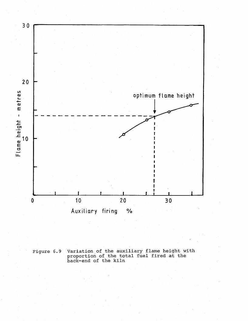
Flam
e he
ight
-
me
tre
s
20
optimum f l ame hei ght
0 10 20 30
Auxi l ia ry f ir ing %
Figure 6.9 Variation of the auxiliary flame height with proportion of the total fuel fired at the back-end of the kiln
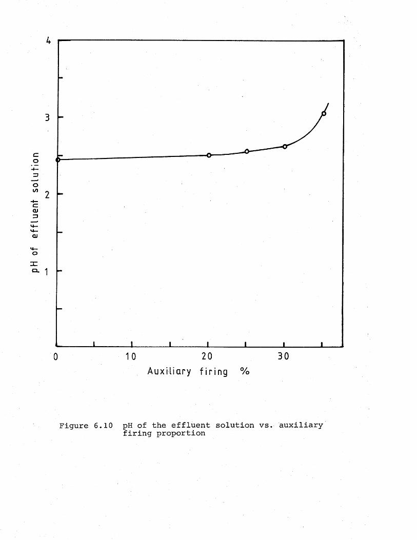
pH
of ef
flu
ent
solu
tio
n
3
20 3010
Au x i l i a r y f i r i n g %
Figure 6.10 pH of the effluent solution vs. auxiliary firing proportion
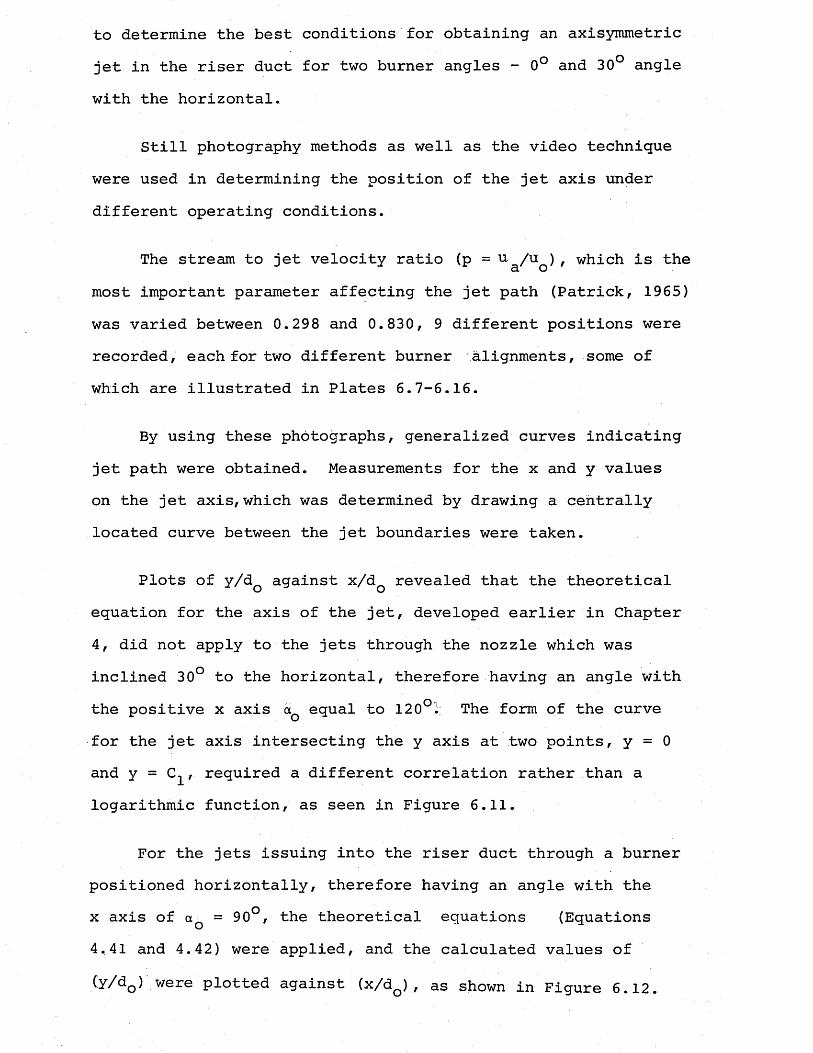
to determine the best conditions for obtaining an axisymmetric jet in the riser duct for two burner angles - 0° and 30° angle with the horizontal.
Still photography methods as well as the video technique were used in determining the position of the jet axis under different operating conditions.
The stream to jet velocity ratio (p = u. /u ), which is thea omost important parameter affecting the jet path (Patrick, 1965) was varied between 0.298 and 0.830, 9 different positions were recorded, each for two different burner alignments, some of which are illustrated in Plates 6.7-6.16.
By using these photographs, generalized curves indicating jet path were obtained. Measurements for the x and y values on the jet axis, which was determined by drawing a centrally located curve between the jet boundaries were taken.
Plots of y/dQ against x/dQ revealed that the theoretical equation for the axis of the jet, developed earlier in Chapter 4, did not apply to the jets through the nozzle which was inclined 30° to the horizontal, therefore having an angle with the positive x axis aQ equal to 120ol: The form of the curvefor the jet axis intersecting the y axis at two points, y = 0 and y = C^, required a different correlation rather than a logarithmic function, as seen in Figure 6.11.
For the jets issuing into the riser duct through a burner positioned horizontally, therefore having an angle with the x axis of aQ = 90°, the theoretical equations (Equations 4,41 and 4.42) were applied, and the calculated values of
(y/d0) were plotted against (x/dQ) , as shown in Figure 6.12.
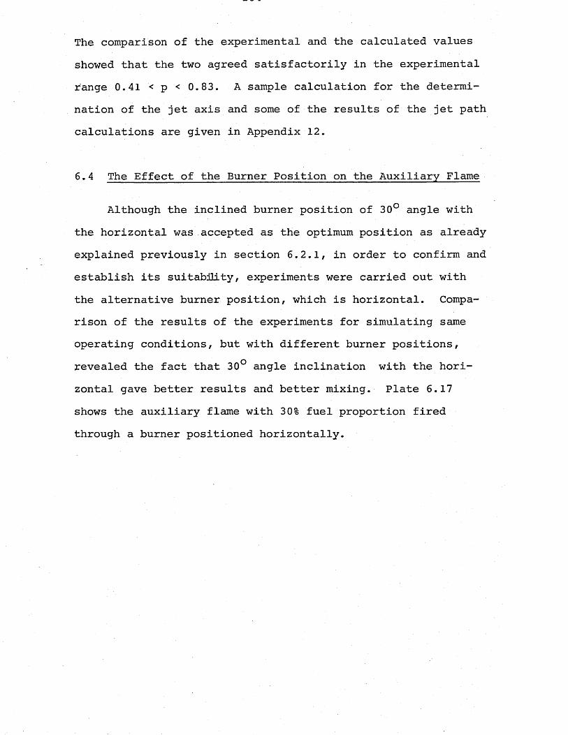
The comparison of the experimental and the calculated values showed that the two agreed satisfactorily in the experimental range 0.41 < p < 0.83. A sample calculation for the determination of the jet axis and some of the results of the jet path calculations are given in Appendix 12.
6.4 The Effect of the Burner Position on the Auxiliary Flame
Although the inclined burner position of 30° angle with the horizontal was accepted as the optimum position as already explained previously in section 6.2.1, in order to confirm and establish its suitability, experiments were carried out with the alternative burner position, which is horizontal. Comparison of the results of the experiments for simulating same operating conditions, but with different burner positions, revealed the fact that 30° angle inclination with the horizontal gave better results and better mixing. Plate 6.17 shows the auxiliary flame with 30% fuel proportion fired through a burner positioned horizontally.

Plate 6.7 Deflected jet path - p = 0.83
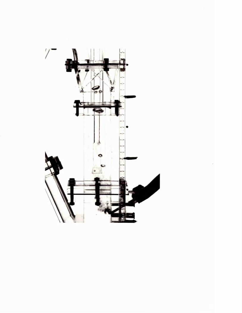

Plate 6.8 Deflected jet path - p =0.62
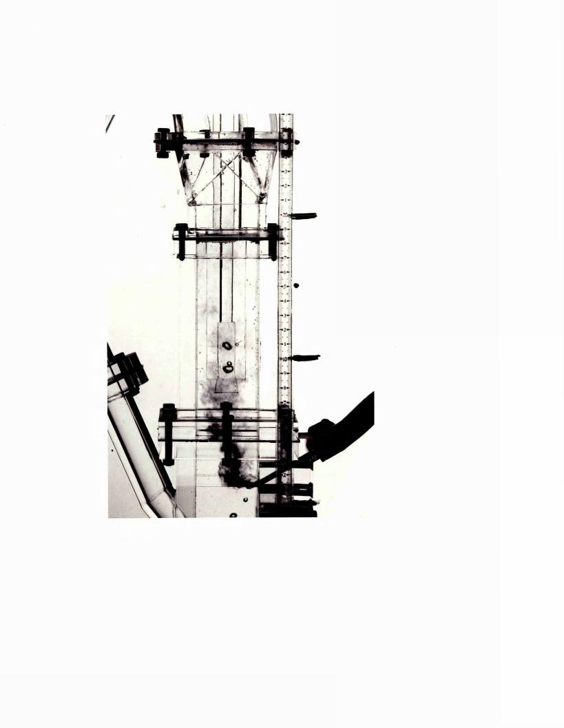

Plate 6.9 Deflected jet path - n =-0.49
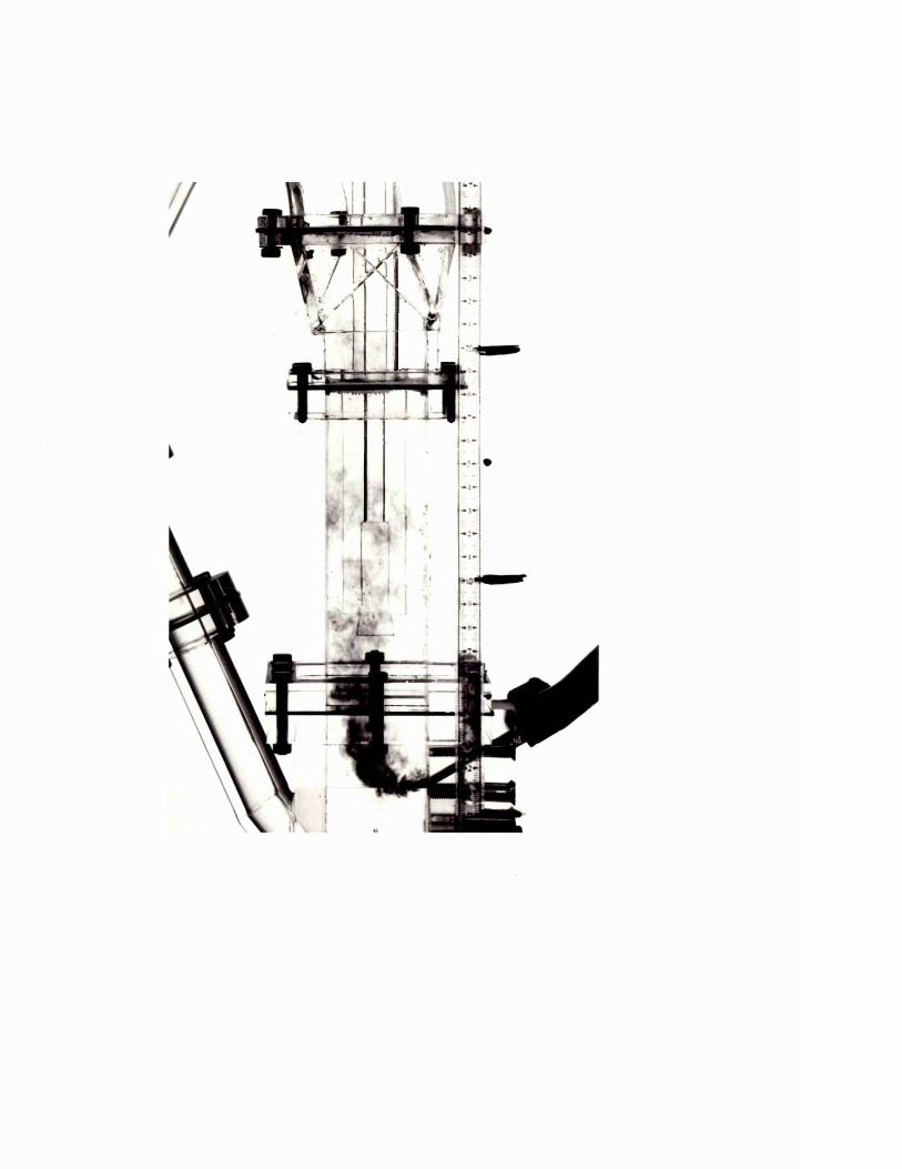

Plate 6.10 Deflected jet path - p - 0.31

Plate 6.11 Deflected jet path - p = 0.25

Plate 6.12 Deflected jet path - p = 0.83

Plate 6.13 Deflected jet path - p = 0.49

Plate 6.14 Deflected jet path - p = 0.41

Plate 6.15 Deflected jet path - p - 0.35

Plate 6.16 Deflected jet path - p = 0.25
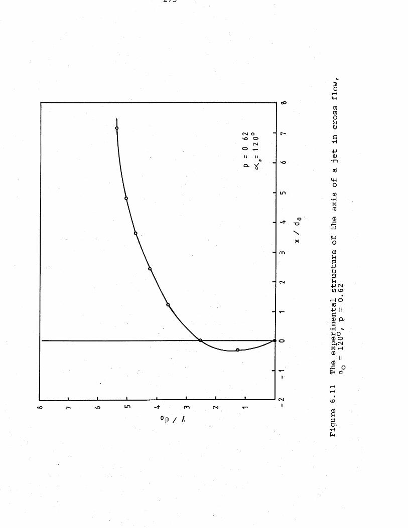
eO
<vj o so oOslo
m
Op / A
Figure
6.11
The experimental structure
of the
axis of
a jet
in cross
flow
on =
120°,
p =
0.62
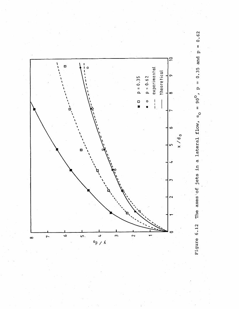
o
LOm CJooQ . CL GO
om CMLO .CO°p/ X
Figure
6.12
The
axes'of
jets in
a lateral
flow,
a =
90°, p
= 0.35
and
p =
0.62

Plate 6.17 30% auxiliary firing through a horizontal burner
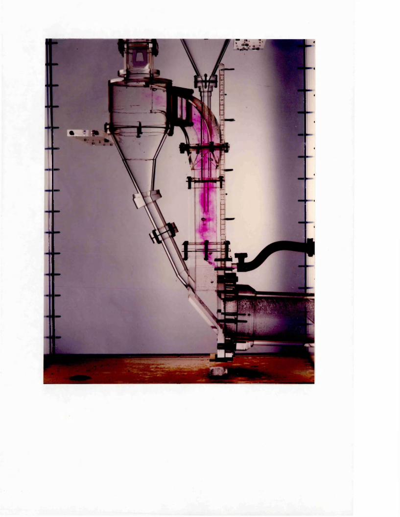
CHAPTER 7
DISCUSSION OF THE RESULTS
7.1 Discussion of the Preliminary Results
7.1.1 Effect of varying kiln conditions on the flame length
The experiments have shown that the acid/alkali technique is capable of predicting the changes in flame length brought about by varying the kiln operating conditions.
The acid/alkali model gave very good visual simulation of the flame providing qualitative results regarding the shape and the position of the flame as well as its dependence on the input operating conditions.
The quantitative results were also obtained by scaling up the model readings to kiln dimensions and introducing the correction factor for density differences in the prototype, as explained earlier in Chapter 6.
The model predictions for the flame length plotted against simulated kiln back-end oxygen concentration values for a constant level of primary air has been shown in Figure 6.1.The figure reveals how the flame length in a rotary kiln is affected by the changes in the oxygen concentration of the back-end gases. At low values of back-end oxygen, the flame gets increasingly longer becoming infinitely long at stoichiometric conditions. At high levels of back-end oxygen, the flame gets shorter, tending to a minimum value which is dependent upon the nozzle diameter and the primary air level. The same behaviour would be observed if the flame length were
to be plotted against the excess air due to the constant relationship between the excess air and the back-end oxygen concentration (Moles, Lain and Shaw, 1974):
B.E.O.% = 0.174 x Excess Air %
The level of back-end oxygen has to be kept at an optimum value since too high levels will result in exhaust gas heat losses, whereas too low levels will result in fuel waste due to incomplete combustion.
The flame lengths obtained by using different sized nozzles were plotted against the nozzle diameter for different excess air levels as in Figure 6.2. Of the four nozzles tested, the results for the three of them, representing the nozzles with the diameters 0.165 m, 0.195 m and 0.241 m, agreed with the results of the kiln trials. As the nozzle diameter is decreased, so the jet velocity increases. The flame length initially becomes shorter, then rapidly increases in length after passing through a minimum value. This behaviour though was not shown by the model experiments. Although the flame length increased with increasing nozzle diameter for those three sizes mentioned, as expected, the behaviour with the smallest nozzle diameter (simulation of 0.1524 m diameter) was different, giving an even shorter flame. This disagreement is indicated on the graph by use of dotted lines, and it was thought to be due to the combustion process being chemically controlled in this region.It has already been established that at low nozzle velocities the combustion process is mixing controlled, whereas, as the velocity increases, the regime passes from being mixing controlled to being chemically controlled. When the regime is chemically
controlled, it cannot be represented by the mixing controlled acid/alkali neutralization reaction, and the modelling technique becomes inapplicable for the operating conditions in this regime.
The effect of the primary air level on the flame length .. is not very significant compared to other factors, like excess air and nozzle diameter. Figure 6.3 shows that flame length decreases slightly with increasing primary air level for a given excess air level. This decrease is to be expected, since with increasing primary air level, there is less secondary air to be mixed with the jet before combustion is complete.
7.1.2 Comparison of the model predictions with the kiln measure-* ments and the theoretical flame lengths
The flame lengths measured from the video recordings taken during the model runs were converted into kiln terms by multiplying with the geometric scale factor. Although the dependence of the so-determined model flame length upon the input variables of the simulated kiln operation was found to be the same as that determined on the real kiln flame, the values of the model flame measurements converted to kiln terms showed a constant difference from the flame lengths measured in the real kiln system, and from the flame lengths calculated by using the Barnstone equation developed by Moles, Lain and Shaw (1974). As already mentioned, this.difference was imputable to the temperature differences occurring in the real kiln, caused by the combustion and the development of the heat from it. Two different factors to take into account the temperature differences occurring between the primary air plus coal and secondary air at the entrance of the kiln and the exit gas at the end of the flame were defined
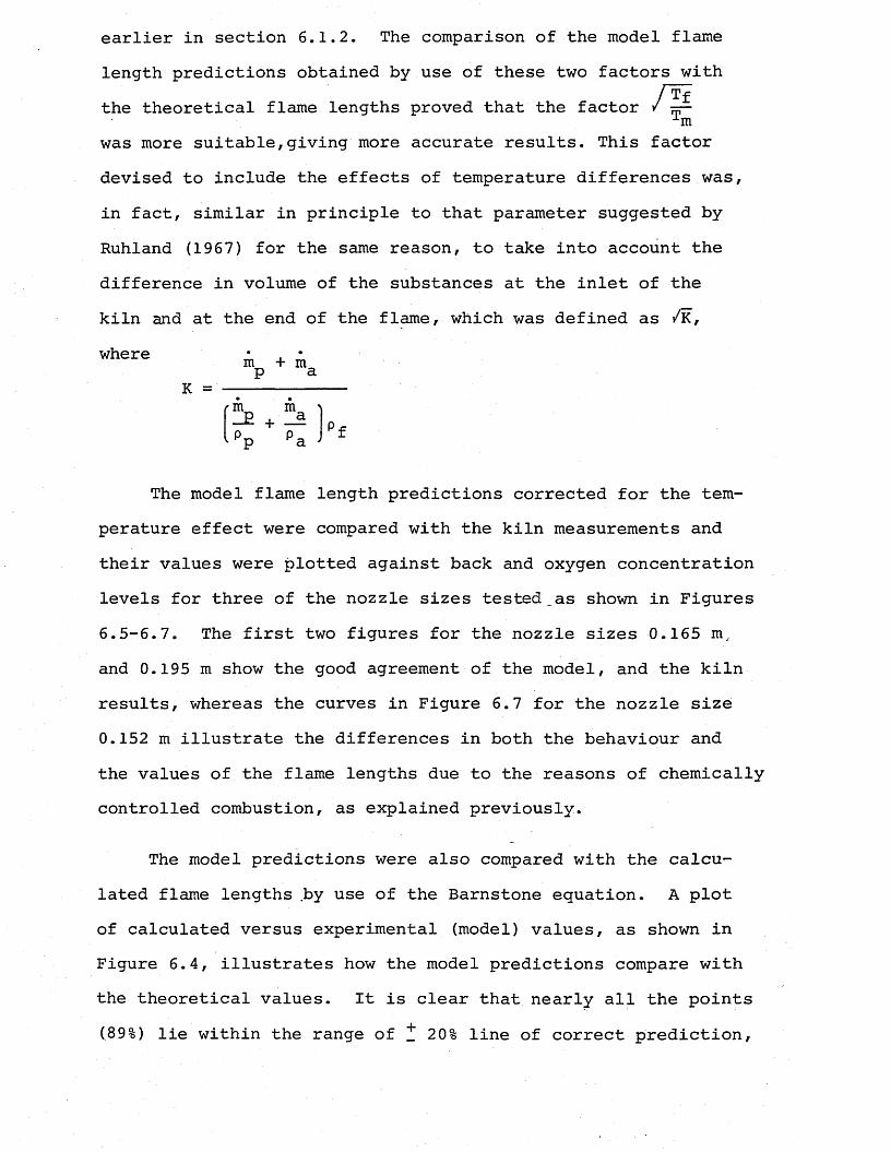
earlier in section 6.1.2. The comparison of the model flame length predictions obtained by use of these two factors withthe theoretical flame lengths proved that the factor 1mwas more suitable,giving more accurate results. This factor devised to include the effects of temperature differences was, in fact, similar in principle to that parameter suggested by Ruhland (1967) for the same reason, to take into account the difference in volume of the substances at the inlet of the kiln and at the end of the flame, which was defined as /K,
The model flame length predictions corrected for the temperature effect were compared with the kiln measurements and their values were plotted against back and oxygen concentration levels for three of the nozzle sizes tested_as shown in Figures 6.5-6.7. The first two figures for the nozzle sizes 0.165 m, and 0.195 m show the good agreement of the model, and the kiln results, whereas the curves in Figure 6.7 for the nozzle size 0.152 m illustrate the differences in both the behaviour and the values of the flame lengths due to the reasons of chemically controlled combustion, as explained previously.
The model predictions were also compared with the calculated flame lengths by use of the Barnstone equation. A plot of calculated versus experimental (model) values, as shown in Figure 6.4, illustrates how the model predictions compare with the theoretical values. It is clear that nearly all the points (89%) lie within the range of ^ 20% line of correct prediction,
whereK
confirming the ability of the acid/alkali mixing technique to simulate the effect on flame length of varying kiln operating conditions with accuracy.
A probable explanation for the 20% error in the model predictions is the inaccuracy in monitoring the flow rates of the acid and alkali. Although the flame lengths were corrected for the excess air levels based on the results of the effluent solution analysis, at the end of each run, this method included the use of the graphs drawn from the results of the experiments which possibly included errors. Therefore it is necessary to find a method of controlling the acid and alkali flow rates during the runs accurately in order to improve the model results.
7.2 Discussion of the Suspension Preheater Model Results
In the application of the secondary firing systems in the riser duct of the four-stage cyclone preheaters with the combustion air passed through the kiln, the following considerations should be taken into account for achieving the optimum operating conditions:
1) Having in mind that the retention time of the raw material particle in a four-stage cyclone preheater of about 50 metres height from the material feed point down to the rotary kiln entrance is approximately 25 seconds (Duda, 1977) and it takes 1-4 seconds for about 90% calcination of the material at temperatures of 900°-i000°C (Steinbiss, 1979), the calcining region in the preheater should be limited to the lowest stage cyclone. The reaction time for complete
calcination of the raw meal at these temperatures is in the range of about 2 to 12 seconds, and it is desirable to avoid complete calcination, for in that case the temperature of the feed material would undergo an abrupt rise already before entry into the kiln and would cause objectionable deposits to form in the calciner.
It has also to be noted that 80% of the heat transfer occurs during the coflowing of the gas and the particles in the riser ducts of the cyclones,and the main function of the cyclones is to separate gas and solid particles at each stage.
Therefore, the best place to apply additional heat input in the preheater system, which would provide the minimum residence time at higher temperatures obtained and also favourable heat transfer conditions , is the riser duct of the kiln, between the fourth and the third stage cyclone dust lines.The length of the combustion zone should be limited only to the entrance of the fourth stage cyclone upper part in order to avoid any temperature increases at the upper stages, which might cause calcination of the raw material to proceed and be completed before entry to the kiln due to longer residence times.
2) Increasing the proportion of the heat input to the preheater will result in increasing carbon monoxide concentrations in the exhaust gas due to the limited combustion distance for the fuel indicating fuel wastage. The length of the burning zone and the amount of fuel fired in the preheater should be limited to avoid CO losses in the exit gas.By increasing the excess air level, the incomplete combustion
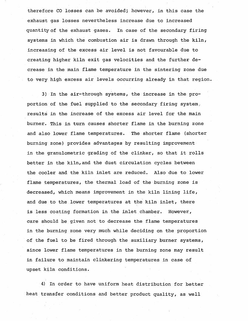
therefore CO losses can be avoided; however, in this case the exhaust gas losses nevertheless increase due to increased quantity of the exhaust gases. In case of the secondary firing systems in which the combustion air is drawn through the kiln, increasing of the excess air level is not favourable due to creating higher kiln exit gas velocities and the further decrease in the main flame temperature in the sintering zone due to very high excess air levels occurring already in that region.
3) In the air-through systems, the increase in the proportion of the fuel supplied to the secondary firing system, results in the increase of the excess air level for the main burner. This in turn causes shorter flame in the burning zone and also lower flame temperatures. The shorter flame (shorter burning zone) provides advantages by resulting improvementin the granulometric grading of the clinker, so that it rolls better in the kiln,and the dust circulation cycles between the cooler and the kiln inlet are reduced. Also due to lower flame temperatures, the thermal load of the burning zone is decreased, which means improvement in the kiln lining life, and due to the lower temperatures at the kiln inlet, there is less coating formation in the inlet chamber. However, care should be given not to decrease the flame temperatures in the burning zone very much while deciding on the proportion of the fuel to be fired through the auxiliary burner systems, since lower flame temperatures in the burning zone may result in failure to maintain clinkering temperatures in case of upset kiln conditions.
4) In order to have uniform heat distribution for better heat transfer conditions and better product quality, as well
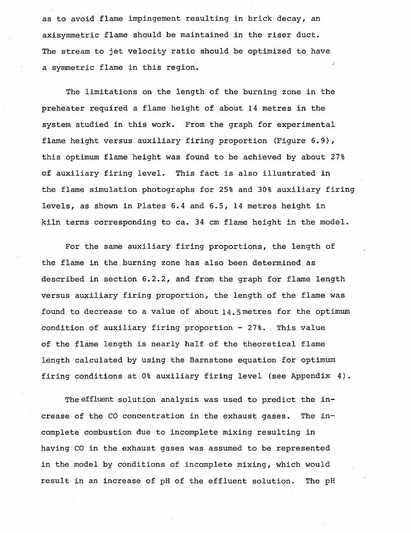
as to avoid flame impingement resulting in brick decay, an axisymmetric flame should be maintained in the riser duct.The stream to jet velocity ratio should be optimized to have a symmetric flame in this region.
The limitations on the length of the burning zone in the preheater required a flame height of about 14 metres in the system studied in this work. From the graph for experimental flame height versus auxiliary firing proportion (Figure 6.9), this optimum flame height was found to be achieved by about 27% of auxiliary firing level. This fact is also illustrated in the flame simulation photographs for 25% and 30% auxiliary firing levels, as shown in Plates 6.4 and 6.5, 14 metres height in kiln terms corresponding to ca. 34 cm flame height in the model.
For the same auxiliary firing proportions, the length of the flame in the burning zone has also been determined as described in section 6.2.2, and from the graph for flame length versus auxiliary firing proportion, the length of the flame was found to decrease to a value of about 14.5 metres for the optimum condition of auxiliary firing proportion - 27%. This value of the flame length is nearly half of the theoretical flame length calculated by using the Barnstone equation for optimum firing conditions at 0% auxiliary firing level (see Appendix 4).
The effluent solution analysis was used to predict the increase of the CO concentration in the exhaust gases. The incomplete combustion due to incomplete mixing resulting in having CO in the exhaust gases was assumed to be represented in the model by conditions of incomplete mixing, which would result in an increase of pH of the effluent solution. The pH
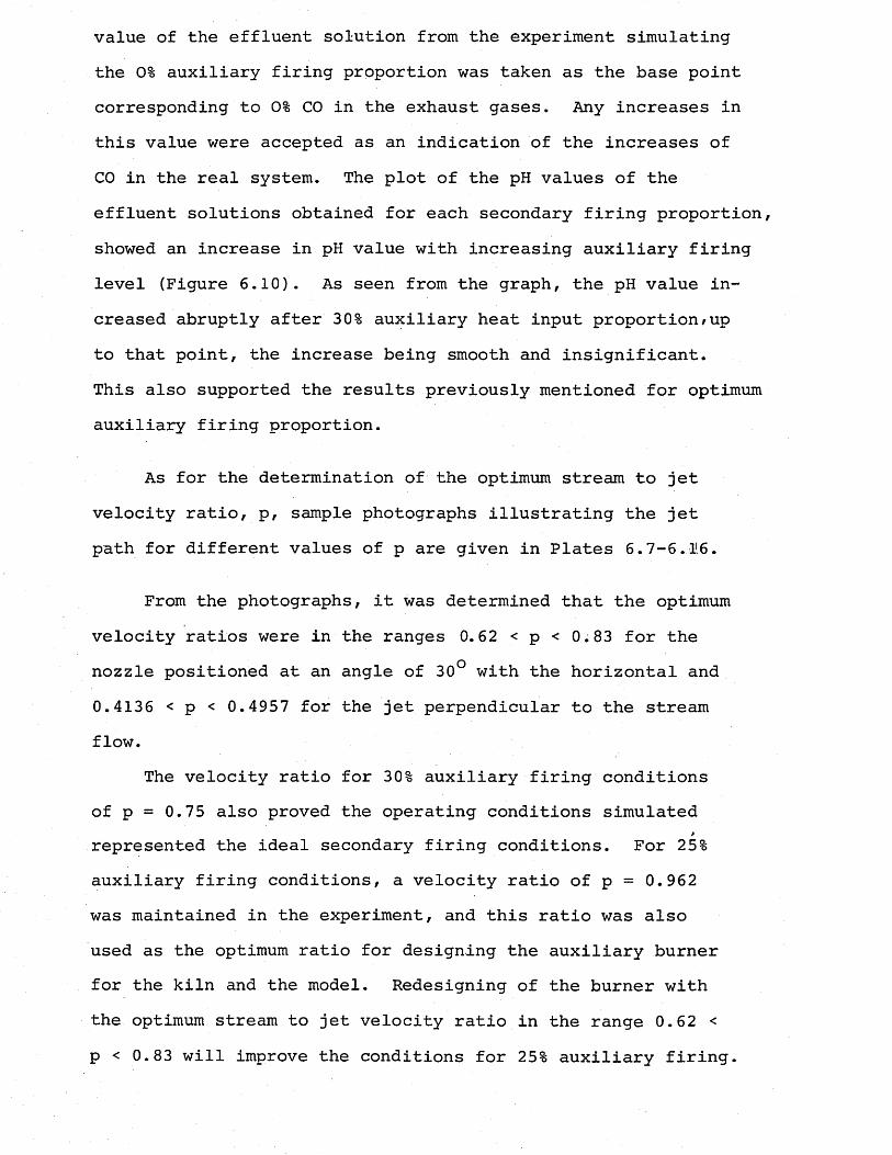
value of the effluent solution from the experiment simulating the 0% auxiliary firing proportion was taken as the base point corresponding to 0% CO in the exhaust gases. Any increases in this value were accepted as an indication of the increases of CO in the real system. The plot of the pH values of the effluent solutions obtained for each secondary firing proportion, showed an increase in pH value with increasing auxiliary firing level (Figure 6.10). As seen from the graph, the pH value increased abruptly after 30% auxiliary heat input proportion/up to that point, the increase being smooth and insignificant.This also supported the results previously mentioned for optimum auxiliary firing proportion.
As for the determination of the optimum stream to jet velocity ratio, p, sample photographs illustrating the jet path for different values of p are given in Plates 6.7-6..116.
From the photographs, it was determined that the optimum velocity ratios were in the ranges 0.62 < p < 0.83 for the nozzle positioned at an angle of 30° with the horizontal and0.4136 < p < 0.4957 for the jet perpendicular to the stream flow.
The velocity ratio for 30% auxiliary firing conditions of p = 0.75 also proved the operating conditions simulated represented the ideal secondary firing conditions. For 25% auxiliary firing conditions, a velocity ratio of p = 0.962 was maintained in the experiment, and this ratio was also used as the optimum ratio for designing the auxiliary burner for the kiln and the model. Redesigning of the burner with the optimum stream to jet velocity ratio in the range 0.62 < p < 0.83 will improve the conditions for 25% auxiliary firing.
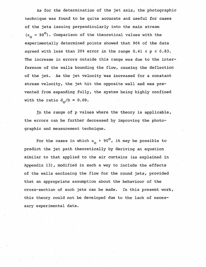
As for the determination of the jet axis, the photographic technique was found to be quite accurate and useful for cases of the jets issuing perpendicularly into the main stream (aQ = 90°). Comparison of the theoretical values with the experimentally determined points showed that 90% of the data agreed with less than 20% error <in the range 0.41 < p < 0.83. The increase in errors outside this range was due to the interference of the walls bounding the flow, causing the deflection of the jet. As the jet velocity was increased for a constant stream velocity, the jet hit the opposite wall and was prevented from expanding fully, the system being highly confined with the ratio dQ/D =0.09.
In the range of p values where the theory is applicable, the errors can be further decreased by improving the photographic and measurement technique.
For the cases in which aQ > 90°, it may be possible to predict the jet path theoretically by deriving an equation similar to that applied to the air curtains (as explained in Appendix 13), modified in such a way to include the effects of the walls enclosing the flow for the round jets, provided that an appropriate assumption about the behaviour of the cross-section of such jets can be made. In this present work, this theory could not be developed due to the lack of necessary experimental data.
For this part of the experiments, due to having two sources of alkali (two jets) in the system with different normalities, the control of the flow rates by use of the effluent solution titration was not possible. However, in order to minimize.the errors caused by the inaccurate flow monitoring extra care was paid to avoid any fluctuations in the rotameter readings and the measuring of the pH of the effluent solution during the runs gave a rough idea about the accuracy of the flows.
Finally, the comparison of the results of the experiments simulating 30% auxiliary firing conditions with two different burner conditions (0° and 30° angle with the horizontal) supported the choice of the inclined" burner position rather than horizontal. Higher effluent pH values obtained with the horizontal burner indicated poorer mixing.
CHAPTER 8
CONCLUSIONS AND RECOMMENDATIONSFOR FURTHER WORK
1. It has been confirmed that the acid/alkali modellingtechnique can be successfully used to predict the flame behaviour, the change of flame length as a result of changes in the kiln input variables like excess air, nozzle diameter and primary air percentage and to obtain quantitative results regarding the length of the flame.
2. The flame lengths in a rotary kiln can be directly predicted by use of simple, chea£), quick modelling techniques, such that:
3. As excess air increases from zero to infinity, the flame length decreases smoothly from infinity to a minimum value. The excess air level is the most important variable in controlling a kiln flame.
4. As the nozzle diameter is increased in size, the flame length decreases rapidly initially, and then slowly increases again. The nozzle diameter (or the jet velocity) is the second important factor influencing the flame length in a rotary kiln.
5. As the primary air increases, the flame length decreases. The effect is not very important.
6. Agreement of the model results with the calculated values obtained from.the Barnstone Equation reconfirms the
model (measured) xm
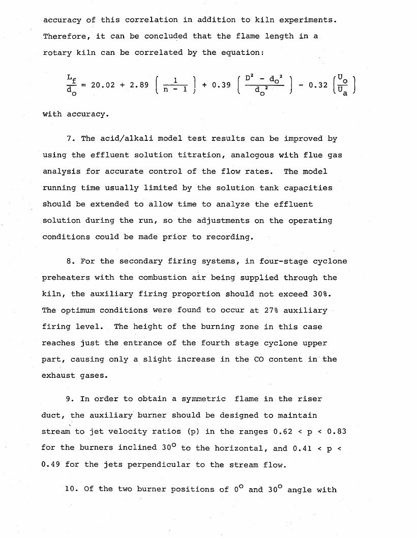
accuracy of this correlation in addition to kiln experiments. Therefore, it can be concluded that the flame length in a rotary kiln can be correlated by the equation:
Lf = 20.02 + 2.89do
"-■-1 , I + 0.39 n - 1 ,f D! - do - 0.32 V_o
ua
with accuracy.
7. The acid/alkali model test results can be improved by using the effluent solution titration, analogous with flue gas analysis for accurate control of the flow rates. The model running time usually limited by the solution tank capacities should be extended to allow time to analyze the effluent solution during the run, so the adjustments on the operating conditions could be made prior to recording.
8. For the secondary firing systems, in four-stage cyclone preheaters with the combustion air being supplied through the kiln, the auxiliary firing proportion should not exceed 30%.The optimum conditions were found to occur at 27% auxiliary firing level. The height of the burning zone in this case reaches just the entrance of the fourth stage cyclone upper part, causing only a slight increase in the CO content in the exhaust gases.
9. In order to obtain a symmetric flame in the riser duct, the auxiliary burner should be designed to maintain stream to jet velocity ratios (p) in the ranges 0.62 < p < 0.83 for the burners inclined 30° to the horizontal, and 0.41 < p < 0.49 for the jets perpendicular to the stream flow.
10. Of the two burner positions of 0° and 30° angle with
the horizontal, the inclined position proved to be better due to better mixing achieved.
For future work, various design modifications on the suspension preheater including the extension of the riser duct, an addition of a separate calciner section in the preheater can be made in order to improve the secondary firing conditions with due regard to the increase of the proportion of the fuel input to be supplied in the riser duct or the calciner.
The acid/alkali technique can be employed in studying the mixing conditions in the systems with a separate air ducting for supplying combustion air for the secondary firing system, either from the cooler or from the kiln hood. Mixing patterns of the tertiary air, fuel and the kiln exit gases can be observed by acid alkali flow visualization technique, and the effect of kiln operating conditions on the mixing of these streams can be investigated in order to determine the optimum conditions.
Unfortunately, the second part of the work on the suspension preheater kiln model lacks comparison with the kiln measurements. If given the opportunity, carrying out plant trials for the same objectives as in the model experiments, will prove to be very useful both in improving the model results as well as confirming them.

NOMENCLATURE
Due to the variety of sources for the theories and equations each involving a different symbolling system used in this work, symbols are defined separately as they appeared in the text. Therefore a separate list of nomenclature will not be added.
REFERENCES
ABRAMOVICH, G.N.Teoriia turbulentnih strui(Gossud. Izdat, fiz-mat. lit, Moskua, 1960) .
ABRAMOVICH, G.N.Turbulent theory of jets (Trans, from Russian)(M.I.T. Press: Camb., Mass., 1963).
AnonymousDikey Gaz Kanalinda Komur ve fuel-oil yakilmasi (Coal and oil firing in the riser duct)Translation from a correspondence between F.L. Smidth Co. and Nuh Cement (Turkey) 2 February 1980.
ANSON, D.Modelling experience with large boilers.Journal of the Institute of Fuel, 40, 20-25, 1967.
BARCHILON, M. and CURTET, R.Some details of the structure of an axisymmetric confined jet with backflow.Transactions of the ASME, Journal of Basic Engineering. 86D, 777-787, Dec. 1964.
BECKER, H.A.Discussion on a theoretical model for non-separated mixing of a confined jet by E. Rzinsky and J.A. Brighton.Trans. Amer. Soc. Mech. Engrs., 94. 556-557, 1972.
BECKER, H.A., HOTTEL, H.C. and WILLIAMS, G.C.Mixing and flow in ducted turbulent jets.9th Symposium on Combustion, 7-20.(Academic Press: Cornell University, New York, 1962).
BEER, J.M.Combustion aerodynamics and burner design.Furnace and Boiler Design Symposium, Inst, of Chem. Engrs.Salford, January 1976.
BEER, J.M.The significance of modelling.Third Symposium on Flames and Industry(British Flame Research Committee and the Institute of Fuel, London, 1966)also:Journal of Institute of Fuel, 39, 466-473, 1966.
BEER, J.M., CHIGIER, N .A. and LEE, K.B.Modelling of double concentric burning jets.9th Symposium on Combustion, 892-900.(Academic Press:New York, 1962).
BERRY, R.I.Cement: Building a new future.Chemical Engineering, 33-35, May 7, 1979.
BIANCA, J.D., PAUVER, W.P. and McGOWAN, J.G.Flow modelling of an atmospheric pressure, entrained type coal gasifier.ASME Meeting(San Francisco, 10-15 Dec. 1978) also:Fluids Engineering in Advanced Energy Systems, p.16 7(G.H. Martson General Electric Company: Philadelphia, 1978).
BOMKE, E.25 years of suspension preheaters for cement raw meal. Zement-Kalk-Gips, 31, 589-594, 1978.
CHEDAILLE, J., LEUCKEL, W. and CHESTERS, A.K.Aerodynamic studies carried out on turbulent jets by the International Flame Research Foundation.Third Symposium on Flames and Industry(Inst, of Fuel, London, 19 Oct., 1966).also:Journal of Institute of Fuel, 39, 506-521, 1966.
CHERADAME, R.The aerodynamics of flames.Energy from Fuels New Development from Fuel Technology Proceedings(North American Fuel Technology Conference, Ottawa, May 31- June 3, 1970) .
CHESTERS, J.H.The flow pattern factor in fuel research.University of Sheffield Fuel SocJournal, 5, 24-29, 1954.
CHIGIER, N.A.Application of model results to design of industrial flames,Paper 1,Fourth Symposium on Flames and Industry(Institute of Fuel, London,. 19-20 September, 1972).also:Journal of Institute of Fuel, 46, 271-278, 1973.
CHIGIER, N.A. and BEER, J.M.The flow region near the nozzle in double concentric jets.Transactions of the ASME, Journal of Basic Engineering, 86D (J), 797-804, 1964.
CLARKE, A.E., GERRARD, A.J. and HOLLIDAY, L.A.Some experience in gas turbine combustion chamber practice using water flow visualization techniques.9th Symposium on Combustion, pp 878-891.(Academic Press, New York, 19 62).
COSTEN, P.G.The Aerodynamics of Auxiliary Firing of Semi-Dry Process Cement Kilns, Ph.D. Thesis.(University of Surrey, Guildford, 1983).
COULSON, J.M. and RICHARDSON, J.F.Chemical Engineering, Vol. 1, 2nd Edition.(Pergamon Press, London, 1965).
CRAYA, A. and CURTET, K.Sur 1'evolution d'un jet en espace confine (On the spread of a confined jet)Comptes Rendus Acad, des Sci., 241. 621-624, 1955.
CURTET, R. and RICOU, F.P.On the tendency to self-preservation in axisymmetric ducted j ets.Transactions of the ASME, Journal of Basic Engineering, 86D, 765-776, 1964 Dec.
CURTIS, R.W. and JOHNSON, L.E.Use of flow models for boiler-furnace design.Journal of Engineering for Power, 81, 371-377, 1959.
DANNENBRICK, W.C., KOHANOWSKI, F.I., HESS, P.O. and LOSIN, E.T.Coal properties and their effect on performance of preheater- kiln system.VDZ Kongress '77, Supplementary paper subject 3 (Dusseldorf, 27.30.9.1977)also:Zement-Kalk-Gips, 30, 618-619, 1977.
DANOWSKI, W. and KIESER, J.Alkali cycles in dry-process cement plants with secondary firing. Zement-Kalk-Gips, 33, 303-305, 1980.
DAVIES, R.M., LUCAS, D.M., MOPPETT, B.E. and GALSWORTHY, R.A. Isothermal model studies of rapid heating furnaces.Journal of the Institute of Fuel, 44, 453-461, 1971.
DAVISON, F.J.Nozzle scaling in isothermal furnace models.Journal of the Institute of Fuel, 41, 470-475, 1968.
DONALD, M.B. and SINGER, H.Entrainment in turbulent fluid jets.Transactions of the Institution of Chemical Engineers, 37, 255-267, 1959.
DUDA, W.H.Cement Data Book(Bauverlag GmbH: Wiesbaden & Berlin, Macdonald & Evans. London, 1977).
EMSBOt J.Smaller cyclone preheaters.LGS. Proceedings, 84-88.(Rock Products, Chicago, Illinois, 1981).
ENKEGAARD, T.How to boost fuel efficiencies, reduce costs. Opportunities lie in clinker coolers and grinding, cyclones, low grade fuels, and materials handling.Rock Products, 85 , 99-112, 1982.
ESSENHIGH, R.H.Predicted burning times of solid particles in an idealized dust flame.Journal of the Institute of Fuel, 34, 239-244, 1961.
EVANS, D.G. and PATRICK, M.A.The use of modelling studies in boiler furnace investigations. Journal of the Institute of Fuel, 39, 414-421, 1966.
FALLOWS, R.G.Visible indication of compositions in model studies of fluid mixin Trans. Instn. Chem. Engrs., 44., T158-T159, 1966.
FRANKE, F.H. and GROSSE DALDRUP, H.Pulverized lignite - source of energy for the cement industry. Zement-Kalk-Gips, 31, 523-525, 1978.
FRICKER, N., PAGE, M.W. and CHEW, J.W.Combustion and heat transfer in reverberatory glass melting , furnaces.International Flame Research Foundation, (Noordwijkerhout,Holland, May 1978)also:British Gas Report MRS E 345
FRISCH, V., JESCHAR, R. and GARDEIK, H.O.Effect of fuel burnout on the operation of the cement rotary kiln with precalcining.Zement-Kalk-Gips, 35, H.5, 256-259, 1982.
FRISCH, V., JESCHAR, R. and GARDEIK, H.O.Precalcining with and without a tertiary air duct - a heat technological comparison with the aid of a mathematical model for energy transfer in the rotary kiln.Zement-Kalk-Gips, 35, 58-65, 1982.
FUKUDA, Y. and UEDA, Y.Pulverized coal combustion successfully used in RSP system. World Cement Technology, l£,pp 238-247 , 1979.
FURNAS, C.C.The rate of calcination of Limestone.Industrial and Engineering Chemistry, 23, 534-538, 1931.
GARDEIK, H.O.Fuel energy consumption in cement burning with precalcining. Zement-Kalk-Gips, 34, H.12, 611-617, 1981.
GARDEIK, H.O. and ROSEMANN, H.Fuel energy consumption and fuel energy aportionment in the: precalcining process. Results of a balance model.Zement-Kalk-Gips, 34, 435-444, 1981.
GARRETT, H.Coal and the US cement industry, Part 1.World Cement Technology, 13, 18-25, 1982.
G.E.F.G.N. Fiche Technique No. 1.Revue Generale de Thermique, 12, 57-59, 1973.
G.E.F.G.N. Fiche Technique No. 7.Revue Generale de Thermique, 13, 537-542, 1974.
GERSTNER, B., SCHLEGEL, R. and SCHWERDTFEGER, I.Calcining by means of secondary firing in the ZAB preheater.Zement-Kalk-Gips, 32, 222-226, 5/1979.
GHESTEM, G. and HERRIQUET, P.The Fives-Cail Babcock approach to precalcining.Preheaters with Precalciner-type E.V.S.-P.C. (Advertising Document, Fives-Cail Babcock).
GRAY, F.A. and ROBERTSON, A.D.The investigation of fluid flow problems by model techniques. Journal of Institute of Fuel, 29, 428-437, 1956.
GRECOV, D. and GUTU-DAMACEANU, E.St. Cere. Energ. Elect., 16, 3, 1966.
GROUME-GRJIMAILO, W.E.The Flow of Gases in Furnaces.(Chapman and Hall:London, 1923).
GUMZ, W.Kurzes Handbuch der Brennstoff- und Feuerungstechnik. (Springer-Verlag: Berlin, Gottingen, Heidelberg, 1953) .
HASTRUP, N.E.Suspension calcining in the calciner and in the kiln inlet. Zement-Kaik-Gips, 29, H.5, 202-206, 1976.
HAWTHORNE, W.R.The Mixing of Gas and Air in Flames, Sc.D. Thesis.(M.I.T., Cambridge, Mass., 1939).
HAWTHORNE, W.R., ROGERS, G.F. and ZACZEK, D.Y.Mixing of gas streams - the penetration of a jet of cold air into a hot stream.Technical Note Eng. 271.(Royal Aircraft Establishment, 1944).
HAWTHORNE, W.R., WEDDELL, D.S. and HOTTEL, H.C.Mixing and combustion in turbulent gas jets.3rd Symposium on Combustion, Flame and Explosion Phenomena, 266-288.(The Williams and Wilkins Co.: Baltimore, 1951).
HELE, SHAW, H.J.S. and HAY, A.Investigation of the nature of surface resistance of waterand of stream-line motion under certain experimental conditions.Trans. Roy. Soc. (London), A195, 303, 1901..
HERCHENBACH, H.Kiln systems for difficult raw materials and fuels.World Cement, 14 y 362-369 , 1983.
HERCHENBACH, H.Modern dry process cement burning with precalcining in the preheater.World Cement Technology, g, 11-15, 1977.
HERCHENBACH, H. and KUPPER, A.Secondary firing systems in four-stage cyclone preheaters: Results and conclusions for their use in existing and in new plants.Zement-Kalk-Gips, 29, H5, 193-197, 1976.
HERCHENBACH, H. and WEBER, H.Operating conditions in the precalciner system.Proceedings International 14th Cement Seminar, 53-58.Rock Products: Chicago, III, 1979.
HINZE, J.O. and VEN DER HEGGE ZIJNEN, B.G.Transfer of heat and matter in the turbulent mixing zone of an axially symmetric jet.Appl. Sci. Res., A1, 435-461, 1949.
HOCHDAHL, 0.Process engineering criteria for coal preparation in the cement works.Zement-Kalk-Gips, 35, 1-10, 1982.
HOGG, A., HOLDEN, C. and SIDDALL, K.G.Use of aerodynamic models in the study of industrial furnaces particularly open hearth furnaces.Seventh Symposium on Combustion (International) pp 639-650. (Butterworths Scientific Publications: London, 1959).
HORN, G.A Study of the Effect of Density Differences on Flow Patterns Ph.D. Thesis(University of Sheffield, Sheffield, 1955) .
HORN, G. and THRING, M.W.The buoyancy effects in furnaces and boilers.Journal of the Institute of Fuel, 29, 437-440, 1956.
HOTTEL, H.C.Burning in laminar and turbulent fuel jets.Proceedings Fourth International Symposium on Combustion, p. 97. (Williams and Wilkins Co.: Baltimore, 1953).
HUBBARD, E.H.Comparison between turbulent jet diffusion flames of gaseous, liquid and pulverized fuels.University of Sheffield, Fuel Society Journal, 9, 63-80, 1958.
HUCKAUF, H., GLETCHMAR, G. and MORGENSTERN, W.Pulverized lignite for cement clinker burning by the ZAB dry process.Zement-Kalk-Gips, 35, 28-32, 1982.
INMAN, C.The use of a simple isothermal model as a guide to flame behaviour in a glass furnace.Journal of the Institute of Fuel, 42, 451-454, 1969.
IVANOV, I.V.Effektivnoe sjiganic nadsloinich gorincihe gazov v topkah (Talin, S.S.S.R., Estonia, Gossud, Izdat, 1959).
IVANOV, Yv. V.Equations for trajectories of jets with acute.blast.Sovetskoe Kotloturbostroenie, g, 1952.
JENKINS, B.G.Outline for a design method for kiln coal firing pipes.Technical Note, ND6, Fergus(University of Surrey, Guildford, Dec. 1979) .JENKINS, B.G.Private Communication, 1984.
JENKINS, B.G.Heat Transfer in Rotary Cement Kilns, Ph.D. Thesis(University of Surrey, Guildford, 1977).
JENKINS, B.G., MANUELPILLAI, D.P.I. and TOSUNOGLU, M. Hood aerodynamics of Southam Works No. 6 kiln.Report FT-RD-78(University of Surrey, Guildford, August 1982) .
JENKINS, B.G. and MOLES, F.D. (a)Firing low volatile coals in Aberthaw Works kilns. Report CE-RF-57(University of Surrey-^Guildford, Oct. 1978).
JENKINS, B.G. and MOLES, F.D. (b)Nozzle design for firing low volatile coals in Aberthaw Works kilns.Report CE-RD-58(University of Surrey, Guildford, Nov. 1978).
JENKINS, B.G. and MOLES, F.D.Flame profiles- in rotary -cement kilns f6r optimal heat transfer. Wet Works Conference(Assoc.Portland Cement Manufs., Westbury,Wilts., 28-29 Jan, 1974)
JOHNSTON, J.The thermal dissociation of calcium carbonate.Journal of the American Chemical Society, 32, 938-946, 1910.
JOHNSTONE, R.E. and THRING, M.W.Pilot Plants, Models and Scale-up Methods in Chemical Engineering (McGraw-Hill: New York, 1957) .
KAWAI, Z., ICHYANAGI, T., SEKINE, K., SUTO, K. and OGAWA, K. Remodelling of flash furnace for coal firing.World Cement, 13, 156-165, 1982.
KAWAI, Z., ICHIYANAGI, T., SUTO, K. and KOBAYASHI, T.Reduction of energy consumption with precalciner kiln systems. Zement-Kalk-Gips, 33, .610-616, 1980.
KHAN, M.N. and MACFADYEN, N.K.An assessment of an acid/alkali technique for simulating flames in isothermal models.M.R.S. Report No. N348(British Gas Corporation Research and Development Division, Midlands Research Station, West Midlands, February, 1980).
KIRK-OTHMEREncyclopedia of Chemical Technology, Vol. 5 (John Wiley & Sons: New York, 1979).
KOHANOWSKI, F.I. and SHY, J.L.Second generation precalcining with bypass for alkali control. Zement-Kalk-Gips, 31, 595-601, 1978.
KRISTMANSON, D. and DANCKWERTS, P.V.Studies in turbulent mixing I - Dilution of a Jet.Chemical Engineering Science, 16, 267-277, 1961.
LAIN, P.B.Flow Patterns in Rotary Cement Kiln Models, Ph.D. Thesis (University of Surrey, Guildford, 19 72) .
LEA, F.M. and DESCH, C.H.The Chemistry of Cement and Concrete (Longmans, Green & Co., 1935).
LOWES, T., LAYNE, P. and WATSON, D.Combustion and heat transfer of flames in cement kilns.VDZ Kongress '77, Supplementary paper subject 3.(27-30, 9, 1977, Dusseldorf). also:Zement-Kalk-Gips, 31, 32-34, 1978(English translation in No. 3, 1978, 62-63).
MACRORY, R.R.A.F. and JEPSEN, O.L.Rugby Cement's low cost conversion from wet process World Cement, 13, N6, 241-246, 1982.
MANUELPILLAI, D.P.I.Aerodynamics and Heat Transfer in Grate Clinker Coolers,Ph.D. Thesis.(University of Surrey, Guildford, August, 1982).
MAYCOCK, J.N.Energy management: Corporate and plant experience.International Cement Seminar Proceedings, 62-66,(Rock Products, Chicago, Illinois, 1980).MOLES, F.D.The economic management of energy in the world's cement industry.1st European Congress on Economics and Management of Energy in Industry.(E.C.E.M.E.I.: Albufeira Algarve, Portugal, 2-5 April 1984).
MOLES, F.D. and JENKINS, B.G.The use of acid/alkali modelling techniques for determining flame length in rotary cement kilns.Report CE-RD-42(University of Surrey, Guildford, June 19 75) .
MOLES, F.D., LAIN, P.B. and SHAW, J.F.G.The determination of flame lengths and firing pipe diameters in rotary cement kilns.Report CE-RD-32(University of Surrey, Guildford, June 19 74).
MOLES, F.D., SYED, Z.A. and JENKINS, B.G.Instrumentation and measurement techniques used in the Barnstone flame trials.Report CE-RD-37(University of Surrey, Guildford, Jan. 1975).
MOLES, F.D., WATSON, D. and LAIN, P.B.The aerodynamics of the rotary cement kiln.4th Symposium on Flames in Industry, Paper 6(Institute of Fuel: London, 19 72)also-:Journal of Institute of Fuel, 46, 353-362, 1973.
MOSTOFIZADEH, Ch. and KRIEGEL, E.Method of visibly revealing three-dimensional flow phenomena in a precalcining model.Zement-Kalk-Gips, 33, 112-115, 1980.
NAREDI, R.Using solid fuels in supplementary firing of rotary cement kilns. Zement-Kalk-Gips, 36, 185-189, 1983.
NORSTER, E.R. and CHAPMAN, C.S.Jet penetration experiments in a circular duct.Combustion and Fuels A.R.C. Meeting
, 11th May 1962).
PAI, S.I.Fluid Dynamics of Jets(Von Nostrand: New York, 1954).
PAULSON, C.A.A simple model technique for simulating flow patterns in a pulverized-fuel-fired furnace.Journal of the Institute of Fuel, 472-474, Nov. 1965.
PATRICK, M.A.Experimental investigation of mixing and flow in a round, turbulent jet injected perpendicularly into a main stream.University of Sheffield, Fuel Society Journal, 16, 46-61, 1965.
PATRICK, M.A.Experimental investigation of mixing and flow in a round, turbulent jet injected perpendicularly into a main stream.Journal of the Institute of Fuel, 4J), 425-432, 1967.
PATTERSON, R.C. and ABRAHAMSEN, R.F.Flow, modelling of furnaces and ducts.ASME Annual Meeting, Paper No. 61-WA-45 (ASME New York, 1961). also:Combustion, 47-55, 1962.
PENNEL, R., GILES, P. and HANSEN, A.Experience in the operation of rotary cement kilns by partial replacement of conventional fuels by domestic and industrial refuse.VDZ Kongress '77, Supplementary paper Subject 6 (Dusseldorf, 27-30 September 1977). also:Zement-Kalk-Gips, 31, H7, 321-322, 1978.
PERAY, K.E. and WADDEL, J.J.The Rotary Cement Kiln(Chem. Pub. Co.: New York, 1972).
PHILBROOK, W.O.Fundamentals of scale model experiments.Journal of Metals, 9, 1353-1358, 1957.
POPESCU, O., RADU, D. and BREZEANU, I.Design method for cement burning plants with secondary firing and some experimental results.VDZ Kongress '77, Supplementary paper Subject 3 (Dusseldorf, 27-30 Sept. 1977) also:Zement-Kalk-Gips, 31, 27-29, 1978.
PRANDTL, L.The Essentials of Fluid Dynamics (Blackie: London, 1952).
PUTNAM, A.A. and UNGAR, E.W.Basic principles of combustion-model research.Transactions of the ASME, 81, 383-388, 1959.
RHYDDERCH, M.J.Buoyancy and furnace model studies.University of Sheffield, Fuel Society Journal, 13, 38-44, 1962.
RICOU, F.D. and SPALDING, D.B.Measurements of entrainment by axisymmetric turbulent jets. Journal of Fluid Mechanics, 11, 21-32, 1961.
RITZMANN, H.Possibilities and limits of precalcining with various rotary kiln systems.Zement-Kalk-Gips, 29, 207-212, 1976.
RITZMANN, H.Precalcination with and without separate air ducting - A critical comparison.Zement - Kalk - Gips, 31, 428-432, 1978.
RITZMANN, H. and BUECH, W.Practical experience in precalcining.IEEE 1972 Cement Industry Technical Conference.(IEEE: Nebraska, 1977).
ROBERTS, A.G. and WILKINS, D.M.The slagging behaviour of coals in cyclone-fired boilers. Part I - A method of predicting slagging behaviour.Journal of the Institute of Fuel, 37, 449-454, 1964.
ROBERTSON, A.D.Modification of the Thring-Newby criterion for problems where flow pattern and mixing are equally important.Journal of the Institute of Fuel, 38, 481-482, 1965.
ROONEY, P.New coal-burning systems in the cement industry.World Cement Technology, 13, 12-17, 1982.
RUHLAND, W.Investigation of flames in the cement rotary kiln.Journal of the Institute of Fuel, 40 . 69-75, 1967.
RUSSEMEYER, H.Results obtained with supplementary firing in the preheater of a 1000 t/day rotary kiln.Zement - Kalk - Gips, 29, H5, 198-201, 1976.
SADOROV, G.S.Flow from a channel into a stationary and moving medium.21 Tekhn. Fiz., 37, 1, 1957.
SOMES, D.E.The Charlevoix conversion: conception to construction. International Cement Seminar Proceedings, 73-78.(Rock Products, Chicago, 1979).
SPALDING, D.B.The art of partial modelling.9th International Symposium on Combustion, pp. 833-843. (Academic Press, New York, 1962).
SPRUNG, S.Das Verhalten des Schwefels beim Brennen von Zementklinker. Schriftenreihe der Zementihdustrie (Beton-Verlag GMBH: Dusseldorg, 1964).
STAMBULEANU, A.Flame Combustion Processes in Industry(Abacus Press: Tunbridge Wells, Kent, 1976).
STEINBISS, E.Experience with precalcining with due regard to substitute fuels. Zement-Kalk-Gips, 32(5), 211-221, 1979.
STEINBISS, E.Multi-jet burner for the special requirements of pulverized coal firing.Zement-Kalk-Gips, 35, 250-252, 1982.
STEVENS, F.C.Energy and the cement industry.Proceedings International 14th Cement Seminar, 79-82.(Rock Products: Chicago, Illinois, 1979).
STREET, P.J. and TWAMLEY, C.S.A technique for flow visualization using chemical indicator solutions.J. Sci. Instrum., 44, 558, 1967.
STRAUSS, A.C.The true costs of energy - Lehigh Portland Cement revises modernization plans to fit the energy picture.Rock Products, ($0, 110-112, and 130—131, (4), 1977.
STYLES, A.C. and SYRED, N.A study of modulatable cyclone combustors using gaseous fuel. Journal of the Institute of Energy, 52 , 159-168, 1979.
TAKEMOTO, K., FUKUDA, Y. and AKITA, S.Operational experiences of the RSP process at Ofinato.VDZ Kongress '77, Supplementary paper, Subject 3(Dusseldorf 27-30 Sept. 1977).also:Zement-Kalk-Gips, 3J., HI, 22-26, 1978.
THRING, M.W.The Science of Flames and Furnaces, 2nd Edition.(Chapman Hall: London, 1962).
THRING, M.W. and NEWBY, M.P.Combustion length of enclosed turbulent jet flames.4th Symposium (Int.) on Combustion, 789-796.(Williams and Wilkins Co. Inc.: Baltimore, 1953).
TIGGESBAUMKER, P., KREFT, W. and BEYER, R.Coal firing systems and their effect on energy expenditure in cement burning.Zement-Kalk-Gips, 35, 197-203, 1982.
TIGGESBAUMKER, P. and ROTHER, W.Operating results obtained with precalcining kiln systems. Polysius-Zementtag '80 (Hannover Messe, 22 April 1980). also:Zement-Kalk-Gips, gg, H6, 294-302, 1980.
TOSUNOGLU, M.A Fuel Policy for Turkey, M.Sc. Thesis (University of Surrey, Guildford, 19 81).
VOSTEEN, B.Vorwarmung und volkommene Kalzination von Zementrohmehl in einem Schwebegass System.Zement-Kalk-Gips, 9, 443-450, 1974.
WATSON, D.Low-grade fuels and their use in cement manufacture. Proceedings International 14th Cement Seminar, 34-37.(Rock Products: Chicago, Illinois, 1979).
WEBER, H.New precalciner concept with short kiln.World Cement, 13(6), 255-258, 1982.
WEBER, P.Alkali Probleme und Alkali Beseitigung in warme sparenden Trockemdrehofen.Zement-Kalk-Gips, 8, 335-344, 1964.
WEDDEL, D.S.Turbulent Mixing in Gas Flames and its Reproduction in Liquid Models, Sc.D. Thesis.(M.I.T., Cambridge, Mass., 1942).
WINGFIELD, G.J.Mixing and recirculation patterns from double concentric jet burners using an isothermal model.Journal of the Institute of Fuel, 40, 456-464, 1967.
WINTER, E.F.*Flow visualization techniques.Progress in Combustion Technology, 1, 1-37, 1960.
WINTER, E.F. and DETERDING, J.H.Apparatus and techniques for the application of a water flow system to the study of aerodynamic systems.British Journal of Applied Physics, 7, 247-260, 1956.
WOHL, K., GAZLEY, C . and KAPP, N.Diffusion flames.3rd Symposium on Combustion, Flame and Explosion Phenomena, 288-300.(The Williams and Wilkins Co.:Baltimore, 1951).
APPENDICES
APPENDIX 1: General data for the Barnstone kiln operationa) Typical daily operation data for the kilnb) Calculated data for the individual Barnstone plant
trials simulated by the model experiments.
APPENDIX 2: Barnstone model experimentsa) General plan and the objectives of the model experimentsb) Model operating conditionsc) Calculation of the model operating conditions
APPENDIX 3: The determination of excess acid level fromeffluent solution analysis
APPENDIX 4: Calculations for the nozzle design for coal firingin the Nuh cement plant
APPENDIX 5: Nozzle design for pulverized lignite firing inthe riser duct of a 1200 ton/day capacity dry process cement kiln
APPENDIX 6 : Calculation of the kiln exit gas volumes and velocities with and without auxiliary firing
APPENDIX 7: Typical operating data for the Nuh cement kilna) Without auxiliary firingb) With auxiliary firing
APPENDIX 8 : Suspension preheater kiln model experiments
a) Experimental plan and objectivesb) Tabulated model operating conditionsc) Typical example for the calculation of the model
operating conditions
APPENDIX 9: Calculation of the adiabatic flame temperatures
APPENDIX 10: Results calculations for the Barnstone model experiments
APPENDIX 11: Results calculations for the suspension preheater model experiments
APPENDIX 12: Calculations and experimental results for determining the axis of jets injected perpendicularly into the main stream
a) Typical calculation for determining the structure of the jet axis theoretically
b) Comparison of the calculated and the experimentally determined jet axes
APPENDIX 13: Determination of the axis of a jet having an angle aQ > tt/2 with the positive x-axis
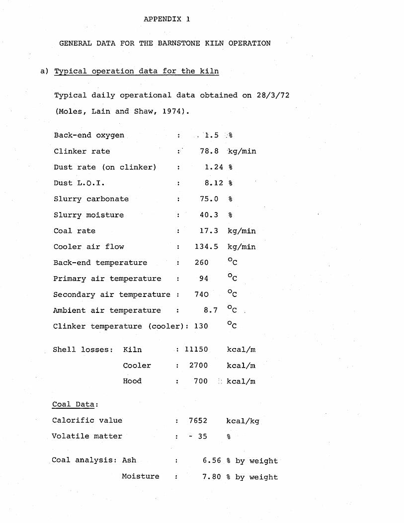
APPENDIX 1
GENERAL DATA FOR THE BARNSTONE KILN OPERATION
a) Typical operation data for the kiln
Typical daily operational data obtained on 28/3/72 (Moles, Lain and Shaw, 1974).
Back-end oxygen Clinker rate Dust rate (on clinker)Dust L.O.I.Slurry carbonate Slurry moisture Coal rate Cooler air flow Back-end temperature Primary air temperature Secondary air temperature Ambient air temperature Clinker temperature (cooler):
. 1.5 .%78.8 kg/min 1.24 %8.12 %
75.0 %40.3 %17.3 kg/min
134.5 kg/min 260 °C94 °C
7408.7 UC .
130
Shell losses: KilnCoolerHood
Coal Data:Calorific value Volatile matter
11150 kcal/m2700 kcal/m700 I. kcal/m
7652 kcal/kg~ 35 %
Coal analysis: AshMoisture
6.56% by weight 7.80% by weight
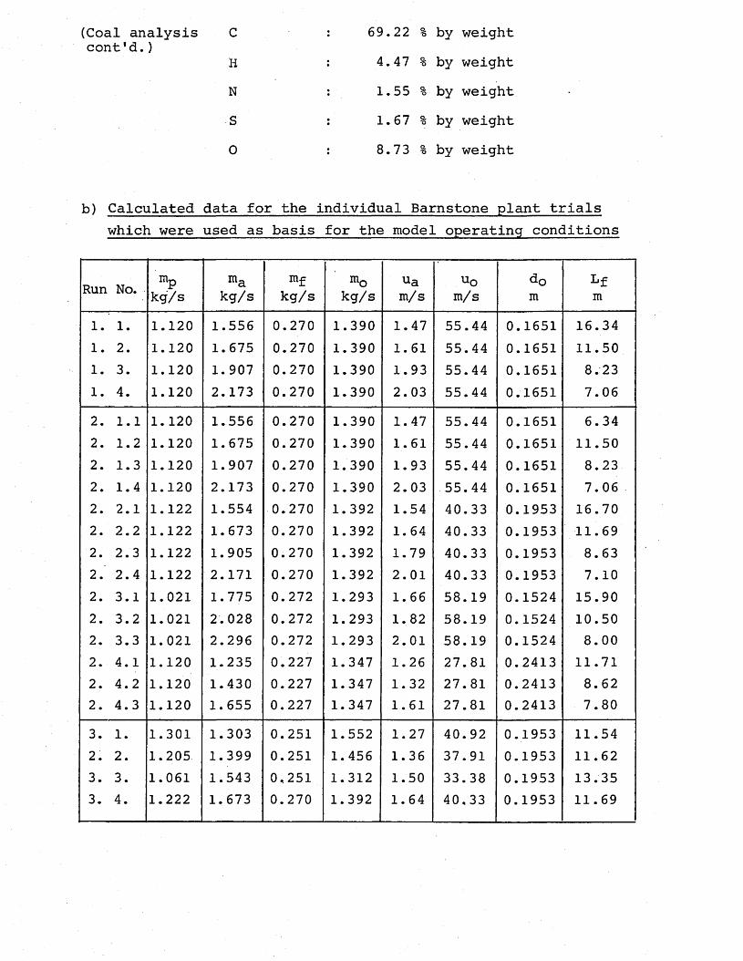
(Coal analysis C : 69.22 % by weightcont'd.)
H : 4.47 % by weightN : 1.55 % by weightS : 1.67 % by weight0 : 8.73 % by weight
b) Calculated data for the individual Barnstone plant trials which were used as basis for the model operating conditions
Run No. - mpkg/s
makg/s
mfkg/s
m 0kg/s
uam/s
uom/s
dom
Lfm
1. 1. 1.120 1.556 0.270 1.390 1.47 55.44 0.1651 16.341. 2. 1.120 1.675 0.270 1.390 1.61 55.44 0.1651 11.501. 3. 1.120 1.907 0.270 1.390 1.93 55.44 0.1651 8.231. 4. 1.120 2.173 0.270 1.390 2.03 55.44 0.1651 7.062. 1.1 1.120 1.556 0.270 1.390 1.47 55.44 0.1651 6.342. 1.2 1.120 1.675 0.270 1.390 1.61 55.44 0.1651 11.502. 1.3 1.120 1.907 0.270 1.390 1.93 55.44 0.1651 8.232. 1.4 1.120 2.173 0.270 1.390 2.03 55.44 0.1651 7.062. 2.1 1.122 1.554 0.270 1.392 1.54 40.33 0.1953 16.702. 2.2 1.122 1.673 0.270 1.392 1.64 40.33 0.1953 11.692. 2.3 1.122 1.905 0.270 1.392 1.79 40.33 0.1953 8.632. 2.4 1.122 2.171 0.270 1.392 2.01 40.33 0.1953 7.102. 3.1 1.021 1.775 0.272 1.293 1.66 58.19 0.1524 15.902. 3.2 1.021 2.028 0.272 1.293 1. 82 58.19 0.1524 10.502. 3.3 1.021 2.296 0.272 1.293 2.01 58.19 0.1524 8.002. 4.1 1.120 1.235 0.227 1.347 1.26 27.81 0.2413 11.712. 4.2 1.120 1.430 0.227 1.347 1.32 27.81 0.2413 8.622. 4.3 1.120 1.655 0.227 1.347 1.61 27.81 0.2413 7.803. 1. 1.301 1.303 0.251 1.552 1.27 40.92 0.1953 11.542. 2. 1.205 1.399 0.251 1.456 1.36 37.91 0.1953 11.623. 3. 1.061 1.543 0,251 1.312 1.50 33.38 0.1953 13.353. 4. 1.222 1.673 0.270 1.392 1.64 40,33 0.1953 11.69
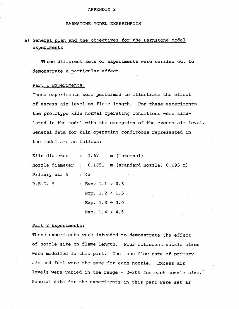
APPENDIX 2
BARNSTONE MODEL EXPERIMENTS
General plan and the objectives for the Barnstone model experiments
Three different sets of experiments were carried out to demonstrate a particular effect.
Part 1 Experiments;These experiments were performed to illustrate the effect of excess air level on flame length. For these experiments the prototype kiln normal operating conditions were simulated in the model with the exception of the excess air level. General data for kiln operating conditoons represented in the model are as follows:
Kiln diameter : 1.67 m (internal)Nozzle diameter : 0.1651 m (standard nozzle: 0.195 m)Primary air % : 43B. E. 0. % : Exp. 1.1 0.5
Exp. 1. 2 1. 5Exp. 1. 3 ->• 3. 0Exp. 1. 4 -*■ 4.5
Part 2 Experiments:These experiments were intended to demonstrate the effect of nozzle size on flame length. Four different nozzle sizes were modelled in this part. The mass flow rate of primary air and fuel were the same for each nozzle. Excess air levels were varied in the range -2-30% for each nozzle size. General data for the experiments in this part were set as
follows:
Experiment 2.1: Nozzle diameter Primary air %B. E • 0 • %
Experiment 2.2: Nozzle diameter Primary air % B.E.O. %
Experiment 2.3: Nozzle diameter Primary air % B.E.O. %
Experiment 2.4: Nozzle diameter Primary air % B.E.O. %
0.1651 m430.5, 1.5, 3.0 and 4.0 for the runs2.1.1, 2.1.2, 2.1.3 and 2.1.4 resp.
0.1953 m 430.5, 1.5, 3.0 and 4.0 for the runs2.2.1, 2.2.2, 2.2.3 and 2.2.4 resp.
0.1524 m 431.5, 3.0 and 4.0 for the runs 2.3.1,2.3.2 and 2.3.3 respectively.
0.2413 m 431.5, 3.0 and 4.0 for the runs 2.4.1,2.4.2 and 2.4.3 respectively.
Part 3 experiments:In this part, the effect of the primary air percentage on the flame length was determined. Three extra values of primary air percentage in addition to the kiln's normal operating value (43%) were investigated. The kiln operating conditions simulated in the model were as follows:
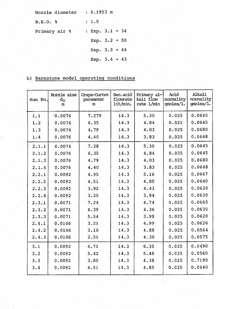
Nozzle diameter B.E.O. %Primary air %
0.1953 m1.5Exp. 3.1 -*- 34 Exp. 3.2 -*- 50 Exp. 3. 3 -*- 4 4 Exp. 3. 4 -*- 4 3
b) Barnstone model operating conditions
Run No.Nozzle size
do mCraya-Curtetparameter
mSec.acid flcwrate lit/min.
Primary alkali flow rate 1/min
Acidnormalitygmoles/1.
Alkalinormalitygmoles/1.
1.1 '0.0076 7.279 14.3 5.30 0.025 0.06451.2 0.0076 6.35 14.3 4.84 0.025 0.06451.3 0.0076 4.79 14.3 4.03 0.025 0.06801.4 0.0076 4.40 14.3 3.83 0.025 0.06482.1.1 0.0076 7.28 14.3 5.30 0.025 0.06452.1.2 0.0076 6.35 14.3 4.84 0.025 0.06452.1.3 0.0076 4.79 14.3 4.03 0.025 0.06802.1.4 0.0076 4.40 14.3 3.83 0.025 0.06482.2.1 0.0092 4.95 14.3 5.16 0.025 0.06672.2.2 0.0092 4.51 14.3 4.85 0.025 0.06402.2.3 0.0092 3.92 14.3 4.43 0.025 0.06202.2.4 0.0092 3.25 14.3 3.94 0.025 0.06302.3.1 0.0071 7.24 14.3 4.74 0.025 0.06602.3.2 0.0071 6.39 14.3 4.36 0.025 0.06302.3.3 0.0071 5.54 14.3 3.99 0.025 0.06202.4.1 0.0106 3.21 14.3 4.99 0.025 0.06262.4.2 0.0106 3.10 14.3 4.89 0.025 0.05642.4.3 0.0106 2.51 14.3 4.30 0.025 0.05753.1 0.0092 6.71 14.3 6.35 0.025 0.04903.2 0.0092 5.42 14.3 5.48 0.025 0.05603.3 0.0092 3.85 14,3 4.38 0.025 0.71903.4 0,0092 4.51 14.3 4.85 0.025 0.0640
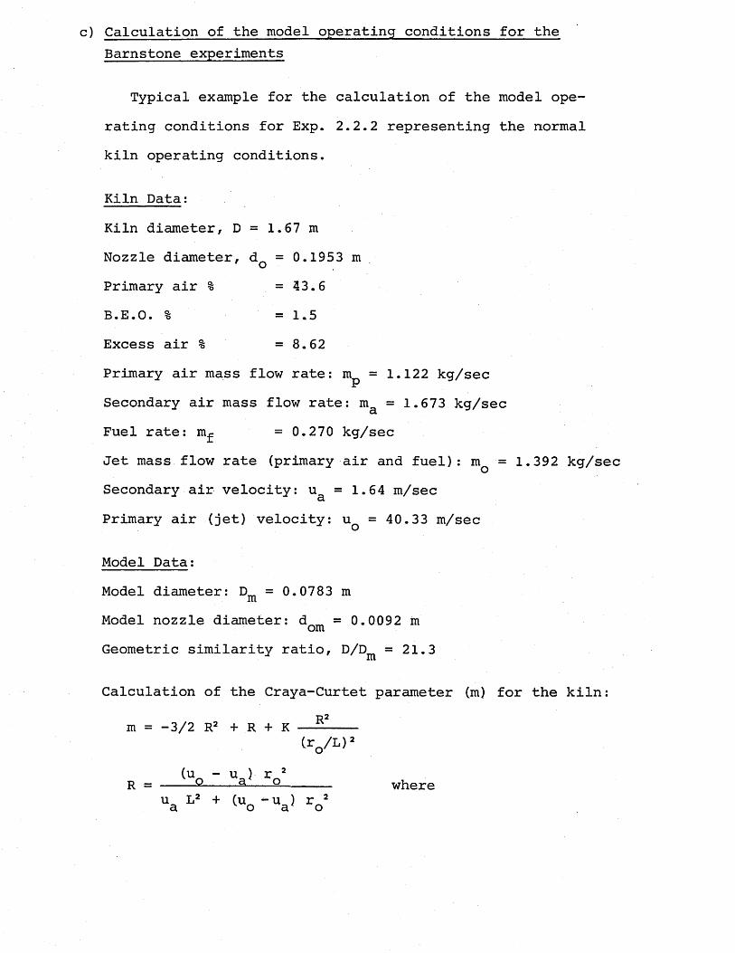
c) Calculation of the model operating conditions for theBarnstone experiments
Typical example for the calculation of the model operating conditions for Exp. 2.2.2 representing the normalkiln operating conditions.
Kiln Data;Kiln diameter, D = 1.67 m Nozzle diameter, dQ = 0.1953 m Primary air % =43.6B.E.O. % = 1.5Excess air % =8.62Primary air mass flow rate: m^ = 1.122 kg/secSecondary air mass flow rate: m = 1.673 kg/secaFuel rate: m^ =0.270 kg/secJet mass flow rate (primary air and fuel): mQ = 1.392 kg/sec Secondary air velocity: u = 1.64 m/sec
u
Primary air (jet) velocity: u q = 40.33 m/sec
Model Data:Model diameter: Dm = 0.0783 mmModel nozzle diameter: d = 0.0092 momGeometric similarity ratio, D/Dm =21.3
Calculation of the Craya-Curtet parameter (m) for the kiln:R2m = -3/2 R2 + R + K
Cr0/L)’
(u - u ) r 2 R = ----2----3---Q------ whereu L2 + (u_ — u ) r 2 a o a o
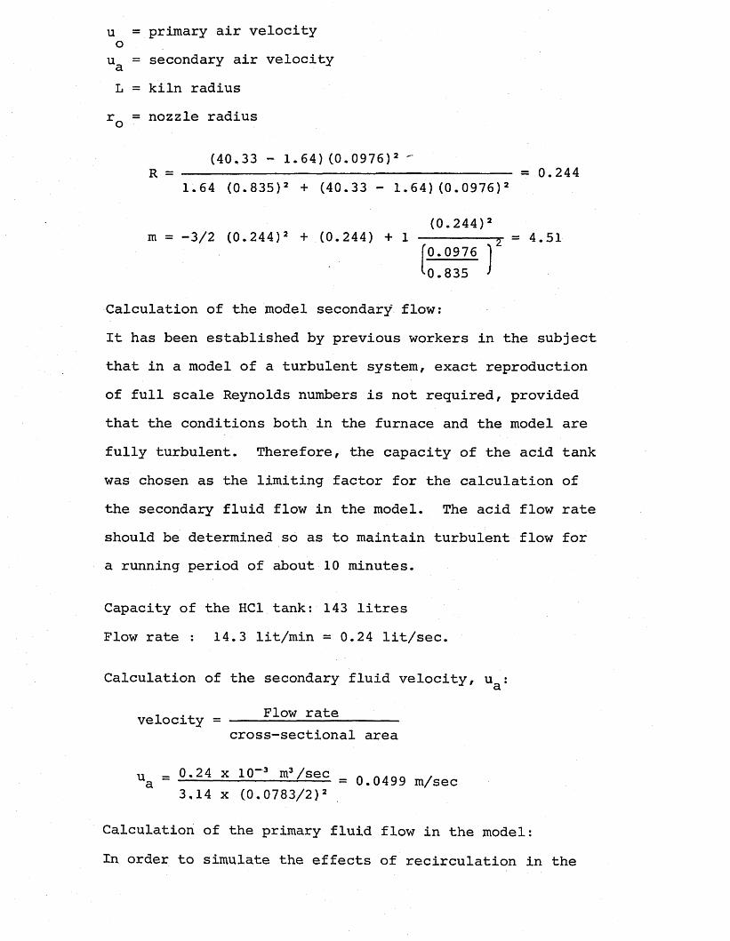
u = primary air velocity o
ua = secondary air velocity L = kiln radius
r = nozzle radius o
(40.33 - 1.64) (0.0976)2 'R = ---------------------------- = 0.244
1.64 (0.835)2 + (40.33 - 1.64) (0.0976)2
(0.244)2m = -3/2 (0.244)2 + (0.244) + 1 ---------r = 4.51
'0.0976 '0.835 >
Calculation of the model secondary flow:It has been established by previous workers in the subject that in a model of a turbulent system, exact reproduction of full scale Reynolds numbers is not required, provided that the conditions both in the furnace and the model are fully turbulent. Therefore, the capacity of the acid tank was chosen as the limiting factor for the calculation of the secondary fluid flow in the model. The acid flow rate should be determined so as to maintain turbulent flow for a running period of about 10 minutes.
Capacity of the HC1 tank: 143 litres Flow rate : 14.3 lit/min = 0.24 lit/sec.
Calculation of the secondary fluid velocity, u :a
velocity = Flow ratecross-sectional area
n _ 0.24 x 10⁻³ m3/sec „ ,ua ~ ------------- L--- = 0.0499 m/sec3,14 x (0.0783/2)2
Calculation of the primary fluid flow in the model:In order to simulate the effects of recirculation in the
model, Craya-Curtet parameter was maintained equal for both the model and the kiln. Since from geometric similarity rQ/L is equal in both systems, m will be equal in both systems for equal R values.
^ i l n = 0,244
Primary fluid velocity uQ was calculated from the equation, (u - u ) r 2
R = --------------------- for model values.u L2 + (u - u ) r 2 a o a o
(u - 0.0499) (0.0046)20.244 = -------- ----------------------------------
(0.0499) (0.03915)2 + ( u q - 0.0499) (0.0046)2
.*. u = 1.216 m/sec o
ua= 24.4
model
Primary fluid (alkali) flow rate: VQ mo<je^
V , n = 1.216 x tr x (0.0046)2 o model
VQ model = x m3/sec = 4.85 lit/min - 0.0808 lit/sec,
Calculation of the normalities of the acid and alkali solutions in the model:In the acid-alkali technique, the combustion reaction in the kiln which is mixing-controlled rather than kinetically controlled, is represented by an equally fast neutralization reaction, which is mixing-controlled. Therefore, the stoichiometric laws of neutralization reactions are applied in the representation of combustion reactions.
NNaOH x VNaOH. = nHC1 x VHC1 (stoich.)
whereN = normality gmoles/lit V = flow rate lit/sec
HC1 normality was kept constant at 0.025 gmoles/lit for all runs.
NNaOH VHC1 (stoich)N V^HCl NaOH
VHC1 VHC1 (stoich) + VX/S
Vx/S = 0.0862 Vstoich>
Stoichiometric secondary air = stoichiometric air requirement - primary air
1 1 O O X 1 /f *7 oStoichiometric air requirement of the kiln — ----- 1--- = 2.571+0.0862 kg/sec
Stoichiometric secondary air % : 2---57 ~ 1,122 = 56.3%2.57
VHC1 (stoich.) = °-563 Vsto±chmVv/q = 0.0862 VHC1 (stQ3-ch>X/b 0.563
Vrci = 14.3 lit/min = 0.24 lit/sec
VHC1 (stoich) = VHC1 “ VX/S
V = V + 0-0052 yHC1 HC1 (stoich) + Q 5g3 VHC1 (stoich)
VHci 0-24VHC1 (stoich) = -----------r = = °-208 lifc/sec1 + 0-0862
0.5631 + 0-0862
0.563
Nn nu - 0^208 x 0.0255 = 0.064 gmoles/lit0.0808
= 2 . 9 2
APPENDIX 3
THE DETERMINATION OF EXCESS ACID LEVEL FROM EFFLUENT TITRATIONS
As already mentioned in section 5.1.6, a method analogous to flue gas analysis was used to check the accuracy of the flow metering to the model, to determine the excess acid percentage in the effluent solution by titrating the sample solution against the sodium hydroxide solution used for each run. The theory is given below, and makes use of the following symbols:
VHC1 = volume flow rate of acid (m3/s)
VNaOH = volume flow rate of alkali (m3 /s)NHC1 = initial acid normalityNNaOH = initial alkali normality
Neff. = effluent solution normality
Rin = ratio of normalities of the input acid andalkali solutions ( « )
HC1 n nR . = effluent normality ratio ( )out Neff-
A = fractional excess acid level (A = excess ^ r„.JL100
The conditions of visualization of the stoichiometric contour, with a fractional acid level of A is:
!HCl_ = !saOH (1 + x) (A3-1)NaOH HC1
The acid left unreacted at the model outlet is diluted by
the total model input flow, VHC + VNaOHf and can keexpressed as,
= ,_X„ NHC1 VHC10 VHC1 + VNaOH ( ’
Rearranging Equation (A3. 1) :
VN VNaOH NaOH
HC1 (1 + X) ,NHC1
and substituting into Equation (A3.2) t the following expression is obtained:
X NtHC1V NNaOH NaOH
NHC1Nef f.
V.NaOH NHC1N, NaOHwhere ----- = R.mN;HC1
(1 + X)
x + (1 + x)
Neff.X NNaOH (1 + X)1 + R. (1 +X)m
NR NaOHout Neff.
1 + Rin (1 + A) X (1 + X)
By measuring the effluent normality ratio Rout/ and substituting with the pre-determined value of R^ into the equation, the value of X can be calculated and compared with the desired value (theoretical) of X inorder to determine the inaccuracy of the flow metering.
APPENDIX 4
CALCULATIONS FOR THE NOZZLE DESIGN FOR COAL FIRING IN THENUH CEMENT PLANT
Considering the fuel situation in Turkey (Tosunoglu,1981), as well as the advantages of burning coal for cement making, lignite from Soma district in Turkey was thought to be the ideal fuel for the Nuh cement kilns.
The nozzle diameter and the operating conditions for the kiln have been calculated by using the recent theories for the improvement of the flame control in rotary kilns to achieve optimum thermal efficiency. The calculated operating data and the nozzle diameter were used as the basis for the determination of the model operating conditions.
(i) Coal Data:The Soma lignite which is proposed as the suitable fuel for the Nuh kiln has the properties similar to the lignite employed in clinker burning in some other East-European countries (Duda, 1977), and it can be used in burning clinker directly.The analysis of the Soma lignite is as follows:
Ultimate analysis (moisture and ash-free basis):c : 65.41H : 5.220 : 27.26N : 1.06S : 1.05Calorific value (gross): 6957 kcal/kg Calorific value (net) : 6682 kcal/kg
Proximate analysis:Moisture content : 13 %Ash content (in raw) : 14.1%Volatile matter : 45.2%Calorific value (gross) : 5072 kcal/kg
The composition is "as received" basis:Moisture : 13 %
Ash : 14.1 %C : 47.68%H : 3.80%O : 19.87%N : 0.773%S : 0.763%
VM : 32.95%
(ii) Calculation of the combustion air (stoichiometric) required: By using the coal analysis data, theoretical air required for 1 kg of lignite is calculated.
Basis: . 1 kg of lignite
Tabular fuel calculationCombustion products
kg/kg mole/kg °2 mole/] kg lignite burntlignite lignite required C02 so2 H2° n2
h20 0.13 0.0072 0.0072Ash 0.141C 0.477 0.0397 0,0397 0.0397H 0.038 0,0380 0.0095 0.0190 0.199 0.0124 0.0062N 0.008 0,0006 0.0003S 0.008 0.0003 0.0003 0.0003
From thisStoichiometric 02 required from air: 0.0433 moles/kgfuelWeight of the stoichiometric 02 from air: 0.0433 x 32 = 1.386
kg 02/kg fuelRatio of nitrogen to oxygen in air: 79/21 = 3.76Weight of nitrogen in stoichiometric air:
0.0433 x 3.76 x 28 = 4.558 kg 02/kg fuelWeight of stoichiometrically required air:
4.558 + 1.386 = 5.944 kg air/kg fuel
(iii) Calculation of the kiln operating conditions:Capacity of the kiln: 1200 tons/day
1200 tons/day x 1000 kg/tons Production rate: ---------------------------- -= 13.89 kg/sec
24 hrs/day x 3600 sec/hr
The back-end oxygen level: The back-end oxygen level is assumedas 2%, a normal value for the dry process cement kilns (based on the data obtained from Nuh and Ak cement kilns in Turkey).
Primary air temperature (T ): 60°C (assumed)lrSecondary air temperature (T&): 800°C (based on Nuh cement data). Specific fuel consumption: from Figure A4.1 for the relationship between the kiln production rate and the specific fuel consumption, which has been derived from a large amount of kiln operation data (Jenkins and Moles, 1978a), the specific fuel consumption for a coal firing kiln of 1200 tons/day (13.89 kg/s) output is predicted as 870 kcal/kg clinker.
Fuel rate* 13«89 kg clinker/sec x 870 kcal/kg clinker = 2 524795 kcal/kg fuel kg fuel/sec.
Stoichiometric air rate: nunt. = 2,52 kg fuel/sec x 5.944 kg air/kg/fuel
= 14,98 kg air/sec
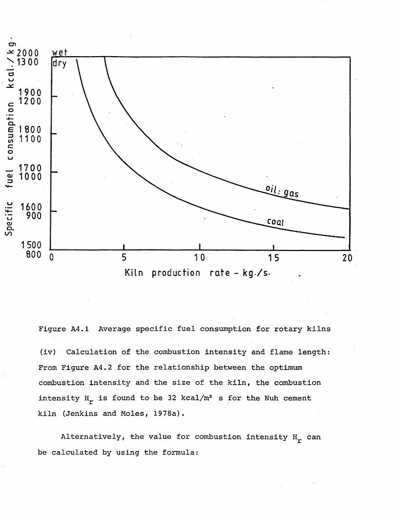
Spec
ific
fu
el
cons
umpt
ion
kc
al.
/kg
-
2 0 0 0 wet 13 00 Idrv
1 9 0 0
1600900
Ki ln product ion r a t e - kg / s -
Figure A4.1 Average specific fuel consumption for rotary kilns
(iv) Calculation of the combustion intensity and flame length: From Figure A4.2 for the relationship between the optimum combustion intensity and the size of the kiln, the combustion intensity Hr is found to be 32 kcal/m2 s for the Nuh cement kiln (Jenkins and Moles, 1978a).
Alternatively, the value for combustion intensity Hr can be calculated by using the formula:
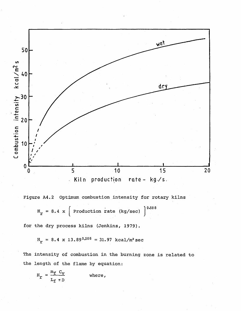
Com
bust
ion
inte
nsit
y k
ca
l/m
^s
40
10
20K i l n pr oduct i on r a t e - k g / s
Figure A4.2 Optimum combustion intensity for rotary kilns
0.50 8H = 8.4 x r Production rate (kg/sec)
for the dry process kilns (Jenkins, 1979).
Hr = 8.4 x 13.890-508 = 31.97 kcal/m2 sec
The intensity of combustion in the burning zone is related to the length of the flame by equation;
_ mf CvHL f IT D
where,
Hr = heat release rate from flame (kcal/m2sec). m^ = fuel rate (kg fuel/sec)Cv = calorific value of the fuel-lower (kcal/kg fuel) Lf = flame length (m)D = kiln diameter (m)
By rearranging the equation for H , the length of the flame is calculated as:
(v) Calculation of the required coal injection conditions: The length of the flame in a coal fired rotary kiln is given by the Barnstone equation:
m& = mass flow rate of secondary air (kg/sec)
= stoichiometric air requirement (kg air/sec)= mass flow rate of fuel x theoretical air requirement
2.52 kg coal/sec x 4795 kcal/kg coal32 kcal/m2sec x i x 3.696 m
L'f 32.53 m
L'f l n2 - d 220.02 + 2.89 + 0.39 fin-1 j 2u
0 32 —E uado o
where= flame length (m)
dQ = nozzle diameter (m) D = kiln diameter (m)
u = velocity of primary air (m/sec)ua = velocity of the secondary air (m/sec)
manum. - m„f t p
of fuelm = mass flow rate of primary air (kg/sec)
hr
Rearranging the Barnstone equation in terms of dQ,
Lf - /lT2 - 4abd = — ----- — :-----o 2a
wherea = 20.02 + 2.89 -iy - 0.39
b = 0.39 D2 - 0.32 %2l3~l £ fP~ >a aTp = primary air temperature (°C)Ta = secondary air temperature (°C)
Primary air percentage should be adjusted so that the resulting nozzle diameter and the nozzle velocity will ensure sufficient momentum in the primary air/fuel stream for the complete en- trainment and mixing of any secondary air into the jet flow. This effect is indicated by the Craya-Curtet parameter m, and if the value of m is greater than 1.5, then there is adequate amount of jet momentum for complete jet mixing.
m = -3/2 R2 + R + R2(d0/D)2
where„ (Up - V (d 0 / 2 ) 2R — ■" 1
ua (D/2) 2 + (up -ua) (d0/2)2
Any value of primary air percentage is assumed and the resulting jet and secondary air flow rates are calculated. Using these values in the rearranged form of the Barnstone equation for dQ, the nozzle diameter and the nozzle velocity are determined. These values are checked with the Craya-Curtet parameter for a value of ^1.5. If m is less than 1,5, then a new value for primary air is assumed, and the burner nozzle must be redesigned following the same procedure.
(vi) Calculations for primary air percentage of 21%: mass flow of primary air: m in kg/sec
hr
m = 14.98 x 0.21 = 3.146 kg/sec P
where stoichiometric air flow rate = 14.38 kg/secExcess air level: for back-end oxygen percentage of 2%,
the excess air level is calculated by using the relation:
B.E.O. % = 0.174 x excess air
Excess air: 11.5%Mass flow rate of excess air: m = 14.98 x 0.115 = 1.723
” kg/sec.Secondary air flow rate: ma in kg/secm& = 14.98 + 1.723 - 3.146 = 13.557 kg/sec
Substititing these values for m , m in the above equationsa . p
for n, a, b, nozzle diameter dQ is calculated:
n = 13 .55714.98 - 3.146
= 1.145
a = 19.63 + 2.891.145-1
= 39.56
b = 0.39 - 0.32 x 3.146 (60 + 273)13.557 (273 + 800)
(3.696)
b = 5. 013 m2
32.53 - / (32.53)2 - (4 x 39.56 x 5.013)d = o 2 x 39.56
dQ = 0.2056 m.
Jet and secondary air velocities are calculated for the operating conditions determined by the above calculated nozzle size and 21% primary air percentage level.
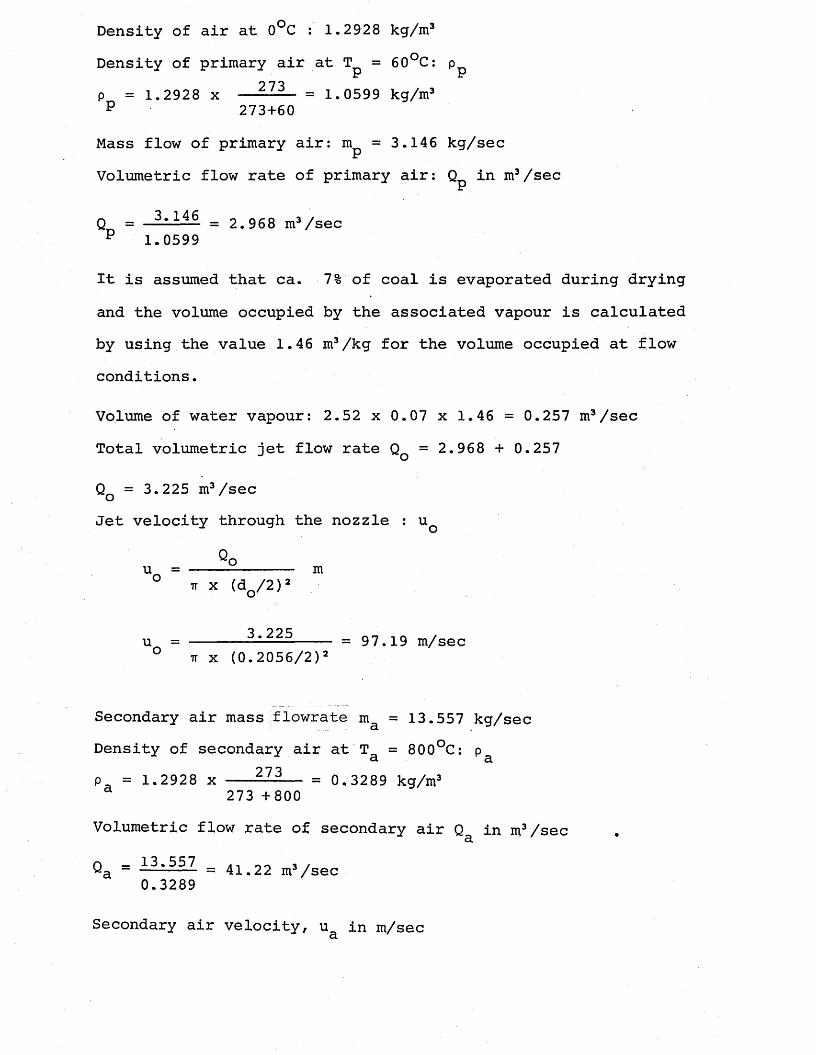
Density of air at 0°C : 1.2928 kg/m3Density of primary air at T = 60°C: pLr hr
p = 1.2928 x — = 1.0599 kg/m3 p 273+60
Mass flow of primary air: m^ = 3.146 kg/secVolumetric flow rate of primary air: Q in m3/sec
hr
q = = 2.968 m3/secP 1.0599
It is assumed that ca. 7% of coal is evaporated during drying and the volume occupied by the associated vapour is calculated by using the value 1.46 m3/kg for the volume occupied at flow conditions.
Volume of water vapour: 2.52 x 0.07 x 1.46 = 0.257 m3/sec Total volumetric jet flow rate Qq = 2.968 + 0.257
Qq = 3.225 m3/secJet velocity through the nozzle : u q
Qou = ----------- mit x (do/2)2
u = ------3.225---- _ 97.19 m/secn x (0.2056/2)3
Secondary air mass flowrate m& = 13.557 kg/secDensity of secondary air at Ta = 800°C: pa aP . = 1.2928 x ------------ — — = 0.3289 kg/m3
273 +800Volumetric flow rate of secondary air Q in m3/secan — 13.557 ^ 0 3 /y - ------ = 41.22 m3/sec
0.3289
Secondary air velocity, u in m/seca
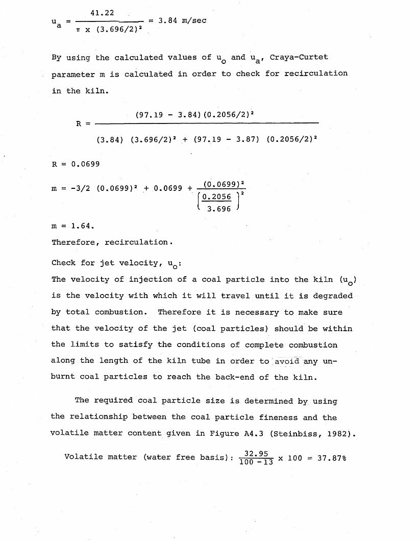
41.22u = — ...... — = 3.84 m/seca n x (3.696/2
By using the calculated values of uQ and ua, Craya-Curtet parameter m is calculated in order to check for recirculation in the kiln.
(97.19 - 3.84) (0.2056/2)2 R = --- ------------------------------------------
(3.84) (3.696/2)2 + (97.19 - 3.87) (0.2056/2)2
R = 0.0699
m = -3/2 (0.0699)2 + 0.0699 + (0-0699)2_ s 20.2056 r '* 3.696 -
m = 1.64.Therefore, recirculation.
Check for jet velocity, uQ;The velocity of injection of a coal particle into the kiln (uQ) is the velocity with which it will travel until it is degraded by total combustion. Therefore it is necessary to make sure that the velocity of the jet (coal particles) should be within the limits to satisfy the conditions of complete combustion along the length of the kiln tube in order to avoid any unburnt coal particles to reach the back-end of the kiln.
The required coal particle size is determined by using the relationship between the coal particle fineness and the volatile matter content given in Figure A4.3 (Steinbiss, 1982).
Volatile matter (water free basis): 13 x 100 = 37.87%
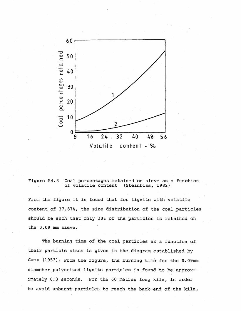
60
toCD
CDCL
LJ
V o la t i l e co n ten t - %
Figure A4.3 Coal percentages retained on sieve as a function of volatile content (Steinbiss, 1982)
From the figure it is found that for lignite with volatile content of 37.87%, the size distribution of the coal particles should be such that only 30% of the particles is retained on the 0.09 mm sieve.
The burning time of the coal particles as a function of their particle sizes is given in the diagram established by Gumz (1953). From the figure, the burning time for the 0.09mm diameter pulverized lignite particles is found to be approximately 0.3 seconds. For the 60 metres long kiln, in order to avoid unburnt particles to reach the back-end of the kiln,
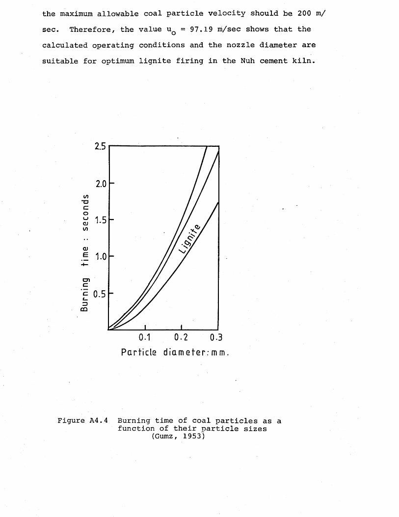
the maximum allowable coal particle velocity should be 200 m/ sec. Therefore, the value uQ = 97.19 m/sec shows that the calculated operating conditions and the nozzle diameter are suitable for optimum lignite firing in the Nuh cement kiln.
to*ocoLJCDI/)
CD
cna
ZJCD
2.5
Part icle d ia m e ter : m m
Figure A4.4 Burning time of coal particles as a function of their particle sizes
(Gumz, 1953)
O 3 /
APPENDIX 5
NOZZLE DESIGN FOR PULVERIZED LIGNITE FIRING IN THE RISER DUCT OF A 1200 TON/DAY CAPACITY DRY-PROCESS CEMENT KILN
The conditions required for firing pulverized coal in the riser duct of a dry-process cement kiln (Humboldt four-stage cyclone preheater system) are summarized as follows (Anon.1980):
1. Firing should be through one burner only.2. The velocity of the primary air and fuel jet should be 28 m/
sec, always greater than 20 m/sec.3. Mass ratio of the coal particles to the tertiary (carrier)
air in the auxiliary firing pipe should not exceed the value 2 kg coal/kg air for coals with volatile matter content over 30%.
Operating conditions:Fuel data: the same lignite used for firing through the mainburner is to be fired through the auxiliary burner. Proportion of the fuel fired at the back end: 25% in the present case.Coal/air ratio in the auxiliary firing pipe: 1 Amount of coal fired in. the riser duct: m^r = 2.52 x 0.25 = 0.63 kg/sec.Mass of the tertiary air (air through auxiliary burner): m
hr
nipr = 0.63 kg/sec.Temperature of the air in the firing pipe: T^r = 60°CDensity of water vapour at 60°C = 0.67 kg/m3Water vapour occupies 1.46 m3/kg at flow conditions.Assuming 7% of the coal is evaporated volume of the water vapourassociated is calculated.Qtt„ = 0.63 x 0.07 x 1.46 = 0,064 m3/sec. w r
Density of air at 60°C, Pa^r 5q0c = 1-0599- kg/m3
Total volumetric flow rate through the nozzle: QQr QQr = 0.594 + 0.064 = 0.658 m3/sec.Velocity through the auxiliary burner: uQr = 28 m/sec.
u = ---2E---°r ¥ (dor/2)2
oo _ 0.658" - « W 2>2
Rearranging for dQr and solving,
d = 2 / m U Z = 0.173 m.° ir x '28
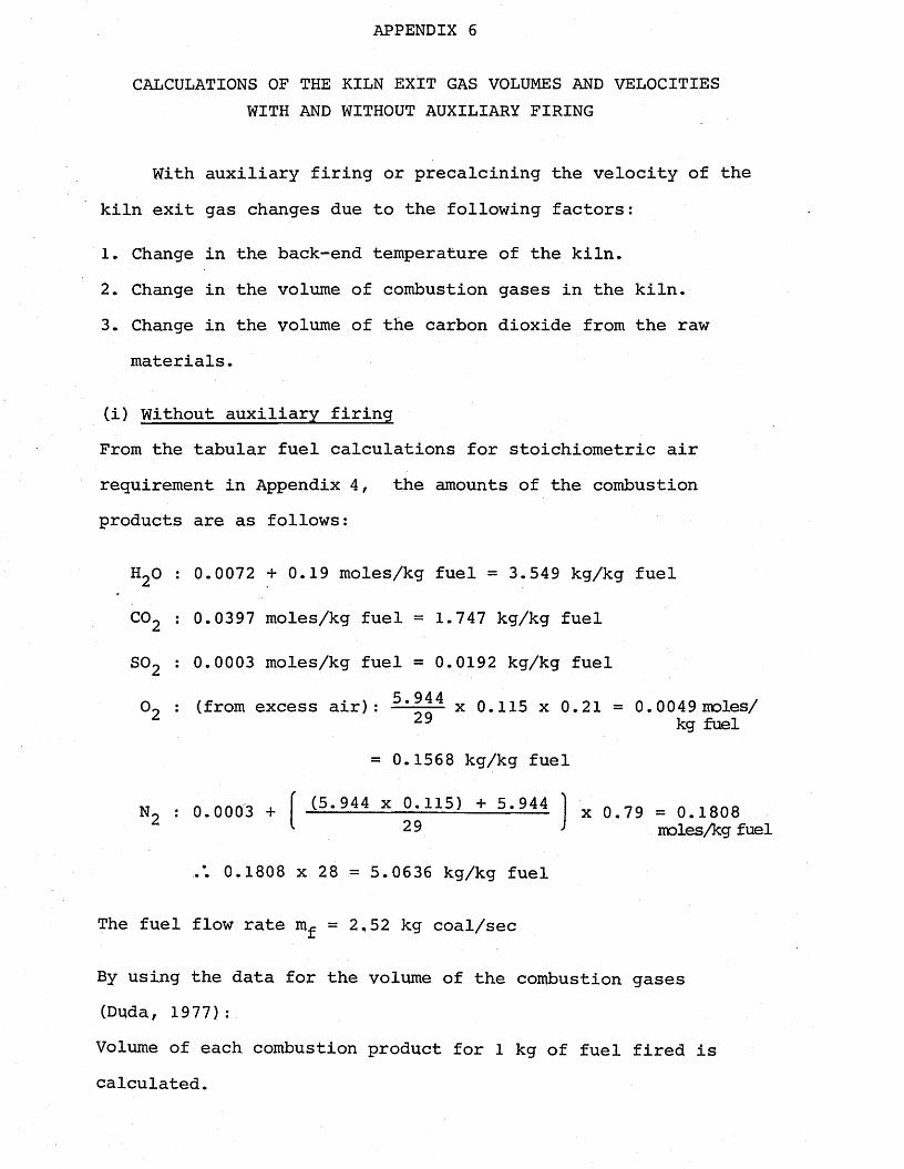
APPENDIX 6
CALCULATIONS OF THE KILN EXIT GAS VOLUMES AND VELOCITIES WITH AND WITHOUT AUXILIARY FIRING
With auxiliary firing or precalcining the velocity of the kiln exit gas changes due to the following factors:
1. Change in the back-end temperature of the kiln.2. Change in the volume of combustion gases in the kiln.3. Change in the volume of the carbon dioxide from the raw
materials.
(i) Without auxiliary firingFrom the tabular fuel calculations for stoichiometric air requirement in Appendix 4, the amounts of the combustion products are as follows:
H20 : 0.0072 + 0.19 moles/kg fuel = 3.549 kg/kg fuel
CC>2 : 0.0397 moles/kg fuel = 1.747 kg/kg fuel
SC>2 : 0.0003 moles/kg fuel = 0.0192 kg/kg fuel5 9 4 40~ : (from excess air): x 0.115 x 0.21 = 0.0049 moles/
29 kg fuel= 0.1568 kg/kg fuel
(5.944 x 0.115) + 5.944N2 : 0.0003 + x 0.79 = 0.1808moles/kg fuel29
.*. 0.1808 x 28 — 5.0636 kg/kg fuel
The fuel flow rate m^ = 2,52 kg coal/sec
By using the data for the volume of the combustion gases (Duda, 1977):Volume of each combustion product for 1 kg of fuel fired is calculated.
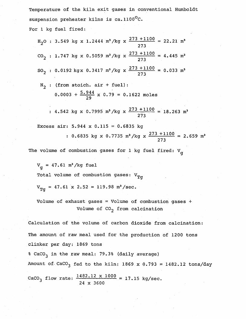
Temperature of the kiln exit gases in conventional Humboldt suspension preheater kilns is ca.H00°C.For 1 kg fuel fired:
H90 : 3.549 kg x 1.2444 m3/kg x 273 + — °- = 22.21 m3 z 273
07 t +11 noC0o : 1.747 kg x 0.5059 m3/kg x ■ - 4.445 m32 273
SO, : 0.0192 kgx 0.3417 m3/kg x 273 +110° = 0.033 m3 2 273
N2 : (from stoich. air + fuel):0.0003 + x 0.79 = 0.1622 moles29
: 4.542 kg x 0.7995 m3/kg x 2-7-3. + ll00 = 18.263 m3273
Excess air: 5.944 x 0.115 = 0.6835 kg: 0.6835 kg x 0.7735 m3/kg x -273 +110° = 2.659 m3
273
The volume of combustion gases for 1 kg fuel fired:
V =47.61 m3/kg fuelgTotal volume of combustion gases: VT^
VTg = x 2«52 = 119.98 m3/sec.
Volume of exhaust gases = Volume of combustion gases +Volume of C02 from calcination
Calculation of the volume of carbon dioxide from calcination:
The amount of raw meal used for the production of 1200 tons clinker per day; 1869 tons% CaC03 in the raw meal; 79.3% (daily average)Amount of-CaCO^ fed to the kiln; 1869 x 0.793 = 1482.12 tons/day
r.-,™ -CT i 1482.12 x 1000 c ,CaCCU flow rate; ------------- = 17.15 kg/sec.24 x 3600
Moles of CaCO_: 17* — = 0.1715 moles/sec.s 100
From the reaction,CaC035£2_CCa0 + C02
0.1715 moles/sec carbon dioxide is released during decarbonation reaction.In the conventional Humboldt suspension preheater kilns with the exit gas temperature of 1100-1200°C, the raw mix is calcined 45% at the kiln entrance. 55% of the calcination is achieved in the kiln.Volume of C02 from decarbonation reaction, vCq2
Vrn = 0.55 x 0.1715 x 44 x 0.5059 x 273 + 1100 2 273= 10.559 m3/sec.
Total volume of gases leaving the kiln (in the riser duct):
Vexhaust gases :1°-559 + 119'98 = 130-539 m3/secRiser duct dimensions: square with dimension of 1.93 m
Cross-sectional area of the riser duct: (L93)2 = 3.725 m2
Velocity of the exhaust gases in the riser duct: U.arU = = 35.044 m/sec.ar 3.725
(ii) With 25% auxiliary firing Total fuel rate m^ = 2,52 kg/sec.
Stoichiometric air requirement of the fuel: 5.944 kg air/kg fuelExcess air: 5,944 x 0,115 = 0.6835 kg air/kg fuelTotal air fed into the kiln; (0.6835 + .5.944) x 2.52 = 16.7
Kg/sec.Fuel fired through the main burner: 2,52 x 0,75 = 1.89 kg/sec.
Fuel fired through the auxiliary burner: 2.52 x 0.25 = 0.63kg/sec. Air through the auxiliary burner: 0.63 kg/sec.Air through the kiln: 16.7 - 0.63 = 16.07 kg/sec.Stoichiometric air for 75% of the fuel through the main burner:
5.944 x 1.89 = 11.23 kg/sec.Excess air: 4.836 kg/sec.
Calculation of the volume of the combustion products at the kiln inlet:In the kilns operating with auxiliary firing, if the air for the auxiliary firing is passed through the kiln, due to the high excess air level in the kiln, the flame temperature is lower than the flame temperatures obtained in the kilns without auxiliary firing. Therefore, the usual temperature of 1100°C at the inlet of the kiln before the riser duct of the dry process kilns without precalcination or secondary firing will be lower in case of auxiliary firing at the back-end. From the figure for temperature at the kiln inlet versus proportion of heat supplied in the preheater, it is found that for 25% secondary firing level, the kiln inlet temperature decreases from 1100°C to 1000°C (Herchenbach and Kupper, 1976).
Volume of combustion gases for 1 kg of fuel fired:
H90 : 3.549 x 1.2444 x I?3 + 10°0 = 20.59 m3273
C02 : 1.747 x 0.5059 x 2-73 ■+ 1000 = 4.12 m3273
S09 ; 0.0192 x 0.3417 x — ■ 00 = 0,030 m3273
; 4,542 x 0,7995 x — 3 + 1Q-Q0 = 16.93 m3273
Excess air: 4.836 x 0.7735 x — ?— > 1000 = 17.44 m3/sec.273
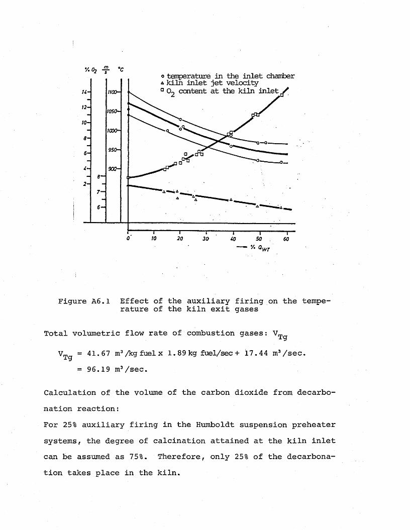
o temperature in the inlet chamber a kiln inlet jet velocity ° 0o content at the kiln inlet /
I— O.
5-&
8—
30
Figure A6.1 Effect of the auxiliary firing on the temperature of the kiln exit gases
Total volumetric flow rate of combustion gases:
VT = 41.67 m3/kg fuel x l. 89 kg fuel/sec + 17.44 m3/sec.i y
= 96.19 m3/sec.
Calculation of the volume of the carbon dioxide from decarbonation reaction;For 25% auxiliary firing in the Humboldt suspension preheater systems, the degree of calcination attained at the kiln inlet can be assumed as 75%. Therefore, only 25% of the decarbonation takes place in the kiln.
344
Vrn = 0.25 x 0.1715 x 44 x 0.5059 x -22 1 ± ..1Q0Q uu2 273
= 4.45 m3/sec.
Total volumetric flow rate of kiln exit gases: Vex. gases
V = 4.45 + 96.19 = 100,64 m3/sec.ex.gases
Velocity of the exhaust gases in the riser duct: Uar
= 100,64 = 27.02 m/sec. ar 3.725
APPENDIX 7
TYPICAL OPERATING DATA FOR THE NUH CEMENT KILN
a) Operating data for the plant before auxiliary firing application - Oil-fired kiln on 26/12/1981.
Daily clinker production capacity: 1100 tons/day Fuel consumption: 102 tons/day Type of fuel: Fuel-oil with 4.5% sulphur Average energy consumption: 885 kcal/kg clinker Raw material: Limestone with admixtures of chalk and clay-
Marlstone with CaCO^ content 76.5%B.E.O. : 2.48%% CO in exhaust gases: 0%Temperatures: Referring to Figure A7.1,
T± = 573°C T2 = 698°C T3 = 802°C T4 = 959°C
Exhaust gas temperature Tex = 330°C Fuel-oil temperature in the burner: 116°C Primary air: 2300 m3/hr at T ^^ (ambient temperature)Air fed to the cooler:
Chamber I : 25900 m3/hr at T ^ [)
Chamber II; 23400 m3/hr Chamber III; 20450 m3/hr Chamber IV: 13400 m3/hr Chamber V : 13000 m3/hr
Cooler exhaust air; 25% of the total cooler inlet air Secondary air: Cooler inlet air -exhaust air
Secondary air temperature, Ta = 806°C Exhaust air temperature, T = 222°C6a
b) Operating data for the plant with auxiliary firing on 23/9/1983
Daily clinker production capacity: 1246 tons/day Type of fuel:(i) Main burner: Fuel-oil with sulphur content 4.5%
Calorific value of the fuel: ca. 9500 kcal/kg
(ii) Auxiliary burner: coarse coalCalorific value of the fuel: ca. 3790 kcal/kg
Fuel consumption: Fuel-oil: 72 tons/dayCoal : lOOtons/day
Specific fuel consumption : 548 (oil) + 304 (coal)= 852 kcal/kg clinker
Raw material: Limestone with admixtures of chalk and clay-Marlstone with CaCO^ content 79.5%
B.E.O. : 1.4%CO in exhaust gases: 0.15%Temperatures: Referring to Figure A7.1,
T, = 540.4°C T2 = 670°C T3 = 782°C T4 = 934.4°C
Exhaust gas temperature T = 335°CCAFuel-oil temperature in the burner: 122°C Primary air: 2900 m3/hr at T,^Air fed to the cooler:
Chamber I : 23000 m3/hr Chamber II: 20600 m3/hr Chamber III: 18000 m3/hr Chamber IV: 12000 m3/hr Chamber V : 10000 m3/hr
Cooler exhaust air: ca. 25% of Exhaust air temperature: Tea = Secondary air temperature: Ta=
the total cooler inlet air233°C825.6°C
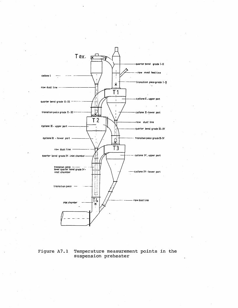
T GXquarter bend grade I-tl
- r a w meal feed linecyclone I
transition piece grade I- I I
raw dust line
cycloneII .upper partquarter bend grade I I - I I I ~
transition piece grade II - I I I ------ cyclone II-lower part
raw dust linecyclone in • upper part
quarter bend grade III - IV
cyclone III - lower part transition piece grade III-IV
raw dust line
cyclone IV, upper partquarter bend grade IV - inlet chamber
transition piece----------lo«ver quarter bend grade IV inlet chamber cyclone IV - lower part
transition piece
raw dust lineinlet chamber
Figure A7.1 Temperature measurement points in the suspension preheater
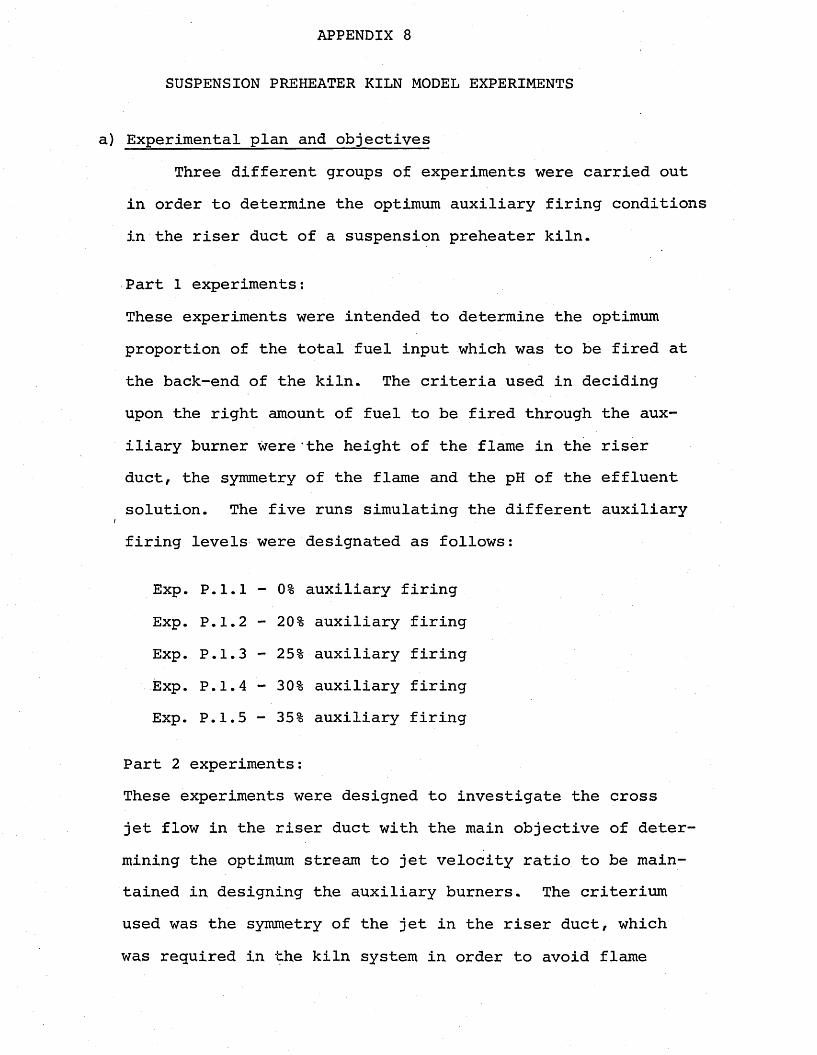
APPENDIX 8
SUSPENSION PREHEATER KILN MODEL EXPERIMENTS
a) Experimental plan and objectivesThree different groups of experiments were carried out
in order to determine the optimum auxiliary firing conditions in the riser duct of a suspension preheater kiln.
Part 1 experiments:These experiments were intended to determine the optimum proportion of the total fuel input which was to be fired at the back-end of the kiln. The criteria used in deciding upon the right amount of fuel to be fired through the auxiliary burner were the height of the flame in the riser duct, the symmetry of the flame and the pH of the effluent solution. The five runs simulating the different auxiliary
I
firing levels were designated as follows:
Exp. P.1.1 - 0% auxiliary firing Exp. P.1.2 - 20% auxiliary firingExp. P.1.3 - 25% auxiliary firingExp. P.1.4 - 30% auxiliary firingExp. P.1.5 - 35% auxiliary firing
Part 2 experiments:These experiments were designed to investigate the cross jet flow in the riser duct with the main objective of determining the optimum stream to jet velocity ratio to be maintained in designing the auxiliary burners. The criterium used was the symmetry of the jet in the riser duct, which was required in the kiln system in order to avoid flame
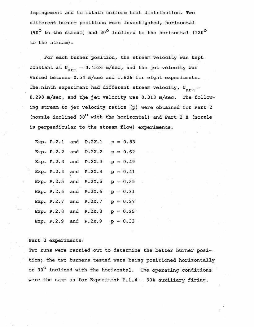
impingement and to obtain uniform heat distribution. Two different burner positions were investigated, horizontal (90° to the stream) and 30° inclined to the horizontal (120° to the stream).
For each burner position, the stream velocity was kept constant at Uarm = 0.4526 m/sec, and the jet velocity was varied between 0.54 m/sec and 1.826 for eight experiments.The ninth experiment had different stream velocity, uarm =*0.298 m/sec, and the jet velocity was 0.313 m/sec. The following stream to jet velocity ratios (p) were obtained for Part 2 (nozzle inclined 30° with the horizontal) and Part 2 X (nozzle is perpendicular to the stream flow) experiments.
Exp. P.2.1 and P.2X.1 P = 0.83Exp. P.2.2 and P.2X.2 P = 0.62Exp. P.2.3 and P.2X.3 P = 0.49Exp. P.2.4 and P.2X.4 P = 0.41Exp. P.2.5 and P.2X.5 P = 0.35Exp. P.2.6 and P.2X.6 P = 0.31Exp. P.2.7 and P.2X.7 P = 0.27Exp. P.2.8 and P.2X.8 P = 0.25Exp. P.2.9 and P.2X.9 P = 0.33
Part 3 experiments;Two runs were carried out to determine the better burner position? the two burners tested were being positioned horizontally or 30° inclined with the horizontal. The operating conditions were the same as for Experiment P,1.4 - 30% auxiliary firing.
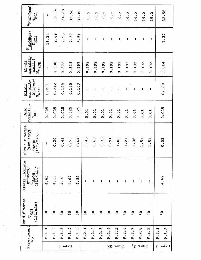
1 rHa Uo aida53mr-co
ooooro
voinC Nro ro
C N<Xk
C N(X>
C N0\
C NC T k
C NC P k
C Ncn
C N<T>
C Ncn
C Ncn
voinC Nro
T?cm rHa uo atdaa
cn in r- i—iCN VO <r» ro in• • • • •
11 cn VO
r"ro
00 CN CN CN CN CN CN CN CN CN CNro r-~ rH CTt CT> CT> CTk cn CTk CTk CTk CT\cn 00 00 iH rH rH rH iH iH rH rH rH• • • • • •' • • • • • • •o o O o O O O o O o o O ooo
rH CN o\ O ro00 C\ 00 VOCN CN rH rH rH• • • • •o O O o O
ooo
in m m in mC N C N C N C N C No o o o o I-1o rHoinC No
o rH co in o V O rH V O rH V O rH rHro in V O V O r- Ok o CN ro in m• • • • • • • « • • • • •o O o o o o o O rH rH rH rH rH
roin
H Q | 2 - Hin CTk O r- CNVO rH r-~ VO 00« « ' « • •
'vT
r-vo
•HH g U \a +>> -HI—IoV O OV O
OV O oV O oV O oV O oV O oV O oV O oV O oVO o oV O
4JaCD£•H •n o a) a aXw
rH CN CO m rH CN CO in VO r" 00 CTk iH CN• • • • • • • • • • • • • • • •rH rH rH ■H iH CN CN CN CN CN CN CN CN CN ro ro• • • • 9 • • • • * • • • • • •CM CM CM CM CM CM CM CM CM CM CM CM CM PM CM CM
i xz *z 'ixva
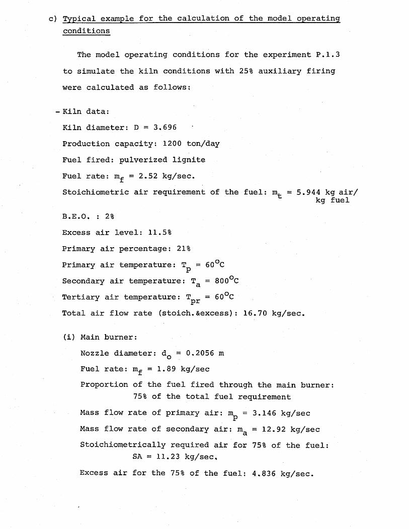
c) Typical example for the calculation of the model operatingconditions
The model operating conditions for the experiment P. 1.3 to simulate the kiln conditions with 25% auxiliary firing were calculated as follows;
- Kiln data;Kiln diameter: D = 3.696 Production capacity; 1200 ton/day Fuel fired: pulverized lignite Fuel rate: m^ = 2.52 kg/sec.Stoichiometric air requirement of the fuel: m. = 5.944 kg air/
kg fuelB.E.O. : 2%Excess air level: 11.5%Primary air percentage: 21%Primary air temperature: T^ = 60°CSecondary air temperature: Ta = 800°CTertiary air temperature: Tpr = 60°CTotal air flow rate (stoich.Sexcess): 16.70 kg/sec.
(i) Main burner:Nozzle diameter: dQ = 0.2056 m Fuel rate: m^ = 1.89 kg/secProportion of the fuel fired through the main burner:
75% of the total fuel requirementMass flow rate of primary air: mp = 3.146 kg/secMass flow rate of secondary air: ma = 12.92 kg/secStoichiometrically required air for 75% of the fuel:
SA = 11.23 kg/sec.Excess air for the 75% of the fuel; 4.836 kg/sec.
Primary air and fuel velocity through the nozzle:u =95.26 m/sec. o
Secondary air velocity: u ' =.3.66 m/sec
(ii) Auxiliary burner:Nozzle diameter: dQr = 0.173 m Fuel rate: mfr =0.63 kg/secProportion of the total fuel fired through the aux
iliary burner: 25%Mass flow rate of the tertiary air: m ^ = 0.63 kg/sec, Velocity of the exhaust gases in the riser duct: u&r =
u „ =27 m/sec. arVelocity of the fuel and tertiary air through the
auxiliary burner: uQr =28 m/sec.
- Model data:Diameter of the model kiln: Dm = 0.0906 mDiameter of the model main nozzle: d = 0.005 momDiameter of the model auxiliary nozzle, d =0.0042mormGeometric scale ratio: d /d = 40.79o om
- Calculation of the Craya-Curtet parameter (m) for the kiln•R2m = -3/2 R2 + R + K
(ro/L)’
(uo "ua> ro2I\ -u L2 + (u — u ) r 2 a o a o
(95.26 - 3,66) (0.2056/2)2 r = -----------------------------------
(3.66) C3.696/2)2 + (95,26 - 3.66) (0.2056/2)
R = 0.072
m = -3/2 (0.072)2 + (0.072) + (0 °72) 2(0.2056/3.696)2
m = 1.68
Calculation of the model secondary and primary flows: Assuming Reynolds number N^e = 10000 for the acid flow at the kiln firing end, the volumetric flowrate of the acid was determined:
Viscosity of water at 15°C: Q = 1.4 x 3.6 kg/hr m.Diameter of the tube: Dm = 0.0906 m Density of water: pR Q = 998 kg/m3
P u D NRe = — T ~
u = . 100_P-P_.-?..!• 4 x 3 -6 = 0.155 m/sec.™ 0.0906 x 998 x 3600
Acid flow rate: VHC^
VH(-, = 0.155 m/sec x 3.14 x (0.0906/2)2 m2= 0.0009986 m3/sec 59.9 lit/min.
.*. Acid flow rate was accepted as 60 litres/minute.
In order to simulate the effects of recirculation in the model, the Craya-Curtet parameter was maintained equal to that in the prototype. The primary flow (alkali) velocity was calculated by using the equation for the Craya-Curtet parameter (m), for equal values of R for the model and the prototype;
(u - 0.155) (0.005/2)2 om0.072 =
(0.155) (0.0906/2)2 .+ ■ (u - 0.155) (0.005/2)2
Solving for uom,
u' = 403 m/sec. omPrimary fluid (alkali) flowrate: vNa0n
VNa0H = 4.03 m/sec x 3.14 x (0.005/2)2 m2= 78.45 x 10“6 m3/sec .". 4.70 lit/min.
Calculation of the normalities of the acid and alkali solutions in the model;According to the stoichiometric laws of neurralization reactions
NNaOH x VNaOH NHC1 x VHC1 (stoich)
Acid normality was kept constant at 0.025 gmoles/literfor all runs.
NNaOH = VHC1 (stoich)N VHC1 NaOH
VHC1 = VHC1 (stoich) + Vx/s
Excess air level for the main burner: 43%
Vx/s “ ^-43 v (stoich)
where VHCl(stoich) :i's t Le stoickiometrically required secondary fluid flow (acid) and V (stajLch) stoichiometrically required total fluid (primary and secondary) representing stoichiometric air in the prototype.Stoichiometric secondary air for the kiln: 72%
^HC1 (stoich) _ q y2 stoich
v = ^ Vx/s 0 HC1(stoich)
VHC1 1 + 0 ^ 1 1 0.72 VHC1 (stoich)
Substituting the acid flow rate VHC = 60 lit/min into the
above equation, VHC (g^ich) was determined:
VHC1 (stoich) = 60 =37-56 lit/min.1 + U *0.72 ,
NNaOH = 37.56 = 7>ggN 4 70HC1 q'/U
Since NHC was kept at 0.025 gmoles/lit,
NNaOH = ^-025 x 7*99 = 0.199 gmoles/lit.
Auxiliary firing modelling:For the auxiliary firing conditions, the flow rate and the normality of the secondary flow were fixed by the conditions of the main firing. To maintain dynamic similarity, stream to jet velocity ratios were kept equal for the model and the prototype.
Total flow through the kiln tube: V^,., . =64.70 lit/min.Htiir)Velocity in the riser duct: u = ■£ — -?-P —- ^ — = 0.488 m/sec.
arm 60 x (0.047)2u ^ = 0.488 m/sec arm '
In the kiln, the ratio of the jet velocity through the auxiliary burner to the stream velocity in the riser duct, p, was calculated as follows;
= V m = 28 =P 27 1,04arm
Maintaining the same ratio in the model, the velocity of the nozzle fluid through the auxiliary burner was calculated.u = L04 x 0.488 = 0.507 m/sec orm
The alkali flowrate through the auxiliary nozzle:
V.T nur \ - 0.507 x tt x (0.0042/2)2 = 6.9 x 10⁻⁶ m3/sec. NaOH(r)
VNaOH(r) = 0.0069 lit/sec .*. 0.414 lit/min.
Normality of the acid solution through the kiln: NHd ( r)
NHCl(r) = 0.00867 gmoles/lit.
VHC1(r) = 64-70 lit/min.
VHC1 (r)stoichwas calculatec to simulate the excess air and the tertiary air percentages in the kiln.
Total air requirement of the fuel fired through the main and the auxiliary burners (stoichiometric and excess) =
16.70 kg/sec.Tertiary air rate: iripr = 0.63 kg/sec.Total air through the kiln: 16.70 - 0.63 = 16.07 kg/sec.
Stoichiometric air requirement of the 75% of the fuel: 11.23 kg/sec.
Stoichiometric air requirement of the 25% of the fuel:3.74 kg/sec.
Stoichiometric secondary requirement of 25% of the fuel: 3.74 - 0.63 = 3.11 kg/sec.
Air supply as secondary air for auxiliary firing:16,07 - 11.23 4.84 kg/sec.
3 11Stoichiometric secondary air ratio: — — — =0.833,74

Total air for auxiliary firing: 4.84 + 0.63 =5.4' Excess air level for auxiliary firing:
1.73 x 100 = 46.26%3.7464.70 lit/min
1 + (0.46/0.83)V T . = = 41.63 lit/min.HCl(r) stoich
^%aOH(rI = 41.63 = 1Q055 NHC1 (r) °‘414
N.t x = 100.55 x 0,00867 = 0.872 gmoles/litre NaOH(r) 3
kg/sec.
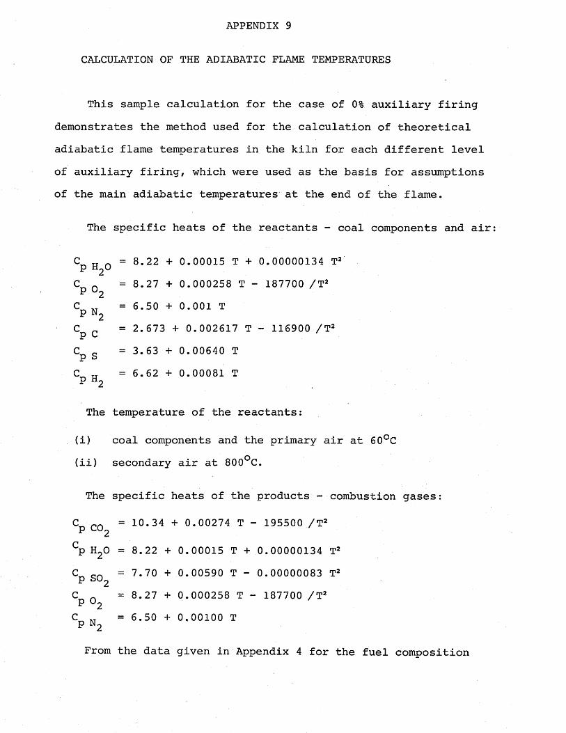
APPENDIX 9
CALCULATION OF THE ADIABATIC FLAME TEMPERATURES
This sample calculation for the case of 0% auxiliary firing demonstrates the method used for the calculation of theoretical adiabatic flame temperatures in the kiln for each different level of auxiliary firing, which were used as the basis for assumptions of the main adiabatic temperatures at the end of the flame.
The specific heats of the reactants - coal components and air
cp H2°= 8.22 + 0.00015 T + 0.00000134 T2
CP °2= 8.27 + 0.000258 T - 187700 /T2
CP N 2 = 6.50 + 0.001 T
CP c = 2.673 +• 0.002617 T - 116900 /T2
CP s = 3.63 + 0.00640 T
CP H2= 6.62 + 0.00081 T
The temperature of the reactants:
(i) coal components and the primary air at 60°C(ii) secondary air at 800°C.
The specific heats of the products - combustion gases:
cp C°2 = 10.34 + 0.00274 T - 195500 /T2
cp h2o = 8.22 + 0.00015 T +0.00000134 T2
cp so2 = 7.70 + 0.00590 T - 0.00000083 T2CP °2
= 8.27 + 0.000258 T - 187700 /T2cp N2
= 6.50 + 0,00100 T
From the data given in Appendix 4 for the fuel composition
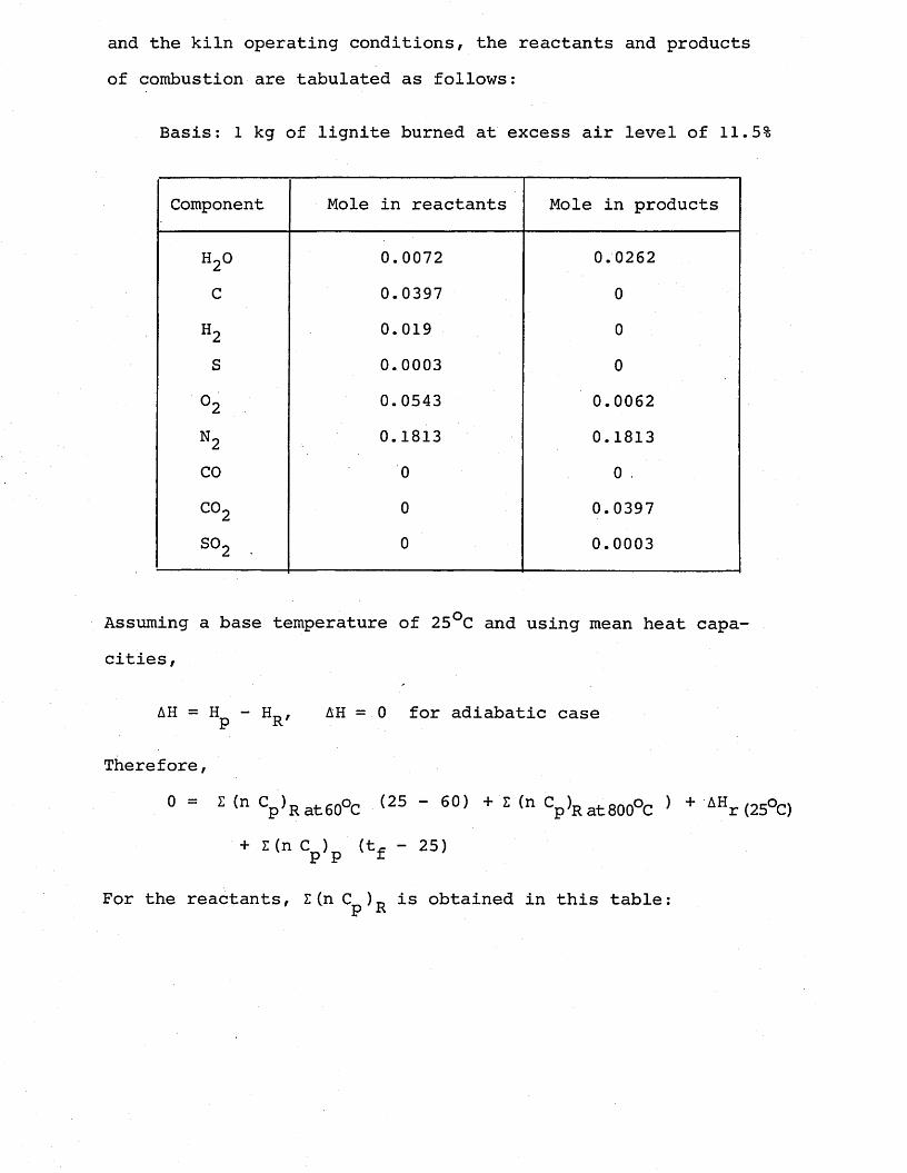
and the kiln operating conditions, the reactants and products of combustion are tabulated as follows:
Basis: 1 kg of lignite burned at excess air level of 11.5%
Component Mole in reactants Mole in products
oCNw 0.0072 0.0262
c 0.0397 0
H2 0.019 0S 0.0003 0
°2 0.0543 0.0062n2 0.1813 0.1813CO 0 0C02 o 0.0397S02 . 0 0.0003
Assuming a base temperature of 25°C and using mean heat capacities,
AH = Hp - Hr, AH = 0 for adiabatic case
Therefore,
0 Z (n S^RatGO^ (25 60) + Z (n Cpat800°C ) + AHr (25°C)+ Z (n C ) (t. - 25)p p f '
For the reactants, Z(n C )„ is obtained in this table:p R
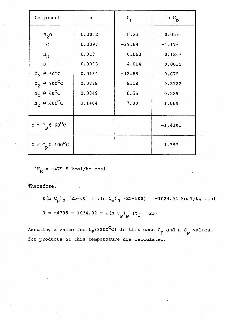
Component n CP n CP
to O 0.0072 8.23 0.059C 0,0397 -29.64 -1.176
H2 0,019 6.668 0.1267S 0.0003 4.014 0.0012
02 @ 60°C 0.0154 -43.85 -0.67502 @ 800°C 0.0389 8.18 0.3182N2 @ 60°C 0.0349 6.56 0.229N2 @ 800°C 0.1464 7.30 1.069
Z n C @ 60°C P -1.4301
Z n C @ 100°C P 1.387
AHR = -479.5 kcal/kg coal
Therefore,
Z(n Cp)R (25-60) + Z (n Cp)R (25-800) = -1024.92 kcal/kg coal
0 = -4795 - 1024.92 + Z (n C ) (tf - 25)P P
Assuming a value for t.e(2200oC) in this case C and n C values,f P Pfor products at this temperature are calculated.
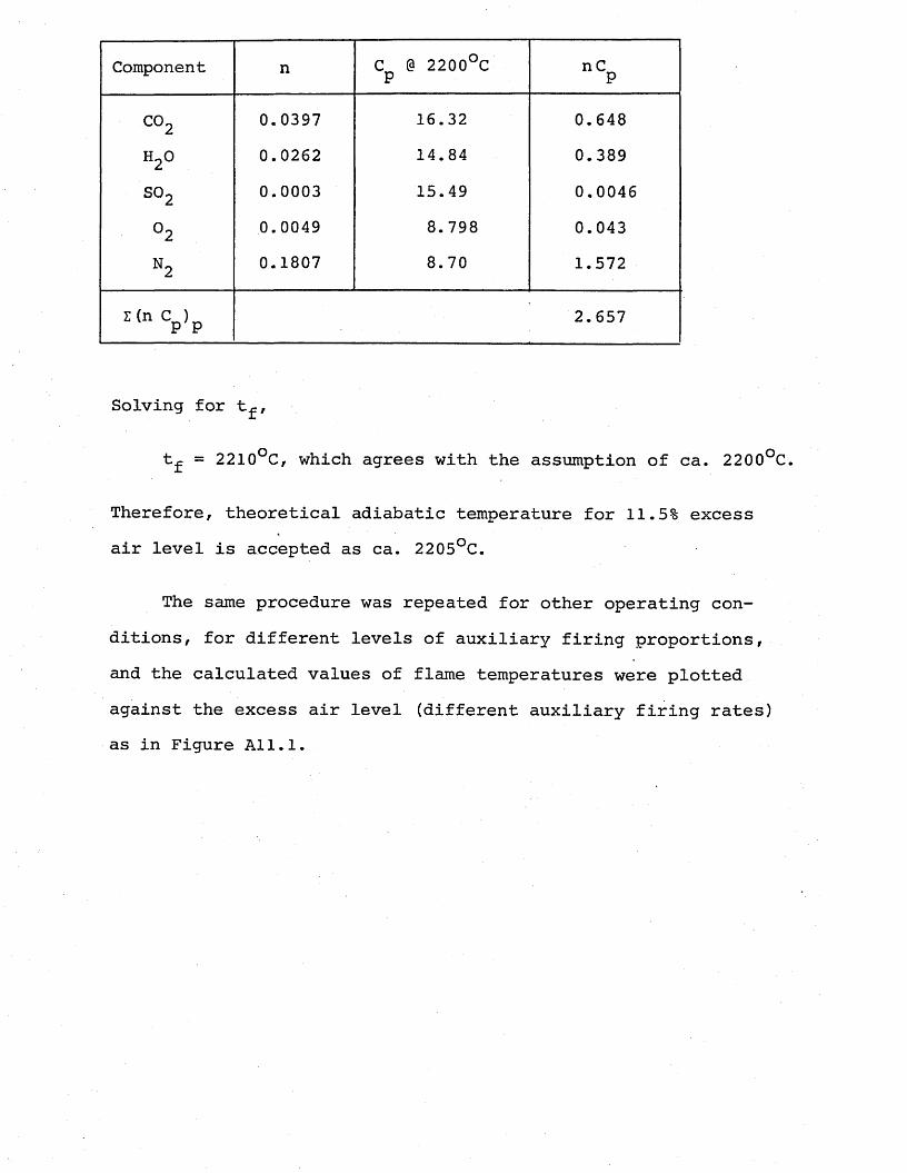
Component n C @ 2200°C P nCP
CO 2 0.0397 16.32 0.648h 20 0.0262 14.84 0.389
so2 0.0003 15.49 0,0046
°2 0.0049 8.798 0.043
N2 0.1807 8.70 1.572
i (“ V p2.657
Solving for tf,
t^ = 2210°C, which agrees with the assumption of ca. 2200°C.
Therefore, theoretical adiabatic temperature for 11.5% excess air level is accepted as ca. 2205°C.
The same procedure was repeated for other operating conditions, for different levels of auxiliary firing proportions, and the calculated values of flame temperatures were plotted against the excess air level (different auxiliary firing rates) as in Figure All.l.
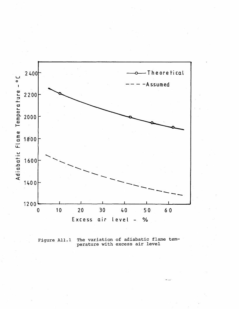
Ad
iab
atic
Fl
ame
Te
mp
era
ture
T h e o r e t i c a l2 400LJO— A ssumed
800
40 0
200200 40 50 6 0
E x c e s s a i r l e v e l - %
Figure All.l The variation of adiabatic flame temperature with excess air level
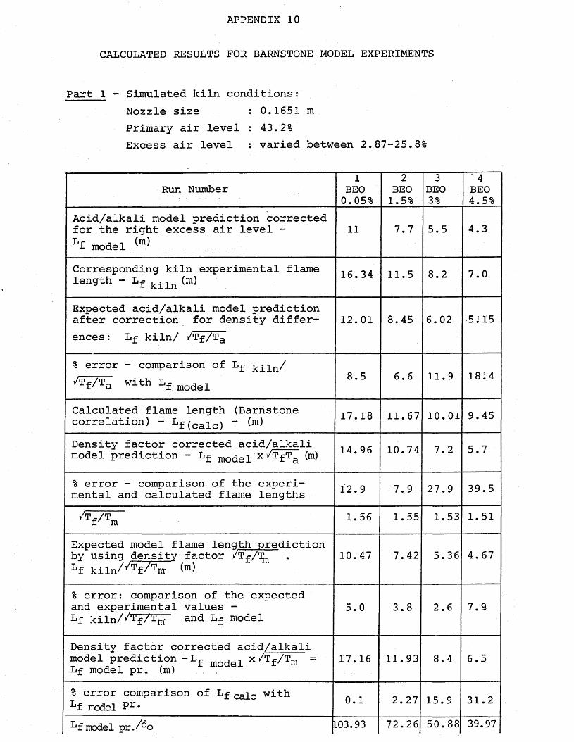
APPENDIX 10
CALCULATED RESULTS FOR BARNSTONE MODEL EXPERIMENTS
Part 1 - Simulated kiln conditions:Nozzle size : 0.1651 mPrimary air level : 43.2%Excess air level : varied between 2.87-25.8%
Run Number1
BEO0.05%
2BEO1.5%
3BEO3%
' 4BEO4.5%
Acid/alkali model prediction corrected for the right excess air level -Lf model ^ .......
11 7.7 5.5 4.3
Corresponding kiln experimental flame length - Lf kiln (m) 16.34 11.5 8.2 7.0
Expected acid/alkali model prediction after correction for density differences : Lf kiln/ /Tf/Ta
12.01 8.45 6.02 5 J. 15
% error - comparison of Lf /Tf/Ta With Lf model 8.5 6.6 11.9 1814
Calculated flame length (Barnstone correlation) - Lf(cafcj - (m) 17.18 11.67 10.01 9.45
Density factor corrected acid/alkali model prediction - Lf model x ^ f Ta ^ 14.96 10.74 7.2 5.7
% error - comparison of the experimental and calculated flame lengths 12.9 7.9 27.9 39.5
/T^/T f' m 1.56 1.55 1.53 1.51
Expected model flame lenqth prediction by using density factor /Tf/T^Lf kiln/^f^m
10.47 7.42 5.36 4.67
% error: comparison of the expected and experimental values - Lf kiln/ J-'fA'rn and Lf model
5.0 3.8 2.6 7.9
Density factor corrected acid/alkali model prediction -L^ mo(jef x /Tf /Tm = Lf model pr. (m) . .
17.16 11.93 8.4 6.5
% error comparison of Lf cafc with Lf model Pr* 0.1 2.27 15.9 31.2
Lf model pr.Ao L03.93 72.26 50.88 39.97
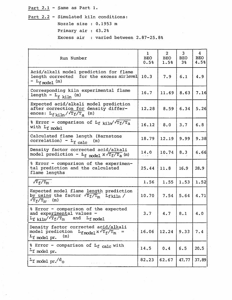
Part 2.1 - Same as Part 1.Part 2.2 - Simulated kiln conditions:
Nozzle size : 0.1953 m Primary air : 43.2%Excess air : varied between 2.87-25.8%
Run Number1
BEO0.5%
2BEO1.5%
3BEO3%
4BEO4.5%
Acid/alkali model prediction for flame length corrected for the excess airlevelLf model
10.3 7.9 6.1 4.9
Corresponding kiln experimental flame length - Lf (m) 16.7 11.69 8.63 7.16
Expected acid/alkali model prediction after correction for density differ- ences: Lf M 1n//T£/Ta (m)
12.28 8.59 6.34 5.26
% Error - comparison of Lf kili/^Tf/Ta with Lf model 16.12 8.0 3.7 6.8
Calculated flame length (Barnstone correlation) - L^ cafc (m) 18.79 12.19 9.99 9.38
Density factor corrected acid/alkali model prediction - Lf x y/Tf/Ta (m) 14.0 10.74 8.3 6.66
% Error - comparison of the experimental prediction and the calculated flame lengths
25.44 11.8 16.9 28.9
/rf/Tm 1.56 1.55 1.53 1.52Expected model flame length prediction by usinq the factor /Tf/Tm Lfkiln / /Tf/Tm, (m)
10.70 7.54 5.64 4.71
% Error - comparison of the expected and experimental values -kf kiln/^f/^m anc kf model
3.7 4.7 8.1 4.0
Density factor corrected acid/alkali model prediction Lf modelx f ^ m = Lf model pr.
16.06 12.24 9.33 7.4
% Error - comparison of Lf cafe with Lf model pr. 14.5 0.4 6.5 20.5
Lf model pr./^o 82.23 62.67 47.77 37.89
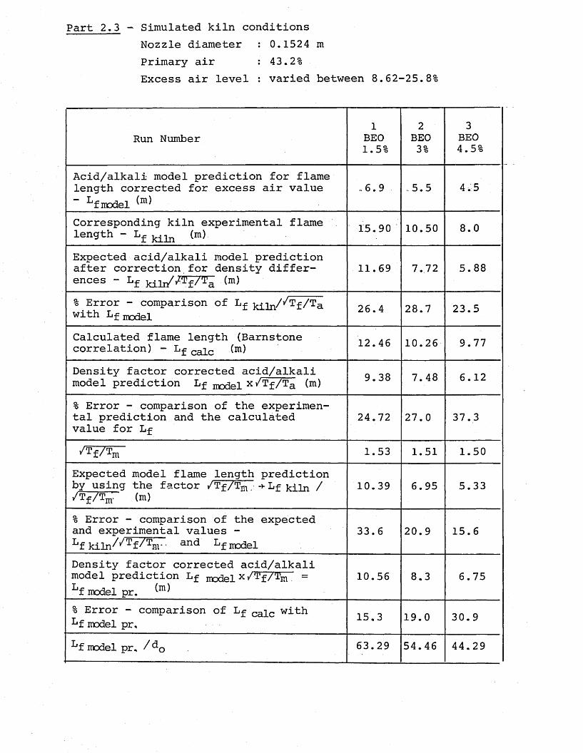
Part 2.3 - Simulated kiln conditionsNozzle diameter : 0.1524 m Primary air : 43.2%Excess air level : varied between 8.62-25.8%
Run Number1
BEO1.5%
2BEO3%
3BEO4.5%
Acid/alkali model prediction for flame length corrected for excess air value” Lfmodel ^
..6.9 -5.5 4.5
Corresponding kiln experimental flame length - Lf (m) 15.90 10.50 8.0
Expected acid/alkali model prediction after correction for density differences - Lf (m)
11.69 7.72 5.88
% Error - comparison of Lf with Lf model 26.4 28.7 23.5
Calculated flame length (Barnstone correlation) - Lf ca]_c (m) 12.46 10.26 9.77
Density factor corrected acid/alkali model prediction Lf model x/Tf/Ta (m) 9.38 7.48 6.12
% Error - comparison of the experimental prediction and the calculated value for Lf
24.72 27.0 37.3
1.53 1.51 1.50Expected model flame length prediction by using the factor /Tf/T^.+Lf win / /Tf/Tm. (m)
10.39 6.95 5.33
% Error - comparison of the expected and experimental values -Lf kiln//Tf/Tnr- and Lf model
33.6 20.9 15.6
Density factor corrected acid/alkali model prediction Lf model X^^f/Tm =Lf model pr. ^
10.56 8.3 6.75
% Error - comparison of Lf calc with Lf model pr. 15.3 19.0 30.9
Lf model pr. /^o 63.29 54.46 44.29
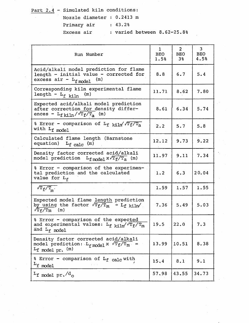
Part 2.4 - Simulated kiln conditions:Nozzle diameter : 0.2413 m Primary air : 43.2%Excess air : varied between 8.62-25.8%
Run Number1
BEO1.5%
2BEO3%
3BEO4.5%
Acid/alkali model prediction for flame length - initial value - corrected for excess air - LfTnnflp1 (m)
8.8 6.7 5.4
Corresponding kiln experimental flame length - Lf (m) 11.71 8.62 7.80
Expected acid/alkali model prediction after correction for density differences - Lf kiln/^f/Ta
8.61 6.34 5.74
% Error - comparison of Lf kilr/^f/^ with Lf model 2.2 5.7 5.8
Calculated flame length (Barnstone equation) Lf caic (m) 12.12 9.73 9.22
Density factor corrected acid/alkali model prediction Lf modelx Tf/Ta 11.97 9.11 7.34
% Error - comparison of the experimental prediction and the calculated value for Lf
1.2 6.3 20.04
/Tf/Tnf 1.59 1.57 1.55
Expected model flame length prediction by using the factor /Tf/Tra Lf kiln/ /Tf/Tm (m)
7.36 5.49 5.03
% Error - comparison of the expected and experimental values: Lf kiIi/y/Tf/Tm and Lf model
19.5 22.0 7.3
Density factor corrected acid/alkali model prediction: Lf modelx y/Tf/Tm = Lf model pr.
13.99 10.51 8.38
% Error - comparison of Lf calc with Lf model
15.4 8.1 9.1
Lf model pr./^o 57.98 43,55 34.73
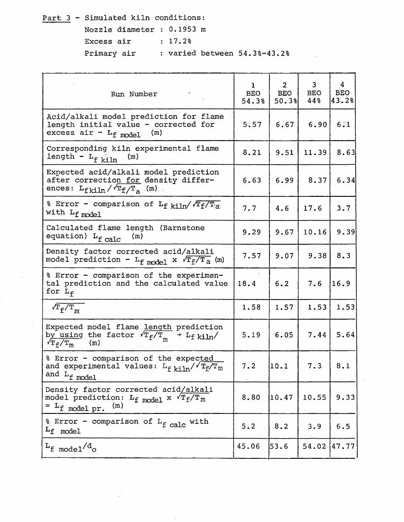
Part 3 - Simulated kiln conditions:Nozzle diameter : 0.1953 mExcess air : 17.2%Primary air : varied between 54.3%-43.2%
Run Number1
BEO54.3%
2BEO50.3%
3BEO44%
4BEO43.2%
Acid/alkali model prediction for flame length initial value - corrected for excess air - Lf (m)
5.57 6.67 6.90 6.1
Corresponding kiln experimental flame length - Lf kiln (m) 8.21 9.51 11.39 8.63
Expected acid/alkali model prediction after correction for density differ- ences: Lfkiln/^f/Ta Cm)
6.63 6.99 8.37 6.34
% Error - comparison of Lf kiln/^f/^a with Lf 7.7 4.6 17.6 3.7
Calculated flame length (Barnstone equation) Lf calc (m) 9.29 9.67 10.16 9.39
Density factor corrected acid/alkali model prediction ” Lf model x /Tf/Ta (m) 7.57 9.07 9.38 8.3
% Error - comparison of the experimental prediction and the calculated value for Lf
18.4 6.2 7.6 16.9
/T-/T f' m 1.58 1.57 1.53 1.53
Expected model flame lenqth prediction by usinq the factor /Tf/T -*• Lf -j^/ /Tf/Tm (m) m
5.19 6.05 7.44 5.64
% Error - comparison of the expected and experimental values: Lf kiin/^Tf/Tmand Lf model
7.2 10.1 7.3 8.1
Density factor corrected acid/alkali model prediction: Lf model x /Tf/Tm~ Lf model pr.
8.80 10.47 10.55 9.33
% Error - comparison of L^ cafc with Lf model 5.2 8.2 3.9 6.5
Lf model^do 45.06 53.6 54.02 47.77
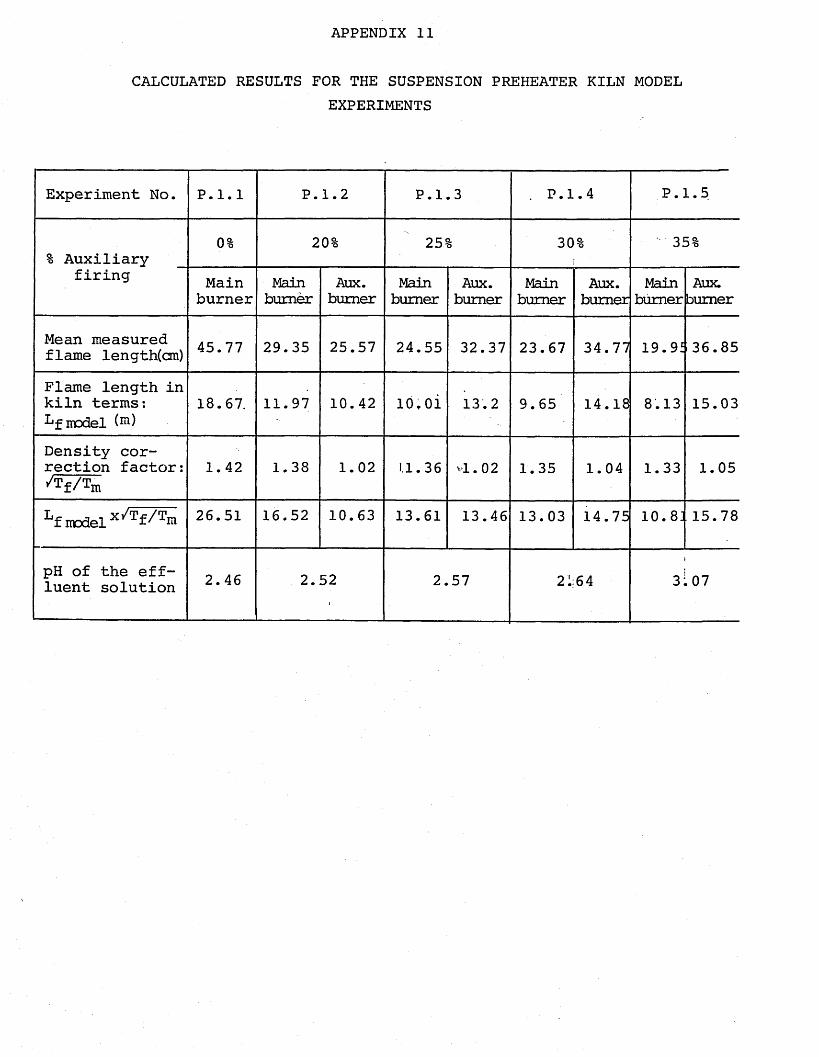
APPENDIX 11
CALCULATED RESULTS FOR THE SUSPENSION PREHEATER KILN MODELEXPERIMENTS
Experiment No. P.1.1 P. 1.2 P.l .3 . P.l .4 p .:L. 5
% Auxiliary-0% 20% 25sI 30% 35%
firing Mainburner
Mainburner
Aux.burner
Mainburner
Aux.burner
Mainburner
Aux.burner
Mainburner
Aux.burner
Mean measured flame length(cm) 45.77 29.35 25.57 24.55 32.37 23.67 34.77 19. 91 36.85
Flame length in kiln terms:Lf model (m)
18.67. 11.97 10.42 10. oi 13.2 9.65 14.18 8.13 15.03
Density correction factor: •'Tf/Tm
1.42 1.38 1.02 1.1.36 *1.02 1.35 1.04 1.33 1.05
Lf ncdel x/Tf/Tm 26.51 16.52 10.63 13.61 13.46 13.03 14.75 10. 8J 15.78
pH of the effluent solution 2.46 2.52 2.57 21 64 3.07
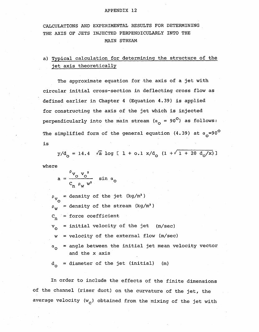
APPENDIX 12
CALCULATIONS AND EXPERIMENTAL RESULTS FOR DETERMINING THE AXIS OF JETS INJECTED PERPENDICULARLY INTO THE
MAIN STREAM
a) Typical calculation for determining the structure of the jet axis theoretically
The approximate equation for the axis of a jet with circular initial cross-section in deflecting cross flow as defined earlier in Chapter 4 (Equation 4.39) is applied for constructing the axis of the jet which is injected perpendicularly into the main stream (aQ = 90°) as follows:
The simplified form of the general equation (4.39) at ao=90° is
y/dQ = 14.4 /a log [ 1 + o.l x/dQ (1 + / 1 + 20 dQ/x) ]
wherepv v 2
a = ---------- sin aCn pw w’
p = density of the jet (kg/m3) o
p = density of the stream (kg/m3) wC = force coefficient nvq = initial velocity of the jet (m/sec)w = velocity of the external flow (m/sec)aQ = angle between the initial jet mean velocity vector
and the x axisdQ = diameter of the jet (initial) (m)
In order to include the effects of the finite dimensions of the channel (riser duct) on the curvature of the jet, the average velocity (wc) obtained from the mixing of the jet with
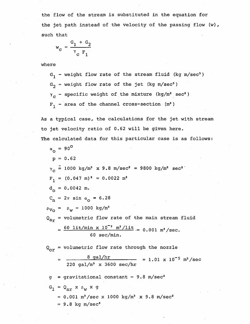
the flow of the stream is substituted in the equation for the jet path instead of the velocity of the passing flow (w), such that
G1 + G2 w = ----------rc F1
whereG^ - weight flow rate of the stream fluid (kg m/sec3)G2 - weight flow rate of the jet (kg m/sec3)Yc - specific weight of the mixture (kg/m2 sec2)F1 - area of the channel cross-section (m2)
As a typical case, the calculations for the jet with streamto jet velocity ratio of 0.62 will be given here.The calculated data for this particular case is as follows:
a = 90° op = 0.62Y = 1000 kg/m3 x 9.8 m/sec2 = 9800 kg/m2 sec2'F± = (0.047 m )2 = 0.0022 m2d^ = 0.0042 m.oC = 2tt sin a = 6.28 n opv0 = pw = 1000 k9/m3Q= = volumetric flow rate of the main stream fluid ~ar
= 60 lit/min x 10~3 myiit ;= 0>0Q1 m3/sec.60 sec/min.
Qor = volumetric flow rate through the nozzle8 gal/hr = 1.01 x 10” 5 m3/sec
220 gal/m3 x 3600 sec/hr
g = gravitational constant = 9.8 m/sec2G-, = Q x p x g 1 var Hw y
= 0.001 m3/sec x 1000 kg/m3 x 9.8 m/sec2= 9.8 kg m/sec3
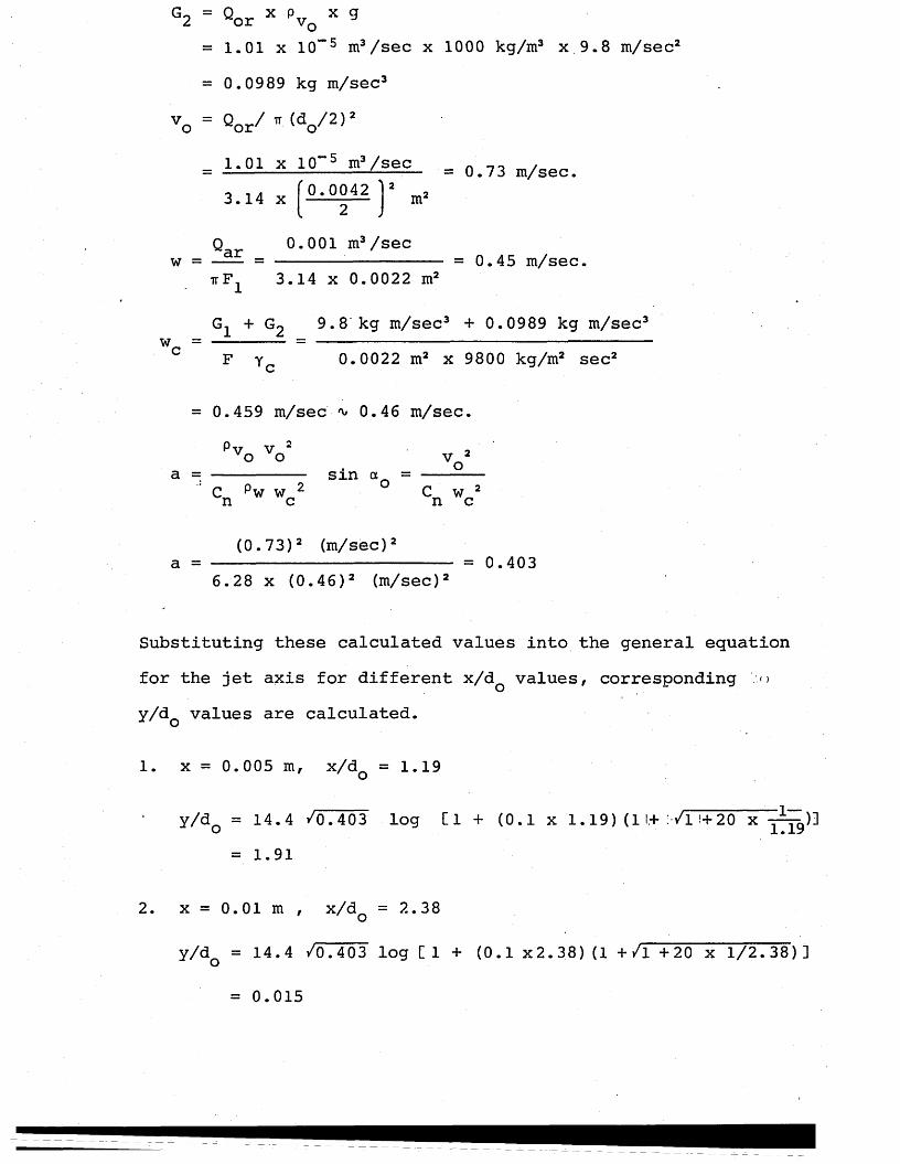
G0 = Q x p x g 2 wor vQ J= 1.01 x 10” 5 m3/sec x 1000 kg/m3 x 9.8 m/sec5 = 0.0989 kg m/sec3
vo = Qor/ * (do/2)S^_.-5
3.14 x= 1-01. x AQ 5 = o. 73 m/sec.
0.0042 ^2 nr
Q 0.001 m3/secw = —— = ------ : = 0.45 m/sec.
ttF 3.14 x 0.0022 m2
wc =G1 + G2 9.8 kg m/sec3 + 0.0989 kg m/sec: F yc 0.0022 m2 x 9800 kg/m2 sec2
= 0.459 m/sec 'v, 0.46 m/sec.Pv v 2° ° voa = --------- s m aQ = ----
C pw w 2 C w 2n c n c
(0.73)2 (m/sec)2a = ------ = 0.403
6.28 x (0.46)2 (m/sec)2
Substituting these calculated values into the general equation for the jet axis for different x/dQ values, corresponding o y/dQ values are calculated.
1. x = 0.005 m, x/dQ = 1.19
y/dQ = 14.4 /0.403 log Cl + (0.1 x 1.19) (1 I.+ Vl '■+ 20 x = 1.91
2. x = 0.01 m , x/dQ = 2.38
y/dQ = 14.4 /0.403 log Cl + (0.1 x 2. 38) (1 + /l +20 x 1/2.38) ]
= 0.015
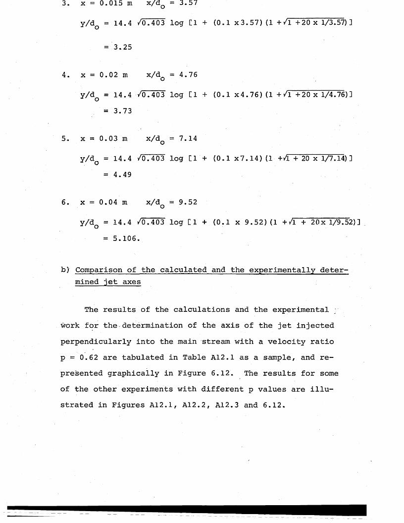
3. x = 0.015m x/^0 =3.57
y/dQ = 14.4 /0.403 log Cl + (0.1 x3.57) (1 + /l +20 x 1/3.57) ]
= 3.25
4. x = 0.0 2 m x/^0 = 4.76
y/dQ = 14.4 VO.403 log [1 + (0.1 x4.76) (1 + /l +20 x 1/4.76)]= 3.73
5. x = 0.03 m x/^0 = 7.14
y/dQ = 14.4 /0.403 log [1 + (0.1 X7.14) (1 +/L + 20 x 1/7.14)3 = 4.49
6. x = 0.04 m x/d^ =9.52oy/dQ = 14.4 /0.403 log Cl + (0.1 x 9.52) (1 +/1 + 20x 1/9.52)]
= 5.106.
b) Comparison of the calculated and the experimentally determined jet axes
The results of the calculations and the experimental ; work for the determination of the axis of the jet injected perpendicularly into the main stream with a velocity ratio p = 0.62 are tabulated in Table A12.1 as a sample, and represented graphically in Figure 6.12. The results for some of the other experiments with different p values are illustrated in Figures A12.1, A12.2, A12.3 and 6.12.
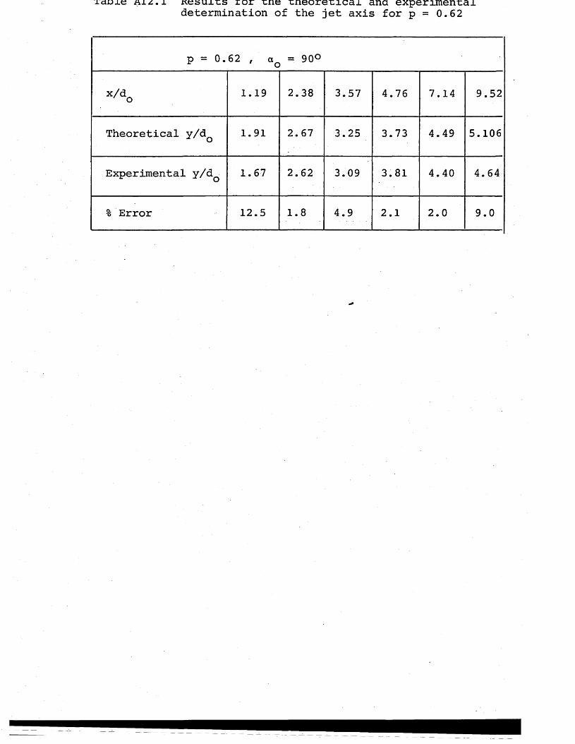
xaoxe Aiz.i results ror rne tneoreticai and experimental determination of the jet axis for p = 0.62
p = 0.62 , a = 90° c o
x/do 1.19 2.38 3.57 4.76 7.14 9.52
Theoretical y/d_ u o 1.91 2.67 3.25 3.73 4.49 5.106
Experimental y/&Q 1.67 2.62 3.09 3.81 4.40 4.64
% Error 12.5 1.8 4.9 2.1 2.0 9.0
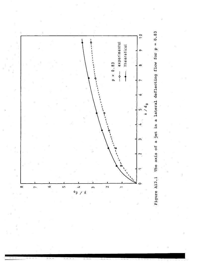
o
OLmC O oo
O n
Ov OC O in m
cooo
IICkUOvwSOr-1mtG •H -P O 0 i—Im0'di—i<dP0-P00G•H-P 0 •I—»0mom
•HX00EH
C N
0uptr>•HP4
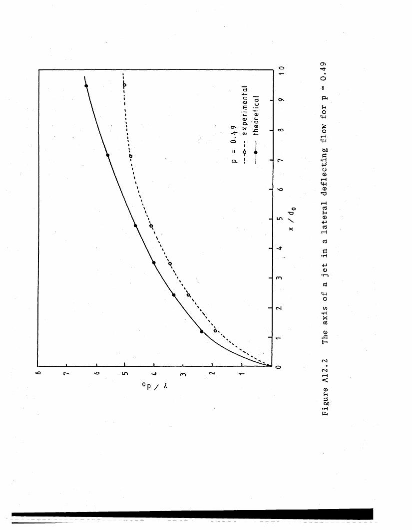
CJ.
CNCJ
CL Os x<J" CJ O i
QJ OO
Ln
m
oo in m
oTO
\X
p / k
Figure A12.2
The axis of
a jet
in
a lateral
deflecting flow
for p
-0.4
9
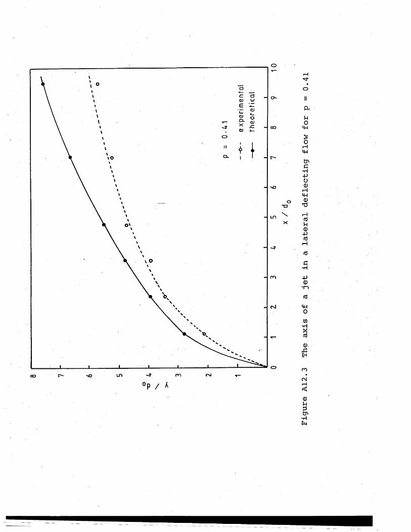
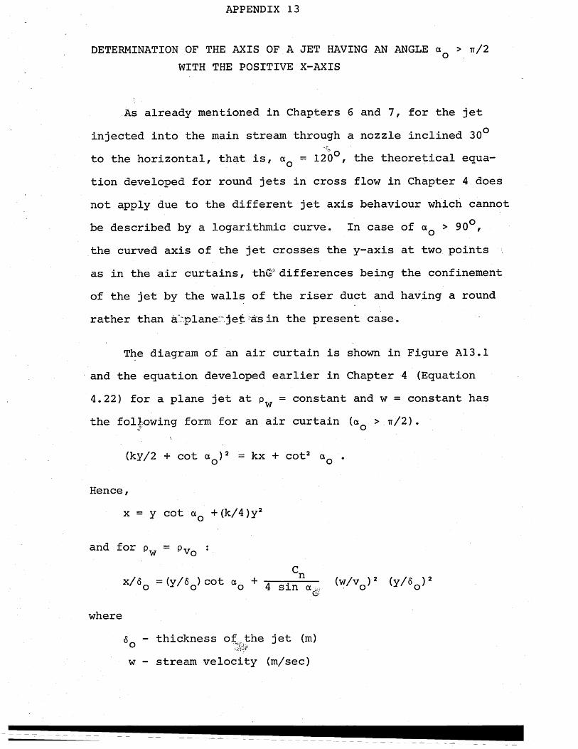
APPENDIX 13
DETERMINATION OF THE AXIS OF A JET HAVING AN ANGLE a > ir/2oWITH THE POSITIVE X-AXIS
As already mentioned in Chapters 6 and 7, for the jet injected into the main stream through a nozzle inclined 30° to the horizontal, that is, aQ = 120°, the theoretical equation developed for round jets in cross flow in Chapter 4 does not apply due to the different jet axis behaviour which cannot be described by a logarithmic curve. In case of aQ > 90°, the curved axis of the jet crosses the y-axis at two points . as in the air curtains, th(s* differences being the confinement of the jet by the walls of the riser duct and having a round rather than ahplane:.'. jet 'as in the present case .
The diagram of an air curtain is shown in Figure A13.1 and the equation developed earlier in Chapter 4 (Equation 4.22) for a plane jet at pw = constant and w = constant has the following form for an air curtain (aQ > tt/2) .
v
(ky/2 + cot aQ )2 = kx + cot2 aQ .
Hence,x = y cot aQ +(k/4)y2
and for Pw = PVo :
x/60 =<y/« >cot ocQ + 4 8lnV : <w/v0 >2 (y/«0 )2
where6 - thickness of the jet (m)°w - stream velocity (m/sec)
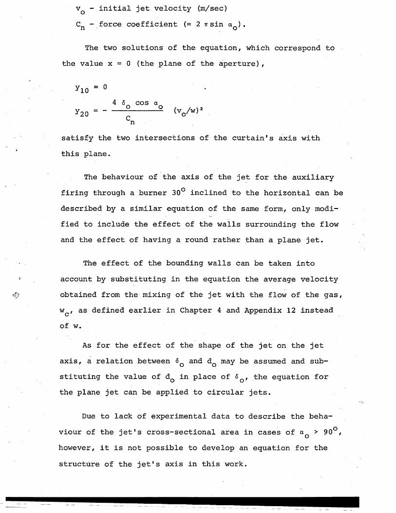
v q - initial jet velocity (m/sec)CR - force coefficient (= 2 tt sin aQ) .
The two solutions of the equation, which correspond to the value x = 0 (the plane of the aperture),
*10 = 04 6 cos a
*20 = " — !------2 (vo/w)2n
satisfy the two intersections of the curtain's axis with this plane.
The behaviour of the axis of the jet for the auxiliary firing through a burner 30° inclined to the horizontal can be described by a similar equation of the same form, only modified to include the effect of the walls surrounding the flowand the effect of having a round rather than a plane jet.
The effect of the bounding walls can be taken into account by substituting in the equation the average velocity obtained from the mixing of the jet with the flow of the gas, wc, as defined earlier in Chapter 4 and Appendix 12 instead of w.
As for the effect of the shape of the jet on the jet axis, a relation between and dQ may be assumed and substituting the value of dQ in place of <5Q, the equation for the plane jet can be applied to circular jets.
Due to lack of experimental data to describe the behaviour of the jet's cross-sectional area in cases of a > 90°,ohowever, it is not possible to develop an equation for the structure of the jet's axis in this work.
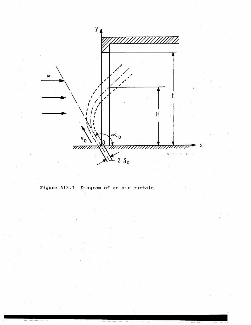
►
vY^-\^o °\ .‘vO \ v
7777777777^y7Z777777777777777777777777777T7*" x
Figure A13.1 Diagram of an air curtain