conceptual design of complex hydromechanical
TRANSCRIPT
Linköping Studies in Science and TechnologyDissertations No. 1883
Conceptual Design of ComplexHydromechanical Transmissions
Karl Uebel
Division of Fluid and Mechatronic SystemsDepartment of Management and Engineering
Linköping University, SE–581 83 Linköping, Sweden
Linköping 2017
Copyright c© Karl Uebel, 2017
Conceptual Design of Complex Hydromechanical Transmissions
ISBN 978-91-7685-447-1ISSN 0345-7524
Distributed by:Division of Fluid and Mechatronic SystemsDepartment of Management and EngineeringLinköping UniversitySE-581 83 Linköping, Sweden
Printed in Sweden by LiU-Tryck, Linköping 2017.
Abstract
This thesis explores the conceptual design process of complex hydromechanicaltransmissions for mobile working machines. Efficient methods for design opti-misation and controller development are presented to support the final conceptselection.
In the endeavour to develop new fuel-efficient driveline solutions for con-struction machines and off-road equipment new complex hydromechanicaltransmission concepts are being investigated. This pursuit is driven by stricteremission legislation, high fuel prices and a desire for a greener image both forcustomers and manufacturers. The trend towards more complex transmissionarchitectures increases the need for more sophisticated product developmentmethods. Complex multiple-mode transmissions are difficult to design andprototype and can be realised in a great number of architectures. By intro-ducing a secondary energy storage in the machine the design space expandsfurther for both hardware and software. There is accordingly a need for morereliable concept assessment in early design stages and the possibility to supportconcurrent engineering throughout the development process.
Previous research on the design and development of hydromechanical trans-missions has been limited to analysis of fixed concept designs or design opti-misation using very simple performance indicators. Existing methodologies forelectrified on-road vehicles are not suitable for off-road working machines withhydromechanical transmissions and hydraulic energy storage.
The proposed conceptual design process uses detailed quasi-static simula-tion models and targets to optimise the fuel efficiency of the specific machinespecifications and operations. It is also shown how high-speed dynamic simula-tions can be used for controller development and hardware-in-the-loop simula-tions to support an efficient product design process. The methods are demon-strated for typical use cases targeting new transmission development for con-struction machines. Software control development is also treated using controloptimisation and real-time simulation. Finally a novel hybrid hydromechanicalmotion system is presented for which an efficient design process is crucial to itsend performance.
i

ii
PopulärvetenskapligSammanfattning
I denna avhandling presenteras nya metoder för utveckling av energieffektivatransmissioner för tunga arbetsfordon och entreprenadmaskiner. Genom attkombinera numerisk optimering av hårdvara och mjukvara tillsammans meddetaljerade simuleringar av maskinens bränsleförbrukning kan designprocessengöras mer effektiv.
Idag finns det en trend mot utveckling av nya energieffektiva hydraul-mekaniska transmissioner och hybridisering av mobila arbetsfordon somexempelvis hjullastare, skogsmaskiner och jordbrukstraktorer. Motiven ärbland annat höga bränslekostnader, hårdare lagstiftning på utsläpp ochföretagens önskan om en grönare profil. En hydraulmekanisk transmissionkombinerar hydraulisk och mekanisk effektöverföring och har kontinuerligtvarierbar utväxling som möjliggör en effektivare framdrivning.
När komplexiteten på transmissionen ökar behövs mer moderna produkt-utvecklingsmetoder. En flerväxlad hydraulmekanisk transmission kan göras iväldigt många utföranden och för hybridfordon med ett extra energilager blirdet än mer komplicerat att välja rätt design.
Metoderna som har använts i denna avhandling optimerar utförandetpå transmissionen genom att simulera maskinen under typiska arbetscykleroch välja den bästa designen ur bränslesynpunkt. Vidare visas hur manmer noggrant kan utvärdera olika koncept genom att simulera delar avtransmissionen och låta modellerna interagera i realtid med fysiska tester.På detta sätt går det att få mer kunskap tidigt i produktutvecklingsprocessenoch därmed undvika att behöva bygga kostsamma prototyper.
Slutligen presenteras ett helt nytt innovativt hybridkoncept för hjullastaremed hög potential för bränslebesparingar. Designmetodiken för konceptet visarsig vara av avgörande betydelse för dess slutliga prestanda.
iii

iv
Acknowledgements
The work in this thesis has been carried out at the Division of Fluid andMechatronic Systems at Linköping University and at Driveline Systems atVolvo Construction Equipment in Eskilstuna.
I would like to thank my main supervisor Petter Krus for his guidance andfor giving me a lot of freedom in my work. I would also like to thank myco-supervisor Jan-Ove Palmberg, who gave me the opportunity to start myPhD studies at Flumes. My other colleagues at Flumes have certainly madethe university a great place to work in. I will in particular remember the tripswe have made together to various conferences, seminars and company visitsaround the world.
The second part of my PhD has been carried out at Volvo ConstructionEquipment in Eskilstuna, where I have truly learned a lot thanks to greatcolleagues. This time has really helped me to see my research from an industryperspective. In particular I would like to thank Henric Lövgren for allowing meto continue my research at Volvo and for always showing trust in me. I wouldalso like to thank Per Mattsson for your precise reviews of my work and KimHeybroek for guidance and inspiration.
Finally I would like to thank Charlotte and Amelie for your love and sup-port. I cannot believe how lucky I am to have you in my life and I treasureevery day together with you.
v

vi
Abbreviations
BSFC Brake Specific Fuel ConsumptionCPR Common Pressure RailCVT Continuously Variable TransmissionDIRECT Dividing RectanglesDP Dynamic ProgrammingECMS Equivalent Consumption Minimisation StrategyEMS Energy Management StrategyGA Genetic AlgorithmGUI Graphical User InterfaceHMT Hydromechanical TransmissionHST Hydrostatic TransmissionHWIL Hardware-in-the-LoopICE Internal Combustion EngineICPS Input-Coupled Power-SplitKD Kick-DownMPC Model Predictive ControllerNN Neural NetworkOC Open-CircuitOCPS Output-Coupled Power-SplitOCV Open-Circuit with ValvePM Pump/MotorPSO Particle Swarm OptimisationSA Simulated AnnealingSCS Secondary Controlled SystemSDP Stochastic Dynamic ProgrammingSOC State-of-ChargeSQP Sequential Quadratic ProgrammingTLM Transmission Line ModellingVDLA Variable Displacement Linear Actuator
vii

viii
Papers
This thesis is based on the following seven appended papers, which will bereferred to by their roman numerals. In the time of writing, paper [VII] isnot yet published and there may therefore be modifications after the reviewprocess is complete. All other papers are printed in their original state withthe exception of changes to the formatting and minor errata. For papers [I],[II], [III] and [V] the first author is the main responsible for the work withsupport from the co-authors. For paper [IV] the first three authors are mutuallyresponsible for the work with support from the last co-author. For paper [VI]the first author is the responsible for the paper, whereas the first co-authorhas been part of the development of the concept and the last co-authors havebeen supporting the work. For paper [VII] the first two authors are mutuallyresponsible for the work with support from the other co-authors.
[I] K. Pettersson and P. Krus. ‘Design Optimization of Complex Hydro-mechanical Transmissions’. In: Journal of Mechanical Design 135.9(2013). doi: 10.1115/1.4024732.
[II] K. Pettersson and P. Krus. ‘Optimisation and Concept Sensitivity ofContinuously Variable Hydromechanical Transmissions’. In: 8th In-ternational Conference on Fluid Power Transmission and Control,(ICFP2013). Hangzhou, China, 2013.
[III] K. Pettersson and P. Krus. ‘Modular Design of Hydromechanical Trans-missions for Mobile Working Machines’. In: 13th Scandinavian Inter-national Conference on Fluid Power (SICFP2013). Linköping, Sweden,2013.
[IV] K. Pettersson, L. V. Larsson, K. V. Larsson and P. Krus. ‘SimulationAided Design and Testing of Hydromechanical Transmissions’. In: 9thJFPS International Symposium on Fluid Power. Matsue, Japan, 2014.
[V] L. V. Larsson, K. Pettersson and P. Krus. ‘Mode Shifting in Hy-brid Hydromechanical Transmissions’. In: ASME/BATH Symposiumon Fluid Power and Motion Control, (FPMC2015). Chicago, Illinois,USA, 2015.
ix
[VI] K. Pettersson, K. Heybroek, P. Mattsson and P. Krus. ‘A Novel Hydro-mechanical Hybrid Motion System for Construction Machines’. In: In-ternational Journal of Fluid Power 18.1 (2017), pp. 17–28. doi: 10.1080/14399776.2016.1210423.
[VII] K. Uebel, H. Raduenz, P. Krus and V. J. de Negri. ‘Design OptimisationStrategies for a Hydraulic Hybrid Wheel Loader’. In: ASME/BATHSymposium on Fluid Power and Motion Control (FPMC2018). Bath,United Kingdom, 2018.
The following papers are not included in the thesis but relate to the same topicand constitute an important part of the background.
[VIII] K. Pettersson, K.-E. Rydberg and P. Krus. ‘Comparative Study of Mul-tiple Mode Power Split Transmissions for Wheel Loaders’. In: The 12thScandinavian International Conference on Fluid Power (SICFP2011),May 18-20. Tampere, Finland, 2011.
[IX] K. Pettersson and P. Krus. ‘Optimering av komplexa hydraulmekaniskatransmissioner för hjullastare’. In: Hydraulikdagarna 2012. Linköping,Sweden, 2012.
[X] K. Pettersson and K. Heybroek. ‘Hydrauliskt hybridsystem för anläggn-ingsmaskiner - Delat energilager är dubbelt energilager’. In: Hydraul-ikdagarna 2015. Linköping, Sweden, 2015.
Additional papers by the author:
[XI] K. Pettersson and S. Tikkanen. ‘Secondary Control in ConstructionMachinery: Design and Evaluation of an Excavator Swing Drive’.In: 11th Scandinavian International Conference on Fluid Power(SICFP2009). Linköping, Sweden, 2009.
[XII] M. Axin, R. Braun, A. Dell’Amico, B. Eriksson, P. Nordin, K. Pet-tersson, I. Staack and P. Krus. ‘Next Generation Simulation Softwareusing Transmission Line Elements’. In: ASME/BATH Symposium onFluid Power and Motion Control (FPMC2010). Bath, United Kingdom,2010.
[XIII] K. Pettersson, K. Heybroek, A. Klintemyr and P. Krus. ‘Analysis andcontrol of a complementary energy recuperation system’. In: 8th Inter-national Fluid Power Conference (IFK2012). Dresden, Germany, 2012.
[XIV] A. Hugo, K. Pettersson, K. Heybroek and P. Krus. ‘Modelling andControl of a Complementary Energy Recuperation System for MobileWorking Machines’. In: 13th Scandinavian International Conference onFluid Power (SICFP2013). Linköping, Sweden, 2013.
x
Contents
1 Introduction 1
1.1 Objectives . . . . . . . . . . . . . . . . . . . . . . . . . . . . . . 3
1.2 Contributions . . . . . . . . . . . . . . . . . . . . . . . . . . . . 3
1.3 Thesis Outline . . . . . . . . . . . . . . . . . . . . . . . . . . . 4
2 Hydromechanical Transmissions 5
2.1 Classification . . . . . . . . . . . . . . . . . . . . . . . . . . . . 5
2.1.1 Single-mode Transmissions . . . . . . . . . . . . . . . . 5
2.1.2 Multiple-mode Transmissions . . . . . . . . . . . . . . . 6
2.1.3 Hydraulic Hybrid Drivelines . . . . . . . . . . . . . . . . 8
2.2 State-of-the-Art . . . . . . . . . . . . . . . . . . . . . . . . . . . 9
2.2.1 Hydrostatic Transmissions . . . . . . . . . . . . . . . . . 9
2.2.2 Power-split Transmissions . . . . . . . . . . . . . . . . . 10
2.2.3 Hydraulic Hybrid Concepts . . . . . . . . . . . . . . . . 10
3 Conceptual Design Process 13
3.1 Concept Generation . . . . . . . . . . . . . . . . . . . . . . . . 14
3.2 Preliminary Sizing . . . . . . . . . . . . . . . . . . . . . . . . . 15
3.2.1 Modelling . . . . . . . . . . . . . . . . . . . . . . . . . . 15
3.2.2 Simulation . . . . . . . . . . . . . . . . . . . . . . . . . 16
3.3 Detailed Simulation . . . . . . . . . . . . . . . . . . . . . . . . 17
3.4 Hardware-in-the-Loop . . . . . . . . . . . . . . . . . . . . . . . 18
xi
4 Design Optimisation 21
4.1 Optimisation Methodology . . . . . . . . . . . . . . . . . . . . 21
4.1.1 Objective Function . . . . . . . . . . . . . . . . . . . . . 22
4.1.2 Optimisation Algorithm . . . . . . . . . . . . . . . . . . 22
4.1.3 Explicit Design Relations . . . . . . . . . . . . . . . . . 23
4.1.4 Controller . . . . . . . . . . . . . . . . . . . . . . . . . . 23
4.1.5 Simulation Model . . . . . . . . . . . . . . . . . . . . . . 24
4.1.6 Combined Design and Controller Optimisation . . . . . 24
4.2 Use Case: Multiple-mode Power-split Transmission . . . . . . . 27
4.2.1 Concept . . . . . . . . . . . . . . . . . . . . . . . . . . . 27
4.2.2 Optimisation . . . . . . . . . . . . . . . . . . . . . . . . 28
4.2.3 Results . . . . . . . . . . . . . . . . . . . . . . . . . . . 29
4.2.4 Discussion . . . . . . . . . . . . . . . . . . . . . . . . . . 31
4.3 Use Case: Parallel Hydraulic Hybrid Wheel Loader . . . . . . . 31
4.3.1 Concept . . . . . . . . . . . . . . . . . . . . . . . . . . . 32
4.3.2 Optimisation . . . . . . . . . . . . . . . . . . . . . . . . 32
4.3.3 Results . . . . . . . . . . . . . . . . . . . . . . . . . . . 34
4.3.4 Discussion . . . . . . . . . . . . . . . . . . . . . . . . . . 36
5 Dynamic Simulation and Testing 37
5.1 Offline Simulation . . . . . . . . . . . . . . . . . . . . . . . . . 38
5.2 Hardware-in-the-Loop Simulation . . . . . . . . . . . . . . . . . 39
5.3 Results and Discussion . . . . . . . . . . . . . . . . . . . . . . . 40
6 A Novel Hybrid Hydromechanical Transmission Concept 43
6.1 Concept . . . . . . . . . . . . . . . . . . . . . . . . . . . . . . . 44
6.1.1 Work Functions . . . . . . . . . . . . . . . . . . . . . . . 45
6.1.2 Driveline . . . . . . . . . . . . . . . . . . . . . . . . . . 45
6.2 Simulation . . . . . . . . . . . . . . . . . . . . . . . . . . . . . . 47
6.3 Discussion . . . . . . . . . . . . . . . . . . . . . . . . . . . . . . 49
7 Discussion 51
xii
8 Conclusions 53
9 Review of Papers 55
References 59
Appended Papers
I Design Optimization of Complex Hydromechanical Trans-missions 71
II Optimisation and Concept Sensitivity of Continuously Vari-able Hydromechanical Transmissions 95
III Modular Design of Hydromechanical Transmissions for Mo-bile Working Machines 109
IV Simulation Aided Design and Testing of HydromechanicalTransmissions 127
V Mode Shifting in Hybrid Hydromechanical Transmissions 145
VI A Novel Hydromechanical Hybrid Motion System for Con-struction Machines 173
VII Design Optimisation Strategies for a Hydraulic HybridWheel Loader 197
xiii

xiv
1Introduction
The off-road industry today faces the challenge of developing machines fasterthan ever before, with higher customer demands and stricter regulations onemissions, noise levels, functional safety and design standards. This needs tobe done with a continuously changing supplier base handling component tech-nologies with rapid changes in performance and cost. Driveline development inparticular is also facing a technology shift where the conventional mechanic/hy-drodynamic solutions are being replaced with more advanced high-efficiencydriveline configurations.
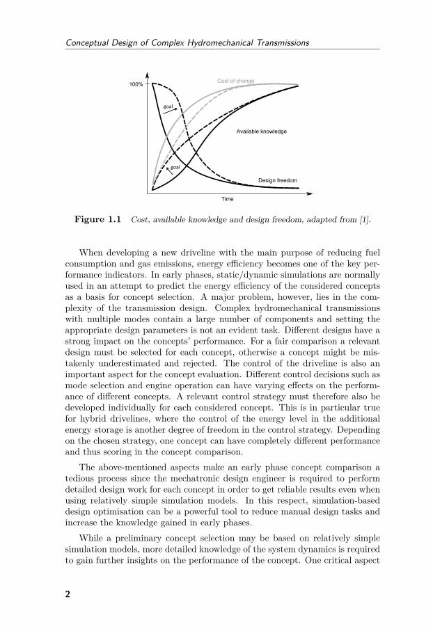
The design process of new drivelines usually include an early conceptualdesign phase where the main system configuration is decided. During thisprocess, numerous concepts are explored and evaluated based on the systemrequirements, technology risks, development costs, machine integration aspects,etc. The target is to define the system architecture and subsystems to set thescope for the upcoming detailed development phase. The off-road industry hastraditionally relied on heuristic design principles and a high degree of functionalprototyping to develop new drivelines. With increased computational powerand modern software tools, the concept decision relies today more and moreon simulation to predict the performance of the studied concepts. This in turnhas been an enabler for set-based engineering, where several concepts can bekept under consideration during a long period without radically increasing theengineering effort. The purpose is to gain as much knowledge of the designspace as possible before ‘freezing’ the design. This way, early decisions withhigh impact on cost can be avoided, see Fig. 1.1.
1
Conceptual Design of Complex Hydromechanical Transmissions
Figure 1.1 Cost, available knowledge and design freedom, adapted from [1].
When developing a new driveline with the main purpose of reducing fuelconsumption and gas emissions, energy efficiency becomes one of the key per-formance indicators. In early phases, static/dynamic simulations are normallyused in an attempt to predict the energy efficiency of the considered conceptsas a basis for concept selection. A major problem, however, lies in the com-plexity of the transmission design. Complex hydromechanical transmissionswith multiple modes contain a large number of components and setting theappropriate design parameters is not an evident task. Different designs have astrong impact on the concepts’ performance. For a fair comparison a relevantdesign must be selected for each concept, otherwise a concept might be mis-takenly underestimated and rejected. The control of the driveline is also animportant aspect for the concept evaluation. Different control decisions such asmode selection and engine operation can have varying effects on the perform-ance of different concepts. A relevant control strategy must therefore also bedeveloped individually for each considered concept. This is in particular truefor hybrid drivelines, where the control of the energy level in the additionalenergy storage is another degree of freedom in the control strategy. Dependingon the chosen strategy, one concept can have completely different performanceand thus scoring in the concept comparison.
The above-mentioned aspects make an early phase concept comparison atedious process since the mechatronic design engineer is required to performdetailed design work for each concept in order to get reliable results even whenusing relatively simple simulation models. In this respect, simulation-baseddesign optimisation can be a powerful tool to reduce manual design tasks andincrease the knowledge gained in early phases.
While a preliminary concept selection may be based on relatively simplesimulation models, more detailed knowledge of the system dynamics is requiredto gain further insights on the performance of the concept. One critical aspect
2
Introduction
in particular is the shifting process for multiple-mode hydromechanical trans-missions in which the hydraulic pump/motor dynamics interact with the mech-anical components. This type of simulation-based analysis is normally moredifficult to automate for a large number of concepts and is more dependenton engineering judgement. Hardware-in-the-Loop simulation is a powerful toolto further decrease the need for transmission prototyping and vehicle testing.Parts of the system can then be tested and other parts of the system simulated.By having the simulation models interact with hardware subsystems in real-time, a more realistic test case is achieved. Furthermore, the test environmentcan be more flexible since it is easier to alter a simulation model than a hard-ware installation. This allows the design process to consider more conceptsalso during late phases in the conceptual design process without the need forphysical prototyping.
1.1 Objectives
The main objective of this thesis is to increase efficiency in the conceptualdesign process of hydromechanical transmissions. Another objective is to sup-port a set-based engineering approach throughout the design process to reducethe risk of unnecessary design iterations. The work targets preliminary sizing,detailed dynamic simulations and simulation-aided testing of hydromechanicaltransmissions. More specifically, the following research questions are formu-lated:RQ1: How can optimisation be used in the design of complex hydromechanical
transmission concepts in early product development phases?RQ2: How can the energy management strategy be treated in the design
optimisation of hydraulic hybrid working machines?RQ3: How can critical dynamic properties of hydromechanical transmissions
be efficiently tested and assessed before a concept selection?
1.2 Contributions
In summary, the scope of this thesis comprises new methods for an improvedproduct design process of complex hydromechanical transmissions. The specificcontributions are:
• Methods for preliminary design optimisation with the focus on energyefficiency.
• Demonstration of design strategies combining energy management anddesign optimisation in hydraulic hybrid machines.
3
Conceptual Design of Complex Hydromechanical Transmissions
• An analysis of the mode shifting control aspects and a classification ofmode shifts for hydromechanical transmissions.
• A simulation platform for high-speed dynamic simulation of hydro-mechanical transmissions.
• A modular Hardware-in-the-Loop test rig suitable for concept assessmentand reuse of offline simulation models.
• A novel hybrid hydromechanical system concept for wheel loaders withshared energy storage between the machine subsystems.
The focus application was wheel loaders, which is a suitable example that isreused throughout the thesis. The methods, however, also apply to other mo-bile working machines found in for instance agriculture, forestry and materialhandling where hydromechanical transmissions are valid driveline solutions.The methods may well also be fully or partly applicable for a wider range ofdriveline design applications.
1.3 Thesis Outline
The second and third chapters constitute the frame of reference for the thesiswith the purpose of setting the contributions in perspective from the currentstate of knowledge in the area. The second chapter introduces the area of hydro-mechanical transmissions with the focus on transmission architectures, whichis the main target for an early concept selection. The current state-of-the-art inindustry is also summarised. The third chapter presents the conceptual designprocess on a high level and relates the activities to previous research in theareas. Chapters four and five summarise the main contributions of the thesis.In chapter four, the methodology of design optimisation of hydromechanicaltransmissions is introduced and demonstrated for two use cases - one multiple-mode power-split concept and one parallel hybrid concept. In chapter five,dynamic simulation and testing are demonstrated with the use of high-speedsimulation software and a Hardware-in-the-Loop test rig. In chapter six, anew hydromechanical hybrid motion system is shown and discussed in terms ofdesign challenges. Chapters seven and eight respectively contain a discussionand conclusions and chapter nine provides brief review of the appended papers.
4
2Hydromechanical
Transmissions
This section gives an overview of the classification and typical applicationsfor Hydromechanical Transmissions (HMTs) with the focus on mobile work-ing machines, where they are typically found. HMTs can be characterisedas transmissions that transfer power both hydraulically and mechanically. Incontrast to passenger cars and commercial vehicles normally equipped withstepped gearboxes, mobile working machines often require a continuously vari-able or at least a narrowly stepped torque/speed conversion range for goodoperability. This can be done with a hydraulic power transformation wherea variable torque/speed ratio is achieved through the control of pump/motordisplacements. By combining a hydrostatic power transformation with mech-anical gears and clutches a wide torque/speed conversion range can be realisedin a relatively simple configuration.
2.1 Classification
2.1.1 Single-mode Transmissions
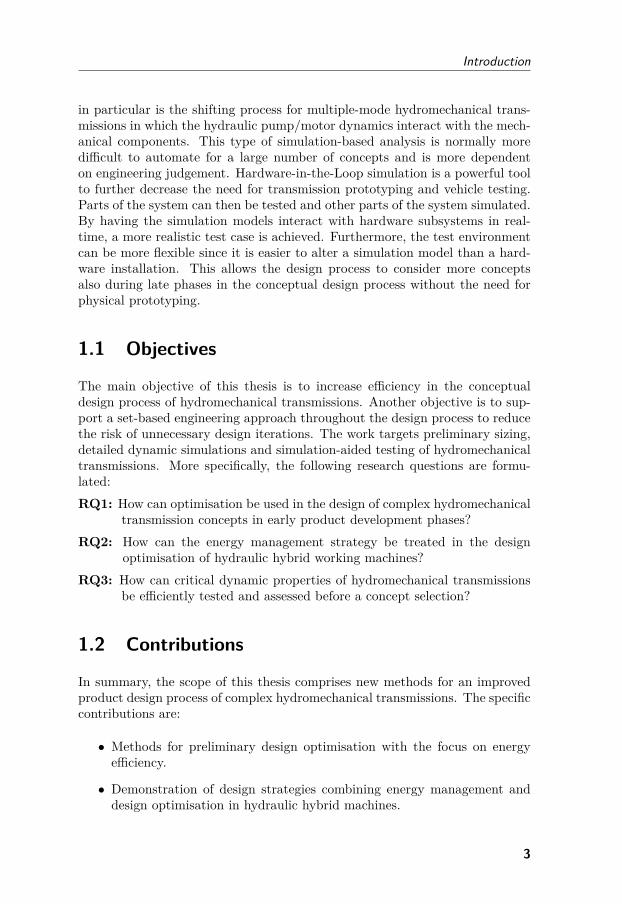
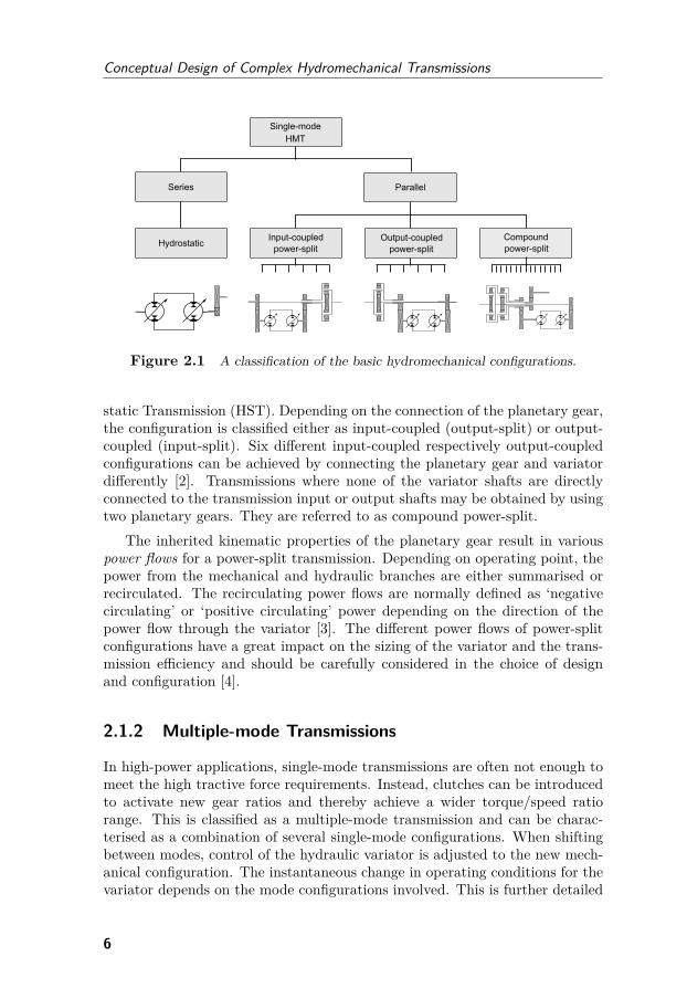
Single-mode HMTs can be categorised as series or parallel configurations, seeFig. 2.1. In a series hydrostatic configuration all power is transferred hy-draulically and mechanically in series. The parallel power-split configurationdivides the power into a mechanical branch and a hydrostatic branch connec-ted in parallel. The summation/split of power between the hydraulic variator,i.e. the pump and motor assembly, and the mechanical shaft is accomplishedby using one or several planetary gears. Since part of the power is alwaystransferred mechanically, the power losses are often smaller than for a Hydro-
5
Conceptual Design of Complex Hydromechanical Transmissions
Figure 2.1 A classification of the basic hydromechanical configurations.
static Transmission (HST). Depending on the connection of the planetary gear,the configuration is classified either as input-coupled (output-split) or output-coupled (input-split). Six different input-coupled respectively output-coupledconfigurations can be achieved by connecting the planetary gear and variatordifferently [2]. Transmissions where none of the variator shafts are directlyconnected to the transmission input or output shafts may be obtained by usingtwo planetary gears. They are referred to as compound power-split.
The inherited kinematic properties of the planetary gear result in variouspower flows for a power-split transmission. Depending on operating point, thepower from the mechanical and hydraulic branches are either summarised orrecirculated. The recirculating power flows are normally defined as ‘negativecirculating’ or ‘positive circulating’ power depending on the direction of thepower flow through the variator [3]. The different power flows of power-splitconfigurations have a great impact on the sizing of the variator and the trans-mission efficiency and should be carefully considered in the choice of designand configuration [4].
2.1.2 Multiple-mode Transmissions
In high-power applications, single-mode transmissions are often not enough tomeet the high tractive force requirements. Instead, clutches can be introducedto activate new gear ratios and thereby achieve a wider torque/speed ratiorange. This is classified as a multiple-mode transmission and can be charac-terised as a combination of several single-mode configurations. When shiftingbetween modes, control of the hydraulic variator is adjusted to the new mech-anical configuration. The instantaneous change in operating conditions for thevariator depends on the mode configurations involved. This is further detailed
6
Hydromechanical Transmissions
in paper [V]. In general, the functionality of each multiple-mode concept canbe described by listing the mode configurations in the concept. Naturally, thenumber of possible multiple-mode concepts increases logarithmically with thenumber of modes. Not all combinations are functionally meaningful. Never-theless, the variety of possible concepts is very large already for two modes andabove.
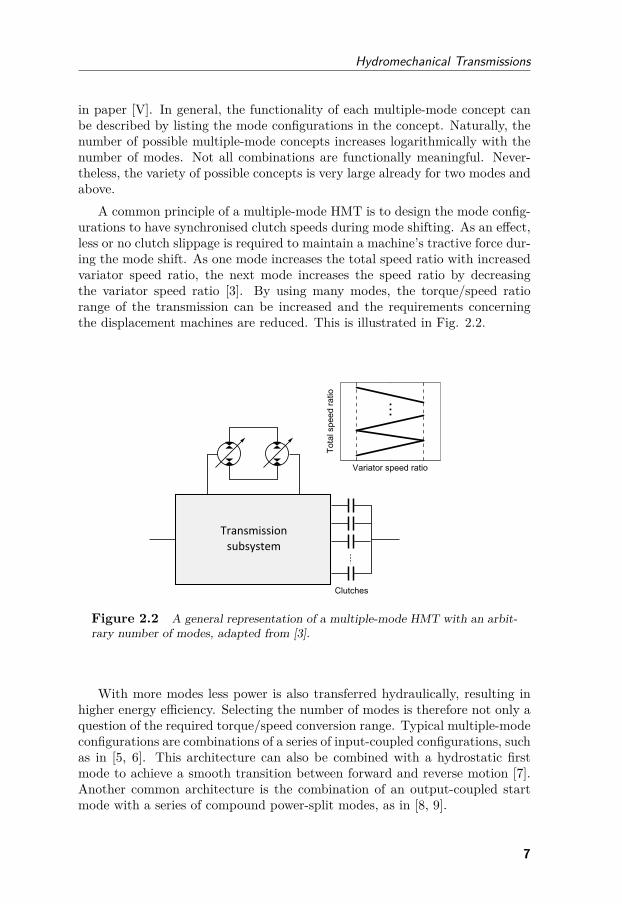
A common principle of a multiple-mode HMT is to design the mode config-urations to have synchronised clutch speeds during mode shifting. As an effect,less or no clutch slippage is required to maintain a machine’s tractive force dur-ing the mode shift. As one mode increases the total speed ratio with increasedvariator speed ratio, the next mode increases the speed ratio by decreasingthe variator speed ratio [3]. By using many modes, the torque/speed ratiorange of the transmission can be increased and the requirements concerningthe displacement machines are reduced. This is illustrated in Fig. 2.2.
Figure 2.2 A general representation of a multiple-mode HMT with an arbit-rary number of modes, adapted from [3].
With more modes less power is also transferred hydraulically, resulting inhigher energy efficiency. Selecting the number of modes is therefore not only aquestion of the required torque/speed conversion range. Typical multiple-modeconfigurations are combinations of a series of input-coupled configurations, suchas in [5, 6]. This architecture can also be combined with a hydrostatic firstmode to achieve a smooth transition between forward and reverse motion [7].Another common architecture is the combination of an output-coupled startmode with a series of compound power-split modes, as in [8, 9].
7
Conceptual Design of Complex Hydromechanical Transmissions
2.1.3 Hydraulic Hybrid Drivelines
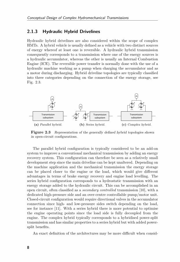
Hydraulic hybrid drivelines are also considered within the scope of complexHMTs. A hybrid vehicle is usually defined as a vehicle with two distinct sourcesof energy whereof at least one is reversible. A hydraulic hybrid transmissionconsequently corresponds to a transmission where one of the energy sources isa hydraulic accumulator, whereas the other is usually an Internal CombustionEngine (ICE). The reversible power transfer is normally done with the use of ahydraulic machine working as a pump when charging the accumulator and asa motor during discharging. Hybrid driveline topologies are typically classifiedinto three categories depending on the connection of the energy storage, seeFig. 2.3.
(a) Parallel hybrid. (b) Series hybrid. (c) Complex hybrid.
Figure 2.3 Representation of the generally defined hybrid topologies shownin open-circuit configurations.
The parallel hybrid configuration is typically considered to be an add-onsystem to improve a conventional mechanical transmission by adding an energyrecovery system. This configuration can therefore be seen as a relatively smalldevelopment step since the main driveline can be kept unaltered. Depending onthe machine application and the mechanical transmission the energy storagecan be placed closer to the engine or the load, which would give differentadvantages in terms of brake energy recovery and engine load levelling. Theseries hybrid configuration corresponds to a hydrostatic transmission with anenergy storage added to the hydraulic circuit. This can be accomplished in anopen circuit, often classified as a secondary controlled transmission [10], with adedicated high-pressure side and an over-centre controllable pump/motor unit.Closed-circuit configuration would require directional valves in the accumulatorconnection since high- and low-pressure sides switch depending on the load,see for instance [11]. With a series hybrid there is more potential to optimisethe engine operating points since the load side is fully decoupled from theengine. The complex hybrid typically corresponds to a hybridised power-splittransmission and has similar properties to a series hybrid but with added power-split benefits.
An exact definition of the architectures may be more difficult when consid-
8
Hydromechanical Transmissions
ering multiple modes and more complex integrated motion systems. By usingclutches, one hybrid driveline configuration can belong to several of the abovecategories depending on which mode is activated, see for instance [12]. Formobile working machines with several power consumers besides the driveline,a clear definition may also be a challenge. Filla [13] makes an attempt toclassify hybrid topologies for wheel loaders which have two clearly identifiedsubsystems - driveline and work functions.
2.2 State-of-the-Art
Since the torque converter made its breakthrough in the 1940s this, in combina-tion with a powershift gearbox, has been a dominant transmission architecturefor heavy mobile working machines. The main reason for this is its low costand robust design with high reliability and well-known behaviour. The marketpresence of HMT concepts depend mostly on the power range of the machines.
2.2.1 Hydrostatic Transmissions
Single-mode hydrostatic transmission concepts are common in smaller powerrange machines (<60 kW), such as compact wheel loaders, telehandlers, reachstackers, skid steer loaders and forklift trucks [14]. In these applications, rel-atively small pumps and motors can be sufficient to meet the requirements ontorque/speed conversion range without the need for a multiple-speed transmis-sion. The HST with a two-speed mechanical transmission is commonly seenin machines up to around 100 kW. This is a way to reach a higher maximummachine speed without dramatically increasing the cost and complexity of thetransmission.
The two-motor transmission was introduced in the 1990s [15] and is basedon two sequentially controlled hydrostatic motors where one is disconnected bya clutch at higher speeds. This is a suitable hydrostatic concept for higher-powered applications up to around 150 kW and is today on the market asa competitor to hydrodynamic powershift transmissions [16, 17]. To reacheven higher power levels a summation gearbox with additional gear ratios andclutches can be introduced [18]. Rydberg [19] gives a comprehensive overviewof the basic hydrostatic transmission concepts and their main properties.
More recently, concepts of partially continuously variable hydrostatic trans-missions have also emerged [20]. With this principle, a hydrostatic transmissionis used for low speeds and stepped gear stages are used for higher speeds, wherea continuously variable torque/speed ratio is not crucial. The idea is to improvetransmission efficiency at high speeds and to reduce the need for large pumpsand motors. The disadvantage is the loss of installation flexibility dependingon the machine application in question.
9
Conceptual Design of Complex Hydromechanical Transmissions
2.2.2 Power-split Transmissions
Multiple-mode power-split HMTs were not extensively used in the off-roadmarkets until the mid-1990s when Fendt launched the ‘Vario’ transmissionfor agricultural tractors [21]. Several manufacturers followed, [6, 22, 23], andmultiple-mode HMTs are today state-of-the-art [24]. The main reasons for thenew development were the increased maturity of hydraulic pumps and motorsin combination with the high complexity of the conventional stepped transmis-sions required to satisfy increased demands concerning operability [25]. From2010 the technology was also introduced in other off-road applications such asconstruction machines, forestry machines and material handling equipment [9,26, 27]. One common focus application is wheel loaders, where reduced fuelconsumption is the main driver behind the development [8, 28, 29]. The fuelsavings that can be made give an attractive customer payback time for the in-creased cost compared to transmissions based on torque converters. Large fuelefficiency improvements are found in operating cycles with low speeds underheavy loads where the torque converter has poor efficiency. The typical bench-mark is earth-moving in a short loading cycle. During transportation, wherethe torque converter normally has the lock-up engaged, the main fuel savingsof the power-split technology come from improved engine operation.
2.2.3 Hydraulic Hybrid Concepts
Pourmovahed [30] gives an overview of the early development of hydraulic hy-bridisation of drivelines that have engendered a large number of patents andresearch publications after the 1970s energy crisis. Matheson and Stecki [31]provide an updated view focusing on automotive applications. Since then, therehas been a minor breakthrough into the market for refuse trucks and shuttlebuses, see for instance [32, 33, 34]. These applications typically drive withmany start and stop operations and by enabling brake energy recovery sub-stantial fuel savings can be made. Both parallel and series hybrids seem viablein this application where the high-power and robust properties of hydrauliccomponents are suitable for hybridisation [11, 35]. In particular the work fromthe US Environmental Protection Agency (EPA) points in this direction [36].Attempts have also been made recently to launch hydraulic hybrid conceptsin passenger cars [37, 38, 39] where it is claimed to be a cost-effective way ofreducing emissions and fuel consumption.
In the area of off-road machines, a few showcased driveline concepts havebeen demonstrated, see for instance [40]. There is, however, no lack of interestfrom academia, where a number of concepts have been investigated, e.g. [41,42, 43, 44]. Serrao et al. [45] show a series hybrid architecture to replace a con-ventional hydrostatic transmission demonstrated on a telehandler application.In this concept it is also possible to connect the boom function to the energy
10
Hydromechanical Transmissions
storage in order to capture potential energy. The fact that mobile workingmachines have additional power consumers that need to be considered in thehybrid system design is stressed in [13] and also emphasised in [46]. In [47] ahybrid motion system is proposed for wheel loaders based on hydraulic trans-formers. Massive fuel savings were reported mainly relating to the decouplingof engine, driveline and work functions, eliminating the losses from parallel op-erations and enabling improved engine management. Another fully integratedhybrid concept for wheel loaders was proposed by the author in paper [VI].
11

Conceptual Design of Complex Hydromechanical Transmissions
12
3Conceptual Design
Process
This chapter describes the conceptual design process on a high level and aimsto also describe the research field within each phase to put the thesis contribu-tions in perspective. Conceptual design corresponds to the early phase in thebeginning of a project where a number concepts are studied and evaluated withrespect to the high-level product requirements. In the INCOSE handbook [48]the activities in the ‘Concept Stage’ are described:
During the Concept Stage, the team begins in-depth studies thatevaluate multiple candidate concepts and eventually provide a sub-stantiated justification for the system concept that is selected. Aspart of this evaluation mockups may be built (for hardware) or coded(for software), engineering models and simulations may be executed,and prototypes of critical components may be built and tested.
In the NASA System Engineering Handbook [49] it is defined in two phases,‘Pre-phase A Concept Studies’ and ‘Phase A Concept and Technology Devel-opment’:
In Pre-Phase A, the SE engine is used to develop the initialconcepts; develop a preliminary/draft set of key high-level require-ments; realize these concepts through modeling, mockups, simula-tion, or other means; and verify and validate that these conceptsand products would be able to meet the key high-level requirements.
Hubka and Eder [50] defines the phases ‘Conceptualizing’ and ‘ConceptualDesign’ , in which similar activities take place. The conceptual design phase is
13
Conceptual Design of Complex Hydromechanical Transmissions
finalised with a final concept selection which is taken through to the detaileddesign stage in the product development process. This milestone is often called‘Concept gate’ or ‘Concept Approval’ [51].
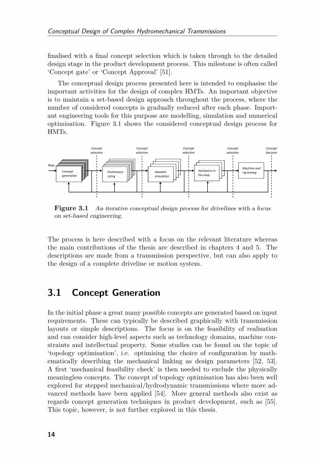
The conceptual design process presented here is intended to emphasise theimportant activities for the design of complex HMTs. An important objectiveis to maintain a set-based design approach throughout the process, where thenumber of considered concepts is gradually reduced after each phase. Import-ant engineering tools for this purpose are modelling, simulation and numericaloptimisation. Figure 3.1 shows the considered conceptual design process forHMTs.
Figure 3.1 An iterative conceptual design process for drivelines with a focuson set-based engineering.
The process is here described with a focus on the relevant literature whereasthe main contributions of the thesis are described in chapters 4 and 5. Thedescriptions are made from a transmission perspective, but can also apply tothe design of a complete driveline or motion system.
3.1 Concept Generation
In the initial phase a great many possible concepts are generated based on inputrequirements. These can typically be described graphically with transmissionlayouts or simple descriptions. The focus is on the feasibility of realisationand can consider high-level aspects such as technology domains, machine con-straints and intellectual property. Some studies can be found on the topic of‘topology optimisation’, i.e. optimising the choice of configuration by math-ematically describing the mechanical linking as design parameters [52, 53].A first ‘mechanical feasibility check’ is then needed to exclude the physicallymeaningless concepts. The concept of topology optimisation has also been wellexplored for stepped mechanical/hydrodynamic transmissions where more ad-vanced methods have been applied [54]. More general methods also exist asregards concept generation techniques in product development, such as [55].This topic, however, is not further explored in this thesis.
14
Conceptual Design Process
3.2 Preliminary Sizing
The preliminary sizing is here considered to be the sizing of key componentsin the transmission. Typical design parameters are gear ratios and maximumdisplacements of pumps/motors, but can also include machine parameters suchas engine torque curve, axle ratio and size of energy storage. The preliminarysizing is done to evaluate the capabilities of a concept to serve as an input tothe first concept selection.
Traditionally, the design is done with static models in order to derive amaximum force-speed diagram of the considered concept and compare this torequirements. See for instance the sizing methods proposed in [56] and [57].This is in particular useful for smaller machines based on sourced drivelinecomponents and with fewer modes and less design freedom. Other commonperformance indicators can be static speed-efficiency diagrams, as in the com-parisons made in [58, 59], and high-level component cost estimations, as shownin [60].
When developing a new driveline with the main purpose to reduce fuel con-sumption, the energy efficiency becomes one of the key performance indicatorsand the main focus in this work. This is primarily evaluated using modellingand simulation as described in the upcoming sections.
3.2.1 Modelling
Several studies have been presented with the focus on modelling energy effi-ciency of HMTs. Casoli et al. [61] present a simulation framework based onstatic torque and speed relationships and a simple vehicle environment. Erkkilä[62] derives similar static models for deriving torque/speed diagrams of differ-ent power-split configurations. Mikeska and Ivantysynova [63] present a Matlabtoolbox specifically designed for simulation of hydromechanical power-splittransmissions using models with a similar detail level to the above-mentionedstudies. In these studies the main focus lies on modelling the torque andflow losses of the pumps/motors, which are often stated to represent the mainpower losses of the transmission. Kohmäscher [64] advocates even more ad-vanced power loss models also for the mechanical components, such as gears,seals and bearings. This, however, would apply more to the later stages of thedesign process.
Substantial work has previously been done on modelling pump/motor powerlosses over the years, where both physical, empirical and analytical models havebeen used. A comprehensive overview and comparison is presented in [65], inwhich the POLYMOD method described in [66] is recommended.
15
Conceptual Design of Complex Hydromechanical Transmissions
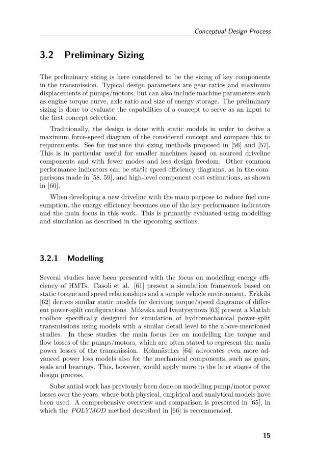
3.2.2 Simulation
In the literature, a widely used simulation principle for the preliminary sizingis quasi-static backward-facing simulation [67]. The principle is based on apre-defined drive cycle that is prescribed to the vehicle power output, see Fig.3.2.
Figure 3.2 Principle of backward-facing vehicle simulation.
The required operation (e.g. torque and speed) of each component is thensequentially calculated backwards in order to fulfil that cycle. The final stepin the calculation is commonly to summarise the power load on the engineand derive the fuel consumption through a map of the Brake Specific FuelConsumption (BSFC). No driver model is thus needed and potentially a verysimple load model as well. This in particular can be useful in off-road workingmachines with varying ground conditions and interaction with for instance agravel pile, which needs a relatively complex model to accurately predict thewheel counterforce [68]. A pre-recorded cycle in terms of vehicle speed andtractive force can be used instead.
The models are often based on static equations and efficiency maps, similarto the detail level described in the previous section. The models are typicallysimulated with few system states and with large time steps, which make theexecution time very short. This type of simulation is useful in the prelim-inary sizing and selection since exactly the same performance is achieved inevery simulation [69]. Backward-facing simulations are therefore also ideal forsimulation-based design optimisation.
The main drawbacks are naturally that many dynamic properties are dis-regarded which can be too great a simplification, as for instance when consid-ering engine emissions with high dependency on transient loads [70]. Further-more, the differences in dynamic performance of the considered concepts arenot shown in backward-facing simulation, which needs to be considered. Forinstance, a hybrid transmission may have a low scoring when comparing fuelefficiency even though additional benefits, such as power boost functionality,exist. In [71] a method is proposed to partially overcome the drawbacks ofbackward-facing simulation by using stable inversions of non-linear systems.
16
Conceptual Design Process
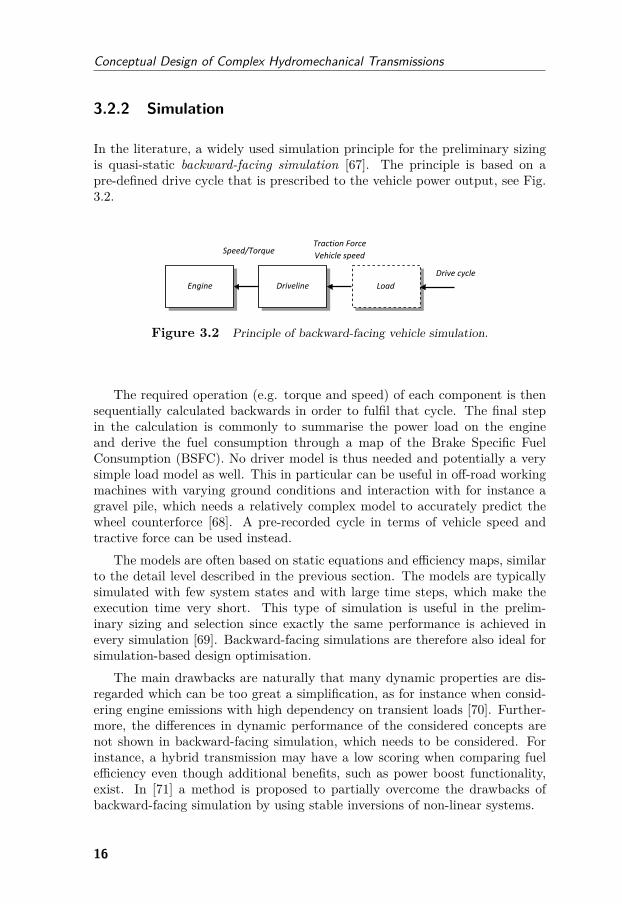
3.3 Detailed Simulation
After a preliminary concept selection (funneling) based on backward-facingsimulation, more detailed dynamic simulations within several domains are re-quired. One important area is one-dimensional powertrain simulation used fora dynamic concept assessment and controller development. This simulationprinciple is commonly referred to as forward-facing simulation, see Fig. 3.3.
Figure 3.3 Principle of forward-facing vehicle simulation.
A drive cycle in terms of vehicle speed is often used as a reference fora driver model to track. For on-road vehicles, the load model is usually interms of a fixed vehicle mass subjected to gravitational force, aerodynamicdrag and rolling resistance. A driver model can in its simplest form be asimple PI controller tracking a speed reference. For off-road working machineswith additional power consumers, the load and operator can be much morecomplex to model [72]. The detail level of the component models is usuallyhigher than in backward-facing simulations and include fundamental dynamiccharacteristics. For instance, a model of a hydrostatic transmission can beexpanded to consider control unit and swash plate dynamics, oil compressibilityand mechanical inertias, but without including detailed effects such as pressurefluctuation due to the individual piston motions. In general forward-facingsimulation includes more system states and is conducted with small (variable)time steps. The execution time is therefore also longer. With forward-facingsimulation, critical control aspects can be investigated and used for conceptscoring, such as mode shifting and pump/motor displacement control [73].
A great many commercially available software packages are available whichare capable of modelling HMTs, see [74] for a review. The main purpose andorigin of the different softwares differ, but the trend is to expand the simulationcapabilities to a wider range of technical domains and handle a full-vehiclesimulation, see for instance [75]. Also, the user is allowed to customize andcreate models with self-developed user code to a greater extent. Examples ofstudies using popular commercial softwares for detailed simulation of HMTsare for instance [76, 77, 78].
Useful methods also exist to bridge the gap between forward-facing andbackward-facing simulations to achieve more modularity and the ability toreuse models [79, 80]. Such frameworks, however, may be difficult to implement
17
Conceptual Design of Complex Hydromechanical Transmissions
across different software platforms.
3.4 Hardware-in-the-Loop
After another concept selection, the few remaining candidates are interestingto prototype and test in rig and/or machine. Usually this is not feasible withina project’s limited time and budget and only one concept is carried throughto the prototyping phase. Hardware-in-the-Loop (HWIL) provides a ‘middleway’ between pure simulation and full prototype tests and is suitable for test-ing identified critical components of the transmission. The concept of HWILsimulations relates to the idea of simulating parts of the system of interestwhile other parts are physically tested. By having the simulation models inter-act with hardware in real-time, a more realistic test case is achieved comparedto offline simulations. HWIL simulation may also refer to the testing of controlcode and communication interface of a physical control unit (the hardware) ina simulation environment, sometimes denoted ‘Controller-in-the-Loop’ . HWILwill here be used as a collective term indicating simulations with real-time bi-directional interaction of power-transferring hardware components. The em-phasis on bi-directional interaction thus excludes (conventional) dynamometersemulating for instance a road profile for a driveline test object.
Today, the use of HWIL simulation is rapidly growing and includes testingof more subsystems in earlier phases. In fact, Fathy et al. [81] state that aparadigm shift has occurred where HWIL simulation is transformed from a con-troller prototyping tool into a method for system synthesis. A high amount ofpower can be active in the simulation, which differentiates ‘Power-in-the-Loop’from HWIL. In recent years the ‘-in-the-Loop’ terminology has expanded withsuch terms as ‘engine-in-the-loop’ and ‘transmission-in-the-loop’ to emphasisewhich component is being tested. In the development of multiple-mode HMTsand hydraulic hybrids, system complexity and control effort are greater thanin conventional stepped transmissions. HWIL simulations are seen as a cost-efficient way to be able to test a common critical subsystem for several differentconcepts [82]. It might also be of interest to reuse the test set-up for differentvehicles or vehicle configurations.
A typical HWIL set-up in the literature is to test the full transmissionconcept in hardware and emulate the engine and load side of the transmission.The engine side can be controlled with electric motors controlled with variable-frequency drives as in [83, 84]. In these studies the load side is emulatedwith a throttle-controlled pump to generate a braking torque. For power-split and hybrid concepts, however, four-quadrant operation is required forthe load side. This can be accomplished with two-mode control of an electricmotor/generator, as in [85, 86]. In [87], the engine and load side are insteademulated with secondary controlled pumps/motors to enable four quadrant
18
Conceptual Design Process
operation. With this set-up the transient dynamics at mode shifts can bedifficult to emulate, in which the load torque can almost instantaneously changesigns. A different approach is done in [88], where the load speed, instead oftorque, is controlled. In [85] it is argued that the load simulator needs to beadapted to the causality of the test object, e.g. using load speed control whentesting a secondary controlled hybrid transmission. In effect, the rig controllersmay switch control strategies depending on the mode selection of a concept.
Already in 1993 an HWIL test rig was presented for hydrostatic trans-missions where both engine and load side are emulated with valve-controlledpumps/motors to enable four-quadrant operation [89]. Many studies have beenmade in the same test rig over the years considering different HMTs [90, 91,92, 93]. The modified test rig is also the basis for the work presented in thisthesis.
19

Conceptual Design of Complex Hydromechanical Transmissions
20

4Design
Optimisation
This chapter describes simulation-based design optimisation of HMT conceptsduring the preliminary sizing phase. The definition of a concept is here limitedto the boundaries of which a transmission can be mathematically parametrisedin an efficient way. A modular multiple-mode transmission can for instancebe treated as one concept and the number of modes as a design parameter,as described in section 4.2. The generalised methodology is first describedand related to previous work. Two use cases are then presented where themethodology is applied.
4.1 Optimisation Methodology
This section describes the design optimisation methodology with the main ob-jective to maximise the energy efficiency of the transmission. This process ispreferably iterated for all considered concepts in the preliminary sizing phaseand the results can then serve as a basis for a concept selection. Figure 4.1shows the main principle of the simulation-based optimisation process. The in-puts to the design process are the requirements and constraints of the transmis-sion for the considered vehicle. The physical requirements might be expressedwith transmission-specific properties, such as torque/speed ratio range andmaximum torques and speeds or as machine requirements in terms of tractiveforce and machine speed. Simple control constraints such as the positioningof gear shift/mode shift speeds are also important to consider at this stage.Further requirements can be expressed in terms of weight and costs if reliablemodels can be derived. More abstract requirements, such as service life, noise
21
Conceptual Design of Complex Hydromechanical Transmissions
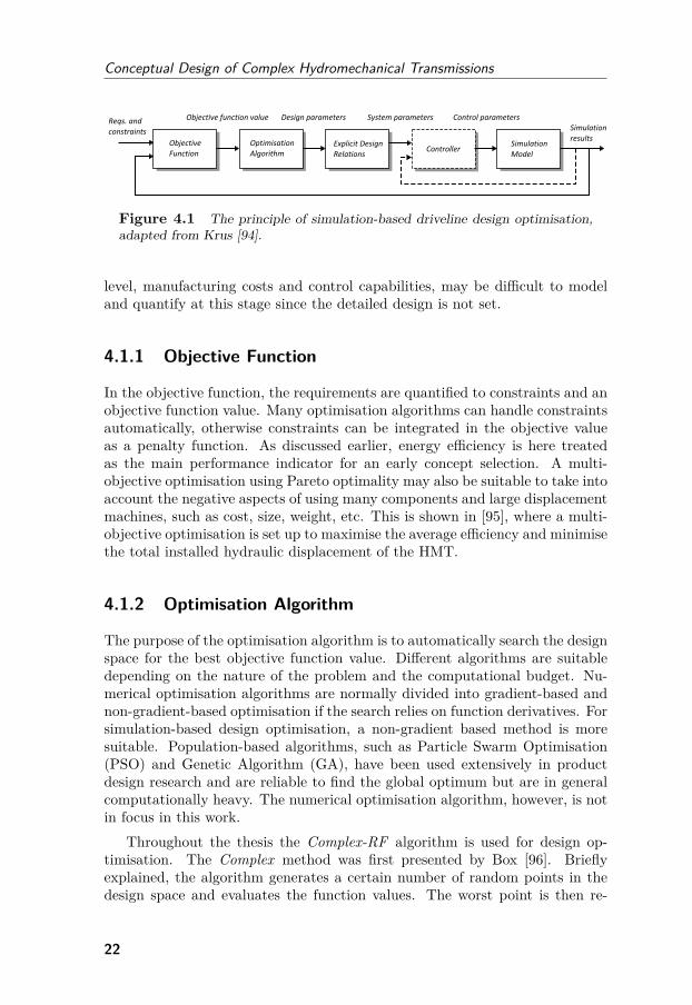
Figure 4.1 The principle of simulation-based driveline design optimisation,adapted from Krus [94].
level, manufacturing costs and control capabilities, may be difficult to modeland quantify at this stage since the detailed design is not set.
4.1.1 Objective Function
In the objective function, the requirements are quantified to constraints and anobjective function value. Many optimisation algorithms can handle constraintsautomatically, otherwise constraints can be integrated in the objective valueas a penalty function. As discussed earlier, energy efficiency is here treatedas the main performance indicator for an early concept selection. A multi-objective optimisation using Pareto optimality may also be suitable to take intoaccount the negative aspects of using many components and large displacementmachines, such as cost, size, weight, etc. This is shown in [95], where a multi-objective optimisation is set up to maximise the average efficiency and minimisethe total installed hydraulic displacement of the HMT.
4.1.2 Optimisation Algorithm
The purpose of the optimisation algorithm is to automatically search the designspace for the best objective function value. Different algorithms are suitabledepending on the nature of the problem and the computational budget. Nu-merical optimisation algorithms are normally divided into gradient-based andnon-gradient-based optimisation if the search relies on function derivatives. Forsimulation-based design optimisation, a non-gradient based method is moresuitable. Population-based algorithms, such as Particle Swarm Optimisation(PSO) and Genetic Algorithm (GA), have been used extensively in productdesign research and are reliable to find the global optimum but are in generalcomputationally heavy. The numerical optimisation algorithm, however, is notin focus in this work.
Throughout the thesis the Complex-RF algorithm is used for design op-timisation. The Complex method was first presented by Box [96]. Brieflyexplained, the algorithm generates a certain number of random points in thedesign space and evaluates the function values. The worst point is then re-
22
Design Optimisation
flected through the centroid of the other points and evaluated again until it isno longer the worst point. The Complex-RF method is an extended versionwhere a randomisation factor and a forgetting factor are added to improve theconvergence to a global optimum [97].
4.1.3 Explicit Design Relations
The generated set of values for the design parameters are translated into systemparameters by using explicit design relations. In some cases the system para-meters and the design parameters are the same and this step is then trivial. Inthe general case, however, there exist many fixed relationships between para-meters in the system which cannot be chosen independently from each other.It is therefore appropriate to define a layer of design relations where relativelyfew independent optimisation variables are expanded to the full set of systemparameters. In the given use case in section 4.2, for instance, the positioning ofa mode shift is a design parameter whereas the actual gear ratios are calculatedbased on the kinematic relationships.
4.1.4 Controller
Depending on the complexity of the simulation model, control algorithms needto be defined for the simulated driveline. When considering non-hybrid vehicles,the driveline operation is more closely coupled to the vehicle motion. The driv-eline can then be simulated with fewer states and control signals. In backward-facing simulations, much of the controller design can be disregarded or definedin advance, for example by using only a simple look-up table for engine op-eration or by assuming constant engine speed [76, 98, 99]. When it comes tohybrid vehicles, the assessment of fuel efficiency is a more difficult task sincethe supervisory control of the secondary energy storage, the Energy Manage-ment Strategy (EMS), plays an important role in the total fuel consumption.In every instance a decision can be made on the split of power between primaryand secondary energy source, resulting in increasing or decreasing the State-of-Charge (SOC).
A common methodology used in the literature to obtain the optimal EMSfor a drive cycle is deterministic Dynamic Programming (DP) [100], whichis able to guarantee a globally optimal solution for a pre-defined load cycle.The sequential nature of the algorithm is powerful for deriving the optimalcontrol decisions in a discrete time series simulation. Since it requires completeknowledge of the drive cycle in advance, the resulting strategy is only suitablefor offline analysis. The results from such optimisation are commonly used as acomparison to a non-cycle-dependent optimal control strategy or simply to gainknowledge about how to construct a manual EMS. Common principles basedon simple control laws, such as ‘if-then’ statements are collectively referred to
23
Conceptual Design of Complex Hydromechanical Transmissions
as rule-based strategies. The rules can include decisions on which situationsto charge/discharge based on thresholds for engine and SOC. More advancedversions include offline-defined maps and models. For certain applications, awell-performing rule-based strategy is easier to implement online and mightadequately well-perform.
Another common principle is the Equivalent Consumption MinimisationStrategy (ECMS) which takes instantaneous decisions on when to dischargeby modelling the expected future cost of charging and vice versa, see [101].By adapting this model according to the studied application, it is possible toachieve a ‘close-to-optimal’ EMS [102]. Other EMS principles are for instanceNeural Network (NN), Stochastic Dynamic Programming (SDP), Model Pre-dictive Controller (MPC) and fuzzy logic controller. See [103] and [104] fora general overview of EMSs for hybrid electric vehicles and [105] for a moreapplication-focused review that also considers hydraulic hybrids.
4.1.5 Simulation Model
The calculated system and control parameters are fed into the simulationmodel, which is used to achieve the specific system characteristics for thegenerated design. With backward-facing simulations the vehicle is simulatedperforming a pre-defined load cycle to make the simulation results represent-able for the typical use case. For on-road passenger and commercial vehiclesthere are numerous standardised drive cycles, whereas the simulation of off-road machines needs to rely on representative recorded cycles from real-worldexperiments. With the focus on evaluating energy-efficiency, the main resultfrom such simulation is the consumed fuel or energy.
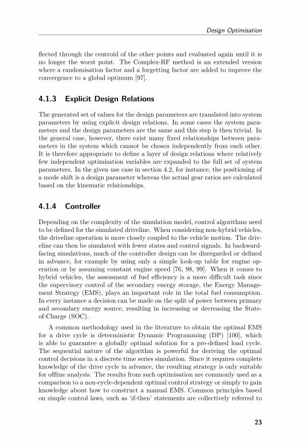
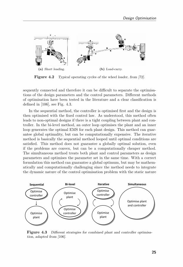
For wheel loaders, two different load cycles are typically used for bench-marking fuel efficiency - the short loading cycle and the load-carry cycle. Dur-ing short loading, the wheel loader approaches and fills the bucket from a gravelpile and then reverses and approaches a load receiver. The gravel is unloadedand the wheel loader then reverses back to the start position. In the load-carrycycle the load receiver is positioned some distance away from the gravel pile,which requires a longer transportation phase. Figure 4.2 shows the principlesof the two operating cycles. See [72] for more details on the specific phases ofthe operating cycles.
4.1.6 Combined Design and Controller Optimisation
Depending on the EMS, one set of hardware design parameters can achieveconsiderably different results in simulated fuel consumption for the consideredload cycle. It is also clear that the optimal EMS can differ greatly dependingon which hardware design is chosen. The design of plant and controller is con-
24
Design Optimisation
(a) Short loading. (b) Load-carry.
Figure 4.2 Typical operating cycles of the wheel loader, from [72].
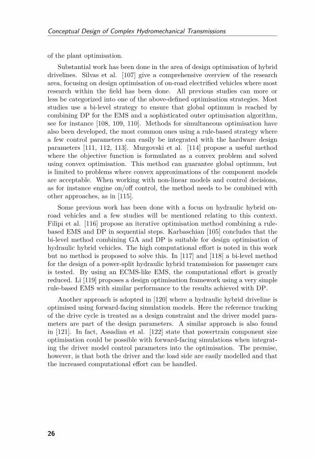
sequently connected and therefore it can be difficult to separate the optimisa-tions of the design parameters and the control parameters. Different methodsof optimisation have been tested in the literature and a clear classification isdefined in [106], see Fig. 4.3.
In the sequential method, the controller is optimised first and the design isthen optimised with the fixed control law. As understood, this method oftenleads to non-optimal designs if there is a tight coupling between plant and con-troller. In the bi-level method, an outer loop optimises the plant and an innerloop generates the optimal EMS for each plant design. This method can guar-antee global optimality, but can be computationally expensive. The iterativemethod is basically the sequential method looped until optimal conditions aresatisfied. This method does not guarantee a globally optimal solution, evenif the problems are convex, but can be a computationally cheaper method.The simultaneous method treats both plant and control parameters as designparameters and optimises the parameter set in the same time. With a correctformulation this method can guarantee a global optimum, but may be mathem-atically and computationally challenging since the method needs to integratethe dynamic nature of the control optimisation problem with the static nature
Figure 4.3 Different strategies for combined plant and controller optimisa-tion, adapted from [106].
25
Conceptual Design of Complex Hydromechanical Transmissions
of the plant optimisation.Substantial work has been done in the area of design optimisation of hybrid
drivelines. Silvas et al. [107] give a comprehensive overview of the researcharea, focusing on design optimisation of on-road electrified vehicles where mostresearch within the field has been done. All previous studies can more orless be categorized into one of the above-defined optimisation strategies. Moststudies use a bi-level strategy to ensure that global optimum is reached bycombining DP for the EMS and a sophisticated outer optimisation algorithm,see for instance [108, 109, 110]. Methods for simultaneous optimisation havealso been developed, the most common ones using a rule-based strategy wherea few control parameters can easily be integrated with the hardware designparameters [111, 112, 113]. Murgovski et al. [114] propose a useful methodwhere the objective function is formulated as a convex problem and solvedusing convex optimisation. This method can guarantee global optimum, butis limited to problems where convex approximations of the component modelsare acceptable. When working with non-linear models and control decisions,as for instance engine on/off control, the method needs to be combined withother approaches, as in [115].
Some previous work has been done with a focus on hydraulic hybrid on-road vehicles and a few studies will be mentioned relating to this context.Filipi et al. [116] propose an iterative optimisation method combining a rule-based EMS and DP in sequential steps. Karbaschian [105] concludes that thebi-level method combining GA and DP is suitable for design optimisation ofhydraulic hybrid vehicles. The high computational effort is noted in this workbut no method is proposed to solve this. In [117] and [118] a bi-level methodfor the design of a power-split hydraulic hybrid transmission for passenger carsis tested. By using an ECMS-like EMS, the computational effort is greatlyreduced. Li [119] proposes a design optimisation framework using a very simplerule-based EMS with similar performance to the results achieved with DP.
Another approach is adopted in [120] where a hydraulic hybrid driveline isoptimised using forward-facing simulation models. Here the reference trackingof the drive cycle is treated as a design constraint and the driver model para-meters are part of the design parameters. A similar approach is also foundin [121]. In fact, Assadian et al. [122] state that powertrain component sizeoptimisation could be possible with forward-facing simulations when integrat-ing the driver model control parameters into the optimisation. The premise,however, is that both the driver and the load side are easily modelled and thatthe increased computational effort can be handled.
26
Design Optimisation
4.2 Use Case:Multiple-mode Power-split Transmission
This section presents a design optimisation process for a multiple-mode power-split transmission implemented for a medium-sized wheel loader.
4.2.1 Concept
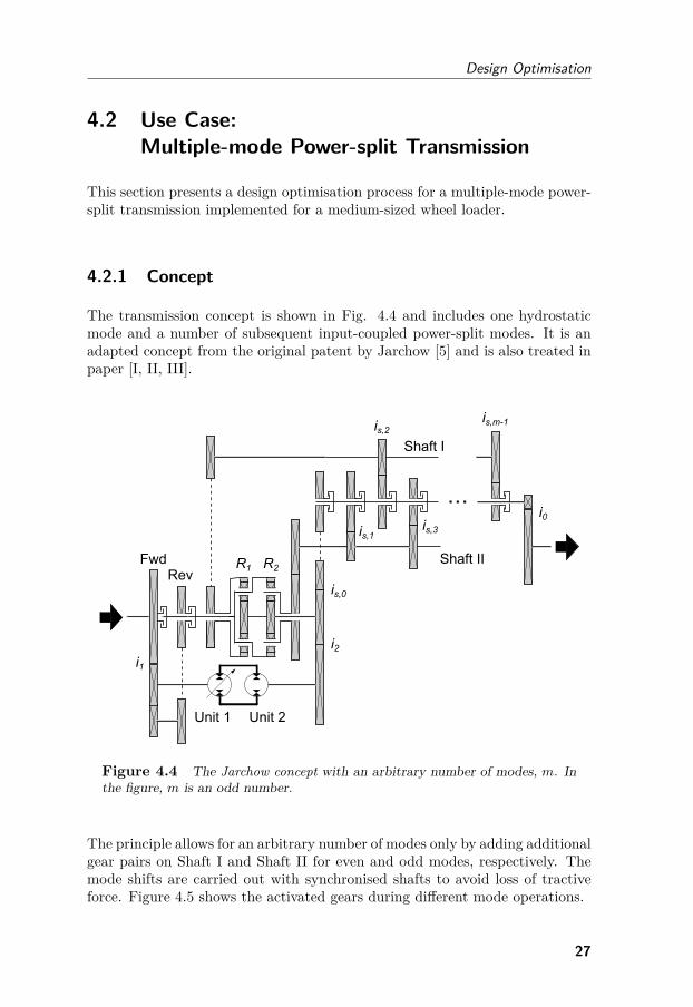
The transmission concept is shown in Fig. 4.4 and includes one hydrostaticmode and a number of subsequent input-coupled power-split modes. It is anadapted concept from the original patent by Jarchow [5] and is also treated inpaper [I, II, III].
Figure 4.4 The Jarchow concept with an arbitrary number of modes, m. Inthe figure, m is an odd number.
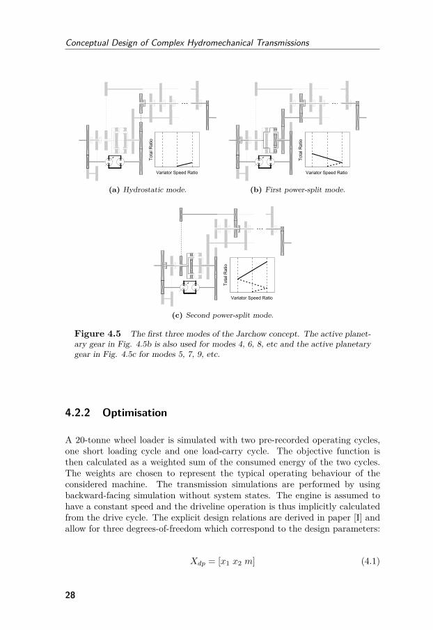
The principle allows for an arbitrary number of modes only by adding additionalgear pairs on Shaft I and Shaft II for even and odd modes, respectively. Themode shifts are carried out with synchronised shafts to avoid loss of tractiveforce. Figure 4.5 shows the activated gears during different mode operations.
27
Conceptual Design of Complex Hydromechanical Transmissions
(a) Hydrostatic mode. (b) First power-split mode.
(c) Second power-split mode.
Figure 4.5 The first three modes of the Jarchow concept. The active planet-ary gear in Fig. 4.5b is also used for modes 4, 6, 8, etc and the active planetarygear in Fig. 4.5c for modes 5, 7, 9, etc.
4.2.2 Optimisation
A 20-tonne wheel loader is simulated with two pre-recorded operating cycles,one short loading cycle and one load-carry cycle. The objective function isthen calculated as a weighted sum of the consumed energy of the two cycles.The weights are chosen to represent the typical operating behaviour of theconsidered machine. The transmission simulations are performed by usingbackward-facing simulation without system states. The engine is assumed tohave a constant speed and the driveline operation is thus implicitly calculatedfrom the drive cycle. The explicit design relations are derived in paper [I] andallow for three degrees-of-freedom which correspond to the design parameters:
Xdp = [x1 x2 m] (4.1)
28
Design Optimisation
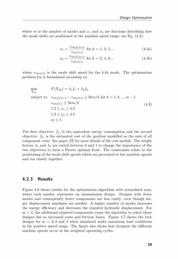
where m is the number of modes and x1 and x2 are fractions describing howthe mode shifts are positioned in the machine speed range, see Eq. (4.2):
x1 = vshift,k+1
vshift,kfor k = 1, 3, 5,... (4.2a)
x2 = vshift,k+1
vshift,kfor k = 2, 4, 6,... (4.2b)
where vshift,k is the mode shift speed for the k:th mode. The optimisationproblem for is formulated according to:
minXdp
F (Xdp) = λ1f1 + λ2f2
subject to vshift,k+1 − vshift,k ≥ 2km/h for k = 1, 2, ...,m− 1vshift,1 ≥ 5km/h1.2 ≤ x1 ≤ 4.21.2 ≤ x2 ≤ 4.2m ≤ 5
(4.3)
The first objective, f1, is the equivalent energy consumption and the secondobjective, f2, is the estimated cost of the gearbox modelled as the sum of allcomponent costs. See paper [II] for more details of the cost models. The weightfactors λ1 and λ2 are varied between 0 and 1 to change the importance of thetwo objectives to form a Pareto optimal front. The constraints relate to thepositioning of the mode shift speeds which are prevented at low machine speedsand too closely together.
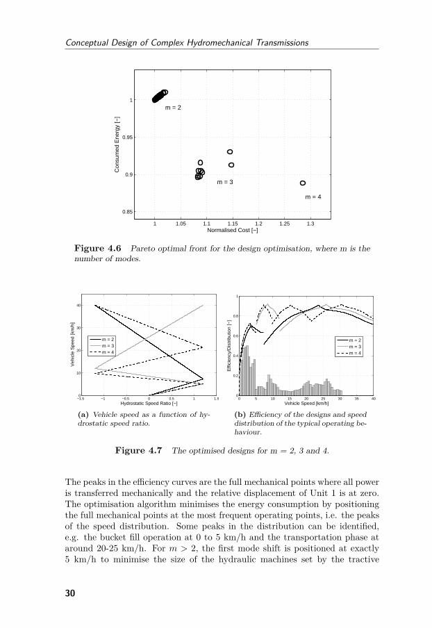
4.2.3 Results
Figure 4.6 shows results for the optimisation algorithm with normalised axes,where each marker represents on transmission design. Designs with fewermodes and consequently fewer components are less costly, even though lar-ger displacement machines are needed. A higher number of modes increasesthe energy efficiency and decreases the required hydraulic displacement. Form > 4, the additional required components cause the algorithm to reject thosedesigns due to increased costs and friction losses. Figure 4.7 shows the bestdesigns for m = 2, 3 and 4 when simulated under maximum load conditionsin the positive speed range. The figure also shows how frequent the differentmachine speeds occur in the weighted operating cycles.
29
Conceptual Design of Complex Hydromechanical Transmissions
1 1.05 1.1 1.15 1.2 1.25 1.3
0.85
0.9
0.95
1
Con
sum
ed E
nerg
y [−
]
Normalised Cost [−]
m = 2
m = 3
m = 4
Figure 4.6 Pareto optimal front for the design optimisation, where m is thenumber of modes.
−1.5 −1 −0.5 0 0.5 1 1.50
10
20
30
40
Veh
icle
Spe
ed [k
m/h
]
Hydrostatic Speed Ratio [−]
m = 2m = 3m = 4
(a) Vehicle speed as a function of hy-drostatic speed ratio.
0 5 10 15 20 25 30 35 400
0.2
0.4
0.6
0.8
1
Effi
cien
cy/D
istr
ibut
ion
[−]
Vehicle Speed [km/h]
m = 2m = 3m = 4
(b) Efficiency of the designs and speeddistribution of the typical operating be-haviour.
Figure 4.7 The optimised designs for m = 2, 3 and 4.
The peaks in the efficiency curves are the full mechanical points where all poweris transferred mechanically and the relative displacement of Unit 1 is at zero.The optimisation algorithm minimises the energy consumption by positioningthe full mechanical points at the most frequent operating points, i.e. the peaksof the speed distribution. Some peaks in the distribution can be identified,e.g. the bucket fill operation at 0 to 5 km/h and the transportation phase ataround 20-25 km/h. For m > 2, the first mode shift is positioned at exactly5 km/h to minimise the size of the hydraulic machines set by the tractive
30
Design Optimisation
force requirements in the first mode. The total installed displacement for theoptimised designs of m = 3 and 4 is consequently the same.
4.2.4 Discussion
The results shows that the energy efficiency of the transmission concept isstrongly coupled to the design. Figure 4.6 shows that even slightly failed op-timisations result in designs with substantially higher energy consumption. Amanual design process may result in even worse energy consumption, since thedesign space of the transmission is very large, see paper [I]. As shown in Fig.4.7b, the combined drive cycles have a large effect on the optimal designs. Ifdifferent cycles are used, the chosen designs will also change.
The positioning of mode shifts is proficiently handled by the optimisationroutine. For the considered transmission concept, the optimal three-modedesign is able to match the main distribution peaks of the drive cycles. Thismakes the four-mode transmission only slightly more efficient and thus moreoften rejected by the optimisations. Designs with a higher number of modesare completely rejected due to the increased cost and power losses of the ad-ditional mechanical components. The required size of the hydraulic variator isthe same for m ≥ 3, which makes transmissions with a higher number of modesless attractive since energy consumption is only slightly improved with everyadditional mode.
4.3 Use Case:Parallel Hydraulic Hybrid Wheel Loader
This section presents a design optimisation process for a parallel hybrid wheelloader driveline. The work is based on paper [VII], where more details can befound. As mentioned above, the control of the secondary energy storage needsto be considered in the design optimisation of hybrid machines. This designproblem, however, has some important differences with respect to electrifiedon-road vehicles. Hydraulic hybridisation implies a smaller energy storage,whereas the relative power capacity is significantly higher. The wheel loaderdriveline is also based on a torque converter with drastically varying efficiencydepending on operating point. Furthermore, since the significant cycles areshort and well-defined, it is easier to mimic a derived optimal control strategywith simple control rules. The premise is therefore that the EMS should bebased on maximising the torque converter efficiency and that an on/off-likestrategy is adequate.
31
Conceptual Design of Complex Hydromechanical Transmissions
4.3.1 Concept
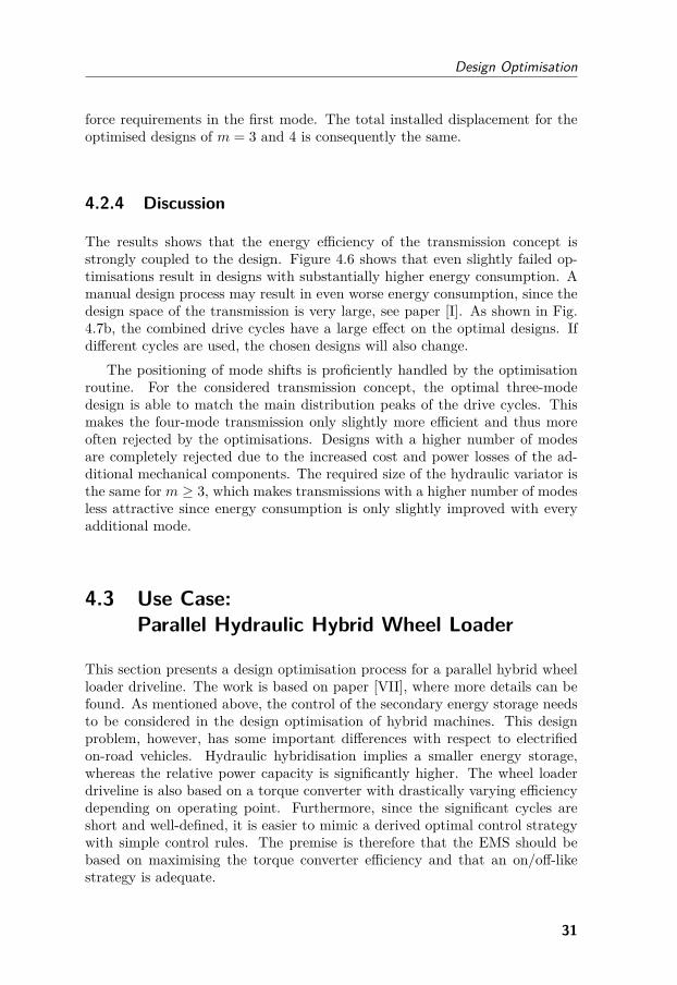
The considered reference machine is a 13.5-tonne wheel loader with 130 kWinstalled engine power. The driveline is based on a four-speed mechanicaltransmission with torque converter and fixed connection to the front and rearaxles. The work functions are based on load-sensing hydraulics with a singleopen-circuit pump. This wheel loader size is frequently used as a productionmachine and is suitable for hybridisation since the torque converter today ac-counts for relatively high power losses in the driveline. Figure 4.8 shows themain principle of the considered concept.
Figure 4.8 The considered wheel loader concept with the add-on hybrid sys-tem enclosed in dashed lines.
The transmission’s output shaft is here equipped with an add-on hydraulicenergy storage system. By controlling the PM displacement a braking torquecan be generated and flow is pumped into the hydraulic accumulator whereenergy is stored. The stored energy can thereafter be reused to add tractionforce to the wheels. Between the PM and the accumulator is an on/off valve,V1, used to isolate the stored hydraulic energy in the accumulator when thehybrid system is not active to avoid unnecessary leakage. A second on/offvalve, V2, is used to short-circuit the PM to minimise drag losses when thePM is not used. A similar hybrid concept can be found in for instance [123].
4.3.2 Optimisation
Four different optimisation strategies are here tested for the considered designproblem. The wheel loader’s motion system is simulated using backward-facing simulations with one input signal controlling the displacement of thepump/motor, and one state which represents the SOC corresponding to thepressure level in the accumulator. The considered load cycle is a merge of
32
Design Optimisation
three subsequent short loading cycles followed by one load-carry cycle. Thisload cycle is used to represent a weighted average operating behaviour of thewheel loader that contains both cycles. The design parameters of the con-sidered system are the PM displacement, DPM (in cm3/rev), the PM gearratio, iPM , and the accumulator’s pre-charge pressure, p0 (in bar). The accu-mulator size is considered to be constant for the optimisation problem. Thedesign optimisation problem is formulated according to the following:
minXdp
F (Xdp)
subject to 0 ≤ DPM ≤ 5000.3 ≤ iPM ≤ 1.7610 ≤ p0 ≤ 300
(4.4)
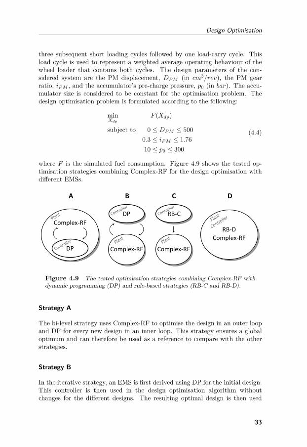
where F is the simulated fuel consumption. Figure 4.9 shows the tested op-timisation strategies combining Complex-RF for the design optimisation withdifferent EMSs.
Figure 4.9 The tested optimisation strategies combining Complex-RF withdynamic programming (DP) and rule-based strategies (RB-C and RB-D).
Strategy A
The bi-level strategy uses Complex-RF to optimise the design in an outer loopand DP for every new design in an inner loop. This strategy ensures a globaloptimum and can therefore be used as a reference to compare with the otherstrategies.
Strategy B
In the iterative strategy, an EMS is first derived using DP for the initial design.This controller is then used in the design optimisation algorithm withoutchanges for the different designs. The resulting optimal design is then used
33
Conceptual Design of Complex Hydromechanical Transmissions
to derive a new EMS that is used in the second loop of the design optimisa-tion and so on. The iterative loop is continued until a convergence criterion issatisfied.
Strategy C
In the sequential strategy, a rule-based EMS, RB-C, is used to decrease thecomputational effort compared to a DP-based EMS. The following simple rulesare defined:- Charge only with braking energy.- Discharge when first gear is engaged.Rules are also added to stop discharging when the pressure approaches thepre-charge pressure and to avoid charging when approaching the maximumaccumulator pressure.
Strategy D
In the simultaneous strategy, another rule-based EMS, RB-D, is applied in asimultaneous plant and controller optimisation. The rules can be summarisedas follows:- Charge if the required prop shaft power is under a certain limit.- Discharge if the required prop shaft torque is over a certain limit.The idea is to charge the energy storage with a high torque converter efficiencyand discharge the energy storage when the torque converter efficiency wouldotherwise have been low. Setting these limits, however, is not an obvious taskand they are therefore included as design parameters in the design optimisationalgorithm.
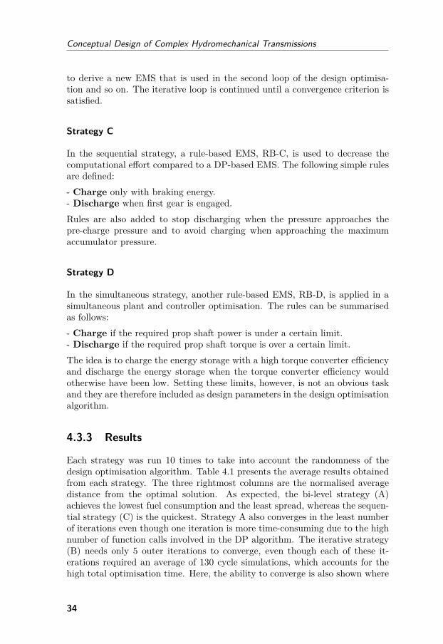
4.3.3 Results
Each strategy was run 10 times to take into account the randomness of thedesign optimisation algorithm. Table 4.1 presents the average results obtainedfrom each strategy. The three rightmost columns are the normalised averagedistance from the optimal solution. As expected, the bi-level strategy (A)achieves the lowest fuel consumption and the least spread, whereas the sequen-tial strategy (C) is the quickest. Strategy A also converges in the least numberof iterations even though one iteration is more time-consuming due to the highnumber of function calls involved in the DP algorithm. The iterative strategy(B) needs only 5 outer iterations to converge, even though each of these it-erations required an average of 130 cycle simulations, which accounts for thehigh total optimisation time. Here, the ability to converge is also shown where
34
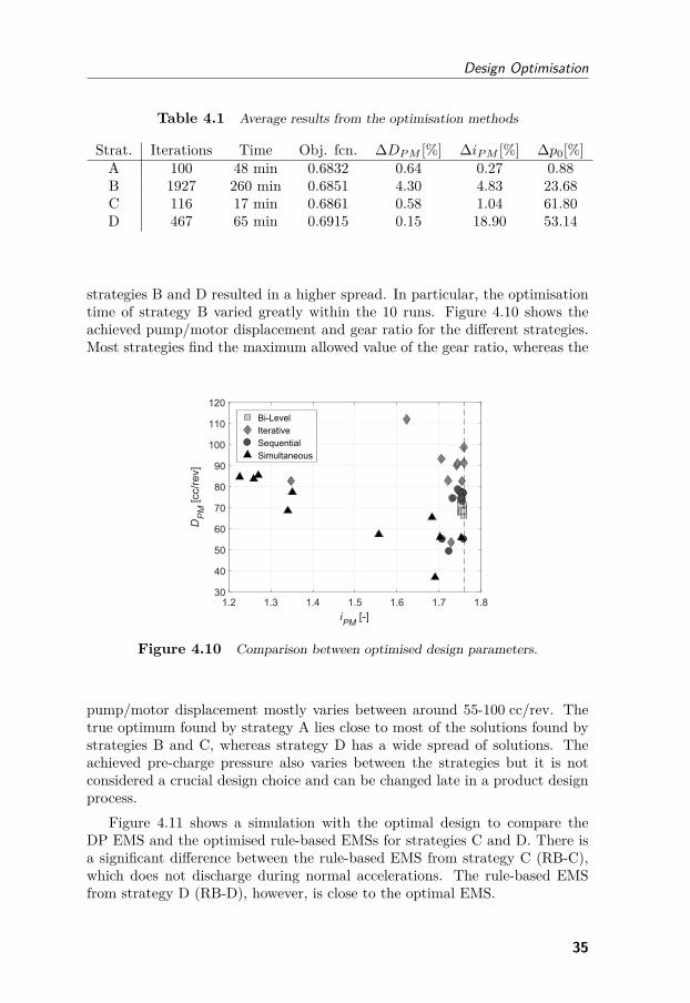
Design Optimisation
Table 4.1 Average results from the optimisation methods
Strat. Iterations Time Obj. fcn. ∆DPM [%] ∆iPM [%] ∆p0[%]A 100 48 min 0.6832 0.64 0.27 0.88B 1927 260 min 0.6851 4.30 4.83 23.68C 116 17 min 0.6861 0.58 1.04 61.80D 467 65 min 0.6915 0.15 18.90 53.14
strategies B and D resulted in a higher spread. In particular, the optimisationtime of strategy B varied greatly within the 10 runs. Figure 4.10 shows theachieved pump/motor displacement and gear ratio for the different strategies.Most strategies find the maximum allowed value of the gear ratio, whereas the
1.2 1.3 1.4 1.5 1.6 1.7 1.8iPM [-]
30
40
50
60
70
80
90
100
110
120
DP
M [c
c/re
v]
Bi-LevelIterativeSequentialSimultaneous
Figure 4.10 Comparison between optimised design parameters.
pump/motor displacement mostly varies between around 55-100 cc/rev. Thetrue optimum found by strategy A lies close to most of the solutions found bystrategies B and C, whereas strategy D has a wide spread of solutions. Theachieved pre-charge pressure also varies between the strategies but it is notconsidered a crucial design choice and can be changed late in a product designprocess.
Figure 4.11 shows a simulation with the optimal design to compare theDP EMS and the optimised rule-based EMSs for strategies C and D. There isa significant difference between the rule-based EMS from strategy C (RB-C),which does not discharge during normal accelerations. The rule-based EMSfrom strategy D (RB-D), however, is close to the optimal EMS.
35
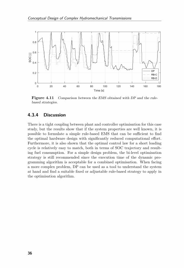
Conceptual Design of Complex Hydromechanical Transmissions
0 20 40 60 80 100 120 140 160 180Time [s]
0
0.2
0.4
0.6
0.8
1S
OC
[-]
DPRB-CRB-D
Figure 4.11 Comparison between the EMS obtained with DP and the rule-based strategies.
4.3.4 Discussion
There is a tight coupling between plant and controller optimisation for this casestudy, but the results show that if the system properties are well known, it ispossible to formulate a simple rule-based EMS that can be sufficient to findthe optimal hardware design with significantly reduced computational effort.Furthermore, it is also shown that the optimal control law for a short loadingcycle is relatively easy to match, both in terms of SOC trajectory and result-ing fuel consumption. For a simple design problem, the bi-level optimisationstrategy is still recommended since the execution time of the dynamic pro-gramming algorithm is acceptable for a combined optimisation. When facinga more complex problem, DP can be used as a tool to understand the systemat hand and find a suitable fixed or adjustable rule-based strategy to apply inthe optimisation algorithm.
36
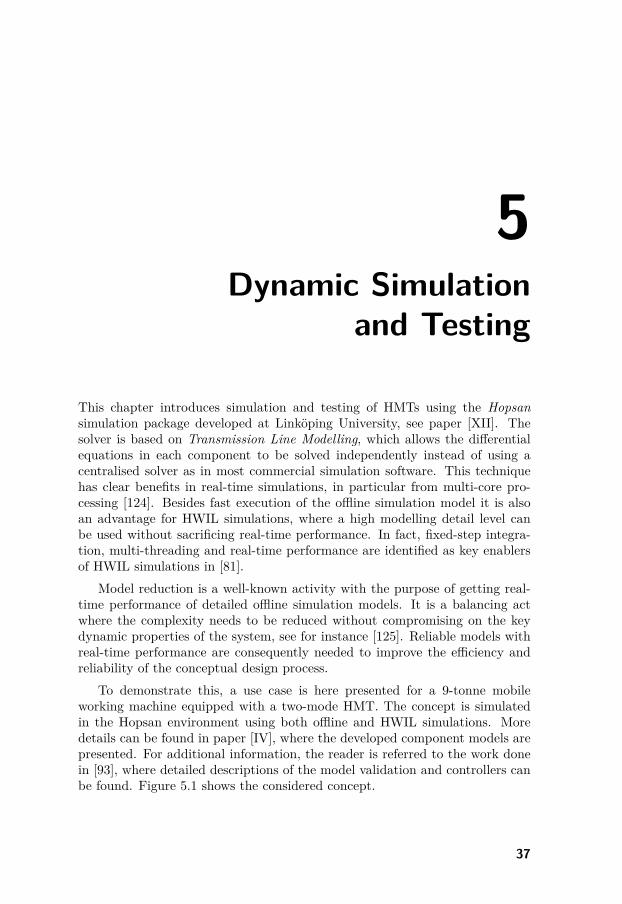
5Dynamic Simulation
and Testing
This chapter introduces simulation and testing of HMTs using the Hopsansimulation package developed at Linköping University, see paper [XII]. Thesolver is based on Transmission Line Modelling, which allows the differentialequations in each component to be solved independently instead of using acentralised solver as in most commercial simulation software. This techniquehas clear benefits in real-time simulations, in particular from multi-core pro-cessing [124]. Besides fast execution of the offline simulation model it is alsoan advantage for HWIL simulations, where a high modelling detail level canbe used without sacrificing real-time performance. In fact, fixed-step integra-tion, multi-threading and real-time performance are identified as key enablersof HWIL simulations in [81].
Model reduction is a well-known activity with the purpose of getting real-time performance of detailed offline simulation models. It is a balancing actwhere the complexity needs to be reduced without compromising on the keydynamic properties of the system, see for instance [125]. Reliable models withreal-time performance are consequently needed to improve the efficiency andreliability of the conceptual design process.
To demonstrate this, a use case is here presented for a 9-tonne mobileworking machine equipped with a two-mode HMT. The concept is simulatedin the Hopsan environment using both offline and HWIL simulations. Moredetails can be found in paper [IV], where the developed component models arepresented. For additional information, the reader is referred to the work donein [93], where detailed descriptions of the model validation and controllers canbe found. Figure 5.1 shows the considered concept.
37
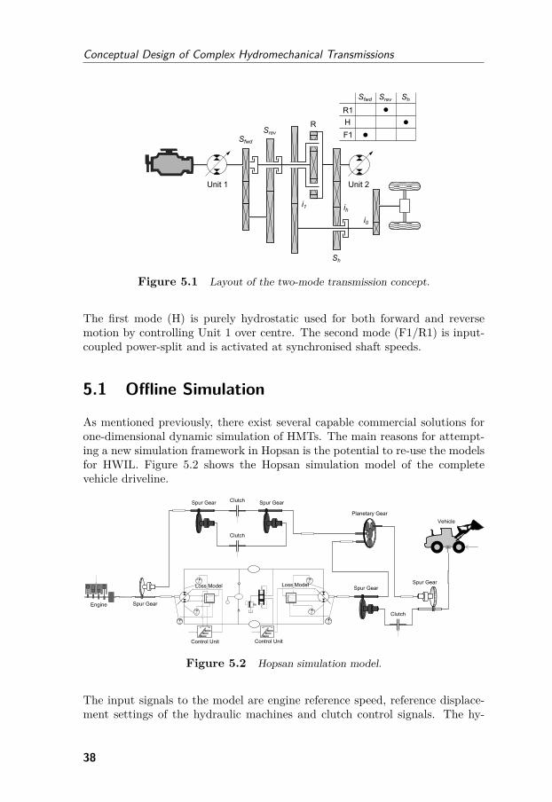
Conceptual Design of Complex Hydromechanical Transmissions
Figure 5.1 Layout of the two-mode transmission concept.
The first mode (H) is purely hydrostatic used for both forward and reversemotion by controlling Unit 1 over centre. The second mode (F1/R1) is input-coupled power-split and is activated at synchronised shaft speeds.
5.1 Offline Simulation
As mentioned previously, there exist several capable commercial solutions forone-dimensional dynamic simulation of HMTs. The main reasons for attempt-ing a new simulation framework in Hopsan is the potential to re-use the modelsfor HWIL. Figure 5.2 shows the Hopsan simulation model of the completevehicle driveline.
Figure 5.2 Hopsan simulation model.
The input signals to the model are engine reference speed, reference displace-ment settings of the hydraulic machines and clutch control signals. The hy-
38
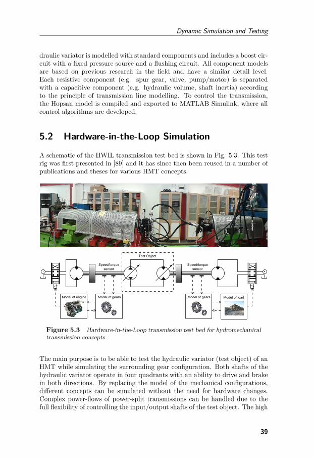
Dynamic Simulation and Testing
draulic variator is modelled with standard components and includes a boost cir-cuit with a fixed pressure source and a flushing circuit. All component modelsare based on previous research in the field and have a similar detail level.Each resistive component (e.g. spur gear, valve, pump/motor) is separatedwith a capacitive component (e.g. hydraulic volume, shaft inertia) accordingto the principle of transmission line modelling. To control the transmission,the Hopsan model is compiled and exported to MATLAB Simulink, where allcontrol algorithms are developed.
5.2 Hardware-in-the-Loop Simulation
A schematic of the HWIL transmission test bed is shown in Fig. 5.3. This testrig was first presented in [89] and it has since then been reused in a number ofpublications and theses for various HMT concepts.
Figure 5.3 Hardware-in-the-Loop transmission test bed for hydromechanicaltransmission concepts.
The main purpose is to be able to test the hydraulic variator (test object) of anHMT while simulating the surrounding gear configuration. Both shafts of thehydraulic variator operate in four quadrants with an ability to drive and brakein both directions. By replacing the model of the mechanical configurations,different concepts can be simulated without the need for hardware changes.Complex power-flows of power-split transmissions can be handled due to thefull flexibility of controlling the input/output shafts of the test object. The high
39
Conceptual Design of Complex Hydromechanical Transmissions
bandwidths of the servo-valves are required to match the stiff load dynamicsand fast changes in inertia. The test bed is today also equipped with hydraulicaccumulators to enable simulation of hybrid transmissions.
For the considered concept, the test bed is used with one dedicated driveside (left) and one load side (right). The drive side is used purely to simulatethe engine of the machine since the variator is directly coupled to the engineshaft. The right side (the load side) is similarly used to simulate the loadof the variator including the mechanical gear configuration, vehicle dynamicsand gravel pile. The drive side is equipped with a servo-valve-controlled fixeddisplacement pump connected to a flywheel inertia. It is speed-controlled inclosed loop to represent the static and dynamic behaviour of the diesel engine.The load side has the same configuration and is used to generate a load torqueon the output of the variator. The flywheel inertia represents the inertia of theload side and the vehicle mass. As the experienced inertia changes dependingon the current mode, the generated torque must compensate for this. Thetorque control of the load side is challenging since there is a strong couplingbetween shaft speed and torque due to the servo valve’s characteristics. Ineffect, one valve opening results in different load torques depending on theshaft speed. See [90] for more details on the main control challenges of the testrig.
The control and measurement system is based on National Instruments’LabView and includes a quad-core real-time PXI computer that handles thesignal processing and interface with the Graphical User Interface (GUI). TheHopsan simulation models and MATLAB Simulink control models are executedin parallel in the real-time computer. Detailed descriptions of the softwareimplementation is can be found in [126].
5.3 Results and Discussion
Figure 5.4 shows the tracked vehicle speed reference and the correspondingsystem pressures of the hydraulic variator. The graphs follow the same patterneven though the highly transient behaviour in the hardware is not completelycovered in the models. At around 7 km/h, the mode shift from H to F1occurs, causing a minor disturbance in vehicle speed and a shift in high and lowpressure sides. This relates to the parallel actuation of clutches and adjustmentof hydraulic machine displacement during the synchronisation of shaft speeds.This causes a temporary loss of tractive force and a small drop in vehicle speed.There is a clear difference between offline simulations and HWIL which is due todifficulties in modelling the highly transient behaviour when the high and lowpressure sides switch. The mode shifting is a critical dynamic situation for thecontroller development and requires precise simulation models to accomplishwell. The HWIL simulation is yet another step to validate the performance
40
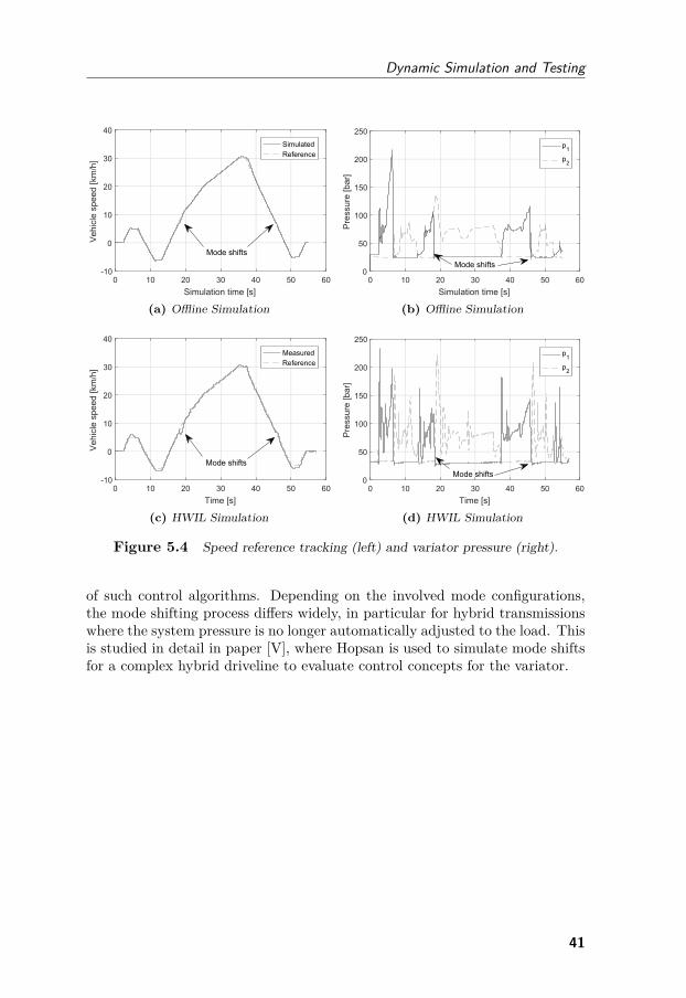
Dynamic Simulation and Testing
0 10 20 30 40 50 60Simulation time [s]
-10
0
10
20
30
40
Veh
icle
spe
ed [k
m/h
]
SimulatedReference
Mode shifts
(a) Offline Simulation
0 10 20 30 40 50 60Simulation time [s]
0
50
100
150
200
250
Pre
ssur
e [b
ar]
p1
p2
Mode shifts
(b) Offline Simulation
0 10 20 30 40 50 60Time [s]
-10
0
10
20
30
40
Veh
icle
spe
ed [k
m/h
]
MeasuredReference
Mode shifts
(c) HWIL Simulation
0 10 20 30 40 50 60Time [s]
0
50
100
150
200
250P
ress
ure
[bar
]p1
p2
Mode shifts
(d) HWIL Simulation
Figure 5.4 Speed reference tracking (left) and variator pressure (right).
of such control algorithms. Depending on the involved mode configurations,the mode shifting process differs widely, in particular for hybrid transmissionswhere the system pressure is no longer automatically adjusted to the load. Thisis studied in detail in paper [V], where Hopsan is used to simulate mode shiftsfor a complex hybrid driveline to evaluate control concepts for the variator.
41

Conceptual Design of Complex Hydromechanical Transmissions
42
6A Novel Hybrid
HydromechanicalTransmission
Concept
This chapter presents a new concept of a hybrid hydromechanical motion sys-tem suitable for mobile working machines with dedicated work functions, heredemonstrated for a wheel loader application. This concept was introduced inpapers [VI] and [X], where more details of the design and simulation can befound.
Previous studies of series hydraulic hybrids for construction machinery, e.g.[47, 127, 128], have demonstrated that Common Pressure Rail (CPR)-basedmotion systems with secondary controlled functions have great potential interms of energy savings. Such systems allow for complete engine/load decoup-ling and advantageous operating points for the engine due to the high flexibilityof the energy management. Losses inherited from parallel operation of func-tions can also be greatly reduced. Additionally, the CPR functionality enableseasy power transfer between the functions with minimal power transformationbetween physical domains since all actuators are hydraulically driven. Thisis particularly useful for machines with parallel actuated functions with four-quadrant load spectra, such as wheel loaders and excavators.
43
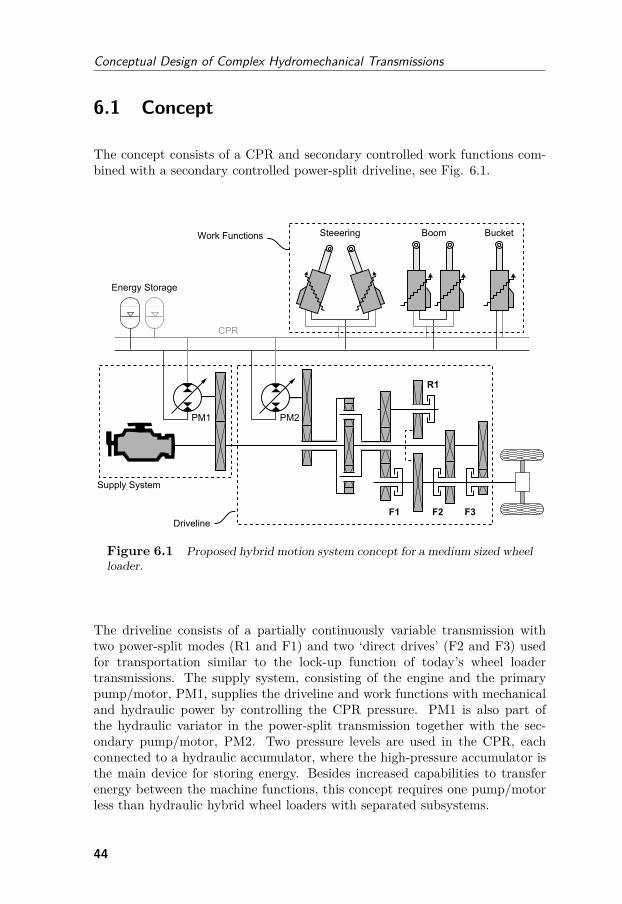
Conceptual Design of Complex Hydromechanical Transmissions
6.1 Concept
The concept consists of a CPR and secondary controlled work functions com-bined with a secondary controlled power-split driveline, see Fig. 6.1.
Figure 6.1 Proposed hybrid motion system concept for a medium sized wheelloader.
The driveline consists of a partially continuously variable transmission withtwo power-split modes (R1 and F1) and two ‘direct drives’ (F2 and F3) usedfor transportation similar to the lock-up function of today’s wheel loadertransmissions. The supply system, consisting of the engine and the primarypump/motor, PM1, supplies the driveline and work functions with mechanicaland hydraulic power by controlling the CPR pressure. PM1 is also part ofthe hydraulic variator in the power-split transmission together with the sec-ondary pump/motor, PM2. Two pressure levels are used in the CPR, eachconnected to a hydraulic accumulator, where the high-pressure accumulator isthe main device for storing energy. Besides increased capabilities to transferenergy between the machine functions, this concept requires one pump/motorless than hydraulic hybrid wheel loaders with separated subsystems.
44
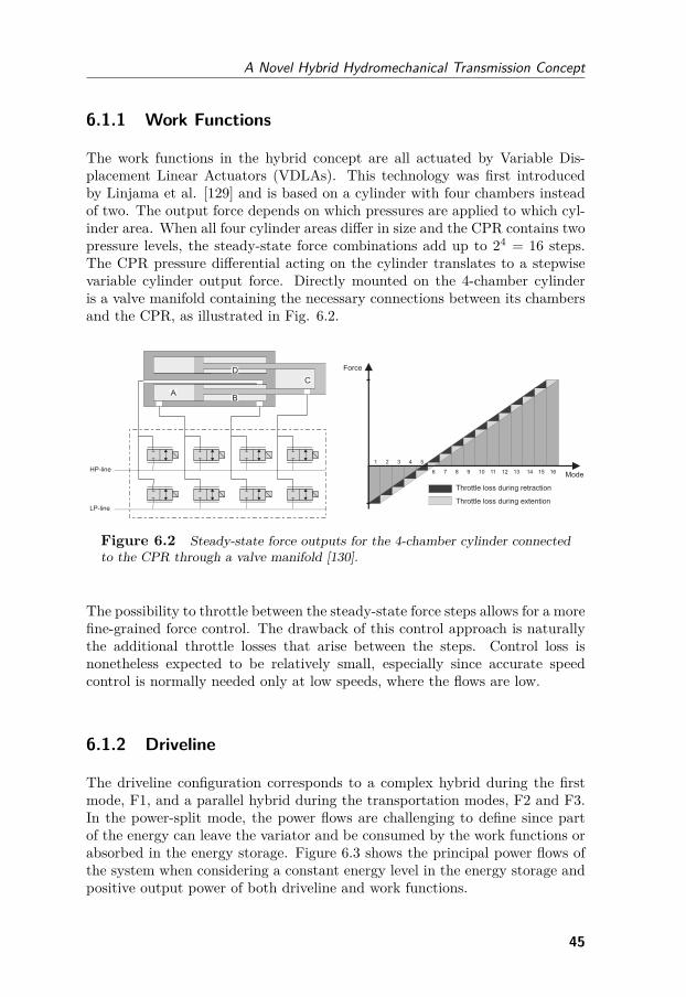
A Novel Hybrid Hydromechanical Transmission Concept
6.1.1 Work Functions
The work functions in the hybrid concept are all actuated by Variable Dis-placement Linear Actuators (VDLAs). This technology was first introducedby Linjama et al. [129] and is based on a cylinder with four chambers insteadof two. The output force depends on which pressures are applied to which cyl-inder area. When all four cylinder areas differ in size and the CPR contains twopressure levels, the steady-state force combinations add up to 24 = 16 steps.The CPR pressure differential acting on the cylinder translates to a stepwisevariable cylinder output force. Directly mounted on the 4-chamber cylinderis a valve manifold containing the necessary connections between its chambersand the CPR, as illustrated in Fig. 6.2.
HP-line
LP-line
D
B
C
A
Mode
Force
1 2 3 4 5
6 7 8 9 10 11 12 13 14 15 16
Throttle loss during retraction
Throttle loss during extention
Figure 6.2 Steady-state force outputs for the 4-chamber cylinder connectedto the CPR through a valve manifold [130].
The possibility to throttle between the steady-state force steps allows for a morefine-grained force control. The drawback of this control approach is naturallythe additional throttle losses that arise between the steps. Control loss isnonetheless expected to be relatively small, especially since accurate speedcontrol is normally needed only at low speeds, where the flows are low.
6.1.2 Driveline
The driveline configuration corresponds to a complex hybrid during the firstmode, F1, and a parallel hybrid during the transportation modes, F2 and F3.In the power-split mode, the power flows are challenging to define since partof the energy can leave the variator and be consumed by the work functions orabsorbed in the energy storage. Figure 6.3 shows the principal power flows ofthe system when considering a constant energy level in the energy storage andpositive output power of both driveline and work functions.
45
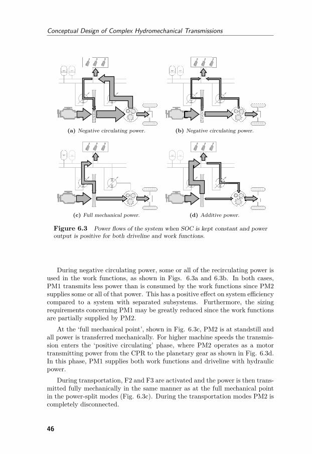
Conceptual Design of Complex Hydromechanical Transmissions
(a) Negative circulating power. (b) Negative circulating power.
(c) Full mechanical power. (d) Additive power.
Figure 6.3 Power flows of the system when SOC is kept constant and poweroutput is positive for both driveline and work functions.
During negative circulating power, some or all of the recirculating power isused in the work functions, as shown in Figs. 6.3a and 6.3b. In both cases,PM1 transmits less power than is consumed by the work functions since PM2supplies some or all of that power. This has a positive effect on system efficiencycompared to a system with separated subsystems. Furthermore, the sizingrequirements concerning PM1 may be greatly reduced since the work functionsare partially supplied by PM2.
At the ‘full mechanical point’, shown in Fig. 6.3c, PM2 is at standstill andall power is transferred mechanically. For higher machine speeds the transmis-sion enters the ‘positive circulating’ phase, where PM2 operates as a motortransmitting power from the CPR to the planetary gear as shown in Fig. 6.3d.In this phase, PM1 supplies both work functions and driveline with hydraulicpower.
During transportation, F2 and F3 are activated and the power is then trans-mitted fully mechanically in the same manner as at the full mechanical pointin the power-split modes (Fig. 6.3c). During the transportation modes PM2 iscompletely disconnected.
46
A Novel Hybrid Hydromechanical Transmission Concept
6.2 Simulation
A simulation of the concept is performed using backward-facing simulationwith the focus on the driveline’s operation. The system is simulated using twostates, representing the engine speed, x1, and the CPR pressure, x2, and twocontrol signals representing the engine torque, u1, and PM1’s displacement,u2. The displacement of PM2 is implicitly derived from the load cycle in asecondary controlled manner taking the CPR pressure into account. The areasettings of the VDLAs are also directly related to the specified speed and forceof the load cycle.
The preliminary sizing of components is dependent on the CPR pressure,which is actively controlled by the EMS. The design and control problem isconsequently tightly coupled. To understand the potential and gain knowledgeabout how to control the system, DP is used to simulate a fixed concept design.The component sizing is done with a downsized engine corresponding to around70% of a baseline machine. The control optimisation problem is mathematicallyformulated according to Eq. 6.1:
minu(t)
∫mfuel(u(t))dt
subject to x = F (x(t), u(t), t)0 ≤ x1(t) ≤ 10 ≤ x2(t) ≤ 10 ≤ u1(t) ≤ 1−1 ≤ u2(t) ≤ 1x1(0) = 0.5x2(0) = 0.5x2(tf ) ≥ 0.5
(6.1)
where mfuel is the fuel rate, x is the system state vector, u is the controlsignal vector, t is the time and tf is the final time. The function F (x(t), u(t), t)describes the backward-facing simulation model. Figure 6.4 shows the mainpowers of the motion system and the relative displacements of PM1 and PM2for the simulated short loading cycle.
47
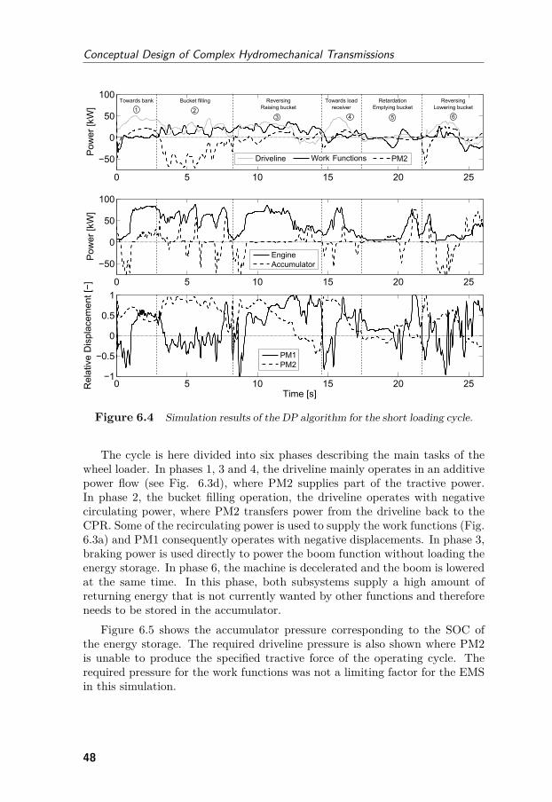
Conceptual Design of Complex Hydromechanical Transmissions
Figure 6.4 Simulation results of the DP algorithm for the short loading cycle.
The cycle is here divided into six phases describing the main tasks of thewheel loader. In phases 1, 3 and 4, the driveline mainly operates in an additivepower flow (see Fig. 6.3d), where PM2 supplies part of the tractive power.In phase 2, the bucket filling operation, the driveline operates with negativecirculating power, where PM2 transfers power from the driveline back to theCPR. Some of the recirculating power is used to supply the work functions (Fig.6.3a) and PM1 consequently operates with negative displacements. In phase 3,braking power is used directly to power the boom function without loading theenergy storage. In phase 6, the machine is decelerated and the boom is loweredat the same time. In this phase, both subsystems supply a high amount ofreturning energy that is not currently wanted by other functions and thereforeneeds to be stored in the accumulator.
Figure 6.5 shows the accumulator pressure corresponding to the SOC ofthe energy storage. The required driveline pressure is also shown where PM2is unable to produce the specified tractive force of the operating cycle. Therequired pressure for the work functions was not a limiting factor for the EMSin this simulation.
48
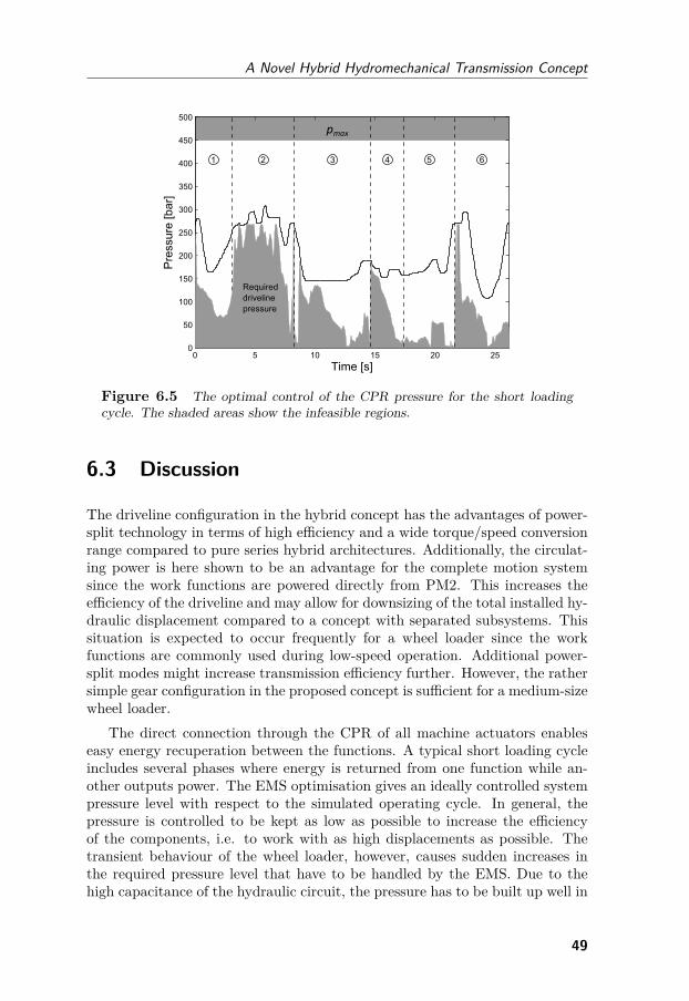
A Novel Hybrid Hydromechanical Transmission Concept
Figure 6.5 The optimal control of the CPR pressure for the short loadingcycle. The shaded areas show the infeasible regions.
6.3 Discussion
The driveline configuration in the hybrid concept has the advantages of power-split technology in terms of high efficiency and a wide torque/speed conversionrange compared to pure series hybrid architectures. Additionally, the circulat-ing power is here shown to be an advantage for the complete motion systemsince the work functions are powered directly from PM2. This increases theefficiency of the driveline and may allow for downsizing of the total installed hy-draulic displacement compared to a concept with separated subsystems. Thissituation is expected to occur frequently for a wheel loader since the workfunctions are commonly used during low-speed operation. Additional power-split modes might increase transmission efficiency further. However, the rathersimple gear configuration in the proposed concept is sufficient for a medium-sizewheel loader.
The direct connection through the CPR of all machine actuators enableseasy energy recuperation between the functions. A typical short loading cycleincludes several phases where energy is returned from one function while an-other outputs power. The EMS optimisation gives an ideally controlled systempressure level with respect to the simulated operating cycle. In general, thepressure is controlled to be kept as low as possible to increase the efficiencyof the components, i.e. to work with as high displacements as possible. Thetransient behaviour of the wheel loader, however, causes sudden increases inthe required pressure level that have to be handled by the EMS. Due to thehigh capacitance of the hydraulic circuit, the pressure has to be built up well in
49
Conceptual Design of Complex Hydromechanical Transmissions
advance of the peaks. In reality, this would be difficult to accomplish withouta predictive control algorithm to avoid compromising the machine’s perform-ance. One possible way of implementation is to size the components to allowfor a pressure window in which the motion system meets the maximum per-formance requirements. This pressure range can then be used by the EMS ina free manner to optimise fuel efficiency.
The input-coupled power-split configuration is shown to be of particularadvantage when it comes to circulating power at low speeds. A different drive-line concept, such as output-coupled power-split, might be useful to adapt theperformance to another machine size. As understood, the design of a com-plex hydraulic hybrid system with shared energy storage is a challenge due tothe strong coupling between hardware and controller design. A manually de-signed EMS must take into account the fact that the SOC directly affects thetransferable power of the motion system.
In summary, the proposed hybrid concept is one step towards an efficienthybrid motion system for mobile working machines with several power con-sumers. The control system is an important part of the complete mechatronicsystem and must be dealt with already in the preliminary sizing phase. Theconcept is a demonstration of a new, innovative concept that requires a modernconceptual design technique to handle the design’s complexity efficiently.
50
7Discussion
An efficient driveline design process relies on finding a suitable modelling detaillevel for each phase. As the model grows more detailed, the modularity becomesmore difficult to maintain and the design task becomes more time-consuming.For the preliminary sizing, traditional calculation of static performance curvesto size and compare concepts might be too simple for future drivelines, whereasa multi-domain 3D machine model is too complex to handle. The target shouldbe to use as simple models as possible without getting misleading outputs. Thisis a key aspect in the use of set-based engineering and numerical optimisationmethods.
Backward-facing simulation of a pre-recorded cycle significantly reduces themodel’s complexity, since the difficulties in operator and load modelling areavoided. In later design phases, however, these simplifications may give falseanswers since pre-recorded cycles will always have inherited properties from thetest machine. Depending on the considered new solution the load cycle maybe more or less representable in the design task.
For complex hydromechanical transmissions a representable preliminary siz-ing is not easily found and numeric optimisation may therefore be an indispens-able tool if multiple concepts are to be considered. The balance between modelfidelity and flexibility must be dealt with by understanding the considered sys-tem before making modelling assumptions. Chwif et al [131] note that someof the main reasons why too complex models are used are lack of understand-ing the real system and unclear objectives with the model. Paper [II] givessome guidance as to which detail level is required during the preliminary sizingphase.
Optimal control of electric and hybrid vehicles is a large research area,covering a wide range of applications and cycles. In academia various ‘close-to-optimal’ strategies are derived by using different methods to formulate the
51
Conceptual Design of Complex Hydromechanical Transmissions
control laws. In the end, much is gained by knowing the application andunderstanding the system at hand. For hydraulic hybrid drivelines, the differentproperties of the energy storage have a substantial impact on the controllerdesign. A globally optimal control strategy can be difficult to realise in anonline machine controller, as seen in paper [VI]. For design optimisation, atarget should be to derive a representative control strategy rather than anoptimised one to avoid a misleading ‘optimal’ design. In general when workingwith optimisation methods, the algorithm is often able to find the weak spotof the model and manages to take advantage of this. The end result is anon-physical behaviour forcing a model refinement such as introducing morestates and model limitations. The iterative search for a well-defined modeland a representable design is likely present within and across all phases in theconceptual design process.
This thesis has treated hydromechanical transmissions with different levelsof complexity with respect to today’s wheel loader motion systems. Eventhough the full hybrid system presented in paper [VI] has high potential, itrequires a complete overhaul of the machine’s hardware and software. Theparallel hybrid system treated in paper [VII] might be a low-cost option withless fuel savings but with a relatively small implementation effort. In any case,the investment costs must give both customer and manufacturer an acceptablepayback time. A middle way would be multiple-mode power-split transmis-sions, such as the concept treated in papers [I, II, III], which seem to havemade a breakthrough into the market. Nevertheless, a successful market intro-duction relies on an efficient design process to select the best concept.
52
8Conclusions
This thesis has as its high-level objective to improve the efficiency of the con-ceptual design process of complex hydromechanical transmissions. Referring tothe more specific research questions stated in chapter 1, the following specificconclusions can be drawn:RQ1: How can optimisation be used in the design of complex hydromechanical
transmission concepts in early product development phases?The design task should be viewed as an optimisation problem where an object-ive function is formulated to reflect the requirements and performance of theconcept. The objective of maximising fuel efficiency is preferably evaluated byusing backward-facing simulations with known loss models and constraints ofthe critical transmission components. The focus should lie on the definitionof a correct modelling detail level which can be used for a fair comparison ofconcepts. Furthermore, the simulated load cycles must be well-defined sincethey have a great influence on the resulting designs. An effort should also bemade to reduce the number of design parameters for complex architectures in-volving several modes. A reliable concept comparison can then be made withlittle engineering effort and a set-based approach.RQ2: How can the energy management strategy be treated in the design
optimisation of hydraulic hybrid working machines?By using dynamic programming a nested design and control optimisation loopcan be used for simpler concepts where the number of states, control signalsand design parameters are kept low. When facing a more complex problem,dynamic programming can be used as a tool to understand the system athand and to find control laws to apply in the optimisation algorithm. Theenergy management of hydraulic hybrid working machines has key differencescompared to on-road electrified vehicles, which need to be considered.
53
Conceptual Design of Complex Hydromechanical Transmissions
RQ3: How can critical dynamic properties of hydromechanical transmissionsbe efficiently tested and assessed before a concept selection?
Forward-facing dynamic simulation is a flexible way of assessing importantcontrol aspects and critical dynamic properties of the concept. In particularthe mode shifting process of multiple-mode concepts is important to consideralready before a final concept selection is made. This involves synchronised pre-cise control of hydraulic machines, clutches and valves to avoid loss of vehicletraction. By using HWIL, a more realistic test case can be achieved for im-portant subsystems. When testing only the hydraulic circuit and simulatingthe mechanical subsystem, the test case can easily be modified for differentconcepts to allow for a set-based engineering design approach. The proposedframework is one feasible way to reuse the offline models in the HWIL simula-tion without model reduction in order to increase the efficiency of the productdesign process.
54
9Review of Papers
Paper I
Design Optimisation of Complex Hydromechanical Transmis-sions
This paper introduces the concept of design optimisation for complex hydro-mechanical transmissions. The design process is established on a high level andimplemented on the Jarchow concept for a large wheel loader. The functionalspace of the transmission is investigated together with how different designsaffect the energy consumption and required installed hydraulic displacementof the transmission. The proficiency of the methodology is thereby establishedand the difficulty of finding the optimal design manually is also shown.
Paper II
Optimisation and Concept Sensitivity of Continuously VariableHydromechanical Transmissions
Multi-objective design optimisation is here used on the Jarchow concept tominimise the energy consumption of the transmission and the total componentcosts of the gearbox. The trade-off between energy efficiency and cost in thedesign task is described. This type of analysis supports the choice of numberof modes. The design’s robustness is also investigated by letting the power lossmodels vary and examining the sensitivity in the results.
55
Conceptual Design of Complex Hydromechanical Transmissions
Paper III
Modular Design of Hydromechanical Transmissions for MobileWorking Machines
This paper uses design optimisation to consider a range of wheel loader applic-ations. The goal is to design a modular transmission concept with a commonhydraulic variator. In high-power vehicles, additional modes are used to matchthe increased requirements concerning the transmission. For this design task,the choice of number of modes for each application and the size of the commonvariator are the global design parameters, whereas the design of each individualtransmission is made in a local optimisation loop.
Paper IV
Simulation Aided Design and Testing of HydromechanicalTransmissions
This paper shows how dynamic simulations can be used in conceptual design ofcomplex hydromechanical transmissions. A full-vehicle Hopsan model of a smallconstruction machine with a two-mode transmission is presented. Controlleralgorithms for the transmission are developed and tested in offline simula-tions and then reused in hardware-in-the-loop simulations. Here the engine,load and the mechanical part of the transmission are simulated in real-time,whereas the hydraulic variator is run in the test rig. The benefits and chal-lenges of hardware-in-the-loop simulations in the design process of complexhydromechanical transmissions are shown.
Paper V
Mode Shifting in Hybrid Hydromechanical Transmissions
In this paper, the problem of shifting modes in complex hybrid hydromechanicaltransmissions is identified. The problem is linked to the hydraulic accumulatorand its influence on the pressure in the hydrostatic circuit. A black box modelapproach is used to identify different mode shift categories and how the modeshift affects the torques on the hydraulic variator for the different categories.Two different configurations of the hydraulic circuit are presented, one of whichincludes a high-speed switching valve. A hybrid transmission concept is thenevaluated in simulations to compare the concepts. The benefits of the high-speed switching valve and the significance of control aspects of fast displacement
56
Review of Papers
actuators for the hydraulic units are shown.
Paper VI
A Novel Hydromechanical Hybrid Motion System for Construc-tion Machines
This paper proposes a new hydromechanical hybrid motion system for wheelloaders with power-split transmission and a shared common pressure railbetween the driveline and work functions. The main aspects of the system’soperation and control strategy are discussed and a design use case is made fora medium-sized wheel loader. The system is then simulated using dynamicprogramming to derive the optimal energy management strategy. A particularbenefit of the system is the advantages of reusing the circulating power in thepower-split transmission to the work functions. The motion system, however,has a tight coupling between its design and control strategy and is a goodexample of a complex concept architecture requiring a modern and efficientdesign process.
Paper VII
Design Optimisation Strategies for a Hydraulic Hybrid WheelLoader
This paper explores design optimisation strategies for hydraulic hybrid drive-lines for mobile working machines and wheel loaders in particular. The mainissue is how to treat a combined design and control optimisation problem wherefour different strategies are tested - both with an optimised energy manage-ment strategy using deterministic dynamic programming and with rule-basedstrategies. The results show that a simple rule-based strategy is enough tofind the optimal design for a parallel hybrid wheel loader, even though energymanagement is far from optimal.
57

Conceptual Design of Complex Hydromechanical Transmissions
58
References
[1] W. J. C. Verhagen, P. Bermell-Garcia, R. E. C. Van Dijk and R. Curran.‘A critical review of Knowledge-Based Engineering: An identification ofresearch challenges’. In: Advanced Engineering Informatics 26.1 (2012),pp. 5–15. doi: 10.1016/j.aei.2011.06.004.
[2] B. Pohl. ‘CVT Split Power Transmissions, A Configuration Versus Per-formance Study with an Emphasis on the Hydromechanical Type’. In:SAE Technical Paper 2002-01-0589 (2002). doi: 10.4271/2002-01-0589.
[3] P. Mattsson. ‘Continuously Variable Split-Power Transmissions withSeveral Modes’. PhD thesis. Chalmers University of Technology,Sweden, 1996.
[4] D. Sung, S. Hwang and H. Kim. ‘Design of hydromechanical transmis-sion using network analysis’. In: Journal of Automotive Engineering219 (2005), pp. 53–63. doi: 10.1243/095440705X6406.
[5] F. Jarchow. ‘Hydrostatischmechanisches Stellkoppelgetriebemiteingangs-seitiger Leistungsverzweigung German Patent no 3 147 447 C2’. 1981.
[6] H. Aitzetmüller. ‘Steyr S-Matic - The future Continuously VariableTransmission for all terrain vehicles’. In: 13th International Conferenceof the ISTVS. Munich, Germany, 1999.
[7] T. Anderl, J. Winkelhake and M. Scherer. ‘Power-split transmissions forconstruction machinery’. In: 8th International Fluid Power Conference(IFK2012). Dresden, Germany, 2012.
[8] G. Stein, A. Fröberg, J. Martinsson, B. Brattberg, R. Filla and J. Un-nebäck. ‘Fuel Efficiency in Construction Equipment - Optimize the Ma-chine as a System’. In: International Commercial Powertrain Confer-ence (ICPC2013). Graz, Austria, 2013.
[9] J. Legner, W. Rebholz and R. Morrison. ‘ZF cPower - HydrostaticMech-anical Powersplit Transmission for Construction and Forest Machinery’.In: 10th International Fluid Power Conference (IFK2016). Dresden,Germany, 2016.
59
Conceptual Design of Complex Hydromechanical Transmissions
[10] R. Kordak. Hydrostatic Drives with Control of the Secondary Unit -The Hydraulic Trainer Volume 6. Lohr Am Main, 1996.
[11] S. Tikkanen, M. G. Kliffken, C. Ehret and S. Baseley. ‘Hydraulic Hy-brid Systems for Working machines and Commercial Vehicles’. In: 51stNational Conference of Fluid Power (NCFP2008). Las Vegas, Nevada,USA, 2008.
[12] J. Meyer, K. Stelson and T. D. nad A. Alleyne. ‘Developing an EnergyManagement Strategy for a Four-Mode Hydraulic Hybrid PassengerVehicle’. In: 52nd National Conference on Fluid Power (NCFP2011).Las Vegas, Nevada, USA, 2011.
[13] R. Filla. ‘Alternative System Solutions for Wheel Loaders and OtherConstruction Equipment’. In: 1st CTI Forum Alternative, Electric andHybrid Drive Trains. Berlin, Germany, 2008.
[14] M. G. Kliffken, S. Mutschler, B. Langenbeck and M.Weber. ‘Systematicof Hydrostatic Drive Trains for Mobile Applications’. In: 6th Interna-tional Fluid Power Conference Dresden (IFK2008). 2008.
[15] G. Leidinger. ‘Hydrotransmatic - Ein Neuartiger Stufenloser, Last-schaltfreier Hydrostatischer Fahrantrieb’. In: O + P Ölhydraulik undPneumatik 36 36.4 (1992), pp. 222–232.
[16] U. Hammerle and N. Krimbacher. ‘Efficiency of Hydrostatic Drivesof Some Selected Construction Machines’. In: 6th International FluidPower Conference Dresden (IFK2008). 2008.
[17] T. Kohmäscher. ‘Multi-Motor Transmissions - Increased TransmissionRatio to Support Advanced Control Systems’. In: 52nd National Con-ference on Fluid Power, NCFP. Las Vegas, Nevada, USA, 2011.
[18] S. Rinck. ‘Hydraulische Antriebssysteme für Radlader Grosser Leis-tung’. In: O+P Ölhydraulik und Pneumatik 39.3 (1995), pp. 158–167.
[19] K.-E. Rydberg. ‘Hydrostatic Drives in Heavy Mobile Machinery - NewConcepts and Development Trends’. In: SAE Technical Paper 981989(1997).
[20] iVT International. JCB claims world first with dual-tech trans-mission for agricultural telehandlers. 2016. url: http : / / www .ivtinternational.com/news.php?NewsID=78772.
[21] P. F. Dziuba and R. Honzek. ‘Neues Stufenloses LeistungsverzweigtesTraktorgetriebe’. In: Agrartechnische Forschung 3.1 (1997), pp. 19–27.
[22] J. Pohlenz and W.-D. Gruhle. ‘Stufenloses Hydrostatisch - MechanischLeistungsverzweigtes Getriebe’. In: O + P Ölhydraulik und Pneumatik46.3 (2002), pp. 154–158.
60
REFERENCES
[23] S. I. Mistry and G. P. Sparks. ‘Infinitely Variable Transmission ( IVT) of John Deere 7000 TEN Series Tractors’. In: ASME InternationalMechanical Engineering Congress & Exposition. New Orleans, LA,USA, 2002.
[24] K. T. Renius and R. Resch. ‘Continuously Variable Tractor Transmis-sions’. In: ASAE Distinguished Lecture Series Tractor Design. 29. 2005.
[25] J. Schueller and N. Khan. ‘Some Conceptual Designs of Heavy VehicleContinuously-Variable Transmissions’. In: International Off-Highway &Powerplant Congress & Exposition. Milwaukee, Wisconsin, USA, 1995.
[26] J. Lawson. ‘Transfer Case?’ In: iVT International (Feb. 2014), pp. 22–50.
[27] S. Mercati, F. Panizzolo and G. Profumo. ‘Power split Hydro-mechanical Variable Transmission (HVT) for off-highway application’.In: 10th International Fluid Power Conference (IFK2016). Dresden,Germany, 2016.
[28] Caterpillar. Caterpillar’s 966K XE Wheel Loader Will Take CentreStage at INTERMAT. 2012. url: http://www.worldhighways.co/event-news/intermat-2012/quarrying-extraction-materials-production/caterpillars- 966k- xe- wheel- loader- will- take-centre-stage-at-intermat/.
[29] A. Fuchs. ‘Liebherr Large Wheel Loader with Power-split Drivetrain’.In: ATZoffhighway worldwide 9.1 (2016), pp. 6–9. doi: 10 . 1007 /s41321-016-0509-7.
[30] A. Pourmovahed. ‘Vehicle propulsion systems with hydraulic energystorage: a literature survey’. In: International Journal of Vehicle Design12.4 (1991), pp. 378–403. doi: 10.1504/IJVD.1991.061690.
[31] J. Stecki and P. Matheson. ‘Advances in Automotive Hydraulic Hy-brid Drives’. In: 6th JFPS International Symposium on Fluid Power.Tsukuba, Japan, 2005.
[32] S. Baseley, C. Ehret, E. Greif and M. G. Kliffken. ‘Hydraulic HybridSystems for Commercial Vehicles’. In: Commercial Vehicle EngineeringCongress and Exhibition. Rosemont, Illinois, USA, 2007.
[33] A. Johansson and J.-C. Ossyra. ‘Hydraulic Hybrid Transmission DesignConsiderations for Optimal Customer Satisfaction’. In: 7th Interna-tional Fluid Power Conference (IFK2010). Aachen, Germany, 2010.
[34] A. Boretti and J. Stecki. ‘Hydraulic Hybrid Heavy Duty Vehicles -Challenges and Opportunities’. In: SAE Commercial Vehicle Engin-eering Congress. Rosemont, Illinois, USA, 2012. doi: 10.4271/2012-01-2036.
61
Conceptual Design of Complex Hydromechanical Transmissions
[35] K.-E. Rydberg. ‘Energy Efficient Hydraulic Hybrid Drives’. In: 11thScandinavian International Conference on Fluid Power (SICFP2009).Linköping, Sweden, 2009.
[36] J. Kargul, A. Moskalik, K. Newman, D. Barba and J. Rockwell. ‘Designand Demonstration of EPA’s Integrated Drive Module for Commer-cial Series Hydraulic Hybrid Trucks and Buses’. In: SAE InternationalJournal of Commercial Vehicles 8.2 (2015), pp. 549–567. doi: 10.4271/2015-01-2850.
[37] P. A. J. Achten, G. E. M. Vael, H. Murrenhoff, T. Kohmäscher andM. Inderelst. ‘Low-emission Hydraulic Hybrid for Passenger Cars’. In:ATZ worldwide 111.5 (2009), pp. 44–50. doi: 10.1007/BF03225073.
[38] J. Taylor, W. Rampen, A. Robertson and N. Caldwell. ‘Digital Dis-placement Hydraulic Hybrids Parallel Hybrid Drives for CommercialVehicles’. In: JSAE Annual Congress. Yokohama, Japan, 2011.
[39] PSA Groupe. Hybrid Air: An innovative full-hybrid petrol solution forthe car of the future. 2016. url: https://www.groupe-psa.com/en/newsroom/automotive-innovation/hybrid-air/.
[40] Dana Off-Highway. Spicer PowerBoost Hydraulic-Hybrid System. 2017.url: http : / / www . dana . com / off - highway / products / spicer -powerboost.
[41] S. Hui, J. Ji-hai and W. Xin. ‘Torque control strategy for a parallelhydraulic hybrid vehicle’. In: Journal of Terramechanics 46.6 (2009),pp. 259–265. doi: 10.1016/j.jterra.2009.08.004.
[42] S. Hui and J. Junqing. ‘Research on the system configuration and en-ergy control strategy for parallel hydraulic hybrid loader’. In: Auto-mation in Construction 19.2 (2010), pp. 213–220. doi: 10.1016/j.autcon.2009.10.006.
[43] D. Fussner, G. Wendel and C. Wray. ‘Analysis of a Hybrid Multi-Mode Hydromechanical Transmission’. In: SAE World Congress. De-troit, Michigan, USA, 2007. doi: 10.4271/2007-01-1455.
[44] F. Wang, M. a. Mohd Zulkefli, Z. Sun and K. a. Stelson. ‘Energy man-agement strategy for a power-split hydraulic hybrid wheel loader’. In:Proceedings of the Institution of Mechanical Engineers, Part D: Journalof Automobile Engineering (2015). doi: 10.1177/0954407015600899.
[45] L. Serrao, G. Ornella, L. Balboni, C. Maximiliano, G. Bort, C. Dousyand F. Zendri. ‘A telehandler vehicle as mobile laboratory for hydraulic- hybrid powertrain technology development’. In: 10th InternationalFluid Power Conference (IFK2016). Dresden, Germany, 2016.
[46] P. A. J. Achten, G. E. M. Vael and K. Heybroek. ‘Efficient hydraulicpumps , motors and transformers for hydraulic hybrid systems in mobilemachinery’. In: VDI Wissensforum. Freidrichshafen, Germany, 2011.
62
REFERENCES
[47] K. Heybroek, G. Vael and J.-O. Palmberg. ‘Towards Resistance-freeHydraulics in Construction Machinery’. In: The 8th International FluidPower Conference (IFK2012). Dresden, Germany, 2012.
[48] INCOSE. INCOSE Systems Engineering Handbook. 3.1. 2007. doi: 10.1016/0016-0032(66)90450-9.
[49] NASA. NASA Systems Engineering Handbook. NASA/SP-2007-6105.2007.
[50] V. Hubka and W. E. Eder. Design science. Springer Verlag, 1996.[51] D. G. Ullman. The Mechanical Design Process. McGraw-Hill, 2010.[52] P. Y. Li and F. Mensing. ‘Optimization and Control of a Hydro-
Mechanical Transmission Based Hybrid Hydraulic Passenger Vehicle’.In: 7th International Fluid Power Conference (IFK2010). Aachen, Ger-many, 2010.
[53] A. Rossetti, A. Macor and M. Scamperle. ‘Optimization of compon-ents and layouts of hydromechanical transmissions’. In: InternationalJournal of Fluid Power 18.2 (2017), pp. 123–134. doi: 10 . 1080 /14399776.2017.1296746.
[54] E. Schneider, J. Müller, M. Leesch and R. Resch. ‘Synthesis of an Eight-Speed Automatic Transmission for Hybrid Drives’. In: ATZoffhighwayworldwide 112.1212010 (2016), pp. 26–30.
[55] C. R. Bryant, D. A. Mcadams and R. B. Stone. ‘A Computational Tech-nique for Concept Generation’. In: ASME 2005 International DesignEngineering Technical Conferences & Computers and Information inEngineering Conference. Long Beach, California, USA, 2005.
[56] R. Paoluzzi and L. G. Zarotti. ‘The minimum size of hydrostatic trans-missions for locomotion’. In: Journal of Terramechanics 50.3 (2013),pp. 153–164. doi: 10.1016/j.jterra.2013.03.006.
[57] R. Paoluzzi and L. G. Zarotti. ‘Properties and sizing methods of 2-motor transmissions’. In: International Journal of Fluid Power 18.1(2017), pp. 3–16. doi: 10.1080/14399776.2016.1234873.
[58] A. Krauss and M. Ivantysynova. ‘Power Split Transmissions VersusHydrostatic Multiple Motor Concepts - A Comparative Analysis’. In:SAE Technical Paper 2004-01-2676 (2004).
[59] B. Carl and M. Ivantysynova. ‘Comparison of Operational Characterist-ics in Power Split Continuously Variable Transmission’. In: CommercialVehicle Engineering Congress and Exhibition. Chicago, Illinois, USA,2006.
[60] S. Mutschler. ‘Economic Evaluation of Hydrostatic Drive Train Con-cepts for Mobile Machinery’. In: 6th International Fluid Power Con-ference, (IFK2008). Dresden, Germany, 2008.
63
Conceptual Design of Complex Hydromechanical Transmissions
[61] P. Casoli, A. Vacca, G. L. Berta, S. Meleti and M. Vescovini. ‘A Nu-merical Model for the Simulation of Diesel / CVT Power Split Trans-mission’. In: 8th International Conference on Engines for Automobiles.Capri, Naples, Italy, 2007.
[62] M. Erkkilä. ‘Model-Based Design of Power-Split Drivelines’. PhDthesis. Tampere University of Technology, 2009.
[63] D. Mikeska and M. Ivantysynova. ‘Virtual Prototyping of Power SplitDrives’. In: Workshop on Power Transmission and Motion Control(PTMC2002). Bath, United Kingdom, 2002.
[64] T. Kohmäscher. ‘Modellbildung, Analyse und Auslegung Hydrostat-ischer Antriebstrangkonzepte’. PhD thesis. RWTH Aachen University,Germany, 2008.
[65] T. Kohmäscher, R. Rahmfeld, H. Murrenhoff and E. Skirde. ‘ImprovedLoss Modeling of Hydrostatic Units - Requirement for Precise Simula-tion of Mobile Working Machine Drivelines’. In: 2007 ASME Interna-tional Mechanical Engineering Congress and Exposition. Seattle, WA,USA, 2007.
[66] D. Mikeska. ‘A Precise Steady-State Model of Displacement Machinesfor the Application in Virtual Prototyping of Power-Split Drives’. In:2nd International FPNI - PhD Symposium on Fluid Power. Modena,Italy, 2002.
[67] L. Guzzella and A. Amstutz. ‘CAE tools for quasi-static modeling andoptimization of hybrid powertrains’. In: IEEE Transactions on Vehicu-lar Technology 48.6 (1999), pp. 1762–1769. doi: 10.1109/25.806768.
[68] A. Ericsson and J. Slättengren. ‘A Model for Predicting Digging Forceswhen Working in Gravel or Other Granulated Material’. In: 15thEuropean ADAMS Users’ Conferences. Rome, Italy, 2000.
[69] K. Steindorff, D. Haensel, T. Lang and H.-H. Harms. ‘Methods forbenchmarking the efficiency of mobile working machines and heavyduty vehicles’. In: 6th International Fluid Power Conference (IFK2008)(2008), pp. 197–207.
[70] R. Johri and Z. Filipi. ‘Optimal energy management of a series hy-brid vehicle with combined fuel economy and low-emission objectives’.In: IMechE Part D: Journal of Automobile Engineering 228.12 (2014),pp. 1424–1439. doi: 10.1177/0954407014522444.
[71] A. Fröberg and L. Nielsen. ‘Efficient drive cycle simulation’. In: IEEETransactions on Vehicular Technology 57.3 (2008), pp. 1442–1453. doi:10.1109/TVT.2007.907310.
[72] R. Filla. ‘Quantifying Operability of Working Machines’. PhD thesis.Linköping: Linköping University, 2011.
64
REFERENCES
[73] L. V. Larsson. ‘Control Aspects of Complex Hydromechanical Trans-missions with a Focus on Displacement Control’. Licentiate thesis.Linköping University, Sweden, 2017. doi: 10.3384/lic.diva-139855.
[74] J. Fulem. ICCT Evaluation of Vehicle Simulation Tools. Tech. rep.ICCT - The International Council on Clean Transportation, 2009.
[75] C. Ciesla, R. Keribar and T. Morel. ‘Engine / Powertrain / VehicleModeling Tool Applicable to All Stages of the Design Process’. In: SAETechnical Paper 2000-01-0934 (2000). doi: 10.4271/2000-01-0934.
[76] H. Jähne, S. Helduser, T. Kohmäscher, H. Murrenhoff, H. Deiters andH.-H. Harms. ‘Drive Line Simulation for increased Energy-Efficiency ofOff-Highway-Machines’. In: 6th International Fluid Power ConferenceDresden (IFK2008). 2008.
[77] S. Yang, Y. Bao, X. Tang, X. Jiao, D. Yang and Q. Wang. ‘IntegratedControl of Hydromechanical Variable Transmissions’. In: MathematicalProblems in Engineering 2015 (2015). doi: 10.1155/2015/290659.
[78] A. Macor, A. Benato, A. Rossetti and Z. Bettio. ‘Study and Simulationof a Hydraulic Hybrid Powertrain’. In: 72nd Conference of the ItalianThermal Machines Engineering Association (ATI2017). Lecce, Italy,2017. doi: 10.1016/j.egypro.2017.08.279.
[79] N. Verdonck, A. Chasse, P. Pognant-Gros and A. Sciarretta. ‘Auto-mated Model Generation for Hybrid Vehicles Optimization and Con-trol’. In: Oil & Gas Science and Technology - Revue de l’InstitutFrançais du Pétrole 65.1 (2010), pp. 115–132. doi: 10.2516/ogst/2009064.
[80] T. Hofman, D. van Leeuwen and M. Steinbuch. ‘Analysis of model-ling and simulation methodologies for vehicular propulsion systems’.In: International Journal of Powertrains 1.2 (2011). doi: 10.1504/IJPT.2011.042763.
[81] H. K. Fathy, Z. S. Filipi, J. Hagena and J. L. Stein. ‘Review ofHardware-in-the-Loop Simulation and Its Prospects in the AutomotiveArea’. In: Modeling and Simulation for Military Applications. Orlanda,FL, USA, 2006. doi: 10.1117/12.667794.
[82] S. C. Oh. ‘Evaluation of Motor Characteristics for Hybrid ElectricVehicles Using the Hardware-in-the-Loop’. In: IEEE Transaction onVehicular Technology 54.3 (2005), pp. 817–824. doi: 10.1109/TVT.2005.847228.
[83] K. Wu, Q. Zhang and A. Hansen. ‘Modelling and identification of ahydrostatic transmission hardware-in-the-loop simulator’. In: Int. J.Veh. Des. 34.1 (2004), pp. 63–75. doi: 10.1504/IJVD.2004.003894.
65
Conceptual Design of Complex Hydromechanical Transmissions
[84] T. O. Deppen, A. G. Alleyne, J. J. Meyer and K. a. Stelson. ‘Comparat-ive Study of Energy Management Strategies for Hydraulic Hybrids’. In:Journal of Dynamic Systems, Measurement, and Control 137.4 (2015).doi: 10.1115/1.4028525.
[85] M. Sprengel and M. Ivantysynova. ‘Hardware-in-the-loop Testing ofa Novel Blended Hydraulic Hybrid Transmission’. In: 8th FPNI Ph.DSymposium on Fluid Power (FPNI2014). Lappeenranta, Finland, 2014.
[86] M. Sprengel and M. Ivantysynova. ‘Neural network based power man-agement of hydraulic hybrid vehicles’. In: International Journal of FluidPower 18.2 (2017), pp. 79–91. doi: 10.1080/14399776.2016.1232117.
[87] R. Kumar and M. Ivantysynova. ‘An Instantaneous Optimization BasedPower Management Strategy to Reduce Fuel Consumption in HydraulicHybrids’. In: International Journal of Fluid Power 12.2 (2011), pp. 15–25. doi: 10.1080/14399776.2011.10781027.
[88] Z. Du, P. Y. Li, K. L. Cheong and T. R. Chase. ‘Design and Exper-imental Validation of a Virtual Vehicle Control Concept for TestingHybrid Vehicles Using a Hydrostatic Dynamometer’. In: ASME Dy-namic Systems and Control Conference. San Antonio, USA, 2014.
[89] A. Jansson, J. Lennevi and J.-O. Palmberg. ‘Modelling, Simulation andControl of a Load Simulator for Hydrostatic Transmissions’. In: 3rdScandinavian International Conference on Fluid Power (SICFP1993).Linköping, Sweden, 1993.
[90] J. Lennevi. ‘Hydrostatic Transmission Control’. PhD thesis. LinköpingUniversity, 1995.
[91] M. Sannelius, K.-E. Rydberg and J.-O. Palmberg. ‘Hydrostatic Trans-missions for Wheel Loaders - An Experimental Study of a Multiple-Motor Concept’. In: 4th JHPS International Symposium on FluidPower. Tokyo, Japan, 1999.
[92] E. Forsberg and S. Ekström. ‘Modelling and Control of HydrostaticTransmission for Construction Machine’. Master’s thesis. Linköping,Sweden: Linköping University, 2010.
[93] L. V. Larsson and K. V. Larsson. ‘Simulation and Testing of Energy Ef-ficient Hydromechanical Drivelines for Construction Machinery’. Mas-ter’s thesis. Linköping, Sweden: Linköping University, 2014.
[94] P. Krus and J. Andersson. ‘Optimizing Optimization for Design Op-timization’. In: ASME Design Engineering Technical Conferencesand Computers and Information in Engineering Conference. Chicago,Illinois, USA, 2003.
66
REFERENCES
[95] A. Rossetti and A. Macor. ‘Multi-objective Optimization of Hydro-mechanical Power Split Transmissions’. In: Mechanism and MachineTheory 62 (2013), pp. 112–128. doi: 10.1016/j.mechmachtheory.2012.11.009.
[96] M. J. Box. ‘A New Method of Constrained Optimization and a Com-parison with Other Methods’. In: The Computer Journal 8.1 (1965),pp. 42–52.
[97] P. Krus. ‘Simulation Based Optimisation for System Design’. In: Inter-national Conference on Engineering Design. Stockholm, Sweden, 2003.doi: 10.4271/2003-01-3014.
[98] J. Liscouet, J.-C. Ossyra, M. Ivantysynova, G. Franzoni and H. Zhang.‘Continuously Variable Transmissions for Truck Applications - Second-ary Control Versus Power Split’. In: 5th International Fluid Power Con-ference (IFK2006). Aachen, Germany, 2006.
[99] A. Macor and A. Rossetti. ‘Optimization of Hydro-mechanical PowerSplit Transmissions’. In: Mechanism and Machine Theory 46.12 (2011),pp. 1901–1919. doi: 10.1016/j.mechmachtheory.2011.07.007.
[100] D. P. Bertsekas. Dynamic Programming and Optimal Control. Athenascientific Belmont, MA, 1995.
[101] C. Musardo, G. Rizzoni, Y. Guezennec and B. Staccia. ‘A-ECMS: AnAdaptive Algorithm for Hybrid Electric Vehicle Energy Management’.In: European Journal of Control 11.4-5 (2005), pp. 509–524. doi: 10.3166/ejc.11.509-524.
[102] S. Onori and L. Serrao. ‘On Adaptive-ECMS strategies for hybrid elec-tric vehicles’. In: International Scientific Conference on Hybrid andElectric Vehicles (RHEVE2011). 2011.
[103] L. Guzzella and A. Sciarretta. Vehicle Propulsion Systems. SpringerVerlag, 2005.
[104] A. Sciarretta and L. Guzzella. ‘Control of Hybrid Electric Vehicles’. In:IEEE Control Systems Magazine 07.1066-033X (2007), pp. 60–70. doi:10.1109/MCS.2007.338280.
[105] M. A. Karbaschian and D. Söffker. ‘Review and Comparison of PowerManagement Approaches for Hybrid Vehicles with Focus on Hy-draulic Drives’. In: Energies 7 (2014), pp. 3512–3536. doi: 10.3390/en7063512.
[106] H. Fathy, J. Reyer, P. Papalambros and A. Ulsov. ‘On the couplingbetween the plant and controller optimization problems’. In: AmericanControl Conference (AAC). Arlington, VA, USA, 2001. doi: 10.1109/ACC.2001.946008.
67
Conceptual Design of Complex Hydromechanical Transmissions
[107] E. Silvas, T. Hofman, N. Murgovski, P. Etman and M. Steinbuch.‘Review of Optimization Strategies for System-Level Design in Hy-brid Electric Vehicles’. In: IEEE Transactions on Vehicular TechnologyMarch (2016). doi: 10.1109/TVT.2016.2547897.
[108] E. Silvas, E. Bergshoeff, T. Hofman and M. Steinbuch. ‘Comparison ofBi-level Optimization Frameworks for Sizing and Control of a HybridElectric Vehicle’. In: IEEE Vehicle Power and Propulsion Conference(VPPC2014). Coimbra, Portugal, 2014. doi: 10.1109/VPPC.2014.7007029.
[109] R. M. Patil. ‘Combined Design and Control Optimization: Applicationto Optimal PHEV Design and Control for Multiple Objectives’. PhDthesis. University of Michigan, 2012.
[110] S. Ebbesen, C. Dönitz and L. Guzzella. ‘Particle swarm optimisation forhybrid electric drive-train sizing’. In: International Journal of VehicleDesign 58.2/3/4 (2012), pp. 181–199. doi: 10 . 1504 / IJVD . 2012 .047382.
[111] D. W. Gao, C. Mi and A. Emadi. ‘Modeling and Simulation of Electricand Hybrid Vehicles’. In: Proceedings of the IEEE 95.4 (2007), pp. 729–745. doi: 10.1109/JPROC.2006.890127.
[112] L. Xudong, W. Yanping and D. Jianmin. ‘Optimal Sizing of a SeriesHybrid Electric Vehicle Using a Hybrid Genetic Algorithm’. In: IEEEInternational Conference on Automation and Logistics. Jinan, China,2007. doi: 10.1109/ICAL.2007.4338737.
[113] W. Xiaolan, C. Binggang, W. Jianping and W. Zhanbin. ‘Applicationof Particle Swarm Optimization for Component Sizes in Parallel Hy-brid Electric Vehicles’. In: IEEE World Congress on ComputationalIntelligence. Hong Kong, 2008.
[114] N. Murgovski, L. Johannesson, J. Hellgren, B. Egardt and J. Sjöberg.‘Convex Optimization of Charging Infrastructure Design and Compon-ent Sizing of a Plug-in Series HEV Powertrain’. In: 18th IFAC WorldCongress. Milano, Italy, 2011. doi: 10.3182/20110828-6-IT-1002.01047.
[115] M. Pourabdollah, N. Murgovski, A. Grauers and B. Egardt. ‘An iterat-ive dynamic programming / convex optimization procedure for optimalsizing and energy management of PHEVs’. In: 19th World Congress.Cape Town, South Africa, 2014.
[116] Z. Filipi et al. ‘Combined Optimisation of Design and Power Man-agement of the Hydraulic Hybrid Propulsion System for the 6 x 6 Me-dium Truck’. In: International Journal of Heavy Vehicle Systems 11.3/4(2004), pp. 372–402.
68
REFERENCES
[117] K. L. Cheong, P. Y. Li and T. R. Chase. ‘Optimal Design of Power-SplitTransmissions for Hydraulic Hybrid Passenger Vehicles’. In: AmericanControl Conference (ACC). San Fransisco, CA, USA, 2011.
[118] Z. Du, K. L. Cheong, P. Y. Li and T. R. Chase. ‘Fuel Economy Com-parisons of Series, Parallel and HMT Hydraulic Hybrid Architectures’.In: American Control Conference (ACC). Washington DC, USA, 2013.
[119] C.-T. Li and H. Peng. ‘Optimal Configuration Design for HydraulicSplit Hybrid Vehicles’. In: American Control Conference (AAC). Bal-timore, Maryland, USA, 2010.
[120] K. Baer and P. Krus. ‘Design Study and Parameter Optimization for aLight-Weight Series Hydraulic Hybrid Vehicle’. In: 14th ScandinavianInternational Conference on Fluid Power (SICFP15). Tampere, Fin-land, 2015.
[121] B. Moulik, M. A. Karbaschian and S. Dirk. ‘Size and Parameter Adjust-ment Of a Hybrid Hydraulic Powertrain Using a Global Multi-ObjectiveOptimization Algorithm’. In: Vehicle Power and Propulsion Conference(VPPC). Beijing, China, 2013.
[122] F. Assadian, G. Mohan and S. Longo. ‘Comparative analysis of forward-facing models vs backward-facing models in powertrain component siz-ing’. In: Hybrid and Electric Vehicles Conference (HEVC2013). Lon-don, United Kingdom, 2013. doi: 10.1049/cp.2013.1920.
[123] S. Hui. ‘Multi-objective optimization for hydraulic hybrid vehicle basedon adaptive simulated annealing genetic algorithm’. In: EngineeringApplications of Artificial Intelligence 23.1 (2010), pp. 27–33. doi: 10.1016/j.engappai.2009.09.005.
[124] R. Braun and P. Krus. ‘Multi-threaded distributed system simula-tions using transmission line modelling’. In: Simulation 92.10 (2016),pp. 921–930. doi: 10.1177/0037549716667243.
[125] H. K. Fathy, R. Ahlawat and J. L. Stein. ‘Proper Powertrain Modelingfo Engine-in-the-Loop Simulation’. In: ASME International MechanicalEngineering Congress & Exposition. Orlando, Florida, USA, 2005.
[126] R. Braun and P. Krus. ‘Multi-Threaded Real-Time Simulations of FluidPower Systems Using Transmission Line Elements’. In: 8th Interna-tional Fluid Power Conference (IFK2012). Dresden, Germany, 2012.
[127] M. Inderelst. ‘Energy Efficient System Layout for Work Hydraulics ofExcavators’. In: 12th Scandinavian International Conference on FluidPower (SICFP2011). Tampere, Finland, 2011.
[128] S. Wei, J. Jihai, X. Su and H. R. Karimi. ‘Parameter Matching Analy-sis of Hydraulic Hybrid Excavators Based on Dynamic ProgrammingAlgorithm’. In: Journal of Applied Mathematics 2013 (2013). doi: 10.1155/2013/615608.
69
Conceptual Design of Complex Hydromechanical Transmissions
[129] M. Linjama, H.-P. Vihtanen, A. Sipola and M. Vilenius. ‘SecondaryControlled Multi-Chamber Hydraulic Cylinder’. In: 11th ScandinavianInternational Conference on Fluid Power (SICFP2009). Linköping,Sweden, 2009.
[130] K. Heybroek and E. Norlin. ‘Hydraulic Multi-Chamber Cylindersin Construction Machinery’. In: Hydraulikdagarna 2015. Linköping,Sweden, 2015.
[131] L. Chwif, M. R. P. Barretto and R. J. Paul. ‘On Simulation Model Com-plexity’. In: Winter Simulation Conference. Orlando, Florida, USA,2000. doi: 10.1109/WSC.2000.899166.
70

Papers
The papers associated with this thesis have been removed for copyright reasons. For more details about these see:
http://urn.kb.se/resolve?urn=urn:nbn:se:liu:diva-142895