compression ratio influence on maximum load of a natural gas fueled hcci engine
TRANSCRIPT
02P-147
Compression Ratio Influence on Maximum Load of a Natural Gas Fueled HCCI Engine
Jan-Ola Olsson, Per Tunestål, Bengt Johansson Lund Institute of Technology
Scott Fiveland, Rey Agama, Martin Willi Caterpillar Inc.
Dennis Assanis University of Michigan
Copyright © 2002 Society of Automotive Engineers, Inc.
ABSTRACT
This paper discusses the compression ratio influence on maximum load of a Natural Gas HCCI engine. The Volvo TD100 truck engine is controlled in a closed-loop fashion by enriching the Natural Gas mixture with Hydrogen. The first section of the paper illustrates and discusses the potential of using hydrogen enrichment of natural gas to control combustion timing. Cylinder pressure is used as the feedback and the 50 percent burn angle is maintained. Full-cycle simulation is compared to some of the experimental data and then used to enhance some of the experimental observations dealing with ignition timing, thermal boundary conditions, emissions and how they affect engine stability and performance. High load issues common to HCCI are discussed in light of the inherent performance and emissions tradeoff and the disappearance of feasible operating space at high engine loads. The problems of tighter limits for combustion timing, unstable operational points and physical constraints at high loads are discussed and illustrated by experimental results. Finally, the operational limits are affected by compression ratio at high load, based on the criteria discussed in the second part.
INTRODUCTION
Homogeneous Charge Compression Ignition (HCCI) is a hybrid of the well-known Spark Ignition (SI) and Compression Ignition (CI) engine concepts. As in an SI engine, a homogeneous fuel-air mixture is created in the inlet system. During the compression stroke the temperature of the mixture increases and reaches the point of auto ignition; i.e. the mixture burns without the help of any ignition system, just as in a CI engine. The first studies of this phenomenon in engines were performed on 2-stroke engines [1-6]. The primary purpose of using HCCI combustion in 2-stroke engines is to reduce
the HC emissions at part load operation. Later studies on 4-stroke engines have shown that it is possible to achieve high efficiencies and low NOX emissions by using a high compression ratio and lean mixtures [7-50]. In the 4-stroke case, a number of experiments have been performed where the HCCI combustion in itself is studied. This has mostly been done with single cylinder engines, which normally do not provide brake values. However, Stockinger et al. [21]. demonstrated brake efficiency of 35% on a 4-cylinder 1.6 liter engine at 5 bar Brake Mean Effective Pressure (BMEP). Later studies have shown brake thermal efficiencies above 40% at 6 bar BMEP [22].
Since the homogeneous mixture auto ignites, combustion starts more or less simultaneously in the entire cylinder. To limit the rate of combustion under these conditions, the mixture must be highly diluted. In this study a highly diluted mixture is achieved by the use of excess air. The use of externally recycled exhausts (EGR) or controlling the amount of internal residual gas, are other effective ways to produce a diluted mixture. Without sufficient mixture dilution, problems associated with extremely rapid combustion and knocking-like phenomena will occur, as well as excessive NOX production. On the other hand, an overly lean mixture will result in incomplete combustion or even misfire.
It is commonly accepted that the onset of combustion is controlled by chemical kinetics [18, 27-34, 37, 46, 49, 50]: As the mixture in the cylinder is compressed, the temperature and pressure increase. Temperature and pressure history, together with the concentration of O2, different fuel contents and combustion products, governs how combustion is initiated. As a consequence, combustion timing will be strongly influenced by air-fuel ratio, inlet temperature, compression ratio, residual gases and, if used, EGR.
In the present study, natural gas is used as the primary fuel and combustion is controlled by a closed-loop control system, adding hydrogen as an additive to control combustion phasing. The study basically has two scopes: 1) to show the ability to use hydrogen as a means of combustion control for a natural gas fueled HCCI engine. 2) to study the effect of compression ratio on high load constraints, using the system with closed-loop control of hydrogen enriched natural gas.
This paper has three parts. The first part illustrates and discusses the potential of using hydrogen enrichment of natural gas to control combustion timing. This part includes both simulation and experimental results. The second part discusses high load in an HCCI engine. The problems of tighter limits for combustion timing, unstable operational points and physical constraints at high loads are discussed and illustrated by experimental results. The third part shows how the operational limits are affected by compression ratio at high load, based on the criteria discussed in the second part.
Simulations are used to explain some of the phenomena, which are observed experimentally, and to test conditions that are not feasible for experimental testing.
EXPERIMENTAL APPARAT US
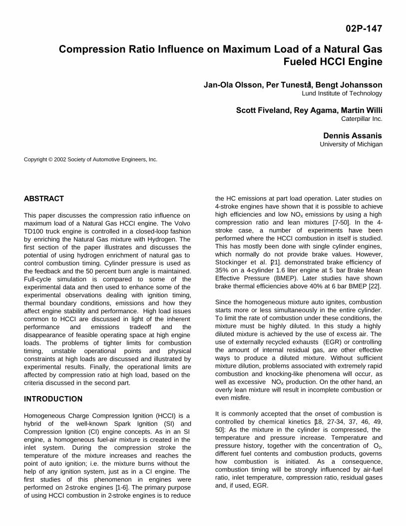
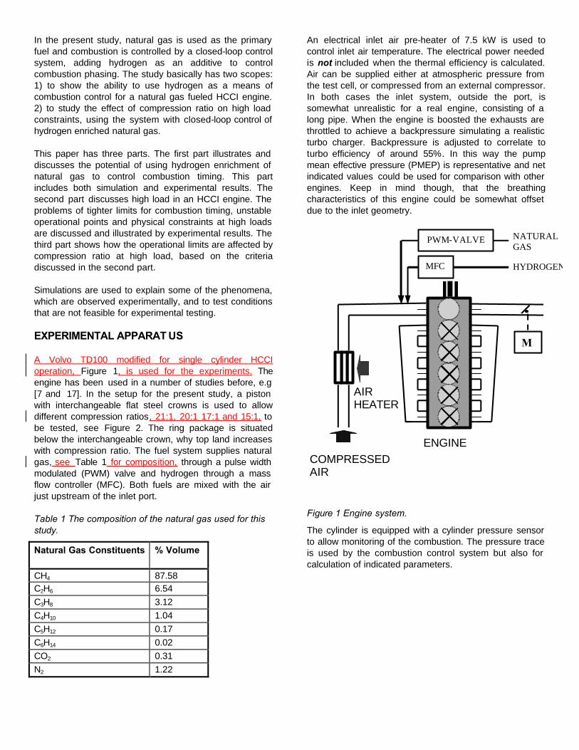
A Volvo TD100 modified for single cylinder HCCI operation, Figure 1, is used for the experiments. The engine has been used in a number of studies before, e.g [7 and 17]. In the setup for the present study, a piston with interchangeable flat steel crowns is used to allow different compression ratios, 21:1, 20:1 17:1 and 15:1, to be tested, see Figure 2. The ring package is situated below the interchangeable crown, why top land increases with compression ratio. The fuel system supplies natural gas, see Table 1 for composition, through a pulse width modulated (PWM) valve and hydrogen through a mass flow controller (MFC). Both fuels are mixed with the air just upstream of the inlet port.
Table 1 The composition of the natural gas used for this study.
Natural Gas Constituents % Volume
CH4 87.58 C2H6 6.54 C3H8 3.12 C4H10 1.04 C5H12 0.17 C6H14 0.02 CO2 0.31 N2 1.22
An electrical inlet air pre-heater of 7.5 kW is used to control inlet air temperature. The electrical power needed is not included when the thermal efficiency is calculated. Air can be supplied either at atmospheric pressure from the test cell, or compressed from an external compressor. In both cases the inlet system, outside the port, is somewhat unrealistic for a real engine, consisting of a long pipe. When the engine is boosted the exhausts are throttled to achieve a backpressure simulating a realistic turbo charger. Backpressure is adjusted to correlate to turbo efficiency of around 55%. In this way the pump mean effective pressure (PMEP) is representative and net indicated values could be used for comparison with other engines. Keep in mind though, that the breathing characteristics of this engine could be somewhat offset due to the inlet geometry.
HYDROGEN
AIR HEATER
ENGINE
M
COMPRESSED AIR
NATURAL GAS
PWM-VALVE
MFC
Figure 1 Engine system.
The cylinder is equipped with a cylinder pressure sensor to allow monitoring of the combustion. The pressure trace is used by the combustion control system but also for calculation of indicated parameters.
Figure 2 The piston, with the 15:1 compression ratio crown assembled. To the left of the piston is shown the crowns for 17:1, 20:1 and 21:1 compression ratios.
The cylinder head of the engine is in its original configuration and the camshaft has the same properties as in the natural gas fueled SI engines of the same series. The properties of the engine are summarized in Table 2.
Table 2 Geometric specifications of the engine. Valve timings refer to 1mm lift plus lash.
Displacement volume 1 600 cm3 Compression Ratio Varied Bore 120.65 mm Stroke 140 mm Connecting Rod 260 mm Exhaust Valve Open 39° BBDC Exhaust Valve Close 10° BTDC Intake Valve Open 5° ATDC Intake Valve Close 13° ABDC
An emission measurement system sampling exhausts is used to measure the exhaust concentrations of O2, CO, CO2, HC, NOX and NO. The Flame Ionization Detector (FID), measuring HC, is calibrated using CH4 and concentration of HC is given as CH4 equivalent.
The combustion control system is a modified version of the system used previously together with another engine [22]. The cylinder pressure trace and the inlet conditions are sampled and some key parameters characterizing the operational situation are calculated in real time. Combustion timing, characterized by the crank angle of 50% burnt, CA50, is calculated through an analysis of the net heat release. A PID controller, modifying the ratio between the two fuels, natural gas and hydrogen, is used to keep combustion timing at the set point. Net IMEP is integrated from the pressure trace and another PID controller, adjusting the total amount of fuel heat controls this variable. In this way both combustion timing and load is controlled at the same time.
In this study, all experiments are run at 1000 rpm. Speed does influence the HCCI combustion process, but to limit complexity speed is not varied.
MODELING THE HCCI ENGINE
The compression ignition engine simulation of Fiveland and Assanis [33, 34] is used for model validation. The main advantage of the full cycle simulation, over a variable volume reactor (i.e. closed cycle) model, is that it directly computes gas exchange as well as the internal residual trapped in the engine cylinder. Furthermore, it converges, through a series of iterations, to a steady state solution.
The cycle simulation can be operated either i) over the full engine cycle calculation, which includes gas exchange and steady state iteration, or ii) over a partial engine cycle calculation (i.e. variable volume reactor). The latter has been reported in several studies [19, 29, 30, 32]. Calculations of this type are useful when investigating fundamental issues; such as the effect of different complex chemistry schemes or heat transfer treatments on ignition prediction, because they decouple the effects of gas exchange modeling and cycle iteration.
SIMULATION ASSUMPTIONS – The HCCI thermodynamic formulation, the physical submodels, and the simulation structure are discussed in detail by Fiveland and Assanis [33, 34]. Only the pertinent simulation assumptions will be briefly reviewed. The simulation is currently written in a single cylinder version, primarily because fundamental studies lend themselves to this configuration. The engine simulation is a sequence of four-stroke processes. The gas exchange event is governed by quasi-steady, one-dimensional flow equations that are used to predict flow past valves. The compression event is defined from Intake Valve Closing (IVC) to a transition point prescribed when chemical reactions become important.
The combustion event for the HCCI simulation differs from those of the SI and DICI types. As a result of the premixed, compression ignition principle, the rate of combustion is strictly limited by the chemical kinetics. Hence, the combustion event has been modeled using the CHEMKIN libraries [37], adapted for a variable volume plenum. The evolution of heat release and species is governed by a user-defined kinetic scheme. The combustion subroutine accounts for heat transfer effects and is operational under both single and multi-zone configurations. Later in expansion, the reacting flow mixture attains chemical equilibrium in response to the changing in-cylinder conditions, and eventually the composition freezes. At this point the mixture is again non-reacting and the chemical energy source term tends to zero.
To improve the thermal simulation, a finite-difference wall temperature model, for the piston, head, and cylinder liner
has been implemented. The piston and cylinder head are solved implicitly in one-dimension. The cylinder liner temperature model is formulated to account for both radial and axial temperature gradients. This axis-symmetric formulation is carried out implicitly in cylindrical coordinates. Implicit schemes were formulated to take advantage of the fact that parabolic equations have flat characteristics. Therefore, the solution lends itself to implicit schemes, which can be shown through a Fourier mode analysis to be unconditionally stable [38]. The wall temperature model is directly coupled to the in-cylinder combustion process via the gas-side convection/conduction boundary condition. Only the combustion sub model will be revisited here because it is paramount to the discussion that follows.
SIMULATION VALIDATION- Before using the simulation to enhance the experimental analysis, it will be briefly evaluated against its ability to predict 50% mass fraction burned timing when subject to variations in the volume percentage of hydrogen. Previous validation work has been done with the cycle simulation using two-component fuel blends [55]. The engine used in that study was the same Volvo TD 100. In that work the simulation clearly showed the ability to predict both the 10 and 50% mass fraction burned positions when subject to changes in composition. It was concluded from that study that perfect agreement couldn’t be expected due to both simulation assumptions and measurement uncertainties.
COMBUSTION CONTROL BY HYDROGEN
Since HCCI lacks a direct means of controlling combustion initiation, an indirect method has to be used. Several studies have reported the use of air pre heating for combustion control [17, 46]. This method has the advantage of keeping combustion efficiency high, even at low load, and it does not require extensive hardware changes to the engine or supply of an additional fuel. However the control is not very fast. In some cases compression ratio [36] or valve timing [47] have been used to provide control of ignition angle. These methods have great performance potential, but require extensive changes to the engine. In other studies two fuels with different ignition characteristics have been used [22, 23]. This solution provides rapid response, but using two fuels are probably not considered a practical solution.
In the present study natural gas is the primary fuel and hydrogen is added as an ignition improver to control the onset of combustion. Basically this is the same solution as the two fuels mentioned above, but the advantage is that hydrogen could be produced online, by a reformer, from natural gas. A reformer using air would convert natural gas basically from the following reaction:
( ) 222222 887.11887.12
nNHnnCOnNOn
HC nn +++↔+++
From this reaction not only hydrogen, H2, would be
produced, but also carbon monoxide, CO. This reaction is somewhat exothermic and for methane the lower heat value decreases from 50 MJ/kg CH4 to 47.7 MJ/kg reformed CH4, calculated from reference [42]. For the mixture of natural gas assumed for the present study the heat value would go down from, unreformed, 47.6 MJ/kg natural gas to, reformed, 45.1 MJ/kg natural gas (based on mass before reforming).
The reforming reaction being exothermic means that the reformer will warm up and a penalty in efficiency will be paid, since the fuel supplied to the engine has a lower heating value than the not reformed natural gas.
In applications where water could be supplied, a reformer could use the following reactions to avoid producing CO [48]:
( ) 2222 12 HnnCOOnHHC nn ++↔++
222 HCOOHCO +↔+
The sum of these reactions is endothermic and for methane the lower heat value would increase to 60 MJ/kg reformed CH4. Of course this kind of reformer requires heat to be added. This heat could be taken from the exhausts if they were hot enough, resulting in an increased thermal efficiency of the engine. In an HCCI engine this will probably not be possible, but heat added to the reformer from fuel will be brought into the engine as an increased heat value and thus the thermal efficiency is unaffected.
In the present study externally supplied hydrogen is used for convenience. From a control aspect it should not be a problem if CO was added as well, the mixture would probably still act as an ignition improver, at least as long as the reformed gas is a small part of the total fuel. However some conclusions below regarding emissions and combustion efficiency may not be valid if CO is added as well.
When discussing the fraction of H2 it makes a big difference in numbers whether volume fraction or mass fraction is discussed. In this paper mass fraction is used in the text. Figure 3 shows how volume fraction relates to mass fraction for H2 mixed with natural gas.
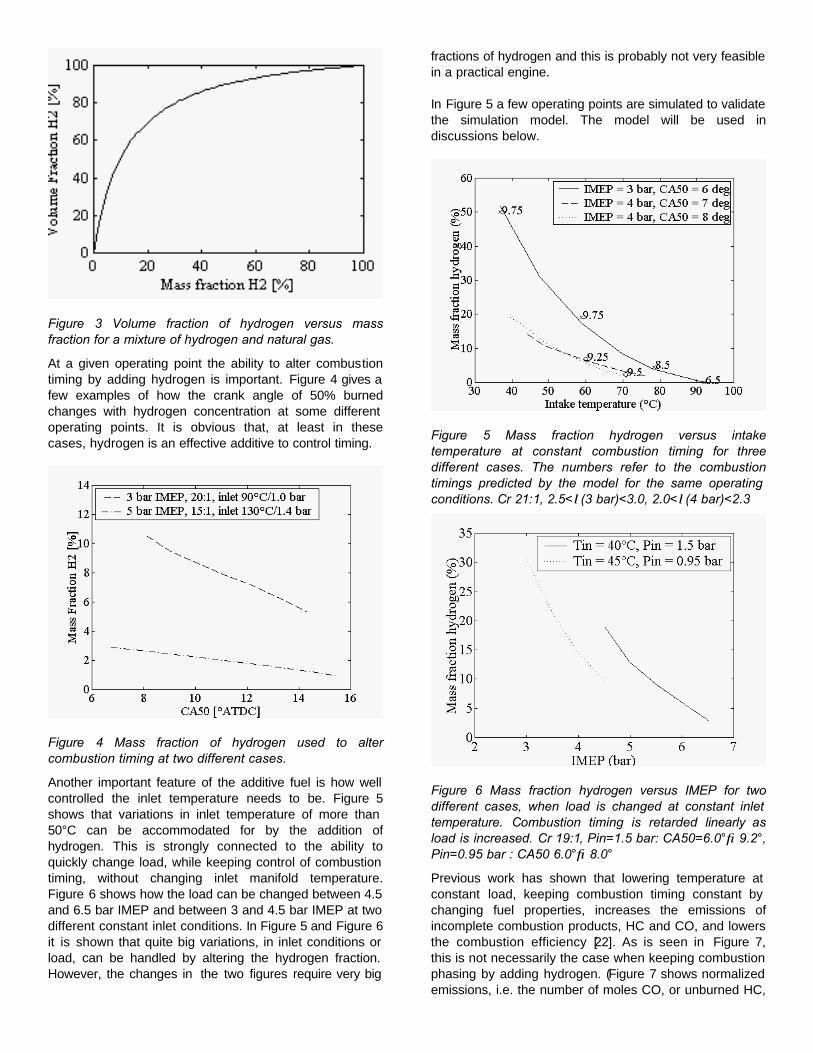
Figure 3 Volume fraction of hydrogen versus mass fraction for a mixture of hydrogen and natural gas.
At a given operating point the ability to alter combustion timing by adding hydrogen is important. Figure 4 gives a few examples of how the crank angle of 50% burned changes with hydrogen concentration at some different operating points. It is obvious that, at least in these cases, hydrogen is an effective additive to control timing.
Figure 4 Mass fraction of hydrogen used to alter combustion timing at two different cases.
Another important feature of the additive fuel is how well controlled the inlet temperature needs to be. Figure 5 shows that variations in inlet temperature of more than 50°C can be accommodated for by the addition of hydrogen. This is strongly connected to the ability to quickly change load, while keeping control of combustion timing, without changing inlet manifold temperature. Figure 6 shows how the load can be changed between 4.5 and 6.5 bar IMEP and between 3 and 4.5 bar IMEP at two different constant inlet conditions. In Figure 5 and Figure 6 it is shown that quite big variations, in inlet conditions or load, can be handled by altering the hydrogen fraction. However, the changes in the two figures require very big
fractions of hydrogen and this is probably not very feasible in a practical engine.
In Figure 5 a few operating points are simulated to validate the simulation model. The model will be used in discussions below.
Figure 5 Mass fraction hydrogen versus intake temperature at constant combustion timing for three different cases. The numbers refer to the combustion timings predicted by the model for the same operating conditions. Cr 21:1, 2.5<λ(3 bar)<3.0, 2.0<λ(4 bar)<2.3
Figure 6 Mass fraction hydrogen versus IMEP for two different cases, when load is changed at constant inlet temperature. Combustion timing is retarded linearly as load is increased. Cr 19:1, Pin=1.5 bar: CA50=6.0°→9.2°, Pin=0.95 bar : CA50 6.0°→8.0°
Previous work has shown that lowering temperature at constant load, keeping combustion timing constant by changing fuel properties, increases the emissions of incomplete combustion products, HC and CO, and lowers the combustion efficiency [22]. As is seen in Figure 7, this is not necessarily the case when keeping combustion phasing by adding hydrogen. (Figure 7 shows normalized emissions, i.e. the number of moles CO, or unburned HC,
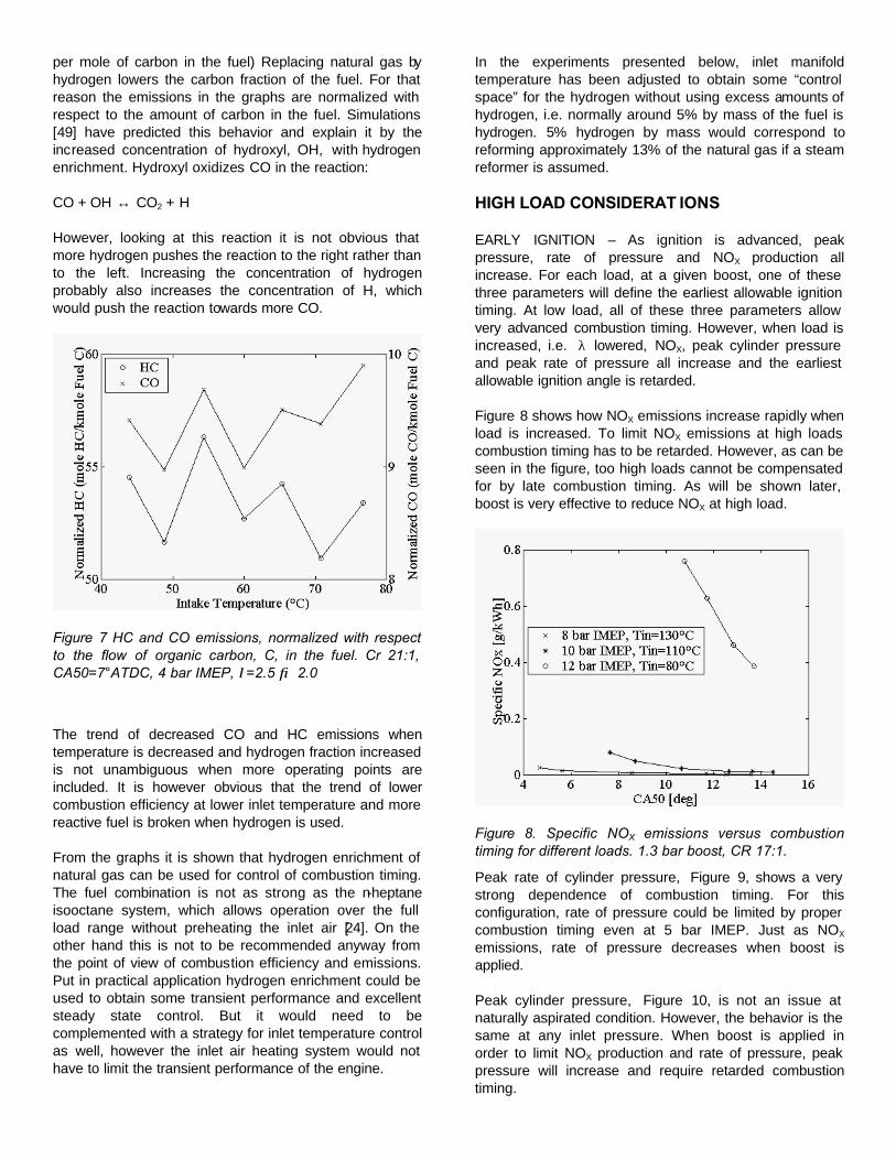
per mole of carbon in the fuel) Replacing natural gas by hydrogen lowers the carbon fraction of the fuel. For that reason the emissions in the graphs are normalized with respect to the amount of carbon in the fuel. Simulations [49] have predicted this behavior and explain it by the increased concentration of hydroxyl, OH, with hydrogen enrichment. Hydroxyl oxidizes CO in the reaction:
CO + OH ↔ CO2 + H
However, looking at this reaction it is not obvious that more hydrogen pushes the reaction to the right rather than to the left. Increasing the concentration of hydrogen probably also increases the concentration of H, which would push the reaction towards more CO.
Figure 7 HC and CO emissions, normalized with respect to the flow of organic carbon, C, in the fuel. Cr 21:1, CA50=7°ATDC, 4 bar IMEP, λ=2.5 → 2.0
The trend of decreased CO and HC emissions when temperature is decreased and hydrogen fraction increased is not unambiguous when more operating points are included. It is however obvious that the trend of lower combustion efficiency at lower inlet temperature and more reactive fuel is broken when hydrogen is used.
From the graphs it is shown that hydrogen enrichment of natural gas can be used for control of combustion timing. The fuel combination is not as strong as the n-heptane isooctane system, which allows operation over the full load range without preheating the inlet air [24]. On the other hand this is not to be recommended anyway from the point of view of combustion efficiency and emissions. Put in practical application hydrogen enrichment could be used to obtain some transient performance and excellent steady state control. But it would need to be complemented with a strategy for inlet temperature control as well, however the inlet air heating system would not have to limit the transient performance of the engine.
In the experiments presented below, inlet manifold temperature has been adjusted to obtain some “control space” for the hydrogen without using excess amounts of hydrogen, i.e. normally around 5% by mass of the fuel is hydrogen. 5% hydrogen by mass would correspond to reforming approximately 13% of the natural gas if a steam reformer is assumed.
HIGH LOAD CONSIDERAT IONS
EARLY IGNITION – As ignition is advanced, peak pressure, rate of pressure and NOX production all increase. For each load, at a given boost, one of these three parameters will define the earliest allowable ignition timing. At low load, all of these three parameters allow very advanced combustion timing. However, when load is increased, i.e. λ lowered, NOX, peak cylinder pressure and peak rate of pressure all increase and the earliest allowable ignition angle is retarded.
Figure 8 shows how NOX emissions increase rapidly when load is increased. To limit NOX emissions at high loads combustion timing has to be retarded. However, as can be seen in the figure, too high loads cannot be compensated for by late combustion timing. As will be shown later, boost is very effective to reduce NOX at high load.
Figure 8. Specific NOX emissions versus combustion timing for different loads. 1.3 bar boost, CR 17:1.
Peak rate of cylinder pressure, Figure 9, shows a very strong dependence of combustion timing. For this configuration, rate of pressure could be limited by proper combustion timing even at 5 bar IMEP. Just as NOX emissions, rate of pressure decreases when boost is applied.
Peak cylinder pressure, Figure 10, is not an issue at naturally aspirated condition. However, the behavior is the same at any inlet pressure. When boost is applied in order to limit NOX production and rate of pressure, peak pressure will increase and require retarded combustion timing.
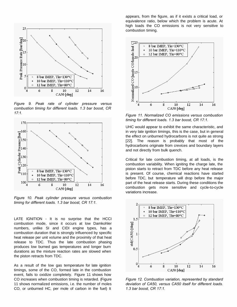
Figure 9. Peak rate of cylinder pressure versus combustion timing for different loads. 1.3 bar boost, CR 17:1.
Figure 10. Peak cylinder pressure versus combustion timing for different loads. 1.3 bar boost, CR 17:1.
LATE IGNITION - It is no surprise that the HCCI combustion mode, since it occurs at low Damkohler numbers, unlike SI and CIDI engine types, has a combustion duration that is strongly influenced by specific heat release per unit volume and the proximity of that heat release to TDC. Thus the late combustion phasing produces low burned gas temperatures and longer burn durations as the mixture reaction rates are slowed when the piston retracts from TDC.
As a result of the low gas temperature for late ignition timings, some of the CO, formed late in the combustion event, fails to oxidize completely. Figure 11 shows how CO increases when combustion timing is retarded. (Figure 11 shows normalized emissions, i.e. the number of moles CO, or unburned HC, per mole of carbon in the fuel) It
appears, from the figure, as if it exists a critical load, or equivalence ratio, below which the problem is acute. At high loads the CO emissions is not very sensitive to combustion timing.
Figure 11. Normalized CO emissions versus combustion timing for different loads. 1.3 bar boost, CR 17:1.
UHC would appear to exhibit the same characteristic, and in very late ignition timings, this is the case, but in general the effect on unburned hydrocarbons is not quite as strong [22]. The reason is probably that most of the hydrocarbons originate from crevices and boundary layers and not directly from bulk quench.
Critical for late combustion timing, at all loads, is the combustion variability. When igniting the charge late, the piston starts to retract from TDC before any heat release is present. Of course, chemical reactions have started before TDC, but temperature will drop before the major part of the heat release starts. During these conditions the combustion gets more sensitive and cycle-to-cycle variations increase.
Figure 12. Combustion variation, represented by standard deviation of CA50, versus CA50 itself for different loads. 1.3 bar boost, CR 17:1.
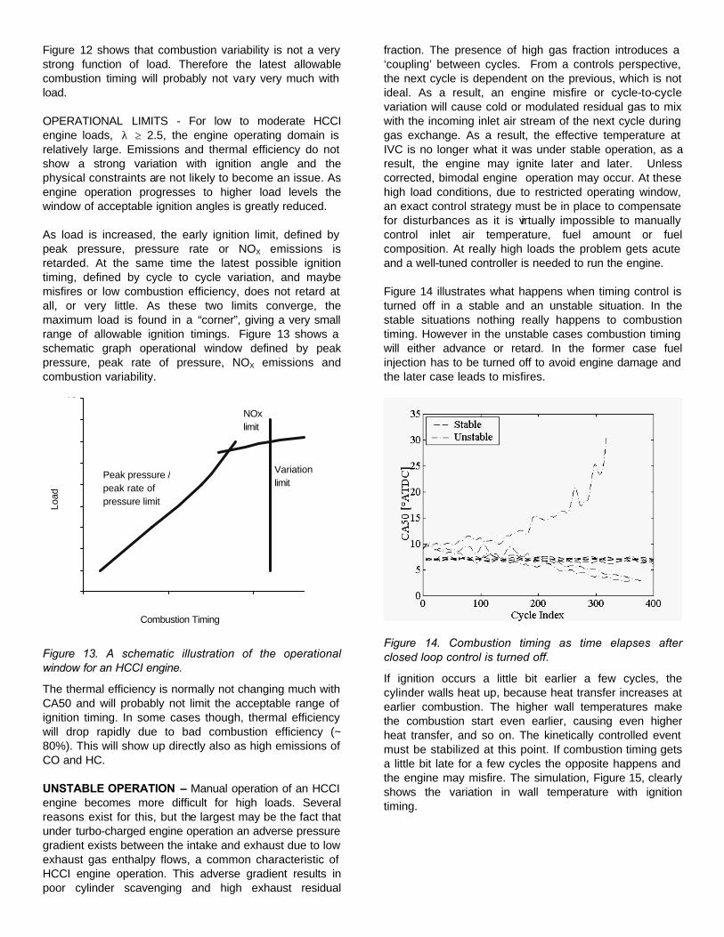
Figure 12 shows that combustion variability is not a very strong function of load. Therefore the latest allowable combustion timing will probably not vary very much with load.
OPERATIONAL LIMITS - For low to moderate HCCI engine loads, λ ≥ 2.5, the engine operating domain is relatively large. Emissions and thermal efficiency do not show a strong variation with ignition angle and the physical constraints are not likely to become an issue. As engine operation progresses to higher load levels the window of acceptable ignition angles is greatly reduced.
As load is increased, the early ignition limit, defined by peak pressure, pressure rate or NOX emissions is retarded. At the same time the latest possible ignition timing, defined by cycle to cycle variation, and maybe misfires or low combustion efficiency, does not retard at all, or very little. As these two limits converge, the maximum load is found in a “corner”, giving a very small range of allowable ignition timings. Figure 13 shows a schematic graph operational window defined by peak pressure, peak rate of pressure, NOX emissions and combustion variability.
5
6
7
8
9
10
11
12
13
14
2 7 12
Peak pressure / peak rate of pressure limit
NOx limit
Variation limit
Combustion Timing
Load
Figure 13. A schematic illustration of the operational window for an HCCI engine.
The thermal efficiency is normally not changing much with CA50 and will probably not limit the acceptable range of ignition timing. In some cases though, thermal efficiency will drop rapidly due to bad combustion efficiency (~ 80%). This will show up directly also as high emissions of CO and HC.
UNSTABLE OPERATION – Manual operation of an HCCI engine becomes more difficult for high loads. Several reasons exist for this, but the largest may be the fact that under turbo-charged engine operation an adverse pressure gradient exists between the intake and exhaust due to low exhaust gas enthalpy flows, a common characteristic of HCCI engine operation. This adverse gradient results in poor cylinder scavenging and high exhaust residual
fraction. The presence of high gas fraction introduces a ‘coupling’ between cycles. From a controls perspective, the next cycle is dependent on the previous, which is not ideal. As a result, an engine misfire or cycle-to-cycle variation will cause cold or modulated residual gas to mix with the incoming inlet air stream of the next cycle during gas exchange. As a result, the effective temperature at IVC is no longer what it was under stable operation, as a result, the engine may ignite later and later. Unless corrected, bimodal engine operation may occur. At these high load conditions, due to restricted operating window, an exact control strategy must be in place to compensate for disturbances as it is virtually impossible to manually control inlet air temperature, fuel amount or fuel composition. At really high loads the problem gets acute and a well-tuned controller is needed to run the engine.
Figure 14 illustrates what happens when timing control is turned off in a stable and an unstable situation. In the stable situations nothing really happens to combustion timing. However in the unstable cases combustion timing will either advance or retard. In the former case fuel injection has to be turned off to avoid engine damage and the later case leads to misfires.
Figure 14. Combustion timing as time elapses after closed loop control is turned off.
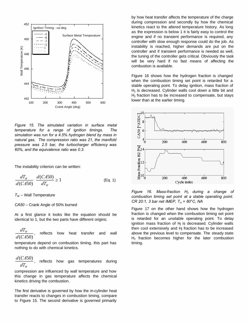
If ignition occurs a little bit earlier a few cycles, the cylinder walls heat up, because heat transfer increases at earlier combustion. The higher wall temperatures make the combustion start even earlier, causing even higher heat transfer, and so on. The kinetically controlled event must be stabilized at this point. If combustion timing gets a little bit late for a few cycles the opposite happens and the engine may misfire. The simulation, Figure 15, clearly shows the variation in wall temperature with ignition timing.
442
444
446
448
450
452
100 200 300 400 500 600
-9-6-3-115
Wal
l Tem
pera
ture
(K
)
Crank Angle (deg)
Ignition Timing - ca-deg
Surface Metal Temperature
Figure 15. The simulated variation in surface metal temperature for a range of ignition timings. The simulation was run for a 4.5% hydrogen blend by mass in natural gas. The compression ratio was 21, the manifold pressure was 2.5 bar, the turbocharger efficiency was 60%, and the equivalence ratio was 0.3.
The instability criterion can be written:
1)50(
)50(≥⋅
W
W
dTCAd
CAddT
(Eq. 1)
TW – Wall Temperature
CA50 – Crank Angle of 50% burned
At a first glance it looks like the equation should be identical to 1, but the two parts have different origins:
)50(CAd
dTW , reflects how heat transfer and wall
temperature depend on combustion timing, this part has nothing to do with chemical kinetics.
WdT
CAd )50(, reflects how gas temperatures during
compression are influenced by wall temperature and how this change in gas temperature affects the chemical kinetics driving the combustion.
The first derivative is governed by how the in-cylinder heat transfer reacts to changes in combustion timing, compare to Figure 15. The second derivative is governed primarily
by how heat transfer affects the temperature of the charge during compression and secondly by how the chemical kinetics react to the altered temperature history. As long as the expression is below 1 it is fairly easy to control the engine and if no transient performance is required, any controller with slow enough response could do the job. As instability is reached, higher demands are put on the controller and if transient performance is needed as well, the tuning of the controller gets critical. Obviously the task will be very hard if no fast means of affecting the combustion is available.
Figure 16 shows how the hydrogen fraction is changed when the combustion timing set point is retarded for a stable operating point. To delay ignition, mass fraction of H2 is decreased. Cylinder walls cool down a little bit and H2 fraction has to be increased to compensate, but stays lower than at the earlier timing.
Figure 16. Mass-fraction H2 during a change of combustion timing set point at a stable operating point. CR 20:1, 3 bar net IMEP, Tin = 80°C, NA
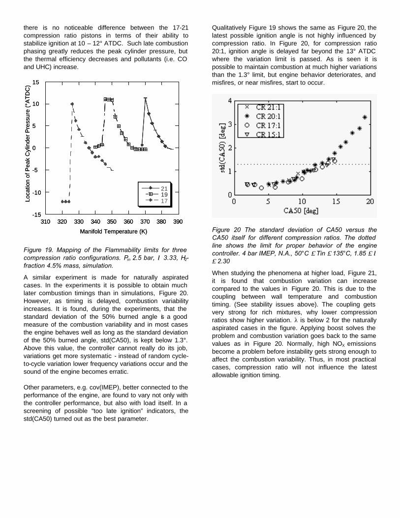
Figure 17 on the other hand shows how the hydrogen fraction is changed when the combustion timing set point is retarded for an unstable operating point. To delay ignition mass fraction of H2 is decreased. Cylinder walls then cool extensively and H2 fraction has to be increased above the previous level to compensate. The steady state H2 fraction becomes higher for the later combustion timing.
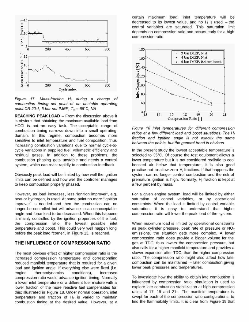
Figure 17. Mass-fraction H2 during a change of combustion timing set point at an unstable operating point.CR 20:1, 5 bar net IMEP, Tin = 55°C, NA
REACHING PEAK LOAD – From the discussion above it is obvious that obtaining the maximum available load from HCCI is not an easy task. The acceptable range of combustion timing narrows down into a small operating domain. In this regime, combustion becomes more sensitive to inlet temperature and fuel composition, thus increasing combustion variations due to normal cycle-to-cycle variations in supplied fuel, volumetric efficiency and residual gases. In addition to these problems, the combustion phasing gets unstable and needs a control system, which can react rapidly to combustion feedback.
Obviously peak load will be limited by how well the ignition limits can be defined and how well the controller manages to keep combustion properly phased.
However, as load increases, less “ignition improver”, e.g. heat or hydrogen, is used. At some point no more “ignition improver” is needed and then the combustion can no longer be controlled but will advance to an unacceptable angle and force load to be decreased. When this happens is mainly controlled by the ignition properties of the fuel, the compression ratio, the lowest possible inlet temperature and boost. This could very well happen long before the peak load “corner”, in Figure 13, is reached.
THE INFLUENCE OF COMPRESSION RATIO
The most obvious effect of higher compression ratio is the increased compression temperature and corresponding reduced manifold temperature that is required for a given load and ignition angle. If everything else were fixed (i.e. engine thermodynamics conditions), increased compression ratio would advance ignition timing. Normally a lower inlet temperature or a different fuel mixture with a lower fraction of the more reactive fuel compensates for this; illustrated in Figure 18. Under normal operation, inlet temperature and fraction of H2 is varied to maintain combustion timing at the desired value. However, at a
certain maximum load, inlet temperature will be decreased to its lowest value, and no H2 is used – the control variables are saturated. This saturation limit depends on compression ratio and occurs early for a high compression ratio.
Figure 18 Inlet temperatures for different compression ratios at a few different load and boost situations. The H2 fraction and ignition angle is not exactly the same between the points, but the general trend is obvious.
In the present study the lowest acceptable temperature is selected to 35°C. Of course the test equipment allows a lower temperature but it is not considered realistic to cool boosted air below that temperature. It is also good practice not to allow zero H2 fractions. If that happens the system can no longer control combustion and the risk of premature ignition is high. Normally, H2 fraction is kept at a few percent by mass.
For a given engine system, load will be limited by either saturation of control variables, or by operational constraints. When the load is limited by control variable saturation, it is easy to understand that higher compression ratio will lower the peak load of the system.
When maximum load is limited by operational constraints as peak cylinder pressure, peak rate of pressure or NOX emissions, the situation gets more complex. A lower compression ratio does provide a bigger volume for the gas at TDC, thus lowers the compression pressure, but also calls for a higher manifold temperature and provides a slower expansion after TDC, than the higher compression ratio. The compression ratio might also affect how late combustion can be maintained – later combustion giving lower peak pressures and temperatures.
To investigate how the ability to obtain late combustion is influenced by compression ratio, simulation is used to explore late combustion stabilization at high compression ratios of 17, 19 and 21. The manifold temperature is swept for each of the compression ratio configurations, to find the flammability limits. It is clear from Figure 19 that
there is no noticeable difference between the 17-21 compression ratio pistons in terms of their ability to stabilize ignition at 10 – 12° ATDC. Such late combustion phasing greatly reduces the peak cylinder pressure, but the thermal efficiency decreases and pollutants (i.e. CO and UHC) increase.
-15
-10
-5
0
5
10
15
310 320 330 340 350 360 370 380 390
211917Lo
catio
n of
Pea
k C
ylin
der P
ress
ure
(°A
TDC
)
Manifold Temperature (K)
-15
-10
-5
0
5
10
15
310 320 330 340 350 360 370 380 390
211917Lo
catio
n of
Pea
k C
ylin
der P
ress
ure
(°A
TDC
)
Manifold Temperature (K)
Figure 19. Mapping of the Flammability limits for three compression ratio configurations. Pin 2.5 bar, λ 3.33, H2-fraction 4.5% mass, simulation.
A similar experiment is made for naturally aspirated cases. In the experiments it is possible to obtain much later combustion timings than in simulations, Figure 20. However, as timing is delayed, combustion variability increases. It is found, during the experiments, that the standard deviation of the 50% burned angle is a good measure of the combustion variability and in most cases the engine behaves well as long as the standard deviation of the 50% burned angle, std(CA50), is kept below 1.3°. Above this value, the controller cannot really do its job, variations get more systematic - instead of random cycle-to-cycle variation lower frequency variations occur and the sound of the engine becomes erratic.
Other parameters, e.g. cov(IMEP), better connected to the performance of the engine, are found to vary not only with the controller performance, but also with load itself. In a screening of possible “too late ignition” indicators, the std(CA50) turned out as the best parameter.
Qualitatively Figure 19 shows the same as Figure 20, the latest possible ignition angle is not highly influenced by compression ratio. In Figure 20, for compression ratio 20:1, ignition angle is delayed far beyond the 13° ATDC where the variation limit is passed. As is seen it is possible to maintain combustion at much higher variations than the 1.3° limit, but engine behavior deteriorates, and misfires, or near misfires, start to occur.
Figure 20 The standard deviation of CA50 versus the CA50 itself for different compression ratios. The dotted line shows the limit for proper behavior of the engine controller. 4 bar IMEP, N.A., 50°C ≤ Tin ≤ 135°C, 1.85 ≤ λ ≤ 2.30
When studying the phenomena at higher load, Figure 21, it is found that combustion variation can increase compared to the values in Figure 20. This is due to the coupling between wall temperature and combustion timing. (See stability issues above). The coupling gets very strong for rich mixtures, why lower compression ratios show higher variation. λ is below 2 for the naturally aspirated cases in the figure. Applying boost solves the problem and combustion variation goes back to the same values as in Figure 20. Normally, high NOX emissions become a problem before instability gets strong enough to affect the combustion variability. Thus, in most practical cases, compression ratio will not influence the latest allowable ignition timing.
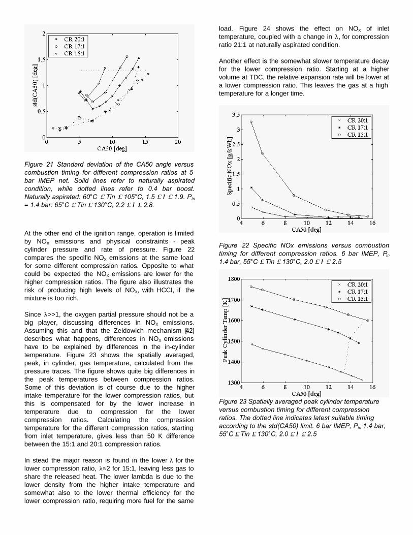
Figure 21 Standard deviation of the CA50 angle versus combustion timing for different compression ratios at 5 bar IMEP net. Solid lines refer to naturally aspirated condition, while dotted lines refer to 0.4 bar boost. Naturally aspirated: 60°C ≤ Tin ≤ 105°C, 1.5 ≤ λ ≤ 1.9. Pin = 1.4 bar: 65°C ≤ Tin ≤ 130°C, 2.2 ≤ λ ≤ 2.8.
At the other end of the ignition range, operation is limited by NOX emissions and physical constraints - peak cylinder pressure and rate of pressure. Figure 22 compares the specific NOX emissions at the same load for some different compression ratios. Opposite to what could be expected the NOX emissions are lower for the higher compression ratios. The figure also illustrates the risk of producing high levels of NOX, with HCCI, if the mixture is too rich.
Since λ>>1, the oxygen partial pressure should not be a big player, discussing differences in NOX emissions. Assuming this and that the Zeldowich mechanism [42] describes what happens, differences in NOX emissions have to be explained by differences in the in-cylinder temperature. Figure 23 shows the spatially averaged, peak, in cylinder, gas temperature, calculated from the pressure traces. The figure shows quite big differences in the peak temperatures between compression ratios. Some of this deviation is of course due to the higher intake temperature for the lower compression ratios, but this is compensated for by the lower increase in temperature due to compression for the lower compression ratios. Calculating the compression temperature for the different compression ratios, starting from inlet temperature, gives less than 50 K difference between the 15:1 and 20:1 compression ratios.
In stead the major reason is found in the lower λ for the lower compression ratio, λ≈2 for 15:1, leaving less gas to share the released heat. The lower lambda is due to the lower density from the higher intake temperature and somewhat also to the lower thermal efficiency for the lower compression ratio, requiring more fuel for the same
load. Figure 24 shows the effect on NOX of inlet temperature, coupled with a change in λ, for compression ratio 21:1 at naturally aspirated condition.
Another effect is the somewhat slower temperature decay for the lower compression ratio. Starting at a higher volume at TDC, the relative expansion rate will be lower at a lower compression ratio. This leaves the gas at a high temperature for a longer time.
Figure 22 Specific NOx emissions versus combustion timing for different compression ratios. 6 bar IMEP, Pin 1.4 bar, 55°C ≤ Tin ≤ 130°C, 2.0 ≤ λ ≤ 2.5
Figure 23 Spatially averaged peak cylinder temperature versus combustion timing for different compression ratios. The dotted line indicates latest suitable timing according to the std(CA50) limit. 6 bar IMEP, Pin 1.4 bar, 55°C ≤ Tin ≤ 130°C, 2.0 ≤ λ ≤ 2.5
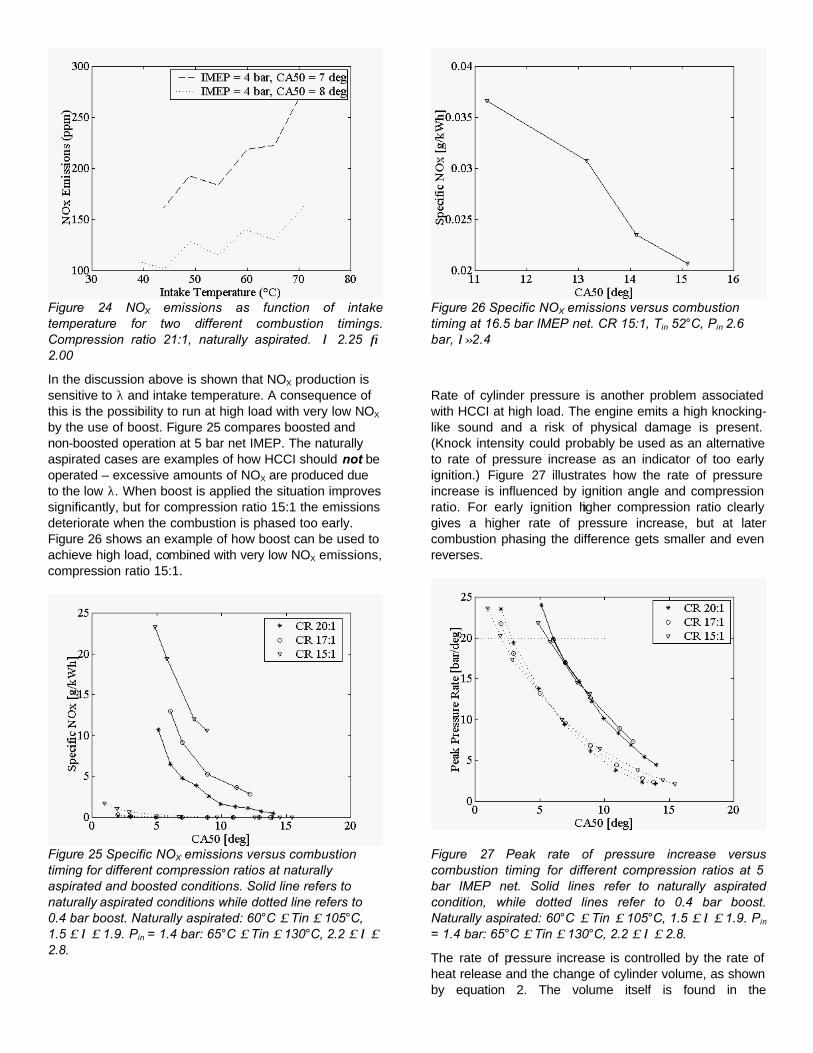
Figure 24 NOX emissions as function of intake temperature for two different combustion timings. Compression ratio 21:1, naturally aspirated. λ 2.25 → 2.00
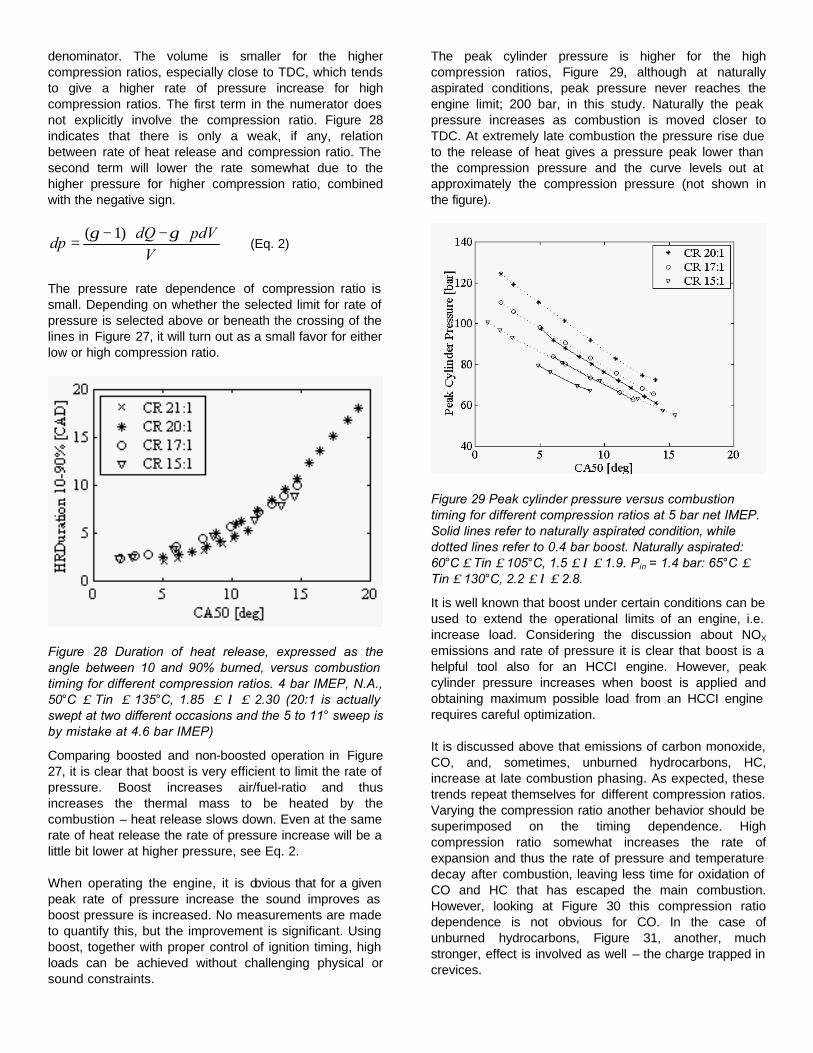
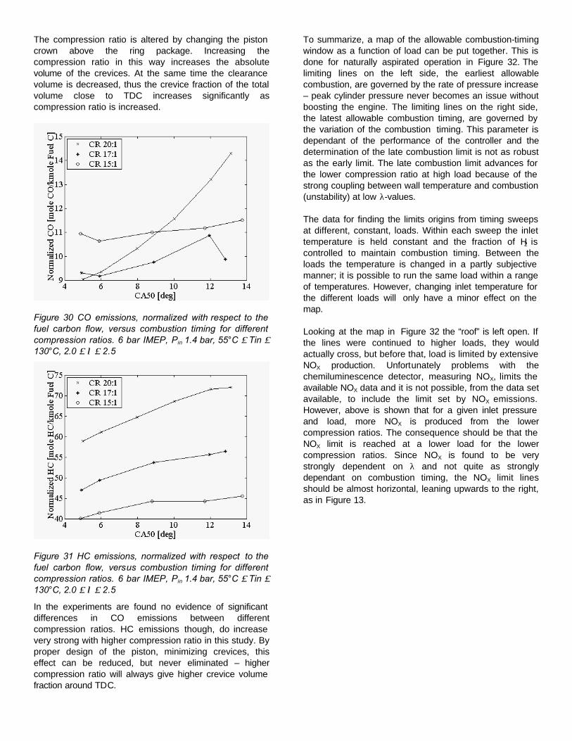
In the discussion above is shown that NOX production is sensitive to λ and intake temperature. A consequence of this is the possibility to run at high load with very low NOX by the use of boost. Figure 25 compares boosted and non-boosted operation at 5 bar net IMEP. The naturally aspirated cases are examples of how HCCI should not be operated – excessive amounts of NOX are produced due to the low λ. When boost is applied the situation improves significantly, but for compression ratio 15:1 the emissions deteriorate when the combustion is phased too early. Figure 26 shows an example of how boost can be used to achieve high load, combined with very low NOX emissions, compression ratio 15:1.
Figure 25 Specific NOX emissions versus combustion timing for different compression ratios at naturally aspirated and boosted conditions. Solid line refers to naturally aspirated conditions while dotted line refers to 0.4 bar boost. Naturally aspirated: 60°C ≤ Tin ≤ 105°C, 1.5 ≤ λ ≤ 1.9. Pin = 1.4 bar: 65°C ≤ Tin ≤ 130°C, 2.2 ≤ λ ≤ 2.8.
Figure 26 Specific NOX emissions versus combustion timing at 16.5 bar IMEP net. CR 15:1, Tin 52°C, Pin 2.6 bar, λ≈2.4
Rate of cylinder pressure is another problem associated with HCCI at high load. The engine emits a high knocking-like sound and a risk of physical damage is present. (Knock intensity could probably be used as an alternative to rate of pressure increase as an indicator of too early ignition.) Figure 27 illustrates how the rate of pressure increase is influenced by ignition angle and compression ratio. For early ignition higher compression ratio clearly gives a higher rate of pressure increase, but at later combustion phasing the difference gets smaller and even reverses.
Figure 27 Peak rate of pressure increase versus combustion timing for different compression ratios at 5 bar IMEP net. Solid lines refer to naturally aspirated condition, while dotted lines refer to 0.4 bar boost. Naturally aspirated: 60°C ≤ Tin ≤ 105°C, 1.5 ≤ λ ≤ 1.9. Pin = 1.4 bar: 65°C ≤ Tin ≤ 130°C, 2.2 ≤ λ ≤ 2.8.
The rate of pressure increase is controlled by the rate of heat release and the change of cylinder volume, as shown by equation 2. The volume itself is found in the
denominator. The volume is smaller for the higher compression ratios, especially close to TDC, which tends to give a higher rate of pressure increase for high compression ratios. The first term in the numerator does not explicitly involve the compression ratio. Figure 28 indicates that there is only a weak, if any, relation between rate of heat release and compression ratio. The second term will lower the rate somewhat due to the higher pressure for higher compression ratio, combined with the negative sign.
VpdVdQ
dp⋅−⋅−
=γγ )1(
(Eq. 2)
The pressure rate dependence of compression ratio is small. Depending on whether the selected limit for rate of pressure is selected above or beneath the crossing of the lines in Figure 27, it will turn out as a small favor for either low or high compression ratio.
Figure 28 Duration of heat release, expressed as the angle between 10 and 90% burned, versus combustion timing for different compression ratios. 4 bar IMEP, N.A., 50°C ≤ Tin ≤ 135°C, 1.85 ≤ λ ≤ 2.30 (20:1 is actually swept at two different occasions and the 5 to 11° sweep is by mistake at 4.6 bar IMEP)
Comparing boosted and non-boosted operation in Figure 27, it is clear that boost is very efficient to limit the rate of pressure. Boost increases air/fuel-ratio and thus increases the thermal mass to be heated by the combustion – heat release slows down. Even at the same rate of heat release the rate of pressure increase will be a little bit lower at higher pressure, see Eq. 2.
When operating the engine, it is obvious that for a given peak rate of pressure increase the sound improves as boost pressure is increased. No measurements are made to quantify this, but the improvement is significant. Using boost, together with proper control of ignition timing, high loads can be achieved without challenging physical or sound constraints.
The peak cylinder pressure is higher for the high compression ratios, Figure 29, although at naturally aspirated conditions, peak pressure never reaches the engine limit; 200 bar, in this study. Naturally the peak pressure increases as combustion is moved closer to TDC. At extremely late combustion the pressure rise due to the release of heat gives a pressure peak lower than the compression pressure and the curve levels out at approximately the compression pressure (not shown in the figure).
Figure 29 Peak cylinder pressure versus combustion timing for different compression ratios at 5 bar net IMEP. Solid lines refer to naturally aspirated condition, while dotted lines refer to 0.4 bar boost. Naturally aspirated: 60°C ≤ Tin ≤ 105°C, 1.5 ≤ λ ≤ 1.9. Pin = 1.4 bar: 65°C ≤ Tin ≤ 130°C, 2.2 ≤ λ ≤ 2.8.
It is well known that boost under certain conditions can be used to extend the operational limits of an engine, i.e. increase load. Considering the discussion about NOX emissions and rate of pressure it is clear that boost is a helpful tool also for an HCCI engine. However, peak cylinder pressure increases when boost is applied and obtaining maximum possible load from an HCCI engine requires careful optimization.
It is discussed above that emissions of carbon monoxide, CO, and, sometimes, unburned hydrocarbons, HC, increase at late combustion phasing. As expected, these trends repeat themselves for different compression ratios. Varying the compression ratio another behavior should be superimposed on the timing dependence. High compression ratio somewhat increases the rate of expansion and thus the rate of pressure and temperature decay after combustion, leaving less time for oxidation of CO and HC that has escaped the main combustion. However, looking at Figure 30 this compression ratio dependence is not obvious for CO. In the case of unburned hydrocarbons, Figure 31, another, much stronger, effect is involved as well – the charge trapped in crevices.
The compression ratio is altered by changing the piston crown above the ring package. Increasing the compression ratio in this way increases the absolute volume of the crevices. At the same time the clearance volume is decreased, thus the crevice fraction of the total volume close to TDC increases significantly as compression ratio is increased.
Figure 30 CO emissions, normalized with respect to the fuel carbon flow, versus combustion timing for different compression ratios. 6 bar IMEP, Pin 1.4 bar, 55°C ≤ Tin ≤ 130°C, 2.0 ≤ λ ≤ 2.5
Figure 31 HC emissions, normalized with respect to the fuel carbon flow, versus combustion timing for different compression ratios. 6 bar IMEP, Pin 1.4 bar, 55°C ≤ Tin ≤ 130°C, 2.0 ≤ λ ≤ 2.5
In the experiments are found no evidence of significant differences in CO emissions between different compression ratios. HC emissions though, do increase very strong with higher compression ratio in this study. By proper design of the piston, minimizing crevices, this effect can be reduced, but never eliminated – higher compression ratio will always give higher crevice volume fraction around TDC.
To summarize, a map of the allowable combustion-timing window as a function of load can be put together. This is done for naturally aspirated operation in Figure 32. The limiting lines on the left side, the earliest allowable combustion, are governed by the rate of pressure increase – peak cylinder pressure never becomes an issue without boosting the engine. The limiting lines on the right side, the latest allowable combustion timing, are governed by the variation of the combustion timing. This parameter is dependant of the performance of the controller and the determination of the late combustion limit is not as robust as the early limit. The late combustion limit advances for the lower compression ratio at high load because of the strong coupling between wall temperature and combustion (unstability) at low λ-values.
The data for finding the limits origins from timing sweeps at different, constant, loads. Within each sweep the inlet temperature is held constant and the fraction of H2 is controlled to maintain combustion timing. Between the loads the temperature is changed in a partly subjective manner; it is possible to run the same load within a range of temperatures. However, changing inlet temperature for the different loads will only have a minor effect on the map.
Looking at the map in Figure 32 the “roof” is left open. If the lines were continued to higher loads, they would actually cross, but before that, load is limited by extensive NOX production. Unfortunately problems with the chemiluminescence detector, measuring NOX, limits the available NOX data and it is not possible, from the data set available, to include the limit set by NOX emissions. However, above is shown that for a given inlet pressure and load, more NOX is produced from the lower compression ratios. The consequence should be that the NOX limit is reached at a lower load for the lower compression ratios. Since NOX is found to be very strongly dependent on λ and not quite as strongly dependant on combustion timing, the NOX limit lines should be almost horizontal, leaning upwards to the right, as in Figure 13.
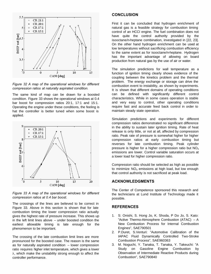
Figure 32 A map of the operational windows for different compression ratios at naturally aspirated condition.
The same kind of map can be drawn for a boosted condition. Figure 33 shows the operational windows at 0.4 bar boost for compression ratios 20:1, 17:1 and 15:1. Operating the engine under these conditions, the feeling is hat the controller is better tuned when some boost is applied.
Figure 33 A map of the operational windows for different compression ratios at 0.4 bar boost.
The crossings of the lines are believed to be correct in Figure 33. Above in this section is shown that for late combustion timing the lower compression ratio actually gives the highest rate of pressure increase. This shows up in the left limit lines above – under boosted condition the earliest allowable timing is late enough for the phenomenon to be important.
The crossing of the late combustion limit lines are more pronounced for the boosted case. The reason is the same as for naturally aspirated condition – lower compression ratio requires higher inlet temperature, which gives a lower λ, which make the unstability strong enough to affect the controller performance.
CONCLUSION
First it can be concluded that hydrogen enrichment of natural gas is a feasible strategy for combustion timing control of an HCCI engine. The fuel combination does not have quite the control authority provided by the isooctane/n-heptane combination, investigated in [22, 23]. On the other hand hydrogen enrichment can be used at low temperatures without sacrificing combustion efficiency to the same extent as for isooctane/n-heptane. Hydrogen has the important advantage of allowing on board production from natural gas by the use of air or water.
The simulation predictions for wall temperature as a function of ignition timing clearly shows evidence of the coupling between the kinetics problem and the thermal problem. The energy exchange or storage can drive the combustion event to instability, as shown by experiments. It is shown that different domains of operating conditions can be defined with significantly different control characteristics. While in some cases operation is stable and very easy to control, other operating conditions require fast and accurate feed back control in order to maintain steady state operation.
Simulation predictions and experiments for different compression ratios demonstrated no significant difference in the ability to sustain later ignition timing. Rate of heat release is only little, or not at all, affected by compression ratio. Peak rate of pressure is somewhat higher for higher compression ratios at early combustion timing but reverses for late combustion timing. Peak cylinder pressure is higher for a higher compression ratio but NOX emissions are lower. Control variable saturation occurs at a lower load for higher compression ratio.
Compression ratio should be selected as high as possible to minimize NOX emissions at high load, but low enough that control authority is not sacrificed at peak load.
ACKNOWLEDGMENTS
The Center of Competence sponsored this research and the technicians at Lund Institute of Technology made it possible.
REFERENCES
1. S: Onishi, S. Hong Jo, K. Shoda, P Do Jo, S. Kato: ”Active Thermo-Atmosphere Combustion (ATAC) – A New Combustion Process for Internal Combustion Engines”, SAE790501
2. P.Duret, S.Venturi: ”Automotive Calibration of the IAPAC Fluid Dynamically Controlled Two-Stroke Combustion Process”, SAE960363
3. M. Noguchi, Y. Tanaka, T. Tanaka, Y. Takeuchi: ”A Study on Gasoline Engine Combustion by Observation of Intermediate Reactive Products during Combustion”, SAE790840
4. N. Iida: ”Combustion Analysis of Methanol-Fueled Active Thermo-Atmosphere Combustion (ATAC) Engine Using a Spectroscopic Observation” SAE940684
5. Y. Ishibashi, M. Asai: ”Improving the Exhaust Emissions of Two-Stroke Engines by Applying the Activated Radical Combustion”, SAE960742
6. R. Gentili, S. Frigo, L. Tognotti, P. Hapert, J. Lavy: ”Experimental study of ATAC (Active Thermo-Atmosphere Combustion) in a Two-Stroke Gasoline Engine”, SAE 970363
7. A. Hultqvist, M. Christensen, B. Johansson, A. Franke, M. Richter, M. Aldén: ”A Study of the Homogeneous Charge Compression Ignition Combustion Process by Chemiluminescence Imaging”, SAE1999-01-3680
8. P. Najt, D.E. Foster: ”Compression-Ignited Homoge-neous Charge Combustion”, SAE830264
9. R.H. Thring: ”Homogeneous-Charge Compression-Ignition (HCCI) Engines”, SAE892068
10. T. Aoyama, Y. Hattori, J. Mizuta, Y. Sato: ”An Experimental Study on Premixed-Charge Compression Ignition Gasoline Engine”, SAE960081
11. T.W. Ryan, T.J. Callahan: ”Homogeneous Charge Compression Ignition of Diesel Fuel”, SAE961160
12. H. Suzuki, N. Koike, H. Ishii, M. Odaka: ”Exhaust Purification of Diesel Engines by Homogeneous Charge with Compression Ignition”, SAE970313, SAE970315
13. A. W. Gray III, T. W. Ryan III: ”Homogeneous Charge Compression Ignition (HCCI) of Diesel Fuel”, SAE971676
14. H. Suzuki, N. Koike, M. Odaka: ”Combustion Control Method of Homogeneous Charge Diesel Engines”, SAE980509
15. T. Seko, E. Kuroda: ”Methanol Lean Burn in an Auto-Ignition Engine”, SAE980531
16. A. Harada, N. Shimazaki, S. Sasaki, T. Miyamoto, H. Akagawa, K. Tsujimura: ”The Effects of Mixture Formation on Premixed Lean Diesel Combustion”, SAE980533
17. M. Christensen, P. Einewall, B. Johansson: ”Homo-geneous Charge Compression Ignition (HCCI) Using Isooctane, Ethanol and Natural Gas – A Comparison to Spark Ignition Operation", SAE972874
18. M. Christensen, B. Johansson, P. Amnéus, F. Mauss: ”Supercharged Homogeneous Charge Compression Ignition”, SAE 980787
19. M. Christensen, B. Johansson: ”Influence of Mixture Quality on Homogeneous Charge Compression Ignition”, SAE982454
20. M. Christensen, B. Johansson: ”Homogeneous Charge Compression Ignition with Water Injection”, SAE1999-01-0182
21. M. Stockinger, H. Schäpertöns, P. Kuhlmann, Versuche an einem gemischansaugenden mit Selbszündung, MTZ 53 (1992).
22. J.-O. Olsson, O. Erlandsson, B. Johansson: “Experiments and Simulations of a Six-Cylinder
Homogeneous Charge Compression (HCCI) Engine”, SAE 2000-01-2867
23. J.-O. Olsson, P. Tunestål, B. Johansson: ”Closed-Loop Control of an HCCI Engine”, SAE 2001-01-1031
24. J.-O. Olsson, P. Tunestål, G. Haraldsson, B. Johansson, ”A Turbo Charged Dual Fuel HCCI Engine”, SAE 2001-01-1896
25. Weaver, C.S., “Natural Gas Vehicles – A Review of the State of the Art,” SAE Paper 892133.
26. Westbrook C.K., and Pitz W., 1983, “Effects of Propane and Ignition of Methane-Ethane-Air Mixtures,” Combustion Science and Technology, Vol. 33, pp. 315-319.
27. Fraser, A.F., Siebers, D.L., Edwards, C.F., “Autoignition of Methane and Natural Gas in a Simulated Diesel Environment,” SAE Paper 910227, 1991.
28. Naber J.D., D.L. Siebers, J.A. Caton, Westbrook C.K., Di Julio S.S., “Natural Gas Autoignition Under Diesel Conditions: Experiments and Chemical Kinetic Modeling,” SAE Paper 942034, 1994.
29. Smith, J.R., S.M. Aceves, C. Westbrook, and W. Pitz, “Modeling of Homogeneous Charge Compression Ignition (HCCI) of Methane,” Proceedings of the 1997 ASME Internal Combustion Engine Fall Technical Conference, ASME Paper No. 97-ICE-68, ICE-VOL. 29-3, pp. 85-90, 1997.
30. Amneus, P., Nilsson, D., Christensen, M., and Johansson, B., “Homogeneous Charge Compression Ignition Engine: Experiments and Detailed Kinetic Calculations,” The Fourth Symposium on Diagnostics and Modeling of Combustion in Internal Combustion Engines, Comodia 98, pp. 567-572, 1998.
31. Aceves, A.M., Flowers, D.L., Westbrook, C.K., Smith, J.R., Pitz, W., Dibble, R., Christensen, M., and Johansson, “A Multi-Zone Model for Prediction of HCCI Combustion and Emissions,” SAE Paper 2000-01-0327.
32. Flowers, D., Aceves, S., Westbrook, C.K., Smith, J.R., and Dibble, R., “Sensitivity of Natural Gas HCCI Combustion to Fuel and Operating Parameters Using Detailed Kinetic Modeling,” UCRL-JC-135058.
33. Fiveland S.B., and Assanis D.N., “A Four-Stroke Homogeneous Charge Compression Ignition Engine Simulation for Combustion and Performance Studies,” SAE Paper 2000-01-0332, 2000.
34. Fiveland, S.B., and Assanis, D.N., “Development of a Two-Zone HCCI Combustion Model Accounting for Boundary Layer Effects,” SAE 2001-01-1028.
35. Hiltner, J., Agama, R., Mauss, F., Johansson, B., and Christensen, M. “HCCI Operation with Natural Gas: Fuel Composition Implications” ASME: Internal Combustion Engine Technology Conference, September 24-27, 2000.
36. Christensen, M., Hultqvist, A., and Johansson, B., “Demonstrating the Multi Fuel Capability of a Homogeneous Charge Compression Ignition Engine with Variable Compression Ratio,” SAE Paper 99FL-223.
37. Kee, R.J., F.M. Rupley, and J.A. Miller, “Chemkin-II: A FORTRAN Chemical Kinetics Package for the Analysis of Gas-Phase Chemical Kinetics,” Sandia National Labs Report SAND89-8009B, 1991.
38. Tannehill, J.C., Anderson D.A., Pletcher R.H., Computational Fluid Mechanics and Heat Transfer, Taylor and Francis, Washington D.C., 1997.
39. Agarwal, A. and D.N. Assanis, “Modeling the Effect of Natural Gas Composition on Ignition Delay Under Compression Ignition Conditions,” SAE Paper 971711, 1997.
40. Jessee, J.P., R.F. Gansman, and W.F. Fiveland, “Multi-Dimensional Analysis of Turbulent Natural Gas Flames Using Detailed Chemical Kinetics,” Combustion Science and Technology, Vol.129, pp. 113-140, 1997.
41. Warnatz J., "A Reaction Mechanism for the Description of Low and High Temperature Oxidation of Hydrocarbon-Air Mixtures at Lean and Rich Conditions,” Personal Communication 1999.
42. Heywood, J.B., Internal Combustion Engine Fundamentals, McGraw-Hill, 1988.
43. Noyes, R.N., Analytical Prediction of Discharge Coefficients for Engine Poppet Valves, General Motors Research Laboratories (GMRL) #346, 1980
44. Tsurushima, T., Harada, Akira, Iwashiro, Y., Enomoto, Y., Asaumi, Y., Aoyagi, Thermodynamic
Charactersitics of Premixed Compression Ignition. SAE 2001-01-1891.
45. Krieger, R.B., and Borman, G.L., “The Computation of Apparent Heat Release for the Internal Combustion Engine,” Proceedings of the Ninth International Symposium on Combustion, pp. 1069 – 1082, The Combustion Institute, 1962.
46. S. M. Aceves, J. Martinez-Frias, D. L. Flowers J. R. Smith R. W. Dibble, “HCCI Engine Control by Thermal Management”, SAE 2000-01-2869
47. D. Law, J. Allen, D. Kemp, G. Kirkpatrick, T. Copland, “Controlled Combustion in an IC-Engine with a Fully Variable Valve Train”, SAE 2001-01-0251
48. K. Jordal, “Modeling and Performance of Gas Turbine Cycles with Various Means of Blade Cooling”, Doctoral Dissertation, Lund Institute of Technology 2001, ISBN 91-7894-135-1
49. C. Uykur, G.T. Reader & D.S-K. Ting, "Hydrogen addition for controlling methane fueled HCCI engine operation," 2001 Spring Technical Meeting, The Combustion Institute, Canadian Section.
50. Fiveland, S.B., Agama, R., Christensen, M., Johansson, B., Hiltner, J., Mauss, F., Assanis, D., “Experimental and Simulated Results Detailing the Sensitivity of Natural Gas HCCI Engines to Fuel Composition, SAE 2001-01-3609.