a chemical kinetics model of iso-octane oxidation for hcci engines
TRANSCRIPT
www.fuelfirst.com
Fuel 85 (2006) 2593–2604
A chemical kinetics model of iso-octane oxidation for HCCI engines
Ming Jia *, Maozhao Xie
Department of Power Engineering, Dalian University of Technology, Dalian 116024, China
Received 18 September 2005; received in revised form 23 December 2005; accepted 11 February 2006Available online 12 June 2006
Abstract
The necessity of developing a practical iso-octane mechanism for homogeneous charge compression ignition (HCCI) engines is pre-sented after various different experiments and currently available mechanisms for iso-octane oxidation being reviewed and the perfor-mance of these mechanisms applied to experiments relevant to HCCI engines being analyzed. A skeletal mechanism including 38species and 69 reactions is developed, which could predict satisfactorily ignition timing, burn rate and the emissions of HC, CO andNOx for HCCI multi-dimensional modeling. Comparisons with various experiment data including shock tube, rapid compressionmachine, jet stirred reactor and HCCI engine indicate good performance of this mechanism over wide ranges of temperature, pressureand equivalence ratio, especially at high pressure and lean equivalence ratio conditions. By applying the skeletal mechanism to a single-zone model of HCCI engine, we found out that the results were substantially identical with those from the detailed mechanism developedby Curran et al. but the computing time was reduced greatly.� 2006 Elsevier Ltd. All rights reserved.
Keywords: Iso-octane; Chemical kinetics model; Homogeneous charge compression ignition (HCCI) engine
1. Introduction
Homogeneous Charge Compression Ignition (HCCI)engine is currently under widespread investigation due toits high thermal efficiency and low emissions of NOx andparticulate matter [1]. Unlike diesel combustion, wherein-cylinder turbulence for flame diffusion is of great impor-tance, or gasoline engine combustion where the mixture isignited by spark and it is followed by the flame front prop-agation, HCCI combustion is ignited by the compressionfrom the piston motion, so the fuel chemical kinetics playsa dominate role during the whole combustion process [2,3].With rapid growth of the HCCI engine research, the studyon chemical kinetics mechanism of many compoundsbecomes very active. Iso-octane which exhibits similartrends to gasoline over the HCCI operating range, attractsextensive attentions.
0016-2361/$ - see front matter � 2006 Elsevier Ltd. All rights reserved.
doi:10.1016/j.fuel.2006.02.018
* Corresponding author. Tel./fax: +86 411 84706302.E-mail address: [email protected] (M. Jia).
In this study, currently available iso-octane oxidationmechanisms and relevant experimental studies have beenreviewed. The necessity of developing a new practical iso-octane mechanism for HCCI combustion is brought outafter these iso-octane mechanisms have been used to simu-late experimental results under HCCI combustion condi-tions. A new skeletal mechanism suitable for HCCImulti-dimensional modeling is developed and validatedby different experiments related to HCCI combustion.
2. Overview of iso-octane oxidation mechanisms andrelevant experiments
2.1. Iso-octane oxidation mechanisms
Eleven popular iso-ocatne oxidation mechanisms arelisted in Table 1. Among these mechanisms, Shell model[4] is a generalized model, in which the two stage ignitioncharacter of high carbon fuel is realized by an eight-stepchain branching scheme. Despite the fact that the modelwas developed 30 years ago, it remains one of the mostpopular models for implementations into CFD codes for
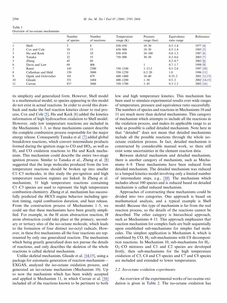
Table 1Overview of iso-octane mechanisms
Numberof species
Numberof reactions
Temperaturerange (K)
Pressurerange (bar)
Equivalenceratio range
References
1 Shell 5 8 650–850 10–30 0.5–1.4 1977 [4]2 Cox and Cole 10 15 650–900 10–30 0.5–1.4 1985 [5]3 Hu and Keck 13 18 650–850 10–100 0.8–1.3 1987 [6]4 Tanaka 32 55 750–900 30–50 0.2–0.6 2003 [7]5 Zheng 45 69 0.2–0.7 2002 [8]6 Davis and Law 69 406 1 0.7–1.7 1998 [9]7 Ranzi 145 2500 550–1100 1–13.5 0.5–2.0 1997 [10]8 Callanhan and Held 150 3000 550–1250 0.2–20 1.0 1996 [11]9 Ogink and Golovichev 101 479 600–1400 10–40 0.33–2 2001 [12,13]10 Glaude 351 1684 600–1200 1–50 0.5–2 2002 [14,15]11 Curran 857 3606 550–1700 1–45 0.3–1.5 2002 [16]
2594 M. Jia, M. Xie / Fuel 85 (2006) 2593–2604
its simplicity and generalized form. However, Shell modelis a mathematical model, so species appearing in this modeldo not exist in actual reactions. In order to avoid this draw-back and make the fuel reaction kinetics closer to real pro-cess, Cox and Cole [5], Hu and Keck [6] added the kineticsinformation of high hydrocarbon oxidation to Shell model.However, only low temperature reactions are included inthe Mechanisms 1–3, so these mechanisms cannot describethe complete combustion process responsible for the majorenergy release. Consequently Tanaka et al. [7] added globalbreakdown reactions, which convert intermediate productsformed during the ignition stage to CO and HO2, as well asH2 and CO oxidation reactions to Hu and Keck mecha-nism. This mechanism could describe the entire two-stageignition process. Similar to Tanaka et al., Zheng et al. [8]suggested that the large molecules produced from the lowtemperature reactions should be broken up into smallerC1–C3 molecules, in this study the pre-ignition and hightemperature reaction regimes are linked. In Zheng et al.mechanism, 31 high temperature reactions containingC1–C3 species are used to represent the high temperaturecombustion chemistry. Zheng et al. mechanism has success-fully predicted the HCCI engine behavior including igni-tion timing, rapid combustion duration, and heat release.From the construction process of Mechanisms 1–5, wecould see that these mechanisms have been greatly simpli-fied. For example, in the H atom abstraction reaction, Hatom abstraction could take place at the primary, second-ary or tertiary sites of the iso-octane molecule, which leadsto the formation of four distinct iso-octyl radicals. How-ever, in these five mechanisms all the four reactions are rep-resented by only one generalized reaction. The mechanismwhich being greatly generalized does not pursue the detailsof reactions, and only describes the skeleton of the wholereactions is called skeletal mechanism.
Unlike skeletal mechanism, Glaude et al. [14,15], using apackage for automatic generation of reaction mechanism—EXGAS, analyzed the iso-octane oxidation process, andgenerated an iso-octane mechanism (Mechanism 10). Upto now the mechanism which has been widely acceptedand applied is Mechanism 11, in which Curran et al. [16]included all of the reactions known to be pertinent to both
low and high temperature kinetics. This mechanism hasbeen used to simulate experimental results over wide rangesof temperature, pressure and equivalence ratio successfully.The numbers of species and reactions in Mechanisms 10 and11 are much more than skeletal mechanisms. This categoryof mechanism which attempts to include all the reactions inthe oxidation process, and makes its applicable range to aswide as possible is called detailed mechanism. Note here inthat ‘‘detailed’’ does not mean that detailed mechanismsinclude all the possible reactions through the whole iso-octane oxidation process. In fact, detailed mechanism isconstructed by considerable manual work, so there stillexist some uncertainties in the element reaction data.
Between skeletal mechanism and detailed mechanism,there is another category of mechanism, such as Mecha-nisms 6–9. These mechanisms have been reduced fromdetailed mechanism. The detailed mechanism was reducedto a lumped kinetics model involving only a limited numberof intermediate steps, e.g., [10]. The mechanism whichincludes about 100 species and is reduced based on detailedmechanism is called reduced mechanism.
Approaches of constructing these mechanisms could bedivided into two categories. One approach is based onmathematical analysis, and a typical example is Shellmodel. Because this type of mechanism is far from the realreaction process, so the details of the reactions cannot bedescribed. The other category is hierarchical approach,such as Mechanisms 4–11. This approach emphasizes thatreaction mechanism for complex fuels are built sequentiallyupon established sub-mechanisms for simpler fuel mole-cules. The simplest application is Mechanism 4, which iscombined by CO, H2 sub-mechanisms with C8 decomposi-tion reactions. In Mechanism 10, sub-mechanisms for H2–O2–CO mixtures and C1 and C2 species are developedfirstly, then sub-mechanisms for the high temperatureoxidation of C3, C4 and C5 species and C7 and C8 speciesare included and extended to lower temperatures.
2.2. Iso-octane oxidation experiments
An overview of the experimental works of iso-ocatne oxi-dation is given in Table 2. The iso-octane oxidation has
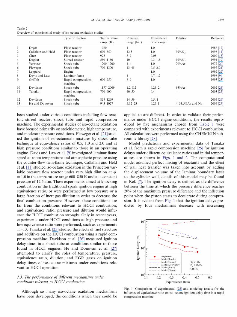
Table 2Overview of experimental study of iso-octane oxidation studies
Type of reactors Temperaturerange (K)
Pressurerange (bar)
Equivalenceratio range
Dilution Reference
1 Dryer Flow reactor 1080 1 1.0 – 1986 [17]2 Callahan and Held Flow reactor 600–850 12.5 1.0 99%N2 1996 [11]3 Chen Flow reactor 925 3–9 0.05 – 2000 [18]4 Dagaut Stirred reactor 550–1150 10 0.3–1.5 99%N2 1994 [19]5 Vermeer Shock tube 1200–1700 1–4 1.0 70%Ar 1972 [20]6 Fieweger Shock tube 700–1300 13–45 0.5–2.0 – 1997 [21]7 Leppard Engine 1.0 – 1992 [22]8 Davis and Law Laminar flame 1 0.7–1.7 – 1998 [9]9 Griffith Rapid compressions
machine600–950 6–9 1.0 – 1993 [23]
10 Davidson Shock tube 1177–2009 1.2–8.2 0.25–2 93%Ar 2002 [24]11 Tanaka Rapid compressions
machine750–900 40–50 0.4 – 2003 [25]
12 Davidson Shock tube 855–1269 14–59 0.5, 1 – 2005 [26]13 He and Donovan Shock tube 943–1027 5.12–23 0.25–1 4–33.5%Ar and N2 2005 [27]
Equivalence Ratio
Igni
tion
Del
ay(m
s)
0.1 0.2 0.3 0.4 0.5 0.6100
101
102
ExperimentModel (Tanaka)Model (Curran)Model (Golovichev)Model (Ranzi)Model (Glaude)
T0: 318K
P0: 0.1MPa
CR: 16
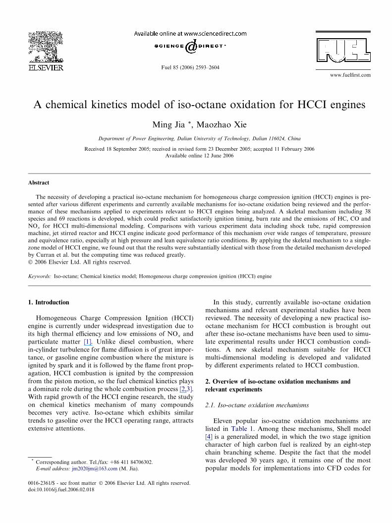
Fig. 1. Comparison of experimental [25] and modeling results for theinfluence of equivalence ratio on iso-octane ignition delay time in a rapidcompression machine.
M. Jia, M. Xie / Fuel 85 (2006) 2593–2604 2595
been studied under various conditions including flow reac-tor, stirred reactor, shock tube and rapid compressionmachine. The experimental studies of iso-octane oxidationhave focused primarily on stoichiometric, high temperature,and moderate pressure conditions. Fieweger et al. [21] stud-ied the ignition of iso-octane/air mixtures by shock tubetechnique at equivalence ratios of 0.5, 1.0 and 2.0 and athigh pressure conditions similar to those in an operatingengine. Davis and Law et al. [9] investigated laminar flamespeed at room temperature and atmospheric pressure usingthe counter-flow twin-flame technique. Callahan and Heldet al. [11] studied iso-octane oxidation in the Princeton var-iable pressure flow reactor under very high dilution at /= 1.0 in the temperature range 600–850 K and at a constantpressure of 12.5 atm. These experiments aimed at knockingcombustion in the traditional spark ignition engine at highequivalence ratio, or were performed at low pressure or alarge fraction of inert gas dilution in order to decrease thefinal combustion pressure. However, these conditions arefar from the conditions relevant to HCCI combustion,and equivalence ratio, pressure and dilution would influ-ence the HCCI combustion strongly. Only in recent years,experiments under HCCI conditions at high pressure andlow equivalence ratio were performed, such as experiments11–13. Tanaka et al. [25] studied the effects of fuel structureand additives on the HCCI combustion using a rapid com-pression machine. Davidson et al. [26] measured ignitiondelay times in a shock tube at conditions similar to thosefound in HCCI engines. He and Donovan et al. [27]attempted to clarify the roles of temperature, pressure,equivalence ratio, dilution, and EGR gases on ignitiondelay times of iso-octane mixtures under conditions rele-vant to HCCI operation.
2.3. The performance of different mechanisms under
conditions relevant to HCCI combustion
Although so many iso-octane oxidation mechanismshave been developed, the conditions which they could be
applied to are different. In order to validate their perfor-mance under HCCI engine conditions, the results repro-duced by five mechanisms chosen from Table 1 werecompared with experiments relevant to HCCI combustion.All calculations were performed using the CHEMKIN sub-routine library [28].
Model predictions and experimental data of Tanakaet al. from a rapid compression machine [25] for ignitiondelays under different equivalence ratios and initial temper-atures are shown in Figs. 1 and 2. The computationalmodel assumed perfect mixing of reactants and the effectof wall heat transfer was taken into account by addingthe displacement volume of the laminar boundary layerto the cylinder wall, details of this model may be foundin Ref. [7]. The ignition delay is defined as the differencebetween the time at which the pressure difference reaches20% of the maximum pressure difference and the inflectionpoint when the piston starts to decelerate during compres-sion. It is evident from Fig. 1 that the ignition delays pre-dicted by four mechanisms decrease with increasing
Initial Temperature (K)
Igni
tion
Del
ay(m
s)
290 300 310 320 330 340 350 360100
101
102
103 ExperimentModel (Tanaka)Model (Curran)Model (Golovichev)Model (Ranzi)Model (Glaude)
φ: 0.4
P0: 0.1MPa
CR: 16
Fig. 2. Comparison of experimental [25] and modeling results for theinfluence of initial temperature on iso-octane ignition delay time in a rapidcompression machine.
Temperature1000/T5 (K)
Igni
tion
Del
ay(m
s)
0.8 0.9 1 1.1 1.2 1.310-2
10-1
100
101
102
ExperimentModel (Tanaka)Model (Curran)Model (Golovichev)Model (Ranzi)Model (Glaude)
φ: 0.5
P5: 40bar
Fig. 3. Comparison of experimental [21] and modeling results for theinfluence of initial temperature on iso-octane ignition delay time in a shocktube.
Temperature 1000/T5 (K)
Igni
tion
Del
ay(m
s)
0.8 0.85 0.9 0.95 110-2
10-1
100
ExperimentModel (Tanaka)Model (Curran)Model (Golovichev)Model (Ranzi)Model (Glaude)
φ: 0.5
P5 : 50atm
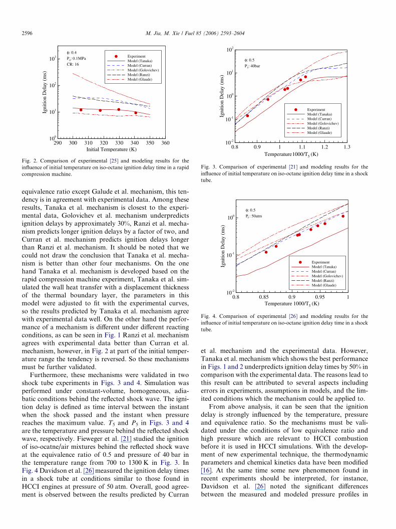
Fig. 4. Comparison of experimental [26] and modeling results for theinfluence of initial temperature on iso-octane ignition delay time in a shocktube.
2596 M. Jia, M. Xie / Fuel 85 (2006) 2593–2604
equivalence ratio except Galude et al. mechanism, this ten-dency is in agreement with experimental data. Among theseresults, Tanaka et al. mechanism is closest to the experi-mental data, Golovichev et al. mechanism underpredictsignition delays by approximately 30%, Ranzi et al. mecha-nism predicts longer ignition delays by a factor of two, andCurran et al. mechanism predicts ignition delays longerthan Ranzi et al. mechanism. It should be noted that wecould not draw the conclusion that Tanaka et al. mecha-nism is better than other four mechanisms. On the onehand Tanaka et al. mechanism is developed based on therapid compression machine experiment, Tanaka et al. sim-ulated the wall heat transfer with a displacement thicknessof the thermal boundary layer, the parameters in thismodel were adjusted to fit with the experimental curves,so the results predicted by Tanaka et al. mechanism agreewith experimental data well. On the other hand the perfor-mance of a mechanism is different under different reactingconditions, as can be seen in Fig. 1 Ranzi et al. mechanismagrees with experimental data better than Curran et al.mechanism, however, in Fig. 2 at part of the initial temper-ature range the tendency is reversed. So these mechanismsmust be further validated.
Furthermore, these mechanisms were validated in twoshock tube experiments in Figs. 3 and 4. Simulation wasperformed under constant-volume, homogeneous, adia-batic conditions behind the reflected shock wave. The igni-tion delay is defined as time interval between the instantwhen the shock passed and the instant when pressurereaches the maximum value. T5 and P5 in Figs. 3 and 4are the temperature and pressure behind the reflected shockwave, respectively. Fieweger et al. [21] studied the ignitionof iso-ocatne/air mixtures behind the reflected shock waveat the equivalence ratio of 0.5 and pressure of 40 bar inthe temperature range from 700 to 1300 K in Fig. 3. InFig. 4 Davidson et al. [26] measured the ignition delay timesin a shock tube at conditions similar to those found inHCCI engines at pressure of 50 atm. Overall, good agree-ment is observed between the results predicted by Curran
et al. mechanism and the experimental data. However,Tanaka et al. mechanism which shows the best performancein Figs. 1 and 2 underpredicts ignition delay times by 50% incomparison with the experimental data. The reasons lead tothis result can be attributed to several aspects includingerrors in experiments, assumptions in models, and the lim-ited conditions which the mechanism could be applied to.
From above analysis, it can be seen that the ignitiondelay is strongly influenced by the temperature, pressureand equivalence ratio. So the mechanisms must be vali-dated under the conditions of low equivalence ratio andhigh pressure which are relevant to HCCI combustionbefore it is used in HCCI simulations. With the develop-ment of new experimental technique, the thermodynamicparameters and chemical kinetics data have been modified[16]. At the same time some new phenomenon found inrecent experiments should be interpreted, for instance,Davidson et al. [26] noted the significant differencesbetween the measured and modeled pressure profiles in
M. Jia, M. Xie / Fuel 85 (2006) 2593–2604 2597
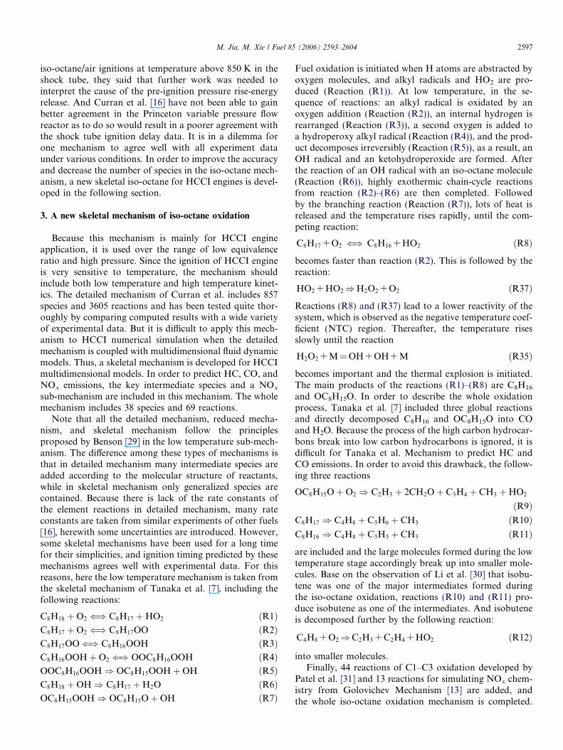
iso-octane/air ignitions at temperature above 850 K in theshock tube, they said that further work was needed tointerpret the cause of the pre-ignition pressure rise-energyrelease. And Curran et al. [16] have not been able to gainbetter agreement in the Princeton variable pressure flowreactor as to do so would result in a poorer agreement withthe shock tube ignition delay data. It is in a dilemma forone mechanism to agree well with all experiment dataunder various conditions. In order to improve the accuracyand decrease the number of species in the iso-octane mech-anism, a new skeletal iso-octane for HCCI engines is devel-oped in the following section.
3. A new skeletal mechanism of iso-octane oxidation
Because this mechanism is mainly for HCCI engineapplication, it is used over the range of low equivalenceratio and high pressure. Since the ignition of HCCI engineis very sensitive to temperature, the mechanism shouldinclude both low temperature and high temperature kinet-ics. The detailed mechanism of Curran et al. includes 857species and 3605 reactions and has been tested quite thor-oughly by comparing computed results with a wide varietyof experimental data. But it is difficult to apply this mech-anism to HCCI numerical simulation when the detailedmechanism is coupled with multidimensional fluid dynamicmodels. Thus, a skeletal mechanism is developed for HCCImultidimensional models. In order to predict HC, CO, andNOx emissions, the key intermediate species and a NOx
sub-mechanism are included in this mechanism. The wholemechanism includes 38 species and 69 reactions.
Note that all the detailed mechanism, reduced mecha-nism, and skeletal mechanism follow the principlesproposed by Benson [29] in the low temperature sub-mech-anism. The difference among these types of mechanisms isthat in detailed mechanism many intermediate species areadded according to the molecular structure of reactants,while in skeletal mechanism only generalized species arecontained. Because there is lack of the rate constants ofthe element reactions in detailed mechanism, many rateconstants are taken from similar experiments of other fuels[16], herewith some uncertainties are introduced. However,some skeletal mechanisms have been used for a long timefor their simplicities, and ignition timing predicted by thesemechanisms agrees well with experimental data. For thisreasons, here the low temperature mechanism is taken fromthe skeletal mechanism of Tanaka et al. [7], including thefollowing reactions:
C8H18 þO2 () C8H17 þHO2 ðR1ÞC8H17 þO2 () C8H17OO ðR2ÞC8H17OO() C8H16OOH ðR3ÞC8H16OOHþO2 () OOC8H16OOH ðR4ÞOOC8H16OOH) OC8H15OOHþOH ðR5ÞC8H18 þOH) C8H17 þH2O ðR6ÞOC8H15OOH) OC8H15OþOH ðR7Þ
Fuel oxidation is initiated when H atoms are abstracted byoxygen molecules, and alkyl radicals and HO2 are pro-duced (Reaction (R1)). At low temperature, in the se-quence of reactions: an alkyl radical is oxidated by anoxygen addition (Reaction (R2)), an internal hydrogen isrearranged (Reaction (R3)), a second oxygen is added toa hydroperoxy alkyl radical (Reaction (R4)), and the prod-uct decomposes irreversibly (Reaction (R5)), as a result, anOH radical and an ketohydroperoxide are formed. Afterthe reaction of an OH radical with an iso-octane molecule(Reaction (R6)), highly exothermic chain-cycle reactionsfrom reaction (R2)–(R6) are then completed. Followedby the branching reaction (Reaction (R7)), lots of heat isreleased and the temperature rises rapidly, until the com-peting reaction:
C8H17 + O2 () C8H16 + HO2 ðR8Þ
becomes faster than reaction (R2). This is followed by thereaction:
HO2 + HO2)H2O2 + O2 ðR37Þ
Reactions (R8) and (R37) lead to a lower reactivity of thesystem, which is observed as the negative temperature coef-ficient (NTC) region. Thereafter, the temperature risesslowly until the reaction
H2O2 + M = OH + OH + M ðR35Þ
becomes important and the thermal explosion is initiated.The main products of the reactions (R1)–(R8) are C8H16
and OC8H15O. In order to describe the whole oxidationprocess, Tanaka et al. [7] included three global reactionsand directly decomposed C8H16 and OC8H15O into COand H2O. Because the process of the high carbon hydrocar-bons break into low carbon hydrocarbons is ignored, it isdifficult for Tanaka et al. Mechanism to predict HC andCO emissions. In order to avoid this drawback, the follow-ing three reactions
OC8H15OþO2 ) C2H3 þ 2CH2Oþ C3H4 þ CH3 þHO2
ðR9ÞC8H17 ) C4H8 þ C3H6 þ CH3 ðR10ÞC8H16 ) C4H8 þ C3H5 þ CH3 ðR11Þ
are included and the large molecules formed during the lowtemperature stage accordingly break up into smaller mole-cules. Base on the observation of Li et al. [30] that isobu-tene was one of the major intermediates formed duringthe iso-octane oxidation, reactions (R10) and (R11) pro-duce isobutene as one of the intermediates. And isobuteneis decomposed further by the following reaction:
C4H8 + O2)C2H3 + C2H4 + HO2 ðR12Þ
into smaller molecules.Finally, 44 reactions of C1–C3 oxidation developed by
Patel et al. [31] and 13 reactions for simulating NOx chem-istry from Golovichev Mechanism [13] are added, andthe whole iso-octane oxidation mechanism is completed.
1000/T [K]
Igni
tion
Del
ay(m
s)
0.8 0.9 1.0 1.1 1.2 1.3 1.4 1.510-2
10-1
100
101
102
Φ=0.5Φ=1.0Φ=2.0
Points: ExperimentLines: Model (This study)
P5 :40 bar
Fig. 5. Comparison of experimental [21] and modeling results for theinfluence of initial temperature on iso-octane ignition delay time at threedifferent equivalence ratios in a shock tube.
1000/T [K]
Igni
tion
Del
ay(m
s)
0.8 0.9 1.0 1.1 1.2 1.3
10-2
10-1
100
101
Φ=0.5Φ=1.0
Points: ExperimentLines: Model (This study)
P5 :50 atm
Fig. 6. Comparison of experimental [26] and modeling results for theinfluence of initial temperature on iso-octane ignition delay time at twodifferent equivalence ratios in a shock tube.
1000/T [K]
Igni
tion
Del
ay(m
s)
0.8 0.9 1.0 1.1 1.2 1.3 1.4 1.510-2
10-1
100
101
102
P5=17 barP5=34 barP5=40 barP5=45 bar
Points: ExperimentLines: Model (This study)
Φ:1.0
Fig. 7. Comparison of experimental [21] and modeling results for theinfluence of initial temperature on iso-octane ignition delay time at fourdifferent pressures in a shock tube.
2598 M. Jia, M. Xie / Fuel 85 (2006) 2593–2604
Unlike Ranzi et al. [10] and Callanhan et al. [11] incorpo-rating detailed C1–C3 mechanism, in order to keep themechanism size compact, the C1–C3 reactions are takenfrom a reduced mechanism for HCCI engines developedby Patel et al. [31]. The final reaction set is presented inthe appendix. The thermochemical data in this mechanismare calculated using Benson group estimation technique[32].
Although the reaction mechanism is essentially deve-loped by analyzing, selecting and reconstructing currentavailable mechanisms, the simplifications in the mechanismshould not be considered arbitrarily performed. This mech-anism is developed for prediction of ignition delay, heatrelease rate, fuel consumption, CO formation and produc-tion of other species with as few species as possible. Thusthe main reactions are carefully chosen from other skeletaland reduced mechanisms, and the kinetics constants in thekey reactions have been modified in order to agree betterwith measurement. For example, the most important reac-tions in the initial reactions and CO oxidation reactionwere identified based on sensitivity analysis, and the rateconstants in these reactions were adjusted to match exper-imental data. Therefore, differing from other skeletal mech-anisms, this mechanism not only could be used to predictignition delay and heat release rate, but also shows goodperformance in predictions of HC and CO emissions inHCCI combustion.
4. Mechanism validation
The iso-octane mechanism is validated on the basis ofseveral experiments relevant to HCCI engines. The ignitiondelays were compared with measurements in shock tubesand a rapid compression machine. Moreover, CO, CO2,and iso-octane concentrations were simulated at differenttemperatures in a jet stirred reactor. Finally an experimentin a HCCI engine provides a further test of the mechanism.
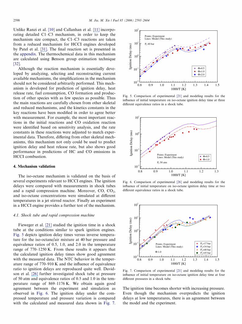
4.1. Shock tube and rapid compression machine
Fieweger et al. [21] studied the ignition time in a shocktube at the conditions similar to spark ignition engines.Fig. 5 depicts ignition delay times versus inverse tempera-ture for the iso-octane/air mixture at 40 bar pressure andequivalence ratios of 0.5, 1.0, and 2.0 in the temperaturerange of 770–1250 K. From these results it appears thatthe calculated ignition delay times show good agreementwith the measured data. The NTC behavior in the temper-ature range of 770–910 K and the influence of equivalenceratio to ignition delays are reproduced quite well. David-son et al. [26] further investigated shock tube at pressureof 50 atm and equivalence ratios of 0.5 and 1.0 in the tem-perature range of 869–1176 K. We obtain again goodagreement between the experiment and simulation asobserved in Fig. 6. The ignition delay under the com-pressed temperature and pressure variation is comparedwith the calculated and measured data shown in Fig. 7.
The ignition time becomes shorter with increasing pressure.Even though the mechanism overpredicts the ignitiondelays at low temperatures, there is an agreement betweenthe model and the experiment.
Equivalence Ratio
Bur
nR
ate
(MP
a/m
s)
0.1 0.2 0.3 0.4 0.5 0.610-2
10-1
100
101
102
103
ExperimentModel (This study)
T0: 318K
P0: 0.1MPa
CR: 16
Fig. 10. Comparison of experimental [25] and modeling results for theinfluence of equivalence ratio on iso-octane burn duration in a compres-sion machine.
M. Jia, M. Xie / Fuel 85 (2006) 2593–2604 2599
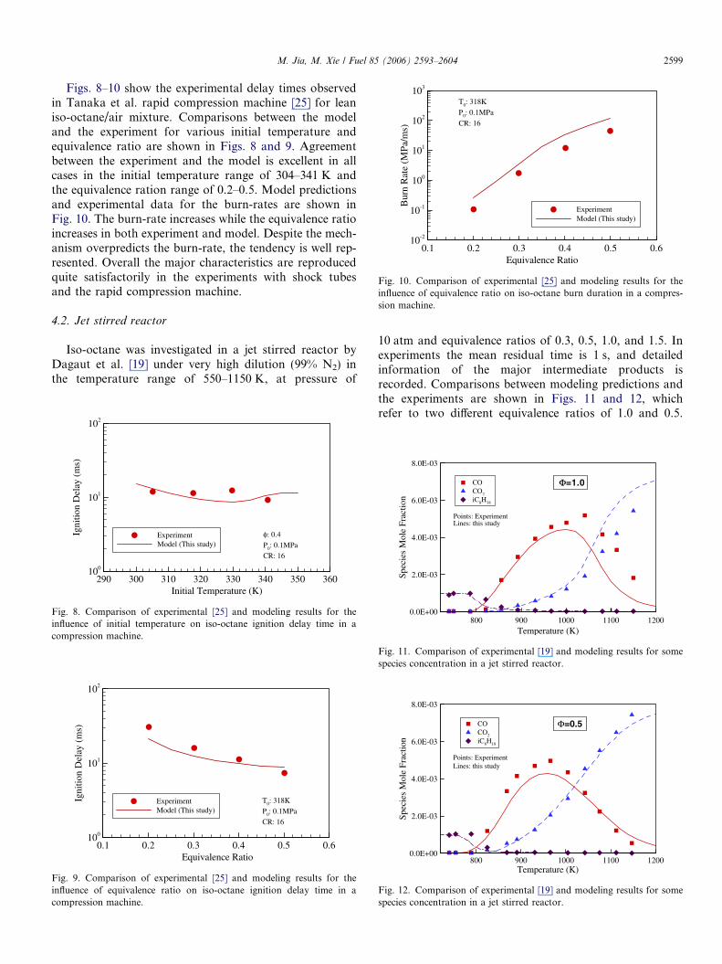
Figs. 8–10 show the experimental delay times observedin Tanaka et al. rapid compression machine [25] for leaniso-octane/air mixture. Comparisons between the modeland the experiment for various initial temperature andequivalence ratio are shown in Figs. 8 and 9. Agreementbetween the experiment and the model is excellent in allcases in the initial temperature range of 304–341 K andthe equivalence ration range of 0.2–0.5. Model predictionsand experimental data for the burn-rates are shown inFig. 10. The burn-rate increases while the equivalence ratioincreases in both experiment and model. Despite the mech-anism overpredicts the burn-rate, the tendency is well rep-resented. Overall the major characteristics are reproducedquite satisfactorily in the experiments with shock tubesand the rapid compression machine.
4.2. Jet stirred reactor
Iso-octane was investigated in a jet stirred reactor byDagaut et al. [19] under very high dilution (99% N2) inthe temperature range of 550–1150 K, at pressure of
Initial Temperature (K)
Igni
tion
Del
ay(m
s)
290 300 310 320 330 340 350 360100
101
102
ExperimentModel (This study)
φ: 0.4
P0: 0.1MPa
CR: 16
Fig. 8. Comparison of experimental [25] and modeling results for theinfluence of initial temperature on iso-octane ignition delay time in acompression machine.
Equivalence Ratio
Igni
tion
Del
ay(m
s)
0.1 0.2 0.3 0.4 0.5 0.6100
101
102
ExperimentModel (This study)
T0: 318K
P0: 0.1MPa
CR: 16
Fig. 9. Comparison of experimental [25] and modeling results for theinfluence of equivalence ratio on iso-octane ignition delay time in acompression machine.
10 atm and equivalence ratios of 0.3, 0.5, 1.0, and 1.5. Inexperiments the mean residual time is 1 s, and detailedinformation of the major intermediate products isrecorded. Comparisons between modeling predictions andthe experiments are shown in Figs. 11 and 12, whichrefer to two different equivalence ratios of 1.0 and 0.5.
Temperature (K)
Spec
ies
Mol
e Fr
actio
n
800 900 1000 1100 12000.0E+00
2.0E-03
4.0E-03
6.0E-03
8.0E-03
COCO2
iC8H18
Points: ExperimentLines: this study
Φ=1.0
Fig. 11. Comparison of experimental [19] and modeling results for somespecies concentration in a jet stirred reactor.
Temperature (K)
Spe
cies
Mol
eF
ract
ion
800 900 1000 1100 12000.0E+00
2.0E-03
4.0E-03
6.0E-03
8.0E-03
COCO2
iC8H18
Points: ExperimentLines: this study
Φ=0.5
Fig. 12. Comparison of experimental [19] and modeling results for somespecies concentration in a jet stirred reactor.
Crank angle (degree)
Pres
sure
(Bar
)
340 350 360 370 380 390 40020
40
60
80
100
Φ=0.06Φ=0.10Φ=0.14Φ=0.18Φ=0.22Φ=0.26Motored
Experiment
Crank angle (degree)
Pre
ssur
e(B
ar)
340 350 360 370 380 390 40020
40
60
80
100
120
Φ=0.06Φ=0.10Φ=0.14Φ=0.18Φ=0.22Φ=0.26Motored
Model
Solid lines: CurranDashed lines: this study
Fig. 13. Cylinder pressure for various equivalence ratios for the modeland the experiment [33] in a HCCI engine.
Fig. 14. View of KIVA-3V grid at 55� before TDC.
2600 M. Jia, M. Xie / Fuel 85 (2006) 2593–2604
Iso-octane, CO, and CO2 concentrations have been com-pared. Simulations are performed under the assumptionsof isothermal, constant pressure, and perfect mixing condi-tions. Time dependent calculations are run for a long timeuntil a steady state solution is obtained. Despite CO isunderestimated and CO2 is overestimated at equivalenceratio of 1.0, the profiles of fuel, CO and CO2 are well repro-duced by the model in Figs. 11 and 12.
4.3. HCCI engine
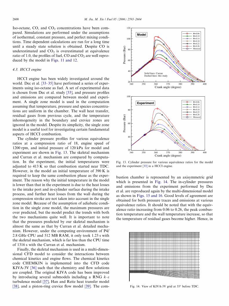
HCCI engine has been widely investigated around theworld. Dec et al. [33–35] have performed a series of exper-iments using iso-octane as fuel. A set of experimental datais chosen from Dec et al. study [33], and pressure profilesand emissions are compared between model and experi-ment. A single zone model is used in the computationassuming that temperature, pressure and species concentra-tions are uniform in the chamber. The wall heat transfer,residual gases from previous cycle, and the temperatureinhomogeneity in the boundary and crevice zones areignored in the model. Despite its simplicity, the single zonemodel is a useful tool for investigating certain fundamentalaspects of HCCI combustion.
The cylinder pressure profiles for various equivalenceratios at a compression ratio of 18, engine speed of1200 rpm, and initial pressure of 120 kPa for model andexperiment are shown in Fig. 13. The skeletal mechanismand Curran et al. mechanism are compared by computa-tion. In the experiment, the initial temperatures wereadjusted to 413 K so that combustion started near TDC.However, in the model an initial temperature of 390 K isrequired to keep the same combustion phase as the exper-iment. The reason why the initial temperature in the modelis lower than that in the experiment is due to the heat lossesto the intake port and in-cylinder surface during the intakeprocess, and further heat losses from the wall during thecompression stroke are not taken into account in the singlezone model. Because of the assumption of adiabatic condi-tion in the single zone model, the maximum pressures areover predicted, but the model predict the trends with boththe two mechanisms quite well. It is important to notethat the pressures predicted by our skeletal mechanism isalmost the same as that by Curran et al. detailed mecha-nism. However, under the computing environment of P4/2.8 GHz CPU and 512 MB RAM, it only took 1.23 s withthe skeletal mechanism, which is far less than the CPU timeof 1316 s with the Curran et al. mechanism.
Finally, the skeletal mechanism is used in a multi-dimen-sional CFD model to consider the interactions betweenchemical kinetics and engine flows. The chemical kineticscode CHEMKIN is implemented into the CFD codeKIVA-3V [36] such that the chemistry and flow solutionsare coupled. The original KIVA code has been improvedby introducing several submodels including a RNG k–eturbulence model [37], Han and Reitz heat transfer model[38], and a piston-ring crevice flow model [39]. The com-
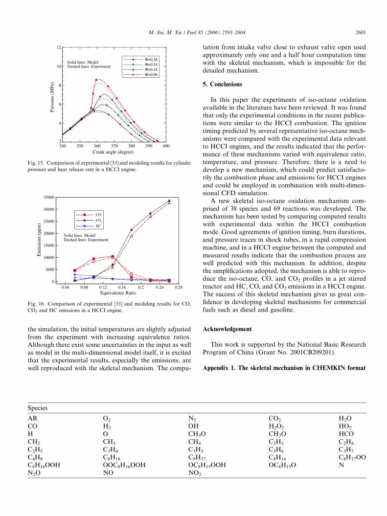
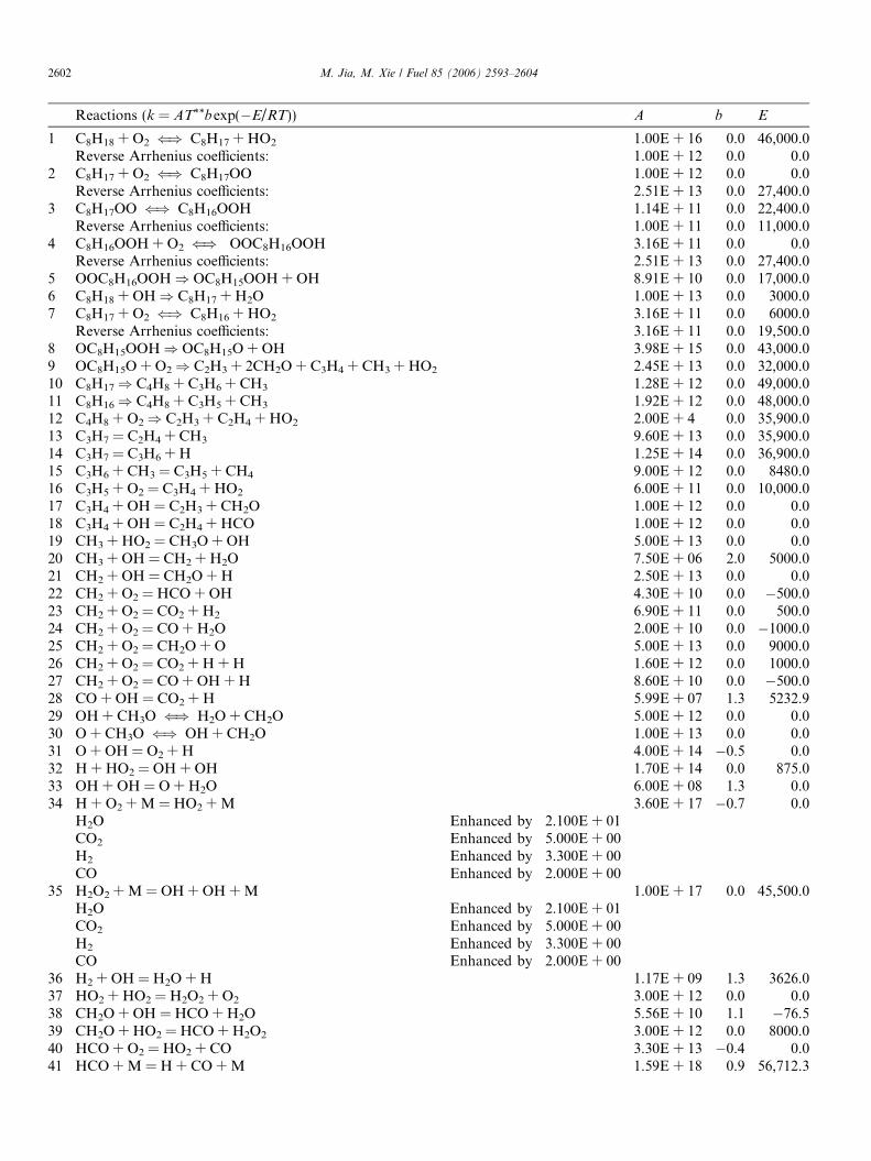
bustion chamber is represented by an axisymmetric gridwhich is presented in Fig. 14. The in-cylinder pressuresand emissions from the experiment performed by Decet al. are reproduced again by the multi-dimensional modelas shown in Figs. 15 and 16. Good levels of agreement areobtained for both pressure traces and emissions at variousequivalence ratios. It should be noted that with the equiv-alence ratio increasing from 0.06 to 0.26, the peak combus-tion temperature and the wall temperature increase, so thatthe temperature of residual gases become higher. Hence, in
Equivalence Ratio
Em
issi
ons
(ppm
)
0.04 0.08 0.12 0.16 0.2 0.24 0.280
5000
10000
15000
20000
25000
30000
35000
CO
CO2
HC
Solid lines: ModelDashed lines: Experiment
Fig. 16. Comparison of experimental [33] and modeling results for CO,CO2 and HC emissions in a HCCI engine.
Crank angle (degree)
Pre
ssur
e(M
Pa)
340 350 360 370 380 390 4002
4
6
8
10
12
Φ=0.26Φ=0.14Φ=0.18Φ=0.06
Solid lines: ModelDashed lines: Experiment
Fig. 15. Comparison of experimental [33] and modeling results for cylinderpressure and heat release rate in a HCCI engine.
M. Jia, M. Xie / Fuel 85 (2006) 2593–2604 2601
the simulation, the initial temperatures are slightly adjustedfrom the experiment with increasing equivalence ratios.Although there exist some uncertainties in the input as wellas model in the multi-dimensional model itself, it is excitedthat the experimental results, especially the emissions, arewell reproduced with the skeletal mechanism. The compu-
Species
AR O2 N2
CO H2 OHH O CH3OCH2 CH3 CH4
C2H5 C3H4 C3H5
C4H8 C8H18 C8H1
C8H16OOH OOC8H16OOH OC8HN2O NO NO2
tation from intake valve close to exhaust valve open usedapproximately only one and a half hour computation timewith the skeletal mechanism, which is impossible for thedetailed mechanism.
5. Conclusions
In this paper the experiments of iso-octane oxidationavailable in the literature have been reviewed. It was foundthat only the experimental conditions in the recent publica-tions were similar to the HCCI combustion. The ignitiontiming predicted by several representative iso-octane mech-anisms were compared with the experimental data relevantto HCCI engines, and the results indicated that the perfor-mance of these mechanisms varied with equivalence ratio,temperature, and pressure. Therefore, there is a need todevelop a new mechanism, which could predict satisfacto-rily the combustion phase and emissions for HCCI enginesand could be employed in combination with multi-dimen-sional CFD simulation.
A new skeletal iso-octane oxidation mechanism com-prised of 38 species and 69 reactions was developed. Themechanism has been tested by comparing computed resultswith experimental data within the HCCI combustionmode. Good agreements of ignition timing, burn durations,and pressure traces in shock tubes, in a rapid compressionmachine, and in a HCCI engine between the computed andmeasured results indicate that the combustion process arewell predicted with this mechanism. In addition, despitethe simplifications adopted, the mechanism is able to repro-duce the iso-octane, CO, and CO2 profiles in a jet stirredreactor and HC, CO, and CO2 emissions in a HCCI engine.The success of this skeletal mechanism gives us great con-fidence in developing skeletal mechanisms for commercialfuels such as diesel and gasoline.
Acknowledgement
This work is supported by the National Basic ResearchProgram of China (Grant No. 2001CB209201).
Appendix 1. The skeletal mechanism in CHEMKIN format
CO2 H2OH2O2 HO2
CH2O HCOC2H3 C2H4
C3H6 C3H7
7 C8H16 C8H17OO
15OOH OC8H15O N
Reactions (k = AT**bexp(�E/RT)) A b E
1 C8H18 + O2 () C8H17 + HO2 1.00E + 16 0.0 46,000.0Reverse Arrhenius coefficients: 1.00E + 12 0.0 0.0
2 C8H17 + O2 () C8H17OO 1.00E + 12 0.0 0.0Reverse Arrhenius coefficients: 2.51E + 13 0.0 27,400.0
3 C8H17OO () C8H16OOH 1.14E + 11 0.0 22,400.0Reverse Arrhenius coefficients: 1.00E + 11 0.0 11,000.0
4 C8H16OOH + O2 () OOC8H16OOH 3.16E + 11 0.0 0.0Reverse Arrhenius coefficients: 2.51E + 13 0.0 27,400.0
5 OOC8H16OOH) OC8H15OOH + OH 8.91E + 10 0.0 17,000.06 C8H18 + OH) C8H17 + H2O 1.00E + 13 0.0 3000.07 C8H17 + O2 () C8H16 + HO2 3.16E + 11 0.0 6000.0
Reverse Arrhenius coefficients: 3.16E + 11 0.0 19,500.08 OC8H15OOH) OC8H15O + OH 3.98E + 15 0.0 43,000.09 OC8H15O + O2) C2H3 + 2CH2O + C3H4 + CH3 + HO2 2.45E + 13 0.0 32,000.010 C8H17) C4H8 + C3H6 + CH3 1.28E + 12 0.0 49,000.011 C8H16) C4H8 + C3H5 + CH3 1.92E + 12 0.0 48,000.012 C4H8 + O2) C2H3 + C2H4 + HO2 2.00E + 4 0.0 35,900.013 C3H7 = C2H4 + CH3 9.60E + 13 0.0 35,900.014 C3H7 = C3H6 + H 1.25E + 14 0.0 36,900.015 C3H6 + CH3 = C3H5 + CH4 9.00E + 12 0.0 8480.016 C3H5 + O2 = C3H4 + HO2 6.00E + 11 0.0 10,000.017 C3H4 + OH = C2H3 + CH2O 1.00E + 12 0.0 0.018 C3H4 + OH = C2H4 + HCO 1.00E + 12 0.0 0.019 CH3 + HO2 = CH3O + OH 5.00E + 13 0.0 0.020 CH3 + OH = CH2 + H2O 7.50E + 06 2.0 5000.021 CH2 + OH = CH2O + H 2.50E + 13 0.0 0.022 CH2 + O2 = HCO + OH 4.30E + 10 0.0 �500.023 CH2 + O2 = CO2 + H2 6.90E + 11 0.0 500.024 CH2 + O2 = CO + H2O 2.00E + 10 0.0 �1000.025 CH2 + O2 = CH2O + O 5.00E + 13 0.0 9000.026 CH2 + O2 = CO2 + H + H 1.60E + 12 0.0 1000.027 CH2 + O2 = CO + OH + H 8.60E + 10 0.0 �500.028 CO + OH = CO2 + H 5.99E + 07 1.3 5232.929 OH + CH3O () H2O + CH2O 5.00E + 12 0.0 0.030 O + CH3O () OH + CH2O 1.00E + 13 0.0 0.031 O + OH = O2 + H 4.00E + 14 �0.5 0.032 H + HO2 = OH + OH 1.70E + 14 0.0 875.033 OH + OH = O + H2O 6.00E + 08 1.3 0.034 H + O2 + M = HO2 + M 3.60E + 17 �0.7 0.0
H2O Enhanced by 2.100E + 01CO2 Enhanced by 5.000E + 00H2 Enhanced by 3.300E + 00CO Enhanced by 2.000E + 00
35 H2O2 + M = OH + OH + M 1.00E + 17 0.0 45,500.0H2O Enhanced by 2.100E + 01CO2 Enhanced by 5.000E + 00H2 Enhanced by 3.300E + 00CO Enhanced by 2.000E + 00
36 H2 + OH = H2O + H 1.17E + 09 1.3 3626.037 HO2 + HO2 = H2O2 + O2 3.00E + 12 0.0 0.038 CH2O + OH = HCO + H2O 5.56E + 10 1.1 �76.539 CH2O + HO2 = HCO + H2O2 3.00E + 12 0.0 8000.040 HCO + O2 = HO2 + CO 3.30E + 13 �0.4 0.041 HCO + M = H + CO + M 1.59E + 18 0.9 56,712.3
2602 M. Jia, M. Xie / Fuel 85 (2006) 2593–2604
Appendix 1 (continued)
Reactions (k = AT**bexp(�E/RT)) A b E
42 CH3 + CH3O = CH4 + CH2O 4.30E + 14 0.0 0.043 C2H4 + OH = CH2O + CH3 6.00E + 13 0.0 960.044 C2H4 + OH = C2H3 + H2O 8.02E + 13 0.0 5955.045 C2H3 + O2 = CH2O + HCO 4.00E + 12 0.0 �250.046 C2H3 + HCO = C2H4 + CO 6.03E + 13 0.0 0.047 C2H5 + O2 = C2H4 + HO2 2.00E + 10 0.0 �2200.048 CH4 + O2 = CH3 + HO2 7.90E + 13 0.0 56,000.049 OH + HO2 = H2O + O2 7.50E + 12 0.0 0.050 CH3 + O2 = CH2O + OH 3.80E + 11 0.0 9000.051 CH4 + H = CH3 + H2 6.60E + 08 1.6 10,840.052 CH4 + OH = CH3 + H2O 1.60E + 06 2.1 2460.053 CH4 + O = CH3 + OH 1.02E + 09 1.5 8604.054 CH4 + HO2 = CH3 + H2O2 9.00E + 11 0.0 18,700.055 CH4 + CH2 = CH3 + CH3 4.00E + 12 0.0 �570.056 C3H6 = C2H3 + CH3 3.15E + 15 0.0 85,500.057 N + NO = N2 + O 3.50E + 13 0.0 330.058 N + O2 = NO + O 2.65E + 12 0.0 6400.059 N + OH = NO + H 7.33E + 13 0.0 1120.060 N + CO2 = NO + CO 1.90E + 11 0.0 3400.061 N2O + O = N2 + O2 1.40E + 12 0.0 10,810.062 N2O + O = NO + NO 2.90E + 13 0.0 23,150.063 N2O + H = N2 + OH 4.40E + 14 0.0 18,880.064 N2O + OH = N2 + HO2 2.00E + 12 0.0 21,060.065 N2O + M = N2 + O + M 1.30E + 11 0.0 59,620.066 NO + HO2 = NO2 + OH 2.11E + 12 0.0 �480.067 NO2 + O = NO + O2 3.90E + 12 0.0 �240.068 NO2 + H = NO + OH 1.32E + 14 0.0 360.069 NO + O + M = NO2 + M 1.06E + 20 �1.4 0.0
Note: A units mole-cm-s-K, E units cal/mole.
M. Jia, M. Xie / Fuel 85 (2006) 2593–2604 2603
References
[1] Thing RH. Homogeneous charge compression ignition (HCCI)engines. SAE 892068, 1989.
[2] Aoyama T, Hattori Y, Mizuta Ji, Sato Y. An experimental study onpremixed-charge compression ignition gasoline engine. SAE 960081,1996.
[3] Franke A, Richter M, Alden M, Hultqvist A, Johansson B.Optical diagnostics applied to a naturally aspirated homoge-neous charge compression ignition engine. SAE 1999-01-3649,1999.
[4] Halstead MP, Kirsch LJ, Quinn CP. The autoignition of hydrocarbonfuels at high temperatures and pressures – fitting of a mathematicalmodel. Combust Flame 1977;30:45–60.
[5] Cox RA, Cole JA. Chemical aspects of the autoignition of hydro-carbon–air mixtures. Combust Flame 1985;60:109–23.
[6] Hu H, Keck JC. Autoignition of adiabatically compressed combus-tible gas mixtures. SAE 872110, 1987.
[7] Tanaka S, Ayala F, Keck JC. A reduced chemical kinetic model forHCCI combustion of primary reference fuels in a rapid compressionmachine. Combust Flame 2003;133:467–81.
[8] Zheng J, Yang W, Miller DL, Cernansky NP. A skeletal chemicalkinetic model for the HCCI combustion process. SAE 2002-01-0423,2002.
[9] Davis SG, Law CK. Laminar flame speeds and oxidation kinetics ofiso-octane–air and n-heptane–air flames. Proc Combust Inst 1998;27:521–7.
[10] Ranzi E, Faravelli T, Gaffuri P, Sogaro A, D’Anna A, Ciajolo A. Awide-range modeling study of iso-octane oxidation. Combust Flame1997;108:24–42.
[11] Callahan CV, Held TJ, Dryer FL, Minetti R, Ribaucour M, SochetLR, et al. Experimental data and kinetic modeling of primaryreference fuel mixtures. Proc Combust Inst 1996;26:739–46.
[12] Ogink R, Golovitchev V. Gasoline HCCI modeling: computerprogram combining detailed chemistry and gas exchange processes.SAE 2001-01-3614, 2001.
[13] Golovitchev V. The mechanism of iso-octane; 2002. Available from:http://www.tfd.chalmers.se/~valeri/MECH.html.
[14] Buda F, Bounaceur R, Warth V, Glaude PA, Fournet R, Battin-Leclerc F. Progress toward a unified detailed kinetic model for theautoignition of alkanes from c4 to c10 between 600 and 1200 K.Combust Flame 2005;142:170–86.
[15] Glaude PA, Fournet R, Warth V, Battin-Leclerc F, Come GM,Scacchi G. The mechanism of iso-octane; 2002. Available from:http://www.ensic.u-nancy.fr/DCPR/Anglais/GCR/generatedmecan-isms/isooctane.
[16] Curran HJ, Gaffuri P, Pitz WJ, Westbrook CK. A comprehensivemodeling study of iso-octane oxidation. Combust Flame 2002;129:253–80.
[17] Dryer FL, Brezinsky K. A flow reactor study of the oxidation of n-octane and isooctane. Combust Sci Technol 1986;45:199–212.
[18] Chen JS, Litzinger TA, Curran HJ. Lean oxidation of iso-octane inthe intermediate temperature regime at elevated pressures. CombustSci Technol 2000;156:49–79.
2604 M. Jia, M. Xie / Fuel 85 (2006) 2593–2604
[19] Dagaut P, Reuillon M, Cathonnet M. High pressure oxidation ofliquid fuels from low to high temperature. 1. N-heptane and iso-octane. Combust Sci Technol 1994;95:233–60.
[20] Vermeer DJ, Meyer JW, Oppenheim AK. Auto-ignition of hydro-carbons behind reflected shock waves. Combust Flame 1972;18:327–36.
[21] Fieweger K, Blumenthal R, Adomeit G. Self-ignition of s.I. enginemodel fuels: a shock tube investigation at high pressure. CombustFlame 1997;109:599–619.
[22] Leppard WR. The autoignition chemistries of primary reference fuels,olefin/paraffin binary mixtures, and non-linear octane blending. SAE922325, 1992.
[23] Griffiths JF, Halford-Maw PA, Rose DJ. Fundamental features ofhydrocarbon autoignition in a rapid compression machine. CombustFlame 1993;95:291–306.
[24] Davidson DF, Oehlschlaeger MA, Herbon JT, Hanson RK. Shocktube measurements of iso-octane ignition times and oh concentrationtime histories. Proc Combust Inst 2002;29:1295–301.
[25] Tanaka S, Ayala F, Keck JC, Heywood JB. Two-stage ignition inHCCI combustion and HCCI control by fuels and additives.Combust Flame 2003;132:219–39.
[26] Davidson DF, Gauthier BM, Hanson RK. Shock tube ignitionmeasurements of iso-octane/air and toluene/air at high pressures.Proc Combust Inst 2005;30:1175–82.
[27] He X, Donovan MT, Zigler BT, Palmer TR, Walton SM, WooldridgeMS, Atreya A. An experimental and modeling study of iso-octaneignition delay times under homogeneous charge compression ignitionconditions. Combust Flame 2005;142:266–75.
[28] Kee RJ, Rupley FM, Meeks E, Miller JA. CHEMKIN-III: a fortranchemical kinetics package for the analysis of gasphase chemical andplasma kinetics. Report No. SAND96-8216, Sandia National Labo-ratories; 1996.
[29] Benson SW. The kinetics and thermochemistry of chemical oxidationwith application to combustion and flames. Prog Energy Combust Sci1981;7:125–34.
[30] Li H, Prabhu SK, Miller DL, Cernansky NP. Autoignition chemistrystudies on primary reference fuels in a motored engine. SAE 942062,1994.
[31] Patel A, Kong SC, Reitz RD. Development and validation of reducedreaction mechanism for HCCI engine simulation. SAE 2004-01-0558.
[32] Benson SW. Thermochemical kinetics. New York: John Wiley &Sons; 1976.
[33] Dec JE, Sjoberg M. A parametric study of HCCI combustion – thesources of emissions at low loads and the effects of GDI fuel injection.SAE 2003-01-0752, 2003.
[34] Sjoberg M, Dec JE. An investigation of the relationship betweenmeasured intake temperature, BDC temperature, and combustionphasing for premixed and DI HCCI engines. SAE 2004-01-1900,2004.
[35] Sjoberg M, Dec JE. Comparing enhanced natural thermal stratifica-tion against retarded combustion phasing for smoothing of HCCIheat-release rates. SAE 2004-01-2994, 2004.
[36] Alamos L. KIVA-3V: A block-structured KIVA program for engineswith vertical or canted values. LA-18818-MS, Los Alamos NationalLaboratory; 1997.
[37] Han ZW, Reitz RD. Turbulence modeling of internal combustionengines using RNG k–e models. Combust Sci Technol 1995;106:267–95.
[38] Han ZW, Reitz RD. A temperature wall function formulation forvariable-density turbulence flows with application to engines convec-tive heat transfer modeling. Int J Heat Mass Transfer 1997;40:613–25.
[39] Namazian M, Heywood JE. Flow in the piston-cylinder-ring crevicesof a spark-ignition engine: effect on hydrocarbon emissions, efficiencyand power. SAE 820088, 1982.