components for area-efficient stormwater treatment systems
TRANSCRIPT

LICENTIATE T H E S I S
ISSN 1402-1757ISBN 978-91-7790-828-9 (print)ISBN 978-91-7790-829-6 (pdf)
Luleå University of Technology 2021
Ivan Milovanović C
omponents for area-efficient storm
water treatm
ent systems
Department of Civil, Environmental and Natural Resources EngineeringDivision of Architecture and Water
Components for area-efficient stormwater treatment systems
Ivan Milovanović
Urban Water Engineering
Tryck: Lenanders Grafiska, 136718
136718 LTU_Milovanovic.indd Alla sidor136718 LTU_Milovanovic.indd Alla sidor 2021-05-17 10:312021-05-17 10:31

Components for area-efficient
stormwater treatment systems
Ivan Milovanović
Luleå, 2021
Urban Water Engineering
Division of Architecture and Water
Department of Civil, Environmental and Natural Resources Engineering
Luleå University of Technology

Printed by Luleå University of Technology, Graphic Production 2021
ISSN 1402-1757
ISBN: 978-91-7790-828-9 (print)
ISBN: 978-91-7790-829-6 (electronic)
Luleå 2021
www.ltu.se

i
Preface This licentiate thesis presents a summary of my research carried out in the Urban Water
Engineering group at the Department of Civil, Environmental and Natural Resources
Engineering at Luleå University of Technology. This study was funded by the Swedish Research Council FORMAS, project numbers 2016-20075 and 2016-01447 and by
Vinnova as part of the DRIZZLE Centre for Stormwater management (grant number
2016-05176) and GreenNano (grant number 2018-00441), whose support is greatly appreciated. The work was also carried out as a part of a research cluster
Stormwater&Sewers, a collaboration between Swedish municipalities of Luleå, Skellefteå,
Östersund, Boden, and the water ytilities Vakin, MittSverige Vatten & Avfall, VASYD,
the Swedish Water and the Urban Water Engineering research group.
Firstly, I would like to express my sincere gratitude to my supervisors Annelie Hedström
and Inga Herrmann for all of the motivation, guidance and help with my work. I would
also like to thank Maria Viklander and Jiri Marsalek who helped me greatly with my
work by sharing their vast knowledge and experience.
Furthermore, I would like to express my honest gratitude to Vojtěch Bareš and Tomas Picek who provided great support in planning for and conducting hydraulic experiments
in Prague, as well as making me feel welcome in their city. I would also like to thank
Filip Nedorost for assisting in setting up the hydraulic model of the bottom grid structure
and performing the initial model runs.
I would further like to thank Statens Fastighetsverk, specifically Svante Nilsson, Håkan
Andersson and Micke Östman who assisted me with the operation of the filter installation
in the National museum. I truly appreciate Jenny Pirrad for the interest and feedback
regarding the zeolite filter installation.
The field work and laboratory experiments could not have been carried out without the
help from my colleagues. I would like to thank Ico, Brenda, Sarah, Saida, Alexandra, Joel
and Robert for helping me sample in Stockholm and making sure nothing and no-one falls on my head while I was in the manhole. Rasmus, thank you for the help with the
translation of abstract. Huge thanks to Kerstin Nordqvist for her help and endless patience
while working with me in the laboratory. To Peter Rosander, thank you for all your
help with setting up the sampling site in Stockholm. Furthermore, I would like to thank
Snežana and Arya for running the column experiments with great care and precission.
I would like to thank all of my friends both from work and outside of it who helped me
feel welcome in Luleå. Thank you for all the fun times and your friendship!
Finally, I would like to thank all of my family and friends in Serbia for their support,
especially my parents Miodrag and Dragana for their love and encouragements. To my
friends, thank you for making me feel like I never left for Sweden whenever we see each
other. Snežana, thank you for being wonderful girlfrend and mother, for all of the love, support, and faith in me while I was writing this thesis. Luka, you little scallywag, thank
you for your unconditional love and the joy you brought to our lives.
Ivan Milovanović
Luleå, May 2021

ii
iii
Abstract With progressing urbanisation, treatment of urban stormwater is a vital issue that should
be addressed to ensure good water quality in receiving water bodies. Treatment may be
performed near the source, with different filter systems using various filter materials, or by using an end-of-pipe method, e.g. a stormwater pond. One constraint in the urban
environment is the lack of available space in developed areas, where stormwater treatment
facilities are needed the most. Methods developed to treat the stormwater runoff have been the focus of previous studies but the increasing standards of water quality and
increasing land constraint pressures demand the further development of stormwater
treatment systems. Both laboratory and field experiments are necessary to understand and
improve the treatment processes as well as to evaluate how the implemented methods perform under field conditions. The aim of the thesis was to increase the knowledge
about the components in stormwater treatment systems that can be used in area-efficient
treatment facilities. In order to compare four potential stormwater filter materials (peat,
bark, air-blown polypropylene and milkweed), column experiments were carried out using synthetic stormwater that simulated road runoff. Experiments were carried out to
evaluate the impacts of the ageing of synthetic stormwater quality during laboratory
testing, including dissolved metal concentrations and their impact on the estimation of filter efficiency. In a field study, a full-scale application of a zeolite filter installation was
investigated, with a focus on service life and the efficiency of treating copper roof runoff.
In order to further investigate a novel sedimentation device, a bottom grid structure
(BGS), promoting sediment settling in a smaller area of a stormwater pond, a hydraulic modelling study was conducted to investigate the impact of the cell geometry of the
structure on sediment settling and the impact of the structure on pond maintenance and sediment resuspension.
The column tests of four different filter materials showed that bark and peat had higher
treatment efficiency for dissolved metals than milkweed and polypropylene, with the
order of efficiency being peat>bark>milkweed>polypropylene. All four of the filter materials showed a total metal reduction of over 70%, which could be due to the
separation of particle-bound metals in the columns. The ageing of the synthetic
stormwater showed that dissolved metals, particularly copper, decreased in concentration, quite rapidly. During one experiment run, the dissolved copper concentration was
reduced to 15% of its initial value. In order to account for the concentration changes an
equation was proposed that normalised the concentration of dissolved metal over the
duration of the experiment. During the observation period of 16 months, the zeolite installation removed 52% to 82% and 48% to 94% of total and dissolved copper,
respectively. However, the effluent concentrations were still high (360-600 μg/l). There
was also an indication of the decreasing filter performance over time with a prediction
that the treatment level of total copper would drop to approximately 25% by the end of the service life of three years. The hydraulic experiments on a scaled model of a BGS
showed that wider cells were on average 13% more efficient in trapping the particles than
the narrower variant. The cell wall angle also had an impact (tilted walls added to the
sedimentation efficiency), although the applicability of such cell structures can be questioned, as this cell shape may hinder maintenance efforts. It was also hypothesised
that the inclusion of the BGS in the pond reduces the area needed for sediment settling, thus making the pond more area-efficient and easier to include in an urbanised setting.

iv
v
Sammanfattning Med den pågående urbaniseringen är dagvattenrening en viktig del för att försäkra en god
vattenkvalitet i recipienter. Dagvattenrening kan utföras nära källan genom att använda
olika filtersystem med olika filtermaterial, eller genom att använda en end-of-pipe metod, exempelvis en dagvattendamm. Ett hinder när det gäller stadsmiljö är platsbristen i
bebyggda områden, just där reningen behövs som mest. Metoder för behandling av
dagvatten har avhandlats i tidigare studier, men med ökande krav på rening för att
förbättra vattenkvalitet samt brist på tillgänglig ytor för rening krävs det ytterligare utveckling av dagvattenreningssystemen. Både laboratorieförsök och fältförsök är
nödvändiga för att förstå och förbättra reningsprocesserna samt utvärdera hur de
implementerade metoderna presterar under naturliga förhållanden. Syftet med detta arbete var att öka kunskapen om komponenter i dagvattenreningssystem som kan
användas i yteffektiva reningsanläggningar. För att jämföra fyra potentiella filtermaterial
för dagvatten (torv, bark, luftblåst polypropylen och sidenört), utfördes
kolonnexperiment med syntetiskt dagvatten framställt att efterlikna trafikdagvatten Experiment, uppställda i laboratoriemiljö, utfördes för att utvärdera hur kvaliteten på
syntetiskt dagvattnet påverkas av åldrande, inkluderat lösta metallkoncentrationer, samt
dess inverkan på bedömning av filtereffektivitet. I ett fältförsök undersöktes en fullskalig tillämpning av en installation med zeolitfilter, med fokus på livslängd och
reningseffektivitet gällande takavrinning från koppartak. För att ytterligare undersöka en
ny typ av sedimentationsapparatur som främjar sedimentering i ett mindre område i en
dagvattendamm, ett så kallat sedimentationsraster, utfördes en hydraulisk modelleringsstudie för att utforska betydelsen av rastrets cellgeometri och dess inverkan på underhåll och återsuspension av sediment.
Kolonnexperimenten med fyra olika filtermaterial visade att bark och torv hade högre
reningseffektivitet för lösta metaller än sidenört och polypropylen, med
effektivitetsgraden i storleksordning torv>bark>sidenört>polypropylen. Alla fyra
filtermaterial visade på en total metallreduktion om mer än 70 %, vilket förklarades med separation av partikelbundna metaller i kolonn. Åldrandet av syntetiskt dagvatten visade
att koncentrationen av lösta metaller, i synnerhet koppar, minskade ganska snabbt. Under
ett specifikt försök reducerades halten löst koppar till 15 % av det ursprungliga värdet. För att ta höjd för koncentrationsförändringarna föreslogs en ekvation som normaliserade
koncentrationen av lösta metaller. Under observationsperioden på 16 månader avlägsnade
zeolitfiltret 52–82 % och 48–94 % av totalt respektive löst koppar. Dock var
kopparkoncentrationen i det behandlade vattnet fortfarande hög, 360-600 μg/l. Det fanns
också en indikation på minskad reningsförmåga över tid och en prognos över filtrets
förmåga att rena totalt koppar visade på en minskning till nära 25 % då livstiden på tre år uppnåtts. De hydrauliska experimenten på en nerskalad modell av sedimentationsrastret
visade att bredare celler var i genomsnitt 13 % mer effektiva på att fånga partiklar jämfört
med en smalare variant. Cellernas vägglutning var också av betydelse (lutande väggar ökade sedimentationseffektiviteten), även om nyttan med sådana väggar kan ifrågasättas
då underhållsarbetet försvåras. Användandet av ett raster i en dagvattendamm kan minska
den yta som krävs för sedimentation, vilket kan göra dammen mer yteffektiv och lättare att inkludera i en urbaniserad miljö.

vi

vii
Table of Contents Preface .................................................................................................................................... i
Abstract ................................................................................................................................ iii
Sammanfattning ...................................................................................................................... v
List of papers .......................................................................................................................... ix
1. Introduction ................................................................................................................... 1
2. Background .................................................................................................................... 5
2.1. Pollutants in stormwater ............................................................................................ 5
2.2. Stormwater treatment systems ................................................................................... 5
2.2.1. Treatment in stormwater ponds ...................................................................... 6
2.2.2 Filter materials in stormwater treatment ................................................................. 8
2.3. Area limitations in urban stormwater treatment ....................................................... 10
3. Methods ....................................................................................................................... 11
3.1. Study design ........................................................................................................... 11
3.1.1. Filter column experiment (Paper I) ............................................................... 11
3.1.2. Synthetic stormwater ageing (Paper I)........................................................... 13
3.1.3. Full-scale zeolite filter study (Paper II) .......................................................... 13
3.1.4. Physical hydraulic model for bottom grid structure (Paper III) ...................... 15
3.2. Laboratory analyses ................................................................................................. 18
3.3. Data analyses ........................................................................................................... 19
4. Results ......................................................................................................................... 21
4.1. Ageing of synthetic stormwater ............................................................................... 21
4.2. Total and dissolved metal concentrations in the influents and effluents of the studied
filters 23
4.3. Metal removal efficiency of the investigated filters ................................................... 25
4.4. BGS Modelling results ............................................................................................ 27
5. Discussion .................................................................................................................... 31
5.1. Impact of BGS cell design of sedimentation effectiveness and suggestion for future
studies ............................................................................................................................... 31
5.2. Filter effectiveness in metal treatment from stormwater ........................................... 32
5.2.1. Treatment efficiency of filter materials .......................................................... 32
5.2.2. Applicability of filters for stormwater treatment. ........................................... 34
5.3. Synthetic stormwater as a proxy for stormwater in experiments ............................... 34
5.4. Stormwater treatment and area efficiency ................................................................ 36
6. Conclusions .................................................................................................................. 37
7. Literature ...................................................................................................................... 39

viii

ix
List of papers
Paper I Milovanović, I., Herrmann, I., G., Hedström, A., Nordqvist, K., Müller,
A., Viklander, M.
Synthetic stormwater for laboratory testing of filter materials.
Submitted to Environmental Technology
Paper II Milovanović, I., Hedström, A., Herrmann, I., Viklander, M.
Performance of a Zeolite Filter treating Copper Roof Runoff
Submitted to Urban Water Journal
Paper III Milovanović, I., Vojtěch, B., Hedström, A., Herrmann, I., Picek, T.,
Marsalek, J. & Viklander, M. (2020).
Enhancing stormwater sediment settling at detention pond inlets by a bottom grid
structure (BGS)
Water Science and Technology, 81(2), 274-282
Paper
No
Development
of idea
Research study
design
Data
collection
Data processing
analysis and
interpretation
Manuscript
preparation (writing
and data
presentation)
Submission and
response to
reviewers
1 No
contribution
No
contribution
No
contribution
Shared
responsibility
Shared responsibility -
2 No
contribution
Shared
responsibility
Responsible Responsible Shared responsibility Responsible
3 No
Contribution
Contributed Shared
responsibility
Shared
responsibility
Shared responsibility Shared
responsibility
Responsible – developed, consulted (where needed) and implemented a plan for
completion of the task.
Shared responsibility – made essential contributions towards the task completion in
collaboration with other members in the research team
Contributed – worked on some aspects of the task completion
No contribution – for valid reason, has not contributed to completing the task (e.g.
joining the research project after the task completion)
N/A – Not applicable

x

1
1. Introduction Urbanisation is an ongoing phenomenon where the population shifts from rural to urban
areas. In 2007, for the first time, more people lived in towns and cities than outside on
the countryside, and by the middle of the 21st century, it is expected that 68% of mankind
will live in urban areas (Kundu and Pandey, 2020). One of the many effects of this is the
change in the hydrological cycle. The increase of paved surfaces, associated with
urbanisation, leads to the increase of stormwater runoff quantity and decrease in
stormwater quality.
Historically, the focus was on safely handling stormwater flow, but now more attention
is paid to stormwater quality and its impact on receiving water bodies (Fletcher et al.,
2015). Hvitved-Jacobsen et al. (2010) identified and divided the pollutants in stormwater
into six categories: solids, metals, biodegradable organic matter, organic micropollutants,
pathogenic microorganisms and nutrients. Metals are pollutants of particular interest due
to their toxicity. Kayhanian et al. (2008) identified that copper and zinc are primary causes
of toxicity to fish, and are often found in urban stormwater runoff. Stormwater treatment
systems are used to mitigate the impact of the stormwater pollution on the environment.
In this thesis, the focus will be on stormwater treatment systems based on filtration, and
sedimentation of particles.
Stormwater ponds are among the most used stormwater treatment systems (Fletcher et
al., 2015) and their main purpose is to allow for peak flow retention and sedimentation
of solids in stormwater (Persson, 1999). However, because the removal of pollutants from
stormwater takes place via the sedimentation, ponds are not efficient in treating dissolved
pollutants (Buren et al., 1997). Stormwater filter systems are often used as a method of
treating both particulate and dissolved pollutants from urban runoff (Hatt et al., 2008).
Their downside, compared to ponds, is that they require much more frequent
maintenance in order to operate efficiently. These two systems could be combined in a
so-called treatment train, which utilises stormwater ponds to remove coarser sediment
particles, which could clog the filter system, from the stormwater, as well as filters to
remove the dissolved pollutants.
One of the limitations in selecting and designing stormwater treatment systems is the area
needed for their function. Shortage of space is often cited as one of the reasons for not
implementing stormwater control measures in existing urban infrastructure (Faram and
Andoh, 2007; Cettner et al., 2014). Thus, it is important to consider the area-efficiency
of these measures, and possible ways for how to reduce the footprint required while
maintaining the necessary level of stormwater treatment.
1.1. Aim and research objectives
The aim of the thesis is to provide better knowledge about the components of the area-
efficient facilities used for stormwater treatment. Particular attention was paid to the
treatment of total and dissolved metals and the removal of total suspended solids.

2
Furthermore, this thesis contributes with a discussion related to the area-efficiency aspect
of stormwater treatment systems, and their implementation in existing urban
infrastructure. Besides summarising the knowledge, the licentiate thesis will offer further
improvements to these facilities and provide recommendations for future application.
The research objectives of the thesis were:
1. to assess possible improvements of stormwater ponds with respect to sediment settling
using a bottom grid structure,
2. to analyse the effectiveness of different filter materials to treat stormwater in laboratory
and field conditions,
3. to provide comparison between different methods for stormwater treatment.
The thesis consists of three Papers (Paper I-III). In Paper I, suitability of four different
filter materials was tested in laboratory setting. The filter materials in question was peat,
bark, milkweed and polypropylene. Paper II focused on a full-scale application of a zeolite
filter installation. Lifetime and efficiency in treating total and dissolved Cu and Zn from
roof runoff of the filter were investigated. Paper III focused on laboratory experiments
with bottom grid structures, more specifically, on how does the geometry of the bottom
grid structure influence sediment settling.
Components for
stormwater treatment
Dissolved pollutants
Particle-bound pollutants
Study conditions
Bottom Grid
Structure
Zeolite
Milkweed, bark,
peat, polypropylene Laboratory
Field
Paper II
Paper I
Figure 1: Synthesis of the licentiate.

3
Table 1: Summary of papers.
Paper Paper I Paper II Paper III
Component
Studied
Filter materials
(Milkweed, Bark,
Peat, Polypropylene)
Zeolite filter Bottom Grid
Structure
Type of pollutants
Particulate/Dissolved metals
Particulate/Dissolved metals
Solids
Water Synthetic
Stormwater
Copper roof runoff Neralite spiked
water
Setting Laboratory Field Laboratory
The thesis consists of seven chapters: Chapter 1 provides the introduction of research
topic and presents aims and objectives of the thesis. Chapter 2 focuses on the previous
research about filtration stormwater treatment systems and stormwater ponds, including
the aspect of area-effectiveness. Chapter 3 presents the methods used to in laboratory and
field experiments on filter materials used in stormwater treatment systems, and a
description of the hydraulic model of a bottom grid structure. Chapter 4 presents the
results obtained in those experiments. Chapter 5 discusses the results obtained in
laboratory and field studies by comparing it to the previous studies done, as well as
discussing the area needed for the operation of stormwater treatment systems investigated.
Chapter 6 presents the main conclusions drawn from the thesis, and finally, chapter 7
provides the list of references used in this thesis. The three journal papers are appended
at the end.

4

5
2. Background This section presents a brief literature overview of the methods for stormwater treatment,
focusing specifically on pollutants in stormwater, stormwater ponds, stormwater filters,
and area constraint issues.
2.1. Pollutants in stormwater
Stormwater runoff is considered to be a significant transport vector of pollutants, which
leads to the worsening of water quality in the receiving water bodies (Lee et al., 2007;
Kayhanian et al., 2008). The contaminants found in stormwater include metals, nutrients,
polycyclic aromatic hydrocarbons, (PAHs), chlorinated benzenes, bacteria and
microplastics, among others (Tsanis et al., 1994; Marsalek et al., 1999; Galfi et al., 2016;
Müller et al., 2020). Contaminants found in urban stormwater can roughly be divided
into particulate-associated pollutants and dissolved ones (Makepeace et al., 1995). The
dissolved pollutants are sometimes further classified into colloid and truly dissolved
pollutants (Lindfors et al., 2020). Suspended solids represent one of the main pollutants
in stormwater primarily because of other pollutants (such as metals, phosphorus and
organic compounds) that adsorb to particles (Herngren et al., 2005; Horowitz et al., 2008;
Wakida et al., 2013; Borris et al., 2016). Metals belong to one of the most studied
stormwater pollutants and the stormwater runoff is considered to be one of the main
sources of metal pollution to natural water (Gnecco et al., 2005; Barbosa et al., 2012;
Huber et al., 2016c). Some of the major sources of metal pollution are atmospheric
deposition, vehicular transportation activities and metallic building envelopes
(Gunawardena et al., 2013; Müller et al., 2019). Some of the metals that are of the greatest
concern include copper (Cu), zinc (Zn), lead (Pb), cadmium (Cd), chromium (Cr) and
nickel (Ni) (Makepeace et al., 1995). Although there is an established correlation between
solids in stormwater and metal concentration (Beck and Birch, 2012; Djukić et al., 2016),
still a considerable fraction of metals in stormwater can be found in dissolved phase, which
treatment systems that focus on sedimentation or mechanical filtration of particles cannot
address.
2.2. Stormwater treatment systems
Stormwater treatment systems are used in order to manage the stormwater pollution
described above, and thus relieving the pressure on the receiving water bodies.
Stormwater treatment facilities can either be located close to the source of pollutants or
as an end-of-pipe treatment Measures to decrease the pollutants in stormwater can be
divided into structural, where a system is implemented to treat the stormwater, or non-
structural, aiming at reducing the pollution by controlling the source through various
legal measures such as town planning controls, pollution prevention procedures,
education and regulatory controls (Taylor and Wong, 2002). Some of the structural
stormwater methods are presented in Table 2. In this thesis, focus is on stormwater ponds
and filtering systems.

6
Table 2: Structural stormwater management and treatment methods (adapted from Georgia Stormwater Management Manual, table 3.1.1 ( 2015)).
Structural measure Description
Stormwater Pond Constructed retention basins that have a permanent pool of
water.
Stormwater Wetlands Constructed wetland systems that consist of combination of
marsh areas, open waters and semi-wet areas
Enhanced Swales Vegetated open channels that are designed to capture and
treat stormwater in dry or wet cells formed by dams
Bioretention Systems Shallow stormwater basins or landscaped areas which utilize engineered soils and vegetation to capture and treat
stormwater runoff by filtration. Runoff is then either
returned to the pipe system, or percolated through the
ground.
Filtering systems Filtering systems that use material that is able to provide
enhanced removal of contaminants.
2.2.1. Treatment in stormwater ponds
Stormwater ponds are one of the most encountered stormwater control measures
(Fletcher et al., 2015). Ponds are end-of pipe stormwater treatment system, meaning that
they are located at the down-stream area of the catchment. Main function of earlier
stormwater ponds was their ability to prevent flooding by reducing the flow peak of the
from intensive rains, but later pond systems also have been constructed to enhance
sedimentation, therefore improving stormwater quality. Most important aspects of the
stormwater pond design is the settling area and pond shape (Persson, 1999; Al-Rubaei et
al., 2017). The land area recommended for a stormwater pond (percentage of impervious
watershed) has been estimated to approximately 1–2 % of the catchment area, which can
be problematic to achieve, given densely built urban areas (Persson et al., 1999; Johnson,
2007). In a study where eight different ponds in Sweden were evaluated with respect to
pollutant removal efficiency, Persson and Pettersson (2009) found that stormwater ponds
were able to remove 38 – 83 % of the TSS. The metal removal rates varied, both between
the metals and the different ponds (6-85%). It was shown that removal was higher for the
ponds that had a specific pond area above 200 m2 ha-1 (corresponding to 2 % of the
catchment area).

7
Besides sediment settling and flood mitigation, ponds offer a place for recreation, , carbon
sequestration, space for wildlife and other ecosystem services, which are also a reason for
including ponds in urban infrastructure (Lawrence et al., 1996; Moore and Hunt, 2012).
As with any other stormwater control system, in order to ensure that stormwater ponds
function properly, it is important to maintain the pond systems at required intervals
(Erickson et al., 2013). One of the main reasons for the decrease of hydraulic and
treatment performance of stormwater ponds is the accumulation of sediment, which
effectively reduces the storage volume of the stormwater pond (Al-Rubaei, 2016). This
leads to reduced retention capacity, thus it is important to remove accumulated sediment
to ensure proper operation of stormwater ponds. In a study conducted in 2017, it was
found that out of 25 ponds surveyed in Sweden, 54% required at least minor maintenance
(Al-Rubaei et al., 2017). In order to ensure that ponds are accessible for required
maintenance, an easy access to the ponds is required. This is not always the case, as the
same survey by Al-Rubaei et al. (2017) found that some ponds were designed in a way
that made access for inspection and maintenance difficult.
One way to reduce the required area and increase the sedimentation effectiveness of
ponds is an implementation of additional devices in stormwater ponds. The most
common structure associated with stormwater ponds are forebays. Forebay is a pool
located near the inlet structure which is designed to both increase sedimentation
efficiency of a stormwater pond, and to allow for easier access for maintenance (Johnson,
2007; Blecken et al., 2017). Another way to provide enhanced pollution removal
capabilities of pond systems can be to introduce floating wetlands, a system of floating
plants where the water flows through the roots, which capture finer particles that would
not settle in the pond (Headley and Tanner, 2006; Johnson, 2007)
A novel sedimentation device, a bottom grid structure (BGS), has been suggested to
increase the particle sedimentation in stormwater ponds by introducing vertical vortexes
in the flow as the water passes over the structure thus guiding the sediments into the cells
(He and Marsalek, 2014; He et al., 2014). Given that the concept of the bottom grid
structure is relatively new, only two studies have been carried to investigate its
effectiveness in enhancing sedimentation in stormwater ponds (He and Marsalek, 2014;
He et al., 2014). The complex structure of the BGS and it’s interaction with the sediment
in the flow means that numerical modelling of that behaviour is difficult, so previous
studies have been carried out in hydraulic laboratory and in field conditions. In a
hydraulic laboratory experiment, He and Marsalek (2014) showed that the enhancement
of sedimentation rate was proportional to the flow speed along the top of the BGS, before
stabilising at a maximum value. The BGS was found to increase the sedimentation for 10
– 30%, compared to the experiments with bare bottom, and with the devices
performance increasing as the flow increased. It was hypothesised that the increase was
both due to the function of vortex generation, and shielding settled sediment from
resuspension that would have been caused by more powerful flow. In order to further

8
assess the impact of a BGS on sedimentation in stormwater ponds and to be able to suggest
the design of a BGS, more detailed investigations into effects of cell design on the
sedimentation effectiveness and reduction of sediment resuspension, as well as full-scale
experiments of BGS performance would be required (He and Marsalek, 2014; He et al.,
2014).
2.2.2. Filter materials in stormwater treatment
Filter systems are used for stormwater treatment before the stormwater release in
receiving water body (Kandra et al., 2014).The level of treatment of pollutants depends
both on the characteristics of the filter system, the filter material and the targeted
pollutants.
Various filter systems can be applied to treat both particulate-bound and dissolved
pollutants from the stormwater. The filter systems include small filter units such as in
gullypot filters, but metal-adsorbing filter materials can also be added to the soil medium
of bioretention systems to increase the retention of metals (Søberg et al., 2019)
Filter effectiveness has been found to depend on numerous parameters. In a batch
experiment where 10 different filter material for bioretention systems were tested, the
authors found that material with higher pH, lower organic content and higher specific
surface tended to increase the treatment of dissolved metals (Søberg et al., 2019). The
filter performance also depends on factors such as filter design and inflow concentration.
Färm (2002) found that the treatment of metals from a synthetic stormwater depended
on the hydraulic load, where the treatment effectiveness increased with decreased
hydraulic load in the experiments. Similar results were found by Brown et al. (2000),
who found that the metal treatment efficiency of peat correlated to the loading rates,
where the treatment level decreased with higher loading rates. Removal of solids from
the stormwater also depends on physical characteristics of both pollutants and filter
material such as pollutant particle size and material pore size (Clark and Pitt, 2012). This
also means that the filtration ability of filter material will reduce with the operation due
to clogging. Therefore proper maintenance of filter systems is required.
The filter materials used in stormwater treatment facilities can roughly be divided into
organic materials such as compost, bark, peat and biochar and inorganic materials such as
sand, minerals and iron-based materials (Okaikue-Woodi et al., 2020). The processes that
lead to dissolved metal removal from stormwater are adsorption, precipitation, ion
exchange and chemisorption (Reddy et al., 2014). Biochar has been studied and suggested
as a filter material for stormwater treatment due to its low cost, and effectiveness in
removing both organic pollutants from stormwater via diffusion, and metals via
complexation (Okaikue-Woodi et al., 2020). Bark has been a popular filter material due
to its availability and the capacity to treat pollutants from the stormwater. From the tree
biomass, bark has shown the highest capacity of metal sorption (Şen et al., 2015). Metal
removal efficiency of bark depends on the tree species, pre-treatment of bark, pH of
influent, and influent concentration, but the reported rate of removal varied between 50
and 99% (Gaballah and Kilbertus, 1998). Peat is another organic filter material which is

9
created by the decomposition of vegetation in marches, bogs or swamps (Spedding,
1988). Peat has been utilised as a filter material in stormwater and waste water treatment
due to its capacity to remove metals from the influent (Brown et al., 2000).
One group of filter materials known for their cation exchange properties are zeolites.
Zeolites are porous natural minerals mined throughout the world and they have been
used in stormwater and wastewater treatment systems for treating pollutants such as
metals, ammonium and bacteria (Hedström, 2001; Pitcher et al., 2004; Gray, 2012; Li et
al., 2016). Both natural zeolites such as chabasite, mordenite, clinoptilolite and artificial
zeolites have been studied in a number of laboratory experiments to determine their
efficiency in removing pollutants from stormwater. Sometimes the zeolites are pre-
treated with a sodium chloride solution to increase the cation exchange capacity(Li et al.,
2011). Ion exchange ability of zeolites have been previously confirmed in numerous
studies (Ćurković et al., 1997; Doula et al., 2002; Pitcher et al., 2004; Athanasiadis et al.,
2007). In a study by Pitcher et al., (2004), a synthetic zeolite MAP and modernite were
tested for their ability to treat dissolved metals from the stormwater,. The results of the
study showed that zeolites were able to remove more than 42-90 % of studied metals
(Zn, Cu, Pb, Cd). Färm (2002) found that a mixture of a silicate rock and zeolite was
able to reduce concentration of metals in water, but that level of reduction depended
significantly on the hydraulic loading rate. In a field experiment carried out by
Athanasiadis et al. (2007), an infiltration system including clinoptilolite as a filter
materialwas able to reduce the copper from a copper roof runoff up to 96 %, during the
30–month long investigation period. The concentration of copper decreased in the
percolated water to a value lower than the discharge level set by German Federal Soil
Protection Act and Ordinance.
The filter effectiveness in treating pollutants from stormwater has been determined in
controlled environment (batch tests and column experiments) or in field setups. In the
experiments, researchers have used either real stormwater (Sansalone, 1999; Barrett,
2010), collected in situ, or made an approximation of the stormwater by creating
synthetic stormwater (Blecken et al., 2009; Reddy et al., 2014; Björklund and Li, 2015
among others). There are various levels of approximations of real stormwater. One
example is when the synthetic stormwater based on a single pollutant, such as copper,
zinc, or another metal (Huber et al., 2016a; Norman, 2018). This approach is suitable
when testing how a specific pollutant is treated by a filter material. Next level in
approximation of stormwater is a combination of metals that is dissolved in water, which
helps to illuminate how different metals compete for adsorption sites on filter material
(Sounthararajah et al., 2017; Haile and Fuerhacker, 2018). However, there are fewer
studies that tried to mimic stormwater by including sediments in synthetic stormwater
(Søberg et al., 2017; Ng et al., 2018).
Due to differences in conditions in the laboratory and field, pilot scale tests are often
required to validate findings from batch and column experiments. However, field studies
are fewer in number compared to those carried out in laboratory. In a critical review

10
article on contaminant removal by filter materials (Okaikue-Woodi et al., 2020), only
seven out of 38 filter material studies, had been evaluated in field.
2.3. Area limitations in urban stormwater treatment
In 2015, UN adopted the Sustainable Development Goals (SDGs) as a "blueprint to
achieve a better and more sustainable future for all" (United Nations, 2015). The SDGs
serve to promote multidisciplinary cooperation and a holistic approach to addressing
global challenges. Since the need for stormwater treatment facilities is greatest in highly
populated areas, it is not possible to plan their construction without a holistic approach.
Links between water and the SDGs have been previously established. Stormwater
treatment facilities address several SDGs, specifically SDG 6 (clean water and sanitation),
SDG 11 (sustainable cities and communities), SDG 9 (industry, innovation and
infrastructure), SDG 13 (climate action), SDG 14 (life below the water), SDG 15 (life on
land), SDG 12 (responsible consumption and production), SDG 17 (partnership for the
goals), SDG 3 (good health and wellbeing and SDG 8 (Decent work and economic
growth) (Blecken, 2018). SDG 11 – Sustainable cities and communities aims to make
cities inclusive, safe, resilient and sustainable. However, interviews with water
professionals in Sweden revealed that they were doubtful whether it would be possible
to utilise sustainable stormwater ideas due to problems concerning the absence of available
land and the cost of implementing such programs (Cettner et al., 2014).
Recently, more effort has been put to enumerate the economic value of stormwater
facilities. Numerous tools and models are available to assess the benefits from green
stormwater infrastructure (Joksimovic and Alam, 2014; Eckart et al., 2018; Hoang et al.,
2018; Bixler et al., 2020; Hamann et al., 2020). B£ST (Benefits Estimation Tool), for
example, divides the benefits of blue green infrastructure in several categories such as Air
Quality, Amenity, Biodiversity, Flooding, Groundwater recharge, Recreation, Tourism,
Water quality and Carbon reduction and sequestration, among others (Ashley et al.,
2018).
With the stated concerns of the absences of available land, and the fact that the stormwater
systems are needed the most in the areas that are mostly populated, it becomes clear that
the improvement of area-efficiency of stormwater treatment systems would make them
easier to integrate in the existing city infrastructure.

11
3. Methods In order to answer the research questions, two general approaches were taken, laboratory
experiments (Papers I and III) and a field experiment (Paper II). The laboratory
experiments with synthetic stormwater (Paper I) were carried out in the laboratory of
Luleå University of Technology during the period June – July 2016 and January –
February 2017, the field-testing of a zeolite filter (Paper II) was conducted during the
period March 2018 – March 2020 in Stockholm. The laboratory experiment on a bottom
grid structure (Paper III) was carried out at the Czech Technical University in Prague in
2018. First, study design is explained in Section 3.1, followed by analytical procedures
used for the analysis (Section 3.2), and then by data analysis in Section 3.3.
3.1. Study design
3.1.1. Filter column experiment (Paper I)
Eight filter columns with an inner diameter of 74 mm (Figure 2) were filled with four
different filter materials (milkweed (M), bark (B), peat (P) and polypropylene (PP) Figure
3). The volume of filter material added to each column was approximately 0.3 L. In order
to ensure an even flow distribution through the cross section, glass beads were placed
above and below the filter material. In order to reduce the dispersion of the filter material,
a piece of geotextile was placed between the glass beads and the filter material. This type
of geotextile is often used in full-scale applications of stormwater gully pot filters (Paul
and Tota-Maharaj, 2015).
Figure 2: Experimental set-up for the column experiment (dimensions in mm).
influent
solution
peristaltic
pump
glass beads for even
flow distribution
filter material
74ca. 50-70

12
In order to achieve a similar filter bed volume in each column, different masses of filter
material were used: 9 g and 13 g of milkweed, 50 g and 45 g of bark, 51 g and 64 g of
peat, and 22 g and 24 g of polypropylene, for the duplicate columns. The bark used was
the commercial product Zugol (Zugol, n.d.), which consisted of 85–90% pine bark and
10-15% wood fibre with a density of 0.25 kg/dm3. Milkweed, peat and polypropylene
were acquired through commercial means. The choice to include these filter materials
was driven by the desire to test proven stormwater treatment materials (bark, peat) with
emerging materials (milkweed, polypropylene) in a complex synthetic stormwater
solution. Bark and peat have been proven to be a low-cost sorption material in previous
studies which focused on their applicability in stormwater treatment (Färm, 2002; Al-
Faqih et al., 2008; Kalmykova et al., 2009; Björklund and Li, 2015; Ilyas and Muthanna,
2017). Milkweed and polypropylene have previously been used for the treatment of oil
from water (Praba Karana et al., 2011; Li et al., 2012), and polypropylene has been a
subject of studies in stormwater treatment experiments (Lee et al., 2005).
The first phase of the experiment consisted of three consecutive days of loading, after
which the columns were left for four days to rest. After three weeks, the experimental
set-up was left to rest for six months. After that, the second phase of loading commenced
and continued for 5 weeks with the same loading and resting periods as during the first
phase of the study. During the loading, synthetic stormwater was pumped from the
chamber with influent solution by peristaltic pumps with plastic tubing through the
columns in an up-flow mode. During the first phase, the flow was set at 0.005–0.008 L
min-1, which corresponded to 0.07–0.11 m3 m-2 h-1. During the second phase, the flow
was increased to 0.012–0.014 L min-1, which corresponded to 0.16–0.20 m3 m–2h–1.
Samples from the influent chamber were taken from each daily batch at the beginning of
a run and at the end of it, the day after. The effluent water from each column was
collected in separate effluent chambers. Samples from the effluent chambers were taken
each day at the end of the loading phase. Samples were analysed on the total and dissolved
metal content, TSS, and pH, and during the first week of the experiments, particle size
distribution was also determined.
Figure 3: Filter materials used in the column experiment (from left to right), Bark, Peat, Milkweed and Airblown Polypropylene (left) and column experiment set-up (right).

13
The influent solution was a synthetic stormwater prepared to simulate heavily polluted
stormwater runoff. The synthetic stormwater was prepared by adding metal solutions to
tap water, alongside oil and collected sediment from an underground sedimentation basin
in Stockholm, Sweden. Achieved concentrations for TSS, total and dissolved metals are
presented in Table 3.
Table 3: Achieved chemical and physical characteristics of the influent batches of synthetic stormwater used for filter column experiment with standard deviations in brackets (n=24).
Parameter Total concentration Dissolved concentration
TSS (mg L-1) 140 (18) -
Cd (µg L-1) 0.96 (0.1) 0.61 (0.1)
Cr (µg L-1) 14.5 (1.2) 5.4 (0.4)
Cu (µg L-1) 117 (20) 17.8 (9.1)
Ni (µg L-1) 11.6 (1.0) 7.08 (0.5)
Pb (µg L-1) 23.9 (2.0) 4.8 (2.1)
Zn (µg L-1) 374 (21) 161 (16)
3.1.2. Synthetic stormwater ageing (Paper I)
The effect of ageing on the quality of the synthetic stormwater was evaluated in the short
term (one-day experiments) and the long term (eleven days). The purpose was to
demonstrate how the synthetic stormwater quality, especially the dissolved metal
concentrations, changed after the preparation of synthetic stormwater. During the short-
term experiment, samples of the influent were taken at 15, 100, and 1200 minutes after
the preparation of synthetic stormwater and they were analysed for metals (described in
Section 3.2). Samples from the synthetic stormwater were also taken at the beginning
and the end of the loading phases, as described in 3.1.1. For the eleven-day experiments,
samples were taken on day 2, day 3, day 5, day 8 and day 11, and they were analysed for
TOC, DOC, TSS, pH, Turbidity, and metals further described in Section 3.2.
3.1.3. Full-scale zeolite filter study (Paper II)
In 2017, a new copper roof was installed as a part of the renovation of Stockholm
National Museum. In order to treat the runoff from the roof, a commercial stormwater
filter system with zeolite as filter material was installed in the garden of the museum. Due
to the size of the roof, a filter system including five units in parallel was installed. The
filter system was put into operation in July 2018. The runoff from the roof, as well as the
runoff from a small part of the park in which the filter unit was located, was first collected
in a collection tank and pumped into a storage tank. From the storage tank, the
stormwater was transferred to an influent sampling tank (Figure 2). From this tank, the
water was pumped through the filter units, in an up-flow mode. The pump was operated
automatically; starting once a certain depth of water level had been reached in the storage
tank, and stopped once the water level fell to the stop point. This pump operation pattern
was reflected in the effluent flow, which showed varying flow intensities and peaks during

14
the sampling occasions. After the filter units, the water was transported by gravity through
pipes to an outlet manhole for sampling (Figure 4).
Figure 4: The zeolite filter installation for treatment of run-off with high copper concentrations.
The five filter units were operating under the loading rate of 6.7 m3 m–2h–1. Each unit
had a diameter of 1 m, height of 0.5 m, and a filter element weighing 66 kg (3P Technik,
2020). The zeolite used as the filter material was a synthetic zeolite with the chemical
formula Na2O*Al2O3*2.4SiO2*nH2O (Gmbh, 2010).
In order to assess the treatment capacity of the zeolite filter units, seven sampling
occasions were carried out between December 2018 and March 2020. Samples were
taken from the influent (2–7 samples), and effluent (3–6 samples), see Table 4.
The sampling was carried out simultaneously at the influent well and at the outlet
manhole. The first inflow sample was taken while the pump in the influent well was
being turned on, and the first outlet sample was taken when the first flow was detected
in the outlet manhole. Originally, the plan was to take automated flow-proportional
samples, but the variability of the flow proved to be too great to allow for that.
At both the inlet and the outlet sampling points, samples were taken time-proportionally.
At the outlet, additional samples were taken to cover the peaks of the flow described
above. Influent samples were taken using a Rüttner water sampler. At the outlet,
sampling was performed manually, by placing a container underneath the outlet pipe to
collect the water, at pre-determined time intervals. The intervals of the time-proportional
sampling were determined in order to obtain the planned number of time-proportional
samples (5) for each occasion. On the first two sampling occasions, a limited volume of
water was stored in the storage tank on the sampling day, and therefore, fewer time-
proportional samples were taken. After each sampling occasion, the samples were filtered
in situ through 0.45 μm filters in order to obtain samples for the dissolved metal and
dissolved organic carbon analyses.
Influent well Outlet manhole
Influent sampling point
Effluent sampling point
with flow measurement
Filter units
Collection tank
Storage tank

15
Table 4: Number of samples taken from the influent and effluent of the zeolite filter on each
sampling occasion.
Sampling occasion
1 2 3 4 5 6 7
Date 03-12-18 06-03-19 02-05-19 27-06-19 09-09-19 07-11-19 19-03-20
Influent samples 2 4 7 5 5 5 5
Effluent
samples 4 3 6 5 5 5 5
Peak effluent samples 0 0 3 3 4 2 3
Sampling
duration (minutes) 45 45 60 40 40 40 40
3.1.4. Physical hydraulic model for bottom grid structure (Paper III)
In order to assess the effect of different BGS cell geometries on sediment entrapment, a
scaled hydraulic model was constructed. The model was built in the Hydraulics
Laboratory of the Czech Technical University in Prague. The water supply system for
the hydraulic laboratory was connected to an inlet tank. A synthetic sediment solution
was added to the inlet pipe, using a peristaltic pump at different rates, to ensure a constant
inflow sediment concentration of 100 mg L-1 in order to simulate stormwater sediment.
The PVC powder Neralite was used with a specific gravity of 1.32 and d50 of 143 µm. In
order to ensure that the sediment did not settle on the bottom of the chamber, sediment
solution was constantly stirred. The chamber holding the synthetic sediment solution was
placed on electronic weighing scales that continuously measured the dose of sediment.
The BGS model (Figures 3, 4 and 5) with a width of 0.5 m and a length of 1 m was
placed in an existing flume. Since the diameter of the pipe feeding the water with the
sediment to the BGS model was 100 mm, and the width of the BGS model was 500 mm,
there was a noticeable effect of expansion. To test the effect of expansion on the sediment
transport, two set-ups were used. The first set-up was with a sudden expansion from the
inlet pipe to the flume, and the second with a channel diffuser with length of 0.5 m
(Figure 4). A multiple slots weir controlled the water depth in the BGS tank where it
was possible to fit or remove metal planks to ensure a constant water level at different
flow rates.

16
Figure 5: Cross section of the BGS model.
Figure 6: Plan view of the BGS model.
Figure 7: BGS model during one of the runs (left) and during a break in between the runs (right).
The discharge from the water supply system through the BGS model was measured using
an electromagnetic flowmeter, Krohne Waterflux 300, with an accuracy of 1% of the
measured value. The flow was measured with another flow measurement device – a
Thompson weir with a level meter (accuracy 2-5%). To avoid sediment settling in the
inlet pipe and also to ensure a subcritical flow regime throughout the BGS tank, flow
rates from 1 to 4 L s-1 were selected. The factors evaluated for the BGS structure were
cell widths, depths, and cross-wall angles (Figure 8).

17
In total, 24 runs of the BGS modelling experiment were carried out for selected flow
conditions (Table 5).
In order to test whether the differences obtained during the BGS runs with different
parameters were due to uncertainty of measurements and variability of runs, run 23
(Table 5) was replicated five times with the following settings: d = 10cm, w= 5 cm, α =
90°, and Q = 3 L s-1.
Table 5: Settings of the investigated factors in the BGS experiments.
Run Inlet transition
Bottom arrange-
menta
Cell width w
[cm]
Cell depth d
[cm]
Cross-wall
angle α [°]
Flow-rate Q
[l/s]
Flow velocity
V [m/s]
Flow depth
h [cm]
1 suddenb BGS 5 5 90 2 0.08 5 2 sudden BGS 5 5 90 1 0.04 5
3 sudden BGS 5 5 90 1 0.03 7.5 4 sudden BGS 5 5 90 2 0.05 7.5
5 sudden BGS 5 5 90 4 0.11 7.5
6 sudden smooth - - - 1 0.03 7.5 7 sudden smooth - - - 2 0.05 7.5
8 diffuserc smooth - - - 2 0.05 7.5 9 diffuser smooth - - - 3 0.08 7.5
10 diffuser smooth - - - 4 0.11 7.5
11 diffuser BGS 5 5 90 2 0.05 7.5
12 diffuser BGS 5 5 90 3 0.08 7.5
13 diffuser BGS 5 5 90 4 0.11 7.5 14 diffuser BGS 5 10 90 2 0.05 7.5
15 diffuser BGS 5 10 90 3 0.08 7.5 16 diffuser BGS 5 10 90 4 0.11 7.5
17 diffuser BGS 5 10 90 1 0.03 7.5
18 diffuser BGS 10 10 90 2 0.05 7.5 19 diffuser BGS 10 10 90 3 0.08 7.5
20 diffuser BGS 10 10 90 4 0.11 7.5 21 diffuser BGS 5 10 60 2 0.05 7.5
22 diffuser BGS 5 10 120 2 0.05 7.5
23 diffuser BGS 5 10 120 3 0.08 7.5 24 diffuser BGS 5 10 60 3 0.08 7.5
a Bottom of the BGS tank; bSudden expansion – the inlet pipe was connected directly to the BGS tank; cDiffuser expansion
Figure 8: BGS cells and their features varied in the experiments, cell width (w), cell height (d) cross-wall angle (α ) and flow depth (h) (left) and a photo of the cells during a model run (right).

18
3.2. Laboratory analyses
In both Paper I and Paper II, total suspended solids were analysed by filtration through
glass fibre filters according to the relevant standard (European Committee for
Standardisation, 2005). Turbidity was analysed by the HACH 2100N Turbidity meter in
the laboratory. pH values were measured in situ for Paper I and II using the WTW
pH3110 set, which was calibrated at the start of each sampling occasion. Particle size
distribution (PSD) was analysed with a laser scattering particle size distribution analyser,
Horiba LA-960. The metal analyses were carried out at an accredited laboratory
according to the Swedish Standards Institute, (2009). Total metal concentrations were
determined using ICP-SFMS according to SS-EN ISO 11885:2009 (Swedish Standards
Institute, 2009). The reporting limit for copper was 1 μg L-1. Müller et al. (2019) observed
the copper concentration in copper roof runoff to be approximately 3000 μg/l, indicating
that the reporting limit above was sufficient. Concentrations of dissolved metals were
determined using ICP -SFMS according to SS-EN ISO 17294-2:2016. Samples for
dissolved metals were filtered through a 0.45 µm filter prior to analyses. Metals included
in the analyses were (Fe, Mg, Na, Al, As, Ba, Cd, Co, Cr, Cu, Hg, Mn, Mo, Ni, Pb, V
and Zn)
The uncertainty of each analysis was reported by the laboratory and it takes into account
instrument instability, uncertainty in balances, volumetric equipment, and errors in the
calibration standards (Joint Committee For Guides In Metrology, 2008). When
calculating average uncertainty for a sampling occasion in the zeolite filter study, mean
concentrations and their uncertainties were obtained using Equations 1 and 2.
𝑐�� =∑ 𝑐𝑖,𝑛
𝑛1
𝑛 (𝑒𝑞 1)
𝑢�� =
√∑ 𝑢𝑖,𝑛2𝑛
1
𝑛 (𝑒𝑞 2)
Where, 𝑐�� was the mean concentration for the sampling occasion i in which a total
number of n samples was taken, and 𝑢�� was the uncertainty for the same sampling
occasion. The uncertainty was then compared to the variability of samples taken, and a
larger one was used.
At the end of a BGS model run, sediment was vacuumed from the BGS cells using a
peristaltic pump and placed in a bucket that was allowed to dry in the oven (at 50 °C).
After the drying, the sediment weight was measured and the trapping efficiency was
calculated by comparing the mass of the sediment fed into the model with the mass of
dry sediment.

19
3.3. Data analyses
For the filter systems (Paper II), the performance was not only dependant on the amount
of time they were in operation, but also perhaps more related to the amount of water
treated by the filter, expressed in bed volumes treated. That was calculated according to
Equation 3.
𝑛0 =𝑉𝑤
𝑉𝑓
(𝑒𝑞 3)
where, 𝑛0 was the number of bed volumes treated, 𝑉𝑤 was the volume of the treated
water at different sampling occasions and 𝑉𝑓 was the volume of the filter. By estimating
the treated bed volumes, as well as the level of treatment on each sampling occasion, it
was possible to determine the filter ageing effects on the treatment efficiency.
The volume of treated water was determined by analysing daily precipitation data from
a Swedish Meteorological and Hydrological Institute weather station (station number
98210), which was located approximately 2 km from the field site.
In order to evaluate whether there was a significant difference between the copper
concentrations of the time-proportional samples and the peak flow samples in the effluent
of the zeolite filter (Paper II), a Welch’s test was used (Ruxton, 2006) where the null
hypothesis was that there was no significant difference between the peak samples and
time-proportional samples.
In the instances where the concentrations of total and dissolved metals and TSS were
under the limit of detection (LOD) (Papers I and II), an additional analysis was conducted
in order to identify the frequency of this occurrence in relation to the total number of
samples. In cases where the number of samples under LOD represented less than 15% of
the total number, half of the LOD was set as the value for those samples under LOD,
following the advice of the EPA (US EPA, 2006). When the number of samples under
LOD exceeded 15% of the total number of samples, the value of sample was set at the
LOD, as this reflects the “worst case scenario” in filter treatment performance.
In order to assess the performance of the filter columns in treating dissolved metals from
synthetic stormwater, it was necessary to determine the influent concentration of
dissolved metals. This was challenging because the sediment added to the synthetic
stormwater quickly adsorbed the dissolved metals. To take this into account, the
following calculation procedure was suggested and used. Time-weighted average of the
dissolved metals in the influent was calculated using the data from the short-term ageing
experiment described in 3.1. Time-weighted average concentrations were calculated
according to Equation 4 and essentially represented the integral of the curve representing
the dissolved metal concentration in the influent throughout the duration of each loading
phase.

20
𝐶𝑎𝑣𝑔 =∑
(𝐶𝑖 + 𝐶𝑖−1)2
(𝑡𝑖 −3𝑖=1 𝑡𝑖−1)
𝑇(𝑒𝑞 4)
where 𝐶𝑎𝑣𝑔 was the average influent concentration, Ci was the concentration of the
element in question at the time step ti and the total experiment time was T. The proposed
coefficient that would account for the change in dissolved concentration in synthetic
stormwater was obtained using Equation 5.
𝑘𝑐,𝑚 =
∑ (𝐶𝑎𝑣𝑔,𝑗
𝐶0,𝑗)3
𝑗=1
3(𝑒𝑞 5)
where 𝑘𝑐,𝑚 stands for the adjustment coefficient for metal m, 𝐶0,𝑗 stands for initial
concentration for the experiment day j, and 𝐶𝑎𝑣𝑔,𝑗 for the time-weighted average
concentration for the experiment day j, obtained by Equation 4. Inflow concentrations
of dissolved metals for the column experiment were then determined by multiplying the
initial concentrations by the corresponding coefficient 𝑘𝑐,𝑚. Metal removal efficiencies
were then calculated by comparing the time-weighted average synthetic stormwater
concentrations and effluent concentrations throughout the experiment (Equation 6).
𝑅𝑚 =
∑ ((𝐶𝑖𝑛,𝑖
𝑚 ∗ 𝑘𝑐𝑚) − 𝐶𝑒,𝑖
𝑚
(𝐶𝑖𝑛,𝑖𝑚 ∗ 𝑘𝑐
𝑚)) × 100𝑛
𝑖=1
𝑛 [%] (𝑒𝑞 6)
Where, 𝑅𝑚 represents the removal efficiency for metal m, 𝐶𝑖𝑛,𝑖𝑚
is the initial influent
concentration for the metal m, and batch i, 𝑘𝑐𝑚
is the adjustment coefficient for the metal
m, and 𝐶𝑒,𝑖 is the effluent concentration of the metal m for batch i, and 𝑛 is the total
number of experiment days.

21
4. Results This section will present the results from the laboratory and field experiments in the thesis
and will focus on total and dissolved Cu, and Zn effluent concentrations, total and
dissolved Cu and Zn treatment, and BGS model results, as well as ageing experiments
with synthetic stormwater.
4.1. Ageing of synthetic stormwater
During the 11-day ageing experiment of the synthetic stormwater (Figure 9) a peak was
observed at day 8.
Figure 9: Concentrations of total and dissolved Cu (left) and Zn (right) in the synthetic stormwater during the 11–day ageing experiment.
There was a decrease in the dissolved concentration of Zn during the experiment period,
where the concentration decreased from 77 to 46 µg L-1. For dissolved Cu it seems that
there was an increase of the dissolved concentration over the duration of the experiment,
although low dissolved concentrations, close to LOD, might introduce some uncertainty
into the results. For both total Cu and total Zn, there was a peak on day 8 of testing
which may be explained by the sampling on that day, which in turn, may be explained
by the accumulation of sediment near the outlet of the tank with synthetic stormwater.
Low dissolved Cu (and to lesser extent Zn) concentrations may be explained by the fast
decrease of the dissolved concentration noticed in the short-term ageing experiment
(Figure 10).
0
1
2
3
4
0
50
100
150
200
250
0 2 4 6 8 10 12
Dis
solv
ed c
on
cen
trat
ion
[μ
g/L}
Tota
l co
nce
ntr
atio
n [
µg/
L]
Cu total Cu dissolved
0
20
40
60
80
100
0
200
400
600
800
1000
1200
0 2 4 6 8 10 12
Dis
solv
ed c
on
cen
trat
ion
[μ
g/L]
Tota
l co
nce
ntr
atio
n [
µg/
L]
Zn total Zn dissolved
22
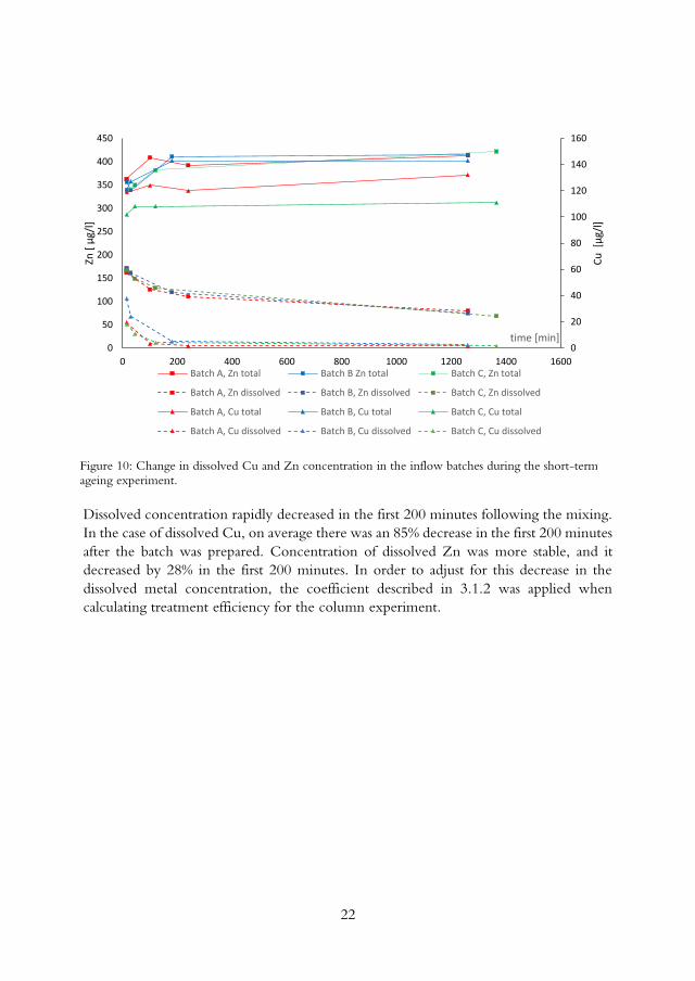
Dissolved concentration rapidly decreased in the first 200 minutes following the mixing.
In the case of dissolved Cu, on average there was an 85% decrease in the first 200 minutes
after the batch was prepared. Concentration of dissolved Zn was more stable, and it
decreased by 28% in the first 200 minutes. In order to adjust for this decrease in the
dissolved metal concentration, the coefficient described in 3.1.2 was applied when
calculating treatment efficiency for the column experiment.
0
20
40
60
80
100
120
140
160
0
50
100
150
200
250
300
350
400
450
0 200 400 600 800 1000 1200 1400 1600
Cu
[µ
g/l]
Zn [
µg/
l]
time [min]
Batch A, Zn total Batch B Zn total Batch C, Zn total
Batch A, Zn dissolved Batch B, Zn dissolved Batch C, Zn dissolved
Batch A, Cu total Batch B, Cu total Batch C, Cu total
Batch A, Cu dissolved Batch B, Cu dissolved Batch C, Cu dissolved
Figure 10: Change in dissolved Cu and Zn concentration in the inflow batches during the short-term ageing experiment.

23
4.2. Total and dissolved metal concentrations in the influents and effluents of
the studied filters
The concentrations of Cu in the influent of the zeolite filter ranged from 916 µg L-1 to
2124 µg L-1 with 93% of it being dissolved (Figure 11). The effluent concentrations
ranged from 360 µg L-1 to 600 µg L-1 and the dissolved fraction accounted for 80% of
total Cu (Figure 11). As for Zn, concentrations in the influent ranged from 190 µg L-1 to
460 µg L-1, and the effluent values were 20 µg L-1 to 80 µg L-1. The dissolved phase
accounted for 93% of both the influent and the effluent.
Concentrations of total and dissolved metals analysed in samples taken from the synthetic
stormwater batch and the effluent from the columns containing milkweed, bark, peat and
polypropylene are presented in Figure 12.
0
500
1000
1500
2000
2500
Cu
[μ
g/l]
Total Influent
Effluent
0
500
1000
1500
2000
2500
Cu
[μ
g/l]
Dissolved Influent
Effluent
0
100
200
300
400
500
600
Zn [
μg/
l]
Total Influent
Effluent
0
100
200
300
400
500
Zn [
μg/
l]
Dissolved Influent
Effluent
Figure 11: Average total and dissolved concentration of Cu and Zn in the influent and effluent of the zeolite filter for seven sampling occasions.

24
Figure 12: Total and dissolved concentrations of Cu and Zn in the column experiment in the inflow and the outflow from duplicate columns. The red line indicates the break in the experiment. Order of charts from left to right: Milkweed, Bark, Peat, Polypropylene.
0
100
200
300
400
500
0 20 40
Tota
l Zn
[µ
g/l]
time [days]0
100
200
300
400
500
0 20 40
0
100
200
300
400
500
0 20 40
0
100
200
300
400
500
0 20 40
0
50
100
150
200
0 20 40
Dis
solv
ed Z
n [
µg/
l]
time [days]0
50
100
150
200
0 20 40
0
50
100
150
200
0 20 40
0
50
100
150
200
0 20 40
0
2
4
6
8
10
12
0 20 40
Dis
solv
ed C
u[µ
g/l]
time [days]0
2
4
6
8
10
12
0 20 40
0
2
4
6
8
10
12
0 20 40
0
2
4
6
8
10
12
0 20 40
0
50
100
150
200
0 20 40
0
50
100
150
200
0 20 40
0
50
100
150
200
0 20 40
0
50
100
150
200
0 20 40
Tota
l Cu
[µ
g/l]
time [days]

25
When comparing metal concentrations in the influents of column and field experiment,
it can be seen that the Cu concentration was about 10 – 20 times higher in the roof-
runoff of the field experiment than in synthetic stormwater used for the column
experiments. This is expected, since influent for the column experiments (Paper I) was
created to simulate a polluted road runoff, which by nature is more diverse in pollutant
loading than the copper roof runoff (Paper II). The zinc concentrations in the influent to
the filters were similar (387–467 µg L-1 in column experiment and 186–464 µg L-1 in the
roof runoff).
4.3. Metal removal efficiency of the investigated filters
In general, treatment efficiency of the zeolite filter ranged from 52-82% for total Cu and
49-85% for dissolved Cu (Table 6). There was a noticeable trend of a decrease in
treatment efficiency. Regarding the zinc treatment, efficiency varied between 51-94%
for the total Zn, and 48-94% for the dissolved Zn (Table 6).
Table 6: Treatment efficiency of the zeolite filter (%) during each event for total and dissolved
copper and zinc.
Copper Zinc
Total Dissolved Total Dissolved
03-12-18 82 85 94 94
06-03-19 63 68 64 62
02-05-19 69 74 84 87
27-06-19 68 74 75 75
09-09-19 56 57 59 55
07-11-19 80 82 82 82
19-03-20 52 49 51 48
0
10
20
30
40
50
60
70
80
90
100
0 2000 4000 6000 8000 10000
Zin
c tr
eatm
net
Bedload volumes treated
0
10
20
30
40
50
60
70
80
90
0 5000 10000
Copper
tre
atm
ent
Bedload volumes treated
Figure 13: Change in the treatment efficiency of total copper (left) and zinc (right) in relation to total bed load volumes treated over time.

26
There is a noticeable drop in treatment efficiency for both total Cu and Zn throughout
the duration of the experiment conducted for Paper II, with treatment efficiency
dropping from 82% and 92% to 48% and 50% for total Cu and Zn, respectively.
In the column experiment the level of total treatment of Zn was considerably higher than
dissolved for all of the studied filter materials (74–95%). The same was true for total Cu,
where removal varied from 86–96%.The high level of treatment could be attributed to
the filtering process, where most of the particulate-bound metals were removed by
removing the sediment from the synthetic stormwater. Figure 14 shows the removal
efficiency for total and dissolved Cu and Zn for the column experiment.
The negative removal rate for Cu treatment across all filter materials may indicate that
the coefficient used to adjust the starting inflow concentration of dissolved copper may
overestimate the concentration, since no change in pH was detected between the inflow
and outflow samples.
It is difficult to make a direct comparison of filter treatment efficiency between the
column experiments (Paper I) and the field experiment (Paper II) due to the differences
in filter media, and due to inherent differences between field conditions and laboratory
conditions, such as hydraulic loading, approximation of stormwater, and the generally
more controlled conditions present in the laboratory study. However, some observations
0
20
40
60
80
100
M B P PP
Rem
ova
l eff
icie
ncy
[%
]
a)
0
20
40
60
80
100
M B P PP
Rem
ova
l eff
icie
ncy
[%
]
b)
-140
-120
-100
-80
-60
-40
-20
0
M B P PP
Rem
ova
l eff
icie
ncy
[%
]
c)
0
20
40
60
80
100
M B P PP
Rem
ova
l eff
icie
ncy
[%
]
d)
Figure 14: Removal efficiency of milkweed (M), bark (B), peat (P) and polypropylene (PP) with respect to total Cu (a), total Zn (b), dissolved Cu (c) and dissolved Zn (d). Left and right bars represent two replicates for each filter material.

27
could be made. The treatment of total and dissolved Zn could be compared due to the
similarity of total Zn concentrations. The treatment of dissolved Zn by “traditional”
stormwater filter materials (bark and peat) in the column experiment was approximately
75 and 81%, respectively. The treatment of total and dissolved Zn by the zeolite filter
was comparable, 51–94% and 48–94%, respectively, over the observed period. These
three materials showed a much higher treatment level than milkweed and polypropylene,
which could remove dissolved Zn from the synthetic stormwater by 16 and 8%,
respectively.
4.4. BGS Modelling results
The most influential factor for all of the runs was discharge, as it dictated the streamwise
velocity in the model (Figures 16-18). With the increase in velocity, if all of the other
parameters remained the same, trapping efficiency decreased. The runs with the sudden
transition set-up showed a very uneven flow pattern in the BGS tank, with a dominant
flow jet passing through the middle of the tank, and two noticeable asymmetrical
backflow jets forming on the sides of the tank. There was a noticeable pattern of cells
devoid of sediment on the pathway of the jet, indicating that the high velocity prevented
sediment deposition, and the backflow jets promoted suspended sediment settling (Figure
15).
Figure 15: Photo of the BGS grid with a visible region of cells devoid of sediment, simulating the jet stream trajectory.
The expansion used in runs 8-24 reduced this negative occurrence, and allowed a
relatively uniform velocity distribution along the BGS tank. This also increased sediment
settling efficiency of the BGS, for Q = 2 l/s, the runs with the diffuser were 45% more
effective than the sudden expansion ones, whereas for Q = 4 l/s, the BGS effectiveness
of the diffuser proved to be more than 70% more effective than the run with the sudden
expansion. When comparing the effectiveness of various BGS configurations to the bare
bottom runs, in general, BGS runs were 25% more efficient in removing sediment. The
only flow for which this was not the case was Q = 4 l/s, where the bare bottom run
removed about 10% more sediment than the best preforming BGS run. However, it has
to be noted that this was the only case for all of the experiment set-ups in which the
performance increased with the flow, so the validity of this point is questionable.

28
Besides vertical walls, BGS models with cross-wall angle-cell inclinations of 60° and 120°
were also tested. Cross-walls with both angles performed better than the 90-degree walls.
There was a noticeable amount of sediment settled on the wall surface, which could be
the reason behind the increase of the settling efficiency. This was again more noticeable
for the higher flow rate .
0
10
20
30
40
50
60
0 1 2 3 4 5
Trap
pin
g Ef
fici
ency
[%
]
Q [l/s]
Diffuser
Suddenexpansion
0
10
20
30
40
50
60
0 1 2 3 4 5
Trap
pin
g Ef
fici
ency
[%
]
Q [l/s]
Smooth
BGS
0
10
20
30
40
50
60
0 2 4 6
Trap
pin
g Ef
fici
ency
[%
]
Q [l/s]
No BGS
d : 5 cm
d : 10 cm
0
10
20
30
40
50
60
0 1 2 3 4 5
Trap
pin
g Ef
fici
ency
[%
]
Q [l/s]
w : 5 cm
w : 10 cm
15
20
25
30
35
40
45
0 1 2 3 4
Trap
pin
g Ef
fici
ency
[%
]
Q [l/s]
90°120°No BGS60°
Figure 16: Sediment trapping efficiency for cell depths of 5 and 10 cm, and the cross-wall angle of 90° (left); Sediment trapping efficiency for no BGS, the cell width of 5 cm and two depths (5 and 10 cm), and the cross-wall angle of 90° (right).
Figure 17: Sediment trapping efficiencies with and without the diffuser (cell width and depth 5 cm,
cross-wall angle 90°), and (right) Sediment trapping efficiencies in runs with and without BGS (smooth bottom runs).
Figure 18: Sediment trapping efficiency for varying wall angles.

29
Model set-ups with BGS cell sizes of 10 cm were on average about 10% more effective
than the runs with a cell width of 5 cm (Figure 16, left). This was more noticeable for
lower flow rates, while for Q = 4 l/s, there was no difference between the different cell
widths. Within the range of tested depths, there was no difference in the sedimentation
rate (Figure 16, right).
The repeatability test was carried out for d = 10 cm, w= 5 cm, α = 90°, and Q = 3 L/s.
The documented sediment trapping efficiency was 28% with a standard deviation of
0.5%. The result indicated that the differences in the performance in the various BGS
settings were not due to the uncertainty of experimental runs.

30

31
5. Discussion In this chapter, the results that were presented in the previous chapter are discussed within
the context of previous studies. In Section 5.1, filter material effectiveness and the
application of stormwater filters are discussed. Section 5.2 discusses the preparation and
ageing of synthetic stormwater. Section 5.3 presents the impact of a bottom grid structure
(Paper III) on stormwater treatment capacities of stormwater ponds.
5.1. Impact of BGS cell design of sedimentation effectiveness and suggestion
for future studies
One of the main design parameters of a stormwater pond is the area needed for the
sedimentations of particles (Persson, 1999). Urbanisation is one of the leading causes of
increased stormwater runoff, and the decrease of its quality (Walsh et al., 2005) and
available area in urban space are often limiting factors. Based on results from field
measurements (He et al., 2014), the implementation of a BGS could increase the
equivalent settling area by 5 to 60 times.
The hydraulic modelling study helped to determine the impact of BGS cell parameters
on the sedimentation efficiency of the structure. However, the results are not directly
translatable to the field conditions. In order to translate experiment results from the model
to the prototype, it is necessary to keep the relationship between the inertia and gravity
forces identical. This relationship is expressed by the Froude number (eq. 8).
𝐹𝑟 =𝑉2
𝑔ℎ(𝑒𝑞 8)
Where V is flow velocity, g is the acceleration of gravity, and h is the water depth. The
Froude number should be same on both the model and the prototype. Since the gravity
acceleration is the same on both the model and the prototype, it leads to Equation 9.
𝐹𝑟𝑚 = 𝐹𝑟𝑝 →𝑉2
𝑚
ℎ𝑚
=𝑉2
𝑝
ℎ𝑝
(𝑒𝑞 9)
In the experiments conducted on the BGS model, it was assumed that the length scale
L* = Lp/Lm = 10, where L* is the scale factor, Lp represents lengths in the prototype
and Lm stands for lengths on the model. That would mean that the prototype would
have a length of 10 m, a width of 5 m and a cell wall height of 50–100 cm. Modelling
sediment transport was challenging. Studied conditions did not allow the requirements
for the sediment properties (density and particle diameter) to be fully satisfied, thus the
model was suitable for providing qualitative comparisons between different cell designs,
but not for quantified results.
Gathered data from the experiment suggest that the width of the cell impacts the settling
efficiency, with wider cells providing enhanced sedimentation (Figure 16). Another
factor that proved important was cell wall angle, where experiment set-ups with inclined
walls provided on average 20% better sediment removal rate. However, the drawback of

32
this configuration might be too great, as it would likely be difficult to maintain such a
structure, given the geometry of the cell walls.
One of the key factors often neglected is the maintenance of stormwater control
measures. According to (Al-Rubaei et al., 2017), half of the inspected 25 stormwater
ponds in Sweden were in need of maintenance. The inclusion of a BGS system could
address this issue, as most of the sediment could be expected to settle in the cells. From
there it could be extracted by means of hydraulic dredging, a practice that is used to
maintain stormwater ponds (Drake and Guo, 2008). The BGS would also reduce the size
of the area in need of dredging, compared to dredging the whole pond or forebay.
The inclusion of the BGS in the stormwater pond should reduce sediment resuspension,
which is important since stormwater pond sediment can contain elevated levels of metals
such as Cr, Cu and Pb (Marsalek and Marsalek, 1997).
Finally, the next research phase should focus on optimising the geometry of the BGS
cells, and then testing it in field conditions, since it will always be challenging to fully
simulate the complex behaviour of sediment transport over such a structure in laboratory
conditions.
5.2. Filter effectiveness in metal treatment from stormwater
5.2.1. Treatment efficiency of filter materials
Peat
Peat filters have been the subject of numerous studies that focused on their capacity to
remove pollutants from wastewater and stormwater (Couillard, 1994; Crist et al., 1996;
Brown et al., 2000; Kalmykova et al., 2009). In a field study investigating treatment from
highway runoff, Zhou et al. (2003) determined that the filtration system containing peat
as filter material was able to remove 90% of total Zn, and 70% of dissolved Zn, from the
runoff. Similarly, in the column study, peat columns removed 94% of total Zn, and 81%
of dissolved Zn, over the duration of the experiment, and it was the most effective filter
material in removing dissolved Zn from the synthetic stormwater.
Bark
Bark has shown high capacity to remove metal ions from waste and stormwater (Vázquez
et al., 2002; Jang et al., 2005; Genç-Fuhrman et al., 2007; Nehrenheim and Gustafsson,
2008). In the column study, bark was the second most effective material at treating
dissolved zinc from the synthetic stormwater, with an average efficiency of 75%, over the
duration of the experiment.
Milkweed
Milkweed as a material has been proven to have high oil sorption capacity. In a study
that compared multiple sorbents (milkweed, kapok, cotton, wool, polypropylene and
kenaf), milkweed showed the highest sorption capacity (Choi, 1996). In a study that
assessed the sorption capacities of different filter materials at various concentrations of Cu
and Zn, milkweed was found to be able to reduce the concentration of Zn in cases where
the influent concentration did not exceed 500 µg. In the column experiment described

33
in this thesis, Milkweed was not able to achieve the same level of removal of dissolved
Zn as bark and peat. It should be noted that due to the volume limitation, the mass of
used milkweed was several times lower than bark and peat. Milkweed columns were
packed with 9 and 13 g of filter material, while bark and peat had 35 and 50 g, and 51
and 64 g, respectively. When adjusted for the mass of the filter material (Table 4, Paper
I), milkweed showed a comparable reduction to bark and peat. It should also be noted
that milkweed columns achieved the highest removal of the dissolved Cu.
Polypropylene
The main reason to include polypropylene in the study is its capacity to remove oil from
the stormwater runoff (Praba Karana et al., 2011). In the column study described in 3.1.1,
polypropylene showed the lowest removal efficiency of the four tested filter materials,
removing 8% of the dissolved Zn from the synthetic stormwater. The batch studies
conducted by Norman (2018), also showed that the material demonstrated no sorption
capacity. In previous studies, the examined polypropylene has been modified. For
example, Mavlyankariev and Rhee (2007) showed that when coated with Manganese
Dioxide, polypropylene granules show high removal efficiency for Pb, Cu, Cd and Zn.
Zeolite
The inflow for the field experiment in Paper II was runoff from a copper roof. The
quality of inflow was comparable to similar studies. In the influent, the total Cu
concentration was in the range of 900–2100 µg L-1, with 93% of it found in the dissolved
fraction. This is in line with other studies concerning Cu roof runoff. Athanasiadis et al.
(2007), reported the event mean concentration of approximately 1600 µg L-1 and in a
study investigating runoff from a Cu roof in Stockholm, Jönsson (2013) reported the
concentration ranges of 945–3400 µg L-1.
In a study by Athanasiadis et al., (2007), it was shown that a filter system with zeolite
installed as a barrier material was able to reduce the total Cu up to 97%. This level of
treatment has not been reached in the study in Paper III. However it is important to
point out the differences between the two systems. The filter system, as described in
3.1.2, contains a pump that allowed the stored water to be treated. In the study referenced
above, water was allowed to flow gravitationally through the system, which could explain
higher treatment efficiency. The average treatment of total and dissolved Cu in the field
experiment was 69, and 73%, respectively (Table 5 and Figure 13). Given the level of
the inflow concentration of Cu, this meant that the level of Cu in the effluent exceeded
the recommendation by the authorities multiple times (City of Gothenburg, 2020).
In order to reduce the impact of the pollutants of the receiving water body, a filter system
should provide a high level of treatment throughout its service life. According to the
current trend of decreasing performance (Figure 13) this would not be the case. The
service life of the filter system studied in (Paper II) is three years (3P Technik, 2020). If
the current trend were to be continued, the treatment level of total Cu and Zn would
drop to 25%, and 7% by the end of the stated service life.

34
An explanation for lower treatment efficiency in the filter system evaluated in this thesis
compared to previous studies, such as (Athanasiadis et al., 2007) is that the hydraulic
loading of the filter system is too high to allow efficient metal removal. In a study that
investigated the performance of columns packed with different filter materials (peat,
zeolite and calcium silicate rock), Färm (2002) found that there was a significant decrease
of metal treatment by the columns with the increase of hydraulic load. The decrease of
the performance in that study was observed when the hydraulic loading increased above
3.5 m3 m–2h–1, which is almost two times lower than the load in the analysed filter system
presented in this thesis (6.7 m3 m–2h–1). Future studies of the impact of the hydraulic load
on the treatment performance of the zeolite filter installation could demonstrate how
much of an effect a decrease in hydraulic load would have on the improvement of metal
removal.
5.2.2. Applicability of filters for stormwater treatment.
Filter materials can be used either to enhance stormwater treatment in other stormwater
treatment systems such as bioretention systems, as stand–alone solutions such as gully-pot
filters or as a part of a treatment train, a sequence of stormwater control measures that
aims to maximise the control of pollutants from the runoff (Wong et al., 2002). The
treatment train approach aims to utilise the specific strengths of stormwater treatment
methods to achieve more efficient stormwater treatment. For example, clogging can
reduce the effectiveness of infiltration trenches, permeable pavements and other filtration
based stormwater control measures (Hatt et al., 2007; Ziyath et al., 2011; Blecken et al.,
2017). That could be prevented if the filtration step was preceded by a system efficient
in removing larger solids from the stormwater, such as a stormwater pond. Ponds are
efficient in removing solids from the stormwater, and their insufficient dissolved pollutant
treatment would be remedied by the filter systems.
Bark, Peat and Zeolite showed high dissolved metal removal, and could be considered as
suitable materials in these filter installations. Milkweed and polypropylene have not
shown as good removal of pollutants, so it is likely that they would need to be adapted
before their use as stormwater filter material.
5.3. Synthetic stormwater as a proxy for stormwater in experiments
Synthetic stormwater is a model of the stormwater runoff found in situ that is used for
various laboratory studies in order to test different filter materials to determine their
effectiveness in removing various pollutants. The advantage of using synthetic stormwater
over natural, or collected, stormwater is that it allows better repeatability and in general
more controlled experiments. The disadvantage is that synthetic stormwater will never
truly replicate the chemical, physical and biological characteristics of real stormwater
(Hatt et al., 2007). Synthetic stormwater used in Paper I was created to simulate the
runoff from a polluted road. Metal concentrations were targeted to be in the range of
those found in the literature (Makepeace et al., 1995; Davis et al., 2001; Camponelli et
al., 2010). When compared to the other studies that also used synthetic stormwater, the
values for heavy metals also fell within the range of the values used by other researchers

35
(Haselbach et al., 2014; Lim et al., 2015; Borris et al., 2016; Genç-Fuhrman et al., 2016;
Huber et al., 2016b; Rycewicz-Borecki et al., 2016; Søberg et al., 2017).
The ageing of SW is an important factor to consider when taking into account filter
effectiveness. Often a filter performance is judged based on the reduction of pollutant
concentrations. Commonly, one way to determine the performance of the filter is to
compare the concentration in the inflow and at the outflow from the filter set-up (Genç-
Fuhrman et al., 2007; Blecken et al., 2009; Søberg et al., 2019), usually by following a
formula similar to the one presented in 3.3.3 (Equation 6). Thus determining the
importance of the initial concentration when estimating filter effectiveness. As shown in
Paper I, there is a rapid change in dissolved metal concentration upon mixing. In Paper
I, a time-weighted average concentration was introduced to account for this change.
Figure 19 presents the impact on filter efficiency of different methods of accounting for
the change in the synthetic stormwater. The methods are as follows: (I) “Starting” uses
the dissolved concentration of the metal at the start of the experiment as the inflow
concentration. (II) “Mid” uses the average of the concentration at the start of the
experiment, and one found in samples at the end of the experiment. (III) “Integral” uses
the time–weighted coefficient defined in Chapter 3.1.2. (Equations 4–6).
Figure 19: Impact of different correction methods of inlet concentrations on dissolved Cu (left) and Zn (right) treatment efficacy. Starting – initial concentration of dissolved metals. Mid – mean of the initial
concentration of dissolved metals and the measured concentration at the end of the experiment, and Integral – adjusting the initial concentration with time–weighted coefficients.
The difference between the different methods depends on how quickly the level of
dissolved metal concentration changed in the synthetic stormwater. It was far more
noticeable for Cu, where the Starting scenario resulted in 73.7% treatment level of peat
columns, the Mid scenario resulted in 56.8% treatment, and the Integral scenario with
time-weighted coefficient indicated a negative removal of -120%. The negative removal
of Cu might indicate that the time resolution of the method was too low, since the pH
of the influent and effluent solutions did not vary significantly (7.7 in synthetic
stormwater, 7.2 in peat column outflow). More detailed analysis (more frequent time–
steps) could have resulted in a more precise method to determine inflow concentration
of dissolved C. The difference was present in other metals as well, although it was not as
pronounced. In the case of dissolved Zn, the three methods did not differ as much. When
observing the effectiveness of peat columns, the use of Starting, Mid and Integral methods
-150
-100
-50
0
50
100
starting mid integral
Rem
ova
l eff
icie
ncy
[%
]
0
20
40
60
80
100
starting mid integral
Rem
ova
l eff
icie
ncy
[%
]
M
B
P
PP

36
resulted in 88, 84 and 80% Zn removal, respectively.Since the 11–day ageing experiment
showed little change in the metal concentration over the first 6 days of the duration of
the experiment, and the shorter ageing experiment showed that most of the reduction in
dissolved metal concentration took place in the first three hours following the mixing, it
is recommended in future similar studies that water should be mixed at least three hours
before the start of the experiment, to allow a more stable inflow concentration.
Furthermore, it is also recommended to conduct test runs before the actual experiment
in order to determine the amount of metal salts needed for spiking the synthetic
stormwater.
In the BGS modelling study, water spiked with Neralite was used to simulate stormwater
runoff. Since the sediment used in the modelling study had a uniform diameter, effects
of particle size have not been addressed. Laboratory studies conducted by He and
Marsalek (2014) indicated that the structure was more successful in trapping larger
particles than smaller ones, particularly under higher flow conditions.
5.4. Stormwater treatment and area efficiency
An integral approach to stormwater management in relation to other urban infrastructure
is needed, so it is important to determine, and where possible reduce, the area that
stormwater systems require to function properly. Stormwater systems are most needed in
urban environments, where space requirements have to be balanced between different
functions. In one of the studies included in this thesis, the need for the surface area was
bypassed by placing the collection and storage tank, as well as the five filter units, below
the ground. This is, however, not always possible, since the area below the ground is
often occupied by pipes, cables and other utilities. The total area occupied by the filter
installation was approximately 60 m2. The combined surface of the roof and the part of
the park that was treated was approximately 4800 m2, so the area needed for treatment
amounted to 1.25% of the catchment, which is comparable to the area typically needed
for stormwater ponds (Persson et al., 1999). If the hydraulic loading of the filter was to
be decreased, in order to improve the treatment efficiency, the required area of the filter
installation would increase even further. Another way to utilise filter media consists of
stand–alone solutions such as gully pot filters or catch basin inserts (Lau et al., 2001; Färm,
2004). These filters are located in gully pots and are intended to treat stormwater at the
source. The advantage of these systems is that they can be easily retrofitted in existing
urban drainage infrastructure, and that they do not have a land footprint of their own.
However, the disadvantage is that these systems are easily clogged and require frequent
maintenance (Atlanta Regional Commission, 2001).
One of the main design parameters of a stormwater pond is the area needed for
sedimentation of particles (Persson, 1999). Based on results from a field experiment it has
been hypothesised that the implementation of a BGS could decrease the required
equivalent settling area by 5 to 60 times (He et al., 2014), which would make
implementation of stormwater ponds in urban areas more feasible.

37
6. Conclusions The aim of this licentiate was to summarise and provide better knowledge about the
components of area-efficient stormwater treatment facilities, as well as to further increase
the knowledge about laboratory experiments to evaluate potential filter materials that
could be used in said facilities. The following conclusions can be drawn:
The experiments that compared the ability of different filter materials to treat total and
dissolved metals from synthetic stormwater showed that the order of efficiency of filter
materials were: peat>bark>milkweed>polypropylene. All of the filter materials exhibited
high total metal removal, although that was likely to be the case due to the column set-
up, where the combination of filter materials, geotextile and glass beads, removed a
considerable amount of total solids that had pollutants attached to them. Bark and peat
columns achieved 75% and 81% dissolved metal removal, respectively. While milkweed
and polypropylene showed a far lower removal efficiency (16% and 8%, respectively),
milkweed showed a removal rate comparable to bark and peat, when adjusted for the
mass of the filter present in the columns.
The field study that investigated the Cu and Zn removal efficiency of a zeolite filter
treating runoff from a copper roof showed that the treatment level for total and dissolved
Cu ranged between 52–82% and 48–94%, respectively. Zn removal was estimated at 49–
85% and 48–64% for total and dissolved zinc, respectively. Besides a relatively high Cu
removal rate, effluent concentrations still exceeded the recommended effluent values
suggested by environmental authorities by more than 30 times. The trend in the
treatment over time also indicated that the performance would continue to deteriorate.
High hydraulic loading, compared to the similar studies, was identified as a potential
reason for the lower Cu removal rate.
In order to further the understanding of the dissolved metal behaviour in synthetic
stormwater, an 11-day ageing experiment was conducted, as well as a one-day ageing
experiment. The 11-day ageing experiment showed that dissolved metals remained stable
used up to 6 days after mixing. The triplicates of the one-day experiment showed a rapid
change in dissolved metal concentration shortly after the mixing, with the most rapid
changes detected in dissolved Cu, where the concentration decreased by 85% in the first
200 minutes following the preparation of synthetic stormwater. It was shown that the
different methods of calculating filter effectiveness led to drastically different results for
removal, thus a time-weighted coefficient was proposed that would account for the
changes of the dissolved metals in synthetic stormwater and provide more precise
treatment values.
In order to improve settling efficiency of stormwater ponds, at the same time as reducing
the area for settling, a novel device bottom grid structure was investigated in a series of
tests performed in a hydraulic laboratory, on a scaled model. The tests showed that the
larger cells were more effective in capturing model sediment, increasing the efficiency by 13%.
Inclined walls increased the efficiency of the BGS model, although their implementation in
prototype and full scale might prove problematic due to maintenance requirements.

38

39
7. Literature 3P Technik, 2020. Hydrosystem 1000 [WWW Document]. URL
www.3ptechnik.de/index.php?article_id=23&clang=4&model=3100130&t=true (accessed 6.22.20).
Al-Faqih, L., Johnson, P.D., Allen, S.J., 2008. Evaluation of a new peat-based sorbent for metals capture. Bioresource Technology 99, 1394–1402.
Al-Rubaei, A.M., 2016. Long-Term Performance, Operation and Maintenance Needs of Stormwater Control Measures. Doctoral Thesis, Luleå Technical University.
Al-Rubaei, A.M., Merriman, L.S., Hunt, W.F., M., Viklander, M., Marsalek, J.,
Blecken, G.-T., 2017. Survey of the Operational Status of 25 Swedish Municipal Stormwater Management Ponds. Journal of Environmental Engineering 143(6)
Ashley, R., Gersonius, B., Digman, C., Horton, B., Smith, B., Shaffer, P., 2018.
Including uncertainty in valuing blue and green infrastructure for stormwater management. Ecosystem services 33, 237–246.
Athanasiadis, K., Helmreich, B., Horn, H., 2007. On-site infiltration of a copper roof
runoff: Role of clinoptilolite as an artificial barrier material. Water Research 41, 3251–3258.
Atlanta Regional Commission, 2015. Georgia Stomrwater Management Manual.
Atlanta Regional Commission, 2001. Georgia Stormwater Management Manual, Volume 2: Technical Handbook. August.
Barbosa, A.E., Fernandes, J.N., David, L.M., 2012. Key issues for sustainable urban stormwater management. Water Research 46, 6787–6798.
Barrett, M.E., 2010. Evaluation of Sand Filter Performance, Technical (Online) Report - University of Texas at Austin, Center for Research in Water Resources.
Beck, H.J., Birch, G.F., 2012. Spatial and temporal variance of metal and suspended
solids relationships in urban stormwater - Implications for monitoring. Water, Air and Soil Pollution 223, 1005–1015.
Bixler, T.S., Houle, J., Ballestero, T.P., Mo, W., 2020. A spatial life cycle cost
assessment of stormwater management systems. Science of Total Environment 728, 138787.
Björklund, K., Li, L., 2015. Evaluation of low-cost materials for sorption of
hydrophobic organic pollutants in stormwater. Journal of Environmental Management 159, 106–114.
Blecken, G., 2018. Drizzle Cards 3 - Luleå University of Technology [WWW
Document]. URL https://www.ltu.se/research/subjects/VA-teknik/Forskningsprojekt/DRIZZLE/Forskningsprojekt/Drizzle-Cards-3?l=en (accessed 4.26.21).

40
Blecken, G.T., Hunt, W.F., Al-Rubaei, A.M., Viklander, M., Lord, W.G., 2017.
Stormwater control measure (SCM) maintenance considerations to ensure designed functionality. Urban Water Journal 14, 278–290.
Blecken, G.T., Zinger, Y., Deletić , A., Fletcher, T.D., Viklander, M., 2009.
Influence of intermittent wetting and drying conditions on heavy metal removal by stormwater biofilters. Water Research 43, 4590–4598.
Borris, M., Österlund, H., Marsalek, J., Viklander, M., 2016. Contribution of coarse
particles from road surfaces to dissolved and particle-bound heavy metal loads in runoff: A laboratory leaching study with synthetic stormwater. Science of the Total Environment 573, 212–221.
Brown, P.A., Gill, S.A., Allen, S.J., 2000. Metal Removal From Wastewater Using Peat. Water Research 34, 3907–3916.
Buren, M.A. Van, Watt, W.E., Marsalek, J., 1997. Removal of Selected Urban
Stormwater Constituents by an On-stream Pond. Journal of Environmental Planning and Management.
Camponelli, K.M., Lev, S.M., Snodgrass, J.W., Landa, E.R., Casey, R.E., 2010.
Chemical fractionation of Cu and Zn in stormwater, roadway dust and stormwater pond sediments. Environmental Pollution 158, 2143–2149.
Cettner, A., Ashley, R., Hedström, A., Viklander, M., 2014. Sustainable development and urban stormwater practice. Urban Water Journal 11, 185–197.
Choi, H.-M., 1996. Needlepunched Cotton Nonwovens and Other Natural Fibers as
Oil Cleanup Sorbents. Journal of Environmental Science and Health. Part A: Environmental Science and Engineering and Toxicology 31, 1411–1457.
City of Gothenburg, 2020. Riktlinjer och riktvärden för utsläpp av förorenat vatten till dagvattennät och recipient (Report number R2020:13).
Clark, S.E., Pitt, R., 2012. Targeting treatment technologies to address specific
stormwater pollutants and numeric discharge limits. Water Research 46, 6715–6730.
Couillard, D., 1994. The use of peat in wastewater treatment. Water Research 28, 1261–1274.
Crist, R.H., Martin, J.R., Chonko, J., Crist, D.R., 1996. Uptake of metals on peat
moss: An ion-exchange process. Environmental Science and Technology 30, 2456–2461.
Ćurković, L., Cerjan-Stefanović, Š., Filipan, T., 1997. Metal ion exchange by natural
and modified zeolites. Water Research 31, 1379–1382.
Davis, A.P., Shokouhian, M., Ni, S., 2001. Loading estimates of lead, copper,
cadmium, and zinc in urban runoff from specific sources. Chemosphere 44, 997–1009.

41
Djukić, A., Lekić, B., Rajaković-Ognjanović, V., Veljović, D., Vulić, T., Djolić, M.,
Naunovic, Z., Despotović, J., Prodanović, D., 2016. Further insight into the
mechanism of heavy metals partitioning in stormwater runoff. Journal of Environmental Management 168, 104–110.
Doula, M., Ioannou, A., Dimirkou, A., 2002. Copper adsorption and Si, Al, Ca, Mg,
and Na release from clinoptilolite. Journal of Colloid and Interface Science 245, 237–250.
Drake, J., Guo, Y., 2008. Maintenance of Wet Stormwater Ponds in Ontario. Canadian Water Resources Journal 33, 351–368.
Eckart, K., McPhee, Z., Bolisetti, T., 2018. Multiobjective optimization of low impact development stormwater controls. Journal of Hydrology 562, 564–576.
Erickson, A.J., Weiss, P.T., Gulliver, J.S., 2013. Optimizing stormwater treatment
practices: A handbook of assessment and maintenance. Springer Science & Business Media.
European Committee for Standardisation, 2005. EN 872:2005 Water quality - Determination of suspended solids - Method by filtration through glass fibre filters. European Committee for Standardization, Brussels, Belgium.
Faram, M.G., Andoh, R.Y.G., 2007. Treatment of urban run-off using innovative below-ground separation and filtration technologies. Proc. Comb. Int. Conf.
Comput. Control Water Ind. CCWI2007 Sustain. Urban Water Manag. SUWM2007 535–542.
Färm, C., 2004. Constructed Filters and Detention Ponds for Metal Reduction in Storm Water. Doctoral Thesis, Märalden University.
Färm, C., 2002. Metal sorption to natural filter substrates for storm water treatment—column studies. Science of the Total Environment 298, 17–24.
Fletcher, T.D., Shuster, W., Hunt, W.F., Ashley, R., Butler, D., Arthur, S.,
Trowsdale, S., Barraud, S., Semadeni-Davies, A., Bertrand-Krajewski, J.L.,
Mikkelsen, P.S., Rivard, G., Uhl, M., Dagenais, D., Viklander, M., 2015. SUDS,
LID, BMPs, WSUD and more – The evolution and application of terminology surrounding urban drainage. Urban Water Journal 12, 525–542.
Gaballah, I., Kilbertus, G., 1998. Recovery of heavy metal ions through decontamination of synthetic solutions and industrial effluents using modified barks. Journal of Geochemical Exploration 62, 241–286.
Galfi, H., Österlund, H., Marsalek, J., Viklander, M., 2016. Indicator bacteria and
associated water quality constituents in stormwater and snowmelt from four urban catchments. Journal of Hydrology 539, 125–140.
Genç-Fuhrman, H., Mikkelsen, P.S., Ledin, A., 2016. Simultaneous removal of As,
Cd, Cr, Cu, Ni and Zn from stormwater using high-efficiency industrial sorbents:
Effect of pH, contact time and humic acid. Science of the Total Environment 566–567, 76–85.

42
Genç-Fuhrman, H., Mikkelsen, P.S., Ledin, A., 2007. Simultaneous removal of As,
Cd, Cr, Cu, Ni and Zn from stormwater: Experimental comparison of 11 different sorbents. Water Research 41, 591–602.
Horn, H., 2010. Lehrstuhl für Siedlungswasserwirtschaft Bericht zur Prüfung von zwei
Behandlungsanlage für Zink- bzw . Kupferdachabflüsse nach den Prüfkriterien des LfU Bayern im Auftrag Inhaltsverzeichnis 49 (In German).
Gnecco, I., Berretta, C., Lanza, L.G., La Barbera, P., 2005. Storm water pollution in the urban environment of Genoa, Italy. Atmospheric Research 77, 60–73.
Gray, C.S., 2012. The Use of Natural Zeolites As a Sorbent for Treatment of Dissolved Heavy Metals in Stormwater Runoff. Proceedings from GeoCongress 2012
Gunawardena, J., Egodawatta, P., Ayoko, G.A., Goonetilleke, A., 2013. Atmospheric
deposition as a source of heavy metals in urban stormwater. Atmospheric Environment 68, 235–242.
Haile, T., Fuerhacker, M., 2018. Simultaneous Adsorption of Heavy Metals from
Roadway Stormwater Runoff Using Different Filter Media in Column Studies. Water 10, 1160.
Hamann, F., Blecken, G.-T., Ashley, R.M., Viklander, M., 2020. Valuing the Multiple
Benefits of Blue-Green Infrastructure for a Swedish Case Study: Contrasting the
Economic Assessment Tools B£ST and TEEB. Journal of Sustainable Water in the Built Environment 6, 05020003.
Haselbach, L., Poor, C., Tilson, J., 2014. Dissolved zinc and copper retention from stormwater runoff in ordinary portland cement pervious concrete. Construction and Building Materials 53, 652–657.
Hatt, B.E., Fletcher, T.D., Deletic, A., 2008. Hydraulic and pollutant removal
performance of fine media stormwater filtration systems. Environmental Science & Technology 42, 2535–2541.
Hatt, B.E., Fletcher, T.D., Deletic, A., 2007. Treatment performance of gravel filter
media: Implications for design and application of stormwater infiltration systems. Water Research 41, 2513–2524.
He, C., Marsalek, J., 2014. Enhancing sedimentation and trapping sediment with a
bottom grid structure. Journal of Environmental Engineering (United States) 140, 21–29.
He, C., Post, Y., Rochfort, Q., Marsalek, J., 2014. Field study of an innovative sediment capture device: Bottom grid structure. Water, Air, & Soil Pollution 225.
Headley, T., Tanner, C.C., 2006. Application of Floating Wetlands for Enhanced Stormwater Treatment: A Review. Report
Hedström, A., 2001. Ion exchange of ammonium in zeolites: a literature review. Journal of Environmental Engineering, 20, 269–276.

43
Herngren, L., Goonetilleke, A., Ayoko, G.A., 2005. Understanding heavy metal and
suspended solids relationships in urban stormwater using simulated rainfall. Journal of Environmental Management 76, 149–158.
Hoang, L., Fenner, R.A., Skenderian, M., 2018. A conceptual approach for evaluating
the multiple benefits of urban flood management practices. Journal of Flood Risk Management 11, S943–S959.
Horowitz, A.J., Elrick, K.A., Smith, J.J., 2008. Monitoring urban impacts on suspended
sediment, trace element, and nutrient fluxes within the City of Atlanta, Georgia,
USA: Program design, methodological considerations, and initial results. Hydrological Processes 22, 1473–1496.
Huber, M., Badenberg, S.C., Wulff, M., Drewes, J.E., Helmreich, B., 2016a. Evaluation of factors influencing lab-scale studies to determine heavy metal removal by six sorbents for stormwater treatment. Water (Switzerland) 8.
Huber, M., Hilbig, H., Badenberg, S.C., Fassnacht, J., Drewes, J.E., Helmreich, B., 2016b. Heavy metal removal mechanisms of sorptive filter materials for road runoff
treatment and remobilization under de-icing salt applications. Water Research 102, 453–463.
Huber, M., Welker, A., Helmreich, B., 2016c. Critical review of heavy metal pollution
of traffic area runoff: Occurrence, influencing factors, and partitioning. Science of the Total Environment 541, 895–919.
Hvitved-Jacobsen, T., Vollertsen, J., Nielsen, A.H., 2010. Urban and highway
stormwater pollution: Concepts and engineering, Urban and Highway Stormwater Pollution: Concepts and Engineering.
Ilyas, A., Muthanna, T.M., 2017. Assessment of upscaling potential of alternative
adsorbent materials for highway stormwater treatment in cold climates. Environmental Technology (United Kingdom) 38, 705–717.
Jang, A., Seo, Y., Bishop, P.L., 2005. The removal of heavy metals in urban runoff by sorption on mulch. Environmental Pollution 133, 117–127.
Johnson, J.L., 2007. Evaluation of Stormwater Wetland and Wet Pond Forebay Design and Stormwater Wetland Pollutant Removal Efficiency. Master Thesis. North Carolina State University
Joint Committee For Guides In Metrology, 2008. Evaluation of measurement data — Guide to the expression of uncertainty in measurement. Int. Organ. Stand. Geneva ISBN 50, 134.
Joksimovic, D., Alam, Z., 2014. Cost efficiency of Low Impact Development (LID)
stormwater management practices, in: Procedia Engineering. Elsevier Ltd, 734–741.

44
Jönsson, A., 2013. Copper in storm water runoff from a naturally patinated copper roof
and a parking space – variations in fluxes during a rainfall in Stockholm. Report number U4439, Swedish Environmental Research Institute IVL, Sweden.
Kalmykova, Y., Strömvall, A.M., Rauch, S., Morrison, G., 2009. Peat filter
performance under changing environmental conditions. Journal of Hazardous Materials 166, 389–393.
Kandra, H.S., McCarthy, D., Fletcher, T.D., Deletic, A., 2014. Assessment of clogging
phenomena in granular filter media used for stormwater treatment. Journal of Hydrology 512, 518–527.
Kayhanian, M., Stransky, C., Bay, S., Lau, S.L., Stenstrom, M.K., 2008. Toxicity of urban highway runoff with respect to storm duration. Science of the Total Environment 389, 386–406.
Kundu, D., Pandey, A.K., 2020. World Urbanisation: Trends and Patterns, in: Developing National Urban Policies. Springer Singapore, pp. 13–49.
Lau, S.-L., Khan, E., Stenstrom, M.K., 2001. Catch basin inserts to reduce pollution from stormwater. Water Science and Technology, 44 (7), 23-34
Lawrence, A.I., Marsalek, J., Ellis, J.B., Urbonas, B., 1996. Stormwater detention & BMPs. Journal of Hydraulic Research 34, 799–813.
Lee, B.C., Matsui, S., Shimizu, Y., Matsuda, T., Tanaka, Y., 2005. A new installation
for treatment of road runoff: up-flow filtration by porous polypropylene media. Water Science and Technology, 52, 225–232.
Lee, H., Swamikannu, X., Radulescu, D., Kim, S. jai, Stenstrom, M.K., 2007. Design of stormwater monitoring programs. Water Research 41, 4186–4196.
Li, M., Zhu, X., Zhu, F., Ren, G., Cao, G., Song, L., 2011. Application of modified zeolite for ammonium removal from drinking water. Desalination 271, 295–300.
Li, S., Wei, J., Wang, A., Nie, Y., Yang, H., Wang, L., Zhou, B., 2012. Enhancing
oil-sorption performance of polypropylene fiber by surface modification via UV-induced graft polymerization of butyl acrylate. Water Science and Technology 66, 2647–2652.
Li, Y., McCarthy, D.T., Deletic, A., 2016. Escherichia coli removal in copper-zeolite-
integrated stormwater biofilters: Effect of vegetation, operational time, intermittent drying weather. Journal of Ecological Engineering 90, 234–243.
Lim, H.S., Lim, W., Hu, J.Y., Ziegler, A., Ong, S.L., 2015. Comparison of filter media
materials for heavy metal removal from urban stormwater runoff using biofiltration systems. Journal of Environmental Management 147, 24–33.
Lindfors, S., Österlund, H., Lundy, L., Viklander, M., 2020. Metal size distribution in
rainfall and snowmelt-induced runoff from three urban catchments. Science of the Total Environment 743, 140813.
45
Makepeace, D.K., Smith, D.W., Stanley, S.J., 1995. Urban Stormwater Quality: Summary of Contaminant Data. Crit. Rev. Environ. Sci. Technol. 25, 93–139.
Marsalek, J., Marsalek, P.M., 1997. Characteristics of sediments from a stormwater management pond. Water Science and Technology 36, 117–122.
Marsalek, J., Rochfort, Q., Brownlee, B., Mayer, T., Servos, M., 1999. An exploratory study of urban runoff toxicity. Water Science and Technology
Mavlyankariev, S.A., Rhee, D.S., 2007. Removal of Heavy Metal Ions from Aqueous
Solution by Manganese Dioxide-Coated Polypropylene Granules: An Implication of Rainwater Runoff Treatment. Materials Science Forum 544–545, 131–134.
Moore, T.L.C., Hunt, W.F., 2012. Ecosystem service provision by stormwater wetlands and ponds - A means for evaluation? Water Research 46, 6811–6823.
Müller, A., Österlund, H., Marsalek, J., Viklander, M., 2020. The pollution conveyed
by urban runoff: A review of sources. Science of the Total Environment 709, 136125.
Müller, A., Österlund, H., Nordqvist, K., Marsalek, J., Viklander, M., 2019. Building
surface materials as sources of micropollutants in building runoff: A pilot study. Science of the Total Environment
Nehrenheim, E., Gustafsson, J.P., 2008. Kinetic sorption modelling of Cu, Ni, Zn, Pb
and Cr ions to pine bark and blast furnace slag by using batch experiments. Bioresource Technology 99, 1571–1577.
Ng, K.T., Herrero, P., Hatt, B., Farrelly, M., McCarthy, D., 2018. Biofilters for urban
agriculture: Metal uptake of vegetables irrigated with stormwater. Journal of Ecological Engineering 122, 177–186.
Norman, P.A., 2018. Filter Materials for Sorption of Cu and Zn in Stormwater Treatment: A Batch Equilibrium and Kinetic study Filter Materials for Sorption of Cu and Zn in Stormwater Treatment I. Luleå University of Technology, Luleå.
Okaikue-Woodi, F.E.K., Cherukumilli, K., Ray, J.R., 2020. A critical review of contaminant removal by conventional and emerging media for urban stormwater treatment in the United States. Water Research
Paul, P., Tota-Maharaj, K., 2015. Laboratory Studies on Granular Filters and Their Relationship to Geotextiles for Stormwater Pollutant Reduction. Water 7, 1595–
Persson, J., 1999. Hydraulic Efficiency in Pond Design. Doctoral Thesis. Chalmers University of Technology, Göteborg, Sweden.
Persson, J., Pettersson, T.J.R., 2009. Monitoring, sizing and removal efficiency in stormwater ponds. E-WAter.
Persson, J., Somes, N.L.G., Wong, T.H.F., 1999. Hydraulic Efficiency of Constructed Wetlands and Ponds. Water Science and Technology 40, 291–300.
Pitcher, S.K., Slade, R.C.T., Ward, N.I., 2004. Heavy metal removal from motorway stormwater using zeolites. Science of the Total Environment 334–335, 161–166.

46
Praba Karana, C., Rengasamy, R.S., Das, D., 2011. Oil spill cleanup by structured fibre assembly. Indian Journal of Fibre & Textile Research 36, 190–200.
Reddy, K.R., Xie, T., Dastgheibi, S., 2014. Removal of heavy metals from urban
stormwater runoff using different filter materials. The Journal of Environmental Chemical Engineering. 2 (1) 282-292.
Ruxton, G.D., 2006. The unequal variance t-test is an underused alternative to Student’s t-test and the Mann-Whitney U test. Behavioral Ecology 17, 688–690.
Rycewicz-Borecki, M., McLean, J.E., Dupont, R.R., 2016. Bioaccumulation of copper, lead, and zinc in six macrophyte species grown in simulated stormwater bioretention systems. Journal of Environmental Management 166, 267–275.
Sansalone, J.J., 1999. Adsorptive infiltration of metals in urban drainage — media characteristics. Science of the Total Environment 235, 179–188.
Şen, A., Pereira, H., Olivella, M.A., Villaescusa, I., 2015. Heavy metals removal in
aqueous environments using bark as a biosorbent. International Journal of Environmental Science and Technology, 12 391–404.
Søberg, L.C., Viklander, M., Blecken, G.T., 2017. Do salt and low temperature impair metal treatment in stormwater bioretention cells with or without a submerged zone? Science of the Total Environment 579, 1588–1599.
Søberg, L.C., Winston, R., Viklander, M., Blecken, G.T., 2019. Dissolved metal
adsorption capacities and fractionation in filter materials for use in stormwater bioretention facilities. Water Research X 4, 100032.
Sounthararajah, D.P., Loganathan, P., Kandasamy, J., Vigneswaran, S., 2017.
Removing heavy metals using permeable pavement system with a titanate nano-fibrous adsorbent column as a post treatment. Chemosphere 168, 467–473.
Spedding, P.J., 1988. Peat. Fuel 67 (7), 883-900.
Swedish Standards Institute, 2009. Svensk Standard SS-EN ISO 11885:2009. Euro code SS-EN-1191-2.
Taylor, A., Wong, T., 2002. Non-structural stormwater quality best management practices-an overview of their use, value, cost and evaluation.
Tsanis, I.K., Xu, P., Marsalek, J., 1994. Estimates of Toxic Contaminant Mean Concentrations and Loads from Runoff Water Quality Data. Journal of Great Lakes Research 20, 435–442.
United Nations, 2015. Transforming our world : the 2030 Agenda for Sustainable
Development.
Vázquez, G., González-Álvarez, J., Freire, S., López-Lorenzo, M., Antorrena, G.,
2002. Removal of cadmium and mercury ions from aqueous solution by sorption
on treated Pinus pinaster bark: Kinetics and isotherms. Bioresource Technology 82, 247–251.

47
Wakida, F.T., Martinez-Huato, • S, Garcia-Flores, • E, Piñ On-Colin, T.D.J.,
Espinoza-Gomez, • H, Ames-López, • A, 2013. Pollutant association with
suspended solids in stormwater in Tijuana, Mexico. International Journal of Environmental Science and Technology
Walsh, C.J., Roy, A.H., Feminella, J.W., Cottingham, P.D., Groffman, P.M., Morgan, R.P., 2005. The urban stream syndrome: current knowledge and the search for a cure. Journal of the North American Benthological Society Soc. 24, 706–723.
Wong, T.H.F., Fletcher, T.D., Duncan, H.P., Coleman, J.R., Jenkins, G.A., 2002. A Model for Urban Stormwater Improvement Conceptualisation, in: Ninth International Conference on Urban Drainage .
Zhou, W., Barry, A.E., Beck, F., Thomas, A.E., Green, S., 2003. Evaluation of a peat
filtration system for treating highway runoff in a karst setting. Environmental Geology 187–202.
Ziyath, A.M., Mahbub, P., Goonetilleke, A., Adebajo, M.O., Kokot, S., Oloyede, A.,
2011. Influence of Physical and Chemical Parameters on the Treatment of Heavy
Metals in Polluted Stormwater Using Zeolite—A Review. Journal of Water Resource and Protection 03, 758–767.
Zugol [WWW Document]. URL https://www.zugol.com/ (accessed 2.4.21).

Paper I
Ivan Milovanović, Inga Herrmann, Annelie Hedström, Kerstin Nordqvist,
Alexandra Müller, Maria Viklander
Synthetic Stormwater for Laboratory Testing
of Filter Materials
Submitted to Environmental Technology


For the full licentiate thesis, including the paper “Synthetic Stormwater for Laboratory
Testing of Filter Materials” please contact the author ([email protected]) for a
physical copy of the licentiate.

Paper II
Ivan Milovanović, Annelie Hedström, Inga Herrmann, Maria Viklander
Performance of a Zeolite Filter Treating
Copper Roof Runoff
Submitted to Urban Water Journal


For the full licentiate thesis, including the paper “Performance of a Zeolite Filter
Treating Copper Roof Runoff” please contact the author ([email protected])
for a physical copy of the licentiate.

Paper III
Ivan Milovanović, Vojtěch Bareš, Annelie Hedström, Inga Herrmann, Tomas
Picek, Jiri Marsalek, Maria Viklander
Enhancing stormwater sediment settling at
detention pond inlets by a bottom grid
structure (BGS)
Water Science and Technology, 2020, Vol. 81, p. 274-282
Reprinted from Ivan Milovanović, Vojtěch Bareš, Annelie Hedström, Inga Herrmann, Tomas Picek, Jiri
Marsalek, Maria Viklander; Enhancing stormwater sediment settling at detention pond inlets by a
bottom grid structure (BGS). Water Sci Technol 2020; 81 (2): 274–282. doi:
https://doi.org/10.2166/wst.2020.101 with permision from IWA.


En
po
Iva
In
M
AB
Sto
sto
Th
sto
in
sto
an
mo
wa
we
sed
tha
Fu
Ke
IN
Prur
anpo
br
sowadr
wiofatt
Th
Co
ada
(ht
2
doi
Downloaded from hby guest
.2 | 2020
74 © 2020 The Authors Water Science & Technology | 81on
hancing stormwater sediment settling at detentind inlets by a bottom grid structure (BGS)
g auth
nd Nat
ogy,
n Milovanovic , Vojtech Bareš , Annelie Hedström ,
ga Herrmann , Tomas Picek, Jiri Marsalek and
aria Viklander
STRACT
rmwater sediments of various sizes and densities are recognised as one of the most important
rmwater quality parameters that can be conventionally controlled by settling in detention ponds.
e bottom grid structure (BGS) is an innovative concept proposed in this study to enhance removal of
rmwater sediments entering ponds and reduce sediment resuspension. This concept was studied
a hydraulic scale model with the objective of elucidating the effects of the BGS geometry on
rmwater sediment trapping. Towards this end, the BGS cell size and depth, and the cell cross-wall
gle were varied for a range of flow rates, and the sediment trapping efficiency was measured in the
del. The main value of the observed sediment trapping efficiencies, in the range from 13 to 55%,
s a comparative assessment of various BGS designs. In general, larger cells (footprint 10 × 10 cm)
Ivan Milovanovic (correspondinAnnelie HedströmInga HerrmannJiri MarsalekMaria ViklanderDepartment of Civil, Environmental aResources Engineering,
Luleå University of Technology,97187 Luleå,SwedenE-mail: [email protected]
Vojtech BarešTomas PicekDepartment of Hydraulics and Hydrol
,
ponds
y caof
ilitioffe hear
deterunoby
ninng T
estoreduction of the risk(Bentzen ) and
et al. ), pond sedisposed of at tim(Rishon ). Suc
is is an Open Access article distributed under the terms of the Creative
mmons Attribution Licence (CC BY 4.0), which permits copying,
ptation and redistribution, provided the original work is properly cited
tp://creativecommons.org/licenses/by/4.0/).
: 10.2166/wst.2020.101
ttp://iwaponline.com/wst/article-pdf/81/2/274/679722/wst081020274.pdf
or)
ural
re more effective than the smaller cells (5 × 5 cm), the cell depth exerted small influence on
iment trapping, and the cells with inclined cross-walls proved more effective in sediment trapping
n the vertical cross-walls. However, the BGS with inclined cross-walls would be harder to maintain.
ture studies should address an optimal cell design and testing in an actual stormwater pond.
Faculty of Civil Engineering,Czech Technical University in Prague166 29 Prague,Czech Republic
y words | hydraulic scale modelling, sediment settling, sediment trapping efficiency, stormwater
TRODUCTION
ogressing urbanisation leads to profound changes of theban water cycle manifested by increased surface runoff
d deterioration of runoff quality by discharges of variousllutants, including stormwater sediments (Walsh et al.). In this context, stormwater sediments represent aoad spectrum of particle sizes, including total suspended
lids (TSS) and bedload sediment, and impact both theter quality in the receiving waters and operation ofainage systems. Former impacts include TSS interference
th quality processes in the water column, impairmentaquatic biota (Bilotta & Brazier ), and transport ofached chemicals and faecal microorganisms (USEPA
). Bedload sediment size classes comprising sand and
fine gravel maand reduction
in drainage faccontrols of runbeen among thment since the
of stormwaterfor controllingwater sediment
Well-functiotities of incomi; Pettersson
the pond. For r
use blockage of conveyance elements,water and sediment storage volumes
es, including the ponds. Consequently,peaks and stormwater sediments haveighest priorities of stormwater manage-ly 1970s. Since then, tens of thousands
ntion ponds have been built worldwideff peaks by storage and removing storm-settling.
g stormwater ponds remove high quan-SS and coarse sediment (Yousef et al.), which deposit and spread throughout
ration of the pond design conditions andof contaminated sediment resuspensionwashout during high flows (Karlsson
diments need to be removed and safelye intervals as short as 16–17 yearsh a task represents one of the most

cos
redustepwith
nenforewatgrit
waysedstre
cellthe
wat(suspvelo
settsaleis th
thefurtthe
factranidea
BGturespremai
turebenwith
ld be inexpensively removed by common
ment, and (ii) such operations wouldencrod
ent.s ofsesstrap
sug
D
h thcale
winsumotyp
5 ×(iii
e m
ell
mo
aleabod p
romleta
1%
Figur
27
Downloaded from http://iwapby guest
tly items in pond maintenance (Al-Rubaei et al. ). Toce the costs of pond sediment management, the firstwas to introduce sediment forebays into pond design,forebays occupying up to one third of the total perma-
t pool area (MOEE ). Recognizing that even thebay cleanout is an onerous task, pre-treatment of storm-er immediately upstream of the pond, by swales or oil/separators, was recommended (MOEE ). Another
of achieving this objective would be to incorporate aiment trap, with a small footprint, immediately down-am of the stormwater inlet into the pond.
Non-proprietary devices comprising bottom grid (orular) structures for enhancing settling and protectingsettled sediment against resuspension in confined
ers were proposed; for example, by He & Marsalek) and Simpson et al. (). Both structures enhancedended sediment settling by secondary currents in lowcity fields, and reduced the risk of resuspension of the
led sediment by confinement within the grid (He & Mar-k ). The main difference between the two structurese cell shape: rectangular for BGS and a honeycomb in
cellular structure. The bottom grid structure (BGS) washer tested in the field, and in comparison to settling onbare bed, it increased the sediment removal rate by a
or ranging from about 4 to 11, for various particle sizeges (He et al. ). Such promising results led to theof pre-treating stormwater entering the pond by a
S device, which is easier and less expensive to manufac-than the cellular design. Thus, to reduce sedimentading throughout the pond or forebay and lower thentenance costs, it is proposed here to place a BGS struc-
downstream of the pond inlet, leading to the following
washout and cou
municipal equipreduce the frequexpensive and p
stream environmThe objective
comparatively asgeometries to en
sediment and (ii)
MATERIALS AN
Experiments witin a hydraulic s
testing, the followas designed ashypothetical prot
and BGS cells 0.was chosen, andconducted in th
fluxes and BGS c
Hydraulic scale
The hydraulic scthe Hydraulics Lsity in Prague an
was fed water f(LWSS) via an inmeasured using
300 (accuracy <
5 I. Milovanovic et al. | Enhancing stormwater sediment settling at pond inlets by a bottom grid structure
efits: (i) coarser sediment immobilization in the BGSa small footprint, where it would be protected against
measurement device2–5%), was placed
e 1 | Experimental setup of the BGS model.
online.com/wst/article-pdf/81/2/274/679722/wst081020274.pdf
Water Science & Technology | 81.2 | 2020
y of pond dredging, which is relativelyuces negative impacts on the down-
the study reported on here were to: (i)the feasibility of using BGSs of variousand immobilize incoming stormwater
gest future research and development.
METHODS
e BGS sediment trap were conductedmodel. For model construction and
g steps were taken: (i) a scale modeling a geometric scale 1:10 applied toe dimensions (the inlet sewer D¼ 1 m,
0.5 m, 0.5 m deep), (ii) model sediment) sediment trapping experiments wereodel for selected flow rates, sediment
designs. Further details follow.
del and model sediment
model, shown in Figure 1, was built inratory of the Czech Technical Univer-laced in an existing 1-m flume, which
the laboratory water supply systemtank. The discharge in the LWSS wasMID flowmeter, Krohne Waterflux
of the measured value). Another flow
, a Thompson weir (90� notch; accuracyat the inflow to an existing 1-m wide
flu
PVsettra
teswachwa
disex
0.5wito
theofloc0.5
ofcaan
shtra
co
mi
(siwaanav
su(spD5
wasedex
suffi
to eb) ant m
succenerimthe
ae mm
ntrantaCP/B
e tha mreds of
.05entcon
cond
donetrie
steael s4 L
inflsu
s).
subw ddep
Fig
2
Downloaded from hby guest
me. From the inlet tank, water flowed through a 100 mm
C pipe (L¼ 2 m, S¼ 0.3 ‰) to the BGS tank (i.e. atling tank fitted with BGS on the bottom). Two types ofnsition between the pipe outfall and the BGS tank were
ted: (i) a sudden expansion (i.e. the inlet pipe openings flush with the upstream BGS tank headwall) and (ii) aannel diffuser transition, 0.5 m long. The outer diffuserlls formed an angle of 40�, and insertion of three flow
tribution baffles formed four flow channels with anpansion angle of ∼10� (Figure 2).The BGS tank, shown in Figure 2, was 1.0 m long and
m wide, and on its bottom rested the grid structure,th a basic cell size of 50 × 50 × 50 mm (L ×W ×D), subjectmodifications during selected runs. The water depth in
model was controlled by a sill at the downstream endthe BGS tank, and by an inclined multiple-slots weirated at the downstream end of the outlet section, aboutm downstream of the sill. Two initial runs with a depth
5 cm indicated that a greater depth was needed for flowlming, recognizing that the BGS tank also functions asinlet stilling basin. The addition of the BGS structure
ould increase the sediment trapping and protect thepped sediment against a washout (He & Marsalek). Consequently, the remaining runs were done with a
nstant depth of 7.5 cm.The selection of a model sediment represents a compro-
se between the specifications of ‘ideal’ material properties
zes in low tens of μm, density slightly exceeding that ofter), the practicality of running settling experimentsd retrieving the settled sediment from the model, andailability of suitable materials on the market. After
ch considerations, a granular PVC ‘powder’ NERALIT®
ecific gravity¼ 1.32, d50¼ 143 μm, settling velocity
0¼ 0.0033 m/s calculated and 0.0034 m/s measured)
s selected as the model sediment. The choice of model
working with a
ual experimentsthe same time, (pended sedime
100 mg/L metsome other con
During expintroduced into
rate producing100 mg/L in thwater/sediment
sediment conceously stirred co(ISMATEC M
would produc100 mg/L. Assediment delivetinuous reading
resolution of 0mass of sedimunder the stock
Experimental
As commonlystructure geom
are done in atrations of modflow rates (1–
settling in theand maintain aabout Q� 4 L/
Q¼ 1–4 L/s, arequired the floquently, this
76 I. Milovanovic et al. | Enhancing stormwater sediment settling at pond inlets by a bottom grid structure
iment concentration was governed by practicality ofperimental methods, subject to two constraints: (a)
downstream flow cend of the BGS
ure 2 | Plan view of the experimental set-up of the BGS model.
ttp://iwaponline.com/wst/article-pdf/81/2/274/679722/wst081020274.pdf
ciently large mass of material in individ-
nsure accuracy of measurements and, atvoiding the interference of excessive sus-ass with flow dynamics. The choice of
h conditions (as would probably dotrations as well).ental runs, the model sediment wasmodel upstream of the inlet pipe, at a
nominal sediment concentration ofodel inflow. For this purpose, a stock ofixture was prepared, with the model
tion of C¼ 250 g/L placed in a continu-iner and pumped by a peristaltic pumpVP 360) at calculated rates, which
e inflow sediment concentration ofass balance check, the actual mass ofin individual runs was verified from con-an electronic weigh scale (KERN 572,
g, representing 0.1–0.3% of the totalused in runs with Q¼ 1–4 L/s) placedtainer.
itions
e in comparative testing of settlings (Stovin & Saul ), investigations
dy flow regime with constant concen-ediment. Towards this end, a range of/s) was selected to avoid sediment
ow pipe (starting at about Q¼ 1 L/s)bcritical flow regime in the model forFor the range of model flows studied,
critical flow regime in the BGS tank,epth of 7.5 cm in the tank, and conse-th was maintained in all runs by
Water Science & Technology | 81.2 | 2020
ontrols (i.e. the sill at the downstreamtank and the downstream weir). A

labo
ing(b)flow
sedscentheper
sedmenMin
andmoout
sitioratecroin t
lowexp
tota(180so t
sousedretr
bepletestiunc
supResside
studBG
: flo
rcevity
el aude numbers in the model and prototype.diment transport similarity is much moreaus
e nosimd, t
emios,
DIS
ofankxpeof t
d 2)settthe
antheara
quensuflowectiv
diffod
t th
Figur
27
Downloaded from http://iwapby guest
ratory protocol for model runs comprised the follow-
steps: (a) prepare the water-model sediment mixture,set up the hydraulic conditions in the model (therate and depth) and start feeding in the water-
iment mixture, (c) run a preselected experimentalario for durations of 30–50 minutes, (d) after finishingrun, retrieve the settled sediment from the BGS by aistaltic pump, decant the water-sediment mixture, dry
iment in the oven (at 50 �C), and weigh the dry sedi-t, and (e) calculate the trapping efficiency Etr¼Mtr/, where Mtr is the sediment mass trapped in the BGS
Min is the mass of sediment fed into the BGSdel. In total, 24 runs of the BGS model were carriedfor various flow conditions (two flow depths, two tran-
ns from the inlet pipe to the BGS tank, four flows), and combinations of cell widths, depths, andss-wall angles (see Figure 3 for notation and Table 1he next section).
Uncertainties in trapping efficiencies Etr were relatively, because they represent values averaged over theeriment durations of 30–50 minutes. Furthermore, the
l mass of sediment fed into the BGS during each run–720 g, for 30 minutes) was weighed accurately (0.5 g),he uncertainty in Min could be neglected. The remaining
rce of uncertainty was the trapped (retrieved) mass ofiment, which could be underestimated (i.e. incompleteieval and processing), or overestimated (should there
some sediment leftovers from previous runs, or incom-e sediment drying). Mtr uncertainty was conservativelymated at 5–10%, and this estimate also represents theertainty in Etr and its estimated magnitude was further
ported by the results of repeated runs presented in theults and Discussion section. Finally, this simplified con-ration of uncertainties is acceptable in the context of
Model similarity
The dominant foare those of gra
between the moding identical FroHowever, the sechallenging, bec
need to reproducas in the Froudeconditions studie
the model was deof various scenar
RESULTS AND
The presentationBGS (settling) tresults of all 24 e
Initial runs
(5 cm; runs 1 anpipe to the BGSagitated flow in
through the tankon both sides offor effective sep
water and, consesituation by: (i) eby adjusting thehydraulically eff
BGS tank by aby running the mtank (i.e. withou
7 I. Milovanovic et al. | Enhancing stormwater sediment settling at pond inlets by a bottom grid structure
y objectives constituting a comparative assessment ofS geometries.
quasi-uniform distribThe testing of the Band 11–24).
Experimental reeffective inflow transtructure on the tan
There is a significwith and without thQ¼ 2 l/s, the diffusthan the sudden tran
difference increasedIn general, runs
efficient in removin
without the BGS (Fhighest discharge (
e 3 | BGS cells and their features varied in the experiments: cell width – w, flow
depth – h, cell height – d and cross-wall angle – α.
online.com/wst/article-pdf/81/2/274/679722/wst081020274.pdf
w and sediment transport
s driving flow through the BGS modeland inertia, for which the similarity
nd prototype is achieved by maintain-
Water Science & Technology | 81.2 | 2020
e of complexities resulting from the
t only the forces of gravity and inertia,ilitude, but also viscous forces. For thehis was not feasible and, consequently,
ed as providing qualitative comparisonsbut not fully quantified results.
CUSSION
results starts with the hydraulics of thefollowed by sediment trapping. The
rimental runs are presented in Table 1.he BGS model with low flow depth
and a sudden transition from the inletling tank (runs 1–7) indicated a highlytank, with a high velocity jet passing
d two large backflow eddies formingjet. Such conditions were disruptive
tion of the incoming sediment from
ntly, the first steps were to correct thisring subcritical flow through the facility
depth to 7.5 cm and (ii) providing ae transition for the pipe inlet to the
user. Such measures were fine-tunedel with a smooth bottom in the BGSe BGS) in runs 6–10 and produced a
ution of flow across the tank width.GS cell geometries followed (runs 3–5
sults documenting the benefits of thesition and the presence of the BGSk bottom are presented in Figure 4.
ant difference between the resultse diffuser transition (Figure 4(a)): forer proved to be 45% more effectivesition, while for Q¼ 4 l/s, the relative
to 73%.with the BGS were about 25% moreg sediment from the flow than those
igure 4(b)), except for run 10 with theQ¼ 4 l/s), which was done with a

Figure 4 | (a) Sediment trapping efficiencies with and without the diffuser (cell width and depth 5 cm, cross-wall angle 90�) and (b) sediment trapping efficiencies in runs with and without
BGS (smooth bottom runs).
Table 1 | Experimental run parameter settings and the corresponding trapping efficiencies
RunInlettransition
Bottomarrangementa
Cell width w[cm]
Cell depth d[cm]
Cross-wallangle α [�]
Flow-rateQ [l/s]
Flow velocity V[m/s]
Flow depthh [cm]
Trapping efficiencyEtr [%]
1 Suddenb BGS 5 5 90 2 0.08 5 19
2 Sudden BGS 5 5 90 1 0.04 5 36
3 Sudden BGS 5 5 90 1 0.03 7.5 33
4 Sudden BGS 5 5 90 2 0.05 7.5 25
5 Sudden BGS 5 5 90 4 0.11 7.5 13
6 Sudden Smooth – – – 1 0.03 7.5 25
7 Sudden Smooth – – – 2 0.05 7.5 20
8 Diffuserc Smooth – – – 2 0.05 7.5 36
9 Diffuser Smooth – – – 3 0.08 7.5 18
10 Diffuser Smooth – – – 4 0.11 7.5 26
11 Diffuser BGS 5 5 90 2 0.05 7.5 40
12 Diffuser BGS 5 5 90 3 0.08 7.5 24
13 Diffuser BGS 5 5 90 4 0.11 7.5 23
14 Diffuser BGS 5 10 90 2 0.05 7.5 34
15 Diffuser BGS 5 10 90 3 0.08 7.5 27
16 Diffuser BGS 5 10 90 4 0.11 7.5 20
17 Diffuser BGS 5 10 90 1 0.03 7.5 55
18 Diffuser BGS 10 10 90 2 0.05 7.5 43
19 Diffuser BGS 10 10 90 3 0.08 7.5 30
20 Diffuser BGS 10 10 90 4 0.11 7.5 20
21 Diffuser BGS 5 10 60 2 0.05 7.5 39
22 Diffuser BGS 5 10 120 2 0.05 7.5 40
23 Diffuser BGS 5 10 120 3 0.08 7.5 33
24 Diffuser BGS 5 10 60 3 0.08 7.5 32
aBottom of the BGS tank.bSudden expansion – the inlet pipe was connected directly to the BGS tank.cDiffuser expansion.
278 I. Milovanovic et al. | Enhancing stormwater sediment settling at pond inlets by a bottom grid structure Water Science & Technology | 81.2 | 2020
Downloaded from http://iwaponline.com/wst/article-pdf/81/2/274/679722/wst081020274.pdfby guest
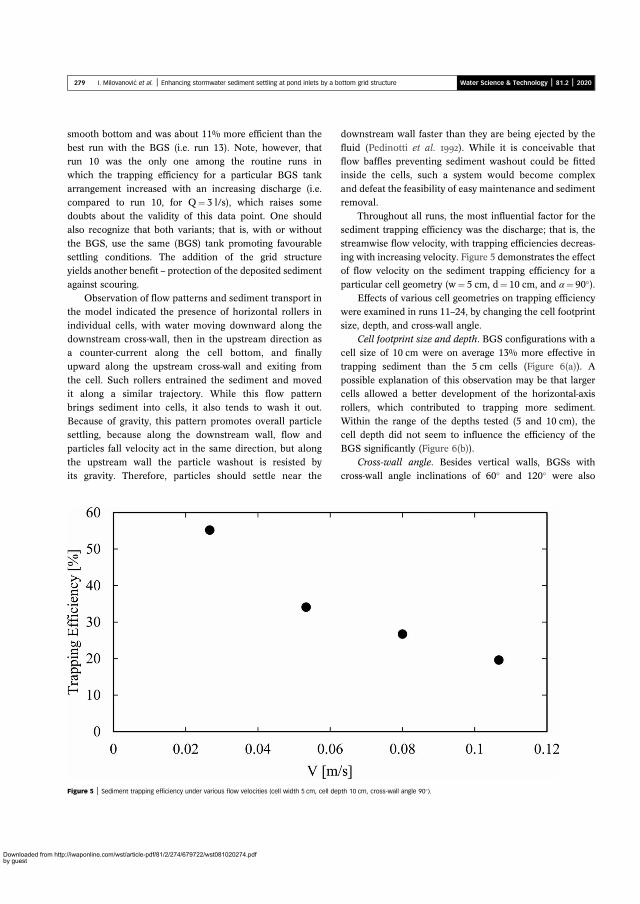
smo
bestrunwhi
arracomdoualso
thesettyiel
aga
the
inddowa cupw
theit abrin
Becsettpar
theits
l fas
et aentsu
asib
all rg ef
velog von
omeiouru
crossizw
nt
tionbettont
e of
Figur
27
Downloaded from http://iwapby guest
oth bottom and was about 11% more efficient than the
run with the BGS (i.e. run 13). Note, however, that10 was the only one among the routine runs in
ch the trapping efficiency for a particular BGS tank
ngement increased with an increasing discharge (i.e.pared to run 10, for Q¼ 3 l/s), which raises somebts about the validity of this data point. One shouldrecognize that both variants; that is, with or without
BGS, use the same (BGS) tank promoting favourableling conditions. The addition of the grid structureds another benefit – protection of the deposited sediment
inst scouring.Observation of flow patterns and sediment transport inmodel indicated the presence of horizontal rollers in
ividual cells, with water moving downward along thenstream cross-wall, then in the upstream direction asounter-current along the cell bottom, and finallyard along the upstream cross-wall and exiting from
cell. Such rollers entrained the sediment and movedlong a similar trajectory. While this flow patterngs sediment into cells, it also tends to wash it out.
ause of gravity, this pattern promotes overall particle
downstream wal
fluid (Pedinottiflow baffles previnside the cells,
and defeat the feremoval.
Throughoutsediment trappin
streamwise flowing with increasinof flow velocity
particular cell geEffects of var
were examined in
size, depth, andCell footprint
cell size of 10 cmtrapping sedime
possible explanacells allowed arollers, which c
Within the rang
9 I. Milovanovic et al. | Enhancing stormwater sediment settling at pond inlets by a bottom grid structure
ling, because along the downstream wall, flow andticles fall velocity act in the same direction, but along
upstream wall the particle washout is resisted bygravity. Therefore, particles should settle near the
cell depth did not sBGS significantly (F
Cross-wall anglecross-wall angle inc
e 5 | Sediment trapping efficiency under various flow velocities (cell width 5 cm, cell depth 10 cm, cross-wall angle 90�
online.com/wst/article-pdf/81/2/274/679722/wst081020274.pdf
ter than they are being ejected by the
l. ). While it is conceivable thating sediment washout could be fittedch a system would become complex
ility of easy maintenance and sediment
uns, the most influential factor for theficiency was the discharge; that is, the
city, with trapping efficiencies decreas-elocity. Figure 5 demonstrates the effectthe sediment trapping efficiency for a
try (w¼ 5 cm, d¼ 10 cm, and α¼ 90�).s cell geometries on trapping efficiencyns 11–24, by changing the cell footprint
s-wall angle.e and depth. BGS configurations with aere on average 13% more effective inthan the 5 cm cells (Figure 6(a)). A
of this observation may be that largerer development of the horizontal-axisributed to trapping more sediment.
the depths tested (5 and 10 cm), the
Water Science & Technology | 81.2 | 2020
eem to influence the efficiency of theigure 6(b)).
. Besides vertical walls, BGSs withlinations of 60� and 120� were also
).

teswicotho
bysetim
ofcothe
me
tieα¼ditag28
ted,erenexp
atab
ne we.archuntingdrau
ctuentsedrmw
ered
Fig nt trap
Fig
280 I. Milovanovic et al. | Enhancing stormwater sediment settling at pond inlets by a bottom grid structure Water Science & Technology | 81.2 | 2020
Downloaded from hby guest
ted, following up on the idea of settling enhancementth lamella plates. Cross-walls with both angles performedmparably and removed about 20% more sediment thanse with 90� walls (Figure 7). This result was explained
the increased wall surface on which the sediment couldtle. While this configuration might be beneficial forproving settling, its drawback would be the maintenance
the inclined walls, which would be more challengingmpared to cells with vertical walls, particularly wheresediment removal would be done by the suction of sedi-
nt from the BGS cells.In support of the discussion of experimental uncertain-
s (see Methods), a typical run with w¼ 5 cm, d¼ 10 cm,90�, and Q¼ 3 L/s was repeated five times. For the con-
ions addressed, the repeatability tests showed a very close
for the case tesamong the diffuncertainties intesting of repe
useful to examiremain the sam
Future resechallenges encosmall engineertransport in hy
engineering struThe experim
knowledge ofinserted into sto
lenges encount
ure 6 | (a) Sediment trapping efficiency for cell depths of 5 and 10 cm, and the cross-wall angle of 90� ; (b) sedime
(5 and 10 cm), and a cross-wall angle of 90� .
reement characterized by a mean trapping efficiency of% and a standard deviation of 0.5%. This suggests that,
including the attesediment settling in
quiescent conditiogained here was sbest summarized b
scale modelling ofstructures offers ‘lithe results reported
tive and best suitedas was the case in(Stovin & Saul ). Within the re
indicate that an in-trate the settlingsmall area, from wh
removed using convsuction trucks).
ure 7 | Sediment removal efficiency for different cross-wall angles, a cell depth of
10 cm, and a cell width of 5 cm.
ttp://iwaponline.com/wst/article-pdf/81/2/274/679722/wst081020274.pdf
the differences in trapping efficienciest experiments cannot be attributed toerimental techniques. However, furtherility for different conditions would be
hether the level of repeatability would
. This section explores two classes of
ered in studies of sediment removal bystructures: (a) modelling of sedimentlic scale models and (b) testing of small
res in the field.al study reported on here expanded theiment settling in engineered facilitiesater ponds, and demonstrated the chal-
in scale modelling of settling structures,mpts to attain model similitude forcomplex flow fields (i.e. as opposed to
ns in settling basins). The experienceimilar to the findings in the literature,y Gill & Pugh’s () statement that
sediment transport in small engineeringmited precision at best’. Consequently,herein should be understood as informa-
for comparisons of design alternatives,the earlier studies of a similar nature
; Dufresne et al. ; He & Marsalekalm of such limitations, the study results
pond sediment trap (BGS) can concen-of coarser particles to a relativelyich the sediments could be inexpensively
entional municipal equipment (vacuum
ping efficiency for no BGS, a cell width of 5 cm, two depths
faciandcien
infldistHethe
plastheThe
viduparthan
Thelarlflocfind
sedsedusin
torynotthan
conroficos
CO
A ssedduc
of sobjerese
BGdepstud
intowalcerncom
thewasin t
of tpha
opt
t sh
EM
fund
ct nedish Innovation Agency – Vinnova,önN
genormupp
Neand
errBle
wediron.
28
Downloaded from http://iwapby guest
In field installations, stormwater would enter the BGS
lity in the form of hydrographs with varying dischargessediment concentrations. Consequently, trapping effi-cies would vary with the varying Q, and the sediment
ux and characteristics, including the particle sizeributions and densities. Such conditions were tested byet al. () in a simplified field experiment, in whichgrid structure was mimicked by batteries of open-top
tic containers (22 × 22 × 11 cm, L ×W ×H) attached topond bottom at 10 m downstream from the pond inlet.results showed that these containers representing indi-
al cells retained 4–11 times more sediment mass (withticle diameters D< 250 μm and D< 32 μm, respectively)the bare pond bottom over a period of three months.
capture of very fine particles (D< 32 μm) was particu-y surprising and could result from the settling ofculated particles after the cessation of runoff. Theseings also point out the importance of field testing of
iment trapping devices. The effect of particle sizes oniment trapping was not addressed in our experimentsg a model sediment with a single particle size. In labora-
experiments performed by He & Marsalek (), it wased that the BGS trapped higher rates of larger particles
structure and the
the BGS concep
ACKNOWLEDG
This study was
FORMAS, projeand by the SwUDI project Gr
Governmental A– Centre for St04390), whose s
also thank Filiphydraulic model
REFERENCES
Al-Rubaei, A. M., MMarsalek, J. &status of 25 Sponds. J. Envi
1 I. Milovanovic et al. | Enhancing stormwater sediment settling at pond inlets by a bottom grid structure
smaller ones, especially for higher flow rates. Finally,
sideration of using the BGS sediment trap in new or ret-
1061/(ASCE)EE.1Bentzen, T. R. 3D
of hids. W.363zierids o849als,
dept R, C.l hycouv/tsc6.pd, J. a b. dochfove ser A76-znderratioter p3),
watestry
tted ponds would require a site-specific assessment oft and benefits.
NCLUSIONS
cale-model study of the Bottom Grid Structure (BGS)iment trap at the inlet of a stormwater impoundment pro-ed information on the feasibility of such a pre-treatment
tormwater entering the impoundment, with the ultimatective of reducing maintenance costs. At this phase ofarch, the following conclusions can be drawn: (a) the
S would effectively confine coarser sediment (bedload)osits to a small area in the pond; (b) as tested in thisy, the BGS effectiveness was improved by placing it
an inlet stilling basin comprising a diffuser with wingls, an apron and a water level control sill; and (c) con-ing the settling cell geometry, larger cells (10 cm,pared to 5 cm cells) appeared more effective, increasing
efficiency by 13%; no strong influence of the cell depthnoted, and while inclined cross-walls improved settling
he model, their use might be counterproductive because
he costlier maintenance requirements. The next researchse should focus on the need for the stilling basin
resuspensiondetention pon2166/wst.2010
Bilotta, G. S. & Brasuspended solRes. 42 (12), 2
Dufresne, M., DewPirotton, M. and sedimentInt. J. Sedimen
Gill, T. W. & Pughscaled physicaCongress, Vanwww.usbr.govPAP/PAP-099
He, C. & Marsaleksediment with140 (1), 21–29
He, C., Post, Y., Roof an innovatistructure, Wats11270-014-19
Karlsson, K., Viklametal concentfrom stormwaMater. 178 (1–129.
MOEE StormManual. Mini
online.com/wst/article-pdf/81/2/274/679722/wst081020274.pdf
imal geometry of BGS cells. Ultimately,
ould be tested in the field.
ENTS
ed by the Swedish Research Council
umbers 2016-20075 and 2016-01447
Water Science & Technology | 81.2 | 2020
ano, and the VINNOVA (Swedish
cy for Innovation Systems) DRIZZLEwater Management (Grant no. 2017-ort is greatly appreciated. The authors
dorost for assisting in setting up therunning some of the model runs.
iman, L. S., Hunt III, W. F., Viklander, M.,cken, G.-T. Survey of the operationalsh municipal stormwater managementEng. (ASCE) 143 (6), 499–505. doi:10.943-7870.0001203.modelling of transport, deposition andghway deposited sediments in wetater Sci. Technol. 62 (3), 736–742. doi:10.., R. E. Understanding the influence ofn water quality and aquatic biota. Water–2861. doi:10.1016/j.watres.2008.03.018.B. J., Erpicum, S., Archambeau, P. &Experimental investigation of flow patternosition in rectangular shallow reservoirs.es. 25 (3), 258–230.A. Sediment transport similitude fordraulic modelling. In: Proc. 33rd IAHRer, BC, pp. 1–8. Available from: https:///techreferences/hydraulics_lab/pubs/f (accessed 24 May 2019). Enhancing sedimentation and trappingottom grid structure. J. Environ. Eng.i:10.1061/(ASCE)EE.1943-7870.0000774.rt, Q. & Marsalek, J. Field studyediment capture device: bottom gridir Soil Pollut. 225 (6), 1976. doi:10.1007/., M., Scholes, L. & Revitt, M. Heavyns and toxicity in water and sedimentonds and sedimentation tanks. J. Hazard.612–618. doi:10.1016/j.jhazmat.2010.01.
r Management Planning and Designof the Environment (MOE), Toronto, ON.

Pe
Pe
Ris
Sim
ul, A.Water
esults oFinal
2
Downloaded from hby guest
dinotti, S., Mariotti, G. & Banerjee, S. Direct numericalsimulation of particle behavior in the wall region of turbulentflow in horizontal channels. Int. J. Multiphase Flow 18 (6),927–941. doi:10.1016/0301-9322(92)90068-R.
Stovin, V. & Sastructures.
USEPA RVolune I –
82 I. Milovanovic et al. | Enhancing stormwater sediment settling at pond inlets by a bottom grid structure
hon, R. Investigation of the Sediment Removal Frequencyfor Wet-Detention Stormwater Management Pond.M.A.Sc. Thesis, Ryerson University, Toronto, Canada.pson, T., Wang, J. & Vasconcelos, J. G. Cellularconfinement systems to prevent resuspension in sedimentbasins. J. Environ. Eng. 144 (5). doi:10.1061/(ASCE)EE.1943-7870.0001363.
syndrome: curreJ. North Am. Bedoi:10.1899/04-0
Yousef, Y. A., HvitvedSediment accumTotal Environ. 149697(94)90268-2
First received 19 September 2019; accepted in revised form 24 February 2020.
ttp://iwaponline.com/wst/article-pdf/81/2/274/679722/wst081020274.pdf
Sedimentation in storage tankSci. Technol. 29 (1–2), 363–372.f the Nationwide Urban Runoff Program.Report. Rept. WH-554, U.S. EPA, Water
Water Science & Technology | 81.2 | 2020
ttersson, T. J. R. Stormwater Ponds for PollutionReduction. PhD Thesis, Department of Sanitary Engineering,Chalmers University of Technology, Goteborg, Sweden.
Planning Division, Washington, DC.Walsh, C. J., Roy, A., Feminella, J., Cottingham, P., Groffman,
P. & Raymond, M. The urban stream
nt knowledge and the search for a cure.nthol. Soc. 24 (3), 706–723.28.1.-Jacobsen, T., Sloat, J. & Lindeman, W. ulation in detention or retention ponds. Sci.6–147, 451–456. doi:10.1016/0048-.Available online 5 March 2020


LICENTIATE T H E S I S
ISSN 1402-1757ISBN 978-91-7790-828-9 (print)ISBN 978-91-7790-829-6 (pdf)
Luleå University of Technology 2021
Ivan Milovanović C
omponents for area-efficient storm
water treatm
ent systems
Department of Civil, Environmental and Natural Resources EngineeringDivision of Architecture and Water
Components for area-efficient stormwater treatment systems
Ivan Milovanović
Urban Water Engineering
Tryck: Lenanders Grafiska, 136718
136718 LTU_Milovanovic.indd Alla sidor136718 LTU_Milovanovic.indd Alla sidor 2021-05-17 10:312021-05-17 10:31