stormwater management design guide - city of onkaparinga
TRANSCRIPT

November 2019
Stormwater Management Design Guide
ECM Set 4059308
Contents
1.0 Introduction ..................................................................................................................... 1
1.1 Design Guide Scope .............................................................................. 1
1.2 Objectives........................................................................................... 2
1.3 Design Standards .................................................................................. 2
1.4 Design Rainfall ...................................................................................... 3 2.0 Small Scale Developments (single dwellings, minor infill land divisions) ................ 4
2.1 Engineering Survey Site Plan ............................................................... 4
2.2 Stormwater Management Site Plan ..................................................... 5
2.3 General Design Requirements .......................................................... 6
2.4 On Site Detention (OSD) Requirements .............................................. 7
2.5 Minor Additions to Residential Dwellings or Industrial Buildings (increase to impervious area of less than 50m2) ....................................... 10
2.6 Options for properties that do not fall to the street ......................... 11
2.7 Alternate Detention Storage Options ................................................ 11
2.8 Stormwater Design Report ................................................................ 12
2.9 Minimum Finished Floor levels........................................................... 12
2.9.1 Driveways, Paving and Path Drainage .......................................... 12
2.10 Stormwater Outlets and Scour Protection ..................................... 12 3.0 Large Scale Development (> 4 lot Land Divisions, >1500 m2 Sites, Includes
New Public Road, if Applicable) .................................................................................. 14
3.1 Design Standards ................................................................................ 14
3.2 Design Parameters ............................................................................. 16
3.3 Engineering Survey Site Plan ............................................................. 16
3.4 The Stormwater Management Site Plan............................................ 17
3.5 Stormwater Management Report ...................................................... 17
3.6 Stormwater Design Requirements .................................................... 19
3.7 Provision of Drainage for Future Upstream Development of Adjacent Properties ..................................................................................... 21
3.8 Inter Allotment Drainage ................................................................... 22
3.9 Open Channels and Watercourses ..................................................... 23
3.10 Culverts/Road Crossings ................................................................. 24
3.11 Detention System ............................................................................ 24
3.11.1 Detention Basin above Ground .................................................... 24
3.11.2 Spillways and Outlet Weirs ......................................................... 25
3.11.3 Inlets and Outlets ........................................................................ 26
3.11.4 Use of Underground Detention System ...................................... 26

3.12 Design Requirements for a Service Station/Car Wash ................. 27 4.0 Stormwater Quality Management ................................................................................ 28
4.1 Carpark Stormwater Quality Treatment Requirements ................... 29
4.2 Stormwater Quality Treatment Devices and MUSIC Modelling ....... 30
4.3 Rainwater Tanks ................................................................................. 32
4.4 Gross Pollutant Traps ......................................................................... 32
4.5 Sedimentation Basins ......................................................................... 33
4.6 Constructed Wetlands ........................................................................ 34
4.7 Vegetated Swales ............................................................................... 35
4.8 Permeable Pavement .......................................................................... 35
4.9 Infiltration System ............................................................................. 36
4.10 Detention Basins .............................................................................. 36
4.11 Bio-filtration Systems (Bioretention, Infiltration and Raingardens) ................................................................................................ 36
4.12 Stormwater Quality Management Fee............................................ 37

1
1.0 Introduction This guideline is intended to assist with the implementation of the Planning Scheme by providing guidance for the management of stormwater runoff as a resource.
This guideline compliments other information available that support integrated water management planning through the provision of specific guidance for flood and disaster management, waterway health objectives and acceptable outcomes for development.
The City of Onkaparinga (Council) Stormwater Management Design Guideline is intended to apply a standard approach to the interpretation and implementation of the relevant aspects of the Planning Scheme. They offer a degree of certainty to applicants, Council and the community. Where an applicant is proposing a solution that is different from the guidelines the onus is on the applicant to demonstrate the facts and circumstances to support the solution.
Council is committed to the successful implementation of integrated water management within the local government area. Fundamental to such a strategy is achieving satisfactory management of stormwater runoff from both a quality and quantity perspective. The main principles of stormwater management are as follows:
To provide for the safety and welfare of the general and affected community, including protection from flooding, and the safe enjoyment of open space and other land adjacent to stormwater drainage infrastructure.
To provide for free and unrestricted access and safety of staff and contractors required to construct and maintain all components of the network.
To achieve stormwater quality improvement targets as set by State and Council policy.
To contribute wherever possible to the enjoyment of open space.
To integrate stormwater drainage quantity and quality management as part of a total streetscape/open space approach to maximise opportunities for multiple objectives (including safety, amenity, passive and/or active recreation, biodiversity, water quality and flood protection) to be achieved.
To implement Water Sensitive Urban Design as a tool to manage flood protection, water quality and stormwater harvesting and reuse schemes.
1.1 Design Guide Scope
This guide provides detailed guidance on the design requirements, form and level of documentation required to facilitate approval for stormwater drainage for development within the City of Onkaparinga. It should be read in conjunction with Council’s Development Plan and Conditions issued by Council in relation to the development application. The Development Plan includes area wide objectives regarding the management and protection of the environment, including specific objectives regarding water quality.
To satisfy Council’s policy and the objectives of the development plan, Council has adopted stormwater management service standards which encompass flood protection objectives and water quality/environment protection objectives. Accordingly, Council’s stormwater management design guidelines for development reflect requirements to achieve both flood protection and water quality protection/improvement.
Separate design guidelines have been prepared for different scales of development, as follows:
Small scale – Single residential dwellings and infill residential land divisions, to a maximum of 4 dwellings, a maximum of 1500m2 total site area and where no new public roads are to be created (refer Section 2).

2
Large scale - All other residential, industrial and commercial developments (refer Section 3).
1.2 Objectives
Stormwater systems shall be designed to achieve the following:
• Prevent inundation of development and to ensure that surface flow paths convey floodwaters within suitable velocity/depth limits.
• Inconvenience to traffic and pedestrians as a result of storm events is minimised by controlled flow where possible.
• Consider all ultimate upstream and downstream catchment characteristics to achieve a total system which does not adversely affect existing stormwater systems or properties within the catchment.
• Stormwater quality targets are achieved by a combination of integrated stormwater treatment and filtration principles.
• The impacts of erosion and sediment on the environment are minimised.
• Minimise maintenance requirements.
• Enhance the urban landscape and biodiversity of the area.
• Demonstrate the adoption and integration of principles of Water Sensitive Urban Design including wherever possible, water conservation and passive or active re-use.
• Preserve natural drainage systems, including the associated environmental flows.
Access and ownership:
Components of the stormwater network that provide for network wide benefits for stormwater management shall be vested with the City of Onkaparinga.
Therefore:
The drainage network is to be designed with the intention that wherever possible, all network drainage infrastructure (other than inter of allotment drainage) is to be located in public road, or within open space reserves where applicable and multiple objectives as per Section 1.2 are able to be met.
Drainage components that only service two or less Torrens title allotments or any strata or community plan developments are to remain as private infrastructure in appropriately established private easements.
Allotment drainage systems servicing more than Two Torrens title allotments are to be located in easements complying with Section 3.8.
All access points into underground network drains (junction boxes) are to be located within the public road boundary or in open space.
1.3 Design Standards
The stormwater drainage system must be designed in accordance with:
Council’s Stormwater Management Design Guide.
AS/NZS 3500.3:2003-Plumbing and Drainage- Part3: Stormwater Drainage.
Building Code of Australia.
Other relevant design guides which may provide further supporting design guidance, that are recognized by Council include:

3
Australian Rainfall and Runoff (ARR 2016) (www.arr.ga.gov.au).
Australian Runoff Quality (ARQ).
Water Sensitive Urban Design – Greater Adelaide Region Technical Manual – (DPLG, 2010).
Queensland Urban Drainage Manual (2013).
Department of Planning, Transport and Infrastructure (DPTI) Stormwater Design DD 300.
Framework for the Integration of Flood and Stormwater Management into Open Space Version 1.1, August 2011, published by Healthy Waterways Limited.
1.4 Design Rainfall
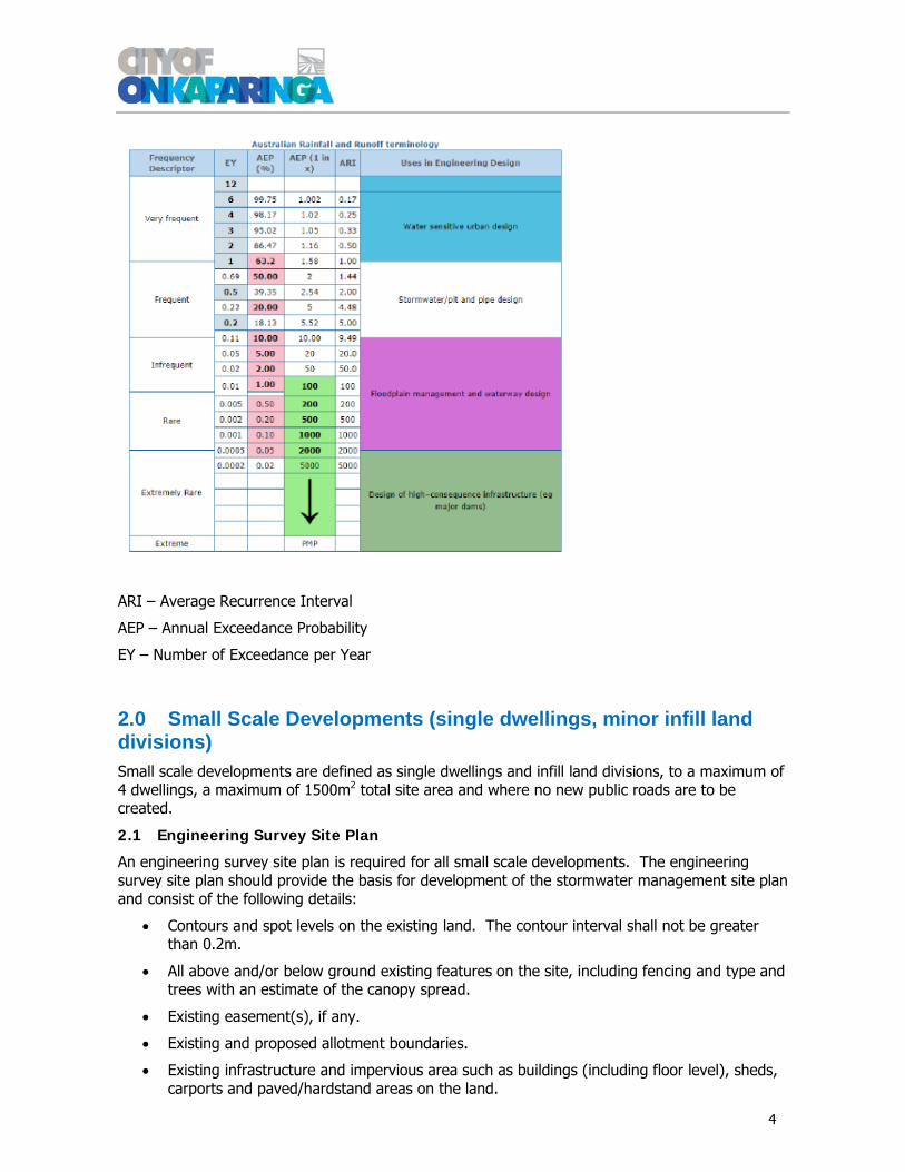
Design Intensity-Frequency-Duration (IFD) Rainfall depths and temporal patterns shall be derived in accordance with Bureau of Metrology (BOM) and Australian Rainfall & Runoff (ARR 2016) for the Onkaparinga Council area. Reference is made to the Australian Rainfall and Runoff Data Hub (http://data.arr-software.org/) to obtain hydrological modelling data including IFD depths and temporal patterns. A PDF copy of the ARR Data hub input data and results shall be provided with the calculations.
ARR 2016 breaks much new ground, containing new theory and new terminology such as ‘quantiles’, ‘ensembles’ and Monte Carlo Analysis. Many parts require theoretical knowledge to fully understand, and are directed to experienced engineers.
ARR 2016 is supplemented by many other manuals, such as the Queensland Urban Drainage Manual (1992, 2007-08, 2013), Austroads Road Design Guides (2013), state highway authority department manuals, and development control manuals from municipal councils. In matters relating to water quality and conservation, ARR 2016 is complemented by Australian Runoff Quality, released by Engineers Australia in 2005.
The major system shall provide safe overland flow conveyance, whilst the minor system shall be designed to minimize the impact of nuisance inundation and unsafe flow depths and velocities during frequent events. The service standard for the network varies according to the level and type of development, as follows:
Where the minor system is being relied upon to cater for major storm events (in addition to minor flows) – 1% Annual Exceedance Probability (AEP).
As defined in Table 1 (Section 3.1).
Note that this document refer to AEP, which is defined as the probability that a given rainfall total accumulated over a given duration will be exceeded in any one year, which is in line with current industry practice. The conversion from Average Recurrence Interval (ARI) to AEP to the number of Exceedances per Year (EY) is shown below.
4
ARI – Average Recurrence Interval
AEP – Annual Exceedance Probability
EY – Number of Exceedance per Year
2.0 Small Scale Developments (single dwellings, minor infill land divisions) Small scale developments are defined as single dwellings and infill land divisions, to a maximum of 4 dwellings, a maximum of 1500m2 total site area and where no new public roads are to be created.
2.1 Engineering Survey Site Plan
An engineering survey site plan is required for all small scale developments. The engineering survey site plan should provide the basis for development of the stormwater management site plan and consist of the following details:
Contours and spot levels on the existing land. The contour interval shall not be greater than 0.2m.
All above and/or below ground existing features on the site, including fencing and type and trees with an estimate of the canopy spread.
Existing easement(s), if any.
Existing and proposed allotment boundaries.
Existing infrastructure and impervious area such as buildings (including floor level), sheds, carports and paved/hardstand areas on the land.

5
Adjacent road, footpath, stormwater pits and connecting pipes, downpipe connections, trees, verge and associated services.
2.2 Stormwater Management Site Plan
The stormwater management site plan (drawing) shall be based on the engineering survey site plan as defined in Section 2.1 and shall include sufficient detail to assess the suitability/capability of the proposed stormwater management arrangements for compliance with Council’s service standards.
The stormwater management site plan (drawing) shall primarily show the proposed method of managing stormwater. The drawing, is to include:
All above and/or below ground proposed features on the site including any existing or proposed easements and drainage reserves.
Grading(contours) or spot levels for proposed finished surface levels, and expected drainage patterns (direction of flow). The contour interval shall not be greater than 0.2m.
All pervious and impervious areas (buildings and covered/paved areas, paths and driveways with materials used, and any landscaping including plants, and mulched areas shown schematically).
Proposed building finished floor level(s).
Proposed earthworks (cut/fill line) and retaining walls on the site in association with the development. The top and bottom levels of the retaining wall are to be shown on the plan.
The proposed depth of any fill or cut over stormwater drainage easements. (Note Council will not permit cut in excess of 200mm, or fill in excess of 500mm over any existing drainage easement).
All existing Council owned and other public service infrastructure (trees, footpaths, stobie/light poles, stormwater side entry pits).
All proposed stormwater management devices (downpipes, sumps, underground pipes, spoon drains, grated trench drains, culverts, detention, retention and/or other devices) including:
Location and size of proposed above ground retention tanks and stormwater detention tanks.
Inlet and outlet pipe sizes and orifice arrangement (if required), including level and size for all detention and stormwater drainage works.
Above and/or below ground stormwater discharge points into Council’s existing drainage infrastructure.
Any easements required (whether for Council or private).
Sufficient levels to demonstrate that the proposed system will drain to the designated point of discharge.
Pump specification with flow rate if any sump & pump is used to manage surface runoff.
Note:
No private drainage (or other) infrastructure is to be installed or constructed in or over a Council easement, except where it provides a direct connection to Council’s stormwater infrastructure.

6
2.3 General Design Requirements
General design requirements for all small scale developments include:
Stormwater detention systems and/or Water Sensitive Urban Design (WSUD) techniques shall be integrated within the development for flood control as per the objectives in Section 1.2.
Refer to Section 2.4 for on-site detention requirements.
Roof and surface stormwater runoff from the site must be managed within the site, without increasing flood risk to buildings on the site and adjoining properties.
Overland flow paths are to be provided within the site or sufficient pit and pipe capacity is provided to safely convey stormwater runoff from a 1% AEP storm event, to the agreed point of discharge.
No overflow onto adjoining properties will be permitted, up to a 1% AEP storm event, unless there is a designated point of discharge to an existing easement, or drainage reserve or public road with attributes suitable to accept the flow.
Any stormwater runoff discharging to an existing easement must not exceed the flow capacity of stormwater infrastructure within the easement (underground pipe or culvert plus any swale within the easement).
Flows at discharge points shall be managed to ensure protection from scouring of natural/earth channels.
All individual property stormwater drainage systems should be discharged direct to the Street front or inter allotment drainage system where available.
Where the subject land is within 50m of the centerline of a watercourse, or as specifically requested by Council, in the absence of any available information from Council, floodplain mapping of nearby watercourses is to be undertaken to establish 1% AEP flood levels at the development site, to demonstrate that the development complies with Council’s requirements for the development to be flood free and safe.
Where overland flow is required to be conveyed by a swale, within an easement, a Land Management Agreement (LMA) is to be placed on all properties limiting the use of the affected land and requiring unobstructed openings of sufficient capacity in all fences across the easement/swale.
The following methods can be adopted for stormwater flow calculations:
• Rational Method (Methodology to be as outlined in Australian Rainfall and Runoff 2016).
• DRAINS model software.
The following methodologies may be used for flood modeling:
• HEC RAS – centerline and cross sections along watercourse – 2D model.
• 2D industry standard flood models e.g. TUFLOW, Mike and digital terrain model of resolution /accuracy to ±100mm.
A surface level profile, flood extent plot and flood modeling data files are to be provided with the submission.

7
2.4 On Site Detention (OSD) Requirements
Discharge of stormwater from the site, to Council's drainage system, must be effectively located and managed to minimise the risk of frequent excessive flow width and velocity in roadways, erosion of watercourses and flooding of properties.
On-site detention systems provide temporary storage of stormwater runoff from developments and restrict discharge from the site to a rate which Council's existing drainage system is more capable of accommodating.
Unless integrated into the overall design calculations for managing discharge off site, as part of a stormwater management plan for a land division, or otherwise prescribed in a development approval and included in a Land Management Agreement (LMA), on-site detention is not required for individual single dwellings in an approved greenfield land division.
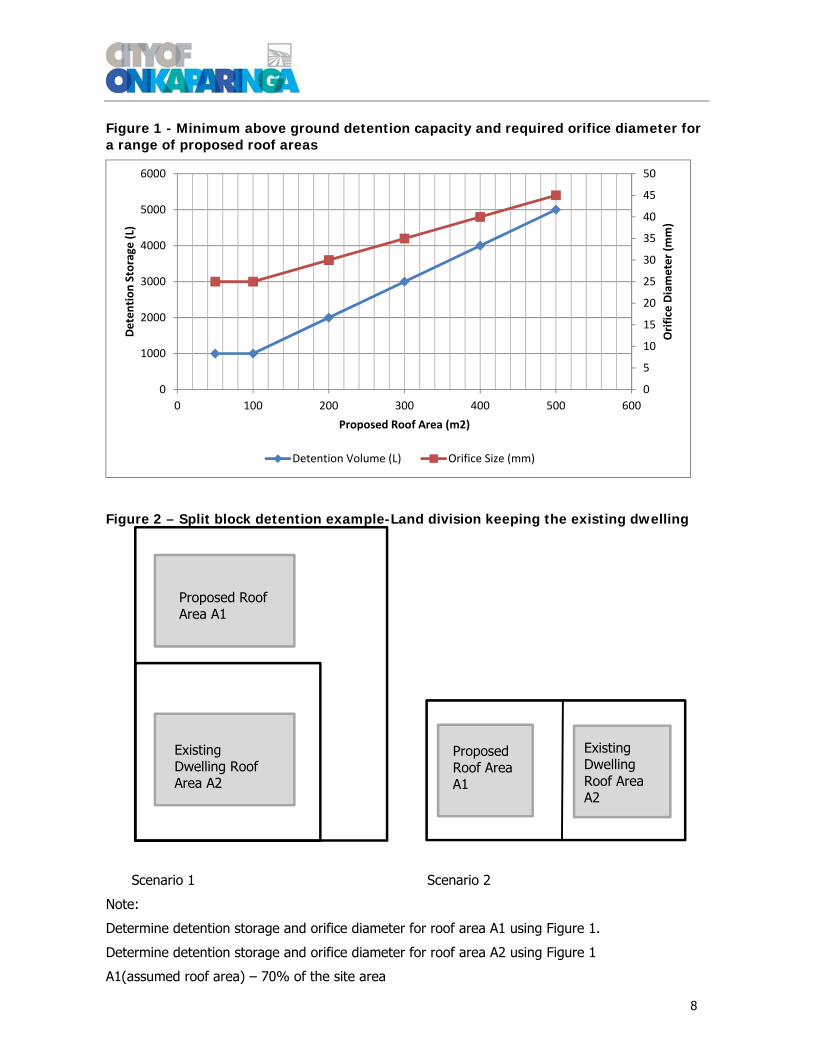
If above ground tanks are used for detaining stormwater runoff from roofed areas then the on-site detention volume shall be calculated from Figure 1, based on the increase in impervious roof area. This method is only applicable for “Small Scale” developments as defined for the purposes of this Guide.
Where such development will result in a greater increase in the proposed roof area greater than 500m2, to that shown in Figure 1, the detention system must be designed by a suitably qualified professional engineer. In this case pre and post development calculations are to be provided to demonstrate that the post-development flow rate does not exceed the equivalent pre-development flow rate, for the minor system design event, as defined in Table 1. In addition, 1% AEP storm flow path is required to be demonstrated.
Where the development is comprised of multiple allotments, the required detention volume for each lot is to be calculated based on the proposed roof area on each lot.
Detention storage shall be retrofitted to an existing dwelling, where such a dwelling is proposed to be retained as part of division of the property. Refer to Figure 2 for a split block example.
A minimum roof area of 90% must be connected to the on-site detention tank.
Outflows from detention tank systems are generally to be by gravity with 'free outlet’ control. However, 'drowned outlets' may be permitted if supporting calculations can be provided showing that sufficient pressure head can be generated to direct 1% AEP flows to the street via a sealed system.
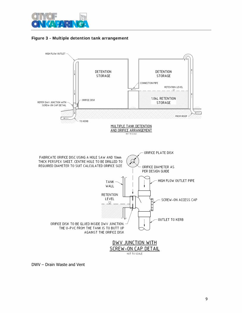
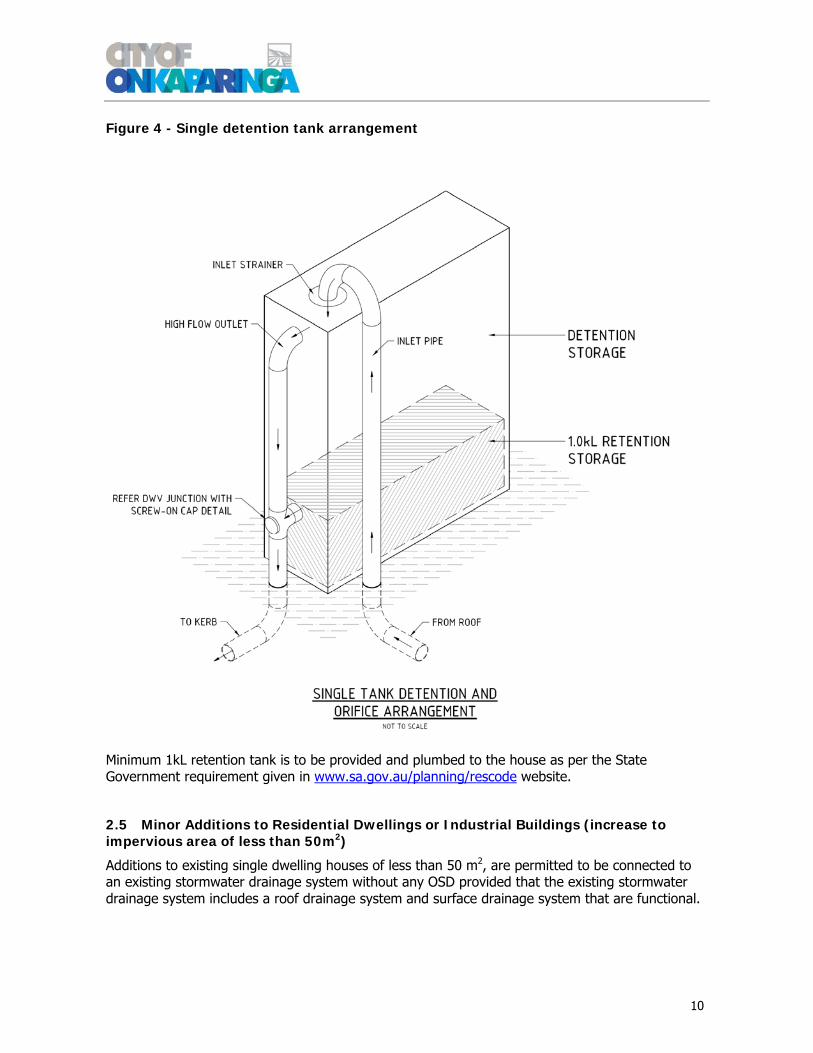
The design of the tank is to conform to one of the general arrangements shown in Figures 3 and 4. Orifice systems for on-site detention (OSD) tanks shall be located in a readily accessible area to facilitate regular inspection and maintenance, and the orifice plate should be clearly and permanently marked on the outside with “Do not remove except for maintenance” and “Re-install immediately after cleaning/maintenance”.
8
Proposed Roof Area A1
Existing Dwelling Roof Area A2
Figure 1 - Minimum above ground detention capacity and required orifice diameter for a range of proposed roof areas
Figure 2 – Split block detention example-Land division keeping the existing dwelling
Scenario 1 Scenario 2
Note:
Determine detention storage and orifice diameter for roof area A1 using Figure 1.
Determine detention storage and orifice diameter for roof area A2 using Figure 1
A1(assumed roof area) – 70% of the site area
0
5
10
15
20
25
30
35
40
45
50
0
1000
2000
3000
4000
5000
6000
0 100 200 300 400 500 600
Orifice Diameter (m
m)
Detention Storage
(L)
Proposed Roof Area (m2)
Detention Volume (L) Orifice Size (mm)
Existing Dwelling Roof Area A2
Proposed Roof Area A1
9
Figure 3 - Multiple detention tank arrangement
DWV – Drain Waste and Vent
10
Figure 4 - Single detention tank arrangement
Minimum 1kL retention tank is to be provided and plumbed to the house as per the State Government requirement given in www.sa.gov.au/planning/rescode website.
2.5 Minor Additions to Residential Dwellings or Industrial Buildings (increase to impervious area of less than 50m2)
Additions to existing single dwelling houses of less than 50 m2, are permitted to be connected to an existing stormwater drainage system without any OSD provided that the existing stormwater drainage system includes a roof drainage system and surface drainage system that are functional.

11
2.6 Options for properties that do not fall to the street
The following options are to be considered to manage stormwater runoff from a site that does not naturally fall to the street.
1. Connect to an inter allotment drain, should one be available.
2. Establish a private drainage easement through adjoining properties (subject to adjoining property owner approval and Council approval).
3. Roof water discharge to the street by a ‘sealed system’ and surface run-off to be collected and managed (for all events up to and including the 1% AEP event) via either:
a. Pumping from a collection pit (maximum discharge to the street should not exceed pre development flow rate for the total site with battery operated warning alarm system). The pump specification and flow rate are to be submitted to Council. Minimum storage of 2,000 Liters (L) is required for pumping chamber, in addition to detention volume storage.
or
b. One or more soakage pits with overflow pipe, should geotechnical testing of site soils support this practice (and not impact adversely on adjacent properties or proposed development of the site). The design should comply with On-site Retention of Stormwater-Minister's Specification SA 78AA. The overflow pipe must discharge into a sump and pump or spreader without inundating surrounding properties.
4. If options 3-a and 3-b are not possible and there is no safe overland flow path acceptable to Council for events up to and including the 1% AEP storm event, roof water and surface runoff should be collected in an adequate storage tank to cater for the 1% AEP critical storm duration event such that site runoff can be managed without flooding of buildings, undercrofts or adjoining properties. A pump with battery operated warning alarm system is to be provided and maximum discharge flow rate to the street should not exceed the predevelopment flow for the total site. The pump system shall be in accordance with Australian Standard AS/NZS3500.3. Note that the combined effective storage must equal at least the volume of run off expected from a storm of 10% AEP, lasting for 120 min.
Note: For all of the above options, calculations must be provided to demonstrate compliance with pre and post development discharge control scenarios for the 1% AEP critical storm duration, and system capacity is sufficient to prevent downstream discharge into private property in all events up to the 1% AEP. During demolition and earthworks stormwater is to be managed to prevent flooding adjacent properties. A Soil Erosion Drainage Management Plan (SEDMP) is required prior to undertaking any earthworks on site.
2.7 Alternate Detention Storage Options
If above ground rainwater detention tanks are not used for detaining stormwater runoff from roofed areas and alternative detention measures such as a vegetated basin or swale with an outlet to Council’s stormwater system (including discharge to the kerb) are to be utilised, then the detention requirements are:
A minimum roofed area of 90% must be connected to the detention system.
The 5% AEP peak flow from the detention system is not to exceed 0.01 L/s/m2 of roofed area. Provisions must be made for flows from a 1% AEP storm event to spill over the property boundary to the receiving roadway or easement/drainage reserve.
12
A pit or headwall with an orifice plate will be required to control the discharge of stormwater from the detention system to the kerb. The orifice is to be readily accessible to facilitate unblocking if required.
2.8 Stormwater Design Report
A brief report will be required to accompany the calculations for any detention system to justify the detention volume. Additional information including any further plans and detailed drawings, in addition to the information stated in Section 2.2, is required in the accompanying brief report containing all the information supporting the proposed stormwater design. Such information would include all relevant calculations supporting all aspects of the stormwater design and specific details for construction where they differ from the standard detention tank requirements.
2.9 Minimum Finished Floor levels
Mainstream flooding is defined as water that flows over the banks of creeks and rivers. Properties affected by mainstream flooding for the 1% AEP flood event require minimum floor height. Freeboard describes a factor of safety expressed in millimeters above a flood level for flood protective or control works. Adding a freeboard to a flood level can greatly reduce the risk of a structure flooding.
In mainstream flooding, the minimum floor level is calculated by adding a 300 mm freeboard to the highest 1% AEP mainstream flood level for a particular property.
Where properties are adjacent to major trunk drainage channels and overland flow paths, the finished floor levels of new building developments should be a minimum of 300mm above the 1% AEP flood level adjacent to the development.
In the absence of any local flood level information all new building developments finished floor levels should be a minimum of 300mm above the top of kerb of the street fronting the development. In general, paved areas and driveways should grade away from the buildings and out to the street to provide an overland flow path for the major system (1% AEP). Where this cannot be achieved because the allotment grades to the rear, the floor levels should be set a minimum 150mm above the natural ground level at the face of the building at the highest point on the allotment.
2.9.1 Driveways, Paving and Path Drainage
Paved areas, driveways, etc. should be graded to direct stormwater runoff for the major storm flows away from the buildings and to provide an overland stormwater flow path towards the roadway, or drainage easement, or where this is not available, to a single collection point. Details of the collection system, including temporary storage, pump systems, soakage systems or other are to be shown on the stormwater management plan.
2.10 Stormwater Outlets and Scour Protection
Pipe drainage outfalls to new open channels and natural creeks must be designed to control the discharge velocity and spread the concentrated discharge to avoid erosion to the bed and banks. Wherever practical, vegetated swales or drainage channels must be provided downstream from the pipe outlet.
Provide scour protection to the main creek/waterway or flow path if the pipe or box culvert flow velocity is greater than 0.5 m/s.

13
All outlets are to be set back a distance of more than three times the bank height measured from the toe of a watercourse bank and angled into the direction of main channel flow. All stormwater outlets are to be located above the invert level of any adjacent waterway. The proposed location and the invert level should be determined by the developer/engineer, and justification provided to Council for approval.
Private drainage infrastructure is NOT to be installed on Council land, without prior Council approval. Any requirements for scour control should be managed within the private property boundary so that flows exiting the property comply with Council requirements for scour control. Note: no private infrastructure is to be installed within or over the Council drainage easement. . A permit is required for any alteration to levels on a Council drainage easement (including fill and cut), or for the installation or encroachment of any permanent structure. Please refer to Council’s website “Encroachment Over Council Easements” for further information.
All stormwater outlet connections to street kerbs must comply with Council’s standard drawings SD-213, 214 and 215. Inter and front of allotment drainage connections are to comply with Council’s standard drawing SD-220 to SD-223.

14
3.0 Large Scale Development (> 4 lot Land Divisions, >1500 m2 Sites, Includes New Public Road, if Applicable) Large scale developments are defined as residential developments having greater than 4 lots, greater than 1,500 m2 in area and include new public roads (if applicable), and all industrial and commercial developments.
3.1 Design Standards
Minimum design Annual Exceedance Probability (AEP) and Average Recurrence Intervals (ARI) for the major/minor systems are shown in Table 1. The ARI are shown in ( ).
Table 1 - Design Annual Exceedance Probability and Average Recurrence Intervals
*Road hierarchy based on Council’s road network plan
All calculations must be carried out by a competent qualified professional engineer experienced in hydrologic and hydraulic design, utilising drainage models and calculations that are accepted as current industry standards. For the drainage in Department of Planning, Transport and Infrastructure (DPTI) roads, reference shall be made to the DPTI Stormwater Design DD300 for drainage standards.
A DRAINS model is required for all large scale land divisions and industrial/commercial development.
A MUSIC model is required for water quality improvement to meet Council’s water quality targets is given section 4.0
Surface flow criteria for the major/minor systems are shown in Table 2.
Major and Minor System Design AEP
Land Use and Road Hierarchy Major System Minor System
Industrial/Commercial 1% (100) 10% (10)
Urban Residential
‐ Local Road*
‐ Distributor/Collector*
1% (100)
1% (100)
20% (5)
10% (10)
Rural Residential
- Local Road*
1% (100)
20% (5)
15
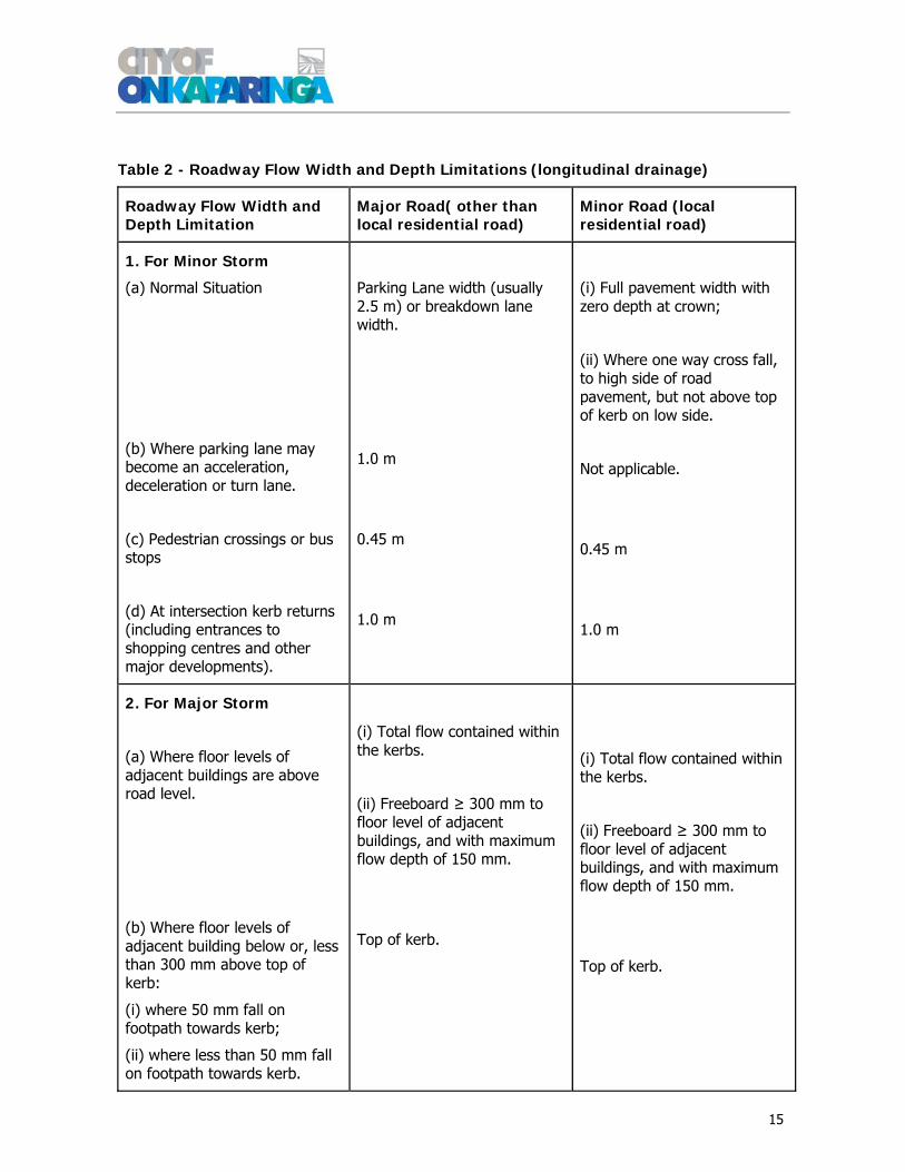
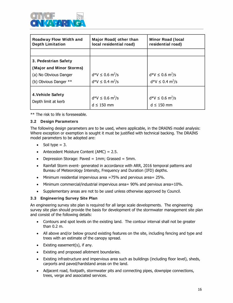
Table 2 - Roadway Flow Width and Depth Limitations (longitudinal drainage)
Roadway Flow Width and Depth Limitation
Major Road( other than local residential road)
Minor Road (local residential road)
1. For Minor Storm
(a) Normal Situation
(b) Where parking lane may become an acceleration, deceleration or turn lane.
(c) Pedestrian crossings or bus stops
(d) At intersection kerb returns (including entrances to shopping centres and other major developments).
Parking Lane width (usually 2.5 m) or breakdown lane width.
1.0 m
0.45 m
1.0 m
(i) Full pavement width with zero depth at crown;
(ii) Where one way cross fall, to high side of road pavement, but not above top of kerb on low side.
Not applicable.
0.45 m
1.0 m
2. For Major Storm
(a) Where floor levels of adjacent buildings are above road level.
(b) Where floor levels of adjacent building below or, less than 300 mm above top of kerb:
(i) where 50 mm fall on footpath towards kerb;
(ii) where less than 50 mm fall on footpath towards kerb.
(i) Total flow contained within the kerbs.
(ii) Freeboard ≥ 300 mm to floor level of adjacent buildings, and with maximum flow depth of 150 mm.
Top of kerb.
(i) Total flow contained within the kerbs.
(ii) Freeboard ≥ 300 mm to floor level of adjacent buildings, and with maximum flow depth of 150 mm.
Top of kerb.
16
Roadway Flow Width and Depth Limitation
Major Road( other than local residential road)
Minor Road (local residential road)
3. Pedestrian Safety
(Major and Minor Storms)
(a) No Obvious Danger
(b) Obvious Danger **
d*V ≤ 0.6 m2/s
d*V ≤ 0.4 m2/s
d*V ≤ 0.6 m2/s
d*V ≤ 0.4 m2/s
4.Vehicle Safety
Depth limit at kerb
d*V ≤ 0.6 m2/s
d ≤ 150 mm
d*V ≤ 0.6 m2/s
d ≤ 150 mm
** The risk to life is foreseeable.
3.2 Design Parameters
The following design parameters are to be used, where applicable, in the DRAINS model analysis: Where exception or exemption is sought it must be justified with technical backing. The DRAINS model parameters to be adopted are:
Soil type = 3.
Antecedent Moisture Content (AMC) = 2.5.
Depression Storage: Paved = 1mm; Grassed = 5mm.
Rainfall Storm event- generated in accordance with ARR, 2016 temporal patterns and Bureau of Meteorology Intensity, Frequency and Duration (IFD) depths.
Minimum residential impervious area =75% and pervious area= 25%.
Minimum commercial/industrial impervious area= 90% and pervious area=10%.
Supplementary areas are not to be used unless otherwise approved by Council.
3.3 Engineering Survey Site Plan
An engineering survey site plan is required for all large scale developments. The engineering survey site plan should provide the basis for development of the stormwater management site plan and consist of the following details:
Contours and spot levels on the existing land. The contour interval shall not be greater than 0.2 m.
All above and/or below ground existing features on the site, including fencing and type and trees with an estimate of the canopy spread.
Existing easement(s), if any.
Existing and proposed allotment boundaries.
Existing infrastructure and impervious area such as buildings (including floor level), sheds, carports and paved/hardstand areas on the land.
Adjacent road, footpath, stormwater pits and connecting pipes, downpipe connections, trees, verge and associated services.

17
3.4 The Stormwater Management Site Plan
The stormwater management site plan shall be based on the engineering survey site plan and shall include sufficient details of the width and extents of all roads, reserves, allotment areas and orientation to assess the suitability/capability of the proposed stormwater management arrangements for compliance with Council’s service standards.
The stormwater management site plan (drawing) shall primarily show the proposed method of managing stormwater. The plan is to include a drawing at a scale of minimum 1:200 showing:
All above and/or below ground proposed features on the site including any existing or proposed easements and drainage reserves.
Grading(contours) or spot levels for proposed finished surface levels, and expected drainage patterns (direction of flow). The contour interval shall not be greater than 0.2m.
All pervious and impervious areas (buildings and covered/paved areas, paths and driveways with materials used, and any landscaping including plants, and mulched areas shown schematically).
Proposed building finished floor level(s).
Proposed earthworks (cut/fill line)/retaining walls on the site in association with the development. The top and bottom levels of all retaining walls are to be shown on the plan.
The proposed depth of any fill or cut over stormwater drainage easements. (Note Council will not permit cut in excess of 0.2m, or fill in excess of 0.5m over any existing drainage easement).
All existing Council owned and other public service infrastructure (trees, footpaths, stobie/light poles, stormwater side entry pits).
All proposed stormwater management devices (downpipes, sumps, underground pipes, spoon drains, culverts, detention, retention and/or other devices) including:
Location and size of proposed above ground retention tanks and stormwater detention tanks.
Inlet and outlet pipe sizes and orifice arrangement (if required), including level and size for all detention and stormwater drainage works.
Above and/or below ground stormwater discharge points into Council’s existing drainage infrastructure.
Any easements required (whether for Council, or private). Sufficient levels to demonstrate that the proposed system will drain to the
designated point of discharge. Pump specification with flow rate if any sump & pump is used to manage
surface runoff.
3.5 Stormwater Management Report
The purpose of the stormwater management report is not only to substantiate the detailed design, but to identify the drainage constraints and to clearly demonstrate that the drainage system can be integrated into the site's overall stormwater management and proposed layout.
The stormwater management report must include the following information.
Introduction
Identify the individual or company etc. that the plan is being submitted for (i.e. the client) and who (company) has prepared the report.

18
Brief description of the proposed development and whether it is a small or large scale development in terms of these Guidelines.
Existing Development
Description of the existing development and a plan (figure/drawing) showing the site boundary, existing pervious and impervious catchment areas on the site.
The plan must show any external catchments that will contribute stormwater runoff to the site or will be diverted around the site, and watercourses in close proximity to the site that may have an impact due to flood extents.
Description of existing stormwater assets and any drainage easements or reserves.
Proposed Stormwater Management Strategy
Description of the proposed development and a plan showing the proposed pervious and impervious catchment areas.
A dot point summary of Council’s key design criteria/requirements relevant to the particular development.
A description of the proposed stormwater management strategy. A plan showing the proposed stormwater management strategy, including proposed
pits, pipes, detention and stormwater quality improvement measures and proposed design levels (spot levels or concept design contours).
Analysis of the Stormwater Management Strategy
A summary of the hydrologic and hydraulic modelling input data and assumptions, including a table showing the existing and proposed development catchment areas and percentage impervious fractions.
Summary of the existing and proposed development peak flow rates for the minor and major storm events. Images of the existing and proposed development DRAINS modelling results are to be shown in an appendix.
Commentary on the hydrologic and hydraulic modelling results. Commentary on any specific details of the proposed system including requirements
for orifice plates, orifice diameter and centre or invert level. A summary of the stormwater quality modelling input data and assumptions. An image showing the MUSIC model catchments and treatment train with the
treatment train effectiveness summary table to demonstrate full or partial compliance with Council’s targets in Section 3.8.
Commentary on the stormwater quality modelling results.
Maintenance
A table with a general asset description (pits, GPT, swales etc.) and the required frequency of inspection and cleaning.
Commentary on any particular inspection and maintenance activities to be undertaken during the life of the asset.
A schedule of design life expectations for all components.
Conclusion
Summary of the proposed development, stormwater strategy and results.
The following information is to be provided to Council with the Stormwater Management Report:
DRAINS model.
DRAINS model soft copy (.drn) with background image.
Sub-catchment plan indicating catchment area.

19
MUSIC model
MUSIC model soft copy (.sqz) using Council’s input data and background sub catchment image.
Detention volume and water quality measure verification
Detention or water quality treatment features design drawings are required to verify the volume/area and performance. The following information is to be submitted to Council:
CAD file A copy of the Design Documentation (PDF Format). The Proposed Design Surface in AutoCAD .DWG format (3D
Triangles). Proposed Weir Level/Overflow Levels and widths. Sufficient details of plant species and extents of specified plantings. Sufficient details of any filtration media. Any other information required to verify claimed performance.
Certification by a qualified Civil engineer that if constructed in accordance with the design, the stormwater management scheme will achieve the modelled performance, and that the scheme and areas allowed for any components of the scheme is sufficient to address the anticipated form and density of development for the site.
3.6 Stormwater Design Requirements
The following stormwater design requirements and approvals are required for all large scale developments:
The peak flow rate leaving the development should not exceed the pre development flow rates for minor and major system storm events, as defined in Table 1. In this case, detention volume shall be calculated for the gap flow between pre and post development peak flows. Detention basin shall be designed so that peak flow from the proposed development up to 1%AEP does not exceed the existing peak flow from the site. Peak flows (pre and post development) are to be calculated using same methodology.
If the developer believes that the existing drainage system may be able to safely convey more than the pre-development flow rate for both the minor and major post development storm events, as defined in Table 1, then the developer may choose to undertake a detailed analysis of the receiving stormwater system. If there is sufficient flow capacity for the post development flow rate for both minor and major storm event, developer will require to having a commercial agreement with Council and contribution can be negotiated based on the detention volume.
All properties are protected from a 1% AEP storm event with freeboards to floor levels as defined in Section 2.9.
Secondary protection drainage flow path is provided allowing a surcharge due to 50% blockage of sag pits and 20% blockage of on grade pits.
Flow widths for minor and major storm events are to be in accordance with Table 2.
The product of flow velocity and depth is not to exceed the values defined in Table 2.
Drainage calculations and modeling method should consider the ultimate, (maximum density) development case. Hydrologic and hydraulic calculations are to be undertaken using DRAINS and stormwater quality modelling is to be undertaken using MUSIC, for all land developments.
20
Watercourses, open drains and flow path are to be aligned such that they are free flowing and free of obstructions, and located on public road, open space, drainage reserve or easements. Where an overland flow is proposed along an easement, a Land Management Agreement shall be put in place to prevent the use of the land for any other purpose and to prevent obstruction of the flow path by fencing and retaining works.
Local underground drainage systems have the capacity to convey peak flow rates resulting from a minor AEP storm event with the hydraulic grade line being no closer than 150 mm from the water table level.
At a sag point, the underground drainage system accommodates a minimum of the flows resulting from a minor AEP storm event with 50% blockage provided there is a defined overland flow path for the gap flow to flow from a 1% AEP storm event. If there is not a defined overland flow path through a drainage reserve/easement then the underground drainage accommodates the flows resulting from a 1% AEP storm event.
A minimum pipe size of 375mm Reinforced Concrete Pipe (RCP) is to be adopted for all road drainage. The minimum pipe grade is 0.5% unless otherwise approved. Technical justification to be provided for lesser grades.
All side entry pits shall be double side entry pits (1900 mm x 600 mm) and junction boxes shall be minimum 900 mm x 900 mm in accordance with Council’s Standard Drawings.
Pipes used in network and trunk drainage shall be reinforced Concrete Pipe (RCP) with rubber ring joints and a minimum strength class 2, appropriate for the conditions.
Plastic heavy duty sewer grade pipes or Fibre Reinforced Concrete (FRC) pipes, minimum diameter of 150mm are to be used for front and rear allotment drainage, where provided, in a Council easement.
Stormwater pipe installation shall comply with the requirement of current Australian Standard AS/NZS 3725.
Design calculations shall include:
• A plot of the peak hydraulic grade line for the minor storm event.
• A check of flow widths and flows across junctions as stipulated in Table 2.
• A check of road flow capacity and overland flow path capacity (if any) based on full road cross section to confirm 1% AEP flows are contained within the road reserve.
Junction boxes shall be provided:
• On all drainage lines at all changes in alignment and grade.
• At a maximum spacing of 80 m for up to diameter 450 mm pipe. • At a maximum spacing of 100 m for diameter 525 mm or more.
150 mm upright kerb and gutter in accordance with Council standards and AS 2876 is to be used for all kerbing work within the development unless otherwise agreed by Council.
Safe and convenient all weather access shall be provided for personnel, plant and equipment for maintenance and cleaning activities for any water quality or detention facilities located on Council land.
Unless otherwise approved by Council, all Side Entry Pits shall be double chamber units compliant with current Council standard details SD-206 and 207. Side Entry Pits shall be set in a concrete lintel frame having Terra Firma Lids with 2 x Bianco Class B lock down covers. The colour of the lid should be approved by Council.

21
Device/facility sizing and design must provide for optimum maintenance intervention intervals recommended by manufacturers or regular inspection to determine the frequency of the cleaning and de-silting.
All network drainage infrastructure, including open channels, detention, retention or water quality improvement infrastructure, is required to be located entirely within land owned by Council, either as public road or dedicated drainage reserve.
Overland flow path for 1%AEP shall be demonstrated.
In accordance with Council’s Development Plan, land area proposed to serve a stormwater management purpose, in excess of 10% of the required open space area, will not be included within the developers 12.5% allocation of land for public open space. The only exception to this will be if it can be demonstrated to the satisfaction of Council that the area affected by the proposal satisfies the guiding principles for passive, active or recreational open space as described in Framework for the Integration of Flood and Stormwater Management into Open Space Version 1.1, August 2011, published by Healthy Waterways Limited.
Developers are encouraged to provide water management systems which contribute to multiple objectives and integrate landscape principles and features into water management systems to facilitate the incorporation of drainage systems as open space.
Land otherwise classified as operational open space including drainage easements and drainage reserves, or which otherwise does not satisfy Council’s open space requirements, shall not contribute to the 12.5% open space.
Where the subject land is within 50m of the centerline of a watercourse, or as specifically requested by Council, in the absence of any available information from Council, floodplain mapping of nearby watercourses is to be undertaken to establish 1% AEP flood levels at the development site, to demonstrate that the development complies with Council’s requirements for the development to be flood free, or safe.
Where overland flow is required to be conveyed by a swale within an easement, a Land Management Agreement is to be placed on all properties limiting the use of the affected land and requiring unobstructed openings of sufficient capacity in all fences across the easement/swale.
3.7 Provision of Drainage for Future Upstream Development of Adjacent Properties
The following provisions must be made in any new development for future upstream developments:
Provision must be made for the future orderly development of adjacent properties with respect to stormwater drainage where at least part of those upslope properties would drain through the development, or the most feasible location for stormwater drainage infrastructure to service those properties is within the development.
If a piped drainage connection is provided for up-slope development, the drainage infrastructure and any drainage reserve required to accommodate the infrastructure must fully extend to the boundary of the up-slope site to ensure that the up-slope property owner does not have to undertake works in the down-slope property to connect to this stormwater infrastructure.
The development is to design any up-slope stormwater connection for fully developed catchment flows. In the case of an up-slope greenfield catchment the development can assume that stormwater detention will be provided on the up-slope catchment to limit post

22
development flow rates to greenfield flow rates or an agreed percentage impervious fraction to be provided by Council. The surface flows should be managed to prevent flooding of the developed area either by cut off drains (as a temporary measure), or combination of cut off drains and drainage network.
Where land upstream will not be developed, or has not been provided with inter allotment drainage network, protection from flooding or inundation from up-slope surface flows in the form of embankments, swales and/or other drainage infrastructure must be provided. The protection must be located either within an easement on adjacent land, or within a drainage reserve within the current development. The width and extent of any easements created must provide a direct connection to a public road or Council owned open space and must provide adequate access for Council plant to undertake required maintenance of the embankment or swale within the easement. Where the swale/embankment is to be provided in an easement, Land Management Agreement must be placed on all affected properties to prevent obstruction of the swale by fences or other development, structures or works.
3.8 Inter Allotment Drainage
Inter allotment drainage lines are installed within dedicated easements by the developer at the time of construction of the subdivision to facilitate the draining of surface water from lots that are unable to drain to the street.
Every attempt should be made in determining site gradients and levels, to provide for allotment run off to be directed directly to a road, and not via inter of allotment drainage.
If no other option is available to allow direct discharge to a road, inter allotment drainage shall be provided and contained within an easement as detailed in Council’s standard drawings.
Any easement for all runs exceeding one single allotment shall be in long form under Section 232d of the real Property Act, in favor of Council.
Where a drain on private land services one allotment only, any easement is to be in the name of the allotment it services, and not in Council’s name. Where inter allotment drainage is to be provided (at no cost to Council) servicing more than two allotments, they shall be in the name of the Council and shall be an absolute minimum of 3 m wide (if solely for stormwater drainage, or 4 m wide if combined with SA water for sewer or water supply) with a minimum of 1.2 m clearance from the edge of the pipe to the easement boundary.
Where the pipe diameter is 900mm or more, the easement shall be increased in width by 1m (in addition to any other requirements for increased width). Where the depth to invert of inter allotment drainage pipe exceeds 1.5 m at any point between any two junction boxes, the easement width shall be increased by a factor of 1:1 for each additional 0.5 m in depth.
The ground level on the easement shall be graded at the same level, and gradient as the balance of the allotment, to minimize the potential for building developers to seek to add fill or cut on the easement.
Drainage junction boxes shall be located at all changes in: direction, pipe size, grade and at the beginning and end of the run. For the purposes of maintenance the maximum spacing between junction boxes is to be 40 m. Pits and junction boxes shall be constructed in accordance with Council’s Standard Drawings. Minimum size of the junction box shall be 900 mm x 900 mm.
Front of allotment underground drainage directly connected into Council’s network drainage system shall be provided for industrial/commercial land divisions, and along all one-way cross-fall roads and flush kerb roadways.
Rear allotment drainage shall be designed and constructed to convey peak flows from a 1% AEP storm event, from the potential pervious and impervious areas of the allotment unless there is an

23
overland flow path provided via a drainage reserve or drainage easement established for this purpose.
3.9 Open Channels and Watercourses
It is an objective of Council’s development plan that wherever possible, natural systems, including watercourses and lakes should be protected and preserved.
There is also a legal obligation under the Natural Resources Management Act to protect watercourses and the ecosystems.
Accordingly, development along and around watercourses should be designed to be sensitive to the ecological values the watercourse provides, and any works proposed in or adjacent to the watercourse should be designed and constructed so that they have minimal impact on the health of the watercourse.
Discharge to a suitable natural watercourse or channel may be allowed subject to:
The ongoing responsibility for management of stormwater discharging into a watercourse on private property will be subject to the provisions of the Natural Resources Management Act, and shall not be Council’s responsibility. However, details for design and construction of the discharge are to be provided for approval under Council’s delegated powers under the Development Act.
Compliance with Council’s water quality targets shown in Section 4.0.
The watercourse shall be protected against erosion at the point of discharge. In this regard an outfall apron or energy dissipation structure shall be provided and shall not obstruct flows in the watercourse.
If erosion control works are required at the point of discharge onto a private watercourse, an easement to Council is required to cover the extent of any works, and an appropriate buffer to facilitate access. The easement is to connect and interface with a public road or reserve to facilitate access.
Generally, only a single discharge point to the watercourse from the development will be permitted, unless topographical constraints dictate otherwise i.e. individual discharges from individual allotments will not be accepted.
Permanent scour protection must be provided wherever flow velocity exceeds 0.5 m/s for an unvegetated channel:
The use of geofabric or fibre matting is not acceptable for permanent scour protection.
Techniques using flow velocity control and/or rock chutes, drop structures or lining must be used.
Where rock chutes or drop structures are proposed, they are to be designed using specialist models in accordance with best practice guidelines.
If vegetation is required to achieve bed stabilization, then a landscaping plan (using indigenous native aquatic and semi aquatic plants) must be provided and implemented, and commitment made to maintenance and establishment for a minimum of 12 months.
Reference is made to the Queensland Urban Drainage Manual, 2013 for assistance in designing and stabilizing open channels or watercourses.
24
3.10 Culverts/Road Crossings
Culvert design shall be in accordance with Guide to Road Design - ‘Part 5B: Drainage – Open Channels, Culverts and Floodways’, Austroads.
The effect of a 50 percent blockage in culverts should be considered in overland flow calculations.
Minimum requirements for rural, local, collector and distributor roads:
For collector and distributor roads, sufficient flow capacity will be provided in combination between under road bridge or culvert, and overland flow to limit overland flow velocity and depth to low hazard (less than 0.4 m2/s) in a 1% AEP storm event.
For local roads, sufficient flow capacity will be provided in under road bridge or culvert, to convey a 5% AEP storm event.
For rural roads, sufficient flow capacity will be provided in under road bridge or culvert, to convey a 5% AEP storm event.
There is no tangible adverse impact on upstream or downstream flood extents or hazard level as a result of compliance with the above.
Minor drainage pipe/conduit systems shall conform to the following requirements:
Minimum pipe size 375mm
Minimum box culvert size 600mm wide x 450mm high at minimum 2% grade unless otherwise approved by Council.
Minimum flow velocity 0.5 m/s.
Minimum pipe grade 0.5%, unless otherwise approved by Council.
Erosion control measures shall be provided at the upstream and downstream ends of culvert crossings, in accordance with Guide to Road Design - ‘Part 5B: Drainage – Open Channels, Culverts and Floodways’, Austroads.
3.11 Detention System
3.11.1 Detention Basin above Ground
Detention basin design is to consider the following aspects relating to public safety and maintenance:
All detention systems must be designed with simple, safe, cost-effective maintenance in mind.
Maximum water depth shall be 1.2 m in the 1% AEP storm event.
Detention basins should have maximum side slopes of 1V:5H or flatter within the basin.
Alternative embankment construction designs for the other banks will be accepted providing the design can demonstrate:
Landscape integration and aesthetic and amenity added value (i.e. it must look good).
Structural integrity.
Maintainability.
25
Where embankment grades are less than 1V:5H, and height is greater than 1.0m, appropriate safety railing must be provided for protection from falls.
A low flow vegetated swale/channel from the inlet to the outlet is mandatory in all above ground detention basins and is to be designed to convey the peak 1EY flow rate entering the basin.
The minimum clear width around the top of all banks and walls on a detention basin is 3m. A width of 3m is required where access is not available across open space or direct from a public road. If landscaping is to be provided, the minimum width is to be provided clear of any landscaping elements.
A galvanised steel mesh frame angled over the depth of the headwall apron is to be provided on all outlet structures to reduce the risk of blockage and people being trapped against the headwall during high flow events.
Pipe systems shall contain the design outflow through the detention basin wall with suitable bulkhead (trench-stop) protection to prevent water infiltration and “piping” between the conduit and the surrounding material.
The pipe outlet structure shall be designed to avoid blockages, where a catchment may be the source of significant amounts of vegetation matter. Outlets should include a device for energy dissipation.
Minimum basin slope from inlet to outlet and across the basin shall be 1%. The risk of sediment accumulation is to be considered in the design of the basin.
Access for maintenance vehicles shall be provided by an all-weather access track to the satisfaction of Council.
3.11.2 Spillways and Outlet Weirs
The following provisions must be made with respect to spillways and outlet weirs:
Where it has been identified that there is a potential risk to loss of life and significant damage as a result of a retention/detention basin embankment failure, the basin is to be designed in accordance with Australian National Committee on Large Dams (ANCOLD) guidelines.
Overflow weirs or spillways must be designed to convey at least the 1% AEP peak discharge, assuming that the basin storage is full and the low-level outlet(s) are blocked. Refer also to the ANCOLD guidelines for any requirements to size the spillway for a more significant storm event.
The overspill must not inundate nor concentrate flows onto adjoining properties.
Spillways need to be designed to ensure they will not scour and are suitably anchored.
Spillways are to be located as close to natural ground level as possible (e.g. where the embankment crest is lowest) and preferably in insitu material.
Minimum freeboard of 300mm above the estimated 1% AEP water level is required to top of embankment level.
26
3.11.3 Inlets and Outlets
Basin design is to consider the following aspects relating to public safety and maintenance:
Vegetated screenings can be provided, but these must be located sufficiently away as to not affect the hydraulic performance of the inlet and outlet structures, or interfere with maintenance access.
Outlets may utilise pits, weirs, pipes and box culverts.
Where the outlet is within a wet retention basin (wetland) or bio-retention basin, a concrete apron should extend at least 1m from these structures to minimise vegetation growing adjacent to it and impacting on the hydraulics of the outlet.
Outlet screens that minimise blockages are to be used.
Outlet structures generally consist of orifice plates (fixed to the outlet structure) or culverts placed at a low level in the basin to cater for the discharge of normal outflows.
Minimum outlet orifice size shall be 150mm in diameter.
Where an orifice plate is provided:
The structure should be secured to prevent illegal access.
The plate shall be fixed so that it can be removed.
Clear, safe, all weather access for emergency and routine clearing must be provided.
A debris protection screen in front of the outlet is required.
A gross pollutant trap is required upstream of the orifice plate, to remove gross pollutants and reduce the risk of blockage, if the orifice diameter is less than 375 mm.
3.11.4 Use of Underground Detention System
Council does not support the installation of underground detention storage in the form of oversized pipes and box culverts (on the trunk drainage line) because they will generally not provide sufficient detention in a drainage system and if not designed correctly are likely to adversely impact on drainage design requirements and may cause unwanted, accelerated sedimentation, resulting in underperformance by the drainage system.
Underground detention systems are only permitted if Council agrees, in special circumstances.
The following provisions must be complied with in respect to underground detention systems:
If oversize pipes or box culvert or any approved devices for storage are proposed, the loss of storage associated with the structure being on a slope must be factored into the volume calculations.
The base must have fall to the outlet (minimum grade 0.5%) and from all edges towards the flow path to prevent permanent ponding occurring.
Long term ponding of water over the floor of the detention system will not be acceptable i.e. Outlets are to be located at invert level of unit to prevent permanent ponding within unit.
A minimum 900mm x 900mm grated maintenance access and venting opening must be provided over the underground detention outlet.

27
Installation of step irons is required where pit depth is greater than 1.2m.
The detention system is to be structurally designed and certified to adequately withstand all expected service loads and provide adequate service life.
An overflow or bypass outlet for flows exceeding a 1% AEP storm event, or in the event of accidental blockage, must be provided ensuring any overflow is not directed into private property.
Locate the detention system outside of the tree protection zone of trees that must be retained.
In areas of high water tables or floodplains the tank is to be designed to ensure it resists buoyancy effects.
Gross pollutants/litter/coarse sediments shall be removed prior to discharge into the detention system with a primary treatment system sized to treat the peak flow rate to the detention basin.
An air vent shall be installed at a suitable location.
3.12 Design Requirements for a Service Station/Car Wash
In the stormwater management plan, the following requirements shall be met/provided in addition to all other relevant requirements:
Surface runoff from under the canopy area must be treated to remove hydrocarbons in accordance with EPA requirements, prior to discharge to the Council drainage system.
Car wash and Auto wash surface runoff must be connected to the sewer in accordance with EPA requirements, and is to be shown on the drawing.
External surface runoff (not under the canopy) is to be treated by an approved sediment and oil removal device prior to discharging to the detention system.
Roof water from canopies and buildings on the site must be discharged to the Council drainage system separately, via a detention system otherwise in accordance with these guidelines.
The manufacturer’s specification for all treatment devices should be provided.
Detention system details should be shown in the drawings.

28
4.0 Stormwater Quality Management Council’s service levels for stormwater quality management acknowledge the influence of the Adelaide Coastal Waters Study and Regional Natural Resources Management Plans and our stormwater management obligations under the agreement with State Government.
Stormwater quality improvement devices are required when:
• Development Site area greater than 1500 m2 (large scale development).• The development has 10 or more car spaces.
• New public road is created.
• Where discharge is to occur directly into a watercourse or receiving water body a minimum of compliance with gross pollutant and suspended solids treatment targets is mandatory.
Stormwater runoff quality in outflows from new development shall have load reduction (when compared to untreated Stormwater outflows) improvement equivalent to:
80% reduction in Total Suspended Solids (TSS).
60% reduction in Total Phosphorous (TP).
45% reduction in Total Nitrogen (TN).
90% reduction in Gross Pollutants.
There are a number of guiding principles that underpin the objectives for stormwater management and the implementation of WSUD in the Greater Adelaide Region. These principles should be addressed when undertaking the planning and implementation of stormwater management on a site or at a catchment level.
Council supports the use of a variety of purpose specific and suited WSUD treatments to achieve water quality targets. Integrated WSUD techniques are detailed in the Water Sensitive Urban Design Guide for Greater Adelaide. A treatment train approach shall be applied and demonstrated using Primary, Secondary and Tertiary WSUD techniques, as shown below.

29
Source (Melbourne Water)
Stormwater quality modeling must be undertaken based on works proposed as new development or infrastructure extension, renewal or upgrades.
A MUSIC model is required to simulate the proposed stormwater quality treatment train in order to demonstrate compliance with Council stormwater quality target requirements. The stormwater quality improvement performance must be demonstrated using MUSIC version 6 or latest. Water quality calculations are to be carried out by a qualified engineer as per the guidelines given in Australian Runoff Quality and MUSIC guidelines.
4.1 Carpark Stormwater Quality Treatment Requirements
Developments with 10 or more car spaces are required to incorporate into the drainage system a device capable of removing oil and sediment from the driveway and carpark stormwater run-off. An appropriate oil separator or interceptor must be provided on site, treating all run off from impermeable areas (excluding roofing), and prior to discharge into Council’s drainage system.
The oil separator or interceptor must be sized to treat 50% of the 1EY peak flow rate.
Design drawings must show the manufacturer, type and model of any proposed proprietary stormwater quality treatment device.
Sediment and oil removal devices must be maintained in accordance with the manufacture’s maintenance procedure and the maintenance requirements are to be documented in the
30
stormwater management plan. Safe and convenient access shall be provided for personnel, plant and equipment for maintenance and cleaning activities.
4.2 Stormwater Quality Treatment Devices and MUSIC Modelling
Appropriate stormwater quality treatment measures for a development, dependent on site constraints and opportunities, will be required to achieve the stormwater quality improvement targets shown in Section 4.0. This section describes typical stormwater quality improvement measures and provides parameters to be used when preparing a MUSIC model to simulate the performance of the proposed stormwater quality improvement measures.
The default parameters in MUSIC for the first order decay k-C* model used to define the treatment efficiency of each treatment device should be used unless local relevant treatment performance monitoring can be used as reasonable justification for modification of the default parameters. Reference should be made to the MUSIC User Manual.
In order to avoid any confusion relating to treatment node input data, the following advice for modelling stormwater quality treatment systems within the City of Onkaparinga is provided.
Note: The following stormwater treatment measures are not to be modelled within the MUSIC program: Natural waterways, Natural wetlands, Naturalised channel systems, Environmental buffers and ornamental Lake/Pond systems.
Stormwater Treatment Parameters
Stormwater Treatment Measures
Selected Key Parameter Values and Design Guidance
Bioretention systems (basins & swales)
High flow bypass = generally 50% off the 1EY flow (to be calculated by consulting Engineer).
Extended detention depth = 0.3 m (for basins)
Saturated hydraulic conductivity = 180 mm/hr
Filter depth = 0.5-0.8 m
TN content of filter media = >600mg/kg
Orthophosphate content of filter media = >30mg/kg
Exfiltration rate = 0 mm/hr
Basins are typically lined, have a submerged zone with carbon present and the basin will be vegetated with effective nutrient removal plants.
Note that a submerged (saturated) zone requires a specially designed outlet pit configuration.
Gross pollutant traps (GPT)
Gross pollutant removal rates should be obtained for the specific GPT type proposed. Additional information is available in this guideline and from the MUSIC Modelling Guideline.
High flow bypass = generally 50% of the 1EY flow (to be calculated by GPT manufacturer).
31
Stormwater Treatment Measures
Selected Key Parameter Values and Design Guidance
GPT should only be used for primary treatment, to remove gross pollutants and coarse sediment. No further nutrient (TN and TP) treatment should be attributed to a GPT i.e. nitrogen and phosphorous reductions from GPT’s must be set to zero. The Total Suspended Solids (TSS) removal rate cannot exceed 25%.
Wetlands
High flow bypass = 1EY flow (to be calculated by consulting Engineer).
Inlet pond volume calculated using: Inlet pond surface area = 10% of macrophyte zone
(storage surface) area. Inlet pond depth = 0.6m (minimum)
Extended detention depth = 0.25 - 0.75 m based on outlet design
Notional detention time target = 72 hours.
Swales
Bed slope = 1-4%
Vegetation heights of 0.05-0.5 m are acceptable; however MUSIC assumes that swales are heavily vegetated when modelling their treatment performance. Mown grass swales should not be expected to provide significant stormwater treatment and should not be modelled in MUSIC.
Rainwater tanks
Rainwater tank will be considered as part of the treatment train if it is a combined system with on-site detention and retention (at least 90% of the roof area connected). In this case, a Land Management Agreement is required.
At least 50 m2 roof area is contributed to the rainwater tank for each dwelling.
Demand for toilet flushing is 85 litre per day and for laundry 120 litre per day for each dwelling.
It should be noted that in "lumping" rainwater tanks into one node, the designer has to ensure that the performance of the "lumped" tank will be identical to an individual tank. Ensure that depth above overflow is kept the same as for a single tank (i.e. the headspace is the same), the volume, surface area and demand are all scaled by the number of tanks, and the overflow pipe diameter is scaled by the square root of the number of tanks, as the overflow capacity for the lumped tank is a function of the increase in cross sectional area of the overflow pipe, rather than the diameter.
32
Rainfall & Evaporation Inputs
The rainfall and evaporation data recommended for MUSIC modelling within the City of Onkaparinga is the Noarlunga Weather Station, station number 023885. Council requires all stormwater quality modelling to use the Noarlunga Weather Station 6-minute rainfall data. A modelling period of 01/01/2005 to 01/10/2009 is available from Council. You are required to contact Council to obtain the MUSIC model meteorological template file (.mlb extension).
Average Noarlunga potential evapotranspiration (PET) data is to be adopted for MUSIC modelling. The monthly PET values are shown below.
Daily Evapotranspiration for Noarlunga
Month Jan Feb Mar Apr May Jun Jul Aug Sep Oct Nov Dec
PET (mm/day)
7.3 6.5 4.5 3.5 2.2 1.5 1.8 2.4 3.7 4.8 5.6 7.4
4.3 Rainwater Tanks
Rainwater tanks can be effective in reducing peak flow rates from roofed areas and reducing the volume of stormwater runoff from a development, if there is significant reuse potential on site.
Rainwater tanks will only be considered as part of the treatment train if it is a combined system with on-site detention and retention. At least 90% of the roof area must be connected to the tank and a Land Management Agreement is put in place, imposing the rainwater tank requirements to be enforced on all subsequent building development. Otherwise, the effect of rainwater tanks shall be ignored for hydrologic and water quality calculations.
4.4 Gross Pollutant Traps
Gross pollutants traps (GPT) (including trash racks) are structures that use physical processes to trap solid waste such as litter and coarse sediment. They should only be used for primary treatment, to remove gross pollutants and coarse sediment. No further nutrient (TN and TP) treatment should be attributed to a GPT i.e. nitrogen and phosphorous reductions from GPT’s must be set to zero. The Total Suspended Solids (TSS) removal rate cannot exceed 25%.
Selection of the type of gross pollutant trapping device for a particular application must occur as part of the conceptual design process. Unless being used to treat inflows into an underground detention system, the GPT is to be designed to treat half of the peak 60% AEP storm event flow rate. Flows up to the peak 1% AEP storm event will bypass the systems via an alternative bypass arrangement.
Additionally, at specifically defined locations it may be necessary to design GPTs to treat flows greater than half of the peak 60% AEP storm event flow rate. This requirement will be based on an assessment of the capacity of the receiving waterway downstream of the GPT to accept the pollutant load and the hydraulics of the drainage system. If treating flows into an underground detention system, the GPT must treat 100% of the peak inflow rate.
An appropriate head loss “k” value is to be adopted in hydraulic calculations to account for head losses associated with the GPT.
The location for installation of a GPT should be based on an assessment of the stormwater drainage catchment both upstream and downstream of the proposed site. The assessment should identify the size, hydrological and hydraulic response of the catchment, identify the source and type of pollutants likely to be generated by the catchment both present and in the future. Where
33
provided as primary treatment for a biofilter or wetland, the GPT should be located as close as practicable to the inlet point to the wetland or biofilter, and upstream of all other inlets.
GPT devices are to be located such that a downstream overland flow path through public road or open space is available to carry any surcharge flows which may occur as a result of blockages or other causes.
The design of removable basket collection system must ensure that floatable contaminates do not overspill the basket during lifting/cleanout operations. Design should make provision to enable the device to be cleaned by a mechanical vacuum induction truck and basket lift-out, with plant that is readily available.
An all weather access track suitable for use by Council maintenance vehicles is required to provide access from a public road to the site of the GPT, to facilitate cleaning.
4.5 Sedimentation Basins
Sedimentation basins serve to remove coarse to medium-sized sediments (typical target size of particles is 125μm or larger) and are located immediately downstream of a GPT. They facilitate the settling of particles through temporary detention and the reduction of flow velocities. A sedimentation basin should always be constructed upstream of a bio filtration system or wetland.
Determining the critical size of a sedimentation basin is crucial to:
Prevent smothering of downstream treatment measures (if the basin is too small).
Avoid the accumulation of smaller particles of higher contaminant concentrations (in the case of over-sized basins).
Prevent the need for frequent desilting.
Key considerations in the design of sedimentation basins include:
The design flow rate through the sedimentation basin should be the peak 1EY flow rate.
A bypass structure should provide for flow bypass of downstream macrophyte zones within wetlands for storm events in excess of the design flow rate and up to the 1% AEP storm event. Weirs are often a suitable method of controlling surface flows so that large events can bypass a treatment measure, while allowing the required flow to pass through the system.
Sedimentation basins are often large structures requiring substantial area and are important assets when constructed upstream of wetlands. When available space is constrained, the sediment basin size should not be compromised if forming part of a treatment train. If the site constrains the total size of the treatment system, the macrophyte zone in the wetland should be reduced accordingly.
The sedimentation basin should be designed to remove 95% of particles greater than 125μm in a 1EY storm event.
Approach batter slopes should be no steeper than 1V:5H. All edges should have safety benches of at least 1.5m to 3.0m wide from the edge of the normal top water level.
Safety benches should have a maximum grade of 1V:8H for the first 1.5m – 3.0m before changing to a 1V:5H grade for at least the next 0.5m. Beyond this the grade may be a maximum of 1V:3H. It is recommended that an independent safety audit be conducted for each design.
34
4.6 Constructed Wetlands
Constructed wetland systems are shallow, extensively vegetated water bodies that remove pollutants through enhanced sedimentation, fine filtration and pollutant uptake processes. Stormwater runoff is passed slowly through the vegetated areas, which filter sediments and pollutants, and biofilms establish on the plants, which absorb nutrients and other contaminants. Wetlands are well suited to treat large volumes of stormwater runoff and have the advantage of improving local amenity and providing habitat diversity. Key design issues to consider include:
Verifying the size and configuration for treatment, determining design flows, designing the inlet zone (see sedimentation basins), layout of the macrophyte zone; hydraulic structures, selecting plant species and planting densities and providing access for maintenance.
The constructed wetland should treat at least 90% of Mean Annual Runoff through the use of a stored event volume above the normal standing water level of the wetland.
A high flow bypass should be capable of taking flows in excess of design flows (typically a 1EY storm event).
The wetland design must meet safety requirements and implement reasonable safety measures. This includes fencing, safety batters, signage and benching.
Approach batter slopes should be no steeper than 1V:5H. All edges should have safety benches of at least 1.5m to 3.0m wide from the edge of the normal top water level.
Safety benches should have a maximum grade of 1V:8H for the first 1.5m – 3.0m before changing to a 1V:5H grade for at least the next 0.5m. Beyond this, may be up to a maximum of 1V:3H. The safety bench should be densely planted with emergent macrophytes such that casual entry will be difficult.
Ensure that the required detention time is achieved by using outlet risers to control flows.
The riser outlet pipe should be sized to act as an emergency overflow equivalent to the 1EY AEP peak flow rate.
A minimum of a 0.3m freeboard for the embankment is required.
Where possible, wetlands should be constructed in the base of detention basins to reduce land uptake.
When considering the macrophyte zone layout, it is important to optimise hydraulic efficiency (i.e. reduce dead zones and short circuiting of water). The optimal hydraulic efficiency value for constructed wetlands should be not less than 0.5 and greater than 0.7 where possible.
The wetland should be divided into four macrophyte zones, an open water zone, submerged marsh zone, deep marsh zone and shallow marsh zone. The percentage allocation of each zone is outlined in Table 9.2, Section 9.6.3 of the WSUD Engineering Procedures: Stormwater Manual (Melbourne Water, 2005) and should be followed. Refer to the plant species list in the Council Addendum of the WSUD Engineering Procedures: Stormwater Manual (Melbourne Water, 2005) for suitable vegetation options.
Wetlands require large areas of land for construction and are unsuited to steeply sloping land.
A geotechnical investigation is required prior to design to determine soil profiles and infiltration rates. Hydrogeological investigations may also be required in areas where there is a likelihood of groundwater discharge or high seasonal water tables.
35
4.7 Vegetated Swales
Vegetated swales convey stormwater, provide removal of coarse and medium sediment and can reduce the runoff volume from a development. Vegetated swales are similar to bioretention swales, but are less effective in removing nitrogen from stormwater, as they do not feature the filtering component and convey water on the surface only.
The longitudinal slope of a swale is the most important consideration. Swales are most efficient with slopes of 1% to 4%. Lower than this, swales can become waterlogged and/or have stagnant pooling, while steeper slopes may have high flow velocities, with potential erosion and vegetation damage risks.
Where swales are publicly accessible, flow depths and velocities must be acceptable from a public risk perspective.
Vehicle and pedestrian traffic should be kept off swales as they may damage vegetation and create preferential flow paths. Appropriate mitigation measures should be implemented to restrict traffic.
Swale side slopes depend on Council regulations, traffic access and the provision of crossings. Typically 1V:9H side slopes are suitable. For maintenance requirements, grassed swales requiring mowing must not have side slopes steeper than 1V:5H.
4.8 Permeable Pavement
Permeable pavements are porous surfaces which overlay an aggregate layer of crushed stone or gravel. Stormwater runoff passes through the permeable pavement to the aggregate layer before it is discharged to a piped drainage system. This process reduces peak flow rates from the site by providing detention storage and increasing the time of concentration for stormwater to enter the downstream drainage system and improves the quality of stormwater runoff by removing site pollutants.
Permeable paving can be used to:
Reduce site impervious areas. Reduce the volume of stormwater that is discharges to the external drainage system. Provide retention and detention storage on the site. Delay and slow the rate of stormwater flow through the development to the discharge
point. Improve the quality of stormwater runoff from the site.
Permeable paving may be used subject to the following conditions:
Permeable paving is only used within areas of car parking or pedestrian pathways. This does not include driveway and On Site Detention (OSD) areas.
Permeable paving is graded towards a piped drainage system so that runoff is controlled where a rainfall event exceeds the infiltration rate of the pavement.
Where permeable paving is located upstream of OSD systems, all treated and bypass water from the permeable paving shall be directed to the OSD.
The permeable pavement provided must be a hard stand material or bonded asphaltic material such as pervious concrete.
It is noted that the use of permeable pavements in the Adelaide region needs to be considered with caution with regards to allowing direct infiltration into clay soils. In such cases where reactive clay soil exists there is a potential for movement of structural footings, pavement etc.
In such cases, the use of an impermeable liner can be used to ensure seepage water is collected via sub surface drainage and directed to the street drainage system.

36
Certification and standard drawings of the permeable paving must be provided. The certification shall demonstrate that the permeable paving is suitable for its intended use (i.e. withstands the loads from cars, etc.).
4.9 Infiltration System
Infiltration system, in the right soil conditions, can be effective in reducing the stormwater runoff volume discharged to the street drainage system. They are highly effective at improving soil moisture conditions around trees and the landscape to enhance tree growth, health and shade. However, specific design requirements must be met in order to effectively use these techniques.
Infiltration devices include:
Trenches
Wells
Beds
Infiltration devices are generally gravel filled (excluding well) and designed to be incorporated into other WSUD elements or on their own. Stormwater runoff needs to be pre-treated to remove sediments, litter and organic matter prior to discharge into an infiltration device. Reference is made to “On-Site Retention of Stormwater”, Ministers Specification SA 78AA, September 2003.
4.10 Detention Basins
Refer Section 3.11 for general design requirements for detention basins.
For water quality purposes, vegetated detention basins can be effective at removing sediment, nitrogen and phosphorus. Detention basins with vegetated low flow channels and invert can be included in the treatment train. Depending on the basin configuration, it may be more appropriate to simulate the treatment performance of a detention basin low flow channel as a vegetated swale. Treatment performance shall only be accepted for minor flow rates that do not exceed the capacity of the low flow channel.
Detention basins with a concrete lined low flow channel and invert, with no provision to retain standing water, or non- vegetated are not permitted to be used as a treatment measure in the treatment train.
4.11 Bio-filtration Systems (Bioretention, Infiltration and Raingardens)
It is Council’s preference that for large scale land divisions, secondary and tertiary stormwater quality treatment control is achieved through the provision of wetlands with appropriate active depth limitations, in conjunction with integrated WSUD street scale components, in lieu of detention basins and biofilters located on drainage, or open space reserves.
Individual biofilters with an area in excess of 200m2 will not be accepted as a water quality treatment system as they are unable to be effectively maintained and do not facilitate community use of the area.
Appropriate maintenance access provisions (access ramps, machinery access) are to be specifically incorporated into the design, to the satisfaction of Council.
Where bio-filtration systems are proposed, they are to be designed in accordance with the report titled ‘Adoption Guidelines for Stormwater Bio-filtration Systems –Summary Report, Cities as Water Supply Catchments – Sustainable Technologies’
The concept design stage must establish the optimal combination of bio-filtration system surface area, filter media saturated hydraulic conductivity, depths of media and extended detention depth using a continuous simulation modelling approach such as MUSIC software. Any adjustment of design parameters during the detailed design stage will require the continuous simulation
37
modelling to be rerun to assess the impact on the overall treatment performance of the bio-filtration system.
Bio-filtration systems are to be designed as submerged systems with a liner (minimum 1 mm thick HDPE liner).
The design of the inflow systems to bio filtration basins needs to consider a number of functions:
Scour protection – In most biofiltration applications stormwater flows will enter the biofiltration basin as concentrated flow (piped, channel or open channel) and as such is it is important to slow and spread flows using appropriate scour (rock) protection. If inflow to the biofiltration basin is via sheet flow at a concrete edge strip or openings in a kerb, then scour protection must be provided along all batters where water can enter the basin.
Coarse sediment forebay – Where stormwater runoff from the catchment is delivered directly to a biofiltration basin without any coarse sediment management (through vegetated swale or buffer treatment) a coarse sediment forebay is to be included in the design. The forebay is to remove coarse sediment (>1 mm) from stormwater to minimise the risk of vegetation in the biofiltration basin being smothered
Constant low base flows have to be taken into consideration during the concept design phase as constant low base flows can blind the filter material and promote weed growth within permanently saturated areas.
In relation to biofiltration systems, temporary protective layers must be installed and left in place throughout the allotment building phase to ensure sediment laden waters do not clog the filtration media and building traffic does not enter the biofiltration system.
At the completion of the allotment building phase the temporary measures (i.e. geofabric and turf) are removed along with all accumulated sediment and the bio-filtration system re-profiled and planted in accordance with the approved plant schedule. Establishment of the vegetation to design condition can require more than two growing seasons, depending on the vegetation types, during which regular watering and removal of weeds will be required.
Planting schedules for all biofiltration systems are to be shown on the civil plans.
4.12 Stormwater Quality Management Fee
Where development is for the division of land into 10 or more spaces or allotments, and stormwater quality improvements, consistent with Council service standard, cannot be conveniently or cost effectively provided on site, provided there is no direct discharge proposed into a watercourse, the developer has an option to pay Council a contribution rate per hectare in lieu of provision of providing the required infrastructure.
Stormwater quality in outflows from new development, at each stage, shall have load reduction improvement as stated in Section 4.0. A MUSIC model is required for each stage of development.
The stormwater quality contribution shall be determined, based on the level of stormwater quality improvement achieved, compared to the required stormwater improvements as listed in Section 4.0, and using a weighted average (as determined in accordance with the weightings listed below), multiplied by Council’s estimated cost for provision of this infrastructure. Currently the contribution is $17,931/ha total area (as current for 2017/18 financial year). Contact Council for the updated contribution in future financial years.
The management fee is paid into a reserve fund and is used to fund other Council projects which provide equivalent water quality improvement performance within the catchment.

38
Pro rata reduction to the fee (if applicable) shall be determined using the following weightings, combined to provide a weighted average:
Gross pollutant reduction (Gross Pollutant) = 25% of target load reduction
Total Suspended solids (TSS) = 25% of target load reduction
Total Nitrogen reduction (TN) = 25% of target load reduction
Total Phosphorous reduction (TP) = 25% of target load reduction.
Note that if stormwater is proposed to discharge directly into a watercourse or receiving waters, then stormwater quality service level compliance is required, and the option of payment of a service charge is extinguished.
The final stormwater quality management fee will be determined on completion of the entire development and any previous overpayment or underpayment, as subsequently amended due to further staging works, will be refunded or collected.