cmgm prepress workflow (review draft) - printplanet.com
TRANSCRIPT
Page 1
CMGM Prepress Workflow (review draft)Offset Proofing & Platemaking
Premedia Lab 204CTUpdated: November 2013 (tmb)
Step 1: File PrepThere are a host of tips for preparing prepress files (see your instructor for a more complete list) but here are the key concepts that are particularly meaningful to the output workflow and platemaking.
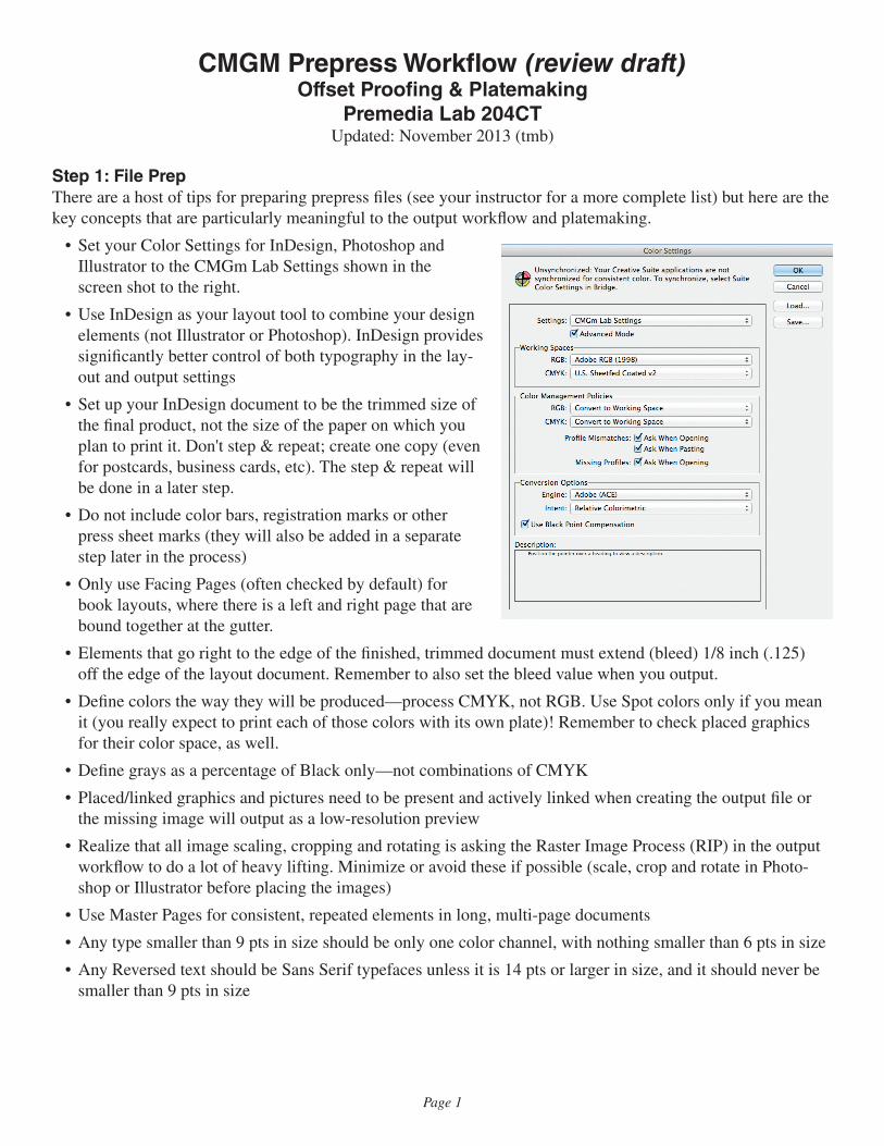
• Set your Color Settings for InDesign, Photoshop and Illustrator to the CMGm Lab Settings shown in the screen shot to the right.
• Use InDesign as your layout tool to combine your design elements (not Illustrator or Photoshop). InDesign provides significantly better control of both typography in the lay-out and output settings
• Set up your InDesign document to be the trimmed size of the final product, not the size of the paper on which you plan to print it. Don't step & repeat; create one copy (even for postcards, business cards, etc). The step & repeat will be done in a later step.
• Do not include color bars, registration marks or other press sheet marks (they will also be added in a separate step later in the process)
• Only use Facing Pages (often checked by default) for book layouts, where there is a left and right page that are bound together at the gutter.
• Elements that go right to the edge of the finished, trimmed document must extend (bleed) 1/8 inch (.125) off the edge of the layout document. Remember to also set the bleed value when you output.
• Define colors the way they will be produced—process CMYK, not RGB. Use Spot colors only if you mean it (you really expect to print each of those colors with its own plate)! Remember to check placed graphics for their color space, as well.
• Define grays as a percentage of Black only—not combinations of CMYK
• Placed/linked graphics and pictures need to be present and actively linked when creating the output file or the missing image will output as a low-resolution preview
• Realize that all image scaling, cropping and rotating is asking the Raster Image Process (RIP) in the output workflow to do a lot of heavy lifting. Minimize or avoid these if possible (scale, crop and rotate in Photo-shop or Illustrator before placing the images)
• Use Master Pages for consistent, repeated elements in long, multi-page documents
• Any type smaller than 9 pts in size should be only one color channel, with nothing smaller than 6 pts in size
• Any Reversed text should be Sans Serif typefaces unless it is 14 pts or larger in size, and it should never be smaller than 9 pts in size
Page 2
Step 2: PDF Output
How to create a proper PDF file for the output workflow…
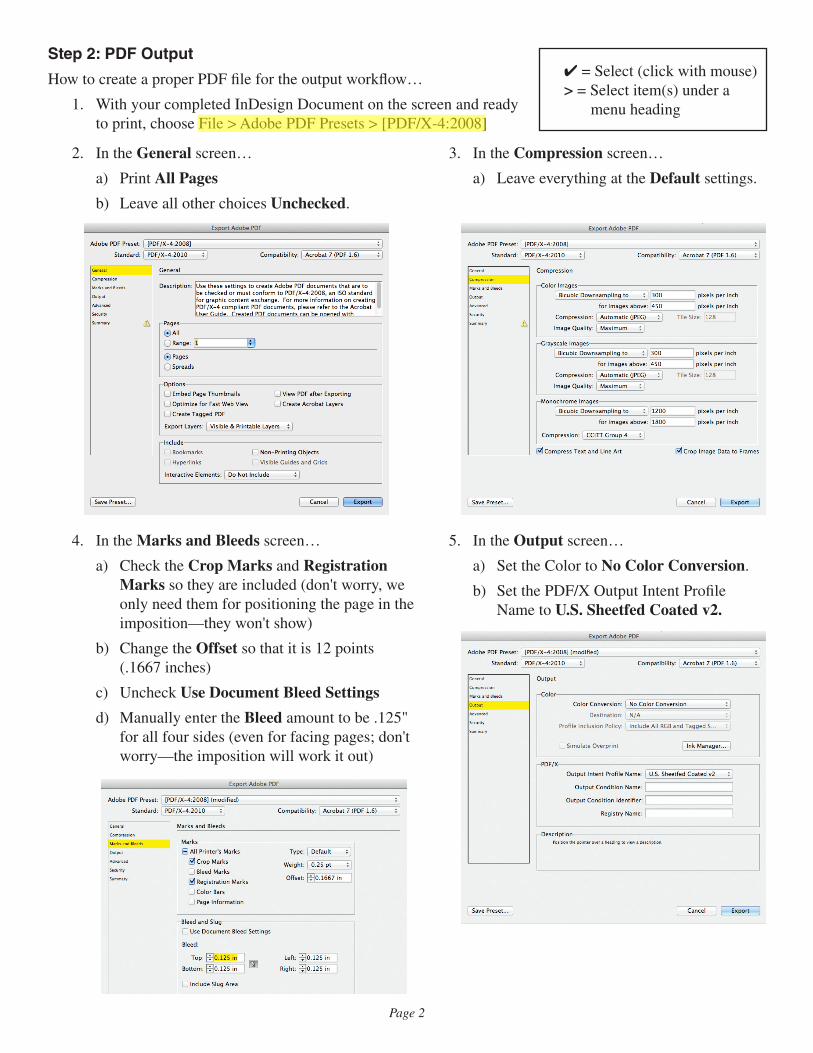
1. With your completed InDesign Document on the screen and ready to print, choose File > Adobe PDF Presets > [PDF/X-4:2008]
2. In the General screen…
a) Print All Pages
b) Leave all other choices Unchecked.
3. In the Compression screen…
a) Leave everything at the Default settings.
4. In the Marks and Bleeds screen…
a) Check the Crop Marks and Registration Marks so they are included (don't worry, we only need them for positioning the page in the imposition—they won't show)
b) Change the Offset so that it is 12 points (.1667 inches)
c) Uncheck Use Document Bleed Settings
d) Manually enter the Bleed amount to be .125" for all four sides (even for facing pages; don't worry—the imposition will work it out)
5. In the Output screen…
a) Set the Color to No Color Conversion.
b) Set the PDF/X Output Intent Profile Name to U.S. Sheetfed Coated v2.
✔ = Select (click with mouse)> = Select item(s) under a
menu heading
Page 3
Step 3: Prinergy Evo Setup
How to connect to the Prinergy Evo server and prepare for output…
1. Log in to the Prinergy Server Job Data folder (alias on the Dock)
a. If it asks you to log in, use cmgmstudent for the username and evo1034 for the password.
2. Launch the Prinergy Evo client on the lab workstations
a. The server IP Address should display (144.13.146.50). ✔ Other and type it in, if needed.
b. ✔ the Connect button to connect to the Prinergy server.
3. Copy your PDF file to the Job Data folder.
a. Create a folder in the Job Data folder on the Prinergy Evo server. Name the folder after Your Class Number and the Name of Your Project (and Your Last Name if directed by your instructor).
b. Drag a copy of your PDF output file from your workstation to this new folder.
Step 4: PDF Refining
The first processing step for your PDF output file…
1. Arrange your screen so you can see all of the Prinergy Evo windows (the Process Viewer and all of the Process Template palettes below it.
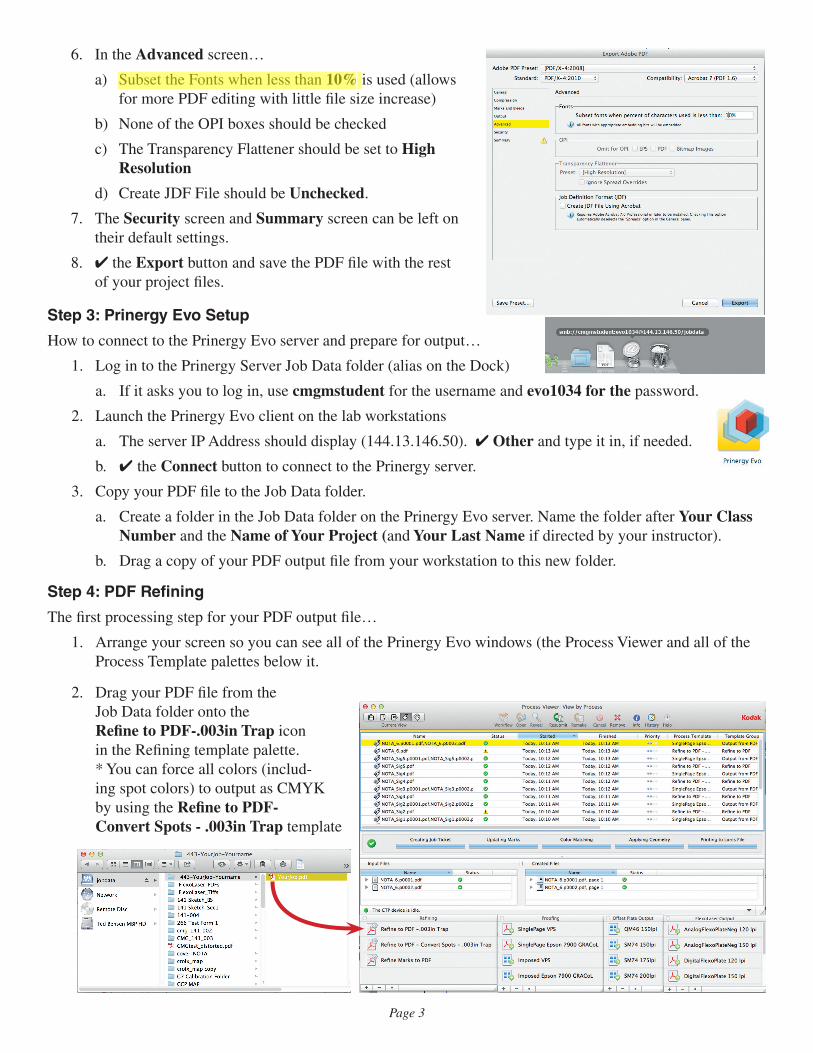
2. Drag your PDF file from the Job Data folder onto the Refine to PDF-.003in Trap icon in the Refining template palette. * You can force all colors (includ- ing spot colors) to output as CMYK by using the Refine to PDF- Convert Spots - .003in Trap template
6. In the Advanced screen…
a) Subset the Fonts when less than 10% is used (allows for more PDF editing with little file size increase)
b) None of the OPI boxes should be checked
c) The Transparency Flattener should be set to High Resolution
d) Create JDF File should be Unchecked.
7. The Security screen and Summary screen can be left on their default settings.
8. ✔ the Export button and save the PDF file with the rest of your project files.
Page 4
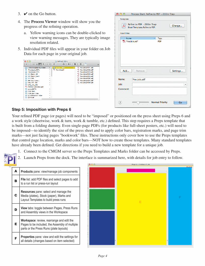
3. ✔ on the Go button.
4. The Process Viewer window will show you the progress of the refining operation.
a. Yellow warning icons can be double-clicked to view warning messages. They are typically image resolution related.
5. Individual PDF files will appear in your folder on Job Data for each page in your original job.
Step 5: Imposition with Preps 6
Your refined PDF page (or pages) will need to be “imposed” or positioned on the press sheet using Preps 6 and a work style (sheetwise, work & turn, work & tumble, etc.) defined. This step requires a Preps template that is built from a folding dummy. Even single-page PDFs (for products like full-sheet posters, etc.) will need to be imposed—to identify the size of the press sheet and to apply color bars, registration marks, and page trim marks—not just facing pages "bookwork" files. These instructions only cover how to use the Preps templates that control page location, marks and color bars—NOT how to create those templates. Many standard templates have already been defined. Get directions if you need to build a new template for a unique job.
1. Connect to the CMGM server so the Preps Templates and Marks folder can be accessed by Preps.
2. Launch Preps from the dock. The interface is summarized here, with details for job entry to follow.
A Products pane: view/manage job components
B File list: add PDF files and select pages to add to a run list or press-run layout
CResources pane: select and manage the Media (plates), Stock (paper), Marks and Layout Templates to build press runs
D View tabs: toggle between Pages, Press Runs and Assembly views in the Workspace
EWorkspace: review, rearrange and edit the Pages to be included, the Assembly of multiple parts or the Press Runs (plate layouts)
F Properties pane: view and edit the settings for all details (changes based on item selected)
A
B
C
D
EF
Page 5
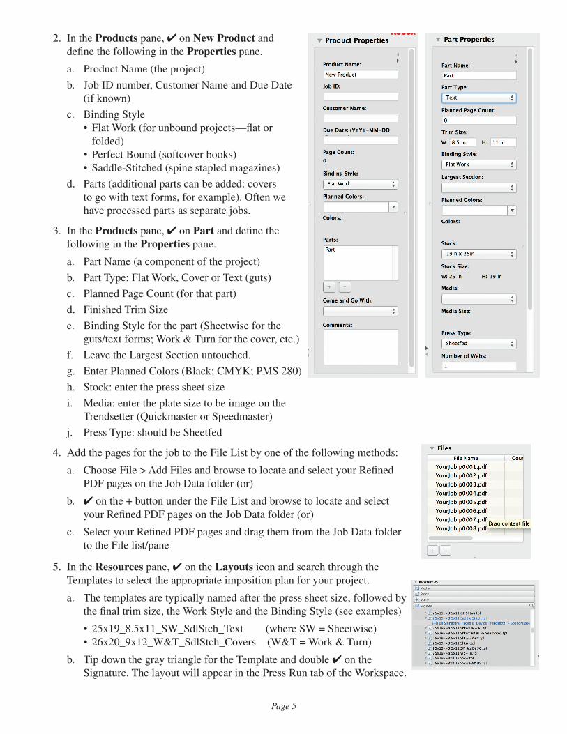
2. In the Products pane, ✔ on New Product and define the following in the Properties pane.
a. Product Name (the project)
b. Job ID number, Customer Name and Due Date (if known)
c. Binding Style• Flat Work (for unbound projects—flat or
folded)• Perfect Bound (softcover books)• Saddle-Stitched (spine stapled magazines)
d. Parts (additional parts can be added: covers to go with text forms, for example). Often we have processed parts as separate jobs.
3. In the Products pane, ✔ on Part and define the following in the Properties pane.
a. Part Name (a component of the project)
b. Part Type: Flat Work, Cover or Text (guts)
c. Planned Page Count (for that part)
d. Finished Trim Size
e. Binding Style for the part (Sheetwise for the guts/text forms; Work & Turn for the cover, etc.)
f. Leave the Largest Section untouched.
g. Enter Planned Colors (Black; CMYK; PMS 280)
h. Stock: enter the press sheet size
i. Media: enter the plate size to be image on the Trendsetter (Quickmaster or Speedmaster)
j. Press Type: should be Sheetfed
4. Add the pages for the job to the File List by one of the following methods:
a. Choose File > Add Files and browse to locate and select your Refined PDF pages on the Job Data folder (or)
b. ✔ on the + button under the File List and browse to locate and select your Refined PDF pages on the Job Data folder (or)
c. Select your Refined PDF pages and drag them from the Job Data folder to the File list/pane
5. In the Resources pane, ✔ on the Layouts icon and search through the Templates to select the appropriate imposition plan for your project.
a. The templates are typically named after the press sheet size, followed by the final trim size, the Work Style and the Binding Style (see examples)
• 25x19_8.5x11_SW_SdlStch_Text (where SW = Sheetwise)• 26x20_9x12_W&T_SdlStch_Covers (W&T = Work & Turn)
b. Tip down the gray triangle for the Template and double ✔ on the Signature. The layout will appear in the Press Run tab of the Workspace.
Page 6
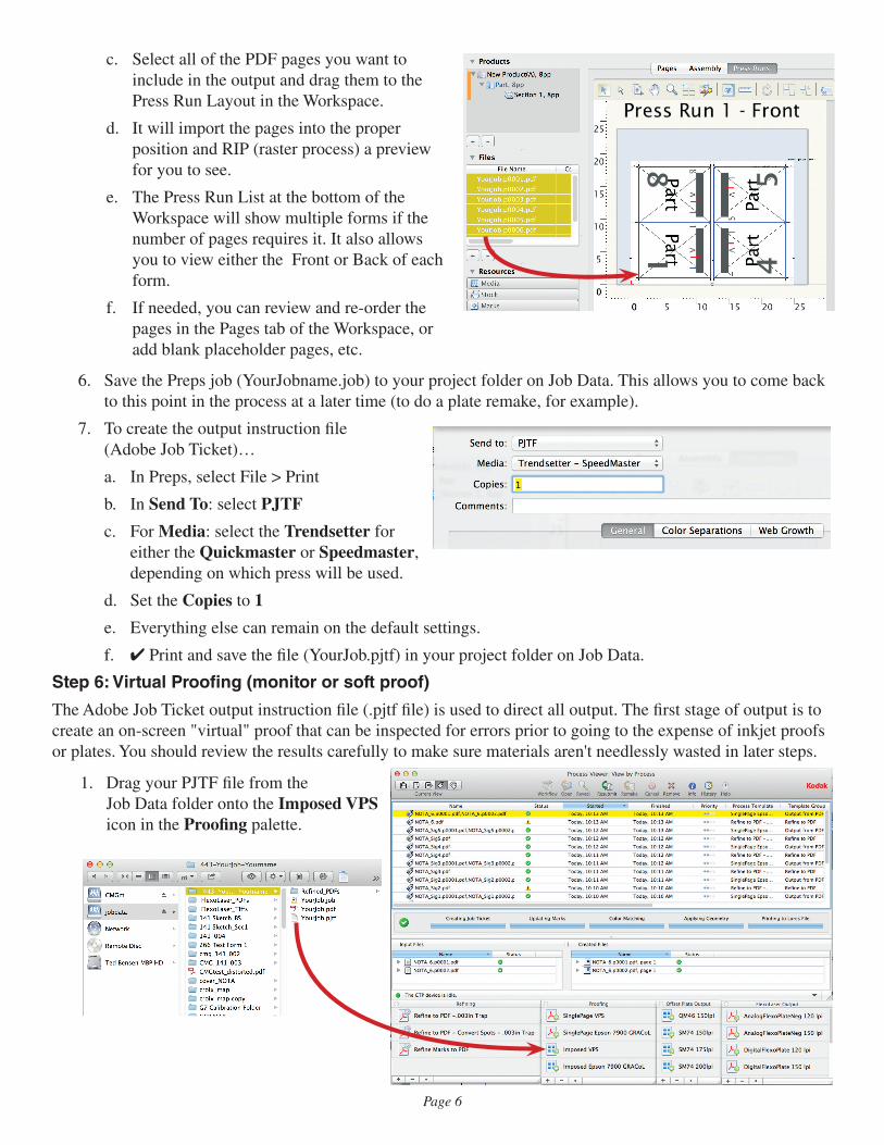
c. Select all of the PDF pages you want to include in the output and drag them to the Press Run Layout in the Workspace.
d. It will import the pages into the proper position and RIP (raster process) a preview for you to see.
e. The Press Run List at the bottom of the Workspace will show multiple forms if the number of pages requires it. It also allows you to view either the Front or Back of each form.
f. If needed, you can review and re-order the pages in the Pages tab of the Workspace, or add blank placeholder pages, etc.
6. Save the Preps job (YourJobname.job) to your project folder on Job Data. This allows you to come back to this point in the process at a later time (to do a plate remake, for example).
7. To create the output instruction file (Adobe Job Ticket)…
a. In Preps, select File > Print
b. In Send To: select PJTF
c. For Media: select the Trendsetter for either the Quickmaster or Speedmaster, depending on which press will be used.
d. Set the Copies to 1
e. Everything else can remain on the default settings.
f. ✔ Print and save the file (YourJob.pjtf) in your project folder on Job Data.
Step 6: Virtual Proofing (monitor or soft proof)
The Adobe Job Ticket output instruction file (.pjtf file) is used to direct all output. The first stage of output is to create an on-screen "virtual" proof that can be inspected for errors prior to going to the expense of inkjet proofs or plates. You should review the results carefully to make sure materials aren't needlessly wasted in later steps.
1. Drag your PJTF file from the Job Data folder onto the Imposed VPS icon in the Proofing palette.
Page 7
2. ✔ on the Go button.
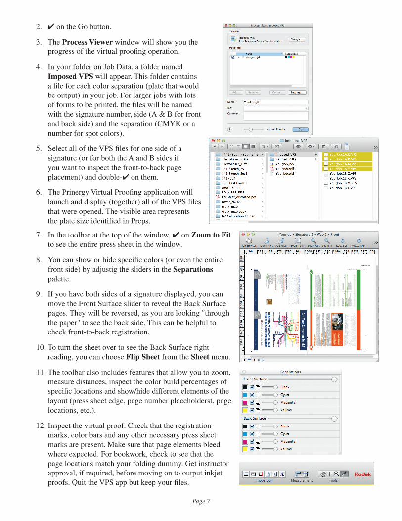
3. The Process Viewer window will show you the progress of the virtual proofing operation.
4. In your folder on Job Data, a folder named Imposed VPS will appear. This folder contains a file for each color separation (plate that would be output) in your job. For larger jobs with lots of forms to be printed, the files will be named with the signature number, side (A & B for front and back side) and the separation (CMYK or a number for spot colors).
5. Select all of the VPS files for one side of a signature (or for both the A and B sides if you want to inspect the front-to-back page placement) and double-✔ on them.
6. The Prinergy Virtual Proofing application will launch and display (together) all of the VPS files that were opened. The visible area represents the plate size identified in Preps.
7. In the toolbar at the top of the window, ✔ on Zoom to Fit to see the entire press sheet in the window.
8. You can show or hide specific colors (or even the entire front side) by adjustig the sliders in the Separations palette.
9. If you have both sides of a signature displayed, you can move the Front Surface slider to reveal the Back Surface pages. They will be reversed, as you are looking "through the paper" to see the back side. This can be helpful to check front-to-back registration.
10. To turn the sheet over to see the Back Surface right-reading, you can choose Flip Sheet from the Sheet menu.
11. The toolbar also includes features that allow you to zoom, measure distances, inspect the color build percentages of specific locations and show/hide different elements of the layout (press sheet edge, page number placeholderst, page locations, etc.).
12. Inspect the virtual proof. Check that the registration marks, color bars and any other necessary press sheet marks are present. Make sure that page elements bleed where expected. For bookwork, check to see that the page locations match your folding dummy. Get instructor approval, if required, before moving on to output inkjet proofs. Quit the VPS app but keep your files.
Page 8
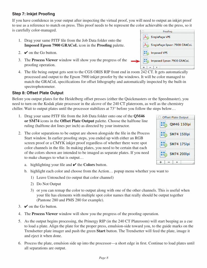
Step 7: Inkjet Proofing
If you have confidence in your output after inspecting the virtual proof, you will need to output an inkjet proof to use as a reference to match on press. This proof needs to be represent the color achievable on the press, so it is carefully color-managed.
1. Drag your same PJTF file from the Job Data folder onto the Imposed Epson 7900 GRACoL icon in the Proofing palette.
2. ✔ on the Go button.
3. The Process Viewer window will show you the progress of the proofing operation.
4. The file being output gets sent to the CGS ORIS RIP front end in room 242 CT. It gets automatically processed and output to the Epson 7900 inkjet proofer by the windows. It will be color managed to match the GRACoL specifications for offset lithography and automatically inspected by the built-in spectrophotometer.
Step 8: Offset Plate OutputBefore you output plates for the Heidelberg offset presses (either the Quickmasters or the Speedmaster), you need to turn on the Kodak plate processor in the alcove of the 240 CT plateroom, as well as the chemistry chiller. Wait to output plates until the processor stabilizes at 73° before you follow the steps below…
1. Drag your same PJTF file from the Job Data folder onto one of the QM46 or SM74 icons in the Offset Plate Output palette. Choose the halftone line ruling (halftone dot lines per inch) as directed by your instructor.
2. The color separations to be output are shown alongside the file in the Process Start window. In earlier proofing steps, you ended up with either an RGB screen proof or a CMYK inkjet proof regardless of whether there were spot color channels in the file. In making plates, you need to be certain that each of the colors shown are intended to be imaged as separate plates. If you need to make changes to what is output…
a. highlighting your file and ✔ the Colors button.
b. highlight each color and choose from the Action… popup menu whether you want to
1) Leave Untouched (to output that color channel)
2) Do Not Output
3) or you can remap the color to output along with one of the other channels. This is useful when your file has elements with multiple spot color names that really should be output together (Pantone 280 and PMS 280 for example).
3. ✔ on the Go button.
4. The Process Viewer window will show you the progress of the proofing operation.
5. As the output begins processing, the Prinergy RIP (in the 240 CT Plateroom) will start beeping as a cue to load a plate. Align the plate for the proper press, emulsion-side toward you, to the guide marks on the Trendsetter plate imager and push the green Start button. The Trendsetter will feed the plate, image it and eject it when done.
6. Process the plate, emulsion side up into the processor—a short edge in first. Continue to load plates until all separations are output.