cisco application centric infrastructure fundamentals
TRANSCRIPT

Cisco Application Centric Infrastructure Fundamentals, Release 6.0(x)First Published: 2022-06-17
Americas HeadquartersCisco Systems, Inc.170 West Tasman DriveSan Jose, CA 95134-1706USAhttp://www.cisco.comTel: 408 526-4000
800 553-NETS (6387)Fax: 408 527-0883

© 2022 Cisco Systems, Inc. All rights reserved.

Trademarks
THESPECIFICATIONSAND INFORMATIONREGARDINGTHEPRODUCTSREFERENCED INTHISDOCUMENTATIONARESUBJECTTOCHANGEWITHOUTNOTICE. EXCEPTASMAYOTHERWISEBE AGREED BY CISCO IN WRITING, ALL STATEMENTS, INFORMATION, ANDRECOMMENDATIONS IN THIS DOCUMENTATION ARE PRESENTED WITHOUT WARRANTY OFANY KIND, EXPRESS OR IMPLIED.
The Cisco End User License Agreement and any supplemental license terms govern your use of any Ciscosoftware, including this product documentation, and are located at:http://www.cisco.com/go/softwareterms.Cisco product warranty information is available athttp://www.cisco.com/go/warranty. US Federal Communications Commission Notices are found herehttp://www.cisco.com/c/en/us/products/us-fcc-notice.html.
IN NO EVENT SHALL CISCO OR ITS SUPPLIERS BE LIABLE FOR ANY INDIRECT, SPECIAL,CONSEQUENTIAL, OR INCIDENTAL DAMAGES, INCLUDING, WITHOUT LIMITATION, LOSTPROFITS OR LOSS OR DAMAGE TO DATA ARISING OUT OF THE USE OR INABILITY TO USETHIS MANUAL, EVEN IF CISCO OR ITS SUPPLIERS HAVE BEEN ADVISED OF THE POSSIBILITYOF SUCH DAMAGES.
Any products and features described herein as in development or available at a future date remain in varyingstages of development and will be offered on a when-and if-available basis. Any such product or featureroadmaps are subject to change at the sole discretion of Cisco and Cisco will have no liability for delay in thedelivery or failure to deliver any products or feature roadmap items that may be set forth in this document.
Any Internet Protocol (IP) addresses and phone numbers used in this document are not intended to be actualaddresses and phone numbers. Any examples, command display output, network topology diagrams, andother figures included in the document are shown for illustrative purposes only. Any use of actual IP addressesor phone numbers in illustrative content is unintentional and coincidental.
The documentation set for this product strives to use bias-free language. For the purposes of this documentationset, bias-free is defined as language that does not imply discrimination based on age, disability, gender, racialidentity, ethnic identity, sexual orientation, socioeconomic status, and intersectionality. Exceptions may bepresent in the documentation due to language that is hardcoded in the user interfaces of the product software,language used based on RFP documentation, or language that is used by a referenced third-party product.
Cisco and the Cisco logo are trademarks or registered trademarks of Cisco and/or its affiliates in the U.S. andother countries. To view a list of Cisco trademarks, go to this URL: www.cisco.com go trademarks. Third-partytrademarks mentioned are the property of their respective owners. The use of the word partner does not implya partnership relationship between Cisco and any other company. (1721R)
Cisco Application Centric Infrastructure Fundamentals, Release 6.0(x)iii

Cisco Application Centric Infrastructure Fundamentals, Release 6.0(x)iv
TrademarksTrademarks
C O N T E N T S
Trademarks iiiP R E F A C E
New and Changed Information 1C H A P T E R 1
New and Changed Information 1
Cisco Application Centric Infrastructure 3C H A P T E R 2
About the Cisco Application Centric Infrastructure 3
About the Cisco Application Policy Infrastructure Controller 3
Cisco Application Centric Infrastructure Fabric Overview 4
Determining How the Fabric Behaves 5
ACI Policy Model 7C H A P T E R 3
About the ACI Policy Model 7
Policy Model Key Characteristics 7
Logical Constructs 8
The Cisco ACI Policy Management Information Model 9
Tenants 10
VRFs 11
Application Profiles 12
Endpoint Groups 13
IP-Based EPGs 15
Microsegmentation 15
Intra-EPG Endpoint Isolation 16
Bridge Domains and Subnets 16
Bridge Domain Options 18
Attachable Entity Profile 21
Cisco Application Centric Infrastructure Fundamentals, Release 6.0(x)v

VLANs and EPGs 22
Access Policies Automate Assigning VLANs to EPGs 22
Native 802.1p and Tagged EPGs on Interfaces 23
Per Port VLAN 25
VLAN Guidelines for EPGs Deployed on vPCs 27
Configuring Flood in Encapsulation for All Protocols and Proxy ARP Across Encapsulations 27
Contracts 32
Labels, Filters, Aliases, and Subjects Govern EPG Communications 33
Configuring Contract or Subject Exceptions for Contracts 35
Taboos 36
About Contract Inheritance 36
About Contract Preferred Groups 37
Optimize Contract Performance 39
What vzAny Is 41
About Copy Services 42
Outside Networks 42
Managed Object Relations and Policy Resolution 43
Default Policies 44
Trans Tenant EPG Communications 46
Tags 47
About APIC Quota Management Configuration 47
Fabric Provisioning 49C H A P T E R 4
Fabric Provisioning 50
Startup Discovery and Configuration 50
Fabric Inventory 51
Provisioning 52
Multi-Tier Architecture 53
APIC Cluster Management 54
Cluster Management Guidelines 54
About Cold Standby for a Cisco APIC Cluster 55
Maintenance Mode 56
Stretched ACI Fabric Design Overview 57
Stretched ACI Fabric Related Documents 58
Cisco Application Centric Infrastructure Fundamentals, Release 6.0(x)vi
Contents

Fabric Policies Overview 58
Fabric Policy Configuration 59
Access Policies Overview 61
Access Policy Configuration 62
Port Channel and Virtual Port Channel Access 63
FEX Virtual Port Channels 63
Fibre Channel and FCoE 65
Supporting Fibre Channel over Ethernet Traffic on the Cisco ACI Fabric 65
Fibre Channel Connectivity Overview 67
802.1Q Tunnels 70
About ACI 802.1Q Tunnels 70
Dynamic Breakout Ports 72
Configuration of Breakout Ports 72
Configuring Port Profiles 72
Port Profile Configuration Summary 75
Port Tracking Policy for Fabric Port Failure Detection 79
Q-in-Q Encapsulation Mapping for EPGs 80
Layer 2 Multicast 81
About Cisco APIC and IGMP Snooping 81
How IGMP Snooping is Implemented in the ACI Fabric 82
Virtualization Support 83
The APIC IGMP Snooping Function, IGMPv1, IGMPv2, and the Fast Leave Feature 83
The APIC IGMP Snooping Function and IGMPv3 83
Cisco APIC and the IGMP Snooping Querier Function 84
Fabric Secure Mode 84
Configuring Fast Link Failover Policy 85
About Port Security and ACI 85
Port Security and Learning Behavior 85
Protect Mode 86
Port Security at Port Level 86
Port Security Guidelines and Restrictions 86
About First Hop Security 87
About MACsec 88
Data Plane Policing 89
Cisco Application Centric Infrastructure Fundamentals, Release 6.0(x)vii
Contents
Scheduler 90
Firmware Upgrade 90
Configuration Zones 93
Geolocation 94
Forwarding Within the ACI Fabric 95C H A P T E R 5
About Forwarding Within the ACI Fabric 95
ACI Fabric Optimizes Modern Data Center Traffic Flows 96
VXLAN in ACI 97
Layer 3 VNIDs Facilitate Transporting Inter-subnet Tenant Traffic 98
Policy Identification and Enforcement 100
ACI Fabric Network Access Security Policy Model (Contracts) 101
Access Control List Limitations 101
Contracts Contain Security Policy Specifications 102
Security Policy Enforcement 104
Multicast and EPG Security 105
Multicast Tree Topology 106
About Traffic Storm Control 107
Storm Control Guidelines and Limitations 107
Fabric Load Balancing 109
Endpoint Retention 112
IP Endpoint Learning Behavior 113
About Proxy ARP 114
Loop Detection 120
Modes of Mis-cabling Protocol 121
Guidelines and Restrictions for MCP Strict mode 122
Rogue Endpoint Detection 123
About the Rogue Endpoint Control Policy 123
Networking and Management Connectivity 125C H A P T E R 6
DHCP Relay 125
DNS 127
In-Band and Out-of-Band Management Access 128
In-Band Management Access 128
Cisco Application Centric Infrastructure Fundamentals, Release 6.0(x)viii
Contents
Out-of-Band Management Access 129
IPv6 Support 130
Global Unicast Addresses 131
Link-Local Addresses 132
Static Routes 133
Neighbor Discovery 133
Duplicate Address Detection 134
Stateless Address Autoconfiguration (SLAAC) and DHCPv6 134
Routing Within the Tenant 135
Configuring Route Reflectors 135
Common Pervasive Gateway 135
WAN and Other External Networks 136
Router Peering and Route Distribution 136
Networking Domains 137
Bridged and Routed Connectivity to External Networks 138
Layer 2 Out for Bridged Connectivity to External Networks 138
Bridged Interface to an External Router 139
Layer 3 Out for Routed Connectivity to External Networks 140
Static Route Preference 141
Route Import and Export, Route Summarization, and Route Community Match 142
Shared Services Contracts Usage 145
Shared Layer 3 Out 146
Bidirectional Forwarding Detection 149
ACl IP SLAs 151
Layer 3 Multicast 152
About the Fabric Interface 153
Enabling IPv4/IPv6 Multicast Routing 154
Guidelines, Limitations, and Expected Behaviors for Configuring Layer 3 IPv4/IPv6 Multicast 155
Cisco ACI GOLF 157
Route Target filtering 160
Distributing BGP EVPN Type-2 Host Routes to a DCIG 161
Multipod 161
Multipod Provisioning 163
Multi-Pod QoS and DSCP Translation Policy 165
Cisco Application Centric Infrastructure Fundamentals, Release 6.0(x)ix
Contents

About Anycast Services 165
Remote Leaf Switches 166
About Remote Leaf Switches in the ACI Fabric 166
Remote Leaf Switch Restrictions and Limitations 172
QoS 175
L3Outs QoS 175
Class of Service (CoS) Preservation for Ingress and Egress Traffic 175
Multi-Pod QoS and DSCP Translation Policy 176
Translating Ingress to Egress QoS Markings 177
HSRP 177
About HSRP 177
About Cisco APIC and HSRP 178
Guidelines and Limitations 179
HSRP Versions 180
ACI Transit Routing, Route Peering, and EIGRP Support 181C H A P T E R 7
ACI Transit Routing 181
Transit Routing Use Cases 181
ACI Fabric Route Peering 186
Route Redistribution 186
Route Peering by Protocol 187
Transit Route Control 191
Default Policy Behavior 193
EIGRP Protocol Support 193
EIGRP L3extOut Configuration 195
EIGRP Interface Profile 196
User Access, Authentication, and Accounting 197C H A P T E R 8
User Access, Authorization, and Accounting 197
Multiple Tenant Support 197
User Access: Roles, Privileges, and Security Domains 198
Accounting 199
Routed Connectivity to External Networks as a Shared Service Billing and Statistics 200
Custom RBAC Rules 200
Cisco Application Centric Infrastructure Fundamentals, Release 6.0(x)x
Contents

Selectively Expose Physical Resources across Security Domains 201
Enable Sharing of Services across Security Domains 201
APIC Local Users 201
Externally Managed Authentication Server Users 203
Cisco AV Pair Format 206
RADIUS Authentication 207
TACACS+ Authentication 207
LDAP/Active Directory Authentication 208
User IDs in the APIC Bash Shell 208
Login Domains 209
SAML Authentication 209
Virtual Machine Manager Domains 211C H A P T E R 9
Cisco ACI VM Networking Support for Virtual Machine Managers 211
VMM Domain Policy Model 213
Virtual Machine Manager Domain Main Components 213
Virtual Machine Manager Domains 214
VMM Domain VLAN Pool Association 214
VMM Domain EPG Association 215
Trunk Port Group 217
EPG Policy Resolution and Deployment Immediacy 218
Guidelines for Deleting VMM Domains 219
Layer 4 to Layer 7 Service Insertion 221C H A P T E R 1 0
Layer 4 to Layer 7 Service Insertion 221
Layer 4 to Layer 7 Policy Model 222
About Service Graphs 222
About Policy-Based Redirect 224
About Symmetric Policy-Based Redirect 226
Automated Service Insertion 226
About Device Packages 227
About Device Clusters 229
About Device Managers and Chassis Managers 230
About Concrete Devices 233
Cisco Application Centric Infrastructure Fundamentals, Release 6.0(x)xi
Contents
About Function Nodes 234
About Function Node Connectors 234
About Terminal Nodes 234
About Privileges 235
Service Automation and Configuration Management 235
Service Resource Pooling 235
Management Tools 237C H A P T E R 1 1
Management Tools 237
About the Management GUI 237
About the CLI 237
User Login Menu Options 238
Customizing the GUI and CLI Banners 239
REST API 239
About the REST API 239
API Inspector 240
Visore Managed Object Viewer 241
Management Information Model Reference 241
Locating Objects in the MIT 243
Tree-Level Queries 244
Class-Level Queries 244
Object-Level Queries 245
Managed-Object Properties 246
Accessing the Object Data Through REST Interfaces 247
Configuration Export/Import 248
Configuration Database Sharding 248
Configuration File Encryption 248
Configuration Export 249
Configuration Import 250
Tech Support, Statistics, Core 251
Programmability Using Puppet 252
About Puppet 252
Cisco ciscoacipuppet Puppet Module 252
Puppet Guidelines and Limitations for ACI 253
Cisco Application Centric Infrastructure Fundamentals, Release 6.0(x)xii
Contents

Monitoring 255C H A P T E R 1 2
Faults, Errors, Events, Audit Logs 255
Faults 255
Log Record Objects 257
About the Log Record Objects 257
Viewing the Log Record Objects Using the GUI 258
Errors 259
Statistics Properties, Tiers, Thresholds, and Monitoring 260
About Statistics Data 261
Configuring Monitoring Policies 261
Tetration Analytics 265
About Cisco Tetration Analytics Agent Installation 265
NetFlow 265
About NetFlow 265
NetFlow Support and Limitations 266
Troubleshooting 267C H A P T E R 1 3
Troubleshooting 267
About ACL Contract Permit and Deny Logs 268
ARPs, ICMP Pings, and Traceroute 268
Atomic Counters 269
About Digital Optical Monitoring 270
Health Scores 271
System and Pod Health Scores 271
Tenant Health Scores 273
MO Health Scores 273
Health Score Aggregation and Impact 275
About SPAN 276
About SNMP 276
About Syslog 276
About the Troubleshooting Wizard 277
About Cisco Nexus 9000 Switch Secure Erase 278
Cisco Application Centric Infrastructure Fundamentals, Release 6.0(x)xiii
Contents

Label Matching 279A P P E N D I X A
Label Matching 279
Contract Scope Examples 281A P P E N D I X B
Contract Scope Examples 281
Secure Properties 285A P P E N D I X C
Secure Properties 285
Configuration Zone Supported Policies 289A P P E N D I X D
Configuration Zone Supported Policies 289
ACI Terminology 293A P P E N D I X E
ACI Terminology 293
Cisco Application Centric Infrastructure Fundamentals, Release 6.0(x)xiv
Contents

C H A P T E R 1New and Changed Information
This chapter contains the following sections:
• New and Changed Information, on page 1
New and Changed InformationThe following tables provide an overview of the significant changes to this guide up to this current release.The table does not provide an exhaustive list of all changes made to the guide or of the new features up tothis release.
Table 1: New Features and Changed Information for Cisco APIC Release 6.0(1)
Where DocumentedDescriptionFeature
About Cisco Nexus 9000 SwitchSecure Erase, on page 278
Cisco Nexus 9000 switches utilizepersistent storage to maintainsystem software images, switchconfiguration, software logs, andoperational history. Each of theseareas can contain user-specificinformation such as details onnetwork architecture and design,and potential target vectors forwould-be attackers. The secureerase feature enables youcomprehensively to erase thisinformation, which you can dowhen you return a switch withreturn merchandise authorization(RMA), upgrade or replace aswitch, or decommission a systemthat has reached its end-of-life.
Cisco Nexus 9000 switch secureerase
Cisco Application Centric Infrastructure Fundamentals, Release 6.0(x)1

Cisco Application Centric Infrastructure Fundamentals, Release 6.0(x)2
New and Changed InformationNew and Changed Information
C H A P T E R 2Cisco Application Centric Infrastructure
This chapter contains the following sections:
• About the Cisco Application Centric Infrastructure, on page 3• About the Cisco Application Policy Infrastructure Controller, on page 3• Cisco Application Centric Infrastructure Fabric Overview, on page 4• Determining How the Fabric Behaves, on page 5
About the Cisco Application Centric InfrastructureThe Cisco Application Centric Infrastructure (ACI) allows application requirements to define the network.This architecture simplifies, optimizes, and accelerates the entire application deployment life cycle.
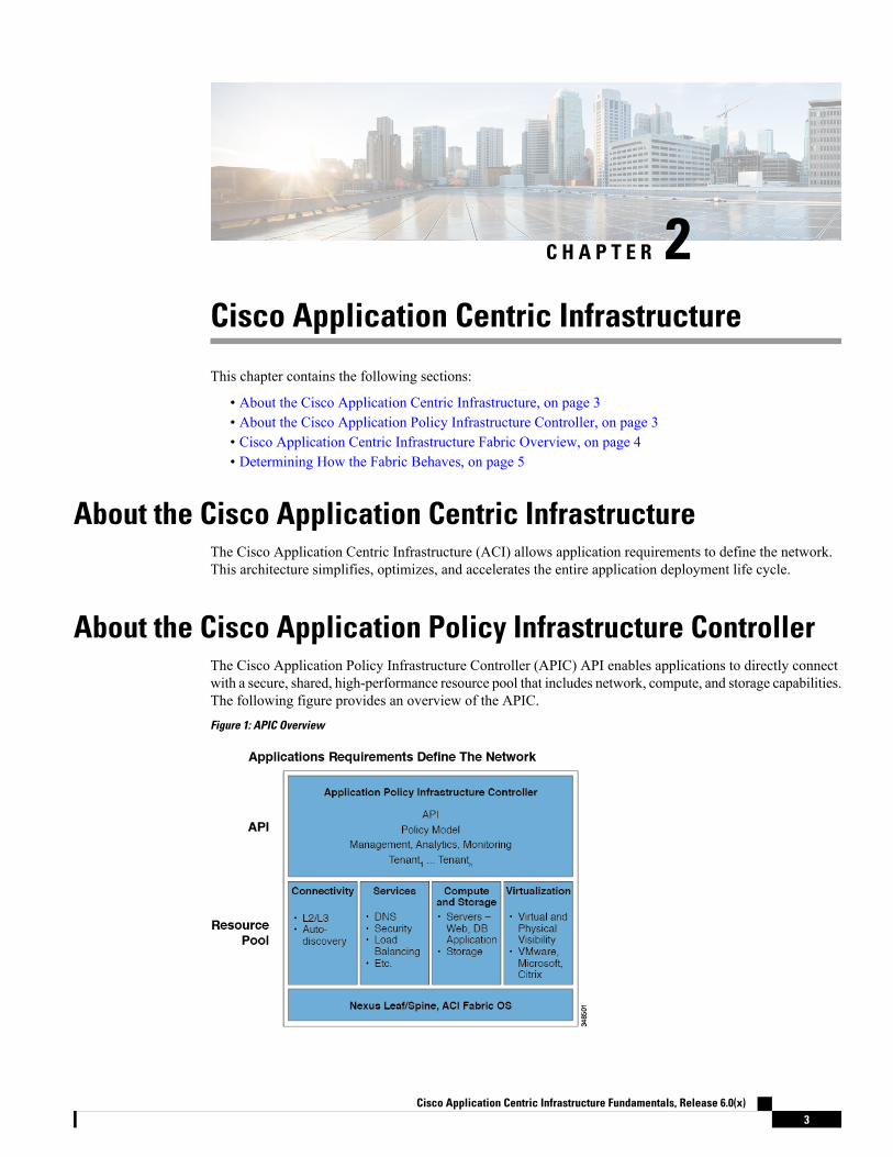
About the Cisco Application Policy Infrastructure ControllerThe Cisco Application Policy Infrastructure Controller (APIC) API enables applications to directly connectwith a secure, shared, high-performance resource pool that includes network, compute, and storage capabilities.The following figure provides an overview of the APIC.
Figure 1: APIC Overview
Cisco Application Centric Infrastructure Fundamentals, Release 6.0(x)3

The APIC manages the scalable ACI multi-tenant fabric. The APIC provides a unified point of automationand management, policy programming, application deployment, and health monitoring for the fabric. TheAPIC, which is implemented as a replicated synchronized clustered controller, optimizes performance, supportsany application anywhere, and provides unified operation of the physical and virtual infrastructure. The APICenables network administrators to easily define the optimal network for applications. Data center operatorscan clearly see how applications consume network resources, easily isolate and troubleshoot application andinfrastructure problems, and monitor and profile resource usage patterns.
Cisco Application Centric Infrastructure Fabric OverviewThe Cisco Application Centric Infrastructure Fabric (ACI) fabric includes Cisco Nexus 9000 Series switcheswith the APIC to run in the leaf/spine ACI fabric mode. These switches form a “fat-tree” network by connectingeach leaf node to each spine node; all other devices connect to the leaf nodes. The APIC manages the ACIfabric. The recommended minimum configuration for the APIC is a cluster of three replicated hosts. TheAPIC fabric management functions do not operate in the data path of the fabric. The following figure showsan overview of the leaf/spin ACI fabric.
Figure 2: ACI Fabric Overview
The ACI fabric provides consistent low-latency forwarding across high-bandwidth links (40 Gbps and100-Gbps). Traffic with the source and destination on the same leaf switch is handled locally, and all othertraffic travels from the ingress leaf to the egress leaf through a spine switch. Although this architecture appearsas two hops from a physical perspective, it is actually a single Layer 3 hop because the fabric operates as asingle Layer 3 switch.
The ACI fabric object-oriented operating system (OS) runs on each Cisco Nexus 9000 Series node. It enablesprogramming of objects for each configurable element of the system.
The ACI fabric OS renders policies from the APIC into a concrete model that runs in the physical infrastructure.The concrete model is analogous to compiled software; it is the form of the model that the switch operatingsystem can execute. The figure below shows the relationship of the logical model to the concrete model andthe switch OS.
Cisco Application Centric Infrastructure Fundamentals, Release 6.0(x)4
Cisco Application Centric InfrastructureCisco Application Centric Infrastructure Fabric Overview

Figure 3: Logical Model Rendered into a Concrete Model
All the switch nodes contain a complete copy of the concrete model. When an administrator creates a policyin the APIC that represents a configuration, the APIC updates the logical model. The APIC then performs theintermediate step of creating a fully elaborated policy that it pushes into all the switch nodes where the concretemodel is updated.
The Cisco Nexus 9000 Series switches can only execute the concrete model. Each switch has a copy of theconcrete model. If the APIC goes offline, the fabric k.jpg functioning but modifications to the fabric policiesare not possible.
Note
The APIC is responsible for fabric activation, switch firmware management, network policy configuration,and instantiation. While the APIC acts as the centralized policy and network management engine for thefabric, it is completely removed from the data path, including the forwarding topology. Therefore, the fabriccan still forward traffic even when communication with the APIC is lost.
The Cisco Nexus 9000 Series switches offer modular and fixed 1-, 10-, 40-, and 100-Gigabit Ethernet switchconfigurations that operate in either Cisco NX-OS stand-alone mode for compatibility and consistency withthe current Cisco Nexus switches or in ACImode to take full advantage of the APIC's application policy-drivenservices and infrastructure automation features.
Determining How the Fabric BehavesThe ACI fabric allows customers to automate and orchestrate scalable, high performance network, computeand storage resources for cloud deployments. Key players who define how the ACI fabric behaves includethe following:
• IT planners, network engineers, and security engineers
• Developers who access the system via the APIC APIs
• Application and network administrators
The Representational State Transfer (REST) architecture is a key development method that supports cloudcomputing. The ACI API is REST-based. The World Wide Web represents the largest implementation of asystem that conforms to the REST architectural style.
Cloud computing differs from conventional computing in scale and approach. Conventional environmentsinclude software and maintenance requirements with their associated skill sets that consume substantialoperating expenses. Cloud applications use system designs that are supported by a very large scale infrastructurethat is deployed along a rapidly declining cost curve. In this infrastructure type, the system administrator,development teams, and network professionals collaborate to provide a much higher valued contribution.
Cisco Application Centric Infrastructure Fundamentals, Release 6.0(x)5
Cisco Application Centric InfrastructureDetermining How the Fabric Behaves

In conventional settings, network access for compute resources and endpoints is managed through virtualLANs (VLANs) or rigid overlays, such as Multiprotocol Label Switching (MPLS), that force traffic throughrigidly defined network services, such as load balancers and firewalls. The APIC is designed forprogrammability and centralized management. By abstracting the network, the ACI fabric enables operatorsto dynamically provision resources in the network instead of in a static fashion. The result is that the time todeployment (time to market) can be reduced from months or weeks to minutes. Changes to the configurationof virtual or physical switches, adapters, policies, and other hardware and software components can be madein minutes with API calls.
The transformation from conventional practices to cloud computing methods increases the demand for flexibleand scalable services from data centers. These changes call for a large pool of highly skilled personnel toenable this transformation. The APIC is designed for programmability and centralized management. A keyfeature of the APIC is the web API called REST. The APIC REST API accepts and returns HTTP or HTTPSmessages that contain JavaScript Object Notation (JSON) or ExtensibleMarkup Language (XML) documents.Today, manyweb developers use RESTful methods. Adopting webAPIs across the network enables enterprisesto easily open up and combine services with other internal or external providers. This process transforms thenetwork from a complex mixture of static resources to a dynamic exchange of services on offer.
Cisco Application Centric Infrastructure Fundamentals, Release 6.0(x)6
Cisco Application Centric InfrastructureDetermining How the Fabric Behaves
C H A P T E R 3ACI Policy Model
This chapter contains the following sections:
• About the ACI Policy Model, on page 7• Policy Model Key Characteristics, on page 7• Logical Constructs, on page 8• The Cisco ACI Policy Management Information Model, on page 9• Tenants, on page 10• VRFs, on page 11• Application Profiles, on page 12• Endpoint Groups, on page 13• Bridge Domains and Subnets, on page 16• Attachable Entity Profile, on page 21• VLANs and EPGs, on page 22• Contracts, on page 32• Outside Networks, on page 42• Managed Object Relations and Policy Resolution, on page 43• Default Policies, on page 44• Trans Tenant EPG Communications, on page 46• Tags, on page 47• About APIC Quota Management Configuration, on page 47
About the ACI Policy ModelThe ACI policy model enables the specification of application requirements policies. The APIC automaticallyrenders policies in the fabric infrastructure. When a user or process initiates an administrative change to anobject in the fabric, the APIC first applies that change to the policy model. This policy model change thentriggers a change to the actual managed endpoint. This approach is called a model-driven framework.
Policy Model Key CharacteristicsKey characteristics of the policy model include the following:
Cisco Application Centric Infrastructure Fundamentals, Release 6.0(x)7

• As a model-driven architecture, the software maintains a complete representation of the administrativeand operational state of the system (the model). The model applies uniformly to fabric, services, systembehaviors, and virtual and physical devices attached to the network.
• The logical and concrete domains are separated; the logical configurations are rendered into concreteconfigurations by applying the policies in relation to the available physical resources. No configurationis carried out against concrete entities. Concrete entities are configured implicitly as a side effect of thechanges to the APIC policy model. Concrete entities can be, but do not have to be, physical (such as avirtual machine or a VLAN).
• The system prohibits communications with newly connected devices until the policy model is updatedto include the new device.
• Network administrators do not configure logical and physical system resources directly but rather definelogical (hardware independent) configurations and APIC policies that control different aspects of thesystem behavior.
Managed object manipulation in themodel relieves engineers from the task of administering isolated, individualcomponent configurations. These characteristics enable automation and flexible workload provisioning thatcan locate any workload anywhere in the infrastructure. Network-attached services can be easily deployed,and the APIC provides an automation framework to manage the life cycle of those network-attached services.
Logical ConstructsThe policy model manages the entire fabric, including the infrastructure, authentication, security, services,applications, and diagnostics. Logical constructs in the policy model define how the fabric meets the needsof any of the functions of the fabric. The following figure provides an overview of the ACI policy modellogical constructs.
Figure 4: ACI Policy Model Logical Constructs Overview
Cisco Application Centric Infrastructure Fundamentals, Release 6.0(x)8
ACI Policy ModelLogical Constructs
Fabric-wide or tenant administrators create predefined policies that contain application or shared resourcerequirements. These policies automate the provisioning of applications, network-attached services, securitypolicies, and tenant subnets, which puts administrators in the position of approaching the resource pool interms of applications rather than infrastructure building blocks. The application needs to drive the networkingbehavior, not the other way around.
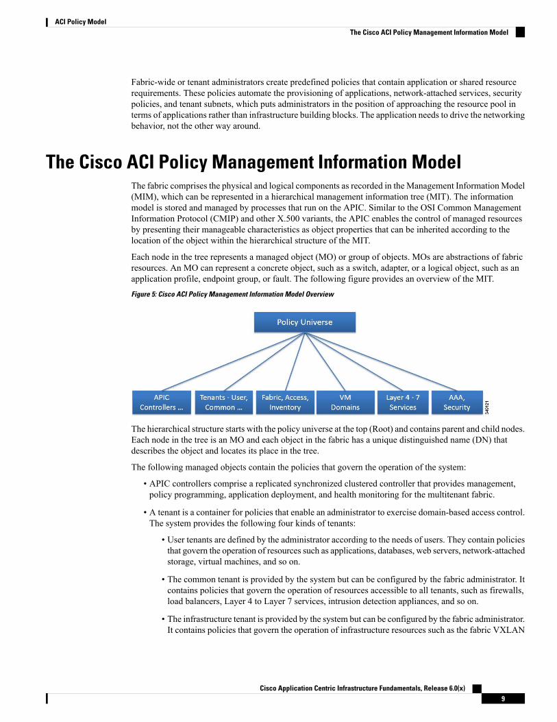
The Cisco ACI Policy Management Information ModelThe fabric comprises the physical and logical components as recorded in the Management InformationModel(MIM), which can be represented in a hierarchical management information tree (MIT). The informationmodel is stored and managed by processes that run on the APIC. Similar to the OSI Common ManagementInformation Protocol (CMIP) and other X.500 variants, the APIC enables the control of managed resourcesby presenting their manageable characteristics as object properties that can be inherited according to thelocation of the object within the hierarchical structure of the MIT.
Each node in the tree represents a managed object (MO) or group of objects. MOs are abstractions of fabricresources. An MO can represent a concrete object, such as a switch, adapter, or a logical object, such as anapplication profile, endpoint group, or fault. The following figure provides an overview of the MIT.
Figure 5: Cisco ACI Policy Management Information Model Overview
The hierarchical structure starts with the policy universe at the top (Root) and contains parent and child nodes.Each node in the tree is an MO and each object in the fabric has a unique distinguished name (DN) thatdescribes the object and locates its place in the tree.
The following managed objects contain the policies that govern the operation of the system:
• APIC controllers comprise a replicated synchronized clustered controller that provides management,policy programming, application deployment, and health monitoring for the multitenant fabric.
• A tenant is a container for policies that enable an administrator to exercise domain-based access control.The system provides the following four kinds of tenants:
• User tenants are defined by the administrator according to the needs of users. They contain policiesthat govern the operation of resources such as applications, databases, web servers, network-attachedstorage, virtual machines, and so on.
• The common tenant is provided by the system but can be configured by the fabric administrator. Itcontains policies that govern the operation of resources accessible to all tenants, such as firewalls,load balancers, Layer 4 to Layer 7 services, intrusion detection appliances, and so on.
• The infrastructure tenant is provided by the system but can be configured by the fabric administrator.It contains policies that govern the operation of infrastructure resources such as the fabric VXLAN
Cisco Application Centric Infrastructure Fundamentals, Release 6.0(x)9
ACI Policy ModelThe Cisco ACI Policy Management Information Model

overlay. It also enables a fabric provider to selectively deploy resources to one or more user tenants.Infrastructure tenant polices are configurable by the fabric administrator.
• The management tenant is provided by the system but can be configured by the fabric administrator.It contains policies that govern the operation of fabric management functions used for in-band andout-of-band configuration of fabric nodes. The management tenant contains a private out-of-boundaddress space for the APIC/fabric internal communications that is outside the fabric data path thatprovides access through the management port of the switches. The management tenant enablesdiscovery and automation of communications with virtual machine controllers.
• Access policies govern the operation of switch access ports that provide connectivity to resources suchas storage, compute, Layer 2 and Layer 3 (bridged and routed) connectivity, virtual machine hypervisors,Layer 4 to Layer 7 devices, and so on. If a tenant requires interface configurations other than thoseprovided in the default link, Cisco Discovery Protocol (CDP), Link Layer Discovery Protocol (LLDP),Link Aggregation Control Protocol (LACP), or Spanning Tree, an administrator must configure accesspolicies to enable such configurations on the access ports of the leaf switches.
• Fabric policies govern the operation of the switch fabric ports, including such functions as Network TimeProtocol (NTP) server synchronization, Intermediate System-to-Intermediate System Protocol (IS-IS),Border Gateway Protocol (BGP) route reflectors, Domain Name System (DNS) and so on. The fabricMO contains objects such as power supplies, fans, chassis, and so on.
• Virtual Machine (VM) domains group VM controllers with similar networking policy requirements. VMcontrollers can share VLAN or Virtual Extensible Local Area Network (VXLAN) space and applicationendpoint groups (EPGs). The APIC communicates with the VM controller to publish networkconfigurations such as port groups that are then applied to the virtual workloads.
• Layer 4 to Layer 7 service integration life cycle automation framework enables the system to dynamicallyrespond when a service comes online or goes offline. Policies provide service device package andinventory management functions.
• Access, authentication, and accounting (AAA) policies govern user privileges, roles, and security domainsof the Cisco ACI fabric.
The hierarchical policy model fits well with the REST API interface. When invoked, the API reads from orwrites to objects in the MIT. URLs map directly into distinguished names that ide.jpgy objects in the MIT.Any data in the MIT can be described as a self-contained structured tree text document encoded in XML orJSON.
TenantsA tenant (fvTenant) is a logical container for application policies that enable an administrator to exercisedomain-based access control. A tenant represents a unit of isolation from a policy perspective, but it does notrepresent a private network. Tenants can represent a customer in a service provider setting, an organizationor domain in an enterprise setting, or just a convenient grouping of policies. The following figure providesan overview of the tenant portion of the management information tree (MIT).
Cisco Application Centric Infrastructure Fundamentals, Release 6.0(x)10
ACI Policy ModelTenants
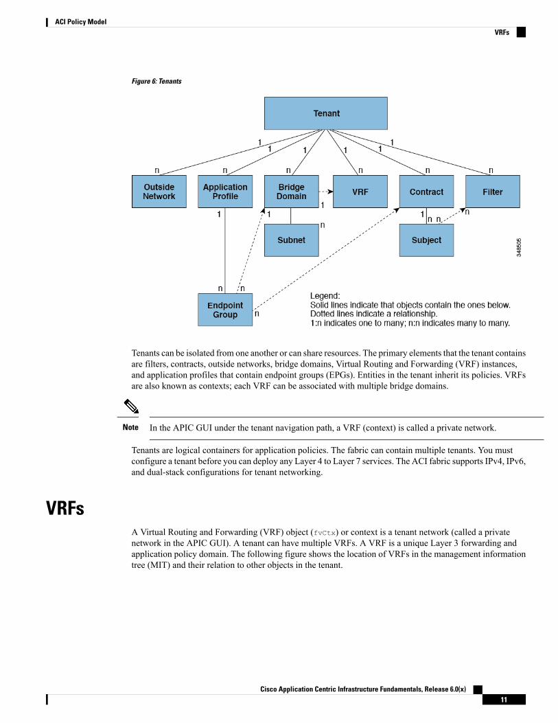
Figure 6: Tenants
Tenants can be isolated from one another or can share resources. The primary elements that the tenant containsare filters, contracts, outside networks, bridge domains, Virtual Routing and Forwarding (VRF) instances,and application profiles that contain endpoint groups (EPGs). Entities in the tenant inherit its policies. VRFsare also known as contexts; each VRF can be associated with multiple bridge domains.
In the APIC GUI under the tenant navigation path, a VRF (context) is called a private network.Note
Tenants are logical containers for application policies. The fabric can contain multiple tenants. You mustconfigure a tenant before you can deploy any Layer 4 to Layer 7 services. The ACI fabric supports IPv4, IPv6,and dual-stack configurations for tenant networking.
VRFsA Virtual Routing and Forwarding (VRF) object (fvCtx) or context is a tenant network (called a privatenetwork in the APIC GUI). A tenant can have multiple VRFs. A VRF is a unique Layer 3 forwarding andapplication policy domain. The following figure shows the location of VRFs in the management informationtree (MIT) and their relation to other objects in the tenant.
Cisco Application Centric Infrastructure Fundamentals, Release 6.0(x)11
ACI Policy ModelVRFs

Figure 7: VRFs
A VRF defines a Layer 3 address domain. One or more bridge domains are associated with a VRF. All of theendpoints within the Layer 3 domain must have unique IP addresses because it is possible to forward packetsdirectly between these devices if the policy allows it. A tenant can containmultiple VRFs. After an administratorcreates a logical device, the administrator can create a VRF for the logical device, which provides a selectioncriteria policy for a device cluster. A logical device can be selected based on a contract name, a graph name,or the function node name inside the graph.
In the APIC GUI, a VRF (fvCtx) is also called a "Context" or "Private Network."Note
Application ProfilesAn application profile (fvAp) defines the policies, services and relationships between endpoint groups (EPGs).The following figure shows the location of application profiles in the management information tree (MIT)and their relation to other objects in the tenant.
Figure 8: Application Profiles
Application profiles contain one or more EPGs. Modern applications contain multiple components. Forexample, an e-commerce application could require a web server, a database server, data located in a storage
Cisco Application Centric Infrastructure Fundamentals, Release 6.0(x)12
ACI Policy ModelApplication Profiles

area network, and access to outside resources that enable financial transactions. The application profile containsas many (or as few) EPGs as necessary that are logically related to providing the capabilities of an application.
EPGs can be organized according to one of the following:
• The application they provide, such as a DNS server or SAP application (see Tenant Policy Example inCisco APIC REST API Configuration Guide).
• The function they provide (such as infrastructure)
• Where they are in the structure of the data center (such as DMZ)
• Whatever organizing principle that a fabric or tenant administrator chooses to use
Endpoint GroupsThe endpoint group (EPG) is themost important object in the policymodel. The following figure showswhereapplication EPGs are located in the management information tree (MIT) and their relation to other objects inthe tenant.
Figure 9: Endpoint Groups
An EPG is a managed object that is a named logical entity that contains a collection of endpoints. Endpointsare devices that are connected to the network directly or indirectly. They have an address (identity), a location,attributes (such as version or patch level), and can be physical or virtual. Knowing the address of an endpoint
Cisco Application Centric Infrastructure Fundamentals, Release 6.0(x)13
ACI Policy ModelEndpoint Groups
also enables access to all its other identity details. EPGs are fully decoupled from the physical and logicaltopology. Endpoint examples include servers, virtual machines, network-attached storage, or clients on theInternet. Endpoint membership in an EPG can be dynamic or static.
The ACI fabric can contain the following types of EPGs:
• Application endpoint group (fvAEPg)
• Layer 2 external outside network instance endpoint group (l2extInstP)
• Layer 3 external outside network instance endpoint group (l3extInstP)
• Management endpoint groups for out-of-band (mgmtOoB) or in-band ( mgmtInB) access.
EPGs contain endpoints that have common policy requirements such as security, virtual machine mobility(VMM), QoS, or Layer 4 to Layer 7 services. Rather than configure and manage endpoints individually, theyare placed in an EPG and are managed as a group.
Policies apply to EPGs, never to individual endpoints. An EPG can be statically configured by an administratorin the APIC, or dynamically configured by an automated system such as vCenter or OpenStack.
When an EPG uses a static binding path, the encapsulation VLAN associated with this EPG must be part ofa static VLAN pool. For IPv4/IPv6 dual-stack configurations, the IP address property is contained in thefvStIp child property of the fvStCEpMO. Multiple fvStIp objects supporting IPv4 and IPv6 addresses canbe added under one fvStCEp object. When upgrading ACI from IPv4-only firmware to versions of firmwarethat support IPv6, the existing IP property is copied to an fvStIpMO.
Note
Regardless of how an EPG is configured, EPG policies are applied to the endpoints they contain.
WAN router connectivity to the fabric is an example of a configuration that uses a static EPG. To configureWAN router connectivity to the fabric, an administrator configures an l3extInstP EPG that includes anyendpoints within an associated WAN subnet. The fabric learns of the EPG endpoints through a discoveryprocess as the endpoints progress through their connectivity life cycle. Upon learning of the endpoint, thefabric applies the l3extInstP EPG policies accordingly. For example, when aWAN connected client initiatesa TCP session with a server within an application (fvAEPg) EPG, the l3extInstP EPG applies its policies tothat client endpoint before the communication with the fvAEPg EPGweb server begins.When the client serverTCP session ends and communication between the client and server terminate, that endpoint no longer existsin the fabric.
If a leaf switch is configured for static binding (leaf switches) under an EPG, the following restrictions apply:
• The static binding cannot be overridden with a static path.
• Interfaces in that switch cannot be used for routed external network (L3out) configurations.
• Interfaces in that switch cannot be assigned IP addresses.
Note
Virtual machine management connectivity to VMware vCenter is an example of a configuration that uses adynamic EPG. Once the virtual machine management domain is configured in the fabric, vCenter triggers thedynamic configuration of EPGs that enable virtual machine endpoints to start up, move, and shut down asneeded.
Cisco Application Centric Infrastructure Fundamentals, Release 6.0(x)14
ACI Policy ModelEndpoint Groups

IP-Based EPGsAlthough encapsulation-based EPGs are commonly used, IP-based EPGs are suitable in networks where thereis a need for large numbers of EPGs that cannot be supported by Longest Prefix Match (LPM) classification.IP-based EPGs do not require allocating a network/mask range for each EPG, unlike LPM classification. Also,a unique bridge domain is not required for each IP-based EPG. The configuration steps for an IP-based EPGare like those for configuring a virtual IP-based EPG that is used in the Cisco AVS vCenter configuration.
Observe the following guidelines and limitations of IP-based EPGs:
• IP-based EPGs are supported starting with the APIC 1.1(2x) and ACI switch 11.1(2x) releases on thefollowing Cisco Nexus N9K switches:
• Switches with "E" on the end of the switch name, for example, N9K-C9372PX-E.
• Switches with "EX" on the end of the switch name, for example, N9K-93108TC-EX.
The APIC raises a fault when you attempt to deploy IP-based EPGs on older switches that do not supportthem.
• IP-based EPGs can be configured for specific IP addresses or subnets, but not IP address ranges.
• IP-based EPGs are not supported in the following scenarios:
• In combination with static EP configurations.
• External, infrastructure tenant (infra) configurations will not be blocked, but they do not take effect,because there is no Layer 3 learning in this case.
• In Layer 2-only bridge domains, IP-based EPG does not take effect, because there is no routedtraffic in this case. If proxy ARP is enabled on Layer 3 bridge domains, the traffic is routed even ifendpoints are in the same subnet. So IP-based EPG works in this case.
• Configurations with a prefix that is used both for shared services and an IP-based EPG.
MicrosegmentationMicrosegmentation associates endpoints frommultiple EPGs into amicrosegmented EPG according to virtualmachine attributes, IP address, or MAC address. Virtual machine attributes include: VNic domain name, VMidentifier, VM name, hypervisor identifier, VMM domain, datacenter, operating system, or custom attribute.
Some advantages of microsegmentation include the following:
• Stateless white list network access security with line rate enforcement.
• Per-microsegment granularity of security automation through dynamic Layer 4 - Layer 7 service insertionand chaining.
• Hypervisor agnostic microsegmentation in a broad range of virtual switch environments.
• ACI policies that easily move problematic VMs into a quarantine security zone.
• When combined with intra-EPG isolation for bare metal and VM endpoints, microsegmentation canprovide policy driven automated complete endpoint isolation within application tiers.
For any EPG, the ACI fabric ingress leaf switch classifies packets into an EPG according to the policiesassociatedwith the ingress port. Microsegmented EPGs apply policies to individual virtual or physical endpoints
Cisco Application Centric Infrastructure Fundamentals, Release 6.0(x)15
ACI Policy ModelIP-Based EPGs

that are derived based on the VM attribute, MAC address, or IP address specified in the microsegmented EPGpolicy.
Intra-EPG Endpoint IsolationIntra-EPG endpoint isolation policies provide full isolation for virtual or physical endpoints; no communicationis allowed between endpoints in an EPG that is operating with isolation enforced. Isolation enforced EPGsreduce the number of EPG encapsulations required when many clients access a common service but are notallowed to communicate with each other.
An EPG is isolation enforced for all Cisco Application Centric Infrastructure (ACI) network domains or none.While the Cisco ACI fabric implements isolation directly to connected endpoints, switches connected to thefabric are made aware of isolation rules according to a primary VLAN (PVLAN) tag.
If an EPG is configured with intra-EPG endpoint isolation enforced, these restrictions apply:
• All Layer 2 endpoint communication across an isolation enforced EPG is dropped within a bridge domain.
• All Layer 3 endpoint communication across an isolation enforced EPG is dropped within the same subnet.
• Preserving QoS CoS priority settings is not supported when traffic is flowing from an EPGwith isolationenforced to an EPG without isolation enforced.
Note
BPDUs are not forwarded through EPGs with intra-EPG isolation enabled. Therefore, when you connect anexternal Layer 2 network that runs spanning tree in a VLAN that maps to an isolated EPG on Cisco ACI,Cisco ACI might prevent spanning tree in the external network from detecting a Layer 2 loop. You can avoidthis issue by ensuring that there is only a single logical link between Cisco ACI and the external network inthese VLANs.
Bridge Domains and SubnetsA bridge domain (fvBD) represents a Layer 2 forwarding construct within the fabric. The following figureshows the location of bridge domains (BDs) in the management information tree (MIT) and their relation toother objects in the tenant.
Figure 10: Bridge Domains
Cisco Application Centric Infrastructure Fundamentals, Release 6.0(x)16
ACI Policy ModelIntra-EPG Endpoint Isolation

A BD must be linked to a VRF (also known as a context or private network). With the exception of a Layer2 VLAN, it must have at least one subnet (fvSubnet) associated with it. The BD defines the unique Layer 2MAC address space and a Layer 2 flood domain if such flooding is enabled. While a VRF defines a uniqueIP address space, that address space can consist of multiple subnets. Those subnets are defined in one or moreBDs that reference the corresponding VRF.
The options for a subnet under a BD or under an EPG are as follows:
• Public—the subnet can be exported to a routed connection.
• Private—the subnet applies only within its tenant.
• Shared—the subnet can be shared with and exported to multiple VRFs in the same tenant or acrosstenants as part of a shared service. An example of a shared service is a routed connection to an EPGpresent in another VRF in a different tenant. This enables traffic to pass in both directions across VRFs.An EPG that provides a shared service must have its subnet configured under that EPG (not under a BD),and its scope must be set to advertised externally, and shared between VRFs.
Shared subnets must be unique across the VRF involved in the communication.When a subnet under an EPG provides a Layer 3 external network shared service,such a subnet must be globally unique within the entire ACI fabric.
Note
BD packet behavior can be controlled in the following ways:
ModePacket Type
You can enable or disable ARP Flooding; withoutflooding, ARP packets are sent with unicast.
If the limitIpLearnToSubnets in fvBD isset, endpoint learning is limited to the BDonly if the IP address is in a configuredsubnet of the BD or an EPG subnet that isa shared service provider.
Note
ARP
L2 Unknown Unicast, which can be Flood orHardware Proxy.
When the BD has L2 Unknown Unicastset to Flood, if an endpoint is deleted thesystem deletes it from both the local leafswitches as well as the remote leaf switcheswhere the BD is deployed, by selectingClear Remote MAC Entries.Without thisfeature, the remote leaf continues to havethis endpoint learned until the timerexpires.
Note
Modifying the L2 Unknown Unicast setting causestraffic to bounce (go down and up) on interfaces todevices attached to EPGs associated with this bridgedomain.
Unknown Unicast
Cisco Application Centric Infrastructure Fundamentals, Release 6.0(x)17
ACI Policy ModelBridge Domains and Subnets

ModePacket Type
L3 Unknown Multicast Flooding
Flood—Packets are flooded on ingress and borderleaf switch nodes only. With N9K-93180YC-EX,packets are flooded on all the nodes where a bridgedomain is deployed.
Optimized—Only 50 bridge domains per leaf aresupported. This limitation is not applicable forN9K-93180YC-EX.
Unknown IP Multicast
Multi-Destination Flooding, which can be one ofthe following:
• Flood in BD—flood in bridge domain
• Flood in Encapsulation—flood in encapsulation
• Drop—drop the packets
L2 Multicast, Broadcast, Unicast
Beginning with Cisco APIC Release 3.1(1), on the Cisco Nexus 9000 series switches (with names endingwith EX and FX and onwards), the following protocols can be flooded in encapsulation or flooded in a bridgedomain: OSPF/OSPFv3, BGP, EIGRP, CDP, LACP, LLDP, ISIS, IGMP, PIM, ST-BPDU, ARP/GARP,RARP, ND.
Note
Bridge domains can span multiple switches. A bridge domain can contain multiple subnets, but a subnet iscontained within a single bridge domain. If the bridge domain (fvBD) limitIPLearnToSubnets property isset to yes, endpoint learning will occur in the bridge domain only if the IP address is within any of theconfigured subnets for the bridge domain or within an EPG subnet when the EPG is a shared service provider.Subnets can span multiple EPGs; one or more EPGs can be associated with one bridge domain or subnet. Inhardware proxy mode, ARP traffic is forwarded to an endpoint in a different bridge domain when that endpointhas been learned as part of the Layer 3 lookup operation.
Bridge Domain OptionsA bridge domain can be set to operate in flood mode for unknown unicast frames or in an optimized modethat eliminates flooding for these frames. When operating in flood mode, Layer 2 unknown unicast traffic isflooded over the multicast tree of the bridge domain (GIPo). For the bridge domain to operate in optimizedmode you should set it to hardware-proxy. In this case, Layer 2 unknown unicast frames are sent to thespine-proxy anycast VTEP address.
Changing from unknown unicast flooding mode to hw-proxy mode is disruptive to the traffic in the bridgedomain.
Caution
If IP routing is enabled in the bridge domain, the mapping database learns the IP address of the endpoints inaddition to the MAC address.
Cisco Application Centric Infrastructure Fundamentals, Release 6.0(x)18
ACI Policy ModelBridge Domain Options
TheLayer 3 Configurations tab of the bridge domain panel allows the administrator to configure the followingparameters:
• Unicast Routing: If this setting is enabled and a subnet address is configured, the fabric provides thedefault gateway function and routes the traffic. Enabling unicast routing also instructs the mappingdatabase to learn the endpoint IP-to-VTEP mapping for this bridge domain. The IP learning is notdependent upon having a subnet configured under the bridge domain.
• Subnet Address: This option configures the SVI IP addresses (default gateway) for the bridge domain.
• Limit IP Learning to Subnet: This option is similar to a unicast reverse-forwarding-path check. If thisoption is selected, the fabric will not learn IP addresses from a subnet other than the one configured onthe bridge domain.
Enabling Limit IP Learning to Subnet is disruptive to the traffic in the bridge domain.Caution
Scaled L2 Only Mode - Legacy Mode
In Cisco ACI, the same VLAN ID can be reused for any purpose as long as the VLAN is deployed on differentleaf nodes. This allows the Cisco ACI fabric to overcome the theoretical maximum number of VLANs 4094as a fabric. However, to accomplish this, and also to hide the complexity of underlying VxLAN implementation,each individual leaf node can contain smaller number of VLANs. This may pose a problem when the densityof VLANs per leaf node is required. In such a scenario, you can enable Scaled L2 Only mode, formerlyknown as legacy mode on the bridge domain. A bridge domain in scaled L2 only mode allows large numberof VLANs per leaf node. However, such a bridge domain has some limitations.
For the number of VLANs or bridge domains supported per leaf node with or without scaled L2 only mode,see Verified Scalability Guide for your specific release.
Limitations for Scaled L2 Only Mode
The following are limitations for legacy mode or scaled L2 only mode.
• The bridge domain can contain only one EPG and one VLAN.
• Unicast routing is not supported.
• Contracts are not supported.
• Dynamic VLAN allocation for VMM integration is not supported.
• Service graph is not supported.
• A QoS policy is not supported.
• The bridge domain essentially behaves as a VLAN in standalone Cisco NX-OS.
Scaled L2 Only Mode Configuration
The following are considerations to configure a bridge domain in scaled L2 only mode.
• VLAN ID is configured on the bridge domain.
• VLAN IDs configured under the EPG are overridden.
Cisco Application Centric Infrastructure Fundamentals, Release 6.0(x)19
ACI Policy ModelBridge Domain Options

• Enabling or disabling a scaled L2 only mode on an existing bridge domain will impact service.
Cisco APIC will automatically undeploy and redeploy the bridge domain when the VLAN ID is differentfrom what was used prior to the change.
When the same VLAN ID is used before and after the mode change, Cisco APIC will not automaticallyundeploy and redeploy the bridge domain. You must manually undeploy and redeply the bridge domain,which can be performed by deleting and recreating the static port configuration under the EPG.
• When changing the VLAN ID for scaled L2 only mode, you must first disable the mode, then enablescaled L2 only mode with the new VLAN ID.
Disabling IP Learning per Bridge Domain
IP learning per bridge domain is disabled when two hosts are connected as active and standby hosts to theCisco ACI switches. The MAC learning still occurs in the hardware but the IP learning only occurs from theARP/GARP/ND processes. This functionality allows for flexible deployments, for example, firewalls or localgateways.
See the following guidelines and limitations for disabling IP learning per bridge domain:
• Layer 3 multicast is not supported because the source IP address is not learned to populate the S,Ginformation in the remote top-of-rack (ToR) switches.
• As the DL bit is set in the iVXLAN header, the MAC address is also not learned from the data path inthe remote TORs. It results in flooding of the unknown unicast traffic from the remote TOR to all TORsin the fabric where this BD is deployed. It is recommended to configure the BD in proxymode to overcomethis situation if endpoint dataplane learning is disabled.
• ARP should be in flood mode and GARP based detection should be enabled.
• When IP learning is disabled, Layer 3 endpoints are not flushed in the corresponding VRF. It may leadto the endpoints pointing to the same TOR forever. To resolve this issue, flush all the remote IP endpointsin this VRF on all TORs.
The configuration change of disabling dataplane learning on the BD doesn’t flush previously locally learnedendpoints. This limits the disruption to existing traffic flows. MAC learned endpoints age as usual if the CiscoACI leaf sees no traffic with the given source MAC for longer than the endpoint retention policy.
Disabling IP dataplane learning means that the endpoint IP information is not updated as a result of trafficforwarding, but Cisco ACI can refresh the endpoint IP information with ARP/ND. This means that the agingof the local endpoints (whether they were learned before the configuration change, or they are learned afterthe configuration change) differs slightly from the normal aging and it depends also from System > System
Settings > Endpoint Controls > IP Aging.
If IP Aging is disabled, traffic from a source MAC that matches an already learned endpoint MAC, refreshesthe MAC addresses information in the endpoint table, and as a result also refreshes the IP information (thisis the same as IP dataplane learning enabled).
If IP Aging is enabled, ACI ages out endpoint IP addresses individually (this is no different fromwhat happenswith IP dataplane learning enabled), but differently from configurations with IP dataplane learning enabled,traffic from a known sourceMAC and IP that matches an already learned endpoint, refreshes theMAC addressinformation in the endpoint table, but not the IP information.
Note
Cisco Application Centric Infrastructure Fundamentals, Release 6.0(x)20
ACI Policy ModelBridge Domain Options
Attachable Entity ProfileThe ACI fabric provides multiple attachment points that connect through leaf ports to various external entitiessuch as bare metal servers, virtual machine hypervisors, Layer 2 switches (for example, the Cisco UCS fabricinterconnect), or Layer 3 routers (for example Cisco Nexus 7000 Series switches). These attachment pointscan be physical ports, FEX ports, port channels, or a virtual port channel (vPC) on leaf switches.
When creating a VPC domain between two leaf switches, both switches must be in the same switch generation,one of the following:
• Generation 1 - Cisco Nexus N9K switches without “EX” or "FX" on the end of the switch name; forexample, N9K-9312TX
• Generation 2 – Cisco Nexus N9K switches with “EX” or "FX" on the end of the switch model name; forexample, N9K-93108TC-EX
Switches such as these two are not compatible VPC peers. Instead, use switches of the same generation.
Note
An Attachable Entity Profile (AEP) represents a group of external entities with similar infrastructure policyrequirements. The infrastructure policies consist of physical interface policies that configure various protocoloptions, such as Cisco Discovery Protocol (CDP), Link Layer Discovery Protocol (LLDP), or Link AggregationControl Protocol (LACP).
An AEP is required to deploy VLAN pools on leaf switches. Encapsulation blocks (and associated VLANs)are reusable across leaf switches. An AEP implicitly provides the scope of the VLAN pool to the physicalinfrastructure.
The following AEP requirements and dependencies must be accounted for in various configuration scenarios,including network connectivity, VMM domains, and multipod configuration:
• The AEP defines the range of allowed VLANS but it does not provision them. No traffic flows unlessan EPG is deployed on the port. Without defining a VLAN pool in an AEP, a VLAN is not enabled onthe leaf port even if an EPG is provisioned.
• A particular VLAN is provisioned or enabled on the leaf port that is based on EPG events either staticallybinding on a leaf port or based on VM events from external controllers such as VMware vCenter orMicrosoft Azure Service Center Virtual Machine Manager (SCVMM).
• Attached entity profiles can be associated directly with application EPGs, which deploy the associatedapplication EPGs to all those ports associated with the attached entity profile. The AEP has a configurablegeneric function (infraGeneric), which contains a relation to an EPG (infraRsFuncToEpg) that is deployedon all interfaces that are part of the selectors that are associated with the attachable entity profile.
A virtual machine manager (VMM) domain automatically derives physical interface policies from the interfacepolicy groups of an AEP.
An override policy at the AEP can be used to specify a different physical interface policy for a VMM domain.This policy is useful in scenarios where a VM controller is connected to the leaf switch through an intermediateLayer 2 node, and a different policy is desired at the leaf switch and VM controller physical ports. For example,you can configure LACP between a leaf switch and a Layer 2 node. At the same time, you can disable LACPbetween the VM controller and the Layer 2 switch by disabling LACP under the AEP override policy.
Cisco Application Centric Infrastructure Fundamentals, Release 6.0(x)21
ACI Policy ModelAttachable Entity Profile

VLANs and EPGs
Access Policies Automate Assigning VLANs to EPGsWhile tenant network policies are configured separately from fabric access policies, tenant policies are notactivated unless their underlying access policies are in place. Fabric access external-facing interfaces connectto external devices such as virtual machine controllers and hypervisors, hosts, routers, or Fabric Extenders(FEXs). Access policies enable an administrator to configure port channels and virtual port channels, protocolssuch as LLDP, CDP, or LACP, and features such as monitoring or diagnostics.
Figure 11: Association of Endpoint Groups with Access Policies
In the policy model, EPGs are tightly coupled with VLANs. For traffic to flow, an EPG must be deployed ona leaf port with a VLAN in a physical, VMM, L2out, L3out, or Fibre Channel domain. For more information,see Networking Domains, on page 137.
In the policy model, the domain profile associated to the EPG contains the VLAN instance profile. The domainprofile contains both the VLAN instance profile (VLAN pool) and the attacheable Access Entity Profile(AEP), which are associated directly with application EPGs. The AEP deploys the associated applicationEPGs to all the ports to which it is attached, and automates the task of assigning VLANs. While a large datacenter could easily have thousands of active virtual machines provisioned on hundreds of VLANs, the ACIfabric can automatically assign VLAN IDs from VLAN pools. This saves a tremendous amount of time,compared with trunking down VLANs in a traditional data center.
VLAN Guidelines
Use the following guidelines to configure the VLANs where EPG traffic will flow.
• Multiple domains can share a VLAN pool, but a single domain can only use one VLAN pool.
Cisco Application Centric Infrastructure Fundamentals, Release 6.0(x)22
ACI Policy ModelVLANs and EPGs

• To deploy multiple EPGs with same VLAN encapsulation on a single leaf switch, see Per Port VLAN,on page 25.
Native 802.1p and Tagged EPGs on InterfacesWhen assigning Access (802.1p or Untagged) modes, follow these guidelines to ensure that devices thatrequire untagged or 802.1p packets operate as expected when they are connected to access ports of an ACIleaf switch.
These guidelines apply to EPGs deployed on ports on a single leaf switch. When EPGs are deployed ondifferent switches, these restrictions do not apply.
• In the APIC GUI, when you assign VLANs on ports to EPGs, you can assign one of the following VLANmodes: Trunk, Access (802.1p), or Access (Untagged).
• Only one 802.1p VLAN or one untagged VLAN is allowed on a port. It can be one or the other but notboth.
• For generation 1 switches, if an EPG deployed on any port on a leaf switch is configured with Access(Untagged) mode, all the ports used by the EPG should be untagged on the same leaf switch and its VPCpeer (if there is one). You can have a combination of untagged and tagged ports on generation 2 switches(with -EX, -FX, or -FX2 suffixes).
• You can deploy different EPGs using (tagged) VLAN numbers in Trunk mode on the same port, withan EPG deployed on the port in Access (Untagged) mode.
There are some differences in traffic handling, depending on the switch, when a leaf switch port is associatedwith a single EPG that is configured as Access (802.1p) or Access (Untagged) modes.
Generation 1 Switches
• If the port is configured in Access (802.1p) mode:
• On egress, if the access VLAN is the only VLAN deployed on the port, then traffic will be untagged.
• On egress, if the port has other (tagged) VLANs deployed along with an untagged EPG, then trafficfrom that EPG is zero tagged.
• On egress, for all FEX ports, traffic is untagged, irrespective of one or more VLAN tags configuredon the port.
• The port accepts ingress traffic that is untagged, tagged, or in 802.1p mode.
• If a port is configured in Access (Untagged) mode:
• On egress, the traffic from the EPG is untagged.
• The port accepts ingress traffic that is untagged, tagged, or 802.1p.
Generation 2 Switches
Generation 2 switches, or later, do not distinguish between the Access (Untagged) and Access (802.1p)modes. When EPGs are deployed on Generation 2 ports configured with either Untagged or 802.1p mode:
• On egress, traffic is always untagged on a node where this is deployed.
Cisco Application Centric Infrastructure Fundamentals, Release 6.0(x)23
ACI Policy ModelNative 802.1p and Tagged EPGs on Interfaces

• The port accepts ingress traffic that is untagged, tagged, or in 802.1p mode.
VLAN Mode Combinations on Ports: First Generation and Second Generation Hardware Running Cisco APICReleases Prior to 3.2(3i)
VLAN Mode Combinations Supported for One EPG
EPG 1 on different ports, the following VLAN modesare allowed:
EPG 1 on Port 1, with VLAN mode:
Trunk or 802.1pTrunk
UntaggedUntagged
Trunk or 802.1p802.1p
VLAN Mode Combinations Supported for Multiple EPGs
EPG 2 on port 1, the followingmodes are allowed:
EPG 1 on port 2, the followingmodes are allowed:
EPG 1 on port 1 with VLAN mode:
TrunkUntaggedUntagged
TrunkTrunk or 802.1p802.1p
Trunk or 802.1p or untagged802.1p or TrunkTrunk
VLAN Mode Combinations on Ports: Second Generation Hardware Running Cisco APIC Release 3.2(3i) orLater
VLAN Mode Combinations Supported for One EPG
EPG 1 on different ports, the following VLAN modesare allowed:
EPG 1 on Port 1, with VLAN mode:
Trunk (tagged) or untagged or 802.1pTrunk
Untagged or 802.1p or trunk (tagged)Untagged
Trunk (tagged) or 802.1p or untagged802.1p
VLAN Mode Combinations Supported for Multiple EPGs
EPG 2 on port 1, the followingmodes are allowed:
EPG 1 on port 2, the followingmodes are allowed:
EPG 1 on port 1 with VLAN mode:
Trunk (tagged)Untagged or 802.1p or trunk(tagged)
Untagged
Trunk (tagged)Trunk (tagged) or 802.1p oruntagged
802.1p
Trunk (tagged) or 802.1p oruntagged
802.1p or trunk (tagged) oruntagged
Trunk
Cisco Application Centric Infrastructure Fundamentals, Release 6.0(x)24
ACI Policy ModelNative 802.1p and Tagged EPGs on Interfaces
Certain older network interface cards (NICs) that send traffic on the native VLAN untagged, drop return trafficthat is tagged as VLAN 0. This is normally only a problem on interfaces configured as trunk ports. However,if an Attachable Entity Profile (AEP) for an access port is configured to carry the infra VLAN, then it is treatedas a trunk port, even though it is configured as an access port. In these circumstances, packets sent on thenative VLAN from the switch with Network Flow Engine (NFE) cards will be tagged as VLAN 0, and olderswitch NICs may drop them. Options to address this issue include:
• Removing the infra VLAN from the AEP.
• Configuring "port local scope" on the port. This enables per-port VLAN definition and allows the switchequipped with NFE to send packets on the native VLAN, untagged.
Note
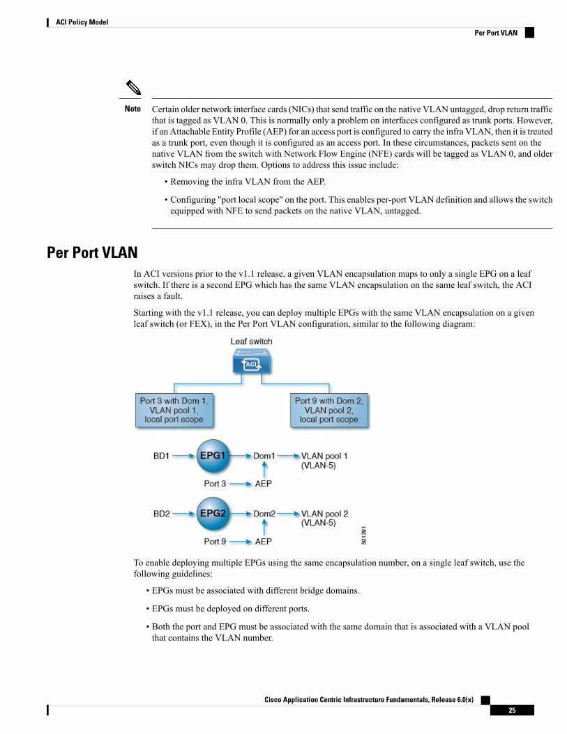
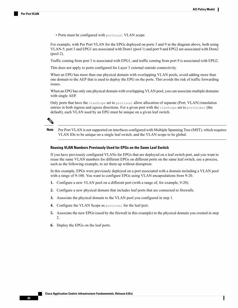
Per Port VLANIn ACI versions prior to the v1.1 release, a given VLAN encapsulation maps to only a single EPG on a leafswitch. If there is a second EPG which has the same VLAN encapsulation on the same leaf switch, the ACIraises a fault.
Starting with the v1.1 release, you can deploy multiple EPGs with the same VLAN encapsulation on a givenleaf switch (or FEX), in the Per Port VLAN configuration, similar to the following diagram:
To enable deploying multiple EPGs using the same encapsulation number, on a single leaf switch, use thefollowing guidelines:
• EPGs must be associated with different bridge domains.
• EPGs must be deployed on different ports.
• Both the port and EPG must be associated with the same domain that is associated with a VLAN poolthat contains the VLAN number.
Cisco Application Centric Infrastructure Fundamentals, Release 6.0(x)25
ACI Policy ModelPer Port VLAN
• Ports must be configured with portLocal VLAN scope.
For example, with Per Port VLAN for the EPGs deployed on ports 3 and 9 in the diagram above, both usingVLAN-5, port 3 and EPG1 are associated with Dom1 (pool 1) and port 9 and EPG2 are associated with Dom2(pool 2).
Traffic coming from port 3 is associated with EPG1, and traffic coming from port 9 is associated with EPG2.
This does not apply to ports configured for Layer 3 external outside connectivity.
When an EPG has more than one physical domain with overlapping VLAN pools, avoid adding more thanone domain to the AEP that is used to deploy the EPG on the ports. This avoids the risk of traffic forwardingissues.
When an EPG has only one physical domain with overlapping VLAN pool, you can associate multiple domainswith single AEP.
Only ports that have the vlanScope set to portlocal allow allocation of separate (Port, VLAN) translationentries in both ingress and egress directions. For a given port with the vlanScope set to portGlobal (thedefault), each VLAN used by an EPG must be unique on a given leaf switch.
Per Port VLAN is not supported on interfaces configured withMultiple Spanning Tree (MST), which requiresVLAN IDs to be unique on a single leaf switch, and the VLAN scope to be global.
Note
Reusing VLAN Numbers Previously Used for EPGs on the Same Leaf Switch
If you have previously configured VLANs for EPGs that are deployed on a leaf switch port, and you want toreuse the same VLAN numbers for different EPGs on different ports on the same leaf switch, use a process,such as the following example, to set them up without disruption:
In this example, EPGs were previously deployed on a port associated with a domain including a VLAN poolwith a range of 9-100. You want to configure EPGs using VLAN encapsulations from 9-20.
1. Configure a new VLAN pool on a different port (with a range of, for example, 9-20).
2. Configure a new physical domain that includes leaf ports that are connected to firewalls.
3. Associate the physical domain to the VLAN pool you configured in step 1.
4. Configure the VLAN Scope as portLocal for the leaf port.
5. Associate the new EPGs (used by the firewall in this example) to the physical domain you created in step2.
6. Deploy the EPGs on the leaf ports.
Cisco Application Centric Infrastructure Fundamentals, Release 6.0(x)26
ACI Policy ModelPer Port VLAN
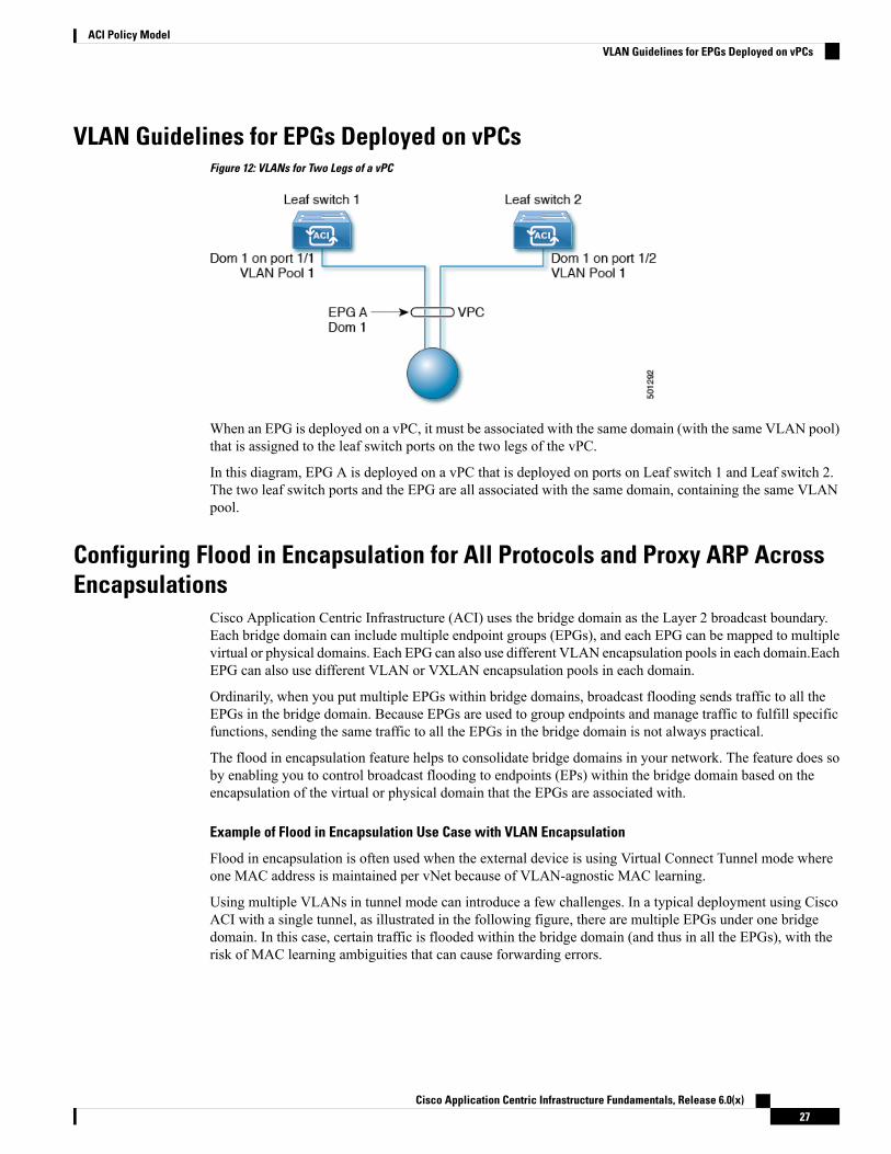
VLAN Guidelines for EPGs Deployed on vPCsFigure 12: VLANs for Two Legs of a vPC
When an EPG is deployed on a vPC, it must be associated with the same domain (with the same VLAN pool)that is assigned to the leaf switch ports on the two legs of the vPC.
In this diagram, EPG A is deployed on a vPC that is deployed on ports on Leaf switch 1 and Leaf switch 2.The two leaf switch ports and the EPG are all associated with the same domain, containing the same VLANpool.
Configuring Flood in Encapsulation for All Protocols and Proxy ARP AcrossEncapsulations
Cisco Application Centric Infrastructure (ACI) uses the bridge domain as the Layer 2 broadcast boundary.Each bridge domain can include multiple endpoint groups (EPGs), and each EPG can be mapped to multiplevirtual or physical domains. Each EPG can also use different VLAN encapsulation pools in each domain.EachEPG can also use different VLAN or VXLAN encapsulation pools in each domain.
Ordinarily, when you put multiple EPGs within bridge domains, broadcast flooding sends traffic to all theEPGs in the bridge domain. Because EPGs are used to group endpoints and manage traffic to fulfill specificfunctions, sending the same traffic to all the EPGs in the bridge domain is not always practical.
The flood in encapsulation feature helps to consolidate bridge domains in your network. The feature does soby enabling you to control broadcast flooding to endpoints (EPs) within the bridge domain based on theencapsulation of the virtual or physical domain that the EPGs are associated with.
Example of Flood in Encapsulation Use Case with VLAN Encapsulation
Flood in encapsulation is often used when the external device is using Virtual Connect Tunnel mode whereone MAC address is maintained per vNet because of VLAN-agnostic MAC learning.
Using multiple VLANs in tunnel mode can introduce a few challenges. In a typical deployment using CiscoACI with a single tunnel, as illustrated in the following figure, there are multiple EPGs under one bridgedomain. In this case, certain traffic is flooded within the bridge domain (and thus in all the EPGs), with therisk of MAC learning ambiguities that can cause forwarding errors.
Cisco Application Centric Infrastructure Fundamentals, Release 6.0(x)27
ACI Policy ModelVLAN Guidelines for EPGs Deployed on vPCs

Figure 13: Challenges of Cisco ACI with VLAN Tunnel Mode
In this topology, the blade switch (virtual connect in this example) has a single tunnel network defined thatuses one uplink to connect with the Cisco ACI leaf node. Two user VLANs, VLAN 10 and VLAN 11 arecarried over this link. The bridge domain is set in flooding mode as the servers’ gateways are outside theCisco ACI cloud. ARP negotiations occur in the following process:
• The server sends one ARP broadcast request over the VLAN 10 network.
• The ARP packet travels through the tunnel network to the external server, which records the sourceMACaddress, learned from its downlink.
• The server then forwards the packet out its uplink to the Cisco ACI leaf switch.
• The Cisco ACI fabric sees the ARP broadcast packet entering on access port VLAN 10 and maps it toEPG1.
• Because the bridge domain is set to flood ARP packets, the packet is flooded within the bridge domainand thus to the ports under both EPGs as they are in the same bridge domain.
• The same ARP broadcast packet comes back over the same uplink.
• The blade switch sees the original source MAC address from this uplink.
Result: The blade switch has the same MAC address learned from both the downlink port and uplink portwithin its single MAC forwarding table, causing traffic disruptions.
Recommended Solution
The flood in encapsulation option is used to limit flooding traffic inside the bridge domain to a singleencapsulation. When EPG1/VLAN X and EPG2/VLAN Y share the same bridge domain and flood inencapsulation is enabled, the encapsulation flooding traffic does not reach the other EPG/VLAN.
Cisco Application Centric Infrastructure Fundamentals, Release 6.0(x)28
ACI Policy ModelConfiguring Flood in Encapsulation for All Protocols and Proxy ARP Across Encapsulations
Beginning with Cisco Application Policy Infrastructure Controller (APIC) release 3.1(1), on the Cisco Nexus9000 series switches (with names ending with EX and FX and onwards), all protocols are flooded inencapsulation. Also, when flood in encapsulation is enabled under the bridge domain for any inter-VLANtraffic, Proxy ARP ensures that the MAC flap issue does not occur. It also limits all flooding (ARP, GARP,and BUM) to the encapsulation. The restriction applies for all EPGs under the bridge domain where it isenabled.
Before Cisco APIC release 3.1(1), these features are not supported (proxy ARP and all protocols being includedwhen flooding within encapsulation). In an earlier Cisco APIC release or earlier generation switches (withoutEX or FX on their names), if you enable flood in encapsulation it does not function, no informational fault isgenerated, but Cisco APIC decreases the health score by 1.
Note
Beginning with Cisco APIC release 3.2(5), you can configure flood in encapsulation for EPGs associatedwith VXLAN encapsulation. Previously, only VLANs were supported for flood in encapsulation for virtualdomains. You configure flood in encapsulation when you create or modify a bridge domain or an EPG.
Note
The recommended solution is to support multiple EPGs under one bridge domain by adding an external switch.This design with multiple EPGs under one bridge domain with an external switch is illustrated in the followingfigure.
Cisco Application Centric Infrastructure Fundamentals, Release 6.0(x)29
ACI Policy ModelConfiguring Flood in Encapsulation for All Protocols and Proxy ARP Across Encapsulations
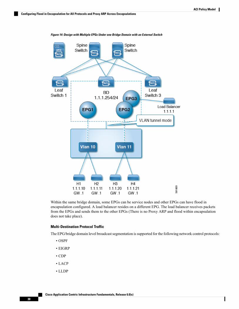
Figure 14: Design with Multiple EPGs Under one Bridge Domain with an External Switch
Within the same bridge domain, some EPGs can be service nodes and other EPGs can have flood inencapsulation configured. A load balancer resides on a different EPG. The load balancer receives packetsfrom the EPGs and sends them to the other EPGs (There is no Proxy ARP and flood within encapsulationdoes not take place).
Multi-Destination Protocol Traffic
The EPG/bridge domain level broadcast segmentation is supported for the following network control protocols:
• OSPF
• EIGRP
• CDP
• LACP
• LLDP
Cisco Application Centric Infrastructure Fundamentals, Release 6.0(x)30
ACI Policy ModelConfiguring Flood in Encapsulation for All Protocols and Proxy ARP Across Encapsulations

• IS-IS
• BGP
• IGMP
• PIM
• STP-BPDU (flooded within EPG)
• ARP/GARP (controlled by ARP Proxy)
• ND
Flood in Encapsulation Limitations
The following limitations apply when using flood in encapsulation for all protocols:
• Flood in encapsulation does not work in ARP unicast mode.
• Neighbor Solicitation (Proxy NS/ND) is not supported for this release.
• Because proxy Address Resolution Protocol (ARP) is enabled implicitly, ARP traffic can go to the CPUfor communication between different encapsulations.
To ensure even distribution to different ports to process ARP traffic, enable per-port Control PlanePolicing (CoPP) for ARP with flood in encapsulation.
• Flood in encapsulation is supported only in bridge domain in flood mode and ARP in flood mode. Bridgedomain spine proxy mode is not supported.
• IPv4 Layer 3 multicast is not supported.
• IPv6 NS/ND proxy is not supported when flood in encapsulation is enabled. As a result, the connectionbetween two endpoints that are under same IPv6 subnet but resident in EPGswith different encapsulationmay not work.
• VM migration to a different VLAN has momentary issues (60 seconds). VM migration to a differentVLAN or VXLAN has momentary issues (60 seconds).
• Setting up communication between VMs through a firewall, as a gateway, is not recommended becauseif the VM IP address changes to the gateway IP address instead of the firewall IP address, then the firewallcan be bypassed.
• Prior releases are not supported (even interoperating between prior and current releases).
• A mixed-mode topology with older-generation Application Leaf Engine (ALE) and Application SpineEngine (ASE) is not recommended and is not supported with flood in encapsulation. Enabling themtogether can prevent QoS priorities from being enforced.
• Flood in encapsulation is not supported for EPG and bridge domains that are extended across Cisco ACIfabrics that are part of the same Multi-Site domain. However, flood in encapsulation is still working andfully supported, and works for EPGs or bridge domains that are locally defined in Cisco ACI fabrics,independently from the fact those fabrics may be configured for Multi-Site. The same considerationsapply for EPGs or bridge domains that are stretched between Cisco ACI fabric and remote leaf switchesthat are associated to that fabric.
• Flood in encapsulation is not supported on EPGs where microsegmentation is configured.
Cisco Application Centric Infrastructure Fundamentals, Release 6.0(x)31
ACI Policy ModelConfiguring Flood in Encapsulation for All Protocols and Proxy ARP Across Encapsulations

• Flood in encapsulation is not supported for Common Pervasive Gateway. See the chapter "CommonPervasive Gateway" in the Cisco APIC Layer 3 Networking Configuration Guide.
• If you configure the flood in encapsulation on all EPGs of a bridge domain, ensure that you configurethe flood in encapsulation on the bridge domain as well.
• IGMP snooping is not supported with flood in encapsulation.
• There is a condition that causes Cisco ACI to flood in the bridge domain (instead of the encapsulation)packets that are received on an EPG that is configured for flood in encapsulation. This happens regardlessof whether the administrator configured flood in encapsulation directly on the EPG or on the bridgedomain. The condition for this forwarding behavior is if the ingress leaf node has a remote endpoint forthe destination MAC address while the egress leaf node does not have a corresponding local endpoint.This can happen due to reasons such as an interface flapping, an endpoint flush due to STP TCN, learningbeing disabled on the bridge domain due to an excessive amount of moves, and so on.
In the 4.2(6o) and later 4.2(6) releases, 4.2(7m) and later 4.2(7) releases, and 5.2(1g) and later releases,this behavior was enhanced. If the administrator enables flood in encapsulation on the bridge domain(instead of the EPG), Cisco ACI does not send out such packets on any encapsulations from downlinksfacing external devices on the non-ingress (egress and transit) leaf nodes. This new behavior preventsthe packets from leaking to unexpected encapsulations. When flood in encapsulation is enabled only atan EPG level, the non-ingress leaf node may still flood packets in the bridge domain instead of theencapsulation. For more information, see the enhancement bug CSCvx83364.
ContractsIn addition to EPGs, contracts (vzBrCP) are key objects in the policy model. EPGs can only communicatewith other EPGs according to contract rules. The following figure shows the location of contracts in themanagement information tree (MIT) and their relation to other objects in the tenant.
Figure 15: Contracts
An administrator uses a contract to select the type(s) of traffic that can pass between EPGs, including theprotocols and ports allowed. If there is no contract, inter-EPG communication is disabled by default. Thereis no contract required for intra-EPG communication; intra-EPG communication is always implicitly allowed.
You can also configure contract preferred groups that enable greater control of communication between EPGsin a VRF. If most of the EPGs in the VRF should have open communication, but a few should only have
Cisco Application Centric Infrastructure Fundamentals, Release 6.0(x)32
ACI Policy ModelContracts

limited communication with the other EPGs, you can configure a combination of a contract preferred groupand contracts with filters to control communication precisely.
Contracts govern the following types of endpoint group communications:
• Between ACI fabric application EPGs (fvAEPg), both intra-tenant and inter-tenant
In the case of a shared service mode, a contract is required for inter-tenantcommunication. A contract is used to specify static routes across VRFs, eventhough the tenant VRF does not enforce a policy.
Note
• Between ACI fabric application EPGs and Layer 2 external outside network instance EPGs (l2extInstP)
• Between ACI fabric application EPGs and Layer 3 external outside network instance EPGs (l3extInstP)
• Between ACI fabric out-of-band (mgmtOoB) or in-band (mgmtInB) management EPGs
Contracts govern the communication between EPGs that are labeled providers, consumers, or both. EPGproviders expose contracts with which a would-be consumer EPG must comply. The relationship between anEPG and a contract can be either a provider or consumer. When an EPG provides a contract, communicationwith that EPG can be initiated from other EPGs as long as the communication complies with the providedcontract.When an EPG consumes a contract, the endpoints in the consuming EPGmay initiate communicationwith any endpoint in an EPG that is providing that contract.
An EPG can both provide and consume the same contract. An EPG can also provide and consume multiplecontracts simultaneously.
Note
Labels, Filters, Aliases, and Subjects Govern EPG CommunicationsLabel, subject, alias and filter managed-objects enable mixing and matching among EPGs and contracts soas to satisfy various applications or service delivery requirements. The following figure shows the locationof application subjects and filters in the management information tree (MIT) and their relation to other objectsin the tenant.
Figure 16: Labels, Subjects, and Filters
Cisco Application Centric Infrastructure Fundamentals, Release 6.0(x)33
ACI Policy ModelLabels, Filters, Aliases, and Subjects Govern EPG Communications
Contracts can containmultiple communication rules andmultiple EPGs can both consume and providemultiplecontracts. Labels control which rules apply when communicating between a specific pair of EPGs. A policydesigner can compactly represent complex communication policies and re-use these policies across multipleinstances of an application. For example, the sample policy in the Cisco Application Centric InfrastructureFundamentals "Contract Scope Examples" chapter shows how the same contract uses labels, subjects, andfilters to differentiate how communications occur among different EPGs that require HTTP or HTTPS.
Labels, subjects, aliases and filters define EPG communications according to the following options:
• Labels are managed objects with only one property: a name. Labels enable classifying which objects canand cannot communicate with one another. Label matching is done first. If the labels do not match, noother contract or filter information is processed. The label match attribute can be one of these values: atleast one (the default), all, none, or exactly one. The Cisco Application Centric InfrastructureFundamentals "Label Matching" chapter shows simple examples of all the label match types and theirresults.
Labels can be applied to a variety of provider and consumer managed objects,including EPGs, contracts, bridge domains, DHCP relay policies, and DNSpolicies. Labels do not apply across object types; a label on an application EPGhas no relevance to a label on a bridge domain.
Note
Labels determine which EPG consumers and EPG providers can communicate with one another. Labelmatching determines which subjects of a contract are used with a given EPG provider or EPG consumerof that contract.
The two types of labels are as follows:
• Subject labels that are applied to EPGs. Subject label matching enables EPGs to choose a subset ofthe subjects in a contract.
• Provider/consumer labels that are applied to EPGs. Provider/consumer label matching enablesconsumer EPGs to choose their provider EPGs and vice versa.
• Aliases are alternative names you can apply to objects, which can be changed, unlike the name.
• Filters are Layer 2 to Layer 4 fields, TCP/IP header fields such as Layer 3 protocol type, Layer 4 ports,and so forth. According to its related contract, an EPG provider dictates the protocols and ports in boththe in and out directions. Contract subjects contain associations to the filters (and their directions) thatare applied between EPGs that produce and consume the contract.
When a contract filter match type is All, best practice is to use the VRFunenforced mode. Under certain circumstances, failure to follow these guidelinesresults in the contract not allowing traffic among EPGs in the VRF.
Note
• Subjects are contained in contracts. One or more subjects within a contract use filters to specify the typeof traffic that can be communicated and how it occurs. For example, for HTTPS messages, the subjectspecifies the direction and the filters that specify the IP address type (for example, IPv4), the HTTPprotocol, and the ports allowed. Subjects determine if filters are unidirectional or bidirectional. Aunidirectional filter is used in one direction. Unidirectional filters define in or out communications but
Cisco Application Centric Infrastructure Fundamentals, Release 6.0(x)34
ACI Policy ModelLabels, Filters, Aliases, and Subjects Govern EPG Communications
not the same for both. Bidirectional filters are the same for both; they define both in and outcommunications.
Configuring Contract or Subject Exceptions for ContractsIn Cisco APIC Release 3.2(1), contracts between EPGs are enhanced to enable denying a subset of contractproviders or consumers from participating in the contract. Inter-EPG contracts and Intra-EPG contracts aresupported with this feature.
You can enable a provider EPG to communicate with all consumer EPGs except those that match criteriaconfigured in a subject or contract exception. For example, if you want to enable an EPG to provide servicesto all EPGs for a tenant, except a subset, you can enable those EPGs to be excluded. To configure this, youcreate an exception in the contract or one of the subjects in the contract. The subset is then denied access toproviding or consuming the contract.
Labels, counters, and permit and deny logs are supported with contracts and subject exceptions.
To apply an exception to all subjects in a contract, add the exception to the contract. To apply an exceptiononly to a single subject in the contract, add the exception to the subject.
When adding filters to subjects, you can set the action of the filter (to permit or deny objects that match thefilter criteria). Also forDeny filters, you can set the priority of the filter. Permit filters always have the defaultpriority. Marking the subject-to-filter relation to deny automatically applies to each pair of EPGs where thereis a match for the subject. Contracts and subjects can include multiple subject-to-filter relationships that canbe independently set to permit or deny the objects that match the filters.
Exception Types
Contract and subject exceptions can be based on the following types and include regular expressions, such asthe * wildcard:
DescriptionExampleException criteria exclude theseobjects as defined in the ConsumerRegex and Provider Regex fields
This example, excludes EPGs usingthe common tenant from consumingcontracts provided by the t1 tenant.
<vzException consRegex=
“common” field= “Tenant” name=
“excep03” provRegex= “t1” />
Tenant
This example excludes members ofctx1 from consuming the servicesprovided by the same VRF.
<vzException consRegex= “ctx1”
field= “Ctx” name= “excep05”
provRegex= “ctx1” />
VRF
The example assumes that multipleEPGs exist, with names startingwith EPGPa, and they should all bedenied as consumers for thecontract provided by EPg03
<vzException consRegex=
“EPgPa.*” field= “EPg” name=
“excep03” provRegex= “EPg03”
/>
EPG
Cisco Application Centric Infrastructure Fundamentals, Release 6.0(x)35
ACI Policy ModelConfiguring Contract or Subject Exceptions for Contracts

DescriptionExampleException criteria exclude theseobjects as defined in the ConsumerRegex and Provider Regex fields
This example excludes epg193 fromconsuming the contract providedby epg200.
<vzException consRegex=
“uni/tn-t36/ap-customer/epg-epg193”
field= “Dn” name=“excep04”
provRegex=
“uni/tn-t36/ap-customer/epg-epg200”
/>
Dn
The example excludes objectsmarked with the red tag fromconsuming and those marked withthe green tag from participating inthe contract.
<vzException consRegex= “red”
field= “Tag” name= “excep01”
provRegex= “green” />
Tag
TaboosWhile the normal processes for ensuring security still apply, the ACI policy model aids in assuring the integrityof whatever security practices are employed. In the ACI policy model approach, all communications mustconform to these conditions:
• Communication is allowed only based on contracts, which are managed objects in the model. If there isno contract, inter-EPG communication is disabled by default.
• No direct access to the hardware; all interaction is managed through the policy model.
Taboo contracts can be used to deny specific traffic that is otherwise allowed by contracts. The traffic to bedropped matches a pattern (such as, any EPG, a specific EPG, or traffic matching a filter). Taboo rules areunidirectional, denying any matching traffic coming toward an EPG that provides the contract.
With Cisco APIC Release 3.2(x) and switches with names that end in EX or FX, you can alternatively use asubject Deny action or Contract or Subject Exception in a standard contract to block traffic with specifiedpatterns.
About Contract InheritanceTo streamline associating contracts to new EPGs, you can now enable an EPG to inherit all the (provided andconsumed) contracts associated directly to another EPG in the same tenant. Contract inheritance can beconfigured for application, microsegmented, L2Out, and L3Out EPGs.
With Release 3.x, you can also configure contract inheritance for Inter-EPG contracts, both provided andconsumed. Inter-EPG contracts are supported on Cisco Nexus 9000 Series switches with EX or FX at the endof their model name or later models.
You can enable an EPG to inherit all the contracts associated directly to another EPG, using the APIC GUI,NX-OS style CLI, and the REST API.
Cisco Application Centric Infrastructure Fundamentals, Release 6.0(x)36
ACI Policy ModelTaboos

Figure 17: Contract Inheritance
In the diagram above, EPG A is configured to inherit Provided-Contract 1 and 2 and Consumed-Contract 3from EPG B (contract master for EPG A).
Use the following guidelines when configuring contract inheritance:
• Contract inheritance can be configured for application, microsegmented (uSeg), external L2Out EPGs,and external L3Out EPGs. The relationships must be between EPGs of the same type.
• Both provided and consumed contracts are inherited from the contract master when the relationship isestablished.
• Contract masters and the EPGs inheriting contracts must be within the same tenant.
• Changes to the masters’ contracts are propagated to all the inheritors. If a new contract is added to themaster, it is also added to the inheritors.
• An EPG can inherit contracts from multiple contract masters.
• Contract inheritance is only supported to a single level (cannot be chained) and a contract master cannotinherit contracts.
• Labels with contract inheritance is supported. When EPG A inherits a contract from EPG B, if differentsubject labels are configured under EPG A and EPG B, APIC uses the label configured under EPG Bfor the contract inherited from EPG B. APIC uses the label configured under EPG A for the contractwhere EPG A is directly involved.
• Whether an EPG is directly associated to a contract or inherits a contract, it consumes entries in TCAM.So contract scale guidelines still apply. For more information, see the Verified Scalability Guide for yourrelease.
• vzAny security contracts and taboo contracts are not supported.
• Beginning in Cisco APIC releases 5.0(1) and 4.2(6), contract inheritance with a service graph is supportedif the contract and EPGs are in the same tenant.
For information about configuring Contract Inheritance and viewing inherited and standalone contracts, seeCisco APIC Basic Configuration Guide.
About Contract Preferred GroupsThere are two types of policy enforcements available for EPGs in a VRF with a contract preferred groupconfigured:
Cisco Application Centric Infrastructure Fundamentals, Release 6.0(x)37
ACI Policy ModelAbout Contract Preferred Groups
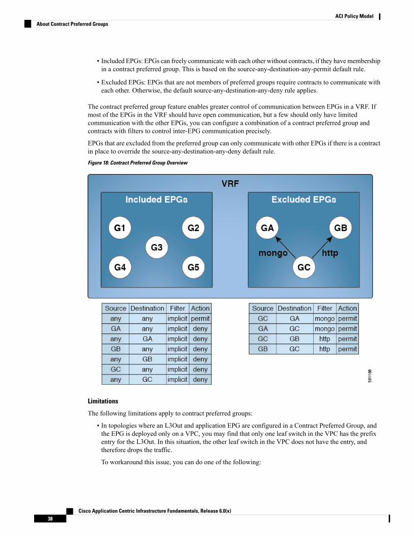
• Included EPGs: EPGs can freely communicate with each other without contracts, if they havemembershipin a contract preferred group. This is based on the source-any-destination-any-permit default rule.
• Excluded EPGs: EPGs that are not members of preferred groups require contracts to communicate witheach other. Otherwise, the default source-any-destination-any-deny rule applies.
The contract preferred group feature enables greater control of communication between EPGs in a VRF. Ifmost of the EPGs in the VRF should have open communication, but a few should only have limitedcommunication with the other EPGs, you can configure a combination of a contract preferred group andcontracts with filters to control inter-EPG communication precisely.
EPGs that are excluded from the preferred group can only communicate with other EPGs if there is a contractin place to override the source-any-destination-any-deny default rule.
Figure 18: Contract Preferred Group Overview
Limitations
The following limitations apply to contract preferred groups:
• In topologies where an L3Out and application EPG are configured in a Contract Preferred Group, andthe EPG is deployed only on a VPC, you may find that only one leaf switch in the VPC has the prefixentry for the L3Out. In this situation, the other leaf switch in the VPC does not have the entry, andtherefore drops the traffic.
To workaround this issue, you can do one of the following:
Cisco Application Centric Infrastructure Fundamentals, Release 6.0(x)38
ACI Policy ModelAbout Contract Preferred Groups

• Disable and reenable the contract group in the VRF
• Delete and recreate the prefix entries for the L3Out EPG
• Also, where the provider or consumer EPG in a service graph contract is included in a contract group,the shadow EPG can not be excluded from the contract group. The shadow EPG will be permitted in thecontract group, but it does not trigger contract group policy deployment on the node where the shadowEPG is deployed. To download the contract group policy to the node, you deploy a dummy EPG withinthe contract group .
Due to CSCvm63145, an EPG in a Contract Preferred Group can consume a shared service contract, butcannot be a provider for a shared service contract with an L3Out EPG as consumer.
Optimize Contract PerformanceStarting with Cisco APIC, Release 3.2, you can configure bidirectional contracts that support more efficienthardware TCAM storage of contract data. With optimization enabled, contract statistics for both directionsare aggregated.
TCAM Optimization is supported on the second generation Cisco Nexus 9000 Series top of rack (TOR)switches, which are those with suffixes of EX, FX, and FX2, and later (for example, N9K-C93180LC-EX orN9K-C93180YC-FX).
To configure efficient TCAM contract data storage, you enable the following options:
• Mark the contracts to be applied in both directions between the provider and consumer.
• For filters with IP TCP or UDP protocols, enable the reverse port option.
• When configuring the contract subjects, select the Enable Policy Compression directive, which addsthe no_stats option to the action attribute of the actrl:Rule managed object.
Limitations
With the Enable Policy Compression (no_stats) option selected, per-rule statistics are lost. However,combined rule statistics for both directions are present in the hardware statistics.
After upgrading to Cisco APIC 3.2(1), to add the no_stats option to a pre-upgrade contract subject (withfilters or filter entries), you must delete the contract subject and reconfigure it with the Enable PolicyCompression directive. Otherwise, compression does not occur.
For each contract with a bi-directional subject filter, Cisco NX-OS creates 2 rules:
• A rule with an sPcTag and dPcTag that is marked direction=bi-dir, which is programmed in hardware
• A rule marked with direction=uni-dir-ignore which is not programmed
Rules with the following settings are not compressed:
• Rules with priority other than fully_qual
• Opposite rules (bi-dir and uni-dir-ignore marked) with non-identical properties, such as actionincluding directives, prio, qos or markDscp
• Rule with Implicit or implarp filters
Cisco Application Centric Infrastructure Fundamentals, Release 6.0(x)39
ACI Policy ModelOptimize Contract Performance

• Rules with the actions Deny, Redir, Copy, or Deny-log
The following MO query output shows the two rules for a contract, that is considered for compression:
apic1# moquery -c actrlRuleTotal Objects shown: 2
# actrl.RulescopeId : 2588677sPcTag : 16388dPcTag : 49156fltId : 67action : no_stats,permitactrlCfgFailedBmp :actrlCfgFailedTs : 00:00:00:00.000actrlCfgState : 0childAction :ctrctName :descr :direction : bi-dirdn : sys/actrl/scope-2588677/rule-2588677-s-16388-d-49156-f-67id : 4112lcOwn : implicitmarkDscp : unspecifiedmodTs : 2019-04-27T09:01:33.152-07:00monPolDn : uni/tn-common/monepg-defaultname :nameAlias :operSt : enabledoperStQual :prio : fully_qualqosGrp : unspecifiedrn : rule-2588677-s-16388-d-49156-f-67status :type : tenant
# actrl.RulescopeId : 2588677sPcTag : 49156dPcTag : 16388fltId : 64action : no_stats,permitactrlCfgFailedBmp :actrlCfgFailedTs : 00:00:00:00.000actrlCfgState : 0childAction :ctrctName :descr :direction : uni-dir-ignoredn : sys/actrl/scope-2588677/rule-2588677-s-49156-d-16388-f-64id : 4126lcOwn : implicitmarkDscp : unspecifiedmodTs : 2019-04-27T09:01:33.152-07:00monPolDn : uni/tn-common/monepg-defaultname :nameAlias :operSt : enabledoperStQual :prio : fully_qualqosGrp : unspecifiedrn : rule-2588677-s-49156-d-16388-f-64
Cisco Application Centric Infrastructure Fundamentals, Release 6.0(x)40
ACI Policy ModelOptimize Contract Performance
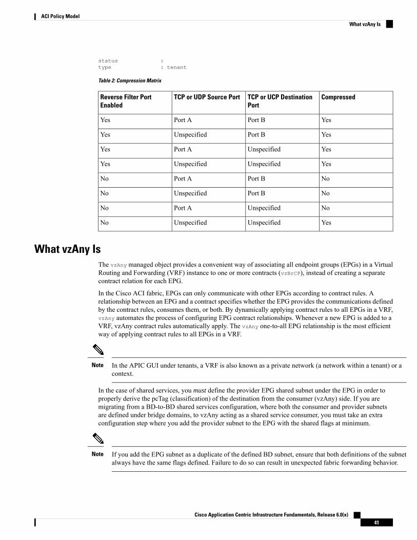
status :type : tenant
Table 2: Compression Matrix
CompressedTCP or UCP DestinationPort
TCP or UDP Source PortReverse Filter PortEnabled
YesPort BPort AYes
YesPort BUnspecifiedYes
YesUnspecifiedPort AYes
YesUnspecifiedUnspecifiedYes
NoPort BPort ANo
NoPort BUnspecifiedNo
NoUnspecifiedPort ANo
YesUnspecifiedUnspecifiedNo
What vzAny IsThe vzAny managed object provides a convenient way of associating all endpoint groups (EPGs) in a VirtualRouting and Forwarding (VRF) instance to one or more contracts (vzBrCP), instead of creating a separatecontract relation for each EPG.
In the Cisco ACI fabric, EPGs can only communicate with other EPGs according to contract rules. Arelationship between an EPG and a contract specifies whether the EPG provides the communications definedby the contract rules, consumes them, or both. By dynamically applying contract rules to all EPGs in a VRF,vzAny automates the process of configuring EPG contract relationships. Whenever a new EPG is added to aVRF, vzAny contract rules automatically apply. The vzAny one-to-all EPG relationship is the most efficientway of applying contract rules to all EPGs in a VRF.
In the APIC GUI under tenants, a VRF is also known as a private network (a network within a tenant) or acontext.
Note
In the case of shared services, you must define the provider EPG shared subnet under the EPG in order toproperly derive the pcTag (classification) of the destination from the consumer (vzAny) side. If you aremigrating from a BD-to-BD shared services configuration, where both the consumer and provider subnetsare defined under bridge domains, to vzAny acting as a shared service consumer, you must take an extraconfiguration step where you add the provider subnet to the EPG with the shared flags at minimum.
If you add the EPG subnet as a duplicate of the defined BD subnet, ensure that both definitions of the subnetalways have the same flags defined. Failure to do so can result in unexpected fabric forwarding behavior.
Note
Cisco Application Centric Infrastructure Fundamentals, Release 6.0(x)41
ACI Policy ModelWhat vzAny Is
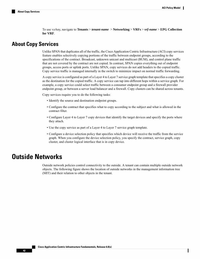
To use vzAny, navigate to Tenants > tenant-name > Networking > VRFs > vrf-name > EPG Collectionfor VRF.
About Copy ServicesUnlike SPAN that duplicates all of the traffic, the Cisco Application Centric Infrastructure (ACI) copy servicesfeature enables selectively copying portions of the traffic between endpoint groups, according to thespecifications of the contract. Broadcast, unknown unicast and multicast (BUM), and control plane trafficthat are not covered by the contract are not copied. In contrast, SPAN copies everything out of endpointgroups, access ports or uplink ports. Unlike SPAN, copy services do not add headers to the copied traffic.Copy service traffic is managed internally in the switch to minimize impact on normal traffic forwarding.
A copy service is configured as part of a Layer 4 to Layer 7 service graph template that specifies a copy clusteras the destination for the copied traffic. A copy service can tap into different hops within a service graph. Forexample, a copy service could select traffic between a consumer endpoint group and a firewall providerendpoint group, or between a server load balancer and a firewall. Copy clusters can be shared across tenants.
Copy services require you to do the following tasks:
• Identify the source and destination endpoint groups.
• Configure the contract that specifies what to copy according to the subject and what is allowed in thecontract filter.
• Configure Layer 4 to Layer 7 copy devices that identify the target devices and specify the ports wherethey attach.
• Use the copy service as part of a Layer 4 to Layer 7 service graph template.
• Configure a device selection policy that specifies which device will receive the traffic from the servicegraph. When you configure the device selection policy, you specify the contract, service graph, copycluster, and cluster logical interface that is in copy device.
Outside NetworksOutside network policies control connectivity to the outside. A tenant can contain multiple outside networkobjects. The following figure shows the location of outside networks in the management information tree(MIT) and their relation to other objects in the tenant.
Cisco Application Centric Infrastructure Fundamentals, Release 6.0(x)42
ACI Policy ModelAbout Copy Services
Figure 19: Outside Networks
Outside network policies specify the relevant Layer 2 (l2extOut) or Layer 3 (l3extOut) properties that controlcommunications between an outside public or private network and the ACI fabric. External devices, such asrouters that connect to the WAN and enterprise core, or existing Layer 2 switches, connect to the front panelinterface of a leaf switch. The leaf switch that provides such connectivity is known as a border leaf. The borderleaf switch interface that connects to an external device can be configured as either a bridged or routed interface.In the case of a routed interface, static or dynamic routing can be used. The border leaf switch can also performall the functions of a normal leaf switch.
Managed Object Relations and Policy ResolutionRelationship managed objects express the relation between managed object instances that do not sharecontainment (parent-child) relations. MO relations are established between the source MO and a target MOin one of the following two ways:
• An explicit relation (fvRsPathAtt) defines a relationship based on the target MO distinguished name(DN).
• A named relation defines a relationship based on the target MO name.
The dotted lines in the following figure shows several common MO relations.
Cisco Application Centric Infrastructure Fundamentals, Release 6.0(x)43
ACI Policy ModelManaged Object Relations and Policy Resolution

Figure 20: MO Relations
For example, the dotted line between the EPG and the bridge domain defines the relation between those twoMOs. In this figure, the EPG (fvAEPg) contains a relationship MO (fvRsBD) that is named with the name ofthe target bridge domain MO (fvBD). For example, if production is the bridge domain name(tnFvBDName=production), then the relation name would be production (fvRsBdName=production).
In the case of policy resolution based on named relations, if a target MO with a matching name is not foundin the current tenant, the ACI fabric tries to resolve in the common tenant. For example, if the user tenantEPG contained a relationship MO targeted to a bridge domain that did not exist in the tenant, the system triesto resolve the relationship in the common tenant. If a named relation cannot be resolved in either the currenttenant or the common tenant, the ACI fabric attempts to resolve to a default policy. If a default policy existsin the current tenant, it is used. If it does not exist, the ACI fabric looks for a default policy in the commontenant. Bridge domain, VRF, and contract (security policy) named relations do not resolve to a default.
Default PoliciesThe initial values of the APIC default policies values are taken from the concrete model that is loaded in theswitch. A fabric administrator can modify default policies.
Default policies can be modified or deleted. Deleting a default policy can result in a policy resolution processto complete abnormally.
Warning
The ACI fabric includes default policies for many of its core functions. Examples of default policies includethe following:
• Bridge domain (in the common tenant)
Cisco Application Centric Infrastructure Fundamentals, Release 6.0(x)44
ACI Policy ModelDefault Policies

• Layer 2 and Layer 3 protocols
• Fabric initialization, device discovery, and cabling detection
• Storm control and flooding
• Virtual port channel
• Endpoint retention for caching and aging of learned endpoints in switch buffers
• Loop detection
• Monitoring and statistics
To avoid confusion when implementing configurations that use default policies, document changes made todefault policies. Be sure there are no current or future configurations that rely on a default policy beforedeleting a default policy. For example, deleting a default firmware update policy could result in a problematicfuture firmware update.
Note
When the ACI fabric is upgraded, the existing policy default values persist, even if the default value changesin the newer release. When the node connects to the APIC for the first time, the node registers itself withAPIC which pushes all the default policies to the node. Any change in the default policy is pushed to the node.
A default policy serves multiple purposes:
• Allows a fabric administrator to override the default values in the model.
• If an administrator does not provide an explicit policy, the APIC applies the default policy. Anadministrator can create a default policy and the APIC uses that unless the administrator provides anyexplicit policy.
For example, according to actions the administrator does or does not take, the APIC will do the following:
• Because the administrator does not specify the LLDP policy for the selected ports, the APIC applies thedefault LLDP interface policy for the ports specified in the port selector.
• If the administrator removes a port from a port selector, the APIC applies the default policies to that port.In this example, if the administrator removes port 1/15 from the port selector, the port is no longer partof the port channel and the APIC applies all the default policies to that port.
The following scenarios describe common policy resolution behavior:
• A configuration explicitly refers to the default policy: if a default policy exists in the current tenant, it isused. Otherwise, the default policy in tenant common is used.
• A configuration refers to a named policy (not default) that does not exist in the current tenant or in tenantcommon: if the current tenant has a default policy, it is used. Otherwise, the default policy in tenantcommon is used.
This does not apply to a bridge domain or a VRF (private network) in a tenant.Note
Cisco Application Centric Infrastructure Fundamentals, Release 6.0(x)45
ACI Policy ModelDefault Policies

• A configuration does not refer to any policy name: if a default policy exists in the current tenant, it isused. Otherwise, the default policy in tenant common is used.
For bridge domains andVRFs, this only applies if the connectivity instrumentationpolicy (fvConnInstrPol) in the common tenant has the appropriate bridge domainor VRF flag set. This prevents unintended EPGs from being deployed in tenantcommon subnets.
Note
The policy model specifies that an object is using another policy by having a relation managed object (MO)under that object and that relation MO refers to the target policy by name. If this relation does not explicitlyrefer to a policy by name, then the system will try to resolve a policy called default. Bridge domains (BD)and VRFs (Ctx) are exceptions to this rule.
An endpoint group (EPG) has a relation to a BD (fvRsBd) that has a property called tnFvBDName. If this is notset (tnVfBDName=""), the connectivity instrumentation policy (fvConnInstrPol) derives the behavior for thiscase. This policy applies for all EPG cases (VMM, baremetal, l2ext, l3ext). The instrumentation policy usesthe bdctrl property to control whether the default BD policy will be used and the ctxCtrl property to controlwhether the default VRF (Ctx) policy will be used. The following options are the same for both:
• do not instrument: the leaf switch will not use the default policy.
• instrument-and-no-route: instrument the policy and do not enable routing.
• instrument-and-route: instrument the policy and enable routing.
Trans Tenant EPG CommunicationsEPGs in one tenant can communicate with EPGs in another tenant through a contract interface contained ina shared tenant. The contract interface is an MO that can be used as a contract consumption interface by theEPGs that are contained in different tenants. By associating to an interface, an EPG consumes the subjectsrepresented by the interface to a contract contained in the shared tenant. Tenants can participate in a singlecontract, which is defined at some third place. More strict security requirements can be satisfied by definingthe tenants, contract, subjects, and filter directions so that tenants remain completely isolated from one another.
Follow these guidelines when configuring shared services contracts:
• When a contract is configured between in-band and out-of-band EPGs, the following restrictions apply:
• Both EPGs should be in the same VRF (context).
• Filters apply in the incoming direction only.
• Layer 2 filters are not supported.
• QoS does not apply to in-band Layer 4 to Layer 7 services.
• Management statistics are not available.
• Shared services for CPU-bound traffic are not supported.
• Contracts are needed for inter-bridge domain traffic when a private network is unenforced.
Cisco Application Centric Infrastructure Fundamentals, Release 6.0(x)46
ACI Policy ModelTrans Tenant EPG Communications

• Prefix-based EPGs are not supported. Shared Services are not supported for a Layer 3 external outsidenetwork. Contracts provided or consumed by a Layer 3 external outside network need to be consumedor provided by EPGs that share the same Layer 3 VRF.
• A shared service is supported only with non-overlapping and non-duplicate subnets. When configuringsubnets for shared services, follow these guidelines:
• Configure the subnet for a shared service provider under the EPG, not under the bridge domain.
• Subnets configured under an EPG that share the same VRFmust be disjointed and must not overlap.
• Subnets leaked from one VRF to another must be disjointed and must not overlap.
• Subnets advertised from multiple consumer networks into a VRF or vice versa must be disjointedand must not overlap.
If two consumers are mistakenly configured with the same subnet, recover fromthis condition by removing the subnet configuration for both, then reconfigurethe subnets correctly.
Note
• Do not configure a shared service with AnyToProv in the provider VRF. TheAPIC rejects this configurationand raises a fault.
• The private network of a provider cannot be in unenforced mode while providing a shared service.
TagsObject tags simplify API operations. In an API operation, an object or group of objects can be referenced bythe tag name instead of by the distinguished name (DN). Tags are child objects of the item they tag; besidesthe name, they have no other properties.
Use a tag to assign a descriptive name to a group of objects. The same tag name can be assigned to multipleobjects. Multiple tag names can be assigned to an object. For example, to enable easy searchable access to allweb server EPGs, assign a web server tag to all such EPGs. Web server EPGs throughout the fabric can belocated by referencing the web server tag.
About APIC Quota Management ConfigurationStarting in the Cisco Application Policy Infrastructure Controller (APIC) Release 2.3(1), there are limits onnumber of objects a tenant admin can configure. This enables the admin to limit what managed objects thatcan be added under a given tenant or globally across tenants.
This feature is useful when you want to limit any tenant or group of tenants from exceeding ACI maximumsper leaf or per fabric or unfairly consuming a majority of available resources, potentially affecting other tenantson the same fabric.
Cisco Application Centric Infrastructure Fundamentals, Release 6.0(x)47
ACI Policy ModelTags

Cisco Application Centric Infrastructure Fundamentals, Release 6.0(x)48
ACI Policy ModelAbout APIC Quota Management Configuration

C H A P T E R 4Fabric Provisioning
This chapter contains the following sections:
• Fabric Provisioning, on page 50• Startup Discovery and Configuration, on page 50• Fabric Inventory, on page 51• Provisioning, on page 52• Multi-Tier Architecture, on page 53• APIC Cluster Management, on page 54• Maintenance Mode, on page 56• Stretched ACI Fabric Design Overview, on page 57• Stretched ACI Fabric Related Documents, on page 58• Fabric Policies Overview, on page 58• Fabric Policy Configuration, on page 59• Access Policies Overview, on page 61• Access Policy Configuration, on page 62• Port Channel and Virtual Port Channel Access, on page 63• FEX Virtual Port Channels, on page 63• Fibre Channel and FCoE, on page 65• 802.1Q Tunnels, on page 70• Dynamic Breakout Ports, on page 72• Configuring Port Profiles, on page 72• Port Profile Configuration Summary, on page 75• Port Tracking Policy for Fabric Port Failure Detection, on page 79• Q-in-Q Encapsulation Mapping for EPGs, on page 80• Layer 2 Multicast, on page 81• Fabric Secure Mode, on page 84• Configuring Fast Link Failover Policy, on page 85• About Port Security and ACI, on page 85• About First Hop Security, on page 87• About MACsec, on page 88• Data Plane Policing, on page 89• Scheduler, on page 90• Firmware Upgrade, on page 90• Configuration Zones , on page 93
Cisco Application Centric Infrastructure Fundamentals, Release 6.0(x)49

• Geolocation, on page 94
Fabric ProvisioningCisco Application Centric Infrastructure (ACI) automation and self-provisioning offers these operationadvantages over the traditional switching infrastructure:
• A clustered logically centralized but physically distributed APIC provides policy, bootstrap, and imagemanagement for the entire fabric.
• The APIC startup topology auto discovery, automated configuration, and infrastructure addressing usesthese industry-standard protocols: Intermediate System-to-Intermediate System (IS-IS), Link LayerDiscovery Protocol (LLDP), and Dynamic Host Configuration Protocol (DHCP).
• TheAPIC provides a simple and automated policy-based provisioning and upgrade process, and automatedimage management.
• APIC provides scalable configuration management. Because ACI data centers can be very large,configuring switches or interfaces individually does not scale well, even using scripts. APIC pod,controller, switch, module and interface selectors (all, range, specific instances) enable symmetricconfigurations across the fabric. To apply a symmetric configuration, an administrator defines switchprofiles that associate interface configurations in a single policy group. The configuration is then rapidlydeployed to all interfaces in that profile without the need to configure them individually.
Startup Discovery and ConfigurationThe clustered APIC controller provides DHCP, bootstrap configuration, and image management to the fabricfor automated startup and upgrades. The following figure shows startup discovery.
Figure 21: Startup Discovery Configuration
The Cisco Nexus ACI fabric software is bundled as an ISO image, which can be installed on the Cisco APICserver through the KVM interface on the Cisco Integrated Management Controller (CIMC). The Cisco NexusACI Software ISO contains the Cisco APIC image, the firmware image for the leaf node, the firmware imagefor the spine node, default fabric infrastructure policies, and the protocols required for operation.
The ACI fabric bootstrap sequence begins when the fabric is booted with factory-installed images on all theswitches. The Cisco Nexus 9000 Series switches that run the ACI firmware and APICs use a reserved overlay
Cisco Application Centric Infrastructure Fundamentals, Release 6.0(x)50
Fabric ProvisioningFabric Provisioning

for the boot process. This infrastructure space is hard-coded on the switches. The APIC can connect to a leafthrough the default overlay, or it can use a locally significant identifier.
The ACI fabric uses an infrastructure space, which is securely isolated in the fabric and is where all thetopology discovery, fabric management, and infrastructure addressing is performed. ACI fabric managementcommunication within the fabric takes place in the infrastructure space through internal private IP addresses.This addressing scheme allows the APIC to communicate with fabric nodes and other Cisco APIC controllersin the cluster. The APIC discovers the IP address and node information of other Cisco APIC controllers inthe cluster using the Link Layer Discovery Protocol (LLDP)-based discovery process.
The following describes the APIC cluster discovery process:
• Each APIC in the Cisco ACI uses an internal private IP address to communicate with the ACI nodes andother APICs in the cluster. The APIC discovers the IP address of other APIC controllers in the clusterthrough the LLDP-based discovery process.
• APICs maintain an appliance vector (AV), which provides a mapping from an APIC ID to an APIC IPaddress and a universally unique identifier (UUID) of the APIC. Initially, each APIC starts with an AVfilled with its local IP address, and all other APIC slots are marked as unknown.
• When a switch reboots, the policy element (PE) on the leaf gets its AV from the APIC. The switch thenadvertises this AV to all of its neighbors and reports any discrepancies between its local AV and neighbors'AVs to all the APICs in its local AV.
Using this process, the APIC learns about the other APIC controllers in the ACI through switches. Aftervalidating these newly discovered APIC controllers in the cluster, the APIC controllers update their local AVand program the switches with the newAV. Switches then start advertising this newAV. This process continuesuntil all the switches have the identical AV and all APIC controllers know the IP address of all the other APICcontrollers.
Prior to initiating a change to the cluster, always verify its health. When performing planned changes to thecluster, all controllers in the cluster should be healthy. If one or more of the APIC controllers in the clusteris not healthy, remedy that situation before proceeding with making changes to the cluster. Also, assure thatcluster controllers added to the APIC are running the same version of firmware as the other controllers in theAPIC cluster. See the KB: Cisco ACI APIC Cluster Management article for guidelines that must be followedto assure that making changes the APIC cluster complete normally.
Note
The ACI fabric is brought up in a cascading manner, starting with the leaf nodes that are directly attached tothe APIC. LLDP and control-plane IS-IS convergence occurs in parallel to this boot process. The ACI fabricuses LLDP- and DHCP-based fabric discovery to automatically discover the fabric switch nodes, assign theinfrastructure VXLAN tunnel endpoint (VTEP) addresses, and install the firmware on the switches. Prior tothis automated process, a minimal bootstrap configuration must be performed on the Cisco APIC controller.After the APIC controllers are connected and their IP addresses assigned, the APIC GUI can be accessed byentering the address of any APIC controller into a web browser. The APIC GUI runs HTML5 and eliminatesthe need for Java to be installed locally.
Fabric InventoryThe policy model contains a complete real-time inventory of the fabric, including all nodes and interfaces.This inventory capability enables automation of provisioning, troubleshooting, auditing, and monitoring.
Cisco Application Centric Infrastructure Fundamentals, Release 6.0(x)51
Fabric ProvisioningFabric Inventory
For Cisco ACI fabric switches, the fabric membership node inventory contains policies that identify the nodeID, serial number, and name. Third-party nodes are recorded as unmanaged fabric nodes. Cisco ACI switchescan be automatically discovered, or their policy information can be imported. The policymodel also maintainsfabric member node state information.
ConditionNode States
No policy. All nodes require a policy; without a policy, a member node state is unknown.Unknown
A transient state showing that the node is being discovered and waiting for host traffic.Discovering
The node has policy but has never been brought up in the fabric.Undiscovered
The node is a Cisco switch but it is not supported. For example, the firmware versionis not compatible with ACI fabric.
Unsupported
The node has a policy, was discovered, but a user disabled it. The node can be reenabled.
Specifying the wipe option when decommissioning a leaf switch results inthe APIC attempting to remove all the leaf switch configurations on both theleaf switch and on the APIC. If the leaf switch is not reachable, only theAPIC is cleaned. In this case, the user must manually wipe the leaf switchby resetting it.
Note
Decommissioned
The node is unreachable. It had been discovered but currently is not accessible. Forexample, it may be powered off, or its cables may be disconnected.
Inactive
The node is an active member of the fabric.Active
Disabled interfaces can be ones blacklisted by an administrator or ones taken down because the APIC detectsanomalies. Examples of link state anomalies include the following:
• A wiring mismatch, such as a spine connected to a spine, a leaf connected to a leaf, a spine connectedto a leaf access port, a spine connected to a non-ACI node, or a leaf fabric port connected to a non-ACIdevice.
• A fabric name mismatch. The fabric name is stored in each ACI node. If a node is moved to anotherfabric without resetting it to a back to factory default state, it will retain the fabric name.
• A UUID mismatch causes the APIC to disable the node.
If an administrator uses the APIC to disable all the leaf nodes on a spine, a spine reboot is required to recoveraccess to the spine.
Note
ProvisioningThe APIC provisioning method automatically brings up the ACI fabric with the appropriate connections. Thefollowing figure shows fabric provisioning.
Figure 22: Fabric Provisioning
Cisco Application Centric Infrastructure Fundamentals, Release 6.0(x)52
Fabric ProvisioningProvisioning

After Link Layer Discovery Protocol (LLDP) discovery learns all neighboring connections dynamically, theseconnections are validated against a loose specification rule such as "LEAF can connect to only SPINE-L1-*"or "SPINE-L1-* can connect to SPINE-L2-* or LEAF." If a rule mismatch occurs, a fault occurs and theconnection is blocked because a leaf is not allowed to be connected to another leaf, or a spine connected to aspine. In addition, an alarm is created to indicate that the connection needs attention. The Cisco ACI fabricadministrator can import the names and serial numbers of all the fabric nodes from a text file into the APICor allow the fabric to discover the serial numbers automatically and then assign names to the nodes using theAPIC GUI, command-line interface (CLI), or API. The APIC is discoverable via SNMP. It has the followingasysobjectId: ciscoACIController OBJECT IDENTIFIER ::= { ciscoProducts 2238 }
Multi-Tier Architecture3-tier Core-Aggregation-Access architectures are common in data center network topologies. As of the CiscoAPIC Release 4.1(1), you can create a multi-tier ACI fabric topology that corresponds to theCore-Aggregation-Access architecture, thus mitigating the need to upgrade costly components such as rackspace or cabling. The addition of a tier-2 leaf layer makes this topology possible. The tier-2 leaf layer supportsconnectivity to hosts or servers on the downlink ports and connectivity to the leaf layer (aggregation) on theuplink ports.
In the multi-tier topology, the leaf switches initially have uplink connectivity to the spine switches and downlinkconnectivity to the tier-2 leaf switches. To make the entire topology an ACI fabric, all ports on the leaf switchesconnecting to tier-2 leaf fabric ports must be configured as fabric ports (if not already using the default fabricports). After APIC discovers the tier-2 leaf switch, you can change the downlink port on the tier-2 leaf to afabric port and connect to an uplink port on the middle layer leaf.
The following figure shows an example of a multi-tier fabric topology.
Figure 23: Multi-Tier Fabric Topology Example
While the topology in the above image shows the CiscoAPIC and L3Out/EPG connected to the leaf aggregationlayer, the tier-2 leaf access layer also supports connectivity to APICs and L3Out/EPGs.
Cisco Application Centric Infrastructure Fundamentals, Release 6.0(x)53
Fabric ProvisioningMulti-Tier Architecture

APIC Cluster Management
Cluster Management GuidelinesThe Cisco Application Policy Infrastructure Controller (APIC) cluster comprises multiple Cisco APICs thatprovide operators a unified real time monitoring, diagnostic, and configuration management capability forthe ACI fabric. To assure optimal system performance, follow the guidelines below for making changes tothe Cisco APIC cluster.
Prior to initiating a change to the cluster, always verify its health. When performing planned changes to thecluster, all controllers in the cluster should be healthy. If one or more of the Cisco APICs' health status in thecluster is not "fully fit," remedy that situation before proceeding. Also, assure that cluster controllers addedto the Cisco APIC are running the same version of firmware as the other controllers in the Cisco APIC cluster.
Note
Follow these general guidelines when managing clusters:
• We recommend that you have at least 3 active Cisco APICs in a cluster, along with additional standbyCisco APICs. In most cases, we recommend a cluster size of 3, 5, or 7 Cisco APICs. We recommend 4Cisco APICs for a two site multi-pod fabric that has between 80 to 200 leaf switches.
• Disregard cluster information from Cisco APICs that are not currently in the cluster; they do not provideaccurate cluster information.
• Cluster slots contain a Cisco APIC ChassisID. Once you configure a slot, it remains unavailable untilyou decommission the Cisco APIC with the assigned ChassisID.
• If a Cisco APIC firmware upgrade is in progress, wait for it to complete and the cluster to be fully fitbefore proceeding with any other changes to the cluster.
• When moving a Cisco APIC, first ensure that you have a healthy cluster. After verifying the health ofthe Cisco APIC cluster, choose the Cisco APIC that you intend to shut down. After the Cisco APIC hasshut down, move the Cisco APIC, re-connect it, and then turn it back on. From the GUI, verify that theall controllers in the cluster return to a fully fit state.
Only move one Cisco APIC at a time.Note
• When an Cisco APIC cluster is split into two or more groups, the ID of a node is changed and the changesare not synchronized across all Cisco APICs. This can cause inconsistency in the node IDs between CiscoAPICs and also the affected leaf nodes may not appear in the inventory in the Cisco APIC GUI. Whenyou split a Cisco APIC cluster, decommission the affected leaf nodes from a Cisco APIC and registerthem again, so that the inconsistency in the node IDs is resolved and the health status of the APICs in acluster are in a fully fit state.
• Before configuring the Cisco APIC cluster, ensure that all of the Cisco APICs are running the samefirmware version. Initial clustering of Cisco APICs running differing versions is an unsupported operationand may cause problems within the cluster.
Cisco Application Centric Infrastructure Fundamentals, Release 6.0(x)54
Fabric ProvisioningAPIC Cluster Management
This section contains the following topics:
About Cold Standby for a Cisco APIC ClusterThe Cold Standby functionality for a Cisco Application Policy Infrastructure Controller (APIC) cluster enablesyou to operate the Cisco APICs in a cluster in an Active/Standbymode. In a Cisco APIC cluster, the designatedactive Cisco APICs share the load and the designated standby Cisco APICs can act as a replacement for anyof the Cisco APICs in the active cluster.
As an admin user, you can set up the Cold Standby functionality when the Cisco APIC is launched for thefirst time.We recommend that you have at least three active Cisco APICs in a cluster, and one or more standbyCisco APICs. As an admin user, you can initiate the switch over to replace an active Cisco APIC with astandby Cisco APIC.
Important Notes
• There must be three active Cisco APICs to add a standby Cisco APIC.
• The standby Cisco APIC need to run with the same firmware version of the cluster when the standbyCisco APICs join the cluster during the initial setup.
• During an upgrade process, after all the active Cisco APICs are upgraded, the standby Cisco APICs arealso upgraded automatically.
• During the initial setup, IDs are assigned to the standby Cisco APICs. After a standby Cisco APIC isswitched over to an active Cisco APIC, the standby Cisco APIC (new active) starts using the ID of thereplaced (old active) Cisco APIC.
• The admin login is not enabled on the standby Cisco APICs. To troubleshoot a Cold Standby CiscoAPIC, you must log in to the standby using SSH as rescue-user.
• During the switch over, the replaced active Cisco APIC needs to be powered down to prevent connectivityto the replaced Cisco APIC.
• Switch over fails under the following conditions:
• If there is no connectivity to the standby Cisco APIC.
• If the firmware version of the standby Cisco APIC is not the same as that of the active cluster.
• After switching over a standby Cisco APIC to be active, you can setup another standby Cisco APIC, ifneeded.
• If Retain OOB IP address for Standby (new active) is checked, the standby (new active) APIC willretain its original standby OOB Management IP address.
• If Retain OOB IP address for Standby (new active) is not checked:
• If only one active APIC is down: The standby (new active) Cisco APIC will use the old active CiscoAPIC's OOB Management IP address.
• If more than one active Cisco APICs are down: The standby (new active) Cisco APIC will try touse the active APIC's OOBManagement IP address, but it may fail if the shard of OOBManagementIP address configuration for the active APIC is in the minority state.
• For Cisco ACI Multi-Pod, if the old active Cisco APIC and the standby Cisco APIC use different OOBManagement IP subnets, you must check the option to have the standby (new active) Cisco APIC retain
Cisco Application Centric Infrastructure Fundamentals, Release 6.0(x)55
Fabric ProvisioningAbout Cold Standby for a Cisco APIC Cluster
its original standby OOB Management IP address. Otherwise, you will lose OOB Management IPconnectivity to the standby (new active) Cisco APIC. This situation might happen if the old active CiscoAPIC and the standby Cisco APIC are in the different pods.
If OOBManagement IP connectivity is lost because of this reason or if more than one active Cisco APICsare down, you must create a new Static Node Management OOB IP Address to change the new active(previously standby) APIC OOBManagement IP address. Note that you must have the cluster out of theminority state to make the configuration change.
• The standby Cisco APIC does not participate in policy configuration or management.
• No information is replicated to the standby Cisco APICs, not even the administrator credentials.
Maintenance ModeFollowing are terms that are helpful to understand when using maintenance mode:
• Graceful Insertion and Removal (GIR): The operation used to isolate a switch from user traffic.
• Maintenance mode: Used to isolate a switch from user traffic for debugging purposes. You can put aswitch in maintenance mode by enabling the Maintenance (GIR) field in the Fabric Membershippage in the APIC GUI, located at Fabric > Inventory > Fabric Membership (right-click on a switchand choose Maintenance (GIR)).
If you put a switch in maintenance mode, that switch is not considered as a part of the operational ACIfabric infra and it will not accept regular APIC communications. Therefore, performing a firmwareupgrade for a switch in this state is not supported, since it may fail or may get stuck in an incompletestatus indefinitely if you attempt to perform a firmware upgrade on it while it is in this state.
The maintenance mode allows you to isolate a switch from the network with minimum service disruption. Inthe maintenance mode you can perform real-time debugging without affecting traffic.
You can use maintenance mode to gracefully remove a switch and isolate it from the network in order toperform debugging operations. The switch is removed from the regular forwarding path with minimal trafficdisruption.
In graceful removal, all external protocols are gracefully brought down except the fabric protocol (IS-IS) andthe switch is isolated from the network. During maintenance mode, the maximummetric is advertised in IS-ISwithin the Cisco Application Centric Infrastructure (Cisco ACI) fabric and therefore the leaf switch inmaintenance mode does not attract traffic from the spine switches. In addition, all front-panel interfaces onthe switch are shutdown except for the fabric interfaces. To return the switch to its fully operational (normal)mode after the debugging operations, you must recommission the switch. This operation will trigger a statelessreload of the switch.
In graceful insertion, the switch is automatically decommissioned, rebooted, and recommissioned. Whenrecommissioning is completed, all external protocols are restored and maximum metric in IS-IS is reset after10 minutes.
The following protocols are supported:
• Border Gateway Protocol (BGP)
• Enhanced Interior Gateway Routing Protocol (EIGRP)
• Intermediate System-to-Intermediate System (IS-IS)
Cisco Application Centric Infrastructure Fundamentals, Release 6.0(x)56
Fabric ProvisioningMaintenance Mode
• Open Shortest Path First (OSPF)
• Link Aggregation Control Protocol (LACP)
Protocol Independent Multicast (PIM) is not supported.
Important Notes
• If a border leaf switch has a static route and is placed in maintenance mode, the route from the borderleaf switch might not be removed from the routing table of switches in the ACI fabric, which causesrouting issues.
To work around this issue, either:
• Configure the same static route with the same administrative distance on the other border leaf switch,or
• Use IP SLA or BFD for track reachability to the next hop of the static route
• Upgrading or downgrading a switch in maintenance mode is not supported.
• While the switch is in maintenance mode, the Ethernet port module stops propagating the interface relatednotifications. As a result, if the remote switch is rebooted or the fabric link is flapped during this time,the fabric link will not come up afterward unless the switch is manually rebooted (using the acidiagtouch clean command), decommissioned, and recommissioned.
• While the switch is in maintenance mode, CLI 'show' commands on the switch show the front panel portsas being in the up state and the BGP protocol as up and running. The interfaces are actually shut and allother adjacencies for BGP are brought down, but the displayed active states allow for debugging.
• For multi-pod, IS-IS metric for redistributed routes should be set to less than 63. To set the IS-ISmetric for redistributed routes, choose Fabric > Fabric Policies > Pod Policies > IS-IS Policy.
• Existing GIR supports all Layer 3 traffic diversion. With LACP, all the Layer 2 traffic is also divertedto the redundant node. Once a node goes into maintenancemode, LACP running on the node immediatelyinforms neighbors that it can no longer be aggregated as part of port-channel. All traffic is then divertedto the vPC peer node.
Stretched ACI Fabric Design OverviewStretched ACI fabric is a partially meshed design that connects ACI leaf and spine switches distributed inmultiple locations. Typically, an ACI fabric implementation is a single site where the full mesh design connectseach leaf switch to each spine switch in the fabric, which yields the best throughput and convergence. Inmulti-site scenarios, full mesh connectivity may be not possible or may be too costly. Multiple sites, buildings,or rooms can span distances that are not serviceable by enough fiber connections or are too costly to connecteach leaf switch to each spine switch across the sites.
The following figure illustrates a stretched fabric topology.
Cisco Application Centric Infrastructure Fundamentals, Release 6.0(x)57
Fabric ProvisioningStretched ACI Fabric Design Overview
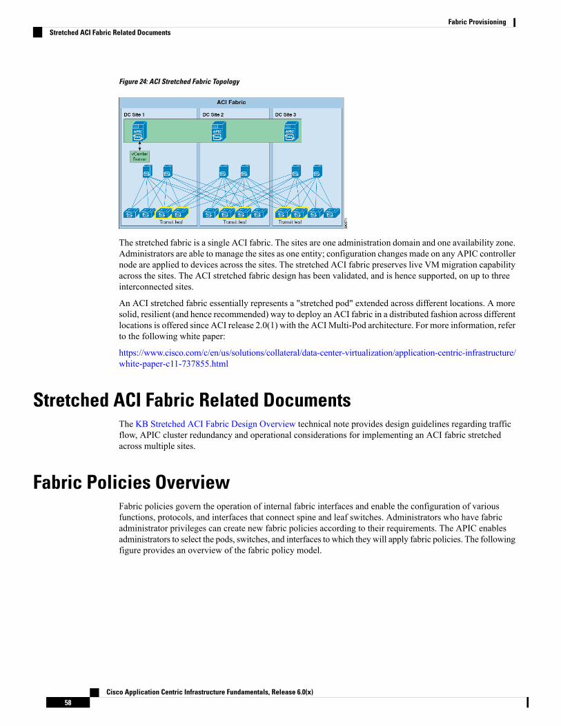
Figure 24: ACI Stretched Fabric Topology
The stretched fabric is a single ACI fabric. The sites are one administration domain and one availability zone.Administrators are able to manage the sites as one entity; configuration changes made on any APIC controllernode are applied to devices across the sites. The stretched ACI fabric preserves live VM migration capabilityacross the sites. The ACI stretched fabric design has been validated, and is hence supported, on up to threeinterconnected sites.
An ACI stretched fabric essentially represents a "stretched pod" extended across different locations. A moresolid, resilient (and hence recommended) way to deploy an ACI fabric in a distributed fashion across differentlocations is offered since ACI release 2.0(1) with the ACIMulti-Pod architecture. For more information, referto the following white paper:
https://www.cisco.com/c/en/us/solutions/collateral/data-center-virtualization/application-centric-infrastructure/white-paper-c11-737855.html
Stretched ACI Fabric Related DocumentsThe KB Stretched ACI Fabric Design Overview technical note provides design guidelines regarding trafficflow, APIC cluster redundancy and operational considerations for implementing an ACI fabric stretchedacross multiple sites.
Fabric Policies OverviewFabric policies govern the operation of internal fabric interfaces and enable the configuration of variousfunctions, protocols, and interfaces that connect spine and leaf switches. Administrators who have fabricadministrator privileges can create new fabric policies according to their requirements. The APIC enablesadministrators to select the pods, switches, and interfaces to which they will apply fabric policies. The followingfigure provides an overview of the fabric policy model.
Cisco Application Centric Infrastructure Fundamentals, Release 6.0(x)58
Fabric ProvisioningStretched ACI Fabric Related Documents
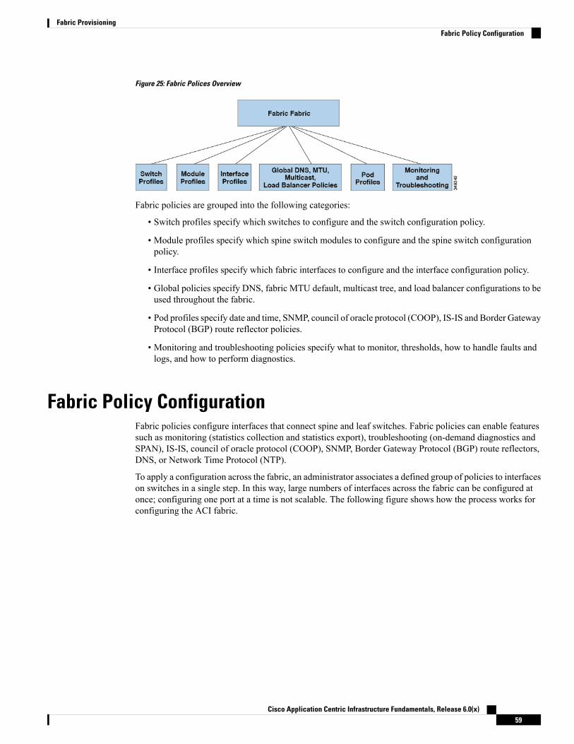
Figure 25: Fabric Polices Overview
Fabric policies are grouped into the following categories:
• Switch profiles specify which switches to configure and the switch configuration policy.
• Module profiles specify which spine switch modules to configure and the spine switch configurationpolicy.
• Interface profiles specify which fabric interfaces to configure and the interface configuration policy.
• Global policies specify DNS, fabric MTU default, multicast tree, and load balancer configurations to beused throughout the fabric.
• Pod profiles specify date and time, SNMP, council of oracle protocol (COOP), IS-IS and Border GatewayProtocol (BGP) route reflector policies.
• Monitoring and troubleshooting policies specify what to monitor, thresholds, how to handle faults andlogs, and how to perform diagnostics.
Fabric Policy ConfigurationFabric policies configure interfaces that connect spine and leaf switches. Fabric policies can enable featuressuch as monitoring (statistics collection and statistics export), troubleshooting (on-demand diagnostics andSPAN), IS-IS, council of oracle protocol (COOP), SNMP, Border Gateway Protocol (BGP) route reflectors,DNS, or Network Time Protocol (NTP).
To apply a configuration across the fabric, an administrator associates a defined group of policies to interfaceson switches in a single step. In this way, large numbers of interfaces across the fabric can be configured atonce; configuring one port at a time is not scalable. The following figure shows how the process works forconfiguring the ACI fabric.
Cisco Application Centric Infrastructure Fundamentals, Release 6.0(x)59
Fabric ProvisioningFabric Policy Configuration
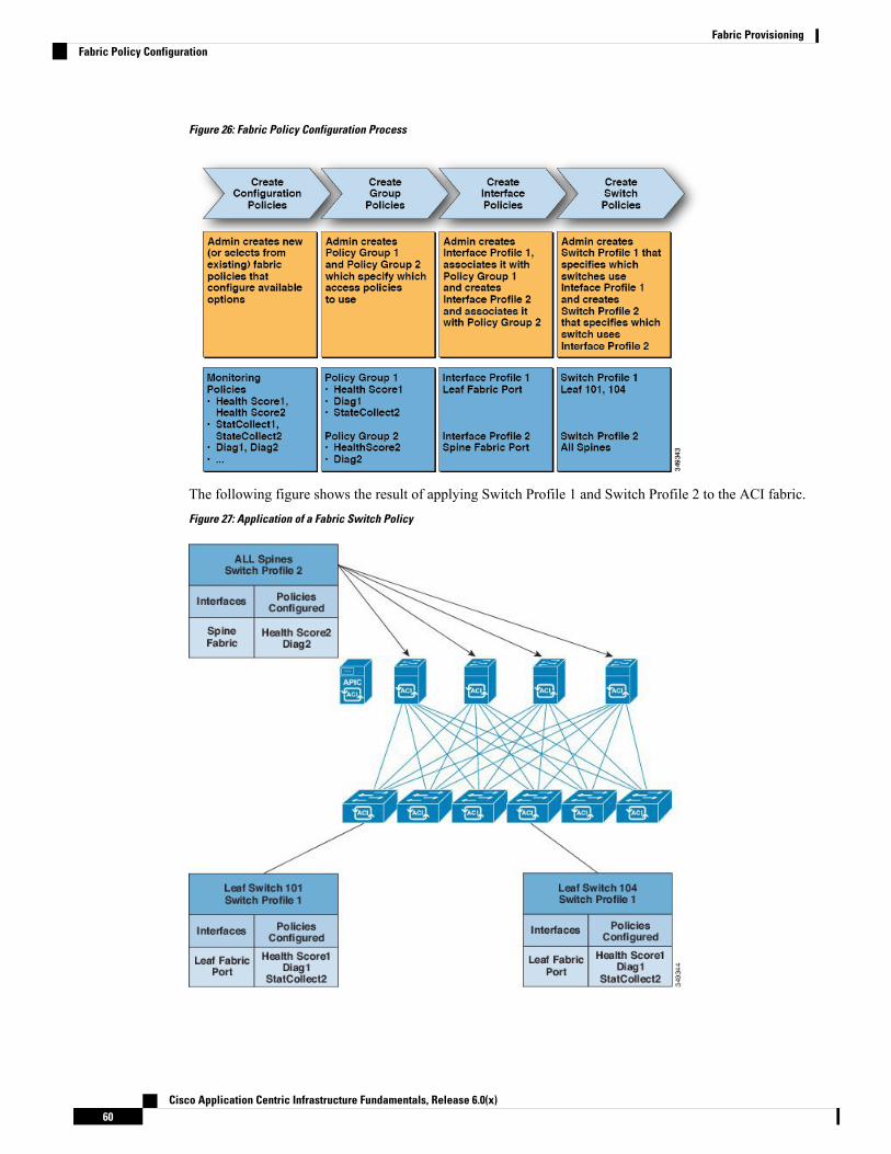
Figure 26: Fabric Policy Configuration Process
The following figure shows the result of applying Switch Profile 1 and Switch Profile 2 to the ACI fabric.
Figure 27: Application of a Fabric Switch Policy
Cisco Application Centric Infrastructure Fundamentals, Release 6.0(x)60
Fabric ProvisioningFabric Policy Configuration
This combination of infrastructure and scope enables administrators to manage fabric configuration in ascalable fashion. These configurations can be implemented using the REST API, the CLI, or the GUI. TheQuick Start Fabric Interface Configuration wizard in the GUI automatically creates the necessary underlyingobjects to implement such policies.
Access Policies OverviewAccess policies configure external-facing interfaces that connect to devices such as virtual machine controllersand hypervisors, hosts, network attached storage, routers, or Fabric Extender (FEX) interfaces. Access policiesenable the configuration of port channels and virtual port channels, protocols such as Link Layer DiscoveryProtocol (LLDP), Cisco Discovery Protocol (CDP), or Link Aggregation Control Protocol (LACP), andfeatures such as statistics gathering, monitoring, and diagnostics.
The following figure provides an overview of the access policy model.
Figure 28: Access Policy Model Overview
Access policies are grouped into the following categories:
• Switch profiles specify which switches to configure and the switch configuration policy.
• Module profiles specify which leaf switch access cards and access modules to configure and the leafswitch configuration policy.
• Interface profiles specify which access interfaces to configure and the interface configuration policy.
• Global policies enable the configuration of DHCP, QoS, and attachable access entity (AEP) profilefunctions that can be used throughout the fabric. AEP profiles provide a template to deploy hypervisorpolicies on a large set of leaf ports and associate a Virtual Machine Management (VMM) domain andthe physical network infrastructure. They are also required for Layer 2 and Layer 3 external networkconnectivity.
• Pools specify VLAN, VXLAN, and multicast address pools. A pool is a shared resource that can beconsumed by multiple domains such as VMM and Layer 4 to Layer 7 services. A pool represents a rangeof traffic encapsulation ide.jpgiers (for example, VLAN IDs, VNIDs, and multicast addresses).
• Physical and external domains policies include the following:
• External bridged domain Layer 2 domain profiles contain the port and VLAN specifications that abridged Layer 2 network connected to the fabric uses.
• External routed domain Layer 3 domain profiles contain the port and VLAN specifications that arouted Layer 3 network connected to the fabric uses.
Cisco Application Centric Infrastructure Fundamentals, Release 6.0(x)61
Fabric ProvisioningAccess Policies Overview

• Physical domain policies contain physical infrastructure specifications, such as ports and VLAN,used by a tenant or endpoint group.
• Monitoring and troubleshooting policies specify what to monitor, thresholds, how to handle faults andlogs, and how to perform diagnostics.
Access Policy ConfigurationAccess policies configure external-facing interfaces that do not connect to a spine switch. External-facinginterfaces connect to external devices such as virtual machine controllers and hypervisors, hosts, routers, orFabric Extenders (FEXs). Access policies enable an administrator to configure port channels and virtual portchannels, protocols such as LLDP, CDP, or LACP, and features such as monitoring or diagnostics.
Sample XML policies for switch interfaces, port channels, virtual port channels, and change interface speedsare provided in Cisco APIC Rest API Configuration Guide.
While tenant network policies are configured separately from fabric access policies, tenant policies are notactivated unless the underlying access policies they depend on are in place.
Note
To apply a configuration across a potentially large number of switches, an administrator defines switch profilesthat associate interface configurations in a single policy group. In this way, large numbers of interfaces acrossthe fabric can be configured at once. Switch profiles can contain symmetric configurations for multiple switchesor unique special purpose configurations. The following figure shows the process for configuring access tothe ACI fabric.
Figure 29: Access Policy Configuration Process
The following figure shows the result of applying Switch Profile 1 and Switch Profile 2 to the ACI fabric.
Cisco Application Centric Infrastructure Fundamentals, Release 6.0(x)62
Fabric ProvisioningAccess Policy Configuration
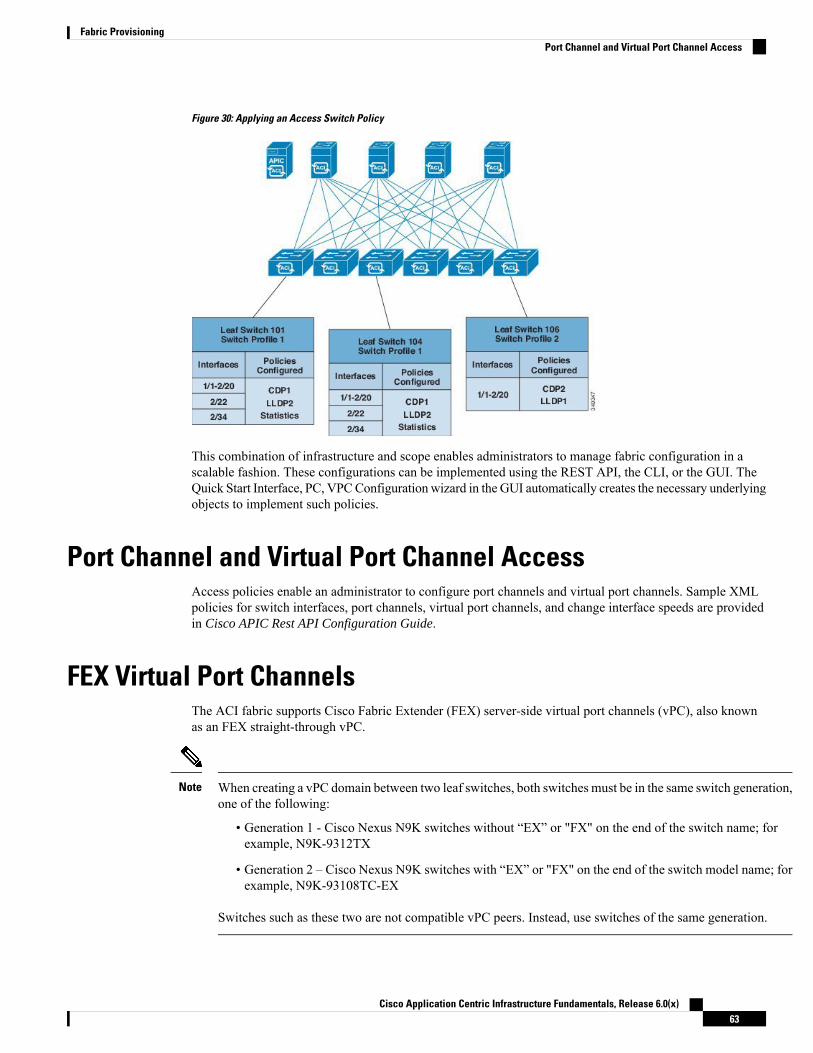
Figure 30: Applying an Access Switch Policy
This combination of infrastructure and scope enables administrators to manage fabric configuration in ascalable fashion. These configurations can be implemented using the REST API, the CLI, or the GUI. TheQuick Start Interface, PC, VPCConfiguration wizard in the GUI automatically creates the necessary underlyingobjects to implement such policies.
Port Channel and Virtual Port Channel AccessAccess policies enable an administrator to configure port channels and virtual port channels. Sample XMLpolicies for switch interfaces, port channels, virtual port channels, and change interface speeds are providedin Cisco APIC Rest API Configuration Guide.
FEX Virtual Port ChannelsThe ACI fabric supports Cisco Fabric Extender (FEX) server-side virtual port channels (vPC), also knownas an FEX straight-through vPC.
When creating a vPC domain between two leaf switches, both switches must be in the same switch generation,one of the following:
• Generation 1 - Cisco Nexus N9K switches without “EX” or "FX" on the end of the switch name; forexample, N9K-9312TX
• Generation 2 – Cisco Nexus N9K switches with “EX” or "FX" on the end of the switch model name; forexample, N9K-93108TC-EX
Switches such as these two are not compatible vPC peers. Instead, use switches of the same generation.
Note
Cisco Application Centric Infrastructure Fundamentals, Release 6.0(x)63
Fabric ProvisioningPort Channel and Virtual Port Channel Access
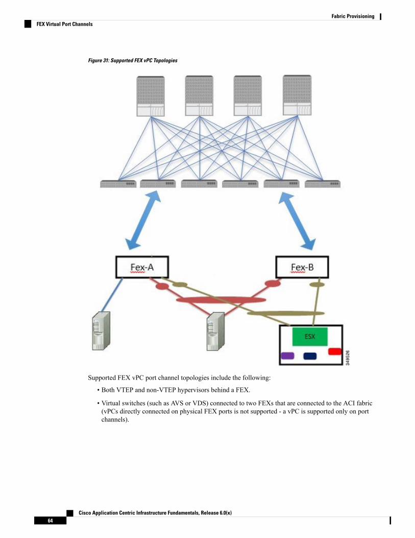
Figure 31: Supported FEX vPC Topologies
Supported FEX vPC port channel topologies include the following:
• Both VTEP and non-VTEP hypervisors behind a FEX.
• Virtual switches (such as AVS or VDS) connected to two FEXs that are connected to the ACI fabric(vPCs directly connected on physical FEX ports is not supported - a vPC is supported only on portchannels).
Cisco Application Centric Infrastructure Fundamentals, Release 6.0(x)64
Fabric ProvisioningFEX Virtual Port Channels

When using GARP as the protocol to n.jpgy of IP to MAC binding changes to different interfaces on the sameFEX you must set the bridge domain mode to ARP Flooding and enable EP Move Detection Mode:GARP-based Detection, on the L3 Configuration page of the bridge domain wizard. This workaround isonly required with Generation 1 switches. With Generation 2 switches or later, this is not an issue.
Note
Fibre Channel and FCoEFor Fibre Channel and FCoE configuration information, see theCisco APIC Layer 2 Networking ConfigurationGuide.
Supporting Fibre Channel over Ethernet Traffic on the Cisco ACI FabricCisco Application Centric Infrastructure (ACI) enables you to configure andmanage support for Fibre Channelover Ethernet (FCoE) traffic on the Cisco ACI fabric.
FCoE is a protocol that encapsulates Fibre Channel packets within Ethernet packets, thus enabling storagetraffic to move seamlessly between a Fibre Channel SAN and an Ethernet network.
A typical implementation of FCoE protocol support on the Cisco ACI fabric enables hosts located on theEthernet-based Cisco ACI fabric to communicate with SAN storage devices located on a Fibre Channelnetwork. The hosts are connecting through virtual F ports deployed on an Cisco ACI leaf switch. The SANstorage devices and Fibre Channel network are connected through a Fibre Channel Forwarding (FCF) bridgeto the Cisco ACI fabric through a virtual NP port, deployed on the same Cisco ACI leaf switch as is the virtualF port. Virtual NP ports and virtual F ports are also referred to generically as virtual Fibre Channel (vFC)ports.
In the FCoE topology, the role of the Cisco ACI leaf switch is to provide a path for FCoE traffic between thelocally connected SAN hosts and a locally connected FCF device. The leaf switch does not perform localswitching between SAN hosts, and the FCoE traffic is not forwarded to a spine switch.
Note
Topology Supporting FCoE Traffic Through Cisco ACI
The topology of a typical configuration supporting FCoE traffic over the Cisco ACI fabric consists of thefollowing components:
Cisco Application Centric Infrastructure Fundamentals, Release 6.0(x)65
Fabric ProvisioningFibre Channel and FCoE

Figure 32: Cisco ACI Topology Supporting FCoE Traffic
• One or more Cisco ACI leaf switches configured through Fibre Channel SAN policies to function as anNPV backbone.
• Selected interfaces on the NPV-configured leaf switches configured to function as virtual F ports, whichaccommodate FCoE traffic to and from hosts running SANmanagement or SAN-consuming applications.
• Selected interfaces on the NPV-configured leaf switches configured to function as virtual NP ports, whichaccommodate FCoE traffic to and from a Fibre Channel Forwarding (FCF) bridge.
The FCF bridge receives Fibre Channel traffic from Fibre Channel links typically connecting SAN storagedevices and encapsulates the Fibre Channel packets into FCoE frames for transmission over the Cisco ACIfabric to the SAN management or SAN Data-consuming hosts. It receives FCoE traffic and repackages itback to the Fibre Channel for transmission over the Fibre Channel network.
In the above Cisco ACI topology, FCoE traffic support requires direct connections between the hosts andvirtual F ports and direct connections between the FCF device and the virtual NP port.
Note
Cisco Application Centric Infrastructure Fundamentals, Release 6.0(x)66
Fabric ProvisioningSupporting Fibre Channel over Ethernet Traffic on the Cisco ACI Fabric

Cisco Application Policy Infrastructure Controller (APIC) servers enable an operator to configure and monitorthe FCoE traffic through the Cisco APIC GUI, or NX-OS-style CLI, or through application calls to the RESTAPI.
Topology Supporting FCoE Initialization
In order for FCoE traffic flow to take place as described, you must also set up separate VLAN connectivityover which SANHosts broadcast FCoE Initialization protocol (FIP) packets to discover the interfaces enabledas F ports.
vFC Interface Configuration Rules
Whether you set up the vFC network and EPG deployment through the Cisco APIC GUI, NX-OS-style CLI,or the REST API, the following general rules apply across platforms:
• F port mode is the default mode for vFC ports. NP port mode must be specifically configured in theInterface policies.
• The load balancing default mode is for leaf-switch or interface level vFC configuration is src-dst-ox-id.
• One VSAN assignment per bridge domain is supported.
• The allocation mode for VSAN pools and VLAN pools must always be static.
• vFC ports require association with a VSAN domain (also called Fibre Channel domain) that containsVSANs mapped to VLANs.
Fibre Channel Connectivity OverviewCisco ACI supports Fibre Channel (FC) connectivity on a leaf switch using N-Port Virtualization (NPV)mode. NPV allows the switch to aggregate FC traffic from locally connected host ports (N ports) into a nodeproxy (NP port) uplink to a core switch.
A switch is in NPV mode after enabling NPV. NPV mode applies to an entire switch. Each end deviceconnected to an NPV mode switch must log in as an N port to use this feature (loop-attached devices are notsupported). All links from the edge switches (in NPV mode) to the NPV core switches are established as NPports (not E ports), which are used for typical inter-switch links.
In the FC NPV application, the role of the ACI leaf switch is to provide a path for FC traffic between thelocally connected SAN hosts and a locally connected core switch. The leaf switch does not perform localswitching between SAN hosts, and the FC traffic is not forwarded to a spine switch.
Note
FC NPV Benefits
FC NPV provides the following:
• Increases the number of hosts that connect to the fabric without adding domain IDs in the fabric. Thedomain ID of the NPV core switch is shared among multiple NPV switches.
• FC and FCoE hosts connect to SAN fabrics using native FC interfaces.
Cisco Application Centric Infrastructure Fundamentals, Release 6.0(x)67
Fabric ProvisioningFibre Channel Connectivity Overview

• Automatic traffic mapping for load balancing. For newly added servers connected to NPV, traffic isautomatically distributed among the external uplinks based on current traffic loads.
• Static traffic mapping. A server connected to NPV can be statically mapped to an external uplink.
FC NPV Mode
Feature-set fcoe-npv in ACI will be enabled automatically by default when the first FCoE/FC configurationis pushed.
FC Topology
The topology of various configurations supporting FC traffic over the ACI fabric is shown in the followingfigure:
• Server/storage host interfaces on the ACI leaf switch can be configured to function as either native FCports or as virtual FC (FCoE) ports.
• An uplink interface to a FC core switch can be configured as any of the following port types:
Cisco Application Centric Infrastructure Fundamentals, Release 6.0(x)68
Fabric ProvisioningFibre Channel Connectivity Overview

• native FC NP port
• SAN-PO NP port
• An uplink interface to a FCF switch can be configured as any of the following port types:
• virtual (vFC) NP port
• vFC-PO NP port
• N-Port ID Virtualization (NPIV) is supported and enabled by default, allowing an N port to be assignedmultiple N port IDs or Fibre Channel IDs (FCID) over a single link.
• Trunking can be enabled on an NP port to the core switch. Trunking allows a port to support more thanone VSAN. When trunk mode is enabled on an NP port, it is referred to as a TNP port.
• Multiple FC NP ports can be combined as a SAN port channel (SAN-PO) to the core switch. Trunkingis supported on a SAN port channel.
• FC F ports support 4/16/32 Gbps and auto speed configuration, but 8Gbps is not supported for hostinterfaces. The default speed is "auto."
• FC NP ports support 4/8/16/32 Gbps and auto speed configuration. The default speed is "auto."
• Multiple FDISC followed by Flogi (nested NPIV) is supported with FC/FCoE host and FC/FCoE NPlinks.
• An FCoE host behind a FEX is supported over an FCoE NP/uplink.
• Starting in the APIC 4.1(1) release, an FCoE host behind a FEX is supported over the Fibre ChannelNP/uplink.
• All FCoE hosts behind one FEX can either be load balanced across multiple vFC and vFC-PO uplinks,or through a single Fibre Channel/SAN port channel uplink.
• SAN boot is supported on a FEX through an FCoE NP/uplink.
• Starting in the APIC 4.1(1) release, SAN boot is also supported over a FC/SAN-PO uplink.
• SAN boot is supported over vPC for FCoE hosts that are connected through FEX.
Cisco Application Centric Infrastructure Fundamentals, Release 6.0(x)69
Fabric ProvisioningFibre Channel Connectivity Overview

802.1Q Tunnels
About ACI 802.1Q TunnelsFigure 33: ACI 802.1Q Tunnels
You can configure 802.1Q tunnels on edge (tunnel) ports to enable point-to-multi-point tunneling of Ethernetframes in the fabric, with Quality of Service (QoS) priority settings. A Dot1q tunnel transports untagged,802.1Q tagged, and 802.1ad double-tagged frames as-is across the fabric. Each tunnel carries the traffic froma single customer and is associated with a single bridge domain. Cisco Application Centric Infrastructure(ACI) front panel ports can be part of a Dot1q tunnel. Layer 2 switching is done based on the destinationMAC (DMAC) and regular MAC learning is done in the tunnel. Edge port Dot1q tunnels are supported onCisco Nexus 9000 series switches with "EX" or later suffixes in the switch model name.
You can configure multiple 802.1Q tunnels on the same core port to carry double-tagged traffic from multiplecustomers, each distinguished with an access encapsulation configured for each 802.1Q tunnel. You can alsodisable MAC address learning on 802.1Q tunnels. Both edge ports and core ports can belong to an 802.1Qtunnel with access encapsulation and disabledMAC address learning. Both edge ports and core ports in Dot1qtunnel are supported on Cisco Nexus 9000 series switches with "FX" or later suffixes in the switch modelname.
IGMP and MLD packets can be forwarded through 802.1Q tunnels.
Terms used in this document may be different in the Cisco Nexus 9000 Series documents.
Table 3: 802.1Q Tunnel Terminology
Cisco Nexus 9000 Series DocumentsACI Documents
Tunnel PortEdge Port
Cisco Application Centric Infrastructure Fundamentals, Release 6.0(x)70
Fabric Provisioning802.1Q Tunnels

Cisco Nexus 9000 Series DocumentsACI Documents
Trunk PortCore Port
The following guidelines and restrictions apply:
• Layer 2 tunneling of VTP, CDP, LACP, LLDP, and STP protocols is supported with the followingrestrictions:
• Link Aggregation Control Protocol (LACP) tunneling functions as expected only with point-to-pointtunnels using individual leaf interfaces. It is not supported on port channels (PCs) or virtual portchannels (vPCs).
• CDP and LLDP tunneling with PCs or vPCs is not deterministic; it depends on the link it choosesas the traffic destination.
• To use VTP for Layer 2 protocol tunneling, CDP must be enabled on the tunnel.
• STP is not supported in an 802.1Q tunnel bridge domain when Layer 2 protocol tunneling is enabledand the bridge domain is deployed on Dot1q tunnel core ports.
• Cisco ACI leaf switches react to STP TCN packets by flushing the end points in the tunnel bridgedomain and flooding them in the bridge domain.
• CDP and LLDP tunneling with more than two interfaces flood packets on all interfaces.
• The destination MAC address of Layer 2 protocol packets tunneled from edge to core ports isrewritten as 01-00-0c-cd-cd-d0 and the destinationMAC address of Layer 2 protocol packets tunneledfrom core to edge ports is rewritten with the standard default MAC address for the protocol.
• If a PC or vPC is the only interface in a Dot1q tunnel and it is deleted and reconfigured, remove theassociation of the PC/VPC to the Dot1q tunnel and reconfigure it.
• For 802.1Q tunnels deployed on switches that have EX in the product ID, Ethertype combinations of0x8100+0x8100, 0x8100+0x88a8, 0x88a8+0x8100, and 0x88a8+0x88a8 for the first two VLAN tagsare not supported.
If the tunnels are deployed on a combination of EX and FX or later switches, then this restriction stillapplies.
If the tunnels are deployed only on switches that have FX or later in the product ID, then this restrictiondoes not apply.
• For core ports, the Ethertypes for double-tagged frames must be 0x8100 followed by 0x8100.
• You can include multiple edge ports and core ports (even across leaf switches) in a Dot1q tunnel.
• An edge port may only be part of one tunnel, but a core port can belong to multiple Dot1q tunnels.
• Regular EPGs can be deployed on core ports that are used in 802.1Q tunnels.
• L3Outs are not supported on interfaces enabled for Dot1q tunnel.
• FEX interfaces are not supported as members of a Dot1q tunnel.
• Interface-level statistics are supported for interfaces in Dot1q tunnel, but statistics at the tunnel level arenot supported.
Cisco Application Centric Infrastructure Fundamentals, Release 6.0(x)71
Fabric ProvisioningAbout ACI 802.1Q Tunnels

Dynamic Breakout Ports
Configuration of Breakout PortsBreakout cables are suitable for very short links and offer a cost effective way to connect within racks andacross adjacent racks. Breakout enables a 40 Gigabit (Gb) port to be split into four independent and logical10Gb ports, a 100Gb port to be split into four independent and logical 25Gb ports, or a 400Gb port to be splitinto four independent and logical 100Gb ports.
You configure breakout on the down links (also known as the access-facing ports or downlink ports) andfabric links of the switches. Fabric links form the connections between the leaf switches and spine switches,or between the tier 1 leaf switches and tier 2 leaf switches for a multi-tier topology.
Configuring Port ProfilesUplink and downlink conversion is supported on Cisco Nexus 9000 series switches with names that end inEX or FX, and later (for example, N9K-C9348GC-FXP or N9K-C93240YC-FX2). A FEX connected toconverted downlinks is also supported.
For information about the supported supported Cisco switches, see Port Profile Configuration Summary, onpage 75.
When an uplink port is converted to a downlink port, it acquires the same capabilities as any other downlinkport.
Restrictions
• Fast Link Failover policies and port profiles are not supported on the same port. If port profile is enabled,Fast Link Failover cannot be enabled or vice versa.
• The last 2 uplink ports of supported leaf switches cannot be converted to downlink ports (they are reservedfor uplink connections.)
• Dynamic breakouts (both 100Gb and 40Gb) are supported on profiled QSFP ports on theN9K-C93180YC-FX switch. Breakout and port profile are supported together for conversion of uplinkto downlink on ports 49-52. Breakout (both 10g-4x and 25g-4x options) is supported on downlink profiledports.
• The N9K-C9348GC-FXP does not support FEX.
• Breakout is supported only on downlink ports, and not on fabric ports that are connected to other switches.
• A Cisco ACI leaf switch cannot have more than 56 fabric links.
Guidelines
In converting uplinks to downlinks and downlinks to uplinks, consider the following guidelines.
Cisco Application Centric Infrastructure Fundamentals, Release 6.0(x)72
Fabric ProvisioningDynamic Breakout Ports

GuidelineSubject
If a decommissioned node has the Port Profile feature deployed on it, the portconversions are not removed even after decommissioning the node. It isnecessary to manually delete the configurations after decommission, for theports to return to the default state. To do this, log onto the switch, run thesetup-clean-config.sh -k script, and wait for it to run. Then, enter thereload command. The -k script option allows the port-profile setting to persistacross the reload, making an additional reboot unnecessary.
Decommissioning nodeswith port profiles
When the maximum uplink port limit is reached and ports 25 and 27 areconverted from uplink to downlink and back to uplink on Cisco 93180LC-EXswitches:
On Cisco N9K-93180LC-EX switches, ports 25 and 27 are the original uplinkports. Using the port profile, if you convert port 25 and 27 to downlink ports,ports 29, 30, 31, and 32 are still available as four original uplink ports. Becauseof the threshold on the number of ports (which is maximum of 12 ports) thatcan be converted, you can convert 8 more downlink ports to uplink ports. Forexample, ports 1, 3, 5, 7, 9, 13, 15, 17 are converted to uplink ports and ports29, 30, 31 and 32 are the 4 original uplink ports (the maximum uplink portlimit on Cisco 93180LC-EX switches).
When the switch is in this state and if the port profile configuration is deletedon ports 25 and 27, ports 25 and 27 are converted back to uplink ports, butthere are already 12 uplink ports on the switch (as mentioned earlier). Toaccommodate ports 25 and 27 as uplink ports, 2 random ports from the portrange 1, 3, 5, 7, 9, 13, 15, 17 are denied the uplink conversion and this situationcannot be controlled by the user.
Therefore, it is mandatory to clear all the faults before reloading the leaf nodeto avoid any unexpected behavior regarding the port type. It should be notedthat if a node is reloaded without clearing the port profile faults, especiallywhen there is a fault related to limit-exceed, the port might not be in an expectedoperational state.
Maximum uplink port limit
Breakout Limitations
LimitationsReleasesSwitch
• 40Gb and 100Gb dynamic breakouts aresupported on ports 1 through 24 on oddnumbered ports.
• When the top ports (odd ports) are broken out,then the bottom ports (even ports) are errordisabled.
• Port profiles and breakouts are not supportedon the same port. However, you can apply aport profile to convert a fabric port to adownlink, and then apply a breakoutconfiguration.
Cisco APIC 3.1(1) and laterN9K-C93180LC-EX
Cisco Application Centric Infrastructure Fundamentals, Release 6.0(x)73
Fabric ProvisioningConfiguring Port Profiles
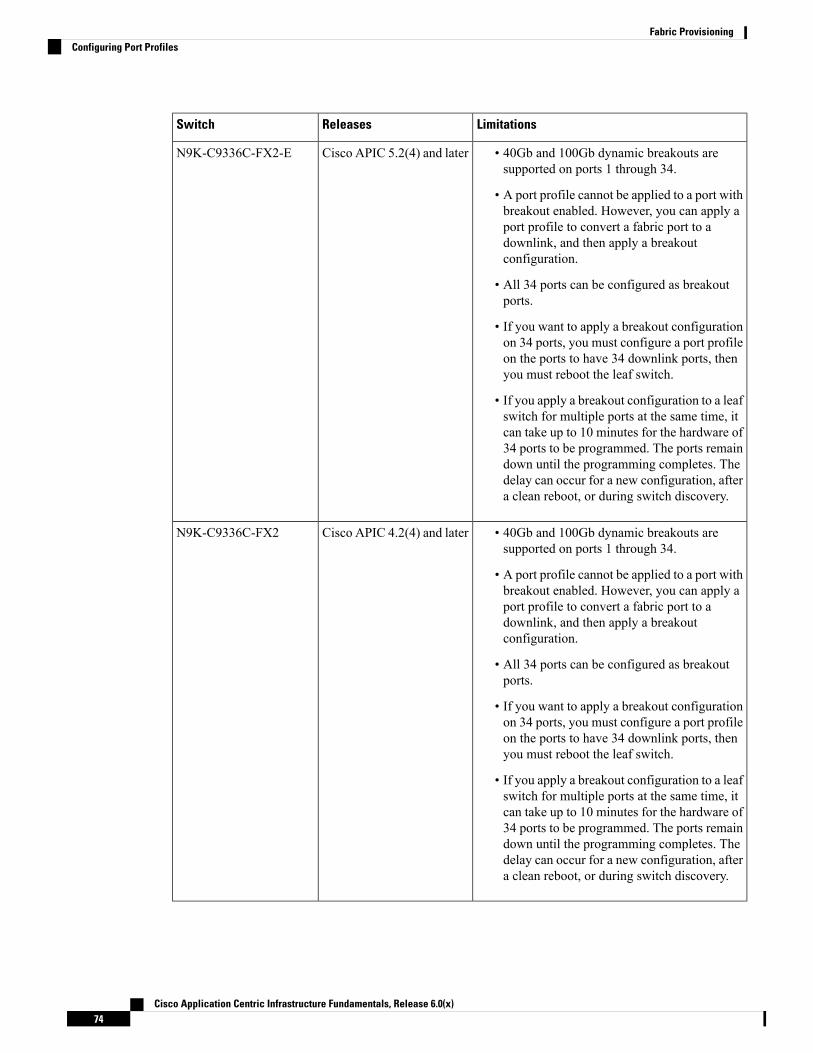
LimitationsReleasesSwitch
• 40Gb and 100Gb dynamic breakouts aresupported on ports 1 through 34.
• A port profile cannot be applied to a port withbreakout enabled. However, you can apply aport profile to convert a fabric port to adownlink, and then apply a breakoutconfiguration.
• All 34 ports can be configured as breakoutports.
• If you want to apply a breakout configurationon 34 ports, you must configure a port profileon the ports to have 34 downlink ports, thenyou must reboot the leaf switch.
• If you apply a breakout configuration to a leafswitch for multiple ports at the same time, itcan take up to 10 minutes for the hardware of34 ports to be programmed. The ports remaindown until the programming completes. Thedelay can occur for a new configuration, aftera clean reboot, or during switch discovery.
Cisco APIC 5.2(4) and laterN9K-C9336C-FX2-E
• 40Gb and 100Gb dynamic breakouts aresupported on ports 1 through 34.
• A port profile cannot be applied to a port withbreakout enabled. However, you can apply aport profile to convert a fabric port to adownlink, and then apply a breakoutconfiguration.
• All 34 ports can be configured as breakoutports.
• If you want to apply a breakout configurationon 34 ports, you must configure a port profileon the ports to have 34 downlink ports, thenyou must reboot the leaf switch.
• If you apply a breakout configuration to a leafswitch for multiple ports at the same time, itcan take up to 10 minutes for the hardware of34 ports to be programmed. The ports remaindown until the programming completes. Thedelay can occur for a new configuration, aftera clean reboot, or during switch discovery.
Cisco APIC 4.2(4) and laterN9K-C9336C-FX2
Cisco Application Centric Infrastructure Fundamentals, Release 6.0(x)74
Fabric ProvisioningConfiguring Port Profiles
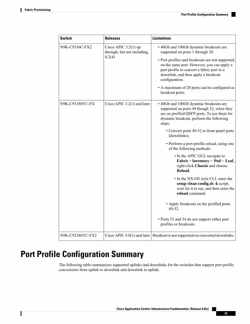
LimitationsReleasesSwitch
• 40Gb and 100Gb dynamic breakouts aresupported on ports 1 through 30.
• Port profiles and breakouts are not supportedon the same port. However, you can apply aport profile to convert a fabric port to adownlink, and then apply a breakoutconfiguration.
• A maximum of 20 ports can be configured asbreakout ports.
Cisco APIC 3.2(1) upthrough, but not including,4.2(4)
N9K-C9336C-FX2
• 40Gb and 100Gb dynamic breakouts aresupported on ports 49 though 52, when theyare on profiled QSFP ports. To use them fordynamic breakout, perform the followingsteps:
• Convert ports 49-52 to front panel ports(downlinks).
• Perform a port-profile reload, using oneof the following methods:
• In the APIC GUI, navigate toFabric > Inventory > Pod > Leaf,right-click Chassis and chooseReload.
• In the NX-OS style CLI, enter thesetup-clean-config.sh -k script,wait for it to run, and then enter thereload command.
• Apply breakouts on the profiled ports49-52.
• Ports 53 and 54 do not support either portprofiles or breakouts.
Cisco APIC 3.2(1) and laterN9K-C93180YC-FX
Breakout is not supported on converted downlinks.Cisco APIC 4.0(1) and laterN9K-C93240YC-FX2
Port Profile Configuration SummaryThe following table summarizes supported uplinks and downlinks for the switches that support port profileconversions from uplink to downlink and downlink to uplink.
Cisco Application Centric Infrastructure Fundamentals, Release 6.0(x)75
Fabric ProvisioningPort Profile Configuration Summary

ReleaseSupported
Max Downlinks(Server Ports)
Max Uplinks (FabricPorts)
Default LinksSwitch Model
3.1(1)Same as default portconfiguration
48 x 100M/1GBASE-T downlinks
4 x 10/25 Gbps SFP28uplinks
2 x 40/100 GbpsQSFP28 uplinks
48 x 100M/1GBASE-T downlinks
4 x 10/25 Gbps SFP28downlinks
2 x 40/100 GbpsQSFP28 uplinks
N9K-C9348GC-FXP1
3.1(1)24 x 40GbpsQSFP28downlinks(1-24)
2 x 40/100 GbpsQSFP28downlinks(25, 27)
4 x 40/100 GbpsQSFP28uplinks(29-32)
Or
12 x 100 GbpsQSFP28downlinks(oddnumber from 1-24)
2 x 40/100 GbpsQSFP28 downlinks(25, 27)
4 x 40/100 GbpsQSFP28uplinks(29-32)
18 x 40 Gbps QSFP28downlinks (from 1-24)
6 x 40 Gbps QSFP28uplinks(from 1-24)
2 x 40/100 GbpsQSFP28 uplinks(25,27)
4 x 40/100 GbpsQSFP28uplinks(29-32)
Or
6 x 100 Gbps QSFP28downlinks(odd numberfrom 1-24)
6 x 100 Gbps QSFP28uplinks(odd numberfrom 1-24)
2 x 40/100 GbpsQSFP28 uplinks(25,27)
4 x 40/100 GbpsQSFP28uplinks(29-32)
24 x 40 Gbps QSFP28downlinks(1-24)
2 x 40/100 GbpsQSFP28 uplinks(25,27)
4 x 40/100 GbpsQSFP28uplinks(29-32)
Or
12 x 100GbpsQSFP28downlinks(odd numberfrom 1-24)
2 x 40/100 GbpsQSFP28 uplinks(25,27)
4 x 40/100 GbpsQSFP28uplinks(29-32)
N9K-C93180LC-EX
3.1(1)48 x 10/25 Gbps fiberdownlinks
4 x 40/100 GbpsQSFP28 downlinks
2 x 40/100 GbpsQSFP28 uplinks
Same as default portconfiguration
48 x 10/25 Gbps fiberdownlinks
6 x 40/100 GbpsQSFP28 uplinks
N9K-C93180YC-EX
N9K-C93180YC-FX
N9K-C93180YC-FX3 4.0(1)48 x 10/25 Gbps fiberuplinks
6 x 40/100 GbpsQSFP28 uplinks
5.1(3)
Cisco Application Centric Infrastructure Fundamentals, Release 6.0(x)76
Fabric ProvisioningPort Profile Configuration Summary

ReleaseSupported
Max Downlinks(Server Ports)
Max Uplinks (FabricPorts)
Default LinksSwitch Model
3.1(1)48 x 10/25 Gbps fiberdownlinks
4 x 40/100 GbpsQSFP28 downlinks
2 x 40/100 GbpsQSFP28 uplinks
Same as default portconfiguration
48 x 10GBASE-Tdownlinks
6 x 40/100 GbpsQSFP28 uplinks
N9K-C93108TC-EX2
N9K-C93108TC-FX2
N9K-C93108TC-FX34.0(1)
5.1(3)
3.2(1)Same as default portconfiguration
18 x 40/100 GbpsQSFP28 downlinks
18 x 40/100 GbpsQSFP28 uplinks
30 x 40/100 GbpsQSFP28 downlinks
6 x 40/100 GbpsQSFP28 uplinks
N9K-C9336C-FX2
3.2(3)34 x 40/100 GbpsQSFP28 downlinks
2 x 40/100 GbpsQSFP28 uplinks
18 x 40/100 GbpsQSFP28 downlinks
18 x 40/100 GbpsQSFP28 uplinks
4.1(1)34 x 40/100 GbpsQSFP28 downlinks
2 x 40/100 GbpsQSFP28 uplinks
36 x 40/100 GbpsQSFP28 uplinks
5.2(4)34 x 40/100 GbpsQSFP28 downlinks
2 x 40/100 GbpsQSFP28 uplinks
36 x 40/100 GbpsQSFP28 uplinks
30 x 40/100 GbpsQSFP28 downlinks
6 x 40/100 GbpsQSFP28 uplinks
N9K-C9336C-FX2-E
4.0(1)48 x 10/25 Gbps fiberdownlinks
10 x 40/100 GbpsQSFP28 downlinks
2 x 40/100 GbpsQSFP28 uplinks
Same as default portconfiguration
48 x 10/25 Gbps fiberdownlinks
12 x 40/100 GbpsQSFP28 uplinks
N9K-93240YC-FX2
4.1(1)48 x 10/25 Gbps fiberuplinks
12 x 40/100 GbpsQSFP28 uplinks
4.1(2)96 x 10G BASE-Tdownlinks
10 x 40/100 GbpsQSFP28 downlinks
2 x 40/100 GbpsQSFP28 uplinks
Same as default portconfiguration
96 x 10G BASE-Tdownlinks
12 x 40/100 GbpsQSFP28 uplinks
N9K-C93216TC-FX2
Cisco Application Centric Infrastructure Fundamentals, Release 6.0(x)77
Fabric ProvisioningPort Profile Configuration Summary

ReleaseSupported
Max Downlinks(Server Ports)
Max Uplinks (FabricPorts)
Default LinksSwitch Model
4.1(2)96 x 10/25 GbpsSFP28 downlinks
10 x 40/100 GbpsQSFP28 downlinks
2 x 40/100 GbpsQSFP28 uplinks
44 x 10/25Gbps SFP28downlinks
52 x 10/25Gbps SFP28uplinks
12 x 40/100GbpsQSFP28 uplinks
96 x 10/25 GbpsSFP28 downlinks
12 x 40/100 GbpsQSFP28 uplinks
N9K-C93360YC-FX2
4.2(2)28 x 40/100 GbpsQSFP28 downlinks
6 x 40/100/400 GbpsQSFP-DD downlinks
2 x 40/100/400 GbpsQSFP-DD uplinks
28 x 40/100 GbpsQSFP28 uplinks
8 x 40/100/400 GbpsQSFP-DD uplinks
28 x 40/100 GbpsQSFP28 downlinks
8 x 40/100/400 GbpsQSFP-DD uplinks
N9K-C93600CD-GX
4.2(3)62 x 40/100 GbpsQSFP28 downlinks
2 x 40/100 GbpsQSFP28 uplinks
64 x 40/100 GbpsQSFP28 uplinks
48 x 40/100 GbpsQSFP28 downlinks
16 x 40/100 GbpsQSFP28 uplinks
N9K-C9364C-GX
5.1(4)14 x 40/100/400GbpsQSFP-DD downlinks
16 x 40/100/400 GbpsQSFP-DD uplinks
12 x 40/100/400 GbpsQSFP-DD downlinks
4 x 40/100/400 GbpsQSFP-DD uplinks
N9K-C9316D-GX
5.2(3)2 x 1/10 Gbps SFP+downlinks
30 x 40/100/400GbpsQSFP-DD downlinks
2 x 40/100/400 GbpsQSFP-DD uplinks
2 x 1/10 Gbps SFP+downlinks
32 x 40/100/400 GbpsQSFP-DD uplinks
2 x 1/10 Gbps SFP+downlinks
24 x 40/100/400 GbpsQSFP-DD downlinks
8 x 40/100/400 GbpsQSFP-DD uplinks
N9K-C9332D-GX2B
5.2(5)2 x 1/10 Gbps SFP+downlinks
46 x 40/100/400GbpsQSFP-DD downlinks
2 x 40/100/400 GbpsQSFP-DD uplinks
2 x 1/10 Gbps SFP+downlinks
48 x 40/100/400 GbpsQSFP-DD uplinks
2 x 1/10 Gbps SFP+downlinks
36 x 40/100/400 GbpsQSFP-DD downlinks
12 x 40/100/400 GbpsQSFP-DD uplinks
N9K-C9348D-GX2A
Cisco Application Centric Infrastructure Fundamentals, Release 6.0(x)78
Fabric ProvisioningPort Profile Configuration Summary

ReleaseSupported
Max Downlinks(Server Ports)
Max Uplinks (FabricPorts)
Default LinksSwitch Model
5.2(5)2 x 1/10 Gbps SFP+downlinks
62 x 40/100/400GbpsQSFP-DD downlinks
2 x 40/100/400 GbpsQSFP-DD uplinks
2 x 1/10 Gbps SFP+downlinks
64 x 40/100/400 GbpsQSFP-DD uplinks
2 x 1/10 Gbps SFP+downlinks
48 x 40/100/400 GbpsQSFP-DD downlinks
16 x 40/100/400 GbpsQSFP-DD uplinks
N9K-C9364D-GX2A
1 Does not support FEX.
2 Only uplink to downlink conversion is supported.
Port Tracking Policy for Fabric Port Failure DetectionFabric port failure detection can be enabled in the port tracking system settings. The port tracking policymonitors the status of fabric ports between leaf switches and spine switches, and ports between tier-1 leafswitches and tier-2 leaf switches. When an enabled port tracking policy is triggered, the leaf switches takedown all access interfaces on the switch that have EPGs deployed on them.
If you enabled the Include APIC ports when port tracking is triggered option, port tracking disables CiscoApplication Policy Infrastructure Controller (APIC) ports when the leaf switch loses connectivity to all fabricports (that is, there are 0 fabric ports). Enable this feature only if the Cisco APICs are dual- or multihomedto the fabric. Bringing down the Cisco APIC ports helps in switching over to the secondary port in the caseof a dual-homed Cisco APIC.
Port tracking is located under System > System Settings > Port Tracking.Note
The port tracking policy specifies the number of fabric port connections that trigger the policy, and a delaytimer for bringing the leaf switch access ports back up after the number of specified fabric ports is exceeded.
The following example illustrates how a port tracking policy behaves:
• The port tracking policy specifies that the threshold of active fabric port connections each leaf switchthat triggers the policy is 2.
• The port tracking policy triggers when the number of active fabric port connections from the leaf switchto the spine switches drops to 2.
• Each leaf switch monitors its fabric port connections and triggers the port tracking policy according tothe threshold specified in the policy.
• When the fabric port connections come back up, the leaf switch waits for the delay timer to expire beforebringing its access ports back up. This gives the fabric time to reconverge before allowing traffic toresume on leaf switch access ports. Large fabrics may need the delay timer to be set for a longer time.
Cisco Application Centric Infrastructure Fundamentals, Release 6.0(x)79
Fabric ProvisioningPort Tracking Policy for Fabric Port Failure Detection

Use caution when configuring this policy. If the port tracking setting for the number of active spine ports thattriggers port tracking is too high, all leaf switch access ports will be brought down.
Note
Q-in-Q Encapsulation Mapping for EPGsUsing Cisco Application Policy Infrastructure Controller (APIC), you can map double-tagged VLAN trafficingressing on a regular interface, PC, or vPC to an EPG. When this feature is enabled, when double-taggedtraffic enters the network for an EPG, both tags are processed individually in the fabric and restored todouble-tags when egressing the Cisco Application Centric Infrastructure (ACI) switch. Ingressing single-taggedand untagged traffic is dropped.
The following guidelines and limitations apply:
• This feature is only supported on Cisco Nexus 9300-FX platform switches.
• Both the outer and inner tag must be of EtherType 0x8100.
• MAC learning and routing are based on the EPG port, sclass, and VRF instance, not on the accessencapsulations.
• QoS priority settings are supported, derived from the outer tag on ingress, and rewritten to both tags onegress.
• EPGs can simultaneously be associated with other interfaces on a leaf switch, that are configured forsingle-tagged VLANs.
• Service graphs are supported for provider and consumer EPGs that are mapped to Q-in-Q encapsulatedinterfaces. You can insert service graphs, as long as the ingress and egress traffic on the service nodesis in single-tagged encapsulated frames.
• When vPC ports are enabled for Q-in-Q encapsulationmode, VLAN consistency checks are not performed.
The following features and options are not supported with this feature:
• Per-port VLAN feature
• FEX connections
• Mixed mode
For example, an interface in Q-in-Q encapsulation mode can have a static path binding to an EPG withdouble-tagged encapsulation only, not with regular VLAN encapsulation.
• STP and the "Flood in Encapsulation" option
• Untagged and 802.1p mode
• Multi-pod and Multi-Site
• Legacy bridge domain
• L2Out and L3Out connections
• VMM integration
Cisco Application Centric Infrastructure Fundamentals, Release 6.0(x)80
Fabric ProvisioningQ-in-Q Encapsulation Mapping for EPGs

• Changing a port mode from routed to Q-in-Q encapsulation mode
• Per-VLAN mis-cabling protocol on ports in Q-in-Q encapsulation mode
Layer 2 Multicast
About Cisco APIC and IGMP SnoopingIGMP snooping is the process of listening to Internet Group Management Protocol (IGMP) network traffic.The feature allows a network switch to listen in on the IGMP conversation between hosts and routers andfilter multicasts links that do not need them, thus controlling which ports receive specific multicast traffic.
Cisco APIC provides support for the full IGMP snooping feature included on a traditional switch such as theN9000 standalone.
• Policy-based IGMP snooping configuration per bridge domain
APIC enables you to configure a policy in which you enable, disable, or customize the properties ofIGMP Snooping on a per bridge-domain basis. You can then apply that policy to one or multiple bridgedomains.
• Static port group implementation
IGMP static port grouping enables you to pre-provision ports, already statically-assigned to an applicationEPG, as the switch ports to receive and process IGMP multicast traffic. This pre-provisioning preventsthe join latency which normally occurs when the IGMP snooping stack learns ports dynamically.
Static group membership can be pre-provisioned only on static ports (also called, static-binding ports)assigned to an application EPG.
• Access group configuration for application EPGs
An “access-group” is used to control what streams can be joined behind a given port.
An access-group configuration can be applied on interfaces that are statically assigned to an applicationEPG in order to ensure that the configuration can be applied on ports that will actually belong to the thatEPG.
Only Route-map-based access groups are allowed.
You can use vzAny to enable protocols such as IGMP Snooping for all the EPGs in a VRF. For moreinformation about vzAny, see Use vzAny to Automatically Apply Communication Rules to all EPGs in aVRF.
To use vzAny, navigate to Tenants > tenant-name > Networking > VRFs > vrf-name > EPG Collectionfor VRF.
Note
Cisco Application Centric Infrastructure Fundamentals, Release 6.0(x)81
Fabric ProvisioningLayer 2 Multicast
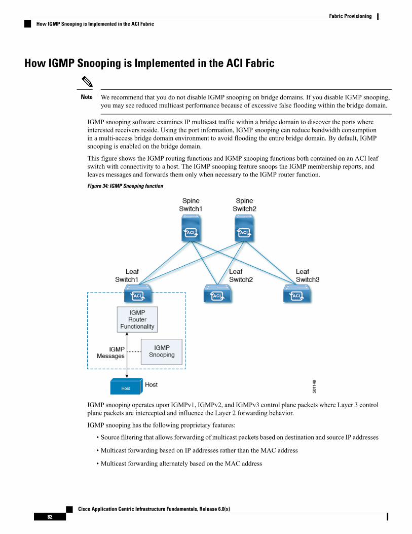
How IGMP Snooping is Implemented in the ACI Fabric
We recommend that you do not disable IGMP snooping on bridge domains. If you disable IGMP snooping,you may see reduced multicast performance because of excessive false flooding within the bridge domain.
Note
IGMP snooping software examines IP multicast traffic within a bridge domain to discover the ports whereinterested receivers reside. Using the port information, IGMP snooping can reduce bandwidth consumptionin a multi-access bridge domain environment to avoid flooding the entire bridge domain. By default, IGMPsnooping is enabled on the bridge domain.
This figure shows the IGMP routing functions and IGMP snooping functions both contained on an ACI leafswitch with connectivity to a host. The IGMP snooping feature snoops the IGMP membership reports, andleaves messages and forwards them only when necessary to the IGMP router function.
Figure 34: IGMP Snooping function
IGMP snooping operates upon IGMPv1, IGMPv2, and IGMPv3 control plane packets where Layer 3 controlplane packets are intercepted and influence the Layer 2 forwarding behavior.
IGMP snooping has the following proprietary features:
• Source filtering that allows forwarding of multicast packets based on destination and source IP addresses
• Multicast forwarding based on IP addresses rather than the MAC address
• Multicast forwarding alternately based on the MAC address
Cisco Application Centric Infrastructure Fundamentals, Release 6.0(x)82
Fabric ProvisioningHow IGMP Snooping is Implemented in the ACI Fabric

The ACI fabric supports IGMP snooping only in proxy-reporting mode, in accordance with the guidelinesprovided in Section 2.1.1, "IGMP Forwarding Rules," in RFC 4541:
IGMP networks may also include devices that implement "proxy-reporting", in which reports received from downstream hosts aresummarized and used to build internal membership states. Suchproxy-reporting devices may use the all-zeros IP Source-Addresswhen forwarding any summarized reports upstream. For this reason,IGMP membership reports received by the snooping switch must notbe rejected because the source IP address is set to 0.0.0.0.
As a result, the ACI fabric will send IGMP reports with the source IP address of 0.0.0.0.
For more information about IGMP snooping, see RFC 4541.Note
Virtualization SupportYou can define multiple virtual routing and forwarding (VRF) instances for IGMP snooping.
On leaf switches, you can use the show commandswith a VRF argument to provide a context for the informationdisplayed. The default VRF is used if no VRF argument is supplied.
The APIC IGMP Snooping Function, IGMPv1, IGMPv2, and the Fast LeaveFeature
Both IGMPv1 and IGMPv2 support membership report suppression, which means that if two hosts on thesame subnet want to receive multicast data for the same group, the host that receives a member report fromthe other host suppresses sending its report. Membership report suppression occurs for hosts that share a port.
If no more than one host is attached to each switch port, you can configure the fast leave feature in IGMPv2.The fast leave feature does not send last member query messages to hosts. As soon as APIC receives an IGMPleave message, the software stops forwarding multicast data to that port.
IGMPv1 does not provide an explicit IGMP leave message, so the APIC IGMP snooping function must relyon the membership message timeout to indicate that no hosts remain that want to receive multicast data for aparticular group.
The IGMP snooping function ignores the configuration of the last member query interval when you enablethe fast leave feature because it does not check for remaining hosts.
Note
The APIC IGMP Snooping Function and IGMPv3The IGMPv3 snooping function in APIC supports full IGMPv3 snooping, which provides constrained floodingbased on the (S, G) information in the IGMPv3 reports. This source-based filtering enables the device toconstrain multicast traffic to a set of ports based on the source that sends traffic to the multicast group.
Cisco Application Centric Infrastructure Fundamentals, Release 6.0(x)83
Fabric ProvisioningVirtualization Support

By default, the IGMP snooping function tracks hosts on each VLAN port in the bridge domain. The explicittracking feature provides a fast leave mechanism. Because every IGMPv3 host sends membership reports,report suppression limits the amount of traffic that the device sends to other multicast-capable routers. Whenreport suppression is enabled, and no IGMPv1 or IGMPv2 hosts requested the same group, the IGMP snoopingfunction provides proxy reporting. The proxy feature builds the group state from membership reports fromthe downstream hosts and generates membership reports in response to queries from upstream queriers.
Even though the IGMPv3membership reports provide a full accounting of group members in a bridge domain,when the last host leaves, the software sends a membership query. You can configure the parameter lastmember query interval. If no host responds before the timeout, the IGMP snooping function removes thegroup state.
Cisco APIC and the IGMP Snooping Querier FunctionWhen PIM is not enabled on an interface because the multicast traffic does not need to be routed, you mustconfigure an IGMP snooping querier function to send membership queries. In APIC, within the IGMP Snooppolicy, you define the querier in a bridge domain that contains multicast sources and receivers but no otheractive querier.
Cisco ACI has by default, IGMP snooping enabled. Additionally, if the Bridge Domain subnet control has“querier IP” selected, then the leaf switch behaves as a querier and starts sending query packets. Querier onthe ACI leaf switch must be enabled when the segments do not have an explicit multicast router (PIM is notenabled). On the Bridge Domain where the querier is configured, the IP address used must be from the samesubnet where the multicast hosts are configured.
The IP address for the querier should not be a broadcast IP address, multicast IP address, or 0 (0.0.0.0).Note
When an IGMP snooping querier is enabled, it sends out periodic IGMP queries that trigger IGMP reportmessages from hosts that want to receive IP multicast traffic. IGMP snooping listens to these IGMP reportsto establish appropriate forwarding.
The IGMP snooping querier performs querier election as described in RFC 2236. Querier election occurs inthe following configurations:
• When there are multiple switch queriers configured with the same subnet on the sameVLAN on differentswitches.
• When the configured switch querier is in the same subnet as with other Layer 3 SVI queriers.
Fabric Secure ModeFabric secure mode prevents parties with physical access to the fabric equipment from adding a switch orAPIC controller to the fabric without manual authorization by an administrator. Starting with release 1.2(1x),the firmware checks that switches and controllers in the fabric have valid serial numbers associated with avalid Cisco digitally signed certificate. This validation is performed upon upgrade to this release or during aninitial installation of the fabric. The default setting for this feature is permissive mode; an existing fabriccontinues to run as it has after an upgrade to release 1.2(1) or later. An administrator with fabric-wide accessrights must enable strict mode. The following table summarizes the two modes of operation:
Cisco Application Centric Infrastructure Fundamentals, Release 6.0(x)84
Fabric ProvisioningCisco APIC and the IGMP Snooping Querier Function
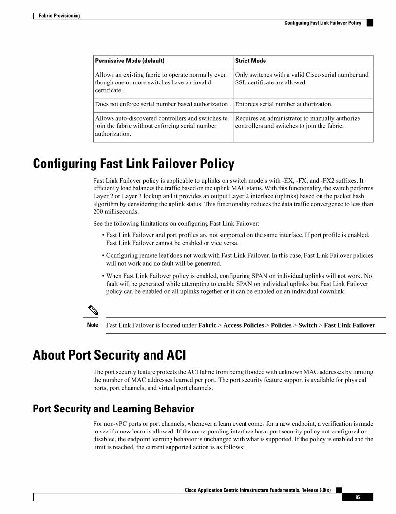
Strict ModePermissive Mode (default)
Only switches with a valid Cisco serial number andSSL certificate are allowed.
Allows an existing fabric to operate normally eventhough one or more switches have an invalidcertificate.
Enforces serial number authorization.Does not enforce serial number based authorization .
Requires an administrator to manually authorizecontrollers and switches to join the fabric.
Allows auto-discovered controllers and switches tojoin the fabric without enforcing serial numberauthorization.
Configuring Fast Link Failover PolicyFast Link Failover policy is applicable to uplinks on switch models with -EX, -FX, and -FX2 suffixes. Itefficiently load balances the traffic based on the uplinkMAC status.With this functionality, the switch performsLayer 2 or Layer 3 lookup and it provides an output Layer 2 interface (uplinks) based on the packet hashalgorithm by considering the uplink status. This functionality reduces the data traffic convergence to less than200 milliseconds.
See the following limitations on configuring Fast Link Failover:
• Fast Link Failover and port profiles are not supported on the same interface. If port profile is enabled,Fast Link Failover cannot be enabled or vice versa.
• Configuring remote leaf does not work with Fast Link Failover. In this case, Fast Link Failover policieswill not work and no fault will be generated.
• When Fast Link Failover policy is enabled, configuring SPAN on individual uplinks will not work. Nofault will be generated while attempting to enable SPAN on individual uplinks but Fast Link Failoverpolicy can be enabled on all uplinks together or it can be enabled on an individual downlink.
Fast Link Failover is located under Fabric > Access Policies > Policies > Switch > Fast Link Failover.Note
About Port Security and ACIThe port security feature protects the ACI fabric from being flooded with unknownMAC addresses by limitingthe number of MAC addresses learned per port. The port security feature support is available for physicalports, port channels, and virtual port channels.
Port Security and Learning BehaviorFor non-vPC ports or port channels, whenever a learn event comes for a new endpoint, a verification is madeto see if a new learn is allowed. If the corresponding interface has a port security policy not configured ordisabled, the endpoint learning behavior is unchanged with what is supported. If the policy is enabled and thelimit is reached, the current supported action is as follows:
Cisco Application Centric Infrastructure Fundamentals, Release 6.0(x)85
Fabric ProvisioningConfiguring Fast Link Failover Policy

• Learn the endpoint and install it in the hardware with a drop action.
• Silently discard the learn.
If the limit is not reached, the endpoint is learned and a verification is made to see if the limit is reachedbecause of this new endpoint. If the limit is reached, and the learn disable action is configured, learning willbe disabled in the hardware on that interface (on the physical interface or on a port channel or vPC). If thelimit is reached and the learn disable action is not configured, the endpoint will be installed in hardware witha drop action. Such endpoints are aged normally like any other endpoints.
When the limit is reached for the first time, the operational state of the port security policy object is updatedto reflect it. A static rule is defined to raise a fault so that the user is alerted. A syslog is also raised when thelimit is reached.
In case of vPC, when theMAC limit is reached, the peer leaf switch is also notified so learning can be disabledon the peer. As the vPC peer can be rebooted any time or vPC legs can become unoperational or restart, thisstate will be reconciled with the peer so vPC peers do not go out of sync with this state. If they get out of sync,there can be a situation where learning is enabled on one leg and disabled on the other leg.
By default, once the limit is reached and learning is disabled, it will be automatically re-enabled after thedefault timeout value of 60 seconds.
Protect ModeThe protect mode prevents further port security violations from occurring. Once the MAC limit exceeds themaximum configured value on a port, all traffic from excess MAC addresses will be dropped and furtherlearning is disabled.
Port Security at Port LevelIn the APIC, the user can configure the port security on switch ports. Once the MAC limit has exceeded themaximum configured value on a port, all traffic from the exceededMAC addresses is forwarded. The followingattributes are supported:
• Port Security Timeout—The current supported range for the timeout value is from 60 to 3600 seconds.
• Violation Action—The violation action is available in protect mode. In the protect mode, MAC learningis disabled and MAC addresses are not added to the CAM table. Mac learning is re-enabled after theconfigured timeout value.
• Maximum Endpoints—The current supported range for the maximum endpoints configured value isfrom 0 to 12000. If the maximum endpoints value is 0, the port security policy is disabled on that port.
Port Security Guidelines and RestrictionsThe guidelines and restrictions are as follows:
• Port security is available per port.
• Port security is supported for physical ports, port channels, and virtual port channels (vPCs).
• Static and dynamic MAC addresses are supported.
Cisco Application Centric Infrastructure Fundamentals, Release 6.0(x)86
Fabric ProvisioningProtect Mode

• MAC address moves are supported from secured to unsecured ports and from unsecured ports to securedports.
• The MAC address limit is enforced only on the MAC address and is not enforced on a MAC and IPaddress.
• Port security is not supported with the Fabric Extender (FEX).
About First Hop SecurityFirst-Hop Security (FHS) features enable a better IPv4 and IPv6 link security and management over the layer2 links. In a service provider environment, these features closely control address assignment and derivedoperations, such as Duplicate Address Detection (DAD) and Address Resolution (AR).
The following supported FHS features secure the protocols and help build a secure endpoint database on thefabric leaf switches, that are used to mitigate security threats such as MIM attacks and IP thefts:
• ARP Inspection—allows a network administrator to intercept, log, and discard ARP packets with invalidMAC address to IP address bindings.
• ND Inspection—learns and secures bindings for stateless autoconfiguration addresses in Layer 2 neighbortables.
• DHCP Inspection—validates DHCP messages received from untrusted sources and filters out invalidmessages.
• RA Guard—allows the network administrator to block or reject unwanted or rogue router advertisement(RA) guard messages.
• IPv4 and IPv6 Source Guard—blocks any data traffic from an unknown source.
• Trust Control—a trusted source is a device that is under your administrative control. These devicesinclude the switches, routers, and servers in the Fabric. Any device beyond the firewall or outside thenetwork is an untrusted source. Generally, host ports are treated as untrusted sources.
FHS features provide the following security measures:
• Role Enforcement—Prevents untrusted hosts from sending messages that are out the scope of their role.
• Binding Enforcement—Prevents address theft.
• DoS Attack Mitigations—Prevents malicious end-points to grow the end-point database to the pointwhere the database could stop providing operation services.
• Proxy Services—Provides some proxy-services to increase the efficiency of address resolution.
FHS features are enabled on a per tenant bridge domain (BD) basis. As the bridge domain, may be deployedon a single or across multiple leaf switches, the FHS threat control andmitigationmechanisms cater to a singleswitch and multiple switch scenarios.
Cisco Application Centric Infrastructure Fundamentals, Release 6.0(x)87
Fabric ProvisioningAbout First Hop Security

About MACsecMACsec is an IEEE 802.1AE standards based Layer 2 hop-by-hop encryption that provides data confidentialityand integrity for media access independent protocols.
MACsec, provides MAC-layer encryption over wired networks by using out-of-band methods for encryptionkeying. The MACsec Key Agreement (MKA) Protocol provides the required session keys and manages therequired encryption keys.
The 802.1AE encryption with MKA is supported on all types of links, that is, host facing links (links betweennetwork access devices and endpoint devices such as a PC or IP phone), or links connected to other switchesor routers.
MACsec encrypts the entire data except for the Source and DestinationMAC addresses of an Ethernet packet.The user also has the option to skip encryption up to 50 bytes after the source and destination MAC address.
To provide MACsec services over the WAN or Metro Ethernet, service providers offer Layer 2 transparentservices such as E-Line or E-LAN using various transport layer protocols such as Ethernet over MultiprotocolLabel Switching (EoMPLS) and L2TPv3.
The packet body in an EAP-over-LAN (EAPOL) Protocol Data Unit (PDU) is referred to as a MACsec KeyAgreement PDU (MKPDU).When noMKPDU is received from a participants after 3 hearbeats (each hearbeatis of 2 seconds), peers are deleted from the live peer list. For example, if a client disconnects, the participanton the switch continues to operate MKA until 3 heartbeats have elapsed after the last MKPDU is receivedfrom the client.
APIC Fabric MACsec
The APIC will be responsible for the MACsec keychain distribution to all the nodes in a Pod or to particularports on a node. Below are the supported MACsec keychain and MACsec policy distribution supported bythe APIC.
• A single user provided keychain and policy per Pod
• User provided keychain and user provided policy per fabric interface
• Auto generated keychain and user provided policy per Pod
A node can have multiple policies deployed for more than one fabric link. When this happens, the per fabricinterface keychain and policy are given preference on the affected interface. The auto generated keychain andassociated MACsec policy are then given the least preference.
APIC MACsec supports two security modes. The MACsec must secure only allows encrypted traffic on thelink while the should secure allows both clear and encrypted traffic on the link. Before deploying MACsecin must secure mode, the keychain must be deployed on the affected links or the links will go down. Forexample, a port can turn on MACsec in must secure mode before its peer has received its keychain resultingin the link going down. To address this issue the recommendation is to deploy MACsec in should securemode and once all the links are up then change the security mode to must secure.
Any MACsec interface configuration change will result in packet drops.Note
Cisco Application Centric Infrastructure Fundamentals, Release 6.0(x)88
Fabric ProvisioningAbout MACsec

MACsec policy definition consists of configuration specific to keychain definition and configuration relatedto feature functionality. The keychain definition and feature functionality definitions are placed in separatepolicies. Enabling MACsec per Pod or per interface involves deploying a combination of a keychain policyand MACsec functionality policy.
Using internal generated keychains do not require the user to specify a keychain.Note
APIC Access MACsec
MACsec is used to secure links between leaf switch L3out interfaces and external devices. APIC providesGUI and CLI to allow users to program the MACsec keys and MacSec configuration for the L3Out interfaceson the fabric on a per physical/pc/vpc interface basis. It is the responsibility of the user to make sure that theexternal peer devices are programmed with the correct MacSec information.
Data Plane PolicingUse data plane policing (DPP) to manage bandwidth consumption on ACI fabric access interfaces. DPPpolicies can apply to egress traffic, ingress traffic, or both. DPPmonitors the data rates for a particular interface.When the data rate exceeds user-configured values, marking or dropping of packets occurs immediately.Policing does not buffer the traffic; therefore, the transmission delay is not affected. When traffic exceeds thedata rate, the ACI fabric can either drop the packets or mark QoS fields in them.
Egress data plane policers are not supported on switched virtual interfaces (SVI).Note
DPP policies can be single-rate, dual-rate, and color-aware. Single-rate policies monitor the committedinformation rate (CIR) of traffic. Dual-rate policers monitor both CIR and peak information rate (PIR) oftraffic. In addition, the system monitors associated burst sizes. Three colors, or conditions, are determined bythe policer for each packet depending on the data rate parameters supplied: conform (green), exceed (yellow),or violate (red).
Typically, DPP policies are applied to physical or virtual layer 2 connections for virtual or physical devicessuch as servers or hypervisors, and on layer 3 connections for routers. DPP policies applied to leaf switchaccess ports are configured in the fabric access (infraInfra) portion of the ACI fabric, and must be configuredby a fabric administrator. DPP policies applied to interfaces on border leaf switch access ports (l3extOut orl2extOut) are configured in the tenant (fvTenant) portion of the ACI fabric, and can be configured by a tenantadministrator.
Only one action can be configured for each condition. For example, a DPP policy can to conform to the datarate of 256000 bits per second, with up to 200 millisecond bursts. The system applies the conform action totraffic that falls within this rate, and it would apply the violate action to traffic that exceeds this rate. Color-awarepolicies assume that traffic has been previously marked with a color. This information is then used in theactions taken by this type of policer.
Cisco Application Centric Infrastructure Fundamentals, Release 6.0(x)89
Fabric ProvisioningData Plane Policing

SchedulerA schedule allows operations, such as configuration import/export or tech support collection, to occur duringone or more specified windows of time.
A schedule contains a set of time windows (occurrences). These windows can be one time only or can recurat a specified time and day each week. The options defined in the window, such as the duration or the maximumnumber of tasks to be run, determine when a scheduled task executes. For example, if a change cannot bedeployed during a given maintenance window because the maximum duration or number of tasks has beenreached, that deployment is carried over to the next maintenance window.
Each schedule checks periodically to see whether the APIC has entered one or more maintenance windows.If it has, the schedule executes the deployments that are eligible according to the constraints specified in themaintenance policy.
A schedule contains one or more occurrences, which determine the maintenance windows associated withthat schedule. An occurrence can be one of the following:
• One-timeWindow—Defines a schedule that occurs only once. This window continues until the maximumduration of the window or the maximum number of tasks that can be run in the window has been reached.
• Recurring Window—Defines a repeating schedule. This window continues until the maximum numberof tasks or the end of the day specified in the window has been reached.
After a schedule is configured, it can then be selected and applied to the following export and firmware policiesduring their configuration:
• Tech Support Export Policy
• Configuration Export Policy -- Daily AutoBackup
• Firmware Download
Firmware UpgradePolicies on the APIC manage the following aspects of the firmware upgrade processes:
• What version of firmware to use.
• Downloading firmware images from Cisco to the APIC repository.
• Compatibility enforcement.
• What to upgrade:
• Switches
• The APIC
• The compatibility catalog
• When the upgrade will be performed.
• How to handle failures (retry, pause, ignore, and so on).
Cisco Application Centric Infrastructure Fundamentals, Release 6.0(x)90
Fabric ProvisioningScheduler
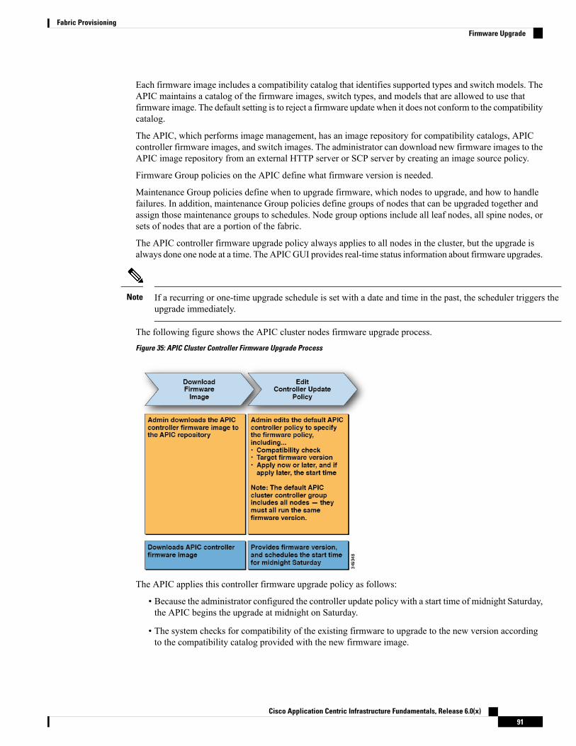
Each firmware image includes a compatibility catalog that identifies supported types and switch models. TheAPIC maintains a catalog of the firmware images, switch types, and models that are allowed to use thatfirmware image. The default setting is to reject a firmware update when it does not conform to the compatibilitycatalog.
The APIC, which performs image management, has an image repository for compatibility catalogs, APICcontroller firmware images, and switch images. The administrator can download new firmware images to theAPIC image repository from an external HTTP server or SCP server by creating an image source policy.
Firmware Group policies on the APIC define what firmware version is needed.
Maintenance Group policies define when to upgrade firmware, which nodes to upgrade, and how to handlefailures. In addition, maintenance Group policies define groups of nodes that can be upgraded together andassign those maintenance groups to schedules. Node group options include all leaf nodes, all spine nodes, orsets of nodes that are a portion of the fabric.
The APIC controller firmware upgrade policy always applies to all nodes in the cluster, but the upgrade isalways done one node at a time. The APICGUI provides real-time status information about firmware upgrades.
If a recurring or one-time upgrade schedule is set with a date and time in the past, the scheduler triggers theupgrade immediately.
Note
The following figure shows the APIC cluster nodes firmware upgrade process.
Figure 35: APIC Cluster Controller Firmware Upgrade Process
The APIC applies this controller firmware upgrade policy as follows:
• Because the administrator configured the controller update policy with a start time of midnight Saturday,the APIC begins the upgrade at midnight on Saturday.
• The system checks for compatibility of the existing firmware to upgrade to the new version accordingto the compatibility catalog provided with the new firmware image.
Cisco Application Centric Infrastructure Fundamentals, Release 6.0(x)91
Fabric ProvisioningFirmware Upgrade

• The upgrade proceeds one node at a time until all nodes in the cluster are upgraded.
Because the APIC is a replicated cluster of nodes, disruption should be minimal.An administrator should be aware of the system load when considering schedulingAPIC upgrades, and should plan for an upgrade during a maintenance window.
Note
• The ACI fabric, including the APIC, continues to run while the upgrade proceeds.
The controllers upgrade in random order. Each APIC controller takes about 10minutes to upgrade. Once a controller image is upgraded, it drops from the cluster,and it reboots with the newer version while the other APIC controllers in thecluster remain operational. Once the controller reboots, it joins the cluster again.Then the cluster converges, and the next controller image starts to upgrade. If thecluster does not immediately converge and is not fully fit, the upgrade will waituntil the cluster converges and is fully fit. During this period, aWaiting for ClusterConvergence message is displayed.
Note
• If a controller node upgrade fails, the upgrade pauses and waits for manual intervention.
The following figure shows how this process works for upgrading all the ACI fabric switch nodes firmware.
Figure 36: Switch Firmware Upgrade Process
The APIC applies this switch upgrade policy as follows:
• Because the administrator configured the controller update policy with a start time of midnight Saturday,the APIC begins the upgrade at midnight on Saturday.
• The system checks for compatibility of the existing firmware to upgrade to the new version accordingto the compatibility catalog provided with the new firmware image.
Cisco Application Centric Infrastructure Fundamentals, Release 6.0(x)92
Fabric ProvisioningFirmware Upgrade
• The upgrade proceeds five nodes at a time until all the specified nodes are upgraded.
A firmware upgrade causes a switch reboot; the reboot can disrupt the operationof the switch for several minutes. Schedule firmware upgrades during amaintenance window.
Note
• If a switch node fails to upgrade, the upgrade pauses and waits for manual intervention.
Refer to theCisco APIC Management, Installation, Upgrade, and Downgrade Guide for detailed step-by-stepinstructions for performing firmware upgrades.
Configuration ZonesConfiguration zones divide the ACI fabric into different zones that can be updated with configuration changesat different times. This limits the risk of deploying a faulty fabric-wide configuration that might disrupt trafficor even bring the fabric down. An administrator can deploy a configuration to a non-critical zone, and thendeploy it to critical zones when satisfied that it is suitable.
The following policies specify configuration zone actions:
• infrazone:ZoneP is automatically created upon system upgrade. It cannot be deleted or modified.
• infrazone:Zone contains one or more pod groups (PodGrp) or one or more node groups (NodeGrp).
You can only choose PodGrp or NodeGrp; both cannot be chosen.Note
Anode can be part of only one zone (infrazone:Zone). NodeGrp has two properties: name, and deploymentmode. The deployment mode property can be:
• enabled - Pending updates are sent immediately.
• disabled - New updates are postponed.
• Do not upgrade, downgrade, commission, or decommission nodes in adisabled configuration zone.
• Do not do a clean reload or an uplink/downlink port conversion reload ofnodes in a disabled configuration zone.
Note
• triggered - pending updates are sent immediately, and the deployment mode is automatically resetto the value it had before the change to triggered.
When a policy on a given set of nodes is created, modified, or deleted, updates are sent to each node wherethe policy is deployed. Based on policy class and infrazone configuration the following happens:.
Cisco Application Centric Infrastructure Fundamentals, Release 6.0(x)93
Fabric ProvisioningConfiguration Zones

• For policies that do not follow infrazone configuration, the APIC sends updates immediately to all thefabric nodes.
• For policies that follow infrazone configuration, the update proceeds according to the infrazoneconfiguration:
• If a node is part of an infrazone:Zone, the update is sent immediately if the deployment mode ofthe zone is set to enabled; otherwise the update is postponed.
• If a node is not part of aninfrazone:Zone, the update is done immediately, which is the ACI fabricdefault behavior.
GeolocationAdministrators use geolocation policies to map the physical location of ACI fabric nodes in data centerfacilities. The following figure shows an example of the geolocation mapping feature.
Figure 37: Geolocation
For example, for fabric deployment in a single room, an administrator would use the default room object, andthen create one or more racks to match the physical location of the switches. For a larger deployment, anadministrator can create one or more site objects. Each site can contain one or more buildings. Each buildinghas one or more floors. Each floor has one or more rooms, and each room has one or more racks. Finally eachrack can be associated with one or more switches.
Cisco Application Centric Infrastructure Fundamentals, Release 6.0(x)94
Fabric ProvisioningGeolocation

C H A P T E R 5Forwarding Within the ACI Fabric
This chapter contains the following sections:
• About Forwarding Within the ACI Fabric, on page 95• ACI Fabric Optimizes Modern Data Center Traffic Flows, on page 96• VXLAN in ACI, on page 97• Layer 3 VNIDs Facilitate Transporting Inter-subnet Tenant Traffic, on page 98• Policy Identification and Enforcement, on page 100• ACI Fabric Network Access Security Policy Model (Contracts), on page 101• Multicast Tree Topology, on page 106• About Traffic Storm Control, on page 107• Storm Control Guidelines and Limitations, on page 107• Fabric Load Balancing, on page 109• Endpoint Retention, on page 112• IP Endpoint Learning Behavior, on page 113• About Proxy ARP, on page 114• Loop Detection, on page 120• Rogue Endpoint Detection, on page 123
About Forwarding Within the ACI FabricThe ACI fabric supports more than 64,000 dedicated tenant networks. A single fabric can support more thanone million IPv4/IPv6 endpoints, more than 64,000 tenants, and more than 200,000 10G ports. The ACI fabricenables any service (physical or virtual) anywhere with no need for additional software or hardware gatewaysto connect between the physical and virtual services and normalizes encapsulations for Virtual ExtensibleLocal Area Network (VXLAN) / VLAN / Network Virtualization using Generic Routing Encapsulation(NVGRE).
The ACI fabric decouples the endpoint identity and associated policy from the underlying forwarding graph.It provides a distributed Layer 3 gateway that ensures optimal Layer 3 and Layer 2 forwarding. The fabricsupports standard bridging and routing semantics without standard location constraints (any IP addressanywhere), and removes flooding requirements for the IP control plane Address Resolution Protocol (ARP)/ Gratuitous Address Resolution Protocol (GARP). All traffic within the fabric is encapsulated within VXLAN.
Cisco Application Centric Infrastructure Fundamentals, Release 6.0(x)95
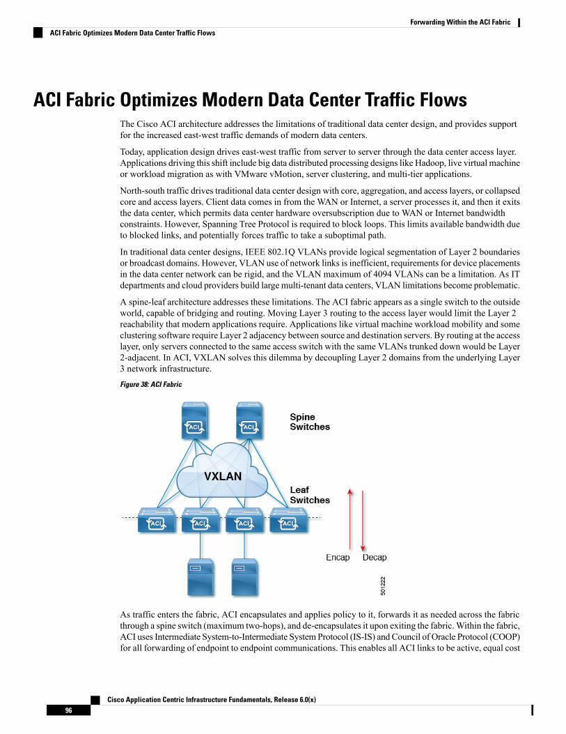
ACI Fabric Optimizes Modern Data Center Traffic FlowsThe Cisco ACI architecture addresses the limitations of traditional data center design, and provides supportfor the increased east-west traffic demands of modern data centers.
Today, application design drives east-west traffic from server to server through the data center access layer.Applications driving this shift include big data distributed processing designs like Hadoop, live virtual machineor workload migration as with VMware vMotion, server clustering, and multi-tier applications.
North-south traffic drives traditional data center design with core, aggregation, and access layers, or collapsedcore and access layers. Client data comes in from the WAN or Internet, a server processes it, and then it exitsthe data center, which permits data center hardware oversubscription due to WAN or Internet bandwidthconstraints. However, Spanning Tree Protocol is required to block loops. This limits available bandwidth dueto blocked links, and potentially forces traffic to take a suboptimal path.
In traditional data center designs, IEEE 802.1Q VLANs provide logical segmentation of Layer 2 boundariesor broadcast domains. However, VLAN use of network links is inefficient, requirements for device placementsin the data center network can be rigid, and the VLAN maximum of 4094 VLANs can be a limitation. As ITdepartments and cloud providers build large multi-tenant data centers, VLAN limitations become problematic.
A spine-leaf architecture addresses these limitations. The ACI fabric appears as a single switch to the outsideworld, capable of bridging and routing. Moving Layer 3 routing to the access layer would limit the Layer 2reachability that modern applications require. Applications like virtual machine workload mobility and someclustering software require Layer 2 adjacency between source and destination servers. By routing at the accesslayer, only servers connected to the same access switch with the same VLANs trunked down would be Layer2-adjacent. In ACI, VXLAN solves this dilemma by decoupling Layer 2 domains from the underlying Layer3 network infrastructure.
Figure 38: ACI Fabric
As traffic enters the fabric, ACI encapsulates and applies policy to it, forwards it as needed across the fabricthrough a spine switch (maximum two-hops), and de-encapsulates it upon exiting the fabric.Within the fabric,ACI uses Intermediate System-to-Intermediate System Protocol (IS-IS) and Council of Oracle Protocol (COOP)for all forwarding of endpoint to endpoint communications. This enables all ACI links to be active, equal cost
Cisco Application Centric Infrastructure Fundamentals, Release 6.0(x)96
Forwarding Within the ACI FabricACI Fabric Optimizes Modern Data Center Traffic Flows

multipath (ECMP) forwarding in the fabric, and fast-reconverging. For propagating routing informationbetween software defined networks within the fabric and routers external to the fabric, ACI uses theMultiprotocol Border Gateway Protocol (MP-BGP).
VXLAN in ACIVXLAN is an industry-standard protocol that extends Layer 2 segments over Layer 3 infrastructure to buildLayer 2 overlay logical networks. The ACI infrastructure Layer 2 domains reside in the overlay, with isolatedbroadcast and failure bridge domains. This approach allows the data center network to grow without the riskof creating too large a failure domain.
All traffic in the ACI fabric is normalized as VXLAN packets. At ingress, ACI encapsulates external VLAN,VXLAN, and NVGRE packets in a VXLAN packet. The following figure shows ACI encapsulationnormalization.
Figure 39: ACI Encapsulation Normalization
Forwarding in the ACI fabric is not limited to or constrained by the encapsulation type or encapsulationoverlay network. An ACI bridge domain forwarding policy can be defined to provide standard VLAN behaviorwhere required.
Because every packet in the fabric carries ACI policy attributes, ACI can consistently enforce policy in a fullydistributedmanner. ACI decouples application policy EPG identity from forwarding. The following illustrationshows how the ACI VXLAN header identifies application policy within the fabric.
Figure 40: ACI VXLAN Packet Format
Cisco Application Centric Infrastructure Fundamentals, Release 6.0(x)97
Forwarding Within the ACI FabricVXLAN in ACI

The ACI VXLAN packet contains both Layer 2 MAC address and Layer 3 IP address source and destinationfields, which enables efficient and scalable forwarding within the fabric. The ACI VXLAN packet headersource group field identifies the application policy endpoint group (EPG) to which the packet belongs. TheVXLAN Instance ID (VNID) enables forwarding of the packet through tenant virtual routing and forwarding(VRF) domains within the fabric. The 24-bit VNID field in the VXLAN header provides an expanded addressspace for up to 16 million unique Layer 2 segments in the same network. This expanded address space givesIT departments and cloud providers greater flexibility as they build large multitenant data centers.
VXLAN enables ACI to deploy Layer 2 virtual networks at scale across the fabric underlay Layer 3infrastructure. Application endpoint hosts can be flexibly placed in the data center network without concernfor the Layer 3 boundary of the underlay infrastructure, while maintaining Layer 2 adjacency in a VXLANoverlay network.
Layer 3 VNIDs Facilitate Transporting Inter-subnet Tenant TrafficThe ACI fabric provides tenant default gateway functionality that routes between the ACI fabric VXLANnetworks. For each tenant, the fabric provides a virtual default gateway that spans all of the leaf switchesassigned to the tenant. It does this at the ingress interface of the first leaf switch connected to the endpoint.Each ingress interface supports the default gateway interface. All of the ingress interfaces across the fabricshare the same router IP address and MAC address for a given tenant subnet.
The ACI fabric decouples the tenant endpoint address, its identifier, from the location of the endpoint that isdefined by its locator or VXLAN tunnel endpoint (VTEP) address. Forwarding within the fabric is betweenVTEPs. The following figure shows decoupled identity and location in ACI.
Figure 41: ACI Decouples Identity and Location
VXLAN uses VTEP devices to map tenant end devices to VXLAN segments and to perform VXLANencapsulation and de-encapsulation. Each VTEP function has two interfaces:
• A switch interface on the local LAN segment to support local endpoint communication through bridging
• An IP interface to the transport IP network
The IP interface has a unique IP address that identifies the VTEP device on the transport IP network knownas the infrastructure VLAN. The VTEP device uses this IP address to encapsulate Ethernet frames and transmitthe encapsulated packets to the transport network through the IP interface. A VTEP device also discovers theremote VTEPs for its VXLAN segments and learns remote MAC Address-to-VTEP mappings through its IPinterface.
The VTEP in ACI maps the internal tenant MAC or IP address to a location using a distributed mappingdatabase. After the VTEP completes a lookup, the VTEP sends the original data packet encapsulated in
Cisco Application Centric Infrastructure Fundamentals, Release 6.0(x)98
Forwarding Within the ACI FabricLayer 3 VNIDs Facilitate Transporting Inter-subnet Tenant Traffic
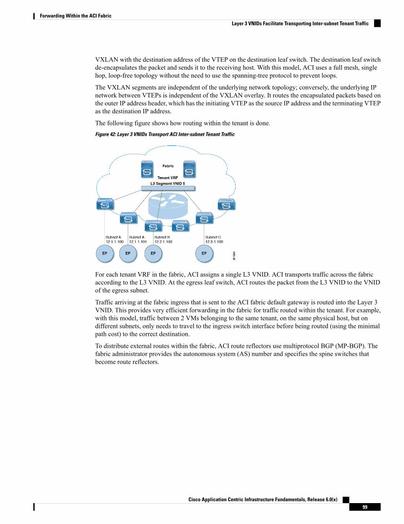
VXLAN with the destination address of the VTEP on the destination leaf switch. The destination leaf switchde-encapsulates the packet and sends it to the receiving host. With this model, ACI uses a full mesh, singlehop, loop-free topology without the need to use the spanning-tree protocol to prevent loops.
The VXLAN segments are independent of the underlying network topology; conversely, the underlying IPnetwork between VTEPs is independent of the VXLAN overlay. It routes the encapsulated packets based onthe outer IP address header, which has the initiating VTEP as the source IP address and the terminating VTEPas the destination IP address.
The following figure shows how routing within the tenant is done.
Figure 42: Layer 3 VNIDs Transport ACI Inter-subnet Tenant Traffic
For each tenant VRF in the fabric, ACI assigns a single L3 VNID. ACI transports traffic across the fabricaccording to the L3 VNID. At the egress leaf switch, ACI routes the packet from the L3 VNID to the VNIDof the egress subnet.
Traffic arriving at the fabric ingress that is sent to the ACI fabric default gateway is routed into the Layer 3VNID. This provides very efficient forwarding in the fabric for traffic routed within the tenant. For example,with this model, traffic between 2 VMs belonging to the same tenant, on the same physical host, but ondifferent subnets, only needs to travel to the ingress switch interface before being routed (using the minimalpath cost) to the correct destination.
To distribute external routes within the fabric, ACI route reflectors use multiprotocol BGP (MP-BGP). Thefabric administrator provides the autonomous system (AS) number and specifies the spine switches thatbecome route reflectors.
Cisco Application Centric Infrastructure Fundamentals, Release 6.0(x)99
Forwarding Within the ACI FabricLayer 3 VNIDs Facilitate Transporting Inter-subnet Tenant Traffic
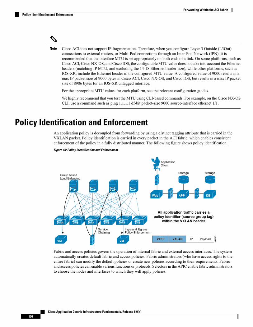
Cisco ACIdoes not support IP fragmentation. Therefore, when you configure Layer 3 Outside (L3Out)connections to external routers, or Multi-Pod connections through an Inter-Pod Network (IPN), it isrecommended that the interface MTU is set appropriately on both ends of a link. On some platforms, such asCisco ACI, Cisco NX-OS, and Cisco IOS, the configurableMTU value does not take into account the Ethernetheaders (matching IP MTU, and excluding the 14-18 Ethernet header size), while other platforms, such asIOS-XR, include the Ethernet header in the configured MTU value. A configured value of 9000 results in amax IP packet size of 9000 bytes in Cisco ACI, Cisco NX-OS, and Cisco IOS, but results in a max IP packetsize of 8986 bytes for an IOS-XR untagged interface.
For the appropriate MTU values for each platform, see the relevant configuration guides.
We highly recommend that you test the MTU using CLI-based commands. For example, on the Cisco NX-OSCLI, use a command such as ping 1.1.1.1 df-bit packet-size 9000 source-interface ethernet 1/1.
Note
Policy Identification and EnforcementAn application policy is decoupled from forwarding by using a distinct tagging attribute that is carried in theVXLAN packet. Policy identification is carried in every packet in the ACI fabric, which enables consistentenforcement of the policy in a fully distributed manner. The following figure shows policy identification.
Figure 43: Policy Identification and Enforcement
Fabric and access policies govern the operation of internal fabric and external access interfaces. The systemautomatically creates default fabric and access policies. Fabric administrators (who have access rights to theentire fabric) can modify the default policies or create new policies according to their requirements. Fabricand access policies can enable various functions or protocols. Selectors in the APIC enable fabric administratorsto choose the nodes and interfaces to which they will apply policies.
Cisco Application Centric Infrastructure Fundamentals, Release 6.0(x)100
Forwarding Within the ACI FabricPolicy Identification and Enforcement

ACI Fabric Network Access Security Policy Model (Contracts)The ACI fabric security policy model is based on contracts. This approach addresses limitations of traditionalaccess control lists (ACLs). Contracts contain the specifications for security policies that are enforced ontraffic between endpoint groups.
The following figure shows the components of a contract.
Figure 44: Contract Components
EPG communications require a contract; EPG to EPG communication is not allowed without a contract. TheAPIC renders the entire policy model, including contracts and their associated EPGs, into the concrete modelin each switch. Upon ingress, every packet entering the fabric is marked with the required policy details.Because contracts are required to select what types of traffic can pass between EPGs, contracts enforce securitypolicies.While contracts satisfy the security requirements handled by access control lists (ACLs) in conventionalnetwork settings, they are a more flexible, manageable, and comprehensive security policy solution.
Access Control List LimitationsTraditional access control lists (ACLs) have a number of limitations that the ACI fabric security modeladdresses. The traditional ACL is very tightly coupled with the network topology. They are typically configuredper router or switch ingress and egress interface and are customized to that interface and the traffic that isexpected to flow through those interfaces. Due to this customization, they often cannot be reused acrossinterfaces, much less across routers or switches.
Traditional ACLs can be very complicated and cryptic because they contain lists of specific IP addresses,subnets, and protocols that are allowed as well as many that are specifically not allowed. This complexitymeans that they are difficult to maintain and often simply just grow as administrators are reluctant to removeany ACL rules for fear of creating a problem. Their complexity means that they are generally only deployedat specific demarcation points in the network such as the demarcation between the WAN and the enterpriseor the WAN and the data center. In this case, the security benefits of ACLs are not exploited inside theenterprise or for traffic that is contained within the data center.
Another issue is the possible huge increase in the number of entries in a single ACL. Users often want tocreate an ACL that allows a set of sources to communicate with a set of destinations by using a set of protocols.
Cisco Application Centric Infrastructure Fundamentals, Release 6.0(x)101
Forwarding Within the ACI FabricACI Fabric Network Access Security Policy Model (Contracts)

In the worst case, if N sources are talking to M destinations using K protocols, there might be N*M*K linesin the ACL. The ACL must list each source that communicates with each destination for each protocol. Itdoes not take many devices or protocols before the ACL gets very large.
The ACI fabric security model addresses these ACL issues. The ACI fabric security model directly expressesthe intent of the administrator. Administrators use contract, filter, and label managed objects to specify howgroups of endpoints are allowed to communicate. These managed objects are not tied to the topology of thenetwork because they are not applied to a specific interface. They are simply rules that the network mustenforce irrespective of where these groups of endpoints are connected. This topology independence meansthat these managed objects can easily be deployed and reused throughout the data center not just as specificdemarcation points.
The ACI fabric security model uses the endpoint grouping construct directly so the idea of allowing groupsof servers to communicate with one another is simple. A single rule can allow an arbitrary number of sourcesto communicate with an equally arbitrary number of destinations. This simplification dramatically improvestheir scale and maintainability which also means they are easier to use throughout the data center.
Contracts Contain Security Policy SpecificationsIn the ACI security model, contracts contain the policies that govern the communication between EPGs. Thecontract specifies what can be communicated and the EPGs specify the source and destination of thecommunications. Contracts link EPGs, as shown below.
EPG 1 --------------- CONTRACT --------------- EPG 2
Endpoints in EPG 1 can communicate with endpoints in EPG 2 and vice versa if the contract allows it. Thispolicy construct is very flexible. There can be many contracts between EPG 1 and EPG 2, there can be morethan two EPGs that use a contract, and contracts can be reused across multiple sets of EPGs, and more.
There is also directionality in the relationship between EPGs and contracts. EPGs can either provide or consumea contract. An EPG that provides a contract is typically a set of endpoints that provide a service to a set ofclient devices. The protocols used by that service are defined in the contract. An EPG that consumes a contractis typically a set of endpoints that are clients of that service. When the client endpoint (consumer) tries toconnect to a server endpoint (provider), the contract checks to see if that connection is allowed. Unlessotherwise specified, that contract would not allow a server to initiate a connection to a client. However, anothercontract between the EPGs could easily allow a connection in that direction.
This providing/consuming relationship is typically shown graphically with arrows between the EPGs and thecontract. Note the direction of the arrows shown below.
EPG 1 <-------consumes-------- CONTRACT <-------provides-------- EPG 2
The contract is constructed in a hierarchical manner. It consists of one or more subjects, each subject containsone or more filters, and each filter can define one or more protocols.
Cisco Application Centric Infrastructure Fundamentals, Release 6.0(x)102
Forwarding Within the ACI FabricContracts Contain Security Policy Specifications

Figure 45: Contract Filters
The following figure shows how contracts govern EPG communications.
Figure 46: Contracts Determine EPG to EPG Communications
For example, you may define a filter called HTTP that specifies TCP port 80 and port 8080 and another filtercalled HTTPS that specifies TCP port 443. You might then create a contract called webCtrct that has two setsof subjects. openProv and openCons are the subjects that contain the HTTP filter. secureProv and secureConsare the subjects that contain the HTTPS filter. This webCtrct contract can be used to allow both secure andnon-secure web traffic between EPGs that provide the web service and EPGs that contain endpoints that wantto consume that service.
These same constructs also apply for policies that govern virtual machine hypervisors.When an EPG is placedin a virtual machine manager (VMM) domain, the APIC downloads all of the policies that are associated withthe EPG to the leaf switches with interfaces connecting to the VMM domain. For a full explanation of VMMdomains, see the Virtual Machine Manager Domains chapter of Application Centric InfrastructureFundamentals. When this policy is created, the APIC pushes it (pre-populates it) to a VMM domain thatspecifies which switches allow connectivity for the endpoints in the EPGs. The VMM domain defines the set
Cisco Application Centric Infrastructure Fundamentals, Release 6.0(x)103
Forwarding Within the ACI FabricContracts Contain Security Policy Specifications

of switches and ports that allow endpoints in an EPG to connect to. When an endpoint comes on-line, it isassociated with the appropriate EPGs.When it sends a packet, the source EPG and destination EPG are derivedfrom the packet and the policy defined by the corresponding contract is checked to see if the packet is allowed.If yes, the packet is forwarded. If no, the packet is dropped.
Contracts consist of 1 or more subjects. Each subject contains 1 or more filters. Each filter contains 1 or moreentries. Each entry is equivalent to a line in an Access Control List (ACL) that is applied on the Leaf switchto which the endpoint within the endpoint group is attached.
In detail, contracts are comprised of the following items:
• Name—All contracts that are consumed by a tenant must have different names (including contractscreated under the common tenant or the tenant itself).
• Subjects—A group of filters for a specific application or service.
• Filters—Used to classify traffic based upon layer 2 to layer 4 attributes (such as Ethernet type, protocoltype, TCP flags and ports).
• Actions—Action to be taken on the filtered traffic. The following actions are supported:
• Permit the traffic (regular contracts, only)
• Mark the traffic (DSCP/CoS) (regular contracts, only)
• Redirect the traffic (regular contracts, only, through a service graph)
• Copy the traffic (regular contracts, only, through a service graph or SPAN)
• Block the traffic (taboo contracts)
With Cisco APIC Release 3.2(x) and switches with names that end in EX or FX, you can alternativelyuse a subject Deny action or Contract or Subject Exception in a standard contract to block trafficwith specified patterns.
• Log the traffic (taboo contracts and regular contracts)
• Aliases—(Optional) A changeable name for an object. Although the name of an object, once created,cannot be changed, the Alias is a property that can be changed.
Thus, the contract allows more complex actions than just allow or deny. The contract can specify that trafficthat matches a given subject can be re-directed to a service, can be copied, or can have its QoS level modified.With pre-population of the access policy in the concrete model, endpoints can move, new ones can comeon-line, and communication can occur even if the APIC is off-line or otherwise inaccessible. The APIC isremoved from being a single point of failure for the network. Upon packet ingress to the ACI fabric, securitypolicies are enforced by the concrete model running in the switch.
Security Policy EnforcementAs traffic enters the leaf switch from the front panel interfaces, the packets are marked with the EPG of thesource EPG. The leaf switch then performs a forwarding lookup on the packet destination IP address withinthe tenant space. A hit can result in any of the following scenarios:
1. A unicast (/32) hit provides the EPG of the destination endpoint and either the local interface or the remoteleaf switch VTEP IP address where the destination endpoint is present.
Cisco Application Centric Infrastructure Fundamentals, Release 6.0(x)104
Forwarding Within the ACI FabricSecurity Policy Enforcement

2. A unicast hit of a subnet prefix (not /32) provides the EPG of the destination subnet prefix and either thelocal interface or the remote leaf switch VTEP IP address where the destination subnet prefix is present.
3. A multicast hit provides the local interfaces of local receivers and the outer destination IP address to usein the VXLAN encapsulation across the fabric and the EPG of the multicast group.
Multicast and external router subnets always result in a hit on the ingress leaf switch. Security policyenforcement occurs as soon as the destination EPG is known by the ingress leaf switch.
Note
A miss result in the forwarding table causes the packet to be sent to the forwarding proxy in the spine switch.The forwarding proxy then performs a forwarding table lookup. If it is a miss, the packet is dropped. If it isa hit, the packet is sent to the egress leaf switch that contains the destination endpoint. Because the egress leafswitch knows the EPG of the destination, it performs the security policy enforcement. The egress leaf switchmust also know the EPG of the packet source. The fabric header enables this process because it carries theEPG from the ingress leaf switch to the egress leaf switch. The spine switch preserves the original EPG inthe packet when it performs the forwarding proxy function.
On the egress leaf switch, the source IP address, source VTEP, and source EPG information are stored in thelocal forwarding table through learning. Because most flows are bidirectional, a return packet populates theforwarding table on both sides of the flow, which enables the traffic to be ingress filtered in both directions.
Multicast and EPG SecurityMulticast traffic introduces an interesting problem. With unicast traffic, the destination EPG is clearly knownfrom examining the packet’s destination. However, with multicast traffic, the destination is an abstract entity:the multicast group. Because the source of a packet is never a multicast address, the source EPG is determinedin the same manner as in the previous unicast examples. The derivation of the destination group is wheremulticast differs.
Because multicast groups are somewhat independent of the network topology, static configuration of the (S,G) and (*, G) to group binding is acceptable. When the multicast group is placed in the forwarding table, theEPG that corresponds to the multicast group is also put in the forwarding table.
This document refers to multicast stream as a multicast group.Note
The leaf switch always views the group that corresponds to the multicast stream as the destination EPG andnever the source EPG. In the access control matrix shown previously, the row contents are invalid where themulticast EPG is the source. The traffic is sent to the multicast stream from either the source of the multicaststream or the destination that wants to join the multicast stream. Because the multicast stream must be in theforwarding table and there is no hierarchical addressing within the stream, multicast traffic is access controlledat the ingress fabric edge. As a result, IPv4 multicast is always enforced as ingress filtering.
The receiver of the multicast streammust first join the multicast stream before it receives traffic. When sendingthe IGMP Join request, the multicast receiver is actually the source of the IGMP packet. The destination isdefined as the multicast group and the destination EPG is retrieved from the forwarding table. At the ingresspoint where the router receives the IGMP Join request, access control is applied. If the Join request is denied,the receiver does not receive any traffic from that particular multicast stream.
Cisco Application Centric Infrastructure Fundamentals, Release 6.0(x)105
Forwarding Within the ACI FabricMulticast and EPG Security

The policy enforcement for multicast EPGs occurs on the ingress by the leaf switch according to contractrules as described earlier. Also, the multicast group to EPG binding is pushed by the APIC to all leaf switchesthat contain the particular tenant (VRF).
Multicast Tree TopologyThe ACI fabric supports forwarding of unicast, multicast, and broadcast traffic from access ports. Allmultidestination traffic from the endpoint hosts is carried as multicast traffic in the fabric.
The ACI fabric consists of spine and leaf switches that are connected in a Clos topology (named after CharlesClos) where traffic that enters an ingress interface can be routed through any of the available middle stagespine switches, to the relevant egress switch. The leaf switches have two types of ports: fabric ports forconnecting to spine switches and access ports for connecting servers, service appliances, routers, FabricExtender (FEX), and so forth.
The leaf switches (also known as "top of rack" or "ToR" switches) are attached to the spine switches (alsoknown as "end of row" or "EoR" switches). The leaf switches are not connected to each other and spineswitches connect only to the leaf switches. In this Clos topology, every lower-tier switch is connected to eachof the top-tier switches in a full-mesh topology. A spine switch failure only slightly degrades the performancethrough the ACI fabric. The data path is chosen so that the traffic load is evenly distributed between the spineswitches.
The ACI fabric uses Forwarding Tag (FTAG) trees to load balance multi-destination traffic. Allmulti-destination traffic is forwarded in the form of encapsulated IP multicast traffic within the fabric. Theingress leaf assigns an FTAG to the traffic when forwarding it to the spine. The FTAG is assigned in thepacket as part of the destination multicast address. In the fabric, the traffic is forwarded along the specifiedFTAG tree. Spine and any intermediate leaf switches forward traffic based on the FTAG ID. One forwardingtree is built per FTAG ID. Between any two nodes, only one link forwards per FTAG. Because of the use ofmultiple FTAGs, parallel links can be used with each FTAG choosing a different link for forwarding. Thelarger the number of FTAG trees in the fabric means the better the load balancing potential is. The ACI fabricsupports up to 12 FTAGs.
The following figure shows a topology with four FTAGs. Every leaf switch in the fabric is connected to eachFTAG either directly or through transit nodes. One FTAG is rooted on each of the spine nodes.
Figure 47: Multicast Tree Topology
If a leaf switch has direct connectivity to the spine, it uses the direct path to connect to the FTAG tree. If thereis no direct link, the leaf switch uses transit nodes that are connected to the FTAG tree, as shown in the figure
Cisco Application Centric Infrastructure Fundamentals, Release 6.0(x)106
Forwarding Within the ACI FabricMulticast Tree Topology

above. Although the figure shows each spine as the root of one FTAG tree, multiple FTAG tree roots couldbe on one spine.
As part of the ACI Fabric bring-up discovery process, the FTAG roots are placed on the spine switches. TheAPIC configures each of the spine switches with the FTAGs that the spine anchors. The identity of the rootsand the number of FTAGs is derived from the configuration. The APIC specifies the number of FTAG treesto be used and the roots for each of those trees. FTAG trees are recalculated every time there is a topologychange in the fabric.
Root placement is configuration driven and is not re-rooted dynamically on run-time events such as a spineswitch failure. Typically, FTAG configurations are static. An FTAG can be re-anchored from one spine toanother when a spine switch is added or removed because the administrator might decide to redistribute theFTAG across the remaining or expanded set of spine switches.
About Traffic Storm ControlA traffic storm occurs when packets flood the LAN, creating excessive traffic and degrading networkperformance. You can use traffic storm control policies to prevent disruptions on Layer 2 ports by broadcast,unknown multicast, or unknown unicast traffic storms on physical interfaces.
By default, storm control is not enabled in the ACI fabric. ACI bridge domain (BD) Layer 2 unknown unicastflooding is enabled by default within the BD but can be disabled by an administrator. In that case, a stormcontrol policy only applies to broadcast and unknown multicast traffic. If Layer 2 unknown unicast floodingis enabled in a BD, then a storm control policy applies to Layer 2 unknown unicast flooding in addition tobroadcast and unknown multicast traffic.
Traffic storm control (also called traffic suppression) allows you to monitor the levels of incoming broadcast,multicast, and unknown unicast traffic over a one second interval. During this interval, the traffic level, whichis expressed either as percentage of the total available bandwidth of the port or as the maximum packets persecond allowed on the given port, is compared with the traffic storm control level that you configured. Whenthe ingress traffic reaches the traffic storm control level that is configured on the port, traffic storm controldrops the traffic until the interval ends. An administrator can configure a monitoring policy to raise a faultwhen a storm control threshold is exceeded.
Storm Control Guidelines and LimitationsConfigure traffic storm control levels according to the following guidelines and limitations:
• Typically, a fabric administrator configures storm control in fabric access policies on the followinginterfaces:
• A regular trunk interface.
• A direct port channel on a single leaf switch.
• A virtual port channel (a port channel on two leaf switches).
• Beginning with release 4.2(1), support is now available for triggering SNMP traps fromCisco ApplicationCentric Infrastructure (ACI) when storm control thresholds are met, with the following restrictions:
• There are two actions associated with storm control: drop and shutdown. With the shutdown action,interface traps will be raised, but the storm control traps to indicate that the storm is active or clear
Cisco Application Centric Infrastructure Fundamentals, Release 6.0(x)107
Forwarding Within the ACI FabricAbout Traffic Storm Control
is not determined by the shutdown action. Storm control traps with the shutdown action on thepolicy should therefore be ignored.
• If the ports flap with the storm control policy on, clear and active traps are seen together when thestats are collected. Clear and active traps are typically not seen together, but this is expected behaviorin this case.
• For port channels and virtual port channels, the storm control values (packets per second or percentage)apply to all individual members of the port channel. Do not configure storm control on interfaces thatare members of a port channel.
For switch hardware, beginning with Cisco Application Policy InfrastructureController (APIC) release 1.3(1) and switch release 11.3(1), for port channelconfigurations, the traffic suppression on the aggregated port may be up to twotimes the configured value. The new hardware ports are internally subdividedinto these two groups: slice-0 and slice-1. To check the slicing map, use thevsh_lc command show platform internal hal l2 port gpd and look forslice 0 or slice 1 under the Sl column. If port channel members fall on bothslice-0 and slice-1, allowed storm control traffic may become twice the configuredvalue because the formula is calculated based on each slice.
Note
• When configuring by percentage of available bandwidth, a value of 100 means no traffic storm controland a value of 0.01 suppresses all traffic.
• Due to hardware limitations and the method by which packets of different sizes are counted, the levelpercentage is an approximation. Depending on the sizes of the frames that make up the incoming traffic,the actual enforced level might differ from the configured level by several percentage points.Packets-per-second (PPS) values are converted to percentage based on 256 bytes.
• Maximum burst is the maximum accumulation of rate that is allowed when no traffic passes. When trafficstarts, all the traffic up to the accumulated rate is allowed in the first interval. In subsequent intervals,traffic is allowed only up to the configured rate. The maximum supported is 65535 KB. If the configuredrate exceeds this value, it is capped at this value for both PPS and percentage.
• The maximum burst that can be accumulated is 512 MB.
• On an egress leaf switch in optimized multicast flooding (OMF) mode, traffic storm control will not beapplied.
• On an egress leaf switch in non-OMF mode, traffic storm control will be applied.
• On a leaf switch for FEX, traffic storm control is not available on host-facing interfaces.
• Traffic storm control unicast/multicast differentiation is not supported on Cisco Nexus C93128TX,C9396PX, C9396TX, C93120TX, C9332PQ, C9372PX, C9372TX, C9372PX-E, or C9372TX-E switches.
• SNMP traps for traffic storm control are not supported on Cisco Nexus C93128TX, C9396PX, C9396TX,C93120TX, C9332PQ, C9372PX, C9372TX, C9372PX-E, C9372TX-E switches.
• Traffic storm control traps is not supported on Cisco Nexus C93128TX, C9396PX, C9396TX, C93120TX,C9332PQ, C9372PX, C9372TX, C9372PX-E, or C9372TX-E switches.
• Storm Control Action is supported only on physical Ethernet interfaces and port channel interfaces.
Cisco Application Centric Infrastructure Fundamentals, Release 6.0(x)108
Forwarding Within the ACI FabricStorm Control Guidelines and Limitations

Beginning with release 4.1(1), StormControl Shutdown option is supported.When the shutdown actionis selected for an interface with the default Soak Instance Count, the packets exceeding the threshold aredropped for 3 seconds and the port is shutdown on the 3rd second. The default action is Drop. WhenShutdown action is selected, the user has the option to specify the soaking interval. The default soakinginterval is 3 seconds. The configurable range is from 3 to 10 seconds.
• If the data plane policing (DPP) policer that is configured for the interface has a value that is lower thanstorm policer's value, the DPP policer will take the precedence. The lower value that is configured betweenthe DPP policer and storm policer is honored on the configured interface.
• Beginning with release 4.2(6), the storm policer is enforced for all forwarded control traffic in the leafswitch for the DHCP, ARP, ND, HSRP, PIM, IGMP, and EIGRP protocols regardless of whether thebridge domain is configured for Flood in BD or Flood in Encapsulation. This behavior change appliesonly to EX and later leaf switches.
• With EX switches, you can configure both the supervisor policer and storm policer for one of theprotocols. In this case, if a server sends traffic at a rate higher than the configured supervisor policerrate (Control Plane Policing, CoPP), then the storm policer will allow more traffic than what isconfigured as the storm policer rate. If the incoming traffic rate is equal to or less than supervisorpolicer rate, then the storm policer will correctly allow the configured storm traffic rate. This behavioris applicable irrespective of the configured supervisor policer and storm policer rates.
• One side effect of the storm policer now being enforced for all forwarded control traffic in the leafswitch for the specified protocols is that control traffic that gets forwarded in the leaf switch willnow get subjected to storm policer drops. In previous releases, no such storm policer drops occurfor the protocols that are affected by this behavior change.
• Traffic storm control cannot police multicast traffic in a bridge domain or VRF instance that has PIMenabled.
• When the storm control policer is applied on a port channel interface, the allowed rate may be more thanthe configured rate. If the member links of the port channel span across multiple slices, then the allowedtraffic rate will be equal to the configured rate multiplied by the number of slices across which the memberlinks span.
The port-to-slice mapping depends on the switch model.
As an example, assume that there is a port channel that has member links port1, port2, and port3 with astorm policer rate of 10Mbps.
• If port1, port2, and port3 belong to slice1, then traffic is policed to 10Mbps.
• If port1 and port2 belong to slice1 and port3 belongs to slice2, then traffic is policed to 20Mbps.
• If port1 belongs to slice1, port2 belongs to slice2, and port3 belongs to slice3, then traffic is policedto 30Mbps.
Fabric Load BalancingThe ACI fabric provides several load balancing options for balancing the traffic among the available uplinklinks. This topic describes load balancing for leaf to spine switch traffic.
Cisco Application Centric Infrastructure Fundamentals, Release 6.0(x)109
Forwarding Within the ACI FabricFabric Load Balancing
Static hash load balancing is the traditional load balancing mechanism used in networks where each flow isallocated to an uplink based on a hash of its 5-tuple. This load balancing gives a distribution of flows acrossthe available links that is roughly even. Usually, with a large number of flows, the even distribution of flowsresults in an even distribution of bandwidth as well. However, if a few flows are much larger than the rest,static load balancing might give suboptimal results.
ACI fabric Dynamic Load Balancing (DLB) adjusts the traffic allocations according to congestion levels. Itmeasures the congestion across the available paths and places the flows on the least congested paths, whichresults in an optimal or near optimal placement of the data.
DLB can be configured to place traffic on the available uplinks using the granularity of flows or flowlets.Flowlets are bursts of packets from a flow that are separated by suitably large gaps in time. If the idle intervalbetween two bursts of packets is larger than the maximum difference in latency among available paths, thesecond burst (or flowlet) can be sent along a different path than the first without reordering packets. This idleinterval is measured with a timer called the flowlet timer. Flowlets provide a higher granular alternative toflows for load balancing without causing packet reordering.
DLB modes of operation are aggressive or conservative. These modes pertain to the timeout value used forthe flowlet timer. The aggressive mode flowlet timeout is a relatively small value. This very fine-grained loadbalancing is optimal for the distribution of traffic, but some packet reordering might occur. However, theoverall benefit to application performance is equal to or better than the conservative mode. The conservativemode flowlet timeout is a larger value that guarantees packets are not to be re-ordered. The tradeoff is lessgranular load balancing because new flowlet opportunities are less frequent. While DLB is not always ableto provide the most optimal load balancing, it is never worse than static hash load balancing.
Although all Nexus 9000 Series switches have hardware support for DLB, the DLB feature is not enabled inthe current software releases for second generation platforms (switches with EX, FX, and FX2 suffixes).
Note
The ACI fabric adjusts traffic when the number of available links changes due to a link going off-line orcoming on-line. The fabric redistributes the traffic across the new set of links.
In all modes of load balancing, static or dynamic, the traffic is sent only on those uplinks or paths that meetthe criteria for equal cost multipath (ECMP); these paths are equal and the lowest cost from a routingperspective.
Dynamic Packet Prioritization (DPP), while not a load balancing technology, uses some of the samemechanismsas DLB in the switch. DPP configuration is exclusive of DLB. DPP prioritizes short flows higher than longflows; a short flow is less than approximately 15 packets. Because short flows are more sensitive to latencythan long ones, DPP can improve overall application performance.
All DPP prioritized traffic has CoS 3 marked in spite of custom QoS configuration.
When these packets are ingressing and egressing same Leaf the CoS value is retained, leading to the framesleaving the Fabric with CoS3 marking.
GPRS tunneling protocol (GTP) is used mainly to deliver data on wireless networks. Cisco Nexus switchesare places in Telcom Datacenters. When packets are being sent through Cisco Nexus 9000 switches in adatacenter, traffic needs to be load-balanced based on the GTP header. When the fabric is connected with anexternal router through link bundling, the traffic is required to be distributed evenly between all bundlemembers (For example, Layer 2 port channel, Layer 3 ECMP links, Layer 3 port channel, and L3Out on theport channel). GTP traffic load balancing is performed within the fabric as well.
To achieve GTP load balancing, Cisco Nexus 9000 Series switches use 5-tuple load balancing mechanism.The load balancing mechanism takes into account the source IP, destination IP, protocol, Layer 4 resource
Cisco Application Centric Infrastructure Fundamentals, Release 6.0(x)110
Forwarding Within the ACI FabricFabric Load Balancing
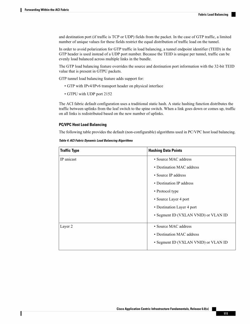
and destination port (if traffic is TCP or UDP) fields from the packet. In the case of GTP traffic, a limitednumber of unique values for these fields restrict the equal distribution of traffic load on the tunnel.
In order to avoid polarization for GTP traffic in load balancing, a tunnel endpoint identifier (TEID) in theGTP header is used instead of a UDP port number. Because the TEID is unique per tunnel, traffic can beevenly load balanced across multiple links in the bundle.
The GTP load balancing feature overrides the source and destination port information with the 32-bit TEIDvalue that is present in GTPU packets.
GTP tunnel load balancing feature adds support for:
• GTP with IPv4/IPv6 transport header on physical interface
• GTPU with UDP port 2152
The ACI fabric default configuration uses a traditional static hash. A static hashing function distributes thetraffic between uplinks from the leaf switch to the spine switch. When a link goes down or comes up, trafficon all links is redistributed based on the new number of uplinks.
PC/VPC Host Load Balancing
The following table provides the default (non-configurable) algorithms used in PC/VPC host load balancing.
Table 4: ACI Fabric Dynamic Load Balancing Algorithms
Hashing Data PointsTraffic Type
• Source MAC address
• Destination MAC address
• Source IP address
• Destination IP address
• Protocol type
• Source Layer 4 port
• Destination Layer 4 port
• Segment ID (VXLAN VNID) or VLAN ID
IP unicast
• Source MAC address
• Destination MAC address
• Segment ID (VXLAN VNID) or VLAN ID
Layer 2
Cisco Application Centric Infrastructure Fundamentals, Release 6.0(x)111
Forwarding Within the ACI FabricFabric Load Balancing

Hashing Data PointsTraffic Type
For Layer 2 frames: Source MAC address andDestination MAC address
For IP traffic:
• Source IP address
• Destination IP address
• Source MAC address
• Destination MAC address
• Layer 4 Source Port
• Layer 4 Destination Port
• Protocol
• System generated random number
End Host (PC and VPC) traffic
Endpoint RetentionRetaining cached endpoint MAC and IP addresses in the switch improves performance. The switch learnsabout endpoints as they become active. Local endpoints are on the local switch. Remote endpoints are onother switches but are cached locally. The leaf switches store location and policy information about endpointsthat are attached directly to them (or through a directly attached Layer 2 switch or Fabric Extender), localendpoints, and endpoints that are attached to other leaf switches on the fabric (remote endpoints in thehardware). The switch uses a 32-Kb entry cache for local endpoints and a 64-Kb entry cache for remoteendpoints.
Software that runs on the leaf switch actively manages these tables. For the locally attached endpoints, thesoftware ages out entries after a retention timer for each entry has expired. Endpoint entries are pruned fromthe switch cache as the endpoint activity ceases, the endpoint location moves to another switch, or the lifecycle state changes to offline. The default value for the local retention timer is 15 minutes. Before removingan inactive entry, the leaf switch sends three ARP requests to the endpoint to see if it really has gone away.If the switch receives no ARP response, the entry is pruned. For remotely attached endpoints, the switch agesout the entries after five minutes of inactivity. The remote endpoint is immediately reentered in the table if itbecomes active again.
Version 1.3(1g) adds silent host tracking that will be triggered for any virtual and local hosts.
There is no performance penalty for not having the remote endpoint in the table other than policies are enforcedat the remote leaf switch until the endpoint is cached again.
Note
When subnets of a bridge domain are configured to be enforced, the endpoint retention policy operates in thefollowing way:
• New endpoints with IP addresses not contained in the subnets of the bridge domain are not learned.
Cisco Application Centric Infrastructure Fundamentals, Release 6.0(x)112
Forwarding Within the ACI FabricEndpoint Retention

• Already learned endpoints age out of the endpoint retention cache if the device does not respond fortracking.
This enforcement process operates in the same way regardless of whether the subnet is defined under a bridgedomain or if the subnet is defined under and EPG.
The endpoint retention timer policy can be modified. Configuring a static endpoint MAC and IP addressenables permanently storing it in the switch cache by setting its retention timer to zero. Setting the retentiontimer to zero for an entry means that it will not be removed automatically. Care must be taken when doingso. If the endpoint moves or its policy changes, the entry must be refreshed manually with the updatedinformation through the APIC. When the retention timer is nonzero, this information is checked and updatedinstantly on each packet without APIC intervention.
The endpoint retention policy determines how pruning is done. Use the default policy algorithm for mostoperations. Changing the endpoint retention policy can affect system performance. In the case of a switch thatcommunicates with thousands of endpoints, lowering the aging interval increases the number of cache windowsavailable to support large numbers of active endpoints.When the endpoint count exceeds 10,000, we recommenddistributing endpoints across multiple switches.
Observe the following guidelines regarding changing the default endpoint retention policy:
• Remote Bounce Interval = (Remote Age * 2) + 30 seconds
• Recommended default values:
• Local Age = 900 seconds
• Remote Age = 300 seconds
• Bounce Age = 630 seconds
• Upgrade considerations: When upgrading to any ACI version older than release 1.0(1k), assure that thedefault values of endpoint retention policy (epRetPol) under tenant common are as follows: Bounce Age= 660 seconds.
IP Endpoint Learning BehaviorWhen an ACI bridge domain is configured with unicast routing enabled, not only does it learnMAC addresses,but it also learns IP addresses associated with the MAC addresses.
ACI tracks and requires MAC addresses to be unique per bridge domain. In ACI, endpoints are based on asingle MAC address, but any number of IP addresses can be tied to a single MAC address in a bridge domain.ACI links these IP addresses to a MAC address. It is possible that a MAC address represents an endpoint thatonly has an IP address.
Therefore ACI may learn and store local endpoints as follows:
• Only a MAC address
• MAC address with a single IP address
• MAC address with multiple IP addresses
The third case occurs if a server has multiple IP addresses on the same MAC address, such as primary andsecondary IP addresses. It could also occur if the ACI fabric learns a server's MAC and IP addresses on the
Cisco Application Centric Infrastructure Fundamentals, Release 6.0(x)113
Forwarding Within the ACI FabricIP Endpoint Learning Behavior
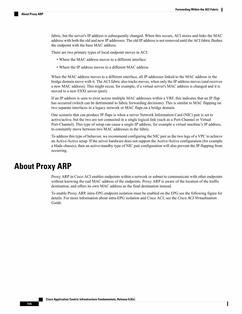
fabric, but the server's IP address is subsequently changed. When this occurs, ACI stores and links the MACaddress with both the old and new IP addresses. The old IP address is not removed until the ACI fabric flushesthe endpoint with the base MAC address.
There are two primary types of local endpoint moves in ACI:
• Where the MAC address moves to a different interface
• Where the IP address moves to a different MAC address
When the MAC address moves to a different interface, all IP addresses linked to the MAC address in thebridge domain move with it. The ACI fabric also tracks moves, when only the IP address moves (and receivesa new MAC address). This might occur, for example, if a virtual server's MAC address is changed and it ismoved to a new ESXI server (port).
If an IP address is seen to exist across multiple MAC addresses within a VRF, this indicates that an IP flaphas occurred (which can be detrimental to fabric forwarding decisions). This is similar to MAC flapping ontwo separate interfaces in a legacy network or MAC flaps on a bridge domain.
One scenario that can produce IP flaps is when a server Network Information Card (NIC) pair is set toactive/active, but the two are not connected in a single logical link (such as a Port-Channel or VirtualPort-Channel). This type of setup can cause a single IP address, for example a virtual machine’s IP address,to constantly move between two MAC addresses in the fabric.
To address this type of behavior, we recommend configuring the NIC pair as the two legs of a VPC to achievean Active/Active setup. If the server hardware does not support the Active/Active configuration (for examplea blade chassis), then an active/standby type of NIC pair configuration will also prevent the IP flapping fromoccurring.
About Proxy ARPProxy ARP in Cisco ACI enables endpoints within a network or subnet to communicate with other endpointswithout knowing the real MAC address of the endpoints. Proxy ARP is aware of the location of the trafficdestination, and offers its own MAC address as the final destination instead.
To enable Proxy ARP, intra-EPG endpoint isolation must be enabled on the EPG see the following figure fordetails. For more information about intra-EPG isolation and Cisco ACI, see the Cisco ACI VirtualizationGuide.
Cisco Application Centric Infrastructure Fundamentals, Release 6.0(x)114
Forwarding Within the ACI FabricAbout Proxy ARP

Figure 48: Proxy ARP and Cisco APIC
Proxy ARP within the Cisco ACI fabric is different from the traditional proxy ARP. As an example of thecommunication process, when proxy ARP is enabled on an EPG, if an endpoint A sends an ARP request forendpoint B and if endpoint B is learned within the fabric, then endpoint A will receive a proxy ARP responsefrom the bridge domain (BD) MAC. If endpoint A sends an ARP request for endpoint B, and if endpoint Bis not learned within the ACI fabric already, then the fabric will send a proxy ARP request within the BD.Endpoint B will respond to this proxy ARP request back to the fabric. At this point, the fabric does not senda proxy ARP response to endpoint A, but endpoint B is learned within the fabric. If endpoint A sends anotherARP request to endpoint B, then the fabric will send a proxy ARP response from the BD MAC.
The following example describes the proxy ARP resolution steps for communication between clients VM1and VM2:
1. VM1 to VM2 communication is desired.
Cisco Application Centric Infrastructure Fundamentals, Release 6.0(x)115
Forwarding Within the ACI FabricAbout Proxy ARP

Figure 49: VM1 to VM2 Communication is Desired.
Table 5: ARP Table State
StateDevice
IP = * MAC = *VM1
IP = * MAC = *ACI fabric
IP = * MAC = *VM2
2. VM1 sends an ARP request with a broadcast MAC address to VM2.
Figure 50: VM1 sends an ARP Request with a Broadcast MAC address to VM2
Cisco Application Centric Infrastructure Fundamentals, Release 6.0(x)116
Forwarding Within the ACI FabricAbout Proxy ARP
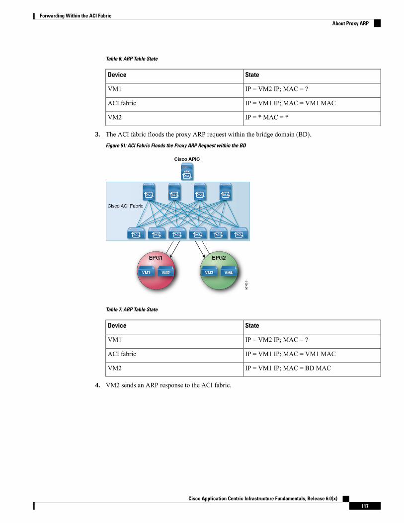
Table 6: ARP Table State
StateDevice
IP = VM2 IP; MAC = ?VM1
IP = VM1 IP; MAC = VM1 MACACI fabric
IP = * MAC = *VM2
3. The ACI fabric floods the proxy ARP request within the bridge domain (BD).
Figure 51: ACI Fabric Floods the Proxy ARP Request within the BD
Table 7: ARP Table State
StateDevice
IP = VM2 IP; MAC = ?VM1
IP = VM1 IP; MAC = VM1 MACACI fabric
IP = VM1 IP; MAC = BD MACVM2
4. VM2 sends an ARP response to the ACI fabric.
Cisco Application Centric Infrastructure Fundamentals, Release 6.0(x)117
Forwarding Within the ACI FabricAbout Proxy ARP

Figure 52: VM2 Sends an ARP Response to the ACI Fabric
Table 8: ARP Table State
StateDevice
IP = VM2 IP; MAC = ?VM1
IP = VM1 IP; MAC = VM1 MACACI fabric
IP = VM1 IP; MAC = BD MACVM2
5. VM2 is learned.
Figure 53: VM2 is Learned
Cisco Application Centric Infrastructure Fundamentals, Release 6.0(x)118
Forwarding Within the ACI FabricAbout Proxy ARP

Table 9: ARP Table State
StateDevice
IP = VM2 IP; MAC = ?VM1
IP = VM1 IP; MAC = VM1 MAC
IP = VM2 IP; MAC = VM2 MAC
ACI fabric
IP = VM1 IP; MAC = BD MACVM2
6. VM1 sends an ARP request with a broadcast MAC address to VM2.
Figure 54: VM1 Sends an ARP Request with a Broadcast MAC Address to VM2
Table 10: ARP Table State
StateDevice
IP = VM2 IP MAC = ?VM1
IP = VM1 IP; MAC = VM1 MAC
IP = VM2 IP; MAC = VM2 MAC
ACI fabric
IP = VM1 IP; MAC = BD MACVM2
7. The ACI fabric sends a proxy ARP response to VM1.
Cisco Application Centric Infrastructure Fundamentals, Release 6.0(x)119
Forwarding Within the ACI FabricAbout Proxy ARP
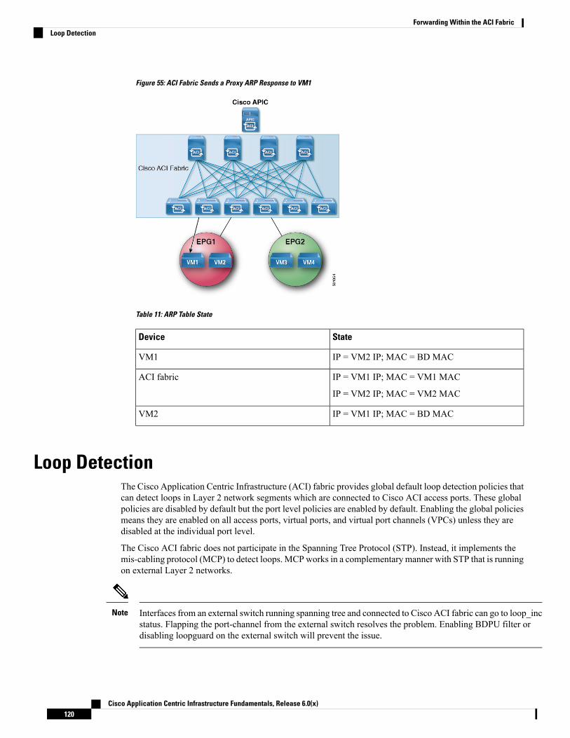
Figure 55: ACI Fabric Sends a Proxy ARP Response to VM1
Table 11: ARP Table State
StateDevice
IP = VM2 IP; MAC = BD MACVM1
IP = VM1 IP; MAC = VM1 MAC
IP = VM2 IP; MAC = VM2 MAC
ACI fabric
IP = VM1 IP; MAC = BD MACVM2
Loop DetectionThe Cisco Application Centric Infrastructure (ACI) fabric provides global default loop detection policies thatcan detect loops in Layer 2 network segments which are connected to Cisco ACI access ports. These globalpolicies are disabled by default but the port level policies are enabled by default. Enabling the global policiesmeans they are enabled on all access ports, virtual ports, and virtual port channels (VPCs) unless they aredisabled at the individual port level.
The Cisco ACI fabric does not participate in the Spanning Tree Protocol (STP). Instead, it implements themis-cabling protocol (MCP) to detect loops. MCPworks in a complementary manner with STP that is runningon external Layer 2 networks.
Interfaces from an external switch running spanning tree and connected to Cisco ACI fabric can go to loop_incstatus. Flapping the port-channel from the external switch resolves the problem. Enabling BDPU filter ordisabling loopguard on the external switch will prevent the issue.
Note
Cisco Application Centric Infrastructure Fundamentals, Release 6.0(x)120
Forwarding Within the ACI FabricLoop Detection

A fabric administrator provides a key that MCP uses to identify which MCP packets are initiated by the CiscoACI fabric. The administrator can choose how theMCP policies identify loops and how to act upon the loops:syslog only, or disable the port.
While endpoint moves such as VM moves are normal, they can be symptomatic of loops if the frequency ishigh, and the interval between moves is brief. A separate global default endpoint move loop detection policyis available but is disabled by default. An administrator can choose how to act upon move detection loops.
Also, an error disabled recovery policy can enable ports that loop detection and BPDU policies disabled afteran interval that the administrator can configure.
The MCP runs in native VLAN mode where the MCP BPDUs sent are not VLAN tagged, by default. MCPcan detect loops due to mis-cabling if the packets sent in native VLAN are received by the fabric, but if thereis a loop in non-native VLANs in EPG VLANs then it is not detected. Starting with release 2.0(2), CiscoApplication Policy Infrastructure Controller (APIC) supports sendingMCPBPDUs in all VLANs in the EPGsconfigured therefore any loops in those VLANs are detected. A new MCP configuration mode allows you toconfigureMCP to operate in a mode whereMCP PDUs are sent in all EPGVLANs that a physical port belongsto by adding 802.1Q header with each of the EPG VLAN ID to the PDUs transmitted.
Starting with the 3.2(1) release, the Cisco ACI fabric provides faster loop detection with transmit frequenciesfrom 100 millisecond to 300 seconds.
In the 5.2(3) release and later, if your configuration has more than 256 VLANs per interface, fault F4268 isgenerated. If your configuration has more than 2000 logical ports (port x VLAN) per leaf switch, fault F4269is generated.
Per-VLANMCP will only run on 256 VLANs per interface. If there are more than 256 VLANs, then the firstnumerical 256 VLANs are chosen.
MCP is not supported on fabrix extender (FEX) host interface (HIF) ports.
Note
Modes of Mis-cabling ProtocolMCP can operate in two modes:
• Non-strict mode: When an MCP-enabled port is up, data traffic and control plane traffic (such as STP,MCP protocol packets) are accepted. MCP monitors the link for loops and if a loop is detected, the linkis error-disabled. In this mode, packets are sent at 2-second intervals, per the globalMCP instance policy.The default time for loop detection in this mode is 7 seconds.
• Strict mode: Beginning with Release 5.2(4), MCP supports strict mode. As soon as the MCP-enabledport is up, MCP packets are sent at aggressive intervals for a short duration to check for loops. This iscalled the early loop detection phase, where in, the link (connected to the port) is checked for loops beforeaccepting data traffic. When a loop is detected, the port is error-disabled and shut down. If no loop isdetected, the port starts forwarding data traffic. MCP starts sending packets using non-aggressive timersper the global MCP instance policy.
If MCP strict mode is configured on a port that is already up, MCP is not going to perform early loopdetection on this port. Flap the ports for MCP strict mode configuration to take immediate effect.
Sequence of events for MCP strict mode:
1. When the MCP-enabled port comes up, the initial delay timer is initiated. Only link-level controlpackets (such as LLDP, CDP, STP) are accepted and forwarded. Data traffic is not accepted during
Cisco Application Centric Infrastructure Fundamentals, Release 6.0(x)121
Forwarding Within the ACI FabricModes of Mis-cabling Protocol
this period of time. The initial delay timer is the time for STP to converge on the external L2 network.The default value is zero, but, depending on the topology and on how the spanning tree is configuredon the external network, you may want to set an initial delay of 45 to 60 seconds to give time forSTP to converge and break the loop (if any). If STP is not enabled on the external L2 network, initialdelay timer should be set to 0.
2. The grace period timer is initiated after the initial delay timer expires. During this period, the portaggressively transmits MCP packets which are used for loop detection. Early loop detection takesplace during this time. If a loop is detected, the port is error-disabled. The default value is 3 seconds.Data traffic is not accepted during this period of time.
During the grace timer period,MCP overrides the following globalMCP instance policy configuration:
• If a loop is detected, MCP error-disables the port even if the Port Disable checkbox is notselected in the GUI.
• Receiving a single MCP frame is considered a loop, even if the MCP multiplication factor isset to a value greater than 1.
3. After the grace period timer expires, and no loop is detected, the port is moved to the forwardingstate and data traffic is accepted. MCP packets are sent at non-aggressive intervals, per the globaltransmission frequency configuration.
Guidelines and Restrictions for MCP Strict modeConfigure strict mode MCP according to the following guidelines and limitations:
• MCP strict mode is not supported on FEX ports.
• MCP strict mode is not supported on QinQ edge ports.
• When MCP strict mode is enabled on a port, vPC fast convergence is not supported. vPC traffic takes alonger time to converge.
• Strict modeMCP control packets cannot be decoded by leaf switches running versions earlier than APICrelease 5.2(4). So, all leaf switches participating in MCP should have a minimum version of 5.2(4) forstrict loop detection to work.
• Disable strict mode on MCP-enabled ports before downgrading the fabric to releases prior to APICversion 5.2(4). If strict mode is not disabled, then strict loop detection will not work on switches withearlier versions.
• If strict mode is enabled on a port on a leaf switch, STP BPDUs are accepted even if that specific VLANis not enabled on the port. If there are misconfigurations on the remote side, this can result in unintendedSTP states on the external L2 switch.
• Set MCPCoPP burst and CoPP rate to 5000 when either strict mode is enabled or transmission frequencyis less than 2 seconds.
• When two MCP strict-enabled ports come up at the same time, there is a possibility that both the portswill be error-disabled when a loop is detected on either side.
Cisco Application Centric Infrastructure Fundamentals, Release 6.0(x)122
Forwarding Within the ACI FabricGuidelines and Restrictions for MCP Strict mode

Rogue Endpoint Detection
About the Rogue Endpoint Control PolicyA rogue endpoint attacks leaf switches through frequently, repeatedly injecting packets on different leaf switchports and changing 802.1Q tags (thus, emulating endpoint moves) causing learned class and EPG port changes.Misconfigurations can also cause frequent IP and MAC address changes (moves).
Such rapid movement in the fabric causes significant network instability, high CPU usage, and in rare instances,endpoint mapper (EPM) and EPM client (EPMC) crashes due to significant and prolonged messaging andtransaction service (MTS) buffer consumption. Also, such frequent moves may result in the EPM and EPMClogs rolling over very quickly, hampering debugging for unrelated endpoints.
The rogue endpoint control feature addresses this vulnerability by quickly:
• Identifying such rapidly moving MAC and IP endpoints.
• Stopping the movement by temporarily making endpoints static, thus quarantining the endpoint.
• Prior to 3.2(6) release: Keeping the endpoint static for the Rogue EP Detection Interval and droppingthe traffic to and from the rogue endpoint. After this time expires, deleting the unauthorized MAC or IPaddress.
• In the 3.2(6) release and later: Keeping the endpoint static for the Rogue EP Detection Interval (thisfeature no longer drops the traffic). After this time expires, deleting the unauthorizedMAC or IP address.
• Generating a host tracking packet to enable the system to re-learn the impacted MAC or IP address.
• Raising a fault to enable corrective action.
The rogue endpoint control policy is configured globally and, unlike other loop preventionmethods, functionsat the level of individual endpoints (IP and MAC addresses). It does not distinguish between local or remotemoves; any type of interface change is considered a move in determining if an endpoint should be quarantined.
The rogue endpoint control feature is disabled by default.
Cisco Application Centric Infrastructure Fundamentals, Release 6.0(x)123
Forwarding Within the ACI FabricRogue Endpoint Detection

Cisco Application Centric Infrastructure Fundamentals, Release 6.0(x)124
Forwarding Within the ACI FabricAbout the Rogue Endpoint Control Policy

C H A P T E R 6Networking and Management Connectivity
This chapter contains the following sections:
• DHCP Relay, on page 125• DNS, on page 127• In-Band and Out-of-Band Management Access, on page 128• IPv6 Support, on page 130• Routing Within the Tenant, on page 135• WAN and Other External Networks, on page 136• Layer 3 Multicast, on page 152• Cisco ACI GOLF , on page 157• Multipod, on page 161• About Anycast Services, on page 165• Remote Leaf Switches, on page 166• QoS, on page 175• HSRP, on page 177
DHCP RelayAlthough ACI fabric-wide flooding is disabled by default, flooding within a bridge domain is enabled bydefault. Because flooding within a bridge domain is enabled by default, clients can connect to DHCP serverswithin the same EPG. However, when the DHCP server is in a different EPG or Virtual Routing and Forwarding(VRF) instance than the clients, DHCP Relay is required. Also, when Layer 2 flooding is disabled, DHCPRelay is required.
When the ACI fabric acts as a DHCP relay, it inserts the DHCPOption 82 (the DHCPRelay Agent InformationOption) in DHCP requests that it proxies on behalf of clients. If a response (DHCP offer) comes back froma DHCP server without Option 82, it is silently dropped by the fabric. When ACI acts as a DHCP relay, DHCPservers providing IP addresses to compute nodes attached to the ACI fabric must support Option 82.Windows2003 and 2008 do not support option 82 but Windows 2012 does.
Note
The figure below shows the managed objects in the management information tree (MIT) that can containDHCP relays: user tenants, the common tenant, the infra tenant, the mgmt tenant, and fabric access.
Cisco Application Centric Infrastructure Fundamentals, Release 6.0(x)125

Figure 56: DHCP Relay Locations in the MIT
DHCP relay is limited to a single subnet per bridge domain.Note
The figure below shows the logical relationships of the DHCP relay objects within a user tenant.
Figure 57: Tenant DHCP Relay
The DHCP Relay profile contains one or more providers. An EPG contains one or more DHCP servers, andthe relation between the EPG and DHCP Relay specifies the DHCP server IP address. The consumer bridgedomain contains a DHCP label that associates the provider DHCP server with the bridge domain. Labelmatching enables the bridge domain to consume the DHCP Relay.
The bridge domain DHCP label must match the DHCP Relay name.Note
Cisco Application Centric Infrastructure Fundamentals, Release 6.0(x)126
Networking and Management ConnectivityDHCP Relay
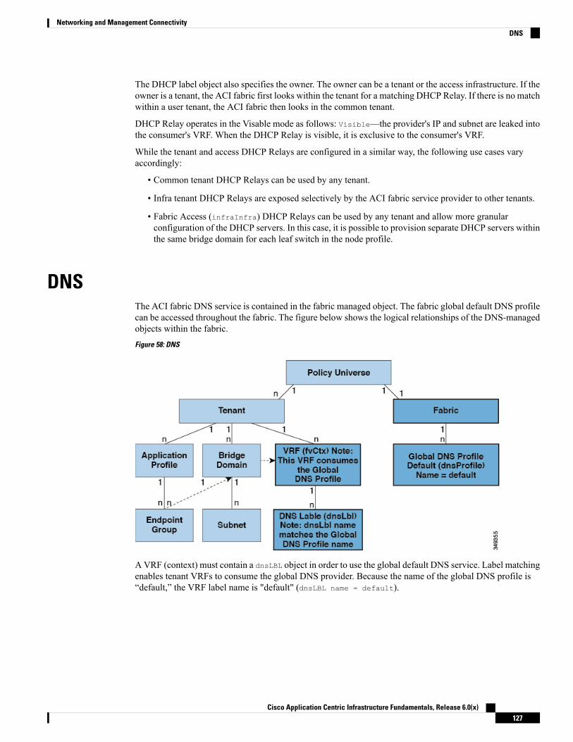
The DHCP label object also specifies the owner. The owner can be a tenant or the access infrastructure. If theowner is a tenant, the ACI fabric first looks within the tenant for a matching DHCP Relay. If there is no matchwithin a user tenant, the ACI fabric then looks in the common tenant.
DHCP Relay operates in the Visable mode as follows: Visible—the provider's IP and subnet are leaked intothe consumer's VRF. When the DHCP Relay is visible, it is exclusive to the consumer's VRF.
While the tenant and access DHCP Relays are configured in a similar way, the following use cases varyaccordingly:
• Common tenant DHCP Relays can be used by any tenant.
• Infra tenant DHCP Relays are exposed selectively by the ACI fabric service provider to other tenants.
• Fabric Access (infraInfra) DHCP Relays can be used by any tenant and allow more granularconfiguration of the DHCP servers. In this case, it is possible to provision separate DHCP servers withinthe same bridge domain for each leaf switch in the node profile.
DNSThe ACI fabric DNS service is contained in the fabric managed object. The fabric global default DNS profilecan be accessed throughout the fabric. The figure below shows the logical relationships of the DNS-managedobjects within the fabric.
Figure 58: DNS
AVRF (context) must contain a dnsLBL object in order to use the global default DNS service. Label matchingenables tenant VRFs to consume the global DNS provider. Because the name of the global DNS profile is“default,” the VRF label name is "default" (dnsLBL name = default).
Cisco Application Centric Infrastructure Fundamentals, Release 6.0(x)127
Networking and Management ConnectivityDNS

In-Band and Out-of-Band Management AccessThe mgmt tenant provides a convenient means to configure access to fabric management functions. Whilefabric management functions are accessible through the APIC, they can also be accessed directly throughin-band and out-of-band network policies.
Static and Dynamic Management Access
APIC supports both static and dynamic management access. For simple deployments where users managethe IP addresses of a few leaf and spine switches, configuring static in-band and out-of-band managementconnectivity is simpler. For more complex deployments, where you might have a large number of leaf andspine switches that require managing many IP addresses, static management access is not recommended. Fordetailed information about static management access, see Cisco APIC and Static Management Access.
In-Band Management AccessThe following figure shows an overview of the mgmt tenant in-band fabric management access policy.
Figure 59: In-Band Management Access Policy
The management profile includes the in-band EPGMO that provides access to management functions via thein-band contract (vzBrCP). The vzBrCP enables fvAEPg, l2extInstP, andl3extInstP EPGs to consume thein-band EPG. This exposes the fabric management to locally connected devices, as well as devices connectedover Layer 2 bridged external networks, and Layer 3 routed external networks. If the consumer and providerEPGs are in different tenants, they can use a bridge domain and VRF from the common tenant. Authentication,access, and audit logging apply to these connections; any user attempting to access management functionsthrough the in-band EPG must have the appropriate access privileges.
The figure below shows an in-band management access scenario.
Cisco Application Centric Infrastructure Fundamentals, Release 6.0(x)128
Networking and Management ConnectivityIn-Band and Out-of-Band Management Access

Figure 60: In-Band Management Access Scenario
Out-of-Band Management AccessThe following figure shows an overview of the mgmt tenant out-of-band fabric management access policy.
Figure 61: Out-of-Band Management Access Policy
The management profile includes the out-of-band EPG MO that provides access to management functionsvia the out-of-band contract (vzOOBBrCP). The vzOOBBrCP enables the external management instance profile(mgmtExtInstP) EPG to consume the out-of-band EPG. This exposes the fabric node supervisor ports tolocally or remotely connected devices, according to the preference of the service provider.While the bandwidthof the supervisor ports will be lower than the in-band ports, the supervisor ports can provide direct access to
Cisco Application Centric Infrastructure Fundamentals, Release 6.0(x)129
Networking and Management ConnectivityOut-of-Band Management Access

the fabric nodes when access through the in-band ports is unavailable. Authentication, access, and auditlogging apply to these connections; any user attempting to accessmanagement functions through the out-of-bandEPG must have the appropriate access privileges. When an administrator configures an external managementinstance profile, it specifies a subnet range for devices that are allowed out-of-band access. Any device notin this range will not have out-of-band access.
The figure below shows how out-of-bandmanagement access can be consolidated through a dedicated switch.
Figure 62: Out-of-Band Access Scenario
While some service providers choose to restrict out-of-band connectivity to local connections, others canchoose to enable routed or bridged connections from external networks. Also, a service provider can chooseto configure a set of policies that include both in-band and out-of-band management access for local devicesonly, or both local and remote devices.
Starting with APIC release 1.2(2), when a contract is provided on an out-of-band node management EPG, thedefault APIC out-of-band contract source address is the local subnet that is configured on the out-of-bandnode management address. Previously, any address was allowed to be the default APIC out-of-band contractsource address.
Note
IPv6 SupportTheACI fabric supports the following IPv6 features for in-band and out-of-band interfaces, tenant addressing,contracts, shared services, routing, Layer 4 - Layer 7 services, and troubleshooting:
• IPv6 address management, pervasive software virtual interface (SVI) bridge domain subnets, outsidenetwork external interface addresses, and routes for shared services such as load balancers or intrusiondetection.
• Neighbor Discovery using ICMPv6messages known as router advertisements (RA) and router solicitations(RS), and Duplicate Address Detection (DAD),
Cisco Application Centric Infrastructure Fundamentals, Release 6.0(x)130
Networking and Management ConnectivityIPv6 Support

• Stateless Address Auto configuration (SLAAC) and DHCPv6.
• Bridge domain forwarding.
• Troubleshooting (see the atomic counters, SPAN, iping6, and traceroute topics in the TroubleshootingChapter).
• IPv4 only, IPv6 only, or dual stack configuration of in-band and out-of-band interfaces.
Limitations of the current ACI fabric IPv6 implementation include the following:
• Multicast Listener Discovery (MLD) snooping is not supported.
• For IPv6 management, only static addresses are permitted; dynamic IPv6 pools are not supported forIPv6 management.
• IPv6 tunnel interfaces (Intra-Site Automatic Tunnel Addressing Protocol, 6to4 and so forth) are notsupported within the fabric; IPv6 tunnel traffic run over the fabric is transparent to the fabric.
ACI fabric interfaces can be configured with link local, global unicast, and multicast IPv6 addresses.
While many of the examples provided in this manual use IPv4 addresses, IPv6 addresses could also be used.Note
A global unicast address can be routed across the public Internet; it is globally unique within a routing domain.A Link Local Address (LLA) has link-local scope and is unique on the link (subnet). The LLA cannot berouted across subnets. These are used by control protocols such as neighbor discovery or OSPF. Multicastaddresses are used by IPv6 control protocols such as Neighbor Discovery to deliver packets to more than oneendpoint. These are not configurable; they are automatically generated by the protocol components.
Global Unicast AddressesAn administrator can manually specify one or more complete 128-bit IPv6 global unicast addresses on aninterface in compressed or uncompressed format. For example, the administration can specify the address inone of the following formats: '2001:0000:0000:0001:0000:0000:0000:0003', '2001:0:0:1:0:0:0:3', '2001:0:0:1::3'.In the ACI fabric naming property, an IPv6 address is always represented in the compressed format. In theabove example, the Relative Name is: 2001:0:0:1::3. The administrator can choose any mask length asappropriate for the address.
An administrator can also specify an ACI fabric IPv6 global unicast address in EUI-64 format. As specifiedin RFC2373, Extended Unique Identifier (EUI) enables a host to assign itself a unique 64-bit IPv6 interfaceidentifier (EUI-64). The IPv6 EUI-64 format address is obtained by incorporating the switch MAC addresswithin the 128-bit IPv6 global unicast address. This feature of IPv6 eliminates the need for manual configurationor DHCP. An IPv6 address for a bridge domain or Layer 3 interface specified in the EUI-64 format is formedthis way: <IPv6 prefix>::/<mask>/eui64 where the mask is <=64. For example, 2002::/64/eui64 is what theadministrator specifies, and the switch assigns the address as 2002::222:bdff:fef8:19ff/64. The switch usesthe switch MAC address to create the EUI-64 address. The formed IPv6 address is contained in the operAddrfield of the ipv6If object.
The EUI-64 format can only be used for pervasive bridge domain and Layer 3 interface addresses. It cannotbe used for other IP fields in the fabric such as an external server address or for DHCP relay.
Note
Cisco Application Centric Infrastructure Fundamentals, Release 6.0(x)131
Networking and Management ConnectivityGlobal Unicast Addresses

Bridge domain subnets and Layer 3 external interface IP addresses can be IPv6 global addresses with a maskranging from /1 to /127. A bridge domain can contain multiple IPv4 and IPv6 subnets. To support IPv4 andIPv6 address on the same L3 external interface, the administrator creates multiple interface profiles. Whenan EPG or external EpP gets deployed on the switch, the presence of a manually configured link-local addressfor the equivalent bridge domain/L3 Interface or an IPv6 address for the subnet/address field results in thecreation of ipv6If interface in the switch.
Link-Local AddressesOne Link-Local Address (LLA) can be assigned to an interface. The LLA can be autogenerated or configuredby an administrator. By default, an ACI LLA is autogenerated by the switch in EUI-64 format. An administratormust configure at least one global address on the interface for an autogenerated LLA to be generated on theswitch. The autogenerated address is saved in the operllAddr field of the ipv6IfMO. For pervasive SVIsthe MAC address used is the same as the configured interface MAC address. For other kinds of interfaces theswitch MAC address is used. An administrator has the option to manually specify a complete 128-bit IPv6link-local address on an interface in compressed or uncompressed format.
The switch hardware tables are limited to one LLA per Virtual Routing and Forwarding (VRF) instance.Note
Each pervasive bridge domain can have a single IPv6 LLA. This LLA can be set by an administrator, or canbe automatically configured by the switch when one isn't provided.When automatically configured, the switchforms the LLA in the modified EUI-64 format where the MAC address is encoded in the IPv6 address to forma unique address. A pervasive bridge domain uses one LLA on all the leaf nodes.
Follow these guidelines for setting LLAs:
• For external SVI and VPC members, the LLA is unique for every leaf node.
• LLAs can be changed to manual (non-zero manually specified link-local addresses) or auto (by manuallysetting the specified link-local address to zero) anytime in the lifecycle of the interface.
• LLAs specified by an administrator must conform to the IPv6 link-local format (FE80:/10).
• The IPv6 interface MO (ipv6If) is created on the switch upon the creation of the first global address onthe interface, or when an administrator manually configures an LLA, whichever happens first.
• An administrator-specified LLA is represented in the llAddr property in the bridge domain and Layer3 interface objects in the logical model.
• The LLA used by the switch (either from llAddr or autogenerated when llAddr is zero is representedin the operLlAddr property in the corresponding ipv6If object.
• Operational LLA-related errors like duplicate LLAs are detected by the switch during Duplicate AddressDetection process and recorded in operStQual field in the ipv6If object or raise faults as appropriate.
• Apart from the llAddr fields, an LLA (FE80:/10) cannot be a valid address in any other IP address fieldin the APIC (such as external server addresses or bridge domain subnets) as these addresses cannot berouted.
Cisco Application Centric Infrastructure Fundamentals, Release 6.0(x)132
Networking and Management ConnectivityLink-Local Addresses

Static RoutesACI IPv6 static routes are similar to what is supported in the IPv4, except for the address and prefix formatdifferences in the configurations. The following types of static routes are typically handled by IPv6 staticroute module:
• Local Routes: Any /128 address configured on an interface leads to a local route that points to the CPU.
• Direct routes: For any configured address on a pervasive BD, the policy element pushes a subnet routepointing to an IPv4 proxy tunnel destination on the spine. For any configured address on a non-pervasiveLayer 3 external interface, the IPv6 manager module automatically pushes a subnet route pointing to theCPU.
• Static routes pushed from PE: Used for external connectivity. The next hop IPv6 address for such routescan be on a directly connected subnet on the external router or a recursive next hop that can be resolvedto a real next hop on a directly connected subnet. Note that the interface model does not allow an interfaceas a next hop (though it is supported in the switch). Used to enable shared services across tenants, thenext hop for shared-services static routes is located in the shared services Virtual Routing and Forwarding(VRF) instance, which is different from the tenant VRF, where the route is installed on the ingress leafswitches.
Neighbor DiscoveryThe IPv6 Neighbor Discovery (ND) protocol is responsible for the address auto configuration of nodes,discovery of other nodes on the link, determining the link-layer addresses of other nodes, duplicate addressdetection, finding available routers and DNS servers, address prefix discovery, and maintaining reachabilityinformation about the paths to other active neighbor nodes.
ND-specific Neighbor Solicitation or Neighbor Advertisement (NS or NA) and Router Solicitation or RouterAdvertisement (RS or RA) packet types are supported on all ACI fabric Layer 3 interfaces, including physical,Layer 3 sub interface, and SVI (external and pervasive). Up to APIC release 3.1(1x), RS/RA packets are usedfor auto configuration for all Layer 3 interfaces but are only configurable for pervasive SVIs.
Starting with APIC release 3.1(2x), RS/RA packets are used for auto configuration and are configurable onLayer 3 interfaces including routed interface, Layer 3 sub interface, and SVI (external and pervasive).
ACI bridge domain ND always operates in flood mode; unicast mode is not supported.
The ACI fabric ND support includes the following:
• Interface policies (nd:IfPol) control ND timers and behavior for NS/NA messages.
• ND prefix policies (nd:PfxPol) control RA messages.
• Configuration of IPv6 subnets for ND (fv:Subnet).
• ND interface policies for external networks.
• Configurable ND subnets for external networks, and arbitrary subnet configurations for pervasive bridgedomains are not supported.
Configuration options include the following:
• Adjacencies
• Configurable Static Adjacencies: (<vrf, L3Iface, ipv6 address> --> mac address)
Cisco Application Centric Infrastructure Fundamentals, Release 6.0(x)133
Networking and Management ConnectivityStatic Routes
• Dynamic Adjacencies: Learned via exchange of NS/NA packets
• Per Interface
• Control of ND packets (NS/NA)
• Neighbor Solicitation Interval
• Neighbor Solicitation Retry count
• Control of RA packets
• Suppress RA
• Suppress RA MTU
• RA Interval, RA Interval minimum, Retransmit time
• Per Prefix (advertised in RAs) control
• Lifetime, preferred lifetime
• Prefix Control (auto configuration, on link)
• Neighbor Discovery Duplicate Address Detection (DAD)
Duplicate Address DetectionDuplicate address detection (DAD) discovers any other node on the link that is already using the addressbeing configured. DAD is performed for both link-local and global addresses. Each configured addressmaintains the following DAD states:
• NONE—This is the state when the address is initially created before attempting the DAD.
• VALID—This is the state that represents the address has successfully passed the DAD process withoutdetecting the address as a duplicate address.
• DUP—This is the state that represents the address is found as duplicate on the link.
Any configured address is usable for sending and receiving IPv6 traffic only if its DAD state is VALID.
Stateless Address Autoconfiguration (SLAAC) and DHCPv6The following host configurations are supported:
• SLAAC only
• DHCPv6 only
• SLAAC and DHCPv6 stateless used together use SLAAC for address configuration only, but usesDHCPv6 for DNS resolution and other functions.
IPv6 addresses are supported for DHCP relay. DHCPv6 relay applies across Virtual Routing and Forwarding(VRF) instances. DHCP relay over VLAN and VXLAN are also supported. DHCPv4 works in conjunctionwith DHCPv6.
Cisco Application Centric Infrastructure Fundamentals, Release 6.0(x)134
Networking and Management ConnectivityDuplicate Address Detection

Routing Within the TenantThe Application Centric Infrastructure (ACI) fabric provides tenant default gateway functionality and routesbetween the fabric virtual extensible local area (VXLAN) networks. For each tenant, the fabric provides avirtual default gateway or Switched Virtual Interface (SVI) whenever a subnet is created on the APIC. Thisspans any switch that has a connected endpoint for that tenant subnet. Each ingress interface supports thedefault gateway interface and all of the ingress interfaces across the fabric share the same router IP addressand MAC address for a given tenant subnet.
Configuring Route ReflectorsACI fabric route reflectors use multiprotocol BGP (MP-BGP) to distribute external routes within the fabric.To enable route reflectors in the ACI fabric, the fabric administrator must select the spine switches that willbe the route reflectors, and provide the autonomous system (AS) number. It is recommended to configure atleast two spine nodes per pod as MP-BGP route reflectors for redundancy.
After route reflectors are enabled in the ACI fabric, administrators can configure connectivity to externalnetworks through leaf nodes using a component called Layer 3 Out (L3Out). A leaf node configured with anL3Out is called a border leaf. The border leaf exchanges routes with a connected external device via a routingprotocol specified in the L3Out. You can also configure static routes via L3Outs.
After both L3Outs and spine route reflectors are deployed, border leaf nodes learn external routes via L3Outs,and those external routes are distributed to all leaf nodes in the fabric via spine MP-BGP route reflectors.
Check the Verified Scalability Guide for Cisco APIC for your release to find the maximum number of routessupported by a leaf.
Common Pervasive GatewayMultiple ACI fabrics can be configured with an IPv4 common gateway on a per bridge domain basis. Doingso enables moving one or more virtual machines (VM) or conventional hosts across the fabrics while the hostretains its IP address. VM host moves across fabrics can be done automatically by the VM hypervisor. TheACI fabrics can be co-located, or provisioned across multiple sites. The Layer 2 connection between the ACIfabrics can be a local link, or can be across a routed WAN link. The following figure illustrates the basiccommon pervasive gateway topology.
Cisco Application Centric Infrastructure Fundamentals, Release 6.0(x)135
Networking and Management ConnectivityRouting Within the Tenant

Figure 63: ACI Multi-Fabric Common Pervasive Gateway
The per-bridge domain common pervasive gateway configuration requirements are as follows:
• The bridge domain MAC (mac) values for each fabric must be unique.
The default bridge domain MAC (mac) address values are the same for all ACIfabrics. The common pervasive gateway requires an administrator to configurethe bridge domain MAC (mac) values to be unique for each ACI fabric.
Note
• The bridge domain virtual MAC (vmac) address and the subnet virtual IP address must be the same acrossall ACI fabrics for that bridge domain. Multiple bridge domains can be configured to communicate acrossconnected ACI fabrics. The virtual MAC address and the virtual IP address can be shared across bridgedomains.
WAN and Other External NetworksExternal routers that connect to the WAN and the enterprise core connect to the front panel interfaces of theleaf switch. The leaf switch interface that connects to the external router can be configured as a bridgedinterface or a routing peer.
Router Peering and Route DistributionAs shown in the figure below, when the routing peer model is used, the leaf switch interface is staticallyconfigured to peer with the external router’s routing protocol.
Cisco Application Centric Infrastructure Fundamentals, Release 6.0(x)136
Networking and Management ConnectivityWAN and Other External Networks
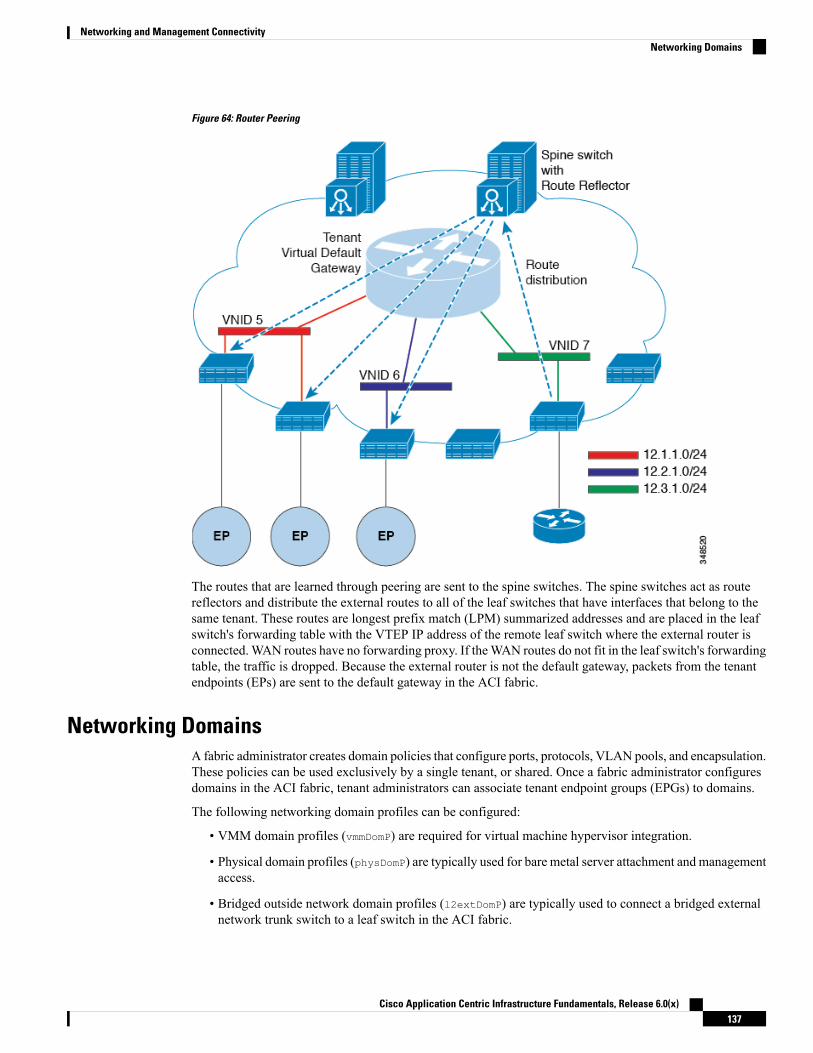
Figure 64: Router Peering
The routes that are learned through peering are sent to the spine switches. The spine switches act as routereflectors and distribute the external routes to all of the leaf switches that have interfaces that belong to thesame tenant. These routes are longest prefix match (LPM) summarized addresses and are placed in the leafswitch's forwarding table with the VTEP IP address of the remote leaf switch where the external router isconnected.WAN routes have no forwarding proxy. If theWAN routes do not fit in the leaf switch's forwardingtable, the traffic is dropped. Because the external router is not the default gateway, packets from the tenantendpoints (EPs) are sent to the default gateway in the ACI fabric.
Networking DomainsA fabric administrator creates domain policies that configure ports, protocols, VLAN pools, and encapsulation.These policies can be used exclusively by a single tenant, or shared. Once a fabric administrator configuresdomains in the ACI fabric, tenant administrators can associate tenant endpoint groups (EPGs) to domains.
The following networking domain profiles can be configured:
• VMM domain profiles (vmmDomP) are required for virtual machine hypervisor integration.
• Physical domain profiles (physDomP) are typically used for bare metal server attachment and managementaccess.
• Bridged outside network domain profiles (l2extDomP) are typically used to connect a bridged externalnetwork trunk switch to a leaf switch in the ACI fabric.
Cisco Application Centric Infrastructure Fundamentals, Release 6.0(x)137
Networking and Management ConnectivityNetworking Domains

• Routed outside network domain profiles (l3extDomP) are used to connect a router to a leaf switch in theACI fabric.
• Fibre Channel domain profiles (fcDomP) are used to connect Fibre Channel VLANs and VSANs.
A domain is configured to be associated with a VLAN pool. EPGs are then configured to use the VLANsassociated with a domain.
EPG port and VLAN configurations must match those specified in the domain infrastructure configurationwith which the EPG associates. If not, the APIC will raise a fault. When such a fault occurs, verify that thedomain infrastructure configuration matches the EPG port and VLAN configurations.
Note
Bridged and Routed Connectivity to External NetworksOutside network managed objects enable Layer 2 and Layer 3 tenant connectivity to external networks. TheGUI, CLI, or REST API can be used to configure tenant connectivity to external networks. To easily locatethe external network access points in the fabric, Layer 2 and Layer 3 external leaf nodes can be tagged as"Border Leaf Nodes."
Layer 2 Out for Bridged Connectivity to External NetworksTenant Layer 2 bridged connectivity to external networks is enabled by associating a fabric access (infraInfra)external bridged domain (L2extDomP) with the Layer 2 external instance profile (l2extInstP) EPG of a Layer2 external outside network (l2extOut) as shown in the figure below.
Cisco Application Centric Infrastructure Fundamentals, Release 6.0(x)138
Networking and Management ConnectivityBridged and Routed Connectivity to External Networks
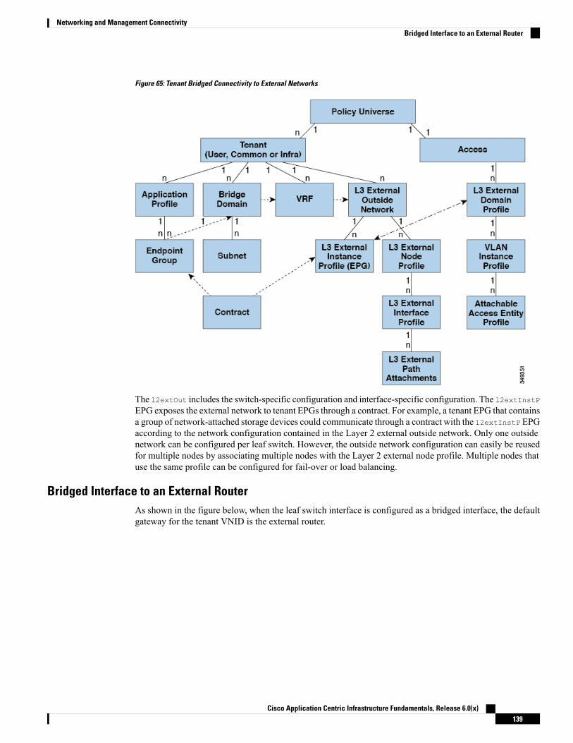
Figure 65: Tenant Bridged Connectivity to External Networks
The l2extOut includes the switch-specific configuration and interface-specific configuration. The l2extInstPEPG exposes the external network to tenant EPGs through a contract. For example, a tenant EPG that containsa group of network-attached storage devices could communicate through a contract with the l2extInstP EPGaccording to the network configuration contained in the Layer 2 external outside network. Only one outsidenetwork can be configured per leaf switch. However, the outside network configuration can easily be reusedfor multiple nodes by associating multiple nodes with the Layer 2 external node profile. Multiple nodes thatuse the same profile can be configured for fail-over or load balancing.
Bridged Interface to an External RouterAs shown in the figure below, when the leaf switch interface is configured as a bridged interface, the defaultgateway for the tenant VNID is the external router.
Cisco Application Centric Infrastructure Fundamentals, Release 6.0(x)139
Networking and Management ConnectivityBridged Interface to an External Router
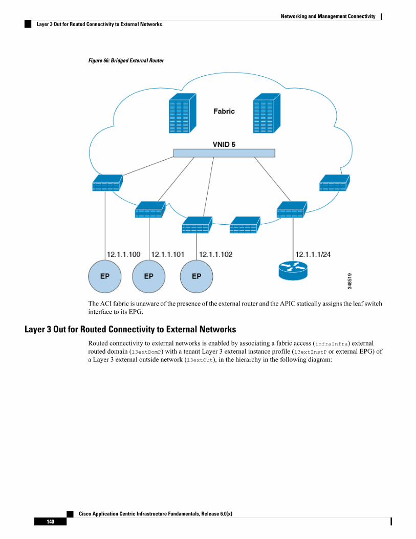
Figure 66: Bridged External Router
The ACI fabric is unaware of the presence of the external router and the APIC statically assigns the leaf switchinterface to its EPG.
Layer 3 Out for Routed Connectivity to External NetworksRouted connectivity to external networks is enabled by associating a fabric access (infraInfra) externalrouted domain (l3extDomP) with a tenant Layer 3 external instance profile (l3extInstP or external EPG) ofa Layer 3 external outside network (l3extOut), in the hierarchy in the following diagram:
Cisco Application Centric Infrastructure Fundamentals, Release 6.0(x)140
Networking and Management ConnectivityLayer 3 Out for Routed Connectivity to External Networks

Figure 67: Policy Model for Layer 3 External Connections
A Layer 3 external outside network (l3extOut object) includes the routing protocol options (BGP, OSPF, orEIGRP or supported combinations) and the switch-specific and interface-specific configurations. While thel3extOut contains the routing protocol (for example, OSPF with its related Virtual Routing and Forwarding(VRF) and area ID), the Layer 3 external interface profile contains the necessary OSPF interface details. Bothare needed to enable OSPF.
The l3extInstP EPG exposes the external network to tenant EPGs through a contract. For example, a tenantEPG that contains a group of web servers could communicate through a contract with the l3extInstP EPGaccording to the network configuration contained in the l3extOut. The outside network configuration caneasily be reused for multiple nodes by associating the nodes with the L3 external node profile. Multiple nodesthat use the same profile can be configured for fail-over or load balancing. Also, a node can be added tomultiple l3extOuts resulting in VRFs that are associated with the l3extOuts also being deployed on that node.For scalability information, refer to the current Verified Scalability Guide for Cisco ACI.
Static Route PreferenceStatic route preference within the ACI fabric is carried in MP-BGP using cost extended community.
Cisco Application Centric Infrastructure Fundamentals, Release 6.0(x)141
Networking and Management ConnectivityStatic Route Preference

The following figure illustrates how the ACI fabric keeps static route preferences intact across leaf switchesso that route selection happens based on this preference.
Figure 68: Static Route Preference
This figure shows a MP-BGP route coming to leaf switch 3 (L3) from leaf switch 4 (L4) that wins over a localstatic route. A static route is installed in the Unicast Routing Information Base (URIB) with the preferenceconfigured by an administrator. On an ACI non-border leaf switch, a static route is installed with leaf switch4 (L4) as its nexthop. When nexthop on L4 is not available, the L3 static route becomes the best route infabric.
If a static route in a leaf switch is defined with next hop Null 0, MP-BGP does not advertise that route toother leaf switches in fabric.
Note
Route Import and Export, Route Summarization, and Route Community MatchSubnet route export or import configuration options can be specified according to the scope and aggregationoptions described below.
For routed subnets, the following scope options are available:
• Export Route Control Subnet: Controls the export route direction.
• Import Route Control Subnet: Controls the import route direction.
Cisco Application Centric Infrastructure Fundamentals, Release 6.0(x)142
Networking and Management ConnectivityRoute Import and Export, Route Summarization, and Route Community Match
Import route control is supported for BGP and OSPF, but not EIGRP.Note
• External Subnets for the External EPG (Security Import Subnet): Specifies which external subnets havecontracts applied as part of a specific external L3Out EPG (l3extInstP). For a subnet under thel3extInstP to be classified as an external EPG, the scope on the subnet should be set to "import-security".Subnets of this scope determine which IP addresses are associated with the l3extInstP. Once this isdetermined, contracts determine with which other EPGs that external subnet is allowed to communicate.For example, when traffic enters the ACI switch on the Layer 3 external outside network (L3extOut), alookup occurs to determine which source IP addresses are associated with the l3extInstP. This actionis performed based on Longest Prefix Match (LPM) so that more specific subnets take precedence overmore general subnets.
• Shared Route Control Subnet: In a shared service configuration, only subnets that have this propertyenabled will be imported into the consumer EPG Virtual Routing and Forwarding (VRF). It controls theroute direction for shared services between VRFs.
• Shared Security Import Subnet: Applies shared contracts to imported subnets. The default specificationis External Subnets for the external EPG.
Routed subnets can be aggregated.When aggregation is not set, the subnets are matched exactly. For example,if 11.1.0.0/16 is the subnet, then the policy will not apply to a 11.1.1.0/24 route, but it will apply only if theroute is 11.1.0.0/16. However, to avoid a tedious and error prone task of defining all the subnets one by one,a set of subnets can be aggregated into one export, import or shared routes policy. At this time, only 0/0subnets can be aggregated. When 0/0 is specified with aggregation, all the routes are imported, exported, orshared with a different VRF, based on the selection option below:
• Aggregate Export: Exports all transit routes of a VRF (0/0 subnets).
• Aggregate Import: Imports all incoming routes of given L3 peers (0/0 subnets).
Aggregate import route control is supported for BGP and OSPF, but not forEIGRP.
Note
• Aggregate Shared Routes: If a route is learned in one VRF but needs to be advertised to another VRF,the routes can be shared by matching the subnet exactly, or can be shared in an aggregate way accordingto a subnet mask. For aggregate shared routes, multiple subnet masks can be used to determine whichspecific route groups are shared between VRFs. For example, 10.1.0.0/16 and 12.1.0.0/16 can be specifiedto aggregate these subnets. Or, 0/0 can be used to share all subnet routes across multiple VRFs.
Routes shared between VRFs function correctly on Generation 2 switches (Cisco Nexus N9K switches with"EX" or "FX" on the end of the switch model name, or later; for example, N9K-93108TC-EX). On Generation1 switches, however, there may be dropped packets with this configuration, because the physical ternarycontent-addressable memory (TCAM) tables that store routes do not have enough capacity to fully supportroute parsing.
Note
Cisco Application Centric Infrastructure Fundamentals, Release 6.0(x)143
Networking and Management ConnectivityRoute Import and Export, Route Summarization, and Route Community Match
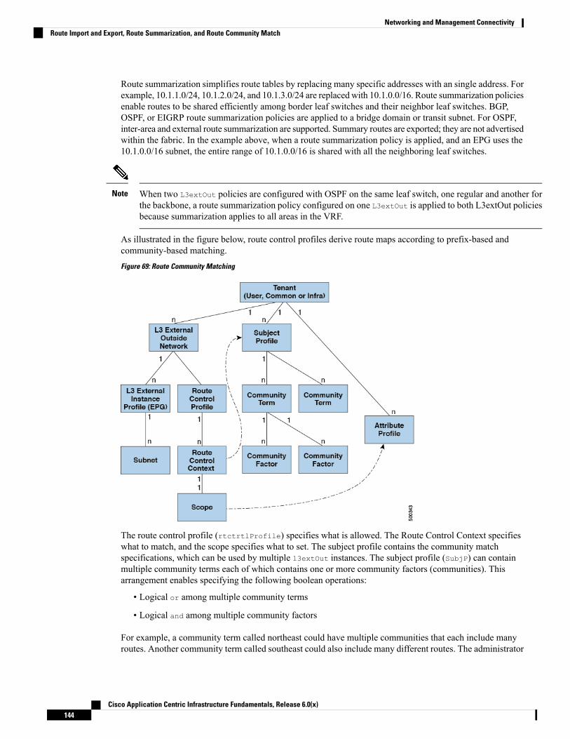
Route summarization simplifies route tables by replacing many specific addresses with an single address. Forexample, 10.1.1.0/24, 10.1.2.0/24, and 10.1.3.0/24 are replaced with 10.1.0.0/16. Route summarization policiesenable routes to be shared efficiently among border leaf switches and their neighbor leaf switches. BGP,OSPF, or EIGRP route summarization policies are applied to a bridge domain or transit subnet. For OSPF,inter-area and external route summarization are supported. Summary routes are exported; they are not advertisedwithin the fabric. In the example above, when a route summarization policy is applied, and an EPG uses the10.1.0.0/16 subnet, the entire range of 10.1.0.0/16 is shared with all the neighboring leaf switches.
When two L3extOut policies are configured with OSPF on the same leaf switch, one regular and another forthe backbone, a route summarization policy configured on one L3extOut is applied to both L3extOut policiesbecause summarization applies to all areas in the VRF.
Note
As illustrated in the figure below, route control profiles derive route maps according to prefix-based andcommunity-based matching.
Figure 69: Route Community Matching
The route control profile (rtctrtlProfile) specifies what is allowed. The Route Control Context specifieswhat to match, and the scope specifies what to set. The subject profile contains the community matchspecifications, which can be used by multiple l3extOut instances. The subject profile (SubjP) can containmultiple community terms each of which contains one or more community factors (communities). Thisarrangement enables specifying the following boolean operations:
• Logical or among multiple community terms
• Logical and among multiple community factors
For example, a community term called northeast could have multiple communities that each include manyroutes. Another community term called southeast could also include many different routes. The administrator
Cisco Application Centric Infrastructure Fundamentals, Release 6.0(x)144
Networking and Management ConnectivityRoute Import and Export, Route Summarization, and Route Community Match
could choose to match one, or the other, or both. A community factor type can be regular or extended. Careshould be taken when using extended type community factors, to ensure there are no overlaps among thespecifications.
The scope portion of the route control profile references the attribute profile (rtctrlAttrP) to specify whatset-action to apply, such as preference, next hop, community, and so forth. When routes are learned from anl3extOut, route attributes can be modified.
The figure above illustrates the case where an l3extOut contains a rtctrtlProfile. A rtctrtlProfile canalso exist under the tenant. In this case, the l3extOut has an interleak relation policy (L3extRsInterleakPol)that associates it with the rtctrtlProfile under the tenant. This configuration enables reusing thertctrtlProfile for multiple l3extOut connections. It also enables keeping track of the routes the fabriclearns fromOSPF to which it gives BGP attributes (BGP is used within the fabric). A rtctrtlProfile definedunder an L3extOut has a higher priority than one defined under the tenant.
The rtctrtlProfile has two modes: combinable, and global. The default combinable mode combinespervasive subnets (fvSubnet) and external subnets (l3extSubnet) with the match/set mechanism to renderthe route map. The global mode applies to all subnets within the tenant, and overrides other policy attributesettings. A global rtctrtlProfile provides permit-all behavior without defining explicit (0/0) subnets. Aglobal rtctrtlProfile is used with non-prefix based match rules where matching is done using differentsubnet attributes such as community, next hop, and so on. Multiple rtctrtlProfile policies can be configuredunder a tenant.
rtctrtlProfile policies enable enhanced default import and default export route control. Layer 3 Outsidenetworks with aggregated import or export routes can have import/export policies that specify supporteddefault-export and default–import, and supported 0/0 aggregation policies. To apply a rtctrtlProfile policyon all routes (inbound or outbound), define a global default rtctrtlProfile that has no match rules.
While multiple l3extOut connections can be configured on one switch, all Layer 3 outside networks configuredon a switch must use the same rtctrtlProfile because a switch can have only one route map.
Note
The protocol interleak and redistribute policy controls externally learned route sharing with ACI fabric BGProutes. Set attributes are supported. Such policies are supported per L3extOut, per node, or per VRF. Aninterleak policy applies to routes learned by the routing protocol in the L3extOut. Currently, interleak andredistribute policies are supported for OSPF v2 and v3. A route control policy rtctrtlProfile has to bedefined as global when it is consumed by an interleak policy.
Shared Services Contracts UsageShared services enable communications across tenants while preserving the isolation and security policies ofthe tenants. A routed connection to an external network is an example of a shared service that multiple tenantsuse.
Follow these guidelines when configuring shared services contracts.
• For shared services that export subnets to different Virtual Routing and Forwarding (VRF) instances(also known as contexts or private networks), the subnet must be configured under an EPG, and the scopemust be set to Advertised Externally and Shared Between VRFs.
• Contracts are not needed for inter-bridge domain traffic when a VRF is unenforced.
• Contracts are needed for shared service inter-VRF traffic, even when a VRF is unenforced.
• The VRF of a provider EPG cannot be in unenforced mode while providing a shared service.
Cisco Application Centric Infrastructure Fundamentals, Release 6.0(x)145
Networking and Management ConnectivityShared Services Contracts Usage

• A shared service is supported only with non-overlapping and non-duplicate subnets. When configuringsubnets for shared services, follow these guidelines:
• Configure the subnet for a shared service provider under the EPG, not under the bridge domain.
• Subnets configured under an EPG that share the same VRFmust be disjointed and must not overlap.
• Subnets leaked from one VRF to another must be disjointed and must not overlap.
• Subnets leaked from multiple consumer networks into a VRF or vice versa must be disjointed andmust not overlap.
If two consumers are mistakenly configured with the same subnet, recover fromthis condition by removing the subnet configuration for both then reconfigurethe subnets correctly.
Note
• Do not configure a shared service with AnyToProv in the provider VRF. TheAPIC rejects this configurationand raises a fault.
• When a contract is configured between in-band and out-of-band EPGs, the following restrictions apply:
• Both EPGs should be in the same VRF.
• Ffilters apply only in the incoming direction.
• Layer 2 filters are not supported.
• QoS does not apply to in-band Layer 4 to Layer 7 services.
• Management statistics are not available.
• Shared services for CPU-bound traffic are not supported.
Shared Layer 3 OutA shared Layer 3 outside network (L3extOut) configuration provides routed connectivity to external networksas a shared service. An L3extOut profile (l3extInstP) EPG provides routed connectivity to external networks.It can be provisioned as a shared service in any tenant (user, common, infra, or mgmt). Prior to release 1.2(1x),this configuration was only supported in the user and common tenants. An EPG in any tenant can use a sharedservices contract to connect with an l3extInstP EPG regardless of where in the fabric that l3extInstP EPGis provisioned. This simplifies the provisioning of routed connectivity to external networks; multiple tenantscan share a single l3extInstP EPG for routed connectivity to external networks. Sharing an l3extInstP EPGis more efficient because it consumes only one session on the switch regardless of how many EPGs use thesingle shared l3extInstP EPG.
All switches that will use l3extInstP EPG shared service contracts require the hardware and software supportavailable starting with the APIC 1.2(1x) and switch 11.2(1x) releases. Refer to the Cisco APIC Management,Installation, Upgrade, and Downgrade Guide and Release Notes documentation for more details.
Note
The figure below illustrates the major policy model objects that are configured for a shared l3extInstP EPG.
Cisco Application Centric Infrastructure Fundamentals, Release 6.0(x)146
Networking and Management ConnectivityShared Layer 3 Out

Figure 70: Shared Layer 3 Out Policy Model
Take note of the following guidelines and limitations for shared Layer 3 outside network configurations:
• No tenant limitations: Tenants A and B can be any kind of tenant (user, common, infra, mgmt.). Theshared l3extInstP EPG does not have to be in the common tenant.
• Flexible placement of EPGs: EPG A and EPG B in the illustration above are in different tenants. EPGA and EPG B could use the same bridge domain and VRF, but they are not required to do so. EPG Aand EPG B are in different bridge domains and different VRFs but still share the same l3extInstP EPG.
• A subnet can be private, public, or shared. A subnet that is to be advertised into a consumer or providerEPG of an L3extOut must be set to shared. A subnet that is to be exported to an L3extOut must be setto public.
• The shared service contract is exported from the tenant that contains the l3extInstP EPG that providesshared Layer 3 outside network service. The shared service contract is imported into the tenants thatcontain the EPGs that consume the shared service.
• Do not use taboo contracts with a shared L3 out; this configuration is not supported.
• The l3extInstP as a shared service provider is supported, but only with non l3extInstP consumers (wherethe L3extOut EPG is the same as the l3extInstP).
• Traffic Disruption (Flap): When an l3instP EPG is configured with an external subnet of 0.0.0.0/0 withthe scope property of the l3instP subnet set to shared route control (shared-rctrl), or shared security(shared-security), the VRF is redeployed with a global pcTag. This will disrupt all the external traffic inthat VRF (because the VRF is redeployed with a global pcTag).
• Prefixes for a shared L3extOut must to be unique. Multiple shared L3extOut configurations with thesame prefix in the same VRF will not work. Be sure that the external subnets (external prefixes) that areadvertised into a VRF are unique (the same external subnet cannot belong to multiple l3instPs). AnL3extOut configuration (for example, named L3Out1) with prefix1 and a second Layer 3 outside
Cisco Application Centric Infrastructure Fundamentals, Release 6.0(x)147
Networking and Management ConnectivityShared Layer 3 Out
configuration (for example, named L3Out2) also with prefix1 belonging to the same VRF will not work(because only 1 pcTag is deployed). Different behaviors of L3extOut are possible when configured onthe same leaf switch under the same VRF. The two possible scenarios are as follows:
• Scenario 1 has an L3extOut with an SVI interface and two subnets (10.10.10.0/24 and 0.0.0.0/0)defined. If ingress traffic on the Layer 3 outside network has the matching prefix 10.10.10.0/24,then the ingress traffic uses the External EPG pcTag. If ingress traffic on the Layer 3 Outside networkhas the matching default prefix 0.0.0.0/0, then the ingress traffic uses the External Bridge pcTag.
• Scenario 2 has an L3extOut using a routed or routed-sub-interface with two subnets (10.10.10.0/24and 0.0.0.0/0) defined. If ingress traffic on the Layer 3 outside network has the matching prefix10.10.10.0/24, then the ingress traffic uses the External EPG pcTag. If ingress traffic on the Layer3 outside network has the matching default prefix 0.0.0.0/0, then the ingress traffic uses the VRFpcTag.
• As a result of these described behaviors, the following use cases are possible if the same VRF andsame leaf switch are configured with L3extOut-A and L3extOut-B using an SVI interface:
Case 1 is for L3extOut-A: This External Network EPG has two subnets defined: 10.10.10.0/24 &0.0.0.0/1. If ingress traffic on L3extOut-A has the matching prefix 10.10.10.0/24, it uses the externalEPG pcTag & contract-A which is associated with L3extOut-A.When egress traffic on L3extOut-Ahas no specific match found, but there is a maximum prefix match with 0.0.0.0/1, it uses the ExternalBridge Domain (BD) pcTag & contract-A.
Case 2 is for L3extOut-B: This External Network EPG has one subnet defined: 0.0.0.0/0. Wheningress traffic on L3extOut-B has the matching prefix10.10.10.0/24 (which is definedunderL3extOut-A), it uses the External EPG pcTag of L3extOut-A and the contract-A which is tiedwith L3extOut-A. It does not use contract-B which is tied with L3extOut-B.
• Traffic not permitted: Traffic is not permitted when an invalid configuration sets the scope of the externalsubnet to shared route control (shared-rtctrl) as a subset of a subnet that is set to shared security(shared-security). For example, the following configuration is invalid:
• shared rtctrl: 10.1.1.0/24, 10.1.2.0/24
• shared security: 10.1.0.0/16
In this case, ingress traffic on a non-border leaf with a destination IP of 10.1.1.1 is dropped, since prefixes10.1.1.0/24 and 10.1.2.0/24 are installed with a drop rule. Traffic is not permitted. Such traffic can beenabled by revising the configuration to use the shared-rtctrl prefixes as shared-security prefixes aswell.
• Inadvertent traffic flow: Prevent inadvertent traffic flow by avoiding the following configuration scenarios:
• Case 1 configuration details:
• A Layer 3 outside network configuration (for example, named L3extOut-1) with VRF1 is calledprovider1.
• A second Layer 3 outside network configuration (for example, named L3extOut-2) with VRF2is called provider2.
• L3extOut-1 VRF1 advertises a default route to the Internet, 0.0.0.0/0 which enables bothshared-rtctrl and shared-security.
• L3extOut-2 VRF2 advertises specific subnets to DNS and NTP, 192.0.0.0/8 which enablesshared-rtctrl.
Cisco Application Centric Infrastructure Fundamentals, Release 6.0(x)148
Networking and Management ConnectivityShared Layer 3 Out

• L3extOut-2 VRF2 has specific subnet 192.1.0.0/16, which enables shared-security.
• Variation A: EPG Traffic Goes to Multiple VRFs.
• Communications between EPG1 and L3extOut-1 is regulated by an allow_all contract.
• Communications between EPG1 and L3extOut-2 is regulated by an allow_all contract.
Result: Traffic from EPG1 to L3extOut-2 also goes to 192.2.x.x.
• Variation B: An EPG conforms to the allow_all contract of a second shared Layer 3 outsidenetwork.
• Communications between EPG1 and L3extOut-1 is regulated by an allow_all contract.
• Communications between EPG1 and L3extOut-2 is regulated by an allow_icmp contract.
Result: Traffic from EPG1 to L3extOut-2 to 192.2.x.x conforms to the allow_all contract.
• Case 2 configuration details:
• A L3extOut profile (l3instP) has one shared prefix and other non-shared prefixes.
• Traffic coming in with src = non-shared is allowed to go to the EPG
• Variation A: Unintended traffic goes through an EPG.
L3extOut (l3instP) EPG traffic goes through a L3extOut that has these prefixes:
- 192.0.0.0/8 = import-security, shared-rtctrl
- 192.1.0.0/16 = shared-security
- The EPG has 1.1.0.0/16 = shared
Result: Traffic going from 192.2.x.x also goes through to the EPG.
• Variation B: Unintended traffic goes through an EPG. Traffic coming in a shared L3extOutcan go through the EPG.
- The shared L3extOut VRF has an EPG with pcTag = prov vrf and a contract set toallow_all
- The EPG <subnet> = shared.
Result: The traffic coming in on the Layer 3 out can go through the EPG.
Bidirectional Forwarding DetectionUse Bidirectional Forwarding Detection (BFD) to provide sub-second failure detection times in the forwardingpath between ACI fabric border leaf switches configured to support peering router connections.
BFD is particularly useful in the following scenarios:
• When the peering routers are connected through a Layer 2 device or a Layer 2 cloud where the routersare not directly connected to each other. Failures in the forwarding path may not be visible to the peerrouters. The only mechanism available to control protocols is the hello timeout, which can take tens ofseconds or even minutes to time out. BFD provides sub-second failure detection times.
Cisco Application Centric Infrastructure Fundamentals, Release 6.0(x)149
Networking and Management ConnectivityBidirectional Forwarding Detection

• When the peering routers are connected through a physical media that does not support reliable failuredetection, such as shared Ethernet. In this case too, routing protocols have only their large hello timersto fall back on.
• When many protocols are running between a pair of routers, each protocol has its own hello mechanismfor detecting link failures, with its own timeouts. BFD provides a uniform timeout for all the protocols,which makes convergence time consistent and predictable.
Observe the following BFD guidelines and limitations:
• Beginning with APIC Release 3.1(1), BFD between leaf and spine switches is supported onfabric-interfaces for IS-IS. In addition, BFD feature on spine switch is supported for OSPF and staticroutes.
• Beginning with Cisco APIC release 5.2(4), the BFD feature is supported for static routes that are reachableusing secondary IPv4/IPv6 subnets that are configured on routed interfaces. Static BFD session cannotbe sourced from a secondary subnet of L3Out interface if there are more than one addresses configuredin the subnet. Shared subnet address (used for vPC scenario) and floating IP address used for floatingL3Out are allowed as additional addresses in the subnet and are automatically skipped, and are not usedto source static BFD session.
Modifying the secondary address that is being used for sourcing the session isallowed by adding a new address in the same subnet and later removing theprevious one.
Note
• BFD is supported on modular spine switches that have -EX and -FX line cards (or newer versions), andBFD is also supported on the Nexus 9364C non-modular spine switch (or newer versions).
• BFD between VPC peers is not supported.
• Beginning with APIC Release 5.0(1), BFDmultihop is supported on leaf switches. Themaximum numberof BFD sessions is unchanged, as BFD multihop sessions are now included in the total.
• Beginning with APIC Release 5.0(1), ACI supports C-bit-aware BFD. The C-bit on incoming BFDpackets determines whether BFD is dependent or independent of the control plane.
• BFD over iBGP is not supported for loopback address peers.
• BFD sub interface optimization can be enabled in an interface policy. One sub-interface having this flagwill enable optimization for all the sub-interfaces on that physical interface.
• BFD for BGP prefix peer not supported.
Cisco Application Centric Infrastructure Fundamentals, Release 6.0(x)150
Networking and Management ConnectivityBidirectional Forwarding Detection
Cisco ACI does not support IP fragmentation. Therefore, when you configure Layer 3 Outside (L3Out)connections to external routers, or Multi-Pod connections through an Inter-Pod Network (IPN), it isrecommended that the interface MTU is set appropriately on both ends of a link. On some platforms, such asCisco ACI, Cisco NX-OS, and Cisco IOS, the configurableMTU value does not take into account the Ethernetheaders (matching IP MTU, and excluding the 14-18 Ethernet header size), while other platforms, such asIOS-XR, include the Ethernet header in the configured MTU value. A configured value of 9000 results in amax IP packet size of 9000 bytes in Cisco ACI, Cisco NX-OS, and Cisco IOS, but results in a max IP packetsize of 8986 bytes for an IOS-XR untagged interface.
For the appropriate MTU values for each platform, see the relevant configuration guides.
We highly recommend that you test the MTU using CLI-based commands. For example, on the Cisco NX-OSCLI, use a command such as ping 1.1.1.1 df-bit packet-size 9000 source-interface ethernet 1/1.
Note
ACl IP SLAsMany companies conduct most of their business online and any loss of service can affect their profitability.Internet service providers (ISPs) and even internal IT departments now offer a defined level of service, aservice level agreement (SLA), to provide their customers with a degree of predictability.
IP SLA tracking is a common requirement in networks. IP SLA tracking allows a network administrator tocollect information about network performance in real time. With the Cisco ACI IP SLA, you can track anIP address using ICMP and TCP probes. Tracking configurations can influence route tables, allowing forroutes to be removed when tracking results come in negative and returning the route to the table when theresults become positive again.
ACI IP SLAs are available for the following:
• Static routes:
• New in ACI 4.1
• Automatically remove or add a static route from/to a route table
• Track the route using ICMP and TCP probes
• Policy-based redirect (PBR) tracking:
• Available since ACI 3.1
• Automatically remove or add a next -hop
• Track the next-hop IP address using ICMP and TCP probes, or a combination using L2Ping
• Redirect traffic to the PBR node based on the reachability of the next-hop
For more information about PBR tracking, see Configuring Policy-Based Redirect in the Cisco APIC Layer4 to Layer 7 Services Deployment Guide.
For either feature, you can perform a network action based on the results of the probes, including configuration,using APIs, or running scripts.
Note
Cisco Application Centric Infrastructure Fundamentals, Release 6.0(x)151
Networking and Management ConnectivityACl IP SLAs

ACI IP SLA Supported Topologies
The following ACI fabric topologies support IP SLA:
• Single Fabric: IP SLA tracking is supported for IP address reachable through both L3out and EPG/BD
• Multi-Pod
• You can define a single object tracking policy across different Pods.
• A workload can move from one Pod to another. The IP SLA policy continues to check accessibilityinformation and detects if an endpoint has moved.
• If an endpoint moves to another Pod, IP SLA tracking is moved to the other Pod as well, so thattracking information is not passed through the IP network.
• Remote Leaf
• You can define single object tracking policies across ACI main data center and the remote leafswitch.
• IP SLA probes on remote leaf switches track IP addresses locally without using the IP network.
• A workload can move from one local leaf to a remote leaf. The IP SLA policy continues to checkaccessibility information and detects if an endpoint has moved.
• IP SLA policies move to the remote leaf switches or ACI main data center, based on the endpointlocation, for local tracking, so that tracking traffic is not passed through the IP network.
Layer 3 Multicast
Prior to Cisco APIC release 4.2(1), Cisco ACI had support for Layer 3 multicast IPv4. Cisco APIC release4.2(1) adds support to connect multicast applications using IPv6 multicast, where you can use IPv6 multicastto enable IPv6 multicast applications to send multicast over IPv6 from senders in the Cisco ACI fabric toexternal receivers.
The information in this chapter has been updated to reflect this additional support for Layer 3 IPv6 multicast.
Note
In the ACI fabric, most unicast and IPv4/IPv6 multicast routing operate together on the same border leafswitches, with the IPv4/IPv6 multicast protocol operating over the unicast routing protocols.
In this architecture, only the border leaf switches run the full Protocol Independent Multicast (PIM) or PIM6protocol. Non-border leaf switches run PIM/PIM6 in a passive mode on the interfaces. They do not peer withany other PIM/PIM6 routers. The border leaf switches peer with other PIM/PIM6 routers connected to themover L3 Outs and also with each other.
The following figure shows border leaf switch 1 and border leaf switch 2 connecting to router 1 and router 2in the IPv4/IPv6 multicast cloud. Each virtual routing and forwarding (VRF) in the fabric that requiresIPv4/IPv6 multicast routing will peer separately with external IPv4/IPv6 multicast routers.
Cisco Application Centric Infrastructure Fundamentals, Release 6.0(x)152
Networking and Management ConnectivityLayer 3 Multicast

Figure 71: Overview of Multicast Cloud
About the Fabric InterfaceThe fabric interface is a virtual interface between software modules and represents the fabric for IPv4/IP6multicast routing. The interface takes the form of a tunnel interface with the tunnel destination being the VRFGIPo (Group IP outer address)1. PIM6 shares the same tunnel that PIM4 uses. For example, if a border leafis the designated forwarder responsible for forwarding traffic for a group, then the fabric interface would bein the outgoing interface (OIF) list for the group. There is no equivalent for the interface in hardware. Theoperational state of the fabric interface should follow the state published by the intermediatesystem-to-intermediate system (IS-IS).
Each multicast-enabled VRF requires one or more border leaf switches configured with a loopback interface.You must configure a unique IPv4 loopback address on all nodes in a PIM-enabled L3Out. The Router-IDloopback or another unique loopback address can be used.
Note
Any loopback configured for unicast routing can be reused. This loopback address must be routed from theexternal network and will be injected into the fabricMP-BGP (Multiprotocol Border Gateway Protocol) routes
1 The GIPo (Group IP outer address) is the destination multicast IP address used in the outer IP header of the VXLAN packet for all multi-destination packets(Broadcast, Unknown unicast, and Multicast) packets forwarded within the fabric.
Cisco Application Centric Infrastructure Fundamentals, Release 6.0(x)153
Networking and Management ConnectivityAbout the Fabric Interface

for the VRF. The fabric interface source IP will be set to this loopback as the loopback interface. The followingfigure shows the fabric for IPv4/IP6 multicast routing.
Figure 72: Fabric for IPv4/IP6 Multicast Routing
Enabling IPv4/IPv6 Multicast RoutingThe process to enable or disable IPv4 or IPv6 multicast routing in a Cisco ACI fabric occurs at three levels:
• VRF level: Enable multicast routing at the VRF level.
• L3Out level: Enable PIM/PIM6 for one or more L3Outs configured in the VRF.
• Bridge domain level: Enable PIM/PIM6 for one or more bridge domains where multicast routing isneeded.
At the top level, IPv4/IPv6multicast routingmust be enabled on the VRF that has anymulticast routing-enabledbridge domains. On an IPv4/IPv6 multicast routing-enabled VRF, there can be a combination of IPv4/IPv6multicast routing-enabled bridge domains and bridge domains where IPv4/IPv6 multicast routing is disabled.A bridge domain with IPv4/IPv6 multicast routing disabled will not show on the VRF IPv4/IPv6 multicastpanel. An L3Out with IPv4/IPv6 multicast routing-enabled will show up on the panel, but any bridge domainthat has IPv4/IPv6 multicast routing enabled will always be a part of a VRF that has IPv4/IPv6 multicastrouting enabled.
IPv4/IPv6 multicast routing is not supported on the leaf switches such as Cisco Nexus 93128TX, 9396PX,and 9396TX. All the IPv4/IPv6multicast routing and any IPv4/IPv6multicast-enabledVRF should be deployedonly on the switches with -EX and -FX in their product IDs.
Layer 3 Out ports and sub-interfaces are supported. Support for external SVIs varies, depending on the release:
• For releases prior to release 5.2(3), external SVIs are not supported. Since external SVIs are not supportedin releases prior to 5.2(3), PIM/PIM6 cannot be enabled in L3-VPC in those releases.
• Beginning with release 5.2(3), support is available for Layer 3 multicast on an SVI L3Out. PIM issupported on SVI L3Outs for physical ports and port-channels but not for vPCs.
Note
Cisco Application Centric Infrastructure Fundamentals, Release 6.0(x)154
Networking and Management ConnectivityEnabling IPv4/IPv6 Multicast Routing

Guidelines, Limitations, and Expected Behaviors for Configuring Layer 3IPv4/IPv6 Multicast
See the following guidelines and restrictions:
• Guidelines and Limitations for IPv4 and IPv6 Multicast, on page 155
• Guidelines and Limitations for IPv4 Multicast, on page 156
• Guidelines and Limitations for IPv6 Multicast, on page 157
Guidelines and Limitations for IPv4 and IPv6 Multicast
The following restrictions apply for both IPv4 and IPv6 multicast:
• The Layer 3 IPv4/IPv6 multicast feature is supported on second generation leaf switches. A secondgeneration switch is one with -EX, -FX, -FX2, -FX3, -GX, or any later suffix in the product ID.
• Custom QoS policy is not supported for Layer 3 multicast traffic sourced from outside the CiscoApplication Centric Infrastructure (ACI) fabric (received from L3Out).
• Enabling PIMv4/PIM6 and Advertise Host routes on a bridge domain is supported.
• Layer 3 multicast is enabled at the VRF level and the multicast protocols will function within the VRFinstance. Each VRF instance can have multicast enabled or disabled independently.
• After a VRF instance is enabled for multicast, the individual bridge domains and L3Outs under theenabled VRF instance can be enabled for multicast configuration. By default, multicast is disabled in allbridge domains and L3Outs.
• Bidirectional PIMv4/PIM6 is currently not supported.
• Multicast routers are not supported in pervasive bridge domains.
• The supported route scale is 2,000. The multicast scale number is a combined scale that includes bothIPv4 and IPv6. The total route limit is defined as route counts. Each IPv4 route is counted as 1, and eachIPv6 route is counted as 4. Even with node profiles that support more multicast scales, the IPv6 routescale will remain at 2,000.
• PIMv4/PIM6 is supported on Layer 3 Out routed interfaces and routed subinterfaces including Layer 3port-channel interfaces. PIMv4/PIM6 is not supported on Layer 3 Out SVI interfaces.
• Enabling PIMv4/PIM6 on an L3Out causes an implicit external network to be configured. This actionresults in the L3Out being deployed and protocols potentially coming up even if you have not definedan external network.
• If the multicast source is connected to Leaf-A as an orphan port and you have an L3Out on Leaf-B, andLeaf-A and Leaf-B are in a vPC pair, the EPG encapsulation VLAN tied to the multicast source willneed to be deployed on Leaf-B.
• The behavior of an ingress leaf switch receiving a packet from a source that is attached to a bridge domaindiffers for Layer 3 IPv4 or IPv6 multicast support:
• For Layer 3 IPv4 multicast support, when the ingress leaf switch receives a packet from a sourcethat is attached on a bridge domain, and the bridge domain is enabled for IPv4 multicast routing,the ingress leaf switch sends only a routed VRF instance copy to the fabric (routed implies that theTTL is decremented by 1, and the source-mac is rewritten with a pervasive subnetMAC). The egress
Cisco Application Centric Infrastructure Fundamentals, Release 6.0(x)155
Networking and Management ConnectivityGuidelines, Limitations, and Expected Behaviors for Configuring Layer 3 IPv4/IPv6 Multicast

leaf switch also routes the packet into receivers in all the relevant bridge domains. Therefore, if areceiver is on the same bridge domain as the source, but on a different leaf switch than the source,that receiver continues to get a routed copy, although it is in the same bridge domain. This alsoapplies if the source and receiver are on the same bridge domain and on the same leaf switch, ifPIM is enabled on this bridge domain.
For more information, see details about Layer 3 multicast support for multipod that leverages existingLayer 2 design, at the following link Adding Pods.
• For Layer 3 IPv6 multicast support, when the ingress leaf switch receives a packet from a sourcethat is attached on a bridge domain, and the bridge domain is enabled for IPv6 multicast routing,the ingress leaf switch sends only a routed VRF instance copy to the fabric (routed implies that theTTL is decremented by 1, and the source-mac is rewritten with a pervasive subnetMAC). The egressleaf switch also routes the packet into receivers. The egress leaf also decrements the TTL in thepacket by 1. This results in TTL being decremented two times. Also, for ASM the multicast groupmust have a valid RP configured.
• You cannot use a filter with inter-VRF multicast communication.
Cisco ACI does not support IP fragmentation. Therefore, when you configure Layer 3 Outside (L3Out)connections to external routers, or Multi-Pod connections through an Inter-Pod Network (IPN), it isrecommended that the interface MTU is set appropriately on both ends of a link. On some platforms, such asCisco ACI, Cisco NX-OS, and Cisco IOS, the configurableMTU value does not take into account the Ethernetheaders (matching IP MTU, and excluding the 14-18 Ethernet header size), while other platforms, such asIOS-XR, include the Ethernet header in the configured MTU value. A configured value of 9000 results in amax IP packet size of 9000 bytes in Cisco ACI, Cisco NX-OS, and Cisco IOS, but results in a max IP packetsize of 8986 bytes for an IOS-XR untagged interface.
For the appropriate MTU values for each platform, see the relevant configuration guides.
We highly recommend that you test the MTU using CLI-based commands. For example, on the Cisco NX-OSCLI, use a command such as ping 1.1.1.1 df-bit packet-size 9000 source-interface ethernet 1/1.
Note
Guidelines and Limitations for IPv4 Multicast
The following restrictions apply specifically for IPv4 multicast:
• If the border leaf switches in your Cisco ACI fabric are running multicast and you disable multicast onthe L3Out while you still have unicast reachability, you will experience traffic loss if the external peeris a Cisco Nexus 9000 switch. This impacts cases where traffic is destined towards the fabric (where thesources are outside the fabric but the receivers are inside the fabric) or transiting through the fabric (wherethe source and receivers are outside the fabric, but the fabric is transit).
• Any Source Multicast (ASM) and Source-Specific Multicast (SSM) are supported for IPv4.
• You can configure a maximum of four ranges for SSM multicast in the route map per VRF instance.
• IGMP snooping cannot be disabled on pervasive bridge domains with multicast routing enabled.
• Starting with Release 3.1(1x), Layer 3 multicast is supported with FEX. Multicast sources or receiversthat are connected to FEX ports are supported. For further details about how to add FEX in your testbed,see Configure a Fabric Extender with Application Centric Infrastructure at this URL:
Cisco Application Centric Infrastructure Fundamentals, Release 6.0(x)156
Networking and Management ConnectivityGuidelines, Limitations, and Expected Behaviors for Configuring Layer 3 IPv4/IPv6 Multicast

https://www.cisco.com/c/en/us/support/docs/cloud-systems-management/application-policy-infrastructure-controller-apic/200529-Configure-a-Fabric-Extender-with-Applica.html.For releases preceeding Release 3.1(1x), Layer 3 multicast is not supported with FEX. Multicast sourcesor receivers that are connected to FEX ports are not supported.
Guidelines and Limitations for IPv6 Multicast
The following restrictions apply specifically for IPv6 multicast:
• Source Specific Multicast (SSM) is supported, but RFC 3306 - Unicast-Prefix-based IPv6 MulticastAddresses specifies a fixed SSM range. Therefore, the SSM range cannot be changed in IPv6.
• You can configure a maximum of four ranges for SSM multicast in the route map per VRF instance.
• Any Source Multicast (ASM) is supported for IPv6.
• OIF and VRF scale numbers for IPv6 are the same as they are for IPv4.
• For PIM6 only static RP configuration is supported. Auto-RP and BSR are not supported for PIM6.
• Receivers inside the fabric are not supported. MLD Snoop Policy must be disabled when enabling IPv6multicast. MLD snooping and PIM6 cannot be enabled in the same VRF instance.
• Currently, Layer 3 Multicast Listener Discovery (MLD) is not supported with Cisco ACI.
• Fabric Rendezvous Point (RP) is not supported for IPv6 multicast.
• Cisco Multi-Site Orchestrator support is not available.
Cisco ACI GOLFThe Cisco ACI GOLF feature (also known as Layer 3 EVPN Services for Fabric WAN) enables much moreefficient and scalable ACI fabric WAN connectivity. It uses the BGP EVPN protocol over OSPF for WANrouters that are connected to spine switches.
Cisco Application Centric Infrastructure Fundamentals, Release 6.0(x)157
Networking and Management ConnectivityCisco ACI GOLF
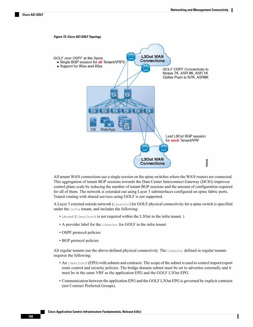
Figure 73: Cisco ACI GOLF Topology
All tenantWAN connections use a single session on the spine switches where theWAN routers are connected.This aggregation of tenant BGP sessions towards the Data Center Interconnect Gateway (DCIG) improvescontrol plane scale by reducing the number of tenant BGP sessions and the amount of configuration requiredfor all of them. The network is extended out using Layer 3 subinterfaces configured on spine fabric ports.Transit routing with shared services using GOLF is not supported.
A Layer 3 external outside network (L3extOut) for GOLF physical connectivity for a spine switch is specifiedunder the infra tenant, and includes the following:
• LNodeP (l3extInstP is not required within the L3Out in the infra tenant. )
• A provider label for the L3extOut for GOLF in the infra tenant.
• OSPF protocol policies
• BGP protocol policies
All regular tenants use the above-defined physical connectivity. The L3extOut defined in regular tenantsrequires the following:
• An l3extInstP (EPG) with subnets and contracts. The scope of the subnet is used to control import/exportroute control and security policies. The bridge domain subnet must be set to advertise externally and itmust be in the same VRF as the application EPG and the GOLF L3Out EPG.
• Communication between the application EPG and the GOLF L3Out EPG is governed by explicit contracts(not Contract Preferred Groups).
Cisco Application Centric Infrastructure Fundamentals, Release 6.0(x)158
Networking and Management ConnectivityCisco ACI GOLF

• An l3extConsLbl consumer label that must be matched with the same provider label of an L3Out forGOLF in the infra tenant. Label matching enables application EPGs in other tenants to consume theLNodeP external L3Out EPG.
• The BGP EVPN session in the matching provider L3extOut in the infra tenant advertises the tenantroutes defined in this L3Out.
Guidelines and Limitations
Observe the following GOLF guidelines and limitations:
• GOLF routers must advertise at least one route to Cisco ACI in order to accept traffic. No tunnel iscreated between leaf switches and the external routers until Cisco ACI receives a route from the externalrouters.
• All Cisco Nexus 9000 Series ACI-mode switches and all of the Cisco Nexus 9500 platform ACI-modeswitch line cards and fabric modules support GOLF. With Cisco APIC, release 3.1(x) and higher, thisincludes the N9K-C9364C switch.
• At this time, only a single GOLF provider policy can be deployed on spine switch interfaces for thewhole fabric.
• Up to APIC release 2.0(2), GOLF is not supported with multipod. In release 2.0 (2) the two features aresupported in the same fabric only over Cisco Nexus N9000K switches without “EX” on the end of theswitch name; for example, N9K-9312TX. Since the 2.1(1) release, the two features can be deployedtogether over all the switches used in the multipod and EVPN topologies.
• When configuring GOLF on a spine switch, wait for the control plane to converge before configuringGOLF on another spine switch.
• A spine switch can be added to multiple provider GOLF outside networks (GOLF L3Outs), but theprovider labels have to be different for each GOLF L3Out. Also, in this case, the OSPF Area has to bedifferent on each of the L3extOuts and use different loopback addresses.
• The BGP EVPN session in the matching provider L3Out in the infra tenant advertises the tenant routesdefined in this L3extOut.
• When deploying three GOLF Outs, if only 1 has a provider/consumer label for GOLF, and 0/0 exportaggregation, APIC will export all routes. This is the same as existing L3extOut on leaf switches fortenants.
• If there is direct peering between a spine switch and a data center interconnect (DCI) router, the transitroutes from leaf switches to the ASR have the next hop as the PTEP of the leaf switch. In this case, definea static route on the ASR for the TEP range of that ACI pod. Also, if the DCI is dual-homed to the samepod, then the precedence (administrative distance) of the static route should be the same as the routereceived through the other link.
• The default bgpPeerPfxPol policy restricts routes to 20, 000. For ACIWAN Interconnect peers, increasethis as needed.
• In a deployment scenario where there are two L3extOuts on one spine switch, and one of them has theprovider label prov1 and peers with the DCI 1, the second L3extOut peers with DCI 2 with providerlabel prov2. If the tenant VRF has a consumer label pointing to any 1 of the provider labels (either prov1or prov2), the tenant route will be sent out both DCI 1 and DCI 2.
Cisco Application Centric Infrastructure Fundamentals, Release 6.0(x)159
Networking and Management ConnectivityCisco ACI GOLF
• When aggregating GOLF OpFlex VRFs, the leaking of routes cannot occur in the ACI fabric or on theGOLF device between the GOLF OpFlex VRF and any other VRF in the system. An external device(not the GOLF router) must be used for the VRF leaking.
Cisco ACI does not support IP fragmentation. Therefore, when you configure Layer 3 Outside (L3Out)connections to external routers, or Multi-Pod connections through an Inter-Pod Network (IPN), it isrecommended that the interface MTU is set appropriately on both ends of a link. On some platforms, such asCisco ACI, Cisco NX-OS, and Cisco IOS, the configurableMTU value does not take into account the Ethernetheaders (matching IP MTU, and excluding the 14-18 Ethernet header size), while other platforms, such asIOS-XR, include the Ethernet header in the configured MTU value. A configured value of 9000 results in amax IP packet size of 9000 bytes in Cisco ACI, Cisco NX-OS, and Cisco IOS, but results in a max IP packetsize of 8986 bytes for an IOS-XR untagged interface.
For the appropriate MTU values for each platform, see the relevant configuration guides.
We highly recommend that you test the MTU using CLI-based commands. For example, on the Cisco NX-OSCLI, use a command such as ping 1.1.1.1 df-bit packet-size 9000 source-interface ethernet 1/1.
Note
Route Target filteringRoute target filtering is the practice of optimizing BGP routing tables by filtering the routes that are storedon them. This action can be accomplished by explicit route target policy or by automated algorithm.
Route Target Policy
A route target policy explicitly defines the BGP routes that can be shared between VRFs. It specifies whichlocal routes can be exported from the local VRF to another and specifies which routes can be imported intothe local VRF from external VRFs.
Within APIC, route target policies can be specified during creation or configuration of a VRF. which can inturn be associated with an L3 Out policy to define BGP route sharing associated with that policy.
Auto Route Target filtering
Auto route target filtering implements an automated algorithm for optimizing BGP routing tables for maximumoverall efficiency, conserving memory by filtering out storage of all imported BGP route targets except forthose associated with directly connected VPNs.
When a VRF receives a BGP VPN-IPv4 or VPN-IPv6 route target from another Policy Element (PE) router,BGP stores that route target in its local routing table only if at least one VRF imports a route target of thatroute. If no VRF imports any of the route targets of the route, BGP discards the route target; The intention isthat BGP keeps track of route targets only for directly connected VPNs, and discards all other VPN-IPv4 orVPN-IPv6 route targets to conserve memory.
If a new VPN is connected to the router (that is, if the import route-target list of a VRF changes), BGPautomatically sends a route-refresh message to obtain the routes that it previously discarded.
Cisco Application Centric Infrastructure Fundamentals, Release 6.0(x)160
Networking and Management ConnectivityRoute Target filtering

Distributing BGP EVPN Type-2 Host Routes to a DCIGIn APIC up to release 2.0(1f), the fabric control plane did not send EVPN host routes directly, but advertisedpublic bridge domain (BD) subnets in the form of BGP EVPN type-5 (IP Prefix) routes to a Data CenterInterconnect Gateway (DCIG). This could result in suboptimal traffic forwarding. To improve forwarding,in APIC release 2.1x, you can enable fabric spines to also advertise host routes using EVPN type-2 (MAC-IP)host routes to the DCIG along with the public BD subnets.
To do so, you must perform the following steps:
1. When you configure the BGP Address Family Context Policy, enable Host Route Leak.
2. When you leak the host route to BGP EVPN in a GOLF setup:
a. To enable host routes when GOLF is enabled, the BGP Address Family Context Policy must beconfigured under the application tenant (the application tenant is the consumer tenant that leaks theendpoint to BGP EVPN) rather than under the infrastructure tenant.
b. For a single-pod fabric, the host route feature is not required. The host route feature is required toavoid sub-optimal forwarding in a multi-pod fabric setup. However, if a single-pod fabric is setup,then in order to leak the endpoint to BGP EVPN, a Fabric External Connection Policy must beconfigured to provide the ETEP IP address. Otherwise, the host route will not leak to BGP EVPN.
3. When you configure VRF properties:
a. Add the BGP Address Family Context Policy to the BGP Context Per Address Families for IPv4 andIPv6.
b. Configure BGP Route Target Profiles that identify routes that can be imported or exported from theVRF.
MultipodMultipod enables provisioning a more fault tolerant fabric comprised of multiple pods with isolated controlplane protocols. Also, multipod provides more flexibility with regard to the full mesh cabling between leafand spine switches. For example, if leaf switches are spread across different floors or different buildings,multipod enables provisioning multiple pods per floor or building and providing connectivity between podsthrough spine switches.
Multipod uses MP-BGP EVPN as the control-plane communication protocol between the ACI spines indifferent Pods.WAN routers can be provisioned in the IPN, directly connected to spine switches, or connectedto border leaf switches. Multipod uses a single APIC cluster for all the pods; all the pods act as a single fabric.Individual APIC controllers are placed across the pods but they are all part of a single APIC cluster.
Cisco Application Centric Infrastructure Fundamentals, Release 6.0(x)161
Networking and Management ConnectivityDistributing BGP EVPN Type-2 Host Routes to a DCIG
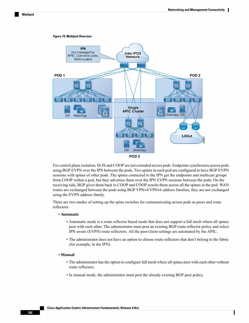
Figure 74: Multipod Overview
For control plane isolation, IS-IS and COOP are not extended across pods. Endpoints synchronize across podsusing BGP EVPN over the IPN between the pods. Two spines in each pod are configured to have BGP EVPNsessions with spines of other pods. The spines connected to the IPN get the endpoints and multicast groupsfrom COOP within a pod, but they advertise them over the IPN EVPN sessions between the pods. On thereceiving side, BGP gives them back to COOP and COOP synchs them across all the spines in the pod. WANroutes are exchanged between the pods using BGP VPNv4/VPNv6 address families; they are not exchangedusing the EVPN address family.
There are two modes of setting up the spine switches for communicating across pods as peers and routereflectors:
• Automatic
• Automatic mode is a route reflector based mode that does not support a full mesh where all spinespeer with each other. The administrator must post an existing BGP route reflector policy and selectIPN aware (EVPN) route reflectors. All the peer/client settings are automated by the APIC.
• The administrator does not have an option to choose route reflectors that don’t belong to the fabric(for example, in the IPN).
• Manual
• The administrator has the option to configure full mesh where all spines peer with each other withoutroute reflectors.
• In manual mode, the administrator must post the already existing BGP peer policy.
Cisco Application Centric Infrastructure Fundamentals, Release 6.0(x)162
Networking and Management ConnectivityMultipod
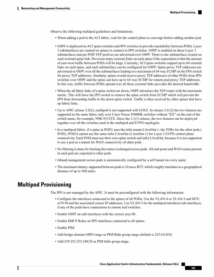
Observe the following multipod guidelines and limitations:
• When adding a pod to the ACI fabric, wait for the control plane to converge before adding another pod.
• OSPF is deployed on ACI spine switches and IPN switches to provide reachability between PODs. Layer3 subinterfaces are created on spines to connect to IPN switches. OSPF is enabled on these Layer 3subinterfaces and per POD TEP prefixes are advertised over OSPF. There is one subinterface created oneach external spine link. Provision many external links on each spine if the expectation is that the amountof east-west traffic between PODs will be large. Currently, ACI spine switches support up to 64 externallinks on each spine, and each subinterface can be configured for OSPF. Spine proxy TEP addresses areadvertised in OSPF over all the subinterfaces leading to a maximum of 64 way ECMP on the IPN switchfor proxy TEP addresses. Similarly, spines would receive proxy TEP addresses of other PODs from IPNswitches over OSPF and the spine can have up to 64 way ECMP for remote pod proxy TEP addresses.In this way, traffic between PODs spread over all these external links provides the desired bandwidth.
• When the all fabric links of a spine switch are down, OSPF advertises the TEP routes with the maximummetric. This will force the IPN switch to remove the spine switch from ECMP which will prevent theIPN from forwarding traffic to the down spine switch. Traffic is then received by other spines that haveup fabric links.
• Up to APIC release 2.0(2), multipod is not supported with GOLF. In release 2.0 (2) the two features aresupported in the same fabric only over Cisco Nexus N9000K switches without “EX” on the end of theswitch name; for example, N9K-9312TX. Since the 2.1(1) release, the two features can be deployedtogether over all the switches used in the multipod and EVPN topologies.
• In a multipod fabric, if a spine in POD1 uses the infra tenant L3extOut-1, the TORs for the other pods (POD2, POD3) cannot use the same infra L3extOut (L3extOut-1) for Layer 3 EVPN control planeconnectivity. Each POD must use their own spine switch and infra L3extOut, because it is not supportedto use a pod as a transit for WAN connectivity of other pods.
• No filtering is done for limiting the routes exchanged across pods. All end-point andWAN routes presentin each pod are exported to other pods.
• Inband management across pods is automatically configured by a self tunnel on every spine.
• Themaximum latency supported between pods is 10msec RTT, which roughly translates to a geographicaldistance of up to 500 miles.
Multipod ProvisioningThe IPN is not managed by the APIC. It must be preconfigured with the following information:
• Configure the interfaces connected to the spines of all PODs. Use the VLAN-4 or VLAN-5 and MTUof 9150 and the associated correct IP addresses. Use VLAN-5 for the multipod interfaces/sub-interfaces,if any of the pods have connections to remote leaf switches.
• Enable OSPF on sub-interfaces with the correct area ID.
• Enable DHCP Relay on IPN interfaces connected to all spines.
• Enable PIM.
• Add bridge domain GIPO range as PIM Bidir group range (default is 225.0.0.0/8).
• Add 239.255.255.240/28 as PIM bidir group range.
Cisco Application Centric Infrastructure Fundamentals, Release 6.0(x)163
Networking and Management ConnectivityMultipod Provisioning
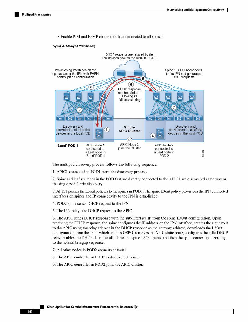
• Enable PIM and IGMP on the interface connected to all spines.
Figure 75: Multipod Provisioning
The multipod discovery process follows the following sequence:
1. APIC1 connected to POD1 starts the discovery process.
2. Spine and leaf switches in the POD that are directly connected to the APIC1 are discovered same way asthe single pod fabric discovery.
3. APIC1 pushes the L3out policies to the spines in POD1. The spine L3out policy provisions the IPN connectedinterfaces on spines and IP connectivity to the IPN is established.
4. POD2 spine sends DHCP request to the IPN.
5. The IPN relays the DHCP request to the APIC.
6. The APIC sends DHCP response with the sub-interface IP from the spine L3Out configuration. Uponreceiving the DHCP response, the spine configures the IP address on the IPN interface, creates the static routto the APIC using the relay address in the DHCP response as the gateway address, downloads the L3Outconfiguration from the spine which enables OSPG, removes the APIC static route, configures the infra DHCPrelay, enables the DHCP client for all fabric and spine L3Out ports, and then the spine comes up accordingto the normal bringup sequence.
7. All other nodes in POD2 come up as usual.
8. The APIC controller in POD2 is discovered as usual.
9. The APIC controller in POD2 joins the APIC cluster.
Cisco Application Centric Infrastructure Fundamentals, Release 6.0(x)164
Networking and Management ConnectivityMultipod Provisioning

Multi-Pod QoS and DSCP Translation PolicyWhen traffic is sent and received within the Cisco ACI fabric, the QoS Level is determined based on the CoSvalue of the VXLAN packet's outer header. In Multi-Pod topologies, where devices that are not under CiscoAPIC's management may modify the CoS values in the transiting packets, you can preserve the QoS Levelsetting by creating a mapping between the Cisco ACI and the DSCP value within the packet.
If you are not concerned with preserving the QoS settings in the IPN traffic between pods, but would like topreserve the original CoS values of the packets ingressing and egressing the fabric, see Class of Service (CoS)Preservation for Ingress and Egress Traffic, on page 175 instead.
Figure 76: Multi-Pod Topology
As illustrated in this figure, traffic between pods in a Multi-Pod topology passes through an IPN, which maycontain devices that are not under Cisco APIC's management. When a network packet is sent from a spine ora leaf switch in POD1, the devices in the IPN may modify the 802.1p value in the packet. In this case, whenthe frame reaches a spine or a leaf switch in POD2, it would have an 802.1p value that was assigned by theIPN device, instead of the Cisco ACI QoS Level value assigned at the source in POD1.
In order to preserve the proper QoS Level of the packet and avoid high priority packets from being delayedor dropped, you can use a DSCP translation policy for traffic that goes between multiple PODs connected byan IPN. When a DSCP translation policy is enabled, Cisco APIC converts the QoS Level value (representedby the CoS value of the VXLAN packet) to a DSCP value according to the mapping rules you specify. Whena packet sent from POD1 reaches POD2, the mapped DSCP value is translated back into the original CoSvalue for the appropriate QoS Level.
About Anycast ServicesAnycast services are supported in the Cisco ACI fabric. A typical use case is to support Cisco AdaptiveSecurity Appliance (ASA) firewalls in the pods of a multipod fabric, but Anycast could be used to enableother services, such as DNS servers or printing services. In the ASA use case, a firewall is installed in everypod and Anycast is enabled, so the firewall can be offered as an Anycast service. One instance of a firewallgoing down does not affect clients, as the requests are routed to the next, nearest instance available. You installASA firewalls in each pod, then enable Anycast and configure the IP address and MAC addresses to be used.
Cisco Application Centric Infrastructure Fundamentals, Release 6.0(x)165
Networking and Management ConnectivityMulti-Pod QoS and DSCP Translation Policy
APIC deploys the configuration of the Anycast MAC and IP addresses to the leaf switches where the VRF isdeployed or where there is a contract to allow an Anycast EPG.
Initially, each leaf switch installs the Anycast MAC and IP addresses as a proxy route to the spine switch.When the first packet from the Anycast Service is received, the destination information for the service isinstalled on the leaf switch behind which the service is installed. All other leaf switches continue to point tothe spine proxy. When the Anycast service has been learned, located behind a leaf in a pod, COOP installsthe entry on the spine switch to point to the service that is local to the pod.
When the Anycast service is running in one pod, the spine receives the route information for the Anycastservice present in the pod through BGP-EVPN. If the Anycast service is already locally present, then COOPcaches the Anycast service information of the remote pod. This route through the remote pod is only installedwhen the local instance of the service goes down.
Remote Leaf Switches
About Remote Leaf Switches in the ACI FabricWith an ACI fabric deployed, you can extend ACI services and APIC management to remote data centerswith Cisco ACI leaf switches that have no local spine switch or APIC attached.
The remote leaf switches are added to an existing pod in the fabric. All policies deployed in the main datacenter are deployed in the remote switches, which behave like local leaf switches belonging to the pod. Inthis topology, all unicast traffic is through VXLAN over Layer 3. Layer 2 broadcast, unknown unicast, andmulticast (BUM) messages are sent using Head End Replication (HER) tunnels without the use of Layer 3multicast (bidirectional PIM) over theWAN. Any traffic that requires use of the spine switch proxy is forwardedto the main data center.
The APIC system discovers the remote leaf switches when they come up. From that time, they can be managedthrough APIC, as part of the fabric.
• All inter-VRF traffic (pre-release 4.0(1)) goes to the spine switch before being forwarded.
• For releases prior to Release 4.1(2), before decommissioning a remote leaf switch, you must first deletethe vPC.
Note
Characteristics of Remote Leaf Switch Behavior in Release 4.0(1)
Starting in Release 4.0(1), remote leaf switch behavior takes on the following characteristics:
• Reduction of WAN bandwidth use by decoupling services from spine-proxy:
• PBR: For local PBR devices or PBR devices behind a vPC, local switching is used without goingto the spine proxy. For PBR devices on orphan ports on a peer remote leaf, a RL-vPC tunnel is used.This is true when the spine link to the main DC is functional or not functional.
• ERSPAN: For peer destination EPGs, a RL-vPC tunnel is used. EPGs on local orphan or vPC portsuse local switching to the destination EPG. This is true when the spine link to the main DC isfunctional or not functional.
Cisco Application Centric Infrastructure Fundamentals, Release 6.0(x)166
Networking and Management ConnectivityRemote Leaf Switches

• Shared Services: Packets do not use spine-proxy path reducing WAN bandwidth consumption.
• Inter-VRF traffic is forwarded through an upstream router and not placed on the spine.
• This enhancement is only applicable for a remote leaf vPC pair. For communication across remoteleaf pairs, a spine proxy is still used.
• Resolution of unknown L3 endpoints (through ToR glean process) in a remote leaf location whenspine-proxy is not reachable.
Characteristics of Remote Leaf Switch Behavior in Release 4.1(2)
Before Release 4.1(2), all local switching (within the remote leaf vPC peer) traffic on the remote leaf locationis switched directly between endpoints, whether physical or virtual, as shown in the following figure.
Figure 77: Local Switching Traffic: Prior to Release 4.1(2)
In addition, before Release 4.1(2), traffic between the remote leaf switch vPC pairs, either within a remotelocation or between remote locations, is forwarded to the spine switches in the ACI main data center pod, asshown in the following figure.
Cisco Application Centric Infrastructure Fundamentals, Release 6.0(x)167
Networking and Management ConnectivityAbout Remote Leaf Switches in the ACI Fabric

Figure 78: Remote Switching Traffic: Prior to Release 4.1(2)
Starting in Release 4.1(2), support is now available for direct traffic forwarding between remote leaf switchesin different remote locations. This functionality offers a level of redundancy and availability in the connectionsbetween remote locations, as shown in the following figure.
Cisco Application Centric Infrastructure Fundamentals, Release 6.0(x)168
Networking and Management ConnectivityAbout Remote Leaf Switches in the ACI Fabric
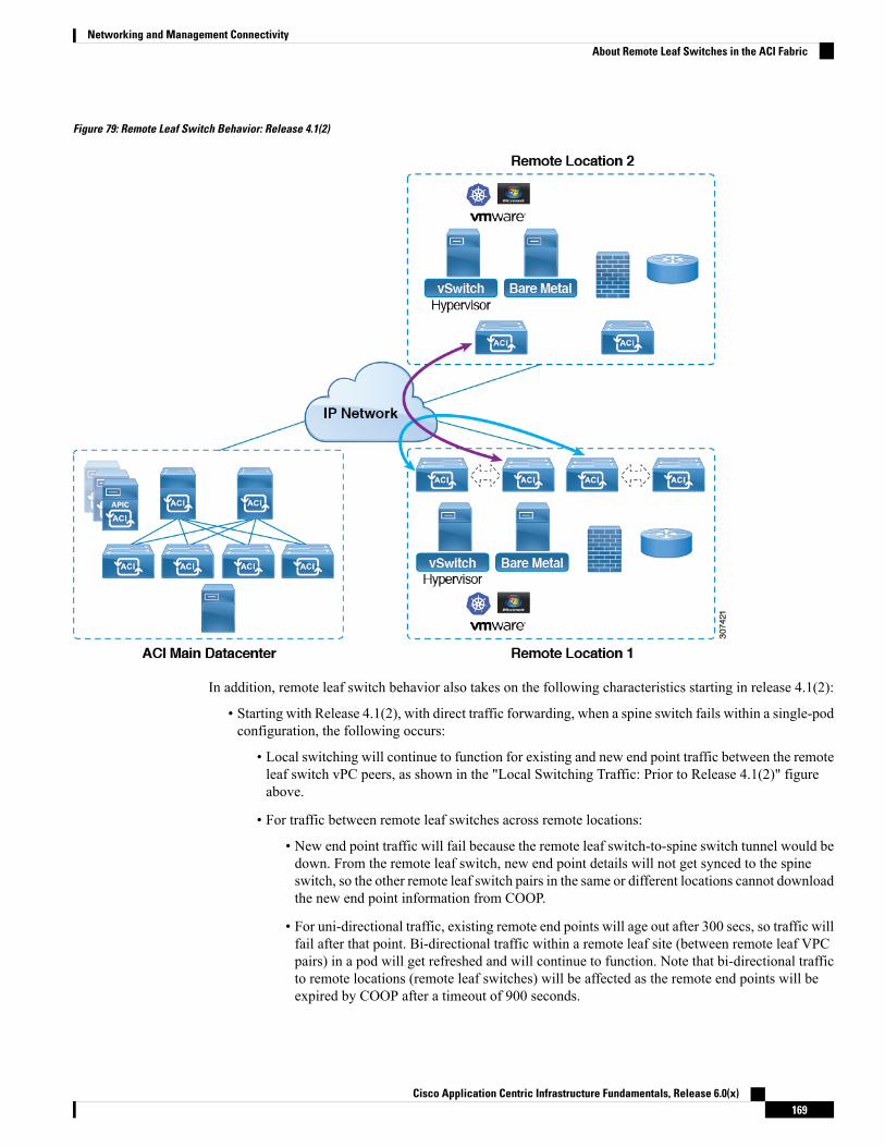
Figure 79: Remote Leaf Switch Behavior: Release 4.1(2)
In addition, remote leaf switch behavior also takes on the following characteristics starting in release 4.1(2):
• Starting with Release 4.1(2), with direct traffic forwarding, when a spine switch fails within a single-podconfiguration, the following occurs:
• Local switching will continue to function for existing and new end point traffic between the remoteleaf switch vPC peers, as shown in the "Local Switching Traffic: Prior to Release 4.1(2)" figureabove.
• For traffic between remote leaf switches across remote locations:
• New end point traffic will fail because the remote leaf switch-to-spine switch tunnel would bedown. From the remote leaf switch, new end point details will not get synced to the spineswitch, so the other remote leaf switch pairs in the same or different locations cannot downloadthe new end point information from COOP.
• For uni-directional traffic, existing remote end points will age out after 300 secs, so traffic willfail after that point. Bi-directional traffic within a remote leaf site (between remote leaf VPCpairs) in a pod will get refreshed and will continue to function. Note that bi-directional trafficto remote locations (remote leaf switches) will be affected as the remote end points will beexpired by COOP after a timeout of 900 seconds.
Cisco Application Centric Infrastructure Fundamentals, Release 6.0(x)169
Networking and Management ConnectivityAbout Remote Leaf Switches in the ACI Fabric

• For shared services (inter-VRF), bi-directional traffic between end points belonging to remoteleaf switches attached to two different remote locations in the same pod will fail after the remoteleaf switch COOP end point age-out time (900 sec). This is because the remote leafswitch-to-spine COOP session would be down in this situation. However, shared services trafficbetween end points belonging to remote leaf switches attached to two different pods will failafter 30 seconds, which is the COOP fast-aging time.
• L3Out-to-L3Out communication would not be able to continue because the BGP session tothe spine switches would be down.
• When there is remote leaf direct uni-directional traffic, where the traffic is sourced from one remote leafswitch and destined to another remote leaf switch (which is not the vPC peer of the source), there willbe a milli-second traffic loss every time the remote end point (XR EP) timeout of 300 seconds occurs.
• With a remote leaf switches with ACI Multi-Site configuration, all traffic continues from the remote leafswitch to the other pods and remote locations, even with a spine switch failure, because traffic will flowthrough an alternate available pod in this situation.
10 Mbps Bandwidth Support in IPN for Remote Leaf Switches
Youmight have situations where most of the data traffic from the remote leaf switches is local and the Inter-PodNetwork (IPN) is needed only for management purposes. In these situations, you may not need a 100 MbpsIPN. To support these environments, starting with Release 4.2(4), support is now available for 10 Mbps as aminimum bandwidth in the IPN.
To support this, the following requirements should be met:
• The IPN path is only used for managing remote leaf switches (management functions such as upgradesand downgrades, discovery, COOP, and policy pushes).
• Configure IPN with the QoS configuration in order to prioritize control and management plane trafficbetween the Cisco ACI datacenter and remote leaf switch pairs based on the information provided in thesection "Creating DSCP Translation Policy Using Cisco APIC GUI".
• All traffic from the Cisco ACI datacenter and remote leaf switches is through the local L3Out.
• The EPG or bridge domain are not stretched between the remote leaf switch and the ACImain datacenter.
• You should pre-download software images on the remote leaf switches to reduce upgrade time.
The following figure shows a graphical representation of this feature.
Cisco Application Centric Infrastructure Fundamentals, Release 6.0(x)170
Networking and Management ConnectivityAbout Remote Leaf Switches in the ACI Fabric
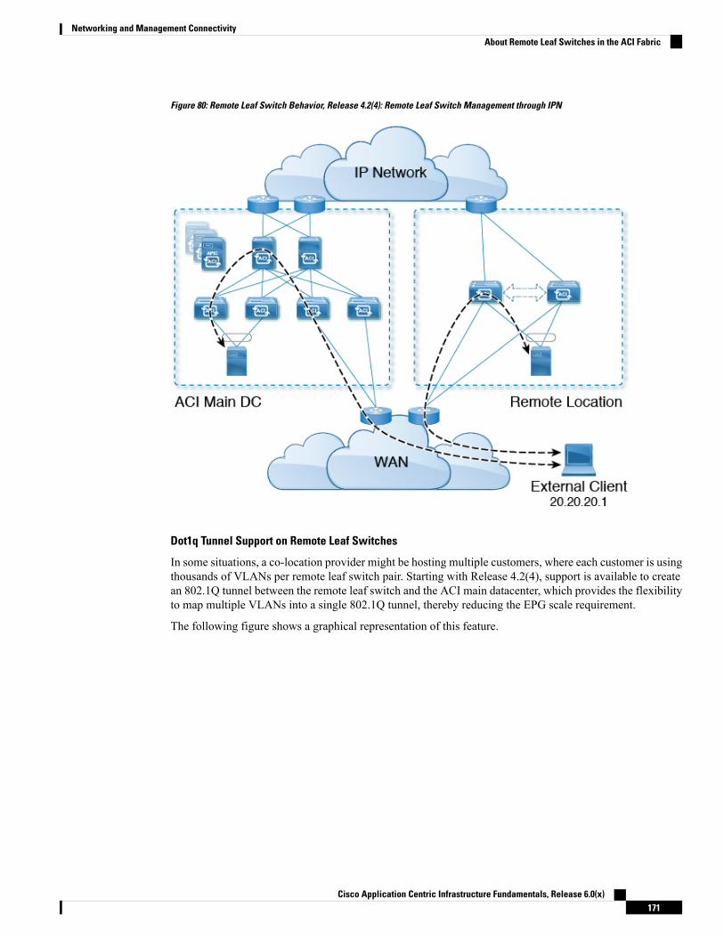
Figure 80: Remote Leaf Switch Behavior, Release 4.2(4): Remote Leaf Switch Management through IPN
Dot1q Tunnel Support on Remote Leaf Switches
In some situations, a co-location provider might be hosting multiple customers, where each customer is usingthousands of VLANs per remote leaf switch pair. Starting with Release 4.2(4), support is available to createan 802.1Q tunnel between the remote leaf switch and the ACI main datacenter, which provides the flexibilityto map multiple VLANs into a single 802.1Q tunnel, thereby reducing the EPG scale requirement.
The following figure shows a graphical representation of this feature.
Cisco Application Centric Infrastructure Fundamentals, Release 6.0(x)171
Networking and Management ConnectivityAbout Remote Leaf Switches in the ACI Fabric

Figure 81: Remote Leaf Switch Behavior, Release 4.2(4): 802.1Q Tunnel Support on Remote Leaf Switches
Create this 802.1Q tunnel between the remote leaf switch and the ACI main datacenter using the instructionsprovided in the "802.1Q Tunnels" chapter in theCisco APIC Layer 2 Networking Configuration Guide, locatedin the Cisco APIC documentation landing page.
You can configure remote leaf switches in the APIC GUI, either with and without a wizard, or use the RESTAPI or the NX-OS style CLI.
Remote Leaf Switch Restrictions and LimitationsThe following guidelines and restrictions apply to remote leaf switches:
• The remote leaf solution requires the /32 tunnel end point (TEP) IP addresses of the remote leaf switchesand main data center leaf/spine switches to be advertised across the main data center and remote leafswitches without summarization.
• If you move a remote leaf switch to a different site within the same pod and the new site has the samenode ID as the original site, you must delete and recreate the virtual port channel (vPC).
• With the Cisco N9K-C9348GC-FXP switch, you can perform the initial remote leaf switch discoveryonly on ports 1/53 or 1/54. Afterward, you can use the other ports for fabric uplinks to the ISN/IPN forthe remote leaf switch.
The following sections provide information on what is supported and not supported with remote leaf switches:
• Supported Features, on page 173
• Unsupported Features, on page 173
• Changes For Release 5.0(1), on page 175
• Changes For Release 5.2(3), on page 175
Cisco Application Centric Infrastructure Fundamentals, Release 6.0(x)172
Networking and Management ConnectivityRemote Leaf Switch Restrictions and Limitations

Supported Features
Stretching of an L3Out SVI within a vPC remote leaf switch pair is supported.
Beginning with Cisco APIC release 4.2(4), the 802.1Q (Dot1q) tunnels feature is supported.
Beginning with Cisco APIC release 4.1(2), the following features are supported:
• Remote leaf switches with ACI Multi-Site
• Traffic forwarding directly across two remote leaf vPC pairs in the same remote data center or acrossdata centers, when those remote leaf pairs are associated to the same pod or to pods that are part of thesame multipod fabric
• Transit L3Out across remote locations, which is when the main Cisco ACI data center pod is a transitbetween two remote locations (the L3Out in RL location-1 and L3Out in RL location-2 areadvertising prefixes for each other)
Beginning with Cisco APIC release 4.0(1), the following features are supported:
• Q-in-Q Encapsulation Mapping for EPGs
• PBR Tracking on remote leaf switches (with system-level global GIPo enabled)
• PBR Resilient Hashing
• Netflow
• MacSec Encryption
• Troubleshooting Wizard
• Atomic counters
Unsupported Features
Full fabric and tenant policies are supported on remote leaf switches in this release with the exception of thefollowing features, which are unsupported:
• GOLF
• vPod
• Floating L3Out
• Stretching of L3Out SVI between local leaf switches (ACI main data center switches) and remote leafswitches or stretching across two different vPC pairs of remote leaf switches
• Copy service is not supported when deployed on local leaf switches and when the source or destinationis on the remote leaf switch. In this situation, the routable TEP IP address is not allocated for the localleaf switch. For more information, see the section "Copy Services Limitations" in the "Configuring CopyServices" chapter in the Cisco APIC Layer 4 to Layer 7 Services Deployment Guide, available in theAPIC documentation page.
• Layer 2 Outside Connections (except Static EPGs)
• Copy services with vzAny contract
• FCoE connections on remote leaf switches
Cisco Application Centric Infrastructure Fundamentals, Release 6.0(x)173
Networking and Management ConnectivityRemote Leaf Switch Restrictions and Limitations

• Flood in encapsulation for bridge domains or EPGs
• Fast Link Failover policies are for ACI fabric links between leaf and spine switches, and are not applicableto remote leaf connections. Alternative methods are introduced in Cisco APIC Release 5.2(1) to achievefaster convergence for remote leaf connections.
• Managed Service Graph-attached devices at remote locations
• Traffic Storm Control
• Cloud Sec Encryption
• First Hop Security
• Layer 3 Multicast routing on remote leaf switches
• Maintenance mode
• TEP to TEP atomic counters
The following scenarios are not supported when integrating remote leaf switches in a Multi-Site architecturein conjunction with the intersite L3Out functionality:
• Transit routing between L3Outs deployed on remote leaf switch pairs associated to separate sites
• Endpoints connected to a remote leaf switch pair associated to a site communicating with the L3Outdeployed on the remote leaf switch pair associated to a remote site
• Endpoints connected to the local site communicating with the L3Out deployed on the remote leaf switchpair associated to a remote site
• Endpoints connected to a remote leaf switch pair associated to a site communicating with the L3Outdeployed on a remote site
The limitations above do not apply if the different data center sites are deployed as pods as part of the sameMulti-Pod fabric.
Note
The following deployments and configurations are not supported with the remote leaf switch feature:
• It is not supported to stretch a bridge domain between remote leaf nodes associated to a given site (APICdomain) and leaf nodes part of a separate site of a Multi-Site deployment (in both scenarios where thoseleaf nodes are local or remote) and a fault is generated on APIC to highlight this restriction. This appliesindependently from the fact that BUM flooding is enabled or disabled when configuring the stretchedbridge domain on theMulti-Site Orchestrator (MSO). However, a bridge domain can always be stretched(with BUM flooding enabled or disabled) between remote leaf nodes and local leaf nodes belonging tothe same site (APIC domain).
• Spanning Tree Protocol across remote leaf switch location and main data center.
• APICs directly connected to remote leaf switches.
• Orphan port channel or physical ports on remote leaf switches, with a vPC domain (this restriction appliesfor releases 3.1 and earlier).
Cisco Application Centric Infrastructure Fundamentals, Release 6.0(x)174
Networking and Management ConnectivityRemote Leaf Switch Restrictions and Limitations

• With and without service node integration, local traffic forwarding within a remote location is onlysupported if the consumer, provider, and services nodes are all connected to remote leaf switches are invPC mode.
• /32 loopbacks advertised from the spine switch to the IPN must not be suppressed/aggregated towardthe remote leaf switch. The /32 loopbacks must be advertised to the remote leaf switch.
Changes For Release 5.0(1)
Beginning with Cisco APIC release 5.0(1), the following changes have been applied for remote leaf switches:
• The direct traffic forwarding feature is enabled by default and cannot be disabled.
• A configuration without direct traffic forwarding for remote leaf switches is no longer supported. If youhave remote leaf switches and you are upgrading to Cisco APIC Release 5.0(1), review the informationprovided in the section "About Direct Traffic Forwarding" and enable direct traffic forwarding using theinstructions in that section.
Changes For Release 5.2(3)
Beginning with Cisco APIC release 5.2(3), the following changes have been applied for remote leaf switches:
• The IPN underlay protocol to peer between the remote leaf switches and the upstream router can be eitherOSPF or BGP. In previous releases, only an OSPF underlay is supported.
QoS
L3Outs QoSL3Out QoS can be configured using Contracts applied at the external EPG level. Starting with Release 4.0(1),L3Out QoS can also be configured directly on the L3Out interfaces.
If you are running Cisco APIC Release 4.0(1) or later, we recommend using the custom QoS policies applieddirectly to the L3Out to configure QoS for L3Outs.
Note
Packets are classified using the ingress DSCP or CoS value so it is possible to use custom QoS policies toclassify the incoming traffic into Cisco ACI QoS queues. A custom QoS policy contains a table mapping theDSCP/CoS values to the user queue and to the new DSCP/CoS value (in case of marking). If there is nomapping for a specific DSCP/CoS value, the user queue is selected by the QoS priority setting of the ingressL3Out interface if configured.
Class of Service (CoS) Preservation for Ingress and Egress TrafficWhen traffic enters the Cisco ACI fabric, each packet's priority is mapped to a Cisco ACI QoS level. TheseQoS levels are then stored in the CoS field and DE bit of the packet's outer header while the original headersare discarded.
Cisco Application Centric Infrastructure Fundamentals, Release 6.0(x)175
Networking and Management ConnectivityQoS

If you want to preserve the original CoS values of the ingressing packets and restore it when the packet leavesthe fabric, you can enable the 802.1p Class of Service (CoS) preservation using a global fabric QoS policyas described in this section.
The CoS preservation is supported in single pod and multipod topologies, however in multipod topologies,CoS preservation can be used only when you are not concerned with preserving the settings in the IPN betweenpods. To preserve the CoS values of the packets as they are transiting the IPN, use the DSCP translation policyas described in Multi-Pod QoS and DSCP Translation Policy, on page 165.
Multi-Pod QoS and DSCP Translation PolicyWhen traffic is sent and received within the Cisco ACI fabric, the QoS Level is determined based on the CoSvalue of the VXLAN packet's outer header. In Multi-Pod topologies, where devices that are not under CiscoAPIC's management may modify the CoS values in the transiting packets, you can preserve the QoS Levelsetting by creating a mapping between the Cisco ACI and the DSCP value within the packet.
If you are not concerned with preserving the QoS settings in the IPN traffic between pods, but would like topreserve the original CoS values of the packets ingressing and egressing the fabric, see Class of Service (CoS)Preservation for Ingress and Egress Traffic, on page 175 instead.
Figure 82: Multi-Pod Topology
As illustrated in this figure, traffic between pods in a Multi-Pod topology passes through an IPN, which maycontain devices that are not under Cisco APIC's management. When a network packet is sent from a spine ora leaf switch in POD1, the devices in the IPN may modify the 802.1p value in the packet. In this case, whenthe frame reaches a spine or a leaf switch in POD2, it would have an 802.1p value that was assigned by theIPN device, instead of the Cisco ACI QoS Level value assigned at the source in POD1.
In order to preserve the proper QoS Level of the packet and avoid high priority packets from being delayedor dropped, you can use a DSCP translation policy for traffic that goes between multiple PODs connected byan IPN. When a DSCP translation policy is enabled, Cisco APIC converts the QoS Level value (representedby the CoS value of the VXLAN packet) to a DSCP value according to the mapping rules you specify. Whena packet sent from POD1 reaches POD2, the mapped DSCP value is translated back into the original CoSvalue for the appropriate QoS Level.
Cisco Application Centric Infrastructure Fundamentals, Release 6.0(x)176
Networking and Management ConnectivityMulti-Pod QoS and DSCP Translation Policy

Translating Ingress to Egress QoS MarkingsCisco APIC enables translating the DSCP and CoS values of the ingressing traffic to a QoS Level to be usedinside the Cisco ACI fabric. Translation is supported only if the DSCP values are present in the IP packet andCoS values are present in the Ethernet frames.
For example, this functionality allows the Cisco ACI fabric to classify the traffic for devices that classify thetraffic based only on the CoS value, such as Layer-2 packets, which do not have an IP header.
CoS Translation Guidelines and Limitations
Youmust enable the global fabric CoS preservation policy, as described in Class of Service (CoS) Preservationfor Ingress and Egress Traffic, on page 175.
CoS translation is not supported on external L3 interfaces.
CoS translation is supported only if the egress frame is 802.1Q encapsulated.
CoS translation is not supported when the following configuration options are enabled:
• Contracts are configured that include QoS.
• The outgoing interface is on a FEX.
• Multipod QoS using a DSCP policy is enabled.
• Dynamic packet prioritization is enabled.
• If an EPG is configured with intra-EPG endpoint isolation enforced.
• If an EPG is configured with allow-microsegmentation enabled.
HSRP
About HSRPHSRP is a first-hop redundancy protocol (FHRP) that allows a transparent failover of the first-hop IP router.HSRP provides first-hop routing redundancy for IP hosts on Ethernet networks configured with a defaultrouter IP address. You use HSRP in a group of routers for selecting an active router and a standby router. Ina group of routers, the active router is the router that routes packets, and the standby router is the router thattakes over when the active router fails or when preset conditions are met.
Many host implementations do not support any dynamic router discovery mechanisms but can be configuredwith a default router. Running a dynamic router discovery mechanism on every host is not practical for manyreasons, including administrative overhead, processing overhead, and security issues. HSRP provides failoverservices to such hosts.
When you use HSRP, you configure the HSRP virtual IP address as the default router of the host (instead ofthe IP address of the actual router). The virtual IP address is an IPv4 or IPv6 address that is shared among agroup of routers that run HSRP.
When you configure HSRP on a network segment, you provide a virtual MAC address and a virtual IP addressfor the HSRP group. You configure the same virtual address on each HSRP-enabled interface in the group.You also configure a unique IP address andMAC address on each interface that acts as the real address. HSRP
Cisco Application Centric Infrastructure Fundamentals, Release 6.0(x)177
Networking and Management ConnectivityTranslating Ingress to Egress QoS Markings
selects one of these interfaces to be the active router. The active router receives and routes packets destinedfor the virtual MAC address of the group.
HSRP detects when the designated active router fails. At that point, a selected standby router assumes controlof the virtual MAC and IP addresses of the HSRP group. HSRP also selects a new standby router at that time.
HSRP uses a priority designator to determine which HSRP-configured interface becomes the default activerouter. To configure an interface as the active router, you assign it with a priority that is higher than the priorityof all the other HSRP-configured interfaces in the group. The default priority is 100, so if you configure justone interface with a higher priority, that interface becomes the default active router.
Interfaces that run HSRP send and receive multicast User Datagram Protocol (UDP)-based hello messagesto detect a failure and to designate active and standby routers. When the active router fails to send a hellomessage within a configurable period of time, the standby router with the highest priority becomes the activerouter. The transition of packet forwarding functions between the active and standby router is completelytransparent to all hosts on the network.
You can configure multiple HSRP groups on an interface. The virtual router does not physically exist butrepresents the common default router for interfaces that are configured to provide backup to each other. Youdo not need to configure the hosts on the LAN with the IP address of the active router. Instead, you configurethem with the IP address of the virtual router (virtual IP address) as their default router. If the active routerfails to send a hello message within the configurable period of time, the standby router takes over, respondsto the virtual addresses, and becomes the active router, assuming the active router duties. From the hostperspective, the virtual router remains the same.
Packets received on a routed port destined for the HSRP virtual IP address terminate on the local router,regardless of whether that router is the active HSRP router or the standby HSRP router. This process includesping and Telnet traffic. Packets received on a Layer 2 (VLAN) interface destined for the HSRP virtual IPaddress terminate on the active router.
Note
About Cisco APIC and HSRPHSRP in Cisco ACI is supported only on routed-interface or sub-interface. Therefore HSRP can only beconfigured under Layer 3 Out. Also there must be Layer 2 connectivity provided by external device(s) suchas a Layer 2 switch between ACI leaf switches running HSRP because HSRP operates on leaf switches byexchangingHellomessages over external Layer 2 connections. AnHSRP hellomessage does not pass throughthe spine switch.
The following is an example topology of an HSRP deployment in Cisco APIC.
Cisco Application Centric Infrastructure Fundamentals, Release 6.0(x)178
Networking and Management ConnectivityAbout Cisco APIC and HSRP
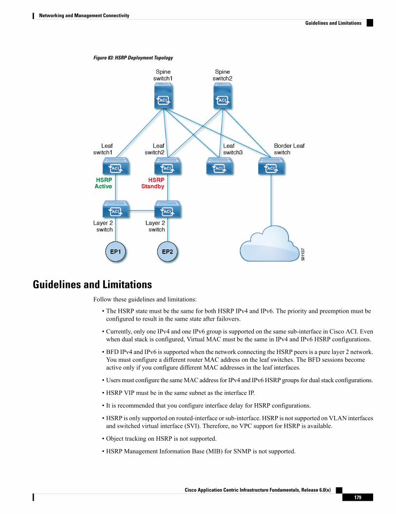
Figure 83: HSRP Deployment Topology
Guidelines and LimitationsFollow these guidelines and limitations:
• The HSRP state must be the same for both HSRP IPv4 and IPv6. The priority and preemption must beconfigured to result in the same state after failovers.
• Currently, only one IPv4 and one IPv6 group is supported on the same sub-interface in Cisco ACI. Evenwhen dual stack is configured, Virtual MAC must be the same in IPv4 and IPv6 HSRP configurations.
• BFD IPv4 and IPv6 is supported when the network connecting the HSRP peers is a pure layer 2 network.You must configure a different router MAC address on the leaf switches. The BFD sessions becomeactive only if you configure different MAC addresses in the leaf interfaces.
• Usersmust configure the sameMAC address for IPv4 and IPv6HSRP groups for dual stack configurations.
• HSRP VIP must be in the same subnet as the interface IP.
• It is recommended that you configure interface delay for HSRP configurations.
• HSRP is only supported on routed-interface or sub-interface. HSRP is not supported on VLAN interfacesand switched virtual interface (SVI). Therefore, no VPC support for HSRP is available.
• Object tracking on HSRP is not supported.
• HSRP Management Information Base (MIB) for SNMP is not supported.
Cisco Application Centric Infrastructure Fundamentals, Release 6.0(x)179
Networking and Management ConnectivityGuidelines and Limitations

• Multiple group optimization (MGO) is not supported with HSRP.
• ICMP IPv4 and IPv6 redirects are not supported.
• Cold Standby and Non-Stop Forwarding (NSF) are not supported because HSRP cannot be restarted inthe Cisco ACI environment.
• There is no extended hold-down timer support as HSRP is supported only on leaf switches. HSRP is notsupported on spine switches.
• HSRP version change is not supported in APIC. You must remove the configuration and reconfigurewith the new version.
• HSRP version 2 does not inter-operate with HSRP version 1. An interface cannot operate both version1 and version 2 because both versions are mutually exclusive. However, the different versions can berun on different physical interfaces of the same router.
• Route Segmentation is programmed in Cisco Nexus 93128TX, Cisco Nexus 9396PX, and Cisco Nexus9396TX leaf switches when HSRP is active on the interface. Therefore, there is no DMAC=router MACcheck conducted for route packets on the interface. This limitation does not apply for Cisco Nexus93180LC-EX, Cisco Nexus 93180YC-EX, and Cisco Nexus 93108TC-EX leaf switches.
• HSRP configurations are not supported in the Basic GUImode. The Basic GUImode has been deprecatedstarting with APIC release 3.0(1).
• Fabric to Layer 3 Out traffic will always load balance across all the HSRP leaf switches, irrespective oftheir state. If HSRP leaf switches span multiple pods, the fabric to out traffic will always use leaf switchesin the same pod.
• This limitation applies to some of the earlier Cisco Nexus 93128TX, Cisco Nexus 9396PX, and CiscoNexus 9396TX switches. When using HSRP, the MAC address for one of the routed interfaces or routedsub-interfaces must be modified to prevent MAC address flapping on the Layer 2 external device. Thisis because Cisco APIC assigns the same MAC address (00:22:BD:F8:19:FF) to every logical interfaceunder the interface logical profiles.
HSRP VersionsCisco APIC supports HSRP version 1 by default. You can configure an interface to use HSRP version 2.
HSRP version 2 has the following enhancements to HSRP version 1:
• Expands the group number range. HSRP version 1 supports group numbers from 0 to 255. HSRP version2 supports group numbers from 0 to 4095.
• For IPv4, uses the IPv4 multicast address 224.0.0.102 or the IPv6 multicast address FF02::66 to sendhello packets instead of the multicast address of 224.0.0.2, which is used by HSRP version 1.
• Uses the MAC address range from 0000.0C9F.F000 to 0000.0C9F.FFFF for IPv4 and 0005.73A0.0000through 0005.73A0.0FFF for IPv6 addresses. HSRP version 1 uses the MAC address range0000.0C07.AC00 to 0000.0C07.ACFF.
Cisco Application Centric Infrastructure Fundamentals, Release 6.0(x)180
Networking and Management ConnectivityHSRP Versions

C H A P T E R 7ACI Transit Routing, Route Peering, and EIGRPSupport
This chapter contains the following sections:
• ACI Transit Routing, on page 181• Transit Routing Use Cases, on page 181• ACI Fabric Route Peering, on page 186• Transit Route Control, on page 191• Default Policy Behavior, on page 193• EIGRP Protocol Support, on page 193
ACI Transit RoutingThe ACI fabric supports transit routing, which enables border routers to perform bidirectional redistributionwith other routing domains. Unlike the stub routing domains of earlier ACI releases, that block transitredistribution, bidirectional redistribution passes routing information from one routing domain to another.Such redistribution lets the ACI fabric provide full IP connectivity between different routing domains. Doingso can also provide redundant connectivity by enabling backup paths between routing domains.
Design transit redistribution policies that avoid suboptimal routing or the more serious problem of routingloops. Typically, transit redistribution does not preserve the original topology and link-state information andredistributes external routes in distance-vector fashion (routes are advertised as vector prefixes and associateddistances even with link-state protocols). Under these circumstances, the routers can inadvertently form routingloops that fail to deliver packets to their destination.
Transit Routing Use CasesTransit Routing Between Layer 3 Domains
Multiple Layer 3 domains such as external pods, mainframes, service nodes, or WAN routers can peer withthe ACI fabric to provide transit functionality between them.
Cisco Application Centric Infrastructure Fundamentals, Release 6.0(x)181

Figure 84: Transit Routing Between Layer 3 Domains
Mainframe Traffic Transiting the ACI Fabric
Mainframes can function as IP servers running standard IP routing protocols that accommodate requirementsfrom Logical Partitions (LPARs) and Virtual IP Addressing (VIPA).
Cisco Application Centric Infrastructure Fundamentals, Release 6.0(x)182
ACI Transit Routing, Route Peering, and EIGRP SupportTransit Routing Use Cases
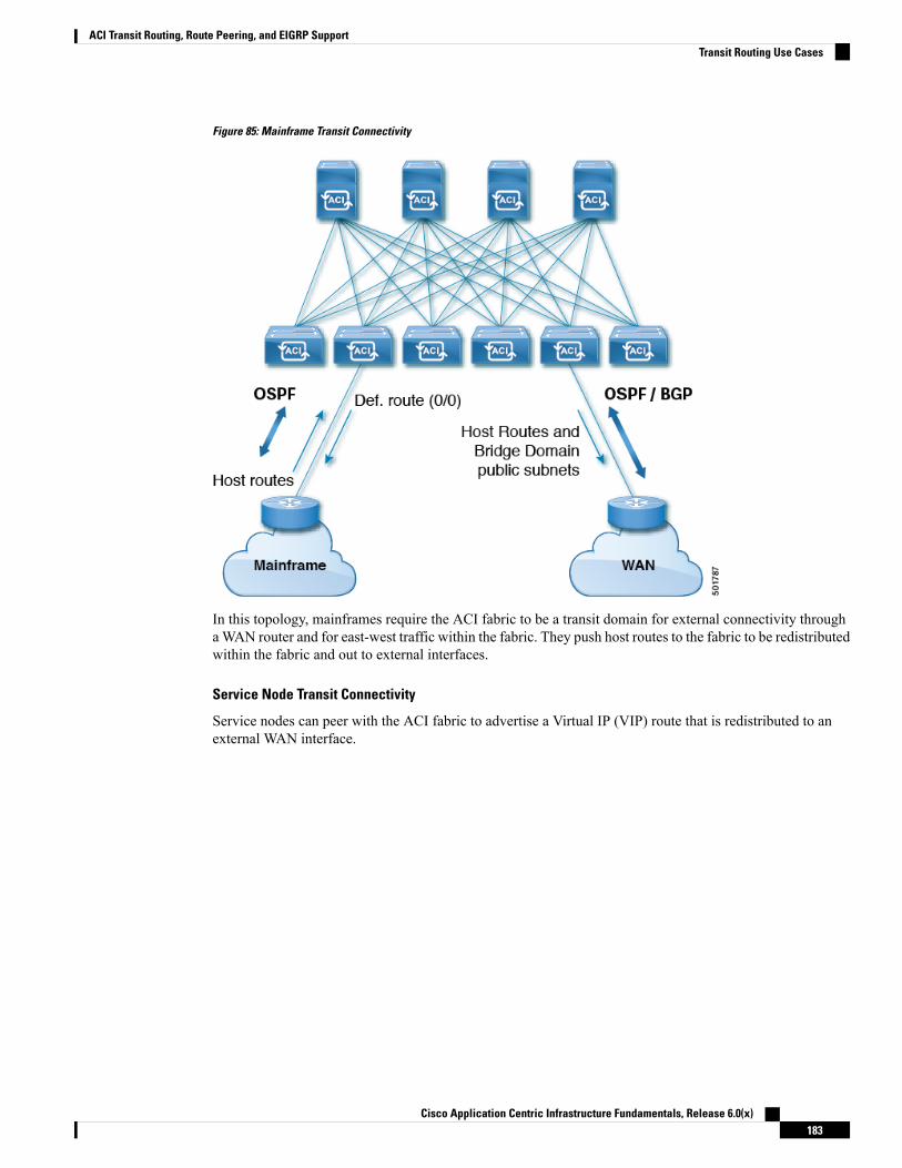
Figure 85: Mainframe Transit Connectivity
In this topology, mainframes require the ACI fabric to be a transit domain for external connectivity throughaWAN router and for east-west traffic within the fabric. They push host routes to the fabric to be redistributedwithin the fabric and out to external interfaces.
Service Node Transit Connectivity
Service nodes can peer with the ACI fabric to advertise a Virtual IP (VIP) route that is redistributed to anexternal WAN interface.
Cisco Application Centric Infrastructure Fundamentals, Release 6.0(x)183
ACI Transit Routing, Route Peering, and EIGRP SupportTransit Routing Use Cases

Figure 86: Service Node Transit Connectivity
The VIP is the external facing IP address for a particular site or service. A VIP is tied to one or more serversor nodes behind a service node.
Multipod in a Transit-Routed Configuration
In a multipod topology, the fabric acts as a transit for external connectivity and interconnection betweenmultiple pods. Cloud providers can deploy managed resource pods inside a customer datacenter. Thedemarcation point can be an L3Out with OSPF or BGP peering with the fabric.
Cisco Application Centric Infrastructure Fundamentals, Release 6.0(x)184
ACI Transit Routing, Route Peering, and EIGRP SupportTransit Routing Use Cases
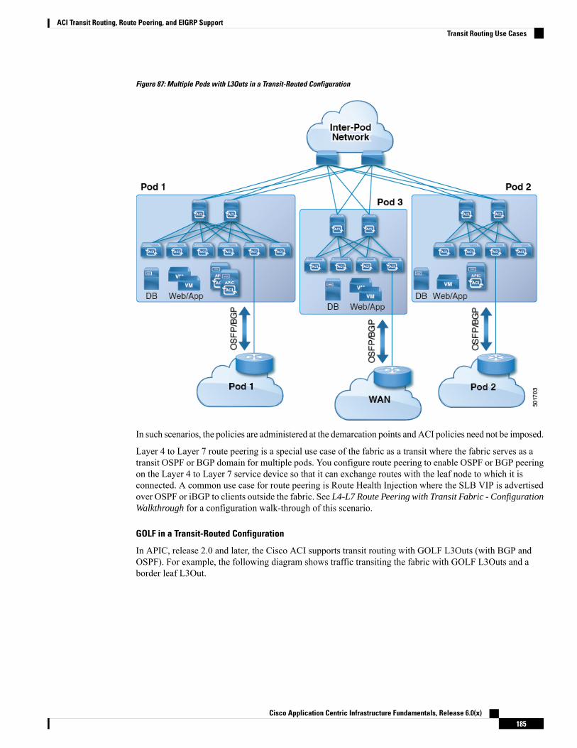
Figure 87: Multiple Pods with L3Outs in a Transit-Routed Configuration
In such scenarios, the policies are administered at the demarcation points and ACI policies need not be imposed.
Layer 4 to Layer 7 route peering is a special use case of the fabric as a transit where the fabric serves as atransit OSPF or BGP domain for multiple pods. You configure route peering to enable OSPF or BGP peeringon the Layer 4 to Layer 7 service device so that it can exchange routes with the leaf node to which it isconnected. A common use case for route peering is Route Health Injection where the SLB VIP is advertisedover OSPF or iBGP to clients outside the fabric. See L4-L7 Route Peering with Transit Fabric - ConfigurationWalkthrough for a configuration walk-through of this scenario.
GOLF in a Transit-Routed Configuration
In APIC, release 2.0 and later, the Cisco ACI supports transit routing with GOLF L3Outs (with BGP andOSPF). For example, the following diagram shows traffic transiting the fabric with GOLF L3Outs and aborder leaf L3Out.
Cisco Application Centric Infrastructure Fundamentals, Release 6.0(x)185
ACI Transit Routing, Route Peering, and EIGRP SupportTransit Routing Use Cases

Figure 88: GOLF L3Outs and a Border Leaf L3Out in a Transit-Routed Configuration
ACI Fabric Route PeeringLayer 3 connectivity and peering with the fabric is configured using a Layer 3 external outside network(l3extOut) interface. The peering protocol configuration along with route redistribution andinbound/outbound-filtering rules is associated with an l3extOut. The ACI fabric does not appear as a giantrouter to the external peers, but rather as a transit between separate Layer 3 domains. The peering considerationson one l3extOut need not affect the peering considerations on other l3extOut policies. The ACI fabric usesMP-BGP for distributing external routes inside the fabric.
Route RedistributionInbound routes from external peers are redistributed into the ACI fabric using MP-BGP, subject to inboundfiltering rules. These can be transit routes or external routes in the case of WAN connectivity. MP-BGPdistributes the routes to all the leaves (including other border leaves) where the tenant is deployed.
Cisco Application Centric Infrastructure Fundamentals, Release 6.0(x)186
ACI Transit Routing, Route Peering, and EIGRP SupportACI Fabric Route Peering

Figure 89: Route Redistribution
Inbound route filtering rules select a subset of routes advertised by the external peers to the fabric on thel3extOut interfaces. The import filter route-map is generated by using the prefixes in the prefix based EPG.The import filter list is associated only with MP-BGP to restrict the prefixes distributed into the fabric. Setactions can also be associated with import route-maps.
In the outbound direction, an administrator has the option to advertise default routes or transit routes andbridge domain public subnets. If default route advertisement is not enabled, outbound route filtering selectivelyadvertises routes as configured by the administrator.
Currently, route-maps are created with a prefix-list on a per-tenant basis to indicate the bridge domain publicsubnets to be advertised to external routers. In addition, a prefix-list has to be created to allow all transit routesto be advertised to an external router. The prefix-list for transit routes are configured by an administrator. Thedefault behavior is to deny all transit route advertisement to an external router.
The following options are available for the route-maps associated with transit routes:
• Permit-all: Allow all transit routes to be redistributed and advertised outside.
• Match prefix-list: Only a subset of transit routes are redistributed and advertised outside.
• Match prefix-list and set action: A set action can be associated with a subset of transit routes to tag routeswith a particular attribute.
The bridge domain public subnets and transit route prefixes can be different prefix-lists but combined into asingle route-map with different sequence numbers. Transit routes and bridge domain public subnets are notexpected to have the same prefixes, so prefix-list matches are mutually exclusive.
Route Peering by ProtocolRoute peering can be configured per protocol when combining BGP and OSPF with static routes.
Cisco Application Centric Infrastructure Fundamentals, Release 6.0(x)187
ACI Transit Routing, Route Peering, and EIGRP SupportRoute Peering by Protocol
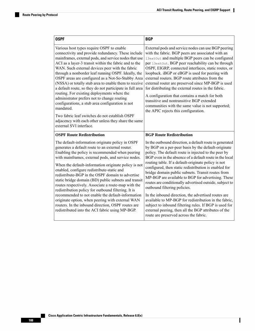
BGPOSPF
External pods and service nodes can use BGP peeringwith the fabric. BGP peers are associated with anl3extOut and multiple BGP peers can be configuredper l3extOut. BGP peer reachability can be throughOSPF, EIGRP, connected interfaces, static routes, orloopback. iBGP or eBGP is used for peering withexternal routers. BGP route attributes from theexternal router are preserved since MP-BGP is usedfor distributing the external routes in the fabric.
A configuration that contains a match for bothtransitive and nontransitive BGP extendedcommunities with the same value is not supported;the APIC rejects this configuration.
Various host types require OSPF to enableconnectivity and provide redundancy. These includemainframes, external pods, and service nodes that useACI as a layer-3 transit within the fabric and to theWAN. Such external devices peer with the fabricthrough a nonborder leaf running OSPF. Ideally, theOSPF areas are configured as a Not-So-Stubby Area(NSSA) or totally stub area to enable them to receivea default route, so they do not participate in full arearouting. For existing deployments where theadministrator prefers not to change routingconfigurations, a stub area configuration is notmandated.
Two fabric leaf switches do not establish OSPFadjacency with each other unless they share the sameexternal SVI interface.
BGP Route Redistribution
In the outbound direction, a default route is generatedby BGP on a per-peer basis by the default-originatepolicy. The default route is injected to the peer byBGP even in the absence of a default route in the localrouting table. If a default-originate policy is notconfigured, then static redistribution is enabled forbridge domain public subnets. Transit routes fromMP-BGP are available to BGP for advertising. Theseroutes are conditionally advertised outside, subject tooutbound filtering policies.
In the inbound direction, the advertised routes areavailable to MP-BGP for redistribution in the fabric,subject to inbound filtering rules. If BGP is used forexternal peering, then all the BGP attributes of theroute are preserved across the fabric.
OSPF Route Redistribution
The default-information originate policy in OSPFgenerates a default route to an external router.Enabling the policy is recommended when peeringwith mainframes, external pods, and service nodes.
When the default-information originate policy is notenabled, configure redistribute-static andredistribute-BGP in the OSPF domain to advertisestatic bridge domain (BD) public subnets and transitroutes respectively. Associate a route-map with theredistribution policy for outbound filtering. It isrecommended to not enable the default-informationoriginate option, when peering with external WANrouters. In the inbound direction, OSPF routes areredistributed into the ACI fabric using MP-BGP.
Cisco Application Centric Infrastructure Fundamentals, Release 6.0(x)188
ACI Transit Routing, Route Peering, and EIGRP SupportRoute Peering by Protocol
BGPOSPF
BGP Route filtering
Inbound route filtering in BGP is applied using aroute-map on a per-peer basis. A route-map isconfigured at the peer-af level in the in-direction, tofilter the transit routes to be allowed in the fabric.
In the outbound direction, static routes areredistributed into BGP at the dom-af level. Transitroutes from MP-BGP are available to the externalBGP peering sessions. A route-map is configured atthe peer-af level in the out-direction to allow onlypublic subnets and selected transit routes outside.Optionally, a set action to advertise a communityvalue for selected prefixes is configured on theroute-map.
The bridge domain public subnets and transit routeprefixes can be different prefix-lists but combinedinto a single route-map at the peer-af level withdifferent sequence numbers.
OSPF Route filtering
You can configure OSPF to limit the number ofLink-State Advertisements (LSAs) accepted from anexternal peer to avoid over consumption of the routetable, caused by a rogue external router.
Inbound route filtering is supported for Layer 3external outside tenant networks using OSPF. It isapplied using a route-map in the in-direction, to filtertransit routes allowed in the fabric.
In the outbound direction, configure redistribute-staticand redistribute-BGP at the OSPF domain level.Configure a route-map to filter the bridge domainpublic subnets and transit routes. Optionally, someprefixes in the route-map can also be configured witha set action to add route tags. Inter-area prefixes arealso filtered using the outbound filter list andassociating it with an OSPF area.
BGP Dynamic Neighbor Support and Private ASControl
Instead of providing a specific neighbor address, adynamic neighbor range of addresses can be provided.
Private Autonomous System (AS) numbers can be inthe range from 64512 to 65535. They cannot beadvertised to a global BGP table. Private AS numberscan be removed from the AS path on a per peer basisand can only be used for eBGP peers according to thefollowing options:
• Remove Private AS – Remove if the AS pathonly has private AS numbers.
• Remove All – Remove if the AS path has bothprivate and public AS numbers.
• Replace AS – Replace the private AS with thelocal AS number.
Remove all and replace AS can onlybe set if remove private AS is set.
Note
OSPF Name Lookup, Prefix Suppression, and Type7 Translation
OSPF can be configured to enable name lookup forrouter IDs and suppress prefixes.
The APIC system performs OSPF ForwardingAddress Suppression in the Translated Type-5 LSAsfeature, which causes an NSSA ABR to translateType-7 LSAs to Type-5 LSAs. To avoid this, use the0.0.0.0 subnet as the forwarding address instead ofthe one that is specified in the Type-7 LSA. Thisfeature causes routers that are configured not toadvertise forwarding addresses into the backbone todirect forwarded traffic to the translating NSSAASBRs.
BGP dampening minimizes propagation into the fabric of flapping e-BGP routes that were received fromexternal routers that are connected to border leaf switches (BLs). Frequently flapping routes from externalrouters are suppressed on BLs based on criteria you configure. They are then prohibited from redistributionto iBGP peers (ACI spine switches). Suppressed routes are reused after a configured time. Each flap penalizesthe e-BGP route with a penalty of 1000. When the flap penalty reaches a defined suppress-limit threshold(default 2000), the e-BGP route is marked as dampened. Dampened routes are not advertised to other BGP
Cisco Application Centric Infrastructure Fundamentals, Release 6.0(x)189
ACI Transit Routing, Route Peering, and EIGRP SupportRoute Peering by Protocol

peers. The penalty is decremented to half after every half-life interval (the default is 15 minutes). A dampenedroute is reused if the penalty falls below a specified reuse-limit (the default is 750). A dampened route issuppressed at most for a specified maximum suppress time (maximum of 45 minutes).
Use the BGP weight attribute to select a best path. The weight ( from 0 to 65,535) is assigned locally to aspecific router. The value is not propagated or carried through any of the route updates. By default, paths thatthe router originates have a weight of 32,768, and other paths have a weight of 0. Routes with a higher weightvalue have preference when there are multiple routes to the same destination. Set the weight under the BGPneighbor or under the route map.
BGP peering is typically configured to the neighbor’s loopback address. In such cases, loopback reachabilityis statically configured or advertised (more commonly) through OSPF. The loopback interface is configuredas a passive interface and added into the OSPF area. There are no redistribution policies that are attached toOSPF. The route redistribution implementation is through BGP. Route filtering can be configured in L3Outsfor tenant networks that use either BGP or OSPF.
External routes can also be programmed as static routes on the border leaf in the respective tenants. A peeringprotocol is not required if the external routes are programmed as static routes on the border leaf. Externalstatic routes are redistributed to other leaf switches in the fabric through MP-BGP, subject to import filtering.Starting with release 1.2(1x), static route preference incoming within the ACI fabric is carried in MP-BGPusing a cost extended community. On an L3Out connection, an MP-BGP route coming from Layer 4 winsover a local static route. A route is installed in the Unicast Routing Information Base (URIB) with the preferencethat is specified by an administrator. On an ACI nonborder leaf switch, a route is installed with Layer 4 asnexthop. When nexthop on Layer 4 is not available, the Layer 3 static route becomes the best route in fabric.
Figure 90: Static Route Policy Model for Transit
For l3extOut connections, external endpoints are mapped to an external EPG based on IP prefixes. For eachl3extOut connection, you can create one or more external EPGs, based on whether different endpoints requiredifferent policies.
Each external EPG is associated with a class-id. Each prefix in the external EPG is programmed in the hardwareto derive the corresponding class-id. The prefixes are only qualified VRF instance and not by the l3extOutinterface on which they are deployed.
Cisco Application Centric Infrastructure Fundamentals, Release 6.0(x)190
ACI Transit Routing, Route Peering, and EIGRP SupportRoute Peering by Protocol

The union of prefixes from all the l3extOut policies in the same VRF is programmed on all the leaf switcheswhere the l3extOut policies are deployed. The source and destination class-ids corresponding to the sourceand destination IP address in a packet are derived at the ingress leaf and the policy is applied on the ingressleaf itself, based on the configured contract. If a contract allows traffic between two prefixes on two L3Outinterfaces, then packets with any combination of the source and destination IP address (belonging to theconfigured prefixes) is allowed between the L3Out interfaces. If there is no contract between the EPGs, thetraffic is dropped at the ingress leaf.
Since prefixes are programmed on every leaf switch where l3extOut policies are deployed, the total numberof prefixes APIC supports for prefix-based EPGs is limited to 1000 for the fabric.
Overlapping or equal subnets cannot be configured on different l3extOut interfaces in the same VRF. Ifoverlapping or equal subnets are required, then a single l3extOut is used for transit with appropriate exportprefixes.
Transit Route ControlA route transit is defined to import traffic through a Layer 3 outside network L3extOut profile (l3extInstP),where it is to be imported. A different route transit is defined to export traffic through another l3extInstPwhere it is to be exported.
Since multiple l3extOut policies can be deployed on a single node or multiple nodes in the fabric, a varietyof protocol combinations are supported. Every protocol combination can be deployed on a single node usingmultiple l3extOut policies or multiple nodes using multiple l3extOut policies. Deployments of more thantwo protocols in different l3extOut policies in the fabric are supported.
Export route-maps are made up of prefix-list matches. Each prefix-list consists of bridge domain (BD) publicsubnet prefixes in the VRF and the export prefixes that need to be advertised outside.
Route control policies are defined in an l3extOut policy and controlled by properties and relations associatedwith the l3extOut. APIC uses the enforceRtctrl property of the l3extOut to enforce route control directions.The default is to enforce control on export and allow all on import. Imported and exported routes(l3extSubnets), are defined in the l3extInstP. The default scope for every route is import. These are theroutes and prefixes which form a prefix-based EPG.
All the import routes form the import route map and are used by BGP and OSPF to control import. All theexport routes form the export route map used by OSPF and BGP to control export.
Import and export route control policies are defined at different levels. All IPv4 policy levels are supportedfor IPv6. Extra relations that are defined in the l3extInstP and l3extSubnetMOs control import.
Default route leak is enabled by defining the l3extDefaultRouteLeakPMO under the l3extOut.
l3extDefaultRouteLeakP can have Virtual Routing and Forwarding (VRF) scope or L3extOut scope per areafor OSPF and per peer for BGP.
The following set rules provide route control:
• rtctrlSetPref
• rtctrlSetRtMetric
• rtctrlSetRtMetricType
Additional syntax for the rtctrlSetCommMO includes the following:
• no-advertise
Cisco Application Centric Infrastructure Fundamentals, Release 6.0(x)191
ACI Transit Routing, Route Peering, and EIGRP SupportTransit Route Control

• no-export
• no-peer
BGP
The ACI fabric supports BGP peering with external routers. BGP peers are associated with an l3extOut policyandmultiple BGP peers can be configured per l3extOut. BGP can be enabled at the l3extOut level by definingthe bgpExtPMO under an l3extOut.
Although the l3extOut policy contains the routing protocol (for example, BGP with its related VRF), theL3Out interface profile contains the necessary BGP interface configuration details. Both are needed to enableBGP.
Note
BGP peer reachability can be through OSPF, EIGRP, a connected interface, static routes, or a loopback. iBGPor eBGP can be used for peering with external routers. The BGP route attributes from the external router arepreserved since MP-BGP is used for distributing the external routes in the fabric. BGP enables IPv4 and/orIPv6 address families for the VRF associated with an l3extOut. The address family to enable on a switch isdetermined by the IP address type defined in bgpPeerP policies for the l3extOut. The policy is optional; ifnot defined, the default will be used. Policies can be defined for a tenant and used by a VRF that is referencedby name.
You must define at least one peer policy to enable the protocol on each border leaf (BL) switch. A peer policycan be defined in two places:
• Under l3extRsPathL3OutAtt—a physical interface is used as the source interface.
• Under l3extLNodeP—a loopback interface is used as the source interface.
OSPF
Various host types require OSPF to enable connectivity and provide redundancy. These include mainframedevices, external pods and service nodes that use the ACI fabric as a Layer 3 transit within the fabric and totheWAN. Such external devices peer with the fabric through a nonborder leaf switch running OSPF. Configurethe OSPF area as an NSSA (stub) area to enable it to receive a default route and not participate in full-arearouting. Typically, existing routing deployments avoid configuration changes, so a stub area configuration isnot mandated.
You enable OSPF by configuring an ospfExtP managed object under an l3extOut. OSPF IP address familyversions configured on the BL switch are determined by the address family that is configured in the OSPFinterface IP address.
Although the l3extOut policy contains the routing protocol (for example, OSPF with its related VRF andarea ID), the Layer 3 external interface profile contains the necessary OSPF interface details. Both are neededto enable OSPF.
Note
You configure OSPF policies at the VRF level by using the fvRsCtxToOspfCtxPol relation, which you canconfigure per address family. If you do not configured it, default parameters are used.
You configure the OSPF area in the ospfExtP managed object, which also exposes IPv6 the required areaproperties.
Cisco Application Centric Infrastructure Fundamentals, Release 6.0(x)192
ACI Transit Routing, Route Peering, and EIGRP SupportTransit Route Control
Default Policy BehaviorWhen there are no contracts between two prefix-based EPGs, traffic between unknown-source andunknown-destination prefixes are dropped. These drops are achieved by implicitly programming differentclass-ids for unknown source and destination prefixes. Since the class-ids are different, they are impacted bythe class-unequal rule and packets are denied. The class-unequal drop rule also causes packets to be droppedfrom known source and destination IP addresses to unknown source and destination IP addresses and viceversa.
Due to this change in the default behavior, the class-id programming for catch-all (0/0) entries has beenchanged as illustrated in the example below:
• Unknown source IP address is EPG1.
• Unknown destination IP address is EPG2.
• Unknown source IP <—> Unknown destination IP => class-unequal rule => DROP.
• User-configured default prefixes (0/0) = EPG3 and (10/8) = EPG4. Contract between EPG3 and EPG4is set to ALLOW.
• Programmed rules:
• EPG1 <—> EPG4 => class-unequal rule => DROP
• EPG4 <—> EPG2 => class-unequal rule => DROP
EIGRP Protocol SupportEIGRP protocol is modeled similar to other routing protocols in the Cisco Application Centric Infrastructure(ACI) fabric.
Supported Features
The following features are supported:
• IPv4 and IPv6 routing
• Virtual routing and forwarding (VRF) and interface controls for each address family
• Redistribution with OSPF across nodes
• Default route leak policy per VRF
• Passive interface and split horizon support
• Route map control for setting tag for exported routes
• Bandwidth and delay configuration options in an EIGRP interface policy
• Authentication support
Cisco Application Centric Infrastructure Fundamentals, Release 6.0(x)193
ACI Transit Routing, Route Peering, and EIGRP SupportDefault Policy Behavior
Unsupported Features
The following features are not supported:
• Stub routing
• EIGRP used for BGP connectivity
• Multiple EIGRP L3extOuts on the same node
• Per-interface summarization (an EIGRP summary policy will apply to all interfaces configured underan L3Out)
• Per interface distribute lists for import and export
Categories of EIGRP Functions
EIGRP functions can be broadly categorized as follows:
• Protocol policies
• L3extOut configurations
• Interface configurations
• Route map support
• Default route support
• Transit support
Primary Managed Objects That Support EIGRP
The following primary managed objects provide EIGRP support:
• EIGRP Address Family Context Policy eigrpCtxAfPol: Address Family Context policy configuredunder fvTenant (Tenant/Protocols).
• fvRsCtxToEigrpCtxAfPol: Relation from a VRF to a eigrpCtxAfPol for a given address family (IPv4or IPv6). There can be only one relation for each address family.
• eigrpIfPol: EIGRP Interface policy configured in fvTenant.
• eigrpExtP: Enable flag for EIGRP in an L3extOut.
• eigrpIfP: EIGRP interface profile attached to an l3extLIfP.
• eigrpRsIfPol: Relation from EIGRP interface profile to an eigrpIfPol.
• Defrtleak: Default route leak policy under an l3extOut.
EIGRP Protocol Policies Supported Under a Tenant
The following EIGRP protocol policies are supported under a tenant:
• EIGRP Interface policy (eigrpIfPol)—contains the configuration that is applied for a given addressfamily on an interface. The following configurations are allowed in the interface policy:
• Hello interval in seconds
Cisco Application Centric Infrastructure Fundamentals, Release 6.0(x)194
ACI Transit Routing, Route Peering, and EIGRP SupportEIGRP Protocol Support

• Hold interval in seconds
• One or more of the following interface control flags:
• split horizon
• passive
• next hop self
• EIGRP Address Family Context Policy (eigrpCtxAfPol)—contains the configuration for a givenaddress family in a given VRF. An eigrpCtxAfPol is configured under tenant protocol policies and canbe applied to one or more VRFs under the tenant. An eigrpCtxAfPol can be enabled on a VRF througha relation in the VRF-per-address family. If there is no relation to a given address family, or the specifiedeigrpCtxAfPol in the relation does not exist, then the default VRF policy created under the common tenantis used for that address family.
The following configurations are allowed in the eigrpCtxAfPol:
• Administrative distance for internal route
• Administrative distance for external route
• Maximum ECMP paths allowed
• Active timer interval
• Metric version (32-bit / 64-bit metrics)
EIGRP L3extOut ConfigurationEIGRP is the main protocol used for advertising the fabric public subnets, connect routes, static routes, andtransit routes configured on the leaf switches.
There is an enable/disable flag for EIGRP for a given Layer 3 external outside network (l3extOut) routeddomain.
The autonomous system number that is a tag used for EIGRP and is not the same as the fabric ASN used byBGP.
Note
EIGRP cannot be enabled with BGP and OSPF on the same L3extOut.
The following EIGRP transit scenarios are supported:
• EIGRP running in an L3extOut on one node and OSPF running in another L3extOut on a different node.
Multiple EIGRP L3extOuts are not supported on the same node in the sameVirtual Routing and Forwarding (VRF).
Note
• EIGRP to static route transit.
Cisco Application Centric Infrastructure Fundamentals, Release 6.0(x)195
ACI Transit Routing, Route Peering, and EIGRP SupportEIGRP L3extOut Configuration

EIGRP Interface ProfileTo enable EIGRP on an interface, an EIGRP profile needs to be configured under the interface profile in theL3extOut->Node->Interface hierarchy. An EIGRP profile has a relation to an EIGRP interface policy enabledin the tenant. In the absence of a relation or interface policy in the tenant, the default EIGRP interface policyin the common tenant is used. EIGRP is enabled on all interfaces contained in the interface profile. This includesL3-Port, Sub-interfaces, External SVI on ports, port-channels, and VPCs contained in the interface profile.
Route-map infrastructure and settings in the policy model are common across all the protocols. The route-mapset actions are a superset of actions to cover BGP, OSPF, and EIGRP. The EIGRP protocol supports the settag option in route maps used for interleak/redistribution. These route maps are configured on a per-VRFbasis. If the L3extOut has both IPv4 and IPv6 interfaces, then an interleak policy is applied on both IPv4 andIPv6 address families for that VRF.
At this time, VRF-level route maps are supported, but interface route maps are not supported.Note
The default route leak policy on the L3extOut is protocol agnostic in terms of the configuration. Propertiesenabled in the default route leak policy are a superset of the individual protocols. Supported configurationsin the default route leak are as follows:
• Scope: VRF is the only scope supported for EIGRP.
• Always: The switch advertises the default route only if present in the routing table or advertises itregardless.
• Criteria: only or in-addition. With the only option, only the default route is advertised by EIGRP. Within-addition, the public subnets and transit routes are advertised along with the default route.
The default route leak policy is enabled in the domain per VRF per address family.
By default, the protocol redistribution interleak policies with appropriate route maps are set up for all validconfigurations. The administrator enables transit routing purely by virtue of creating l3extInstP subnets withscope=export-route control to allow certain routes to be transmitted between two L3extOuts in the same VRF.Apart from the scope of l3extInstP subnets, there are no special protocol specific configurations for coveringtransit cases. Apart from the scope, which is protocol-specific, other parameters of the default route leak policyare common across all the protocols.
The OSPF on another L3extOut on a different node transit scenario is supported with EIGRP.
Observe the following EIGRP guidelines and limitations:
• At this time, multiple EIGRP L3Outs are not supported on the same leaf switch.
• All routes are imported on an L3extOut that uses EIGRP. Import subnet scope is disabled in the GUI ifEIGRP is the protocol on the L3extOut.
Cisco Application Centric Infrastructure Fundamentals, Release 6.0(x)196
ACI Transit Routing, Route Peering, and EIGRP SupportEIGRP Interface Profile

C H A P T E R 8User Access, Authentication, and Accounting
This chapter contains the following sections:
• User Access, Authorization, and Accounting, on page 197• Multiple Tenant Support, on page 197• User Access: Roles, Privileges, and Security Domains, on page 198• Accounting, on page 199• Routed Connectivity to External Networks as a Shared Service Billing and Statistics, on page 200• Custom RBAC Rules, on page 200• APIC Local Users, on page 201• Externally Managed Authentication Server Users, on page 203• User IDs in the APIC Bash Shell, on page 208• Login Domains, on page 209• SAML Authentication, on page 209
User Access, Authorization, and AccountingApplication Policy Infrastructure Controller (APIC) policies manage the authentication, authorization, andaccounting (AAA) functions of the Cisco Application Centric Infrastructure (ACI) fabric. The combinationof user privileges, roles, and domains with access rights inheritance enables administrators to configure AAAfunctions at the managed object level in a granular fashion. These configurations can be implemented usingthe REST API, the CLI, or the GUI.
There is a known limitation where you cannot have more than 32 characters for the login domain name. Inaddition, the combined number of characters for the login domain name and the user name cannot exceed 64characters.
Note
Multiple Tenant SupportA core Application Policy Infrastructure Controller (APIC) internal data access control system providesmultitenant isolation and prevents information privacy from being compromised across tenants. Read/writerestrictions prevent any tenant from seeing any other tenant's configuration, statistics, faults, or event data.
Cisco Application Centric Infrastructure Fundamentals, Release 6.0(x)197
Unless the administrator assigns permissions to do so, tenants are restricted from reading fabric configuration,policies, statistics, faults, or events.
User Access: Roles, Privileges, and Security DomainsThe APIC provides access according to a user’s role through role-based access control (RBAC). An CiscoApplication Centric Infrastructure (ACI) fabric user is associated with the following:
• A predefined or custom role, which is a set of one or more privileges assigned to a user
• A set of privileges, which determine the managed objects (MOs) to which the user has access
• For each role, a privilege type: no access, read-only, or read-write
• One or more security domain tags that identify the portions of the management information tree (MIT)that a user can access
Roles and Privileges
A privilege controls access to a particular function within the system. The ACI fabric manages access privilegesat the managed object (MO) level. Every object holds a list of the privileges that can read from it and a listof the privileges that can write to it. All objects that correspond to a particular function will have the privilegefor that function in its read or write list. Because an object might correspond to additional functions, its listsmight contain multiple privileges. When a user is assigned a role that contains a privilege, the user is givenread access to the associated objects whose read list specifies read access, and write access to those whosewrite list specifies write access.
As an example, 'fabric-equipment' is a privilege that controls access to all objects that correspond to equipmentin the physical fabric. An object corresponding to equipment in the physical fabric, such as 'eqptBoard,' willhave 'fabric-equipment' in its list of privileges. The 'eqptBoard' object allows read-only access for the'fabric-equipment' privilege. When a user is assigned a role such as 'fabric-admin' that contains the privilege'fabric-equipment,' the user will have access to those equipment objects, including read-only access to the'eqptBoard' object.
Some roles contain other roles. For example, '-admin' roles such as tenant-admin, fabric-admin, access-adminare groupings of roles with the same base name. For example, ‘access-admin’ is a grouping of'access-connectivity', 'access-equipment', 'access-protocol', and 'access-qos.' Similarly, tenant-admin is agrouping of roles with a ‘tenant‘ base, and fabric-admin is a grouping of roles with a ‘fabric‘ base.
The 'admin' role contains all privileges.
Note
For more details about roles and privileges see APIC Roles and Privileges Matrix.
Security Domains
A security domain is a tag associated with a certain subtree in the ACI MIT object hierarchy. For example,the default tenant “common” has a domain tag common. Similarly, the special domain tag all includes theentire MIT object tree. An administrator can assign custom domain tags to the MIT object hierarchy. Forexample, an administrator could assign the “solar” domain tag to the tenant named solar. Within the MIT,only certain objects can be tagged as security domains. For example, a tenant can be tagged as a securitydomain but objects within a tenant cannot.
Cisco Application Centric Infrastructure Fundamentals, Release 6.0(x)198
User Access, Authentication, and AccountingUser Access: Roles, Privileges, and Security Domains
Security Domain password strength parameters can be configured by creating Custom Conditions or byselecting Any Three Conditions that are provided.
Note
Creating a user and assigning a role to that user does not enable access rights. It is necessary to also assignthe user to one or more security domains. By default, the ACI fabric includes two special pre-created domains:
• All—allows access to the entire MIT
• Infra— allows access to fabric infrastructure objects/subtrees, such as fabric access policies
For read operations to the managed objects that a user's credentials do not allow, a "DN/Class Not Found"error is returned, not "DN/Class Unauthorized to read." For write operations to a managed object that a user'scredentials do not allow, an HTTP 401 Unauthorized error is returned. In the GUI, actions that a user'scredentials do not allow, either they are not presented, or they are grayed out.
Note
A set of predefined managed object classes can be associated with domains. These classes should not haveoverlapping containment. Examples of classes that support domain association are as follows:
• Layer 2 and Layer 3 network managed objects
• Network profiles (such as physical, Layer 2, Layer 3, management)
• QoS policies
When an object that can be associated with a domain is created, the user must assign domain(s) to the objectwithin the limits of the user's access rights. Domain assignment can be modified at any time.
If a virtual machine management (VMM) domain is tagged as a security domain, the users contained in thesecurity domain can access the correspondingly tagged VMM domain. For example, if a tenant named solaris tagged with the security domain called sun and a VMM domain is also tagged with the security domaincalled sun, then users in the solar tenant can access the VMM domain according to their access rights.
AccountingACI fabric accounting is handled by these twomanaged objects (MO) that are processed by the samemechanismas faults and events:
• The aaaSessionLRMO tracks user account login and logout sessions on the APIC and switches, andtoken refresh. The ACI fabric session alert feature stores information such as the following:
• Username
• IP address initiating the session
• Type (telnet, https, REST etc.)
• Session time and length
• Token refresh – a user account login event generates a valid active token which is required in orderfor the user account to exercise its rights in the ACI fabric.
Cisco Application Centric Infrastructure Fundamentals, Release 6.0(x)199
User Access, Authentication, and AccountingAccounting
Token expiration is independent of login; a user could log out but the tokenexpires according to the duration of the timer value it contains.
Note
• The aaaModLRMO tracks the changes users make to objects and when the changes occurred.
• If the AAA server is not pingable, it is marked unavailable and a fault is seen.
Both the aaaSessionLR and aaaModLR event logs are stored in APIC shards. Once the data exceeds the pre-setstorage allocation size, it overwrites records on a first-in first-out basis.
In the event of a destructive event such as a disk crash or a fire that destroys an APIC cluster node, the eventlogs are lost; event logs are not replicated across the cluster.
Note
The aaaModLR and aaaSessionLRMOs can be queried by class or by distinguished name (DN). A class queryprovides all the log records for the whole fabric. All aaaModLR records for the whole fabric are available fromthe GUI at the Fabric > Inventory > POD > History > Audit Log section, The APIC GUI History > AuditLog options enable viewing event logs for a specific object identified in the GUI.
The standard syslog, callhome, REST query, and CLI export mechanisms are fully supported for aaaModLRand aaaSessionLRMO query data. There is no default policy to export this data.
There are no pre-configured queries in the APIC that report on aggregations of data across a set of objects orfor the entire system. A fabric administrator can configure export policies that periodically export aaaModLRand aaaSessionLR query data to a syslog server. Exported data can be archived periodically and used togenerate custom reports from portions of the system or across the entire set of system logs.
Routed Connectivity to External Networks as a Shared ServiceBilling and Statistics
The Cisco Application Policy Infrastructure Controller (APIC) can be configured to collect byte count andpacket count billing statistics from a port configured for routed connectivity to external networks as a sharedservice. The external networks are represented as external L3Out endpoint group (l3extInstP managed object)in Cisco Application Centric Infrastructure (ACI). Any EPG in any tenant can share an external L3Out EPGfor routed connectivity to external networks. Billing statistics can be collected for each EPG in any tenantthat uses an external L3Out EPG as a shared service. The leaf switch where the external L3Out EPG isprovisioned forwards the billing statistics to the Cisco APIC where they are aggregated. Accounting policiescan be configured to export these billing statics periodically to a server.
Custom RBAC RulesRBAC rules enable a fabric-wide administrator to provide access across security domains that would otherwisebe blocked. Use RBAC rules to expose physical resources or share services that otherwise are inaccessiblebecause they are in a different security domain. RBAC rules provide read access only to their target resources.The GUI RBAC rules page is located under Admin => AAA => Security Management. RBAC rules can be
Cisco Application Centric Infrastructure Fundamentals, Release 6.0(x)200
User Access, Authentication, and AccountingRouted Connectivity to External Networks as a Shared Service Billing and Statistics

created prior to the existence of a resource. Descriptions of RBAC rules, roles, and privileges (and theirdependencies) are documented in the Management Information Model reference.
Used for viewing the policies configured including troubleshooting policies.
Note that ops role cannot be used for creating new monitoring and troubleshooting policies. They need to bedone using the admin privilege, just like any other configurations in the APIC.
Selectively Expose Physical Resources across Security DomainsA fabric-wide administrator uses RBAC rules to selectively expose physical resources to users that otherwiseare inaccessible because they are in a different security domain.
For example, if a user in tenant Solar needs access to a virtual machine management (VMM) domain, thefabric-wide admin could create an RBAC rule to allow this. The RBAC rule is comprised of these two parts:the distinguished name (DN) that locates the object to be accessed plus the name of the security domain thatcontains the user who will access the object. So, in this example, when designated users in the security domainSolar are logged in, this rule gives them access to the VMM domain as well as all its child objects in the tree.To give users in multiple security domains access to the VMM domain, the fabric-wide administrator wouldcreate an RBAC rule for each security domain that contains the DN for the VMM domain plus the securitydomain.
While an RBAC rule exposes an object to a user in a different part of the management information tree, it isnot possible to use the CLI to navigate to such an object by traversing the structure of the tree. However, aslong as the user knows the DN of the object included in the RBAC rule, the user can use the CLI to locate itvia an MO find command.
Note
Enable Sharing of Services across Security DomainsA fabric-wide administrator uses RBAC rules to provision trans-tenant EPG communications that enableshared services across tenants.
APIC Local UsersAn administrator can choose not to use external AAA servers but rather configure users on the APIC itself.These users are called APIC-local users.
At the time a user sets their password, the APIC validates it against the following criteria:
• Minimum password length is 8 characters.
• Maximum password length is 64 characters.
• Has fewer than three consecutive repeated characters.
• Must have characters from at least three of the following characters types: lowercase, uppercase, digit,symbol.
• Does not use easily guessed passwords.
• Cannot be the username or the reverse of the username.
Cisco Application Centric Infrastructure Fundamentals, Release 6.0(x)201
User Access, Authentication, and AccountingSelectively Expose Physical Resources across Security Domains

• Cannot be any variation of cisco, isco or any permutation of these characters or variants obtained bychanging the capitalization of letters therein.
Cisco ACI uses a crypt library with a SHA256 one-way hash for storing passwords. At rest hashed passwordsare stored in an encrypted filesystem. The key for the encrypted filesystem is protected using the TrustedPlatform Module (TPM).
The APIC also enables administrators to grant access to users configured on externally managed authenticationLightweight Directory Access Protocol (LDAP), RADIUS, TACACS+, or SAML servers. Users can belongto different authentication systems and can log in simultaneously to the APIC.
The following figure shows how the process works for configuring an admin user in the local APICauthentication database who has full access to the entire ACI fabric.
Figure 91: APIC Local User Configuration Process
The security domain "all" represents the entire Managed Information Tree (MIT). This domain includes allpolicies in the system and all nodes managed by the APIC. Tenant domains contain all the users and managedobjects of a tenant. Tenant administrators should not be granted access to the "all" domain.
Note
The following figure shows the access that the admin user Joe Stratus has to the system.
Cisco Application Centric Infrastructure Fundamentals, Release 6.0(x)202
User Access, Authentication, and AccountingAPIC Local Users

Figure 92: Result of Configuring Admin User for "all" Domain
The user Joe Stratus with read-write "admin" privileges is assigned to the domain "all" which gives him fullaccess to the entire system.
Externally Managed Authentication Server UsersThe following figure shows how the process works for configuring an admin user in an external RADIUSserver who has full access to the tenant Solar.
Cisco Application Centric Infrastructure Fundamentals, Release 6.0(x)203
User Access, Authentication, and AccountingExternally Managed Authentication Server Users

Figure 93: Process for Configuring Users on External Authentication Servers
The following figure shows the access the admin user Jane Cirrus has to the system.
Cisco Application Centric Infrastructure Fundamentals, Release 6.0(x)204
User Access, Authentication, and AccountingExternally Managed Authentication Server Users

Figure 94: Result of Configuring Admin User for Tenant Solar
In this example, the Solar tenant administrator has full access to all the objects contained in the Solar tenantas well as read-only access to the tenant Common. Tenant admin Jane Cirrus has full access to the tenantSolar, including the ability to create new users in tenant Solar. Tenant users are able to modify configurationparameters of the ACI fabric that they own and control. They also are able to read statistics and monitor faultsand events for the entities (managed objects) that apply to them such as endpoints, endpoint groups (EPGs)and application profiles.
In the example above, the user Jane Cirrus was configured on an external RADIUS authentication server. Toconfigure an AV Pair on an external authentication server, add a Cisco AV Pair to the existing user record.The Cisco AV Pair specifies the Role-Based Access Control (RBAC) roles and privileges for the user on theAPIC. The RADIUS server then propagates the user privileges to the APIC controller.
In the example above, the configuration for an open radius server (/etc/raddb/users) is as follows:janecirrus Cleartext-Password := "<password>"Cisco-avpair = "shell:domains = solar/admin/,common//read-all(16001)"
This example includes the following elements:
• janecirrus is the tenant administrator
• solar is the tenant
• admin is the role with write privileges
Cisco Application Centric Infrastructure Fundamentals, Release 6.0(x)205
User Access, Authentication, and AccountingExternally Managed Authentication Server Users

• common is the tenant-common subtree that all users should have read-only access to
• read-all is the role with read privileges
Cisco AV Pair FormatThe Cisco APIC requires that an administrator configure a Cisco AV Pair on an external authentication serverand only looks for one AV pair string. To do so, an administrator adds a Cisco AV pair to the existing userrecord. The Cisco AV pair specifies the APIC required RBAC roles and privileges for the user.
In order for the AV pair string to work, it must be formatted as follows:shell:domains =ACI_Security_Domain_1/ACI_Write_Role_1|ACI_Write_Role_2|ACI_Write_Role_3/ACI_Read_Role_1|ACI_Read_Role_2,ACI_Security_Domain_2/ACI_Write_Role_1|ACI_Write_Role_2|ACI_Write_Role_3/ACI_Read_Role_1|ACI_Read_Role_2,ACI_Security_Domain_3/ACI_Write_Role_1|ACI_Write_Role_2|ACI_Write_Role_3/ACI_Read_Role_1|ACI_Read_Role_2
• shell:domains= - Required so that ACI reads the string correctly. This must always prepend the shellstring.
• ACI_Security_Domain_1//admin - Grants admin read only access to the tenants in this security domain.
• ACI_Security_Domain_2/admin - Grants admin write access to the tenants in this security domain.
• ACI_Security_Domain_3/read-all - Grants read-all write access to the tenants in this security domain.
/'s separate the security domain, write, read sections of the string. |’s separate multiple write or read roleswithin the same security domain.
Note
Starting with Cisco APIC release 2.1, if no UNIX ID is provided in AV Pair, the APIC allocates the uniqueUNIX user ID internally.
Note
The APIC supports the following regexes:shell:domains\\s*[=:]\\s*((\\S+?/\\S*?/\\S*?)(,\\S+?/\\S*?/\\S*?){0,31})(\\(\\d+\\))$shell:domains\\s*[=:]\\s*((\\S+?/\\S*?/\\S*?)(,\\S+?/\\S*?/\\S*?){0,31})$
Examples:
• Example 1: A Cisco AV Pair that contains a single Login domain with only writeRoles:
shell:domains=ACI_Security_Domain_1/Write_Role_1|Write_Role_2/
• Example 2: A Cisco AV Pair that contains a single Login domain with only readRoles:
shell:domains=Security_Domain_1//Read_Role_1|Read_Role_2
Cisco Application Centric Infrastructure Fundamentals, Release 6.0(x)206
User Access, Authentication, and AccountingCisco AV Pair Format

The "/" character is a separator between writeRoles and readRoles per Login domain and is required even ifonly one type of role is to be used.
The Cisco AVpair string is case sensitive. Although a fault may not be seen, using mismatching cases for thedomain name or roles could lead to unexpected privileges being given.
Note
AV Pair GUI Configuration
The security domain is defined in the ACI GUI under Admin > AAA > Security Management > SecurityDomains and assigned to a tenant under Tenants > Tenant_Name > Policy.
A security domain must have either a read or write role. These roles are defined inAPIC >Admin > SecurityManagement > Roles. If a role is input into the write section it automatically grants read privileges of thesame level so there is no need to have ACI_Security_Domain_1/admin/admin.
RADIUS AuthenticationRemote Authentication Dial-In User Service (RADIUS) is a networking protocol that provides centralizedauthentication, authorization, and accounting (AAA) management for users who connect and use a networkservice.
To configure users on RADIUS servers, the APIC administrator must configure the required attributes(shell:domains) using the cisco-av-pair attribute. The default user role is network-operator.
The SNMPv3 authentication protocol options are SHA and MD5. The privacy protocol options are AES-128and DES. If these options are not specified in the cisco-av-pair attribute, MD5 and DES are the defaultauthentication protocols.
For example, SNMPv3 authentication and privacy protocol attributes can be specified as follows:snmpv3:auth=SHA priv=AES-128
Similarly, the list of domains would be as follows:shell:domains="domainA domainB …"
TACACS+ AuthenticationTerminal Access Controller Access Control System Plus (TACACS+) is another remote AAA protocol thatis supported by Cisco devices. TACACS+ has the following advantages over RADIUS authentication:
• Provides independent AAA facilities. For example, the Cisco Application Policy Infrastructure Controller(APIC) can authorize access without authenticating.
• Uses TCP to send data between the AAA client and server, enabling reliable transfers with aconnection-oriented protocol.
• Encrypts the entire protocol payload between the switch and the AAA server to ensure higher dataconfidentiality. RADIUS encrypts passwords only.
• Uses the av-pairs that are syntactically and configurationally different than RADIUS but the Cisco APICsupports shell:domains.
Cisco Application Centric Infrastructure Fundamentals, Release 6.0(x)207
User Access, Authentication, and AccountingRADIUS Authentication

The following XML example configures the Cisco Application Centric Infrastructure (ACI) fabric to workwith a TACACS+ provider at IP address 10.193.208.9:<aaaTacacsPlusProvider name="10.193.208.9"
key="test123"authProtocol="pap"/>
While the examples provided here use IPv4 addresses, IPv6 addresses could also be used.Note
The following guidelines and limitations apply when using TACACS+:
• The TACACS server and TACACs ports must be reachable by ping.
• The TACACS server with the highest priority is considered first to be the primary server.
LDAP/Active Directory AuthenticationSimilar to RADIUS and TACACS+, LDAP allows a network element to retrieve AAA credentials that canbe used to authenticate and then authorize the user to perform certain actions. An added certificate authorityconfiguration can be performed by an administrator to enable LDAPS (LDAP over SSL) trust and preventman-in-the-middle attacks.
The XML example below configures the ACI fabric to work with an LDAP provider at IP address 10.30.12.128.
While the examples provided here use IPv4 addresses, IPv6 addresses could also be used.Note
<aaaLdapProvider name="10.30.12.128"rootdn="CN=Manager,DC=ifc,DC=com"basedn="DC=ifc,DC=com"SSLValidationLevel="strict"attribute="CiscoAVPair"enableSSL="yes"
key="myldappwd"filter="cn=$userid"port="636" />
For LDAP configurations, best practice is to use CiscoAVPair as the attribute string. If customer faces theissue using Object ID 1.3.6.1.4.1.9.22.1, an additional Object ID 1.3.6.1.4.1.9.2742.1-5 can also be used inthe LDAP server.
Instead of configuring the Cisco AVPair, you have the option to create LDAP group maps in the APIC.
Note
User IDs in the APIC Bash ShellUser IDs on the APIC for the Linux shell are generated within the APIC for local users. Users whoseauthentication credential is managed on external servers, the user ID for the Linux shell can be specified inthe cisco-av-pair. Omitting the (16001) in the above cisco-av-pair is legal, in which case the remote user gets
Cisco Application Centric Infrastructure Fundamentals, Release 6.0(x)208
User Access, Authentication, and AccountingLDAP/Active Directory Authentication

a default Linux user ID of 23999. Linux User IDs are used during bash sessions, allowing standard Linuxpermissions enforcement. Also, all managed objects created by a user are marked as created-by that user’sLinux user ID.
The following is an example of a user ID as seen in the APIC Bash shell:admin@ifav17-ifc1:~> touch myfileadmin@ifav17-ifc1:~> ls -l myfile-rw-rw-r-- 1 admin admin 0 Apr 13 21:43 myfileadmin@ifav17-ifc1:~> ls -ln myfile-rw-rw-r-- 1 15374 15374 0 Apr 13 21:43 myfileadmin@ifav17-ifc1:~> iduid=15374(admin) gid=15374(admin) groups=15374(admin)
Login DomainsA login domain defines the authentication domain for a user. Login domains can be set to the Local, LDAP,RADIUS, TACACS+, DUO, SAML, RSA, or OAuth 2 authentication mechanisms. When accessing thesystem fromREST, the CLI, or the GUI, the APIC enables the user to select the correct authentication domain.
For example, in the REST scenario, the username is prefixed with a string so that the full login usernamelooks as follows:apic:<domain>\<username>
If accessing the system from the GUI, the APIC offers a drop-down list of domains for the user to select. Ifno apic: domain is specified, the default authentication domain servers are used to look up the username.
Starting in ACI version 1.0(2x), the login domain fallback of the APIC defaults local. If the defaultauthentication is set to a non-local method and the console authentication method is also set to a non-localmethod and both non-local methods do not automatically fall back to local authentication, the APIC can stillbe accessed via local authentication.
To access the APIC fallback local authentication, use the following strings:
• From the GUI, use apic:fallback\\username.
• From the REST API, use apic#fallback\\username.
Do not change the fallback login domain. Doing so could result in being locked out of the system.Note
SAML AuthenticationSAML is an XML-based open standard data format that enables administrators to access a defined set of Ciscocollaboration applications seamlessly after signing into one of those applications. SAML describes the exchangeof security related information between trusted business partners. It is an authentication protocol used byservice providers to authenticate a user. SAML enables exchange of security authentication informationbetween an Identity Provider (IdP) and a service provider.
SAML SSO uses the SAML 2.0 protocol to offer cross-domain and cross-product single sign-on for Ciscocollaboration solutions. SAML 2.0 enables SSO across Cisco applications and enables federation betweenCisco applications and an IdP. SAML 2.0 allows Cisco administrative users to access secure web domains to
Cisco Application Centric Infrastructure Fundamentals, Release 6.0(x)209
User Access, Authentication, and AccountingLogin Domains
exchange user authentication and authorization data, between an IdP and a Service Provider while maintaininghigh security levels. The feature provides secure mechanisms to use common credentials and relevantinformation across various applications.
The authorization for SAML SSO Admin access is based on Role-Based Access Control (RBAC) configuredlocally on Cisco collaboration applications.
SAML SSO establishes a Circle of Trust (CoT) by exchanging metadata and certificates as part of theprovisioning process between the IdP and the Service Provider. The Service Provider trusts the IdP's userinformation to provide access to the various services or applications.
Service providers are no longer involved in authentication. SAML 2.0 delegates authentication away fromthe service providers and to the IdPs.
Note
The client authenticates against the IdP, and the IdP grants an Assertion to the client. The client presents theAssertion to the Service Provider. Since there is a CoT established, the Service Provider trusts the Assertionand grants access to the client.
Enabling SAML SSO results in several advantages:
• It reduces password fatigue by removing the need for entering different user name and passwordcombinations.
• It transfers the authentication from your system that hosts the applications to a third party system.UsingSAML SSO, you can create a circle of trust between an IdP and a service provider. The serviceprovider trusts and relies on the IdP to authenticate the users.
• It protects and secures authentication information. It provides encryption functions to protect authenticationinformation passed between the IdP, service provider, and user. SAML SSO can also hide authenticationmessages passed between the IdP and the service provider from any external user.
• It improves productivity because you spend less time re-entering credentials for the same identity.
• It reduces costs as fewer help desk calls are made for password reset, thereby leading to more savings.
Cisco Application Centric Infrastructure Fundamentals, Release 6.0(x)210
User Access, Authentication, and AccountingSAML Authentication

C H A P T E R 9Virtual Machine Manager Domains
This chapter contains the following sections:
• Cisco ACI VM Networking Support for Virtual Machine Managers, on page 211• VMM Domain Policy Model, on page 213• Virtual Machine Manager Domain Main Components , on page 213• Virtual Machine Manager Domains, on page 214• VMM Domain VLAN Pool Association, on page 214• VMM Domain EPG Association, on page 215• Trunk Port Group, on page 217• EPG Policy Resolution and Deployment Immediacy, on page 218• Guidelines for Deleting VMM Domains, on page 219
Cisco ACI VM Networking Support for Virtual MachineManagers
Benefits of ACI VM Networking
Cisco Application Centric Infrastructure (ACI) virtual machine (VM) networking supports hypervisors frommultiple vendors. It provides the hypervisors programmable and automated access to high-performancescalable virtualized data center infrastructure.
Programmability and automation are critical features of scalable data center virtualization infrastructure. TheCiscoACI open RESTAPI enables virtual machine integrationwith and orchestration of the policymodel-basedCisco ACI fabric. Cisco ACI VM networking enables consistent enforcement of policies across both virtualand physical workloads that are managed by hypervisors from multiple vendors.
Attachable entity profiles easily enable VMmobility and placement of workloads anywhere in the Cisco ACIfabric. The Cisco Application Policy Infrastructure Controller (APIC) provides centralized troubleshooting,application health score, and virtualization monitoring. Cisco ACI multi-hypervisor VM automation reducesor eliminates manual configuration and manual errors. This enables virtualized data centers to support largenumbers of VMs reliably and cost effectively.
Supported Products and Vendors
Cisco ACI supports virtual machine managers (VMMs) from the following products and vendors:
Cisco Application Centric Infrastructure Fundamentals, Release 6.0(x)211
• Cisco Unified Computing System Manager (UCSM)
Integration of Cisco UCSM is supported beginning in Cisco Cisco APICRelease 4.1(1). For information,see the chapter "Cisco ACI with Cisco UCSM Integration in theCisco ACI Virtualization Guide, Release4.1(1).
• Cisco Application Centric Infrastructure (ACI) Virtual Pod (vPod)
Cisco ACI vPod is in general availability beginning in Cisco APIC Release 4.0(2). For information, seethe Cisco ACI vPod documentation on Cisco.com.
• Cisco ACI Virtual Edge
For information, see the Cisco ACI Virtual Edge documentation on Cisco.com.
• Cloud Foundry
Cloud Foundry integration with Cisco ACI is supported beginning with Cisco APIC Release 3.1(2). Forinformation, see the knowledge base article, Cisco ACI and Cloud Found Integration on Cisco.com.
• Kubernetes
For information, see the knowledge base article, Cisco ACI and Kubernetes Integration on Cisco.com.
• Microsoft System Center Virtual Machine Manager (SCVMM)
For information, see the chapters "Cisco ACI with Microsoft SCVMM" and "Cisco ACI with MicrosoftWindows Azure Pack" in the Cisco ACI Virtualization Guide on Cisco.com
• OpenShift
For information, see the OpenShift documentation on Cisco.com.
• OpenStack
For information, see the OpenStack documentation on Cisco.com.
• Red Hat Virtualization (RHV)
For information, see the knowledge base article, Cisco ACI and Red Hat Integration on Cisco.com.
• VMware Virtual Distributed Switch (VDS)
For information, see the chapter "Cisco "ACI with VMware VDS Integration" in the Cisco ACIVirtualization Guide.
See the Cisco ACI Virtualization Compatibility Matrix for the most current list of verified interoperableproducts.
Beginning with Cisco APIC Release 5.0(1), Cisco Application Virtual Switch (AVS) is no longer supported.If you use Cisco AVS and upgrade to Cisco APIC Release 5.0(1), in case of issues, the fabric will not besupported. Also, a fault will be raised for the Cisco AVS domain.
If you use Cisco AVS, we recommend that you migrate to Cisco Application Centric Infrastructure (ACI)Virtual Edge Virtual Edge. See the Cisco ACI Virtual Edge Installation Guide, Release 3.0(x) on Cisco.com.
Note
Cisco Application Centric Infrastructure Fundamentals, Release 6.0(x)212
Virtual Machine Manager DomainsCisco ACI VM Networking Support for Virtual Machine Managers
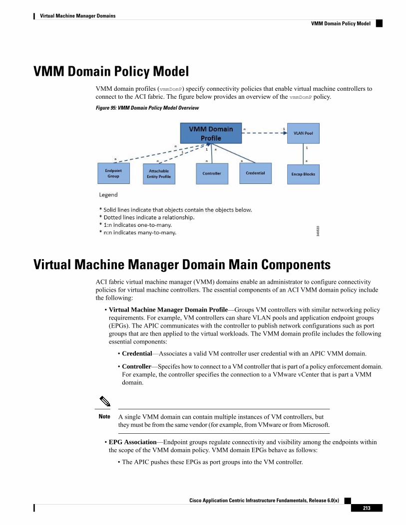
VMM Domain Policy ModelVMM domain profiles (vmmDomP) specify connectivity policies that enable virtual machine controllers toconnect to the ACI fabric. The figure below provides an overview of the vmmDomP policy.
Figure 95: VMM Domain Policy Model Overview
Virtual Machine Manager Domain Main ComponentsACI fabric virtual machine manager (VMM) domains enable an administrator to configure connectivitypolicies for virtual machine controllers. The essential components of an ACI VMM domain policy includethe following:
• Virtual Machine Manager Domain Profile—Groups VM controllers with similar networking policyrequirements. For example, VM controllers can share VLAN pools and application endpoint groups(EPGs). The APIC communicates with the controller to publish network configurations such as portgroups that are then applied to the virtual workloads. The VMM domain profile includes the followingessential components:
• Credential—Associates a valid VM controller user credential with an APIC VMM domain.
• Controller—Specifes how to connect to a VM controller that is part of a policy enforcement domain.For example, the controller specifies the connection to a VMware vCenter that is part a VMMdomain.
A single VMM domain can contain multiple instances of VM controllers, buttheymust be from the same vendor (for example, fromVMware or fromMicrosoft.
Note
• EPG Association—Endpoint groups regulate connectivity and visibility among the endpoints withinthe scope of the VMM domain policy. VMM domain EPGs behave as follows:
• The APIC pushes these EPGs as port groups into the VM controller.
Cisco Application Centric Infrastructure Fundamentals, Release 6.0(x)213
Virtual Machine Manager DomainsVMM Domain Policy Model
• An EPG can span multiple VMM domains, and a VMM domain can contain multiple EPGs.
• Attachable Entity Profile Association—Associates a VMM domain with the physical networkinfrastructure. An attachable entity profile (AEP) is a network interface template that enables deployingVM controller policies on a large set of leaf switch ports. An AEP specifies which switches and portsare available, and how they are configured.
• VLAN Pool Association—AVLANpool specifies theVLAN IDs or ranges used for VLAN encapsulationthat the VMM domain consumes.
Virtual Machine Manager DomainsAn APIC VMM domain profile is a policy that defines a VMM domain. The VMM domain policy is createdin APIC and pushed into the leaf switches.
VMM domains provide the following:
• A common layer in the ACI fabric that enables scalable fault-tolerant support for multiple VM controllerplatforms.
• VMM support for multiple tenants within the ACI fabric.
VMM domains contain VM controllers such as VMware vCenter or Microsoft SCVMMManager and thecredential(s) required for the ACI API to interact with the VM controller. A VMM domain enables VMmobility within the domain but not across domains. A single VMM domain can contain multiple instances ofVM controllers but they must be the same kind. For example, a VMM domain can contain many VMwarevCenters managing multiple controllers each running multiple VMs but it may not also contain SCVMMManagers. A VMM domain inventories controller elements (such as pNICs, vNICs, VM names, and so forth)and pushes policies into the controller(s), creating port groups, and other necessary elements. The ACI VMMdomain listens for controller events such as VM mobility and responds accordingly.
VMM Domain VLAN Pool AssociationVLAN pools represent blocks of traffic VLAN identifiers. A VLAN pool is a shared resource and can beconsumed by multiple domains such as VMM domains and Layer 4 to Layer 7 services.
Each pool has an allocation type (static or dynamic), defined at the time of its creation. The allocation typedetermines whether the identifiers contained in it will be used for automatic assignment by the Cisco APIC(dynamic) or set explicitly by the administrator (static). By default, all blocks contained within a VLAN poolhave the same allocation type as the pool but users can change the allocation type for encapsulation blockscontained in dynamic pools to static. Doing so excludes them from dynamic allocation.
A VMM domain can associate with only one dynamic VLAN pool. By default, the assignment of VLANidentifiers to EPGs that are associated with VMM domains is done dynamically by the Cisco APIC. Whiledynamic allocation is the default and preferred configuration, an administrator can statically assign a VLANidentifier to an endpoint group (EPG) instead. In that case, the identifiers used must be selected fromencapsulation blocks in the VLAN pool associated with the VMM domain, and their allocation type must bechanged to static.
The Cisco APIC provisions VMM domain VLAN on leaf ports based on EPG events, either statically bindingon leaf ports or based on VM events from controllers such as VMware vCenter or Microsoft SCVMM.
Cisco Application Centric Infrastructure Fundamentals, Release 6.0(x)214
Virtual Machine Manager DomainsVirtual Machine Manager Domains

In dynamic VLAN pools, if a VLAN is disassociated from an EPG, it is automatically reassociated with theEPG in five minutes.
Note
Dynamic VLAN association is not a part of configuration rollback, that is, in case an EPG or tenant wasinitially removed and then restored from the backup, a newVLAN is automatically allocated from the dynamicVLAN pools.
Note
VMM Domain EPG AssociationThe Cisco Application Centric Infrastructure (ACI) fabric associates tenant application profile endpoint groups(EPGs) to virtual machine manager (VMM) domains, The Cisco ACI does so either automatically by anorchestration component such as Microsoft Azure, or by a Cisco Application Policy Infrastructure Controller(APIC) administrator creating such configurations. An EPG can span multiple VMM domains, and a VMMdomain can contain multiple EPGs.
Figure 96: VMM Domain EPG Association
In the preceding illustration, end points (EPs) of the same color are part of the same EPG. For example, allthe green EPs are in the same EPG although they are in two different VMM domains.
See the latest Verified Scalability Guide for Cisco ACI for virtual network and VMM domain EPG capacityinformation.
Cisco Application Centric Infrastructure Fundamentals, Release 6.0(x)215
Virtual Machine Manager DomainsVMM Domain EPG Association

Figure 97: VMM Domain EPG VLAN Consumption
Multiple VMM domains can connect to the same leaf switch if they do not have overlapping VLAN pools onthe same port. Similarly, you can use the same VLAN pools across different domains if they do not use thesame port of a leaf switch.
Note
EPGs can use multiple VMM domains in the following ways:
• An EPGwithin a VMMdomain is identified by using an encapsulation identifier. Cisco APIC canmanagethe identifier automatically, or the administrator can statically select it. An example is a VLAN, a VirtualNetwork ID (VNID).
• An EPG can be mapped to multiple physical (for baremetal servers) or virtual domains. It can use differentVLAN or VNID encapsulations in each domain.
By default, the Cisco APIC dynamically manages the allocatiion of a VLAN for an EPG. VMware DVSadministrators have the option to configure a specific VLAN for an EPG. In that case, the VLAN is chosenfrom a static allocation block within the pool that is associated with the VMM domain.
Note
Applications can be deployed across VMM domains.
Cisco Application Centric Infrastructure Fundamentals, Release 6.0(x)216
Virtual Machine Manager DomainsVMM Domain EPG Association

Figure 98: Multiple VMM Domains and Scaling of EPGs in the Fabric
While livemigration of VMswithin a VMMdomain is supported, livemigration of VMs across VMMdomainsis not supported.
When you change the VRF on a bridge domain that is linked to an EPG with an associated VMM domain,the port-group is deleted and then added back on vCenter. This results in the EPG being undeployed from theVMM domain. This is expected behavior.
Note
Trunk Port GroupYou use a trunk port group to aggregate the traffic of endpoint groups (EPGs) for VMware virtual machinemanager (VMM) domains. Unlike regular port groups, which are configured under the Tenants tab in theCisco Application Policy Infrastructure Controller (APIC) GUI, trunk port groups are configured under theVM Networking tab. Regular port groups follow the T|A|E format of EPG names.
The aggregation of EPGs under the same domain is based on a VLAN range, which is specified as encapsulationblocks contained in the trunk port group.Whenever the encapsulation of an EPG is changed or the encapsulationblock of a trunk port group is changed, the aggregation is re-evaluated to determine if the EGP should beaggregated.
A trunk port group controls the leaf deployment of network resources, such as VLANs, that allocated to theEPGs being aggregated. The EPGs include both base EPG and microsegmented (uSeg) EPGs. In the case ofa uSeg EPG, the VLAN ranges of the trunk port group are needed to include both the primary and secondaryVLANs.
Cisco Application Centric Infrastructure Fundamentals, Release 6.0(x)217
Virtual Machine Manager DomainsTrunk Port Group

EPG Policy Resolution and Deployment ImmediacyWhenever an endpoint group (EPG) associates to a virtual machinemanager (VMM) domain, the administratorcan choose the resolution and deployment preferences to specify when a policy should be pushed into leafswitches.
Resolution Immediacy
• Pre-provision: Specifies that a policy (for example, VLAN, VXLAN binding, contracts, or filters) isdownloaded to a leaf switch even before a VM controller is attached to the virtual switch (for example,VMware vSphere Distributed Switch (VDS). This pre-provisions the configuration on the switch.
This helps the situation where management traffic for hypervisors/VM controllers is also using the virtualswitch associated to the Cisco Application Policy Infrastructure Controller (APIC) VMMdomain (VMMswitch).
Deploying a VMMpolicy such as VLAN on a Cisco Application Centric Infrastructure (ACI) leaf switchrequires Cisco APICto collect CDP/LLDP information from both hypervisors through the VM controllerand Cisco ACI leaf switch. However, if the VM controller is supposed to use the same VMM policy(VMM switch) to communicate with its hypervisors or even Cisco APIC, the CDP/LLDP informationfor hypervisors can never be collected because the policy that is required for VM controller/hypervisormanagement traffic is not deployed yet.
When using pre-provision immediacy, policy is downloaded to Cisco ACI leaf switch regardless ofCDP/LLDP neighborship. Even without a hypervisor host that is connected to the VMM switch.
• Immediate: Specifies that EPG policies (including contracts and filters) are downloaded to the associatedleaf switch software upon ESXi host attachment to a DVS. LLDP or OpFlex permissions are used toresolve the VM controller to leaf node attachments.
The policy will be downloaded to leaf when you add host to the VMM switch. CDP/LLDP neighborshipfrom host to leaf is required.
• On Demand: Specifies that a policy (for example, VLAN, VXLAN bindings, contracts, or filters) ispushed to the leaf node only when an ESXi host is attached to a DVS and a VM is placed in the portgroup (EPG).
The policy will be downloaded to the leaf when host is added to the VMM switch. The VM needs to beplaced into a port group (EPG). CDP/LLDP neighborship from host to leaf is required.
With both immediate and on demand, if host and leaf lose LLDP/CDP neighborship the policies areremoved.
Cisco Application Centric Infrastructure Fundamentals, Release 6.0(x)218
Virtual Machine Manager DomainsEPG Policy Resolution and Deployment Immediacy
In OpFlex-based VMM domains, an OpFlex agent on the hypervisor reports aVM/EP virtual network interface card (vNIC) attachment to an EPG to the leafOpFlex process. When using On Demand Resolution Immediacy, the EPGVLAN/VXLAN is programmed on all leaf port channel ports, virtual port channelports, or both when the following are true:
• Hypervisors are connected to leafs on port channel or virtual port channelattached directly or through blade switches.
• A VM or instance vNIC is attached to an EPG.
• Hypervisors are attached as part of the EPG or VMM domain.
Opflex-based VMM domains are Microsoft Security Center Virtual MachineManager (SCVMM) and HyperV, Cisco ACI Virtual Edge, and Cisco ApplicationVirtual Switch (AVS).
Note
Deployment Immediacy
Once the policies are downloaded to the leaf software, deployment immediacy can specify when the policyis pushed into the hardware policy content-addressable memory (CAM).
• Immediate: Specifies that the policy is programmed in the hardware policy CAM as soon as the policyis downloaded in the leaf software.
• On demand: Specifies that the policy is programmed in the hardware policy CAM only when the firstpacket is received through the data path. This process helps to optimize the hardware space.
When you use on demand deployment immediacy withMAC-pinned VPCs, the EPG contracts are not pushedto the leaf ternary content-addressble memory (TCAM) until the first endpoint is learned in the EPG on eachleaf. This can cause uneven TCAM utilization across VPC peers. (Normally, the contract would be pushedto both peers.)
Note
Guidelines for Deleting VMM DomainsFollow the sequence below to assure that the Cisco Application Policy Infrastructure Controller (APIC) requestto delete a VMM domain automatically triggers the associated VM controller (for example VMware vCenteror Microsoft SCVMM) to complete the process normally, and that no orphan EPGs are stranded in the CiscoApplication Centric Infrastructure (ACI) fabric.
1. The VM administrator must detach all the VMs from the port groups (in the case of VMware vCenter) orVM networks (in the case of SCVMM), created by the Cisco APIC.
2. The Cisco ACI administrator deletes the VMM domain in the Cisco APIC. The Cisco APIC triggersdeletion of VMware VDS or SCVMM logical switch and associated objects.
Cisco Application Centric Infrastructure Fundamentals, Release 6.0(x)219
Virtual Machine Manager DomainsGuidelines for Deleting VMM Domains

The VM administrator should not delete the virtual switch or associated objects (such as port groups or VMnetworks); allow the Cisco APIC to trigger the virtual switch deletion upon completion of step 2 above. EPGscould be orphaned in the Cisco APIC if the VM administrator deletes the virtual switch from the VM controllerbefore the VMM domain is deleted in the Cisco APIC.
Note
If this sequence is not followed, the VM controller does delete the virtual switch associated with the CiscoAPIC VMM domain. In this scenario, the VM administrator must manually remove the VM and vtepassociations from the VM controller, then delete the virtual switch(es) previously associated with the CiscoAPIC VMM domain.
Cisco Application Centric Infrastructure Fundamentals, Release 6.0(x)220
Virtual Machine Manager DomainsGuidelines for Deleting VMM Domains

C H A P T E R 10Layer 4 to Layer 7 Service Insertion
This chapter contains the following sections:
• Layer 4 to Layer 7 Service Insertion, on page 221• Layer 4 to Layer 7 Policy Model, on page 222• About Service Graphs, on page 222• About Policy-Based Redirect, on page 224• Automated Service Insertion, on page 226• About Device Packages, on page 227• About Device Clusters, on page 229• About Device Managers and Chassis Managers, on page 230• About Concrete Devices, on page 233• About Function Nodes, on page 234• About Function Node Connectors, on page 234• About Terminal Nodes, on page 234• About Privileges, on page 235• Service Automation and Configuration Management, on page 235• Service Resource Pooling, on page 235
Layer 4 to Layer 7 Service InsertionThe Cisco Application Policy Infrastructure Controller (APIC) manages network services. Policies are usedto insert services. APIC service integration provides a life cycle automation framework that enables the systemto dynamically respond when a service comes online or goes offline. Shared services that are available to theentire fabric are administered by the fabric administrator. Services that are for a single tenant are administeredby the tenant administrator.
The APIC provides automated service insertion while acting as a central point of policy control. APIC policiesmanage both the network fabric and services appliances. The APIC can configure the network automaticallyso that traffic flows through the services. Also, the APIC can automatically configure the service accordingto the application's requirements. This approach allows organizations to automate service insertion andeliminate the challenge of managing all of the complex traffic-steering techniques of traditional serviceinsertion.
Cisco Application Centric Infrastructure Fundamentals, Release 6.0(x)221

Layer 4 to Layer 7 Policy ModelThe Layer 4 to Layer 7 service device type policies includes key managed objects such as services supportedby the package and device scripts. The following figure shows the objects of the Layer 4 to Layer 7 servicedevice type policy model.
Figure 99: Layer 4 to Layer 7 Policy Model
Layer 4 to Layer 7 service policies contain the following:
• Services—Contains metadata for all the functions provided by a device such as SSL offloading andload-balancing. ThisMO contains the connector names, encapsulation type, such as VLAN and VXLAN,and any interface labels.
• Device Script—Represents a device script handler that contains meta information about the relatedattributes of the script handler including its name, package name, and version.
• Function Profile Group Container—Objects that contain the functions available to the service devicetype. Function profiles contain all the configurable parameters supported by the device organized intofolders.
About Service GraphsThe Cisco Application Centric Infrastructure (ACI) treats services as an integral part of an application. Anyservices that are required are treated as a service graph that is instantiated on the Cisco ACI fabric from theCisco Application Policy Infrastructure Controller (APIC). Users define the service for the application, whileservice graphs identify the set of network or service functions that are needed by the application.
A service graph represents the network using the following elements:
• Function node: A function node represents a function that is applied to the traffic, such as a transform(SSL termination, VPN gateway), filter (firewalls), or terminal (intrusion detection systems). A functionwithin the service graph might require one or more parameters and have one or more connectors.
• Terminal node: A terminal node enables input and output from the service graph.
• Connector: A connector enables input and output from a node.
• Connection: A connection determines how traffic is forwarded through the network.
After the graph is configured in the Cisco APIC, the Cisco APIC automatically configures the servicesaccording to the service function requirements that are specified in the service graph. The Cisco APIC alsoautomatically configures the network according to the needs of the service function that is specified in theservice graph, which does not require any change in the service device.
Cisco Application Centric Infrastructure Fundamentals, Release 6.0(x)222
Layer 4 to Layer 7 Service InsertionLayer 4 to Layer 7 Policy Model
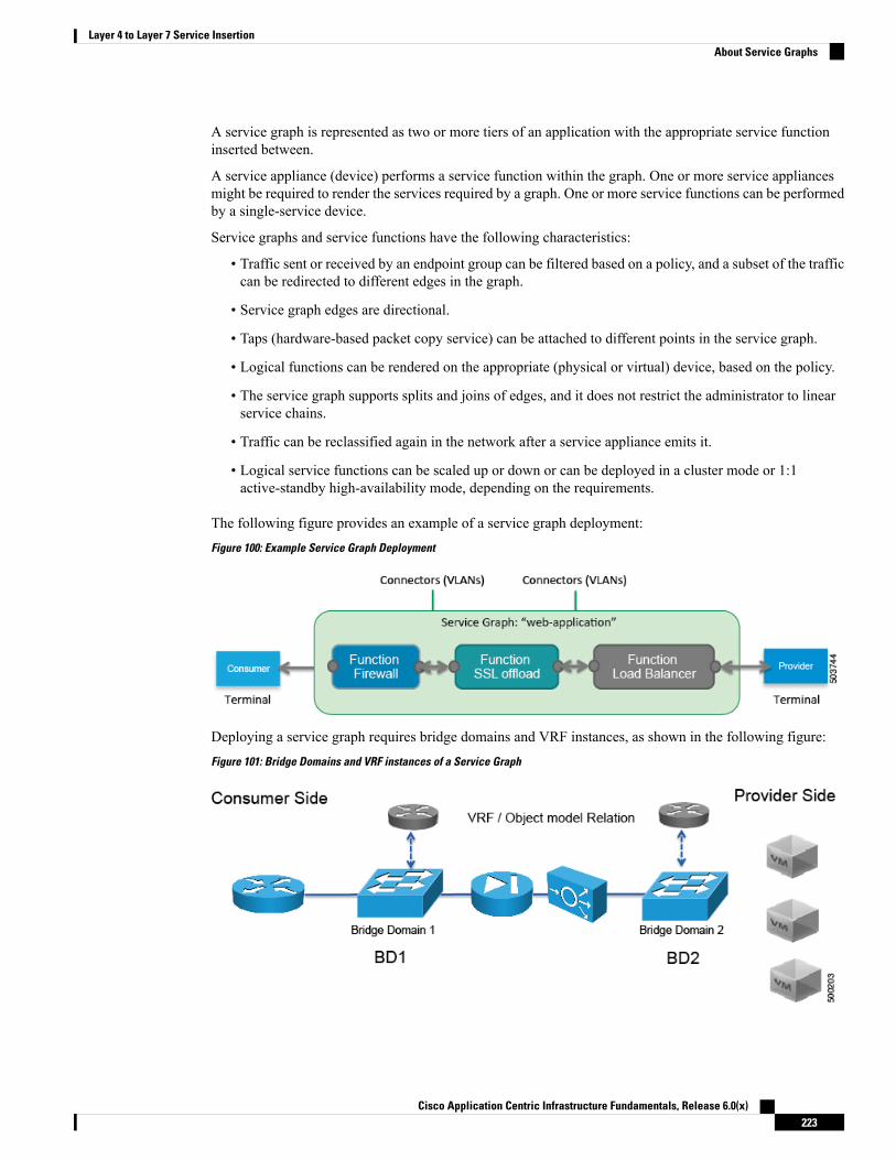
A service graph is represented as two or more tiers of an application with the appropriate service functioninserted between.
A service appliance (device) performs a service function within the graph. One or more service appliancesmight be required to render the services required by a graph. One or more service functions can be performedby a single-service device.
Service graphs and service functions have the following characteristics:
• Traffic sent or received by an endpoint group can be filtered based on a policy, and a subset of the trafficcan be redirected to different edges in the graph.
• Service graph edges are directional.
• Taps (hardware-based packet copy service) can be attached to different points in the service graph.
• Logical functions can be rendered on the appropriate (physical or virtual) device, based on the policy.
• The service graph supports splits and joins of edges, and it does not restrict the administrator to linearservice chains.
• Traffic can be reclassified again in the network after a service appliance emits it.
• Logical service functions can be scaled up or down or can be deployed in a cluster mode or 1:1active-standby high-availability mode, depending on the requirements.
The following figure provides an example of a service graph deployment:
Figure 100: Example Service Graph Deployment
Deploying a service graph requires bridge domains and VRF instances, as shown in the following figure:
Figure 101: Bridge Domains and VRF instances of a Service Graph
Cisco Application Centric Infrastructure Fundamentals, Release 6.0(x)223
Layer 4 to Layer 7 Service InsertionAbout Service Graphs

If you have some of the legs of a service graph that are attached to endpoint groups in other tenants, whenyou use the Remove Related Objects of Graph Template function in the GUI, the Cisco APIC does notremove contracts that were imported from tenants other than where the service graph is located. The CiscoAPIC also does not clean endpoint group contracts that are located in a different tenant than the service graph.You must manually remove these objects that are in different tenants.
Note
About Policy-Based RedirectCisco Application Centric Infrastructure (ACI) policy-based redirect (PBR) enables provisioning serviceappliances, such as firewalls or load balancers. Typical use cases include provisioning service appliances thatcan be pooled, tailored to application profiles, scaled easily, and have reduced exposure to service outages.PBR simplifies the deployment of service appliances by enabling the provisioning consumer and providerendpoint groups to be all in the same virtual routing and forwarding (VRF) instance. PBR deployment consistsof configuring a route redirect policy and a cluster redirect policy, and creating a service graph template thatuses the route and cluster redirect policies. After the service graph template is deployed, use the serviceappliance by enabling endpoint groups to consume the service graph provider endpoint group. This can befurther simplified and automated by using vzAny. While performance requirements may dictate provisioningdedicated service appliances, virtual service appliances can also be deployed easily using PBR.
The following figure illustrates the use case of redirecting specific traffic to the firewall:
Figure 102: Use Case: Redirecting Specific Traffic to the Firewall
In this use case, you must create two subjects. The first subject permits HTTP traffic, which then gets redirectedto the firewall. After the traffic passes through the firewall, it goes to the Web endpoint. The second subjectpermits all traffic, which captures traffic that is not redirected by the first subject. This traffic goes directlyto the Web endpoint.
The following figure illustrates a sample ACI PBR physical topology:
Cisco Application Centric Infrastructure Fundamentals, Release 6.0(x)224
Layer 4 to Layer 7 Service InsertionAbout Policy-Based Redirect

Figure 103: Sample ACI PBR Physical Topology
The following figure illustrates a sample ACI PBR logical topology:
Figure 104: Sample ACI PBR Logical Topology
While these examples illustrate simple deployments, ACI PBR enables scaling up mixtures of both physicaland virtual service appliances for multiple services, such as firewalls and server load balancers.
Cisco Application Centric Infrastructure Fundamentals, Release 6.0(x)225
Layer 4 to Layer 7 Service InsertionAbout Policy-Based Redirect
About Symmetric Policy-Based RedirectSymmetric policy-based redirect (PBR) configurations enable provisioning a pool of service nodes so thatthe traffic between the consumer and provider endpoint groups is load-balanced based on the policy. Thetraffic is redirected to one of the service nodes in the pool, depending on the source and destination IP equal-costmulti-path routing (ECMP) prefix hashing.
Symmetric PBR configurations require 9300-EX hardware or later.Note
Sample symmetric PBR REST posts are listed below:Under fvTenant svcCont
<vnsSvcRedirectPol name=“LoadBalancer_pool”><vnsRedirectDest name=“lb1” ip=“1.1.1.1” mac=“00:00:11:22:33:44”/><vnsRedirectDest name=“lb2” ip=“2.2.2.2” mac=“00:de:ad:be:ef:01”/><vnsRedirectDest name=“lb3” ip=“3.3.3.3” mac=“00:de:ad:be:ef:02”/>
</vnsSvcRedirectPol>
<vnsLIfCtx name=“external”><vnsRsSvcRedirectPol tnVnsSvcRedirectPolName=“LoadBalancer_pool”/><vnsRsLIfCtxToBD tDn=“uni/tn-solar/bd-fwBD”>
</vnsLIfCtx>
<vnsAbsNode name=“FW” routingMode=“redirect”>
Sample symmetric PBR NX-OS-style CLI commands are listed below.
The following commands under the tenant scope create a service redirect policy:apic1(config-tenant)# svcredir-pol fw-externalapic1(svcredir-pol)# redir-dest 2.2.2.2 00:11:22:33:44:56
The following commands enable PBR:apic1(config-tenant)# l4l7 graph FWOnly contract defaultapic1(config-graph)# service FW svcredir enable
The following commands set the redirect policy under the device selection policy connector:apic1(config-service)# connector externalapic1(config-connector)# svcredir-pol tenant solar name fw-external
Automated Service InsertionAlthough VLAN and virtual routing and forwarding (VRF) stitching is supported by traditional serviceinsertion models, the Application Policy Infrastructure Controller (APIC) can automate service insertion andthe provisioning of network services, such as Secure Sockets Layer (SSL) offload, server load balancing(SLB), Web Application firewall (WAF), and firewall, while acting as a central point of policy control. Thenetwork services are typically rendered by service appliances, such as Application Delivery Controllers (ADCs)and firewalls. The APIC policies manage both the network fabric and services appliances. The APIC canconfigure the network automatically so that traffic flows through the services. The APIC can also automaticallyconfigure the service according to the application's requirements, which allows organizations to automateservice insertion and eliminate the challenge of managing the complex techniques of traditional serviceinsertion.
Cisco Application Centric Infrastructure Fundamentals, Release 6.0(x)226
Layer 4 to Layer 7 Service InsertionAbout Symmetric Policy-Based Redirect

About Device PackagesThe Application Policy Infrastructure Controller (APIC) requires a device package to configure and monitorservice devices. You add service functions to the APIC through the device package. A device package managesa single class of service devices and provides the APIC with information about the device and its capabilities.A device package is a zip file that contains the following parts:
An XML file that defines the following:
• Device properties:
• Model—Model of the device.
• Vendor—Vendor of the device.
• Version—Software version of the device.
• Functions provided by a device, such as load balancing, contentswitching, and SSL termination.
• Interfaces and network connectivity information for each function.
• Device configuration parameters.
• Configuration parameters for each function.
Device specification
A Python script that interacts with the device from the APIC. APIC eventsare mapped to function calls that are defined in the device script. A devicepackage can contain multiple device scripts. A device script can interfacewith the device by using REST, SSH, or any similar mechanism.
Device script
Function parameters with default values that are specified by the vendor. Youcan configure a function to use these default values.
Function profile
A configuration file that specifies parameters that are required by a device.This configuration can be shared by one or more graphs using a device.
Device-level configurationparameters
You can create a device package or it can be provided by a device vendor or Cisco.
The following figure illustrates the interaction of a device package and the APIC:
Cisco Application Centric Infrastructure Fundamentals, Release 6.0(x)227
Layer 4 to Layer 7 Service InsertionAbout Device Packages

Figure 105: Device Package and the APIC
The functions in a device script are classified into the following categories:
• Device/Infrastructure—For device level configuration and monitoring
• Service Events—For configuring functions, such as a server load balancer or Secure Sockets Layer, onthe device
• Endpoint/Network Events—For handling endpoint and network attach/detach events
The APIC uses the device configuration model that is provided in the device package to pass the appropriateconfiguration to the device scripts. The device script handlers interface with the device using its REST or CLIinterface.
Cisco Application Centric Infrastructure Fundamentals, Release 6.0(x)228
Layer 4 to Layer 7 Service InsertionAbout Device Packages
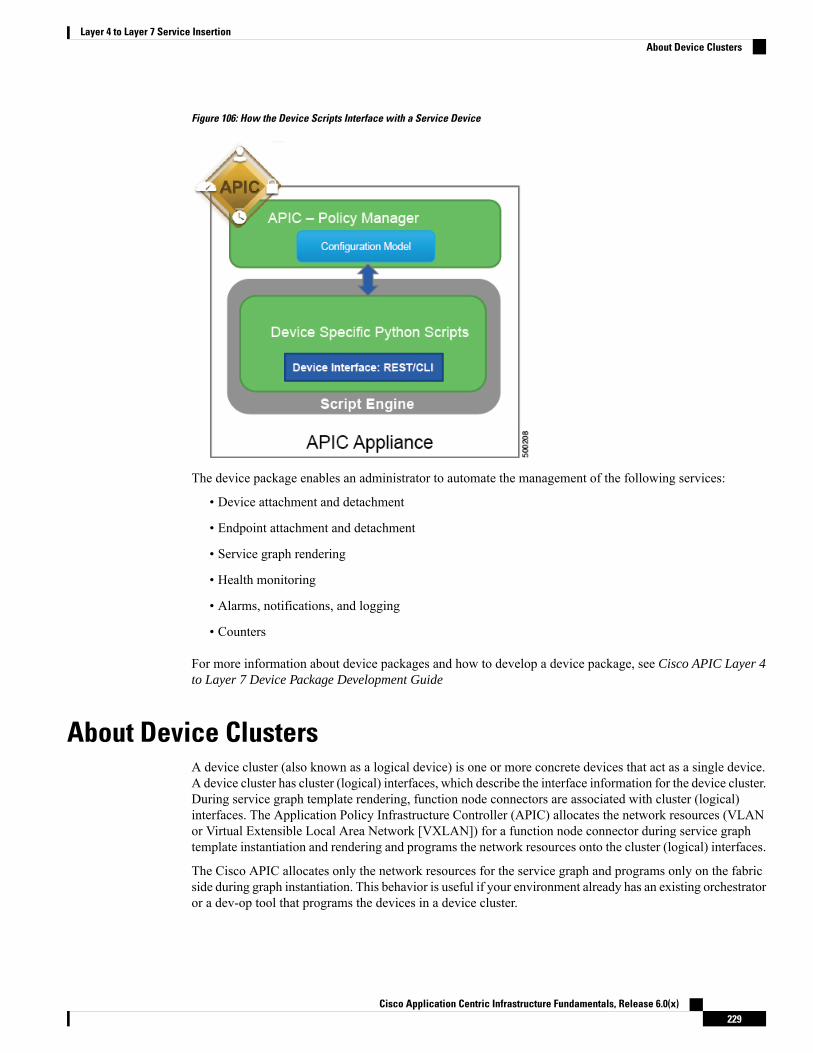
Figure 106: How the Device Scripts Interface with a Service Device
The device package enables an administrator to automate the management of the following services:
• Device attachment and detachment
• Endpoint attachment and detachment
• Service graph rendering
• Health monitoring
• Alarms, notifications, and logging
• Counters
For more information about device packages and how to develop a device package, see Cisco APIC Layer 4to Layer 7 Device Package Development Guide
About Device ClustersA device cluster (also known as a logical device) is one or more concrete devices that act as a single device.A device cluster has cluster (logical) interfaces, which describe the interface information for the device cluster.During service graph template rendering, function node connectors are associated with cluster (logical)interfaces. The Application Policy Infrastructure Controller (APIC) allocates the network resources (VLANor Virtual Extensible Local Area Network [VXLAN]) for a function node connector during service graphtemplate instantiation and rendering and programs the network resources onto the cluster (logical) interfaces.
The Cisco APIC allocates only the network resources for the service graph and programs only on the fabricside during graph instantiation. This behavior is useful if your environment already has an existing orchestratoror a dev-op tool that programs the devices in a device cluster.
Cisco Application Centric Infrastructure Fundamentals, Release 6.0(x)229
Layer 4 to Layer 7 Service InsertionAbout Device Clusters
The Cisco APIC needs to know the topology information (logical interface and concrete interface) for thedevice cluster and devices. This information enables the Cisco APIC to program the appropriate ports on theleaf switch, and the Cisco APIC can also use this information for troubleshooting wizard purposes. The CiscoAPIC also needs to know the relation to DomP, which is used for allocating the encapsulation.
The following settings are not needed:
• Connectivity information for the logical device (vnsLDevViP) and devices (CDev): management IP address,credentials, and in-band connectivity information
• Information about supported function type (go-through, go-to, L1, L2)
• Information about context awareness (single context or multi-context)
The service graph template uses a specific device that is based on a device selection policy (called a logicaldevice context) that an administrator defines.
An administrator can set up a maximum of two concrete devices in active-standby mode.
To set up a device cluster, you must perform the following tasks:
1. Connect the concrete devices to the fabric.
2. Assign the management IP address to the device cluster.
3. Register the device cluster with the Cisco APIC.
The Cisco APIC does not validate a duplicate IP address that is assigned to two device clusters. The CiscoAPIC can provision the wrong device cluster when two device clusters have the samemanagement IP address.If you have duplicate IP addresses for your device clusters, delete the IP address configuration on one of thedevices and ensure there are no duplicate IP addresses that are provisioned for the management IP addressconfiguration.
Note
About Device Managers and Chassis ManagersA device manager serves as a single point of configuration for a set of clusters in a Cisco Application CentricInfrastructure (ACI) fabric. The administration or operational state is presented in the native GUI of thedevices. A device manager handles configuration on individual devices and enables you to simplify theconfiguration in the Application Policy Infrastructure Controller (APIC). You create a template in devicemanager, then populate the device manager with instance-specific values from the APIC, which requires onlya few values.
The following figure illustrates a device manager controlling multiple devices in a cluster:
Cisco Application Centric Infrastructure Fundamentals, Release 6.0(x)230
Layer 4 to Layer 7 Service InsertionAbout Device Managers and Chassis Managers
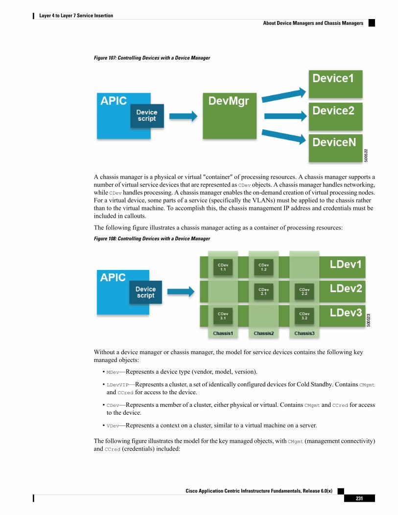
Figure 107: Controlling Devices with a Device Manager
A chassis manager is a physical or virtual "container" of processing resources. A chassis manager supports anumber of virtual service devices that are represented as CDev objects. A chassis manager handles networking,while CDev handles processing. A chassis manager enables the on-demand creation of virtual processing nodes.For a virtual device, some parts of a service (specifically the VLANs) must be applied to the chassis ratherthan to the virtual machine. To accomplish this, the chassis management IP address and credentials must beincluded in callouts.
The following figure illustrates a chassis manager acting as a container of processing resources:
Figure 108: Controlling Devices with a Device Manager
Without a device manager or chassis manager, the model for service devices contains the following keymanaged objects:
• MDev—Represents a device type (vendor, model, version).
• LDevVIP—Represents a cluster, a set of identically configured devices for Cold Standby. Contains CMgmtand CCred for access to the device.
• CDev—Represents a member of a cluster, either physical or virtual. Contains CMgmt and CCred for accessto the device.
• VDev—Represents a context on a cluster, similar to a virtual machine on a server.
The following figure illustrates the model for the key managed objects, with CMgmt (management connectivity)and CCred (credentials) included:
Cisco Application Centric Infrastructure Fundamentals, Release 6.0(x)231
Layer 4 to Layer 7 Service InsertionAbout Device Managers and Chassis Managers

Figure 109: Managed Object Model Without a Device Manager or Chassis Manager
CMgmt (host + port) and CCred (username + password) allow the script to access the device and cluster.
A device manager and chassis manager adds the ability to control the configuration of clusters and devicesfrom a central management station. The chassis adds a parallel hierarchy to the MDev object and ALDev objectto allow a CDev object to be tagged as belonging to a specific chassis. The following managed objects areadded to the model to support the device and chassis manager concept:
• MDevMgr—Represents a type of device manager. An MDevMgr can manage a set of different MDevs, whichare typically different products from the same vendor.
• DevMgr—Represents a device manager. Access to the manager is provided using the contained CMgmt
and CCred managed objects. Each cluster can be associated with only one DevMgr.
• MChassis—Represents a type of chassis. This managed object is typically included in the package.
• Chassis—Represents a chassis instance. It contains the CMgmt and CCred[Secret] managed objects toprovide connectivity to the chassis.
The following figure illustrates the device manager object model:
Cisco Application Centric Infrastructure Fundamentals, Release 6.0(x)232
Layer 4 to Layer 7 Service InsertionAbout Device Managers and Chassis Managers

Figure 110: Device Manager Object Model
The following figure illustrates the chassis manager object model:
Figure 111: Chassis Manager Object Model
About Concrete DevicesA concrete device can be either a physical device or a virtual device. A concrete device has concrete interfaces.When a concrete device is added to a logical device, the concrete interfaces are mapped to the logical interfaces.During service graph template instantiation, VLANs and VXLANs are programmed on concrete interfacesthat are based on their association with logical interfaces.
Cisco Application Centric Infrastructure Fundamentals, Release 6.0(x)233
Layer 4 to Layer 7 Service InsertionAbout Concrete Devices
About Function NodesA function node represents a single service function. A function node has function node connectors, whichrepresent the network requirement of a service function.
The Cisco Application Policy Infrastructure Controller (APIC) only allocates the network resources andprograms the VLAN/VXLAN on fabric side.
The following settings are not needed:
• MFunc relation
• Information about the supported function type (go-through, go-to)
The Cisco APIC needs to know the network information (LIF, CIF) for the function node. This informationis needed so that the Cisco APIC can program the network appropriately on the leaf switch, and the CiscoAPIC can also use this information for troubleshooting wizard purposes.
The following settings are still needed:
• LDevCtx to enable the selection of LDevVip during graph instantiation
• LIfCtx to enable the selection of LIf during graph instantiation
• Bridge domain in LIfCtx
• Route peering in LIfCtx
• Subnet in LIfCtx
For a Cisco ACI Multi-Site configuration, up to 2 nodes can be deployed in a service graph. For a non-CiscoACI Multi-Site configuration, up to 5 nodes can be deployed in a service graph.
Note
About Function Node ConnectorsA function node connector connects a function node to the service graph and is associated with the appropriatebridge domain and connections based on the graph's connector's subset. Each connector is associated with aVLAN or Virtual Extensible LAN (VXLAN). Each side of a connector is treated as an endpoint group (EPG),and whitelists are downloaded to the switch to enable communication between the two function nodes.
About Terminal NodesTerminal nodes connect a service graph with the contracts. You can insert a service graph for the trafficbetween two application endpoint groups (EPGs) by connecting the terminal node to a contract. Once connected,traffic between the consumer EPG and provider EPG of the contract is redirected to the service graph.
Cisco Application Centric Infrastructure Fundamentals, Release 6.0(x)234
Layer 4 to Layer 7 Service InsertionAbout Function Nodes

About PrivilegesAn administrator can grant privileges to the roles in the APIC. Privileges determine what tasks a role is allowedto perform. Administrators can grant the following privileges to the administrator roles:
DescriptionPrivilege
• Create a management EPG• Create management connectivity to other objects
nw-svc-connectivity
• Create a service graph• Attach a service graph to an application EPG anda contract
• Monitor a service graph
nw-svc-policy
• Create a device cluster• Create a concrete device• Create a device context
nw-svc-device
Only an infrastructure administrator can upload a device package to the APIC.Note
Service Automation and Configuration ManagementThe Cisco APIC can optionally act as a point of configurationmanagement and automation for service devicesand coordinate the service devices with the network automation. The Cisco APIC interfaces with a servicedevice by using Python scripts and calls device-specific Python script functions on various events.
The device scripts and a device specification that defines functions supported by the service device are bundledas a device package and installed on the Cisco APIC. The device script handlers interface with the device byusing its REST interface (preferred) or CLI based on the device configuration model.
Service Resource PoolingThe Cisco ACI fabric can perform nonstateful load distribution across many destinations. This capabilityallows organizations to group physical and virtual service devices into service resource pools, which can befurther grouped by function or location. These pools can offer high availability by using standardhigh-availability mechanisms or they can be used as simple stateful service engines with the load redistributedto the other members if a failure occurs. Either option provides horizontal scale out that far exceeds the currentlimitations of the equal-cost multipath (ECMP), port channel features, and service appliance clustering, whichrequires a shared state.
Cisco ACI can perform a simple version of resource pooling with any service devices if the service devicesdo not have to interact with the fabric, and it can perform more advanced pooling that involves coordinationbetween the fabric and the service devices.
Cisco Application Centric Infrastructure Fundamentals, Release 6.0(x)235
Layer 4 to Layer 7 Service InsertionAbout Privileges

Cisco Application Centric Infrastructure Fundamentals, Release 6.0(x)236
Layer 4 to Layer 7 Service InsertionService Resource Pooling

C H A P T E R 11Management Tools
This chapter contains the following sections:
• Management Tools, on page 237• About the Management GUI, on page 237• About the CLI, on page 237• User Login Menu Options, on page 238• Customizing the GUI and CLI Banners, on page 239• REST API, on page 239• Configuration Export/Import, on page 248• Programmability Using Puppet, on page 252
Management ToolsCisco Application Centric Infrastructure (ACI) tools help fabric administrators, network engineers, anddevelopers to develop, configure, debug, and automate the deployment of tenants and applications.
About the Management GUIThe following management GUI features provide access to the fabric and its components (leaves and spines):
• Based on universal web standards (HTML5). No installers or plugins are required.
• Access to monitoring (statistics, faults, events, audit logs), operational and configuration data.
• Access to the APIC and spine and leaf switches through a single sign-on mechanism.
• Communication with the APIC using the same RESTful APIs that are available to third parties.
About the CLIThe CLI features an operational and configuration interface to the APIC, leaf, and spine switches:
• Implemented from the ground up in Python; can switch between the Python interpreter and CLI
• Plugin architecture for extensibility
Cisco Application Centric Infrastructure Fundamentals, Release 6.0(x)237

• Virtual Routing and Forwarding (VRF)-based access to monitoring, operation, and configuration data
• Automation through Python commands or batch scripting
User Login Menu OptionsThe user login drop-downmenu provides several configuration, diagnostic, reference, and preference options.The figure below shows this drop-down menu.
Figure 112: User Login Menu Options
The options include the following:
• AAA options for changing the user password, SSHKeys, X509 Ce.jpgicate, and viewing the permissionsof the logged-on user.
The ACI fabric must be configured with an active Network Time Protocol (NTP)policy to assure that the system clocks on all devices are correct. Otherwise, ace.jpgicate could be rejected on nodes with out-of-sync time.
Note
• Show API Inspector opens the API Inspector.
• API Documentation opens the Management Information Model reference.
• Remote Logging.
• Debug information.
• About the current version number of the software.
• Settings preferences for using the GUI.
Cisco Application Centric Infrastructure Fundamentals, Release 6.0(x)238
Management ToolsUser Login Menu Options

• Logout to exit the system.
Customizing the GUI and CLI BannersGUI and CLI banners can be in the Admin >AAA> Security management section of the GUI. The CLI bannerdisplays before user login authentication. The CLI banner is a text based string printed as-is to the console.The GUI banner displays before user login authentication. The GUI banner is a URL. The URL must allowthe being placed in an iFrame. If the URL x-frame-option is set to deny or sameorigin, the URL will notappear before user login authentication.
REST API
About the REST APIThe Application Policy Infrastructure Controller (APIC) REST API is a programmatic interface that usesREST architecture. The API accepts and returns HTTP (not enabled by default) or HTTPS messages thatcontain JavaScript Object Notation (JSON) or Extensible Markup Language (XML) documents. You can useany programming language to generate the messages and the JSON or XML documents that contain the APImethods or Managed Object (MO) descriptions.
The REST API is the interface into the management information tree (MIT) and allows manipulation of theobject model state. The same REST interface is used by the APIC CLI, GUI, and SDK, so that wheneverinformation is displayed, it is read through the REST API, and when configuration changes are made, theyare written through the RESTAPI. The RESTAPI also provides an interface through which other informationcan be retrieved, including statistics, faults, and audit events. It even provides a means of subscribing topush-based event notification, so that when a change occurs in the MIT, an event can be sent through a websocket.
Standard REST methods are supported on the API, which includes POST, GET, and DELETE operationsthrough HTTP. The POST and DELETE methods are idempotent, meaning that there is no additional effectif they are called more than once with the same input parameters. The GET method is nullipotent, meaningthat it can be called zero or more times without making any changes (or that it is a read-only operation).
Payloads to and from the REST interface can be encapsulated through either XML or JSON encoding. In thecase of XML, the encoding operation is simple: the element tag is the name of the package and class, and anyproperties of that object are specified as attributes of that element. Containment is defined by creating childelements.
For JSON, encoding requires definition of certain entities to reflect the tree-based hierarchy; however, thedefinition is repeated at all levels of the tree, so it is fairly simple to implement after it is initially understood.
• All objects are described as JSON dictionaries, in which the key is the name of the package and class.The value is another nested dictionary with two keys: attribute and children.
• The attribute key contains a further nested dictionary describing key-value pairs that define attributes onthe object.
• The children key contains a list that defines all the child objects. The children in this list are dictionariescontaining any nested objects, which are defined as described here.
Cisco Application Centric Infrastructure Fundamentals, Release 6.0(x)239
Management ToolsCustomizing the GUI and CLI Banners
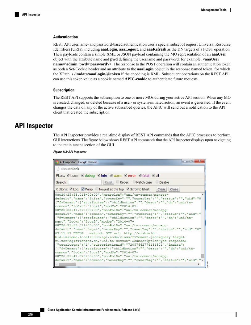
Authentication
REST API username- and password-based authentication uses a special subset of request Universal ResourceIdentifiers (URIs), including aaaLogin, aaaLogout, and aaaRefresh as the DN targets of a POST operation.Their payloads contain a simple XML or JSON payload containing the MO representation of an aaaUserobject with the attribute name and pwd defining the username and password: for example, <aaaUsername='admin' pwd='password'/>. The response to the POST operation will contain an authentication tokenas both a Set-Cookie header and an attribute to the aaaLogin object in the response named token, for whichthe XPath is /imdata/aaaLogin/@token if the encoding is XML. Subsequent operations on the REST APIcan use this token value as a cookie named APIC-cookie to authenticate future requests.
Subscription
The REST API supports the subscription to one or more MOs during your active API session. When any MOis created, changed, or deleted because of a user- or system-initiated action, an event is generated. If the eventchanges the data on any of the active subscribed queries, the APIC will send out a notification to the APIclient that created the subscription.
API InspectorThe API Inspector provides a real-time display of REST API commands that the APIC processes to performGUI interactions. The figure below showsRESTAPI commands that the API Inspector displays upon navigatingto the main tenant section of the GUI.
Figure 113: API Inspector
Cisco Application Centric Infrastructure Fundamentals, Release 6.0(x)240
Management ToolsAPI Inspector

Visore Managed Object ViewerVisore is a read-only management information tree (MIT) browser as shown in the figure below. It enablesdistinguished name (DN) and class queries with optional filters.
Figure 114: Visore MO Viewer
The Visore managed object viewer is at this location: http(s)://host[:port]/visore.html
Management Information Model ReferenceThe Management Information Model (MIM) contains all of the managed objects in the system and theirproperties. For details, see the Cisco APIC Management Information Model Reference Guide.
See the following figure for an example of how an administrator can use the MIM to research an object in theMIT.
Cisco Application Centric Infrastructure Fundamentals, Release 6.0(x)241
Management ToolsVisore Managed Object Viewer
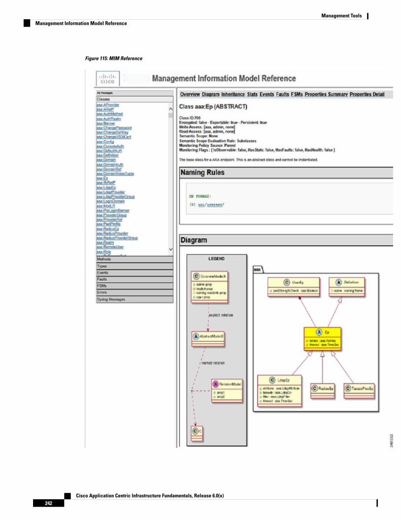
Figure 115: MIM Reference
Cisco Application Centric Infrastructure Fundamentals, Release 6.0(x)242
Management ToolsManagement Information Model Reference

Locating Objects in the MITThe Cisco ACI uses an information-model-based architecture (management information tree [MIT]) in whichthe model describes all the information that can be controlled by a management process. Object instances arereferred to as managed objects (MOs).
The following figure shows the distinguished name, which uniquely represents any given MO instance, andthe relative name, which represents the MO locally underneath its parent MO. All objects in the MIT existunder the root object.
Figure 116: MO Distinguished and Relative Names
Every MO in the system can be identified by a unique distinguished name (DN). This approach allows theobject to be referred to globally. In addition to its distinguished name, each object can be referred to by itsrelative name (RN). The relative name identifies an object relative to its parent object. Any given object'sdistinguished name is derived from its own relative name that is appended to its parent object's distinguishedname.
A DN is a sequence of relative names that uniquely identifies an object:dn = {rn}/{rn}/{rn}/{rn}
dn =”sys/ch/lcslot-1/lc/leafport-1”
Distinguished names are directly mapped to URLs. Either the relative name or the distinguished name can beused to access an object, depending on the current location in the MIT.
Cisco Application Centric Infrastructure Fundamentals, Release 6.0(x)243
Management ToolsLocating Objects in the MIT

Because of the hierarchical nature of the tree and the attribute system used to identify object classes, the treecan be queried in several ways for obtaining managed object information. Queries can be performed on anobject itself through its distinguished name, on a class of objects such as a switch chassis, or on a tree-levelto discover all members of an object.
Tree-Level QueriesThe following figure shows two chassis that are queried at the tree level.
Figure 117: Tree-Level Queries
Both queries return the referenced object and its child objects. This approach is useful for discovering thecomponents of a larger system. In this example, the query discovers the cards and ports of a given switchchassis.
Class-Level QueriesThe following figure shows the second query type: the class-level query.
Cisco Application Centric Infrastructure Fundamentals, Release 6.0(x)244
Management ToolsTree-Level Queries
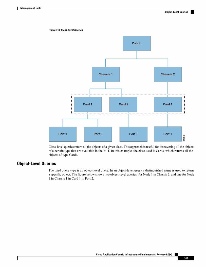
Figure 118: Class-Level Queries
Class-level queries return all the objects of a given class. This approach is useful for discovering all the objectsof a certain type that are available in the MIT. In this example, the class used is Cards, which returns all theobjects of type Cards.
Object-Level QueriesThe third query type is an object-level query. In an object-level query a distinguished name is used to returna specific object. The figure below shows two object-level queries: for Node 1 in Chassis 2, and one for Node1 in Chassis 1 in Card 1 in Port 2.
Cisco Application Centric Infrastructure Fundamentals, Release 6.0(x)245
Management ToolsObject-Level Queries
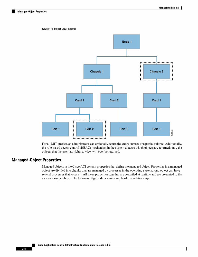
Figure 119: Object-Level Queries
For all MIT queries, an administrator can optionally return the entire subtree or a partial subtree. Additionally,the role-based access control (RBAC) mechanism in the system dictates which objects are returned; only theobjects that the user has rights to view will ever be returned.
Managed-Object PropertiesManaged objects in the Cisco ACI contain properties that define the managed object. Properties in a managedobject are divided into chunks that are managed by processes in the operating system. Any object can haveseveral processes that access it. All these properties together are compiled at runtime and are presented to theuser as a single object. The following figure shows an example of this relationship.
Cisco Application Centric Infrastructure Fundamentals, Release 6.0(x)246
Management ToolsManaged-Object Properties

Figure 120: Managed Object Properties
The example object has three processes that write to property chunks that are in the object. The datamanagementengine (DME), which is the interface between the Cisco APIC (the user) and the object, the port manager,which handles port configuration, and the spanning tree protocol (STP) all interact with chunks of this object.The APIC presents the object to the user as a single entity compiled at runtime.
Accessing the Object Data Through REST InterfacesREST is a software architecture style for distributed systems such as the World Wide Web. REST hasincreasingly displaced other design models such as Simple Object Access Protocol (SOAP) andWeb ServicesDescription Language (WSDL) due to its simpler style. The Cisco APIC supports REST interfaces forprogrammatic access to the entire Cisco ACI solution.
The object-based information model of Cisco ACI makes it a very good fit for REST interfaces: URLs andURIs map directly to distinguished names that identify objects on the MIT, and any data on the MIT can bedescribed as a self-contained structured text tree document that is encoded in XML or JSON. The objectshave parent-child relationships that are identified using distinguished names and properties, which are readand modified by a set of create, read, update, and delete (CRUD) operations.
Objects can be accessed at their well-defined address, their REST URLs, using standard HTTP commandsfor retrieval andmanipulation of Cisco APIC object data. The URL format used can be represented as follows:<system>/api/[mo|class]/[dn|class][:method].[xml|json]?{options}
The various building blocks of the preceding URL are as follows:
• system: System identifier; an IP address or DNS-resolvable hostname
• mo | class: Indication of whether this is a MO in the MIT, or class-level query
• class: MO class (as specified in the information model) of the objects queried; the class name isrepresented as <pkgName><ManagedObjectClassName>
• dn: Distinguished name (unique hierarchical name of the object in the MIT) of the object queried
• method: Optional indication of the method being invoked on the object; applies only to HTTP POSTrequests
• xml | json: Encoding format
Cisco Application Centric Infrastructure Fundamentals, Release 6.0(x)247
Management ToolsAccessing the Object Data Through REST Interfaces

• options: Query options, filters, and arguments
With the capability to address and access an individual object or a class of objects with the REST URL, anadministrator can achieve complete programmatic access to the entire object tree and to the entire system.
The following are REST query examples:
• Find all EPGs and their faults under tenant solar.http://192.168.10.1:7580/api/mo/uni/tn-solar.xml?query-target=subtree&target-subtree-class=fvAEPg&rsp-subtree-include=faults
• Filtered EPG queryhttp://192.168.10.1:7580/api/class/fvAEPg.xml?query-target-filter=eq(fvAEPg.fabEncap,%20"vxlan-12780288")
Configuration Export/ImportAll APIC policies and configuration data can be exported to create backups. This is configurable via an exportpolicy that allows either scheduled or immediate backups to a remote server. Scheduled backups can beconfigured to execute periodic or recurring backup jobs. By default, all policies and tenants are backed up,but the administrator can optionally specify only a specific subtree of the management information tree.Backups can be imported into the APIC through an import policy, which allows the system to be restored toa previous configuration.
Configuration Database ShardingThe APIC cluster uses a large database technology called sharding. This technology provides scalability andreliability to the data sets generated and processed by the APIC. The data for APIC configurations is partitionedinto logically bounded subsets called shards which are analogous to database shards. A shard is a unit of datamanagement, and the APIC manages shards in the following ways:
• Each shard has three replicas.
• Shards are evenly distributed across the appliances that comprise the APIC cluster.
One or more shards are located on each APIC appliance. The shard data assignments are based on apredetermined hash function, and a static shard layout determines the assignment of shards to appliances.
Configuration File EncryptionAs of release 1.1(2), the secure properties of APIC configuration files can be encrypted by enabling AES-256encryption. AES encryption is a global configuration option; all secure properties conform to the AESconfiguration setting. It is not possible to export a subset of the ACI fabric configuration such as a tenantconfiguration with AES encryption while not encrypting the remainder of the fabric configuration. See theCisco Application Centric Infrastructure Fundamentals, "Secure Properties" chapter for the list of secureproperties.
The APIC uses a 16 to 32 character passphrase to generate the AES-256 keys. The APIC GUI displays a hashof the AES passphrase. This hash can be used to see if the same passphrases was used on two ACI fabrics.This hash can be copied to a client computer where it can be compared to the passphrase hash of another ACIfabric to see if they were generated with the same passphrase. The hash cannot be used to reconstruct theoriginal passphrase or the AES-256 keys.
Cisco Application Centric Infrastructure Fundamentals, Release 6.0(x)248
Management ToolsConfiguration Export/Import

Observe the following guidelines when working with encrypted configuration files:
• Backward compatibility is supported for importing old ACI configurations into ACI fabrics that use theAES encryption configuration option.
Reverse compatibility is not supported; configurations exported fromACI fabricsthat have enabled AES encryption cannot be imported into older versions of theAPIC software.
Note
• Always enable AES encryption when performing fabric backup configuration exports. Doing so willassure that all the secure properties of the configuration will be successfully imported when restoringthe fabric.
If a fabric backup configuration is exported without AES encryption enabled,none of the secure properties will be included in the export. Since such anunencrypted backup would not include any of the secure properties, it is possiblethat importing such a file to restore a system could result in the administratoralong with all users of the fabric being locked out of the system.
Note
• The AES passphrase that generates the encryption keys cannot be recovered or read by an ACIadministrator or any other user. The AES passphrase is not stored. The APIC uses the AES passphraseto generate the AES keys, then discards the passphrase. The AES keys are not exported. The AES keyscannot be recovered since they are not exported and cannot be retrieved via the REST API.
• The same AES-256 passphrase always generates the same AES-256 keys. Configuration export files canbe imported into other ACI fabrics that use the same AES passphrase.
• For troubleshooting purposes, export a configuration file that does not contain the encrypted data of thesecure properties. Temporarily turning off encryption before performing the configuration export removesthe values of all secure properties from the exported configuration. To import such a configuration filethat has all secure properties removed, use the import merge mode; do not use the import replace mode.Using the import merge mode will preserve the existing secure properties in the ACI fabric.
• By default, the APIC rejects configuration imports of files that contain fields that cannot be decrypted.Use caution when turning off this setting. Performing a configuration import inappropriately when thisdefault setting is turned off could result in all the passwords of the ACI fabric to be removed upon theimport of a configuration file that does not match the AES encryption settings of the fabric.
Failure to observe this guideline could result in all users, including fabricadministrations, being locked out of the system.
Note
Configuration ExportThe following figure shows how the process works for configuring an export policy.
Cisco Application Centric Infrastructure Fundamentals, Release 6.0(x)249
Management ToolsConfiguration Export

Figure 121: Workflow for Configuring an Export Policy
The APIC applies this policy in the following way:
• A complete system configuration backup is performed once a month.
• The backup is stored in XML format on the BigBackup FTP site.
• The policy is triggered (it is active).
Configuration ImportAn administrator can create an import policy that performs the import in one of the following two modes:
• Best-effort—ignores objects within a shard that cannot be imported. If the version of the incomingconfiguration is incompatible with the existing system, shards that are incompatible are not be importedwhile the import proceeds with those that can be imported.
• Atomic—ignores shards that contain objects that cannot be imported while proceeding with shards thatcan be imported. If the version of the incoming configuration is incompatible with the existing system,the import terminates.
An import policy supports the following combinations of mode and type:
• Best-effort Merge—imported configuration is merged with existing configuration but ignores objectsthat cannot be imported.
• Atomic Merge—imported configuration is merged with the existing configuration, but ignores shardsthat contain objects that cannot be imported.
• Atomic Replace—overwrites existing configuration with imported configuration data. Any objects inthe existing configuration that do not exist in the imported configuration are deleted. Objects are deletedfrom the existing configuration that have children in the existing configuration but do not have childrenin the incoming imported configuration. For example, if an existing configuration has two tenants, solarand wind, but the imported backed up configuration was saved before the tenant wind was created, tenantsoar is restored from the backup but tenant wind is deleted.
Cisco Application Centric Infrastructure Fundamentals, Release 6.0(x)250
Management ToolsConfiguration Import

The following figure shows how the process works for configuring an import policy.
Figure 122: Workflow for Configuring an Import Policy
The APIC applies this policy in the following way:
• A policy is created to perform a complete system configuration restore from monthly backup.
• The atomic replace mode does the following:
• Overwrites the existing configuration.
• Deletes any existing configuration objects that are not present in the imported file.
• Deletes non-present children objects.
• The policy is untriggered (it is available but has not been activated).
Tech Support, Statistics, CoreAn administrator can configure export policies in the APIC to export statistics, technical support collections,faults and events, to process core files and debug data from the fabric (APIC as well as switch) to any externalhost. The exports can be in a variety of formats, including XML, JSON, web sockets, SCP, or HTTP. Exportsare subscribable, and can be streaming, periodic, or on-demand.
The maximum number of statistics export policies is approximately equal to the number of tenants. Eachtenant can have multiple statistics export policies and multiple tenants can share the same export policy, butthe total number of policies is limited to approximately the number of tenants.
Note
Cisco Application Centric Infrastructure Fundamentals, Release 6.0(x)251
Management ToolsTech Support, Statistics, Core

An administrator can configure policy details such as the transfer protocol, compression algorithm, andfrequency of transfer. Policies can be configured by users who are authenticated using AAA. A securitymechanism for the actual transfer is based on a username and password. Internally, a policy element handlesthe triggering of data.
Programmability Using Puppet
About PuppetPuppet is a configuration management tool from Puppet Labs, Inc. Although Puppet was originally designedfor large scale server management, many datacenter operators would like to consolidate server and networkdevice provisioning using the same tool.
The following items are the primary components of a Puppet implementation:
• Manifest – A Puppet manifest is a collection of property definitions for setting the state of a manageddevice (node). The details for checking and setting these property states are abstracted so that a manifestcan be used for more than one operating system or platform.
• Master – A Puppet master (server) typically runs on a separate dedicated server and serves multiplenodes. The Puppet master compiles configuration manifests and provides them to the nodes on request.
• Agent or Device – A Puppet agent runs on the node, where it periodically connects to the Puppet masterto request a configuration manifest. The agent reconciles the received manifest with the current state ofthe node, updating the node state as necessary to resolve any differences. For nodes that cannot run anembedded Puppet agent or prefer not to, Puppet supports a construct called a Puppet device. A Puppetdevice is essentially a proxy mechanism, external to the node, that requests the manifest from the Puppetmaster on behalf of the node. The Puppet device then applies any updates required by the receivedmanifest to the node. To leverage this capability, a vendor must provide a vendor-specific implementationof the device class along with a Puppet module that makes use of the device. The vendor-specific deviceclass uses a proprietary protocol or API to configure the remote node.
For further information and documentation about Puppet, see the Puppet website at the following URL:https://puppet.com/.
Cisco ciscoacipuppet Puppet ModuleAn APIC controller does not run an embedded Puppet agent. Instead, Cisco provides a Puppet module("ciscoacipuppet"), which uses a Cisco ACI-specific Puppet device to relay configurationmanagement requeststo the APIC controller. The ciscoacipuppet module interprets change information in the received Puppetmanifest and translates the change requests into APICRESTAPImessages to implement configuration changesin the ACI fabric.
For details on the installation, setup, and usage of the ciscoacipuppet module, refer to the documentation onGitHub and Puppet Forge at the following URLs:
• GitHub – https://github.com/cisco/cisco-network-puppet-module
• Puppet Forge – https://forge.puppet.com/puppetlabs/ciscoacipuppet
Cisco Application Centric Infrastructure Fundamentals, Release 6.0(x)252
Management ToolsProgrammability Using Puppet

Puppet Guidelines and Limitations for ACI• Only a subset of APIC managed objects can be provisioned using the ciscoacipuppet Puppet module. Tounderstand the level of support and the limitations, refer to the ciscoacipuppet module documentationon GitHub and Puppet Forge.
Cisco Application Centric Infrastructure Fundamentals, Release 6.0(x)253
Management ToolsPuppet Guidelines and Limitations for ACI

Cisco Application Centric Infrastructure Fundamentals, Release 6.0(x)254
Management ToolsPuppet Guidelines and Limitations for ACI

C H A P T E R 12Monitoring
This chapter contains the following sections:
• Faults, Errors, Events, Audit Logs, on page 255• Statistics Properties, Tiers, Thresholds, and Monitoring, on page 260• About Statistics Data, on page 261• Configuring Monitoring Policies, on page 261• Tetration Analytics, on page 265• NetFlow, on page 265
Faults, Errors, Events, Audit Logs
For information about faults, events, errors, and system messages, see the Cisco APIC Faults, Events, andSystem Messages Management Guide and the Cisco APIC Management Information Model Reference, aWeb-based application.
Note
The APIC maintains a comprehensive, current run-time representation of the administrative and operationalstate of the ACI Fabric system in the form of a collection of MOs. The system generates faults, errors, events,and audit log data according to the run-time state of the system and the policies that the system and user createto manage these processes.
The APIC GUI enables you to create customized "historical record groups" of fabric switches, to which youcan then assign customized switch policies that specify customized size and retention periods for the auditlogs, event logs, health logs, and fault logs maintained for the switches in those groups.
The APICGUI also enables you to customize a global controller policy that specifies size and retention periodsfor the audit logs, event logs, health logs, and fault logs maintained for the controllers on this fabric.
FaultsBased on the run-time state of the system, the APIC automatically detects anomalies and creates fault objectsto represent them. Fault objects contain various properties that are meant to help users diagnose the issue,assess its impact and provide a remedy.
For example, if the system detects a problem associated with a port, such as a high parity-error rate, a faultobject is automatically created and placed in the management information tree (MIT) as a child of the port
Cisco Application Centric Infrastructure Fundamentals, Release 6.0(x)255

object. If the same condition is detected multiple times, no additional instances of the fault object are created.After the condition that triggered the fault is remedied, the fault object is preserved for a period of timespecified in a fault life-cycle policy and is finally deleted. See the following figure.
Figure 123: Fault Life Cycle
A life cycle represents the current state of the issue. It starts in the soak time when the issue is first detected,and it changes to raised and remains in that state if the issue is still present. When the condition is cleared, itmoves to a state called "raised-clearing" in which the condition is still considered as potentially present. Thenit moves to a "clearing time" and finally to "retaining". At this point, the issue is considered to be resolvedand the fault object is retained only to provide the user visibility into recently resolved issues.
Each time that a life-cycle transition occurs, the system automatically creates a fault record object to log it.Fault records are never modified after they are created and they are deleted only when their number exceedsthe maximum value specified in the fault retention policy.
The severity is an estimate of the impact of the condition on the capability of the system to provide service.Possible values are warning, minor, major and critical. A fault with a severity equal to warning indicates apotential issue (including, for example, an incomplete or inconsistent configuration) that is not currentlyaffecting any deployed service. Minor and major faults indicate that there is potential degradation in the servicebeing provided. Critical means that a major outage is severely degrading a service or impairing it altogether.Description contains a human-readable description of the issue that is meant to provide additional informationand help in troubleshooting.
The following figure shows the process for fault and events reporting:
Cisco Application Centric Infrastructure Fundamentals, Release 6.0(x)256
MonitoringFaults
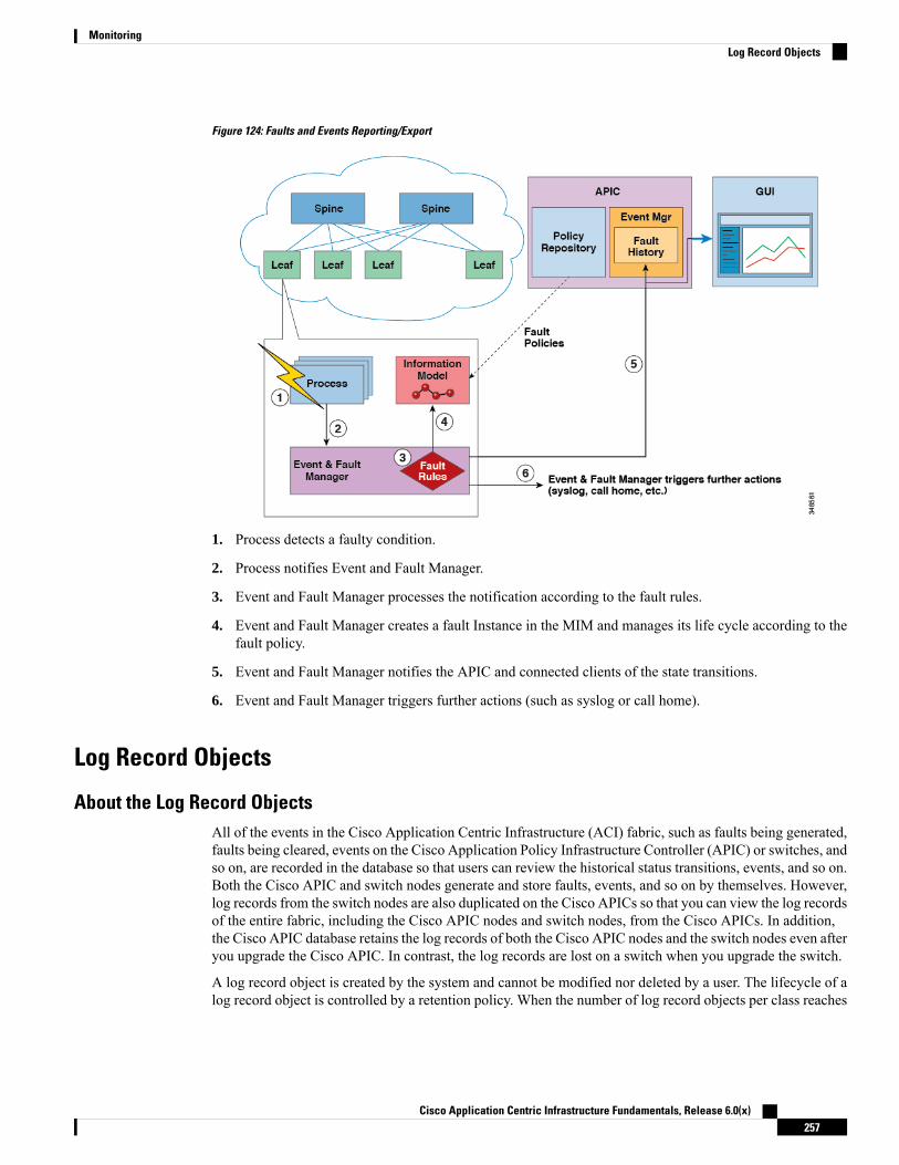
Figure 124: Faults and Events Reporting/Export
1. Process detects a faulty condition.
2. Process notifies Event and Fault Manager.
3. Event and Fault Manager processes the notification according to the fault rules.
4. Event and Fault Manager creates a fault Instance in the MIM and manages its life cycle according to thefault policy.
5. Event and Fault Manager notifies the APIC and connected clients of the state transitions.
6. Event and Fault Manager triggers further actions (such as syslog or call home).
Log Record Objects
About the Log Record ObjectsAll of the events in the Cisco Application Centric Infrastructure (ACI) fabric, such as faults being generated,faults being cleared, events on the Cisco Application Policy Infrastructure Controller (APIC) or switches, andso on, are recorded in the database so that users can review the historical status transitions, events, and so on.Both the Cisco APIC and switch nodes generate and store faults, events, and so on by themselves. However,log records from the switch nodes are also duplicated on the Cisco APICs so that you can view the log recordsof the entire fabric, including the Cisco APIC nodes and switch nodes, from the Cisco APICs. In addition,the Cisco APIC database retains the log records of both the Cisco APIC nodes and the switch nodes even afteryou upgrade the Cisco APIC. In contrast, the log records are lost on a switch when you upgrade the switch.
A log record object is created by the system and cannot be modified nor deleted by a user. The lifecycle of alog record object is controlled by a retention policy. When the number of log record objects per class reaches
Cisco Application Centric Infrastructure Fundamentals, Release 6.0(x)257
MonitoringLog Record Objects

the maximum limit in the retention policy, the oldest log record objects are purged from database to makeroom for the new records.
The log record objects are divided into the following log record classes:
• Fault Records: Fault records show the history of lifecycle change. A fault rule is defined on a managedobject class. When a managed object has a faulty condition, a fault is raised and becomes associated withthe managed object. When the faulty condition is gone, the fault is cleared. Every time a fault is raisedor cleared or the lifecycle state is changed, a fault record object is created to record the change of thefault state.
• Event Records: These are events managed by the Cisco APIC. Each event record represents an eventthat occurred on the switches or on the Cisco APIC nodes. An event rule is defined on a managed objectclass. When a managed object state matches the event rule, an event (or eventRecord object) is created.For example, if you unplug a card from a switch, the switch event manager generates an event notificationfor the user operation.
• Audit Logs: Audit logs are historic records that log when a managed object is changed and includeswhich user made the change. Audit logs also log thosemanaged objects changed by the system internally.
• Session Logs: Session logs are historic records that log when a user logged in or out of the Cisco APICor a switch and includes the client's IP address.
• Health Records: Health records are historical records of the health score change on a managed object.Every time a managed object's health score changes by 5 points, a health record object is created.
The maximum number of each log record objects in the fabric is defined by the retention policy, which couldbe millions across the fabric. When querying such huge amounts data, the response to the query may becomeslow and in the worst case the query may fail. To prevent that, beginning with Cisco APIC release 5.1(1), thereader process was enhanced specifically for log record objects to respond much faster. However, as a tradeoff, the sorting across queries (pages) is not guaranteed.
The query performance improvement and the new limitation apply only to the query for the log record objectsmentioned in this section.
Beginning with Cisco APIC release 5.2(3), with the new API query option time-range that is supported onlyfor log record objects, the Cisco APIC can respond to the API query for the log record objects much fasterwhile maintaining sorting across pages. The Cisco APIC GUI also uses the time-range option for improvedperformance and sorting. For more information about querying log record objects, see the Cisco APIC RESTAPI Configuration Guide, Release 4.2(x) and Later.
Viewing the Log Record Objects Using the GUIYou can use the Cisco Application Policy Infrastructure Controller (APIC) GUI to view the log record objectsfrom the database of either the Cisco APIC or a switch. Beginning with the 5.2(3) release, use one of thefollowing methods to view the log record objects:
• For all Cisco APICs and switches in the fabric, go to the System > History tab, then choose one of thelog record tabs in the Work pane.
• For a specific switch, go to theFabric > Inventory tab. In theNavigation pane, go to pod_id > leaf_name.In the Work pane, choose the History tab, then choose one of the log record subtabs.
The records are displayed in descending order based on the created time and date. You can narrow the displayedlog records based on a time period by clicking the down arrow to the right of the History within the last xtime_measurement and choosing a time period. The custom choice enables you to specify any range of dates.
Cisco Application Centric Infrastructure Fundamentals, Release 6.0(x)258
MonitoringViewing the Log Record Objects Using the GUI

You can also narrow the displayed log records by creating one or more filters. Click in the Filter by attributesfield, choose an attribute, choose an operator, then choose or enter a value (depending on the attribute). Repeatthis process for each filter that you want to create.
Alternatively, hover over a value in the table of records, which causes a filter icon to appear (represented bya funnel) to the right of the value, then click the icon. Doing so automatically creates a filter with the appropriateparameters. For example, if you are viewing the fault records and you click the filter icon for fault codeF103824, a filter is created with the following parameters: Code == F103824. The automatically-created filteronly supports the == operator.
Use the Rows drop-down list at the bottom of the Work pane to choose how many records you want to viewper page. Higher Rows values might result in a slower GUI response time. The Rows value resets to thedefault of 10 if you click on a different log record class.
The Actions menu enables you to perform the following action:
• Download All: Downloads all of the records of the chosen class to your local system. The time rangeand filters that you specified are ignored. You can download the records as an XML or JSON file.
If you are viewing the log record objects from the System > History tab, you can click the 3 dots at the rightend of a row to perform additional actions with that specific record. For the event records, the possible actionsare as follows:
• Change Severity: Changes the severity of the event to the severity that you choose. All new events withthe same event code will also have the chosen severity. The severity of all other existing events with thesame event code are not changed.
• Ignore Event: The event will no longer be displayed, and all new events with the same event code willnot be displayed. All other existing events with the same event code continue to be displayed.
• Open in Object Store Browser: Opens the specific record in the Object Store Browser in a new Webbrowser tab.
• Save As: Downloads the specific record to your local system. You can download the records as an XMLor JSON file.
For all other log record classes, the possible actions are as follows:
• Open in Object Store Browser: Opens the specific record in the Object Store Browser in a new Webbrowser tab.
• Save As: Downloads the specific record to your local system. You can download the records as an XMLor JSON file.
ErrorsAPIC error messages typically display in the APIC GUI and the APIC CLI. These error messages are specificto the action that a user is performing or the object that a user is configuring or administering. These messagescan be the following:
• Informational messages that provide assistance and tips about the action being performed
• Warning messages that provide information about system errors related to an object, such as a useraccount or service profile, that the user is configuring or administering
• Finite state machine (FSM) status messages that provide information about the status of an FSM stage
Cisco Application Centric Infrastructure Fundamentals, Release 6.0(x)259
MonitoringErrors

Many error messages contain one or more variables. The information that the APIC uses to replace thesevariables depends upon the context of the message. Some messages can be generated by more than one typeof error.
Statistics Properties, Tiers, Thresholds, and MonitoringStatistics enable trend analysis and troubleshooting. Statistics gathering can be configured for ongoing oron-demand collection. Statistics provide real-time measures of observed objects. Statistics can be collectedin cumulative counters and gauges.
Figure 125: Various Sources of Statistics
Policies define what statistics are gathered, at what intervals, and what actions to take. For example, a policycould raise a fault on an EPG if a threshold of dropped packets on an ingress VLAN is greater than 1000 persecond.
Statistics data are gathered from a variety of sources, including interfaces, VLANs, EPGs, application profiles,ACL rules, tenants, or internal Cisco Application Policy Infrastructure Controller (APIC) processes. Statisticsaccumulate data in 5-minute, 15-minute, 1-hour, 1-day, 1-week, 1-month, 1-quarter, or 1-year samplingintervals. Shorter duration intervals feed longer intervals.
A variety of statistics properties are available, including average, minimum, maximum, trend, and rate ofchange. Collection and retention times are configurable. Policies can specify if the statistics are to be gatheredfrom the current state of the system or to be accumulated historically or both. For example, a policy couldspecify that historical statistics be gathered for 5-minute intervals over a period of 1 hour. The 1 hour is amoving window. Once an hour has elapsed, the incoming 5 minutes of statistics are added, and the earliest 5minutes of data are abandoned.
Cisco Application Centric Infrastructure Fundamentals, Release 6.0(x)260
MonitoringStatistics Properties, Tiers, Thresholds, and Monitoring

Themaximum number of 5-minute granularity sample records is limited to 3 samples (15 minutes of statistics).All other sample intervals are limited to 1,000 sample records. For example, hourly granularity statistics canbe maintained for up to 41 days. Statistics will not be maintained for longer than these limits. To gatherstatistics for longer durations, create an export policy.
Note
About Statistics DataThe following types of managed objects (MOs) are associated with statistics data that is collected by theobserver module:
• History data
• Current data
The MO names corresponding to these objects start with a two-letter prefix: HD or CD. HD indicates historydata while CD indicates current data. For example, "CDl2IngrBytesAg15min." The MO name is also anindicator of the time interval for which the data is collected. For example, "CDl2IngrBytesAg15min" indicatesthat the MO corresponds to 15-minute intervals.
A CD object holds currently running data, and the values that the object holds change as time passes. However,at the end of a given time interval, the data collected in a CD object is copied to an HD object and the CDobject attributes are reset to 0. For example, at the end of a given 15-minute interval, the data in theCDl2IngrBytesAg15min object ismoved to theHDl2IngrBytesAg15min object and theCDl2IngrBytesAg15minobject is reset.
If a CD...15min object data is closely observed for more than 15 minutes, you can notice that the value goesto 0, then gets incremented twice and goes to 0 again. This is because the values are getting updated every 5minutes. The third update (at the end of 15 minutes) goes unnoticed, as the data was rolled up to the HD objectand the CD object was reset as soon as that update occurred.
CD...15min objects are updated every 5 minutes and CD...5min objects are updated every 10 seconds.CD...15min objects are rolled up as HD...15min objects and CD...5min are rolled up as HD...5min objects.
The data that any CD object holds is dynamic and for all practical purposes it must be considered to be internaldata. HD data objects can be used for any further analytical purposes and can be considered to be publishedor static data.
The HD objects are also rolled up as time passes. For example, three consecutive HD...5min data objectscontribute to one HD...15min object. The length of time that one HD...5min object resides in the system isdecided by the statistic collection policies.
Configuring Monitoring PoliciesAdministrators can create monitoring policies with the following four broad scopes:
• Fabric Wide: includes both fabric and access objects
• Access (also known as infrastructure): access ports, FEX, VM controllers, and so on
• Fabric: fabric ports, cards, chassis, fans, and so on
Cisco Application Centric Infrastructure Fundamentals, Release 6.0(x)261
MonitoringAbout Statistics Data

• Tenant: EPGs, application profiles, services, and so on
The Cisco Application Policy Infrastructure Controller (APIC) includes the following four classes of defaultmonitoring policies:
• monCommonPol (uni/fabric/moncommon): applies to both fabric and access infrastructure hierarchies
• monFabricPol (uni/fabric/monfab-default): applies to fabric hierarchies
• monInfraPol (uni/infra/monifra-default): applies to the access infrastructure hierarchy
• monEPGPol (uni/tn-common/monepg-default): applies to tenant hierarchies
In each of the four classes of monitoring policies, the default policy can be overridden by a specific policy.For example, a monitoring policy applied to the Solar tenant (tn-solar) would override the default one for theSolar tenant while other tenants would still be monitored by the default policy.
Each of the four objects in the figure below contains monitoring targets.
Figure 126: Four Classes of Default Monitoring Policies
The Infra monitoring policy contains monInfra targets, the fabric monitoring policy contains monFab targets,and the tenant monitoring policy contains monEPG targets. Each of the targets represent the correspondingclass of objects in this hierarchy. For example, under the monInfra-default monitoring policy, there is atarget representing FEX fabric-facing ports. The policy details regarding how tomonitor these FEX fabric-facingports are contained in this target. Only policies applicable to a target are allowed under that target. Note thatnot all possible targets are auto-created by default. The administrator can add more targets under a policy ifthe target is not there.
The common monitoring policy (monCommonPol) has global fabric-wide scope and is automatically deployedon all nodes in the fabric, including the Cisco APICs. Any source (such as syslog, callhome, or SNMP) locatedunder the common monitoring policy captures all faults, events, audits and health occurrences. The singlecommon monitoring policy monitors the whole fabric. The threshold of the severity for syslog and snmp orurgency for callhome can be configured according to the level of detail that a fabric administrator determinesis appropriate.
Multiple monitoring policies can be used to monitor individual parts of the fabric independently. For example,a source under the global monitoring policy reflects a global view. Another source under a custommonitoringpolicy deployed only to some nodes could closely monitor their power supplies. Or, specific fault or eventoccurrences for different tenants could be redirected to n.jpgy specific operators.
Sources located under other monitoring policies capture faults, events and audits within a smaller scope. Asource located directly under a monitoring policy, captures all occurrences within the scope (for examplefabric or infra). A source located under a target, captures all occurrences related to that target (for example,eqpt:Psu for power supply). A source located under a fault/event severity assignment policy captures onlythe occurrences that match that particular fault or event as ide.jpgied by the fault/event code.
Cisco Application Centric Infrastructure Fundamentals, Release 6.0(x)262
MonitoringConfiguring Monitoring Policies

When a fault/event/audit is generated, all applicable sources are used. For example, consider the followingconfiguration:
• Syslog source 4, pointing to syslog group 4 is defined for fault F0123.
• Syslog source 3, pointing to syslog group 3 is defined for target power supply (eqpt:Psu).
• Syslog source 2, pointing to syslog group 2 is defined for scope infra.
• Syslog source 1, pointing to syslog group 1 is defined for the common monitoring policy.
If fault F0123 occurs on anMO of class eqpt:Psu in scope infra, a syslog message is sent to all the destinationsin syslog groups 1-4, assuming the severity of the message is at or above the minimum defined for each sourceand destination. While this example illustrates a syslog configuration, callhome and SNMP configurationswould operate in the same way.
The following figure shows how the process works for configuring a fabric monitoring policy for statistics.
Figure 127: Workflow for Configuring an Access Monitoring Policy
The Cisco APIC applies this monitoring policy as shown in the following figure:
Cisco Application Centric Infrastructure Fundamentals, Release 6.0(x)263
MonitoringConfiguring Monitoring Policies

Figure 128: Result of Sample Access Monitoring Policy
Monitoring policies can also be configured for other system operations, such as faults or health scores. Thestructure of monitoring policies map to this hierarchy:
Monitoring Policy
• Statistics Export
• Collection Rules
• Monitoring Targets
• Statistics Export
• Collection Rules
• Statistics
• Collection Rules
• Thresholds Rules
• Statistics Export
Statistics Export policies option in the following figure define the format and destination for statistics to beexported. The output can be exported using the FTP, HTTP, or SCP protocols. The format can be JSON orXML. The user or administrator can also choose to compress the output. Export can be defined under Statistics,Monitoring Targets, or under the top-level monitoring policy. The higher-level definition of Statistics Exporttakes precedence unless there is a defined lower-level policy.
Monitoring policies are applied to specific observable objects (such as ports, cards, EPGs, and tenants) orgroups of observable objects by using selectors or relations. Monitoring policies define the following things:
• Statistics are collected and retained in the history.
• Threshold crossing faults are triggered.
Cisco Application Centric Infrastructure Fundamentals, Release 6.0(x)264
MonitoringConfiguring Monitoring Policies

• Statistics are exported.
Collection rules are defined per sampling interval, as specified by the granularity. The rules configure whetherthe collection of statistics should be turned on or off, and when turned on, what the history retention periodshould be. Monitoring Targets correspond to observable objects (such as ports and EPGs). Collection Rulescan be defined under Statistics, Monitoring Targets, or under the top-level Monitoring Policy. The higher-leveldefinition of Collection Rules takes precedence unless there is a defined lower-level policy.
Statistics correspond to groups of statistical counters (such as ingress-counters, egress-counters, ordrop-counters).
Threshold rules are defined under collection rules and are applied to the corresponding sampling-interval thatis defined in the parent collection rule.
Tetration Analytics
About Cisco Tetration Analytics Agent InstallationThe Cisco Tetration agent installation is accomplished by downloading the RPM Package Manager (RPM)file from the Cisco Tetration cluster and upload it to APIC. The Cisco Tetration cluster send a notification tothe switch whenever a later version of the Cisco Tetration agent is uploaded.
There are two possible scenarios regarding the installation of the image on the switch:
• The Cisco Tetration image is not installed on the switch: the switch receives a notification from APIC,downloads and installs the Cisco Tetration agent image on the container on the switch.
• The Cisco Tetration image is installed on the switch and the switch receives a notification from the APIC.The switch checks if the APIC version is higher than that of the agent image already installed. If theversion is higher, the switch downloads and installs the latest Cisco Tetration image on the container onthe switch.
The image is installed in persistent memory. On reboot, after receiving controller notification from APIC, theswitch starts the Cisco Tetration agent irrespective of the image that is available on APIC.
NetFlow
About NetFlowThe NetFlow technology provides the metering base for a key set of applications, including network trafficaccounting, usage-based network billing, network planning, as well as denial of services monitoring, networkmonitoring, outbound marketing, and data mining for both service providers and enterprise customers. Ciscoprovides a set of NetFlow applications to collect NetFlow export data, perform data volume reduction, performpost-processing, and provide end-user applications with easy access to NetFlow data. If you have enabledNetFlow monitoring of the traffic flowing through your datacenters, this feature enables you to perform thesame level of monitoring of the traffic flowing through the Cisco Application Centric Infrastructure (CiscoACI) fabric.
Cisco Application Centric Infrastructure Fundamentals, Release 6.0(x)265
MonitoringTetration Analytics
Instead of hardware directly exporting the records to a collector, the records are processed in the supervisorengine and are exported to standard NetFlow collectors in the required format.
For detailed information about configuring and using NetFlow, see Cisco APIC and NetFlow.
For information about configuring NetFlowwith virtual machine networking, see theCisco ACI VirtualizationGuide.
NetFlow Support and LimitationsNetFlow is supported on EX, FX, and FX2 and newer switches. For a full list of switch models supported ona specific release, see the Cisco Nexus 9000 ACI-Mode Switches Release Notes for that release.
NetFlow on remote leaf switches is supported starting with Cisco Application Policy Infrastructure Controller(APIC) release 4.0(1).
The following list provides information about the available support for NetFlow and the limitations of thatsupport:
• Cisco Application Centric Infrastructure (ACI) supports only ingress and not egress NetFlow. Packetsentering from a spine switch cannot be captured reliably with NetFlow on a bridge domain.
• NetFlow on spine switches is not supported, and tenant level information cannot be derived locally fromthe packet on the spine switch.
• The hardware does not support any active/inactive timers. The flow table records get aggregated as thetable gets flushed, and the records get exported every minute.
• At every export interval, software cache gets flushed and the records that are exported in the next intervalwill have a reset packet/byte count and other statistics, even if the flow was long-lived.
• The filter TCAM has no labels for bridge domain or interfaces. If a NetFlowmonitor is added to 2 bridgedomains, the NetFlowmonitor uses 2 rules for IPv4, or 8 rules for IPv6. As such, the scale is very limitedwith the 1K filter TCAM.
• ARP/ND are handled as IP packets and their target protocol addresses are put in the IP fields with somespecial protocol numbers from 249 to 255 as protocol ranges. NetFlow collectors might not understandthis handling.
• The ICMP checksum is part of the Layer 4 src port in the flow record, so for ICMP records, many flowentries will be created if this is not masked, as is similar for other non-TCP/UDP packets.
• Cisco ACI-mode switches support only two active exporters.
Cisco Application Centric Infrastructure Fundamentals, Release 6.0(x)266
MonitoringNetFlow Support and Limitations
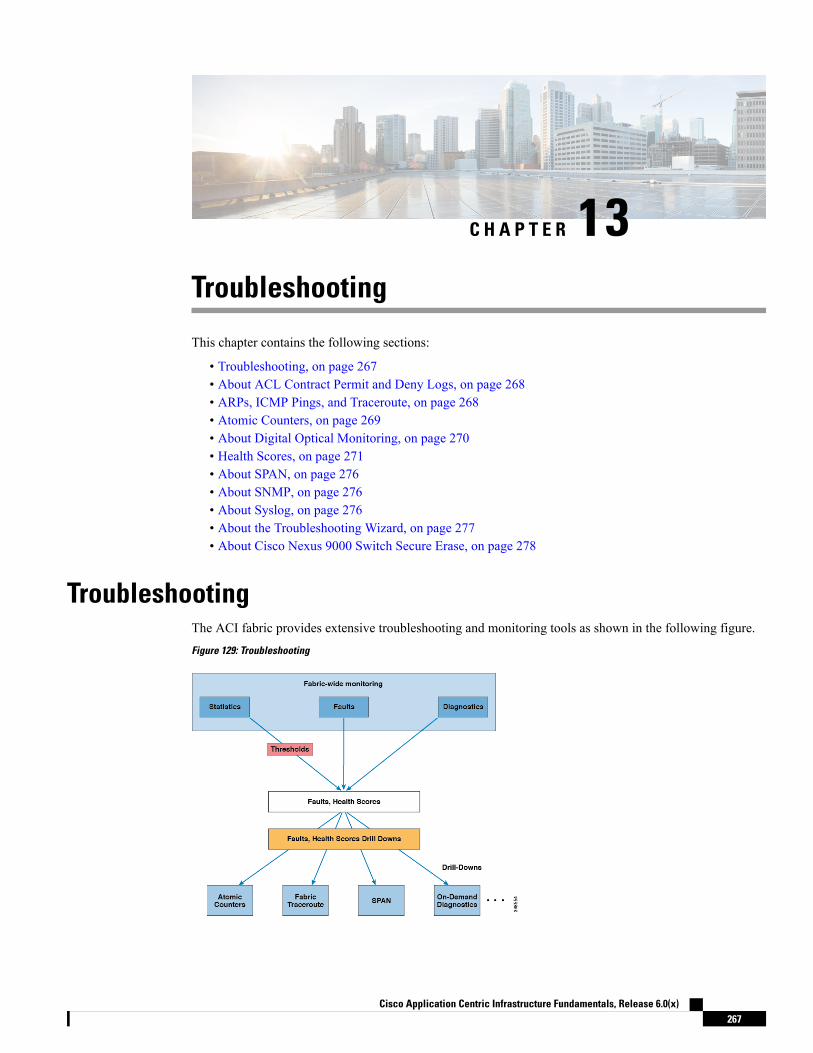
C H A P T E R 13Troubleshooting
This chapter contains the following sections:
• Troubleshooting, on page 267• About ACL Contract Permit and Deny Logs, on page 268• ARPs, ICMP Pings, and Traceroute, on page 268• Atomic Counters, on page 269• About Digital Optical Monitoring, on page 270• Health Scores, on page 271• About SPAN, on page 276• About SNMP, on page 276• About Syslog, on page 276• About the Troubleshooting Wizard, on page 277• About Cisco Nexus 9000 Switch Secure Erase, on page 278
TroubleshootingThe ACI fabric provides extensive troubleshooting and monitoring tools as shown in the following figure.
Figure 129: Troubleshooting
Cisco Application Centric Infrastructure Fundamentals, Release 6.0(x)267

About ACL Contract Permit and Deny LogsTo log and/or monitor the traffic flow for a contract rule, you can enable and view the logging of packets orflows that were allowed to be sent because of contract permit rules or the logging of packets or flows thatwere dropped because of:
• Taboo contract deny rules
• Deny actions in contract subjects
• Contract or subject exceptions
• ACL contract permit in the ACI fabric is only supported on Nexus 9000 Series switches with names thatend in EX or FX, and all later models. For example, N9K-C93180LC-EX or N9K-C9336C-FX.
• Deny logging in the ACI fabric is supported on all platforms.
• Using log directive on filters in management contracts is not supported. Setting the log directive willcause zoning-rule deployment failure.
For information on standard and taboo contracts and subjects, see Cisco Application Centric InfrastructureFundamentals and Cisco APIC Basic Configuration Guide.
EPG Data Included in ACL Permit and Deny Log Output
Up to Cisco APIC, Release 3.2(1), the ACL permit and deny logs did not identify the EPGs associated withthe contracts being logged. In release 3.2(1) the source EPG and destination EPG are added to the output ofACI permit and deny logs. ACL permit and deny logs include the relevant EPGs with the following limitations:
• Depending on the position of the EPG in the network, EPG data may not be available for the logs.
• When configuration changes occur, log data may be out of date. In steady state, log data is accurate.
The most accurate EPG data in the permit and deny logs results when the logs are focussed on:
• Flows from EPG to EPG, where the ingress policy is installed at the ingress TOR and the egress policyis installed at the egress TOR.
• Flows from EPG to L3Out, where one policy is applied on the border leaf TOR and the other policy isapplied on a non-BL TOR.
EPGs in the log output are not supported for uSeg EPGs or for EPGs used in shared services (including sharedL3Outs).
ARPs, ICMP Pings, and TracerouteARPs for the default gateway IP address are trapped at the ingress leaf switch. The ingress leaf switch unicaststhe ARP request to the destination and the destination sends the ARP response.
Cisco Application Centric Infrastructure Fundamentals, Release 6.0(x)268
TroubleshootingAbout ACL Contract Permit and Deny Logs
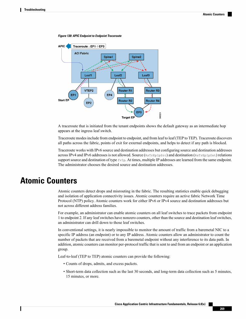
Figure 130: APIC Endpoint to Endpoint Traceroute
A traceroute that is initiated from the tenant endpoints shows the default gateway as an intermediate hopappears at the ingress leaf switch.
Traceroute modes include from endpoint to endpoint, and from leaf to leaf (TEP to TEP). Traceroute discoversall paths across the fabric, points of exit for external endpoints, and helps to detect if any path is blocked.
Traceroute works with IPv6 source and destination addresses but configuring source and destination addressesacross IPv4 and IPv6 addresses is not allowed. Source (RsTrEpIpSrc) and destination (RsTrEpIpDst) relationssupport source and destination of type fvIp. At times, multiple IP addresses are learned from the same endpoint.The administrator chooses the desired source and destination addresses.
Atomic CountersAtomic counters detect drops and misrouting in the fabric. The resulting statistics enable quick debuggingand isolation of application connectivity issues. Atomic counters require an active fabric Network TimeProtocol (NTP) policy. Atomic counters work for either IPv6 or IPv4 source and destination addresses butnot across different address families.
For example, an administrator can enable atomic counters on all leaf switches to trace packets from endpoint1 to endpoint 2. If any leaf switches have nonzero counters, other than the source and destination leaf switches,an administrator can drill down to those leaf switches.
In conventional settings, it is nearly impossible to monitor the amount of traffic from a baremetal NIC to aspecific IP address (an endpoint) or to any IP address. Atomic counters allow an administrator to count thenumber of packets that are received from a baremetal endpoint without any interference to its data path. Inaddition, atomic counters can monitor per-protocol traffic that is sent to and from an endpoint or an applicationgroup.
Leaf-to-leaf (TEP to TEP) atomic counters can provide the following:
• Counts of drops, admits, and excess packets.
• Short-term data collection such as the last 30 seconds, and long-term data collection such as 5 minutes,15 minutes, or more.
Cisco Application Centric Infrastructure Fundamentals, Release 6.0(x)269
TroubleshootingAtomic Counters
• A breakdown of per-spine traffic is available only when the number of TEPs, leaf or VPC, is less than64.
• Ongoing monitoring.
Leaf-to-leaf (TEP to TEP) atomic counters are cumulative and cannot be cleared. However, because 30-secondatomic counters reset at 30-second intervals, they can be used to isolate intermittent or recurring problems.
Note
Tenant atomic counters can provide the following:
• Application-specific counters for traffic across the fabric, including drops, admits, and excess packets
• Modes include the following:
• Endpoint-to-endpoint MAC address, or endpoint-to-endpoint IP address. Note that a single targetendpoint could have multiple IP addresses associated with it.
• EPG to EPG
• EPG to endpoint
• EPG to * (any)
• Endpoint to external IP address
Beginning with the 5.2(3) release, endpoint security groups (ESGs) can be used as an alternative forEPGs in these modes.
Use of atomic counters is not supported when the endpoints are in different tenants or in different VirtualRouting and Forwarding (VRF) instances (also known as contexts or private networks) within the same tenant.Atomic counters work for IPv6 source and destinations but configuring source and destination IP addressesacross IPv4 and IPv6 addresses is not allowed.
Endpoint-to-endpoint atomic counter statistics are not reported for Layer 2 bridged traffic with IPv6 headerswhen the endpoints belong to the same EPG.
For atomic counters to work for traffic flowing from an EPG or ESG to an L3Out EPG, configure the L3OutEPG with 0/1 and 128/1 to match all prefixes instead of 0/0.
Note
About Digital Optical MonitoringReal-time digital optical monitoring (DOM) data is collected from SFPs, SFP+, and XFPs periodically andcompared with warning and alarm threshold table values. The DOM data collected are transceiver transmitbias current, transceiver transmit power, transceiver receive power, and transceiver power supply voltage.
Cisco Application Centric Infrastructure Fundamentals, Release 6.0(x)270
TroubleshootingAbout Digital Optical Monitoring

Health ScoresThe ACI fabric uses a policy model to combine data into a health score. Health scores can be aggregated fora variety of areas such as for the system, infrastructure, tenants, applications, or services.
ACI fabric health information is available for the following views of the system:
• System— aggregation of system-wide health, including pod health scores, tenant health scores, systemfault counts by domain and type, and the APIC cluster health state.
• Pod — aggregation of health scores for a pod (a group of spine and leaf switches), and pod-wide faultcounts by domain and type.
• Tenant — aggregation of health scores for a tenant, including performance data for objects such asapplications and EPGs that are specific to a tenant, and tenant-wide fault counts by domain and type.
• Managed Object — health score policies for managed objects (MOs), which includes their dependentand related MOs. These policies can be customized by an administrator.
System and Pod Health ScoresThe system and pod health scores are based on the leaf and spine switches health scores as well as the numberof end-points learned on the leaf switches. The GUI SystemDashboard also displays system-wide fault countsby domain type, along with the APIC cluster per-node admin state, operational state, and health state.
Figure 131: System Health Scores
Cisco Application Centric Infrastructure Fundamentals, Release 6.0(x)271
TroubleshootingHealth Scores

The pod health scores are based on the leaf and spine switches health scores as well as the number of end-pointslearnt on the leaf switches. The GUI fabric pod dashboard screen also displays pod-wide fault counts bydomain and type.
Figure 132: Pod Health Scores
The system and pod health scores are calculated the same way. The calculation is based on the weightedaverage of the leaf health scores divided by the total number of learned end points of the leaf switches timesthe spine coefficient which is derived from the number of spines and their health scores.
The following equation shows how this calculation is done.
Figure 133: System and Pod Health Score Calculation
The following legend defines the equation components.
• HealthLeafi is the health score of the leaf switch.
• WeightLeafi is the number of end-points on the leaf switch.
• NLeaf is the number of leaf switches in the fabric.
• HealthSpinei is the health score of the spine switch.
• NSpine is the number of spine switches in the fabric.
Cisco Application Centric Infrastructure Fundamentals, Release 6.0(x)272
TroubleshootingSystem and Pod Health Scores
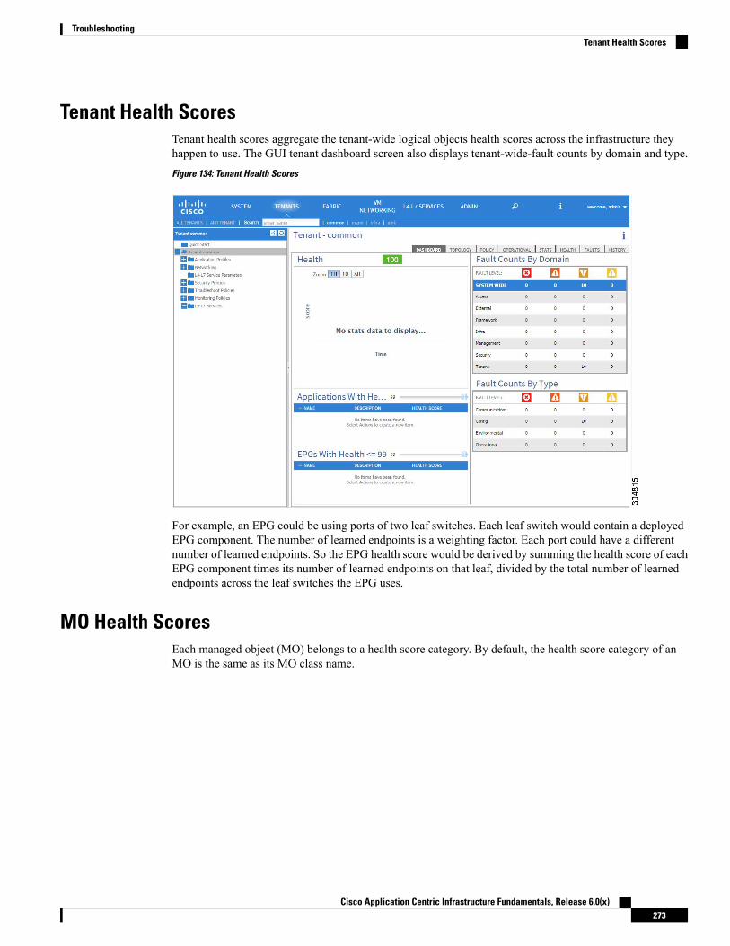
Tenant Health ScoresTenant health scores aggregate the tenant-wide logical objects health scores across the infrastructure theyhappen to use. The GUI tenant dashboard screen also displays tenant-wide-fault counts by domain and type.
Figure 134: Tenant Health Scores
For example, an EPG could be using ports of two leaf switches. Each leaf switch would contain a deployedEPG component. The number of learned endpoints is a weighting factor. Each port could have a differentnumber of learned endpoints. So the EPG health score would be derived by summing the health score of eachEPG component times its number of learned endpoints on that leaf, divided by the total number of learnedendpoints across the leaf switches the EPG uses.
MO Health ScoresEach managed object (MO) belongs to a health score category. By default, the health score category of anMO is the same as its MO class name.
Cisco Application Centric Infrastructure Fundamentals, Release 6.0(x)273
TroubleshootingTenant Health Scores

Figure 135: MO Health Score
Each health score category is assigned an impact level. The five health score impact levels are Maximum,High, Medium, Low, and None. For example, the default impact level of fabric ports is Maximum and thedefault impact level of leaf ports is High. Certain categories of children MOs can be excluded from healthscore calculations of its parent MO by assigning a health score impact of None. These impact levels betweenobjects are user configurable. However, if the default impact level is None, the administrator cannot overrideit.
The following factors are the various impact levels:
Maximum: 100% High: 80% Medium: 50% Low: 20% None: 0%
The category health score is calculated using an Lp -Norm formula. The health score penalty equals 100minusthe health score. The health score penalty represents the overall health score penalties of a set of MOs thatbelong to a given category and are children or direct relatives of the MO for which a health score is beingcalculated.
The health score category of an MO class can be changed by using a policy. For example, the default healthscore category of a leaf port is eqpt:LeafP and the default health score category of fabric ports is eqpt:FabP.However, a policy that includes both leaf ports and fabric ports can be made to be part of the same categorycalled ports.
Cisco Application Centric Infrastructure Fundamentals, Release 6.0(x)274
TroubleshootingMO Health Scores
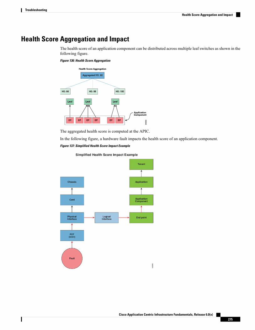
Health Score Aggregation and ImpactThe health score of an application component can be distributed across multiple leaf switches as shown in thefollowing figure.
Figure 136: Health Score Aggregation
The aggregated health score is computed at the APIC.
In the following figure, a hardware fault impacts the health score of an application component.
Figure 137: Simplified Health Score Impact Example
Cisco Application Centric Infrastructure Fundamentals, Release 6.0(x)275
TroubleshootingHealth Score Aggregation and Impact

About SPANYou can use the Switched Port Analyzer (SPAN) utility to perform detailed troubleshooting or to take a sampleof traffic from a particular application host for proactive monitoring and analysis.
SPAN copies traffic from one or more ports, VLANs, or endpoint groups (EPGs) and sends the copied trafficto one or more destinations for analysis by a network analyzer. The process is nondisruptive to any connecteddevices and is facilitated in the hardware, which prevents any unnecessary CPU load.
You can configure SPAN sessions to monitor traffic received by the source (ingress traffic), traffic transmittedfrom the source (egress traffic), or both. By default, SPAN monitors all traffic, but you can configure filtersto monitor only selected traffic.
You can configure SPAN on a tenant or on a switch. When configured on a switch, you can configure SPANas a fabric policy or an access policy.
APIC supports the encapsulated remote extension of SPAN (ERSPAN).
Multinode SPAN
APIC traffic monitoring policies can SPAN policies at the appropriate places to track members of eachapplication group and where they are connected. If any member moves, APIC automatically pushes the policyto the new leaf switch. For example, when an endpoint VMotions to a new leaf switch, the SPAN configurationautomatically adjusts.
Additional Information
Refer to the Cisco APIC Troubleshooting Guide for detailed information about the configuration, use, andlimitations of SPAN.
About SNMPThe Cisco Application Centric Infrastructure (ACI) provides extensive SNMPv1, v2, and v3 support, includingManagement Information Bases (MIBs) and notifications (traps). The SNMP standard allows any third-partyapplications that support the different MIBs to manage and monitor the Cisco ACI fabric.
SNMPv3 provides extended security. Each SNMPv3 device can be selectively enabled or disabled for SNMPservice. In addition, each device can be configured with a method of handling SNMPv1 and v2 requests.
Beginning in the 4.2(6) release, SNMPv3 supports the Secure Hash Algorithm-2 (SHA-2) authentication type.
For more information about using SNMP, see the Cisco ACI MIB Quick Reference.
About SyslogDuring operation, a fault or event in the Cisco Application Centric Infrastructure (ACI) system can triggerthe sending of a system log (syslog) message to the console, to a local file, and to a logging server on anothersystem. A system log message typically contains a subset of information about the fault or event. A systemlog message can also contain audit log and session log entries.
Cisco Application Centric Infrastructure Fundamentals, Release 6.0(x)276
TroubleshootingAbout SPAN
For a list of syslog messages that the APIC and the fabric nodes can generate, see http://www.cisco.com/c/en/us/td/docs/switches/datacenter/aci/apic/sw/1-x/syslog/guide/aci_syslog/ACI_SysMsg.html.
Note
Many system log messages are specific to the action that a user is performing or the object that a user isconfiguring or administering. These messages can be the following:
• Informational messages, providing assistance and tips about the action being performed
• Warning messages, providing information about system errors related to an object, such as a user accountor service profile, that the user is configuring or administering
In order to receive and monitor system log messages, you must specify a syslog destination, which can be theconsole, a local file, or one or more remote hosts running a syslog server. In addition, you can specify theminimum severity level of messages to be displayed on the console or captured by the file or host. The localfile for receiving syslog messages is /var/log/external/messages.
A syslog source can be any object for which an object monitoring policy can be applied. You can specify theminimum severity level of messages to be sent, the items to be included in the syslog messages, and the syslogdestination.
You can change the display format for the Syslogs to NX-OS style format.
Additional details about the faults or events that generate these system messages are described in the CiscoAPIC Faults, Events, and System Messages Management Guide, and system log messages are listed in theCisco ACI System Messages Reference Guide.
Not all system log messages indicate problems with your system. Some messages are purely informational,while others may help diagnose problemswith communications lines, internal hardware, or the system software.
Note
About the Troubleshooting WizardThe Troubleshooting Wizard allows you to understand and visualize how your network is behaving, whichcan ease your networking concerns should issues arise. For example, you might have two endpoints that arehaving intermittent packet loss, but you do not understand why. Using the Troubleshooting Wizard, you canevaluate the issue so that you can effectively resolve the issue rather than logging onto each machine that yoususpect to be causing this faulty behavior.
This wizard allows you (the administrative user) to troubleshoot issues that occur during specific time framesfor the chosen source and destination. You can define a time window in which you want to perform the debug,and you can generate a troubleshooting report that you can send to TAC.
Related TopicsGetting Started with the Troubleshooting WizardTopology in the Troubleshooting Wizard
Cisco Application Centric Infrastructure Fundamentals, Release 6.0(x)277
TroubleshootingAbout the Troubleshooting Wizard

About Cisco Nexus 9000 Switch Secure EraseCisco Nexus 9000 switches utilize persistent storage to maintain system software images, switch configuration,software logs, and operational history. Each of these areas can contain user-specific information such as detailson network architecture and design, and potential target vectors for would-be attackers. The secure erasefeature enables you comprehensively to erase this information, which you can do when you return a switchwith return merchandise authorization (RMA), upgrade or replace a switch, or decommission a system thathas reached its end-of-life.
This feature erases user data in the following storage devices:
• SSD
• EMMC
• MTD
• CMOS
• NVRAM
Not every switch model has all these storage devices.Note
Cisco Application Centric Infrastructure Fundamentals, Release 6.0(x)278
TroubleshootingAbout Cisco Nexus 9000 Switch Secure Erase

A P P E N D I X ALabel Matching
This chapter contains the following sections:
• Label Matching, on page 279
Label MatchingLabel matching is used to determine which consumer and provider EPGs can communicate. Contract subjectsof a given producer or consumer of that contract determine that consumers and providers can communicate.
The match type algorithm is determined by the matchT attribute that can have one of the following values:
• All
• AtLeastOne (default)
• None
• AtmostOne
When both EPG and contract subject labels exist, label matching is done first for EPGs, then for contractsubjects.
When checking for a match of provider labels, vzProvLbl, and consumer labels, vzConsLbl, the matchT isdetermined by the provider EPG.
When checking for a match of provider or consumer subject labels, vzProvSubjLbl, vzConsSubjLbl, in EPGsthat have a subject, the matchT is determined by the subject.
The same matchT logic is the same for EPG and contract subject labels. The following table shows simpleexamples of all the EPG and contract subject provider and consumer match types and their results. In thistable, a [ ] entry indicates no labels (NULL).
Result should bevzConsLbl
vzConsSubLbl
vzProvLbl
vzProvSubLbl
matchT
match[ ][ ]All
matchLabelX, LabelYLabelX, LabelYAll
no matchLabelX, LabelZLabelX, LabelYAll
Cisco Application Centric Infrastructure Fundamentals, Release 6.0(x)279

Result should bevzConsLbl
vzConsSubLbl
vzProvLbl
vzProvSubLbl
matchT
no matchLabelXLabelX, LabelYAll
matchLabelX, LabelYLabelXAll
no matchLabelX[ ]All
no match[ ]LabelXAll
matchLabelXLabelX, LabelYAtLeastOne
no matchLabelZLabelX, LabelYAtLeastOne
no match[ ]LabelXAtLeastOne
no matchLabelX[ ]AtLeastOne
match[ ][ ]AtLeastOne
matchLabelYLabelXNone
no matchLabelXLabelXNone
no matchLabelYLabelX, LabelYNone
no matchLabelX, LabelYLabelXNone
no matchLabelX[ ]None
match[ ]LabelXNone
match[ ][ ]None
matchLabelXLabelXAtmostOne
no matchLabelX, LabelYLabelX, LabelYAtmostOne
matchLabelX, LabelYLabelX, LabelZAtmostOne
no matchLabelYLabelXAtmostOne
no matchLabelX[ ]AtmostOne
no match[ ]LabelXAtmostOne
match[ ][ ]AtmostOne
Cisco Application Centric Infrastructure Fundamentals, Release 6.0(x)280
Label MatchingLabel Matching

A P P E N D I X BContract Scope Examples
This chapter contains the following sections:
• Contract Scope Examples, on page 281
Contract Scope ExamplesLet's say we have EPG1 and EPG2 in VRF1 and EPG3 and EPG4 in VRF2 using a contract called C1, andthe scope = context.
• EPG1 provides and EPG2 consumes contract C1
• EPG3 provides and EPG4 consumes contract C1
In this example all four EPGs share the same contract, but two of them are in one Virtual Routing andForwarding (VRF) instance (also known as a context or private network) and two of them in the other VRF.The contract is applied only between EPG1 and EPG2, and then separately between EPG3 and EPG4. Thecontract is limited to whatever the scope is, which in this case is the VRF.
The same thing applies if the scope = application profile. If two application profiles have EPGs and ifthe scope = application profile, then the contract is enforced on EPGs in their application profiles.
Below you see an APIC GUI screenshot of two contracts.
Cisco Application Centric Infrastructure Fundamentals, Release 6.0(x)281

Figure 138: Security Policy Contract Example
One contract is for web-to-app communication, which has a scope of application profile. The app-to-dbcontract has a scope of VRF. The app1 and app2 applications profiles are in the same VRF. Each applicationprofile contains EPGs.
Because the scope of the contract app-to-db is enforced at the VRF level, and both application profiles belongto the same VRF, all consumers of the app-to-db contract are allowed to communicate with its provider EPGs.
• EPG-app1-db can communicate bi-directionally with EPG-app1-app
• EPG-app2-db can communicate bi-directionally with EPG-app2-app
• EPG-app1-db can communicate bi-directionally with EPG-app2-app
• EPG-app2-db can communicate bi-directionally with EPG-app1-app
The next pairs of endpoints using the web-to-app contracts with a scope of application-profile allow only theprovider and consumers of the contract to communicate within that application profile.
Cisco Application Centric Infrastructure Fundamentals, Release 6.0(x)282
Contract Scope ExamplesContract Scope Examples

• EPG-app1-app can communicate with EPG-app1-web
• EPG-app2-app can communicate with EPG-app2-web
Unlike those above, the app and db EPGs cannot communicate outside of their application profiles.
Cisco Application Centric Infrastructure Fundamentals, Release 6.0(x)283
Contract Scope ExamplesContract Scope Examples

Cisco Application Centric Infrastructure Fundamentals, Release 6.0(x)284
Contract Scope ExamplesContract Scope Examples
A P P E N D I X CSecure Properties
This chapter contains the following sections:
• Secure Properties, on page 285
Secure PropertiesThe table below lists the secure properties of managed objects that include a password field property type.
Cisco Application Centric Infrastructure Fundamentals, Release 6.0(x)285
PropertyManaged Object ClassPropertyType
keypki:KeyRingPasswordField
hashSecretpki:WebTokenData
initializationVectorpki:WebTokenData
keypki:WebTokenData
keypki:CsyncSharedKey
pwdpki:CertReq
keymcp:Inst
keymcp:InstPol
pwdsysdebug:BackupBehavior
userPasswdstats:Dest
passwordfirmware:CcoSource
passwordfirmware:InternalSource
passwordf firmware:OSource
passwordfirmware:Source
passwordbgp:PeerDef
passwordbgp:Peer
passwordbgp:APeerP
passwordbgp:PeerP
keybfd:AuthP
pwdcomp:UsrAccP
pwdcomp:Ctrlr
keyaaa:LdapProvider
monitoringPasswordaaa:LdapProvider
pwdHistoryaaa:UserData
keyaaa:TacacsPlusProvider
passwordaaa:TacacsPlusProvidermonitoring
keyaaa:AProvider
Cisco Application Centric Infrastructure Fundamentals, Release 6.0(x)286
Secure PropertiesSecure Properties

PropertyManaged Object ClassPropertyType
aaa:AProvider monitoringPassword
keyaaa:RadiusProvider
monitoringPasswordaaa:RadiusProvider
pwdaaa:User
newPasswordaaa:ChangePassword
oldPasswordaaa:ChangePassword
keyospf:AuthP
Keyospf:IfPauth
Keyospf:AIfPauth
authKeyospf:IfDef
userPasswdfile:RemotePath
userPasswdfile:ARemotePath
pwdvmm:UsrAccP
authKeysnmp:UserSecP
privKeysnmp:UserSecP
authKeysnmp:UserP
privKeysnmp:UserP
authKeysnmp:AUserP
privKeysnmp:AUserP
authKeyvns:VOspfVEncapAsc
passwordvns:SvcPkgSource
webtokenvns:SvcPkgSource
valuevns:CCredSecret
Cisco Application Centric Infrastructure Fundamentals, Release 6.0(x)287
Secure PropertiesSecure Properties

Cisco Application Centric Infrastructure Fundamentals, Release 6.0(x)288
Secure PropertiesSecure Properties
A P P E N D I X DConfiguration Zone Supported Policies
This chapter contains the following sections:
• Configuration Zone Supported Policies, on page 289
Configuration Zone Supported PoliciesThe following policies are supported for configuration zones:analytics:CfgSrvbgp:InstPolcallhome:Groupcallhome:InvPcallhome:QueryGroupcdp:IfPolcdp:InstPolcomm:Polcomp:DomPcoop:Poldatetime:Poldbgexp:CorePdbgexp:TechSupPdhcp:NodeGrpdhcp:PodGrpedr:ErrDisRecoverPolep:ControlPep:LoopProtectPeqptdiagp:TsOdFabPeqptdiagp:TsOdLeafPfabric:AutoGEpfabric:ExplicitGEpfabric:FuncPfabric:HIfPolfabric:L1IfPolfabric:L2IfPolfabric:L2InstPolfabric:L2PortSecurityPolfabric:LeCardPfabric:LeCardPGrpfabric:LeCardSfabric:LeNodePGrpfabric:LePortPfabric:LePortPGrpfabric:LFPortSfabric:NodeControlfabric:OLeafS
Cisco Application Centric Infrastructure Fundamentals, Release 6.0(x)289
fabric:OSpineSfabric:PodPGrpfabric:PortBlkfabric:ProtGEpfabric:ProtPolfabric:SFPortSfabric:SpCardPfabric:SpCardPGrpfabric:SpCardSfabric:SpNodePGrpfabric:SpPortPfabric:SpPortPGrpfc:DomPfc:FabricPolfc:IfPolfc:InstPolfile:RemotePathfvns:McastAddrInstPfvns:VlanInstPfvns:VsanInstPfvns:VxlanInstPinfra:AccBaseGrpinfra:AccBndlGrpinfra:AccBndlPolGrpinfra:AccBndlSubgrpinfra:AccCardPinfra:AccCardPGrpinfra:AccNodePGrpinfra:AccPortGrpinfra:AccPortPinfra:AttEntityPinfra:CardSinfra:ConnFexBlkinfra:ConnFexSinfra:ConnNodeSinfra:DomPinfra:FexBlkinfra:FexBndlGrpinfra:FexGrpinfra:FexPinfra:FuncPinfra:HConnPortSinfra:HPathSinfra:HPortSinfra:LeafSinfra:NodeBlkinfra:NodeGrpinfra:NodePinfra:OLeafSinfra:OSpineSinfra:PodBlkinfra:PodGrpinfra:PodPinfra:PodSinfra:PolGrpinfra:PortBlkinfra:PortPinfra:PortSinfra:PortTrackPolinfra:Profileinfra:SHPathSinfra:SHPortSinfra:SpAccGrpinfra:SpAccPortGrp
Cisco Application Centric Infrastructure Fundamentals, Release 6.0(x)290
Configuration Zone Supported PoliciesConfiguration Zone Supported Policies

infra:SpAccPortPinfra:SpinePinfra:SpineSisis:DomPoll2ext:DomPl2:IfPoll2:InstPoll2:PortSecurityPoll3ext:DomPlacp:IfPollacp:LagPollldp:IfPollldp:InstPolmcp:IfPolmcp:InstPolmgmt:NodeGrpmgmt:PodGrpmon:FabricPolmon:InfraPolphys:DomPpsu:InstPolqos:DppPolsnmp:Polspan:Destspan:DestGrpspan:SpanProvspan:SrcGrpspan:SrcTargetShadowspan:SrcTargetShadowBDspan:SrcTargetShadowCtxspan:TaskParamspan:VDestspan:VDestGrpspan:VSpanProvspan:VSrcGrpstormctrl:IfPolstp:IfPolstp:InstPolstp:MstDomPolstp:MstRegionPoltrig:SchedPvmm:DomPvpc:InstPolvpc:KAPol
Cisco Application Centric Infrastructure Fundamentals, Release 6.0(x)291
Configuration Zone Supported PoliciesConfiguration Zone Supported Policies

Cisco Application Centric Infrastructure Fundamentals, Release 6.0(x)292
Configuration Zone Supported PoliciesConfiguration Zone Supported Policies

A P P E N D I X EACI Terminology
This chapter contains the following sections:
• ACI Terminology, on page 293
ACI TerminologyDescriptionIndustry Standard Term
(Approximation)Cisco ACI Term
A changeable name for a given object. Whilethe name of an object, once created, cannotbe changed, the Alias is a field that can bechanged. For more details, refer to "UsingTags and Alias" section under "Using theREST API":
AliasAlias
The API Inspector in the Cisco APIC GUIprovides a real-time display of the REST APIcommands that the Cisco APIC processes toperform GUI interactions.
—API Inspector
The Cisco ACIApp Center allows you to fullyenable the capabilities of the Cisco APIC bywriting applications running on the controller.Using the Cisco ACI App Center, customers,developers, and partners are able to buildapplications to simplify, enhance, andvisualize their use cases. These applicationsare hosted and shared at the Cisco ACI AppCenter and installed in the Cisco APIC.
—App Center
Cisco Application Centric Infrastructure Fundamentals, Release 6.0(x)293

DescriptionIndustry Standard Term(Approximation)
Cisco ACI Term
The Cisco APIC, which is implemented as areplicated synchronized clustered controller,provides a unified point of automation andmanagement, policy programming, applicationdeployment, and health monitoring for theCisco ACI multitenant fabric. The minimumrecommended size for a Cisco APIC clusteris three controllers.
Approximation of clustercontroller
Application PolicyInfrastructure Controller(APIC)
An application profile (fvAp) defines thepolicies, services, and relationships betweenendpoint groups (EPGs).
—Application Profile
Atomic counters allow you to gather statisticsabout traffic between leafs. Using atomiccounters, you can detect drops and misroutingin the fabric, enabling quick debugging andisolation of application connectivity issues.For example, an administrator can enableatomic counters on all leaf switches to tracepackets from endpoint 1 to endpoint 2. If anyleaf switches have nonzero counters, otherthan the source and destination leaf switches,an administrator can drill down to those leafswitches.
Atomic CountersAtomic Counters
An Attachable Access Entity Profile (AEP)is used to group domains with similarrequirements. By grouping domains intoAEPsand associating them, the fabric knows wherethe various devices in the domain live and theApplication Policy Infrastructure Controller(APIC) can push theVLANs and policywhereit needs to be.
—Attachable Entity Profile
Border leaf switches refers to a leaf that isconnected to a layer 3 device like externalnetwork devices or services such as firewallsand router ports. Other devices like serverscan also connect to it.
Border Leaf SwitchesBorder Leaf Switches
A bridge domain is a set of logical ports thatshare the same flooding or broadcastcharacteristics. Like a virtual LAN (VLAN),bridge domains span multiple devices.
Bridge DomainBridge Domain
Cisco Application Centric Infrastructure Fundamentals, Release 6.0(x)294
ACI TerminologyACI Terminology
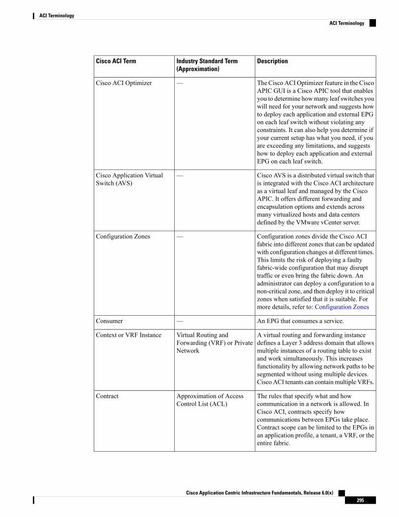
DescriptionIndustry Standard Term(Approximation)
Cisco ACI Term
The Cisco ACI Optimizer feature in the CiscoAPIC GUI is a Cisco APIC tool that enablesyou to determine howmany leaf switches youwill need for your network and suggests howto deploy each application and external EPGon each leaf switch without violating anyconstraints. It can also help you determine ifyour current setup has what you need, if youare exceeding any limitations, and suggestshow to deploy each application and externalEPG on each leaf switch.
—Cisco ACI Optimizer
Cisco AVS is a distributed virtual switch thatis integrated with the Cisco ACI architectureas a virtual leaf and managed by the CiscoAPIC. It offers different forwarding andencapsulation options and extends acrossmany virtualized hosts and data centersdefined by the VMware vCenter server.
—Cisco Application VirtualSwitch (AVS)
Configuration zones divide the Cisco ACIfabric into different zones that can be updatedwith configuration changes at different times.This limits the risk of deploying a faultyfabric-wide configuration that may disrupttraffic or even bring the fabric down. Anadministrator can deploy a configuration to anon-critical zone, and then deploy it to criticalzones when satisfied that it is suitable. Formore details, refer to: Configuration Zones
—Configuration Zones
An EPG that consumes a service.—Consumer
A virtual routing and forwarding instancedefines a Layer 3 address domain that allowsmultiple instances of a routing table to existand work simultaneously. This increasesfunctionality by allowing network paths to besegmented without using multiple devices.Cisco ACI tenants can containmultiple VRFs.
Virtual Routing andForwarding (VRF) or PrivateNetwork
Context or VRF Instance
The rules that specify what and howcommunication in a network is allowed. InCisco ACI, contracts specify howcommunications between EPGs take place.Contract scope can be limited to the EPGs inan application profile, a tenant, a VRF, or theentire fabric.
Approximation of AccessControl List (ACL)
Contract
Cisco Application Centric Infrastructure Fundamentals, Release 6.0(x)295
ACI TerminologyACI Terminology
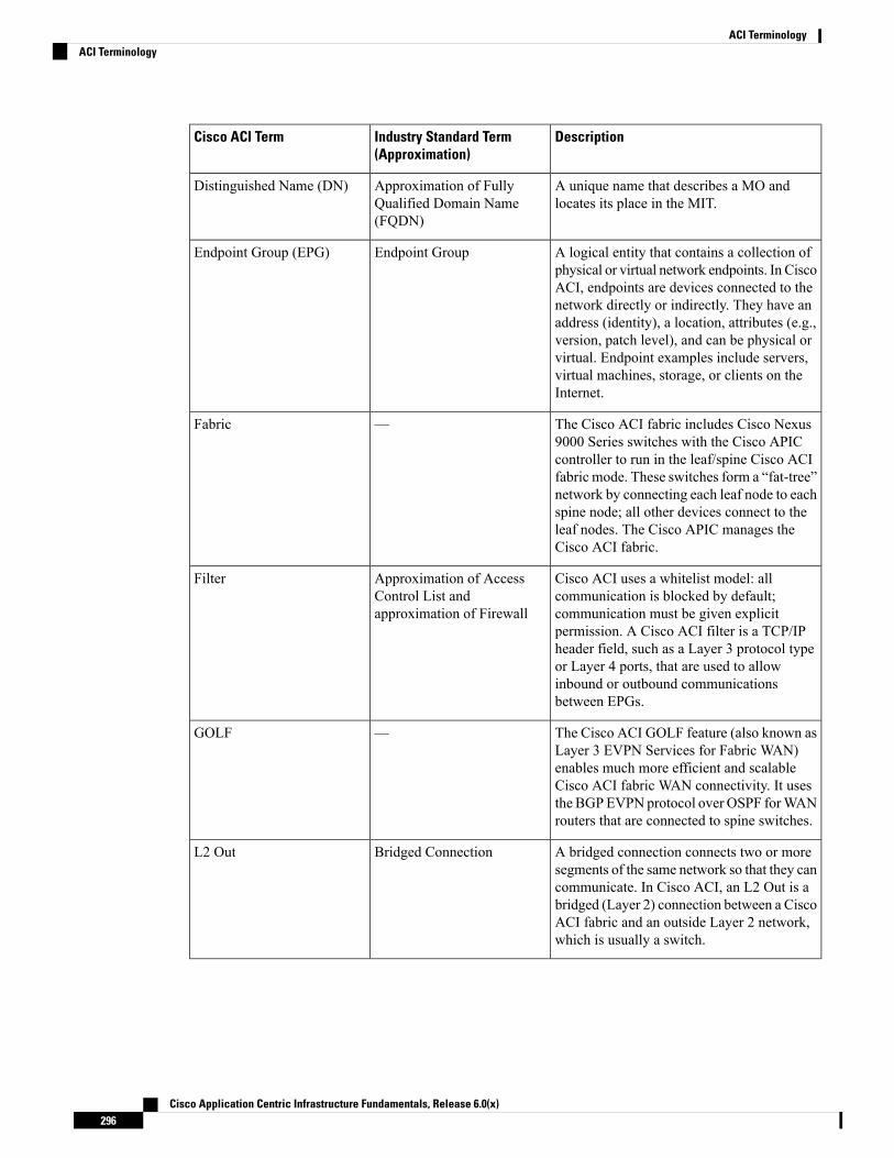
DescriptionIndustry Standard Term(Approximation)
Cisco ACI Term
A unique name that describes a MO andlocates its place in the MIT.
Approximation of FullyQualified Domain Name(FQDN)
Distinguished Name (DN)
A logical entity that contains a collection ofphysical or virtual network endpoints. In CiscoACI, endpoints are devices connected to thenetwork directly or indirectly. They have anaddress (identity), a location, attributes (e.g.,version, patch level), and can be physical orvirtual. Endpoint examples include servers,virtual machines, storage, or clients on theInternet.
Endpoint GroupEndpoint Group (EPG)
The Cisco ACI fabric includes Cisco Nexus9000 Series switches with the Cisco APICcontroller to run in the leaf/spine Cisco ACIfabric mode. These switches form a “fat-tree”network by connecting each leaf node to eachspine node; all other devices connect to theleaf nodes. The Cisco APIC manages theCisco ACI fabric.
—Fabric
Cisco ACI uses a whitelist model: allcommunication is blocked by default;communication must be given explicitpermission. A Cisco ACI filter is a TCP/IPheader field, such as a Layer 3 protocol typeor Layer 4 ports, that are used to allowinbound or outbound communicationsbetween EPGs.
Approximation of AccessControl List andapproximation of Firewall
Filter
The Cisco ACI GOLF feature (also known asLayer 3 EVPN Services for Fabric WAN)enables much more efficient and scalableCisco ACI fabric WAN connectivity. It usesthe BGPEVPNprotocol over OSPF forWANrouters that are connected to spine switches.
—GOLF
A bridged connection connects two or moresegments of the same network so that they cancommunicate. In Cisco ACI, an L2 Out is abridged (Layer 2) connection between a CiscoACI fabric and an outside Layer 2 network,which is usually a switch.
Bridged ConnectionL2 Out
Cisco Application Centric Infrastructure Fundamentals, Release 6.0(x)296
ACI TerminologyACI Terminology

DescriptionIndustry Standard Term(Approximation)
Cisco ACI Term
A routed Layer 3 connection uses a set ofprotocols that determine the path that datafollows in order to travel across multiplenetworks from its source to its destination.Cisco ACI routed connections perform IPforwarding according to the protocol selected,such as BGP, OSPF, or EIGRP.
Routed ConnectionL3 Out
Label matching is used to determine whichconsumer and provider EPGs cancommunicate. Contract subjects of a givenproducer or consumer of that contractdetermine that consumers and providers cancommunicate. A label matching algorithm isused determine this communication. For moredetails, refer to: ACI Fundamentals Guide
—Label
An abstract representation of networkresources that are managed. In Cisco ACI, anabstraction of a Cisco ACI fabric resource.
MOManaged Object (MO)
A hierarchical management information treecontaining all the managed objects (MOs) ofa system. In Cisco ACI, the MIT contains allthe MOs of the Cisco ACI fabric. The CiscoACI MIT is also called the ManagementInformation Model (MIM).
MITManagement InformationTree (MIT)
Microsegmentationwith the CiscoApplicationCentric Infrastructure (ACI) provides theability to automatically assign endpoints tological security zones called endpoint groups(EPGs) based on various network-based orvirtual machine (VM)-based attributes.
Microsegmentation,micro-segmentation
Microsegmentation withCisco ACI
Cisco Application Centric Infrastructure Fundamentals, Release 6.0(x)297
ACI TerminologyACI Terminology
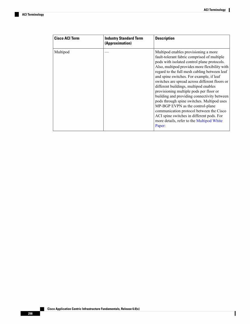
DescriptionIndustry Standard Term(Approximation)
Cisco ACI Term
Multipod enables provisioning a morefault-tolerant fabric comprised of multiplepods with isolated control plane protocols.Also, multipod provides more flexibility withregard to the full mesh cabling between leafand spine switches. For example, if leafswitches are spread across different floors ordifferent buildings, multipod enablesprovisioning multiple pods per floor orbuilding and providing connectivity betweenpods through spine switches. Multipod usesMP-BGP EVPN as the control-planecommunication protocol between the CiscoACI spine switches in different pods. Formore details, refer to the Multipod WhitePaper:
—Multipod
Cisco Application Centric Infrastructure Fundamentals, Release 6.0(x)298
ACI TerminologyACI Terminology

DescriptionIndustry Standard Term(Approximation)
Cisco ACI Term
A fabric administrator creates domain policiesthat configure ports, protocols, VLAN pools,and encapsulation. These policies can be usedexclusively by a single tenant, or they can beshared. Once a fabric administrator configuresdomains in the Cisco ACI fabric, tenantadministrators can associate tenant endpointgroups (EPGs) to domains. A domain isconfigured to be associated with a VLANpool. EPGs are then configured to use theVLANs associated with a domain. You canconfigure the following domain types:
• VMM domain profiles (vmmDomP) arerequired for virtual machine hypervisorintegration.
• Physical domain profiles (physDomP)are typically used for bare metal serverattachment and management access.
• Bridged outside network domain profiles(l2extDomP) are typically used toconnect a bridged external network trunkswitch to a leaf switch in the Cisco ACIfabric.
• Routed outside network domain profiles(l3extDomP) are used to connect a routerto a leaf switch in the Cisco ACI fabric.
• Fibre Channel domain profiles (fcDomP)are used to connect Fibre ChannelVLANs and VSANs.
—Networking Domains
Named entity that contains genericspecifications for controlling some aspect ofsystem behavior. For example, a Layer 3Outside Network Policy would contain theBGP protocol to enable BGP routing functionswhen connecting the fabric to an outside Layer3 network.
—Policy
Named entity that contains the necessaryconfiguration details for implementing one ormore instances of a policy. For example, aswitch node profile for a routing policy wouldcontain all the switch-specific configurationdetails required to implement the BGP routingprotocol.
—Profile
Cisco Application Centric Infrastructure Fundamentals, Release 6.0(x)299
ACI TerminologyACI Terminology

DescriptionIndustry Standard Term(Approximation)
Cisco ACI Term
An EPG that provides a service.—Provider
The Quota management feature enables anadmin to limit what managed objects can beadded under a given tenant or globally acrosstenants. Using Quota Management, you canlimit any tenant or group of tenants fromexceeding Cisco ACI maximums per leafswitch or per fabric or unfairly consumingmost available resources, potentially affectingother tenants on the same fabric.
For example, a user has configured a bridgedomain quota of maximum 6 across the entireACI policy model with a fault action. Thecode would be:apic1(config)# quota fvBD max 6 scopeuni exceed-action fault
Quota ManagementQuota Management
The Cisco Application Policy InfrastructureController (APIC) REST API is aprogrammatic interface that uses RESTarchitecture. The API accepts and returnsHTTP (not enabled by default) or HTTPSmessages that contain JavaScript ObjectNotation (JSON) or Extensible MarkupLanguage (XML) documents. The RESTAPIis the interface into the managementinformation tree (MIT) and allowsmanipulation of the object model state. Thesame REST interface is used by the CiscoAPIC CLI, GUI, and SDK, so that wheneverinformation is displayed, it is read through theREST API, and when configuration changesare made, they are written through the RESTAPI. The RESTAPI also provides an interfacethrough which other information can beretrieved, including statistics, faults, and auditevents. It even provides a means ofsubscribing to push-based event notification,so that when a change occurs in the MIT, anevent can be sent through a web socket.
REST APIREST API
In a Cisco ACI Multi-Site configuration, theSchema is a container for single or multipletemplates that are used for defining policies.
—Schema
Cisco Application Centric Infrastructure Fundamentals, Release 6.0(x)300
ACI TerminologyACI Terminology

DescriptionIndustry Standard Term(Approximation)
Cisco ACI Term
The Cisco APIC cluster domain or singlefabric, treated as a Cisco ACI region andavailability zone. It can be located in the samemetro-area as other sites, or spacedworld-wide.
SiteSite
Stretched Cisco ACI fabric is a partiallymeshed design that connects Cisco ACI leafand spine switches distributed in multiplelocations. The stretched fabric is a singleCisco ACI fabric. The sites are oneadministration domain and one availabilityzone. Administrators are able to manage thesites as one entity; configuration changesmade on any Cisco APIC controller node areapplied to devices across the sites. Thestretched Cisco ACI fabric preserves live VMmigration capability across the sites. Objects(tenants, VRFs, EPGs, bridge-domains,subnets, or contracts) can be stretched whenthey are deployed to multiple sites.
—Stretched ACI
In Cisco ACI, subjects in a contract specifywhat information can be communicated andhow.
Approximation of AccessControl List
Subject
Object tags simplify API operations. In anAPI operation, an object or group of objectsis referenced by the tag name instead of bythe distinguished name (DN). Tags are childobjects of the item they tag; besides the name,they have no other properties.
For more details, refer to "Using Tags andAlias" section under "Using the REST API".
—Tags
In a Cisco ACI Multi-Site configuration,templates are framework to hold policies andconfiguration objects that are pushed to thedifferent sites. These templates reside withinschemas that are defined for each site.
TemplateTemplate
Cisco Application Centric Infrastructure Fundamentals, Release 6.0(x)301
ACI TerminologyACI Terminology

DescriptionIndustry Standard Term(Approximation)
Cisco ACI Term
A secure and exclusive virtual computingenvironment. In Cisco ACI, a tenant is a unitof isolation from a policy perspective, but itdoes not represent a private network. Tenantscan represent a customer in a service providersetting, an organization or domain in anenterprise setting, or just a convenientgrouping of policies. Cisco ACI tenants cancontain multiple private networks (VRFinstances).
TenantTenant
The vzAny managed object provides aconvenient way of associating all endpointgroups (EPGs) in a Virtual Routing andForwarding (VRF) instance to one or morecontracts, instead of creating a separatecontract relation for each EPG. For moredetails, see Use vzAny to AutomaticallyApply Communication Rules to all EPGs ina VRF.
—vzAny
Cisco Application Centric Infrastructure Fundamentals, Release 6.0(x)302
ACI TerminologyACI Terminology