characterization of slag-metal droplet-gas emulsion in oxygen steelmaking converters
TRANSCRIPT
ISIJ International, Vol. 38 (1 998), No. 11, pp. 1225-1 232
DynamicModelof Slag Foamingin OxygenSteel makingConverters
Paretosh MISRA.BrahmaDEOand R. P. CHHABRA1)
Department of Materials and Metallurgical Engineering, Indian Institute of Technology, Kanpur 208016, India.
1)Departmentof Chemical Engineering, Indian Institute of Technology, Kanpur 208016, India.E-mail: bdeo(~).iitk.ernet,in
(Received on March 18. 1998; accepted in final form on July 22. l998)
The foaming and emulsification of steelmaking slags can be analyzed in terms of an emulsion numberwhich is defined as the ratio of the velocity of gas bubbles and that of metai droplets present in slag at anygiven stage of the blow. An improved procedure is suggested to evaluate the viscosity of gas-slag foam at
high gas void fractions. The calculated velocity of gas bubbles in foaming slags is verified using the
experimental results reported in literature, A critical comparison is also madewith the other approachesavailable in the literature, It is shownthat the emulsion numberis directly related to foaming conditions. Adynamic model of slag foaming is developed on the basis of the bubble and droplet ve[ocities, changingslag composition and temperature and the continuous reduction of iron oxide content of slag during the
main blow period. Combinedeffects of lance nozzle design and blowing regime on slag foaming are discussed.
KEYWORDS:steelmaking; foaming; emulsion; metal droplets; bubbles; converter.
l. Introduction
The phenomenonof slag foaming and emulsification
in oxygen steel making converters is of great practical
significance during the middle blow period (i.e., between3070o/o of blow time). The slag samples collected dur-ing this period have revealed the presence of entrapped
gas bubbles, metal droplets of varying slzes and also
undissolved lime particles coated with a thln layer ofdicalcium silicate. In spite of the inhomogeneities pres-ent in slag, the decarburization rate during middleblow period is nearly constant. The foaming of slag is
such that lance tip is fully submergedin the foam. Onlywhen the foaming becomesexcessive, slopping occurs,which in turn leads to undesirable loss by entrainmentof iron as iron droplets and FeOfrom the converter. In
our previous work,1) the (slag)-(metal droplet)(gas)emulsion was characterized through a dimensionless
parameter, namely, Emulsion numberEn, defined as:
Meanresidence time of metal droplets in slag, (Td)En= ----- - ----------------------------Meanresidence time of gas bubbles in slag, (Tb)
_ _Vg
..........(1)~ ~ Vd ""
The settling velocity of metal droplets Vd wascalculated
by employing the expression proposed by Gal-Or andWaslol'2):
Vd-(P--p~g)gd~
As~ ""~""-"-"(2)~ 18u*g
where the factor A~~ accounts for the inter-particle
interactlons of ensembleof droplets (A**> l)
A -sm~s/3 9 1- )+
[3
- - -3't,g(1-ipl/3)(1 ip ip~/3)_3ip~Jkt~,1/3
2(4)
~ ,*'~
1225
2,tsg( I -ip~/3) + (3 +2c~/3)~m
and the average diameter of droplets, dm' can be calcu-latedl'3) by knowing the limiting diameter of droplets,dlim' ejected from the jet impact zone
dm=0.2d]im~'
""~"~(3)
where
6r 2 J (~L)= -
c!t 1206pdlim 5.513xlO- LIO T P'tll.27 coso1Pat
Thesymbols are defined andexplained in Nomenclature.The term /Isg represents the viscosity of slag in the
presence of gas bubbles. In our previous work, l) the valueof ,t~g wascalculated by using the equation
2~s(1 -ipg)
~sg= 3(1-ipgl/3) """"~~""(4)
For a typical case of steelmaking slag the values are:viscosity of slag (~~) -O.079 Pa' s; massof slag- 23 OOOkg; surface tension of slag ((T~)-O.469N/m; density ofslag (p~)-2991.4kgm~3; gas void fraction (ipg)-0.9,viscosity of metal (~*)-O.00568 Pa' s, fraction of metaldroplets in slag (ip~)-0.00020, and diameter of metaldroplets (d~) -0.024 m, density of metal droplets (p*) -7000kgm~3.The value of ~~g Wascalculated as 0.151
Pa's and from Eq. (2) the corresponding value of Vd
was found to be 20.95m/s. Subsequently, an extensive
literature sLurvey has shownthat this order of magnitudeof Vd is actually muchgreater than the reported values
O 1998 ISIJ
ISIJ International, Vol. 38
in laboratory experiments; for example,4) measuredvalues of Vd is only in the range of 0.2m/s. Therefore,further refinements in our previous analysis are necessary.
A simple calculation (considering the volume ratio ofslag foam to available converter volume) will showthatin the middle blow period the gas void fraction in slag
foam mayrange from O.70.95. At such high gas voidfractions the viscosity of slag-gas continuous phase is
expected to increase substantially. Due to the lack ofavailable space at high gas void fraction and highviscosity of slag foam, the motion of liquid metal droplets
would be severely restricted. The impediment in thesettling rate of metal droplets is usually called "walleffect". In our previous work the wall effects wereneglected and this presumably resulted in the unrealis-tic values of droplet veloclty of the order of 20m/s.
Reassessmentof droplet velocity, Vd, is one of the
aspects of discussion of this paper. The experimentalvalues of bubble velocity in slag-gas foams as reportedin literature, are also verified. Newvalues of emulsionnumberare calculated for the conditions of interest in
oxygen steelmaking converters where the carbon con-taining metal droplets fall through the gas-slag foamand simultaneously reduce the FeOin slag to molteniron and generate additional gas due to the reaction
FeO+(C)~Fe+ (CO)g. After verifying bubble anddroplet velocities, a dynamic model of slag foaming is
developed which can be used to predict the possibility
of excessive slopping. Nozzle designs and the correspond-ing blowing regimes mustbe chosencarefully to minimizethe possibility of slopping. As far as knownto us, this
is the first attempt at developing such a dynamicmodelof slag foaming in oxygen steelmaking converters onthe basis of fundamental considerations and in whichthe contributions of gas, slag and metal are consideredsirnultaneously.
2. Rationalization ofthe Effect ofViscosity ofSlag Foamon Settling Velocity of Metal Droplets
Eilers5) proposed an expression to calculate the vis-
cosity of a suspension with a high solid phase concen-tration
(1998), No. 11
7
6
S
T- 4
~>)
~'e3
>e;
+;
~SLo~' 2
~:~
i
o
~-g~ O 6
~-g~ O 7
~err =~s[1
+(1 - ip/ipmax) '
(5)J2l .25
In our system it is primarily the gas bubbles which aredispersed in liquid slag. In view of the immobilizationof the bubble surface by impurities, which suppresses theinternal circulation inside the bubbles, Eq. (5) can beused for gas-1iquid system as a first approximation.Further, for solid spheres of samesize, ip -0.74 (in
maxEq. (5)). In the case of gas bubbles, however, in spite oftheir immobilization, the gas bubbles in foam can still
deform and ip can achieve values close to unity.g,~a*
Thus if c in Eq. (5) is approximated to be unity thenmax
for a slag-gas continum /~sg can be expressed as:
Psgkts[1+
.
(6)=l .25
1- ipg
Accordingly. Asmcan nowbe calculated from Eq. (3) by
@1998 ISIJ
~ = 0.8g
~ - 0.9g~
1226
2
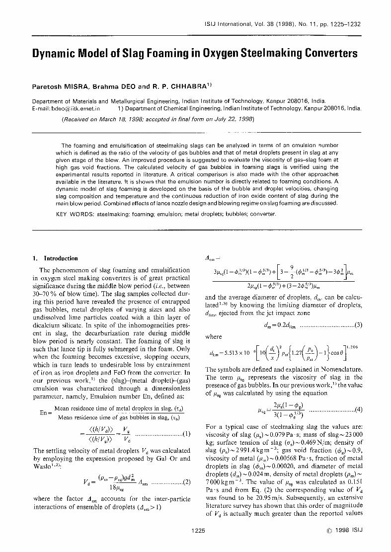
Fig. l.
2.1 2.2 2.3 2.4 2.5 2.6 2.7 2.8Lance Height (m) ~
Droplet velocity in gasslag foam at different lance
heights; gas void fraction values chosenare in the range0.60.9.
substituting the value of u~g from Eq. (6). For a knownvalue of ~sg Wecan nowcalculate the droplet velocity(Vd) from Eq. (2). Again, for the typical case:
CaO-45~ FeO 15 ~ SIO 200/0, MnO-8olo,
MgO-4o/o, Al203 - 3o/o, CaF2- I .4 o/o, P205- 3'6 o/o),
temperature- 1873K and gas void fraction-0.90, thevalue of Vd for a lance height of 2mis 0.2m/s. Dropletdiameter actually dependsupon lance height. Using Eq.(2), Vd is plotted as a function of lance height in Fig. l.
If these values of Vd are comparedwith that reported in
our previous work,1) it would be observed that the newvalue of Vd is smaller by approximately a factor, ~
3(1 -ip 1/3)(2.25
_ip )2
~= g g2(1 -
ipg)3
For ipg=0.90, ~equals 94.3; droplet velocity accordingto the present work is therefore smaller by a factor ofnearly 100. The resulting newvalues of droplet velocity
seem to be fairly close to the reported experimentalvalues. '
3. Comparison and Verification of Calculated BubbleVelocity
Bubble velocity is calculated using the sameexpression
as suggested previously,1) i.e.,
V -(Psm~Pg)9db
(1 -ipl/3) ..........(8)g 12~sm
where average bubble diameter is calculated using the
following expression6)
[-b=6)1/3
d I l/2
..(9)
cr
22 0.52g(pgPs2m)1/3
lO
ISIJ International, Vo[.
9
8
T7
~6~
>5'-*.~
~4
3
2
a6
Fig.
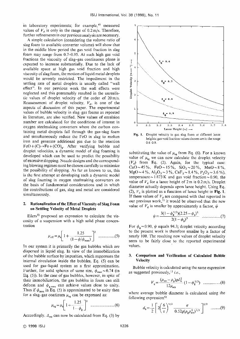
J~angeL al. 8)
!Y
Gouet al 1])
I)resent work
Ogawaet ai lo)
o 6s 0.7s 0.8 0.8s 0.9 0.9s0.7GasVoid Fraction, cg --~
2. Estimated bubble velocity in foaming slags accordingto present work and the equations proposed by otherinvestigators8,l0.1 l); cg is assumed0.9.
l
It is interesting to comparethe velocity of gas bubblescalculated from Eq. (8) with other models reported in
literature. Typical steelmaking slag composition chosenfor this purpose is sameas mentionedearlier (temperature
l 873K) and the variation of bubble velocity with gasvoid fraction, as calculated from Eq. (8), is shownin Fig.
2.
Ito and Fruehan7) have defined a foaming index (~)
(for gas-slag foam only) as the average residence timeof gas bubbles in a gas-slag foam as,
h h~ ~- ipg•VgJF """""~""(lO)~Vg
where V~ is the superficial gas velocity and VgJF is the
actual bubble velocity. Theheight of foam, h, is given by
W,h
p~(1 - ipg)A ""'"""""(1 l)
where W~is the mass of slag and A is the nominalslagmetal interfacial area. According to Jiang andFruehan8) the Foamingindex, ~, dependson viscosity,
surface tension and density of slag
~-115P
..........(12)
J~~:
FromEqs. (lO)-(12)
VJF-h~/fl~~a,p~
_V~~//~Tcr~p~
.........(13)ip I15,1~ I15A(1 - ipg)~~ipg
where V~ is the volume of slag. If the bubble velocity
predicted from Eq. (13) is to be comparedwith Eq. (8),
then, as a first approximation it can be assumedthat
psm p~, (psm p) p and //sm (213)p (since ip~
38 (1998), No. 11
It can nowbe seen that the bubble velocity is inversely
proportional to viscosity in both the cases (present
work and that of Jiang and Fruehan8)). However, thepredictions from Eqs. (8) and (13) are just opposite ofeach other with respect to the effect of gas void fraction,ipg, on bubble velocity (Fig. 2); whereas Eq. (8) predicts
a continuous decrease in bubble velocity with increasein ipg (bubble velocity being proportional to (1 -ip~/3)),
Eq. (13) implies a minimumat ipg-O.5 (bubble velocity
being proportional to I/(ipg(1 -ipg))). It maybe noted that
Eq. (8), as originally derived by GalOr and Wasl0,2) is
based on first principles while Eq. (13) is derived fromdimensional analysis. In principle, Eq. (8) can be usedwith a degree of reliability and should be preferred overEq. (13).
In another approach, Ogawaet al.10) adopted the
Wallis model to find the gas void fraction as
Jc(1 ipg)=W. ""
"""""(14)
whereJ is superficial velocity of gas phaseand W. is the
velocity of a single bubble in an infinite medium, i.e.
W-(p~~- pg)gdb2
....,.....(1 5)
" ~ 12psm
The gas bubble velocity of an ensembleof bubbles can
nowbe calculated from the expression
VHG J ..........(16)g ~ ipg ""'
Onsubstituting the value of Jweget
VgHG-(Psm P)9d
12~~*b (1-ipg)
.... ....
......(17)
The bubble velocity calculated from Eq. (17) is also
plotted in Fig. 2for the sake of comparison. It is evident
from Fig. 2 that trend of variation of bubble velocity
calculated from Eqs. (8) and (17) is of similar nature (in
contrast with Eq. (1 3)); according to Eq. (17), the bubblevelocity is proportional to (1 - cg) and according to Eq.(8) it is proportional to (1-ip~/3) thereby showing aqualitative agreementbetween these approaches.
Gouet al.11) have classified the foaming behavior ofslags into two categories: expanded slag and foamingslag. If it is assumedthat the gas velocity and gas voidfraction are constant throughout the expandedslag andalso (pg-P~)O~p~, p~g(~~p~(1 -ipg) and dVg/dh~~O, thensuperficial gas bubble velocity can be calculated from
ip~/(1-
ipg) =0.9 l(V~)o 573 ...........(1 8)
According to Eq. (18) bubble velocity is proportional to
ipg2.49
(1 -ipg)1•7s
The bubble velocity calculated from Eq. (18) is also
plotted in Fig. 2as a function of gas void fraction. It is
clear that the trend of variation of bubble velocity with
gas void fraction obtained from Eq. (8) is opposite to
that from Eq. (18).
1227 C 1998 ISIJ
ISIJ International, Vol, 38 (1 998), No. 11
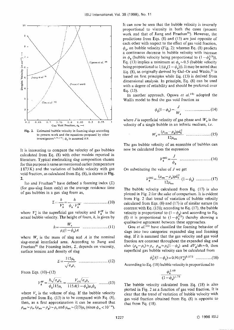
Table l. Functional dependenceof bubble velocily on varlous parameters in difflerent models.
Factor FromEq. (8)
G'al-Or workFromEq. (12) FromEq. (17)
JjangFruehan Gouet a!.
Bubble velocity is proportional lo
Fi'orn Eq. (16)
Ogawaei a/.
Density
Surface tensionViscosity
Gasfraction
*
**
(p,lpg) I13
(T*
l /(/i,)
(1 ip 1/3)g
Jp~Jcr'~'~,
l l't,
l/(ips( I- 4)*))
for a glven volume of slag
assuming that p~ P,,, and bubble diameter do not changewith height
Table
c~49l 75(1 -
(1'g)
(p*l pg) I13
a*
1/(/t,)
[1 -ipg]
2. Comparisonof calculated bubble velocity in foaming slags with the experimental values reported in literature.8~ I l)
Slag density
(kg m~ 3)
Surfacetension
(kg s~ 2)
Viscosity
(kgmI s~ l)
Foamheight
(m)
Measuredvelocity
(ms~1)
Estimatedvelocit y,
present work(ms~ l)
Estirnated
velocity byJjang e! a/.8)
(ms~ 1)
Ratio of
presentto Jjang
e! a/.
Estim'ated
velocity byOgawaef a!.lo]
(ms~ I)
Estimatedvelocity by
Gouel a!,i 1)
(ms~1)
3042.00
3092.00
3142.00
2996.00
3123.OO
3265.00
Note l:
Note 2:
0.572 0.228 50.4340.646 0.4 18 0.6160.350 0.678 l.21 1O576 O.202 50.4340.762 0.475 0.6930.343 0.686 l .376
O. 59 l0.578 O. 160 50.4340.750 0.8680.337 0.690 l.712
0.655 0.555 0.835O568 O. 169 50.4340.354 0.664 1.608
0.686 0.7 18O. 576 O. 132 50.434l .0540.340 0.68 1 2.0800.585 O. I13 50.4340.72 l 0.852 1.214 0.7020.322 2.469
Themaster slag containing 69 "/. CaO,23 ~/* Si02 and 8~/~ MgOto which different amountsof FeOand MnOare addcd; experimcntsin alumina cruclbles and final A1203content upto 18 a/o; temperature 1773 K, area of crucible O.O0132m2, massof slag O, 14 kg, bubblediameter assumed0.033 m, ',md gas void fraction 0.9.
In the last columns estimated velocity, according to Goue! a!.,i 1) dependsonly on gas void fraction and it is samefor all cases.
Table 3. Comparisonof calculated bubble velocity in foaming slags with the experimental values reported in literature.8~ 11)
Slag density
(kg m~ 3)
Surfacetension
(kg s~ 2)
Vlscosity
(kgm~I s~ l)
Foamheight
(m)
Measuredvelocity
(ms~ l)
Estimatedvelocity,
present work(ms~ l)
Estimatedvelocity by
Jiang el a/.s)
(ms~ 1)
Ratlo ofpresentto Jiang
el al.
Estimatedvelocity by
Ogawaet a/. Io)
(ms~ 1)
Estirnated
velocity byGoue/ a/, 11)
(ms~ 1)
3OO0.00 0.2 12 0.783 0.8070.565 O. I14
3056.00 0,208 O.769 0.9320.569 O.099
3115.00 0.204 0.754 1.0740.572 0.086
Note: The master slag containing 69 "/o CaO, 23"/o Si02 and 8"/o MgOother conditions are sameas mentioned at the bottom of Table 2.
0.7380.845
0.966
l .093
l . I02l.111
2.3382. 7013.112
50.43450.43450.434
tO Which different amounts of FeO and MnOare added;
For the sake of easy comparison of all the approaches,the predicted effects of various parameters on bubblevelocity are summarizedin Table 1. It can be seen that
the predicted effects of surface tension, density, viscosity
and gas void fraction on bubble velocity are fundament-ally of samenature for the present work and that for
Ogawaet al., but they differ considerably from the worksof others which are based either on dimensional analysis
or on empirical formulae.Roth et al.9) carried out laboratory experiments at
l 773K and someof their results are summarized in
Tables 2and 3. Predictions from Eqs. (8), (13), (17) and
(18) are also summarizedin Tables 2and 3. In calculating
the bubble velocity values, as listed in Tables 2and 3,
ipg wasassumedto be approximately 0.9 on the basis ofinltial and final foam heights achieved in the laboratoryexperiment of Roth et a/.9)
Although the predictions from Eq. (8) happen to be
in qualitative agreement (in order of magnitude) withthe predictions from Eq. (13) (see Tables 2and 3 for
comparison), Eq. (8) is theoretically correct and shouldbe used, preferably with somefactor for adaptation tospecific experimental conditions. Estimated bubble ve-locities from Eq. (17) are higher by a factor of 2-3while those from Eq. (18) are higher by a factor ofapproximately 60 (vis a vis the experimentally observedvalues).
Extensive experiments are required in the lower rangesof ipg (0.30 to 0.6) to confirm the applicability of modelsbecause, at present, almost no experimental data exist in
thls range for steel making slags.
4. Emulsion Numberas an Indicator of Slopping
In order to calculate Emulsion number, Eq. (8) is
employedfor calculating Vg and Eqs. (2), (3) and (6) are
O1998 ISIJ 1228
20
ISIJ International. Vol. 38 (1 998), No. 11
15
TJ:2
~::'
~;
F~ Iae:'
~Fil
5
Lance Height = 2.8 m
Lance Height = 2.4 m
Lance Helght = 2.0 m
os oss a6 a65 a7 a7s a8 a85 a.9 0.95Gasv.id F~*.ti.*, c* ~
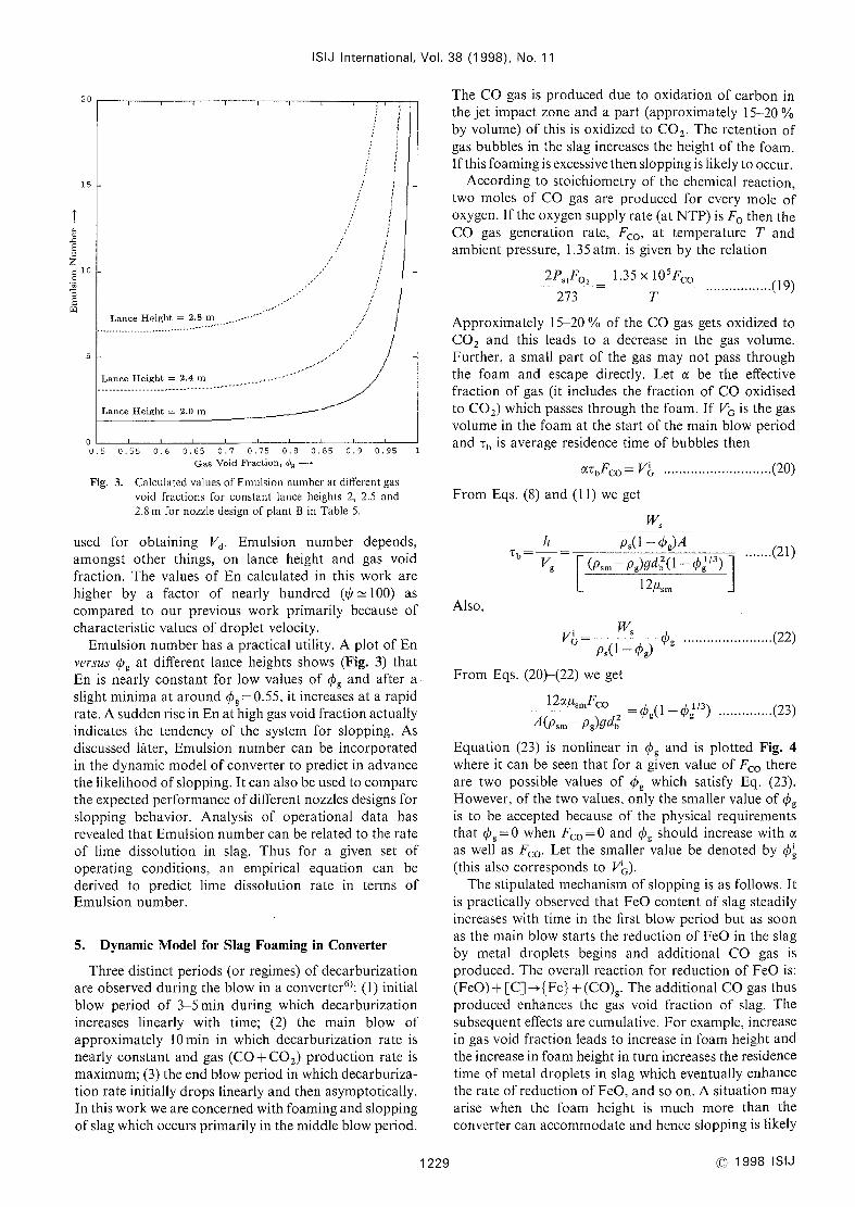
Fig. 3. Calculated values ofEmulsion numberat different gasvoid fractions for constant lance heights 2, 2.5 and2.8 mfor nozzle design of plant B in Table 5.
used for obtaining Vd. Emulsion number depends,
amongst other things, on lance height and gas voidfraction. The values of En calculated in this work arehigher by a factor of nearly hundred (~:~~lOO) ascompared to our previous work primarily because ofcharacteristic values of drop]et velocity.
Emulsion numberhas a practical utility. Aplot of Enve,'sus ipg at different lance helghts shows (Fig. 3) that
En is nearly constant for low values of ipg and after aslight minimaat around nf)g =0.55, it increases at a rapid
rate. Asuddenrise in Enat high gas void fraction actually
Indicates the tendency of the system for slopping. Asdiscussed later, Emulsion numbercan be incorporatedin the dynamicmodelof converter to predict in advancethe likelihood of slopping. It can also be used to comparethe expected performance of different nozzles designs for
slopping behavior. Analysis of operational data hasrevealed that Emulsion numbercan be related to the rate
of llme dissolution in slag. Thus for a given set ofoperating conditions, an empirical equation can bederived to predict lime dissolution rate in terms ofEmulsion number.
5. DynamicModel for Slag Foamingin Converter
Three distinct periods (or regimes) of decarburization
are observed during the blow in a converter6): (1) initial
blow period of 3-5 min during which decarburizationincreases linearly with time; (2) the main blow ofapproximately lOmin in which decarburization rate is
nearly constant and gas (C0+C02)production rate is
maximum;(3) the end blow period in which decarburiza-tion rate initially drops linearly and then asymptotically.
In this workweare concernedwith foaming andsloppingof slag which occurs primarily in the middle blow period.
1229
The COgas is produced due to oxidation of carbon in
the jet impact zone and a part (approximately 15-20 o/o
by vo]ume) of this is oxidized to C02' The retention of
gas bubbles in the slag increases the height of the foam.If this foaming is excessive then slopping is likely to occur.
According to stoichiometry of the chemical reaction,
two moles of COgas are produced for every mole ofoxygen. If the oxygensupply rate (at I\JTP) is Fo then the
COgas generation rate. Fco, at temperature T andambient pressure, 1.35 atm. is given by the relation
2P.tF0= I.35 x 10SFCO..........(19)
273 TApproximately 15-20 o/o of the COgas gets oxidized to
C02 and this leads to a decrease in the gas volume.Further, a smal] part of the gas maynot pass throughthe foam and escape directly. Let c( be the effective
fraction of gas (it includes the fraction of COoxidised
to C02) which passes through the foam. If V;~ is the gasvolume in the foamat the start of the main blow periodand Tb is average residence time of bubbles then
c(TbFc0=ViG....
..........(20)
FromEqs. (8) and (1 1) weget
W.
h_
p~(1-ipg)ATb
Vg ~ (p~~ - pg)gd~(1 -ipgl/3)
~~~'(21)
12,t*~
Also,
. WV'Gp~(1-ipg,
ipg..
..........(22)
FromEqs. (20)-(22) weget
__1~c(,(,~lF_co _ ...
......(23)A(p~~-pg)gclb2
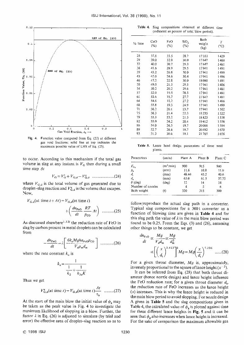
ip (1-ip~/3).... .
Equation (23) is nonlinear In ipg and is plotted Fig. 4where it can be seen that for a given value of Fco there
are two possible values of ipg which satisfy Eq. (23).
However, of the two values, only the smaller value of cgis to be accepted because of the physical requirementsthat ipg=0 whenFc0=0and ipg Should increase with oe
as well as Fco' Let the smaller value be denoted by ip;
(this also corresponds to V;~)-
The stipulated mechanismof slopping is as follows. It
is practica]ly observed that FeOcontent of slag steadily
increases with time in the first blow period but as soonas the main blow starts the reduction of FeOin the slag
by metal droplets begins and additional COgas is
produced. The overall reaction for reduction of FeOis:
(FeO)+ [C] -~{Fe} + (CO)g. Theadditional COgas thusproduced enhances the gas void fraction of slag. Thesubsequent effects are cumulative. For example, increasein gas void fraction leads to increase in foamheight andthe increase in foamheight in turn increases the residence
time of metal droplets in slag which eventually enhancethe rate of reduction of FeO,and so on. Asituation mayarise when the foam height Is muchmore than the
converter can accommodateand hence s]opping is likely
O1998 ISIJ
ISIJ International. Vol. 38 (1 998), No. 11
O, 12
a.l
o . a8
'e
~0.06
:J
l~
>l::
o~
O 041:'*v
~a . a2
O
LHS of Eq. (23)
RHSof Eq. (23)
Table 4. Slag compositions obtained at different time(indicated as percent of total blow period).
~ tlmeCaO("/.)
o 0.2 0.4 0.6 0.8GasVoid Fraction, ~g *H*
Fig. 4. Function value computed from Eq. (23) at different
gas void fractions; solid line at top indicates the
maximumpossible value of LHSof Eq. (23).
FeO(~/*)
Si02("/,)
Bathweight
(kg)
T('C)
2529323639434650545761
646871
757982868993
37.8
39.0
40.0
41.6
43.245.047.249.0
50.2
52.0
53.6
54.6
55.8
56.2
56.3
55.3
55.0
54.0
52.7
51,3
33.5
32.0
30.7
28.9
26.8
24.6
22.8
21.5
20.2
19.5
18.7
18.2
19.3
20. l21.4
23.224.2
26.3
28.6
30.6
28.7
30.0
29.3
29.5
30.0
30.4
30.0
29.5
29.6
28.5
27.7
27.2
24.9
23.7
22.3
21.5
20.419.7
l8.7
18.1
l7353
17647
17647
1794Il794I17941
l808817941
l794l1794117 64717941179411794118 235
l88231941220OOO20 88221 765
l 429
1460
l 481
l 491
l 499
l 496
l 491
l 486
l 481
l 481
1481
1486
1499
l 502
1522
l 538
I 558
1584
l 620
l 656
Table 5. Lance head design parameters of three steel
plants.
to occur. According to this mechanismif the total gasvolume in slag at any instant is VGthen during a smalltime step At
VG VG+VG,d- VeG,d......
..........(24)
where VG,d is the total volume of gas generated due todropletslag reaction and V'G,d is the volumethat escapes.Now,
VG,d(at time t+ At) = VG,d(at time t)
+dnFeo RTAt
....(25)
dt pco
As discussed elsewherel'l2) the reduction rate of FeOin
slag by carbon present in metal droplets can be calculatedfrom
odnF.o
_~6k MghaFeoPco
....(26)
dt VdP~d~
where the rate constant ko is
ko =1
1 1+k2 k3*K
Thus weget
VGd(at time t) = VG,d(at time t) t ........(27)
At the start of the main blow the initial value of ipg maybe taken as the peak value in Fig. 4 to investigate the
maximumlikelihood of slopping in a blow. Further, thefactor ~in Eq. (26) is adjusted to simulate (by trial anderror) the effective area of droplet-slag reaction so as to
Parameters (umts) Plant A Plant B Plant C
Fo,
p~d*
d.
e(deg)
Numberof nozzles
Bath weight
(m3/min)(atm)
(mm)(mm)(deg)
(t)
900
l I.6
48.44
63.0
12
4330
915l0.8
45.2
61.3
14
5315
900
l I.O
40.6
57.7514
6300
@1998 ISIJ 1230
follow/reproduce the actual slag path in a converter.Typical slag compositions for a 300t converter as afunction of blowing time are given in Table 4and forthis slag path the value of ~in the main blow period wasfound to be O.25. Fromthe Eqs. (3) and (26), assumingother things to be constant, weget
dnFeooc
Mg ocMgVdd~ dm3dt
[(_) I Mg Mg(-)2.412J3
=7,236xt xt
'oc
. .(28)
d "'dFor a given throat diameter, Mg is, approximately,inversely proportional to the square of lance height (x ~ 2).
It can be inferred from Eq. (28) that both throat di-
ameter (hence nozzle design) and lance height influencethe FeOreduction rate; for a given throat diameter dt'
the reduction rate of FeOincreases as the lance height(x) increases. This is why the lance height is reduced in
the mainblow period to avoid slopping. For nozzle design
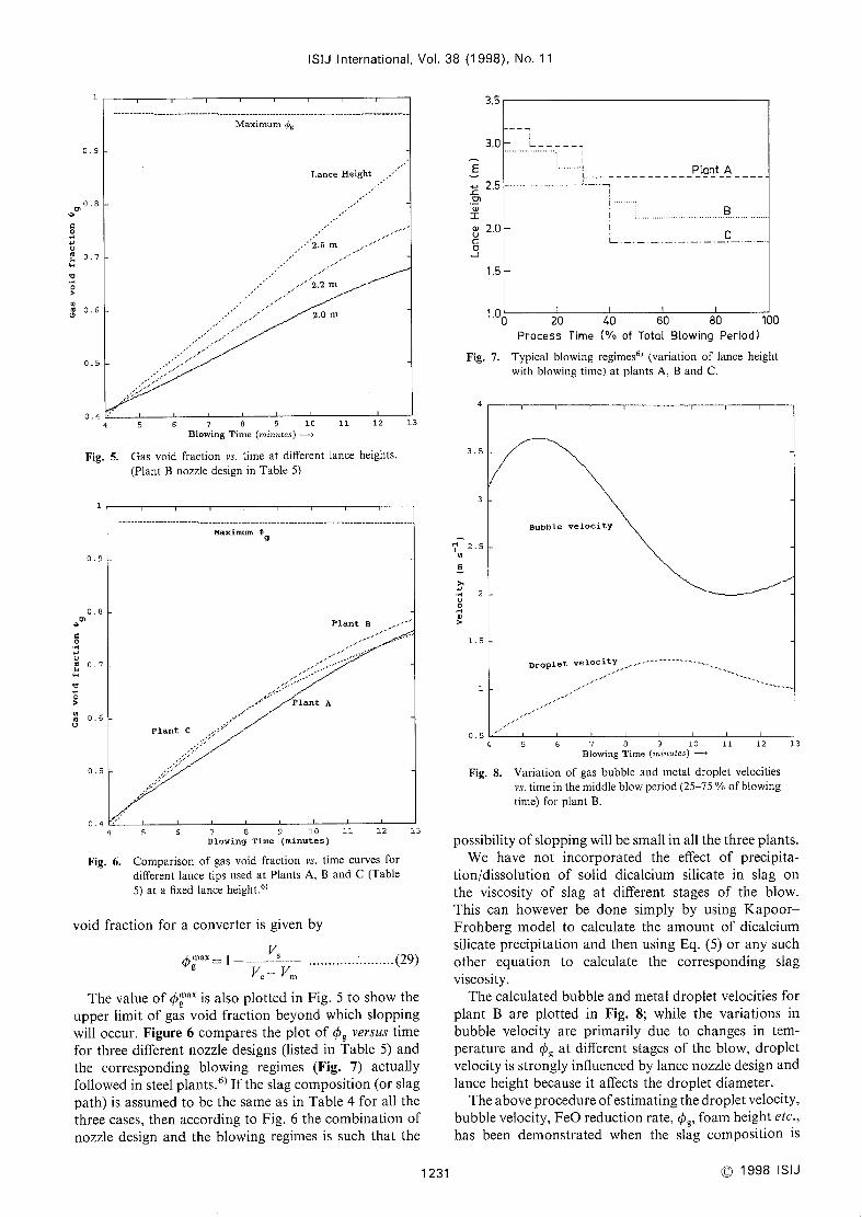
A given in Table 5and the slag compositions given in
Table 4, the calculated value of cg is plotted against timefor three different lance heights in Fig. 5and it can be
seen that ipg also increases whenlance height is increased.
For the sake of comparison the maximumallowable gas
ISIJ International, Vol. 38 (1 998), No. 11
l
a.9
osOi
I::
o~'u~07l~
~~,
e>o,
~06
a.s
04
Maximumcg
Lance Height
•"2.5 nl
'2.2 m
2,0 m
3.S
3,0
E~ 2.5J:c,,
e,:ce,u 2.0c:
oJ1.5
1,oo
L_
•IL. _
PLant A
[ ~IL _ _
JP__
5 9 Io ll 12 136Blowing Time (minutes) -~,
Gasvoid fraction vs, time at different lance heights.
(Plant Bnozzle design in Table 5)
Fig. 7.
4
4
40 10060 8020Process Time ('/~ of TotoL BLowing Period)
Typical blowing regimes6] (variation of lance height
with blowing time) at plants A, Band C.
Fig. 5.
l
3.5
ol
a9
a8,el
,:
o~,ua, 0.7~l
~,
~nj 0.6O
as
a.4
Flant C
Maximuln ~g
Plant A
Plant B
6 Io ll 12Blowing Time (minutes)
6. Comparisonof gas void fractlon vs, tirne curves for
different lance tips used at Plants A, Band C(Table
5) at a fixed lance height.6)
3
H 25,n
Fi
~,JH
2UOQ)
>
l.5
l
as
Bubble
Droplet
velocity
veloclty
13
4
Fig. 8.
io 12 13llBlowing Time
(m9s~~ie*)
-~Variation of gas bubble and metal droplet velocities
vs, time in the middle blow period (2575 o/o of blowingtime) for plant B.
Fig.
4
void fraction for a converter is given by
***V*
,.. . . . . . . .
(29)ipg = V.-V~ "'l-
Thevalue of ip~"' is also plotted in Fig. 5to showthe
upper limit of gas void fraction beyondwhich sloppingwill occur. Figure 6comparesthe plot of cg versus timefor three different nozzle designs (1isted in Table 5) andthe corresponding blowing regimes (Fig. 7) actually
followed in steel plants.6) If the slag composition (or slag
path) is assumedto be the sameas in Table 4for all the
three cases, then according to Fig. 6the combination of
nozzle design and the blowing regimes is such that the
1231
possibility of slopping will be small in all the three plants.
Wehave not incorporated the effect of precipita-
tion/dissolution of solid dicalcium silicate in slag onthe viscosity of slag at different stages of the blow.This can however be done simply by using Kapoor-Frohberg model to calculate the amount of dicalciumsilicate precipitation and then using Eq. (5) or any suchother equation to calculate the corresponding slag
viscosity.
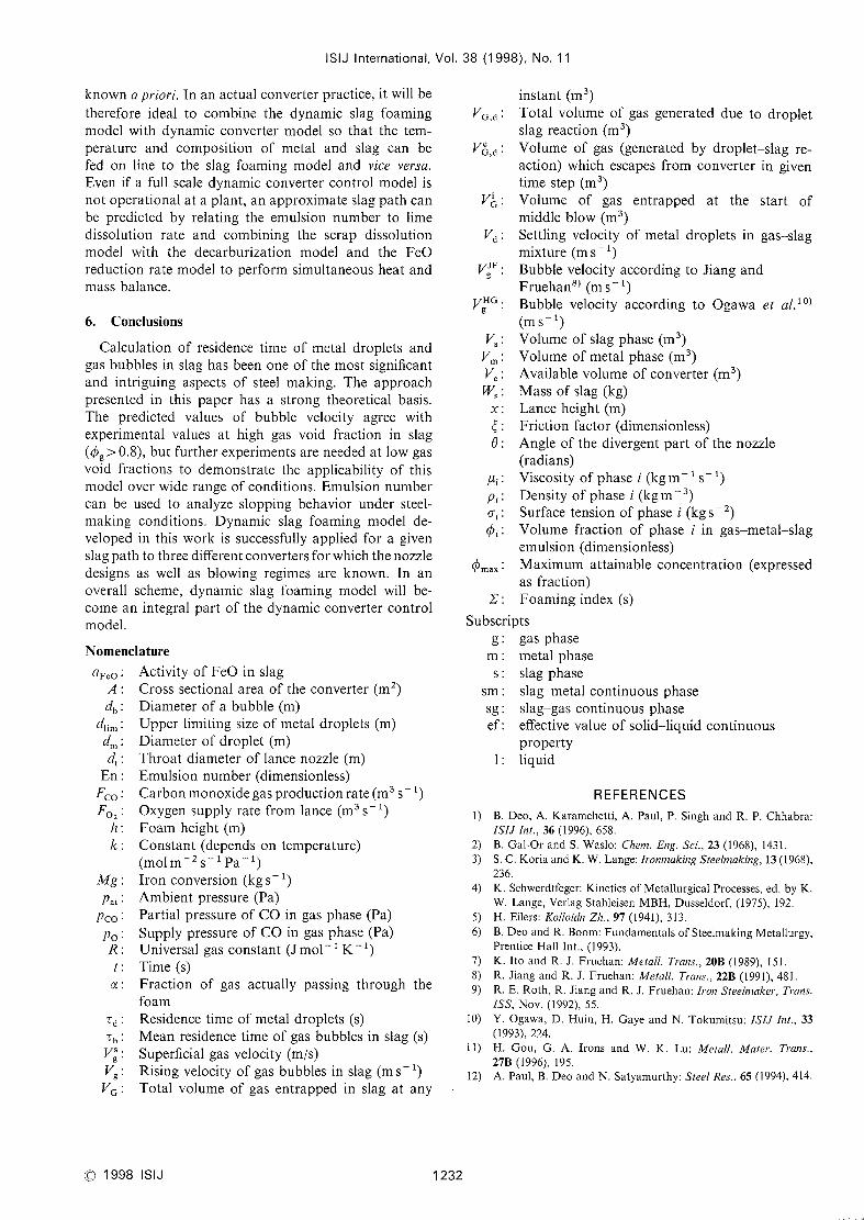
Thecalculated bubble and metal droplet velocities for
plant B are plotted in Fig. 8; while the variations in
bubble velocity are primarily due to changes in tem-perature and ipg at different stages of the blow, droplet
velocity is strongly influenced by lance nozzle design andlance height because it affects the droplet diameter.
Theaboveprocedure of estimating the droplet velocity,
bubb]e velocity, FeOreduction rate, ipg, foamheight etc.,
has been demonstrated when the slag composition is
@1998 Is]J
ISIJ Internationai, Vol.
knowna p,'io,"i. In an actual converter practice, it will betherefore ideal to combine the dynamlc slag foamingmodel with dynamic converter model so that the tem-perature and composition of metal and slag can befed on line to the siag foaming model and vice versa.
Even if a full scale dynamic converter control model is
not operational at a plant, an approximate slag path canbe predicted by relating the emulsion numberto limedissolution rate and combining the scrap dissolution
model with the decarburization model and the FeOreduction rate mode] to perform simultaneous heat andmassbalance.
6. Conclusions
Calculation of residence time of metal droplets andgas bubbles in slag has been one of the most significant
and intriguing aspects of stee] making. The approachpresented in this paper has a strong theoretical basis.
The predicted values of bubble velocity agree withexperimental values at high gas void fraction in slag((/)g >0.8), but further experiments are neededat low gasvoid fractions to demonstrate the applicability of this
model over wide range of conditions. Emulsion numbercan be used to analyze slopplng behavlor under steel-
making conditions. Dynamic slag foaming model de-
veloped in this work is successfully applied for a givenslag path to three different converters for which the nozzledeslgns as well as blowing regimes are known. In anoverall scheme, dynamic slag foaming model will be-
comean integral part of the dynamic converter controlmodel.
Nomenclature
aF*o: Activity of FeOin slag
A: Cross sectional area of the converter (m2)db : Diameter of a bubble (m)
clli*': Upper 1lmiting size of metal droplets (m)c!~ : Diameter of droplet (m)d*: Throat diameter of lance nozzle (m)
En: Emulsion number(dimensionless)
Fco: Carbonmonoxidegasproductionrate(m3s~1)F0= : Oxygensupply rate from lance (m3sl)
h: Foamheight (m)
k: Constant (depends on temperature)(mol m~2s I Pai)
Mg: Iron conversion (kgs~1)
p.* : Ambient pressure (Pa)
pco : Partial pressure of COin gas phase (Pa)
po : Supply pressure of COin gas phase (Pa)
R: Universal gas constant (J mol- I K~1)
t: Tlme (s)
c( : Fractlon of gas actually passing through the
foamTd : Residence time of metal droplets (s)
Tb : Meanresidence time of gas bubbles in slag (s)
V** : Superficial gas velocity (m/s)Vg: Rising velocity of gas bubbles in slag (ms~ 1)
VG: Total volume of gas entrapped in slag at any
38 (1998). No. 11
instant (m3)VG,d: Total volume of gas generated due to droplet
slag reaction (m3)V'G,d: Volumeof gas (generated by droplet-slag re-
action) which escapes from converter in giventime step (m3)
ViG : Volume of gas entrapped at the start ofmiddle blow (m3)
Vd : Settling velocity of metal droplets in gas-slagmixture (ms~ 1)
VgJF: Bubble velocity according to Jiang andFruehan8) (ms 1)
VgHG: Bubble velocity according to Ogawaet al.10)
(ms~ 1)
V~: Volumeof slag phase (m3)
V~: Volumeof metal phase (m3)V. : Available volume of converter (m3)
Ws: Massof slag (kg)
x : Lance height (m)
~: Friction factor (dimensionless)
O: Angle of the divergent part of the nozzle(radians)
~i : Viscosity of phase i (kg m~I s~ l)
Pi : Denslty of phase i (kgm3)Gri : Surface tension of phase i (kg s~2)ipi: Volume fraction of phase i in gas-metal-slag
emulsion (dimensionless)ip~.. : Maximumattainable concentration (expressed
as fraction)2, : Foamingindex (s)
Subscripts
g: gas phase
m: metal phase
s: slag phase
sm: slag-metal continuous phasesg : slag-gas continuous phaseef: effective value of solid-1iquid continuous
propertyl : Iiquid
REFERENCES1) B. Deo. A. Karamchetti. A. Paul, P. Singh and R. P. Chhabra:
ISIJ Int., 36 (1996), 658.
2) B. Gal-Or and S. Waslo: Cllem. Eng. Sci., 23 (1968), 1431.3) S. C. Koria and K. W.Lange: I,'onmaking Steelmaking, 13 (1968),
236.
4) K. Schwerdtfeger: Kinetics ofMetallurgical Processes, ed by K.W. Lange. Verlag Stahleisen MBH,Dusseldorf, (1975), 192.
5) H. Eilers: Kol!oicin Zll., 97 (1941), 313.
6) B. Deoand R. Boom:FundamentalsofSteelmaking Metallurgy,Prentice Hall Int., (1993).
7) K. Ito and R. J. Fruehan: Metal!. T,'ans., 20B (1989), 151.
8) R. Jiang and R. J. Fruehan: Meta!1. T,'a,Is., 22B (1991), 481.9) R. E. Roth, R. Jiang and R. J. Fruehan: I,'0,1 Stee!make", T,'a'Is.
ISS, Nov. (1992), 55.
10) Y. Ogawa.D. Huin, H. Gayeand N. Tokumitsu: ISIJ Int., 33(1993), •~24.
l 1) H. Gou. G. A. Irons and W. K. Lu: Metal!. Male". T,'cl'Is,,
27B (1996), 195.
12) A. Paul, B Deoand N. Satyamurthy: Stee! Res., 65 (1994). 414.
O1998 IS]J 1232