chapter 6 buildings and support facilities
TRANSCRIPT
© 2018, American Railway Engineering and Maintenance-of-Way Association 6-i
1
3
6
CHAPTER 6
BUILDINGS AND SUPPORT FACILITIES1
TABLE OF CONTENTS
Part/Section Description Page
1 Specifications and General Design Criteria for Railway Buildings . . . . . . . . . . . . . . . . . . . . . . . . . . . . . . . . 6-1-11.1 Organization of Bid Documents . . . . . . . . . . . . . . . . . . . . . . . . . . . . . . . . . . . . . . . . . . . . . . . . . . . . . . . . . 6-1-31.2 General Design Criteria for Railway Buildings . . . . . . . . . . . . . . . . . . . . . . . . . . . . . . . . . . . . . . . . . . . . . 6-1-91.3 Design Criteria . . . . . . . . . . . . . . . . . . . . . . . . . . . . . . . . . . . . . . . . . . . . . . . . . . . . . . . . . . . . . . . . . . . . . . 6-1-12
2 Design Criteria for Railway Office Buildings . . . . . . . . . . . . . . . . . . . . . . . . . . . . . . . . . . . . . . . . . . . . . . . . . 6-2-12.1 Site Considerations . . . . . . . . . . . . . . . . . . . . . . . . . . . . . . . . . . . . . . . . . . . . . . . . . . . . . . . . . . . . . . . . . . . 6-2-32.2 Functional Requirements. . . . . . . . . . . . . . . . . . . . . . . . . . . . . . . . . . . . . . . . . . . . . . . . . . . . . . . . . . . . . . . 6-2-32.3 Spacial Requirements . . . . . . . . . . . . . . . . . . . . . . . . . . . . . . . . . . . . . . . . . . . . . . . . . . . . . . . . . . . . . . . . . 6-2-52.4 Structural Requirements . . . . . . . . . . . . . . . . . . . . . . . . . . . . . . . . . . . . . . . . . . . . . . . . . . . . . . . . . . . . . . . 6-2-92.5 Finish Materials. . . . . . . . . . . . . . . . . . . . . . . . . . . . . . . . . . . . . . . . . . . . . . . . . . . . . . . . . . . . . . . . . . . . . . 6-2-102.6 Mechanical Considerations . . . . . . . . . . . . . . . . . . . . . . . . . . . . . . . . . . . . . . . . . . . . . . . . . . . . . . . . . . . . . 6-2-132.7 Electrical Equipment . . . . . . . . . . . . . . . . . . . . . . . . . . . . . . . . . . . . . . . . . . . . . . . . . . . . . . . . . . . . . . . . . . 6-2-142.8 Fire and Life Safety. . . . . . . . . . . . . . . . . . . . . . . . . . . . . . . . . . . . . . . . . . . . . . . . . . . . . . . . . . . . . . . . . . . 6-2-16
3 Design Criteria for Spot Car Repair Shops . . . . . . . . . . . . . . . . . . . . . . . . . . . . . . . . . . . . . . . . . . . . . . . . . . . 6-3-13.1 General . . . . . . . . . . . . . . . . . . . . . . . . . . . . . . . . . . . . . . . . . . . . . . . . . . . . . . . . . . . . . . . . . . . . . . . . . . . . 6-3-33.2 Site Considerations . . . . . . . . . . . . . . . . . . . . . . . . . . . . . . . . . . . . . . . . . . . . . . . . . . . . . . . . . . . . . . . . . . . 6-3-33.3 Building Codes . . . . . . . . . . . . . . . . . . . . . . . . . . . . . . . . . . . . . . . . . . . . . . . . . . . . . . . . . . . . . . . . . . . . . . 6-3-43.4 Structural Requirements . . . . . . . . . . . . . . . . . . . . . . . . . . . . . . . . . . . . . . . . . . . . . . . . . . . . . . . . . . . . . . . 6-3-53.5 Space Requirements . . . . . . . . . . . . . . . . . . . . . . . . . . . . . . . . . . . . . . . . . . . . . . . . . . . . . . . . . . . . . . . . . . 6-3-53.6 Mechanical, Electrical and Specialized Equipment . . . . . . . . . . . . . . . . . . . . . . . . . . . . . . . . . . . . . . . . . . 6-3-73.7 Finish. . . . . . . . . . . . . . . . . . . . . . . . . . . . . . . . . . . . . . . . . . . . . . . . . . . . . . . . . . . . . . . . . . . . . . . . . . . . . . 6-3-83.8 Miscellaneous Considerations. . . . . . . . . . . . . . . . . . . . . . . . . . . . . . . . . . . . . . . . . . . . . . . . . . . . . . . . . . . 6-3-93.9 Mechanical . . . . . . . . . . . . . . . . . . . . . . . . . . . . . . . . . . . . . . . . . . . . . . . . . . . . . . . . . . . . . . . . . . . . . . . . . 6-3-93.10 Environmental Control . . . . . . . . . . . . . . . . . . . . . . . . . . . . . . . . . . . . . . . . . . . . . . . . . . . . . . . . . . . . . . . . 6-3-11
1 The material in this and other chapters in the AREMA Manual for Railway Engineering is published as recommended practice to railroads and others concerned with the engineering, design and construction of railroad fixed properties (except signals and communications), and allied services and facilities. For the purpose of this Manual, RECOMMENDED PRACTICE is defined as a material, device, design, plan, specification, principle or practice recommended to the railways for use as required, either exactly as presented or with such modifications as may be necessary or desirable to meet the needs of individual railways, but in either event, with a view to promoting efficiency and economy in the location, construction, operation or maintenance of railways. It is not intended to imply that other practices may not be equally acceptable.
© 2018, American Railway Engineering and Maintenance-of-Way Association
6-ii AREMA Manual for Railway Engineering
TABLE OF CONTENTS (CONT)
Part/Section Description Page
3.11 Summary . . . . . . . . . . . . . . . . . . . . . . . . . . . . . . . . . . . . . . . . . . . . . . . . . . . . . . . . . . . . . . . . . . . . . . . . . . 6-3-12
4 Design Criteria for Diesel Repair Facilities . . . . . . . . . . . . . . . . . . . . . . . . . . . . . . . . . . . . . . . . . . . . . . . . . . 6-4-14.1 Introduction . . . . . . . . . . . . . . . . . . . . . . . . . . . . . . . . . . . . . . . . . . . . . . . . . . . . . . . . . . . . . . . . . . . . . . . . 6-4-34.2 Site Considerations . . . . . . . . . . . . . . . . . . . . . . . . . . . . . . . . . . . . . . . . . . . . . . . . . . . . . . . . . . . . . . . . . . 6-4-154.3 Building Arrangement . . . . . . . . . . . . . . . . . . . . . . . . . . . . . . . . . . . . . . . . . . . . . . . . . . . . . . . . . . . . . . . . 6-4-164.4 Equipment and Related Facilities . . . . . . . . . . . . . . . . . . . . . . . . . . . . . . . . . . . . . . . . . . . . . . . . . . . . . . . 6-4-194.5 Service Facilities . . . . . . . . . . . . . . . . . . . . . . . . . . . . . . . . . . . . . . . . . . . . . . . . . . . . . . . . . . . . . . . . . . . . 6-4-254.6 Building Superstructure Details. . . . . . . . . . . . . . . . . . . . . . . . . . . . . . . . . . . . . . . . . . . . . . . . . . . . . . . . . 6-4-304.7 Heating and Ventilation . . . . . . . . . . . . . . . . . . . . . . . . . . . . . . . . . . . . . . . . . . . . . . . . . . . . . . . . . . . . . . . 6-4-324.8 Electrical Lighting and Power Supply. . . . . . . . . . . . . . . . . . . . . . . . . . . . . . . . . . . . . . . . . . . . . . . . . . . . 6-4-344.9 Pollution (Noise-Air-Water) . . . . . . . . . . . . . . . . . . . . . . . . . . . . . . . . . . . . . . . . . . . . . . . . . . . . . . . . . . . 6-4-354.10 Communications and Data. . . . . . . . . . . . . . . . . . . . . . . . . . . . . . . . . . . . . . . . . . . . . . . . . . . . . . . . . . . . . 6-4-354.11 Fire Protection . . . . . . . . . . . . . . . . . . . . . . . . . . . . . . . . . . . . . . . . . . . . . . . . . . . . . . . . . . . . . . . . . . . . . . 6-4-364.12 Blue Signal/Flag Protection. . . . . . . . . . . . . . . . . . . . . . . . . . . . . . . . . . . . . . . . . . . . . . . . . . . . . . . . . . . . 6-4-374.13 Storage Tanks. . . . . . . . . . . . . . . . . . . . . . . . . . . . . . . . . . . . . . . . . . . . . . . . . . . . . . . . . . . . . . . . . . . . . . . 6-4-374.14 Track Drip Collection . . . . . . . . . . . . . . . . . . . . . . . . . . . . . . . . . . . . . . . . . . . . . . . . . . . . . . . . . . . . . . . . 6-4-38
5 Energy Conservation and Audits . . . . . . . . . . . . . . . . . . . . . . . . . . . . . . . . . . . . . . . . . . . . . . . . . . . . . . . . . . . 6-5-15.1 Introduction . . . . . . . . . . . . . . . . . . . . . . . . . . . . . . . . . . . . . . . . . . . . . . . . . . . . . . . . . . . . . . . . . . . . . . . . 6-5-35.2 Elements of Energy Conservation Program . . . . . . . . . . . . . . . . . . . . . . . . . . . . . . . . . . . . . . . . . . . . . . . 6-5-45.3 Strategies and Economics . . . . . . . . . . . . . . . . . . . . . . . . . . . . . . . . . . . . . . . . . . . . . . . . . . . . . . . . . . . . . 6-5-55.4 Advances in Energy Cost Savings for Railway Buildings and Shop Facilities. . . . . . . . . . . . . . . . . . . . . 6-5-65.5 Types of Audits . . . . . . . . . . . . . . . . . . . . . . . . . . . . . . . . . . . . . . . . . . . . . . . . . . . . . . . . . . . . . . . . . . . . . 6-5-75.6 Organization of Railroad Energy Management Program . . . . . . . . . . . . . . . . . . . . . . . . . . . . . . . . . . . . . 6-5-85.7 Audit Survey Instrumentation . . . . . . . . . . . . . . . . . . . . . . . . . . . . . . . . . . . . . . . . . . . . . . . . . . . . . . . . . . 6-5-95.8 Justification of Program. . . . . . . . . . . . . . . . . . . . . . . . . . . . . . . . . . . . . . . . . . . . . . . . . . . . . . . . . . . . . . . 6-5-135.9 Appendix A . . . . . . . . . . . . . . . . . . . . . . . . . . . . . . . . . . . . . . . . . . . . . . . . . . . . . . . . . . . . . . . . . . . . . . . . 6-5-155.10 Appendix B . . . . . . . . . . . . . . . . . . . . . . . . . . . . . . . . . . . . . . . . . . . . . . . . . . . . . . . . . . . . . . . . . . . . . . . . 6-5-175.11 Appendix C . . . . . . . . . . . . . . . . . . . . . . . . . . . . . . . . . . . . . . . . . . . . . . . . . . . . . . . . . . . . . . . . . . . . . . . . 6-5-23
6 Locomotive Sanding Facilities . . . . . . . . . . . . . . . . . . . . . . . . . . . . . . . . . . . . . . . . . . . . . . . . . . . . . . . . . . . . . 6-6-16.1 Introduction . . . . . . . . . . . . . . . . . . . . . . . . . . . . . . . . . . . . . . . . . . . . . . . . . . . . . . . . . . . . . . . . . . . . . . . . 6-6-26.2 Sanding Facility . . . . . . . . . . . . . . . . . . . . . . . . . . . . . . . . . . . . . . . . . . . . . . . . . . . . . . . . . . . . . . . . . . . . . 6-6-36.3 System Types . . . . . . . . . . . . . . . . . . . . . . . . . . . . . . . . . . . . . . . . . . . . . . . . . . . . . . . . . . . . . . . . . . . . . . . 6-6-66.4 Sanding Components . . . . . . . . . . . . . . . . . . . . . . . . . . . . . . . . . . . . . . . . . . . . . . . . . . . . . . . . . . . . . . . . . 6-6-126.5 Environmental Considerations. . . . . . . . . . . . . . . . . . . . . . . . . . . . . . . . . . . . . . . . . . . . . . . . . . . . . . . . . . 6-6-176.6 References . . . . . . . . . . . . . . . . . . . . . . . . . . . . . . . . . . . . . . . . . . . . . . . . . . . . . . . . . . . . . . . . . . . . . . . . . 6-6-18
7 Design Criteria for Railway Materials Management Facilities . . . . . . . . . . . . . . . . . . . . . . . . . . . . . . . . . . 6-7-17.1 Site Considerations . . . . . . . . . . . . . . . . . . . . . . . . . . . . . . . . . . . . . . . . . . . . . . . . . . . . . . . . . . . . . . . . . . 6-7-27.2 Functional Requirements . . . . . . . . . . . . . . . . . . . . . . . . . . . . . . . . . . . . . . . . . . . . . . . . . . . . . . . . . . . . . . 6-7-37.3 Fire Protection . . . . . . . . . . . . . . . . . . . . . . . . . . . . . . . . . . . . . . . . . . . . . . . . . . . . . . . . . . . . . . . . . . . . . . 6-7-67.4 Exterior Storage . . . . . . . . . . . . . . . . . . . . . . . . . . . . . . . . . . . . . . . . . . . . . . . . . . . . . . . . . . . . . . . . . . . . . 6-7-6
8 Design Criteria for Railway Passenger Stations. . . . . . . . . . . . . . . . . . . . . . . . . . . . . . . . . . . . . . . . . . . . . . . 6-8-18.1 Introduction . . . . . . . . . . . . . . . . . . . . . . . . . . . . . . . . . . . . . . . . . . . . . . . . . . . . . . . . . . . . . . . . . . . . . . . . 6-8-38.2 Site . . . . . . . . . . . . . . . . . . . . . . . . . . . . . . . . . . . . . . . . . . . . . . . . . . . . . . . . . . . . . . . . . . . . . . . . . . . . . . . 6-8-48.3 Functional Requirements . . . . . . . . . . . . . . . . . . . . . . . . . . . . . . . . . . . . . . . . . . . . . . . . . . . . . . . . . . . . . . 6-8-8
© 2018, American Railway Engineering and Maintenance-of-Way Association
AREMA Manual for Railway Engineering 6-iii
1
3
4
TABLE OF CONTENTS (CONT)
Part/Section Description Page
8.4 Building Systems. . . . . . . . . . . . . . . . . . . . . . . . . . . . . . . . . . . . . . . . . . . . . . . . . . . . . . . . . . . . . . . . . . . . . 6-8-158.5 Mechanical Systems . . . . . . . . . . . . . . . . . . . . . . . . . . . . . . . . . . . . . . . . . . . . . . . . . . . . . . . . . . . . . . . . . . 6-8-188.6 Electrical Systems . . . . . . . . . . . . . . . . . . . . . . . . . . . . . . . . . . . . . . . . . . . . . . . . . . . . . . . . . . . . . . . . . . . . 6-8-198.7 Boarding Platforms . . . . . . . . . . . . . . . . . . . . . . . . . . . . . . . . . . . . . . . . . . . . . . . . . . . . . . . . . . . . . . . . . . . 6-8-218.8 Station and Platform Examples . . . . . . . . . . . . . . . . . . . . . . . . . . . . . . . . . . . . . . . . . . . . . . . . . . . . . . . . . . 6-8-258.9 Train Service and Inspection Facilities . . . . . . . . . . . . . . . . . . . . . . . . . . . . . . . . . . . . . . . . . . . . . . . . . . . . 6-8-33
9 Design Criteria for Centralized Maintenance-of-Way Equipment Repair Shops . . . . . . . . . . . . . . . . . . . . 6-9-19.1 Introduction . . . . . . . . . . . . . . . . . . . . . . . . . . . . . . . . . . . . . . . . . . . . . . . . . . . . . . . . . . . . . . . . . . . . . . . . . 6-9-29.2 Machine Maintenance Area. . . . . . . . . . . . . . . . . . . . . . . . . . . . . . . . . . . . . . . . . . . . . . . . . . . . . . . . . . . . . 6-9-49.3 Other Workshop Areas . . . . . . . . . . . . . . . . . . . . . . . . . . . . . . . . . . . . . . . . . . . . . . . . . . . . . . . . . . . . . . . . 6-9-59.4 Machine and Material Handling . . . . . . . . . . . . . . . . . . . . . . . . . . . . . . . . . . . . . . . . . . . . . . . . . . . . . . . . . 6-9-89.5 Support Areas . . . . . . . . . . . . . . . . . . . . . . . . . . . . . . . . . . . . . . . . . . . . . . . . . . . . . . . . . . . . . . . . . . . . . . . 6-9-9
10 Design Criteria for Observation Towers. . . . . . . . . . . . . . . . . . . . . . . . . . . . . . . . . . . . . . . . . . . . . . . . . . . . . . 6-10-110.1 Introduction . . . . . . . . . . . . . . . . . . . . . . . . . . . . . . . . . . . . . . . . . . . . . . . . . . . . . . . . . . . . . . . . . . . . . . . . . 6-10-210.2 Types . . . . . . . . . . . . . . . . . . . . . . . . . . . . . . . . . . . . . . . . . . . . . . . . . . . . . . . . . . . . . . . . . . . . . . . . . . . . . . 6-10-310.3 Tower Construction . . . . . . . . . . . . . . . . . . . . . . . . . . . . . . . . . . . . . . . . . . . . . . . . . . . . . . . . . . . . . . . . . . . 6-10-310.4 Special Features. . . . . . . . . . . . . . . . . . . . . . . . . . . . . . . . . . . . . . . . . . . . . . . . . . . . . . . . . . . . . . . . . . . . . . 6-10-6
11 Design Criteria for CTC Centers . . . . . . . . . . . . . . . . . . . . . . . . . . . . . . . . . . . . . . . . . . . . . . . . . . . . . . . . . . . 6-11-111.1 Site Considerations (1991) . . . . . . . . . . . . . . . . . . . . . . . . . . . . . . . . . . . . . . . . . . . . . . . . . . . . . . . . . . . . . 6-11-211.2 Equipment . . . . . . . . . . . . . . . . . . . . . . . . . . . . . . . . . . . . . . . . . . . . . . . . . . . . . . . . . . . . . . . . . . . . . . . . . . 6-11-211.3 Functional Requirements. . . . . . . . . . . . . . . . . . . . . . . . . . . . . . . . . . . . . . . . . . . . . . . . . . . . . . . . . . . . . . . 6-11-411.4 Support Systems . . . . . . . . . . . . . . . . . . . . . . . . . . . . . . . . . . . . . . . . . . . . . . . . . . . . . . . . . . . . . . . . . . . . . 6-11-411.5 Room Finishes. . . . . . . . . . . . . . . . . . . . . . . . . . . . . . . . . . . . . . . . . . . . . . . . . . . . . . . . . . . . . . . . . . . . . . . 6-11-5
12 Design Criteria for a Locomotive Washing Facility . . . . . . . . . . . . . . . . . . . . . . . . . . . . . . . . . . . . . . . . . . . . 6-12-112.1 Introduction . . . . . . . . . . . . . . . . . . . . . . . . . . . . . . . . . . . . . . . . . . . . . . . . . . . . . . . . . . . . . . . . . . . . . . . . . 6-12-212.2 Washing Facility . . . . . . . . . . . . . . . . . . . . . . . . . . . . . . . . . . . . . . . . . . . . . . . . . . . . . . . . . . . . . . . . . . . . . 6-12-2
13 Passenger Rail (Coach)/Locomotive Maintenance, Repair and Servicing Facilities . . . . . . . . . . . . . . . . . . 6-13-113.1 Site Considerations . . . . . . . . . . . . . . . . . . . . . . . . . . . . . . . . . . . . . . . . . . . . . . . . . . . . . . . . . . . . . . . . . . . 6-13-213.2 Functional Requirements. . . . . . . . . . . . . . . . . . . . . . . . . . . . . . . . . . . . . . . . . . . . . . . . . . . . . . . . . . . . . . . 6-13-313.3 Special Requirements – Coach Shop . . . . . . . . . . . . . . . . . . . . . . . . . . . . . . . . . . . . . . . . . . . . . . . . . . . . . 6-13-513.4 Special Requirements – Combined Coach Locomotive Shop . . . . . . . . . . . . . . . . . . . . . . . . . . . . . . . . . . 6-13-713.5 Special Equipment. . . . . . . . . . . . . . . . . . . . . . . . . . . . . . . . . . . . . . . . . . . . . . . . . . . . . . . . . . . . . . . . . . . . 6-13-813.6 Structural Requirements . . . . . . . . . . . . . . . . . . . . . . . . . . . . . . . . . . . . . . . . . . . . . . . . . . . . . . . . . . . . . . . 6-13-913.7 Mechanical Requirements . . . . . . . . . . . . . . . . . . . . . . . . . . . . . . . . . . . . . . . . . . . . . . . . . . . . . . . . . . . . . . 6-13-913.8 Electrical Requirements . . . . . . . . . . . . . . . . . . . . . . . . . . . . . . . . . . . . . . . . . . . . . . . . . . . . . . . . . . . . . . . 6-13-1013.9 Illustrations . . . . . . . . . . . . . . . . . . . . . . . . . . . . . . . . . . . . . . . . . . . . . . . . . . . . . . . . . . . . . . . . . . . . . . . . . 6-13-11
14 Roofing Systems Descriptions and Recommendations for Selection . . . . . . . . . . . . . . . . . . . . . . . . . . . . . . . 6-14-114.1 Introduction . . . . . . . . . . . . . . . . . . . . . . . . . . . . . . . . . . . . . . . . . . . . . . . . . . . . . . . . . . . . . . . . . . . . . . . . . 6-14-214.2 Selecting a System . . . . . . . . . . . . . . . . . . . . . . . . . . . . . . . . . . . . . . . . . . . . . . . . . . . . . . . . . . . . . . . . . . . 6-14-314.3 Roofing Systems . . . . . . . . . . . . . . . . . . . . . . . . . . . . . . . . . . . . . . . . . . . . . . . . . . . . . . . . . . . . . . . . . . . . . 6-14-414.4 Conclusions . . . . . . . . . . . . . . . . . . . . . . . . . . . . . . . . . . . . . . . . . . . . . . . . . . . . . . . . . . . . . . . . . . . . . . . . . 6-14-29
15 Inspection of Railway Buildings . . . . . . . . . . . . . . . . . . . . . . . . . . . . . . . . . . . . . . . . . . . . . . . . . . . . . . . . . . . . 6-15-115.1 Organization and Inspection Preparation . . . . . . . . . . . . . . . . . . . . . . . . . . . . . . . . . . . . . . . . . . . . . . . . . . 6-15-2
© 2018, American Railway Engineering and Maintenance-of-Way Association
6-iv AREMA Manual for Railway Engineering
TABLE OF CONTENTS (CONT)
Part/Section Description Page
15.2 Inspectors. . . . . . . . . . . . . . . . . . . . . . . . . . . . . . . . . . . . . . . . . . . . . . . . . . . . . . . . . . . . . . . . . . . . . . . . . . 6-15-215.3 Inspections . . . . . . . . . . . . . . . . . . . . . . . . . . . . . . . . . . . . . . . . . . . . . . . . . . . . . . . . . . . . . . . . . . . . . . . . . 6-15-315.4 Conducting an Inspection . . . . . . . . . . . . . . . . . . . . . . . . . . . . . . . . . . . . . . . . . . . . . . . . . . . . . . . . . . . . . 6-15-315.5 Inspection Reports . . . . . . . . . . . . . . . . . . . . . . . . . . . . . . . . . . . . . . . . . . . . . . . . . . . . . . . . . . . . . . . . . . . 6-15-5
16 Design Criteria for Main Line Fueling Facilities . . . . . . . . . . . . . . . . . . . . . . . . . . . . . . . . . . . . . . . . . . . . . . 6-16-116.1 Introduction . . . . . . . . . . . . . . . . . . . . . . . . . . . . . . . . . . . . . . . . . . . . . . . . . . . . . . . . . . . . . . . . . . . . . . . . 6-16-216.2 Site . . . . . . . . . . . . . . . . . . . . . . . . . . . . . . . . . . . . . . . . . . . . . . . . . . . . . . . . . . . . . . . . . . . . . . . . . . . . . . . 6-16-216.3 Types of Main Line Fueling Facilities. . . . . . . . . . . . . . . . . . . . . . . . . . . . . . . . . . . . . . . . . . . . . . . . . . . . 6-16-316.4 Services Provided . . . . . . . . . . . . . . . . . . . . . . . . . . . . . . . . . . . . . . . . . . . . . . . . . . . . . . . . . . . . . . . . . . . 6-16-4
17 Other Yard and Terminal Facilities . . . . . . . . . . . . . . . . . . . . . . . . . . . . . . . . . . . . . . . . . . . . . . . . . . . . . . . . . 6-17-117.1 Stores . . . . . . . . . . . . . . . . . . . . . . . . . . . . . . . . . . . . . . . . . . . . . . . . . . . . . . . . . . . . . . . . . . . . . . . . . . . . . 6-17-217.2 Storage . . . . . . . . . . . . . . . . . . . . . . . . . . . . . . . . . . . . . . . . . . . . . . . . . . . . . . . . . . . . . . . . . . . . . . . . . . . . 6-17-317.3 Design of Roadway Material Reclamation and Fabrication Facilities . . . . . . . . . . . . . . . . . . . . . . . . . . . 6-17-417.4 Design of Yard Compressed Air Facilities for Train Air Brake Systems. . . . . . . . . . . . . . . . . . . . . . . . . . 6-17-10
Glossary . . . . . . . . . . . . . . . . . . . . . . . . . . . . . . . . . . . . . . . . . . . . . . . . . . . . . . . . . . . . . . . . . . . . . . . . . . . . . . . . . . . 6-G-1
References . . . . . . . . . . . . . . . . . . . . . . . . . . . . . . . . . . . . . . . . . . . . . . . . . . . . . . . . . . . . . . . . . . . . . . . . . . . . . . . . . 6-R-1
INTRODUCTION
The Chapters of the AREMA Manual are divided into numbered Parts, each comprised of related documents (specifications, recommended practices, plans, etc.). Individual Parts are divided into Sections by centered headings set in capital letters and identified by a Section number. These Sections are subdivided into Articles designated by numbered side headings.
Page Numbers – In the page numbering of the Manual (6-2-1, for example) the first numeral designates the Chapter number, the second denotes the Part number in the Chapter, and the third numeral designates the page number in the Part. Thus, 6-2-1 means Chapter 6, Part 2, page 1.
In the Glossary and References, the Part number is replaced by either a “G” for Glossary or “R” for References.
Document Dates – The bold type date (Document Date) at the beginning of each document (Part) applies to the document as a whole and designates the year in which revisions were last made somewhere in the document, unless an attached footnote indicates that the document was adopted, reapproved, or rewritten in that year.
Article Dates – Each Article shows the date (in parenthesis) of the last time the Article was modified.
Revision Marks – All current year revisions (changes and additions) which have been incorporated into the document are identified by a vertical line along the outside margin of the page, directly beside the modified information.
Proceedings Footnote – The Proceedings footnote on the first page of each document gives references to all Association action with respect to the document.
Annual Updates – New manuals, as well as revision sets, will be printed and issued yearly.
© 2018, American Railway Engineering and Maintenance-of-Way Association
© 2018, American Railway Engineering and Maintenance-of-Way Association
© 2018, American Railway Engineering and Maintenance-of-Way Association
© 2018, American Railway Engineering and Maintenance-of-Way Association
© 2018, American Railway Engineering and Maintenance-of-Way Association
© 2018, American Railway Engineering and Maintenance-of-Way Association
© 2018, American Railway Engineering and Maintenance-of-Way Association
© 2018, American Railway Engineering and Maintenance-of-Way Association
© 2018, American Railway Engineering and Maintenance-of-Way Association
© 2018, American Railway Engineering and Maintenance-of-Way Association
© 2018, American Railway Engineering and Maintenance-of-Way Association
© 2018, American Railway Engineering and Maintenance-of-Way Association
© 2018, American Railway Engineering and Maintenance-of-Way Association
© 2018, American Railway Engineering and Maintenance-of-Way Association
© 2018, American Railway Engineering and Maintenance-of-Way Association
© 2018, American Railway Engineering and Maintenance-of-Way Association
© 2018, American Railway Engineering and Maintenance-of-Way Association
© 2018, American Railway Engineering and Maintenance-of-Way Association
Nature of the work.
Nature of space.
Need for privacy.
Need for access.
Need for expansion.
© 2018, American Railway Engineering and Maintenance-of-Way Association
© 2018, American Railway Engineering and Maintenance-of-Way Association
© 2018, American Railway Engineering and Maintenance-of-Way Association
© 2018, American Railway Engineering and Maintenance-of-Way Association
© 2018, American Railway Engineering and Maintenance-of-Way Association
© 2018, American Railway Engineering and Maintenance-of-Way Association
© 2018, American Railway Engineering and Maintenance-of-Way Association
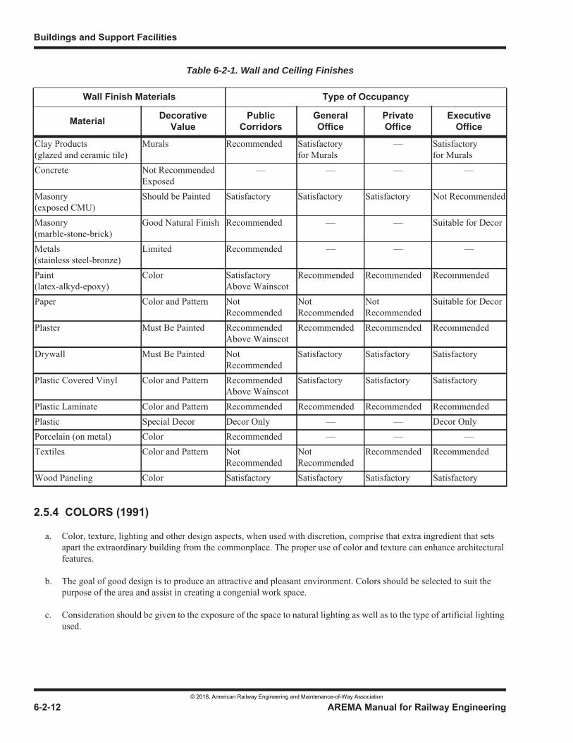
Table 6-2-1. Wall and Ceiling Finishes
© 2018, American Railway Engineering and Maintenance-of-Way Association
© 2018, American Railway Engineering and Maintenance-of-Way Association
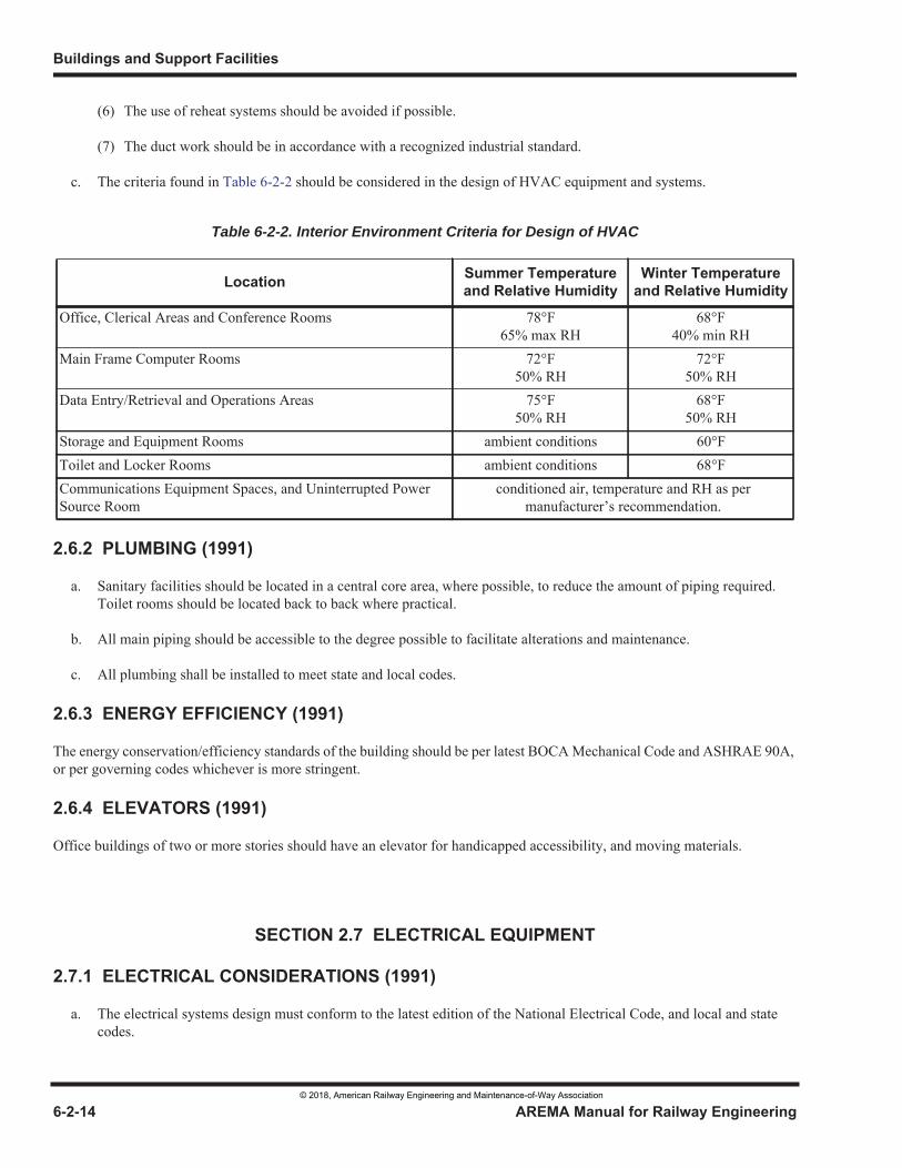
Table 6-2-2. Interior Environment Criteria for Design of HVAC
© 2018, American Railway Engineering and Maintenance-of-Way Association
© 2018, American Railway Engineering and Maintenance-of-Way Association
© 2018, American Railway Engineering and Maintenance-of-Way Association
© 2018, American Railway Engineering and Maintenance-of-Way Association

© 2018, American Railway Engineering and Maintenance-of-Way Association
© 2018, American Railway Engineering and Maintenance-of-Way Association
© 2018, American Railway Engineering and Maintenance-of-Way Association
© 2018, American Railway Engineering and Maintenance-of-Way Association
© 2018, American Railway Engineering and Maintenance-of-Way Association
© 2018, American Railway Engineering and Maintenance-of-Way Association
© 2018, American Railway Engineering and Maintenance-of-Way Association
© 2018, American Railway Engineering and Maintenance-of-Way Association
© 2018, American Railway Engineering and Maintenance-of-Way Association
© 2018, American Railway Engineering and Maintenance-of-Way Association
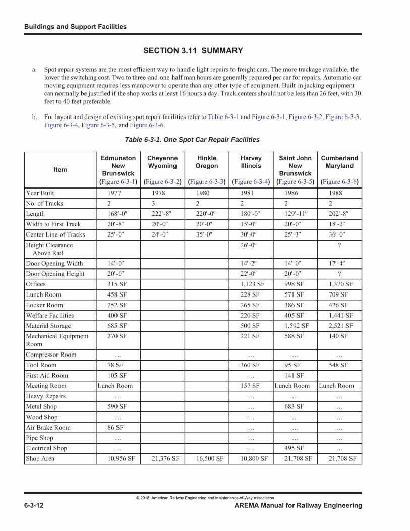
Table 6-3-1. One Spot Car Repair Facilities
© 2018, American Railway Engineering and Maintenance-of-Way Association
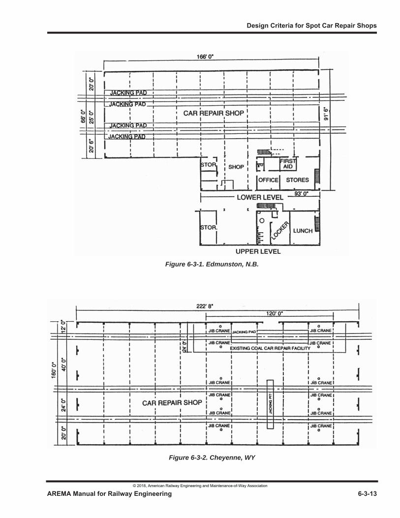
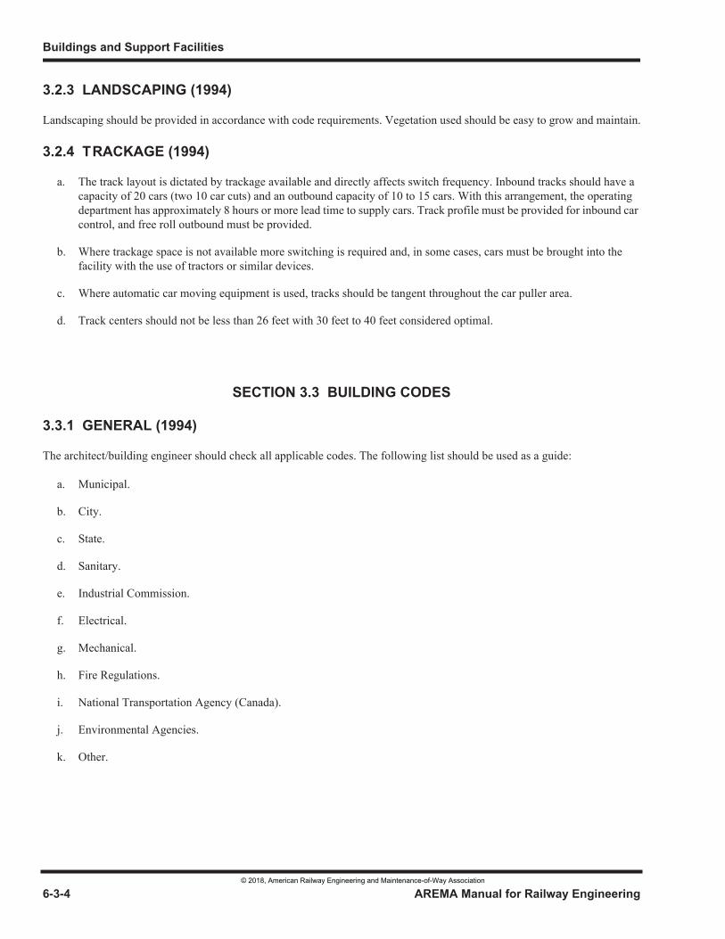
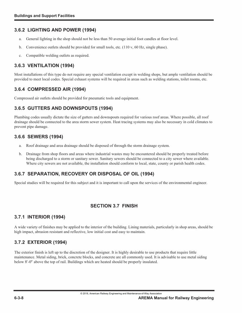
Figure 6-3-1. Edmunston, N.B.
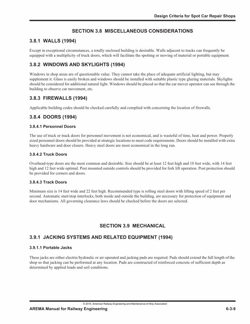
Figure 6-3-2. Cheyenne, WY
© 2018, American Railway Engineering and Maintenance-of-Way Association
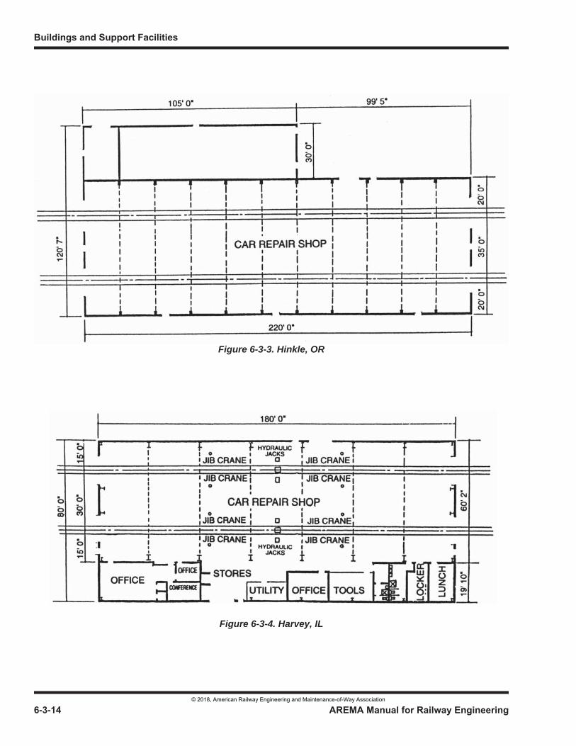
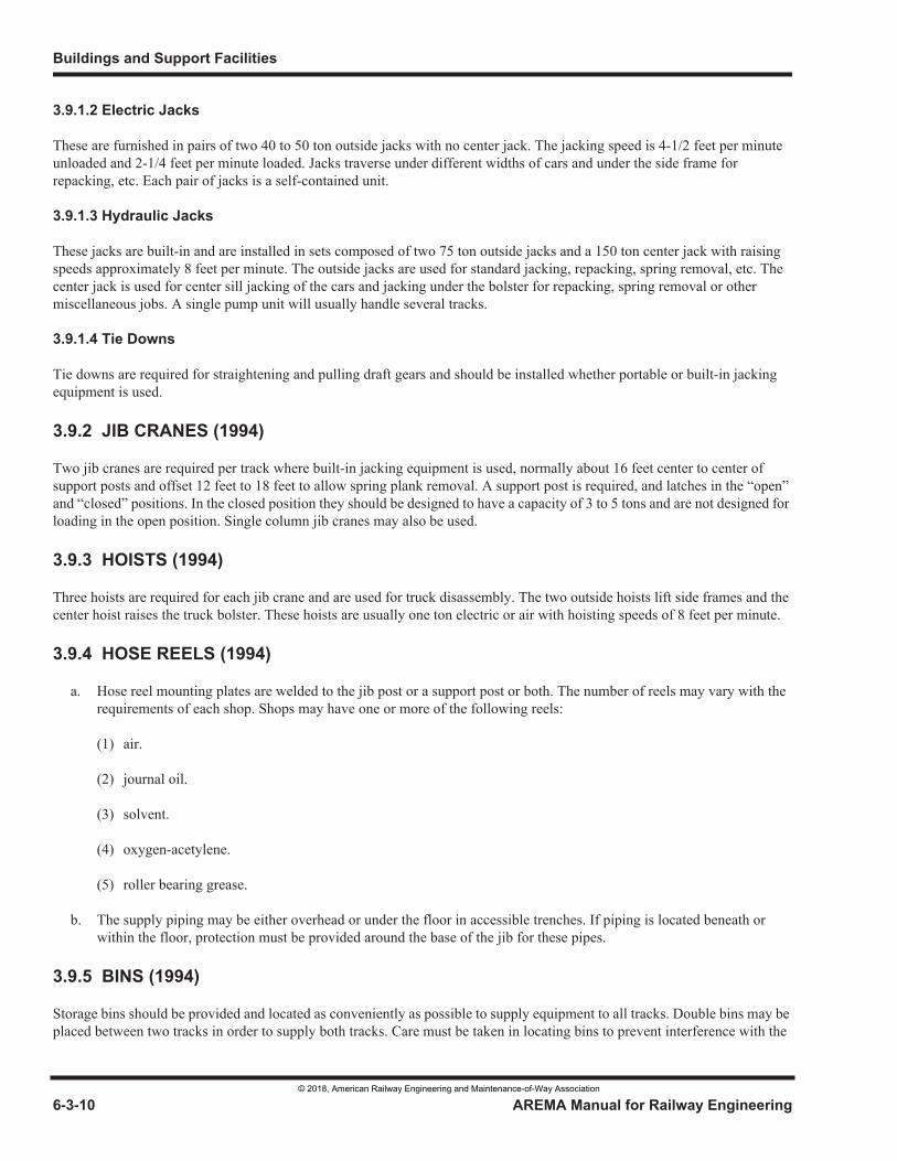
Figure 6-3-3. Hinkle, OR
Figure 6-3-4. Harvey, IL
© 2018, American Railway Engineering and Maintenance-of-Way Association
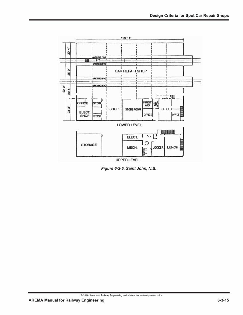
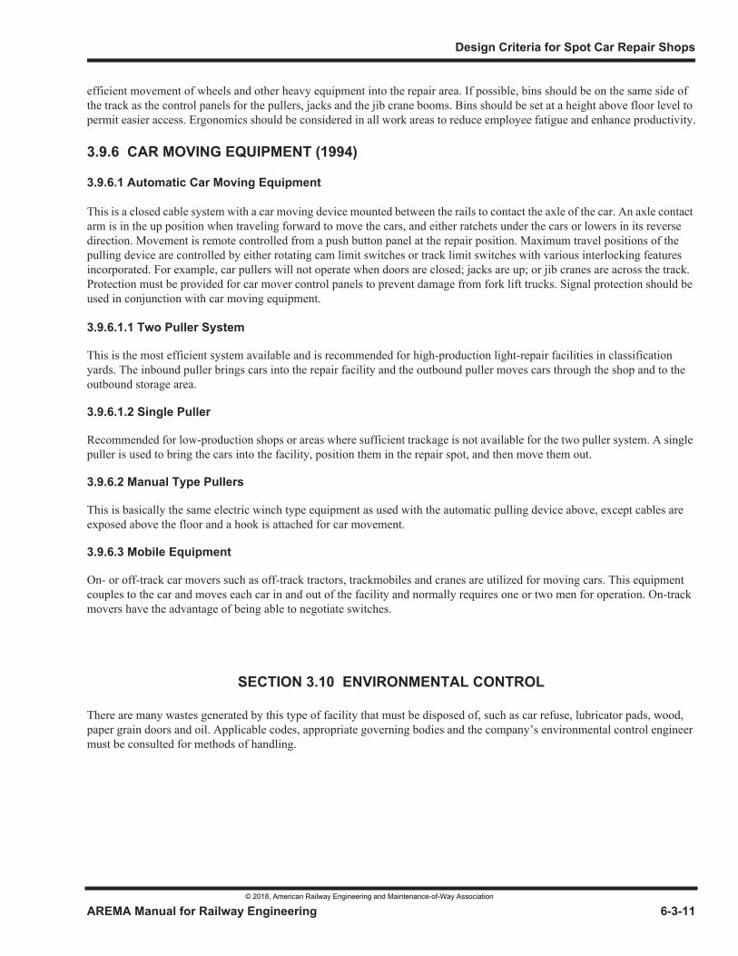
Figure 6-3-5. Saint John, N.B.
© 2018, American Railway Engineering and Maintenance-of-Way Association
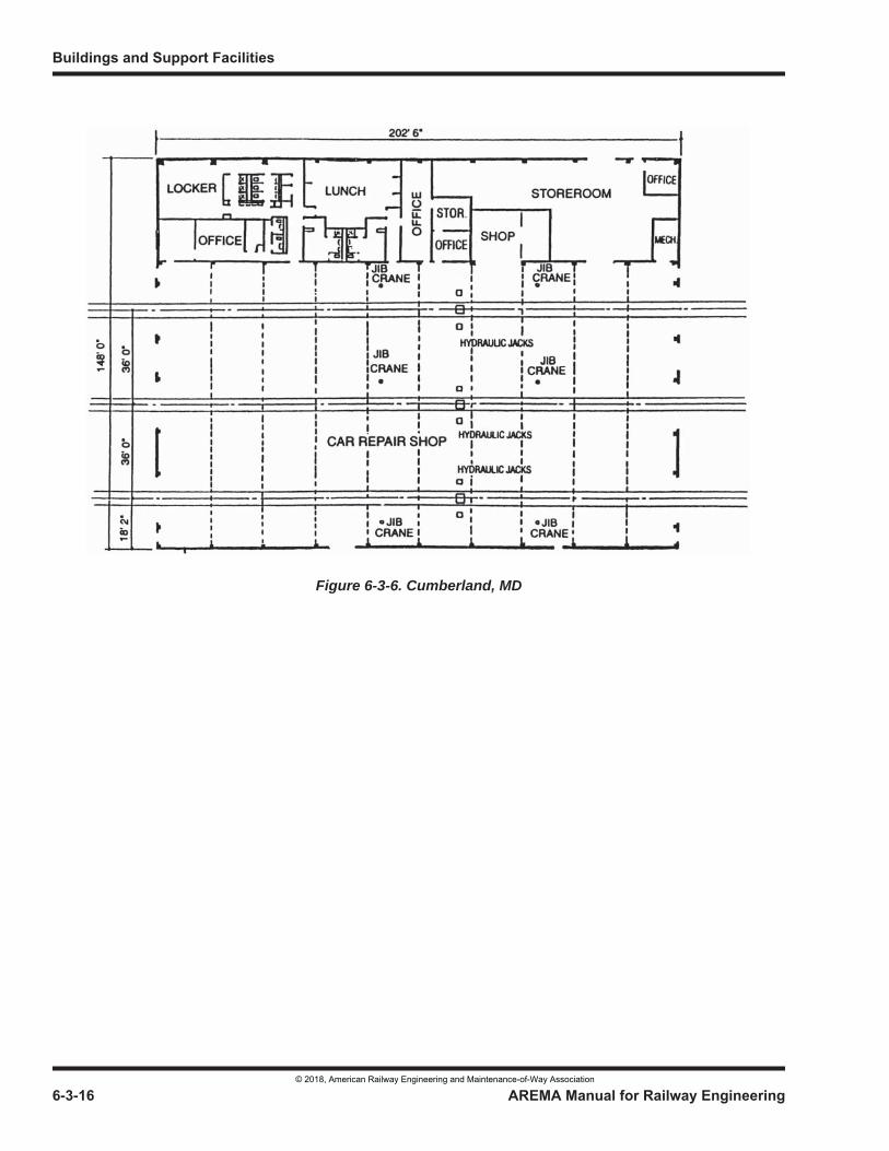
Figure 6-3-6. Cumberland, MD
© 2018, American Railway Engineering and Maintenance-of-Way Association
© 2018, American Railway Engineering and Maintenance-of-Way Association
4.5.9 Compressed Air (2012) . . . . . . . . . . . . . . . . . . . . . . . . . . . . . . . . . . . . . . . . . . . . . . . . . . . . . . . . . . . 6-4-284.5.10 Locomotive Washing (2012) . . . . . . . . . . . . . . . . . . . . . . . . . . . . . . . . . . . . . . . . . . . . . . . . . . . . . . . 6-4-284.5.11 General Washing System (2012) . . . . . . . . . . . . . . . . . . . . . . . . . . . . . . . . . . . . . . . . . . . . . . . . . . . . 6-4-294.5.12 Parts Cleaner (2012) . . . . . . . . . . . . . . . . . . . . . . . . . . . . . . . . . . . . . . . . . . . . . . . . . . . . . . . . . . . . . . 6-4-294.5.13 Electrical Cleaning Solvent (2012) . . . . . . . . . . . . . . . . . . . . . . . . . . . . . . . . . . . . . . . . . . . . . . . . . . 6-4-294.5.14 Welding Gases (2012) . . . . . . . . . . . . . . . . . . . . . . . . . . . . . . . . . . . . . . . . . . . . . . . . . . . . . . . . . . . . 6-4-294.5.15 Electrical Welding (2012) . . . . . . . . . . . . . . . . . . . . . . . . . . . . . . . . . . . . . . . . . . . . . . . . . . . . . . . . . 6-4-294.5.16 Battery Charging (2012). . . . . . . . . . . . . . . . . . . . . . . . . . . . . . . . . . . . . . . . . . . . . . . . . . . . . . . . . . . 6-4-304.5.17 Locomotive Toilet Servicing (2012) . . . . . . . . . . . . . . . . . . . . . . . . . . . . . . . . . . . . . . . . . . . . . . . . . 6-4-304.5.18 Locomotive Deicing (2012) . . . . . . . . . . . . . . . . . . . . . . . . . . . . . . . . . . . . . . . . . . . . . . . . . . . . . . . . 6-4-30
4.6.1 General (2012) . . . . . . . . . . . . . . . . . . . . . . . . . . . . . . . . . . . . . . . . . . . . . . . . . . . . . . . . . . . . . . . . . . 6-4-304.6.2 Floors (2012) . . . . . . . . . . . . . . . . . . . . . . . . . . . . . . . . . . . . . . . . . . . . . . . . . . . . . . . . . . . . . . . . . . . 6-4-314.6.3 Walls and Roof (2012) . . . . . . . . . . . . . . . . . . . . . . . . . . . . . . . . . . . . . . . . . . . . . . . . . . . . . . . . . . . . 6-4-314.6.4 Doors (2012). . . . . . . . . . . . . . . . . . . . . . . . . . . . . . . . . . . . . . . . . . . . . . . . . . . . . . . . . . . . . . . . . . . . 6-4-31
4.7.1 General (2012) . . . . . . . . . . . . . . . . . . . . . . . . . . . . . . . . . . . . . . . . . . . . . . . . . . . . . . . . . . . . . . . . . . 6-4-324.7.2 Ventilating (2012) . . . . . . . . . . . . . . . . . . . . . . . . . . . . . . . . . . . . . . . . . . . . . . . . . . . . . . . . . . . . . . . 6-4-324.7.3 Heating (2012) . . . . . . . . . . . . . . . . . . . . . . . . . . . . . . . . . . . . . . . . . . . . . . . . . . . . . . . . . . . . . . . . . . 6-4-33
4.8.1 General (2012) . . . . . . . . . . . . . . . . . . . . . . . . . . . . . . . . . . . . . . . . . . . . . . . . . . . . . . . . . . . . . . . . . . 6-4-34
4.9.1 Noise (2012) . . . . . . . . . . . . . . . . . . . . . . . . . . . . . . . . . . . . . . . . . . . . . . . . . . . . . . . . . . . . . . . . . . . . 6-4-354.9.2 Air (2012) . . . . . . . . . . . . . . . . . . . . . . . . . . . . . . . . . . . . . . . . . . . . . . . . . . . . . . . . . . . . . . . . . . . . . . 6-4-354.9.3 Water (2012). . . . . . . . . . . . . . . . . . . . . . . . . . . . . . . . . . . . . . . . . . . . . . . . . . . . . . . . . . . . . . . . . . . . 6-4-35
4.10.1 General (2012) . . . . . . . . . . . . . . . . . . . . . . . . . . . . . . . . . . . . . . . . . . . . . . . . . . . . . . . . . . . . . . . . . . 6-4-354.10.2 Internal Communication System (2012) . . . . . . . . . . . . . . . . . . . . . . . . . . . . . . . . . . . . . . . . . . . . . . 6-4-364.10.3 Data System (2012) . . . . . . . . . . . . . . . . . . . . . . . . . . . . . . . . . . . . . . . . . . . . . . . . . . . . . . . . . . . . . . 6-4-364.10.4 Television System (2012). . . . . . . . . . . . . . . . . . . . . . . . . . . . . . . . . . . . . . . . . . . . . . . . . . . . . . . . . . 6-4-36
© 2018, American Railway Engineering and Maintenance-of-Way Association
6-4-1 Typical Site Plan . . . . . . . . . . . . . . . . . . . . . . . . . . . . . . . . . . . . . . . . . . . . . . . . . . . . . . . . . . . . . . . . . . . . . . 6-4-156-4-2 Typical Light Repair Facility. . . . . . . . . . . . . . . . . . . . . . . . . . . . . . . . . . . . . . . . . . . . . . . . . . . . . . . . . . . . . 6-4-166-4-3 Typical Heavy Repair Facility. . . . . . . . . . . . . . . . . . . . . . . . . . . . . . . . . . . . . . . . . . . . . . . . . . . . . . . . . . . . 6-4-176-4-4 Typical Cross Section . . . . . . . . . . . . . . . . . . . . . . . . . . . . . . . . . . . . . . . . . . . . . . . . . . . . . . . . . . . . . . . . . . 6-4-186-4-5 Typical Flow Diagram. . . . . . . . . . . . . . . . . . . . . . . . . . . . . . . . . . . . . . . . . . . . . . . . . . . . . . . . . . . . . . . . . . 6-4-196-4-6 Typical Material Flow Diagram . . . . . . . . . . . . . . . . . . . . . . . . . . . . . . . . . . . . . . . . . . . . . . . . . . . . . . . . . . 6-4-20
6-4-1 Locomotive Shop Check List . . . . . . . . . . . . . . . . . . . . . . . . . . . . . . . . . . . . . . . . . . . . . . . . . . . . . . . . . . . . 6-4-56-4-2 Locomotive Fueling Facility Design Check List. . . . . . . . . . . . . . . . . . . . . . . . . . . . . . . . . . . . . . . . . . . . . . 6-4-14
The material presented herein is intended to familiarize the engineer and designer with the problems they will encounter and should consider in the design of a diesel facility.
a. It is not intended to imply that other practices may not be equally acceptable.
b. Definition of Light, Medium and Heavy Repair may vary among railroads but should not affect the concepts being presented.
c. A check list of the facilities and processes necessary for the efficient operation of the diesel repair shop is presented in Table 6-4-1 as a design guide.
A diesel repair facility constitutes a “facility” designed to arrange an orderly progression of diesel locomotives for repairs, maintenance, servicing and cleaning as required, and to meet inspection requirements of the manufacturer and governmental authorities.
Diesel repair facilities are generally classified as “Heavy Repair,” “Medium Running Repair” and “Light Running Repair and Servicing.” For typical site plans and flow diagrams refer to Figure 6-4-1, Figure 6-4-2, Figure 6-4-3, Figure 6-4-4, Figure 6-4-5 and Figure 6-4-6.
Consists of any work involving truck repair and maintenance, traction motor assembly, dynamic brake grids, etc.
© 2018, American Railway Engineering and Maintenance-of-Way Association
Consists of any work involving repair, air reservoir test, brake change outs, repairs to injector, governors, turbos, etc.
Consists of any work involving oiling, lubricating, testing, minor adjustments and repairs, etc.
© 2018, American Railway Engineering and Maintenance-of-Way Association
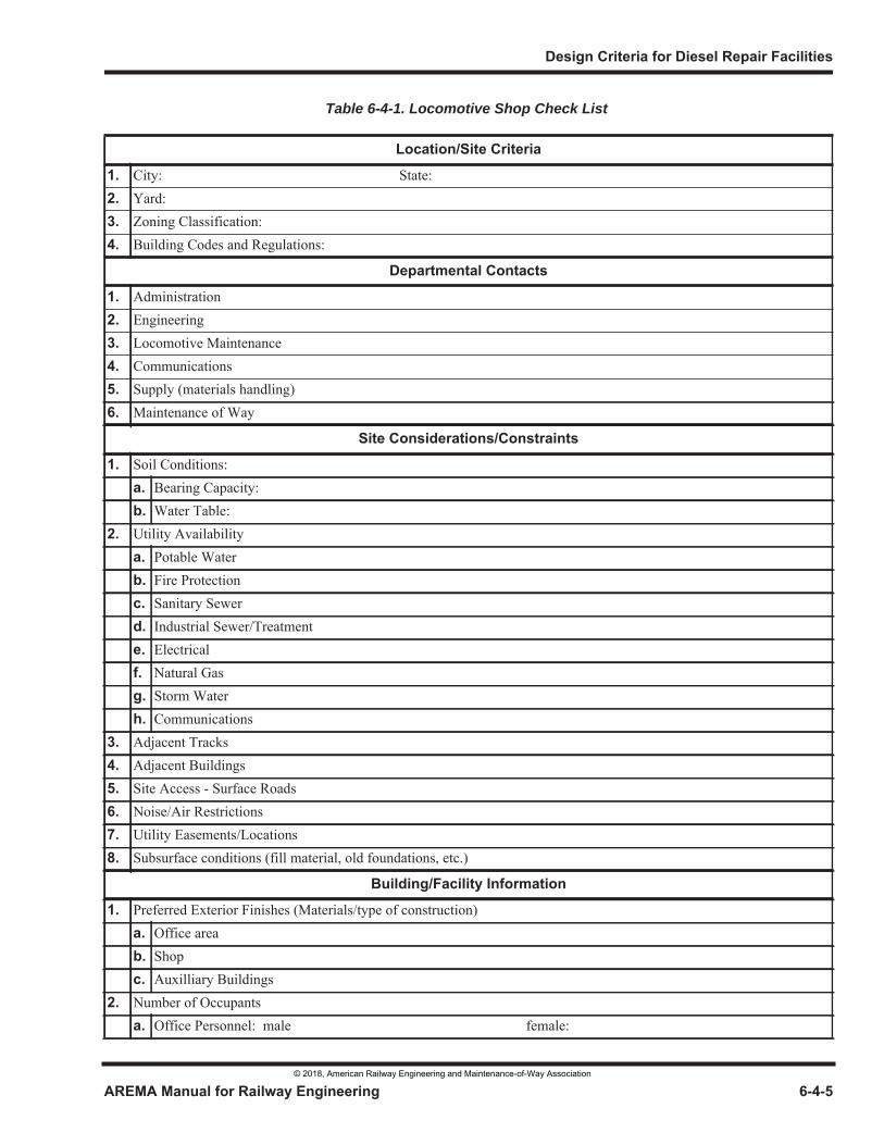
Table 6-4-1. Locomotive Shop Check List
© 2018, American Railway Engineering and Maintenance-of-Way Association
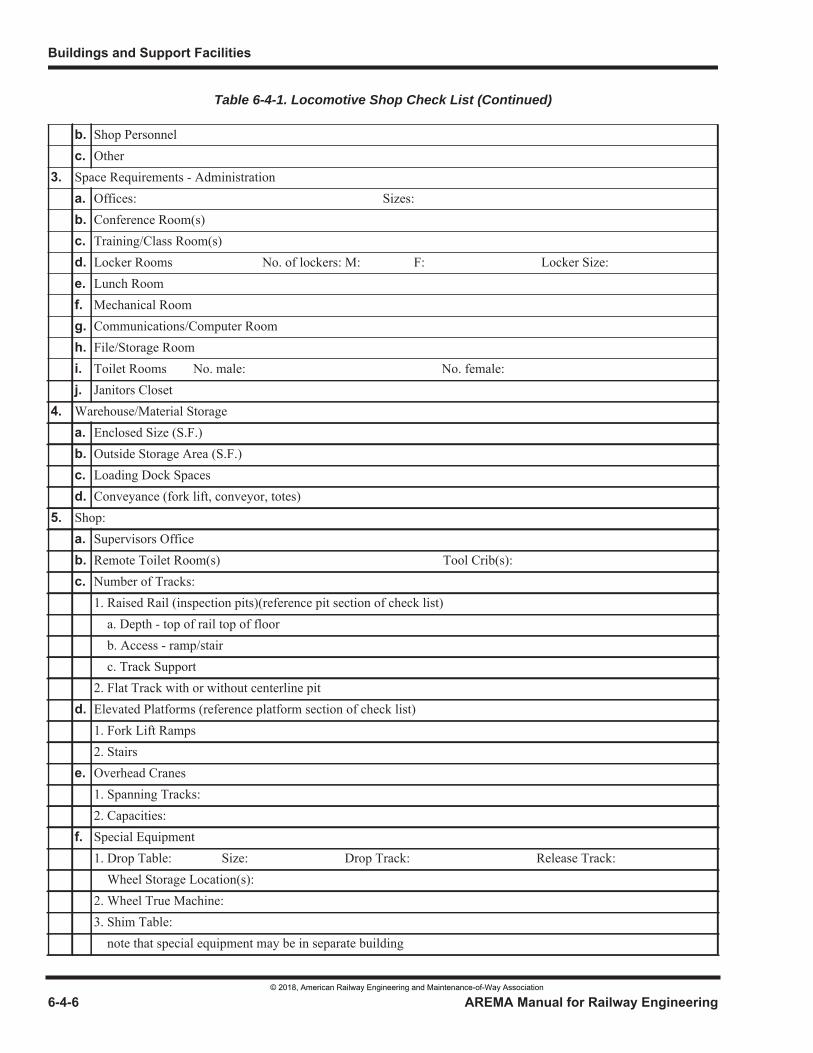
Table 6-4-1. Locomotive Shop Check List (Continued)
© 2018, American Railway Engineering and Maintenance-of-Way Association
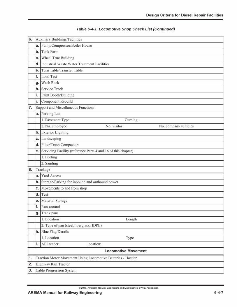
Table 6-4-1. Locomotive Shop Check List (Continued)
© 2018, American Railway Engineering and Maintenance-of-Way Association
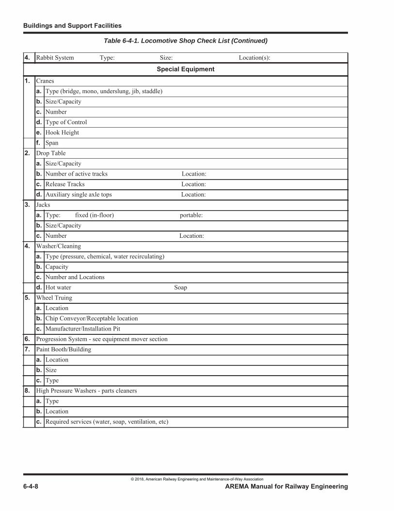
Table 6-4-1. Locomotive Shop Check List (Continued)
© 2018, American Railway Engineering and Maintenance-of-Way Association
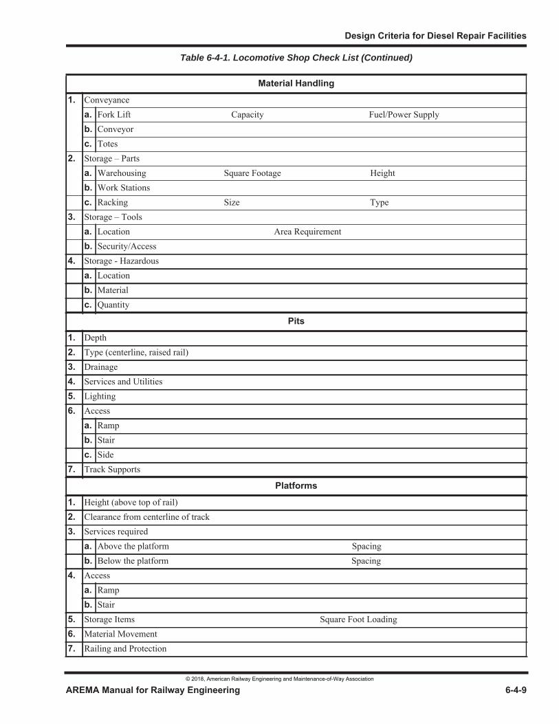
Table 6-4-1. Locomotive Shop Check List (Continued)
© 2018, American Railway Engineering and Maintenance-of-Way Association
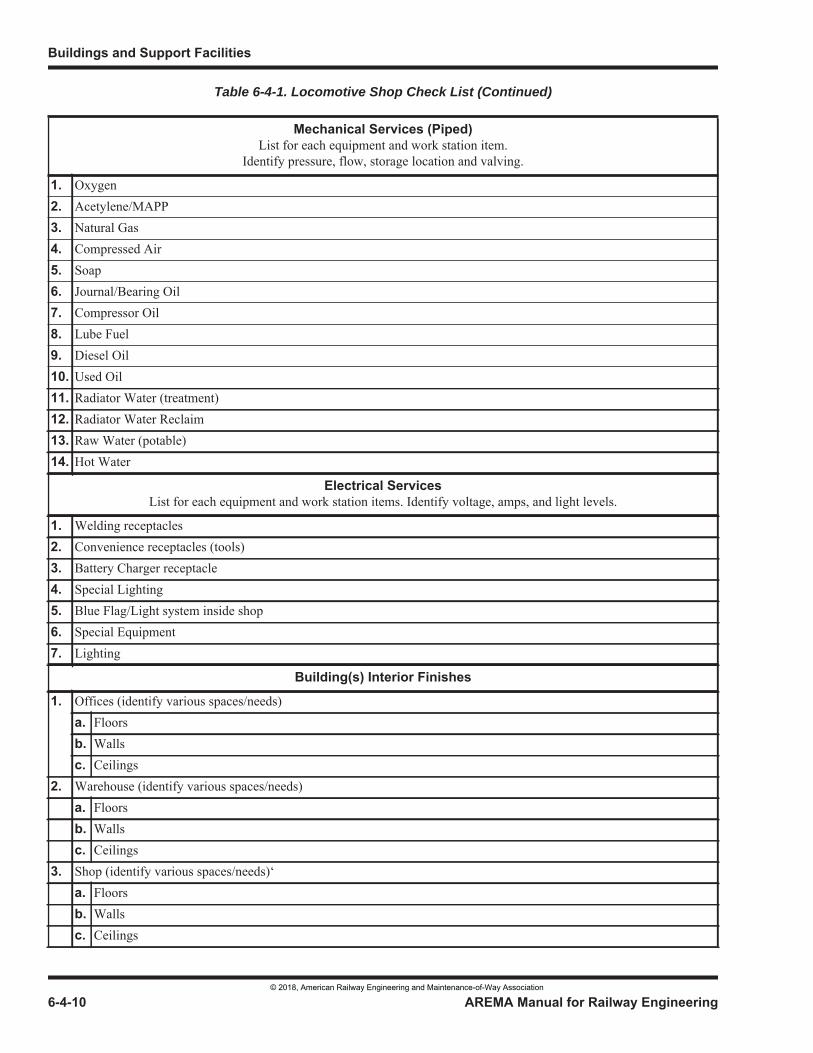
Table 6-4-1. Locomotive Shop Check List (Continued)
© 2018, American Railway Engineering and Maintenance-of-Way Association
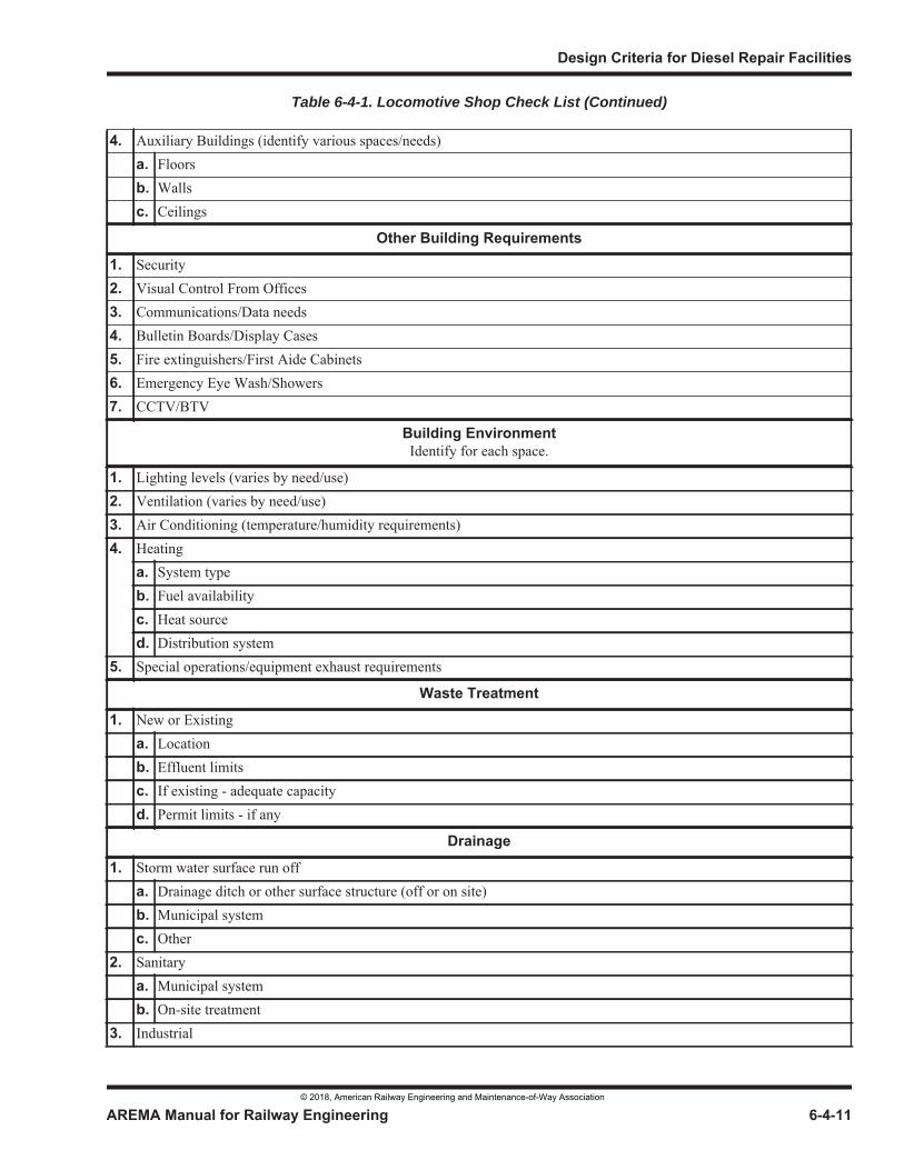
Table 6-4-1. Locomotive Shop Check List (Continued)
© 2018, American Railway Engineering and Maintenance-of-Way Association
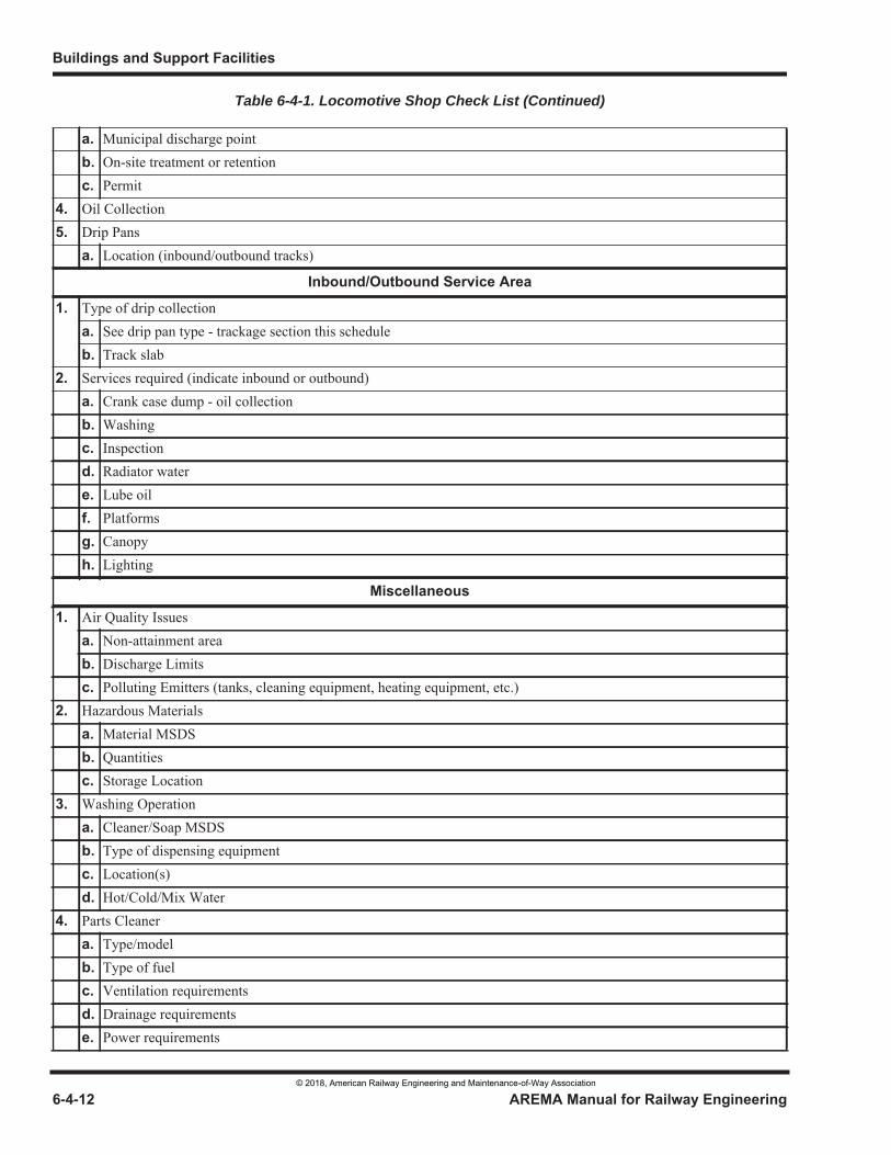
Table 6-4-1. Locomotive Shop Check List (Continued)
© 2018, American Railway Engineering and Maintenance-of-Way Association
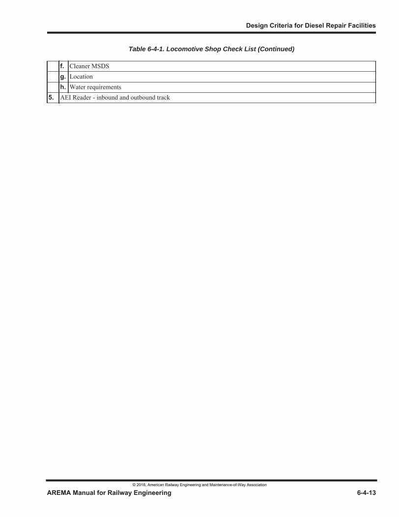
Table 6-4-1. Locomotive Shop Check List (Continued)
© 2018, American Railway Engineering and Maintenance-of-Way Association
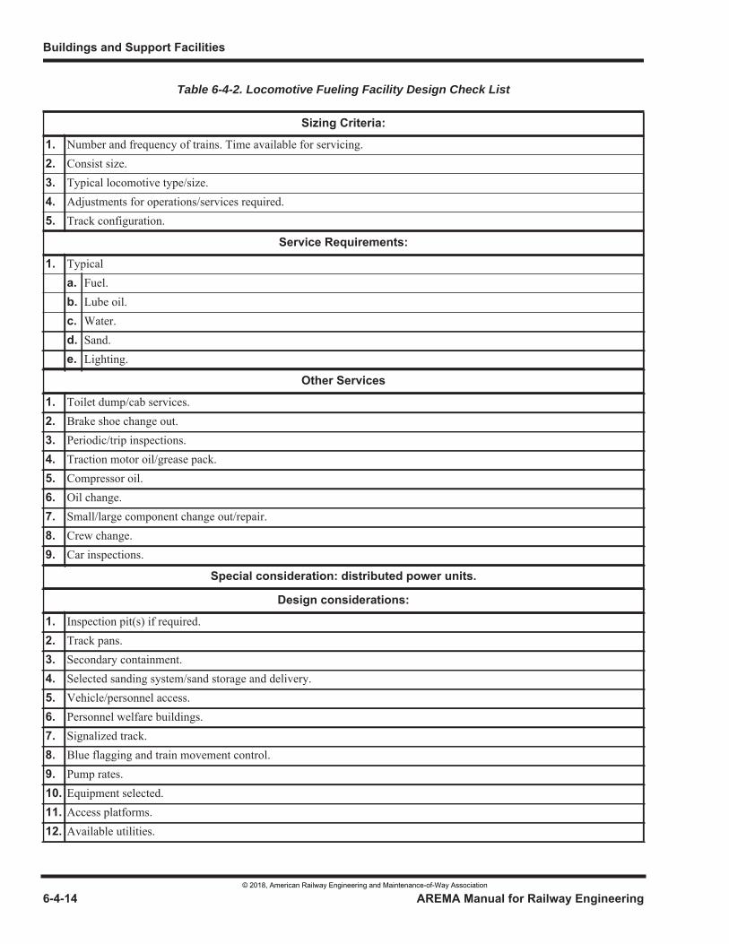
Table 6-4-2. Locomotive Fueling Facility Design Check List
© 2018, American Railway Engineering and Maintenance-of-Way Association
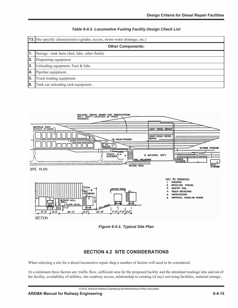
Table 6-4-2. Locomotive Fueling Facility Design Check List
Figure 6-4-1. Typical Site Plan
© 2018, American Railway Engineering and Maintenance-of-Way Association
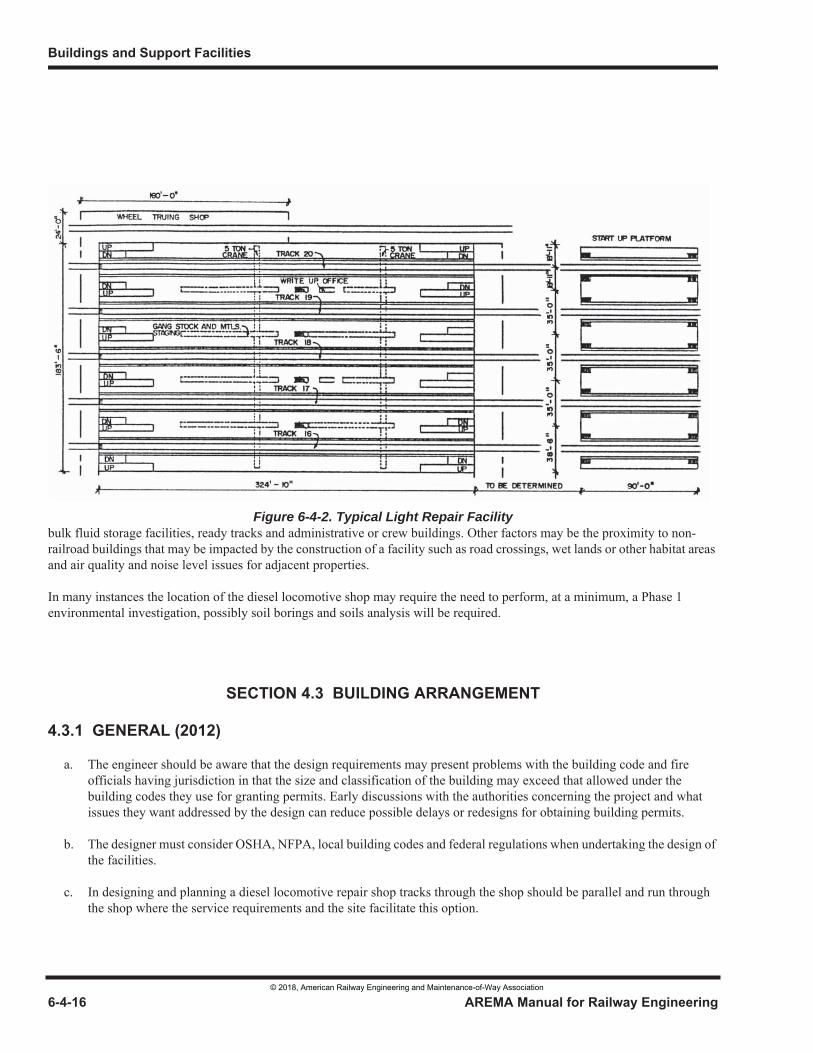
Figure 6-4-2. Typical Light Repair Facility
© 2018, American Railway Engineering and Maintenance-of-Way Association
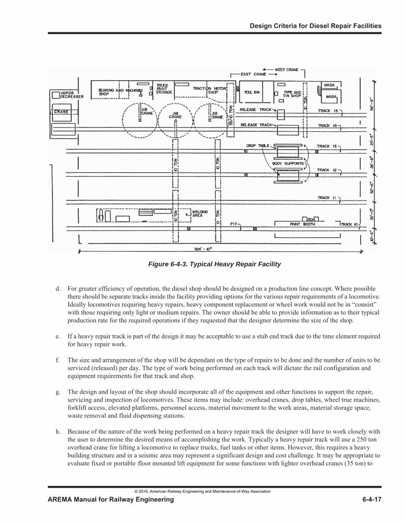
Figure 6-4-3. Typical Heavy Repair Facility
© 2018, American Railway Engineering and Maintenance-of-Way Association
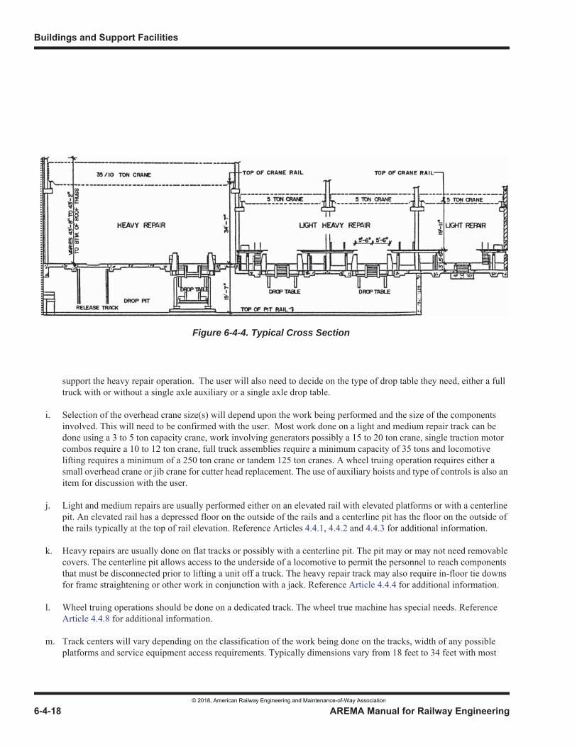
Figure 6-4-4. Typical Cross Section
© 2018, American Railway Engineering and Maintenance-of-Way Association
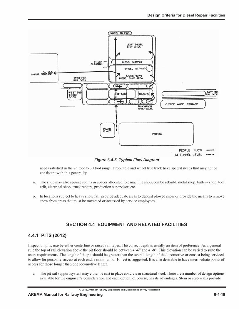
Figure 6-4-5. Typical Flow Diagram
© 2018, American Railway Engineering and Maintenance-of-Way Association
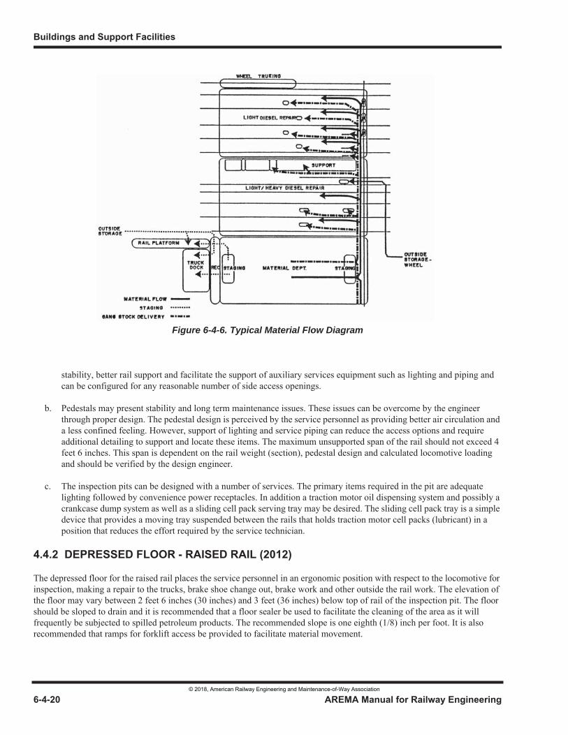
Figure 6-4-6. Typical Material Flow Diagram
© 2018, American Railway Engineering and Maintenance-of-Way Association
© 2018, American Railway Engineering and Maintenance-of-Way Association
© 2018, American Railway Engineering and Maintenance-of-Way Association
© 2018, American Railway Engineering and Maintenance-of-Way Association
© 2018, American Railway Engineering and Maintenance-of-Way Association
© 2018, American Railway Engineering and Maintenance-of-Way Association
© 2018, American Railway Engineering and Maintenance-of-Way Association
© 2018, American Railway Engineering and Maintenance-of-Way Association
© 2018, American Railway Engineering and Maintenance-of-Way Association
© 2018, American Railway Engineering and Maintenance-of-Way Association
© 2018, American Railway Engineering and Maintenance-of-Way Association
© 2018, American Railway Engineering and Maintenance-of-Way Association
© 2018, American Railway Engineering and Maintenance-of-Way Association
© 2018, American Railway Engineering and Maintenance-of-Way Association
© 2018, American Railway Engineering and Maintenance-of-Way Association
© 2018, American Railway Engineering and Maintenance-of-Way Association
© 2018, American Railway Engineering and Maintenance-of-Way Association
© 2018, American Railway Engineering and Maintenance-of-Way Association
© 2018, American Railway Engineering and Maintenance-of-Way Association
© 2018, American Railway Engineering and Maintenance-of-Way Association 6-5-1
1
3
6 Part 5
Energy Conservation and Audits1
— 2018 —
FOREWORD
This part was prepared to present a comprehensive approach towards energy conservation in railway buildings and shop facilities, not only from a technical point of view but from a railroad management perspective as well. This report, being somewhat technical in nature, relates useful information for division operating and corporate management personnel and local shop superintendents. Principles outlined in this report can be applied equally by those who formulate shop policies as well as those who are responsible for maintaining offices and shop operations.
TABLE OF CONTENTS
Section/Article Description Page5.1 Introduction . . . . . . . . . . . . . . . . . . . . . . . . . . . . . . . . . . . . . . . . . . . . . . . . . . . . . . . . . . . . . . . . . . . . . . . . . . . 6-5-3
5.1.1 Scope (2018) . . . . . . . . . . . . . . . . . . . . . . . . . . . . . . . . . . . . . . . . . . . . . . . . . . . . . . . . . . . . . . . . . . . . 6-5-3
5.2 Elements of Energy Conservation Program . . . . . . . . . . . . . . . . . . . . . . . . . . . . . . . . . . . . . . . . . . . . . . . . . 6-5-45.2.1 General (2018) . . . . . . . . . . . . . . . . . . . . . . . . . . . . . . . . . . . . . . . . . . . . . . . . . . . . . . . . . . . . . . . . . . . 6-5-45.2.2 Elements of Efficiency (2018) . . . . . . . . . . . . . . . . . . . . . . . . . . . . . . . . . . . . . . . . . . . . . . . . . . . . . . . 6-5-45.2.3 Elements of Sustainability (2018) . . . . . . . . . . . . . . . . . . . . . . . . . . . . . . . . . . . . . . . . . . . . . . . . . . . . 6-5-4
5.3 Strategies and Economics . . . . . . . . . . . . . . . . . . . . . . . . . . . . . . . . . . . . . . . . . . . . . . . . . . . . . . . . . . . . . . . . 6-5-55.3.1 Strategy (2018). . . . . . . . . . . . . . . . . . . . . . . . . . . . . . . . . . . . . . . . . . . . . . . . . . . . . . . . . . . . . . . . . . . 6-5-55.3.2 Economics (2018) . . . . . . . . . . . . . . . . . . . . . . . . . . . . . . . . . . . . . . . . . . . . . . . . . . . . . . . . . . . . . . . . 6-5-55.3.3 Efficiency (2018) . . . . . . . . . . . . . . . . . . . . . . . . . . . . . . . . . . . . . . . . . . . . . . . . . . . . . . . . . . . . . . . . . 6-5-65.3.4 Sustainability (2018) . . . . . . . . . . . . . . . . . . . . . . . . . . . . . . . . . . . . . . . . . . . . . . . . . . . . . . . . . . . . . . 6-5-6
5.4 Advances in Energy Cost Savings for Railway Buildings and Shop Facilities . . . . . . . . . . . . . . . . . . . . . . 6-5-65.4.1 Utility Monitoring and Reporting Operations (2018) . . . . . . . . . . . . . . . . . . . . . . . . . . . . . . . . . . . . . 6-5-65.4.2 Optimizing Electrical Demand (2018) . . . . . . . . . . . . . . . . . . . . . . . . . . . . . . . . . . . . . . . . . . . . . . . . . 6-5-65.4.3 Small Scale Cogenerational Systems (2018) . . . . . . . . . . . . . . . . . . . . . . . . . . . . . . . . . . . . . . . . . . . . 6-5-65.4.4 Boiler Optimization (2018) . . . . . . . . . . . . . . . . . . . . . . . . . . . . . . . . . . . . . . . . . . . . . . . . . . . . . . . . . 6-5-65.4.5 Microcomputer Applications (2018) . . . . . . . . . . . . . . . . . . . . . . . . . . . . . . . . . . . . . . . . . . . . . . . . . . 6-5-75.4.6 Solar Energy (2018) . . . . . . . . . . . . . . . . . . . . . . . . . . . . . . . . . . . . . . . . . . . . . . . . . . . . . . . . . . . . . . . 6-5-75.4.7 Wind Energy (2018). . . . . . . . . . . . . . . . . . . . . . . . . . . . . . . . . . . . . . . . . . . . . . . . . . . . . . . . . . . . . . . 6-5-7
1 References, Vol. 92, 1991, p. 58.
Buildings and Support Facilities
© 2018, American Railway Engineering and Maintenance-of-Way Association
6-5-2 AREMA Manual for Railway Engineering
TABLE OF CONTENTS
Section/Article Description Page
5.4.8 Compressed Air (2018). . . . . . . . . . . . . . . . . . . . . . . . . . . . . . . . . . . . . . . . . . . . . . . . . . . . . . . . . . . . 6-5-7
5.5 Types of Audits . . . . . . . . . . . . . . . . . . . . . . . . . . . . . . . . . . . . . . . . . . . . . . . . . . . . . . . . . . . . . . . . . . . . . . . . 6-5-75.5.1 Definition (2018) . . . . . . . . . . . . . . . . . . . . . . . . . . . . . . . . . . . . . . . . . . . . . . . . . . . . . . . . . . . . . . . . 6-5-75.5.2 Cost/Opportunities (2018) . . . . . . . . . . . . . . . . . . . . . . . . . . . . . . . . . . . . . . . . . . . . . . . . . . . . . . . . . 6-5-75.5.3 Categories (2018) . . . . . . . . . . . . . . . . . . . . . . . . . . . . . . . . . . . . . . . . . . . . . . . . . . . . . . . . . . . . . . . . 6-5-8
5.6 Organization of Railroad Energy Management Program . . . . . . . . . . . . . . . . . . . . . . . . . . . . . . . . . . . . . 6-5-85.6.1 Auditor Qualifications (2018) . . . . . . . . . . . . . . . . . . . . . . . . . . . . . . . . . . . . . . . . . . . . . . . . . . . . . . 6-5-85.6.2 Record Collection (2018) . . . . . . . . . . . . . . . . . . . . . . . . . . . . . . . . . . . . . . . . . . . . . . . . . . . . . . . . . . 6-5-9
5.7 Audit Survey Instrumentation. . . . . . . . . . . . . . . . . . . . . . . . . . . . . . . . . . . . . . . . . . . . . . . . . . . . . . . . . . . . 6-5-95.7.1 Scope (2018). . . . . . . . . . . . . . . . . . . . . . . . . . . . . . . . . . . . . . . . . . . . . . . . . . . . . . . . . . . . . . . . . . . . 6-5-95.7.2 Measuring Railway Building and Facility Shop Losses (2018). . . . . . . . . . . . . . . . . . . . . . . . . . . . . 6-5-95.7.3 Measuring Electrical Systems (2018). . . . . . . . . . . . . . . . . . . . . . . . . . . . . . . . . . . . . . . . . . . . . . . . . 6-5-105.7.4 Temperature Measuring Systems (2018) . . . . . . . . . . . . . . . . . . . . . . . . . . . . . . . . . . . . . . . . . . . . . . 6-5-105.7.5 Surface Pyrometer (2018). . . . . . . . . . . . . . . . . . . . . . . . . . . . . . . . . . . . . . . . . . . . . . . . . . . . . . . . . . 6-5-105.7.6 Psychrometer (2018) . . . . . . . . . . . . . . . . . . . . . . . . . . . . . . . . . . . . . . . . . . . . . . . . . . . . . . . . . . . . . 6-5-115.7.7 Portable Electronic Thermometer (2018) . . . . . . . . . . . . . . . . . . . . . . . . . . . . . . . . . . . . . . . . . . . . . . 6-5-115.7.8 Boiler Test Kit (2018) . . . . . . . . . . . . . . . . . . . . . . . . . . . . . . . . . . . . . . . . . . . . . . . . . . . . . . . . . . . . 6-5-115.7.9 Measuring Heating, Ventilation and Air Conditioning (HVAC) (2018). . . . . . . . . . . . . . . . . . . . . . . 6-5-125.7.10 Compressed Air Demand Analysis (2018) . . . . . . . . . . . . . . . . . . . . . . . . . . . . . . . . . . . . . . . . . . . . . 6-5-13
5.8 Justification of Program. . . . . . . . . . . . . . . . . . . . . . . . . . . . . . . . . . . . . . . . . . . . . . . . . . . . . . . . . . . . . . . . . 6-5-135.8.1 Life-cycle Costing (2018). . . . . . . . . . . . . . . . . . . . . . . . . . . . . . . . . . . . . . . . . . . . . . . . . . . . . . . . . . 6-5-135.8.2 Best Practices (2018) . . . . . . . . . . . . . . . . . . . . . . . . . . . . . . . . . . . . . . . . . . . . . . . . . . . . . . . . . . . . . 6-5-14
5.9 Appendix A . . . . . . . . . . . . . . . . . . . . . . . . . . . . . . . . . . . . . . . . . . . . . . . . . . . . . . . . . . . . . . . . . . . . . . . . . . . 6-5-15
5.10 Appendix B . . . . . . . . . . . . . . . . . . . . . . . . . . . . . . . . . . . . . . . . . . . . . . . . . . . . . . . . . . . . . . . . . . . . . . . . . . . 6-5-16
5.11 Appendix C . . . . . . . . . . . . . . . . . . . . . . . . . . . . . . . . . . . . . . . . . . . . . . . . . . . . . . . . . . . . . . . . . . . . . . . . . . . 6-5-22
LIST OF TABLES
Table Description Page
6-5-1 Example Walkthrough Audit of a Railroad Office Building . . . . . . . . . . . . . . . . . . . . . . . . . . . . . . . . . . . . 6-5-156-5-2 Energy Savings Checklist (Space Conditioning: Heating, Ventilation, Air Conditioning) . . . . . . . . . . . . . 6-5-166-5-3 Energy Conservation Measures . . . . . . . . . . . . . . . . . . . . . . . . . . . . . . . . . . . . . . . . . . . . . . . . . . . . . . . . . . 6-5-22
Energy Conservation and Audits
© 2018, American Railway Engineering and Maintenance-of-Way Association
AREMA Manual for Railway Engineering 6-5-3
1
3
4
SECTION 5.1 INTRODUCTION
5.1.1 SCOPE (2018)
a. Railway buildings and shop facilities of the past were designed and constructed, primarily, by initial costs and not operating costs. This has resulted in a large inventory of railroad buildings that, by today's standards, do not utilize many of the new techniques and systems which maximize energy efficiency. With the increased importance of sustainability, or "being green", conservation or saving of energy in railroad shops, offices and ancillary buildings has become a higher priority for railroad management.
b. It has now become more practical than ever to investigate and employ energy-saving strategies. New energy conservation technologies have become increasingly reliable and affordable, making them cost effective and readily applicable to most railway buildings and shop facilities.
c. Energy conservation is most effective when it reaches out to all stakeholders. The principles contained in this Part can be applied by senior managers, occupants/end-users and operations and maintenance staff in railway buildings and shop facilities.
d. With the ever-increasing cost of energy, conservation in railway buildings and shop facilities makes good business sense. A systematic energy management plan requires knowledge of how to prioritize and implement an effective energy audit. Rapid advances in technology has brought with it new, reliable, user-friendly and cost-effective products and helpful testing instrumentation for performing successful energy audits.
e. Currently, the programing associated with most facility owners does not require LEED, Green Building or other form of certification; however, it is usually in the Owners' best interest to ensure that a building is easily maintainable, durable, and sustainable over an estimated 50 year service life. Techniques, methods and materials that would be used to achieve LEED or Green Building certification should be incorporated in the building as a matter of good design practice. Should the Owner desire to attain LEED, Green Building or other type of certification, additional costs and schedule impacts for certification formal submittals and certifications should be evaluated by all stake holders on the project team.
f. Organizations that promote energy conservation, efficiency and sustainability as it pertains to building and facility design and certification include but are not necessarily limited to the following:
(a) Green Business Certification Incorporated (LEED certification) (www.gbci.org).
(b) Green Globes (www.greenglobes.com)
(c) Living Building Challenge (www.ilbi.org)
(d) International Building Code (IBC) - International Green Construction Code (IgCC) (www.iccsafe.org)
(e) U.S. Green Building Council (USGBC) (www.usgbc.org)
(f) General Services Administration (GSA) (www.gsa.org)
Buildings and Support Facilities
© 2018, American Railway Engineering and Maintenance-of-Way Association
6-5-4 AREMA Manual for Railway Engineering
SECTION 5.2 ELEMENTS OF ENERGY CONSERVATION PROGRAM
5.2.1 GENERAL (2018)
a. An energy conservation effort is only as effective as the commitment of senior management and the resources allocated to it. Implementation of this type of energy management plan is usually carried out either by an energy manager (coordinator) or by an energy committee. Energy audits are often prioritized by how efficient (or inefficient) the building or facility is. A good indicator is the Energy Use Intensity, or EUI. This is simply the energy usage of the building or facility, in BTUs, divided by its footprint area in square feet. A more efficient building will have a low EUI. A less efficient building will have a higher EUI. By comparing the EUI of a building with buildings of similar size, type and usage, it can be seen which building could benefit from an energy audit, and which buildings could benefit the most.
b. Once the energy audits have been prioritized, the most preliminary kind of audit is called an ASHRAE Level 1. This is from the ASHRAE (American Society of Heating, Refrigerating and Air-Conditioning Engineers) threelevel system of classifying energy audits, Level 1 being the most preliminary and Level 3 being the most rigorous. For an ASHRAE Level 1 energy audit, the initial survey for energy losses at a railroad facility can be performed quite adequately by a walk-through visual inspection. This kind of audit will uncover numerous opportunities for energy conservation. Some savings can be achieved through routine maintenance and operational adjustments; others require capital expenditures.
(1) Major examples of typical energy saving opportunities in and around railroad facilities are leaking steam and compressed-air lines, shop personnel taping or wedging air valves open, uninsulated steam lines, open doors and windows, overheated storehouses, and improper operation of ventilation systems.
(2) Energy savings cannot be achieved until the source is identified where it is being used and when and where it is being wasted. This is the intent and goal of the energy audit.
c. In an energy conservation effort, one must review the energy saving opportunities and establish an order of priority for potential energy conservation measures based on cost, savings, and ease of implementation. The energy audit identifies potential energy conservation measures, so that informed decisions can be made as to which measures to implement. The energy audit seeks to ask and answer the following questions:
(1) What savings can be anticipated?
(2) How long will it take to pay back the energy saving investment? Most railroads report a reduction in energy use due to energy conservation efforts in the 10-30% range. These savings are usually the result, not of specialized technical changes, but of ordinary modifications in routine maintenance and operational adjustments directed at "plugging the facility leaks."
d. An important part of any energy saving program consists of raising energy awareness among railroad employees. This can take many forms: literature to inform employees on energy-saving practices in the office, shop, and other yard facilities. Some railroads may use stickers, posters, signs, etc. Consequently, they should be used randomly. Motivation at this stage is to demonstrate company support for a solid energy savings program and to initiate it as a vital part of the railroad's daily business.
5.2.2 ELEMENTS OF EFFICIENCY (2018)
a. Reserved for future section on elements of efficiency.
5.2.3 ELEMENTS OF SUSTAINABILITY (2018)
a. Reserved for future section of elements of sustainability.
Energy Conservation and Audits
© 2018, American Railway Engineering and Maintenance-of-Way Association
AREMA Manual for Railway Engineering 6-5-5
1
3
4
SECTION 5.3 STRATEGIES AND ECONOMICS
5.3.1 STRATEGY (2018)
a. Conservation or saving of energy does not automatically take place. Senior management must be strongly committed and genuinely interested. Management must be persistent in their commitment to conserving and must communicate this commitment. Finally, energy monitoring must be built into the checks and balances at each facility. It must be constantly monitored, and the managers held accountable for its use.
b. A program should be devised to meet all energy conserving needs whether it be routine or on an emergency basis. This program should contain, as a minimum, the following points:
(1) Develop and implement strategies.
(2) Assure continuity of office or shop facility operations.
(3) Develop and maintain an energy profile for each office or shop facility.
(4) Monitor energy supply and costs.
(5) Manage conservation programs.
(6) Measure energy usage.
(7) Stay abreast of changing technologies.
(8) Implement financial payback analysis program.
c. Further savings will have to come through strategies in areas such as building operations, better insulating materials and prudent use of utilities. Such savings are produced through better building design and maximum control of utility and HVAC systems.
5.3.2 ECONOMICS (2018)
a. The primary function of building insulation is to reduce the loss of energy from a surface operating at a temperature other than ambient. The economic use of building insulation is to reduce overall operating cost. In determining the most economic design for an insulating system, two or more insulating materials may be evaluated for least cost for a given thermal performance. In any railroad building or shop facility being investigated for retrofit and for any energy saving opportunities, it is desirable to analyze the past utility bills as a basis against which projected savings in energy usage can be evaluated. Utility data is also helpful in validating the method of calculating energy usage. If the calculations match closely to the actual energy usage, then projections of energy savings resulting from any proposed modifications can have a high degree of reliability.
b. The growing complexity of mechanical and electrical building systems has made computer, microprocessor and automated energy management systems (EMS) essential in more and more railway buildings and shop facilities. With larger and more complex buildings today, the need for automatic centralized building control and optimized energy management has increased.
c. The most comprehensive approach to building energy management is to have the capability to monitor and control, from the desired location, fire suppression systems; fire alarm systems; security systems; data monitoring and audio communications equipment systems; HVAC operation and control systems; and closed-circuit television and center command systems.
Buildings and Support Facilities
© 2018, American Railway Engineering and Maintenance-of-Way Association
6-5-6 AREMA Manual for Railway Engineering
5.3.3 EFFICIENCY (2018)
a. Reserved for future section on efficiency strategies
5.3.4 SUSTAINABILITY (2018)
a. Reserved for future section on sustainability strategies.
SECTION 5.4 ADVANCES IN ENERGY COST SAVINGS FOR RAILWAY BUILDINGSAND SHOP FACILITIES
5.4.1 UTILITY MONITORING AND REPORTING OPERATIONS (2018)
A well-organized facility energy monitoring and reporting system allows the facility manager to determine where energy is being used, and how much is being used. It identifies the larger users and identifies which areas are likely to obtain the greatest benefits from energy conservation measures.
5.4.2 OPTIMIZING ELECTRICAL DEMAND (2018)
Some railroad facilities use on-site power to reduce operating costs. This result is accomplished through peak-shaving that calls for the application of generator power to selected loads that are shed from the normal utility supply. This results in lower demand charges from the utility by cutting power peaks during selected 15 minute or 30 minute intervals.
5.4.3 SMALL SCALE COGENERATIONAL SYSTEMS (2018)
a. "Small Scale" cogeneration units are defined as 15-500 KW's. The key to this size system is to utilize both heat and power. Power can be in the form of mechanical shaft power or, with the aid of a generator, electricity. Packaged cogeneration systems may become a major energy industry, according to studies prepared for the Department of Energy. These systems are most attractive in areas where high electricity rates exist, or have relatively low natural gas prices.
b. Types of cogeneration systems available:
(1) Internal Combustion Engines.
(2) Organic Rankine Cycle.
(3) Steam Rankine Cycle.
5.4.4 BOILER OPTIMIZATION (2018)
a. There are several energy conservation measures that can be implemented to improve most small boiler installations.
b. Improvements can include the installation of heat recovery equipment, turbulators, condensate recovery equipment, high efficiency burners, furnace pressure controls and hot water temperature reset schedules.
Energy Conservation and Audits
© 2018, American Railway Engineering and Maintenance-of-Way Association
AREMA Manual for Railway Engineering 6-5-7
1
3
4
5.4.5 MICROCOMPUTER APPLICATIONS (2018)
The microprocessor-based monitoring and control can help to manage energy costs in various ways:
a. Verification and analysis of utility billing.
b. Calculations of Btu's from kwh, therms, pounds of steam, gallons of oil, etc.
c. Calculation of Energy Utilization Index in Btu's/Square Foot/Year.
d. Graphic analysis of utility billing.
e. Life Cycle Costing (LCC) of energy saving opportunities.
f. Building energy analyses.
g. Simulation studies.
5.4.6 SOLAR ENERGY (2018)
a. Reserved for future section on solar energy.
5.4.7 WIND ENERGY (2018)
a. Reserved for future section on wind energy.
5.4.8 COMPRESSED AIR (2018)
a. Reserved for future section on compressed air.
SECTION 5.5 TYPES OF AUDITS
5.5.1 DEFINITION (2018)
The simplest definition for an energy audit is as follows: An energy audit serves the purpose of identifying where railway buildings or shop facilities use energy and identifies energy saving opportunities.
5.5.2 COST/OPPORTUNITIES (2018)
There is a direct relationship to the cost of the audit (amount of data collected and analyzed) and the number of energy saving opportunities to be found.
a. A first differentiation is made between the cost of the audit which determines the type of audit to be used. If the building has a very high EUI compared to buildings of similar size, type and use could justify a more in-depth audit such as ASHRAE Level 2 or Level 3, or a Level 1 audit as a triage approach, then allow for a following Level 2 audit if the Level 1 audit reveals many potential energy conservation opportunities.
b. Energy conservation measures can take numerous forms, depending on the type of facility. For example, a building audit may emphasize the railway office building envelope, lighting, and HVAC requirements. On the other hand, an
Buildings and Support Facilities
© 2018, American Railway Engineering and Maintenance-of-Way Association
6-5-8 AREMA Manual for Railway Engineering
audit of a mechanical shop facility may emphasize the process requirements (i.e. welding, grinding, sanding, steam cleaning, wheel dismounting, etc.).
5.5.3 CATEGORIES (2018)
As defined by ASHRAE, energy audits fall into three categories or levels, namely, Level1, Level 2 and Level 3.
5.5.3.1 ASHRAE Level 1 Energy Audit
The Level 1 audit, sometimes called a walk-through audit, is the most basic. It involves minimal interviews with site operating personnel, a brief review of facility utility bills and other operating data, and a walk-through of the facility, looking for blatant sources of energy waste. The Level 1 report includes a preliminary energy use analysis and details and presents low-cost/no-cost measures and potential capital improvements for further study. Corrective measures are described, and preliminary estimates of implementation cost vs. potential energy cost savings give simple payback periods. An ASHRAE Level 1 energy audit is not sufficient for reaching a final decision on implementing proposed measures. However, it is adequate for prioritizing energy efficiency projects and assessing the need for a more detailed audit. This type of audit is the least costly, can be performed on the Division Level and identifies preliminary energy savings (Section 5.9, Appendix A).
5.5.3.2 ASHRAE Level 2 Energy Audit
A Level 2 audit includes the preliminary ASHRAE Level 1 analysis and adds more detailed energy calculations and financial analysis of proposed energy conservation measures. The Financial Analysis or Life Cycle Cost Analysis provides the facility owner with a comprehensive understanding of the financial benefits of implementing the respective energy conservation measures. Utility bills are collected for a 24 to 36 month period to allow evaluation of the facility's energy/demand rate structure and energy usage profiles. This type of audit identifies all energy conservation measures applicable to the facility, given its operating parameters. Using computer modeling software, a detailed scenario is run for each energy conservation measure. Sufficient detail is provided to make informed decisions regarding project implementation.
5.5.3.3 ASHRAE Level 3
Level 3 is the most rigorous level of an energy audit, sometimes called an "investment grade audit." It expands on the potential capital-intensive projects identified in the Level 2 analysis and adds more detailed field data gathering as well as a more rigorous engineering analysis. It provides detailed project cost and savings calculations with the high level of confidence required for major capital investment decisions. It expands on the Level 2 audit by providing a very detailed computer model comparing energy use characteristics with those of the building all energy conservation measures hypothetically implemented. The building model is calibrated using actual utility data to provide a realistic baseline against which to compare proposed energy conservation measures. Also included in a Level 3 energy audit is a load profile analysis and selective sub-metering of major energy consuming systems and monitoring of system operating characteristics.
SECTION 5.6 ORGANIZATION OF RAILROAD ENERGY MANAGEMENT PROGRAM
5.6.1 AUDITOR QUALIFICATIONS (2018)
a. The auditor should have an engineering degree and be trained in the following areas:
(1) Heating, ventilating and air conditioning design and construction;
(2) Building operations, including the operation of the environmental systems;
(3) Building Automation Systems, particularly control hardware, software and sequences of operation;
Energy Conservation and Audits
© 2018, American Railway Engineering and Maintenance-of-Way Association
AREMA Manual for Railway Engineering 6-5-9
1
3
4
(4) Be familiar with HVAC System balancing, testing and adjusting procedures.
b. The auditor should possess a working knowledge of the applicable codes, standards and executive orders as it relates to energy conservation and auditing. The auditor should be familiar with available grants, rebates, and energy efficiency labeling of industrial equipment
5.6.2 RECORD COLLECTION (2018)
a. The first step in an energy management plan involving energy audits is to establish a baseline with which to compare potential energy conservation measures (ECMs). This method requires accurate records. The purpose of this reference is to introduce some record keeping techniques that will apply to railway buildings and shop facilities.
b. Maintaining records of energy is essential to energy conservation. As an energy conservation program evolves, the kinds of records kept and the information they impart will become increasingly refined and specific. Information indicating building or shop-wide energy consumption is needed. The Accounting Department on most railroads will probably have these figures or be able to collect them. If practicable, arrange for the compilation of data from the past three years. This data will provide a useful basis on which to show building and shop facility trends in energy consumption.
c. Suggested forms for compiling initial records of energy use can be found in most energy management reference books. From bills paid for utilities, such as electricity, gas, and oil, one can find the quantities of each fuel or form of energy used. Ultimately, what is needed is a summary of total building or shop energy use. To construct such a summary, one must first convert all the energy quantities to a common unit. The Btu is the preferred choice.
d. The primary target for energy auditing is to find three to five major energy conservation measures in the railway offices or shops that demonstrate the need for, and the benefits of, an energy conservation program. It is important to understand that the objective in this survey is to identify the ECMs that offer the greatest potential for saving energy. At this point, the auditor is not expected to positively identify all energy saving opportunities. We are, however, concerned instead with identifying those ESOs that we believe have the greatest potential and warrant further study.
e. Assisting in the search of ECMs, refer to the checklist in Section 5.10, Appendix B, categorized by end use (i.e. boilers, compressed air systems) rather than energy source (oil, gas, electricity). This will enable us to focus on one process or operation during the survey before moving to the next. This list of possible ESOs is not intended to be complete but to serve as an incentive in searching for major Btu losses. National Bureau of Standards Handbook 115 (EPIC) also has a comparable checklist that may serve a similar purpose during an audit.
SECTION 5.7 AUDIT SURVEY INSTRUMENTATION
5.7.1 SCOPE (2018)
To complete an energy audit survey, it is necessary to clarify energy usage and coinciding losses. To illustrate, various types of instruments can aid in the energy audit survey.
5.7.2 MEASURING RAILWAY BUILDING AND FACILITY SHOP LOSSES (2018)
a. Infrared (IR) energy exists naturally and can be measured by remote heat-sensing equipment. Lightweight, portable infrared systems are available to help determine energy losses. In essence, an infrared scanning device is a diagnostic tool that can be used to determine building or shop facility heat losses.
Buildings and Support Facilities
© 2018, American Railway Engineering and Maintenance-of-Way Association
6-5-10 AREMA Manual for Railway Engineering
b. An energy scan of the building or shop facility can be made through an aerial survey using the infrared equipment. Several companies offer aerial scan services. Aerial scans can determine underground pipe leaks, hot gas discharges, pipeline leaks, etc.
5.7.3 MEASURING ELECTRICAL SYSTEMS (2018)
The ammeter, voltmeter, wattmeter, power factor meter and foot-candle meter are usually required to do an electrical survey.
5.7.3.1 Ammeters
a. To measure electrical currents, ammeters are used. Generally, for most audits, alternating currents are measured. Ammeters used in audits are portable and are easily attached and removed.
b. b.Ammeters supply direct measurements of electrical current that are one of the parameters needed to calculate electrical energy. The second parameter required to calculate energy is voltage, and this unit is measured by a voltmeter.
5.7.3.2 Voltmeter
There are several types of electrical meters which read voltage or current. A voltmeter measures the difference in electrical potential between two points in an electrical circuit.
5.7.3.3 Wattmeter
The portable wattmeter can be used to indicate by direct reading electrical energy in watts. It can also be calculated by measuring voltage, current and the angle between them (power factor angle).
5.7.3.4 Footcandle Meters
Footcandle meters measure illumination levels in units of foot-candles through a light-sensitive barrier layer of cells contained within them. They are usually pocket size and portable and are meant to be used as field instruments to survey levels of illumination. Foot-candle meters differ from conventional photographic light meters in that they are color and cosine corrected.
5.7.4 TEMPERATURE MEASURING SYSTEMS (2018)
a. For maximizing system performance, knowledge of the temperature of a fluid, surface, etc., is essential.
b. Temperature measuring instruments such as thermometers can be used in an energy audit. The type of thermometer to be used is usually dictated by cost, durability, and application.
c. Air-conditioning, ventilation and hot-water service applications (temperature ranges 50°F to 250°F) require a multi-purpose portable battery-operated thermometer. Three separate probe devices are usually provided to measure liquid, air or surface temperatures.
d. In the case of boiler and oven stacks up to 1000°F, a dial thermometer is required. Thermocouples are used for measurements above 1000°F.
5.7.5 SURFACE PYROMETER (2018)
a. Surface Pyrometers are instruments that measure the temperature of surfaces. They are somewhat more complex than other temperature instruments because their probe must make intimate contact with the surface being measured.
Energy Conservation and Audits
© 2018, American Railway Engineering and Maintenance-of-Way Association
AREMA Manual for Railway Engineering 6-5-11
1
3
4
b. Surface Pyrometers help in assessing heat losses through walls and also for testing steam traps.
c. They are divided into two classes: low-temperature (up to 250°F) and high-temperature (up to 700°F). Low- temperature units are usually part of multipurpose thermometer kits. High-temperature units are more specialized.
d. There are also non-contact pyrometers that measure infrared radiation from surfaces regarding temperature. These are suitable for general work and also for measuring surfaces that are visually but not physically accessible.
e. A more specialized instrument is the Optical Pyrometer. The Optical Pyrometer is for high-temperature work (above 1500°F) because it measures the temperature of bodies that are incandescent because of their temperature.
5.7.6 PSYCHROMETER (2018)
a. Psychrometers are instruments that measure relative humidity based on the relation of the dry-bulb temperature and the wet-bulb temperature. To know the overall heat content (enthalpy) of the air, it is necessary to measure both values concurrently.
b. Relative humidity is of prime importance in HVAC and drying operations. Portable data loggers are currently available, which are user-friendly, reasonably priced and reasonably accurate. The temperature humidity and lighting levels, measured over a period of time, can be extremely valuable in an energy analysis.
5.7.7 PORTABLE ELECTRONIC THERMOMETER (2018)
a. Portable electronic thermometers are adaptable temperature measurement tools. The battery-powered basic thermometers when housed in a carrying case, are suitable for industrial uses.
b. Pocket size digital, battery-operated thermometers are convenient for spot checks or where a number of rapid temperature readings are taken.
5.7.8 BOILER TEST KIT (2018)
a. Boiler test kits contain the following:
• CO2 Gas Analyzer.
• O2 Gas Analyzer.
• Inclined Monometer.
• CO Gas Analyzer.
b. The purpose of the components of the kit is to help evaluate fireside boiler operation. Good combustion usually means high carbon dioxide (CO2), low oxygen (O2), and little or no trace of carbon monoxide (CO).
(1) The Fyrite type gas analyzer differs from the Orsat apparatus in that it is more limited in application and less accurate. The chief advantages of the Fyrite are that it is simple and easy to use and is inexpensive. This device is used many times in an energy audit. Three readings using the Fyrite analyzer should be made, and the results averaged.
(2) The draft gage is used to measure pressure. It can be a pocket type or the inclined monometer type with a test kit.
(3) To measure combustion completeness, the smoke detector is used. Smoke is unburned carbon, it wastes fuel, causes air pollution and fouls heat-exchanger surfaces. To use the instrument, a measured volume of flue gas is
Buildings and Support Facilities
© 2018, American Railway Engineering and Maintenance-of-Way Association
6-5-12 AREMA Manual for Railway Engineering
drawn through filter paper with the probe. The smoke spot is compared visually with a standard scale, and a measure of smoke density is determined.
(4) The combustion electronic analyzer permits fast, close adjustments. The unit contains digital displays. A standard sample assembly with probe allows for stack measurements through a single stack or breaching hole.
5.7.9 MEASURING HEATING, VENTILATION AND AIR CONDITIONING (HVAC) (2018)
5.7.9.1 Air Velocity Measurement
a. Smoke pellets - Limited use and low cost.
b. Anemometer (deflecting vane) - good indication of air movement with an acceptable order of accuracy.
c. Anemometer (revolving vane) - good indicator of air movement with acceptable accuracy.
d. Pitot tube - A standard air measurement device with good levels of accuracy. Pitot tubes are useful in taking airflow readings in HVAC ducts.
e. Impact tube - usually packaged air flow meter kits, complete with various jets for testing ducts, grills, open areas, etc.
f. Heated thermocouple - these units are sensitive, accurate and expensive.
5.7.9.2 Temperature Measurement
The temperature devices most commonly used are as follows:
a. Glass thermometers - considered to be the most useful of temperature measuring instruments - accurate, convenient, but fragile.
b. Resistance thermometers - considered to be very useful for A/C testing. Accuracy is good, reliable and convenient to use.
c. Thermocouples - similar to resistance thermometers, but do not require battery power source.
d. Pressure bulb thermometers - more suitable for permanent installation. An accurate instrument.
e. Data Loggers - used for recording room or space temperature over a period of time. Data gathered can be easily uploaded to a computer to generate charts and tables used for energy analysis. Considered reasonably accurate and are reasonably priced.
5.7.9.3 Pressure Measurement (Absolute and Differential)
Common devices used for measuring pressure in HVAC applications are as follows:
a. Draft gages - can be portable and used for either direct pressure or pressure differential.
b. Manometer - can be portable. Used for direct pressure reading and with pitot tubes for air flows.
c. Swing Vane gages - can be portable. Usually used for air flow.
d. Bourdon tube gages - very useful for measuring all forms of system fluid pressures from 5 psi up.
Energy Conservation and Audits
© 2018, American Railway Engineering and Maintenance-of-Way Association
AREMA Manual for Railway Engineering 6-5-13
1
3
4
5.7.9.4 Humidity Measurement
Common devices used for humidity measurement are digital electronic psychrometers. Basically these are wet and dry bulb thermometers. They can be purchased with multiple probe attachments for measuring air in a variety of locations and conditions. Costs are low, and they are convenient to use.
5.7.10 COMPRESSED AIR DEMAND ANALYSIS (2018)
a. Reserved for a future section on compressed air demand analysis.
SECTION 5.8 JUSTIFICATION OF PROGRAM
5.8.1 LIFE-CYCLE COSTING (2018)
a. An important aspect of an energy conservation program is to quantify the cost savings that are most likely to be realized through the investment in an energy conservation measure. To justify the implementation cost, a knowledge of life-cycle costing is required.
b. The life-cycle cost analysis evaluates the total cost of ownership, broken down to include and separate maintenance costs (service and parts) from operational costs. It takes into account the "time value" of money and can incorporate fuel cost escalation into economic modeling. This approach is used to compare to costeffectiveness of different systems. In other words, the life-cycle cost analysis considers the overall cost of ownership with regard to the life expectancy of the system rather than just the initial cost of the system. To compare energy savings, it is necessary to convert all cash flow for each measure to an equivalent base. The lifecycle cost analysis takes into account the "time value" of money. Thus, a dollar in hand today is more valuable than one received at some time in the future. This is why time value must be placed on all incoming and outgoing cash flows. To convert cash from one time to another, any of the six commonly accepted standard interest factors can be used.
c. Interest factors can be determined from computer programs and interest tables.
d. Three most commonly used methods in life-cycle costing are the annual cost, present worth, and rate-of-return analysis.
(1) In the present worth method, a minimum rate of return (i) is stipulated. All future expenditures are converted to present values using the interest factors. The alternative with lowest effective first cost will be most desirable.
(2) A similar procedure will be implemented in the annual cost method. The difference is that the first cost is converted to an annual expenditure. The alternative with lowest effective annual cost is the most desirable.
(3) In the rate-of-return method, a trial-and-error procedure is required. Interpolation from the interest tables can determine what rate of return (i) will give an interest factor that will make the overall cash flow balance. The rate-of-return analysis gives a good indication of the overall ranking of separate alternates.
(4) The effect of escalation in fuel costs can greatly impact the final decisions. When an annual cost grows at a steady rate, it may be treated as a gradient, and the Gradient Present Worth Factor can be used.
(5) When life-cycle costing is used to compare several alternatives the differences between costs are important. For example, if one alternate forces additional preventative or recurring maintenance or operating expense to occur, then these factors as well as energy costs need to be considered. Remember, what was previously expended for the
Buildings and Support Facilities
© 2018, American Railway Engineering and Maintenance-of-Way Association
6-5-14 AREMA Manual for Railway Engineering
item to be replaced is irrelevant. The only factor to be considered is whether the new cost can be justified based on the projected savings over its useful life.
e. Simple payback analysis is sometimes used instead of the methods previously identified. The simple payback is defined as initial investment divided by annualized savings after taxes. The simple payback method does not take into account the effect of interest or escalation rate.
(1) Since the payback period is relatively simple to calculate and due to the fact railroads wish to recover their investment as rapidly as possible, the payback method is more commonly accepted.
(2) Simple payback should be used in conjunction with other decision-making tools When used by itself it may result in choosing less profitable investments that yield high initial returns over shorter periods as compared with more profitable investments that provide profits over longer periods of time.
5.8.2 BEST PRACTICES (2018)
a. Reserved for a future section on industry best practices.
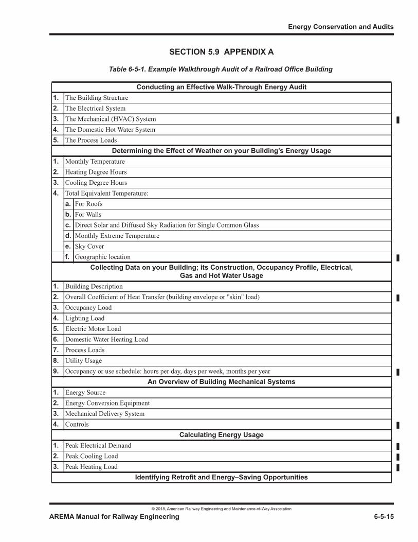
Energy Conservation and Audits
© 2018, American Railway Engineering and Maintenance-of-Way Association
AREMA Manual for Railway Engineering 6-5-15
1
3
4
SECTION 5.9 APPENDIX A
Table 6-5-1. Example Walkthrough Audit of a Railroad Office Building
Conducting an Effective Walk-Through Energy Audit1. The Building Structure2. The Electrical System3. The Mechanical (HVAC) System4. The Domestic Hot Water System5. The Process Loads
Determining the Effect of Weather on your Building’s Energy Usage1. Monthly Temperature2. Heating Degree Hours3. Cooling Degree Hours4. Total Equivalent Temperature:
a. For Roofsb. For Wallsc. Direct Solar and Diffused Sky Radiation for Single Common Glassd. Monthly Extreme Temperaturee. Sky Coverf. Geographic location
Collecting Data on your Building; its Construction, Occupancy Profile, Electrical, Gas and Hot Water Usage
1. Building Description2. Overall Coefficient of Heat Transfer (building envelope or "skin" load)3. Occupancy Load4. Lighting Load5. Electric Motor Load6. Domestic Water Heating Load7. Process Loads8. Utility Usage9. Occupancy or use schedule: hours per day, days per week, months per year
An Overview of Building Mechanical Systems1. Energy Source2. Energy Conversion Equipment3. Mechanical Delivery System4. Controls
Calculating Energy Usage1. Peak Electrical Demand2. Peak Cooling Load3. Peak Heating Load
Identifying Retrofit and Energy–Saving Opportunities
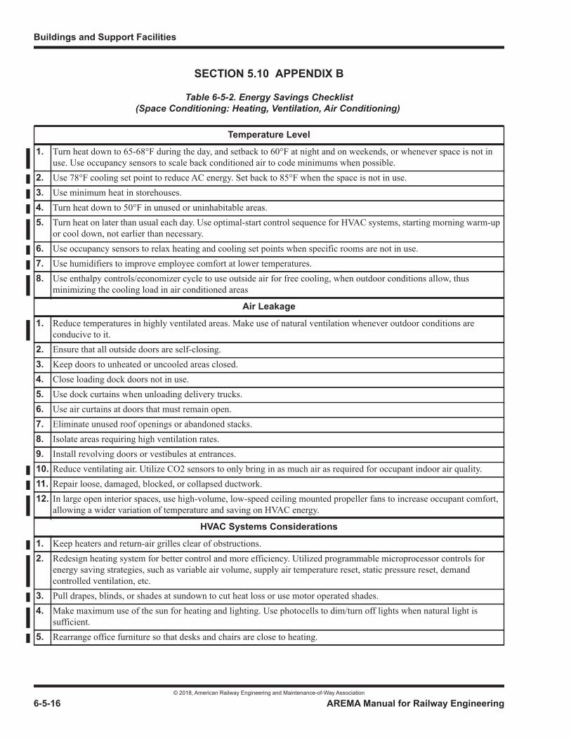
Buildings and Support Facilities
© 2018, American Railway Engineering and Maintenance-of-Way Association
6-5-16 AREMA Manual for Railway Engineering
SECTION 5.10 APPENDIX B
Table 6-5-2. Energy Savings Checklist(Space Conditioning: Heating, Ventilation, Air Conditioning)
Temperature Level
1. Turn heat down to 65-68°F during the day, and setback to 60°F at night and on weekends, or whenever space is not in use. Use occupancy sensors to scale back conditioned air to code minimums when possible.
2. Use 78°F cooling set point to reduce AC energy. Set back to 85°F when the space is not in use.3. Use minimum heat in storehouses.4. Turn heat down to 50°F in unused or uninhabitable areas.5. Turn heat on later than usual each day. Use optimal-start control sequence for HVAC systems, starting morning warm-up
or cool down, not earlier than necessary.6. Use occupancy sensors to relax heating and cooling set points when specific rooms are not in use.7. Use humidifiers to improve employee comfort at lower temperatures.8. Use enthalpy controls/economizer cycle to use outside air for free cooling, when outdoor conditions allow, thus
minimizing the cooling load in air conditioned areas
Air Leakage
1. Reduce temperatures in highly ventilated areas. Make use of natural ventilation whenever outdoor conditions are conducive to it.
2. Ensure that all outside doors are self-closing.3. Keep doors to unheated or uncooled areas closed.4. Close loading dock doors not in use.5. Use dock curtains when unloading delivery trucks.6. Use air curtains at doors that must remain open.7. Eliminate unused roof openings or abandoned stacks.8. Isolate areas requiring high ventilation rates.9. Install revolving doors or vestibules at entrances.10. Reduce ventilating air. Utilize CO2 sensors to only bring in as much air as required for occupant indoor air quality.11. Repair loose, damaged, blocked, or collapsed ductwork.12. In large open interior spaces, use high-volume, low-speed ceiling mounted propeller fans to increase occupant comfort,
allowing a wider variation of temperature and saving on HVAC energy.
HVAC Systems Considerations
1. Keep heaters and return-air grilles clear of obstructions.2. Redesign heating system for better control and more efficiency. Utilized programmable microprocessor controls for
energy saving strategies, such as variable air volume, supply air temperature reset, static pressure reset, demand controlled ventilation, etc.
3. Pull drapes, blinds, or shades at sundown to cut heat loss or use motor operated shades.4. Make maximum use of the sun for heating and lighting. Use photocells to dim/turn off lights when natural light is
sufficient.5. Rearrange office furniture so that desks and chairs are close to heating.
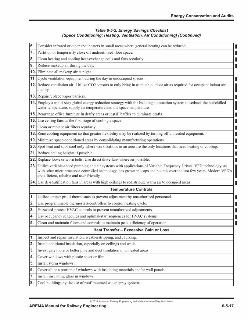
Energy Conservation and Audits
© 2018, American Railway Engineering and Maintenance-of-Way Association
AREMA Manual for Railway Engineering 6-5-17
1
3
4
6. Consider infrared or other spot heaters in small areas where general heating can be reduced.7. Partition or temporarily close off underutilized floor space.8. Clean heating and cooling heat-exchange coils and fans regularly.9. Reduce makeup air during the day.10. Eliminate all makeup air at night.11. Cycle ventilation equipment during the day in unoccupied spaces.12. Reduce ventilation air. Utilize CO2 sensors to only bring in as much outdoor air as required for occupant indoor air
quality.13. Repair/replace vapor barriers.14. Employ a multi-step global energy reduction strategy with the building automation system to setback the hot/chilled
water temperature, supply air temperature and the space temperature.15. Rearrange office furniture in drafty areas or install baffles to eliminate drafts.16. Use ceiling fans as the first stage of cooling a space.17. Clean or replace air filters regularly.18. Zone cooling equipment so that greater flexibility may be realized by turning off unneeded equipment.19. Minimize space-conditioned areas by consolidating manufacturing operations.20. Spot-heat and spot-cool only where work stations in an area are the only locations that need heating or cooling.21. Reduce ceiling heights if possible.22. Replace loose or worn belts. Use direct drive fans wherever possible.23. Utilize variable-speed pumping and air systems with applications of Variable Frequency Drives. VFD technology, as
with other microprocessor-controlled technology, has grown in leaps and bounds over the last few years. Modern VFD's are efficient, reliable and user-friendly.
24. Use de-stratification fans in areas with high ceilings to redistribute warm air to occupied areas.
Temperature Controls
1. Utilize tamper-proof thermostats to prevent adjustment by unauthorized personnel.2. Use programmable thermostats/controllers to control heating cycle.3. Password-protect HVAC controls to prevent unauthorized adjustments.4. Use occupancy schedules and optimal-start sequences for HVAC systems5. Clean and maintain filters and controls to maintain peak efficiency of operation.
Heat Transfer – Excessive Gain or Loss
1. Inspect and repair insulation, weatherstripping, and caulking.2. Install additional insulation, especially on ceilings and walls.3. Investigate more or better pipe and duct insulation in unheated areas.4. Cover windows with plastic sheet or film.5. Install storm windows.6. Cover all or a portion of windows with insulating materials and/or wall panels.7. Install insulating glass in windows.8. Cool buildings by the use of roof-mounted water spray systems.
Table 6-5-2. Energy Savings Checklist(Space Conditioning: Heating, Ventilation, Air Conditioning) (Continued)
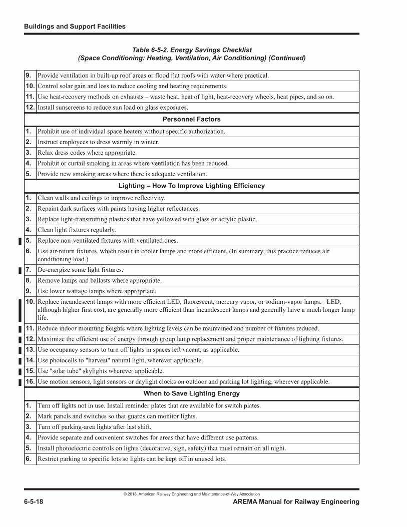
Buildings and Support Facilities
© 2018, American Railway Engineering and Maintenance-of-Way Association
6-5-18 AREMA Manual for Railway Engineering
9. Provide ventilation in built-up roof areas or flood flat roofs with water where practical.10. Control solar gain and loss to reduce cooling and heating requirements.11. Use heat-recovery methods on exhausts – waste heat, heat of light, heat-recovery wheels, heat pipes, and so on.12. Install sunscreens to reduce sun load on glass exposures.
Personnel Factors
1. Prohibit use of individual space heaters without specific authorization.2. Instruct employees to dress warmly in winter.3. Relax dress codes where appropriate.4. Prohibit or curtail smoking in areas where ventilation has been reduced.5. Provide new smoking areas where there is adequate ventilation.
Lighting – How To Improve Lighting Efficiency
1. Clean walls and ceilings to improve reflectivity.2. Repaint dark surfaces with paints having higher reflectances.3. Replace light-transmitting plastics that have yellowed with glass or acrylic plastic.4. Clean light fixtures regularly.5. Replace non-ventilated fixtures with ventilated ones.6. Use air-return fixtures, which result in cooler lamps and more efficient. (In summary, this practice reduces air
conditioning load.)7. De-energize some light fixtures.8. Remove lamps and ballasts where appropriate.9. Use lower wattage lamps where appropriate.10. Replace incandescent lamps with more efficient LED, fluorescent, mercury vapor, or sodium-vapor lamps. LED,
although higher first cost, are generally more efficient than incandescent lamps and generally have a much longer lamp life.
11. Reduce indoor mounting heights where lighting levels can be maintained and number of fixtures reduced.12. Maximize the efficient use of energy through group lamp replacement and proper maintenance of lighting fixtures.13. Use occupancy sensors to turn off lights in spaces left vacant, as applicable.14. Use photocells to "harvest" natural light, wherever applicable.15. Use "solar tube" skylights wherever applicable.16. Use motion sensors, light sensors or daylight clocks on outdoor and parking lot lighting, wherever applicable.
When to Save Lighting Energy
1. Turn off lights not in use. Install reminder plates that are available for switch plates.2. Mark panels and switches so that guards can monitor lights.3. Turn off parking-area lights after last shift.4. Provide separate and convenient switches for areas that have different use patterns.5. Install photoelectric controls on lights (decorative, sign, safety) that must remain on all night.6. Restrict parking to specific lots so lights can be kept off in unused lots.
Table 6-5-2. Energy Savings Checklist(Space Conditioning: Heating, Ventilation, Air Conditioning) (Continued)
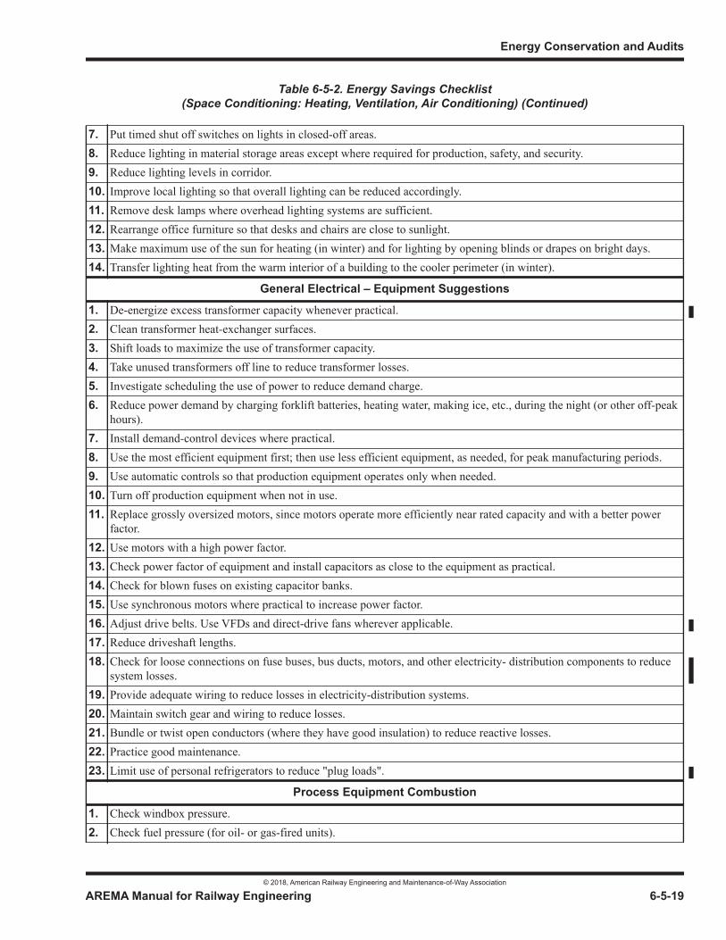
Energy Conservation and Audits
© 2018, American Railway Engineering and Maintenance-of-Way Association
AREMA Manual for Railway Engineering 6-5-19
1
3
4
7. Put timed shut off switches on lights in closed-off areas.8. Reduce lighting in material storage areas except where required for production, safety, and security.9. Reduce lighting levels in corridor.10. Improve local lighting so that overall lighting can be reduced accordingly.11. Remove desk lamps where overhead lighting systems are sufficient.12. Rearrange office furniture so that desks and chairs are close to sunlight.13. Make maximum use of the sun for heating (in winter) and for lighting by opening blinds or drapes on bright days.14. Transfer lighting heat from the warm interior of a building to the cooler perimeter (in winter).
General Electrical – Equipment Suggestions
1. De-energize excess transformer capacity whenever practical.2. Clean transformer heat-exchanger surfaces.3. Shift loads to maximize the use of transformer capacity.4. Take unused transformers off line to reduce transformer losses.5. Investigate scheduling the use of power to reduce demand charge.6. Reduce power demand by charging forklift batteries, heating water, making ice, etc., during the night (or other off-peak
hours).7. Install demand-control devices where practical.8. Use the most efficient equipment first; then use less efficient equipment, as needed, for peak manufacturing periods.9. Use automatic controls so that production equipment operates only when needed.10. Turn off production equipment when not in use.11. Replace grossly oversized motors, since motors operate more efficiently near rated capacity and with a better power
factor.12. Use motors with a high power factor.13. Check power factor of equipment and install capacitors as close to the equipment as practical.14. Check for blown fuses on existing capacitor banks.15. Use synchronous motors where practical to increase power factor.16. Adjust drive belts. Use VFDs and direct-drive fans wherever applicable.17. Reduce driveshaft lengths.18. Check for loose connections on fuse buses, bus ducts, motors, and other electricity- distribution components to reduce
system losses.19. Provide adequate wiring to reduce losses in electricity-distribution systems.20. Maintain switch gear and wiring to reduce losses.21. Bundle or twist open conductors (where they have good insulation) to reduce reactive losses.22. Practice good maintenance.23. Limit use of personal refrigerators to reduce "plug loads".
Process Equipment Combustion
1. Check windbox pressure.2. Check fuel pressure (for oil- or gas-fired units).
Table 6-5-2. Energy Savings Checklist(Space Conditioning: Heating, Ventilation, Air Conditioning) (Continued)
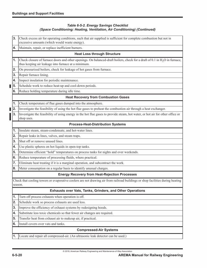
Buildings and Support Facilities
© 2018, American Railway Engineering and Maintenance-of-Way Association
6-5-20 AREMA Manual for Railway Engineering
3. Check excess air for operating conditions, such that air supplied is sufficient for complete combustion but not in excessive amounts (which would waste energy).
4. Maintain, repair, or replace inefficient burners.
Heat Loss through Structure
1. Check closure of furnace doors and other openings. On balanced-draft boilers, check for a draft of 0.1 in H2O in furnace, thus keeping air leakage into furnace at a minimum.
2. On pressurized boilers, check for leakage of hot gases from furnace.3. Repair furnace lining.4. Inspect insulation for periodic maintenance.5. Schedule work to reduce heat-up and cool-down periods.6. Reduce holding temperature during idle time.
Heat Recovery from Combustion Gases
1. Check temperature of flue gases dumped into the atmosphere.2. Investigate the feasibility of using the hot flue gases to preheat the combustion air through a heat exchanger.3. Investigate the feasibility of using energy in the hot flue gases to provide steam, hot water, or hot air for other office or
shop uses.
Process-Heat-Distribution Systems
1. Insulate steam, steam-condensate, and hot-water lines.2. Repair leaks in lines, valves, and steam traps.3. Shut off or remove unused lines.4. Use plastic spheres on hot liquids in open-top tanks.5. Determine efficient “hold” temperatures on process tanks for nights and over weekends.6. Reduce temperature of processing fluids, where practical.7. Eliminate heat treating if it is a marginal operation, and subcontract the work.8. Meter consumption on a regular basis to identify unusual charges.
Energy Recovery from Heat-Rejection Processes
Check that cooling towers or evaporative coolers are not drawing air from railroad buildings or shop facilities during heating season.
Exhausts over Vats, Tanks, Grinders, and Other Operations
1. Turn off process exhausts when operation is off.2. Schedule work so process exhausts are used less.3. Improve the efficiency of exhaust systems by redesigning hoods.4. Substitute less toxic chemicals so that fewer air changes are required.5. Transfer heat from exhaust air to makeup air, if practical.6. Install covers over vats and tanks.
Compressed-Air Systems
1. Locate and repair all compressed-air. (An ultrasonic leak detector can be used.)
Table 6-5-2. Energy Savings Checklist(Space Conditioning: Heating, Ventilation, Air Conditioning) (Continued)
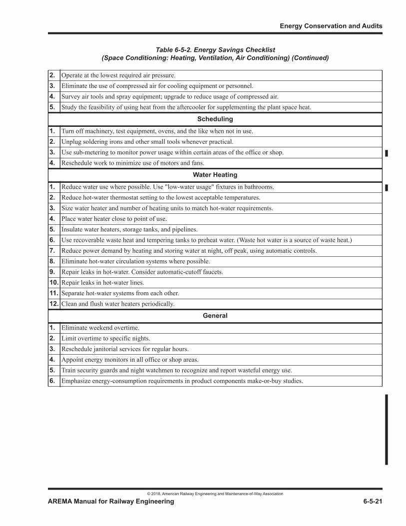
Energy Conservation and Audits
© 2018, American Railway Engineering and Maintenance-of-Way Association
AREMA Manual for Railway Engineering 6-5-21
1
3
4
2. Operate at the lowest required air pressure.3. Eliminate the use of compressed air for cooling equipment or personnel.4. Survey air tools and spray equipment; upgrade to reduce usage of compressed air.5. Study the feasibility of using heat from the aftercooler for supplementing the plant space heat.
Scheduling
1. Turn off machinery, test equipment, ovens, and the like when not in use.2. Unplug soldering irons and other small tools whenever practical.3. Use sub-metering to monitor power usage within certain areas of the office or shop.4. Reschedule work to minimize use of motors and fans.
Water Heating
1. Reduce water use where possible. Use "low-water usage" fixtures in bathrooms.2. Reduce hot-water thermostat setting to the lowest acceptable temperatures.3. Size water heater and number of heating units to match hot-water requirements.4. Place water heater close to point of use.5. Insulate water heaters, storage tanks, and pipelines.6. Use recoverable waste heat and tempering tanks to preheat water. (Waste hot water is a source of waste heat.)7. Reduce power demand by heating and storing water at night, off peak, using automatic controls.8. Eliminate hot-water circulation systems where possible.9. Repair leaks in hot-water. Consider automatic-cutoff faucets.10. Repair leaks in hot-water lines.11. Separate hot-water systems from each other.12. Clean and flush water heaters periodically.
General
1. Eliminate weekend overtime.2. Limit overtime to specific nights.3. Reschedule janitorial services for regular hours.4. Appoint energy monitors in all office or shop areas.5. Train security guards and night watchmen to recognize and report wasteful energy use.6. Emphasize energy-consumption requirements in product components make-or-buy studies.
Table 6-5-2. Energy Savings Checklist(Space Conditioning: Heating, Ventilation, Air Conditioning) (Continued)
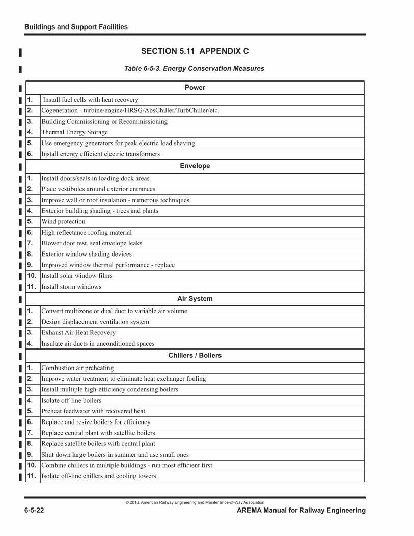
Buildings and Support Facilities
© 2018, American Railway Engineering and Maintenance-of-Way Association
6-5-22 AREMA Manual for Railway Engineering
SECTION 5.11 APPENDIX C
Table 6-5-3. Energy Conservation Measures
Power
1. Install fuel cells with heat recovery2. Cogeneration - turbine/engine/HRSG/AbsChiller/TurbChiller/etc.3. Building Commissioning or Recommissioning4. Thermal Energy Storage5. Use emergency generators for peak electric load shaving6. Install energy efficient electric transformers
Envelope
1. Install doors/seals in loading dock areas2. Place vestibules around exterior entrances3. Improve wall or roof insulation - numerous techniques4. Exterior building shading - trees and plants5. Wind protection6. High reflectance roofing material7. Blower door test, seal envelope leaks8. Exterior window shading devices9. Improved window thermal performance - replace10. Install solar window films11. Install storm windows
Air System
1. Convert multizone or dual duct to variable air volume2. Design displacement ventilation system3. Exhaust Air Heat Recovery4. Insulate air ducts in unconditioned spaces
Chillers / Boilers
1. Combustion air preheating2. Improve water treatment to eliminate heat exchanger fouling3. Install multiple high-efficiency condensing boilers4. Isolate off-line boilers5. Preheat feedwater with recovered heat6. Replace and resize boilers for efficiency7. Replace central plant with satellite boilers8. Replace satellite boilers with central plant9. Shut down large boilers in summer and use small ones10. Combine chillers in multiple buildings - run most efficient first11. Isolate off-line chillers and cooling towers
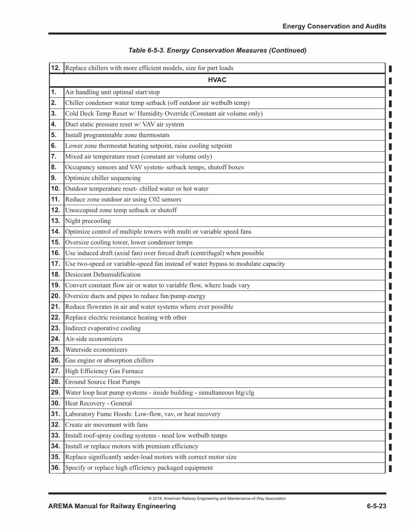
Energy Conservation and Audits
© 2018, American Railway Engineering and Maintenance-of-Way Association
AREMA Manual for Railway Engineering 6-5-23
1
3
4
12. Replace chillers with more efficient models, size for part loads
HVAC
1. Air handling unit optimal start/stop2. Chiller condenser water temp setback (off outdoor air wetbulb temp)3. Cold Deck Temp Reset w/ Humidity Override (Constant air volume only)4. Duct static pressure reset w/ VAV air system5. Install programmable zone thermostats6. Lower zone thermostat heating setpoint, raise cooling setpoint7. Mixed air temperature reset (constant air volume only)8. Occupancy sensors and VAV system- setback temps, shutoff boxes9. Optimize chiller sequencing10. Outdoor temperature reset- chilled water or hot water11. Reduce zone outdoor air using C02 sensors12. Unoccupied zone temp setback or shutoff13. Night precooling14. Optimize control of multiple towers with multi or variable speed fans15. Oversize cooling tower, lower condenser temps16. Use induced draft (axial fan) over forced draft (centrifugal) when possible17. Use two-speed or variable-speed fan instead of water bypass to modulate capacity18. Desiccant Dehumidification19. Convert constant flow air or water to variable flow, where loads vary20. Oversize ducts and pipes to reduce fan/pump energy21. Reduce flowrates in air and water systems where ever possible22. Replace electric resistance heating with other23. Indirect evaporative cooling24. Air-side economizers25. Waterside economizers26. Gas engine or absorption chillers27. High Efficiency Gas Furnace28. Ground Source Heat Pumps29. Water loop heat pump systems - inside building - simultaneous htg/clg30. Heat Recovery - General31. Laboratory Fume Hoods: Low-flow, vav, or heat recovery32. Create air movement with fans33. Install roof-spray cooling systems - need low wetbulb temps34. Install or replace motors with premium efficiency35. Replace significantly under-load motors with correct motor size36. Specify or replace high efficiency packaged equipment
Table 6-5-3. Energy Conservation Measures (Continued)
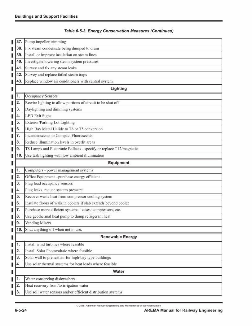
Buildings and Support Facilities
© 2018, American Railway Engineering and Maintenance-of-Way Association
6-5-24 AREMA Manual for Railway Engineering
37. Pump impeller trimming38. Fix steam condensate being dumped to drain39. Install or improve insulation on steam lines40. Investigate lowering steam system pressures41. Survey and fix any steam leaks42. Survey and replace failed steam traps43. Replace window air conditioners with central system
Lighting
1. Occupancy Sensors2. Rewire lighting to allow portions of circuit to be shut off3. Daylighting and dimming systems4. LED Exit Signs5. Exterior/Parking Lot Lighting6. High Bay Metal Halide to T8 or T5 conversion7. Incandenscents to Compact Fluorescents8. Reduce illumination levels in overlit areas9. T8 Lamps and Electronic Ballasts - specify or replace T12/magnetic10. Use task lighting with low ambient illumination
Equipment
1. Computers - power management systems2. Office Equipment - purchase energy efficient3. Plug load occupancy sensors4. Plug leaks, reduce system pressure5. Recover waste heat from compressor cooling system6. Insulate floors of walk in coolers if slab extends beyond cooler7. Purchase more efficient systems - cases, compressors, etc.8. Use geothermal heat pump to dump refrigerant heat9. Vending Misers10. Shut anything off when not in use.
Renewable Energy
1. Install wind turbines where feasible2. Install Solar Photovoltaic where feasible3. Solar wall to preheat air for high-bay type buildings4. Use solar thermal systems for heat loads where feasible
Water
1. Water conserving dishwashers2. Heat recovery from/to irrigation water3. Use soil water sensors and/or efficient distribution systems
Table 6-5-3. Energy Conservation Measures (Continued)
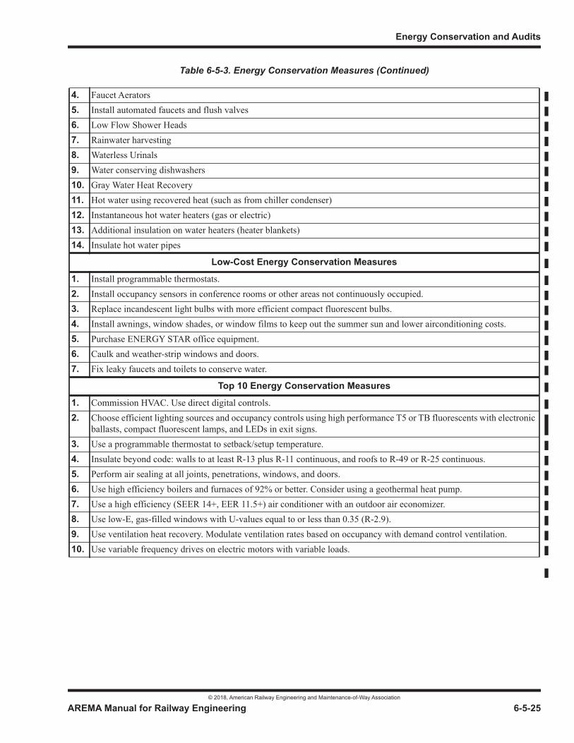
Energy Conservation and Audits
© 2018, American Railway Engineering and Maintenance-of-Way Association
AREMA Manual for Railway Engineering 6-5-25
1
3
4
4. Faucet Aerators5. Install automated faucets and flush valves6. Low Flow Shower Heads7. Rainwater harvesting8. Waterless Urinals9. Water conserving dishwashers10. Gray Water Heat Recovery11. Hot water using recovered heat (such as from chiller condenser)12. Instantaneous hot water heaters (gas or electric)13. Additional insulation on water heaters (heater blankets)14. Insulate hot water pipes
Low-Cost Energy Conservation Measures
1. Install programmable thermostats.2. Install occupancy sensors in conference rooms or other areas not continuously occupied.3. Replace incandescent light bulbs with more efficient compact fluorescent bulbs.4. Install awnings, window shades, or window films to keep out the summer sun and lower airconditioning costs.5. Purchase ENERGY STAR office equipment.6. Caulk and weather-strip windows and doors.7. Fix leaky faucets and toilets to conserve water.
Top 10 Energy Conservation Measures
1. Commission HVAC. Use direct digital controls.2. Choose efficient lighting sources and occupancy controls using high performance T5 or TB fluorescents with electronic
ballasts, compact fluorescent lamps, and LEDs in exit signs.3. Use a programmable thermostat to setback/setup temperature.4. Insulate beyond code: walls to at least R-13 plus R-11 continuous, and roofs to R-49 or R-25 continuous.5. Perform air sealing at all joints, penetrations, windows, and doors.6. Use high efficiency boilers and furnaces of 92% or better. Consider using a geothermal heat pump.7. Use a high efficiency (SEER 14+, EER 11.5+) air conditioner with an outdoor air economizer.8. Use low-E, gas-filled windows with U-values equal to or less than 0.35 (R-2.9).9. Use ventilation heat recovery. Modulate ventilation rates based on occupancy with demand control ventilation.10. Use variable frequency drives on electric motors with variable loads.
Table 6-5-3. Energy Conservation Measures (Continued)
Buildings and Support Facilities
© 2018, American Railway Engineering and Maintenance-of-Way Association
6-5-26 AREMA Manual for Railway Engineering
THIS PAGE INTENTIONALLY LEFT BLANK.
© 2018, American Railway Engineering and Maintenance-of-Way Association
© 2018, American Railway Engineering and Maintenance-of-Way Association
© 2018, American Railway Engineering and Maintenance-of-Way Association
© 2018, American Railway Engineering and Maintenance-of-Way Association
© 2018, American Railway Engineering and Maintenance-of-Way Association
© 2018, American Railway Engineering and Maintenance-of-Way Association

© 2018, American Railway Engineering and Maintenance-of-Way Association
© 2018, American Railway Engineering and Maintenance-of-Way Association
© 2018, American Railway Engineering and Maintenance-of-Way Association
© 2018, American Railway Engineering and Maintenance-of-Way Association
© 2018, American Railway Engineering and Maintenance-of-Way Association
© 2018, American Railway Engineering and Maintenance-of-Way Association
© 2018, American Railway Engineering and Maintenance-of-Way Association
© 2018, American Railway Engineering and Maintenance-of-Way Association
© 2018, American Railway Engineering and Maintenance-of-Way Association
© 2018, American Railway Engineering and Maintenance-of-Way Association
© 2018, American Railway Engineering and Maintenance-of-Way Association
Useful Information on the Design of Steel Bins and Silos,
Venting Atmospheric and Low Pressure Storage Tanks,
© 2018, American Railway Engineering and Maintenance-of-Way Association
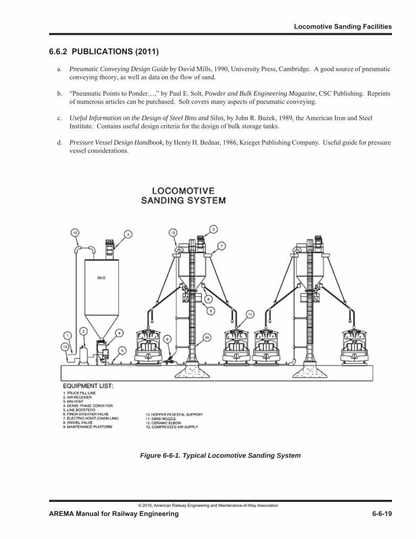
Pneumatic Conveying Design Guide
Powder and Bulk Engineering Magazine,
Useful Information on the Design of Steel Bins and Silos,
Pressure Vessel Design Handbook,
Figure 6-6-1. Typical Locomotive Sanding System
© 2018, American Railway Engineering and Maintenance-of-Way Association
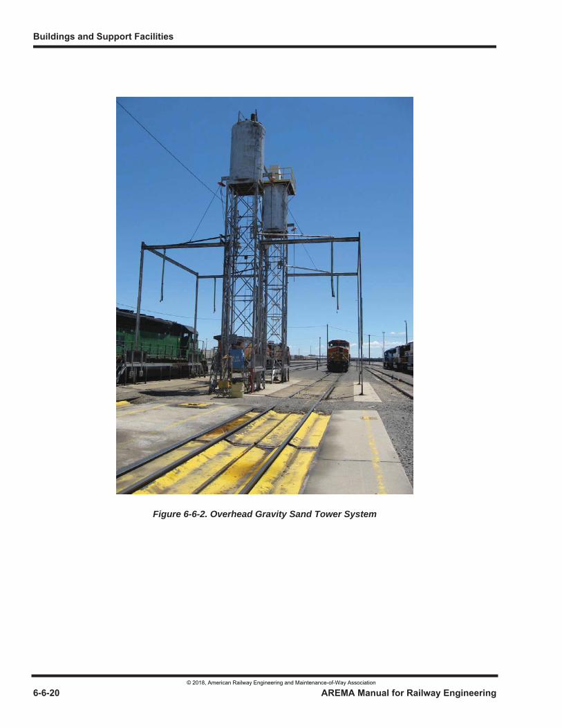
Figure 6-6-2. Overhead Gravity Sand Tower System
© 2018, American Railway Engineering and Maintenance-of-Way Association
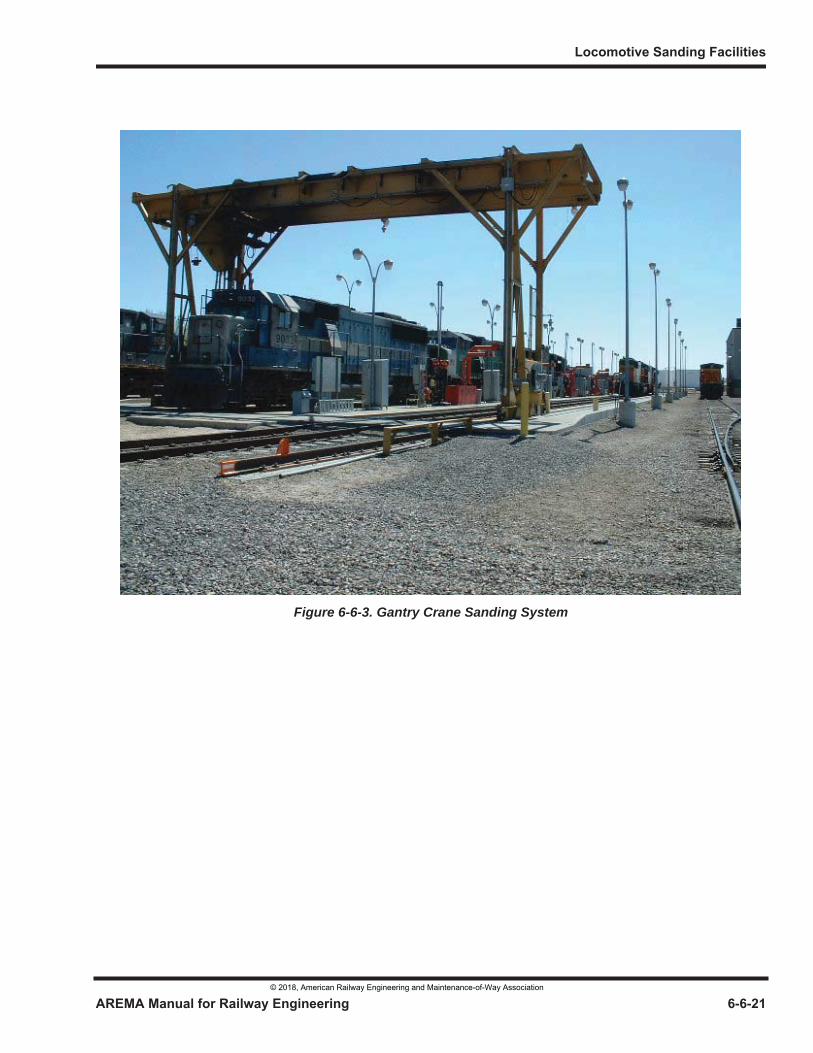
Figure 6-6-3. Gantry Crane Sanding System
© 2018, American Railway Engineering and Maintenance-of-Way Association
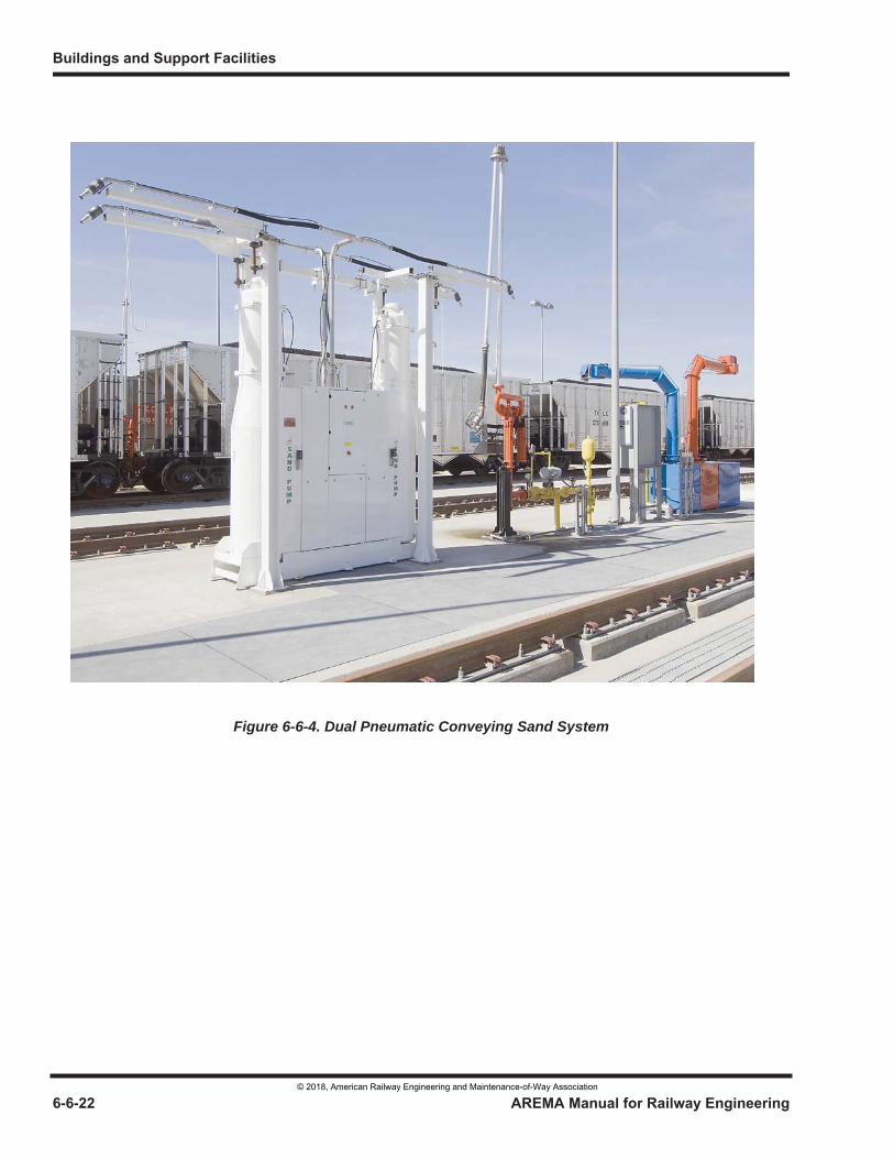
Figure 6-6-4. Dual Pneumatic Conveying Sand System
© 2018, American Railway Engineering and Maintenance-of-Way Association
© 2018, American Railway Engineering and Maintenance-of-Way Association
© 2018, American Railway Engineering and Maintenance-of-Way Association
© 2018, American Railway Engineering and Maintenance-of-Way Association
© 2018, American Railway Engineering and Maintenance-of-Way Association
AREMA Manual for Railway Engineering
© 2018, American Railway Engineering and Maintenance-of-Way Association
© 2018, American Railway Engineering and Maintenance-of-Way Association
6-8-1
1
3
6 Part 8
Design Criteria for Railway Passenger Stations1
— 2015 —
TABLE OF CONTENTS
Section/Article Description Page
8.1 Introduction . . . . . . . . . . . . . . . . . . . . . . . . . . . . . . . . . . . . . . . . . . . . . . . . . . . . . . . . . . . . . . . . . . . . . . . . . . . 6-8-38.1.1 General (2011) R(2014) . . . . . . . . . . . . . . . . . . . . . . . . . . . . . . . . . . . . . . . . . . . . . . . . . . . . . . . . . . . . 6-8-38.1.2 Types of Stations (2014) . . . . . . . . . . . . . . . . . . . . . . . . . . . . . . . . . . . . . . . . . . . . . . . . . . . . . . . . . . . 6-8-3
8.2 Site . . . . . . . . . . . . . . . . . . . . . . . . . . . . . . . . . . . . . . . . . . . . . . . . . . . . . . . . . . . . . . . . . . . . . . . . . . . . . . . . . . . 6-8-48.2.1 Selection (2014) . . . . . . . . . . . . . . . . . . . . . . . . . . . . . . . . . . . . . . . . . . . . . . . . . . . . . . . . . . . . . . . . . . 6-8-48.2.2 Station Development (2014) . . . . . . . . . . . . . . . . . . . . . . . . . . . . . . . . . . . . . . . . . . . . . . . . . . . . . . . . 6-8-4
8.3 Functional Requirements. . . . . . . . . . . . . . . . . . . . . . . . . . . . . . . . . . . . . . . . . . . . . . . . . . . . . . . . . . . . . . . . . 6-8-88.3.1 General Building Considerations (2014) . . . . . . . . . . . . . . . . . . . . . . . . . . . . . . . . . . . . . . . . . . . . . . . 6-8-88.3.2 Intercity Passenger Stations (2014) . . . . . . . . . . . . . . . . . . . . . . . . . . . . . . . . . . . . . . . . . . . . . . . . . . . 6-8-98.3.3 Commuter Stations (2014) . . . . . . . . . . . . . . . . . . . . . . . . . . . . . . . . . . . . . . . . . . . . . . . . . . . . . . . . . . 6-8-138.3.4 Intermodal Passenger Stations (2014) . . . . . . . . . . . . . . . . . . . . . . . . . . . . . . . . . . . . . . . . . . . . . . . . . 6-8-148.3.5 Combination Freight and Passenger Stations (2014) . . . . . . . . . . . . . . . . . . . . . . . . . . . . . . . . . . . . . . 6-8-158.3.6 Historic Buildings (2014). . . . . . . . . . . . . . . . . . . . . . . . . . . . . . . . . . . . . . . . . . . . . . . . . . . . . . . . . . . 6-8-15
8.4 Building Systems. . . . . . . . . . . . . . . . . . . . . . . . . . . . . . . . . . . . . . . . . . . . . . . . . . . . . . . . . . . . . . . . . . . . . . . . 6-8-158.4.1 General (2014) . . . . . . . . . . . . . . . . . . . . . . . . . . . . . . . . . . . . . . . . . . . . . . . . . . . . . . . . . . . . . . . . . . . 6-8-158.4.2 Interior Finishes (2014) . . . . . . . . . . . . . . . . . . . . . . . . . . . . . . . . . . . . . . . . . . . . . . . . . . . . . . . . . . . . 6-8-178.4.3 Structural Types (2014) . . . . . . . . . . . . . . . . . . . . . . . . . . . . . . . . . . . . . . . . . . . . . . . . . . . . . . . . . . . . 6-8-17
8.5 Mechanical Systems . . . . . . . . . . . . . . . . . . . . . . . . . . . . . . . . . . . . . . . . . . . . . . . . . . . . . . . . . . . . . . . . . . . . . 6-8-188.5.1 Heating, Ventilating, and Air Conditioning (2014) . . . . . . . . . . . . . . . . . . . . . . . . . . . . . . . . . . . . . . . 6-8-188.5.2 Plumbing (2014) . . . . . . . . . . . . . . . . . . . . . . . . . . . . . . . . . . . . . . . . . . . . . . . . . . . . . . . . . . . . . . . . . 6-8-18
8.6 Electrical Systems. . . . . . . . . . . . . . . . . . . . . . . . . . . . . . . . . . . . . . . . . . . . . . . . . . . . . . . . . . . . . . . . . . . . . . . 6-8-198.6.1 Lighting (2014) . . . . . . . . . . . . . . . . . . . . . . . . . . . . . . . . . . . . . . . . . . . . . . . . . . . . . . . . . . . . . . . . . . 6-8-198.6.2 Power (2014) . . . . . . . . . . . . . . . . . . . . . . . . . . . . . . . . . . . . . . . . . . . . . . . . . . . . . . . . . . . . . . . . . . . . 6-8-198.6.3 Escalators/Elevators (2014) . . . . . . . . . . . . . . . . . . . . . . . . . . . . . . . . . . . . . . . . . . . . . . . . . . . . . . . . . 6-8-208.6.4 Train Information Systems (2014) . . . . . . . . . . . . . . . . . . . . . . . . . . . . . . . . . . . . . . . . . . . . . . . . . . . . 6-8-208.6.5 Closed Circuit Television (CCTV) (2014) . . . . . . . . . . . . . . . . . . . . . . . . . . . . . . . . . . . . . . . . . . . . . . 6-8-208.6.6 Communications Support (2014) . . . . . . . . . . . . . . . . . . . . . . . . . . . . . . . . . . . . . . . . . . . . . . . . . . . . . 6-8-21
1 References, Vol. 76, 1975, p. 185; Vol. 86, 1985, p. 18.
© 2018, American Railway Engineering and Maintenance-of-Way Association
Building and Support Facilities
6-8-2 AREMA Manual for Railway Engineering
TABLE OF CONTENTS (CONT)
Section/Article Description Page
8.7 Boarding Platforms. . . . . . . . . . . . . . . . . . . . . . . . . . . . . . . . . . . . . . . . . . . . . . . . . . . . . . . . . . . . . . . . . . . . . 6-8-218.7.1 General (2014) . . . . . . . . . . . . . . . . . . . . . . . . . . . . . . . . . . . . . . . . . . . . . . . . . . . . . . . . . . . . . . . . . . 6-8-218.7.2 Disabled Access Regulations (2014) . . . . . . . . . . . . . . . . . . . . . . . . . . . . . . . . . . . . . . . . . . . . . . . . . 6-8-238.7.3 Platform Dimensions (2014) . . . . . . . . . . . . . . . . . . . . . . . . . . . . . . . . . . . . . . . . . . . . . . . . . . . . . . . 6-8-238.7.4 Platform Lighting (2014) . . . . . . . . . . . . . . . . . . . . . . . . . . . . . . . . . . . . . . . . . . . . . . . . . . . . . . . . . . 6-8-24
8.8 Station and Platform Examples. . . . . . . . . . . . . . . . . . . . . . . . . . . . . . . . . . . . . . . . . . . . . . . . . . . . . . . . . . . 6-8-25
8.9 Train Service and Inspection Facilities . . . . . . . . . . . . . . . . . . . . . . . . . . . . . . . . . . . . . . . . . . . . . . . . . . . . . 6-8-338.9.1 General Requirements (2015) . . . . . . . . . . . . . . . . . . . . . . . . . . . . . . . . . . . . . . . . . . . . . . . . . . . . . . 6-8-338.9.2 Regulatory Requirements (2015) . . . . . . . . . . . . . . . . . . . . . . . . . . . . . . . . . . . . . . . . . . . . . . . . . . . . 6-8-348.9.3 Mechanical Inspection Facilities (2015) . . . . . . . . . . . . . . . . . . . . . . . . . . . . . . . . . . . . . . . . . . . . . . 6-8-358.9.4 Water Facilities (2015) . . . . . . . . . . . . . . . . . . . . . . . . . . . . . . . . . . . . . . . . . . . . . . . . . . . . . . . . . . . . 6-8-358.9.5 Waste Disposal Facilities (2015) . . . . . . . . . . . . . . . . . . . . . . . . . . . . . . . . . . . . . . . . . . . . . . . . . . . . 6-8-368.9.6 Locomotive Servicing Facilities in Stations (2015) . . . . . . . . . . . . . . . . . . . . . . . . . . . . . . . . . . . . . . 6-8-378.9.7 Layover Facilities (2015) . . . . . . . . . . . . . . . . . . . . . . . . . . . . . . . . . . . . . . . . . . . . . . . . . . . . . . . . . . 6-8-388.9.8 Trash Removal (2015) . . . . . . . . . . . . . . . . . . . . . . . . . . . . . . . . . . . . . . . . . . . . . . . . . . . . . . . . . . . . 6-8-398.9.9 Security and Safety (2015) . . . . . . . . . . . . . . . . . . . . . . . . . . . . . . . . . . . . . . . . . . . . . . . . . . . . . . . . . 6-8-39
LIST OF FIGURES
Figure Description Page
6-8-1 Intercity Ticket Counter Layout . . . . . . . . . . . . . . . . . . . . . . . . . . . . . . . . . . . . . . . . . . . . . . . . . . . . . . . . . . 6-8-126-8-2 Bus Loading Dock Layouts . . . . . . . . . . . . . . . . . . . . . . . . . . . . . . . . . . . . . . . . . . . . . . . . . . . . . . . . . . . . . 6-8-166-8-3 Intercity Passenger Station 300 PHP - Ground Floor Plan . . . . . . . . . . . . . . . . . . . . . . . . . . . . . . . . . . . . . 6-8-266-8-4 Intercity Passenger Station 300 PHP - Mezzanine Floor Plan. . . . . . . . . . . . . . . . . . . . . . . . . . . . . . . . . . . 6-8-276-8-5 Intercity Passenger Station 300 PHP . . . . . . . . . . . . . . . . . . . . . . . . . . . . . . . . . . . . . . . . . . . . . . . . . . . . . . 6-8-286-8-6 Intermodal Rail-Bus Station 150 PHP - Floor Plan . . . . . . . . . . . . . . . . . . . . . . . . . . . . . . . . . . . . . . . . . . . 6-8-286-8-7 Intercity Passenger Station 25 PHP - Unmanned Passenger Shelter Floor Plan . . . . . . . . . . . . . . . . . . . . . 6-8-296-8-8 Intercity Passenger Station 50 PHP - Waiting Room and Ticket Counter . . . . . . . . . . . . . . . . . . . . . . . . . . 6-8-306-8-9 Commuter Passenger Station 300 PHP . . . . . . . . . . . . . . . . . . . . . . . . . . . . . . . . . . . . . . . . . . . . . . . . . . . . 6-8-316-8-10 Commuter Passenger Station - Dual height platform for multiple styles of passenger cars . . . . . . . . . . . . 6-8-326-8-11 Intercity and Commuter Passenger Station - Platform 50” ATR height . . . . . . . . . . . . . . . . . . . . . . . . . . . 6-8-336-8-12 Example of Water Facility . . . . . . . . . . . . . . . . . . . . . . . . . . . . . . . . . . . . . . . . . . . . . . . . . . . . . . . . . . . . . . 6-8-366-8-13 Example of HEP cabinet . . . . . . . . . . . . . . . . . . . . . . . . . . . . . . . . . . . . . . . . . . . . . . . . . . . . . . . . . . . . . . . 6-8-39
LIST OF TABLES
Table Description Page
6-8-1 Parking and Curb Requirements . . . . . . . . . . . . . . . . . . . . . . . . . . . . . . . . . . . . . . . . . . . . . . . . . . . . . . . . . 6-8-56-8-2 Passenger Service Characteristics . . . . . . . . . . . . . . . . . . . . . . . . . . . . . . . . . . . . . . . . . . . . . . . . . . . . . . . . 6-8-86-8-3 Interior Space Requirements . . . . . . . . . . . . . . . . . . . . . . . . . . . . . . . . . . . . . . . . . . . . . . . . . . . . . . . . . . . . 6-8-96-8-4 Illumination Levels . . . . . . . . . . . . . . . . . . . . . . . . . . . . . . . . . . . . . . . . . . . . . . . . . . . . . . . . . . . . . . . . . . . 6-8-196-8-5 Rolling Stock Interfaces with Station Platforms . . . . . . . . . . . . . . . . . . . . . . . . . . . . . . . . . . . . . . . . . . . . . 6-8-24
© 2018, American Railway Engineering and Maintenance-of-Way Association
Design Criteria for Railway Passenger Stations
AREMA Manual for Railway Engineering 6-8-3
1
3
4
SECTION 8.1 INTRODUCTION
8.1.1 GENERAL (2011) R(2014)
a. A passenger station comprises the building(s), site access, parking, tracks, platforms, and all appurtenances necessary to conduct transportation. The following portions of this Section will provide the guidelines for developing a comprehensive station design program. This Part is focused upon rail facilities that are part of the “general system of railroad transportation” and are regulated by the federal government. They may also be applied to other rail transit projects with modificaitions to suit the local conditions.
b. Various government agencies and/or public supported corporations have for the most part, assumed providing passenger services in North America. Service is provided over existing-freight railroad lines and/or lines owned by the local government agency or public supported corporation. As a result, the local government agency or public supported corporation funds new passenger station facilities. The facilities are distinct from those facilities required for freight operations.
c. Traditionally, railway stations have served as a gateway of commerce into and out of a community and as the origin/destination source of passenger traffic. In the early 1900’s, during the peak of private railway station construction, the railway station was viewed, in some cases, as a marketing tool and in other cases as a source of pride and identity to the community.
By the late 1990’s, many of the privately built railway stations have been demolished and/or utilized for purposes unrelated to railroad transportation. Of those early 1900 stations that remain in use, many have been restored to their earlier grandeur while others have simply been reasonably maintained. Overall, however, two new station types have appeared. These are the suburban/commuter stations, and long distance, intercity rail stations, which are often built with funds from a designated national rail passenger carrier or a combination of public-private funding as part of mixed use developments.
Of the two new types of stations mentioned above, most have rail carrier established design criteria to be followed. When outside parties become involved, modifications to a design program are required to incorporate other site and building functions.
d. In addition to the basic rail passenger station building and platforms, terminal stations often require train servicing yards and facilities that are integral to the operation of the station. This part incorporates design criteria previously found in Chapter 14 for passenger yards and facilities.
8.1.2 TYPES OF STATIONS (2014)
Stations are classified (as follows) by the type of transportation services offered:
a. Intercity. Service characterized by travel between metropolitan areas in excess of 120 miles by passengers who journey periodically and may require additonal services such as checked baggage, on-board food, and, in some cases, reservations for seats or sleeping accommodations. In North America, Amtrak and VIA Rail Canada are the primary intercity passenger carriers.
b. Suburban/Commuter. Service characterized by travel distances less than 120 miles on a repetitive daily schedule, which is usually oriented to peark service during the morning and evening hours.
c. Intermodal. Service characterized by a combination of Intercity and/or Suburban/Commuter rail service plus additional public transportation modes, such as long distance and local bus routes, marine ferry service, heavy/light rail rapid transit, airport ground access, and centralized private auto parking.
© 2018, American Railway Engineering and Maintenance-of-Way Association
Building and Support Facilities
6-8-4 AREMA Manual for Railway Engineering
d. Terminal. A location where train services end is a terminal station, and which may require added facilities to service train equipment during layover periods. The facilities may include storage tracks for extra locomotives and cars, office and locker facilities for conductors, engineers, and/or on-board catering staff, storage spaces for stocking food service cars, vehicle maintenance and storage space, standby power for car heating and cooling, potable water systems, locomotive fueling, compressed air to charge train brake systems, and inspection pit(s). Actual facilities required will vary widely by specific location and nature of the train service offered.
SECTION 8.2 SITE
8.2.1 SELECTION (2014)
Factors affecting the selection of a station site include passenger convenience, availability of land, easy access to mainline tracks on tangent, access to local streets and arterial roadways, access to mass transit, availability of utility services, favorable soil conditions, suitable zoning, and visibility. In selecting a site, efforts should be made to avoid sites within railway signal interlockings or with extensive communication pole lines in order to avoid signal relocation costs. If a station site is in close proximity to a highway grade crossing, allowance must be made to permit the trains to stop at the platform without unnecessarily blocking the roaday during the station stop. Care should also be taken to identify longitudinal utility easements such as fiber-optic cables and ducts, petroleum and high pressure gas mains, and electric power transmission lines, as relocation or mitigation costs can often exceed the construction cost of the station facilities. Because rail corridors are often located in low lying areas, existing drainage structures and stormwater management facilities should be identified early in the planning process as such facilities rarely are designed for railroad structural loadings and can impose significant design challenges and extra cost if they must be modified.
8.2.2 STATION DEVELOPMENT (2014)
8.2.2.1 Parking
a. The most land intensive requirement for a new railroad station is parking. Parking for passengers and/or “meeters and greeters” must be convenient to the station. Where convenient parking is in short supply near the station, parking may have to be controlled to ensure space turnover and/or availability. Passengers taking intercity trips of several days must believe the parking is safe and secure at all hours. Passengers expect parking to be reasonably available at all hours when trains depart from the station and should be split between short term and long term spaces. When parking demand reaches 80% average daily occupancy, planning should commence to expand the parking. Parking demand may be satisfied by either the rail service operator or by private sector businesses in close proximity to the station. Secure storage for bicycles should be provided; this requirement may be met with a bicycle concessionaire. Larger stations may require a dedicated area for a rental car concessions.
b. The number of parking spaces to be provided at each station will vary according to the type of station being considered (i.e., commuter vs. intercity). For instance, the intercity passenger station parking provisions will generally be governed by local building codes and/or ordinances in addition to the estimated peak needs. Commuter station parking, on the other hand, will be determined on the basis of the number daily inbound passengers. If the station is an intermodal station where travelers can utilize busses or local transit, the number of parking spaces may be reduced accordingly. The number of handicapped spaces convenient to the station entrance shall be no less than the number required by federal regulation or state/local codes, whichever is greater.
c. In designing a parking facility, adequate space should be provided to permit expansion of the parking facility and to accommodate storm water detention requirements were appropriate. Planning should include adequate land area for these detention requirements to meet the initial size of the lot including any planned or anticipated expansion. These detention areas, in many cases, may serve as buffer strips and/or means to accommodate any green space requirements.
© 2018, American Railway Engineering and Maintenance-of-Way Association
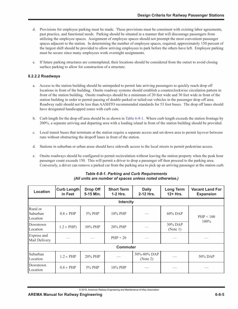
Design Criteria for Railway Passenger Stations
AREMA Manual for Railway Engineering 6-8-5
1
3
4
d. Provisions for employee parking must be made. These provisions must be consistent with existing labor agreements, past practice, and functional needs. Parking should be situated in a manner that will discourage passengers from utilizing the employee spaces. Assignment of employee spaces should not preempt the most convenient passenger spaces adjacent to the station. In determining the number of employee spaces, required, approximately 150 percent of the largest shift should be provided to allow arriving employees to park before the others have left. Employee parking must be secure since many employees work overnight assignments.
e. If future parking structures are contemplated, their locations should be considered from the outset to avoid closing surface parking to allow for construction of a structure.
8.2.2.2 Roadways
a. Access to the station building should be unimpeded to permit late arriving passengers to quickly reach drop off locations in front of the building. Onsite roadway systems should establish a counterclockwise circulation pattern in front of the station building. Onsite roadways should be a minimum of 20 feet wide and 30 feet wide in front of the station building in order to permit passing of double parked or tailed-out vehicles in the passenger drop off area. Roadway radii should not be less than AASHTO recommended standards for 53 foot buses. The drop off lanes should have designated handicapped zones with curb cuts.
b. Curb length for the drop off area should be as shown in Table 6-8-1. Where curb length exceeds the station frontage by 200%, a separate arriving and departing area with a loading island in front of the station building should be provided.
c. Local transit buses that terminate at the station require a separate access and set-down area to permit layover between runs without obstructing the dropoff lanes in front of the station.
d. Stations in suburban or urban areas should have sidewalk access to the local streets to permit pedestrian access.
e. Onsite roadways should be configured to permit recirculation without leaving the station property when the peak hour passenger count exceeds 150. This will permit a driver to drop a passenger off then proceed to the parking area. Conversely, a driver can remove a parked car from the parking area to pick up an arriving passenger at the station curb.
Table 6-8-1. Parking and Curb Requirements(All units are number of spaces unless noted otherwise.)
Location Curb Lengthin Feet
Drop Off5-15 Min.
Short Term1-2 Hrs.
Daily2-12 Hrs.
Long Term12+ Hrs.
Vacant Land ForExpansion
Intercity
Rural or Suburban Location
0.8 PHP 5% PHP 10% PHP — 60% DAPPHP < 100
100%Downtown Location 1.2 PHP) 30% PHP 20% PHP — 30% DAP
(Note 1)Express and Mail Delivery — — PHP + 20 — — —
Commuter
Suburban Location 1.2 PHP 20% PHP — 50%-80% DAP
(Note 2) — 50% DAP
Downtown Location 0.8 PHP 5% PHP 10% PHP — — —
© 2018, American Railway Engineering and Maintenance-of-Way Association
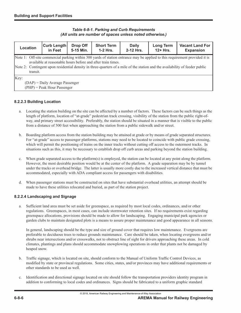
Building and Support Facilities
6-8-6 AREMA Manual for Railway Engineering
8.2.2.3 Building Location
a. Locating the station building on the site can be affected by a number of factors. These factors can be such things as the length of platform, location of “at-grade” pedestrian track crossing, visibility of the station from the public right-of-way, and primary street accessibility. Preferably, the station should be situated in a manner that is visible to the public from a distance of 500 feet when approaching the station from a public sidewalk and/or street.
b. Boarding platform access from the station building may be attained at grade or by means of grade separated structures. For “at-grade” access to passenger platforms, stations may need to be located to coincide with public grade crossing, which will permit the positioning of trains on the inner tracks without cutting off access to the outermost tracks. In situations such as this, it may be necessary to establish drop off curb areas and parking beyond the station building.
c. When grade separated access to the platform(s) is employed, the station can be located at any point along the platform. However, the most desirable position would be at the center of the platform. A grade separation may be by tunnel under the tracks or overhead bridge. The latter is usually more costly due to the increased vertical distance that must be accommodated, especially with ADA compliant access for passengers with disabilities.
d. When passenger stations must be constructed on sites that have substantial overhead utilities, an attempt should be made to have these utilities relocated and buried, as part of the station project.
8.2.2.4 Landscaping and Signage
a. Sufficient land area must be set aside for greenspace, as required by most local codes, ordinances, and/or other regulations. Greenspaces, in most cases, can include stormwater retention sites. If no requirements exist regarding greenspace allocations, provisions should be made to allow for landscaping. Engaging municipal park agencies or garden clubs to maintain designated plots is a means to assure proper maintenance and good appearance in all seasons.
In general, landscaping should be the type and size of ground cover that requires low maintenance. Evergreens are preferable to deciduous trees to reduce grounds maintenance. Care should be taken, when locating evergreens and/or shrubs near intersections and/or crosswalks, not to obstruct line of sight for drivers approaching these areas. In cold climates, plantings and plans should accommodate snowplowing operations in order that plants not be damaged by heaped snow.
b. Traffic signage, which is located on site, should conform to the Manual of Uniform Traffic Control Devices, as modified by state or provincal regulations. Some cities, states, and/or provinces may have additional requirements or other standards to be used as well.
c. Identification and directional signage located on site should follow the transportation providers identity program in addition to conforming to local codes and ordinances. Signs should be fabricated to a uniform graphic standard
Note 1: Off-site commercial parking within 300 yards of station entrance may be applied to this requirement provided it is available at reasonable hours before and after train times.
Note 2: Contingent upon residential density in three-quarters of a mile of the station and the availability of feeder public transit.
Key: (DAP) = Daily Average Passenger (PHP) = Peak Hour Passenger
Table 6-8-1. Parking and Curb Requirements(All units are number of spaces unless noted otherwise.)
Location Curb Lengthin Feet
Drop Off5-15 Min.
Short Term1-2 Hrs.
Daily2-12 Hrs.
Long Term12+ Hrs.
Vacant Land ForExpansion
© 2018, American Railway Engineering and Maintenance-of-Way Association
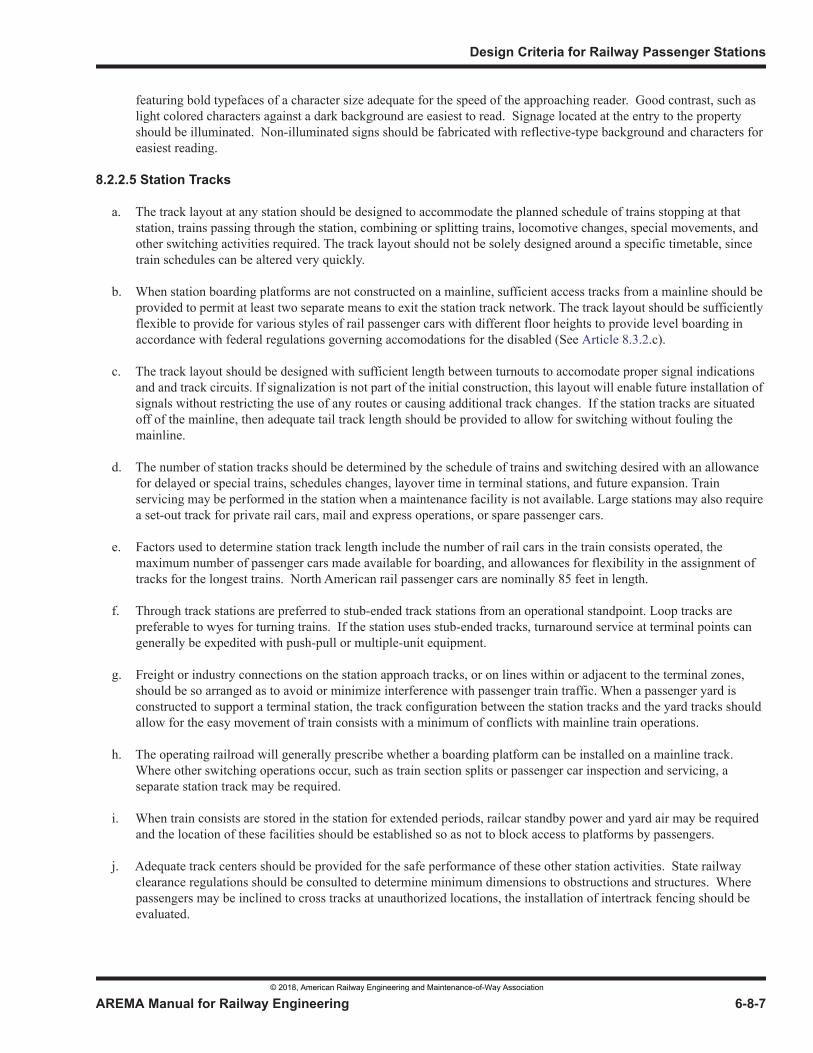
Design Criteria for Railway Passenger Stations
AREMA Manual for Railway Engineering 6-8-7
1
3
4
featuring bold typefaces of a character size adequate for the speed of the approaching reader. Good contrast, such as light colored characters against a dark background are easiest to read. Signage located at the entry to the property should be illuminated. Non-illuminated signs should be fabricated with reflective-type background and characters for easiest reading.
8.2.2.5 Station Tracks
a. The track layout at any station should be designed to accommodate the planned schedule of trains stopping at that station, trains passing through the station, combining or splitting trains, locomotive changes, special movements, and other switching activities required. The track layout should not be solely designed around a specific timetable, since train schedules can be altered very quickly.
b. When station boarding platforms are not constructed on a mainline, sufficient access tracks from a mainline should be provided to permit at least two separate means to exit the station track network. The track layout should be sufficiently flexible to provide for various styles of rail passenger cars with different floor heights to provide level boarding in accordance with federal regulations governing accomodations for the disabled (See Article 8.3.2.c).
c. The track layout should be designed with sufficient length between turnouts to accomodate proper signal indications and and track circuits. If signalization is not part of the initial construction, this layout will enable future installation of signals without restricting the use of any routes or causing additional track changes. If the station tracks are situated off of the mainline, then adequate tail track length should be provided to allow for switching without fouling the mainline.
d. The number of station tracks should be determined by the schedule of trains and switching desired with an allowance for delayed or special trains, schedules changes, layover time in terminal stations, and future expansion. Train servicing may be performed in the station when a maintenance facility is not available. Large stations may also require a set-out track for private rail cars, mail and express operations, or spare passenger cars.
e. Factors used to determine station track length include the number of rail cars in the train consists operated, the maximum number of passenger cars made available for boarding, and allowances for flexibility in the assignment of tracks for the longest trains. North American rail passenger cars are nominally 85 feet in length.
f. Through track stations are preferred to stub-ended track stations from an operational standpoint. Loop tracks are preferable to wyes for turning trains. If the station uses stub-ended tracks, turnaround service at terminal points can generally be expedited with push-pull or multiple-unit equipment.
g. Freight or industry connections on the station approach tracks, or on lines within or adjacent to the terminal zones, should be so arranged as to avoid or minimize interference with passenger train traffic. When a passenger yard is constructed to support a terminal station, the track configuration between the station tracks and the yard tracks should allow for the easy movement of train consists with a minimum of conflicts with mainline train operations.
h. The operating railroad will generally prescribe whether a boarding platform can be installed on a mainline track. Where other switching operations occur, such as train section splits or passenger car inspection and servicing, a separate station track may be required.
i. When train consists are stored in the station for extended periods, railcar standby power and yard air may be required and the location of these facilities should be established so as not to block access to platforms by passengers.
j. Adequate track centers should be provided for the safe performance of these other station activities. State railway clearance regulations should be consulted to determine minimum dimensions to obstructions and structures. Where passengers may be inclined to cross tracks at unauthorized locations, the installation of intertrack fencing should be evaluated.
© 2018, American Railway Engineering and Maintenance-of-Way Association
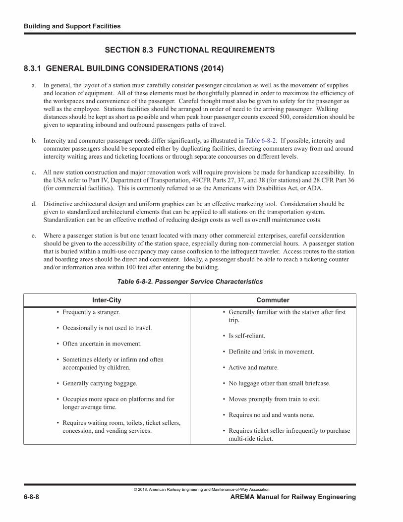
Building and Support Facilities
6-8-8 AREMA Manual for Railway Engineering
SECTION 8.3 FUNCTIONAL REQUIREMENTS
8.3.1 GENERAL BUILDING CONSIDERATIONS (2014)
a. In general, the layout of a station must carefully consider passenger circulation as well as the movement of supplies and location of equipment. All of these elements must be thoughtfully planned in order to maximize the efficiency of the workspaces and convenience of the passenger. Careful thought must also be given to safety for the passenger as well as the employee. Stations facilities should be arranged in order of need to the arriving passenger. Walking distances should be kept as short as possible and when peak hour passenger counts exceed 500, consideration should be given to separating inbound and outbound passengers paths of travel.
b. Intercity and commuter passenger needs differ significantly, as illustrated in Table 6-8-2. If possible, intercity and commuter passengers should be separated either by duplicating facilities, directing commuters away from and around intercity waiting areas and ticketing locations or through separate concourses on different levels.
c. All new station construction and major renovation work will require provisions be made for handicap accessibility. In the USA refer to Part IV, Department of Transportation, 49CFR Parts 27, 37, and 38 (for stations) and 28 CFR Part 36 (for commercial facilities). This is commonly referred to as the Americans with Disabilities Act, or ADA.
d. Distinctive architectural design and uniform graphics can be an effective marketing tool. Consideration should be given to standardized architectural elements that can be applied to all stations on the transportation system. Standardization can be an effective method of reducing design costs as well as overall maintenance costs.
e. Where a passenger station is but one tenant located with many other commercial enterprises, careful consideration should be given to the accessibility of the station space, especially during non-commercial hours. A passenger station that is buried within a multi-use occupancy may cause confusion to the infrequent traveler. Access routes to the station and boarding areas should be direct and convenient. Ideally, a passenger should be able to reach a ticketing counter and/or information area within 100 feet after entering the building.
Table 6-8-2. Passenger Service Characteristics
Inter-City Commuter
• Frequently a stranger.
• Occasionally is not used to travel.
• Often uncertain in movement.
• Sometimes elderly or infirm and often accompanied by children.
• Generally carrying baggage.
• Occupies more space on platforms and for longer average time.
• Requires waiting room, toilets, ticket sellers, concession, and vending services.
• Generally familiar with the station after first trip.
• Is self-reliant.
• Definite and brisk in movement.
• Active and mature.
• No luggage other than small briefcase.
• Moves promptly from train to exit.
• Requires no aid and wants none.
• Requires ticket seller infrequently to purchase multi-ride ticket.
© 2018, American Railway Engineering and Maintenance-of-Way Association
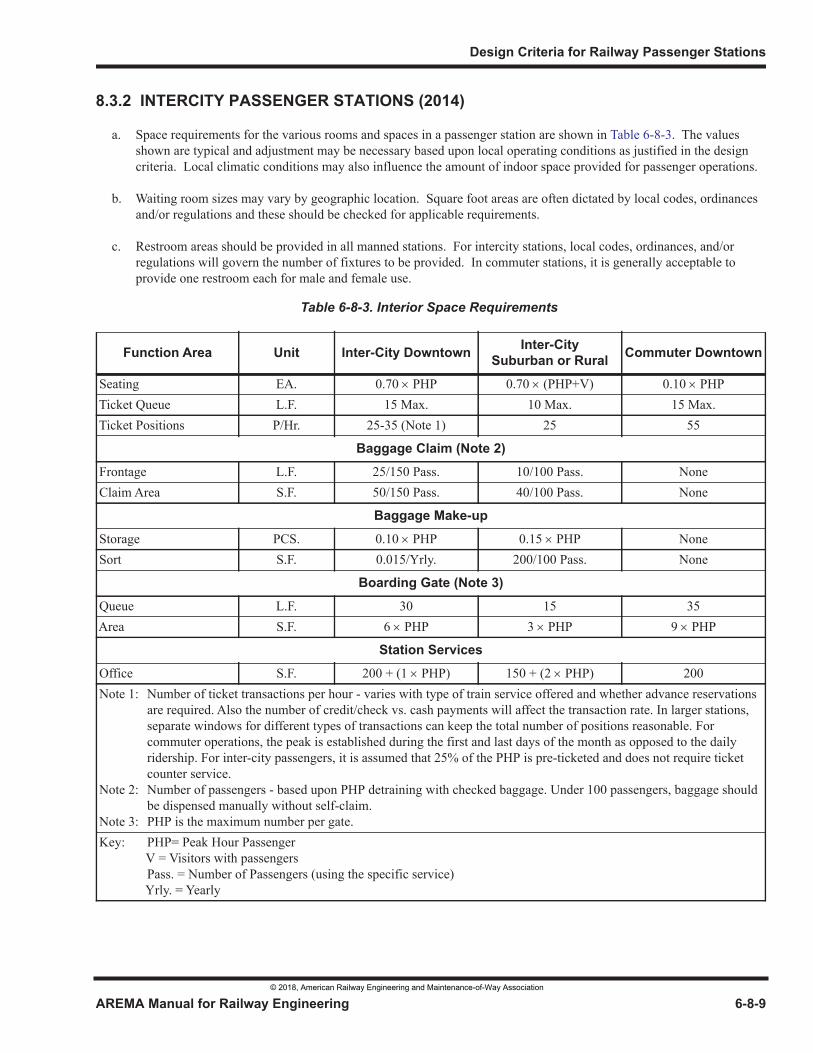
Design Criteria for Railway Passenger Stations
AREMA Manual for Railway Engineering 6-8-9
1
3
4
8.3.2 INTERCITY PASSENGER STATIONS (2014)
a. Space requirements for the various rooms and spaces in a passenger station are shown in Table 6-8-3. The values shown are typical and adjustment may be necessary based upon local operating conditions as justified in the design criteria. Local climatic conditions may also influence the amount of indoor space provided for passenger operations.
b. Waiting room sizes may vary by geographic location. Square foot areas are often dictated by local codes, ordinances and/or regulations and these should be checked for applicable requirements.
c. Restroom areas should be provided in all manned stations. For intercity stations, local codes, ordinances, and/or regulations will govern the number of fixtures to be provided. In commuter stations, it is generally acceptable to provide one restroom each for male and female use.
Table 6-8-3. Interior Space Requirements
Function Area Unit Inter-City Downtown Inter-CitySuburban or Rural Commuter Downtown
Seating EA. 0.70 PHP 0.70 (PHP+V) 0.10 PHPTicket Queue L.F. 15 Max. 10 Max. 15 Max.Ticket Positions P/Hr. 25-35 (Note 1) 25 55
Baggage Claim (Note 2)
Frontage L.F. 25/150 Pass. 10/100 Pass. NoneClaim Area S.F. 50/150 Pass. 40/100 Pass. None
Baggage Make-up
Storage PCS. 0.10 PHP 0.15 PHP NoneSort S.F. 0.015/Yrly. 200/100 Pass. None
Boarding Gate (Note 3)
Queue L.F. 30 15 35Area S.F. 6 PHP 3 PHP 9 PHP
Station Services
Office S.F. 200 + (1 PHP) 150 + (2 PHP) 200Note 1: Number of ticket transactions per hour - varies with type of train service offered and whether advance reservations
are required. Also the number of credit/check vs. cash payments will affect the transaction rate. In larger stations, separate windows for different types of transactions can keep the total number of positions reasonable. For commuter operations, the peak is established during the first and last days of the month as opposed to the daily ridership. For inter-city passengers, it is assumed that 25% of the PHP is pre-ticketed and does not require ticket counter service.
Note 2: Number of passengers - based upon PHP detraining with checked baggage. Under 100 passengers, baggage should be dispensed manually without self-claim.
Note 3: PHP is the maximum number per gate.Key: PHP= Peak Hour Passenger V = Visitors with passengers
Pass. = Number of Passengers (using the specific service) Yrly. = Yearly
© 2018, American Railway Engineering and Maintenance-of-Way Association
Building and Support Facilities
6-8-10 AREMA Manual for Railway Engineering
d. Corridor widths in stations should be no less than prescribed by local codes, ordinances and/or regulations, but also recognizing that some passengers carrying baggage will move at a slower pace than others, hence the ability to pass without interfering with opposing traffic is recommended.
8.3.2.1 Waiting Room
A waiting area is an area where passengers wait for trains prior to queuing or proceeding to the platform. Waiting areas are normally located away from the primary travel path between the ticket counter and the boarding areas. Passengers going directly from the station entrance or ticket counter should not have to disturb passengers seated in the waiting area. Seating units should be modular and arranged in clusters.
In large stations, multiple waiting areas can be provided off of the primary travel paths between ticket counters and boarding areas to allow passengers for specific trains to be grouped together. In these locations, furnishings should be provided to enhance the comfort of the passenger. In some larger stations a semi-private lounge area for first class and premium status frequent travelers may be offered. Such faciltiies are usually locatedconvenient to the boarding platforms.
8.3.2.2 Concourses
Concourses are areas where passengers walk to and from trains and where passengers queue in anticipation of boarding trains. In large stations there may be several concourses, particularly if arriving and departing passengers are separated. Where boarding gates for many tracks are employed, the concourse should have adequate depth and length to hold approximately 75 percent of the normal peak passenger count for each train. Concourse size may be controlled through use of passenger information systems that do not post track and/or gate numbers until the train is ready to board, encouraging passengers to remain in the waiting areas and avoiding long queues in front of gates to the platforms.
Concourses occupied with concessions or other travel services must contain additional width in order to maintain an unobstructed walkway in the middle of the concourse.
Where concourses are more than 150 feet in length, graphics should be installed to repeat destination messages in bold, clear typefaces that will not require the passenger to stop or slow down in the travel path to read the messaging. Train Information display units should not be placed in the center of concourse travel paths in order to avoid passengers stopping and/or slowing to read information.
8.3.2.3 Ticketing
Ticketing areas will vary in size, based upon the nature of the rail traffic conducted within the station. The following criteria may be applicable as noted:
a. The ticket area should have an appropriate number of sales positions available in order to keep ticket queue waiting time to no more than five minutes during normal times and no more than eight minutes during peak times. When more than three positions are operated, consideration should be given to a single serpentine line so that passengers are served on a first come, first served basis.
If specialized train services are offered, a separate window position(s) may be required to give expedited service to these passengers. At least one ticket position must be designed for use by wheelchair seated patrons.
Average transaction time to ticket a passenger will vary from 1 minute for reserved coach travel to four minutes for multi-segment reserved travel. Ticketing transaction time will increase by at least 90 seconds when credit card transactions are handled.
Use of self-service ticketing machines can reduce the number of staffed positions. A machine can process an average of 12-15 transactions per hour. If a self-service ticket machine is the only method used to dispense tickets, a courtesy phone to a reservation center or other manned location can help patrons with special needs.
© 2018, American Railway Engineering and Maintenance-of-Way Association
Design Criteria for Railway Passenger Stations
AREMA Manual for Railway Engineering 6-8-11
1
3
4
b. A ticket sales counter area is illustrated in Figure 6-8-1 showing recommended distances between the counter and the backwall. The ticket counter should be designed in standard modules that will permit flexibility and updating as newer technology is deployed. If possible, an information position should be located at the most accessible end of the ticket counter in order to permit sales agents to provide this service without having patrons wait in the regular ticket sales queue. This position can also serve as an overflow ticketing position during peak periods.
c. Where security considerations mandate the use of ticket counter safety glazing for personnel protection, vertical speaking slots should be provided. Passenger checking of baggage should be accomplished at the ticket counter to expedite the movement of passengers through the pre-boarding process.
d. The ticketing area will require a secure back office for agents to handle their administrative duties out of sight of the passenger. A storage room for spare forms, a safe for money and ticket stock, and an area for placement of communications, teleprinters and computer reservations equipment should be provided. It may be desirable to provide a combination coatroom/lunchroom and toilets for ticketing employees. The ticket back office should be the most secure area in the station with access closely controlled.
8.3.2.4 Baggage Facilities
Baggage facilities will vary in size according to the number of trains with baggage service and the number of pieces of baggage arriving and/or departing per train. The following criteria may be applicable:
a. The movement of outbound baggage from the ticket counter to the baggage make-up area may be manual or automated depending upon the distance and baggage quantities involved. Baggage checked more than 45 minutes prior to train departure should be placed in a secure baggage holding area.
Bulk users of package services or group passenger movements should be able to deliver their items directly to the baggage room via an outside door. A truck dock type arrangement would be appropriate when significant amounts of bulk shipments are processed through the baggage facility.
The baggage facility should contain secure space for the storage of unclaimed baggage as well as the storage of carts and baggage tractor(s). Depending upon the type of fuels used in tractors, the building codes may require special ventilation or fire separation.
b. Inbound baggage from a train may be dispensed on the platform at the station building when the quantity of baggage is small. When the platform claim is not used, a dutch door separating the baggage facility from the ticket queue area can be effective.
In larger stations, a self-claim baggage facility should be provided to expedite passenger service. Where the number of pieces of luggage is between 30 and 50, a simple stainless steel gravity rack will suffice. A wall separating the baggage claim area from the baggage room should be provided in order to block off viewing back into the baggage room and any wall penetrations should be equipped with lockable doors or security screens. When arriving baggage exceeds 50 pieces per train, an automated conveyor self-claim device should be considered with claiming frontage as shown in Table 6-8-3.
8.3.2.5 Restrooms
Public restrooms should be provided according to local codes, ordinances and/or regulations. Restrooms and drinking fountains must meet current ADA and local regulations. Restroom entrances should be located in the line of sight of the ticket counter in order to permit employees to monitor and exercise control over access, if necessary. Baby-changing facilities should be provided in each restroom.
© 2018, American Railway Engineering and Maintenance-of-Way Association
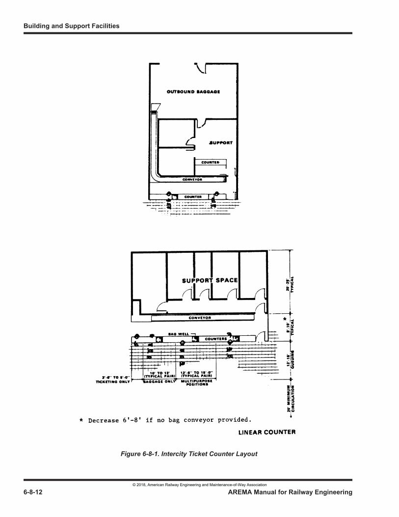
Building and Support Facilities
6-8-12 AREMA Manual for Railway Engineering
Figure 6-8-1. Intercity Ticket Counter Layout
© 2018, American Railway Engineering and Maintenance-of-Way Association
Design Criteria for Railway Passenger Stations
AREMA Manual for Railway Engineering 6-8-13
1
3
4
8.3.2.6 Support Facilities
Other administrative support services may be required in the station such as on-board services crew base, commissary, loco and car repair staff spaces, train operations offices, and security office. Support facilities, however, will vary according to station size, location of the station or line, and other ancillary facilities available. A site specific design criteria document should be developed for larger stations to identify the requirements of the support facilities. These facilities should be broken down into public access and secure areas. Security and access controls along with appropriate signage should be specified.
Vending areas in small and medium stations should be convenient to the waiting areas and grouped into a single area in order to maintain cleanliness and to concentrate plumbing, mechanical and electrical services.
If concessions are included in the station design, the concession areas require roughed in utilities to support tenant leasehold improvements and should face well trafficked areas but not reduce the aisle widths.
8.3.3 COMMUTER STATIONS (2014)
Commuter stations differ significantly from intercity train stations. Depending on a number of factors, the most prevalent being peak train ridership, commuter stations vary from a building to a simple open or enclosed shelter on the boarding platform.
8.3.3.1 Waiting Room
Generally, commuter passengers will use a waiting room during inclement weather or when it is extremely hot if the waiting room is air conditioned. The size of the waiting room will be dependent upon the peak passenger load in a 15 minute period. Local building codes, ordinances and regulations will then stipulate the square foot area to be provided based upon the occupancy.
Waiting room furnishings should be hard, durable, utilitarian-type furniture, which can be safely secured to the floor or walls. Waiting rooms may be locked during periods when an employee is not present.
8.3.3.2 Ticketing Facilities
In commuter stations ticketing is generally handled througha combination of ticket machines and manned sales positions. The sales office should be large enough to accommodate a desk, ticket counter with ticket window and storage cabinet. The ticket window should be equipped with a locking rolling shutter door when the ticket agent is not present. The number of ticket positions will be governed by the average business day of the month. The ticket office should be positioned with window sightlines to the boarding platform. Security glazing may be required.
In many commuter service, vending machines issue tickets exclusively. Also, if proof of payment systems are used and the station platforms are part of the paid area, then provisions must be made for validation machines at the entrance to the platforms. Ticket vending machines should be located in well lighted and very public locations, alarmed and possibly placed under video surveillance.
8.3.3.3 Restroom Facilities
Public restroom facilities within commuter stations are generally minimal or may not be provided at all. If provided, they must meet ADA requirements and may be arranged as separate female and male facilities, or a single ADA compliant restroom may be provided. It is recommended that the local building code, ordinances and/or regulations be consulted to determine the type and size of restroom facilities to be provided. When public restroom access is required, the station agent may have control over access to the facilities with a remote operated lock. If a station is manned and no public restroom is provided, then an “agent use only” toilet may be required. Consult local codes, ordinances and/or regulations for determination of number and configuration of facilities to be provided.
© 2018, American Railway Engineering and Maintenance-of-Way Association
Building and Support Facilities
6-8-14 AREMA Manual for Railway Engineering
8.3.3.4 Support Facilities
In commuter stations a mechanical equipment room and janitor’s closet may be needed. Separate space to accommodate concessions can be provided but care should be taken to avoid disrupting passenger flows and/or passenger waiting space.
In terminal facilities space will be required for lost and found articles, Stationmaster’s Office (to operate Train Information Systems), storage lockers, employee locker rooms, janitor’s closets, supply rooms and storage areas. In addition, workshop space may also be needed for mechanical personnel assigned to the station.
Concession space may also be desired. These spaces should not be located in a manner that will constrict the normal peak hour passenger flows and/or disrupt the function of the station.
8.3.3.5 Concourses
These are areas within large stations, which direct passengers to and from the boarding platforms to the street. Concourses must be wide enough to rapidly convey the hundreds of commuters that unload simultaneously. When concessions front on the concourses, five feet of concourse width in front of each establishment must be subtracted from the effective width of the concourse. In planning travel paths through a large commuter station, care should be exercised to avoid conflicting travel paths of major groups of passengers. In many instances, routing large numbers of passengers on a more circuitous route to avoid conflicts will provide faster ingress and egress. Concourses, which provide queue space at track gates, must be widened to permit other passengers to pass standing persons. Graphics in the concourses should use bold characters short, clear wording. The use of graphic symbols and color coding are also effective means of conveying information without causing the stranger to stop or slow down to read messages. Where train information display units are used, these should be mounted out of the main travel paths to preclude obstructing the concourse passage. Where ticket vending machines and control gates are used, the station must be designed with paid and non-paid concourses. Adequate queuing space must be provided on both sides of the control gates. If escalators are employed, the impacts of having one of the devices out of service for maintenance should be considered in sizing the concourse areas near the escalators and alternate stairs and ramps.
8.3.3.6 Graphic and Advertising Standards
In developing a major commuter station, clear graphic and advertising standards should be established early to ensure concessionaires do not erect uncoordinated signage that makes essential directional signage ineffective. A uniform graphics band in the station will assist passengers in finding the services and transportation facilities desired. Visual and audible messaging devices as prescribed in the regulations for disabled or impaired travelers and guests should be integrated in the graphic standards.
8.3.4 INTERMODAL PASSENGER STATIONS (2014)
Intermodal stations are effective in promoting use of local connecting public transport since they reduce the time lost transferring from one mode of travel to another. Each carrier participating in an intermodal station benefits from the potential increased revenue resulting from connecting traffic plus reduced operating expenses by sharing common facilities such as corridors, waiting room, restrooms, parking, and building maintenance personnel. The following factors should be considered:
a. The station peak hour passenger count should be determined by superimposing all carrier loads. The common circulation concourse or waiting room should have a unified graphics band to direct passengers to their respective carriers and concession preferences. In larger stations, each carrier may have its individual waiting area immediately adjacent to the departure point of the transit vehicles.
b. Most intermodal stations involve transfers between one or more rail carrier(s) and/or bus operators. Rail services, in many areas, have interline agreements with bus companies that permit passengers to travel on a through ticket. In configuring the station spaces, the passengers making such transfers should easily be able to recognize the travel path to the other carriers.
© 2018, American Railway Engineering and Maintenance-of-Way Association
Design Criteria for Railway Passenger Stations
AREMA Manual for Railway Engineering 6-8-15
1
3
4
c. Bus companies generally will have individual standards for loading positions. However, Figure 6-8-2 shows a 45 degree configuration. Right hand loading should be employed whenever possible. City transit buses may load on a scalloped curb platform with a tail out condition. A typical platform configuration is shown in Figure 6-8-2.
d. There may be additional modes such as marine ferries, airport limousines, urban people movers, and streetcars. It is not possible to cover every conceivable combination in this Chapter. The principles of handling passengers are similar regardless of mode with an emphasis on making the transfer convenient and easily identified.
8.3.5 COMBINATION FREIGHT AND PASSENGER STATIONS (2014)
In developing the scope of work for a combination freight and passenger station, it is important to recognize that each facility may be operating at different hours and some degree of separation and isolation is desirable. Access to the passenger portion of the station should be very prominent, when compared to the freight agency, to preclude rail passengers from entering the freight office. As with the other types of stations, the using departments should itemize their requirements on a design criteria questionnaire. The designer should then apply the needs independently at first, then identify those project elements that are common and can be shared to reduce capital and operating costs. Separately designed parking areas for each function should be provided.
8.3.6 HISTORIC BUILDINGS (2014)
Buildings, which have been listed on Historic Buildings Registers, must be maintained with the same general exterior appearance. Some state and local regulations also require interior historical features to be preserved and maintained also. Before starting a project on a protected building, the State Historic Preservation Office (SHPO) should be consulted. Adaptive use of the architectural heritage into a modern functioning transportation space is perferred to simple historical restoration. With the latter, the station spaces, even though restored, still appear to be “old” and do not promote the image of the modern railroad rolling stock. It is possible to aesthetically combine modern materials with historic buildings for an attractive and functional station facility. Some jurisdictions offer tax credits to restore older buildings which may provide a business incentive to work with private parties to share in the construction and building operating costs.
SECTION 8.4 BUILDING SYSTEMS
8.4.1 GENERAL (2014)
The selection of materials for the building envelope and the building systems should foster energy efficiency and low operating costs. If a LEED (leadership in energy and environmental design) certification for the building is contemplated, the overall design program should establish the goals early in the selection process.
a. The exterior appearance of a rail passenger station should be attractive, fit into the community it serves, and convey a sense of permanence. The use of distinctive architectural elements in all stations of a single transportation system can serve as a marketing tool, promote public recognition, and be a source of community pride. Exterior materials such as masonry, precast concrete, stone or similar hard durable products should be used. Windows and doors should be made of high quality commercial grade storefront elements. Where metal, composite materials and wood panels are employed, they should be kept away from the grade line to prevent corrosion and rot. Rail stations often operate outside normal business hours and their peak energy demands may occur late at night, hence normal design calculations may have to be altered to achieve energy savings. However, since train schedules can change quickly or intercity trains may operate off schedule, the building systems controls must be flexible and adaptable to rapidly changing conditions.
© 2018, American Railway Engineering and Maintenance-of-Way Association
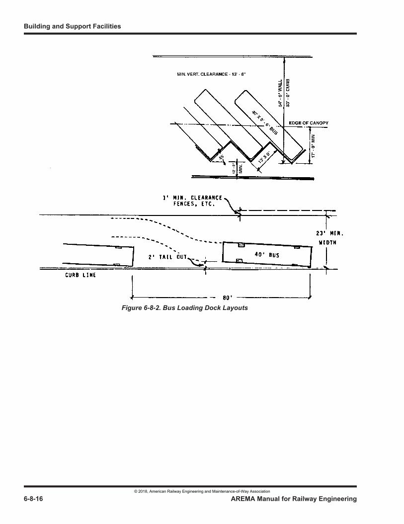
Building and Support Facilities
6-8-16 AREMA Manual for Railway Engineering
Figure 6-8-2. Bus Loading Dock Layouts
© 2018, American Railway Engineering and Maintenance-of-Way Association
Design Criteria for Railway Passenger Stations
AREMA Manual for Railway Engineering 6-8-17
1
3
4
b. The selection of exterior finishes should result in low operating and maintenance costs by using only materials that do not require work at less than ten year cycles. Where platform canopies are employed, the exterior finishes of the station should be repeated to whatever extent possible in order to create a unified appearance.
8.4.2 INTERIOR FINISHES (2014)
a. Public and employee spaces in station buildings should be constructed of hard durable surfaces that reduce maintenance, are vandal resistant, and maintain an attractive appearance for many years. Walls within the station should utilize, if possible, the masonry of the exterior wall, painted concrete block, glazed block, and/or composite or metal wall products.
b. Floor finishes can be quarry tile, terrazzo or terrazzo epoxy tile. In non-public areas, the floors can be treated concrete floors or industrial grade resilent flooring. Ceilings can be of a variety of materials depending on the architectural look desired and cost, but ease of access into overhead spaces for maintenance of building systems and future utilities should dictate selection. In public areas as well as in non-public areas, ceilings will have to meet building code requirements for fire resistance.
c. If gypsum wallboard is used in the station, it should be backed up with plywood in public areas to prevent puncturing. In restroom areas, partitions should be constructed of masonry, if possible. In large intercity stations, consideration should be given to utilizing softer finishes in order to control noise and to enhance the comfort of the passenger. Carpeting should also be considered for use in low traffic waiting room areas.
d. In commuter stations, wall finishes should be of a hard durable surface and vandal resistant. Floors can be treated concrete, terrazzo, and/or terrazzo epoxy tile. Ceilings can be lay-in acoustic metal tile or gypsum board. Painted surfaces should be selected to permit easy removal of graffiti.
e. In non-public spaces, commercial office finishes may be used. Baggage areas and storeroom walls can be painted concrete block or metal stud partitions. In baggage areas, a plywood wainscot should be utilized if a metal stud and gypsum wallboard is used for partitions.
8.4.3 STRUCTURAL TYPES (2014)
a. The type of construction will be influenced by the size and location of the station building. Small stations may utilize exterior bearing walls with clear span joists, or pre-engineered building systems. Larger stations will likely employ structural steel or reinforced concrete frames.
In selecting a structural system, the station designer and structural engineer should collaborate on the most economical structural system possible to complement the intended design with a minimum of interior bearing walls. In addition, the structural system employed should allow for expansion of the station in the future. If expansion occurs, it will most likely be parallel to the railroad tracks. Areas most likely to require expansion in a station are the waiting room, baggage room, and ticket counter area. Interior columns and bearing walls should be placed such that they do not limit expansion.
b. Design loads for floors and roofs will be dictated by local codes and/or regulations.
© 2018, American Railway Engineering and Maintenance-of-Way Association
Building and Support Facilities
6-8-18 AREMA Manual for Railway Engineering
SECTION 8.5 MECHANICAL SYSTEMS
8.5.1 HEATING, VENTILATING, AND AIR CONDITIONING (2014)
a. Heating, ventilating, and air conditioning (HVAC) systems can be supplied in variety of forms in order to meet the desired design needs. Prepackaged systems and/or individual equipment may be utilized based upon the size of the areas to be served. The optimum choice would dictate that the system be highly energy efficient, provide low cost operation, and be easily maintained. Consideration should be given to purchasing the same type of equipment for each station, in order to minimize maintenance parts and standardizing service.
b. Before designing an HVAC system, the designer should review local building codes and/or regulations for specific requirements. Assistance in sizing system requirements can be found in the American Society of Heating, Refrigeration & Air Conditioning (ASHRAE) handbook.
c. When designing the heating and air conditioning system, consideration should be given to establishing zone control of the system. Each area served would then be controlled by individual thermostats and timers. Thermostats should be tamper-proof and key-controlled, in order to avoid having numerous individuals attempting to adjust the thermostat to meet their own individual criteria.
d. Ventilation can be provided by introducing make-up air into the primary air handling equipment. When food preparation areas are present, adequate tempered make-up air will be necessary in order to replace exhaust hood air. Restrooms will require independent exhaust air systems. Outside air intakes should be located away from railroad tracks and roadways in order to avoid ingesting exhaust fumes from locomotives and motor vehicles.
8.5.2 PLUMBING (2014)
a. Sanitary facilities located within a station must be sized in accordance with local building code requirements and/or regulations. Where possible, restrooms should be placed back to back with a common pipe chase in order to minimize cost. The size of the chase should consider future maintenance. Also, piping should be run in pipe chassis wherever possible and accessible clean outs provided. Roof drains should be separated from sanitary drains.
b. Fixtures selected for use in the station should be of the highest commercial grade. Hot water heaters should be located near the fixtures being served. For security reasons, tank-style toilets should not be used.
c. In some stations, it may be necessary to have two water systems: one system, providing water to the station and grounds; a second system, providing potable water to water tanks on rail passenger cars. In the latter cases, it is important to consult local building codes and/or regulations concerning backflow preventive devices that must be provided. In the United States when potable train service watering is required, the design and construction of such systems must be approved in advance by the Interstate Travel Sanitation Branch of the US Food and Drug Administration.
© 2018, American Railway Engineering and Maintenance-of-Way Association
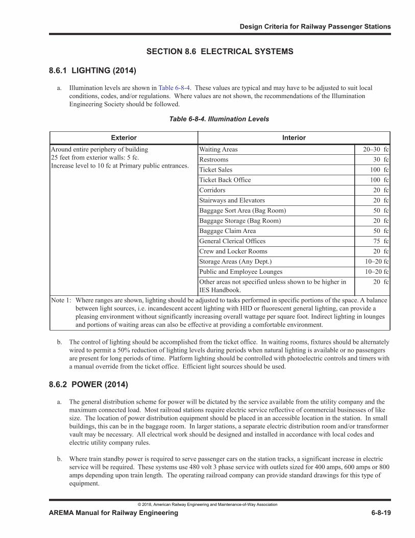
Design Criteria for Railway Passenger Stations
AREMA Manual for Railway Engineering 6-8-19
1
3
4
SECTION 8.6 ELECTRICAL SYSTEMS
8.6.1 LIGHTING (2014)
a. Illumination levels are shown in Table 6-8-4. These values are typical and may have to be adjusted to suit local conditions, codes, and/or regulations. Where values are not shown, the recommendations of the Illumination Engineering Society should be followed.
b. The control of lighting should be accomplished from the ticket office. In waiting rooms, fixtures should be alternately wired to permit a 50% reduction of lighting levels during periods when natural lighting is available or no passengers are present for long periods of time. Platform lighting should be controlled with photoelectric controls and timers with a manual override from the ticket office. Efficient light sources should be used.
8.6.2 POWER (2014)
a. The general distribution scheme for power will be dictated by the service available from the utility company and the maximum connected load. Most railroad stations require electric service reflective of commercial businesses of like size. The location of power distribution equipment should be placed in an accessible location in the station. In small buildings, this can be in the baggage room. In larger stations, a separate electric distribution room and/or transformer vault may be necessary. All electrical work should be designed and installed in accordance with local codes and electric utility company rules.
b. Where train standby power is required to serve passenger cars on the station tracks, a significant increase in electric service will be required. These systems use 480 volt 3 phase service with outlets sized for 400 amps, 600 amps or 800 amps depending upon train length. The operating railroad company can provide standard drawings for this type of equipment.
Table 6-8-4. Illumination Levels
Exterior InteriorAround entire periphery of building25 feet from exterior walls: 5 fc. Increase level to 10 fc at Primary public entrances.
Waiting Areas 20–30 fcRestrooms 30 fcTicket Sales 100 fcTicket Back Office 100 fcCorridors 20 fcStairways and Elevators 20 fcBaggage Sort Area (Bag Room) 50 fcBaggage Storage (Bag Room) 20 fcBaggage Claim Area 50 fcGeneral Clerical Offices 75 fcCrew and Locker Rooms 20 fcStorage Areas (Any Dept.) 10–20 fcPublic and Employee Lounges 10–20 fcOther areas not specified unless shown to be higher in IES Handbook.
20 fc
Note 1: Where ranges are shown, lighting should be adjusted to tasks performed in specific portions of the space. A balance between light sources, i.e. incandescent accent lighting with HID or fluorescent general lighting, can provide a pleasing environment without significantly increasing overall wattage per square foot. Indirect lighting in lounges and portions of waiting areas can also be effective at providing a comfortable environment.
© 2018, American Railway Engineering and Maintenance-of-Way Association
Building and Support Facilities
6-8-20 AREMA Manual for Railway Engineering
c. Since most railroad stations are classified as places of public assembly, emergency lighting for the evacuation of the building in the event of power failure is often required. The use of nickel-cadmium battery emergency light units or battery supplied fluorescent or LED ballasts strategically placed around the building will provide at least 30 minutes of light.
d. Tractors and small vehicles used in the station are often electrically powered. Provisions for charging batteries should be made. Provisions for positive ventilation should be coordinated with the mechanical designer.
8.6.3 ESCALATORS/ELEVATORS (2014)
Elevators should be installed in multi-level stations and/or where multi-level areas cannot be reached by ADA compliant ramps. Elevator cab size should be sufficient to accommodate wheelchair access. When elevators are used for public access to boarding platforms, consideration must be given to alternate accessible paths when service interruptions required occur for routine inspection and service. Elevators used to move baggage between levels should be of sufficient size to accommodate baggage carts. Local building codes and/or regulations should be consulted for specific requirements. Use hospital cab elevators can provide the capacity and cab size for handling both passengers and small carts with baggage. Escalators used in stations should be sized to meet peak passenger loads. Escalators should be located adjacent to stairways serving the same levels for instance when they are not operating. If escalators are installed in outdoor environments, the structural frames should be corrosion protected and machinery specified for the ambient temperatures to be encountered.
8.6.4 TRAIN INFORMATION SYSTEMS (2014)
a. Public address systems should be provided to make announcements of train arrivals and departures. Speakers should be low power types, closely spaced to reduce reverberation. The microphone locations should be at the ticket counter, information counter, and in the boarding areas on concourses. Where multiple platforms are constructed, consideration to zoning the PA system to permit targeted announcements should be made. In intermodal stations, a common public address system should be provided with all carriers having access to make announcements in the common areas of the station. One method to accomplish this is the use of telephone tone access input to the PA amplifier. Visual displays of audible announcements conforming to ADA must be provided.
b. The display of train arrival and departure information should be accomplished using annunciation boards or visual display units. In small stations, manually operated menu or slat board behind the ticket counter is adequate. In larger stations, a central display system manipulated by the stationmaster or a computer microprocessor can display the same information at many locations throughout the station. Computer based systems can also synthesize speech for train announcements.
c. Visual and audible train information should be displayed on the station platforms clearly indicating the departure time, destination and the appropriate track for boarding. If intercity trains with different accommodations or classes of service are operated, the train information disply should indicate boarding locations along the platform length. If a station is not manned, the platform information system should be addressable from the railroad’s control facility to advise passengers of impending arrivals and delayed trains, and disruptions of service.
8.6.5 CLOSED CIRCUIT TELEVISION (CCTV) (2014)
In some passenger station locations, CCTV may be useful for crowd management as well as security. Within the station, CCTV can be used to cover public waiting areas, stairways, corridors and ticket window locations. CCTV can also be used to monitor parking lots and passenger drop-off points. Displays can be installed in the ticket agent’s office, in the local police station or railroad security office as appropriate. Each display should be equipped and/or linked to a recording device capable of recording events in accordance with an integrated security program.
© 2018, American Railway Engineering and Maintenance-of-Way Association
Design Criteria for Railway Passenger Stations
AREMA Manual for Railway Engineering 6-8-21
1
3
4
8.6.6 COMMUNICATIONS SUPPORT (2014)
a. A raceway system for installation of telephone wiring should be designed into the station building. Raceways should be routed to a telephone backboard in accordance with phone company and railroad company requirements. In addition to the business phones, the raceway system should also include data lines to modems, and special occupant phone services such as motel/hotel reservation centers and car rental concessions. If a large number of tenants are located in the station building, consideration must be given to a private exchange or electronic switching unit to provide phone services from the local phone company service point to the individual tenant. If private railway telephone systems are routed through the building, adequate space for frame rooms and wiring routes must be provided. Private railway communications systems often employ microwave or fiber-optic transmission equipment. Adequate space and support facilities such as emergency generator or UPS battery backup systems may be needed.
b. If any of the personnel in the station require a radio base station, consideration should be given to the installation of an antenna mast on the roof of the station with a standard electrical weatherhead. This mast will preclude later cutting and patching of new roofing by personnel not experienced as roofing mechanics.
SECTION 8.7 BOARDING PLATFORMS
8.7.1 GENERAL (2014)
A station boarding platform is a structure or area adjacent to tracks for passenger boarding or alighting. Design of the platform dimensional relationships to top of rail and centerline of track are totally dependent upon the type of passenger cars serving the station, state railroad clearance regulations, federal regulations for accommodating the disabled, and the host operating railroad’s clearance requirements. Where different railcar designs are operated, it may be necessary to have multiple platforms or multiple station tracks with specific dimensional tolerances.
Platforms should be located on tangent track whenever possible in order to provide the train crew with a clear view of the passengers, and to allow the passengers a view of oncoming trains. When curved platforms are unavoidable, a limitation of 1°40’ of curvature or one inch in elevation of outer rail is desirable. If curvature or elevation of the outside rail exceeds this limit alternative platform locations should be considered. Also, platforms should be located clear of switches and outside of signaled areas of an interlocking. Other design considerations include:
a. In planning a passenger station it is important to devise a coordinated arrangement between the track layout and the station proper which will, at reasonable cost, provide maximum convenience, efficiency, and economy in rendering all the platform services. Particularly at high traffic stations, it is extremely desirable that baggage trucks shall not ordinarily have to traverse or occupy platform space being used for the accommodation of passengers. Determination of the type of platform (i.e. combined or separate trucking and passenger) best suited to a particular situation is dependent upon the character and volume of the various kinds of traffic handled, the type of station (i.e. stub, through or loop), the location and type of approaches to the platforms for the various kinds of traffic, the relation of the various approaches to each other, the relative lengths of platforms and trains, space available for station track and platform development, and the method of operation. Because there are so many variables involved, final conclusion as to the best arrangement can only be reached with a thorough study.
b. For a high traffic through station, with track level below or above the station floor level, combined platforms could be installed sufficient in length to permit stopping the passenger carrying cars in the center zone leaving the end zones clear for service vehicles. Passengers would reach or leave the platforms via ramps, stairways or escalators at the middle third of the platforms and service vehicles would reach or leave the platforms by elevators or ramps, at or near the ends.
© 2018, American Railway Engineering and Maintenance-of-Way Association
Building and Support Facilities
6-8-22 AREMA Manual for Railway Engineering
c. Platforms located between two tracks used exclusively for passengers should have a minimum width of 17 feet, which is sufficient to accommodate the passengers from one arriving train, one line of travel for passengers to a departing train, and a row of columns or platform furnishings in the center of the platform. This width will normally meet most requirements for through passenger train operation. Additional platform width may be required for terminal stations where an entire train discharges passengers simultaneously. Federal regulations require a width of no less than six feet between the edge of the platform and the face of structures, columns, and furnishings to permit service carts and wheelchairs to safely pass.
d. Platforms for small and medium size stations should be no less than 10 feet wide but width may be increased up to 20 feet depending upon the passenger occupancy at peak times, platform fixtures, canopy supports, passenger shelters, signage, and other objects that impede passage of pedestrians and service vehicles. Federal regulations require a width of no less than six feet between the edge of the platform and the face of structures, columns, and furnishings to permit service carts and wheelchairs to safely pass. Platforms should slope away from the track edge to direct storm water away from the track and ballast section.
e. Platform fencing and guardrails should be located along the back side of the platform where ever there is a vertical drop of 12 inches or more, where active railroad tracks are located behind a platform, where there is a sloped embankment, and/or at any location deemed a hazard to pedestrians. Care must be exercised to review state clearance regulations to insure that fencing does not impose a hazard to railroad employees performing switching or train inspection activities.
f. Canopies should be considered for exposed platforms where adverse weather or extreme heat is a regular occurrence. If funds do not allow full coverage, then short sections of canopy should be used where most passengers are expected to wait on the platform prior to boarding. Canopies should be architecturally integrated into the station building design through the use of common fascia materials and color schemes. Canopy structures should feature structural elements that have clean appearance and promote easy cleaning and painting. The designer should consider use of precast concrete elements or fabricated steel tube framing to minimize maintenance costs and retain attractive appearance.
g. Platform graphics should divide the platform into boarding sectors of two to three cars each. Sectors should be identified with alphabetical characters to avoid confusion with track numbers.
h. Ramps are a preferred means for movement of passengers to and from station platforms if they can be so installed as not to increase materially the distance traveled by passengers, nor materially decrease the space on the station platform available for the accommodation of trains. Good results can be accomplished in many cases by the use of both stairways and ramps. Ramps are preferred over elevators from a maintenance perspective. Ramp slopes and configuration must comply with accessibility regulations; recommended slope is 1:12 with landings every 40 feet.
i. Elevators are required for the use by handicapped and elderly patrons and should be considered for any vertical change in excess of 15 feet. If only one elevator is installed, an alternate accessible path needs to be identified, perhaps under the supervision of an employee, to allow the disabled and mobility impaired to access the platform. If handling baggage and passengers on the same elevator is required, a “hospital cab” elevator should be considered.
j. Ramps are the preferred means of providing vertical transportation for trucking (non-passenger) operations. The ramp surface should be finished with a non-slip material. The minimum clear width for trucking ramps designed to accommodate one line of traffic is 6 feet.
k. Stairways should be a minimum of 48 inches wide using a maximum tread riser of 7 inches complying with ADA and local code requirements. At non-terminal stations, arriving and departing passengers will often be using the stairways at the same time which necessitates double width or multiple stairs to handle the up and down flows simultaneously.
© 2018, American Railway Engineering and Maintenance-of-Way Association
Design Criteria for Railway Passenger Stations
AREMA Manual for Railway Engineering 6-8-23
1
3
4
8.7.2 DISABLED ACCESS REGULATIONS (2014)
The information in this Article is based on current United States regulations. Appropriate review of similar regulations for other jurisdictions is suggested. The access design requirements and guidance documents issued by the US Federal Railroad Administration require level boarding to the greatest extent possible. Level boarding is defined in the Code of Federal Regulations as a maximum three inch horizontal gap with a vertical variance of plus or minus 0.625 inches. Where these tolerances cannot be achieved, use of a bridge plate between the platform and the railcar door threshold is permitted. Where freight service clearances preclude a platform height matching the car floor height, use of portable lifts on the station platform or a car-mounted lift is allowed. In those situations, the designer must meet with the responsible operating railroads and the Federal Railroad Administration to determine how best to serve the needs of all the users. Where new stations are constructed on existing railway lines, the designer should carefully review Section 37.42 of Title 49 of the Code of Federal Regulations for guidance and applicability. The use of “mini-high” platforms is no longer considered acceptable as all new railcars are required to be ADA accessible and if open to passengers, then they should be open to the disabled as well. The use of public funds to construct new station facilities or alter existing facilities may require the owner/operator to upgrade those facilities to comply with the current ADA regulations. Once constructed, the dimensional relationships between platform edge/surface to the top of rail and track centerline must be maintained to remain in compliance with ADA regulations. Tactile strips must be located along the edge of platforms adjacent to the tracks and at changes in elevation. If the accessible path crosses tracks at grade, flangeways may not exceed two inches in width and filler strips may be required.
8.7.3 PLATFORM DIMENSIONS (2014)
Platform heights above top of rail will be determined by the types of railroad cars operated through the station. Table 6-8-5 summarizes the majority of car types used in North America. This table is not all inclusive and reflects only the car types in use on the date of the section. New rail systems or new car procurements, especially if not interoperating with another passenger rail network, may adopt different car floor heights. Before designing any platforms, the rail equipment diagrams and the operating railroad structure clearance diagrams should be consulted. Distance from the centerline of track to the edge of platform will be established on a case by case basis depending upon the width of the passenger cars at the boarding door threshold, the operating railroad’s clearance diagram, other equipment that must be operated on the station track, and the height of the platform surface above the top of rail. Platform lengths are determined by the nominal number of cars in trains, the level of patronage at the station, and whether checked baggage service is offered. The designer should specify a platform length that allows all the required activities to be performed with only one positioning of the train during a station stop. Platform lengths are based upon car length (nominally 85 feet), times the number of cars with a margin of 40 feet for braking. Actual platform lengths will vary according to site constraints and train operational requirements.
© 2018, American Railway Engineering and Maintenance-of-Way Association
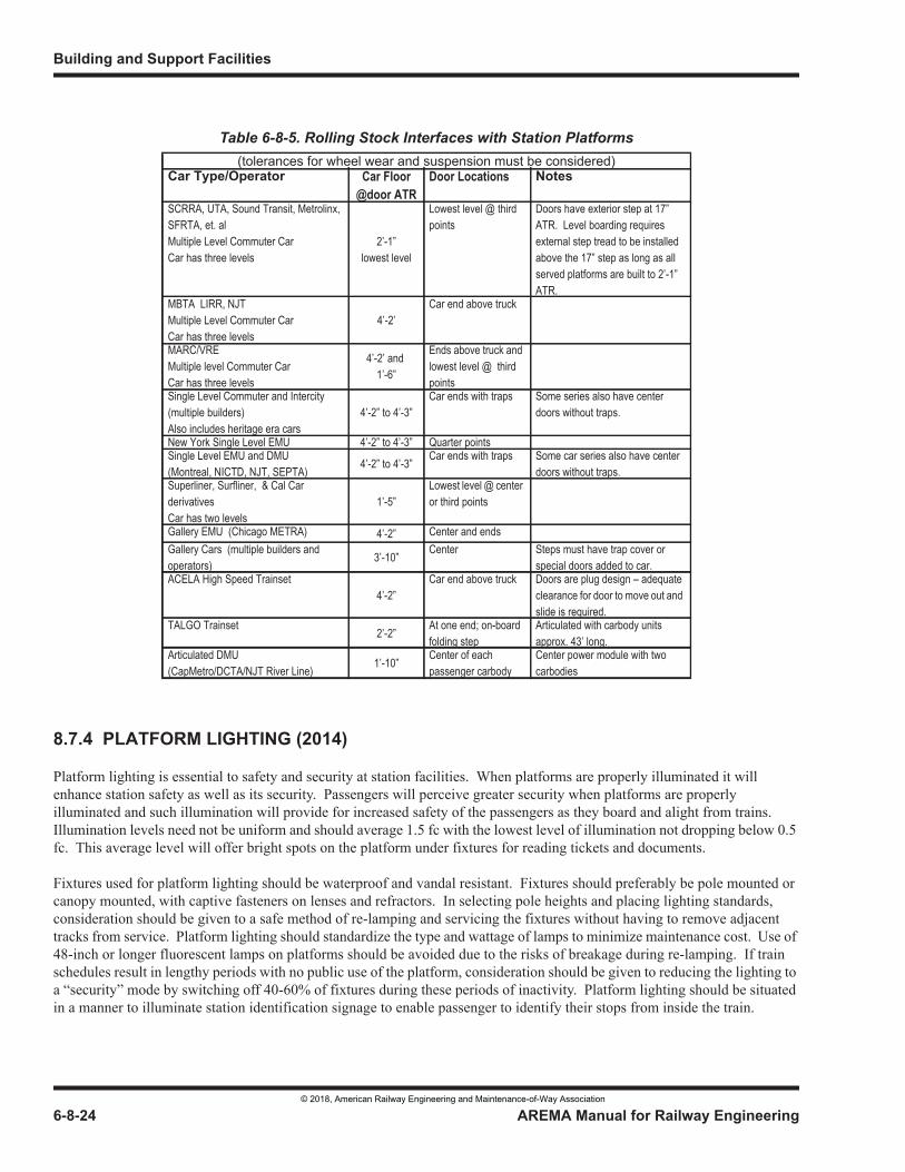
Building and Support Facilities
6-8-24 AREMA Manual for Railway Engineering
8.7.4 PLATFORM LIGHTING (2014)
Platform lighting is essential to safety and security at station facilities. When platforms are properly illuminated it will enhance station safety as well as its security. Passengers will perceive greater security when platforms are properly illuminated and such illumination will provide for increased safety of the passengers as they board and alight from trains. Illumination levels need not be uniform and should average 1.5 fc with the lowest level of illumination not dropping below 0.5 fc. This average level will offer bright spots on the platform under fixtures for reading tickets and documents.
Fixtures used for platform lighting should be waterproof and vandal resistant. Fixtures should preferably be pole mounted or canopy mounted, with captive fasteners on lenses and refractors. In selecting pole heights and placing lighting standards, consideration should be given to a safe method of re-lamping and servicing the fixtures without having to remove adjacent tracks from service. Platform lighting should standardize the type and wattage of lamps to minimize maintenance cost. Use of 48-inch or longer fluorescent lamps on platforms should be avoided due to the risks of breakage during re-lamping. If train schedules result in lengthy periods with no public use of the platform, consideration should be given to reducing the lighting to a “security” mode by switching off 40-60% of fixtures during these periods of inactivity. Platform lighting should be situated in a manner to illuminate station identification signage to enable passenger to identify their stops from inside the train.
Table 6-8-5. Rolling Stock Interfaces with Station Platforms(tolerances for wheel wear and suspension must be considered)
Car Type/Operator Car Floor @door ATR
Door Locations Notes
SCRRA, UTA, Sound Transit, Metrolinx, SFRTA, et. alMultiple Level Commuter Car Car has three levels
2’-1”lowest level
Lowest level @ third points
Doors have exterior step at 17” ATR. Level boarding requires external step tread to be installed above the 17” step as long as all served platforms are built to 2’-1” ATR.
MBTA LIRR, NJT Multiple Level Commuter CarCar has three levels
4’-2’Car end above truck
MARC/VRE Multiple level Commuter CarCar has three levels
4’-2’ and 1’-6”
Ends above truck and lowest level @ third points
Single Level Commuter and Intercity (multiple builders)Also includes heritage era cars
4’-2” to 4’-3”Car ends with traps Some series also have center
doors without traps.
New York Single Level EMU 4’-2” to 4’-3” Quarter pointsSingle Level EMU and DMU(Montreal, NICTD, NJT, SEPTA) 4’-2” to 4’-3” Car ends with traps Some car series also have center
doors without traps. Superliner, Surfliner, & Cal Car derivativesCar has two levels
1’-5”Lowest level @ center or third points
Gallery EMU (Chicago METRA) 4’-2” Center and ends Gallery Cars (multiple builders and operators) 3’-10” Center Steps must have trap cover or
special doors added to car. ACELA High Speed Trainset
4’-2”Car end above truck Doors are plug design – adequate
clearance for door to move out and slide is required.
TALGO Trainset 2’-2” At one end; on-board folding step
Articulated with carbody units approx. 43’ long.
Articulated DMU (CapMetro/DCTA/NJT River Line) 1’-10” Center of each
passenger carbodyCenter power module with two carbodies
© 2018, American Railway Engineering and Maintenance-of-Way Association
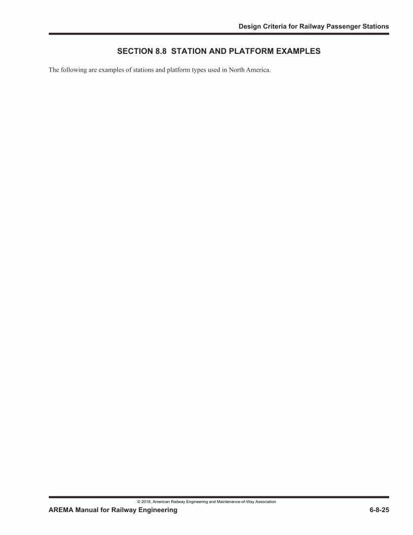
Design Criteria for Railway Passenger Stations
AREMA Manual for Railway Engineering 6-8-25
1
3
4
SECTION 8.8 STATION AND PLATFORM EXAMPLES
The following are examples of stations and platform types used in North America.
© 2018, American Railway Engineering and Maintenance-of-Way Association
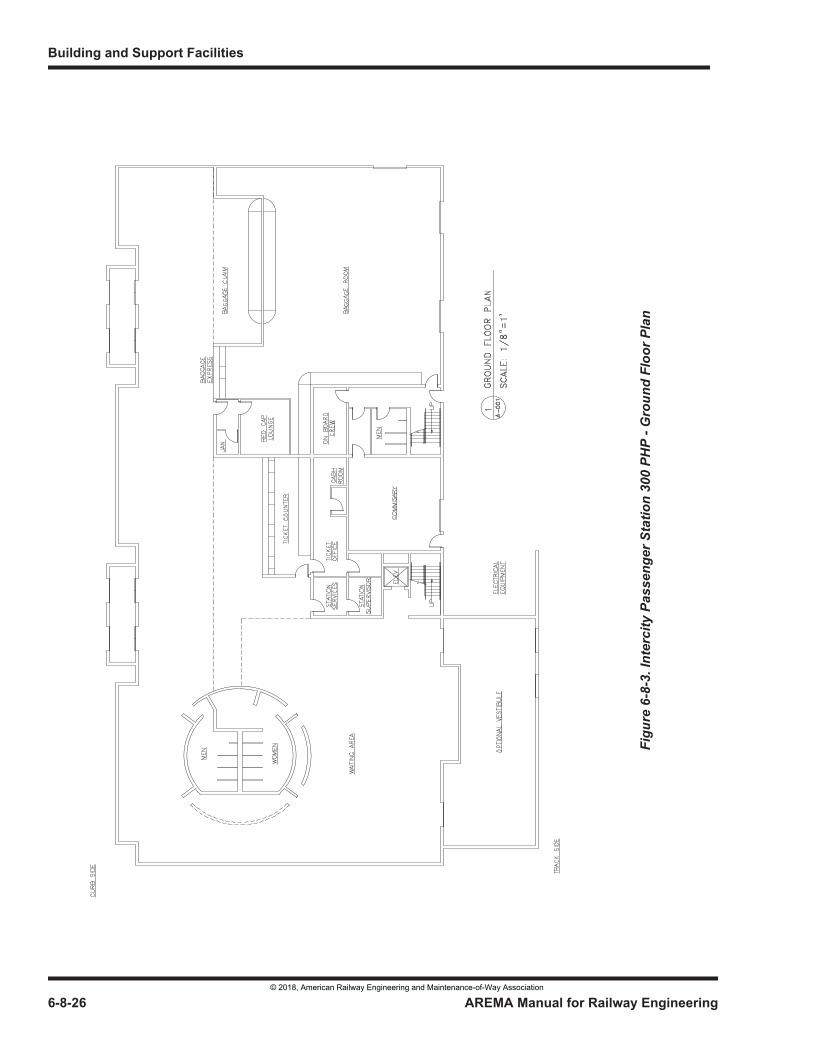
Building and Support Facilities
6-8-26 AREMA Manual for Railway Engineering
Figu
re 6
-8-3
. Int
erci
ty P
asse
nger
Sta
tion
300
PHP
- Gro
und
Floo
r Pla
n
© 2018, American Railway Engineering and Maintenance-of-Way Association
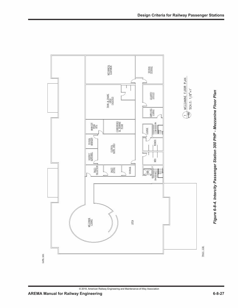
Design Criteria for Railway Passenger Stations
AREMA Manual for Railway Engineering 6-8-27
Figu
re 6
-8-4
. Int
erci
ty P
asse
nger
Sta
tion
300
PHP
- Mez
zani
ne F
loor
Pla
n
© 2018, American Railway Engineering and Maintenance-of-Way Association
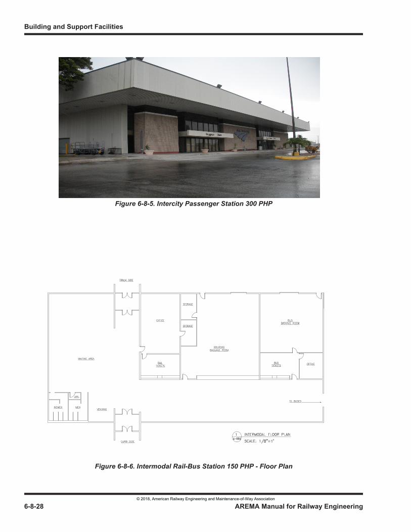
Building and Support Facilities
6-8-28 AREMA Manual for Railway Engineering
Figure 6-8-5. Intercity Passenger Station 300 PHP
Figure 6-8-6. Intermodal Rail-Bus Station 150 PHP - Floor Plan
© 2018, American Railway Engineering and Maintenance-of-Way Association
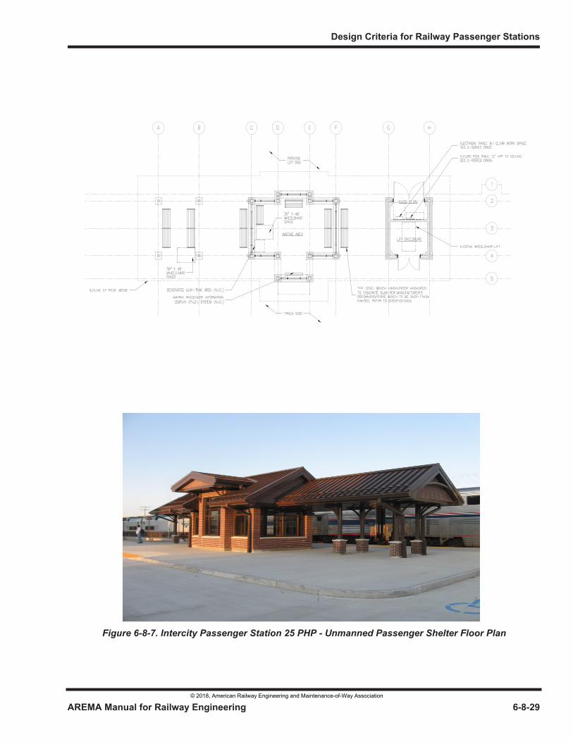
Design Criteria for Railway Passenger Stations
AREMA Manual for Railway Engineering 6-8-29
1
3
4
Figure 6-8-7. Intercity Passenger Station 25 PHP - Unmanned Passenger Shelter Floor Plan
© 2018, American Railway Engineering and Maintenance-of-Way Association
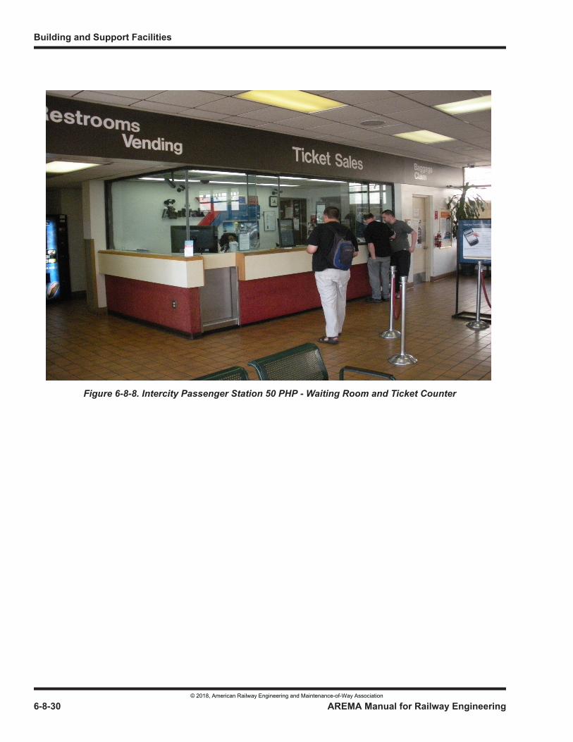
Building and Support Facilities
6-8-30 AREMA Manual for Railway Engineering
Figure 6-8-8. Intercity Passenger Station 50 PHP - Waiting Room and Ticket Counter
© 2018, American Railway Engineering and Maintenance-of-Way Association
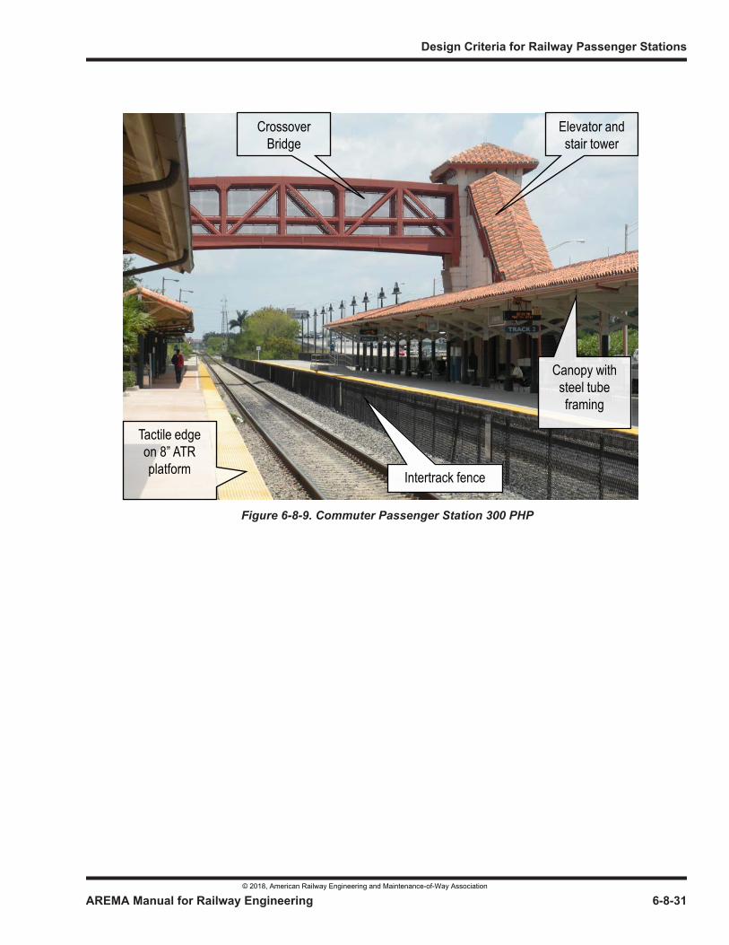
Design Criteria for Railway Passenger Stations
AREMA Manual for Railway Engineering 6-8-31
1
3
4
Figure 6-8-9. Commuter Passenger Station 300 PHP
Tactile edge on 8” ATR platform Intertrack fence
Elevator and stair tower
Crossover Bridge
Canopy with steel tube framing
© 2018, American Railway Engineering and Maintenance-of-Way Association
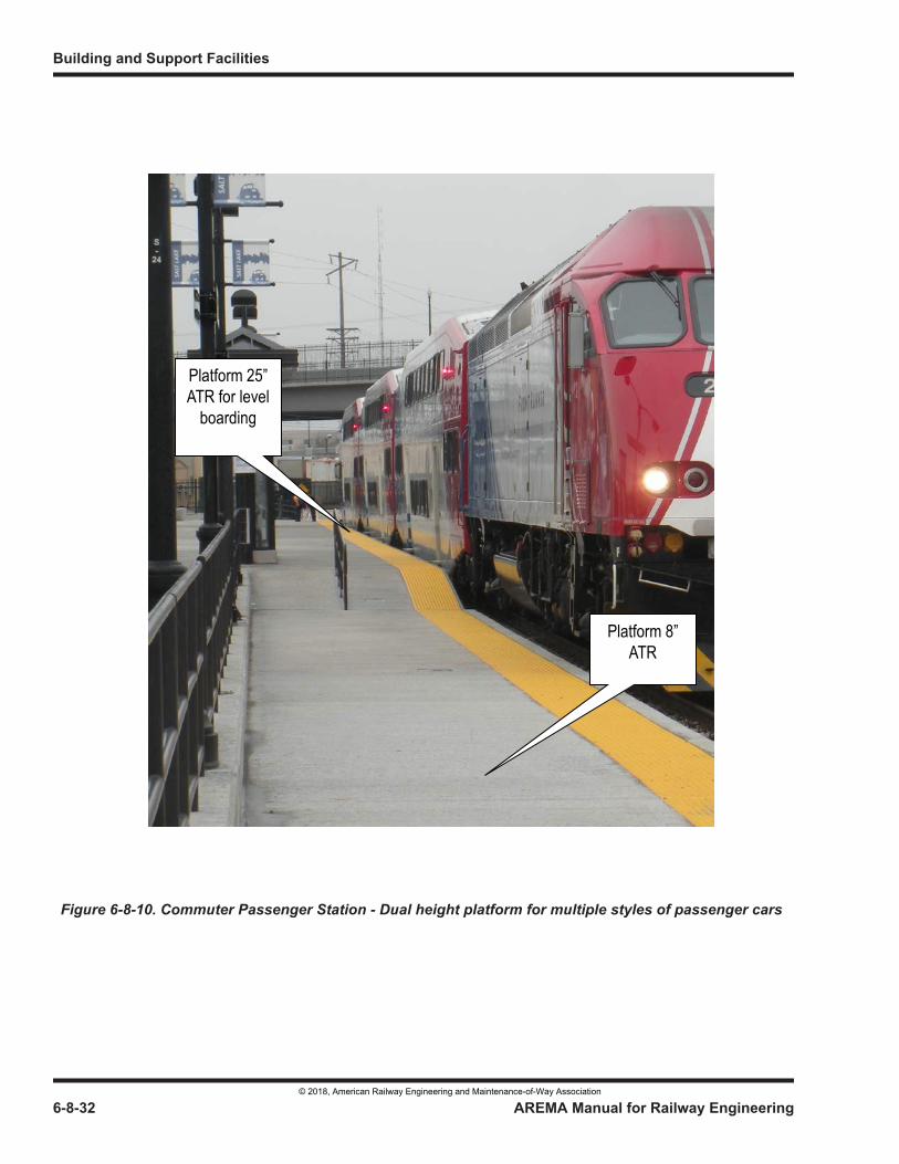
Building and Support Facilities
6-8-32 AREMA Manual for Railway Engineering
Figure 6-8-10. Commuter Passenger Station - Dual height platform for multiple styles of passenger cars
Platform 8” ATR
Platform 25” ATR for level
boarding
© 2018, American Railway Engineering and Maintenance-of-Way Association
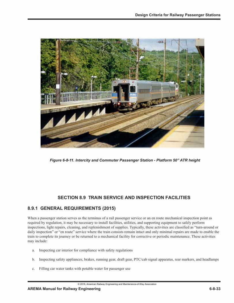
Design Criteria for Railway Passenger Stations
AREMA Manual for Railway Engineering 6-8-33
1
3
4SECTION 8.9 TRAIN SERVICE AND INSPECTION FACILITIES
8.9.1 GENERAL REQUIREMENTS (2015)
When a passenger station serves as the terminus of a rail passenger service or an en route mechanical inspection point as required by regulation, it may be necessary to install facilities, utilities, and supporting equipment to safely perform inspections, light repairs, cleaning, and replenishment of supplies. Typically, these activities are classified as “turn-around or daily inspection” or “en route” service where the train consists remain intact and only minimal repairs are made to enable the train to complete its journey or be returned to a mechanical facility for corrective or periodic maintenance. These activities may include:
a. Inspecting car interior for compliance with safety regulations
b. Inspecting safety appliances, brakes, running gear, draft gear, PTC/cab signal apparatus, rear markers, and headlamps
c. Filling car water tanks with potable water for passenger use
Figure 6-8-11. Intercity and Commuter Passenger Station - Platform 50” ATR height
© 2018, American Railway Engineering and Maintenance-of-Way Association
Building and Support Facilities
6-8-34 AREMA Manual for Railway Engineering
d. Servicing and cleaning of toilets and emptying waste collection tanks
e. Washing of exterior car windows
f. Cleaning interior of passenger cars
g. Stocking food service cars with supplies and ice (commissary related)
h. Removing on-board trash
i. Fueling of locomotives
j. Providing 480 volt Headend Power and brake trainline compressed air during layover periods
k. Providing convenience outlets for use of portable tools and portable lighting equipment
These activities may occur on the public station passenger platforms or on designated tracks adjacent to the public platforms depending upon the quantity of rail cars serviced and the nature of the work performed. Configuration of non-public, service platforms (height above top of rail and distance from track centerline) may be governed by the types of passenger cars used recognizing that some mechanical inspections will require access to undercar equipment and public platforms will be designed for compliance with “level-boarding” accessibility requirements. When employees are required to be under or in-between rail cars to perform any of these activities, there must be a positive blocking device applied to the track or consist (Blue-flag protection). This Manual section is not intended to serve as design criteria for major mechanical department installations and passenger car storage yards.
8.9.2 REGULATORY REQUIREMENTS (2015)
The specific mechanical inspection requirements for daily, turnaround, and en route service are contained in regulations of the Federal Railroad Administration and Transport Canada. A passenger train “en route inspection” involves an examination of safety appliances and brakes at not more than 1000 mile intervals. Station designers should identify and carefully review the levels of inspection contemplated by the railroad’s mechanical officers and ascertain the safest manner under which to accomplish these inspections. For stations with low frequency of passenger service and without “qualified mechanical persons (QMPs) present, performing these activities can be accomplished on the public station platforms as long as the train consist remains intact. However, specific solutions will be determined by a combination of available personnel, labor agreements, trip duration, proximity to alternate mechanical facilities, “on-call” resources, and ambient temperature extremes.
The US Public Health Service regulates interstate sanitation and food handling activities and requires approval of design drawings for all installations involving sanitation prior to their construction. Canada has similar regulations enforced by multiple agencies. This includes potable water, trash removal, waste tank disposal, temperature control of perishable foods, and cleanliness of all storage and transport containers for foodstuffs. If foodstuff storage and ice making equipment is provided in the station building, these areas are also subject to design review and periodic inspection by state, provincial, and federal health officers.
State and provincial transportation officials regulate side and vertical clearances to fixed structures and other objects to assure hazardous conditions are not created for train service employees. Any sub-standard clearances must be submitted to the responsible state agency for issuance of a waiver or other authorization prior to placing the track in service.
Service roadways should connect all areas of the station platforms and outside entry. Multiple access paths may be provided to avoid train equipment blocking a single crossing. Roadways designated as fire lanes should be designed so that the turning radius restrictions of local fire department trucks are considered. In areas subject to heavy snowfall, the design of roadways should contemplate snow removal and storage so as not to obstruct vision or access.
© 2018, American Railway Engineering and Maintenance-of-Way Association
Design Criteria for Railway Passenger Stations
AREMA Manual for Railway Engineering 6-8-35
1
3
4
8.9.3 MECHANICAL INSPECTION FACILITIES (2015)
8.9.3.1 Inspection Pits
To reduce switching costs and shorten train turnaround times at stations, inspection pits may be provided to conduct undercar inspections, observations, or minor repairs of the car trucks, wheels, brakes and other safety critical equipment. Whether a pit is required will be determined by the maintenance program for the specific passenger cars assigned and applicable regulations and the staffing requirements of the mechanical department.
Pits have two configurations: a pedestal pit where rails are placed atop steel or concrete pedestals which give access to both sides of the wheels and related running gear; and a gauge pit which provides a depressed area only between the rails with the rails bearing atop the pit walls. The depth of the pit should be established by the type of rolling stock employed in that it should be possible to walk upright on the floor of the pit under the lowest part of the passenger car. This may require bench steps in the pit or use of portable step stools in the pit to reach components within the car truck.
Pits may be “continuous” for inspecting an entire stationary train or “single car” for inspecting one car at a time or a train as it rolls slowly over the pit. In the latter case, the pit would usually be installed on a lead track that accesses the station platforms. Where trains pass over a single car pit for inspection, other tracks should be provided for servicing and repair work. Side entrances to pits should be provided at sufficient intervals to allow quick evacuation if necessary in the event a train is stopped atop the inspection pit. Removable handrails extending above the top of rail per OSHA regulations are needed along end entrance stairways.
The pit should be well drained and equipped with recessed lights for general lighting and GFI protected receptacles for service lights and small tools. In locations with heavy snowfalls, pit covers or roofing over the pit area or radiant heating to melt snow and ice may be required. Pits may be cast-in-place or precast concrete.
8.9.3.2 Walking surfaces
Employees responsible for inspecting and servicing trains require walking surfaces that are free from hazardous conditions that may cause a personal injury. Walking surfaces should be well drained, reasonably level and free of tripping hazards and have adequate side clearance to adjacent tracks. If work is routinely accomplished during hours of darkness, lighting adequate for the task should be provided.
8.9.3.3 Positive blocking device - Blue Flag Protection
If mechanical work is accomplished on the station tracks where employees are required to be under or in between rail cars, each station track must have a positive blocking device or derail with a “blue-flag” warning installed to protect workers. A permanent “blue-light” system installed on each track may improve efficiency and worker safety.
8.9.4 WATER FACILITIES (2015)
Potable water sources and installations are regulated by the federal authorities [USA Title21, Code of Federal Regulations Parts 1240 and 1250; Consolidated Regulations of Canada c.1105]. Passenger cars with potable water tanks should be filled at their primary maintenance facility and topped off at terminals or at en route service points. At yards or stations where train equipment may be watered, a piping system of adequate capacity connected to potable hydrants or hose reels should be provided. Dispensing points should be spaced two car lengths apart, preferably serving two tracks. Where station dwell time is short, potable hydrants may be spaced for every car. Water service should be distributed so that no more than 100 feet of hose is necessary to reach a car. Regulations require that the potable water system or each potable hydrant or reel be isolated from the water supply with a reduced pressure backflow preventer. In cold climates, a heated cabinet may be required to house the backflow preventer(s) and hose reels. If hose reels are not used, then a stand to hold the hose off the ground when not in use must be provided. A potable connection should be nominal 1 inch size using FDA approved food grade hose provided with approved nozzle or end fitting, ball valve for local control, a nozzle or fitting covers to keep dirt from entering or contaminating the hose connectors. By regulation, potable water outlets may only be used for filling passenger car tanks. Non-
© 2018, American Railway Engineering and Maintenance-of-Way Association
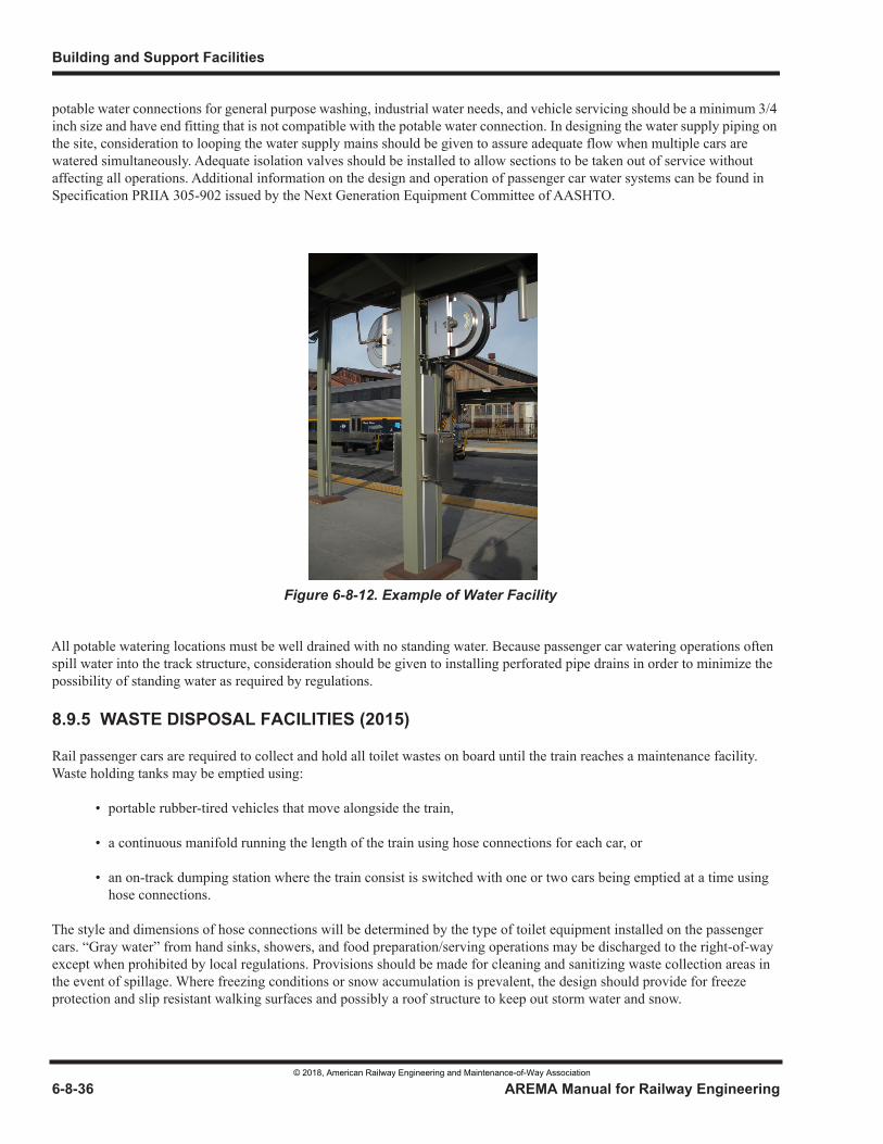
Building and Support Facilities
6-8-36 AREMA Manual for Railway Engineering
potable water connections for general purpose washing, industrial water needs, and vehicle servicing should be a minimum 3/4 inch size and have end fitting that is not compatible with the potable water connection. In designing the water supply piping on the site, consideration to looping the water supply mains should be given to assure adequate flow when multiple cars are watered simultaneously. Adequate isolation valves should be installed to allow sections to be taken out of service without affecting all operations. Additional information on the design and operation of passenger car water systems can be found in Specification PRIIA 305-902 issued by the Next Generation Equipment Committee of AASHTO.
All potable watering locations must be well drained with no standing water. Because passenger car watering operations often spill water into the track structure, consideration should be given to installing perforated pipe drains in order to minimize the possibility of standing water as required by regulations.
8.9.5 WASTE DISPOSAL FACILITIES (2015)
Rail passenger cars are required to collect and hold all toilet wastes on board until the train reaches a maintenance facility. Waste holding tanks may be emptied using:
• portable rubber-tired vehicles that move alongside the train,
• a continuous manifold running the length of the train using hose connections for each car, or
• an on-track dumping station where the train consist is switched with one or two cars being emptied at a time using hose connections.
The style and dimensions of hose connections will be determined by the type of toilet equipment installed on the passenger cars. “Gray water” from hand sinks, showers, and food preparation/serving operations may be discharged to the right-of-way except when prohibited by local regulations. Provisions should be made for cleaning and sanitizing waste collection areas in the event of spillage. Where freezing conditions or snow accumulation is prevalent, the design should provide for freeze protection and slip resistant walking surfaces and possibly a roof structure to keep out storm water and snow.
Figure 6-8-12. Example of Water Facility
© 2018, American Railway Engineering and Maintenance-of-Way Association
Design Criteria for Railway Passenger Stations
AREMA Manual for Railway Engineering 6-8-37
1
3
4
8.9.5.1 Recirculating toilets
Short distance and regional trains often use recirculating toilets that contain a disinfectant solution with an odor suppressant (blue water) for each toilet. The solution in the toilet hopper is recirculated when the flush button is activated to clear the toilet hopper. The toilet hopper can provide 24-60 hours of service depending upon the level of passenger use that dilutes the recirculating solution and reduces the ability to control odors. Toilet waste connections are located on the underside of the car under the toilet room. There is also a toilet charging connection for non-potable water or a pre-mixed blue water solution. This style of toilet will drain by gravity into a manifold or portable service vehicle tank.
8.9.5.2 Full retention toilets
Regional and long distance trains use low volume clean water flushing and a vacuum source to clear the toilet hopper and move wastes to a holding tank. When the flush button is activated, an on-board vacuum pump is energized to lower the air pressure in the holding tank which then subsequently opens a valve at the individual toilet hopper, emptying the toilet bowl. The waste holding tank is nominally sized to provide capacity for at 150% of the longest scheduled trip duration. Because the contents of a holding tank has low amounts of fluids, the tanks generally require a vacuum assisted system (either a stationary manifold or portable equipment) to drain them completely within a reasonable period of time during a train’s turnaround time. The clean flushing water is obtained from the potable water storage tanks on the passenger car.
8.9.5.3 Waste disposal facility/building
If railroad-owned portable toilet servicing equipment is used, a waste disposal building may be required on site to empty these vehicles into a sanitary sewer. Such a building should have adequate supplies of hot water and employee hand washing facilities. If an outside contractor is used to service waste holding tanks, the contractor will remove the contents to an off-site location for disposal to the municipal sewer system. If using portable equipment, the width and turning radii of the inter-track walkways and roadways must be designed to allow these vehicles to safety circulate.
8.9.6 LOCOMOTIVE SERVICING FACILITIES IN STATIONS (2015)
8.9.6.1 Environmental controls
If locomotives are stored on a train consist in a station, the area under the locomotive(s) may require environmental mitigation to collect lubricant drippings and air reservoir blow-down residue. This can be accomplished with absorbent mats attached to ties, a concrete slab with direct fixation rails, or collection pans of metal or fiberglass construction. Drains from this area may require a gravity separator to prevent lubricants from entering the storm drain system. There may be an accumulation of traction sand at these locations if the brake trainline air is dropped frequently. Catch basins in the drainage system should have deep sumps to avoid having sand enter drain pipes.
If operating diesel locomotives in a station with structural overbuild, forced ventilation and noise abatement treatments may be required. For guidance on ventilation requirements, refer to Chapter 6, Section 4.7.
8.9.6.2 Diesel locomotive fueling
If locomotive fueling is accomplished in the station, it may be done with either fuel trucks or piped fuel stands. At locations where fueling routinely occurs, spill pans or a concrete spill containment track slab may be required depending upon the fuel volumes delivered, the terms and conditions of vendor contracts, and the amounts of precipitation experienced. Guidance on piped fuel systems can be found in this Manual, Chapter 6, Part 16. Control of spills and stormwater runoff from track collection pans should be part of an overall site environmental mitigation as required by local codes and regulations. Depending upon the proximity to the station building, special fire suppression or fire separation construction may be required as specified in local codes.
If fuel trucks are used for locomotive fueling, roadways and rail grade crossings should be designed with wide turns and unobstructed sight lines that allow for safe movement with a minimum of backing. Crossings should be located where
© 2018, American Railway Engineering and Maintenance-of-Way Association
Building and Support Facilities
6-8-38 AREMA Manual for Railway Engineering
equipment will not likely be parked and preferably outside blue flag/derail protection areas. Care should be used to avoid placing crossings adjacent to structures that will limit sight lines causing “blind” crossings. If at all possible, crossings should not be placed through switch points.
8.9.6.3 PTC and Cab signal test loop
Locomotives and cab cars equipped with cab signal, positive train control (PTC), or automatic train operation (ATO) technologies are required to be tested at a minimum of daily by a qualified inspector and written evidence of the test placed in the operator cab. This testing can be with portable test equipment or a test loop in the gauge of the track. The railroad signal department should be consulted for the location and number of test loops or other related equipment that may be required at a station.
8.9.7 LAYOVER FACILITIES (2015)
Layover facilities allow the storage of trainsets in stations with headend electric power and trainline air when the locomotive is turned off or removed to another facility for service. Headend power allows passenger cars to have lighting/heating/cooling and convenience power for passenger car cleaning and maintenance. Layover facilities are desirable for station occupancies in excess of one hour unless there are air quality or noise issues at the station. The locations of layover connections to trains should be established at one end of the train consist such that length of train does not affect the point of connection. This would be dictated by a bumping post or a station crosswalk that cannot be obstructed.
8.9.7.1 Brake Trainline air
Brake train line connections supply 110 psig dry (-40F dewpoint) compressed air meeting APTA SS-M-011 to keep the passenger car brake systems charged during layover. Supply is through an AAR standard gladhand FS-5 brake hose coupling on a minimum length of 10 ft. of pressure rated hose located in the gauge of the track. If passenger equipment has a main reservoir equalizing pipe, then a second hose connection with a LS-4 coupling is required. Refer to APTA RP-M-001 for additional information on material specifications. Ball valves are recommended for control of the air at the connecting point. A ½ inch bleed valve should be provided so the compressed air in the hoses can be bled off before disconnecting the trainline hoses. In designing the compressed air distribution system, piping should slope to a condensate trap. If widely dispersed trainline air connections are required, consideration should be given to multiple compressor/dryer installations to avoid long pipe runs. The volume capacity of the installed compressors may be reduced if air receivers are installed. In areas where freezing weather is common, air piping and traps should be protected from condensate freeze-up with sufficient bury depth, the introduction of approved pneumatic antifreeze products, use of external pipe insulation and heat tracing or a combination thereof.
8.9.7.2 Headend power
Headend power (HEP) is provided at 480 volt, three phase of sufficient ampacity to supply train power requirements. The size of the HEP connection will be determined by the length of train and the most severe ambient conditions. Passenger cars typically have a “Standby” or “Layover” mode to reduce power consumption when cars are unoccupied in a station; in this mode interior temperatures and lighting are adjusted. However, the ampacity of the HEP must be sized for normal load so passenger cars can be pre-conditioned before departure. HEP installations should have protection for undervoltage, phase loss, ground fault, multiple source isolation, and trainline complete (TLC) monitoring. Commercially manufactured HEP cabinets that contain all of these features are available from multiple suppliers (see Figure 6-8-13). Installations come in nominal 150 amp, 400 amp, and 800 amp sizes. HEP cable assemblies are fabricated of highly flexible welding cable and should only be procured from vendors qualified to manufacture such assemblies with industry standard plugs and receptacles. Consult APTA Recommended Practices RP-E-016-99, RP-E-017-99, and RP-E-018-99 for additional guidance on wire and cable assemblies for car and train HEP equipment.
© 2018, American Railway Engineering and Maintenance-of-Way Association
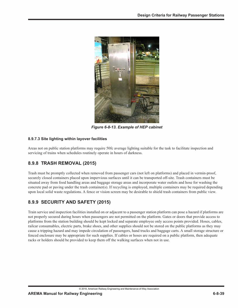
Design Criteria for Railway Passenger Stations
AREMA Manual for Railway Engineering 6-8-39
1
3
4
8.9.7.3 Site lighting within layover facilities
Areas not on public station platforms may require 50fc average lighting suitable for the task to facilitate inspection and servicing of trains when schedules routinely operate in hours of darkness.
8.9.8 TRASH REMOVAL (2015)
Trash must be promptly collected when removed from passenger cars (not left on platforms) and placed in vermin-proof, securely closed containers placed upon impervious surfaces until it can be transported off-site. Trash containers must be situated away from food handling areas and baggage storage areas and incorporate water outlets and hose for washing the concrete pad or paving under the trash container(s). If recycling is employed, multiple containers may be required depending upon local solid waste regulations. A fence or vision screen may be desirable to shield trash containers from public view.
8.9.9 SECURITY AND SAFETY (2015)
Train service and inspection facilities installed on or adjacent to a passenger station platform can pose a hazard if platforms are not properly secured during hours when passengers are not permitted on the platform. Gates or doors that provide access to platforms from the station building should be kept locked and separate employee only access points provided. Hoses, cables, railcar consumables, electric parts, brake shoes, and other supplies should not be stored on the public platforms as they may cause a tripping hazard and may impede circulation of passengers, hand trucks and baggage carts. A small storage structure or fenced enclosure may be appropriate for such supplies. If cables or hoses are required on a public platform, then adequate racks or holders should be provided to keep them off the walking surfaces when not in use.
Figure 6-8-13. Example of HEP cabinet
© 2018, American Railway Engineering and Maintenance-of-Way Association

Building and Support Facilities
6-8-40 AREMA Manual for Railway Engineering
THIS PAGE INTENTIONALLY LEFT BLANK.
© 2018, American Railway Engineering and Maintenance-of-Way Association
© 2018, American Railway Engineering and Maintenance-of-Way Association
© 2018, American Railway Engineering and Maintenance-of-Way Association
© 2018, American Railway Engineering and Maintenance-of-Way Association
© 2018, American Railway Engineering and Maintenance-of-Way Association
© 2018, American Railway Engineering and Maintenance-of-Way Association
© 2018, American Railway Engineering and Maintenance-of-Way Association
© 2018, American Railway Engineering and Maintenance-of-Way Association
© 2018, American Railway Engineering and Maintenance-of-Way Association
© 2018, American Railway Engineering and Maintenance-of-Way Association
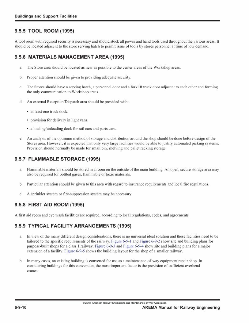
© 2018, American Railway Engineering and Maintenance-of-Way Association
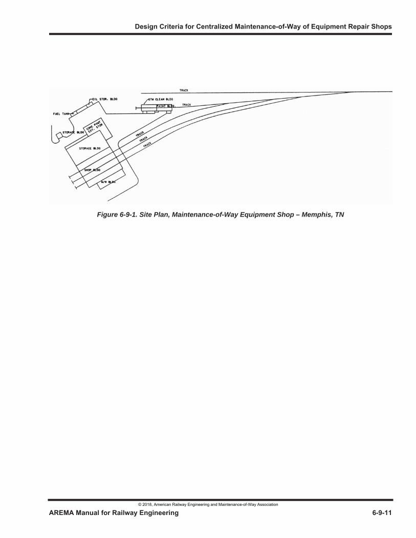
Figure 6-9-1. Site Plan, Maintenance-of-Way Equipment Shop – Memphis, TN
© 2018, American Railway Engineering and Maintenance-of-Way Association
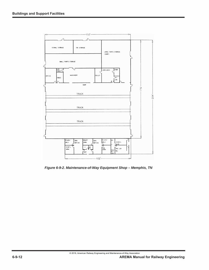
Figure 6-9-2. Maintenance-of-Way Equipment Shop – Memphis, TN
© 2018, American Railway Engineering and Maintenance-of-Way Association
Figure 6-9-3. Site Plan, Maintenance-of-Way Equipment Shop – Charlotte, NC
© 2018, American Railway Engineering and Maintenance-of-Way Association
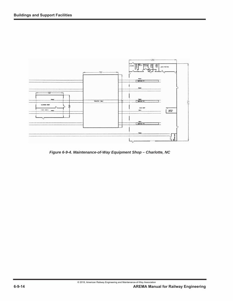
Figure 6-9-4. Maintenance-of-Way Equipment Shop – Charlotte, NC
© 2018, American Railway Engineering and Maintenance-of-Way Association
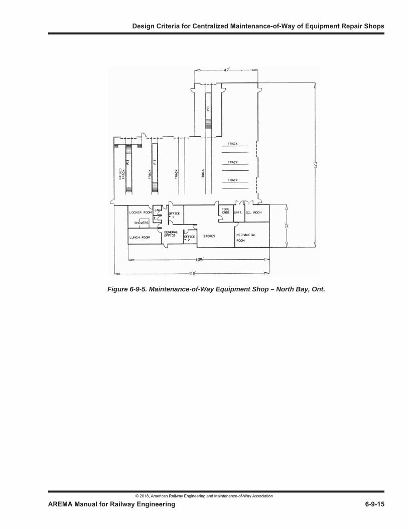
Figure 6-9-5. Maintenance-of-Way Equipment Shop – North Bay, Ont.
© 2018, American Railway Engineering and Maintenance-of-Way Association

© 2018, American Railway Engineering and Maintenance-of-Way Association
© 2018, American Railway Engineering and Maintenance-of-Way Association 6-10-1
1
3
6 Part 10
Design Criteria for Observation Towers
— 2018 —
FOREWORD
An observation tower is an elevated structure from which supervisory personnel can visually supervise yard crews and yard engine operations. Observation towers are located in classification yards, intermodal facilities, auto loading/unloading facilities and coach yards.
The observation tower permits the yardmaster not only to visually supervise yard crews but also to develop greater switching efficiency through better switch crew utilization. Towers are generally located at the switching end or lead end of the yard for rail operations and near the middle of the yard for other types of facilities.
With this most recent update, it is noted that Observation Towers are no longer commonly built and have declined in usage over recent years in favor of utilizing more effective and less expensive technologies. These include remotely operated high resolution cameras positioned at strategic locations around the rail yard facility. By their nature, Observation Towers entail a number of disadvantages including the high cost of construction, operation, and maintenance.
The Committee has updated and/or retained the following information in the design manual for reference in the event that the user should need consideration for existing tower facility modifications or renovations, or in the event that a new tower structure is required due to special circumstances to facilitate rail operations and/or security.
TABLE OF CONTENTS
Section/Article Description Page
10.1 Introduction . . . . . . . . . . . . . . . . . . . . . . . . . . . . . . . . . . . . . . . . . . . . . . . . . . . . . . . . . . . . . . . . . . . . . . . . . . . 6-10-210.1.1 Site Consideration (2018) . . . . . . . . . . . . . . . . . . . . . . . . . . . . . . . . . . . . . . . . . . . . . . . . . . . . . . . . . . 6-10-2
10.2 Types . . . . . . . . . . . . . . . . . . . . . . . . . . . . . . . . . . . . . . . . . . . . . . . . . . . . . . . . . . . . . . . . . . . . . . . . . . . . . . . . . 6-10-310.2.1 General (2018) . . . . . . . . . . . . . . . . . . . . . . . . . . . . . . . . . . . . . . . . . . . . . . . . . . . . . . . . . . . . . . . . . . . 6-10-3
10.3 Tower Construction . . . . . . . . . . . . . . . . . . . . . . . . . . . . . . . . . . . . . . . . . . . . . . . . . . . . . . . . . . . . . . . . . . . . . 6-10-310.3.1 General Construction Materials (2018) . . . . . . . . . . . . . . . . . . . . . . . . . . . . . . . . . . . . . . . . . . . . . . . . 6-10-310.3.2 Mechanical and Electrical Facilities and Equipment (2018) . . . . . . . . . . . . . . . . . . . . . . . . . . . . . . . . 6-10-5
Buildings and Support Facilities
© 2018, American Railway Engineering and Maintenance-of-Way Association
6-10-2 AREMA Manual for Railway Engineering
TABLE OF CONTENTS (CONT)
Table Description Page
10.4 Special Features . . . . . . . . . . . . . . . . . . . . . . . . . . . . . . . . . . . . . . . . . . . . . . . . . . . . . . . . . . . . . . . . . . . . . . . 6-10-610.4.1 Tower Size (2018) . . . . . . . . . . . . . . . . . . . . . . . . . . . . . . . . . . . . . . . . . . . . . . . . . . . . . . . . . . . . . . . 6-10-610.4.2 Tower Roof Overhang (2018). . . . . . . . . . . . . . . . . . . . . . . . . . . . . . . . . . . . . . . . . . . . . . . . . . . . . . . 6-10-710.4.3 Closed Circuit Television (CCTV) (2018) . . . . . . . . . . . . . . . . . . . . . . . . . . . . . . . . . . . . . . . . . . . . . 6-10-710.4.4 Tower Furnishings (2018) . . . . . . . . . . . . . . . . . . . . . . . . . . . . . . . . . . . . . . . . . . . . . . . . . . . . . . . . . 6-10-710.4.5 Towers (Photos and Figures) (2018) . . . . . . . . . . . . . . . . . . . . . . . . . . . . . . . . . . . . . . . . . . . . . . . . . 6-10-8
LIST OF FIGURES
Figure Description Page
6-10-1 Tower Constructed as Part of Yard Buildings - Sample A . . . . . . . . . . . . . . . . . . . . . . . . . . . . . . . . . . . . . . 6-10-106-10-2 Tower Constructed as Part of Yard Buildings - Sample B . . . . . . . . . . . . . . . . . . . . . . . . . . . . . . . . . . . . . . 6-10-116-10-3 Tower Constructed as Part of Yard Buildings – Sample C . . . . . . . . . . . . . . . . . . . . . . . . . . . . . . . . . . . . . 6-10-126-10-4 Prefabricated Tower . . . . . . . . . . . . . . . . . . . . . . . . . . . . . . . . . . . . . . . . . . . . . . . . . . . . . . . . . . . . . . . . . . . 6-10-136-10-5 Tower Constructed as Part of Coach Shop. . . . . . . . . . . . . . . . . . . . . . . . . . . . . . . . . . . . . . . . . . . . . . . . . . 6-10-146-10-6 Automobile Mixing Center Facility . . . . . . . . . . . . . . . . . . . . . . . . . . . . . . . . . . . . . . . . . . . . . . . . . . . . . . . 6-10-156-10-7 Typical Glass Sections . . . . . . . . . . . . . . . . . . . . . . . . . . . . . . . . . . . . . . . . . . . . . . . . . . . . . . . . . . . . . . . . . 6-10-16
SECTION 10.1 INTRODUCTION
10.1.1 SITE CONSIDERATION (2018)
a. The primary function of the observation tower is to observe yard operations and to better supervise switching operations. These activities are conducted from the observation level, which is the room at the top of the tower building. It is characterized with large glass windows providing yard facility observation by tower personnel. Yard operations will typically include the building of trains in classification yards, along with train staging, traffic and departure control. The location of the observation tower is a very important consideration. The optimum height from the top of rail or pavement to the observation floor will typically vary between 30 and 60 feet for rail operations and 15 to 25 feet at other activities such as mainline intersection control locations. However, each particular location will dictate the optimal height. The site location for the yard tower should be determined by the track geometry of the particular yard location and the specific operations to be conducted. As a rule, the tower should be 50 feet back from the switching lead to permit observation of switching operations, and at the centerline of the classification tracks to permit maximum observation down the line of classification tracks. Towers for other types of operation should be located near the center of the operation for good observation of the entire facility.
b. The number of working staff who will occupy the observation tower at any given time varies and has typically been reduced over time with the use of new technology allowing computer control and remote observations. For a classification yard, the number of staff at the hump lead will typically consist of two individuals including a yard master and a terminal operations manager. Rail yard operations typically run 24-hours a day, 7-days a week. The towers are manned continually through 3-shifts of 8-hours duration each. Additional space for visitors or other temporary activities, including training, and construction or work crew monitoring should be provided.
c. Many rail yards are located within urban areas and are bisected by overhead structures carrying vehicular traffic or utilities. These structures can complicate the determination of the appropriate height and location for the construction
Design Criteria for Observation Towers
© 2018, American Railway Engineering and Maintenance-of-Way Association
AREMA Manual for Railway Engineering 6-10-3
1
3
4
of a tower. Studies conducted to determine the optimum location and height for a tower may incorporate the use of an unmanned aerial vehicle (UAV) equipped with camera equipment to provide views from various positions within the proximity of the proposed tower structure. A key advantage of a UAV is that it can provide preliminary views from multiple locations within a relatively short time frame Where practical, the information obtained from UAV data can be followed up through the use of a bucket truck or other personnel lifting equipment with a high reach boom allowing the local operating supervisor to confirm both an appropriate height and location for the tower based upon actual observation. Once a location and height have been agreed upon the observation level floor height can then be determined by actual field measurement.
SECTION 10.2 TYPES
10.2.1 GENERAL (2018)
a. Most Owners' Programs do not require LEED Certification. However, it is in the Owner's interest that a building be easily maintainable, durable, efficient, and sustainable over a 50-year service life. Techniques, methods, and materials that would be included to achieve LEED certification should be incorporated in the building as a matter of good design. Should the Owner desire to attain LEED certification, additional cost and schedule impacts for LEED formal submissions and certifications should be evaluated by all stakeholders in the project. See Technical Guidance Part 5 - Energy Conservation and Efficiency.
b. Observation towers may be constructed as independent structures, as a part of a multi-story building, or as an addition to an already existing building.
c. Independent towers are functional structures, and capital expenditure considerations generally dictate that they be constructed of the most economically practical materials available, have an acceptable service life, and require minimal maintenance. The size, height, location, and other considerations may also contribute to the choice of materials selected for the tower construction.
d. When constructed as a part of a new facility and/or an addition to an already existing building, the choice of materials used to construct the tower may be dictated by the structural and aesthetic components of the building that will support the tower. When considering incorporation of the tower into an existing or a new facility, note that the location of the tower under these circumstances is a key component in achieving the effectiveness of the tower itself.
e. All buildings, including observation towers, should comply with federal, state, provincial, local, and other governing entities to ensure safety and accessibility.
SECTION 10.3 TOWER CONSTRUCTION
10.3.1 GENERAL CONSTRUCTION MATERIALS (2018)
a. The structural and aesthetic components of the overall building structure will determine materials used in the construction of a tower. Lightweight, fire resistive, standard components should be utilized.
Interior finishes and materials chosen need to recognize that acoustical treatment must be of the utmost consideration, since the tower will contain large areas of reflective surfaces and equipment such as printers and radios which will (may) generate significant noise levels. Consequently, carpeting may be better suited than vinyl tile on the floor and acoustic tile ceilings may be more effective than ordinary dry wall ceilings. Ceiling tiles should also be of darker flat
Buildings and Support Facilities
© 2018, American Railway Engineering and Maintenance-of-Way Association
6-10-4 AREMA Manual for Railway Engineering
colortones to reduce the potential for light reflection during nighttime operations. Noise deadening wall coverings as applicable should also be considered.
b. State, provincial, local, ANSI, and ADA codes and regulations will require the inclusion of an elevator in the design of the tower in order to accommodate handicap accessibility. Elevator access should extebnd all the way to the observation level. Stairways leading to the observation level may be interior and/or exterior. Local codes may require that the observation level be served by at least two stairways. Interior stairways may be concrete filled metal pan stairways while exterior stairs should be open metal stairways with open grating type treads to reduce the potential for water, snow, and ice accumulations.
c. Window glazing should be located only on the faces of the tower where yard operations are to be observed. This is usually on three observation level walls. The fourth wall may typically be used for a toilet room, service panels, heating/cooling equipment and other essential facilities. In situations where the fourth wall must remain open for observation purposes, the above listed components may be located on the floor immediately below the observation level.
The lower and upper glass line should be dictated by line of sight. The lower glass line should be as close to the floor as possible, allowing sufficient space for heating baseboard units, service outlets, conduit, etc. The upper glass line should be located above the eye line height for a 95th percentile person who is standing (generally 73-inches). In most cases, points of observation for rail operations are all below eye level in the yard. Reduction of glass panels above this point will be beneficial in reducing sun glare, sky brightness, and radiant heating. The use of thermal break frames with thermopane or triple pane glazing with low E (emissivity) glass for all observation windows will reduce solar gain and heat loss and will also help to eliminate the possibility of condensation and fogging of the glass surface. Designing and installing the glazing to be sloped or angled toward the ground, as opposed to installing it strictly vertical, can also reduce solar gain.
Glare reducing glass is not recommended for use in observation towers since this type of material reduces night visibility at a time when clear observation is most critical. Additional heat gain that may result from not using this type of glass can be compensated for during the day by providing increased air conditioning.
Observation level window glazing may be installed vertically or sloped. Sloped glazing, oriented such that the typical lines of sight pass through the glass at a perpendicular angle is used widely. This orientation will reduce the potential for viewing distortion. It is note that sloped glazing does place additional stress on the glass, making it more susceptible to cracking thus requiring that it be designed to accommodate the angled loadings.
With regard to the safety of the tower staff, the developed area along the yard periphery should be considered. Where vehicle bridges are close by and/or there is a history of high crime including shootings, it may be prudent to consider bulletproof glazing on those sides that are exposed to these areas.
d. For observation towers the maximum standard size window framing should be used. Vertical window pane dividers, also known as mullions, should be minimal in quantity and designed to be as narrow as possible in order to optimize the field of view. Care should be taken to avoid locating mullions in the center of critical viewing areas. Corner columns can create a visual problem and should be avoided. Use of sealed corner glazing should be used rather than mullions at corners.
Use of vertical pivoted sash for tower windows offers the advantage of permitting window washing from the inside of the tower. This is practical for vertically oriented glazing and cannot normally be applied to sloped windows. Fixed sashes and sloped windows will typically require an alternative method for exterior access and servicing such as a catwalk as discussed in section "e", below.
e. Catwalks are typically installed around the outside perimeter of the tower to provide service access to the windows and additional observation advantages. The catwalk can be used to provide better visibility to areas of the yard where the windows may cause glare or otherwise interfere with obtaining a clear view of a specific area. It can also allow observers to view conditions directly below and immediately adjacent to the tower or building structure that are not
Design Criteria for Observation Towers
© 2018, American Railway Engineering and Maintenance-of-Way Association
AREMA Manual for Railway Engineering 6-10-5
1
3
4
within the interior lines of sight. In addition, supervisory personnel can utilize the catwalk to better monitor and direct construction or service crews that are working close by.
Catwalks should be constructed of open grating to provide non-slip footing and minimize the potential for water, snow, and ice accumulations. A typical minimum tread width of 42-inches is recommended. Fall protection in the form of safety hand railings and harness connection cabling should extend around the full outside perimeter of the catwalk. Railings should include horizontal rails set to a minimal height of 42-inches or in accordance with local codes. At least one intermediate, or mid-rail set at a height of 24-inches should also be included. Railings can typically consist of 2-inch diameter round pipe painted in safety yellow. One-half inch diameter cable may be substituted for the pipe railing in situations where the pipe may disrupt the field of view to critical areas.
10.3.2 MECHANICAL AND ELECTRICAL FACILITIES AND EQUIPMENT (2018)
a. Towers whether independent structures or an integral part of another structure should have easily accessible toilet facilities for both sexes. The number and type of fixtures to be provided should be derived from the local building code and/or regulations. The toilet facility(ies) must also be ADA compliant.
In independent towers, toilets should preferably be accessible to personnel at the observation level. Facilities may be included at a lower level in situations where adequate space or visibility requirements dictate the need for a separate location as noted in section 10.3.1.c. Towers located in other types of buildings should be equipped with at least one toilet or facilities in the immediate vicinity of the tower itself.
Water and drain lines serving towers should be well insulated and, in colder climates, equipped with heat tracing in order to prevent freezing. Water supply lines, drain lines and interior downspouts located in pipe chases or adjacent to outside walls should be insulated and heat traced in order to prevent freezing.
Drain lines should be equipped with cleanouts that are easily accessible. All plumbing shall meet state and local codes.
b. Towers should be adequately heated, ventilated and air-conditioned. Ventilation requirements should be in accordance with current ASHRAE recommendations. Heating and air conditioning systems should be provided which will adequately heat and cool the tower. Special consideration must be given to the exposure factor and the large amount of glass area within the tower.
Various types of HVAC systems, and/or fuel sources may be considered. Electricity, as a fuel source, should be considered for independent tower structures. Heating can be combined with cooling in rooftop or split systems. Baseboard heating is also suitable if through-wall package air conditioning units are considered.
In consideration of energy conservation, the use of economizer cycles and programmable thermostats should be considered in the HVAC system design. However, careful consideration should be given to its effect on humidity control in order to prevent window fogging
c. The tower electrical system design must conform to the latest edition of the National Electrical Code, along with applicable state or local codes. The designer should make use of products which are tested and certified by qualified and recognized testing laboratories such as the Underwriters Laboratory (U.L.).
Conduits, raceways, boxes, conductors and feeders should be sized according to current requirements along with additional capacity for the addition of equipment. Spare conduits should be considered for future use.
A standby system should be provided as a backup for vital equipment and/or computer systems. In addition, surge protection should be utilized where appropriate (computer equipment) and should conform to NEC Article 280. The tower structure should be equipped with lightning rods and be fully grounded in accordance with NEC, state and local codes.
Buildings and Support Facilities
© 2018, American Railway Engineering and Maintenance-of-Way Association
6-10-6 AREMA Manual for Railway Engineering
Communication equipment should be powered through dedicated circuits and have an emergency backup power system. This emergency power system could be a UPS system, generator and/or secondary utility company power source.
Communication, telephone and any large electrical equipment items should be located either below the observation floor level of the tower or in a separate well-ventilated room and in some cases air conditioned space. The provision of HVAC service to the equipment room should be considered where temperature extremes (either hot or cold) are anticipated.
d. The design of the interior tower lighting must take into consideration any adjustment and/or flexibility needed to produce the most ideal conditions possible in order to carry out outside observance tasks at all times of the day or night and in all types of weather.
Appropriate general lighting must be provided as well as spot or individual shielded lighting for reading panels, consoles, switch lists, etc. Lighting fixture rheostats should be installed on all general lighting to furnish the required contrast between inside and outside natural lighting conditions.
Special consideration should be made for night time operations to ensure that interior lighting does not obscure the exterior views of yard operations. Focused table or work lamps that do not emit scattered light throughout the observation level work space should be specified. Flat dark colored matte surfaces should be employed to the extent practical. Alternative night time lighting utilizing low level red or blue spectrum fixtures may also be utilized. Outside lighting should be factored into the tower design in order to avoid blinding the tower occupant and obscuring the viewing areas.
e. Fire protection equipment should be incorporated into the tower design, in accordance with the national Fire Protection Association's (NFPA) Life Safety Code, NFPA 101, and the Uniform Building Code (UBC). A fully automatic suppression system such as ceiling mounted sprinklers is typically appropriate unless the specific location is subject to freezing. Standpipe and an exterior fire department connection may be required for towers with an observation level elevation exceeding 5-stories or 53-feet, depending on available water pressures. The design of the system should be coordinated with local fire protection authorities.
Automatic smoke detection and alarm systems shall be installed in all tower facilities. Smoke detectors shall be located near all probable sources of fire or smoke, including mechanical equipment rooms, return air plenums, electrical equipment, and materials storage.
At least one fire extinguisher should be kept and maintained in an accessible location within the observation level. The fire suppression agent for handheld extinguishers shall be suitable for Class A, B, and C fires.
SECTION 10.4 SPECIAL FEATURES
10.4.1 TOWER SIZE (2018)
a. The tower size should be determined by the number of employees who will be in the observation portion of the tower during a work shift, and; the amount and size of consoles, cabinets, CCTV monitors, and type of radio equipment used in this area. Adequate space should be provided for shift employees and to accommodate visitors, supervisory staff, and training activities.
Adequate space must be provided around the equipment to either repair and/or replace that equipment without disrupting operations. The equipment should be located in a manner that will not impair the maximum visibility factor and working ergonomics of the staff.
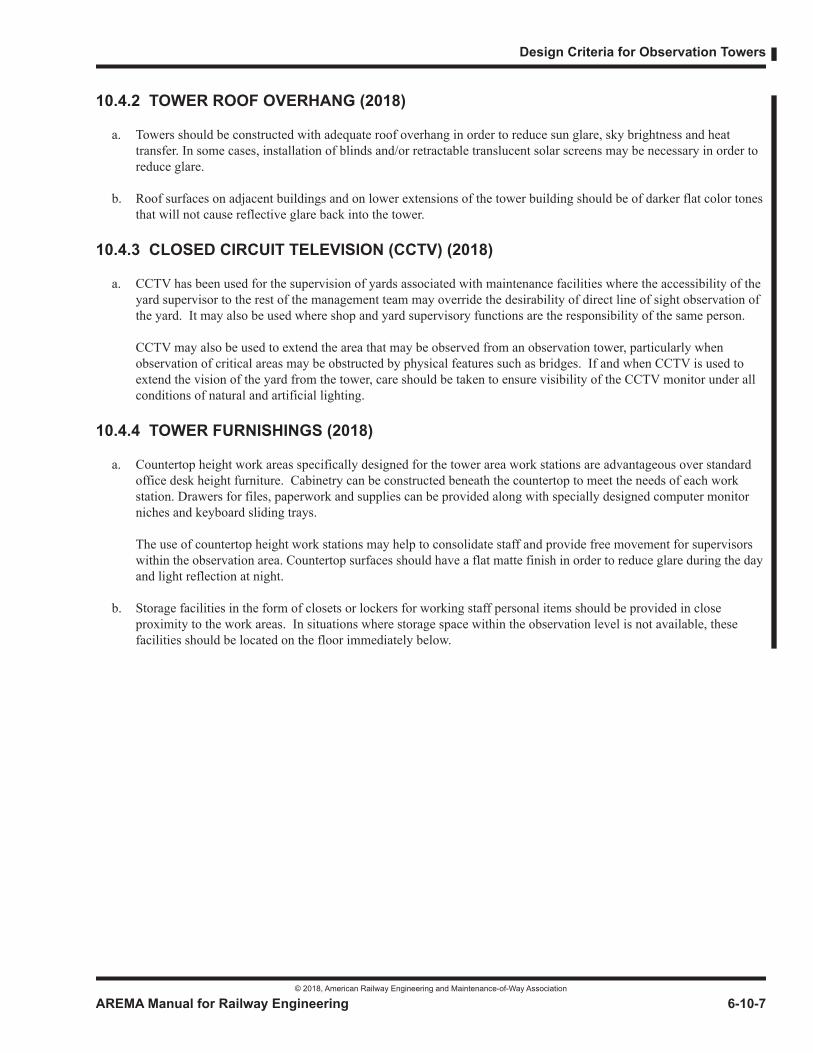
Design Criteria for Observation Towers
© 2018, American Railway Engineering and Maintenance-of-Way Association
AREMA Manual for Railway Engineering 6-10-7
1
3
4
10.4.2 TOWER ROOF OVERHANG (2018)
a. Towers should be constructed with adequate roof overhang in order to reduce sun glare, sky brightness and heat transfer. In some cases, installation of blinds and/or retractable translucent solar screens may be necessary in order to reduce glare.
b. Roof surfaces on adjacent buildings and on lower extensions of the tower building should be of darker flat color tones that will not cause reflective glare back into the tower.
10.4.3 CLOSED CIRCUIT TELEVISION (CCTV) (2018)
a. CCTV has been used for the supervision of yards associated with maintenance facilities where the accessibility of the yard supervisor to the rest of the management team may override the desirability of direct line of sight observation of the yard. It may also be used where shop and yard supervisory functions are the responsibility of the same person.
CCTV may also be used to extend the area that may be observed from an observation tower, particularly when observation of critical areas may be obstructed by physical features such as bridges. If and when CCTV is used to extend the vision of the yard from the tower, care should be taken to ensure visibility of the CCTV monitor under all conditions of natural and artificial lighting.
10.4.4 TOWER FURNISHINGS (2018)
a. Countertop height work areas specifically designed for the tower area work stations are advantageous over standard office desk height furniture. Cabinetry can be constructed beneath the countertop to meet the needs of each work station. Drawers for files, paperwork and supplies can be provided along with specially designed computer monitor niches and keyboard sliding trays.
The use of countertop height work stations may help to consolidate staff and provide free movement for supervisors within the observation area. Countertop surfaces should have a flat matte finish in order to reduce glare during the day and light reflection at night.
b. Storage facilities in the form of closets or lockers for working staff personal items should be provided in close proximity to the work areas. In situations where storage space within the observation level is not available, these facilities should be located on the floor immediately below.
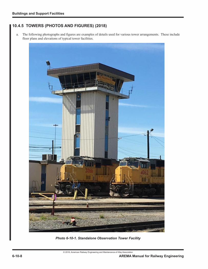
Buildings and Support Facilities
© 2018, American Railway Engineering and Maintenance-of-Way Association
6-10-8 AREMA Manual for Railway Engineering
10.4.5 TOWERS (PHOTOS AND FIGURES) (2018)
a. The following photographs and figures are examples of details used for various tower arrangements. These include floor plans and elevations of typical tower facilities.
Photo 6-10-1. Standalone Observation Tower Facility
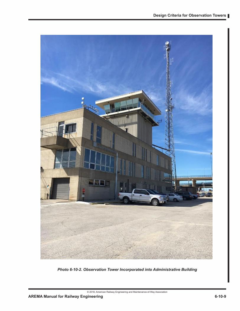
Design Criteria for Observation Towers
© 2018, American Railway Engineering and Maintenance-of-Way Association
AREMA Manual for Railway Engineering 6-10-9
1
3
4
Photo 6-10-2. Observation Tower Incorporated into Administrative Building
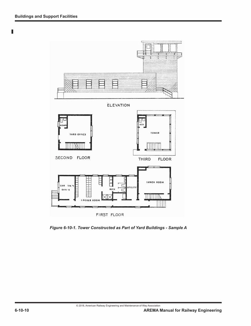
Buildings and Support Facilities
© 2018, American Railway Engineering and Maintenance-of-Way Association
6-10-10 AREMA Manual for Railway Engineering
Figure 6-10-1. Tower Constructed as Part of Yard Buildings - Sample A
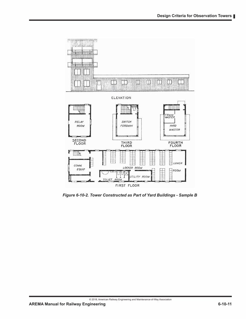
Design Criteria for Observation Towers
© 2018, American Railway Engineering and Maintenance-of-Way Association
AREMA Manual for Railway Engineering 6-10-11
1
3
4
Figure 6-10-2. Tower Constructed as Part of Yard Buildings - Sample B
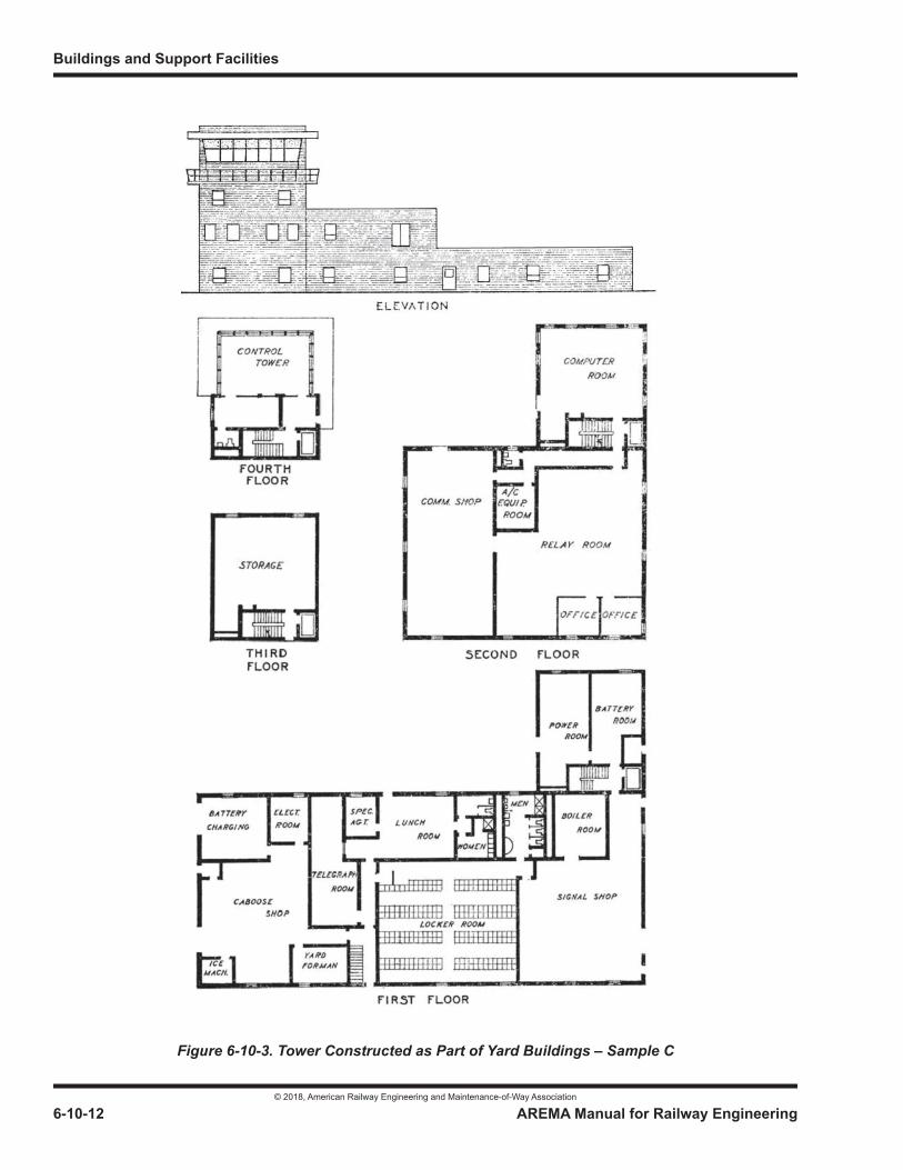
Buildings and Support Facilities
© 2018, American Railway Engineering and Maintenance-of-Way Association
6-10-12 AREMA Manual for Railway Engineering
Figure 6-10-3. Tower Constructed as Part of Yard Buildings – Sample C
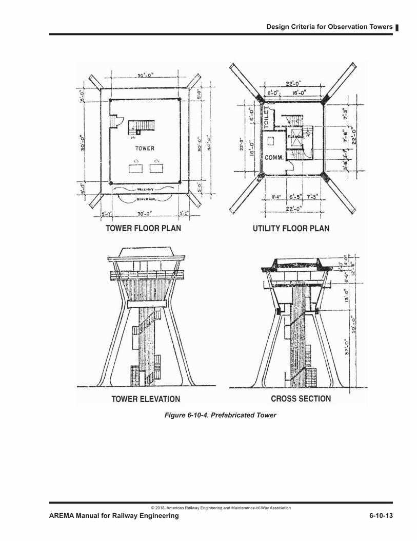
Design Criteria for Observation Towers
© 2018, American Railway Engineering and Maintenance-of-Way Association
AREMA Manual for Railway Engineering 6-10-13
1
3
4
Figure 6-10-4. Prefabricated Tower
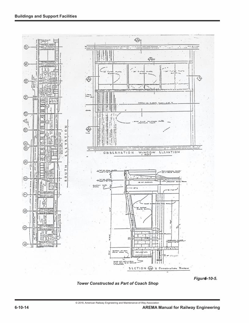
Buildings and Support Facilities
© 2018, American Railway Engineering and Maintenance-of-Way Association
6-10-14 AREMA Manual for Railway Engineering
Figure 6-10-5. Tower Constructed as Part of Coach Shop
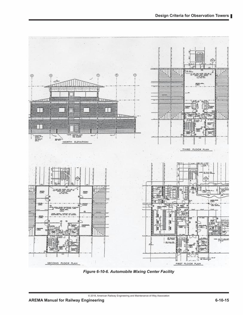
Design Criteria for Observation Towers
© 2018, American Railway Engineering and Maintenance-of-Way Association
AREMA Manual for Railway Engineering 6-10-15
1
3
4
Figure 6-10-6. Automobile Mixing Center Facility
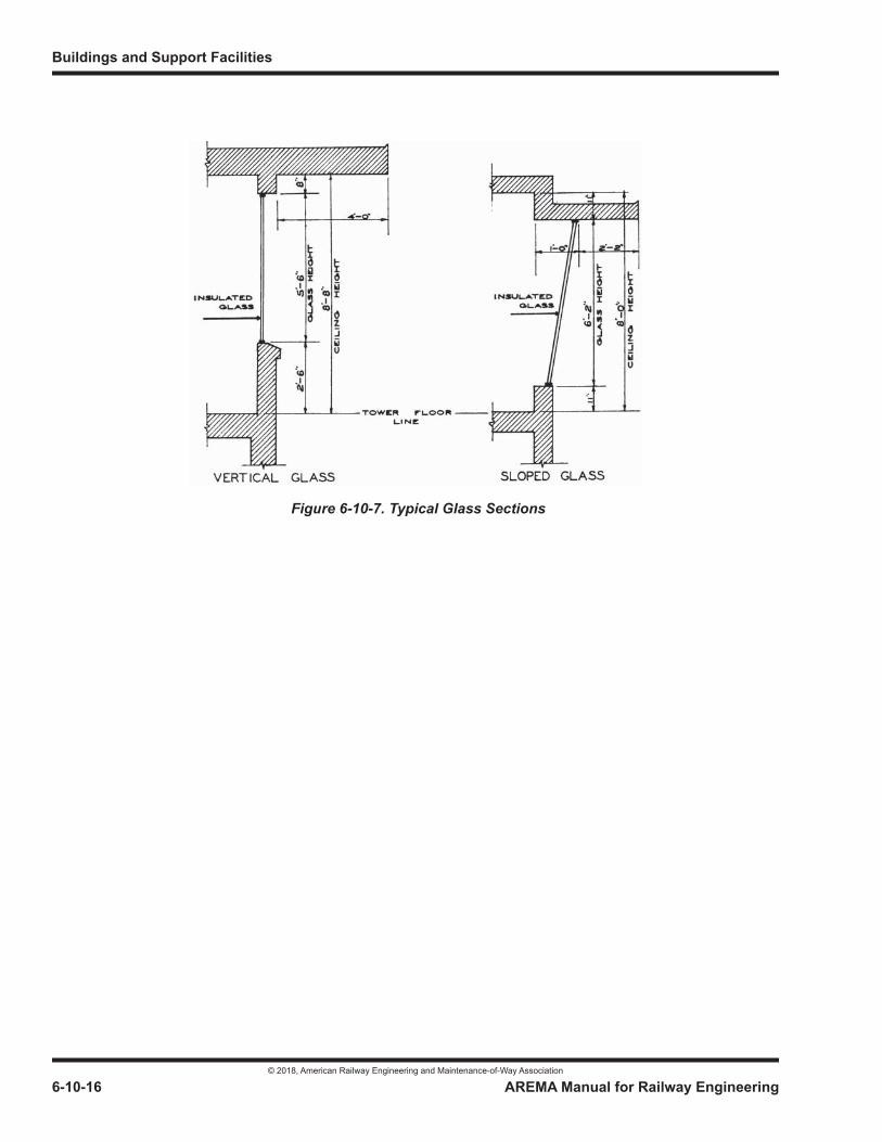
Buildings and Support Facilities
© 2018, American Railway Engineering and Maintenance-of-Way Association
6-10-16 AREMA Manual for Railway Engineering
Figure 6-10-7. Typical Glass Sections
© 2018, American Railway Engineering and Maintenance-of-Way Association
© 2018, American Railway Engineering and Maintenance-of-Way Association
© 2018, American Railway Engineering and Maintenance-of-Way Association
© 2018, American Railway Engineering and Maintenance-of-Way Association
© 2018, American Railway Engineering and Maintenance-of-Way Association
© 2018, American Railway Engineering and Maintenance-of-Way Association
© 2018, American Railway Engineering and Maintenance-of-Way Association
© 2018, American Railway Engineering and Maintenance-of-Way Association
© 2018, American Railway Engineering and Maintenance-of-Way Association
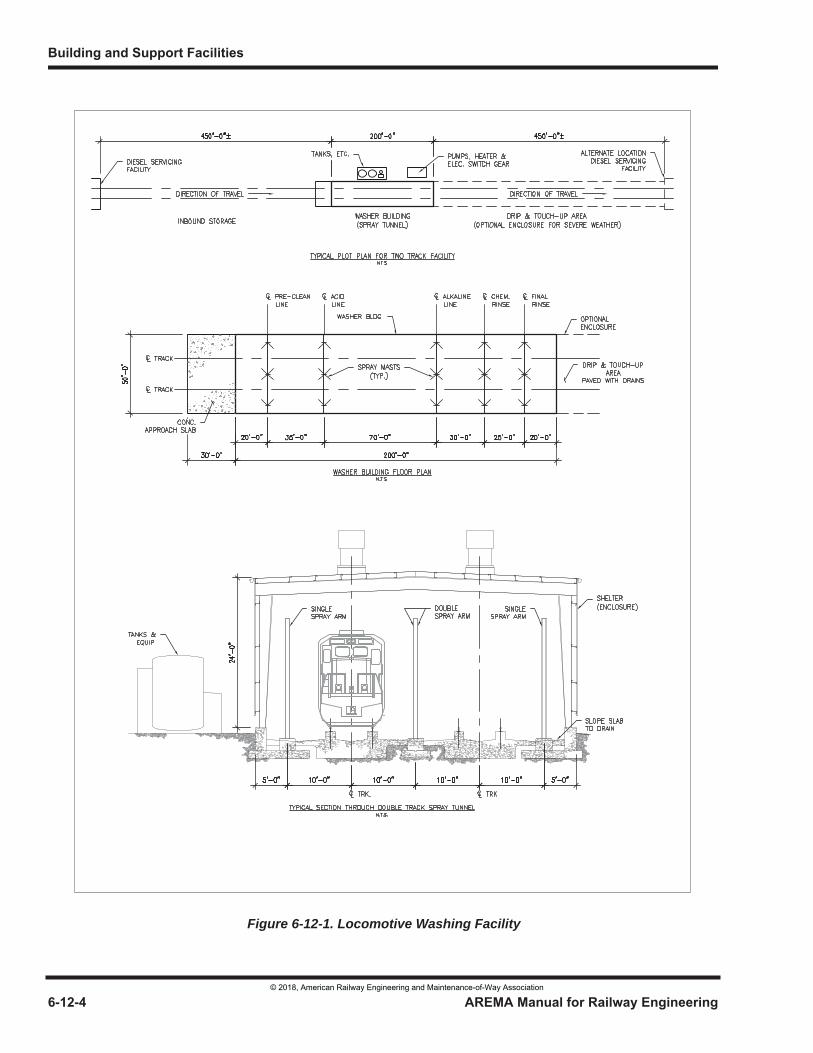
Figure 6-12-1. Locomotive Washing Facility
© 2018, American Railway Engineering and Maintenance-of-Way Association
© 2018, American Railway Engineering and Maintenance-of-Way Association
© 2018, American Railway Engineering and Maintenance-of-Way Association
© 2018, American Railway Engineering and Maintenance-of-Way Association
© 2018, American Railway Engineering and Maintenance-of-Way Association
© 2018, American Railway Engineering and Maintenance-of-Way Association
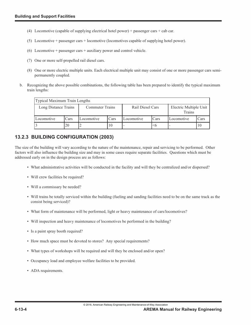
© 2018, American Railway Engineering and Maintenance-of-Way Association
© 2018, American Railway Engineering and Maintenance-of-Way Association
© 2018, American Railway Engineering and Maintenance-of-Way Association
© 2018, American Railway Engineering and Maintenance-of-Way Association
© 2018, American Railway Engineering and Maintenance-of-Way Association
© 2018, American Railway Engineering and Maintenance-of-Way Association
© 2018, American Railway Engineering and Maintenance-of-Way Association
© 2018, American Railway Engineering and Maintenance-of-Way Association

© 2018, American Railway Engineering and Maintenance-of-Way Association
© 2018, American Railway Engineering and Maintenance-of-Way Association
© 2018, American Railway Engineering and Maintenance-of-Way Association
© 2018, American Railway Engineering and Maintenance-of-Way Association
© 2018, American Railway Engineering and Maintenance-of-Way Association
© 2018, American Railway Engineering and Maintenance-of-Way Association
© 2018, American Railway Engineering and Maintenance-of-Way Association
© 2018, American Railway Engineering and Maintenance-of-Way Association
© 2018, American Railway Engineering and Maintenance-of-Way Association
© 2018, American Railway Engineering and Maintenance-of-Way Association
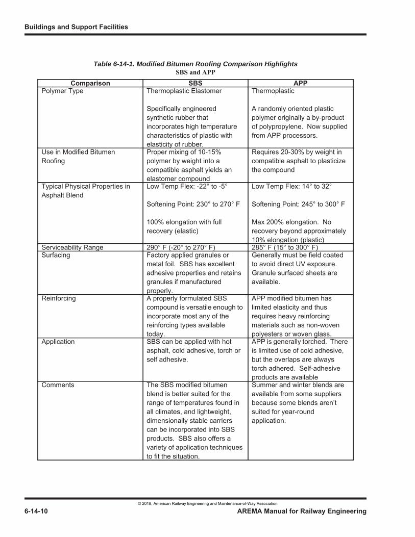
Table 6-14-1. Modified Bitumen Roofing Comparison Highlights
© 2018, American Railway Engineering and Maintenance-of-Way Association
© 2018, American Railway Engineering and Maintenance-of-Way Association
© 2018, American Railway Engineering and Maintenance-of-Way Association
© 2018, American Railway Engineering and Maintenance-of-Way Association
SPRI’s Wind Load Design Guide for Low-Sloped Flexible Membrane Roofing Systems (hereafter, the Guide)
SPRI R-4, Wind Design Standard for Ballasted Single-Ply Roofing Systems,
SPRI RP-4 recognizes three levels of increasing severity of wind loading of membrane roofing design: Systems 1, 2 and 3
© 2018, American Railway Engineering and Maintenance-of-Way Association
adhered fully adhered
© 2018, American Railway Engineering and Maintenance-of-Way Association
© 2018, American Railway Engineering and Maintenance-of-Way Association
© 2018, American Railway Engineering and Maintenance-of-Way Association
Specification for Poly (Vinyl Chloride) Sheet Roofing.
© 2018, American Railway Engineering and Maintenance-of-Way Association
© 2018, American Railway Engineering and Maintenance-of-Way Association
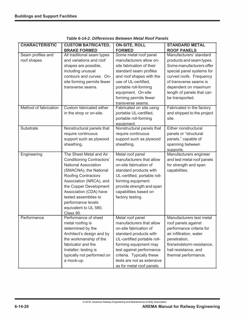
Table 6-14-2. Differences Between Metal Roof Panels
© 2018, American Railway Engineering and Maintenance-of-Way Association
SMACNA’s Architectural Sheet Metal Manual NRCA’s Architectural Sheet Metal and Metal Roofing Manual (part of the NRCA Roofing and Waterproofing Manual).
SMACNA’s Architectural Sheet Metal Manual
locked crimped.
© 2018, American Railway Engineering and Maintenance-of-Way Association
double lock
single lock
capped standing seam
© 2018, American Railway Engineering and Maintenance-of-Way Association
© 2018, American Railway Engineering and Maintenance-of-Way Association
The Asphalt Roofing Manufacturers Association (ARMA) and NRCA
© 2018, American Railway Engineering and Maintenance-of-Way Association
© 2018, American Railway Engineering and Maintenance-of-Way Association
Tile Roofing Institute (TRI).
Concrete and Clay Roof Tile Installation Manual.
Concrete and Clay Roof Tile Design Criteria Installation Manual
© 2018, American Railway Engineering and Maintenance-of-Way Association
© 2018, American Railway Engineering and Maintenance-of-Way Association
Concrete and Clay Tile Roof Design Criteria Manual for Cold and Snow Regions,
NRCA’s The NRCA Roofing and Waterproofing Manual
© 2018, American Railway Engineering and Maintenance-of-Way Association
© 2018, American Railway Engineering and Maintenance-of-Way Association
© 2018, American Railway Engineering and Maintenance-of-Way Association
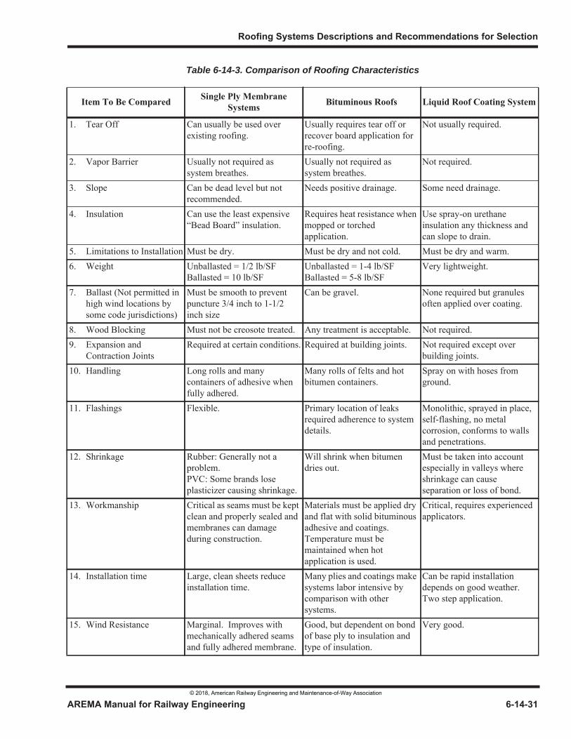
Table 6-14-3. Comparison of Roofing Characteristics
© 2018, American Railway Engineering and Maintenance-of-Way Association
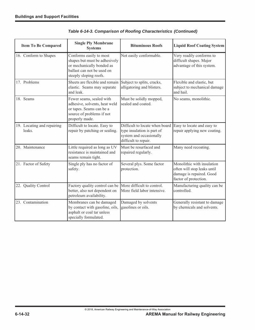
Table 6-14-3. Comparison of Roofing Characteristics (Continued)
© 2018, American Railway Engineering and Maintenance-of-Way Association
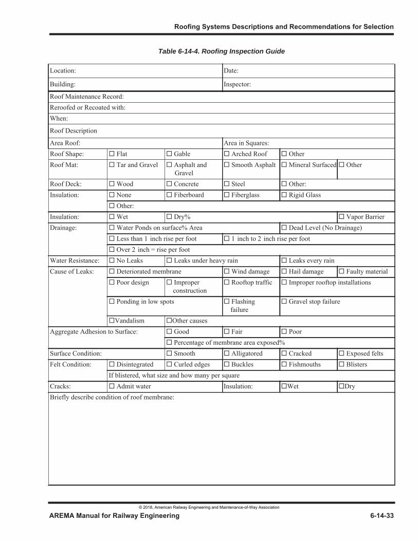
Table 6-14-4. Roofing Inspection Guide
© 2018, American Railway Engineering and Maintenance-of-Way Association
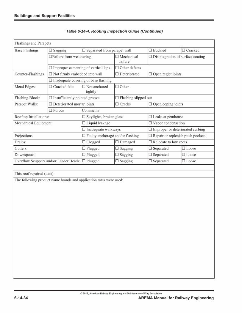
Table 6-14-4. Roofing Inspection Guide (Continued)
© 2018, American Railway Engineering and Maintenance-of-Way Association
© 2018, American Railway Engineering and Maintenance-of-Way Association 6-15-1
1
3
6 Part 15
Inspection of Railway Buildings1
— 2018 —
FOREWORD
a. Railway buildings represent a significant capital investment and should be properly maintained in order to protect that investment while providing an acceptable level of safety to its users. Effective building maintenance involves both reactive and programmed maintenance activities. Reactive maintenance, involves repairs and/or replacement of building components to address an immediate problem. Programmed Maintenance, involves addressing a predetermined list of facility maintenance needs, which can be scheduled over a period of time. A maintenance program for a building is generally based upon an inspection program performed once a year but not less than once every five years, the actual interval should be established by the importance of the building to the ongoing business operations of the railroad as well as the age and condition of the structure as determined in previous inspections. Inspections should be performed by qualified professionals.
b. The inspection program is generally carried out in order to identify deficiencies that may affect the structural integrity of the building, its functionality and/or its resiliency to the effects of severe weather conditions. The inspection program can also be used to confirm compliance with regulatory code and compliance issues as they relate to the International Building Code (IBC), Americans with Disabilities Act of 1990 (ADA), National Building Code of Canada and other federal, state, provincial and local regulatory bodies. In addition, the inspection program should be used to identify potential safety hazards which may pose a threat to the employees and/or visitors of the building.
c. A building inspection program can be used to identify short term and long term costs associated with the items appearing in the inspection report. These costs can be utilized to establish capital budget(s) for repairs or modifications within a specified time period.
TABLE OF CONTENTS
Section/Article Description Page
15.1 Organization and Inspection Preparation . . . . . . . . . . . . . . . . . . . . . . . . . . . . . . . . . . . . . . . . . . . . . . . . . . . 6-15-2
15.2 Inspectors . . . . . . . . . . . . . . . . . . . . . . . . . . . . . . . . . . . . . . . . . . . . . . . . . . . . . . . . . . . . . . . . . . . . . . . . . . . . . 6-15-2
15.3 Inspections. . . . . . . . . . . . . . . . . . . . . . . . . . . . . . . . . . . . . . . . . . . . . . . . . . . . . . . . . . . . . . . . . . . . . . . . . . . . . 6-15-3
1 References Vol. 85, 1984, p 29
Buildings and Support Facilities
© 2018, American Railway Engineering and Maintenance-of-Way Association
6-15-2 AREMA Manual for Railway Engineering
TABLE OF CONTENTS (CONT)
Section/Article Description Page
15.4 Conducting an Inspection . . . . . . . . . . . . . . . . . . . . . . . . . . . . . . . . . . . . . . . . . . . . . . . . . . . . . . . . . . . . . . . 6-15-3
15.5 Inspection Reports . . . . . . . . . . . . . . . . . . . . . . . . . . . . . . . . . . . . . . . . . . . . . . . . . . . . . . . . . . . . . . . . . . . . . 6-15-6
LIST OF FIGURES
Figure Description Page
6-15-1 Building Inspection Report . . . . . . . . . . . . . . . . . . . . . . . . . . . . . . . . . . . . . . . . . . . . . . . . . . . . . . . . . . . . . 6-15-8
SECTION 15.1 ORGANIZATION AND INSPECTION PREPARATION
a. Building inspections should be performed in an orderly fashion, utilizing predetermined criteria, methods and sequence. The exterior of the building should be inspected from the visible foundation level to the top of the walls or underside of the eaves. The roof should also be inspected along with any parapet walls or other structures on the roof. Positive drainage around the building and/or facility should be verified. On the interior of the building, the basement and/or crawl space and each floor above the basement level should be inspected, including any attic space. A thorough inspection of each room on each floor should be performed, to include floors, walls, ceilings, (including the space above suspended ceilings), as well as mechanical, electrical and plumbing components. All buildings should comply with all local, state, provincial, and federal building codes.
b. In addition to the building inspection, the ground surface area surrounding the building should also be inspected. The grounds inspection should cover such things as grading, drainage, lighting, walkways, crosswalks, warning devices, parking and accessibility.
c. If original construction drawings or project as-built drawings are available, they should be used to verify the current configuration and conditions of the building. Sketches should be made of any changes which may have been made to the building layout, plumbing, mechanical, fire protection and electrical characteristics that are not reflected in available reference drawings.
d. At the time of the inspection an interview of the person(s) in charge of the building should be conducted in order to ascertain if any unnoticeable conditions may exist that warrant further investigation.
e. The person in charge of the overall building inspection should, if at all possible, arrange to have the area Buildings and Bridge Supervisor and/or his representative accompany the inspection team.
SECTION 15.2 INSPECTORS
a. Persons assigned to the inspection of a building should be qualified in their particular area of expertise. A typical inspection team should consist of a civil engineer, structural engineer, architect, construction project manager,
Inspection of Railway Buildings
© 2018, American Railway Engineering and Maintenance-of-Way Association
AREMA Manual for Railway Engineering 6-15-3
1
3
4
mechanical engineer, electrical engineer, and/or skilled tradesperson. Other qualified individuals may be equally appropriate depending upon the nature of the building or facility being inspected.
b. Upon completion of the physical inspection of the building, the inspectors should record their inspection notes in a format which can be easily read and used by non-technical persons responsible for the buildings' operation and maintenance. Figure 6-15-1 is an example of a form which could be used for this purpose. Entries on the form should be legible, and easily understood. Where conditions exist that require more detailed information, this information should be included in a separate attachment(s).
SECTION 15.3 INSPECTIONS
a. a.Building and facility inspections should be scheduled on an ongoing periodic basis, normally on an annual or bi-annual basis. In the latter case, inspections are called for only when a problem occurs which requires immediate attention. In all cases however, the process of conducting the inspection should be similar and consistent.
b. Annual or bi-annual inspections are an important resource for monitoring the conditions of buildings and facilities. These inspections are a valuable tool for identifying potential, developing problems that may affect the integrity of the building or facility. Inspections may also serve to identify potential environmental problems, as well as energy inefficiencies that may exist. Through the inspection process, buildings and facilities can be maintained in a manner which will foster operational efficiencies, assure their design life and possibly prolong that life. Inspections serve as a planning tool for budgeting programmed maintenance and major expenditures to help avoid failures or catastrophic loss. There are numerous commercial software programs that incorporate an asset database, asset condition reporting, a work order initiation and follow-up process, and an asset history. They provide an integrated platform for conducting building inspections and scheduling building maintenance, identifying "state-of-good-repair" backlog, and anticipating asset upgrading or replacement. These programs provide inspection forms in both hard copy and electronic form and can generate budgets for capital planning purposes.
c. Public funding of rail projects may impose as a condition of a grant the requirement to develop and follow a formal Asset Management Plan that periodically reviews the condition of infrastructure and critical facilities. Building inspections are an element of asset management which may support the owner with its compliance of contractual or regulatory requirements.
SECTION 15.4 CONDUCTING AN INSPECTION
The following paragraphs of this manual are not included to serve as a comprehensive guide on what to check when inspecting a building and/or facility. The information provided is intended only to serve as a guide and a reminder to those charged with the inspection duties to be mindful of these potential conditions.
a. Structural inspections of a building and/or facility should begin at the foundation level. The visible portions of the exterior foundation should be checked for cracks and/or other forms of damage. Concrete stairs, stoops and/or ramps attached to the building should be checked for settlement and/or separation and assessed as to whether or not remedial measures are necessary. If steel framing is involved bolted connections should be inspected for corrosion, or; if welded joints are used, inspect for cracking and/or separations. Steel framing should also be checked for corrosion and stress due to possible overloading or damage due to impacts, heavy winds, foundation movements, etc.
Inside basements or crawl spaces, walls and floor surfaces should be checked for cracks and water infiltration. If concrete ceilings are present, check for cracking and/or spalling along bearing points. Columns and piers should be
Buildings and Support Facilities
© 2018, American Railway Engineering and Maintenance-of-Way Association
6-15-4 AREMA Manual for Railway Engineering
inspected for cracking, spalling and/or other damage. Concrete pits should be inspected for cracking in the floor and walls. Note if any water infiltration is present.
Accessible timber framing elements, including; wood sills, plates, joists, rafters, studs, headers, header joists, struts, collar beams, door bucks, stair runners, columns and corner posts should be checked for splitting and stress due to overloading or fatigue. Also, ensure that no decay is visible due to water damage and/or insects such as termites. Similar checks should also be made on all floors of the building if applicable, as well as the attic. In the attic, also check for water stains on framing or damp insulation that may indicate damage to the roof sheathing.
b. Architectural inspections should focus on the interior and exterior condition of the building. On the exterior, the inspection should examine the condition of the masonry, metal panels, concrete, wood or composite surfaces, whichever is applicable. Exterior surfaces should be checked to ensure applied protectants are in a condition that will protect the underlying material from degradation. Positive drainage around the building or facility should be also be verified. For masonry work, mortar joints should be checked for possible deterioration. Metal buildings should be checked for loose, missing or damaged trim and/or panels, rusting elements or missing fasteners. Concrete walls should be checked for cracking and spalling, which could potentially allow water to penetrate into the building interior. Wood surfaces should be checked for decay and/or other types of damage. Regardless of the type of construction, inspection should carefully evaluate the condition of sealants and caulking at joints and junctions of dissimilar materials.
Walk-through and overhead doors should be checked to ensure serviceability and proper functionality, including the proper operation of limit switches and safety devices. Overhead door apparatus such as tracks/guides, reels, springs, motors, cables, chains, etc. should be checked for damage or fatigue. Track frame and/or guide mounts should be checked to ensure that connections to the building or facility are solid. Overhead door panels or slats should be checked for damage or fatigue. Walk-through doors and accessories, such as panels, hinges, closers, thresholds, kick plates, hold-opens, stops, pulls, push bars, latches/locks, etc. should be checked.
Window exteriors should be checked to ensure caulking is intact or hasn't dried out and/or pulled free of its contact surfaces. Also note any broken glass or seals which may be leaking on double glazed windows. For wooden sash, check for possible decay. For operable sash, test the operation of hardware, especially if the window is considered an alternate emergency exit.
Eaves and fascia boards should be checked for decay and mold, failure of hardware, and proper functioning of eave vents to reduce condensation in attic spaces. On metal trim, check for separations and/or loose pieces. Inspect gutters and downspouts for proper functionality. Check for damage or restrictions including debris, dents, rust and/or attachment hardware failure that may result in improper pitch to the downspouts or drains. Inspect scuppers, window jambs and door jambs for looseness, decay and/or other types of damage.
On the interior, inspect floors, walls, and ceilings for possible damage and/or adverse wear. Check for water spots, indicating possible rain water or plumbing leaks. Ensure that door and window hardware are properly functioning, especially panic hardware on prescribed exits. In areas where ceramic tile, glazed tile and/or masonry products are used, check grout and sealants for damage or degradation. Stairs and stairwells should be checked for safe tread condition, secure handrails, adequate lighting, signage and/or any unsafe condition. Verify that elevators have been inspected as required by code enforcement officials by reviewing certificates at the start of the inspection. Elevator cabs and individual elevator floor call stations should be inspected to ensure proper operations. Portable fire extinguishers and standpipe hose cabinets should be inspected for condition, suitability of fire class hazard and current inspection tagging by a qualified fire protection specialist.
On the roof, inspect flashings and sealants for separation and/or other types of damage. Check the condition of the roof surface itself for ponding, membrane fatigue, bubbles, tears, rust, missing or damaged fasteners, sealants or other potential trouble spots. Inspect curbs, scuppers, flashings and counter-flashings around mechanical equipment and other roof penetrations such as plumbing vents.
Inspection of Railway Buildings
© 2018, American Railway Engineering and Maintenance-of-Way Association
AREMA Manual for Railway Engineering 6-15-5
1
3
4
c. The mechanical inspection should include the heating, air conditioning, exhaust and ventilation systems, as well as plumbing and fire protection systems. When service contractors are utilized for mechanical systems maintenance, review all recent service reports prior to starting an inspection.
The heating, ventilation and air conditioning (HVAC) systems checks will vary according to the types of systems used and only those persons familiar with the operation of these types of systems should be used for the inspection. In general, HVAC systems should be checked for clean filters, proper belt tension on fans, clean fan wheels, clean coils, clean strainer baskets, if applicable, and that traps, valves, pressure reducing stations, condensate pumps, drains and air vents are all operating properly. Natural gas or Liquefied Petroleum Gas burners, supply lines, line connections, pilot systems, thermocouples, force air fans, ventilation, etc. should be checked. Boilers and hot water generator burners, fuel filters and relief valves should be inspected. Work reports should be checked to ensure that maintenance requirements are being met. Storage tanks when visible, should be inspected for adequate containment, pipe connections, markings, and alarms. Air compressors and air receivers, relief valves, condensate drains and coolers/dryers should be checked for proper operation and current compliance with pressure vessel codes.
The sequence of operation for each HVAC system should be reviewed, followed by verification of proper operation of thermostats and other controls. Motorized dampers, fire dampers, diffusers, grilles, and fans should be checked for proper settings and operation. Inspection and/or service reports should be checked, if available, for re-occurring problems.
Plumbing inspections should begin at the main water and sewer/ storm drain service points where they enter or leave the building. Water meters and backflow preventers should be inspected for correct installation and operation, including secure attachment of the electrical service ground to the incoming water service. Piping for sewer and water should be checked for damage and/or leaks. Cleanouts should be accessible. Toilet areas should be checked to determine if faucets are working properly, water closets flush correctly, and hot water tanks are installed properly with functioning relief valves and required safety devices.
Fire suppression systems including water sprinkler systems should be inspected for damage. Sprinkler heads, leaks in the piping (on wet systems) and that the fire pump, if applicable, is being exercised according to the manufacturer's directions. Dry fire suppression systems should be checked to ensure proper charge and activation valves and alarms have been inspected and tested. Service records for gaseous fire suppression systems should be reviewed and the fire protection specialist consulted for any anomalies noted. All control valves should be adequately marked, clear of obstructions, and padlocked in the open position if required by code. Hazardous materials storage areas should be inspected for required signage, containment, fire suppression and rated construction isolation as required by code enforcement officials. Inspections should keep alert for improper storage of hazardous or flammable materials in areas not so designated.
Building drainage systems should be checked for deterioration and clogging. Oil/water separators, grease traps, triple basins and other waste type holding tanks should also be checked to ensure they are operating properly and being serviced on a regular basis.
Electrical inspections should determine if adequate power exists in the building. If possible, occupant interview may help in determining if there is any history of dimming lights or repeated circuit breaker trips. Panels should be clear of obstructions and panel board directories are up to date. Fuse and/or breakers should be checked on each circuit in order to verify that they are properly sized and functional. Ground fault and arc fault circuit interrupters should be tested. Outlets and switches should be checked for fatigue, damage to covers and/or proper functionality. Emergency lighting and other life safety systems should be checked to ensure that the systems are operating properly. If emergency or standby power systems are installed, review maintenance records and simulate a power failure to verify the systems operate as intended. Where electrical grounding jumpers are installed on equipment or lightning protection, inspections should verify that connections are tight and electrical continuity to a grounding electrode is present.
Lighting should be checked to determine that reasonable lumens or foot-candles exist in work spaces for the tasks being performed. Note if the fixtures lenses and safety guards, if used, are clean and/or in need of replacement. Note if
Buildings and Support Facilities
© 2018, American Railway Engineering and Maintenance-of-Way Association
6-15-6 AREMA Manual for Railway Engineering
improper or unauthorized extension cords are in use, and if any wiring appears to have been added to the facility which does not meet local electrical code requirements.
d. Environmental inspections are also a necessity on many buildings and facilities where asbestos, lead paint, and/or hazardous chemical/substance may have been used and/or are expected to be found.
If an environmental inspection is deemed appropriate for the building and/or facility a qualified environmental engineer and/or consultant should be employed. This individual and/or firm should then conduct a thorough investigation of the building and/or facility to determine if any hazardous materials, chemicals and/or substances are present. A full report should be provided outlining the findings of the inspection.
In the event that hazardous materials, chemicals and/or substances are found, proper documentation of the findings should be prepared. Documentation should consist of what specifically was found, extent of the material, identification of the substance and/or chemical, photographs, and; the approximate cost for abatement.
As noted earlier in this section, the above is not intended to serve as the criteria for an inspection, but merely to alert the reader as to the many items which need to be considered when conducting a thorough building and facility inspection. While many of the above referenced items will be common to almost any building and/or facility, each building and/or facility will have their own unique needs and inspection requirements.
SECTION 15.5 INSPECTION REPORTS
a. Once the inspection has been completed and notes compiled, a report should be prepared which identifies any substandard or unacceptable condition(s) identified during the inspection. Any condition identified during the inspection that would represent a hazard to personnel or to the safety of the structure, should be brought to the immediate attention of the responsible person in charge of the inspection and official in charge of the building or facility at the time of the inspection. Final reporting may be developed by grouping items according to location in or around the building/facility, or by separate discipline lists arranged by priority rating.
Each discipline should categorize the results of their individual inspections in order to assist those receiving the information to identify immediate and long-term needs. When requested, estimates of costs may be prepared for the work on an individual line item basis to support future maintenance planning.
b. Urgent items needing correction may be assigned to specific parties and monthly reporting as to status of repairs or corrections made to the designated railroad official(s).
c. A suggested rating system is proposed which can serve as a guide for determining the importance of the repairs needed and response type that may be advisable. This rating system is as follows:
(1) Potentially hazardous to personnel and/or personnel safety. Urgent action required
(2) Compromises structural integrity of the building and/or facility. Immediate action warranted.
(3) Requires major maintenance and if not attended to promptly will cost substantially more at a later date. Schedule additional study and establish future actions.
(4) If corrected will reduce building and/or facility operating cost. Evaluate and budget if necessary
(5) Corrective action will improve image, appearance and/or personal comfort. Evaluate and budget if necessary
Inspection of Railway Buildings
© 2018, American Railway Engineering and Maintenance-of-Way Association
AREMA Manual for Railway Engineering 6-15-7
1
3
4
(6) Regular maintenance has been neglected and/or performed improperly. Revised operating practices or maintenance methods should be established.
(7) No work required. Revised operating practices or maintenance methods may be needed.
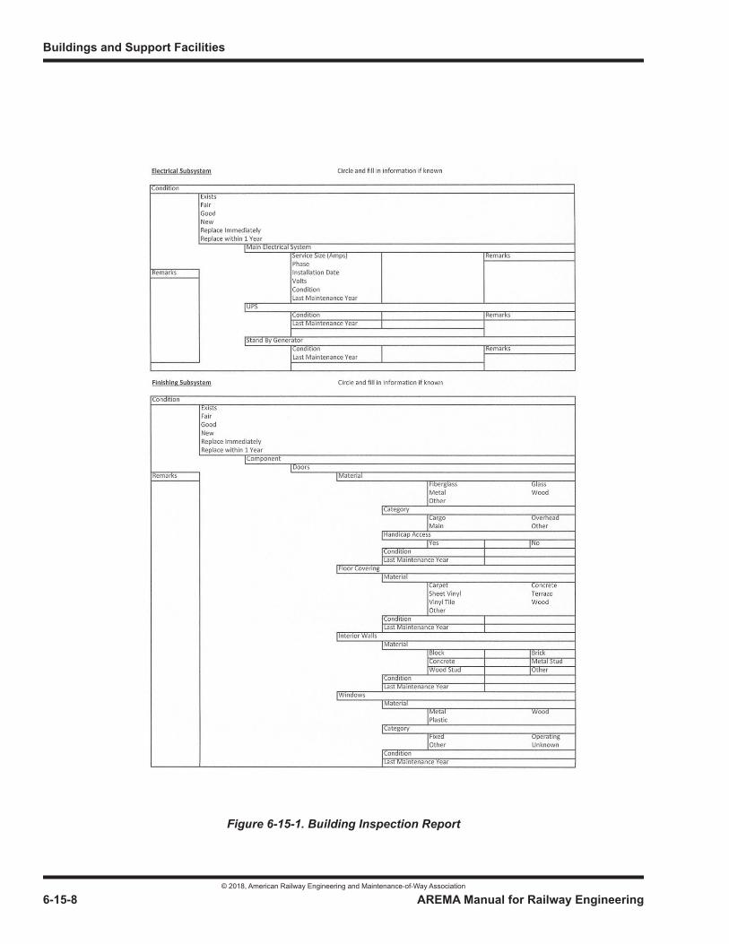
Buildings and Support Facilities
© 2018, American Railway Engineering and Maintenance-of-Way Association
6-15-8 AREMA Manual for Railway Engineering
THIS PAGE INTENTIONALLY LEFT BLANK.
Figure 6-15-1. Building Inspection Report
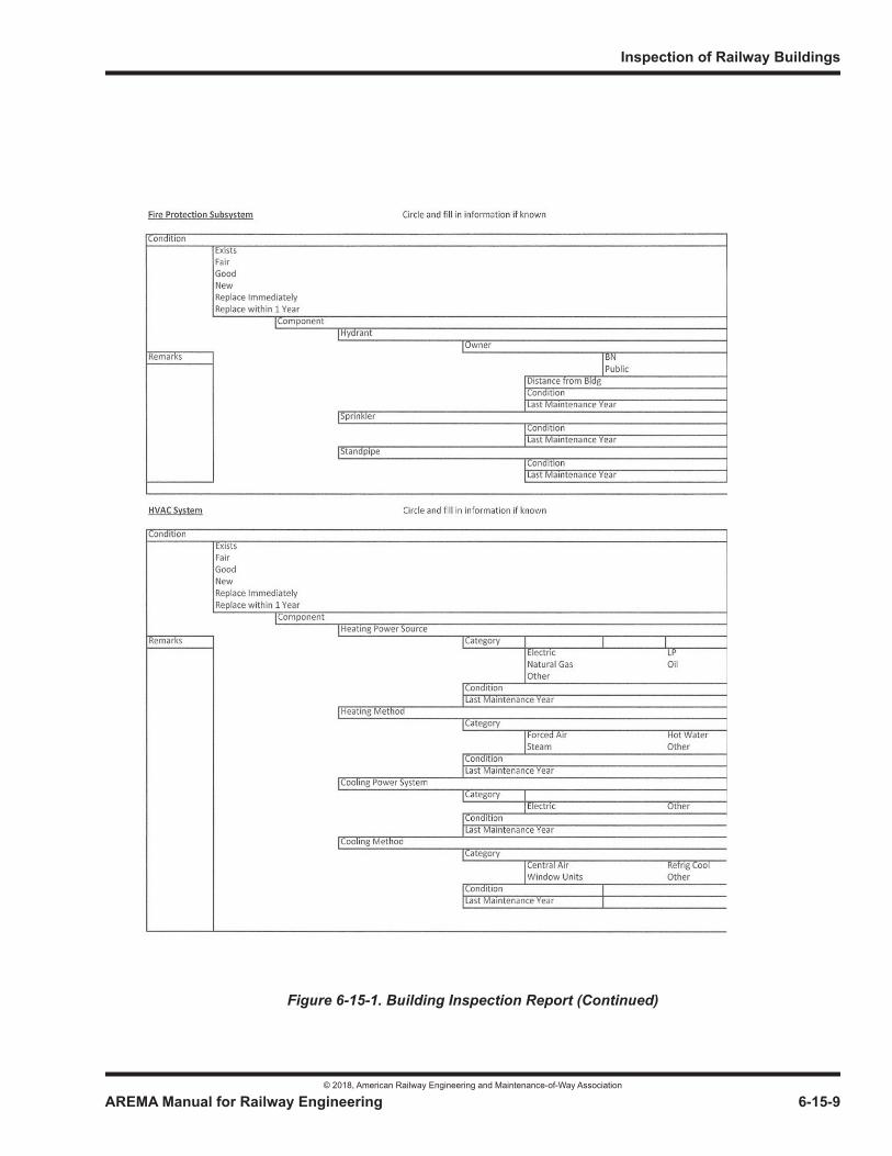
Inspection of Railway Buildings
© 2018, American Railway Engineering and Maintenance-of-Way Association
AREMA Manual for Railway Engineering 6-15-9
1
3
4
Figure 6-15-1. Building Inspection Report (Continued)

Buildings and Support Facilities
© 2018, American Railway Engineering and Maintenance-of-Way Association
6-15-10 AREMA Manual for Railway Engineering
THIS PAGE INTENTIONALLY LEFT BLANK.
© 2018, American Railway Engineering and Maintenance-of-Way Association
© 2018, American Railway Engineering and Maintenance-of-Way Association

© 2018, American Railway Engineering and Maintenance-of-Way Association
© 2018, American Railway Engineering and Maintenance-of-Way Association
© 2018, American Railway Engineering and Maintenance-of-Way Association
© 2018, American Railway Engineering and Maintenance-of-Way Association
© 2018, American Railway Engineering and Maintenance-of-Way Association

© 2018, American Railway Engineering and Maintenance-of-Way Association
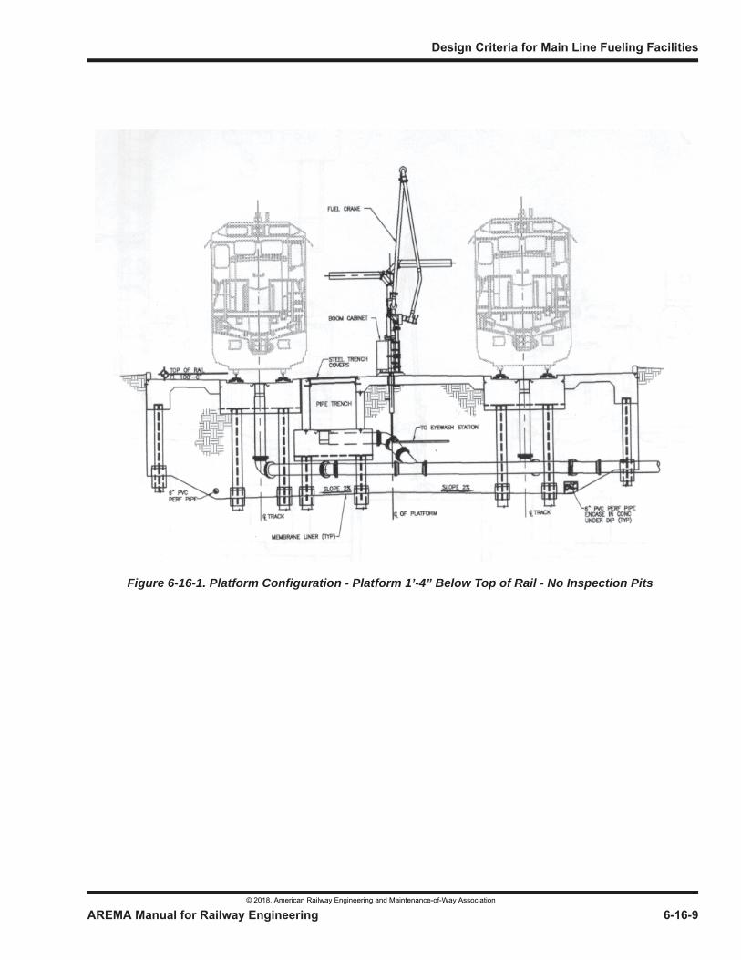
Figure 6-16-1. Platform Configuration - Platform 1’-4” Below Top of Rail - No Inspection Pits
© 2018, American Railway Engineering and Maintenance-of-Way Association
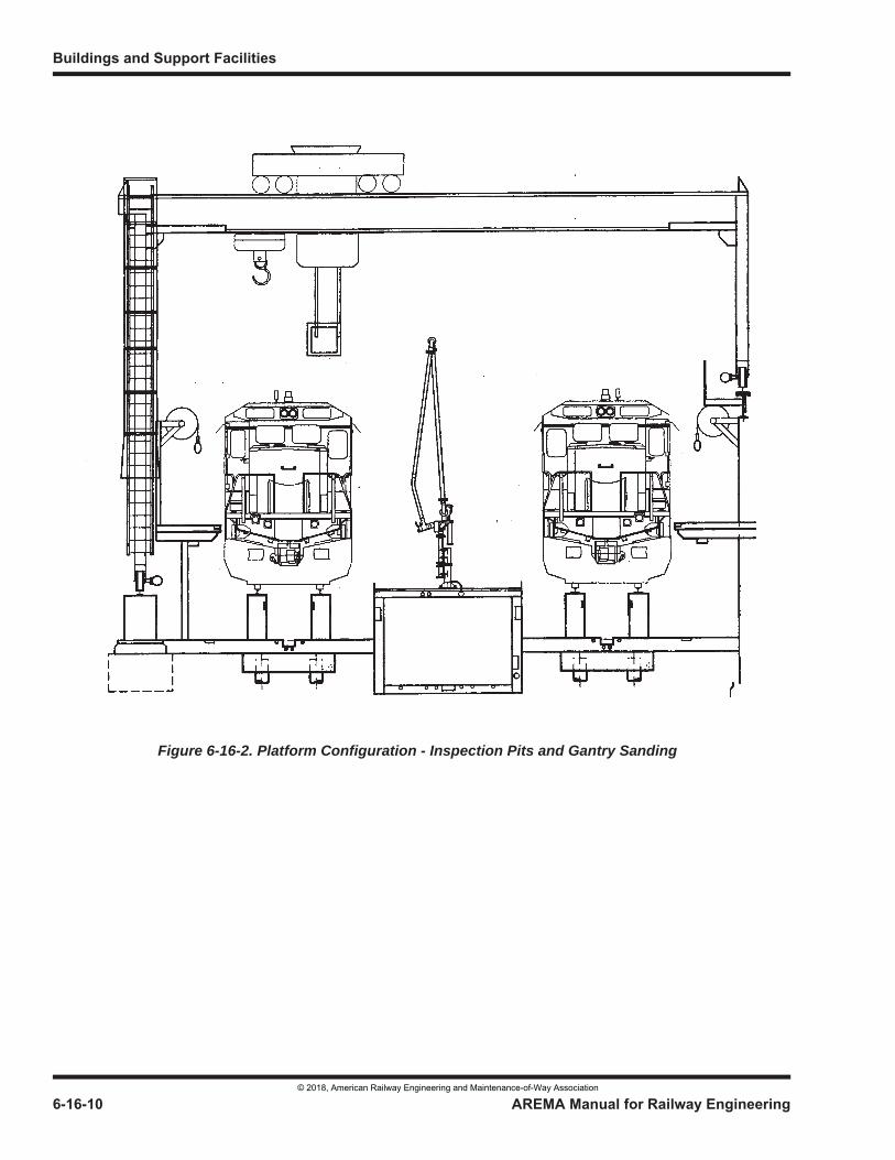
Figure 6-16-2. Platform Configuration - Inspection Pits and Gantry Sanding
© 2018, American Railway Engineering and Maintenance-of-Way Association
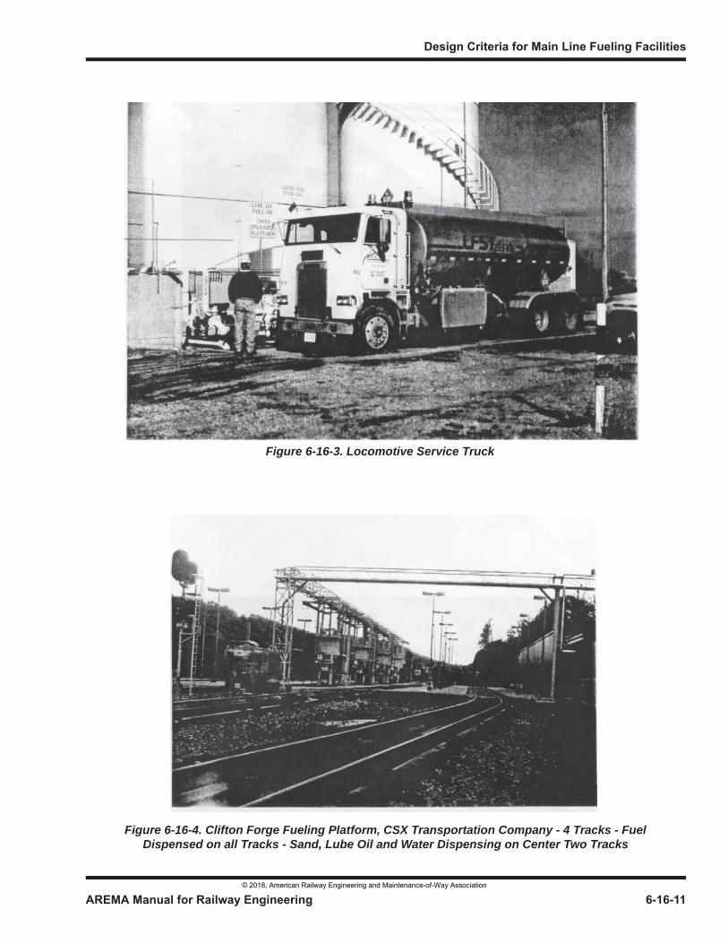
Figure 6-16-3. Locomotive Service Truck
Figure 6-16-4. Clifton Forge Fueling Platform, CSX Transportation Company - 4 Tracks - Fuel Dispensed on all Tracks - Sand, Lube Oil and Water Dispensing on Center Two Tracks
© 2018, American Railway Engineering and Maintenance-of-Way Association
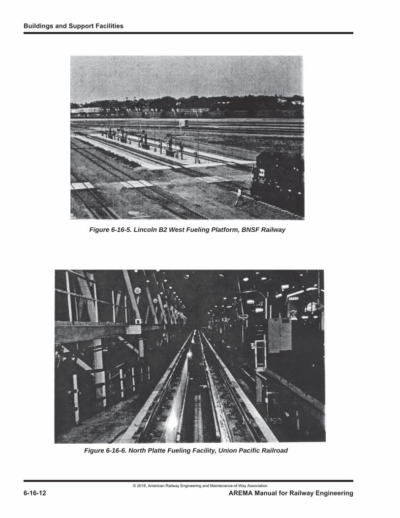
Figure 6-16-5. Lincoln B2 West Fueling Platform, BNSF Railway
Figure 6-16-6. North Platte Fueling Facility, Union Pacific Railroad
© 2018, American Railway Engineering and Maintenance-of-Way Association
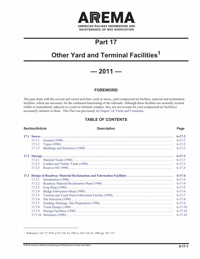
© 2018, American Railway Engineering and Maintenance-of-Way Association
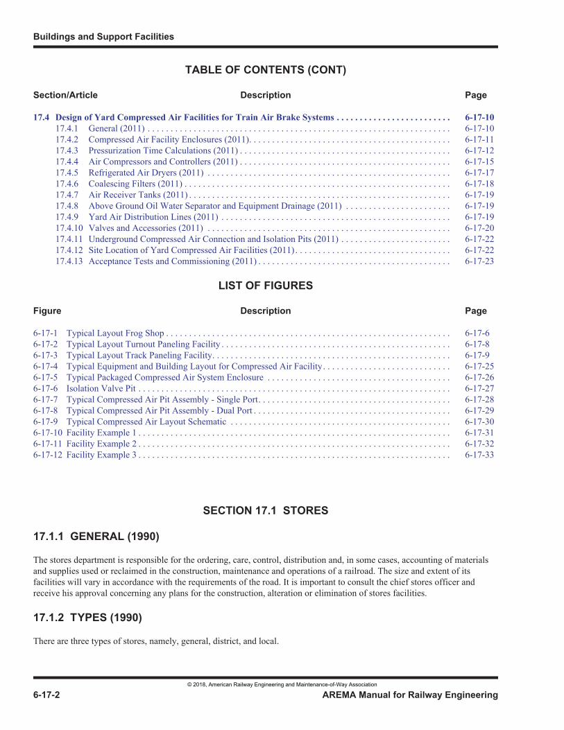
© 2018, American Railway Engineering and Maintenance-of-Way Association
© 2018, American Railway Engineering and Maintenance-of-Way Association
© 2018, American Railway Engineering and Maintenance-of-Way Association
Manual for Railway Engineering
© 2018, American Railway Engineering and Maintenance-of-Way Association
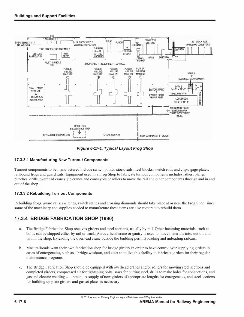
Figure 6-17-1. Typical Layout Frog Shop
© 2018, American Railway Engineering and Maintenance-of-Way Association
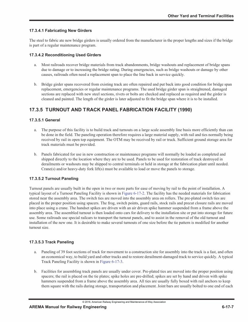
© 2018, American Railway Engineering and Maintenance-of-Way Association
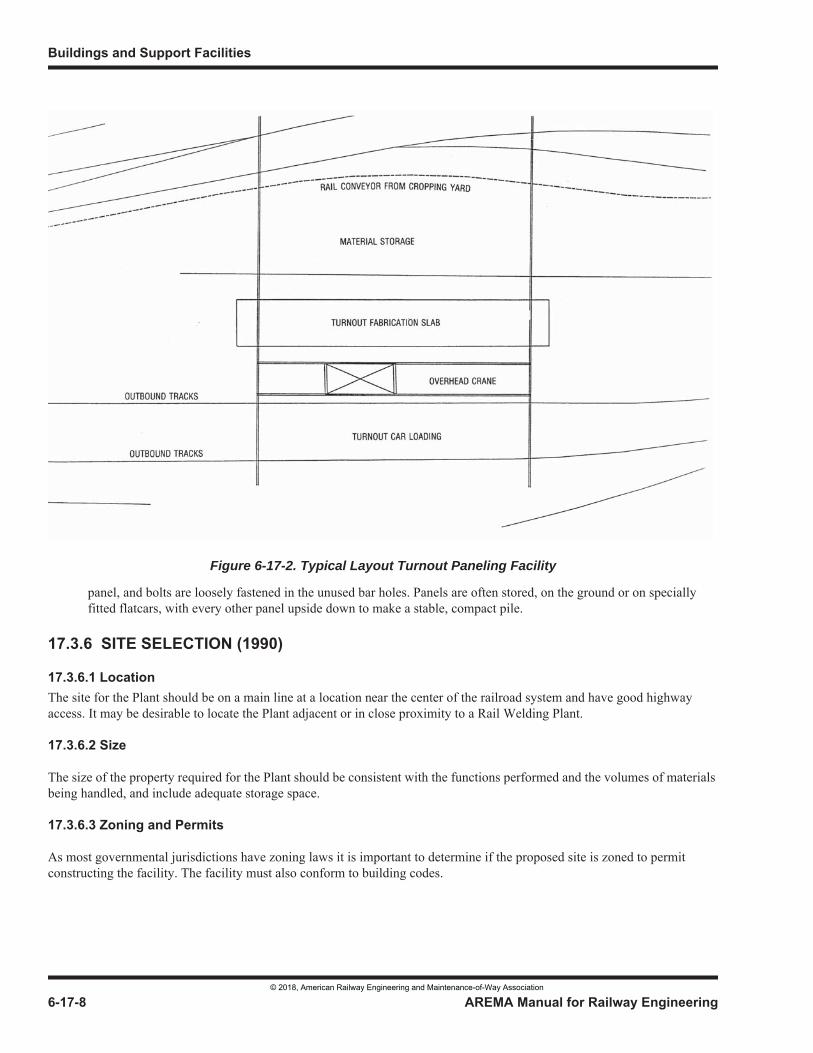
Figure 6-17-2. Typical Layout Turnout Paneling Facility
© 2018, American Railway Engineering and Maintenance-of-Way Association
Figure 6-17-3. Typical Layout Track Paneling Facility
© 2018, American Railway Engineering and Maintenance-of-Way Association
© 2018, American Railway Engineering and Maintenance-of-Way Association
© 2018, American Railway Engineering and Maintenance-of-Way Association
© 2018, American Railway Engineering and Maintenance-of-Way Association
© 2018, American Railway Engineering and Maintenance-of-Way Association
© 2018, American Railway Engineering and Maintenance-of-Way Association
© 2018, American Railway Engineering and Maintenance-of-Way Association
© 2018, American Railway Engineering and Maintenance-of-Way Association
© 2018, American Railway Engineering and Maintenance-of-Way Association
© 2018, American Railway Engineering and Maintenance-of-Way Association
© 2018, American Railway Engineering and Maintenance-of-Way Association
© 2018, American Railway Engineering and Maintenance-of-Way Association
© 2018, American Railway Engineering and Maintenance-of-Way Association
© 2018, American Railway Engineering and Maintenance-of-Way Association
© 2018, American Railway Engineering and Maintenance-of-Way Association
© 2018, American Railway Engineering and Maintenance-of-Way Association
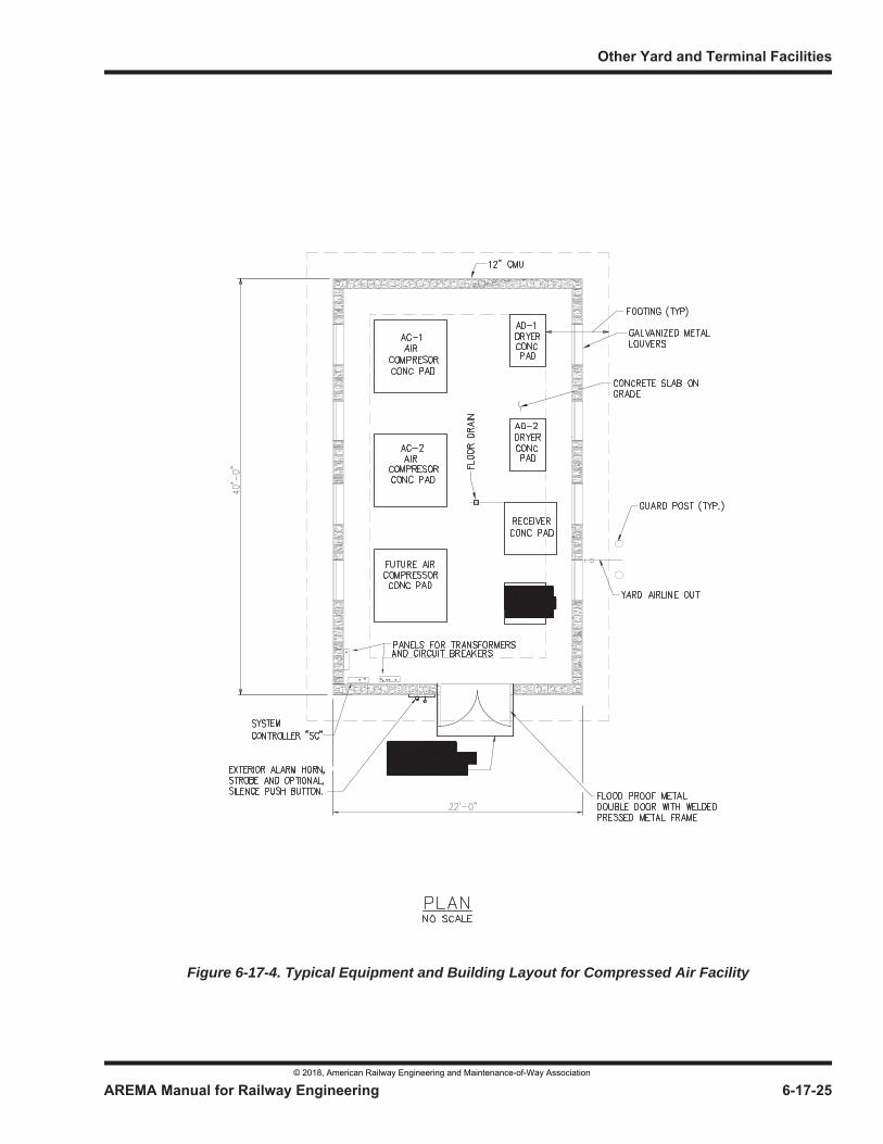
Figure 6-17-4. Typical Equipment and Building Layout for Compressed Air Facility
© 2018, American Railway Engineering and Maintenance-of-Way Association
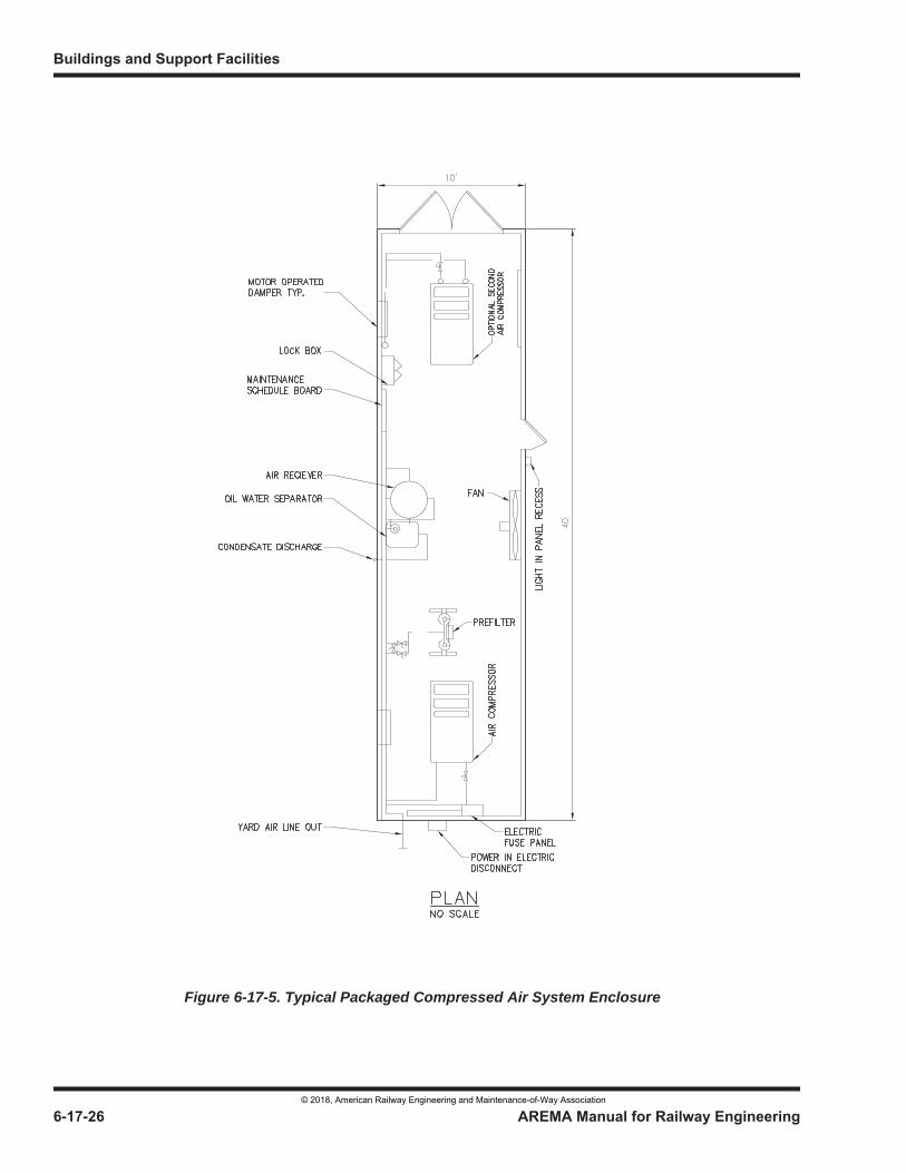
Figure 6-17-5. Typical Packaged Compressed Air System Enclosure
© 2018, American Railway Engineering and Maintenance-of-Way Association
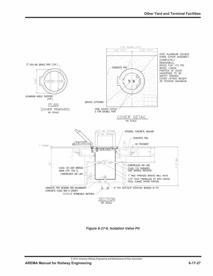
Figure 6-17-6. Isolation Valve Pit
© 2018, American Railway Engineering and Maintenance-of-Way Association
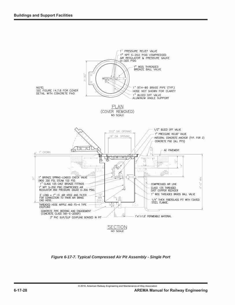
Figure 6-17-7. Typical Compressed Air Pit Assembly - Single Port
© 2018, American Railway Engineering and Maintenance-of-Way Association
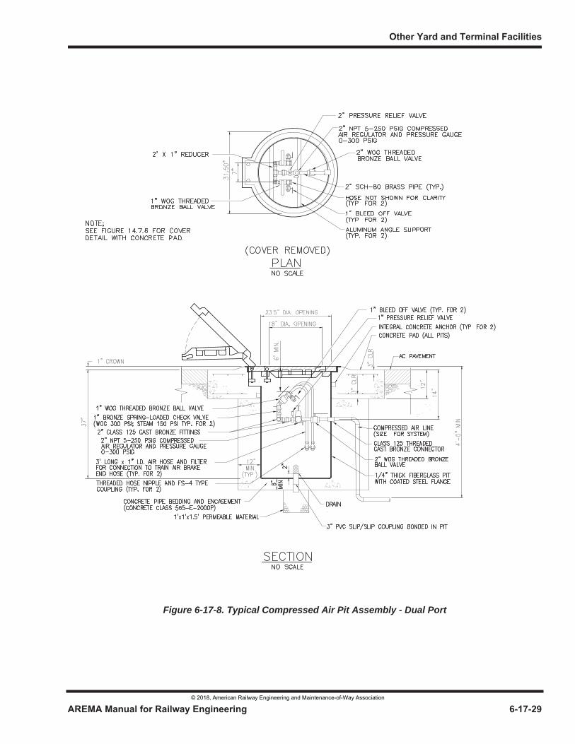
Figure 6-17-8. Typical Compressed Air Pit Assembly - Dual Port
© 2018, American Railway Engineering and Maintenance-of-Way Association
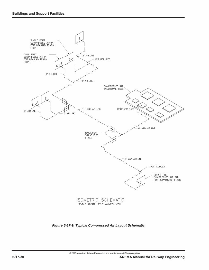
Figure 6-17-9. Typical Compressed Air Layout Schematic
© 2018, American Railway Engineering and Maintenance-of-Way Association
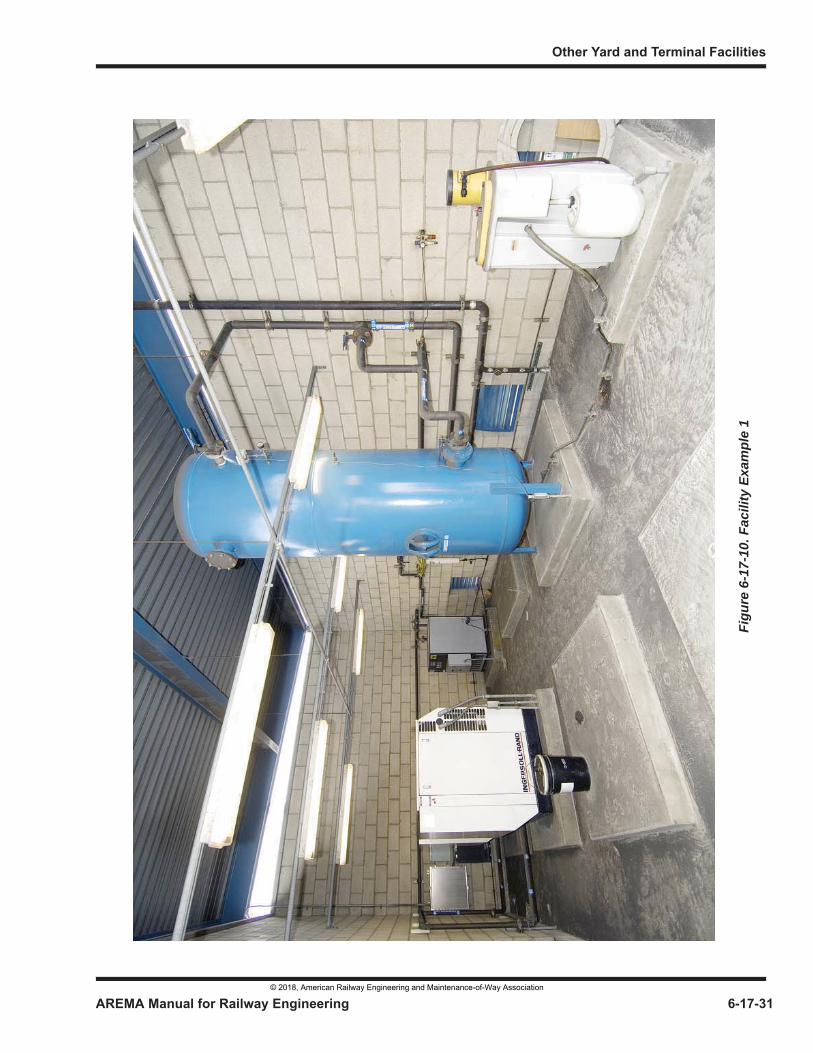
Figu
re 6
-17-
10. F
acili
ty E
xam
ple
1
© 2018, American Railway Engineering and Maintenance-of-Way Association
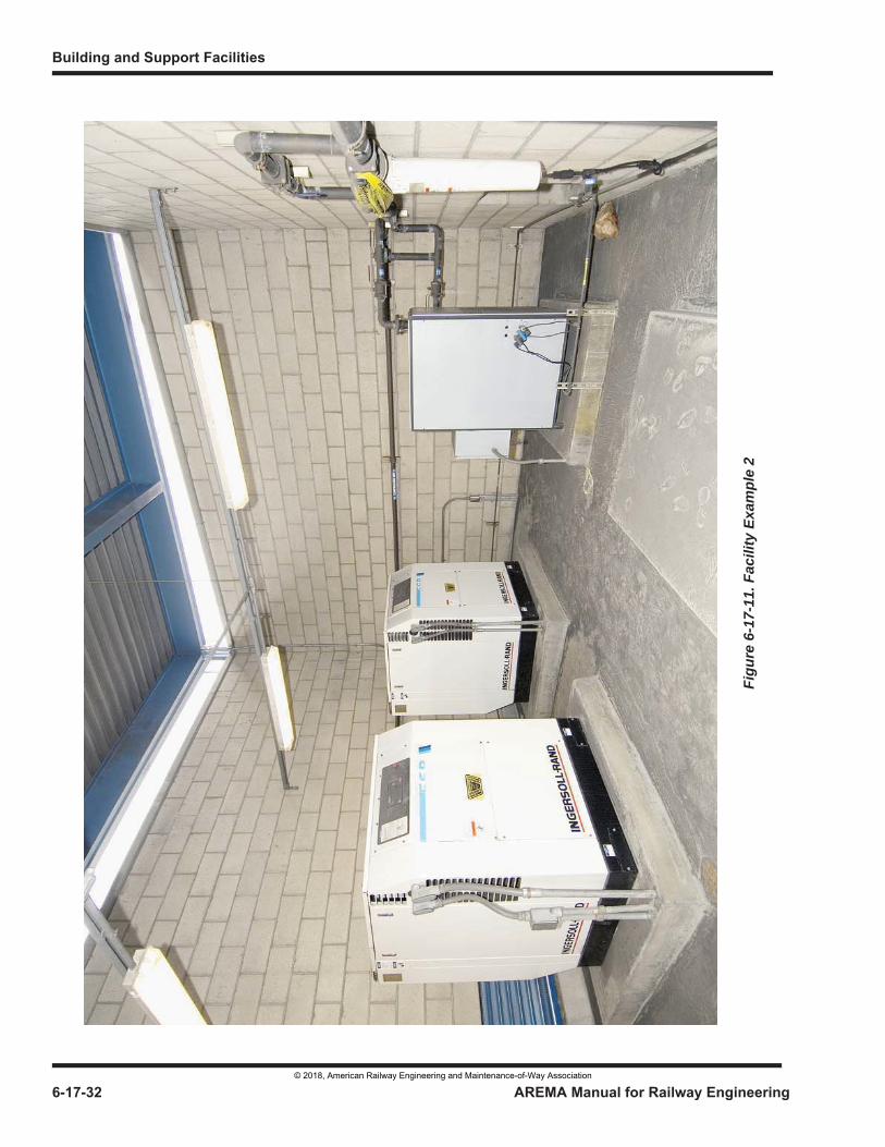
Figu
re 6
-17-
11. F
acili
ty E
xam
ple
2
© 2018, American Railway Engineering and Maintenance-of-Way Association

Figure 6-17-12. Facility Example 3
© 2018, American Railway Engineering and Maintenance-of-Way Association

© 2018, American Railway Engineering and Maintenance-of-Way Association
© 2018, American Railway Engineering and Maintenance-of-Way Association
© 2018, American Railway Engineering and Maintenance-of-Way Association
© 2018, American Railway Engineering and Maintenance-of-Way Association
© 2018, American Railway Engineering and Maintenance-of-Way Association
© 2018, American Railway Engineering and Maintenance-of-Way Association
© 2018, American Railway Engineering and Maintenance-of-Way Association