chapter 1430 transit facilities - m22-01.20 design manual
TRANSCRIPT

WSDOT Design Manual M 22-01.20 Page 1430-1
September 2021
Chapter 1430 Transit Facilities
1430.01 General
1430.02 Bus Stops and Pullouts
1430.03 Passenger Amenities
1430.04 Park and Ride Lots
1430.05 Transfer/Transit Centers
1430.06 Roadway and Intersection Design
1430.07 Documentation
1430.08 References
Exhibit 1430-1 Bus Zone Dimensions
Exhibit 1430-2 Pullout for Bus Stop along a Road
Exhibit 1430-3 Bus Stop Pullouts: Arterial Streets
Exhibit 1430-4 Bus Zone and Pullout after Right Turn
Exhibit 1430-5 Bus Stop Accessibility Features
Exhibit 1430-6 Bus Berth Design
Exhibit 1430-7 Design Alternative for a Combination of Bus Berths at a Platform
1430.01 General
This chapter provides general siting and design information for transit facilities. It is intended for Washington
State Department of Transportation (WSDOT) engineering and planning staff, local transit providers, developers,
and local agencies engaged in the collaborative development of transit facilities on or adjacent to state
highways.
The main points covered in this chapter are:
• Bus Stop Policy: WSDOT’s policy for developing bus stops on state highways is presented. The policy
calls for WSDOT and the transit provider to work together to locate stops on state highways. Bus stop
placement considerations are also provided.
• Park and Ride Lots: Basic guidelines for development of park and ride lots are presented.
• Transit/Transfer Centers: Guidance on these centers is provided. Guidance in the Park and Ride section
may apply as well.
• Universal Access: The requirements of the Americans with Disabilities Act (ADA) apply to bus stops and
shelters, park and ride lots, and transit centers. This information is presented in various sections of the
chapter, with additional references provided.
• Tools and Resources: Additional guidance and criteria are recommended and referenced, such as: other
chapters in the Design Manual for designing intersections and road approaches; the Roadside Manual
for parking lot design; the local transit authority’s own standards; and AASHTO.
The design and planning information that follows supports the development of public transit infrastructure and
services on state highways.
Design Manual topics and chapters commonly used in conjunction with this chapter include:
• Right of way and access control: Chapter 510 through Chapter 560.
• Intersections and road approaches: Chapter 1300 through Chapter 1370.
• Americans with Disabilities Act (ADA) and sidewalk design: Chapter 1510.
• High-occupancy vehicle (HOV) facilities: Chapter 1410 and Chapter 1420.
1430.02 Bus Stops and Pullouts
WSDOT’s Modal Integration Goal seeks to optimize existing system capacity through better interconnectivity of
all transportation modes. In support of this goal, WSDOT promotes safe and efficient public transportation
services on state highways, including transit routes and stops.

Chapter 1430 Transit Facilities
WSDOT Design Manual M 22-01.20 Page 1430-2
September 2021
On limited access facilities, bus stops are only allowed at designated locations, such as flyer stops. (See Chapter
520, Chapter 530, and Chapter 540 for access control policy and guidance.)
Bus stops may be approved on non-limited access facilities at the transit agency’s request and upon formal
review by WSDOT for sight distance and universal access requirements at the proposed location. At a transit
agency’s option, a bus stop on these highways may be located either within the travel lane, or outside the travel
lane in a pullout. Contact the State Traffic Engineer for information on how to process a transit agency proposal
for either an in-lane or pullout bus stop and for more information about the approval process.
Refer to WAC 468-46, Transit Vehicle Stop Zones, for additional details.
The bus stop is the point of contact between the passenger and the transit services. The simplest bus stop is a
location by the side of the road. The highest quality bus stop is an area that provides passenger amenities and
protection from the weather. Bus stops are typically maintained by the transit agency. The bus boarding and
alighting pad, the path to the shelter, and the area within the shelter must meet the requirements for universal
access. Coordinate with the local transit agency regarding the location and what type of bus stop to use.
For additional information on bus stop treatments, see Understanding Flexibility in Transportation Design –
Washington and the transit agency’s standards for treatment.
1430.02(1) Bus Stop Placement Guidelines
The information in this section is offered as an example of good practice, and is not intended to be binding by
either the transit agency or WSDOT.
Placement of bus stops addresses the needs and convenience of transit providers, riders, and highway or street
operations. Basic considerations include:
• The need for safe, secure, and convenient service for patrons
• Access for people with disabilities
• Convenient passenger transfers to other intersecting bus routes or transfer points
• Connection to nearby pedestrian circulation systems
• Presence and width of sidewalks, crosswalks, and curb ramps
• Pedestrian activity through intersections
• Ability of the stop to accommodate transit dwell time and the loading/unloading of wheel chairs and
bicycles
• Adequate curb space for the number of buses expected at the stop at one time
• Ease of reentering traffic stream (if a pullout)
• Design characteristics and operational considerations of the highway or street
• Presence of on-street automobile parking and truck delivery zones
• Traffic control devices near the bus stop, such as signals or stop signs
• Volumes and turning movements of other traffic, including bicycles
• Proximity and traffic volumes of nearby driveways
• Street grade
• Proximity to rail crossings
• Accommodating transit priority equipment at signalized intersections
• Transit queue bypass at signalized intersections
• Often stops are paired on each side of a highway or street
• Proximity to intersections
Chapter 1430 Transit Facilities
WSDOT Design Manual M 22-01.20 Page 1430-3
September 2021
Where blocks are exceptionally long or where bus patrons are concentrated well away from intersections,
midblock bus stops and midblock crosswalks may be beneficial. Contact the Region Traffic Engineer when a
midblock bus stop is being considered on a multilane roadway to determine crossing design details and
treatments that may be required. (See Chapter 1510 and the Traffic Manual for more information on midblock
crossings.)
It is common to clearly mark the bus stop as a NO PARKING zone or as a BUS ONLY zone with signs and/or curb
painting.
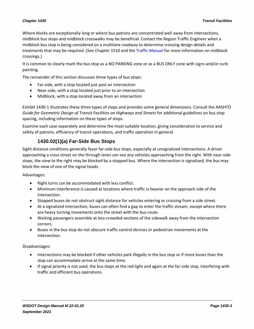
The remainder of this section discusses three types of bus stops:
• Far-side, with a stop located just past an intersection
• Near-side, with a stop located just prior to an intersection
• Midblock, with a stop located away from an intersection
Exhibit 1430-1 illustrates these three types of stops and provides some general dimensions. Consult the AASHTO
Guide for Geometric Design of Transit Facilities on Highways and Streets for additional guidelines on bus stop
spacing, including information on these types of stops.
Examine each case separately and determine the most suitable location, giving consideration to service and
safety of patrons, efficiency of transit operations, and traffic operation in general.
1430.02(1)(a) Far-Side Bus Stops
Sight distance conditions generally favor far-side bus stops, especially at unsignalized intersections. A driver
approaching a cross street on the through lanes can see any vehicles approaching from the right. With near-side
stops, the view to the right may be blocked by a stopped bus. Where the intersection is signalized, the bus may
block the view of one of the signal heads.
Advantages:
• Right turns can be accommodated with less conflict.
• Minimum interference is caused at locations where traffic is heavier on the approach side of the
intersection.
• Stopped buses do not obstruct sight distance for vehicles entering or crossing from a side street.
• At a signalized intersection, buses can often find a gap to enter the traffic stream, except where there
are heavy turning movements onto the street with the bus route.
• Waiting passengers assemble at less-crowded sections of the sidewalk away from the intersection
corners.
• Buses in the bus stop do not obscure traffic control devices or pedestrian movements at the
intersection.
Disadvantages:
• Intersections may be blocked if other vehicles park illegally in the bus stop or if more buses than the
stop can accommodate arrive at the same time.
• If signal priority is not used, the bus stops at the red light and again at the far-side stop, interfering with
traffic and efficient bus operations.

Chapter 1430 Transit Facilities
WSDOT Design Manual M 22-01.20 Page 1430-4
September 2021
1430.02(1)(b) Near-Side Bus Stops
Advantages:
• May be considered in cases where a far-side bus stop location does not provide a secure, convenient, or
feasible boarding location for passengers.
• Minimum interference is caused where traffic is heavier on the departure side than on the approach
side of the intersection.
• Less interference is caused where the cross street is a one-way street from right to left.
• Passengers generally exit the bus close to the crosswalk.
• There is less interference with traffic turning onto the bus route street from a side street.
Disadvantages:
• Can cause conflicts with right-turning traffic.
• Buses often obscure sight distance to stop signs, traffic signals, or other control devices, as well as to
pedestrians crossing in front of the bus.
• Where the bus stop is too short to accommodate buses arriving at the same time, the overflow may
obstruct the traffic lane.
• If a queue bypass or bus lane is not used at a signalized intersection, then vehicles waiting at a red signal
may block buses from accessing the bus stop, which will require the bus to wait through multiple signal
cycles to enter and then depart the bus stop.
1430.02(1)(c) Midblock Bus Stops
Midblock stop areas are desirable under the following conditions: where traffic or physical street characteristics
prohibit a near- or far-side stop adjacent to an intersection, or where large factories, commercial
establishments, or other large bus passenger generators exist. Locate a midblock stop at the far side of a
pedestrian crosswalk (if one exists), so that standing buses do not block an approaching motorist’s view of
pedestrians in the crosswalk.
Advantages:
• Buses cause a minimum of interference with the sight distance of both vehicles and pedestrians.
• Stops can be located adjacent to major bus passenger generators and attractors.
• Allows riders to board buses closest to the crosswalk.
Disadvantages:
• Increases walking distance for passengers crossing at intersections.
• Buses may or may not have difficulty reentering the flow of traffic.
• Driveway access may or may not be negatively impacted.

Chapter 1430 Transit Facilities
WSDOT Design Manual M 22-01.20 Page 1430-5
September 2021
Exhibit 1430-1 Bus Zone Dimensions
Near-Side Bus Stop
L
L
Far-Side Bus Stop
Midblock Bus Stop
L
Bus
Parked car
Minimum Lengths for Bus Curb Loading Zones (L)[1]
Approx. Bus Length
Loading Zone Length (feet)
One-Bus Stop Two-Bus Stop
Far-Side[2] Near-Side[3] [4] Midblock Far-Side[2] Near-Side[3][4] Midblock
25 65 90 125 90 120 150
30 70 95 130 100 130 160
35 75 100 135 110 140 170
40 80 105 140 120 150 180
60 100 125 160 160 190 220
Notes:
[1] Based on bus 1 ft from curb on 40 ft wide streets. When bus is 0.5 ft from curb, add 20 ft near-side, 15 ft far-side, and 20 ft midblock. Add 15 ft when street is 35 ft wide, and 30 ft when street is 32 ft wide.
[2] Measured from extension of building line or established stop line. Add 15 ft where buses make a right turn.
[3] Add 30 ft where right-turn volume is high for other vehicles. [4] Measured from head of bus zone as determined by the transit agency (may depend on ADA
considerations). Add 15 ft where buses make a right turn.
Chapter 1430 Transit Facilities
WSDOT Design Manual M 22-01.20 Page 1430-6
September 2021
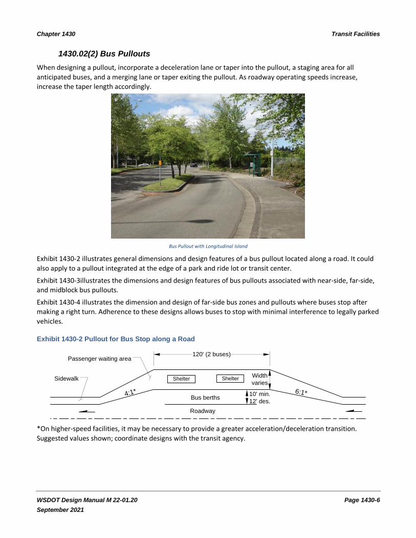
1430.02(2) Bus Pullouts
When designing a pullout, incorporate a deceleration lane or taper into the pullout, a staging area for all
anticipated buses, and a merging lane or taper exiting the pullout. As roadway operating speeds increase,
increase the taper length accordingly.
Bus Pullout with Longitudinal Island
Exhibit 1430-2 illustrates general dimensions and design features of a bus pullout located along a road. It could
also apply to a pullout integrated at the edge of a park and ride lot or transit center.
Exhibit 1430-3illustrates the dimensions and design features of bus pullouts associated with near-side, far-side,
and midblock bus pullouts.
Exhibit 1430-4 illustrates the dimension and design of far-side bus zones and pullouts where buses stop after
making a right turn. Adherence to these designs allows buses to stop with minimal interference to legally parked
vehicles.
Exhibit 1430-2 Pullout for Bus Stop along a Road
120' (2 buses)
ShelterSidewalk
Passenger waiting area
4:1* 6:1*Bus berths
Roadway
ShelterWidth
varies
10' min.
12' des.
*On higher-speed facilities, it may be necessary to provide a greater acceleration/deceleration transition.
Suggested values shown; coordinate designs with the transit agency.

Chapter 1430 Transit Facilities
WSDOT Design Manual M 22-01.20 Page 1430-7
September 2021
Exhibit 1430-3 Bus Stop Pullouts: Arterial Streets
Notes:
This exhibit provides some general values; coordinate with transit provider for actual dimensions.
[1] For right-turn lane design, see Chapter 1310.
[2] Based on a 40 ft bus. Add 20 ft for articulated bus. Add 45 ft (65 ft articulated) for each additional
bus.

Chapter 1430 Transit Facilities
WSDOT Design Manual M 22-01.20 Page 1430-8
September 2021
Exhibit 1430-4 Bus Zone and Pullout after Right Turn
Bus
Parked car
Far-Side Bus Pullout
After Right Turn
130' *
35' 40' * 35'
30
'Far-Side Bus Stop
* Based on 40' bus. Add 20' for articulated bus.50' - 100' R
90' * 40' min
60' Des.
12'
25' - 50' R
1430.03 Passenger Amenities
1430.03(1) Bus Stop Waiting Areas
Bus passengers desire a comfortable place to wait for the bus. Providing an attractive, pleasant setting for the
passenger waiting area is an important factor in attracting bus users.
Important elements of a bus stop include:
• ADA Standards • Protection from passing traffic • Lighting • Security
• Paved surface • Protection from the environment • Seating or other street furniture (if the wait may be long) • Information about routes serving the stop

Chapter 1430 Transit Facilities
WSDOT Design Manual M 22-01.20 Page 1430-9
September 2021
Providing protection from passing traffic involves locating stops where there is enough space, so passengers can
wait away from the edge of the traveled roadway. The buffering distance from the roadway increases with
traffic speed and traffic volume. Where vehicle speeds are 30 mph or below, 5 feet is a satisfactory distance. In a
heavy-volume arterial with speeds up to 45 mph, a distance of 10 feet provides passenger comfort.
Passengers arriving at bus stops, especially infrequent riders, want information and reassurance. Provide
information that includes the numbers or names of routes serving the stop. Other important information may
include a system route map, the hours and days of service, schedules, and a phone number for information.
Information technology systems are evolving and some transit agencies now provide information about wait
time until the next bus and kiosks to purchase the fare before boarding.
Where shelters are not provided, a bus stop sign and passenger bench are desirable, depending on weather
conditions. The sign indicates to passengers where to wait and can provide some basic route information. The
information provided and format used is typically the responsibility of the local transit agency.
1430.03(2) Passenger Shelters
Passenger shelters provide protection for waiting transit users and create driver awareness of intermodal
connections involving vulnerable users. Locate the shelter conveniently for users, without blocking the sidewalk
or the drivers’ line of sight.
Providing shelters (and footing for shelters) is normally the responsibility of the local transit agency; it provides
for shelter design and footing needs. State motor vehicle funds cannot be used for design or construction of
shelters, except for the concrete pad.
Lighting can enhance passenger safety and security. Lighting makes the shelter visible to passing traffic and
allows waiting passengers to read the information provided. General street lighting is usually sufficient. Where
streetlights are not in place, consider streetlights or transit shelter lights. For information on illumination, see
Chapter 1040.
A properly drained paved surface is needed so passengers do not traverse puddles and mud in wet weather.
Protection from the environment is typically provided by a shelter, which offers shade from the sun, protection
from rain and snow, and a wind break.
Shelters can range from simple to elaborate. The latter type may serve as an entrance landmark for a residential
development or business complex and be designed to carry through the architectural theme of the complex. If a
non-public transportation entity shelter is provided, its design and siting must be approved by the local transit
agency. The reasons for this approval include safety, barrier-free design, intermodal connections, and long-term
maintenance concerns.
Consider shelters at bus stops in new commercial and office developments and in places where large numbers of
elderly and disabled persons wait, such as at hospitals and senior centers. In residential areas, shelters are
placed at the highest-volume stops.
In order to use buses that are accessible, bus stops must also be accessible. The nature and condition of streets,
sidewalks, passenger loading pads, curb ramps, and other bus stop facilities can constitute major obstacles to
mobility and accessibility. State, local, public, and private agencies need to work closely with public
transportation officials to provide universal access.
Involve the local transit agency in the bus stop pad design and location so that lifts can actually be deployed at
the site.

Chapter 1430 Transit Facilities
WSDOT Design Manual M 22-01.20 Page 1430-10
September 2021
In order to access a bus stop, it is important that the path to the stop also be accessible. This can be
accomplished by the use of sidewalks with curb ramps. For sidewalk design and curb ramp information, see
Chapter 1510 and the Standard Plans. Exhibit 1430-5 depicts ADA standards for bus stop locations.
Exhibit 1430-5 Bus Stop Accessibility Features
Design bus shelter clear space to meet the requirements found in ADA Standards for Transportation Facilities.
Passenger shelter showing clear space
For more details, see:
• Chapter 3, ADA Standards for Transportation Facilities, United States Access Board
https://www.access-board.gov/ada/
• Chapter 8, ADA Standards for Transportation Facilities, United States Access Board
https://www.access-board.gov/ada/

Chapter 1430 Transit Facilities
WSDOT Design Manual M 22-01.20 Page 1430-11
September 2021
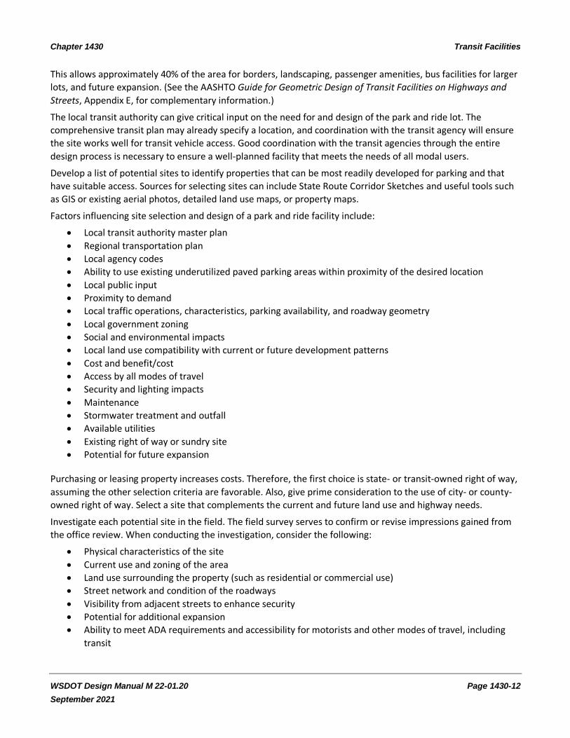
1430.04 Park and Ride Lots
Park and ride lots provide parking for people who wish to transfer from private vehicles, bicycles, and other
modes to public transit or carpools/vanpools. Most park and ride lots located within urban areas are served by
transit agencies. Leased lots, such as at churches or shopping centers, or park and rides in rural locations, may
have no bus service and only serve carpools and vanpools.
Park and ride lot
HOV facilities are often considered and included in larger park and ride lots, to improve access for transit and
carpools (see Chapter 1410).
Park and ride needs and locations are determined through planning processes typically conducted by transit
agencies, WSDOT, and/or RTPOs/MPOs. Once the need is identified, then the project lead should be identified.
Early and continual coordination between the project lead and other stakeholders, authorities, and agencies is
critical.
A Cooperative Agreement is written by Headquarters (HQ) Real Estate Services for the purpose of assigning
maintenance and/or operational responsibilities for a WSDOT park and ride lot to a transit agency or local
governmental agency. (See the Agreements Manual and the HQ Real Estate Services Cooperative Agreement
form.)
When a memorandum of understanding (MOU) or other formal agreement exists that outlines the design,
funding, maintenance, and operation of park and ride lots, it must be reviewed for requirements pertaining to
new lots. If the requirements in the MOU or other formal agreement cannot be met, the MOU must be
renegotiated.
1430.04(1) Site Selection
In determining the location of a park and ride lot, public input is a valuable tool. Estimated parking demand and
other factors determine the size of the lot. Traveler convenience is an important siting factor. Locations that
minimize overall trip travel time are most attractive to commuters. Park and rides near freeway access tend to
be heavily used because they minimize overall trip travel time for the most people. Freeway proximity makes it
easier for transit authorities to provide frequent route service. Other factors that may affect the initial size of
the park and ride lot may include available land, the state of the economy, energy availability and cost,
perceived congestion, transit service frequency, and environmental controls.
Consider sizing the facility to allow for a conservative first-stage construction with expansion possibilities. As a
rule of thumb, 1 acre can accommodate approximately 90 vehicles in a park and ride lot.
Chapter 1430 Transit Facilities
WSDOT Design Manual M 22-01.20 Page 1430-12
September 2021
This allows approximately 40% of the area for borders, landscaping, passenger amenities, bus facilities for larger
lots, and future expansion. (See the AASHTO Guide for Geometric Design of Transit Facilities on Highways and
Streets, Appendix E, for complementary information.)
The local transit authority can give critical input on the need for and design of the park and ride lot. The
comprehensive transit plan may already specify a location, and coordination with the transit agency will ensure
the site works well for transit vehicle access. Good coordination with the transit agencies through the entire
design process is necessary to ensure a well-planned facility that meets the needs of all modal users.
Develop a list of potential sites to identify properties that can be most readily developed for parking and that
have suitable access. Sources for selecting sites can include State Route Corridor Sketches and useful tools such
as GIS or existing aerial photos, detailed land use maps, or property maps.
Factors influencing site selection and design of a park and ride facility include:
• Local transit authority master plan
• Regional transportation plan
• Local agency codes
• Ability to use existing underutilized paved parking areas within proximity of the desired location
• Local public input
• Proximity to demand
• Local traffic operations, characteristics, parking availability, and roadway geometry
• Local government zoning
• Social and environmental impacts
• Local land use compatibility with current or future development patterns
• Cost and benefit/cost
• Access by all modes of travel
• Security and lighting impacts
• Maintenance
• Stormwater treatment and outfall
• Available utilities
• Existing right of way or sundry site
• Potential for future expansion
Purchasing or leasing property increases costs. Therefore, the first choice is state- or transit-owned right of way,
assuming the other selection criteria are favorable. Also, give prime consideration to the use of city- or county-
owned right of way. Select a site that complements the current and future land use and highway needs.
Investigate each potential site in the field. The field survey serves to confirm or revise impressions gained from
the office review. When conducting the investigation, consider the following:
• Physical characteristics of the site
• Current use and zoning of the area
• Land use surrounding the property (such as residential or commercial use)
• Street network and condition of the roadways
• Visibility from adjacent streets to enhance security
• Potential for additional expansion
• Ability to meet ADA requirements and accessibility for motorists and other modes of travel, including
transit

Chapter 1430 Transit Facilities
WSDOT Design Manual M 22-01.20 Page 1430-13
September 2021
• Proximity of any existing parking facilities (such as church or shopping center parking lots) that are
underutilized during the day
• Potential for joint use of facilities with businesses (such as day care centers or dry cleaners) or land uses
compatible with park and ride patrons
• Congestion and other design considerations
• Avoiding locations that encourage noncommuter use (such as proximity to a high school)
The desirable location for park and ride lot along one-way couplets is between the two one-way streets, with
access from both streets. When this is not achievable, provide additional signing to guide users to and from the
facility.
Establish potential sites, with transit agency input, and complete public meetings and environmental procedures
prior to finalizing the design. Follow the procedures outlined in Chapter 210.
1430.04(2) Design Guidance
The remainder of this section covers basic design principles and guidance for park and ride lots. Design features
are to be in compliance with local requirements. In some cases, variances to local design requirements may be
needed to provide for the safety and security of facility users.
Common design components with park and ride lots include:
• Geometric design of access points
• Selection of a design bus type
• Efficient traffic flows, both internal and external circulation, for transit, carpools, vanpools, pedestrians,
and bicycles
• ADA-compliant features
• Parking space layout (including accessible stalls)
• Pavements
• Shelters
• Seating or other street furniture
• Exclusive HOV facilities
• Bicycle facilities
• Motorcycle facilities
• Traffic control devices (including signs, signals, and permanent markings)
• Illumination (within the lot and along the streets)
• Stormwater treatment, drainage, and erosion control
• Security for facility users and vehicles (emergency call boxes or telephones)
• Landscape preservation and development
• Environmental mitigation
• Restroom facilities (for transit drivers only or open to the public)
• Trash receptacles
• Artwork (where required by other agencies)
The degree to which the desirable attributes of any component are sacrificed to obtain the benefits of another
component can only be determined on a site-specific basis. However, these guidelines present the optimum
design elements of each factor.
Large park and ride lots are intended to be transfer points from private automobiles and other modes to transit buses. The same basic principles are used in designing all park and ride lots.

Chapter 1430 Transit Facilities
WSDOT Design Manual M 22-01.20 Page 1430-14
September 2021
Park and Ride lots that serve a large number of buses and/or routes may also serve as Transfer/Transit Centers; in these cases section Section 1430.05 would also apply.
1430.04(2)(a) Access
Provide for all modes of transport used to arrive at and depart from transit facilities. The six basic modes are pedestrian, bicycle, motorcycle, automobile, vanpool, and bus.
Coordinate with the local jurisdiction and transit authorities to develop the park and ride lot’s ingress and egress locations for transit and for other vehicles. Design the access route, circulation patterns, and return routes to minimize travel time. Exclusive direct connections for buses, vanpools, and carpools may reduce transit costs and save time for riders.
Design transit facility access points on intersecting collector or local streets where possible. Locate the access to avoid the queues from nearby intersections. Provide vehicle storage lanes for entering and exiting vehicles to ensure ease of access and encourage use of the facility. To avoid increasing congestion on the highway or the community that the facility serves, locate entrances and exits where a traffic signal, or other intersection control type (see Chapter 1300), can be reasonably installed at a later time, if needed.
Entrances and exits to park and rides range in scale from full public intersections to driveways, depending on contextual factors such as traffic volumes and remoteness. Design access points using criteria in the 1300 chapter series (Division 13) or other published design guidelines used by the local agency.
When locating access points on a state highway, see chapters in the 500 series (Division 5) for information about access control types (managed or limited access) and standard access spacing and other requirements.
When designing the entrance/exit locations used by buses, start the design using a 15-foot lane width, and then adjust as needed using the bus design vehicle and turn simulation software (such as AutoTURN®) to verify the design.
1430.04(2)(b) Internal Circulation
Provide walkways to minimize pedestrian use of a circulation road or an aisle to minimize pedestrian conflict points with other modes.
Make the pedestrian circulation path from any parking stall to the loading zone as direct as possible. Where pedestrian movement originates from an outlying part of a large parking lot, consider a walkway that extends toward the loading zone in a straight line.
For additional criteria for pedestrian movement, see Design Manual Chapter 1510 and Chapter 630 of the Roadside Manual.
Pedestrian Access Route

Chapter 1430 Transit Facilities
WSDOT Design Manual M 22-01.20 Page 1430-15
September 2021
Locate major vehicular circulation routes within a park and ride lot at the periphery of the parking area to
minimize vehicle-pedestrian conflicts. Take care that an internal intersection is not placed too close to a street
intersection. Consider a separate loading area with priority parking for vanpools. Wherever possible, do not mix
buses and auto circulation.
Close coordination with the local transit authority is critical in the design of internal circulation for buses and
vanpools. Design bus circulation routes to provide for easy movement, with efficient terminal operations and
convenient passenger transfers. Design bus routes within the internal layout, including entrance and exit
driveways, to the turning radius of the design bus vehicle.
Additional considerations for internal circulation are:
• Base the general design for the individual user modes on the priority sequence of: pedestrians, bicycles,
feeder buses, and park and ride area.
• Design the different traffic flows (auto, pedestrian, bicycle, and bus) circulating within the lot to be
understandable to all users, and to minimize conflicting movements between modes.
• Disperse vehicular movements within the parking area by the strategic location of entrances, exits, and
aisles.
• Do not confront drivers with more than one decision at a time.
• Provide clear signing for all modes.
• Make the pedestrian circulation routes ADA-compliant (see Chapter 1510).
• Parking stall and access aisle surfaces shall be even and smooth, with surface slopes not exceeding 2%.
• Consider future expansion.
• Align parking aisles to facilitate convenient pedestrian movement toward the bus loading zone.
• Locate the passenger loading zone either in a central location, to minimize the pedestrian walking
distance from the parking area to the loading zone, or near the end of the facility, to minimize the
transit travel time.
• In large lots, you may need to provide more than one waiting area for multiple buses.
1430.04(2)(c) Parking Area Design
Refer to the Roadside Manual for detailed guidance on parking area design. Some general guidelines follow.
Normally, internal circulation is two way with 90° parking. However, one-way aisles with angled parking may be
advantageous in a smaller lot due to the limited available space or to promote a specific circulation pattern.
Provide parking for bicycles, motorcycles, and private automobiles, as well as carpools, vanpools, and buses.
Locate accessible parking stalls close to the transit loading and unloading area. Two accessible parking stalls may
share a common access aisle. For information on the number and design of accessible stalls, see the Roadside
Manual and the parking space layouts in the Standard Plans. Sign accessible parking stalls in accordance with
the requirements of RCW 46.61.581. Parking stalls and access aisle surfaces shall be even and smooth, with
surface slopes not exceeding 2%.
Locate the bicycle-parking area relatively close to the transit passenger loading area, separated from motor
vehicles by curbing or other physical barriers, without landscaping that hides the bike area from view, and with a
direct route from the street.
• Design the bike-parking area to discourage pedestrians from inadvertently walking into the area and
tripping. Provide lots that are served by public transit, with lockers or with a rack that will support the
bicycle frame and allow at least one wheel to be locked.

Chapter 1430 Transit Facilities
WSDOT Design Manual M 22-01.20 Page 1430-16
September 2021
• Consider providing shelters for bicycle racks. For bicycles, the layout normally consists of stalls 2.5 feet x
6 feet, at 90° to aisles, with a minimum aisle width of 4 feet. Coordinate decisions to provide bicycle
lockers, racks, and shelters with the local transit authority and the region subject matter experts.
For more information, see Understanding Flexibility in Transportation Design – Washington. It is complementary
to the content in this chapter, and provides more insights to modal designs, environment and aesthetics,
community engagement, jurisdictional coordination.
1430.04(2)(d) Drainage
Provide sufficient slope for surface drainage, as ponding of water in a lot is undesirable for both vehicles and
pedestrians. This is particularly true in cold climates where freezing may create icy spots. The maximum grade is
2%. Install curb, gutter, and surface drains and grates where needed. Coordinate designs for drainage and
pedestrian access routes to avoid conflicts. Coordinate drainage design with the local agency to make sure
appropriate codes are followed. For additional drainage information, see Design Manual Chapter 800 and the
Roadside Manual.
1430.04(2)(e) Pavement Design
Design pavement to conform to design specifications for each of the different uses and loadings that a particular
portion of a lot or roadway is expected to handle. Bus lanes are typically Portland cement concrete pavement.
Within the parking area, HMA-type pavements are typically used. Coordinate the pavement designs with the
local transit agency and local jurisdiction. Consult with the Region Materials Engineer on pavement section
requirements. There may be benefits to permeable pavement if space for stormwater facilities is limited.
1430.04(2)(f) Driver Guidance
Provide a well thought out design for traffic movements within the lot using the proper pavement markings and
signage for safe and efficient use by all users of the lot. Typically, reflectorized markings for centerlines, lane
lines, channelizing lines, and lane arrows are needed to guide or separate patron and transit traffic. Install park
and ride identification signs. For signing and pavement markings, see Chapter 1020 and Chapter 1030 and the
MUTCD.
1430.04(2)(g) Shelters
Coordinate with the transit agency on the need, location, design, and installation of pedestrian shelters. To
satisfy local needs, shelters may be individually designed, provided by the transit agency, or selected from a
variety of commercially available designs. These designs must meet ADA accessibility requirements. Consider the
following features in shelter design:
• Select open locations with good visibility for user safety.
• Situate enclosed shelters away from edges of driveways and roadways to keep users dry.
• Select materials and locations where the bus driver can see waiting passengers.
• Avoid using doors, for ease of maintenance and to limit vandalism opportunities.
• Allow for a small air space along the bottom of the enclosure panels, to permit air circulation and reduce
debris collection.
• Optional features you may provide are: lighting; heat; telephone; static or electronic travel information
(schedules); electronic fare collection equipment; commercial advertisements for revenue generation;
and trash receptacles.
For additional information on passenger amenities, see Section 1430.03.

Chapter 1430 Transit Facilities
WSDOT Design Manual M 22-01.20 Page 1430-17
September 2021
1430.04(2)(h) Illumination, Safety, and Security
Lighting is important from a safety standpoint and as a deterrent to criminal activity in both the parking area and
the shelters. For guidance, see Design Manual Chapter 1040, Chapter 630 of the Roadside Manual, local agency
criteria, and AASHTO.
The Guide for Geometric Design of Transit Facilities on Highways and Streets, AASHTO, 2014, states: “Security at
stations and major stops—both manned and unmanned—should be achieved by closed circuit television
monitoring, provision of call boxes, good visibility and lighting, police surveillance, and effective designs. Both
the actual security and the passengers’ perceptions of security are important for a viable service or operation.”
(See the Guide for more information.)
1430.04(2)(i) Planting Areas
Selectively preserve existing vegetation and provide new plantings to afford a balanced environment for the
park and ride lot user. For guidance and policy, see the Roadside Manual and the Roadside Policy Manual,
respectively.
1430.04(2)(j) Fencing
For fencing guidelines, see Chapter 560 and discuss with the partnering transit agency.
1430.04(2)(k) Maintenance
Maintenance of park and ride lots outside state right of way is the responsibility of the local transit authority.
Negotiate maintenance agreements with local transit authorities or other appropriate parties during the design
phase, to identify the requirements and responsibilities for the maintenance. A Cooperative Agreement is
written by HQ Real Estate Services for the purpose of assigning maintenance and/or operational responsibilities
for a WSDOT park and ride lot to a transit agency or local governmental agency. (See the Agreements Manual
and the HQ Real Estate Services Cooperative Agreement form.)
Consider the following in the maintenance plan:
• Cost estimate
• Periodic inspection
• Pavement repair
• Traffic control devices (signs and pavement markings)
• Lighting
• Mowing
• Cleaning of drainage structures
• Sweeping/trash pickup
• Landscaping
• Shelters
• Snow and ice control
Understanding Flexibility in Transportation Design – Washington, 2005 provides more information on many of
the above topics.
1430.05 Transfer/Transit Centers
Transfer/transit centers are large multimodal bus stops where buses on a number of routes converge to allow
riders the opportunity to change buses or transfer to other modes.

Chapter 1430 Transit Facilities
WSDOT Design Manual M 22-01.20 Page 1430-18
September 2021
Transit centers are frequently major activity centers and serve as destination points.
Many factors dictate the particular needs of each transit center. Design of a transit center considers such
features as passenger volume; number of buses on the site at one time; local auto and pedestrian traffic levels;
and universal access.
Transit agencies generally lead in the development of transfer/transit centers, and their standards apply. Consult
the AASHTO Guide for Geometric Design of Transit Facilities on Highways and Streets for more comprehensive
overviews and design guidelines for these facilities.
1430.05(1) Bus Platforms
At a transit center where several transit routes converge and where buses congregate (lay over), multiple bus
berths or spaces are typically needed, along with areas where passengers boarding or alighting the bus can take
refuge. Typically, there are several design styles for multi-berth bus platforms (see AASHTO). Parallel and
sawtooth types are described below.
An important aspect in multiple bus berthing is proper signing and marking for the bus bays for both operators
and passengers. Clearly delineate the route served by each bay. Consider pavement marking to indicate
stopping positions. Separate layover bays may be needed for terminating bus routes, or the layover function can
be provided at the passenger platform if the platform only serves a single route. Consider future service plans
and maximize flexibility in the design of transit center bays and circulation.
Portland cement concrete pavement is desirable for pedestrian walkways on the platform, for ease of cleaning.
Where buses are equipped with a bicycle rack, provide for the loading and unloading of bicycles.
Exhibit 1430-6 shows typical parallel and sawtooth designs for parking 40-foot buses for passengers boarding
and alighting at a platform. The sawtooth design does not require buses to arrive or depart in any order.
Exhibit 1430-7 is an example of a platform design that has a combination of parallel and sawtooth bus berths at
a platform. The sawtooth design provides more space-efficient berthing, as the parallel design shown may
require that buses arrive and/or depart in order. Coordinate the bus berth style and platform design with the
local transit authority throughout the design process, and obtain its concurrence for the final design.
In the design of parallel bus berths, additional roadway width is needed for swing-out maneuvers if shorter bus
loading platforms are utilized. The roadway width and the amount of lineal space required at the bus platform
are directly related where designs allow departing buses to pull out from the platform around a standing bus.
The shorter the berth length allowed, the wider the roadway. Use turn simulation software (such as AutoTURN®)
to verify the design.
Considerable length is needed in a parallel design to permit a bus to pass and pull into a platform in front of a
parked bus. Design the bus aisle so that a bus can by-pass another bus stopped at the platform. The decision to
provide a parallel design to accommodate a by-pass maneuver may depend on how many routes service the
location, and the frequency of service.
1430.05(2) Flow/Movement Alternatives
Two primary alternatives for vehicle and passenger movement are possible for transfer centers, regardless of
the type of bus berths used, as shown in Exhibit 1430-6. Buses may line up along one side of the transfer center.
This type of arrangement is generally suitable for a limited number of buses due to the walking distances for
transferring passengers. For a larger number of buses, an arrangement similar to Exhibit 1430-7 can minimize
transfer time by consolidating the buses in a smaller area.

Chapter 1430 Transit Facilities
WSDOT Design Manual M 22-01.20 Page 1430-19
September 2021
Consult the AASHTO Guide for Geometric Design of Transit Facilities on Highways and Streets for more
comprehensive overviews and design guidelines.
Exhibit 1430-6 Bus Berth Design
Parallel Design
80' [1]
80' [1]
10' min.
12' des.
Sawtooth Design[2]
40' [1]
16'
8'
15' 10'
Notes:
[1] Dimensions shown are for a 40-ft bus; adjust the length when designing for a longer bus.
[2] Design shown is an example; contact the local transit agency for additional information.

Chapter 1430 Transit Facilities
WSDOT Design Manual M 22-01.20 Page 1430-20
September 2021
Exhibit 1430-7 Design Alternative for a Combination of Bus Berths at a Platform
1430.06 Roadway and Intersection Design
Refer to chapters in the 1100, 1200, and 1300 series (Divisions 11, 12, and 13) for guidance on roadway and
intersection design controls and design elements. Some brief discussions are provided below.
1430.06(1) Pavement
Coordinate the pavement design (type and thickness) of a transit project, whether initiated by a public
transportation agency or a private entity, with WSDOT or the local agency public works department, depending
on highway, street, or road jurisdiction. These agencies play a major role in determining the paving section for
the particular project.
Consult with the Region Materials Engineer on pavement section requirements.

Chapter 1430 Transit Facilities
WSDOT Design Manual M 22-01.20 Page 1430-21
September 2021
1430.06(2) Grades
Roadway grades refer to the maximum desirable slope or grade, or the maximum slope based on the minimum
design speed that a 40-foot bus can negotiate efficiently. For roadway grade guidance, see Chapter 1220 or the
Local Agency Guidelines.
Bus speed on grades is directly related to the weight/horsepower ratio. Select grades that permit uniform
operation at an affordable cost. In cases where the roadway is steep, a climbing lane for buses and trucks may
be needed. For climbing lane guidance, see Chapter 1270. Avoid abrupt changes in grade due to bus overhangs
and ground clearance.
1430.06(3) Lane Widths
Guidance on roadway and lane widths is given in Chapter 1230 or the Local Agency Guidelines, based on the
context, modal users, needs of the highway or road, and jurisdiction.
1430.06(4) Design Vehicle Characteristics
Most transit agencies operate several types of buses within their systems. Vehicle sizes range from articulated
buses to passenger vans operated for specialized transportation purposes and vanpooling. Several bus types are
listed below. (See Chapter 1103, Design Controls, and Chapter 1300 for design vehicle guidance.)
1430.06(4)(a) City Buses (CITY-BUS)
These traditional urban transit vehicles are typically 40 feet long and have a wheelbase of approximately 25 feet.
Many of these vehicles are equipped with either front or rear door wheelchair lifts or a front “kneeling” feature
that reduces the step height for mobility-impaired patrons. Installing higher curb can reduce the time it takes to
kneel a bus and thus increase reliability.
1430.06(4)(b) Articulated Buses
Because articulated buses (A-BUS) are hinged between two sections, these vehicles can turn within a relatively
short radius. Articulated buses are typically 60 feet in length, with a wheelbase of 22 feet from the front axle to
the mid axle and 19 feet from the mid axle to the rear axle. If articulated buses are the common bus using a
stop, adjust the length of the pullout accordingly to avoid conflicts.
1430.06(4)(c) Small Buses
Some transit agencies operate small buses, which are designed for use in low-volume situations or for driving on
lower-class roads. Small buses are also used for transportation of elderly and disabled persons and for shuttle
services. Passenger vans are a type of small bus used for specialized transportation and vanpooling. Since the
vehicle specifications vary so widely within this category, consult the local transit authority for the specifications
of the particular vehicle in question.

Chapter 1430 Transit Facilities
WSDOT Design Manual M 22-01.20 Page 1430-22
September 2021
1430.06(5) Intersection Radii
A fundamental characteristic of transit-accessible development is convenient access and circulation for transit
vehicles. It is important that radii at intersections be designed to accommodate turning buses. Radii that
accommodate turning buses reduce conflicts between automobiles and buses, reduce bus travel time, and
provide maximum comfort for the passengers.
Refer to Chapter 1300 and Chapter 1310 for intersection design guidance, and take the following factors into
consideration in designing intersection radii:
• Right of way availability
• Angle of intersection
• Width and number of lanes on the intersecting streets
• Feasibility of channelization adjustments such as set-back stop bar or adjusted center line
• Design vehicle turning radius
• On-street parking and/or curb extensions (see Chapter 1510)
• Allowable bus encroachment
• Operating speed and speed reductions
• Adequate intersection sight distance
• Needs of pedestrians, bicyclists, and other design users (see chapters in the 1100 series (Division 11) for
contextual discussions and Chapter 1230 for roadway types.)
Because of space limitations and generally lower operating speeds in urban areas, curve radii for turning
movements are typically smaller than those used in rural areas.
1430.07 Documentation
Refer to Chapter 300 for design documentation requirements.
1430.08 References
1430.08(1) Federal/State Laws and Codes
Americans with Disabilities Act of 1990 (ADA) (28 Code of Federal Regulations [CFR] Part 36, Appendix A, as
revised July 1, 1994)
Revised Code of Washington (RCW) 46.61.581, Parking spaces for persons with disabilities – Indication, access –
Failure, penalty
RCW 70.92.120, Handicap symbol – Display – Signs showing location of entrance for handicapped
Washington Administrative Code (WAC) Chapter 468-46, Transit vehicle stop zones
WAC 468-510-010, High occupancy vehicles (HOVs)

Chapter 1430 Transit Facilities
WSDOT Design Manual M 22-01.20 Page 1430-23
September 2021
1430.08(2) Design Guidance
ADA Field Guide for Accessible Public Rights of Way, WSDOT
www.wsdot.wa.gov/publications/manuals/fulltext/m0000/ada_field_guide.pdf
ADA Standards for Accessible Design, U.S. Department of Justice (USDOJ), 2010; consists of 28 CFR parts 35 & 36
and the ADA and Architectural Barriers Act (ABA) Accessibility Guidelines for Buildings and Facilities (ADA-
ABAAG; also referred to as the 2004 ADAAG), July 23, 2004, U.S. Access Board. (For buildings and on-site
facilities; applies to new construction or alterations as of March 15, 2012.)
www.access-board.gov/guidelines-and-standards
ADA Standards for Transportation Facilities, USDOT, 2006; consists of 49 CFR Parts 37 & 38 and the ADA and ABA
Accessibility Guidelines for Buildings and Facilities (ADA-ABAAG; also referred to as the 2004 ADAAG), July 23,
2004, U.S. Access Board as modified by USDOT. (For transit, light rail, and similar public transportation facilities.)
www.access-board.gov/guidelines-and-standards
Manual on Uniform Traffic Control Devices for Streets and Highways, USDOT, FHWA; as adopted and modified by Chapter 468-95 WAC “Manual on uniform traffic control devices for streets and highways” (MUTCD)
Plans Preparation Manual, M 22-31, WSDOT
Roadside Manual, M 25-30, WSDOT
Standard Plans for Road, Bridge, and Municipal Construction (Standard Plans), M 21-01, WSDOT
Traffic Manual, M 51-02, WSDOT
Revised Draft Guidelines for Accessible Public Rights-of-Way (PROWAG), November 23, 2005, U.S. Access Board.
The current best practices for evaluation and design of pedestrian facilities in the public right of way per the following FHWA memoranda: [Archived]INFORMATION: Public Rights-of-Way Access Advisory - Resources - Bicycle and Pedestrian Program - Environment - FHWA (dot.gov)
www.access-board.gov/guidelines-and-standards
Transit Capacity and Quality of Service Manual, Third Edition (TCRP Report 165), Transportation Research Board.
www.trb.org/Main/Blurbs/169437.aspx
1430.08(3) Supporting Information
A Policy on Geometric Design of Highways and Streets (Green Book), AASHTO, current edition
ADA Standards for Accessible Design, U.S. Department of Justice
www.ada.gov/stdspdf.htm
Bus Use of Highways: Planning and Design Guidelines, National Cooperative Highway Research Program Report 155, Transportation Research Board, 1975
Guide for Geometric Design of Transit Facilities on Highways and Streets, AASHTO, 2014
The AASHTO Guide provides a comprehensive reference of current practice in the geometric design of transit facilities on streets and highways.
Guidelines for the Location and Design of Bus Stops, Transit Cooperative Research Program (TCRP) Report 19, Transportation Research Board, 1996
Understanding Flexibility in Transportation Design – Washington, WSDOT, 2005
www.wsdot.wa.gov/research/reports/600/638.1.htm

Chapter 1430 Transit Facilities
WSDOT Design Manual M 22-01.20 Page 1430-24
September 2021