cathodic protection criteria for buried carbon steel structures
TRANSCRIPT

Cathodic protection criteria for buried carbon steel
structures
Joint EFC/CEOCOR Working group
20th of May 2021

Table of Contents
1 Scope ............................................................................... 4
2 Introduction ....................................................................... 5
3 Definitions and abbreviations................................................. 8
4 Existing standards and procedures ......................................... 9
4.1 Introduction.............................................................................9
4.2 IR-free potential .......................................................................9
4.3 Instant Off-potential ................................................................10
4.4 On-potential ..........................................................................10
4.5 100 mV cathodic polarization ....................................................10
4.6 Tafel criterion .........................................................................11
4.7 Other criteria .........................................................................11
4.8 Problems associated with heterogeneous polarization ....................11
4.9 Summary ..............................................................................13
5 The mechanism of cathodic protection .................................. 14
5.1 Introduction ...........................................................................14
5.2 Literature review ....................................................................14
5.2.1 Introduction..........................................................................14
5.2.2 Increase of pH and passivation with concentration polarization .....14
5.2.3 The problems associated with activation polarization ...................15
5.2.4 The IR-free potential and the pH-value .....................................16
5.2.5 The IR-free potential in the case of activation polarization ............20
5.2.6 Electrochemical description of the processes ..............................22
5.2.7 Conclusion ...........................................................................25
5.3 Consequences on criteria .........................................................26
5.3.1 Introduction..........................................................................26
5.3.2 The significance of the on-potential ..........................................26
5.3.3 The significance of the IR-free potential ....................................27
5.3.4 Consequences .......................................................................28

3/68
5.4 Consequences on interference conditions ....................................28
5.4.1 Introduction..........................................................................28
5.4.2 AC interference .....................................................................28
5.4.3 Constant DC interference .......................................................29
5.4.4 Time variant DC interference ...................................................29
5.4.5 Conclusions ..........................................................................31
5.5 Consequences of the model concepts .........................................31
6 New concepts for protection criteria ...................................... 33
6.1 Introduction ...........................................................................33
6.2 The underlying mechanism .......................................................34
6.3 The effect of anodic stray current interference..............................37
6.4 The effect of cathodic stray current interference ...........................43
6.5 Establishing Eref and Jref ............................................................49
6.5.1 Introduction..........................................................................49
6.5.2 Concentration polarization and the resulting Jref...........................49
6.5.3 Determining Eref ....................................................................50
6.5.4 Soil resistivity .......................................................................55
6.6 Implementation of the protection criteria ....................................56
7 Summary ......................................................................... 61
8 Referenced standards and codes .......................................... 63
9 Literature ......................................................................... 64

4/68
1 Scope
In recent years a number of key factors have significantly influenced cathodic protection and
the assessment of effectiveness. State of the art three-layer polyethylene coatings and up to
date construction techniques in combination with an appropriate quality control system result
in extraordinary high coating resistances and only limited numbers of small coating defects.
Unless specific measurement techniques are used (e.g. coupon measurement), on such struc-
tures the assessment of effectiveness of cathodic protection according to EN ISO 15589-1 is
no longer possible since the measurement at the metal / electrolyte phase boundary accord-
ing to EN 13509 is only applicable on large individual coating defects with relevant ohmic
drops in the soil. Additionally, the increasing ac interference observed on many structures is
significantly impacting the assessment of effectiveness with conventional methods, since the
separation of the decoupling devices is no longer possible for safety reasons and conventional
survey techniques may become inapplicable. Moreover, ac corrosion has become a key con-
cern with respect to the integrity of the structures and the thresholds in EN ISO 18086 (limited
maximum tolerated protection current density) are conflicting with the requirements in EN
ISO 15589-1 and EN 50162 (minimum required IR-free potential). Currently, demonstrating
compliance to all these standards based on measurements on the protected structures may
be difficult to achieve. The complexity of the interactions and the importance of the integrity
of the protected structures calls for the assessment of the current state of knowledge, an
assessment of the involved mechanisms and the corresponding interactions as well as the
elaboration of suitable procedures that allow for using possible new protection criteria for the
assessment of the effectiveness of cathodic protection. The scope of the present document
elaborated in a joint EFC/CEOCOR working group is the summary of the theoretical back-
ground, the assessment of the corresponding model concepts and an outline on important
issues that remain open for future discussions. These aspects could be used for the upcoming
revision of EN ISO 15589-1.

5/68
2 Introduction
Cathodic protection (CP) has been systematically applied on pipelines since 1928 [1]. Despite
the long and successful application of this technology, there is still significant controversy
about the applicable protection criteria, the corresponding threshold values and the underly-
ing mechanisms. While there is general agreement that the protection is achieved through
electrochemical polarization, there was only limited consideration to the type of polarization
and the respective characteristics.
Within this document the argumentation is illustrated by means of experimental data plotted
into Pourbaix diagrams, as shown in Figure 1. It is relevant to note that these are constructed
based on thermodynamic data. The Pourbaix diagrams are valid only in the absence of sub-
stances, which can form soluble complexes of insoluble salts with Iron [2]. The predominant
species relevant for buried structures responsible for deviation from the shown behaviour are
carbonates (as illustrated in Figure 10), sulphides and organic acids. In the last years various
investigations with respect to cathodic protection have confirmed the understanding, that the
pH is an important parameter in providing the corrosion protection [3-6]. In many cases
relatively small protection current densities result in a significant increase of the pH-value at
the steel surface of coating defects of pipelines. This increase of the pH favours the formation
of a passive film, which significantly limits any further corrosion [4-6]. By means of model
calculations, that are based on thermodynamic and kinetic data, all currently used protection
criteria in CP can readily be explained when taking into account the relevance of the pH and
the formation of a passive film [7-10]. Based on these considerations the bedding conditions
and the associated mass transport at the steel surface is a key determining factor in the
effectiveness of CP.
Figure 1: Polarization of steel with cathodic current according to Leeds [11]. Green: Concentration po-larization of a well bedded coating defect; Red: Activation polarization of a poorly bedded coating defect. Solid lines delineating the thermodynamic stability of the various areas as-sume the conventional concentration of 10-6 M Fe2+.

6/68
An increase of the pH-value at the steel surface, however, can only occur, when the pipeline
is bedded in fine sand and soil, or if the precipitation of calcareous deposits from water with
increased hardness is taking place. Under these circumstances the convection of water at the
coating defect will be limited and the hydroxide ions that are formed at the steel surface by
the cathodic current entering the steel surface can only be transported by means of diffusion
and migration. Hence, they will accumulate and the pH-value at the steel surface will increase.
Under these conditions relatively small protection current densities are required to cause a
change in concentration of hydroxide ions at the steel surface. This type of polarization cor-
responds to a concentration polarization as shown by the green line in Figure 1. In contrast,
the presence of streaming and especially soft water, as it can be expected in rough bedding
material, will result in a rapid dilution of the generated hydroxide ions. Alternatively, the
increase of the pH can be limited by the activity of sulphate reducing bacteria (SRB) [3]. Note
that recent RNA studies have resulted in many sulphate reducing species being re-classified
as Achaea. So, instead of sulphate reducing bacteria, the technically correct term is sulphate
reducing prokaryotes. The increase of the pH-value and the formation of the passive film will
not occur under these circumstances. As a consequence, corrosion protection can only be
achieved by activation polarization into the immunity domain. Since the immunity domain is
cathodic of the hydrogen equilibrium potential line, the polarization towards or into immunity
is only possible with highly increased current densities. This case is illustrated by the red line
in Figure 1.
The discussion of the two extreme cases of polarization ignores the fact that any activation
polarization will give rise to some concentration polarization and all concentration polarization
will have some activation polarization. In Figure 1 the extreme cases of these two types of
polarization are shown. For further differentiation the key differences between them are dis-
cussed below:
Limited mass transport due to bedding in soil and sand, or formation of calcareous deposits
on coating defects resulting in concentration polarization:
• The required current density for the increase of the pH-value and the formation of a
passive film is in the range of 1 mA/m2
• After passivation of the steel, often a much higher current density will establish that
is determined by external parameters, such as the on-potential, the diffusion limited
oxygen reduction current and the spread resistance of the coating defect
• In the presence and maintenance of passivity an IR-free potential more positive than
any conventional protection criterion (e.g. more positive than -0.85 VCSE) does not
have to be interpreted as corrosion
• In the presence of passivity, limited anodic interference has only a minor impact on
the corrosion behaviour
In case of fast mass transport due to contact with streaming and especially soft water or
neutralization of the formed hydroxide ions due to microbial activity, the polarization is
achieved through activation polarization:
• A reduction of corrosion rate is achieved by shifting the IR-free potential in the nega-
tive direction, i.e. in the immunity domain
• The required current densities for achieving the immunity domain are in the range of
1 A/m2 or higher due to the kinetics of the hydrogen evolution reaction
• IR-free potentials more positive than the protection criterion of -0.95 VCSE indicate
corrosion

7/68
• In the case of activation polarization, anodic interference has a dramatic impact on
the corrosion behaviour due to the potential being consistently in the area where sol-
uble Fe2+ is thermodynamically stable.
• Under typical operation conditions of CP, it can be difficult to achieve protection of
larger coating defects in higher resistive soil
The above list is not exhaustive. A more detailed discussion is given in [12]. These parameters
demonstrate the importance of mass transport and hence the bedding of the pipeline. Effec-
tive CP is comparably easy to achieve on a well bedded pipeline where limited mass transport
favours concentration polarization. In contrast, in the case of poor bedding conditions and
fast mass transport, it can be very difficult to achieve sufficient corrosion protection by means
of activation polarization. For larger coating defects in high resistivity soil unrealistically neg-
ative on-potentials may be required to achieve sufficient corrosion protection. This makes it
questionable whether or not achieving immunity by means of activation polarization is possi-
ble in all cases.
For the design, control and effectiveness of CP systems and the requirements for coatings
and backfill of pipelines it is of the utmost importance to have an understanding of the pre-
dominant and relevant controlling parameters. This is even more important for interference
conditions. In order to define a generally accepted understanding of the relevant processes
for the next revisions of the relevant standards this document summarizes the current state
of the art.

8/68
3 Definitions and abbreviations
Some of the following definitions deviate from those in the current standards and codes. They
are required for the discussion in this document to clearly distinguish time and place depend-
ent effects.
Coating defect: Defect in the coating of the structure consisting of at least one electrode.
Earth: Conductive mass of the earth, whose electric potential at any point is conventionally
taken as equal to zero
Homogeneous Electrode: Metal surface with homogeneous potential distribution. In this
document for simplification the term "electrode" was used instead of "homogeneous elec-
trode".
Electrode potential (E): A potential resulting from two or more electrochemical reactions
occurring simultaneously on one electrode. The assessment may require sampling rates of up
to 1 kHz in ac interference conditions.
IR-free potential (EIR-free): Electrode potential free from any voltage errors caused by the
IR-drop due to protection current or any other dc current. This must be measured with a
frequency of less than 10 Hz. The IR-free potential (EIR-free) is linked to the on potential (Eon)
through the spread resistance (R), the electrode surface (A) and the current density (Jdc)
according to equation (1).
AR
EEJ
onfreeIR
dc
−=
−(1)
Note that the measured IR-free potential value will vary with the method of measurement;
in particular with the sampling rate, which can significantly affect the measured value de-
pending on the environment and especially in the presence of ac interference. Hence, the
measurement procedure must be clearly documented. See CEOCOR WG D "off potential"
report.
On-potential (Eon): Structure potential where the sum of all dc-currents on all the electrodes
is different from zero (under effective CP the sum of the current is cathodic). The measure-
ment is taken with a rate of less than 10 Hz and requires the following information: reference
electrode position (e.g. earth, above structure, at relevant position), connection point to the
structure and time.
Instant off-potential (Eoff): Structure potential measured within 0.1 to 1 seconds after
synchronized interruption of all the cathodic protection current sources .The potential value
requires the following information: Time delay for taking the reading, reference electrode
position (e.g. earth, above structure, at relevant position), connection point to the structure
and time. In this condition, stray currents and equalizing currents flow on and off the struc-
ture. The sum of all these dc currents flowing on and off the structure is zero. However, for a
structure with several coating defects this measured value will not be IR-free.
Spread resistance (R): Ohmic resistance through a coating defect to earth.
Structure: Coated metal surface consisting of more than one electrode.

9/68
4 Existing standards and procedures
4.1 Introduction
The discussion of the existing standards and procedures in this section is based on [13].
Currently the effectiveness of cathodic protection is assessed based on the following interna-
tionally accepted standards:
EN 12954:2001, "Cathodic protection of buried or immersed metallic structures - General
principles and application for pipelines"
EN 14505:2005, "Cathodic protection of complex structures"
EN ISO 15589-1:2015, "Petroleum and natural gas industries - Cathodic protection of pipe-
line transportation systems - Part 1: On-land pipelines"
EN 15112:2006, "External cathodic protection of well casing"
NACE SP0169:2013, "Control of External Corrosion on Underground or Submerged Metallic
Piping Systems"
The corresponding criteria and the associated protection criteria are discussed in the follow-
ing.
4.2 IR-free potential
The IR-free potential (or polarized potential) has been widely accepted as a protection crite-
rion and was incorporated in EN 12954 [14]. IR free potential (EIR-free) is the structure-to-
electrolyte potential measured without the voltage error caused by the IR drop due to the
protection current or any other current. Threshold values are shown inTable 1. Note that all
potential values in the relevant standards and in this document are in reference to saturated
Copper/Coppersulfate electrode (CSE).
Table 1: Threshold values applicable for the IR-free potential
Conditions EIR-free [VCSE]
Aerobic conditions (Oxygen pre-
sent)
Normal conditions:
ρ < 100 Ωm; T < 40°C
-0.85
Normal conditions:
ρ < 100 Ωm; T > 60°C
-0.95
Aerated sandy soils
100 Ωm < ρ < 1000 Ωm;
T < 40°C
-0.75
Aerated sandy soils
ρ > 1000 Ωm, T < 40°C
-0.65
Anaerobic conditions
(no oxygen present)
Aggressive soils, SRB -0.95
The resistivity of the soil is indicated by the symbol, ρ. It is important to note that there are
various threshold values for various conditions. The -0.95 VCSE [2] and -0.85 VCSE [4] thresh-
olds are based on thermodynamic considerations. In contrast, the threshold values of -0.75
VCSE and -0.65 VCSE for soils of increased soil resistivity were determined empirically [15].

10/68
These values are identical with those in EN ISO 15589-1. Also, it is important to note the fact
that these values apply to the IR-free potential of the steel of individual electrodes or coating
defects only. It may not be confused with the instant off-potential. The determination of the
IR-free potential according to EN 13509 is only possible by means of the so called intensive
measurement or with coupons. A detailed description of the associated problems is given in
the section below titled, "Problems associated with heterogeneous polarization".
4.3 Instant Off-potential
The instant-off potential is the structure-to-electrolyte potential measured immediately after
interruption of all sources of applied cathodic protection current. It is often used as an ap-
proximation of the IR-free potential. However, it must be clearly stated that this simplification
according to EN 13509 may only be made when there are no equalizing currents (such as in
the case of a coupon). The source of the equalizing currents involves multiple factors. For
example, different geometry and different soil conditions at various coating defects will result
in different current densities and, therefore, different IR-free potentials of the individual elec-
trodes. When interrupting all sources of cathodic protection current, equalizing currents will
establish due to the different IR-free potentials at the various coating defects. These currents
will cause IR-drops that are often significant. A detailed description of the associated problems
is given in the section below titled, "Problems associated with heterogeneous polarization".
The instant-off potential of a structure only corresponds to the IR-free potential if it can be
assumed that all electrodes of that structure are identically polarized. Naturally, this assump-
tion is generally not fulfilled. Although used in many countries, the applicability of the instant
off-potential, as an approximation of the IR-free potential, is still subject to debate, because
it represents a relevant deviation from the requirements of EN 12954, EN ISO 15589-1 and
EN 13509.
4.4 On-potential
The on-potential has been widely used for assessing the effectiveness of cathodic protection.
It is still the primary protection criterion in EN 14505. According to EN 14505, a threshold
value of -1.2 VCSE is required for a soil resistivity less than 100 Ωm. The on-potential is also
included in NACE SP0169 with respect to a threshold value of -0.85 VCSE; however, with the
comment that the IR drop needs to be considered. The on-potential was originally introduced
by Kuhn [1] in combination with a threshold value of -0.85 VCSE. Kuhn’s theoretical consider-
ations were that the natural potential of steel electrodes in soil cannot be more negative than
-0.85 VCSE. Applying an on-potential more negative than -0.85 VCSE, therefore, results in a
current entering into all electrodes.
4.5 100 mV cathodic polarization
The shift of 100 mV cathodic polarization criterion is described in NACE SP0169 and EN ISO
15589-1. The criterion is based on the fact that a shift of the IR-free potential to more nega-
tive values decreases the corrosion rate. With a shift of 100 mV a decrease of the corrosion
rate by a factor of 10 can be expected. This effect is empirically demonstrated by von Baeck-
mann [14]. This concept requires homogeneous electrodes, which is also the case for the
instant off-potential criterion.

11/68
This effect is considered in EN ISO 15589-1 by limiting its application to homogeneously
polarized cases. This will be discussed further in Section 4.8.
According to EN ISO 15589-1 the application of the 100 mV polarization criterion should be
avoided at higher operating temperatures, in soils containingSRB, or with interference cur-
rents, equalizing currents and telluric currents. These conditions should be characterized prior
to using this criterion. Furthermore, the criterion should not be used on structures connected
to or consisting of mixed metal components. Many countries do not measure this criterion
because the expectation and assumptions indicated above are not likely met and sometimes
unfeasible. This is the reason for the absence of this criterion in the EN 12954.
4.6 Tafel criterion
The Tafel criterion or log "I vs. E" criterion is based on increasing the protection current and
recording the corresponding structure potential. At low current densities the oxygen reduction
will occur, while at increased current densities hydrogen evolution will take place as discussed
in more detail in Section 5.2.6 and illustrated with the blue lines in Figure 15. With the onset
of hydrogen evolution, a change in slope is observed in the log I vs. E plot. From the technical
point of view this criterion is ensuring that the CP system polarizes many electrodes of the
structure to the hydrogen evolution. In EN 15112 this method is described for assessing the
effectiveness of external cathodic protection of well casings.
4.7 Other criteria
The 300 mV polarization criterion is described in EN 14505 and referenced in NACE SP0169.
It is the negative shift of the on-potential caused by the application of the protection current.
The application of this criterion does not necessarily result in an on-potential more negative
than -0.85 VCSE. Therefore, it cannot be assumed that current will be entering into all coating
defects. The on-potential criterion is therefore a more suitable criterion.
4.8 Problems associated with heterogeneous polarization
A key problem associated with instant–off potential and 100 mV shift in cathodic polarization
measurements is the heterogeneous polarization of electrodes and coating defects. This is
caused by heterogeneous soil resistivity, heterogeneous aeration, and by the different sizes
of the coating defects. These differences among the various coating defects on a structure
result in different current densities and, therefore, different IR-free potentials of all individual
coating defects. This situation is described in Figure 2. When the protection current sources
are interrupted (figure right), the differences of IR-free potentials among the various coating
defects cause the flow of equalizing currents. The coating defects with better polarization
(i.e., more negative IR-free potentials) will act as anodes that provide protection current to
the less polarized coating defects. This is illustrated in Figure 2. The resulting equalizing cur-
rents in the case of interrupted protection current cause a potential value that is composed
of the IR-free potential of all the coating defects plus the associated IR-drops due to the
equalizing currents. After interruption of the external cathodic protection current the individ-
ual electrodes of the structure still experience polarization. As a consequence, they do not
fulfil the definition for the IR-free potential. The instant off potential is therefore only the
special case of an on-potential measurement where the external current flow to the system
is zero. This very effect is the basis of the intensive measurement as described in EN 13509.

12/68
It must be clearly stated that a structure never has an IR-free potential, unless all electrodes
exhibit the same IR-free potential. In this case there is not equalizing current and the instant
off potential may according to EN 13509 be used for assessing the IR-free potential based on
an instant off potential measurement, since identical IR-free potentials will result in zero
equalizing currents.
As a consequence, the Eoff of a pipeline with two coating defects with the individual IR-free
potentials (EIR-free1 and EIR-free2) and spread resistances (R1 and R2) can be calculated accord-
ing to equation (2) [16-19]
21
1221
RR
REREE
freeIRfreeIR
off+
+=
−−(2)
The consequence of the equalizing currents is the overestimation of the polarization of the
less polarized coating defects in the instant off-potential measurement. Moreover this effect
will significantly affect the 100 mV shift in cathodic polarization.
Figure 2: Effect of coating defect size and heterogeneous polarization on the off-
potential. The situations with (left) and without (right) protection current are shown.
Figure 3: Data collected on a PE-coated pipeline. Both the 1 cm2 and the 7 cm2 coupon consist of a rod shaped coupon with a circular coating defect.
The equalizing currents will cause a current to enter or leave the coating defects at interrupted
protection current. Since there is a current flowing, the measurement does not represent an

13/68
IR-free potential. Due to this effect there are various countries that are not using instant off-
potential and 100 mV polarization measurements. This is illustrated by the fact that the EN
12954 specifically states IR-free potentials and does not even mention the 100 mV potential
shift criterion. Moreover, related limitations are stated in EN ISO 15589-1. This clearly shows
that the current standards are consistent within themselves and that their competent appli-
cation provides correct results. The related effects are described in full detail in [14].
As a consequence of the equalizing currents the IR-free potential of the coating defects on a
structure can only be determined with the intensive measurement technique. According to
EN ISO 15589-1 this is the simultaneously measured pipe-to-electrolyte potentials and asso-
ciated perpendicular potential gradients. Hence, the intensive measurement is a concurrent
close interval potential survey (CIPS) and direct current voltage gradient (DCVG) measure-
ment. The IR-free potential is determined from collected data based on an extrapolation to
the situation with zero current and consequently zero IR-drop. Since this method requires a
relevant ohmic drop (typically larger than 25 mV) caused by the current entering the coating
defect, it is not applicable in the case of increased pipeline depths (e.g. larger than 5m), at
moderate on-potentials (e.g. more positive than -1 V CSE) and on modern state of the art
structures coated with 3 layer polyethylene.
The problems associated with equalizing currents influencing the measured instant off-poten-
tials are illustrated (Figure 3) by a field survey on a pipeline equipped with numerous coupons.
The coupons consisted of bare surfaces of 1 and 7 cm2. The IR-free potentials detected on
the coupons are in dramatic contrast to the instant off-potential measured at the very same
test post with the reference electrode positioned directly above the coupons. Despite electrical
connection to the pipeline the instant off-potential measurement did not reflect the actual IR-
free potential of the coupons.
This confirms that the IR-drops caused by the equalizing currents can be significant and sig-
nificantly influences the conclusion of the entire survey. While it is often observed that IR-
free potentials measured on coupons exhibit significantly different values than the instant off-
potential measured on the pipeline, the results in Figure 3 represent an extreme case. This is
due to the fact that the instant off-potential is dominated by largest and least resistive coating
defects [16-19] according to equation (2). The obtained value for the instant off-potential is,
therefore, to a large degree arbitrary and may be very misleading. It especially leads in many
cases to a severe overestimation of the polarization of the coating defects in more resistive
environment that generally receive smaller current densities. For this reason, EN 13509 does
not allow the use of the instant-off potential measurement for assessing the IR-free potential
in presence of equalizing currents.
4.9 Summary
The discussion of the various criteria has shown the considerable problems associated with
the IR-free potential measurement. The full compliance with the required measurement of
the IR-free potential of EN ISO 15589-1 is only possible with the intensive measurement or
with coupons. Since the intensive measurement is limited to structures with relevant coating
defect sizes, compliance of modern pipeline systems with EN ISO 15589-1 can only be
demonstrated with coupons. However, if the bedding conditions and the mass transport ex-
hibit the relevance as discussed in section 1 the installation of the coupons predominantly
influences the result. In this view also the use of coupons needs to be reconsidered and the
applicability of the EN ISO 15589-1 in the current form has to be fundamentally questioned.

14/68
5 The mechanism of cathodic protection
5.1 Introduction
The fact that the requirements of the current standards for assessing the effectiveness of
cathodic protection cannot be fulfilled on modern pipeline systems the relevant difference
between concentration and activation polarization as discussed in Section 1 have severe con-
sequences on the application of cathodic protection and the assessment of its effectiveness.
If there is a lack of understanding of the involved processes, it will not be possible to develop
appropriate protection criteria.
5.2 Literature review
5.2.1 Introduction
In the light of these concepts it is therefore relevant to revisit literature and compare those
results with the proposed concepts. The following discussion will be based on the various
aspects of the current understanding [20].
5.2.2 Increase of pH and passivation with concentration polarization
All the relevant processes described in Figure 1 for concentration polarization were essentially
discussed by Evans in 1923 for the corrosion of steel in heterogeneous aeration [21]. In order
to illustrate his concept, the relevant effects are discussed by means of the Evans droplet test
as shown in Figure 4:
A piece of steel with a water droplet on top will develop within a few minutes a localized
corrosion process based on the reduction of oxygen according to reaction (3) and the oxida-
tion of iron according to reaction (4).
𝑂2 + 2𝐻2𝑂 + 4𝑒− → 4𝑂𝐻− (3)
2𝐹𝑒 → 2𝐹𝑒2+ + 4𝑒− (4)
The heterogeneous aeration due to the different diffusion distances for oxygen causes an
increase of the pH at the edges of the droplet while oxygen depletion in the centre will result
in increased corrosion. This mechanism originally reported by Evans was summarized by
Pourbaix [2] in 1974 as follows:
"When a piece of iron is immersed in a practically neutral non-buffered solution, which is
aerated in one region (edges of the droplet) and not aerated in another (centre of the droplet),
it is noticed that this differential aeration produces an increase in the corrosion rate in the
non-aerated regions, and a decrease in the corrosion rate in the aerated regions, with a flow
of electric current between these regions. On account of the increase of the pH due to the
reduction of oxygen, the aerated regions will be passivated, and the non-aerated regions will
not be passivated."

15/68
Figure 4: Schematic illustration of the Evans droplet test causing local increase of pH
due to heterogeneous aeration and subsequent passivation (yellow).
This description by Pourbaix is in good agreement with the effects illustrated inFigure 1 for
concentration polarization. In other words, the Evans droplet test is a case of cathodic pro-
tection by means of a galvanic anode in the form of a poorly aerated steel surface. This very
concept of increase of pH and formation of a passive film is confirmed by the Max Planck
Institute für Eisenforschung in the case of cut edge tests of galvanized steel [22]. It was
found that the good corrosion protection caused by the limited cathodic current densities
delivered by zinc can only be explained based on a pH increase and subsequent passivation.
In 1928 Kuhn introduced cathodic protection as a means to control corrosion on pipelines. He
introduced the value of -0.85 VCSE for the on-potential and stated for the current entering on
the cathodic areas [1]:
"It causes a film of hydroxide to form, which protects these areas from corrosion"
The process of accumulation of hydroxide ions and increase of pH is most effective in non-
buffered solutions with hindered mass transport, since otherwise the increase of the pH is
limited and passivation will be delayed. Evans indeed observed that the current density re-
quired for achieving cathodic protection is dependent on the convection of the electrolyte. At
increased flow rates higher current densities are required to compensate for the dilution of
the hydroxide ions, as Evans stated in 1946 [23].
Based on these observations it can be concluded that some of the first discussions of the
electrochemical corrosion processes of steel already took into account the effects of change
of concentration at the steel surface and the resulting passivation.
5.2.3 The problems associated with activation polarization
The key problem associated with activation polarization is the fact that the immunity domain
of iron is cathodic of the hydrogen evolution equilibrium line and hence outside the stability
domain of water. Polarizing into the immunity, therefore, requires significantly increased pro-
tection current densities. Achieving cathodic protection by means of activation polarization is,
therefore, difficult and requires increased current densities. This problem was recognized by
von Baeckmann in the first edition of his Handbook in 1971 [24]. The discrepancy between
the theoretically expected high current densities with the comparably small ones observed in
the practical application led him to the conclusion that the hydrogen evolution is kinetically
hindered by an over-potential:
"The existence of such an over-potential, i.e. a kinetic inhibition for the hydrogen evolution,
is an important precondition for the applicability of CP. Otherwise the hydrogen evolution

16/68
would represent an important potential barrier. Otherwise the required negative potentials
for immunity could not be reached."
However, investigations have clearly shown that there is no relevant over potential for hy-
drogen evolution on steel [25]. Consequently in the third edition of the Handbook 1988 [26]
this explanation is no longer found. Instead the mechanism of cathodic protection is described
as follows:
• Immunity cannot be reached
• Hence the protection criteria can only be determined empirically
• The strong decrease of the corrosion rate with decreasing potential in oxygen contain-
ing solutions is caused by the formation of oxide covering layers with the involvement
of OH- and O2
This description is in good agreement with the discussed effects in Figure 1. The polarization
close to or into immunity is practically not possible and the change in concentration of hy-
droxide ions is considered to be at least relevant in certain cases. However, the fact that no
model is proposed for the mechanism of cathodic protection has severe implications. If the
criteria are purely empirical, they are only applicable for the very conditions under which they
were determined. It follows immediately that the thresholds for the IR-free potential of -0.75
and -0.65 VCSE of EN 12954 and EN ISO 15589-1 may only be applied in the case of coating
defects that are well bedded in fine sand, since those were the very conditions under which
these thresholds were determined [15]. Interestingly, for well bedded conditions in combina-
tion with concentration polarization these values can readily be confirmed by recent model
calculations [7-10]. Therefore, these criteria in EN 12954 implicitly require optimized mass
transport conditions and concentration polarization. The same applies for the current densities
stated in the EN ISO 15589-1.
5.2.4 The IR-free potential and the pH-value
One of the first investigations with respect to the relevance of the threshold of -0.85 VCSE was
performed by Schwerdtfeger and McDorman [27] in 1951. They observed that the corrosion
potential of steel in anaerobic electrolytes lays between the equilibrium line for reaction (2)
at -0.95 VCSE and the hydrogen evolution line (Figure 5). The values gradually decrease with
increasing pH, reaching -0.85 VCSE at pH-values of 9. These results are in agreement with the
expected corrosion potential of iron under hydrogen evolution [7-10]. They are moreover
consistent with the line shown in Figure 1 for concentration polarization, since their data
demonstrate that an IR-free potential of steel more negative than -0.85 VCSE is linked to a pH
larger than 9. Moreover, these data demonstrate that the steel does not exhibit a relevant
over potential for hydrogen evolution, since a kinetic inhibition for hydrogen evolution would
result in more negative potentials. This has relevant technical implications: The electrodepo-
sition of iron by polarization close to or into immunity is limited to few specific applications
due to the required current densities well above 10 A/m2. Hence, the very conditions that
prevent an extensive application of electrodeposition of iron make the cathodic protection of
steel by activation polarization close to or into immunity impractical [26].

17/68
Figure 5: Corrosion potentials of steel in anaerobic electrolytes as a function of pH
replotted from [27]
Figure 6: The pH values obtained after polarization in mass transport limited electrolytes replotted from [28]. All corrosion rates were below 0.01 mm/year. Red: anaerobic; blue: aerated; green: oxygenated.
18/68
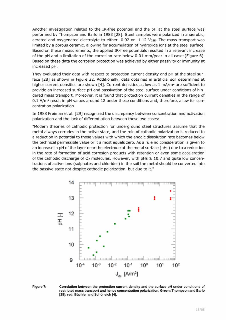
Another investigation related to the IR-free potential and the pH at the steel surface was
performed by Thompson and Barlo in 1983 [28]. Steel samples were polarized in anaerobic,
aerated and oxygenated electrolyte to either -0.92 or -1.12 VCSE. The mass transport was
limited by a porous ceramic, allowing for accumulation of hydroxide ions at the steel surface.
Based on these measurements, the applied IR-free potentials resulted in a relevant increase
of the pH and a limitation of the corrosion rate below 0.01 mm/year in all cases (Figure 6).
Based on these data the corrosion protection was achieved by either passivity or immunity at
increased pH.
They evaluated their data with respect to protection current density and pH at the steel sur-
face [28] as shown in Figure 22. Additionally, data obtained in artificial soil determined at
higher current densities are shown [4]. Current densities as low as 1 mA/m2 are sufficient to
provide an increased surface pH and passivation of the steel surface under conditions of hin-
dered mass transport. Moreover, it is found that protection current densities in the range of
0.1 A/m2 result in pH values around 12 under these conditions and, therefore, allow for con-
centration polarization.
In 1988 Freiman et al. [29] recognized the discrepancy between concentration and activation
polarization and the lack of differentiation between these two cases:
"Modern theories of cathodic protection for underground steel structures assume that the
metal always corrodes in the active state, and the role of cathodic polarization is reduced to
a reduction in potential to those values with which the anodic dissolution rate becomes below
the technical permissible value or it almost equals zero. As a rule no consideration is given to
an increase in pH of the layer near the electrode at the metal surface (pHs) due to a reduction
in the rate of formation of acid corrosion products with retention or even some acceleration
of the cathodic discharge of O2 molecules. However, with pHs ≥ 10.7 and quite low concen-
trations of active ions (sulphates and chlorides) in the soil the metal should be converted into
the passive state not despite cathodic polarization, but due to it."
Figure 7: Correlation between the protection current density and the surface pH under conditions of restricted mass transport and hence concentration polarization. Green: Thompson and Barlo [28]; red: Büchler and Schöneich [4].

19/68
Figure 8: Representation of the corrosion rate from field tests [30] in the Pourbaix
diagram. The corrosion rates for the green dots are smaller than 0.03 mm/year, while the red dots exhibit higher corrosion rates.
This conclusion is in line with the effects discussed in Figure 1. They are confirmed by the
extensive field investigations of CP and the related protection criteria performed by Barlo in
1994. Coupons were cathodically protected under defined conditions during 5 years in Aus-
tralia, Canada and the USA [30]. In Figure 8 the IR-free potentials and the pH values calcu-
lated from the relationship in Figure 7 are plotted. The pH of the corroding coupons was
estimated to be in the neutral domain. The results for the coupons with small corrosion rates
(green dots) show a sufficiently increased pH for passivation. This explains the small corrosion
rates even at IR-free potentials more positive than -0.85 VCSE. Based on these data it is clear
that the corrosion protection can readily be determined based on the pH value rather than on
the IR-free potential. Interestingly, applying the same approach to the data collected in Ger-
many between 2011 and 2013 [31] resulted in an even better correlation between pH and
corrosion protection. As long as the average current density was cathodic (larger than 1
mA/m2) and the average on-potential was more negative than -0.85 VCSE, no corrosion was
observed. This good agreement between the field test [31] with the model concepts in Figure
1 can readily be explained by the special care that was taken with respect to bedding of the
coupons: they were oriented upward by an angle of 45° to prevent loss of contact with the
soil in the case of soil settling. Hence, the bedding conditions were ideal, the mass transport
was highly limited and the build-up of an increased pH with concentration polarization was
possible even at small current densities. This confirms the relevance of the mass transport
for the corrosion behaviour.
The problems associated with a limited pH increase are nicely illustrated by the investigation
of Kajiyama and Okamura in 1999 [3] as shown in Figure 9 The acid produced by the SRB
required activation polarization in order to achieve protection, while in absence of SRB an
increase of pH and protection through passivation was readily possible. These data are again

20/68
in good agreement with the proposed model concept in Figure 1 and can readily be explained
by means of concentration and activation polarization, respectively.
Figure 9: The pH and IR-free potential dependence determined for soils with (red) and without (green) SRB according to [3].
The results of Schwerdtfeger and McDorman (Figure 5), of Thompson and Barlo (Figure 6)
and Kajiyama and Okamura (Figure 9) demonstrate a link between the pH and the IR-free
potential as suggested by Leeds in 1992 (Figure 1). Kasahara, Sato and Adachi [32] also
demonstrated a similar relationship between the IR-free potential, current density and pH. In
the case of limited mass transport (sand bedding) and absence of SRB the protection current
as small as 1 mA/m2 causes an increase of surface pH and subsequent passivation. IR-free
potentials more negative than -0.85 VCSE indicate an increase of the pH above 9 and the
possibility of passive conditions under these circumstances.
5.2.5 The IR-free potential in the case of activation polarization
Most literature data can readily be explained based on the concept for concentration polari-
zation. However, there are relevant factors affecting the corrosion behaviour that are often
overlooked. Pourbaix has pointed out in 1960 [33] that the cathodic polarization of steel in
buffered solution can initiate or accelerate corrosion. The naturally formed protective passive
film or rust layer can be cathodically dissolved and, therefore, cause an increase of corrosion
rates under insufficient cathodic protection. The investigation of Schwenk [34] has indeed
confirmed strongly increased corrosion rates in the range of 0.3 mm/year caused by polari-
zation of steel to IR-free potentials of -0.85 VCSE in carbonate buffers of pH 9.5. In his test
IR-free potentials more positive than -0.65 VCSE did not exhibit any relevant corrosion and
the polarization to values more negative than -0.95 VCSE limited the corrosion rate to irrele-
vant levels. This effect is schematically illustrated for a solution of pH 7 in Figure 10. It is
relevant to note that in the presence of carbonates the corrosion domain is further extended

21/68
to higher pH values well above 10 as indicated with the blue domain for 1 M CO2 [35].
Schwenk used concentrations in this range and confirms that no active domain is observed
at pH-values of 11 [34].
Figure 10: Possible acceleration of corrosion due to cathodic activation polarization (red
arrow) from the passivity into corrosion domain in a buffered near neutral electrolyte according to [33, 34]. In yellow the pH dependent protection criteria proposed by Pourbaix are shown [2, 33]. In blue the expected
additional corrosion domain in 1 M CO2 is shown [35]. The green circles represent the expected pH values based on the IR-free potential values of -0.85 and -0.95 VCSE in anaerobic conditions in the case of concentration polarization.
Figure 11: Polarization scans (cathodic currents with positive sign) in electrolytes with various pH values redrawn according to [36]

22/68
It must be assumed that the possible risk of corrosion acceleration due to activation polari-
zation from the passivity into the corrosion domain has motivated Pourbaix to propose pH
dependent protection criteria as indicated with the yellow line in Figure 10 [2, 33]. Pourbaix's
approach is in important contrast to the requirements of EN 12954 and EN ISO 15589-1.
Even the most negative threshold of -0.95 VCSE for the IR-free potential can only be accepted
according to his concept, if the pH increase is limited. In case of a pH increase above values
of 11, which has to be expected at typical current densities of 0.1 A/m2 based on the data in
Figure 7, a threshold of -1.05 VCSE would be required (according to the yellow line in Figure
10). Based on Pourbaix's concept, the application of the current standards would result in
significant corrosion risks.
The absence of an active domain anodic of the immunity in the pH range of 9 to 14 is, there-
fore, of utmost importance for the application of cathodic protection. Based on the results in
Figure 7, it has to be expected that all well bedded coating defects exhibit pH values from 9
to 13. Moreover, the EN 12954 and EN ISO 15589-1 require the IR-free potential to be in the
range of -0.85 to -1.2 VCSE. This happens to be the transition domain between immunity and
passivity with a possible presence of an active passive transition. There is no literature pre-
senting any relevant active dissolution in the corresponding potential and pH-domain, with
the exception of carbonate solutions. Typical results from Heusler et al from1958 [36] are
presented in Figure 11. Clearly no relevant anodic dissolution is observed in the pH range
from 9.5 to 13. At pH 15 however, significant anodic dissolution is observed. These results
are in line with Schmuki et al. [37] for measurements at pH 13.
In contrast, active dissolution has to be expected in the case of increased carbonate concen-
trations as shown in Figure 10. This thermodynamically expected domain is experimentally
confirmed by literature [34, 38]. A certain level of carbonates has to be expected in any soil
and a consumption of the carbonates by precipitation of siderite (FeCO3) is expected. This
may contribute to the formation of covering layers that will enhance the increase of pH and
contribute to a concentration polarization. Nevertheless, in the case of streaming soft and
especially buffered water any threshold more positive than -0.95 VCSE for the IR-free potential
under activation polarization cannot be justified based on the available literature.
In contrast, under mass transport limited conditions on well bedded coating defects a limited
concentration of carbonates may be expected. The precipitation of siderite will rapidly de-
crease their concentration and favor the formation of a passive film. This is confirmed by the
data of Schwenk that show a rapid decrease of the corrosion rate in his test with a limited
electrolyte volume [34]. In the case of concentration polarization, the application of a thresh-
old of -0.95 VCSE for the IR-free potential indicates a pH increase to 11. Under these conditions
protection even in increased carbonate concentration according to the green circle inFigure
10 may be expected.
5.2.6 Electrochemical description of the processes
The effects taking place under cathodic protection are discussed in the following by means of
a calculation model [39, 40] that includes the kinetic and thermodynamic data [2] as well as
the mass transport processes [4, 41, 42] in order to illustrate the relevant electrochemical
factors.
The calculations are performed for a well bedded electrode surface of 10 cm2 allowing for
concentration polarization. Furthermore, a diffusion limited oxygen reduction current density
of 0.1 A/m2 was assumed. In Figure 12 the calculated corrosion potential of -0.78 VCSE for
steel in a neutral soil with a resistivity of 60 Ωm is shown. Based on the polarization scans,

23/68
the potential, and pH value in the Pourbaix diagram [2] it is clear, that corrosion will occur
and that the potential of steel is controlled by the hydrogen evolution.
When applying a cathodic protection with an on-potential of -0.82 VCSE the IR-free potential
and the pH-value at the steel surface are changed according toFigure 13. The cathodic cur-
rent of significantly less than 1 mA/m2 is not sufficient to result in corrosion protection. The
potential and the pH are within the corrosion domain of the Pourbaix diagram. Decreasing
the on-potential to a value of -0.84 VCSE results in a significant modification of the situation
(Figure 14). In this case the increase of the pH is sufficient for the formation of a protective
passive film, resulting in corrosion protection. It is found that a slight change in the on-po-
tential of 20 mV results in an increase of the cathodic current to 0.1 A/m2. The detailed
analysis of this effect shows that this current is not the cause of the corrosion protection, but
the consequence of the passivity. This means that a slight increase in the protection current
as shown in Figure 13 causes a slight increase of the pH at the steel surface above 9, which
is sufficient to allow for the formation of the passive film. This formation of the passive film
in return causes the control of the potential by the diffusion of oxygen rather than by hydro-
gen evolution.
This observation is crucial for the discussion of the significance of the protection criteria. The
cathodic current density that is established after reaching the corrosion protection by means
of passivity is a consequence of the passivity, the spread resistance, the diffusion limited
oxygen reduction current and the on-potential. This explains why until today no agreement
for a critical current density can be found in literature. Based on the model calculation the
required cathodic current density for passivation under the given mass transport conditions
is in the range of 1 mA/m2. However, the subsequently establishing current density is arbi-
trary, since it depends on external parameters.
Figure 12: EIR-free calculated for a soil resistivity of 60 Ωm. Left: Pourbaix diagram withthe red dot showing the conditions at the steel surface. The dashed horizontal
line represents the protection criterion of -0.85 VCSE according to EN ISO 15589-1 and the solid horizontal line the corrosion potential of -0.78 VCSE that is expected under the given circumstances. Right: Polarization curves for an-odic (red) and cathodic reactions (blue) on steel at the corresponding pH value based on published literature data [39, 40].

24/68
Figure 13: EIR-free calculated for a soil resistivity of 60 Ωm. Left: Pourbaix diagram withthe calculated values shown as a red dot. The dashed horizontal line repre-sents the protection criterion of -0.85 VCSE according to EN ISO 15589-1 and the solid horizontal line the on-potential of -0.82 VCSE. Right: Polarization
curves for anodic (red) and cathodic reactions (blue) on steel at the corre-sponding pH value. The length of the green line is showing the magnitude of the current density.
Figure 14: EIR-free calculated for a soil resistivity of 60 Ωm and an on-potential of
-0.84 VCSE. Details to the plot are described in Figure 13.

25/68
Figure 15: EIR-free calculated for a soil resistivity of 60 Ωm and an on-potential of -1.3 VCSE. Details to the plot are described in Figure 13.
The further decrease of the on-potential to -1.3 VCSE causes an additional increase of the
current density and the pH-value as can be seen in Figure 15. In this case the current of 0.5
A/m2 is controlled by the hydrogen evolution. The IR-free potential of the steel surface is still
in the passivity domain.
The discussion shows that the protection criterion in EN ISO 15589-1 for normal conditions
can be explained with the equilibrium line for hydrogen evolution that is reaching the passivity
domain in the Pourbaix diagram at a potential value of -0.85 VCSE according to [4]. Hence,
potentials more negative than -0.85 VCSE are bound to exhibit a sufficient increase in pH to
provide passivity. At increased current densities it is possible that the immunity range is
reached at elevated pH-values. The IR-free potential in the discussed cases was either con-
trolled by the diffusion controlled oxygen reduction (Figure 14) or hydrogen evolution (Figure
15). Interestingly, in the calculated configuration an on-potential more negative than -0.85
VCSE results in corrosion protection, which is in line with the observations of Robert Kuhn [1,
43].
5.2.7 Conclusion
Based on literature achieving corrosion protection by activation polarization close to or into
immunity is difficult if not impossible. In contrast, there is wide agreement that cathodic
protection is achieved by an increased pH and subsequent passivation. The second edition of
the standard CP textbook by Peabody [44] from 2001 nicely summarizes this observation:
"The concepts presented for CP (activation polarization) are fundamentally correct at the in-
stant that CP is applied but are too simplistic to consider the time-dependent behaviour of a
cathodically protected underground structure….. This pH increase (concentration polarization)
is beneficial because the corrosion rate of steel decreases with increasing pH, even under
freely corroding conditions. The decrease in corrosion rate is the result of the formation of a
protective oxide film on the metal surface in the elevated pH environment, a process referred
to as passivation."
This view is confirmed by more recent work [45-47]. Based on the review of literature the
requirements in EN 12954 and EN ISO 15589-1 can only be explained by means of concen-
tration polarization. If the cathodic protection would be based on a shift of the IR-free poten-
tial into or towards immunity, no threshold for the IR-free potential more positive than -0.95
26/68
VCSE could be tolerated. More positive values would represent a significant corrosion risk. The
fact that the more positive threshold values -0.85, -0.75 and -0.65 VCSE have been success-
fully applied in the past years, confirms the fact that corrosion control is readily possible at
these values and that concentration polarization is typically the predominant process. Denying
the relevance of the pH-increase and concentration polarization implicitly puts the technical
relevance of the current standards into question.
5.3 Consequences on criteria
5.3.1 Introduction
Based on the above discussion of the literature, the effect of concentration polarization, the
increase of pH and the subsequent passivation for the corrosion protection of steel was
demonstrated. The discussion of the threshold of -0.85 VCSE and the relevance of the on-
potential versus an IR-free potential has continued since Kuhn's original publication in 1928.
The corresponding literature is revisited with the proposed concept of activation and concen-
tration polarization. This discussion is not only relevant for the future work on the correspond-
ing standards, but significantly affects the protection criteria for stray current corrosion.
5.3.2 The significance of the on-potential
Kuhn has proposed in 1928 [1] an on-potential (Eon) criterion of -0.85 VCSE. He identified the
galvanic corrosion among differently aerated coating defects as the reason for the high cor-
rosion rates. He found that applying a sufficiently negative on-potential ensures the compen-
sation of these galvanic couples and a strong limitation of the corrosion process. Based on
the above discussion his conclusion was technically sound and correct. The work of
Schwerdtfeger and McDorman [27] has clearly shown that the IR-free potential (EIR-free) of a
steel surface corroding even under anaerobic conditions is always more positive than -0.85
VCSE unless the pH is increased above 9. In most electrolytes such an increase of pH is suffi-
cient for passivation. Based on equation (5) it must therefore be concluded that any on-
potential more negative than -0.85 VCSE is bound to result in a cathodic current I on an indi-
vidual coating defect. This conclusion is independent on the spread resistance R and hence
the soil resistivity.
R
EEI
onfreeIR −=
−(5)
Taking into account the results in Figure 7 the current density for achieving pH 9 and hence
passivation is as small as 1 mA/m2 in the case of hindered mass transport and concentration
polarization. At this current density negligible ohmic drop will be obtained even with large
coating defects and increased soil resistivity. This explains the good success of Kuhn's criteria
based on an on-potential and underlines its technical relevance.
It is argued that the very low soil resistivities in the Mississippi Delta, where Kuhn ran his
experiment, have resulted in negligible ohmic drops [48]. This argument ignores the fact that
Kuhn was working with coal tar dipped coated pipelines. The high current demand required
by the comparably large metal surface area negates the effects upon the magnitude of the
ohmic drop caused by the low soil resistivity in the range of 6 Ωm. However, when considering
the small current densities required for protection, Kuhn's success with the on-potential cri-
terion can readily be explained on the basis of concentration polarization. It might be relevant
to consider that he performed his work on cast iron pipes. The limited mechanical properties

27/68
of this material required careful bedding of the pipelines and it may be assumed that this has
favoured a limited mass transport and the build-up of an alkaline environment.
It follows that the on-potential is sufficient as a protection criterion in the case of a well
bedded coating defect with limited mass transport allowing for concentration polarization in
the case of homogeneous current distribution within the individual coating defects. This was
indeed confirmed in a field test in Germany, where no relevant corrosion was found if the on-
potential averaged over 24 hours was more negative than -0.85 VCSE in the case of coating
defects of 1cm2 surface [31]. Consequently, the average current density was cathodic, and
the pH could increase on the specifically well bedded probes with limited mass transport al-
lowing for pH increase and passivation.
5.3.3 The significance of the IR-free potential
While the on-potential is a suitable method to ensure current entering into the coating defects,
the IR-free potential in the case of concentration polarization corresponds to a pH measure-
ment. This was already demonstrated by Schwerdtfeger and McDorman [27]. It could be
argued based on Figure 1 that under concentration polarization (green line) an IR-free po-
tential of -0.85 VCSE corresponds to a pH 9 and IR-free potential of -0.95 VCSE corresponds to
a pH of 11. The corresponding positions in the Pourbaix diagram are shown inFigure 10 by
means of the green circles. Hence, these two empirically observed criteria for the IR-free
potential that were already reported by 1957 [49] can readily be explained. Within this con-
text also the maximum negative value of -1.2 VCSE for the IR-free potential stated in EN ISO
15589-1 can be explained. This corresponds to a pH value above 13, where issues with ca-
thodic disbondment have to be expected. It is relevant to note that this threshold has limited
relevance with respect to activation polarization, since activation polarization is characterized
by a lack of increase in pH. Limited issues with disbondment of the coating have to be ex-
pected in the case of activation polarization.
Within this discussion it is crucial to understand that the threshold values of -0.85, -0.95 and
-1.2 VCSE are only applicable for an estimation of the pH value at the steel surface, if the IR-
free potential is controlled by hydrogen evolution as indicated by the green line inFigure 1.
In contrast, if the IR-free potential is a result of the activation controlled oxygen reduction,
as has been discussed in [7-10], significantly more positive values in the range of -0.65 or -
0.75 VCSE may be expected as observed by Funk et al. in 1987 [15] in well aerated soils. This
explains the corresponding values in EN 12954 and EN ISO 15589-1 for high resistive well
aerated soils. However, under these conditions the IR-free potential may not be used to de-
termine the pH with respect to protection levels or over-protection. In the case of concentra-
tion polarization, where CP is resulting in an increased pH and the formation of a passive film,
it must be concluded that the IR-free potential is irrelevant for judging the corrosion protec-
tion of a passive surface [7-10]. This is best illustrated in Figure 8: The judgment of the
corrosion situation is best done based on the pH value rather than the IR-free potential. In
low resistive or poorly aerated soils the IR-free potential depends on the pH and may, there-
fore, be used to demonstrate the protection. Under well aerated conditions the IR-free po-
tential does no longer correlate with pH and it is, therefore, irrelevant to draw any conclusion
with respect to the corrosion situation.
Whenever this build-up of an increased pH is not possible due to a high removal rate of the
formed hydroxide ions, such as in soft streaming water or in presence of SRB (see Figure 9),
an activation polarization is required at significantly increased current densities. In this case
only an IR-free potential of at least -0.95 VCSE can assure sufficient corrosion protection by
polarization close to or into immunity. Not meeting this threshold in the case of activation
polarization is inherently linked to corrosion.

28/68
5.3.4 Consequences
The discussion of the IR-free potential (required in EN 12954 and EN ISO 15589-1) as well
as the on-potential (required in EN 14505) demonstrates the relevance of these two criteria
under the respective circumstances. Kuhn's approach with the on-potential is technically
sound and valid until today in the case of concentration polarization for well bedded struc-
tures. However, it was bound to fail in the cases where the pH could not increase. Corrosion
damages during the 1980's in Germany on a poorly bedded pipeline caused by SRB resulted
in the introduction of the IR-free potential criterion in Europe in combination with a threshold
value of -0.95 VCSE. Based on the above discussion this is technically correct and justified.
While the approaches developed in the past are well justified, they lead to a key problem
when it comes to determine the effectiveness of cathodic protection: As long as the bedding
and the mass transport conditions of individual coating defects are not known it is very difficult
to justify a protection criterion other than an IR-free potential in combination with a threshold
value of -0.95 VCSE. This assures corrosion protection in case of activation polarization to
immunity or concentration polarization to a pH value of 11. However, not meeting this crite-
rion in the case of concentration polarization does not indicate a corrosion risk, in the case of
activation polarization it does.
5.4 Consequences on interference conditions
5.4.1 Introduction
In the above discussion the presence of ac and dc interference has been excluded. However,
for the practical application their effect on the corrosion process is of utmost importance. It
is beyond the scope of this document to treat these issues in detail. For simplification, the
following assumptions were made:
• The reference electrode is placed above the structure
• The structure is coated with a state of the art three-layer PE coating with a coating
resistance of at least 1 MΩm2 exhibiting individual coating defects that are more dis-
tant than the structure depth
• The distance between the interfering source and the pipeline is significantly larger
than the structure depth. As a consequence, the distance from the reference electrode
placed above the coating defect is smaller than the distance between two neighbour-
ing coating defects.
In the following only the most relevant effects of the individual parameters will be addressed.
They are based on the available literature and on the proposed model concepts.
5.4.2 AC interference
Based on EN ISO 18086 there is general agreement that ac interference is caused by in-
creased ac and dc current densities. This is especially critical in the case of concentration
polarization, since the buildup of an increased hydroxide concentration at the steel surface
and its distribution into the surrounding soil causes a relevant decrease of the spread re-
sistance of the coating defects. Under given interference conditions the increase of pH and
the drop of the spread resistance leads to increased current densities and, therefore, to an
increased corrosion risk. The influencing processes according to the principles given in EN ISO
18086 are described in [50] in more detail. In the current understanding of the process it is
the alternating formation and dissolution of the passive film within the transition between

29/68
immunity and passivity at pH values around 13 that are responsible for the ac corrosion
process [51]. So far there is no known case of ac corrosion under activation polarization
conditions, which may be explained as follows: Based on theoretical considerations a short
term decrease in cathodic protection current density and especially anodic currents caused
by ac interference are expected to cause relevant corrosion damage as well. The key ad-
vantage in the case of activation polarization is the lack of pH increase and the absence of a
decrease in spread resistance, which limit the risk of increased ac current densities and,
hence, the risk for corrosion damages. This is indeed confirmed for the rails in the wet Simplon
tunnel atmosphere. This was in absence of CP and therefore lack of pH increase where the ac
traction return current was required to cause relevant corrosion of the rails [52].
Due to the relevant effect of pH and spread resistance, the corrosion rate is strongly controlled
by the on-potential. More negative on-potentials result in higher pH at the steel surface, lower
spread resistance and therefore higher ac corrosion rates. This makes the ac corrosion pro-
cess for unknown mass transport conditions critical in the case of both, anodic and cathodic,
dc interference.
5.4.3 Constant DC interference
In the case of constant dc interference, as it may be caused by a foreign CP system, the
gradients in the soil will, depending on the polarity of the interference, either decrease (anodic
interference) or increase (cathodic interference) the protection current density on a given
coating defect. In the case of an anodic interference, the above discussion allows for some
conclusions depending on the mass transport conditions and the predominant type of polari-
zation:
• In the case of concentration polarization, the on-potential measured above the struc-
ture must be at least more negative than -0.85 VCSE. For practical reasons it was found
that a safety margin is necessary and that a value of -1 VCSE should be used [53].
Under these conditions a cathodic current will be flowing towards the coating defect,
resulting in an increased pH and passivity if concentration polarization is sufficient. If
the ideal conditions of bedding, leading to adequate concentration polarization are not
in place, corrosion remains possible. In the case of activation polarization any shift of
the on-potential more positive than the minimum required value will cause an inherent
risk of corrosion. With the Tafel slope of less than 100 mV/dec for the iron dissolution
reaction (2) even a small shift of the on-potential to a less negative level can result in
relevant corrosion [54]. Corrosion has to be expected already in the case of a de-
creased protection current density in the coating defect of less than 1 A/m2 [30].As a
consequence, anodic interference under activation control must be compensated by
shifting the on-potential more negative, with all the negative consequences on ac cor-
rosion risk on the corresponding well bedded coating defects exhibiting concentration
polarization.
In the past not much attention was paid to cathodic interference. However, in combination of
ac interference a cathodic interference (e.g. caused by an anode) can dramatically increase
the corrosion risk of the structure as follows from the requirements in EN ISO 18086.
5.4.4 Time variant DC interference
In case of interference caused by dc traction systems, typically both, anodic and cathodic
potential excursions are observed when the potential is monitored against a reference elec-
trode placed above the structure. In a first approach the time variant stray current interfer-

30/68
ence could, therefore, be considered as low frequent ac interference. This has important con-
sequences that are ignored when only focusing on anodic potential excursions as it is currently
required according to EN 50162.
• In the case of concentration polarization with an increased pH in the coating defect
and a subsequently formed passive film, the shift of the IR-free potential in the anodic
direction does not represent an imminent corrosion risk as follows immediately from
Figure 8. In the first edition of Peabody's "Control of Pipeline Corrosion" from 1967 it
is stated: "When steel is immersed in a sufficiently caustic solution with a pH around
11 and higher, it can be made to discharge current without appreciable metal loss”
Similar effects are reported by [6, 28, 55-57]. Nagayama and Kawamura [58] have
shown how current may be passed through a steel surface by means of the redox
system Fe2+/Fe3+ in the presence of a passive film with a very high efficiency. Schmuki
et al. [37] have also shown how the repetitive and reversible Fe2+/Fe3+/Fe2+ transition
cycle can occur. The data demonstrates that in the presence of a passive film it is
possible to observe anodic activity with no oxidation of Fe provided the potential does
not become sufficiently cathodic to dissolve the passive film through electrochemical
reduction.
Figure 16: Influence of the chloride ion concentration on the pitting potential. Chloride
concentration from 0.001 M (green), 0.01 M (yellow), 0.1 M (orange) to 1 M (red) [59].
• In chloride containing environments the initiation of pitting corrosion could in principle
occur, but detailed investigations have shown that the redox system Fe2+/Fe3+ does
not only consume large amounts of the passed anodic charge [4], but also limits the
anodic excursion of the potential to values within the grey area in Figure 16. This
makes the initiation of pitting corrosion less probable. Notably, this grey area is ca-
thodic to the most negative possible pitting potential in solutions with pH-values above
11 even with very high chloride concentrations of 1 M [59] as shown in Figure 16. The
chloride ion concentration will usually always be far less than 1 M under all practical
31/68
conditions (e.g. seawater has an approximate molarity of 0.48 M) and hence the pit-
ting potential will in most cases be more positive than the gray area. Much lower
chloride ion concentrations will usually occur in soils and the pitting potential becomes
more positive in Figure 16 as the chloride ion concentration decreases from 100 to 10-
3 M. Hence the anodic excursion required for the initiation of pitting at low chloride
concentrations or high pH-values is often insufficient.
In the case of concentration polarization, the only key requirement is a sufficiently
increased pH value at the steel surface. This is achieved by a current passing to the
steel surface that is on average cathodic (e.g. averaged over 24 hours). Important
anodic potential excursions can be tolerated, if their duration does not substantially
decrease the surface pH. In a first approach a net cathodic current can be assured
with an average on-potential that is more negative than -1.2 VCSE. Shifting this value
more cathodic will increase alkalinity and increase the tolerance with respect to pro-
longed anodic potential excursions.
• In the case of activation polarization cathodic excursion cannot compensate for anodic
current discharge. Furthermore, a rust layer containing the redox buffer Fe2+/Fe3+
cannot form due to the solubility of Fe2+. Hence, even decreasing the protection cur-
rent density can cause an imminent corrosion risk and anodic current discharge is not
acceptable, since this will result in iron oxidation to dissolved Fe2+. Even IR-free po-
tentials more negative than -0.85 VCSE and the absence of on-potentials more positive
than this value can already cause relevant corrosion. Based on [54] even minor anodic
shifts of the IR-free potential result in relevant acceleration of the corrosion process.
In this respect anodic excursions must be strictly limited in the case of activation
polarization.
In the case of time variant DC interference, the expected corrosion behaviour is significantly
dependent on the type of polarization and the mass transport conditions at the steel surface.
5.4.5 Conclusions
The above discussion clearly demonstrates the importance of the bedding conditions and the
resulting mass transport at the coating defect surface. In the case of concentration polariza-
tion on a well bedded coating defect severe ac and dc interference conditions are manageable
and controllable. In contrast, in poor bedding conditions under activation polarization inter-
ference is critical. In the case of combined ac and dc interference, mitigation of the corrosion
risk may become very challenging.
5.5 Consequences of the model concepts
The above discussion has highlighted some of the relevant processes taking place under ca-
thodic protection. The discussion of the processes has a focus on individual coating defects.
The presence of different coating defects with strongly different mass transport characteristics
on the same structure has important consequences that need to be addressed. It may tech-
nically be achievable to ensure that all coating defects are well bedded at pipeline construc-
tion. Alternatively, some defects in poor bedding conditions will be in electrolytes that enable
calcareous deposits to form and these will result in and enhance concentration polarization.
However, it cannot be certain that all coating defects in poor bedding will develop calcareous
deposits. Therefore, in typical cases for a pipeline it is possible that a large number of coating
defects will exhibit concentration polarization, but a smaller number can only be protected by
means of activation polarization. The relevant implications are discussed below:

32/68
Cathodic disbondment: Achieving sufficiently high current densities for activation polariza-
tion on the poorly bedded coating defects is inevitably going to cause over-protection on at
least some of the well bedded coating defects. It is technically not possible to ensure IR-free
potentials more negative than -0.95 VCSE on the poorly bedded ones and guarantee IR-free
potentials more positive than -1.2 VCSE on the well bedded ones. In this respect the require-
ments of EN ISO 15589-1 cannot be fulfilled in the case of concentration and activation po-
larization on the same structure.
The IR-free potential to measure the surface pH: The above discussion has shown that
the IR-free potential measurement is a suitable method for assessing the surface pH of a
coating defect exhibiting concentration polarization as long as the IR-free potential is con-
trolled by hydrogen evolution. This is explaining the relevance of this criterion. Problems occur
in the case of increased aeration, increased coating defect size and increased soil resistivity,
when polarization to the hydrogen evolution is not possible under typical operation conditions
of CP. Often this leads to a shift of the on-potential to more negative values by increasing the
current output of CP-rectifiers. This will further shift the IR-free potential to more negative
values, increase current density and surface pH resulting in a risk of over-protection. This is
due to the fact that the threshold of -1.2 VCSE represents a pH measurement as well, which is
not applicable in the case of well aerated conditions. As a consequence, the IR-free potentials
can be well more positive than -0.85 VCSE, but CP has led to critical pH values at the steel
surface resulting in cathodic disbondment.
The application of -0.85, -0.75 and -0.65 VCSE: These values specified by EN 12954 and
EN ISO 15589-1 are only applicable in the case of concentration polarization. They will not
provide corrosion protection in the case of activation polarization. Under unknown mass
transport conditions, it is difficult to justify their use.
The on-potential: The on-potential does not deliver any information with respect to an in-
dividual coating defect. However, average values more negative than -1.2 VCSE, as required
by EN 14505, ensures an average cathodic current to enter every individual coating defect.
This can be considered a first minimum requirement for an effective CP. In the case of limited
mass transport, build-up of an increased pH and passivation this will ensure corrosion pro-
tection in many cases. This explains the collectively good experience with CP, since most
structures fulfil this on-potential requirement and have limited mass transport at most of their
coating defects.
Interference conditions: Based on the above discussion, combined ac and dc interference
can only be managed if all the coating defects can be protected by means of concentration
polarization. Otherwise, severe anodic and cathodic interference in combination with high ac
interference become practically impossible to mitigate.

33/68
6 New concepts for protection criteria
6.1 Introduction
The application of cathodic protection (CP) is generally statutory for high pressure gas- and
oil-pipelines. Moreover, CP is frequently used for water pipelines and buried containers. The
relevant underlying principles and protection criteria are stated in EN ISO 15589-1:2017. In
the last years various investigations with respect to CP have raised the understanding, that
the pH is an important parameter in providing the corrosion protection [3-6, 60, 61]. In many
cases relatively small protection current densities in the range of a few tens of mA/m2 result
in an increase of the pH-value at the steel surface of coating defects of pipelines. This increase
of the pH favours the formation of a passive film, which significantly limits any further corro-
sion [4-6, 55, 60, 61]. By means of model calculations, that are based on thermodynamic
and kinetic data, all currently used protection criteria in CP can readily be explained when
taking into account the relevance of the pH and the formation of a passive film [7-10]. Based
on these considerations the accumulation of alkalinity and hence the mass transport at the
steel surface are key determining factors in the effectiveness of CP. These aspects and the
associated implications are discussed in detail by Angst et al [62]. Today’s understanding of
the mechanisms involved in CP provide a new view on the protection criteria and the pro-
cesses taking place during interference conditions. This far reaching understanding has influ-
enced the criteria in EN ISO 18086 for the assessment of AC corrosion and the work on ISO
21857 with respect to anodic stray current interference.
The relevant aspects involved in cathodic protection and the associated implications are pre-
sented. The physical and chemical significance of the protection criteria in EN ISO 15589-1
are explained and the implications with respect to the assessment of the effectiveness of CP
are highlighted. Furthermore, the processes taking place under anodic stray current interfer-
ence are discussed. These aspects are currently integrated in ISO 21857 and will provide a
simple and straightforward approach to the assessment of the corrosion risk of pipelines un-
der time variant stray current interference. Additionally, the implications of over polarization
and the resulting AC corrosion risk will be discussed in the context of EN ISO 18086.
The far-reaching understanding of the mechanisms taking place during cathodic protection
have led to conclusive models with respect to interference conditions. Based on these con-
cepts it is today possible to determine the effectiveness of CP based on a new approach that
is presented in the following. This approach is based on the documents DVGW GW 21, GW
28 and GW 28 B1. In Germany these documents have the status of a recognized state of the
art. The main advantage of this documents is their applicability on all types of pipelines inde-
pendent on their interference conditions. Based on them it is possible to assess the effective-
ness of CP of AC and DC interfered pipelines based on the readily measurable on-potential
and AC voltage, rather than the IR-free potential that can typically only be determined by
means of coupon measurements on most modern pipelines.
Within this section a description of the underlying mechanism and a discussion of the contri-
bution of the interference conditions is presented. Additionally, a description of the associated
controlling parameters and the influencing factors is presented. Furthermore, a proposal for
their quantification is given and examples for the field application is presented. These aspects
form the basis for future discussion and elaboration.

34/68
6.2 The underlying mechanism
There is general agreement that the effectiveness of CP is based on polarization of the steel
surface [1, 63, 64]. However, the actual chemical process that causes the polarization is often
not further discussed despite of its important consequences on various aspects of the effec-
tiveness. According to EN ISO 8044 the polarization and the associated the change of poten-
tial of a steel surface is caused by the cathodic current. This polarization can be achieved
through activation polarization. The cathodic current flow inadvertently results in a change of
the soil composition as a result of the electrochemical reactions taking place. This change of
potential caused by the concentration change is called concentration polarization. According
to von Baeckmann the activation polarization is achieved within milliseconds as a result of
the current flow through the steel surface and the concentration polarization is built up within
a fraction of a second, minutes or even hours [65]. Based on the present model concepts
discussed in this document a more differentiated understanding is available today with re-
spect to the involved electrochemical processes. The concentration polarization at the steel
surface as a result of the CP current changes the composition of the soil not only in the
immediate vicinity of the steel surface but also in the surrounding environment. This effect
provokes a shift of both the pH and the potential along the hydrogen equilibrium line (blue
arrows in Figure 17). The increase of the pH at the steel surface and in the surrounding soil
as well as the passivation are illustrated in Figure 19a. Since the hydrogen equilibrium poten-
tial, which correlates with the cathodic limit of water stability, depends on the pH (hydrogen
evolution line in Figure 17), the pH-value at the steel surface can directly be determined
based on the IR-free potential. This has been discussed in detail by Angst et al [62] and is
confirmed by the data of Yan et al [66] as reported in [67]. For this reason, the protection
potentials according to EN ISO 15589-1 can readily be explained:
• The EIR-free of -0.85 VCSE corresponds to a pH of 9, which is, according to Figure 17,
sufficient for achieving passivity
• The EIR-free of -0.95 VCSE corresponds to a pH of 10,5 (yellow circle in the middle of
Figure 17), which allows for passivity even in aggressive soils
• On the other hand, the EIR-free of -1.2 VCSE corresponds to a pH of 13 (yellow circle to
the right in Figure 17), which, according to EN ISO 15589-1, may cause problems with
the adhesion of coatings.
It should be noted in this context, that a pH value of 13 is typical for concrete. In concrete
the formation of a protective passive film and the resulting corrosion protection for the steel
reinforcement are well accepted.
The dependence of the pH-value at the steel surface on the CP current density has been
investigated by several authors. The results are shown in Figure 18. It can be concluded that
cathodic current densities in the range from 20 to 1000 mA/m2, which are typical for the CP
the exposed steel within the coating defects on buried pipelines, result in pH-levels from 10.5
to 12.5. According to Figure 17 these levels correlate with IR-free potentials in the range from
-0.95 to -1.2VCSE. Correspondingly, it is readily possible to plot the IR-free potential associated
with the achieved surface pH value as shown on the right vertical axis in Figure 18. This
consideration shows the relevance of the current density, the surface pH, the generation of
an environment conducive to passivation as well as the protection criteria based on IR-free
potentials for the practical implementation of CP on buried pipelines.

35/68
Figure 17: Pourbaix-diagram (Fe/H2O) illustrating the cathodic polarization of steel [2]. The blue arrow shows the effect of concentration polarization and the resulting enhancement of the pH-level as well as the passivation. The yellow circles indicate the position of the protection potentials according to EN ISO 15589-1.
Based on this consideration the IR-free potential is associated with a surface pH measurement
rather than the actual corrosion protection of the steel. Since an increase in pH is associated
with passivation, corrosion protection is achieved. This view was emphasized by Freiman [29]
and is today widely accepted. The standard CP textbook by Peabody [44] on CP describes the
process as follows:
"The concepts presented for CP (activation polarization) are fundamentally correct at the in-
stant that CP is applied but are too simplistic to consider the time-dependent behaviour of a
cathodically protected underground structure….. This pH increase (concentration polarization)
is beneficial because the corrosion rate of steel decreases with increasing pH, even under
freely corroding conditions. The decrease in corrosion rate is the result of the formation of a
protective oxide film on the metal surface in the elevated pH environment, a process referred
to as passivation."

36/68
Figure 18: The pH-value at the steel surface as a function of the cathodic current density according to different literature sources summarized in [68]. On the right
vertical axis, the expected IR-free potentials associated with the hydrogen equilibrium line are shown.
The relevance of passivation reveals another highly relevant aspect that immediately follows
from Figure 17: The IR-free potential is not suitable for assessing the corrosion situation of a
passive steel surface under cathodic protection. Passivity is present at increased pH over a
wide potential range extending from the hydrogen evolution line all the way to the oxygen
evolution line. In well aerated resistive soils, it may not be possible to achieve a sufficiently
high current density to polarize the steel surface to the hydrogen evolution line. The resulting
IR-free potential may well be in the range of -0.65 and -0.75 VCSE. As long as the pH is
increased, passivity and hence corrosion protection is achieved under such conditions [9].
This immediately explains the corresponding protection criteria determined by Funk et al [15]
that are stated in EN ISO 15589-1.
It immediately follows that no correlation between the corrosion rate and the IR-free potential
may be expected. Therefore, without consideration of soil resistivity and aeration single IR-
free potential criteria can be associated with corrosion protection as emphasized by Table 1
in EN ISO 15589-1. This is because the IR-free potential may only be used as a pH measure-
ment when the IR-free potential of the steel is controlled by the hydrogen electrode. At in-
creased aeration of the soil this is not the case and the IR-free potential becomes an irrelevant
number with respect to the assessment of the achieved pH and hence the level of corrosion
protection.
This consideration raises the question with respect to an appropriate protection criterion.
Based on Figure 18 a current density in the range of 1 mA/m2 is sufficient to increase the pH
to a level that generates conditions conducive to passivation. At such low current densities,
the IR-error is negligible in many soils and even increased coating defect sizes. An example
of a model calculation of such a configuration is shown in Figure 27. For sufficiently low soil
resistivity and smaller coating defects corrosion protection is achieved as soon as the on-
potential is more negative than -0.85 VCSE. This is fully in line with the concepts and protection
criterion proposed by Kuhn [1]. A more recent analysis of the two most extensive field inves-
tigations performed with respect to CP protection criteria performed so far has clearly shown

37/68
that the on-potential is at least as reliable as the IR-free potential with respect to the assess-
ment of corrosion protection on coupons [69] with sizes below 20 cm2, which is fully in line
with the above conclusion. This raises the question with respect to the appropriate level of
on-potential that provides enough pH increase for the generation of conditions conducive to
passivation. While this current density of 1 mA/m2 may be sufficient for well bedded coating
defects smaller than 20 cm2, higher current density may be necessary in other conditions.
The required level of current density required for achieving corrosion protection predomi-
nantly depends on the bedding conditions (see [62]) but also the coating defect size. The key
parameter is the so-called reference current density Jref that is required to increase the pH
and establish effective CP. The reference on-potential that is required to ensure Jref on all
coating defects is called Eref according to DVGW GW 21. For well bedded pipelines in sand and
soil with small coating defects Eref may be as positive as -0.85 VCSE. Based on Angst et al [62]
a value of -1.0 VCSE is suggested for such conditions, since such an on-potential ensures
current entering into all coating defects.
6.3 The effect of anodic stray current interference
It follows from the above consideration that the cathodic protection of steel is based on the
increase of the pH-value and the resulting passivity. This discussion illustrates that the as-
sessment of stray current interference of cathodically protected pipelines needs to be reas-
sessed in the light of today's knowledge. The present mechanistic models, the available liter-
ature as well as available empirical data allow to develop new interference assessment con-
cepts and corresponding thresholds. These will be presented and discussed in the following.
The cathodic protection based on passivity has far reaching consequences for the assessment
of time variant stray current interference of a cathodically protected pipeline. The IR-free
potential is a pH measurement rather than a controlling parameter for the assessment of the
level of corrosion protection. This has immediate consequences on the assessment of the
corrosion risk under an interfered situation: The temporary anodic shift of the IR-free poten-
tial of a passive steel surface in the positive direction as a result of anodic stray current
interference, is not necessarily linked to a corrosion process. The IR-free potential more pos-
itive than the protection criterion of e.g. -0.95 VCSE is only the result of an influenced and
hence irrelevant pH-measurement. In the case of well aerated soils IR-free potentials of -
0.65 and -0.75 VCSE are required for addressing this influencing effect of oxygen in well aer-
ated soils in EN ISO 15589-1. Similar to the case of the oxidizing action of oxygen in the case
of well aerated soils where IR-free potentials of -0.85 and -0.95 VCSE are no longer applicable
significantly more positive IR-free potentials may well be associated with corrosion protection
under anodic stray current interference. In both the well aerated soil and the anodic stray
current interference condition the IR-free potential is no longer controlled by hydrogen evo-
lution and therefore becomes a meaningless number.
Time variant interference is typically caused by DC-operated railways or trams. In these
cases, the anodic interference has by experience in Holland typically a maximum duration of
about 300 seconds. In contrast, time variant anodic stray current discharge from coating
defects on pipelines under AC interference occurs at much higher frequency resulting anodic
current discharge for only about 10 ms in the case of 50 Hz interference. Moreover, telluric
interference is well known to cause time variant interference at very low frequency with an-
odic interference duration in the range of up to several hours. It is evident from the above
discussion that a time limited anodic current discharge does not necessarily result in corro-
sion. In fact, the anodic polarization will only shift the potential in the positive direction within
the passive domain, which usually does not result in corrosion. The anodic charge will rather

38/68
be consumed for the oxidation of ferrous ions (Fe(II)) within the oxide layers on the steel
surface as described in [4]. As a consequence, the repeated cathodic and anodic interference
caused by DC-operated railways or trams will cause a relevant charge transfer through the
steel surface. This electric charge, however, will not be consumed by the corrosion reaction,
but will be used for the redox system Fe(II)/Fe(III)/Fe(II). Bette observed this phenomenon
already in 2005 [70] and described it with capacitive charging effects. In fact, the above-
mentioned redox system acts as a pseudo-capacity and may readily be compared to the
charging/discharging of an accumulator. Consequently, the combination of passivity with this
redox system explains the empirical observation that a time limited anodic current will neither
result in major anodic potential shifts nor in corrosion. All more recent investigations of stray
current induced corrosion on cathodically protected pipelines confirm that the electric charge
will not be consumed for the corrosion reaction as long as the steel surface is passive [6, 28,
55, 56, 71, 72]. Hence, anodic current discharge is not inevitably related to a corrosive dis-
solution of the metal following Faradays Law, i.e. an anodic current does not always result in
corrosion. This is due to the fact that the anodic charge is consumed for the reaction
Fe(II)/Fe(III) on the passive surface, rather than the reaction Fe(0)/Fe(II) in the case of time
variant stray current interference.
The criteria specified in EN 50162:2004 are, however, based on the assumption of a time
constant anodic stray current load. Hence it is required to discuss the effects of a time con-
stant anodic current on the corrosion processes. In case of a time constant anodic current it
is not possible to achieve an increase of the pH at the steel surface. In fact, a time constant
anodic current results in a decreasing pH-value and thus in an acidification (cause by concen-
tration polarization) at the steel surface leading to corrosion according to Figure 19b. Moreo-
ver, the effect of a decreasing pH-value is illustrated with a red arrow in Figure 20. The
formation of an acidic electrolyte provokes corrosive conditions and passivation will be im-
possible. Under such circumstances it is to be expected, that 100% of the anodic current is
consumed by the redox system Fe(0)/Fe(II), i.e. for the corrosion reaction. This underlines,
that EN 50162:2004, which had been elaborated for time variant interference from DC-
operated railways or trams, is based on incorrect assumptions: The relevant increase of the
pH-value as a result of effective CP, which is crucial for the effectiveness of cathodic protec-
tion, the resulting passivation, the relevance of the redox system Fe(II)/Fe(III) and also the
consequences of a CP current that is cathodic when averaged over a representative period of
time, are ignored.
(a) (b)
Figure 19: Schematic illustration of cathodic concentration polarization (a) and anodic
concentration polarization (b). The cathodic current entering the steel surface, results in a depletion of oxygen, an increase of the pH-value in the soil and passivation (a). The anodic current leaving the steel surface results in a lowering of the pH-value and provokes corrosion (b). The intensity of colouring indicates the extent of pH change.

39/68
Based on the above discussed aspects various influencing factors can be identified, which
relevantly control the corrosion under time variant stray current interference:
Anodic current will decrease the pH, while cathodic current will result in an increase of pH at
the steel surface. It immediately follows that the average current over a full interference cycle
(e.g. 24 hours) represents a relevant parameter. This is due to the fact that the current
efficiency for alkalinity formation is at least as good as the one for acidity formation in the
case of steel. An average cathodic current is therefore bound to result in a pH increase over
time irrespective of temporary anodic excursions. Hence the polarity of the average electrical
charge controls the direction of pH change at the steel surface. If the excess of cathodic
charge is associated with a permanent and sufficient increase of the steel surface pH, corro-
sion protection is achieved. This effect of concentration polarization can best be illustrated
based on an analogy: In absence of anodic current discharge or in case of cathodic interfer-
ence a reservoir of alkalinity is accumulated at the steel surface. This reservoir will be con-
sumed during anodic current discharge. Saving alkalinity provides, therefore, corrosion pro-
tection during the hard times under anodic current discharge. As long as more alkalinity is
saved than consumed, an increased surface pH and hence corrosion protection is ensured
even under severe time variant anodic stray current interference.
This analogy reveals important implications: The duration of the anodic interference is bound
to be relevant, since the decrease of pH is not only a result of anodic current discharge.
Diffusion and migration into the surrounding soil, neutralisation with carbon dioxide as well
as convection and streaming water will contribute to a loss of the accumulated alkalinity.
These effects are negligible with respect to the pH at the steel surface in the case of short
anodic interference during AC interference of 50 Hz or short telluric interference of up to 3
seconds. This is illustrated by means of the green arrows in Figure 20. Indeed, experience
confirms that there is no detrimental effect with respect to corrosion caused by loss of surface
pH under such conditions. However, based on the argumentation in EN 50162 they would
have to result in relevant metal loss as a result of Faradays law and an assumed reaction of
Fe(0)/Fe(II).
In contrast, a duration of the anodic interference of 30 seconds causes a relevant change of
the surface pH during the anodic excursion, although the time averaged current is cathodic.
(blue arrows in Figure 20). Such durations are typical for tram operation. A further increase
of the duration of the anodic interference to 300 seconds, as they are characteristic for DC
train operation, can cause a major loss of surface pH resulting in temporary initiation of cor-
rosion (orange arrows in Figure 20). While the subsequent cathodic interference will re-es-
tablish passivating conditions according to Figure 20, a non-negligible corrosion rate will be
observed in this interference situation. Based on the above discussion the efficiency of the
anodic current with respect to the reaction Fe(0)/Fe(II) will be smaller than 100 % since only
a fraction of the anodic charge is consumed for corrosion. This effect is indeed experimentally
observed in the case of time variant anodic interference [70].

40/68
Figure 20: Polarisation of steel under stray current interference illustrated in the Pourbaix diagram [2]. The red arrow shows the concentration polarization under time constant anodic interference (in case of ineffective CP). A time variant interference in case of effective CP is illustrated with the green, blue and orange double arrows. The different duration of the anodic interference
of 3 (green), 30 (blue) and 300 (orange) seconds results in different levels of
concentration polarisation at a given cathodic charge.
Theoretically, the duration of the anodic interference is expected to be relevant with respect
to the corrosion behaviour. However, there are additional aspects that require consideration
in the practical application. The current will flow through individual coating defects as illus-
trated in Figure 19, which typically have various sizes and geometries and are in contact with
various soils with different aeration and resistivities. It is therefore necessary to consider
these aspects in the case of the practical application of the above concepts.
Based on the above discussion the current density is relevant with respect to the surface pH
that is established (see Figure 18). With decreasing defect size and decreasing soil resistivity
increased current densities are expected. As a consequence, in case of a time constant inter-
ference (red arrow inFigure 20) highest corrosion rates have to be expected on smallest coat-
ing defects in least resistive soil. However, in the case of time variant interference (e.g.
caused by a DC traction system) it is observed that also the cathodic current densities are
increased in this configuration. It follows that the effect of defect size and soil resistivity during
time variant interference is essentially eliminated: High anodic current densities will be fol-
lowed by high cathodic current densities. This will maintain an average cathodic current and
hence corrosion protection irrespective of defect size and soil resistivity.
Based on this consideration only the following influencing parameters need to be considered:
• A reference current density (Jref) for establishing effective CP at the steel surface in
accordance with EN ISO 15589-1 is required. Typical values are between 20 to 200
mA/m2.

41/68
• The cathodic charge must be larger than the anodic charge resulting in a time aver-
aged pH increase at the steel surface.
• With increasing duration of the anodic excursion, the cathodic charge needs to be
proportionally larger compared to the anodic charge. The excess in alkalinity is re-
quired to compensate for the contribution of migration and diffusion of alkalinity in the
surrounding soil. This will ensure a durably increased pH at the steel surface and pre-
vents the conditions shown with the orange arrows in Figure 20.
This consideration is illustrated in Figure 21 by means of schematic measuring data collected
on a coupon on a cathodically protected pipeline under DC traction interference. The Jref is
required to establish effective CP. This Jref is measured in the non-interfered situation, for
example during the night in absence of train operation. During the day the train operation is
causing anodic and cathodic current densities on the coupon, which are often a multiple of
Jref.
Figure 21: Schematic evolution of the current density in the coating defect (or a coupon) on a stray current interfered pipeline. The cathodic (blue) and anodic (red)
charges are obtain based on the surface integral of the respective current densities. The duration ta corresponds to the longest anodic excursion.
The ratio of the anodic and cathodic charge is relevant with respect to concentration polari-
zation and hence the pH at the steel surface. The assessment of the corrosion risk can, there-
fore, be performed based on equation (1) with the anodic interference charge Qa (total red
surface in Figure 21) and cathodic interference charge Qc (total blue surface in Figure 21)
over the representative period.
Q ≤ (Qc-Qa)/Qa (1)
The value on the right-hand side of equation (1) describes the ratio of anodic and cathodic
charge. For identical charges a value of zero is obtained. When the cathodic charge is double
the anodic charge, it equals 1. Experimentally it was found that for artificial soil and artificial
soil solutions with increased hardness the dependence of Q from ta can be described by equa-
tion (2) [73]:
Q = ta*0.004 s-1 ≤ (Qc-Qa)/Qa) (2)

42/68
Based on Ohm's law it is, however, possible to translate the current density consideration into
a potential consideration under the following assumptions:
• The polarization resistances for anodic and cathodic reactions are small compared to
the spread resistance. This is indeed the case for both the hydrogen evolution as well
as the redox system Fe(II)/Fe(III).
• The spread resistance does not relevantly change during the cathodic and anodic in-
terference. This might not be the case during extended interference durations, but the
cathodic interference will always result in lower spread resistance (and hence smaller
potential change) compared to the anodic interference. This assumption is, therefore,
conservative.
Figure 22: Schematic potential evolution of a cathodically protected pipeline. The anodic
interference ΔEa,avg is the result of the average anodic shift of the potential relative to Eref. The duration ta corresponds to the largest anodic excursion.
Under these conditions for a typical DC traction interference DVGW GW 21 states with respect
to the potential analysis equation (3) as the minimum requirement with respect to stray cur-
rent protection:
Eon,avg ≤ Eref –ΔEa,avg (3)
The on-potential averaged over 24 hours (Eon,avg) must accordingly be more negative than
the reference potential (Eref) minus the average anodic interference (ΔEa,avg). Similarly to the
charge consideration in equation (1), a stronger anodic interference can hence be compen-
sated by larger cathodic charge, which is obtained at a more negative average on-potential.
In Figure 22 the analogy between the current density (seeFigure 21) and the potential evo-
lution is evident. Eref corresponds to the minimal required on-potential in absence of DC in-
terference for establishing effective CP. Eref correspondingly ensures Jref. Eon,avg is the time
average of all on-potential values recorded over a representative period of time. ΔEa,avg cor-
responds to the average of all red potential values minus Eref. Equation (3) was first published
in 2009 and has today the status of a recognized state of the art in Germany. It is applicable
for DC-traction interference where typical maximum values of ta of about 250 seconds are
observed, which results according to equation (2) in a value for Q of 1. Indeed, it can be
demonstrated that equation (1) and equation (3) are mathematically identical for Q=1 [73].

43/68
It is hence readily possible to extend the application range of equation (3) based on the
conditions in equation (2) and consider the effect of various values of ta according to equation
(4).
Eon,avg ≤ Eref – Q*ΔEa,avg = Eref – 0.004s-1 *ta*ΔEa,avg (4)
According to [73] and equation (4) the equivalence of the charge and potential consideration
is evident as shown in equation (5):
Q ≤ (Qc-Qa)/Qa = (Eref – Eon,avg)/ΔEa,avg (5)
The relevance and the correctness of the requirements of DVGW GW 21 and the underlying
concepts are confirmed by the independent validation in [73] based on an electrical charge
consideration. The crucial advantage of equation (4) is the expansion of the application range
of the DVGW GW 21 to the entire frequency domain of anodic stray current interference. This
domain ranges from AC frequencies (ta=0.01 s) over DC traction interference (ta=300s) and
tidal interference (ta=22'000s) to time constant interference (ta=infinite).
The validity of equation (4) and (5) is confirmed in [73] as well as the requirement of DVGW
GW 21 for values of ta in the range of a few minutes. For infinitely small values of ta Q is
approaching zero according to equation (2). Hence the anodic charge (or anodic potential
excursion) may be approximately identical to the cathodic charge (or cathodic potential ex-
cursion). Based on equation (4) Eon,avg must only be more negative than Eref in this case. This
is indeed confirmed by extensive field investigations in Germany [74]. Based on these data
no corrosion is expected even in the case of AC current densities as high as several hundred
A/m2 at sufficiently negative average on-potentials (e.g. more negative than -1 VCSE).
Equation (4) is also confirmed for very large values of ta, as they are observed in case of time
constant stray current interference. In this case Q becomes infinite and equation (5) can only
be satisfied when the anodic charge (or ΔEa,avg) approaches zero. This is indeed only possible
if equation (6) is fulfilled:
Eon ≤ Eref –ΔEa,max (6)
The on-potential must be shifted in the cathodic direction by the maximum anodic shift
(ΔEa,max). This eliminates any anodic interference and Qa becomes zero satisfying equation
(1). Indeed, this is a common procedure for mitigation of time constant anodic stray current
interference.
This consideration confirms the relevance of equation (4). It is well established by practical
application in the last 10 years in Germany and can be expanded to cover the entire frequency
domain of anodic stray current interference ranging from AC interference to time constant
anodic DC interference. It allows for an assessment of the stray current corrosion risk as well
as the identification and control of mitigation measures based on readily measurable potential
data followed by an averaging process. The above procedure is introduced in ISO 21857.
6.4 The effect of cathodic stray current interference
The above discussion of anodic stray current interference has highlighted the relevant pro-
cesses taking place under anodic stray current discharge. It has been shown that these con-
cepts can be expanded to explain all the effects taking place over the entire frequency domain
including the AC interference condition that is included in the scope of ISO 21857. This raises

44/68
the question with respect to the relevance of EN ISO 18086 that also covers criteria with
respect to AC corrosion. This apparent conflict can readily be resolved when taking into ac-
count the relevant mechanism of AC corrosion: The above discussion with respect to anodic
interference has clearly shown that AC corrosion as a result of anodic interference cannot
occur as long as effective CP is established by applying an average on potential more negative
than Eref (e.g. -1.0 VCSE). Based on this consideration AC corrosion as a result of anodic current
discharge is effectively excluded by establishing effective CP, which is based on an increase
of the pH value at the steel surface and the establishing of a protective passive film. Anodic
current discharge is therefore irrelevant as long as the passivating conditions are maintained
which is indeed the case for the very short anodic excursions in the case of AC interference.
In contrast, EN ISO 18086 does not cover the corrosion aspects of anodic stray current inter-
ference, but those caused by excessive cathodic polarization. Indeed, the first leaks on ca-
thodically protected pipelines occurred in over polarization conditions at on-potentials more
negative than -2 VCSE [75, 76]. Correspondingly, EN ISO 18086 limits the level of AC current
density (Jac) to less than 30 A/m2 or the DC current density (Jdc) to less than 1 A/m2. This
implies that AC corrosion is an over polarization problem since limiting the level of cathodic
current density is an effective measure that eliminates the AC corrosion risk. It has been
demonstrated that AC corrosion can readily controlled by means of limiting Jdc to values below
1 A/m2 [50].
The complexity of these effects requires a more detailed discussion, in order to highlight the
relevant processes taking place under AC interference conditions. For illustrating the effect of
AC interference on the actual IR-free potentials as a function of the current density (J) were
recorded by Bette in artificial soils at a data acquisition rate of more than 1 kHz [77]. These
results for two coupons are shown in Figure 23. Despite of significantly increased JDC the EIR-
free is temporarily anodic of the protection criterion of -0.85 VCSE on both coupons. Based on
the concurrently recorded corrosion rate data a metal loss is only observed when a temporary
polarization cathodic of -1.2 VCSE occurs. As discussed above, the polarization cathodic of -
1.2 VCSE only occurs at JDC larger than 1 A/m2. Special attention must be paid to the time
dependence of EIR-free, which shows a variation in the range of 0.4 V as a function of the
polarity of the current density (J). Based on the data inFigure 23 this time dependence can
be assessed with a data acquisition rate of at least 1 kHz. Slower measuring rates of less than
10 Hz, as they are usually applied in CP for assessing the EIR-free, do not show this time de-
pendence due to the filter systems in the measuring instruments. Hence, the question re-
garding the physical significance of the various EIR-free in Figure 23 rises. In this context only
the most relevant influencing factors and the corresponding conclusions will be addressed. A
more detailed discussion of the involved processes is given in [78].

45/68
Figure 23: IR-free potentials determined on an ER coupon as a function of the current density (J) under ac-interference of 16.7 Hz (cathodic currents with a positive
sign). Green: No corrosion at Jdc 1 A/m2, Jac 128 A/m2; Red: Corrosion at Jdc 11 A/m2, Jac 309 A/m2 according to [77]. The full circles correspond to EIR-free
and the empty circles to the most negative cathodic excursion called EH.
Based on Figure 23 it is not possible to determine a single value for the EIR-free. It is, however,
possible to determine an average of all the recorded values, which in a first approach corre-
sponds to the classical slowly measured (about 100 ms after interrupting Jdc) EIR-free. This
value is illustrated with the full circles in Figure 23. Additionally, in Figure 23 also the most
negative potential excursion limited by hydrogen evolution can be determined, which accord-
ing to the model concept controls the ac-corrosion process. This parameter is in the following
context described as EH shown by means of the empty circles in Figure 23. These data confirm
the relevance of the Jdc and Jac given in EN ISO 18086. They furthermore demonstrate that it
is the excessive cathodic polarization rather than the anodic polarization that initiates the AC
corrosion process. Based on this discussion and in particular based on the potential variation
in Figure 23 it is possible to further elaborate the relevant processes taking place under AC
interference. It follows from the above discussion that in absence of AC-interference equation
(7) applies:
HfreeIR EE =− (7)
In presence of AC interference equation (8) applies with the contribution of the so called
faradic rectification ΔEF [79].
FHfreeIR EEE +=− (8)
This consideration represents a rough simplification of the processes taking place at the steel
surface under exclusion of all time-dependent contributions. However, it provides a physical
description for the empirically observed effects caused by the rectification of Jac. The size and
the polarity of ΔEF are dependent on the ratio of the Tafel slopes of the anodic and cathodic

46/68
activation-controlled reactions. It is characteristic for passive systems that ΔEF has a positive
sign. This effect was used for so called "wet rectifiers" (or electrolytic rectifiers) in the past.
Also, the DC decoupling devices based on Nickel plates in KOH solution (the so-called Kirk
cells) are based on this effect. The key requirement for the electrodes used for wet rectifiers
(and decoupling devices) was their passivity (see e.g. [80-82]). This results in a large non-
symmetric current-potential behavior and a strong rectification.
The Jdc, which passes through a coating defect with a metallic surface of A, is the result of the
difference between Eon and EIR-free as well as the spread resistance R according to equation
(9). For Eon more positive than -1.2 VCSE it was demonstrated that Jdc can approach zero [50].
Based on this concept it is possible to limit ac-corrosion and satisfy the protection criterion of
Jdc < 1 A/m2 in EN ISO 18086 through the control of Eon even at very high levels of AC-
interference.
AR
EEJ
onfreeIR
dc
−=
−
(9)
The Jac passing through the metal surface causes a shift of the EIR-free in positive direction
according to equation (8) and as illustrated with the full circles in Figure 23 with respect to
the empty circles. For the determination of Jdc the EIR-free (average EIR-free) is relevant, which
is a result of EH and ΔEF. The evaluation of the literature data [4, 83] with respect to Jac and
the resulting anodic shift of EIR-free under assumption of a linear behaviour allows describing
ΔEF with a factor f according to equation (10) [40, 84, 85].
(10)
( ) fEEARJARU onHdcac +−=(11)
The combination of equations (9) and (10) results in equation (11), which is a description of
the Eon and the allowable Uac as a function of the critical Jdc in the case of effective cathodic
protection.
The further consideration of the thermodynamic [2] and kinetic [37, 41] parameters with a
mathematical description of the decrease of the spread resistance caused by the increase of
the pH-value at the steel surface [4] as a result of Jdc and the resulting spread of alkalinity as
shown in Figure 19a allows for a more detailed description of the corrosion process under AC-
interference on the basis of equation (11) [40, 84, 85]. This detailed model concept allows
for explaining the relevant discrepancy between the actual damages on pipelines and the high
corrosion rate on coupons as described in [85].
Based on equation (11) the acceptable Uac reaches a value close to zero for decreasing defect
sizes. In contrast, an increase of the metallic surface A in the coating defect will increase the
acceptable Uac. This has a relevant implication, since any corrosion process will cause an
increase of the metallic surface as demonstrated in [40, 84, 85]. These considerations and
the subsequent validation of the model have revealed that any AC corrosion process will reach
negligible values once a certain corrosion depth has been reached. This is the result of the
increase of the steel surface caused by the corrosion process and a direct consequence of the
geometrical morphology of the corrosion site and equation (11). If the soil resistivity (ρ), the
average Eon and Uac, the original coating defect size and the allowable corrosion depth are
known, an assessment of the acceptable interference conditions is possible. The key conclu-
sions for ac-corrosion are therefore as follows:
AR
UfE ac
F
=

47/68
• At small coating defects AC-corrosion cannot be prevented
• AC-corrosion will reach negligible rates at a certain depth
• This depth is higher on large coating defects than on small coating defects
These qualitative conclusions are in good agreement with the empirical observation of the
last decades. Leaks due to AC interference were primarily observed on pipelines with small
pipe wall thickness. Moreover, very high corrosion rates were found on thin coupons while
only corrosion depths in the range of 1 to 2 mm were found on the associated pipelines.
Based on laboratory and field investigation a numerical description of all influencing parame-
ters was developed. In particular the effect of pH increase at the steel surface and the migra-
tion of alkalinity into the surrounding soil (as shown in Figure 19a) was numerically described.
The individual parameters were first calibrated in laboratory investigations and then validated
in field tests [39, 86]. The applicability of the model was thus demonstrated. Moreover, the
expected influence of the metallic surface as a function of corrosion depth on the corrosion
rate was confirmed. This validated model confirms the empirical experience collected in the
past 30 years. It allows, therefore, predicting the critical conditions and optimizing mitigation
measures in the practical operation of pipelines. The resulting numerical model and the as-
sociated parameters were 2018 introduced into the document DVGW GW 28 B1 that repre-
sents the recognized state of the art in Germany.
This model for AC corrosion can explain the discrepancy between the high corrosion rates
observed on coupons and the very limited number of damages on pipelines. The increase of
the steel surface due to the corrosion process results with increasing corrosion depth in de-
creasing current densities. When they reach the threshold current densities stated in EN ISO
18086 the AC-corrosion process is expected to reach negligible rates. Based on the important
relevance of the corroding steel surface and hence the corrosion depth, the AC-corrosion rate
is strongly time dependent and of limited relevance. The very high corrosion rates in the early
stages of AC-corrosion decrease rapidly with progressing depth. Hence, it is impossible to
extrapolate a corrosion rate determined over a limited exposure time to the operation time
of the pipeline.
All the available data demonstrate that the assessment of the acceptable AC interference
level can only be based on an acceptable corrosion depth. The discussion of the critical coating
defect surface demonstrates, that the assumption of a critical coating defect surface of 1 cm2
already implies an acceptable corrosion depth in the range of one to two millimetres. The
meeting of the requirements of EN ISO 18086 on coupons with 1 cm2 defect surface cannot
exclude higher current densities on smaller coating defects and hence corrosion. As predicted
by the model calculation, these small coating defects never lead to perforation of pipelines.
It is expected that they corrode rapidly in the early stages, but then the corrosion rate reaches
negligible values within 1 to 2 mm depth. These considerations clearly show that the present
standard has an implicitly accepted maximum corrosion depth, which confirms that the oc-
currence of AC-corrosion in the range of a few millimetres cannot be excluded on any pipeline
even when all applicable standards are applied.
The validation of the model allows for the assessment of the AC-corrosion risk on pipelines
caused by cathodic interference. The numerical description of the relevant influencing factors
offers the possibility to correctly address them and optimize mitigation measures. Examples
of this consideration for a maximum corrosion depth of 5 mm are shown in Figure 24. Clearly,
an important dependence of the admissible Uac on ρ and Eon is found, demonstrating that it is
impossible to define generally valid interference levels for Uac. The requirements in Figure 24
allow for determining critical sections of the pipeline system as well as the development of
mitigation strategies. Experience shows that depending of the various factors the highest
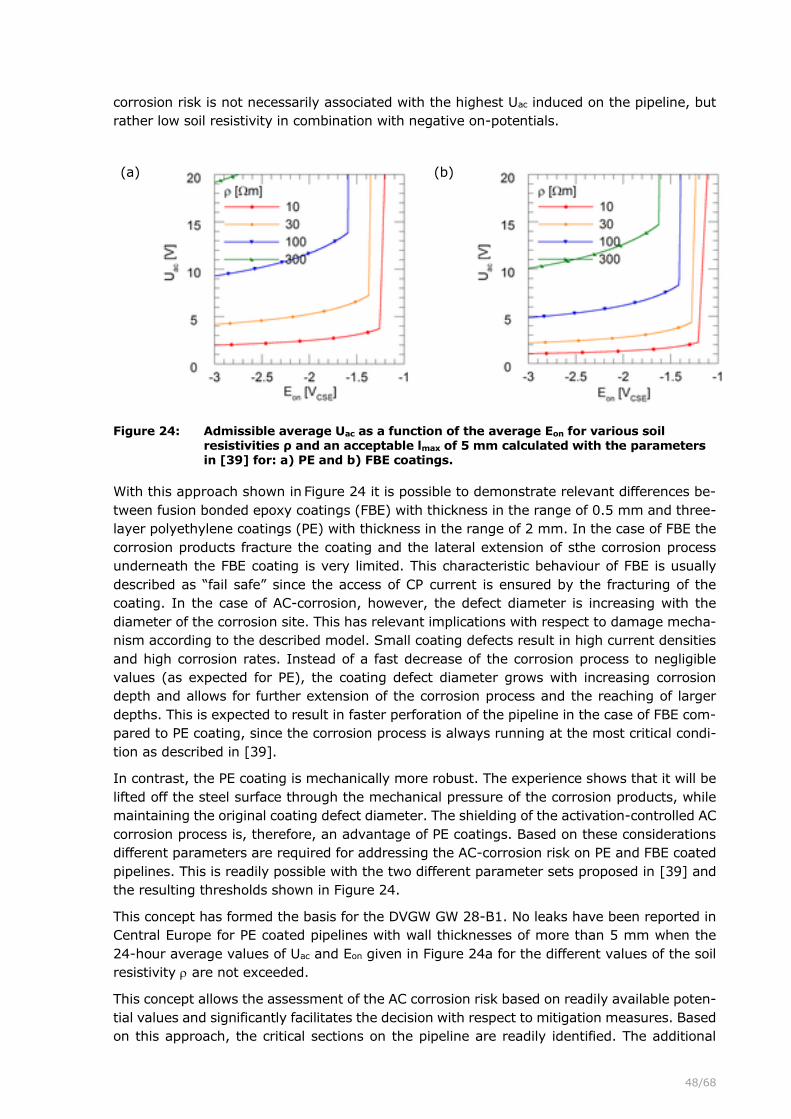
48/68
corrosion risk is not necessarily associated with the highest Uac induced on the pipeline, but
rather low soil resistivity in combination with negative on-potentials.
(a) (b)
Figure 24: Admissible average Uac as a function of the average Eon for various soil resistivities ρ and an acceptable lmax of 5 mm calculated with the parameters in [39] for: a) PE and b) FBE coatings.
With this approach shown in Figure 24 it is possible to demonstrate relevant differences be-
tween fusion bonded epoxy coatings (FBE) with thickness in the range of 0.5 mm and three-
layer polyethylene coatings (PE) with thickness in the range of 2 mm. In the case of FBE the
corrosion products fracture the coating and the lateral extension of sthe corrosion process
underneath the FBE coating is very limited. This characteristic behaviour of FBE is usually
described as “fail safe” since the access of CP current is ensured by the fracturing of the
coating. In the case of AC-corrosion, however, the defect diameter is increasing with the
diameter of the corrosion site. This has relevant implications with respect to damage mecha-
nism according to the described model. Small coating defects result in high current densities
and high corrosion rates. Instead of a fast decrease of the corrosion process to negligible
values (as expected for PE), the coating defect diameter grows with increasing corrosion
depth and allows for further extension of the corrosion process and the reaching of larger
depths. This is expected to result in faster perforation of the pipeline in the case of FBE com-
pared to PE coating, since the corrosion process is always running at the most critical condi-
tion as described in [39].
In contrast, the PE coating is mechanically more robust. The experience shows that it will be
lifted off the steel surface through the mechanical pressure of the corrosion products, while
maintaining the original coating defect diameter. The shielding of the activation-controlled AC
corrosion process is, therefore, an advantage of PE coatings. Based on these considerations
different parameters are required for addressing the AC-corrosion risk on PE and FBE coated
pipelines. This is readily possible with the two different parameter sets proposed in [39] and
the resulting thresholds shown in Figure 24.
This concept has formed the basis for the DVGW GW 28-B1. No leaks have been reported in
Central Europe for PE coated pipelines with wall thicknesses of more than 5 mm when the
24-hour average values of Uac and Eon given in Figure 24a for the different values of the soil
resistivity are not exceeded.
This concept allows the assessment of the AC corrosion risk based on readily available poten-
tial values and significantly facilitates the decision with respect to mitigation measures. Based
on this approach, the critical sections on the pipeline are readily identified. The additional

49/68
installation of coupons in these specific areas allows for demonstrating the correctness of the
numerical analysis and the determination of the current densities required by EN ISO 18086.
In the evaluation of these data the relevance of processes described in equation (11) and in
[39] still need to be taken into account.
6.5 Establishing Eref and Jref
6.5.1 Introduction
Based on the present discussion it is evident that the assessment of Jref and Eref are of key
relevance with respect to protection criteria. A possible procedure for identifying these values
is presented in the following. The assessment of Jref and Eref requires the identification of a
number of relevant influencing parameters. They are discussed in the following.
6.5.2 Concentration polarization and the resulting Jref
An increase of the pH value on the steel surface and hence sufficient concentration polariza-
tion is always possible, if sufficiently high current densities are applied. The following relevant
influencing factors affect the required level of Jref:
• Bedding: A sufficient quantity of fine bedding material leads to a more homogene-
ous current distribution due to a smaller shielding of large stones. In addition, there
is a greater retention capacity for water. Fine bedding of the pipeline contributes to
smaller levels of Jref and less negative Eref.
• Water hardness: An increased water hardness favours the formation of calcareous
deposits on coating defects and can thus compensate a coarse bedding. Soft water
cannot form a chalk-bed and also prevents the precipitation of salts of organic acids
and carbonates. Soft water hence increases Jref and shifts Eref to more negative val-
ues.
• Flow: Flowing water can dilute the hydroxide ions and leads to higher required pro-
tective current densities. Extreme cases are changing groundwater levels or rainfall
flowing through the pipe trench, which are then empty again. In combination with
coarse bedding materials and good aeration, heterogeneous conditions and increased
corrosion rates are to be expected. Flow hence increases Jref and shifts Eref to more
negative values.
• Aeration: Increased aeration makes it difficult to achieve a homogeneous current
density distribution due to the possibility of heterogeneous aeration and favours par-
tial passivation and the formation of galvanic elements within individual coating de-
fects. On larger coating defects an increased aeration may increase Jref and shift Eref
to more negative values.
• Coating defect size: Smaller coating defects favour homogenous conditions and
therefore require smaller current densities. Small coating defects requires smaller
levels of Jref and in particular less negative Eref.
As a result of these boundary conditions, requirements for Jref can be derived. Depending on
these conditions, Jref can vary between 1 mA/m² and 3 A/m² within individual coating defects
on buried structures. While it is possible to identify influencing parameters, there is presently
no concept available with respect to quantifying Jref. In the following a conservative approach
with respect to the quantification of Jref as a function of the influencing parameters is given in
equation (a).
𝐽𝑟𝑒𝑓 = 𝑎 + 𝑏 + 𝑐 ⋅ (𝑑 + 𝑒) (a)

50/68
The equation (a) as well as the values for the parameters “a” through “e” shown in Table 1
are based on semi empirical estimations so far. Their application must be calibrated with
practical experience. In case of doubt it may be useful to apply a value of the 0.1 A/m² in
absence of any further information as a first conservative approximation.
Table 1: Relevant factors influencing Jref
Defect surface [cm2] <1 1-10 10-100
a [A/m²] 0.01 0.03 0.1
Aeration (JO2) [A/m²] <0.01 0.01 - 0.1 0.1 - 1
b [A/m²] 0.01 0.1 1
Hardness [°fH] 0-15 15-25 >25
c [-] 1 0 0
Flow [m/day] <0.1 0.1 - 1 >1
d [A/m²] 0 0.1 1
Bedding size [mm] < 1 1-10 > 10
e [A/m²] 0 0.1 1
The quantifying of these influencing parameters allows for determining a value for Jref that is
based on the presently known influencing parameters. Furthermore, this procedure assists in
an improved risk assessment and the identification of the potentially critical pipeline sections.
Hence, the present model concepts allow for the first time the identification and consideration
of the relevant influencing factors in the assessment of the corrosion risk based on a physical
chemical concept that is passed on well recognized concepts. Therefore, this evaluation is
expected to provide an improved risk assessment of pipelines.
6.5.3 Determining Eref
With Jref it is possible to determine Eref based on the spread resistance of individual coating
defects and Ohms law (equation (9)). A generally accepted approach for determining the
spread resistance R for a disc shaped coating defect it given in equation (b) for the defect
diameter d and the soil resistivity :
𝑅 =𝜌
2⋅𝑑 (b)
It is evident that the spread resistance is controlled by the soil resistivity and the defect size.
Practical experience shows that it is normally not possible to determine the spread resistance
of a coating defect based on the soil resistivity and the coating defect size. This is a conse-
quence of the reduction of the local soil resistivity at the coating defect due to the increased
OH- ion concentration as well as their distribution into the adjacent soil. Consequently, effec-
tive CP and the associated concentration polarization results in a reduction in the spread
resistance, a further increase of the current density and an increase of the potential gradient
measured at the soil surface. This interaction between concentration polarization, spread re-
sistance and DCVG indications usually makes it impossible to determine the actual coating
defect size based on voltage gradients. The associated effects and the validated correspond-
ing mathematical model are described in detail in [39, 87]. While it is not possible to deter-
mine the actual spread resistance and assess the defect size based on DCVG data and the

51/68
pipeline depth, it is possible to estimate the largest possible spread resistance and the asso-
ciated largest possible coating defect size for the worst-case assumption of absence of any
far reaching concentration polarization into the adjacent soil. This concept is discussed in the
following.
Figure 25: Dependence of Eref from defect diameter d (and defect surface A) and soil re-
sistivity for a Jref of 0.02 A/m2.
Based on the assumed limitation of the pH increase to the very steel surface it is possible to
calculate Eref required to achieve Jref for various coating defect sizes and soil resistivities.
Combining equation (b) with equation (9) immediately allows to calculate the required Eref to
achieve the Jref for any given coating defect diameter d as a function of the soil resistivity as
shown in equations (f) and (g).
𝐽𝑟𝑒𝑓 =8∙(𝐸𝐼𝑅−𝑓𝑟𝑒𝑒−𝐸𝑟𝑒𝑓)
𝜌∙𝜋∙𝑑 (f)
𝐸𝑟𝑒𝑓 = 𝐸𝐼𝑅−𝑓𝑟𝑒𝑒 − 𝐽𝑟𝑒𝑓 ∙𝜋∙𝑑∙𝜌
8 (g)
Assuming a Jref of 20 mA/m2 and making a conservative assumption for EIR-free of -1 VCSE, it is
immediately possible to calculate the required Eref for various coating defect sizes. Again,
these are worst-case assumptions, since any effect of concentration polarization on the
spread resistance is ignored. The results are shown in Figure 25. It is evident that higher soil
resistivities and larger coating defects require more negative on potentials to achieve the
current density of 20 mA/m2. This current density is expected to result in a surface pH of 10.5
and an IR-free potential of –0.95 VCSE in the case of good bedding conditions according to
Figure 18.
In the practical application the defect size on the pipeline is usually not known and it is gen-
erally accepted that it is not possible to determine it based on DCVG surveys due to unknown
level of spread of the concentration polarization into the soil and the resulting decrease of the

52/68
soil resistivity in the direct vicinity of the coating defect. Despite of unknown defect size dis-
tribution on the pipeline it is common practice to install coupons for demonstrating the effec-
tiveness of CP. Based on the data in Figure 25 it is evident that demonstration of CP effec-
tiveness is only possible, if the coupon is installed in the highest possible soil resistivity and
if the coupon represents the largest possible coating defect. If it is accepted that the coupons
are suitable for demonstrating the effectiveness of CP, then the choice of coupons size can
be used to determine the required level of Eref based on Figure 25. For a 100 cm2 coupon in
soil resistivity of up to 300 Ωm an on potential of -1.28 VCSE would be required to achieve
20 mA/m2, a pH of 10.5 and an IR-free potential of -0.95 VCSE at the steel surface.
Figure 26: Worst-case coating defect diameter in absence of far reaching concentration polarization calculated for various DCVG indications as well as pipeline depths x.
This argumentation can be further extended. The use of this coupon is only justified if it is
confirmed that there are no bigger coating defects on the pipeline. It is common practice to
perform DCVG on pipelines and it is justified and appropriate to profit from these data for the
assessment of the effectiveness of CP. According to [26] the diameter d of a coating defect
in absence of any concentration polarization can readily be determined based on the %IR (or
U/U0) obtained in DCVG surveys for a given distance x of the reference electrode from the
disc shaped defect according to equation (c):
𝑑 = 2𝑥 ∙ tan (𝑈∙𝜋
𝑈0∙2) = 2𝑥 ∙ tan (
%𝐼𝑅∙𝜋
200) (c)
The calculation of the worst-case size coating defects associated with the obtained DCVG
indications according to equation (d) is shown in Figure 26. The following conclusions are
possible based on the worst-case consideration assuming absence of any spread of alkalinity
from the steel surface into the adjacent soil:

53/68
a) The largest possible coating defect can be determined based on the %IR indications.
This allows to verify the appropriateness of the chosen coupons size for the assess-
ment of the effectiveness of CP. For the example of the 100 cm2 coupon it follows
from Figure 26 that all coating defects with more than 3 %IR at a pipeline depth of
1.5 m or more need to be repaired. Otherwise the choice of coupons size cannot be
justified.
b) Alternatively, it is possible to recalculate the required Eref to ensure effective CP based
on the determined worst-case defect size according to equation (c) based on equation
(g) or Figure 25.
c) If neither item a) or b) are possible the actual current density for a worst-case con-
sideration can be calculated and compared to the parameters in Table 1 and equation
(a). This procedure allows for identifying areas with increased risk that will justify
further consideration.
This simple argumentation highlights the possibilities associated with the use of generally
accepted concepts in CP. Their combination with well-established chemical and physical con-
cepts allows for determining effectiveness of CP, optimize the protection or perform a risk
assessment. Since this approach is based on readily accessible CP parameters the problems
associated with the determination of an IR-free potential are overcome and an assessment
of actual cause and effect is performed.
The acceptable threshold with respect to %IR is often discussed. Some companies use %IR
indication thresholds for the integrity management of pipelines. Based on the present discus-
sion it immediately follows that it is readily possible to perform an assessment of effectiveness
of CP based on DCVG for the special case of a worst-case consideration. Combining equations
(b), (c) and (9) immediately provides equation (d) that describes the current density achieved
for a given DCVG indication at a given on-potential. This argumentation can be further ex-
panded and the required Eref can be calculated to ensure a required Jref based on equation
(e).
𝐽𝑟𝑒𝑓 =4∙(𝐸𝐼𝑅−𝑓𝑟𝑒𝑒−𝐸𝑟𝑒𝑓)
𝜌∙𝜋∙𝑥∙tan(%𝐼𝑅∙𝜋
200)
(d)
𝐸𝑟𝑒𝑓 = 𝐸𝐼𝑅−𝑓𝑟𝑒𝑒 − 𝐽𝑟𝑒𝑓 ∙ tan (%𝐼𝑅∙𝜋
200)𝜋
4∙ 𝜌 ∙ 𝑥 (e)
An application example of equation (e) is shown in Figure 27 for a Jref of 2 mA/m2. According
to Figure 18 this will result in a surface pH higher than 9 and an IR-free potential more
negative than -0.85 VCSE. According to Figure 27 this current density of 2 mA/m2 is exceeded
for soil resistivities smaller than 300 Ωm and for on-potentials more negative than -1.2 VCSE
even at 30% IR indications. At 1000 Ωm this current density and hence this level of corrosion
protection could be ensured up to 10% IR indications. This is well in line with the field expe-
rience on numerous FBE coated pipelines that are not allowed to be operated at on-potentials
significantly more negative than -1.2 VCSE in order to avoid overprotection issues. Despite of
the comparably positive level of on-potential effective corrosion protection is achieved even
at increased %IR-indications, provided the soil conditions according to EN ISO 15589-1 allow
for the use of an Ep of -0.95 VCSE.
In Figure 28 the same consideration is shown für a Jref of 20 mA/m2. According to Figure 18
this will result in a surface pH of 10.5 and an IR-free potential more negative than -0.95 VCSE.
This Ep and hence this current density are required to ensure corrosion protection in anaerobic
aggressive soils according to EN ISO 15589-1. Based on Figure 28 this current density of 20

54/68
mA/m2 is exceeded for soil resistivities smaller than 30 Ωm and for on-potentials more neg-
ative than -1.3 VCSE even at 30% IR indications. At 300 Ωm this current density can only be
ensured at the on-potential of -1.3 VCSE for %IR indications of up to 3%.
Figure 27: Dependence of Eref from the %IR indication (U/U0) and soil resistivity for the
following conditions: Jref of 0.002 A/m2; x of 1.5 m and EIR-free of -0.85 VCSE.
Figure 28: Dependence of Eref from the %IR indication (U/U0) and soil resistivity for the following conditions: Jref of 0.02 A/m2; x of 1.5 m and EIR-free of -0.95 VCSE.

55/68
Figure 29: Dependence of Eref from the %IR indication (U/U0) and soil resistivity soil re-sistivity for the following conditions: Jref of 0.1 A/m2; x of 1.5 m and EIR-free of -1.0 VCSE.
In Figure 29 the same consideration is shown für a Jref of 100 mA/m2. According to Figure 18
this will result in a surface pH above 11 and an IR-free potential more negative than -1.0
VCSE. According to Figure 29 this current density of 100 mA/m2 is exceeded for soil resistivities
smaller than 30 Ωm and for on-potentials more negative than -1.4 VCSE only at 7% IR indica-
tions. At 300 Ωm this current density can only be ensured at an on-potential of -1.4 VCSE for
%IR indications of up to 0.7%. According to Figure 26 this corresponds to a coating or coupon
defect size of 10 cm2. The application of an Eon of -1.4 VCSE in soils of 300 Ωm will ensure
current densities of 100 mA/m2 on all coupons and coating defects smaller than 10 cm2.
Note that this consideration applies to the worst-case consideration where no spread of alka-
linity into the surrounding soil has occurred. With a spread of alkalinity, a significantly in-
creased current density of 350 mA/m2 would be expected when calculated on the validated
numerical model presented in [39]. In contrast, the formation of a calcareous deposit layer
that covers 90% of the coupon would result in a current density of 26 mA/m2 calculated with
an assumed defect surface of 10 cm2. However, this is only a result of an erroneous defect
surface. In fact, the formation of the calcareous deposit would have caused an effective cur-
rent density on the remaining steel surface of 1 cm2 of 264 mA/m2 when the real defect
surface would have been considered. This 1 cm2 is the remaining surface of a 10cm2 defect
with 90% coverage of calcareous deposits.
This discussion highlights the relevance of the influencing parameters, the possibility of as-
sessing the worst-case coating defect size and calculating the required Eref for ensuring a
minimum current density with respect to providing effective CP.
6.5.4 Soil resistivity
The above discussion has highlighted the relevance of the soil resistivity in assessing effec-
tiveness of CP. While the procedures for measuring the resistivity are well established the
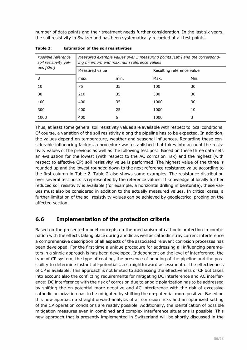
56/68
number of data points and their treatment needs further consideration. In the last six years,
the soil resistivity in Switzerland has been systematically recorded at all test points.
Table 2: Estimation of the soil resistivities
Possible reference
soil resistivity val-
ues [Ωm]
Measured example values over 3 measuring points [Ωm] and the correspond-
ing minimum and maximum reference values
Measured value Resulting reference value
3 max. min. Max. Min.
10 75 35 100 30
30 210 35 300 30
100 400 35 1000 30
300 400 25 1000 10
1000 400 6 1000 3
Thus, at least some general soil resistivity values are available with respect to local conditions.
Of course, a variation of the soil resistivity along the pipeline has to be expected. In addition,
the values depend on temperature, weather and seasonal influences. Regarding these con-
siderable influencing factors, a procedure was established that takes into account the resis-
tivity values of the previous as well as the following test post. Based on these three data sets
an evaluation for the lowest (with respect to the AC corrosion risk) and the highest (with
respect to effective CP) soil resistivity value is performed. The highest value of the three is
rounded up and the lowest rounded down to the next reference resistance value according to
the first column in Table 2. Table 2 also shows some examples. The resistance distribution
over several test posts is represented by the reference values. If knowledge of locally further
reduced soil resistivity is available (for example, a horizontal drilling in bentonite), these val-
ues must also be considered in addition to the actually measured values. In critical cases, a
further limitation of the soil resistivity values can be achieved by geoelectrical probing on the
affected section.
6.6 Implementation of the protection criteria
Based on the presented model concepts on the mechanism of cathodic protection in combi-
nation with the effects taking place during anodic as well as cathodic stray current interference
a comprehensive description of all aspects of the associated relevant corrosion processes has
been developed. For the first time a unique procedure for addressing all influencing parame-
ters in a single approach is has been developed. Independent on the level of interference, the
type of CP system, the type of coating, the presence of bonding of the pipeline and the pos-
sibility to determine instant off-potentials, a straightforward assessment of the effectiveness
of CP is available. This approach is not limited to addressing the effectiveness of CP but takes
into account also the conflicting requirements for mitigating DC interference and AC interfer-
ence: DC interference with the risk of corrosion due to anodic polarization has to be addressed
by shifting the on-potential more negative and AC interference with the risk of excessive
cathodic polarization has to be mitigated by shifting the on-potential more positive. Based on
this new approach a straightforward analysis of all corrosion risks and an optimized setting
of the CP operation conditions are readily possible. Additionally, the identification of possible
mitigation measures even in combined and complex interference situations is possible. This
new approach that is presently implemented in Switzerland will be shortly discussed in the

57/68
following based on a hypothetical example. A PE coated pipeline with a wall thickness of 5 mm
in soil with a resistivity between 30 to 100 Ωm is assumed. This process requires three steps:
1. First Eref needs to be determined. This value corresponds to the on-potential that is
required to ensure Jref and hence effective CP on all coating defects. Typical values for
Eref are between -1.0 to -1.6 VCSE. The assessment of Eref can for example be based
on EIR-free values potentials in absence of DC interference on the pipeline, EIR-free values
determined on coupons or current density considerations taking into account Figure
18. In the given example an Eref of -1.05 VCSE is determined as shown in Figure 30a.
In absence of stray current interference effective CP is ensured when the Eon is more
negative than the red line shown in Figure 30a.
2. Secondly the average anodic interference relative to Eref is recorded over a representa-
tive period of time. For DC traction interference this is typically 24-hours. In the pre-
sent example ΔEa,avg was found to be about 0.4 V. The largest anodic interference
period ta is determined to be 250 seconds. According to equation (4) a required Eon,avg
of about -1.45 VCSE is calculated. This corresponds to the blue line in Figure 30b. Ef-
fective CP under anodic stray current interference is ensured when the Eon averaged
over 24 hours is more negative than the blue line shown in Figure 30b.
3. Thirdly the applicable interference line of Figure 24a for a PE coated pipeline for the
smallest soil resistivity is selected. In the present example the soil resistivity ranges
from 30 to 100 Ωm. Correspondingly, the orange line for 30 Ωm is selected. These
threshold values for the acceptable average Uac are plotted in Figure 30c in orange.
Effective corrosion protection is ensured when the 24 h average Uac is below the or-
ange line and the 24 h average Eon is more negative than the blue line.
Based on this approach a straightforward assessment of effective corrosion protection is pos-
sible based on the present model concept of the mechanisms involved in cathodic protection.
The example shown in Figure 30c emphasizes the conflicting requirements with respect to
mitigating anodic stray current interference and AC interference. The mitigation of DC inter-
ference requires the shifting of the Eon,avg to -1.45 VCSE. It follows from Figure 30c that effective
corrosion protection in this combined AC and DC interference situation can only be managed
by lowering the average Uac to values in the range of 5 V. In contrast, in absence of DC
interference the risk of AC corrosion could effectively have been eliminated by applying a 24-
hour average on-potential in the range of -1.2 VCSE. In this case even significantly increased
levels of Uac can be tolerated and mitigation of AC corrosion is possible based on a simple
adjustment of the rectifiers rather than the installation of expensive earthing installations.
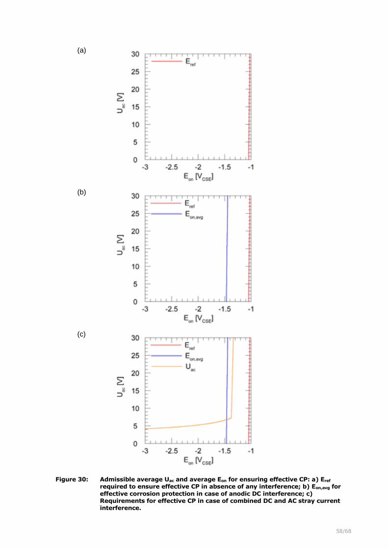
58/68
(a)
(b)
(c)
Figure 30: Admissible average Uac and average Eon for ensuring effective CP: a) Eref
required to ensure effective CP in absence of any interference; b) Eon,avg for
effective corrosion protection in case of anodic DC interference; c) Requirements for effective CP in case of combined DC and AC stray current interference.

59/68
This example illustrates that the new understanding of the mechanisms involved in cathodic
protection provides a comprehensive model that describes all influencing parameters. This
model has some key consequences on a number of aspects that have not been appropriately
addressed in the past:
• Cathodic protection is achieved by applying a cathodic current to a steel structure.
While there is some contribution of an activation polarization at the very moment the
current is applied, the relevant polarization that provides corrosion protection is a
result of the concentration polarization. This change in concentration with respect to
oxygen and hydroxide concentration at the steel surface requires time to build up.
• Due to the time constants involved in concentration polarization, the corrosion pro-
tection is not lost when CP is interrupted or when anodic current discharge occurs.
The slow diffusion processes associated with the loss of concentration polarization
explain the relevance of 24-hour average values and the irrelevance of anodic inter-
ference during time variant stray current interference.
• The IR-free potential is a measure of concentration polarization. It detects the deple-
tion of oxygen and the level of pH increase at the steel surface as a result of the
cathodic current. It corresponds to a pH measurement based on the hydrogen elec-
trode on the steel surface. IR-free potentials (measured 0.1 to 1 second after inter-
rupting the CP current) more negative than -0.85 VCSE are only possible at pH values
higher than 9. At such high pH values conditions for the formation of a protective
passive film are given in many soils.
• In aggressive soil conditions in presence of carbonates, sulphides and humic acids, as
they are typically found under anaerobic conditions, a pH of 10.5 corresponding to an
IR-free potential of -0.95 VCSE is required for passivation and hence corrosion protec-
tion.
• The IR-free potential may not be used to assess corrosion protection in case of anodic
interference or in aerated soils. The pH electrode only provides reliable data with re-
spect to the pH-value when the steel potential is controlled by the hydrogen reduction.
Oxygen and stray current turn these IR-free potentials and the associated pH-meas-
urements into meaningless numbers.
• Anodic stray current interference is irrelevant with respect to the integrity of pipelines
as long as the concentration polarization (i.e. the increased pH at the steel surface) is
maintained. Longer anodic interference can hence be compensated by means of an
increased level of CP.
• At very low levels of CP (e.g. at on-potentials of -0.9 VCSE) no anodic current discharge
can be tolerated based on the presented concept due to the absence of a enough
concentration polarization.
• The new approach with respect to the assessment of effective CP under anodic stray
current interference covers the entire frequency range of stray currents including AC
interference, DC traction interference, tidal interference, telluric interference and even
time constant anodic interference.
• While anodic AC interference has no relevance with respect to the integrity of pipelines
in case of effective CP, high corrosion rates occur due to AC voltages in the case of
over-polarization. Hence AC corrosion is a problem associated with over polarization
resulting in cathodic interference.
60/68
• The numerical modelling of all relevant processes in CP provides a simple approach
with respect to the assessment of the AC corrosion risk. The consideration of all influ-
encing parameters allows for translating the requirements in EN ISO 18086 into po-
tential based threshold values.
• The assessment of the stray current corrosion risk is readily possible based on DC and
AC potential measurements on pipelines in normal operation conditions. This method-
ology is applicable to all pipelines independent on their interference condition and the
possibility of synchronous interruption of all DC current sources, such as rectifiers, DC
decoupling devices, galvanic anodes, drainages and bonds. For the first time the cor-
rosion protection of all pipelines can be assessed based on the same concept.
• The effectiveness of CP can be assessed even in case of combined AC and DC inter-
ference. Based on the presented concepts the planning of mitigation measures and
the assessment of their effectiveness are readily possible. Areas with high corrosion
risk and possibly inacceptable conditions are identified. Based on this risk analysis the
locations for the installation of coupons or probes can be identified. Having coupons
installed in the highest risk areas significantly increases the value of their readings.
• The presented concepts have the status of a recognized state of the art in Germany
based on the documents DVGW GW 21 and DVGW GW 28 B1.
The various aspects presented in this paper provide a complete description of cathodic pro-
tection and the relevant influencing parameters. Based on these concepts a new approach
with respect to the assessment of the effectiveness of CP is possible. The effectiveness is
determined based on the readily accessible average values of Eon and Uac. This concept is
applicable to all pipelines independent on the coating system, the interference conditions, the
possibility to interrupt all CP current sources, the presence of galvanic anodes and drainage
bonds. Since all relevant influencing parameters are considered, an objective assessment of
corrosion protection possible. This approach allows for identifying areas with increased risk
and the evaluation of mitigation measures. In areas with conflicting requirements it may not
be possible to find ideal solutions with respect to corrosion protection. Based on these con-
cepts it will, however, be possible to operate the CP under optimized conditions while mini-
mizing the corrosion risks caused by conflicting requirements. Considering the relevant asso-
ciated costs of mitigation, the use of objective, technically correct and justifiable assessment
criteria is highest importance.

61/68
7 Summary
This document summarizes the outcome of the discussion performed within the joint EFC and
CEOCOR working group "protection criteria" with respect to the processes taking place under
cathodic protection, the relevance of the present protection criteria in EN ISO 15589-1 and
the possible solutions with respect to future criteria. The document was elaborated from 2016
to 2021 in a total of 11 working group meetings at Ceocor and Eurocorr congresses. The
document contains a description of relevant influencing parameters and proposes a possible
new procedure of assessing effectiveness of cathodic protection that is based on the DVGW
documents GW10, GW 21, GW27, GW 28 and GW 28 B1. These documents have the status
of a recognised state of the art within Germany. The benefit of this proposed procedure is
that it is based on on-potentials and AC voltages. As a consequence, it has the potential to
be applied to all cathodically protected buried steel structures irrespective of their size, their
interference condition, the possibility to determine instant off potentials and their size. The
goal of this document is to illustrate a possible procedure for assessing the optimized opera-
tion conditions of cathodic protection within the conflicting requirements given in EN ISO
15589-1, EN ISO 18086, EN 50162 and ISO 21857. This procedure not only allows for demon-
strating effective corrosion protection but also identifying areas of lowest level of corrosion
protection and optimal locations for the installation of coupons. These identified locations are
expected to represent the most severe conditions on the pipeline and the installed coupons
are, therefore, representative of these worst-case conditions. It is suggested that the instal-
lation of coupons in these locations can justify the use of a limited number of coupons for
demonstrating effectiveness of cathodic protection.
Within the working group agreement has been achieved on the following aspects of this doc-
ument:
• Cathodic protection is achieved by applying a cathodic current to the buried steel
structure.
• The cathodic current results in an increase of the surface pH and this process is of
high importance for the corrosion protection to be achieved. Beneficial aspects of the
pH increase are the formation of calcareous deposits and the generation of an envi-
ronment that is conducive to the formation of protective oxide films.
• The protection criteria given in EN ISO 15589-1 with respect to the IR-free potential
are relevant for assessing the effectiveness of cathodic protection.
• The instant-off potential may only be used as an approximation to the IR-free potential
and will not provide relevant information in the case of DC and AC interference condi-
tions or in case of exchange currents. As a consequence, on modern well-coated struc-
tures assessing the effectiveness of CP is only possible with coupon measurements.
• The on-potential cannot be used as an approximation to the IR-free potential. How-
ever, the on-potential is a parameter that can be assessed on all pipeline systems
independent on the level of AC and DC interference, the ability to synchronously switch
rectifiers and decoupling devices as well as the size of the pipeline network.
• The on-potential affects the current density on individual coating defects. At a given
on-potential decreasing current densities are obtained with increasing coating defect
size and increasing soil resistivity. In contrast shifting the on-potential to more nega-
tive values will result in higher current densities on a given coating defect in a given
soil resistivity.

62/68
• The present standards have conflicting requirements: EN ISO 15589-1 and EN 50162
may require the shifting of the on-potential in the negative direction to meet the pro-
tection criteria associated with the IR-free potential. In contrast the meeting of the
limiting DC current density of 1 A/m2 in EN ISO 18086 as well as limiting over-polari-
sation according to EN ISO 15589-1 may require shifting the on-potential in the pos-
itive direction.
While there was agreement on these important aspects, a number of important issues remain
open for future discussion:
• No agreement could be achieved whether protective oxide films will spontaneously
form in the alkaline environment formed at the steel surface. While one view was that
it was sufficient for the protective oxide film formation to keep the IR-free potential in
the passivity domain of the Pourbaix diagram, another view was that an oxidizing
action caused by an anodic current discharge during AC or DC interference was re-
quired for its formation.
• The properties of the protective surface oxide films, their composition as well as their
stability as a function of soil composition and formation conditions were not further
detailed within the working group.
• While there was agreement that the soil parameters listed in this document are rele-
vant with respect to the cathodic current density to achieve corrosion protection, no
agreement was achieved whether this list is final or whether the proposed quantifica-
tion of the influence of these parameters is correct.
• While soil resistivity and soil aeration are important parameters for assessing the pro-
tection criteria with respect to the IR-free potential according to EN ISO 15589-1, no
final proposal with respect to the assessment method and the lateral measurement
resolution for these parameters was agreed on.
• The assessment of the effectiveness of CP based on 24-hour average values of on-
potential and AC voltage was not considered relevant by all participants of the working
group.
• The applicability of electrochemical equilibrium thermodynamics presented in this doc-
ument are put into question as detailed in [88]. Instead, the relevance of electrode
kinetic consideration is considered more relevant as discussed in [89].
Despite of the open aspects it was agreed to finalize this document. It will be relevant to
apply these concepts and test the obtained results in the field application. The assessment of
most of the parameters proposed in this document are anyways required for a competent
application of the present EN ISO 15589-1, since the protection criteria based on IR-free
potentials depend on soil resistivity. Furthermore, the performing of DCVG investigations, the
determination of the on-potential and the AC voltage are common practice for most of the
operators. Since the most relevant data are anyways collected by most pipeline operators on
the basis of their function and effectiveness control of cathodic protection, the proposed pro-
cedures can readily be applied and tested. First promising results are meanwhile available
[90]. The collected experience in the next years will allow for a revisiting and further elabo-
ration of this document.

63/68
8 Referenced standards and codes
DVGW GW 21:2014 Stray current interference of buried metallic structures caused by
direct current systems (Beeinflussung von unterirdischen metal-
lischen Anlagen durch Streuströme von Gleichstromanlagen)
DVGW GW 28:2014 Assessment of the corrosion risk of cathodically protected pipelines
caused by alternating current (Beurteilung der Korrosionsgefähr-
dung durch Wechselstrom bei kathodisch geschützten Stahl-
rohrleitungen und Schutzmassnahmen)
DVGW GW 28 B1:2018 Assessment of the corrosion risk of cathodically protected pipelines
caused by alternating current: Annex 1: Modified criteria for AC volt-
age and on-potential (Beurteilung der Korrosionsgefährdung durch
Wechselstrom bei kathodisch geschützten Stahlrohrleitungen und
Schutzmassnahmen: Beiblatt 1: Modifizierte Kriterien für Wechsel-
spannung und Einschaltpotential)
EN 12954:2001 Cathodic protection of buried or immersed metallic structures. Gen-
eral principles and application for pipelines
EN 13509:2003 Cathodic protection measurement techniques
EN 14505:2005 Cathodic protection of complex structures
EN 50162:2004 Protection against corrosion by stray current from direct current sys-
tems
EN ISO 15589-1:2015 Petroleum, petrochemical and natural gas industries - Cathodic pro-
tection of pipeline systems - Part 1: On-land pipelines
EN ISO 18086:2019 Corrosion of metals and alloys - Determination of AC corrosion - Pro-
tection criteria
ISO 21857:2021 Prevention of corrosion on pipeline systems influenced by stray cur-
rents
NACE SP0169:2013 Control of External Corrosion on Underground or Submerged Metallic
Piping Systems
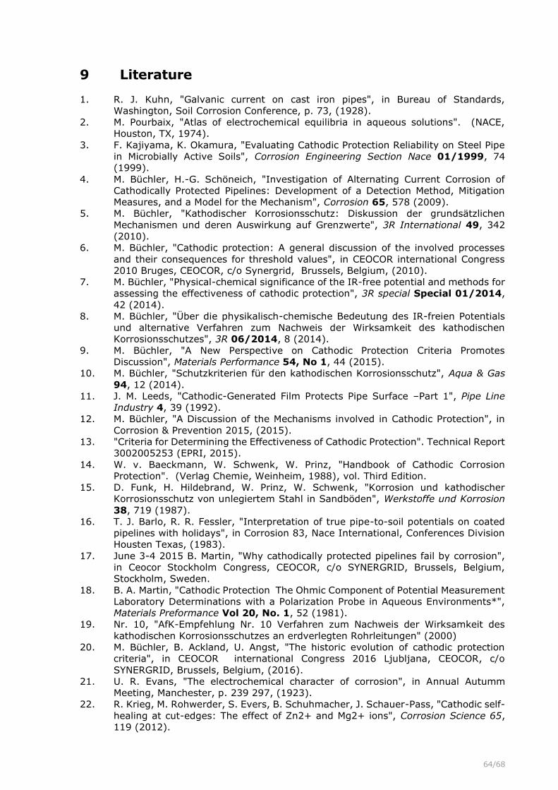
64/68
9 Literature
1. R. J. Kuhn, "Galvanic current on cast iron pipes", in Bureau of Standards,
Washington, Soil Corrosion Conference, p. 73, (1928).
2. M. Pourbaix, "Atlas of electrochemical equilibria in aqueous solutions". (NACE,
Houston, TX, 1974).
3. F. Kajiyama, K. Okamura, "Evaluating Cathodic Protection Reliability on Steel Pipe
in Microbially Active Soils", Corrosion Engineering Section Nace 01/1999, 74
(1999).
4. M. Büchler, H.-G. Schöneich, "Investigation of Alternating Current Corrosion of
Cathodically Protected Pipelines: Development of a Detection Method, Mitigation
Measures, and a Model for the Mechanism", Corrosion 65, 578 (2009).
5. M. Büchler, "Kathodischer Korrosionsschutz: Diskussion der grundsätzlichen
Mechanismen und deren Auswirkung auf Grenzwerte", 3R International 49, 342
(2010).
6. M. Büchler, "Cathodic protection: A general discussion of the involved processes
and their consequences for threshold values", in CEOCOR international Congress
2010 Bruges, CEOCOR, c/o Synergrid, Brussels, Belgium, (2010).
7. M. Büchler, "Physical-chemical significance of the IR-free potential and methods for
assessing the effectiveness of cathodic protection", 3R special Special 01/2014,
42 (2014).
8. M. Büchler, "Über die physikalisch-chemische Bedeutung des IR-freien Potentials
und alternative Verfahren zum Nachweis der Wirksamkeit des kathodischen
Korrosionsschutzes", 3R 06/2014, 8 (2014).
9. M. Büchler, "A New Perspective on Cathodic Protection Criteria Promotes
Discussion", Materials Performance 54, No 1, 44 (2015).
10. M. Büchler, "Schutzkriterien für den kathodischen Korrosionsschutz", Aqua & Gas
94, 12 (2014).
11. J. M. Leeds, "Cathodic-Generated Film Protects Pipe Surface –Part 1", Pipe Line
Industry 4, 39 (1992).
12. M. Büchler, "A Discussion of the Mechanisms involved in Cathodic Protection", in
Corrosion & Prevention 2015, (2015).
13. "Criteria for Determining the Effectiveness of Cathodic Protection". Technical Report
3002005253 (EPRI, 2015).
14. W. v. Baeckmann, W. Schwenk, W. Prinz, "Handbook of Cathodic Corrosion
Protection". (Verlag Chemie, Weinheim, 1988), vol. Third Edition.
15. D. Funk, H. Hildebrand, W. Prinz, W. Schwenk, "Korrosion und kathodischer
Korrosionsschutz von unlegiertem Stahl in Sandböden", Werkstoffe und Korrosion
38, 719 (1987).
16. T. J. Barlo, R. R. Fessler, "Interpretation of true pipe-to-soil potentials on coated
pipelines with holidays", in Corrosion 83, Nace International, Conferences Division
Housten Texas, (1983).
17. June 3-4 2015 B. Martin, "Why cathodically protected pipelines fail by corrosion",
in Ceocor Stockholm Congress, CEOCOR, c/o SYNERGRID, Brussels, Belgium,
Stockholm, Sweden.
18. B. A. Martin, "Cathodic Protection The Ohmic Component of Potential Measurement
Laboratory Determinations with a Polarization Probe in Aqueous Environments*",
Materials Preformance Vol 20, No. 1, 52 (1981).
19. Nr. 10, "AfK-Empfehlung Nr. 10 Verfahren zum Nachweis der Wirksamkeit des
kathodischen Korrosionsschutzes an erdverlegten Rohrleitungen" (2000)
20. M. Büchler, B. Ackland, U. Angst, "The historic evolution of cathodic protection
criteria", in CEOCOR international Congress 2016 Ljubljana, CEOCOR, c/o
SYNERGRID, Brussels, Belgium, (2016).
21. U. R. Evans, "The electrochemical character of corrosion", in Annual Autumm
Meeting, Manchester, p. 239 297, (1923).
22. R. Krieg, M. Rohwerder, S. Evers, B. Schuhmacher, J. Schauer-Pass, "Cathodic self-
healing at cut-edges: The effect of Zn2+ and Mg2+ ions", Corrosion Science 65,
119 (2012).

65/68
23. U. R. Evans, in Passivity and protection. (Edward Arnold & Co, London, 1946).
24. W. v. Baeckmann, W. Schwenk, W. Prinz, "Handbuch des kathodischen
Korrosionsschutzes Theorie und Praxis der elektrochemischen Schutzverfahren".
(VCH, ed. 1. Ausgabe, 1971).
25. "Electrochemical Processing". J. Bockris, Ed., Comprehensive Treatise of
Electrochemistry (Springer, New York, 1981).
26. W. v. Baeckmann, W. Schwenk, W. Prinz, "Handbuch des kathodischen
Korrosionsschutzes Theorie und Praxis der elektrochemischen Schutzverfahren".
(VCH Verlagsgesellschaft Weinheim, 1989).
27. W. J. Schwerdtfeger, O. N. McDorman, "Potential and Current Requirements for the
Cathodic Protection of Steel in Soils", Journal of Research of the Nationa l Bureau
of Standards 47, 104 (1951).
28. N. G. Thompson, T. J. Barlo, "Fundamental process of cathodically protecting steel
pipelines", in Gas Research Conference, Government Institute, Rockville, MD, USA,
(1983).
29. L. I. Freiman, I. V. Strizhevskii, M. Y. Yunovich, "Passivation of iron in soil with
cathodic protection", Protection of Metals 24, 104 (1988).
30. M. Büchler, "The effectiveness of cathodic protection: A critical discussion of
protection criteria and threshold values", in CEOCOR international Congress 2015,
Stockholm, CEOCOR, c/o SYNERGRID, Brussels, Belgium, (2015).
31. M. Büchler, D. Joos, "Minimierung der Wechselstromkorrosionsgefährdung mit
aktivem kathodischen Korrosionsschutz", DVGW - energie/wasser-praxis
November 2013, 13 (2013).
32. K. Kasahara, T. Sato, H. Adachi, "Results of Polarization Potential and Current
Density Surveys on Existing Buried Pipelines", Materials Performance 19, 49
(1980).
33. M. Pourbaix, "Bedingungen für den kathodischen Korrosionsschutz", Werkstoffe und
Korrosion 12, 761 (1960).
34. W. Schwenk, "Bemerkungen zur alkalischen Korrosion von Eisen und zu den damit
verbundenen Grundlagenfragen", Werkstoffe und Korrosion, 287 (1983).
35. E. Deltombe, A. Pourbaix, "Equilibrium Potential-pH Diagram for theSystem Fe-
CO2-H2O AT 25°C", in CITLE, Proceeding of the sixthe meeting, (1955).
36. K. E. Heusler, K. G. Weil, K. F. Bonhöffer, "Die Bedeutung des Flade-Potentials für
die Pasivität des Eisens in alkalischen Lösungen", Z.physik.Chem. Neue Folge,
Bonhoeffer-Gedenkbd. 15, 149 (1958).
37. P. Schmuki et al., "Passivity of Iron in Alkaline Solutions Studied by In Situ XANES
and a Laser Reflection Technique", J. Electrochem. Soc. 6, 2097 (1999).
38. B. G. Ackland, "Stress Corrosion Cracking in the Weld, Heat Affected Zone and Base
Metal of a Line Pipe Weld", Australian Welding Research Journal 11, 48 (1982).
39. M. Büchler, D. Joos, "AC-corrosion on cathodically protected pipelines: A discussion
of the involved processes and their consequences on mitigation measures", in The
european corrosion congress EUROCORR, Dechema e.V., (2016).
40. M. Büchler, "The a.c. corrosion rate: A discussion of the influencing factors and the
consequences on the durability of cathodically protected pipelines", in The european
corrosion congress EUROCORR, Dechema e.V., (2014).
41. M. Büchler, P.Schmuki, H. Böhni, "Formation and Dissolution of the Passive Film on
Iron studied by a Light Reflectance Technique", J. Electrochem. Soc. 144, 2307
(1997).
42. M. Büchler, P. Schmuki, H. Böhni, "Iron Passivity in Borate Buffer: Formation of a
Deposit Layer and its Influence on the Semiconducting Properties", J. Electrochem.
Soc. 145, 609 (1998).
43. R. J. Kuhn, "The early history of cathodic protection in the United Staes - some
recollections", Corrosion Prevention & Control, 46 (1958).
44. A. W. Peabody, "Control of Pipeline Corrosion". R. L. Bianchetti, Ed. (Nace, Houston,
Texas 77027, ed. 2, 2001).
45. Š. Msallomová, P. Novák, M. Kouril, "Influence of Cathodic Protection on pH and
Change of Soil Electrolyte composition", in Metal 2015, Metal 2015, (2015).
66/68
46. P. Novák, M. Kouril, S. Msallamová, T. Hron, J. Hruska, "Significance of Steel
Cathodic Passivation in Corrosion", in International Corrosion Congress: Corrosion
Control in the Service of Society, 3, (2008).
47. E. G. Kuznetsova, L. V. Remezkova, "About Corrosion Macrocells Formed on
Underground Pipelines at the Switched off Cathodic Protection", Protection of Metals
37, 262 (2001).
48. R. A. Gummow, W. Fieltsch, S. M. Segall, "Would the real -850 mV CSE potential
criterion please stand up", in Corrosion 2012, 4, NACE, (2012).
49. J. H. Gosden et al., "Cathodic protection of buried structures". (Joint committee for
coordination of the CP of buried structures, 1957).
50. M. Büchler, "Alternating current corrosion of cathodically protected pipelines:
Discussion of the involved processes and their consequences on the critical
interference values", Materials and Corrosion 63, 1181 (2012).
51. R. Gregoor, A. Pourbaix, "Detection and assessment of the importance of induced
AC corrosion", in CEOCOR 5th international conference, CEOCOR, c/o C.I.B.E.,
Brussels, Belgium, (2000).
52. A. Dänzler-Ischer, "Ueber die Abrostungserscheinungen am eisernen Oberbau im
Simplontunnel", Schweizerische Bauzeitung 15 / Band 59/60, 12 (1912).
53. U. Angst et al., "Cathodic protection of soil buried steel pipelines – a critical
discussion of protection criteria and threshold values", Materials and Corrosion in
press.
54. T. P. Hoar, T. W. Farrer, "The anodic characteristics of mild steel in dilute aqueous
soil electrolytes", Corrosion Science 1, 49 (1961).
55. L. I. Freiman, E. G. Kuznetsova, "Model investigation of the peculiarities of the
corrosion and cathodic protection of steel in the insulation defects on underground
steel pipelines", Protection of Metals 37, 484 (2001).
56. M. Ormellese, A. Brenna, L. Lazzari, F. Brugnetti, "Effects of anodic interference on
carbon steel under cathodic protection condition", in The european corrosion
congress EUROCORR, Dechema e.V., (2014).
57. Y. Huo, M. Y. Tan, M. Forsyth, "Visualising dynamic passivation and localised
corrosion processes occurring on buried steel surfaces under the effect of anodic
transients", Electrochemistry Communications 66, 21 (2016).
58. M. Nagayama, S. Kawamura, "Anodic Oxidation of Ferrous Ion on Passive Iron",
Electrochimica Acta 12, 1109 (1967).
59. M. Pourbaix, "Significance of Protection Potential Pitting and Intergranular
Corrosion", Corrosion 26, 431 (1970).
60. J. M. Leeds, "Cathodic-Generated Film Protects Pipe Surface –Part 1", Pipe Line
Industry, 39 (1992).
61. N. G. Thompson, T. J. Barlo., "Fundamental process of cathodically protecting steel
pipelines", in Gas Research Conference, Government Institute, Rockville, MD, USA,
(1983).
62. U. Angst et al., "Cathodic protection of soil buried steel pipelines – a critical
discussion of protection criteria and threshold values", Materials and Corrosion 11,
9 (2016).
63. W. Baeckmann, W. Schwenk, W. Prinz, "Handbuch des kathodischen
Korrosionsschutzes". (Verlag Chemie, Weinheim, 1988), vol. 3. Auflage.
64. T. J. Barlo, "Field Testing the Criteria for Cathodic Protection of buried Pipelines".
PRCI, Ed., PRCI (Technical Toolboxes, Inc. Housten Texas, Houston, 1994).
65. W. v. Baeckmann, "Taschenbuch für den kathodischen Korrosionsschutz". (Vulkan
Verlag, Essen, ed. 6. Auflage, 1996).
66. L. Yan, M. Arafin, J.-P. Gravel, "Penetration of Cathodic Protection into Pipeline
Coating Disbondment", in Corrosion Conference & Expo 2017, NACE International,
Publications Division, (2017).
67. M. Büchler, D. Joos, "The effectiveness of cathodic corrosion protection under
shielding conditions: Disbonded factory applied coatings", 3R special Special
01/2018, 1 (2018).

67/68
68. A. Junker, L. V. Nielsen, "AC Corrosion and the Pourbaix Diagram", in CEOCOR
international Congress 2018 Stratford upon Avon, CEOCOR, c/o SYNERGRID,
Brussels, Belgium, (2018).
69. D. Joos, M. Büchler, "An objective discussion of cathodic protection criteria based
on literature data", in CEOCOR international Congress 2017 Luxembourg, CEOCOR,
c/o SYNERGRID, Brussels, Belgium, (2017).
70. U. Bette, T. Schulte, "Massenverlust von Stahl bei wechselnder anodischer und
kathodischer Beaufschlagung", 3R International 44, 392 (2005).
71. T. Nagai, H.Yamanaka, A. Nishikawa, H. Nonaka, "Influence of Anodic Current on
Corrosion Protection Conditions of Buried Steel Pipeline under Cathodic Protection",
in Corrosion Conference & Expo 2017, NACE International, Publications Division,
(2017).
72. September, 9-13 2018 L. Sanders, S. Fontaine, V. Vasseur, M. Barbalat, C.
Dombard, "D.c. stray currents: Evaluation of the relevance of the risk assessment
criterion proposed by the European Standard EN 50162 Part 3", in 21th european
corrosion congress EUROCORR, ICE Kraków Congress Centre, ICE Krakow, Poland.
73. M. Büchler, D. Joos, H.-G. Schöneich, "Assessing the risk of stray current induced
corrosion: Protection criteria developed based on the present understanding of the
involved processes", in CEOCOR international Congress 2018 Copenhagen,
CEOCOR, c/o SYNERGRID, Brussels, Belgium, (2019).
74. M. Büchler, C.-H. Voûte, D. Joos, "Field investigation of a.c. corrosion", in CEOCOR
international Congress 2011 Menthon-Saint-Bernard, CEOCOR, c/o SYNERGRID,
Brussels, Belgium, (2011).
75. G. Heim, G. Peez, "Wechselstrombeeinflussung einer kathodisch geschützten
Erdgashochdruckleitung", 3R International 27. Jahrgang, Heft 5, 345 (1988).
76. B. Meier, "Kontrollarbeiten an der Erdgasleitung Rhonetal", GWA 4/1989, 193
(1989).
77. U. Bette, "Ermittlung des Ausschaltpotentials an ER-Coupons von
wechselspannungsbeeinflussten Rohrleitungen", 3R International, 44 (2013).
78. M. Büchler, "Wechselstromkorrosion an kathodisch geschützten Rohrleitungen: Eine
Diskussion der beteiligten Prozesse und der Konsequenzen für die betriebliche
Umsetzung von Schutzmaßnahmen", 3R 6/2016, 52 (2016).
79. I. Ibrahim et al., "On the mechanism of ac assisted corrosion of buried pipelines
and its cp mitigation", in IPC2008, p. 64380, ASME, (2008).
80. J. Sebor, L. Simek, "Über elektrolytische Gleichrichtung von Wechselstrom",
Zeitschrift für Elektrochemie 13, 113 (1908).
81. F. Fischer, "Übergangswiderstand und Polarisation an der Aluminiumanode, ein
Beitrag zur Kenntnis der Ventil- oder Drosselzelle", Zeitschrift für Elektrochemie 46,
869 (1904).
82. Grätz, "Über ein Elektrochemisches Verfahren, um Wechselströme in Gleichströme
zu verwanden", Zeitschrift für Elektrochemie 2, 67 (1897).
83. S. Goidanich, L. Lazzari, M. Ormellese, "AC interference effects on polarised steel",
in CEOCOR 6th international Congress, CEOCOR, c/o C.I.B.E., Brussels, Belgium,
(2003).
84. M. Büchler, "Beurteilung der Wechselstromkorrosionsgefährdung von Rohrleitungen
mit Probeblechen: Relevante Einflussgrössen für der Bewertung der ermittelten
Korrosionsgeschwindigkeit", 3R, 36 (2013).
85. M. Büchler, "Determining the a.c. corrosion risk of pipelines based on coupon
measurements", in CEOCOR International Congress 2013, CEOCOR, c/o
SYNERGRID, Brussels, Belgium, (2013).
86. M. Büchler, D. Joos, "Die Wechselstromkorrosionsgeschwindigkeit: Die relevanten
Einflussgrößen sowie deren Bedeutung für die Dauerhaftigkeit von kathodisch
geschützten Rohrleitungen", DVGW - energie/wasser-praxis 4, 54 (2016).
87. M. Büchler, D. Joos, "AC-corrosion on cathodically protected pipelines: A description
of the involved processes, the risk assessment and a new normative approach",
Ochrona przed Korozja 61, No. 8/18, 204 (2018).

68/68
88. J. Barthel, R. Deiss, "The limits of the Pourbaix diagram in the interpretation of the
kinetics of corrosion and cathodic protection of underground pipelines", Materials
and Corrosion, 1 (2020).
89. C. Googan, "The cathodic protection potential criteria: Evaluation ofthe evidence",
Materials and Corrosion (2020).
90. A. Vimalanandan, K. Abraham, H.-G. Schöneich, M. Büchler, "Determining the
effectiveness of cathodic protection of buried pipelines", in CEOCOR international
Congress 2019 Copenhagen, CEOCOR, c/o SYNERGRID, Brussels, Belgium, (2019).