cathodic protection of a container ship using a detailed
TRANSCRIPT
Journal of
Marine Science and Engineering
Article
Cathodic Protection of A Container Ship Using ADetailed BEM Model
Dimitrios T. Kalovelonis 1, Dimitrios C. Rodopoulos 1, Theodoros V. Gortsas 2,Demosthenes Polyzos 1 and Stephanos V. Tsinopoulos 2,*
1 Department of Mechanical Engineering & Aeronautics, University of Patras, 26504 Patras, Greece;[email protected] (D.T.K.); [email protected] (D.C.R.); [email protected] (D.P.)
2 Department of Mechanical Engineering, University of Peloponnese, 26334 Patras, Greece; [email protected]* Correspondence: [email protected]
Received: 16 April 2020; Accepted: 18 May 2020; Published: 20 May 2020
Abstract: In the present work, an impressed current cathodic protection (ICCP) system for theprotection against corrosion of a 399-m-length container ship throughout its service life is designed.The study is carried out with the aid of a boundary element method code, accelerated by an adaptivecross approximation scheme, utilizing a detailed large-scale model. The exact geometry of the ship,the progressive damage of the coating system, and the dynamic state during the cruise of the ship arethe main parameters taken into consideration in modelling. The main objective of the design processis to minimize the electric power, delivered by the ICCP system, determining the optimal numberand location of the installed inert anodes to accomplish the absolute minimum protection potentialon the immersed steel surfaces of the ship and, simultaneously, avoid overprotection. Performing anextensive parametric study, a six-zone ICCP system is proposed, consisting of 10 anodes at the hulland four identical anodes at each of four thrusters.
Keywords: cathodic protection; ICCP system; boundary element method (BEM); large-scale problems;adaptive cross approximation; ACA/BEM
1. Introduction
The steel structure of a ship that is exposed to seawater is naturally prone to corrode. Use ofcoating systems is standard practice for corrosion control. However, mechanical wear, biological attack,and aging occur throughout the service time of a ship. As a result, the coating systems breakdown,losing incrementally their ability to prevent susceptibility to corrosion. The combination of coating andimpressed current cathodic protection (ICCP) systems ensures adequate corrosion protection [1–12]throughout the service life of a ship. In modern ICCP systems, the delivered current is regulated invarying conditions with the aid of automated control systems.
Seawater temperature, pH, salinity, and oxygen concentration influence corrosion initiation.Furthermore, the galvanic coupling between dissimilar materials, turbulent flow caused by propellers,dynamic conditions during the cruise of the ship, and biofouling all affect the corrosion rate [5].The design of an ICCP system is dependent on the polarization characteristics of the exposed metalsand alloys, the chemical and electrical properties of seawater, the geometry of the immersed surfaces,and the service life and the operational aspects of the ship.
A well-established and powerful numerical tool for analyzing cathodic protection problems isthe boundary element method (BEM) [4–21]. One remarkable advantage it offers is the reduction ofthe dimensionality of the problem by one. Thus, although the electrochemical process occurs at themetallic surface and the surrounding electrolyte volume, cathodic protection (CP) problems can besolved by discretizing only the under protection metallic surface. In the last few decades, BEM has
J. Mar. Sci. Eng. 2020, 8, 359; doi:10.3390/jmse8050359 www.mdpi.com/journal/jmse
J. Mar. Sci. Eng. 2020, 8, 359 2 of 14
been extensively used to solve sacrificial CP and ICCP problems mainly in ships [4–18], offshore andsubsea structures [19,20], buried pipelines, underground structures, and steel-reinforced concrete [21],as well as optimization problems regarding the optimum placement of the anodes [8].
However, despite its advantages, the application of conventional BEM to large-scale problemssuffers from very time-consuming computations and high demands for computer memory capacity.On the other hand, the design of an efficient ICCP system demands accurate modelling of the exactgeometry of complex metallic structures. The use of hierarchical matrices (HM) and adaptive crossapproximation (ACA) techniques, accelerate the computation of matrix [A] drastically and also reducethe memory requirements [20].
In this work, an ICCP system of a container ship is designed, with the aid of the ACA/BEM code,proposed in a previous work of the present co-authors [20], utilizing a detailed large-scale model.The problem is modelled, taking into consideration the exact geometry of the ship, the progressivedamage of the coating system in various regions and the dynamic conditions during cruise. The mainobjectives of the design process are the following: (i) the calculation of the optimal number and locationof the installed inert anodes to achieve the required absolute minimum protection potential on theimmersed steel surfaces of the ship; (ii) the determination of electrical insulation needed, around theIC anodes, to avoid overprotection; and (iii) the estimation of the location of the reference electrodesused as sensors to adjust the delivered current.
2. Governing Equations of an ICCP Problem for Immersed Structures in Semi-InfiniteElectrolytes and ACA/BEM
2.1. Governing Equations
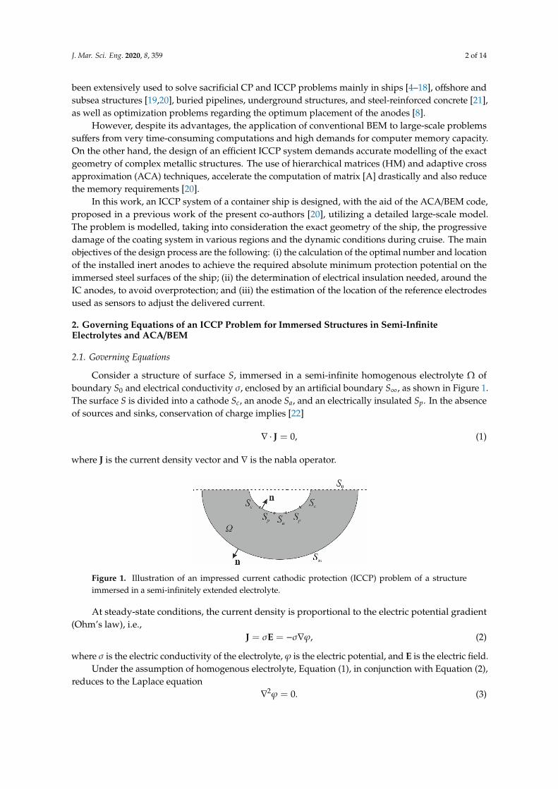
Consider a structure of surface S, immersed in a semi-infinite homogenous electrolyte Ω ofboundary S0 and electrical conductivity σ, enclosed by an artificial boundary S∞, as shown in Figure 1.The surface S is divided into a cathode Sc, an anode Sa, and an electrically insulated Sp. In the absenceof sources and sinks, conservation of charge implies [22]
∇ · J = 0, (1)
where J is the current density vector and ∇ is the nabla operator.
J. Mar. Sci. Eng. 2020, 8, x FOR PEER REVIEW 2 of 14
solved by discretizing only the under protection metallic surface. In the last few decades, BEM has been extensively used to solve sacrificial CP and ICCP problems mainly in ships [4–18], offshore and subsea structures [19,20], buried pipelines, underground structures, and steel-reinforced concrete [21], as well as optimization problems regarding the optimum placement of the anodes [8].
However, despite its advantages, the application of conventional BEM to large-scale problems suffers from very time-consuming computations and high demands for computer memory capacity. On the other hand, the design of an efficient ICCP system demands accurate modelling of the exact geometry of complex metallic structures. The use of hierarchical matrices (HM) and adaptive cross approximation (ACA) techniques, accelerate the computation of matrix [A] drastically and also reduce the memory requirements [20].
In this work, an ICCP system of a container ship is designed, with the aid of the ACA/BEM code, proposed in a previous work of the present co-authors [20], utilizing a detailed large-scale model. The problem is modelled, taking into consideration the exact geometry of the ship, the progressive damage of the coating system in various regions. and the dynamic conditions during cruise. The main objectives of the design process are the following: i) the calculation of the optimal number and location of the installed inert anodes to achieve the required absolute minimum protection potential on the immersed steel surfaces of the ship; ii) the determination of electrical insulation needed, around the IC anodes, to avoid overprotection; and iii) the estimation of the location of the reference electrodes used as sensors to adjust the delivered current.
2. Governing Equations of an ICCP Problem for Immersed Structures in Semi-Infinite Electrolytes and ACA/BEM
2.1. Governing Equations
Consider a structure of surface S, immersed in a semi-infinite homogenous electrolyte Ω of boundary S0 and electrical conductivity σ, enclosed by an artificial boundary S∞, as shown in Figure. 1. The surface S is divided into a cathode Sc, an anode Sa, and an electrically insulated Sp. In the absence of sources and sinks, conservation of charge implies [22]
0J , (1)
where J is the current density vector and ∇ is the nabla operator.
Figure 1. Illustration of an impressed current cathodic protection (ICCP) problem of a structure immersed in a semi-infinitely extended electrolyte.
At steady-state conditions, the current density is proportional to the electric potential gradient (Ohm’s law), i.e.,
J E , (2)
where σ is the electric conductivity of the electrolyte, φ is the electric potential, and E is the electric field.
Under the assumption of homogenous electrolyte, Equation (1), in conjunction with Equation (2), reduces to the Laplace equation
2 0 . (3)
Figure 1. Illustration of an impressed current cathodic protection (ICCP) problem of a structureimmersed in a semi-infinitely extended electrolyte.
At steady-state conditions, the current density is proportional to the electric potential gradient(Ohm’s law), i.e.,
J = σE = −σ∇ϕ, (2)
where σ is the electric conductivity of the electrolyte, ϕ is the electric potential, and E is the electric field.Under the assumption of homogenous electrolyte, Equation (1), in conjunction with Equation (2),
reduces to the Laplace equation∇
2ϕ = 0. (3)
J. Mar. Sci. Eng. 2020, 8, 359 3 of 14
The current density i at a surface with a normal unit vector n, in terms of ϕ is expressed as follows:
i = n · J = −σn · ∇ϕ = −σ∂nϕ, (4)
where ∂nϕ = n · ∇ϕ is the directional derivative concerning the normal unit vector n, defined at allsurfaces (Figure 1).
The integral representation of Equation (3) at a field point x, reads [20]
c(x)ϕ(x) +∫
S∪S∞
∂nG(x, y)ϕ(y)dSy =
∫S∪S∞
G(x, y)∂nϕ(y)dSy, (5)
where y is a source point, lying on the boundary (S∪S∞); c(x) is a jump coefficient, taking the values 0.5or 1 when x is on the boundary (S∪S∞) or 1 inside the electrolyte Ω, respectively; and G(x,y) is themodified 3D half-space fundamental solution, given from the following expression [20]:
G(x, y) = 14πr +
14πr′
∂nG(x, y) = − 14πr2 n · ∇r′ − 1
4πr′2 n · ∇r′
r′ =∣∣∣y− x′
∣∣∣ , (6)
where x′ is the reflection of the field point x with respect to the semi-infinite free surface S0 of theelectrolyte. The advantage of utilizing the modified half-space fundamental solution Equation (6),instead of the 3D full-space corresponding solution, is that the discretization of the semi-infiniteboundary S0 is avoided.
At the boundaries S and S∞, the following boundary conditions are imposed. At perfectly electricinsulated boundary Sp and at the artificial boundary S∞, the current density vanishes. At the cathodeSc, a nonlinear Robin boundary condition between potential and current density is imposed, known asa polarization curve, which is usually derived experimentally, taking into account the real conditionsof the galvanic cell. At the anode boundary Sa, a known current density is imposed. Consequently,the above-described boundary conditions read
i(x) = −σ∂nϕ(x) = 0, x ∈ Sp, (7)
ic(x) = f (ϕc(x)), x ∈ Sc, (8)
ia(x) = −σ∂nϕ(x) = J0, x ∈ Sa, (9)
i(x) = −σ∂nϕ(x) = 0, x ∈ S∞, (10)
with f being the polarization curve at the cathode Sc. Boundary condition Equation (10), imposed atS∞, implies that Gauss law, which states that the total electric flux through any closed surface is equalto the total charge enclosed by the surface, is fulfilled.
2.2. ACA/BEM
The above-described CP problem can be solved efficiently with BEM. The advantage of thereduction of problem’s dimensionality by one makes BEM an ideal tool for dealing with problems ofinfinite or semi-infinite domains [4–21].
According to BEM, the boundaries S and S∞ are discretized into quadrilateral or/and triangularsurface elements. Each element has a certain number of geometrical and functional nodes. The entireset of the geometrical nodes form the mesh of the discretization. On the surface of each element, thegeometry is approximated via polynomial shape functions of specific order and the coordinates ofits geometrical nodes, i.e., the continuous surface is described approximately by a finite number ofgeometrical nodes in 3D space. Similarly, on the surface of each element, both unknown and known(by the imposed boundary conditions) fields, potential ϕ, and current density i are assumed to vary
J. Mar. Sci. Eng. 2020, 8, 359 4 of 14
as polynomial functions of specific order and are approximated via interpolation functions, and thecorresponding field values at the functional nodes, i.e., the infinite Degrees of Freedom (DoFs) of thecontinuous medium, are interpolated by a finite number of nodal values.
Then, the integral Equation (5) is transformed in a discretized form and is collocated for eachfunctional node. The integrals over each surface element are either regular or singular and areevaluated numerically, employing gauss quadrature for the former and special integration techniquesfor the latter. Assembling the discretized integral Equations (5) of all functional nodes, one obtains thefollowing system of algebraic equations:
[H] · φ = [G] · i, (11)
where the elements of matrices [H] and [G] contain a summation of integrals, while the vectors φand i contain all the known and unknown values of potential and current density, respectively, atfunctional nodes.
At cathode surface Sc, due to the nonlinear nature of the boundary conditions, a Newton–Raphsoniterative procedure is applied. According to this scheme, the boundary conditions Equation (8) obtainthe following incremental form:
∂nϕkc(x) =
1σ f
(ϕk−1
c (x))+ 1
σ∂ f(ϕk−1
c (x))∂ϕ ∆ϕk
c(x), x ∈ Sc
ϕkc(x) = ϕk−1
c (x) + ∆ϕkc(x)
(12)
where k is the iteration step.Rearranging Equation (11), with the aid of Equations (7), (9), (10), and (12), one obtains the
following linear algebraic system of equations, for each iteration k:[Ak−1
]·
xk
=
Bk−1
. (13)
Finally, the linear algebraic system of Equations (13) is solved, for each iteration k, by means of theiterative GMRES solver.
As soon as, the boundary value problem has been solved and potential and current density havebeen calculated at the functional nodes, the potential at a point x located inside the electrolyte can beeasily obtained by integral Equation (5), with c(x) = 1.
The use of HM and ACA techniques accelerates the computation of matrix [A] drastically andalso reduces the memory requirements. According to ACA/BEM, the matrix [A] is organized intoa hierarchical structure of blocks, depending on the geometry of the problem. Applying a geometricalcriterion, the blocks are characterized either as non-admissible, where the ACA algorithm is inefficient,and thus the conventional BEM is employed, or admissible, where ACA is applied, and thus,only a small number of their rows and columns are calculated. Each admissible block is approximatedwith a low-rank matrix via a small summation of vector products, formed by the previously calculatedrows and columns. This low-rank matrix format, in conjunction with an iterative solver, like GMRES,leads to a significant reduction in memory requirements and CPU time, due to the acceleration of thematrix-vector multiplication
Details of the above described in brief, ACA/BEM, one can find in Rodopoulos et al. [20].
3. ICCP System Design of an 18270 TEU Capacity Container Ship
In this section, an ICCP system of an 18270 20-foot equivalent unit (TEU) capacity container shipis designed. To this aim, the ICCP problem is solved numerically, with the aid of the above-describedACA/BEM code, utilizing a detailed large-scale model.
The main objective of the study is to calculate the optimal number and location of the installedinert anodes to achieve the required absolute minimum protection potential, delivering the minimum
J. Mar. Sci. Eng. 2020, 8, 359 5 of 14
current. Furthermore, the electrical insulation needed around the IC anodes to avoid overprotectionand the locations of the reference electrodes are determined.
3.1. Description of the Container Ship
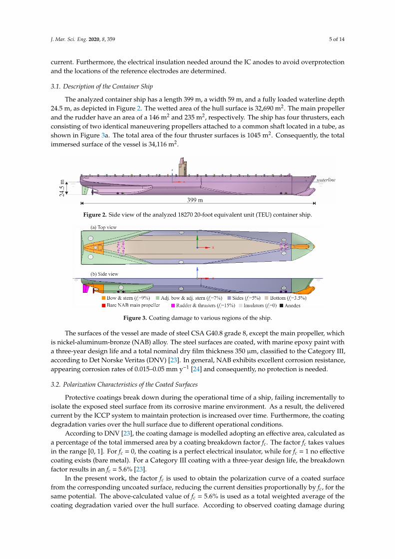
The analyzed container ship has a length 399 m, a width 59 m, and a fully loaded waterline depth24.5 m, as depicted in Figure 2. The wetted area of the hull surface is 32,690 m2. The main propellerand the rudder have an area of a 146 m2 and 235 m2, respectively. The ship has four thrusters, eachconsisting of two identical maneuvering propellers attached to a common shaft located in a tube, asshown in Figure 3a. The total area of the four thruster surfaces is 1045 m2. Consequently, the totalimmersed surface of the vessel is 34,116 m2.
J. Mar. Sci. Eng. 2020, 8, x FOR PEER REVIEW 5 of 14
The main objective of the study is to calculate the optimal number and location of the installed inert anodes to achieve the required absolute minimum protection potential, delivering the minimum current. Furthermore, the electrical insulation needed around the IC anodes to avoid overprotection and the locations of the reference electrodes are determined.
3.1. Description of the Container Ship
The analyzed container ship has a length 399 m, a width 59 m, and a fully loaded waterline depth 24.5 m, as depicted in Figure 2. The wetted area of the hull surface is 32690 m2. The main propeller and the rudder have an area of a 146 m2 and 235 m2, respectively. The ship has four thrusters, each consisting of two identical maneuvering propellers attached to a common shaft located in a tube, as shown in Figure 3a. The total area of the four thruster surfaces is 1045 m2. Consequently, the total immersed surface of the vessel is 34116 m2.
The surfaces of the vessel are made of steel CSA G40.8 grade 8, except the main propeller, which is nickel-aluminum-bronze (NAB) alloy. The steel surfaces are coated, with marine epoxy paint with a three-year design life and a total nominal dry film thickness 350 μm, classified to the Category III, according to Det Norske Veritas (DNV) [23]. In general, NAB exhibits excellent corrosion resistance, appearing corrosion rates of 0.015-0.05 mm y-1 [24] and consequently, no protection is needed.
Figure 2. Side view of the analyzed 18270 20-foot equivalent unit (TEU) container ship.
3.2. Polarization Characteristics of the Coated Surfaces
Protective coatings break down during the operational time of a ship, failing incrementally to isolate the exposed steel surface from its corrosive marine environment. As a result, the delivered current by the ICCP system to maintain protection is increased over time. Furthermore, the coating degradation varies over the hull surface due to different operational conditions.
According to DNV [23], the coating damage is modelled adopting an effective area, calculated as a percentage of the total immersed area by a coating breakdown factor fc. The factor fc takes values in the range [0, 1]. For fc = 0, the coating is a perfect electrical insulator, while for fc = 1 no effective coating exists (bare metal). For a Category III coating with a three-year design life, the breakdown factor results in an fc = 5.6% [23].
In the present work, the factor fc is used to obtain the polarization curve of a coated surface from the corresponding uncoated surface, reducing the current densities proportionally by fc, for the same potential. The above-calculated value of fc=5.6% is used as a total weighted average of the coating degradation varied over the hull surface. According to observed coating damage during maintenance of commercial ships [1], the coating degradation is modelled, grouping the immersed hull surface into six regions of constant damage, as shown in Figure 3. The areas of each region are bow—710 m2, adjacent bow—1743 m2, sides—14,231 m2, bottom—9228 m2, adjacent stern—5780 m2, and stern—998 m2. At the end of the coating’s design life, the damage is assumed to be 9% at the bow and stern regions, 7% at the adjacent bow and adjacent stern regions, 5% at the sides region, and 3.5% at the bottom region. Finally, increased damage of 15% is assumed to the rudder and thrusters surfaces due to a high degree of turbulence. The weighted average of the above breakdown factor values is 5.61%.
Figure 2. Side view of the analyzed 18270 20-foot equivalent unit (TEU) container ship.J. Mar. Sci. Eng. 2020, 8, x FOR PEER REVIEW 6 of 14
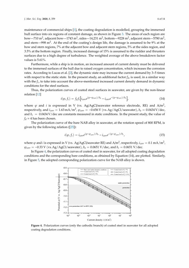
Figure 3. Coating damage to various regions of the ship.
Furthermore, while a ship is in motion, an increased amount of current density must be delivered to the immersed surfaces of the hull due to raised oxygen concentration, which increases the corrosion rates. According to Lucas et al. [2], the dynamic state may increase the current demand by 3–5 times with respect to the static state. In the present study, an additional factor fd, is used, in a similar way with the fc, to take into account the above-mentioned increased current density demand in dynamic conditions for the steel surfaces.
Thus, the polarization curves of coated steel surfaces in seawater, are given by the non-linear relation [12]
- / - /, corr a corr cb b
c d c corr corri f f f i e i e , (14)
where φ and i is expressed in V (vs. Ag/AgCl/seawater reference electrode, RE) and Α/m2, respectively, and 21.63 mA/mcorri , vs. 0.656V( )Ag/AgCl/seawatercorr , 0.0434 V/decab , and
0.0434V/deccb are constants measured in static conditions. In the present study, the value of fd =4 has been chosen.
The polarization curve of the bare NAB alloy in seawater, at the rotation speed of 800 RPM, is given by the following relation ([25]):
co rr a corr cφ-φ / b φ-φ / bc corr corri φ , f i e i e , (15)
where φ and i is expressed in V (vs. Ag/AgCl/seawater RE) and Α/m2, respectively, 20.1mA/mcorri , vs. 0.33V( )Ag/AgCl/seawatercorr , c0.065 1V/deab , and 0.0651V/deccb .
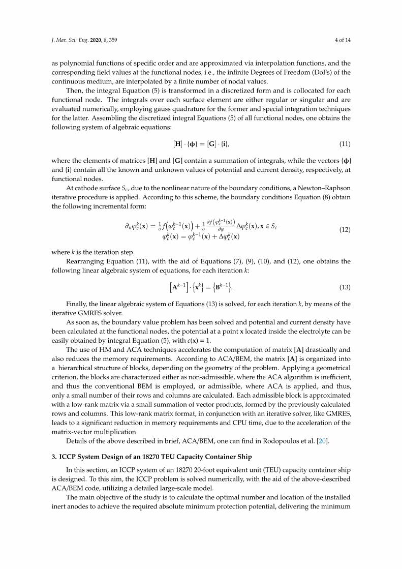
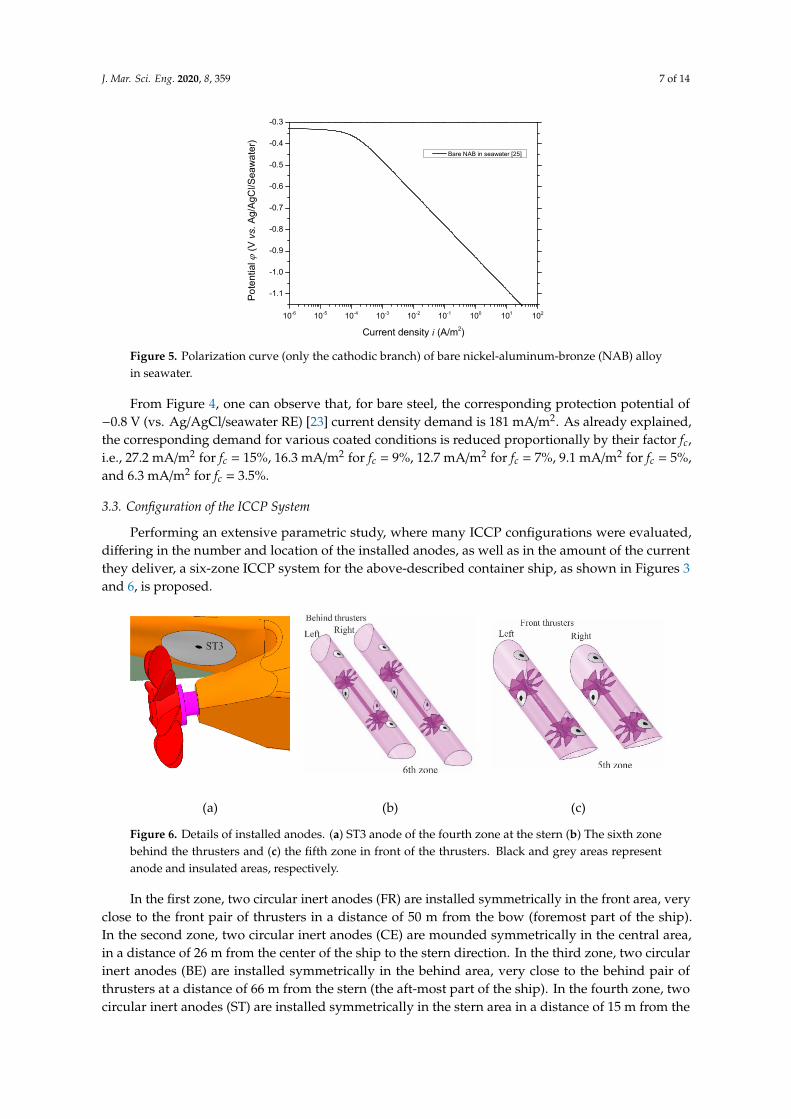
In Figure 4, the polarization curves of coated steel in seawater, for all adopted coating degradation conditions and the corresponding bare conditions, as obtained by Equation (14), are plotted. Similarly, in Figure 5, the adopted corresponding polarization curve for the NAB alloy is shown.
10-4 10-3 10-2 10-1 100 101 102-1.3
-1.2
-1.1
-1.0
-0.9
-0.8
-0.7
-0.6
-0.5
under protection
Coated steel of fc=7% Coated steel of fc=5% Coated steel of fc=3.5%
Bare steel under dynamic condtions Coated steel of fc=15% Coated steel of fc=9%
Pote
ntia
l (V
vs.
Ag/
AgC
l/Sea
wat
er)
Current density i (A/m2)
protection
over protection (ACC to DNV [23])
Figure 4. Polarization curves (only the cathodic branch) of coated steel in seawater for all adopted coating degradation conditions.
Figure 3. Coating damage to various regions of the ship.
The surfaces of the vessel are made of steel CSA G40.8 grade 8, except the main propeller, whichis nickel-aluminum-bronze (NAB) alloy. The steel surfaces are coated, with marine epoxy paint witha three-year design life and a total nominal dry film thickness 350 µm, classified to the Category III,according to Det Norske Veritas (DNV) [23]. In general, NAB exhibits excellent corrosion resistance,appearing corrosion rates of 0.015–0.05 mm y−1 [24] and consequently, no protection is needed.
3.2. Polarization Characteristics of the Coated Surfaces
Protective coatings break down during the operational time of a ship, failing incrementally toisolate the exposed steel surface from its corrosive marine environment. As a result, the deliveredcurrent by the ICCP system to maintain protection is increased over time. Furthermore, the coatingdegradation varies over the hull surface due to different operational conditions.
According to DNV [23], the coating damage is modelled adopting an effective area, calculated asa percentage of the total immersed area by a coating breakdown factor fc. The factor fc takes valuesin the range [0, 1]. For fc = 0, the coating is a perfect electrical insulator, while for fc = 1 no effectivecoating exists (bare metal). For a Category III coating with a three-year design life, the breakdownfactor results in an fc = 5.6% [23].
In the present work, the factor fc is used to obtain the polarization curve of a coated surfacefrom the corresponding uncoated surface, reducing the current densities proportionally by fc, for thesame potential. The above-calculated value of fc = 5.6% is used as a total weighted average of thecoating degradation varied over the hull surface. According to observed coating damage during
J. Mar. Sci. Eng. 2020, 8, 359 6 of 14
maintenance of commercial ships [1], the coating degradation is modelled, grouping the immersedhull surface into six regions of constant damage, as shown in Figure 3. The areas of each region arebow—710 m2, adjacent bow—1743 m2, sides—14,231 m2, bottom—9228 m2, adjacent stern—5780 m2,and stern—998 m2. At the end of the coating’s design life, the damage is assumed to be 9% at thebow and stern regions, 7% at the adjacent bow and adjacent stern regions, 5% at the sides region, and3.5% at the bottom region. Finally, increased damage of 15% is assumed to the rudder and thrusterssurfaces due to a high degree of turbulence. The weighted average of the above breakdown factorvalues is 5.61%.
Furthermore, while a ship is in motion, an increased amount of current density must be deliveredto the immersed surfaces of the hull due to raised oxygen concentration, which increases the corrosionrates. According to Lucas et al. [2], the dynamic state may increase the current demand by 3–5 timeswith respect to the static state. In the present study, an additional factor fd, is used, in a similar waywith the fc, to take into account the above-mentioned increased current density demand in dynamicconditions for the steel surfaces.
Thus, the polarization curves of coated steel surfaces in seawater, are given by the non-linearrelation [12]
i(ϕ, fc) = fd fc[icorre(ϕ−ϕcorr)/ba − icorre−(ϕ−ϕcorr)/bc
], (14)
where ϕ and i is expressed in V (vs. Ag/AgCl/seawater reference electrode, RE) and A/m2,respectively, and icorr = 1.63 mA/m2, ϕcorr = −0.656 V (vs.Ag/AgCl/seawater), ba = 0.0434 V/dec,and bc = 0.0434 V/dec are constants measured in static conditions. In the present study, the value offd = 4 has been chosen.
The polarization curve of the bare NAB alloy in seawater, at the rotation speed of 800 RPM, isgiven by the following relation ([25]):
i(ϕ, fc) = icorre(ϕ−ϕcorr)/ba − icorre−(ϕ−ϕcorr)/bc , (15)
where ϕ and i is expressed in V (vs. Ag/AgCl/seawater RE) and A/m2, respectively, icorr = 0.1 mA/m2,ϕcorr = −0.33 V (vs.Ag/AgCl/seawater), ba = 0.0651 V/dec, and bc = 0.0651 V/dec.
In Figure 4, the polarization curves of coated steel in seawater, for all adopted coating degradationconditions and the corresponding bare conditions, as obtained by Equation (14), are plotted. Similarly,in Figure 5, the adopted corresponding polarization curve for the NAB alloy is shown.
J. Mar. Sci. Eng. 2020, 8, x FOR PEER REVIEW 6 of 14
Figure 3. Coating damage to various regions of the ship.
Furthermore, while a ship is in motion, an increased amount of current density must be delivered to the immersed surfaces of the hull due to raised oxygen concentration, which increases the corrosion rates. According to Lucas et al. [2], the dynamic state may increase the current demand by 3–5 times with respect to the static state. In the present study, an additional factor fd, is used, in a similar way with the fc, to take into account the above-mentioned increased current density demand in dynamic conditions for the steel surfaces.
Thus, the polarization curves of coated steel surfaces in seawater, are given by the non-linear relation [12]
- / - /, corr a corr cb b
c d c corr corri f f f i e i e , (14)
where φ and i is expressed in V (vs. Ag/AgCl/seawater reference electrode, RE) and Α/m2, respectively, and 21.63 mA/mcorri , vs. 0.656V( )Ag/AgCl/seawatercorr , 0.0434 V/decab , and
0.0434V/deccb are constants measured in static conditions. In the present study, the value of fd =4 has been chosen.
The polarization curve of the bare NAB alloy in seawater, at the rotation speed of 800 RPM, is given by the following relation ([25]):
co rr a corr cφ-φ / b φ-φ / bc corr corri φ , f i e i e , (15)
where φ and i is expressed in V (vs. Ag/AgCl/seawater RE) and Α/m2, respectively, 20.1mA/mcorri , vs. 0.33V( )Ag/AgCl/seawatercorr , c0.065 1V/deab , and 0.0651V/deccb .
In Figure 4, the polarization curves of coated steel in seawater, for all adopted coating degradation conditions and the corresponding bare conditions, as obtained by Equation (14), are plotted. Similarly, in Figure 5, the adopted corresponding polarization curve for the NAB alloy is shown.
10-4 10-3 10-2 10-1 100 101 102-1.3
-1.2
-1.1
-1.0
-0.9
-0.8
-0.7
-0.6
-0.5
under protection
Coated steel of fc=7% Coated steel of fc=5% Coated steel of fc=3.5%
Bare steel under dynamic condtions Coated steel of fc=15% Coated steel of fc=9%
Pote
ntia
l (V
vs.
Ag/
AgC
l/Sea
wat
er)
Current density i (A/m2)
protection
over protection (ACC to DNV [23])
Figure 4. Polarization curves (only the cathodic branch) of coated steel in seawater for all adopted coating degradation conditions. Figure 4. Polarization curves (only the cathodic branch) of coated steel in seawater for all adoptedcoating degradation conditions.
J. Mar. Sci. Eng. 2020, 8, 359 7 of 14J. Mar. Sci. Eng. 2020, 8, x FOR PEER REVIEW 7 of 14
10-6 10-5 10-4 10-3 10-2 10-1 100 101 102
-1.1
-1.0
-0.9
-0.8
-0.7
-0.6
-0.5
-0.4
-0.3
Bare NAB in seawater [25]
Pote
ntia
l (V
vs.
Ag/
AgC
l/Sea
wat
er)
Current density i (A/m2) Figure 5. Polarization curve (only the cathodic branch) of bare nickel-aluminum-bronze (NAB) alloy
in seawater.
From Figure 4, one can observe that, for bare steel, the corresponding protection potential of – 0.8 V (vs. Ag/AgCl/seawater RE) [23] current density demand is 181 mA/m2. As already explained, the corresponding demand for various coated conditions is reduced proportionally by their factor fc, i.e., 27.2 mA/m2 for fc = 15%, 16.3 mA/m2 for fc = 9%, 12.7 mA/m2 for fc = 7%, 9.1 mA/m2 for fc = 5%, and 6.3 mA/m2 for fc = 3.5%.
3.3. Configuration of the ICCP System
Performing an extensive parametric study, where many ICCP configurations were evaluated, differing in the number and location of the installed anodes, as well as in the amount of the current they deliver, a six-zone ICCP system for the above-described container ship, as shown in Figures 3 and 6, is proposed.
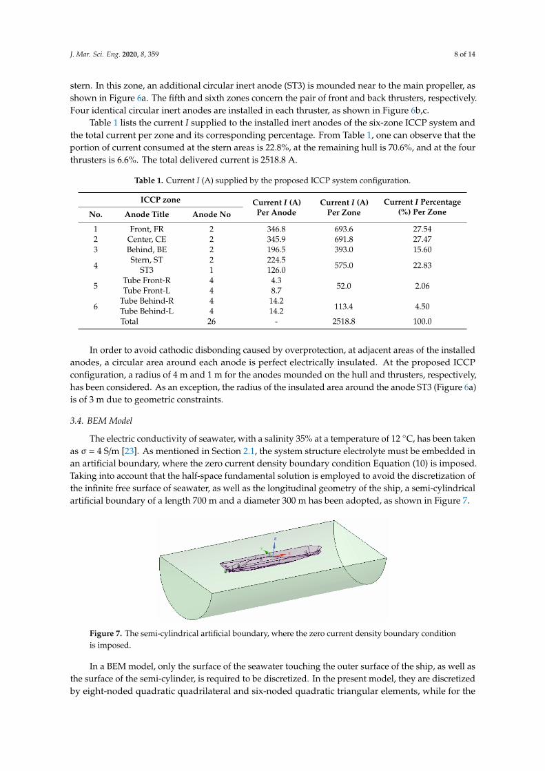
In the first zone, two circular inert anodes (FR) are installed symmetrically in the front area, very close to the front pair of thrusters in a distance of 50 m from the bow (foremost part of the ship). In the second zone, two circular inert anodes (CE) are mounded symmetrically in the central area, in a distance of 26 m from the center of the ship to the stern direction. In the third zone, two circular inert anodes (BE) are installed symmetrically in the behind area, very close to the behind pair of thrusters at a distance of 66m from the stern (the aft-most part of the ship). In the fourth zone, two circular inert anodes (ST) are installed symmetrically in the stern area in a distance of 15 m from the stern. In this zone, an additional circular inert anode (ST3) is mounded near to the main propeller, as shown in Figure 6a. The fifth and sixth zones concern the pair of front and back thrusters, respectively. Four identical circular inert anodes are installed in each thruster, as shown in Figures 6b,c.
(a) (b) (c)
Figure 6. Details of installed anodes. (a) ST3 anode of the fourth zone at the stern (b) The sixth zone behind the thrusters and (c) the fifth zone in front of the thrusters. Black and grey areas represent anode and insulated areas, respectively.
Figure 5. Polarization curve (only the cathodic branch) of bare nickel-aluminum-bronze (NAB) alloyin seawater.
From Figure 4, one can observe that, for bare steel, the corresponding protection potential of−0.8 V (vs. Ag/AgCl/seawater RE) [23] current density demand is 181 mA/m2. As already explained,the corresponding demand for various coated conditions is reduced proportionally by their factor fc,i.e., 27.2 mA/m2 for fc = 15%, 16.3 mA/m2 for fc = 9%, 12.7 mA/m2 for fc = 7%, 9.1 mA/m2 for fc = 5%,and 6.3 mA/m2 for fc = 3.5%.
3.3. Configuration of the ICCP System
Performing an extensive parametric study, where many ICCP configurations were evaluated,differing in the number and location of the installed anodes, as well as in the amount of the currentthey deliver, a six-zone ICCP system for the above-described container ship, as shown in Figures 3and 6, is proposed.
J. Mar. Sci. Eng. 2020, 8, x FOR PEER REVIEW 7 of 14
10-6 10-5 10-4 10-3 10-2 10-1 100 101 102
-1.1
-1.0
-0.9
-0.8
-0.7
-0.6
-0.5
-0.4
-0.3
Bare NAB in seawater [25]
Pote
ntia
l (V
vs.
Ag/
AgC
l/Sea
wat
er)
Current density i (A/m2) Figure 5. Polarization curve (only the cathodic branch) of bare nickel-aluminum-bronze (NAB) alloy
in seawater.
From Figure 4, one can observe that, for bare steel, the corresponding protection potential of – 0.8 V (vs. Ag/AgCl/seawater RE) [23] current density demand is 181 mA/m2. As already explained, the corresponding demand for various coated conditions is reduced proportionally by their factor fc, i.e., 27.2 mA/m2 for fc = 15%, 16.3 mA/m2 for fc = 9%, 12.7 mA/m2 for fc = 7%, 9.1 mA/m2 for fc = 5%, and 6.3 mA/m2 for fc = 3.5%.
3.3. Configuration of the ICCP System
Performing an extensive parametric study, where many ICCP configurations were evaluated, differing in the number and location of the installed anodes, as well as in the amount of the current they deliver, a six-zone ICCP system for the above-described container ship, as shown in Figures 3 and 6, is proposed.
In the first zone, two circular inert anodes (FR) are installed symmetrically in the front area, very close to the front pair of thrusters in a distance of 50 m from the bow (foremost part of the ship). In the second zone, two circular inert anodes (CE) are mounded symmetrically in the central area, in a distance of 26 m from the center of the ship to the stern direction. In the third zone, two circular inert anodes (BE) are installed symmetrically in the behind area, very close to the behind pair of thrusters at a distance of 66m from the stern (the aft-most part of the ship). In the fourth zone, two circular inert anodes (ST) are installed symmetrically in the stern area in a distance of 15 m from the stern. In this zone, an additional circular inert anode (ST3) is mounded near to the main propeller, as shown in Figure 6a. The fifth and sixth zones concern the pair of front and back thrusters, respectively. Four identical circular inert anodes are installed in each thruster, as shown in Figures 6b,c.
(a) (b) (c)
Figure 6. Details of installed anodes. (a) ST3 anode of the fourth zone at the stern (b) The sixth zone behind the thrusters and (c) the fifth zone in front of the thrusters. Black and grey areas represent anode and insulated areas, respectively.
Figure 6. Details of installed anodes. (a) ST3 anode of the fourth zone at the stern (b) The sixth zonebehind the thrusters and (c) the fifth zone in front of the thrusters. Black and grey areas representanode and insulated areas, respectively.
In the first zone, two circular inert anodes (FR) are installed symmetrically in the front area, veryclose to the front pair of thrusters in a distance of 50 m from the bow (foremost part of the ship).In the second zone, two circular inert anodes (CE) are mounded symmetrically in the central area,in a distance of 26 m from the center of the ship to the stern direction. In the third zone, two circularinert anodes (BE) are installed symmetrically in the behind area, very close to the behind pair ofthrusters at a distance of 66 m from the stern (the aft-most part of the ship). In the fourth zone, twocircular inert anodes (ST) are installed symmetrically in the stern area in a distance of 15 m from the
J. Mar. Sci. Eng. 2020, 8, 359 8 of 14
stern. In this zone, an additional circular inert anode (ST3) is mounded near to the main propeller, asshown in Figure 6a. The fifth and sixth zones concern the pair of front and back thrusters, respectively.Four identical circular inert anodes are installed in each thruster, as shown in Figure 6b,c.
Table 1 lists the current I supplied to the installed inert anodes of the six-zone ICCP system andthe total current per zone and its corresponding percentage. From Table 1, one can observe that theportion of current consumed at the stern areas is 22.8%, at the remaining hull is 70.6%, and at the fourthrusters is 6.6%. The total delivered current is 2518.8 A.
Table 1. Current I (A) supplied by the proposed ICCP system configuration.
ICCP zone Current I (A)Per Anode
Current I (A)Per Zone
Current I Percentage(%) Per ZoneNo. Anode Title Anode No
1 Front, FR 2 346.8 693.6 27.542 Center, CE 2 345.9 691.8 27.473 Behind, BE 2 196.5 393.0 15.60
4Stern, ST 2 224.5
575.0 22.83ST3 1 126.0
5Tube Front-R 4 4.3
52.0 2.06Tube Front-L 4 8.7
6Tube Behind-R 4 14.2
113.4 4.50Tube Behind-L 4 14.2Total 26 - 2518.8 100.0
In order to avoid cathodic disbonding caused by overprotection, at adjacent areas of the installedanodes, a circular area around each anode is perfect electrically insulated. At the proposed ICCPconfiguration, a radius of 4 m and 1 m for the anodes mounded on the hull and thrusters, respectively,has been considered. As an exception, the radius of the insulated area around the anode ST3 (Figure 6a)is of 3 m due to geometric constraints.
3.4. BEM Model
The electric conductivity of seawater, with a salinity 35% at a temperature of 12 C, has been takenas σ = 4 S/m [23]. As mentioned in Section 2.1, the system structure electrolyte must be embedded inan artificial boundary, where the zero current density boundary condition Equation (10) is imposed.Taking into account that the half-space fundamental solution is employed to avoid the discretization ofthe infinite free surface of seawater, as well as the longitudinal geometry of the ship, a semi-cylindricalartificial boundary of a length 700 m and a diameter 300 m has been adopted, as shown in Figure 7.
J. Mar. Sci. Eng. 2020, 8, x FOR PEER REVIEW 8 of 14
Table 1 lists the current I supplied to the installed inert anodes of the six-zone ICCP system and the total current per zone and its corresponding percentage. From Table 1, one can observe that the portion of current consumed at the stern areas is 22.8%, at the remaining hull is 70.6%, and at the four thrusters is 6.6%. The total delivered current is 2518.8 A.
Table 1. Current I (A) supplied by the proposed ICCP system configuration.
ICCP zone Current I (A)
Per Anode Current I (A)
Per Zone Current I Percentage (%)
Per Zone No. Anode Title Anode No
1 Front, FR 2 346.8 693.6 27.54 2 Center, CE 2 345.9 691.8 27.47 3 Behind, BE 2 196.5 393.0 15.60
4 Stern, ST 2 224.5
575.0 22.83 ST3 1 126.0
5 Tube Front-R 4 4.3
52.0 2.06 Tube Front-L 4 8.7
6 Tube Behind-R 4 14.2
113.4 4.50 Tube Behind-L 4 14.2
Total 26 - 2518.8 100.0
In order to avoid cathodic disbonding caused by overprotection, at adjacent areas of the installed anodes, a circular area around each anode is perfect electrically insulated. At the proposed ICCP configuration, a radius of 4 m and 1 m for the anodes mounded on the hull and thrusters, respectively, has been considered. As an exception, the radius of the insulated area around the anode ST3 (Figure 6a) is of 3 m due to geometric constraints.
3.4. BEM Model
The electric conductivity of seawater, with a salinity 350/0 at a temperature of 12 °C, has been taken as σ=4 S/m [23]. As mentioned in Section 2.1, the system structure electrolyte must be embedded in an artificial boundary, where the zero current density boundary condition Equation (10) is imposed. Taking into account that the half-space fundamental solution is employed to avoid the discretization of the infinite free surface of seawater, as well as the longitudinal geometry of the ship, a semi-cylindrical artificial boundary of a length 700 m and a diameter 300 m has been adopted, as shown in Figure 7.
Figure 7. The semi-cylindrical artificial boundary, where the zero current density boundary condition is imposed. Figure 7. The semi-cylindrical artificial boundary, where the zero current density boundary conditionis imposed.
In a BEM model, only the surface of the seawater touching the outer surface of the ship, as well asthe surface of the semi-cylinder, is required to be discretized. In the present model, they are discretizedby eight-noded quadratic quadrilateral and six-noded quadratic triangular elements, while for the
J. Mar. Sci. Eng. 2020, 8, 359 9 of 14
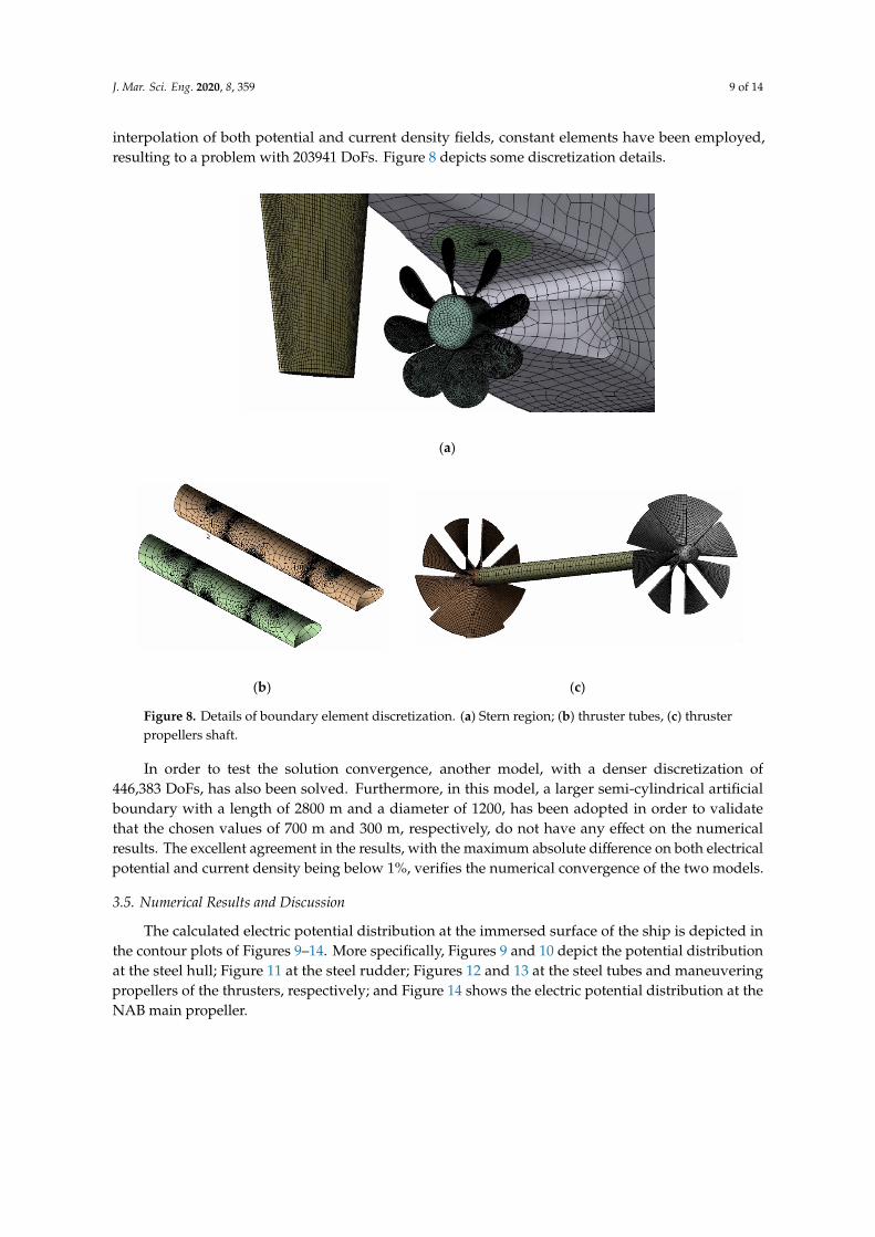
interpolation of both potential and current density fields, constant elements have been employed,resulting to a problem with 203941 DoFs. Figure 8 depicts some discretization details.
J. Mar. Sci. Eng. 2020, 8, x FOR PEER REVIEW 9 of 14
In a BEM model, only the surface of the seawater touching the outer surface of the ship, as well as the surface of the semi-cylinder, is required to be discretized. In the present model, they are discretized by eight-noded quadratic quadrilateral and six-noded quadratic triangular elements, while for the interpolation of both potential and current density fields, constant elements have been employed, resulting to a problem with 203941 DoFs. Figure 8 depicts some discretization details.
(a)
(b) (c)
Figure 8. Details of boundary element discretization. (a) Stern region; (b) thruster tubes, (c) thruster propellers shaft.
In order to test the solution convergence, another model, with a denser discretization of 446,383 DoFs, has also been solved. Furthermore, in this model, a larger semi-cylindrical artificial boundary with a length of 2800 m and a diameter of 1200 , has been adopted in order to validate that the chosen values of 700 m and 300 m, respectively, do not have any effect on the numerical results. The excellent agreement in the results, with the maximum absolute difference on both electrical potential and current density being below 1%, verifies the numerical convergence of the two models.
3.5. Numerical Results and Discussion
The calculated electric potential distribution at the immersed surface of the ship is depicted in the contour plots of Figures 9–14. More specifically, Figures 9 and 10 depict the potential distribution at the steel hull; Figure 11 at the steel rudder; Figures 12 and 13 at the steel tubes and maneuvering propellers of the thrusters, respectively; and Figure 14 shows the electric potential distribution at the NAB main propeller.
Figure 8. Details of boundary element discretization. (a) Stern region; (b) thruster tubes, (c) thrusterpropellers shaft.
In order to test the solution convergence, another model, with a denser discretization of446,383 DoFs, has also been solved. Furthermore, in this model, a larger semi-cylindrical artificialboundary with a length of 2800 m and a diameter of 1200, has been adopted in order to validatethat the chosen values of 700 m and 300 m, respectively, do not have any effect on the numericalresults. The excellent agreement in the results, with the maximum absolute difference on both electricalpotential and current density being below 1%, verifies the numerical convergence of the two models.
3.5. Numerical Results and Discussion
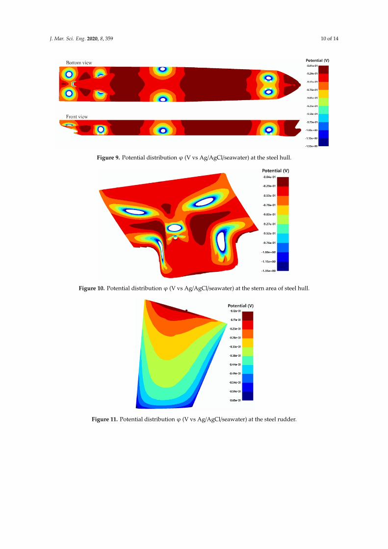
The calculated electric potential distribution at the immersed surface of the ship is depicted inthe contour plots of Figures 9–14. More specifically, Figures 9 and 10 depict the potential distributionat the steel hull; Figure 11 at the steel rudder; Figures 12 and 13 at the steel tubes and maneuveringpropellers of the thrusters, respectively; and Figure 14 shows the electric potential distribution at theNAB main propeller.
J. Mar. Sci. Eng. 2020, 8, 359 10 of 14
J. Mar. Sci. Eng. 2020, 8, x FOR PEER REVIEW 10 of 14
Figure 9. Potential distribution φ (V vs Ag/AgCl/seawater) at the steel hull.
Figure 10. Potential distribution φ (V vs Ag/AgCl/seawater) at the stern area of steel hull.
Figure 11. Potential distribution φ (V vs Ag/AgCl/seawater) at the steel rudder.
Figure 9. Potential distribution ϕ (V vs Ag/AgCl/seawater) at the steel hull.
J. Mar. Sci. Eng. 2020, 8, x FOR PEER REVIEW 10 of 14
Figure 9. Potential distribution φ (V vs Ag/AgCl/seawater) at the steel hull.
Figure 10. Potential distribution φ (V vs Ag/AgCl/seawater) at the stern area of steel hull.
Figure 11. Potential distribution φ (V vs Ag/AgCl/seawater) at the steel rudder.
Figure 10. Potential distribution ϕ (V vs Ag/AgCl/seawater) at the stern area of steel hull.
J. Mar. Sci. Eng. 2020, 8, x FOR PEER REVIEW 10 of 14
Figure 9. Potential distribution φ (V vs Ag/AgCl/seawater) at the steel hull.
Figure 10. Potential distribution φ (V vs Ag/AgCl/seawater) at the stern area of steel hull.
Figure 11. Potential distribution φ (V vs Ag/AgCl/seawater) at the steel rudder. Figure 11. Potential distribution ϕ (V vs Ag/AgCl/seawater) at the steel rudder.
J. Mar. Sci. Eng. 2020, 8, 359 11 of 14
J. Mar. Sci. Eng. 2020, 8, x FOR PEER REVIEW 11 of 14
Figure 12. Potential distribution φ (V vs Ag/AgCl/seawater) at the steel tubes of the thrusters.
Figure 13. Potential distribution φ (V vs Ag/AgCl/seawater) at the steel maneuvering propellers of the thrusters.
Figure 14. Potential distribution φ (V vs Ag/AgCl/seawater) at the NAB main propeller.
From Figures 9 and 10, one can observe that the electric potential at the hull varies in the range of −0.801 and −1.53 V (vs. Ag/AgCl/seawater RE). Similarly, Figure 11 reveals that, the potential at the rudder is in the range of −0.812 and −0.865 V, and Figures 12 and 13 show that at the tubes and maneuvering propellers of the thrusters, the potential varies in the ranges of −0.804 and −1.15 V and
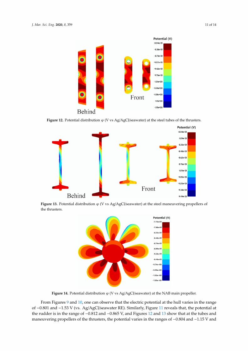
Figure 12. Potential distribution ϕ (V vs Ag/AgCl/seawater) at the steel tubes of the thrusters.
J. Mar. Sci. Eng. 2020, 8, x FOR PEER REVIEW 11 of 14
Figure 12. Potential distribution φ (V vs Ag/AgCl/seawater) at the steel tubes of the thrusters.
Figure 13. Potential distribution φ (V vs Ag/AgCl/seawater) at the steel maneuvering propellers of the thrusters.
Figure 14. Potential distribution φ (V vs Ag/AgCl/seawater) at the NAB main propeller.
From Figures 9 and 10, one can observe that the electric potential at the hull varies in the range of −0.801 and −1.53 V (vs. Ag/AgCl/seawater RE). Similarly, Figure 11 reveals that, the potential at the rudder is in the range of −0.812 and −0.865 V, and Figures 12 and 13 show that at the tubes and maneuvering propellers of the thrusters, the potential varies in the ranges of −0.804 and −1.15 V and
Figure 13. Potential distribution ϕ (V vs Ag/AgCl/seawater) at the steel maneuvering propellers ofthe thrusters.
J. Mar. Sci. Eng. 2020, 8, x FOR PEER REVIEW 11 of 14
Figure 12. Potential distribution φ (V vs Ag/AgCl/seawater) at the steel tubes of the thrusters.
Figure 13. Potential distribution φ (V vs Ag/AgCl/seawater) at the steel maneuvering propellers of the thrusters.
Figure 14. Potential distribution φ (V vs Ag/AgCl/seawater) at the NAB main propeller.
From Figures 9 and 10, one can observe that the electric potential at the hull varies in the range of −0.801 and −1.53 V (vs. Ag/AgCl/seawater RE). Similarly, Figure 11 reveals that, the potential at the rudder is in the range of −0.812 and −0.865 V, and Figures 12 and 13 show that at the tubes and maneuvering propellers of the thrusters, the potential varies in the ranges of −0.804 and −1.15 V and
Figure 14. Potential distribution ϕ (V vs Ag/AgCl/seawater) at the NAB main propeller.
From Figures 9 and 10, one can observe that the electric potential at the hull varies in the rangeof −0.801 and −1.53 V (vs. Ag/AgCl/seawater RE). Similarly, Figure 11 reveals that, the potential atthe rudder is in the range of −0.812 and −0.865 V, and Figures 12 and 13 show that at the tubes andmaneuvering propellers of the thrusters, the potential varies in the ranges of −0.804 and −1.15 V and
J. Mar. Sci. Eng. 2020, 8, 359 12 of 14
−0.804 and −0.949 V, respectively. Finally, from Figure 14, one can observe that the electric potential atthe NAB main propeller varies in the range of −0.773 and −1.05 V (vs. Ag/AgCl/seawater RE).
According to DNV [23], the potential of a steel structure, immersed in seawater, must be in therange of −0.8 V to −1.15 V (vs. Ag/AgCl/seawater RE). The minimum protection potential of −0.8 Vcorresponds to a shift by 0.142 V in the negative direction of the free corrosion potential of steel inseawater (Equation (14)). For less negative potentials than −0.8 V, a steel structure is under-protected,while for more negative potentials than −1.15 V, it is overprotected, where disbonding or blistering ofthe coating, due to extreme hydrogen generation may occur. However, most of the new marine coatingsystems can resist cathodic disbonding to much more negative potential values than −1.15 V, even toa potential of −2 V [1].
In conclusion, the contour plots of Figures 9–13 reveal that on all immersed steel surfaces of theship, the electric potential is more negative than −0.8 V (vs. Ag/AgCl/seawater RE), and thus, all theexposed steel surfaces are cathodically protected. Furthermore, the most negative electric potentials atthe rudder, the maneuvering propellers, and the tubes are −0.865 V, −0.949 V, and −1.15 V, respectively,and thus, no overprotection occurs, even if the more restricted limit of −0.15 V is adopted. However,the value −1.53 V exhibited at the hull is more negative than the overprotection limit of −1.15 Vintroduced by DNV [23] and less negative, than the corresponding one of −2 V adopted by Lee andLim [1]. Based on our experience, we consider that no overprotection occurred due to the used marineepoxy coating by the proposed ICCP system. I the above-mentioned overprotection limits are adopted,the area of the used electrical insulators must be reconsidered accordingly.
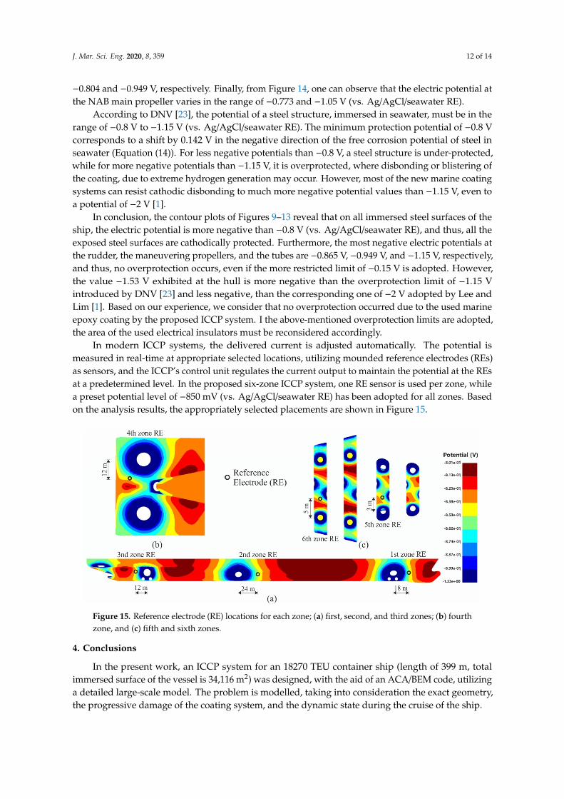
In modern ICCP systems, the delivered current is adjusted automatically. The potential ismeasured in real-time at appropriate selected locations, utilizing mounded reference electrodes (REs)as sensors, and the ICCP’s control unit regulates the current output to maintain the potential at the REsat a predetermined level. In the proposed six-zone ICCP system, one RE sensor is used per zone, whilea preset potential level of −850 mV (vs. Ag/AgCl/seawater RE) has been adopted for all zones. Basedon the analysis results, the appropriately selected placements are shown in Figure 15.
J. Mar. Sci. Eng. 2020, 8, x FOR PEER REVIEW 12 of 14
−0.804 and −0.949 V, respectively. Finally, from Figure 14, one can observe that the electric potential at the NAB main propeller varies in the range of −0.773 and −1.05 V (vs. Ag/AgCl/seawater RE).
According to DNV [23], the potential of a steel structure, immersed in seawater, must be in the range of −0.8 V to −1.15 V (vs. Ag/AgCl/seawater RE). The minimum protection potential of −0.8 V corresponds to a shift by 0.142 V in the negative direction of the free corrosion potential of steel in seawater (Equation (14)). For less negative potentials than −0.8 V, a steel structure is under-protected, while for more negative potentials than −1.15 V, it is overprotected, where disbonding or blistering of the coating, due to extreme hydrogen generation may occur. However, most of the new marine coating systems can resist cathodic disbonding to much more negative potential values than −1.15 V, even to a potential of −2 V [1].
In conclusion, the contour plots of Figures 9–13 reveal that on all immersed steel surfaces of the ship, the electric potential is more negative than −0.8 V (vs. Ag/AgCl/seawater RE), and thus, all the exposed steel surfaces are cathodically protected. Furthermore, the most negative electric potentials at the rudder, the maneuvering propellers, and the tubes are −0.865 V, −0.949 V, and −1.15 V, respectively, and thus, no overprotection occurs, even if the more restricted limit of −0.15 V is adopted. However, the value −1.53 V exhibited at the hull is more negative than the overprotection limit of −1.15 V introduced by DNV [23] and less negative, than the corresponding one of −2 V adopted by Lee and Lim [1]. Based on our experience, we consider that no overprotection occurred due to the used marine epoxy coating by the proposed ICCP system. I the above-mentioned overprotection limits are adopted, the area of the used electrical insulators must be reconsidered accordingly.
In modern ICCP systems, the delivered current is adjusted automatically. The potential is measured in real-time at appropriate selected locations, utilizing mounded reference electrodes (REs) as sensors, and the ICCP’s control unit regulates the current output to maintain the potential at the REs at a predetermined level. In the proposed six-zone ICCP system, one RE sensor is used per zone, while a preset potential level of −850 mV (vs. Ag/AgCl/seawater RE) has been adopted for all zones. Based on the analysis results, the appropriately selected placements are shown in Figure 15.
Figure 15. Reference electrode (RE) locations for each zone; (a) first, second, and third zones; (b)
fourth zone, and (c) fifth and sixth zones.
4. Conclusions
In the present work, an ICCP system for an 18270 TEU container ship (length of 399 m, total immersed surface of the vessel is 34,116 m2) was designed, with the aid of an ACA/BEM code, utilizing a detailed large-scale model. The problem is modelled, taking into consideration the exact geometry, the progressive damage of the coating system, and the dynamic state during the cruise of the ship.
Figure 15. Reference electrode (RE) locations for each zone; (a) first, second, and third zones; (b) fourthzone, and (c) fifth and sixth zones.
4. Conclusions
In the present work, an ICCP system for an 18270 TEU container ship (length of 399 m, totalimmersed surface of the vessel is 34,116 m2) was designed, with the aid of an ACA/BEM code, utilizinga detailed large-scale model. The problem is modelled, taking into consideration the exact geometry,the progressive damage of the coating system, and the dynamic state during the cruise of the ship.
J. Mar. Sci. Eng. 2020, 8, 359 13 of 14
In performing an extensive parametric study, a six-zone ICCP system was proposed, consisting of10 anodes at the hull and four identical anodes at each of four thrusters and a total current demand of2643 A. The portion of the consumed current is 22.8%at the stern areas, 70.6% at the remaining hulland 6.6% at the thrusters.
According to the obtained numerical results, the exhibited electric potentials are more negativethan the minimum protection level of −0.8 V (vs. Ag/AgCl/seawater RE). Thus, all the exposedsteel surfaces of the ship are cathodically protected by the proposed ICCP system. However, themost negative value of −1.53 V appeared close to the insulated areas and is more negative than theoverprotection limit of −1.15 V introduced by DNV [23] but less negative than the corresponding oneof −2 V adopted by Lee and Lim [1]. If the above-mentioned overprotection limits are adopted, thearea of the used electrical insulators must be reconsidered accordingly.
Author Contributions: Conceptualization, S.V.T. and D.P.; methodology, D.T.K., D.C.R., T.V.G., and S.V.T.;software, D.C.R. and T.V.G.; investigation, D.T.K. and S.V.T.; data curation, D.T.K.; writing—original draftpreparation, D.T.K. and S.V.T.; writing—review and editing, D.P.; supervision, D.P. All authors have read andagreed to the published version of the manuscript.
Funding: This research was partially funded by “Andreas Mentzelopoulos Scholarships for the University ofPatras” (Grant No. 3372). Furthermore, this research has been co-financed by the European Union and GreekNational Funds through the Regional Operational Program “Western Greece 2014–2020” (Grant No. 80763), underthe call “Regional research and innovation strategies for smart specialization (RIS3) in Information Technologyand Telecommunications” (Project: 5038699 entitled “Innovative and Qualitative Software Package for ModelingIndustrial Problems in Electromagnetics –IQPATRAS”).
Conflicts of Interest: The authors declare no conflict of interest.
References
1. Lee, M.J.; Lim, C.S. ICCP System Design on the Hull of an Ice Breaker by Computational Analysis, NACE CorrosionConference and Expo, San Antonio, TX, USA, 9–13 March 2014; NACE International: Houston, TX, USA, 2014.
2. Lucas, K.E.; Thomas, E.D.; Kaznoff, A.I.; Hogan, E.A. Design of Impressed Current Cathodic Protection(ICCP) systems for U.S. Navy Hulls. In Designing Cathodic Protection Systems for Marine Structures and Vehicles;Hack, H.P., Ed.; American Society for Testing and Materials: West Conshohocken, PA, USA, 1999; pp. 17–33.
3. Mathiazhagan, A. Design and Programming of Cathodic Protection for ships. Int. J. Chem. Eng. 2010, 1,217–221. [CrossRef]
4. Iwata, M.; Huang, Y.; Fujimoto, Y. Application of BEM to Design of the Impressed Current Cathodic ProtectionSystem for Ship Hull. J. Soc. Naval. Arch. Jpn. 1992, 171, 377–383. [CrossRef]
5. DeGiorgi, V.G.; Hogan, E.; Lucas, K.E.; Wimmer, S.A. Shipboard impressed current cathodic protectionsystem (ICCP) analysis. WIT Trans. State Art Sci. Eng. 2005, 7, 13–44.
6. Wang, Y.; KarisAllen, K.J. Comparison of Impressed Current Cathodic Protection Numerical ModelingResults with Physical Scale Modeling Data. Corr. Sci. 2010, 66, 105001-15. [CrossRef]
7. Wang, Y.; Brennan, D.P.; Chernuka, M. Parametric Studies of a Shipboard Impressed Current CathodicProtection System Using a Boundary Element Code. In Boundary Element Technology XV; Brebbia, C.A.,Dippery, R.E., Eds.; WIT Press: Southampton, UK, 2003; pp. 181–191.
8. Santana Diaz, E.; Adey, R. Optimization of the performance of an ICCP system by changing current suppliedand position of the anode. In Boundary Elements XXIV; Brebbia, C.A., Tadeu, A., Popov, V., Eds.; WIT Press:Southampton, UK, 2002; pp. 181–191.
9. Wu, J.; Xing, S.; Yun, F. The influence of coating damage on the ICCP cathodic protection effect. WIT Trans.Eng. Sci. 2009, 65, 89–96.
10. DeGiorgi, V.G. A review of computational analyses of ship cathodic protection systems. WIT Trans. Model.Simul. 1997, 18, 829–838.
11. DeGiorgi, V.G. Evaluation of perfect paint assumptions in modeling of cathodic protection systems. Eng. Anal.Bound. Elem. 2002, 26, 435–445. [CrossRef]
12. Zamani, N.G. Boundary Element Simulation of the Cathodic Protection System in a Prototype Ship. Appl. Math.Comput. 1988, 26, 119–134. [CrossRef]
J. Mar. Sci. Eng. 2020, 8, 359 14 of 14
13. Santana Diaz, E.; Adey, R. Predicting the coating condition on ships using ICCP system data. Int. J. Numer.Methods Eng. 2004, 62, 727–746. [CrossRef]
14. Wang, Y.; KarisAllen, K.J. Modelling stray current interference to shipboard cathodic protection system.In Proceedings of the DoD—Allied Nations Technical Corrosion Conference, Pittsburg, CA, USA,15 November 2015.
15. DeGiorgi, V.G.; Wimmer, S.A. Geometric details and modeling accuracy requirements for shipboard impressedcurrent cathodic protection system modeling. Eng. Anal. Bound. Elem. 2005, 29, 15–28. [CrossRef]
16. DeGiorgi, V.G.; Thomas, E.D.; Lucas, K.E. Scale effects and verification of modeling of ship cathodic protectionsystems. Eng. Anal. Bound. Elem. 1998, 22, 41–49. [CrossRef]
17. Lorenzi, S.; Pastore, T.; Bellezze, T.; Fratesi, R. Cathodic protection modelling of a propeller shaft. Corros. Sci.2016, 108, 36–46. [CrossRef]
18. Thiel, C.; Broecheler, C.; Ludwar, F.; Rennings, A.; Doose, J.; Erni, D. A Simple Superposition Formulationto Predict the Underwater Electric Potential Signature of Naval Vessels. J. Mar. Sci. Eng. 2020, 105, 105.[CrossRef]
19. Amaya, K.; Aoki, S. Effective boundary element methods in corrosion analysis. Eng. Anal. Bound. Elem.2003, 27, 507–519. [CrossRef]
20. Rodopoulos, D.C.; Gortsas, T.V.; Tsinopoulos, S.V.; Polyzos, D. ACA/BEM for solving large-scale cathodicprotection problems. Eng. Anal. Bound. Elem. 2019, 106, 139–148. [CrossRef]
21. Santos, W.J.; Brasil, S.L.D.C.; Santiago, J.A.F.; Telles, J.C.F. A new solution technique for cathodic protectionsystems with homogeneous region by the boundary element method. Eur. J. Comput. Mech. 2018, 27, 368–382.[CrossRef]
22. Wrobel, L.C. The Boundary Element Method Vol. 1: Application in Thermo-Fluids and Acoustics; Wiley: West Sussex,UK, 2002.
23. Det Norske Veritas. Recommended Practice DNVGL-RP-B401: Cathodic Protection Design; DNV: Oslo,Norway, 2017.
24. Holmes, J.J. Reduction of a Ship’s Magnetic Field Signatures; Morgan & Claypool Publishers: London, UK, 2008.25. Wharton, J.A.; Barik, R.C.; Kear, G.; Wood, R.J.K.; Stokes, K.R.; Walsh, F.C. The corrosion of nickel-aluminum
bronze in seawater. Corros. Sci. 2005, 47, 3336–3367. [CrossRef]
© 2020 by the authors. Licensee MDPI, Basel, Switzerland. This article is an open accessarticle distributed under the terms and conditions of the Creative Commons Attribution(CC BY) license (http://creativecommons.org/licenses/by/4.0/).