bss interfaces and protocols introduction
TRANSCRIPT
Finn Magnusson 03.08.99 KI/ERA/LRB/JA
BSS Interfaces and Protocols
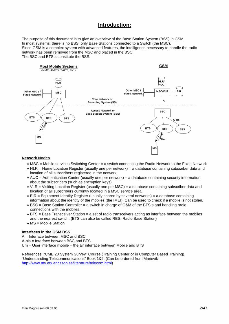
Introduction: The purpose of this document is to give an overview of the Base Station System (BSS) in GSM. In most systems, there is no BSS, only Base Stations connected to a Switch (the MSC). Since GSM is a complex system with advanced features, the intelligence necessary to handle the radio network has been removed from the MSC and placed in the BSC. The BSC and BTS:s constitute the BSS.
Most Mobile Systems(NMT, AMPS, TACS, etc.)
MSC
BTS BTS
HLR
BTS
Other MSCs /Fixed Network
MS
GSM
BTS BTS
HLR/AUC
BTS
Other MSC /Fixed Network
Core Network orSwitching System (SS)
Access Network orBase Station System (BSS)
MS
EIRMSC/VLR
BSC
A
A-bis
Um
Network Nodes
• MSC = Mobile services Switching Center = a switch connecting the Radio Network to the Fixed Network • HLR = Home Location Register (usually one per network) = a database containing subscriber data and
location of all subscribers registered in the network. • AUC = Authentication Center (usually one per network) = a database containing security information
about the subscribers (such as encryption keys). • VLR = Visiting Location Register (usually one per MSC) = a database containing subscriber data and
location of all subscribers currently located in a MSC service area. • EIR = Equipment Identity Register (usually shared by several networks) = a database containing
information about the identity of the mobiles (the IMEI). Can be used to check if a mobile is not stolen. • BSC = Base Station Controller = a switch in charge of O&M of the BTS:s and handling radio
connections with the mobiles. • BTS = Base Transceiver Station = a set of radio transceivers acting as interface between the mobiles
and the nearest switch. (BTS can also be called RBS: Radio Base Station) • MS = Mobile Station
Interfaces in the GSM BSS A = Interface between MSC and BSC A-bis = Interface between BSC and BTS Um = User interface mobile = the air interface between Mobile and BTS References: “CME 20 System Survey” Course (Training Center or in Computer Based Training). “Understanding Telecommunications” Book 1&2. (Can be ordered from Marievik http://www.mv.etx.ericsson.se/literature/telecom.html)
Finn Magnusson 06.09.06 2/47
Finn Magnusson 06.09.06 3/47
Table of Contents
1 BSS HARDWARE OVERVIEW............................................................................................................................. 4
1.1 BLOCK VIEW ....................................................................................................................................................... 4 1.2 CABINET VIEW .................................................................................................................................................... 5
2 BSS INTERFACES: PHYSICAL CHARACTERISTICS .................................................................................... 6
2.1 TRANSMISSION NETWORK (A, A-BIS).................................................................................................................. 6 2.1.1 Transport Media:........................................................................................................................................ 6 2.1.2 TDM structure............................................................................................................................................. 6 2.1.3 Channel mapping........................................................................................................................................ 7
2.2 RADIO NETWORK (UM) ....................................................................................................................................... 9 2.2.1 TDMA structure .......................................................................................................................................... 9 2.2.2 Transport Media:........................................................................................................................................ 9 2.2.3 Channel mapping...................................................................................................................................... 11
2.3 FEATURES TO IMPROVE THE A-BIS CAPACITY .................................................................................................... 13 2.4 HANDLING OF SPEECH/DATA ............................................................................................................................. 14
3 BSS INTERFACES: SIGNALLING PROTOCOLS........................................................................................... 16
3.1 INTRODUCTION: SIGNALLING LAYERS................................................................................................................ 16 3.2 BTS O&M......................................................................................................................................................... 17
3.2.1 The MO model .......................................................................................................................................... 18 3.2.2 Signalling links BSC-BTS ......................................................................................................................... 19 3.2.3 MO states .................................................................................................................................................. 20 3.2.4 O&M procedures for RBS 200.................................................................................................................. 21
3.3 TRAFFIC MANAGEMENT .................................................................................................................................... 22 3.3.1 Radio Resource Management (RR/RR’) ................................................................................................... 23 3.3.2 Mobility Management (MM)..................................................................................................................... 26 3.3.3 Connection Management (CM)................................................................................................................. 27 3.3.4 BTS Management (BTSM) ........................................................................................................................ 27 3.3.5 Traffic Case: Mobile Terminated Call Setup ............................................................................................ 29 3.3.6 Other Traffic Cases................................................................................................................................... 30
3.4 LAPD................................................................................................................................................................ 32 3.4.1 Address Field ............................................................................................................................................ 32 3.4.2 Control Field ............................................................................................................................................ 32
3.5 LAPDM............................................................................................................................................................. 33 3.6 IMPLEMENTATION OF THE SIGNALLING LAYERS IN BSS..................................................................................... 34
4 ARCHITECTURE OF THE RADIO NETWORK ............................................................................................. 35
4.1 INTRODUCTION: DB CONCEPT............................................................................................................................ 35 4.2 BTS ANTENNA SYSTEM .................................................................................................................................... 35
4.2.1 Antenna Near Part .................................................................................................................................... 35 4.2.2 Antenna Types........................................................................................................................................... 37 4.2.3 Antenna Supervision ................................................................................................................................. 39
4.3 CELLULAR NETWORK........................................................................................................................................ 39 4.3.1 Type of Cells ............................................................................................................................................. 40 4.3.2 Frequency allocation ................................................................................................................................ 41 4.3.3 Cell Coverage ........................................................................................................................................... 43
5 BSS DIMENSIONING ........................................................................................................................................... 46
6 ERICSSON BSS FEATURES................................................................................................................................ 47
1
BSS Hardware overview
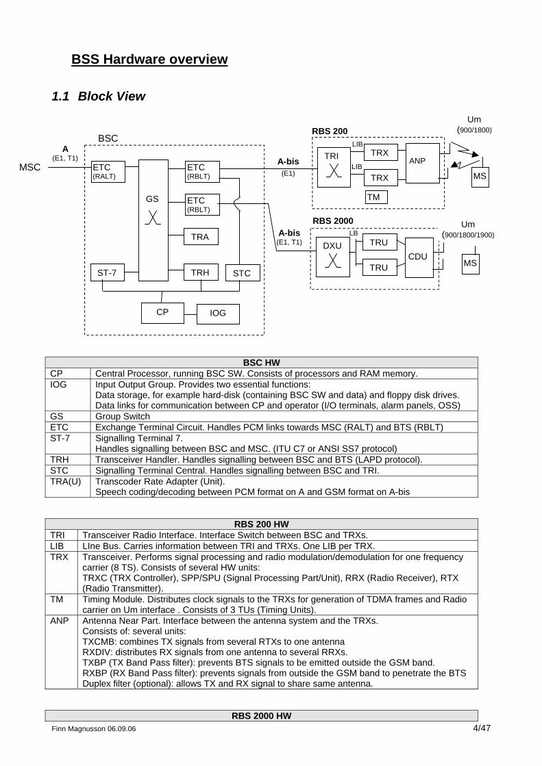
1.1 Block View
BSC
TRI
CP
GS
ST-7
TRA
TRX
TRX
ANP
Um(900/1800)
MS
A(E1, T1)
ETC(RALT)
STCTRH
MSC
LIB
LIB
ETC(RBLT)
ETC(RBLT)
RBS 200
A-bis(E1, T1) DXU TRU
TRUCDU
MS
LBRBS 2000
A-bis(E1)
Um(900/1800/1900)
TM
IOG
BSC HW CP Central Processor, running BSC SW. Consists of processors and RAM memory. IOG Input Output Group. Provides two essential functions:
Data storage, for example hard-disk (containing BSC SW and data) and floppy disk drives. Data links for communication between CP and operator (I/O terminals, alarm panels, OSS)
GS Group Switch ETC Exchange Terminal Circuit. Handles PCM links towards MSC (RALT) and BTS (RBLT) ST-7 Signalling Terminal 7.
Handles signalling between BSC and MSC. (ITU C7 or ANSI SS7 protocol) TRH Transceiver Handler. Handles signalling between BSC and BTS (LAPD protocol). STC Signalling Terminal Central. Handles signalling between BSC and TRI. TRA(U) Transcoder Rate Adapter (Unit).
Speech coding/decoding between PCM format on A and GSM format on A-bis
RBS 200 HW TRI Transceiver Radio Interface. Interface Switch between BSC and TRXs. LIB LIne Bus. Carries information between TRI and TRXs. One LIB per TRX. TRX Transceiver. Performs signal processing and radio modulation/demodulation for one frequency
carrier (8 TS). Consists of several HW units: TRXC (TRX Controller), SPP/SPU (Signal Processing Part/Unit), RRX (Radio Receiver), RTX (Radio Transmitter).
TM Timing Module. Distributes clock signals to the TRXs for generation of TDMA frames and Radio carrier on Um interface . Consists of 3 TUs (Timing Units).
ANP Antenna Near Part. Interface between the antenna system and the TRXs. Consists of: several units: TXCMB: combines TX signals from several RTXs to one antenna RXDIV: distributes RX signals from one antenna to several RRXs. TXBP (TX Band Pass filter): prevents BTS signals to be emitted outside the GSM band. RXBP (RX Band Pass filter): prevents signals from outside the GSM band to penetrate the BTS Duplex filter (optional): allows TX and RX signal to share same antenna.
Finn Magnusson 06.09.06 4/47 RBS 2000 HW
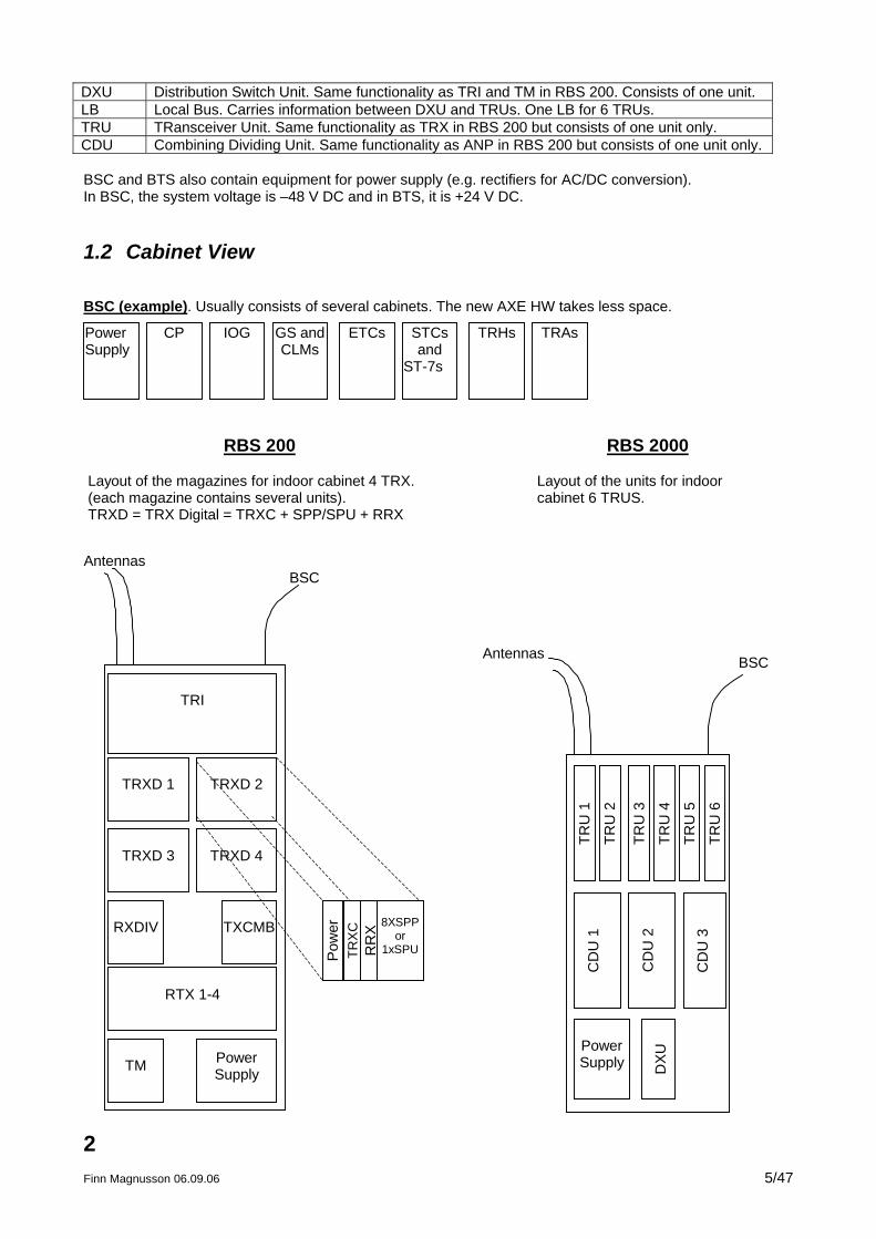
DXU Distribution Switch Unit. Same functionality as TRI and TM in RBS 200. Consists of one unit. LB Local Bus. Carries information between DXU and TRUs. One LB for 6 TRUs. TRU TRansceiver Unit. Same functionality as TRX in RBS 200 but consists of one unit only. CDU Combining Dividing Unit. Same functionality as ANP in RBS 200 but consists of one unit only. BSC and BTS also contain equipment for power supply (e.g. rectifiers for AC/DC conversion). In BSC, the system voltage is –48 V DC and in BTS, it is +24 V DC.
1.2 Cabinet View
BSC (example). Usually consists of several cabinets. The new AXE HW takes less space.
PowerSupply
ETCs TRAsTRHsSTCsand
ST-7s
IOG GS andCLMs
CP
TRXD 1
TRI
TRXD 2
TRXD 3 TRXD 4
RXDIV TXCMB
RTX 1-4
TM PowerSupply
RBS 200
Layout of the magazines for indoor cabinet 4 TRX.(each magazine contains several units).TRXD = TRX Digital = TRXC + SPP/SPU + RRX
TRU
1
TRU
2
TRU
3
TRU
4
TRU
5
TRU
6
CD
U 1
CD
U 2
CD
U 3
PowerSupply D
XU
RBS 2000
Layout of the units for indoorcabinet 6 TRUS.
Antennas
Antennas
BSC
BSC
Pow
erTR
XC
RR
X 8XSPPor
1xSPU
2 Finn Magnusson 06.09.06 5/47
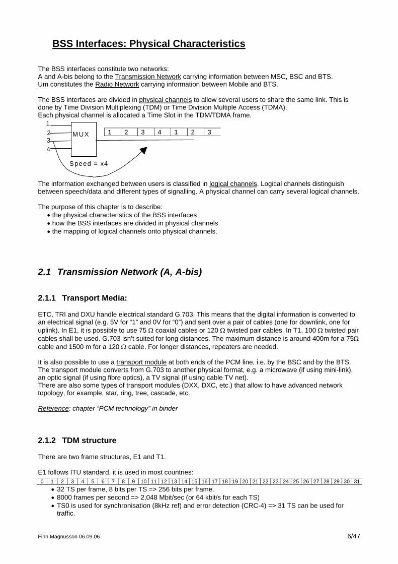
BSS Interfaces: Physical Characteristics The BSS interfaces constitute two networks: A and A-bis belong to the Transmission Network carrying information between MSC, BSC and BTS. Um constitutes the Radio Network carrying information between Mobile and BTS. The BSS interfaces are divided in physical channels to allow several users to share the same link. This is done by Time Division Multiplexing (TDM) or Time Division Multiple Access (TDMA). Each physical channel is allocated a Time Slot in the TDM/TDMA frame.
M UX 1 2 3 4 1 2 312
43
Speed = x4
The information exchanged between users is classified in logical channels. Logical channels distinguish between speech/data and different types of signalling. A physical channel can carry several logical channels. The purpose of this chapter is to describe:
• the physical characteristics of the BSS interfaces • how the BSS interfaces are divided in physical channels • the mapping of logical channels onto physical channels.
2.1 Transmission Network (A, A-bis)
2.1.1 Transport Media:
ETC, TRI and DXU handle electrical standard G.703. This means that the digital information is converted to an electrical signal (e.g. 5V for “1” and 0V for “0”) and sent over a pair of cables (one for downlink, one for uplink). In E1, it is possible to use 75 Ω coaxial cables or 120 Ω twisted pair cables. In T1, 100 Ω twisted pair cables shall be used. G.703 isn’t suited for long distances. The maximum distance is around 400m for a 75Ω cable and 1500 m for a 120 Ω cable. For longer distances, repeaters are needed. It is also possible to use a transport module at both ends of the PCM line, i.e. by the BSC and by the BTS. The transport module converts from G.703 to another physical format, e.g. a microwave (if using mini-link), an optic signal (if using fibre optics), a TV signal (if using cable TV net). There are also some types of transport modules (DXX, DXC, etc.) that allow to have advanced network topology, for example, star, ring, tree, cascade, etc. Reference: chapter “PCM technology” in binder
2.1.2 TDM structure
There are two frame structures, E1 and T1. E1 follows ITU standard, it is used in most countries: 0 1 2 3 4 5 6 7 8 9 10 11 12 13 14 15 16 17 18 19 20 21 22 23 24 25 26 27 28 29 30 31
• 32 TS per frame, 8 bits per TS => 256 bits per frame. • 8000 frames per second => 2,048 Mbit/sec (or 64 kbit/s for each TS) • TS0 is used for synchronisation (8kHz ref) and error detection (CRC-4) => 31 TS can be used for
traffic.
Finn Magnusson 06.09.06 6/47
Finn Magnusson 06.09.06 7/47
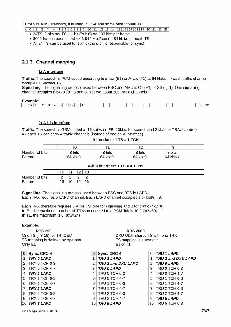
T1 follows ANSI standard, it is used in USA and some other countries s 0 1 2 3 4 5 6 7 8 9 10 11 12 13 14 15 16 17 18 19 20 21 22 23
• 24TS, 8 bits per TS + 1 bit (“s-bit”) => 193 bits per frame • 8000 frames per second => 1,544 Mbit/sec (or 64 kbit/s for each TS) • All 24 TS can be used for traffic (the s-bit is responsible for sync)
2.1.3 Channel mapping
1) A interface
Traffic: The speech is PCM-coded according to µ-law (E1) or A-law (T1) at 64 kbit/s => each traffic channel occupies a 64kbit/s TS. Signalling: The signalling protocol used between BSC and MSC is C7 (E1) or SS7 (T1). One signalling channel occupies a 64kbit/s TS and can serve about 200 traffic channels. Example: 0 C7 T1 T2 T3 T4 T5 T6 T7 T8 T9 T30 T31
2) A-bis interface
Traffic: The speech is GSM-coded at 16 kbit/s (in FR, 13kb/s for speech and 3 kb/s for TRAU control) => each TS can carry 4 traffic channels (instead of one on A-interface)
A interface: 1 TS = 1 TCH
T0 T1 T2 T3 Number of bits 8 bits 8 bits 8 bits 8 bits Bit rate 64 kbit/s 64 kbit/s 64 kbit/s 64 kbit/s
A-bis interface: 1 TS = 4 TCHs T0 T1 T2 T3
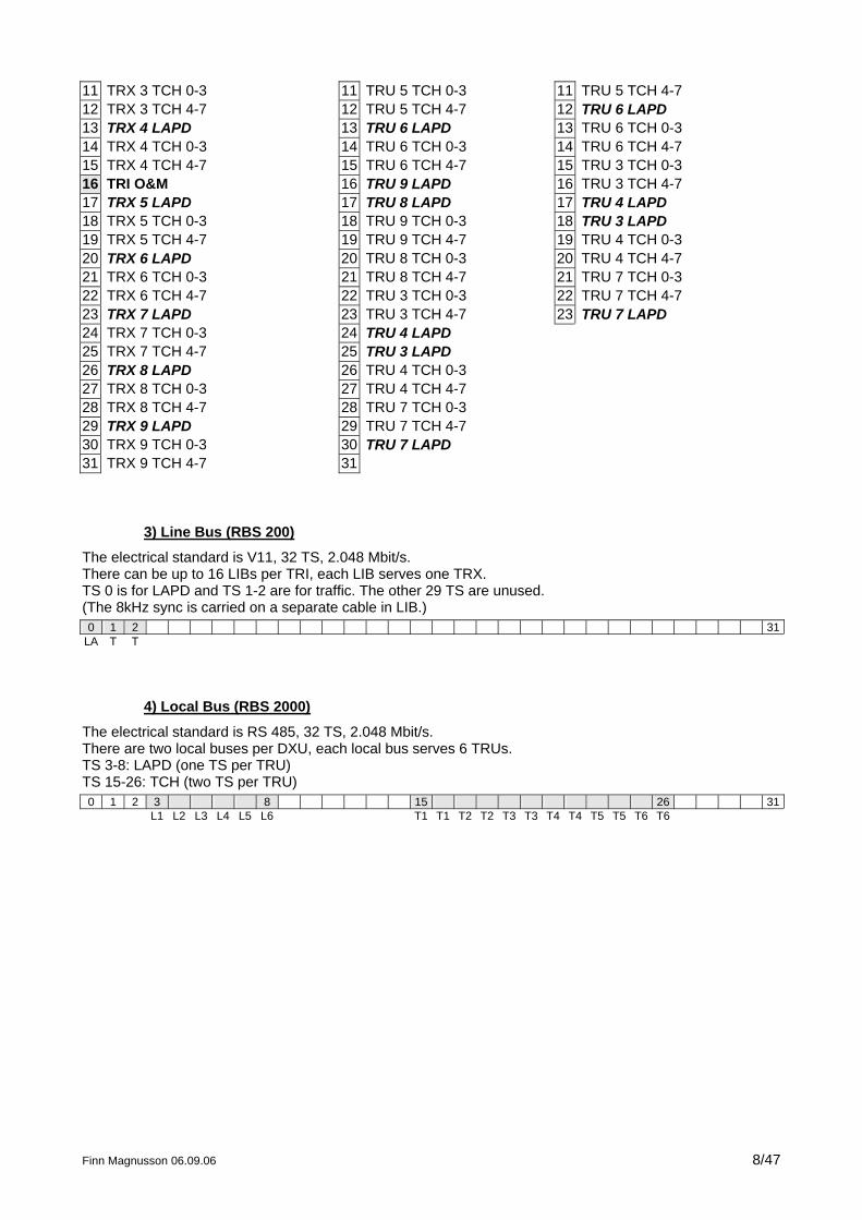
Number of bits 2 2 2 2 Bit rate 16 16 16 16 Signalling: The signalling protocol used between BSC and BTS is LAPD. Each TRX requires a LAPD channel. Each LAPD channel occupies a 64kbit/s TS. Each TRX therefore requires 3 A-bis TS: one for signalling and 2 for traffic (4x2=8). In E1, the maximum number of TRXs connected to a PCM link is 10 (10x3=30) In T1, the maximum is 8 (8x3=24) Example: RBS 200 RBS 2000 One TS (TS 16) for TRI O&M DXU O&M shares TS with one TRX TS mapping is defined by operator TS mapping is automatic Only E1 E1 or T1 0 Sync, CRC-4 0 Sync, CRC-4 0 TRU 1 LAPD 1 TRX 0 LAPD 1 TRU 1 LAPD 1 TRU 2 and DXU LAPD 2 TRX 0 TCH 0-3 2 TRU 2 and DXU LAPD 2 TRU 0 LAPD 3 TRX 0 TCH 4-7 3 TRU 0 LAPD 3 TRU 0 TCH 0-3 4 TRX 1 LAPD 4 TRU 0 TCH 0-3 4 TRU 0 TCH 4-7 5 TRX 1 TCH 0-3 5 TRU 0 TCH 4-7 5 TRU 1 TCH 0-3 6 TRX 1 TCH 4-7 6 TRU 1 TCH 0-3 6 TRU 1 TCH 4-7 7 TRX 2 LAPD 7 TRU 1 TCH 4-7 7 TRU 2 TCH 0-3 8 TRX 2 TCH 0-3 8 TRU 2 TCH 0-3 8 TRU 2 TCH 4-7 9 TRX 2 TCH 4-7 9 TRU 2 TCH 4-7 9 TRU 5 LAPD
10 TRX 3 LAPD 10 TRU 5 LAPD 10 TRU 5 TCH 0-3
Finn Magnusson 06.09.06 8/47
11 TRX 3 TCH 0-3 11 TRU 5 TCH 0-3 11 TRU 5 TCH 4-7 12 TRX 3 TCH 4-7 12 TRU 5 TCH 4-7 12 TRU 6 LAPD 13 TRX 4 LAPD 13 TRU 6 LAPD 13 TRU 6 TCH 0-3 14 TRX 4 TCH 0-3 14 TRU 6 TCH 0-3 14 TRU 6 TCH 4-7 15 TRX 4 TCH 4-7 15 TRU 6 TCH 4-7 15 TRU 3 TCH 0-3 16 TRI O&M 16 TRU 9 LAPD 16 TRU 3 TCH 4-7 17 TRX 5 LAPD 17 TRU 8 LAPD 17 TRU 4 LAPD 18 TRX 5 TCH 0-3 18 TRU 9 TCH 0-3 18 TRU 3 LAPD 19 TRX 5 TCH 4-7 19 TRU 9 TCH 4-7 19 TRU 4 TCH 0-3 20 TRX 6 LAPD 20 TRU 8 TCH 0-3 20 TRU 4 TCH 4-7 21 TRX 6 TCH 0-3 21 TRU 8 TCH 4-7 21 TRU 7 TCH 0-3 22 TRX 6 TCH 4-7 22 TRU 3 TCH 0-3 22 TRU 7 TCH 4-7 23 TRX 7 LAPD 23 TRU 3 TCH 4-7 23 TRU 7 LAPD 24 TRX 7 TCH 0-3 24 TRU 4 LAPD 25 TRX 7 TCH 4-7 25 TRU 3 LAPD 26 TRX 8 LAPD 26 TRU 4 TCH 0-3 27 TRX 8 TCH 0-3 27 TRU 4 TCH 4-7 28 TRX 8 TCH 4-7 28 TRU 7 TCH 0-3 29 TRX 9 LAPD 29 TRU 7 TCH 4-7 30 TRX 9 TCH 0-3 30 TRU 7 LAPD 31 TRX 9 TCH 4-7 31
3) Line Bus (RBS 200)
The electrical standard is V11, 32 TS, 2.048 Mbit/s. There can be up to 16 LIBs per TRI, each LIB serves one TRX. TS 0 is for LAPD and TS 1-2 are for traffic. The other 29 TS are unused. (The 8kHz sync is carried on a separate cable in LIB.) 0 1 2 31
LA T T
4) Local Bus (RBS 2000)
The electrical standard is RS 485, 32 TS, 2.048 Mbit/s. There are two local buses per DXU, each local bus serves 6 TRUs. TS 3-8: LAPD (one TS per TRU) TS 15-26: TCH (two TS per TRU) 0 1 2 3 8 15 26 31 L1 L2 L3 L4 L5 L6 T1 T1 T2 T2 T3 T3 T4 T4 T5 T5 T6 T6
2.2 Radio Network (Um)
2.2.1 TDMA structure
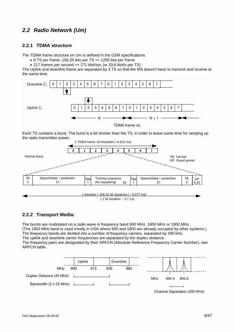
The TDMA frame structure on Um is defined in the GSM specifications. • 8 TS per frame, 156.25 bits per TS => 1250 bits per frame • 217 frames per second => 271 kbit/sec (or 33,8 kbit/s per TS)
The Uplink and downlink frame are separated by 3 TS so that the MS doesn’t have to transmit and receive at the same time.
Each TS contains a burst. The burst is a bit shorter than the TS, in order to leave some time for ramping up the radio transmitter power.
0 1 2 3 4 5 6 7
1 TDMA frame =8 timeslots (~4.615 ms)
1 timeslot = 156.25 bit durations (~ 0.577 ms)( 1 bit duration ~ 3.7 µs)
TB3
Speech/data + protection57
flag1
Training sequence(for equalising) 26
flag1
TB3
GP8.25
TB: Tail bitsGP: Guard period
Normal burst
Speech/data + protection57
2.2.2 Transport Media:
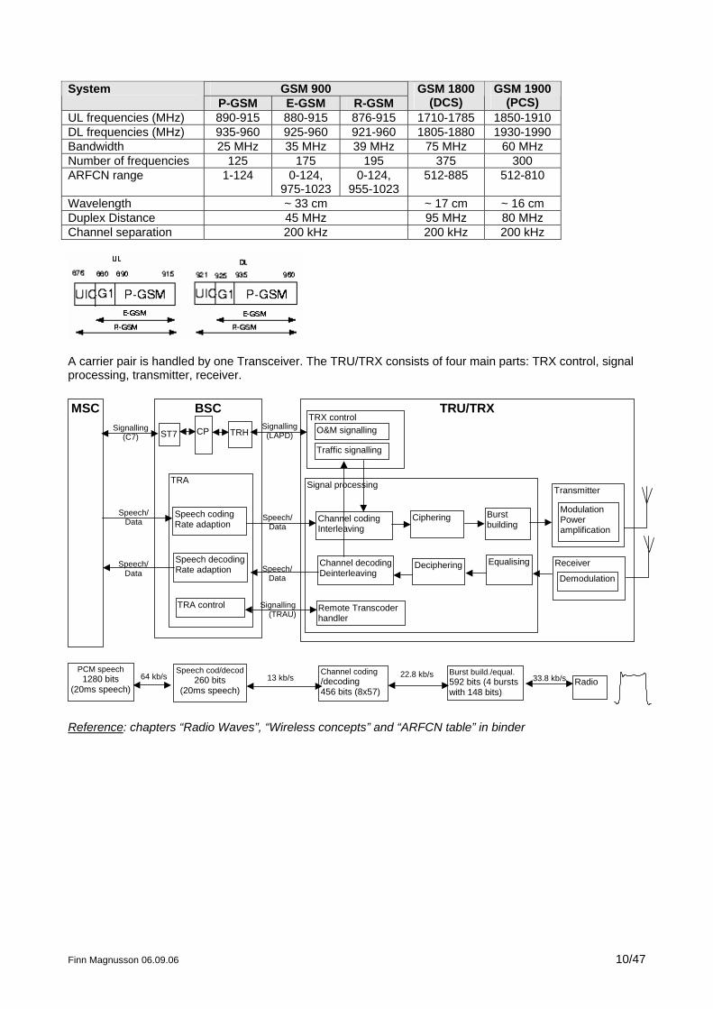
The bursts are modulated on a radio wave in frequency band 900 MHz, 1800 MHz or 1900 MHz. (The 1900 MHz band is used mostly in USA where 900 and 1800 are already occupied by other systems.) The frequency bands are divided into a number of frequency carriers, separated by 200 kHz. The uplink and downlink carrier frequencies are separated by the duplex distance. The frequency pairs are designated by their ARFCN (Absolute Reference Frequency Carrier Number), see ARFCN table.
Finn Magnusson 06.09.06 9/47
GSM 900 System
P-GSM E-GSM R-GSM GSM 1800
(DCS) GSM 1900
(PCS) UL frequencies (MHz) 890-915 880-915 876-915 1710-1785 1850-1910 DL frequencies (MHz) 935-960 925-960 921-960 1805-1880 1930-1990 Bandwidth 25 MHz 35 MHz 39 MHz 75 MHz 60 MHz Number of frequencies 125 175 195 375 300 ARFCN range 1-124 0-124,
975-1023 0-124,
955-1023 512-885 512-810
Wavelength ~ 33 cm ~ 17 cm ~ 16 cm Duplex Distance 45 MHz 95 MHz 80 MHz Channel separation 200 kHz 200 kHz 200 kHz
A carrier pair is handled by one Transceiver. The TRU/TRX consists of four main parts: TRX control, signal processing, transmitter, receiver.
BSC
TRA
Speech codingRate adaption
Speech decodingRate adaption
TRU/TRX
Signal processing
TRH
TRA control
CP
Channel codingInterleaving
Ciphering
Transmitter
ModulationPoweramplification
Receiver
DemodulationDecipheringChannel decoding
Deinterleaving
TRX control
Remote Transcoderhandler
O&M signalling
Traffic signalling
Burstbuilding
Equalising
Signalling(LAPD)
Speech/Data
Speech/Data
Signalling(TRAU)
Speech cod/decod260 bits
(20ms speech)
Channel coding/decoding456 bits (8x57)
Burst build./equal.592 bits (4 burstswith 148 bits)
13 kb/s 22.8 kb/s 33.8 kb/s RadioPCM speech
1280 bits(20ms speech)
64 kb/s
ST7Signalling
(C7)
Speech/Data
Speech/Data
MSC
Reference: chapters “Radio Waves”, “Wireless concepts” and “ARFCN table” in binder
Finn Magnusson 06.09.06 10/47
Finn Magnusson 06.09.06 11/47
2.2.3 Channel mapping
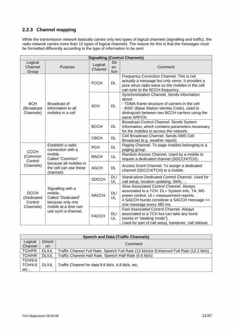
While the transmission network basically carries only two types of logical channels (signalling and traffic), the radio network carries more than 10 types of logical channels. The reason for this is that the messages must be formatted differently according to the type of information to be sent.
Signalling (Control Channels) Logical
Channel Group
Purpose Logical Channel
Direc-tion
Comment
FCCH DL
Frequency Correction Channel. This is not actually a message but only zeros. It provides a pure sinus radio wave so the mobiles in the cell can tune to the BCCH frequency.
SCH DL
Synchronisation Channel. Sends information about: - TDMA frame structure of carriers in the cell - BSIC (Base Station Identity Code), used to distinguish between two BCCH carriers using the same ARFCN.
BCCH DL Broadcast Control Channel. Sends System Information, which contains parameters necessary for the mobiles to access the network.
BCH (Broadcast Channels)
Broadcast of information to all mobiles in a cell
CBCH DL Cell Broadcast Channel. Sends SMS Cell Broadcast (e.g. weather report)
PCH DL Paging Channel. To page mobiles belonging to a paging group.
RACH UL Random Access Channel. Used by a mobile to require a dedicated channel (SDCCH/TCH).
CCCH (Common
Control Channels)
Establish a radio connection with a mobile. Called “Common” because all mobiles in the cell can use these channels.
AGCH DL Access Grant Channel. To assign a dedicated channel (SDCCH/TCH) to a mobile.
SDCCH DL/UL
Stand-alone Dedicated Control Channel. Used for call setup, location updating, SMS, …
SACCH DL/UL
Slow Associated Control Channel. Always associated to a TCH. DL= System Info, TA, MS power control. UL= measurement reports. 4 SACCH bursts constitute a SACCH message => one message every 480 ms.
DCCH (Dedicated
Control Channels)
Signalling with a mobile. Called “Dedicated” because only one mobile at a time can use such a channel.
FACCH DL/UL
Fast Associated Control Channel. Always associated to a TCH but can take any burst (works in “stealing mode”). Used for part of call setup, handover, call release.
Speech and Data (Traffic Channels) Logical
Channel Directi
on Comment
TCH/FR DL/UL Traffic Channel Full Rate. Speech Full Rate (13 kb/s)or Enhanced Full Rate (12.2 kb/s) TCH/HR DL/UL Traffic Channel Half Rate. Speech Half Rate (5.6 kb/s) TCH/9.6 TCH/4.8 etc…
DL/UL Traffic Channel for data 9.6 kb/s, 4.8 kb/s, etc.
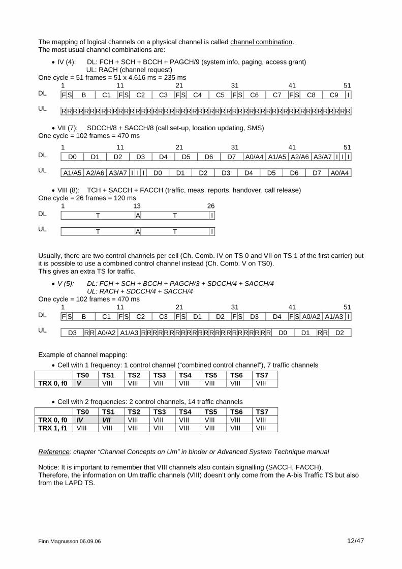
The mapping of logical channels on a physical channel is called channel combination. The most usual channel combinations are:
• IV (4): DL: FCH + SCH + BCCH + PAGCH/9 (system info, paging, access grant) UL: RACH (channel request)
One cycle = 51 frames = 51 x 4.616 ms = 235 ms 1 11 21 31 41 51F S B C1 F S C2 C3 F S C4 C5 F S C6 C7 F S C8 C9 I
RRRRRRRRRRRRRRRRRRRRRRRRRRRRRRRRRRRRRRRRRRRRRRRRRRR
DL
UL
• VII (7): SDCCH/8 + SACCH/8 (call set-up, location updating, SMS) One cycle = 102 frames = 470 ms
1 11 21 31 41 51D0 D1 D2 D3 D4 D5 D6 D7 A0/A4 A1/A5 A2/A6 A3/A7 I I I
A1/A5 A2/A6 A3/A7 I I I D0 D1 D2 D3 D4 D5 D6 D7 A0/A4
DL
UL
• VIII (8): TCH + SACCH + FACCH (traffic, meas. reports, handover, call release) One cycle = 26 frames = 120 ms
1 13 26T A T I
T A T I
DL
UL
Usually, there are two control channels per cell (Ch. Comb. IV on TS 0 and VII on TS 1 of the first carrier) but it is possible to use a combined control channel instead (Ch. Comb. V on TS0). This gives an extra TS for traffic.
• V (5): DL: FCH + SCH + BCCH + PAGCH/3 + SDCCH/4 + SACCH/4 UL: RACH + SDCCH/4 + SACCH/4
One cycle = 102 frames = 470 ms 1 11 21 31 41 51F S B C1 F S C2 C3 F S D1 D2 F S D3 D4 F S A0/A2 A1/A3 I
D3 RR A0/A2 A1/A3 RRRRRRRRRRRRRRRRRRRRRRR D0 D1 RR D2
DL
UL
Example of channel mapping:
• Cell with 1 frequency: 1 control channel (“combined control channel”), 7 traffic channels TS0 TS1 TS2 TS3 TS4 TS5 TS6 TS7 TRX 0, f0 V VIII VIII VIII VIII VIII VIII VIII
• Cell with 2 frequencies: 2 control channels, 14 traffic channels TS0 TS1 TS2 TS3 TS4 TS5 TS6 TS7 TRX 0, f0 IV VII VIII VIII VIII VIII VIII VIII TRX 1, f1 VIII VIII VIII VIII VIII VIII VIII VIII Reference: chapter “Channel Concepts on Um” in binder or Advanced System Technique manual Notice: It is important to remember that VIII channels also contain signalling (SACCH, FACCH). Therefore, the information on Um traffic channels (VIII) doesn’t only come from the A-bis Traffic TS but also from the LAPD TS.
Finn Magnusson 06.09.06 12/47
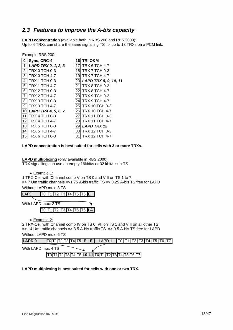
2.3 Features to improve the A-bis capacity
LAPD concentration (available both in RBS 200 and RBS 2000): Up to 4 TRXs can share the same signalling TS => up to 13 TRXs on a PCM link. Example RBS 200: 0 Sync, CRC-4 16 TRI O&M 1 LAPD TRX 0, 1, 2, 3 17 TRX 6 TCH 4-7 2 TRX 0 TCH 0-3 18 TRX 7 TCH 0-3 3 TRX 0 TCH 4-7 19 TRX 7 TCH 4-7 4 TRX 1 TCH 0-3 20 LAPD TRX 8, 9, 10, 11 5 TRX 1 TCH 4-7 21 TRX 8 TCH 0-3 6 TRX 2 TCH 0-3 22 TRX 8 TCH 4-7 7 TRX 2 TCH 4-7 23 TRX 9 TCH 0-3 8 TRX 3 TCH 0-3 24 TRX 9 TCH 4-7 9 TRX 3 TCH 4-7 25 TRX 10 TCH 0-3
10 LAPD TRX 4, 5, 6, 7 26 TRX 10 TCH 4-7 11 TRX 4 TCH 0-3 27 TRX 11 TCH 0-3 12 TRX 4 TCH 4-7 28 TRX 11 TCH 4-7 13 TRX 5 TCH 0-3 29 LAPD TRX 12 14 TRX 5 TCH 4-7 30 TRX 12 TCH 0-3 15 TRX 6 TCH 0-3 31 TRX 12 TCH 4-7 LAPD concentration is best suited for cells with 3 or more TRXs. LAPD multiplexing (only available in RBS 2000): TRX signalling can use an empty 16kbit/s or 32 kbit/s sub-TS
• Example 1: 1 TRX-Cell with Channel comb V on TS 0 and VIII on TS 1 to 7 => 7 Um traffic channels =>1.75 A-bis traffic TS => 0.25 A-bis TS free for LAPD Without LAPD mux: 3 TS LAPD T0 T1 T2 T3 T4 T5 T6 E With LAPD mux: 2 TS T0 T1 T2 T3 T4 T5 T6 LA
• Example 2: 2 TRX-Cell with Channel comb IV on TS 0, VII on TS 1 and VIII on all other TS => 14 Um traffic channels => 3.5 A-bis traffic TS => 0.5 A-bis TS free for LAPD Without LAPD mux: 6 TS
Finn Magnusson 06.09.06 13/47
LAPD 0 T0 T1 T2 T3 T4 T5 E E LAPD 1 T0 T1 T2 T3 T4 T5 T6 T7
With LAPD mux 4 TS T0 T1 T2 T3 T4 T5 L0 L1 T0 T1 T2 T3 T4 T5 T6 T7
LAPD multiplexing is best suited for cells with one or two TRX.
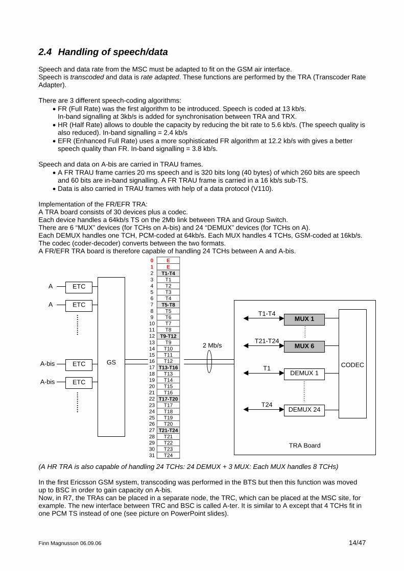
2.4 Handling of speech/data
Speech and data rate from the MSC must be adapted to fit on the GSM air interface. Speech is transcoded and data is rate adapted. These functions are performed by the TRA (Transcoder Rate Adapter). There are 3 different speech-coding algorithms:
• FR (Full Rate) was the first algorithm to be introduced. Speech is coded at 13 kb/s. In-band signalling at 3kb/s is added for synchronisation between TRA and TRX.
• HR (Half Rate) allows to double the capacity by reducing the bit rate to 5.6 kb/s. (The speech quality is also reduced). In-band signalling = 2.4 kb/s
• EFR (Enhanced Full Rate) uses a more sophisticated FR algorithm at 12.2 kb/s with gives a better speech quality than FR. In-band signalling = 3.8 kb/s.
Speech and data on A-bis are carried in TRAU frames.
• A FR TRAU frame carries 20 ms speech and is 320 bits long (40 bytes) of which 260 bits are speech and 60 bits are in-band signalling. A FR TRAU frame is carried in a 16 kb/s sub-TS.
• Data is also carried in TRAU frames with help of a data protocol (V110). Implementation of the FR/EFR TRA: A TRA board consists of 30 devices plus a codec. Each device handles a 64kb/s TS on the 2Mb link between TRA and Group Switch. There are 6 “MUX” devices (for TCHs on A-bis) and 24 “DEMUX” devices (for TCHs on A). Each DEMUX handles one TCH, PCM-coded at 64kb/s. Each MUX handles 4 TCHs, GSM-coded at 16kb/s. The codec (coder-decoder) converts between the two formats. A FR/EFR TRA board is therefore capable of handling 24 TCHs between A and A-bis.
TRA Board
0 E1 E2 T1-T43 T14 T25 T36 T47 T5-T88 T59 T610 T711 T812 T9-T1213 T914 T1015 T1116 T1217 T13-T1618 T1319 T1420 T1521 T1622 T17-T2023 T1724 T1825 T1926 T2027 T21-T2428 T2129 T2230 T2331 T24
DEMUX 1T1
T24
……
.
T1-T4
T21-T24
MUX 1
MUX 6
DEMUX 24
……
….
2 Mb/s
GS
ETC
ETC
ETC
ETC
CODEC
A
A
A-bis
A-bis
……
….
……
….
(A HR TRA is also capable of handling 24 TCHs: 24 DEMUX + 3 MUX: Each MUX handles 8 TCHs) In the first Ericsson GSM system, transcoding was performed in the BTS but then this function was moved up to BSC in order to gain capacity on A-bis. Now, in R7, the TRAs can be placed in a separate node, the TRC, which can be placed at the MSC site, for example. The new interface between TRC and BSC is called A-ter. It is similar to A except that 4 TCHs fit in one PCM TS instead of one (see picture on PowerPoint slides).
Finn Magnusson 06.09.06 14/47

Finn Magnusson 06.09.06 15/47
3
BSS Interfaces: Signalling protocols
3.1 Introduction: signalling layers
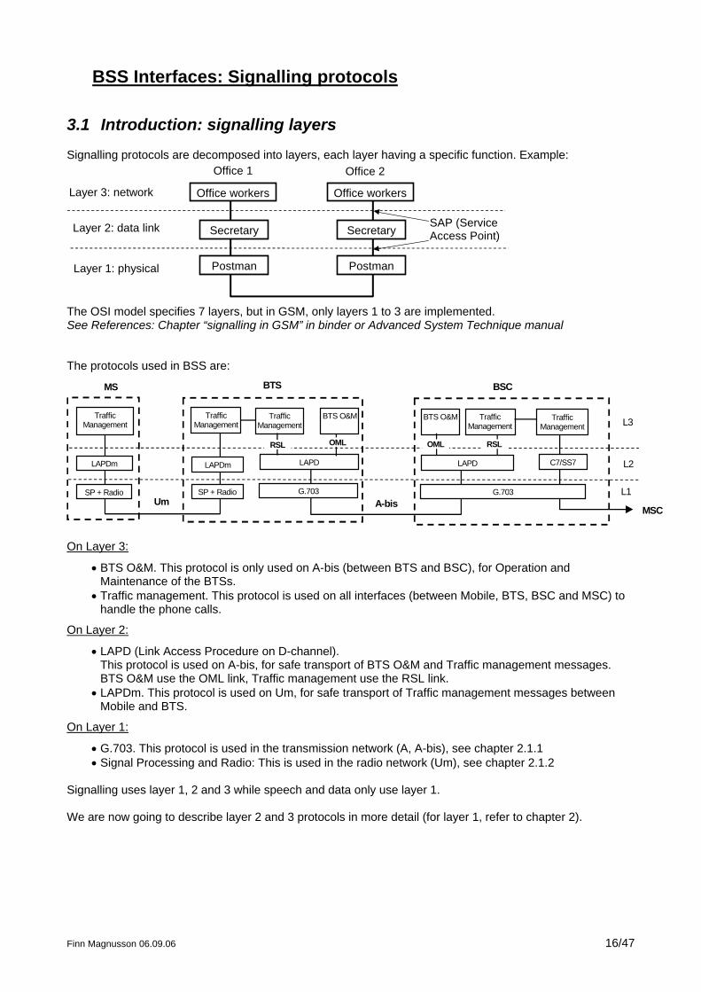
Signalling protocols are decomposed into layers, each layer having a specific function. Example:
Office workers
Secretary
Postman
Office workers
Secretary
Postman
Layer 3: network
Layer 2: data link
Layer 1: physical
Office 1 Office 2
SAP (ServiceAccess Point)
The OSI model specifies 7 layers, but in GSM, only layers 1 to 3 are implemented. See References: Chapter “signalling in GSM” in binder or Advanced System Technique manual The protocols used in BSS are:
TrafficManagement
LAPDm
SP + Radio
TrafficManagement
LAPDm
SP + Radio
MS BTS
TrafficManagement
LAPD
G.703
BTS O&M
LAPD
G.703
BTS O&M TrafficManagement
C7/SS7
MSCUm A-bis
BSC
TrafficManagement
OMLRSL RSLOML
L3
L2
L1
On Layer 3:
• BTS O&M. This protocol is only used on A-bis (between BTS and BSC), for Operation and Maintenance of the BTSs.
• Traffic management. This protocol is used on all interfaces (between Mobile, BTS, BSC and MSC) to handle the phone calls.
On Layer 2:
• LAPD (Link Access Procedure on D-channel). This protocol is used on A-bis, for safe transport of BTS O&M and Traffic management messages. BTS O&M use the OML link, Traffic management use the RSL link.
• LAPDm. This protocol is used on Um, for safe transport of Traffic management messages between Mobile and BTS.
On Layer 1:
• G.703. This protocol is used in the transmission network (A, A-bis), see chapter 2.1.1 • Signal Processing and Radio: This is used in the radio network (Um), see chapter 2.1.2
Signalling uses layer 1, 2 and 3 while speech and data only use layer 1. We are now going to describe layer 2 and 3 protocols in more detail (for layer 1, refer to chapter 2).
Finn Magnusson 06.09.06 16/47
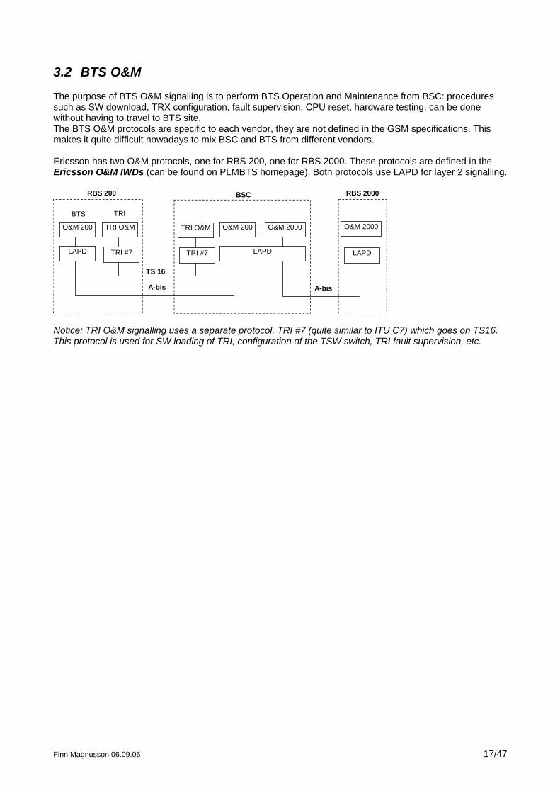
3.2 BTS O&M
The purpose of BTS O&M signalling is to perform BTS Operation and Maintenance from BSC: procedures such as SW download, TRX configuration, fault supervision, CPU reset, hardware testing, can be done without having to travel to BTS site. The BTS O&M protocols are specific to each vendor, they are not defined in the GSM specifications. This makes it quite difficult nowadays to mix BSC and BTS from different vendors. Ericsson has two O&M protocols, one for RBS 200, one for RBS 2000. These protocols are defined in the Ericsson O&M IWDs (can be found on PLMBTS homepage). Both protocols use LAPD for layer 2 signalling.
O&M 200
LAPD
TRI O&M
TRI #7
TRI O&M
TRI #7
O&M 200
LAPD
O&M 2000
LAPD
O&M 2000
TS 16
BTS TRI
RBS 200 BSC RBS 2000
A-bis A-bis
Notice: TRI O&M signalling uses a separate protocol, TRI #7 (quite similar to ITU C7) which goes on TS16. This protocol is used for SW loading of TRI, configuration of the TSW switch, TRI fault supervision, etc.
Finn Magnusson 06.09.06 17/47
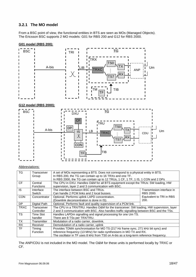
3.2.1 The MO model
From a BSC point of view, the functional entities in BTS are seen as MOs (Managed Objects). The Ericsson BSC supports 2 MO models: G01 for RBS 200 and G12 for RBS 2000. G01 model (RBS 200):
TGTRI
TRX
ANPTRXC
TS0
TS7
…. TX
RX
TMTF
A-bis UmLIB
TIB
BSC
G12 model (RBS 2000):
TGDXU
LB
TRU
CDUTRXC
TS0
TS7
…. TX
RX
TF
A-bis UmIS
CF
CON
DP
TIB
BSC
Abbreviations:
TG Transceiver Group
A set of MOs representing a BTS. Does not correspond to a physical entity in BTS. In RBS 200, the TG can contain up to 16 TRXs and one TF. In RBS 2000, the TG can contain up to 12 TRUs, 1 CF, 1 TF, 1 IS, 1 CON and 2 DPs
CF Central Functions
The CPU in DXU. Handles O&M for all BTS equipment except the TRUs: SW loading, HW supervision, layer 2 and 3 communication with BSC.
IS Interface Switch
The interface between BSC and TRUs. Can handle 2 PCM links and 2 local busses.
CON Concentrator Optional. Performs uplink LAPD concentration. (Downlink deconcentration is done in IS).
DP Digital Path Optional. Performs fault and quality supervision of a PCM link.
Transmission interface in RBS 2000. Equivalent to TRI in RBS 200.
TRXC Transceiver Controller
The CPU in a TRX/TRU. Handles O&M for the transceiver: SW loading, HW supervision, layer 2 and 3 communication with BSC. Also handles traffic signalling between BSC and the TSs.
TS Time Slot handler
Handles LAPDm signalling and signal processing for one Um TS. There are 8 TSs per TRX/TRU.
TX Transmitter Modulation of a radio carrier, downlink. RX Receiver Demodulation of a radio carrier, uplink TF Timing
Function Provides TDMA synchronisation for MO TS (217 Hz frame sync, 271 kHz bit sync) and reference frequency (13 MHz) for radio synthesisers in MO TX and RX. The oscillator in TF uses 8 kHz from TS0 on A-bis as a long-term reference frequency.
The ANP/CDU is not included in the MO model. The O&M for these units is performed locally by TRXC or CF.
Finn Magnusson 06.09.06 18/47
Differences between RBS 200 and RBS 2000:
RBS 200 RBS 2000 Transmission interface (TRI) is not included in the MO model. TRI has its own signalling protocol on TS16.
Transmission interface is represented by MOs IS, CON and DP.
Power and climate alarms, external alarms and antenna alarms are sent on TS 16, via TRI signalling.
Power and climate, antenna and external alarms are handled by CF and are thus sent via LAPD signalling.
TF is implemented in a separate Timing Module (TM) comprising 3 TUs (Timing Units)
TF is implemented a single oscillator, in DXU
TRX is made of up to 13 units: 1 TRXC board, 8 SPP or 1 SPU for the TSs, 1 RTX, 1 RRX and 2 units for power supply (TRXconv and RTXPF).
TRU is made of one unit only.
The MOs can be divided in two categories:
• Control MOs They are responsible for SW handling, HW supervision and A-bis signalling (layer 2 and layer 3). In RBS 200, the Control MO is TRXC. Each TRXC is responsible for respective TSs and RX. One TRXC (the TGC) is responsible for the common resources (TF and TXs). In RBS 2000, the Control MOs are CF and TRXC, also called Service Objects (SO). CF is responsible for common resources (TF, IS, CON, DP). Each TRXC is responsible for respective RX, TX, TSs (TX is not handled as a common resource, from O&M point of view).
• Traffic MOs
They are responsible for handling the traffic on A-bis (IS, CON, DP) or Um (TF, TS, TX, RX). In order to be operational, they need to receive configuration parameters from BSC (e.g. output power and ARFCN for TX, channel combination for TS, etc.). In RBS 200, the traffic MOs are called Logical Units (LU), in RBS 2000, they are called Application Objects (AO).
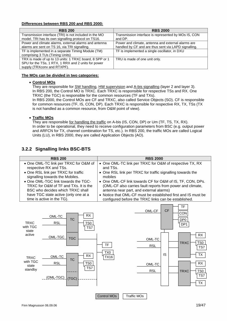
3.2.2 Signalling links BSC-BTS
RBS 200 RBS 2000 • One OML-TC link per TRXC for O&M of
respective RX and TSs. • One RSL link per TRXC for traffic
signalling towards the Mobiles. • One OML-TGC link towards the TGC-
TRXC for O&M of TF and TXs. It is the BSC who decides which TRXC shall have TGC state active (only one at a time is active in the TG).
• One OML-TC link per TRXC for O&M of respective TX, RX and TSs.
• One RSL link per TRXC for traffic signalling towards the mobiles
• One OML-CF link towards CF for O&M of IS, TF, CON, DPs. (OML-CF also carries fault reports from power and climate, antenna near part, and external alarms)
• Notice that OML-CF must be established first and IS must be configured before the TRXC links can be established.
OML-TC
RSL
TC
TGC
RX
TS0TS7
TC
(TGC)
RX
TS0TS7
TF
TX0TX16
OML-TC
OML-TGC
OML-TC
(OML-TGC)
RSL
RSL
TRXCwith TGC
stateactive
TRXCwith TGC
statestandby TRXC
RX
TS0TS7
TX
TRXC
RX
TS0TS7
TX
CFTF
CON
DP0DP1
OML-CF
Control MOs Traffic MOs
OML-TC
RSL
IS
Finn Magnusson 06.09.06 19/47
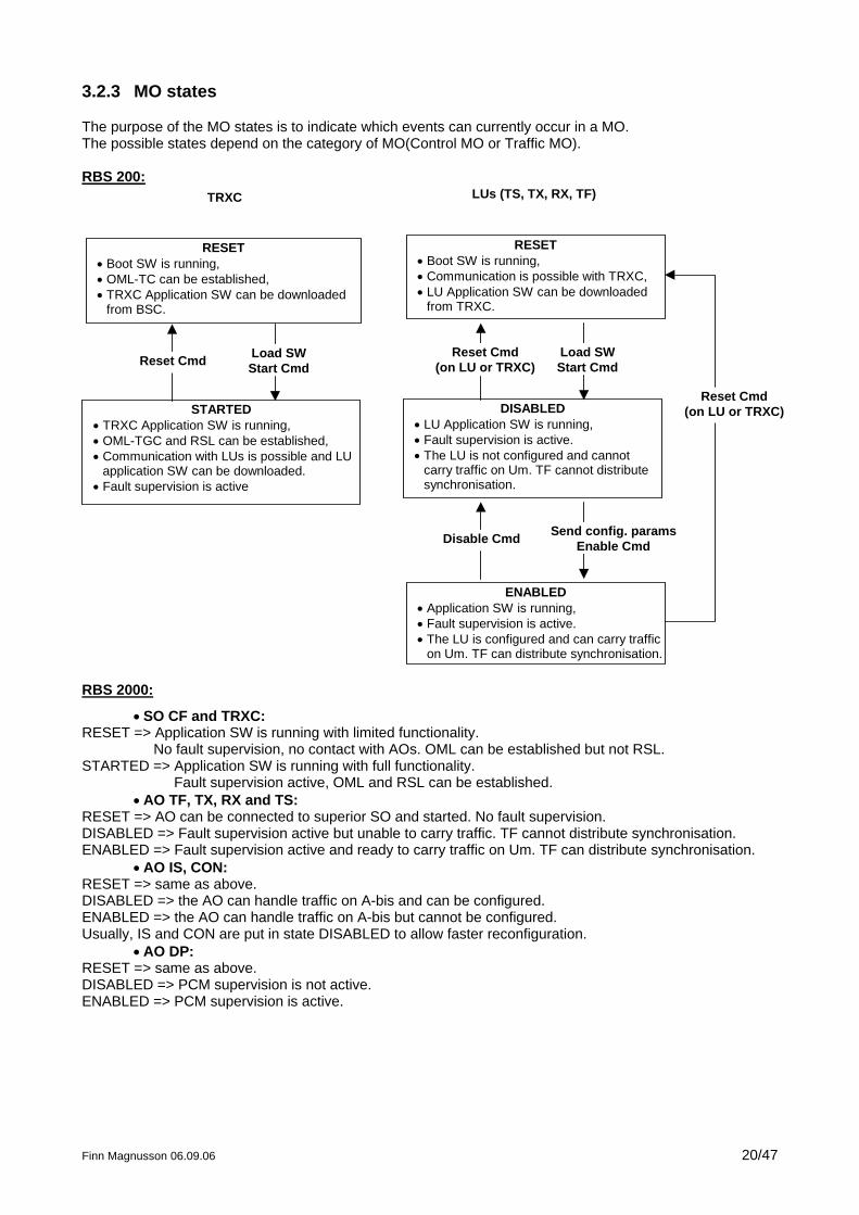
3.2.3 MO states
The purpose of the MO states is to indicate which events can currently occur in a MO. The possible states depend on the category of MO(Control MO or Traffic MO). RBS 200:
RESET• Boot SW is running,• OML-TC can be established,• TRXC Application SW can be downloaded
from BSC.
STARTED• TRXC Application SW is running,• OML-TGC and RSL can be established,• Communication with LUs is possible and LU
application SW can be downloaded.• Fault supervision is active
RESET• Boot SW is running,• Communication is possible with TRXC,• LU Application SW can be downloaded
from TRXC.
DISABLED• LU Application SW is running,• Fault supervision is active.• The LU is not configured and cannot
carry traffic on Um. TF cannot distributesynchronisation.
ENABLED• Application SW is running,• Fault supervision is active.• The LU is configured and can carry traffic
on Um. TF can distribute synchronisation.
TRXC LUs (TS, TX, RX, TF)
Load SWStart CmdReset Cmd Load SW
Start Cmd
Send config. paramsEnable CmdDisable Cmd
Reset Cmd(on LU or TRXC)
Reset Cmd(on LU or TRXC)
RBS 2000:
• SO CF and TRXC: RESET => Application SW is running with limited functionality.
No fault supervision, no contact with AOs. OML can be established but not RSL. STARTED => Application SW is running with full functionality.
Fault supervision active, OML and RSL can be established. • AO TF, TX, RX and TS:
RESET => AO can be connected to superior SO and started. No fault supervision. DISABLED => Fault supervision active but unable to carry traffic. TF cannot distribute synchronisation. ENABLED => Fault supervision active and ready to carry traffic on Um. TF can distribute synchronisation.
• AO IS, CON: RESET => same as above. DISABLED => the AO can handle traffic on A-bis and can be configured. ENABLED => the AO can handle traffic on A-bis but cannot be configured. Usually, IS and CON are put in state DISABLED to allow faster reconfiguration.
• AO DP: RESET => same as above. DISABLED => PCM supervision is not active. ENABLED => PCM supervision is active.
Finn Magnusson 06.09.06 20/47
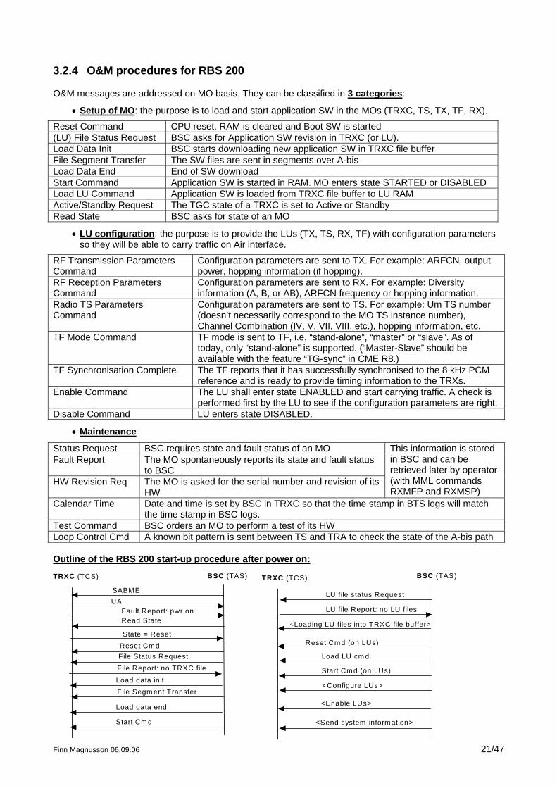
3.2.4 O&M procedures for RBS 200
O&M messages are addressed on MO basis. They can be classified in 3 categories:
• Setup of MO: the purpose is to load and start application SW in the MOs (TRXC, TS, TX, TF, RX).
Reset Command CPU reset. RAM is cleared and Boot SW is started (LU) File Status Request BSC asks for Application SW revision in TRXC (or LU). Load Data Init BSC starts downloading new application SW in TRXC file buffer File Segment Transfer The SW files are sent in segments over A-bis Load Data End End of SW download Start Command Application SW is started in RAM. MO enters state STARTED or DISABLED Load LU Command Application SW is loaded from TRXC file buffer to LU RAM Active/Standby Request The TGC state of a TRXC is set to Active or Standby Read State BSC asks for state of an MO
• LU configuration: the purpose is to provide the LUs (TX, TS, RX, TF) with configuration parameters so they will be able to carry traffic on Air interface.
RF Transmission Parameters Command
Configuration parameters are sent to TX. For example: ARFCN, output power, hopping information (if hopping).
RF Reception Parameters Command
Configuration parameters are sent to RX. For example: Diversity information (A, B, or AB), ARFCN frequency or hopping information.
Radio TS Parameters Command
Configuration parameters are sent to TS. For example: Um TS number (doesn’t necessarily correspond to the MO TS instance number), Channel Combination (IV, V, VII, VIII, etc.), hopping information, etc.
TF Mode Command TF mode is sent to TF, i.e. “stand-alone”, “master” or “slave”. As of today, only “stand-alone” is supported. (“Master-Slave” should be available with the feature “TG-sync” in CME R8.)
TF Synchronisation Complete The TF reports that it has successfully synchronised to the 8 kHz PCM reference and is ready to provide timing information to the TRXs.
Enable Command The LU shall enter state ENABLED and start carrying traffic. A check is performed first by the LU to see if the configuration parameters are right.
Disable Command LU enters state DISABLED.
• Maintenance
Status Request BSC requires state and fault status of an MO Fault Report The MO spontaneously reports its state and fault status
to BSC HW Revision Req The MO is asked for the serial number and revision of its
HW
This information is stored in BSC and can be retrieved later by operator (with MML commands RXMFP and RXMSP)
Calendar Time Date and time is set by BSC in TRXC so that the time stamp in BTS logs will match the time stamp in BSC logs.
Test Command BSC orders an MO to perform a test of its HW Loop Control Cmd A known bit pattern is sent between TS and TRA to check the state of the A-bis path Outline of the RBS 200 start-up procedure after power on:
Finn Magnusson 06.09.06 21/47
TRXC (TCS) BSC (TAS)
SABMEUA
Fault Report: pwr onRead State
State = ResetReset Cm dFile Status Request
File Report: no TRXC file
Load data initFile Segm ent Transfer
Load data end
Start Cm d
LU file status Request
LU file Report: no LU files
<Loading LU files into TRXC file buffer>
Reset Cm d (on LUs)
Load LU cm d
Start Cm d (on LUs)
<Configure LUs>
<Enable LUs>
<Send system inform ation>
TRXC (TCS) BSC (TAS)
EXERCISE: Analysis of an A-bis log taken during power on of RBS 200 (pwr-on1.grc), see my homepage http://www.eral.ericsson.se/~erafima/exercises.html in file “a-bis.zip”.
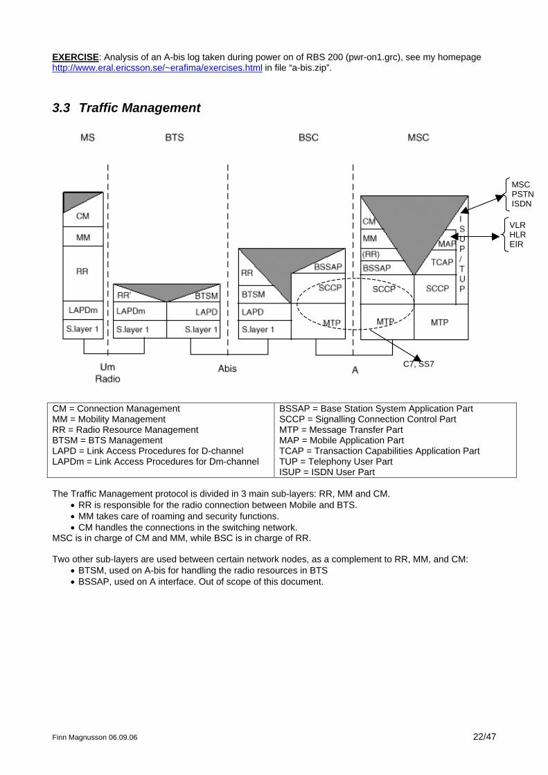
3.3 Traffic Management
C7, SS7
MSC PSTN ISDN
VLR HLR EIR
CM = Connection Management MM = Mobility Management RR = Radio Resource Management BTSM = BTS Management LAPD = Link Access Procedures for D-channel LAPDm = Link Access Procedures for Dm-channel
BSSAP = Base Station System Application Part SCCP = Signalling Connection Control Part MTP = Message Transfer Part MAP = Mobile Application Part TCAP = Transaction Capabilities Application Part TUP = Telephony User Part ISUP = ISDN User Part
The Traffic Management protocol is divided in 3 main sub-layers: RR, MM and CM.
• RR is responsible for the radio connection between Mobile and BTS. • MM takes care of roaming and security functions. • CM handles the connections in the switching network.
MSC is in charge of CM and MM, while BSC is in charge of RR. Two other sub-layers are used between certain network nodes, as a complement to RR, MM, and CM:
• BTSM, used on A-bis for handling the radio resources in BTS • BSSAP, used on A interface. Out of scope of this document.
Finn Magnusson 06.09.06 22/47
Finn Magnusson 06.09.06 23/47
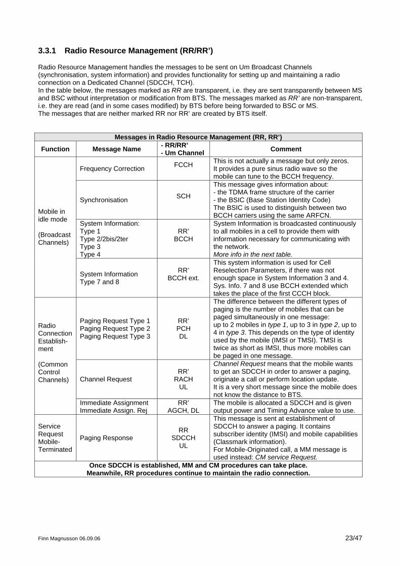
3.3.1 Radio Resource Management (RR/RR’)
Radio Resource Management handles the messages to be sent on Um Broadcast Channels (synchronisation, system information) and provides functionality for setting up and maintaining a radio connection on a Dedicated Channel (SDCCH, TCH). In the table below, the messages marked as RR are transparent, i.e. they are sent transparently between MS and BSC without interpretation or modification from BTS. The messages marked as RR’ are non-transparent, i.e. they are read (and in some cases modified) by BTS before being forwarded to BSC or MS. The messages that are neither marked RR nor RR’ are created by BTS itself.
Messages in Radio Resource Management (RR, RR’)
Function Message Name - RR/RR’ - Um Channel Comment
Frequency Correction FCCH
This is not actually a message but only zeros. It provides a pure sinus radio wave so the mobile can tune to the BCCH frequency.
Synchronisation SCH
This message gives information about: - the TDMA frame structure of the carrier - the BSIC (Base Station Identity Code) The BSIC is used to distinguish between two BCCH carriers using the same ARFCN.
System Information: Type 1 Type 2/2bis/2ter Type 3 Type 4
RR’ BCCH
System Information is broadcasted continuously to all mobiles in a cell to provide them with information necessary for communicating with the network. More info in the next table.
Mobile in idle mode (Broadcast Channels)
System Information Type 7 and 8
RR’ BCCH ext.
This system information is used for Cell Reselection Parameters, if there was not enough space in System Information 3 and 4. Sys. Info. 7 and 8 use BCCH extended which takes the place of the first CCCH block.
Paging Request Type 1 Paging Request Type 2 Paging Request Type 3
RR’ PCH DL
The difference between the different types of paging is the number of mobiles that can be paged simultaneously in one message: up to 2 mobiles in type 1, up to 3 in type 2, up to 4 in type 3. This depends on the type of identity used by the mobile (IMSI or TMSI). TMSI is twice as short as IMSI, thus more mobiles can be paged in one message.
Channel Request RR’
RACH UL
Channel Request means that the mobile wants to get an SDCCH in order to answer a paging, originate a call or perform location update. It is a very short message since the mobile does not know the distance to BTS.
Radio Connection Establish-ment (Common Control Channels)
Immediate Assignment Immediate Assign. Rej
RR’ AGCH, DL
The mobile is allocated a SDCCH and is given output power and Timing Advance value to use.
Service Request Mobile-Terminated
Paging Response RR
SDCCH UL
This message is sent at establishment of SDCCH to answer a paging. It contains subscriber identity (IMSI) and mobile capabilities (Classmark information). For Mobile-Originated call, a MM message is used instead: CM service Request.
Once SDCCH is established, MM and CM procedures can take place. Meanwhile, RR procedures continue to maintain the radio connection.
Finn Magnusson 06.09.06 24/47
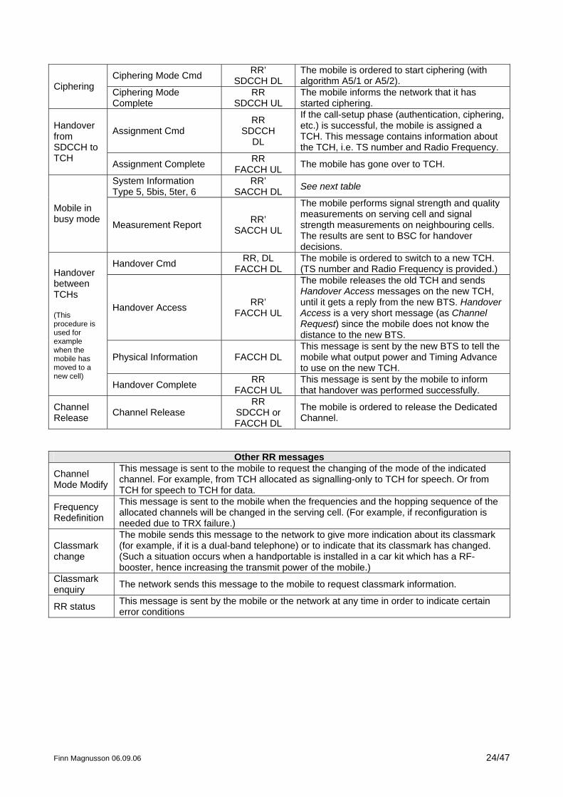
Ciphering Mode Cmd RR’ SDCCH DL
The mobile is ordered to start ciphering (with algorithm A5/1 or A5/2). Ciphering Ciphering Mode
Complete RR
SDCCH UL The mobile informs the network that it has started ciphering.
Assignment Cmd RR
SDCCH DL
If the call-setup phase (authentication, ciphering, etc.) is successful, the mobile is assigned a TCH. This message contains information about the TCH, i.e. TS number and Radio Frequency.
Handover from SDCCH to TCH Assignment Complete RR
FACCH UL The mobile has gone over to TCH.
System Information Type 5, 5bis, 5ter, 6
RR’ SACCH DL See next table
Mobile in busy mode Measurement Report RR’
SACCH UL
The mobile performs signal strength and quality measurements on serving cell and signal strength measurements on neighbouring cells. The results are sent to BSC for handover decisions.
Handover Cmd RR, DL FACCH DL
The mobile is ordered to switch to a new TCH. (TS number and Radio Frequency is provided.)
Handover Access RR’ FACCH UL
The mobile releases the old TCH and sends Handover Access messages on the new TCH, until it gets a reply from the new BTS. Handover Access is a very short message (as Channel Request) since the mobile does not know the distance to the new BTS.
Physical Information FACCH DL This message is sent by the new BTS to tell the mobile what output power and Timing Advance to use on the new TCH.
Handover between TCHs (This procedure is used for example when the mobile has moved to a new cell)
Handover Complete RR FACCH UL
This message is sent by the mobile to inform that handover was performed successfully.
Channel Release Channel Release
RR SDCCH or FACCH DL
The mobile is ordered to release the Dedicated Channel.
Other RR messages
Channel Mode Modify
This message is sent to the mobile to request the changing of the mode of the indicated channel. For example, from TCH allocated as signalling-only to TCH for speech. Or from TCH for speech to TCH for data.
Frequency Redefinition
This message is sent to the mobile when the frequencies and the hopping sequence of the allocated channels will be changed in the serving cell. (For example, if reconfiguration is needed due to TRX failure.)
Classmark change
The mobile sends this message to the network to give more indication about its classmark (for example, if it is a dual-band telephone) or to indicate that its classmark has changed. (Such a situation occurs when a handportable is installed in a car kit which has a RF-booster, hence increasing the transmit power of the mobile.)
Classmark enquiry The network sends this message to the mobile to request classmark information.
RR status This message is sent by the mobile or the network at any time in order to indicate certain error conditions
Finn Magnusson 06.09.06 25/47
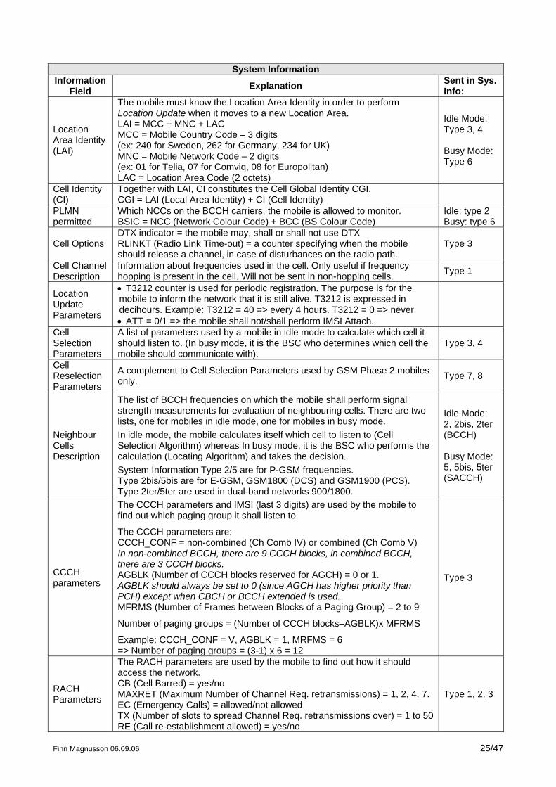
System Information
Information Field Explanation Sent in Sys.
Info:
Location Area Identity (LAI)
The mobile must know the Location Area Identity in order to perform Location Update when it moves to a new Location Area. LAI = MCC + MNC + LAC MCC = Mobile Country Code – 3 digits (ex: 240 for Sweden, 262 for Germany, 234 for UK) MNC = Mobile Network Code – 2 digits (ex: 01 for Telia, 07 for Comviq, 08 for Europolitan) LAC = Location Area Code (2 octets)
Idle Mode: Type 3, 4 Busy Mode: Type 6
Cell Identity (CI)
Together with LAI, CI constitutes the Cell Global Identity CGI. CGI = LAI (Local Area Identity) + CI (Cell Identity)
PLMN permitted
Which NCCs on the BCCH carriers, the mobile is allowed to monitor. BSIC = NCC (Network Colour Code) + BCC (BS Colour Code)
Idle: type 2 Busy: type 6
Cell Options DTX indicator = the mobile may, shall or shall not use DTX RLINKT (Radio Link Time-out) = a counter specifying when the mobile should release a channel, in case of disturbances on the radio path.
Type 3
Cell Channel Description
Information about frequencies used in the cell. Only useful if frequency hopping is present in the cell. Will not be sent in non-hopping cells. Type 1
Location Update Parameters
• T3212 counter is used for periodic registration. The purpose is for the mobile to inform the network that it is still alive. T3212 is expressed in decihours. Example: T3212 = 40 => every 4 hours. T3212 = 0 => never • ATT = 0/1 => the mobile shall not/shall perform IMSI Attach.
Cell Selection Parameters
A list of parameters used by a mobile in idle mode to calculate which cell it should listen to. (In busy mode, it is the BSC who determines which cell the mobile should communicate with).
Type 3, 4
Cell Reselection Parameters
A complement to Cell Selection Parameters used by GSM Phase 2 mobiles only. Type 7, 8
Neighbour Cells Description
The list of BCCH frequencies on which the mobile shall perform signal strength measurements for evaluation of neighbouring cells. There are two lists, one for mobiles in idle mode, one for mobiles in busy mode. In idle mode, the mobile calculates itself which cell to listen to (Cell Selection Algorithm) whereas In busy mode, it is the BSC who performs the calculation (Locating Algorithm) and takes the decision. System Information Type 2/5 are for P-GSM frequencies. Type 2bis/5bis are for E-GSM, GSM1800 (DCS) and GSM1900 (PCS). Type 2ter/5ter are used in dual-band networks 900/1800.
Idle Mode: 2, 2bis, 2ter (BCCH) Busy Mode: 5, 5bis, 5ter (SACCH)
CCCH parameters
The CCCH parameters and IMSI (last 3 digits) are used by the mobile to find out which paging group it shall listen to.
The CCCH parameters are: CCCH_CONF = non-combined (Ch Comb IV) or combined (Ch Comb V) In non-combined BCCH, there are 9 CCCH blocks, in combined BCCH, there are 3 CCCH blocks. AGBLK (Number of CCCH blocks reserved for AGCH) = 0 or 1. AGBLK should always be set to 0 (since AGCH has higher priority than PCH) except when CBCH or BCCH extended is used. MFRMS (Number of Frames between Blocks of a Paging Group) = 2 to 9
Number of paging groups = (Number of CCCH blocks–AGBLK)x MFRMS
Example: CCCH_CONF = V, AGBLK = 1, MRFMS = 6 => Number of paging groups = (3-1) x 6 = 12
Type 3
RACH Parameters
The RACH parameters are used by the mobile to find out how it should access the network. CB (Cell Barred) = yes/no MAXRET (Maximum Number of Channel Req. retransmissions) = 1, 2, 4, 7. EC (Emergency Calls) = allowed/not allowed TX (Number of slots to spread Channel Req. retransmissions over) = 1 to 50 RE (Call re-establishment allowed) = yes/no
Type 1, 2, 3
Finn Magnusson 06.09.06 26/47
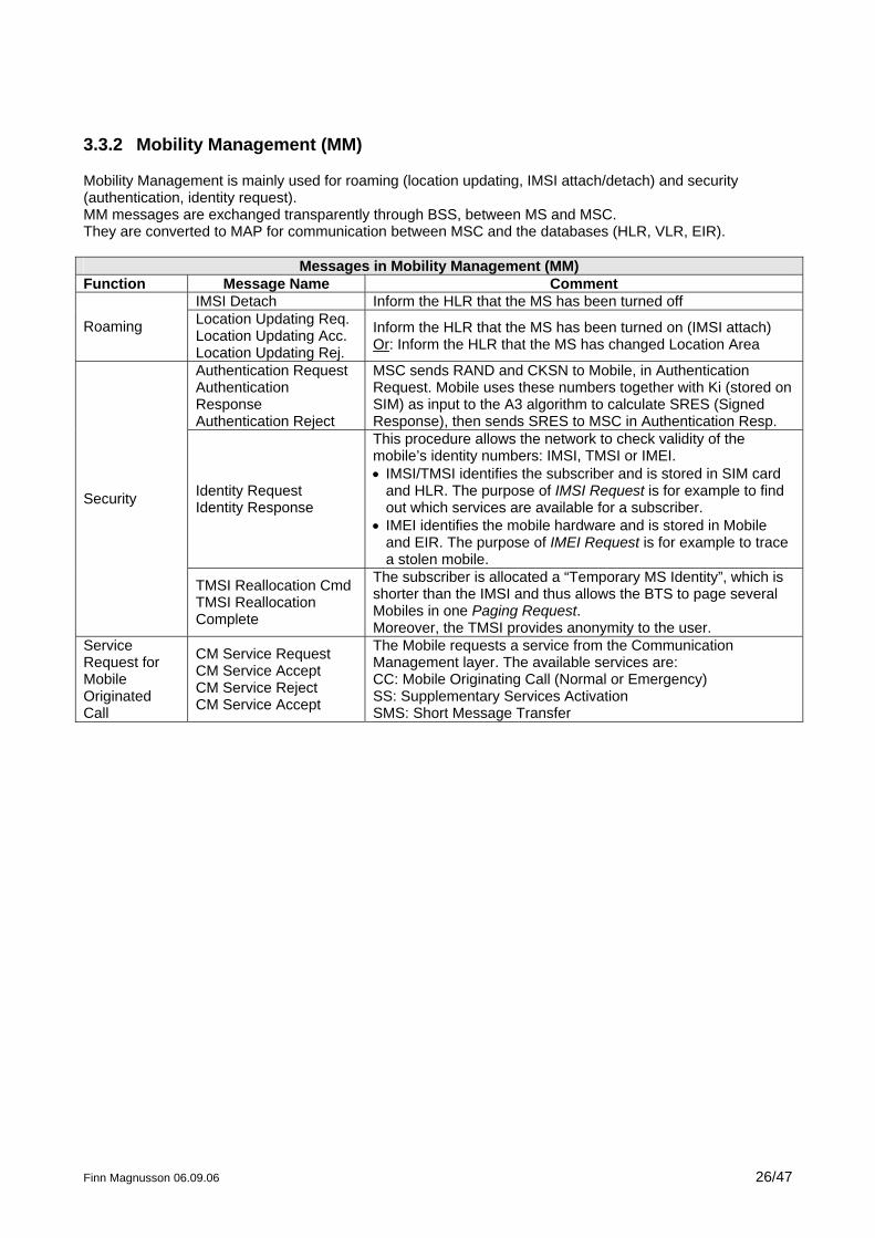
3.3.2 Mobility Management (MM)
Mobility Management is mainly used for roaming (location updating, IMSI attach/detach) and security (authentication, identity request). MM messages are exchanged transparently through BSS, between MS and MSC. They are converted to MAP for communication between MSC and the databases (HLR, VLR, EIR).
Messages in Mobility Management (MM) Function Message Name Comment
IMSI Detach Inform the HLR that the MS has been turned off
Roaming Location Updating Req. Location Updating Acc. Location Updating Rej.
Inform the HLR that the MS has been turned on (IMSI attach) Or: Inform the HLR that the MS has changed Location Area
Authentication Request Authentication Response Authentication Reject
MSC sends RAND and CKSN to Mobile, in Authentication Request. Mobile uses these numbers together with Ki (stored on SIM) as input to the A3 algorithm to calculate SRES (Signed Response), then sends SRES to MSC in Authentication Resp.
Identity Request Identity Response
This procedure allows the network to check validity of the mobile’s identity numbers: IMSI, TMSI or IMEI. • IMSI/TMSI identifies the subscriber and is stored in SIM card
and HLR. The purpose of IMSI Request is for example to find out which services are available for a subscriber.
• IMEI identifies the mobile hardware and is stored in Mobile and EIR. The purpose of IMEI Request is for example to trace a stolen mobile.
Security
TMSI Reallocation Cmd TMSI Reallocation Complete
The subscriber is allocated a “Temporary MS Identity”, which is shorter than the IMSI and thus allows the BTS to page several Mobiles in one Paging Request. Moreover, the TMSI provides anonymity to the user.
Service Request for Mobile Originated Call
CM Service Request CM Service Accept CM Service Reject CM Service Accept
The Mobile requests a service from the Communication Management layer. The available services are: CC: Mobile Originating Call (Normal or Emergency) SS: Supplementary Services Activation SMS: Short Message Transfer
Finn Magnusson 06.09.06 27/47
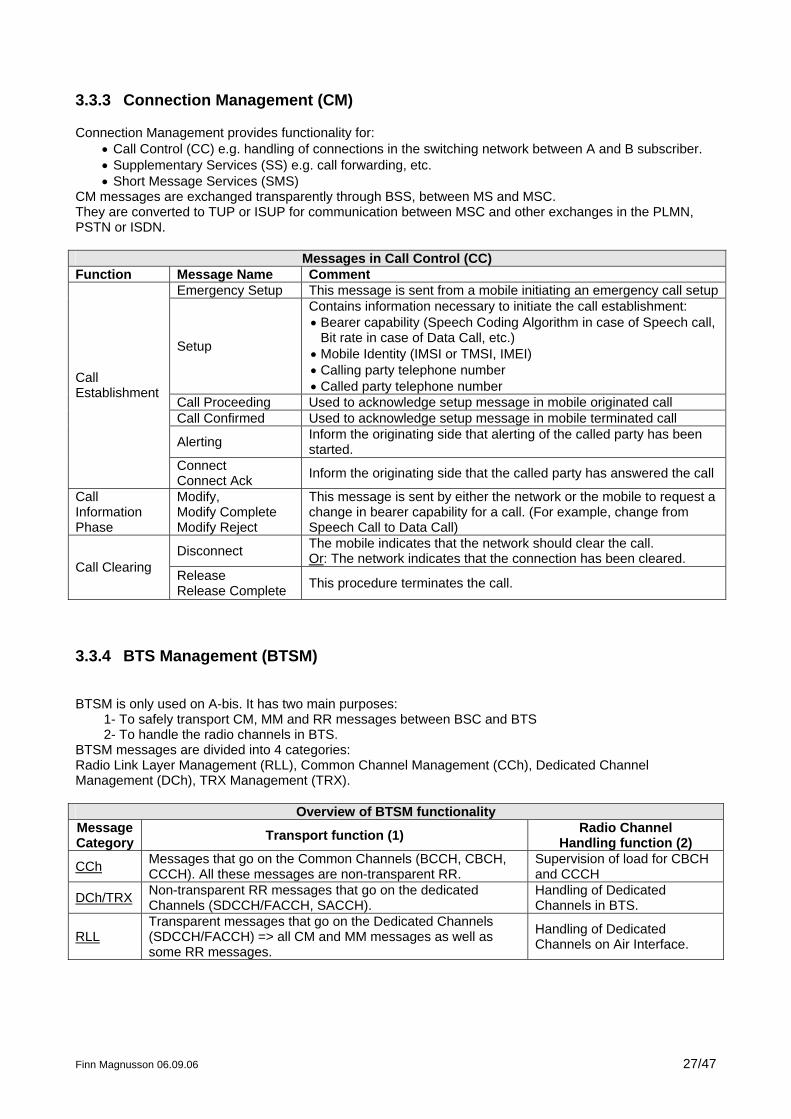
3.3.3 Connection Management (CM)
Connection Management provides functionality for: • Call Control (CC) e.g. handling of connections in the switching network between A and B subscriber. • Supplementary Services (SS) e.g. call forwarding, etc. • Short Message Services (SMS)
CM messages are exchanged transparently through BSS, between MS and MSC. They are converted to TUP or ISUP for communication between MSC and other exchanges in the PLMN, PSTN or ISDN.
Messages in Call Control (CC) Function Message Name Comment
Emergency Setup This message is sent from a mobile initiating an emergency call setup
Setup
Contains information necessary to initiate the call establishment: • Bearer capability (Speech Coding Algorithm in case of Speech call,
Bit rate in case of Data Call, etc.) • Mobile Identity (IMSI or TMSI, IMEI) • Calling party telephone number • Called party telephone number
Call Proceeding Used to acknowledge setup message in mobile originated call Call Confirmed Used to acknowledge setup message in mobile terminated call
Alerting Inform the originating side that alerting of the called party has been started.
Call Establishment
Connect Connect Ack Inform the originating side that the called party has answered the call
Call Information Phase
Modify, Modify Complete Modify Reject
This message is sent by either the network or the mobile to request a change in bearer capability for a call. (For example, change from Speech Call to Data Call)
Disconnect The mobile indicates that the network should clear the call. Or: The network indicates that the connection has been cleared. Call Clearing Release
Release Complete This procedure terminates the call.
3.3.4 BTS Management (BTSM)
BTSM is only used on A-bis. It has two main purposes:
1- To safely transport CM, MM and RR messages between BSC and BTS 2- To handle the radio channels in BTS.
BTSM messages are divided into 4 categories: Radio Link Layer Management (RLL), Common Channel Management (CCh), Dedicated Channel Management (DCh), TRX Management (TRX).
Overview of BTSM functionality Message Category Transport function (1) Radio Channel
Handling function (2)
CCh Messages that go on the Common Channels (BCCH, CBCH, CCCH). All these messages are non-transparent RR.
Supervision of load for CBCH and CCCH
DCh/TRX Non-transparent RR messages that go on the dedicated Channels (SDCCH/FACCH, SACCH).
Handling of Dedicated Channels in BTS.
RLLTransparent messages that go on the Dedicated Channels (SDCCH/FACCH) => all CM and MM messages as well as some RR messages.
Handling of Dedicated Channels on Air Interface.
Finn Magnusson 06.09.06 28/47
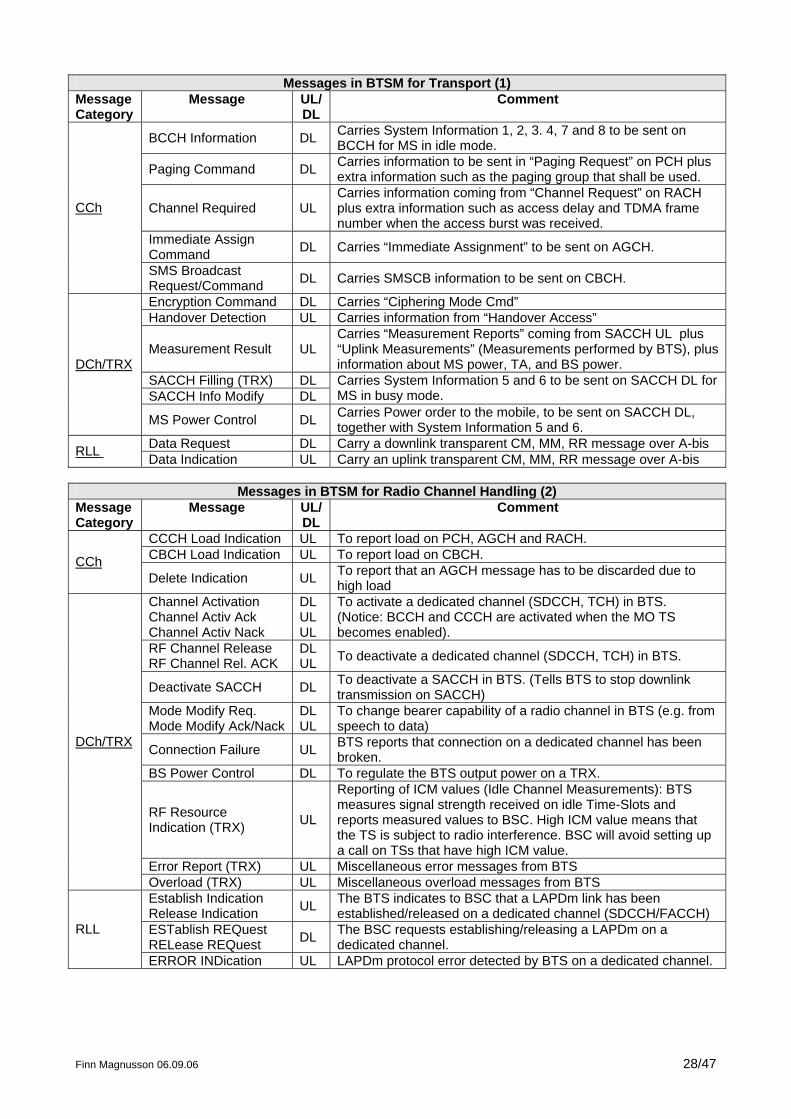
Messages in BTSM for Transport (1) Message Category
Message UL/DL
Comment
BCCH Information DL Carries System Information 1, 2, 3. 4, 7 and 8 to be sent on BCCH for MS in idle mode.
Paging Command DL Carries information to be sent in “Paging Request” on PCH plus extra information such as the paging group that shall be used.
Channel Required UL Carries information coming from “Channel Request” on RACH plus extra information such as access delay and TDMA frame number when the access burst was received.
Immediate Assign Command DL Carries “Immediate Assignment” to be sent on AGCH.
CCh
SMS Broadcast Request/Command DL Carries SMSCB information to be sent on CBCH.
Encryption Command DL Carries “Ciphering Mode Cmd” Handover Detection UL Carries information from “Handover Access”
Measurement Result UL Carries “Measurement Reports” coming from SACCH UL plus “Uplink Measurements” (Measurements performed by BTS), plus information about MS power, TA, and BS power.
SACCH Filling (TRX) DL SACCH Info Modify DL
Carries System Information 5 and 6 to be sent on SACCH DL for MS in busy mode.
DCh/TRX
MS Power Control DL Carries Power order to the mobile, to be sent on SACCH DL, together with System Information 5 and 6.
Data Request DL Carry a downlink transparent CM, MM, RR message over A-bis RLL Data Indication UL Carry an uplink transparent CM, MM, RR message over A-bis
Messages in BTSM for Radio Channel Handling (2) Message Category
Message UL/DL
Comment
CCCH Load Indication UL To report load on PCH, AGCH and RACH. CBCH Load Indication UL To report load on CBCH. CChDelete Indication UL To report that an AGCH message has to be discarded due to
high load Channel Activation Channel Activ Ack Channel Activ Nack
DL UL UL
To activate a dedicated channel (SDCCH, TCH) in BTS. (Notice: BCCH and CCCH are activated when the MO TS becomes enabled).
RF Channel Release RF Channel Rel. ACK
DL UL To deactivate a dedicated channel (SDCCH, TCH) in BTS.
Deactivate SACCH DL To deactivate a SACCH in BTS. (Tells BTS to stop downlink transmission on SACCH)
Mode Modify Req. Mode Modify Ack/Nack
DL UL
To change bearer capability of a radio channel in BTS (e.g. from speech to data)
Connection Failure UL BTS reports that connection on a dedicated channel has been broken.
BS Power Control DL To regulate the BTS output power on a TRX.
RF Resource Indication (TRX) UL
Reporting of ICM values (Idle Channel Measurements): BTS measures signal strength received on idle Time-Slots and reports measured values to BSC. High ICM value means that the TS is subject to radio interference. BSC will avoid setting up a call on TSs that have high ICM value.
Error Report (TRX) UL Miscellaneous error messages from BTS
DCh/TRX
Overload (TRX) UL Miscellaneous overload messages from BTS Establish Indication Release Indication UL The BTS indicates to BSC that a LAPDm link has been
established/released on a dedicated channel (SDCCH/FACCH) ESTablish REQuest RELease REQuest DL The BSC requests establishing/releasing a LAPDm on a
dedicated channel. RLL
ERROR INDication UL LAPDm protocol error detected by BTS on a dedicated channel.
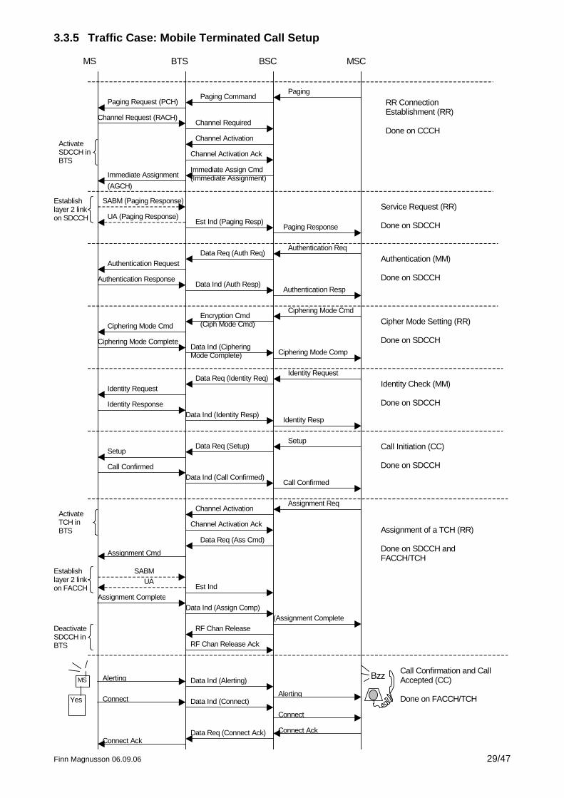
3.3.5 Traffic Case: Mobile Terminated Call Setup
MS BTS BSC MSC
Paging Request (PCH)Paging Command
Paging
Channel Request (RACH)Channel Required
Channel Activation
Channel Activation Ack
Immediate Assign Cmd(Immediate Assignment)Immediate Assignment
(AGCH)
SABM (Paging Response)
UA (Paging Response)Est Ind (Paging Resp)
Paging Response
Authentication RequestData Req (Auth Req)
Authentication Req
Authentication ResponseData Ind (Auth Resp)
Authentication Resp
Ciphering Mode CmdEncryption Cmd(Ciph Mode Cmd)
Ciphering Mode Cmd
Ciphering Mode CompleteData Ind (CipheringMode Complete) Ciphering Mode Comp
Identity RequestData Req (Identity Req)
Identity Request
Identity ResponseData Ind (Identity Resp)
Identity Resp
SetupData Req (Setup)
Setup
Call ConfirmedData Ind (Call Confirmed)
Call Confirmed
Assignment ReqChannel Activation
Channel Activation Ack
Assignment Cmd
SABMUA
Est IndAssignment Complete
Data Req (Ass Cmd)
Data Ind (Assign Comp)(Assignment Complete
RF Chan Release
RF Chan Release Ack
Connect Data Ind (Connect)
Connect
Connect AckData Req (Connect Ack)Connect Ack
RR ConnectionEstablishment (RR)
Done on CCCH
Service Request (RR)
Done on SDCCH
Authentication (MM)
Done on SDCCH
Cipher Mode Setting (RR)
Done on SDCCH
Identity Check (MM)
Done on SDCCH
Call Initiation (CC)
Done on SDCCH
Assignment of a TCH (RR)
Done on SDCCH andFACCH/TCH
Establishlayer 2 linkon SDCCH
Establishlayer 2 linkon FACCH
DeactivateSDCCH inBTS
MS
Yes
BzzAlerting Data Ind (Alerting)
Alerting
Call Confirmation and CallAccepted (CC)
Done on FACCH/TCH
ActivateSDCCH inBTS
ActivateTCH inBTS
Finn Magnusson 06.09.06 29/47
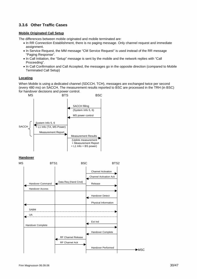
3.3.6 Other Traffic Cases
Mobile Originated Call Setup
The differences between mobile originated and mobile terminated are: • In RR Connection Establishment, there is no paging message. Only channel request and immediate
assignment. • In Service Request, the MM message “CM Service Request” is used instead of the RR message
“Paging Response”. • In Call Initiation, the “Setup” message is sent by the mobile and the network replies with “Call
Proceeding”. • In Call Confirmation and Call Accepted, the messages go in the opposite direction (compared to Mobile
Terminated Call Setup) Locating
When Mobile is using a dedicated channel (SDCCH, TCH), messages are exchanged twice per second (every 480 ms) on SACCH. The measurement results reported to BSC are processed in the TRH (in BSC) for handover decisions and power control.
MS BTS BSC
SACCH filling(System Info 5, 6)
MS power control
System Info 5, 6+ L1 Info (TA, MS Power)
Measurement Results (Uplink measurement + Measurement Report+ L1 Info + BS power)
Measurement Report
SACCH
Handover MS BTS1 BSC BTS2
Channel Activation
Handover Command
Handover Access
Release
Channel Activation Ack
Data Req (Hand Cmd)
Handover Detect
Physical Information
SABM
UA
Est IndHandover Complete
Handover Complete
RF Channel Release
RF Channel Ack
Handover PerformedMSC
Finn Magnusson 06.09.06 30/47
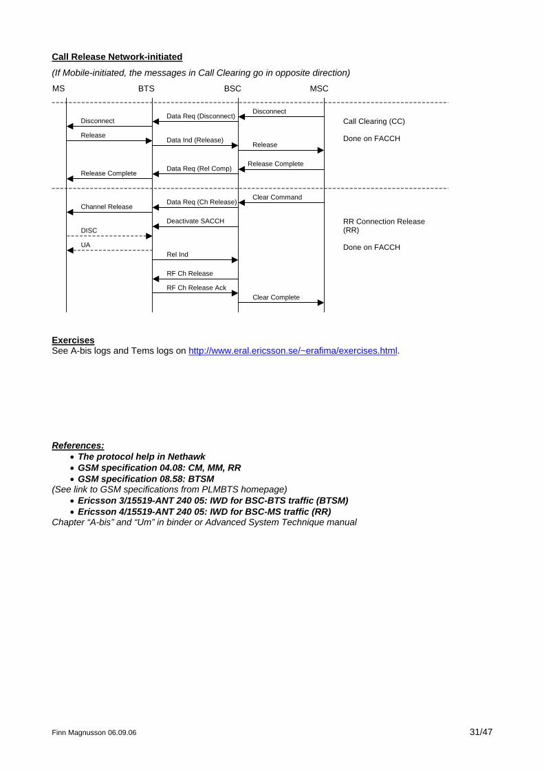
Call Release Network-initiated
(If Mobile-initiated, the messages in Call Clearing go in opposite direction)
MS BTS BSC MSC
DisconnectData Req (Disconnect)
Disconnect
Release
Call Clearing (CC)
Done on FACCHData Ind (Release)Release
Release CompleteData Req (Rel Comp)
Release Complete
Clear CommandData Req (Ch Release)
Channel Release
Deactivate SACCHDISC
UARel Ind
RF Ch Release
RF Ch Release AckClear Complete
RR Connection Release(RR)
Done on FACCH
Exercises See A-bis logs and Tems logs on http://www.eral.ericsson.se/~erafima/exercises.html. References:
• The protocol help in Nethawk • GSM specification 04.08: CM, MM, RR • GSM specification 08.58: BTSM
(See link to GSM specifications from PLMBTS homepage) • Ericsson 3/15519-ANT 240 05: IWD for BSC-BTS traffic (BTSM) • Ericsson 4/15519-ANT 240 05: IWD for BSC-MS traffic (RR)
Chapter “A-bis” and “Um” in binder or Advanced System Technique manual
Finn Magnusson 06.09.06 31/47
Finn Magnusson 06.09.06 32/47
3.4 LAPD
LAPD (Link Access Procedure on D-channel) is a layer 2 protocol defined by ISDN. (In ISDN, signalling channels are called “D-channels”, while traffic channels are called “B-channels”). In GSM, LAPD is used on A-bis for signalling link management and safe transport of layer 3 messages (O&M and Traffic). LAPD Frame format: Flag Address Control Information (Layer 3 message) Check Sum 8 bits (01111110)
16 bits 16 bits Up to 249 bytes, usually under 40 bytes 16 bits
The flag, address field, control field, and check sum constitute the Layer 2 part of the message.
3.4.1 Address Field
The address field consists of two main information elements: • SAPI (Service Access Point Identifier) identifies the logical link, i.e. the kind of layer 3 message that is
being sent (O&M or Traffic Management). There are two logical links: RSL (SAPI=0) and OML (SAPI=62).
RSL (Radio Signalling Link) is used to carry Traffic messages (CM, MM, RR, BTSM). OML (O&M Link) is used for TG O&M (RBS 200 and 2000).
• TEI (Terminal Endpoint Identifier) identifies the physical link, i.e. to which unit in the BTS, the message is destined.
TEI = 0 for TRX/TRU 0; TEI = 1 for TRX/TRU 1, etc. TEI = 58 for TGC (TG Controller, only RBS 200) TEI = 62 for DXU (Only RBS 2000)
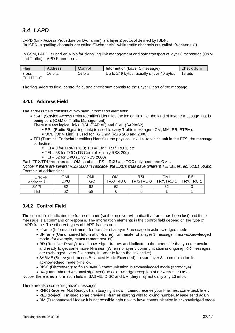
Each TRX/TRU requires one OML and one RSL. DXU and TGC only need one OML. Notice: if there are several RBS 2000 in cascade, the DXUs shall have different TEI values, eg. 62,61,60,etc. Example of addressing:
Link → Address ↓
OML DXU
OML TGC
OML TRX/TRU 0
RSL TRX/TRU 0
OML TRX/TRU 1
RSL TRX/TRU 1
SAPI 62 62 62 0 62 0 TEI 62 58 0 0 1 1
3.4.2 Control Field
The control field indicates the frame number (so the receiver will notice if a frame has been lost) and if the message is a command or response. The information elements in the control field depend on the type of LAPD frame. The different types of LAPD frames are:
• I-frame (Information-frame): for transfer of a layer 3 message in acknowledged mode • UI-frame (Unnumbered Information-frame): for transfer of a layer 3 message in non-acknowledged
mode (for example, measurement results) • RR (Receiver Ready): to acknowledge I-frames and indicate to the other side that you are awake
and ready to get some more I-frames. (When no layer 3 communication is ongoing, RR messages are exchanged every 2 seconds, in order to keep the link active).
• SABME (Set Asynchronous Balanced Mode Extended): to start layer 3 communication in acknowledged mode (=hello).
• DISC (Disconnect): to finish layer 3 communication in acknowledged mode (=goodbye). • UA (Unnumbered Acknowledgement): to acknowledge reception of a SABME or DISC
Notice: there is no information field in SABME, DISC and UA (they may not carry any L3 info). There are also some “negative” messages:
• RNR (Receiver Not Ready): I am busy right now, I cannot receive your I-frames, come back later. • REJ (Reject): I missed some previous I-frames starting with following number. Please send again. • DM (Disconnected Mode): it is not possible right now to have communication in acknowledged mode

3.5 LAPDm
LAPDm is a layer 2 GSM protocol used on all Um signalling channels except RACH, FCH and SCH. It is based on LAPD but with some differences: In LAPDm, the frames are much shorter (maximum 23 bytes) due to the limited space on air interface.
• The address field only uses SAPI (0 for CC, MM and RR, 3 for SMS). There is no need for TEI (only one mobile is addressed on a dedicated channel and all mobiles on a broadcast channel)
• There is no check sum; error detection -and correction- is provided in layer 1 • The SABME message is called “SABM” instead of “SABME”. • There are no RNR or REJ frames. • SABM and UA may carry some L3 information (this is called “piggy backing”).
SAPI: - 0 = CM, MM, RR - 3 = SMS
Type of frames: - SABM, DISC, UA - I-frame, RR - UI-frame
Is there more info inthis message?
MS powerTA
Reference: chapter “A-bis” and “Um” in binder or Advanced System Technique manual LAPD: GSM Specification 08.56 or ITU-T Q.921 or ETS 300625 LAPDm: GSM Specification 04.05 and 04.06
Finn Magnusson 06.09.06 33/47
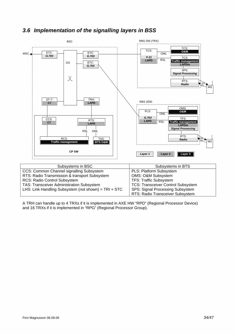
3.6 Implementation of the signalling layers in BSS
CP SW
GS
ETC:G.703
ST-7:C7
TRH:LAPD
CCS:C7
RCS:Traffic management
TAS:BTS O&M
OML
TCS:
V.11LAPD
TCS:O&M
TCS:Traffic management
LAPDm
RBS 200 (TRX)
ETC:G.703
MSC
BSC
ETC:G.703
RTS:Radio
SPS:Signal Processing
RSL
OML
MS
Layer 1
RSL
RTS:LAPD
Layer 2 Layer 3
PLS:
G.703LAPD
OMS:O&M
TFS:Traffic management
LAPDmSignal Processing
RBS 2000
RSL
OML
MS
RTS:Radio
Subsystems in BSC Subsystems in BTS CCS: Common Channel signalling Subsystem RTS: Radio Transmission & transport Subsystem RCS: Radio Control Subsystem TAS: Transceiver Administration Subsystem LHS: Link Handling Subsystem (not shown) = TRI + STC
PLS: Platform Subsystem OMS: O&M Subsystem TFS: Traffic Subsystem TCS: Transceiver Control Subsystem SPS: Signal Processing Subsystem RTS: Radio Transceiver Subsystem
A TRH can handle up to 4 TRXs if it is implemented in AXE HW “RPD” (Regional Processor Device) and 16 TRXs if it is implemented in “RPG” (Regional Processor Group).
Finn Magnusson 06.09.06 34/47
Finn Magnusson 06.09.06 35/47
4 Architecture of the Radio Network
4.1 Introduction: dB concept
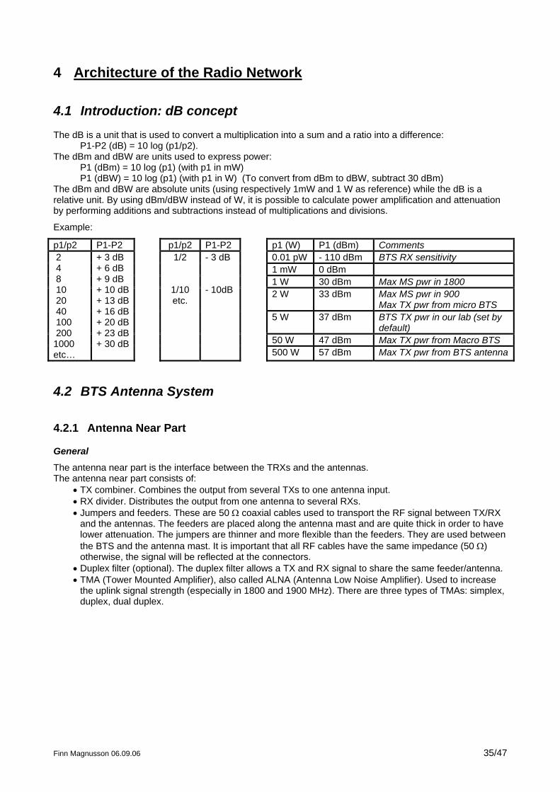
The dB is a unit that is used to convert a multiplication into a sum and a ratio into a difference: P1-P2 (dB) = 10 log (p1/p2).
The dBm and dBW are units used to express power: P1 (dBm) = 10 log (p1) (with p1 in mW) P1 (dBW) = 10 log (p1) (with p1 in W) (To convert from dBm to dBW, subtract 30 dBm)
The dBm and dBW are absolute units (using respectively 1mW and 1 W as reference) while the dB is a relative unit. By using dBm/dBW instead of W, it is possible to calculate power amplification and attenuation by performing additions and subtractions instead of multiplications and divisions.
Example:
p1/p2 P1-P2 p1/p2 P1-P2 p1 (W) P1 (dBm) Comments 0.01 pW - 110 dBm BTS RX sensitivity 1 mW 0 dBm 1 W 30 dBm Max MS pwr in 1800 2 W 33 dBm Max MS pwr in 900
Max TX pwr from micro BTS 5 W 37 dBm BTS TX pwr in our lab (set by
default) 50 W 47 dBm Max TX pwr from Macro BTS
2 4 8 10 20 40 100 200 1000 etc…
+ 3 dB + 6 dB + 9 dB + 10 dB + 13 dB + 16 dB + 20 dB + 23 dB + 30 dB
1/2
1/10 etc.
- 3 dB - 10dB
500 W 57 dBm Max TX pwr from BTS antenna
4.2 BTS Antenna System
4.2.1 Antenna Near Part
General
The antenna near part is the interface between the TRXs and the antennas. The antenna near part consists of:
• TX combiner. Combines the output from several TXs to one antenna input. • RX divider. Distributes the output from one antenna to several RXs. • Jumpers and feeders. These are 50 Ω coaxial cables used to transport the RF signal between TX/RX
and the antennas. The feeders are placed along the antenna mast and are quite thick in order to have lower attenuation. The jumpers are thinner and more flexible than the feeders. They are used between the BTS and the antenna mast. It is important that all RF cables have the same impedance (50 Ω) otherwise, the signal will be reflected at the connectors.
• Duplex filter (optional). The duplex filter allows a TX and RX signal to share the same feeder/antenna. • TMA (Tower Mounted Amplifier), also called ALNA (Antenna Low Noise Amplifier). Used to increase
the uplink signal strength (especially in 1800 and 1900 MHz). There are three types of TMAs: simplex, duplex, dual duplex.
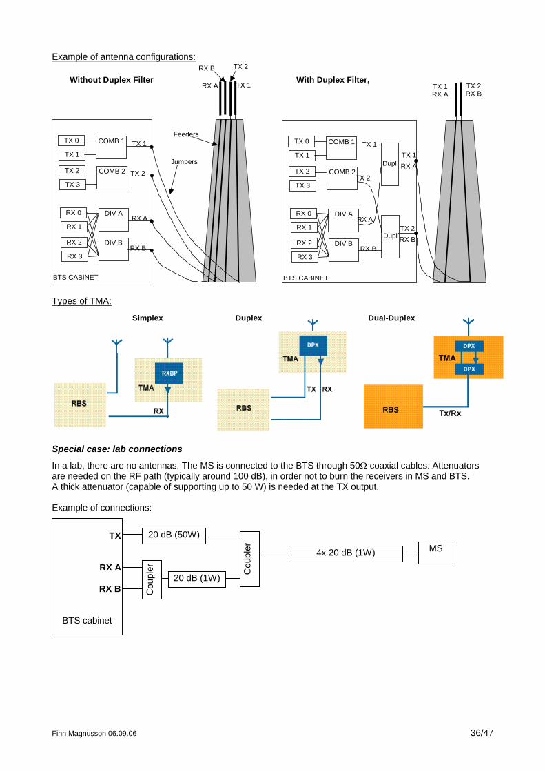
Example of antenna configurations:
BTS CABINET
TX 0 COMB 1
TX 1
TX 2 COMB 2
TX 3
RX 0 DIV A
RX 1
RX 2 DIV B
RX 3
RX A
RX B TX 2
TX 1
TX 1
TX 2
RX B
RX A
Jumpers
Feeders
BTS CABINET
TX 0 COMB 1
TX 1
TX 2 COMB 2
TX 3
RX 0 DIV A
RX 1
RX 2 DIV B
RX 3
TX 1RX A
TX 1
TX 2RX B
TX 2
RX B
RX A
Without Duplex Filter With Duplex Filter,
Dupl
Dupl
TX 1RX A
TX 2RX B
Finn Magnusson 06.09.06 36/47
Types of TMA:
Simplex Duplex Dual-Duplex
Special case: lab connections
In a lab, there are no antennas. The MS is connected to the BTS through 50Ω coaxial cables. Attenuators are needed on the RF path (typically around 100 dB), in order not to burn the receivers in MS and BTS. A thick attenuator (capable of supporting up to 50 W) is needed at the TX output. Example of connections:
TX
RX A
RX B
BTS cabinet
Cou
pler
4x 20 dB (1W) MS
20 dB (1W)
Cou
pler
20 dB (50W)
4.2.2 Antenna Types
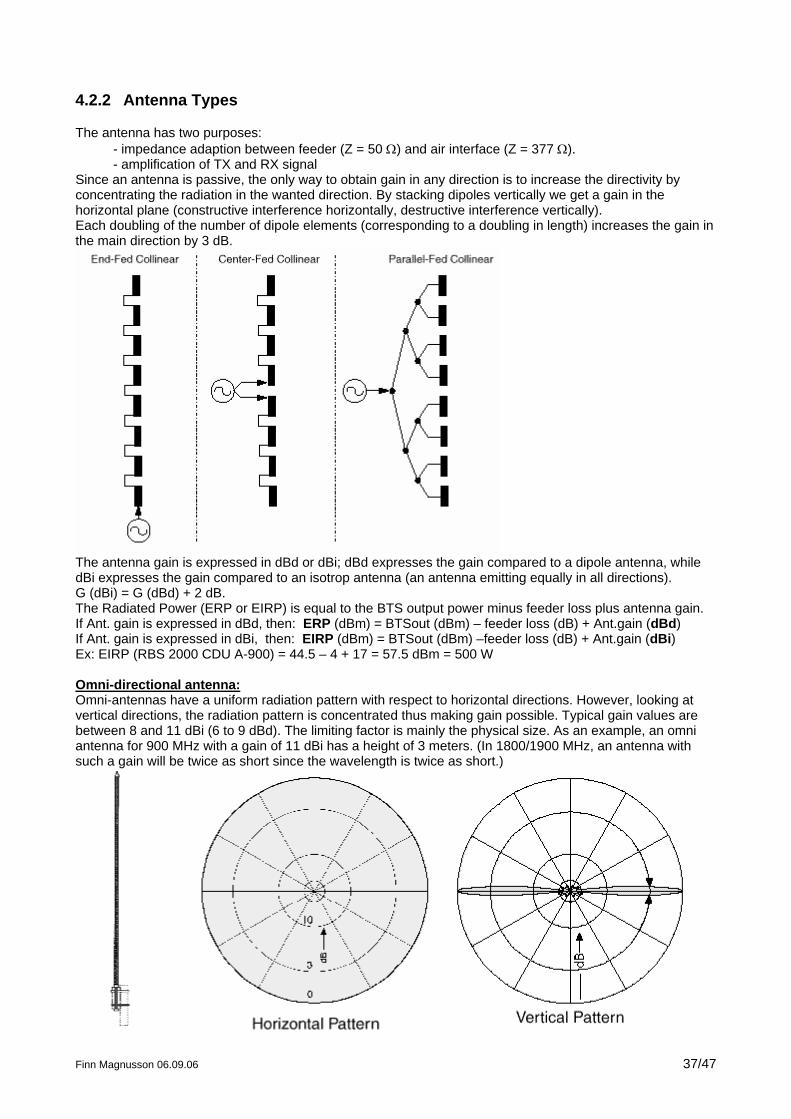
The antenna has two purposes: - impedance adaption between feeder (Z = 50 Ω) and air interface (Z = 377 Ω). - amplification of TX and RX signal
Since an antenna is passive, the only way to obtain gain in any direction is to increase the directivity by concentrating the radiation in the wanted direction. By stacking dipoles vertically we get a gain in the horizontal plane (constructive interference horizontally, destructive interference vertically). Each doubling of the number of dipole elements (corresponding to a doubling in length) increases the gain in the main direction by 3 dB.
The antenna gain is expressed in dBd or dBi; dBd expresses the gain compared to a dipole antenna, while dBi expresses the gain compared to an isotrop antenna (an antenna emitting equally in all directions). G (dBi) = G (dBd) + 2 dB. The Radiated Power (ERP or EIRP) is equal to the BTS output power minus feeder loss plus antenna gain. If Ant. gain is expressed in dBd, then: ERP (dBm) = BTSout (dBm) – feeder loss (dB) + Ant.gain (dBd) If Ant. gain is expressed in dBi, then: EIRP (dBm) = BTSout (dBm) –feeder loss (dB) + Ant.gain (dBi) Ex: EIRP (RBS 2000 CDU A-900) = 44.5 – 4 + 17 = 57.5 dBm = 500 W Omni-directional antenna: Omni-antennas have a uniform radiation pattern with respect to horizontal directions. However, looking at vertical directions, the radiation pattern is concentrated thus making gain possible. Typical gain values are between 8 and 11 dBi (6 to 9 dBd). The limiting factor is mainly the physical size. As an example, an omni antenna for 900 MHz with a gain of 11 dBi has a height of 3 meters. (In 1800/1900 MHz, an antenna with such a gain will be twice as short since the wavelength is twice as short.)
Finn Magnusson 06.09.06 37/47
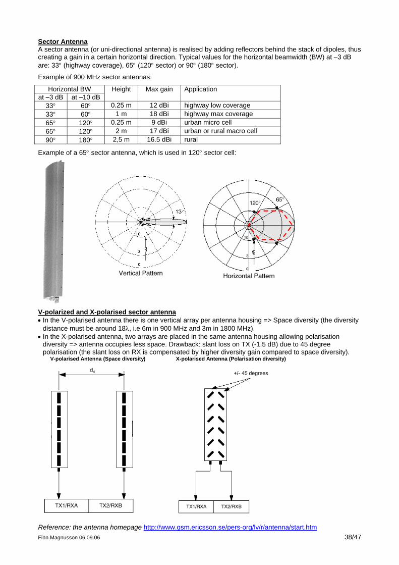
Sector Antenna A sector antenna (or uni-directional antenna) is realised by adding reflectors behind the stack of dipoles, thus creating a gain in a certain horizontal direction. Typical values for the horizontal beamwidth (BW) at –3 dB are: 33° (highway coverage), 65° (120° sector) or 90° (180° sector).
Example of 900 MHz sector antennas:
Horizontal BW at –3 dB at –10 dB
Height Max gain Application
33° 60° 0.25 m 12 dBi highway low coverage 33° 60° 1 m 18 dBi highway max coverage 65° 120° 0.25 m 9 dBi urban micro cell 65° 120° 2 m 17 dBi urban or rural macro cell 90° 180° 2,5 m 16.5 dBi rural
Example of a 65° sector antenna, which is used in 120° sector cell:
V-polarized and X-polarised sector antenna • In the V-polarised antenna there is one vertical array per antenna housing => Space diversity (the diversity
distance must be around 18λ, i.e 6m in 900 MHz and 3m in 1800 MHz). • In the X-polarised antenna, two arrays are placed in the same antenna housing allowing polarisation
diversity => antenna occupies less space. Drawback: slant loss on TX (-1.5 dB) due to 45 degree polarisation (the slant loss on RX is compensated by higher diversity gain compared to space diversity).
V-polarised Antenna (Space diversity) X-polarised Antenna (Polarisation diversity)
+/- 45 degrees
Reference: the antenna homepage http://www.gsm.ericsson.se/pers-org/lv/r/antenna/start.htm Finn Magnusson 06.09.06 38/47
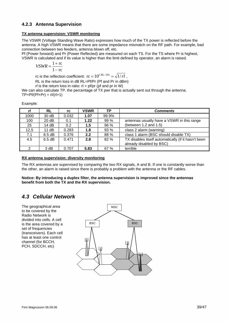
4.2.3 Antenna Supervision
TX antenna supervision: VSWR monitoring
The VSWR (Voltage Standing Wave Ratio) expresses how much of the TX power is reflected before the antenna. A high VSWR means that there are some impedance mismatch on the RF path. For example, bad connection between two feeders, antenna blown off, etc. Pf (Power forward) and Pr (Power Reflected) are measured on each TS. For the TS where Pr is highest, VSWR is calculated and if its value is higher than the limit defined by operator, an alarm is raised.
rc1rc1
−+
=VSWR
rc is the reflection coefficient: rl/110rc )20/-RL( == , RL is the return loss in dB RL=Pf/Pr (Pf and Pr in dBm) rl is the return loss in ratio: rl = pf/pr (pf and pr in W)
We can also calculate TP, the percentage of TX pwr that is actually sent out through the antenna. TP=Pf/(Pf+Pr) = rl/(rl+1) Example:
rl RL rc VSWR TP Comments 1000 30 dB 0.032 1.07 99.9% 100 20 dB 0.1 1.22 99 % 25 14 dB 0.2 1.5 96 %
antennas usually have a VSWR in this range (between 1.2 and 1.5)
12,5 11 dB 0.283 1.8 93 % class 2 alarm (warning) 7.1 8.5 dB 0.376 2.2 88 % class 1 alarm (BSC should disable TX) 4.5 6.5 dB 0.471 2.8 82 % TX disables itself automatically (if it hasn’t been
already disabled by BSC) 2 3 dB 0.707 5.83 67 % terrible
RX antenna supervision: diversity monitoring
The RX antennas are supervised by comparing the two RX signals, A and B. If one is constantly worse than the other, an alarm is raised since there is probably a problem with the antenna or the RF cables. Notice: By introducing a duplex filter, the antenna supervision is improved since the antennas benefit from both the TX and the RX supervision.
4.3 Cellular Network
The geographical area to be covered by the Radio Network is divided into cells. A cell is the area covered by a set of frequencies (transceivers). Each cell has at least one control channel (for BCCH, PCH, SDCCH, etc)
BSC BSC
MSC
Finn Magnusson 06.09.06 39/47
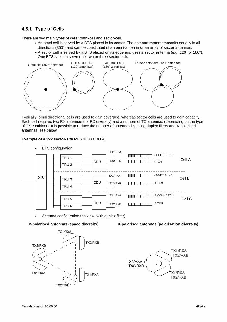
4.3.1 Type of Cells
There are two main types of cells: omni-cell and sector-cell. • An omni cell is served by a BTS placed in its center. The antenna system transmits equally in all
directions (360°) and can be constituted of an omni-antenna or an array of sector antennas. • A sector cell is served by a BTS placed on its edge and uses a sector antenna (e.g. 120° or 180°).
One BTS site can serve one, two or three sector cells.
Omni-site (360° antenna)Two-sector-site(180° antennas)
Three-sector-site (120° antennas)One-sector-site(120° antennas)
Typically, omni directional cells are used to gain coverage, whereas sector cells are used to gain capacity. Each cell requires two RX antennas (for RX diversity) and a number of TX antennas (depending on the type of TX combiner). It is possible to reduce the number of antennas by using duplex filters and X-polarised antennas, see below. Example of a 3x2 sector-site RBS 2000 CDU A
Finn Magnusson 06.09.06 40/47
• BTS configuration
DXU
TRU 1
TRU 2
TRU 3
TRU 4
TRU 6
TRU 5
CDU
CDU
CDU
TX1/RXA
TX2/RXB
TX1/RXA
TX2/RXB
TX1/RXA
TX2/RXB
2 CCH+ 6 TCH
2 CCH+ 6 TCH
2 CCH+ 6 TCH
8 TCH
8 TCH
8 TCH
Cell A
Cell B
Cell C
• Antenna configuration top view (with duplex filter)
V-polarised antennas (space diversity) X-polarised antennas (polarisation diversity)
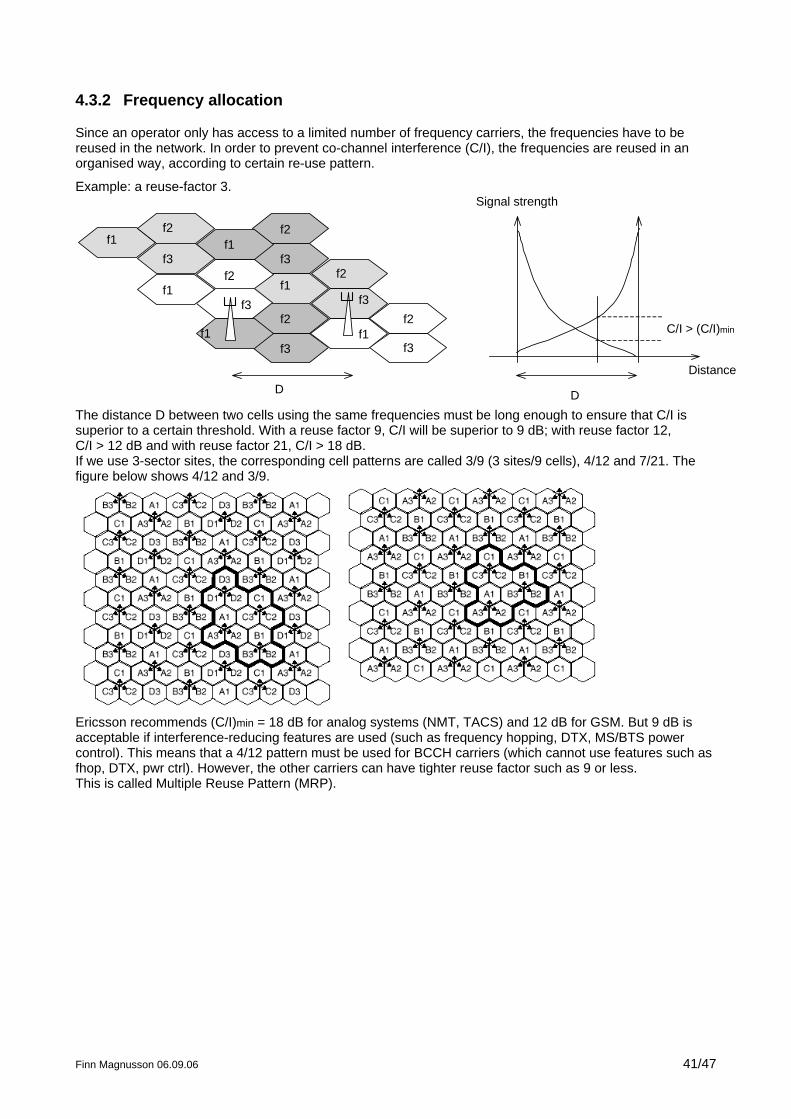
4.3.2 Frequency allocation
Since an operator only has access to a limited number of frequency carriers, the frequencies have to be reused in the network. In order to prevent co-channel interference (C/I), the frequencies are reused in an organised way, according to certain re-use pattern.
Example: a reuse-factor 3.
f1f2
f3
f1f2
f3
f2
f3
f1
f3
f2f1
f1f2
f3
f1
f2
f3f1 C/I > (C/I)min
Signal strength
Distance
DD
The distance D between two cells using the same frequencies must be long enough to ensure that C/I is superior to a certain threshold. With a reuse factor 9, C/I will be superior to 9 dB; with reuse factor 12, C/I > 12 dB and with reuse factor 21, C/I > 18 dB. If we use 3-sector sites, the corresponding cell patterns are called 3/9 (3 sites/9 cells), 4/12 and 7/21. The figure below shows 4/12 and 3/9.
Ericsson recommends (C/I)min = 18 dB for analog systems (NMT, TACS) and 12 dB for GSM. But 9 dB is acceptable if interference-reducing features are used (such as frequency hopping, DTX, MS/BTS power control). This means that a 4/12 pattern must be used for BCCH carriers (which cannot use features such as fhop, DTX, pwr ctrl). However, the other carriers can have tighter reuse factor such as 9 or less. This is called Multiple Reuse Pattern (MRP).
Finn Magnusson 06.09.06 41/47
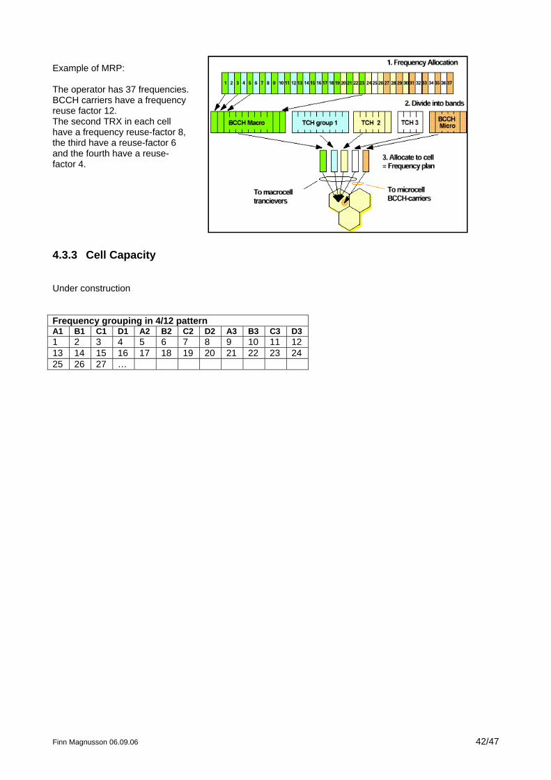
Example of MRP: The operator has 37 frequencies. BCCH carriers have a frequency reuse factor 12. The second TRX in each cell have a frequency reuse-factor 8, the third have a reuse-factor 6 and the fourth have a reuse-factor 4.
4.3.3 Cell Capacity
Under construction Frequency grouping in 4/12 pattern A1 B1 C1 D1 A2 B2 C2 D2 A3 B3 C3 D3 1 2 3 4 5 6 7 8 9 10 11 12 13 14 15 16 17 18 19 20 21 22 23 24 25 26 27 …
Finn Magnusson 06.09.06 42/47
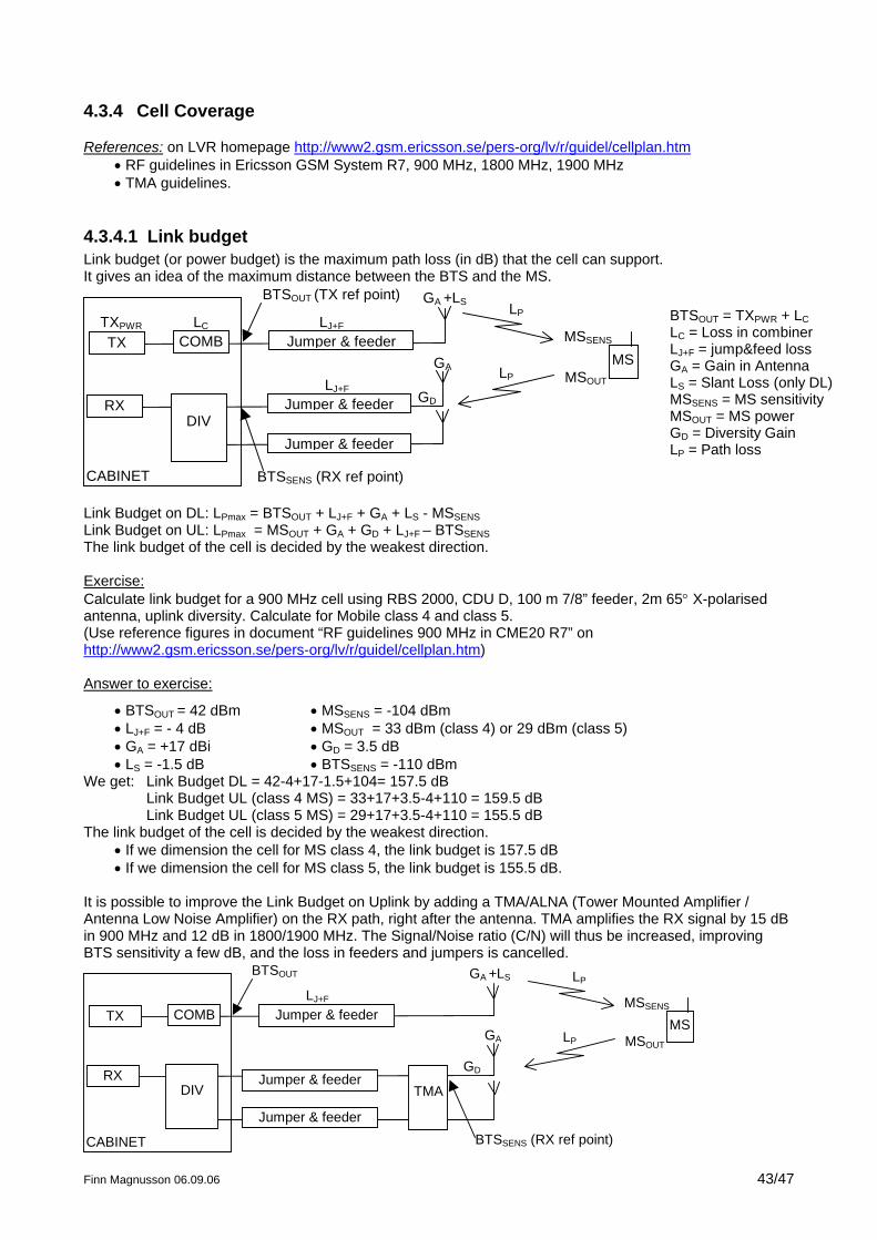
4.3.4 Cell Coverage
References: on LVR homepage http://www2.gsm.ericsson.se/pers-org/lv/r/guidel/cellplan.htm • RF guidelines in Ericsson GSM System R7, 900 MHz, 1800 MHz, 1900 MHz • TMA guidelines.
4.3.4.1 Link budget Link budget (or power budget) is the maximum path loss (in dB) that the cell can support. It gives an idea of the maximum distance between the BTS and the MS.
CABINET
TX COMB Jumper & feeder
RXDIV
Jumper & feeder
Jumper & feeder
MS
BTSOUT (TX ref point)
LC LJ+F
LJ+FMSOUT
MSSENS
GD
GA
GA +LSBTSOUT = TXPWR + LCLC = Loss in combinerLJ+F = jump&feed lossGA = Gain in AntennaLS = Slant Loss (only DL)MSSENS = MS sensitivityMSOUT = MS powerGD = Diversity GainLP = Path loss
LP
LP
BTSSENS (RX ref point)
TXPWR
Link Budget on DL: LPmax = BTSOUT + LJ+F + GA + LS - MSSENSLink Budget on UL: LPmax = MSOUT + GA + GD + LJ+F – BTSSENSThe link budget of the cell is decided by the weakest direction. Exercise: Calculate link budget for a 900 MHz cell using RBS 2000, CDU D, 100 m 7/8” feeder, 2m 65° X-polarised antenna, uplink diversity. Calculate for Mobile class 4 and class 5. (Use reference figures in document “RF guidelines 900 MHz in CME20 R7” on http://www2.gsm.ericsson.se/pers-org/lv/r/guidel/cellplan.htm) Answer to exercise:
• BTSOUT = 42 dBm • LJ+F = - 4 dB • GA = +17 dBi • LS = -1.5 dB
• MSSENS = -104 dBm • MSOUT = 33 dBm (class 4) or 29 dBm (class 5) • GD = 3.5 dB • BTSSENS = -110 dBm
We get: Link Budget DL = 42-4+17-1.5+104= 157.5 dB Link Budget UL (class 4 MS) = 33+17+3.5-4+110 = 159.5 dB Link Budget UL (class 5 MS) = 29+17+3.5-4+110 = 155.5 dB The link budget of the cell is decided by the weakest direction.
• If we dimension the cell for MS class 4, the link budget is 157.5 dB • If we dimension the cell for MS class 5, the link budget is 155.5 dB.
It is possible to improve the Link Budget on Uplink by adding a TMA/ALNA (Tower Mounted Amplifier / Antenna Low Noise Amplifier) on the RX path, right after the antenna. TMA amplifies the RX signal by 15 dB in 900 MHz and 12 dB in 1800/1900 MHz. The Signal/Noise ratio (C/N) will thus be increased, improving BTS sensitivity a few dB, and the loss in feeders and jumpers is cancelled.
CABINET
TX COMB Jumper & feeder
RXDIV
MS
BTSOUT
LJ+F
MSOUT
MSSENS
GD
GA
GA +LS LP
LP
TMAJumper & feeder
BTSSENS (RX ref point)Jumper & feeder
Finn Magnusson 06.09.06 43/47
Finn Magnusson 06.09.06 44/47
Link budget UL (for class 5 MS) becomes: LPmax = MSOUT + GA + GD – BTSSENS = 29 +17 +3.5 + 111.5 = 161 dB (Since the RX ref point is moved after TMA, we don’t count LJ+F on UL) Link Budget on Downlink can be improved by using Software Power Boost (TX-diversity) => + 3 dB This feature however requires that 2 TRXs are used for one frequency carrier so it reduces the capacity by halt. It is only appropriate when using CDU A or RBS 2302.
4.3.4.2 Power balance The goal of power balancing a cell is to determine the BTS output power in order to have the same link budget on UL and DL. LPmax (DL) = BTSOUT + LJ+F + GA + LS - MSSENSLPmax (UL) = MSOUT + GA + GD + LJ+F - BTSSENS (Without TMA) LPmax (UL) = MSOUT + GA + GD – BTSSENS (With TMA) If BTSOUT = BTSOUT(bal) , then LPmax (DL) = LPmax (UL) => BTSOUT(bal) = MSOUT + GD –LS – BTSSENS + MSSENS (Without TMA) or BTSOUT(bal) = MSOUT + GD –LS – LJ+F - BTSSENS + MSSENS (With TMA) If we take the same example as above, we get: BTSOUT(bal) without TMA BTSOUT(bal) with TMA MS class 4 33+3.5+1.5+110-104 =44 33+3.5+1.5+4+111.5-104= 49.5 MS class 5 29+3.5+1.5+110-104 = 40 29+3.5+1.5+4+111.5-104= 45.5 The Maximum BTS output power in our case is 42 dBm (CDU D 900 MHz). If we are dimensioning the cell for MS class 5, then we should not use TMA, since we cannot reach a BTS output power of 49.5 dBm. We must use max BTS output 42 dBm in order to get max coverage. If we are dimensioning the cell for MS class 4, and using TMA, then we should use max power 42 dBm to get max coverage. If we are not using TMA, then we should decrease BTS output to 40 dBm.
4.3.4.3 Cell Size To find out the cell size, the link budget shall be reduced in order to take into account environment characteristics. The following figures are valid for 900 MHz: 1-Rayleigh fading margin RF = 3 dB 2-Interference margin IF = 2 dB 3-Body loss (the head attenuates the signal) BL = 5 dB 4-Environment margin:
a- If Mobile is outdoor: • Car penetration loss (if mobile is placed inside a car) CPL = 6 dB • Log normal fading margin LNF: depends on the environment and the degree of coverage.
Environment Degree of coverage LNF(O) Dense urban 95% 6 dB Urban 95% 5 dB Surburban/Rural 95% 3 dB
b- If mobile is indoor: Environment Degree of coverage LNF(I) BPL (building
penetration loss) Dense urban 95% 9 dB 18 dB Urban 95% 8 dB 18 dB Surburban/Rural 95% 6 dB 12 dB The actual link budget LPMAX (actual) is obtained by subtracting the margins above to the theoretical link budget LPMAX (theoric) that we calculated in the previous exercise. The cell size is obtained with a complicated formula that also depends on the environment (urban or open area). See RF guidelines chap 5.1 if you are interested in seeing these formulas. Exercise:
Finn Magnusson 06.09.06 45/47
Calculate the actual link budget and cell range for the same BTS as above (no TMA), MS class 4, 95% coverage, in the following cases: a- outdoor, urban, in a car b- indoor, rural Answer: a- LPMAX(actual) = LPMAX(theoric) – RF –IF – BL – LNF(O) – CPL = 157.5 - 3 - 2 - 5 – 6 – 6 = 135.5 dB From the tables in RF guidelines, we see that: LPMAX = 135.5 dB in urban environment gives a range R≈ 2 km b- LPMAX(actual) = LPMAX(theoric) – RF –IF – BL – LNF(I) – BPL = 157.5 –3- 2- 5 – 6 –12 = 129.5 dB From the tables in RF guidelines, we see that: LPMAX = 129.5 dB in rural environment gives a range R≈ 7.5 km
Finn Magnusson 06.09.06 46/47
5 BSS Dimensioning References:
• BSC dimensioning: http://www.lmera.ericsson.se/~bscchar/ • Radio Network and Transmission network dimensioning: (LVR homepage)
Example: Dimensioning of the following BSS area
• Number of subscribers: 10 000 • Traffic per subscriber: A=nT=1x90/3600=25 mE (is equivalent to one 90 second-call per hour) • Number of frequencies: 24 • Cell pattern: 4/12 • GoS on air interface: 2% • GoS on A and A-bis: 1 %
Number of cells: Number of frequencies per cell: 24/12=2 Number of traffic channels per cell = 2x8 – 2 =14 (2 control channels) Traffic per cell = 8.2 E (according to Erlang table for 14 channels at GoS 2%) Number of subscribers per cell = 8.2/0.025 = 328 Number of cells = 10 000/328 = 30.5 = 31 To cover this BSS area, we need 31 cells with 2 TRXs in each cell. Number of sites The number of sites will be between 11 (3-sector sites) and 31 (omni-sites). If using 3-sector sites, we will use the configuration 2+2+2. Number of TRHs Number of TRXs = 31 x 2 = 62 Number of RPG-based TRHs = 62/16 = 4 (Number of RPD-based TRHs = 62/4 = 16) Number of TRAs
• If TRAs are semi-permanently connected: In this case we need one TRA channel per Um traffic channel. Number of Um traffic channels = 31 x 14 = 434 Number of TRA boards = 434 / 24 = 18
• If TRAs are in pool In this case, we consider the traffic for the whole BSS = 10 000 x 0.025 = 250 E Number of TRA channels at 2% GoS = 264 (according to Erlang table) Number of TRA boards = 264/24 = 11 Notice: there is usually 16 TRA boards per TRA magazine Number of RALT ETCs Traffic on A interface = traffic in the BSS (all the calls must go up to MSC, even calls within the same BSS) = 250 E Number of RALT devices (A RALT device is equivalent to a PCM TS on A interface) = 264 (according to Erlang table for 250 E at 2% GoS) Number of RALT ETCs = 264/30 (if E1) = 8.8 = 9 Number of RBLT ETCs The dimensioning of RBLTs is highly dependent on the number of sites and the transport network characteristics (use of DXX, cascade, LAPD conc, LAPD mux, etc.). If we use 3-sector sites (6 TRXs in each) and no transmission features, then we need one PCM link for each BTS (one PCM can serve up to 10 TRXs without LAPD conc/mux), i.e. 11, so 11 ETCs. If we use LAPD conc (one PCM can serve up to 13 TRXs), then we can have two sites in cascade on the same PCM (6+6 = 12 < 13), thus reducing the number of PCM links by 2 => 6 ETCs. Which BSC will you choose? How many cabinets will you have (this is the new AXE HW)
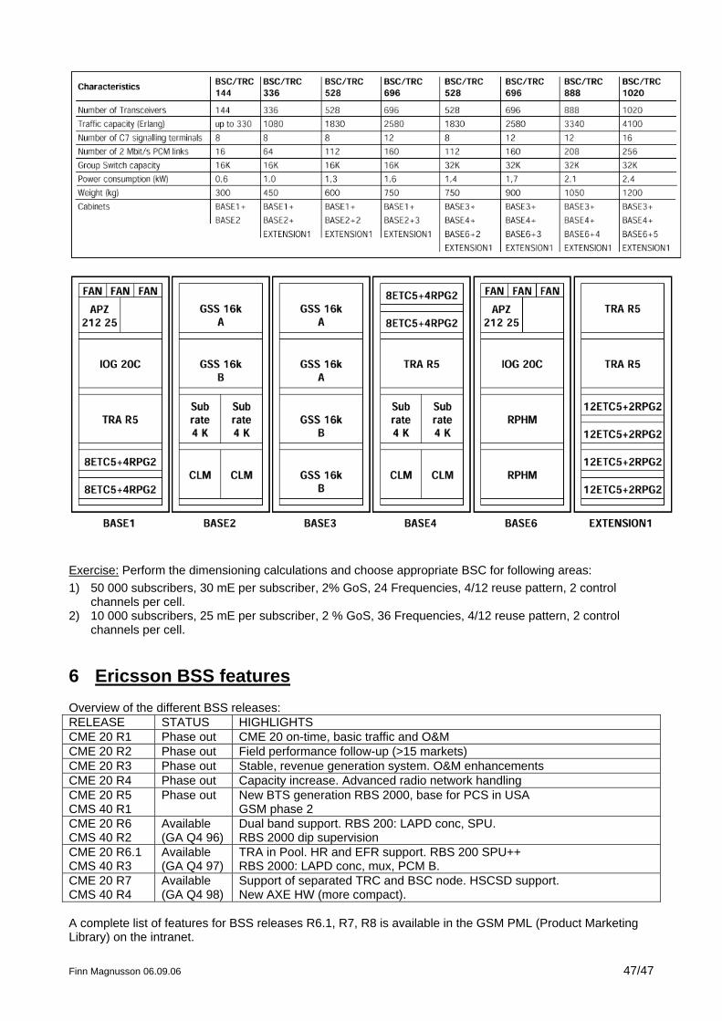
Exercise: Perform the dimensioning calculations and choose appropriate BSC for following areas: 1) 50 000 subscribers, 30 mE per subscriber, 2% GoS, 24 Frequencies, 4/12 reuse pattern, 2 control
channels per cell. 2) 10 000 subscribers, 25 mE per subscriber, 2 % GoS, 36 Frequencies, 4/12 reuse pattern, 2 control
channels per cell.
6 Ericsson BSS features Overview of the different BSS releases: RELEASE STATUS HIGHLIGHTS CME 20 R1 Phase out CME 20 on-time, basic traffic and O&M CME 20 R2 Phase out Field performance follow-up (>15 markets) CME 20 R3 Phase out Stable, revenue generation system. O&M enhancements CME 20 R4 Phase out Capacity increase. Advanced radio network handling CME 20 R5 CMS 40 R1
Phase out New BTS generation RBS 2000, base for PCS in USA GSM phase 2
CME 20 R6 CMS 40 R2
Available (GA Q4 96)
Dual band support. RBS 200: LAPD conc, SPU. RBS 2000 dip supervision
CME 20 R6.1 CMS 40 R3
Available (GA Q4 97)
TRA in Pool. HR and EFR support. RBS 200 SPU++ RBS 2000: LAPD conc, mux, PCM B.
CME 20 R7 CMS 40 R4
Available (GA Q4 98)
Support of separated TRC and BSC node. HSCSD support. New AXE HW (more compact).
A complete list of features for BSS releases R6.1, R7, R8 is available in the GSM PML (Product Marketing Library) on the intranet.
Finn Magnusson 06.09.06 47/47