ferromagnetic user interfaces
TRANSCRIPT
(12) United States Patent Taylor et al.
US008400410B2
US 8,400,410 B2 Mar. 19, 2013
(10) Patent N0.: (45) Date of Patent:
(54) FERROMAGNETIC USER INTERFACES
(75) Inventors: Stuart Taylor, Cambridge (GB); Jonathan Hook, Newcastle-upon-Tyne (GB); Shahram Izadi, Cambridge (GB); Nicolas Villar, Cambridge (GB); David Alexander Butler, Cambridge (GB); Stephen E. Hodges, Cambridge (GB)
(73) Assignee: Microsoft Corporation, Redmond, WA (Us)
( * ) Notice: Subject to any disclaimer, the term of this patent is extended or adjusted under 35 U.S.C. 154(b) by 923 days.
(21) Appl. No.: 12/472,257
(22) Filed: May 26, 2009
(65) Prior Publication Data
US 2010/0302199 A1 Dec. 2, 2010
(51) Int. Cl. G06F 3/041 (2006.01)
(52) US. Cl. ..................................................... .. 345/173
(58) Field of Classi?cation Search ........ .. 345/l56il57, 345/ 1 7341 78
See application ?le for complete search history.
(56) References Cited
U.S. PATENT DOCUMENTS
7,148,875 B2 12/2006 Rosenberg 2002/0044132 A1 4/2002 Fish 2002/0139842 A1 10/2002 Swaine 2004/0080491 A1* 4/2004 Takatsuka et al. .......... .. 345/156 2006/0256075 A1 11/2006 Anastas 2007/0182718 A1* 8/2007 Schooner et al. ........... .. 345/173 2008/0165141 A1 7/2008 Christie 2008/0180399 A1 7/2008 Cheng
OTHER PUBLICATIONS
Bicchi, A., E. P. Scilingo, N. Sgambelluri, and D. De Rossi, Haptic interfaces based on magnetorheological ?uids, Proceedings of
Eurohaptics, 2002, pp. 6-1 1, SA. Wall, B. Riedel, A. Crossan, and M. R. McGee ed. Chouvardas, V. G., and A. N. Miliou, Tactile displays: A short over view and recent developments, Developments, 5th Int’l Conf. on Tech. and Automation, Oct. 2005, pp. 246-251, Dimitris Manolakis, Aristides Gogoussis ed. Fong, T. W., F. Conti, S. Grange and C. Baur, Novel interfaces for remote driving: Gesture, haptic, and PDA, SPIE Telemanipulator and Telepresence Technologies VII, Nov. 2000, Howie M. Choset, Douglas W. Gage, Matthew R. Stein ed. Mavroidis, C., Y. Bar-Cohen, M. BouZit, Haptic interfaces using electrorheological ?uids, Electroactive Polymer (EAP) Actuators as Arti?cial Muscles: Reality, Potentials and Challenges, Ch. 19, Y. Bar-Cohen Editor, SPIE Optical Eng’g. White, T., Introducing liquid haptics in high bandwidth human com puter interfaces, Thesis, Massachusetts Institute of Technology, Jun. 1998. Zhang, Wei-Wei, User interface design with new techniques, Brief Studies in Computer Science, Department of Computer Sciences, University of Tampere, Roope Raisamo and Erkki Makinen (eds), 2004.
* cited by examiner
Primary Examiner * Michael Pervan
(74) Attorney, Agent, or Firm * Zete Law, P.L.L.C.; MacLane C. Key
(57) ABSTRACT
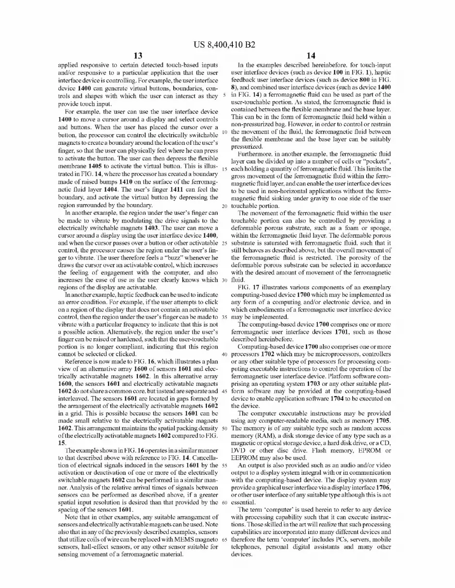
Ferromagnetic user interfaces are described. In embodi ments, user interface devices are described that can detect the location of movement on a user-touchable portion by sensing movement of a ferromagnetic material. In some embodiments sensors are arranged in a two dimensional array, and the user interface device can determine the location of the movement in a plane substantially parallel to the two-dimensional array and the acceleration of movement substantially perpendicular to the two-dimensional array. In other embodiments, user interface devices are described that can cause a raised surface region to be formed on a ferro?uid layer of a user-touchable portion, which is detectable by the touch of a user. Embodi ments describe how the raised surface region can be moved on the ferro?uid layer. Embodiments also describe how the raised surface region can be caused to vibrate.
20 Claims, 17 Drawing Sheets
[1400
US. Patent Mar. 19, 2013 Sheet 1 0117 US 8,400,410 B2
108
FIG. 1

US. Patent Mar. 19, 2013 Sheet 2 or 17
FIG. 2
US. Patent Mar. 19, 2013 Sheet 3 0f 17 US 8,400,410 B2
102
FIG. 3
US. Patent Mar. 19, 2013 Sheet 4 0117 US 8,400,410 B2
Processor
ADC
(_J 403
ADC
ADC
| | | | | | | | | ||||||._
ADC
FIG. 4
US. Patent Mar. 19, 2013 Sheet 5 0f 17 US 8,400,410 B2
FIG. 5
US. Patent Mar. 19, 2013 Sheet 6 0f 17 US 8,400,410 B2
600 i
101% 8
FIG. 6
US. Patent Mar. 19, 2013 Sheet 7 0f 17 US 8,400,410 B2
700 I
106
FIG. 7

US. Patent Mar. 19, 2013 Sheet 8 0f 17 US 8,400,410 B2
FIG. 8
US. Patent Mar. 19, 2013 Sheet 10 or 17 US 8,400,410 B2
802
FIG. 10

US. Patent Mar. 19, 2013 Sheet 11 0117 US 8,400,410 B2
Processor
DAC
DAC
| | | | | | | | | ||||||._
DAC
FIG. 11

US. Patent Mar. 19, 2013 Sheet 12 0117 US 8,400,410 B2
1200
FIG. 12
US. Patent Mar. 19, 2013 Sheet 13 0117 US 8,400,410 B2
{1300
801%
1303 1303 1303 1303 1303 1303
FIG. 13
US. Patent Mar. 19, 2013 Sheet 14 0117 US 8,400,410 B2
{1400
1409
FIG. 14

US. Patent Mar. 19, 2013 Sheet 15 0117 US 8,400,410 B2
{1500
FIG. 15

US. Patent Mar. 19, 2013 Sheet 16 0117 US 8,400,410 B2
FIG. 16
US. Patent Mar. 19, 2013 Sheet 17 0f 17 US 8,400,410 B2
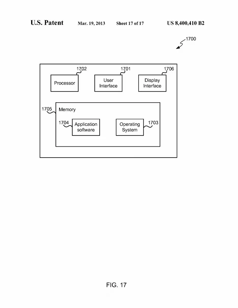
{1700 1702 r.)
Processor User
Interface
1706
17Q_5/\ Memory
179; Application software
Display Interface
Operating System
1703
FIG. 17

US 8,400,410 B2 1
FERROMAGNETIC USER INTERFACES
BACKGROUND
User interface devices enable users to interact With and control computing-based devices. One type of user interface utilizes touch input from a user’s ?ngers to interact With the computer. For example, a touch-pad (also called a track-pad) is commonly provided on a notebook computer, such that, by drawing their ?nger over the touch-pad the user can control the position of a cursor on a display. Such touch-pads can determine the position of the user’s ?nger by detecting local iZed capacitance changes When a ?nger (acting as a virtual ground) is brought into contact With the touch-pad.
Touch-based user interfaces (such as a touch-pad) gener ally provide a hard, continuous surface With Which the user interacts to provide input to the computer. Such devices are only able to sense the location of the user’s touch on the surface of the user interface, and are not able to sense any information in other spatial directions. In addition, user inter face devices Which use capacitive sensing require the pres ence of a ?nger acting as a virtual ground to operate, and do not operate if the user is, for example, Wearing gloves orusing an implement such as a stylus. Furthermore, the user of such a touch-based user interface does not feel any physical or haptic feedback, resulting in a disconnection from the process of interacting With the computer.
The embodiments described beloW are not limited to implementations Which solve any or all of the disadvantages of knoWn user interface devices.
SUMMARY
The folloWing presents a simpli?ed summary of the dis closure in order to provide a basic understanding to the reader. This summary is not an extensive overvieW of the disclosure and it does not identify key/critical elements of the invention or delineate the scope of the invention. Its sole purpose is to present some concepts disclosed herein in a simpli?ed form as a prelude to the more detailed description that is presented later.
Ferromagnetic user interfaces are described. In embodi ments, user interface devices are described that can detect the location of movement on a user-touchable portion by sensing movement of a ferromagnetic material. In some embodiments sensors are arranged in a tWo dimensional array, and the user interface device can determine the location of the movement in a plane substantially parallel to the tWo-dimensional array and the acceleration of movement substantially perpendicular to the tWo-dimensional array. In other embodiments, user interface devices are described that can cause a raised surface
region to be formed on a ferro?uid layer of a user-touchable portion, Which is detectable by the touch of a user. Embodi ments describe hoW the raised surface region can be moved on the ferro?uid layer. Embodiments also describe hoW the raised surface region can be caused to vibrate. Many of the attendant features Will be more readily appre
ciated as the same becomes better understood by reference to the folloWing detailed description considered in connection With the accompanying draWings.
DESCRIPTION OF THE DRAWINGS
The present description Will be better understood from the folloWing detailed description read in light of the accompa nying draWings, Wherein:
20
25
30
35
40
45
50
55
65
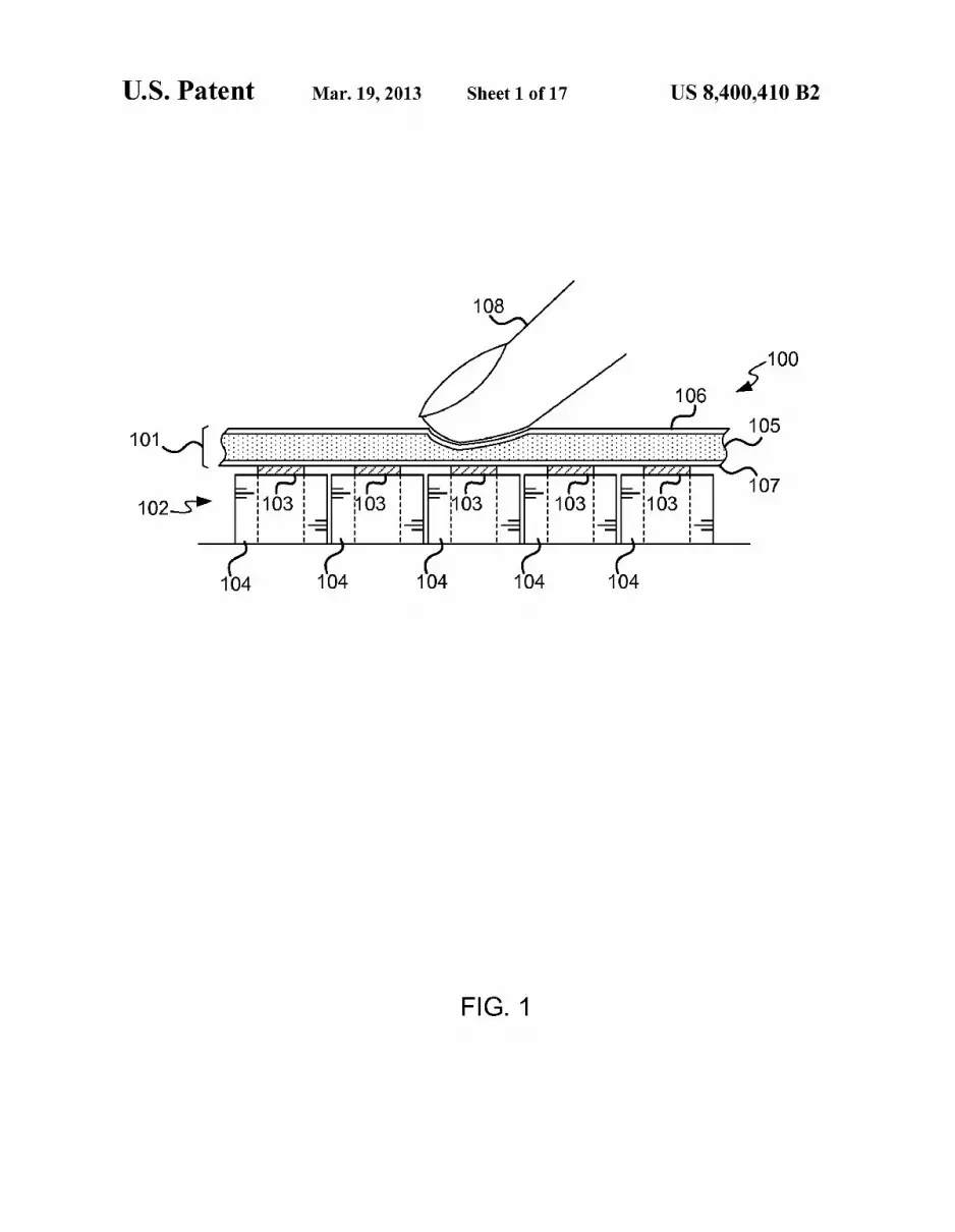
2 FIG. 1 shoWs a user interface device for detecting touch
input based on the movement of ferromagnetic ?uid; FIG. 2 shoWs a plan vieW of a tWo-dimensional sensor
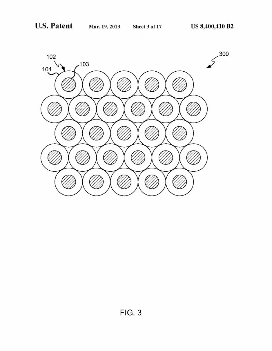
array; FIG. 3 shoWs a plan vieW of an alternative tWo-dimensional
sensor array;
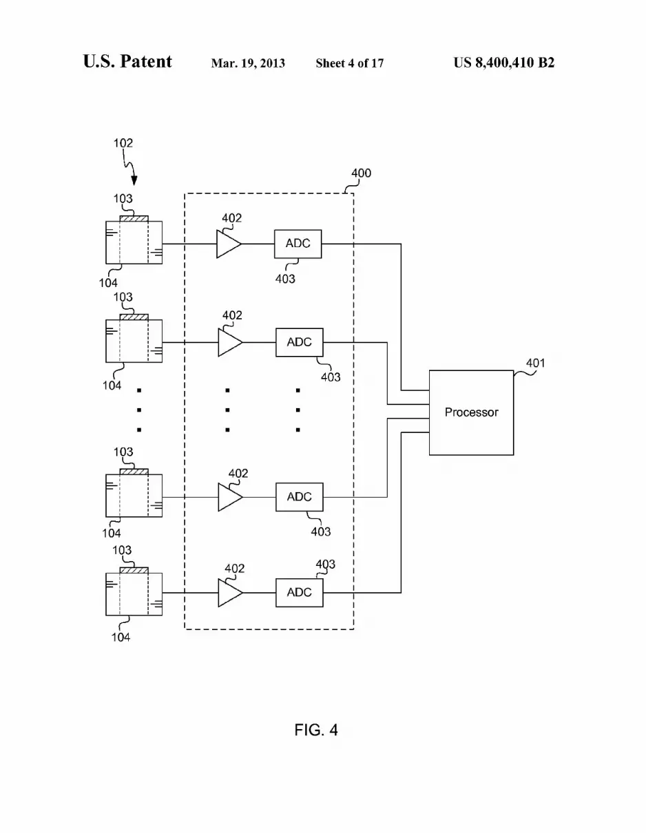
FIG. 4 shoWs a schematic diagram of a circuit for connec tion to the touch input user interface device;
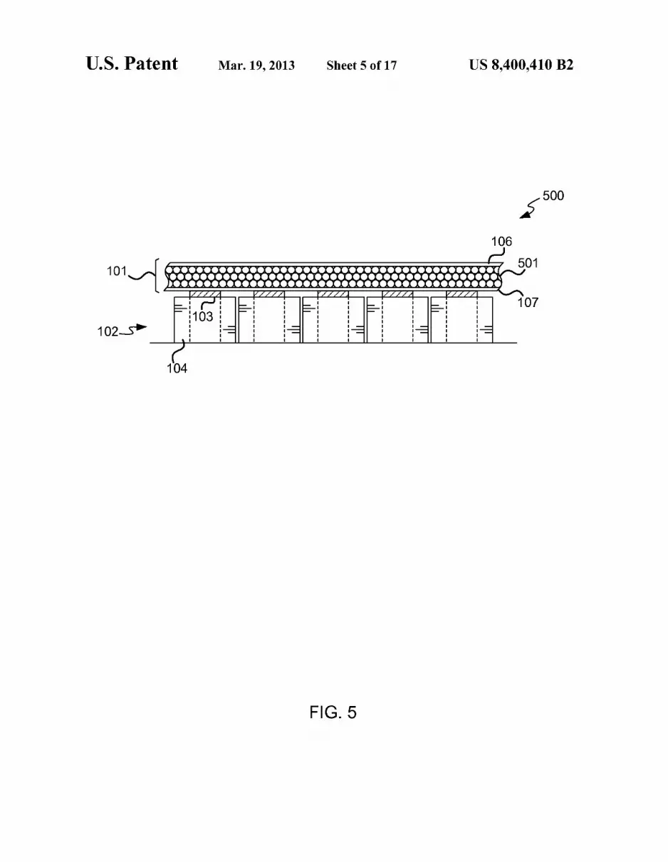
FIG. 5 shoWs a user interface device for detecting touch input based on the movement of ferromagnetic ball bearings;
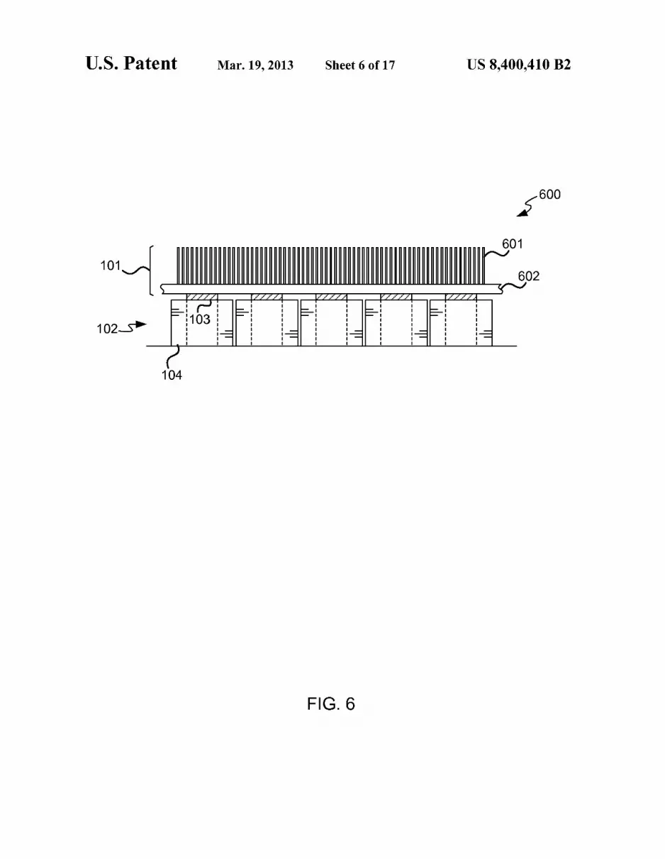
FIG. 6 shoWs a user interface device for detecting touch input based on the movement of ferromagnetic bristles;
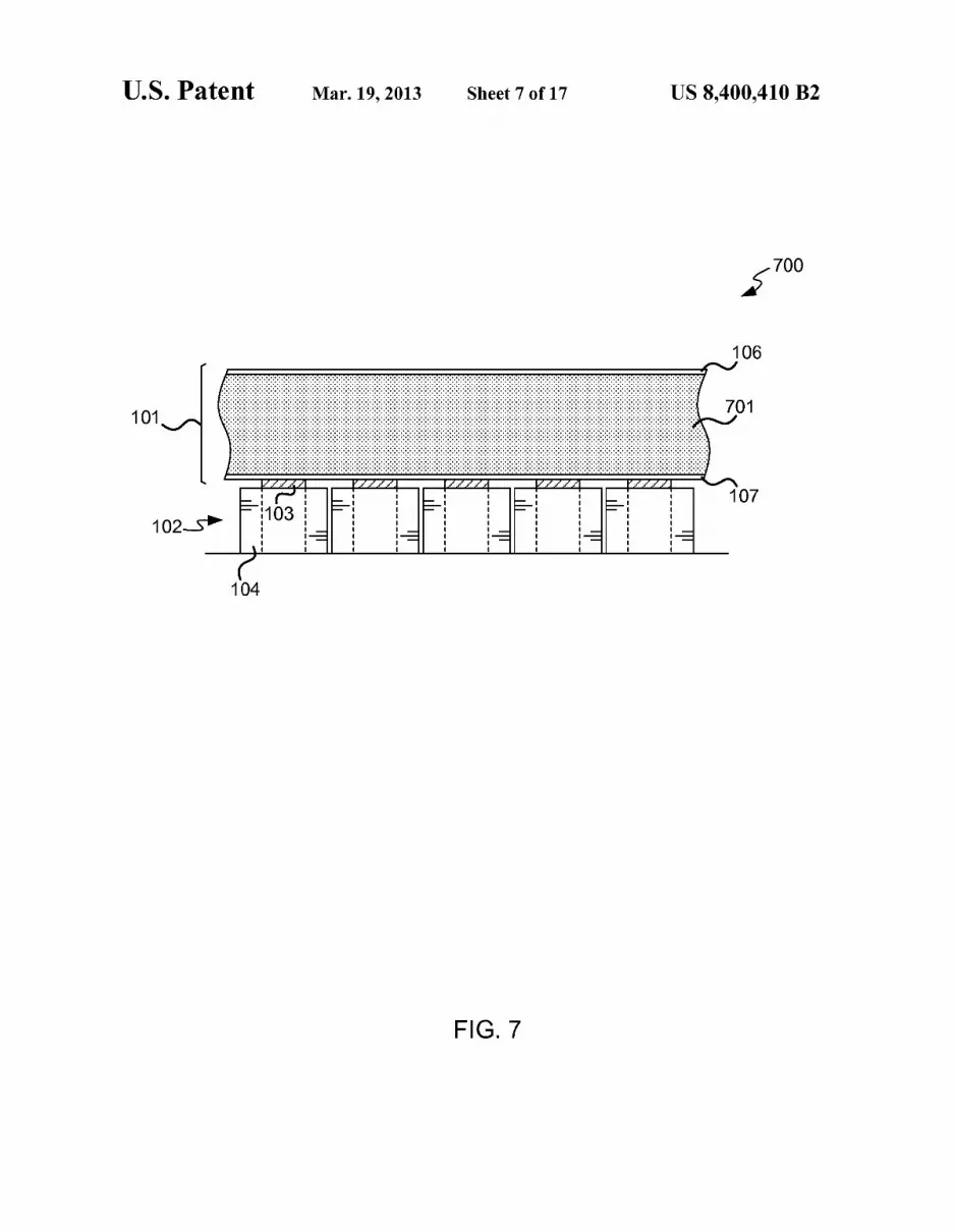
FIG. 7 shoWs a user interface device for detecting touch input based on the movement of ferromagnetic ?lings;
FIG. 8 shoWs a user interface device for providing haptic feedback;
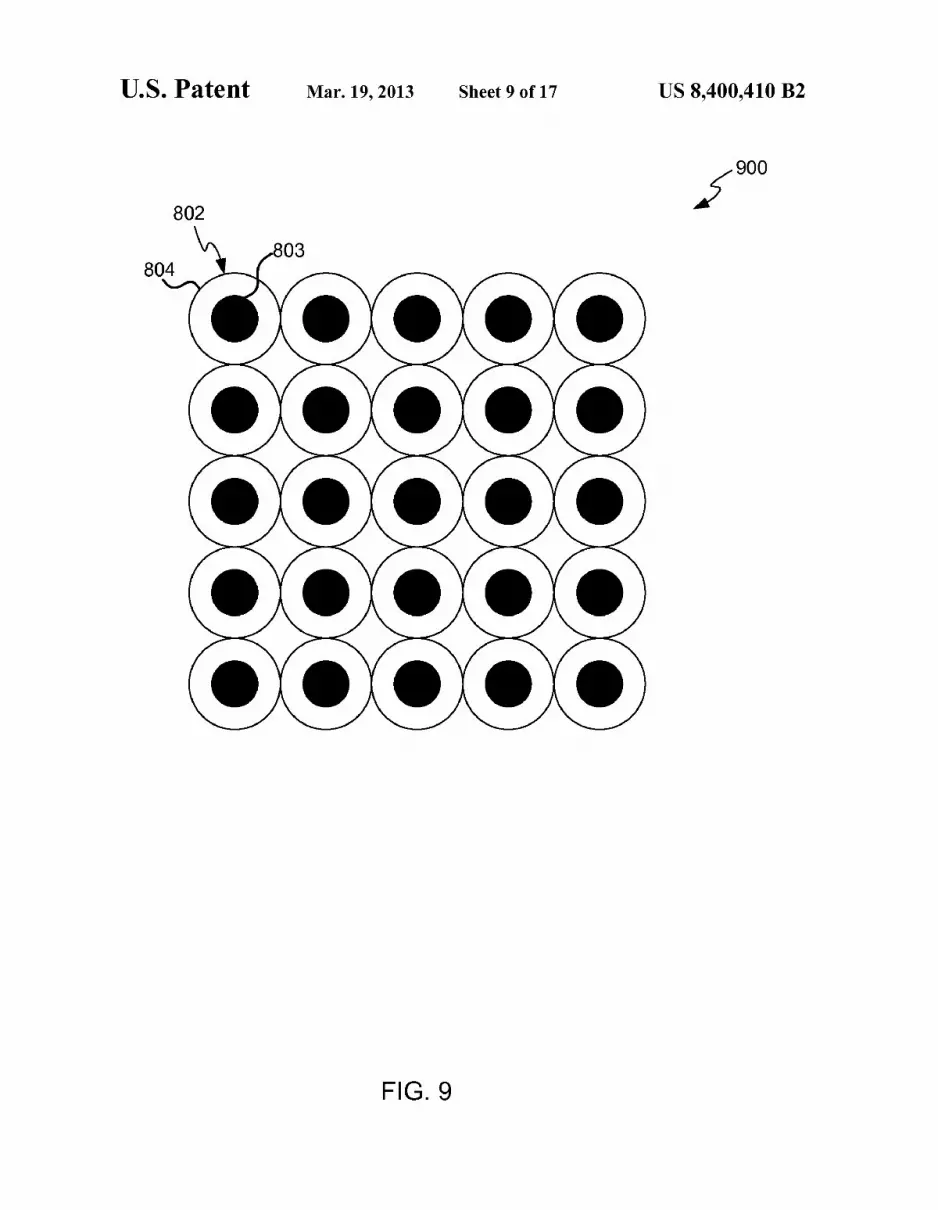
FIG. 9 shoWs a plan vieW of a tWo-dimensional electrically sWitchable magnet array;
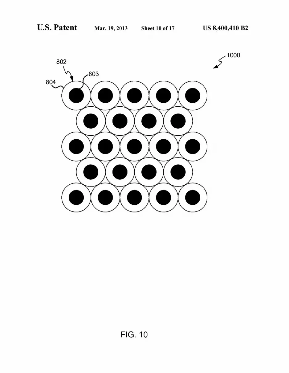
FIG. 10 shoWs an alternative plan vieW of a tWo-dimen sional electrically sWitchable magnet array;
FIG. 11 shoWs a schematic diagram of a circuit for con nection to the haptic feedback user interface device;
FIG. 12 shoWs a user interface device for providing haptic feedback With a raised surface region;
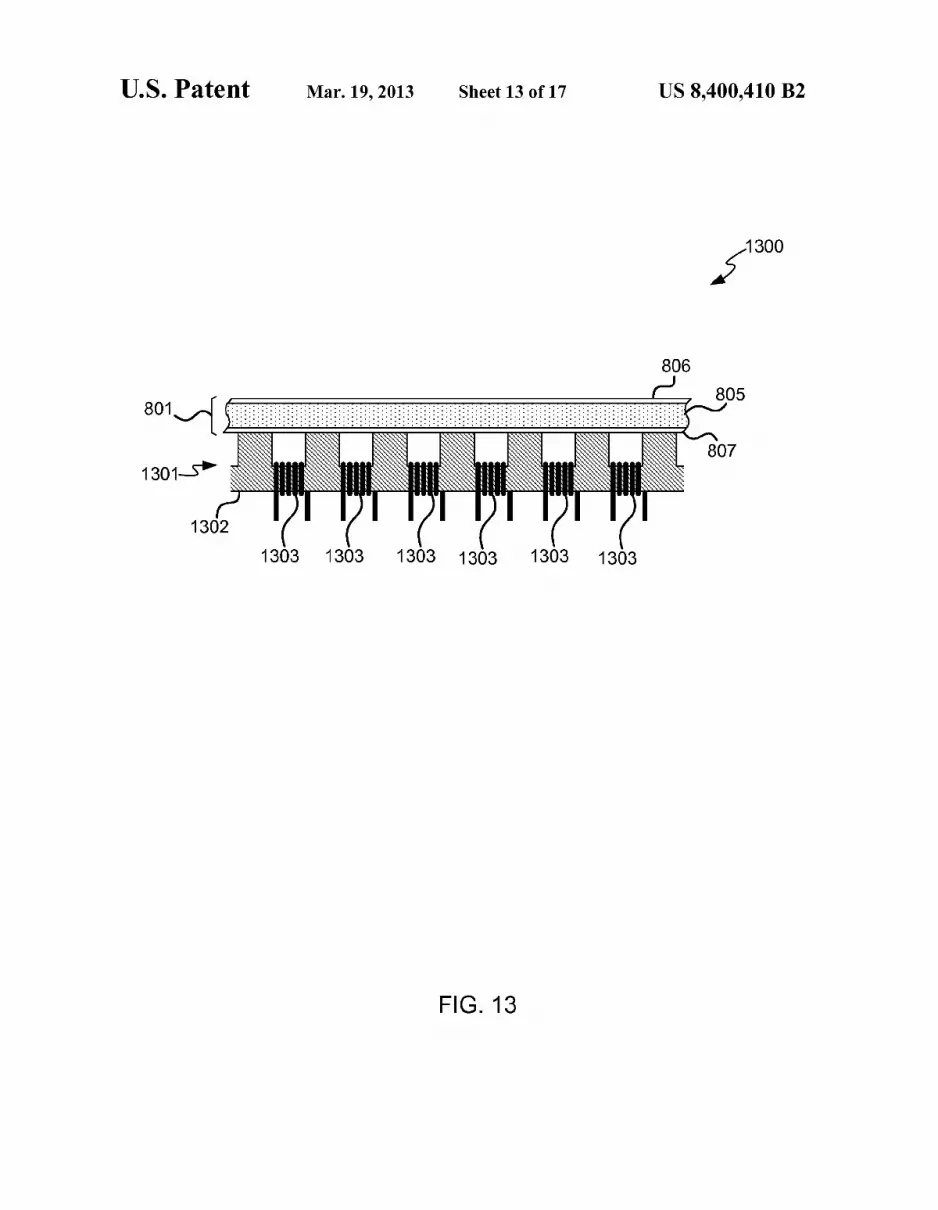
FIG. 13 shoWs a user interface device for providing haptic feedback using shared-core magnets;
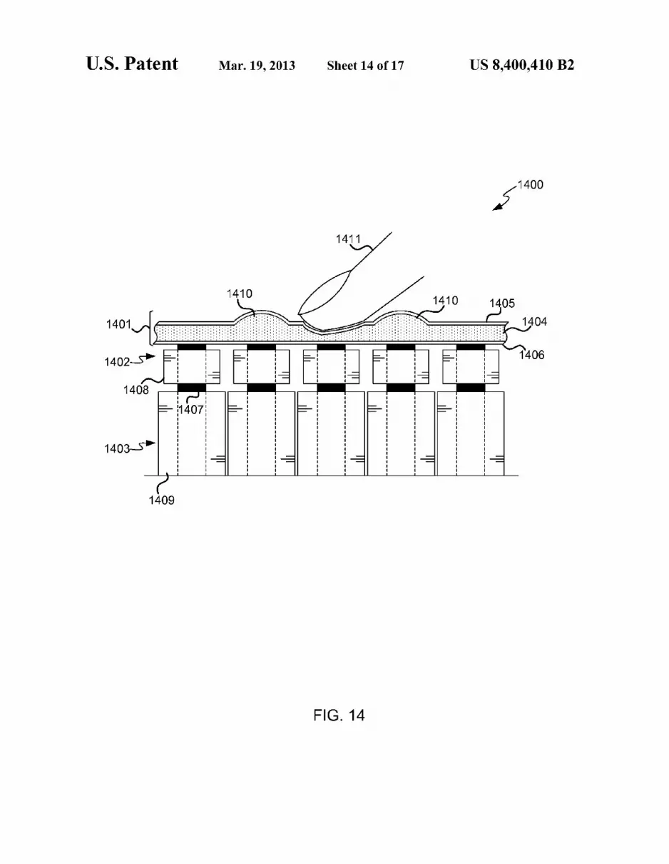
FIG. 14 shoWs a combined user interface device for detect ing touch input and providing haptic feedback;
FIG. 15 shoWs a plan vieW of a tWo-dimensional array of sensors and electrically sWitchable magnet using shared cores;
FIG. 16 shoWs a plan vieW of a tWo-dimensional array of interleaved sensors and electrically sWitchable magnets; and
FIG. 17 shoWs an exemplary computing-based device in Which embodiments of a ferromagnetic user interface may be implemented.
Like reference numerals are used to designate like parts in the accompanying draWings.
DETAILED DESCRIPTION
The detailed description provided beloW in connection With the appended draWings is intended as a description of the present examples and is not intended to represent the only forms in Which the present example may be constructed or utiliZed. The description sets forth the functions of the example and the sequence of steps for constructing and oper ating the example. HoWever, the same or equivalent functions and sequences may be accomplished by different examples.
Although the present examples are described and illus trated herein as being implemented in a computing system, the system described is provided as an example and not a limitation. As those skilled in the art Will appreciate, the present examples are suitable for application in a variety of different types of systems requiring touch-based user inter faces.
FIG. 1 illustrates an example user interface device 100 that detects touch input from a user based on the movement of ferromagnetic material. The user interface device 100 com prises a user-touchable portion 101, beloW Which is a plurality of sensors 102. The sensors 102 shoWn in the example of FIG. 1 are in the form of “pick-up” coils, each comprising a per manent magnet core 103 around Which is Wound a coil of Wire 104. The user-touchable portion 101 comprises a ferromagnetic
?uid layer 105 located betWeen a compliant, ?exible mem brane 106 forming the surface of the user-touchable portion
US 8,400,410 B2 3
101, and a base layer 107. The base layer 107 can be formed from the same compliant material as the ?exible membrane 106, or can be formed from a different, more rigid material.
In the example shoWn in FIG. 1, the user-touchable portion 101 is mounted directly on top of the sensors 102. In other examples, a gap can be present betWeen the user-touchable portion 101 and the sensors 102, or other hardWare can be located betWeen the user-touchable portion 101 and the sen sors 102.
The ferromagnetic ?uid layer 105 can contain any ?uidthat is capable of su?iciently in?uencing a magnetic ?eld. The term ferromagnetic is used here in the broad sense of a mate rial that can experience magnetiZation, ie the material is attracted by a magnetic ?eld. The term ferromagnetic is there fore intended to also include materials that exhibit behaviors including (but not limited to) ferrimagnetism, antiferromag netism, and paramagnetism.
In one example, the ferromagnetic ?uid layer 105 can contain ferro?uid. Ferro?uid is a colloidal mixture compris ing nanometer scale ferromagnetic particles suspended in a carrier ?uid. The particles are held in suspension by the effects of BroWnian motion, and do not settle. The ferromag netic particles are coated With a surfactant to prevent their agglomeration.
In another example, the ferromagnetic ?uid layer 105 can contain magnetorheological ?uid. A magnetorheological ?uid is a suspension of micrometer-scale ferromagnetic par ticles in a carrier ?uid, typically an oil. Both ferro?uids and magnetorheological ?uids are capable of disturbing the mag netic ?eld from the permanent magnet 103, as described beloW.
The plurality of sensors 102 can be arranged in a tWo dimensional array 200, as illustrated in the example plan vieW shoWn in FIG. 2. In this example, the sensors 102 are arranged in a regular grid. Note that the user-touchable portion 101 covers the tWo dimensional array 200 of the sensors 102, but is not illustrated in FIG. 2. The grid of sensors 102 can be of any suitable shape or dimensions to correspond With the user-touchable portion 101. An alternative tWo-dimensional array 300 of sensors 102 is illustrated in FIG. 3, in Which the sensors are more closely packed and not arranged in a regular grid pattern.
FIG. 4 illustrates a circuit diagram for the user interface device 100. Each of the sensors 102 is individually connected to an interface circuit 400. The interface circuit 400 is con nected to a processor 401. In the example shoWn in FIG. 4, the interface circuit 400 comprises a plurality of ampli?ers 402 arranged such that each of the sensors 102 is connected to an input of one of the ampli?ers 402. Each of the ampli?ers 402 has an output connected to the input of one of a plurality of analog to digital converters (ADC) 403. An output from each of the ADCs 403 is connected to the processor 401. Note that the plurality of ADCs 403 can be fabricated on a single integrated circuit, and the plurality of ampli?ers 402 can also be fabricated on a single integrated circuit.
In another example, the plurality of ADCs 403 can be replaced With a single ADC and a multiplexer, such that the multiplexer sWitches betWeen each of the outputs of the ampli?ers 402 in turn, providing the output signals from the ampli?ers to the single ADC sequentially. Similarly, in a further example, the outputs from the sensors 102 can be multiplexed and provided to a single ampli?er sequentially.
The operation of the user interface device 100 is noW described With reference to FIG. 1 and FIG. 4. In a steady state, Without a user touching the user interface device 100, the permanent magnets 103 from each of the sensors 102 are
20
25
30
35
40
45
50
55
60
65
4 creating a constant magnetic ?eld, and no electrical current is ?oWing in the coils of Wire 104. When a user touches the user-touchable portion 101, as
illustrated by the ?nger 108 in FIG. 1, the ?exible membrane 106 is deformed. The deformation of the ?exible membrane 106 causes the ferromagnetic ?uid in the ferromagnetic ?uid layer 105 to move. The movement of the ferromagnetic ?uid disturbs the magnetic ?eld produced by the permanent mag net 103 of the sensor beloW the position of movement. In other Words, the movement of the ferromagnetic ?uid modu lates the magnetic ?ux linking the coil of Wire 104 in the sensor beloW the position of movement. This induces a cur rent in the coil of Wire 104 of the sensor in question. Note that a current can be induced in more than one of the sensors 102,
as described in more detail beloW.
The induced current in the coil of Wire 104 gives rise to a small output electrical signal from the coil of Wire 104. The output electrical signal is ampli?ed by the corresponding ampli?er 402 for the sensor in question. The ampli?ed elec trical signal is converted to a digital value by the correspond ing ADC 403, and the digital value is provided to the proces sor. Preferably, the ADCs 403 and the processor 401 can be arranged to rapidly capture the magnitude of the electrical signal from each of the sensors, such that small delays betWeen electrical signals from different sensors can be dis tinguished. In other Words, the sampling rate of the ADCs 403 is preferably suf?ciently rapid that short differences in arrival times of signals from each of the sensors can be discerned.
The processor analyses the electrical signals from all of the sensors 102, and upon receiving the electrical signal from the sensor beloW the movement, the processor can determine that movement is occurring in the ferromagnetic ?uid in the loca tion corresponding to that sensor. Therefore, in this Way, the location of the touch by the ?nger 108 on the user-touchable portion 101 can be determined.
In addition, the processor can analyZe the magnitude of the electrical signal from the sensor beloW the movement. The magnitude of the electrical signal is an indicator of the accel eration of the touch in the direction substantially perpendicu lar to the plane of the surface of the user-touchable portion 101 (i.e. the direction into the page in FIGS. 2 and 3). This therefore enables the processor to determine a measure of the impact force With Which the user has depressed the ?exible membrane 106. This is possible as a “harder” impact force moves the ferromagnetic ?uid more rapidly than a “softer” impact force.
In other Words, the user interface device 100 is able to determine information about touch inputs in the x and y directions (parallel to the plane of the user-touchable portion 101) and also the Z direction (perpendicular to the plane of the user-touchable portion 101).
In addition to determining the position of movement on the user-touchable portion 101 using the single sensor beloW the movement, the user interface device 100 can also utiliZe information from the surrounding sensors. For example, When touched, a disturbance is caused in the ferromagnetic ?uid, and because of this the magnetic ?elds of sensors sur rounding the touched location are disturbed a short time after the touch. This can be utiliZed by the processor 401 to more accurately determine the position of the touch. The processor 401 can detect an initial electrical signal from one or more
sensors, and then subsequent smaller signals from surround ing sensors after a time delay. The processor 401 uses the relative arrival times of the signals, and interpolates betWeen them to accurately determine the point of origin of the touch.