bioprocessing equipment
TRANSCRIPT

A N I N T E R N A T I O N A L S T A N D A R D
Bioprocessing Equipment
ASME BPE-2007(Revision of ASME BPE-2005)
Copyright 2008 by the American Society of Mechanical Engineers.No reproduction may be made of this material without written consent of ASME.
c

ASME BPE-2007(Revision of ASME BPE-2005)
BioprocessingEquipment
A N A M E R I C A N N A T I O N A L S T A N D A R D
Three Park Avenue • New York, NY 10016
Copyright 2008 by the American Society of Mechanical Engineers.No reproduction may be made of this material without written consent of ASME.
c
Date of Issuance: March 21, 2008
The next edition of this Standard is scheduled for publication in 2009. There will be no addendaissued to this edition.
ASME issues written replies to inquiries concerning interpretations of technical aspects of thisStandard. Interpretations are published on the ASME website under the Committee Pages athttp://www.cstools.asme.org as they are issued.
ASME is the registered trademark of The American Society of Mechanical Engineers.
This code or standard was developed under procedures accredited as meeting the criteria for American NationalStandards. The Standards Committee that approved the code or standard was balanced to assure that individuals fromcompetent and concerned interests have had an opportunity to participate. The proposed code or standard was madeavailable for public review and comment that provides an opportunity for additional public input from industry, academia,regulatory agencies, and the public-at-large.
ASME does not “approve,” “rate,” or “endorse” any item, construction, proprietary device, or activity.
ASME does not take any position with respect to the validity of any patent rights asserted in connection with anyitems mentioned in this document, and does not undertake to insure anyone utilizing a standard against liability forinfringement of any applicable letters patent, nor assume any such liability. Users of a code or standard are expresslyadvised that determination of the validity of any such patent rights, and the risk of infringement of such rights, isentirely their own responsibility.
Participation by federal agency representative(s) or person(s) affiliated with industry is not to be interpreted asgovernment or industry endorsement of this code or standard.
ASME accepts responsibility for only those interpretations of this document issued in accordance with the establishedASME procedures and policies, which precludes the issuance of interpretations by individuals.
No part of this document may be reproduced in any form,in an electronic retrieval system or otherwise,
without the prior written permission of the publisher.
The American Society of Mechanical EngineersThree Park Avenue, New York, NY 10016-5990
Copyright © 2008 byTHE AMERICAN SOCIETY OF MECHANICAL ENGINEERS
All rights reservedPrinted in U.S.A.
Copyright 2008 by the American Society of Mechanical Engineers.No reproduction may be made of this material without written consent of ASME.
c
CONTENTS
Foreword . . . . . . . . . . . . . . . . . . . . . . . . . . . . . . . . . . . . . . . . . . . . . . . . . . . . . . . . . . . . . . . . . . . . . . . . . . . . . . viiStatements of Policy . . . . . . . . . . . . . . . . . . . . . . . . . . . . . . . . . . . . . . . . . . . . . . . . . . . . . . . . . . . . . . . . . . . viiiCommittee Roster . . . . . . . . . . . . . . . . . . . . . . . . . . . . . . . . . . . . . . . . . . . . . . . . . . . . . . . . . . . . . . . . . . . . . ixSummary of Changes . . . . . . . . . . . . . . . . . . . . . . . . . . . . . . . . . . . . . . . . . . . . . . . . . . . . . . . . . . . . . . . . . . xii
Part GR General Requirements . . . . . . . . . . . . . . . . . . . . . . . . . . . . . . . . . . . . . . . . . . . . . . . . . . . . . . . . . 1GR-1 Introduction . . . . . . . . . . . . . . . . . . . . . . . . . . . . . . . . . . . . . . . . . . . . . . . . . . . . . . . . . . . . . . . . . 1GR-2 Scope . . . . . . . . . . . . . . . . . . . . . . . . . . . . . . . . . . . . . . . . . . . . . . . . . . . . . . . . . . . . . . . . . . . . . . . 1GR-3 Inspection . . . . . . . . . . . . . . . . . . . . . . . . . . . . . . . . . . . . . . . . . . . . . . . . . . . . . . . . . . . . . . . . . . . 1GR-4 Inspector/Examiner . . . . . . . . . . . . . . . . . . . . . . . . . . . . . . . . . . . . . . . . . . . . . . . . . . . . . . . . . . 1GR-5 Responsibilities . . . . . . . . . . . . . . . . . . . . . . . . . . . . . . . . . . . . . . . . . . . . . . . . . . . . . . . . . . . . . . 1GR-6 Access for Inspectors . . . . . . . . . . . . . . . . . . . . . . . . . . . . . . . . . . . . . . . . . . . . . . . . . . . . . . . . 2GR-7 Manufacturer’s Quality Assurance Program . . . . . . . . . . . . . . . . . . . . . . . . . . . . . . . . . . 2GR-8 Metric . . . . . . . . . . . . . . . . . . . . . . . . . . . . . . . . . . . . . . . . . . . . . . . . . . . . . . . . . . . . . . . . . . . . . . . 2GR-9 References . . . . . . . . . . . . . . . . . . . . . . . . . . . . . . . . . . . . . . . . . . . . . . . . . . . . . . . . . . . . . . . . . . . 2GR-10 Terms and Definitions . . . . . . . . . . . . . . . . . . . . . . . . . . . . . . . . . . . . . . . . . . . . . . . . . . . . . . . 3
Part SD Design for Sterility and Cleanability . . . . . . . . . . . . . . . . . . . . . . . . . . . . . . . . . . . . . . . . . . . . 9SD-1 Introduction . . . . . . . . . . . . . . . . . . . . . . . . . . . . . . . . . . . . . . . . . . . . . . . . . . . . . . . . . . . . . . . . . 9SD-2 Scope and Purpose . . . . . . . . . . . . . . . . . . . . . . . . . . . . . . . . . . . . . . . . . . . . . . . . . . . . . . . . . . 9SD-3 General Guidelines . . . . . . . . . . . . . . . . . . . . . . . . . . . . . . . . . . . . . . . . . . . . . . . . . . . . . . . . . . 9SD-4 Specific Guidelines . . . . . . . . . . . . . . . . . . . . . . . . . . . . . . . . . . . . . . . . . . . . . . . . . . . . . . . . . . 20SD-5 Testing and Inspection . . . . . . . . . . . . . . . . . . . . . . . . . . . . . . . . . . . . . . . . . . . . . . . . . . . . . . . 54SD-6 Documentation . . . . . . . . . . . . . . . . . . . . . . . . . . . . . . . . . . . . . . . . . . . . . . . . . . . . . . . . . . . . . . 55SD-7 Responsibilities . . . . . . . . . . . . . . . . . . . . . . . . . . . . . . . . . . . . . . . . . . . . . . . . . . . . . . . . . . . . . . 55
Part DT Dimensions and Tolerances for Stainless Steel Automatic Welding andHygienic Clamp Tube Fittings and Process Components . . . . . . . . . . . . . . . . . . . . . . . 56
DT-1 Scope . . . . . . . . . . . . . . . . . . . . . . . . . . . . . . . . . . . . . . . . . . . . . . . . . . . . . . . . . . . . . . . . . . . . . . . 56DT-2 Pressure Rating . . . . . . . . . . . . . . . . . . . . . . . . . . . . . . . . . . . . . . . . . . . . . . . . . . . . . . . . . . . . . . 56DT-3 Marking . . . . . . . . . . . . . . . . . . . . . . . . . . . . . . . . . . . . . . . . . . . . . . . . . . . . . . . . . . . . . . . . . . . . . 56DT-4 Materials . . . . . . . . . . . . . . . . . . . . . . . . . . . . . . . . . . . . . . . . . . . . . . . . . . . . . . . . . . . . . . . . . . . . 56DT-5 Metal Thickness . . . . . . . . . . . . . . . . . . . . . . . . . . . . . . . . . . . . . . . . . . . . . . . . . . . . . . . . . . . . . 56DT-6 Fitting Dimensions . . . . . . . . . . . . . . . . . . . . . . . . . . . . . . . . . . . . . . . . . . . . . . . . . . . . . . . . . . 56DT-7 Tests . . . . . . . . . . . . . . . . . . . . . . . . . . . . . . . . . . . . . . . . . . . . . . . . . . . . . . . . . . . . . . . . . . . . . . . . 57DT-8 Tolerances . . . . . . . . . . . . . . . . . . . . . . . . . . . . . . . . . . . . . . . . . . . . . . . . . . . . . . . . . . . . . . . . . . . 57DT-9 Welding Ends . . . . . . . . . . . . . . . . . . . . . . . . . . . . . . . . . . . . . . . . . . . . . . . . . . . . . . . . . . . . . . . 57DT-10 Hygienic Clamp Ends . . . . . . . . . . . . . . . . . . . . . . . . . . . . . . . . . . . . . . . . . . . . . . . . . . . . . . . . 57DT-11 Heat Treatment . . . . . . . . . . . . . . . . . . . . . . . . . . . . . . . . . . . . . . . . . . . . . . . . . . . . . . . . . . . . . . 57DT-12 Surface Condition . . . . . . . . . . . . . . . . . . . . . . . . . . . . . . . . . . . . . . . . . . . . . . . . . . . . . . . . . . . 57DT-13 Packaging . . . . . . . . . . . . . . . . . . . . . . . . . . . . . . . . . . . . . . . . . . . . . . . . . . . . . . . . . . . . . . . . . . . 57DT-14 Minimum Examination Requirements . . . . . . . . . . . . . . . . . . . . . . . . . . . . . . . . . . . . . . . . 57
Part MJ Material Joining . . . . . . . . . . . . . . . . . . . . . . . . . . . . . . . . . . . . . . . . . . . . . . . . . . . . . . . . . . . . . . . 76MJ-1 Scope . . . . . . . . . . . . . . . . . . . . . . . . . . . . . . . . . . . . . . . . . . . . . . . . . . . . . . . . . . . . . . . . . . . . . . . 76MJ-2 Materials . . . . . . . . . . . . . . . . . . . . . . . . . . . . . . . . . . . . . . . . . . . . . . . . . . . . . . . . . . . . . . . . . . . . 76MJ-3 Joining Processes and Procedures . . . . . . . . . . . . . . . . . . . . . . . . . . . . . . . . . . . . . . . . . . . . 76MJ-4 Weld Joint Design and Preparation . . . . . . . . . . . . . . . . . . . . . . . . . . . . . . . . . . . . . . . . . . . 77MJ-5 Filler Material . . . . . . . . . . . . . . . . . . . . . . . . . . . . . . . . . . . . . . . . . . . . . . . . . . . . . . . . . . . . . . . 77MJ-6 Weld Acceptance Criteria . . . . . . . . . . . . . . . . . . . . . . . . . . . . . . . . . . . . . . . . . . . . . . . . . . . . 78MJ-7 Inspection, Examination, and Testing . . . . . . . . . . . . . . . . . . . . . . . . . . . . . . . . . . . . . . . . . 78MJ-8 Procedure Qualification . . . . . . . . . . . . . . . . . . . . . . . . . . . . . . . . . . . . . . . . . . . . . . . . . . . . . . 84
iii
Copyright 2008 by the American Society of Mechanical Engineers.No reproduction may be made of this material without written consent of ASME.
c
MJ-9 Performance Qualification . . . . . . . . . . . . . . . . . . . . . . . . . . . . . . . . . . . . . . . . . . . . . . . . . . . . 84MJ-10 Documentation Requirements . . . . . . . . . . . . . . . . . . . . . . . . . . . . . . . . . . . . . . . . . . . . . . . . 84MJ-11 Passivation . . . . . . . . . . . . . . . . . . . . . . . . . . . . . . . . . . . . . . . . . . . . . . . . . . . . . . . . . . . . . . . . . . 85
Part SF Stainless Steel and Higher Alloy Product Contact Surface Finishes . . . . . . . . . . . . . . . 86SF-1 Scope . . . . . . . . . . . . . . . . . . . . . . . . . . . . . . . . . . . . . . . . . . . . . . . . . . . . . . . . . . . . . . . . . . . . . . . 86SF-2 Objective . . . . . . . . . . . . . . . . . . . . . . . . . . . . . . . . . . . . . . . . . . . . . . . . . . . . . . . . . . . . . . . . . . . . 86SF-3 Applications . . . . . . . . . . . . . . . . . . . . . . . . . . . . . . . . . . . . . . . . . . . . . . . . . . . . . . . . . . . . . . . . . 86SF-4 Material . . . . . . . . . . . . . . . . . . . . . . . . . . . . . . . . . . . . . . . . . . . . . . . . . . . . . . . . . . . . . . . . . . . . . 86SF-5 Inspection and Techniques Employed in the Classification of Product Contact
Surface Finishes . . . . . . . . . . . . . . . . . . . . . . . . . . . . . . . . . . . . . . . . . . . . . . . . . . . . . . . . . . . 86SF-6 Surface Condition . . . . . . . . . . . . . . . . . . . . . . . . . . . . . . . . . . . . . . . . . . . . . . . . . . . . . . . . . . . 86SF-7 Electropolishing Procedure Qualification . . . . . . . . . . . . . . . . . . . . . . . . . . . . . . . . . . . . . . 87SF-8 Passivation . . . . . . . . . . . . . . . . . . . . . . . . . . . . . . . . . . . . . . . . . . . . . . . . . . . . . . . . . . . . . . . . . . 87
Part SG Equipment Seals . . . . . . . . . . . . . . . . . . . . . . . . . . . . . . . . . . . . . . . . . . . . . . . . . . . . . . . . . . . . . . 89SG-1 Scope and Purpose . . . . . . . . . . . . . . . . . . . . . . . . . . . . . . . . . . . . . . . . . . . . . . . . . . . . . . . . . . 89SG-2 Seal Classes . . . . . . . . . . . . . . . . . . . . . . . . . . . . . . . . . . . . . . . . . . . . . . . . . . . . . . . . . . . . . . . . . 89SG-3 General Provisions for Seals in Bioprocessing Service: User Basic Design
Requirement . . . . . . . . . . . . . . . . . . . . . . . . . . . . . . . . . . . . . . . . . . . . . . . . . . . . . . . . . . . . . . 90SG-4 Special Provisions for Seals in Bioprocessing Service . . . . . . . . . . . . . . . . . . . . . . . . . . 99
Part PM Polymer-Based Materials . . . . . . . . . . . . . . . . . . . . . . . . . . . . . . . . . . . . . . . . . . . . . . . . . . . . . . 103PM-1 Introduction . . . . . . . . . . . . . . . . . . . . . . . . . . . . . . . . . . . . . . . . . . . . . . . . . . . . . . . . . . . . . . . . . 103PM-2 Design Considerations for Polymeric Piping, Tubing, Fittings, Valve Bodies,
and Other Components . . . . . . . . . . . . . . . . . . . . . . . . . . . . . . . . . . . . . . . . . . . . . . . . . . . . 103PM-3 Polymer Material Joining . . . . . . . . . . . . . . . . . . . . . . . . . . . . . . . . . . . . . . . . . . . . . . . . . . . . 106PM-4 Polymer Interior Product Contact Surfaces of Piping, Tubing, Fittings, Valve
Bodies, and Coated or Lined Vessels . . . . . . . . . . . . . . . . . . . . . . . . . . . . . . . . . . . . . . . 109PM-5 Materials of Construction . . . . . . . . . . . . . . . . . . . . . . . . . . . . . . . . . . . . . . . . . . . . . . . . . . . . 109
FiguresSD-1 Hygienic Connections . . . . . . . . . . . . . . . . . . . . . . . . . . . . . . . . . . . . . . . . . . . . . . . . . . . . . . . . 11SD-2 Nonhygienic Connections . . . . . . . . . . . . . . . . . . . . . . . . . . . . . . . . . . . . . . . . . . . . . . . . . . . . 13SD-3 Flat Gasket Applications . . . . . . . . . . . . . . . . . . . . . . . . . . . . . . . . . . . . . . . . . . . . . . . . . . . . . 14SD-4 Recommended and Preferred Drop Designs . . . . . . . . . . . . . . . . . . . . . . . . . . . . . . . . . . 18SD-5 Double Block-and-Bleed Valve Assembly . . . . . . . . . . . . . . . . . . . . . . . . . . . . . . . . . . . . . 19SD-6 Instrument Location Detail: Hygienic Design . . . . . . . . . . . . . . . . . . . . . . . . . . . . . . . . . 20SD-7 Flexible Hygienic Hose Design . . . . . . . . . . . . . . . . . . . . . . . . . . . . . . . . . . . . . . . . . . . . . . . 22SD-8 Tank/Vessel Vent Filters . . . . . . . . . . . . . . . . . . . . . . . . . . . . . . . . . . . . . . . . . . . . . . . . . . . . . 23SD-9 Nozzle Design . . . . . . . . . . . . . . . . . . . . . . . . . . . . . . . . . . . . . . . . . . . . . . . . . . . . . . . . . . . . . . . 25SD-10 Sidewall Instrument Ports . . . . . . . . . . . . . . . . . . . . . . . . . . . . . . . . . . . . . . . . . . . . . . . . . . . . 26SD-11 Dip Tube . . . . . . . . . . . . . . . . . . . . . . . . . . . . . . . . . . . . . . . . . . . . . . . . . . . . . . . . . . . . . . . . . . . . 27SD-12 Vessel Design Tangential Nozzles . . . . . . . . . . . . . . . . . . . . . . . . . . . . . . . . . . . . . . . . . . . . 27SD-13 Vessel Sight Glass Design . . . . . . . . . . . . . . . . . . . . . . . . . . . . . . . . . . . . . . . . . . . . . . . . . . . . 28SD-14-1 Dip Tube Nozzles: Removable Designs . . . . . . . . . . . . . . . . . . . . . . . . . . . . . . . . . . . . . . . 29SD-14-2 Side and Bottom Connections . . . . . . . . . . . . . . . . . . . . . . . . . . . . . . . . . . . . . . . . . . . . . . . . 30SD-15 Agitator Mounting Flanges . . . . . . . . . . . . . . . . . . . . . . . . . . . . . . . . . . . . . . . . . . . . . . . . . . 31SD-16 Sight Glass Design . . . . . . . . . . . . . . . . . . . . . . . . . . . . . . . . . . . . . . . . . . . . . . . . . . . . . . . . . . . 32SD-17 Internal Support Members . . . . . . . . . . . . . . . . . . . . . . . . . . . . . . . . . . . . . . . . . . . . . . . . . . . 33SD-18 Mitered Fittings . . . . . . . . . . . . . . . . . . . . . . . . . . . . . . . . . . . . . . . . . . . . . . . . . . . . . . . . . . . . . 34SD-19 Typical Nozzle Detail . . . . . . . . . . . . . . . . . . . . . . . . . . . . . . . . . . . . . . . . . . . . . . . . . . . . . . . . 34SD-20 Double Tubesheet Heat Exchanger Bonnet Design . . . . . . . . . . . . . . . . . . . . . . . . . . . . 35SD-21-1 Shaft Coupling Construction . . . . . . . . . . . . . . . . . . . . . . . . . . . . . . . . . . . . . . . . . . . . . . . . . 36SD-21-2 Shaft Coupling Seal Arrangement . . . . . . . . . . . . . . . . . . . . . . . . . . . . . . . . . . . . . . . . . . . . 37SD-21-3 Fastener Seal Arrangements . . . . . . . . . . . . . . . . . . . . . . . . . . . . . . . . . . . . . . . . . . . . . . . . . . 38SD-21-4 Shaft Steady Bearing . . . . . . . . . . . . . . . . . . . . . . . . . . . . . . . . . . . . . . . . . . . . . . . . . . . . . . . . . 39SD-21-5 Magnetically-Coupled Mixer (Typical Bottom-Mount) . . . . . . . . . . . . . . . . . . . . . . . . . 40SD-21-6 Double Mechanical Cartridge Seal With Debris Well . . . . . . . . . . . . . . . . . . . . . . . . . . 42
iv
Copyright 2008 by the American Society of Mechanical Engineers.No reproduction may be made of this material without written consent of ASME.
c
SD-22-1 Typical Clean Steam System Isometric . . . . . . . . . . . . . . . . . . . . . . . . . . . . . . . . . . . . . . . . 43SD-22-2 Clean Steam Point-of-Use Design . . . . . . . . . . . . . . . . . . . . . . . . . . . . . . . . . . . . . . . . . . . . . 44SD-22-3 Steam Traps for Clean Steam Systems . . . . . . . . . . . . . . . . . . . . . . . . . . . . . . . . . . . . . . . . 45SD-23 Point-of-Use Piping . . . . . . . . . . . . . . . . . . . . . . . . . . . . . . . . . . . . . . . . . . . . . . . . . . . . . . . . . . 46SD-23-1 Physical Break in Point-of-Use Piping . . . . . . . . . . . . . . . . . . . . . . . . . . . . . . . . . . . . . . . . 47SD-24 Transfer Panel Tolerances . . . . . . . . . . . . . . . . . . . . . . . . . . . . . . . . . . . . . . . . . . . . . . . . . . . . 51SD-25 Transfer Panel Looped Headers . . . . . . . . . . . . . . . . . . . . . . . . . . . . . . . . . . . . . . . . . . . . . . 52SD-26 Transfer Panel Jumpers . . . . . . . . . . . . . . . . . . . . . . . . . . . . . . . . . . . . . . . . . . . . . . . . . . . . . . 53MJ-1 Acceptable and Unacceptable Weld Profiles for Tube Welds . . . . . . . . . . . . . . . . . . . 82SG-1 Basic Components of a Seal . . . . . . . . . . . . . . . . . . . . . . . . . . . . . . . . . . . . . . . . . . . . . . . . . . 92SG-2 Single Dry Running Contacting Seal . . . . . . . . . . . . . . . . . . . . . . . . . . . . . . . . . . . . . . . . . . 93SG-3 Internally Mounted, Process Lubricated Contact Seal . . . . . . . . . . . . . . . . . . . . . . . . . . 93SG-4 Externally Mounted, Process Lubricated Contact Seal . . . . . . . . . . . . . . . . . . . . . . . . . 94SG-5 Double Seal Installation . . . . . . . . . . . . . . . . . . . . . . . . . . . . . . . . . . . . . . . . . . . . . . . . . . . . . . 95SG-6 Tandem Seal Installation . . . . . . . . . . . . . . . . . . . . . . . . . . . . . . . . . . . . . . . . . . . . . . . . . . . . . 95SG-7 Seal Piping and Lubrication Plans . . . . . . . . . . . . . . . . . . . . . . . . . . . . . . . . . . . . . . . . . . . . 96SG-8 Gas Lubricated Noncontacting Double Seal . . . . . . . . . . . . . . . . . . . . . . . . . . . . . . . . . . . 97SG-9 Tandem Seal With Barrier System . . . . . . . . . . . . . . . . . . . . . . . . . . . . . . . . . . . . . . . . . . . . 98SG-10 Typical Packing Installation . . . . . . . . . . . . . . . . . . . . . . . . . . . . . . . . . . . . . . . . . . . . . . . . . . 98SG-11 V-Ring Packing for Reciprocating Applications . . . . . . . . . . . . . . . . . . . . . . . . . . . . . . . 99SG-12 Open Cross-Sectional Lip Seal . . . . . . . . . . . . . . . . . . . . . . . . . . . . . . . . . . . . . . . . . . . . . . . . 99SG-13 Labyrinth Seal . . . . . . . . . . . . . . . . . . . . . . . . . . . . . . . . . . . . . . . . . . . . . . . . . . . . . . . . . . . . . . . 99SG-14 Typical Angle Valve With Rolling Diaphragm and Orifice . . . . . . . . . . . . . . . . . . . . . 100SG-15 Example of Sampling Valve With Uniformly Loaded Sliding Seal . . . . . . . . . . . . . 101SG-16 Typical In-Line Diaphragm Valve With Weir . . . . . . . . . . . . . . . . . . . . . . . . . . . . . . . . . . 101SG-17 Typical Ball Valve Configuration . . . . . . . . . . . . . . . . . . . . . . . . . . . . . . . . . . . . . . . . . . . . . 102PM-1 Acceptable and Unacceptable Weld Profiles for Beadless Welds . . . . . . . . . . . . . . . 108
TablesSD-1 L/D Dimensions for Flow-Through Tee: Full-Size Standard Straight Tee With
Blind Cap . . . . . . . . . . . . . . . . . . . . . . . . . . . . . . . . . . . . . . . . . . . . . . . . . . . . . . . . . . . . . . . . . 15SD-2 L/D Dimensions for Flow-Through Tee: Short Outlet Reducing Tee With Blind
Cap . . . . . . . . . . . . . . . . . . . . . . . . . . . . . . . . . . . . . . . . . . . . . . . . . . . . . . . . . . . . . . . . . . . . . . . 16SD-3 Slope Designations for Gravity-Drained Lines . . . . . . . . . . . . . . . . . . . . . . . . . . . . . . . . 19SD-4 Annular Spacing Recommendations for Hygienic Dip Tubes . . . . . . . . . . . . . . . . . . 26SD-5 Recommended Flow Rates to Achieve 5 fps (1.52 mps) . . . . . . . . . . . . . . . . . . . . . . . 49SD-6 Recommended Flow Rates for Cleaning Vertical Cylindrical Vessels
Having Dished Heads . . . . . . . . . . . . . . . . . . . . . . . . . . . . . . . . . . . . . . . . . . . . . . . . . . . . . 49SD-7 Transfer Panel and Jumper Tolerances . . . . . . . . . . . . . . . . . . . . . . . . . . . . . . . . . . . . . . . . 50DT-1 Nominal O.D. Tubing Sizes . . . . . . . . . . . . . . . . . . . . . . . . . . . . . . . . . . . . . . . . . . . . . . . . . . 59DT-2 Hygienic Unions . . . . . . . . . . . . . . . . . . . . . . . . . . . . . . . . . . . . . . . . . . . . . . . . . . . . . . . . . . . . . 60DT-3 Chemical Composition for Automatic Weld Ends, % . . . . . . . . . . . . . . . . . . . . . . . . . . 60DT-4 Tangent Lengths . . . . . . . . . . . . . . . . . . . . . . . . . . . . . . . . . . . . . . . . . . . . . . . . . . . . . . . . . . . . . 60DT-5 Final Tolerances for Mechanically Polished Fittings and Process
Components . . . . . . . . . . . . . . . . . . . . . . . . . . . . . . . . . . . . . . . . . . . . . . . . . . . . . . . . . . . . . . 61DT-5.1 Hygienic Clamp Ferrule Standard Dimensions and Tolerances . . . . . . . . . . . . . . . . 62DT-6 Final Tolerances for Electropolished Fittings and Process Components . . . . . . . . . 63DT-7 Automatic Tube Weld: 90-deg Elbow . . . . . . . . . . . . . . . . . . . . . . . . . . . . . . . . . . . . . . . . . 63DT-8 Automatic Tube Weld: 45-deg Elbow . . . . . . . . . . . . . . . . . . . . . . . . . . . . . . . . . . . . . . . . . 63DT-9 Automatic Tube Weld: Straight Tee and Cross . . . . . . . . . . . . . . . . . . . . . . . . . . . . . . . . 64DT-10 Automatic Tube Weld: Reducing Tee . . . . . . . . . . . . . . . . . . . . . . . . . . . . . . . . . . . . . . . . . 64DT-11 Automatic Tube Weld: Concentric and Eccentric Reducer . . . . . . . . . . . . . . . . . . . . . . 65DT-12 Automatic Tube Weld: Hygienic Clamp Joint, 90-deg Elbow . . . . . . . . . . . . . . . . . . . 65DT-13 Automatic Tube Weld: Hygienic Clamp Joint, 45-deg Elbow . . . . . . . . . . . . . . . . . . . 66DT-14 Automatic Tube Weld: Short Outlet Hygienic Clamp Joint
Reducing Tee . . . . . . . . . . . . . . . . . . . . . . . . . . . . . . . . . . . . . . . . . . . . . . . . . . . . . . . . . . . . . . 66DT-15 Automatic Tube Weld: Short Outlet Hygienic Clamp Joint Tee . . . . . . . . . . . . . . . . . 67
v
Copyright 2008 by the American Society of Mechanical Engineers.No reproduction may be made of this material without written consent of ASME.
c
DT-16 Hygienic Clamp Joint: 90-deg Elbow . . . . . . . . . . . . . . . . . . . . . . . . . . . . . . . . . . . . . . . . . 67DT-17 Hygienic Clamp Joint: 45-deg Elbow . . . . . . . . . . . . . . . . . . . . . . . . . . . . . . . . . . . . . . . . . 68DT-18 Hygienic Clamp Joint: Straight Tee and Cross . . . . . . . . . . . . . . . . . . . . . . . . . . . . . . . . . 68DT-19 Hygienic Clamp Joint: Reducing Tee . . . . . . . . . . . . . . . . . . . . . . . . . . . . . . . . . . . . . . . . . . 69DT-20 Hygienic Clamp Joint: Short Outlet Reducing Tee . . . . . . . . . . . . . . . . . . . . . . . . . . . . . 69DT-21 Hygienic Clamp Joint: Concentric and Eccentric Reducer . . . . . . . . . . . . . . . . . . . . . . 70DT-22 Automatic Tube Weld: Ferrule . . . . . . . . . . . . . . . . . . . . . . . . . . . . . . . . . . . . . . . . . . . . . . . 71DT-23 Automatic Tube Weld: 180-deg Return Bend . . . . . . . . . . . . . . . . . . . . . . . . . . . . . . . . . . 72DT-24 Hygienic Clamp Joint: 180-deg Return Bend . . . . . . . . . . . . . . . . . . . . . . . . . . . . . . . . . . 72DT-25 Hygienic Mechanical Joint: Short Outlet Run Tee . . . . . . . . . . . . . . . . . . . . . . . . . . . . . 73DT-26 Hygienic Clamp Joint: Tube Weld Concentric and Eccentric Reducer . . . . . . . . . . . 73DT-27 Hygienic Clamp Joint: Short Outlet Tee . . . . . . . . . . . . . . . . . . . . . . . . . . . . . . . . . . . . . . . 74DT-28 Automatic Tube Weld: Instrument Tee . . . . . . . . . . . . . . . . . . . . . . . . . . . . . . . . . . . . . . . . 74DT-29 Hygienic Clamp Joint: Instrument Tee . . . . . . . . . . . . . . . . . . . . . . . . . . . . . . . . . . . . . . . . 74DT-30 Automatic Tube Weld: Cap . . . . . . . . . . . . . . . . . . . . . . . . . . . . . . . . . . . . . . . . . . . . . . . . . . 74DT-V-1 Hygienic Clamp Joint: Weir Style Diaphragm Valve . . . . . . . . . . . . . . . . . . . . . . . . . . . 75MJ-1 Acceptance Criteria for Welds on Pressure Vessels and Tanks . . . . . . . . . . . . . . . . . 79MJ-2 Acceptance Criteria for Welds on Pipe . . . . . . . . . . . . . . . . . . . . . . . . . . . . . . . . . . . . . . . . 80MJ-3 Acceptance Criteria for Welds on Tube . . . . . . . . . . . . . . . . . . . . . . . . . . . . . . . . . . . . . . . 81MJ-4 Acceptance Criteria for Tube-Attachment Welds . . . . . . . . . . . . . . . . . . . . . . . . . . . . . . 83SF-1 Acceptance Criteria for Stainless Steel and Higher Alloy Mechanically
Polished Product Contact Surface Finishes . . . . . . . . . . . . . . . . . . . . . . . . . . . . . . . . . . 87SF-2 Acceptance Criteria for Mechanically Polished and Electropolished Product
Surface Finishes . . . . . . . . . . . . . . . . . . . . . . . . . . . . . . . . . . . . . . . . . . . . . . . . . . . . . . . . . . . 88SF-3 Ra Readings for Product Contact Surfaces . . . . . . . . . . . . . . . . . . . . . . . . . . . . . . . . . . . . . 88SG-1 Common Rotary Seal Materials for Biochemical and Sterile Service . . . . . . . . . . . . 96PM-1 Size Comparison of Common Thermoplastic Sizing Standards . . . . . . . . . . . . . . . . 105
Nonmandatory AppendicesA Commentary: Slag . . . . . . . . . . . . . . . . . . . . . . . . . . . . . . . . . . . . . . . . . . . . . . . . . . . . . . . . . . . 111B Material Examination Log and Weld Log . . . . . . . . . . . . . . . . . . . . . . . . . . . . . . . . . . . . . 112C Slope Measurement . . . . . . . . . . . . . . . . . . . . . . . . . . . . . . . . . . . . . . . . . . . . . . . . . . . . . . . . . . 117
Index . . . . . . . . . . . . . . . . . . . . . . . . . . . . . . . . . . . . . . . . . . . . . . . . . . . . . . . . . . . . . . . . . . . . . . . . . . . . . . . . . . 118
vi
Copyright 2008 by the American Society of Mechanical Engineers.No reproduction may be made of this material without written consent of ASME.
c
FOREWORD
At the 1988 ASME Winter Annual Meeting (WAM), many individuals expressed interest in devel-oping standards for the design of equipment and components for use in the biopharmaceuticalindustry. As a result of this interest, the ASME Council on Codes and Standards (CCS) was petitionedto approve this as a project. The initial scope was approved by the CCS on June 20, 1989, with adirective to the Board on Pressure Technology to initiate this project with the following initial scope:
This standard is intended for design, materials, construction, inspection, and testingof vessels, piping, and related accessories such as pumps, valves, and fittings for use inthe biopharmaceutical industry. The rules provide for the adoption of other ASME andrelated national standards, and when so referenced become part of the standard.
(a) At the 1989 WAM, an ad hoc committee was formed to assess the need to develop furtherthe scope and action plan. The committee met in 1990 and there was consensus concerningthe need to develop standards that would meet the requirements of operational bioprocessing,including:
(1) the need for equipment designs that are both cleanable and sterilizable;(2) the need for special emphasis on the quality of weld surfaces once the required strength
is present;(3) the need for standardized definitions that can be used by material suppliers, designers/
fabricators, and users; and(4) the need to integrate existing standards covering vessels, piping, appurtenances, and
other equipment necessary for the biopharmaceutical industry without infringing on the scopesof those standards.
(b) The BPE Main Committee was structured with six functioning subcommittees and anexecutive committee comprising the main committee chair and the subcommittee chairs. Thesubcommittees are:
(1) General Requirements;(2) Design Relating to Sterility and Cleanability of Equipment;(3) Dimensions and Tolerances;(4) Material Joining;(5) Surface Finishes; and(6) Seals.
(c) Throughout the development of the Standard, close liaison was made with the EuropeanCEN, ASTM, and the AAA Dairy Standards. The purpose was to develop an ASME standardthat would be distinctive, germane, and not in conflict with other industry standards. Whereverpossible, the Committee strived to reference existing standards that are applicable to biopharma-ceutical equipment design and fabrication.
This Standard represents the work of the BPE Standards Committee and includes the follow-ing Parts:
(1) General Requirements;(2) Design for Sterility and Cleanability;(3) Dimensions and Tolerances for Stainless Steel Automatic Welding and Hygienic Clamp
Tube Fittings;(4) Material Joining;(5) Stainless Steel and Higher Alloy Interior Surface Finishes;(6) Equipment Seals; and(7) Polymer-Based Materials.
The first edition of this Standard was approved as an American National Standard on December22, 2005. The second edition was approved by ANSI on October 9, 2007.
Requests for interpretations or suggestions for revision should be sent to Secretary, BPE Commit-tee, The American Society of Mechanical Engineers, Three Park Avenue, New York, NY 10016.
vii
Copyright 2008 by the American Society of Mechanical Engineers.No reproduction may be made of this material without written consent of ASME.
c
STATEMENT OF POLICY ON THE USE OF ASMEMARKS AND CODE AUTHORIZATION IN ADVERTISING
ASME has established procedures to authorize qualified organizations to perform variousactivities in accordance with the requirements of the ASME codes and standards. It is the aimof the Society to provide recognition of organizations so authorized. An organization holdingauthorization to perform various activities in accordance with the requirements of the codes andstandards may state this capability in its advertising literature.
Organizations that are authorized to use Symbol Stamps for marking items or constructionsthat have been constructed and inspected in compliance with ASME codes and standards areissued Certificates. It is the aim of the Society to maintain the standing of the Symbol Stampsfor the benefit of the users, the enforcement jurisdictions, and the holders of the Stamps whocomply with all requirements.
Based on these objectives, the following policy has been established on the usage in advertisingof facsimiles of the symbols, certificates, and references to codes or standards construction. TheAmerican Society of Mechanical Engineers does not “approve,” “certify,” “rate,” or “endorse”any item, construction, or activity and there shall be no statements or implications that mightso indicate. An organization holding a Symbol Stamp and/or a Certificate may state in advertisingliterature that items, constructions, or activities “are built (produced or performed) or activitiesconducted in accordance with the requirements of the applicable ASME code or standard.”
The ASME Symbol Stamp shall be used only for stamping and nameplates as specificallyprovided in the code or standard. However, facsimiles may be used for the purpose of fosteringthe use of such construction. Such usage may be by an association or a society, or by a holderof a Symbol Stamp who may also use the facsimile in advertising to show that clearly specifieditems will carry the symbol. General usage is permitted only when all of a manufacturer’s itemsare constructed under the rules of the applicable code or standard.
The ASME logo, which is the cloverleaf with the letters ASME within, shall not be used byany organization other than ASME.
STATEMENT OF POLICY ON THE USE OF ASMEMARKING TO IDENTIFY MANUFACTURED ITEMS
The ASME codes and standards provide rules for the construction of various items. Theseinclude requirements for materials, design, fabrication, examination, inspection, and stamping.Items constructed in accordance with all of the applicable rules of ASME are identified with theofficial Symbol Stamp described in the governing code or standard.
Markings such as “ASME” and “ASME Standard” or any other marking including “ASME”or the various Symbol Stamps shall not be used on any item that is not constructed in accordancewith all of the applicable requirements of the code or standard.
Items shall not be described on ASME Data Report Forms nor on similar forms referring toASME which tend to imply that all requirements have been met when in fact they have not beenmet. Data Report Forms covering items not fully complying with ASME requirements shall notrefer to ASME or they shall clearly identify all exceptions to the ASME requirements.
ASME’s role as an accrediting rather than certifying organization shall be made clear onstampings, labels, or nameplate markings by inclusion of the words: Certifiedby .
(Fabricator)
viii
Copyright 2008 by the American Society of Mechanical Engineers.No reproduction may be made of this material without written consent of ASME.
c
ASME BIOPROCESSING EQUIPMENT COMMITTEE(The following is the roster of the Committee at the time of approval of this Standard.)
STANDARDS COMMITTEE OFFICERS
A. P. Cirillo, ChairR. J. Zinkowski, Vice Chair
P. D. Stumpf, Secretary
STANDARDS COMMITTEE PERSONNEL
J. Ankers, LifeTek Solutions, Inc.D. D. Baram, Clifton EnterprisesE. A. Benway, Swagelok Co.C. R. Brown, Swagelok Co.W. H. Cagney, GBSC LLCR. D. Campbell, Bechtel National, Inc.A. P. Cirillo, Jacobs Field ServicesR. A. Cotter, Cotter Brothers Corp.J. Dvorscek, Abbott LaboratoriesE. B. Fisher, Fisher EngineeringM. M. Gonzalez, Retired, Amgen, Inc.R. Hanselka, IES, Inc.B. K. Henon, Arc Machines, Inc.M. A. Hohmann, Eli Lilly & Co.T. Hoobyar, ASEPCO
EXECUTIVE COMMITTEE
R. J. Zinkowski, Chair, ITT Engineered ValvesA. P. Cirillo, Vice Chair, Jacobs Field ServicesJ. Ankers, LifeTek Solutions, Inc.E. A. Benway, Swagelok Co.C. R. Brown, Swagelok Co.W. H. Cagney, GBSC LLCR. D. Campbell, Bechtel National, Inc.M. M. Gonzalez, Retired, Amgen, Inc.
SUBCOMMITTEE ON GENERAL REQUIREMENTS AND EDITORIAL REVIEW
E. A. Benway, Chair, Swagelok Co.D. D. Baram, Clifton EnterprisesC. R. Brown, Swagelok Co.W. H. Cagney, GBSC LLC
SUBCOMMITTEE ON DESIGN RELATING TO STERILITY AND CLEANABILITY OF EQUIPMENT
J. Ankers, Chair, LifeTek Solutions, Inc.D. M. Marks, Vice Chair, DME Alliance, Inc.D. Arnold, Pall Filtration Pte. Ltd.B. A. Billmyer, Central States Industrial EquipmentT. M. Canty, JM Canty Associates, Inc.C. Chapman, GEMU ValvesR. A. Cotter, Cotter Brothers Corp.J. Daly, Jacobs EngineeringJ. Dvorscek, Abbott LaboratoriesM. Embury, ASEPCOB. E. Fisher, Fisher EngineeringG. P. Foley, Sr., PBM, Inc.
ix
L. T. Hutton, Arkema, Inc.K. D. Kimbrel, UltraClean Electropolish, Inc.A. Konopka, Eli Lilly & Co.J. T. Mahar, Cuno, Inc.F. J. Manning, VNE Corp.D. M. Marks, DME Alliance, Inc.S. Murakami, Hitachi Plant Technologies Ltd.H. Murphy, Global Stainless Ltd.M. Pelletier, MPP BiodesignsL. J. Peterman, High Purity Connections, Inc.W. L. Roth, Procter & GambleD. P. Sisto, Purity Systems, Inc.P. D. Stumpf, The American Society of Mechanical EngineersC. A. Trumbull, Paul Mueller Co.R. J. Zinkowski, ITT Engineered Valves
B. K. Henon, Arc Machines, Inc.L. T. Hutton, Arkema, Inc.K. D. Kimbrel, UltraClean Electropolish, Inc.F. J. Manning, VNE Corp.H. Murphy, Global Stainless Ltd.D. Smith, ConsultantC. Trumbull, Paul Mueller Co.
R. D. Campbell, Bechtel National, Inc.A. P. Cirillo, Jacobs Field ServicesB. K. Henon, Arc Machines, Inc.M. A. Hohmann, Eli Lilly & Co.
R. F. Foley, Parsons Corp.J. Fortin, BMSM. Gagne, AlphaBio, Inc.R. Hanselka, IES, Inc.T. L. Hobick, Holland Applied TechnologiesC. Kelly, NALUA. J. Kranc, Tech SourceP. M. Kubera, Associated Bioengineers & ConsultantsJ. D. Larson, DCI, Inc.J. Mahar, Cuno, Inc.R. Manser, Bioengineering, Inc.K. Matheis, Jr., Complete Automation, Inc.
Copyright 2008 by the American Society of Mechanical Engineers.No reproduction may be made of this material without written consent of ASME.
c
D. P. McCune, Allegheny Bradford Corp.R. Michalak, Eli Lilly & Co.S. Miller, Wyeth BiopharmaJ. W. Minor, Paul Mueller Co.A. Nemenoff, Habonim Industrial Valves Ltd.T. Nixon, Amgen, Inc.A. Obertanec, LJ Star, Inc.W. Ortiz, Eli Lilly & Co.
SUBCOMMITTEE ON DIMENSIONS AND TOLERANCES
F. J. Manning, Chair, VNE Corp.D. J. Mathien, Vice Chair, Plymouth Tube Co.C. C. Bautz, Alfa Laval, Inc.B. A. Billmyer, Central States Industrial EquipmentC. H. Carnes, Purity Systems, Inc.C. Chapman, GEMU ValvesP. M. Dunbar, VNE Corp.R. J. Elbich, Exigo ManufacturingR. F. Foley, Parsons Corp.
SUBCOMMITTEE ON MATERIAL JOINING
C. A. Trumbull, Chair, Paul Mueller Co.R. D. Campbell, Vice Chair, Bechtel National, Inc.R. E. Avery, ConsultantE. A. Benway, Swagelok Co.R. A. Cotter, Cotter Brothers Corp.R. G. Duran, QAMJ. Dvorscek, Abbott LaboratoriesG. Elkabir, EGMO Ltd.C. W. Elkins, Central States Industrial EquipmentE. L. Gayer, Paul Mueller Co.B. K. Henon, Arc Machines, Inc.M. A. Hohmann, Eli Lilly & Co.
SUBCOMMITTEE ON SURFACE FINISH
M. M. Gonzalez, Chair, Retired, Amgen, Inc.C. H. Carnes, Vice Chair, Purity Systems, Inc.R. E. Avery, Nickel InstituteP. H. Banes, Oakley Specialized Services, Inc.E. R. Blessman, Trent TubeD. Brockmann, Alfa Laval, Inc.J. R. Daniels, ITT Engineered ValvesG. Elkabir, EGMO Ltd.C. W. Elkins, Central States Industrial EquipmentE. L. Gayer, Paul Mueller Co.J. Hamilton, Rath GibsonS. T. Harrison, Harrison Electropolishing L.P.B. K. Henon, Arc Machines, Inc.
SUBCOMMITTEE ON SEALS
C. R. Brown, Chair, Swagelok Co.M. Pelletier, Vice Chair, MPP BiodesignsD. D. Baram, Clifton EnterprisesL. Bongiorno, Flow Smart, Inc.J. M. Burke, Fisher Controls/Baumann DivisionJ. Davis, GE HealthcareJ. Drago, Garlock Sealing TechnologiesR. J. Elbich, Exigo Manufacturing
x
C. N. Pacheco, Amgen, Inc.G. Page, Jr., Nicholson Steam TrapM. Pelletier, MPP BiodesignsJ. J. Rotman, Integrated Project ServicesR. T. Warf, WB Moore, Inc.A. Wells, Spirax SarcoK. J. Westin, AlphaBio, Inc.R. J. Zinkowski, ITT Engineered Valves
M. M. Gonzalez, Retired, Amgen, Inc.R. P. Klemp, Advance Fittings Corp.G. Kroehnert, ConsultantP. McClune, ITT Engineered ValvesH. Murphy, Global Stainless Ltd.L. J. Peterman, High Purity Connections, Inc.C. Taylor, Crane Process Flow TechnologiesS. Van Pelt, Saint-Gobain Performance PlasticsT. G. Wilson, Top Line Process Equipment Co.T. J. Winter, Winter Technologies
C. E. Kettermann, Rath GibsonK. Matheis, Jr., Complete Automation, Inc.D. P. McCune, Allegheny Bradford Corp.N. Olivier, MECOW. Ortiz, Eli Lilly & Co.H. Reinhold, Purity Systems, Inc.W. L. Roth, Procter & GambleJ. A. Shankel, BMW Constructors, Inc.D. P. Sisto, Purity Systems, Inc.P. L. Sturgill, SWECB. J. Uhlenkamp, DCI, Inc.C. Weeks, FST Biopharm ServicesJ. Williams, Piping Systems, Inc.
G. Kroehnert, ConsultantM. Lechevet, SPX-Process EquipmentL. Lei, Saint-Gobain Performance PlasticsF. J. Manning, VNE Corp.D. J. Mathien, Plymouth Tube Co.H. Murphy, Global Stainless Ltd.N. Olivier, MECOD. Perona, Advance Fittings Corp.L. J. Peterman, High Purity Connections, Inc.R. K. Raney, UltraClean Electropolish, Inc.J. Rau, Dockweiler AGP. D. Sedivy, Rath ManufacturingC. Taylor, Crane Process Flow TechnologiesC. A. Trumbull, Paul Mueller Co.
M. C. Gagne, AlphaBio, Inc.F. Guldenberg, Garlock GmbHD. Helmke, Flow Products LLCF. Hinlopen, Alfa Laval, Inc.L. T. Hutton, Arkema, Inc.D. T. Klees, Endress+HauserA. Kranc, Tech SourceM. McFeeters, Roplan, Inc.
Copyright 2008 by the American Society of Mechanical Engineers.No reproduction may be made of this material without written consent of ASME.
c
D. W. Newman, Newman Sanitary Gasket Co.A. R. Obertanec, LJ Star, Inc.R. W. Schnell, Dupont Performance ElastomersE. Tam, Teknor Apex Co.J. Vitti, Crane/Saunders Bio-Pharm
SUBCOMMITTEE ON POLYMERS AND ELASTOMERS
L. T. Hutton, Chair, Arkema, Inc.R. Hanselka, Vice Chair, IESJ. E. Alexander, Newman Sanitary Gasket, Inc.D. Arnold, Pall Filtration Pte. Ltd.J. Davis, GE HealthcareD. Donnelly, James Walker & Co. Ltd.J. Drago, Garlock Sealing TechnologiesP. G. Galvin, George Fischer, Inc.P. R. Khaladkar, DupontL. Lei, Saint-Gobain Performance PlasticsB. B. MacDonald, United Association
SUBCOMMITTEE ON METALLIC MATERIALS OF CONSTRUCTION
K. D. Kimbrel, Chair, UltraClean Electropolish, Inc.P. L. Sturgill, Vice Chair, SWECH. Ahluwalia, Material Selection Resources, Inc.R. E. Avery, Nickel InstituteE. R. Blessman, Trent TubeJ. R. Daniels, ITT Engineered ValvesJ. D. Fritz, TMR StainlessS. T. Harrison, Harrison Electropolishing L.P.
EUROPEAN BPE SUBCOMMITTEE
H. Murphy, Chair, Global Stainless Ltd.G. Elkabir, EGMO Ltd.E. Gallagher, Elan PharmaJ. Henry, Advanced Couplings Ltd.J. Kranzpillar, Tuchenhagen GmbH
SUBCOMMITTEE ON CERTIFICATION
R. D. Campbell, Chair, Bechtel National, Inc.T. L. Hobick, Vice Chair, Holland Applied TechnologiesB. A. Billmyer, Central States Industrial EquipmentD. Brockmann, Alfa Laval, Inc.P. M. Dunbar, VNE Corp.J. Dvorscek, Abbott LaboratoriesR. J. Elbich, Exigo ManufacturingE. L. Gayer, Paul Mueller Co.M. M. Gonzalez, Retired, Amgen, Inc.D. R. Helmke, Flow Products LLCM. A. Hohmann, Eli Lilly & Co.W. M. Huitt, W. M. Huitt Co.
xi
J. D. Vogel, Amgen, Inc.K. J. Westin, AlphaBio, Inc.R. J. Zinkowski, ITT Engineered ValvesM. A. Zumbrum, Maztech, Inc.
D. M. Marks, DME Alliance, Inc.R. Pembleton, Dupont FluoropolymerR. W. Schnell, Dupont Performance ElastomersD. A. Seiler, Arkema, Inc.J. Stover, NewAge Industries, Inc./AdvantaPureE. Tam, Teknor Apex Co.P. Tollens, Endress+HauserS. Van Pelt, Saint-Gobain Performance PlasticsJ. D. Vogel, Amgen, Inc.P. J. Warren, James Walker & Co. Ltd.M. A. Zumbrum, Maztech, Inc.
W. M. Huitt, W. M. Huitt Co.C. E. Kettermann, Rath GibsonK. J. Matheis, Sr., Complete Automation, Inc.D. P. McCune, Allegheny Bradford Corp.R. McGonigle, Active Chemical Corp.R. K. Raney, UltraClean Electropolish, Inc.J. Rau, Dockwelier AGB. J. Uhlenkamp, DCI, Inc.T. J. Winter, Winter Technologies
G. Kroehnert, ConsultantR. P. Pierre, Pierre Guerin SASF. Riedewald, CEI International Ltd.A. van der Lans, Centocor BVS. J. Watson-Davies, PBM, Inc.
L. T. Hutton, Arkema, Inc.C. E. Kettermann, Rath GibsonK. D. Kimbrel, UltraClean Electropolish, Inc.D. T. Klees, Endress+HauserR. P. Klemp, Advance Fittings Corp.A. Landolt, EnerfabK. J. Matheis, Sr., Complete Automation, Inc.D. J. Mathien, Plymouth Tube Co.D. P. McCune, Allegheny Bradford Corp.A. R. Obertanec, LJ Star, Inc.W. L. Roth, Procter & GambleJ. A. Shankel, BMW Constructors, Inc.T. G. Wilson, Top Line Process Equipment Co.
Copyright 2008 by the American Society of Mechanical Engineers.No reproduction may be made of this material without written consent of ASME.
c
ASME BPE-2007SUMMARY OF CHANGES
Following approval by the ASME BPE Committee and ASME, and after public review, ASMEBPE-2007 was approved by the American National Standards Institute on October 9, 2007.
ASME BPE-2007 includes editorial changes, revisions, and corrections introduced in ASMEBPE-2005, as well as the following changes identified by a margin note, (07).
Page Location Change
2, 3 GR-9 References updated
11 Fig. SD-1 Illustration (e) title revised
15, 17, 19, 20 SD-3.11 (1) SD-3.11.2 deleted by errata andSD-3.11.3 through SD-3.11.19redesignated as SD-3.11.2 throughSD-3.11.18, respectively
(2) Second sentence of newlyredesignated SD-3.11.11 deleted
SD-3.12.1 Revised in its entirety
SD-3.12.3 Revised
SD-3.12.5 Revised
Table SD-3 Added
21 SD-4.3.2 Title revised
24, 26 SD-4.7.2(c) Figure reference added
SD-4.7.2(q) Figure reference added
SD-4.7.2(s) Figure reference added
Table SD-4 Redesignated from Table SD-3
28 Fig. SD-13 Vertical rule at left realigned
29–47 SD-4.7.5(b) Revised
Fig. SD-14 Redesignated as Fig. SD-14-2
Fig. SD-15 Redesignated as Fig. SD-14-1 and newFig. SD-15 added
SD-4.8 Revised in its entirety
Figs. SD-21 through (1) Figure SD-21 deletedSD-21-6 (2) Figures SD-21-1 through SD-21-6
added
SD-4.11 Revised in its entirety
Figs. SD-22 through (1) Figure SD-22 deletedSD-22-3 (2) Figures SD-22-1 through SD-22-3
added
xii
Copyright 2008 by the American Society of Mechanical Engineers.No reproduction may be made of this material without written consent of ASME.
c
Page Location Change
Figure SD-23-1 Added
49, 50 Tables SD-5 through SD-7 Redesignated from Tables SD-4 throughSD-6, respectively
56 DT-2 Second paragraph revised
DT-3.1(e) Revised
DT-3.2(a) Second sentence revised
DT-5 (1) In first sentence of first paragraph,“must” replaced with “shall, andsecond Table reference revised
(2) In second paragraph, new lastsentence added
57 DT-8 First paragraph revised
DT-12 Revised in its entirety
58, 59 DT-V-2 Second paragraph revised
DT-V-3.1(f) Revised
DT-V-3.2(a) In second sentence, “must” replaced with“shall”
DT-V-5 (1) In first paragraph, first sentencerevised
(2) In second paragraph, last sentenceadded
DT-V-6 Last paragraph added
DT-V-8 In first paragraph, second table referencerevised
DT-V-9 Second sentence added
DT-V-10 Revised
DT-V-11 Revised
60 Table DT-4 General Note revised
72 Table DT-23 General Note added
75 Table DT-V-1 Added
77, 78 MJ-3.3 Revised
MJ-4.5 Added
MJ-5 Second paragraph revised
MJ-6.4.1 Redesignated as MJ-6.4.2
MJ-6.4.2 Redesignated as MJ-6.4.1
MJ-6.5 Added
80, 81, 83 MJ-7.2.4 Added
Table MJ-3 For Discoloration (weld bead), ProductContact Surfaces column revised
Table MJ-4 Added
84 MJ-8.1 Revised
xiii
Copyright 2008 by the American Society of Mechanical Engineers.No reproduction may be made of this material without written consent of ASME.
c
Page Location Change
MJ-8.2 Revised
MJ-8.3 Revised in its entirety
MJ-9.1 Revised
MJ-9.2 Revised
MJ-9.3 Revised
MJ-10.1 (1) Subparagraph (b)(5) revised(2) Subparagraphs (b)(7) and (b)(8) added
86 SF-1 First sentence revised
SF-3 Revised in its entirety
SF-4 Revised in its entirety
SF-5 Added
SF-6 Added
87 Table SF-1 Revised in its entirety
SF-7 Revised
SF-8 Revised
88 Table SF-2 Revised in its entirety
Table SF-3 Revised in its entirety
Tables SF-4 through SF-10 Deleted
89 SG-2.4 In first paragraph, first sentence revised
SG-2.4.1 Added
91, 92 SG-3.3.1(d)(4) Revised
SG-3.4.2 (1) New subparas. (e) and (g) added, andremainder of subparagraphsredesignated accordingly
(2) New second paragraph added(3) Last paragraph revised
SG-3.4.3 Last sentence added
102 Fig. SG-17 Revised
104 PM-2.6.1 Added
117 Nonmandatory AddedAppendix C
118, 119 Index Updated
xiv
Copyright 2008 by the American Society of Mechanical Engineers.No reproduction may be made of this material without written consent of ASME.
c
ASME BPE-2007
BIOPROCESSING EQUIPMENT
Part GRGeneral Requirements
GR-1 INTRODUCTION
This Standard provides the requirements applicableto the design of equipment used in the bioprocessing,pharmaceutical, and personal care product industries,including aspects related to sterility and cleanability,materials, dimensions and tolerances, surface finish,material joining, and seals. These apply to
(a) components that are in contact with the product,raw materials, or product intermediates during manu-facturing, development, or scale-up
(b) systems that are a critical part of product manufac-ture [e.g., water-for-injection (WFI), clean steam, filtra-tion, and intermediate product storage]
This Standard does not apply to those components ofthe system that are not in contact with the finishedproduct or are a part of the intermediate manufacturingstages (e.g., computer systems, electrical conduits, andexternal system support structures).
Steam sterilized systems normally meet pressure ves-sel design codes. Other equipment or systems as agreedto by the manufacturer and owner/user may not requireadherence to these codes.
When operating under pressure conditions, the sys-tems shall be constructed in accordance with the ASMEBoiler and Pressure Vessel Code (BPVC), Section VIII,Division 1, and the ASME B31.3, Process Piping Code,respectively. The owner/user can stipulate additionalspecifications and requirements. When an application iscovered by laws or regulations issued by an EnforcementAuthority (e.g., municipal, provincial, state, or federal),the final construction requirements shall comply withthese laws. However, all the previously mentioned con-struction codes shall be satisfied including thoseinstances where these codes are not referred to in thecurrent BPE Standard (e.g., weld acceptance criteria,inspection requirements, pressure testing, etc.).
GR-2 SCOPE
This Standard deals with the requirements of the bio-processing, pharmaceutical, and personal care productindustries as well as other applications with relatively
1
high levels of hygienic requirements, covering directly orindirectly the subjects of materials, design, fabrication,pressure systems (vessels and piping), examinations,inspections, testing, and certifications. Items or require-ments that are not specifically addressed in this Standardcannot be considered prohibited. Engineering judg-ments must be consistent with the fundamental princi-ples of this Standard. Such judgments shall not be usedto overrride mandatory regulations or specific prohibi-tions of this Standard.
GR-3 INSPECTION
The inspection requirements are specified in each Partof this Standard. If an inspection or examination planis required, it shall be developed and agreed to by theowner/user, contractor, inspection contractor, and/orengineer ensuring that the systems and componentsmeet this Standard.
GR-4 INSPECTOR/EXAMINER
Inspector and examiner in this Standard shall bedefined for the following:
(a) Pressure Vessels. An Authorized Inspector, asdefined in ASME BPVC, Section VIII, Division 1, para.UG-91
(b) Piping, Tubing, and Non-Code Vessels. An owner/user’s inspector, as defined in ASME B31.3, para. 340.4(a)
(c) Piping and Tubing. An examiner, defined as a per-son who performs quality control examinations for amanufacturer as an employee of the manufacturer asdefined in ASME B31.3, para. 341.1.
When local regulations require that pressure equip-ment be designed and constructed in accordance withstandards other than ASME codes/standards, theinspector in this Standard is defined as one who isacceptable to the relevant regulatory authority.
GR-5 RESPONSIBILITIES
The responsibilities of inspection personnel aredefined as follows.
Copyright 2008 by the American Society of Mechanical Engineers.No reproduction may be made of this material without written consent of ASME.
c
(07)
ASME BPE-2007
GR-5.1 Pressure Vessels
The responsibilities of the owner’s Inspector shall bethe same as the inspector in ASME BPVC, Section VIII,Division 1, UG-91.
GR-5.2 Piping, Tubing, and Non-Code Vessels
The responsibilities of the owner/user’s inspectorshall be in accordance with ASME B31.3, para. 340.2.
GR-6 ACCESS FOR INSPECTORS
Manufacturers of bioprocessing equipment and com-ponents shall allow free access of owner/user andauthorized inspection personnel at all times while workon the equipment or components is being performed.The notification of an impending inspection should bemutually agreed to by the manufacturer and the inspec-tor. Access may be limited to the area of the manufactur-er’s facility where assembly, fabrication, welding, andtesting of the specific equipment or components is beingperformed. Inspectors shall have the right to audit anyexamination, to inspect components using any examina-tion method specified in the Design Specification(including Purchase Order), and review all certificationsand records necessary to satisfy the requirements ofGR-5. The manufacturer shall provide the inspector withwork progress updates.
GR-7 MANUFACTURER’S QUALITY ASSURANCEPROGRAM
The manufacturer shall implement a quality assuranceprogram describing the systems, methods, and proce-dures used to control materials, drawings, specifications,fabrication, assembly techniques, and examination/inspection used in the manufacturing of bioprocessingequipment.
GR-8 METRIC
Metric units in this Standard are conversions fromU.S. Customary units, and are for reference purposesonly unless specified otherwise.
GR-9 REFERENCES
For the purpose of this Standard, the most recentapproved version of the following referenced standardsshall apply:
ANSI/AWS A3.0, Standard Welding Terms andDefinitions
ANSI/AWS QC-1, Standard for AWS Certification ofWelding Inspectors
AWS D18.2, Guide to Weld Discoloration Levels on theInside of Austenitic Stainless Steel Tube
2
Publisher: American Welding Society (AWS), 550 NWLe Jeune Road, Miami, FL 33126
ASME Boiler and Pressure Vessel Code, Section V,Nondestructive Examination
ASME Boiler and Pressure Vessel Code, Section VIII,Division 1, Pressure Vessels
ASME Boiler and Pressure Vessel Code, Section IX,Welding and Brazing Qualifications
ASME B31.1, Power PipingASME B31.3, Process PipingASME B46.1, Surface Texture (Surface Roughness,
Waviness, and Lay)Publisher: The American Society of Mechanical
Engineers (ASME), Three Park Avenue, New York,NY 10016; Order Department: 22 Law Drive, Box 2300,Fairfield, NJ 07007
ASTM A 20/A 20M, Standard Specification for GeneralRequirements for Steel Plates for Pressure Vessels
ASTM A 182/A 182M, Specification for Forged or RolledAlloy and Stainless Steel Pipe Flanges, ForgedFittings, and Valves and Parts for High-TemperatureService
ASTM A 213/A 213M, Specification for Seamless Ferriticand Austenitic Alloy-Steel Boiler, Superheater, andHeat-Exchanger Tubes
ASTM A 269, Seamless and Welded Austenitic StainlessSteel Tubing for General Service
ASTM A 270, Specification for Seamless and WeldedAustenitic Stainless Steel Sanitary Tubing
ASTM A 312/A 312M, Seamless and Welded AusteniticStainless Steel Pipes
ASTM A 351/A 351M, Specification for Castings,Austenitic, Austenitic-Ferritic (Duplex), for Pressure-Containing Parts
ASTM A 380, Practice for Cleaning, Descaling, andPassivation of Stainless Steel Parts, Equipment, andSystems
ASTM A 480/A 480M, Specification for GeneralRequirements for Flat-Rolled Stainless and Heat-Resisting Steel Plate, Sheet, and Strip
ASTM A 484/A 484M, Specification for GeneralRequirements for Stainless and Steel Bars, Billets, andForgings
ASTM A 666, Specification for Austenitic Stainless SteelSheet, Strip, Plate, and Flat Bar
ASTM A 967, Standard Specification for ChemicalPassivation Treatments for Stainless Steel Parts
ASTM B 912, Standard Specification for Passivation ofStainless Steels Using Electropolishing
ASTM E 112, Test Methods for Determining AverageGrain Size
Publisher: ASTM International (ASTM), 100 Barr HarborDrive, P.O. Box C700, West Conshohocken, PA 19428
FDA, 21 CFR, Parts 210 and 211, Current Good Manufac-turing Practices
Copyright 2008 by the American Society of Mechanical Engineers.No reproduction may be made of this material without written consent of ASME.
c
ASME BPE-2007
GMP: current Good Manufacturing Practices, Title 21 ofthe Food and Drug Administration
Publisher: U.S. Food and Drug Administration (U.S.FDA), 5600 Fishers Lane, Rockville, MD 20857
NIH (BL-1/BL-4), Biohazard Containment GuidelinesPublisher: National Institutes of Health (NIH), 9000
Rockville Pike, Bethesda, MD 20892
SNT-TC-1A, Recommended Practice for NondestructiveTesting Personnel Qualification and Certification
Publisher: American Society for Nondestructive Testing(ASNT), 1711 Arlingate Lane, P.O. Box 28518, Colum-bus, OH 43228-0518
3-A, Sanitary StandardsPublisher: Techstreet, 1327 Jones Drive, Ann Arbor,
MI 48105
GR-10 TERMS AND DEFINITIONS
annealing: a treatment process for steel for the purpose ofreducing hardness, improving machinability, facilitatingcold working, or producing a desired mechanical, physi-cal, or other property.
anomaly: a localized surface area that is out of specifica-tions to the surrounding area, and is classified asabnormal.
arc strike: a discontinuity consisting of any localizedremelted metal, heat-affected metal, or change in thesurface profile of any part of a weld or base metalresulting from an arc, generated by the passage of electri-cal current between the surface of the weld or base mate-rial and a current source, such as a welding electrode,magnetic particle prod, or electropolishing electrode.
aseptic: free of pathogenic (causing or capable of causingdisease) microorganisms.
aseptic processing: operating in a manner that preventscontamination of the process.
autogenous weld: a weld made by fusion of the base mate-rial without the addition of filler. (See also gas tungsten-arc welding.)
automatic welding: welding with equipment that per-forms the welding operation without adjustment of thecontrols by a welding operator. The equipment may ormay not perform the loading and unloading of the work.(See also machine welding.)
biologics: therapeutic or diagnostic products generatedand purified from natural sources.
biopharmaceuticals: ethical pharmaceutical drugs derivedthrough bioprocessing.
bioprocessing: the creation of a product utilizing a livingorganism.
3
bioprocessing equipment: equipment, systems, or facilitiesused in the creation of products utilizing living orga-nisms.
blind weld (or closure weld): a weld joint by design thatcannot feasibly be visually inspected internally.
borescope: a device for indirect visual inspection of diffi-cult access locations such as equipment and pipes.
break: a discontinuity in the face of a fitting.
burn-through: excessive melt-through or a hole throughthe root bead of a weld.
burr: excess material protruding from the edge typicallyresulting from operations such as cutting or facing.
butt joint: a joint between two members lying approxi-mately in the same plane.
cavitation: a condition of liquid flow where, after vapor-ization of the liquid, the subsequent collapse of vaporbubbles can produce surface damage.
certification: documented testimony by qualified authori-ties that a system qualification, calibration, validation,or revalidation has been performed appropriately andthat the results are acceptable.
cGMPs: current Good Manufacturing Practices. Currentdesign and operating practices developed by the phar-maceutical industry to meet FDA requirements as pub-lished in the Code of Federal Regulations, Chapter 1,Title 21, Parts 210 and 211.
chromatography: the purification of substances based onthe chemical, physical, and biological properties of themolecules involved.
clean: free of dirt, residues, detergents, or any contami-nants that may affect or adulterate the product orprocess.
clean-in-place (CIP): internally cleaning a piece of equip-ment without relocation or disassembly. The equipmentis cleaned but not necessarily sterilized. The cleaning isnormally done by acid, caustic, or a combination of both,with Water-for-Injection (WFI) rinse.
clean steam: steam free from boiler additives that maybe purified, filtered, or separated. Usually used for inci-dental heating in pharmaceutical applications.
cloudiness: the appearance of a milky white hue acrosssome portion of a surface resulting from the electropol-ish process.
cluster of pits: two or more pits the closest distancebetween each being less than the diameter of any one pit.
cluster porosity: porosity that occurs in clumps or clusters.
compendial water: proported to comply with USP and/or any other acknowledged body of work related tothe quality, manufacture, or distribution of high puritywater.
Copyright 2008 by the American Society of Mechanical Engineers.No reproduction may be made of this material without written consent of ASME.
c
ASME BPE-2007
compression set: permanent deformation of rubber aftersubscription in compression for a period of time, astypically determined by ASTM D 395.
concavity: a condition in which the surface of a weldedjoint is depressed relative to the surface of the tube orpipe. Concavity is measured as a maximum distancefrom the outside or inside diameter surface of a weldedjoint along a line perpendicular to a line joining theweld toes.
consumable insert: a ring of metal placed between thetwo elements to be welded that provides filler for theweld, when performed with fusion welding equipment.A consumable insert can also be used for the root passin a multiple pass weld with the addition of filler wire(also called insert ring).
convexity: a condition in which the surface of a weldedjoint is extended relative to the surface of the tube orpipe. Convexity is measured as a maximum distancefrom the outside or inside diameter surface of a weldedjoint along a line perpendicular to a line joining theweld toes.
cracks: fracture-type discontinuities characterized by asharp tip and high ratio of length and width to openingdisplacement. A crack may not be detected with a stylus.A linear crack will produce a liquid penetrant indicationduring liquid penetration inspection, X-ray, or ultra-sound.
crater: a depression at the termination of a weld bead.
crater cracks: cracks that form in the crater, or end, ofthe weld bead.
creep: a time-dependent permanent deformation thatoccurs under stress levels below the yield stress.
dead leg: an area of entrapment in a vessel or piping runthat could lead to contamination of the product.
defects: discontinuities that by nature or accumulatedeffect (for example, total crack length) render a part orproduct unable to meet minimum applicable acceptablestandards or specifications. This term designates reject-ability. (See also discontinuity.)
deionized water: a grade of purified water produced bythe exchange of cations for hydrogen ions and anionsfor hydroxyl ions.
delamination: separation into constituent layers.
demarcation: a localized area that is dissimilar to thesurrounding areas with a defined boundary.
dent: a large, smooth-bottomed depression whose diam-eter or width is greater than its depth and which willnot produce an indication.
dirty: a relative term indicating the condition of beingcontaminated.
discoloration: any change in surface color from that ofthe base metal. Usually associated with oxidation
4
occurring on the weld and heat-affected zone on theoutside diameter and inside diameter of the weld jointas a result of heating the metal during welding. Colorsmay range from pale bluish-gray to deep blue, and frompale straw color to a black crusty coating.
discontinuity: interruption of the typical structure of aweldment, such as a lack of homogeneity in the mechani-cal, metallurgical, or physical characteristics of the mate-rial or weldment. A discontinuity is not necessarily adefect.
distribution system: centralized system for the deliveryof fluids from point of generation or supply to pointof use.
downslope: that part of an automatic orbital weldsequence during which the welding current is graduallyreduced prior to extinguishing of the welding arc. Thedownslope portion of a welded joint is seen as a taperingof the end of the weld bead with a reduction of penetra-tion from the beginning to the end of the downslope sothat the final weld bead is small with minimal pene-tration.
dross: a concentration of impurity formed in the weldpuddle. It floats to the surface when the metal solidifies(also called slag).
durometer: measurement of hardness related to the resist-ance to penetration of an indenter point in to a materialas typically determined by ASTM D 2240.
elastomer: rubber or rubberlike material possessing elas-ticity. (see also elastomeric material.)
elastomeric material: a material that can be stretched orcompressed repeatedly and, upon immediate release ofstress, will return to its approximate original size.
electropolishing: a controlled electrochemical process uti-lizing acid electrolyte, DC current, anode, and cathodeto smooth the surface by removal of metal.
ethical pharmaceutical: a controlled substance for the diag-nosis or treatment of disease.
excessive penetration: weld penetration that exceeds theacceptance limit for inside diameter convexity. (See alsoconvexity.)
fermentation: the biochemical synthesis of organic com-pounds by microorganisms or cultivated cells.
fermentor (fermenter): a vessel for carrying out fermen-tation.
fluoropolymer: polymer material having a carbon chaineither partially or completely bonded to fluorine atoms.
full penetration: A weld joint is said to be fully penetratedwhen the depth of the weld extends from its face intothe weld joint so that the joint is fully fused. For a tube-to-tube weld, no unfused portions of the weld joint shallbe visible on the inside diameter of a fully penetratedweld.
Copyright 2008 by the American Society of Mechanical Engineers.No reproduction may be made of this material without written consent of ASME.
c
ASME BPE-2007
fusion: the melting together of filler metal and base metal,or of base metal only, that results in coalescence.
fusion welding: welding in which the base material isfused together without the addition of filler material tothe weld. (See also gas tungsten-arc welding.)
gas tungsten-arc welding (GTAW): an arc welding processthat produces coalescence of metals by heating themwith an arc between a tungsten (nonconsumable) elec-trode and the work. Shielding is obtained from a gasor gas mixture. (This process is sometimes called TIGwelding, a nonpreferred term.) GTAW may be per-formed by adding filler material to the weld, or by afusion process in which no filler is added.
gasket: static seal made from deformable material com-pressed between two mating surfaces.
GMP facility: a facility designed, constructed, and oper-ated in accordance with cGMP guidelines establishedby the FDA.
harvesting: the separation of cells from growth media.This can be accomplished by filtration, precipitation, orcentrifugation.
heat number: an alphanumeric identification of a statedtonnage of metal obtained from a continuous meltingin a furnace.
heat-affected zone: that portion of the base metal that hasnot been melted, but whose microstructure or mechani-cal properties have been altered by the heat of weldingor cutting.
hold-up volume: the volume of liquid remaining in a ves-sel or piping system after it has been allowed to drain.
hydrotest: a pressure test of piping, pressure vessels, orpressure-containing parts, usually performed by pres-surizing the internal volume with water at a pressuredetermined by the applicable code.
hygienic: of or pertaining to equipment and piping sys-tems that by design, materials of construction, and oper-ation provide for the maintenance of cleanliness so thatproducts produced by these systems will not adverselyaffect human or animal health.
hygienic clamp joint: a tube outside diameter union con-sisting of two neutered ferrules having flat faces witha concentric groove and mating gasket that is securedwith a clamp, providing a nonprotruding, recesslessproduct contact surface.
hygienic joint: a tube outside diameter union providinga nonprotruding, recessless product contact surface.
icicles: localized regions of excessive penetration, whichusually appear as long, narrow portions of weld metalon the weld underbead. (See also convexity and excessivepenetration.)
inclusions: particles of foreign material in a metallic orpolymer matrix.
5
incomplete fusion (or lack of fusion): a weld discontinuityin which fusion did not occur between weld metal andfaces or between adjoining weld beads. Also, in weldingof tubing, when the weld fully penetrates the wall thick-ness but misses the joint, leaving some portion of theinner (inside diameter) weld joint with unfused edges.
incomplete penetration (or lack of penetration): a grooveweld in which the weld metal does not extend com-pletely through the joint thickness.
indication: a condition or an anomaly of a localized areathat has not been classified as being accepted or rejected.
joint penetration: the depth that a weld extends from itsface into a joint, exclusive of reinforcement.
lack of fusion after reflow: a discontinuity in welding oftubing where, after a reflow or second weld pass hasbeen made, the original joint has still not been con-sumed, leaving the weld joint with unfused edges onthe inner surface.
lamellar tears: terrace-like fractures in the base metal witha basic orientation parallel to the wrought surface;caused by the high stress in the thickness direction thatresults from welding.
laminations: elongated defects in a finished metal prod-uct, resulting from the rolling of a welded or other partcontaining a blowhole. Actually, the blowhole isstretched out in the direction of rolling.
linear porosity: porosity that occurs in a linear pattern.Linear porosity generally occurs in the root pass frominadequate joint penetration.
liquid penetrant indication: refer to ASME BPVC, SectionV, Article 6, para. T-600, for testing an anomaly or anindication.
machine welding: welding with equipment that performsthe welding operation under the constant observationand control of a welding operator. The equipment mayor may not perform the loading and unloading of theworks. (See also automatic welding.)
manual welding: welding in which the entire weldingoperation is performed and controlled by hand.
material type: a commercial designation for a given chem-istry range.
maximum working pressure: the pressure at which thesystem is capable of operating for a sustained periodof time.
maximum working temperature: the temperature at whichthe system must operate for a sustained period of time.The maximum working temperature should relate tothe maximum working pressure and the fluids involved.
meandering: of or pertaining to a weld bead that deviatesfrom side to side across the weld joint rather thantracking the joint precisely.
micron or micrometer (�m): one-millionth of a meter.
Copyright 2008 by the American Society of Mechanical Engineers.No reproduction may be made of this material without written consent of ASME.
c
ASME BPE-2007
misalignment (mismatch): axial offset of the jointmembers.
miter: two or more straight sections of tube matched andjoined in a plane bisecting the angle of junction so asto produce a change of direction.
nick: a surface void anomaly caused by material removalor compression from the surface, whose bottom surfaceis usually irregular.
nominal outside diameter: a numerical identification ofoutside diameter to which tolerances apply.
nominal wall thickness: a numerical identification of wallthickness to which tolerances apply.
nonuniform mechanical polishing marks: a localized surfacepolishing pattern that is dissimilar to the surroundingarea.
off angle: a measurement of face-to-face squareness.
off plane: a measurement of the offset between part cen-terlines or two planes.
orange peel: an appearance of a pebbly surface.
orbital welding: automatic or machine welding of tubesor pipe in-place with the electrode rotating (or orbiting)around the work. Orbital welding can be done with theaddition of filler material or as a fusion process withoutthe addition of filler.
O-ring: ring seal of circular cross section.
overlap: the protrusion of weld metal beyond the weldtoes or weld root. Also, in an orbital weld, that amountby which the end of the weld bead overlaps the begin-ning of the weld bead (not including the downslope)on a single-pass weld.
owner/user: the body upon which final possession oruse rests.
oxidation: the formation of an oxide layer on a metalsurface. When oxidation occurs as a result of welding,it is visible as discoloration. The discoloration or heattint produced by oxidation has been associated with theonset of corrosion in stainless steel piping systems.
oxide layer: an area usually located in the heat-affectedzone of the weldment where an oxidation reaction hastaken place.
passivation: a final treatment/cleaning process used toremove free iron or other anodic contaminants fromthe surfaces of corrosion-resistant steel parts such thatuniform formation of a passive layer is obtained.
passive layer: a passive oxidized film that forms naturallyon the stainless steel surface when exposed to air orsimilar oxidizing environment protecting the underly-ing base metal from corrosion.
PE: polyethylene, polymer material composed of carbonand hydrogen.
6
penetration: see full penetration, incomplete penetration, jointpenetration.
personal care products: products used for personal hygieneor cosmetic care.
PFA: perfluoroalkoxy, copolymer of perfluoroalkoxy andtetrafluoroethylene.
pharmaceutical: relating to the use and/or manufactureof medical drugs or compounds used to diagnose, treat,or prevent a medical condition.
pickling: a chemical process for cleaning and descalingstainless steel and other alloy parts, equipment, andsystems.
pipe: pipe size is determined by diameter and eitherschedule, series, or SDR. For bioprocessing equipment,pipe does not include tube.
pit: a small surface void resulting from a localized lossof base material.
pitch: to cause to be set at a particular angle or slope.Degree of slope or elevation.
polymer: a molecule consisting of many smaller groups.They can be synthesized either through chain reactionsor by templating. Some examples of polymers are plas-tics, proteins, DNA, and dendrimers.
polypropylene (PP): polymer material composed of car-bon and hydrogen.
porosity: cavity-type discontinuities formed by gasentrapment during solidification.
pressure rating: pressure at which a system is designedto operate, allowing for applicable safety factors.
product contact surface: a surface that contacts raw materi-als, process materials, and/or product.
profilometer: an instrument for the measurement of thedegree of surface roughness.
progressive polishing: a mechanical grinding procedurewhere a coarse grit material is used first and the succes-sive operations use a finer and finer grit until the desiredsurface roughness is achieved.
PTFE: polytetrafluoroethylene, homopolymer materialof tetrafluoroethylene.
pure steam: steam that is produced by a steam generatorwhich, when condensed, meets requirements for Water-for-Injection (WFI).
purified water (PW): a classification of water accordingto compendial standards.
PVDF: polyvinylidene fluoride, homopolymer and/orcopolymer material composed of carbon, hydrogen, andfluorine.
pyrogen: a fever-producing substance.
Ra: log of the arithmetic mean of the surface profile.
Ra max.: the highest value of a series of Ra readings.
Copyright 2008 by the American Society of Mechanical Engineers.No reproduction may be made of this material without written consent of ASME.
c
ASME BPE-2007
reflow: a second weld pass made to correct a lack offusion or missed joint.
reinforcement: See convexity.
sanitary: See hygienic.
sanitary (hygienic) weld: generally considered to be agroove weld in a square butt joint made by the GTAW (orplasma) process as a fusion weld without the additionof filler material. A sanitary weld must be completelypenetrated on the weld ID, with little or no discolorationdue to oxidation, and be otherwise without defects thatwould interfere with maintenance in a clean and sterilecondition.
schedule: dimensional standard for pipe as defined byASTM.
SDR: standard dimension ratio, a sizing system for poly-mer piping systems which relates wall thickness to pres-sure rating as defined by ISO.
seal point: location of process boundary created by com-ponents in contact (seal), having sufficient contactstress/load to create media or environmental isolation.
seal weld: a weld used to obtain fluid tightness asopposed to mechanical strength.
self-draining: the elimination of all fluid from the systemdue to the force of gravity alone.
SEM: scanning electron microscope.
semi-automatic arc welding: arc welding with equipmentthat controls only the filler metal feed. The advance ofthe welding is manually controlled.
service life: the life expectancy or number of cycles forwhich the unit will maintain its performance.
size classification: The size of surface deficits is classifiedin two groups: macro, referring to indications that canbe seen in adequate lighting without magnification, andmicro, referring to indications that can be seen only withthe aid of magnification.
slag: a concentration of nonmetallic impurities (oftenoxides or nitrides) that forms in the weld pool and solidi-fies on the underbead or weld top surface. Sometimesreferred to as dross.
slope: an incline or deviation from the horizontal. A tubeor pipe installed in the horizontal plane is said to slopeif one end is positioned higher than the other.
sparger: a device used to agitate, oxygenate, or aerate aliquid by means of compressed air or gas.
spatter: the metal particles expelled during welding thatdo not form part of a weld.
square cut: a tube end cut perpendicular to the tangentplane.
squareness: face-to-face perpendicularity.
star burst: a type of indication created during the reactionof electrochemical etching process on the foreign or
7
refractory material (dross) on the welds or base metal.
steam in place (SIP): the use of steam to sanitize or sterilizea piece of equipment without the use of an autoclave.
sterile: free from living organisms.
sterility: the absence of all life forms.
surface finish: all surfaces as defined by Part SF of thecurrent ASME BPE Standard and/or the owner/user ormanufacturer and referred in Ra �in. or �m.
surface inclusion: particles of foreign material in a metallicmatrix. The particles are usually compounds such asoxides, sulfides, or silicates, but may be a substanceforeign to and essentially insoluble in the matrix.
surface residual: a foreign substance that adheres to asurface by chemical reaction, adhesion, adsorption, orionic bonding (for example, corrosion, rouging, andstaining).
system volume: total volume of liquid in the system,including equipment, piping, valving, and instrumen-tation.
thermoplastic: long chain polymers that are usually notconnected by crosslinks. Once formed, these materialscan be reshaped.
thermoset: long chain polymers that are usually con-nected by crosslinks. Once formed, these materials can-not be reshaped.
transfer panel: a panel to which process and/or utilitiesare piped that mechanically precludes erroneous cross-connections.tube: tube is sized by its nominal outside diameter. Forbioprocessing equipment, tube does not include pipe.
tungsten inclusions: tungsten particles transferred intothe weld deposit by occasional touching of the tungstenelectrode used in the gas tungsten-arc process to thework or to the molten weld metal. These inclusions areoften considered defects that must be removed and theweld repaired prior to final acceptance. Tungsten inclu-sions may be invisible to the unaided eye, but are readilyidentified in a radiograph.
unacceptable leakage: leakage level above which the sys-tem performance is considered unacceptable by the sys-tem user and applicable regulating body.
undercut: a groove melted into the base metal adjacentto the weld toe or weld root and left unfilled by weldmetal.
underfill: a depression on the weld face or root surfaceextending below the adjacent surface of the base metal.(See also concavity.)
Copyright 2008 by the American Society of Mechanical Engineers.No reproduction may be made of this material without written consent of ASME.
c
ASME BPE-2007
uniformly scattered porosity: porosity that is distributedin a weldment in a uniform pattern.
user: see owner/user.
validation: establishing documented evidence that thesystem does what it purports to do.
waviness: undulations or rippling of the surfaces.
8
weld joint design: the shape, dimensions, and configura-tion of the weld joint.
welding operator: one who operates machine or automaticwelding equipment.
WFI: water for injection, a classification of wateraccording to compendial standards.
Copyright 2008 by the American Society of Mechanical Engineers.No reproduction may be made of this material without written consent of ASME.
c
ASME BPE-2007
Part SDDesign for Sterility and Cleanability
SD-1 INTRODUCTION
This Part establishes design guidelines applicable tobioprocessing equipment, components, assemblies, andsystems. This Part shall be used in conjunction withother Parts of this Standard along with applicable refer-ences. Wherever “equipment” is stated in this Part, itshall mean all bioprocessing equipment, components,assemblies, and systems.
SD-2 SCOPE AND PURPOSE
This Part covers closed bioprocessing systems andancillary equipment designs. The purpose of this Partis to create a design framework using proven practices,for maintaining clean and sterile process systems. Pre-ferred methods suggested in this Part represent indus-try’s accepted design practices, should be regarded onlyas a guideline, and are not intended to limit the choice ofalternative designs. The parties (owner/user, designer,and manufacturer) are free to impose their own designcriteria for achieving the necessary requirements. Fig-ures in this Part show several levels of design and fabri-cation. The preferred designation represents an industryaccepted design. The alternate designation representsan industry design for use when physical constraintsprevent the implementation of the preferred design.They are not intended to limit new and possibly betterdesigns. Similarly, there may be equipment being suc-cessfully used that corresponds to the sketches labeled“not recommended.” This Part covers new constructionand should not be used to evaluate the acceptability ofexisting equipment. Cleaning can be performed eitherby disassembling the system [clean out-of-place (COP)]or in situ [clean in-place (CIP)]. This Part will only applyto CIP and steam-in-place (SIP) processes.
This Part does not cover designs relating to hot water[176°F (80°C)], ethylene oxide sanitizing/sterilizing, orother chemical methods. Nevertheless, the basic con-cepts presented in this Part could be applied to thoseapplications.
This Part does not address the issue of software/hardware as it relates to the automation of the cleaningand sterilization process.
SD-3 GENERAL GUIDELINES
All equipment shall be designed for the bioprocessingapplication, requirements, and specifications of the
9
owner/user. It shall be the responsibility of the owner/user to specify the cleanability and sterility requirementsof the equipment.
SD-3.1 Cleanability
SD-3.1.1 All surfaces shall be cleanable. Surfaceimperfections (e.g., crevices, gouges, obvious pits, etc.)shall be eliminated whenever feasible.
SD-3.1.2 Internal horizontal product contact sur-faces shall be minimized.
SD-3.1.3 The equipment shall be drainable andfree of areas where liquids may be retained and wheresoil or contaminants could collect.
SD-3.1.4 The equipment shall be free of areas oflow flow and low velocity or impact where soil or con-taminants could collect.
SD-3.1.5 All product contact surfaces shall beaccessible to the cleaning solutions and shall be accessi-ble to establish and determine efficacy of the cleaningprotocol.
SD-3.1.6 Fasteners or threads shall not be exposedto the process, steam, or cleaning fluids. The use ofthreads within the process requires owner/useragreement. Bolted attachments should be eliminatedwhenever possible.
SD-3.1.7 No engraving or embossing of materials(for identification or traceability reasons) should bemade on the process contact side. When markings arerequired on process contact surfaces, other methods ofidentification should be used.
SD-3.1.8 Design of corners and radii should meetthe following requirements:
All internal angles of 135 deg or less on product con-tact surfaces shall have the maximum radius possiblefor ease of cleanability. Where possible, these surfacesshall have radii of not less than 1⁄8 in. (3.2 mm) exceptwhere required for functional reasons, such as the bon-net/body connection. For special cases, the radii maybe reduced to 1⁄16 in. (1.6 mm) when agreed to by theowner/user. When the 1⁄16 in. (1.6 mm) radii cannot beachieved for essential functional reasons such as flatsealing surfaces and flow control apertures, the productcontact surfaces of these internal angles shall be readilyaccessible for cleaning and inspection.
Copyright 2008 by the American Society of Mechanical Engineers.No reproduction may be made of this material without written consent of ASME.
c
ASME BPE-2007
SD-3.2 Sterility
SD-3.2.1 While recognizing that there are variousmethods for equipment sterilization (see SD-2), thisStandard will refer only to steam sterilization.
SD-3.2.2 Steam sterilizable equipment parts andcomponents should withstand continuous flow of satu-rated steam at a minimum temperature of 266°F (130°C)for a duration of 100 hr minimum under continuoussteady-state conditions. However, at the discretion ofthe owner/user, conditions that are more stringent maybe imposed. The use of elastomers/fluorelastomers(within a piece of equipment) that may thermallydegrade during sterilization will need to be thoroughlyinvestigated by the owner/user or manufacturer. Theoverall life of the equipment may be shortened signifi-cantly if the correct elastomer is not selected.
SD-3.2.3 All product contact surfaces shall reachthe required temperatures during the steam steriliza-tion cycle.
SD-3.3 Surface Finishes
SD-3.3.1 The finishes of product contact surfacesshall be specified by the owner/user in accordance withthe definitions of Part SF in this Standard.
SD-3.3.2 Residual polishing compounds shall beremoved after the polishing operations are completed.
SD-3.3.3 Exterior, nonproduct contact surfaces aredescribed in SD-3.8.
SD-3.4 Materials of Construction
SD-3.4.1 Materials of construction should be capa-ble of withstanding the temperature, pressure, andchemical corrosiveness assuring the purity and integrityof the product. Generally, materials such as 316, 316L,stainless steels, or higher grade materials (AL6XN, 2205,etc.) have been acceptable. The owner/user should beresponsible for the selection of the appropriate materialsof construction for the specific process.
SD-3.4.2 When nonmetallic materials are used(e.g., plastics, elastomers, or adhesives), the owner shallspecify which one of these materials should carry acertificate of compliance. The conformance of materialshould be explicitly stated (e.g., conforming to FDA,21CFR, 177, and USP Section 88 Class VI).
SD-3.4.3 Materials shall be compatible with thestated bioprocessing conditions, cleaning solutions, andsterilizing conditions, etc., as specified by the owner/user.
SD-3.4.4 Clad or electroplated surface coatings,plating, and surface preparatory chemicals may be usedprovided approval from the owner/user has beenobtained. All surface coatings shall remain intact and
10
be tolerant to the process, SIP and CIP fluids, and tem-peratures, without peeling or cracking.
Surfaces exposed to bioprocessing fluids, cleaning andsterilizing conditions must be
(a) homogeneous in nature(b) impervious(c) inert(d) nonabsorbent(e) nontoxic(f) insoluble by process or cleaning fluids(g) resistant to corrosion, scratching, scoring, and dis-
tortion
SD-3.4.5 Materials that are in contact with bio-processing fluids shall be identified by an industry rec-ognized standard (see GR-9).
SD-3.4.6 Transparent materials (e.g., glass, poly-mer) that are used in viewing ports shall be rated forthe applicable pressure, temperature range, and thermalshock.
SD-3.4.7 Internally coated glass shall only be usedif the coating complies with FDA or other regulatoryauthority and approved by the owner/user.
SD-3.5 Fabrication
SD-3.5.1 Fabrication shall be performed in facilitieswhere the product contact surfaces are protected fromcontamination. During field welding and assembly, sur-face contamination shall be prevented.
SD-3.5.2 Systems, equipment, and componentsshall be cleaned with a suitable cleaning agent and cov-ered for protection before shipment. The use of preserva-tive fluids is not recommended.
Any product contact surfaces that require shipmentwith preservatives or coatings should be
(a) mutually agreed to, in advance, by the owner/user and manufacturer
(b) clearly identified to all parties(c) in compliance with FDA or other applicable regu-
lations, as appropriate for the process
SD-3.5.3 The use of blind welds in piping systemsshall be avoided when possible. Proper installationsequencing of the piping system, in most cases, caneliminate most blind welds. See MJ-7.2.3 for furtherdetails.
SD-3.6 Static O-Rings, Seals, and Gaskets (SeeFig. SD-1)
SD-3.6.1 Static seals (in piping, tubing, and similarfittings) should be designed with O-rings as the sealingelements. O-ring grooves should be shaped in accor-dance with the O-ring manufacturer recommendationfor functionality.
O-ring grooves should be designed with cleaning inmind without diminishing their functionality.
Copyright 2008 by the American Society of Mechanical Engineers.No reproduction may be made of this material without written consent of ASME.
c
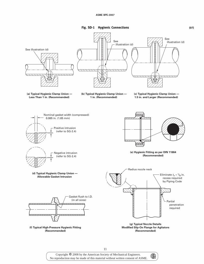
ASME BPE-2007
Fig. SD-1 Hygienic Connections
See illustration (d)
See illustration (d)
(a) Typical Hygienic Clamp Union —
Less Than 1 in. (Recommended)
(b) Typical Hygienic Clamp Union —
1 in. (Recommended)
See illustration (d)
(c) Typical Hygienic Clamp Union —
1.5 in. and Larger (Recommended)
(d) Typical Hygienic Clamp Union —
Allowable Gasket Intrusion
Nominal gasket width (compressed) 0.065 in. (1.65 mm)
Positive intrusion (refer to SG-2.4)
Negative intrusion (refer to SG-2.4)
Gasket flush to I.D. (in all sizes)
(f) Typical High-Pressure Hygienic Fitting
(Recommended)
(e) Hygienic Fitting as per DIN 11864
(Recommended)
Radius nozzle neck
Eliminate tn + 1/8 in. recess required by Piping Code
Partial penetration required
(g) Typical Nozzle Details
Modified Slip-On Flange for Agitators
(Recommended)
11
(07)
Copyright 2008 by the American Society of Mechanical Engineers.No reproduction may be made of this material without written consent of ASME.
c
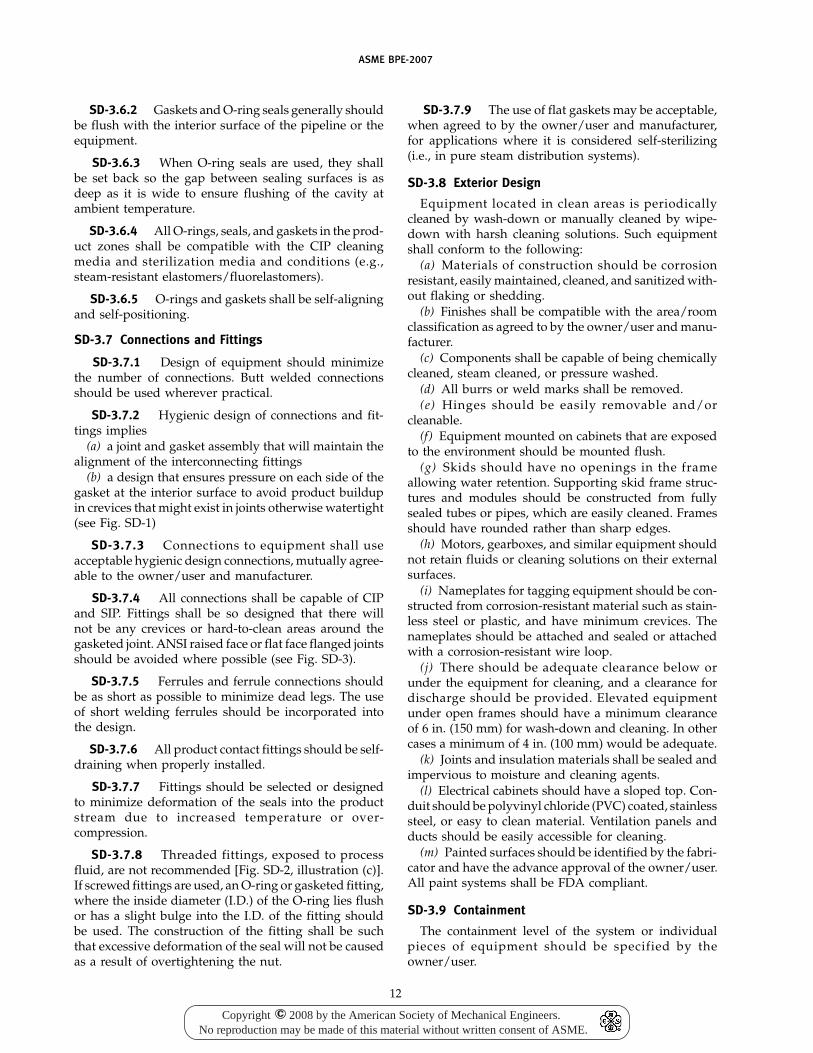
ASME BPE-2007
SD-3.6.2 Gaskets and O-ring seals generally shouldbe flush with the interior surface of the pipeline or theequipment.
SD-3.6.3 When O-ring seals are used, they shallbe set back so the gap between sealing surfaces is asdeep as it is wide to ensure flushing of the cavity atambient temperature.
SD-3.6.4 All O-rings, seals, and gaskets in the prod-uct zones shall be compatible with the CIP cleaningmedia and sterilization media and conditions (e.g.,steam-resistant elastomers/fluorelastomers).
SD-3.6.5 O-rings and gaskets shall be self-aligningand self-positioning.
SD-3.7 Connections and Fittings
SD-3.7.1 Design of equipment should minimizethe number of connections. Butt welded connectionsshould be used wherever practical.
SD-3.7.2 Hygienic design of connections and fit-tings implies
(a) a joint and gasket assembly that will maintain thealignment of the interconnecting fittings
(b) a design that ensures pressure on each side of thegasket at the interior surface to avoid product buildupin crevices that might exist in joints otherwise watertight(see Fig. SD-1)
SD-3.7.3 Connections to equipment shall useacceptable hygienic design connections, mutually agree-able to the owner/user and manufacturer.
SD-3.7.4 All connections shall be capable of CIPand SIP. Fittings shall be so designed that there willnot be any crevices or hard-to-clean areas around thegasketed joint. ANSI raised face or flat face flanged jointsshould be avoided where possible (see Fig. SD-3).
SD-3.7.5 Ferrules and ferrule connections shouldbe as short as possible to minimize dead legs. The useof short welding ferrules should be incorporated intothe design.
SD-3.7.6 All product contact fittings should be self-draining when properly installed.
SD-3.7.7 Fittings should be selected or designedto minimize deformation of the seals into the productstream due to increased temperature or over-compression.
SD-3.7.8 Threaded fittings, exposed to processfluid, are not recommended [Fig. SD-2, illustration (c)].If screwed fittings are used, an O-ring or gasketed fitting,where the inside diameter (I.D.) of the O-ring lies flushor has a slight bulge into the I.D. of the fitting shouldbe used. The construction of the fitting shall be suchthat excessive deformation of the seal will not be causedas a result of overtightening the nut.
12
SD-3.7.9 The use of flat gaskets may be acceptable,when agreed to by the owner/user and manufacturer,for applications where it is considered self-sterilizing(i.e., in pure steam distribution systems).
SD-3.8 Exterior Design
Equipment located in clean areas is periodicallycleaned by wash-down or manually cleaned by wipe-down with harsh cleaning solutions. Such equipmentshall conform to the following:
(a) Materials of construction should be corrosionresistant, easily maintained, cleaned, and sanitized with-out flaking or shedding.
(b) Finishes shall be compatible with the area/roomclassification as agreed to by the owner/user and manu-facturer.
(c) Components shall be capable of being chemicallycleaned, steam cleaned, or pressure washed.
(d) All burrs or weld marks shall be removed.(e) Hinges should be easily removable and/or
cleanable.(f) Equipment mounted on cabinets that are exposed
to the environment should be mounted flush.(g) Skids should have no openings in the frame
allowing water retention. Supporting skid frame struc-tures and modules should be constructed from fullysealed tubes or pipes, which are easily cleaned. Framesshould have rounded rather than sharp edges.
(h) Motors, gearboxes, and similar equipment shouldnot retain fluids or cleaning solutions on their externalsurfaces.
(i) Nameplates for tagging equipment should be con-structed from corrosion-resistant material such as stain-less steel or plastic, and have minimum crevices. Thenameplates should be attached and sealed or attachedwith a corrosion-resistant wire loop.
(j) There should be adequate clearance below orunder the equipment for cleaning, and a clearance fordischarge should be provided. Elevated equipmentunder open frames should have a minimum clearanceof 6 in. (150 mm) for wash-down and cleaning. In othercases a minimum of 4 in. (100 mm) would be adequate.
(k) Joints and insulation materials shall be sealed andimpervious to moisture and cleaning agents.
(l) Electrical cabinets should have a sloped top. Con-duit should be polyvinyl chloride (PVC) coated, stainlesssteel, or easy to clean material. Ventilation panels andducts should be easily accessible for cleaning.
(m) Painted surfaces should be identified by the fabri-cator and have the advance approval of the owner/user.All paint systems shall be FDA compliant.
SD-3.9 Containment
The containment level of the system or individualpieces of equipment should be specified by theowner/user.
Copyright 2008 by the American Society of Mechanical Engineers.No reproduction may be made of this material without written consent of ASME.
c
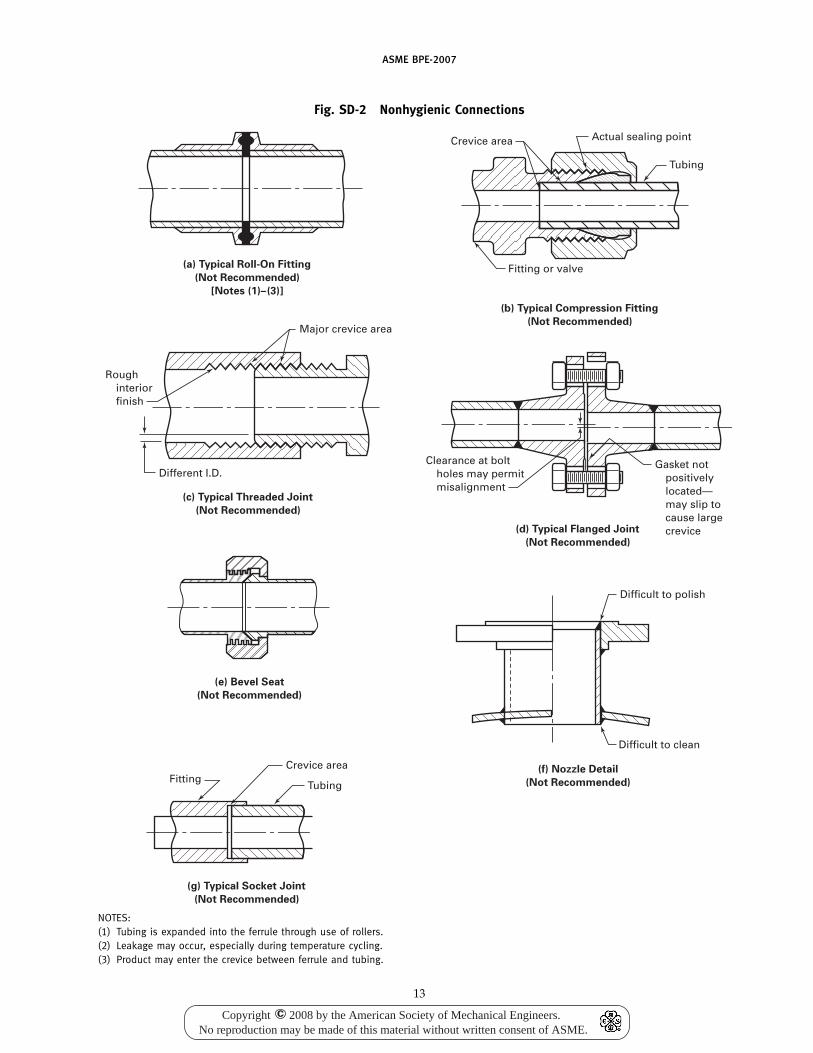
ASME BPE-2007
Fig. SD-2 Nonhygienic Connections
(e) Bevel Seat
(Not Recommended)
FittingTubing
Rough interior finish
Different I.D.Gasket not positively located— may slip to cause large crevice
Clearance at bolt holes may permit misalignment
Major crevice area
Crevice area
(g) Typical Socket Joint
(Not Recommended)
(a) Typical Roll-On Fitting
(Not Recommended)
[Notes (1)–(3)]
(b) Typical Compression Fitting
(Not Recommended)
(d) Typical Flanged Joint
(Not Recommended)
(c) Typical Threaded Joint
(Not Recommended)
Fitting or valve
Tubing
Actual sealing pointCrevice area
Difficult to polish
Difficult to clean
(f) Nozzle Detail
(Not Recommended)
NOTES:(1) Tubing is expanded into the ferrule through use of rollers.(2) Leakage may occur, especially during temperature cycling.(3) Product may enter the crevice between ferrule and tubing.
13
Copyright 2008 by the American Society of Mechanical Engineers.No reproduction may be made of this material without written consent of ASME.
c
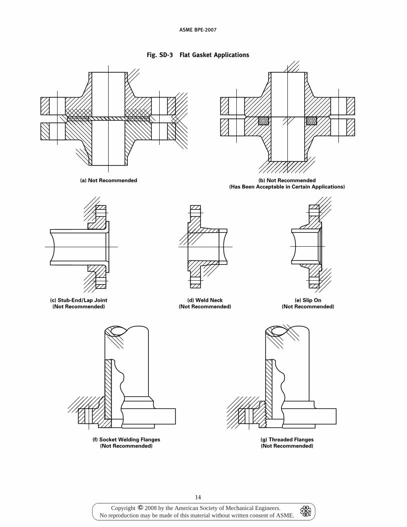
ASME BPE-2007
Fig. SD-3 Flat Gasket Applications
(a) Not Recommended
(c) Stub-End/Lap Joint
(Not Recommended)
(d) Weld Neck
(Not Recommended)
(e) Slip On
(Not Recommended)
(b) Not Recommended
(Has Been Acceptable in Certain Applications)
(f) Socket Welding Flanges
(Not Recommended)
(g) Threaded Flanges
(Not Recommended)
14
Copyright 2008 by the American Society of Mechanical Engineers.No reproduction may be made of this material without written consent of ASME.
c
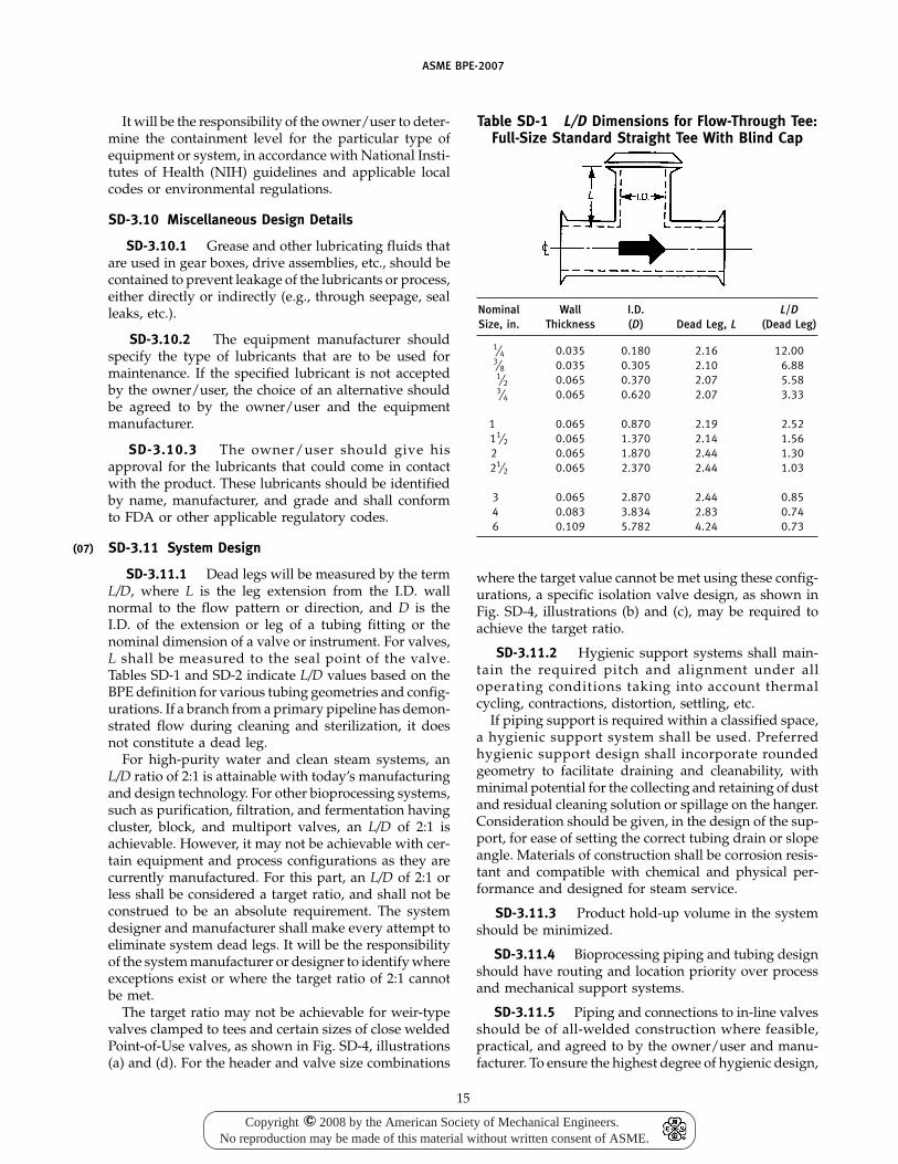
(07)
ASME BPE-2007
It will be the responsibility of the owner/user to deter-mine the containment level for the particular type ofequipment or system, in accordance with National Insti-tutes of Health (NIH) guidelines and applicable localcodes or environmental regulations.
SD-3.10 Miscellaneous Design Details
SD-3.10.1 Grease and other lubricating fluids thatare used in gear boxes, drive assemblies, etc., should becontained to prevent leakage of the lubricants or process,either directly or indirectly (e.g., through seepage, sealleaks, etc.).
SD-3.10.2 The equipment manufacturer shouldspecify the type of lubricants that are to be used formaintenance. If the specified lubricant is not acceptedby the owner/user, the choice of an alternative shouldbe agreed to by the owner/user and the equipmentmanufacturer.
SD-3.10.3 The owner/user should give hisapproval for the lubricants that could come in contactwith the product. These lubricants should be identifiedby name, manufacturer, and grade and shall conformto FDA or other applicable regulatory codes.
SD-3.11 System Design
SD-3.11.1 Dead legs will be measured by the termL/D, where L is the leg extension from the I.D. wallnormal to the flow pattern or direction, and D is theI.D. of the extension or leg of a tubing fitting or thenominal dimension of a valve or instrument. For valves,L shall be measured to the seal point of the valve.Tables SD-1 and SD-2 indicate L/D values based on theBPE definition for various tubing geometries and config-urations. If a branch from a primary pipeline has demon-strated flow during cleaning and sterilization, it doesnot constitute a dead leg.
For high-purity water and clean steam systems, anL/D ratio of 2:1 is attainable with today’s manufacturingand design technology. For other bioprocessing systems,such as purification, filtration, and fermentation havingcluster, block, and multiport valves, an L/D of 2:1 isachievable. However, it may not be achievable with cer-tain equipment and process configurations as they arecurrently manufactured. For this part, an L/D of 2:1 orless shall be considered a target ratio, and shall not beconstrued to be an absolute requirement. The systemdesigner and manufacturer shall make every attempt toeliminate system dead legs. It will be the responsibilityof the system manufacturer or designer to identify whereexceptions exist or where the target ratio of 2:1 cannotbe met.
The target ratio may not be achievable for weir-typevalves clamped to tees and certain sizes of close weldedPoint-of-Use valves, as shown in Fig. SD-4, illustrations(a) and (d). For the header and valve size combinations
15
Table SD-1 L/D Dimensions for Flow-Through Tee:Full-Size Standard Straight Tee With Blind Cap
Nominal Wall I.D. L/DSize, in. Thickness (D) Dead Leg, L (Dead Leg)
1⁄4 0.035 0.180 2.16 12.003⁄8 0.035 0.305 2.10 6.881⁄2 0.065 0.370 2.07 5.583⁄4 0.065 0.620 2.07 3.33
1 0.065 0.870 2.19 2.5211⁄2 0.065 1.370 2.14 1.562 0.065 1.870 2.44 1.3021⁄2 0.065 2.370 2.44 1.03
3 0.065 2.870 2.44 0.854 0.083 3.834 2.83 0.746 0.109 5.782 4.24 0.73
where the target value cannot be met using these config-urations, a specific isolation valve design, as shown inFig. SD-4, illustrations (b) and (c), may be required toachieve the target ratio.
SD-3.11.2 Hygienic support systems shall main-tain the required pitch and alignment under alloperating conditions taking into account thermalcycling, contractions, distortion, settling, etc.
If piping support is required within a classified space,a hygienic support system shall be used. Preferredhygienic support design shall incorporate roundedgeometry to facilitate draining and cleanability, withminimal potential for the collecting and retaining of dustand residual cleaning solution or spillage on the hanger.Consideration should be given, in the design of the sup-port, for ease of setting the correct tubing drain or slopeangle. Materials of construction shall be corrosion resis-tant and compatible with chemical and physical per-formance and designed for steam service.
SD-3.11.3 Product hold-up volume in the systemshould be minimized.
SD-3.11.4 Bioprocessing piping and tubing designshould have routing and location priority over processand mechanical support systems.
SD-3.11.5 Piping and connections to in-line valvesshould be of all-welded construction where feasible,practical, and agreed to by the owner/user and manu-facturer. To ensure the highest degree of hygienic design,
Copyright 2008 by the American Society of Mechanical Engineers.No reproduction may be made of this material without written consent of ASME.
c
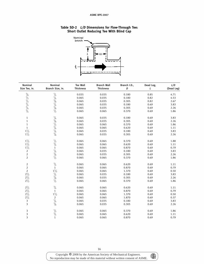
ASME BPE-2007
Table SD-2 L/D Dimensions for Flow-Through Tee:Short Outlet Reducing Tee With Blind Cap
Nominal Nominal Tee Wall Branch Wall Branch I.D., Dead Leg, L/DSize Tee, in. Branch Size, in. Thickness Thickness D L (Dead Leg)
3⁄81⁄4 0.035 0.035 0.180 0.85 4.71
1⁄21⁄4 0.065 0.035 0.180 0.82 4.53
1⁄23⁄8 0.065 0.035 0.305 0.82 2.67
3⁄41⁄4 0.065 0.035 0.180 0.69 3.83
3⁄43⁄8 0.065 0.035 0.305 0.69 2.26
3⁄41⁄2 0.065 0.065 0.370 0.69 1.86
1 1⁄4 0.065 0.035 0.180 0.69 3.831 3⁄8 0.065 0.035 0.305 0.69 2.261 1⁄2 0.065 0.065 0.370 0.69 1.861 3⁄4 0.065 0.065 0.620 0.69 1.11
11⁄21⁄4 0.065 0.035 0.180 0.69 3.83
11⁄23⁄8 0.065 0.035 0.305 0.69 2.26
11⁄21⁄2 0.065 0.065 0.370 0.69 1.88
11⁄23⁄4 0.065 0.065 0.620 0.69 1.11
11⁄2 1 0.065 0.065 0.870 0.69 0.792 1⁄4 0.065 0.035 0.180 0.69 3.832 3⁄8 0.065 0.035 0.305 0.69 2.262 1⁄2 0.065 0.065 0.370 0.69 1.86
2 3⁄4 0.065 0.065 0.620 0.69 1.112 1 0.065 0.065 0.870 0.69 0.792 11⁄2 0.065 0.065 1.370 0.69 0.50
21⁄21⁄4 0.065 0.035 0.180 0.69 3.83
21⁄23⁄8 0.065 0.035 0.305 0.69 2.26
21⁄21⁄2 0.065 0.065 0.370 0.69 1.86
21⁄23⁄4 0.065 0.065 0.620 0.69 1.11
21⁄2 1 0.065 0.065 0.870 0.69 0.7921⁄2 11⁄2 0.065 0.065 1.370 0.69 0.5021⁄2 2 0.065 0.065 1.870 0.69 0.37
3 1⁄4 0.065 0.035 0.180 0.69 3.833 3⁄8 0.065 0.035 0.305 0.69 2.26
3 1⁄2 0.065 0.065 0.370 0.69 1.863 3⁄4 0.065 0.065 0.620 0.69 1.113 1 0.065 0.065 0.870 0.69 0.79
16
Copyright 2008 by the American Society of Mechanical Engineers.No reproduction may be made of this material without written consent of ASME.
c
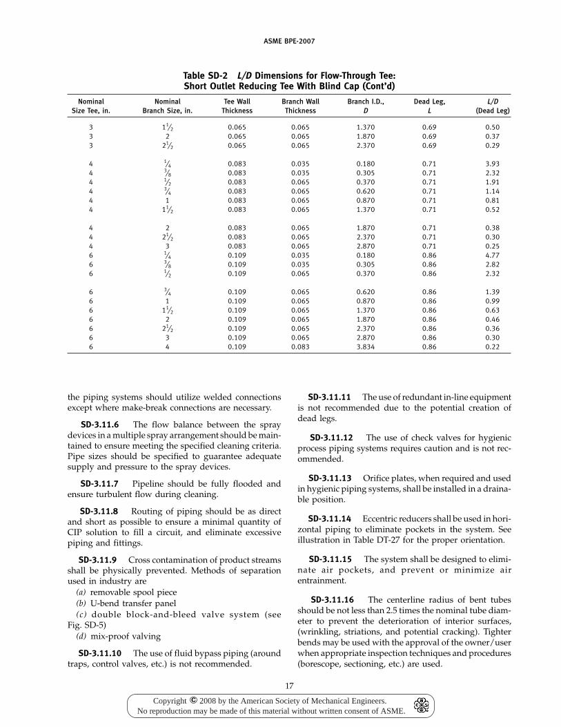
ASME BPE-2007
Table SD-2 L/D Dimensions for Flow-Through Tee:Short Outlet Reducing Tee With Blind Cap (Cont’d)
Nominal Nominal Tee Wall Branch Wall Branch I.D., Dead Leg, L/DSize Tee, in. Branch Size, in. Thickness Thickness D L (Dead Leg)
3 11⁄2 0.065 0.065 1.370 0.69 0.503 2 0.065 0.065 1.870 0.69 0.373 21⁄2 0.065 0.065 2.370 0.69 0.29
4 1⁄4 0.083 0.035 0.180 0.71 3.934 3⁄8 0.083 0.035 0.305 0.71 2.324 1⁄2 0.083 0.065 0.370 0.71 1.914 3⁄4 0.083 0.065 0.620 0.71 1.144 1 0.083 0.065 0.870 0.71 0.814 11⁄2 0.083 0.065 1.370 0.71 0.52
4 2 0.083 0.065 1.870 0.71 0.384 21⁄2 0.083 0.065 2.370 0.71 0.304 3 0.083 0.065 2.870 0.71 0.256 1⁄4 0.109 0.035 0.180 0.86 4.776 3⁄8 0.109 0.035 0.305 0.86 2.826 1⁄2 0.109 0.065 0.370 0.86 2.32
6 3⁄4 0.109 0.065 0.620 0.86 1.396 1 0.109 0.065 0.870 0.86 0.996 11⁄2 0.109 0.065 1.370 0.86 0.636 2 0.109 0.065 1.870 0.86 0.466 21⁄2 0.109 0.065 2.370 0.86 0.366 3 0.109 0.065 2.870 0.86 0.306 4 0.109 0.083 3.834 0.86 0.22
the piping systems should utilize welded connectionsexcept where make-break connections are necessary.
SD-3.11.6 The flow balance between the spraydevices in a multiple spray arrangement should be main-tained to ensure meeting the specified cleaning criteria.Pipe sizes should be specified to guarantee adequatesupply and pressure to the spray devices.
SD-3.11.7 Pipeline should be fully flooded andensure turbulent flow during cleaning.
SD-3.11.8 Routing of piping should be as directand short as possible to ensure a minimal quantity ofCIP solution to fill a circuit, and eliminate excessivepiping and fittings.
SD-3.11.9 Cross contamination of product streamsshall be physically prevented. Methods of separationused in industry are
(a) removable spool piece(b) U-bend transfer panel(c) double block-and-bleed valve system (see
Fig. SD-5)(d) mix-proof valving
SD-3.11.10 The use of fluid bypass piping (aroundtraps, control valves, etc.) is not recommended.
17
SD-3.11.11 The use of redundant in-line equipmentis not recommended due to the potential creation ofdead legs.
SD-3.11.12 The use of check valves for hygienicprocess piping systems requires caution and is not rec-ommended.
SD-3.11.13 Orifice plates, when required and usedin hygienic piping systems, shall be installed in a draina-ble position.
SD-3.11.14 Eccentric reducers shall be used in hori-zontal piping to eliminate pockets in the system. Seeillustration in Table DT-27 for the proper orientation.
SD-3.11.15 The system shall be designed to elimi-nate air pockets, and prevent or minimize airentrainment.
SD-3.11.16 The centerline radius of bent tubesshould be not less than 2.5 times the nominal tube diam-eter to prevent the deterioration of interior surfaces,(wrinkling, striations, and potential cracking). Tighterbends may be used with the approval of the owner/userwhen appropriate inspection techniques and procedures(borescope, sectioning, etc.) are used.
Copyright 2008 by the American Society of Mechanical Engineers.No reproduction may be made of this material without written consent of ASME.
c
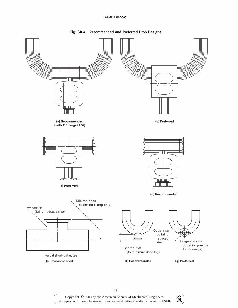
ASME BPE-2007
Fig. SD-4 Recommended and Preferred Drop Designs
Branch(full or reduced size)
Minimal span(room for clamp only)
Short outlet(to minimize dead leg)
Typical short-outlet tee
Tangential sideoutlet (to providefull drainage)
Outlet maybe full orreducedsize
(a) Recommended
(with 2.0 Target L/D)
(c) Preferred
(d) Recommended
(e) Recommended (f) Recommended (g) Preferred
(b) Preferred
18
Copyright 2008 by the American Society of Mechanical Engineers.No reproduction may be made of this material without written consent of ASME.
c
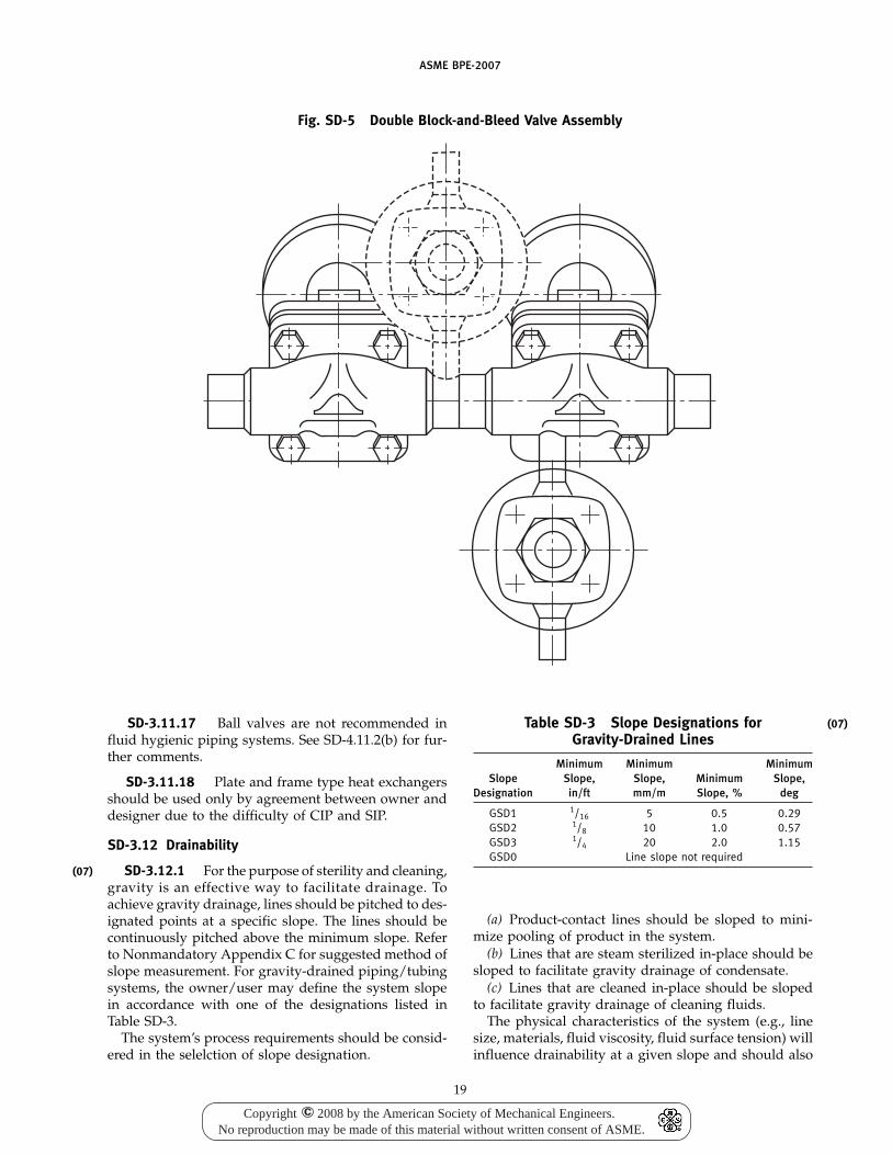
(07)
ASME BPE-2007
Fig. SD-5 Double Block-and-Bleed Valve Assembly
SD-3.11.17 Ball valves are not recommended influid hygienic piping systems. See SD-4.11.2(b) for fur-ther comments.
SD-3.11.18 Plate and frame type heat exchangersshould be used only by agreement between owner anddesigner due to the difficulty of CIP and SIP.
SD-3.12 Drainability
SD-3.12.1 For the purpose of sterility and cleaning,gravity is an effective way to facilitate drainage. Toachieve gravity drainage, lines should be pitched to des-ignated points at a specific slope. The lines should becontinuously pitched above the minimum slope. Referto Nonmandatory Appendix C for suggested method ofslope measurement. For gravity-drained piping/tubingsystems, the owner/user may define the system slopein accordance with one of the designations listed inTable SD-3.
The system’s process requirements should be consid-ered in the selelction of slope designation.
19
Table SD-3 Slope Designations forGravity-Drained Lines
Minimum Minimum MinimumSlope Slope, Slope, Minimum Slope,
Designation in/ft mm/m Slope, % deg
GSD1 1/16 5 0.5 0.29GSD2 1/8 10 1.0 0.57GSD3 1/4 20 2.0 1.15GSD0 Line slope not required
(a) Product-contact lines should be sloped to mini-mize pooling of product in the system.
(b) Lines that are steam sterilized in-place should besloped to facilitate gravity drainage of condensate.
(c) Lines that are cleaned in-place should be slopedto facilitate gravity drainage of cleaning fluids.
The physical characteristics of the system (e.g., linesize, materials, fluid viscosity, fluid surface tension) willinfluence drainability at a given slope and should also
(07)
Copyright 2008 by the American Society of Mechanical Engineers.No reproduction may be made of this material without written consent of ASME.
c
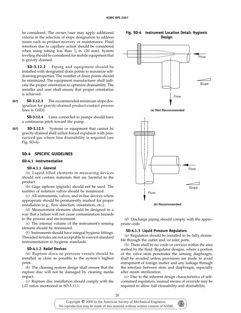
(07)
(07)
ASME BPE-2007
be considered. The owner/user may apply additionalcriteria in the selection of slope designation to addressissues such as product recovery or maintenance. Fluidretention due to capillary action should be consideredwhen using tubing less than 3⁄4 in. (20 mm). Systemleveling should be considered for mobile equipment thatis gravity drained.
SD-3.12.2 Piping and equipment should beinstalled with designated drain points to maximize self-draining properties. The number of drain points shouldbe minimized. The equipment manufacturer shall indi-cate the proper orientation to optimize drainability. Theinstaller and user shall ensure that proper orientationis achieved.
SD-3.12.3 The recommended minimum slope des-ignation for gravity-drained product-contact processlines is GSD2.
SD-3.12.4 Lines connected to pumps should havea continuous pitch toward the pump.
SD-3.12.5 Systems or equipment that cannot begravity-drained shall utilize forced expulsion with pres-surized gas where line drainability is required (seeFig. SD-6).
SD-4 SPECIFIC GUIDELINES
SD-4.1 Instrumentation
SD-4.1.1 General(a) Liquid filled elements in measuring devices
should not contain materials that are harmful to theproduct.
(b) Gage siphons (pigtails) should not be used. Thenumber of isolation valves should be minimized.
(c) All instruments, valves, and in-line devices whereappropriate should be permanently marked for properinstallation (e.g., flow direction, orientation, etc.).
(d) Measurement elements should be designed in away that a failure will not cause contamination hazardsto the process and environment.
(e) The internal volume of the instrument’s sensingelement should be minimized.
(f) Instruments should have integral hygienic fittings.Threaded ferrules are not acceptable to convert standardinstrumentation to hygienic standards.
SD-4.1.2 Relief Devices(a) Rupture discs on pressure vessels should be
installed as close as possible to the system’s highestpoint.
(b) The cleaning system design shall ensure that therupture disc will not be damaged by cleaning mediaimpact.
(c) Rupture disc installation should comply with theL/D ratios mentioned in SD-3.11.1.
20
Fig. SD-6 Instrument Location Detail: HygienicDesign
(a) Not Recommended
(b) Recommended
Flow
Slope
Flow
Flow
Slope
Flow
(d) Discharge piping should comply with the appro-priate code.
SD-4.1.3 Liquid Pressure Regulators(a) Regulators should be installed to be fully draina-
ble through the outlet and/or inlet ports.(b) There shall be no voids or crevices within the area
wetted by the fluid. Regulator designs, where a portionof the valve stem penetrates the sensing diaphragm,shall be avoided unless provisions are made to avoidentrapment of foreign matter and any leakage throughthe interface between stem and diaphragm, especiallyafter steam sterilization.
(c) Due to the inherent design characteristics of self-contained regulators, manual means of override may berequired to allow full cleanability and drainability.
Copyright 2008 by the American Society of Mechanical Engineers.No reproduction may be made of this material without written consent of ASME.
c
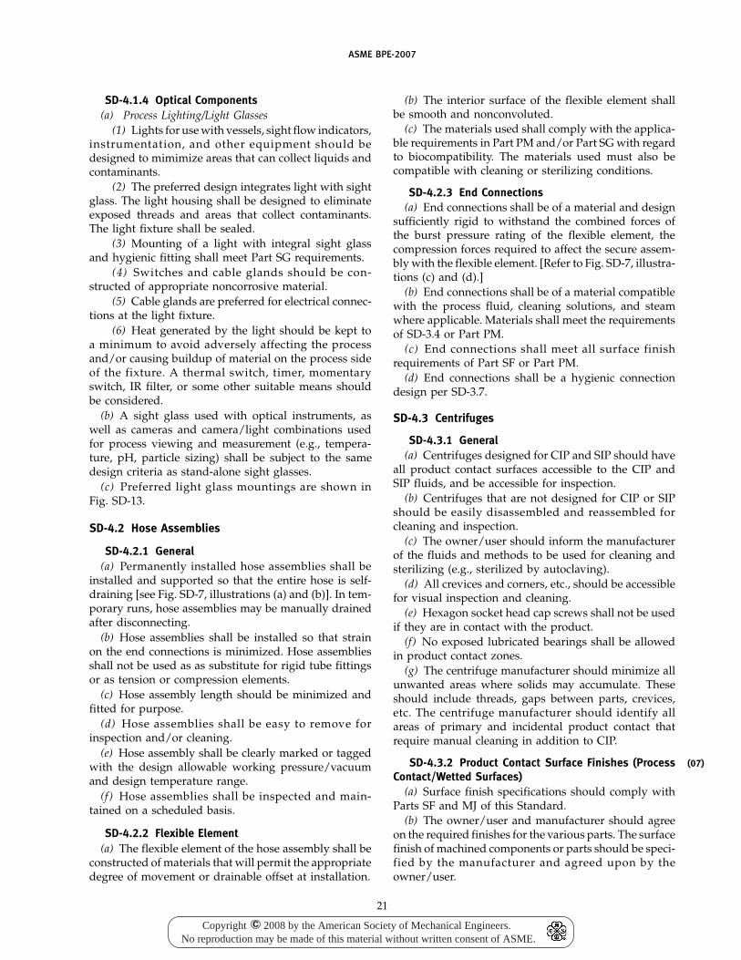
ASME BPE-2007
SD-4.1.4 Optical Components(a) Process Lighting/Light Glasses
(1) Lights for use with vessels, sight flow indicators,instrumentation, and other equipment should bedesigned to mimimize areas that can collect liquids andcontaminants.
(2) The preferred design integrates light with sightglass. The light housing shall be designed to eliminateexposed threads and areas that collect contaminants.The light fixture shall be sealed.
(3) Mounting of a light with integral sight glassand hygienic fitting shall meet Part SG requirements.
(4) Switches and cable glands should be con-structed of appropriate noncorrosive material.
(5) Cable glands are preferred for electrical connec-tions at the light fixture.
(6) Heat generated by the light should be kept toa minimum to avoid adversely affecting the processand/or causing buildup of material on the process sideof the fixture. A thermal switch, timer, momentaryswitch, IR filter, or some other suitable means shouldbe considered.
(b) A sight glass used with optical instruments, aswell as cameras and camera/light combinations usedfor process viewing and measurement (e.g., tempera-ture, pH, particle sizing) shall be subject to the samedesign criteria as stand-alone sight glasses.
(c) Preferred light glass mountings are shown inFig. SD-13.
SD-4.2 Hose Assemblies
SD-4.2.1 General(a) Permanently installed hose assemblies shall be
installed and supported so that the entire hose is self-draining [see Fig. SD-7, illustrations (a) and (b)]. In tem-porary runs, hose assemblies may be manually drainedafter disconnecting.
(b) Hose assemblies shall be installed so that strainon the end connections is minimized. Hose assembliesshall not be used as as substitute for rigid tube fittingsor as tension or compression elements.
(c) Hose assembly length should be minimized andfitted for purpose.
(d) Hose assemblies shall be easy to remove forinspection and/or cleaning.
(e) Hose assembly shall be clearly marked or taggedwith the design allowable working pressure/vacuumand design temperature range.
(f) Hose assemblies shall be inspected and main-tained on a scheduled basis.
SD-4.2.2 Flexible Element(a) The flexible element of the hose assembly shall be
constructed of materials that will permit the appropriatedegree of movement or drainable offset at installation.
21
(b) The interior surface of the flexible element shallbe smooth and nonconvoluted.
(c) The materials used shall comply with the applica-ble requirements in Part PM and/or Part SG with regardto biocompatibility. The materials used must also becompatible with cleaning or sterilizing conditions.
SD-4.2.3 End Connections(a) End connections shall be of a material and design
sufficiently rigid to withstand the combined forces ofthe burst pressure rating of the flexible element, thecompression forces required to affect the secure assem-bly with the flexible element. [Refer to Fig. SD-7, illustra-tions (c) and (d).]
(b) End connections shall be of a material compatiblewith the process fluid, cleaning solutions, and steamwhere applicable. Materials shall meet the requirementsof SD-3.4 or Part PM.
(c) End connections shall meet all surface finishrequirements of Part SF or Part PM.
(d) End connections shall be a hygienic connectiondesign per SD-3.7.
SD-4.3 Centrifuges
SD-4.3.1 General(a) Centrifuges designed for CIP and SIP should have
all product contact surfaces accessible to the CIP andSIP fluids, and be accessible for inspection.
(b) Centrifuges that are not designed for CIP or SIPshould be easily disassembled and reassembled forcleaning and inspection.
(c) The owner/user should inform the manufacturerof the fluids and methods to be used for cleaning andsterilizing (e.g., sterilized by autoclaving).
(d) All crevices and corners, etc., should be accessiblefor visual inspection and cleaning.
(e) Hexagon socket head cap screws shall not be usedif they are in contact with the product.
(f) No exposed lubricated bearings shall be allowedin product contact zones.
(g) The centrifuge manufacturer should minimize allunwanted areas where solids may accumulate. Theseshould include threads, gaps between parts, crevices,etc. The centrifuge manufacturer should identify allareas of primary and incidental product contact thatrequire manual cleaning in addition to CIP.
SD-4.3.2 Product Contact Surface Finishes (ProcessContact/Wetted Surfaces)
(a) Surface finish specifications should comply withParts SF and MJ of this Standard.
(b) The owner/user and manufacturer should agreeon the required finishes for the various parts. The surfacefinish of machined components or parts should be speci-fied by the manufacturer and agreed upon by theowner/user.
(07)
Copyright 2008 by the American Society of Mechanical Engineers.No reproduction may be made of this material without written consent of ASME.
c
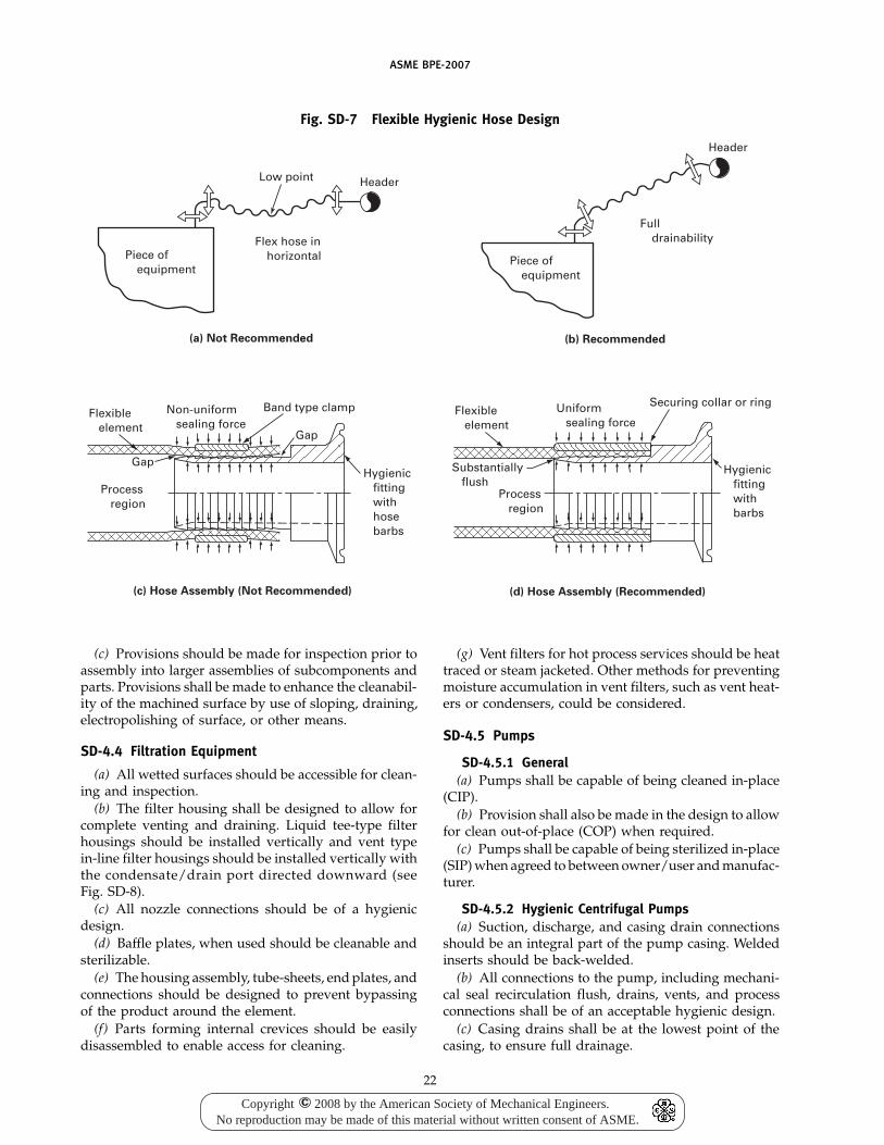
ASME BPE-2007
Fig. SD-7 Flexible Hygienic Hose Design
Full drainability
Piece of equipment
Piece of equipment
Flex hose in horizontal
Header
Low point Header
(a) Not Recommended (b) Recommended
Hygienic fitting with hose barbs
Flexible element
Gap
Process region
Gap
Band type clampNon-uniform sealing force
(c) Hose Assembly (Not Recommended)
Flexible element
Substantially flush
Process region
Hygienic fitting with barbs
Securing collar or ringUniform sealing force
(d) Hose Assembly (Recommended)
(c) Provisions should be made for inspection prior toassembly into larger assemblies of subcomponents andparts. Provisions shall be made to enhance the cleanabil-ity of the machined surface by use of sloping, draining,electropolishing of surface, or other means.
SD-4.4 Filtration Equipment
(a) All wetted surfaces should be accessible for clean-ing and inspection.
(b) The filter housing shall be designed to allow forcomplete venting and draining. Liquid tee-type filterhousings should be installed vertically and vent typein-line filter housings should be installed vertically withthe condensate/drain port directed downward (seeFig. SD-8).
(c) All nozzle connections should be of a hygienicdesign.
(d) Baffle plates, when used should be cleanable andsterilizable.
(e) The housing assembly, tube-sheets, end plates, andconnections should be designed to prevent bypassingof the product around the element.
(f) Parts forming internal crevices should be easilydisassembled to enable access for cleaning.
22
(g) Vent filters for hot process services should be heattraced or steam jacketed. Other methods for preventingmoisture accumulation in vent filters, such as vent heat-ers or condensers, could be considered.
SD-4.5 Pumps
SD-4.5.1 General(a) Pumps shall be capable of being cleaned in-place
(CIP).(b) Provision shall also be made in the design to allow
for clean out-of-place (COP) when required.(c) Pumps shall be capable of being sterilized in-place
(SIP) when agreed to between owner/user and manufac-turer.
SD-4.5.2 Hygienic Centrifugal Pumps(a) Suction, discharge, and casing drain connections
should be an integral part of the pump casing. Weldedinserts should be back-welded.
(b) All connections to the pump, including mechani-cal seal recirculation flush, drains, vents, and processconnections shall be of an acceptable hygienic design.
(c) Casing drains shall be at the lowest point of thecasing, to ensure full drainage.
Copyright 2008 by the American Society of Mechanical Engineers.No reproduction may be made of this material without written consent of ASME.
c
ASME BPE-2007
Fig. SD-8 Tank/Vessel Vent Filters
(a) In-Line Hygienic Design
(Preferred)
Minimum (target L/D of 2:1)
(b) T-Type Less Hygienic Design
(Recommended)
They should be both horizontal and parallel to thepump centerline or perpendicular to the casing’s tangentat a predetermined downward angle.
(d) The use of an elbow type casing drain is not recom-mended. When possible, the casing drain connectionshould project a minimum distance, approaching thetarget L/D ratio of 2:1.
(e) Diaphragm valves are preferred for casing drains.(f) Pump discharge connection should be tilted at
45 deg or the appropriate angle, where practical, to allowfor full venting of the casing, when agreed to by theowner/user.
(g) Impeller drive pins, set screws, rotor pins, etc.,shall be designed to minimize crevices, holes, etc., onproduct contact surfaces, where practical.
(h) Pump casings shall be designed with minimumhold-up volume.
(i) All pump seals shall be designed to prevent con-tamination of the process fluid, consistent with the pro-cess requirements of that fluid.
(j) Shrouded impellers should not be used unlessapproved by all parties, since they cannot be cleaned inplace.
SD-4.5.3 Hygienic Positive Displacement Pumps(a) When possible, positive displacement pumps
should be configured with vertically mounted inlets andoutlets to promote drainability and venting.
(b) When using internal bypass pressure reliefdevices, they should be of a hygienic design. It is pre-ferred that an external, piping mounted relief device
23
(hygienic rupture disc) rather than a pump mountedbypass be used.
SD-4.6 Process (Hygienic) Valves
SD-4.6.1 General: Valves(a) Process flow valves (e.g., diaphragm valves)
should be of a body and port design so that the bodywill optimize drainability when properly installed. Allhygienic valves should be welded into the process line.
(b) Valve surfaces that may become product contactsurfaces if a component (e.g., diaphragm) fails in serviceshall be readily accessible for inspection, maintenance,and cleaning.
(c) Tee-body and cross-body sanitary valves shall bepositioned to ensure that the valve body will optimizedrainability when installed in a piping system.
(d) Isolation and block valves, which are located onbosses or tees, should be installed close-coupled toreduce or eliminate dead legs. (When the stem of a three-port valve moves from one position to the other suchthat all ports are connected for a brief period of time,this will cause mixing at first and then a resultant dead-end in the previous path while the current path is inuse.) If this is not acceptable, two shutoff valves maybe used instead.
(e) Multiport divert valves shall be installed to opti-mize drainability.
(f) The internal volume of the valve should be keptto a minimum.
Copyright 2008 by the American Society of Mechanical Engineers.No reproduction may be made of this material without written consent of ASME.
c
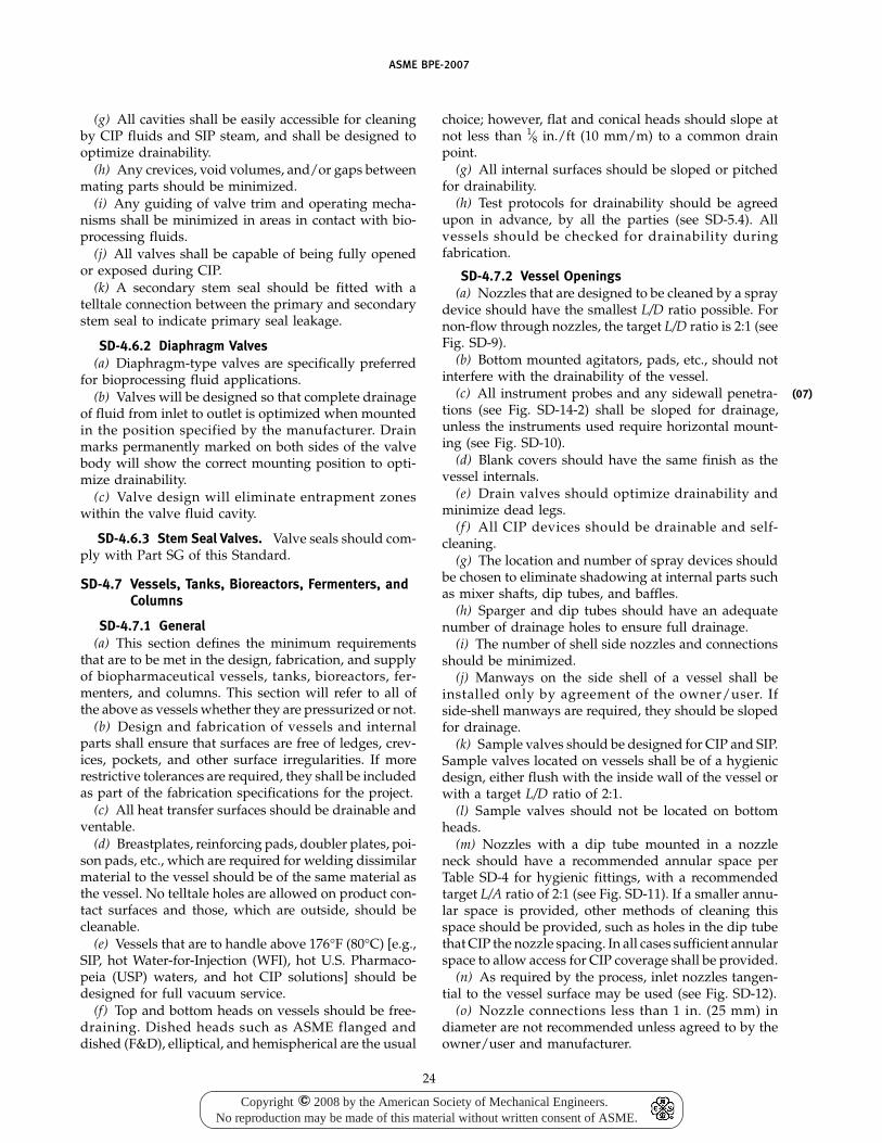
ASME BPE-2007
(g) All cavities shall be easily accessible for cleaningby CIP fluids and SIP steam, and shall be designed tooptimize drainability.
(h) Any crevices, void volumes, and/or gaps betweenmating parts should be minimized.
(i) Any guiding of valve trim and operating mecha-nisms shall be minimized in areas in contact with bio-processing fluids.
(j) All valves shall be capable of being fully openedor exposed during CIP.
(k) A secondary stem seal should be fitted with atelltale connection between the primary and secondarystem seal to indicate primary seal leakage.
SD-4.6.2 Diaphragm Valves(a) Diaphragm-type valves are specifically preferred
for bioprocessing fluid applications.(b) Valves will be designed so that complete drainage
of fluid from inlet to outlet is optimized when mountedin the position specified by the manufacturer. Drainmarks permanently marked on both sides of the valvebody will show the correct mounting position to opti-mize drainability.
(c) Valve design will eliminate entrapment zoneswithin the valve fluid cavity.
SD-4.6.3 Stem Seal Valves. Valve seals should com-ply with Part SG of this Standard.
SD-4.7 Vessels, Tanks, Bioreactors, Fermenters, andColumns
SD-4.7.1 General(a) This section defines the minimum requirements
that are to be met in the design, fabrication, and supplyof biopharmaceutical vessels, tanks, bioreactors, fer-menters, and columns. This section will refer to all ofthe above as vessels whether they are pressurized or not.
(b) Design and fabrication of vessels and internalparts shall ensure that surfaces are free of ledges, crev-ices, pockets, and other surface irregularities. If morerestrictive tolerances are required, they shall be includedas part of the fabrication specifications for the project.
(c) All heat transfer surfaces should be drainable andventable.
(d) Breastplates, reinforcing pads, doubler plates, poi-son pads, etc., which are required for welding dissimilarmaterial to the vessel should be of the same material asthe vessel. No telltale holes are allowed on product con-tact surfaces and those, which are outside, should becleanable.
(e) Vessels that are to handle above 176°F (80°C) [e.g.,SIP, hot Water-for-Injection (WFI), hot U.S. Pharmaco-peia (USP) waters, and hot CIP solutions] should bedesigned for full vacuum service.
(f) Top and bottom heads on vessels should be free-draining. Dished heads such as ASME flanged anddished (F&D), elliptical, and hemispherical are the usual
24
choice; however, flat and conical heads should slope atnot less than 1⁄8 in./ft (10 mm/m) to a common drainpoint.
(g) All internal surfaces should be sloped or pitchedfor drainability.
(h) Test protocols for drainability should be agreedupon in advance, by all the parties (see SD-5.4). Allvessels should be checked for drainability duringfabrication.
SD-4.7.2 Vessel Openings(a) Nozzles that are designed to be cleaned by a spray
device should have the smallest L/D ratio possible. Fornon-flow through nozzles, the target L/D ratio is 2:1 (seeFig. SD-9).
(b) Bottom mounted agitators, pads, etc., should notinterfere with the drainability of the vessel.
(c) All instrument probes and any sidewall penetra-tions (see Fig. SD-14-2) shall be sloped for drainage,unless the instruments used require horizontal mount-ing (see Fig. SD-10).
(d) Blank covers should have the same finish as thevessel internals.
(e) Drain valves should optimize drainability andminimize dead legs.
(f ) All CIP devices should be drainable and self-cleaning.
(g) The location and number of spray devices shouldbe chosen to eliminate shadowing at internal parts suchas mixer shafts, dip tubes, and baffles.
(h) Sparger and dip tubes should have an adequatenumber of drainage holes to ensure full drainage.
(i) The number of shell side nozzles and connectionsshould be minimized.
(j) Manways on the side shell of a vessel shall beinstalled only by agreement of the owner/user. Ifside-shell manways are required, they should be slopedfor drainage.
(k) Sample valves should be designed for CIP and SIP.Sample valves located on vessels shall be of a hygienicdesign, either flush with the inside wall of the vessel orwith a target L/D ratio of 2:1.
(l) Sample valves should not be located on bottomheads.
(m) Nozzles with a dip tube mounted in a nozzleneck should have a recommended annular space perTable SD-4 for hygienic fittings, with a recommendedtarget L/A ratio of 2:1 (see Fig. SD-11). If a smaller annu-lar space is provided, other methods of cleaning thisspace should be provided, such as holes in the dip tubethat CIP the nozzle spacing. In all cases sufficient annularspace to allow access for CIP coverage shall be provided.
(n) As required by the process, inlet nozzles tangen-tial to the vessel surface may be used (see Fig. SD-12).
(o) Nozzle connections less than 1 in. (25 mm) indiameter are not recommended unless agreed to by theowner/user and manufacturer.
(07)
Copyright 2008 by the American Society of Mechanical Engineers.No reproduction may be made of this material without written consent of ASME.
c
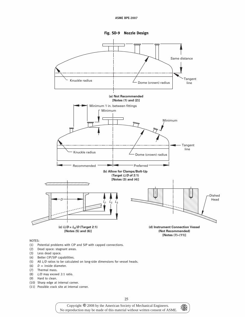
ASME BPE-2007
Fig. SD-9 Nozzle Design
(a) Not Recommended
[Notes (1) and (2)]
(b) Allow for Clamps/Bolt-Up
(Target L/D of 2:1)
[Notes (3) and (4)]
(c) L/D = L3/D (Target 2:1)
[Notes (5) and (6)]
(d) Instrument Connection Vessel
(Not Recommended)
[Notes (7)–(11)]
Same distance
Tangent lineDome (crown) radius
Knuckle radius
PreferredRecommended
Knuckle radiusDome (crown) radius
Minimum
Minimum 1 in. between fittingsMinimum
Tangent line
L2L1D
L3
Dished Head
NOTES:(1) Potential problems with CIP and SIP with capped connections.(2) Dead space: stagnant areas.(3) Less dead space.(4) Better CIP/SIP capabilities.(5) All L/D ratios to be calculated on long-side dimensions for vessel heads.(6) D p inside diameter.(7) Thermal mass.(8) L/D may exceed 2:1 ratio.(9) Hard to clean.(10) Sharp edge at internal corner.(11) Possible crack site at internal corner.
25
Copyright 2008 by the American Society of Mechanical Engineers.No reproduction may be made of this material without written consent of ASME.
c
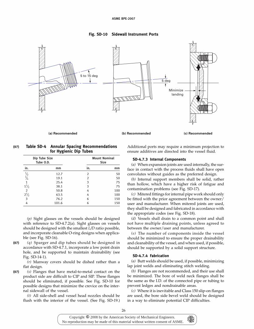
(07)
(07)
(07)
ASME BPE-2007
Fig. SD-10 Sidewall Instrument Ports
(a) Recommended (b) Recommended
5 to 15 deg5 deg
(c) Recommended
Minimize landing
Table SD-4 Annular Spacing Recommendationsfor Hygienic Dip Tubes
Dip Tube Size Mount NominalTube O.D. Size
in. mm in. mm1⁄2 12.7 2 503⁄4 19.1 2 501 25.4 3 75
11⁄2 38.1 3 752 50.8 4 100
21⁄2 63.5 4 1003 76.2 6 1504 101.6 6 150
(p) Sight glasses on the vessels should be designedwith reference to SD-4.7.2(a). Sight glasses on vesselsshould be designed with the smallest L/D ratio possible,and incorporate cleanable O-ring designs when applica-ble (see Fig. SD-16).
(q) Sparger and dip tubes should be designed inaccordance with SD-4.7.1, incorporate a low point drainhole, and be supported to maintain drainability (seeFig. SD-14-1).
(r) Manway covers should be dished rather than aflat design.
(s) Flanges that have metal-to-metal contact on theproduct side are difficult to CIP and SIP. These flangesshould be eliminated, if possible. See Fig. SD-10 forpossible designs that minimize the crevice on the inter-nal sidewall of the vessel.
(t) All side-shell and vessel head nozzles should beflush with the interior of the vessel. (See Fig. SD-19.)
26
Additional ports may require a minimum projection toensure additives are directed into the vessel fluid.
SD-4.7.3 Internal Components(a) When expansion joints are used internally, the sur-
face in contact with the process fluids shall have openconvolutes without guides as the preferred design.
(b) Internal support members shall be solid, ratherthan hollow, which have a higher risk of fatigue andcontamination problems (see Fig. SD-17).
(c) Mitered fittings for internal pipe work should onlybe fitted with the prior agreement between the owner/user and manufacturer. When mitered joints are used,they shall be designed and fabricated in accordance withthe appropriate codes (see Fig. SD-18).
(d) Vessels shall drain to a common point and shallnot have multiple draining points, unless agreed tobetween the owner/user and manufacturer.
(e) The number of components inside the vesselshould be minimized to ensure the proper drainabilityand cleanability of the vessel, and when used, if possible,should be supported by a solid support structure.
SD-4.7.4 Fabrication(a) Butt welds should be used, if possible, minimizing
lap joint welds and eliminating stitch welding.(b) Flanges are not recommended, and their use shall
be minimized. The bore of weld neck flanges shall bethe same as the I.D. of the connected pipe or tubing toprevent ledges and nondrainable areas.
(c) Where it is inevitable and Class 150 slip-on flangesare used, the bore side bevel weld should be designedin a way to eliminate potential CIP difficulties.
Copyright 2008 by the American Society of Mechanical Engineers.No reproduction may be made of this material without written consent of ASME.
c
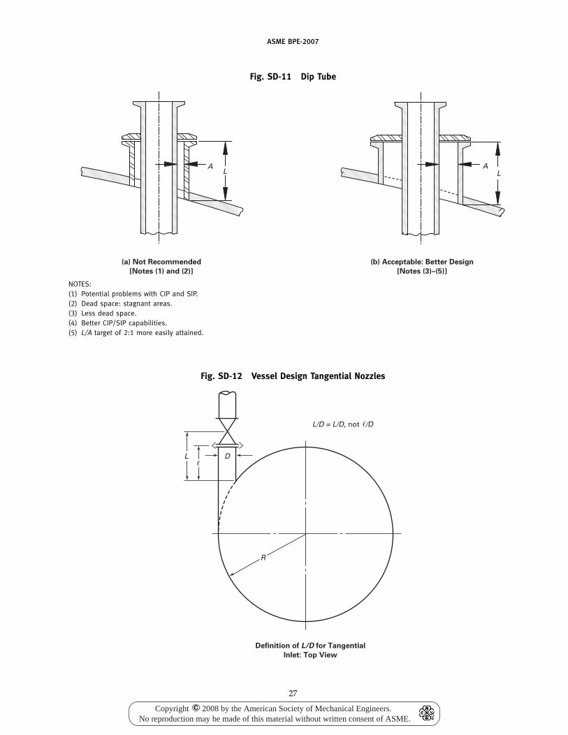
ASME BPE-2007
Fig. SD-11 Dip Tube
(a) Not Recommended
[Notes (1) and (2)]
(b) Acceptable: Better Design
[Notes (3)–(5)]
AL L
A
NOTES:(1) Potential problems with CIP and SIP.(2) Dead space: stagnant areas.(3) Less dead space.(4) Better CIP/SIP capabilities.(5) L/A target of 2:1 more easily attained.
Fig. SD-12 Vessel Design Tangential Nozzles
R
DL
L/D = L/D, not /D
Definition of L/D for Tangential
Inlet: Top View
27
Copyright 2008 by the American Society of Mechanical Engineers.No reproduction may be made of this material without written consent of ASME.
c
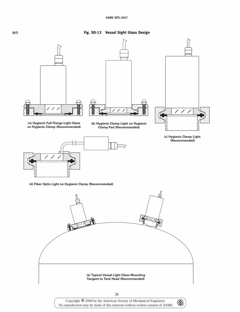
(07)
ASME BPE-2007
Fig. SD-13 Vessel Sight Glass Design
(a) Hygienic Full Flange Light Glass
on Hygienic Clamp (Recommended)(b) Hygienic Clamp Light on Hygienic
Clamp Pad (Recommended)
(c) Hygienic Clamp Light
(Recommended)
(e) Typical Vessel Light Glass Mounting
Tangent to Tank Head (Recommended)
(d) Fiber Optic Light on Hygienic Clamp (Recommended)
28
Copyright 2008 by the American Society of Mechanical Engineers.No reproduction may be made of this material without written consent of ASME.
c
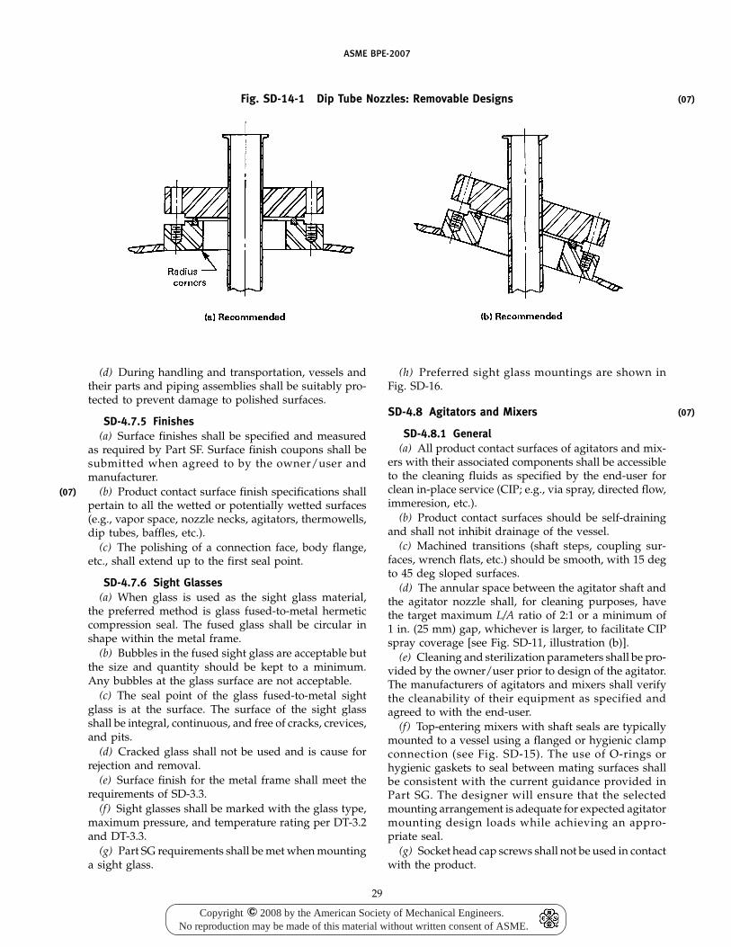
(07)
ASME BPE-2007
Fig. SD-14-1 Dip Tube Nozzles: Removable Designs
(d) During handling and transportation, vessels andtheir parts and piping assemblies shall be suitably pro-tected to prevent damage to polished surfaces.
SD-4.7.5 Finishes(a) Surface finishes shall be specified and measured
as required by Part SF. Surface finish coupons shall besubmitted when agreed to by the owner/user andmanufacturer.
(b) Product contact surface finish specifications shallpertain to all the wetted or potentially wetted surfaces(e.g., vapor space, nozzle necks, agitators, thermowells,dip tubes, baffles, etc.).
(c) The polishing of a connection face, body flange,etc., shall extend up to the first seal point.
SD-4.7.6 Sight Glasses(a) When glass is used as the sight glass material,
the preferred method is glass fused-to-metal hermeticcompression seal. The fused glass shall be circular inshape within the metal frame.
(b) Bubbles in the fused sight glass are acceptable butthe size and quantity should be kept to a minimum.Any bubbles at the glass surface are not acceptable.
(c) The seal point of the glass fused-to-metal sightglass is at the surface. The surface of the sight glassshall be integral, continuous, and free of cracks, crevices,and pits.
(d) Cracked glass shall not be used and is cause forrejection and removal.
(e) Surface finish for the metal frame shall meet therequirements of SD-3.3.
(f) Sight glasses shall be marked with the glass type,maximum pressure, and temperature rating per DT-3.2and DT-3.3.
(g) Part SG requirements shall be met when mountinga sight glass.
29
(h) Preferred sight glass mountings are shown inFig. SD-16.
SD-4.8 Agitators and Mixers
SD-4.8.1 General(a) All product contact surfaces of agitators and mix-
ers with their associated components shall be accessibleto the cleaning fluids as specified by the end-user forclean in-place service (CIP; e.g., via spray, directed flow,immeresion, etc.).
(b) Product contact surfaces should be self-drainingand shall not inhibit drainage of the vessel.
(c) Machined transitions (shaft steps, coupling sur-faces, wrench flats, etc.) should be smooth, with 15 degto 45 deg sloped surfaces.
(d) The annular space between the agitator shaft andthe agitator nozzle shall, for cleaning purposes, havethe target maximum L/A ratio of 2:1 or a minimum of1 in. (25 mm) gap, whichever is larger, to facilitate CIPspray coverage [see Fig. SD-11, illustration (b)].
(e) Cleaning and sterilization parameters shall be pro-vided by the owner/user prior to design of the agitator.The manufacturers of agitators and mixers shall verifythe cleanability of their equipment as specified andagreed to with the end-user.
(f) Top-entering mixers with shaft seals are typicallymounted to a vessel using a flanged or hygienic clampconnection (see Fig. SD-15). The use of O-rings orhygienic gaskets to seal between mating surfaces shallbe consistent with the current guidance provided inPart SG. The designer will ensure that the selectedmounting arrangement is adequate for expected agitatormounting design loads while achieving an appro-priate seal.
(g) Socket head cap screws shall not be used in contactwith the product.
(07)
(07)
Copyright 2008 by the American Society of Mechanical Engineers.No reproduction may be made of this material without written consent of ASME.
c
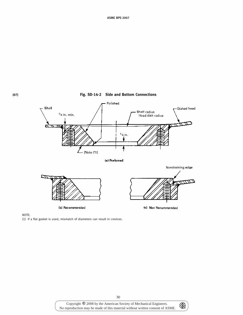
(07)
ASME BPE-2007
Fig. SD-14-2 Side and Bottom Connections
NOTE:(1) If a flat gasket is used, mismatch of diameters can result in crevices.
30
Copyright 2008 by the American Society of Mechanical Engineers.No reproduction may be made of this material without written consent of ASME.
c
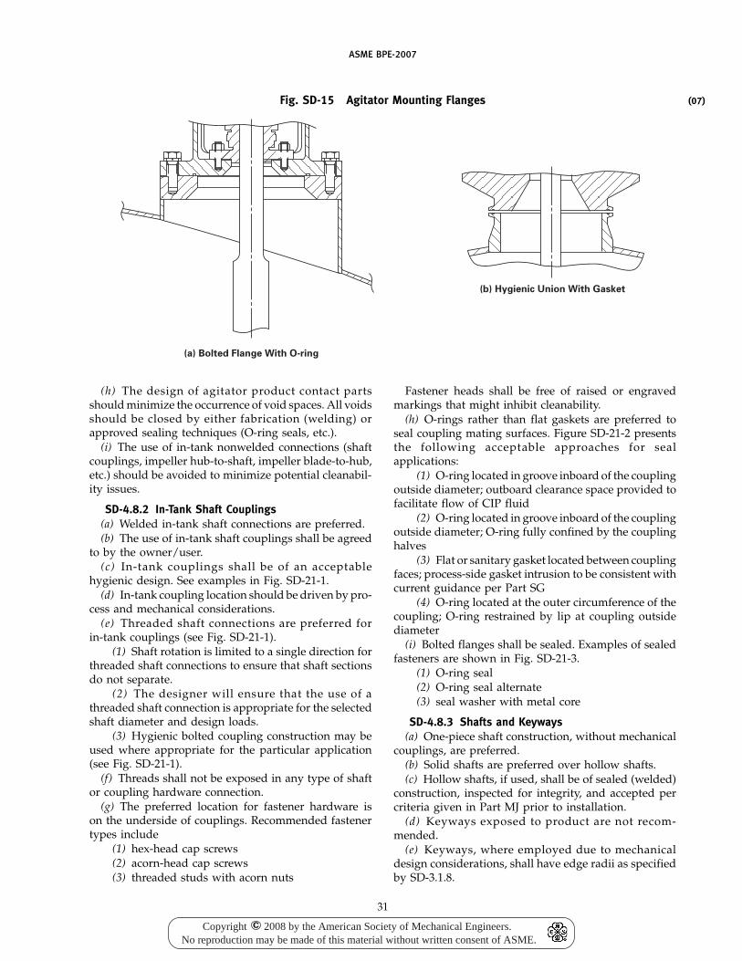
ASME BPE-2007
Fig. SD-15 Agitator Mounting Flanges
(a) Bolted Flange With O-ring
(b) Hygienic Union With Gasket
(h) The design of agitator product contact partsshould minimize the occurrence of void spaces. All voidsshould be closed by either fabrication (welding) orapproved sealing techniques (O-ring seals, etc.).
(i) The use of in-tank nonwelded connections (shaftcouplings, impeller hub-to-shaft, impeller blade-to-hub,etc.) should be avoided to minimize potential cleanabil-ity issues.
SD-4.8.2 In-Tank Shaft Couplings(a) Welded in-tank shaft connections are preferred.(b) The use of in-tank shaft couplings shall be agreed
to by the owner/user.(c) In-tank couplings shall be of an acceptable
hygienic design. See examples in Fig. SD-21-1.(d) In-tank coupling location should be driven by pro-
cess and mechanical considerations.(e) Threaded shaft connections are preferred for
in-tank couplings (see Fig. SD-21-1).(1) Shaft rotation is limited to a single direction for
threaded shaft connections to ensure that shaft sectionsdo not separate.
(2) The designer will ensure that the use of athreaded shaft connection is appropriate for the selectedshaft diameter and design loads.
(3) Hygienic bolted coupling construction may beused where appropriate for the particular application(see Fig. SD-21-1).
(f) Threads shall not be exposed in any type of shaftor coupling hardware connection.
(g) The preferred location for fastener hardware ison the underside of couplings. Recommended fastenertypes include
(1) hex-head cap screws(2) acorn-head cap screws(3) threaded studs with acorn nuts
31
Fastener heads shall be free of raised or engravedmarkings that might inhibit cleanability.
(h) O-rings rather than flat gaskets are preferred toseal coupling mating surfaces. Figure SD-21-2 presentsthe following acceptable approaches for sealapplications:
(1) O-ring located in groove inboard of the couplingoutside diameter; outboard clearance space provided tofacilitate flow of CIP fluid
(2) O-ring located in groove inboard of the couplingoutside diameter; O-ring fully confined by the couplinghalves
(3) Flat or sanitary gasket located between couplingfaces; process-side gasket intrusion to be consistent withcurrent guidance per Part SG
(4) O-ring located at the outer circumference of thecoupling; O-ring restrained by lip at coupling outsidediameter
(i) Bolted flanges shall be sealed. Examples of sealedfasteners are shown in Fig. SD-21-3.
(1) O-ring seal(2) O-ring seal alternate(3) seal washer with metal core
SD-4.8.3 Shafts and Keyways(a) One-piece shaft construction, without mechanical
couplings, are preferred.(b) Solid shafts are preferred over hollow shafts.(c) Hollow shafts, if used, shall be of sealed (welded)
construction, inspected for integrity, and accepted percriteria given in Part MJ prior to installation.
(d) Keyways exposed to product are not recom-mended.
(e) Keyways, where employed due to mechanicaldesign considerations, shall have edge radii as specifiedby SD-3.1.8.
(07)
Copyright 2008 by the American Society of Mechanical Engineers.No reproduction may be made of this material without written consent of ASME.
c
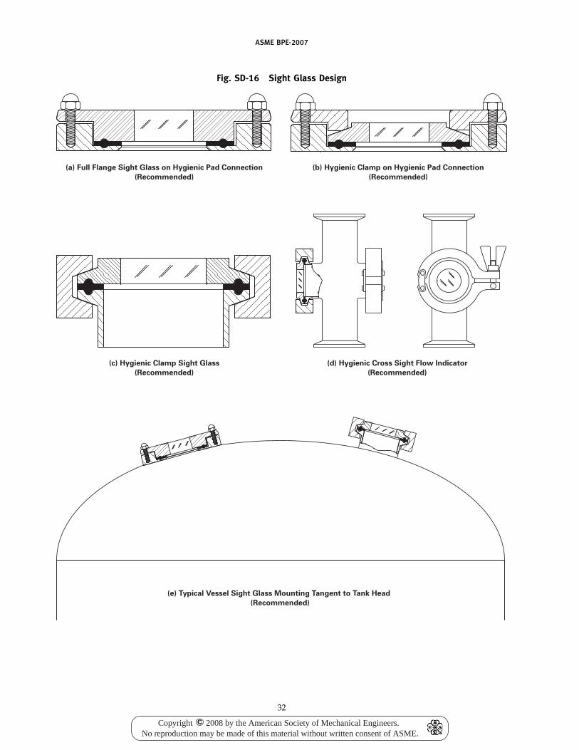
ASME BPE-2007
Fig. SD-16 Sight Glass Design
(a) Full Flange Sight Glass on Hygienic Pad Connection
(Recommended)
(b) Hygienic Clamp on Hygienic Pad Connection
(Recommended)
(c) Hygienic Clamp Sight Glass
(Recommended)
(d) Hygienic Cross Sight Flow Indicator
(Recommended)
(e) Typical Vessel Sight Glass Mounting Tangent to Tank Head
(Recommended)
32
Copyright 2008 by the American Society of Mechanical Engineers.No reproduction may be made of this material without written consent of ASME.
c
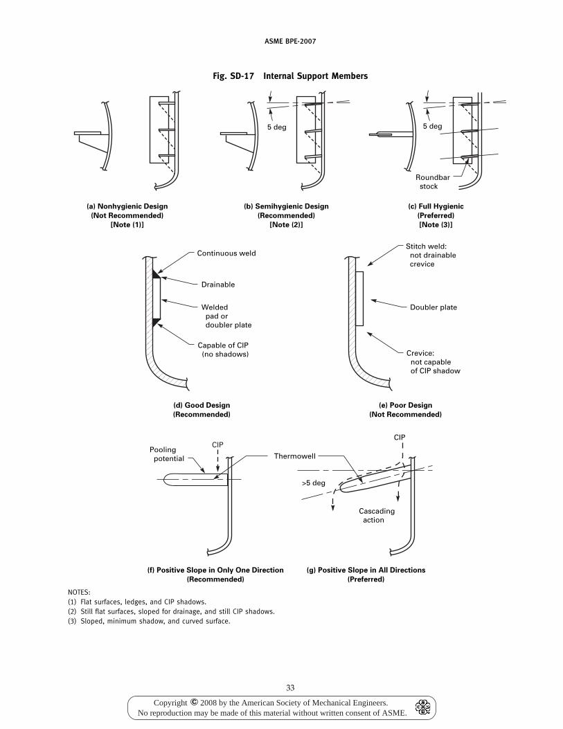
ASME BPE-2007
Fig. SD-17 Internal Support Members
(a) Nonhygienic Design
(Not Recommended)
[Note (1)]
(b) Semihygienic Design
(Recommended)
[Note (2)]
(c) Full Hygienic
(Preferred)
[Note (3)]
(g) Positive Slope in All Directions
(Preferred)
(f) Positive Slope in Only One Direction
(Recommended)
(e) Poor Design
(Not Recommended)
(d) Good Design
(Recommended)
>5 deg
CIP
Thermowell
Capable of CIP (no shadows)
Welded pad or doubler plate
Drainable
Continuous weld
Crevice: not capable of CIP shadow
Doubler plate
Stitch weld: not drainable crevice
Pooling potential
Cascading action
5 deg
Roundbar stock
5 deg
CIP
NOTES:(1) Flat surfaces, ledges, and CIP shadows.(2) Still flat surfaces, sloped for drainage, and still CIP shadows.(3) Sloped, minimum shadow, and curved surface.
33
Copyright 2008 by the American Society of Mechanical Engineers.No reproduction may be made of this material without written consent of ASME.
c
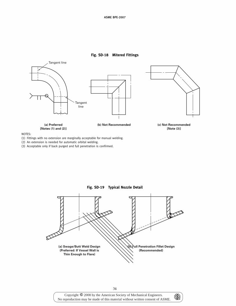
ASME BPE-2007
Fig. SD-18 Mitered Fittings
Tangent line
Tangent line
(a) Preferred
[Notes (1) and (2)]
(b) Not Recommended (c) Not Recommended
[Note (3)]
NOTES:(1) Fittings with no extension are marginally acceptable for manual welding.(2) An extension is needed for automatic orbital welding.(3) Acceptable only if back purged and full penetration is confirmed.
Fig. SD-19 Typical Nozzle Detail
(a) Swage/Butt Weld Design
(Preferred: If Vessel Wall is
Thin Enough to Flare)
(b) Full Penetration Fillet Design
(Recommended)
34
Copyright 2008 by the American Society of Mechanical Engineers.No reproduction may be made of this material without written consent of ASME.
c
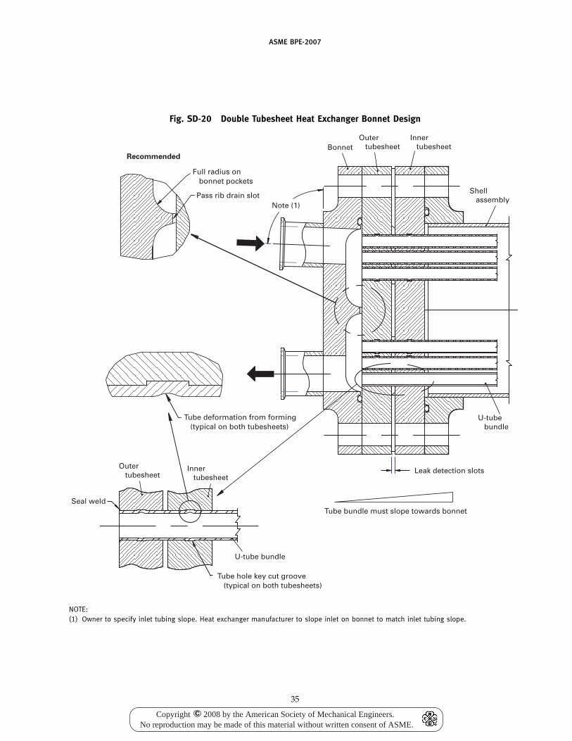
ASME BPE-2007
Fig. SD-20 Double Tubesheet Heat Exchanger Bonnet Design
Recommended
Full radius on bonnet pockets
Pass rib drain slotNote (1)
Tube deformation from forming (typical on both tubesheets)
Seal weld
Tube hole key cut groove (typical on both tubesheets)
Tube bundle must slope towards bonnet
Leak detection slots
Shell assembly
Inner tubesheet
Outer tubesheetBonnet
U-tube bundle
U-tube bundle
Inner tubesheet
Outer tubesheet
NOTE:(1) Owner to specify inlet tubing slope. Heat exchanger manufacturer to slope inlet on bonnet to match inlet tubing slope.
35
Copyright 2008 by the American Society of Mechanical Engineers.No reproduction may be made of this material without written consent of ASME.
c
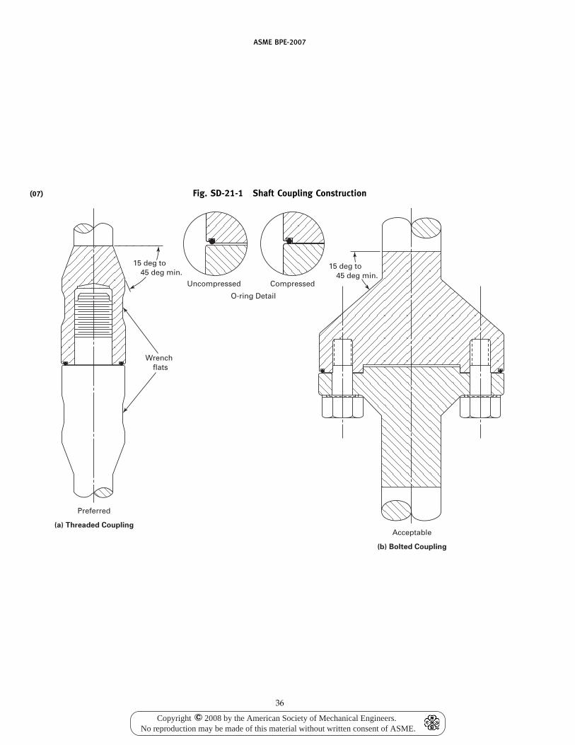
(07)
ASME BPE-2007
Fig. SD-21-1 Shaft Coupling Construction
Preferred
Uncompressed
Wrench flats
15 deg to 45 deg min.
15 deg to 45 deg min.
Compressed
O-ring Detail
(a) Threaded CouplingAcceptable
(b) Bolted Coupling
36
Copyright 2008 by the American Society of Mechanical Engineers.No reproduction may be made of this material without written consent of ASME.
c
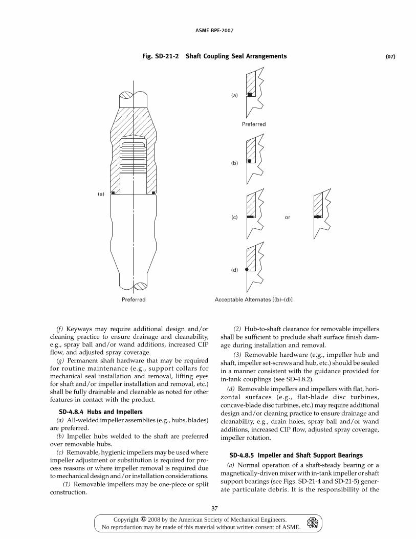
ASME BPE-2007
Fig. SD-21-2 Shaft Coupling Seal Arrangements
Preferred Acceptable Alternates [(b)–(d)]
Preferred
(a)
(a)
(b)
(c) or
(d)
(f) Keyways may require additional design and/orcleaning practice to ensure drainage and cleanability,e.g., spray ball and/or wand additions, increased CIPflow, and adjusted spray coverage.
(g) Permanent shaft hardware that may be requiredfor routine maintenance (e.g., support collars formechanical seal installation and removal, lifting eyesfor shaft and/or impeller installation and removal, etc.)shall be fully drainable and cleanable as noted for otherfeatures in contact with the product.
SD-4.8.4 Hubs and Impellers(a) All-welded impeller assemblies (e.g., hubs, blades)
are preferred.(b) Impeller hubs welded to the shaft are preferred
over removable hubs.(c) Removable, hygienic impellers may be used where
impeller adjustment or substitution is required for pro-cess reasons or where impeller removal is required dueto mechanical design and/or installation considerations.
(1) Removable impellers may be one-piece or splitconstruction.
37
(2) Hub-to-shaft clearance for removable impellersshall be sufficient to preclude shaft surface finish dam-age during installation and removal.
(3) Removable hardware (e.g., impeller hub andshaft, impeller set-screws and hub, etc.) should be sealedin a manner consistent with the guidance provided forin-tank couplings (see SD-4.8.2).
(d) Removable impellers and impellers with flat, hori-zontal surfaces (e.g., flat-blade disc turbines,concave-blade disc turbines, etc.) may require additionaldesign and/or cleaning practice to ensure drainage andcleanability, e.g., drain holes, spray ball and/or wandadditions, increased CIP flow, adjusted spray coverage,impeller rotation.
SD-4.8.5 Impeller and Shaft Support Bearings
(a) Normal operation of a shaft-steady bearing or amagnetically-driven mixer with in-tank impeller or shaftsupport bearings (see Figs. SD-21-4 and SD-21-5) gener-ate particulate debris. It is the responsibility of the
(07)
Copyright 2008 by the American Society of Mechanical Engineers.No reproduction may be made of this material without written consent of ASME.
c
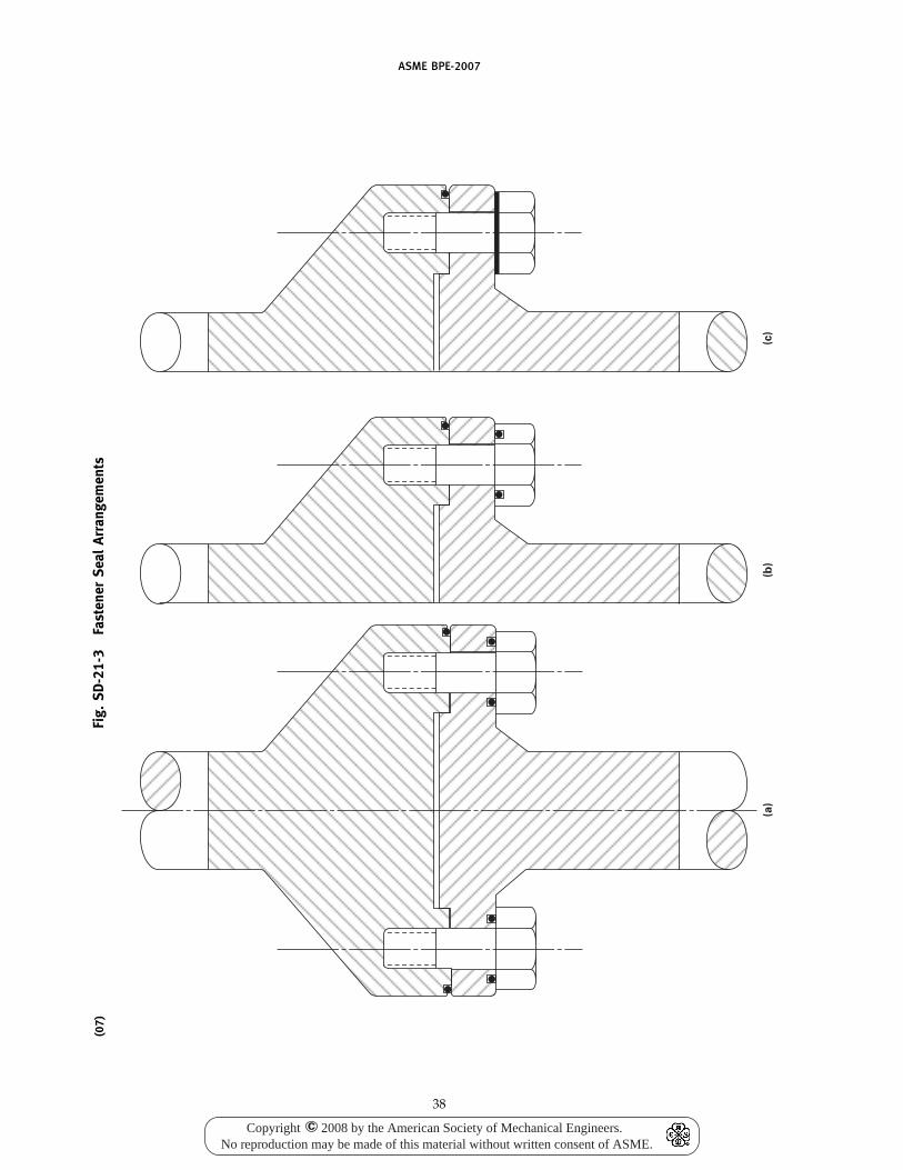
ASME BPE-2007
(07)
Fig.
SD-2
1-3
Fast
ener
Seal
Arra
ngem
ents
(a)
(b)
(c)
38
Copyright 2008 by the American Society of Mechanical Engineers.No reproduction may be made of this material without written consent of ASME.
c
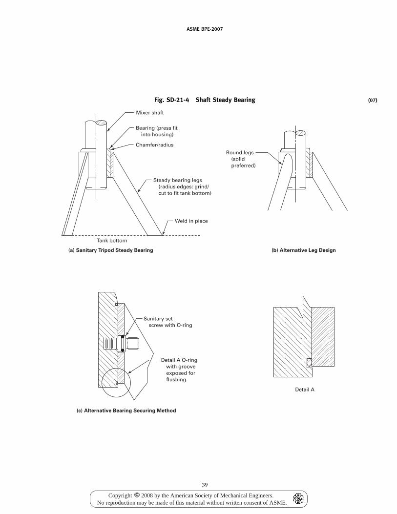
ASME BPE-2007
Fig. SD-21-4 Shaft Steady Bearing
Detail A
Sanitary set screw with O-ring
Mixer shaft
Bearing (press fit into housing)
Chamfer/radius
Weld in place
Steady bearing legs (radius edges: grind/ cut to fit tank bottom)
Round legs (solid preferred)
Tank bottom
Detail A O-ring with groove exposed for flushing
(c) Alternative Bearing Securing Method
(b) Alternative Leg Design(a) Sanitary Tripod Steady Bearing
39
(07)
Copyright 2008 by the American Society of Mechanical Engineers.No reproduction may be made of this material without written consent of ASME.
c
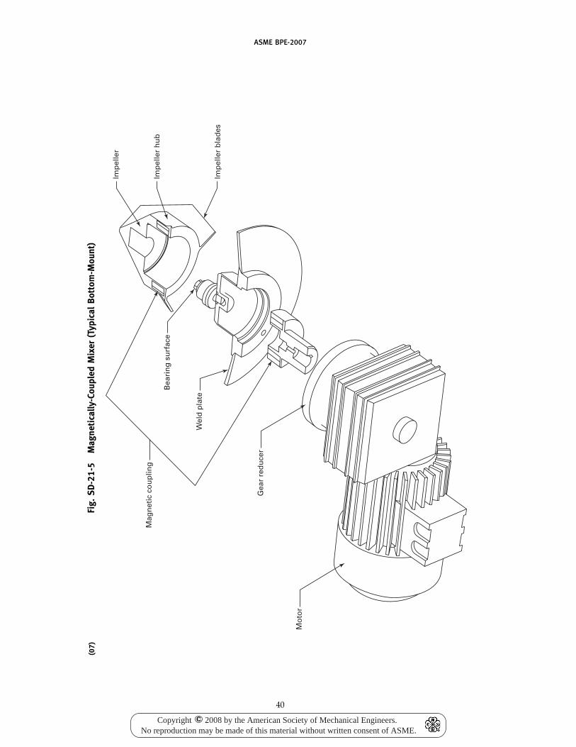
ASME BPE-2007
(07)
Fig.
SD-2
1-5
Mag
neti
cally
-Cou
pled
Mix
er(T
ypic
alB
otto
m-M
ount
)
Mo
tor
Gea
r re
du
cer
Mag
net
ic c
ou
plin
g
Wel
d p
late
Bea
rin
g s
urf
ace
Imp
elle
r b
lad
es
Imp
elle
r h
ub
Imp
elle
r
40
Copyright 2008 by the American Society of Mechanical Engineers.No reproduction may be made of this material without written consent of ASME.
c
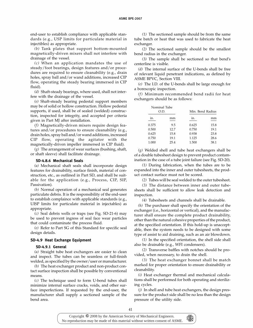
ASME BPE-2007
end-user to establish compliance with applicable stan-dards (e.g., USP limits for particulate material ininjectibles) as appropriate.
(b) Tank plates that support bottom-mountedmagnetically-driven mixers shall not interfere withdrainage of the vessel.
(c) When an application mandates the use ofsteady/foot bearings, design features and/or proce-dures are required to ensure cleanability (e.g., drainholes, spray ball and/or wand additions, increased CIPflow, operating the steady bearing immersed in CIPfluid).
(d) Shaft-steady bearings, where used, shall not inter-fere with the drainage of the vessel.
(e) Shaft-steady bearing pedestal support membersmay be of solid or hollow construction. Hollow pedestalsupports, if used, shall be of sealed (welded) construc-tion, inspected for integrity, and accepted per criteriagiven in Part MJ after installation.
(f) Magnetically-driven mixers require design fea-tures and/or procedures to ensure cleanability (e.g.,drain holes, spray ball and/or wand additions, increasedCIP flow, operating the agitator with themagnetically-driven impeller immersed in CIP fluid).
(g) The arrangement of wear surfaces (bushing, shaft,or shaft sleeve) shall facilitate drainage.
SD-4.8.6 Mechanical Seals(a) Mechanical shaft seals shall incorporate design
features for drainability, surface finish, material of con-struction, etc., as outlined in Part SD, and shall be suit-able for the application (e.g., Process, CIP, SIP,Passivation).
(b) Normal operation of a mechanical seal generatesparticulate debris. It is the responsibility of the end-userto establish complaince with applicable standards (e.g.,UISP limits for particulate material in injectables) asappropriate.
(c) Seal debris wells or traps (see Fig. SD-21-6) maybe used to prevent ingress of seal face wear particlesthat could contaminate the process fluid.
(e) Refer to Part SG of this Standard for specific sealdesign details.
SD-4.9 Heat Exchange Equipment
SD-4.9.1 General(a) Straight tube heat exchangers are easier to clean
and inspect. The tubes can be seamless or full-finishwelded, as specified by the owner/user or manufacturer.
(b) The heat exchanger product and non-product con-tact surface inspection shall be possible by conventionalmeans.
(c) The technique used to form U-bend tubes shallminimize internal surface cracks, voids, and other sur-face imperfections. If requested by the end-user, themanufacturer shall supply a sectioned sample of thebend area.
41
(1) The sectioned sample should be from the sametube batch or heat that was used to fabricate the heatexchanger.
(2) The sectioned sample should be the smallestbend radius in the exchanger.
(3) The sample shall be sectioned so that bend’scenterline is visible.
(d) The internal surface of the U-bends shall be freeof relevant liquid penetrant indications, as defined byASME BPVC, Section VIII.
(e) The I.D. of the U-bends shall be large enough fora borescopic inspection.
(f ) Minimum recommended bend radii for heatexchangers should be as follows:
Nominal TubeO.D. Min. Bend Radius
in. mm in. mm
0.375 9.5 0.625 15.80.500 12.7 0.750 19.10.625 15.8 0.938 23.80.750 19.1 1.125 28.61.000 25.4 1.500 38.1
(g) Welded shell and tube heat exchangers shall beof a double tubesheet design to prevent product contam-ination in the case of a tube joint failure (see Fig. SD-20).
(1) During fabrication, when the tubes are to beexpanded into the inner and outer tubesheets, the prod-uct contact surface must not be scored.
(2) Tubes will be seal welded to the outer tubesheet.(3) The distance between inner and outer tube-
sheets shall be sufficient to allow leak detection andinspection.
(4) Tubesheets and channels shall be drainable.(h) The purchaser shall specify the orientation of the
exchanger (i.e., horizontal or vertical), and the manufac-turer shall ensure the complete product drainability,other than the natural cohesive properties of the product,at the specified orientation. If this hold-up is unaccept-able, then the system needs to be designed with sometype of assist to aid draining, such as an air blowdown.
(1) In the specified orientation, the shell side shallalso be drainable (e.g., WFI condensers).
(2) Transverse baffles with notches should be pro-vided, when necessary, to drain the shell.
(3) The heat exchanger bonnet shall be matchmarked for proper orientation to ensure drainability orcleanability.
(i) Heat exchanger thermal and mechanical calcula-tions shall be performed for both operating and steriliz-ing cycles.
(j) In shell and tube heat exchangers, the design pres-sure for the product side shall be no less than the designpressure of the utility side.
Copyright 2008 by the American Society of Mechanical Engineers.No reproduction may be made of this material without written consent of ASME.
c
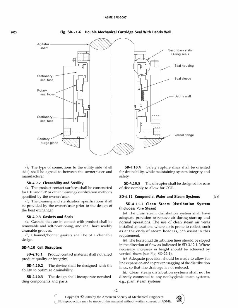
ASME BPE-2007
(07) Fig. SD-21-6 Double Mechanical Cartridge Seal With Debris Well
Agitator shaft
Stationary seal face
Stationary seal face
Sanitary purge gland
Rotary seal faces
Secondary static O-ring seals
Seal housing
Seal sleeve
Debris well
Vessel flange
(k) The type of connections to the utility side (shellside) shall be agreed to between the owner/user andmanufacturer.
SD-4.9.2 Cleanability and Sterility(a) The product contact surfaces shall be constructed
for CIP and SIP or other cleaning/sterilization methodsspecified by the owner/user.
(b) The cleaning and sterilization specifications shallbe provided by the owner/user prior to the design ofthe heat exchanger.
SD-4.9.3 Gaskets and Seals(a) Gaskets that are in contact with product shall be
removable and self-positioning, and shall have readilycleanable grooves.
(b) Channel/bonnet gaskets shall be of a cleanabledesign.
SD-4.10 Cell Disrupters
SD-4.10.1 Product contact material shall not affectproduct quality or integrity.
SD-4.10.2 The device shall be designed with theability to optimize drainability.
SD-4.10.3 The design shall incorporate nonshed-ding components and parts.
42
SD-4.10.4 Safety rupture discs shall be orientedfor drainability, while maintaining system integrity andsafety.
SD-4.10.5 The disrupter shall be designed for easeof disassembly to allow for COP.
SD-4.11 Compendial Water and Steam Systems
SD-4.11.1 Clean Steam Distribution System(Includes: Pure Steam)
(a) The clean steam distribution system shall haveadequate provision to remove air during start-up andnormal operations. The use of clean steam air ventsinstalled at locations where air is prone to collect, suchas at the ends of steam headers, can assist in thisrequirement.
(b) The horizontal distribution lines should be slopedin the direction of flow as indicated in SD-3.12.1. Wherenecessary, increases in height should be achieved byvertical risers (see Fig. SD-22-1).
(c) Adequate provision should be made to allow forline expansion and to prevent sagging of the distributionlines, so that line drainage is not reduced.
(d) Clean steam distribution systems shall not bedirectly connected to any nonhygienic steam systems,e.g., plant steam systems.
(07)
Copyright 2008 by the American Society of Mechanical Engineers.No reproduction may be made of this material without written consent of ASME.
c
ASME BPE-2007
(07)
Fig.
SD-2
2-1
Typi
cal
Clea
nSt
eam
Syst
emIs
omet
ric
Po
int-
of-
Use
(t
yp.)
Min
.
(typ
.)
Sam
ple
co
ole
r
Sam
ple
co
ole
r
Cle
an s
team
g
ener
ato
r
Slo
pe
Slo
pe
Slo
pe
Po
rtab
le
sam
ple
co
ole
r
(op
tio
n)
Sam
ple
Po
rted
b
all
va
lve
(op
tio
n)
Slo
pe
Slo
pe
Slo
pe
in
dir
ecti
on
of
st
eam
flo
w
Th
erm
al
exp
ansi
on
lo
ad
GEN
ERA
LN
OTE
:Pr
ovid
est
eam
trap
s(a
)w
here
line
tran
siti
ons
from
hori
zont
alto
vert
ical
(at
the
bott
omof
the
vert
ical
riser
)(b
)at
leas
tev
ery
100
ft(3
0m
)(c
)at
end
ofea
chhe
ader
orbr
anch
(d)
atth
erm
alex
pans
ion
loop
sor
tran
siti
ons
(e)
whe
rest
eam
issa
mpl
ed
43
Copyright 2008 by the American Society of Mechanical Engineers.No reproduction may be made of this material without written consent of ASME.
c
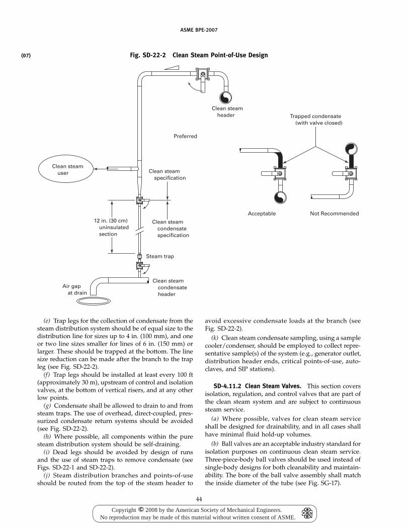
(07)
ASME BPE-2007
Fig. SD-22-2 Clean Steam Point-of-Use Design
Clean steam header
Preferred
Acceptable Not Recommended
Trapped condensate (with valve closed)
Clean steam specification
Clean steam condensate specification
Clean steam condensate header
Air gap at drain
12 in. (30 cm) uninsulated section
Steam trap
Clean steam user
(e) Trap legs for the collection of condensate from thesteam distribution system should be of equal size to thedistribution line for sizes up to 4 in. (100 mm), and oneor two line sizes smaller for lines of 6 in. (150 mm) orlarger. These should be trapped at the bottom. The linesize reduction can be made after the branch to the trapleg (see Fig. SD-22-2).
(f) Trap legs should be installed at least every 100 ft(approximately 30 m), upstream of control and isolationvalves, at the bottom of vertical risers, and at any otherlow points.
(g) Condensate shall be allowed to drain to and fromsteam traps. The use of overhead, direct-coupled, pres-surized condensate return systems should be avoided(see Fig. SD-22-2).
(h) Where possible, all components within the puresteam distribution system should be self-draining.
(i) Dead legs should be avoided by design of runsand the use of steam traps to remove condensate (seeFigs. SD-22-1 and SD-22-2).
(j) Steam distribution branches and points-of-useshould be routed from the top of the steam header to
44
avoid excessive condensate loads at the branch (seeFig. SD-22-2).
(k) Clean steam condensate sampling, using a samplecooler/condenser, should be employed to collect repre-sentative sample(s) of the system (e.g., generator outlet,distribution header ends, critical points-of-use, auto-claves, and SIP stations).
SD-4.11.2 Clean Steam Valves. This section coversisolation, regulation, and control valves that are part ofthe clean steam system and are subject to continuoussteam service.
(a) Where possible, valves for clean steam serviceshall be designed for drainability, and in all cases shallhave minimal fluid hold-up volumes.
(b) Ball valves are an acceptable industry standard forisolation purposes on continuous clean steam service.Three-piece-body ball valves should be used instead ofsingle-body designs for both cleanability and maintain-ability. The bore of the ball valve assembly shall matchthe inside diameter of the tube (see Fig. SG-17).
Copyright 2008 by the American Society of Mechanical Engineers.No reproduction may be made of this material without written consent of ASME.
c
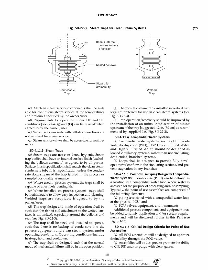
ASME BPE-2007
Fig. SD-22-3 Steam Traps for Clean Steam Systems
Sloped fordrainability
Sealed bellows
Radius internal corners (where practical)
ServiceableTrap
WeldedTrap
(c) All clean steam service components shall be suit-able for continuous steam service at the temperaturesand pressures specified by the owner/user.
(d) Requirements for operation under CIP and SIPconditions [see SD-4.6(j) and (k)] can be relaxed whenagreed to by the owner/user.
(e) Secondary stem seals with telltale connections arenot required for steam service.
(f) Steam service valves shall be accessible for mainte-nance.
SD-4.11.3 Steam Traps(a) Steam traps are not considered hygienic. Steam
trap bodies shall have an internal surface finish (exclud-ing the bellows assembly) as agreed to by all parties.Surface finish specification shall match the clean steamcondensate tube finish specification unless the conden-sate downstream of the trap is used in the process orsampled for quality assurance.
(b) Where used in process systems, the traps shall becapable of effectively venting air.
(c) Where installed on process systems, traps shallbe maintainable to allow easy inspection and cleaning.Welded traps are acceptable if agreed to by theowner/user.
(d) The trap design and mode of operation shall besuch that the risk of soil attachment to the wetted sur-faces is minimized, especially around the bellows andseat (see Fig. SD-22-3).
(e) The trap shall be sized and installed to operatesuch that there is no backup of condensate into theprocess equipment and clean steam system underoperating conditions. Operating conditions includeheat-up, hold, and cooldown.
(f) The trap shall be designed such that the normalmode of mechanical failure will be in the open position.
45
(g) Thermostatic steam traps, installed in vertical traplegs, are preferred for use in clean steam systems (seeFig. SD-22-3).
(h) Trap operation/reactivity should be improved bythe installation of an uninsulated section of tubingupstream of the trap [suggested 12 in. (30 cm) as recom-mended by supplier] (see Fig. SD-22-2).
SD-4.11.4 Compendial Water Systems(a) Compendial water systems, such as USP Grade
Water-for-Injection (WFI), USP Grade Purified Water,and Highly Purified Water, should be designed aslooped circulatory systems, rather than noncirculating,dead-ended, branched systems.
(b) Loops shall be designed to provide fully devel-oped turbulent flow in the circulating sections, and pre-vent stagnation in any branches.
SD-4.11.5 Point-of-Use Piping Design for CompendialWater Systems. Point-of-use (POU) can be defined asa location in a compendial water loop where water isaccessed for the purpose of processing and/or sampling.Typically, the point-of-use assemblies are comprised ofthe following elements:
(a) piping associated with a compendial water loopat the physical POU; and
(b) POU valves, equipment, and instruments.Additional process components and equipment may
be added to satisfy application and/or system require-ments and will be discussed further in this Part (seeFig. SD-23).
SD-4.11.6 Critical Design Criteria for Point-of-UseAssemblies
(a) All POU assemblies will be designed to optimizedrainability through the POU valve.
(b) Assemblies will be designed to promote the abilityto CIP, SIP, and/or purge with clean gasses.
(07)
Copyright 2008 by the American Society of Mechanical Engineers.No reproduction may be made of this material without written consent of ASME.
c
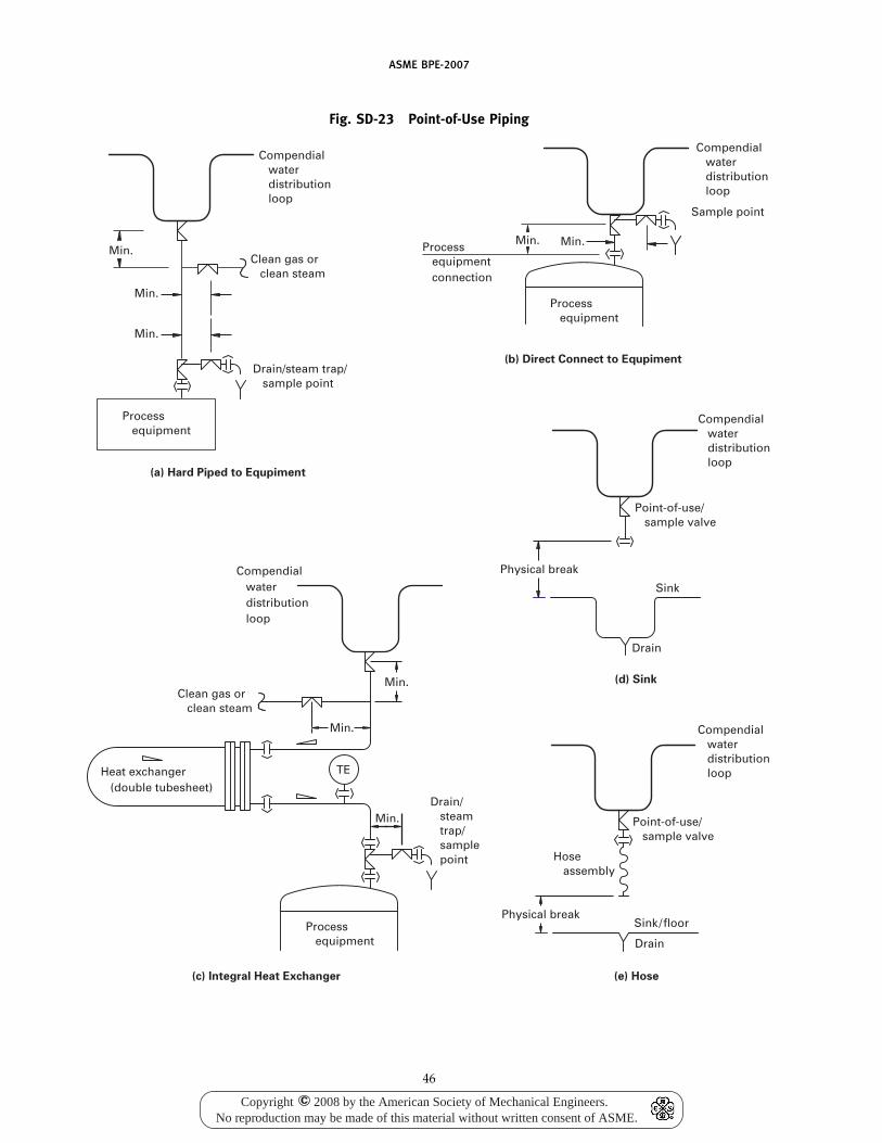
ASME BPE-2007
Fig. SD-23 Point-of-Use Piping
Compendial water distribution loop
Min.
Min.
Min.
Min.
Min.
Min.
Clean gas or clean steam
Clean gas or clean steam
Drain/steam trap/ sample point
Drain/ steam trap/ sample point
Process equipment
(a) Hard Piped to Equpiment
Process equipment
Process equipment connection
Min. Min.
Sample point
Compendial water distribution loop
Compendial water distribution loop
Compendial water distribution loop
Compendial water distribution loop
(b) Direct Connect to Equpiment
(c) Integral Heat Exchanger
(d) Sink
(e) Hose
TEHeat exchanger (double tubesheet)
Physical break
Physical break
Sink
Sink/floor
Drain
Drain
Point-of-use/ sample valve
Point-of-use/ sample valve
Hose assembly
Process equipment
46
Copyright 2008 by the American Society of Mechanical Engineers.No reproduction may be made of this material without written consent of ASME.
c
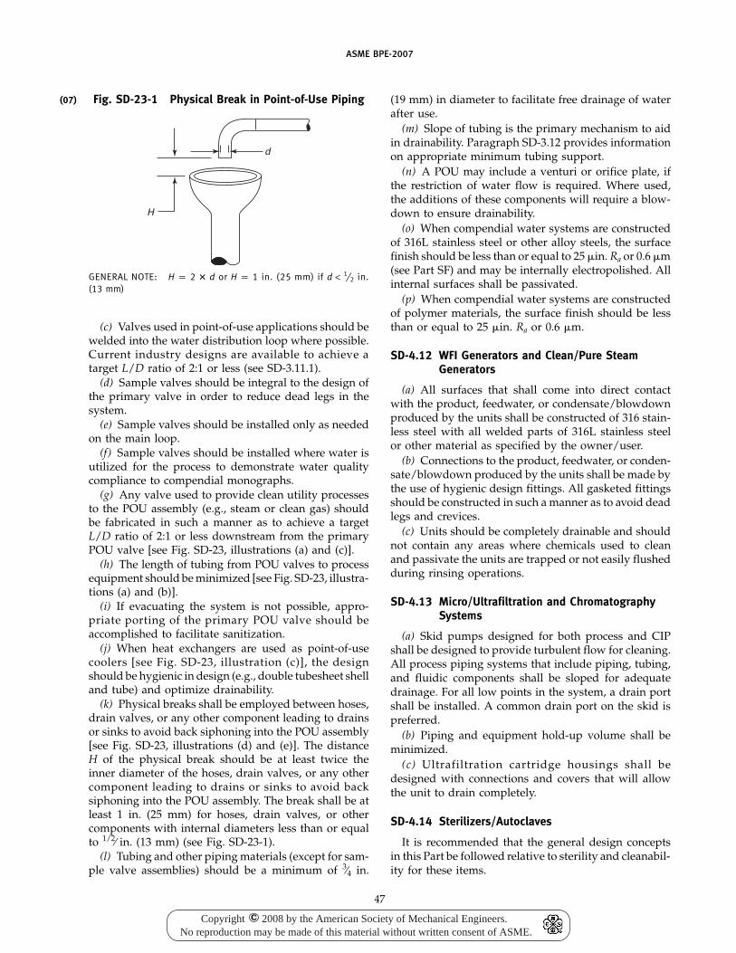
(07)
ASME BPE-2007
Fig. SD-23-1 Physical Break in Point-of-Use Piping
H
d
GENERAL NOTE: H p 2 � d or H p 1 in. (25 mm) if d < 1⁄2 in.(13 mm)
(c) Valves used in point-of-use applications should bewelded into the water distribution loop where possible.Current industry designs are available to achieve atarget L/D ratio of 2:1 or less (see SD-3.11.1).
(d) Sample valves should be integral to the design ofthe primary valve in order to reduce dead legs in thesystem.
(e) Sample valves should be installed only as neededon the main loop.
(f) Sample valves should be installed where water isutilized for the process to demonstrate water qualitycompliance to compendial monographs.
(g) Any valve used to provide clean utility processesto the POU assembly (e.g., steam or clean gas) shouldbe fabricated in such a manner as to achieve a targetL/D ratio of 2:1 or less downstream from the primaryPOU valve [see Fig. SD-23, illustrations (a) and (c)].
(h) The length of tubing from POU valves to processequipment should be minimized [see Fig. SD-23, illustra-tions (a) and (b)].
(i) If evacuating the system is not possible, appro-priate porting of the primary POU valve should beaccomplished to facilitate sanitization.
(j) When heat exchangers are used as point-of-usecoolers [see Fig. SD-23, illustration (c)], the designshould be hygienic in design (e.g., double tubesheet shelland tube) and optimize drainability.
(k) Physical breaks shall be employed between hoses,drain valves, or any other component leading to drainsor sinks to avoid back siphoning into the POU assembly[see Fig. SD-23, illustrations (d) and (e)]. The distanceH of the physical break should be at least twice theinner diameter of the hoses, drain valves, or any othercomponent leading to drains or sinks to avoid backsiphoning into the POU assembly. The break shall be atleast 1 in. (25 mm) for hoses, drain valves, or othercomponents with internal diameters less than or equalto 1/2⁄ in. (13 mm) (see Fig. SD-23-1).
(l) Tubing and other piping materials (except for sam-ple valve assemblies) should be a minimum of 3⁄4 in.
47
(19 mm) in diameter to facilitate free drainage of waterafter use.
(m) Slope of tubing is the primary mechanism to aidin drainability. Paragraph SD-3.12 provides informationon appropriate minimum tubing support.
(n) A POU may include a venturi or orifice plate, ifthe restriction of water flow is required. Where used,the additions of these components will require a blow-down to ensure drainability.
(o) When compendial water systems are constructedof 316L stainless steel or other alloy steels, the surfacefinish should be less than or equal to 25 �in. Ra or 0.6 �m(see Part SF) and may be internally electropolished. Allinternal surfaces shall be passivated.
(p) When compendial water systems are constructedof polymer materials, the surface finish should be lessthan or equal to 25 �in. Ra or 0.6 �m.
SD-4.12 WFI Generators and Clean/Pure SteamGenerators
(a) All surfaces that shall come into direct contactwith the product, feedwater, or condensate/blowdownproduced by the units shall be constructed of 316 stain-less steel with all welded parts of 316L stainless steelor other material as specified by the owner/user.
(b) Connections to the product, feedwater, or conden-sate/blowdown produced by the units shall be made bythe use of hygienic design fittings. All gasketed fittingsshould be constructed in such a manner as to avoid deadlegs and crevices.
(c) Units should be completely drainable and shouldnot contain any areas where chemicals used to cleanand passivate the units are trapped or not easily flushedduring rinsing operations.
SD-4.13 Micro/Ultrafiltration and ChromatographySystems
(a) Skid pumps designed for both process and CIPshall be designed to provide turbulent flow for cleaning.All process piping systems that include piping, tubing,and fluidic components shall be sloped for adequatedrainage. For all low points in the system, a drain portshall be installed. A common drain port on the skid ispreferred.
(b) Piping and equipment hold-up volume shall beminimized.
(c) Ultrafiltration cartridge housings shall bedesigned with connections and covers that will allowthe unit to drain completely.
SD-4.14 Sterilizers/Autoclaves
It is recommended that the general design conceptsin this Part be followed relative to sterility and cleanabil-ity for these items.
Copyright 2008 by the American Society of Mechanical Engineers.No reproduction may be made of this material without written consent of ASME.
c
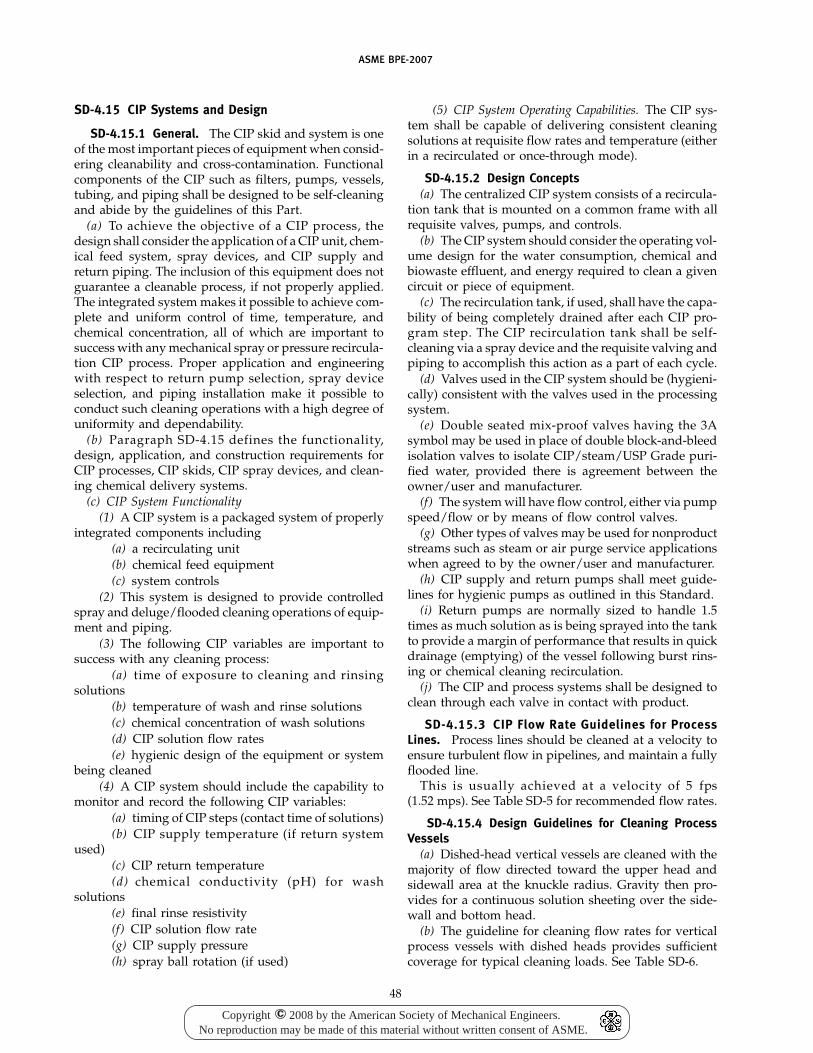
ASME BPE-2007
SD-4.15 CIP Systems and Design
SD-4.15.1 General. The CIP skid and system is oneof the most important pieces of equipment when consid-ering cleanability and cross-contamination. Functionalcomponents of the CIP such as filters, pumps, vessels,tubing, and piping shall be designed to be self-cleaningand abide by the guidelines of this Part.
(a) To achieve the objective of a CIP process, thedesign shall consider the application of a CIP unit, chem-ical feed system, spray devices, and CIP supply andreturn piping. The inclusion of this equipment does notguarantee a cleanable process, if not properly applied.The integrated system makes it possible to achieve com-plete and uniform control of time, temperature, andchemical concentration, all of which are important tosuccess with any mechanical spray or pressure recircula-tion CIP process. Proper application and engineeringwith respect to return pump selection, spray deviceselection, and piping installation make it possible toconduct such cleaning operations with a high degree ofuniformity and dependability.
(b) Paragraph SD-4.15 defines the functionality,design, application, and construction requirements forCIP processes, CIP skids, CIP spray devices, and clean-ing chemical delivery systems.
(c) CIP System Functionality(1) A CIP system is a packaged system of properly
integrated components including(a) a recirculating unit(b) chemical feed equipment(c) system controls
(2) This system is designed to provide controlledspray and deluge/flooded cleaning operations of equip-ment and piping.
(3) The following CIP variables are important tosuccess with any cleaning process:
(a) time of exposure to cleaning and rinsingsolutions
(b) temperature of wash and rinse solutions(c) chemical concentration of wash solutions(d) CIP solution flow rates(e) hygienic design of the equipment or system
being cleaned(4) A CIP system should include the capability to
monitor and record the following CIP variables:(a) timing of CIP steps (contact time of solutions)(b) CIP supply temperature (if return system
used)(c) CIP return temperature(d) chemical conductivity (pH) for wash
solutions(e) final rinse resistivity(f) CIP solution flow rate(g) CIP supply pressure(h) spray ball rotation (if used)
48
(5) CIP System Operating Capabilities. The CIP sys-tem shall be capable of delivering consistent cleaningsolutions at requisite flow rates and temperature (eitherin a recirculated or once-through mode).
SD-4.15.2 Design Concepts(a) The centralized CIP system consists of a recircula-
tion tank that is mounted on a common frame with allrequisite valves, pumps, and controls.
(b) The CIP system should consider the operating vol-ume design for the water consumption, chemical andbiowaste effluent, and energy required to clean a givencircuit or piece of equipment.
(c) The recirculation tank, if used, shall have the capa-bility of being completely drained after each CIP pro-gram step. The CIP recirculation tank shall be self-cleaning via a spray device and the requisite valving andpiping to accomplish this action as a part of each cycle.
(d) Valves used in the CIP system should be (hygieni-cally) consistent with the valves used in the processingsystem.
(e) Double seated mix-proof valves having the 3Asymbol may be used in place of double block-and-bleedisolation valves to isolate CIP/steam/USP Grade puri-fied water, provided there is agreement between theowner/user and manufacturer.
(f) The system will have flow control, either via pumpspeed/flow or by means of flow control valves.
(g) Other types of valves may be used for nonproductstreams such as steam or air purge service applicationswhen agreed to by the owner/user and manufacturer.
(h) CIP supply and return pumps shall meet guide-lines for hygienic pumps as outlined in this Standard.
(i) Return pumps are normally sized to handle 1.5times as much solution as is being sprayed into the tankto provide a margin of performance that results in quickdrainage (emptying) of the vessel following burst rins-ing or chemical cleaning recirculation.
(j) The CIP and process systems shall be designed toclean through each valve in contact with product.
SD-4.15.3 CIP Flow Rate Guidelines for ProcessLines. Process lines should be cleaned at a velocity toensure turbulent flow in pipelines, and maintain a fullyflooded line.
This is usually achieved at a velocity of 5 fps(1.52 mps). See Table SD-5 for recommended flow rates.
SD-4.15.4 Design Guidelines for Cleaning ProcessVessels
(a) Dished-head vertical vessels are cleaned with themajority of flow directed toward the upper head andsidewall area at the knuckle radius. Gravity then pro-vides for a continuous solution sheeting over the side-wall and bottom head.
(b) The guideline for cleaning flow rates for verticalprocess vessels with dished heads provides sufficientcoverage for typical cleaning loads. See Table SD-6.
Copyright 2008 by the American Society of Mechanical Engineers.No reproduction may be made of this material without written consent of ASME.
c
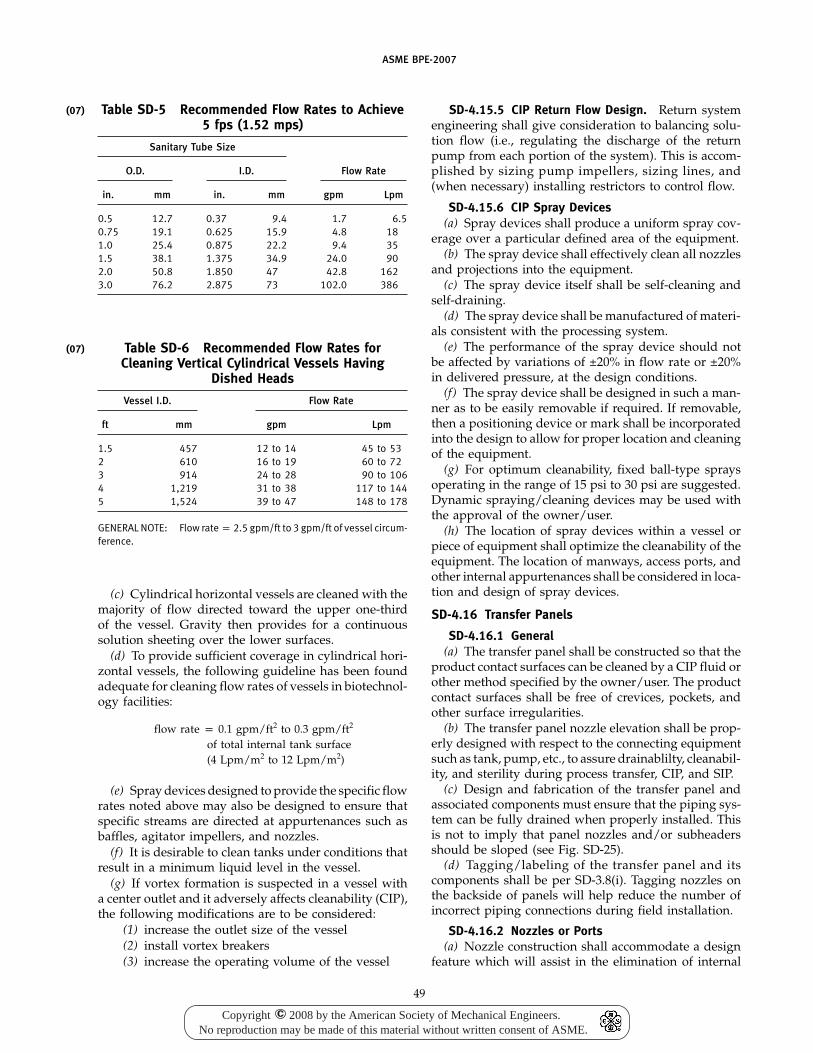
(07)
(07)
ASME BPE-2007
Table SD-5 Recommended Flow Rates to Achieve5 fps (1.52 mps)
Sanitary Tube Size
O.D. I.D. Flow Rate
in. mm in. mm gpm Lpm
0.5 12.7 0.37 9.4 1.7 6.50.75 19.1 0.625 15.9 4.8 181.0 25.4 0.875 22.2 9.4 351.5 38.1 1.375 34.9 24.0 902.0 50.8 1.850 47 42.8 1623.0 76.2 2.875 73 102.0 386
Table SD-6 Recommended Flow Rates forCleaning Vertical Cylindrical Vessels Having
Dished Heads
Vessel I.D. Flow Rate
ft mm gpm Lpm
1.5 457 12 to 14 45 to 532 610 16 to 19 60 to 723 914 24 to 28 90 to 1064 1,219 31 to 38 117 to 1445 1,524 39 to 47 148 to 178
GENERAL NOTE: Flow rate p 2.5 gpm/ft to 3 gpm/ft of vessel circum-ference.
(c) Cylindrical horizontal vessels are cleaned with themajority of flow directed toward the upper one-thirdof the vessel. Gravity then provides for a continuoussolution sheeting over the lower surfaces.
(d) To provide sufficient coverage in cylindrical hori-zontal vessels, the following guideline has been foundadequate for cleaning flow rates of vessels in biotechnol-ogy facilities:
flow rate p 0.1 gpm/ft2 to 0.3 gpm/ft2
of total internal tank surface(4 Lpm/m2 to 12 Lpm/m2)
(e) Spray devices designed to provide the specific flowrates noted above may also be designed to ensure thatspecific streams are directed at appurtenances such asbaffles, agitator impellers, and nozzles.
(f) It is desirable to clean tanks under conditions thatresult in a minimum liquid level in the vessel.
(g) If vortex formation is suspected in a vessel witha center outlet and it adversely affects cleanability (CIP),the following modifications are to be considered:
(1) increase the outlet size of the vessel(2) install vortex breakers(3) increase the operating volume of the vessel
49
SD-4.15.5 CIP Return Flow Design. Return systemengineering shall give consideration to balancing solu-tion flow (i.e., regulating the discharge of the returnpump from each portion of the system). This is accom-plished by sizing pump impellers, sizing lines, and(when necessary) installing restrictors to control flow.
SD-4.15.6 CIP Spray Devices(a) Spray devices shall produce a uniform spray cov-
erage over a particular defined area of the equipment.(b) The spray device shall effectively clean all nozzles
and projections into the equipment.(c) The spray device itself shall be self-cleaning and
self-draining.(d) The spray device shall be manufactured of materi-
als consistent with the processing system.(e) The performance of the spray device should not
be affected by variations of ±20% in flow rate or ±20%in delivered pressure, at the design conditions.
(f) The spray device shall be designed in such a man-ner as to be easily removable if required. If removable,then a positioning device or mark shall be incorporatedinto the design to allow for proper location and cleaningof the equipment.
(g) For optimum cleanability, fixed ball-type spraysoperating in the range of 15 psi to 30 psi are suggested.Dynamic spraying/cleaning devices may be used withthe approval of the owner/user.
(h) The location of spray devices within a vessel orpiece of equipment shall optimize the cleanability of theequipment. The location of manways, access ports, andother internal appurtenances shall be considered in loca-tion and design of spray devices.
SD-4.16 Transfer Panels
SD-4.16.1 General(a) The transfer panel shall be constructed so that the
product contact surfaces can be cleaned by a CIP fluid orother method specified by the owner/user. The productcontact surfaces shall be free of crevices, pockets, andother surface irregularities.
(b) The transfer panel nozzle elevation shall be prop-erly designed with respect to the connecting equipmentsuch as tank, pump, etc., to assure drainablilty, cleanabil-ity, and sterility during process transfer, CIP, and SIP.
(c) Design and fabrication of the transfer panel andassociated components must ensure that the piping sys-tem can be fully drained when properly installed. Thisis not to imply that panel nozzles and/or subheadersshould be sloped (see Fig. SD-25).
(d) Tagging/labeling of the transfer panel and itscomponents shall be per SD-3.8(i). Tagging nozzles onthe backside of panels will help reduce the number ofincorrect piping connections during field installation.
SD-4.16.2 Nozzles or Ports(a) Nozzle construction shall accommodate a design
feature which will assist in the elimination of internal
Copyright 2008 by the American Society of Mechanical Engineers.No reproduction may be made of this material without written consent of ASME.
c
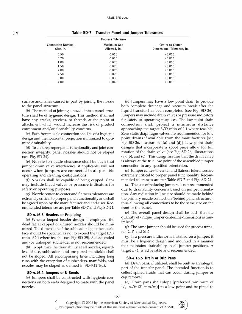
(07)
ASME BPE-2007
Table SD-7 Transfer Panel and Jumper Tolerances
Flatness Tolerance
Connection Nominal Maximum Gap Center-to-CenterSize, in. Allowed, in. Dimensional Tolerance, in.
0.50 0.010 ±0.0150.70 0.010 ±0.0151.00 0.020 ±0.0151.50 0.020 ±0.0152.00 0.025 ±0.0152.50 0.025 ±0.0153.00 0.030 ±0.0154.00 0.040 ±0.015
surface anomalies caused in part by joining the nozzleto the panel structure.
(b) The method of joining a nozzle into a panel struc-ture shall be of hygienic design. This method shall nothave any cracks, crevices, or threads at the point ofattachment which would increase the risk of productentrapment and/or cleanability concerns.
(c) Each front nozzle connection shall be of a hygienicdesign and the horizontal projection minimized to opti-mize drainability.
(d) To ensure proper panel functionality and joint con-nection integrity, panel nozzles should not be sloped(see Fig. SD-24).
(e) Nozzle-to-nozzle clearance shall be such thatjumper drain valve interference, if applicable, will notoccur when jumpers are connected in all possibleoperating and cleaning configurations.
(f) Nozzles shall be capable of being capped. Capsmay include bleed valves or pressure indicators forsafety or operating purposes.
(g) Nozzle center-to-center and flatness tolerances areextremely critical to proper panel functionality and shallbe agreed upon by the manufacturer and end-user. Rec-ommended tolerances are per Table SD-7 and Fig. SD-24.
SD-4.16.3 Headers or Prepiping(a) When a looped header design is employed, the
dead leg at capped or unused nozzles should be mini-mized. The dimension of the subheader leg to the nozzleface should be specified as not to exceed the target L/Dratio of 2:1 where feasible (see Fig. SD-25). A dead-endedand/or unlooped subheader is not recommended.
(b) To optimize the drainability at all nozzles, regard-less of use, subheaders and pre-piped manifolds shallnot be sloped. All encompassing lines including longruns with the exception of subheaders, manifolds, andnozzles may be sloped as defined in SD-3.12.1(d).
SD-4.16.4 Jumpers or U-Bends(a) Jumpers shall be constructed with hygienic con-
nections on both ends designed to mate with the panelnozzles.
50
(b) Jumpers may have a low point drain to provideboth complete drainage and vacuum break after theliquid transfer has been completed (see Fig. SD-26).Jumpers may include drain valves or pressure indicatorsfor safety or operating purposes. The low point drainconnection shall project a minimum distanceapproaching the target L/D ratio of 2:1 where feasible.Zero static diaphragm valves are recommended for lowpoint drains if available from the manufacturer [seeFig. SD-26, illustrations (a) and (d)]. Low point draindesigns that incorporate a spool piece allow for fullrotation of the drain valve [see Fig. SD-26, illustrations(a), (b), and (c)]. This design assures that the drain valveis always at the true low point of the assembled jumperconnection in any specified orientation.
(c) Jumper center-to-center and flatness tolerances areextremely critical to proper panel functionality. Recom-mended tolerances are per Table SD-7 and Fig. SD-24.
(d) The use of reducing jumpers is not recommendeddue to drainability concerns based on jumper orienta-tion. Any reduction in line size should be made behindthe primary nozzle connection (behind panel structure),thus allowing all connections to be the same size on thefront of the panel.
(e) The overall panel design shall be such that thequantity of unique jumper centerline dimensions is min-imized.
(f) The same jumper should be used for process trans-fer, CIP, and SIP.
(g) If a pressure indicator is installed on a jumper, itmust be a hygienic design and mounted in a mannerthat maintains drainability in all jumper positions. Atarget L/D is achievable and recommended.
SD-4.16.5 Drain or Drip Pans(a) Drain pans, if utilized, shall be built as an integral
part of the transfer panel. The intended function is tocollect spilled fluids that can occur during jumper orcap removal.
(b) Drain pans shall slope [preferred minimum of1/4 in./ft (21 mm/m)] to a low point and be piped to
Copyright 2008 by the American Society of Mechanical Engineers.No reproduction may be made of this material without written consent of ASME.
c
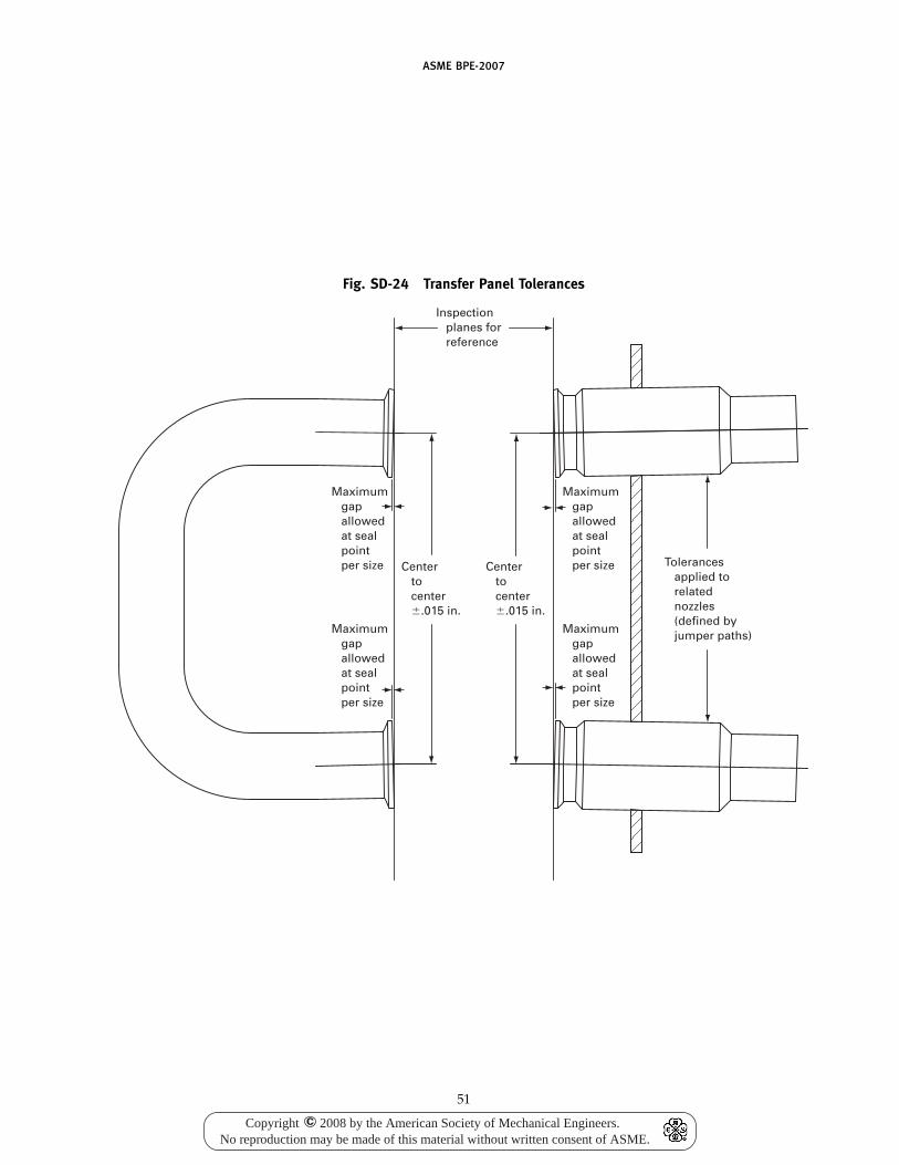
ASME BPE-2007
Fig. SD-24 Transfer Panel Tolerances
Inspection planes for reference
Maximum gap allowed at seal point per size
Maximum gap allowed at seal point per size
Maximum gap allowed at seal point per size
Maximum gap allowed at seal point per size
Center to center �.015 in.
Center to center �.015 in.
Tolerances applied to related nozzles (defined by jumper paths)
51
Copyright 2008 by the American Society of Mechanical Engineers.No reproduction may be made of this material without written consent of ASME.
c
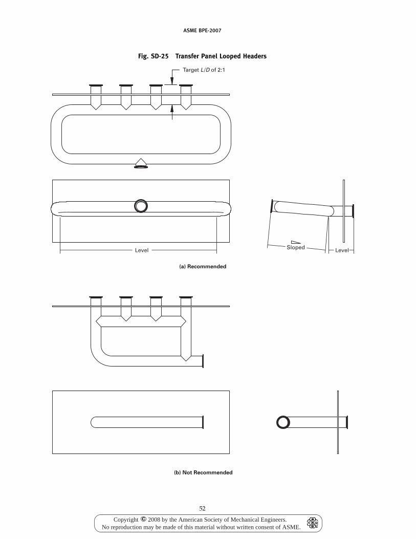
ASME BPE-2007
Fig. SD-25 Transfer Panel Looped Headers
Sloped LevelLevel
(a) Recommended
(b) Not Recommended
Target L /D of 2:1
52
Copyright 2008 by the American Society of Mechanical Engineers.No reproduction may be made of this material without written consent of ASME.
c
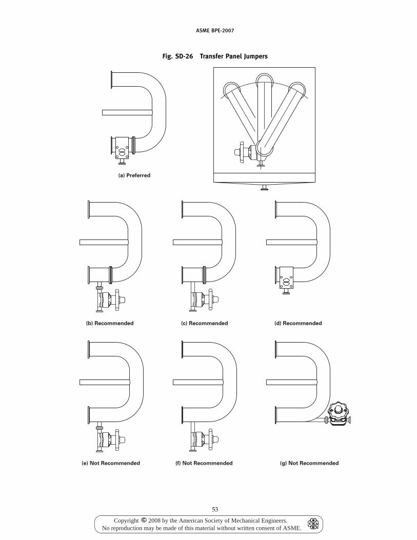
ASME BPE-2007
Fig. SD-26 Transfer Panel Jumpers
(a) Preferred
(d) Recommended(b) Recommended (c) Recommended
(g) Not Recommended(e) Not Recommended (f) Not Recommended
53
Copyright 2008 by the American Society of Mechanical Engineers.No reproduction may be made of this material without written consent of ASME.
c
ASME BPE-2007
the process drain. The depth of the drain pan is deter-mined by calculating the largest spill volume and accom-modating it with a sufficient pan holding volume.Consideration should be given to increasing the drainport connection size in lieu of increasing pan depth. Thepreferred drain port location is central bottom drainingor central back draining.
(c) The elevation of the pan should take into accountthe clearance required for the jumper drain valve posi-tion when a connection is made to the bottom row ofnozzles. The pan should extend horizontally to accom-modate the furthest connection and/or drain point fromthe face of the panel.
SD-4.16.6 Proximity Switches(a) Proximity switches are used to detect the presence
or absence of a jumper with a stem positioned betweenselected nozzles.
(b) The use of magnetic proximity switches, whichare mounted behind the panel structure avoiding theneed to penetrate the panel face, are preferred. Thiselimination of structural penetration will remove anyunnecessary cracks, crevices, or threads at the point ofattachment, thus removing the risk of product entrap-ment and/or sterility concerns.
(c) Jumpers will contain a magnetic stem to activatethe corresponding proximity switch. The use of a ferrousmagnetic material is required; however, it must be fullyencapsulated to ensure that the ferrous material doesnot contaminate the classified manufacturing area.Attention shall be paid to the weld between the sensorstem and the jumper.
(d) The magnet should be of sufficient gauss ratingto properly activate the corresponding proximity switch.In addition, the temperature rating of the magnet shouldwithstand the specified temperature ranges for processand sterilization without compromising the magnet per-formance.
(e) The proximity switch mounting shall be ofhygienic design and structurally sound to maintain thespecified design location.
SD-5 TESTING AND INSPECTION
All testing shall be performed using systems thatavoid surface contamination of the equipment.
There are two types of testing and quality assurancesperformed: performance/calibration and sterility/cleaning. All testing and quality assurance documenta-tion will be stamped with date and time. For each testdocumentation sheet, signatures of the test personneland a supervisor shall be required, confirming the testresults.
SD-5.1 Spray Ball Test
The purpose of a spray ball test is to document properfluid coverage of the internal surface and parts of a
54
tank or piece of equipment. The results give informationabout fluid coverage, a requirement for cleanability. Allinternal instruments shall be installed (e.g., agitators,level probes, dip pipes) during the spray ball testing. Ifit is not practical to conduct the test with all interiorequipment in place, dummy shafts and dip tubes maybe used to check shadowing. Cleaning of impellers mayhave to be verified during production CIP validation,i.e., hot WFI, cleaning agents, etc. Spray balls shall bedrainable, shall provide hole patterns to ensure thatcomplete coverage is attained, and shall be properlymanufactured to minimize corrosion.
The test shall be performed by spraying a dye (e.g.,riboflavin) on the entire interior of the equipment prod-uct/process contact walls, nozzles, and miscellaneoussurfaces. The test may be performed with ambient tem-perature water and before the riboflavin dye has dried.This test will confirm coverage of the sprayballs, but maynot verify cleanability. Cleanability should be checkedusing the full CIP protocol at the facility where the vesselis installed including cleansers and temperatures. Waterused for the following rinse shall meet the requirementsof SD-5.3:
(a) pressure(b) flow (per spray device)(c) burst duration and delay sequence between burstsAcceptance shall be determined when all (100%) of
the dye has been removed via the rinse. This shall bevisually determined using an ultraviolet lamp, or byother verification methods as agreed to by the owner/user and manufacturer.
SD-5.2 Sterility/Cleaning Testing
Sterility and cleanability testing (other than spray balltesting) shall be as agreed to by the owner/user andmanufacturer, and in accordance with accepted industrystandards.
SD-5.3 Hydrostatic Test
Where applicable, all product contact surfaces shall behydrostatically tested with clean purified or deionizedwater filtered at 0.2 �m. If purified or deionized wateris not available, then the water quality for testing shallbe agreed to by the owner/user and manufacturer.
SD-5.4 Drainability Test
A drainability test for vessels shall be conducted asagreed to by all parties. As a proposed test procedure,the following shall be considered. The bottom head ofthe vessel shall be leveled with the outlet nozzle flangeface (to within a tolerance agreed to) and shall be filledapproximately to the weld seam. The outlet valve shallbe opened, and the vessel allowed to drain by gravity.There shall be no puddles of water left on the bottomof the vessel greater than 5 mm in diameter (or as agreedto by the owner/user and manufacturer). If there are
Copyright 2008 by the American Society of Mechanical Engineers.No reproduction may be made of this material without written consent of ASME.
c
ASME BPE-2007
any puddles greater than the agreed-upon diameter, athumb or soft rubber dowel is to be pushed into thecenter of the puddle, displacing the water. If waterreturns to the puddle, that area shall be repaired to thesatisfaction of the owner/user.
SD-6 DOCUMENTATION
Documentation requirements shall be agreed to at theoutset of a design project and shall be available uponrequest or submitted at the agreed-upon time to supportthe requirements of this Standard, as agreed to by theowner/user and manufacturer.
For all bioprocessing ASME Code stamped vessels,National Board registration is recommended to maintainvessel data on file.
Technical documentation to support the design ofequipment and verify conformance with sterility andcleanability criteria may include, but not be limited to,the following:
(a) material handling procedures(b) welding procedures(c) mechanical and electrochemical polishing proce-
dures(d) standard operating and maintenance procedures
and manuals(e) installation procedures(f) piping and instrumentation diagrams and techni-
cal references(g) original equipment manufacturer’s data(h) surface finish certifications
55
(i) detail mechanical drawings and layouts(j) certificates of compliance(k) technical specification sheets of components(l) manufacturer’s data and test reports(m) NDE reports(n) shop passivation procedure(o) material approvals and certifications from
suppliers(p) any additional documentation required by the
userManufacturing documentation shall be maintained
throughout the design and manufacture for each compo-nent, assembly, part, or unit.
All documentation shall be retained by the owner/user. As agreed to by the owner/user and manufacturer,documentation from the manufacturer will be retainedfor the agreed-upon duration of time, but not less thanthree years after manufacture.
SD-7 RESPONSIBILITIES
When designing, specifying, or selecting equipmentand systems that will be sterilizable and cleanable, it isnecessary and important that all parties coordinate allphases of the project (design, specification, fabrication,testing, installation, start-up, validation, and actual pro-duction) to ensure sterilizable and cleanable equipmentand systems.
It shall be the responsibility of all parties involved toadhere to the concepts of this Part (as they apply) toadvance the knowledge and database for sterilizable andcleanable equipment and systems.
Copyright 2008 by the American Society of Mechanical Engineers.No reproduction may be made of this material without written consent of ASME.
c
(07)
(07)
ASME BPE-2007
Part DTDimensions and Tolerances for Stainless Steel AutomaticWelding and Hygienic Clamp Tube Fittings and Process
Components
DT-1 SCOPE
This Part describes the overall dimensions, tolerances,and markings for commercial stainless steel tube auto-matic weld and hygienic clamp fittings and process com-ponents. In addition to fittings, this Part also covers thetolerances and marking of commercial stainless steelprocess components including, but not limited to, tub-ing, vessels, valves, pumps, filter housings, andinstrumentation.
This Part describes the fittings made for use withnominal outside diameter (O.D.) tubing for the sizeslisted in Table DT-1. The dimensions in metric unitsare conversions from the U.S. Customary units, and arelisted for reference only. For nominal metric size tubingand fittings, refer to the appropriate international stan-dards.
Elbows furnished to this Standard shall notbe mitered.
DT-2 PRESSURE RATING
Fittings manufactured to this Part shall meet or exceedthe pressure ratings shown in Table DT-2, and shall havean ambient temperature bursting strength of at leastthree times the 100°F rated internal working pressureas shown in Table DT-2.
Fabricated components employing welds shall berated at 100% of the above ratings.
DT-3 MARKING
DT-3.1 Marking Information
Except as specified in DT-3.2, each fitting and processcomponent shall be permanently marked by any suitablemethod not injurious to the product contact surface toshow the following:
(a) heat number/code traceable to material test reportfor each product contact surface component
(b) material type(c) manufacturer’s name, logo, or trademark(d) reference to this Standard (ASME BPE)(e) product contact surface designation for the appro-
priate BPE specification
56
DT-3.2 Exceptions
(a) Where the size of the fitting or process componentdoes not permit complete marking, the identificationmarks may be omitted in reverse of the order presentedabove. However, the heat number and material typeshall be marked on the fitting or process component.
(b) Where the size of the fitting or process componentdoes not permit complete marking of the heat number,a manufacturer’s code number is acceptable under thisStandard.
DT-4 MATERIALS
Generally, materials furnished to this Standard shallbe Type 316, Type 316L, or other material agreed to bythe purchaser and manufacturer.
Where Type 316L is specified, the material of the auto-matic weld end shall conform to the requirements forchemical composition as prescribed in Table DT-3.
For nonautomatic weld ends, the chemical composi-tion shall meet the requirements of the applicable ASTMspecification.
DT-5 METAL THICKNESS
As these fittings and process components are to matchtube dimensions, the thickness of the weld ends shallconform with the tolerances listed in Table DT-5 andTable DT-6. The nominal wall thickness of the fittingsand process components shall be the same as the tubeto which they are welded.
After fabrication and surface treatment, the wall thick-ness in any formed part of the fitting or process compo-nent, beyond the control portion as defined in DT-8,shall be a minimum of 65% of the nominal wall thickness.For guidelines regarding all shop and field welds, referto Part MJ. All welds shall meet the provisions of MJ-6and Fig. MJ-1.
DT-6 FITTING DIMENSIONS
Dimensions for the fittings covered by this Standardare given in Tables DT-7 through DT-30.
All fittings shall have minimum tangent lengths forautomatic welding per Table DT-4. The tangent length
(07)
(07)
Copyright 2008 by the American Society of Mechanical Engineers.No reproduction may be made of this material without written consent of ASME.
c
(07)
ASME BPE-2007
T is defined as the straight length measured from thewelding end.
All sizes shown are nominal O.D. tube sizes.Fittings not specifically described in Tables DT-7
through DT-30 may be constructed using combinationsof centerline-to-end dimensions from the tables.
For tees and crosses, use Tables DT-18 and DT-19 forstandard clamp leg lengths, Tables DT-14 and DT-15 forshort outlet branch clamp lengths, Table DT-25 for shortoutlet run clamp lengths, and Table DT-9 for weld endlengths. Adjacent legs less than 180 deg apart cannot beconstructed using more than one short outlet sanitaryhygienic clamp.
DT-6.1 Special Angle Fittings
Special angle fittings can be offered if in accordanceto all DT tables, with the exception of O (off angle) inTable DT-5.
DT-7 TESTS
Hydrostatic testing of each fitting is not required inthis Standard; however, fittings shall be capable of with-standing a hydrostatic test pressure of 1.5 times thepressure rating shown in Table DT-2 at 100°F (38°C).
DT-8 TOLERANCES
Tables DT-1, DT-5, DT-5.1, and DT-6 list the requiredtolerances for fittings and process components coveredby this Standard.
These tolerances shall apply after heat and surfacetreatment.
The control portion of the fitting or process compo-nents (refer to C Table DT-5 illustration) is defined asthe length from the welding end over which tolerancesfor wall thickness and O.D. are maintained. The lengthof the control portion is fixed for all sizes at 0.75 in.(19 mm). For exceptions, see Table DT-22 for ferrulelengths.
DT-9 WELDING ENDS
Automatic weld ends furnished to this Standard shallbe furnished with square-cut ends, free from burrs andbreaks.
DT-10 HYGIENIC CLAMP ENDS
Fittings and process components furnished to thisStandard with hygienic clamp ends shall employ gasketmaterials and a gasket design capable of withstandingthe temperatures and pressures established in TableDT-2 and meeting the requirements of Part SG.
Connections meeting all dimensions of Table DT-5.1are considered interchangeable. Alternative sealingdesigns are acceptable provided dimensions A, B, C,
57
and D of Table DT-5.1 are met. Fittings meeting thesealternative requirements shall not be considered inter-changeable with fittings meeting all dimensions ofTable DT-5.1 or other fittings having alternative sealingdesigns.
DT-11 HEAT TREATMENT
Heat treatment of fittings is not a requirement of thisStandard.
Where annealing is used, the annealing procedureshall consist of heating the material to a minimum tem-perature of 1,900°F (1 040°C) and quenching in water orrapid cooling by other means.
DT-12 SURFACE CONDITION
Refer to Part SF for surface condition requirements.
DT-13 PACKAGING
All end connections of fittings or process componentsshall be protected with end caps. Additionally, for fit-tings, they shall be sealed in transparent bags or shrinkwrapped. Additional packaging for process compo-nents, other than fittings, shall be as agreed to by thepurchaser and manufacturer.
DT-14 MINIMUM EXAMINATION REQUIREMENTS
DT-14.1 Visual Inspection
For fittings and process components including, butnot limited to, tubing, valves, pumps, filter housings,and instrumentation, each item shall be visually exam-ined for the following criteria, as a minimum. It is not arequirement that the packaged components be removedfrom the original packaging, provided the following canbe verified:
(a) manufacturer’s name, logo, or trademark(b) alloy/material type(c) description including size and configuration(d) heat number/code(e) product contact surface finish symbol(f) reference to ASME BPE(g) pressure rating for valves(h) no damage or other noncompliances
DT-14.2 Documentation Verification
Verification of Material Test Reports for fittings andprocess components including, but not limited to, tub-ing, valves, pumps, filter housings, and instrumentation,shall be examined for the following criteria, as aminimum:
(a) Material Test Report verified to the applicablespecification(s)
(07)
Copyright 2008 by the American Society of Mechanical Engineers.No reproduction may be made of this material without written consent of ASME.
c
ASME BPE-2007
(b) heat number/code traceable to a Material TestReport
DT-14.3 Physical Examination
For the purposes of this Section, a lot shall be definedas a specific combination of size, configuration, and heatnumber for fittings and process components including,but not limited to, tubing, valves, pumps, filter housings,and instrumentation in a single shipment.
If required by the owner/user, a percentage of eachlot may be physically examined by the manufacturer,installing contractor, inspection contractor, or owner/user for the following criteria:
(a) wall thickness (for weld ends only)(b) outside diameter (O.D.) (for weld ends only)(c) surface finish (as specified)(d) visualWhen required examination reveals a defect(s), an
additional 10% of that lot shall be examined for thespecific defect(s). If this examination reveals anotherdefect, an additional 10% of that lot shall be examinedfor the specific defects(s). If additional defects are found,perform 100% examination or reject the balance of thelot. All examined and accepted material in this lot maybe retained and utilized.
The completed Material Examination Log shalldescribe all of the features listed above. The results ofthe examination shall be recorded on a Material Exami-nation Log. This documentation may be one line itemfor the total quantity of a particular size, configuration,and heat number. The information required to be on theMaterial Examination Log may be in any format, writtenor tabular, to fit the needs of the manufacturer, installingcontractor, inspection contractor, and owner/user aslong as all information is included or referenced.
Refer to Forms MEL-1 and MEL-2, which have beenprovided as a guide for the Material Examination Log(see Nonmandatory Appendix B).
Subsection DT-VDimensions and Tolerances for Stainless SteelValves With Automatic Welding and Hygienic
Clamp Tube Ends
DT-V-1 SCOPE
This Subsection describes the dimensions, tolerances,and markings for stainless steel valves and valvefabrications.
This Subsection describes valves and valve fabrica-tions made for use with nominal outside diameter (O.D.)tubing for the sizes listed in Table DT-1. The dimensionsin metric units are conversions from the U.S. Customaryunits and are listed for reference only. For nominal metricsize valves, please refer to the appropriate internationalstandards.
58
DT-V-2 PRESSURE RATING
Valves manufactured to this Subsection shall be perthe manufacturer ’s marked pressure-temperaturerecommendations.
Fabricated components employing welds shall berated at 100% of the ratings in the preceding paragraph.
DT-V-3 MARKING
DT-V-3.1 Marking Information
Except as specified in DT-V-3.2, each valve shall bepermanently marked by any suitable method not injuri-ous to the product contact surface to show the following:
(a) heat number/code traceable to material test reportfor all wetted metal component parts of the valve orvalve fabrication, if more than one heat is used
(b) valve pressure rating(c) material type(d) manufacturer’s name, logo, or trademark(e) reference to this Standard (ASME BPE)(f) product contact surface designation for the appro-
priate BPE specification
DT-V-3.2 Exceptions
(a) Where the size of the valve does not permit com-plete marking, the identification marks may be omittedin reverse of the order presented above. However, theheat number, valve pressure rating, and material typeshall be marked on the valve.
(b) Where the size of the valve does not permit com-plete marking of the heat number, a manufacturer’s codenumber is acceptable under this Standard.
DT-V-4 MATERIALS
Generally, materials furnished to this Standard shallbe Type 316, Type 316L, or other material agreed to bythe purchaser and manufacturer.
Where Type 316L is specified for valve bodies, materi-als shall be per ASTM A 182, A 240, A 276, A 479, A 511,or A 351 CF3M (316L). The material of the automaticweld end shall conform to the requirements for chemicalcomposition as prescribed in Table DT-3. For nonauto-matic weld ends, the chemical composition shall meetthe requirements of the applicable ASTM specification.
DT-V-5 METAL THICKNESS
As valve and valve fabrications are to match tubedimensions, the thickness of the weld ends within thecontrol portion shall conform to the tolerances listed inTable DT-5 or DT-6. The nominal wall thickness of thevalve ends shall be the same as the tube to which theyare to be welded.
(07)
(07)
(07)
(07)
Copyright 2008 by the American Society of Mechanical Engineers.No reproduction may be made of this material without written consent of ASME.
c
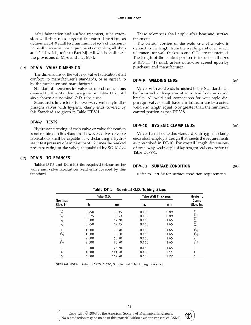
(07)
(07)
ASME BPE-2007
After fabrication and surface treatment, tube exten-sion wall thickness, beyond the control portion, asdefined in DT-8 shall be a minimum of 65% of the nomi-nal wall thickness. For requirements regarding all shopand field welds, refer to Part MJ. All welds shall meetthe provisions of MJ-6 and Fig. MJ-1.
DT-V-6 VALVE DIMENSION
The dimensions of the valve or valve fabrication shallconform to manufacturer’s standards, or as agreed toby the purchaser and manufacturer.
Standard dimensions for valve weld end connectionscovered by this Standard are given in Table DT-1. Allsizes shown are nominal O.D. tube sizes.
Standard dimensions for two-way weir style dia-phragm valves with hygienic clamp ends covered bythis Standard are given in Table DT-V-1.
DT-V-7 TESTS
Hydrostatic testing of each valve or valve fabricationis not required in this Standard; however, valves or valvefabrications shall be capable of withstanding a hydro-static test pressure of a minimum of 1.2 times the markedpressure rating of the valve, as qualified by SG-4.1.1.6.
DT-V-8 TOLERANCES
Tables DT-5 and DT-6 list the required tolerances forvalve and valve fabrication weld ends covered by thisStandard.
Table DT-1 Nominal O.D. Tubing Sizes
Tube O.D. Tube Wall Thickness HygienicNominal ClampSize, in. in. mm in. mm Size, in.
1⁄4 0.250 6.35 0.035 0.89 3⁄43⁄8 0.375 9.53 0.035 0.89 3⁄41⁄2 0.500 12.70 0.065 1.65 3⁄43⁄4 0.750 19.05 0.065 1.65 3⁄4
1 1.000 25.40 0.065 1.65 11⁄211⁄2 1.500 38.10 0.065 1.65 11⁄2
2 2.000 50.80 0.065 1.65 221⁄2 2.500 63.50 0.065 1.65 21⁄2
3 3.000 76.20 0.065 1.65 34 4.000 101.60 0.083 2.11 46 6.000 152.40 0.109 2.77 6
GENERAL NOTE: Refer to ASTM A 270, Supplement 2 for tubing tolerances.
59
These tolerances shall apply after heat and surfacetreatment.
The control portion of the weld end of a valve isdefined as the length from the welding end over whichtolerances for wall thickness and O.D. are maintained.The length of the control portion is fixed for all sizesat 0.75 in. (19 mm), unless otherwise agreed upon bypurchaser and manufacturer.
DT-V-9 WELDING ENDS
Valves with weld ends furnished to this Standard shallbe furnished with square-cut ends, free from burrs andbreaks. All weld end connections for weir style dia-phragm valves shall have a minimum unobstructedweld end length equal to or greater than the minimumcontrol portion as per DT-V-8.
DT-V-10 HYGIENIC CLAMP ENDS
Valves furnished to this Standard with hygienic clampends shall employ a design that meets the requirementsas prescribed in DT-10. For overall length dimensionsof two-way weir style diaphragm valves, refer toTable DT-V-1.
DT-V-11 SURFACE CONDITION
Refer to Part SF for surface condition requirements.
(07)
(07)
(07)
Copyright 2008 by the American Society of Mechanical Engineers.No reproduction may be made of this material without written consent of ASME.
c
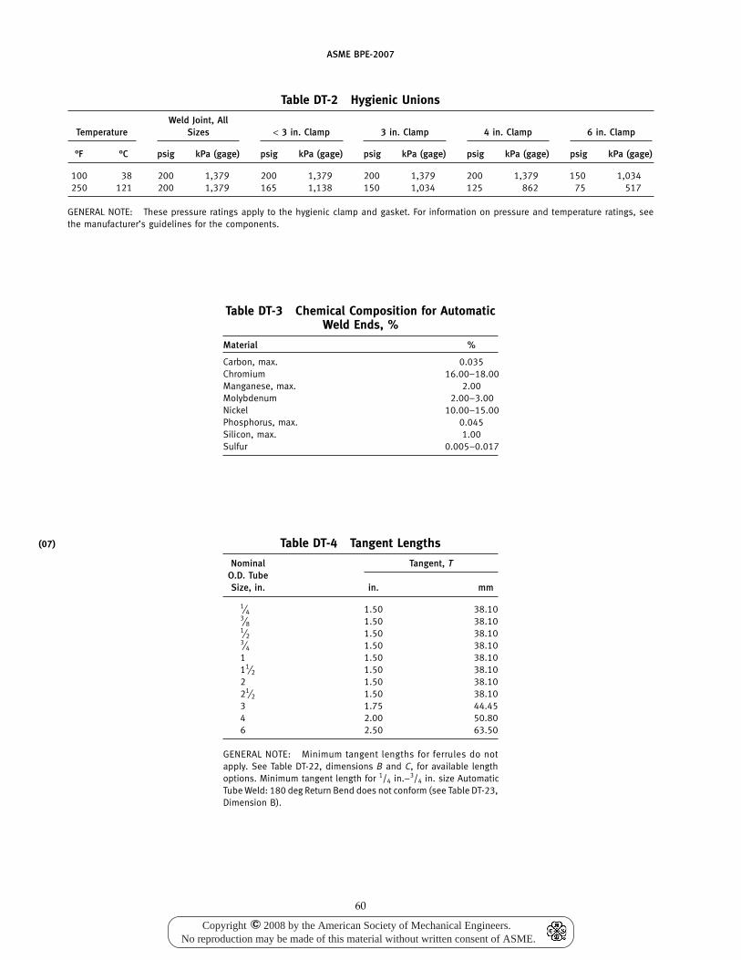
(07)
ASME BPE-2007
Table DT-2 Hygienic Unions
Weld Joint, AllTemperature Sizes < 3 in. Clamp 3 in. Clamp 4 in. Clamp 6 in. Clamp
°F °C psig kPa (gage) psig kPa (gage) psig kPa (gage) psig kPa (gage) psig kPa (gage)
100 38 200 1,379 200 1,379 200 1,379 200 1,379 150 1,034250 121 200 1,379 165 1,138 150 1,034 125 862 75 517
GENERAL NOTE: These pressure ratings apply to the hygienic clamp and gasket. For information on pressure and temperature ratings, seethe manufacturer’s guidelines for the components.
Table DT-3 Chemical Composition for AutomaticWeld Ends, %
Material %
Carbon, max. 0.035Chromium 16.00–18.00Manganese, max. 2.00Molybdenum 2.00–3.00Nickel 10.00–15.00Phosphorus, max. 0.045Silicon, max. 1.00Sulfur 0.005–0.017
Table DT-4 Tangent Lengths
Nominal Tangent, TO.D. TubeSize, in. in. mm
1⁄4 1.50 38.103⁄8 1.50 38.101⁄2 1.50 38.103⁄4 1.50 38.101 1.50 38.1011⁄2 1.50 38.102 1.50 38.1021⁄2 1.50 38.103 1.75 44.454 2.00 50.806 2.50 63.50
GENERAL NOTE: Minimum tangent lengths for ferrules do notapply. See Table DT-22, dimensions B and C, for available lengthoptions. Minimum tangent length for 1/4 in.–3/4 in. size AutomaticTube Weld: 180 deg Return Bend does not conform (see Table DT-23,Dimension B).
60
Copyright 2008 by the American Society of Mechanical Engineers.No reproduction may be made of this material without written consent of ASME.
c
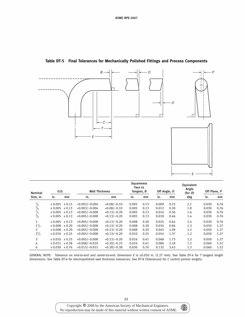
ASME BPE-2007
Table DT-5 Final Tolerances for Mechanically Polished Fittings and Process Components
B
C
T
E
O P
E
O
Squareness EquivalentFace to Angle
O.D. Wall Thickness Tangent, B Off Angle, O Off Plane, PNominal (for O)Size, in. in. mm in. mm in. mm in. mm deg in. mm
1⁄4 ± 0.005 ± 0.13 +0.003/−0.004 +0.08/−0.10 0.005 0.13 0.009 0.23 2.1 0.030 0.763⁄8 ± 0.005 ± 0.13 +0.003/−0.004 +0.08/−0.10 0.005 0.13 0.012 0.30 1.8 0.030 0.761⁄2 ± 0.005 ± 0.13 +0.005/−0.008 +0.13/−0.20 0.005 0.13 0.014 0.36 1.6 0.030 0.763⁄4 ± 0.005 ± 0.13 +0.005/−0.008 +0.13/−0.20 0.005 0.13 0.018 0.46 1.4 0.030 0.76
1 ± 0.005 ± 0.13 +0.005/−0.008 +0.13/−0.20 0.008 0.20 0.025 0.64 1.4 0.030 0.7611⁄2 ± 0.008 ± 0.20 +0.005/−0.008 +0.13/−0.20 0.008 0.20 0.034 0.86 1.3 0.050 1.272 ± 0.008 ± 0.20 +0.005/−0.008 +0.13/−0.20 0.008 0.20 0.043 1.09 1.2 0.050 1.2721⁄2 ± 0.010 ± 0.25 +0.005/−0.008 +0.13/−0.20 0.010 0.25 0.054 1.37 1.2 0.050 1.27
3 ± 0.010 ± 0.25 +0.005/−0.008 +0.13/−0.20 0.016 0.41 0.068 1.73 1.3 0.050 1.274 ± 0.015 ± 0.38 +0.008/−0.010 +0.20/−0.25 0.016 0.41 0.086 2.18 1.2 0.060 1.526 ± 0.030 ± 0.76 +0.015/−0.015 +0.38/−0.38 0.030 0.76 0.135 3.43 1.3 0.060 1.52
GENERAL NOTE: Tolerance on end-to-end and center-to-end: dimension E is ±0.050 in. (1.27 mm). See Table DT-4 for T tangent lengthdimensions. See Table DT-6 for electropolished wall thickness tolerances. See DT-8 (Tolerances) for C control portion lengths.
61
Copyright 2008 by the American Society of Mechanical Engineers.No reproduction may be made of this material without written consent of ASME.
c
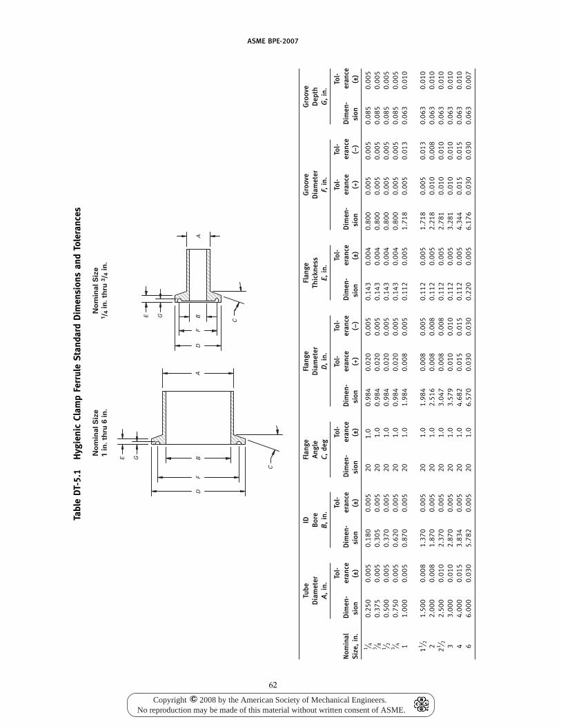
ASME BPE-2007
Tabl
eD
T-5.
1H
ygie
nic
Clam
pFe
rrul
eS
tand
ard
Dim
ensi
ons
and
Tole
ranc
es
No
min
al
Siz
e
1 i
n.
thru
6 i
n.
No
min
al
Siz
e1/ 4
in
. th
ru 3
/ 4 i
n.
E G
E G
DF
BD
FB
AA
C
C
Tube
IDFl
ange
Flan
geFl
ange
Gro
ove
Gro
ove
Dia
met
erB
ore
Ang
leD
iam
eter
Thic
knes
sD
iam
eter
Dep
thA
,in
.B
,in
.C,
deg
D,
in.
E,in
.F,
in.
G,
in.
Tol-
Tol-
Tol-
Tol-
Tol-
Tol-
Tol-
Tol-
Tol-
Nom
inal
Dim
en-
eran
ceD
imen
-er
ance
Dim
en-
eran
ceD
imen
-er
ance
eran
ceD
imen
-er
ance
Dim
en-
eran
ceer
ance
Dim
en-
eran
ceS
ize,
in.
sion
(±)
sion
(±)
sion
(±)
sion
(+)
(−)
sion
(±)
sion
(+)
(−)
sion
(±)
1 ⁄ 40.
250
0.00
50.
180
0.00
520
1.0
0.98
40.
020
0.00
50.
143
0.00
40.
800
0.00
50.
005
0.08
50.
005
3 ⁄ 80.
375
0.00
50.
305
0.00
520
1.0
0.98
40.
020
0.00
50.
143
0.00
40.
800
0.00
50.
005
0.08
50.
005
1 ⁄ 20.
500
0.00
50.
370
0.00
520
1.0
0.98
40.
020
0.00
50.
143
0.00
40.
800
0.00
50.
005
0.08
50.
005
3 ⁄ 40.
750
0.00
50.
620
0.00
520
1.0
0.98
40.
020
0.00
50.
143
0.00
40.
800
0.00
50.
005
0.08
50.
005
11.
000
0.00
50.
870
0.00
520
1.0
1.98
40.
008
0.00
50.
112
0.00
51.
718
0.00
50.
013
0.06
30.
010
11 ⁄ 21.
500
0.00
81.
370
0.00
520
1.0
1.98
40.
008
0.00
50.
112
0.00
51.
718
0.00
50.
013
0.06
30.
010
22.
000
0.00
81.
870
0.00
520
1.0
2.51
60.
008
0.00
80.
112
0.00
52.
218
0.01
00.
008
0.06
30.
010
21 ⁄ 22.
500
0.01
02.
370
0.00
520
1.0
3.04
70.
008
0.00
80.
112
0.00
52.
781
0.01
00.
010
0.06
30.
010
33.
000
0.01
02.
870
0.00
520
1.0
3.57
90.
010
0.01
00.
112
0.00
53.
281
0.01
00.
010
0.06
30.
010
44.
000
0.01
53.
834
0.00
520
1.0
4.68
20.
015
0.01
50.
112
0.00
54.
344
0.01
50.
015
0.06
30.
010
66.
000
0.03
05.
782
0.00
520
1.0
6.57
00.
030
0.03
00.
220
0.00
56.
176
0.03
00.
030
0.06
30.
007
62
Copyright 2008 by the American Society of Mechanical Engineers.No reproduction may be made of this material without written consent of ASME.
c
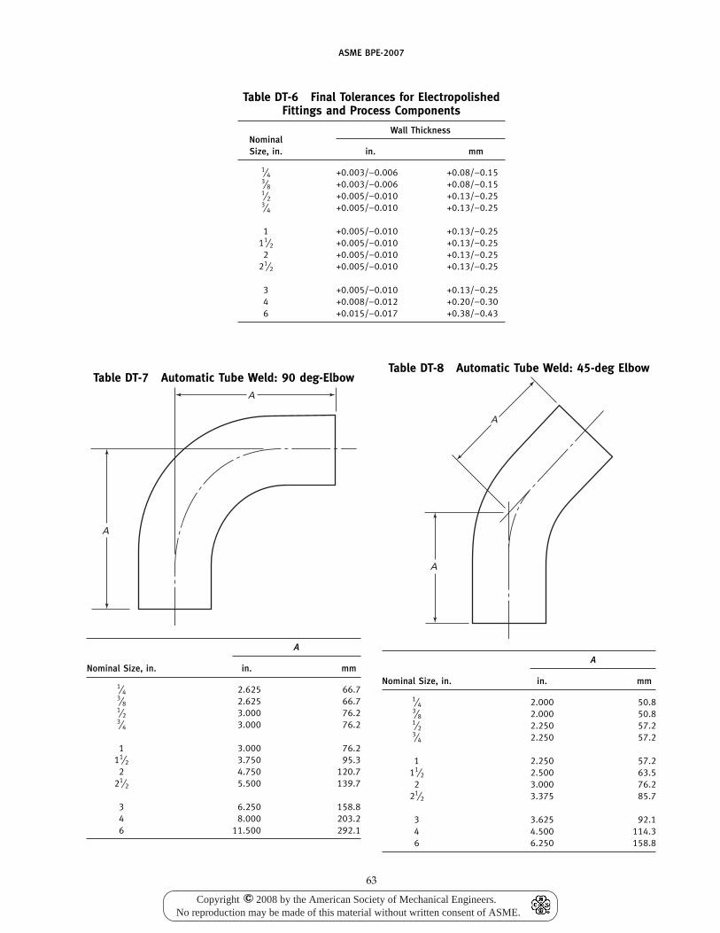
ASME BPE-2007
Table DT-6 Final Tolerances for ElectropolishedFittings and Process Components
Wall ThicknessNominalSize, in. in. mm
1⁄4 +0.003/−0.006 +0.08/−0.153⁄8 +0.003/−0.006 +0.08/−0.151⁄2 +0.005/−0.010 +0.13/−0.253⁄4 +0.005/−0.010 +0.13/−0.25
1 +0.005/−0.010 +0.13/−0.2511⁄2 +0.005/−0.010 +0.13/−0.25
2 +0.005/−0.010 +0.13/−0.2521⁄2 +0.005/−0.010 +0.13/−0.25
3 +0.005/−0.010 +0.13/−0.254 +0.008/−0.012 +0.20/−0.306 +0.015/−0.017 +0.38/−0.43
Table DT-7 Automatic Tube Weld: 90 deg-ElbowA
A
A
Nominal Size, in. in. mm
1⁄4 2.625 66.73⁄8 2.625 66.71⁄2 3.000 76.23⁄4 3.000 76.2
1 3.000 76.211⁄2 3.750 95.3
2 4.750 120.721⁄2 5.500 139.7
3 6.250 158.84 8.000 203.26 11.500 292.1
63
Table DT-8 Automatic Tube Weld: 45-deg Elbow
A
A
A
Nominal Size, in. in. mm
1⁄4 2.000 50.83⁄8 2.000 50.81⁄2 2.250 57.23⁄4 2.250 57.2
1 2.250 57.211⁄2 2.500 63.5
2 3.000 76.221⁄2 3.375 85.7
3 3.625 92.14 4.500 114.36 6.250 158.8
Copyright 2008 by the American Society of Mechanical Engineers.No reproduction may be made of this material without written consent of ASME.
c
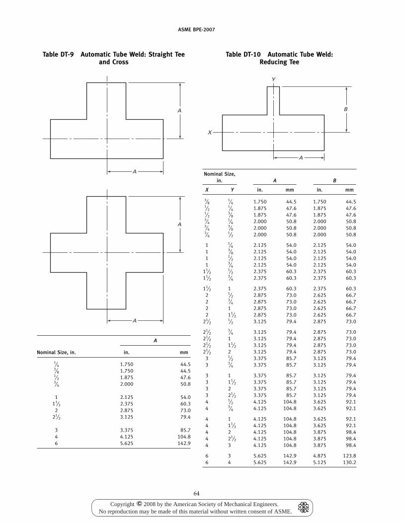
ASME BPE-2007
Table DT-9 Automatic Tube Weld: Straight Teeand Cross
A
A
A
A
A
Nominal Size, in. in. mm
1⁄4 1.750 44.53⁄8 1.750 44.51⁄2 1.875 47.63⁄4 2.000 50.8
1 2.125 54.011⁄2 2.375 60.3
2 2.875 73.021⁄2 3.125 79.4
3 3.375 85.74 4.125 104.86 5.625 142.9
64
Table DT-10 Automatic Tube Weld:Reducing Tee
B
A
X
Y
Nominal Size,in. A B
X Y in. mm in. mm
3⁄81⁄4 1.750 44.5 1.750 44.5
1⁄21⁄4 1.875 47.6 1.875 47.6
1⁄23⁄8 1.875 47.6 1.875 47.6
3⁄41⁄4 2.000 50.8 2.000 50.8
3⁄43⁄8 2.000 50.8 2.000 50.8
3⁄41⁄2 2.000 50.8 2.000 50.8
1 1⁄4 2.125 54.0 2.125 54.01 3⁄8 2.125 54.0 2.125 54.01 1⁄2 2.125 54.0 2.125 54.01 3⁄4 2.125 54.0 2.125 54.0
11⁄21⁄2 2.375 60.3 2.375 60.3
11⁄23⁄4 2.375 60.3 2.375 60.3
11⁄2 1 2.375 60.3 2.375 60.32 1⁄2 2.875 73.0 2.625 66.72 3⁄4 2.875 73.0 2.625 66.72 1 2.875 73.0 2.625 66.72 11⁄2 2.875 73.0 2.625 66.7
21⁄21⁄2 3.125 79.4 2.875 73.0
21⁄23⁄4 3.125 79.4 2.875 73.0
21⁄2 1 3.125 79.4 2.875 73.021⁄2 11⁄2 3.125 79.4 2.875 73.021⁄2 2 3.125 79.4 2.875 73.0
3 1⁄2 3.375 85.7 3.125 79.43 3⁄4 3.375 85.7 3.125 79.4
3 1 3.375 85.7 3.125 79.43 11⁄2 3.375 85.7 3.125 79.43 2 3.375 85.7 3.125 79.43 21⁄2 3.375 85.7 3.125 79.44 1⁄2 4.125 104.8 3.625 92.14 3⁄4 4.125 104.8 3.625 92.1
4 1 4.125 104.8 3.625 92.14 11⁄2 4.125 104.8 3.625 92.14 2 4.125 104.8 3.875 98.44 21⁄2 4.125 104.8 3.875 98.44 3 4.125 104.8 3.875 98.4
6 3 5.625 142.9 4.875 123.86 4 5.625 142.9 5.125 130.2
Copyright 2008 by the American Society of Mechanical Engineers.No reproduction may be made of this material without written consent of ASME.
c
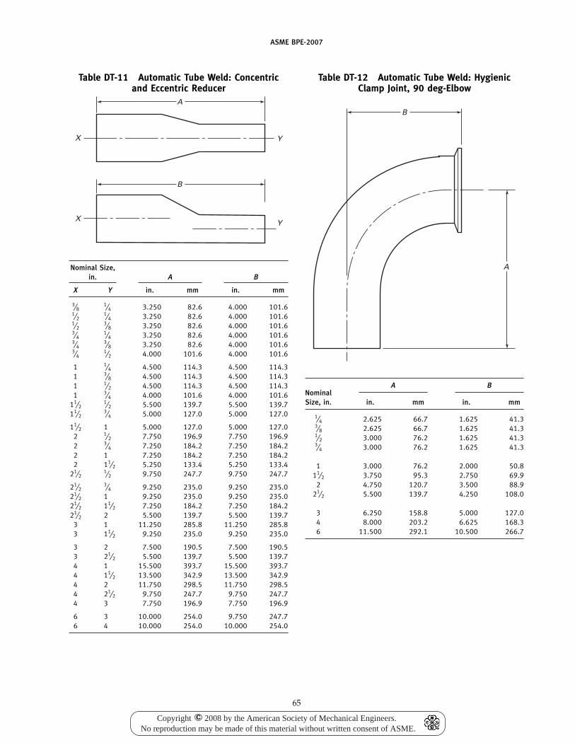
ASME BPE-2007
Table DT-11 Automatic Tube Weld: Concentricand Eccentric Reducer
A
X Y
B
X Y
Nominal Size,in. A B
X Y in. mm in. mm
3⁄81⁄4 3.250 82.6 4.000 101.6
1⁄21⁄4 3.250 82.6 4.000 101.6
1⁄23⁄8 3.250 82.6 4.000 101.6
3⁄41⁄4 3.250 82.6 4.000 101.6
3⁄43⁄8 3.250 82.6 4.000 101.6
3⁄41⁄2 4.000 101.6 4.000 101.6
1 1⁄4 4.500 114.3 4.500 114.31 3⁄8 4.500 114.3 4.500 114.31 1⁄2 4.500 114.3 4.500 114.31 3⁄4 4.000 101.6 4.000 101.6
11⁄21⁄2 5.500 139.7 5.500 139.7
11⁄23⁄4 5.000 127.0 5.000 127.0
11⁄2 1 5.000 127.0 5.000 127.02 1⁄2 7.750 196.9 7.750 196.92 3⁄4 7.250 184.2 7.250 184.22 1 7.250 184.2 7.250 184.22 11⁄2 5.250 133.4 5.250 133.4
21⁄21⁄2 9.750 247.7 9.750 247.7
21⁄23⁄4 9.250 235.0 9.250 235.0
21⁄2 1 9.250 235.0 9.250 235.021⁄2 11⁄2 7.250 184.2 7.250 184.221⁄2 2 5.500 139.7 5.500 139.7
3 1 11.250 285.8 11.250 285.83 11⁄2 9.250 235.0 9.250 235.0
3 2 7.500 190.5 7.500 190.53 21⁄2 5.500 139.7 5.500 139.74 1 15.500 393.7 15.500 393.74 11⁄2 13.500 342.9 13.500 342.94 2 11.750 298.5 11.750 298.54 21⁄2 9.750 247.7 9.750 247.74 3 7.750 196.9 7.750 196.9
6 3 10.000 254.0 9.750 247.76 4 10.000 254.0 10.000 254.0
65
Table DT-12 Automatic Tube Weld: HygienicClamp Joint, 90 deg-Elbow
B
A
A BNominalSize, in. in. mm in. mm
1⁄4 2.625 66.7 1.625 41.33⁄8 2.625 66.7 1.625 41.31⁄2 3.000 76.2 1.625 41.33⁄4 3.000 76.2 1.625 41.3
1 3.000 76.2 2.000 50.811⁄2 3.750 95.3 2.750 69.9
2 4.750 120.7 3.500 88.921⁄2 5.500 139.7 4.250 108.0
3 6.250 158.8 5.000 127.04 8.000 203.2 6.625 168.36 11.500 292.1 10.500 266.7
Copyright 2008 by the American Society of Mechanical Engineers.No reproduction may be made of this material without written consent of ASME.
c
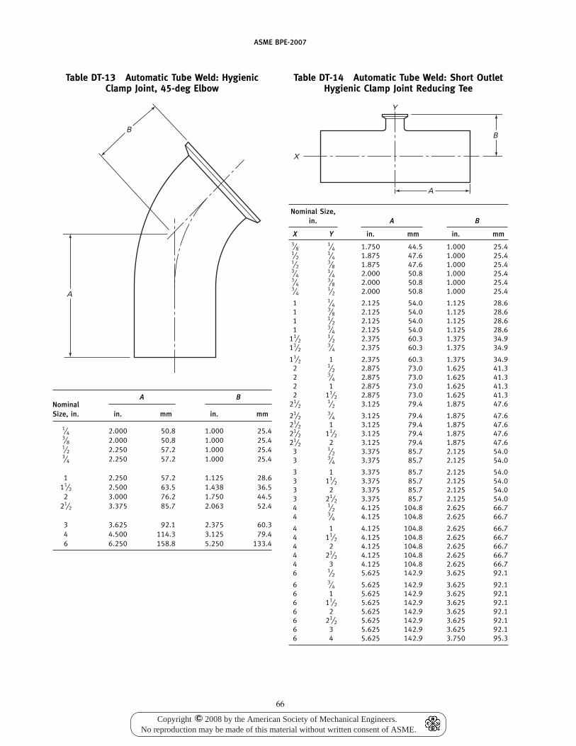
ASME BPE-2007
Table DT-13 Automatic Tube Weld: HygienicClamp Joint, 45-deg Elbow
B
A
A BNominalSize, in. in. mm in. mm
1⁄4 2.000 50.8 1.000 25.43⁄8 2.000 50.8 1.000 25.41⁄2 2.250 57.2 1.000 25.43⁄4 2.250 57.2 1.000 25.4
1 2.250 57.2 1.125 28.611⁄2 2.500 63.5 1.438 36.5
2 3.000 76.2 1.750 44.521⁄2 3.375 85.7 2.063 52.4
3 3.625 92.1 2.375 60.34 4.500 114.3 3.125 79.46 6.250 158.8 5.250 133.4
66
Table DT-14 Automatic Tube Weld: Short OutletHygienic Clamp Joint Reducing Tee
A
X
B
Y
Nominal Size,in. A B
X Y in. mm in. mm3⁄8
1⁄4 1.750 44.5 1.000 25.41⁄2
1⁄4 1.875 47.6 1.000 25.41⁄2
3⁄8 1.875 47.6 1.000 25.43⁄4
1⁄4 2.000 50.8 1.000 25.43⁄4
3⁄8 2.000 50.8 1.000 25.43⁄4
1⁄2 2.000 50.8 1.000 25.4
1 1⁄4 2.125 54.0 1.125 28.61 3⁄8 2.125 54.0 1.125 28.61 1⁄2 2.125 54.0 1.125 28.61 3⁄4 2.125 54.0 1.125 28.6
11⁄21⁄2 2.375 60.3 1.375 34.9
11⁄23⁄4 2.375 60.3 1.375 34.9
11⁄2 1 2.375 60.3 1.375 34.92 1⁄2 2.875 73.0 1.625 41.32 3⁄4 2.875 73.0 1.625 41.32 1 2.875 73.0 1.625 41.32 11⁄2 2.875 73.0 1.625 41.3
21⁄21⁄2 3.125 79.4 1.875 47.6
21⁄23⁄4 3.125 79.4 1.875 47.6
21⁄2 1 3.125 79.4 1.875 47.621⁄2 11⁄2 3.125 79.4 1.875 47.621⁄2 2 3.125 79.4 1.875 47.6
3 1⁄2 3.375 85.7 2.125 54.03 3⁄4 3.375 85.7 2.125 54.0
3 1 3.375 85.7 2.125 54.03 11⁄2 3.375 85.7 2.125 54.03 2 3.375 85.7 2.125 54.03 21⁄2 3.375 85.7 2.125 54.04 1⁄2 4.125 104.8 2.625 66.74 3⁄4 4.125 104.8 2.625 66.7
4 1 4.125 104.8 2.625 66.74 11⁄2 4.125 104.8 2.625 66.74 2 4.125 104.8 2.625 66.74 21⁄2 4.125 104.8 2.625 66.74 3 4.125 104.8 2.625 66.76 1⁄2 5.625 142.9 3.625 92.1
6 3⁄4 5.625 142.9 3.625 92.16 1 5.625 142.9 3.625 92.16 11⁄2 5.625 142.9 3.625 92.16 2 5.625 142.9 3.625 92.16 21⁄2 5.625 142.9 3.625 92.16 3 5.625 142.9 3.625 92.16 4 5.625 142.9 3.750 95.3
Copyright 2008 by the American Society of Mechanical Engineers.No reproduction may be made of this material without written consent of ASME.
c
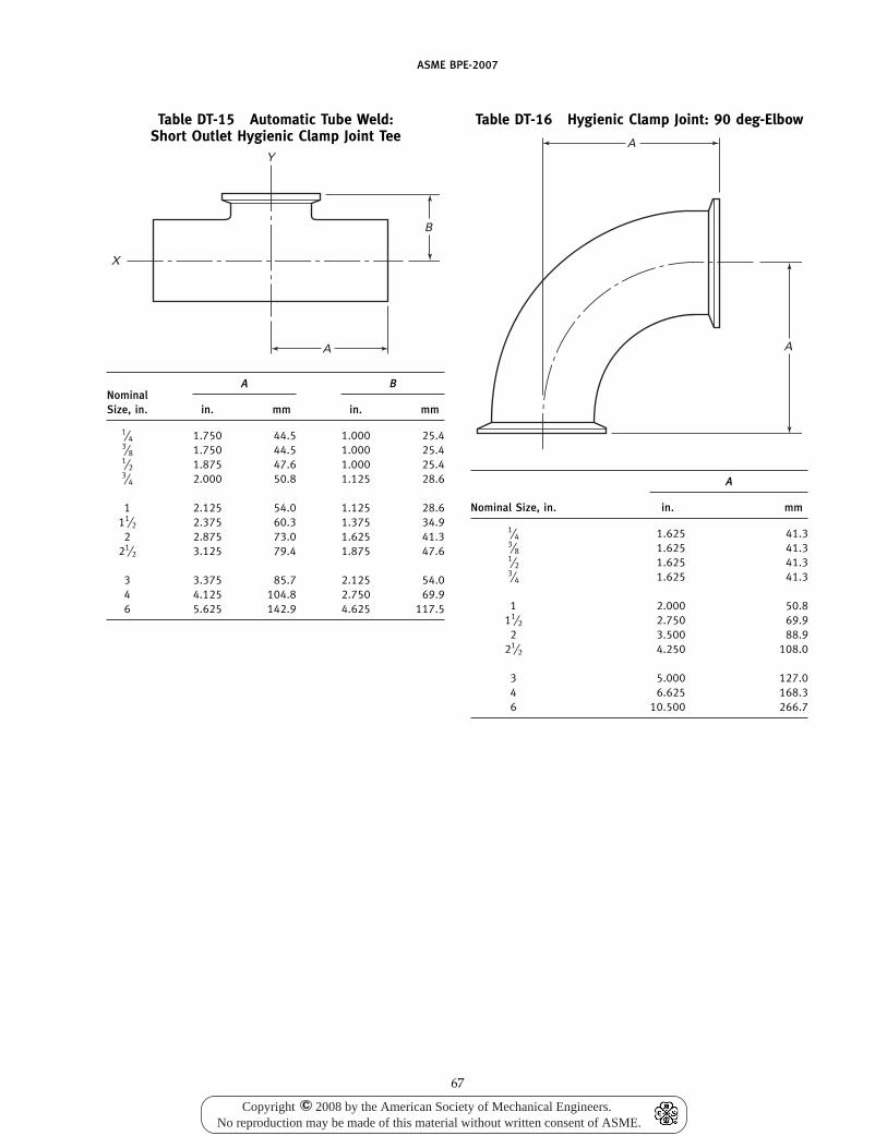
ASME BPE-2007
Table DT-15 Automatic Tube Weld:Short Outlet Hygienic Clamp Joint Tee
A
X
B
Y
A BNominalSize, in. in. mm in. mm
1⁄4 1.750 44.5 1.000 25.43⁄8 1.750 44.5 1.000 25.41⁄2 1.875 47.6 1.000 25.43⁄4 2.000 50.8 1.125 28.6
1 2.125 54.0 1.125 28.611⁄2 2.375 60.3 1.375 34.9
2 2.875 73.0 1.625 41.321⁄2 3.125 79.4 1.875 47.6
3 3.375 85.7 2.125 54.04 4.125 104.8 2.750 69.96 5.625 142.9 4.625 117.5
67
Table DT-16 Hygienic Clamp Joint: 90 deg-Elbow
A
A
A
Nominal Size, in. in. mm
1⁄4 1.625 41.33⁄8 1.625 41.31⁄2 1.625 41.33⁄4 1.625 41.3
1 2.000 50.811⁄2 2.750 69.9
2 3.500 88.921⁄2 4.250 108.0
3 5.000 127.04 6.625 168.36 10.500 266.7
Copyright 2008 by the American Society of Mechanical Engineers.No reproduction may be made of this material without written consent of ASME.
c
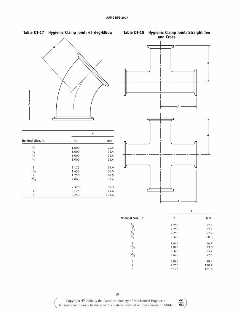
ASME BPE-2007
Table DT-17 Hygienic Clamp Joint: 45 deg-Elbow
A
A
A
Nominal Size, in. in. mm
1⁄4 1.000 25.43⁄8 1.000 25.41⁄2 1.000 25.43⁄4 1.000 25.4
1 1.125 28.611⁄2 1.438 36.5
2 1.750 44.521⁄2 2.063 52.4
3 2.375 60.34 3.125 79.46 5.250 133.4
68
Table DT-18 Hygienic Clamp Joint: Straight Teeand Cross
A
A
A
A
A
Nominal Size, in. in. mm
1⁄4 2.250 57.23⁄8 2.250 57.2
1⁄2 2.250 57.23⁄4 2.375 60.3
1 2.625 66.711⁄2 2.875 73.0
2 3.375 85.721⁄2 3.625 92.1
3 3.875 98.44 4.750 120.76 7.125 181.0
Copyright 2008 by the American Society of Mechanical Engineers.No reproduction may be made of this material without written consent of ASME.
c
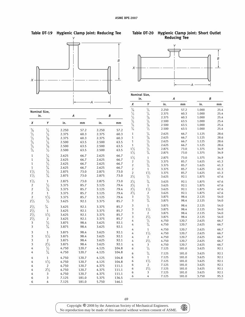
ASME BPE-2007
Table DT-19 Hygienic Clamp Joint: Reducing Tee
B
A
Y
X
Nominal Size,in. A B
X Y in. mm in. mm
3⁄81⁄4 2.250 57.2 2.250 57.2
1⁄21⁄4 2.375 60.3 2.375 60.3
1⁄23⁄8 2.375 60.3 2.375 60.3
3⁄41⁄4 2.500 63.5 2.500 63.5
3⁄43⁄8 2.500 63.5 2.500 63.5
3⁄41⁄2 2.500 63.5 2.500 63.5
1 1⁄4 2.625 66.7 2.625 66.71 3⁄8 2.625 66.7 2.625 66.71 1⁄2 2.625 66.7 2.625 66.71 3⁄4 2.625 66.7 2.625 66.7
11⁄21⁄2 2.875 73.0 2.875 73.0
11⁄23⁄4 2.875 73.0 2.875 73.0
11⁄2 1 2.875 73.0 2.875 73.02 1⁄2 3.375 85.7 3.125 79.42 3⁄4 3.375 85.7 3.125 79.42 1 3.375 85.7 3.125 79.42 11⁄2 3.375 85.7 3.125 79.4
21⁄21⁄2 3.625 92.1 3.375 85.7
21⁄23⁄4 3.625 92.1 3.375 85.7
21⁄2 1 3.625 92.1 3.375 85.721⁄2 11⁄2 3.625 92.1 3.375 85.721⁄2 2 3.625 92.1 3.375 85.7
3 1⁄2 3.875 98.4 3.625 92.13 3⁄4 3.875 98.4 3.625 92.1
3 1 3.875 98.4 3.625 92.13 11⁄2 3.875 98.4 3.625 92.13 2 3.875 98.4 3.625 92.13 21⁄2 3.875 98.4 3.625 92.14 1⁄2 4.750 120.7 4.125 104.84 3⁄4 4.750 120.7 4.125 104.8
4 1 4.750 120.7 4.125 104.84 11⁄2 4.750 120.7 4.125 104.84 2 4.750 120.7 4.375 111.14 21⁄2 4.750 120.7 4.375 111.14 3 4.750 120.7 4.375 111.16 3 7.125 181.0 5.375 136.56 4 7.125 181.0 5.750 146.1
69
Table DT-20 Hygienic Clamp Joint: Short OutletReducing Tee
B
A
X
Y
Nominal Size,in. A B
X Y in. mm in. mm3⁄8
1⁄4 2.250 57.2 1.000 25.41⁄2
1⁄4 2.375 60.3 1.000 25.41⁄2
3⁄8 2.375 60.3 1.000 25.43⁄4
1⁄4 2.500 63.5 1.000 25.43⁄4
3⁄8 2.500 63.5 1.000 25.43⁄4
1⁄2 2.500 63.5 1.000 25.4
1 1⁄4 2.625 66.7 1.125 28.61 3⁄8 2.625 66.7 1.125 28.61 1⁄2 2.625 66.7 1.125 28.61 3⁄4 2.625 66.7 1.125 28.6
11⁄21⁄2 2.875 73.0 1.375 34.9
11⁄23⁄4 2.875 73.0 1.375 34.9
11⁄2 1 2.875 73.0 1.375 34.92 1⁄2 3.375 85.7 1.625 41.32 3⁄4 3.375 85.7 1.625 41.32 1 3.375 85.7 1.625 41.32 11⁄2 3.375 85.7 1.625 41.3
21⁄21⁄2 3.625 92.1 1.875 47.6
21⁄23⁄4 3.625 92.1 1.875 47.6
21⁄2 1 3.625 92.1 1.875 47.621⁄2 11⁄2 3.625 92.1 1.875 47.621⁄2 2 3.625 92.1 1.875 47.6
3 1⁄2 3.875 98.4 2.125 54.03 3⁄4 3.875 98.4 2.125 54.0
3 1 3.875 98.4 2.125 54.03 11⁄2 3.875 98.4 2.125 54.03 2 3.875 98.4 2.125 54.03 21⁄2 3.875 98.4 2.125 54.04 1⁄2 4.750 120.7 2.625 66.74 3⁄4 4.750 120.7 2.625 66.7
4 1 4.750 120.7 2.625 66.74 11⁄2 4.750 120.7 2.625 66.74 2 4.750 120.7 2.625 66.74 21⁄2 4.750 120.7 2.625 66.74 3 4.750 120.7 2.625 66.76 1⁄2 7.125 181.0 3.625 92.1
6 3⁄4 7.125 181.0 3.625 92.16 1 7.125 181.0 3.625 92.16 11⁄2 7.125 181.0 3.625 92.16 2 7.125 181.0 3.625 92.16 21⁄2 7.125 181.0 3.625 92.16 3 7.125 181.0 3.625 92.16 4 7.125 181.0 3.750 95.3
Copyright 2008 by the American Society of Mechanical Engineers.No reproduction may be made of this material without written consent of ASME.
c
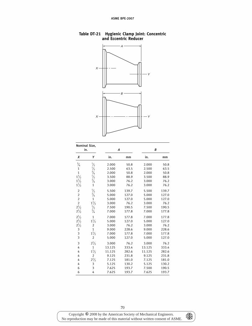
ASME BPE-2007
Table DT-21 Hygienic Clamp Joint: Concentricand Eccentric Reducer
A
Y
X
B
YX
Nominal Size,in. A B
X Y in. mm in. mm
3⁄41⁄2 2.000 50.8 2.000 50.8
1 1⁄2 2.500 63.5 2.500 63.51 3⁄4 2.000 50.8 2.000 50.8
11⁄21⁄2 3.500 88.9 3.500 88.9
11⁄23⁄4 3.000 76.2 3.000 76.2
11⁄2 1 3.000 76.2 3.000 76.2
2 1⁄2 5.500 139.7 5.500 139.72 3⁄4 5.000 127.0 5.000 127.02 1 5.000 127.0 5.000 127.02 11⁄2 3.000 76.2 3.000 76.2
21⁄21⁄2 7.500 190.5 7.500 190.5
21⁄23⁄4 7.000 177.8 7.000 177.8
21⁄2 1 7.000 177.8 7.000 177.821⁄2 11⁄2 5.000 127.0 5.000 127.021⁄2 2 3.000 76.2 3.000 76.2
3 1 9.000 228.6 9.000 228.63 11⁄2 7.000 177.8 7.000 177.83 2 5.000 127.0 5.000 127.0
3 21⁄2 3.000 76.2 3.000 76.24 1 13.125 333.4 13.125 333.44 11⁄2 11.125 282.6 11.125 282.64 2 9.125 231.8 9.125 231.84 21⁄2 7.125 181.0 7.125 181.04 3 5.125 130.2 5.125 130.26 3 7.625 193.7 7.500 190.56 4 7.625 193.7 7.625 193.7
70
Copyright 2008 by the American Society of Mechanical Engineers.No reproduction may be made of this material without written consent of ASME.
c
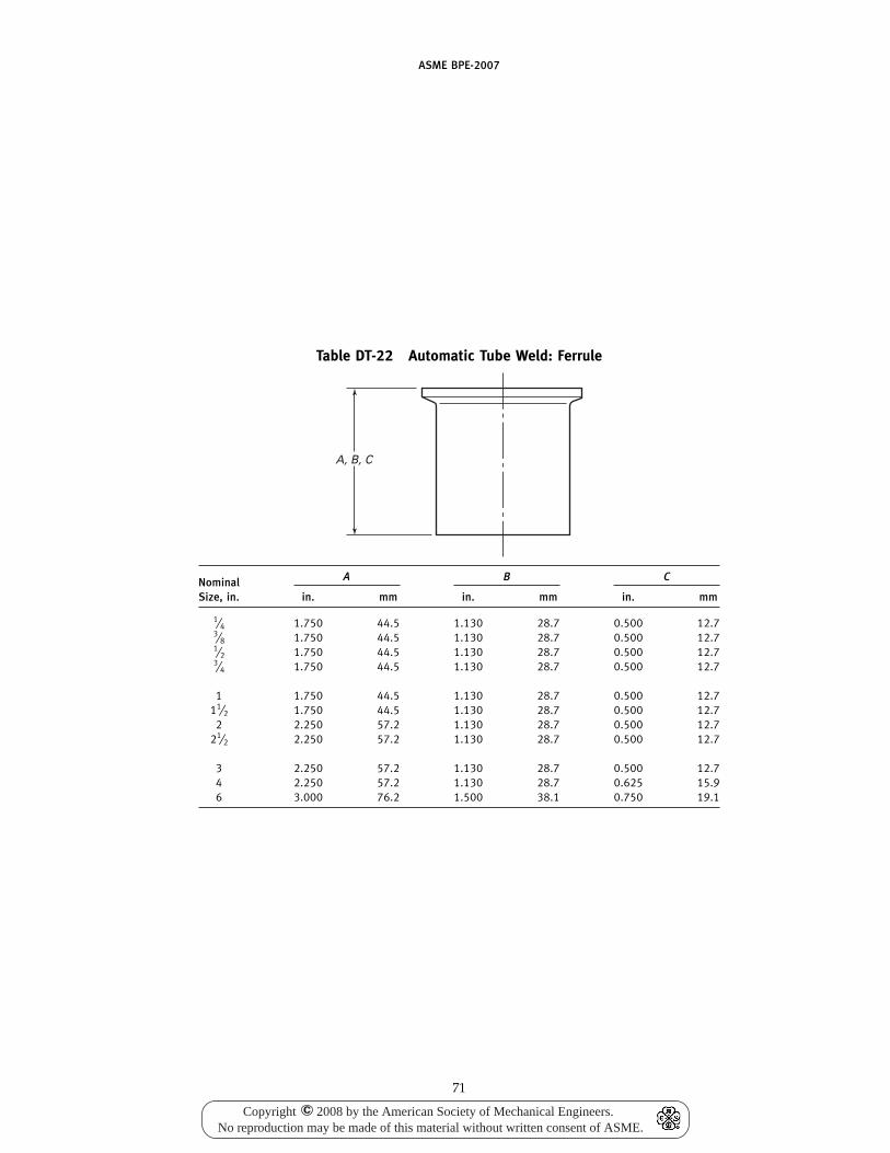
ASME BPE-2007
Table DT-22 Automatic Tube Weld: Ferrule
A, B, C
A B CNominalSize, in. in. mm in. mm in. mm
1⁄4 1.750 44.5 1.130 28.7 0.500 12.73⁄8 1.750 44.5 1.130 28.7 0.500 12.71⁄2 1.750 44.5 1.130 28.7 0.500 12.73⁄4 1.750 44.5 1.130 28.7 0.500 12.7
1 1.750 44.5 1.130 28.7 0.500 12.711⁄2 1.750 44.5 1.130 28.7 0.500 12.7
2 2.250 57.2 1.130 28.7 0.500 12.721⁄2 2.250 57.2 1.130 28.7 0.500 12.7
3 2.250 57.2 1.130 28.7 0.500 12.74 2.250 57.2 1.130 28.7 0.625 15.96 3.000 76.2 1.500 38.1 0.750 19.1
71
Copyright 2008 by the American Society of Mechanical Engineers.No reproduction may be made of this material without written consent of ASME.
c
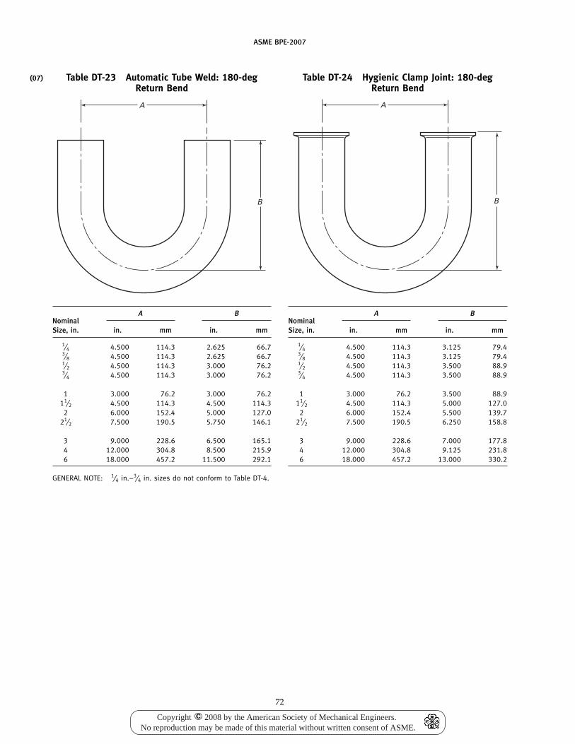
(07)
ASME BPE-2007
Table DT-23 Automatic Tube Weld: 180-degReturn Bend
A
B
A BNominalSize, in. in. mm in. mm
1⁄4 4.500 114.3 2.625 66.73⁄8 4.500 114.3 2.625 66.71⁄2 4.500 114.3 3.000 76.23⁄4 4.500 114.3 3.000 76.2
1 3.000 76.2 3.000 76.211⁄2 4.500 114.3 4.500 114.3
2 6.000 152.4 5.000 127.021⁄2 7.500 190.5 5.750 146.1
3 9.000 228.6 6.500 165.14 12.000 304.8 8.500 215.96 18.000 457.2 11.500 292.1
GENERAL NOTE: 1⁄4 in.–3⁄4 in. sizes do not conform to Table DT-4.
72
Table DT-24 Hygienic Clamp Joint: 180-degReturn Bend
A
B
A BNominalSize, in. in. mm in. mm
1⁄4 4.500 114.3 3.125 79.43⁄8 4.500 114.3 3.125 79.41⁄2 4.500 114.3 3.500 88.93⁄4 4.500 114.3 3.500 88.9
1 3.000 76.2 3.500 88.911⁄2 4.500 114.3 5.000 127.0
2 6.000 152.4 5.500 139.721⁄2 7.500 190.5 6.250 158.8
3 9.000 228.6 7.000 177.84 12.000 304.8 9.125 231.86 18.000 457.2 13.000 330.2
Copyright 2008 by the American Society of Mechanical Engineers.No reproduction may be made of this material without written consent of ASME.
c
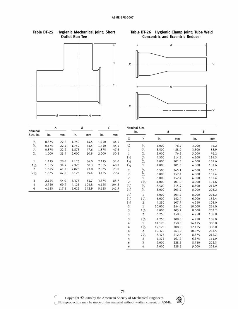
ASME BPE-2007
Table DT-25 Hygienic Mechanical Joint: ShortOutlet Run Tee
B
C
A
A B CNominalSize, in. in. mm in. mm in. mm
1⁄4 0.875 22.2 1.750 44.5 1.750 44.53⁄8 0.875 22.2 1.750 44.5 1.750 44.51⁄2 0.875 22.2 1.875 47.6 1.875 47.63⁄4 1.000 25.4 2.000 50.8 2.000 50.8
1 1.125 28.6 2.125 54.0 2.125 54.011⁄2 1.375 34.9 2.375 60.3 2.375 60.3
2 1.625 41.3 2.875 73.0 2.875 73.021⁄2 1.875 47.6 3.125 79.4 3.125 79.4
3 2.125 54.0 3.375 85.7 3.375 85.74 2.750 69.9 4.125 104.8 4.125 104.86 4.625 117.5 5.625 142.9 5.625 142.9
73
Table DT-26 Hygienic Clamp Joint: Tube WeldConcentric and Eccentric Reducer
A
X Y
B
XY
Nominal Size,in. A B
X Y in. mm in. mm
3⁄41⁄2 3.000 76.2 3.000 76.2
1 1⁄2 3.500 88.9 3.500 88.91 3⁄4 3.000 76.2 3.000 76.2
11⁄21⁄2 4.500 114.3 4.500 114.3
11⁄23⁄4 4.000 101.6 4.000 101.6
11⁄2 1 4.000 101.6 4.000 101.6
2 1⁄2 6.500 165.1 6.500 165.12 3⁄4 6.000 152.4 6.000 152.42 1 6.000 152.4 6.000 152.42 11⁄2 4.000 101.6 4.000 101.6
21⁄21⁄2 8.500 215.9 8.500 215.9
21⁄23⁄4 8.000 203.2 8.000 203.2
21⁄2 1 8.000 203.2 8.000 203.221⁄2 11⁄2 6.000 152.4 6.000 152.421⁄2 2 4.250 107.9 4.250 108.0
3 1 10.000 254.0 10.000 254.03 11⁄2 8.000 203.2 8.000 203.23 2 6.250 158.8 6.250 158.8
3 21⁄2 4.250 108.0 4.250 108.04 1 14.125 358.8 14.125 358.84 11⁄2 12.125 308.0 12.125 308.04 2 10.375 263.5 10.375 263.54 21⁄2 8.375 212.7 8.375 212.74 3 6.375 161.9 6.375 161.96 3 9.000 228.6 8.750 222.36 4 9.000 228.6 9.000 228.6
Copyright 2008 by the American Society of Mechanical Engineers.No reproduction may be made of this material without written consent of ASME.
c
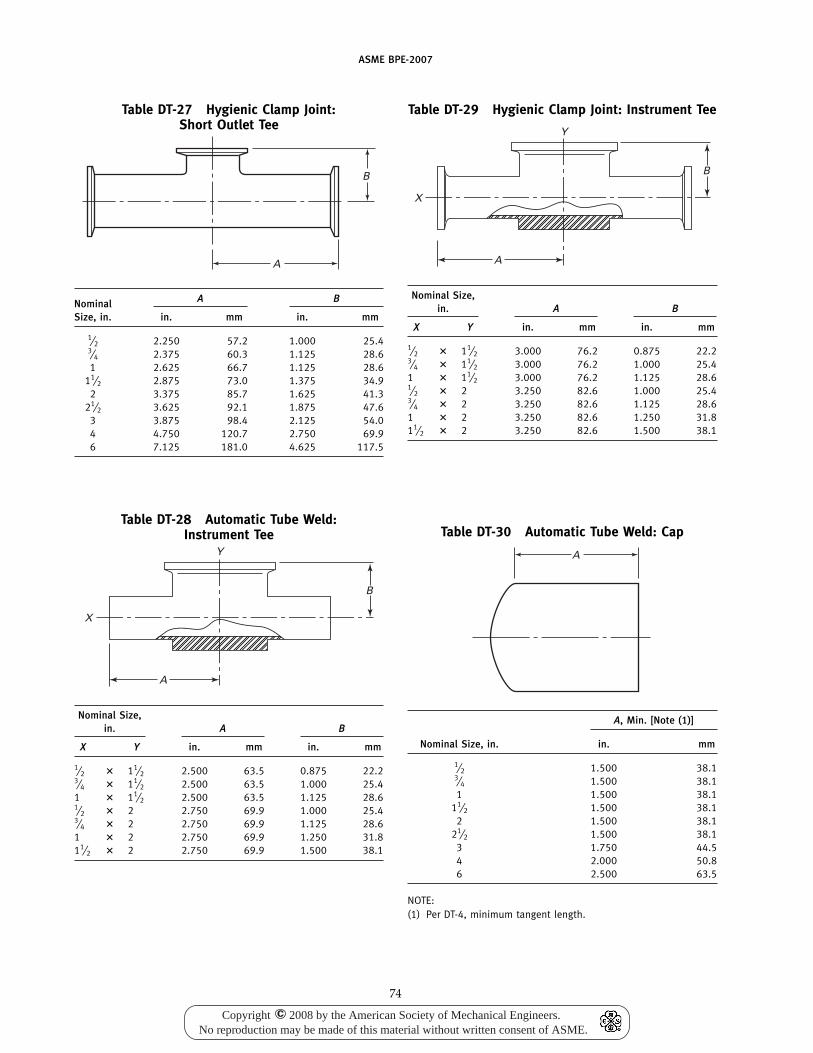
ASME BPE-2007
Table DT-27 Hygienic Clamp Joint:Short Outlet Tee
B
A
A BNominalSize, in. in. mm in. mm
1⁄2 2.250 57.2 1.000 25.43⁄4 2.375 60.3 1.125 28.61 2.625 66.7 1.125 28.6
11⁄2 2.875 73.0 1.375 34.92 3.375 85.7 1.625 41.3
21⁄2 3.625 92.1 1.875 47.63 3.875 98.4 2.125 54.04 4.750 120.7 2.750 69.96 7.125 181.0 4.625 117.5
Table DT-28 Automatic Tube Weld:Instrument Tee
B
X
A
Y
Nominal Size,in. A B
X Y in. mm in. mm
1⁄2 � 11⁄2 2.500 63.5 0.875 22.23⁄4 � 11⁄2 2.500 63.5 1.000 25.41 � 11⁄2 2.500 63.5 1.125 28.61⁄2 � 2 2.750 69.9 1.000 25.43⁄4 � 2 2.750 69.9 1.125 28.61 � 2 2.750 69.9 1.250 31.811⁄2 � 2 2.750 69.9 1.500 38.1
74
Table DT-29 Hygienic Clamp Joint: Instrument Tee
B
X
A
Y
Nominal Size,in. A B
X Y in. mm in. mm
1⁄2 � 11⁄2 3.000 76.2 0.875 22.23⁄4 � 11⁄2 3.000 76.2 1.000 25.41 � 11⁄2 3.000 76.2 1.125 28.61⁄2 � 2 3.250 82.6 1.000 25.43⁄4 � 2 3.250 82.6 1.125 28.61 � 2 3.250 82.6 1.250 31.811⁄2 � 2 3.250 82.6 1.500 38.1
Table DT-30 Automatic Tube Weld: Cap
A
A, Min. [Note (1)]
Nominal Size, in. in. mm
1⁄2 1.500 38.13⁄4 1.500 38.11 1.500 38.1
11⁄2 1.500 38.12 1.500 38.1
21⁄2 1.500 38.13 1.750 44.54 2.000 50.86 2.500 63.5
NOTE:(1) Per DT-4, minimum tangent length.
Copyright 2008 by the American Society of Mechanical Engineers.No reproduction may be made of this material without written consent of ASME.
c
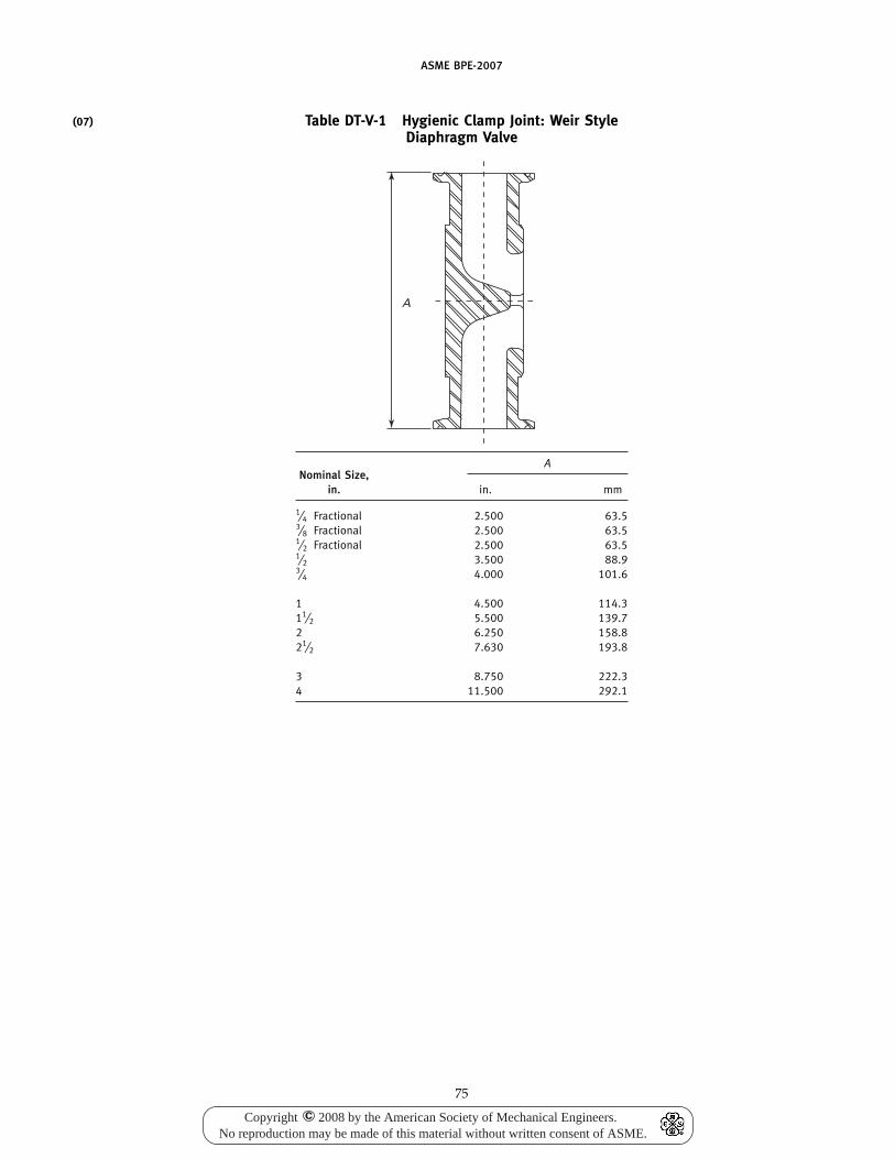
(07)
ASME BPE-2007
Table DT-V-1 Hygienic Clamp Joint: Weir StyleDiaphragm Valve
A
ANominal Size,
in. in. mm
1⁄4 Fractional 2.500 63.53⁄8 Fractional 2.500 63.51⁄2 Fractional 2.500 63.51⁄2 3.500 88.93⁄4 4.000 101.6
1 4.500 114.311⁄2 5.500 139.72 6.250 158.821⁄2 7.630 193.8
3 8.750 222.34 11.500 292.1
75
Copyright 2008 by the American Society of Mechanical Engineers.No reproduction may be made of this material without written consent of ASME.
c
ASME BPE-2007
Part MJMaterial Joining
MJ-1 SCOPE
The requirements of this Part are applicable to thejoining of equipment used in the bioprocessing, pharma-ceutical, and personal care product industries, includingpressure vessels and tanks [which includes heatexchangers, atmospheric tanks, pumps, and any vesselsdesigned and built to the ASME Boiler and PressureVessel Code (BPVC), Section VIII, Division 1], piping(built to ASME B31.3), tubing, and fittings, and shall beused in conjunction with the requirements of ASMEBPVC, Sections VIII and IX, and ASME B31.3, as applica-ble. These materials, joining methods, examinations, etc.,are limited to process systems that contact bioprocessingproducts or product-process streams.
MJ-2 MATERIALS
MJ-2.1 Stainless Steels
Material for process surfaces shall conform toAISI 316L (UNS S31603) and a published ASTM or otherrecognized specification, unless otherwise agreed to bythe purchaser and supplier. All materials (tubing andfittings) shall conform with Table DT-3. However, a pro-cess component or tube with a sulfur content eitherbelow the lower limit or above the upper limit of TableDT-3 can be used in a welded connection, provided thatall of the following conditions are met:
(a) Use of the process component or tube is agreedto by the owner/user.
(b) The process component or tube meets 0.030 wt.% max. sulfur limit.
(c) The process component or tube meets all otherrequirements of Table DT-3.
(d) All welds on the component or tube are internallyinspected and meet the requirements of MJ-6.4.
Material for supporting structures shall conform toAISI 304 or 304L (UNS S30400 or S30403) unless other-wise agreed to by the purchaser and supplier.
MJ-2.2 Nickel Alloys
The use of nickel alloys shall be subject to agreementby the purchaser and supplier. The alloy shall conformto a published ASTM or other recognized specification.It is recommended that weld and finish samples be madefrom the actual heat or lot of material in question, inorder to guarantee the desired results.
76
MJ-2.3 Mechanically Polished Material
Mechanically polished material shall be ready forwelding, i.e., free of grit and residues. Polished materialshall meet the dimensional tolerances of the applicablespecifications, and the surface finish requirements of thisStandard, after polishing has been completed.
MJ-2.4 Electropolished Material
Electropolished material shall be ready for weldingand shall be free of chemical residues and water stains.Surfaces shall meet the surface finish requirements ofPart SF for stainless steel or higher alloys.
MJ-2.5 Other Materials
Other materials (for example, titanium, tantalum,thermoplastic, and glass) may be used, based uponagreement by owner/user and contractor.
MJ-2.6 Weld and Finish Samples
Weld and finish samples, when required, shall bemade from the same material specification and gradeto be used in production in order to demonstrate thedesired results.
MJ-3 JOINING PROCESSES AND PROCEDURES
MJ-3.1 Welds Finished After Welding
For pressure vessels, tanks, and piping and tubingsystems where the process-contact surface of the weldis to be finished after welding, the welding processesused shall be limited to the arc or high energy beam(electron beam and laser beam) processes as definedin ANSI/AWS A3.0. All welding procedures must bequalified per MJ-8 of this Standard. The owner/userand contractor shall agree that the welding processselected will provide the desired results.
MJ-3.2 Welds Used in the As-Welded Condition
For pressure vessels, tanks, and piping and tubingsystems where the process-contact surface of the weldis to be used as is, welding processes shall be limitedto the inert-gas arc processes (such as gas tungsten-arcwelding and plasma arc welding) or the high energybeam processes (such as electron beam or laser beamwelding), as defined in ANSI/AWS A3.0. All weldingprocedures must be qualified per MJ-8 of this Standard.Every effort shall be made to use an automatic or
Copyright 2008 by the American Society of Mechanical Engineers.No reproduction may be made of this material without written consent of ASME.
c
(07)
ASME BPE-2007
machine welding process. Autogenous welds, weldswith filler wire, or consumable inserts are acceptable forthis Standard provided they meet the requirements forall applicable codes. The owner/user and contractorshall agree that the welding process selected will providethe desired results.
MJ-3.3 Nonmetallics
Joining of polymers (e.g., thermoplastics) shall be per-formed in accordance with Part PM. Joining of othernonmetallic materials shall be in accordance with proce-dures and processes recommended by the material man-ufacturer, and approved by the owner/user, usingmaterials or compounds that are inert to the intendedservice.
MJ-3.4 Mechanical Connections
Mechanical connections shall conform to SD-3.7.
MJ-4 WELD JOINT DESIGN AND PREPARATION
MJ-4.1 General
All butt joints in which one or both weld faces is aproduct contact surface shall have continuous completeweld joint penetration. This requirement exists for weldsmade from either one side or from both sides of theweld joint. All weld joints must have the product contactsurfaces properly purged or protected for the preventionof discoloration or contamination. External attachments(e.g., lift lugs, dimple jackets, ladder clips, etc.) musthave any discoloration of the product contact surfaceremoved.
Welds attaching any connection that passes throughthe wall of a tank or vessel, or a branch connection ona pipe or tube system, in which one or both sides of theweld joint is a product contact surface, shall either bejoined with a full penetration groove weld with a rein-forcing fillet weld [similar to Fig. SD-14-2, illustration(a)], or have at least one telltale hole provided if doublefillet welded only [similar to Fig. SD-14-2, illustration(b)]. A telltale hole is required on all lap, tee, corner, oredge joints that have one or both welds as a productcontact surface and are not attached by full penetrationwelds. The telltale hole shall provide a path for productor test media flow in the event of inner weld containmentfailure. Telltale holes are not required when all weldsare on product contact surfaces [e.g., Fig. SD-17, illustra-tion (d) detail or similar]. The telltale hole shall be nolarger than NPS ¼ in. (6.35 mm) and may be tappedfor a preliminary compressed air and soapsuds test fortightness of inside welds. These telltale holes may beplugged when the vessel is in service. The pluggingmaterial used shall not be capable of sustaining pressurebetween the lapped surfaces.
Socket welding is not permitted in process streamsystems or where CIP or SIP requirements are defined.
77
MJ-4.2 Pressure Vessels and Tanks
Joint designs shall be those permitted by ASME BPVC,Section VIII, and shall comply with MJ-4.1.
MJ-4.3 Piping
Joint designs shall be those permitted by ASME B31.3,and shall comply with MJ-4.1.
MJ-4.4 Tubing
Joint designs for hygienic tubing and fittings shall besquare butt joints. The tubing and fittings shall have endsprepared by machining or facing to provide a square endthat meets the requirements of Tables DT-5 and DT-6.The butt weld joints shall be properly cleaned within1/2 in. (13 mm) of the joint area on the inside and outsidesurfaces prior to welding. Welding on tubing shall bedone using automatic (or machine) welding techniques(such as orbital tube welding or lathe welding), exceptwhere size or space will not permit. In that case, manualwelding can be performed, but must be agreed to bythe owner/user and contractor.
MJ-4.5 Tube-Attachment Welds
(a) Tube-attachment welds, as addressed in this Stan-dard, are those that
(1) make branch connections other than those usedto fabricate the fittings described in Part DT of thisStandard
(2) attach tubes to other product forms(3) attach nozzles to transfer panels(4) attach a tube to any part of a hygienic system
(b) Tube-attachment welds not governed by this Partof the Standard include
(1) those governed by MJ-6.4 of this Standard(2) tube-to-tubesheet welds that are governed by
ASME BPVC, Section VIII, Division 1, in addition to thevisual inspection requirements of Part SF and MJ-6.2 ofthis Standard
These welds may be performed by the manual,machine, or an automatic welding process. Joint designsshall comply with MJ-4.1. The weld joints for completepenetration welds shall be prepared by means compati-ble with hygienic service. The weld joints shall be prop-erly cleaned within 1/2 in. (13 mm) on the inside andoutside surfaces, where accessible, prior to welding.Either fillet welds, groove welds, or a combination ofboth may be used.
MJ-5 FILLER MATERIAL
Filler material shall conform to a published AWS spec-ification, or to a proprietary specification agreed tobetween the filler manufacturer, equipment supplier,and end owner/user. Proprietary fillers require specialattention; see MJ-8 of this Standard and QW-250 andQW-350 of ASME BPVC, Section IX. Filler metals may
(07)
(07)
Copyright 2008 by the American Society of Mechanical Engineers.No reproduction may be made of this material without written consent of ASME.
c
ASME BPE-2007
be in the form of welding wire, consumable inserts, orother shapes or forms.
The use of filler metals is neither required nor prohib-ited. When used, filler metals shall be selected to providedeposited weld metal compatible with the materials tobe joined and the service conditions anticipated. Forstainless steel base metals, only low carbon grades ofstainless steel filler metals shall be used (e.g., for 316Lbase metal only 316L or 316LSi filler metal shall be used;for 304L base metal 308L or 316L filler metals shall beused). Stainless steel or nickel alloy with high molybde-num content may require special filler metals. The basemetal manufacturer should be consulted.
MJ-6 WELD ACCEPTANCE CRITERIA
MJ-6.1 General
Welding for a sterile environment requires that theweld shall not result in a surface that will contribute tomicrobiological growth and contamination of the prod-uct. The weld shall not have any discontinuities suchas cracks, voids, porosity, or joint misalignment that willpromote contamination of the product. All welding pro-cedures shall be qualified to MJ-8.
MJ-6.2 Pressure Vessels and Tanks
Weld acceptance criteria for pressure vessels andtanks shall be in accordance with ASME BPVC, SectionVIII, Division 1, with the additional requirements ofTable MJ-1. Where “None” is specified in Table MJ-1,the limits of ASME BPVC Section VIII, Division 1 willapply.
MJ-6.3 Piping
Weld acceptance criteria for piping shall be in accor-dance with ASME B31.3, paras. 341.3.2 through 341.3.4and Table 341.3.2, along with the criterion value notesfor the applicable fluid service category in Table 341.3.2for pipe welds and the additional requirements ofTable MJ-2.
MJ-6.4 Tubing
Weld acceptance criteria (including borescopic accept-ance criteria) for tubing and fittings shall be in accor-dance with Table MJ-3 (see Fig. MJ-1).
Preproduction sample welds, when required, shall besubmitted by the contractor to the owner/user to estab-lish weld quality. Owner/user, contractor, and inspec-tion contractor shall agree to the number and type ofsample welds.
During construction, sample welds shall be made ona regular basis to verify that the equipment is operatingproperly and that the purging setup is adequate to pre-vent discoloration beyond the level agreed upon by theowner/user and contractor. Owner/user and contractorshall agree to the frequency of sample welds. It is
78
strongly recommended that these sample welds be madeat the beginning of each work shift, whenever the purgesource bottle is changed, and when the automatic ormachine welding equipment is changed (such as whenthe orbital tube weld head is changed).
The sample welds described in the preceding para-graphs, and any associated welding machine printedrecords (e.g., welding parameter printouts directly fromwelding machine or downloaded from a weldingmachine), if any, may be disposed of after written accept-ance of the coupons by the owner, the owner’s represen-tative, or the inspector.
MJ-6.4.1 Sample Welds. Sample welds for tubingshall meet all the acceptable criteria of Table MJ-3. Aminimum internal bead width of 1.5 times the nominalwall thickness is required.
MJ-6.4.2 Rewelding. Rewelding (reflow) may beattempted one time only for the following defects:
(a) incomplete penetration (lack of penetration)(b) incomplete fusion (lack of fusion)(c) unconsumed tack welds that can be inspected on
the product contact sideAll rewelds shall either totally consume the original
weld or overlap the orignial weld with no base metalbetween the welds.
MJ-6.5 Tube-Attachment Welds
The acceptance criteria for tube-attachment weldsshall be in accordance with Table MJ-4.
MJ-6.5.1 Sample Welds. Sample welds are notrequired for tube-attachment welds or seal welds.
MJ-6.5.2 Rewelding. Rewelding is allowed, exceptfor welds that are product contact surfaces, for whichthe rewelding restrictions of MJ-6.4.2 apply.
MJ-7 INSPECTION, EXAMINATION, AND TESTING
MJ-7.1 Scope
These paragraphs provide for the inspection/exami-nation of bioprocessing equipment and componentsincluding pressure vessels, tanks, skids, pumps, piping,tubing, fittings, and clamps. Examination methods,terms, and definitions shall be as defined in Part GR ofthis Standard and in other existing recognized codesand standards, including ASME BPVC, Section VIII,Division 1; ASME B31.3; and AWS-QC1 and SNT-TC-1Arequirements for examiner and inspector certifications.
MJ-7.2 Types of Examinations
Owner/user, contractor, inspection contractor, and/orengineer shall agree to the types of examinations, unlessotherwise specified in the applicable code.
MJ-7.2.1 Pressure Vessels and Tanks. Examinationsincluding visual, liquid penetrant, radiographic, and
(07)
(07)
(07)
Copyright 2008 by the American Society of Mechanical Engineers.No reproduction may be made of this material without written consent of ASME.
c
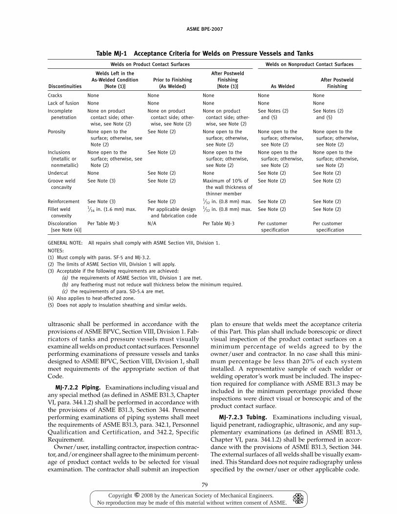
ASME BPE-2007
Table MJ-1 Acceptance Criteria for Welds on Pressure Vessels and Tanks
Welds on Product Contact Surfaces Welds on Nonproduct Contact Surfaces
Welds Left in the After PostweldAs-Welded Condition Prior to Finishing Finishing After Postweld
Discontinuities [Note (1)] (As Welded) [Note (1)] As Welded Finishing
Cracks None None None None None
Lack of fusion None None None None None
Incomplete None on product None on product None on product See Notes (2) See Notes (2)penetration contact side; other- contact side; other- contact side; other- and (5) and (5)
wise, see Note (2) wise, see Note (2) wise, see Note (2)
Porosity None open to the See Note (2) None open to the None open to the None open to thesurface; otherwise, see surface; otherwise, surface; otherwise, surface; otherwise,Note (2) see Note (2) see Note (2) see Note (2)
Inclusions None open to the See Note (2) None open to the None open to the None open to the(metallic or surface; otherwise, see surface; otherwise, surface; otherwise, surface; otherwise,nonmetallic) Note (2) see Note (2) see Note (2) see Note (2)
Undercut None See Note (2) None See Note (2) See Note (2)
Groove weld See Note (3) See Note (2) Maximum of 10% of See Note (2) See Note (2)concavity the wall thickness of
thinner member
Reinforcement See Note (3) See Note (2) 1⁄32 in. (0.8 mm) max. See Note (2) See Note (2)
Fillet weld 1⁄16 in. (1.6 mm) max. Per applicable design 1⁄32 in. (0.8 mm) max. See Note (2) See Note (2)convexity and fabrication code
Discoloration Per Table MJ-3 N/A Per Table MJ-3 Per customer Per customer[see Note (4)] specification specification
GENERAL NOTE: All repairs shall comply with ASME Section VIII, Division 1.
NOTES:(1) Must comply with paras. SF-5 and MJ-3.2.(2) The limits of ASME Section VIII, Division 1 will apply.(3) Acceptable if the following requirements are achieved:
(a) the requirements of ASME Section VIII, Division 1 are met.(b) any feathering must not reduce wall thickness below the minimum required.(c) the requirements of para. SD-5.4 are met.
(4) Also applies to heat-affected zone.(5) Does not apply to insulation sheathing and similar welds.
ultrasonic shall be performed in accordance with theprovisions of ASME BPVC, Section VIII, Division 1. Fab-ricators of tanks and pressure vessels must visuallyexamine all welds on product contact surfaces. Personnelperforming examinations of pressure vessels and tanksdesigned to ASME BPVC, Section VIII, Division 1, shallmeet requirements of the appropriate section of thatCode.
MJ-7.2.2 Piping. Examinations including visual andany special method (as defined in ASME B31.3, ChapterVI, para. 344.1.2) shall be performed in accordance withthe provisions of ASME B31.3, Section 344. Personnelperforming examinations of piping systems shall meetthe requirements of ASME B31.3, para. 342.1, PersonnelQualification and Certification, and 342.2, SpecificRequirement.
Owner/user, installing contractor, inspection contrac-tor, and/or engineer shall agree to the minimum percent-age of product contact welds to be selected for visualexamination. The contractor shall submit an inspection
79
plan to ensure that welds meet the acceptance criteriaof this Part. This plan shall include borescopic or directvisual inspection of the product contact surfaces on aminimum percentage of welds agreed to by theowner/user and contractor. In no case shall this mini-mum percentage be less than 20% of each systeminstalled. A representative sample of each welder orwelding operator’s work must be included. The inspec-tion required for compliance with ASME B31.3 may beincluded in the minimum percentage provided thoseinspections were direct visual or borescopic and of theproduct contact surface.
MJ-7.2.3 Tubing. Examinations including visual,liquid penetrant, radiographic, ultrasonic, and any sup-plementary examinations (as defined in ASME B31.3,Chapter VI, para. 344.1.2) shall be performed in accor-dance with the provisions of ASME B31.3, Section 344.The external surfaces of all welds shall be visually exam-ined. This Standard does not require radiography unlessspecified by the owner/user or other applicable code.
Copyright 2008 by the American Society of Mechanical Engineers.No reproduction may be made of this material without written consent of ASME.
c
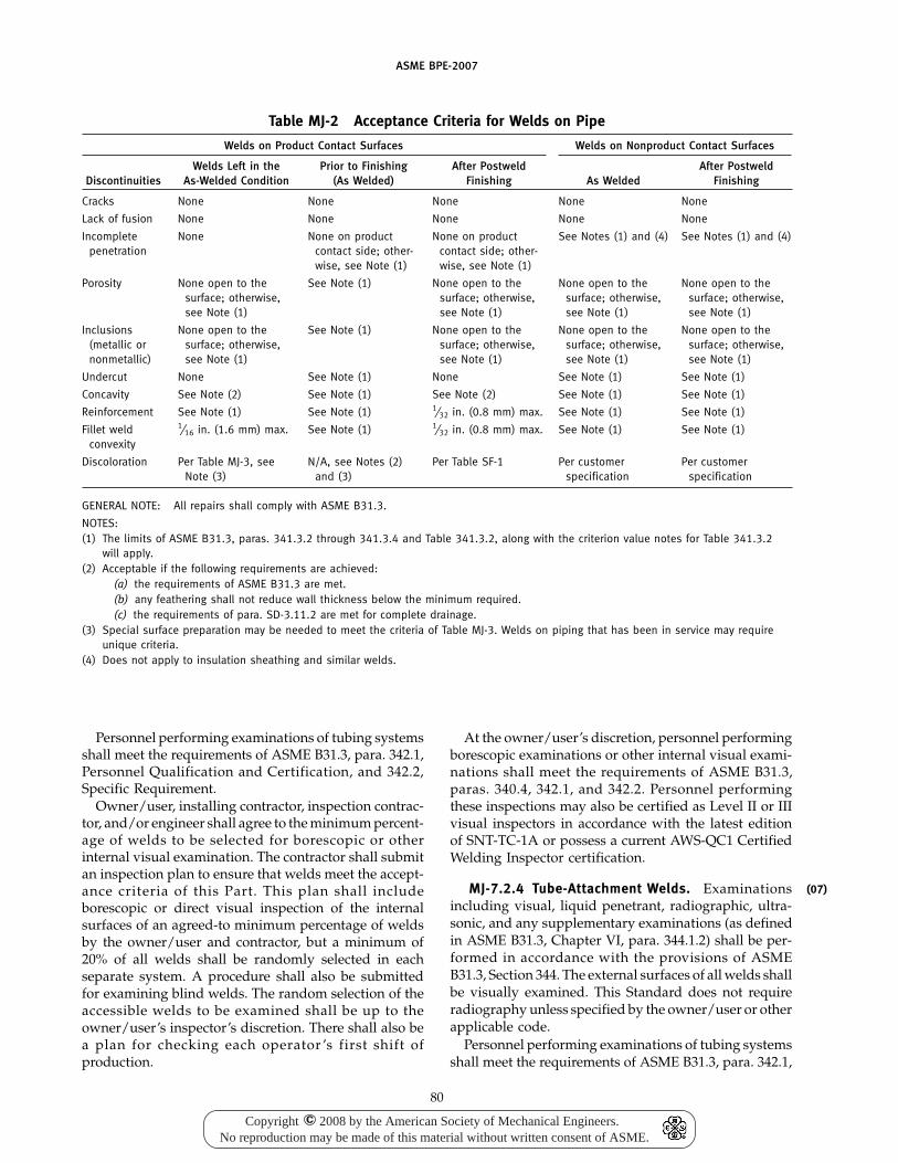
ASME BPE-2007
Table MJ-2 Acceptance Criteria for Welds on Pipe
Welds on Product Contact Surfaces Welds on Nonproduct Contact Surfaces
Welds Left in the Prior to Finishing After Postweld After PostweldDiscontinuities As-Welded Condition (As Welded) Finishing As Welded Finishing
Cracks None None None None None
Lack of fusion None None None None None
Incomplete None None on product None on product See Notes (1) and (4) See Notes (1) and (4)penetration contact side; other- contact side; other-
wise, see Note (1) wise, see Note (1)
Porosity None open to the See Note (1) None open to the None open to the None open to thesurface; otherwise, surface; otherwise, surface; otherwise, surface; otherwise,see Note (1) see Note (1) see Note (1) see Note (1)
Inclusions None open to the See Note (1) None open to the None open to the None open to the(metallic or surface; otherwise, surface; otherwise, surface; otherwise, surface; otherwise,nonmetallic) see Note (1) see Note (1) see Note (1) see Note (1)
Undercut None See Note (1) None See Note (1) See Note (1)
Concavity See Note (2) See Note (1) See Note (2) See Note (1) See Note (1)
Reinforcement See Note (1) See Note (1) 1⁄32 in. (0.8 mm) max. See Note (1) See Note (1)
Fillet weld 1⁄16 in. (1.6 mm) max. See Note (1) 1⁄32 in. (0.8 mm) max. See Note (1) See Note (1)convexity
Discoloration Per Table MJ-3, see N/A, see Notes (2) Per Table SF-1 Per customer Per customerNote (3) and (3) specification specification
GENERAL NOTE: All repairs shall comply with ASME B31.3.
NOTES:(1) The limits of ASME B31.3, paras. 341.3.2 through 341.3.4 and Table 341.3.2, along with the criterion value notes for Table 341.3.2
will apply.(2) Acceptable if the following requirements are achieved:
(a) the requirements of ASME B31.3 are met.(b) any feathering shall not reduce wall thickness below the minimum required.(c) the requirements of para. SD-3.11.2 are met for complete drainage.
(3) Special surface preparation may be needed to meet the criteria of Table MJ-3. Welds on piping that has been in service may requireunique criteria.
(4) Does not apply to insulation sheathing and similar welds.
Personnel performing examinations of tubing systemsshall meet the requirements of ASME B31.3, para. 342.1,Personnel Qualification and Certification, and 342.2,Specific Requirement.
Owner/user, installing contractor, inspection contrac-tor, and/or engineer shall agree to the minimum percent-age of welds to be selected for borescopic or otherinternal visual examination. The contractor shall submitan inspection plan to ensure that welds meet the accept-ance criteria of this Part. This plan shall includeborescopic or direct visual inspection of the internalsurfaces of an agreed-to minimum percentage of weldsby the owner/user and contractor, but a minimum of20% of all welds shall be randomly selected in eachseparate system. A procedure shall also be submittedfor examining blind welds. The random selection of theaccessible welds to be examined shall be up to theowner/user’s inspector’s discretion. There shall also bea plan for checking each operator ’s first shift ofproduction.
80
At the owner/user’s discretion, personnel performingborescopic examinations or other internal visual exami-nations shall meet the requirements of ASME B31.3,paras. 340.4, 342.1, and 342.2. Personnel performingthese inspections may also be certified as Level II or IIIvisual inspectors in accordance with the latest editionof SNT-TC-1A or possess a current AWS-QC1 CertifiedWelding Inspector certification.
MJ-7.2.4 Tube-Attachment Welds. Examinationsincluding visual, liquid penetrant, radiographic, ultra-sonic, and any supplementary examinations (as definedin ASME B31.3, Chapter VI, para. 344.1.2) shall be per-formed in accordance with the provisions of ASMEB31.3, Section 344. The external surfaces of all welds shallbe visually examined. This Standard does not requireradiography unless specified by the owner/user or otherapplicable code.
Personnel performing examinations of tubing systemsshall meet the requirements of ASME B31.3, para. 342.1,
(07)
Copyright 2008 by the American Society of Mechanical Engineers.No reproduction may be made of this material without written consent of ASME.
c
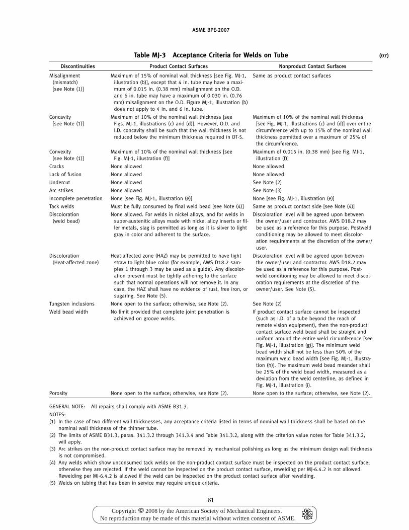
ASME BPE-2007
Table MJ-3 Acceptance Criteria for Welds on Tube
Discontinuities Product Contact Surfaces Nonproduct Contact Surfaces
Misalignment Maximum of 15% of nominal wall thickness [see Fig. MJ-1, Same as product contact surfaces(mismatch) illustration (b)], except that 4 in. tube may have a maxi-[see Note (1)] mum of 0.015 in. (0.38 mm) misalignment on the O.D.
and 6 in. tube may have a maximum of 0.030 in. (0.76mm) misalignment on the O.D. Figure MJ-1, illustration (b)does not apply to 4 in. and 6 in. tube.
Concavity Maximum of 10% of the nominal wall thickness [see Maximum of 10% of the nominal wall thickness[see Note (1)] Figs. MJ-1, illustrations (c) and (d)]. However, O.D. and [see Fig. MJ-1, illustrations (c) and (d)] over entire
I.D. concavity shall be such that the wall thickness is not circumference with up to 15% of the nominal wallreduced below the minimum thickness required in DT-5. thickness permitted over a maximum of 25% of
the circumference.
Convexity Maximum of 10% of the nominal wall thickness [see Maximum of 0.015 in. (0.38 mm) [see Fig. MJ-1,[see Note (1)] Fig. MJ-1, illustration (f)] illustration (f)]
Cracks None allowed None allowed
Lack of fusion None allowed None allowed
Undercut None allowed See Note (2)
Arc strikes None allowed See Note (3)
Incomplete penetration None [see Fig. MJ-1, illustration (e)] None [see Fig. MJ-1, illustration (e)]
Tack welds Must be fully consumed by final weld bead [see Note (4)] Same as product contact side [see Note (4)]
Discoloration None allowed. For welds in nickel alloys, and for welds in Discoloration level will be agreed upon between(weld bead) super-austenitic alloys made with nickel alloy inserts or fil- the owner/user and contractor. AWS D18.2 may
ler metals, slag is permitted as long as it is silver to light be used as a reference for this purpose. Postweldgray in color and adherent to the surface. conditioning may be allowed to meet discolor-
ation requirements at the discretion of the owner/user.
Discoloration Heat-affected zone (HAZ) may be permitted to have light Discoloration level will be agreed upon between(Heat-affected zone) straw to light blue color (for example, AWS D18.2 sam- the owner/user and contractor. AWS D18.2 may
ples 1 through 3 may be used as a guide). Any discolor- be used as a reference for this purpose. Post-ation present must be tightly adhering to the surface weld conditioning may be allowed to meet discol-such that normal operations will not remove it. In any oration requirements at the discretion of thecase, the HAZ shall have no evidence of rust, free iron, or owner/user. See Note (5).sugaring. See Note (5).
Tungsten inclusions None open to the surface; otherwise, see Note (2). See Note (2)
Weld bead width No limit provided that complete joint penetration is If product contact surface cannot be inspectedachieved on groove welds. (such as I.D. of a tube beyond the reach of
remote vision equipment), then the non-productcontact surface weld bead shall be straight anduniform around the entire weld circumference [seeFig. MJ-1, illustration (g)]. The minimum weldbead width shall not be less than 50% of themaximum weld bead width [see Fig. MJ-1, illustra-tion (h)]. The maximum weld bead meander shallbe 25% of the weld bead width, measured as adeviation from the weld centerline, as defined inFig. MJ-1, illustration (i).
Porosity None open to the surface; otherwise, see Note (2). None open to the surface; otherwise, see Note (2).
GENERAL NOTE: All repairs shall comply with ASME B31.3.
NOTES:(1) In the case of two different wall thicknesses, any acceptance criteria listed in terms of nominal wall thickness shall be based on the
nominal wall thickness of the thinner tube.(2) The limits of ASME B31.3, paras. 341.3.2 through 341.3.4 and Table 341.3.2, along with the criterion value notes for Table 341.3.2,
will apply.(3) Arc strikes on the non-product contact surface may be removed by mechanical polishing as long as the minimum design wall thickness
is not compromised.(4) Any welds which show unconsumed tack welds on the non-product contact surface must be inspected on the product contact surface;
otherwise they are rejected. If the weld cannot be inspected on the product contact surface, rewelding per MJ-6.4.2 is not allowed.Rewelding per MJ-6.4.2 is allowed if the weld can be inspected on the product contact surface after rewelding.
(5) Welds on tubing that has been in service may require unique criteria.
81
(07)
Copyright 2008 by the American Society of Mechanical Engineers.No reproduction may be made of this material without written consent of ASME.
c
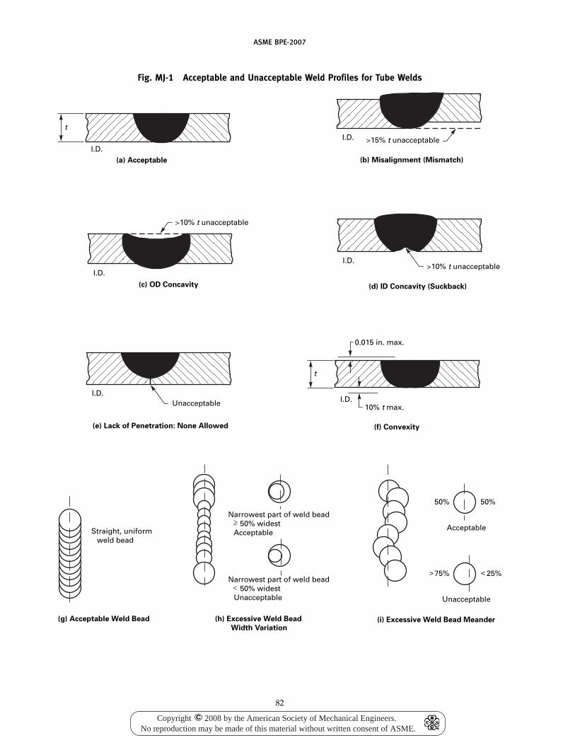
ASME BPE-2007
Fig. MJ-1 Acceptable and Unacceptable Weld Profiles for Tube Welds
Straight, uniform weld bead
Narrowest part of weld bead 50% widest Acceptable
Narrowest part of weld bead 50% widest Unacceptable
Acceptable
50%50%
Unacceptable
25%75%
(g) Acceptable Weld Bead (h) Excessive Weld Bead
Width Variation(i) Excessive Weld Bead Meander
(e) Lack of Penetration: None Allowed
(d) ID Concavity (Suckback)(c) OD Concavity
(b) Misalignment (Mismatch)(a) Acceptable
(f) Convexity
0.015 in. max.
Unacceptable
10% t unacceptable
10% t unacceptable
15% t unacceptable
10% t max.
t
I.D.I.D.
I.D.
I.D.
I.D.
I.D.
t
82
Copyright 2008 by the American Society of Mechanical Engineers.No reproduction may be made of this material without written consent of ASME.
c
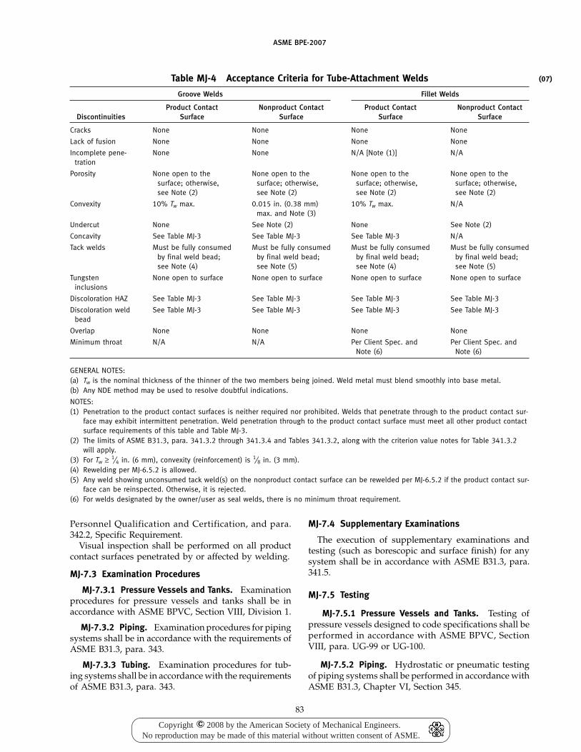
ASME BPE-2007
Table MJ-4 Acceptance Criteria for Tube-Attachment Welds
Groove Welds Fillet Welds
Product Contact Nonproduct Contact Product Contact Nonproduct ContactDiscontinuities Surface Surface Surface Surface
Cracks None None None None
Lack of fusion None None None None
Incomplete pene- None None N/A [Note (1)] N/Atration
Porosity None open to the None open to the None open to the None open to thesurface; otherwise, surface; otherwise, surface; otherwise, surface; otherwise,see Note (2) see Note (2) see Note (2) see Note (2)
Convexity 10% Tw max. 0.015 in. (0.38 mm) 10% Tw max. N/Amax. and Note (3)
Undercut None See Note (2) None See Note (2)
Concavity See Table MJ-3 See Table MJ-3 See Table MJ-3 N/A
Tack welds Must be fully consumed Must be fully consumed Must be fully consumed Must be fully consumedby final weld bead; by final weld bead; by final weld bead; by final weld bead;see Note (4) see Note (5) see Note (4) see Note (5)
Tungsten None open to surface None open to surface None open to surface None open to surfaceinclusions
Discoloration HAZ See Table MJ-3 See Table MJ-3 See Table MJ-3 See Table MJ-3
Discoloration weld See Table MJ-3 See Table MJ-3 See Table MJ-3 See Table MJ-3bead
Overlap None None None None
Minimum throat N/A N/A Per Client Spec. and Per Client Spec. andNote (6) Note (6)
GENERAL NOTES:(a) Tw is the nominal thickness of the thinner of the two members being joined. Weld metal must blend smoothly into base metal.(b) Any NDE method may be used to resolve doubtful indications.
NOTES:(1) Penetration to the product contact surfaces is neither required nor prohibited. Welds that penetrate through to the product contact sur-
face may exhibit intermittent penetration. Weld penetration through to the product contact surface must meet all other product contactsurface requirements of this table and Table MJ-3.
(2) The limits of ASME B31.3, para. 341.3.2 through 341.3.4 and Tables 341.3.2, along with the criterion value notes for Table 341.3.2will apply.
(3) For Tw ≥ 1⁄4 in. (6 mm), convexity (reinforcement) is 1⁄8 in. (3 mm).(4) Rewelding per MJ-6.5.2 is allowed.(5) Any weld showing unconsumed tack weld(s) on the nonproduct contact surface can be rewelded per MJ-6.5.2 if the product contact sur-
face can be reinspected. Otherwise, it is rejected.(6) For welds designated by the owner/user as seal welds, there is no minimum throat requirement.
Personnel Qualification and Certification, and para.342.2, Specific Requirement.
Visual inspection shall be performed on all productcontact surfaces penetrated by or affected by welding.
MJ-7.3 Examination Procedures
MJ-7.3.1 Pressure Vessels and Tanks. Examinationprocedures for pressure vessels and tanks shall be inaccordance with ASME BPVC, Section VIII, Division 1.
MJ-7.3.2 Piping. Examination procedures for pipingsystems shall be in accordance with the requirements ofASME B31.3, para. 343.
MJ-7.3.3 Tubing. Examination procedures for tub-ing systems shall be in accordance with the requirementsof ASME B31.3, para. 343.
83
MJ-7.4 Supplementary Examinations
The execution of supplementary examinations andtesting (such as borescopic and surface finish) for anysystem shall be in accordance with ASME B31.3, para.341.5.
MJ-7.5 Testing
MJ-7.5.1 Pressure Vessels and Tanks. Testing ofpressure vessels designed to code specifications shall beperformed in accordance with ASME BPVC, SectionVIII, para. UG-99 or UG-100.
MJ-7.5.2 Piping. Hydrostatic or pneumatic testingof piping systems shall be performed in accordance withASME B31.3, Chapter VI, Section 345.
(07)
Copyright 2008 by the American Society of Mechanical Engineers.No reproduction may be made of this material without written consent of ASME.
c

(07)
(07)
(07)
(07)
(07)
ASME BPE-2007
MJ-7.5.3 Tubing. Hydrostatic or pneumatic testingof tubing systems shall be performed in accordance withASME B31.3, Chapter VI, Section 345.
MJ-7.6 Records
MJ-7.6.1 Pressure Vessels and Tanks. Records andretention of records for code vessels shall be in accor-dance with ASME BPVC, Section VIII, paras. UW-51 forradiographs, UG-120 for manufacturer’s data reports,and UW-52 for spot examination of welds.
MJ-7.6.2 Piping. Records and retention of recordsassociated with piping shall be in accordance withASME B31.3, Chapter VI, Section 346.
MJ-7.6.3 Tubing. Records and retention of recordsassociated with hygienic tubing shall be in accordancewith ASME B31.3, Chapter VI, Section 346.
MJ-8 PROCEDURE QUALIFICATION
MJ-8.1 Pressure Vessels and Tanks
Welding procedures for pressure vessels and tanksshall be qualified in accordance with ASME BPVC,Section IX, except as modified by the specific code sec-tion under which the vessels or tanks are designed.
MJ-8.2 Piping
Welding procedures for piping systems shall be quali-fied in accordance with ASME BPVC, Section IX, exceptas modified in ASME B31.3.
MJ-8.3 Tubing
Welding procedures for welding of hygienic tubingsystems shall be qualified in accordance with ASMEBPVC, Section IX, except as modified in ASME B31.3,with the following additions:
(a) A change in the type or nominal composition ofthe backing (purge) gas shall require requalification (seeQW-250).
(b) If filler metal is used, a change from one AWSclassification of filler metal to another, or to a proprietaryfiller metal, shall require requalification (see QW-250).
MJ-9 PERFORMANCE QUALIFICATION
MJ-9.1 Pressure Vessels and Tanks
Welder and welding operator performance qualifica-tions for pressure vessels and tanks shall be in accor-dance with ASME BPVC, Section IX, except as modifiedby the specific code section under which the vessels ortanks are designed.
MJ-9.2 Piping
Welder and welding operator performance qualifica-tions for piping systems shall be in accordance with
84
ASME BPVC, Section IX, except as modified in ASMEB31.3.
MJ-9.3 Tubing
Welder and welding operator performance qualifica-tions for welding of hygienic tubing systems shall bein accordance with ASME BPVC, Section IX, except asmodified in ASME B31.3.
MJ-10 DOCUMENTATION REQUIREMENTS
MJ-10.1 Turn Over Package Documentation Required
For cGMP-validated distribution systems (includingthe tubing systems on modules, super skids, and skids,and the shop or field fabrication of tubing, etc.) thefollowing documentation shall be provided to theowner/user or their designee, as a minimum:
(a) Materials Documentation(1) Material Test Reports (MTRs)(2) Certified Material Test Reports (CMTRs)(3) Certificates of Compliance (C of Cs)(4) Material Examination Logs
(b) Welding, Inspection, and Examination Qualifica-tion Documentation (not required for standard fittings,valves, and components unless specifically required bythe owner/user)
(1) Welding Procedure Specifications (WPSs)(2) Procedure Qualification Records (PQRs)(3) Welder Performance Qualifications (WPQs)(4) Welding Operator Performance Qualifications
(WOPQs)(5) Examiner Qualifications(6) Documentation of approval of the above by the
owner’s representative prior to welding(7) Inspector Qualifications(8) Documentation of the approval of (b)(7) above
by the Owner prior to welding(c) Weld Documentation (not required for standard
fittings, valves, and components unless specificallyrequired by the owner/user)
(1) Weld Maps(2) Weld Logs(3) Weld Examination and Inspection Logs(4) Coupon Logs
(d) Testing and Examination Documentation (asapplicable)
(1) Passivation Reports(2) Sprayball Testing(3) Pressure Testing(4) Final Slope Check Documentation(5) Calibration Verification Documentation(6) Purge Gas Certifications(7) Signature Logs(8) Number of Welds — both Manual and
Automatic
(07)
(07)
(07)
(07)
Copyright 2008 by the American Society of Mechanical Engineers.No reproduction may be made of this material without written consent of ASME.
c
ASME BPE-2007
(9) Number of Welds Inspected expressed as a per-centage (%)
(10) Heat Numbers of components must be identi-fied, documented, and fully traceable to the installedsystem
MJ-10.2 Materials Documentation
MJ-10.2.1 Materials Examination. The requirementsfor materials examination/inspection and documenta-tion are listed in DT-14.
MJ-10.2.2 Material Test Reports. The combinationof documents, including Certificates of Compliance(C of Cs), Material Test Reports (MTRs), and/orCertified Material Test Reports (CMTRs) for all metallicequipment and component product contact surfacesdefined in the scope of this Standard shall include thefollowing information, as a minimum:
(a) ASME BPE Standard, including year date(b) material type(c) heat number(d) chemical composition(e) AWS Classification of filler metal, if used(f) alloy designation and material specification of
insert, if used(g) postweld heat treatment documentation, if appli-
cable(h) mechanical properties are not required, but if
included, must be accurate to the raw material specifi-cation
MJ-10.3 Weld Log
The results of the welding, examination, and inspec-tion shall be recorded on a Weld Log. The informationrequired to be on the Weld Log may be in any format,written or tabular, to fit the needs of the manufacturer,installing contractor, inspection contractor, and
85
owner/user as long as all required information isincluded or referenced. Form WL-1 (see NonmandatoryAppendix B) has been provided as a guide for the WeldLog. This form includes the required data plus someother information that is not required. The minimumrequirements are listed below.
(a) isometric drawing number (including revisionnumber)
(b) weld number(c) date welded(d) welder/welding operator identification(e) size(f) examination
(1) date(2) type of examination(3) acceptance/rejection(4) initials
(g) inspection(1) date(2) type of examination(3) acceptance/rejection(4) initials
(h) identification of blind welds(i) identification of manual welds(j) basis of rejectionThe following information shall be recorded on the
Weld Log, an isometric drawing, or other owner/userapproved documentation:
(aa) heat numbers(ab) slope
MJ-11 PASSIVATION
If agreed to by the owner/user and the manufacturer,all welded systems shall be passivated after cleaningand prior to use.
Copyright 2008 by the American Society of Mechanical Engineers.No reproduction may be made of this material without written consent of ASME.
c
(07)
(07)
(07)
ASME BPE-2007
Part SFStainless Steel and Higher Alloy Product Contact Surface
Finishes
SF-1 SCOPE
The purpose of this Part is to provide criteria forstainless steel and higher alloy product contact surfacefinishes for bioprocessing, pharmaceutical, and personalcare products equipment and distribution system com-ponents. This Part shall be referenced when specifyingproduct contact surface finishes for the specific systems,including, but not limited to, vessels and distributionsystem components.
SF-2 OBJECTIVE
The objective is to describe an acceptable product con-tact surface finish on selected materials of constructionto enhance their cleaning, sterilization, and corrosionresistance.
SF-3 APPLICATIONS
This Part shall be applicable to all systems designatedby the owner/user or representative thereof.
Product contact surface requirements shall apply toall accessible and inaccessible areas of the systems thatdirectly or indirectly come in contact with the designatedproduct.
These systems shall include, but are not limited to,one or more of the following:
(a) USP Water-for-Injection (WFI)(b) USP Purified Water(c) USP Pure Steam(d) other product/process contact surface systems
SF-4 MATERIAL
The preferred material of construction for these sys-tems is austenitic stainless steel, type 316L alloy. Othermaterials may be specified by the owner/user. Theymay be of the following form:
(a) Tubing. ASTM A 213/A 213M, ASTM A 269,ASTM A 270 (including Supplementary RequirementsS2. Pharmaceutical Quality Tubing)
(b) Piping. ASTM A 312/A 312M(c) Fittings. To be made to the tube and/or pipe fitting
specifications shown in Part DT and/or GR(d) Plate, Sheet, and Strip. ASTM A 240/A 240M,
ASTM A 666
86
(e) Forged Wrought and Casting. ASTM A 182/A 182M,ASTM A 351/A 351M, and ASTM A 484/A 484M.
SF-5 INSPECTION AND TECHNIQUES EMPLOYED INTHE CLASSIFICATION OF PRODUCT CONTACTSURFACE FINISHES
Product contact surface finish inspections shall bemade by one or more of the following methods:
(a) Visual Inspection(1) direct visual inspection(2) indirect visual inspection (e.g., borescopes,
mirrors)(b) Liquid Penetrant(c) Surface Roughness Measurement Device
(1) profilometer(d) Scanning Electorn Microscope(e) Electron Spectroscopy for Chemical Analysis(f) Auger Electrospectroscopy for Chemical Analysis(g) Replicas. ASTM E 1351Acceptance criteria of stainless steel and higher alloy
mechanically polished product contact surface finishesare shown in Table SF-1.
Acceptance criteria of stainless steel and higher alloyelectropolished product contact surface finishes shallmeet requirements shown in Table SF-2 in addition tothose shown in Table SF-1.
Visual inspection shall be performed under adequateroom lighting. Additional lighting shall be used whenappropriate to illuminate blind or darkened areas andto clarify questionable areas.
SF-6 SURFACE CONDITION
Product contact surfaces of tubing, fittings, valves,vessels, and other process components furnished to thisStandard shall be finished using mechanical polishing,chemical polishing, cold working, machining, and/orelectropolishing processes at the request of theowner/user, in conformance with applicable sections ofthis Part. In addition, all surfaces shall be clean (free ofoils, grease, particulates, grinding compounds, or elec-trolytes).
(07)
(07)
Copyright 2008 by the American Society of Mechanical Engineers.No reproduction may be made of this material without written consent of ASME.
c
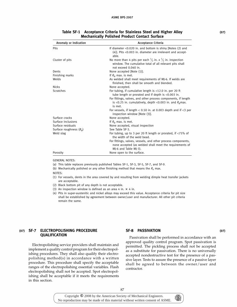
(07)
ASME BPE-2007
Table SF-1 Acceptance Criteria for Stainless Steel and Higher AlloyMechanically Polished Product Contact Surface
Anomaly or Indication Acceptance Criteria
Pits If diameter <0.020 in. and bottom is shiny [Notes (2) and(4)]. Pits <0.003 in. diameter are irrelevant and accept-able.
Cluster of pits No more than 4 pits per each 1⁄2 in. x 1⁄2 in. inspectionwindow. The cumulative total of all relevant pits shallnot exceed 0.040 in.
Dents None accepted [Note (1)].Finishing marks If Ra max. is met.Welds As welded shall meet requirements of MJ-6. If welds are
finished, then shall be smooth and blended.Nicks None accepted.Scratches For tubing, if cumulative length is <12.0 in. per 20 ft
tube length or prorated and if depth is <0.003 in.For fittings, valves, and other process components, if length
is <0.25 in. cumulatively, depth <0.003 in. and Ramax.is met.
For vessels, if length < 0.50 in. at 0.003 depth and if <3 perinspection window [Note (3)].
Surface cracks None accepted.Surface inclusions If Ra max. is met.Surface residuals None accepted, visual inspectionSurface roughness (Ra) See Table SF-3.Weld slag For tubing, up to 3 per 20 ft length or prorated, if <75% of
the width of the weld bead.For fittings, valves, vessels, and other process components,
none accepted (as welded shall meet the requirements ofMJ-6 and Table MJ-3).
Porosity None open to the surface.
GENERAL NOTES:(a) This table replaces previously published Tables SF-1, SF-3, SF-5, SF-7, and SF-9.(b) Mechanically polished or any other finishing method that means the Ra max.
NOTES:(1) For vessels, dents in the area covered by and resulting from welding dimple heat transfer jackets
are acceptable.(2) Black bottom pit of any depth is not acceptable.(3) An inspection window is defined as an area 4 in. � 4 in.(4) Pits in super-austenitic and nickel alloys may exceed this value. Acceptance criteria for pit size
shall be established by agreement between owner/user and manufacturer. All other pit criteriaremain the same.
SF-7 ELECTROPOLISHING PROCEDUREQUALIFICATION
Electropolishing service providers shall maintain andimplement a quality control program for their electropol-ishing procedures. They shall also qualify their electro-polishing method(s) in accordance with a writtenprocedure. This procedure shall specify the acceptableranges of the electropolishing essential variables. Flashelectropolishing shall not be accepted. Spot electropol-ishing shall be acceptable if it meets the requirementsin this section.
87
SF-8 PASSIVATION
Passivation shall be performed in accordance with anapproved quality control program. Spot passivation ispermitted. The pickling process shall not be acceptedas a substitute for passivation. There is no universallyaccepted nondestructive test for the presence of a pas-sive layer. Tests to assure the presence of a passive layershall be agreed to between the owner/user andcontractor.
(07)
(07)
Copyright 2008 by the American Society of Mechanical Engineers.No reproduction may be made of this material without written consent of ASME.
c
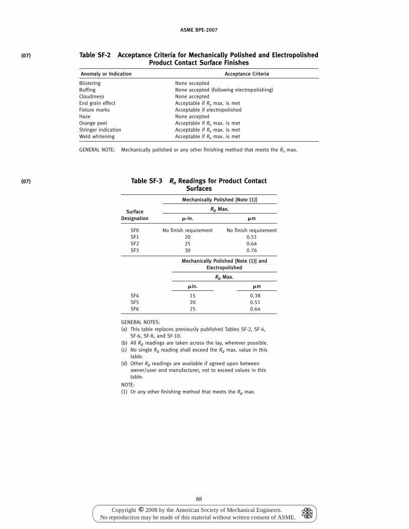
(07)
(07)
ASME BPE-2007
Table SF-2 Acceptance Criteria for Mechanically Polished and ElectropolishedProduct Contact Surface Finishes
Anomaly or Indication Acceptance Criteria
Blistering None acceptedBuffing None accepted (following electropolishing)Cloudiness None acceptedEnd grain effect Acceptable if Ra max. is metFixture marks Acceptable if electropolishedHaze None acceptedOrange peel Acceptable if Ra max. is metStringer indication Acceptable if Ra max. is metWeld whitening Acceptable if Ra max. is met
GENERAL NOTE: Mechanically polished or any other finishing method that meets the Ra max.
Table SF-3 Ra Readings for Product ContactSurfaces
Mechanically Polished [Note (1)]
Ra Max.SurfaceDesignation �-in. �m
SF0 No finish requirement No finish requirementSF1 20 0.51SF2 25 0.64SF3 30 0.76
Mechanically Polished [Note (1)] andElectropolished
Ra Max.
�in. �m
SF4 15 0.38SF5 20 0.51SF6 25 0.64
GENERAL NOTES:(a) This table replaces previously published Tables SF-2, SF-4,
SF-6, SF-8, and SF-10.(b) All Ra readings are taken across the lay, wherever possible.(c) No single Ra reading shall exceed the Ra max. value in this
table.(d) Other Ra readings are available if agreed upon between
owner/user and manufacturer, not to exceed values in thistable.
NOTE:(1) Or any other finishing method that meets the Ra max.
88
Copyright 2008 by the American Society of Mechanical Engineers.No reproduction may be made of this material without written consent of ASME.
c
ASME BPE-2007
Part SGEquipment Seals
SG-1 SCOPE AND PURPOSE
SG-1.1 Scope
This Part defines the design and materials of construc-tion of seals in equipment used in the bioprocessing,pharmaceutical, and personal care products industries.For this purpose, seals are defined as those elements thatcreate or maintain process boundaries between systemcomponents and/or subassemblies in order to ensuresystem integrity in validated process and utility systems.It is not the intent of this Part to inhibit the developmentor use of new technologies.
SG-1.2 Purpose
The purpose of this Part is to enable equipment manu-facturers, system designers, and end-users to specifythe required seal type and performance for a specificapplication.
SG-2 SEAL CLASSES
Seal classes define the level of seal integrity for a givenservice condition with regard to the average effect thatleakage by the seal or catastrophic failure of the sealcan have on the product within the system or on theenvironment exterior of a fluid system.
SG-2.1 Class I Seals
Seals defined under this class may experience someminute leakage due to sliding interaction with stems orshafts such as O-rings [SG-4.1.1.2(a)] or some packings[SG-3.5.6.3(a)]. Class I seals shall be allowed only ina continuously sterilizing environment. Examples arevalves handling sterile steam. Mechanical seals may beof single seal arrangement (SG-3.5.3.1) such as packing[SG-3.5.6.3(a)], lip seals [SG-3.5.6.3(b)], and labyrinthseals [SG-3.5.6.3(c)].
SG-2.2 Class II Seals
Seals defined under this class shall include only non-sliding types of valve seals such as diaphragms[SG-4.1.1.2(b) and (c)]. Mechanical systems shall havemultiple seals (SG-3.5.3.2). Examples of uses of ClassII seals are for Water-for-Injection (WFI) and sucrosesolutions.
SG-2.3 Class III Seals
Valve seals defined under this class shall have nosliding surfaces and shall exhibit a minimum degree of
89
permeation. Examples of uses of Class III seals are fortoxic fluids, highly dangerous fluids, and fluids con-taining pathogenic or recombinant DNA organisms.Shafts or stems shall have a secondary seal[SG-4.1.1.1(b)], while mechanical shaft seals shall havemultiple seals [SG-3.5.3.2(a)] with a barrier fluid.
SG-2.4 Hygienic Fitting Seals
Hygienic fitting seals are used to form a sealed unionbetween two ferrules described in SD-3.7. A sealedflange assembly, illustrated in one of many configura-tions in Fig. SD-1, shall result in a nearly flush interfacebetween the gasket and the ferrule I.D.
The seal manufacturer shall designate the seal intru-sion as Intrusion Category I or Intrusion Category II,per SG-2.4.1. The purpose of a flush interface is to mini-mize the entrapment of the material in a dead spacethat can lead to microbial growth and contamination.Furthermore, excessive intrusion into the process streammay lead to errosion of elastomeric seals, thereby con-taminating the process stream. The amount of intrusiondepends upon the dimensional control of the seal, thehygienic clamp ferrule dimensions [see Table DT-5.1 andFig. SD-1, illustrations (a) through (c)], the amount oftorque applied to the flange, the material properties ofthe seal, the application of steam, and the surface of theseal (wet or dry) during installation.
When choosing a seal material, the end-user shouldconsider the biocompatibility, cleanability, steam stabil-ity, low temperature flexibility, creep resistance, sealabil-ity, leak resistance, solvent resistance, lot traceability,and other factors, depending upon the applicationrequirements. Service intervals should be determinedby the end-user and will depend on the duty cycle.
SG-2.4.1 Hygienic Fitting Seal Intrusion. Hygienicseals shall meet and be designated by one of the follow-ing categories when tested by the seal manufacturers inaccordance with SG-3.4.3:
(a) Intrusion Category I. Seals having a maximumintrusion/recess of 0.025 in. (0.6 mm).
(b) Intrusion Category II. Seals having a maximumintrusion/recess of 0.008 in. (0.2 mm).
The user/owner is responsible for selecting the appro-priate seal to meet their particular process requirements.Seal intrusion is one of many factors to consider in choos-ing a hygienic union.
(07)
(07)
Copyright 2008 by the American Society of Mechanical Engineers.No reproduction may be made of this material without written consent of ASME.
c
ASME BPE-2007
SG-3 GENERAL PROVISIONS FOR SEALS INBIOPROCESSING SERVICE: USER BASICDESIGN REQUIREMENT
SG-3.1 Seal Performance
The equipment supplier shall be informed of all theconditions under which the seal may be expected tooperate. These shall include, in addition to the servicetemperature and pressure, any parameters that mayaffect the seal performance. It is up to the equipmentsupplier to inform the end-user of the life cycle expec-tancy and the methods that will ensure that the sealoperates within its design classification (e.g., routinemaintenance).
SG-3.1.1 Service Temperature. Seals shall be capa-ble of preventing unacceptable leakage when thermalcycled between the rated upper and lower temperaturelimits. The number of allowable thermal cycles shall bestated by the manufacturer.
SG-3.1.2 Service Pressure. The service pressure isthe maximum permissible usage pressure for which theseal meets the maximum permissible leakage rate. Theservice pressure and acceptance level for pressure ratingshall be furnished by the seal supplier.
SG-3.1.3 Bioburden. Bioburden is the concentrationof microbial matter per unit volume. Microbial matterincludes viruses, bacteria, yeast, mold, and parts thereof.
SG-3.1.4 Cavitation Resistance. The seal shall beplaced so as to minimize damage by cavitation.
SG-3.1.5 Sterilization. The complete sterilizationprocedure shall be supplied by the end-user. This shallinclude the methods, frequency, and length of operation.
SG-3.1.6 Cleaning. The complete cleaning proce-dure shall be supplied by the end-user. This shall includethe methods, frequency, and length of operation.
SG-3.1.7 Passivation. The complete passivatingprocedure shall be supplied by the end-user. The equip-ment supplier shall inform the end-user whether theseal will be able to perform as specified after passivation,or whether a new seal is required before the start ofoperation.
SG-3.2 System Requirements
Cleaning and sterilization of a seal occurs on a regularbasis. This is necessary to ensure elimination of anybacterial growth, which could harm future products orthe environment. The methods of cleaning are listed inSG-3.2.1 through SG-3.2.3:
SG-3.2.1 Cleaning Systems(a) Clean-In-Place (CIP). The wetted part of a seal shall
be designed so that accumulation of system media canbe removed through the action of a cleaning solution.The seal should be placed to allow for best drainability.
90
(b) Clean-Out-of-Place (COP). Disassembly forcleaning.
SG-3.2.2 Sterilizing Systems. Seal requirementsshall be based on the sterilization method utilized. Allwetted seal surfaces shall be designed to minimizecracks and crevices. When cracks and crevices cannotbe avoided, sterilization testing shall be performed tovalidate sterility within the system boundaries. All sealsand seal contact surfaces shall be designed to accommo-date expansion and contraction during sterilization andcooling-down stage. Seal materials shall be used thatare corrosion-resistant to saturated steam and puresteam. The seal should be placed to allow for drainageof fluid. The following are typical sterilizing systems:
(a) Steam-In-Place (SIP). All seals and their assembliesshall have a minimum temperature rating meeting therequirements of SD-3.2.2.
(b) Chemical sterilization.(c) Hot air sterilization at 160°C.
SG-3.2.3 Passivation Systems. The following aretypical passivation systems:
(a) acid treatments; and(b) proprietary trade formulations.Full information shall be provided as to the corrosive
or erosive effect on the seal.
SG-3.3 Seal Construction
SG-3.3.1 Materials(a) Biocompatibility. Biocompatibility is defined here
as the ability of a substance or material to be in contactwith living matter such as bacteria or mammalian cellswithout interfering in any way with its metabolism orability to live and procreate. Seal materials shall be bio-compatible with the system fluid to ensure that the sys-tem fluid is not adversely affected by the seal material.The biocompatibility and proper material selection shallbe the responsibility of the system user.
Biocompatibility testing of candidate seals for qualifi-cation requires both in-vivo (animal testing) and in-vitro(testing in glass) tests. In-vivo testing is described in theUnited States Pharmacopeia (USP) in Chapter 88 andinvolves intramuscular implantation, intracutaneousinjection, and systemic toxicity testing. In-vitro testing,on the other hand, is described in the United StatesPharmacopeia in Chapter 87 and is used to place extractfrom candidate seals in direct contact with living cells(typically mouse cells) for a prescribed period of time.The amount of cell lysing (death) is recorded andreported for that particular seal material. Seal manufac-turers must provide, upon customer request, documen-tation (test report) of the in-vivo USP Class VI <88> andthe in-vitro USP <87> testing on final manufacturedseals. Failure of either test indicates unacceptable bio-compatibility of the candidate seal. Such failures areoften attributed to adverse reaction to extractables from
Copyright 2008 by the American Society of Mechanical Engineers.No reproduction may be made of this material without written consent of ASME.
c
(07)
ASME BPE-2007
cured elastomeric seals. Extractables may include cata-lyst residues, cross linking agents, process aids, plasticiz-ers, etc.
Qualification testing of final manufactured seals(actual seals, not generic compounds) can be performedon any given size seal (or combination thereof) withina product group as long as the materials used and themanufacturing process are representative of the entiregroup. Biocompatibility testing must be repeated forsignificant changes in raw materials or processes usedto fabricate seals. Otherwise, biocompatibility testing isused upon initial qualification of the material and pro-cess by the seal manufacturer.
(b) Process Compatibility. Seal materials shall be resis-tant to corrosion from process, cleaning, and sterilizationfluids. Selection shall be based on all media that couldcome in contact with the seal, including cleaning andsterilization media. Special consideration shall be madewhen the exposure is at elevated temperatures.
(c) Permeation Resistance. Seal permeation shall beincluded in seal leakage criteria and not addressed asan individual topic.
(d) Surface Finish(1) Seals shall be free of molding imperfections or
burrs within the system boundary and on sealing sur-faces.
(2) Seals shall be free of foreign matter on surfaceswithin the system boundary and on sealing surfaces.
(3) Surfaces to be sealed shall meet specificationsprovided by seal supplier based on performance andthe requirements in Part SF.
(4) Molded seals and components shall have mold-ing flash removed to prevent contact with the productstream.
(e) Particle Generation. Seal designs should minimizewear that generates particles that could enter theproduct.
(f) Extractables. Compounds not conforming to theapplicable sections of 21 CFR 177 and having potentialproduct contact shall be tested for chemical extractables.Candidate materials shall be tested for chemical extract-ables using the U.S. Pharmacopeia ⟨661⟩ or ⟨381⟩ to assessthe amount of total extractables, residue on ignition,buffering capacity, and the amount of heavy metals.Extractables results shall be available upon user request.Additional analytical techniques may be used to quan-tify specific compounds or elements extracted from sealmaterials if requested by the user.
SG-3.3.2 Crevices. A smooth, contoured, pocketlessinterior surface shall be created when seals are placedbetween the seal contact surfaces. Gaskets and O-ringseals generally should be flush with the interior surfaceof the pipeline or the equipment; refer to Fig. SD-1,illustrations (e) and (f). All recessed seal contact surfacesshall avoid sharp corners, and be easily cleanable withseal removed. All seal and seal contact surfaces shall
91
be designed to minimize cracks or crevices that mightharbor system media, refer to SD-3.6.
SG-3.3.3 Dead Spaces. Dead spaces are definedhere as a void in the wetted portion of the structure notcompletely occupied by a seal, usually required to allowfor thermal expansion of the seal material. These shouldbe avoided; all seal and seal contact surfaces shall bedesigned so that the system is self-draining when sealsare properly installed.
SG-3.4 Compliance Requirements
SG-3.4.1 General Requirements. A certificate ofcompliance shall be issued by the seal manufacturer tocertify compliance to this Standard when required bythe end-user. Additional agreements may be required;refer to SD-3.4.3. At a minimum, seals exposed to processcontact fluids and/or have a high probability of expo-sure will comply to the United States Pharmacopeia(USP) directive with regard to USP <87> and USP ClassVI <88>on biological reactivity [see SG-3.3.1(a)]. Exam-ples of seals coming in direct contact with a processstream include gaskets, O-rings, diaphragms, pinchtubes, and valve stem seals.
SG-3.4.2 Certificate of Compliance. The Certificateof Compliance shall contain the following information:
(a) Manufacturer’s name(b) Part number(c) Lot number(d) Material of construction(e) Compound number(f) Cure Date or Date of Manufacture(g) Intrusion Category (hygienic seals only; see
SG-2.4.1)(h) Compliance to USP <87> and USP Class VI test-
ing <88>(i) Packaging and storage recommendation (This may
be of another document and not certificate ofcompliance)
Marking on the seal package should include items (a)through (h) above.
Manufacturer’s name and lot number shall be markedon either the seal itself or the seal package containingthe seal. The lot number should enable the manufacturerto identify the raw material and processing conditionsused to fabricate the article. Manufacturers are encour-aged to mark the seal itself to avoid potential loss oftraceability and to aid in positive identification of sealsafter removal from a process stream.
SG-3.4.3 Test Requirements. Conformance testingis done upon initial qualification of the hygienic union.Testing is intended to show design conformance and isnot required on every seal. Testing must be repeated forsignificant changes in raw materials or processes usedto fabricate seals. The seal manufacturer shall provide,upon request of the end-user, a certificate of design
(07)
(07)
Copyright 2008 by the American Society of Mechanical Engineers.No reproduction may be made of this material without written consent of ASME.
c
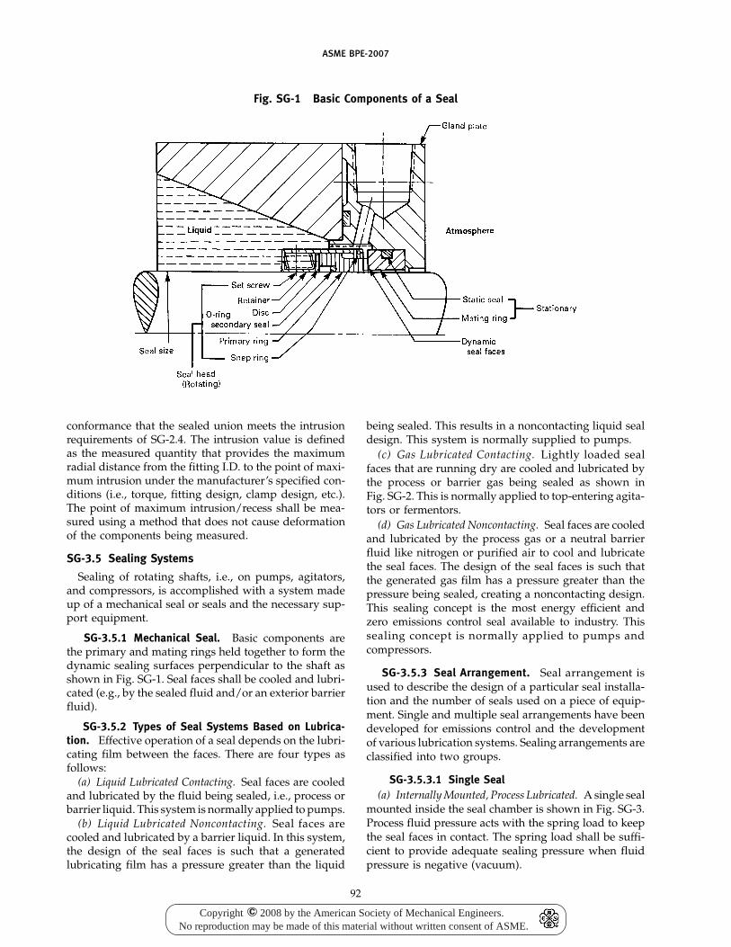
ASME BPE-2007
Fig. SG-1 Basic Components of a Seal
conformance that the sealed union meets the intrusionrequirements of SG-2.4. The intrusion value is definedas the measured quantity that provides the maximumradial distance from the fitting I.D. to the point of maxi-mum intrusion under the manufacturer’s specified con-ditions (i.e., torque, fitting design, clamp design, etc.).The point of maximum intrusion/recess shall be mea-sured using a method that does not cause deformationof the components being measured.
SG-3.5 Sealing Systems
Sealing of rotating shafts, i.e., on pumps, agitators,and compressors, is accomplished with a system madeup of a mechanical seal or seals and the necessary sup-port equipment.
SG-3.5.1 Mechanical Seal. Basic components arethe primary and mating rings held together to form thedynamic sealing surfaces perpendicular to the shaft asshown in Fig. SG-1. Seal faces shall be cooled and lubri-cated (e.g., by the sealed fluid and/or an exterior barrierfluid).
SG-3.5.2 Types of Seal Systems Based on Lubrica-tion. Effective operation of a seal depends on the lubri-cating film between the faces. There are four types asfollows:
(a) Liquid Lubricated Contacting. Seal faces are cooledand lubricated by the fluid being sealed, i.e., process orbarrier liquid. This system is normally applied to pumps.
(b) Liquid Lubricated Noncontacting. Seal faces arecooled and lubricated by a barrier liquid. In this system,the design of the seal faces is such that a generatedlubricating film has a pressure greater than the liquid
92
being sealed. This results in a noncontacting liquid sealdesign. This system is normally supplied to pumps.
(c) Gas Lubricated Contacting. Lightly loaded sealfaces that are running dry are cooled and lubricated bythe process or barrier gas being sealed as shown inFig. SG-2. This is normally applied to top-entering agita-tors or fermentors.
(d) Gas Lubricated Noncontacting. Seal faces are cooledand lubricated by the process gas or a neutral barrierfluid like nitrogen or purified air to cool and lubricatethe seal faces. The design of the seal faces is such thatthe generated gas film has a pressure greater than thepressure being sealed, creating a noncontacting design.This sealing concept is the most energy efficient andzero emissions control seal available to industry. Thissealing concept is normally applied to pumps andcompressors.
SG-3.5.3 Seal Arrangement. Seal arrangement isused to describe the design of a particular seal installa-tion and the number of seals used on a piece of equip-ment. Single and multiple seal arrangements have beendeveloped for emissions control and the developmentof various lubrication systems. Sealing arrangements areclassified into two groups.
SG-3.5.3.1 Single Seal(a) Internally Mounted, Process Lubricated. A single seal
mounted inside the seal chamber is shown in Fig. SG-3.Process fluid pressure acts with the spring load to keepthe seal faces in contact. The spring load shall be suffi-cient to provide adequate sealing pressure when fluidpressure is negative (vacuum).
Copyright 2008 by the American Society of Mechanical Engineers.No reproduction may be made of this material without written consent of ASME.
c
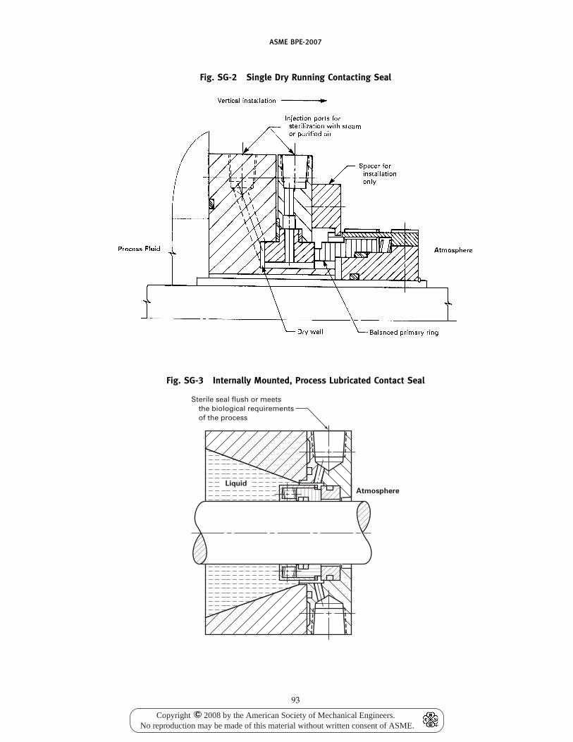
ASME BPE-2007
Fig. SG-2 Single Dry Running Contacting Seal
Fig. SG-3 Internally Mounted, Process Lubricated Contact Seal
Sterile seal flush or meets the biological requirements of the process
LiquidAtmosphere
93
Copyright 2008 by the American Society of Mechanical Engineers.No reproduction may be made of this material without written consent of ASME.
c
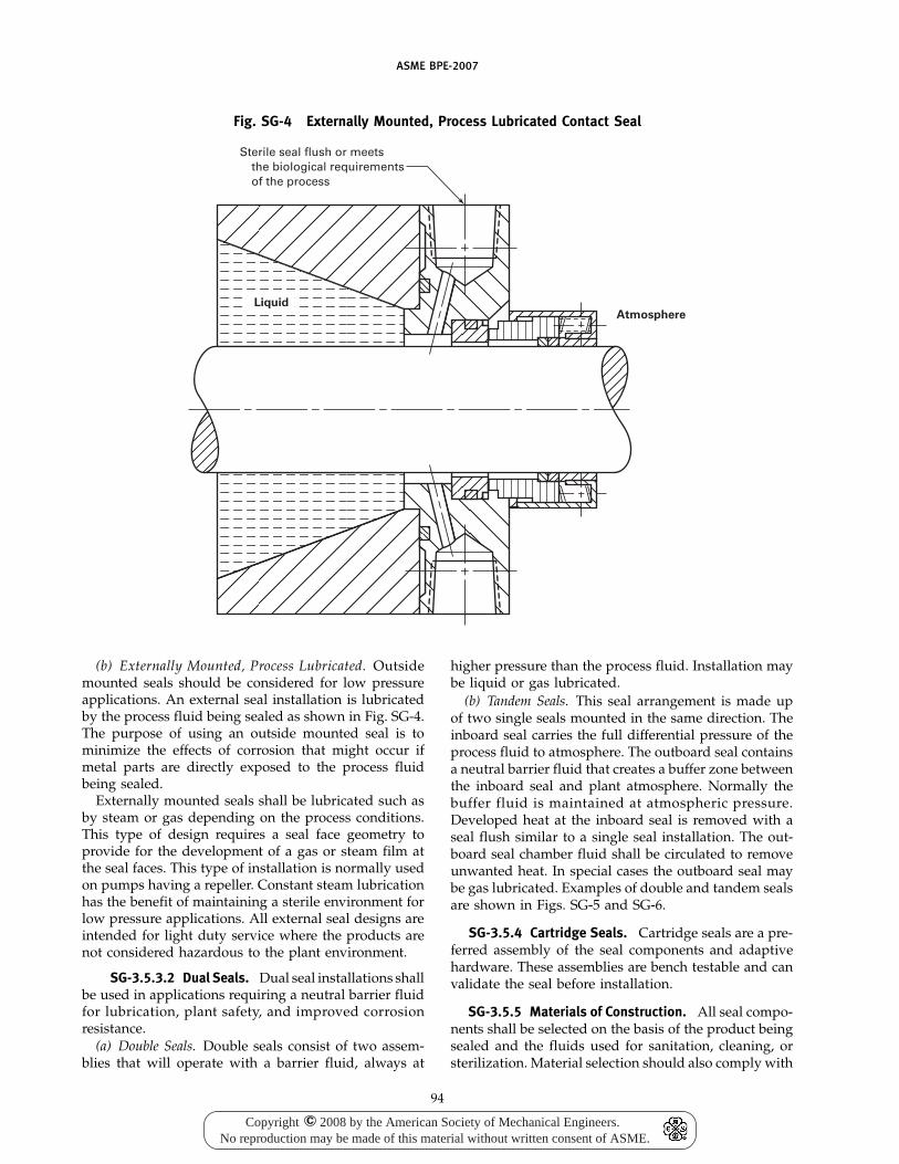
ASME BPE-2007
Fig. SG-4 Externally Mounted, Process Lubricated Contact Seal
Sterile seal flush or meetsthe biological requirementsof the process
AtmosphereLiquid
(b) Externally Mounted, Process Lubricated. Outsidemounted seals should be considered for low pressureapplications. An external seal installation is lubricatedby the process fluid being sealed as shown in Fig. SG-4.The purpose of using an outside mounted seal is tominimize the effects of corrosion that might occur ifmetal parts are directly exposed to the process fluidbeing sealed.
Externally mounted seals shall be lubricated such asby steam or gas depending on the process conditions.This type of design requires a seal face geometry toprovide for the development of a gas or steam film atthe seal faces. This type of installation is normally usedon pumps having a repeller. Constant steam lubricationhas the benefit of maintaining a sterile environment forlow pressure applications. All external seal designs areintended for light duty service where the products arenot considered hazardous to the plant environment.
SG-3.5.3.2 Dual Seals. Dual seal installations shallbe used in applications requiring a neutral barrier fluidfor lubrication, plant safety, and improved corrosionresistance.
(a) Double Seals. Double seals consist of two assem-blies that will operate with a barrier fluid, always at
94
higher pressure than the process fluid. Installation maybe liquid or gas lubricated.
(b) Tandem Seals. This seal arrangement is made upof two single seals mounted in the same direction. Theinboard seal carries the full differential pressure of theprocess fluid to atmosphere. The outboard seal containsa neutral barrier fluid that creates a buffer zone betweenthe inboard seal and plant atmosphere. Normally thebuffer fluid is maintained at atmospheric pressure.Developed heat at the inboard seal is removed with aseal flush similar to a single seal installation. The out-board seal chamber fluid shall be circulated to removeunwanted heat. In special cases the outboard seal maybe gas lubricated. Examples of double and tandem sealsare shown in Figs. SG-5 and SG-6.
SG-3.5.4 Cartridge Seals. Cartridge seals are a pre-ferred assembly of the seal components and adaptivehardware. These assemblies are bench testable and canvalidate the seal before installation.
SG-3.5.5 Materials of Construction. All seal compo-nents shall be selected on the basis of the product beingsealed and the fluids used for sanitation, cleaning, orsterilization. Material selection should also comply with
Copyright 2008 by the American Society of Mechanical Engineers.No reproduction may be made of this material without written consent of ASME.
c
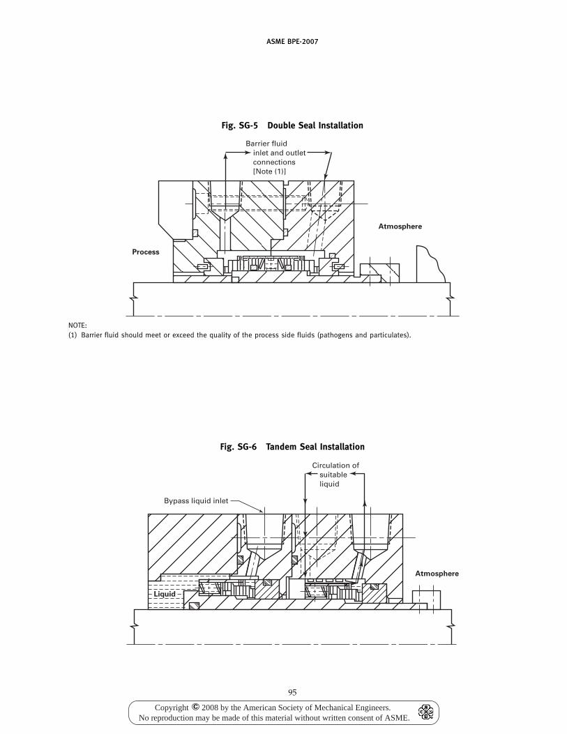
ASME BPE-2007
Fig. SG-5 Double Seal Installation
Barrier fluid inlet and outlet connections [Note (1)]
Process
Atmosphere
NOTE:(1) Barrier fluid should meet or exceed the quality of the process side fluids (pathogens and particulates).
Fig. SG-6 Tandem Seal Installation
Bypass liquid inlet
Circulation ofsuitableliquid
Liquid
Atmosphere
95
Copyright 2008 by the American Society of Mechanical Engineers.No reproduction may be made of this material without written consent of ASME.
c
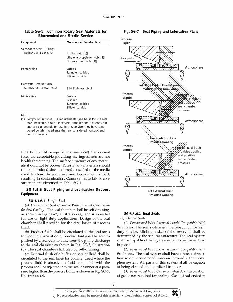
ASME BPE-2007
Table SG-1 Common Rotary Seal Materials forBiochemical and Sterile Service
Component Materials of Construction
Secondary seals, (O-rings,bellows, and gaskets) Nitrile [Note (1)]
Ethylene propylene [Note (1)]Fluorocarbon [Note (1)]
Primary ring CarbonTungsten carbideSilicon carbide
Hardware (retainer, disc,springs, set screws, etc.) 316 Stainless steel
Mating ring CarbonCeramicTungsten carbideSilicon carbide
NOTE:(1) Compound satisfies FDA requirements (see GR-9) for use with
food, beverage, and drug service. Although the FDA does notapprove compounds for use in this service, they have sanc-tioned certain ingredients that are considered nontoxic andnoncarcinogenic.
FDA fluid additive regulations (see GR-9). Carbon sealfaces are acceptable providing the ingredients are nothealth threatening. The surface structure of any materi-als should not be porous. Pores in any materials shouldnot be permitted since the product sealed or the mediaused to clean the structure may become entrapped,resulting in contamination. Common materials of con-struction are identified in Table SG-1.
SG-3.5.6 Seal Piping and Lubrication SupportEquipment
SG-3.5.6.1 Single Seal(a) Dead-Ended Seal Chamber With Internal Circulation
for Seal Cooling. The seal chamber shall be self-draining,as shown in Fig. SG-7, illustration (a), and is intendedfor use on light duty applications. Design of the sealchamber shall provide for the circulation of processfluid.
(b) Product flush shall be circulated to the seal facesfor cooling. Circulation of process fluid shall be accom-plished by a recirculation line from the pump dischargeto the seal chamber as shown in Fig. SG-7, illustration(b). The seal chamber shall also be self-draining.
(c) External flush of a buffer or barrier fluid shall becirculated to the seal faces for cooling. Used where theprocess fluid is abrasive, a fluid compatible with theprocess shall be injected into the seal chamber at a pres-sure higher than the process fluid, as shown in Fig. SG-7,illustration (c).
96
Fig. SG-7 Seal Piping and Lubrication Plans
Flow path
Seal flushprovides coolingand positiveseal chamberpressure
External seal flushprovides coolingand positiveseal chamberpressure
Atmosphere
Atmosphere
Atmosphere
Process
Liquid
(a) Dead-Ended Seal Chamber
With Internal Circulation
(b) Recirculation Line
Provides Cooling
Process
Liquid
Process
Liquid
(c) External Flush
Provides Cooling
SG-3.5.6.2 Dual Seals(a) Double Seals
(1) Pressurized With External Liquid Compatible Withthe Process. The seal system is a thermosyphon for lightduty service. Minimum size of the reservoir shall bedetermined by the seal manufacturer. The seal systemshall be capable of being cleaned and steam-sterilizedin place.
(2) Pressurized With External Liquid Compatible Withthe Process. The seal system shall have a forced circula-tion when service conditions are beyond a thermosy-phon system. All parts of this system shall be capableof being cleaned and sterilized in place.
(3) Pressurized With Gas or Purified Air. Circulationof gas is not required for cooling. Gas is dead-ended in
Copyright 2008 by the American Society of Mechanical Engineers.No reproduction may be made of this material without written consent of ASME.
c
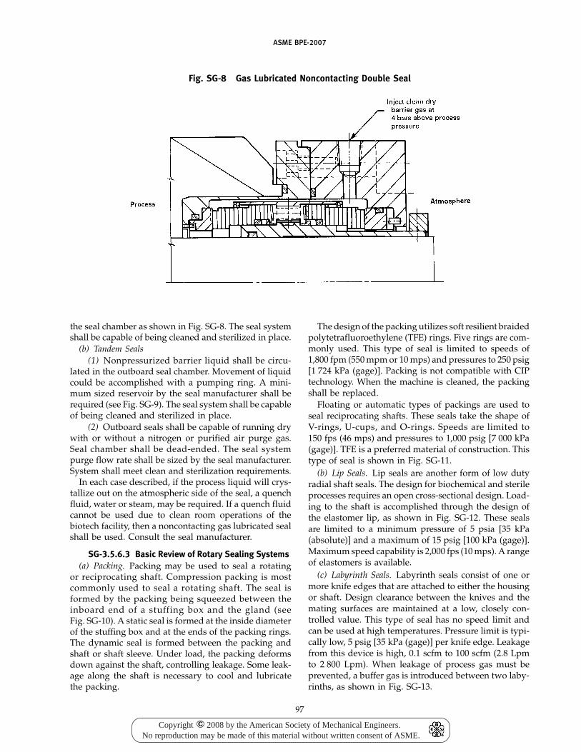
ASME BPE-2007
Fig. SG-8 Gas Lubricated Noncontacting Double Seal
the seal chamber as shown in Fig. SG-8. The seal systemshall be capable of being cleaned and sterilized in place.
(b) Tandem Seals(1) Nonpressurized barrier liquid shall be circu-
lated in the outboard seal chamber. Movement of liquidcould be accomplished with a pumping ring. A mini-mum sized reservoir by the seal manufacturer shall berequired (see Fig. SG-9). The seal system shall be capableof being cleaned and sterilized in place.
(2) Outboard seals shall be capable of running drywith or without a nitrogen or purified air purge gas.Seal chamber shall be dead-ended. The seal systempurge flow rate shall be sized by the seal manufacturer.System shall meet clean and sterilization requirements.
In each case described, if the process liquid will crys-tallize out on the atmospheric side of the seal, a quenchfluid, water or steam, may be required. If a quench fluidcannot be used due to clean room operations of thebiotech facility, then a noncontacting gas lubricated sealshall be used. Consult the seal manufacturer.
SG-3.5.6.3 Basic Review of Rotary Sealing Systems(a) Packing. Packing may be used to seal a rotating
or reciprocating shaft. Compression packing is mostcommonly used to seal a rotating shaft. The seal isformed by the packing being squeezed between theinboard end of a stuffing box and the gland (seeFig. SG-10). A static seal is formed at the inside diameterof the stuffing box and at the ends of the packing rings.The dynamic seal is formed between the packing andshaft or shaft sleeve. Under load, the packing deformsdown against the shaft, controlling leakage. Some leak-age along the shaft is necessary to cool and lubricatethe packing.
97
The design of the packing utilizes soft resilient braidedpolytetrafluoroethylene (TFE) rings. Five rings are com-monly used. This type of seal is limited to speeds of1,800 fpm (550 mpm or 10 mps) and pressures to 250 psig[1 724 kPa (gage)]. Packing is not compatible with CIPtechnology. When the machine is cleaned, the packingshall be replaced.
Floating or automatic types of packings are used toseal reciprocating shafts. These seals take the shape ofV-rings, U-cups, and O-rings. Speeds are limited to150 fps (46 mps) and pressures to 1,000 psig [7 000 kPa(gage)]. TFE is a preferred material of construction. Thistype of seal is shown in Fig. SG-11.
(b) Lip Seals. Lip seals are another form of low dutyradial shaft seals. The design for biochemical and sterileprocesses requires an open cross-sectional design. Load-ing to the shaft is accomplished through the design ofthe elastomer lip, as shown in Fig. SG-12. These sealsare limited to a minimum pressure of 5 psia [35 kPa(absolute)] and a maximum of 15 psig [100 kPa (gage)].Maximum speed capability is 2,000 fps (10 mps). A rangeof elastomers is available.
(c) Labyrinth Seals. Labyrinth seals consist of one ormore knife edges that are attached to either the housingor shaft. Design clearance between the knives and themating surfaces are maintained at a low, closely con-trolled value. This type of seal has no speed limit andcan be used at high temperatures. Pressure limit is typi-cally low, 5 psig [35 kPa (gage)] per knife edge. Leakagefrom this device is high, 0.1 scfm to 100 scfm (2.8 Lpmto 2 800 Lpm). When leakage of process gas must beprevented, a buffer gas is introduced between two laby-rinths, as shown in Fig. SG-13.
Copyright 2008 by the American Society of Mechanical Engineers.No reproduction may be made of this material without written consent of ASME.
c
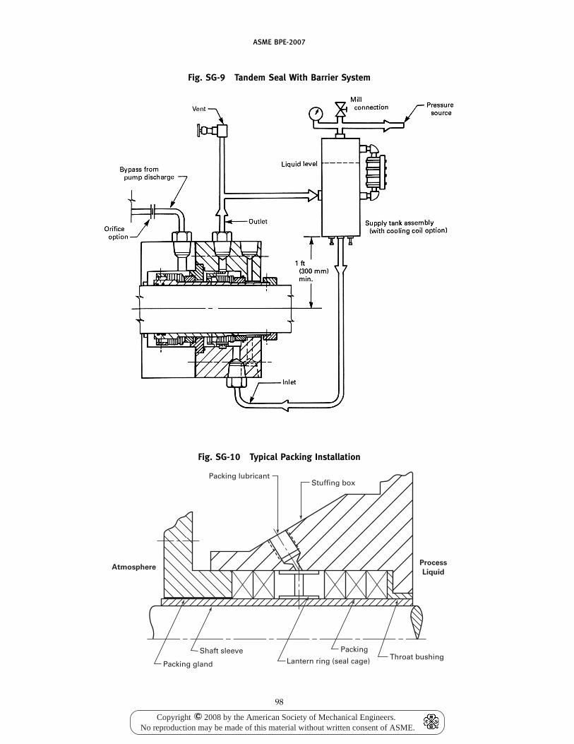
ASME BPE-2007
Fig. SG-9 Tandem Seal With Barrier System
Fig. SG-10 Typical Packing Installation
Packing lubricant
Packing gland
PackingThroat bushingLantern ring (seal cage)
Shaft sleeve
Stuffing box
AtmosphereProcess
Liquid
98
Copyright 2008 by the American Society of Mechanical Engineers.No reproduction may be made of this material without written consent of ASME.
c
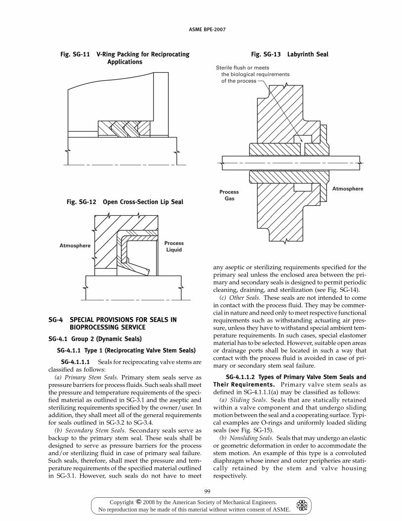
ASME BPE-2007
Fig. SG-11 V-Ring Packing for ReciprocatingApplications
Fig. SG-12 Open Cross-Section Lip Seal
AtmosphereProcess
Liquid
SG-4 SPECIAL PROVISIONS FOR SEALS INBIOPROCESSING SERVICE
SG-4.1 Group 2 (Dynamic Seals)
SG-4.1.1 Type 1 (Reciprocating Valve Stem Seals)
SG-4.1.1.1 Seals for reciprocating valve stems areclassified as follows:
(a) Primary Stem Seals. Primary stem seals serve aspressure barriers for process fluids. Such seals shall meetthe pressure and temperature requirements of the speci-fied material as outlined in SG-3.1 and the aseptic andsterilizing requirements specified by the owner/user. Inaddition, they shall meet all of the general requirementsfor seals outlined in SG-3.2 to SG-3.4.
(b) Secondary Stem Seals. Secondary seals serve asbackup to the primary stem seal. These seals shall bedesigned to serve as pressure barriers for the processand/or sterilizing fluid in case of primary seal failure.Such seals, therefore, shall meet the pressure and tem-perature requirements of the specified material outlinedin SG-3.1. However, such seals do not have to meet
99
Fig. SG-13 Labyrinth Seal
Sterile flush or meetsthe biological requirementsof the process
Process
Gas
Atmosphere
any aseptic or sterilizing requirements specified for theprimary seal unless the enclosed area between the pri-mary and secondary seals is designed to permit periodiccleaning, draining, and sterilization (see Fig. SG-14).
(c) Other Seals. These seals are not intended to comein contact with the process fluid. They may be commer-cial in nature and need only to meet respective functionalrequirements such as withstanding actuating air pres-sure, unless they have to withstand special ambient tem-perature requirements. In such cases, special elastomermaterial has to be selected. However, suitable open areasor drainage ports shall be located in such a way thatcontact with the process fluid is avoided in case of pri-mary or secondary stem seal failure.
SG-4.1.1.2 Types of Primary Valve Stem Seals andTheir Requirements. Primary valve stem seals asdefined in SG-4.1.1.1(a) may be classified as follows:
(a) Sliding Seals. Seals that are statically retainedwithin a valve component and that undergo slidingmotion between the seal and a cooperating surface. Typi-cal examples are O-rings and uniformly loaded slidingseals (see Fig. SG-15).
(b) Nonsliding Seals. Seals that may undergo an elasticor geometric deformation in order to accommodate thestem motion. An example of this type is a convoluteddiaphragm whose inner and outer peripheries are stati-cally retained by the stem and valve housingrespectively.
Copyright 2008 by the American Society of Mechanical Engineers.No reproduction may be made of this material without written consent of ASME.
c
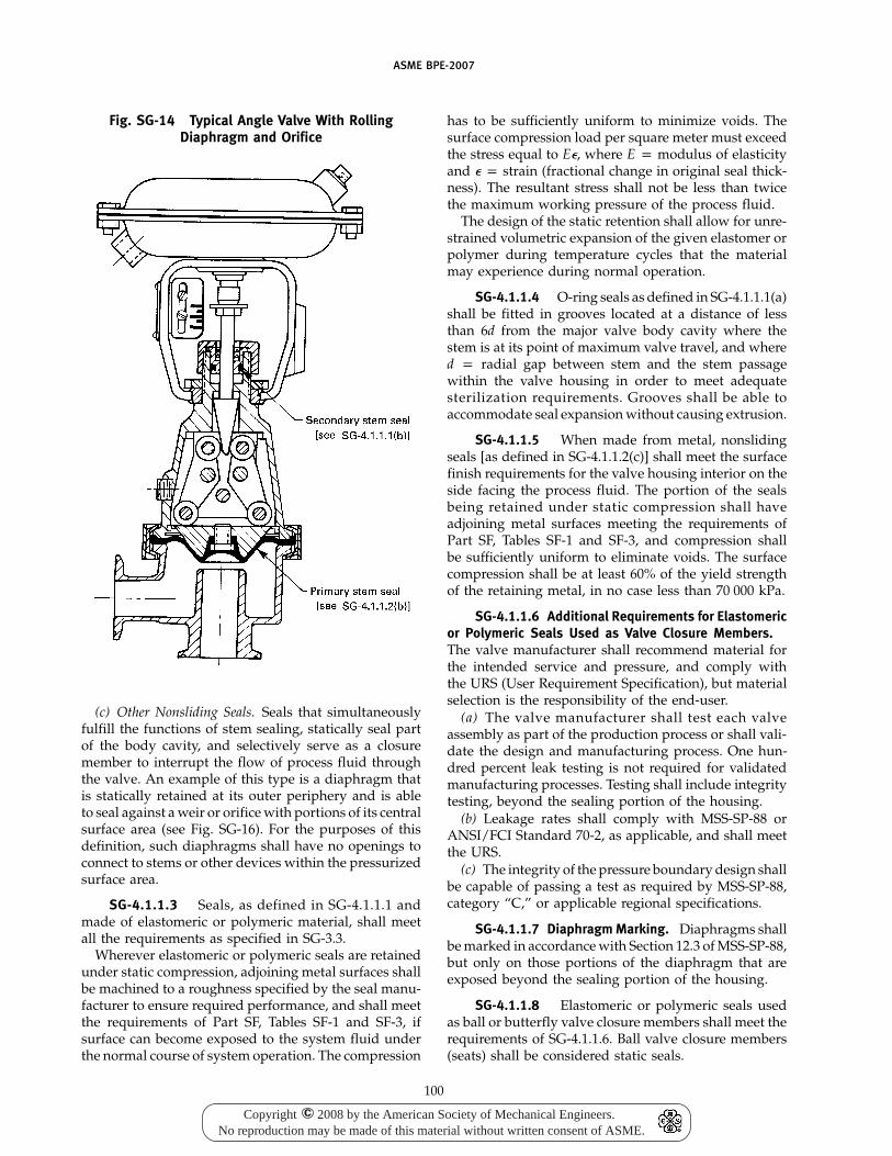
ASME BPE-2007
Fig. SG-14 Typical Angle Valve With RollingDiaphragm and Orifice
(c) Other Nonsliding Seals. Seals that simultaneouslyfulfill the functions of stem sealing, statically seal partof the body cavity, and selectively serve as a closuremember to interrupt the flow of process fluid throughthe valve. An example of this type is a diaphragm thatis statically retained at its outer periphery and is ableto seal against a weir or orifice with portions of its centralsurface area (see Fig. SG-16). For the purposes of thisdefinition, such diaphragms shall have no openings toconnect to stems or other devices within the pressurizedsurface area.
SG-4.1.1.3 Seals, as defined in SG-4.1.1.1 andmade of elastomeric or polymeric material, shall meetall the requirements as specified in SG-3.3.
Wherever elastomeric or polymeric seals are retainedunder static compression, adjoining metal surfaces shallbe machined to a roughness specified by the seal manu-facturer to ensure required performance, and shall meetthe requirements of Part SF, Tables SF-1 and SF-3, ifsurface can become exposed to the system fluid underthe normal course of system operation. The compression
100
has to be sufficiently uniform to minimize voids. Thesurface compression load per square meter must exceedthe stress equal to E�, where E p modulus of elasticityand � p strain (fractional change in original seal thick-ness). The resultant stress shall not be less than twicethe maximum working pressure of the process fluid.
The design of the static retention shall allow for unre-strained volumetric expansion of the given elastomer orpolymer during temperature cycles that the materialmay experience during normal operation.
SG-4.1.1.4 O-ring seals as defined in SG-4.1.1.1(a)shall be fitted in grooves located at a distance of lessthan 6d from the major valve body cavity where thestem is at its point of maximum valve travel, and whered p radial gap between stem and the stem passagewithin the valve housing in order to meet adequatesterilization requirements. Grooves shall be able toaccommodate seal expansion without causing extrusion.
SG-4.1.1.5 When made from metal, nonslidingseals [as defined in SG-4.1.1.2(c)] shall meet the surfacefinish requirements for the valve housing interior on theside facing the process fluid. The portion of the sealsbeing retained under static compression shall haveadjoining metal surfaces meeting the requirements ofPart SF, Tables SF-1 and SF-3, and compression shallbe sufficiently uniform to eliminate voids. The surfacecompression shall be at least 60% of the yield strengthof the retaining metal, in no case less than 70 000 kPa.
SG-4.1.1.6 Additional Requirements for Elastomericor Polymeric Seals Used as Valve Closure Members.The valve manufacturer shall recommend material forthe intended service and pressure, and comply withthe URS (User Requirement Specification), but materialselection is the responsibility of the end-user.
(a) The valve manufacturer shall test each valveassembly as part of the production process or shall vali-date the design and manufacturing process. One hun-dred percent leak testing is not required for validatedmanufacturing processes. Testing shall include integritytesting, beyond the sealing portion of the housing.
(b) Leakage rates shall comply with MSS-SP-88 orANSI/FCI Standard 70-2, as applicable, and shall meetthe URS.
(c) The integrity of the pressure boundary design shallbe capable of passing a test as required by MSS-SP-88,category “C,” or applicable regional specifications.
SG-4.1.1.7 Diaphragm Marking. Diaphragms shallbe marked in accordance with Section 12.3 of MSS-SP-88,but only on those portions of the diaphragm that areexposed beyond the sealing portion of the housing.
SG-4.1.1.8 Elastomeric or polymeric seals usedas ball or butterfly valve closure members shall meet therequirements of SG-4.1.1.6. Ball valve closure members(seats) shall be considered static seals.
Copyright 2008 by the American Society of Mechanical Engineers.No reproduction may be made of this material without written consent of ASME.
c
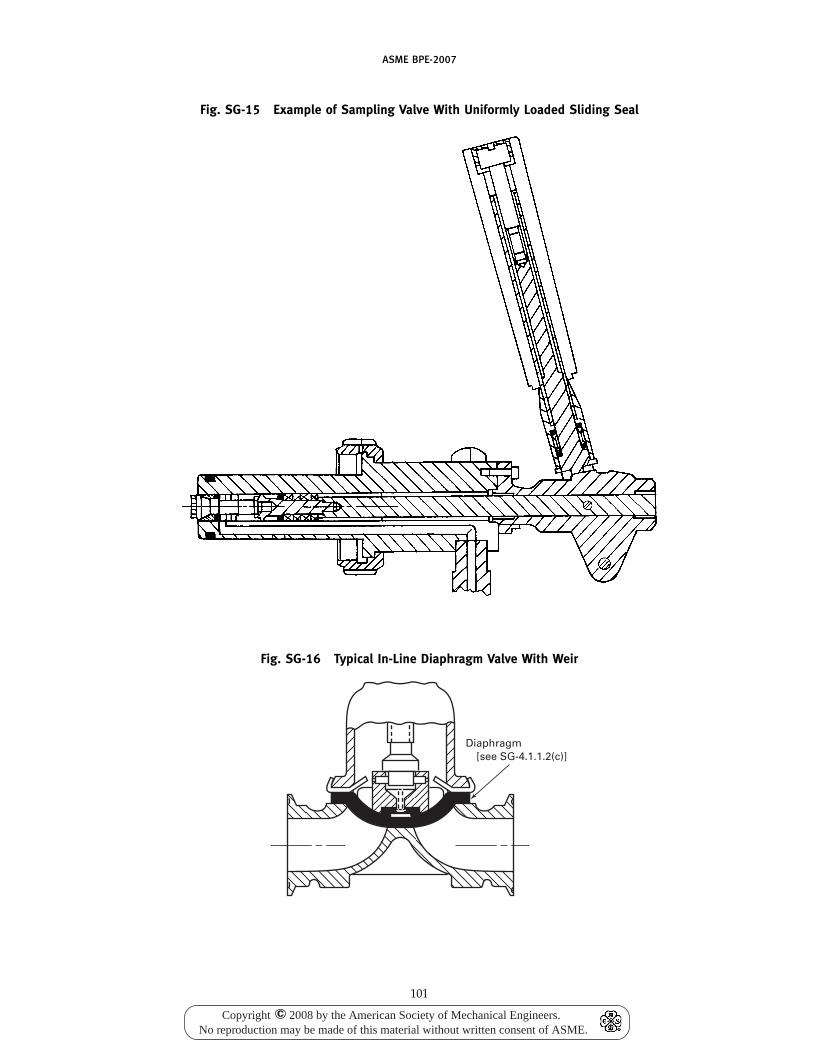
ASME BPE-2007
Fig. SG-15 Example of Sampling Valve With Uniformly Loaded Sliding Seal
Fig. SG-16 Typical In-Line Diaphragm Valve With Weir
Diaphragm[see SG-4.1.1.2(c)]
101
Copyright 2008 by the American Society of Mechanical Engineers.No reproduction may be made of this material without written consent of ASME.
c
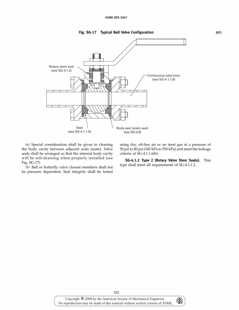
ASME BPE-2007
(07)Fig. SG-17 Typical Ball Valve Configuration
Rotary stem seal(see SG-4.1.2)
Seat(see SG-4.1.1.8)
Body seal (static seal)(see SD-3.6)
Continuous tube bore(see SG-4.1.1.8)
(a) Special consideration shall be given to cleaningthe body cavity between adjacent seals (seats). Valveseals shall be arranged so that the internal body cavitywill be self-draining when properly installed (seeFig. SG-17).
(b) Ball or butterfly valve closure members shall notbe pressure dependent. Seal integrity shall be tested
102
using dry, oil-free air or an inert gas at a pressure of50 psi to 80 psi (345 kPa to 550 kPa) and meet the leakagecriteria of SG-4.1.1.6(b).
SG-4.1.2 Type 2 (Rotary Valve Stem Seals). Thistype shall meet all requirements of SG-4.1.1.2.
Copyright 2008 by the American Society of Mechanical Engineers.No reproduction may be made of this material without written consent of ASME.
c
ASME BPE-2007
Part PMPolymer-Based Materials
PM-1 INTRODUCTION
This Part defines the requirements that are applicableto and unique to the use of polymer-based materialsused in bioprocessing, pharmaceutical, and personalcare products, equipment, components, assemblies, andbioprocessing systems in conjunction with requirementsof other applicable parts of this Standard along withapplicable references. Polymer-based materials includethermoplastics and thermosetting materials, both virginand composite forms. Wherever equipment is referredto in this Part, it shall mean all bioprocessing, pharma-ceutical, and personal care products, equipment, compo-nents, assemblies, and systems.
PM-1.1 Scope and Purpose
The scope and purpose of this Part is to providerequirements for the specification and documentationof bioprocessing, pharmaceutical, and personal careproducts, equipment constructed with polymer-basedmaterials that are required to be cleaned, sterilized, andto be operated in a clean and sterile manner.
NOTE: The design of the equipment and systems should refer-ence Part SD of this Standard. For requirements relating to polymerseals and gaskets, refer to Part SG.
The objective of this Part is to describe and outlineaccepted practices for the use of polymer-based materi-als that have demonstrated their merit in attaining clean-ability and sterility as they relate to bioprocessingequipment. Although acceptable requirements are indi-cated throughout this Part, more stringent requirementsmay be imposed as agreed to by the owner/user andmanufacturer. Figures in this Part show ranges of usageand fabrication. There may be equipment being success-fully used that corresponds to sketches labeled “not rec-ommended.” This Part covers new construction andshall not be used to evaluate the acceptability of existingequipment.
PM-2 DESIGN CONSIDERATIONS FOR POLYMERICPIPING, TUBING, FITTINGS, VALVE BODIES,AND OTHER COMPONENTS
PM-2.1 Sizing Comparisons
Thermoplastic piping systems are available in a vari-ety of sizing standards. Tube (e.g., Schedule 40, Schedule80), Standard Dimensional Ratio (SDR) 11, and SDR 21are some of the most common standards used.
103
Table PM-1 is a reference that compares the outside andinside dimensions of these standards. It is importantto consider these standards when performing system-sizing calculations to enhance dimensional alignment ofpipe/tube inner diameters to allow for sterility, clean-ability, and drainability. Tube inside dimensions are criti-cal for alignment to stainless steel systems.
PM-2.2 Pressure Ratings
Polymer piping systems have varying pressure ratingsdepending on material and sizing standard. Valves andmechanical connections such as sanitary adapters,flanges, or threads may carry pressure ratings indepen-dent of pipe and fittings. Elevated operating tempera-tures will decrease overall system rating. Consultmaterial manufacturers for specific details.
PM-2.3 Thermal Expansion
Polymer materials will expand and contract withchanging temperature conditions. The effect of thermalexpansion must be considered and designed for in eachand every thermoplastic system.
To compensate for thermal expansion it is recom-mended to use loops, offsets, and changes in direction.By using the pipe itself to relieve the stress, the integrityof the pipe system is maintained. The use of bellows orpistons are not recommended due to the formation ofpockets and gaps where liquids may be held up. Theamount of thermal expansion growth in a pipe systemis generally calculated by the following formula:
(U.S. Customary Units)
�L p 12 � L � � � �T
where�L p change in length, in.
L p length of the pipe run, ft� p coefficient of thermal expansion, in./in./°F
material and temperature dependent�T p temperature change, °F
(SI Units)
�L p L � � � �T
where�L p change in length, mm
L p length of the pipe run, mm
Copyright 2008 by the American Society of Mechanical Engineers.No reproduction may be made of this material without written consent of ASME.
c
ASME BPE-2007
� p coefficient of thermal expansion, mm/m/°Cmaterial and temperature dependent
�T p temperature change, °C
Typical coefficients of thermal expansion at room tem-perature by material type are found below. Consult man-ufacturer for exact coefficient values.
(U.S. Customary Units)
PVDF 6.6 � 10–5, in./in./°FPFA 7.0 � 10–5, in./in./°FPP 8.33 � 10–5, in./in./°F
(SI Units)
PVDF 1.2 � 10–5, mm/m/°CPFA 1.2 � 10–5, mm/m/°CPP 1.5 � 10–5, mm/m/°C
�T is the maximum (or minimum) temperature minusthe installation temperature. If the installation tempera-ture or time of year is unknown, it is practical to increasethe �T by 15% for safety. It is not necessary or practicalto use the maximum temperature minus the minimumtemperature unless it will truly be installed in one ofthose conditions.
PM-2.4 System Support Criteria
PM-2.4.1 Support Distances. Supports shall beplaced based on the spacing requirements provided bysystem manufacturers. Hanging distances are based onsystem material as well as the specific gravity and tem-perature of the process media. Operating conditions ofall applicable processes, including CIP and SIP, mustalso be considered. Hanging criteria generally increaseswith system operating temperatures. The placement ofhangers, guides, and anchors is critical in systemsexposed to thermal cycling. Hanger locations should beidentified by the system engineer and laid out to allowfor expansion and contraction of the pipe over its lifeof operation.
PM-2.4.2 Hanger and Clamp Types. Avoid usinghangers that place a pinpoint load on the pipe whentightened. A U-bolt hanger is not recommended for ther-moplastic piping. Hangers that secure the pipe 360 degaround the pipe are preferred. Thermoplastic clampsare also recommended over metal clamps, as they areless likely to scratch the pipe in the event of movement.Clamps should be evaluated to avoid rough edges thatcould damage the pipe. Ideally, if a metal clamp is beingused, an elastomer material should be used in betweenthe pipe and the clamp. Refer to Part SD for exteriorcleanability.
104
PM-2.5 Connections and Fittings
Design of equipment should minimize the numberof mechanical connections. Fusion welded connectionsshould be used wherever practical. Hygienic design ofconnections shall comply with SD-3.7, Connections andFittings.
PM-2.6 Materials
Materials of construction shall not affect the purity orintegrity of the product. It will be the owner/user’sresponsibility to select the appropriate materials of con-struction for the bioprocessing conditions. Materialsshall be compatible with the stated bioprocessing condi-tions, cleaning solutions, and sterilizing conditions, etc.,as specified by the owner/user.
Materials shall be capable of withstanding the temper-ature, pressure and chemical conditions.
Polymer surfaces may be used provided approvalfrom the owner/user has been obtained. All polymerproduct contact surfaces shall be designed to remainintact and be tolerant of applicable SIP and CIP. In gen-eral, product contact surfaces requirements should con-sider the following characteristics:
(a) homogeneous in nature(b) impervious(c) inert(d) nonabsorbent(e) nontoxic(f) insoluble by process or cleaning fluid(g) resistant to degradation, scratching, scoring, and
distortion when exposed to bioprocessing fluids andsterilizing conditions
All polymer materials in contact with bioprocessingfluids or that may have contact with the processing fluidshall be identified by referenced industry standards.Refer to PM-5.
The use of elastomers (within a piece of equipment)that may thermally degrade during sterilization willneed to be thoroughly investigated by the owner/userand manufacturer. The overall life of the equipment maybe shortened significantly if the correct polymer is notselected.
PM-2.6.1 Extractables and Leachables. The deter-mination of extractables/leachables, from polymer-based materials into a product or intermediate, shallbe determined jointly by both the owner/user and themanufacturer of the completed polymer equipment/container (refer to SG-3.3.1). The owner/user shall beresponsible for determining the impact of the extract-ables/leachables on the drug product/intermediates.The owner/user shall be responsible for the determina-tion of the suitability of the usage of polymer equipmentin their drug production manufacturer.
(07)
Copyright 2008 by the American Society of Mechanical Engineers.No reproduction may be made of this material without written consent of ASME.
c
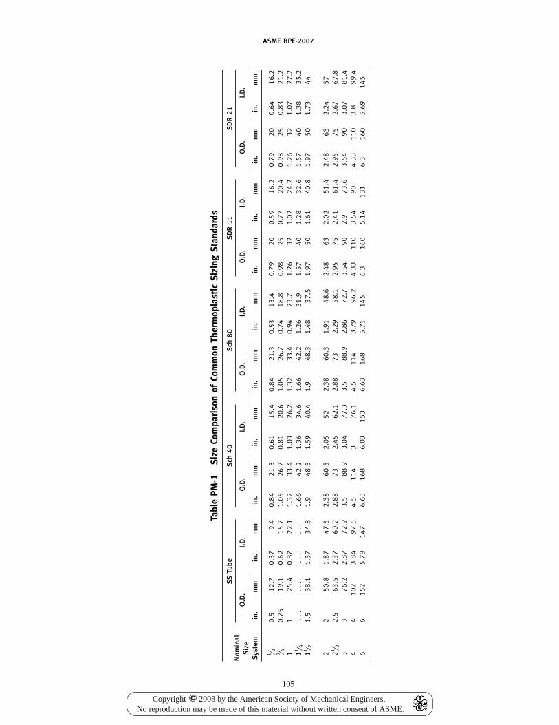
ASME BPE-2007
Tabl
ePM
-1Si
zeCo
mpa
riso
nof
Com
mon
Ther
mop
last
icSi
zing
Stan
dard
s
SSTu
beS
ch40
Sch
80S
DR
11S
DR
21N
omin
alO
.D.
I.D.
O.D
.I.D
.O
.D.
I.D.
O.D
.I.D
.O
.D.
I.D.
Siz
eS
yste
min
.m
min
.m
min
.m
min
.m
min
.m
min
.m
min
.m
min
.m
min
.m
min
.m
m
1 ⁄ 20.
512
.70.
379.
40.
8421
.30.
6115
.40.
8421
.30.
5313
.40.
7920
0.59
16.2
0.79
200.
6416
.23 ⁄ 4
0.75
19.1
0.62
15.7
1.05
26.7
0.81
20.6
1.05
26.7
0.74
18.8
0.98
250.
7720
.40.
9825
0.83
21.2
11
25.4
0.87
22.1
1.32
33.4
1.03
26.2
1.32
33.4
0.94
23.7
1.26
321.
0224
.21.
2632
1.07
27.2
11 ⁄ 4..
...
...
...
.1.
6642
.21.
3634
.61.
6642
.21.
2631
.91.
5740
1.28
32.6
1.57
401.
3835
.211 ⁄ 2
1.5
38.1
1.37
34.8
1.9
48.3
1.59
40.4
1.9
48.3
1.48
37.5
1.97
501.
6140
.81.
9750
1.73
44
22
50.8
1.87
47.5
2.38
60.3
2.05
522.
3860
.31.
9148
.62.
4863
2.02
51.4
2.48
632.
2457
21 ⁄ 22.
563
.52.
3760
.22.
8873
2.45
62.1
2.88
732.
2958
.12.
9575
2.41
61.4
2.95
752.
6767
.83
376
.22.
8772
.93.
588
.93.
0477
.33.
588
.92.
8672
.73.
5490
2.9
73.6
3.54
903.
0781
.44
410
23.
8497
.54.
511
43
76.1
4.5
114
3.79
96.2
4.33
110
3.54
904.
3311
03.
899
.46
615
25.
7814
76.
6316
86.
0315
36.
6316
85.
7114
56.
316
05.
1413
16.
316
05.
6914
5
105
Copyright 2008 by the American Society of Mechanical Engineers.No reproduction may be made of this material without written consent of ASME.
c
ASME BPE-2007
PM-3 POLYMER MATERIAL JOINING
PM-3.1 Scope
The requirements of this Part are applicable to thefusion welding of polymeric materials used for bio-processing equipment. Equipment includes but is notlimited to valves, fittings, tubing, piping, other compo-nents, pumps and lined tanks, reactors, and pressurevessels. These materials, joining methods, examinations,etc., are limited to surfaces in process systems that con-tact bioprocessing products or product-process streams.
PM-3.2 Joining Processes and Procedures for Tubeand Pipe Systems
Polymer tube and pipe systems are joined by a varietyof heat fusion welding methods. Available techniquesinclude various beadless technologies, noncontact IRfusion, butt fusion, and socket fusion.
NOTE: All joining techniques may not be available for all materi-als, nor are all methods acceptable for all processes. Care shouldbe taken in selecting material of construction and joining techniquebased upon application requirement. A brief description of someavailable joining techniques follows.
PM-3.2.1 Beadless Welding. Beadless welding(material-dependent) is compatible with SIP systemsand must be used where system, in-place drainage isrequired. Beadless welding may be used in the processstream or where CIP requirements are defined. Beadlesswelding is the preferred method for system joining.
A variety of beadless welding techniques exists inwhich resultant joints are free from internal beads andcrevices. The primary method of beadless weldinginvolves careful diffusion of heat through the externalsurfaces while maintaining internal support of materialas it becomes molten. Once heated to desired tempera-ture and duration, the molten material flows and readilyjoins as a single piece. An internal support device isinserted in the weld area to prevent the formation onan internal bead. Refer to manufacturers’ written proce-dures for the complete beadless welding process.
PM-3.2.2 Noncontact IR Butt Fusion. IR fusion isnot suitable for SIP systems for it is not considered in-line drainable as required by accepted current GoodManufacturing Practices (cGMP).
IR welding is similar to butt fusion with the significantdifference being the joining material does not come intodirect contact with the heating element. Instead, thematerial is held in close proximity to the heating elementand is heated by radial heat. IR welding uses the samecritical welding parameters of heat soak time, changeover time, and joining force as found with butt fusion.However, by avoiding direct contact with the heatingelement, IR fusion produces a cleaner weld with morerepeatable and smaller bead sizes. Refer to manufactur-ers’ written procedures for the complete noncontact, IRfusion welding process.
106
PM-3.2.3 Contact Butt Fusion. Butt fusion is notsuitable for SIP systems for it is not considered in-linedrainable as required by accepted cGMP.
The principle of butt fusion, as described inASTM D 2657, “Standard Practice for Heat Fusion Join-ing of Polyolefin Pipe and Fittings,” is to heat two sur-faces at the melt temperature, then make contactbetween the two surfaces and allow the two surfaces tofuse together by application of force. The force causesflow of the melted materials to join. Upon cooling, thetwo parts are united. Nothing is added or changedchemically between the two components being joined.Butt fusion does not require solvents or glue to joinmaterial. Butt fusion joints result in external and internalbeads, which may assist with weld quality and inspec-tion criteria.
Refer to manufacturers’ written procedures andASTM D 2657, DVS 2207-11, “Welding of Thermoplas-tics — Heated Tool Welding of Pipes, Pipeline Compo-nents and Sheets Made of PP,” and DVS 2207-15,“Welding of Thermoplastics — Heated Tool Welding ofPipes, Pipeline Components and Sheets Made of PVDF.”
PM-3.2.4 Socket Fusion. Socket fusion is not suit-able for SIP systems for it is not considered in-line drai-nable as required by accepted cGMP.
In socket welding, as described in ASTM D 2657, thepipe end and socket fittings are heated to the weldingtemperature by means of a socket and spigot heaterinserts. Socket welding may be manually performed onpipe diameters up to 2.0 in. (63 mm). Sizes above thatrequire a Bench Socket Tool due to the required joiningforces. In sizes greater than 1 in. (13 mm), a bench-stylemachine may be preferred for ease of operation.
Refer to manufacturers’ written procedures andASTM D 2657, DVS 2207-11, and DVS 2207-15.
PM-3.3 Joint Design and Preparation
The quality of polymeric weld joints depends on thequalification of the welders, the suitability of the equip-ment used, environmental influences, and adherence toapplicable weld standards.
Every welder must be trained and possess a validqualification certificate. Weld component and equip-ment manufacturer, or its representative, shall providecertification training and a valid qualification certificate.
The welding zone must be protected against adverseenvironmental influences including excessive moisture,extreme temperature conditions, excessive drafts, andcontamination sources (i.e., dirt, dust, oil, foreign mate-rial shavings). Environmental condition recommenda-tions shall be included in the Bonding ProcedureSpecification (BPS) provided by the material/equipmentmanufacturer and approved by the owner/user.
PM-3.3.1 Tubing and Pipe. Joint designs for tubing,pipe, and fittings shall be square butt joints. Joiningsurfaces shall have ends prepared by molding, cutting,
Copyright 2008 by the American Society of Mechanical Engineers.No reproduction may be made of this material without written consent of ASME.
c
ASME BPE-2007
machining, or facing to provide a square end that meetsrequirements of Table DT-5 for applicable squareness.The butt weld joints must be completed in accordancewith the BPS. The owner/user and contractor shall agreethat the welding process selected will provide thedesired results.
PM-3.4 Weld Acceptance Criteria
Inspection criteria and methods are dictated by mate-rial type and joining method. Common visual inspectioncriteria includes complete bonding of joining surface,straight and aligned joints, exclusion of dirt and foreignsubstances in weld zone.
PM-3.4.1 Weld Acceptance for Beadless Welds.Visual weld acceptance (including borescopic and lightillumination at 1X magnification) for beadless polymerhygienic pipe, tubing, valves, and fittings that are inter-nally and externally inspected shall be in accordancewith the weld acceptance criteria of this section. ThisPart does not require radiography for polymer materials.Preproduction sample welds, when required, shall besubmitted by the contractor to the owner/user to estab-lish weld quality. Owner/user, contractor, and inspec-tion contractor shall agree to the number and type ofsample welds. During construction, sample welds shallbe made on a regular basis to verify that the equipmentis operating properly and that the setup is adequate toprevent discoloration beyond the level agreed upon bythe owner/user and contractor. Owner/user and con-tractor shall agree to the frequency of sample welds. Itis strongly recommended that these sample welds bemade at the beginning of each work shift and whenchanging the operator or welding equipment.
PM-3.4.1.1 Cracks and Crevices. Any crack orcrevice would generally indicate lack of full penetrationwelds. No internal or external cracks or crevices shallbe permitted in the weld zone. See Fig. PM-1, illustra-tion (b).
PM-3.4.1.2 Pits and Pores. Pits and pores shallnot be present in the weld zone on the interior surface.See Fig. PM-1, illustration (c).
PM-3.4.1.3 Voids. Voids or microbubbles in theweld zone are the result of molten material shrinkingas it cools leaving small voids, usually in the center ofthe weld, due to volume displacement. They are notuncommon in beadless welding and their presence aloneis not reason for rejection. Large voids [limited byPM-3.4.1.3(a)] or excessive voids [limited byPM-2.4.1.3(b)] are not acceptable according to the follow-ing guidelines:
(a) Any single void larger in diameter than 10% ofnominal pipe wall thickness is not acceptable.
(b) The total for all void diameters in a given cross-sectional inspection shall not exceed 10% of nominalpipe wall thickness.
107
See Fig. PM-1, illustration (d).
PM-3.4.1.4 Fit-up and Mismatch. Componentsshall be aligned so as to prevent hold-up volume areasthat would contribute to contamination of the product.The maximum misalignment is 10% of nominal wallthickness [see Fig. PM-1, illustration (e)]. It is not recom-mended to join two polymer components of differentwall thicknesses.
PM-3.4.1.5 Inclusions. Any dark, visible inclusionor specks on the product contact surface of the weldzone are considered foreign materials and are not accept-able. See Fig. PM-1, illustration (f).
PM-3.4.1.6 Discoloration. Slight discoloration inthe weld zone is not uncommon in beadless welding.Slight discoloration would include up to a light "straw"color in the weld zone. Dark color change on the surfaceor at weld interface could indicate improper cleaning orjoint preparation and should be rejected. See Fig. PM-1,illustration (g).
PM-3.4.1.7 Concavity. Maximum inside diameter(I.D.) concavity shall be limited to 10% of the nominalpipe wall thickness. See Fig. PM-1, illustration (h).
PM-3.4.2 Examination Procedures for NonbeadlessWelds. Weld acceptance criteria for piping shall be inaccordance with ASME B31.3, A341.3.2 throughA341.3.4; DVS 2202-1, “Imperfections in ThermoplasticWelding Joints; Features, Descriptions, Evaluations”;and American Welding Society (AWS) G1.10M, “Guidefor the Evaluation of Hot Gas, Hot Gas Extrusion, andHeated Tool Butt Thermoplastic Welds” criteria. Thesestandards contain detailed, nondestructive inspectionrequirements for fabrication of sheets and piping sys-tems by heat welding, socket and butt fusion. Refer tomanufacturers’ inspection criteria for noncontact IR andbeadless welding techniques.
Borescoping of product contact surface weld areas onpolymer systems is not an absolute requirementalthough it may be preferred by owner and inspector.
PM-3.4.3 Testing. Hydrostatic testing of piping andrigid tubing systems shall be performed in accordancewith ASME B31.3, Chapter VI, Section 345. Pneumatictesting shall not be used for polymer systems.
PM-3.4.4 Records. Weld equipment should monitorand record critical weld parameters such as heat, cooltime, and temperature. If the equipment does not havemonitoring or recording capabilities, weld data shall berecorded in welding protocols or on data carriers.
Additional requirements of records and retention ofrecords associated with piping and tubing shall be inaccordance with ASME B31.3, Chapter VI, Section 346.
PM-3.5 Documentation Requirements
The following documentation shall be presented tothe owner/user or his/her designee, as a minimum:
Copyright 2008 by the American Society of Mechanical Engineers.No reproduction may be made of this material without written consent of ASME.
c
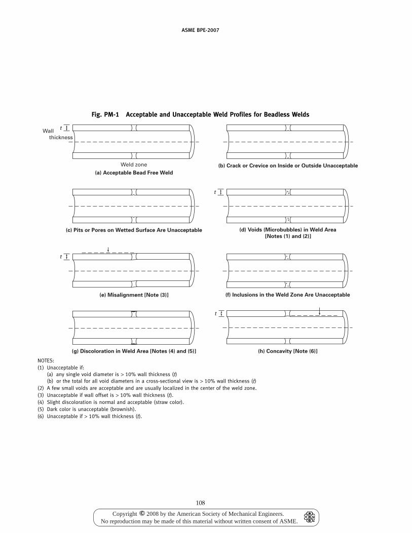
ASME BPE-2007
Fig. PM-1 Acceptable and Unacceptable Weld Profiles for Beadless Welds
Weld zone
Wall thickness
t
(a) Acceptable Bead Free Weld
(b) Crack or Crevice on Inside or Outside Unacceptable
(c) Pits or Pores on Wetted Surface Are Unacceptable
t
(e) Misalignment [Note (3)]
t
(f) Inclusions in the Weld Zone Are Unacceptable
t
(d) Voids (Microbubbles) in Weld Area
[Notes (1) and (2)]
(g) Discoloration in Weld Area [Notes (4) and (5)] (h) Concavity [Note (6)]
NOTES:(1) Unacceptable if:
(a) any single void diameter is > 10% wall thickness (t)(b) or the total for all void diameters in a cross-sectional view is > 10% wall thickness (t)
(2) A few small voids are acceptable and are usually localized in the center of the weld zone.(3) Unacceptable if wall offset is > 10% wall thickness (t).(4) Slight discoloration is normal and acceptable (straw color).(5) Dark color is unacceptable (brownish).(6) Unacceptable if > 10% wall thickness (t).
108
Copyright 2008 by the American Society of Mechanical Engineers.No reproduction may be made of this material without written consent of ASME.
c
ASME BPE-2007
(a) Welding Documentation. Welding ProcedureSpecifications/Parameters (WPS/P) used, their Proce-dure Qualification Records (PQR), and Welder Perform-ance Qualifications/Certification (WPQ/C) or WeldingOperator Performance Qualifications/Certifications(WOPQ/C).
(b) Weld Maps. When required by the owner/user,weld maps of bioprocessing components, weld inspec-tion logs of bioprocessing components (including typeand date of inspection), and welder identification ofeach weld shall be provided either on the weld map oron the inspection log.
It is recommended to utilize fusion equipment whichelectronically stores welding histories and serializeswelds. Welding history shall be turned over, in printedor electronic format, to owner/user upon completion ofwork and as part of the Installation Qualification (IQ)process.
(c) Materials. All molded fittings, molded valves, andextruded pipe shall be intrinsically identified to provide,as a minimum, material of construction, lot number, anddate of production to ensure traceability. Certificate ofcompliance shall be provided for molded/extrudedcomponents not properly labeled.
(d) Testing Records. Other records (e.g., pressure test,surface finish) shall be provided as required byowner/user.
PM-4 POLYMER INTERIOR PRODUCT CONTACTSURFACES OF PIPING, TUBING, FITTINGS,VALVE BODIES, AND COATED OR LINEDVESSELS
Product contact surface finishes, as measured by profi-lometer or other acceptable method, shall be defined byapplication and the owner/user.
PM-5 MATERIALS OF CONSTRUCTION
PM-5.1 Scope
The scope and purpose of this section is to provideinformation related to polymer materials used in bio-processing. Included is information about various typesof materials such as tubing, piping, sheets, weld rods,and other shapes used in such equipment as storagetanks, reactors, agitators, piping, valves, pumps, andhoses.
PM-5.2 Thermoplastic Materials
Polymeric materials for process contact surfaces shallconform to a published ASTM Standard or other recog-nized specification, unless otherwise agreed to by pur-chaser and supplier. Material shall also meet thestandard requirements of the Food and DrugAdministration (FDA) 21 CFR Part 177 and United StatesPharmacopoeia (USP) Class VI.
109
For fusion-welded components, it is the responsibilityof the manufacturer to supply polymeric componentsmanufactured using resins having Melt Flow Rates(MFR) as measured by ASTM D 1238, “Standard TestMethod for Melt Flow Rates of Thermoplastics by Extru-sion Plastometer,” suitable for the intended method ofjoining.
Selection of material of construction shall be decidedby owner and shall be dependent upon factors suchas intended application, specified process quality, andcleaning requirements. Not all materials and joiningmethods are preferred for all applications. Polymer stockmaterial used for product contact, custom fabricationcomponents shall be virgin, unpigmented, and shouldbe compatible with the material used in the rest of theprocess piping/tubing application. Weld rod used in theapplication shall be virgin and unpigmented.
PM-5.2.1 Fluorinated Ethylene-Propylene (FEP). AllFEP resin shall be virgin, of the same type and class asdescribed in ASTM D 2116, and listed in the UnitedStates Code of Federal Register (CFR) Title 21, Chapter1, Part 177.1550 for food contact.
PM-5.2.2 Perfluoroalkoxy (PFA). All PFA resin shallbe virgin, of the same type and class as described inASTM D 3307, and listed in the United States Code ofFederal Register (CFR) Title 21, Chapter 1, Part 177.1550for food contact.
PM-5.2.3 Polypropylene (PP). All PP resin shall bevirgin, of the same type and class as described inASTM D 4101, and listed in the United States Code ofFederal Register (CFR) Title 21, Chapter 1, Part 177.1520for food contact.
PM-5.2.4 Polytetrafluoroethylene (PTFE) and Modi-fied Polytetrafluoroethylene (M PTFE). All PTFE, andmodified PTFE, resin shall be virgin, of the same typesand classes as described in ASTM D 4894 and D 4895,and listed in the United States Code of Federal Register(CFR) Title 21, Chapter 1, Part 177.1550 for food contact.
PM-5.2.5 Polyvinylidene Fluoride (PVDF) and Polyvi-nylidene Fluoride/Hexafluoropropylene (PVDF/HFP). AllPVDF resin shall be virgin as described in ASTM D 3222or ASTM D 5575 and listed in the United States Codeof Federal Register (CFR) Title 21, Chapter 1, Part177.2510 or 177.2600 for food contact.
PM-5.2.6 Filler Materials. Filler materials may beutilized with the preceding materials to enhance proper-ties for uses such as, but not limited to, gaskets and seals.Final fabricated products made with filler materials shallbe USP Class VI compliant.
PM-5.3 Thermoset Elastomers
Original physical properties and other propertiesrequired for satisfactory performance of the elastomer
Copyright 2008 by the American Society of Mechanical Engineers.No reproduction may be made of this material without written consent of ASME.
c
ASME BPE-2007
shall be agreed upon by the user and supplier. Appro-priate documentation, regarding such properties, suchas a certificate of compliance, shall be furnished to theuser. Performance properties may include, for example,hardness specification, compression set limits, minimumtensile strength at break, resistance to media (time, tem-perature, concentration), etc. The elastomer materialused shall conform to relevant Food and Drug Adminis-tration (FDA) and USP Class VI requirements.
PM-5.3.1 Ethylene Propylene (EPM and EPDM). Eth-ylene propylene or ethylene propylene diene monomerelastomer shall be made from 100% virgin polymer asthe sole elastomer component.
110
PM-5.3.2 Silicone (VMQ). Silicone elastomer shallbe made from 100% virgin polymer as the sole elastomercomponent.
PM-5.3.3 Fluoroelastomer (FKM). Fluoroelastomershall be made from 100% virgin polymer as the soleelastomer component.
PM-5.3.4 Perfluoroelastomer (FFKM). Perfluoroelas-tomer shall be made from 100% virgin polymer as thesole elastomer component.PM-5.4 New Materials
New materials or significant reformulations ofexisting materials shall at a minimum conform to USPClass VI requirements (also consider USP 661 andUSP 381) and PM-2 of this document.
Copyright 2008 by the American Society of Mechanical Engineers.No reproduction may be made of this material without written consent of ASME.
c
ASME BPE-2007
NONMANDATORY APPENDIX ACOMMENTARY: SLAG
A-1 GENERAL
(a) Inert-gas welding processes do not introduce slag.(b) Stainless steels, especially type 316L, typically pro-
duce a small, round, black spot at the termination of theweld bead, on the O.D., I.D., or both. This spot is gener-ally unavoidable and has been found to be acceptablein most process applications.
(c) Slag in or on welds may be the result of faultyweld preparation, such as contamination, poor cleaning,or faulty tacking procedures.
111
(d) Slag may also result from melting base metals ofcertain compositions that include elements not normallyreported on Material Test Reports. These elementsinclude, but are not limited to, aluminum, calcium,cerium, and zirconium.
(e) The owner/user and contractor should investigatethe origin of any slag found during weld examination,determine its acceptability, and agree on any correctiveaction.
(f) The inert-gas welding processes themselves do notintroduce a slag because no fluxing materials are used(see GR-10 and AWS 3.0).
Copyright 2008 by the American Society of Mechanical Engineers.No reproduction may be made of this material without written consent of ASME.
c

ASME BPE-2007
NONMANDATORY APPENDIX BMATERIAL EXAMINATION LOG
AND WELD LOG
(See Forms beginning on next page.)
112
Copyright 2008 by the American Society of Mechanical Engineers.No reproduction may be made of this material without written consent of ASME.
c
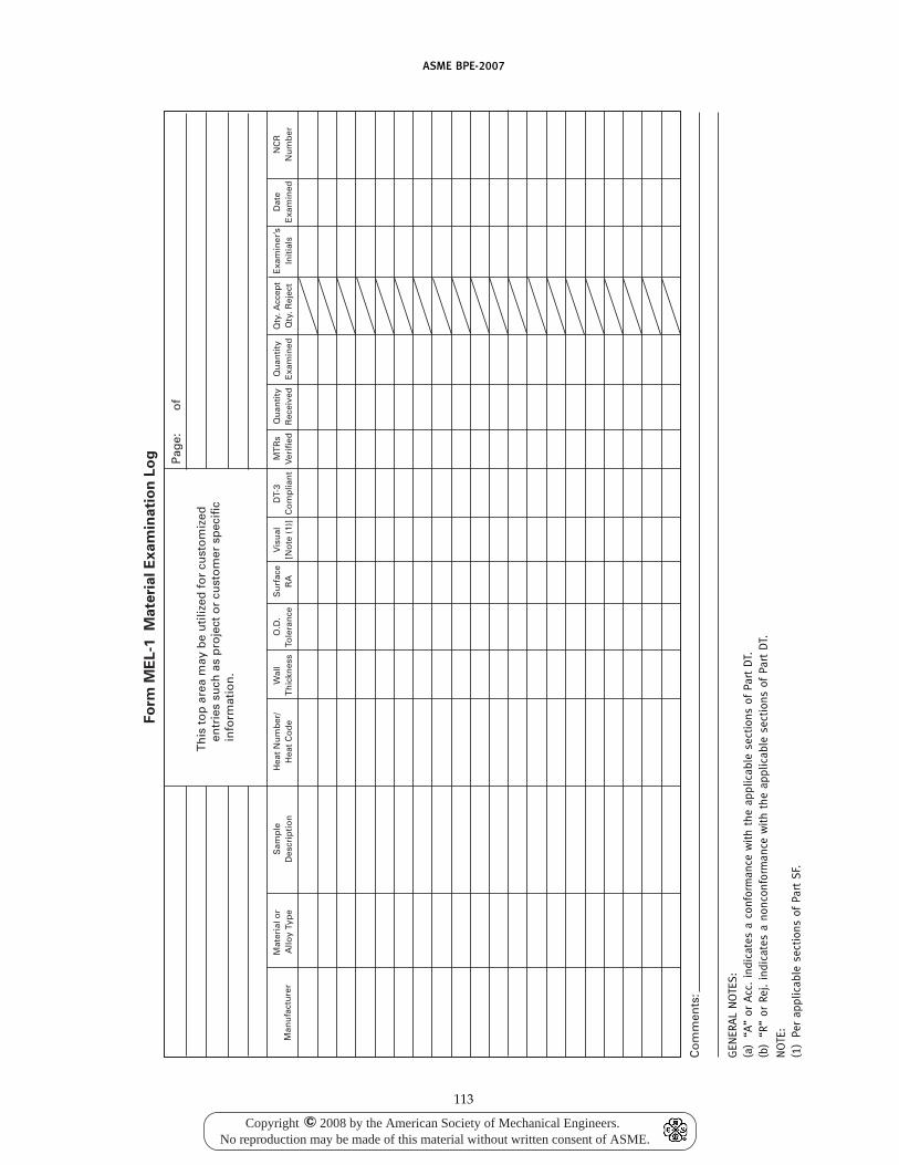
ASME BPE-2007
Fo
rm M
EL-1
M
ate
rial E
xam
inati
on
Lo
g
Co
mm
ents
:
Man
ufa
ctu
rer
Mat
eria
l or
Allo
y Ty
pe
Sam
ple
Des
crip
tio
nH
eat
Nu
mb
er/
Hea
t C
od
eW
all
Th
ickn
ess
O.D
.To
lera
nce
Su
rfac
eR
AV
isu
al[N
ote
(1)
]D
T-3
Co
mp
lian
tM
TR
sVe
rifi
edQ
uan
tity
Rec
eive
dQ
uan
tity
Exa
min
edQ
ty. A
ccep
tQ
ty. R
ejec
tE
xam
iner
’sIn
itia
lsD
ate
Exa
min
edN
CR
Nu
mb
er
Th
is t
op
are
a m
ay b
e u
tiliz
ed f
or
cust
om
ized
en
trie
s su
ch a
s p
roje
ct o
r cu
sto
mer
sp
ecif
ic
info
rmat
ion
.
Pag
e:
o
f
GEN
ERA
LN
OTE
S:
(a)
“A”
orA
cc.
indi
cate
sa
conf
orm
ance
wit
hth
eap
plic
able
sect
ions
ofPa
rtD
T.(b
)“R
”or
Rej.
indi
cate
sa
nonc
onfo
rman
cew
ith
the
appl
icab
lese
ctio
nsof
Part
DT.
NO
TE:
(1)
Per
appl
icab
lese
ctio
nsof
Part
SF.
113
Copyright 2008 by the American Society of Mechanical Engineers.No reproduction may be made of this material without written consent of ASME.
c

ASME BPE-2007
Item
Page: of
Customer company name,
address, contact names,
and number:
Project Information:
Material Specification:
P.O. Number:
Packing List #:
Lot #:
Examiner’s Information:
Manufacturer:
Material/Alloy Type:
Material Description:
Heat Number/Heat Code:
Wall Thickness:
O.D. Tolerance:
Surface RA:
Visual Examination:
MTR Verified:
Quantity Received:
Qty. Accepted:
Qty. Rejected:
Date Inspected:
Comments:
Form MEL-2 Material Examination Log
114
Copyright 2008 by the American Society of Mechanical Engineers.No reproduction may be made of this material without written consent of ASME.
c
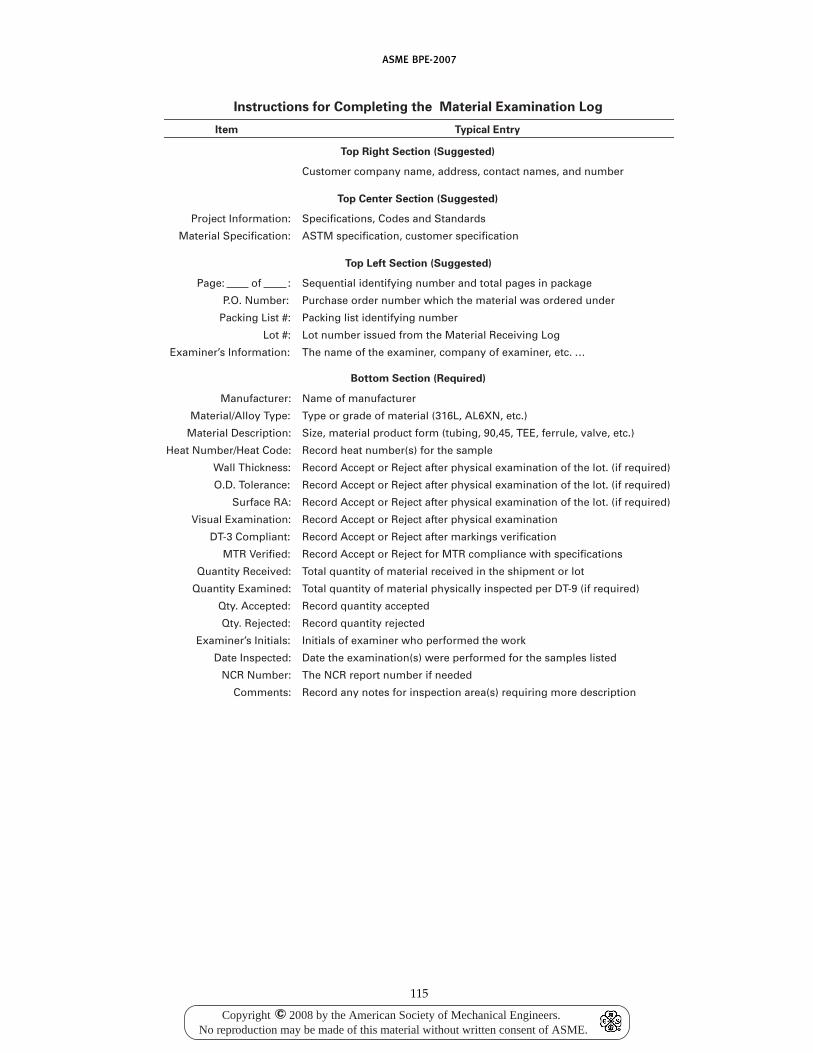
ASME BPE-2007
Item
Customer company name, address, contact names, and number
Project Information:
Material Specification:
Manufacturer:
Material/Alloy Type:
Material Description:
Heat Number/Heat Code:
Wall Thickness:
O.D. Tolerance:
Surface RA:
Visual Examination:
DT-3 Compliant:
MTR Verified:
Quantity Received:
Quantity Examined:
Qty. Accepted:
Qty. Rejected:
Examiner’s Initials:
Date Inspected:
NCR Number:
Comments:
Instructions for Completing the Material Examination Log
Top Right Section (Suggested)
Top Center Section (Suggested)
Specifications, Codes and Standards
ASTM specification, customer specification
Typical Entry
Top Left Section (Suggested)
Sequential identifying number and total pages in package
Purchase order number which the material was ordered under
Packing list identifying number
Lot number issued from the Material Receiving Log
The name of the examiner, company of examiner, etc. ...
Bottom Section (Required)
Name of manufacturer
Type or grade of material (316L, AL6XN, etc.)
Size, material product form (tubing, 90,45, TEE, ferrule, valve, etc.)
Record heat number(s) for the sample
Record Accept or Reject after physical examination of the lot. (if required)
Record Accept or Reject after physical examination of the lot. (if required)
Record Accept or Reject after physical examination of the lot. (if required)
Record Accept or Reject after physical examination
Record Accept or Reject after markings verification
Record Accept or Reject for MTR compliance with specifications
Total quantity of material received in the shipment or lot
Total quantity of material physically inspected per DT-9 (if required)
Record quantity accepted
Record quantity rejected
Initials of examiner who performed the work
Date the examination(s) were performed for the samples listed
The NCR report number if needed
Record any notes for inspection area(s) requiring more description
Page: of :
P.O. Number:
Packing List #:
Lot #:
Examiner’s Information:
115
Copyright 2008 by the American Society of Mechanical Engineers.No reproduction may be made of this material without written consent of ASME.
c
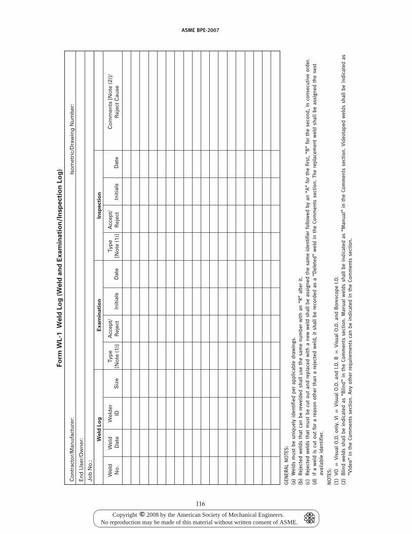
ASME BPE-2007
Fo
rm W
L-1
W
eld
Lo
g (
We
ld a
nd
Ex
am
ina
tio
n/I
nsp
ecti
on
Lo
g)
Wel
dN
o.
Wel
d
Dat
eW
eld
erID
Siz
eTy
pe
[No
te (
1)]
Acc
ept/
Rej
ect
Init
ials
Dat
eTy
pe
[No
te (
1)]
Acc
ept/
Rej
ect
Init
ials
Dat
eC
om
men
ts [
No
te (
2)]/
Rej
ect
Cau
se
Co
ntr
acto
r/M
anu
fact
ure
r:Is
om
etri
c/D
raw
ing
Nu
mb
er:
En
d U
ser/
Ow
ner
:
Job
No
.:
We
ld L
og
Ex
am
ina
tio
nIn
sp
ecti
on
GEN
ERA
LN
OTE
S:
(a)
Wel
dsm
ust
beun
ique
lyid
enti
fied
per
appl
icab
ledr
awin
gs.
(b)
Reje
cted
wel
dsth
atca
nbe
rew
elde
dsh
all
use
the
sam
enu
mbe
rw
ith
an“R
”af
ter
it.
(c)
Reje
cted
wel
dsth
atm
ust
becu
tou
tan
dre
plac
edw
ith
ane
ww
eld
shal
lbe
assi
gned
the
sam
eid
enti
fier
follo
wed
byan
“A”
for
the
first
,“B
”fo
rth
ese
cond
,in
cons
ecut
ive
orde
r.(d
)If
aw
eld
iscu
tou
tfo
ra
reas
onot
her
than
are
ject
edw
eld,
itsh
all
bere
cord
edas
a“D
elet
ed”
wel
din
the
Com
men
tsse
ctio
n.Th
ere
plac
emen
tw
eld
shal
lbe
assi
gned
the
next
avai
labl
eid
enti
fier.
NO
TES
:(1
)VO
pVi
sual
O.D
.on
ly.
VIp
Visu
alO
.D.
and
I.D.
Bp
Visu
alO
.D.
and
Bor
esco
peI.D
.(2
)B
lind
wel
dssh
all
bein
dica
ted
as“B
lind”
inth
eC o
mm
ents
sect
ion.
Man
ual
wel
dssh
all
bein
dica
ted
as“M
anua
l”in
the
Com
men
tsse
ctio
n.Vi
deot
aped
wel
dssh
all
bein
dic a
ted
as“V
ideo
”in
the
Com
men
tsse
ctio
n.A
nyot
her
requ
irem
ents
can
bein
dica
ted
inth
eCo
mm
ents
sect
ion.
116
Copyright 2008 by the American Society of Mechanical Engineers.No reproduction may be made of this material without written consent of ASME.
c
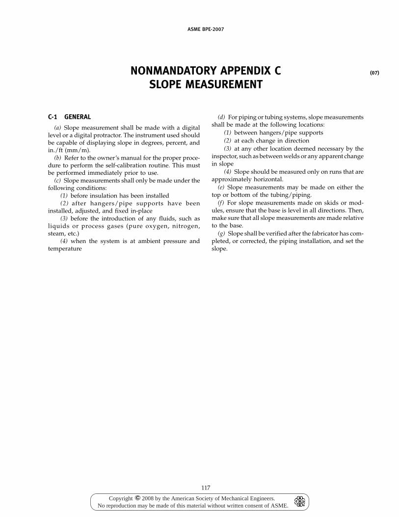
ASME BPE-2007
NONMANDATORY APPENDIX CSLOPE MEASUREMENT
C-1 GENERAL
(a) Slope measurement shall be made with a digitallevel or a digital protractor. The instrument used shouldbe capable of displaying slope in degrees, percent, andin./ft (mm/m).
(b) Refer to the owner’s manual for the proper proce-dure to perform the self-calibration routine. This mustbe performed immediately prior to use.
(c) Slope measurements shall only be made under thefollowing conditions:
(1) before insulation has been installed(2) after hangers/pipe supports have been
installed, adjusted, and fixed in-place(3) before the introduction of any fluids, such as
liquids or process gases (pure oxygen, nitrogen,steam, etc.)
(4) when the system is at ambient pressure andtemperature
117
(d) For piping or tubing systems, slope measurementsshall be made at the following locations:
(1) between hangers/pipe supports(2) at each change in direction(3) at any other location deemed necessary by the
inspector, such as between welds or any apparent changein slope
(4) Slope should be measured only on runs that areapproximately horizontal.
(e) Slope measurements may be made on either thetop or bottom of the tubing/piping.
(f) For slope measurements made on skids or mod-ules, ensure that the base is level in all directions. Then,make sure that all slope measurements are made relativeto the base.
(g) Slope shall be verified after the fabricator has com-pleted, or corrected, the piping installation, and set theslope.
(07)
Copyright 2008 by the American Society of Mechanical Engineers.No reproduction may be made of this material without written consent of ASME.
c

(07)
ASME BPE-2007
INDEX
Acceptance criteria, MJ-6, MJ-7.2.3, Fig. MJ-1, TableMJ-1, Table MJ-2, Table MJ-3, Table MJ-4,Table SF-1, Table SF-2
Annealing, GR-10Arc strike, GR-10Arc welding processes, MJ-3.1Autogenous weld, GR-10Automatic welding, GR-10, MJ-3.2, MJ-4.4, MJ-7.2.3
Barrier fluid, SG-3.5.2, SG-3.5.3.2, SG-3.5.6.2, Fig. SG-5Bioburden, SG-3.1.3Biocompatibility, SG-3.3.1Blind welds, SD-3.5.3, MJ-7.2.3Borescope/Borescopic examination, MJ-6.4, MJ-7.2.3,
MJ-7.4, SF-5(a)Burn-through, GR-10Butt weld/joint, GR-10, SD-3.7.1, SD-4.7.4(a),
SD-4.7.5(a), Fig. SD-19, illustration (a), Fig. SD-20,illustration (a), MJ-4.4
Cartridge seal, SG-3.5.4Cavitation — seal, SG-3.1.4Certification of Compliance, SG-3.4.1, MJ-10.1(a)(3)Classification, SF-5Cleaning — seals, SG-3.1.6Clean-in-place, GR-10, SG-3.2.1Clean-out-of-place, SG-3.2.1Cluster porosity, GR-10Complete weld penetration, MJ-4.1Concavity, GR-10, Fig. MJ-1, illustrations (c) and (d),
Table MJ-1, Table MJ-2, Table MJ-3, Table MJ-4Consumable insert, GR-10, MJ-5Continuous weld, Fig. SD-18, illustration (d)Convexity, GR-10, Fig. MJ-1, illustration (f), Table
MJ-1, Table MJ-2, Table MJ-3, Table MJ-4Corrosion resistance — seal, SG-3.2.2, SG-3.3.1Cracks, GR-10, MJ-6.1Crater, GR-10Crater cracks, GR-10Crevices, SG-3.3.2
Dead spaces, SG-3.3.3Defects, GR-10Diaphragm, SG-2.2, SG-4.1.1.2, SG-4.1.1.7Direct visual inspection, MJ-7.2.3Discoloration, GR-10, PM-3.4.1.6Discontinuity(ies), GR-10, MJ-6.1Documentation, MJ-10Double seals, SG-3.5.3.2, SG-3.5.6.2Downslope, GR-10Dross, GR-10
118
Dual seals, SG-3.5.3.2, SG-3.5.6.2Dynamic seal, SG-4.1
Electron beam welding, MJ-3.1, MJ-3.2Examination/examiner, GR-4, MJ-7
Fabricated components with welds, DT-2Fabrication, SD-3.5
fittings, Fig. SD-19, DT-2heat exchangers, SD-4.9hubs, SD-4.8.4impellers, SD-4.8.4, SD-4.8.5keyways, SD-4.8.3pads, plates, SD-4.7.1(d)piping/pipes, SD-3.11.6, Part MJpressure vessels, SD-4.7.1(b), Part MJpumps, SD-4.5.2(a)tanks, SD-4.7.1(a), Part MJtubing/tubes, Part MJvalves, SD-3.11.5, SD-4.6.1(a)
Field welding, SD-3.5.1Filler material/metal, MJ-5, MJ-8.3(b)Fit-up, PM-3.4.1.4Full penetration, GR-10, Fig. SD-19, illustration (c)Fusion, GR-10Fusion welding, GR-10
Gas tungsten-arc welding (GTAW), GR-10, MJ-3.2General provisions for seals, SG-3
Heat-affected zone, GR-10High energy beam processes, MJ-3.1, MJ-3.2Hydrostatic testing, MJ-7.5.2, MJ-7.5.3
Icicles, GR-10Incomplete fusion, GR-10, MJ-6.4.2(b)Incomplete penetration, GR-10, MJ-6.4.2(a), Fig. MJ-1,
illustration (e), Table MJ-1, Table MJ-2, TableMJ-3, Table MJ-4
Indication, GR-10Inert-gas welding processes, MJ-3.2Inserts, see consumable insertInspection/inspector, GR-3, GR-4, MJ-7, SF-5
Joint penetration, GR-10
Labyrinth seal, SG-3.5.6.3(c)Lack of fusion, see incomplete fusionLack of fusion after reflow, GR-10Lack of penetration, see incomplete penetrationLaminations, GR-10Lap joint welds, SD-4.7.4(a)Laser beam welding, MJ-3.1, MJ-3.2
Copyright 2008 by the American Society of Mechanical Engineers.No reproduction may be made of this material without written consent of ASME.
c

ASME BPE-2007
Lathe welding, MJ-4.4Leakage rate — seal, SG-3.1.2, SG-4.1.1.6, SG-4.1.1.8Linear porosity, GR-10Lip seal, SG-3.5.6.3(b)Liquid penetrant examination, MJ-7.2.1, MJ-7.2.3Lubricated seals, SG-3.5.2
Machine welding, GR-10, MJ-3.2, MJ-4.4, MJ-7.2.3Manual welding, GR-10, MJ-4.4Material Test Reports (MTRs), MJ-10.1(a)(1), MJ-10.2.2Materials of construction — seal, SG-3.3.1, SG-3.5.5,
SG-4.1.1.6, Table SG-1Mechanical seal, SG-2.1Misalignment (mismatch), GR-10, MJ-6.1, Fig. MJ-1,
illustration (b), PM-3.4.1.4Multiple seals, SG-2.3
Nonsliding seal, SG-4.1.1.2
Orbital (tube) welding, GR-10, MJ-4.4O-ring seal, SG-2.1, SG-4.1.1.4Outboard seal, SG-3.5.6.2Outside diameter, DT-6, DT-8Overlap, GR-10
Packing, SG-2.1, SG-3.5.6.3Particle generation — seal, SG-3.3.1Passivation, SG-3.1.7, MJ-11Performance — seal, SG-3.1Permeation resistance, SG-3.3.1Personnel (examination), MJ-7.2.1, MJ-7.2.2, MJ-7.2.3Plasma arc welding, MJ-3.2Pneumatic testing, MJ-7.5.2, MJ-7.5.3Porosity, GR-10, MJ-6.1, Table SF-1Primary stem seal, SG-4.1.1.1(a)Procedure Qualification Record (PQR), MJ-10.1(b)(2)Purge gas, MJ-4.1, MJ-8.3(a)
Radiographic examination, MJ-7.2.1, MJ-7.2.3Random examination/inspection, MJ-7.2.3Records, MJ-7.6Reflow, GR-10, MJ-6.4.2Reinforcement, GR-10Rewelding, MJ-6.4.2Rotary seal, SG-3.5.6.3
Sample welds, MJ-7.2.3Seal arrangements, SG-3.5.3Seal classes, SG-2Seal weld, GR-10, SD-4.9.1(g)(2)Secondary stem seal, SG-4.1.1.1(b)Section IX, Part MJSemi-automatic arc welding, GR-10Service pressure — seal, SG-3.1.2Service temperature — seal, SG-3.1.1Single seal, SG-3.5.3.1, SG-3.5.6.1Slag, GR-10, Table SF-1Sliding seal, SG-4.1.1.2Socket welds, Fig. SD-3, illustration (f), MJ-4.1
119
Spatter, GR-10Special method examinations, MJ-7.2.2Square butt joints, MJ-4.4Steam-in-place, SG-3.2.2(a)Sterilization procedure, SG-3.1.5Stitch weld (intermittent weld), Fig. SD-18,
illustration (e)Suckback, Fig. MJ-1, illustration (d), see also concavitySupplementary examinations, MJ-7.2.3, MJ-7.4Surface finish, GR-10, SG-3.3.1(d), SG-3.5.5, SF-1, SF-2,
SF-5, SF-6
Tandem seals, SG-3.5.3.2(b), SG-3.5.6.2(b)Testing, MJ-7.5Tungsten inclusions, GR-10
Ultrasonic examination, MJ-7.2.1, MJ-7.2.3Undercut, GR-10Underfill, GR-10Uniformly scattered porosity, GR-10
Visual examination, MJ-7.2.1, MJ-7.2.2, MJ-7.2.3,SF-5(a)
Voids, MJ-6.1
Wall thickness, DT-5, DT-6, DT-8Weld acceptance criteria, MJ-6Weld and finish samples, MJ-2.6Weld bead meander, Fig. MJ-1, illustration (i)Weld fittings, SD-3.7, Fig. SD-19, Part DTWeld inspection log, MJ-10.1(c)(3), MJ-10.3, Form
WL-1Weld joint design, GR-10Weld maps, MJ-10.1(c)(1)Weld marks, SD-3.8(d)Weld neck flanges, Fig. SD-3, illustration (d),
SD-4.7.4(b)Weld penetration, MJ-4.1, MJ-6.4.2Weld profiles, Fig. MJ-1Weld seam, SD-5.4Weld width, MJ-6.4.1, Fig. MJ-1, illustrations (g) and
(h)Welded connections, SD-3.11.5Welded product contact surfaces, SD-4.7.5(b)Welder identification, MJ-10.1Welder Performance Qualification (WPQ), MJ-9,
MJ-10.1(b)(3)Welding dissimilar materials, SD-4.7.1(d)Welding ends, DT-8, DT-9Welding operator, GR-10Welding Operator Performance Qualification (WOPQ),
MJ-9, MJ-10.1(b)(4)Welding Procedure Specification (WPS), MJ-10.1(b)(1)Welding procedures, SD-6, MJ-3.2, MJ-6.1, MJ-8Welding wire, MJ-5
Copyright 2008 by the American Society of Mechanical Engineers.No reproduction may be made of this material without written consent of ASME.
c

ASME Services
ASME is committed to developing and delivering technical information. At ASME’s Information Central, we make everyeffort to answer your questions and expedite your orders. Our representatives are ready to assist you in the followingareas:
ASME Press Member Services & Benefits Public InformationCodes & Standards Other ASME Programs Self-Study CoursesCredit Card Orders Payment Inquiries Shipping InformationIMechE Publications Professional Development Subscriptions/Journals/MagazinesMeetings & Conferences Short Courses Symposia VolumesMember Dues Status Publications Technical Papers
How can you reach us? It’s easier than ever!
There are four options for making inquiries* or placing orders. Simply mail, phone, fax, or E-mail us and an InformationCentral representative will handle your request.
Mail Call Toll Free Fax—24 hours E-Mail—24 hoursASME US & Canada: 800-THE-ASME 973-882-1717 [email protected] Law Drive, Box 2900 (800-843-2763) 973-882-5155Fairfield, New Jersey Mexico: 95-800-THE-ASME07007-2900 (95-800-843-2763)
Universal: 973-882-1167
* Information Central staff are not permitted to answer inquiries about the technical content of this code or standard. Information as towhether or not technical inquiries are issued to this code or standard is shown on the copyright page. All technical inquiries must besubmitted in writing to the staff secretary. Additional procedures for inquiries may be listed within.
Copyright 2008 by the American Society of Mechanical Engineers.No reproduction may be made of this material without written consent of ASME.
c

A14307
ASME BPE-2007
Copyright 2008 by the American Society of Mechanical Engineers.No reproduction may be made of this material without written consent of ASME.
c