4 equipment - in.gov
TRANSCRIPT
4 Equipment Concrete Plants Central Mix Plant Ready-Mix Plant Delivery Equipment Paving Equipment Finishing Machine Spreader Slip-Form Pavers Hand Placement Equipment Tining Machine Vibrators Hand Equipment 10 ft Staightedge Tining Hand-Held Vibrators Saws Forms

4-1
CHAPTER FOUR: EQUIPMENT
The importance of having the proper equipment to do the job correctly and efficiently can not be overstated, especially for construction of concrete pavements. This chapter discusses concrete equipment that has a profound effect on the quality of the final pavement.
CONCRETE PLANTS
INDOT categorizes concrete plants as captive plants or commercial plants. Captive plants, sometimes known as portable plants, are usually temporary and are used primarily to produce concrete for a specific INDOT contract. When the contract is completed, the plant is disassembled and moved. Commercial plants are permanent installations and may serve many customers. Concrete plants are inspected and certified by the District Testing. Commercial plants are inspected once a year. Captive plants are inspected at the beginning of each construction season and whenever they are moved to a new location. A concrete plant is made up of several components. These include bins for the cement (and fly ash, if used), weighing hoppers, scales for the fine and coarse aggregates, admixture dispensers, and material conveyors. Before the concrete is produced, the plant Technician is required to verify that all scales are balanced and that all conveyors and hoppers are generally clean and free of foreign materials. Most concrete plants today are operated by the use of computers. The plant operator has a computer card for each mix. When the card is placed into the computer, each material is dropped or conveyed to the scales automatically, one at time. The plant Technician is required to observe the scales for accuracy as each material is weighed. Central mix plants and ready-mix plants are the two types of plants used to supply pavement concrete.

4-2
CENTRAL MIX PLANT
Central mix plants (Figure 4-1) are normally mobile units that are located at large quantity work sites; however, more and more of these types of plants are being placed at permanent locations. A central mix plant proportions and mixes the concrete in the plant. Mixing is required to be no less than 60 seconds for each batch. When using a transit mixer for additional mixing, the mixing time in the central mix plant may be reduced to approximately 30 seconds. The freshly mixed concrete is deposited into trucks for delivery. The delivery truck from a central mix plant does not need to provide any further mixing of the concrete, unless a transit mixer is used.
Figure 4-1. Central Mix Plant and Agitator Truck
READY-MIX PLANT
The second type of plant used is the ready-mix plant (Figure 4-2). Ready-mix concrete plants are the types of plants used most commonly on INDOT contracts and are referred to as "commercial plants". Ready-mix plants batch the ingredients into a truck-mixer and the revolving drum on the truck mixes the ingredients.
4-3
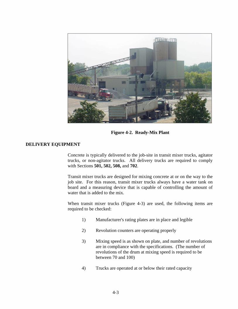
Figure 4-2. Ready-Mix Plant
DELIVERY EQUIPMENT
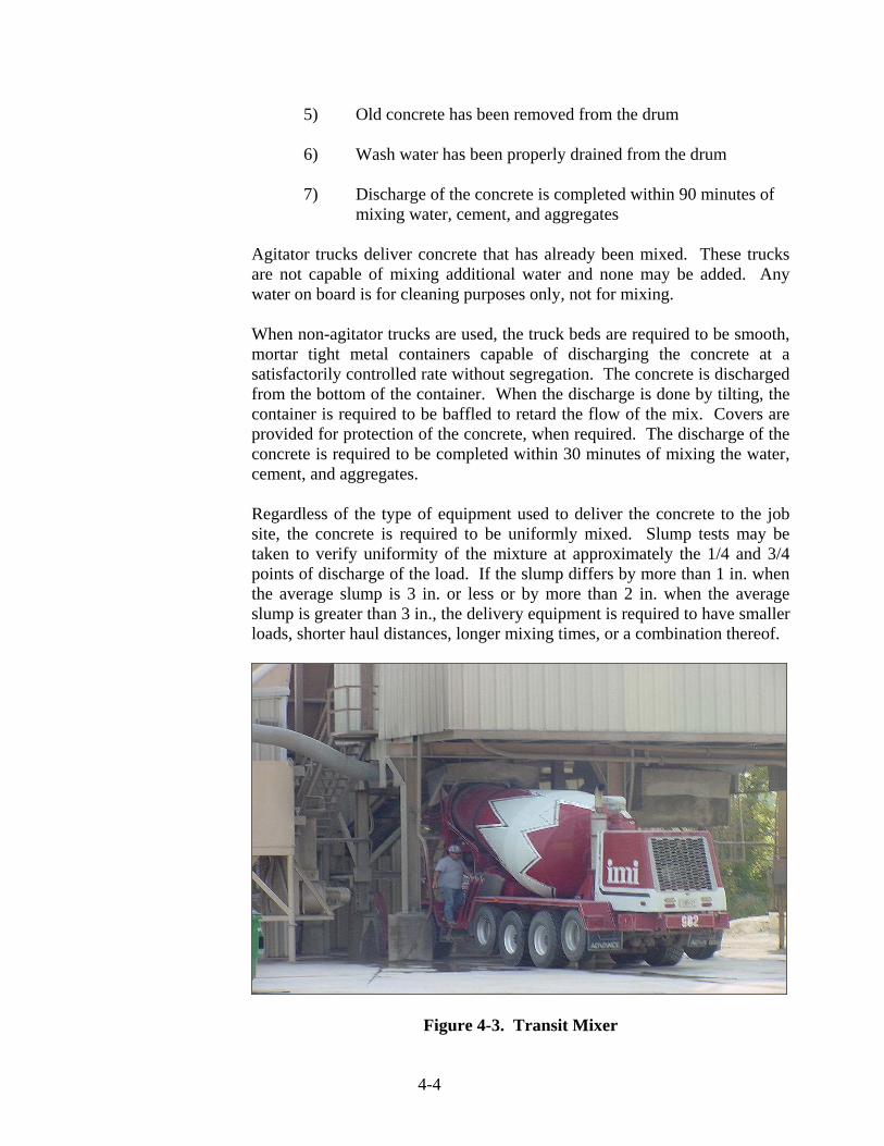
Concrete is typically delivered to the job-site in transit mixer trucks, agitator trucks, or non-agitator trucks. All delivery trucks are required to comply with Sections 501, 502, 508, and 702. Transit mixer trucks are designed for mixing concrete at or on the way to the job site. For this reason, transit mixer trucks always have a water tank on board and a measuring device that is capable of controlling the amount of water that is added to the mix. When transit mixer trucks (Figure 4-3) are used, the following items are required to be checked:
1) Manufacturer's rating plates are in place and legible 2) Revolution counters are operating properly 3) Mixing speed is as shown on plate, and number of revolutions
are in compliance with the specifications. (The number of revolutions of the drum at mixing speed is required to be between 70 and 100)
4) Trucks are operated at or below their rated capacity
4-4
5) Old concrete has been removed from the drum 6) Wash water has been properly drained from the drum 7) Discharge of the concrete is completed within 90 minutes of
mixing water, cement, and aggregates
Agitator trucks deliver concrete that has already been mixed. These trucks are not capable of mixing additional water and none may be added. Any water on board is for cleaning purposes only, not for mixing. When non-agitator trucks are used, the truck beds are required to be smooth, mortar tight metal containers capable of discharging the concrete at a satisfactorily controlled rate without segregation. The concrete is discharged from the bottom of the container. When the discharge is done by tilting, the container is required to be baffled to retard the flow of the mix. Covers are provided for protection of the concrete, when required. The discharge of the concrete is required to be completed within 30 minutes of mixing the water, cement, and aggregates. Regardless of the type of equipment used to deliver the concrete to the job site, the concrete is required to be uniformly mixed. Slump tests may be taken to verify uniformity of the mixture at approximately the 1/4 and 3/4 points of discharge of the load. If the slump differs by more than 1 in. when the average slump is 3 in. or less or by more than 2 in. when the average slump is greater than 3 in., the delivery equipment is required to have smaller loads, shorter haul distances, longer mixing times, or a combination thereof.
Figure 4-3. Transit Mixer
4-5
PAVING EQUIPMENT FINISHING MACHINE
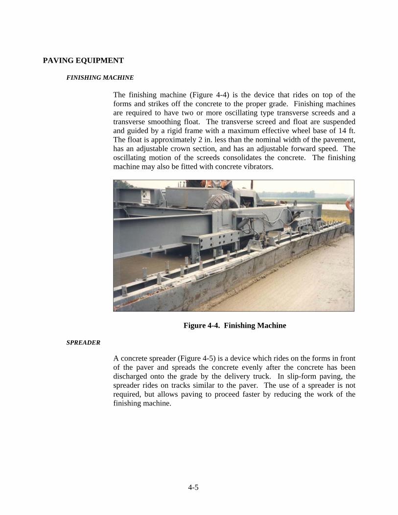
The finishing machine (Figure 4-4) is the device that rides on top of the forms and strikes off the concrete to the proper grade. Finishing machines are required to have two or more oscillating type transverse screeds and a transverse smoothing float. The transverse screed and float are suspended and guided by a rigid frame with a maximum effective wheel base of 14 ft. The float is approximately 2 in. less than the nominal width of the pavement, has an adjustable crown section, and has an adjustable forward speed. The oscillating motion of the screeds consolidates the concrete. The finishing machine may also be fitted with concrete vibrators.
Figure 4-4. Finishing Machine
SPREADER
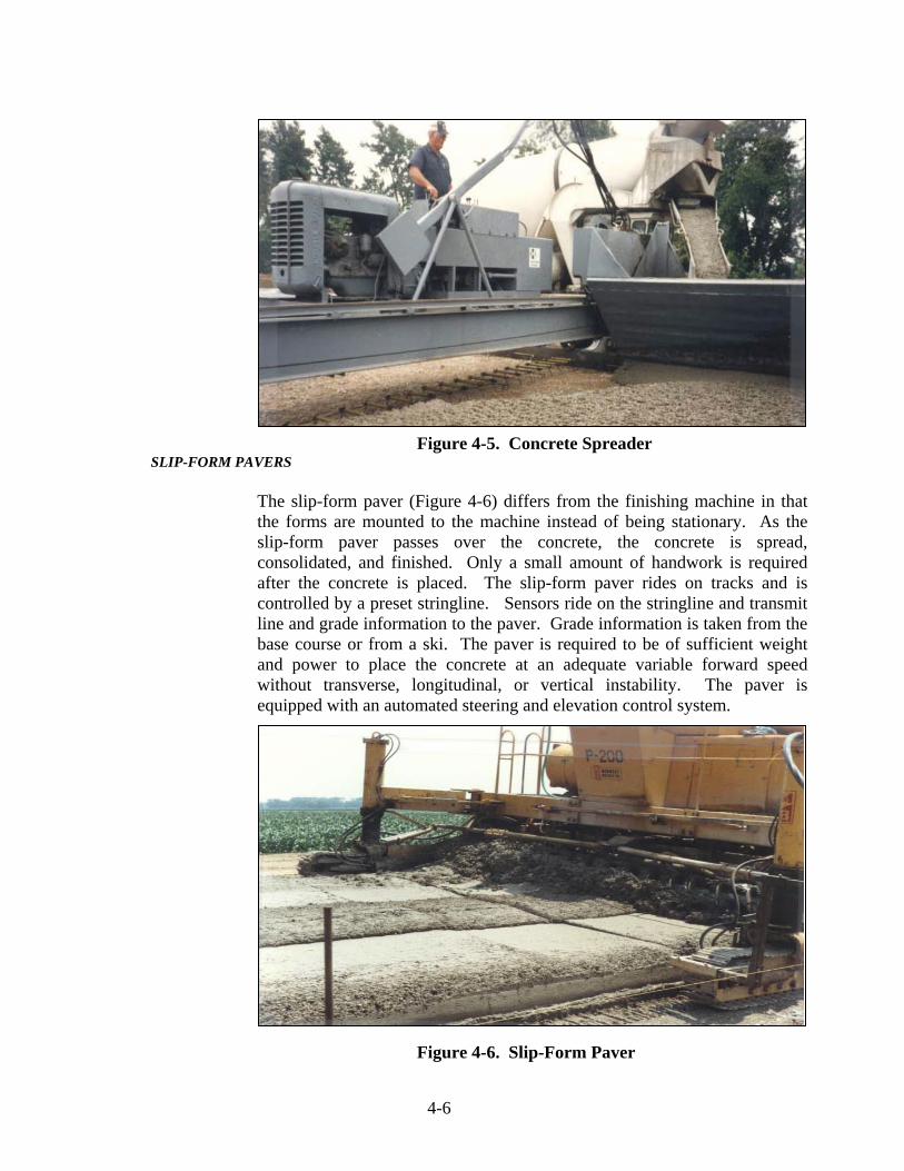
A concrete spreader (Figure 4-5) is a device which rides on the forms in front of the paver and spreads the concrete evenly after the concrete has been discharged onto the grade by the delivery truck. In slip-form paving, the spreader rides on tracks similar to the paver. The use of a spreader is not required, but allows paving to proceed faster by reducing the work of the finishing machine.
4-6
Figure 4-5. Concrete Spreader SLIP-FORM PAVERS
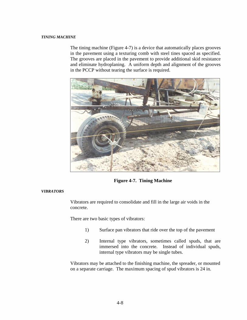
The slip-form paver (Figure 4-6) differs from the finishing machine in that the forms are mounted to the machine instead of being stationary. As the slip-form paver passes over the concrete, the concrete is spread, consolidated, and finished. Only a small amount of handwork is required after the concrete is placed. The slip-form paver rides on tracks and is controlled by a preset stringline. Sensors ride on the stringline and transmit line and grade information to the paver. Grade information is taken from the base course or from a ski. The paver is required to be of sufficient weight and power to place the concrete at an adequate variable forward speed without transverse, longitudinal, or vertical instability. The paver is equipped with an automated steering and elevation control system.
Figure 4-6. Slip-Form Paver

4-7
The slip-form paver is required to be equipped with vibrators capable of vibrating the entire depth and width of the pavement. The paver also is required to be equipped with forms long enough to prevent an edge slump of greater than 3/8 inch from a typical section. If the edge is joined by another pavement, the edge slump may not exceed 1/4 inch. If these requirements cannot be met, additional trailing forms are required to support the plastic concrete for a longer period of time. Mechanical tie bar inserters are required to be rigidly attached to the slip-form paver and may be controlled manually or automatically. The mechanical belt, if used, has a deflector plate mounted on the end of the discharge belt to recombine the concrete. Because the slip-form paver does all the forming of the pavement, the paver should be stopped only when absolutely necessary. When stopped, the paver may leave a slight imperfection in the pavement. All vibrators and tampers should be turned off immediately, if the paver is stopped.
HAND PLACEMENT EQUIPMENT
Hand placement equipment is required to produce a uniform surface that is free of voids and meets the specified smoothness. The mechanical tube finisher, vibratory screed finisher, and mechanical bridge deck finisher are three types of hand placement equipment that are used. A mechanical tube finisher consists of single or multiple rotating strike-off/finish tubes setting approximately transverse to the longitudinal movement of the machine. The length of the finish tubes is required to be a minimum of 2 ft longer than the planned PCCP width. The forward speed of the machine and the rate of the finish tube rotation are required to be variable and reversible to allow for multiple finish passes. A vibratory screed finisher consists of a truss frame with a minimum base width of 1 ft, which extends across the transverse width of the PCCP. The frame is required to extend 2 ft beyond the width of the PCCP and hold the shape of the frame when moved forward. The screed moves forward with either hydraulic or manual wenches, which are capable of maintaining the screed at a right angle to the direction of travel. The screed vibrates when moving forward, and the vibration is required to stop when the forward motion ceases. Vibration is accomplished with mechanical driven eccentric weights or with auxiliary driven pneumatic vibrators. A mechanical bridge deck finishing machine consists of single or multiple rotating cylinders setting approximately parallel to the longitudinal movement of the machine and operated transversely. The forward motion of the machine and the transverse movement of the finish cylinders is required to be variable.
4-8
TINING MACHINE
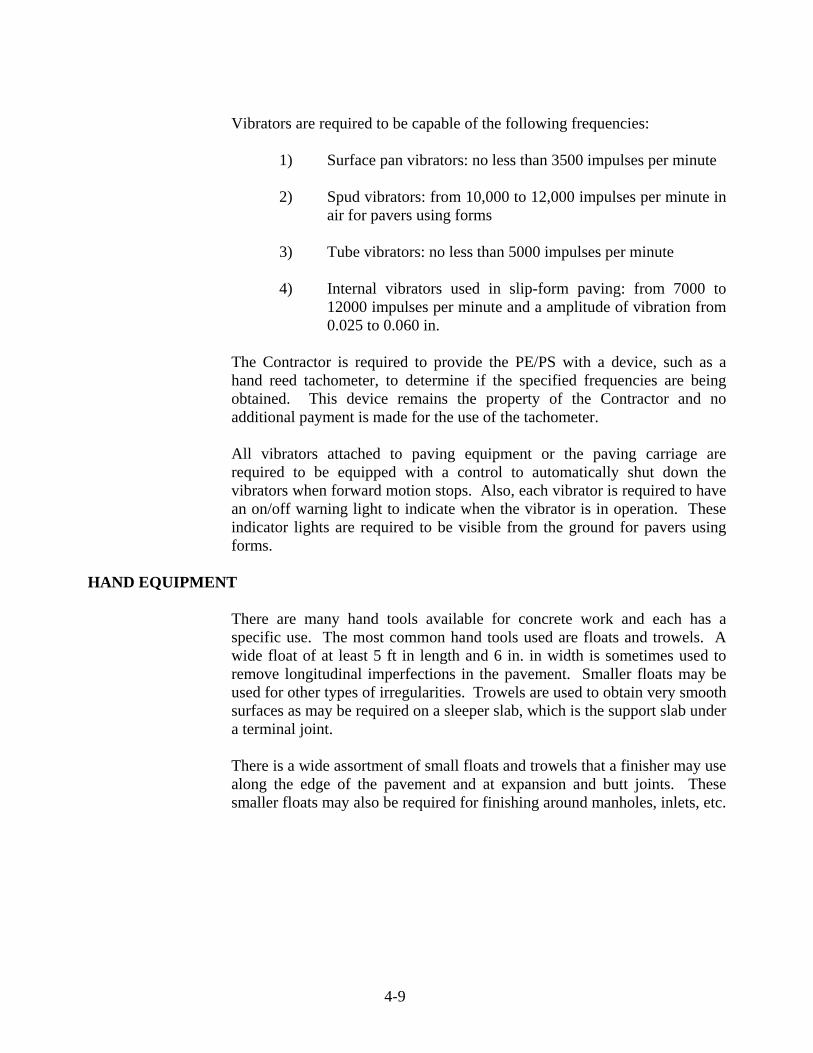
The tining machine (Figure 4-7) is a device that automatically places grooves in the pavement using a texturing comb with steel tines spaced as specified. The grooves are placed in the pavement to provide additional skid resistance and eliminate hydroplaning. A uniform depth and alignment of the grooves in the PCCP without tearing the surface is required.
Figure 4-7. Tining Machine
VIBRATORS
Vibrators are required to consolidate and fill in the large air voids in the concrete.
There are two basic types of vibrators:
1) Surface pan vibrators that ride over the top of the pavement 2) Internal type vibrators, sometimes called spuds, that are
immersed into the concrete. Instead of individual spuds, internal type vibrators may be single tubes.
Vibrators may be attached to the finishing machine, the spreader, or mounted on a separate carriage. The maximum spacing of spud vibrators is 24 in.
4-9
Vibrators are required to be capable of the following frequencies:
1) Surface pan vibrators: no less than 3500 impulses per minute 2) Spud vibrators: from 10,000 to 12,000 impulses per minute in
air for pavers using forms 3) Tube vibrators: no less than 5000 impulses per minute 4) Internal vibrators used in slip-form paving: from 7000 to
12000 impulses per minute and a amplitude of vibration from 0.025 to 0.060 in.
The Contractor is required to provide the PE/PS with a device, such as a hand reed tachometer, to determine if the specified frequencies are being obtained. This device remains the property of the Contractor and no additional payment is made for the use of the tachometer. All vibrators attached to paving equipment or the paving carriage are required to be equipped with a control to automatically shut down the vibrators when forward motion stops. Also, each vibrator is required to have an on/off warning light to indicate when the vibrator is in operation. These indicator lights are required to be visible from the ground for pavers using forms.
HAND EQUIPMENT
There are many hand tools available for concrete work and each has a specific use. The most common hand tools used are floats and trowels. A wide float of at least 5 ft in length and 6 in. in width is sometimes used to remove longitudinal imperfections in the pavement. Smaller floats may be used for other types of irregularities. Trowels are used to obtain very smooth surfaces as may be required on a sleeper slab, which is the support slab under a terminal joint. There is a wide assortment of small floats and trowels that a finisher may use along the edge of the pavement and at expansion and butt joints. These smaller floats may also be required for finishing around manholes, inlets, etc.

4-10
10 ft STRAIGHTEDGE
A 10 foot straightedge (Figure 4-8) with a handle 3 ft longer than one-half of the width of the pavement is used last to remove any longitudinal imperfections or surplus water from the surface.
Figure 4-8. 10 ft. Straightedge
TINING
Final finishing may be done by brooming or tining. Brooming is a method that was widely used in the past where a large push broom was pulled transversely across the pavement to give the pavement texture. This method is only used if specified.
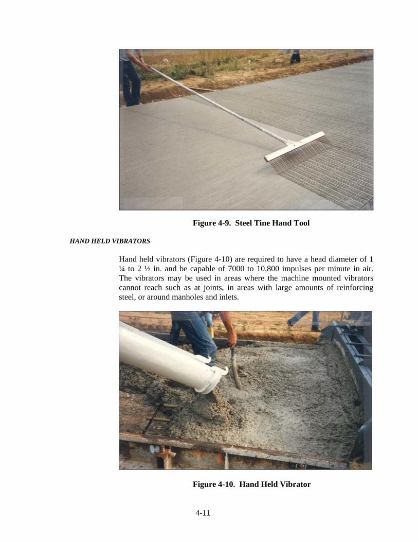
Tining is now the required method for final finishing. This procedure is normally done with a power driven tining device, which makes uniform transverse grooves in the plastic concrete. A hand tool with steel tines (Figure 4-9) may be used on ramps, connections, and other miscellaneous areas where the mechanical groover is not practical.
4-11
Figure 4-9. Steel Tine Hand Tool
HAND HELD VIBRATORS
Hand held vibrators (Figure 4-10) are required to have a head diameter of 1 ¼ to 2 ½ in. and be capable of 7000 to 10,800 impulses per minute in air. The vibrators may be used in areas where the machine mounted vibrators cannot reach such as at joints, in areas with large amounts of reinforcing steel, or around manholes and inlets.
Figure 4-10. Hand Held Vibrator
4-12
SAWS
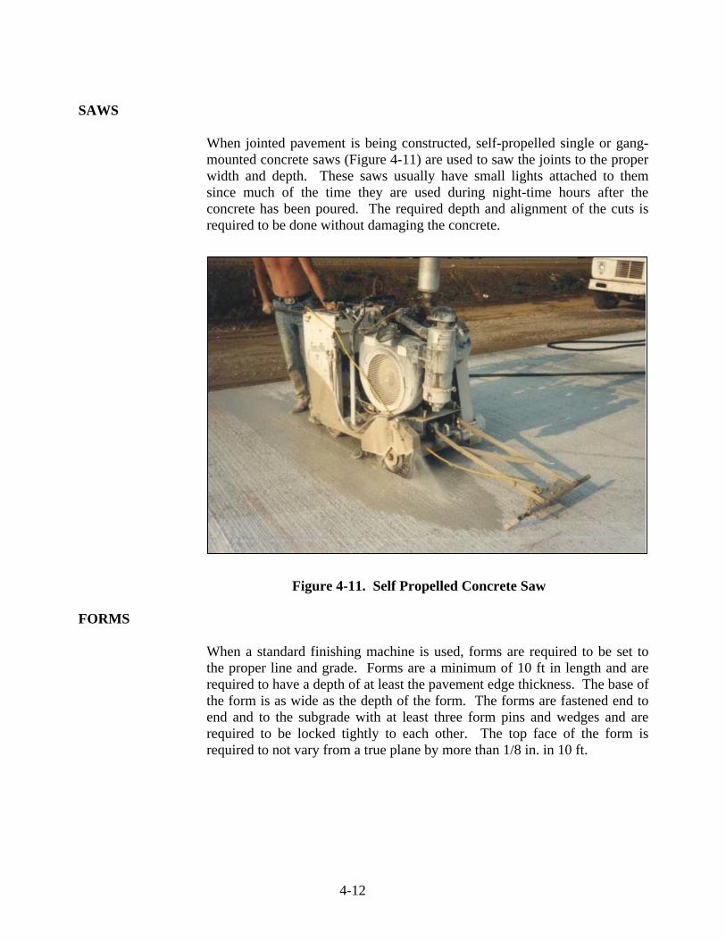
When jointed pavement is being constructed, self-propelled single or gang-mounted concrete saws (Figure 4-11) are used to saw the joints to the proper width and depth. These saws usually have small lights attached to them since much of the time they are used during night-time hours after the concrete has been poured. The required depth and alignment of the cuts is required to be done without damaging the concrete.
Figure 4-11. Self Propelled Concrete Saw FORMS
When a standard finishing machine is used, forms are required to be set to the proper line and grade. Forms are a minimum of 10 ft in length and are required to have a depth of at least the pavement edge thickness. The base of the form is as wide as the depth of the form. The forms are fastened end to end and to the subgrade with at least three form pins and wedges and are required to be locked tightly to each other. The top face of the form is required to not vary from a true plane by more than 1/8 in. in 10 ft.