bfw-tcm-x3 customer refernece no: xxxxxx bfw-tcm-x3 rear axle milling machine with siemens 840d sl...
TRANSCRIPT
BFW-TCM-X3 ELECTRICAL MANUAL
Operation and Maintenance Manual
CUSTOMER REFERNECE NO: xxxxxx
BFW-TCM-X3 REAR AXLE MILLING MACHINE
WITH SIEMENS 840D SL
OPERATOR AND MAINTENANCE MANUAL
Bharat Fritz Werner Limited Machine Tool Manufacturers
Registered Office: Bangalore-560022, India
E-mail:[email protected] Telephone: 0091 (80) 39821100
Machine Operation and MaintenancePage 1
BFW-TCM-X3 ELECTRICAL MANUAL
Operation and Maintenance Manual
URL: www.bfwindia.com Fax: 0091 (80) 28394816
This manual provides essential information and safety precautions necessary for proper operation, adjustment, maintenance and installation of machine. It also describes CNC operation, MDI, Programming steps, alarm messages, parameter settings etc.Please read this manual carefully and thoroughly prior to the operation of this machine to ensure safety, efficiency and reliable performance of the machine for several years.
Also refer to Operator’s Manual, Maintenance Manual, Connecting Manual and Parameter Manuals of CNC for information concerning programming and automatic operation, etc. Refer to the electrical circuit diagram (#29042851) manual for details on electrical circuits.
NEVER OPERATE THE MACHINE WITHOUT READING THIS OPERATION MANUAL CAREFULLY IN ORDER TO GET THOROUGHLY ACQUAINTED WITH THE CAPABILITIES, FUNCTIONS AND SAFETY PROVISIONS OF THIS MACHINE.
BE SURE TO MAKE THIS MANUAL AVAILABLE TO THE OPERATING PERSONNEL.
Machine Operation and MaintenancePage 2
BFW-TCM-X3 ELECTRICAL MANUAL
Operation and Maintenance Manual
IMPORTANT
• Input voltage to machine to be 3 phase, 400V +/- 10%, 50 Hz +/- 2%.• A power transformer is required if the machine voltage is other than 400V +/- 10% AC.• A voltage stabilizer is necessary if this machine is used in situations, where input voltage is fluctuating by more than 5% of specified voltage.• The cables should be thick enough to carry sufficient current and to be crimped properly with no loose connections.
CAUTION
• Machine earthing is very important for CNC machines.• Separate earthing pit has to be made for the machine with sufficient cross section of the
earth wire with copper or Aluminum (Minimum 25 Sq.mm)• All machine accessories like Chip conveyor, Hydraulic Power pack; Electrical cabinet
and machine Bed must be separately grounded.• Also ensure that voltage between earth & neutral should be 0. (Allowed limit 0 to 0.5
volts).• Please ensure that high spike generating equipments (like welding equipments) are not
kept near machine environment and also should not be connected in same power line.• Machine should be in OFF condition before carrying any welding work near or on the
machine.
CHECK AND ENSURE THE ABOVE POINTS BEFORE ENERGIZING THE MACHINE.
Machine Operation and MaintenancePage 3
BFW-TCM-X3 ELECTRICAL MANUAL
Operation and Maintenance Manual
CONTENTS
1. Introduction
1.1. Foreword
1.2. Copyrights, industrial property rights, warranty
1.2.1. Copyrights, industrial property rights
1.2.2. Warranty and liability
1.3. Contacts
1.4. Obligations of the user and of the personnel
1.4.1. Obligations of the user
1.4.2. Obligations of the personnel
2. General safety instructions
2.1. Warning instructions and signs.
2.1.1. Important information
2.1.2. General information
2.1.3. Notes on the selection of the cooling lubricant
2.1.4. Signs Machine Operation and MaintenancePage 4
BFW-TCM-X3 ELECTRICAL MANUAL
Operation and Maintenance Manual
2.1.4.1. Signs without text
1. INTRODUCTION
1.1. Foreword
This user’s manual is intended to familiarise you with the machine and its designated areas of
application.
The user’s manual contains important information on operating the machine safely, correctly and
economically. Observing this information helps to avoid hazards, repair costs and downtimes and
increase the reliability and service life of the machine.
The user’s manual must always be available in a suitable place where the machine is installed.
The user’s manual must be read, understood and used by every person who is entrusted with
working on the machine, for example:
transport and commissioning;operation, including set-up, trouble-shooting during the work process, disposal of production waste and disposal of process materials;service (maintenance, inspection, repair) and/ or;temporary shut-down, taking out of service permanently and/ or disposal of the machine.
This particularly applies to the sections “Safety instructions“, ”Safety information“ and “Safety
and warning information” in the individual sections of this user’s manual. The following basic
principle must always be respected:
Machine Operation and MaintenancePage 5

BFW-TCM-X3 ELECTRICAL MANUAL
Operation and Maintenance Manual
Safety first!
Do not put the machine into operation before you have
read this user’s manual!
The user’s manual is to be supplemented by information concerning existing national regulations
on accident prevention and environmental protection in force in the country of the user.
In addition to the binding regulations valid in the country of use and at the place of
installation,one has to observe the recognised technical rules for safe, professional work.
1.2. Copyrights, industrial property rights, warranty
1.2.1. Copyrights, industrial property rights
The copyright of this user’s manual remains with
Bharat Fritz Werner Ltd.,Off Tumkur road,Yeshwantpur.Po.Bangalore-560022Tel.: 91-80-28395745Fax.: 91-80-28394816
URL: www.bfwindia.comE-Mail: [email protected]
This user’s manual is only intended for users of the machine and related personnel (e.g. transport,
operating and service personnel) for internal use.
The user’s manual contains descriptions, technical details, regulations and information which may
not, in full or in part, be
Machine Operation and MaintenancePage 6
BFW-TCM-X3 ELECTRICAL MANUAL
Operation and Maintenance Manual
copied,distributed,otherwise communicated orutilised without authorisation for the purposes of the competition.
Should a competitor endeavour to view this user’s manual, we expect the same fairness from you
which he also expect from others in such cases.
Violations may lead to legal consequences and make one liable for compensation.
All rights reserved, particularly in the case of patents being awarded or other registrations. We
reserve the right to make technical modifications.
1.2.2. Warranty and liability
Our “General terms of sale and delivery“ apply, which are available to the user on conclusion of the contract.
Warranty and liability claims for personal injury a nd damage to property are excluded when they
can be traced to one or more of the following causes:
• Not using the machine in accordance with its designated use
• Incorrect assembly, commissioning, operation and maintenance of the machine including
associated equipment
• Failure to observe information, regulations and instructions in the user’s manual and signs
on the machine
• Operation of the machine without safety devices and/ or with defective safety devices or
incorrectly fitted or non-operational safety and protective devices
• Deficient servicing of the machine, including associated equipment
Machine Operation and MaintenancePage 7
BFW-TCM-X3 ELECTRICAL MANUAL
Operation and Maintenance Manual
• Repairs carried out incorrectly, including the use of replacement parts which do not
correspond to the manufacturer’s specifications
• Unauthorised structural and/ or functional modifications to the machine
• Unauthorised modification of the software on programmable controls
• Use of devices which generate electromagnetic interference (e.g. mobile telephones, electric
welding equipment), within a radius of 2 meters from the machine during operation of the
machine
• Disasters due to influences from foreign bodies and/ or force majeure
1.3. Contacts
The user’s manual may not be made accessible to third parties or copied without our written
permission.
We reserve the right to make modifications in the interests of continual further development.
Please send enquiries and orders for accessories and replacement parts to the following address,
stating the machine number and model:
Bharat Fritz Werner LtdOff Tumkur road,Yeshwantpur.Po.Bangalore-560022Tel.: 91-80-28395745Fax: 91-80-28394816
URL: www.bfwindia.com
E-Mail: [email protected]
Machine Operation and MaintenancePage 8
BFW-TCM-X3 ELECTRICAL MANUAL
Operation and Maintenance Manual
This will speed up the processing of your enquiry or order.
1.4. Obligations of the user and of the personnel
1.4.1. Obligations of the user
The user undertakes to permit only those persons to work on the machine, with the following
condition that:
They are familiar with the basic regulations on work safety and accident prevention and they have been properly instructed for handling the machine.
They have read and understood this user’s manual and in particular the section “Safety instructions“, the technical safety information and the safety and warning instructions in the individual sections of the manual.
They have been informed of supplements, updates or revisions of the user’s manual and have read and understood them.
1.4.2. Obligations of the personnel
The persons stated below , viz., :
• Supervisors.
• Operators.
• Maintenance personnel and
• Service personnel.
shall confirm with their first / repeated signature the following agreements,viz., that:
They are familiar with the basic regulations on work safety and accident prevention and they have been properly instructed for handling the machine.
They have read and understood this manual completely and in particular the section “Safety instructions“, the technical safety information and the safety and warning
Machine Operation and MaintenancePage 9
BFW-TCM-X3 ELECTRICAL MANUAL
Operation and Maintenance Manual
instructions in the individual sections of this manual.
They have been informed of supplements, updates or revisions of the user’s manual and have read and understood them.
2. General safety instructions
2.1. Warning instructions and signs
2.1.1. Important information
WARNING!
The machine system is supplied generally without any installations forfire fighting and pressure relief in case of deflagrations.
When operating the machine in conjunction with machining processes involving the risks from fire, deflagration or explosion, the warranty will be null and void for the whole machine and thus no claims for liability will be applicable.
Example:
Machine systems in the standard variant are not suited for the machining of magnesium materials, since these materials require special safety arrangements in the machining center.
Under no circumstances should oil and/or water-based coolants be used, to avoid fire and explosion hazards.
The use of such means will make the warranty for the whole machine system null and void, and any claims for liability will be refused.
Machine Operation and MaintenancePage 10

BFW-TCM-X3 ELECTRICAL MANUAL
Operation and Maintenance Manual
DANGER!
In the interior of the machine and in the immediate vicinity of the
working area, smoking and all use of naked flames are strictly
prohibited, as this may activate the fire extinguisher or lead to an
outbreak of fire where magnesium chips are present.
2.1.2. General information
The machine is manufactured according to state-of-the-art technology and the recognised safety
regulations.
CAUTION!
To avoid personal injury and damage to property, the safety
instructions must be observed.
The machine tool may only be used in technically perfect condition,
observing safety instructions and hazard warnings in accordance
with the User’s Manual.
Faults, which impair safety, must be eliminated immediately, as
otherwise liability obligations become null and void.
The user may not make any modifications, additions or
conversions, changes to software or equipment, which affects the
safety of the machine. This also applies, for example, to the
installation and adjustment of safety devices, incorporation of
clamping fixtures in functional processes and welding on
supporting structures.
Machine Operation and MaintenancePage 11
BFW-TCM-X3 ELECTRICAL MANUAL
Operation and Maintenance Manual
The user of the machine is responsible for the supervision of correct observance of the safety
instructions in connection with the machine. We recommend repeating the safety information for
the operators at regular intervals and having this confirmed in writing.
IMPORTANT!
The machine components and their design are intended for the
machining technologies described earlier.
In order to show that all relevant safety instructions are
observed and the machine corresponds to state-of-the-art
technology and the recognised safety regulations.
Only trained personnel who are instructed in safety should be employed for the following
activities concerning the machine:
• Transport• Installation• Commissioning• Operation• Maintenance• Repair
The service personnel must be specially trained in the commissioning and maintenance of the motor
spindles!
ATTENTION!
Read through the operating instructions and this manual through
carefully before working on the machine.
Machine Operation and MaintenancePage 12
BFW-TCM-X3 ELECTRICAL MANUAL
Operation and Maintenance Manual
In your own interests, please ensure that you understand all safety
instructions and observe them when working with the machines.
This applies in particular to persons who work only occasionally on
the machine, for example for troubleshooting, maintenance or
cleaning.
Always keep the user’s manual handy at the place of installation of
the machine!
When working on the machine, do not wear:
Long, untied hair;Loose clothing;Jewellery, including rings!
To avoid damage to the telescopic covers when carrying out
maintenance work, suitable protective measures are to be taken by
the user of the machine.
CAUTION!
Beware of the residual risks when carrying out manual tool change
on the tooling stand and on the working spindle. The tool must be
held tight while being released or otherwise secured against falling
out of the tool holder.
Beware of the residual risk involved when operating the machine in
the SET-UP mode when the workroom protection is open. There is
a risk of injury due to rotation of the tool and moving machine
parts.
Beware of the risk of injury for the following activities:
When inserting tools on the tooling stand due to sharp cutting edgesof the tools,
Machine Operation and MaintenancePage 13
BFW-TCM-X3 ELECTRICAL MANUAL
Operation and Maintenance Manual
During manual tool change on the spindle due to sharp cutting edges of the tools,When changing the work pieces on the clamping stand or the machine bench due to the formation of burr on the work pieces or due to chips.
In addition to this safety manual, observe the generally valid legal and other binding regulations
concerning accident prevention and environmental protection.
2.1.3 Selection of the cooling lubricant
Only emulsifiable cooling lubricants containing mineral oil (with the initials SEM according to
DIN 51385) in the form of an emulsion concentration in water (usable cooling lubricant-emulsion
mixture SEMW according to DIN 51385) should be selected.
ATTENTION!
Do not use Synthetic cooling lubricants!
2.1.4 Signs
The following pictogram or warning signs for safety instructions are used in this manual and on
the machining centres.
Observe these signs on the machine:
Machine Operation and MaintenancePage 14

BFW-TCM-X3 ELECTRICAL MANUAL
Operation and Maintenance Manual
2.1.4.1 Signs without text
Warning of a danger zone
This sign warns of dangers due to residual risks.
It stands for the following:Danger to persons; Danger, Warning, CautionDanger to property; Caution
This sign stands for:Attention, Note, Important
Design of the sign:white pictogram on blue backgroundin a circle
Danger due to electrical power
The sign is attached to all areas of the machine in which electrical
Machine Operation and MaintenancePage 15
BFW-TCM-X3 ELECTRICAL MANUAL
Operation and Maintenance Manual
devices are situated which involve dangers. Particular care should be taken at these points.
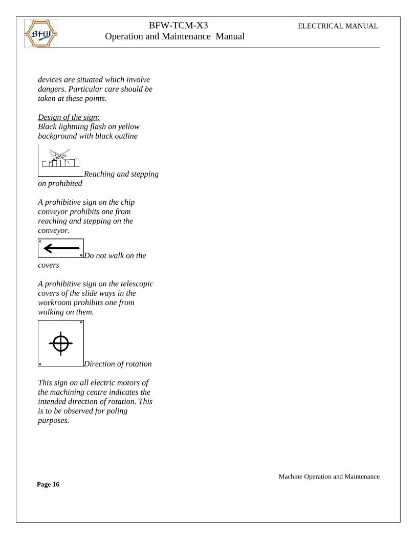
Design of the sign:Black lightning flash on yellow background with black outline
Reaching and steppingon prohibited
A prohibitive sign on the chip conveyor prohibits one from reaching and stepping on the conveyor.
Do not walk on the covers
A prohibitive sign on the telescopic covers of the slide ways in the workroom prohibits one from walking on them.
Direction of rotation
This sign on all electric motors of the machining centre indicates the intended direction of rotation. This is to be observed for poling purposes.
Machine Operation and MaintenancePage 16
BFW-TCM-X3 ELECTRICAL MANUAL
Operation and Maintenance Manual
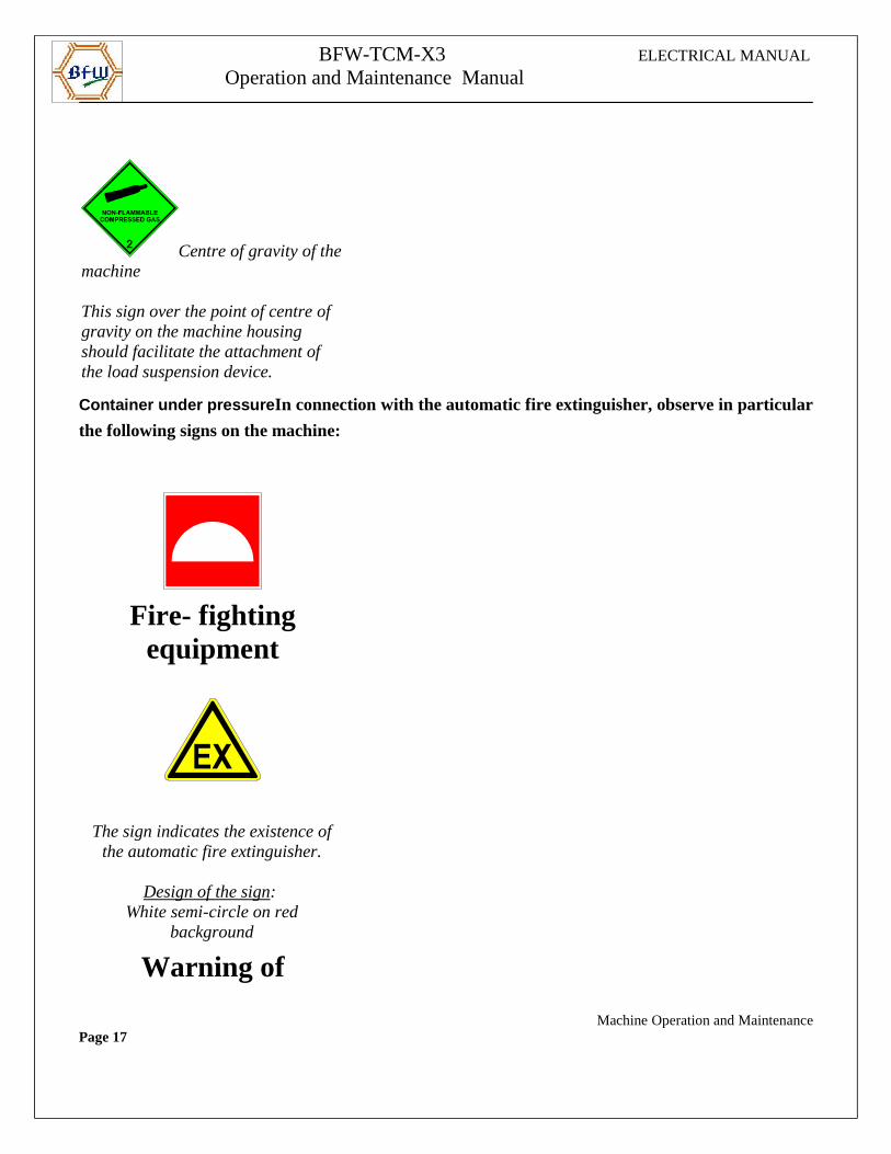
Centre of gravity of themachine
This sign over the point of centre of gravity on the machine housing should facilitate the attachment of the load suspension device.
Container under pressure In connection with the automatic fire extinguisher, observe in particular
the following signs on the machine:
Fire- fightingequipment
The sign indicates the existence ofthe automatic fire extinguisher.
Design of the sign: White semi-circle on red
background
Warning of
Machine Operation and MaintenancePage 17

BFW-TCM-X3 ELECTRICAL MANUAL
Operation and Maintenance Manual
explosiveatmosphere
This sign indicates the danger ofexplosion which may arise in thecase of machining of magnesium.
Design of the sign:Black letters ’EX’ on yellow
background with black outline
Fire, naked flame,smoking prohibited
This sign prohibits the use of nakedflames as well as smoking in theinterior of the machine or in theimmediate vicinity of the workingarea. Violation of this prohibitionmay set off the fire extinguisher ormay lead to the outbreak of fire if
magnesium chips are present.
Design of the sign:
Machine Operation and MaintenancePage 18
BFW-TCM-X3 ELECTRICAL MANUAL
Operation and Maintenance Manual
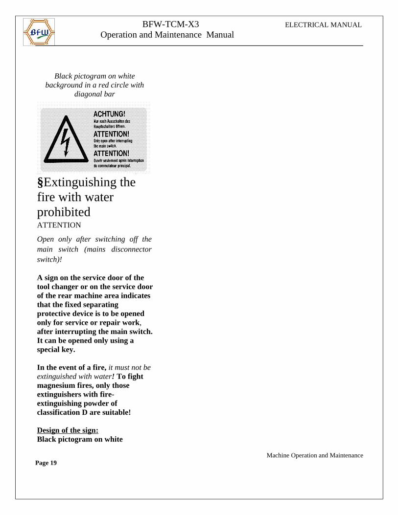
Black pictogram on whitebackground in a red circle with
diagonal bar
§Extinguishing the fire with water prohibited ATTENTION
Open only after switching off themain switch (mains disconnectorswitch)!
A sign on the service door of the tool changer or on the service doorof the rear machine area indicates that the fixed separating protective device is to be opened only for service or repair work, after interrupting the main switch.It can be opened only using a special key.
In the event of a fire, it must not beextinguished with water! To fight magnesium fires, only those extinguishers with fire-extinguishing powder of classification D are suitable!
Design of the sign:Black pictogram on white
Machine Operation and MaintenancePage 19
BFW-TCM-X3 ELECTRICAL MANUAL
Operation and Maintenance Manual
background in red circle with diagonal bar
Operator/Maintenance
Manual
Machine Operation and MaintenancePage 20
BFW-TCM-X3 ELECTRICAL MANUAL
Operation and Maintenance Manual
CONTENTS
1. Machine Operation
1.1.Overview Operating Station
1.2. Main Operating Station
1.2.1. Overview
1.2.2. Machine Specific Operating Panel on NC
1.2.3. Description Of Keys On Machine Specific Operating Panel on NC
1.2.4. Machine Control Panel(MCP)
1.2.5. Description Of Keys On Machine Control Panel(MCP)
1.2.6. Permission Key Switch And Passwords
1.2.7. Display Of Softkeys Of Special Functions
Machine Operation and MaintenancePage 21
BFW-TCM-X3 ELECTRICAL MANUAL
Operation and Maintenance Manual
1.2.8. Manual Operations
1.2.9. Operating panel chip conveyor
1.2.10. Three colour signal lamp
2. Machine Operation Auto/Set-up
2.1. Control ON sequence
2.2. Manual Mode
2.3. Auto Mode
2.3.1. Normal mode
2.3.2. Heating mode
2.4. Moving the axes with open door
3.Axes
3.1. Axes Feed Enable
3.1.1. X1-Axis Feed Enable
3.1.2. Z1-Axis Feed Enable
3.1.3. X2-Axis Feed Enable
3.1.4. Z2-Axis Feed Enable
3.1.5. LH Spindle Enable
3.1.6 RH Spindle Enable
4. Spindle
4.1.LH spindle
4.2. RH spindle
4.3. Spindle rotation in manual mode Machine Operation and MaintenancePage 22
BFW-TCM-X3 ELECTRICAL MANUAL
Operation and Maintenance Manual
5. Hydraulic, Lubrication And Pneumatic
5.1. Hydraulic
5.2. Lubrication
5.3. Pneumatic
6. Chip Conveyor
6.1. LH Chip Conveyor
6.2. RH Chip Conveyor
7.Cutting Air
8. Fixture & Auto door
8.1. LH Locating Cylinder
8.2. RH locating cylinder
8.3. LH Expanding cylinder
8.4. RH Expanding cylinder
8.5. Swing clamp
8.6. Jack cylinder 1
8.7. Jack Lock cylinder 2
8.8. Chip Flap cylinder
8.9. LH Probing cylinder
8.10. RH Probing cylinder
8.11. Auto Door
9. Software CAM and M-Codes
9.1. Software CAM
Machine Operation and MaintenancePage 23
BFW-TCM-X3 ELECTRICAL MANUAL
Operation and Maintenance Manual
9.2. M-Code List Active only in LH station
9.3. M code List Common to LH & RH station
10. Message Description
10.1. Messages Types
11. Machine Data
11.1. General MD
11.2. Channel MD
11.3. Axes & Spindle MD
12. Balluf Probe
13. Part Programs
14. Schneider Drive parameters
Machine Operation and MaintenancePage 24
BFW-TCM-X3 ELECTRICAL MANUAL
Operation and Maintenance Manual
1. Machine Operation
1.1. Overview of the operating stations
Some of the components on the operating station
• Main switch.
• Main operating station.
• Emergency Stop mushroom-head push buttons are locat ed on operating points
Machine Operation and MaintenancePage 25
BFW-TCM-X3 ELECTRICAL MANUAL
Operation and Maintenance Manual
1.2. Main Opearting Station
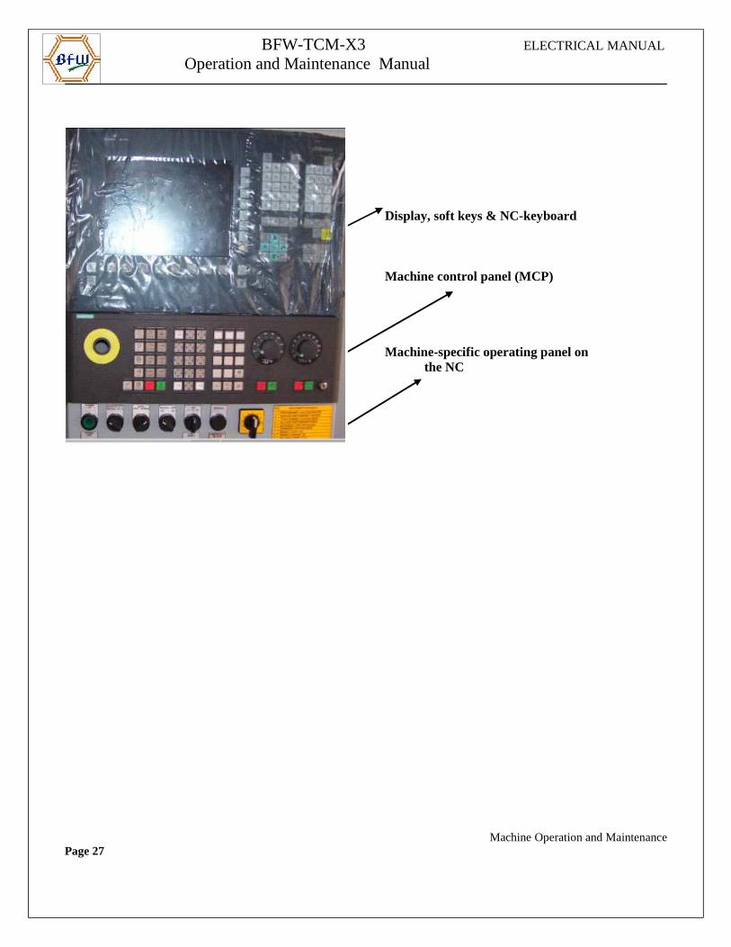
1.2.1. Overview
Machine Operation and MaintenancePage 26
BFW-TCM-X3 ELECTRICAL MANUAL
Operation and Maintenance Manual
Display, soft keys & NC-keyboard
Machine control panel (MCP)
Machine-specific operating panel on the NC
Machine Operation and MaintenancePage 27
BFW-TCM-X3 ELECTRICAL MANUAL
Operation and Maintenance Manual
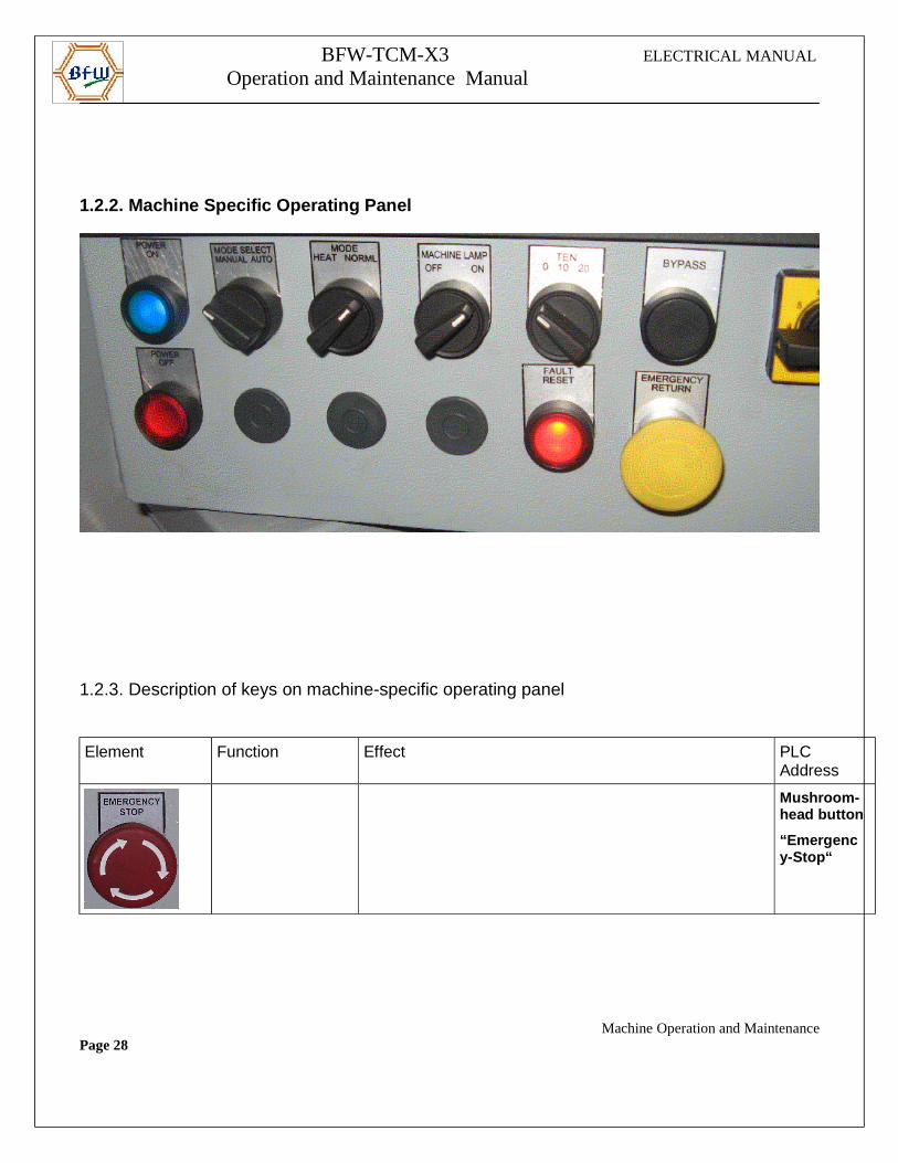
1.2.2. Machine Specific Operating Panel
1.2.3. Description of keys on machine-specific operating panel
Element Function Effect PLC Address
Mushroom-head button
“Emergency-Stop“
Machine Operation and MaintenancePage 28
BFW-TCM-X3 ELECTRICAL MANUAL
Operation and Maintenance Manual
Element Function Effect PLC
Address
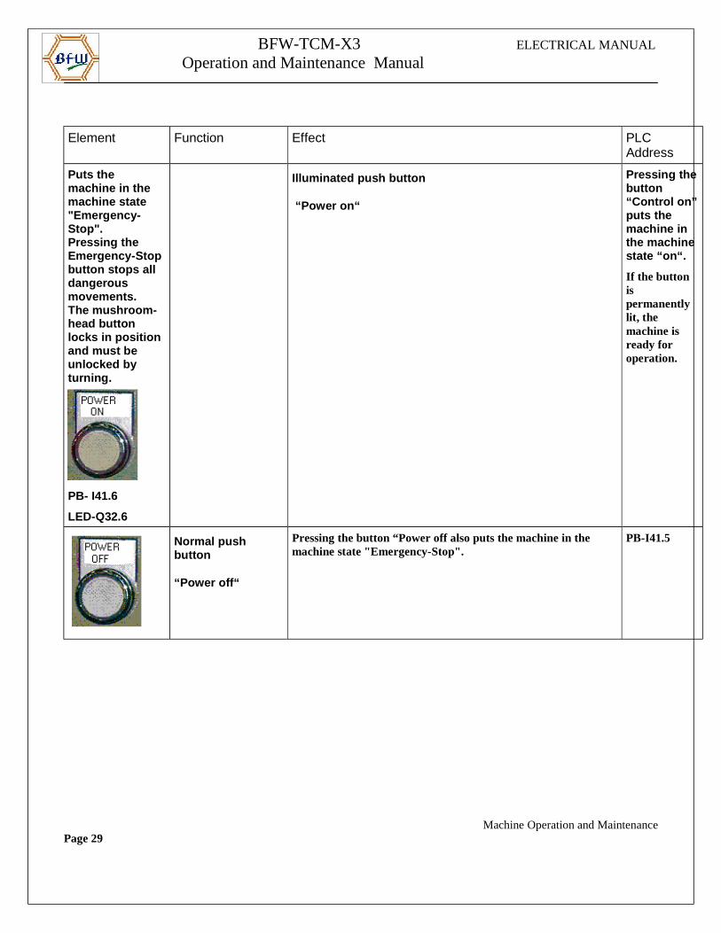
Puts the machine in the machine state "Emergency-Stop".Pressing the Emergency-Stopbutton stops all dangerous movements.The mushroom-head button locks in positionand must be unlocked by turning.
PB- I41.6
LED-Q32.6
Illuminated push button
“Power on“
Pressing thebutton “Control on”puts the machine in the machine state “on“.
If the button is permanently lit, the machine is ready for operation.
Normal push button
“Power off“
Pressing the button “Power off also puts the machine in the machine state "Emergency-Stop".
PB-I41.5
Machine Operation and MaintenancePage 29
BFW-TCM-X3 ELECTRICAL MANUAL
Operation and Maintenance Manual
Element Function Effect PLC
Address
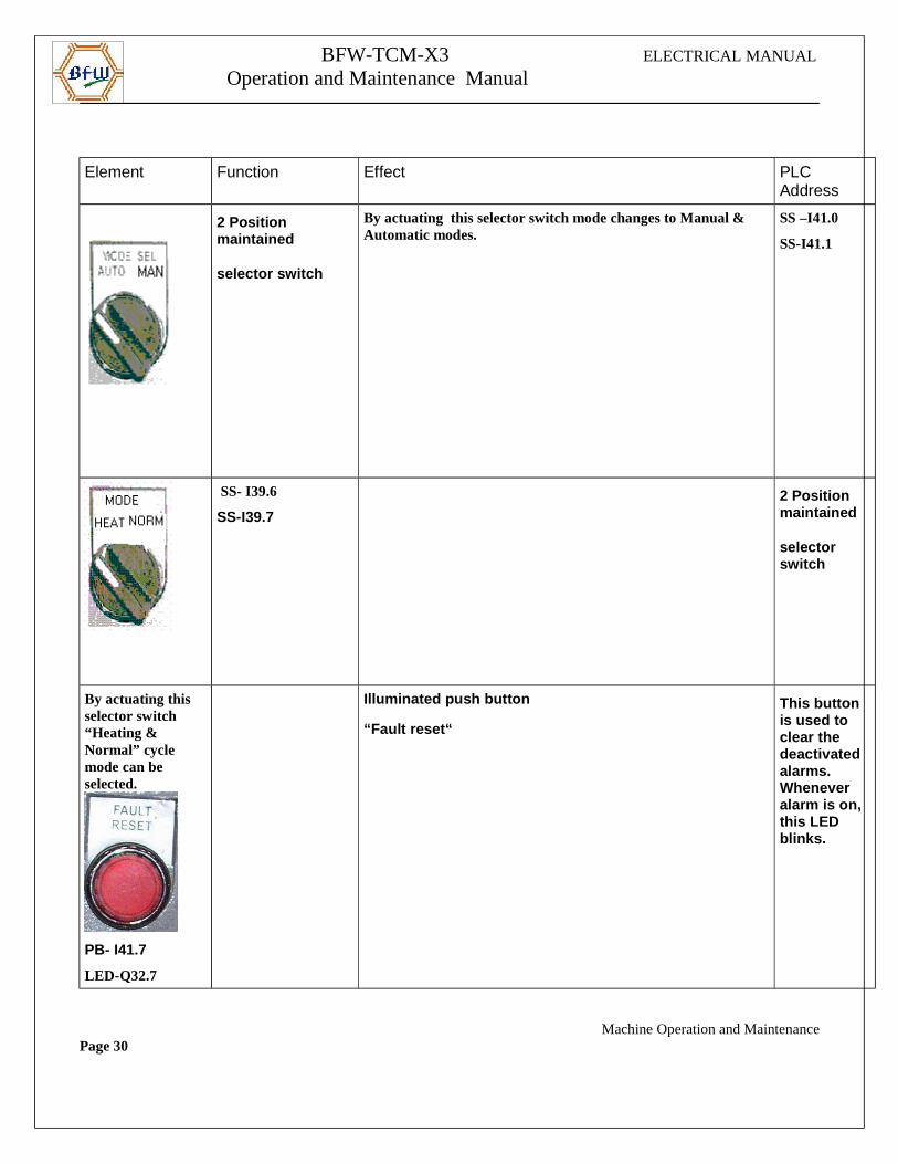
2 Position maintained
selector switch
By actuating this selector switch mode changes to Manual & Automatic modes.
SS –I41.0
SS-I41.1
SS- I39.6
SS-I39.72 Position maintained
selector switch
By actuating this selector switch “Heating & Normal” cycle mode can be selected.
PB- I41.7
LED-Q32.7
Illuminated push button
“Fault reset“
This button is used to clear the deactivated alarms. Whenever alarm is on, this LED blinks.
Machine Operation and MaintenancePage 30
BFW-TCM-X3 ELECTRICAL MANUAL
Operation and Maintenance Manual
Element Function Effect PLC
Address
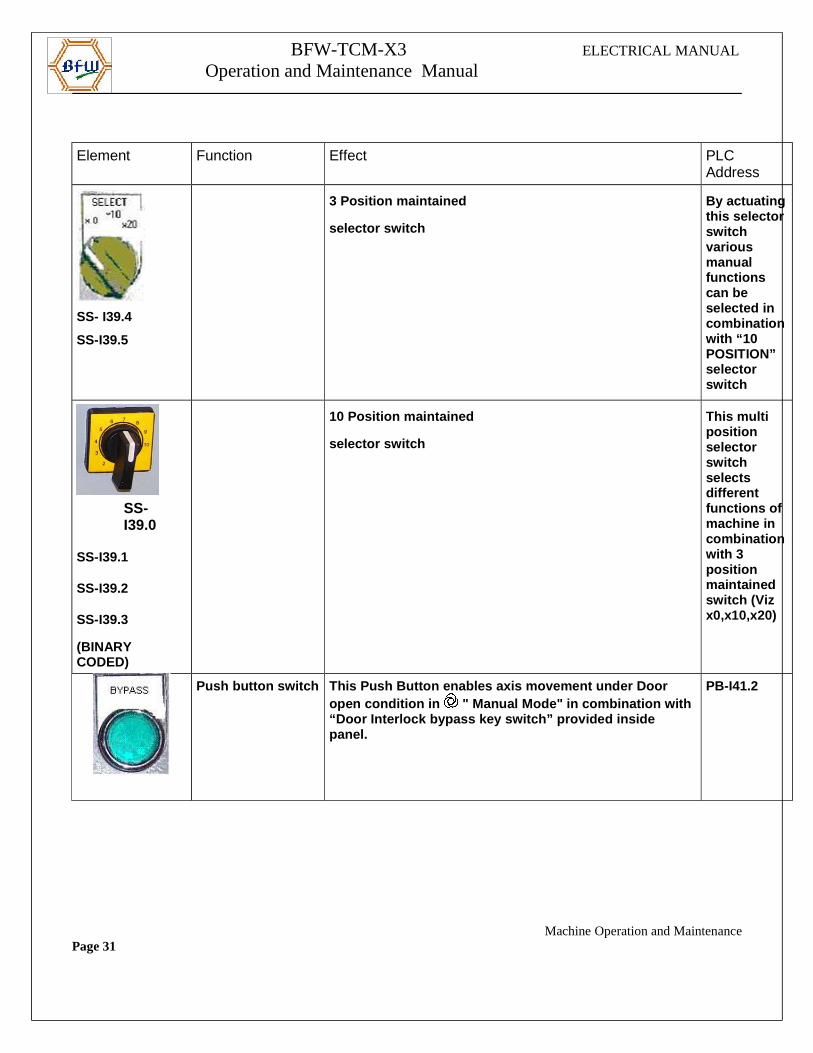
SS- I39.4
SS-I39.5
3 Position maintained
selector switch
By actuatingthis selectorswitch various manual functions can be selected in combinationwith “10 POSITION” selector switch
SS-I39.0
SS-I39.1
SS-I39.2
SS-I39.3
(BINARY CODED)
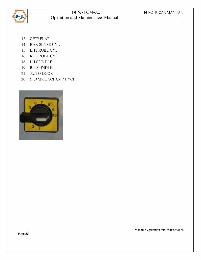
10 Position maintained
selector switch
This multi position selector switch selects different functions of machine in combinationwith 3 position maintained switch (Viz x0,x10,x20)
Push button switch This Push Button enables axis mov ement under Door open condition in " Manual Mode" in combination with “Door Interlock bypass key switch” provided inside panel.
PB-I41.2
Machine Operation and MaintenancePage 31
BFW-TCM-X3 ELECTRICAL MANUAL
Operation and Maintenance Manual
Element Function Effect PLC
Address
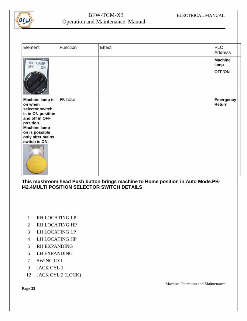
Machine lamp
OFF/ON
Machine lamp ison when selector switch is in ON positionand off in OFF position. Machine lamp on is possible only after mains switch is ON.
PB-I42.4 Emergency Return
This mushroom head Push button brings machine to Ho me position in Auto Mode.PB-I42.4MULTI POSITION SELECTOR SWITCH DETAILS
1 RH LOCATING LP
2 RH LOCATING HP
3 LH LOCATING LP
4 LH LOCATING HP
5 RH EXPANDING
6 LH EXPANDING
7 SWING CYL
9 JACK CYL 1
12 JACK CYL 2 (LOCK)
Machine Operation and MaintenancePage 32
BFW-TCM-X3 ELECTRICAL MANUAL
Operation and Maintenance Manual
MULTI POSITION SELECTOR SWITCH FUNCTION DESCRIPTION
Machine Operation and MaintenancePage 34
BFW-TCM-X3 ELECTRICAL MANUAL
Operation and Maintenance Manual
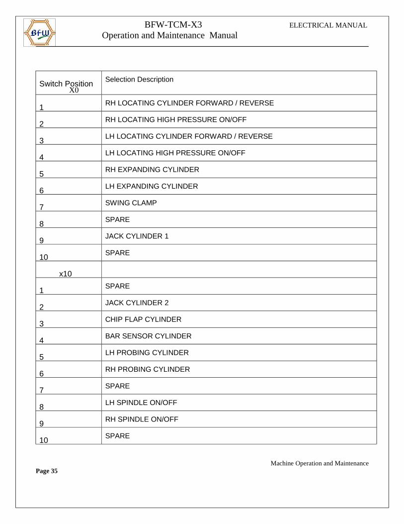
Switch Position X0
Selection Description
1RH LOCATING CYLINDER FORWARD / REVERSE
2RH LOCATING HIGH PRESSURE ON/OFF
3LH LOCATING CYLINDER FORWARD / REVERSE
4LH LOCATING HIGH PRESSURE ON/OFF
5RH EXPANDING CYLINDER
6 LH EXPANDING CYLINDER
7SWING CLAMP
8SPARE
9JACK CYLINDER 1
10SPARE
x10
1SPARE
2JACK CYLINDER 2
3CHIP FLAP CYLINDER
4BAR SENSOR CYLINDER
5LH PROBING CYLINDER
6RH PROBING CYLINDER
7 SPARE
8LH SPINDLE ON/OFF
9RH SPINDLE ON/OFF
10SPARE
Machine Operation and MaintenancePage 35
BFW-TCM-X3 ELECTRICAL MANUAL
Operation and Maintenance Manual
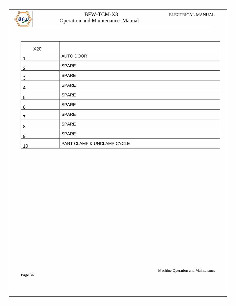
X20
1AUTO DOOR
2SPARE
3SPARE
4SPARE
5SPARE
6SPARE
7SPARE
8SPARE
9SPARE
10 PART CLAMP & UNCLAMP CYCLE
Machine Operation and MaintenancePage 36
BFW-TCM-X3 ELECTRICAL MANUAL
Operation and Maintenance Manual
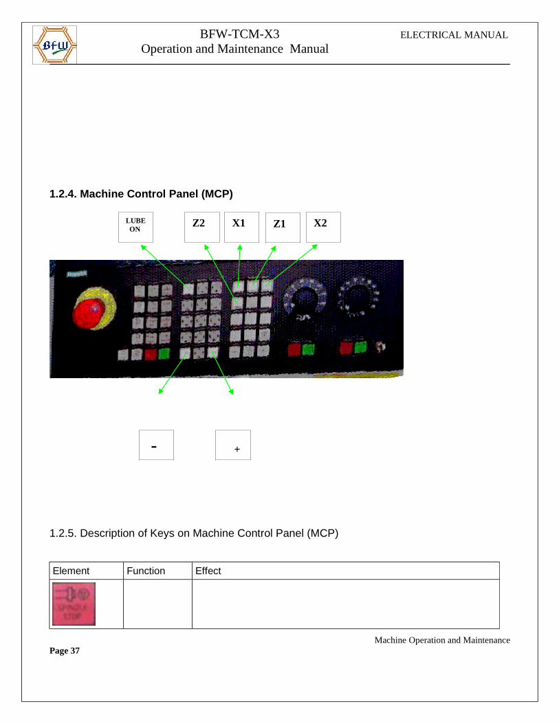
1.2.4. Machine Control Panel (MCP)
1.2.5. Description of Keys on Machine Control Panel (MCP)
Element Function Effect
Machine Operation and MaintenancePage 37
LUBE ON
- +
Z2 X1 Z1 X2
BFW-TCM-X3 ELECTRICAL MANUAL
Operation and Maintenance Manual
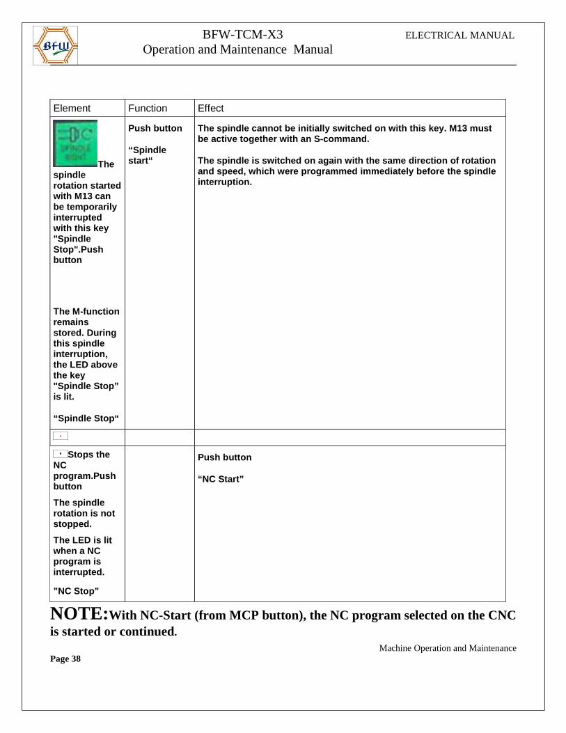
Element Function Effect
The spindle rotation startedwith M13 can be temporarily interrupted with this key "Spindle Stop".Push button
The M-functionremains stored. During this spindle interruption, the LED above the key "Spindle Stop” is lit.
“Spindle Stop“
Push button
“Spindle start“
The spindle cannot be initially switched on with th is key. M13 must be active together with an S-command.
The spindle is switched on again with the same dire ction of rotation and speed, which were programmed immediately before the spindle interruption.
Stops the NC program.Push button
The spindle rotation is not stopped.
The LED is lit when a NC program is interrupted.
”NC Stop”
Push button
“NC Start”
NOTE:With NC-Start (from MCP button), the NC program selected on the CNCis started or continued. Machine Operation and MaintenancePage 38
BFW-TCM-X3 ELECTRICAL MANUAL
Operation and Maintenance Manual
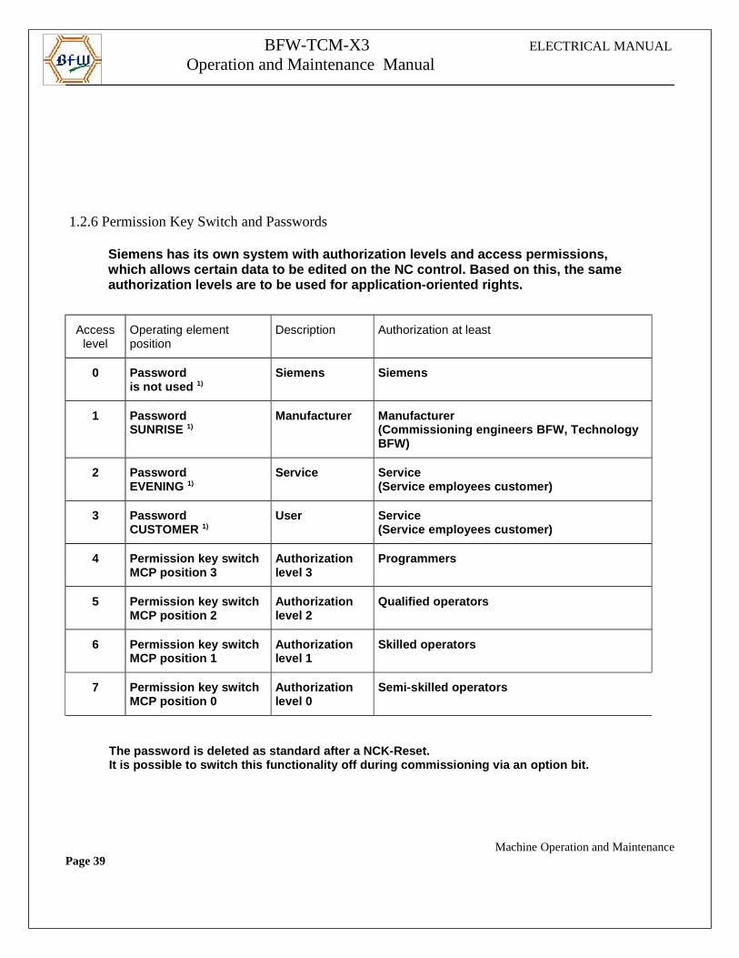
1.2.6 Permission Key Switch and Passwords
Siemens has its own system with authorization level s and access permissions, which allows certain data to be edited on the NC co ntrol. Based on this, the same authorization levels are to be used for application -oriented rights.
Accesslevel
Operating element position
Description Authorization at least
0 Passwordis not used 1)
Siemens Siemens
1 PasswordSUNRISE 1)
Manufacturer Manufacturer (Commissioning engineers BFW, Technology BFW)
2 PasswordEVENING 1)
Service Service (Service employees customer)
3 PasswordCUSTOMER 1)
User Service (Service employees customer)
4 Permission key switch MCP position 3
Authorization level 3
Programmers
5 Permission key switch MCP position 2
Authorization level 2
Qualified operators
6 Permission key switch MCP position 1
Authorization level 1
Skilled operators
7 Permission key switch MCP position 0
Authorization level 0
Semi-skilled operators
The password is deleted as standard after a NCK-Res et. It is possible to switch this functionality off dur ing commissioning via an option bit.
Machine Operation and MaintenancePage 39
BFW-TCM-X3 ELECTRICAL MANUAL
Operation and Maintenance Manual
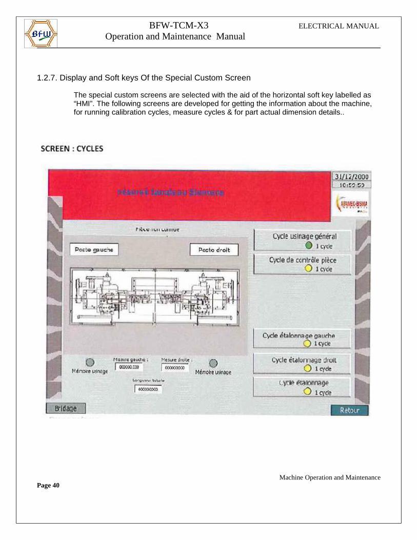
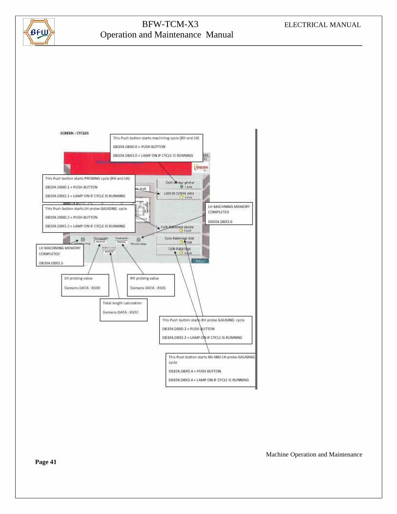
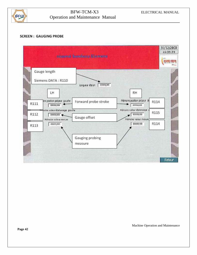
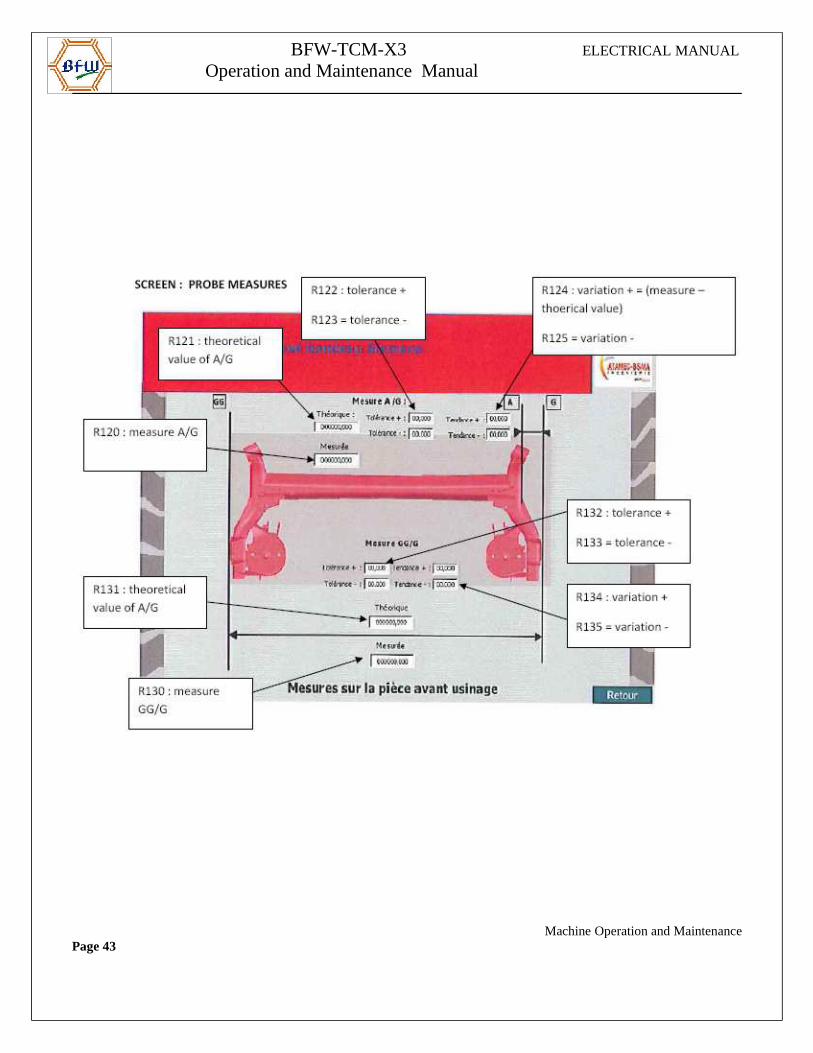
1.2.7. Display and Soft keys Of the Special Custom Screen
The special custom screens are selected with the aid of the horizontal soft key labelled as “HMI”. The following screens are developed for getting the information about the machine, for running calibration cycles, measure cycles & for part actual dimension details..
Machine Operation and MaintenancePage 40
BFW-TCM-X3 ELECTRICAL MANUAL
Operation and Maintenance Manual
Machine Operation and MaintenancePage 41
BFW-TCM-X3 ELECTRICAL MANUAL
Operation and Maintenance Manual
Machine Operation and MaintenancePage 42
BFW-TCM-X3 ELECTRICAL MANUAL
Operation and Maintenance Manual
Machine Operation and MaintenancePage 43
BFW-TCM-X3 ELECTRICAL MANUAL
Operation and Maintenance Manual
1.2.8. Manual Operations
Via the multi position selector switch various manual operation functions can be selected and triggered together with the +/- keys on the machine control panel.
Illumination of the key indicates the following states:
• Unlit, if one or more conditions are not fulfilled for pe rforming the movement.
• Flashes at ½ second intervals, if the conditions to perform the movement are fulf illed.
• Permanently lit when the movement has reached its end position, or the status is reached.
1.2.9 Operating Panel Chip Conveyor
Machine Operation and MaintenancePage 44
BFW-TCM-X3 ELECTRICAL MANUAL
Operation and Maintenance Manual
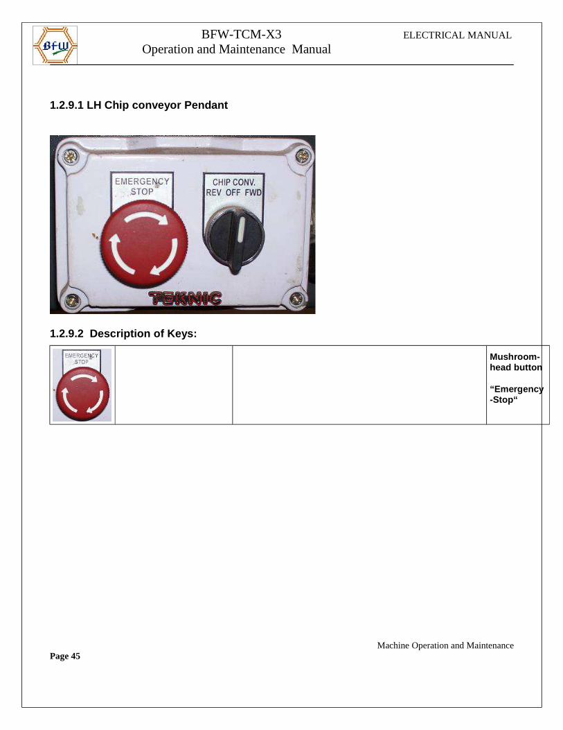
1.2.9.1 LH Chip conveyor Pendant
1.2.9.2 Description of Keys:
Mushroom-head button
“Emergency-Stop“
Machine Operation and MaintenancePage 45
BFW-TCM-X3 ELECTRICAL MANUAL
Operation and Maintenance Manual
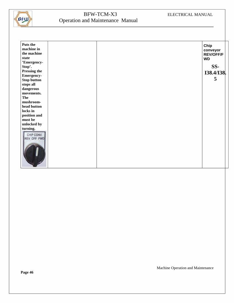
Puts the machine in the machine state ’Emergency-Stop’.Pressing the Emergency-Stop button stops all dangerous movements.The mushroom-head button locks in position and must be unlocked by turning.
Chip conveyor REV/OFF/FWD
SS-I38.4/I38.
5
Machine Operation and MaintenancePage 46
BFW-TCM-X3 ELECTRICAL MANUAL
Operation and Maintenance Manual
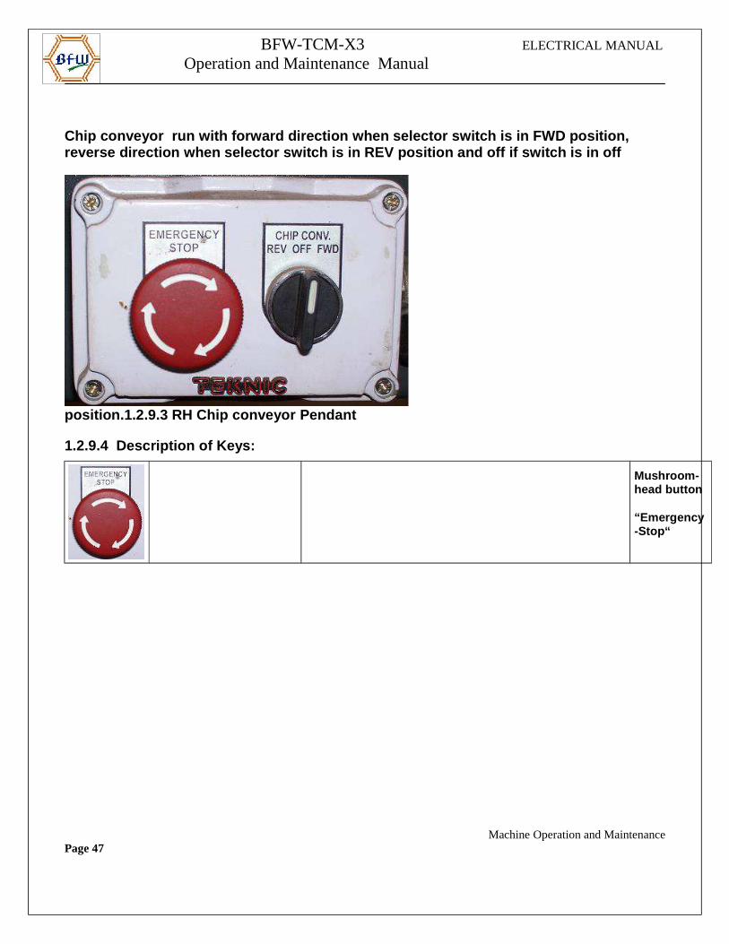
Chip conveyor run with forward direction when sele ctor switch is in FWD position, reverse direction when selector switch is in REV po sition and off if switch is in off
position.1.2.9.3 RH Chip conveyor Pendant
1.2.9.4 Description of Keys:
Mushroom-head button
“Emergency-Stop“
Machine Operation and MaintenancePage 47
BFW-TCM-X3 ELECTRICAL MANUAL
Operation and Maintenance Manual
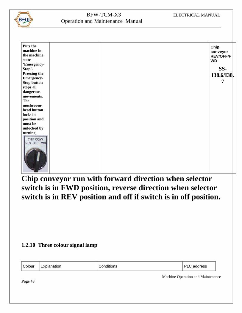
Puts the machine in the machine state ’Emergency-Stop’.Pressing the Emergency-Stop button stops all dangerous movements.The mushroom-head button locks in position and must be unlocked by turning.
Chip conveyor REV/OFF/FWD
SS-I38.6/I38.
7
Chip conveyor run with forward direction when selector switch is in FWD position, reverse direction when selector switch is in REV position and off if switch is in off position.
1.2.10 Three colour signal lamp
Colour Explanation Conditions PLC address
Machine Operation and MaintenancePage 48
BFW-TCM-X3 ELECTRICAL MANUAL
Operation and Maintenance Manual
Red Fault Active “Fault Stop”
“Safety Stop”
Q37.2
Amber Tool change Tool change indication Q37.1
Green Cycle Running Machine works in NC program Q37.0
2. Machine Operation 2.1. Control ON Sequence
• Ensure all emergency stop buttons are released.
• Press “Fault Reset” button once.(control on led blinks if all conditions for control on are satisfied)
• Press Control ON PB on MCP Panel.
Now Control ON LED blinks till Auxiliary units are ready and stays on if the following
Conditions are satisfied.
• All emergency stop PBs are released I33.6=1
• All MPCBs are normal I43.0 to I43.3 =1.
• SLM (Smart Line module) unit is ready I32.2=1.
• Axis motor temperature monitoring signal I32.3=1
• MMC on Ethernet is ready.
• NCK unit is ready
2.2. Manual ModeThis mode is used to do any manual movement or settings on the machine .The door should be in closed condition to do any manual movement. Operator message will be displayed if any safety condition is required for a particular action.
2.3. Auto Mode
2.3.1 Normal ModeThis mode is used for machining the parts. Cycle start is possible only if following conditions are satisfied:
1. All axes in home Zone.
2. No DEFAULT alarms on machine.
3. Lubrication system should be OK
Machine Operation and MaintenancePage 49
BFW-TCM-X3 ELECTRICAL MANUAL
Operation and Maintenance Manual
4. Previously Machined part should be removed from Fixture.
2.3.2. Heating ModeThis mode is used to warm up the machine without doing any machining operation. Cycle start is possible only if following conditions are satisfied:
1. All axes in home Zone.
2. No DEFAULT alarms on machine.
3. Lubrication system should be OK
4. No part should be loaded on the machine.
2.4. Moving the axes with open doors
To enable movement of the axes with open doors, the operating mode switch must be in operating mode manual & following conditions must be fulfilled.
1. The key switch “Door Interlock Bypass OFF/ON” kept inside panel must be made ON.
2. Select Manual Mode
3. Select the axis (X1,Z1,X2 orZ2) from MCP which is to be moved
4. Press + or – button along with “Bypass” push button, the axis starts moving.
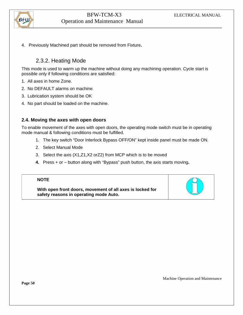
NOTE
With open front doors, movement of all axes is lock ed for safety reasons in operating mode Auto.
Machine Operation and MaintenancePage 50
BFW-TCM-X3 ELECTRICAL MANUAL
Operation and Maintenance Manual
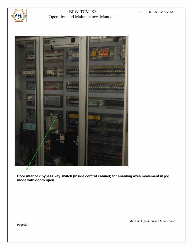
Door interlock bypass key switch (Inside control ca binet) for enabling axes movement in jogmode with doors open.
Machine Operation and MaintenancePage 51
BFW-TCM-X3 ELECTRICAL MANUAL
Operation and Maintenance Manual
3. AXES
3.1. Axes Feed enable in Manual Mode
3.1.1. X1-axis movement is possible only if the fol lowing conditions are satisfied.
1. No DEFAULT alarm should be present.
2. No feed stop from MCP active
3.1.2. Z1-axis movement is possible only if the fol lowing conditions are satisfied.
1. No DEFAULT alarm should be present.
2. No feed stop from MCP active
3.1.3. X2-axis movement is possible only if the f ollowing conditions are satisfied.
1. No DEFAULT alarm should be present.
2. No feed stop from MCP active
3.1.4. Z2-axis movement is possible only if the following conditions are satisfied.
1. No DEFAULT alarm should be present.
2. No feed stop from MCP active
3.1.5 Axes movement in manual mode
1. Select manual mode
2. Select the axis from MCP (X1, Z1, X2 or Z2)
3. Door should be closed
4. Chip flap should be closed
5. Feed override switch not at zero position
6. Press ‘+’ or ‘-‘ key to move the axis
Machine Operation and MaintenancePage 52
BFW-TCM-X3 ELECTRICAL MANUAL
Operation and Maintenance Manual
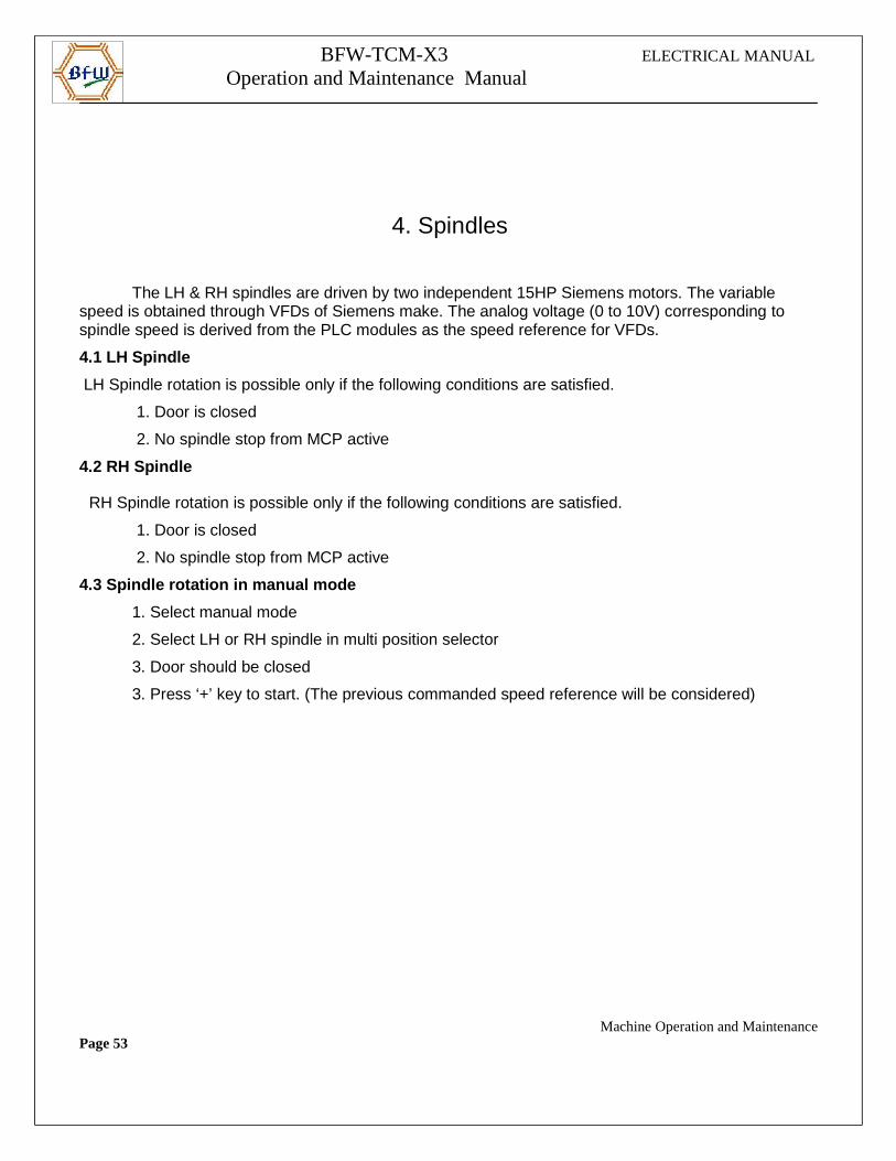
4. Spindles
The LH & RH spindles are driven by two independent 15HP Siemens motors. The variable speed is obtained through VFDs of Siemens make. The analog voltage (0 to 10V) corresponding tospindle speed is derived from the PLC modules as the speed reference for VFDs.
4.1 LH Spindle
LH Spindle rotation is possible only if the following conditions are satisfied.
1. Door is closed
2. No spindle stop from MCP active
4.2 RH Spindle
RH Spindle rotation is possible only if the following conditions are satisfied.
1. Door is closed
2. No spindle stop from MCP active
4.3 Spindle rotation in manual mode
1. Select manual mode
2. Select LH or RH spindle in multi position selector
3. Door should be closed
3. Press ‘+’ key to start. (The previous commanded speed reference will be considered)
Machine Operation and MaintenancePage 53
BFW-TCM-X3 ELECTRICAL MANUAL
Operation and Maintenance Manual
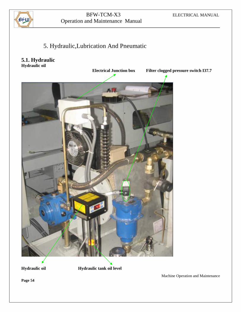
5. Hydraulic,Lubrication And Pneumatic
5.1. HydraulicHydraulic oil
Electrical Junction box Filter clogged pressure switch I37.7
Hydraulic oil Hydraulic tank oil level
Machine Operation and MaintenancePage 54
BFW-TCM-X3 ELECTRICAL MANUAL
Operation and Maintenance Manual
temperature sensor I38.3 monitoring proximity I32.4
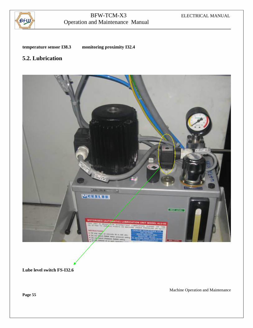
5.2. Lubrication
Lube level switch FS-I32.6
Machine Operation and MaintenancePage 55
BFW-TCM-X3 ELECTRICAL MANUAL
Operation and Maintenance Manual
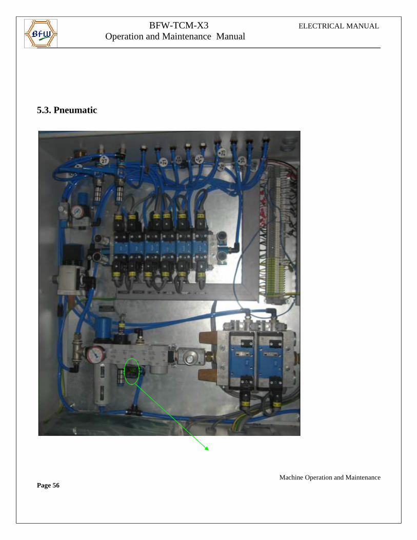
5.3. Pneumatic
Machine Operation and MaintenancePage 56
BFW-TCM-X3 ELECTRICAL MANUAL
Operation and Maintenance Manual
Main Air pressure switch PS-I32.5
6. Chip Conveyor6.1. LH Chip Conveyor Motor
6.1.1. Forward (Q32.2)
To run the chip conveyor in forward direction, forward selector switch on Chip conveyor panel I38.4=1. Manual mode should be selected. Chip conveyor overload limit switch should not get actuated ie I36.1=1
6.1.2. Reverse (Q32.3)
Chip conveyor reverse selector switch on Chip conveyor panel I38.5=1. Manual mode should be selected.
6.2. RH Chip Conveyor Motor6.2.1. Forward (Q32.4) To run the Chip conveyor in forward direction, forward selector switch on Chip conveyor panel I38.6=1. Manual mode should be selected. Chip conveyor overload limit switch should not get actuated ie I36.2=1
6.2.2. Reverse (Q32.5)
Chip conveyor reverse selector switch on Chip conveyor panel I38.7=1. Manual mode should be selected.
6.3 Chip conveyor function in Auto modeBoth Chip conveyor starts running in forward direction when the Auto cycle starts.
Machine Operation and MaintenancePage 57
BFW-TCM-X3 ELECTRICAL MANUAL
Operation and Maintenance Manual
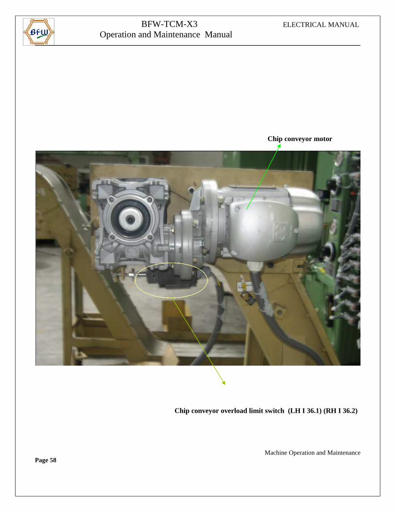
Chip conveyor motor
Chip conveyor overload limit switch (LH I 36.1) (RH I 36.2)
Machine Operation and MaintenancePage 58
BFW-TCM-X3 ELECTRICAL MANUAL
Operation and Maintenance Manual
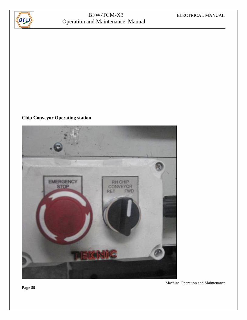
Chip Conveyor Operating station
Machine Operation and MaintenancePage 59
BFW-TCM-X3 ELECTRICAL MANUAL
Operation and Maintenance Manual
7.0. Air for cuttingThe cutting air for spindle can be switched on & off with following M codes.
M58-spindle cutting air on. M59-spindle cutting air on.
8.0. Fixture
In manual mode using “10 position” selector switch & “0/10/20” selector switch we can operate these cylinders Forward & Reverse using “+” & “-“ push button respectively on MCP.
8.1 LH Locating CylinderFollowing conditions must be satisfied.
Precondition for forward motion:1. Door should be closed2. LH expander cylinder should be in reverse position
Precondition for reverse motion:1. Door should be closed
8.2 RH Locating CylinderFollowing conditions must be satisfied.
Precondition for forward motion:1.Door should be closed2.RH expander cylinder should be in reverse position
Precondition for reverse motion: 1.Door should be closed
Machine Operation and MaintenancePage 60
BFW-TCM-X3 ELECTRICAL MANUAL
Operation and Maintenance Manual
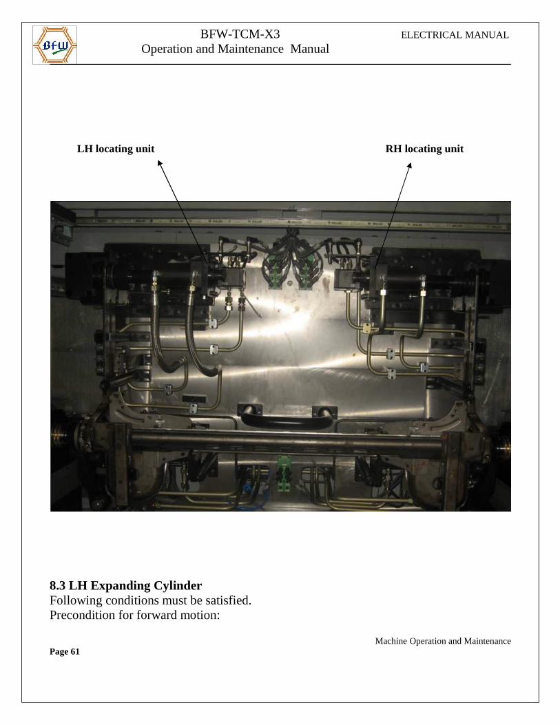
LH locating unit RH locating unit
8.3 LH Expanding CylinderFollowing conditions must be satisfied.Precondition for forward motion:
Machine Operation and MaintenancePage 61
BFW-TCM-X3 ELECTRICAL MANUAL
Operation and Maintenance Manual
1.Door should be closed2.LH Locator should be in forward position
Precondition for reverse motion: 1.Door should be closed
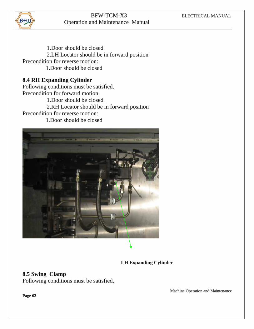
8.4 RH Expanding CylinderFollowing conditions must be satisfied.Precondition for forward motion:
1.Door should be closed2.RH Locator should be in forward position
Precondition for reverse motion: 1.Door should be closed
LH Expanding Cylinder
8.5 Swing Clamp Following conditions must be satisfied.
Machine Operation and MaintenancePage 62
BFW-TCM-X3 ELECTRICAL MANUAL
Operation and Maintenance Manual
Precondition for forward motion:
1.Door should be closedPrecondition for reverse motion: 1.Door should be closed
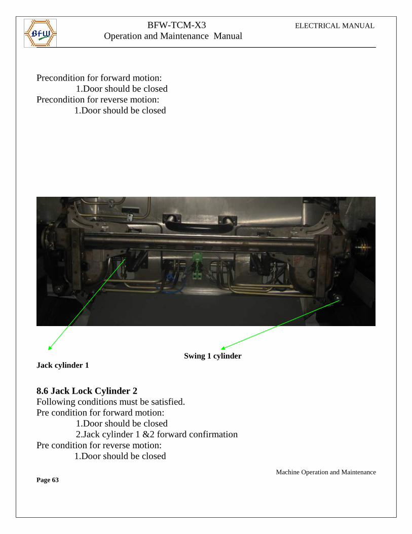
Swing 1 cylinder Jack cylinder 1
8.6 Jack Lock Cylinder 2 Following conditions must be satisfied.Pre condition for forward motion:
1.Door should be closed2.Jack cylinder 1 &2 forward confirmation
Pre condition for reverse motion: 1.Door should be closed
Machine Operation and MaintenancePage 63
BFW-TCM-X3 ELECTRICAL MANUAL
Operation and Maintenance Manual
8.7 Jack cylinder 1Following conditions must be satisfied.Precondition for forward motion:
1.Door should be closed2.Position cylinder Jack cyl 1 in FWD or RET confirmation
Precondition for reverse motion: 1.Door should be closed
8.8 Chip Flap Cylinder Following conditions must be satisfied.Pre condition for forward (close) motion:
1.Door should be closedPre condition for down motion: 1.Door should be closed
2. All axes at home zone
8.9 LH Probe Cylinder Following conditions must be satisfied.Pre condition for forward motion:
1.Door should be closedPre condition for reverse motion: 1.Door should be closed
8.10 RH Probe Cylinder Following conditions must be satisfied.
Machine Operation and MaintenancePage 64
BFW-TCM-X3 ELECTRICAL MANUAL
Operation and Maintenance Manual
Pre condition for forward motion:
1.Door should be closedPre condition for reverse motion: 1.Door should be closed
Probe Cylinder
Machine Operation and MaintenancePage 65
BFW-TCM-X3 ELECTRICAL MANUAL
Operation and Maintenance Manual
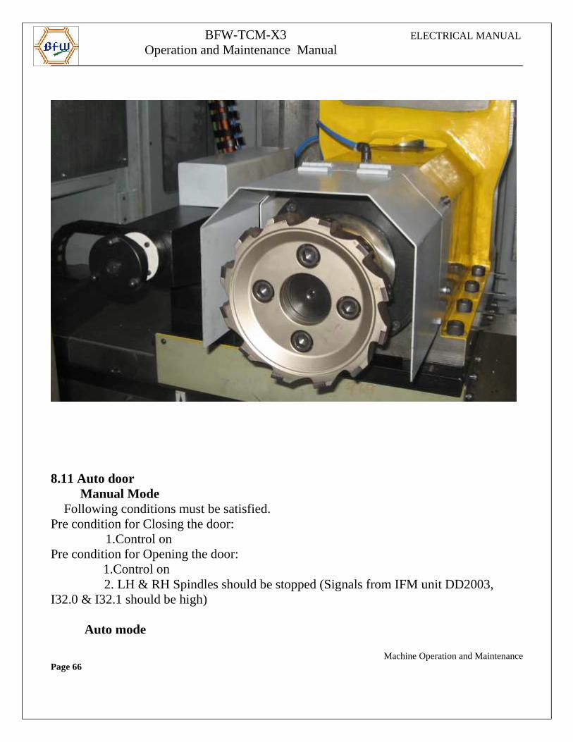
8.11 Auto door Manual Mode Following conditions must be satisfied.Pre condition for Closing the door:
1.Control onPre condition for Opening the door: 1.Control on
2. LH & RH Spindles should be stopped (Signals from IFM unit DD2003, I32.0 & I32.1 should be high)
Auto mode
Machine Operation and MaintenancePage 66
BFW-TCM-X3 ELECTRICAL MANUAL
Operation and Maintenance Manual
In Auto mode door opening is automatic through M functions.
9.0.Software CAM And M-Code
9.1. Software CAMCam signal 1 for X1 axis in home zone setting Data 41500[0] & 41501[0] Cam signal 2 for Z1 axis in home zone setting Data 41500[1] & 41501[1] Cam signal 3 for X2 axis in home zone Setting Data 41500[2] & 41501[2] Cam signal 4 for Z2 axis in home zone Setting Data 41500[3] & 41501[3]
9.2. M-Codes Active Only in LH station
Machine Operation and MaintenancePage 67
BFW-TCM-X3 ELECTRICAL MANUAL
Operation and Maintenance Manual
M12 - Unclamp start
M21 – LH Locating Cylinder Forward
M22 – LH Locating Cylinder Reverse
M23 – LH Locating Cylinder Forward High pressure On
M24 - LH Locating Cylinder Forward High pressure Of f
M25 – RH Locating Cylinder Forward
M26 – RH Locating Cylinder Reverse
M27 – RH Locating Cylinder Forward High pressure On
M28 - RH Locating Cylinder Forward High pressure Of f
M31 – LH Expanding cylinder Forward.
M32 – LH Expanding cylinder Reverse.
M33 – RH Expanding cylinder Forward.
M34 – RH Expanding cylinder Reverse.
M35 – Swing clamp Forward.
M36 – Swing clamp Reverse.
M39 – Jack cylinder 1 Forward.
M54 – Inhibit Emergency return (clamping)
M55 – Validate Emergency return (clamping)
M71 – Jack cylinder 1 Reverse.
M72 – Jack Lock cylinder 2 Forward.
M73 – Jack Lock cylinder 2 Reverse.
M76 – Auto Door Close
M77 – Auto Door Open
9.3. M-Codes common to LH & RH stationM00 - Program Stop.
M01 - Conditional Stop.
M02 - Program End.
M10 -Component clamp confirmation check
M13 - Spindle on
Machine Operation and MaintenancePage 68
BFW-TCM-X3 ELECTRICAL MANUAL
Operation and Maintenance Manual
M15 - Spindle off
M17 – Sub Program End
M30 – Program End.
M50 – Bar Sensing unit up.
M51 – Bar Sensing unit Down.
M52 – Probe cylinder Forward.
M53 – Probe cylinder Reverse.
M58 – Spindle Cutting Air on.
M59 – Spindle Cutting Air off.
M62 – Probe Calibration reading Transfer to NC.
M63 – Probe Measure reading Transfer to NC.
M68 – Cutting over
M74 – Chip Flap Forward.
M75 – Chip Flap Reverse.
M82 – Calibration Bit cycle end
M83 – Measure Cycle End
M84 – Probe Callibration Not OK
M89 – Part is Bad
10. Alarm Description
10.1. Message types
There are generally 2 message types:
• Operator messages
These messages give the operator important informat ion on incorrect operation.They are mostly self-acknowledging.
• Fault messages
Machine Operation and MaintenancePage 69
BFW-TCM-X3 ELECTRICAL MANUAL
Operation and Maintenance Manual
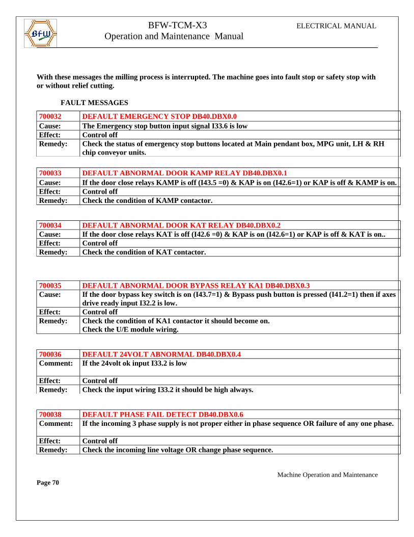
With these messages the milling process is interrupted. The machine goes into fault stop or safety stop with or without relief cutting.
FAULT MESSAGES
700032 DEFAULT EMERGENCY STOP DB40.DBX0.0Cause: The Emergency stop button input signal I33.6 is lowEffect: Control offRemedy: Check the status of emergency stop buttons located at Main pendant box, MPG unit, LH & RH
chip conveyor units.
700033 DEFAULT ABNORMAL DOOR KAMP RELAY DB40.DBX0.1Cause: If the door close relays KAMP is off (I43.5 =0) & KAP is on (I42.6=1) or KAP is off & KAMP is on.Effect: Control offRemedy: Check the condition of KAMP contactor.
700034 DEFAULT ABNORMAL DOOR KAT RELAY DB40.DBX0.2Cause: If the door close relays KAT is off (I42.6 =0) & KAP is on (I42.6=1) or KAP is off & KAT is on..Effect: Control offRemedy: Check the condition of KAT contactor.
700035 DEFAULT ABNORMAL DOOR BYPASS RELAY KA1 DB40.DBX0.3Cause: If the door bypass key switch is on (I43.7=1) & Bypass push button is pressed (I41.2=1) then if axes
drive ready input I32.2 is low.Effect: Control offRemedy: Check the condition of KA1 contactor it should become on.
Check the U/E module wiring.
700036 DEFAULT 24VOLT ABNORMAL DB40.DBX0.4Comment: If the 24volt ok input I33.2 is low
Effect: Control offRemedy: Check the input wiring I33.2 it should be high always.
700038 DEFAULT PHASE FAIL DETECT DB40.DBX0.6Comment: If the incoming 3 phase supply is not proper either in phase sequence OR failure of any one phase.
Effect: Control offRemedy: Check the incoming line voltage OR change phase sequence.
Machine Operation and MaintenancePage 70
BFW-TCM-X3 ELECTRICAL MANUAL
Operation and Maintenance Manual
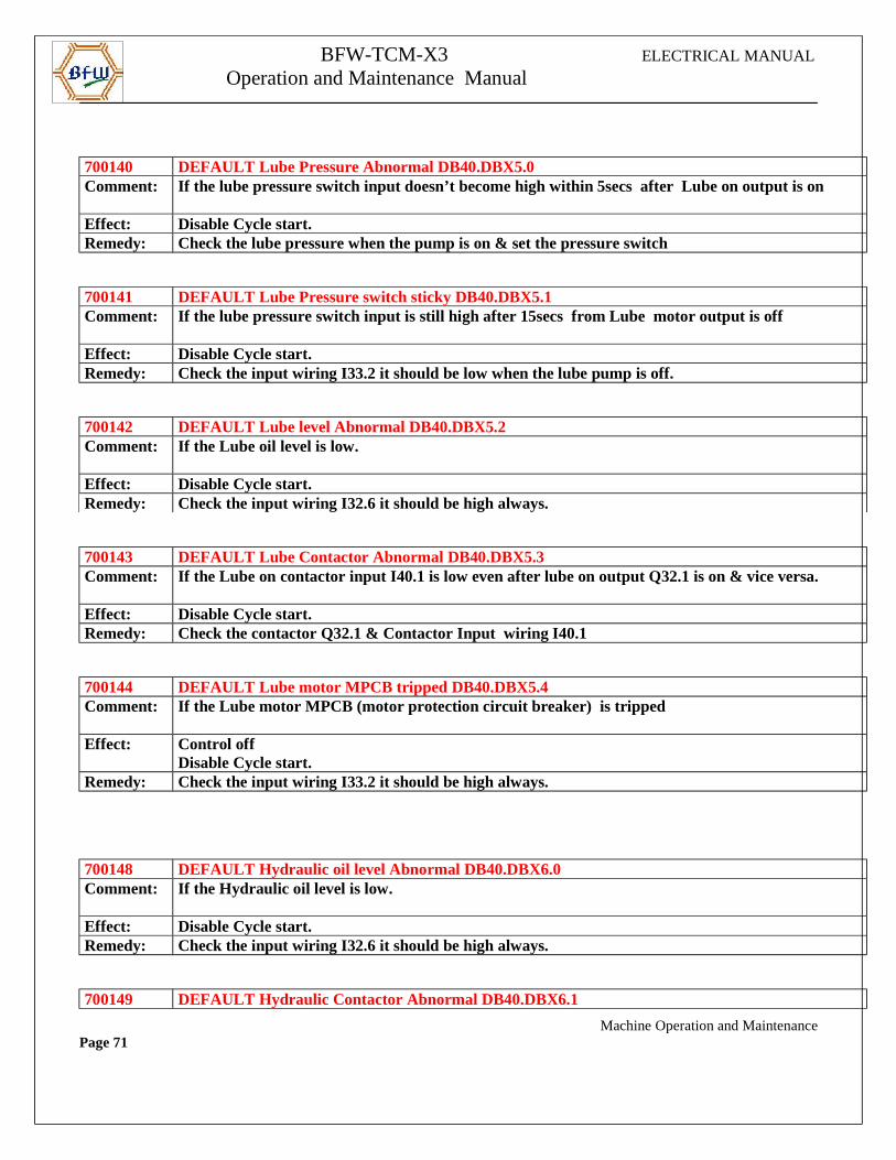
700140 DEFAULT Lube Pressure Abnormal DB40.DBX5.0Comment: If the lube pressure switch input doesn’t become high within 5secs after Lube on output is on
Effect: Disable Cycle start.Remedy: Check the lube pressure when the pump is on & set the pressure switch
700141 DEFAULT Lube Pressure switch sticky DB40.DBX5.1Comment: If the lube pressure switch input is still high after 15secs from Lube motor output is off
Effect: Disable Cycle start.Remedy: Check the input wiring I33.2 it should be low when the lube pump is off.
700142 DEFAULT Lube level Abnormal DB40.DBX5.2Comment: If the Lube oil level is low.
Effect: Disable Cycle start.Remedy: Check the input wiring I32.6 it should be high always.
700143 DEFAULT Lube Contactor Abnormal DB40.DBX5.3Comment: If the Lube on contactor input I40.1 is low even after lube on output Q32.1 is on & vice versa.
Effect: Disable Cycle start.Remedy: Check the contactor Q32.1 & Contactor Input wiring I40.1
700144 DEFAULT Lube motor MPCB tripped DB40.DBX5.4Comment: If the Lube motor MPCB (motor protection circuit breaker) is tripped
Effect: Control offDisable Cycle start.
Remedy: Check the input wiring I33.2 it should be high always.
700148 DEFAULT Hydraulic oil level Abnormal DB40.DBX6.0Comment: If the Hydraulic oil level is low.
Effect: Disable Cycle start.Remedy: Check the input wiring I32.6 it should be high always.
700149 DEFAULT Hydraulic Contactor Abnormal DB40.DBX6.1
Machine Operation and MaintenancePage 71
BFW-TCM-X3 ELECTRICAL MANUAL
Operation and Maintenance Manual
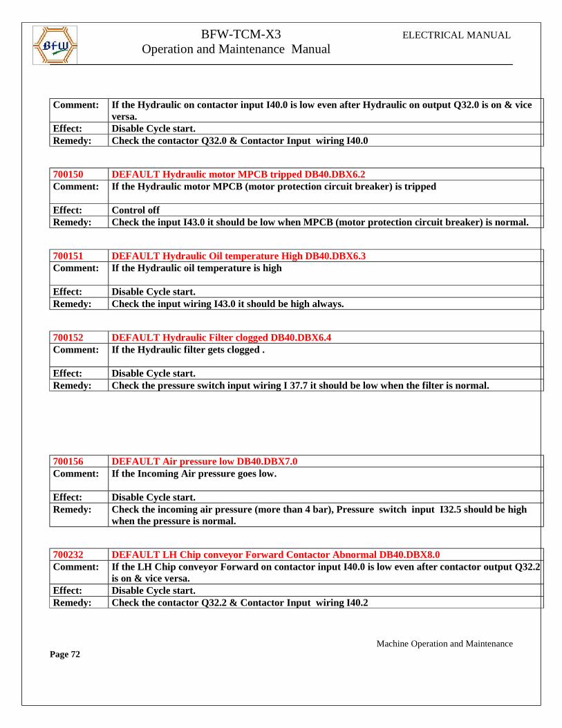
Comment: If the Hydraulic on contactor input I40.0 is low even after Hydraulic on output Q32.0 is on & vice
versa.Effect: Disable Cycle start.Remedy: Check the contactor Q32.0 & Contactor Input wiring I40.0
700150 DEFAULT Hydraulic motor MPCB tripped DB40.DBX6.2Comment: If the Hydraulic motor MPCB (motor protecti on circuit breaker) is tripped
Effect: Control offRemedy: Check the input I43.0 it should be low when MPCB (motor protection circuit breaker) is normal.
700151 DEFAULT Hydraulic Oil temperature High DB40.DBX6.3Comment: If the Hydraulic oil temperature is high
Effect: Disable Cycle start.Remedy: Check the input wiring I43.0 it should be high always.
700152 DEFAULT Hydraulic Filter clogged DB40.DBX6.4Comment: If the Hydraulic filter gets clogged .
Effect: Disable Cycle start.Remedy: Check the pressure switch input wiring I 37.7 it should be low when the filter is normal.
700156 DEFAULT Air pressure low DB40.DBX7.0Comment: If the Incoming Air pressure goes low.
Effect: Disable Cycle start.Remedy: Check the incoming air pressure (more than 4 bar), Pressure switch input I32.5 should be high
when the pressure is normal.
700232 DEFAULT LH Chip conveyor Forward Contactor Abnormal DB40.DBX8.0Comment: If the LH Chip conveyor Forward on contactor input I40.0 is low even after contactor output Q32.2
is on & vice versa.Effect: Disable Cycle start.Remedy: Check the contactor Q32.2 & Contactor Input wiring I40.2
Machine Operation and MaintenancePage 72
BFW-TCM-X3 ELECTRICAL MANUAL
Operation and Maintenance Manual
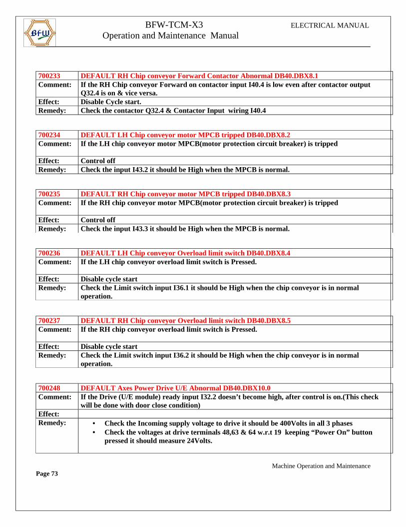
700233 DEFAULT RH Chip conveyor Forward Contactor Abnormal DB40.DBX8.1Comment: If the RH Chip conveyor Forward on contactor input I40.4 is low even after contactor output
Q32.4 is on & vice versa.Effect: Disable Cycle start.Remedy: Check the contactor Q32.4 & Contactor Input wiring I40.4
700234 DEFAULT LH Chip conveyor motor MPCB tripped DB40.DBX8.2Comment: If the LH chip conveyor motor MPCB(motor protection circuit breaker) is tripped
Effect: Control offRemedy: Check the input I43.2 it should be High when the MPCB is normal.
700235 DEFAULT RH Chip conveyor motor MPCB tripped DB40.DBX8.3Comment: If the RH chip conveyor motor MPCB(motor protection circuit breaker) is tripped
Effect: Control offRemedy: Check the input I43.3 it should be High when the MPCB is normal.
700236 DEFAULT LH Chip conveyor Overload limit switch DB40.DBX8.4Comment: If the LH chip conveyor overload limit switch is Pressed.
Effect: Disable cycle startRemedy: Check the Limit switch input I36.1 it should be High when the chip conveyor is in normal
operation.
700237 DEFAULT RH Chip conveyor Overload limit switch DB40.DBX8.5Comment: If the RH chip conveyor overload limit switch is Pressed.
Effect: Disable cycle startRemedy: Check the Limit switch input I36.2 it should be High when the chip conveyor is in normal
operation.
700248 DEFAULT Axes Power Drive U/E Abnormal DB40.DBX10.0Comment: If the Drive (U/E module) ready input I32.2 doesn’t become high, after control is on.(This check
will be done with door close condition)Effect:Remedy: • Check the Incoming supply voltage to drive it should be 400Volts in all 3 phases
• Check the voltages at drive terminals 48,63 & 64 w.r.t 19 keeping “Power On” button pressed it should measure 24Volts.
Machine Operation and MaintenancePage 73
BFW-TCM-X3 ELECTRICAL MANUAL
Operation and Maintenance Manual
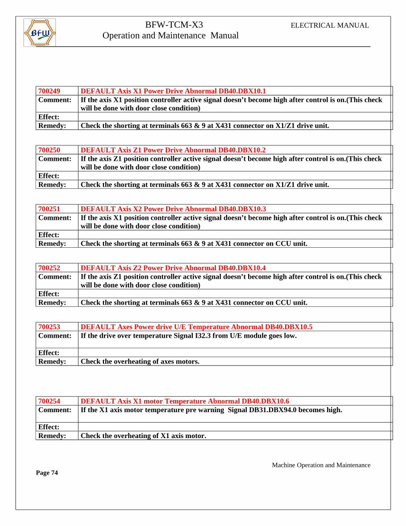
700249 DEFAULT Axis X1 Power Drive Abnormal DB40.DBX10.1Comment: If the axis X1 position controller active signal doesn’t become high after control is on.(This check
will be done with door close condition)Effect:Remedy: Check the shorting at terminals 663 & 9 at X431 connector on X1/Z1 drive unit.
700250 DEFAULT Axis Z1 Power Drive Abnormal DB40.DBX10.2Comment: If the axis Z1 position controller active signal doesn’t become high after control is on.(This check
will be done with door close condition)Effect:Remedy: Check the shorting at terminals 663 & 9 at X431 connector on X1/Z1 drive unit.
700251 DEFAULT Axis X2 Power Drive Abnormal DB40.DBX10.3Comment: If the axis X1 position controller active signal doesn’t become high after control is on.(This check
will be done with door close condition)Effect:Remedy: Check the shorting at terminals 663 & 9 at X431 connector on CCU unit.
700252 DEFAULT Axis Z2 Power Drive Abnormal DB40.DBX10.4Comment: If the axis Z1 position controller active signal doesn’t become high after control is on.(This check
will be done with door close condition)Effect:Remedy: Check the shorting at terminals 663 & 9 at X431 connector on CCU unit.
700253 DEFAULT Axes Power drive U/E Temperature Abnormal DB40.DBX10.5Comment: If the drive over temperature Signal I32.3 from U/E module goes low.
Effect:Remedy: Check the overheating of axes motors.
700254 DEFAULT Axis X1 motor Temperature Abnormal DB40.DBX10.6Comment: If the X1 axis motor temperature pre warning Signal DB31.DBX94.0 becomes high.
Effect:Remedy: Check the overheating of X1 axis motor.
Machine Operation and MaintenancePage 74
BFW-TCM-X3 ELECTRICAL MANUAL
Operation and Maintenance Manual
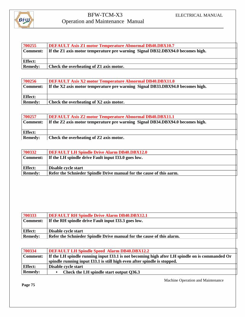
700255 DEFAULT Axis Z1 motor Temperature Abnormal DB40.DBX10.7Comment: If the Z1 axis motor temperature pre warning Signal DB32.DBX94.0 becomes high.
Effect:Remedy: Check the overheating of Z1 axis motor.
700256 DEFAULT Axis X2 motor Temperature Abnormal DB40.DBX11.0Comment: If the X2 axis motor temperature pre warning Signal DB33.DBX94.0 becomes high.
Effect:Remedy: Check the overheating of X2 axis motor.
700257 DEFAULT Axis Z2 motor Temperature Abnormal DB40.DBX11.1Comment: If the Z2 axis motor temperature pre warning Signal DB34.DBX94.0 becomes high.
Effect:Remedy: Check the overheating of Z2 axis motor.
700332 DEFAULT LH Spindle Drive Alarm DB40.DBX12.0Comment: If the LH spindle drive Fault input I33.0 goes low.
Effect: Disable cycle startRemedy: Refer the Schnieder Spindle Drive manual for the cause of this aarm.
700333 DEFAULT RH Spindle Drive Alarm DB40.DBX12.1Comment: If the RH spindle drive Fault input I33.3 goes low.
Effect: Disable cycle startRemedy: Refer the Schnieder Spindle Drive manual for the cause of this alarm.
700334 DEFAULT LH Spindle Speed Alarm DB40.DBX12.2Comment: If the LH spindle running input I33.1 is not becoming high after LH spindle on is commanded Or
spindle running input I33.1 is still high even after spindle is stopped.Effect: Disable cycle startRemedy: • Check the LH spindle start output Q36.3
Machine Operation and MaintenancePage 75
BFW-TCM-X3 ELECTRICAL MANUAL
Operation and Maintenance Manual
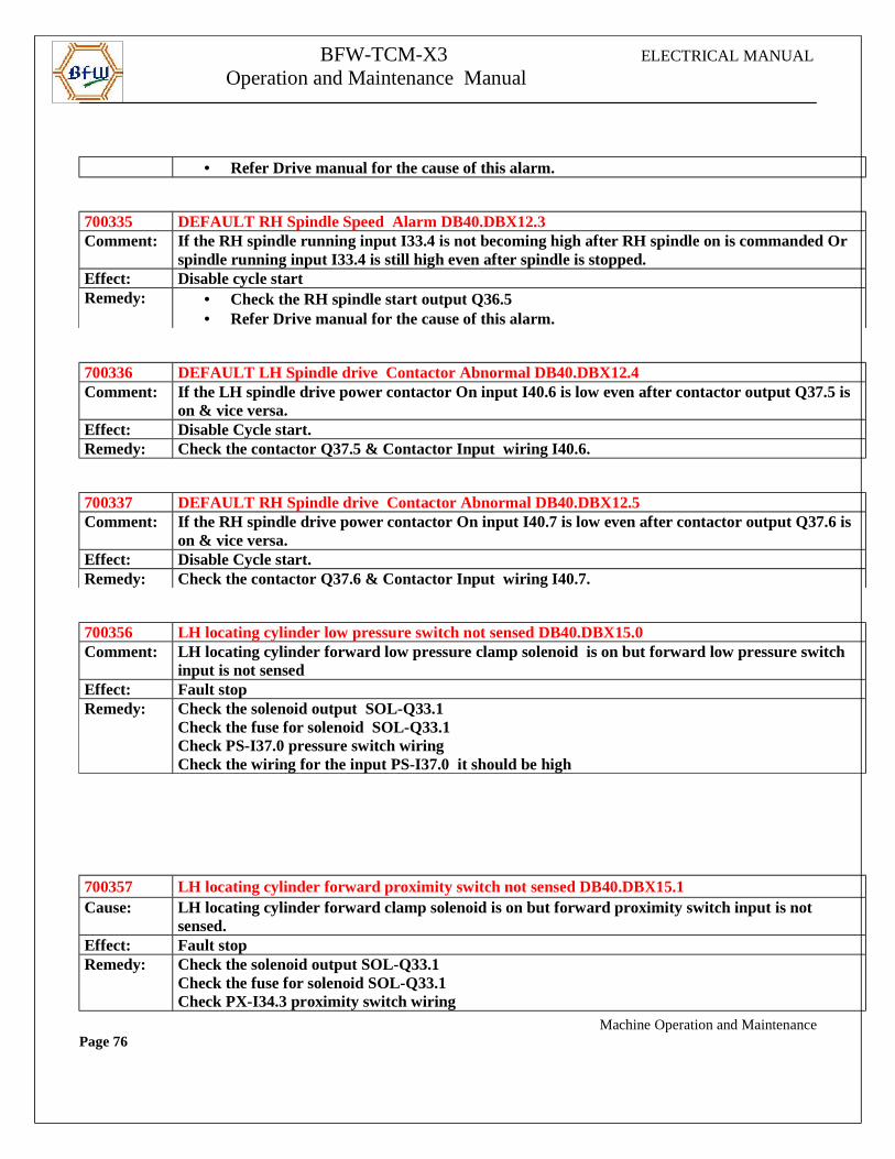
• Refer Drive manual for the cause of this alarm.
700335 DEFAULT RH Spindle Speed Alarm DB40.DBX12.3Comment: If the RH spindle running input I33.4 is not becoming high after RH spindle on is commanded Or
spindle running input I33.4 is still high even after spindle is stopped.Effect: Disable cycle startRemedy: • Check the RH spindle start output Q36.5
• Refer Drive manual for the cause of this alarm.
700336 DEFAULT LH Spindle drive Contactor Abnormal DB40.DBX12.4Comment: If the LH spindle drive power contactor On input I40.6 is low even after contactor output Q37.5 is
on & vice versa.Effect: Disable Cycle start.Remedy: Check the contactor Q37.5 & Contactor Input wiring I40.6.
700337 DEFAULT RH Spindle drive Contactor Abnormal DB40.DBX12.5Comment: If the RH spindle drive power contactor On input I40.7 is low even after contactor output Q37.6 is
on & vice versa.Effect: Disable Cycle start.Remedy: Check the contactor Q37.6 & Contactor Input wiring I40.7.
700356 LH locating cylinder low pressure switch not sensed DB40.DBX15.0Comment: LH locating cylinder forward low pressure clamp solenoid is on but forward low pressure switch
input is not sensedEffect: Fault stopRemedy: Check the solenoid output SOL-Q33.1
Check the fuse for solenoid SOL-Q33.1Check PS-I37.0 pressure switch wiringCheck the wiring for the input PS-I37.0 it should be high
700357 LH locating cylinder forward proximity switch not sensed DB40.DBX15.1Cause: LH locating cylinder forward clamp solenoid is on but forward proximity switch input is not
sensed.Effect: Fault stopRemedy: Check the solenoid output SOL-Q33.1
Check the fuse for solenoid SOL-Q33.1Check PX-I34.3 proximity switch wiring
Machine Operation and MaintenancePage 76
BFW-TCM-X3 ELECTRICAL MANUAL
Operation and Maintenance Manual
Check the wiring for the input PX-I34.3 it should be high
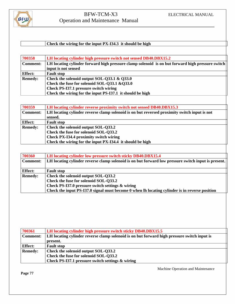
700358 LH locating cylinder high pressure switch not sensed DB40.DBX15.2Comment: LH locating cylinder forward high pressure clamp solenoid is on but forward high pressure switch
input is not sensedEffect: Fault stopRemedy: Check the solenoid output SOL-Q33.1 & Q33.0
Check the fuse for solenoid SOL-Q33.1 &Q33.0Check PS-I37.1 pressure switch wiringCheck the wiring for the input PS-I37.1 it should be high
700359 LH locating cylinder reverse proximity switch not sensed DB40.DBX15.3Comment: LH locating cylinder reverse clamp solenoid is on but reversed proximity switch input is not
sensed.Effect: Fault stopRemedy: Check the solenoid output SOL-Q33.2
Check the fuse for solenoid SOL-Q33.2Check PX-I34.4 proximity switch wiringCheck the wiring for the input PX-I34.4 it should be high
700360 LH locating cylinder low pressure switch sticky DB40.DBX15.4Comment: LH locating cylinder reverse clamp solenoid is on but forward low pressure switch input is present.
Effect: Fault stopRemedy: Check the solenoid output SOL-Q33.2
Check the fuse for solenoid SOL-Q33.2Check PS-I37.0 pressure switch settings & wiringCheck the input PS-I37.0 signal must become 0 when lh locating cylinder is in reverse position
700361 LH locating cylinder high pressure switch sticky DB40.DBX15.5Comment: LH locating cylinder reverse clamp solenoid is on but forward high pressure switch input is
present.Effect: Fault stopRemedy: Check the solenoid output SOL-Q33.2
Check the fuse for solenoid SOL-Q33.2Check PS-I37.1 pressure switch settings & wiring
Machine Operation and MaintenancePage 77
BFW-TCM-X3 ELECTRICAL MANUAL
Operation and Maintenance Manual
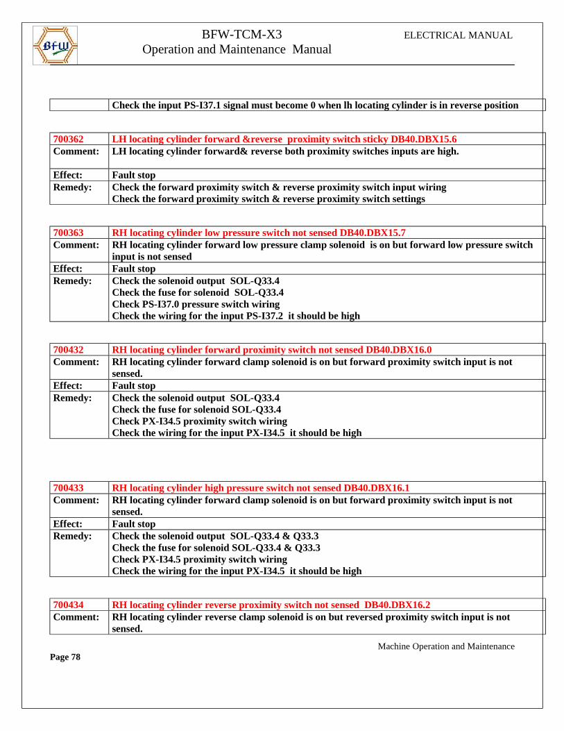
Check the input PS-I37.1 signal must become 0 when lh locating cylinder is in reverse position
700362 LH locating cylinder forward &reverse proximity switch sticky DB40.DBX15.6Comment: LH locating cylinder forward& reverse both proximity switches inputs are high.
Effect: Fault stopRemedy: Check the forward proximity switch & reverse proximity switch input wiring
Check the forward proximity switch & reverse proximity switch settings
700363 RH locating cylinder low pressure switch not sensed DB40.DBX15.7Comment: RH locating cylinder forward low pressure clamp solenoid is on but forward low pressure switch
input is not sensedEffect: Fault stopRemedy: Check the solenoid output SOL-Q33.4
Check the fuse for solenoid SOL-Q33.4Check PS-I37.0 pressure switch wiringCheck the wiring for the input PS-I37.2 it should be high
700432 RH locating cylinder forward proximity switch not sensed DB40.DBX16.0Comment: RH locating cylinder forward clamp solenoid is on but forward proximity switch input is not
sensed.Effect: Fault stopRemedy: Check the solenoid output SOL-Q33.4
Check the fuse for solenoid SOL-Q33.4Check PX-I34.5 proximity switch wiringCheck the wiring for the input PX-I34.5 it should be high
700433 RH locating cylinder high pressure switch not sensed DB40.DBX16.1Comment: RH locating cylinder forward clamp solenoid is on but forward proximity switch input is not
sensed.Effect: Fault stopRemedy: Check the solenoid output SOL-Q33.4 & Q33.3
Check the fuse for solenoid SOL-Q33.4 & Q33.3Check PX-I34.5 proximity switch wiringCheck the wiring for the input PX-I34.5 it should be high
700434 RH locating cylinder reverse proximity switch not sensed DB40.DBX16.2Comment: RH locating cylinder reverse clamp solenoid is on but reversed proximity switch input is not
sensed.
Machine Operation and MaintenancePage 78
BFW-TCM-X3 ELECTRICAL MANUAL
Operation and Maintenance Manual
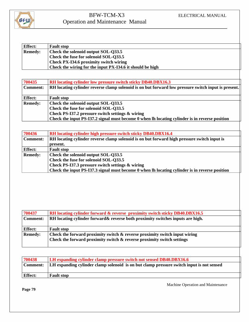
Effect: Fault stopRemedy: Check the solenoid output SOL-Q33.5
Check the fuse for solenoid SOL-Q33.5Check PX-I34.6 proximity switch wiringCheck the wiring for the input PX-I34.6 it should be high
700435 RH locating cylinder low pressure switch sticky DB40.DBX16.3Comment: RH locating cylinder reverse clamp solenoid is on but forward low pressure switch input is present.
Effect: Fault stopRemedy: Check the solenoid output SOL-Q33.5
Check the fuse for solenoid SOL-Q33.5Check PS-I37.2 pressure switch settings & wiringCheck the input PS-I37.2 signal must become 0 when lh locating cylinder is in reverse position
700436 RH locating cylinder high pressure switch sticky DB40.DBX16.4Comment: RH locating cylinder reverse clamp solenoid is on but forward high pressure switch input is
present.Effect: Fault stopRemedy: Check the solenoid output SOL-Q33.5
Check the fuse for solenoid SOL-Q33.5Check PS-I37.3 pressure switch settings & wiringCheck the input PS-I37.3 signal must become 0 when lh locating cylinder is in reverse position
700437 RH locating cylinder forward & reverse proximity switch sticky DB40.DBX16.5Comment: RH locating cylinder forward& reverse both proximity switches inputs are high.
Effect: Fault stopRemedy: Check the forward proximity switch & reverse proximity switch input wiring
Check the forward proximity switch & reverse proximity switch settings
700438 LH expanding cylinder clamp pressure switch not sensed DB40.DBX16.6Comment: LH expanding cylinder clamp solenoid is on but clamp pressure switch input is not sensed
Effect: Fault stop
Machine Operation and MaintenancePage 79
BFW-TCM-X3 ELECTRICAL MANUAL
Operation and Maintenance Manual
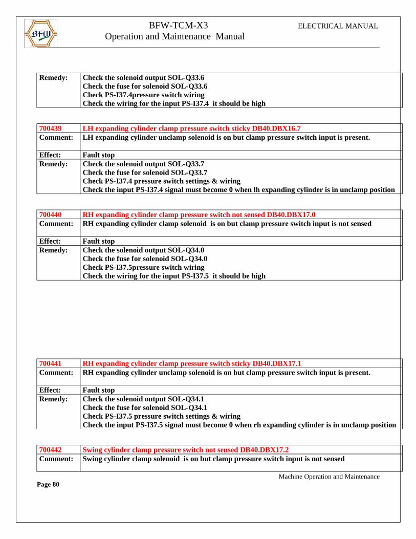
Remedy: Check the solenoid output SOL-Q33.6
Check the fuse for solenoid SOL-Q33.6Check PS-I37.4pressure switch wiringCheck the wiring for the input PS-I37.4 it should be high
700439 LH expanding cylinder clamp pressure switch sticky DB40.DBX16.7Comment: LH expanding cylinder unclamp solenoid is on but clamp pressure switch input is present.
Effect: Fault stopRemedy: Check the solenoid output SOL-Q33.7
Check the fuse for solenoid SOL-Q33.7Check PS-I37.4 pressure switch settings & wiringCheck the input PS-I37.4 signal must become 0 when lh expanding cylinder is in unclamp position
700440 RH expanding cylinder clamp pressure switch not sensed DB40.DBX17.0Comment: RH expanding cylinder clamp solenoid is on but clamp pressure switch input is not sensed
Effect: Fault stopRemedy: Check the solenoid output SOL-Q34.0
Check the fuse for solenoid SOL-Q34.0Check PS-I37.5pressure switch wiringCheck the wiring for the input PS-I37.5 it should be high
700441 RH expanding cylinder clamp pressure switch sticky DB40.DBX17.1Comment: RH expanding cylinder unclamp solenoid is on but clamp pressure switch input is present.
Effect: Fault stopRemedy: Check the solenoid output SOL-Q34.1
Check the fuse for solenoid SOL-Q34.1Check PS-I37.5 pressure switch settings & wiringCheck the input PS-I37.5 signal must become 0 when rh expanding cylinder is in unclamp position
700442 Swing cylinder clamp pressure switch not sensed DB40.DBX17.2Comment: Swing cylinder clamp solenoid is on but clamp pressure switch input is not sensed
Machine Operation and MaintenancePage 80
BFW-TCM-X3 ELECTRICAL MANUAL
Operation and Maintenance Manual
Effect: Fault stopRemedy: Check the solenoid output SOL-Q34.2
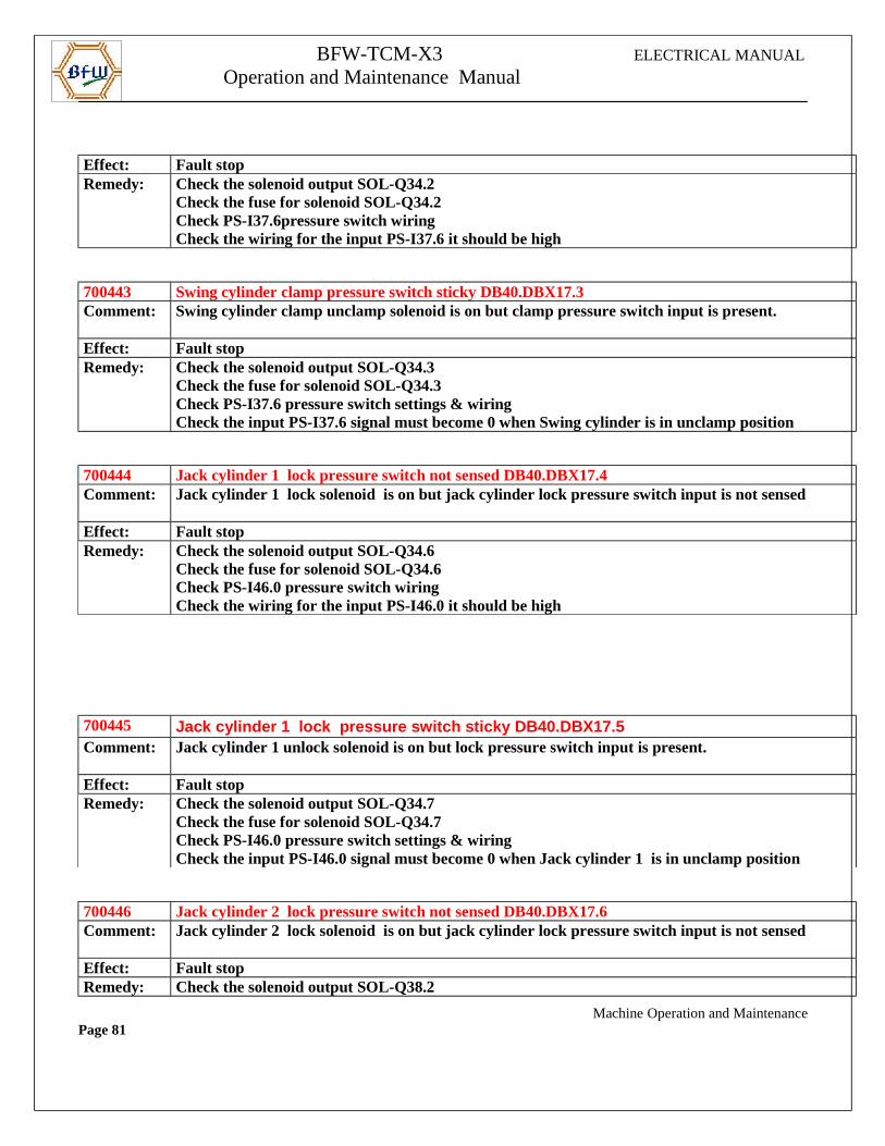
Check the fuse for solenoid SOL-Q34.2Check PS-I37.6pressure switch wiringCheck the wiring for the input PS-I37.6 it should be high
700443 Swing cylinder clamp pressure switch sticky DB40.DBX17.3Comment: Swing cylinder clamp unclamp solenoid is on but clamp pressure switch input is present.
Effect: Fault stopRemedy: Check the solenoid output SOL-Q34.3
Check the fuse for solenoid SOL-Q34.3Check PS-I37.6 pressure switch settings & wiringCheck the input PS-I37.6 signal must become 0 when Swing cylinder is in unclamp position
700444 Jack cylinder 1 lock pressure switch not sensed DB40.DBX17.4Comment: Jack cylinder 1 lock solenoid is on but jack cylinder lock pressure switch input is not sensed
Effect: Fault stopRemedy: Check the solenoid output SOL-Q34.6
Check the fuse for solenoid SOL-Q34.6Check PS-I46.0 pressure switch wiringCheck the wiring for the input PS-I46.0 it should be high
700445 Jack cylinder 1 lock pressure switch sticky DB40. DBX17.5Comment: Jack cylinder 1 unlock solenoid is on but lock pressure switch input is present.
Effect: Fault stopRemedy: Check the solenoid output SOL-Q34.7
Check the fuse for solenoid SOL-Q34.7Check PS-I46.0 pressure switch settings & wiringCheck the input PS-I46.0 signal must become 0 when Jack cylinder 1 is in unclamp position
700446 Jack cylinder 2 lock pressure switch not sensed DB40.DBX17.6Comment: Jack cylinder 2 lock solenoid is on but jack cylinder lock pressure switch input is not sensed
Effect: Fault stopRemedy: Check the solenoid output SOL-Q38.2
Machine Operation and MaintenancePage 81
BFW-TCM-X3 ELECTRICAL MANUAL
Operation and Maintenance Manual
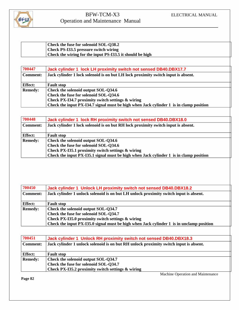
Check the fuse for solenoid SOL-Q38.2Check PS-I33.5 pressure switch wiringCheck the wiring for the input PS-I33.5 it should be high
700447 Jack cylinder 1 lock LH proximity switch not sense d DB40.DBX17.7Comment: Jack cylinder 1 lock solenoid is on but LH lock proximity switch input is absent.
Effect: Fault stopRemedy: Check the solenoid output SOL-Q34.6
Check the fuse for solenoid SOL-Q34.6Check PX-I34.7 proximity switch settings & wiringCheck the input PX-I34.7 signal must be high when Jack cylinder 1 is in clamp position
700448 Jack cylinder 1 lock RH proximity switch not sense d DB40.DBX18.0Comment: Jack cylinder 1 lock solenoid is on but RH lock proximity switch input is absent.
Effect: Fault stopRemedy: Check the solenoid output SOL-Q34.6
Check the fuse for solenoid SOL-Q34.6Check PX-I35.1 proximity switch settings & wiringCheck the input PX-I35.1 signal must be high when Jack cylinder 1 is in clamp position
700450 Jack cylinder 1 Unlock LH proximity switch not sen sed DB40.DBX18.2Comment: Jack cylinder 1 unlock solenoid is on but LH unlock proximity switch input is absent.
Effect: Fault stopRemedy: Check the solenoid output SOL-Q34.7
Check the fuse for solenoid SOL-Q34.7Check PX-I35.0 proximity switch settings & wiringCheck the input PX-I35.0 signal must be high when Jack cylinder 1 is in unclamp position
700451 Jack cylinder 1 Unlock RH proximity switch not sen sed DB40.DBX18.3Comment: Jack cylinder 1 unlock solenoid is on but RH unlock proximity switch input is absent.
Effect: Fault stopRemedy: Check the solenoid output SOL-Q34.7
Check the fuse for solenoid SOL-Q34.7Check PX-I35.2 proximity switch settings & wiring
Machine Operation and MaintenancePage 82
BFW-TCM-X3 ELECTRICAL MANUAL
Operation and Maintenance Manual
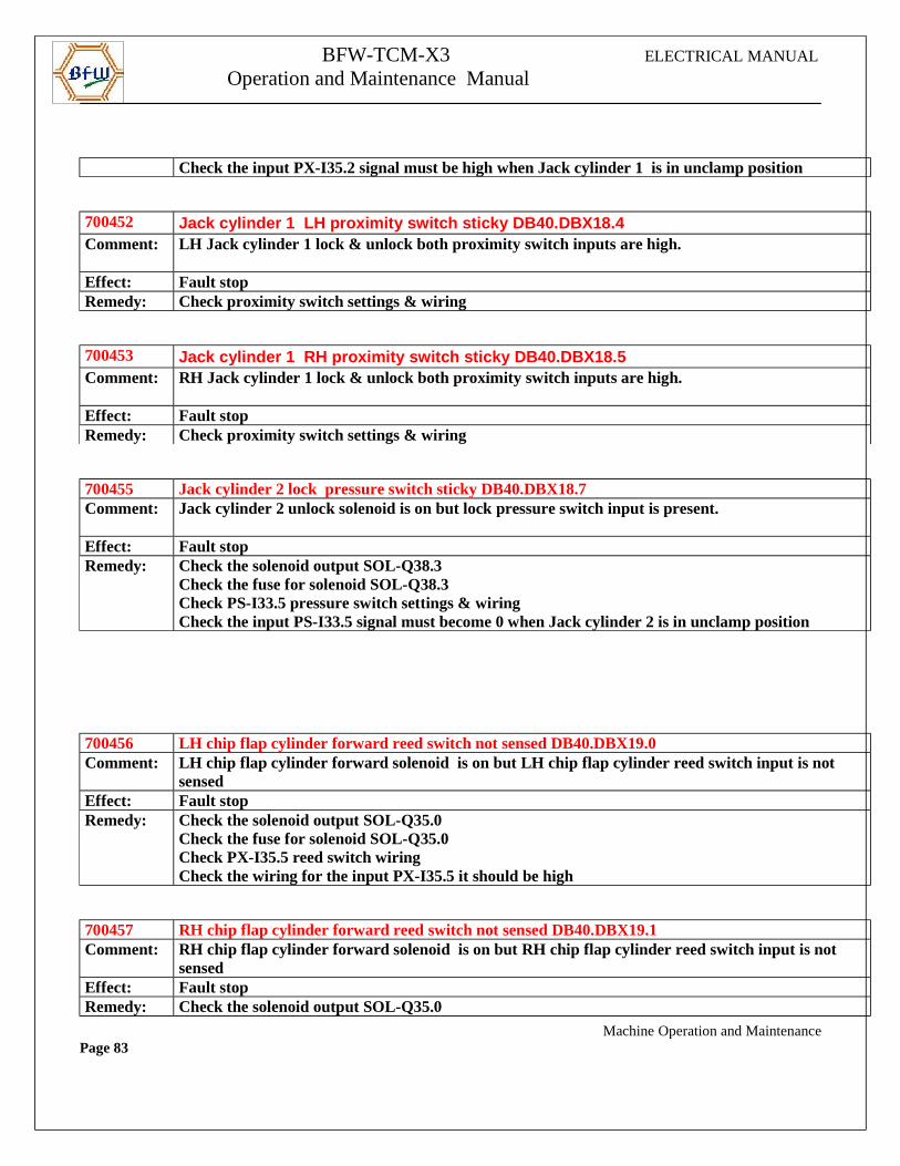
Check the input PX-I35.2 signal must be high when Jack cylinder 1 is in unclamp position
700452 Jack cylinder 1 LH proximity switch sticky DB40.DB X18.4Comment: LH Jack cylinder 1 lock & unlock both proximity switch inputs are high.
Effect: Fault stopRemedy: Check proximity switch settings & wiring
700453 Jack cylinder 1 RH proximity switch sticky DB40.DB X18.5Comment: RH Jack cylinder 1 lock & unlock both proximity switch inputs are high.
Effect: Fault stopRemedy: Check proximity switch settings & wiring
700455 Jack cylinder 2 lock pressure switch sticky DB40.DBX18.7Comment: Jack cylinder 2 unlock solenoid is on but lock pressure switch input is present.
Effect: Fault stopRemedy: Check the solenoid output SOL-Q38.3
Check the fuse for solenoid SOL-Q38.3Check PS-I33.5 pressure switch settings & wiringCheck the input PS-I33.5 signal must become 0 when Jack cylinder 2 is in unclamp position
700456 LH chip flap cylinder forward reed switch not sensed DB40.DBX19.0Comment: LH chip flap cylinder forward solenoid is on but LH chip flap cylinder reed switch input is not
sensedEffect: Fault stopRemedy: Check the solenoid output SOL-Q35.0
Check the fuse for solenoid SOL-Q35.0Check PX-I35.5 reed switch wiringCheck the wiring for the input PX-I35.5 it should be high
700457 RH chip flap cylinder forward reed switch not sensed DB40.DBX19.1Comment: RH chip flap cylinder forward solenoid is on but RH chip flap cylinder reed switch input is not
sensedEffect: Fault stopRemedy: Check the solenoid output SOL-Q35.0
Machine Operation and MaintenancePage 83
BFW-TCM-X3 ELECTRICAL MANUAL
Operation and Maintenance Manual
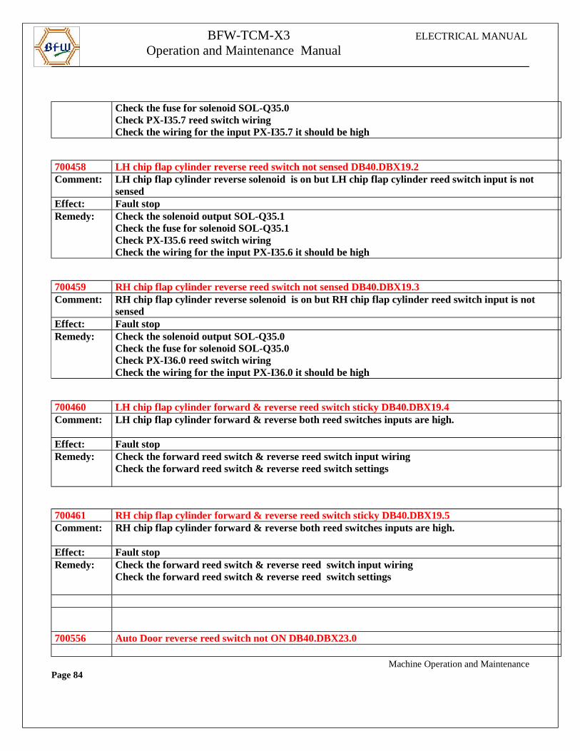
Check the fuse for solenoid SOL-Q35.0Check PX-I35.7 reed switch wiringCheck the wiring for the input PX-I35.7 it should be high
700458 LH chip flap cylinder reverse reed switch not sensed DB40.DBX19.2Comment: LH chip flap cylinder reverse solenoid is on but LH chip flap cylinder reed switch input is not
sensedEffect: Fault stopRemedy: Check the solenoid output SOL-Q35.1
Check the fuse for solenoid SOL-Q35.1Check PX-I35.6 reed switch wiringCheck the wiring for the input PX-I35.6 it should be high
700459 RH chip flap cylinder reverse reed switch not sensed DB40.DBX19.3Comment: RH chip flap cylinder reverse solenoid is on but RH chip flap cylinder reed switch input is not
sensedEffect: Fault stopRemedy: Check the solenoid output SOL-Q35.0
Check the fuse for solenoid SOL-Q35.0Check PX-I36.0 reed switch wiringCheck the wiring for the input PX-I36.0 it should be high
700460 LH chip flap cylinder forward & reverse reed switch sticky DB40.DBX19.4Comment: LH chip flap cylinder forward & reverse both reed switches inputs are high.
Effect: Fault stopRemedy: Check the forward reed switch & reverse reed switch input wiring
Check the forward reed switch & reverse reed switch settings
700461 RH chip flap cylinder forward & reverse reed switch sticky DB40.DBX19.5Comment: RH chip flap cylinder forward & reverse both reed switches inputs are high.
Effect: Fault stopRemedy: Check the forward reed switch & reverse reed switch input wiring
Check the forward reed switch & reverse reed switch settings
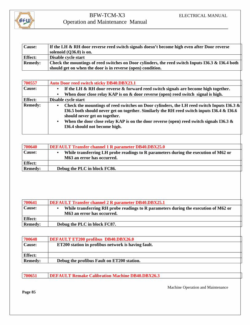
700556 Auto Door reverse reed switch not ON DB40.DBX23.0
Machine Operation and MaintenancePage 84
BFW-TCM-X3 ELECTRICAL MANUAL
Operation and Maintenance Manual
Cause: If the LH & RH door reverse reed switch signals doesn’t become high even after Door reverse
solenoid (Q36.0) is on.Effect: Disable cycle startRemedy: Check the mountings of reed switches on Door cylinders, the reed switch Inputs I36.3 & I36.4 both
should get on when the door is in reverse (open) condition.
700557 Auto Door reed switch sticky DB40.DBX23.1Cause: • If the LH & RH door reverse & forward reed switch signals are become high together.
• When door close relay KAP is on & door reverse (open) reed switch signal is high.Effect: Disable cycle startRemedy: • Check the mountings of reed switches on Door cylinders, the LH reed switch Inputs I36.3 &
I36.5 both should never get on together. Similarly the RH reed switch inputs I36.4 & I36.6 should never get on together.
• When the door close relay KAP is on the door reverse (open) reed switch signals I36.3 & I36.4 should not become high.
700640 DEFAULT Transfer channel 1 R parameter DB40.DBX25.0Cause: • While transferring LH probe readings to R parameters during the execution of M62 or
M63 an error has occurred.Effect:Remedy: Debug the PLC in block FC86.
700641 DEFAULT Transfer channel 2 R parameter DB40.DBX25.1Cause: • While transferring RH probe readings to R parameters during the execution of M62 or
M63 an error has occurred.Effect:Remedy: Debug the PLC in block FC87.
700648 DEFAULT ET200 profibus DB40.DBX26.0Cause: ET200 station in profibus network is having fault.
Effect:Remedy: Debug the profibus Fault on ET200 station.
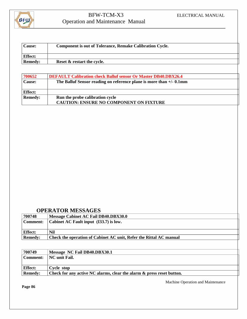
700651 DEFAULT Remake Calibration Machine DB40.DBX26.3
Machine Operation and MaintenancePage 85
BFW-TCM-X3 ELECTRICAL MANUAL
Operation and Maintenance Manual
Cause: Component is out of Tolerance, Remake Calibration Cycle.
Effect: Remedy: Reset & restart the cycle.
700652 DEFAULT Calibration check Balluf sensor Or Master DB40.DBX26.4Cause: The Balluf Sensor reading on reference plane is more than +/- 0.1mm
Effect: Remedy: Run the probe calibration cycle
CAUTION: ENSURE NO COMPONENT ON FIXTURE
OPERATOR MESSAGES700748 Message Cabinet AC Fail DB40.DBX30.0Comment: Cabinet AC Fault input (I33.7) is low.
Effect: NilRemedy: Check the operation of Cabinet AC unit, Refer the Rittal AC manual
700749 Message NC Fail DB40.DBX30.1Comment: NC unit Fail.
Effect: Cycle stopRemedy: Check for any active NC alarms, clear the alarm & press reset button.
Machine Operation and MaintenancePage 86
BFW-TCM-X3 ELECTRICAL MANUAL
Operation and Maintenance Manual
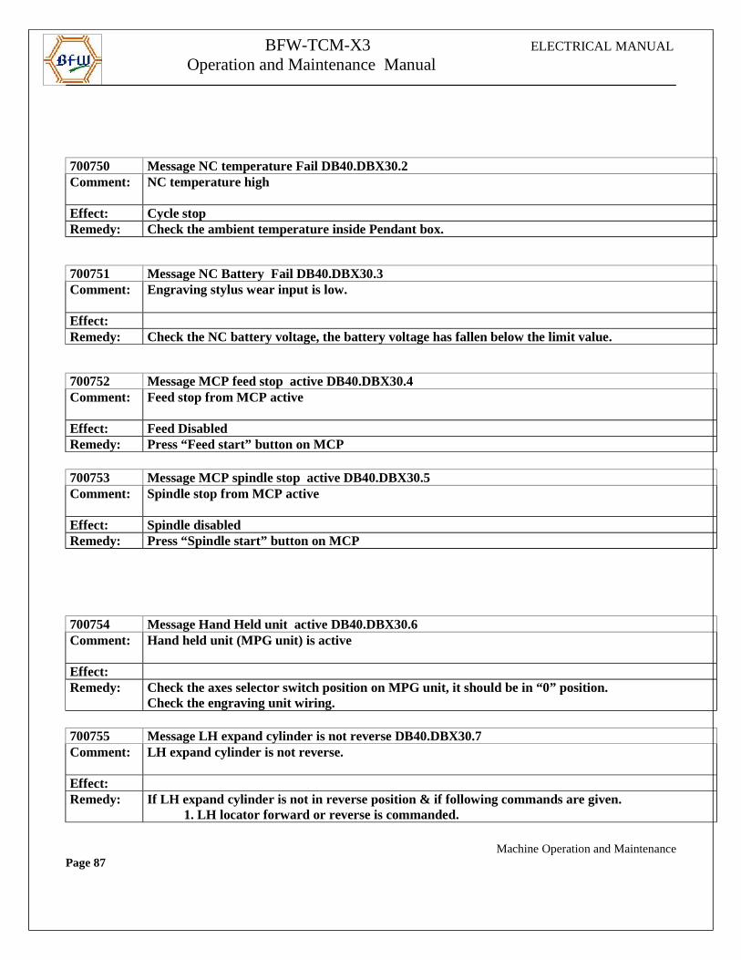
700750 Message NC temperature Fail DB40.DBX30.2Comment: NC temperature high
Effect: Cycle stopRemedy: Check the ambient temperature inside Pendant box.
700751 Message NC Battery Fail DB40.DBX30.3Comment: Engraving stylus wear input is low.
Effect:Remedy: Check the NC battery voltage, the battery voltage has fallen below the limit value.
700752 Message MCP feed stop active DB40.DBX30.4Comment: Feed stop from MCP active
Effect: Feed DisabledRemedy: Press “Feed start” button on MCP
700753 Message MCP spindle stop active DB40.DBX30.5Comment: Spindle stop from MCP active
Effect: Spindle disabledRemedy: Press “Spindle start” button on MCP
700754 Message Hand Held unit active DB40.DBX30.6Comment: Hand held unit (MPG unit) is active
Effect:Remedy: Check the axes selector switch position on MPG unit, it should be in “0” position.
Check the engraving unit wiring.
700755 Message LH expand cylinder is not reverse DB40.DBX30.7Comment: LH expand cylinder is not reverse.
Effect:Remedy: If LH expand cylinder is not in reverse position & if following commands are given.
1. LH locator forward or reverse is commanded.
Machine Operation and MaintenancePage 87
BFW-TCM-X3 ELECTRICAL MANUAL
Operation and Maintenance Manual
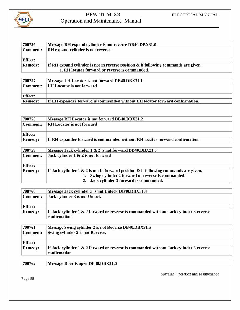
700756 Message RH expand cylinder is not reverse DB40.DBX31.0Comment: RH expand cylinder is not reverse.
Effect:Remedy: If RH expand cylinder is not in reverse position & if following commands are given.
1. RH locator forward or reverse is commanded.
700757 Message LH Locator is not forward DB40.DBX31.1Comment: LH Locator is not forward
Effect:Remedy: If LH expander forward is commanded without LH locator forward confirmation.
700758 Message RH Locator is not forward DB40.DBX31.2Comment: RH Locator is not forward
Effect:Remedy: If RH expander forward is commanded without RH locator forward confirmation
700759 Message Jack cylinder 1 & 2 is not forward DB40.DBX31.3Comment: Jack cylinder 1 & 2 is not forward
Effect:Remedy: If Jack cylinder 1 & 2 is not in forward position & if following commands are given.
1. Swing cylinder 2 forward or reverse is commanded.2. Jack cylinder 3 forward is commanded.
700760 Message Jack cylinder 3 is not Unlock DB40.DBX31.4Comment: Jack cylinder 3 is not Unlock
Effect:Remedy: If Jack cylinder 1 & 2 forward or reverse is commanded without Jack cylinder 3 reverse
confirmation
700761 Message Swing cylinder 2 is not Reverse DB40.DBX31.5Comment: Swing cylinder 2 is not Reverse.
Effect:Remedy: If Jack cylinder 1 & 2 forward or reverse is commanded without Jack cylinder 3 reverse
confirmation
700762 Message Door is open DB40.DBX31.6
Machine Operation and MaintenancePage 88
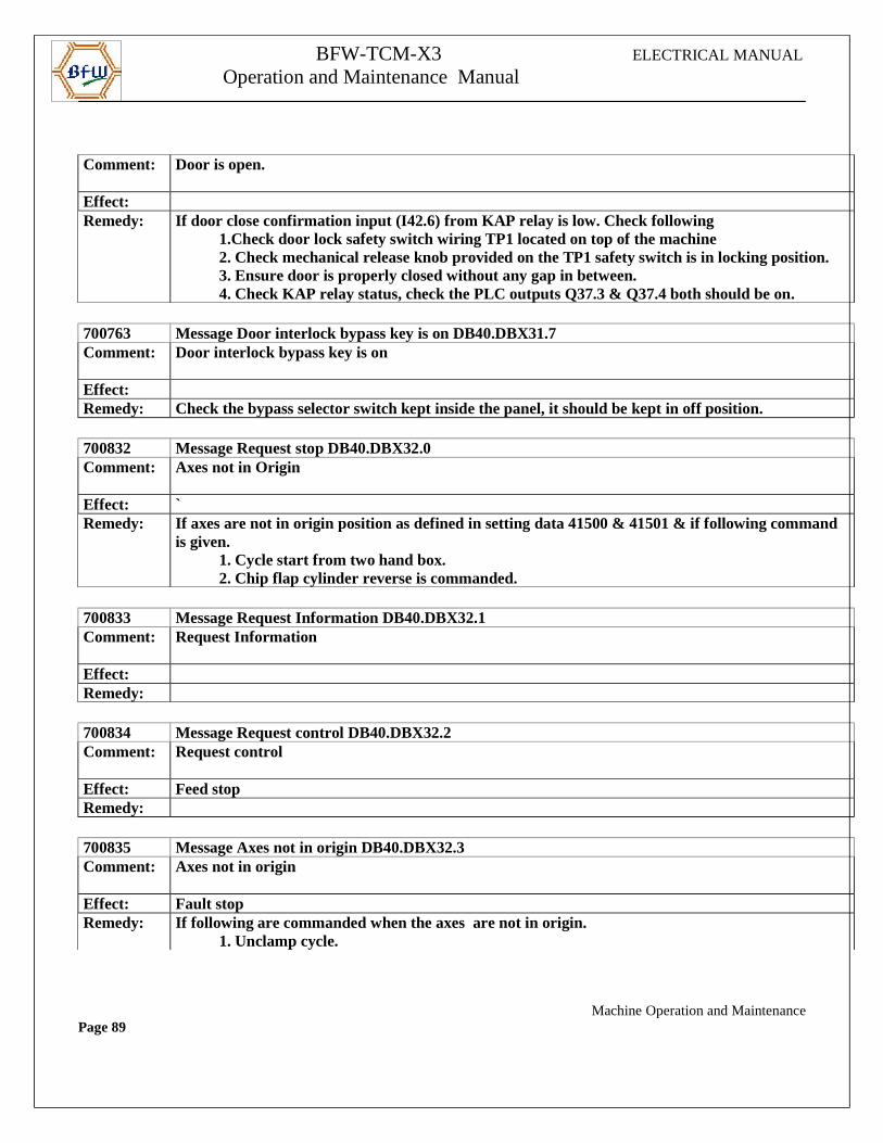
BFW-TCM-X3 ELECTRICAL MANUAL
Operation and Maintenance Manual
Comment: Door is open.
Effect:Remedy: If door close confirmation input (I42.6) from KAP relay is low. Check following
1.Check door lock safety switch wiring TP1 located on top of the machine 2. Check mechanical release knob provided on the TP1 safety switch is in locking position. 3. Ensure door is properly closed without any gap in between. 4. Check KAP relay status, check the PLC outputs Q37.3 & Q37.4 both should be on.
700763 Message Door interlock bypass key is on DB40.DBX31.7Comment: Door interlock bypass key is on
Effect:Remedy: Check the bypass selector switch kept inside the panel, it should be kept in off position.
700832 Message Request stop DB40.DBX32.0Comment: Axes not in Origin
Effect: `Remedy: If axes are not in origin position as defined in setting data 41500 & 41501 & if following command
is given. 1. Cycle start from two hand box. 2. Chip flap cylinder reverse is commanded.
700833 Message Request Information DB40.DBX32.1Comment: Request Information
Effect:Remedy:
700834 Message Request control DB40.DBX32.2Comment: Request control
Effect: Feed stopRemedy:
700835 Message Axes not in origin DB40.DBX32.3Comment: Axes not in origin
Effect: Fault stopRemedy: If following are commanded when the axes are not in origin.
1. Unclamp cycle.
Machine Operation and MaintenancePage 89
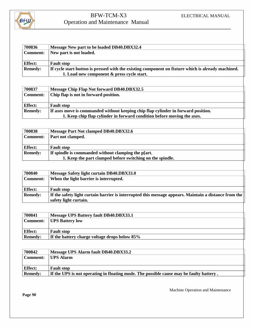
BFW-TCM-X3 ELECTRICAL MANUAL
Operation and Maintenance Manual
700836 Message New part to be loaded DB40.DBX32.4Comment: New part is not loaded.
Effect: Fault stopRemedy: If cycle start button is pressed with the existing component on fixture which is already machined.
1. Load new component & press cycle start.
700837 Message Chip Flap Not forward DB40.DBX32.5Comment: Chip flap is not in forward position.
Effect: Fault stopRemedy: If axes move is commanded without keeping chip flap cylinder in forward position.
1. Keep chip flap cylinder in forward condition before moving the axes.
700838 Message Part Not clamped DB40.DBX32.6Comment: Part not clamped.
Effect: Fault stopRemedy: If spindle is commanded without clamping the p[art.
1. Keep the part clamped before switching on the spindle.
700840 Message Safety light curtain DB40.DBX33.0Comment: When the light barrier is interrupted.
Effect: Fault stopRemedy: If the safety light curtain barrier is interrupted this message appears. Maintain a distance from the
safety light curtain.
700841 Message UPS Battery fault DB40.DBX33.1Comment: UPS Battery low
Effect: Fault stopRemedy: If the battery charge voltage drops below 85%
700842 Message UPS Alarm fault DB40.DBX33.2Comment: UPS Alarm
Effect: Fault stopRemedy: If the UPS is not operating in floating mode. The possible cause may be faulty battery .
Machine Operation and MaintenancePage 90
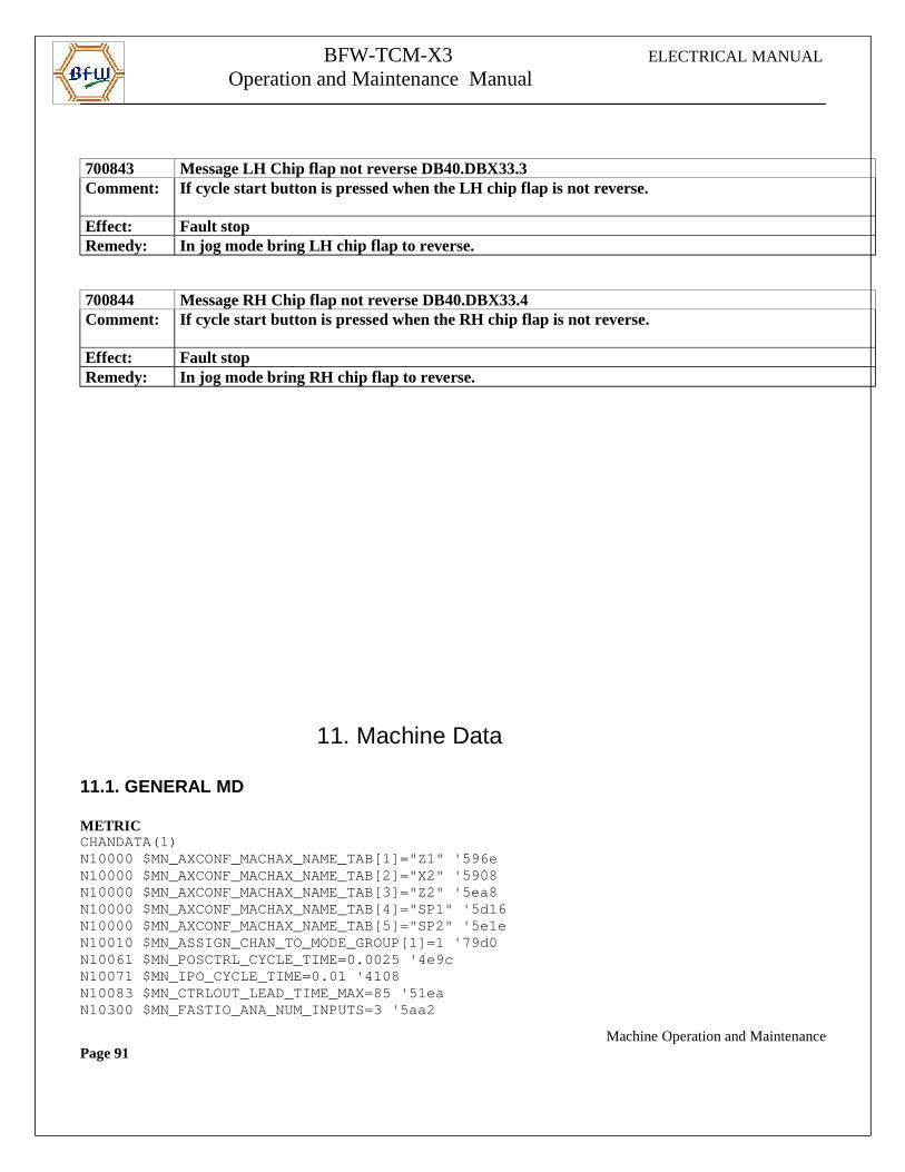
BFW-TCM-X3 ELECTRICAL MANUAL
Operation and Maintenance Manual
700843 Message LH Chip flap not reverse DB40.DBX33.3Comment: If cycle start button is pressed when the LH chip flap is not reverse.
Effect: Fault stopRemedy: In jog mode bring LH chip flap to reverse.
700844 Message RH Chip flap not reverse DB40.DBX33.4Comment: If cycle start button is pressed when the RH chip flap is not reverse.
Effect: Fault stopRemedy: In jog mode bring RH chip flap to reverse.
11. Machine Data
11.1. GENERAL MD
METRICCHANDATA(1)N10000 $MN_AXCONF_MACHAX_NAME_TAB[1]="Z1" '596eN10000 $MN_AXCONF_MACHAX_NAME_TAB[2]="X2" '5908N10000 $MN_AXCONF_MACHAX_NAME_TAB[3]="Z2" '5ea8N10000 $MN_AXCONF_MACHAX_NAME_TAB[4]="SP1" '5d16N10000 $MN_AXCONF_MACHAX_NAME_TAB[5]="SP2" '5e1eN10010 $MN_ASSIGN_CHAN_TO_MODE_GROUP[1]=1 '79d0N10061 $MN_POSCTRL_CYCLE_TIME=0.0025 '4e9cN10071 $MN_IPO_CYCLE_TIME=0.01 '4108N10083 $MN_CTRLOUT_LEAD_TIME_MAX=85 '51eaN10300 $MN_FASTIO_ANA_NUM_INPUTS=3 '5aa2
Machine Operation and MaintenancePage 91
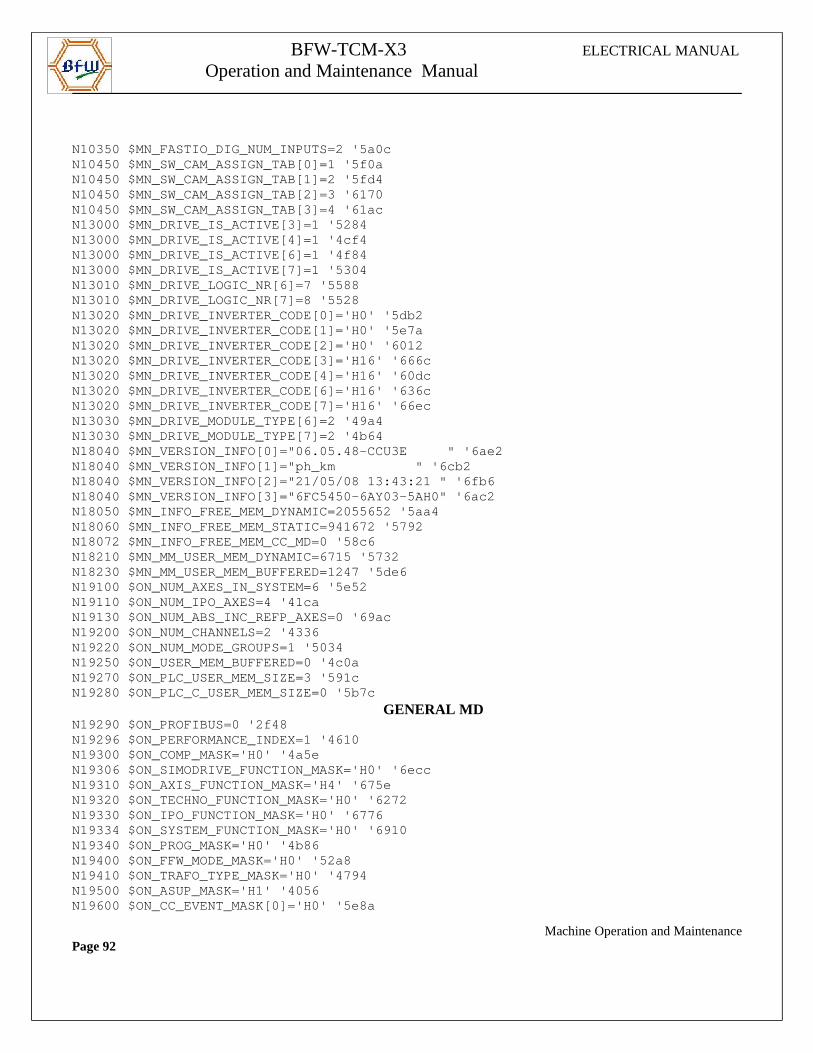
BFW-TCM-X3 ELECTRICAL MANUAL
Operation and Maintenance Manual
N10350 $MN_FASTIO_DIG_NUM_INPUTS=2 '5a0cN10450 $MN_SW_CAM_ASSIGN_TAB[0]=1 '5f0aN10450 $MN_SW_CAM_ASSIGN_TAB[1]=2 '5fd4N10450 $MN_SW_CAM_ASSIGN_TAB[2]=3 '6170N10450 $MN_SW_CAM_ASSIGN_TAB[3]=4 '61acN13000 $MN_DRIVE_IS_ACTIVE[3]=1 '5284N13000 $MN_DRIVE_IS_ACTIVE[4]=1 '4cf4N13000 $MN_DRIVE_IS_ACTIVE[6]=1 '4f84N13000 $MN_DRIVE_IS_ACTIVE[7]=1 '5304N13010 $MN_DRIVE_LOGIC_NR[6]=7 '5588N13010 $MN_DRIVE_LOGIC_NR[7]=8 '5528N13020 $MN_DRIVE_INVERTER_CODE[0]='H0' '5db2N13020 $MN_DRIVE_INVERTER_CODE[1]='H0' '5e7aN13020 $MN_DRIVE_INVERTER_CODE[2]='H0' '6012N13020 $MN_DRIVE_INVERTER_CODE[3]='H16' '666cN13020 $MN_DRIVE_INVERTER_CODE[4]='H16' '60dcN13020 $MN_DRIVE_INVERTER_CODE[6]='H16' '636cN13020 $MN_DRIVE_INVERTER_CODE[7]='H16' '66ecN13030 $MN_DRIVE_MODULE_TYPE[6]=2 '49a4N13030 $MN_DRIVE_MODULE_TYPE[7]=2 '4b64N18040 $MN_VERSION_INFO[0]="06.05.48-CCU3E " '6 ae2N18040 $MN_VERSION_INFO[1]="ph_km " '6cb2N18040 $MN_VERSION_INFO[2]="21/05/08 13:43:21 " '6f b6N18040 $MN_VERSION_INFO[3]="6FC5450-6AY03-5AH0" '6a c2N18050 $MN_INFO_FREE_MEM_DYNAMIC=2055652 '5aa4N18060 $MN_INFO_FREE_MEM_STATIC=941672 '5792N18072 $MN_INFO_FREE_MEM_CC_MD=0 '58c6N18210 $MN_MM_USER_MEM_DYNAMIC=6715 '5732N18230 $MN_MM_USER_MEM_BUFFERED=1247 '5de6N19100 $ON_NUM_AXES_IN_SYSTEM=6 '5e52N19110 $ON_NUM_IPO_AXES=4 '41caN19130 $ON_NUM_ABS_INC_REFP_AXES=0 '69acN19200 $ON_NUM_CHANNELS=2 '4336N19220 $ON_NUM_MODE_GROUPS=1 '5034N19250 $ON_USER_MEM_BUFFERED=0 '4c0aN19270 $ON_PLC_USER_MEM_SIZE=3 '591cN19280 $ON_PLC_C_USER_MEM_SIZE=0 '5b7c
GENERAL MD N19290 $ON_PROFIBUS=0 '2f48N19296 $ON_PERFORMANCE_INDEX=1 '4610N19300 $ON_COMP_MASK='H0' '4a5eN19306 $ON_SIMODRIVE_FUNCTION_MASK='H0' '6eccN19310 $ON_AXIS_FUNCTION_MASK='H4' '675eN19320 $ON_TECHNO_FUNCTION_MASK='H0' '6272N19330 $ON_IPO_FUNCTION_MASK='H0' '6776N19334 $ON_SYSTEM_FUNCTION_MASK='H0' '6910N19340 $ON_PROG_MASK='H0' '4b86N19400 $ON_FFW_MODE_MASK='H0' '52a8N19410 $ON_TRAFO_TYPE_MASK='H0' '4794N19500 $ON_ASUP_MASK='H1' '4056N19600 $ON_CC_EVENT_MASK[0]='H0' '5e8a
Machine Operation and MaintenancePage 92
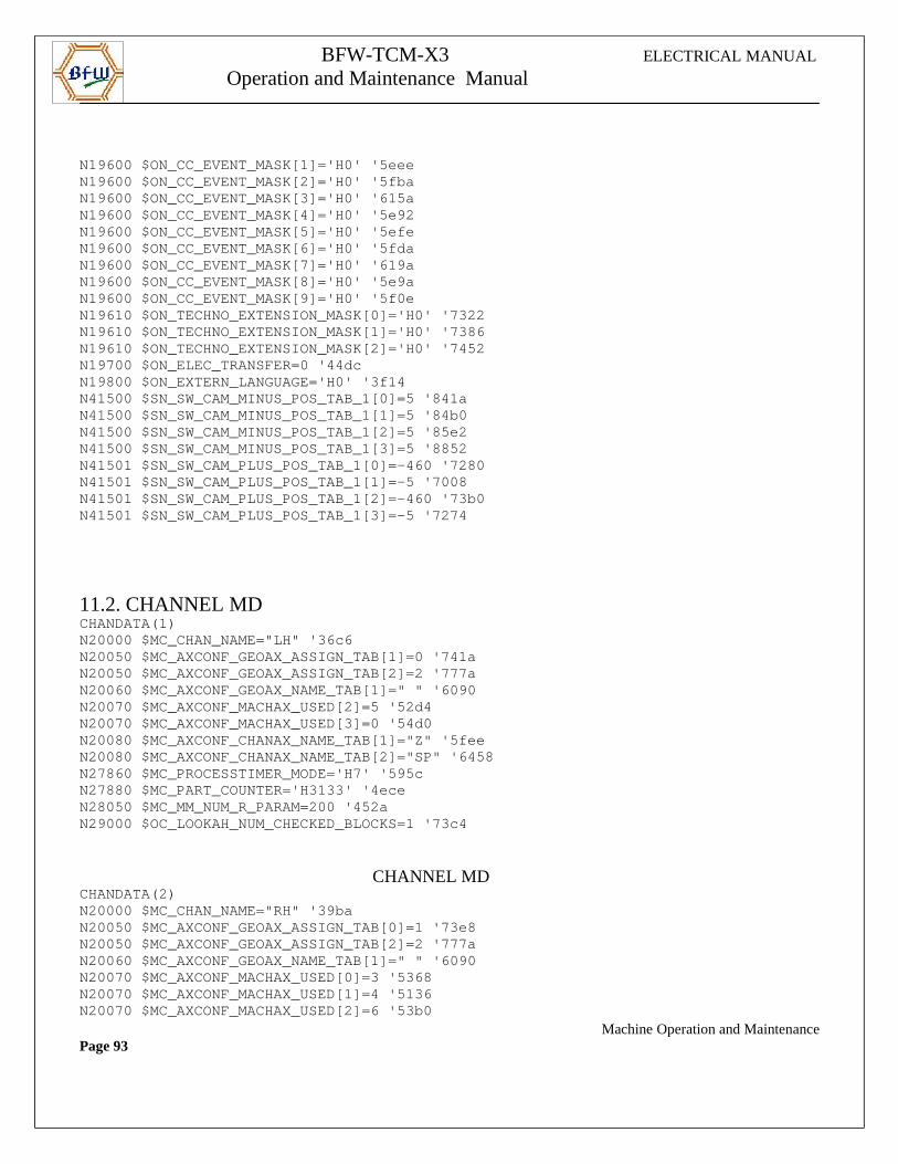
BFW-TCM-X3 ELECTRICAL MANUAL
Operation and Maintenance Manual
N19600 $ON_CC_EVENT_MASK[1]='H0' '5eeeN19600 $ON_CC_EVENT_MASK[2]='H0' '5fbaN19600 $ON_CC_EVENT_MASK[3]='H0' '615aN19600 $ON_CC_EVENT_MASK[4]='H0' '5e92N19600 $ON_CC_EVENT_MASK[5]='H0' '5efeN19600 $ON_CC_EVENT_MASK[6]='H0' '5fdaN19600 $ON_CC_EVENT_MASK[7]='H0' '619aN19600 $ON_CC_EVENT_MASK[8]='H0' '5e9aN19600 $ON_CC_EVENT_MASK[9]='H0' '5f0eN19610 $ON_TECHNO_EXTENSION_MASK[0]='H0' '7322N19610 $ON_TECHNO_EXTENSION_MASK[1]='H0' '7386N19610 $ON_TECHNO_EXTENSION_MASK[2]='H0' '7452N19700 $ON_ELEC_TRANSFER=0 '44dcN19800 $ON_EXTERN_LANGUAGE='H0' '3f14N41500 $SN_SW_CAM_MINUS_POS_TAB_1[0]=5 '841aN41500 $SN_SW_CAM_MINUS_POS_TAB_1[1]=5 '84b0N41500 $SN_SW_CAM_MINUS_POS_TAB_1[2]=5 '85e2N41500 $SN_SW_CAM_MINUS_POS_TAB_1[3]=5 '8852N41501 $SN_SW_CAM_PLUS_POS_TAB_1[0]=-460 '7280N41501 $SN_SW_CAM_PLUS_POS_TAB_1[1]=-5 '7008N41501 $SN_SW_CAM_PLUS_POS_TAB_1[2]=-460 '73b0N41501 $SN_SW_CAM_PLUS_POS_TAB_1[3]=-5 '7274
11.2. CHANNEL MDCHANDATA(1)N20000 $MC_CHAN_NAME="LH" '36c6N20050 $MC_AXCONF_GEOAX_ASSIGN_TAB[1]=0 '741aN20050 $MC_AXCONF_GEOAX_ASSIGN_TAB[2]=2 '777aN20060 $MC_AXCONF_GEOAX_NAME_TAB[1]=" " '6090N20070 $MC_AXCONF_MACHAX_USED[2]=5 '52d4N20070 $MC_AXCONF_MACHAX_USED[3]=0 '54d0N20080 $MC_AXCONF_CHANAX_NAME_TAB[1]="Z" '5feeN20080 $MC_AXCONF_CHANAX_NAME_TAB[2]="SP" '6458N27860 $MC_PROCESSTIMER_MODE='H7' '595cN27880 $MC_PART_COUNTER='H3133' '4eceN28050 $MC_MM_NUM_R_PARAM=200 '452aN29000 $OC_LOOKAH_NUM_CHECKED_BLOCKS=1 '73c4
CHANNEL MDCHANDATA(2)N20000 $MC_CHAN_NAME="RH" '39baN20050 $MC_AXCONF_GEOAX_ASSIGN_TAB[0]=1 '73e8N20050 $MC_AXCONF_GEOAX_ASSIGN_TAB[2]=2 '777aN20060 $MC_AXCONF_GEOAX_NAME_TAB[1]=" " '6090N20070 $MC_AXCONF_MACHAX_USED[0]=3 '5368N20070 $MC_AXCONF_MACHAX_USED[1]=4 '5136N20070 $MC_AXCONF_MACHAX_USED[2]=6 '53b0 Machine Operation and MaintenancePage 93
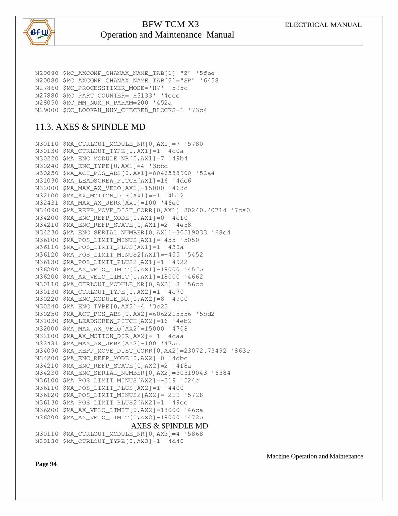
BFW-TCM-X3 ELECTRICAL MANUAL
Operation and Maintenance Manual
N20080 $MC_AXCONF_CHANAX_NAME_TAB[1]="Z" '5feeN20080 $MC_AXCONF_CHANAX_NAME_TAB[2]="SP" '6458N27860 $MC_PROCESSTIMER_MODE='H7' '595cN27880 $MC_PART_COUNTER='H3133' '4eceN28050 $MC_MM_NUM_R_PARAM=200 '452aN29000 $OC_LOOKAH_NUM_CHECKED_BLOCKS=1 '73c4
11.3. AXES & SPINDLE MD N30110 $MA_CTRLOUT_MODULE_NR[0,AX1]=7 '5780N30130 $MA_CTRLOUT_TYPE[0,AX1]=1 '4c0aN30220 $MA_ENC_MODULE_NR[0,AX1]=7 '49b4N30240 $MA_ENC_TYPE[0,AX1]=4 '3bbcN30250 $MA_ACT_POS_ABS[0,AX1]=8046588900 '52a4N31030 $MA_LEADSCREW_PITCH[AX1]=16 '4de6N32000 $MA_MAX_AX_VELO[AX1]=15000 '463cN32100 $MA_AX_MOTION_DIR[AX1]=-1 '4b12N32431 $MA_MAX_AX_JERK[AX1]=100 '46e0N34090 $MA_REFP_MOVE_DIST_CORR[0,AX1]=30240.40714 ' 7ca0N34200 $MA_ENC_REFP_MODE[0,AX1]=0 '4cf0N34210 $MA_ENC_REFP_STATE[0,AX1]=2 '4e58N34230 $MA_ENC_SERIAL_NUMBER[0,AX1]=30519033 '68e4N36100 $MA_POS_LIMIT_MINUS[AX1]=-455 '5050N36110 $MA_POS_LIMIT_PLUS[AX1]=1 '439aN36120 $MA_POS_LIMIT_MINUS2[AX1]=-455 '5452N36130 $MA_POS_LIMIT_PLUS2[AX1]=1 '4922N36200 $MA_AX_VELO_LIMIT[0,AX1]=18000 '45feN36200 $MA_AX_VELO_LIMIT[1,AX1]=18000 '4662N30110 $MA_CTRLOUT_MODULE_NR[0,AX2]=8 '56ccN30130 $MA_CTRLOUT_TYPE[0,AX2]=1 '4c70N30220 $MA_ENC_MODULE_NR[0,AX2]=8 '4900N30240 $MA_ENC_TYPE[0,AX2]=4 '3c22N30250 $MA_ACT_POS_ABS[0,AX2]=6062215556 '5bd2N31030 $MA_LEADSCREW_PITCH[AX2]=16 '4eb2N32000 $MA_MAX_AX_VELO[AX2]=15000 '4708N32100 $MA_AX_MOTION_DIR[AX2]=-1 '4caaN32431 $MA_MAX_AX_JERK[AX2]=100 '47acN34090 $MA_REFP_MOVE_DIST_CORR[0,AX2]=23072.73492 ' 863cN34200 $MA_ENC_REFP_MODE[0,AX2]=0 '4dbcN34210 $MA_ENC_REFP_STATE[0,AX2]=2 '4f8aN34230 $MA_ENC_SERIAL_NUMBER[0,AX2]=30519043 '6584N36100 $MA_POS_LIMIT_MINUS[AX2]=-219 '524cN36110 $MA_POS_LIMIT_PLUS[AX2]=1 '4400N36120 $MA_POS_LIMIT_MINUS2[AX2]=-219 '5728N36130 $MA_POS_LIMIT_PLUS2[AX2]=1 '49eeN36200 $MA_AX_VELO_LIMIT[0,AX2]=18000 '46caN36200 $MA_AX_VELO_LIMIT[1,AX2]=18000 '472e
AXES & SPINDLE MDN30110 $MA_CTRLOUT_MODULE_NR[0,AX3]=4 '5868N30130 $MA_CTRLOUT_TYPE[0,AX3]=1 '4d40
Machine Operation and MaintenancePage 94
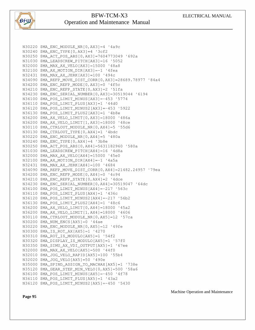
BFW-TCM-X3 ELECTRICAL MANUAL
Operation and Maintenance Manual
N30220 $MA_ENC_MODULE_NR[0,AX3]=4 '4a9cN30240 $MA_ENC_TYPE[0,AX3]=4 '3cf2N30250 $MA_ACT_POS_ABS[0,AX3]=7604773049 '692aN31030 $MA_LEADSCREW_PITCH[AX3]=16 '5052N32000 $MA_MAX_AX_VELO[AX3]=15000 '48a8N32100 $MA_AX_MOTION_DIR[AX3]=-1 '4feaN32431 $MA_MAX_AX_JERK[AX3]=100 '494cN34090 $MA_REFP_MOVE_DIST_CORR[0,AX3]=28689.78977 ' 84a4N34200 $MA_ENC_REFP_MODE[0,AX3]=0 '4f5cN34210 $MA_ENC_REFP_STATE[0,AX3]=2 '51faN34230 $MA_ENC_SERIAL_NUMBER[0,AX3]=30519044 '6194N36100 $MA_POS_LIMIT_MINUS[AX3]=-453 '5774N36110 $MA_POS_LIMIT_PLUS[AX3]=1 '44d0N36120 $MA_POS_LIMIT_MINUS2[AX3]=-453 '5922N36130 $MA_POS_LIMIT_PLUS2[AX3]=1 '4b8eN36200 $MA_AX_VELO_LIMIT[0,AX3]=18000 '486aN36200 $MA_AX_VELO_LIMIT[1,AX3]=18000 '48ceN30110 $MA_CTRLOUT_MODULE_NR[0,AX4]=5 '55d6N30130 $MA_CTRLOUT_TYPE[0,AX4]=1 '4bdcN30220 $MA_ENC_MODULE_NR[0,AX4]=5 '480aN30240 $MA_ENC_TYPE[0,AX4]=4 '3b8eN30250 $MA_ACT_POS_ABS[0,AX4]=5631182960 '580aN31030 $MA_LEADSCREW_PITCH[AX4]=16 '4d8aN32000 $MA_MAX_AX_VELO[AX4]=15000 '45e0N32100 $MA_AX_MOTION_DIR[AX4]=-1 '4a5aN32431 $MA_MAX_AX_JERK[AX4]=100 '4684N34090 $MA_REFP_MOVE_DIST_CORR[0,AX4]=21482.24957 ' 79eaN34200 $MA_ENC_REFP_MODE[0,AX4]=0 '4c94N34210 $MA_ENC_REFP_STATE[0,AX4]=2 '4dceN34230 $MA_ENC_SERIAL_NUMBER[0,AX4]=30519047 '64dcN36100 $MA_POS_LIMIT_MINUS[AX4]=-217 '563cN36110 $MA_POS_LIMIT_PLUS[AX4]=1 '436cN36120 $MA_POS_LIMIT_MINUS2[AX4]=-217 '56b2N36130 $MA_POS_LIMIT_PLUS2[AX4]=1 '48c6N36200 $MA_AX_VELO_LIMIT[0,AX4]=18000 '45a2N36200 $MA_AX_VELO_LIMIT[1,AX4]=18000 '4606N30110 $MA_CTRLOUT_MODULE_NR[0,AX5]=12 '57caN30200 $MA_NUM_ENCS[AX5]=0 '44aeN30220 $MA_ENC_MODULE_NR[0,AX5]=12 '49feN30300 $MA_IS_ROT_AX[AX5]=1 '4270N30310 $MA_ROT_IS_MODULO[AX5]=1 '54f2N30320 $MA_DISPLAY_IS_MODULO[AX5]=1 '57f0N30350 $MA_SIMU_AX_VDI_OUTPUT[AX5]=1 '67eeN32000 $MA_MAX_AX_VELO[AX5]=500 '44f0N32010 $MA_JOG_VELO_RAPID[AX5]=100 '55b4N32020 $MA_JOG_VELO[AX5]=50 '490eN35000 $MA_SPIND_ASSIGN_TO_MACHAX[AX5]=1 '738eN35120 $MA_GEAR_STEP_MIN_VELO[0,AX5]=500 '58a6N36100 $MA_POS_LIMIT_MINUS[AX5]=-450 '4f78N36110 $MA_POS_LIMIT_PLUS[AX5]=1 '43a2N36120 $MA_POS_LIMIT_MINUS2[AX5]=-450 '5430
Machine Operation and MaintenancePage 95
BFW-TCM-X3 ELECTRICAL MANUAL
Operation and Maintenance Manual
N36130 $MA_POS_LIMIT_PLUS2[AX5]=1 '4932
Machine Operation and MaintenancePage 96
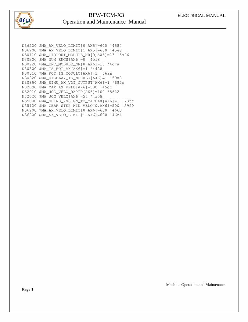
BFW-TCM-X3 ELECTRICAL MANUAL
Operation and Maintenance Manual
N36200 $MA_AX_VELO_LIMIT[0,AX5]=600 '4584N36200 $MA_AX_VELO_LIMIT[1,AX5]=600 '45e8N30110 $MA_CTRLOUT_MODULE_NR[0,AX6]=13 '5a46N30200 $MA_NUM_ENCS[AX6]=0 '45f8N30220 $MA_ENC_MODULE_NR[0,AX6]=13 '4c7aN30300 $MA_IS_ROT_AX[AX6]=1 '4428N30310 $MA_ROT_IS_MODULO[AX6]=1 '56aaN30320 $MA_DISPLAY_IS_MODULO[AX6]=1 '59a8N30350 $MA_SIMU_AX_VDI_OUTPUT[AX6]=1 '685cN32000 $MA_MAX_AX_VELO[AX6]=500 '45ccN32010 $MA_JOG_VELO_RAPID[AX6]=100 '5622N32020 $MA_JOG_VELO[AX6]=50 '4a58N35000 $MA_SPIND_ASSIGN_TO_MACHAX[AX6]=1 '73fcN35120 $MA_GEAR_STEP_MIN_VELO[0,AX6]=500 '59f0N36200 $MA_AX_VELO_LIMIT[0,AX6]=600 '4660N36200 $MA_AX_VELO_LIMIT[1,AX6]=600 '46c4
Machine Operation and MaintenancePage 1
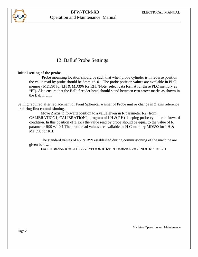
BFW-TCM-X3 ELECTRICAL MANUAL
Operation and Maintenance Manual
12. Balluf Probe Settings
Initial setting of the probe. Probe mounting location should be such that when probe cylinder is in reverse position the value read by probe should be 8mm +/- 0.1.The probe position values are available in PLC memory MD390 for LH & MD396 for RH. (Note: select data format for these PLC memory as “F”). Also ensure that the Balluf reader head should stand between two arrow marks as shown in the Balluf unit.
Setting required after replacement of Front Spherical washer of Probe unit or change in Z axis reference or during first commissioning.
Move Z axis to forward position to a value given in R parameter R2 (from CALIBRATION1, CALIBRATION2 program of LH & RH) keeping probe cylinder in forwardcondition. In this position of Z axis the value read by probe should be equal to the value of R parameter R99 +/- 0.1.The probe read values are available in PLC memory MD390 for LH & MD396 for RH.
The standard values of R2 & R99 established during commissioning of the machine are given below.
For LH station R2= -118.2 & R99 =36 & for RH station R2= -120 & R99 = 37.1
Machine Operation and MaintenancePage 2
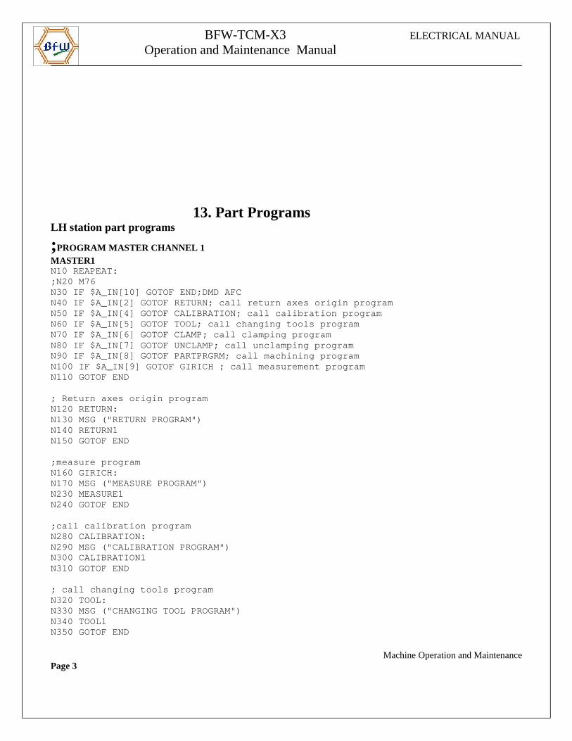
BFW-TCM-X3 ELECTRICAL MANUAL
Operation and Maintenance Manual
13. Part Programs LH station part programs
;PROGRAM MASTER CHANNEL 1 MASTER1N10 REAPEAT:;N20 M76N30 IF $A_IN[10] GOTOF END;DMD AFCN40 IF $A_IN[2] GOTOF RETURN; call return axes orig in programN50 IF $A_IN[4] GOTOF CALIBRATION; call calibration programN60 IF $A_IN[5] GOTOF TOOL; call changing tools pro gramN70 IF $A_IN[6] GOTOF CLAMP; call clamping programN80 IF $A_IN[7] GOTOF UNCLAMP; call unclamping prog ramN90 IF $A_IN[8] GOTOF PARTPRGRM; call machining pro gram N100 IF $A_IN[9] GOTOF GIRICH ; call measurement pr ogramN110 GOTOF END
; Return axes origin programN120 RETURN:N130 MSG ("RETURN PROGRAM")N140 RETURN1N150 GOTOF END ;measure program N160 GIRICH:N170 MSG ("MEASURE PROGRAM")N230 MEASURE1N240 GOTOF END
;call calibration programN280 CALIBRATION:N290 MSG ("CALIBRATION PROGRAM")N300 CALIBRATION1N310 GOTOF END
; call changing tools programN320 TOOL:N330 MSG ("CHANGING TOOL PROGRAM")N340 TOOL1N350 GOTOF END
Machine Operation and MaintenancePage 3
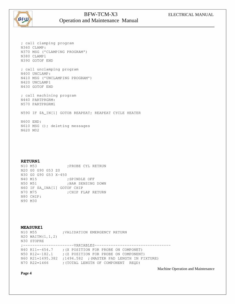
BFW-TCM-X3 ELECTRICAL MANUAL
Operation and Maintenance Manual
; call clamping programN360 CLAMP:N370 MSG ("CLAMPING PROGRAM")N380 CLAMP1N390 GOTOF END
; call unclamping program N400 UNCLAMP:N410 MSG ("UNCLAMPING PROGRAM")N420 UNCLAMP1N430 GOTOF END
; call machining programN440 PARTPRGRM:N570 PARTPRGRM1
N590 IF $A_IN[1] GOTOB REAPEAT; REAPEAT CYCLE HEATE R
N600 END:N610 MSG (); deleting messagesN620 M02
RETURN1N10 M53 ;PROBE CYL RETRUNN20 G0 G90 G53 Z0N30 G0 G90 G53 X-450N40 M15 ;SPINDLE OFFN50 M51 ;BAR SENSING DOWNN60 IF $A_INA[1] GOTOF CHIPN70 M75 ;CHIP FLAP RETURNN80 CHIP:N90 M30
MEASURE1N10 M55 ;VALIDATION EMERGENCY RETURNN20 WAITM(1,1,2)N30 STOPRE;----------------------VARIABLES------------------- --------------N40 R11=-454.7 ;(X POSITION FOR PROBE ON COMPONE T)N50 R12=-182.1 ;(Z POSITION FOR PROBE ON COMPONE NT)N60 R21=1495.382 ;1494.582 ;(MASTER PAD LENGTH IN FIXTURE)N70 R22=1466 ;(TOTAL LENGTH OF COMPONENT REQD )
Machine Operation and MaintenancePage 4
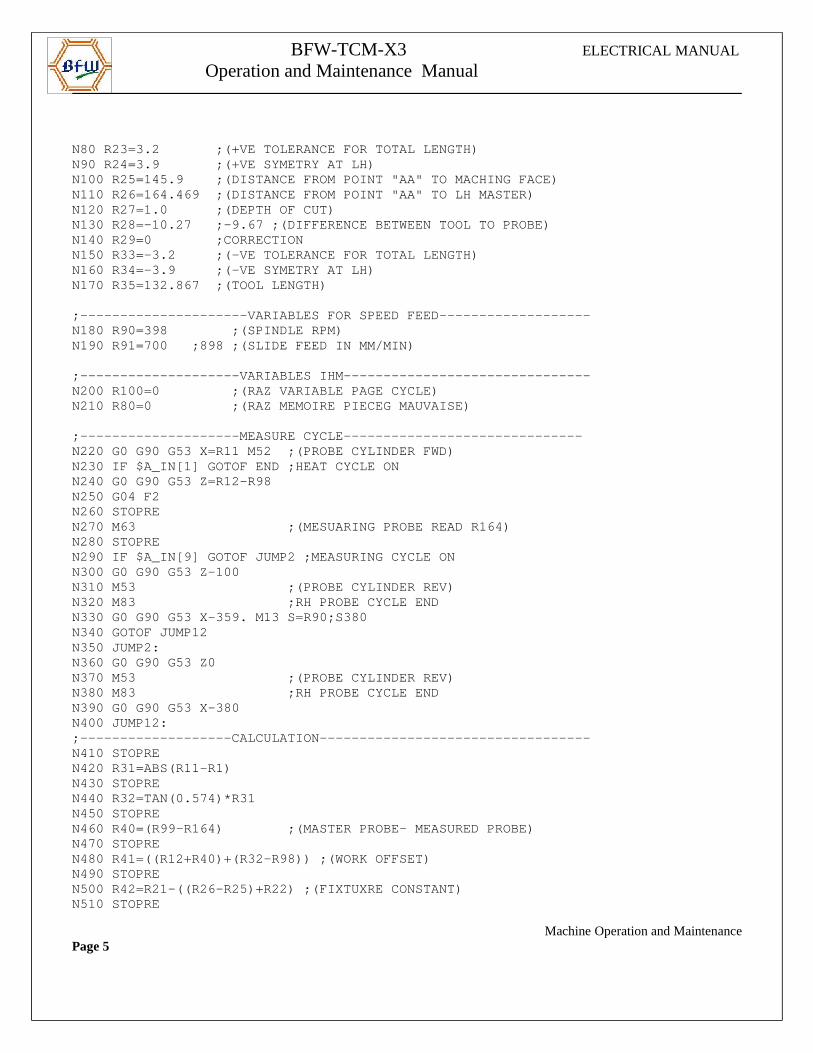
BFW-TCM-X3 ELECTRICAL MANUAL
Operation and Maintenance Manual
N80 R23=3.2 ;(+VE TOLERANCE FOR TOTAL LENGTH)N90 R24=3.9 ;(+VE SYMETRY AT LH)N100 R25=145.9 ;(DISTANCE FROM POINT "AA" TO MAC HING FACE)N110 R26=164.469 ;(DISTANCE FROM POINT "AA" TO LH MASTER)N120 R27=1.0 ;(DEPTH OF CUT)N130 R28=-10.27 ;-9.67 ;(DIFFERENCE BETWEEN TOOL TO PROBE)N140 R29=0 ;CORRECTIONN150 R33=-3.2 ;(-VE TOLERANCE FOR TOTAL LENGTH)N160 R34=-3.9 ;(-VE SYMETRY AT LH)N170 R35=132.867 ;(TOOL LENGTH)
;---------------------VARIABLES FOR SPEED FEED----- --------------N180 R90=398 ;(SPINDLE RPM)N190 R91=700 ;898 ;(SLIDE FEED IN MM/MIN)
;--------------------VARIABLES IHM----------------- --------------N200 R100=0 ;(RAZ VARIABLE PAGE CYCLE)N210 R80=0 ;(RAZ MEMOIRE PIECEG MAUVAISE)
;--------------------MEASURE CYCLE----------------- -------------N220 G0 G90 G53 X=R11 M52 ;(PROBE CYLINDER FWD)N230 IF $A_IN[1] GOTOF END ;HEAT CYCLE ONN240 G0 G90 G53 Z=R12-R98N250 G04 F2N260 STOPREN270 M63 ;(MESUARING PROBE READ R 164)N280 STOPREN290 IF $A_IN[9] GOTOF JUMP2 ;MEASURING CYCLE ONN300 G0 G90 G53 Z-100N310 M53 ;(PROBE CYLINDER REV)N320 M83 ;RH PROBE CYCLE ENDN330 G0 G90 G53 X-359. M13 S=R90;S380N340 GOTOF JUMP12N350 JUMP2:N360 G0 G90 G53 Z0N370 M53 ;(PROBE CYLINDER REV)N380 M83 ;RH PROBE CYCLE ENDN390 G0 G90 G53 X-380N400 JUMP12:;-------------------CALCULATION-------------------- --------------N410 STOPREN420 R31=ABS(R11-R1)N430 STOPREN440 R32=TAN(0.574)*R31N450 STOPREN460 R40=(R99-R164) ;(MASTER PROBE- MEASURED PROBE)N470 STOPREN480 R41=((R12+R40)+(R32-R98)) ;(WORK OFFSET) N490 STOPREN500 R42=R21-((R26-R25)+R22) ;(FIXTUXRE CONSTANT)N510 STOPRE
Machine Operation and MaintenancePage 5
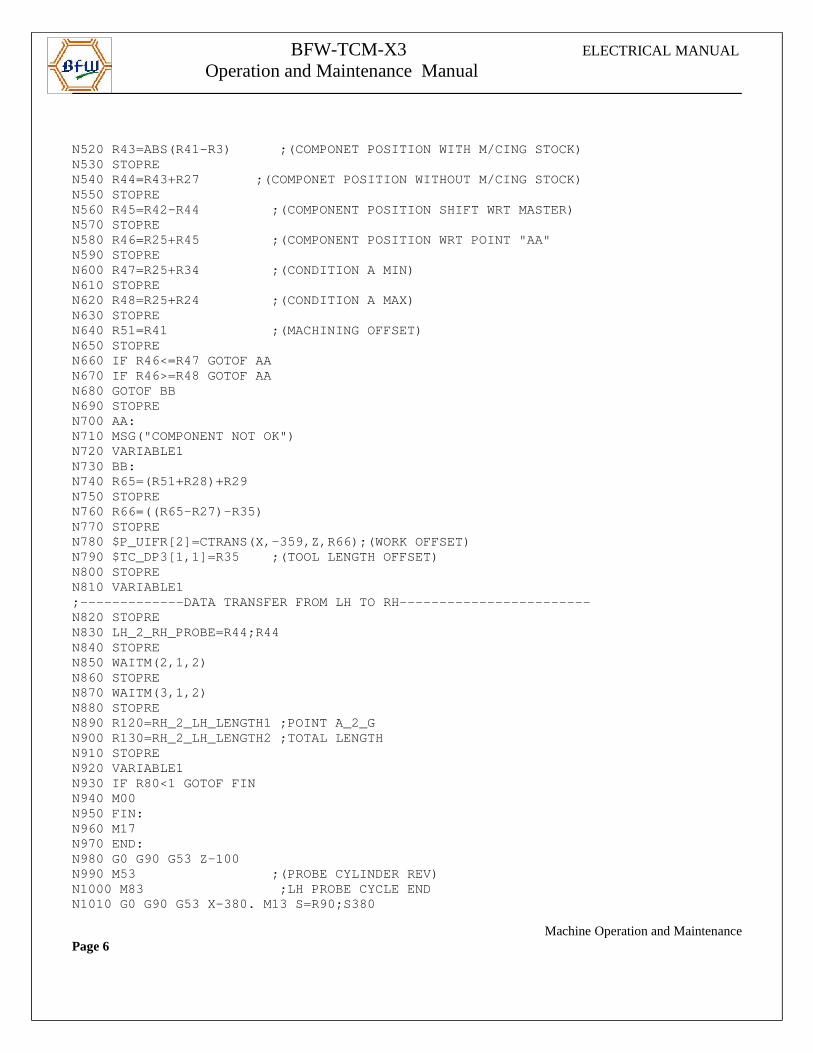
BFW-TCM-X3 ELECTRICAL MANUAL
Operation and Maintenance Manual
N520 R43=ABS(R41-R3) ;(COMPONET POSITION WITH M/CING STOCK)N530 STOPREN540 R44=R43+R27 ;(COMPONET POSITION WITHOUT M/CING STOCK)N550 STOPREN560 R45=R42-R44 ;(COMPONENT POSITION SHIFT WRT MASTER)N570 STOPREN580 R46=R25+R45 ;(COMPONENT POSITION WRT P OINT "AA"N590 STOPREN600 R47=R25+R34 ;(CONDITION A MIN)N610 STOPREN620 R48=R25+R24 ;(CONDITION A MAX)N630 STOPREN640 R51=R41 ;(MACHINING OFFSET)N650 STOPREN660 IF R46<=R47 GOTOF AAN670 IF R46>=R48 GOTOF AAN680 GOTOF BBN690 STOPREN700 AA:N710 MSG("COMPONENT NOT OK")N720 VARIABLE1N730 BB:N740 R65=(R51+R28)+R29N750 STOPREN760 R66=((R65-R27)-R35)N770 STOPREN780 $P_UIFR[2]=CTRANS(X,-359,Z,R66);(WORK OFFSET)N790 $TC_DP3[1,1]=R35 ;(TOOL LENGTH OFFSET)N800 STOPREN810 VARIABLE1;-------------DATA TRANSFER FROM LH TO RH---------- --------------N820 STOPREN830 LH_2_RH_PROBE=R44;R44N840 STOPREN850 WAITM(2,1,2)N860 STOPREN870 WAITM(3,1,2)N880 STOPREN890 R120=RH_2_LH_LENGTH1 ;POINT A_2_GN900 R130=RH_2_LH_LENGTH2 ;TOTAL LENGTHN910 STOPREN920 VARIABLE1N930 IF R80<1 GOTOF FINN940 M00N950 FIN:N960 M17N970 END:N980 G0 G90 G53 Z-100N990 M53 ;(PROBE CYLINDER REV)N1000 M83 ;LH PROBE CYCLE ENDN1010 G0 G90 G53 X-380. M13 S=R90;S380
Machine Operation and MaintenancePage 6
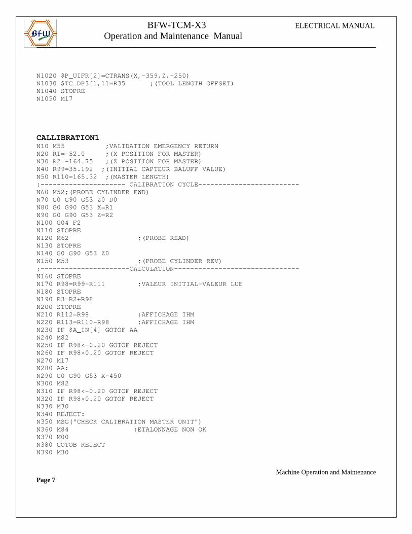
BFW-TCM-X3 ELECTRICAL MANUAL
Operation and Maintenance Manual
N1020 $P_UIFR[2]=CTRANS(X,-359,Z,-250)N1030 $TC_DP3[1,1]=R35 ;(TOOL LENGTH OFFSET)N1040 STOPREN1050 M17
CALLIBRATION1N10 M55 ;VALIDATION EMERGENCY RETURNN20 R1=-52.0 ;(X POSITION FOR MASTER)N30 R2=-164.75 ;(Z POSITION FOR MASTER)N40 R99=35.192 ;(INITIAL CAPTEUR BALUFF VALUE)N50 R110=165.32 ;(MASTER LENGTH);--------------------- CALIBRATION CYCLE----------- --------------N60 M52;(PROBE CYLINDER FWD)N70 G0 G90 G53 Z0 D0N80 G0 G90 G53 X=R1N90 G0 G90 G53 Z=R2N100 G04 F2N110 STOPREN120 M62 ;(PROBE READ)N130 STOPREN140 G0 G90 G53 Z0N150 M53 ;(PROBE CYLINDER REV);----------------------CALCULATION----------------- --------------N160 STOPREN170 R98=R99-R111 ;VALEUR INITIAL-VALEUR LUEN180 STOPREN190 R3=R2+R98N200 STOPREN210 R112=R98 ;AFFICHAGE IHMN220 R113=R110-R98 ;AFFICHAGE IHMN230 IF $A_IN[4] GOTOF AAN240 M82N250 IF R98<-0.20 GOTOF REJECTN260 IF R98>0.20 GOTOF REJECTN270 M17N280 AA:N290 G0 G90 G53 X-450N300 M82N310 IF R98<-0.20 GOTOF REJECTN320 IF R98>0.20 GOTOF REJECTN330 M30N340 REJECT:N350 MSG("CHECK CALIBRATION MASTER UNIT")N360 M84 ;ETALONNAGE NON OKN370 M00N380 GOTOB REJECTN390 M30
Machine Operation and MaintenancePage 7
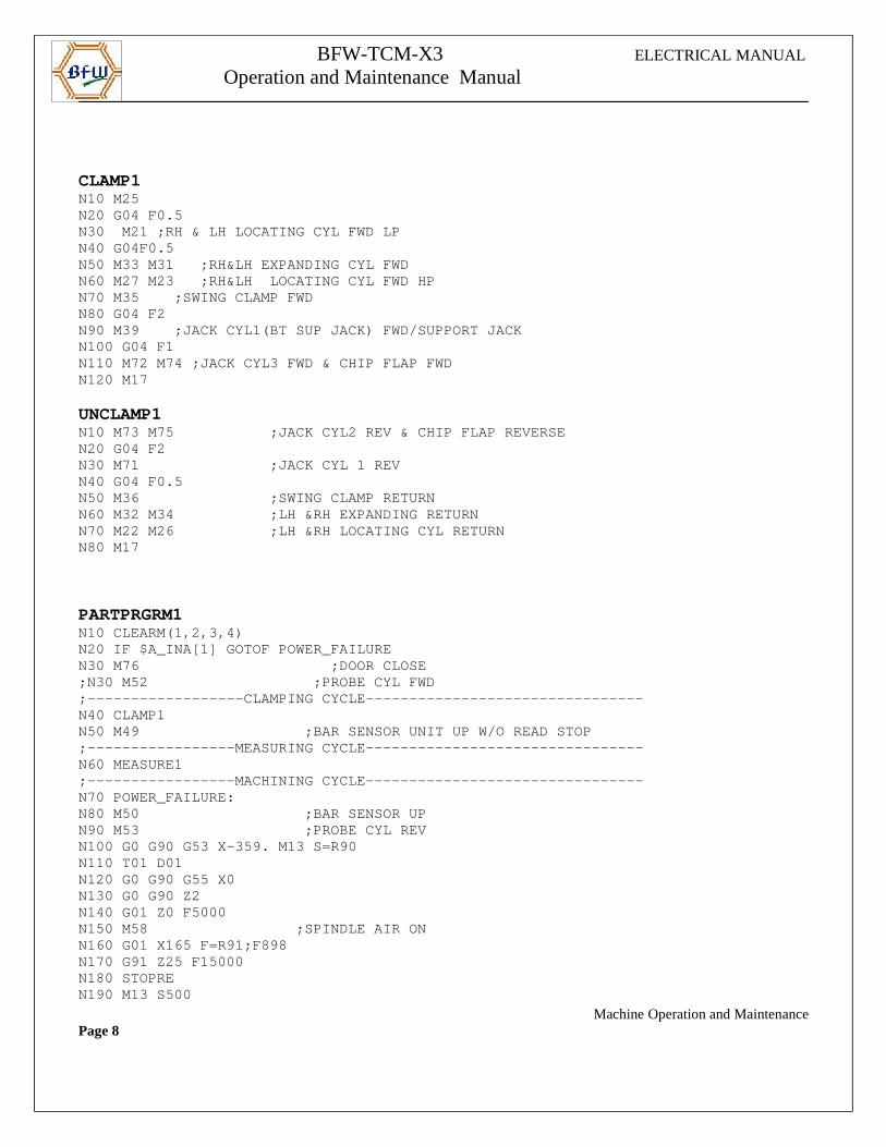
BFW-TCM-X3 ELECTRICAL MANUAL
Operation and Maintenance Manual
CLAMP1N10 M25N20 G04 F0.5N30 M21 ;RH & LH LOCATING CYL FWD LPN40 G04F0.5N50 M33 M31 ;RH&LH EXPANDING CYL FWDN60 M27 M23 ;RH&LH LOCATING CYL FWD HPN70 M35 ;SWING CLAMP FWDN80 G04 F2N90 M39 ;JACK CYL1(BT SUP JACK) FWD/SUPPORT JACK N100 G04 F1N110 M72 M74 ;JACK CYL3 FWD & CHIP FLAP FWDN120 M17
UNCLAMP1N10 M73 M75 ;JACK CYL2 REV & CHIP FLAP RE VERSEN20 G04 F2N30 M71 ;JACK CYL 1 REVN40 G04 F0.5N50 M36 ;SWING CLAMP RETURNN60 M32 M34 ;LH &RH EXPANDING RETURNN70 M22 M26 ;LH &RH LOCATING CYL RETURNN80 M17
PARTPRGRM1N10 CLEARM(1,2,3,4)N20 IF $A_INA[1] GOTOF POWER_FAILUREN30 M76 ;DOOR CLOSE;N30 M52 ;PROBE CYL FWD;------------------CLAMPING CYCLE------------------ --------------N40 CLAMP1N50 M49 ;BAR SENSOR UNIT UP W/O R EAD STOP;-----------------MEASURING CYCLE------------------ --------------N60 MEASURE1;-----------------MACHINING CYCLE------------------ --------------N70 POWER_FAILURE:N80 M50 ;BAR SENSOR UPN90 M53 ;PROBE CYL REVN100 G0 G90 G53 X-359. M13 S=R90N110 T01 D01N120 G0 G90 G55 X0N130 G0 G90 Z2N140 G01 Z0 F5000N150 M58 ;SPINDLE AIR ONN160 G01 X165 F=R91;F898 N170 G91 Z25 F15000N180 STOPREN190 M13 S500
Machine Operation and MaintenancePage 8
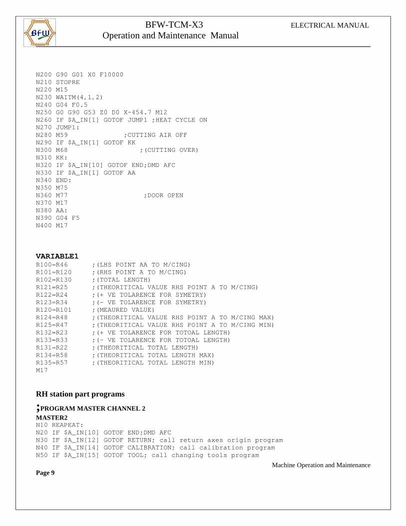
BFW-TCM-X3 ELECTRICAL MANUAL
Operation and Maintenance Manual
N200 G90 G01 X0 F10000N210 STOPREN220 M15 N230 WAITM(4,1,2)N240 G04 F0.5 N250 G0 G90 G53 Z0 D0 X-454.7 M12 N260 IF $A_IN[1] GOTOF JUMP1 ;HEAT CYCLE ONN270 JUMP1:N280 M59 ;CUTTING AIR OFFN290 IF $A_IN[1] GOTOF KKN300 M68 ;(CUTTING OVER)N310 KK:N320 IF $A_IN[10] GOTOF END;DMD AFCN330 IF $A_IN[1] GOTOF AAN340 END:N350 M75N360 M77 ;DOOR OPENN370 M17N380 AA:N390 G04 F5N400 M17
VARIABLE1R100=R46 ;(LHS POINT AA TO M/CING)R101=R120 ;(RHS POINT A TO M/CING)R102=R130 ;(TOTAL LENGTH)R121=R25 ;(THEORITICAL VALUE RHS POINT A TO M/ CING)R122=R24 ;(+ VE TOLARENCE FOR SYMETRY)R123=R34 ;(- VE TOLARENCE FOR SYMETRY)R120=R101 ;(MEAURED VALUE)R124=R48 ;(THEORITICAL VALUE RHS POINT A TO M/ CING MAX)R125=R47 ;(THEORITICAL VALUE RHS POINT A TO M/ CING MIN)R132=R23 ;(+ VE TOLARENCE FOR TOTOAL LENGTH)R133=R33 ;(- VE TOLARENCE FOR TOTOAL LENGTH)R131=R22 ;(THEORITICAL TOTAL LENGTH)R134=R58 ;(THEORITICAL TOTAL LENGTH MAX)R135=R57 ;(THEORITICAL TOTAL LENGTH MIN)M17
RH station part programs
;PROGRAM MASTER CHANNEL 2 MASTER2N10 REAPEAT:N20 IF $A_IN[10] GOTOF END;DMD AFCN30 IF $A_IN[12] GOTOF RETURN; call return axes ori gin programN40 IF $A_IN[14] GOTOF CALIBRATION; call calibratio n programN50 IF $A_IN[15] GOTOF TOOL; call changing tools pr ogram
Machine Operation and MaintenancePage 9
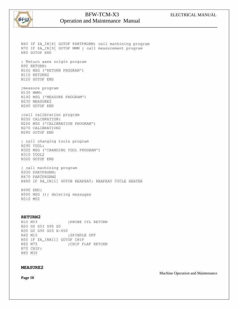
BFW-TCM-X3 ELECTRICAL MANUAL
Operation and Maintenance Manual
N60 IF $A_IN[8] GOTOF PARTPRGRM; call machining pro gram N70 IF $A_IN[9] GOTOF MMM ; call measurement progra mN80 GOTOF END
; Return axes origin programN90 RETURN:N100 MSG ("RETURN PROGRAM")N110 RETURN2N120 GOTOF END
;measure programN130 MMM:N140 MSG ("MEASURE PROGRAM")N230 MEASURE2N240 GOTOF END
;call calibration programN250 CALIBRATION:N260 MSG ("CALIBRATION PROGRAM")N270 CALIBRATION2N280 GOTOF END
; call changing tools programN290 TOOL:N300 MSG ("CHANGING TOOL PROGRAM")N310 TOOL2N320 GOTOF END
; call machining programN330 PARTPRGRM:N470 PARTPRGRM2N480 IF $A_IN[1] GOTOB REAPEAT; REAPEAT CYCLE HEATE R
N490 END:N500 MSG (); deleting messagesN510 M02
RETURN2N10 M53 ;PROBE CYL RETURNN20 G0 G53 G90 Z0N30 G0 G90 G53 X-450N40 M15 ;SPINDLE OFFN50 IF $A_INA[1] GOTOF CHIPN60 M75 ;CHIP FLAP RETURNN70 CHIP:N80 M30
MEASURE2 Machine Operation and MaintenancePage 10
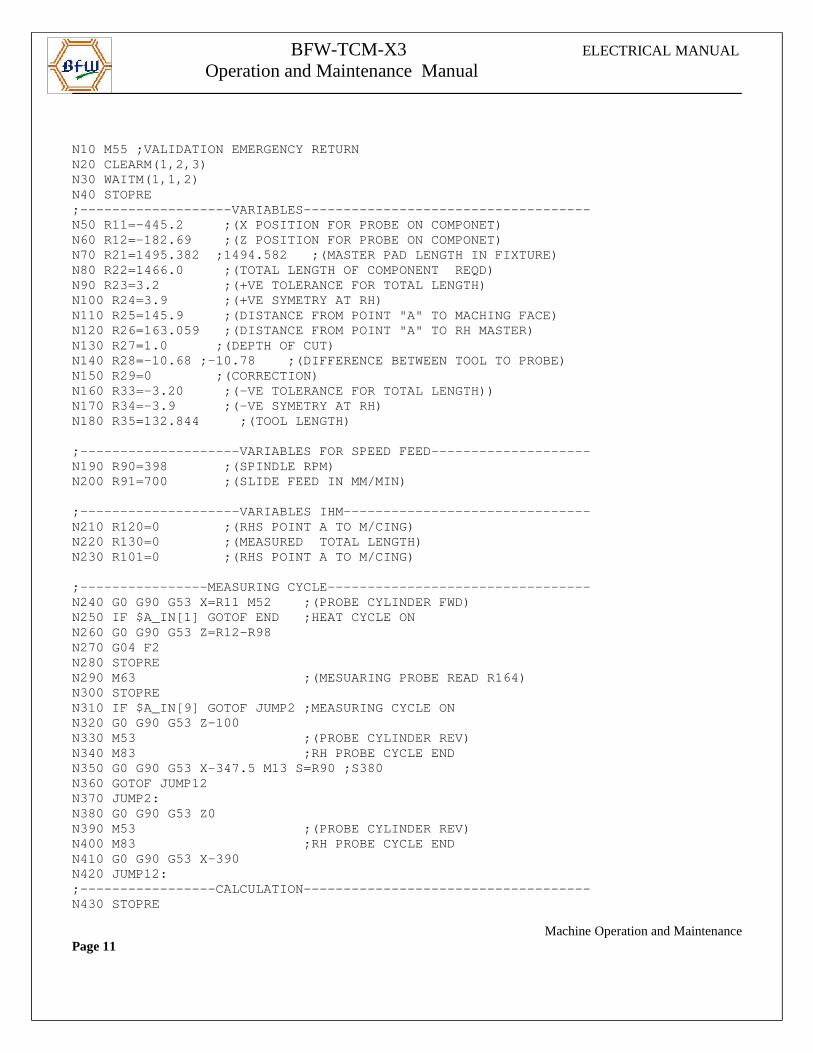
BFW-TCM-X3 ELECTRICAL MANUAL
Operation and Maintenance Manual
N10 M55 ;VALIDATION EMERGENCY RETURNN20 CLEARM(1,2,3)N30 WAITM(1,1,2)N40 STOPRE;-------------------VARIABLES---------------------- --------------N50 R11=-445.2 ;(X POSITION FOR PROBE ON COMPON ET)N60 R12=-182.69 ;(Z POSITION FOR PROBE ON COMPON ET)N70 R21=1495.382 ;1494.582 ;(MASTER PAD LENGTH I N FIXTURE)N80 R22=1466.0 ;(TOTAL LENGTH OF COMPONENT REQ D)N90 R23=3.2 ;(+VE TOLERANCE FOR TOTAL LENGTH )N100 R24=3.9 ;(+VE SYMETRY AT RH)N110 R25=145.9 ;(DISTANCE FROM POINT "A" TO MAC HING FACE)N120 R26=163.059 ;(DISTANCE FROM POINT "A" TO RH MASTER)N130 R27=1.0 ;(DEPTH OF CUT)N140 R28=-10.68 ;-10.78 ;(DIFFERENCE BETWEEN TOO L TO PROBE)N150 R29=0 ;(CORRECTION)N160 R33=-3.20 ;(-VE TOLERANCE FOR TOTAL LENGTH ))N170 R34=-3.9 ;(-VE SYMETRY AT RH)N180 R35=132.844 ;(TOOL LENGTH)
;--------------------VARIABLES FOR SPEED FEED------ --------------N190 R90=398 ;(SPINDLE RPM)N200 R91=700 ;(SLIDE FEED IN MM/MIN)
;--------------------VARIABLES IHM----------------- --------------N210 R120=0 ;(RHS POINT A TO M/CING)N220 R130=0 ;(MEASURED TOTAL LENGTH)N230 R101=0 ;(RHS POINT A TO M/CING)
;----------------MEASURING CYCLE------------------- --------------N240 G0 G90 G53 X=R11 M52 ;(PROBE CYLINDER FWD)N250 IF $A_IN[1] GOTOF END ;HEAT CYCLE ONN260 G0 G90 G53 Z=R12-R98N270 G04 F2N280 STOPREN290 M63 ;(MESUARING PROBE READ R164)N300 STOPREN310 IF $A_IN[9] GOTOF JUMP2 ;MEASURING CYCLE ONN320 G0 G90 G53 Z-100N330 M53 ;(PROBE CYLINDER REV)N340 M83 ;RH PROBE CYCLE ENDN350 G0 G90 G53 X-347.5 M13 S=R90 ;S380N360 GOTOF JUMP12N370 JUMP2:N380 G0 G90 G53 Z0N390 M53 ;(PROBE CYLINDER REV)N400 M83 ;RH PROBE CYCLE ENDN410 G0 G90 G53 X-390N420 JUMP12:;-----------------CALCULATION---------------------- --------------N430 STOPRE
Machine Operation and MaintenancePage 11
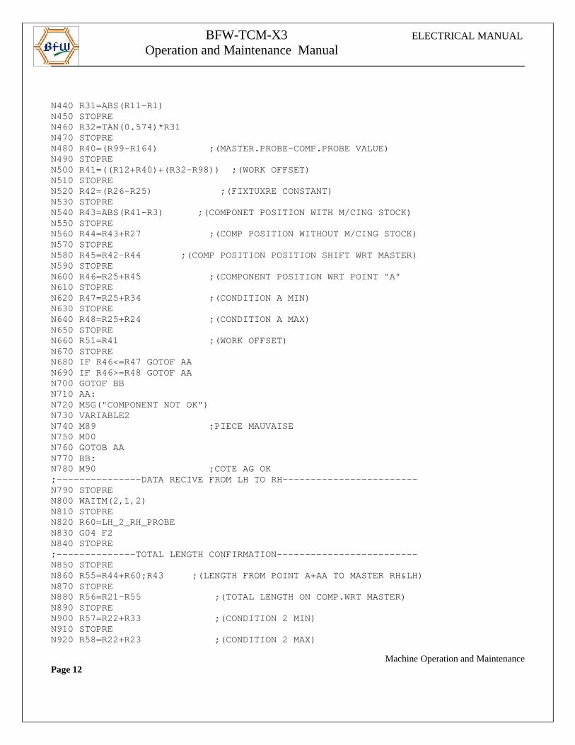
BFW-TCM-X3 ELECTRICAL MANUAL
Operation and Maintenance Manual
N440 R31=ABS(R11-R1)N450 STOPREN460 R32=TAN(0.574)*R31N470 STOPREN480 R40=(R99-R164) ;(MASTER.PROBE-COMP.PRO BE VALUE)N490 STOPREN500 R41=((R12+R40)+(R32-R98)) ;(WORK OFFSET) N510 STOPREN520 R42=(R26-R25) ;(FIXTUXRE CONSTANT)N530 STOPREN540 R43=ABS(R41-R3) ;(COMPONET POSITION WITH M/CING STOCK)N550 STOPREN560 R44=R43+R27 ;(COMP POSITION WITHOUT M/CING STOCK)N570 STOPREN580 R45=R42-R44 ;(COMP POSITION POSITION SHI FT WRT MASTER)N590 STOPREN600 R46=R25+R45 ;(COMPONENT POSITION WR T POINT "A"N610 STOPREN620 R47=R25+R34 ;(CONDITION A MIN)N630 STOPREN640 R48=R25+R24 ;(CONDITION A MAX)N650 STOPREN660 R51=R41 ;(WORK OFFSET)N670 STOPREN680 IF R46<=R47 GOTOF AAN690 IF R46>=R48 GOTOF AAN700 GOTOF BBN710 AA:N720 MSG("COMPONENT NOT OK")N730 VARIABLE2N740 M89 ;PIECE MAUVAISEN750 M00N760 GOTOB AAN770 BB:N780 M90 ;COTE AG OK;---------------DATA RECIVE FROM LH TO RH---------- --------------N790 STOPREN800 WAITM(2,1,2)N810 STOPREN820 R60=LH_2_RH_PROBEN830 G04 F2N840 STOPRE;--------------TOTAL LENGTH CONFIRMATION----------- --------------N850 STOPREN860 R55=R44+R60;R43 ;(LENGTH FROM POINT A+AA T O MASTER RH&LH)N870 STOPREN880 R56=R21-R55 ;(TOTAL LENGTH ON COMP .WRT MASTER)N890 STOPREN900 R57=R22+R33 ;(CONDITION 2 MIN)N910 STOPREN920 R58=R22+R23 ;(CONDITION 2 MAX)
Machine Operation and MaintenancePage 12
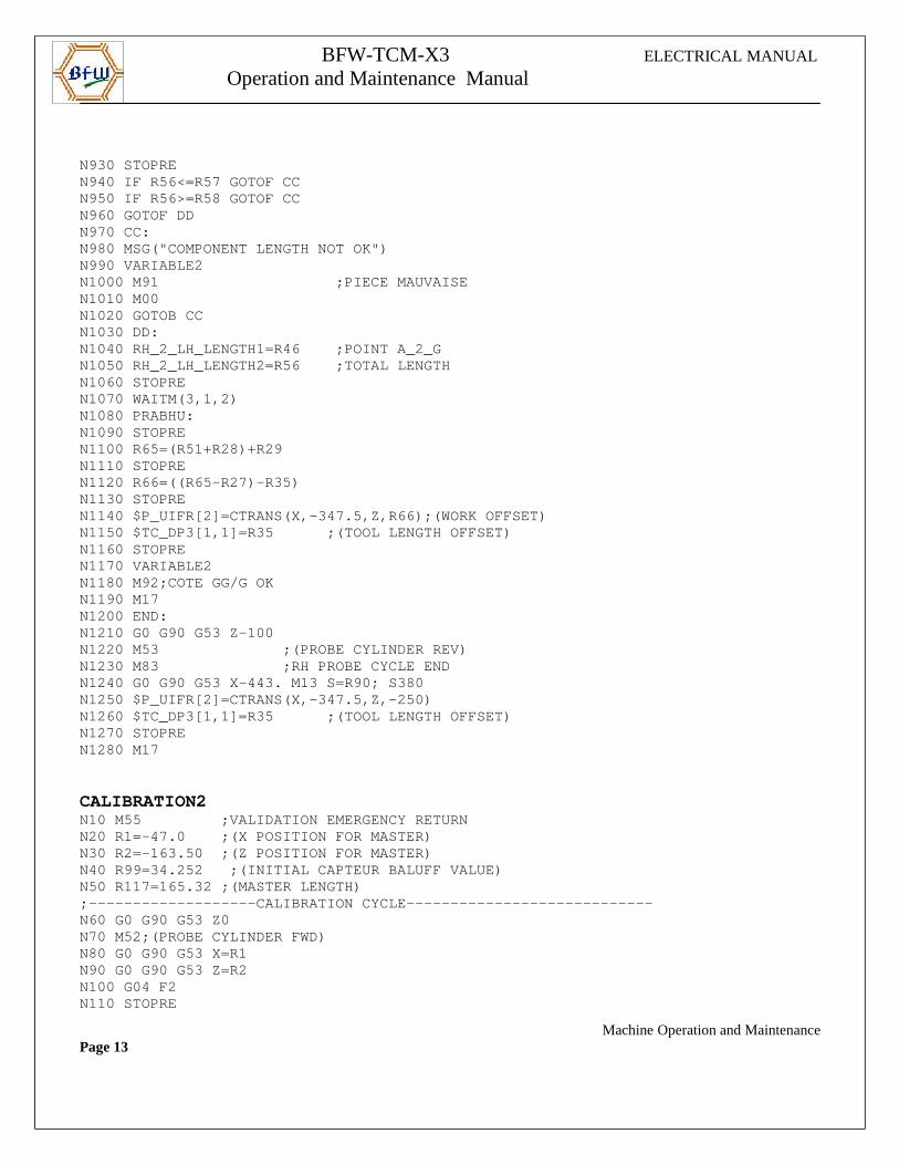
BFW-TCM-X3 ELECTRICAL MANUAL
Operation and Maintenance Manual
N930 STOPREN940 IF R56<=R57 GOTOF CCN950 IF R56>=R58 GOTOF CCN960 GOTOF DDN970 CC:N980 MSG("COMPONENT LENGTH NOT OK")N990 VARIABLE2N1000 M91 ;PIECE MAUVAISEN1010 M00N1020 GOTOB CCN1030 DD:N1040 RH_2_LH_LENGTH1=R46 ;POINT A_2_GN1050 RH_2_LH_LENGTH2=R56 ;TOTAL LENGTHN1060 STOPREN1070 WAITM(3,1,2)N1080 PRABHU:N1090 STOPREN1100 R65=(R51+R28)+R29N1110 STOPREN1120 R66=((R65-R27)-R35)N1130 STOPREN1140 $P_UIFR[2]=CTRANS(X,-347.5,Z,R66);(WORK OFFSE T)N1150 $TC_DP3[1,1]=R35 ;(TOOL LENGTH OFFSET)N1160 STOPREN1170 VARIABLE2N1180 M92;COTE GG/G OKN1190 M17N1200 END:N1210 G0 G90 G53 Z-100N1220 M53 ;(PROBE CYLINDER REV)N1230 M83 ;RH PROBE CYCLE ENDN1240 G0 G90 G53 X-443. M13 S=R90; S380N1250 $P_UIFR[2]=CTRANS(X,-347.5,Z,-250)N1260 $TC_DP3[1,1]=R35 ;(TOOL LENGTH OFFSET)N1270 STOPREN1280 M17
CALIBRATION2N10 M55 ;VALIDATION EMERGENCY RETURNN20 R1=-47.0 ;(X POSITION FOR MASTER)N30 R2=-163.50 ;(Z POSITION FOR MASTER)N40 R99=34.252 ;(INITIAL CAPTEUR BALUFF VALUE)N50 R117=165.32 ;(MASTER LENGTH);-------------------CALIBRATION CYCLE-------------- --------------N60 G0 G90 G53 Z0N70 M52;(PROBE CYLINDER FWD)N80 G0 G90 G53 X=R1N90 G0 G90 G53 Z=R2N100 G04 F2N110 STOPRE
Machine Operation and MaintenancePage 13
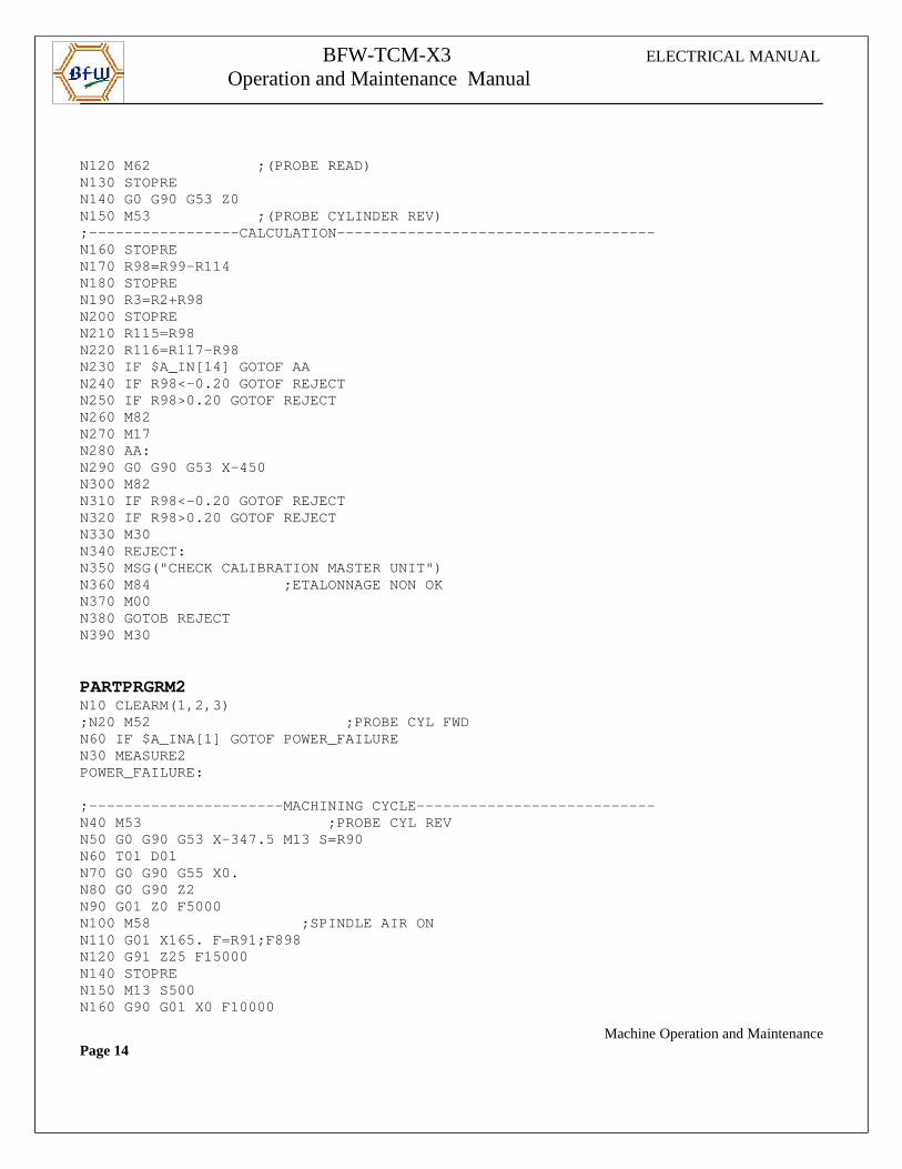
BFW-TCM-X3 ELECTRICAL MANUAL
Operation and Maintenance Manual
N120 M62 ;(PROBE READ)N130 STOPREN140 G0 G90 G53 Z0N150 M53 ;(PROBE CYLINDER REV);-----------------CALCULATION---------------------- --------------N160 STOPREN170 R98=R99-R114 N180 STOPREN190 R3=R2+R98N200 STOPREN210 R115=R98N220 R116=R117-R98N230 IF $A_IN[14] GOTOF AAN240 IF R98<-0.20 GOTOF REJECTN250 IF R98>0.20 GOTOF REJECTN260 M82N270 M17N280 AA:N290 G0 G90 G53 X-450N300 M82N310 IF R98<-0.20 GOTOF REJECTN320 IF R98>0.20 GOTOF REJECTN330 M30N340 REJECT:N350 MSG("CHECK CALIBRATION MASTER UNIT")N360 M84 ;ETALONNAGE NON OKN370 M00N380 GOTOB REJECTN390 M30
PARTPRGRM2N10 CLEARM(1,2,3);N20 M52 ;PROBE CYL FWDN60 IF $A_INA[1] GOTOF POWER_FAILUREN30 MEASURE2POWER_FAILURE:
;----------------------MACHINING CYCLE------------- --------------N40 M53 ;PROBE CYL REVN50 G0 G90 G53 X-347.5 M13 S=R90N60 T01 D01N70 G0 G90 G55 X0.N80 G0 G90 Z2N90 G01 Z0 F5000N100 M58 ;SPINDLE AIR ONN110 G01 X165. F=R91;F898 N120 G91 Z25 F15000N140 STOPREN150 M13 S500N160 G90 G01 X0 F10000
Machine Operation and MaintenancePage 14
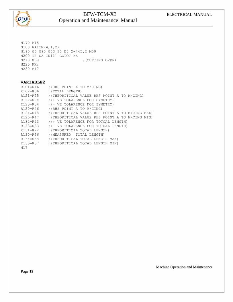
BFW-TCM-X3 ELECTRICAL MANUAL
Operation and Maintenance Manual
N170 M15N180 WAITM(4,1,2)N190 G0 G90 G53 Z0 D0 X-445.2 M59N200 IF $A_IN[1] GOTOF KKN210 M68 ;(CUTTING OVER)N220 KK:N230 M17
VARIABLE2R101=R46 ;(RHS POINT A TO M/CING)R102=R56 ;(TOTAL LENGTH)R121=R25 ;(THEORITICAL VALUE RHS POINT A TO M/CI NG)R122=R24 ;(+ VE TOLARENCE FOR SYMETRY)R123=R34 ;(- VE TOLARENCE FOR SYMETRY)R120=R46 ;(RHS POINT A TO M/CING)R124=R48 ;(THEORITICAL VALUE RHS POINT A TO M/CI NG MAX)R125=R47 ;(THEORITICAL VALUE RHS POINT A TO M/CI NG MIN)R132=R23 ;(+ VE TOLARENCE FOR TOTOAL LENGTH)R133=R33 ;(- VE TOLARENCE FOR TOTOAL LENGTH)R131=R22 ;(THEORITICAL TOTAL LENGTH)R130=R56 ;(MEASURED TOTAL LENGTH)R134=R58 ;(THEORITICAL TOTAL LENGTH MAX)R135=R57 ;(THEORITICAL TOTAL LENGTH MIN)M17
Machine Operation and MaintenancePage 15
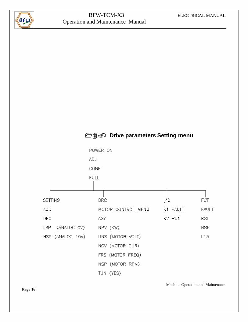
BFW-TCM-X3 ELECTRICAL MANUAL
Operation and Maintenance Manual
������������ Drive parameters Setting menu
Machine Operation and MaintenancePage 16
BFW-TCM-X3 ELECTRICAL MANUAL
Operation and Maintenance Manual
Note:
Chip conveyor will be On in AUTO mode irrespective of selector switch condition.
Note:
Chip conveyor will be On in AUTO mode irrespective of selector switch condition.
Machine Operation and MaintenancePage 17