automatic library generation for blas3 on gpus
TRANSCRIPT
Automatic Library Generation for BLAS3 on GPUs
Huimin Cui∗†, Lei Wang∗†, Jingling Xue‡, Yang Yang∗† and Xiaobing Feng∗
∗Institute of Computing Technology, Chinese Academy of Sciences, China†Graduate University, Chinese Academy of Sciences, China
‡School of Computer Science and Engineering, University of New South Wales, Australia
{cuihm,wlei,yangyang,fxb}@ict.ac.cn [email protected]
Abstract—High-performance libraries, the performance-critical building blocks for high-level applications, will assumegreater importance on modern processors as they become morecomplex and diverse. However, automatic library generatorsare still immature, forcing library developers to manually tunelibrary to meet their performance objectives.
We are developing a new script-controlled compilation frame-work to help domain experts reduce much of the tedious anderror-prone nature of manual tuning, by enabling them to lever-age their expertise and reuse past optimization experiences. Wefocus on demonstrating improved performance and productivityobtained through using our framework to tune BLAS3 routineson three GPU platforms: up to 5.4x speedups over the CUBLASachieved on NVIDIA GeForce 9800, 2.8x on GTX285, and 3.4x onFermi Tesla C2050. Our results highlight the potential benefits ofexploiting domain expertise and the relations between differentroutines (in terms of their algorithms and data structures).
I. INTRODUCTION
Level 3 Basic Linear Algebra Subprograms (BLAS3) are
performance-critical building blocks for high-level scientific
applications, and highly efficient implementations of those
routines enable scientists to achieve high performance at little
cost. Automatically Tuned Linear Algebra Software (ATLAS)
[1] is a well-known automatic BLAS3 generator, which gener-
ates efficient library implementations for platforms possessing
an ANSI/ISO C compiler. Unfortunately, such tools are not
yet available on the state-of-the-art many-core architectures
with tens or even hundreds of cores being integrated onto
a single chip, such as NVIDIA GPUs. As a result, library
developers have to manually tune their applications to meet
their performance objectives, which is tedious, error-prone and
time-consuming [2].
A major challenge when moving to NVIDIA GPUs is
how to reuse earlier tuning results. In ATLAS, the tuning
results for GEMM bring benefits to a number of other BLAS3
routines. For example, the SYMM routine is implemented in
a recursive way so that SYMM is split into smaller SYMM
and GEMM problems. By reusing the tuning experiences for
GEMM, SYMM delivers the performance close to that of
GEMM (108GFLOPS for SYMM compared to 116GFLOPS
for GEMM on an Intel Xeon platform). However, recursion is
not efficiently supported on NVIDIA GPUs. As a result, it is
not straightforward to reuse the tuning results of GEMM for
other BLAS3 routines. For example, on the GTX285 platform,
the performance of GEMM in CUBLAS 3.2 is 420GFLOPS
while SYMM achieves only 155GFLOPS.
We are presently working on developing an automatic
library generator for a number of BLAS3 routines on NVIDIA
GPUs. To enable tuning experiences to be reused, our solution
is to let developers focus on the differences between different
library routines and specify them using the provided ADL
(Adaptor Definition Language) interface. This interface en-
ables developers to define adaptors in terms of optimization
guidelines to relate a new routine with an existing one. For this
purpose, we have developed an OA (Optimization Adaptor)
framework based on our existing EPOD system [3]. This
system provides an EPOD script interface to encapsulate
existing tuning experiences into optimization schemes.
In this paper, we apply our OA framework to tune the
BLAS3 library on three NVIDIA GPU platforms. Our exper-
imental results demonstrate that our method can help library
developers achieve excellent performances rapidly: up to 5.4x
speedups over CUBLAS 3.2 on GeForce 9800, 2.8x for
GTX285, and 3.4x for Fermi Tesla C2050.
The main contributions of this paper include:
• an adaptor definition language, which works together with
EPOD scripts to relate new routines with existing ones;
• an OA framework to generate optimization schemes for
new routines based the developer-provided information
specified using the ADL interface; and
• experimental results showing performance speedups of up
to 5.4x, 2.8x and 3.4x relative to CUBLAS 3.2 on three
different NVIDIA GPU platforms.
The rest of the paper is organized as follows. Section II pro-
vides an overview of our OA framework. Section III explains
the process of encapsulating existing tuning experiences into
individual optimization schemes. Section IV describes how
to extend existing optimization schemes into new ones for
new routines. Section V presents our experimental results and
analysis. Section VI discusses the related work. Section VII
concludes the paper and discusses our future work.
II. THE OA FRAMEWORK
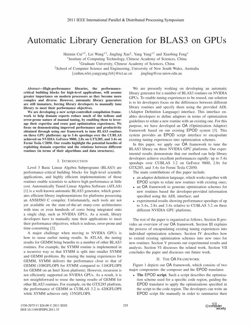
Figure 1 depicts our OA framework, which consists of two
major components: the composer and the EPOD translator.
• The EPOD script. Such a script describes the optimiza-
tion scheme used for a specific code region, guiding the
EPOD translator to apply the optimizations specified in
the script to the code region. The developers can write an
EPOD script file manually in order to summarize their
2011 IEEE International Parallel & Distributed Processing Symposium
1530-2075/11 $26.00 © 2011 IEEE
DOI 10.1109/IPDPS.2011.33
255
2011 IEEE International Parallel & Distributed Processing Symposium
1530-2075/11 $26.00 © 2011 IEEE
DOI 10.1109/IPDPS.2011.33
255
2011 IEEE International Parallel & Distributed Processing Symposium
1530-2075/11 $26.00 © 2011 IEEE
DOI 10.1109/IPDPS.2011.33
255
2011 IEEE International Parallel & Distributed Processing Symposium
1530-2075/11 $26.00 © 2011 IEEE
DOI 10.1109/IPDPS.2011.33
255
2011 IEEE International Parallel & Distributed Processing Symposium
1530-2075/11 $26.00 © 2011 IEEE
DOI 10.1109/IPDPS.2011.33
255
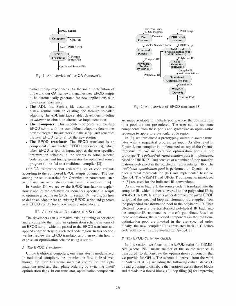
Fig. 1: An overview of our OA framework.
earlier tuning experiences. As the main contribution of
this work, our OA framework enables new EPOD scripts
to be automatically generated for new applications with
developers’ assistance.
• The ADL file. Such a file describes how to relate
a new routine with an existing one through so-called
adaptors. The ADL interface enables developers to define
an adaptor to obtain an alternative implementation.
• The Composer. This module composes an existing
EPOD script with the user-defined adaptors, determines
how to integrate the adaptors into the script, and generates
the new EPOD script(s) for the new routine.
• The EPOD translator. The EPOD translator is an
component of our earlier EPOD framework [3], which
takes EPOD scripts as input, applies the user-specified
optimization schemes in the scripts to some selected
code regions, and finally, generates the optimized source
program (to be fed to a traditional compiler [3]).
Our OA framework will generate a set of code variants
according to the composed EPOD scripts obtained. The best
among the set is searched for. Optimization parameters, such
as tile size, are automatically tuned with the method in [4].
In Section III, we review the EPOD translator to explain
how it applies the optimization sequences specified in scripts
to optimize a routine on GPUs. In Section IV, we discuss how
to define an adaptor for an existing EPOD script and generate
new EPOD scripts for a new routine automatically.
III. CREATING AN OPTIMIZATION SCHEME
The developers can summarize existing tuning experiences
and encapsulate them into an optimization scheme in term of
an EPOD script, which is passed to the EPOD translator and
applied appropriately to a selected code region. In this section,
we first review the EPOD translator and then explain how to
express an optimization scheme using a script.
A. The EPOD Translator
Unlike traditional compilers, our translator is modularized.
In traditional compilers, the optimization flow is fixed even
though the user has some marginal control on the opti-
mizations used and their phase ordering by switching on/off
optimization flags. In our translator, optimization components
Fig. 2: An overview of EPOD translator [3].
are made available in multiple pools, where the optimizations
in a pool are not pre-ordered. The user can select some
components from these pools and synthesize an optimization
sequence to apply to a particular code region.
In [3], we introduced a prototyping source-to-source trans-
lator with a sequential program as input. As illustrated in
Figure 2, our compiler is implemented on top of the Open64
infrastructure. We included two optimization pools in our
prototype. The polyhedral transformation pool is implemented
based on URUK [5], and consists of a number of loop transfor-
mations performed in the polyhedral representation (IR). The
traditional optimization pool is performed on Open64’ com-
piler internal representation (IR) and implemented based on
Open64. The WRaP-IT and URGenT components introduced
in [5] are used for the indicated IR conversions.
As shown in Figure 2, the source code is translated into the
compiler IR, which is then converted to the polyhedral IR by
WRaP-IT. A URUK script is generated from the given EPOD
script and the specified loop transformations are applied from
the polyhedral transformation pool to the polyhedral IR. Then
URGenT converts the transformed polyhedral IR back into
the compiler IR, annotated with user’s guidelines. Based on
these annotations, the requested components in the traditional
optimization pool are invoked in the user-specified order.
Finally, the new compiler IR is translated back to C source
code with the whirl2c routine in Open64. [3]
B. The EPOD Script for GEMM
In this section, we focus on the EPOD script for GEMM-
NN (where “NN” means neither of the source matrices is
transposed) to demonstrate the optimization components that
we provide for GPUs. The scheme is derived from the work
of Volkov et al [2], including the following critical steps: (1)
thread grouping to distribute the iterations across thread blocks
and threads in a thread block, (2) loop tiling [6] for improving
256256256256256
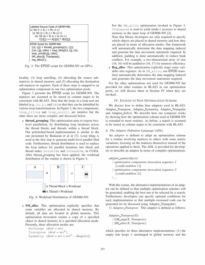
Fig. 3: The EPOD script for GEMM-NN on GPUs.
locality, (3) loop unrolling, (4) allocating the source sub-
matrices in shared memory, and (5) allocating the destination
sub-matrices in registers. Each of these steps is mapped to an
optimization component in our two optimization pools.
Figure 3 presents the EPOD script for GEMM-NN. The
matrices are assumed to be stored in column major to be
consistent with BLAS3. Note that the loops in a loop nest are
labeled (e.g., Li, Lj, and Lk) so that they can be identified by
various loop transformations. In Figure 3, the two components,
loop_tiling and loop_unroll, are intuitive but the
other three are more complex and discussed below.
• thread grouping. This optimization aims to expose two-
level parallelism, by distributing loop iterations across
the thread blocks and threads within a thread block.
Our polyhedral-based implementation is similar to the
one presented by Baskaran et al in [7]. Loop tiling is
used at the first step to generate multi-level parallel tiled
code. Furthermore, thread distribution is used to replace
the loop indices for parallel iterations into block and
thread index, blockIdx and threadIdx, in CUDA.
After thread grouping has been applied, the workload
distribution of the routine is shown in Figure 4.
Fig. 4: Workload Distribution of GEMM-NN.
• SM alloc. This optimization explicitly specifies that
some variables are allocated in shared memory. By
default, all data are located in global memory. This
optimization invocation creates a copy of a specified
object in shared memory in a specified allocation mode.
Presently, three allocation modes are:
NoChange (dest = src)
Transpose (dest = srcT)
Symmetry (dest = src + srcT − diag(src))
For the SM_alloc optimization invoked in Figure 3,
Transpose is used to yield stride-1 accesses to shared
memory in the inner loop of GEMM-NN [2].
Note that library developers are only required to specify
which objects are placed in shared memory and how they
are placed in terms of allocation modes. Our framework
will automatically determine the data mapping induced
and generate the data movement statements required. In
addition, padding is done automatically to reduce bank
conflicts. For example, a two-dimensional array of size
(16, 16) will be padded to (16, 17) for memory efficiency.
• Reg alloc. This optimization explicitly maps some vari-
ables into registers. As in SM_alloc, our EPOD trans-
lator automatically determines the data mapping induced
and generates the data movement statements required.
For the other optimizations not used for GEMM-NN but
provided for other routines in BLAS3 in our optimization
pools, we will discuss them in Section IV when they are
invoked.
IV. EXTEND TO NEW OPTIMIZATION SCHEME
We discuss how to define four adaptors used in BLAS3,
Adaptor Transpose, Adaptor Symmetry, Adaptor Triangular
and Adaptor Solver. We describe how our composer works
by showing how the optimization scheme used in GEMM-NN
is extended to more routines. As before, a matrix is assumed
to be stored in column major to be consistent with BLAS3.
A. The Adaptor Definition Language (ADL)
An adaptor is defined to adapt an optimization scheme
for a routine involving matrices to others with some matrix
variations, focusing on the matrices themselves instead of the
operations applied to them. The ADL is provided for develop-
ers to describe an adaptor in terms of compiler optimizations.
adaptor name(object):
| optimization components invocation sequence 1
{cond(condition 1)}| optimization components invocation sequence 2
{cond(condition 2)}| ...
With this syntax, the alternative implementations of an adap-
tor can be defined so that multiple optimization schemes will
be generated, enabling the best one to be selected by a search.
Furthermore, developers can specify optional conditions for
each implementation so that multiple-versioned code can be
generated (to be discussed using Adaptor Triangular).
1) Adaptor Transpose: This adaptor is defined as follows:
Adaptor Transpose(X):
| GM map(X, Transpose);
| SM alloc(X, Transpose);
which specifies its three alternative implementations: (1) the
empty rule keeps X unchanged in global memory and the
257257257257257
transposition is not applied to the matrix until accessed, (2)
the GM_map rule transposes X in global memory, which means
the transposition is applied before the matrix is used (implying
that the optimization scheme of GEMM-NN can be applied),
and (3) the SM_alloc rule specifies that the transposition
is applied to sub-matrices, if possible, in which case, our
composer will determine the size of shared memory allocated.
Below we examine GM_map, which is implemented based
on the polyhedral IR, including the following steps:
• Step 1. Generate statements for memory allocation and
data mapping. In the case of the Transpose mode, the
corresponding statements are:
f o r ( i = 0 ; i < M; i ++)f o r ( j = 0 ; j < N; j ++)
NewX[ i ] [ j ] = X[ j ] [ i ] ;
• Step 2. Distribute the above statements across the CUDA
thread blocks and threads within a thread block, using the
method similar as the one used for thread_grouping.
• Step 3. Modify the subscript in the polyhedral IR [5] to
replace the reference of X[i][j] with NewX[j][i].
In our OA framework, GM_map is valid only when it is the
first optimization in an optimization sequence.
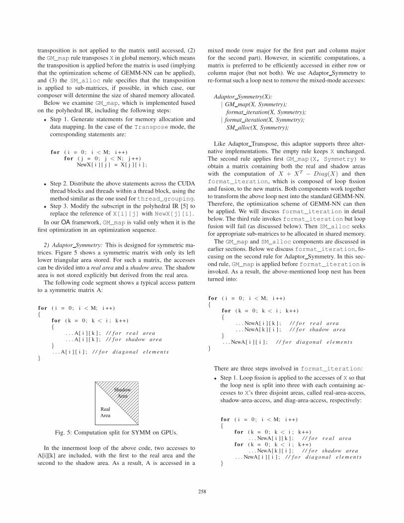
2) Adaptor Symmetry: This is designed for symmetric ma-
trices. Figure 5 shows a symmetric matrix with only its left
lower triangular area stored. For such a matrix, the accesses
can be divided into a real area and a shadow area. The shadow
area is not stored explicitly but derived from the real area.
The following code segment shows a typical access pattern
to a symmetric matrix A:
f o r ( i = 0 ; i < M; i ++){
f o r ( k = 0 ; k < i ; k ++){
. . . A[ i ] [ k ] ; / / f o r r e a l area
. . . A[ i ] [ k ] ; / / f o r shadow area}. . . A[ i ] [ i ] ; / / f o r d i a g o n a l e l e m e n t s
}
Fig. 5: Computation split for SYMM on GPUs.
In the innermost loop of the above code, two accesses to
A[i][k] are included, with the first to the real area and the
second to the shadow area. As a result, A is accessed in a
mixed mode (row major for the first part and column major
for the second part). However, in scientific computations, a
matrix is preferred to be efficiently accessed in either row or
column major (but not both). We use Adaptor Symmetry to
re-format such a loop nest to remove the mixed-mode accesses:
Adaptor Symmetry(X):
| GM map(X, Symmetry);
format iteration(X, Symmetry);
| format iteration(X, Symmetry);
SM alloc(X, Symmetry);
Like Adaptor Transpose, this adaptor supports three alter-
native implementations. The empty rule keeps X unchanged.
The second rule applies first GM_map(X, Symmetry) to
obtain a matrix containing both the real and shadow areas
with the computation of X + XT − Diag(X) and then
format_iteration, which is composed of loop fission
and fusion, to the new matrix. Both components work together
to transform the above loop nest into the standard GEMM-NN.
Therefore, the optimization scheme of GEMM-NN can then
be applied. We will discuss format_iteration in detail
below. The third rule invokes format_iteration but loop
fusion will fail (as discussed below). Then SM_alloc seeks
for appropriate sub-matrices to be allocated in shared memory.
The GM_map and SM_alloc components are discussed in
earlier sections. Below we discuss format_iteration, fo-
cusing on the second rule for Adaptor Symmetry. In this sec-
ond rule, GM_map is applied before format_iteration is
invoked. As a result, the above-mentioned loop nest has been
turned into:
f o r ( i = 0 ; i < M; i ++){
f o r ( k = 0 ; k < i ; k ++){
. . . NewA[ i ] [ k ] ; / / f o r r e a l area
. . . NewA[ k ] [ i ] ; / / f o r shadow area}. . . NewA[ i ] [ i ] ; / / f o r d i a g o n a l e l e m e n t s
}
There are three steps involved in format_iteration:
• Step 1. Loop fission is applied to the accesses of X so that
the loop nest is split into three with each containing ac-
cesses to X’s three disjoint areas, called real-area-access,
shadow-area-access, and diag-area-access, respectively:
f o r ( i = 0 ; i < M; i ++){
f o r ( k = 0 ; k < i ; k ++). . . NewA[ i ] [ k ] ; / / f o r r e a l area
f o r ( k = 0 ; k < i ; k ++). . . NewA[ k ] [ i ] ; / / f o r shadow area
. . . NewA[ i ] [ i ] ; / / f o r d i a g o n a l e l e m e n t s}
258258258258258
• Step 2. After Step 1, the loop nest for real-area-access
accesses X in row major and the loop nest for shadow-
area-access accesses X in column major. When the col-
umn major order is detected, loop interchange is applied
to change it into the row major order:
f o r ( i = 0 ; i < M; i ++){
f o r ( k = 0 ; k < i ; k ++). . . NewA[ i ] [ k ] ; / / f o r r e a l area
f o r ( k = i +1 ; k < K; k ++). . . NewA[ i ] [ k ] ; / / f o r shadow area
. . . NewA[ i ] [ i ] ; / / f o r d i a g o n a l e l e m e n t s}
• Step 3. Loop fusion is applied if possible. If loop inter-
change was applied earlier, there may be an opportunity
to fuse all loop nests to obtain the standard GEMM-NN.
The code shown in Step 2 can be fused into:
f o r ( i = 0 ; i < M; i ++)f o r ( k = 0 ; k < K; k ++)
. . . NewA[ i ] [ k ] ;
In summary, the basic idea behind format_iteration
is to apply loop fission and fusion whenever possible.
Therefore, for the third rule of Adaptor Symmetry, the
loop nests cannot be fused after loop fission so that
format_iteration degenerates into a simple loop fission.
The unfusable code after loop fission is:
f o r ( i = 0 ; i < M; i ++){
f o r ( k = 0 ; k < i ; k ++). . . A[ i ] [ k ] ; / / f o r r e a l area
f o r ( k = 0 ; k < i ; k ++). . . A[ i ] [ k ] ; / / f o r shadow area
. . . A[ i ] [ i ] ; / / f o r d i a g o n a l e l e m e n t s}
3) Adaptor Triangular: This adaptor applies to a triangular
matrix. Unlike a symmetric matrix, which can derive its
shadow area from its real area, a triangular matrix induces
only accesses to the real area. Its typical access pattern is:
f o r ( i = 0 ; i < M; i ++){
f o r ( k = 0 ; k <= i ; k ++){
. . . A[ i ] [ k ] ;}
}
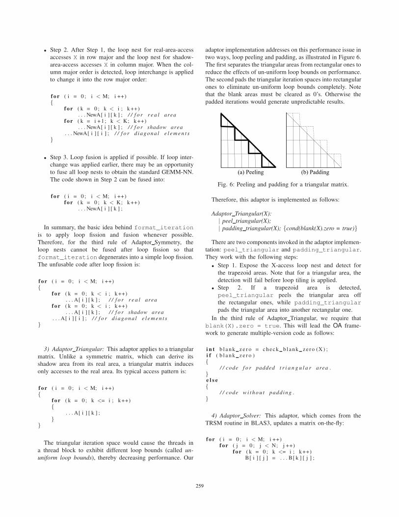
The triangular iteration space would cause the threads in
a thread block to exhibit different loop bounds (called un-
uniform loop bounds), thereby decreasing performance. Our
adaptor implementation addresses on this performance issue in
two ways, loop peeling and padding, as illustrated in Figure 6.
The first separates the triangular areas from rectangular ones to
reduce the effects of un-uniform loop bounds on performance.
The second pads the triangular iteration spaces into rectangular
ones to eliminate un-uniform loop bounds completely. Note
that the blank areas must be cleared as 0’s. Otherwise the
padded iterations would generate unpredictable results.
Fig. 6: Peeling and padding for a triangular matrix.
Therefore, this adaptor is implemented as follows:
Adaptor Triangular(X):
| peel triangular(X);
| padding triangular(X); {cond(blank(X).zero = true)}
There are two components invoked in the adaptor implemen-
tation: peel_triangular and padding_triangular.
They work with the following steps:
• Step 1. Expose the X-access loop nest and detect for
the trapezoid areas. Note that for a triangular area, the
detection will fail before loop tiling is applied.
• Step 2. If a trapezoid area is detected,
peel_triangular peels the triangular area off
the rectangular ones, while padding_triangular
pads the triangular area into another rectangular one.
In the third rule of Adaptor Triangular, we require that
blank(X).zero = true. This will lead the OA frame-
work to generate multiple-version code as follows:
i n t b l a n k z e r o = c h e c k b l a n k z e r o (X ) ;i f ( b l a n k z e r o ){
/ / code f o r padded t r i a n g u l a r area .}e l s e{
/ / code w i t h o u t padd ing .}
4) Adaptor Solver: This adaptor, which comes from the
TRSM routine in BLAS3, updates a matrix on-the-fly:
f o r ( i = 0 ; i < M; i ++)f o r ( j = 0 ; j < N; j ++)
f o r ( k = 0 ; k <= i ; k ++)B[ i ] [ j ] = . . . B[ k ] [ j ] ;
259259259259259
The access pattern is similar to that in TRMM with the dif-
ference that the dependence from B[i][j] to B[i+1][j]
prevents the sub-matrices along the i dimension from be-
ing computed in parallel. This problem can be handled by
thread_grouping. Therefore, the thread grouping returns
a different workload distribution from GEMM-NN with the
adjusted work load for a thread block as shown Figure 7.
As shown in Figure 7, the workload of each thread
block is separated into two parts. Let us take B2 as an
example. B2-A20*B0-A21*B1 can be simultaneously ex-
ecuted by the threads in a thread block, but the final step
B2=TRSM(A22,B2) has to be sequentially executed by only
one thread. Therefore, the adaptor is defined as follows:
Adaptor Solver(X):
| peel triangular(X);
binding triangular(X, 0);
A32A30 A31A33
B0
B1
B2
B3
TRSM
A00
A10A11
A20 A21A22
B0 = TRSM(A00, B0)
=
B1 = B1 -A10*B0
B1 = TRSM(A11, B1)
B2=B2-A20*B0-A21*B1
B2 = TRSM(A22,B2)
B3=B3-A30*B0-A31*B1-A32*B2
B3 = TRSM(A33,B3)
Fig. 7: Workload Distribution for Adaptor Solver.
The binding_triangular component seeks for a tri-
angular area and forces it to be executed in sequential mode.
Therefore, the corresponding code is bounded to an individual
thread in a thread block. The implementation is flexible en-
closing the code region for the triangular area with a condition
of threadIdx.x == 0&&threadIdx.y == 0.
B. The Composer
The composer takes an existing EPOD script and an adaptor
as input, composes the referenced optimization components
together, and derives one (or more) new EPOD scripts for each
adaptor implementation. There are five major components:
splitter, mixer, filter, allocator and generator.
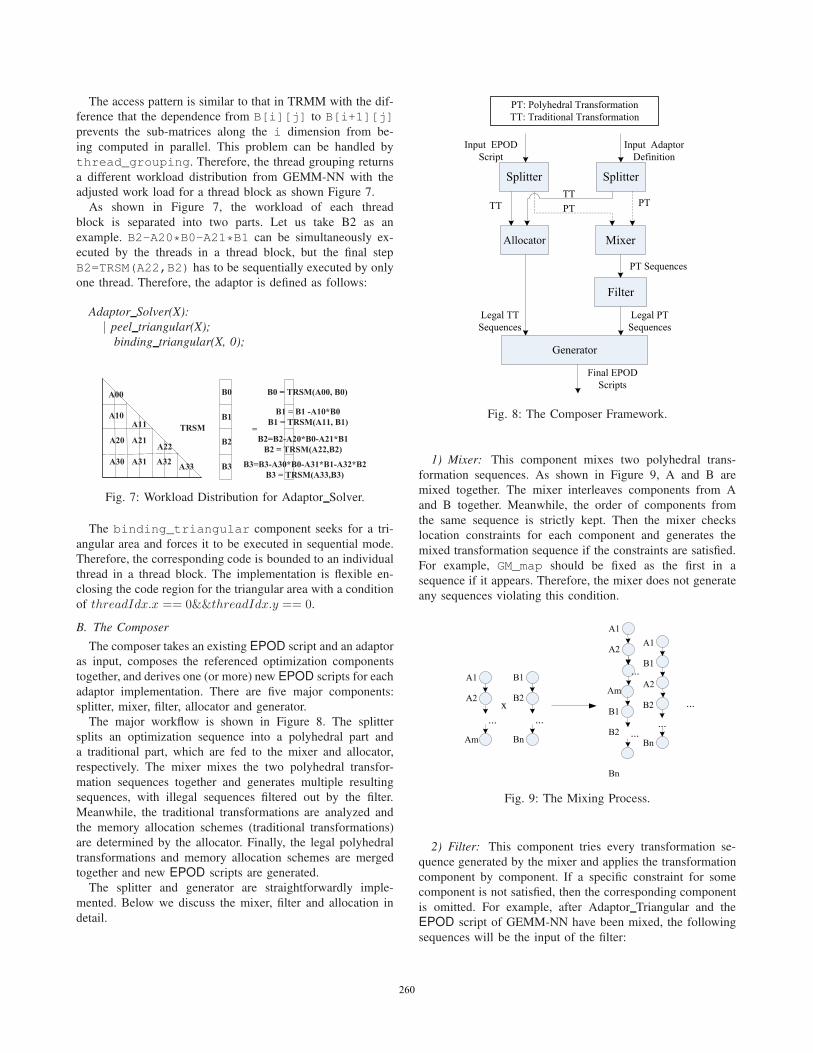
The major workflow is shown in Figure 8. The splitter
splits an optimization sequence into a polyhedral part and
a traditional part, which are fed to the mixer and allocator,
respectively. The mixer mixes the two polyhedral transfor-
mation sequences together and generates multiple resulting
sequences, with illegal sequences filtered out by the filter.
Meanwhile, the traditional transformations are analyzed and
the memory allocation schemes (traditional transformations)
are determined by the allocator. Finally, the legal polyhedral
transformations and memory allocation schemes are merged
together and new EPOD scripts are generated.
The splitter and generator are straightforwardly imple-
mented. Below we discuss the mixer, filter and allocation in
detail.
Fig. 8: The Composer Framework.
1) Mixer: This component mixes two polyhedral trans-
formation sequences. As shown in Figure 9, A and B are
mixed together. The mixer interleaves components from A
and B together. Meanwhile, the order of components from
the same sequence is strictly kept. Then the mixer checks
location constraints for each component and generates the
mixed transformation sequence if the constraints are satisfied.
For example, GM_map should be fixed as the first in a
sequence if it appears. Therefore, the mixer does not generate
any sequences violating this condition.
Fig. 9: The Mixing Process.
2) Filter: This component tries every transformation se-
quence generated by the mixer and applies the transformation
component by component. If a specific constraint for some
component is not satisfied, then the corresponding component
is omitted. For example, after Adaptor Triangular and the
EPOD script of GEMM-NN have been mixed, the following
sequences will be the input of the filter:
260260260260260
1) thread_grouping, loop_tiling,
loop_unroll
2) peel_triangular, thread_grouping,
loop_tiling, loop_unroll
3) thread_grouping, peel_triangular,
loop_tiling, loop_unroll
4) thread_grouping, loop_tiling,
peel_triangular, loop_unroll
5) thread_grouping, loop_tiling,
loop_unroll, peel_triangular
6) padding_triangular, thread_grouping,
loop_tiling, loop_unroll
7) thread_grouping, padding_triangular,
loop_tiling, loop_unroll
8) thread_grouping, loop_tiling,
padding_triangular, loop_unroll
9) thread_grouping, loop_tiling,
loop_unroll, padding_triangular
Sequences 1, 3, 4, 7, 8 are successfully applied and thus
added to a sequence set, denoted semi-output. For Sequences
2 and 6, peel_triangular fails because it cannot detect
a trapezoid area; they degenerate into Sequence 1. For Se-
quences 5 and 9, loop_unroll fails due to the existence of
the non-rectangular areas; they degenerate into the following
two sequences, which are added into semi-output:
1) thread_grouping, loop_tiling,
peel_triangular
2) thread_grouping, loop_tiling,
padding_triangular
In summary, the semi-output of the filter includes seven
sequences. These sequences are checked to ensure that data
dependences are satisfied with the PolyDeps tool [8]. Illegal
ones are removed and the legal ones generated.
3) Allocator: The allocator integrates the memory alloca-
tion invocations in the given EPOD script and the adaptor and
analyzes and determines the final memory allocation scheme,
including which memory hierarchy a matrix should reside
in and the granularity of the memory allocation. Note that
GM_map is not considered because it is a polyhedral-based
transformation and must be applied at the first step.
Consider the matrix multiplication of the form C = αAT ∗B + βC. The adaptor defines one rule that declares A to be
allocated in shared memory, which does not conflict with those
in the EPOD script, so that the declaration is kept.
When we turn to another variation of GEMM, C = αA ∗BT + βC, the adaptor still declares B to be allocated in
shared memory in the Transpose mode. Meanwhile, the
EPOD script also declares B in the same way. In this case, the
allocator integrates both together and generates one declaration
of SM_alloc(B, NoChange).
The memory allocation and the corresponding statements
are processed when SM_alloc is executed, using the method
in [9]. This will not be discussed any further in the paper.
V. PERFORMANCE EVALUATION AND ANALYSIS
We evaluate our work on three GPU platforms: GeForce
9800, GTX285 and Fermi Tesla C2050. In this paper, we focus
on single-precision floating point computations.
• The GeForce 9800 platform consists of 16 streaming
multiprocessors (SMs), each containing 8 streaming pro-
cessors (SPs). Each SM has 8192 registers and a 16KB
local scratchpad memory shared by all simultaneously
active threads in the SM. The peak performance is
429GFLOPS.
• The GTX285 platform consists of 30 SMs, each contain-
ing 8 SPs. Each SM has 16384 registers and a 16KB local
scratchpad memory shared by all simultaneously active
threads in the SM. The peak performance is 709GFLOPS.
• The Fermi Tesla C2050 platform consists of 14 SMs, each
containing 32 SPs. Each SM has 32768 registers and a
48KB local scratchpad memory (configured to be) shared
by all simultaneously active threads in the SM. The peak
performance is over a Tera FLOPS.
The original BLAS3 source programs are first transformed
by our OA framework. Then the transformed source code is
compiled by nvcc with the -O2 optimization flag.
A. Results
Our main results can be summarized as follows:
• Our method can achieve better performances for 24 vari-
ants of BLAS3 routines than those provided in CUBLAS
3.2 with up to 5.4x speedups being achieved;
• Our method has successfully narrowed the performance
gaps between matrix-multiplication variants and the
GEMM-NN routine, showing the benefits of optimizing
libraries by exploiting existing tuning results; and
• Our method shows that it can yield stable performances
for BLAS3 routines for varying problem sizes.
As discussed earlier, our OA framework will generate
multiple alternative EPOD scripts for a given routine with
the best performer being selected by a search.
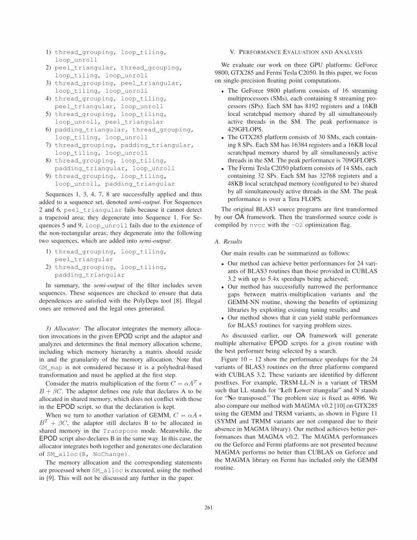
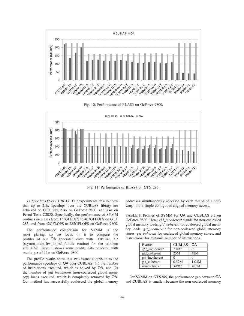
Figure 10 – 12 show the performance speedups for the 24
variants of BLAS3 routines on the three platforms compared
with CUBLAS 3.2. These variants are identified by different
postfixes. For example, TRSM-LL-N is a variant of TRSM
such that LL stands for “Left Lower triangular” and N stands
for “No transposed.” The problem size is fixed as 4096. We
also compare our method with MAGMA v0.2 [10] on GTX285
using the GEMM and TRSM variants, as shown in Figure 11
(SYMM and TRMM variants are not compared due to their
absence in MAGMA library). Our method achieves better per-
formances than MAGMA v0.2. The MAGMA performances
on the Geforce and Fermi platforms are not presented because
MAGMA performs no better than CUBLAS on Geforce and
the MAGMA library on Fermi has included only the GEMM
routine.
261261261261261
0
50
100
150
200
250
Perform
ance
(GFLOPS)
CUBLAS OA
Fig. 10: Performance of BLAS3 on GeForce 9800.
0
100
200
300
400
500
Perform
ance
(GFLOPS)
CUBLAS MAGMA OA
Fig. 11: Performance of BLAS3 on GTX 285.
1) Speedups Over CUBLAS: Our experimental results show
that up to 2.8x speedups over the CUBLAS library are
achieved on GTX 285, 5.4x on GeForce 9800, and 3.4x on
Fermi Tesla C2050. Specifically, the performance of SYMM
routines increases from 155GFLOPS to 403GFLOPS on GTX
285, and from 42GFLOPS to 225GFLOPS on GeForce 9800.
The performance comparison for SYMM is the
most glaring, so we focus on it to compare the
profiles of our OA generated code with CUBLAS 3.2
(ssymm main hw lo left fulltile routine) for the problem
size 4096. Table I shows some profile data collected with
cuda_profile on GeForce 9800.
The profile results show that two issues contribute to the
performance speedups of OA over CUBLAS: (1) the number
of instructions executed, which is halved by OA, and (2)
the number of gld incoherent (non-coalesced global mem-
ory) loads executed, which is completely removed by OA.
Our method has successfully coalesced the global memory
addresses simultaneously accessed by each thread of a half-
warp into a single contiguous aligned memory access.
TABLE I: Profiles of SYMM for OA and CUBLAS 3.2 on
GeForce 9800. Here, gld incoherent stands for non-coalesced
global memory loads, gld coherent for coalesced global mem-
ory loads, gst incoherent for non-coalesced global memory
stores, gst coherent for coalesced global memory stores, and
instructions for dynamic number of instructions.
Events CUBLAS OA
gld incoherent 134M 0
gld coherent 25M 42M
gst incoherent 0 0
gst coherent 0.52M 1.04M
instructions 340M 167M
For SYMM on GTX285, the performance gap between OA
and CUBLAS is smaller, because the non-coalesced memory
262262262262262
0
100
200
300
400
500
600
700
Perform
ance
(GFLOPS)
CUBLAS OA
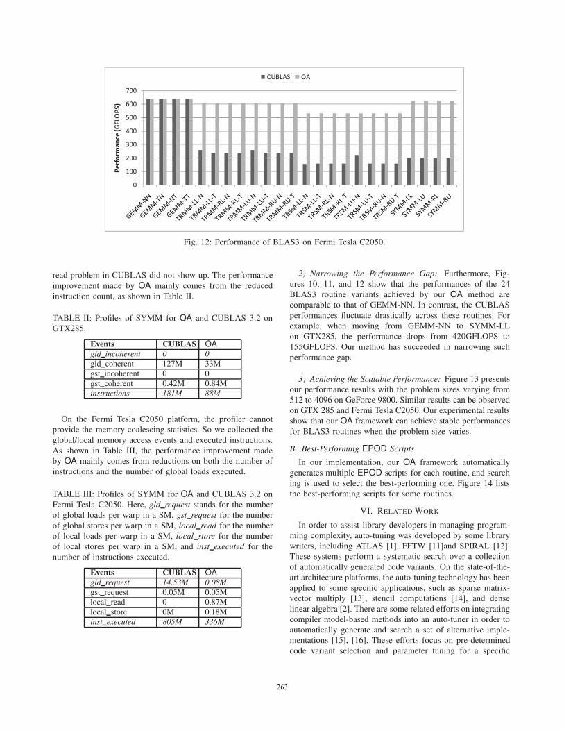
Fig. 12: Performance of BLAS3 on Fermi Tesla C2050.
read problem in CUBLAS did not show up. The performance
improvement made by OA mainly comes from the reduced
instruction count, as shown in Table II.
TABLE II: Profiles of SYMM for OA and CUBLAS 3.2 on
GTX285.
Events CUBLAS OA
gld incoherent 0 0
gld coherent 127M 33M
gst incoherent 0 0
gst coherent 0.42M 0.84M
instructions 181M 88M
On the Fermi Tesla C2050 platform, the profiler cannot
provide the memory coalescing statistics. So we collected the
global/local memory access events and executed instructions.
As shown in Table III, the performance improvement made
by OA mainly comes from reductions on both the number of
instructions and the number of global loads executed.
TABLE III: Profiles of SYMM for OA and CUBLAS 3.2 on
Fermi Tesla C2050. Here, gld request stands for the number
of global loads per warp in a SM, gst request for the number
of global stores per warp in a SM, local read for the number
of local loads per warp in a SM, local store for the number
of local stores per warp in a SM, and inst executed for the
number of instructions executed.
Events CUBLAS OA
gld request 14.53M 0.08M
gst request 0.05M 0.05M
local read 0 0.87M
local store 0M 0.18M
inst executed 805M 336M
2) Narrowing the Performance Gap: Furthermore, Fig-
ures 10, 11, and 12 show that the performances of the 24
BLAS3 routine variants achieved by our OA method are
comparable to that of GEMM-NN. In contrast, the CUBLAS
performances fluctuate drastically across these routines. For
example, when moving from GEMM-NN to SYMM-LL
on GTX285, the performance drops from 420GFLOPS to
155GFLOPS. Our method has succeeded in narrowing such
performance gap.
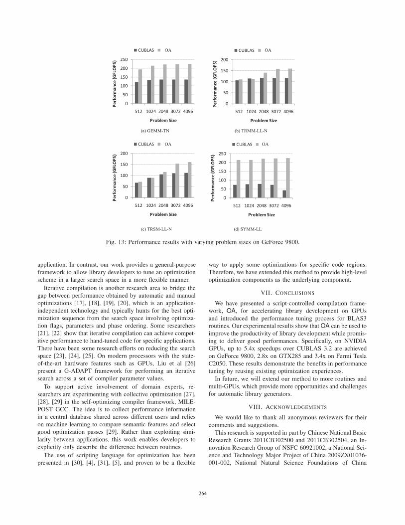
3) Achieving the Scalable Performance: Figure 13 presents
our performance results with the problem sizes varying from
512 to 4096 on GeForce 9800. Similar results can be observed
on GTX 285 and Fermi Tesla C2050. Our experimental results
show that our OA framework can achieve stable performances
for BLAS3 routines when the problem size varies.
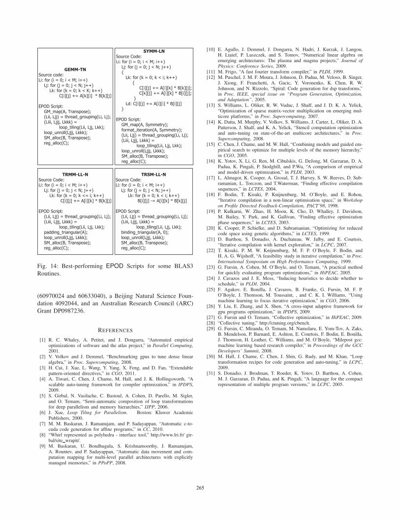
B. Best-Performing EPOD Scripts
In our implementation, our OA framework automatically
generates multiple EPOD scripts for each routine, and search
ing is used to select the best-performing one. Figure 14 lists
the best-performing scripts for some routines.
VI. RELATED WORK
In order to assist library developers in managing program-
ming complexity, auto-tuning was developed by some library
writers, including ATLAS [1], FFTW [11]and SPIRAL [12].
These systems perform a systematic search over a collection
of automatically generated code variants. On the state-of-the-
art architecture platforms, the auto-tuning technology has been
applied to some specific applications, such as sparse matrix-
vector multiply [13], stencil computations [14], and dense
linear algebra [2]. There are some related efforts on integrating
compiler model-based methods into an auto-tuner in order to
automatically generate and search a set of alternative imple-
mentations [15], [16]. These efforts focus on pre-determined
code variant selection and parameter tuning for a specific
263263263263263
0
50
100
150
200
250
512 1024 2048 3072 4096
Perform
ance
(GFLOPS)
Problem Size
CUBLAS LEGO
0
50
100
150
200
512 1024 2048 3072 4096
Perform
ance
(GFLOPS)
Problem Size
CUBLAS LEGO
0
50
100
150
200
512 1024 2048 3072 4096
Perform
ance
(GFLOPS)
Problem Size
CUBLAS LEGO
0
50
100
150
200
250
512 1024 2048 3072 4096Perform
ance
(GFLOPS)
Problem Size
CUBLAS LEGO
(a) GEMM-TN (b) TRMM-LL-N
(d) SYMM-LL(c) TRSM-LL-N
OA OA
OA OA
Fig. 13: Performance results with varying problem sizes on GeForce 9800.
application. In contrast, our work provides a general-purpose
framework to allow library developers to tune an optimization
scheme in a larger search space in a more flexible manner.
Iterative compilation is another research area to bridge the
gap between performance obtained by automatic and manual
optimizations [17], [18], [19], [20], which is an application-
independent technology and typically hunts for the best opti-
mization sequence from the search space involving optimiza-
tion flags, parameters and phase ordering. Some researchers
[21], [22] show that iterative compilation can achieve compet-
itive performance to hand-tuned code for specific applications.
There have been some research efforts on reducing the search
space [23], [24], [25]. On modern processors with the state-
of-the-art hardware features such as GPUs, Liu et al [26]
present a G-ADAPT framework for performing an iterative
search across a set of compiler parameter values.
To support active involvement of domain experts, re-
searchers are experimenting with collective optimization [27],
[28], [29] in the self-optimizing compiler framework, MILE-
POST GCC. The idea is to collect performance information
in a central database shared across different users and relies
on machine learning to compare semantic features and select
good optimization passes [29]. Rather than exploiting simi-
larity between applications, this work enables developers to
explicitly only describe the difference between routines.
The use of scripting language for optimization has been
presented in [30], [4], [31], [5], and proven to be a flexible
way to apply some optimizations for specific code regions.
Therefore, we have extended this method to provide high-level
optimization components as the underlying component.
VII. CONCLUSIONS
We have presented a script-controlled compilation frame-
work, OA, for accelerating library development on GPUs
and introduced the performance tuning process for BLAS3
routines. Our experimental results show that OA can be used to
improve the productivity of library development while promis-
ing to deliver good performances. Specifically, on NVIDIA
GPUs, up to 5.4x speedups over CUBLAS 3.2 are achieved
on GeForce 9800, 2.8x on GTX285 and 3.4x on Fermi Tesla
C2050. These results demonstrate the benefits in performance
tuning by reusing existing optimization experiences.
In future, we will extend our method to more routines and
multi-GPUs, which provide more opportunities and challenges
for automatic library generators.
VIII. ACKNOWLEDGEMENTS
We would like to thank all anonymous reviewers for their
comments and suggestions.
This research is supported in part by Chinese National Basic
Research Grants 2011CB302500 and 2011CB302504, an In-
novation Research Group of NSFC 60921002, a National Sci-
ence and Technology Major Project of China 2009ZX01036-
001-002, National Natural Science Foundations of China
264264264264264
SYMM-LN
Source Code:Li: for (i = 0; i < M; i++) Lj: for (j = 0; j < N; j++) { Lk: for (k = 0; k < i; k++) {
C[i][j] += A[i][k] * B[k][j]; C[k][j] += A[i][k] * B[i][j];
} Ld: C[i][j] += A[i][i] * B[i][j] }
EPOD Script: GM_map(A, Symmetry); format_iteration(A, Symmetry); (Lii, Ljj) = thread_grouping(Li, Lj); (Liii, Ljjj, Lkkk) =
loop_tiling(Lii, Ljj, Lkk); loop_unroll(Ljjj, Lkkk); SM_alloc(B, Transpose); reg_alloc(C);
GEMM-TN
Source code:Li: for (i = 0; i < M; i++) Lj: for (j = 0; j < N; j++) Lk: for (k = 0; k < K; k++)
C[i][j] += A[k][i] * B[k][j]
EPOD Script: GM_map(A, Transpose); (Lii, Ljj) = thread_grouping(Li, Lj); (Liii, Ljjj, Lkkk) =
loop_tiling(Lii, Ljj, Lkk); loop_unroll(Ljjj, Lkkk); SM_alloc(B, Transpose); reg_alloc(C);
TRMM-LL-N
Source Code:Li: for (i = 0; i < M; i++) Lj: for (j = 0; j < N; j++) Lk: for (k = 0; k <= i; k++)
C[i][j] += A[i][k] * B[k][j]
EPOD Script: (Lii, Ljj) = thread_grouping(Li, Lj); (Liii, Ljjj, Lkkk) =
loop_tiling(Lii, Ljj, Lkk); padding_triangular(A); loop_unroll(Ljjj, Lkkk); SM_alloc(B, Transpose); reg_alloc(C);
TRSM-LL-N
Source Code:Li: for (i = 0; i < M; i++) Lj: for (j = 0; j < N; j++) Lk: for (k = 0; k < i; k++)
B[i][j] -= A[i][k] * B[k][j]
EPOD Script: (Lii, Ljj) = thread_grouping(Li, Lj); (Liii, Ljjj, Lkkk) =
loop_tiling(Lii, Ljj, Lkk); binding_triangular(A, 0); loop_unroll(Ljjj, Lkkk); SM_alloc(B, Transpose); reg_alloc(C);
Fig. 14: Best-performing EPOD Scripts for some BLAS3
Routines.
(60970024 and 60633040), a Beijing Natural Science Foun-
dation 4092044, and an Australian Research Council (ARC)
Grant DP0987236.
REFERENCES
[1] R. C. Whaley, A. Petitet, and J. Dongarra, “Automated empiricaloptimizations of software and the atlas project,” in Parallel Computing,2001.
[2] V. Volkov and J. Demmel, “Benchmarking gpus to tune dense linearalgebra,” in Proc. Supercomputing, 2008.
[3] H. Cui, J. Xue, L. Wang, Y. Yang, X. Feng, and D. Fan, “Extendablepattern-oriented directives,” in CGO, 2011.
[4] A. Tiwari, C. Chen, J. Chame, M. Hall, and J. K. Hollingsworth, “Ascalable auto-tuning framework for compiler optimization,” in IPDPS,2009.
[5] S. Girbal, N. Vasilache, C. Bastoul, A. Cohen, D. Parello, M. Sigler,and O. Temam, “Semi-automatic composition of loop transformationsfor deep parallelism and memory hierarchies,” IJPP, 2006.
[6] J. Xue, Loop Tiling for Parallelism. Boston: Kluwer AcademicPublishers, 2000.
[7] M. M. Baskaran, J. Ramanujam, and P. Sadayappan, “Automatic c-to-cuda code generation for affine programs,” in CC, 2010.
[8] “Whirl represented as polyhedra - interface tool,” http://www.lri.fr/ gir-bal/site wrapit/.
[9] M. Baskaran, U. Bondhugula, S. Krishnamoorthy, J. Ramanujam,A. Rountev, and P. Sadayappan, “Automatic data movement and com-putation mapping for multi-level parallel architectures with explicitlymanaged memories,” in PPoPP, 2008.
[10] E. Agullo, J. Demmel, J. Dongarra, N. Hadri, J. Kurzak, J. Langou,H. Ltaief, P. Luszczek, and S. Tomov, “Numerical linear algebra onemerging architectures: The plasma and magma projects,” Journal of
Physics: Conference Series, 2009.[11] M. Frigo, “A fast fourier transform compiler,” in PLDI, 1999.[12] M. Puschel, J. M. F. Moura, J. Johnson, D. Padua, M. Veloso, B. Singer,
J. Xiong, F. Franchetti, A. Gacic, Y. Voronenko, K. Chen, R. W.Johnson, and N. Rizzolo, “Spiral: Code generation for dsp transforms,”in Proc. IEEE, special issue on “Program Generation, Optimization,
and Adaptation”, 2005.[13] S. Williams, L. Oliker, R. W. Vuduc, J. Shalf, and J. D. K. A. Yelick,
“Optimization of sparse matrix-vector multiplication on emerging mul-ticore platforms,” in Proc. Supercomputing, 2007.
[14] K. Datta, M. Murphy, V. Volkov, S. Williams, J. Carter, L. Oliker, D. A.Patterson, J. Shalf, and K. A. Yelick, “Stencil computation optimizationand auto-tuning on state-of-the-art multicore architectures,” in Proc.
Supercomputing, 2008.[15] C. Chen, J. Chame, and M. W. Hall, “Combining models and guided em-
pirical search to optimize for multiple levels of the memory hierarchy,”in CGO, 2005.
[16] K. Yotov, X. Li, G. Ren, M. Cibulskis, G. DeJong, M. Garzaran, D. A.Padua, K. Pingali, P. Stodghill, and P.Wu, “A comparison of empiricaland model-driven optimization,” in PLDI, 2003.
[17] L. Almagor, K. Cooper, A. Grosul, T. J. Harvey, S. W. Reeves, D. Sub-ramanian, L. Torczon, and T.Waterman, “Finding effective compilationsequences,” in LCTES, 2004.
[18] F. Bodin, T. Kisuki, P. Knijnenburg, M. O’Boyle, and E. Rohou,“Iterative compilation in a non-linear optimisation space,” in Workshop
on Profile Directed Feedback-Compilation, PACT’98, 1998.[19] P. Kulkarni, W. Zhao, H. Moon, K. Cho, D. Whalley, J. Davidson,
M. Bailey, Y. Park, and K. Gallivan, “Finding effective optimizationphase sequences,” in LCTES, 2003.
[20] K. Cooper, P. Schielke, and D. Subramanian, “Optimizing for reducedcode space using genetic algorithms,” in LCTES, 1999.
[21] D. Barthou, S. Donadio, A. Duchateau, W. Jalby, and E. Courtois,“Iterative compilation with kernel exploration,” in LCPC, 2007.
[22] T. Kisuki, P. M. W. Knijnenburg, M. F. P. O’Boyle, F. Bodin, andH. A. G. Wijshoff, “A feasibility study in iterative compilation,” in Proc.
International Symposium on High Performance Computing, 1999.[23] G. Fursin, A. Cohen, M. O’Boyle, and O. Temam, “A practical method
for quickly evaluating program optimizations,” in HiPEAC, 2005.[24] J. Cavazos and J. E. Moss, “Inducing heuristics to decide whether to
schedule,” in PLDI, 2004.[25] F. Agakov, E. Bonilla, J. Cavazos, B. Franke, G. Fursin, M. F. P.
O’Boyle, J. Thomson, M. Toussaint, , and C. K. I. Williams, “Usingmachine learning to focus iterative optimization,” in CGO, 2006.
[26] Y. Liu, E. Zhang, and X. Shen, “A cross-input adaptive framework forgpu programs optimization,” in IPDPS, 2009.
[27] G. Fursin and O. Temam, “Collective optimization,” in HiPEAC, 2009.[28] “Collective tuning,” http://ctuning.org/cbench.[29] G. Fursin, C. Miranda, O. Temam, M. Namolaru, E. Yom-Tov, A. Zaks,
B. Mendelson, P. Barnard, E. Ashton, E. Courtois, F. Bodin, E. Bonilla,J. Thomson, H. Leather, C. Williams, and M. O’Boyle, “Milepost gcc:machine learning based research compiler,” in Proceedings of the GCCDevelopers’ Summit, 2008.
[30] M. Hall, J. Chame, C. Chen, J. Shin, G. Rudy, and M. Khan, “Looptransformation recipes for code generation and auto-tuning,” in LCPC,2009.
[31] S. Donadio, J. Brodman, T. Roeder, K. Yotov, D. Barthou, A. Cohen,M. J. Garzaran, D. Padua, and K. Pingali, “A language for the compactrepresentation of multiple program versions,” in LCPC, 2005.
265265265265265