atlas copco refrigerant compressed air dryers
TRANSCRIPT
Atlas CopcoRefrigerant compressed air dryers
FX 1, FX 2, FX 3, FX 4, FX 5, FX 6, FX 7, FX 8, FX 9, FX 10, FX 11,FX 12
Instruction book
Downloaded from www.Manualslib.com manuals search engine

Atlas CopcoRefrigerant compressed air dryers
FX 1, FX 2, FX 3, FX 4, FX 5, FX 6, FX 7, FX 8, FX 9,FX 10, FX 11, FX 12From following serial No. onwards: CAI814019
Instruction bookOriginal instructions
Copyright noticeAny unauthorized use or copying of the contents or any part thereof is prohibited.
This applies in particular to trademarks, model denominations, part numbers anddrawings.
This instruction book is valid for CE as well as non-CE labelled machines. It meets therequirements for instructions specified by the applicable European directives asidentified in the Declaration of Conformity.
2016 - 09
No. 2920 7112 40
www.atlascopco.com
Downloaded from www.Manualslib.com manuals search engine
Table of contents
1 Safety precautions..........................................................................................................4
1.1 SAFETY ICONS................................................................................................................................... 4
1.2 SAFETY PRECAUTIONS, GENERAL...........................................................................................................4
1.3 SAFETY PRECAUTIONS DURING INSTALLATION...........................................................................................5
1.4 SAFETY PRECAUTIONS DURING OPERATION.............................................................................................. 6
1.5 SAFETY PRECAUTIONS DURING MAINTENANCE OR REPAIR........................................................................... 7
2 General description........................................................................................................9
2.1 INTRODUCTION...................................................................................................................................9
2.2 AIR SYSTEM.................................................................................................................................... 11
2.3 REFRIGERATION SYSTEM....................................................................................................................12
2.4 AUTOMATIC REGULATION SYSTEM........................................................................................................ 12
2.5 ELECTRICAL SYSTEM.........................................................................................................................13
3 Installation.....................................................................................................................14
3.1 DIMENSION DRAWINGS.......................................................................................................................14
3.2 INSTALLATION PROPOSAL................................................................................................................... 14
3.3 PICTOGRAPHS................................................................................................................................. 16
4 Operating instructions................................................................................................. 17
4.1 WARNINGS......................................................................................................................................17
4.2 CONTROL PANEL.............................................................................................................................. 17
4.3 DIGITAL CONTROLLER........................................................................................................................18
4.4 STARTING....................................................................................................................................... 23
4.5 DURING OPERATION..........................................................................................................................24
4.6 STOPPING.......................................................................................................................................24
Instruction book
2 2920 7112 40
Downloaded from www.Manualslib.com manuals search engine
5 Maintenance instructions............................................................................................ 26
6 Device settings............................................................................................................. 27
7 Problem solving............................................................................................................28
8 Technical data...............................................................................................................31
8.1 REFERENCE CONDITIONS AND LIMITATIONS............................................................................................ 31
8.2 AIR DRYER DATA.............................................................................................................................. 31
9 Pressure equipment directives................................................................................... 34
10 Declaration of conformity............................................................................................ 35
Instruction book
2920 7112 40 3
Downloaded from www.Manualslib.com manuals search engine
1 Safety precautions
1.1 Safety icons
Explanation
Danger to life
Warning
Important note
1.2 Safety precautions, general
General precautions
All responsibility for any damage or injury resulting from neglecting these precautions, ornon-observance of the normal caution and care required for installation, operation,maintenance and repair, even if not expressly stated, will be disclaimed by themanufacturer.
1. The dryers are designed for normal indoor use.2. The operator must employ safe working practices and observe all related work safety requirements
and regulations.3. If any of the following statements does not comply with the applicable legislation, the stricter of the
two shall apply.4. Installation, operation, maintenance and repair work must only be performed by authorized, trained,
specialized personnel.5. The dryer is not considered capable of producing air of breathing quality. To obtain air of breathing
quality, the compressed air must be adequately purified according to the applicable legislation andstandards.
6. Before any maintenance, repair work, adjustment or any other non-routine checks, stop the dryer,press the emergency stop button, switch off the voltage and depressurize the dryer. In addition, thepower isolating switch must be opened and locked. For plug versions, remove the plug from the wallsocket and secure it.
7. Never play with compressed air. Do not apply the air to your skin or direct an air stream at people.Never use the air to clean dirt from your clothes. When using the air to clean equipment, do so withextreme caution and wear eye protection.
8. The owner is responsible for maintaining the dryer in safe operating condition. Parts and accessoriesshall be replaced if unsuitable for safe operation.
9. It is not allowed to walk or stand on the dryer or its components.
Instruction book
4 2920 7112 40
Downloaded from www.Manualslib.com manuals search engine
1.3 Safety precautions during installation
Precautions during installation1. The dryer must only be lifted using suitable equipment and in accordance with the applicable safety
regulations. Loose or pivoting parts must be securely fastened before lifting. It is strictly forbidden todwell or stay in the risk zone under a lifted load. Lifting acceleration and deceleration must be keptwithin safe limits. Wear a safety helmet when working in the area of overhead or lifting equipment.
2. Place the dryer where the ambient air is as cool and clean as possible. If necessary, install a suctionduct. Never obstruct the air inlet. Care must be taken to minimize the entry of moisture at the inlet air.
3. Any blanking flanges, plugs, caps or desiccant bags must be removed before connecting the pipes.4. Air hoses must be of correct size and suitable for the working pressure. Never use frayed, damaged or
worn hoses. Distribution pipes and connections must be of the correct size and suitable for theworking pressure.
5. The aspirated air must be free of flammable fumes, vapours and particles, e.g. paint solvents, that canlead to internal fire or explosion.
6. Arrange the air intake so that loose clothing worn by people cannot be sucked in.7. Ensure that all piping is free to expand under heat and that it is not in contact with or close to
flammable materials.8. No external force may be exerted on the air outlet valve. The connected pipe must be free of strain.9. If remote control is installed, the machine must bear a clear sign stating "Danger: This machine is
remotely controlled and may start without warning".The operator has to make sure that the machine is stopped and that the isolating switch is open andlocked before any maintenance or repair. As a further safeguard, persons switching on remotelycontrolled machines shall take adequate precautions to ensure that there is no one checking orworking on the machine. To this end, a suitable notice shall be affixed to the starting equipment.
10. Air-cooled machines must be installed in such a way that an adequate flow of cooling air is availableand that the exhausted cooling air does not recirculate to the inlet.
11. The electrical connections must correspond to the applicable codes. The machines must be earthedand protected against short circuits by fuses in all phases. A lockable power isolating switch must beinstalled near the equipment.
12. On machines with automatic start-stop system or if the automatic restart function after voltage failureis activated, a sign stating "This machine may start without warning" must be affixed near theinstrument panel.
13. Never remove or tamper with the safety devices, guards or insulation fitted on the machine. Everypressure vessel or auxiliary installed outside the machine to contain air above atmospheric pressuremust be protected by a pressure-relieving device or devices as required.
14. Piping or other parts with a temperature in excess of 80˚C (176˚F) and which may be accidentallytouched by personnel during normal operation must be guarded or insulated. Other high-temperaturepiping must be clearly marked.
15. For water-cooled machines, the cooling water system installed outside the machine has to beprotected by a safety device with set pressure according to the maximum cooling water inlet pressure.
16. If no safety valve is present in the air net close to the desiccant dryer (e.g. safety valve ofcompressor), full flow safety valves must be installed on the dryer vessels.
17. If the maximum pressure of the compressor is higher than the design pressure of the dryer, a full flowsafety valve must be installed between the compressor and the dryer in order to blow off the excessivepressure in case the safety valve of the dryer should be out of order or blocked.
18. When unit is not permanently secured to the floor in the vertical position or mounted horizontally,access to electrical equipment is feasible through the unit base. In this case additional barriers must beprovided during installation. Tag with "warning high voltage" symbol
Instruction book
2920 7112 40 5
Downloaded from www.Manualslib.com manuals search engine

Also consult following safety precautions: Safety precautions during operation and Safetyprecautions during maintenance or repair.These precautions apply to machinery processing or consuming air or inert gas. Processingof any other gas requires additional safety precautions typical to the application which arenot included herein.Some precautions are general and cover several machine types and equipment; hencesome statements may not apply to your machine.
1.4 Safety precautions during operation
Precautions during operation1. Always be careful when touching any piping or components of the dryer during operation. On dryers
using heat to regenerate the desiccant, some parts will become very hot.2. Use only the correct type and size of hose end fittings and connections. When blowing through a hose
or air line, ensure that the open end is held securely. A free end will whip and may cause injury. Makesure that a hose is fully depressurized before disconnecting it.
3. Persons switching on remotely controlled machines shall take adequate precautions to ensure thatthere is no one checking or working on the machine. To this end, a suitable notice shall be affixed tothe remote start equipment.
4. Never operate the machine when there is a possibility of taking in flammable or toxic fumes, vaporsor particles.
5. Never operate the machine below or in excess of its limit ratings.6. Keep all bodywork closed during operation. Bodywork should be opened for short periods only, e.g.
to carry out routine checks. Wear ear protectors when removing a panel.7. People staying in environments or rooms where the sound pressure level reaches or exceeds 90 dB(A)
shall wear ear protectors.8. Periodically check that:
• All guards are in place and securely fastened• All hoses and/or pipes inside the machine are in good condition, secure and not rubbing• There are no leaks• All fasteners are tight• All electrical leads are secure and in good order• Safety valves and other pressure relief devices are not obstructed by dirt or paint• Air outlet valve and air net, i.e. pipes, couplings, manifolds, valves, hoses, etc. are in good
condition, free of wear or abuse9. If warm cooling air from dryers is used in air heating systems, e.g. to warm up a working area, take
precautions against air pollution and possible contamination of the breathing air.10. Do not remove any of, or tamper with, the sound dampening material.11. Never remove or tamper with the safety devices, guards or insulations fitted on the machine. Every
pressure vessel or auxiliary installed outside the machine to contain air above atmospheric pressureshall be protected by a pressure relieving device or devices as required.
12. Yearly inspect the air receiver. Minimum wall thickness as specified in the instruction book must berespected. Local regulations remain applicable if they are more strict.
Instruction book
6 2920 7112 40
Downloaded from www.Manualslib.com manuals search engine

Also consult following safety precautions: Safety precautions during installation and Safetyprecautions during maintenance or repair.These precautions apply to machinery processing or consuming air or inert gas. Processingof any other gas requires additional safety precautions typical to the application which arenot included herein.Some precautions are general and cover several machine types and equipment; hencesome statements may not apply to your machine.
1.5 Safety precautions during maintenance or repair
Precautions during maintenance or repair1. Always use the correct safety equipment (such as safety glasses, gloves, safety shoes, etc.).2. Use only the correct tools for maintenance and repair work.3. Use only genuine spare parts.4. All maintenance work shall only be undertaken when the machine has cooled down.5. A warning sign bearing a legend such as "Work in progress - do not start" shall be attached to the
starting equipment.6. Persons switching on remotely controlled machines shall take adequate precautions to ensure that
there is no one checking or working on the machine. To this end, a suitable notice shall be affixed tothe remote starting equipment.
7. Close the dryer air outlet valve before connecting or disconnecting a pipe.8. Before removing any pressurized component, effectively isolate the machine from all sources of
pressure and relieve the entire system of pressure.9. Never use flammable solvents or carbon tetrachloride for cleaning parts. Take safety precautions
against toxic vapours of cleaning liquids.10. Scrupulously observe cleanliness during maintenance and repair. Keep dirt away by covering the
parts and exposed openings with a clean cloth, paper or tape.11. Never weld on, or in any way modify, pressure vessels.12. Whenever there is an indication or any suspicion that an internal part of a machine is overheated, the
machine shall be stopped but no inspection covers shall be opened before sufficient cooling time haselapsed; this to avoid the risk of spontaneous ignition of the oil vapor when air is admitted.
13. Never use a light source with open flame for inspecting the interior of a machine, pressure vessel, etc.14. Make sure that no tools, loose parts or rags are left in or on the machine.15. All regulating and safety devices shall be maintained with due care to ensure that they function
properly. They may not be put out of action.16. Before clearing the machine for use after maintenance or overhaul, check that operating pressures,
temperatures and time settings are correct. Check that all control and shut-down devices are fitted andthat they function correctly.
17. Protect the motor, electrical and regulating components, etc. to prevent moisture from entering them,e.g. when steam-cleaning.
18. Make sure that all sound-damping material and vibration dampers, e.g. damping material on thebodywork, is in good condition. If damaged, replace it by genuine material from the manufacturer toprevent the sound pressure level from increasing.
19. Never use caustic solvents which can damage materials of the air net, e.g. polycarbonate bowls.20. The following safety precautions are stressed when handling refrigerant:
• Never inhale refrigerant vapours. Check that the working area is adequately ventilated; ifrequired, use breathing protection.
• Always wear special gloves. In case of refrigerant contact with the skin, rinse the skin withwater. If liquid refrigerant contacts the skin through clothing, never tear off or remove the latter;
Instruction book
2920 7112 40 7
Downloaded from www.Manualslib.com manuals search engine

flush abundantly with fresh water over the clothing until all refrigerant is flushed away; thenseek medical first aid.
21. The following safety precautions are stressed when handling desiccant:• Take precautions not to inhale desiccant dust.• Check that the working area is adequately ventilated; if required, use breathing protection.• Do not overfill the dryer when replacing desiccant.
Also consult following safety precautions: Safety precautions during installation and Safetyprecautions during operation.These precautions apply to machinery processing or consuming air or inert gas. Processingof any other gas requires additional safety precautions typical to the application which arenot included herein.Some precautions are general and cover several machine types and equipment; hencesome statements may not apply to your machine.
Instruction book
8 2920 7112 40
Downloaded from www.Manualslib.com manuals search engine

2 General description
2.1 Introduction
General views
FX 1 up to FX 5
Instruction book
2920 7112 40 9
Downloaded from www.Manualslib.com manuals search engine

FX 6 up to FX 12
IntroductionThe FX air dryers remove moisture from compressed air by cooling the air to near freezing point. Thiscauses water to condense. The condensate is automatically drained. The air is warmed up before leavingthe dryer.
Instruction book
10 2920 7112 40
Downloaded from www.Manualslib.com manuals search engine
2.2 Air system
Air flow diagram
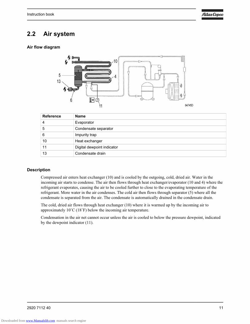
Reference Name4 Evaporator5 Condensate separator6 Impurity trap10 Heat exchanger11 Digital dewpoint indicator13 Condensate drain
DescriptionCompressed air enters heat exchanger (10) and is cooled by the outgoing, cold, dried air. Water in theincoming air starts to condense. The air then flows through heat exchanger/evaporator (10 and 4) where therefrigerant evaporates, causing the air to be cooled further to close to the evaporating temperature of therefrigerant. More water in the air condenses. The cold air then flows through separator (5) where all thecondensate is separated from the air. The condensate is automatically drained in the condensate drain.
The cold, dried air flows through heat exchanger (10) where it is warmed up by the incoming air toapproximately 10˚C (18˚F) below the incoming air temperature.
Condensation in the air net cannot occur unless the air is cooled to below the pressure dewpoint, indicatedby the dewpoint indicator (11).
Instruction book
2920 7112 40 11
Downloaded from www.Manualslib.com manuals search engine

2.3 Refrigeration system
Refrigerant flow diagram
Reference Name1 Refrigerant compressor2 Condenser4 Evaporator7 Expansion capillary tube8 Refrigerant filter
DescriptionCompressor (1) delivers hot, high-pressure refrigerant gas which flows through condenser (2) where mostof the refrigerant condenses.
The liquid flows through the refrigerant dryer/filter (8) to capillary tube (7). The refrigerant leaves thecapillary tube at evaporating pressure.
The refrigerant enters evaporator (4) where it withdraws heat from the compressed air by furtherevaporation at constant pressure. The heated refrigerant leaves the evaporator and flows through the liquidseparator (9) back to the compressor (1).
2.4 Automatic regulation system
Instruction book
12 2920 7112 40
Downloaded from www.Manualslib.com manuals search engine
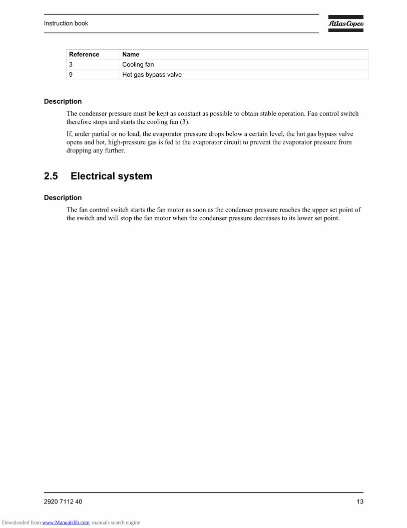
Reference Name3 Cooling fan9 Hot gas bypass valve
DescriptionThe condenser pressure must be kept as constant as possible to obtain stable operation. Fan control switchtherefore stops and starts the cooling fan (3).
If, under partial or no load, the evaporator pressure drops below a certain level, the hot gas bypass valveopens and hot, high-pressure gas is fed to the evaporator circuit to prevent the evaporator pressure fromdropping any further.
2.5 Electrical system
DescriptionThe fan control switch starts the fan motor as soon as the condenser pressure reaches the upper set point ofthe switch and will stop the fan motor when the condenser pressure decreases to its lower set point.
Instruction book
2920 7112 40 13
Downloaded from www.Manualslib.com manuals search engine
3 Installation
3.1 Dimension drawingsThe dimension drawings can be found on the CD-ROM, delivered with the dryer.
Dimension drawing Model2202 7549 00 FX 1 up to FX 52202 7463 00 FX 6 and FX 72202 7464 00 FX 8 up to FX 102202 7465 00 FX 11 and FX 12
Text on drawings Translation or explanationElectric cable outlet Outlet for electric cableCondensate pipe drain outlet Outlet for condensate drain hose or pipeAir inlet Air inletAir outlet Air outletAir flow Air flow directionBushings UL version only Bushings (UL certification version only)Female Female connectionMale Male connectionAll dimensions: mm / inch All dimensions are in mm or inch as indicated on the
drawing
3.2 Installation proposal
Moving
Use a suitable tool (pallet carrier, fork lift truck) to move the dryer.Do not use metal cables for lifting.Move the dryer gently.
Instruction book
14 2920 7112 40
Downloaded from www.Manualslib.com manuals search engine
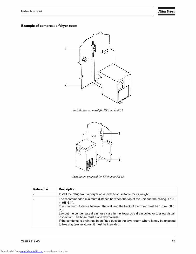
Example of compressor/dryer room
Installation proposal for FX 1 up to FX 5
Installation proposal for FX 6 up to FX 12
Reference Description- Install the refrigerant air dryer on a level floor, suitable for its weight.- The recommended minimum distance between the top of the unit and the ceiling is 1.5
m (58.5 in).The minimum distance between the wall and the back of the dryer must be 1.5 m (58.5in).Lay out the condensate drain hose via a funnel towards a drain collector to allow visualinspection. The hose must slope downwards.If the condensate drain has been fitted outside the dryer room where it may be exposedto freezing temperatures, it must be insulated.
Instruction book
2920 7112 40 15
Downloaded from www.Manualslib.com manuals search engine
Reference Description- The power cable must be connected by a qualified electrician.
Connect the dryer to the correct voltage; if necessary, check the unit data plate.Check that the electrical installation corresponds to local codes. The dryer must beearthed and protected against short circuits using an automatic cut-out device with adifferential device.An isolating switch must be installed near the dryer.
- Connect the compressed air lines to the marked inlet and outlet pipes of the dryer (seeDimension drawings). Provide an air inlet valve and outlet valve. If a bypass pipe andvalve are installed, the dryer can be serviced while it is bypassed.
1 Location of isolating switch and fuses.2 Minimum distance 1.5 m (58.5 in).
3.3 Pictographs
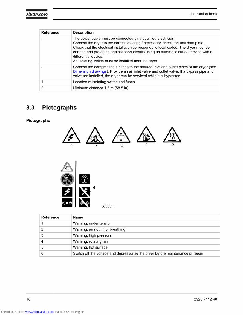
Pictographs
Reference Name1 Warning, under tension2 Warning, air not fit for breathing3 Warning, high pressure4 Warning, rotating fan5 Warning, hot surface6 Switch off the voltage and depressurize the dryer before maintenance or repair
Instruction book
16 2920 7112 40
Downloaded from www.Manualslib.com manuals search engine
4 Operating instructions
4.1 Warnings
Safety precautionsThe operator must apply all relevant safety precautions, including those mentioned in this manual.
Altitude operationConsult your supplier if operating above 3000 m (9843 ft).
4.2 Control panel
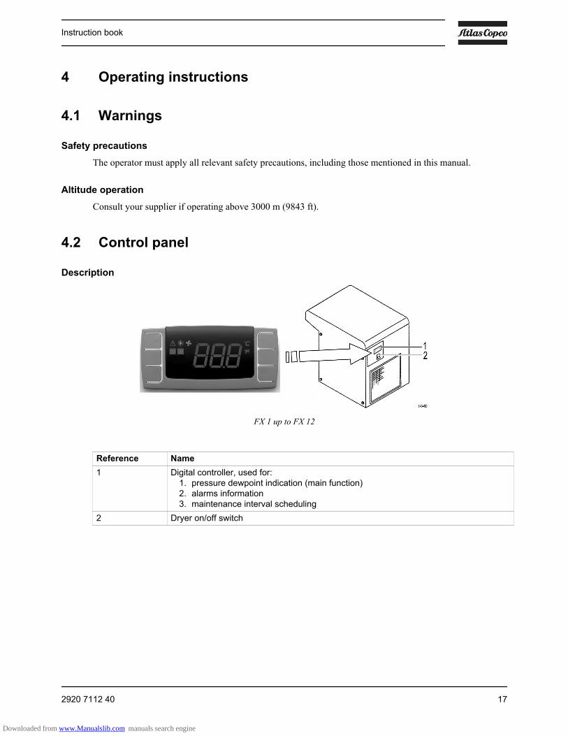
Description
FX 1 up to FX 12
Reference Name1 Digital controller, used for:
1. pressure dewpoint indication (main function)2. alarms information3. maintenance interval scheduling
2 Dryer on/off switch
Instruction book
2920 7112 40 17
Downloaded from www.Manualslib.com manuals search engine

4.3 Digital controller
Identification
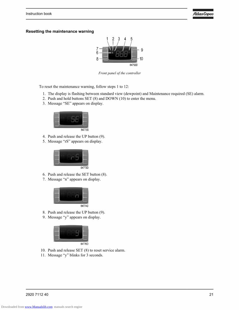
Front panel of the controller
Reference Name1 Alarm icon2 Refrigerant compressor icon3 Fan icon4 PDP (dewpoint) temperature5 Unit (°C or °F)6 Alarm LED7 Button to snooze or to reset the alarm (only for remote alarm function).8 SET button9 UP button10 DOWN button8+9 Back to previous screen8+10 Menu
Icons
Icon Name Mode FunctionAlarm Off No active alarms
On Probe failure alarm High temperature or low
temperature alarm Service alarm
Refrigerant compressor Off Dryer off
On Dryer on Flashing + SE Maintenance warning Flashing + L2 Dewpoint too low
Dryer is stopped
Instruction book
18 2920 7112 40
Downloaded from www.Manualslib.com manuals search engine

Icon Name Mode Function Flashing + H3 Too high discharge
temperature of therefrigerant compressor(see further)Dryer is stopped
Fan Off Fan off
Flashing Not applicable On Fan on
Remote alarm functionDepending on the dryer model, the controller allows to remotely control a number of alarms. This ismanaged by means of a free NC (Normally Closed) contact.
The contact opens in case of an alarm or when the dryer is switched off.
Refer to the table below to identify the availability of the function and refer to the related picture to identifythe physical location of the free contact.
Availability of the remote alarm function
Model Fault message availability P1 P2 P3 L2 H2 H3FX 1 to FX 3 no yes no yes yes noFX 4 and FX 5 yes yes no yes yes noFX 6 to FX 12 yes yes yes yes yes yes
Location of the free contact (1)
Instruction book
2920 7112 40 19
Downloaded from www.Manualslib.com manuals search engine

Fault messages
Flashing fault message Description RemedyFan control probe failure Replace the probe.
Dewpoint temperature probe failure Replace the probe.
Refrigerant compressor dischargetemperature probe failure (onlyavailable on FX 6 to FX 12 withremote alarm function)
Replace the probe.
Pressure dewpoint too high Refer to the fault and remediessection.
Pressure dewpoint too low Refer to the fault and remediessection.
Refrigerant compressor dischargetemperature too high; refrigerantcompressor stopped (only available onFX 6 to FX 12 with remote alarmfunction)
Refer to the fault and remediessection.
Internal EPROM error Reset by pressing one of the fourbuttons.If the problem persists, replace thecontroller.
Maintenance required Perform the maintenance and resetthe alarm.
Instruction book
20 2920 7112 40
Downloaded from www.Manualslib.com manuals search engine
Resetting the maintenance warning
Front panel of the controller
To reset the maintenance warning, follow steps 1 to 12:
1. The display is flashing between standard view (dewpoint) and Maintenance required (SE) alarm.2. Push and hold buttons SET (8) and DOWN (10) to enter the menu.3. Message “SE” appears on display.
4. Push and release the UP button (9).5. Message “rS” appears on display.
6. Push and release the SET button (8).7. Message “n” appears on display.
8. Push and release the UP button (9).9. Message “y” appears on display.
10. Push and release SET (8) to reset service alarm.11. Message “y” blinks for 3 seconds.
Instruction book
2920 7112 40 21
Downloaded from www.Manualslib.com manuals search engine
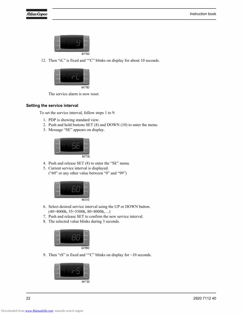
12. Then “rL” is fixed and “°C” blinks on display for about 10 seconds.
The service alarm is now reset.
Setting the service intervalTo set the service interval, follow steps 1 to 9:
1. PDP is showing standard view.2. Push and hold buttons SET (8) and DOWN (10) to enter the menu.3. Message “SE” appears on display.
4. Push and release SET (8) to enter the “SE” menu.5. Current service interval is displayed.
(“60” or any other value between “0” and “99”)
6. Select desired service interval using the UP or DOWN button.(40=4000h, 55=5500h, 80=8000h,…)
7. Push and release SET to confirm the new service interval.8. The selected value blinks during 3 seconds.
9. Then “rS” is fixed and “°C” blinks on display for ~10 seconds.
Instruction book
22 2920 7112 40
Downloaded from www.Manualslib.com manuals search engine
The new service interval is now set.
Freeze protection function (available with Remote Alarm function on FX 6 to FX 12)
Once the digital controller detects a dewpoint temperature below -2°C during more than 2 minutes, (L2Alarm), it switches off the refrigerant compressor.
Resetting the dryer after a refrigerant compressor stop (available with Remote Alarm function onFX6 to FX 12)
Press button 7 to reset the alarm.
The dryer restarts when both the following conditions are true:
• The dewpoint temperature is higher than -2°C• 30 seconds are passed from the refrigerant compressor stop (minimum balancing pressure stop time).
A countdown is available if the reset is made before the minimum stop time.
Silent alarm function (available with Remote Alarm function on FX6 to FX 12)
To snooze the alarm, press button 7.
4.4 Starting
Attention
To ensure optimum operational efficiency, do not use dryer on/off switch repeatedlywithin a short time period.Wait at least 5 minutes to start the dryer again after stopping to allow pressureequalization.To keep the compressed air net free of condensate, start the dryer before starting thecompressor and stop the compressor before stopping the dryer.
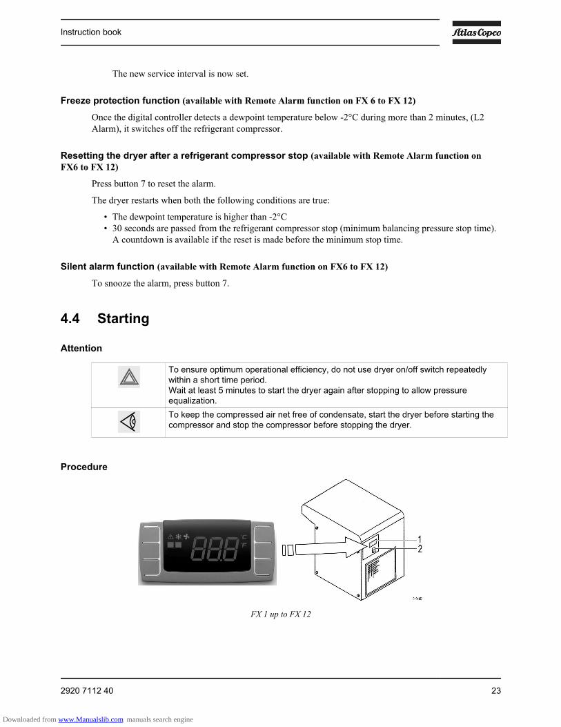
Procedure
FX 1 up to FX 12
Instruction book
2920 7112 40 23
Downloaded from www.Manualslib.com manuals search engine
Step Action1 If installed, close the dryer by-pass valve. See Installation proposal.2 Press dryer on/off switch (2).3 Open dryer air inlet valve (customer's installation).4 Approx. 5 minutes later, open dryer air outlet valve (customer's installation).5 Approx. 10 minutes later, the nominal dewpoint will be reached.
4.5 During operation
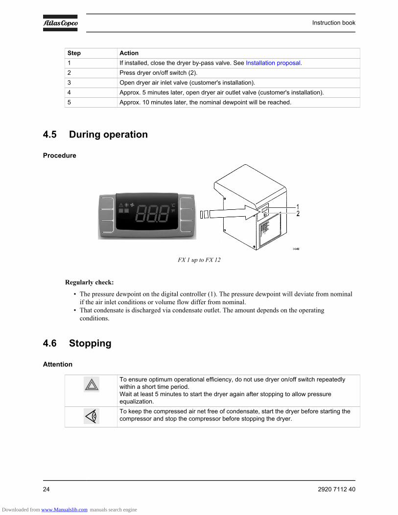
Procedure
FX 1 up to FX 12
Regularly check:
• The pressure dewpoint on the digital controller (1). The pressure dewpoint will deviate from nominalif the air inlet conditions or volume flow differ from nominal.
• That condensate is discharged via condensate outlet. The amount depends on the operatingconditions.
4.6 Stopping
Attention
To ensure optimum operational efficiency, do not use dryer on/off switch repeatedlywithin a short time period.Wait at least 5 minutes to start the dryer again after stopping to allow pressureequalization.To keep the compressed air net free of condensate, start the dryer before starting thecompressor and stop the compressor before stopping the dryer.
Instruction book
24 2920 7112 40
Downloaded from www.Manualslib.com manuals search engine
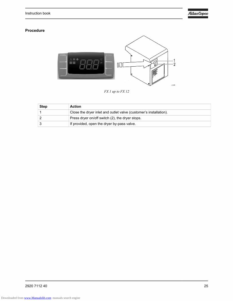
Procedure
FX 1 up to FX 12
Step Action1 Close the dryer inlet and outlet valve (customer’s installation).2 Press dryer on/off switch (2), the dryer stops.3 If provided, open the dryer by-pass valve.
Instruction book
2920 7112 40 25
Downloaded from www.Manualslib.com manuals search engine
5 Maintenance instructions
Safety precautionsBefore starting any maintenance or repair work, close the air inlet and outlet valve and switch off thevoltage.
When removing the side panels of the dryer, be aware that internal elements such as the pipes can be hot.Therefore, wait until the dryer has cooled down before removing the side panels.
Dryers of FX type contain refrigerant HFC.
When handling refrigerant, all applicable safety precautions must be observed. Please be aware ofthe following points:
• Contact of refrigerant with the skin will cause freezing. Special gloves must be worn. In case ofcontact with the skin, the skin should be rinsed with water. On no account may clothing be removed.
• Fluid refrigerant will also cause freezing of the eyes; safety glasses must hence be worn.• Refrigerant is hazardous. Do not inhale refrigerant vapours. Check that the working area is adequately
ventilated.
Local legislationLocal legislation may stipulate that:
• Work on the refrigerant circuit of the cooling dryer or on any equipment which influences its functionmust be undertaken by an authorised control body.
• The installation is checked once a year by an authorised control body.
Instructions• Keep the dryer clean.• Inspect and clean the filter of the automatic condensate drain monthly, in dusty environment drain
weekly:• Release the pressure in the dryer by pressing the TEST push button on top of the condensate
drain (before switching off the supply voltage).• Switch off the voltage• Remove the filter from the automatic drain and clean it with an air jet, working from inside to
outside• Reinstall the filter
• Brush or blow off the finned surface of the condenser monthly. Do not use water or solvents.• Apply the drain wear kit once per year (see Spare Parts list for part number).
These maintenance intervals are intended for well ventilated, non-humid and not dustyenvironments.For particularly high humidity ambient conditions, the intervals should be halved.
Instruction book
26 2920 7112 40
Downloaded from www.Manualslib.com manuals search engine

6 Device settings
Regulating and safety devicesThe regulating and safety devices are factory-adjusted to obtain optimum performance of the dryer. Do notalter the setting of any of the devices.
Instruction book
2920 7112 40 27
Downloaded from www.Manualslib.com manuals search engine
7 Problem solving
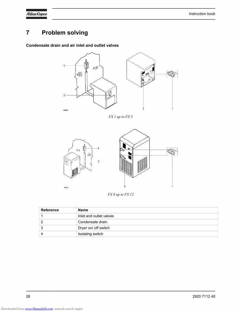
Condensate drain and air inlet and outlet valves
FX 1 up to FX 5
FX 6 up to FX 12
Reference Name1 Inlet and outlet valves2 Condensate drain3 Dryer on/ off switch4 Isolating switch
Instruction book
28 2920 7112 40
Downloaded from www.Manualslib.com manuals search engine

Attention
Use only authorised parts. Any damage or malfunction caused by the use ofunauthorised parts is not covered by Warranty or Product Liability.Apply all relevant safety precautions.Before carrying out any maintenance or repair work on the dryer:Close air inlet and outlet valves (1) of the dryer.Move dryer on/off switch (3) to position 0 to switch off the voltage. See section Stopping.Open the isolating switch (4) to prevent an accidental start.The air inlet and outlet valves (1) can be locked during maintenance or repairwork as follows:
• Close the valve.• Using a wrench, remove the screw fixing the handle.• Lift the handle and turn it until the slot of the handle fits over the blocking edge on
the valve body.• Fit the screw.
Faults and remedies
Condition Fault Remedy1 Pressure dewpoint too high Air inlet temperature too high Check and correct; if necessary,
install a pre-cooler Ambient temperature too high Check and correct; if necessary,
draw cooling air via a duct from acooler place or relocate the dryer
Air inlet pressure too low Increase inlet pressureAdjust the pressure switch
Dryer capacity exceeded Reduce air flow Shortage of refrigerant Have circuit checked for leaks and
recharged Refrigerant compressor does
not runSee 3
Evaporator pressure too high See 5 Condenser pressure too high See 22 Condenser temperature too
high or too lowFan or fan motor out of order Check fan/fan motor
Ambient temperature too high Check and correct; if necessary,draw cooling air via a duct from acooler room or relocate the dryer
Condenser externally clogged Clean condenser3 Compressor stops or does not
startElectric power supply tocompressor is interrupted
Check and correct as necessary
Thermal protection ofrefrigerant compressor motorhas tripped
Reset the thermostatic protection
Restart of the dryer has beentoo fast, not enough time forpressure balancing
Wait a few minutes and restart
Instruction book
2920 7112 40 29
Downloaded from www.Manualslib.com manuals search engine

Condition Fault Remedy4 The condensate drain
remains inoperativeDrain system clogged Have system inspected
5 Evaporator pressure is toohigh or too low at unload
Hot gas by-pass valveincorrectly set or out of order
Have hot gas by-pass valve adjusted
Condenser pressure too highor too low
See 2
Shortage of refrigerant Have circuit checked for leaks andrecharged
Instruction book
30 2920 7112 40
Downloaded from www.Manualslib.com manuals search engine
8 Technical data
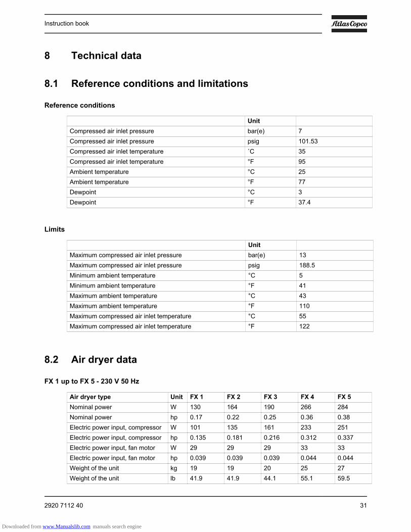
8.1 Reference conditions and limitations
Reference conditions
UnitCompressed air inlet pressure bar(e) 7Compressed air inlet pressure psig 101.53Compressed air inlet temperature ˚C 35Compressed air inlet temperature °F 95Ambient temperature °C 25Ambient temperature °F 77Dewpoint °C 3Dewpoint °F 37.4
Limits
Unit Maximum compressed air inlet pressure bar(e) 13Maximum compressed air inlet pressure psig 188.5Minimum ambient temperature °C 5Minimum ambient temperature °F 41Maximum ambient temperature °C 43Maximum ambient temperature °F 110Maximum compressed air inlet temperature °C 55Maximum compressed air inlet temperature °F 122
8.2 Air dryer data
FX 1 up to FX 5 - 230 V 50 Hz
Air dryer type Unit FX 1 FX 2 FX 3 FX 4 FX 5Nominal power W 130 164 190 266 284Nominal power hp 0.17 0.22 0.25 0.36 0.38Electric power input, compressor W 101 135 161 233 251Electric power input, compressor hp 0.135 0.181 0.216 0.312 0.337Electric power input, fan motor W 29 29 29 33 33Electric power input, fan motor hp 0.039 0.039 0.039 0.044 0.044Weight of the unit kg 19 19 20 25 27Weight of the unit lb 41.9 41.9 44.1 55.1 59.5
Instruction book
2920 7112 40 31
Downloaded from www.Manualslib.com manuals search engine
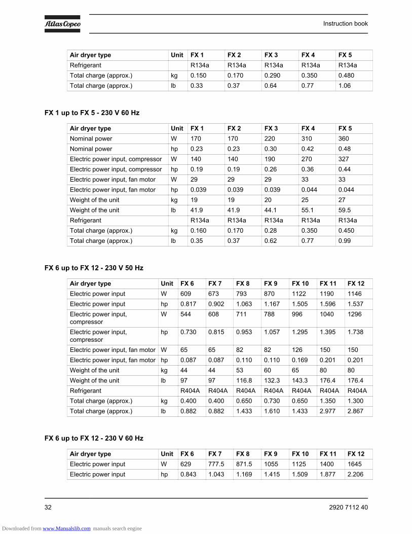
Air dryer type Unit FX 1 FX 2 FX 3 FX 4 FX 5Refrigerant R134a R134a R134a R134a R134aTotal charge (approx.) kg 0.150 0.170 0.290 0.350 0.480Total charge (approx.) lb 0.33 0.37 0.64 0.77 1.06
FX 1 up to FX 5 - 230 V 60 Hz
Air dryer type Unit FX 1 FX 2 FX 3 FX 4 FX 5Nominal power W 170 170 220 310 360Nominal power hp 0.23 0.23 0.30 0.42 0.48Electric power input, compressor W 140 140 190 270 327Electric power input, compressor hp 0.19 0.19 0.26 0.36 0.44Electric power input, fan motor W 29 29 29 33 33Electric power input, fan motor hp 0.039 0.039 0.039 0.044 0.044Weight of the unit kg 19 19 20 25 27Weight of the unit lb 41.9 41.9 44.1 55.1 59.5Refrigerant R134a R134a R134a R134a R134aTotal charge (approx.) kg 0.160 0.170 0.28 0.350 0.450Total charge (approx.) lb 0.35 0.37 0.62 0.77 0.99
FX 6 up to FX 12 - 230 V 50 Hz
Air dryer type Unit FX 6 FX 7 FX 8 FX 9 FX 10 FX 11 FX 12Electric power input W 609 673 793 870 1122 1190 1146Electric power input hp 0.817 0.902 1.063 1.167 1.505 1.596 1.537Electric power input,compressor
W 544 608 711 788 996 1040 1296
Electric power input,compressor
hp 0.730 0.815 0.953 1.057 1.295 1.395 1.738
Electric power input, fan motor W 65 65 82 82 126 150 150Electric power input, fan motor hp 0.087 0.087 0.110 0.110 0.169 0.201 0.201Weight of the unit kg 44 44 53 60 65 80 80Weight of the unit lb 97 97 116.8 132.3 143.3 176.4 176.4Refrigerant R404A R404A R404A R404A R404A R404A R404ATotal charge (approx.) kg 0.400 0.400 0.650 0.730 0.650 1.350 1.300Total charge (approx.) lb 0.882 0.882 1.433 1.610 1.433 2.977 2.867
FX 6 up to FX 12 - 230 V 60 Hz
Air dryer type Unit FX 6 FX 7 FX 8 FX 9 FX 10 FX 11 FX 12Electric power input W 629 777.5 871.5 1055 1125 1400 1645Electric power input hp 0.843 1.043 1.169 1.415 1.509 1.877 2.206
Instruction book
32 2920 7112 40
Downloaded from www.Manualslib.com manuals search engine
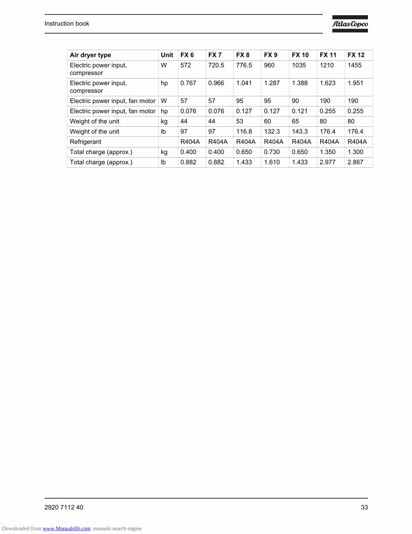
Air dryer type Unit FX 6 FX 7 FX 8 FX 9 FX 10 FX 11 FX 12Electric power input,compressor
W 572 720.5 776.5 960 1035 1210 1455
Electric power input,compressor
hp 0.767 0.966 1.041 1.287 1.388 1.623 1.951
Electric power input, fan motor W 57 57 95 95 90 190 190Electric power input, fan motor hp 0.076 0.076 0.127 0.127 0.121 0.255 0.255Weight of the unit kg 44 44 53 60 65 80 80Weight of the unit lb 97 97 116.8 132.3 143.3 176.4 176.4Refrigerant R404A R404A R404A R404A R404A R404A R404ATotal charge (approx.) kg 0.400 0.400 0.650 0.730 0.650 1.350 1.300Total charge (approx.) lb 0.882 0.882 1.433 1.610 1.433 2.977 2.867
Instruction book
2920 7112 40 33
Downloaded from www.Manualslib.com manuals search engine

9 Pressure equipment directives
Components subject to Pressure Equipment DirectiveAll pressure bearing components are designed category I or less according to European Directive 97/23/EC(until 19/07/2016) or Directive 2014/68/EU (from 20/07/2016 onwards).
Instruction book
34 2920 7112 40
Downloaded from www.Manualslib.com manuals search engine
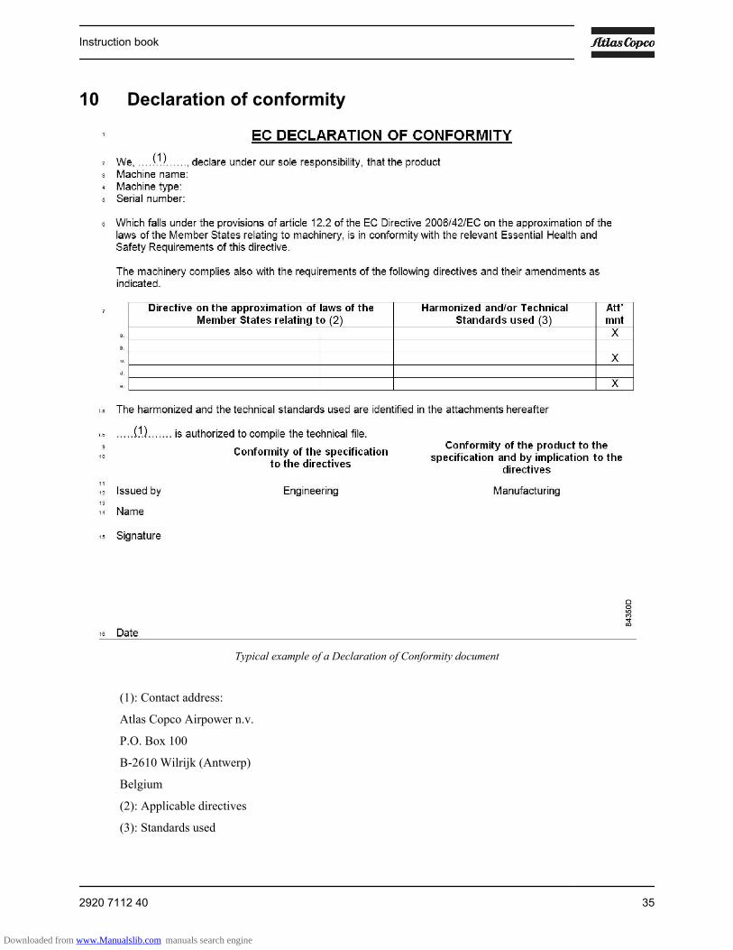
10 Declaration of conformity
Typical example of a Declaration of Conformity document
(1): Contact address:
Atlas Copco Airpower n.v.
P.O. Box 100
B-2610 Wilrijk (Antwerp)
Belgium
(2): Applicable directives
(3): Standards used
Instruction book
2920 7112 40 35
Downloaded from www.Manualslib.com manuals search engine

On the Declaration of Conformity / Declaration by the Manufacturer, the harmonized and/or otherstandards that have been used for the design are shown and/or referred to.
The Declaration of Conformity / Declaration by the Manufacturer is part of the documentation that issupplied with this device.
Instruction book
36 2920 7112 40
Downloaded from www.Manualslib.com manuals search engine

No.
292
0 71
12 4
0 / 2
016
- 09
- Prin
ted
in B
elgi
um
In order to be First in Mind—First in Choice® for all your qualitycompressed air needs, Atlas Copco delivers the products andservices that help to increase your business’ efficiency andprofitability.
Atlas Copco's pursuit of innovation never ceases, driven by ourneed for reliability and efficiency. Always working with you, weare committed to providing you the customized quality airsolution that is the driving force behind your business.
www.atlascopco.com
Downloaded from www.Manualslib.com manuals search engine