assessment of the load-carrying capacity of multi-span masonry arch bridges using fibre beam...
TRANSCRIPT

Engineering Structures 31 (2009) 1634–1647
Contents lists available at ScienceDirect
Engineering Structures
journal homepage: www.elsevier.com/locate/engstruct
Assessment of the load-carrying capacity of multi-span masonry arch bridgesusing fibre beam elementsGianmarco de Felice ∗University Roma Tre, Department of Structures, via Corrado Segre, 6-00146-Rome, Italy
a r t i c l e i n f o
Article history:Received 27 March 2008Received in revised form4 August 2008Accepted 2 February 2009Available online 31 March 2009
Keywords:MasonryBrickworkArchesArch bridgesLimit analysisFibre beam elements
a b s t r a c t
An approach that makes use of non-linear beam elements with fibre cross-section has been used formodelling the ultimate behaviour of multi-span masonry arch bridges. The proposed approach provesable to take into account the interaction among the spans and the non-linear material behaviour withlow computational effort. In order to validate the use of the model for the assessment of masonry archbridges, the load-carrying capacity for typical multi-span railway bridges has been evaluated and theresults compared to experimental results and to currently used limit analysis methods. It is shownthat, by parity of constitutive assumption, the method provides the same results as limit analysis, bothin terms of maximum load prediction and hinges position at collapse; however, taking the effectiveductility capacity into account, a strong reduction in load-carrying capacity with respect to classicallimit analysis was found, depending on rise-to-span arch ratio, piers slenderness and backfill height. Theapproach is then applied to a seven span viaduct of the Italian railway network, for which the effectivemechanical properties of masonry were identified through an experimental campaign on brickworksamples according to the effective material properties surveyed on site.
© 2009 Elsevier Ltd. All rights reserved.
1. Introduction
The last years have witnessed a growing interest in the safetyassessment of masonry bridges, thousands of which are stillin service and constitute an important part of our heritage ofengineering works and, at the same time, a still meaningful part ofour road-railway network. When handling with these structures,which have been designed with empirical rules and have beensubjected in time to an increase in service loading, there is adefinite need of simple tools to be used for assessment anddetermination of the load-carrying capacity.At least two demands are addressed to the scientific commu-
nity: (i) the development of reliable and affordable methods forstructural analysis of masonry bridges and (ii) the improvementof the procedures for appraising the actual structural condition ofthe bridge and evaluating its safety level.The first item concerns,more in general, masonry constructions
as a whole, since some intrinsic difficulties exist in modelling theirbehaviour that is discontinuous, anisotropic and strongly non-linear; to this should be added the geometrical complexity, since,in the case of masonry bridges, members are usually curved withvarying cross-section. The second item is again of a more generalnature, encompassing the safety assessment of existing structures,
∗ Tel.: +39 06 5733 6268; fax: +39 06 5733 6265.E-mail address: [email protected].
0141-0296/$ – see front matter© 2009 Elsevier Ltd. All rights reserved.doi:10.1016/j.engstruct.2009.02.022
which is strongly conditioned by uncertainties of the materialproperties, as well as by time-dependent effects such as fatigueand creep. To this should be added the difficulty of investigationof the structural elements, such as barrel thickness, or backingheight, aswell as the contribution of non-structural elements, suchas fill material, which may have an important effect on the overallmechanical response.In the case of masonry arch bridges, there are a number of
alternative procedures [1] for assessment of load-carrying capac-ity; these include empirical methods, such as the modified Mili-tary Engineering Experimental Establishment (MEXE) method [2],yield design-based methods [3–6], deriving from Heyman’s stud-ies on the yield design of masonry arches [7,8], distinct elementmethods [9], as well as finite element incremental analysis with1D models [10–12]. Some recent approaches have succeeded inmodelling the behaviour of a bridge using 2D or 3D finite ele-ment analysis in order to take into account the interaction of fill-ing with the arch barrel [13], or the contribution of the spandrelwalls [14], in line with what was observed in experimental testson scale models [15–17], and on real bridges [18,19]. Despite theresults achieved, an intrinsic difficulty remains in 2D or 3D non-linear finite element modelling, deriving from the high depen-dence of the results on input parameters and boundary conditions,not easy to determine. In any cases, these approacheswould gener-ally require a high computational effort, especially for multi-spanbridges, which pertain to a more refined analysis and is not justi-fied for initial or intermediate-level assessment.

G. de Felice / Engineering Structures 31 (2009) 1634–1647 1635
Fig. 1. Fibre beam model.
As far as a preliminary load-carrying capacity evaluation isrequired, the great simplicity together with its feasibility forpractical applications, makes the yield design-based method themost widely used tool for assessment. However, the use of suchmethod, raises the question of the limited ductility capacity ofmasonry. It is well known that masonry has a brittle behaviourin traction and a strain softening in compression, with a decreaseof load capacity after the peak load; therefore, the yield designapproach, which implicitly assumes a plastic behaviour of thematerial, may lead to an overestimate of the load capacity of thestructure [20]. The classical assumption of no tensile resistance,allows overcoming this problem in traction, which however stillremains in compression, especially for shallow or long spanmasonry bridges that may be subjected to high loading witha relatively weak material strength, and therefore the possiblefailure due to crushing of masonry cannot be neglected. In thesecases, the limited ductility in compression can be handled byapplying a reduction factor to masonry strength, but its calibrationstill remains one of themain drawbacks for the use of yield design-based methods. Another drawback to the application of yielddesign-based methods, lies in the lack of control for displacementor strain quantities, since the problem is driven by equilibrium andstrength conditions and the kinematics is introduced only throughthe virtual work equation. On the contrary, a displacement-based prediction of the structural behaviour may be relevant forassessment purposes, especially under time-varying loading, suchas seismic action.The aim of this paper is to propose an approach for preliminary
assessment of multi-span masonry arch bridges that makes useof non-linear incremental analysis, using beam elements, alonga research line that dates back to the well known study ofCastigliano [21] for the bridge over the Dora close to Turin, andincludes some recent contributions [10,12]. In the present case,aiming at taking into account the effective behaviour of masonryunder compression, which may be relevant for the assessment asshown by some recent experimental tests [22], while consideringthe interaction between normal force, bending moment andcurvature, recourse is had to a fibre beam cross-section. The use ofbeamswith fibre cross-section has become current for the analysisof reinforced concrete structures, but, as far as the author knows,has never been used for structural analysis of masonry arches.The outline of the paper is as follows. After a brief recall of the
non-linear beammodelwith fibre section (Section 2), a comparison
with limit analysis for two and three-span railway arch bridgesunder travelling concentrated load is performed, consideringeither infinite compressive strength or finite compressive strengthwith unlimited ductility (Section 3). Then, the influence ofmaterial behaviour is investigated, having recourse to the Kent& Park model [23] for describing the uniaxial constitutivebehaviour of masonry, when varying the slope of the post-peak descending linear branch. The analyses, which provide themaximum travelling load of the bridges, show the effect ofmaterial post-peak behaviour on the load-carrying capacity. Theapproach is then applied to the analysis of a model three-spanbridge (Section 4) tested up to collapse at Bolton Institute [24]and the results are compared to experiments in terms of bothcarrying capacity and collapse mechanism. The second part ofthe paper is devoted to the analysis of an existing seven spanviaduct, which is part of the Rome–Viterbo railway line incentral Italy (Section 5); the effective behaviour of masonry undercompression is first determined by means of experimental tests(Section 6), the uniaxial constitutive behaviour is therefore definedaccording to experimental results and, finally, the effective load-carrying capacity is estimated according to the proposed approach(Section 7), showing to what extent a limit analysis approachwould lead to an overestimate of loading capacity.
2. Fibre element model
The recourse to a fibre beam model for analysing the non-linear behaviour of masonry arches derives from the followingconsiderations. Some recent experiments on masonry prismssubjected to eccentric compression [25,26] have shown thatthe classical hypothesis that plane section remains plane afterdeformation, holds true for brick masonry even in the non-linear range, when stress concentrations and cracks start todevelop; besides, the intrinsic difficulty in defining the non-linear constitutive behaviour of the beam, as for instance thedependence of flexural hysteretic behaviour on axial load, alsodue to the lack of experimental data, suggests deriving thesection force–deformation relation from the uniaxial stress–strainbehaviour of the material. Therefore, looking for a compromisebetween simplicity and accuracy, the arch is discretized intorectilinear beams and each beam is subdivided into longitudinalfibres, whose stress–strain behaviour is defined according tothe material properties that can be easily obtained throughexperiments. The non-linear constitutive relation of the beamsection is not given explicitly but is derived by integrationof the stress–strain relation of the fibres. Referring to Fig. 1,following [27], let us denote by d(x) =
{χz(x) χy(x) ε(x)
}the
generalizeddeformations of the cross-sectionA(x) at the abscissa x,comprising the two curvatures and the axial strain at the referenceaxis; according to the assumption that plane section remains plainand normal to the beam axis x during the deformation history, thestrain distribution over the section writes: ε(x, y, z) = a(y, z)d(x),where a(y, z) = {−y z 1}.Once the material constitutive relation is specified, the strain
distribution yields the tangent material modulus E(x, y, z) and thecorresponding stress σ(x, y, z) = E(x, y, z)ε(x, y, z). Therefore,according to the virtual work equality, the section stiffness matrixk(x) and the resisting force vector D(x) =
{Mz(x)My(x) N(x)
},
comprising the two bending moments and the axial force, thatcorrespond to deformation d(x) are obtained by integrating overthe cross-section as:
k(x) =∫A(x)aT(y, z)E(x, y, z)a(y, z)dA (1)
D(x) =∫A(x)aT(y, z)σ (x, y, z)dA. (2)
The evaluation of the integrals (1) and (2) is performed bysubdividing the generic section x into n(x) fibres and applying the

1636 G. de Felice / Engineering Structures 31 (2009) 1634–1647
Fig. 2. Geometry of two and three-span bridges under examination (from [29]).
mid-point integration rule:
k(x) ∼=n(x)∑i=1
aT(yi, zi)E(x, yi, zi)Ai(x)a(yi, zi) (3)
D(x) ∼=n(x)∑i=1
aT(yi, zi)σ (x, yi, zi)Ai(x) (4)
where Ai(x) is the area of the i-th fibre at section x. As suggestedin [28,10] a flexibility-based formulation is adopted for theFE analysis, which ensures that equilibrium is strictly satisfiedwithin the element; according to flexibility approach, the elementstiffness matrix is obtained by inverting the flexibility matrix: K =F−1, where
F =∫ L
0bT(x)k−1(x)b(x)dx (5)
L being the element length, k(x) the section stiffness matrix, andb(x) the force interpolation functionsmatrix,which is derived formthe equilibrium of axial force and bending moments within theelement.The iteration scheme proposed in [28] which is based on
Newton–Raphson method, is used for solving the non-linearequation both at the element level and at the structural level.In this scheme, the determination of the element resisting forcesfor given nodal displacements is based on residual deformations,which ensures that equilibrium along the element is alwayssatisfied, while force–deformation relation is approximated bylinearization about the present state. As will be shown in thenext chapter, the non-linear solution strategy adopted is ableto provide the load displacement curve of the bridge, includingthe descending branch, even if some numerical instability mayarise after the onset of strain softening. This latter point is quiterelevant for masonry elements, more than for reinforced concreteones since, due to the lack of steel, when the effective materialbehaviour is considered, the masonry section displays limit-pointtype instability. An improved solution strategy based on arch-length type method with Riks iteration scheme is currently understudy, as a tool for the analysis of masonry bridges under severetime-varying loading.As regards the fibre uniaxial constitutive relation, masonry
is assumed to have no tensile resistance and to behave undercompression according to the following threemodels of increasingcomplexity: (i) linearly elastic with infinite resistance as proposedby Heyman for stone arches [7,8]; (ii) elastic-perfectly plasticwith finite compressive strength and unlimited ductility; (iii) withan ascending branch represented by a second-degree paraboliccurve, a subsequent linear descending softening branch and a final
Table 1Geometric and mechanic characteristics of two and three-span bridges underexamination.
Geometrical/Mechanical properties Arch bridgesSpan (at the intrados) (mm) 15000Arch depth (mm) 750Fill in crown (mm) 750Masonry specific weight (kN/m3) 22Fill specific weight (kN/m3) 24Rise (at the intrados) (mm) 3750 (shallow)–5250 (deep)Pier height (mm) 7500Pier depth (mm) 2200
constant branch according to theKent& Park (K&P)model [23]. TheK&P model is defined by three parameters, namely the peak stressfc , the corresponding strain εc , the ultimate strain εu. Denotingby σ̃ = σ/fc , and ε̃ = ε/εc the normalized stress and strain,respectively, the three branches take the form:
σ̃ = 2ε̃ − ε̃2, for 0 ≤ ε̃ ≤ 1;
σ̃ = 1− 0.8(ε̃ − 1η − 1
), for 1 ≤ ε̃ ≤ η;
σ̃ = 0.2, for ε̃ ≥ η
(6)
where η = εu/εc .The K&P constitutive model is able to represent in a greater
detail the effective behaviour of masonry under compression asshown by the experimental tests presented in Section 6. The firsttwo material models, while being less accurate, have been widelyused in structural analysis of masonry arches; they will be usedin the following section to compare the results provided by thepresent approach to those given by limit analysis.
3. Load-carrying capacity of masonry arch railway bridges
In this section, the present approach that makes use of beamswith fibre cross-section is used for evaluating the load-carryingcapacity of one to three-span masonry arch bridges representativeof some medium-to-high span bridges of the European railwaynetwork (Fig. 2). The bridges under study have been recentlyexamined in [29]; they have span of 15m and arch depth of 0.75m,with either shallow (rise/span ratio equal to 0.25) or deep arches(rise/span ratio equal to 0.35); their geometrical and mechanicalcharacteristics are reported in Table 1. The capacity of the bridgesunder concentrated travelling loadhas been evaluated, consideringa diffusion angle trough the fill θ = 40◦+ 40◦ so that the effectivelive loading on the arch barrel can be schematised as uniformlydistributed. A slight sensitivity of the results on the discretization
G. de Felice / Engineering Structures 31 (2009) 1634–1647 1637
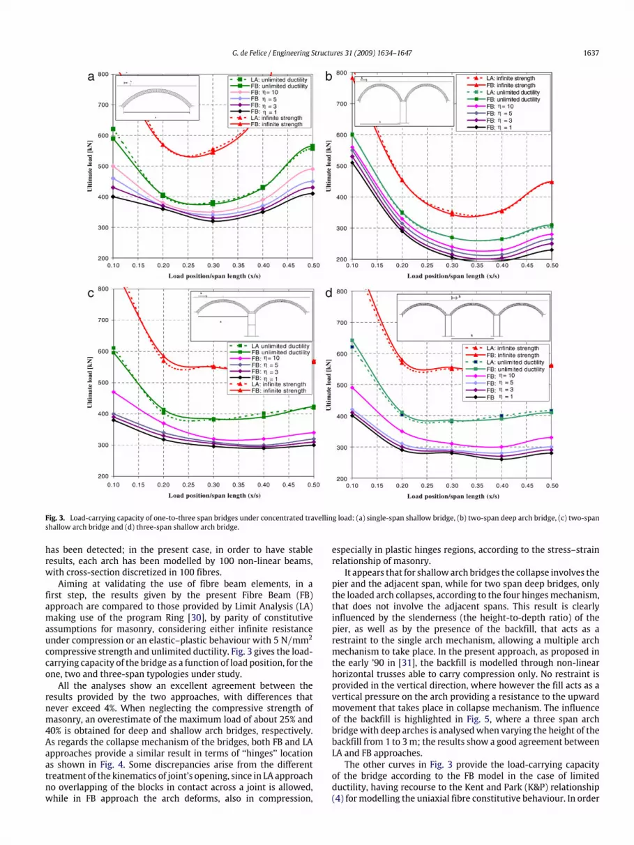
Fig. 3. Load-carrying capacity of one-to-three span bridges under concentrated travelling load: (a) single-span shallow bridge, (b) two-span deep arch bridge, (c) two-spanshallow arch bridge and (d) three-span shallow arch bridge.
has been detected; in the present case, in order to have stableresults, each arch has been modelled by 100 non-linear beams,with cross-section discretized in 100 fibres.Aiming at validating the use of fibre beam elements, in a
first step, the results given by the present Fibre Beam (FB)approach are compared to those provided by Limit Analysis (LA)making use of the program Ring [30], by parity of constitutiveassumptions for masonry, considering either infinite resistanceunder compression or an elastic–plastic behaviour with 5 N/mm2compressive strength and unlimited ductility. Fig. 3 gives the load-carrying capacity of the bridge as a function of load position, for theone, two and three-span typologies under study.All the analyses show an excellent agreement between the
results provided by the two approaches, with differences thatnever exceed 4%. When neglecting the compressive strength ofmasonry, an overestimate of the maximum load of about 25% and40% is obtained for deep and shallow arch bridges, respectively.As regards the collapse mechanism of the bridges, both FB and LAapproaches provide a similar result in terms of ‘‘hinges’’ locationas shown in Fig. 4. Some discrepancies arise from the differenttreatment of the kinematics of joint’s opening, since in LA approachno overlapping of the blocks in contact across a joint is allowed,while in FB approach the arch deforms, also in compression,
especially in plastic hinges regions, according to the stress–strainrelationship of masonry.It appears that for shallow arch bridges the collapse involves the
pier and the adjacent span, while for two span deep bridges, onlythe loaded arch collapses, according to the four hingesmechanism,that does not involve the adjacent spans. This result is clearlyinfluenced by the slenderness (the height-to-depth ratio) of thepier, as well as by the presence of the backfill, that acts as arestraint to the single arch mechanism, allowing a multiple archmechanism to take place. In the present approach, as proposed inthe early ’90 in [31], the backfill is modelled through non-linearhorizontal trusses able to carry compression only. No restraint isprovided in the vertical direction, where however the fill acts as avertical pressure on the arch providing a resistance to the upwardmovement that takes place in collapse mechanism. The influenceof the backfill is highlighted in Fig. 5, where a three span archbridgewith deep arches is analysedwhen varying the height of thebackfill from 1 to 3m; the results show a good agreement betweenLA and FB approaches.The other curves in Fig. 3 provide the load-carrying capacity
of the bridge according to the FB model in the case of limitedductility, having recourse to the Kent and Park (K&P) relationship(4) for modelling the uniaxial fibre constitutive behaviour. In order

1638 G. de Felice / Engineering Structures 31 (2009) 1634–1647
Fig. 4. Collapse mechanisms of two and three-span shallow arch bridges obtained with limit analysis (up) and fibre beam (down) models, respectively.
Fig. 5. Load-carrying capacity of three-span deep arch bridges, under concentratedtravelling load, when varying backfill height.
to evaluate the influence of the post-peak behaviour, a parametricstudy is performed, where the different curves in Fig. 3 correspondto different slopes of the descending branch, fromplastic behaviourwith unlimited ductility (η = ∞), to post-peak brittle behaviour(η = 1). The results show a significant reduction in loadingcapacity when increasing the slope of the descending branch,more pronounced for shallow arches. For two span arch bridges,a decrease in the capacity of about 25%–30% is found when thematerial behaviour turns fromperfectly plastic to post-peak brittle,for both deep and shallow arches. An even stronger dependence isfound for three-span shallow arch bridges, with a reduction in loadcapacity of about 33%. The load deflection curve of a single-spandeep arch bridge under concentrated load acting at 0.35 of the spanlength is highlighted in Fig. 6(a), when varying the constitutiveuniaxial relation of masonry in compression. The figure clearlyshows that an increase of the descending slope of post-peakbranch is responsible for a more fragile global behaviour, with ananticipation of the limit point along the load–displacement curve,inducing a significant reduction of the load capacity. The effectivereduction in load capacity with respect to a perfectly ductile
behaviour is highlighted in Fig. 6(b) in the case of K&P uniaxialbehaviour, for decreasing values of the ratio η = εu/εc : it isshown that, by parity of material strength, the post-peak softeningdescending branch of material behaviour induces a strength decayup to almost 30% of the one predicted in the case of a perfectlyplastic behaviour.These results can be compared with those presented in [12]
where an elastic plastic (EP) behaviour for masonry is consideredwith a limited ultimate strain εul = δεel, where εel is the elasticstrain at peak stress and δ the available ductility. At section level,the post-peak slope of the softening branch defined by η can beassociated with an equivalent available ductility δ and thereforeboth models are able to provide a comparable estimate of thebending moment capacity when limited ductility is available, asshown in Fig. 7 for a single span shallow arch bridge. In this case,similar results are reached when assuming EP behaviour with1.4 ≤ δ ≤ 2.5 or adopting the K&P model with 1 ≤ η ≤ 5. Aslightly higher discrepancy arises for two and three span bridges.The difference between the two approaches can be explained byreferring to the kinematics of the bridge close to collapse: whenadopting the EP behaviour, once the ultimate deformation εulis reached at the compressed edge of the cross-section, failureof masonry by crushing occurs and therefore the section is nolonger able to sustain external loading; conversely,when assumingK&P behaviour, once the softening branch (Fig. 6) is reached, thesection may continue to deform with a progressive decrease ofbending capacity. As far as the overall behaviour is concerned, thedifferences in the constitutive assumptionswould imply a differentredistribution of the normal force and bending moment throughthe arches: while in [12] failure occurs essentially with crushingin one section rather than by the activation of a mechanism, inthe present approach, the formation of a four hinges mechanismmay take place, togetherwith a progressive degradation of bendingcapacity in the critical hinge sections. Therefore, at the global level,the reduction in bending capacity of hinges induces a decrease inthe load–displacement curve after the maximum load is reached(Fig. 6).
4. Comparison with experimental results
In this section, the model three-span bridge tested up tocollapse in Bolton Institute [24] has been analysed using fibre beamelements and the results compared to the experimental ones. Thebridge (Fig. 8) contained three no. 3 m spans, with span-to-rise

G. de Felice / Engineering Structures 31 (2009) 1634–1647 1639
Fig. 6. (a) Load–displacement curve for a single-span deep arch bridge under concentrated travelling load when varying the uniaxial behaviour of masonry in compression.(b) Decrease in load capacity of a single-span deep arch bridge when increasing the slope of descending branch with respect to a perfectly plastic behaviour.
Fig. 7. Load-carrying capacity of a single span shallow arch bridge underconcentrated travelling load: comparison between the elastic plastic model withlimited ductility proposed in [12] and the K&P model.
ratio 4:1; the arch ring is 215mm thick and 2880mmdepth. It wasbuilt with very strong brickwork: the mean compressive strengthwas 26.8 N/mm2, the initial tangent modulus 16.2 kN/mm2 itsunit weight 22.4 kN/m3. It was filled with crushed limestone withbulk unit weight of 22.2 kN/m3. The load was applied througha concrete beam, such as the load length was 420 mm applied750 mm to the north of the crown of the central span. The bridgewas built with spandrel walls detached from the arch barrels ofeach of the spans.Masonry have been modelled with K&P relationship defined
according to the given material properties and assuming adescending branch with η = 3; however, in this case the very highbrickwork strength combinedwith the relatively small dimensionsof the specimen, is such that the strength does not affect the load-carrying capacity and therefore the classical assumption of infinitestrength would practically lead to the same results. For largerspans and lower strength, the material properties will becomemuch more important as will be shown in Section 7. The fillwas considered simply as a weight, allowing, at the same timea smoother distribution of the load over the bridge, through adiffusion angle θ = 35◦ + 35◦, the spandrel walls have not beingincluded in the analysis. The arch rings are modelled by 100 non-linear beam elements each, with the cross-section discretized in100 fibres.
Fig. 8. Geometry of the model bridge tested in [24].

1640 G. de Felice / Engineering Structures 31 (2009) 1634–1647
Fig. 9. Comparison between numerical and experimental results: (a) load–displacement curve and (b) load versus pier displacement response.
Fig. 10. Failure mode: comparison between experimental [24] (up) and numerical(down) results. The numbers indicate the position and sequence of cracks detectedby the model.
The analysis provides a load-carrying capacity of 325 kN,slightly higher than the failure load of 320 kN given by the test. InFig. 9(a) the load–displacement numerical response is compared tothe model bridge experimental one [24], showing similar resultsexcept for the onset of non-linear behaviour, where the model isstiffer than the experiment. In Fig. 9(b) the north and south piersdisplacements are plotted against the load: the model is able toaccurately reproduce the south pier displacement while, contraryto experiment where some movement was measured, the north
pier is not mobilised in the model. This difference is responsiblefor the higher stiffness in the numerical load–displacement curve.The predicted failuremechanism is shown in Fig. 10 and comparedto experimental one; the numbers indicate the position of cracks atfailure and the sequence in which cracks formwhen increasing theapplied load. The mode of failure in hingedmechanism is correctlypredicted and the sequence of cracks corresponds to the onedetected during the experiment (see [24] for details). The rathergood agreement between model prediction and experimentalresults should be attributed also to the fact that the bridge is builtwith detached walls; for bridges with attached spandrel walls,their contribution to the overall strength is much more difficult toassess since itwould require amore refinedmodel, having recourseto 2D media, with non-linear anisotropic behaviour [13,32].
5. A case of study: The Ronciglione viaduct
The viaduct under study is part of the railway line betweenRome and Viterbo, which was built between 1890 and 1894. Theline has an overall length of about 95 km, and comprises 15viaducts with spans ranging from 10 to 25 m. The one under studyis probably the most important viaduct of the line; it is madeof seven barrel-vaults spanning 18 m each, and six piers with amaximum height of 45 m (Figs. 11–15, Table 2).The foundation is made in concrete with flint crushed stone,
hydraulic lime and pozzolana, on a volcanic tuff soil. The masonryof the piers is in rough tuff stone masonry, with squared stones on
Fig. 11. View of the Ronciglione viaduct.

G. de Felice / Engineering Structures 31 (2009) 1634–1647 1641
Fig. 12. Plan and front view of the Ronciglione viaduct.
Fig. 13. Piers fabric (left) arch barrel and spandrel wall (centre) and pier-abutment (right).
Table 2Main geometric properties of Ronciglione viaduct.
Arches PiersNo Height (mm) Width at the top (mm) Width at the base (mm)
Span (mm) 18000Rise (mm) 9000 1 15714 3000 4100Arch thickness (mm) 1070 2 23400 4500 5904Fill in crown (mm) 930 3 35369 3000 5476Backfill height (mm) 4760 4 35316 3000 5472Masonry specific weight (kN/m3) 19 5 27285 4500 6139Fill specific weight (kN/m3) 17 6 13700 3000 3960

1642 G. de Felice / Engineering Structures 31 (2009) 1634–1647
Fig. 14. Transversal sections at the first (a) and at the third span (b) of the viaduct.
Fig. 15. Bridge under construction.
the external face; the pier has corners and horizontal chains every3 m, made with squared flint stones (Fig. 13(a)). The barrel vaultsare made with bricks (Fig. 13(b)) and hydraulic mortar consistingof lime and pozzolana, without cement; the vaults have 18 mspan, 9 m rise. The spandrel walls are 0.75 m thick and about11 m from the springing, they are made with regular courses oftuff squared-stones (Fig. 13(b)). The dimensions of the structural
elements have been deduced from original drawings and verifiedin site. The arch ring is 1.07 m thick and 4.60 m depth; the piershave dimensions 3.00 × 4.60 m at the top and rise toward thebase, with a constant slope of 3.5% in longitudinal direction, and aslope varying between 5% and 6% in transversal direction (Fig. 14).The second and the fifth piers are provided with buttresses intransversal direction (Fig. 13(c)) and are dimensioned 1.5 m larger

G. de Felice / Engineering Structures 31 (2009) 1634–1647 1643
Fig. 16. Experimental stress–strain curves of original brick samples (left) and brick samples used for building masonry specimens (right).
Table 3Experimental results of bricks under compression.
Compressive strength (N/mm2) Strain at peak stress (10−3) Elastic modulus (N/mm2)
Original brick samples from the railway viaduct(18 samples)
Mean 29.85 11.1 3067
Deviation 7.33 3.21 731Historical brick samples used for buildingmasonry specimens (10 samples)
Mean 30.51 9.45 3918
Deviation 5.24 2.10 395
in longitudinal direction, to be able to carry the asymmetric archthrust during the construction, allowing the arch barrel vaults tobe made in three subsequent steps making use of the same woodcentring (Fig. 15). According to original drawings, the height ofthe backfill is about 4.76 m from the springing. The bridge is notin service anymore, for economical reasons, but is still in goodconditions of maintenance.
6. Experimental and analytical stress–strain behaviour ofbrickwork
The brickwork used in the viaduct is made with semi-industrialized bricks with dimensions 280mmhigh, 140mmwideand 55 mm thick and lime mortar with sand and pozzolana. Someoriginal specimens of the bricks used in the vaults have beenfound on site, from which twenty cubic samples with 45–50 mmside have been extracted and subjected to monotonic and cycliccompression (Fig. 16). The main mechanical properties of thebricks are recalled in Table 3.Aiming at reproducing in the laboratory the brickwork used
in the vaults, old bricks with the same dimension as the originalspecimens, and similar mechanical properties, have been found:it was a stock of about 300 bricks manufactured at the beginningof the XX century in the same region of the bridge. Eleven cubicsamples with 48 mm side have been extracted from six of thesebricks, and subjected to monotonic and cyclic compression tests inthe direction normal to the face of the bed joints; the mechanicalproperties obtained form the experiments are listed in Table 3and the whole experimental stress–strain curves are depictedin Fig. 16. The comparison between the experimental results oforiginal samples and those extracted from the available historicstock shows very similar mechanical properties on average, witha discrepancy of about 2% in compressive strength and lower than15% in elastic module.
As regards the mortar, based on petrographic analyses, it wasfound that it is made with lime and pozzolana extracted from oneof the volcanic deposits of the Sabatini Mountains in central Italy.The granulometry varies from lime to fine gravel, between 0.01and 4.50 mm; the distribution of the aggregate within the matrixis homogeneous and the grains are not oriented; the thickeningis higher than 50% and therefore it is possible to estimate thatthe original ratio between binder and aggregate was about 1:4.A mortar with similar characteristics was then prepared in thelaboratory to be usedwith the previously described bricks, in orderto build specimens having similar characteristics to the masonryused in the viaduct.Six specimensmade by five layers of half brickwith base dimen-
sions mm 140 × 140 and height 300 mm have been constructedand subjected to centred compression under displacement control.The tests have been carried out using an MTS hydraulic load framewith 500 kN load rating, under displacement control with veloc-ity 0.01 mm/s. The deformation of the specimen was measured bytwo resistive transducers with sensitivity 0.05 mm, while the loadwas measured directly by the load cell integrated within the loadframe. The surfaces of the specimen in contact with the load plateswere accurately prepared with a thin (about 3 mm thick) layer ofthe samemortar used for the joints in order obtain a plane surface,such as to avoid stress concentration.The behaviour of masonry under compression remained linear
elastic up to the appearance of the first crack, which takes placeat a vertical stress between 50% and 80% of the peak stress.However, as shown by the cyclic tests, some irreversible effectsappear in the linear range, due to the mortar layer compaction,which causes an increase in the stiffness of the specimen in theloading cycles subsequent to the first unloading. Under increasingloading, new vertical cracks appear and propagate to the otherlayers of bricks; at peak load, the specimen is divided into

1644 G. de Felice / Engineering Structures 31 (2009) 1634–1647
Table 4Experimental results of masonry prisms in compression.
Compressive strength fc Deformation at peak stress εc Elastic modulus secant at 0.4fc E Ultimate strain at 0.2fcεu(N/mm2) (10−3) (N/mm2) (10−3)
Minimum 6.14 3.60 1274 15.28Maximum 8.49 7.90 3963 19.72Average 7.54 5.52 2094 17.84
Fig. 17. Experimental behaviour of six brickwork samples made by five layers ofbricks and six mortar joints, with base mm. 140×140 and height 300 mm undercompression.
slender parts separated by vertical cracks. At this stage, the load-carrying capacity decreases almost linearly, with the progressivespalling of the external slices of the specimen. The stress–straincurves of monotonic and cyclic tests are reported in Fig. 17;the average mechanical properties, together with the relativestandard deviation, are summarized in Table 4. On the basis of theexperimental results, the following values are given to the K&Pparameters which are necessary to define the constitutive model:fc = 7.54 N/mm2, εc = 5.52 × 10⁻³, εu = 1.78 × 10⁻², and thecorresponding stress–strain curve is reported in Fig. 17 togetherwith the experimental ones.
7. Conservative estimate of load-carrying capacity
The seven barrel vaults comprising the viaduct have beenmodelled each with 100 rectilinear beams having cross-sectionof 1070 mm wide and 4600 mm depth. The use of rectilinear
beam elements proves to be satisfactory as far as recourse ismade to a refined discretization of the arches. The cross-sectionhas been discretized in 300 fibres, that were shown as theconvenient number below which a decrease in the limit loadbecomes appreciable. The piers were discretized in 50 beams withincreasing section according to their slope. A rigid link was put atthe springing to connect the pier with the arches. The backfill, upto the height of 4760 mm from the springing has been modelledwith horizontal non-linear trusses able to carry compression only(Fig. 18).As in Section 3, the load-carrying capacity of the viaduct
under concentrated travelling load was estimated having recourseto different material properties. More precisely, masonry wasmodelled with no-tensile resistance and: (i) infinite resistanceunder compression, (ii) finite strength equal to the averageexperimental value of 7.54 N/mm2 and infinite ductility capacityand (iii) finite strength equal to 7.54 N/mm2 and limited ductility,with a softening branch, according to the K&P model as deducedform the experimental outcomes presented in the previous section.Clearly, the latter model, which reproduces more accurately thematerial behaviour, will provide the best estimate of the limitload that can be taken as the reference value for evaluatingthe amount of overestimate in the two previous models. Theresults are represented in Fig. 19, where the load-carrying capacityof the bridge against the load position is drawn; the live loadacting at the middle of the central span, which has higherpiers, results as the most vulnerable condition; for the effectivebrickwork behaviour a limit load of 1650 kN is obtained andthe corresponding collapse mechanism is represented in Fig. 20.When assuming unlimited ductility, the estimated value of themaximum load increases up to 2720 kN and, in the case of infinitecompressive strength, up to 3270 kN, with an overestimate ofabout 65% and 98%, respectively. These results clearly show, for thebridges under study, the relevance of material properties in load-carrying capacity evaluation: inaccurate assumptions concerningeither strength or effective ductility of masonry may lead tosignificant errors in terms of load bearing capacity of the bridge.Such a different behaviour is explained in Fig. 21 where theload–displacement response of the bridge under a concentrated
Fig. 18. FE model of the viaduct.

G. de Felice / Engineering Structures 31 (2009) 1634–1647 1645
Fig. 19. Load bearing capacity of Ronciglione viaduct under concentrated travelling load: (i) infinite compressive strength; (ii) compressive strength equal to 7.54 N/mm2and infinite ductility; (iii) effective brickwork behaviour.
Fig. 20. Collapse mechanism of the viaduct under concentrated load at the crown of central span.
load at the crown of central span is shown. Both the downwarddisplacement of the crown at the central span and the upwarddisplacement of crown at the adjacent span are plotted. Thetwo curves both refer to the average experimental compressivestrength of 7.54 MPa, but differ in the post-peak behaviour,which obey either the perfectly plastic model or the K&P modelpreviously defined. The response is practically coincident up to aload of about 1000 kN, and then differs substantially: for ductilebehaviour the load increases up to unacceptable values of thedisplacement, while taking into account the effective behaviour ofmasonry, the load increases only up to a displacement of about280 mm when the maximum bending capacity of the crownsection is reached and then starts to decrease while the hingemechanism develops.Let us now compare the results to those presented in [12]
where a railway viaduct with similar geometric characteristicswas analysed. The predicted collapse mechanisms are somehowsimilar for the two bridges, but a difference in carrying capacityis assessed, which depends on the differences in the way thebackfill is modelled as well as the limited ductility capacity istaken into account as discussed in Section 3. According to [12], astrong dependence of the load- carrying capacity on the stiffnessof the piers has been detected. However, it should be pointed outthat the spandrel walls would certainly stiffen the arch viaduct,thus providing an increase in load bearing and therefore the load-carrying capacity evaluated according to the present approach hasto be considered as a conservative estimate.In Fig. 22 the stress distribution provided by the model in the
cross-sections at the crown and at the springing of the centralspan of the bridge is shown at three different loading stages:(i) under permanent load, (ii) under the design (cat. C3) railway
Fig. 21. Load–displacement response for different material behaviour.
load consisting of four axes concentrated loads of 200 kN each anda constant load of 72 kN/m distributed over a length of 11.1 m, and(iii) under maximum load. The stress distributions depicted wereobtained by applying permanent loading in several subsequentsteps according to the construction phases of the viaduct, that is,considering that the three central spans have been built only afterthe two lateral spans were completed (Fig. 15), and adding thebackfill and the filling weights in successive steps. However, the

1646 G. de Felice / Engineering Structures 31 (2009) 1634–1647
Fig. 22. Stress state in the cross-section at springing (left) and at the crown (right) of the mid-span at three different loading stages: (i) under permanent load, (ii) underthe design (cat. C3) railway load and (iii) under maximum load.
model does not take into account the settlement of the piers, northe shrinkage and viscous deformations that take place during andafter the construction; therefore the results have to be consideredcarefully and are not expected to effectively reproduce the stateof stress in the viaduct; they only give a rough estimate. Inany case, it appears that under permanent loading, a low stresslevel is expected, with the cross-section all in compression and amaximum stress of about 0.5 N/mm2. Under the design railwayload, the crown section becomes partialised with a maximumstress of about 1.3 N/mm2. The stress distribution at collapsereveals a compressive resultant very close to the edge of the sectionthat allows the hinge mechanism to take place.
8. Final remarks and conclusions
An approach for a preliminary estimate of the load-carryingcapacity of masonry arch bridges that takes into account theeffective ductility capacity of masonry under compression ispresented and applied to multi-span railway viaducts. Theapproach offers a good compromise between simplicity andaccuracy: the bridge is reduced to the arch-pier system, takinginto account the backfill and considering the interaction betweennormal force and bending moment in the non-linear behaviour,as far as the assumption of plane section remaining plane isreasonably accurate. It generally provides a conservative estimateof the load-carrying capacity of the bridge, since neither the arch-fill nor the arch-spandrel interactions are considered. Taking intoaccount these latter effects may induce an increase in carryingcapacity as stated by several experimental [16,18,22,24,33] andtheoretical [13,14,32] contributions.As far as the behaviour of the arch barrel alone is considered,
a reliable estimate of the maximum load is provided, which isintermediate between the ductile behaviour implicitly assumed inyield design-basedmethods [8] and the perfectly brittle behaviour,pertaining to an elastic-based approach [11].The analyses performed for two and three-span arch bridges
show that, by parity ofmaterial constitutive assumptions, the sameresults provided by limit analysis are achieved, both in terms ofload bearing capacity and failure mechanism. However, once thelimited ductility capacity is taken into account, a decrease in themaximum load varying from about 20% to 35% depending on theshape of the bridge (number of spans, rise to span ratio, piers and
backfill height) is obtained for the bridge typologies examined,showing that current limit analysis methods are not conservative.The proposed approach is finally applied to a seven span railway
viaduct, whose mechanical properties have been estimatedthrough experimental tests on brickwork specimens; the Kent &Park constitutive law fitting the experimental results was used formodelling the uniaxial behaviour ofmasonry and the load-carryingcapacity of the bridge estimated accordingly.One of the advantages of the proposed approach is that itmakes
use of available general-purpose engineering software, havingrecourse to analysis methods accepted and widely used in otherfields of structural engineering and consistent with the philosophyof modern design and assessment codes.In conclusion, the paper makes a contribution towards the
development of analysis tools for assessing and preserving existingmasonry arch bridges.
Acknowledgements
The financial contribution by Italian Network of SeismicLaboratories (RELUIS) 2005-08 Pr., Research line 1 ‘‘Evaluation andreduction of seismic vulnerability of existing masonry buildings’’and 3 ‘‘Evaluation and reduction of seismic risk of existing bridges’’,is gratefully acknowledged.
References
[1] Hughes TG, BlacklerMJ. A reviewof theUKmasonry arch assessmentmethods.Proc Inst Civ Eng 1997;122:305–15.
[2] Department of Transport. Design manual for roads and bridges. Vol. 3, Sec. 4,Part. 4, The assessment of highway bridges and structures. London (UK); 1997.
[3] HarveyWEJ. Application of the mechanism analysis to masonry arches. StructEng 1988;66(5):77–84.
[4] GilbertM,Melbourne C. Rigid-block analysis ofmasonry structures. Struct Eng1994;72(21):356–61.
[5] Clemente P, Occhiuzzi A, Raithel A. Limit behaviour of stone arch bridges. ASCEJ Struct Eng 1995;121(7):1045–50.
[6] Boothby TE. Elastic plastic stability of jointedmasonry arches. Eng Struct 1997;19(5):345–51.
[7] Heyman J. The stone skeleton. Internat J Solids Struct 1966;2(2):249–79.[8] Heyman J. The masonry arch. London (England): Ellis Horwood; 1982.[9] Lemos JV. Discrete element modelling of masonry structures. Internat J ArchHeritage 2007;1(2):190–213.
[10] Molins C, Roca P. Capacity of masonry arches and spatial structures. ASCE JStruct Eng 1998;124(6):653–63.

G. de Felice / Engineering Structures 31 (2009) 1634–1647 1647
[11] Boothby TE. Load rating of masonry arch bridges. ASCE J Bridge Eng 2001;6(2):79–86.
[12] Brencich A, De Francesco U. Assessment of multi-span masonry arch bridges.Part I: A simplified approach. Part II : Examples and applications. ASCE J BridgeEng 2004;9(6):582–98.
[13] Cavicchi A, Gambarotta L. Collapse analysis of masonry bridges taking intoaccount arch-fill interaction. Eng Struct 2005;27(4):605–15.
[14] Fanning PJ, Boothby TE, Roberts BJ. Longitudinal and transverse effects inmasonry arch assessment. Construct Building Mater 2001;15(1):51–60.
[15] Prentice DJ, Ponniah DA. Testing ofmulti-spanmodel of masonry arch bridges.In: Proc. centenary year bridge conference. Cardiff (UK): Elsevier Science;1994. p. 169–74.
[16] Melbourne C, Wagstaff M. Load tests to collapse of three large-scale mul-tispan brickwork arch bridges. In: Bridge management, Vol. 2 – Inspec-tion, maintenance assessment and repair. London (UK): Thomas Telford;1993.
[17] Robinson JI, Ponniah DA, Prentice DJ. Soil pressure measurements on amulti-span brick arch. In: Proc. 7th int. conf. on structural faults and repair.Edinburgh: Eng. Tech. Press; 1997. p. 111–9.
[18] Page J. Load test to collapse on two arch bridges at Preston. Shropshireand Prestwood, Staffordshire. Department of Transport. Transport and RoadResearch Laboratory Report 110. Crowthorne (England); 1987.
[19] Marefat MS, Ghahremani E, Ataei S. Load test of a plain concrete arch railwaybridge of 20-m span. Construct Building Mater 2004;18(9):661–7.
[20] Salençon J. Calcul à la rupture et analyse limite. Paris (FR): Presses de l’ENPC;1983.
[21] Castigliano CAP. Theorie de l’equilibre des systemes elastiques et sesapplications. Augusto Federico Negro, Torino, Italy; 1879. In: Andrews ES,editor. Elastic stress in structures Transation by Andrews. London: ScottGreenwood & Sons; 1919.
[22] Léon J, Espejo SR. Load test to collapse on the masonry arch bridge at Urnieta.In: Lourenco PB, Oliveira DV, Portela D, editors. Proc. 5th international conf. onarch bridges. 2007. p. 969–75.
[23] Kent DC, Park R. Flexural members with confined concrete. ASCE J Struct Div1971;97(ST7):1969–90.
[24] Melbourne C, Gilbert M, Wagstaff M. The collapse behaviour of multispanbrickwork arch bridges. Struct Eng 1997;75(17):297–305.
[25] Brencich A, Gambarotta L. Mechanical response of solid clay brickwork undereccentric loading Part I: Unreinforced masonry. Mater Struct 2005;38(2):257–66.
[26] de Felice G. Experimental investigation on historic brickwork subjected toeccentric axial load. In: Lourenco PB, Roca P, Modena C, Agrawal S, editors.Proc. 5th int. conf. on structural analysis of historical constructions. NewDelhi(India): Macmillan; 2006. p. 809–16.
[27] Spacone E, Filippou FC, Taucer F. Fibre beam-column model for non-linearanalysis of R/C frames: Part I formulation. Earthq Eng Struct Dyn 1996;25(7):711–25.
[28] Spacone E, Ciampi V, Filippou FC. Mixed formulation of nonlinear beam finiteelement. Comput and Structures 1996;58(1):71–83.
[29] Brencich A, De Francesco U, Gambarotta L. Non-linear elasto-plastic collapseanalysis of multi-span masonry arch bridges. In: Abdunur C, editor. Proc 3rdint. conf. on arch bridges. Paris (FR): Presses de l’ENPC; 2001. p. 513–22.
[30] Gilbert M. Ring, theory and modelling guide. Sheffield (UK): University ofSheffield; 2005.
[31] Choo BS, CoutieMG, GongNG. Finite-element analysis ofmasonry arch bridgesusing tapered elements. Proc Inst Civ Eng 1991;91:755–70.
[32] Cavicchi A, Gambarotta L. Lower bound limit analysis of masonry bridgesincluding arch-fill interaction. Eng Struct 2007;29:3002–14.
[33] Royles R, Hendry AW. Model tests on masonry arches. Proc Inst Civ Eng 1991;91:299–321.