design of steel tied arch bridges.pdf
TRANSCRIPT

I ~
RRll71
7305
I I I I I I I I I I I I I I I I I I
''l
AN ALThRNATI VI:;
By Dann H. Hall' and A. Rlchard LaWln'
Far American Institute Of Steel CalstructlOO
July '985
, Bri<i3e SOftware Del/elopnent International Ltd. Coo[ersl:urg, Pennsy ll/ania
I '~ ':0 I" , -i-'T)
I TABLE OF CINl'ENl'S
I Page
I 1 . 0 SlMlARY 1
1 .1 Introduction
I 1.2 Problem statement 1.3 Objective 1 . 4 AWroach
I 1 . 5 Alternate ~thod
2 . 0 INTOOOOCl'IGl 5
I 2 . 1 Present Practice 2.2 Problems With Present Practice
I 2.3 Proposed Alternate ~thod
2 . 3 . 1 General 2.3.2 Erection of the Arch Ribs
I 2.3 . 3 Erection of Deck Units 2.3 .4 Jldvantages of Alternate ~thod
I 3. 0 DESIQI EXAMPLE BY ALTffiNATE ME:llICD 17
3.1 General
I 3 . 2 Design Considerations
3.2 . 1 Live Load 3 . 2 . 2 Dead Wad
I 3.2 . 3 Construction Loads 3.2 . 4 'lhermal Wad 3. 2 . 5 Post Tensioning
I 4 . 0 Analysis Using Finite Element Models 25
I 4.1 General 4.2 Floor Beam 4 . 3 Placement of Deck Units
I 4 . 3.1 Arch Rib 4 . 3 . 2 Hangers and Dead Wad Tie Cable 4. 3 . 3 Precast Deck Units
I 4 . 3 . 4 Bearings 4. 3.5 Procedure
I 4 . 4 Integrated Model 4 . 4. 1 General 4. 4. 2 Tie Beam
I 4.4.3 Deck 4.4.4 Floor Beams 4 . 4 . 5 Procedure
I
<:>
I ~ -ii--.J
I Page
I 5 . 0 RESULTS 38
5. 1 General
I 5 . 2 Floor Beam 5 . 3 Arch Ribs
5 . 3 . 1 General
I 5.3 . 2 Deck Unit Staging 5 . 3 . 3 Superimposed Dead Load 5 . 3 . 4 Temperature
I 5 . 3. 5 Live Load
5 . 4 HarY:Jers
I 5 . 4. 1 General 5 . 4 . 2 Deck Unit staging 5. 4. 3 Superimposed Dead Load
I 5 . 4. 4 Temperature 5 . 4. 5 Live Load
I 5 . 5 Dead Load Tie Cable and Reactions
5 . 5 . 1 General 5. 5 . 2 Deck Unit staging
I 5. 5 . 3 Superimposed Dead Load 5 . 5 . 4 Temperature 5. 5.5 Live Load
I 5. 6 Tie Beams 5 . 6 . 1 General
I 5 . 6 . 2 Deck Unit Staging 5 . 6 . 3 Superimposed Dead Load 5 . 6 . 4 Temperature
I 5 . 6 . 5 Live Load
5 . 7 Deck
I 5 . 7 . 1 General 5. 7 . 2 Deck Unit Staging 5 . 7 . 3 Superimposed Dead Load
I 5 . 7 . 4 Temperature 5 . 7 . 5 Live Load
I 5 . 8 Post Tensioning 5 . 8 . 1 General 5 . 8 . 2 Deck
I 5.8 . 3 Tie Beam
6 . 0 CIN:llJSlOOS 86
I 7 .0~ 88
I 8 . 0 BIBLI(X;RAPHY 89
I ,~ 'p 'n -iii-
I LIST OF FIQJRES
I FIGURE TITLE
2 . 1 Typical Tied Arch Brici3e
I 2. 2 Alternate Design - Deck am Tie Beam Unit
I 2. 3MB Alternate Design - Arch Erection Schemes
2.4 Dead Load Tie cable Anchorage
I 2.5 Erection Schane for Deck Units
I 2.6 Deck Unit layout
2.7 Arch Rib to Tie Beam Detail
I 3 . 1 Design Study Example
I 3. 2 Design Study Arch Rib Cross Section
3. 3 Design Study Deck Unit
I 3. 4 Design Study Deck Cross section
I 4 . 1 Floor Beam am Deck /ot:ldel
I 4 . 2 Arch Rib am Staging /ot:ldel
4.3MB Staging sequence - Stage 2 - Stage 3
I 4 . 4 Integrated /ot:ldel - Overview
I 4. 5 Integrated /ot:ldel - Details
5 . 1 Floor Beam M:rnent Envelope
I 5 . 2 Floor Beam Shear Envelope
I 5 . 3 Floor Beam Elevation
5 . 4 Floor Beam Influence Line
I 5.5 Accumulated M:rnents in Arch Rib D.le to Deck Units
I 5 . 6 Accumulated 'll1rusts in Arch Rib D.le to
Deck Units
I
I I I I I I I I I I I I I I I I I I
FIGURE
5. 7
5. 8
5. 9
5 . 10
5 . 11
5 . 12
- iv-
LISI' OF FIGJRES (O:xltinued)
TITLE
Stress Envelopes in Arch Rib DJe to Deck Units
Dead Load ~ts in Tie Beam
Locatioo of Recorded Deck stresses
stresses in top of Deck DJe to Superimp:>sed Dead Load am 'l'e!1;lera ture - Design 1
Stresses in top of Deck DJe to Superimp:>sed Dead Load am 'l'err{lerature - Design 2
Stresses in bottan of Deck DJe to Superimposed Dead
Load am 'l'e!1;lerature - DeSign 2

~
I '~ '.(1 .", -v-~
I LIST CF TABUS
I TABLE TITLE
I 3. 1 Design Example CCInparison
4. 1 M:ldel Explanation for Fig 5
I 5.1 Dead Load M:Inents in Arch Rib lAJe to Deck Units
I 5. 2 Dead Load Thrusts in Arch Rib lAJe to Deck Units
5 . 3 Accunulated M:Inents in Arch Rib !Ale to Deck Units
I 5. 4 AccuIlulated Thrusts in Arch Rib lAJe to Deck Units
I 5. 5 Accunulated Stresses in Arch Rib !Ale to Deck Units
I 5. 6 SUmnary of Arch Rib /obrents
5. 7 S\mnary of Arch Rib Thrusts
I 5.8 Factor ed /obrents in Arch Rib
I 5. 9 Factored Thrusts in Arch Rib
5. 10 SUmnary of stresses in Arch Rib
I 5. 11 Hanger Forces for Dead Load
I 5. 12 AccuIlulated Forces in Hangers for Dead Load
5 . 13 SUmnary of Forces in Hangers
I 5. 14 Reaction and Tie cable Forces
I 5. 15 Tie Beam stresses at Hanger - Design 1
Tie Beam Stresses at Hanger - Design 2 5 . 16
I 5. 17 Tie Beam stresses Between Hangers - Design 2
I 5. 18 Deck Stresses Top Line "A"
I I
... I ·~
I I I I I I I I I I I I I I I I I I
•
-vi-
LIST OF TABLES (Ccntirued)
TITLE
5. 19 Deck stresses Botton Line "A"
5. 20 Deck stresses Top Line "B"
5. 21 Deck Stresses Botton Line "B"
5. 22 Deck stresses Top Line "C"
5. 23 Deck stresses Botton Line "C"
I']) .J)
'" .....
1 I I I I I 1 I I I I I I I I I I I
1
1. 0 Stmnary
1 . 1 Introduction
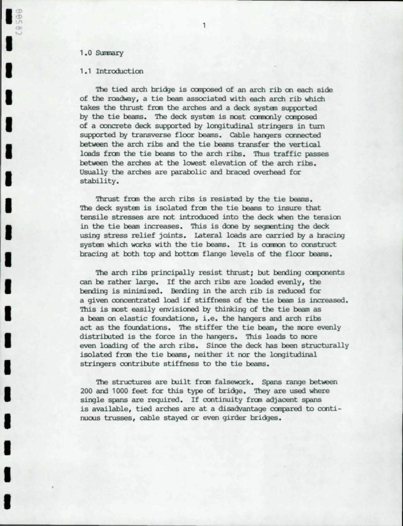
'!he tied arch brici:Je is canposed of an arch rib 00 each side of the roadway , a tie beam associated with each arch rib which takes the thrust fran the arches arrl a deck system supported by the t ie beams . The deck system is most <X1i11ccl.y canposed of a concrete deck supported by lo~itudinal str~ers in turn supported by transverse floor beams . Cable ~ers cconected between the arch ribs arrl the tie beams transfer the vertical loads fran the tie beams to the arch ribs . Thus traffic passes between the arches at the lowest elevation of the arch ribs . Usually the arches are parabolic arrl braced overhead for stability.
Thrust fran the arch ribs is resisted by the tie beams . '!he deck system is isolated fran the tie beams to insure that tensile stresses are not introduced into the deck when the tensioo in the tie beam increases. This is dooe by segmen~ the deck using stress relief joints. Lateral loads are carried by a brac~ system which works with the tie beams . It is <X1i1'O' to construct brac~ at both top and bottan flange levels of the floor beams.
The arch ribs principally resist thrust ; rut bending <X1iip:uents can be rather large. If the arch ribs are loaded evenly, the berrling is minimized . Berrling in the arch rib is reduced for a given concentrated load if stiffness of the tie beam is increased. This i s most easily envisioned by thinking of the tie beam as a beam on elastic foundations , i.e. the ~ers and arch ribs act as the foundatioos . The stiffer the tie beam, the !lOre evenly distriruted is the force in the ~ers. This leads to !lOre even loadi~ of the arch ribs . Since the deck has been structurally i solated fran the tie beams , neither it nor the lo~itudinal stringers cootriOOte stiffness to the tie beams .
'!he structures are ruilt fran falsework . Spans range between 200 arrl 1000 feet for this type of brici:Je . They are used where single spans are required . If cootinuity fran adjacent spans is available , tied arches are at a disadvantage canpared to cootinuous trusses , cable stayed or even girder brici:Jes.
2
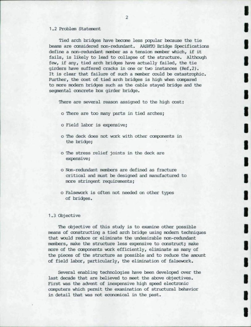
1 .2 Problan Statement
Tied arch bridJes have becane less p::lpular because the tie beams are cx:nsidered n::lI'l-redurrlant. AASID'O BridJe Specifications define a n::lI'l-redundant member as a tension member which, if it fails, is likely to lead to collapse of the structure. Although few, if any, tied arch bridJes have actually failed, the tie girders have suffered cracks in one or two instances (Ref,2). It is clear that failure of such a member could be catastrophic. Further, the cost of tied arch bridJes is high when canpared to more modem bridges such as the cable stayed bridge and the segmental cx:ncrete box girder bridJe.
There are several reason assigned to the high cost:
o 'lbere are teo many parts in tied arches;
o Field labor is expensive;
o '!be deck does not work with other CXl1ifXll,ents in the bridJe;
o '!be stress relief joints in the deck are expensive;
o Ncn-redundant members are defined as fracture cri tical and must be designed and manufactured to more stringent requiranents;
o Falsework is often not needed on other types of bridJes.
1.3 Objective
'!be objective of this study is to examine other p:lssible means of constructing a tied arch bridge using modem techniques that WOlld reduce or eliminate the undesirable 11Cl1-redundant members, nake the structure less expensive to cx:nstruct; nake more of the CXl1ifXll,ents work efficiently, eliminate as many of the pieces of the structure as possible and to reduce the amount of field labor, particularly, the elimination of falsework.
Several enabling technologies have been developed over the last decade that are believed to meet the above objectives. First was the advent of inexpensive high speed electrcnic cx:mputers which pennit the examination of structural behavior in detail that was not eccnanical in the past.
I I I I I I I I I I I I I I I I I I I
I I I I I I I I I I I I I I I I I I
3
Secorxl , the developroent of additives am improved techniques permit the routine manufacture of high strerl3th ooncrete. '!here have been bridges Wilt using ooncrete strerqths specified as high as 8000 psi (Ref. 3 ) •
'!he anphasis of this study is <Xl the use of the electronic CCII1p.lter technology by applying a bridge analysis am design canputer program to the study . High strer¥jth ooncrete is employed in the design rut the technology is not examined in detail.
1 . 4 Approach
An alternate scheme for the oonstruction of a tied arch bridge has been developed . A design study was then perforrred which was based <Xl an existiN3 design and the resulting design cxxnpared to the original. The analysis was perforrred using a series of canputer programs called the BR.IIX;E-SYSTElo1sm developed by Bridge Software Developroent International , Ltd . '!he canputer generated rrodel of the tied arch had to be nodified by harxl .
'!he BRTIXiE-SYSTElo1sm is based <Xl the finite element method of analysis . It permits the designer to ruild , analyze and design large ccrnplex steel girder bridges efficiently.
1.5 Alternate t-Ethod
In the proposed scheme , the arch ribs are erected first . 'lhey may be erected usiN3 a high-line or each half of the arch rib may be rotated into place fran it bearing . ~ing the erection , thrust IlU.lst be taken by the arutments or by a temporary cable between the ems of the ribs .
After the arch ribs are erected , permanent cables are placed between the ems of arch ribs to carry dead load thrust. '!he cables must be supported by the haN3ers to prevent sagging am reductioo of the effective m:xfulus .
The deck and tie beam are precast ooncrete units . Each unit of the deck exterxls full width of the bridge . 'lhe deck is cast intergrally with the tie beams . Each unit is equal in lBN3th to the haN3er spaciN3 . '!he deck is supported <Xl CXlI1(XJSite steel transverse floor beams which frame into the tie beams . '!he units are floated urrler the bridge am lifted into place by hoists oonnected to the arch ribs .
•
4
When the units are in place and cast-in-place ooncrete c::att>letes the closure in the center, the units are post tensiooed. Finally, the ends of the deck are cast-in-place and the deck is post tensioned to the ends of the arch ribs.
'Ihe concrete tie beams resist cnly thrust fran the applied live loads and superimposed dead loads while the thrust fran the dead load of the arch and deck system is resisted by the dead load tie cable. Thus the tie beam is ncn-reduroant.
'!he deck is an integral unit after post tensioniD:} and the joints within the span have been eliminated. nus permits the deck to carry lateral loads tD the ahJtments. '!here is no need for lateral bracing in cases where the deck is wide enough tD resist these loads.
'Ihe entire structure may be erected without falsework. 'Ibis should speed constructicn and greatly simplify scheduling ccnstruction and obtainiD:} permits to obstruct channels'-
A large anount of the field labor has been eliminated rut the contractDr still has the work of Wilding the deck units. However, this work is off-site and not subject tD weather and other undesirable features of field work.
Structural steel weight is reduoed by approximately 2.6 millicn pounds. Atout 350,000 pamds of post tensioning steel is used. The dead load tie cables weigh about 300,000 pourds. Han:.lers remains unchanged.
- - -- -
I I I I I I I I I I I I I I I I I I I
.p
I :~ I
I I I I II I I I I I I I I I I·
- ---------
5
2.0 INl'RCUJcrICN
2.1 Present Practice
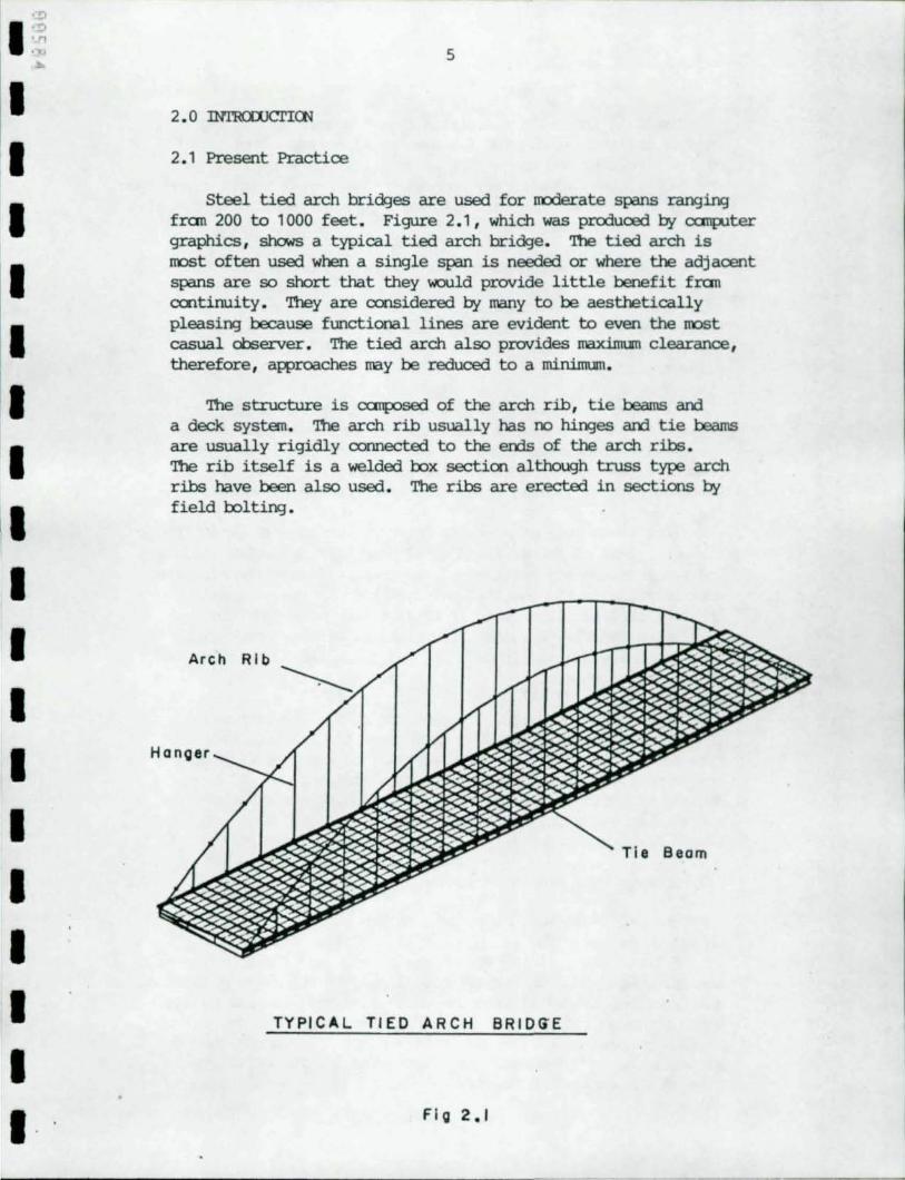
steel tied arch bridges are used for ll'Oderate spans ranging fran 200 to 1000 feet. Figure 2.1, which was produced try cx:rnp.1ter graphics, shows a typical tied arch bridge. 'nle tied arch is roost often used when a single span is needed or where the adjacent spans are so short that they would provide little benefit fran exntinuity. They are oonsidered try many to be aesthetically pleasirJj because functional lines are evident to even the roost casual observer. The tied arch also provides maximum clearance, therefore, awroaches may be reduced to a minimum.
'Ibe structure is cx:mposed of the arch rib, tie beams and a deck system. 'nle arch rib usually has no hirJjes and tie beams are usually rigidly connected to the errls of the arch ribs. 'nle rib itself is a welded box sectioo although truss type arch ribs have been also used. The ribs are erected in sections try field bolting.
Arch Rib
Hanoer
Tie Beam
TYPICAL TIED ARCH BRID<lE
Fi 0 2.1
6
'llu:ust in the arch is resisted by a tie beam connecting the eros of the arch ribs. 'nle tie beam is also erected in secticns by field I::x:lltir¥3 and can either be an I- or I::x:lx-shaped member. 'llle two tie beam !IlE!I1tlers are oonnect.ed with a full rrarent axmection to the arch rib and they are subjected to I::x:lth tensile and flexural loads.
Hanger cables are used to suspend the tie beams fran the arch ribs. It is through these han:Jers that the arch receives vertical loads. 'nle hangers are CCIlIlDnly spaced at aI::olt 40 feet. 'llle shape of the arch rib has been develcped for uniform vertical loadirv:J; and a parabola can be shown to be the IlOSt efficient shape.
Tie beams connecting the eros of the arch ribs support a series of transverse flcor beams. Floor beams are spaced so they fall at hanger locations to minimize herDing in the tie beams. Floor beams frame into the tie beams at their tql. Diagonal bracir¥3 resists transverse loads on the structure.
Floor beams support a series of IOr¥3ibrlinal strir¥3ers. 'nle strir¥3ers rest on either fixed or sliding bearings which isolate the floor beams fran lTOVerrent of the deck. Because the tie beam must be rigid in the longitudinal direction to resist tension, the deck lIUst act separately if it is to be prevented fran develqling tensile stresses. la¥Jitudinal strains occur fran live loads and thermal loads. 'nle joints in the deck are called stress relief joints.
'nle IlOSt CCIlIlDn method of construction of tied arches is to place falsework in the span to support the tie beam and arch ribs during erection. 'nle falsework nay be kept in place durirv:! erection of the deck system and castir¥3 of the deck. 'Ibis is done to minimize unsyrrmetrical loads durirv:! construction which might cause overstresses in the arch ribs.
2.2 Problems With Present Practice
Sane engineers have expressed concern aI::x:lut the tied arch bridge described. 'nle tie members are critical to the safety of the structure. If the tie member should fail for any reascn, the structure would be likely to collapse. In the days of riveted construction, tie beams were canposed of several thinner plates which provided redundancy. Presently, they are oanposed of three or farr plates welded into a single member. If a crack should be initiated in the member, it is possible for it to propagate through the entire tie !IlE!I1tler.
I I I I I I I I I I I I I I I I I I I
I I I I I I I I I I I I I I I I I I
- -- - --- - --- ---,
7
'!he MSH'ro Brid:le Specifications (Ref.5 ) defines tension manbers that can cause collapse as Fracture Critical Members (F'Cl>!s ).
'!he Specification requires them to be designed to lower fatigue stresses . '!he material is subjected to lI'Ore stringent toughness and inspection requirements duri1'XJ' fabrication . '1hese cautionary measures increase the cost of the brid:le rut the structure i s still non-reduOOant . Sane designers choose not to design nonreduOOant structures if they can be avoided.
Another undesirable characteristic is the many stress relief joints in the deck. 'll1ese joints:
o Present problems for maintenance ;
o Introduce a rough riding surface;
o Add significantly to the initial cost.
'!he steel weight of the tied arch brid:le is not significantly lower than other types of brid:le construction am fabrication am erection costs are alI'01'XJ' the highest .
'll1e need for falsework increases the cost of construction by not only adding cost directly rut also by increasing the time to bJild the bri~e. Falsework may provide an obstructi on in shiWi1'XJ' channels .
If the tied arch bridge is to remain a viable option, ways must be found to make it more canpetitive.
2 . 3 Proposed Alternate Method
2 . 3 . 1 General
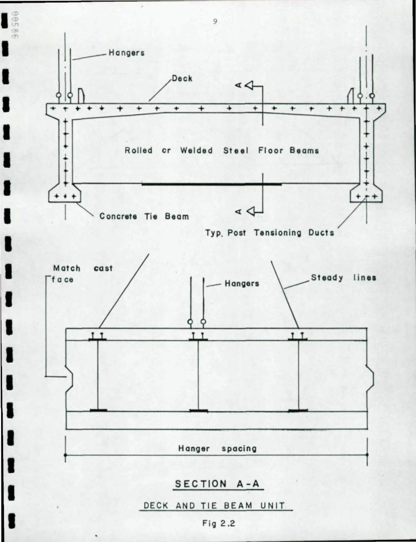
'!he proposed method involves the use of precast deck units am a dead load tie manber connect ing the eros of the arch ribs acting as the tie beam for dead loads . It also assists the tie beam in carrying live am superiroposed dead loads . '!he arch ribs remain similar in awearance to conventional tied arch designs . Calstruction differs significantly fran normal in that the alternate structure may be erected without falsewark . '!he deck is made of precast concrete units . '!hese units include segnents of the two tie beams cast integrally with the deck as sOOwn in Figure 2 . 2 . '!he units are post tensicoed to overCOlle tensile stresses in them due to thrust fran the arch ribs am local effects .
8
Reik and Hansel describe a similar bric'kJe in Gennany. 'Ihe Gennan structure utilized a p:>St tensiC11ed cast in place deck . 'Ihe tie beams were steel (Ref . 4) .
Each precast deck unit is equal in length to the hanger spacing . 'Ihe deck units are hoisted into place using the hangers and other stabilizing lines as shown in Figure 2. 3 . Transverse floor beams are spaced to permit the deck to span across the floor beams withaJt longitudinal stringers . 'lllree floor beams per precast unit is usually sufficient. Floor beams are CUllfXJSite with the deck for all dead and live loads . steel has been used for the floor beams to minimize weight and to reduce forming . 'Ibere are no dia~<:JllS between floor beams . 1hls reduces ooncern for secxn::lary web bending which may cause fatigue problems . 'Ihe deck is able to resist lateral loads since it is an integral element without stress relief joints. 'Ihere shwld be no need for a lateral bracing system.
'Ihe deck units are to be match cast. A standard type of shear key 00 the interfaces will provide for shear transfer.
2.3 . 2 Erectioo of the Arch Ribs
'Ihe alternate method is best suited to sites where the span is over navigable water. A small cable is stretched across the span to take the thrust of the arch under its own weight . 'Ihe Ernst Equatioo or sane other method of det:ermini.ng equivalent stiffness for a sagging cable can be used to ccrnpute the cable trodulus . It is necessary to prestress the cable to obtain a reasooable rrodulus .
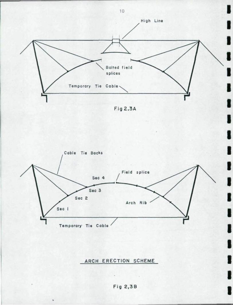
'Ihe arch can be erected fran each pier using a high-line as shown in Figure 2. 3A. 'Ihe center sectioo of the arch can be erected fran the high-line as shown. Alternatively , each half arch rib can be rotated into place and spliced at the center as shown in Figure 2 . 3B. At least ooe concrete arch has been successfully I::uilt in Gennany using a similar technique . (Ref.1 ) . Wind bracing rrust be added between the arch ribs in either case prior to placing the deck units 00 the structure.
Q1ce the arch ribs are erected, the initial rranents and thrusts in the arch can be adjusted by tensiooing the temporary cable. 'Ihe temporary cables are replaced by permanent dead load tie cables .
I I I I I I I I I I I I I I I' I I I I
I ~ • ~.
I I I I I I I I I I I I I I I I I I
9
~ __ HQngers -
Match face
+ ... + ~
Rolled cr Welded Steel Floor Beams
Concrete Tie Beam
Typ. Post Tensioning Ducts
_ Hangers
Hanger s paci ng
SECTION A-A
DECK AND TIE BEAM UNIT
Fig 2.2
...
t
I inn
Temporary Tie
r bl
•
Tie Backs
Sec 4
Sec 3
2
10
splices
cable~
F.ig 2.3A
/ Fiel d splice
Temporar), · Tie Cable
ARCH ERECTION SCHEME
Fig 2,38
Line
I I I I I I I I I I I I I I I I I I I
I:.; 'n ...
I I I I I I I I I I I I I I I I I I
11
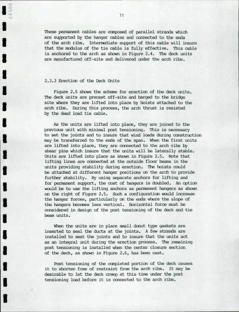
'!bese pennanent cables are cx::mp::lSed of parallel strands which are suworted by the hanger cables and oormected to the ends of the arch ribs . Intermediate supp:>rt of this cable will insure that the rrodulus of the tie cable is fully effective . 'Ibis cable is anchored to the arch as shcMn in Figure 2. 4. '!be deck units are manufactured off-site and delivered under the arch ribs.
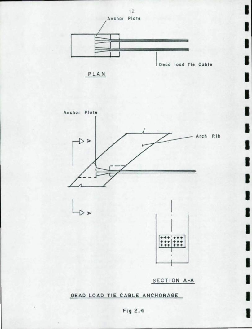
2.3 . 3 Erection of the Deck Units
Figure 2.5 shows the schena for erection of the deck units. '!be deck units are precast off-site and barged to the bridge site where they are lifted into place by hoists attached to the arch ribs. Olril'B this process, the arch thrust is resisted by the dead load tie cable .
As the units are lifted into place , they are joined to the previoos unit with minimal post tensi~. 'Ibis is necessary to set the joints and to insure that wind loads duril'B construction ooy be transferred to the ends of the span . When the first units are lifted into place , they are connected to the arch ribs by shear pins which insure that the units will be laterally stable . Units are lifted into place as shcMn in Figure 2. 5 . Note that liftil'B lines are oonnected at the outside floor beams in the units provi~ stability duril'B erection . '!be hoists could be attached at different ~er positions on the arch to provide further stability. By usil'B separate anchors for lif~ and for pennanent support, the cost of ~ers is doubled . An ~tion would be to use the lifting anchors as permanent ~ers as shcMn on the right of Figure 2. 5 . SUch a configuration would increase the ~er forces , particularly on the ends where the sl~ of the ~ers beccrnes less vertical . Horizontal force oust be considered in design of the post tensioning of the deck and tie beam units .
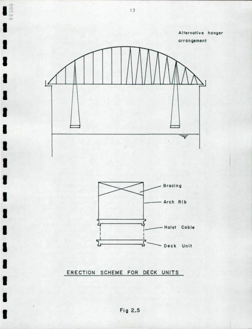
When the units are in place small donut type gaskets are inserted to seal the ducts at the joints. A few strands are installed to seat the joints and to insure that the units act as an integral unit during the erection prooess. '!be ranainil'B p:>st tensi~ is installed when the center closure section of the deck, as shcMn in Figure 2.6, has been cast.
Post tensioning of the oc:mpleted p:>rtion of the deck causes it to shorten free of restraint fran the arch ribs. It ooy be desirable to let the deck creep at this tiJre under the post tensioning load before it is oormected to the arch ribs.
/
P LA N
Anchor Plote
12
Anchor Plate
I
Dead load
..... 'to.t" +- ....... ....... t+ ..
I I
Tie Cable
Arch Rib
SEC TI ON A-A
DEAD LOAD TIE CABLE ANCHORAGE
Fig 2.4
I I I I I I I I I I I
I I I I I I I I I
I:;' "1 .",
I I I I I I I I I I I I I I I I I I
13
Alternative hanger
arrangement
Bracing
1_-- Arch Rib
I I_----Hoist Cable
I I
i-----........,.r-- Deck Unit
ERECTION SCHEME FOR DECK UNITS
Fig 2.5
14
Typ Precast Deck Unll
/ Typ Hanger
• • • . . . • . ~
. • .' • . • • . ~
~ % . . • . . . • • • . . . . . • . ~
Cenl.r closure Arch RI b.
DECK PLAN
(Shaded orea 10 be casl-In-place)
DECK UNIT LAYOUT
Fig 2.6
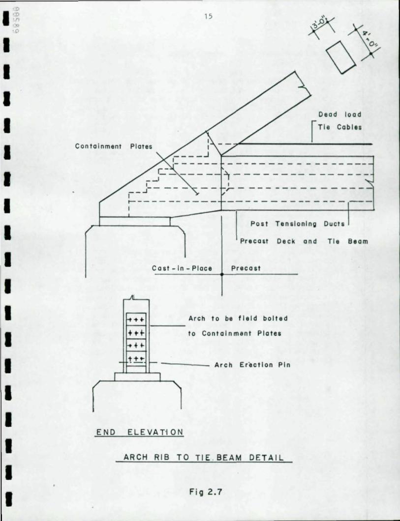
Next the deck. is to be oonnected to the arch ribs, The end sections of the deck are now cast. '!he end sections are cx:rnposed of portions of the deck. between the arch ribs and portions of the tie beams between the end of the precast units and the arch ribs as shown in Figure 2.7. Final post tensioni~ is then drne to form a full manent oonnection between the arch and the tie beams. 'lhis will cause a slight decrease in the post tensic:t'lirg stress already in the deck..
To minimize weight, a concrete str~ of 8000 psi is suggested where good aggregate is available. Sane research iIrlicates that high str~ concrete tends to creep less.
Tie beams are designed for vertical beIrli~ induced by the floor beams framing into than. They rust also resist berrling induced by the arch ribs and ~ers.
Since the deck. is integral with the tie beams, it resists berrli~ forces as part of the tie beam. Design of post tensicni~ in the deck rust consider local berrling stresses as well as overall berrli~ and thrust stresses . The force fran the arches and tie beams is transferred into the deck through shear. To aC1:UlIIodate shear, the deck. rust be thicker at the edges than it need be for local berrling.
I I I I I I I I I I I I I I I I I I I
I ';: ')0
I I I I I I I I I I I I I I I I I I
."
Containment
-
I /
END
15
Dead load r Tie Cables
'1- - - - - - -- - - - - - --I ~--------------
Post Tensioning Ducts
Precau Deck and Tie Beam
Cast -In - Place Precast
AI
~~. Arch to be field bolted
+tt- to Cantalnment Plate.
'+f"
t:t..! l- Arch Erectlan Pin
I '\
ELE VAT'I 0 N
ARCH RIB TO TIE. BEAM DETAIL
Fig 2.7
16
2.3.4 Advantages of the Alternate /oEthod
'l1le proposed alternate method of <XlI1Structioo eliminates the earlier outlined disadvantages of the tied arch. 'l1le problem of noo-redundancy in the tie beams is eliminated by the Illlltiple wires in the dead load tie cable and the post tensiooir¥j strand in the deck units. Instead of a large sir¥jle element tie beam, multiple small wires are used to resist thrust fran the arch ril:s.
'l1le oostly stress relief joints in the deck are eliminated by post tensiooir¥j the deck. Falsework is also eliminated. 'lhls is nade possible by the dead load tie cable which provides support durir¥j <XlI1Structioo of the deck. HqJefully, <XlI1Structioo will be nuch faster and navigatioo channels will be un-obstructed except for short periods.
Reduced steel weight should oontribJte to lo./er oosts through both less base naterial and oonnectir¥J naterial such as splice plates and bolts. Fewer splices also lead to reduced field labor.
'l1le use of steel and ooncrete appears at first to be in reverse of good practice in that steel is used for the arch which is viewed as mainly a canpressioo member while the deck coocrete is used as part of the tie member which is viewed as nainly a tension member. H<:7ft'ever, the arch is also a flexural member subjected to rather large be!rlir¥J stresses. D..irir¥J <XlI1Struction, loads nay induce net tensile stresses in the arch rib. 'l1le deck is used as part of the tie member which rrakes the overall design IOClre efficient. 'l1le tie member is actually canposed of high strength steel wire strand with respect to dead load applied prior to post tensiooir¥j. Tensile forces have been isolated fran the flexural loads. 'lhls permits the use of efficient high st.rer¥jth strand.
I I I I I I I I I I I I I I I I I I I
I I I I I I I I I I I I I I I I I I
17
3 . 0 DESIGl EXAMPLE BY ALTERNATE ME1lKD
3 . 1 General
'll1e best way to determine the feasibility of the proposed metlxxi i s to perform a design study . 'll1e objective of this study is not to develop a o:xnplete design , rut to examine the obvious probl ems in sufficient detail to determine feasibility of the method.
An existing design was selected as a basis for the design study . 'll1e original design was chan3ed only where necessary to aCCUlllodate the alternate approach. This permitted sane rather interesti\'¥j a:mparisons of member sizes and design forces . AASH'ro Load Factor provisions were used in the study .
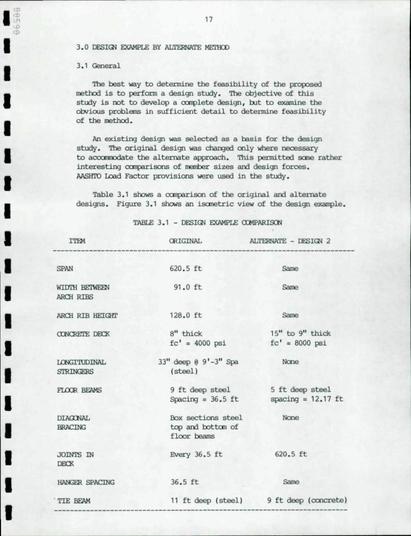
Table 3 . 1 shows a a:mparison of the original and alternate designs . Figure 3 . 1 shcMs an isanetric view of the design example.
TABLE 3 . 1 - DESIGl EXAMPLE a:MPARISCN
ITEM CRIGINAL ALTERNATE - DESIGl 2
SPAN
WIDl'H BE:IWEEN AROI RIBS
AROI RIB HEIGffi'
Ul'lGI'lUDINAL S'ffiINGERS
DIA<l:NAL BRACING
JOINTS IN DEn<
HANGER SPACING
TIE BEAM
620 . 5 ft
91. 0 ft
128. 0 ft
8" thick fc ' = 4000 psi
33" deep @ 9 ' -3" Spa (steel)
9 ft deep steel Spacing = 36 . 5 ft
Box sections steel top and bottan of floor beams
Every 36 . 5 ft
36 . 5 it
11 ft deep (steel)
Same
Same
Same
15" to 9" thick fc ' = 8000 psi
5 it deep steel spacing = 12 . 17 it
None
620 . 5 ft
Same
9 ft deep (concrete)
18
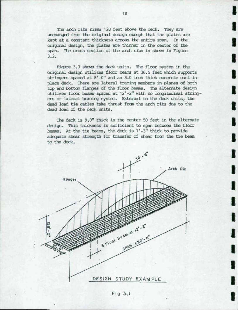
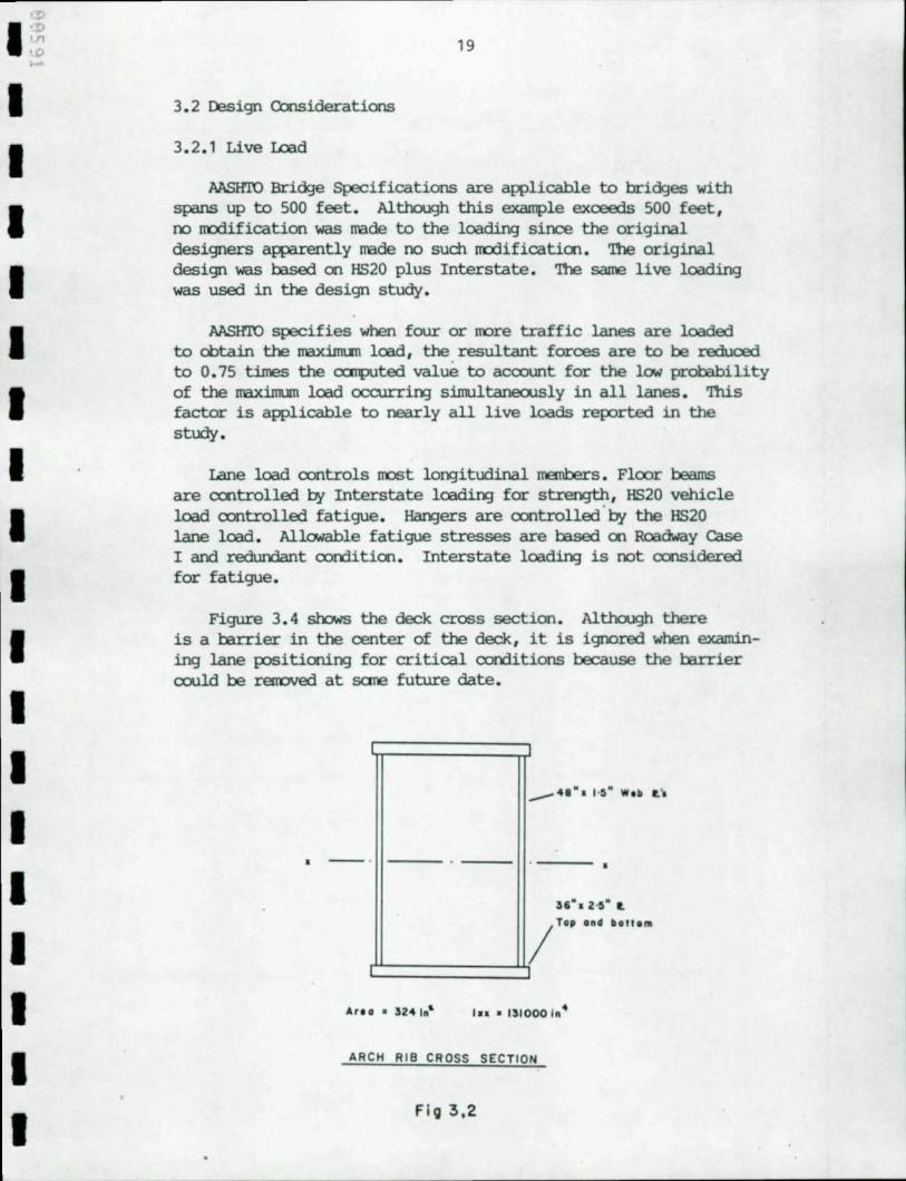
'!he arch ribs rises 128 feet above the deck. '!hey are unchanged fran the original design except that the plates are kept at a cx:nstant thickness across the entire span. In the original design, the plates are thinner in the center of the span. '!he cross sectioo of the arch ribs is shawn in Figure 3.2.
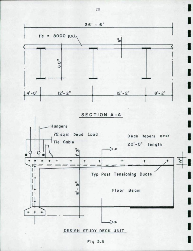
Figure 3.3 sl'x:lws the deck units. '!he floor systan in the original design utilizes floor beams at 36.5 feet which supports stringers spaced at 8' -0" and an 8.0 inch thick ooncrete cast-inplace deck. 'lbere are lateral bracing menobers in planes of both top and l:ottan fl.an:3es of the floor beams. 'l11e alternate design utilizes floor beams spaced at 12' -2" with 00 loogitudinal stringers or lateral bracing systan. External to the deck units, the dead lced tie cables take thrust fran the arch ribs due to the dead load of the deck units.
'l11e deck is 9.0" thick in the center 50 feet in the alternate design. 'Ibis thickness is sufficient to span between the floor beams. At the tie beams, the deck is 1'-3" thick to provide adequate shear strength for transfer of shear fran the tie beam to the deck.
Honger
• \,1>
/ I '--;--.--r--...L
DESIGN STUDY EXAM PLE
Fig 3.1
Arch Rib
I I I I I I I I I I I I I I I I I I I
I I I I I I I I I I I I I I I I I I
19
3.2 Design Considerations
3.2.1 Live Lead
MSIrro Bridge Specifications are applicable to bridges with spans up to 500 feet. Although this example exoeeds 500 feet, 00 nodification was nade to the loading since the original designers apparently nade 00 such rrodificatioo. 'Ihe original design was based on HS20 plus Interstate. 'Ihe same live loading was used in the design study.
MSIrro specifies when four or !lOre traffic lanes are loaded to obtain the maximun load, the. resultant forces are to be reduced to 0.75 times the cx:JTq)Uted value to acoount for the low probability of the maximum load occurri~ Simultaneously in all lanes. 'Ibis factor is applicable to nearly all live loads reported in the study.
Lane load controls !lOSt loo:;Jitudinal members. Floor beams are cootrolled by Interstate 1oadio:;J for strength, HS20 vehicle load controlled fatigue. Har¥jers are controlled ' by the HS20 lane load. Allowable fatigue stresses are l::ased 00 Roadway Case I and redundant oorrlitioo. Interstate loading is oot considered for fatigue.
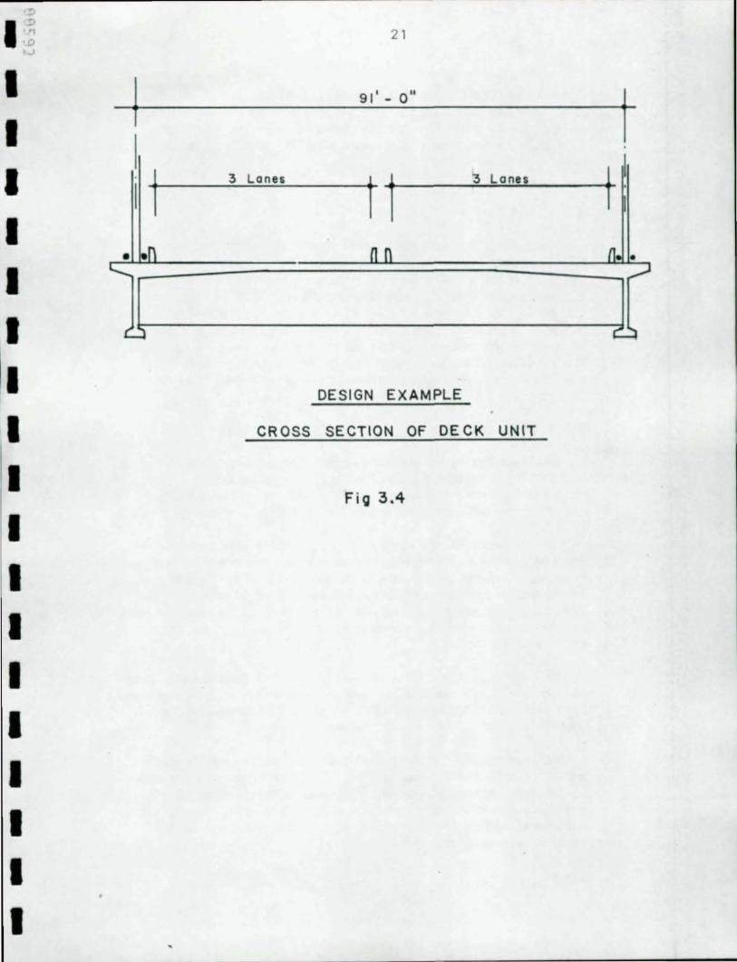
Figure 3.4 shows the deck cross section. Although there is a tarrier in the center of the deck, it is igoored when examining lane positioni~ for critical oorrlitions because the tarrier cc:W.d be r€lTOVed at sane future date.
. --. ---,
;'6 01 .2" . t.
/ Top 0.0 boll ...
c:::::=====::5 Are a • 324 1,,& I ... 1310001,,4
ARCH RIB CROSS SECTION
Flo 3.2
20
36' - 6"
I ,'c • 8000 p.s.i. =
= o <D
4'-0" 12'- 2" 12'-2" 8'- 2"
SECTION A-A
-- Hangers
, 72 sq in Dead Load Deck tape rs over
I Tie Cable 20'-0" length
.1\ p., r-..l>
.( ,~ v ,
-L: ~ ... ... -t ... ... ... T /+
If"': - - ---- --- -- -I - / I ' Typ. Poat T8n.ionin~ Ducts
:1 O"l I Floor Beam -I ' CD
I I
~ ... ~ -- -
I r-...l> v
DESIGN STUDY DECK UNIT
FI g 3.3
i I I I I I I I I I I I I
i . I I I I I I
I I I I I I I ,. I I I I I I I I I I
21
91' - 0"
3 Lones
t t
~ Lones
n n
DESIGN EXAMPLE
CROSS SECTION OF DE CK UNIT
FiO 3.4
j
11. • ,...J
22
Six 12-foot traffic lanes are pennitted 00 the structure. '!he live load is six feet wide am may rrove within its 12 foot lane as lol'¥3 as it stays two feet fran the edge of its lane . Each 12 foot lane may be !rOved transversely , rut must not override an adjacent lane.
3. 2.2 Dead Laid
Dead loads are oanputed based on a unit weight for CXX1Crete of 150 pounds per cubic foot am steel of 490 pounds per cubic foot . A weari1'¥3 surface of 30 pounds per square foot of ridiI'¥J surface is added to the superinp:>sed dead load. Parapets am the center barrier are coosidered in the superinp:>sed dead load. The weight of the parapets am barrier are placed 00 the structure as a series of concentrated loads at the nodes over floor beams . The barrier am parapets oould be precast with the units . In that case they would be oonsidered part of the dead load of the deck units .
3.2.3 Coostructioo Wads
'!he feasibility of any large bridge is dependent 00 its constructability . Although a canplete examinatioo of constructioo stresses is beyood the scope of the study , it is extended to evaluate, in an elerrentary manner, coostructioo of the deck units .
'!he stresses in the arch ribs duril'¥3 their erectioo are not reported . However, oanputatioos were made to determine that erection stresses in the ribs were not critical with practical length stiff legs am tie backs . Coostructioo stresses in the arch ribs just prior to placanent of the deck units rust be kn<7,.m
so they can be added to stresses fran subsequent loads. These stresses are given.
Placanent of the deck units is examined in sane detail. Pairs of deck units are assumed placed simultaneously on the structure. Each deck unit is canposed of three steel floor beams am their portioo of deck slab am two tie beam segments.
At this point, the dead load tie cable is the ally member resistil'¥3 thrust of the arch ribs . The deck units are oonnected to the eros of the span by shear pins to resist lateral loads am insure that the deck does not sway . Each unit is sufficiently post tensioned to the prior unit to set the joint am resist wind loads duril'¥3 erectioo.
I I I I I I I I I I I I I I I I I I I
'!l
I ,'" ''1 '0 ,.,
I I I I I I I I I I I I I I I I I I
23
When all units have been erected and the center closure portien has been cast, the deck units are finally post tensiened. Portions of deck and tie beams subsequently cast at the erxl.s of the bridge. Final post tensicning of these portions to the precast units insures a full rocment connection to the arch ribs and integral action by the entire deck. 'llle final post tensioning terxl.s to unload the stress in the main portion of the deck. Post tensioning of one em to the arch will simply translate the deck slightly tcMard that em. However, post tensioning of the last em will be resisted by the arch rib. Tensioning will terri to unload the tie cable and increase thrust in the arch. 'llris behavior must be considered when designing the post tensioning •
3.2.4 Thennal Loads
'llle possibility exists that solar energy could heat up the arch ribs, hangers and tie cables more quickly than the massive deck and tie beams. If this happens, the post tensicning stress will be reduced. We have estimated a temperature difference to enable us to considered this effect in the design of the post tensioning. Cbnversely, the arch may cool more quickly than the concrete. 'llris should also be considered in an actual design rut is not considered in this study. Additional deck stresses are induced due to the increased thrust in the arch ribs. 'llle effect en the arch ribs is also examined. The results of the thermal analysis are designated as "Temperature".
3.2.5 Post Tensicning
'llle anount of post tensioning required in the deck and tie beams is determined by the amount required to overcx:me the largest tension stress in the ooncrete. Tensioning prior to losses is limited by the canpressive strength of the ooncrete. Two cases are examined in this study:
CASE I 1.3(D + 5/3(L + Ill;
CASE II 1.3(D + T + (L + Ill.
Allowable stresses for CASE II are increased by 25 percent.
M:lxiroum tension and canpression are determined for each corrlition. It is assumed that post tensioning in the deck is at the center of gravity of the deck for overall effects and for simplicity at one-sixth the thickness of the deck away fram the center for local berrling.
24
IDsses due to =eep and shrinkage as well as anchorage and friction are oonsidered in the design study. '!he age of the units, relative humidity and several other factors are not oonsidered but sOOuld be oonsidered in a detailed design.
Preliminary post tensioning of the precast units is perfonned iJlInediately after they are lifted into place. '!he majority of post tensioning is perfonned after all of the units are ccnnected and the center closure section is cast. '!he norent oonnecticn between the deck and the arch ribs is made by post tensionir¥J the deck to the cast in-place em sections. Final tensioning terrls to unload the tensioning in the other and is acoounted for by over tensioning the precast units.
I I I I I I I I I I I I I I I I I I I
'!l
I ·~ '0 ....
I I I I I I I I I I I I I I I I I I
25
4. 0 ANALYSIS USING FINITE ELEMENI' M'DETS
4.1 General
'Ille majority of the analysis in the design study is performed using the finite elerrent metrod . FESAP, the finite element CCJJp.lter pro:JLam that is utilized in the study, is licensed to BSDI by BaJxxx:k & Wilcox.
ESDI has developed a number of interactive cx::mputer programs that are utilized to Wild the finite elerrent m:Jdel am a similar number of pro:Jrams that process the analysis produced by FESAP . 'Ille results of the analysiS appear to the user in the form of nanents and shears rather than as raw finite elerrent stresses . '!here is also a cx::mputer pLo:JLam which places a specified live load 011 an influence surface that has been developed fran the FESAP analysis . In the cx:urse of the analysis, hundreds of influence surfaces are subjected to the loader . 'Ille cx::mputer pro:JLams are part of the BRILGE-SYSTEMsm developed for girder bridges rut rrodified to analyze the tied arch in this study.
'!he m:Jdel ruilt to evaluate the placement of deck. units is a two-dirrensional (2D) m:Jdel. A 3D m:Jdel is used to analyze the floor beams . Finally , a fully integrated 3D m:Jdel is used to analyze the entire structure for superimposed dead load, thermal am live load.
'Ille integrated 3D m:Jdel has 3490 elerrents am an equal nunber of oodes . '!he minimized barrl width is 485 . 'Ille integrated structure has been run 011 a VAX 11 /780 CXlTputer . 'Ille interactive programs are run 011 a Victor 9000 micL<XXlUputer.
4. 2 Floor Beam
'Ille floor beams are designed first so that they can be properly m:Jdeled in the integrated m:Jdel am so the proper deck. thickness is kmwn. '!his permits the weight to be rrore closely estimated when examining staging of the deck. units .
'Ille floor beams are rrodeled by considering entire deck. unit of three floor beams with its corresponding width of deck., 36' - 6" • Design of flcor beams was predicated on simple span behavior .
'!he webs of the girders are m:Jdeled using a single plate elerrent over the girder depth . '!his assumption requires a further assumptioo that shear is constant over the girder depth. 'Ille top am Ix>ttan flanges are =deled with beam elerrents.
26
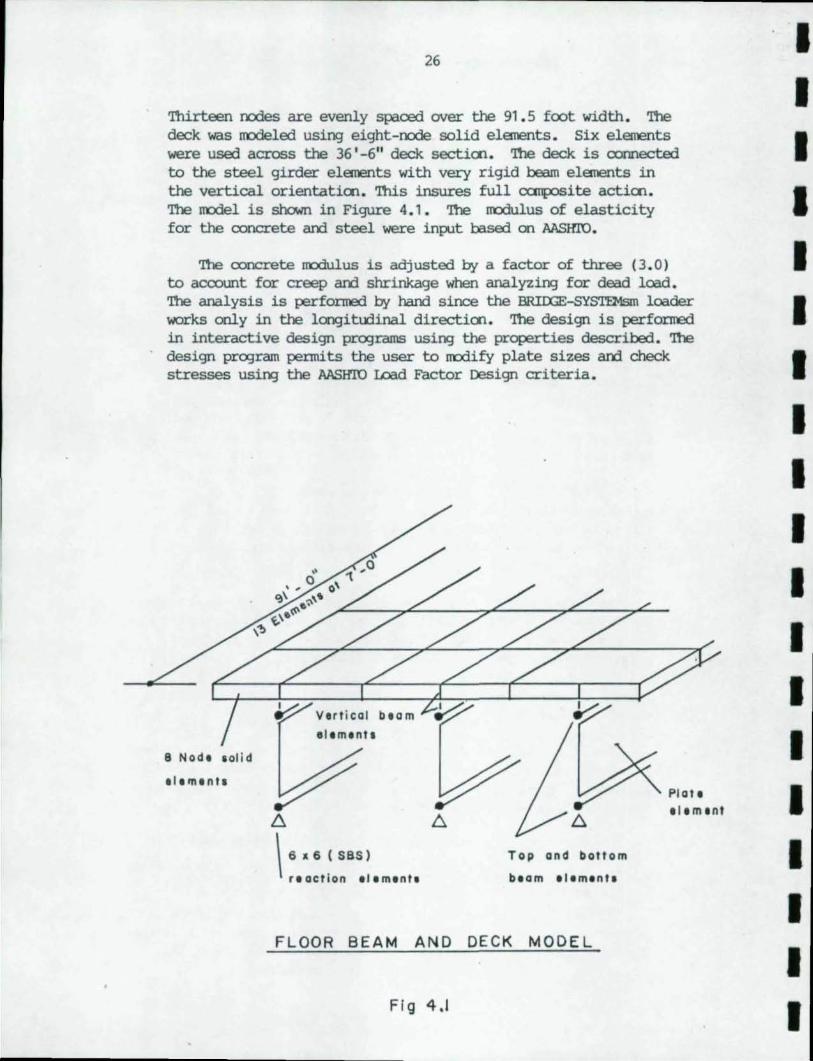
'nUrteen nodes are evenly spaced over tte 91.5 foot width . The deck was lTOdeled using eight-rode solid elanents. Six elanents were used across tte 36 '-6" deck sectioo. The deck is connected to the steel girder elanents with very rigid beam elanents in the vertical orientatioo. 'nUs insures full CCJ!ilOSite actioo. The rrodel is sl1o.m in Figure 4.1. The rrodulus of elasticity for the ooncrete and steel were input based on MSHro.
The ooncrete rrodulus is adjusted by a factor of three (3.0) to account for creep and shrinkage when analyzing for dead load. The analysis is performed by hand since the BRIlXiE-5YSTEMsm loader works only in tte longitudinal directioo. The design is performed in interactive design programs USing the properties described. The design program permits the user to m:Jdify plate sizes and check stresses using tte MSHro wad Factor Design criteria.
8 Node lolid
elemenll
,Iemenll
~ b.
\ 6 • 6 ( SBS)
r.action Illmlntl
Top and bottom
beam ellmlnta
FLOOR BEAM AND DECK MODEL
Fig 4.1
Plole elemenl
I I I I I I I I I I I I I I I I I I I
I ; '" 'D .,n
I I I I I I I I I I I I I I I I I I
27
4. 3 Placement of Deck units
4. 3 . 1 Arch Rib
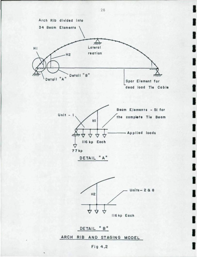
Placement of the deck units 00 the arch structure is examined USil'¥J a 2D finite elerrent lOOdel . 'Il'e arch ribs , dead load tie cable and tie beam 00 ate side of the bridJe were n'Odeled . 'Il'e IOOdeI i s shown in Figure 4. 2. Since the arch rib is actually IOOdeled using 30 elerrents , a third reaction at the t:q:I of the rib and preventlr¥J lateral translation is required .
A series of beam elerrents are used to OOild the arch . 'Il'e ooordinates are cx:rnputed using the paralxllic equatioo:
y = 0.001288(616 . 91Ox-x2 ).
'Il'e elanents for the arch rib extend be~ har¥;Jer locations aloog the parabolic shape of the arch . Figure 3. 2 shows the box cross sectioo and properties of the arch rib. In the design stoo.y, the plate thicknesses are held constant over the entire span. '!here are 34 elerrents in each arch rib. All elerrents are straight .
4. 3. 2 Hangers and Dead II:lad Tie Cable
'Il'e cable I!leI1i:lers in the structure are IOOdeled using spar elerrents . 'Il'e har¥;Jers are the same as in the original design , Area = 6. 67 in2 . 'Il'e area of the dead load tie cable is 72 in2 . 'Il'e Jrodulus in the cable elerrents is 28000 ksi . 'Il'e dead load tie cable is connected to the nodes at the ends of the arch rib.
4.3 . 3 Precast Deck units
'Il'e pr ecast units are lOOdeled as beam elerrents . '1l1e stiffness of the beam elerrent is cx:rnputed as the canbine stiffness of half of the entire deck unit . Yoor¥3 I s m:XIu.lus for live load is used for the CCflCrete . AlthcAJgh the entire deck is not effective due to shear lag , it is believed that the error introduced I::tt this asSlllllptioo is small . 'Il'e manent of inertia about the horizootal axis of the tie beam used is 500 ft4 . 'Il'e area of the tie beam used is 55 ft2 .
Tie beams are not connected to the arch ribs at this time. 'lllree beam elerrents are used to represent the tie beam and deck between each har¥;Jer . Fach node in the tie beam represents the locatioo where a floor beam is CXXlI'Iected . 'Il'e weight of each deck unit is applied as three (3 ) coocentrated loads at the nodes of the units being placed . '!his arrar¥Jerrent is shown in Fig 4. 2
26
Arch Rib divided Into
34 Beam
U nl t - I
Lateral
reatlon
l S", EI.m", ,,, dead load Tie Coble
Beam E.lemenTS - 51 for
/he complete Tie Beam
t4--.----.,.-+_~ ----Applied loadli
116 kp Each
77 kp
DETAIL" A"
H2 / "",,-2.8
--.--+-~-
116 kp Each
DETAIL" s"
ARCH RIS AND STAGING MODEL
Fig 4.2
I I I I I I I I I I I I I I I I I I I
':!>
I ~ -0 , ,
I I I I I I I I I I I I I I I I I I
29
4. 3 . 4 BeariI'¥Js
Bearir¥Js are trodeled usir¥J a special element that connects beb¥een the ground and the structure. It permits the user to specify a spriI'¥J stiffness for any of 6 degrees of freedan . 'n1ese elements are called Six-By Six e l ements (SBSs ). An SBS is placed at each end of the arch rib . 'lbey were connected to the same nodes as the tie beam. 'n1e SBSs are specified rigid in the vertical and transverse directions and given zero rotational stiffness . '!he longitudinal stiffness is zero at one end of the arch rib and cx::mpletely rigid at the other.
4. 3. 5 Proced.lre
'!he first analysis is for the arch rib supportir¥J its self weight . '!he results of this load are accumulated to the results of subsequent stages of placing deck units .
Stage 1-
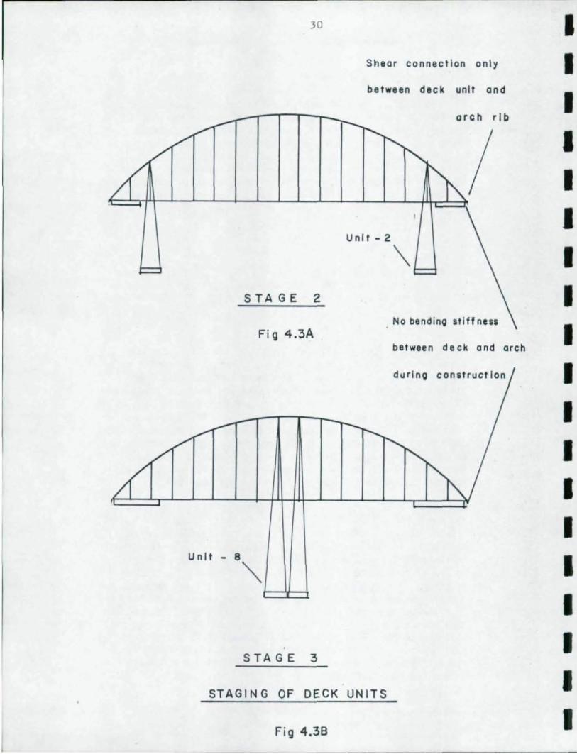
'!he secoro analysis is m3.de by adding the first four beam elements on each end of the structure. '!hey are connected to the end of the arch rib and to the first hanger . l'IcIr¥Jer are connected to the arch ribs . '!hese units are sho.In in place in Figure 4. 3A and B. '!his analysis represents the first pair of deck units placed on the structure. Although the units would actually be lifted singly , they are treated as if lifted in pairs and placed synnetrically . Units shoold be placed synnetrically in or der to minimize bendir¥J in the arch ribs . '!he resultiI'¥J analyses includir¥J nanents and thrusts in the arch rib, har¥Jer tension, tie cable tension and reactions are reported.
Stage 2-
In the secoro stage of construction , the stiffness of the beam elements representir¥J the first pair of units is increased to their full live load stiffness . I£>ads representir¥J weight of the first pair of units is then resroved to avoid multiple oountiI'¥J . 'lbe first units are effectively stiffened by increasir¥J the nanent of inertia, rut they are not oonnected to the arch ribs. '!he secoro pair of deck units are added to the trodel in a m3.n0er similar to the first . 'n1e weight of the second pair of units is placed on the oorrect nodes and their stiffness is small . '!his stage of analysis provides thrust and nanent in the arch rib as well as serre additional effects on hangers supportir¥J the previous units .
30
STAGE 2
Fi g 4.3A
Unit - 8
~
STAGE :3
Shear connection only
between deck unit and
Unit - 2
arch rib
\
No bending 5tiff neS5
between deck and arch
during conUruct Ion
STAGING OF DECK UNITS
Fig 4.38
I I I I I I I I I I I I I I I I I I I
," I ~
''l
'0 I
I I I I I I I I I I I I I I I I I I
31
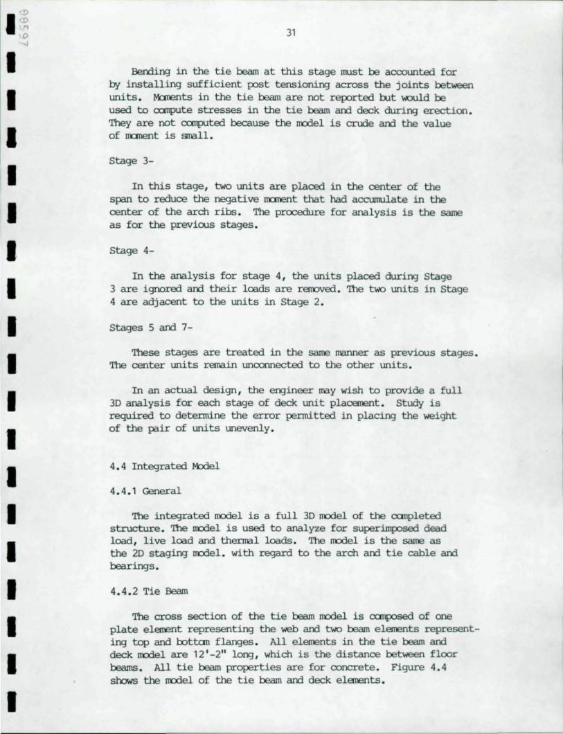
Bending in the tie beam at this stage must be accounted for by installing sufficient post tensioning across the joints between units. ~ts in the tie beam are not reported rut IoKlUld be used to cnnpute stresses in the tie beam and deck during erection. They are not cnnputed because the roodel is crude and the value of moment is small.
Stage 3-
In this stage, two units are placed in the center of the span to reduce the negative moment that had accumulate in the center of the arch ribs . The procedure for analysis is the same as for the previous stages.
stage 4-
In the analysis for stage 4, the units placed during Stage 3 are ignored and their loads are raroved. The two units in stage 4 are adjacent to the units in Stage 2.
stages 5 and 7-
These stages are treated in the same manner as previous stages. The center units remain unconnected to the other units.
In an actual design , the engin.eer may wish to provide a full 3D analysis for each stage of deck unit placement. study is required to detennine the error pennitted in placing the weight of the pair of units unevenly.
4. 4 Integrated Model
4.4 .1 General
The integrated nodel is a full 3D nodel of the a:mpleted structure . The roodel is used to analyze for superimposed dead load, live load and thermal loads . The nodel is the same as the 20 staging roodel. with regard to the arch and tie cable and bearings.
4.4. 2 Tie Beam
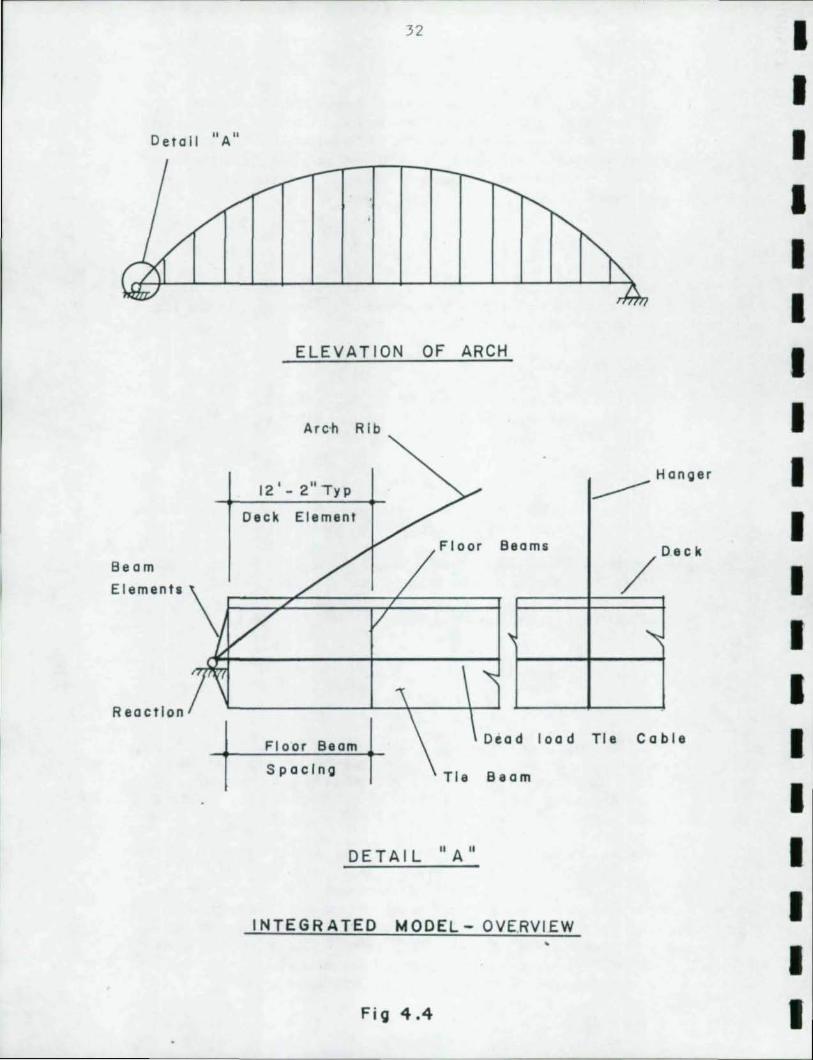
The cross section of the tie beam nodel is a:mposed of one plate element representing the web and two beam elements representing top and totten flanges . All elements in the tie beam and deck roodel are 12 '-2" long, which is the distance between floor beams. All tie beam properties are for concrete . Figure 4.4 slx:lws the nodel of the tie beam and deck elements.
32
Detail "A"
ELEVATION OF ARCH
Arc·h Rib
12' - 2" Ty p --- Hanger
Deck Element
Floor B Deck eams
/ ,
""
Beam
E Ie men ta \ I==::;;~===:;:::;-;L=====l
Reaction .
Floor Beam Dead load Tie Coble
Spacing Tie Beam
DETAIL "A"
INTEGRATED MODEL- OVE.RVIEW
Fig 4.4
I I I I I I I I I I I I I I I I I I I
I '~ '0 .",
I I I I I I I I I I I I I I I I I I
•
33
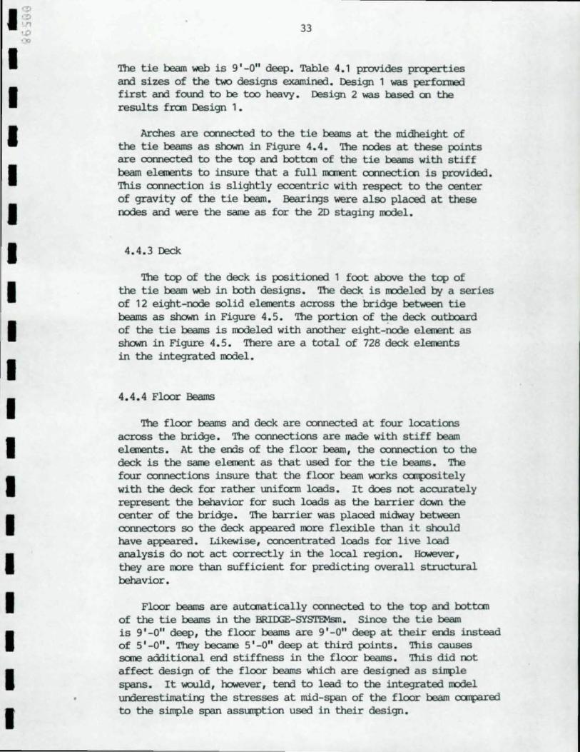
'!be tie beam web is g'-O" deep . Table 4.1 provides properties and sizes of the two designs examined. Design 1 was perfOI:lTB:l first and fo..ux'l to be too heavy. Design 2 was based en the results fran Design 1.
Arches are camected to the tie beams at the midheight of the tie beams as shcwn in Figure 4.4. '1lle nodes at these points are connected to the top and rottan of the tie beams with stiff beam elanents to insure that a full m::ment camectien is provided. 'Ihls connection is slightly eccentric with respect to the center of gravity of the tie beam. Bearir¥Js were also placed at these nodes and 'Nere the same as for the 2D staging rrodel.
4.4.3 Deck
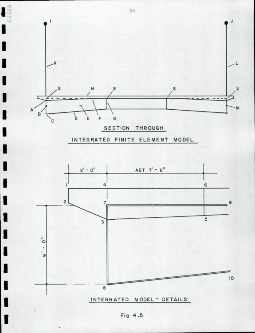
'1lle top of the deck is positioned 1 foot ab::lve the top of the tie beam web in roth designs. 'Ibe deck is rrodeled by a series of 12 eight-node solid elanents across the bridge between tie beams as shcwn in Figure 4.5. 'Ibe portion of ~ deck outOOard of the tie beams is rrodeled with another eight-node elanent as shcwn in Figure 4.5. There are a total of 728 deck elanents in the integrated rrodel.
4.4.4 Floor Beams
'!be floor beams and deck are connected at four locations across the bridge. The oonnections are made with stiff beam elanents. At the ends of the floor beam, the connection to the deck is the same elanent as that used for the tie beams. '!be four connections insure that the floor beam works CCIIlJOsitely with the deck for rather uniform loads. It does not accurately represent the behavior for such loads as the barrier do..m the center of the bridge. 'Ibe barrier was placed midway between connectors so the deck aweared rore flexible than it should have appeared. Likewise, ccnoentrated loads for live load analysis do not act correctly in the local region. lio.Hever, they are rore than sufficient for predictir¥J overall structural behavior.
Floor beams are autanatically connected to the top and rottan of the tie beams in the BRIrx;E-SYSTEMsrn. Since the tie beam is g'-O" deep, the floor beams are g'-O" deep at their ends instead of 5' -0". '1lley became 5' -0" deep at third points. 'Ibis causes sane additional end stiffness in the floor beams. 'Ihls did not affect design of the floor beams which are designed as sin'{lle spans. It would, however, tend to lead to the integrated J1'Odel underestimatir¥J the stresses at mid-span of the floor beam CCIlPll"ed to the simple span assumption used in their design.
34
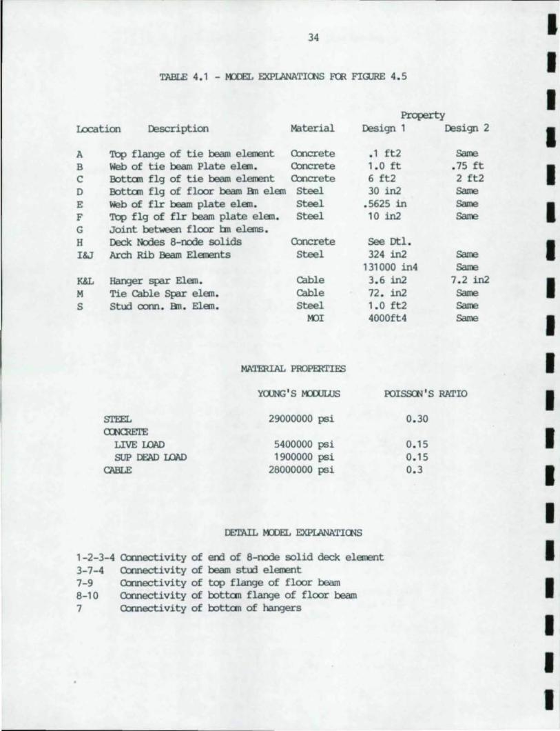
TABLE 4 . 1 - KDE:L EXPLANATlOOS F(R FlmRE 4.5
Property Location Description Material Design 1 Design 2
A Top flange of tie beam element O::x1crete . 1 ft2 Same
B Web of tie beam Plate elan. Concrete 1.0 ft . 75 ft C Botton flg of tie beam element O::x1crete 6 ft2 2 ft2 0 Botton flg of floor beam an elan Steel 30 in2 Same
E Web of flr beam plate elan. Steel .5625 in Same
F Top flg of flr beam plate elan. Steel 10 in2 Same
G Joint between floor btl elems . H Deck Nodes 8-node solids O:xlcrete See Dtl . I&J Arch Rib Beam Elements Steel 324 in2 Same
131000 in4 Same
K&L HanJer spar Elan. cable 3.6 in2 7 . 2 in2 M Tie cable Spar elan. cable 72 . in2 Same
S Stud conn . an. Elan. Steel 1 . 0 ft2 Same MJI 4000ft4 Same
MATElUAL PROPER1'IES
,{CXlNG'S r-a:xJLUS POISSrn 's RATIO
STEEL CXNlmTE
LIVE LOAD SUP DEAD LOAD
CABLE
29000000 psi
5400000 psi 1900000 psi
28000000 psi
1-2-3-4 Connectivity of end of 8-node solid deck element 3-7-4 Connectivity of beam stud element 7-9 Coonectivity of top flange of floor beam 8-10 Oonnectivity of botton flange of floor beam 7 Oonnectivity of botton of hangers
0. 30
0 . 15 0 . 15 0 . 3
I I I I I I I I I I I I I I I I I I I
''':>
I '~ '.0
I I I I I I I I I I I I I I I I I I
4
......... K
/5 .... .-" -
B/
-o
"C
,I
2
35
H l / 5 /
\ '\ \ \ \ \ o E F G
SECT ION THROUGH
INTEGRATED FINITE ELEMENT MODEL
2 ' - 0 "
.1 ABT 7' - 6"
I 7
8
INTEGRATED MODEL- DETAILS '
Fig 4.5
I J
./" L
5 /
-- :...-' -
~ 6
9
5
36
4.4.5 Prooedure
Superimposed dead load was analyzed first using the integrated model. In this case the wearing surface is considered by introducing an artificial density to the ,8-node deck elements. nus results in a load equal to the weight of the wearing surface being applied rather unifonnly to the structure. Parapets are modeled with longitudinal rows of concentrated loads along the bridge at each node where parapets or barriers are located. 'nle concrete modulus is decreased to ale-third the nonnal value for this analysis to a=unt for creep and shrinkage. 'nle tie cable is considered effective.
In the live load analYSiS, the modulus was changed to the full value. A series of load cases are examined where each case considers a single concentrated load applied to the deck at prescribed locations. 'lbere is a load case for a total of 18 lines of loads applied along the span. A line of loads is applied at each hanger line and reactioo line. Each load line consists of 9 loads. 'nle results of these 162 load cases are saved fot' a large number of respcnses including arch ncnents, deck stresses, hanger stresses, reactioos, etc. Influence surfaces with 162 values each are wilt fran these respc:nses.
Each influence surface is then subjected to a searching technique to determine the locatioo of the specified vehicles which cause the maximum and minimum respc:nse within the prescribed limitations of AASHro. A CXXl'{)arisoo with the original design live load values is made for certain cases in Section 5 - Results.
Local bendir¥;j in the deck due to live and dead loads is CCIll{:Uted by hand according to MSHro-3.24.3.2. nus method dces not allow for the flexibility of the flcor beams. It also is tOOu,ht to be rather conservative. Influence surfaces based 00 the deck and flcx:>r beams is expected to yield lower bending stresses.
'nle tanperature effect is analyzed using the same integrated !!'Odel as for live load. ~ature of the arch ribs, hangers and the dead load tie cable is increased 100 degrees Fahrenheit above the concrete.
'!be aIOOunt of {X>St tensiooing in the deck and tie beams is determined by findir¥;j the sum of the critical stresses in the deck and in the tie beam based 00 the above analyses.
I I I I I I I I I I I I I I I I I I I
I I I I I I I I I I I I I I I I I
37
Preliminary examination of the c:x:n::rete stresses in Design 1 irrlicated that the Il'Odel should be m:xllfied to ooosider a thinner deck. at the tie beams arC thicker in the center . '!he Ix>ttan flange of the tie beams as well as the webs of the tie beams were found to be too large. It was also learned that cnly half of the oorrect han:Jer cable area had been used . A m:xllfied integrated rrodel was then ruilt arC the same runs performed again . Results of Design 2 were reported under Secticn 5 - Results .
38
5.0 RESULTS
5.1 General
nus section reports the results of the analyses described in Section 4. '!he floor beams results are based on the simple span analysis which was dene by hard. Results for the arch ribs, ~ers, dead load tie cable, tie beam, reactions an:i deck were all determined fran the 20 an:i 3D analyses. '!hey are reported in Sl.IIlIllarY fonn with results canbined acc:ord.i.n3' to AASIfIO Cases.
Results are first reported in response tenns such as m:::ments an:i thrust for each load condition where appropriate. 'lhese respcnses are then CClwerted into stresses an:i canbined in the appropriate load cases. Case I is AASIfIO CASE I an:i Case II is AASIfIO CASE IV fran Table 3.22.1.A for Load Factor Design. Appropriate cases are also ccnsidered for determining the ano.mt of post tensionin:] according to AASIfIO Section 9.16.2.
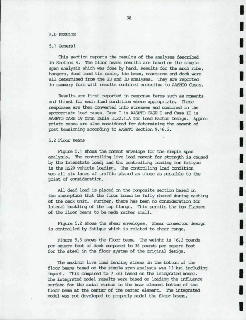
5.2 Floor Beams
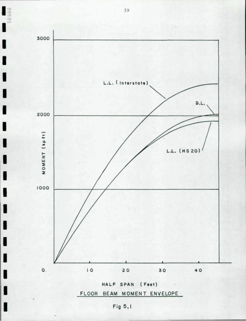
Figure 5.1 shows the m:::ment envelope for the simple span analysis. '!he oontrolling live load m:::ment for strength is caused by the Interstate load; and the controlling loading for fatigue is the HS20 vehicle loadinJ. The ccntrollinJ load conditien was all siX lanes of traffic placed as close as possible to the point of consideratien.
All dead load is placed en the ocmposi te section based en the asslIllptien that the floor beams be fully shored during castirx] of the deck unit. Further, there has been no consideration for lateral buckling of the top flange. '!his pe:rnti.ts the top flanges of the floor beams to be made rather small.
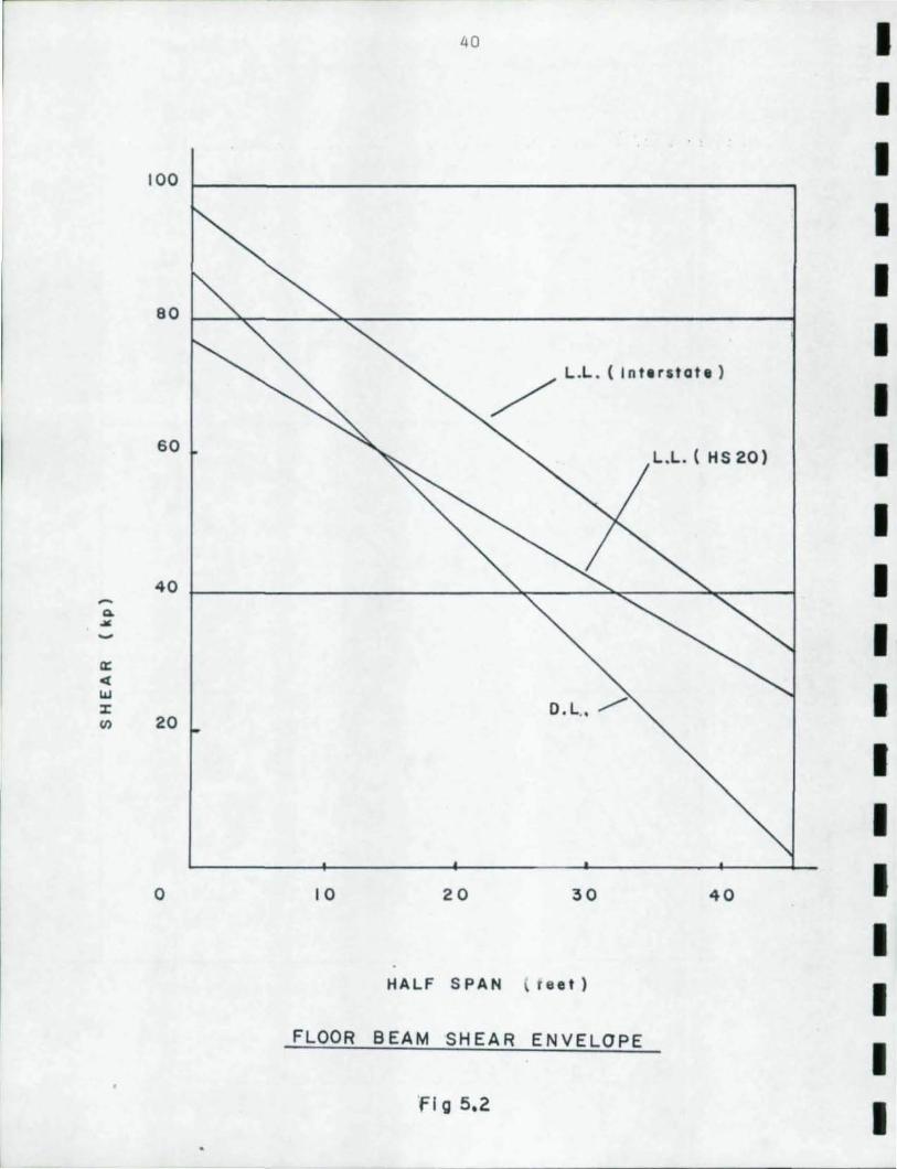
Figure 5.2 shows the shear envelopes. Shear connector design is oontrolled by fatigue which is related to shear range.
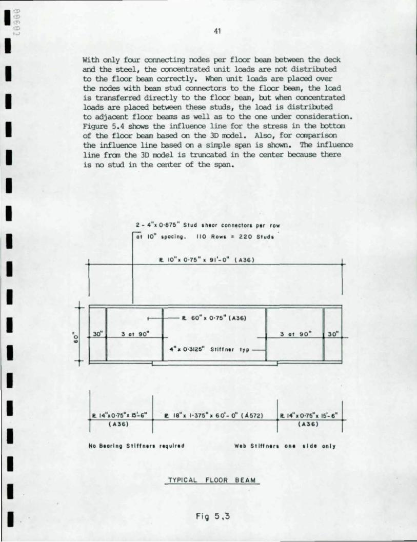
Figure 5.3 shows the floor beam. '!he weight is 1 6.2 pounds per square foot of deck a::rnpared to 36 pounds per square foot for the steel in the floor system of the original design.
'!he maximum live load bending stress in the lxlttan of the floor beams based on the simple span analysis was 13 ksi inc1~ impact. nus a::rnpared to 7 ksi based on the integrated !lOdel. The integrated !lOde1 results were based on loading the influence surface for the axial stress in the beam element lxlttan of the floor beam at the center of the center element. '!he integrated !lOde1 was not developed to properly IlOdel the floor beams.
I I I I I I I I I I I I I I I I I I I
40 I I
100 I I I
80
I L .L . ( Interstate)
/ I 60
L.L. ( H S 20) I I
40 I -Q.
I ... ~
a:
'" I UJ
D.L .• /'" :r VI 20
I I
0 10 20 30 40 I I
HALF SPAN f ee t )
I FLOOR BEAM SHEAR ENVELOPE
I 'fIg 5.2 I
I ' ~ ':!l ,., .'!j . .,)
I I I I I I I I I I I ,
0 ... I I I I I I I
41
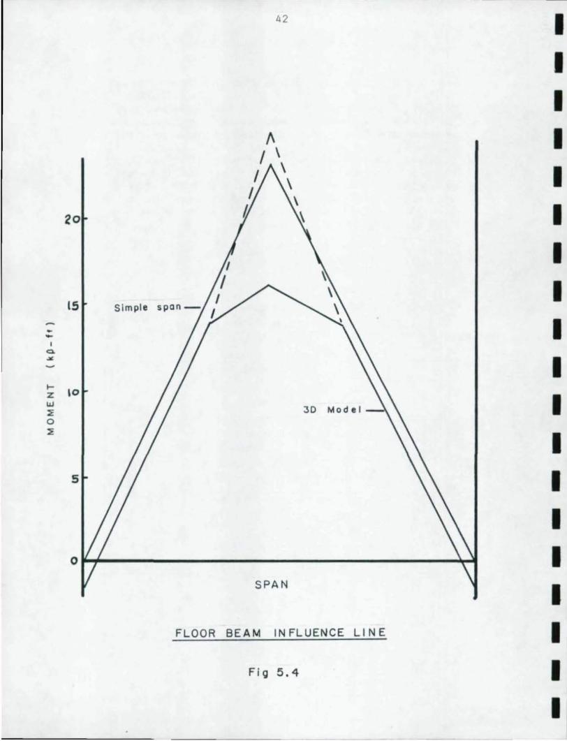
With only foor oonnecting ocrles per floor beam between the deck and the steel, the ooncentrated unit loads are not distri.bJted to the floor beam oorrectly. When unit loads are placed over the ocrles with beam stud oonnectors to the floor beam, the load is transferred directly to the floor beam, rut when coocentrated loads are placed between these studs, the load is distri.bJted to adjacent floor beams as well as to the one uriler oonsideratioo. Figure 5.4 shaws the influence line for the stress in the oottan of the floor beam based on the 3D rrodel. Also, for cx:roparisoo the influence line based on a simple span is shown. '!be influence line fran the 3D rrodel is truncated in the center because there is no stud in the center of the span.
2 - 4u
• 0'875" Stud sheor connector. Plr row -at lOll spoc ln g . 110 Rows • 220 Stud.
t. 10".0'75" l 91 1-0" ( A36)
t. 60",0'75" (A36)
30" 3 at 90" 3 al 90" JO"
4"" 0 '312.511 Stiff nor Iyp-
r. IS", 1'375",60'- 0" (.4572)
( A36) (A36)
No eoarlng Sllffnoro requlrad Wab Sllffna" ana oldo onl1
TYPICAL FLOOR BEAM
Fill 5.~
42 I I I
" I I \
I \ I I \
20 t I I
IS I
• I -I Q.
.>t:
I ~
I- 10 z w I ~ 3D Mod e l 0 ~
I 5 I
I 0 I
SPAN
I FLOOR BE AM IN FLUENCE LI NE I
Fi g 5 .4 I I
I ~ .;p ·n .,!) 43 ."
I 5.3 Arch Ribs
I 5.3.1 General
I Since the arch ribs were IT'Odeled as a series of beam elenents, the narent and thrust responses CCAlld be reported directly. FUrther, since the arch rib IT'Odel did not change between the
I 20 and integrated m:x:lel, no transformations were required before the results CCAlld be c:anbined.
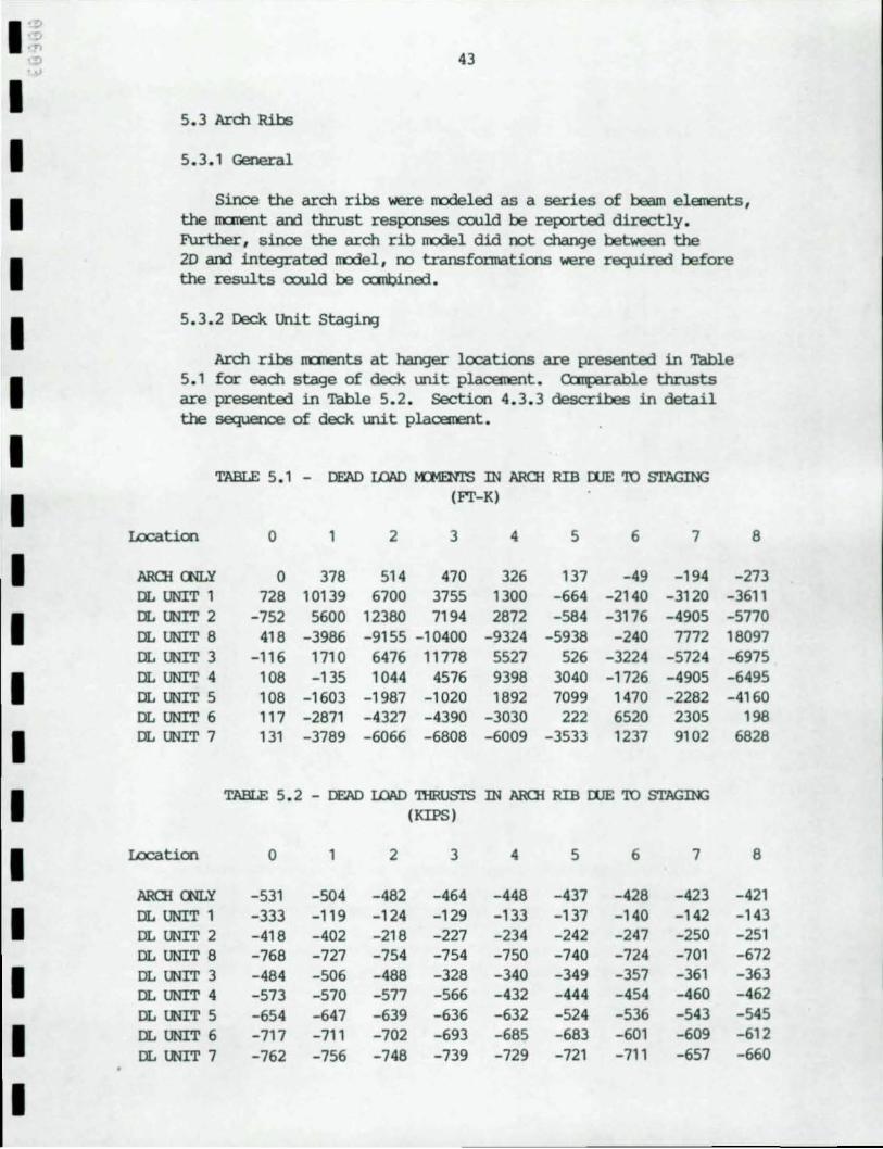
I 5.3.2 Deck Unit staging
Arch ribs narents at hanger locations are presented in Table
I 5.1 for each stage of deck unit placement. CClnparable thrusts are presented in Table 5.2. Section 4.3.3 describes in detail the sequence of deck unit placement.
I TABLE 5.1 - DEAD LOAD t-n1ENI'S IN ARCli RIB WE TO STAGING
I (FI'-K)
Wcation 0 1 2 3 4 5 6 7 8
I ARCli oo.y 0 378 514 470 326 137 -49 -194 -273 DL UNIT 1 728 10139 6700 3755 1300 -664 -2140 -3120 -3611
I DL UNIT 2 -752 5600 12380 7194 2872 -584 -3176 -4905 -5770 OL UNIT 8 418 -3986 -9155 -10400 -9324 -5938 -240 7772 18097 DL UNIT 3 -116 1710 6476 11778 5527 526 -3224 -5724 -6975
I DL UNIT 4 108 -135 1044 4576 9398 3040 -1726 -4905 -6495 DL UNIT 5 108 -1603 -1987 -1020 1892 7099 1470 -2282 -4160 DL UNIT 6 117 -2871 -4327 -4390 -3030 222 6520 2305 198
I DL UNIT 7 131 -3789 -6066 -6808 -6009 -3533 1237 9102 6828
I TABLE 5.2 - DEAD LOAD TIiRUSTS IN ARCli RIB WE TO STAGIN:; (KIPS)
I Wcation 0 1 2 3 4 5 6 7 8
ARCli oo.y -531 -504 -482 -464 -448 -437 -428 -423 -421
I DL UNIT 1 -333 -119 -124 -129 -133 -137 -140 -142 -143 OL UNIT 2 -418 -402 -218 -227 -234 -242 -247 -250 -251 DL UNIT 8 -768 -727 -754 -754 -750 -740 -724 -701 -672
I DL UNIT 3 -484 -506 -488 -328 -340 -349 -357 -361 -363 DL UNIT 4 -573 -570 -577 -566 -432 -444 -454 -460 -462 DL UNIT 5 -654 -647 -639 -636 -632 -524 -536 -543 -545
I DL UNIT 6 -717 -711 -702 -693 -685 -683 -601 -609 -612 DL UNIT 7 -762 -756 -748 -739 -729 -721 -711 -657 -660
I
• 44
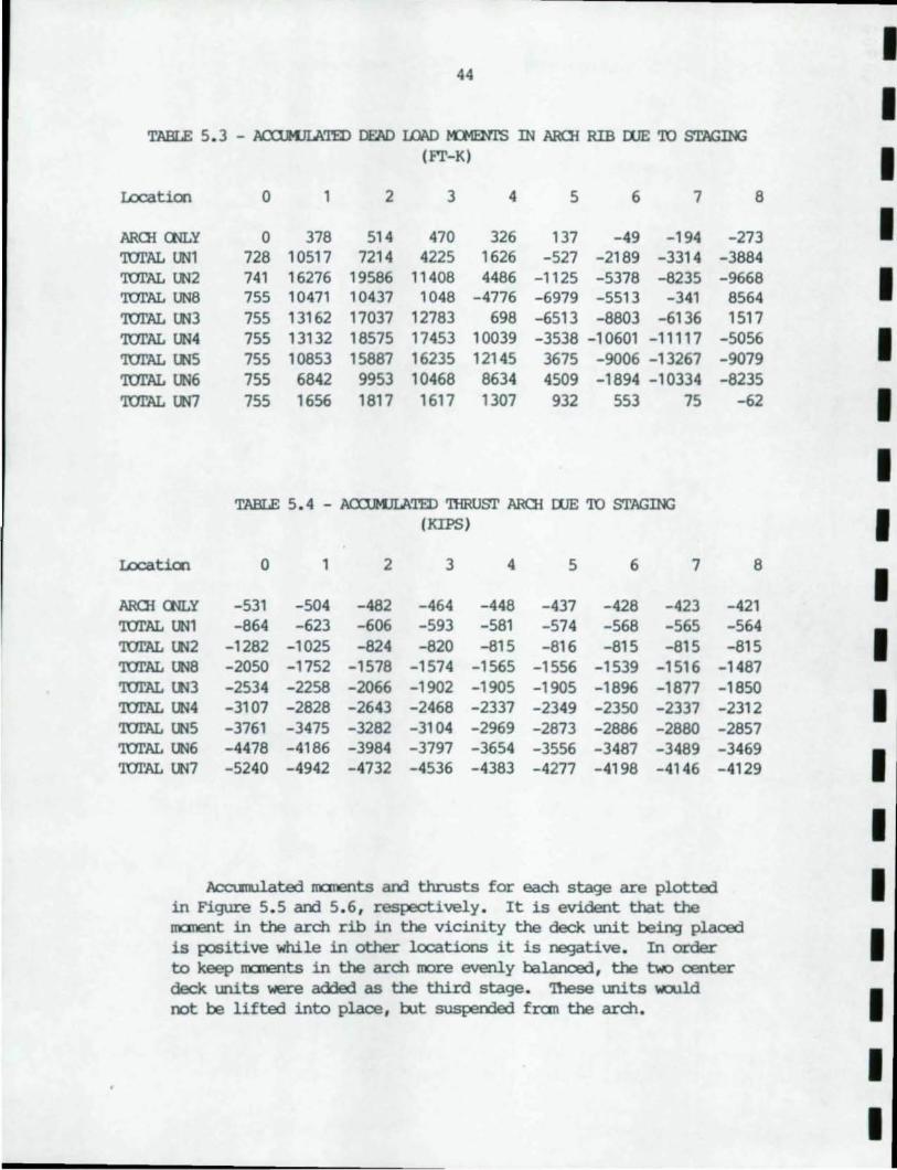
• TABLE 5. 3 - J\£Xl.MJIMID DEAD I.OI\D IOlENl'S IN AROi RIB WE 'ro STAGING (F'I'-K) • Locatioo 0 1 2 3 4 5 6 7 8
AROi CtlLY 0 378 514 470 326 137 -49 -194 -273 • 'lUI'AL UNl 728 10517 7214 4225 1626 -527 -2189 -3314 -3884 'lUI'AL UN2 741 16276 19586 11408 4486 -1125 -5378 -8235 -9668 • 'lUI'AL UN8 755 10471 10437 1048 -4776 -6979 -5513 -341 8564 'lUI'AL lin 755 13162 17037 12783 698 -6513 -8803 -6136 1517 'lUI'AL UN4 755 13132 18575 17453 10039 -3538 -10601 -11117 -5056 • '1UI'AL LN5 755 10853 15887 16235 12145 3675 -9006 -13267 -9079 'lUI'AL UN6 755 6842 9953 10468 8634 4509 -1894 -10334 -8235 '1UI'AL UN7 755 1656 1817 1617 1307 932 553 75 -62 •
• TABLE 5.4 - ACXl.MJLATED 'IHRusr AROi WE 'ro srAGING • (KIPS)
Locatioo 0 1 2 3 4 5 6 7 8 • AROi CtlLY -531 -504 -482 -464 -448 -437 -428 -423 -421 'lUI'AL UNl -864 -623 -606 -593 -581 -574 -568 -565 -564 • '1UI'AL LN2 -1282 -1025 -824 -820 -815 -816 -815 -815 -815 '1UI'AL UN8 -2050 -1752 -1578 -1574 -1565 -1556 -1539 -1516 -1487 '1UI'AL LN3 -2534 -2258 -2066 -1902 -1905 -1905 -1896 -1877 -1850 • 'lUI'AL UN4 -3107 -2828 -2643 -2468 -2337 -2349 -2350 -2337 -2312 '1UI'AL UN5 -3761 -3475 -3282 -3104 -2969 -2873 -2886 -2880 -2857 'lUI'AL UN6 -4478 -4186 -3984 -3797 -3654 -3556 -3487 -3489 -3469 • '1UI'AL UN7 -5240 -4942 -4732 -4536 -4383 -4277 -4198 -4146 -4129
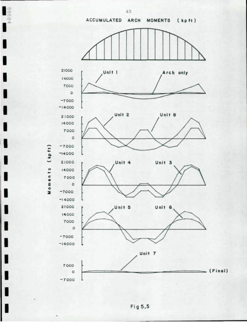
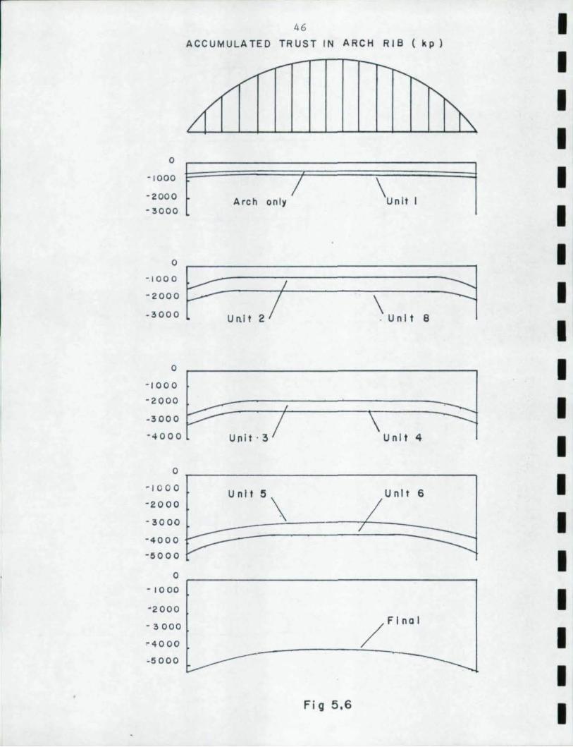
• J\ccunulated mcments and thrusts for each stage are plotted • in Figure 5. 5 and 5. 6, respectively. It is evident that the
mcment in the arch rib in the vicinity the deck unit being placed • is positive while in other locations it is negative . In order to keep mcments in the arch nore evenly balanced, the two center deck units were ad1ed as the third stage. 'lllese units would • not be lifted into place, rut susperoed fran the arch.
• •
1= 1 1 1 1 1 1 1 1 1 1 1 1 1 1 1 1 1 1
~ .. ... a. .. .. .. c: • E o ::I
21000
14000
1.000
o
-7000
-14000
21000
14000
1000
o
-1000
-1 4 000
21000
14 000
7000
o -1000
-14000
2rOOO
14.000
1000
o
-7000
-14000
7000
o -7000
45
ACCUM ULATED ARCH MOMENTS ( kp ft )
Arch only
2 U nl t 8
/
Un i t 3
I / U';' 7
( Fi nol )
Fi g 5,5
a
- 1000
-2000
-3000
o -10 0 a -2000
- 3000
0
- 1000
- 2000
-3000
- 4000
0
- J 00 0
-2000
- 3000
-4000
-5000
0
- 1000
- 2000
- 3000
" 4000
-5000
46
ACCUMULATED TRUST IN ARCH RIB ( kp)
,........--- r--,........., /,/ "t'--
~ ~
t /
I
Arch on ly
P-unl-t 27-1-/ --\u-nlt-. ~
Uni t ·3 U nl t 4
Unlt5 \ U nl t 6
/ FlnOI
Fig 5,6
I I I I I I I I I I
I I I I I I
I :; .",
.ct>
1 1 1 1 1 1 1 1 1 1 1 1 1 1 1 1 1 1
'n
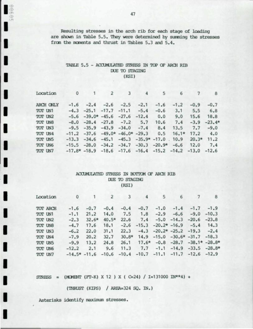
47
Resulting stresses in the arch rib for each stage of loading are shown in Table 5. 5. '!hey were determined by SU1'IIlin:J the stresses fran the nanents and thrust in Tables 5. 3 and 5. 4.
I.ocatioo
AROI rnLY ror lM ror W2 ror ~8 ror UN3 ror ~4 ror UN5 ror UN6 ror UN7
I.ocatioo
ror AROl ror UNl ror UN2 ror UN8 ror UN3 ror UN4
TABLE 5. 5 - ACXlMJLATED smESS IN TOP OF AROI RIB OOE oro STAGING
(KS1)
0 1 2 3 4 5 6
-1.6 -2 . 4 -2 . 6 -2 . 5 -2 . 1 -1.6 -1.2 -4 . 3 -25 . 1 -17 . 7 -11.1 -5 . 4 -0 . 6 3.1 -5.6 -39 . 0* -45 . 6 -27.6 -12.4 0.0 9.0 -8 . 0 -28 . 4 -27 . 8 -7 . 2 5. 7 10 . 6 7. 4 -9 . 5 -35 . 9 -43 . 9 -34.0 -7.4 8. 4 13.5
-11 . 2 -37 . 6 -49 . 0* -46.0* -29 . 3 0. 5 16 . 1* -13 . 3 -34 . 6 -45 . 1 -45 . 3 -35 . 9* -17 . 0 10. 9 -15 . 5 -28 . 0 -34 . 2 -34 . 7 -30 . 3 -20 . 9* -6 . 6 -17.8* -18.9 -18.6 -17 . 6 -16 . 4 -15.2 -14.2
J\CCl.MJIATED smESS IN OOl'lCM OF AROI RIB OOEoro~
(KSI)
0 1 2 3 4 5 6
-1 . 6 -0 . 7 -0 . 4 -0 . 4 -0 .7 -1 . 0 -1.4 - 1. 1 21.2 14 . 0 7. 5 1. 8 -2 . 9 -6 . 6 -2 . 3 32 . 6* 40 . 5* 22 . 6 7. 4 -5 . 0 -14 . 3 -4 . 7 17. 6 18 .1 -2 . 6 -15 . 3 -20 . 2* -16.9 -6 . 2 22 . 0 31.1 22 . 3 -4 . 3 -20 . 2* -25.2
7
-0 . 9 5. 5
15. 6 -3 . 9 7. 7
17.2 20 . 3* 12 . 0
-13 . 0
7
-1 . 7 -9.0
-20 . 6 -5 . 4
-19 . 3 -7 . 9 20 . 2 32 . 7 30 . 8* 14 . 9 -15 . 0 -30.6* -31 . 7
8
-0.7 6. 8
18.8 -23.4* -9.0 4.0
11.2 7. 4
-12 . 6
8
-1.9 -10 . 3 -23 . 8 14 . 3 -2 . 4
-18.3 ror UN5 -9 . 9 13 . 2 24 . 8 26 . 1 17 . 6* -0 . 8 -28 . 7 -38 . 1* -28 . 8* ror UN6 -12 . 2 2.1 9. 6 11.3 7.7 - 1.1 -14.9 -33.5 -28 . 8* ror UN7 -14.5* -11 . 6 -10 . 6 -10 . 4 -10.7 -11.1 -11.7 -12.6 -12 . 9
smESS = (1OIENl' (FT-K) X 12 ) X ( C=24) / 1=131000 IN**4) +
('lllRUST (KIPS) / ARFA=324 SO. IN . )
Asterisks identify maxiJI1l.I1l stresses .
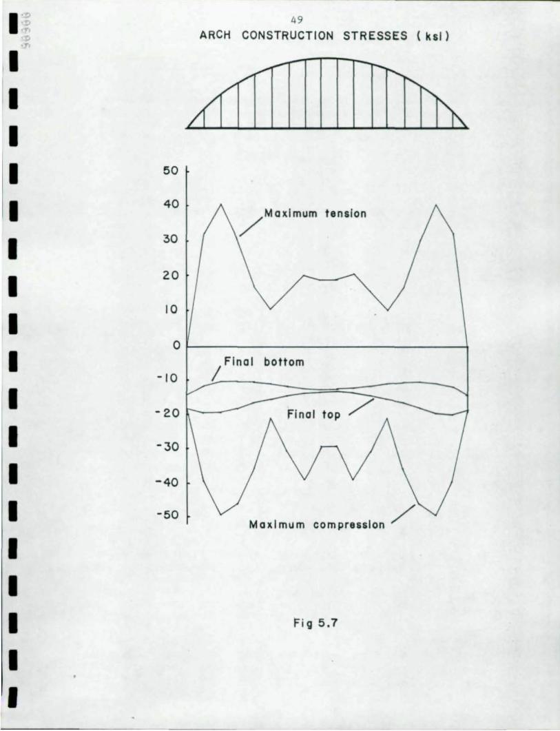
48
Figure 5.7 sl1a.Is the stress envelope of maximum tensile and maximum CXlI1Pressive stresses in the arch rib during placanent of the deck units. The envelopes are based on Table 5.5. They daronstrate the critical locations. The unfactored stress in both top and botton of the arch rib approach the yield stress so the sectioo of the arch rib co..Jld be increased, or the erectioo sequence might be IrOdified to lower stresses. A factor of safety of at least 1.25 would be expected. Stresses in the arch rib after all deck units have been placed are plotted on the sane figure for CXJI1Parison. The thrust is seen to be about 15 ksi while the bending stress does not exceed 10 ksi. DJring staging, rranent daninated the loading over thrust. The parabolic shape of the arch ribs keeps bending to a minimum when loads are applied unifonnly along the span.
Alth0J9h it is not practical to lift two units at owosite eros of the span simultaneaJ.sly, no analysis was perfonned to consider single units placed in an unsyrrmetrical manner. It is thought that sane error shculd be permitted in simultaneaJ.sly lifting two units. The effect of this error can- easily be determined and shoold be considered when determining a factor of safety. Another (Xlssibility is to join two units prior to lifting. 1hl.s would permit using the hanger locatioos to attach the hoist cables without the units beccming unstable or introducing a different han)er arrangement.
5.3.3 SUperinp)sed Dead Load
'!he superinp)sed dead load is CXJT1POsed of the wearing surface and barriers. Results for rranent and thrust are presented in Tables 5.6 and 5.7 , respectively. 'furust is large with respect to the rranent CXJI1Pared to the staging results. '!his is expected for loads applied unifonoly along the span.
I I I I I I I I I I I I I I I I I I I
I '~ ;; .-:>
49
ARCH CONSTRUCTION STRESSES (ksl)
I I I I 50
I 40
I 30
/MaXlmum tension
I 20
I 10
0
I -10
Final bottom /
I -20 Final top /
I -30
I -40
I -50 Maximum compression /
I I I r i g 5.7
I I
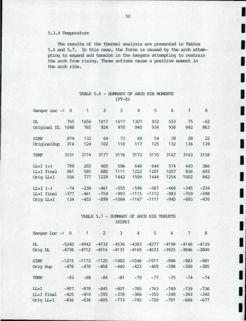
50 I 5.3.4 Tarpmiture I
'lhe results of the thental analysis are presented in Tables I 5.6 and 5. 7. In this case, the force is caused by the arch attan-pting to expand and tension in the ~ers attanptil'¥1 to restrain
I the arch fran rising. 'lhese actions cause a positive rranent in the arch ribs .
I TABLE 5.6 - Sl»lARY OF ARCH RIB t-nlENl'S I (Fr-K)
Han:Jer I£x:: -) 0 1 2 3 4 5 6 7 8 I DL 755 1656 1817 1617 1307 932 553 75 -62
I original DL 1048 765 924 970 940 934 936 842 863
SIMP 874 132 64 73 68 54 39 28 22
I originalSUp 314 124 102 110 117 125 132 136 139
TEMP 3151 3174 3177 3176 3173 3170 3167 3163 3159
I IL+I (+) 799 202 409 596 648 644 574 443 386 IL+I final 961 585 880 1111 1222 1201 1057 836 693
I orig IL+I 556 777 1229 1442 1509 1444 1254 1002 842
IL+I (-) -74 -238 -461 -555 -596 -561 -468 -345 -234
I IL+I final -377 -461 -754 -993 -1115 -1112 -983 -759 -598 orig IL+I 134 -455 -899 -1084 -1167 -1111 -945 -693 -476
I TABLE 5. 7 - Sl»1ARY OF ARCli RIB 'lllRusrs
(KIPS)
I Han:Jer I£x:: -) 0 1 2 3 4 5 6 7 8
DL -5240 -4942 -4732 -4536 -4383 -4277 -4198 -4146 -4129 I orig DL -4736 -4712 -4516 -4131 -4169 -4033 -3925 -3846 -3800
SIMP -1215 -1172 -1125 -1082 -1046 -1017 -998 -983 -981 I orig Sup -476 -476 -458 -440 -423 -409 -398 -390 -385
TEMP -93 -88 -84 -81 -79 -77 -75 -74 -74 I IL+I -907 -878 -845 -801 -785 -763 -749 -739 -736 I LL+I final -425 -410 -393 -378 -366 -355 -349 -343 -342 orig IL+I -836 -836 -805 -773 -745 -720 -701 -686 -677
I
I I I I I I I I I I I I I I I I I I
51
'n1e appropriate temperature range to be used is a qualitative matter to be oonsidered in design which is beyood the srope of this study. However, it is s~gested that 100 degrees is excessive. 'n1e range would depend 00 the oolor of the metal parts and 00
the env:irorJrent.
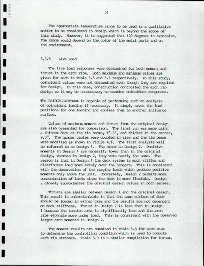
5 . 3. 5 Live Lead
'n1e live load responses were determined for both nonent and thrust in the arch ribs . Both maxinun and mininun values are given for each in Table 5.5 and 5 . 6 respectively . In this study, ooincident values were not detel:mi.ned even though they are required for design . In this case, ooostruction oontrolled the arch rib design so it may be unnecessary to examine ooincident resp:xlSeS.
'n1e BRIIXiE-SYS'l»1sm is capable of performir¥J such an analysis of ooincident loadir¥J if necessary. It simply saves the load positions for ooe Ioadil'¥) and awlies than to another influence surfaoe .
Values of maxirm.Jn nonent and thrust fran the original design are also presented for canparisoo . 'n1e final run was made usirv; a thinner deck at the tie beams , 1 ' -3", and thicker in the center , 9. 0" • '!be han;jer cables were doobled in size and the tie beams were IIOdified as shown in Figure 4. 1 . 'n1e first analysis will be referred to as Design 1. 'n1e other as Design 2. Positive nonents in Design 1 are generally lower than in the original design , whereas in Design 2, they were nearly the same . 'n1e reasoo is that in Design 1 the deck systan is llllch stiffer and distribJtes load more evenly CNer the han;jers . nus is ooosistent with the observatioo of the stagir¥J loads which produoe positive nonents only above the unit . Cbnversely , Design 2 permits more ooncentration of loads since the deck is more flexible . Design 2 closely awroximates the original design values in both senses.
'Ilu:usts are similar between Design 1 and the original design. nus result is understandable in that the same surfaoe of deck shalld be loaded in either case and the results are not dependent 00 deck stiffness . 'Ilu:ust in Design 2 is less than in Design 1 because the tensioo area is Significantly less and the arch ribs elcogate more under load . nus is oonsistent with the observed larger arch nonents in Design 2.
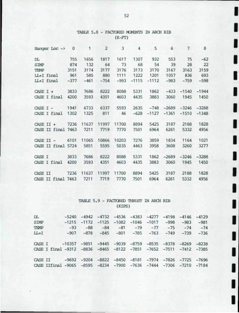
'n1e nonent results are ocrnbined in Table 5.8 for each case to detel:mi.ne the oontrollir¥J oorditioo which is used to canpute arch rib stresses . Table 5. 9 is a similar canpilatioo for thrust .
52 I
TABIE 5. 8 - FACImEIl fo01ENl'S IN AROi RIB I (K-FT)
I Hanger Loc -) 0 1 2 3 4 5 6 7 8
DL 755 1656 1817 1617 1307 932 553 75 -62 I SIMP 874 132 64 73 68 54 39 28 22 TEMP 3151 3174 3177 3176 3173 3170 3167 3163 3159
I LL+I final 961 585 880 1111 1222 1201 1057 836 693 LL+I final -377 -461 -754 -993 -1115 -1112 -983 -759 -598
CASE I + 3833 7686 8222 8088 5331 1862 -433 -1540 -1944 I CASE I final 4200 3593 4351 4603 4435 3883 3060 1945 1450
CASE I - 1941 6733 6337 5593 2635 -748 -2689 -3246 -3288 I CASE I final 1302 1325 811 46 -628 -1127 -1361 -1510 -1348
CASE II + 7236 11637 11997 11700 8894 5425 3187 2188 1828 I CASE II final 7463 7211 7719 7770 7501 6964 6261 5332 4956
CASE II - 6101 11065 10866 10203 7276 3859 1834 1164 1021 I CASE II final 5724 5851 5595 5035 4463 3958 3608 3260 3277
CASE I 3833 7686 8222 8088 5331 1862 -2689 -3246 -3288 I CASE I final 4200 3593 4351 4603 4435 3883 3060 1945 1450
CASE II 7236 11637 11997 11700 8894 5425 3187 2188 1828 I CASE II final 7463 7211 7719 7770 7501 6964 6261 5332 4956
I TABLE 5.9 - FACl'CRED 'ffiRUSl' IN AROi RIB I (KIPS)
DL -5240 -4942 -4732 -4536 -4383 -4277 -4198 -4146 -4129 I SIMP -1215 -1172 -1125 -1082 -1046 -1017 -998 -983 -981 TEMP -93 -88 -84 -81 -79 -77 -75 -74 -74 LL+I -907 -878 -845 -801 -785 -763 -749 -739 -736 I CASE I -10357 -9851 -9445 -9039 -8759 -8535 -8378 -8269 -8238 CASE I final -9312 -8836 -8465 -8122 -7851 -7652 -7511 -7412 -7385 I CASE II -9692 -9204 -8822 -8450 -8181 -7974 -7826 -7725 -7696 CASE IIfinal -9065 -8595 -8234 -7900 -7636 -7444 -7306 -7210 -7184 I
I I
I I I I I I I I I I I I I I I I I I
53
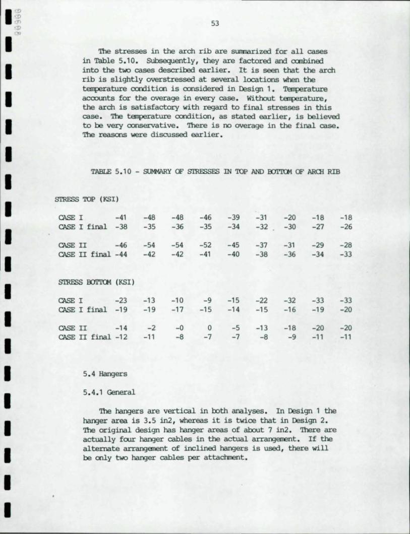
'!be stresses in the arch rib are sumnarized for all cases in Table 5.1 0 . Subsequently , they are factored and canbined into the two cases described earlier. It is seen that the arch rib is slightly overstressed at several locations when the teIJllerature CCI1ditioo is oonsidered in Design 1. Temperature acoounts for the overage in every case . Without temperature , the arch is satisfactory with regard to final stresses in this case . '1be temperature CCI1dition , as stated earlier, is believed to be very oonservative . 'Ihere is no overage in the final case. '1be reasons were discussed earlier.
TABLE 5 . 10 - S!M11\R¥ OF S'IRESSFS IN 'lQP AND OOI"ltJl1 OF AROl RIB
S1RESS'lQP (KS1)
cr.sE I -41 -48 -48 -46 -39 -31 -20 -18 CASE I final -38 -35 -36 -35 -34 -32 -30 -27
cr.sE II -46 -54 -54 -52 -45 -37 -31 -29 CASE II final -44 -42 -42 -41 -40 -38 -36 -34
S1RESS 00l'KM (KSI)
cr.sE I -23 -13 -10 -9 -15 -22 -32 -33 cr.sE I final -19 -19 -17 -15 -14 -15 -16 -19
cr.sE II -14 -2 -0 0 -5 -13 -18 -20 CASE II final -12 -11 -8 -7 -7 -8 -9 -11
5 . 4 Hangers
5 . 4 . 1 General
'1be hangers are vertical in both analyses . In Design 1 the hanger area is 3 . 5 in2 , whereas it is twioe that in Design 2 . '1be original design has hanger areas of about 7 in2 . '1bere are actually foor hanger cables in the actual arran::jement . If the alternate arran::jement of inclined hangers is used , there will be ooly two hanger cables per attachrent.
-18 -26
-28 -33
-33 -20
-20 -11
54
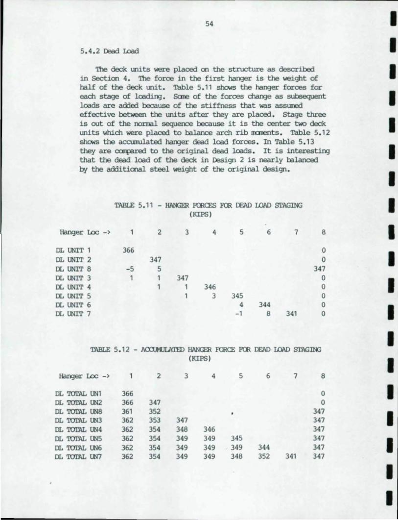
5.4.2 Dead Load
'!he deck \IDits were placed 00 the stnx::ture as described in Sectioo 4. '!he force in the first harger is the weight of half of the deck \IDit . Table 5.11 sOOws the harger forces for each stage of loadirq. sane of the forces cha.n:Je as subsequent loads are added because of the stiffness that was assured effective between the \IDits after they are placed . stage three is out of the ncmnal sequence because it is the center two deck \IDits which were placed to balance arch rib lOCIlleIlts . Table 5. 12 sOOws the accumulated I'la.rqer dead load forces . In Table 5 . 13 they are carpared to the original dead loads . It is interestirq that the dead load of the deck in Design 2 is nearly balanced by the additiooal steel weight of the original design.
Har;;er I.oc - >
DL UNIT 1
DL UNIT 2
DL UNIT 8 DL UNIT 3 DL UNIT 4 DL mIT 5 DL UNIT 6 DL mIT 7
TABLE 5. 11 - HANGER FCRCES FeR DEAD LOAD STlIGING (KIPS)
1
366
-5 1
2
347 5 1 1
3
347 1 1
4
346 3
5
345 4
-1
6
344 8
7
341
8
o o
347 o o o o o
TABLE 5. 12 - ACXl.MJLATED HANGER FeRCE FCR DEAD LOAD STAGING (KIPS )
Har;;er I.oc - >
DL 'lUI'AL UN1 DL 'lUI'AL lN2 DL 'lUl'AL UN8 DL 'lUI'AL lN3 DL 'lUI'AL UN4 DL 'lUI'AL UN5 DL 'lUI'AL UN6 DL 'lUI'AL 1N7
1
366 366 361 362
362 362 362 362
2
347 352 353 354 354 354 354
3
347 348 349 349 349
4
346 349 349 349
5
345 349 348
6
344 352
7
341
8
o o
347 347 347 347 347 347
I I I I I I I I I I I I I I I I I I I
I I I I I I I I I I I I I I I I I
55
5 . 4 . 3 Superinp:>sed Dead Load
'nle hanger forces are nearly equal exoept for the ooe closest to the arch rib which is slightly less than the others because the berrling stiffness of the tie beam transmits sane of the load directly to the supports .
'nle superimposed dead load is different fran the original design because the barriers were not considered in the superimposed dead load of the original design .
5 . 4. 4 Temperature
'nle results are equal for all rut the first hanger . 'nle force is a result of the arch attempting to lift upward . 'nle upward novanent is approximately proportional to the stiffness of the deck unit. 'nle force in the first hanger is larger for the sane reason that the first hanger foroe was smaller in the superinp:>sed dead load case .
5 . 4 . 5 Live Load
Live load was found to be oontrolled by lane load rather than vehicle load. 'nle triOOtary area may be larger in the alternate deck than for the original design where the stress relief joints tend to limit the trirutary area . Also, the tie beam in the original design was less rigid . However , the differences bet.....een the alternate am original designs are not large.
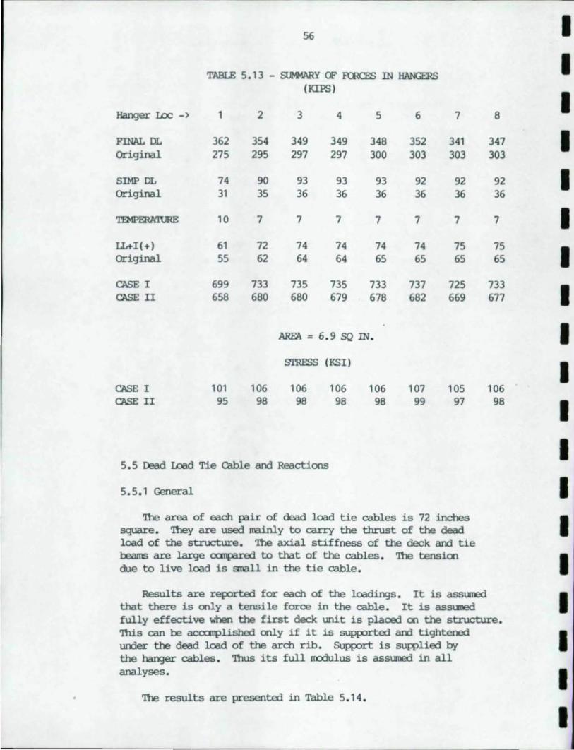
Hanger Loc -)
FINAL DL Original
SIMP DL Original
lL+I(+) Original
CASE I CASE II
CASE I CASE II
56
TABLE 5. 13 - SlMlARY CF F'CRCES IN HANGE&S (KIPS)
1
362 275
74 31
10
61 55
699 658
101 95
2
354 295
90 35
7
72 62
733 680
106 98
3
349 297
93 36
7
74 64
735 680
4
349 297
93 36
7
74 64
735 679
5
348 300
93 36
7
74 65
733 678
AREA = 6. 9 SO IN.
S'ffiESS (KSI)
106 98
106 98
106 98
6
352 303
92 36
7
74 65
737 682
107 99
5 . 5 Dead IDad Tie Cable and Reactions
5. 5. 1 General
7
341 303
92 36
7
75 65
725 669
105 97
'!he area of each pair of dead load tie cables is 72 inches square . '!hey are used mainly to carry the thrust of the dead load of the structure . '!he axial stiffness of the deck and tie beams are large canpared to that of the cables . '!he tensioo due to live load is small in the tie cable.
8
347 303
92 36
7
75 65
733 677
106 98
Results are reported for each of the loadir¥Js. It is assuned that there is ally a tensile force in the cable . It is assuned fully effective when the first deck unit is placed 00 the structure. 'Ibis can be accc:rrplished ally if it is supported and tightened under the dead load of the arch rib . Support is supplied by the harY:)er cables . '!hus its full rrodulus is assuned in all analyses .
'!he results are presented in Table 5. 14 .
I I I I I I I I I I I I I I I I I I I
I'~
.~ ... I I I I I I I I I I I I I I I I I I
. ~ 57
5.5.2 StaginJ of the Deck. Units
'!he individual and aocumulated results are reported for each stage of loadirg. '!he results are linear and additive in the dead load tie cable and reactions.
5.5.3 Superimposed Dead Load
Superimposed dead load thrust is carried by both the tie cable and the deck units. }b,o,1ever the COl'ICI'ete is assumed to be ally Cl'le-third as stiff as for the live load and ~ature analyses. '!he reactiCl'l in:licates that the alternate design is slightly heavier than the original design.
5.5.4 Temperature
'!he ass~tiCl'l for this load caused the arch and tie cable to beoane lCX'¥jer. '!his caused a reductiCl'l in the dead load force in the tie cable. '!his load is shown as an increase in the tensile force in the deck and as increased bendinJ nanent in the arch ribs. '!he ~ature difference of 100 degrees Fahrenheit was rather arbitrary, rut not unreasonable. I.engthenirg of the hargers also occurred due to the ~ature charge. '!his had a tendency to rroderate the uplift Cl'l the deck due to the raisirg of the arch ribs.
5.5.5 Live Load
Live load causes maximum thrust in the tie cable when the thrust in the arch ribs are maximum and positive nanent in the arch is maximum. '!here is no live load that can cause a reductiCl'l in the cable tension. Cable thrust is also maximum when the reaction is naximum. '!hus, the same live loadinJ is applied for each response. It is interestirg to note that the ratio of cable thrust to reaction force is greater for superimposed dead load than for live load. '!he reaSQ'l for this is that the tensile stiffness of the concrete in the deck units is greater for live load than for superimposed dead load. '1hus, the deck is assigned a larger portion of the live load than it is for the superimposed dead load.
It is interestinJ to note that the reaction is the same as in the original design.
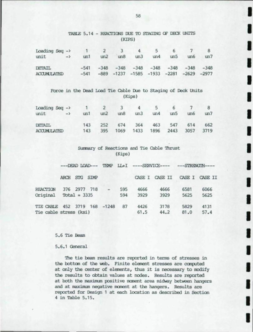
58
TABLE 5.1 4 - REACl'IOOS OOE TO STAGING (F DID< UNITS (KIPS)
Loadi1'¥] Seq - > 1 2 3 4 5 6 7 8 unit -> unl un2 un8 un3 un4 un5 un6 un7
Df:l'AIL -541 -348 -348 -348 -348 -348 -348 -348 J\al.IM.JIATED -541 -889 -1237 -1585 -1933 -2281 -2629 -2977
Force in the Dead Load Tie cable D.le to stagi1'¥] of Deck Units (Kips)
Toad; 1'¥] Seq - > 1 2 3 4 5 6 7 8 unit -> unl un2 un8 un3 un4 un5 un6 un7
lEl'AIL 143 252 674 364 463 547 614 662 ACXlMJLATED 143 395 1069 1433 1896 2443 3057 3719
SuIl1nary of Reactions am Tie cable 'l11rust (Kips)
---DEAD LOAD--- TEMP LLt-I ----SERVICE---- ---S'I'RENGIH----
l\RClI STG SIMP CASE I CASE II CASE I CASE II
RFACrIOO 376 2977 718 595 4666 4666 6581 6066 Original Total = 3335 594 3929 3929 5625 5625
TIE CABLE 452 3719 168 -1248 87 4426 3178 5829 4131 Tie cable stress (ksi) 61.5 44.2 81.0 57 . 4
5.6 Tie Beam
5.6.1 General
'1lle tie beam results are reported in terms of stresses in the botton of the web. Finite element stresses are ocmputed at only the center of elements, thus it is necessary to rrodify the results to obtain values at nodes. Results are reported at both the maximum positive m:::ment area midway between har¥Jers am at maxinum negative m:::ment at the har¥Jers . Results are reported f= Design 1 at each location as described in Section 4 in Table 5.15 .
I I I I I I I I I I I I I I I I I I I
I '~ • !:I .'f') .... ......
I I I I I I I I I I I I II I I I I I
59
'fue dead load results were recanputed by harrl. 'fue values for the tie beam are not cx:rnpared to the original design values because the dead load tie cable causes significant differences in behavior in the alternate design cx:rnpared to the original.
Canplete results for Design 2 are reported in Tables 5.16 and 5.17.
5.6.2 Dead Load
The stress for maximum and positive dead load rrarent was canp.lted using the IT'Cldel shown in figure 5.8.
5.6.3 Temperature
Stresses in the oottan of the tie beam web at the hanger are reported as the average of the stresses in the two elements on each side of that hanger. Results in the center element between angers was used for the center lcx:ation.
/1:)st of the tie beam is in tension. Ibwever, it is of interest to note that the beam undergoes c:anpression in the center of the span. 'lttis is caused in part by the arch rib lifting the tie beam enoogh to overoane the tension due to thrust. Since the arch is rrore vertical near the ends of the span, its thermal expansion gives a upward berrl near the ends which introduces a positive rrarent in the tie beam. 'lttis produces a tensile stress in the oottan which is additive to the thrust stress. In the center of the span the negative berrling rrarent produces c:anpression in the oottan that overoanes the tensile stress due to thrust. 'fue hanger forces are equal except for the first hanger fran the support.
5.5 Superimposed Dead Load
SUperimposed dead load, like the thennal loading, mainly applies tensile force in the tie beam . At no lcx:ation is there a canpressive stress reported in the oottan of the tie beam. stresses reported have been determined in the same manner as the thermal analySis.
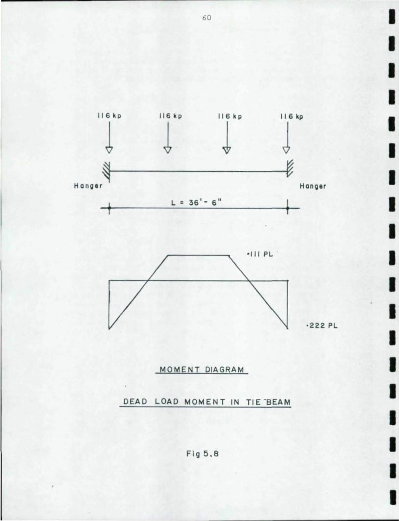
116 kp
l ~
Hang. r
t
60
116 kp 116 k p 116 kp
l J J ~
Hanger
L: 36'- 6" ~
-III PL
·222 PL
MOMENT DIAGRAM
DEAD LOAD MOMENT IN TIE -SEAM
Fig 5.8
I I I I I I I I I I I I I I I I I I I
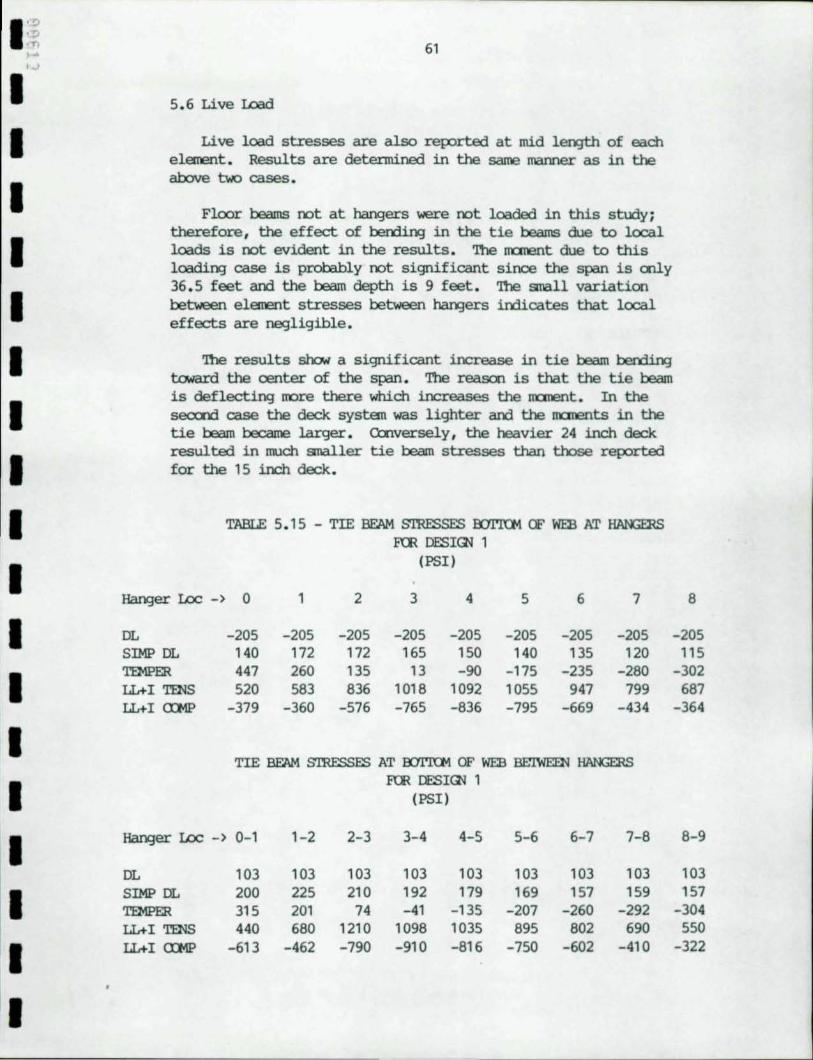
I ::; .r, ....
I I I 1 I I I I I I I I I I I I I I
' .... 61
5 . 6 Live Load
Live load stresses are also reported at mid ler¥Jth of each element . Results are determined in the same manner as in the above t\oIO cases.
Floor beams not at hangers were not loaded in this study; therefore , the effect of berrling in the tie beams due to local loads is not evident in the results . The aanent due to this loading case is protably not significant since the span is cnly 36 . 5 feet and the beam depth is 9 feet . '!he small variation beb.>een element stresses beb.>een hangers indicates that local effects are negligible.
'!he results show a significant increase in tie beam bending toward the center of the span . '!he reasoo is that the tie beam is deflecting more there which increases the m::ment. In the secood case the deck system was lighter and the m::ments in the tie beam becarre larger . Ccnversely , the heavier 24 inch deck resulted in much smaller tie beam stresses than those reported for the 15 inch deck.
TABLE 5 . 15 - TIE BEAM S'rnESSES roI'KM OF WEB AT ~ FeR DESI~ 1
(PSI)
Hanger Lee -) 0 1 2 3 4 5 6 7
DL -205 -205 -205 -205 -205 -205 - 205 -205 SIMP DL 140 172 172 165 150 140 135 120 TEMPER 447 260 135 13 -90 -175 -235 -280 LL+I TENS 520 583 836 1018 1092 1055 947 799 LL+I m1P -379 -360 -576 -765 -836 -795 -669 -434
TIE BEAM S'ffiESSES AT oorn::M OF WEB BE'IWEEN HANGERS FeR DESI~ 1
(PSI )
Hanger Lee -) 0-1 1-2 2-3 3-4 4-5 5-6 6-7 7-8
DL 103 103 103 103 103 103 103 103 SIMP DL 200 225 210 192 179 169 157 159 TEMPER 315 201 74 -41 - 135 -207 -260 -292 LL+I TENS 440 680 1210 1098 1035 895 802 690 LL+I m1P -613 -462 -790 -910 -816 -750 -602 -410
8
-205 115
-302 687
-364
8-9
103 157
-304 550
- 322
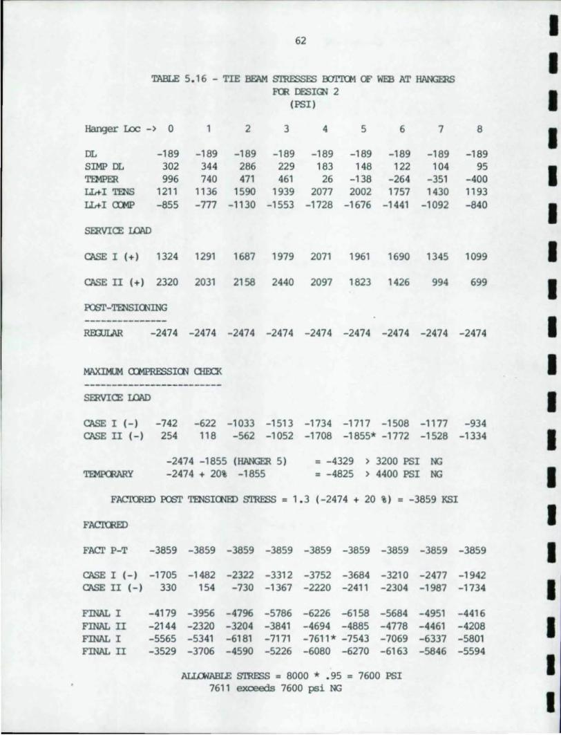
I 62
I TABLE 5.16 - TIE BEAM S'rnESSES Wl'ltM CF WEB AT H1INGEltS
Frn DESI~ 2 I (PSII
Hanger Loc -) 0 1 2 3 4 5 6 7 8 I DL -189 -189 -189 -189 -189 -189 -189 -189 -189 SIMP DL 302 344 286 229 183 148 122 104 95
I TEMPER 996 740 471 461 26 -138 -264 -351 -400 LL+I TENS 1211 1136 1590 1939 2077 2002 1757 1430 1193 LL+I mn> -855 -777 -1130 -1553 -1728 -1676 -1441 -1092 -840 I SERVICE I£lAD
CASE I (+1 1324 1291 1687 1979 2071 1961 1690 1345 1099 I CASE II (+1 2320 2031 2158 2440 2097 1823 1426 994 699 I POST-TENSICNING --------------- I REXm.AR -2474 -2474 -2474 -2474 -2474 -2474 -2474 -2474 -2474
MAXlMJM crMPRESSI(]II 0i0CK I -------------------------SERVICE I£lAD I CASE I (-) -742 -622 -1033 -1513 -1734 -1717 -1508 -1177 -934 CASE II (-I 254 118 -562 -1052 -1708 -1855* -1772 -1528 -1334 I
-2474 -1855 (HANGER 51 = -4329 ) 3200 PSI NG 'I'EMP(EARY -2474 + 20% -1855 = -4825 ) 4400 PSI NG I
FACICmD POST TENSI(]IIE[) S'ffiESS = 1.3 (-2474 + 20 %1 = -3859 KSI
FJ\CIUm) I FACl' P-T -3859 -3859 -3859 -3859 -3859 -3859 -3859 -3859 -3859 I CASE I (-) -1705 -1482 -2322 -3312 -3752 -3684 -3210 -2477 -1942 CASE II (-I 330 154 -730 -1367 -2220 -2411 -2304 -1987 -1734 I FINAL I -4179 -3956 -47% -5786 -6226 -6158 -5684 -4951 -4416 FINAL II -2144 -2320 -3204 -3841 -4694 -4885 -4778 -4461 -4208 I FINAL I -5565 -5341 -6181 -7171 -7611* -7543 -7069 -6337 -5801 FINAL II -3529 -3706 -4590 -5226 -6080 -6270 -6163 -5846 -5594
I ALLOWABLE STRESS = 8000 * .95 = 7600 PSI 7611 evceecls 7600 psi NG
I
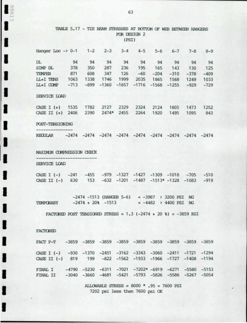
I '~ 63 ... . , I TABLE 5.17 - TIE BEAM STRESSES Nr a:YrrQ.1 CF 1m3 BE'l"IIDl ~
RR lESIrn 2
I (PSI)
Hanger I.oc -> 0-1 1-2 2-3 3-4 4-5 5-6 6- 7 7-6 6-9
I DL 94 94 94 94 94 94 94 94 94 SIMP DL 376 350 267 236 195 165 143 130 125
I TEMPER 671 606 347 126 -60 - 204 -310 -376 -409 LL+I TENS 1063 1336 1746 1999 2035 1665 1566 1249 1033 LL+I CXMP -713 -699 -1360 -1657 -1716 -1566 -1255 -929 - 729
I srnVICE LOAD
I CASE I (+) 1535 1762 2127 2329 2324 2124 1605 1473 1252 CASE II (+) 2406 2390 2474* 2455 2264 1920 1495 1095 643
I POST-TENSIrnING -------------RmJLAR -2474 -2474 -2474 -2474 -2474 -2474 -2474 -2474 -2474
I MAXIK.M a:MPRESSICN rnEO<
I -------------------------srnVICE LOAD
I CASE I (-I -241 -455 -979 -1327 -1427 -1309 -1016 -705 -510 CASE II (-) 630 153 -632 -1201 -1467 -1513* -1326 -1063 -919
I -2474 -1513 (HANGER 5-6) = -3967 > 3200 PSI NG
I 'l'EMPCEARY -2474 + 20% -1513 = -4462 > 4400 PSI NG
FACKRID POST TENSICNED S'rnESS = 1.3 (-2474 + 20 %) = - 3659 KSI
I FACKRID
I FAcr P-T -3659 -3659 -3659 -3659 -3659 -3659 -3659 -3659 - 3659
I CASE I (-) -930 -1370 -2451 -3162 -3343 -3060 -2411 -1721 -1294 CASE II (-I 619 199 -622 -1562 -1933 -1966 -1727 -1406 -1194
I FINAL I -4790 -5230 -6311 -7021 -7202* -6919 -6271 -5560 -5153 FINAL II -3040 -3660 -4661 -5421 -5793 -5626 -5566 -5267 -5054
I ALLOWABLE S'rnESS = 6000 * .95 = 7600 PSI
7202 psi less than 7600 psi OK
I
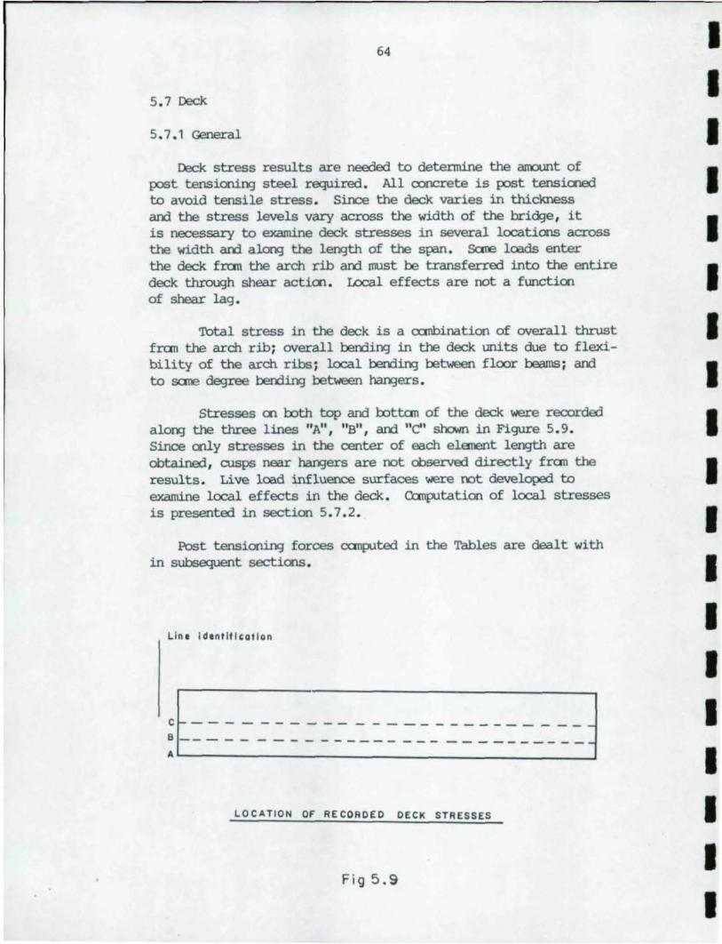
64
5.7 Deck
5.7.1 General
Deck stress results are needed to detennine the arrount of post tensionin:] steel required. All ooncrete is post tensiooed to avoid tensile stress. Since the deck varies in thickness arrl the stress levels vary across the width of the bridge, it is necessary to examine deck stresses in several locatiCX'lS across the width arrl al.cn3 the length of the span. Sane loads enter the deck fran the arch rib arrl must be transferred into the entire deck through shear actien. Local effects are not a functien of shear lag.
Total stress in the deck is a <XIl\bination of overall thrust fran the arch rib; overall berrling in the deck units due to flexibility of the arch ribs; local berrling between floor beams; arrl to sane degree bendiI¥J between han;jers.
Stresses en I::oth top arrl I::ottan of the deck were recorded aloo:; the three lines "A", "B", arrl "en shc1Hn in Figure 5.9. Since cnly stresses in the center of each element length are obtained, cusps near ha.rBers are not observed directly fran the results. Live load influence surfaces were not developed to examine local effects in the deck. Canp.ltation of local stresses is presented in section 5.7.2.
Post tensionID) forces c:anp.lted in the Tables are dealt with in subsequent sectiCX'lS.
Lin. Idontlfl,atlan
LOCATION OF RECORDED DECK STRESSES
Fig 5.9
I I I I I I I I I I I I I I I I I I I
1':::-, r, 1-
I I I I I I II II I I I I I I I I I I
65
5.7.2 Local Effects
'llie local beOOing due to live and dead loads is ccmputed:
o:ntinuoos Span = 12'-2" = 12.17 ft
Dead lDad /obnent: Deck 'lhlckness = 9.0 in. Density o:ncrete = 0.150 k/cuft Future Wearing Surface = 0.030 ksf
W = 0.150(0.75) + 0.030 = 0.142 k/ft
Dead I.Dad /obnent = 1 WL = 1 (0.142)(12.17)(12.17) = 1.75 K-ft 12 12
HS20 Live lDad /obnent = 0.900L K-ft for simple span AASHTO 3.2.33 (For o:ntinuous Span Use 80 percent of the simple span value). M = (0.80)(0.900)(12.17) = 8.76 K-ft
Secticn M::ldulus of Deck
I = 1 bt = 1(1)(0.75) = 0.0351 ft 12 12
S = I/(t/2) = 0.0351/0.375 = 0.09375 ft
Dead I.Dad stress
f = M/s = 1.75/0.09375 = 18.66 ksf = 130 psi
Live I.Dad stress incllrling 30 percent impact
f = 1.30(8.76/0.09375) = 121.50 ksf = 844 psi
'lbtal Local Deck stress = 130 + 844 = 974 psi
For deck thickness = 1.25 ft:
W = 0.150(1.25) + 0.030 = 0.2175k/ft
s = 1 bt = 1(1.0)(1.25) = 0.260 ft 6 6
Dead lDad /obnent = 1 WL = 1(0.2175)(12.17) = 2.68 K-ft 12 12
Dead lDad stress = 2.68/0.260 = 10.32 ksf = 72 psi
f Live I.Dad = 1.30(8.76/0.260) = 43.80 ksf = 304 psi
'lbtal Local Deck Stress = 72 + 304 = 376 psi
66
Deck stresses are reported in Tables 5.18 through 5.23. '!he discussion below relates to these tables. '!he tables are broken into two parts so that the locations at the l'la.rBers arrl between the l'la.rBers may be reported clearly. The tanperature arrl superimposed runs were not observed to be different enough to warrant the use of different values in positive arrl negative m::ment areas of the deck.
The results for superimposed dead load arrl temperature runs are shown in Figures 5.10, 5.11 an::! 5.1 2 . Stresses are plotted for the entire bridge width for each oorxlition. In each figure there is a plot of the stress at the em of the span, the quarterpoint arrl the mid-point of the span. Figures 5.1 0 arrl 5.11 shc7.I stresses in the top of the deck for DeSign 1 arrl 2, respectively. Figure 5.12 shows stress levels in the bottom of the deck for Design 2.
5.7.3 Dead Load
Dead load stress due to the weight of the units is ClCITp.lted as if the structure was canpleted before the dead load was placed on the structure. '!he deck is not affected by thrust or overall beOOing due to its own weight since the dead load tie cable carries thrust fran the arch rib arrl the deck units are not attached to the arch ribs at that tiIre.
5.7.4 Superimposed Dead Load
Superimposed dead load is applied after the deck units have becane part of the integrated structure. It may be thought of as having two ~ts; the thrust arrl the local beOOing. '!he stresses reported are results of the oenter element between l'la.rBers. '!he one exception is the stress at the arch rib. 'Ibis value is the stress in the element closest to the arch. '!he oenter element is used because it is at the max:iJlulm positive m::ment location with respect to local berxling. All values represent a CXI1lbination of the two canponents; thrust arrl local effects.
The results show clearly that the thrust is the daninate cullpollent. At the em of the span, the stress is highest where the thrust enters the deck. In the middle of the deck, the stress is small. At the quarter point arrl at mid-span the stress is much lower in Line "A" than at the other locations. 'Ibis is due to the thicker deck at these points. Shear has distribJted the thrust rather uniformly over the deck by the quarter-point.
I I I I I I I I I I I I I I I I I I I
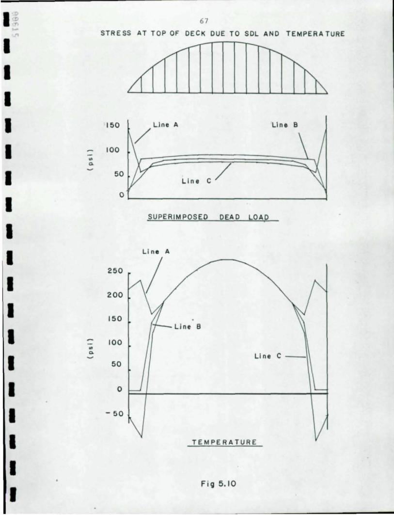
I ~ ... "
I I I I I I I I I I I I I I I I I I
.. 0. ~
67
STRESS AT TOP OF DECK DUE TO SOL AND TEMPERATURE
150 A LIne B
100
50 Line C /
O~ ______________________________ ~
SUPE'RIMPOSED DEAD LOAD ,
LI ne A
250
200 /
150 , ..,...~ Llne 8
100
Line C --·\1 50
o
- 50
TEMPERATURE
Fig 5.10
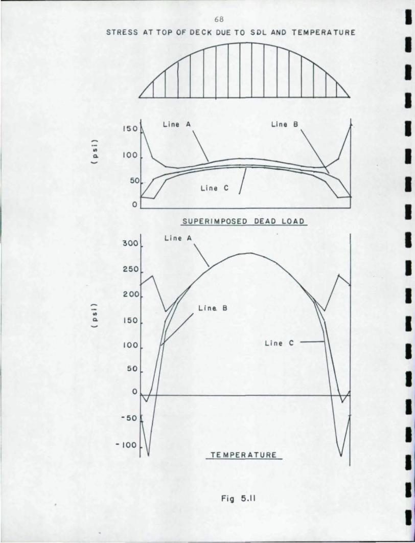
~ .. 0-~
~ -.. 0-~
68
STRESS AT TOP OF DECK DUE TO SOL AND TEMPERATURE
~--:--
/<"'" r---. .........
"',,-~ '" 150 Line A Line B
\ 100
LI ne C / 0
SUPERIMPOSED DEAD LOAD
300 Li ne A
\ 250
200
Line. B
150
100 II ne C
50
0
-50
- 100 TE MPER ATURE
Fig 5.11
I I I I I I I I I I I I I I I
I I I I I
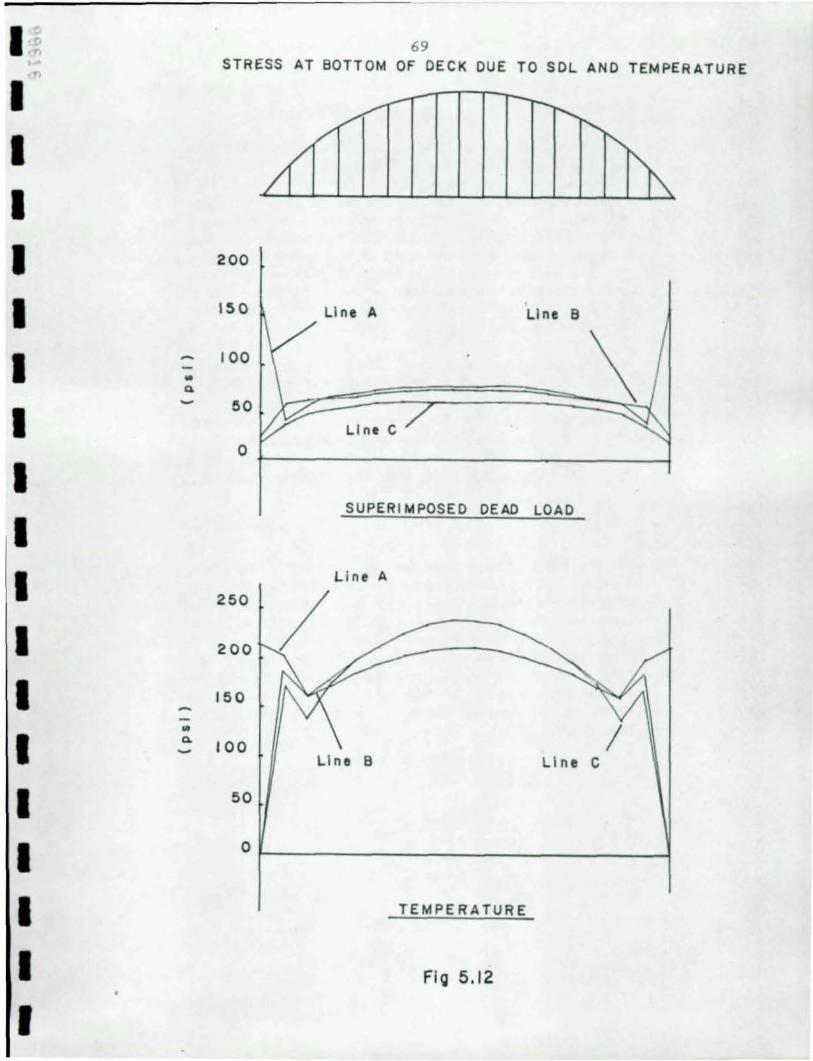
1'1> ....
1 I I I I I I I I I I I I I I I I I
~ .. ~ -
'" ~ -
69 STRESS AT BOTTOM OF DECK DUE TO SOL AND TEMPERATURE
2 00
150 LI ne A LIne B
100
50
LI ne C 0
SUPERIMPOSED DEAD LOAD
L i ne A
250
200
150
100 / L i ne 8 LI ne C
50
0
TEMPERATURE
Fig 5.1 2
70
5.7.5 Tanperature
'1lle results for this analysis were obtained in the same manner as for super~ dead load. This run did not produce observable variation in deck stresses between hangers since there were no vertical loads applied. Temperature has t'n'O apparent effects en the deck: '1lle arch is attempting to lift the deck U~i and the arch is attempting to lengthen the deck due to expansion roth longitudinally and vertically of the arch ribs and l~ of the dead load tie cable. In the analysis, the tie cable actually pulled on the deck whereas is the actual structure, it would anount to a transfer of the dead load thrust fran the cable to the deck and tie beam units.
As in super:iJrposed dead load, there is a large difference is stress across the deck at the ends of the span. This occurs because the force in the deck is introduced by the arch rib and dead load tie cable. In fact, shear lag is so severe that the center of the deck reverses sign to maintain equilibriun. At the quarter point of the span tensile force is equal across the bridge width and remains equal over the center portion.
5.7 . 6 Live I£>ad
'1lle local effects were cc::Ilputed by haOO as was local dead load stress. The overall stresses were determined fran the loader which positicns the live load to produce maximum and minimum stresses in each elarent investigated . '1lle reported values are the average of the t'n'O elarents en each side of a hanger . '!be influences surfaces are produced by loading only positions over floor beams at hangers, thus the local effects of bending over floor beams are not evident in these results. '1lle haOO calculated local stresses are added to the stresses determined by the loader.
I I I I I I I I I I I
I I I I I I
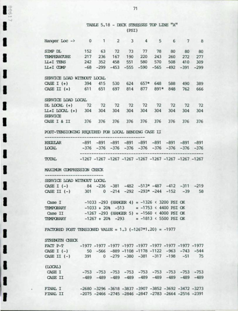
I '~ 71 .!) ·n .-~
I TABIE 5. 18 - !lEO< S'ffiESSES 'roP LINE "A" (PSI)
I Ranger Lac -) 0 1 2 3 4 5 6 7 8
SIMP DL 152 63 72 73 77 78 80 80 80
I TEMPERA'IURE 217 236 167 190 220 243 260 272 277 lL+I TENS 242 352 458 551 580 570 508 410 309 lL+I aMP -68 -299 -453 -555 -590 -565 -492 -391 -299
I SERVICE LOAD WI'llU1l' LCX:AL CASE I (+) 394 415 530 624 657* 648 588 490 389
I CASE II (+) 611 651 697 814 877 891* 848 762 666
SERVICE LOAD LCX:AL
I DL LCX:AL (+) 72 72 72 72 72 72 72 72 72 lL+ I LCX:AL (+) 304 304 304 304 304 304 304 304 304 SERVICE
I CASE I & II 376 376 376 376 376 376 376 376 376
I PQ;T-TENSICNING REQJIRED f"'ffi LCX:AL BENDING CASE 1;1
-------------------------------------------RmJLI\R -891 -891 -891 -891 -891 -891 -891 -891 -891 LCX:AL -376 -376 -376 -376 -376 -376 -376 -376 -376
I -----------------------------------------------------'rol'AL -1267 -1267 -1267 -1267 -1267 -1267 -1267 -1267 -1267
I MAXDI.M aMPRESSICN 0ID:l< -------------------------
I SERVICE LOAD WI'I1UJT LCX:AL CASE I (-) 84 -236 -381 -482 -513* -487 -412 -311 -219 CASE II (-) 301 0 -214 -292 -293* -244 -152 -39 58
I Case I -1033 -293 (HANGER 4) = -1326 ( 3200 PSI OK 'l'EMPCIlARY -1033 + 20% -513 = -1753 ( 4400 PSI OK
I case II -1267 -293 (HANGER 5) = -1560 ( 4000 PSI OK
'l'EMPCIlARY -1267 + 20% -293 = -1813 ( 5500 PSI OK
I FACItRED PQ;T TENSICNED VAWE = 1. 3 (-1267*1.20) = -1977
S'ffiENG'lll 0ID:l<
I FACr P-T -1977 -1977 -1977 -1977 -1977 -1977 -1977 -1977 -1977 CASE I (-) 50 -566 -889 -1108 -1178 -1122 -963 -743 -544 CASE II (-) 391 0 -279 -380 -381 -317 -198 -51 75
I (LCX:AL) CASE I -753 -753 -753 -753 -753 -753 -753 -753 -753
I CASE II -489 -489 -489 -489 -489 -489 -489 -489 -489
FINAL I -2680 -3296 -3618 -3837 -3907 -3852 -3692 -3472 -3273
I FINAL II -2075 -2466 -2745 -2846 -2847 -2783 -2664 -2516 -2391
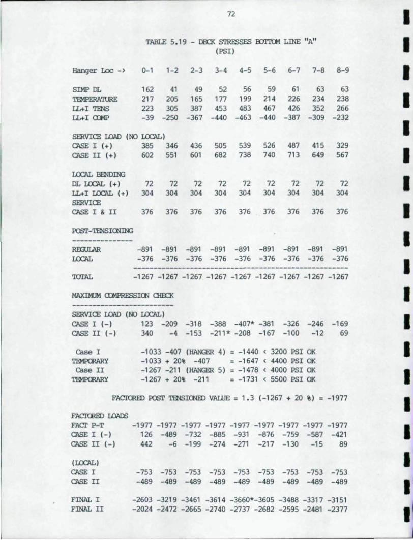
72 I TABLE 5. 1 9 - OED< STRESSES a:Jl'l'Oo1 LINE "A" I (PSI)
~er lDc-> 0-1 1-2 2-3 3-4 4-5 5-6 6-7 7-8 8-9 I SIMP DL 162 41 49 52 56 59 61 63 63 TEMPERA'lURE 217 205 165 177 199 214 226 234 238 I LL+I TENS 223 305 387 453 483 467 426 352 266 LL+I mtP -39 -250 -367 -440 -463 -440 -387 -309 -232
SERVICE IJ:W) (NO LOCAL) I CASE I (+) 385 346 436 505 539 526 487 415 329 CASE II (+) 602 551 601 682 738 740 713 649 567 I LOCAL BENDING
I DL LOCAL (+1 72 72 72 72 72 72 72 72 72 LL+I LOCAL (+) 304 304 304 304 304 304 304 304 304 SERVICE
I CASE I & II 376 376 376 376 376 376 376 376 376
POOT-TENSIOOING
I ---------------RmJLAR -891 -891 -891 -891 -891 -891 -891 -891 -891 LOCAL -376 -376 -376 -376 -376 -376 -376 -376 -376
I -----------------------------------------------------'lUl'AL -1267 -1267 -1267 -1267 -1267 -1267 -1267 -1267 -1267
MAXDlJM ru!PRESSIOO OlEn< I -------------------------SERVICE IJ:W) (NO LOCAL)
I CASE I (-I 123 -209 -318 -388 -407* -381 -326 -246 -169 CASE II (-) 340 -4 -153 -211* -208 -167 -100 -12 69
case I -1033 -407 (HANGER 4) = -1440 < 3200 PSI OK I ~y -1033 + 20% -407 = -1647 < 4400 PSI OK case II -1267 -211 (HANGER 5) = -1478 < 4000 PSI OK I ~y -1267 + 20% -211 = -1731 < 5500 PSI OK
FACTORED POOT TENSIONED VALUE = 1.3 (-1267 + 20 %) = -1977 I I FACKRED I.OI\OO FAcr P-T -1977 -1977 -1977 -1977 -1977 -1977 -1977 -1977 -1977 I CASE I (-) 126 -489 -732 -885 -931 -876 -759 -587 -421 CASE II (-) 442 -6 -199 -274 -271 -217 -130 -15 89
(LOCAL) I CASE I -753 -753 -753 -753 -753 -753 -753 -753 -753 CASE II -489 -489 -489 -489 -489 -489 -489 -489 -489 I FINAL I -2603 -3219 -3461 -3614 -3660*-3605 -3488 -3317 -3151 FINAL II -2024 -2472 -2665 -2740 -2737 -2682 -2595 -2481 -2377 I
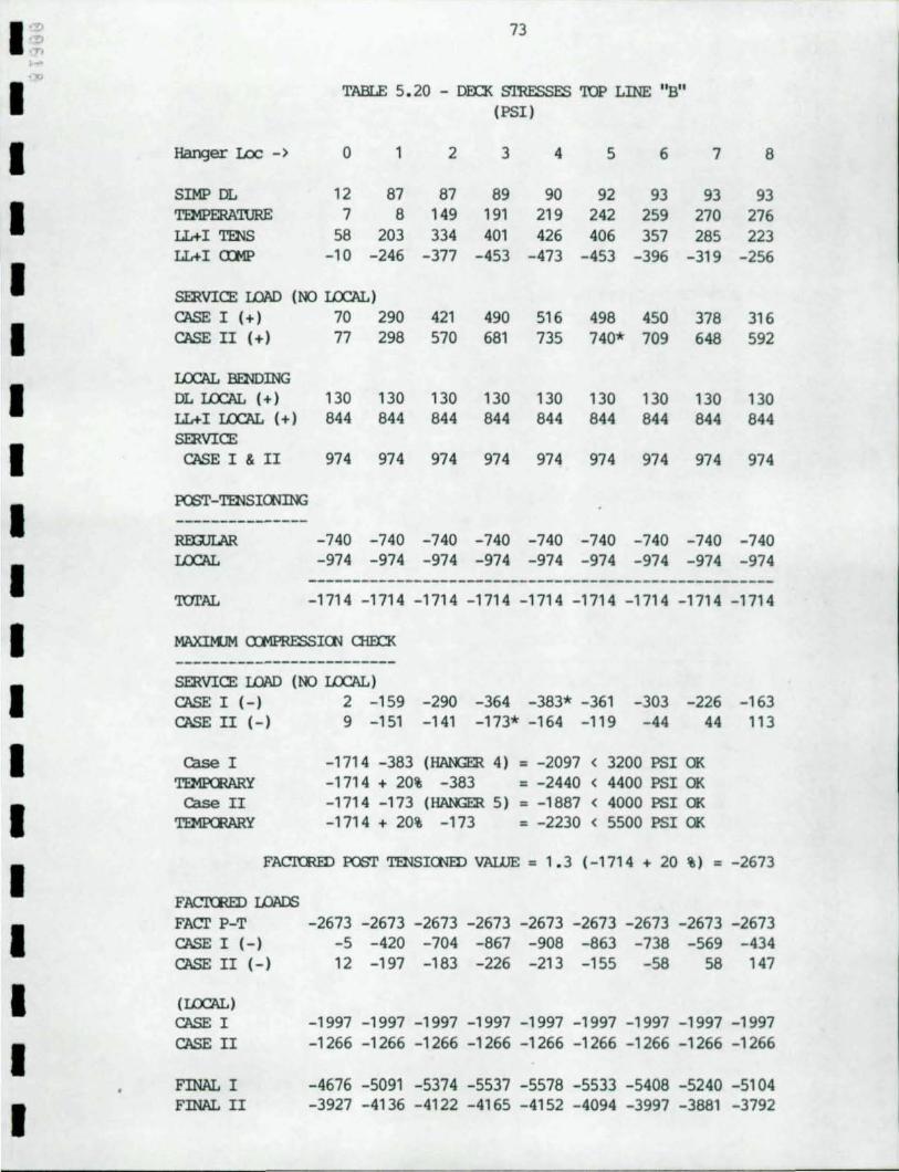
I '~ 73 .!> ..,.. ... -10
I TABLE 5.20 - DEO< Sl'RESSES TOP LINE "B" (PSI)
I Hanger Lac - > 0 1 2 3 4 5 6 7 8
SIMP DL 12 87 87 89 90 92 93 93 93
I TEMPERA'IURE 7 8 149 191 219 242 259 270 276 LL+I TENS 58 203 334 401 426 406 357 285 223 LL+I a:MP -10 -246 -377 -453 -473 -453 -396 -319 -256
I SERVICE LOAD (NO IJX:AL) CASE I (+) 70 290 421 490 516 498 450 378 316
I CASE II (+) 77 298 570 681 735 740* 709 648 592
IJX:AL BENDING
I DL IJX:AL (+) 130 130 130 130 130 130 130 130 130 LL+ I IJX:AL (+) 844 844 844 844 844 844 844 844 844
I SERVICE CASEI&II 974 974 974 974 974 974 974 974 974
I PC6T-TENSIOOING ---------------RmJLAR -740 -740 -740 -740 -740 -740 -740 -740 -740
I IJX:AL -974 -974 -974 -974 -974 -974 -974 -974 -974
-----------------------------------------------------'lUI'AL -1714 -1714 -1714 -1714 -1714 -1714 -1714 -1714 -1714
I MAXIM.JM CDlPRESSIOO OID::K
-------------------------
I SERVICE LOAD (NO IJX:AL) CASE I (-) 2 -159 -290 -364 -383* -361 -303 -226 -163 CASE II (-) 9 -151 -141 -173* -164 -119 -44 44 113
I case I -1714 -383 (HANGER 4) = -2097 < 3200 PSI OK ~y -1714 + 20% -383 = -2440 < 4400 PSI OK
I case II -1714 -173 (HANGER 5) = -1887 < 4000 PSI OK ~y -1714 + 20% -173 = -2230 < 5500 PSI OK
I FACl'CRID PC6T TENSIOOID VALUE = 1.3 (-1714 + 20 %) = -2673
FACl'CRID LOADS
I FAcr P-T -2673 -2673 -2673 -2673 -2673 -2673 -2673 -2673 -2673 CASE I (-) -5 -420 -704 -867 -908 -863 -738 -569 -434 CASE II (-) 12 -197 -183 -226 -213 -155 -58 58 147
I (IJX:AL) CASE I -1997 -1997 -1997 -1997 -1997 -1997 -1997 -1997 -1997
I CASE II -1266 -1266 -1266 -1266 -1266 -1266 -1266 -1266 -1266
FINAL I -4676 -5091 -5374 -5537 -5578 -5533 -5408 -5240 -5104
I FINAL II -3927 -4136 -4122 -4165 -4152 -4094 -3997 -3881 -3792
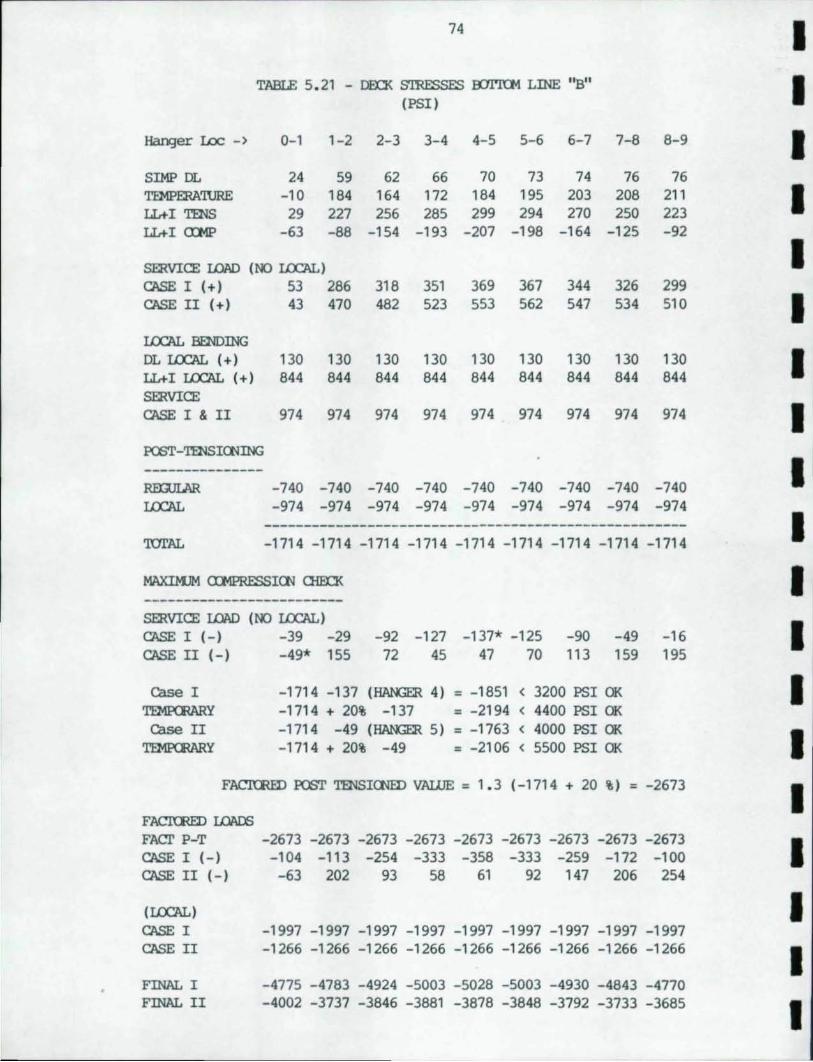
74
TABLE 5.21 - OED< STRESSES a::::tI'KM LINE ''Btl (PSI)
Hanger I.oc - > 0-1 1-2 2-3 3-4 4-5 5-6 6-7 7-8 8-9
SIMP DL 24 59 62 66 70 73 74 76 76 TEMPERAWRE -10 184 164 172 184 195 203 208 211 LL+I TENS 29 227 256 285 299 294 270 250 223 LL+I <nIP -63 -88 -154 -193 -207 -198 -164 -125 -92
smVICE LOI\D (NO LOCAL) CASE I (+) 53 286 318 351 369 367 344 326 299 CASE II (+) 43 470 482 523 553 562 547 534 510
LOCAL IDIDING DL LOCAL (+) 130 130 130 130 130 130 130 130 130 LL+I LOCAL (+) 844 844 844 844 844 844 844 844 844 smVICE CASE I & II 974 974 974 974 974 974 974 974 974
PCST-TENSICNING ---------------RmJLAR -740 -740 -740 -740 -740 -740 -740 -740 -740 LOCAL -974 -974 -974 -974 -974 -974 -974 -974 -974
-----------------------------------------------------'lUl'AL -1714 -1714 -1714 -1714 -1714 -1714 -1714 -1714 -1714
MAXlMJM a:MPRESSICN <lim< -------------------------smVICE LOI\D (NO LOCAL) CASE I (-) -39 -29 -92 -127 -137* -125 -90 -49 -16 CASE II (-) -49* 155 72 45 47 70 113 159 195
case I -1714 -137 (HANGER 4) = -1851 ( 3200 PSI OK ~y -1714 + 20% -137 = -2194 ( 4400 PSI OK case II -1714 -49 (HANGER 5) = -1763 ( 4000 PSI OK ~y -1714 + 20% -49 = -2106 ( 5500 PSI OK
FACTORED PCST TENSIONED VALUE = 1.3 (-1714 + 20 %) = -2673
FACImED LOAC6 FACT P-T -2673 -2673 -2673 -2673 -2673 -2673 -2673 -2673 -2673 CASE I (-) -104 -113 -254 -333 -358 -333 -259 -172 -100 CASE II (-) -63 202 93 58 61 92 147 206 254
(LOCAL) CASE I CASE II
FINAL I FINAL II
-1997 -1997 -1997 -1997 -1997 -1997 -1997 -1997 -1997 - 1266 -1266 -1266 -1266 - 1266 -1266 -1266 -1266 -1266
-4775 -4783 -4924 -5003 -5028 -5003 -4930 -4843 -4770 -4002 -3737 -3846 -3881 -3878 -3848 -3792 -3733 -3685
I I I I I I I I I I I I I I I I I I I
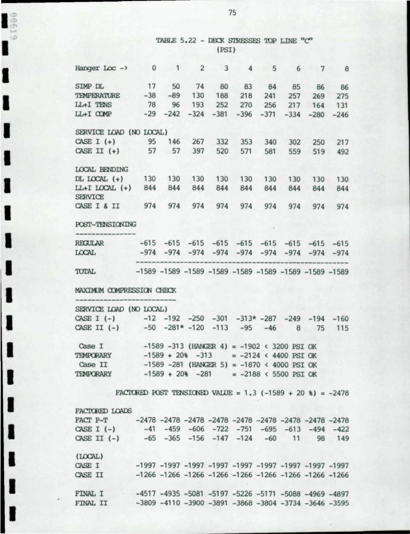
I .::> ..... -'0
I I I I I I I I I I I I I I I I I I
75
TABLE 5.22 - DEn< S'IRFSSFS 'lOP LINE "C" (PSI)
Hanger Loc -) 0 1 2 3 4 5 6 7 8
SIMP DL 17 50 74 80 83 84 85 86 86 TEMPERA'lURE -38 -89 130 188 218 241 257 269 275 IL+I TENS 78 96 193 252 270 256 217 164 131 IL+I a::MP -29 -242 -324 -381 -396 -371 -334 -280 -246
smVICE LOAD (NO I.O:AL) CA'>E I (+) 95 146 267 332 353 340 302 250 217 CA'>E II (+1 57 57 397 520 571 581 559 519 492
I.O:AL WIDING
DL I.O:AL (+ I 130 130 130 130 130 130 130 130 130 IL+ I I.O:AL (+ I 844 844 844 844 844 844 844 844 844 smVICE CA'>E I & II 974 974 974 974 974 974 974 974 974
FOOT-TENSIauNG ---------------RmJLAR -615 -615 -615 -615 -615 -615 -615 -615 -615 I.O:AL -974 -974 -974 -974 -974 -974 -974 -974 -974
-----------------------------------------------------'lUl'AL -1589 -1589 -1589 -1589 -1589 -1589 -1589 -1589 -1589
MAXIMJM <n!PRffi'>IGl 0iE0< -------------------------smVICE LOAD (NO I.O:AL)
CA'>E I (-I -12 -192 -250 -301 -313* -287 -249 -194 -160 CA'>E II (-) -50 -281* -120 -113 -95 -46 8 75 115
Case I -1589 -313 (HANGER 41 = -1902 < 3200 PSI OK '1'EMl'C:RARY -1589 + 20% -313 = -2124 < 4400 PSI OK
Case II -1589 -281 (HANGER 51 = -1870 < 4000 PSI OK TEMPCRARY -1589 + 20% -281 = -2188 < 5500 PSI OK
FACTORED FOOT TENSIONED VALUE = 1. 3 (-1589 + 20 %1 = -2478
FACItmD I.CllIOO FACT P-T -2478 -2478 -2478 -2478 -2478 -2478 -2478 -2478 -2478 CA'>E I (-) -41 -459 -606 -722 -751 -695 -613 -494 -422 CA'>E II (-I -65 -365 -156 -147 -124 -60 11 98 149
(I.O:ALI CA'>E I CASE II
FINAL I FINAL II
-1997 -1997 -1997 -1997 -1997 -1997 -1997 -1997 -1997 -1266 -1266 -1266 -1266 -1266 -1266 -1266 -1266 -1266
-4517 -4935 -5081 -5197 -5226 -5171 -5088 -4969 -4897 -3809 -4110 -3900 -3891 -3868 -3804 -3734 -3646 -3595
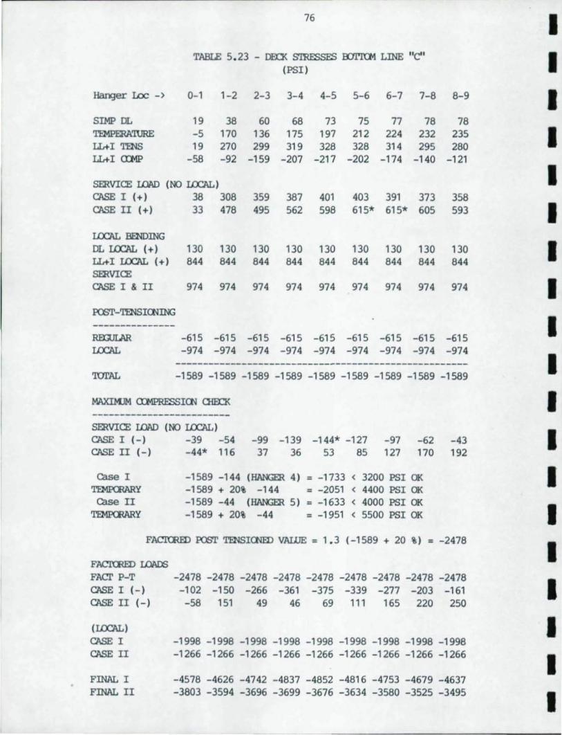
76 I TABLE 5.23 - DEO< S'ffiESSES roI'l'CM LINE "e" I (PSI)
Hanger I.oc -) 0-1 1-2 2-3 3-4 4-5 5-6 6-7 7-8 8-9 I SIMP DL 19 38 60 68 73 75 77 78 78 TEMPERA'IURE -5 170 136 175 197 212 224 232 235 I ILtI TENS 19 270 299 319 328 328 314 295 280 ILtI a:MP -58 -92 -159 -207 -217 -202 -174 -140 -121
SERVICE l.OI\D (NO I.CX:AL) I CASE I (+) 38 308 359 387 401 403 391 373 358 CASE II (+) 33 478 495 562 598 615* 615* 605 593 I I.CX:AL BENDING DL I.CX:AL (+) 130 130 130 130 130 130 130 130 130 I ILt I I.CX:AL (+) 844 844 844 844 844 844 844 844 844 SERVICE CASE I & II 974 974 974 974 974 974 974 974 974 I FOOT-TENSICNING --------------- I REX;ULAR -615 -615 -615 -615 -615 -615 -615 -615 -615 I.CX:AL -974 -974 -974 -974 -974 -974 -974 -974 -974
----------------------------------------------------- I 'IOTAL -1589 -1589 -1589 -1589 -1589 -1589 -1589 -1589 -1589
MAXIM.JM CDlPRESSICN OlEn< I -------------------------SERVICE l.OI\D (NO I.CX:AL)
I CASE I (-) -39 -54 -99 -139 -144* -127 -97 -62 -43 CASE II (-) -44* 116 37 36 53 85 127 170 192
case I -1589 -144 (HANGm 4) = -1733 < 3200 PSI OK I TEMPCRARY -1589 + 20% -144 = -2051 < 4400 PSI OK Case II -1589 -44 (HANGm 5) = -1633 < 4000 PSI OK
I TEMPCRARY -1589 + 20% -44 = -1951 < 5500 PSI OK
FACTORED FOOT TENSIONED VALUE = 1.3 (-1589 + 20 %) = -2478
I FACTORED IJ:lI\OO
FACf P-T -2478 -2478 -2478 -2478 -2478 -2478 -2478 -2478 -2478
I CASE I (-) -102 -150 -266 -361 -375 -339 -277 -203 -161 CASE II (-) -58 151 49 46 69 111 165 220 250
(I.CX:AL) I CASE I -1998 -1998 -1998 -1998 -1998 -1998 -1998 -1998 -1998 CASE II -1266 -1266 -1266 -1266 -1266 -1266 -1266 -1266 -1266
I FINAL I -4578 -4626 -4742 -4837 -4852 -4816 -4753 -4679 -4637 FINAL II -3803 -3594 -3696 -3699 -3676 -3634 -3580 -3525 -3495
I
I ·~ . .)
1.:0
1 1 1 1 I I 1 I I I 1 I I I I I I
77
5.8 Post Tensioning Q:rnp..ItatialS
5.8.1 General
Design of p:>St tensioning is based on section 8 of the AASmO Brid3e Specification. It is assurred that no creep or shrinkage have been raroved fran the units prior to tensioning. This is a o::nservative assumption with regard to a l.aI:ge brid3e.
CASE I includes dead and live loads. CASE II includes dead, live and terrperature loads. All allowable stresses for CASE II are increased to 125 percent of the allowable according to AASHrO Table 3.22.1A. (Ref. 5) •
Post tensioning is designed for local berrling in the deck. I.ocal berrliD;J includes dead and live load rocrnents ocmputed l::1t assll1liD;J that floor beams are rigid. This strand is draped to follow the local rocrnent envelope. Post tensioniD;J applies maximun cx:mpression where the local berrling produces tensile stress. en the other side of the deck, the same p:>St tensioniD;J produces no cx:mpression. 'Ihus, the local cx:mpression does not have to be added to its p:>St tensioning stress when checki.r¥3 for crushiD;J.
Overall stress in the deck due to thrust and beroing of the entire deck unit is assurred to be OCl'lStant across the deck when designing lX'st tensioning to resist it. '!he maximun value fran either the tq;> or botton is used. This p:>St tensioning is p:>Sitioned in the center of the deck.
Strand in the botton flaD;Je of the tie beam is designed based on tension and cx:mpression in botton of the web element. It is assuned OCl'lStant over the entire span as is p:>St tensioning stress in the deck. 'lbere is no design presented for strand in the web.
'!he following paraneters are used in designing p:>St tensioning:
Cbncrete -
fc' = 8000 psi Density = 150 pef Young's Modulus = 5700 ksi Allowable strand anchorage = 3000 psi.
Post Tensioning Steel -
Ultimate strength = 270 ksi Yield Stress = 216 ksi YOUD3"'s Modulus = 28000 ksi
78
5.8.2 Deck
Post tensioning in the deck is divided into two parts. Q1e part is used to IX'St tension the deck for local berrling stresses due to dead and live load. '1llee seo:xld part is used to post tension for overall tensioo forces in the deck. CNerall forces are due to superimposed dead load, tanperature and live loads. Post tensiooing for local m::rnents is placed eccentrically ooe sixth the depth of the deck toward the tensile stress. At floor beams the local berrli03 m::rnent is negative so the strand would be located t/6 above the center of gravity of the deck. By p.1tting strand at this locatioo, a canpressive stress is irrluced on ooe side equal to (2t/9)*Force. 'llle other side has zero cx:mpression. 'llle ranainin:J strand is placed at the center of the deck.
'llle canpressive strength of the deck ITBy rx>t be exceeded at the time of p:lst tensionin:J. 'lhls limit is based of a phi factor = 0.95 and load factors appropriate factors plus IX'St tensiooing stress with a load factor of 1.3. Allowable tensile stress is zero.
Allowable stress of O. 55fc I for the unfactored loads must not be exceeded prior to losses in p:lst tensionin:J. 'Ihis incltrles the sun of any canbinatioo of local and overall stresses and post tensioni03 forces.
'llle allowable stress of O. 4fc I for unfactored loads must not be exceeded after losses have occurred.
No tensioo ITBy occur in concrete under any canbinatioo of loads. 'lhls is simply to insure that the joints do not open.
strand stress shall rx>t exceed 0.7*ult1JTBte strength of the strand when it is installed.
strand must not exceed 0.8*Yield of the strand under perJTBnent loads after losses.
Loss of post tensionifB shall incltrle ooosideration for the following factors:
Shrinkage - SH Creep of Cbncrete - CRc Creep of steel - CRs Elastic shortening ES
In addition, friction losses in strand ducts shall be considered •
I I I I I I I I I I I I I I I I I I I
I :; ,., '-' I
I I I I I I I I I I I I I I I I I
79
Steel Allowables
Post tensioning must overcane all tension stresses in the concrete without failin;J the ooncrete in the CCIlpression regicn. AASH'IU-Secticn 9 is used to check allowable stresses.
Assumpticns: Para. 9.1 3.2.1 Strains vary linearly over depth of secticn. Para. 9.14 phi = 1 . 0 for factory produced ooncrete. Para. 9.15.1 TaTIporary stress before losses due to
creep am shrinkage = 0.70 * stren:Jth of prestress steel
0.70 * 270000 = 189000 psi
stress at service load = 0.80 * yield strength of post tensioning steel.
= 0.80 * 216000 = 172800 psi
Para 9.15.2.1 Post tens oonc (Before losses) . = 0.55 * stren;Jth
= 0.55* 8000 =4400 psi
Para 9.51.2.2 Stress at service load
Comp.= 0.40 * strength = 0.40 * 8000 = 3200 psi Tensicn = 6*(stren;Jth)**0.5 bomed reinf. case = 6 (8000) **0.5 = 537 psi
Para 9.15.2.4 Anchorage = 3000 psi
Para. 9.16.1 Friction loss
Wire galva. metal sheathin;J = 0.0002 K/ft To = Tx( 1 +KL) L = Span/2 Because jack.ir¥J will oc= fran both ends. To = Tx(1 + 0.0002*310) = Tx(1.062)
Para. 9.16.2.1
SH shrinkage = 0.80(17000 - 150RH) = 0.80(17000 - 150*70) = 5200 psi
ES elast. short. = 0.5(Es/Eci)*fcir = 0.5(28/5.4)*1589 = 3896 psi
80
CcXlcrete Creep
CRc = 12*fcir - 7*fcds fcir = concrete stress at the center of gravity of the prestre
ssil'¥3 steel due to prestressil'¥3 force and dead load of beam inmediately after transfer; fcir shall be oanputed at the section or sections of maximum narent. (At this stage, the initial stress in the tendm has been reduced I:7t elastic shortening of the concrete and teOOon frictial for post-tensioni~ members. The reductions to initial tendal stress due to these factors can be estimated, or the reduced tendm stress can be taken as 0.63fs' for typical pretensiaJed members.)
CRc = 12*1500 - 7*0 = 18000
Creep of steel
CRs = 20000 - 0.3FR - 0.4ES -0.2(SH + CRc) for 270 ksi strand
= 20000 - 0.3(10714) - 0.4(3896) -0.2(5200 + 18000) = 10587 psi
Para. 9.17.4
Allow. Steel Stress in Bonded members fsu* = fls *(1 - 0.5(p*f ls/f lc) effective prestress after loss not less than 0.5f IS
say p* = 0.005 or 1/2 percent fsu* = 270000(1 - 0.5(0.005*270000/8000) = 247219 psi
Total loss equals:
SH + ES + CRc + CRs
5200 + 3896 + 18000 + 10714 = 37810 psi
Percent Loss = 37810/189000 = 20 percent
Friction 0.062
I I I I I I I I I I I I I I I I I I I
.... , .... , I I , , , I I I I I I , I , II I
81
Design of post tensioniN3 in deck
Phi = 0. 95 ; Strergth = 7600 psi
strergth
CASE I 0. 95*8000 > 1. 3(DL + 5/3 (LL+I )) CASE II 0.95*8000 > 1.3(DL + T + (LL+I))
steel 0. 95*270000 = 256500 psi
Service
Percent loss = Estimated at 20%
Before losses
CASE I o::ncrete
Ccmpression 0. 55*8000 = 4400 > DL + (LL+I) + Post tension*1.20 Tension = 0. 0
CASE II a:ncrete
Ccmpression 0. 55*8000*1 . 25 = 5500 ) DL + (LL+I) + T + Post tension*1.20 Tension = 0.0
steel 0. 7*270000 = 189000 psi before losses
After Losses
o::ncrete
CASE I Ccmpression 0. 40*8000 = 3200 > DL + (LL+I) + Post tension
CASE II 0. 40*8000*1 . 25 = 4000 > DL + (LL+I) + T + Post tension
Steel 0. 8*216000 = 172800 psi after losses
82
~termine the level of stress permitted in the stram before losses.
Final stress must be less than 172800 psi.
Loss of prestress in steel = 37810 psi.
Before loss limit = 172800 + 37810 = 210610 psi
Absolute limit = 189000 psi
Since 210190 ) 189000, limit = 189000 psi
Stress in stram after losses = 189000 - 37801 = 151199 psi
Area of 1-270 ksi 1/2" dia stram = 0.153 in2
Line "A" t = 15"
Local berxling stress = 376 psi top am oottan. Positioo stram at 15/6 = 2.5 " al:ove center of deck. Allowable stress in steel = 151199 psi Area ale 1/2" dia stram = 0.153 in2
Stress due to ~t tensicnirg placed at 1/6 deck thickness fran center of gravity en side of tensien stress. nus stram is to be draped to match local beOOing rrarents.
f = 2F/t F required = (t/2)*f = 15/2*(376) = 2820 pounds/inch or 2820 * 12 = 33840 pounds/ft
No. stram reqd = 33840/(0.153*151199) = 1.45 Adjust for 6.2% frictien loss. 1.45 * 1.062 = 1.54
say 1.5 stram/ft.
Stram for axial forces in deck
Critical case - After losses = 1267 psi (CASE II) to avoid any tensien in deck.
No. stram = 1267*15*12/(0.153*151199) = 10.06 Adjust for 6.2% frictien. 10.06 * 1.062 = 10.68
= say 11 stram/ft
I I I I I I I I I I I I I I I I I I I
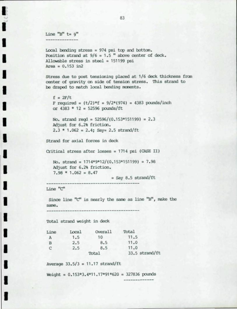
f I I I I I I I I I I I I I I I I I
83
Line "B" t= 9"
Ux::al bending stress = 974 psi top am lx>ttan. Positien strand at 9/6 = 1.5 " above center of deck . Allowable stress in steel = 151199 psi Area = 0. 153 in2
Stress due to post tensioning placed at 1/6 deck thickness fran center of gravity en side of tensien stress . This stram to be draped to match local bending nx:ments .
f = 2F/t F required = (t/2)*f = 9/2*(974) = 4383 pounds/inch or 4383 * 12 = 52596 pounds/ft
No. stram reqd = 52596/(0 . 153*151199) = 2. 3 Adjust for 6 . 2% frictien . 2 . 3 * 1 . 062 = 2.4 ; Say= 2. 5 stram/ft
stram for axial forces in deck
Critical stress after losses = 1714 psi (CASE II)
No . strand = 1714*9*12/(0 . 153*151199) = 7.98 Adjust for 6 . 2% friction . 7 . 98 * 1 . 062 = 8 . 47
= Say 8.5 strand/ft
Line "e"
Since line "e" is nearly the same as line ' 'B'', make the same. ----------------------------------------
Total stram weight in deck
Line Ux::al Overall Total A 1. 5 10 11.5 B 2. 5 8 . 5 11.0 e 2.5 8.5 " .0
Total 33 . 5 strand/ft
Average 33 . 5/ 3 = 1 1 .17 stram/ ft
Weight = 0. 153*3 . 4*11.17*91*620 = 327836 pounds
84
5. 8. 3 Post Tensionio:; in Tie Beam Botton Flange
Maximum required post tensioning stress before losses equals 2474 psi.
Force = 2474 * 2 * 144 = 712500 pounds Allowable strand stress = 151199 psi
Reqd No. strand = 712500/(. 153*151199) = 30 . 8 strand Adjust for 6 . 2% friction . 30 . 8 * 1 . 062 = 32 . 7
= Say 33 strand
Since botton flange is overstressed in canpression, the flange must be made larger than 2 square feet. 'lhls should reduce the stresses to a point that the 33 strand will be satisfactory.
Required weight of strand in flanges of tie beam
33 * 0. 153 * 3.4 * 620 * 2 = 21287 pounds
TOtal strand weight = 327836 + 21287 = 349122 pounds
Cl1eck anchorage area in deck. Design anchorage stress = 3000 psi.
Maximum force = 151199 * 11 * 0.153 = 270244 pounds/ft.
or 270277/(9*12 ) = 2502 psi < 3000 psi OK
No extra ooncrete required for anchorage . However , it is recx:mnended that the end sections be thickened to simplify positienio:; post tensicnin3' anchors .
Cl1eck cast-in-place end sectiens . %ese sections must be cast and post tensioned after the precast units have been post tensioned . Since sectien to be be post tensionio:; will cause a tensile force in the remainder of the deck prior tensiooing will tend to be relieved. 'Il1e cast-in-place sectien is 10 feet 100:;. 'lhls will cause an increase in the strand stress of 10/ 620 = 1. 5 % if the last stressio:; is of the same magnitwe as in the precast units. Additional post tensioning foroe will be required to overcane thrust and berxlio:; in the arch ribs. 'lhls additicnal post tensioning will be a larger percentage en shorter bridges.
I I I I I I I I I I I I I I I I I I I
I,
I I I I I I I I I I I I I I I I I I
85
other Ccnsideratioos
It is clear that a lower strergth coocrete is acceptable for the deck in the study am that it WOJld not have a large effect on the tension flanges of the tie beams .
Q1e coold interpret specification on the ~ature condition to rrean that the unlikehood of all loads beirxJ maximl.In at the same tine is 10;1 so that one may reduce the total tensile stress for CASE II t7t 1/1 . 25 . If that is true, CASE I WOJld control post tensioning am the area of stram required WOJld be less than 9i ven al:ove.
Transverse deck stresses were not examined. If the tie beam provides significant restraint to the floor beams, it will lead to tensile stresses in the deck am sane transverse prestressing steel may be desirable .
86
6.0 Conclusions
It is the intent of the study to investigate design options which may lead to more practical tied arch bridges. Based upoo this design study, it appears that the ideas suggested warrant further consideratien.
'!he total weight of the proposed structure is cnly slightly IOClre than the conventional design. The steel weight of the alternate is much less than that of the original design. '!he arch ribs increased fran a.i:loot 1.7 million poUIXls to a.i:loot 1.85 million pounds. '!he arch bracing stayed the same at a.i:loot 925 t:OOusaOO p:>unds. The tie beams decreased fran a.i:loot 1.6 million poUIXls to zero. '!he floor systan is decreased fran a.i:loot 2 million poUIXls to atout 930 tOOusand p:>unds.
'!he 8000 psi concrete strength is higher than that camonly used in present practice. However, 8000 psi concrete is being used on the Fast Huntington Bridge in West Virginia with no rep:>rted prdllems (Ref.3). However, the analyses irrlicate that 6000 psi concrete ~d be adequate for this instance.
'!he use of 15 inch thick deck at the tie beams appears to be excessive. Shear lag appears to be critical cnly at the ends of the span. It seems rea.scnable to expect that a 9 inch deck with a large chamfer could be used over the entire span with the exceptien of the ends of the span near the arch ribs. At these locations a deck thickness of 15 inches is recamerrled. '!hese p:>rtions are cast in-place so special deck units are not required. 'Ibis IOCldification would further reduce weight. '!he use of a cx::rrp:l5ite steel plate en the bottan of the deck in these regions has been used for shear transfer in Germany (Ref. 4) • SUch a cllar¥3e ~ further reduce structure weight.
Erection of the arch ribs by rotating than into p:>sition am splicing than has significant benefits in erection time am freedan fran falsework obstructing water traffic. '!he erection procedure was rep:>rted for a concrete arch bridge in Germany(Ref.1). '!here the engineers felt that the method was econcmical for longer spans.
Another configuration of the deck was examined where the stiffness was less than that of the cases rep:>rted. An important relationship between deck stiffness am arch rranents was evident. As the deck becanes stiffer, arch live load rranents decreases. '!he reascn for this is that the parabolic arch is designed for a uniform load. If the deck equalizes the loads, the rranent in the arch will be snaller, permitting thinner arch ribs.
I I I I I I I I I I I I I I I I I I I
I ~
I I I I I I I I I I I I I I I I I I
87
'!be normal tied arch bridge deperrls ooly en the tie beam for stiffness whereas the suggested method utilizes the entire deck stiffness . '!be tie beams were made 9 feet deep ~ to 11 feet en the original design . 'Ihis reductien in stiffness was rrore than balanced by the aalitien of the deck. A greater depth would have reduced the rrcrnent in the arch rut the arch was cc:ntrolled by the erectien so no benefit would have resulted . '!be reduced depth would lead to a decrease in wind loading .
Since the deck is integral with the tie beam , lateral loads may be resisted by the deck and tie beams . 'Ihls permitted the eliminatien of two levels of diagc:nal bracio:J required in the original design.
'!be use of the dead load tie cable and the {XlSt tensioned tie beams insures that the ties are not fracture critical. '!bey further simplify construction by reducir¥J the amount of field 001 tio;J .
'!be continuous deck provides a much SIllX)ther- riding surface and a reductien in maintenance oosts . It is roost probable that an impervious wearir¥J surface would be installed to further protect the joints. '!be oost of this surfacio:J must be considered in any econanic evaluation. It appears that a reascoable amount of {XlSt tensionio;J steel is required .
88
7. 0 Acknowledgements
'lhls ~k was initiated at the request of the lvnerican Institute of Steel Constructioo who fuOOed a portion of the ~k for which we are greatful. '!hey al so provided the design drawings for the original design fran which the alternate design was derived . '!he interest aOO encouragement of AISC staff are also appreciated .
'!here have been fruitful discussions with several design consultants concerning this ~k. Particularly helpful was the finn of Al:vid Grant & Associates whan we learned, t:.c:Mard the em of the ~k, had designed a bridge not dissimilar to that proposed . Unfortunately , for various reasons not related to the adequecy of the design , the structure was not bJilt.
'!he figures were drawn by G. !:avid Brierley~ of ESDI who also reviewed the entire manuscript aOO made flUII'eI'OUS oootributicns . Lon B. VanFossen of ESDI produced the carrputer runs, made the carrputer rrodels used aOO reviewed the n.anuscript .
I I I I I I I I I I I I I I I I I I I
I I I I I I I I I I I I I I I II I
89
8.0 Bibliography
1. "Arch halves fall, making pivotal link in Germany" Engineering News Record, June 13, 1985.
2. ''Bridge fixed quickly under traffic", Engineering News Record, November 19, 1981.
3. "Hybrid girder in cable-stayed debJ.t" ,Engineering Engineering News Record, June 13, 1985.
4. Roik, Karlheinz arrl Haesel, Jochen, "cx:MPa3ITE BRII:GES IN GERMANY", Second US~apan Joint Saninar on canposite arrl Mixed Calstruction, University Washingtal, Seattle. July 18-20, 1984.
5. "Standard Specifications for Highway Bridges, 'lhirteenth Etlition", ~ican Association of state Highway arrl Transportation Officials, Washingtoo, D. C., 1 983.

1:1' " ......
I ~
1 1 I 1 1 1 1 I I I I I I I I I I