arsenic removal via electrocoagulation from heavy metal contaminated groundwater in la comarca...
TRANSCRIPT
Journal of Hazardous Materials B124 (2005) 247–254
Arsenic removal via electrocoagulation from heavy metal contaminatedgroundwater in La Comarca Lagunera Mexico
Jose R. Pargaa,∗, David L. Cockeb, Jesus L. Valenzuelac, Jewel A. Gomesb,Mehmet Kesmezb, George Irwind, Hector Morenob, Michael Weirb
a Institute Technology of Saltillo, Department of Metallurgy and Materials Science, V. Carranza 2400, C.P. 25280, Saltillo, Coahuila, M´exicob Lamar University, Gill Chair of Chemistry and Chemical Engineering, Beaumont, TX 77710, USA
c University of Sonora, Hermosillo, Sonora, M´exicod Lamar University, Department of Chemistry and Physics, Beaumont, TX 77710, USA
Received 23 December 2004; received in revised form 3 May 2005; accepted 7 May 2005Available online 28 June 2005
Abstract
ted in thec ment andN lop thec on (EC) isa study willp icroscopy,t rmed at irone EC productsr©
K
1
Liiw1itre
(
nicals oflead
tomsnicas
nces,ness,icityughle toandin
nsent
0d
Arsenic contamination is an enormous worldwide problem. A large number of people dwelling in Comarca Lagunera, situaentral part of northern Mexico, use well water with arsenic in excess of the water standard regulated by the Secretary of Environatural Resources of Mexico (SEMARNAT), to be suitable for human health. Individuals with lifetime exposure to arsenic develassic symptoms of arsenic poisoning. Among several options available for removal of arsenic from well water, electrocoagulativery promising electrochemical treatment technique that does not require the addition of chemicals or regeneration. First, this
rovide an introduction to the fundamental concepts of the EC method. In this study, powder X-ray diffraction, scanning electron mransmission Mossbauer spectroscopy and Fourier transform infrared spectroscopy were used to characterize the solid products folectrodes during the EC process. The results suggest that magnetite particles and amorphous iron oxyhydroxides present in theemove arsenic(III) and arsenic(V) with an efficiency of more than 99% from groundwater in a field pilot scale study.
2005 Elsevier B.V. All rights reserved.
eywords:Arsenic removal; Electrocoagulation; Drinking water; Iron electrodes
. Introduction
The occurrence of arsenic in groundwater of La Comarcaagunera is a major problem for Mexico. The contamination
s on a large scale and 30 years have passed since arsenic camento picture[1–3]. Arsenic concentration has been found inell water from several communities ranging from 0.24 to.0 ppm. Most of this region is reputed to have substrata rich
n arsenic. Therefore, the arsenic in ground water is largelyhe result of minerals dissolving naturally from weatheredocks and soils, which is known to produce high-arsenic lev-ls in well water. Other possible sources of contamination
∗ Corresponding author. Tel.: +52 844 4389515; fax: +52 844 4389515.E-mail addresses:[email protected], [email protected]
J.R. Parga).
can be referred to, for example, the use of organoarsepesticides in the cotton fields and also millions of tonslag or fallout from roaster off-gas emissions of onesmelter in 1945[1–5]. In La Comarca Lagunera Mexico,thousands of people have already contracted the sympof arsenic poisoning and two million are at risk of arsecontamination from drinking well water. Effects, suchchanges on skin pigmentation, gastrointestinal disturbaneurological changes, lung cancer and muscular weakcharacterize arsenic poisoning in humans. Arsenic toxhas no known effective medicine for treatment, althodrinking arsenic-free water can help the affected peopreduce or remove of the symptoms of arsenic toxicityprotect the health and well-being of rural people livingacute problem areas of Mexico. Socio-economic conditioof Mexico demand low-cost as well as efficient treatm
304-3894/$ – see front matter © 2005 Elsevier B.V. All rights reserved.oi:10.1016/j.jhazmat.2005.05.017
248 J.R. Parga et al. / Journal of Hazardous Materials B124 (2005) 247–254
Table 1A comparison of main arsenic removal technologies[9–15]
Technologies Advantages Disadvantages Removal (%)
Oxidation/precipitationAir oxidation Relatively simple, low-cost but slow
processMainly removes arsenic (V) and accelerate theoxidation process
80
In situ arsenic removalAlso oxidizes other inorganic andorganic constituents in water
Chemical oxidation Oxidizes other impurities and killsmicrobes
Efficient control of the pH and oxidation step isneeded
90
Relatively simple and rapid processMinimum residual mass
Coagulation/co-precipitationAlum coagulation Durable powder chemicals are available Produces toxic sludges 90
Relatively low capital cost and simple inoperation
Low removal of arsenic
Effective over a wider range of pH. Pre-oxidation may be required
Iron coagulation Common chemicals are available Medium removal of As(III) 94.5More efficient than alum coagulation onweigh basis
Sedimentation and filtration needed
Lime softening Most common chemicals are availablecommercially
Readjustment of pH is required 91
Sorption techniquesActivated alumina Relatively well known and commercially
availableNeeds replacement after four to five regeneration 88
Iron coated sand Expected to be cheap Yet to be standardized 93No regeneration is required Produces toxic solid wasteRemove both As(III) and As(V)
Ion exchange resin Well-defined medium and capacity High cost medium 87The process is less dependent on pH ofwater
Requires high-tech operation and maintenance
Exclusive ion specific resin to removearsenic
Regeneration creates a sludge disposal problemAs(III) is difficult to removeLife of resins
Membrane techniquesNanofiltration Well-defined and high-removal efficiency Very high-capital cost 95
Pre-conditioningHigh water rejection
Reverse osmosis No toxic solid waste is produced High tech operation and maintenance 96Electrodialysis Capable of removal of other
contaminantsToxic wastewater produced 95
systems that could be implemented in the rural areas orcities.
The main arsenic species present in natural waters arearsenate ions AsO4−3 (oxidation state V) and arsenite ionsH3AsO3, H2AsO3
− and HAsO3−2 (oxidation state III). How-
ever, As(V) ions are most prevalent in oxygenated water whileAs(III) is found in anaerobic conditions, like in well wateror in groundwater. The literature on arsenic concludes thatthe most common valence states of arsenic in well water areAs(V) or arsenate, and As(III) or arsenite. In the pH range of4–10, the trivalent As(III) species are neutral in charge, whilethe As(V) are negatively charged. The removal efficiency forarsenic is often much lower for As(III) than for As(V) byusing anyone of the conventional technologies for eliminationof arsenic from water[6,7], so either elevation of pH[7] oroxidation of arsenite to arsenate[8] is considered a prerequi-
site for any treatment method to be efficient. Therefore, treat-ment of arsenic contaminated well water through appropriatetechnology is one option to mitigate the arsenic problem.
Various technologies have been used for removing arsenicfrom groundwater. The most commonly used technologiesinclude co-precipitation with alum or iron, adsorption ontocoagulated floc, ion exchange resin, reverse osmosis andmembrane techniques. A review of these technologies alongwith their distinct advantages and disadvantages is shown inTable 1 [9–15]. The major disadvantage of most of the tech-niques presented inTable 1is that they are unable to removeAs(III) efficiently. In addition, none of these processes forthe arsenic removal use electrocoagulation with air injection.It is intended to update the process development in arsenicremoval and consider the economic factors involved in imple-menting lower drinking water standards for arsenic.
J.R. Parga et al. / Journal of Hazardous Materials B124 (2005) 247–254 249
These drawbacks have forced municipalities and vari-ous industries to search for effective alternative treatmenttechnologies for arsenic removal, ideally by electrochemicalmethods. Electrocoagulation (EC) is one of the most effi-cient technologies for removal of both As(III) and As(V)from contaminated water. As removal is rapid with highercurrent densities[15,16]. Balasubramanian and Madhavan[15] reported about their EC experiments without air injec-tion over a wide range of operational conditions and foundthat the efficient removal of arsenic takes about 7 h and therate of arsenic removal for this technique depends on the ini-tial arsenic concentration.
Therefore, the purpose of this research is to investigatethe use of modified EC process with air injection to enhancethe removal of highly water soluble As(III) and As(V) com-pounds from groundwater. Electrocoagulation with air injec-tion integrates the high-arsenic removal efficiency of EC withthe advantage of a shortened reactive retention time and min-imum residual mass, and thereby it reduces the operatingcosts. This has received very little attention, although thisprocess has the potential to eliminate the disadvantages ofthe classical treatment techniques. A review of the litera-ture reveals that the potential of EC with air injection asan alternative to the conventional treatment processes hasnot yet been adequately explored due to technical and eco-nomical reasons[17]. Although also, the sludge from thisp logiess al-lr ag-n an bee ation(
2
emi-c oyedp ry-i cusedo thef ula-t valr aset ando ple.S opu-l aterc ffers oms i-t eousm tantc reten-t con-
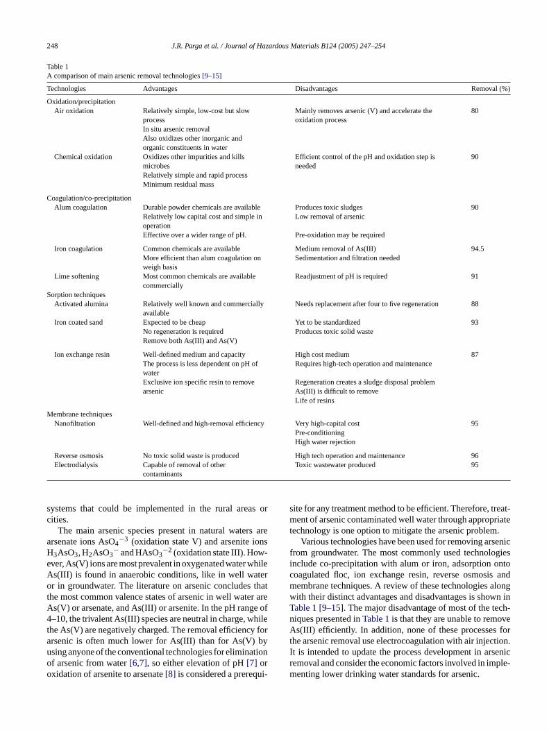
stituent concentrations dictate the operating parameters ofthe process[22]. The EC process operates on the principlethat the cations produced electrolytically from iron and/oraluminum anodes enhance the coagulation of contaminantsfrom an aqueous medium. Electrophoretic motion tends toconcentrate negatively charged particles in the region ofthe anode and positively charged ions in the region of thecathode. The consumable, or sacrificial, metal anodes areused to continuously produce polyvalent metal cations in thevicinity of the anode. These cations neutralize the negativecharge of the particles carried toward the anodes by elec-trophoretic motion, thereby facilitating coagulation. In theflowing EC techniques, the production of polyvalent cationsfrom the oxidation of the sacrificial anodes (Fe and Al) andthe electrolysis gases (H2 and O2) works in combinationto flocculate the coagulant materials. Even inert electrodes,such as titanium and the passage of an alternating currenthave also been observed to remove metal ions from solutionsand to initiate the coagulation of suspended solids.Fig. 1illustrates the schematic diagram of the process. As men-tioned above, gas bubbles produced by the electrolysis carrythe pollutant to the top of the solution where it is concen-trated, collected and removed. The removal mechanisms inEC may involve oxidation, reduction, decomposition, depo-sition, coagulation, absorption, adsorption, precipitation andflotation.
ancet (III)a ded andi nts,r ula-t clest blest r thei icalr echa-
rocess generates invaluable materials for other technouch as Fe3AsGa for semiconductor manufacturing and gium arsenide (GaAs/Ge) for solar cell production[18]. Aecent study[19] shows that EC can be combined with metic seeding to produce a magnetic aggregate that cfficiently separated by high-gradient magnetic separHGMS) in-line with the EC reactor.
. Electrocoagulation characteristics
Electrocoagulation has been known as an electrochal phenomenon for the last century. It has been emplreviously for treating many types of wastewater with va
ng degrees of success. However, most studies have fon the efficiency of waste removal without exploring
undamental mechanisms involved in the electrocoagion process[20]. This electrochemical method of remoequires very small quantities of salt addition to increhe conductivity of the solution, and the maintenanceperation of the electrocoagulation cells is relatively simince 1970, this technology has become increasingly p
ar around the world for treatment of industrial wastewontaining metals[20]. Electrocoagulation processes oignificant potential for removing soluble ionic species frolution, particularly heavy metals[21]. EC operating condions are highly dependent on the chemistry of the aquedium, especially conductivity and pH. Other impor
haracteristics such as particle size, type of electrodes,ion time between plates, plate spacing and chemical
However, it is the reactions of the metal ions that enhhe formation of the coagulant. The metal cations of Asnd As(V) react with the OH− ions produced at the cathouring the evolution of hydrogen to yield both soluble
nsoluble hydroxides that will react with or adsorb pollutaespectively, from the solution and also contribute to coagion by neutralizing the negatively charged colloidal partihat may be present at neutral or alkaline pH. This enahe particles to approach closely and agglomerate undenfluence of van der Waals attractive forces. The chemeactions that have been proposed to describe EC m
Fig. 1. An illustration of the electrocoagulation mechanism.
250 J.R. Parga et al. / Journal of Hazardous Materials B124 (2005) 247–254
nisms for the production of H2(g) and OH−(aq) (cathode) and
H+(aq) (anode)[17] are:When M(s) = Fe metal electrode:
Fe(s)→ Fe2++2e− (1)
Fe2+ → Fe3++e− (2)
Anode:
aM(s) → aMn+ + an(e−) (3)
2H2O → O2 + 4H+ + 4e− (4)
Cathode:
an(H2O) + an(e−) → an
2H2 + an(OH−) (5)
4H++4e− → 2H2 (6)
Overall:
aM(s) + (2 + an)H2O
→(
2 + an
2
)H2 + O2 + an(OH−) + aMn+ (7)
where constanta is a stoichiometric coefficient andn is num-ber of electrons.
The pH of the medium rises as a result of this electro-c ea emovet x-a tiona
used[ lec-t rrentd ffec-t redt
3
tusc icale owers
e thea s tubem ver-t steele erticalg s Oa ater witha odes( ol-u was
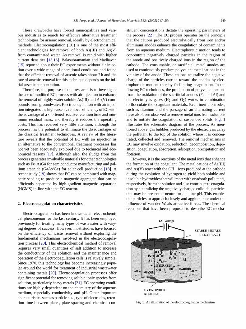
Fig. 2. A schematic diagram of the electrocoagulation reactor.
used to control the current and potential. The electrolyte solu-tions were prepared with deionized water with conductivity of0.95�S (Aldrich Chemical Co., +99.5% A.C.S. reagent, lot#DI02350AI) and the conductivity was controlled by adding1 g of NaCl per liter of water (Fisher, 99.8% A.C.S. Certi-fied, lot #995007). The arsenic contaminated well water wascollected from groundwater wells in La Comarca LaguneraMexico. The pH was adjusted (as needed) using∼0.13 MNaOH solution prepared with NaOH pellets (EM, 97%, lot#36349739). Prior to each trial, the pH and conductivityof each solution were recorded. The aerated solution waspumped through the cell at a flow rate of about 600 ml/minand after 2.0–4.0 l of well water solution were treated, theruns were stopped and the slurry pH and conductivity wererecorded. The solutions and solids were then separated byfiltration through cellulose filter paper. The sludge from theEC was dried either in an oven or under vacuum at room tem-perature. The samples were analyzed by atomic absorptionspectroscopy (AAS, model Varian A 220). For the calibrationcurve of arsenic concentration, the arsenic standard solution(VW 4202-1) from Sigma–Aldrich was used. A schematicdiagram of the cell is shown inFig. 2.
4. Results and discussion
4i
oxr ndedp by
hemical process and the Fe(OH)n(s) formed remains in thqueous stream as gelatinous suspension, which can r
he As(III) and As(V) from well waters, either by completion or by electrostatic attraction followed by coaguland flotation.
Generally, in the EC process, bipolar electrodes are23,24]. It has been reported that cells with bipolar erodes, connected in series operating at relatively low cuensities, produce iron or aluminum coagulant more e
ively, more rapidly and more economically when compao chemical coagulation.
. Experimental
The electrocoagulation with air injection apparaonsisted of a flow-through reactor with parallel vertlectrodes, a peristaltic feed pump, an air pump and a pupply.
This EC system uses a modified EC process wherrsenic contaminated water is passed through a porouedium where air is injected before passing through the
ical electrodes in the EC cell. Seven vertical carbonlectrodes were used as anode and cathode. The veometry of the plates allowed the use of the gaseou2nd H2 generated in the electrolysis of water to facilitemoval of the ferric and ferrous species associatedrsenic contaminants. The neighboring vertical electr10.0 cm× 15.4 cm) were 6 mm apart and the internal vme of the reactor was 1200 ml. A variable transformer
.1. Arsenic removal by electrocoagulation with airnjection
The H2(g) and O2(g) produced as a result of the redeactions and the air injection may remove any suspearticles of iron coagulant impregnated with arsenic
J.R. Parga et al. / Journal of Hazardous Materials B124 (2005) 247–254 251
Table 2Summary of arsenic removal by EC analytical results by using with andwithout air injection methods
pH As (ppm) As removal(%)
Ceff (%)
Feed solution 2.86 (in) 2.24 None NoneWithout air injection 6.36 (exit) 0.10 95.54 97.3With air injection 8.30 (exit) 0.005 99.77 102
Note:The method of analysis was EPA 200.7 (which is an analytical methodfor identification of metals and trace elements by ICP/Atomic EmissionSpectrometry).
electroflotation. Exact electrochemical reaction mechanismsinvolved are not yet completely understood. However, theEC of well water containing As(III) and As(V) producesan insoluble complex sludge, containing iron and arsenicoxides and hydroxides while leaving negligible or zero con-centrations of arsenic from the well water.Table 2shows acomparison of the results by using the same variables (40 Vand 4 A) for removal of arsenic of the same feed solutionwithout and with air injection for the laboratory EC cell.The increase in As removal efficiency with air injection incomparison to without air injection indeed justify the advan-tage of aeration in EC process for the removal of arsenic.An EPA report by Lowry and Lowry[25] on oxidation ofAs(III) by aeration and storageconcluded that As(III) is notoxidized by oxygen on aeration or by dissolved oxygen andthey suspected that removal of As(III) could be occurred dueto its adsorption on precipitated iron oxide. Dissolved oxy-gen or aeration can enhance the oxidation process of iron.Kumar et al.[16] reported that As(III) removal mechanismin electrocoagulation with iron electrodes seems to be oxida-tion of As(III) to As(V) and surface complexation with ironhydroxides. Surface studies of the floc are essential for con-firming these assumptions that will be carried out in our futureresearch.
The current efficiency (Ceff) was calculated using the fol-lowing equation:
C
w yuw aftere
cen-t rofilef ighertSe timew nicrK toC ont
current density has no significant effect on the final totalarsenic removal.
Since reaction Eqs.(4) and(5) contain protons or hydrox-ides, respectively, the pH value is an important factor forarsenic removal in both acid and basic solutions. In addition,it influences the stability of the adsorbed arsenic species on insitu generated iron oxide/hydroxide/oxyhydroxide species.
4.2. Product characterization
It is difficult to differentiate between the iron oxide andoxyhydroxide species using only a single analytical tech-nique. In this study, powder X-ray diffraction (XRD), Scan-ning electron microscopy (SEM), transmission Mossbauerspectroscopy (TMS) and Fourier transform infrared spec-troscopy (FT-IR) were used to characterize the solid productsformed from carbon steel electrodes during EC.
4.2.1. X-ray diffractionDiffractograms were obtained with a Bruker AXS
D4 Endeavor diffractometer operating with a Cu K�radiation source filtered with a graphite monochromator(λ = 1.5406A). The samples were wet ground to a fine pow-der (isopropyl alcohol from Sigma–Aldrich) and pressed intoa sample holder. The XRD scans were recorded from 20◦ to80◦ 2θ, with 0.02◦ step-width and with a 10 s counting timef n at4 efi ppmoI ogena , andl
4xy-
h ergyd ere)s ith al
4olid
pM on a± ofw xidec netics ironoh
4-IR
s bro-m ally
eff = MEXP
MTH× 100 (8)
here the theoretical mass of iron (MTH) was obtained bsing the Faraday relation and the experimental mass (MEXP)as obtained by the electrode mass difference before andach experiment.
For various current and voltage values, arsenic conration versus residence time plots showed the same por arsenic removal: the longer the residence time, the hhe removal of arsenic species from the solution (seeFig. 8).ince the current density applied (3.7–4.6 mA/cm2) in thesexperiments did not differ appreciably and the residentas also very low (90 s), obviously its effect on arse
emoval efficiency was not observed. Chen et al.[26] andumar et al.[16] also reported similar results. Accordinghen et al.[26], current density has no significant effect
otal pollutant removal and according to Kumar et al.[16],
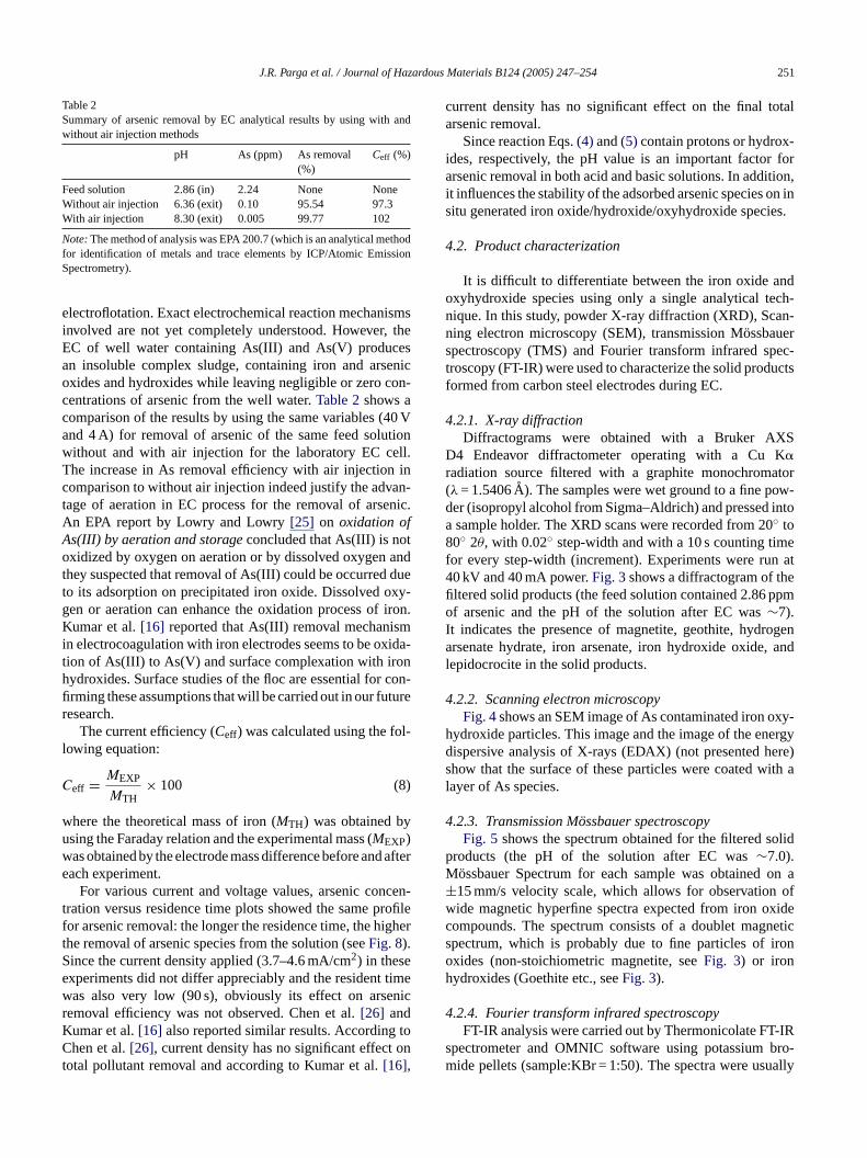
or every step-width (increment). Experiments were ru0 kV and 40 mA power.Fig. 3shows a diffractogram of thltered solid products (the feed solution contained 2.86f arsenic and the pH of the solution after EC was∼7).
t indicates the presence of magnetite, geothite, hydrrsenate hydrate, iron arsenate, iron hydroxide oxide
epidocrocite in the solid products.
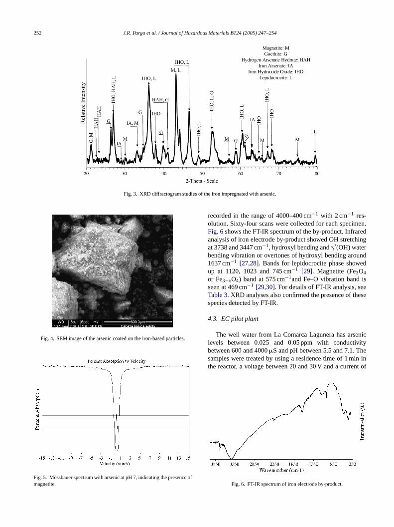
.2.2. Scanning electron microscopyFig. 4shows an SEM image of As contaminated iron o
ydroxide particles. This image and the image of the enispersive analysis of X-rays (EDAX) (not presented hhow that the surface of these particles were coated wayer of As species.
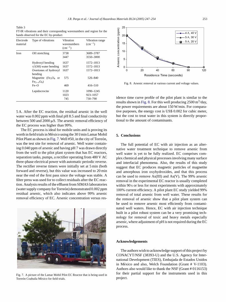
.2.3. Transmission M¨ossbauer spectroscopyFig. 5 shows the spectrum obtained for the filtered s
roducts (the pH of the solution after EC was∼7.0).ossbauer Spectrum for each sample was obtained15 mm/s velocity scale, which allows for observationide magnetic hyperfine spectra expected from iron oompounds. The spectrum consists of a doublet magpectrum, which is probably due to fine particles ofxides (non-stoichiometric magnetite, seeFig. 3) or ironydroxides (Goethite etc., seeFig. 3).
.2.4. Fourier transform infrared spectroscopyFT-IR analysis were carried out by Thermonicolate FT
pectrometer and OMNIC software using potassiumide pellets (sample:KBr = 1:50). The spectra were usu
252 J.R. Parga et al. / Journal of Hazardous Materials B124 (2005) 247–254
Fig. 3. XRD diffractogram studies of the iron impregnated with arsenic.
Fig. 4. SEM image of the arsenic coated on the iron-based particles.
Fig. 5. Mossbauer spectrum with arsenic at pH 7, indicating the presence ofmagnetite.
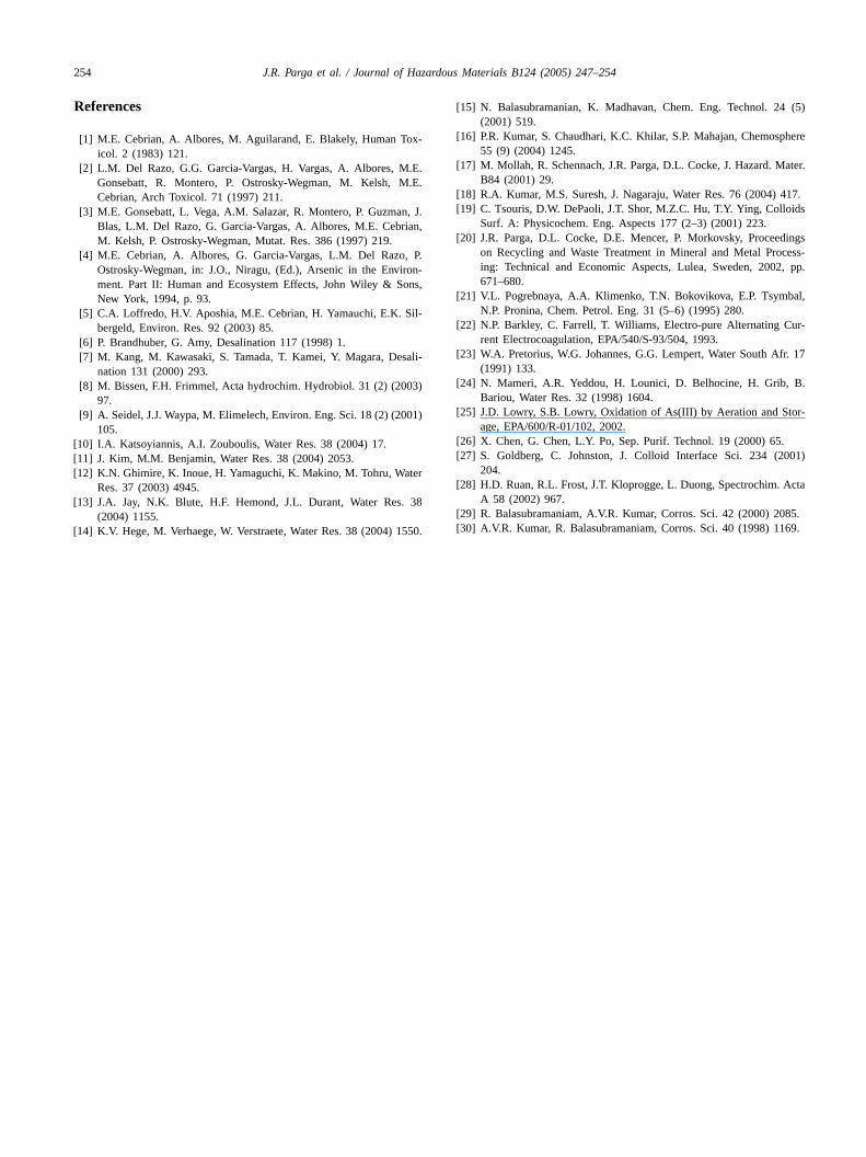
recorded in the range of 4000–400 cm−1 with 2 cm−1 res-olution. Sixty-four scans were collected for each specimen.Fig. 6shows the FT-IR spectrum of the by-product. Infraredanalysis of iron electrode by-product showed OH stretchingat 3738 and 3447 cm−1, hydroxyl bending and�′(OH) waterbending vibration or overtones of hydroxyl bending around1637 cm−1 [27,28]. Bands for lepidocrocite phase showedup at 1120, 1023 and 745 cm−1 [29]. Magnetite (Fe3O4or Fe3−xO4) band at 575 cm−1and Fe–O vibration band isseen at 469 cm−1 [29,30]. For details of FT-IR analysis, seeTable 3. XRD analyses also confirmed the presence of thesespecies detected by FT-IR.
4.3. EC pilot plant
The well water from La Comarca Lagunera has arseniclevels between 0.025 and 0.05 ppm with conductivitybetween 600 and 4000�S and pH between 5.5 and 7.1. Thesamples were treated by using a residence time of 1 min inthe reactor, a voltage between 20 and 30 V and a current of
Fig. 6. FT-IR spectrum of iron electrode by-product.
J.R. Parga et al. / Journal of Hazardous Materials B124 (2005) 247–254 253
Table 3FT-IR vibrations and their corresponding wavenumbers and region for thebands observed for the EC by-product
Electrodematerial
Type of vibrations Vibrationwavenumbers(cm−1)
Vibration range(cm−1)
Iron OH stretching 3738 3689–37873447 3550–3000
Hydroxyl bending 1637 1572–1813�′(OH) water bending 1637 1572–1813Overtones of hydroxylbending
1637 1572–1813
Magnetite (Fe3O4 orFe3−xO4)
575 526–840
Fe–O 469 416–510
Lepidocrocite 1120 1090–12451023 923–1057745 730–790
5 A. After the EC reaction, the residual arsenic in the wellwater was 0.002 ppm with final pH 8.5 and final conductivitybetween 500 and 2000�S. The arsenic removal efficiency ofthe EC process was higher than 99%.
The EC process is ideal for mobile units and is proving itsworth in field trials in Mexico using the 30 l/min Lamar MobilPilot Plant as shown inFig. 7. Well #50, in the city of Torreon,was the test site for removal of arsenic. Well water contain-ing 0.040 ppm of arsenic and having pH 7 was drawn directlyfrom the well to the pilot plant system that has EC reactors,separation tanks, pumps, a rectifier operating from 480 V ACthree-phase electrical power with automatic periodic reverse.The rectifier reverse timers were initially set at 5 min (bothforward and reverse), but this value was increased to 20 minnear the end of the first pass since the voltage was stable. Afilter press was used for to collect residuals after the EC reac-tion. Analysis results of the effluent from SIMAS laboratories(water supply company for Torreon) demonstrated 0.002 ppmresidual arsenic, which also indicates above 99% arsenicremoval efficiency of EC. Arsenic concentration versus res-
F d inT
Fig. 8. Arsenic removal at various current and voltage values.
idence time curve profile of the pilot plant is similar to theresults shown inFig. 8. For this well producing 2500 m3/day,the power requirements are about 150 W/min. For compara-tive purposes, the energy cost is US$ 0.002 for cubic meter,but the cost to treat water in this system is directly propor-tional to the amount of contaminants.
5. Conclusions
The full potential of EC with air injection as an alter-native water treatment technique to remove arsenic fromwell water is yet to be fully realized. EC comprises com-plex chemical and physical processes involving many surfaceand interfacial phenomena. Also, the results of this studysuggest that EC produces magnetic particles of magnetiteand amorphous iron oxyhydroxides, and that this processcan be used to remove As(III) and As(V). The 99% arsenicremoval in the experimental EC reactor is usually completedwithin 90 s or less for most experiments with approximately100% current efficiency. A pilot plant EC study yielded 99%removal of total arsenic from well water. These results forthe removal of arsenic show that a pilot plant system canbe used to remove arsenic most efficiently from contami-nated well waters. Hence, EC with air injection technique
ch-allye EC
ct byer-idos3).53)this
ig. 7. A picture of the Lamar Mobil Pilot EC Reactor that is being useorreon Coahuila Mexico for field trials.
built in a pilot robust system can be a very promising tenology for removal of toxic and heavy metals especiarsenic, where adjustment of pH is not required during thprocess.
Acknowledgements
The authors wish to acknowledge support of this projeCONACYT/NSF (38393-U) and the U.S. Agency for Intnational Development (TIES), Embajada de Estados Unin Mexico and also, Welch Foundation (Grant # V-110Authors also would like to thank the NSF (Grant # 01161for their partial support for the instruments used inproject.
254 J.R. Parga et al. / Journal of Hazardous Materials B124 (2005) 247–254
References
[1] M.E. Cebrian, A. Albores, M. Aguilarand, E. Blakely, Human Tox-icol. 2 (1983) 121.
[2] L.M. Del Razo, G.G. Garcia-Vargas, H. Vargas, A. Albores, M.E.Gonsebatt, R. Montero, P. Ostrosky-Wegman, M. Kelsh, M.E.Cebrian, Arch Toxicol. 71 (1997) 211.
[3] M.E. Gonsebatt, L. Vega, A.M. Salazar, R. Montero, P. Guzman, J.Blas, L.M. Del Razo, G. Garcia-Vargas, A. Albores, M.E. Cebrian,M. Kelsh, P. Ostrosky-Wegman, Mutat. Res. 386 (1997) 219.
[4] M.E. Cebrian, A. Albores, G. Garcia-Vargas, L.M. Del Razo, P.Ostrosky-Wegman, in: J.O., Niragu, (Ed.), Arsenic in the Environ-ment. Part II: Human and Ecosystem Effects, John Wiley & Sons,New York, 1994, p. 93.
[5] C.A. Loffredo, H.V. Aposhia, M.E. Cebrian, H. Yamauchi, E.K. Sil-bergeld, Environ. Res. 92 (2003) 85.
[6] P. Brandhuber, G. Amy, Desalination 117 (1998) 1.[7] M. Kang, M. Kawasaki, S. Tamada, T. Kamei, Y. Magara, Desali-
nation 131 (2000) 293.[8] M. Bissen, F.H. Frimmel, Acta hydrochim. Hydrobiol. 31 (2) (2003)
97.[9] A. Seidel, J.J. Waypa, M. Elimelech, Environ. Eng. Sci. 18 (2) (2001)
105.[10] I.A. Katsoyiannis, A.I. Zouboulis, Water Res. 38 (2004) 17.[11] J. Kim, M.M. Benjamin, Water Res. 38 (2004) 2053.[12] K.N. Ghimire, K. Inoue, H. Yamaguchi, K. Makino, M. Tohru, Water
Res. 37 (2003) 4945.[13] J.A. Jay, N.K. Blute, H.F. Hemond, J.L. Durant, Water Res. 38
(2004) 1155.[14] K.V. Hege, M. Verhaege, W. Verstraete, Water Res. 38 (2004) 1550.
[15] N. Balasubramanian, K. Madhavan, Chem. Eng. Technol. 24 (5)(2001) 519.
[16] P.R. Kumar, S. Chaudhari, K.C. Khilar, S.P. Mahajan, Chemosphere55 (9) (2004) 1245.
[17] M. Mollah, R. Schennach, J.R. Parga, D.L. Cocke, J. Hazard. Mater.B84 (2001) 29.
[18] R.A. Kumar, M.S. Suresh, J. Nagaraju, Water Res. 76 (2004) 417.[19] C. Tsouris, D.W. DePaoli, J.T. Shor, M.Z.C. Hu, T.Y. Ying, Colloids
Surf. A: Physicochem. Eng. Aspects 177 (2–3) (2001) 223.[20] J.R. Parga, D.L. Cocke, D.E. Mencer, P. Morkovsky, Proceedings
on Recycling and Waste Treatment in Mineral and Metal Process-ing: Technical and Economic Aspects, Lulea, Sweden, 2002, pp.671–680.
[21] V.L. Pogrebnaya, A.A. Klimenko, T.N. Bokovikova, E.P. Tsymbal,N.P. Pronina, Chem. Petrol. Eng. 31 (5–6) (1995) 280.
[22] N.P. Barkley, C. Farrell, T. Williams, Electro-pure Alternating Cur-rent Electrocoagulation, EPA/540/S-93/504, 1993.
[23] W.A. Pretorius, W.G. Johannes, G.G. Lempert, Water South Afr. 17(1991) 133.
[24] N. Mameri, A.R. Yeddou, H. Lounici, D. Belhocine, H. Grib, B.Bariou, Water Res. 32 (1998) 1604.
[25] J.D. Lowry, S.B. Lowry, Oxidation of As(III) by Aeration and Stor-age, EPA/600/R-01/102, 2002.
[26] X. Chen, G. Chen, L.Y. Po, Sep. Purif. Technol. 19 (2000) 65.[27] S. Goldberg, C. Johnston, J. Colloid Interface Sci. 234 (2001)
204.[28] H.D. Ruan, R.L. Frost, J.T. Kloprogge, L. Duong, Spectrochim. Acta
A 58 (2002) 967.[29] R. Balasubramaniam, A.V.R. Kumar, Corros. Sci. 42 (2000) 2085.[30] A.V.R. Kumar, R. Balasubramaniam, Corros. Sci. 40 (1998) 1169.