application for approval of packaging of fissile radioactive
TRANSCRIPT
WESTINGHOUSE ELECTRIC COMPANY LLCNUCLEAR FUEL
APPLICATION FOR APPROVALOF PACKAGING OF
FISSILE RADIOACTIVE MATERIAL(MCC SHIPPING CONTAINERS)
PACKAGE IDENTIFICATION NUMBERUSAI9239IAF
Revision 12August 2006
U.S. NUCLEAR REGULATORY COMMISSIONDOCKET 71-9239
Information in this record was deletedin accordance with the Freedom of !nfonalorfAct, exemptions
1ý ýV\
TABLE OF CONTENTS
TABLE OF CONTENTS......................................................................................... iiiRECORD OF REVISIONS ............................... ;...................................................... ViiLIST OF EFFECTIVE PAGES .................................................................................. ix
CHAPTER 1:1.11.2
GENERAL INFORMATION............................................................ 1-1INTRODUCTION........................................................................ 1-1PACKAGE DESCRIPTION ............................................................ 1-1
APPENDIX 1-1APPENDIX 1-2APPENDIX 1-3APPENDIX 1-4APPENDIX 1-5APPENDIX 1-6
APPENDIX 1-7
APPENDIX 1-8
REFERENCES .... .......................................... Al-I-ICONTAINER EQUIPMENT SPECIFICATIONS....... Al-2-1CONTAINER DRAWINGS................................. Al-3-1RADIONUCLIDE QUANTITIES.......................... A1-4-1FUEL ASSEMBLY PARAMETERS....................... Al-S-iASSEMBLY NEUTRON ABSORBERSPECIFICATIONS .......................................... Al1-6-1Gd2O3 NEUTRON ABSORBER PLATESSPECIFICATIONS .......................................... Al-7-1DESIGN COMPARISON OF THE MCC-5PACKAGE TO THE MCC-4 PACKAGE.................. Al-8-1
CHAPTER 2:2.12.22.32.42.52.62.72.82.9
STRUCTURAL EVALUATION........................................................ 2-1STRUCTURAL DESIGN ............................................................... 2-1WEIGHTS AND CENTERS OF GRAVITY ........................................... 2-1MECHANICAL PROPERTIES OF MATERIALS .................................... 2-1GENERAL STANDARDS FOR ALL PACKAGES................................... 2-2STANDARD FOR TYPE B AND LARGE QUANTITY PACKAGING ............ 2-2NORMAL CONDITIONS OF TRANSPORT ......................................... 2-2HYPOTHETICAL ACCIDENT CONDITIONS ...................................... 2-4SPECIAL FORM................................... 2-7FUEL RODS.............I................................................................. 2-7
APPENDIX 2-1APPENDIX 2-2
APPENDIX 2-3APPENDIX 2-4
APPENDIX 2-5
APPENDIX 2-5.1APPENDIX 2-5.2
REFERENCES............................................... A2-1-1CONTAINER WEIGHTS AND CENTERS OFGRAVITY.................................................... A2-2-1CONTAINER LOAD SUSPENSION SYSTEM .......... A2-3-1CALCULATIONS AND EVALUATIONSRELATING TO ASSESSMENT OF NORMALCONDITIONS OF TRANSPORT.......................... A2-4-1CALCULATIONS AND EVALUATIONSRELATING TO ASSESSMENT OFHYPOTHETICAL ACCIDENT CONDITIONS .......... A2-5-1CALCULATIONS......................................... A2-5.1-1EVALUATION OF DROP ANGLE ...................... A2-5.2- 1
III August 2006Revision 12
Docket No. 71-9239
TABLE OF CONTENTS (cont.)
APPENDIX 2-5.3APPENDIX 2-5.4
APPENDIX 2-5.5
APPENDIX 2-6
EVALUATION OF TEST RESULTS .................... A2-5.3-1CLAMPING FRAME COMPRESSIONTEST RESULTS............................................ A2-5.4-1MCC-3JMCC-4 BOUNDING CASEASSESSMENT ............................................ A2-5.5-ISTRUCTURAL CALCULATIONS ANDEVALUATIONS RELATING TO THEASSESSMENT FOR TRANSPORTATIONOF VVER 1000 FUEL .................................... A2-6.5-1
CHAPTER 3:
CHAPTER 4:4.14.24.3
CHAPTER 5:
CHAPTER 6:.6.16.26.36.46.5
THERMAL EVALUATION............................................................. 3-1
CONTAINMENT......................................................................... 4-1CONTAINMENT BOUNDARY........................................................ 4-1REQUIREMENTS FOR NORMAL CONDITIONS OFTRANSPORT............. 4-1CONTAINMENT REQUIREMENTS FOR THE HYPOTHETICALACCIDENT CONDITION .............................................................. 4-1
SHIELDING EVALUATION ........................................................... 5-1
CRITICALITY EVALUATION ......................................................... 6-1DISCUSSION AND RESULTS.........;................................................ 6-1PACKAGE FUEL LOADING........................................................... 6-3MODEL SPECIFICATION.............................................................. 6-3CRITICALITY CALCULATION ..................................................... 6-14CRITICAL BENCHMARK EXPERIMENTS........................................ 6-16
APPENDIX 6-2
APPENDIX 6-3
REFERENCES ............................................... A6-1-1EVALUATION OF THE NUCLEARCRITICALITY SAFETY OF UNPACKAGEDFUEL ASSEMBLIES........................................ A6-2-1EVALUATION OF THE NUCLEARCRITICALITY SAFETY OF PACKAGEDFUEL ASSEMBLIES........................................ A6-3-1
CHAPTER 7:
7.1
7.37.47.5
ROUTINE SHIPPING CONTAINER UTILIZATION SUMMARYOPERATING PROCEDURES .......................................................... 7-1RECEIVE FUEL ASSEMBLY SHIPPING CONTAINER............................ 7-1CLEAN SHIPPING CONTAINER ..................................................... 7-1REFURBISH SHIPPING CONTAINER............................................... 7-1PREPARE CONTAINER FOR FUEL ASSEMBLY LOADING ..................... 7-1INSPECTION ............................................................................ 7-2
Docket No. 71-9239 IV Iv August 2006Revision 12
TABLE OF CONTENTS (cont.)
7.67.77.87.97.107.117.12
CHAPTER 8:
8.18.28.3
FUEL ASSEMBLY LOADING......................................................... 7-2INSPECTION ............................................................................ 7-4CLOSE SHIPPING CONTAINER ...................................................... 7-4INSPECTION..................................... ..... 74TRUCK LOADING OF SHIPPING CONTAINERS ................................. 7-4REGULATORY........................................................................... 7-5INSPECTION ............................................................................ 7-5
ACCEPTANCE TESTS, MAINTENANCE PROGRAM ANDRECERTIFICATION PROGRAM...................................................... 8-1ACCEPTANCE TESTS .......................... 0....................................... 8-IMAINTENANCE PROGRAM......I.................................................... 8-1RECERTIFICATION PROGRAM ............................. ........................ 8-1
Docket No. 7 1-9239 V August 2006Revision 12
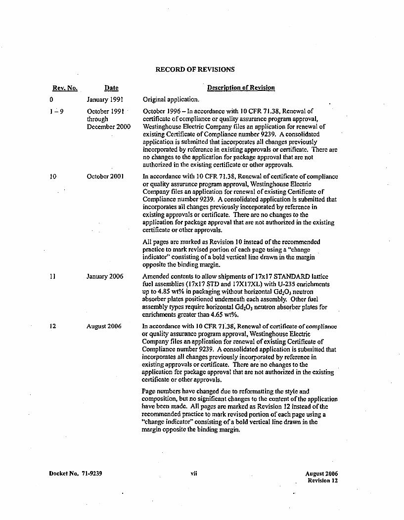
RECORD OF REVISIONS
Rev. No.
0
1-9
10
Date
January 1991
October 1991throughDecember 2000
October 2001
I1I January21006
12 August 2006
Docket No. 7 1-9239
Descripition or Revision
Original application.
October 1996 -In accordane with 10 CFR 71.38, Renewal ofcertificate of compliance or quality assurance program approval,Westinghouse Electric Company files an application for renewal ofexisting Certificate of Compliance number 9239. A consolidatedapplication is submitted that incorporates all changes previouslyincorporated by reference in existing approvals or certificate. There areno changes to the application for package approval that are notauthorized in the existing certificate or other approvals.
In accordane with 10 CFR 71.38, Renewal of certificate of complianceor quality assurance program approval, Westinghouse ElectricCompany files an application for renewal of existing Certificate ofCompliance number 9239. A consolidated application is submitted thatincorporates all changes previously incorporated by reference inexisting approvals or certificate. There are no changes to theapplication for package approval that are not authorized in the existingcertificate or other approvals.
All pages are marked as Revision 10 instead of the recommendedpractice to mark revised portion of each page using a "changeindicator" consisting of a bold vertical line drawn in the marginopposite the binding margin.
Amended contents to allow shipments of 1 7x 17 STANDARD latticefuel assemblies (17x17 STD and I7Xl7XL) with U-235 enrichmentsup to 4.85 wt% in packaging without horizontal Gd2O3 neutronabsorber plates positioned underneath each assembly. Other fuelassembly types require horizontal Gd2O3 neutron absorber plates forenrichments greater than 4.65 wt%.
In accordance with 10 CFR 71.38, Renewal of certificate of complianceor quality assurance program approval, Westinghouse ElectricCompany files an application for renewal of existing Certificate ofCompliance number 9239. A consolidated application is submitted thatincorporates all changes previously incorporated by reference inexisting approvals or certificate. There are no changes to theapplication for package approval that are not authorized in the existingcertificate or other approvals.
Page numbers have changed due to reformatting the style andcomposition, but no significant changes to the content of the applicationhave been made. All pages are marked as Revision 12 instead of therecommended practice to mark revised portion of each page using a"change indicator" consisting of a bold vertical line drawn in themargin opposite the binding margin.
vii August 2006Revision 12
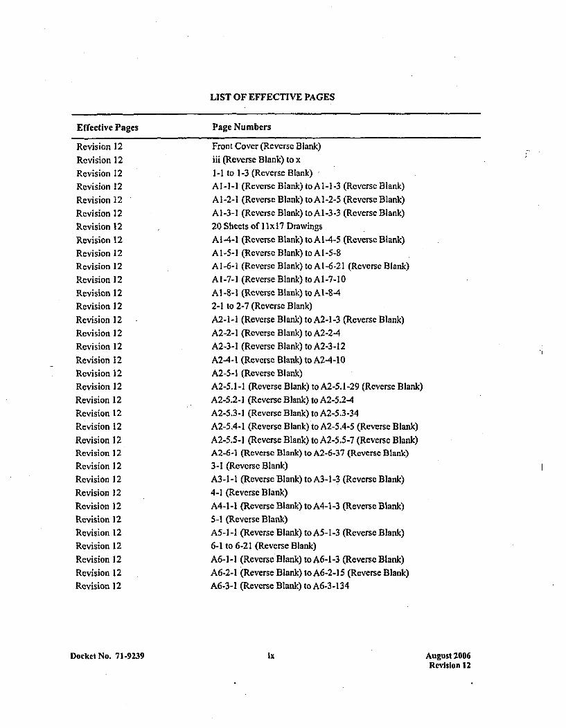
LIST OF EFFECTIVE PAGES
Effective Pages Page Numbers
Revision 12Revision 12Revision 12Revision 12Revision 12Revision 12Revision 12Revision 12Revision 12Revision 12Revision 12Revision 12Revision 12Revision 12Revision 12Revision 12Revision 12Revision 12Revision 12Revision 12Revision 12Revision 12Revision 12Revision 12Revision 12Revision 12Revision 12Revision 12Revision 12Revision 12Revision 12Revision 12Revision 12Revision 12
Front Cover (Reverse Blank)iii (Reverse Blank) to x1-1 to 1-3 (Reverse Blank)Al-I-i (Reverse Blank) toMi-l-3 (Reverse Blank)A 1 -2-1 (Reverse Blank) to Al1-2-5 (Revecrse Blank)A] -3-1 (Reverse Blank) to Al-3-3 (Reverse Blank)20 Sheets of I I x17 DrawingsAl -4-1 (Reverse Blank) to Al1-4-5 (Reverse Blank)Al1-5-1 (Reverse Blank) to Al1-5-8A 1 -6-1 (Reverse Blank) to AI1-6-21 (Reverse Blank)A 1-7-1 (Reverse Blank) to Al1 -7-10*A1-8-l1 (Reverse Blank) to A 1-8-42-I to 2-7 (Reverse Blank)A2-1 -1 (Reverse Blank) to A2-1-3 (Reverse Blank)A2-2-1 (Reverse Blank) to A2-2-4A2-3-1 (Reverse Blank) to A2-3-12A2-4-1 (Reverse Blank) to A2-4-1O0A2-5-1 (Reverse Blank)A2-5. 1-1 (Reverse Blank) to A2-5.1-29 (Reverse Blank)A2-5.2-1 (Reverse Blank) to A2-5.2-4A2-5.3-1 (Reverse Blank) to A2-5.3-34A2-5.4-1 (Reverse Blank) to A2-5.4-5 (Reverse Blank)A2-5.5-1 (Reverse Blank) to A2-5.5-7 (Reverse Blank)A2-6-1 (Reverse Blank) to A2-6-37 (Reverse Blank)3-1 (Reverse Blank)A3-1 -1 (Reverse Blank) to AM- -3 (Reverse Blank)4-I (Reverse Blank)A4-1 -1 (Reverse Blank) to A4-1-3 (Reverse Blank)5-1 (Reverse Blank)A5-1I-I (Reverse Blank) to A5-1-3 (Reverse Blank)6-1 to 6-21 (Reverse Blank)A6-1I-1 (Reverse Blank) to A6-1-3 (Reverse Blank)A6-2-1 (Reverse Blank) to A6-2-15 (Reverse Blank)A6-3-1 (Reverse Blank) to A6-3-1 34
F
Docket No. 71-9239 ix August 2006Revision 12
LIST OF EFFECTIVE PAGES (co nt.)
Effective Pages Page Numbers
Revision 12Revision 12Revision 12Revision 12
7-1 to 7-5 (Reverse Blank)A7-1 -1 (Reverse Blank) to A7-1-3 (Reverse Blank)8-1 to 8-2A8-1I-1 (Reverse Blank) to A8-1-3 (Reverse Blank)
Docket No. 71-9239 x August 2006Revision 12
CHAPTER 1: GENERAL INFORMATION
1.1 IN4TRODUCTION
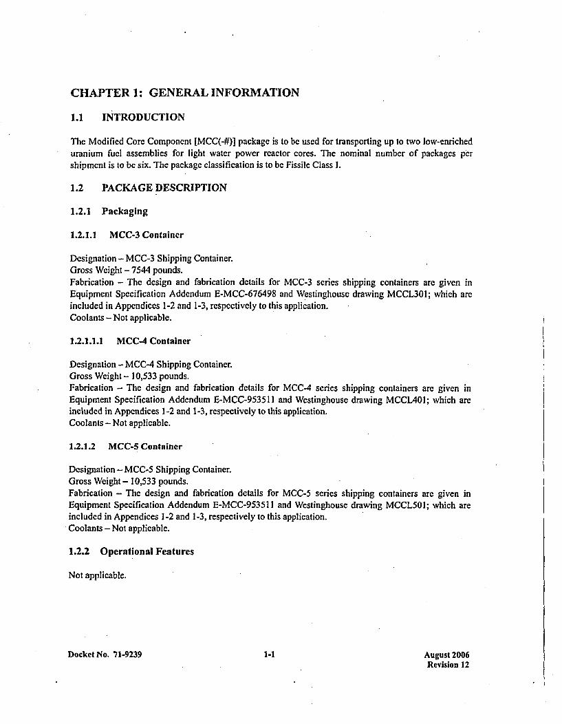
The Modified Core Component [MCC(-#)] package is to be used for transporting up to two low-enricheduranium fuel assemblies for light water power reactor cores. The nominal number of packages pershipment is to be six. The package classification is~to be Fissile Class 1.
1.2 PACKAGE DESCRIPTION
1.2.1 Packaging
1.2.1.1 MCC-3 Container
Designation - MCC-3 Shipping Container.Gross Wcight - 7544 pounds.Fabrication - The design and fabrication details for MCC-3 series shipping containers are given inEquipment Specification Addendum E-MCC-676498 and Westinghouse drawing MCCL3OI; which areincluded in Appendices 1-2 and 1-3, respectively to this application.Coolants - Not applicable.
1.2.1.1.1 MCC-4 Container
Designation - MCC-4 Shipping Container.Gross Weight - 10,533 pounds.Fabrication - The design and fabrication details for MCC-4 series shipping containers are given inEquipment Specification Addendum E-MCC-9535 11 and Westinghouse drawing MCCL4Ol; which areincluded in Appendices 1-2 and 1-3, respectively to this application.Coolants - Not applicable.
1.2.1.2 MCC-5 Container
Designation - MCC-5 Shipping Container.Gross Weight - 10,533 pounds.Fabrication - The design and fabrication details for MCC-5 series shipping containers are given inEquipment Specification Addendum E-MCC-9535 11 and Westinghouse drawing MCCL5O I; which areincluded in Appendices 1-2 and 1-3, respectively to this application.Coolants - Not applicable.
1.2.2 Operational Features
Not applicable.
Docket No. 71-9239 1-1 August 2006Revision 12

1.2.3 Contents of Packaging ,
1.2.3.1 MCC-3 Container - Contents Description
Identification and Enrichment of Special Nuclear Material (SNM) - The SNM'will be unirradiateduranium enriched up to 5 w/o in the isotopc U-235. Nominal weight-pcrccnt quantities *of principalradionuclides, at maximum enrichment, are 3 U 0.044 ; 211U: 5.000; 216U: 0.004; 2381U: 94.952.Radionuclide quantity details arc included in Appendix 1-4 to this application.
Form of SNM - The SNM will be in the formn of clad fuel assemblies. In the clad form, the assemblieswill not disruptively react or decompose at the Accident Thermal Condition. No chips, powders, orsolutions will be offered for transport in this packaging. Specific data on maximum assembly parametersarc included in Appendix 1-5 to this application.
Neutron Absorbers, etc. - For fuel assemblies containing enrichments greater than the limitingenrichment dictated by the limiting reactivity value, integral assembly neutron absorbers may be includedas necessary to meet the limit. Specific information concerning such absorbers is included in Appendix I-6 to this application. Neutron absorber plates, consisting of carbon steel, with Gd2Q3 affixed to each sideof the p late, are mounted in the packaging. Two permanently mounted plates are installed such that theyare between the contained fuel assemblies. Additional such plates may be installed beneath the containedfuel assemblies, as required to meet the limiting reactivity value. The installation is such that the presenceof the neutron absorber plates may be readily detected by visual examination. Specific informationconcerning the Gd2O3 neutron absorber plates is included in Appendix 1-7 to this application.
*Maximum Weight of Fissile Contents - 51.2 Kg 235u.*Maximum Net Weight of Contents - 3300 pounds.*Maximum Decay Heat - Not applicable.
The contents will be loaded in such a fashion that if the package were to be flooded and subsequentlydrained, any water which may have penetrated the contents would drain simultaneously.
1.2.3.2 MICC.4 Container - Contents Description
The contents description for the MCC-3 container is directly applicable to the MCC-4 container, except asfollows:
*Maximum Weight of Fissile Content - 59.7 Kg 235u.
* Maximum Net Weight of Contents - 3870 pounds.
1.2.3.3 MCC-5 Container - Contents Description
The contents description for the MCC-3 container is directly applicable to the MCC-5 container, except asfollows:
There are Gd2O3 neutron absorber plates which are permanently installed in the MCC-S container: thetwo, previously described, which are installed between the two assemblies; and segmented plates which
Docket No. 71-9239 1-2 August 2006Revision 12
are installed under the strongback. Additional vee-shapcd plates may be installed beneath the containedfuel assemblies as required to meet the limiting reactivity value.
* Maximum Weight of Fissile Content - 52 Kg 115U.
* Maximum Net Weight of Contents - 3700 pounds.
The MCC-5 package is essentially identical in design and size as the MCC-4 package, but with severalminor notable differences. The significance of these minor differences is addressed in Sections 6 and 7,and Appendices 1-2, 1-3, 2-2, 2-6, 6-2, and 6-3. A specific list of the minor differenes is provided inAppendix 1-8, Design Comparison of the MCC-5 Package to the MCC-4 Package.
Docket No. 7 1-9239 1-3 August 2006Revision 12
APPENDIX 1-1REFERENCES
Docket No. 71-9239 Al-I-I August 2006Revision 12
* REFERENCES
No documents referenced in thc tecxt of this section.
Docket No. 71-9239 Al-1-3 August 2006Revision 12
APPENDIX 1-2CONTAINER EQUIPMENT SPECIFICATIONS
Docket No. 71-9239 Al-2-1 August 2006Revision 12
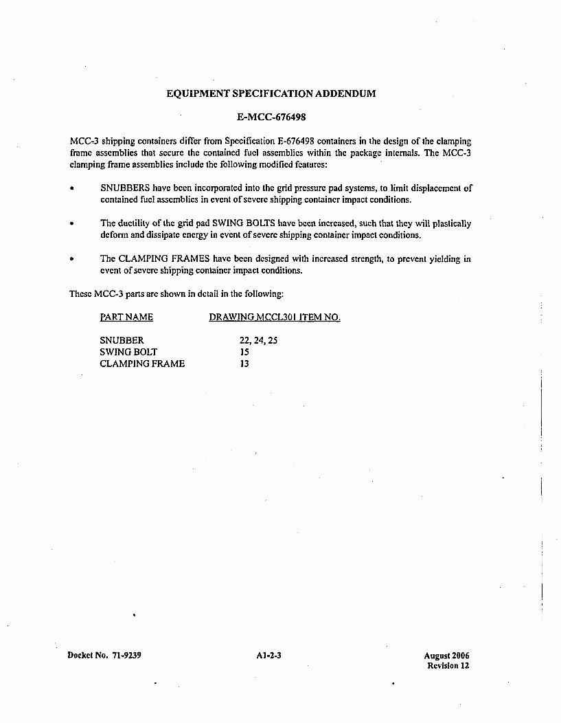
EQUIPMENT SPECIFICATION ADDENDUM
E-MCC-676498
MCC-3 shipping containers differ from Specification E-676498 containers in the design of the clampingframe assemblies that sccurc the contained fuel assemblies within the package internals. The MCC-3clamping frame assemblies include the following modified features:
* SNUBBERS have been incorporated into the grid pressure pad systems, to limit displacement ofcontained fuel assemblies in event of severe shipping container impact conditions.
* The ductility of the grid pad SWING BOLTS have been increased, such that they will plasticallydeform and dissipate energy in event of severe shipping container impact conditions.
* The CLAMPING FRAMES have been designed with increased strength, to prevent yielding inevent of severe shipping container impact conditions.
These MCC-3 parts are shown in detail in the following:
PART NAME DRAWING MCCL301 ITEM NO.
SNUBBER 22, 24, 25SWING BOLT 15CLAMPING FRAME 13
Docket No. 71-9239 Al-2-3 August 2006Revision 12
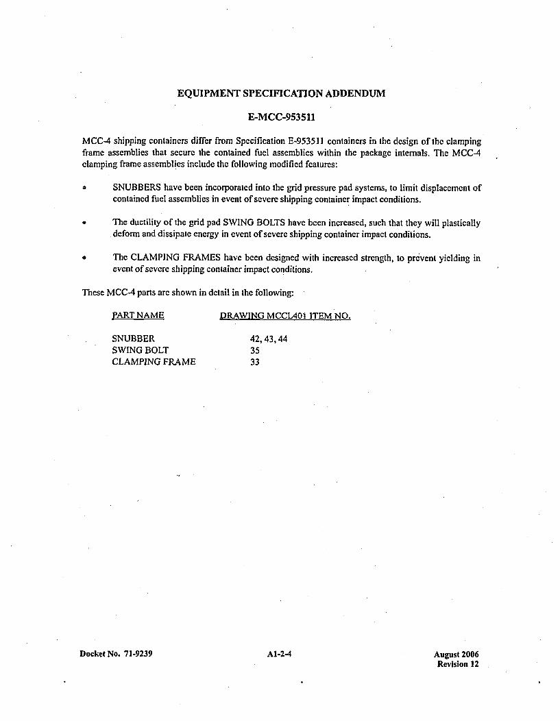
EQUIPMENT SPECIFICATION ADDENDUM
E-MCC-953511
MCC-.4 shipping containers differ from Spcification E-953511 containers in the design of the clampingframe assemblies that sccurc the contained fuel assemblies within the package internals. The MCC-4clamping frame assemblies include the following modified features:
* SNUBBERS have been incorporated into the grid pressure pad systems, to limit displacement ofcontained fuel assemblies in event of sevcre shipping container impact conditions.
* The ductility of the grid pad SWING BOLTS have been increased, such that they will plasticallydeform and dissipate energy in event of severe shipping container impact conditions.
* The CLAMPING FRAMES have been designed with increased strength, to prevent yielding inevent of severe shipping container impact conditions.
These MCC-4 parts arc shown in detail in the following:
PART NAME
SNUBBERSWING BOLTCLAMPING FRAME
Docket No. 71-9239
DRAWING MCCL4OI ITEM NO.
42, 43, 443533
Al-2-4 August 2006Revision 12
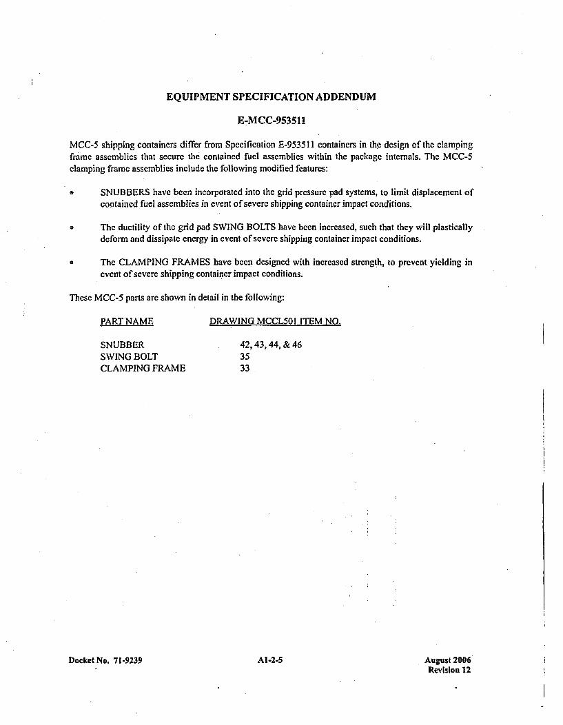
EQUIPMENT SPECIFICATION ADDENDUM
E-MCC-953511I
MCC-S shipping containers differ from Specification E-9535 11 containers in the dcsign of the clampingframe assemblies that secure the contained fuel assemblies within the package internals. The MCC-5clamping frame assemblies include the following modified features:
o SNUBBERS have been incorporated into the grid pressure pad systems, to limit displacement ofcontained fuel assemblies in event of severe shipping container impact conditions.
* The ductility of the grid pad SWING BOLTS have been increased, such that they will plasticallydeform and dissipate energy in event of severe shipping container impact conditions.
* The CLAMPING FRAMES have been designed with increased strength, to prevent yielding inevent of severe shipping container impact conditions.
These MCC-5 parts are shown in detail in the following:
PART NAME DRAWING MCCL501 ITEM NO.
SNUBBERSWING BOLTCLAMPING FRAME
42, 43, 44, & 463533
Docket No. 71-9239 Al-2-5 August 2006Revision 12

APPENDIX 1-3CONTAINER DRAWINGS
Docket No. 71-9239 Al-3-1 August 2006Revision 12
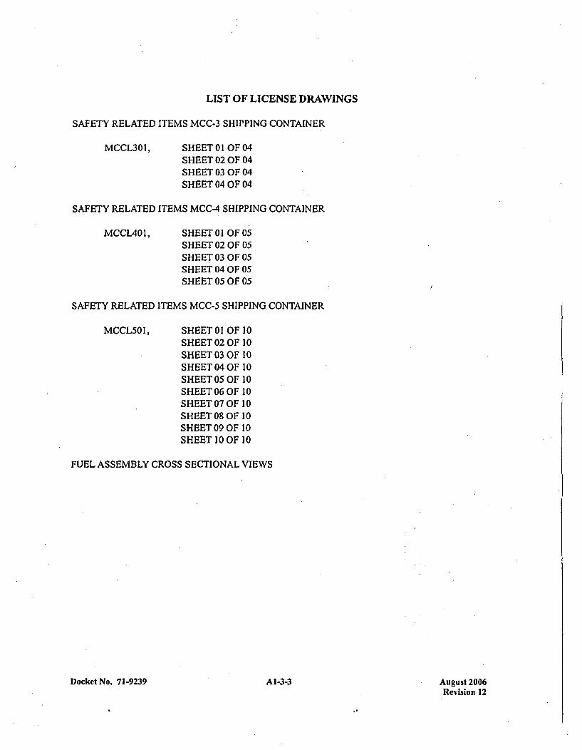
LIST OF LICENSE DRAWINGS
SAFETY RELATED ITEMS MCC-3 SHIPPING CONTAINER
MCCL3OI, SHEET 0 1 OF 04SHEET 02 OF 04SHEET 03 OF 04SHEET 04 OF 04
SAFETY RELATED ITEMS MCC-4 SHIPPING CONTAINER
MCCL401, SHEET 0 1 OFO05SHEET 02 OF 05SHEET 03 OF 05SHEET 04 OF 05SHEET 05 OF 05
SAFETY RELATED ITEMS MCC-5 SHIPPING CONTAINER
MCCL5OI, SHEET 01OF 10SHEET 02 OF 10SHEET 03 OF 10SHEET 04 OF 10SHEET 050FOF1SHEET 06 OF 10SHEET 07 OF 10SHEETO08OF 10SHEET09 OF 10SHEET 10OOF 10
FUEL ASSEMBLY CROSS SECTIONAL VIEWS
Docket No. 71-9239 Al-3-3 August 2006Revision 12
APPENDIX 1-4RADIONUCLIDE QUANTITIES
A1-4-1 uut20Docket No. 71-9239Revision 12
RADIONUCLIDE QUANTITIES
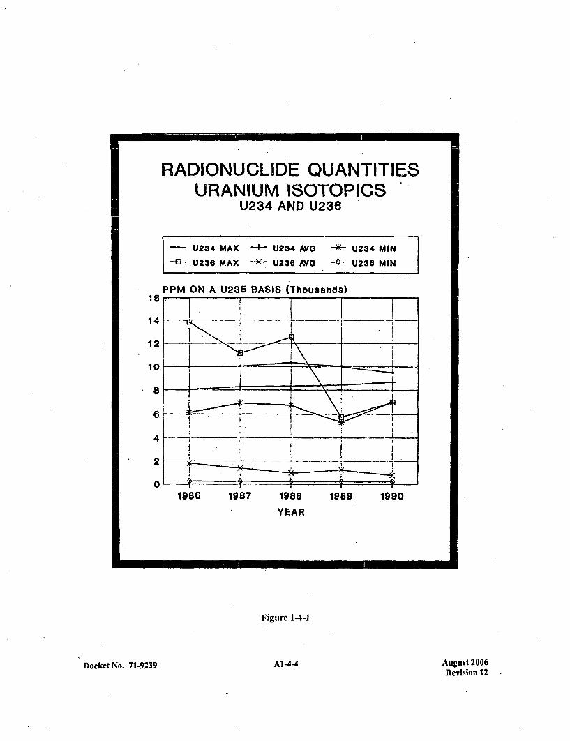
Figure 1-4-1 provides a five ycar history of Uranium isotopic measurements at the Columbia FuelFabrication Facility. The isotopes of interest in this figure arc 214U and "36U. Only these two isotopes areplotted since 235U and 238U arc relatively fixed. The 234U levels have been constant over the five yearperiod while 236U levels have varied significantly. The variance in 236 U levels is of little concern due to itslow specific activity. However , 234U levels are expected to be consistent since it is present in naturaluranium and is therefore enriched along with 23'U. The isotope 234 U accounts for 70-80 percent of thespecific activity of low enriched uranium. Data for 1990 indicate a 234 U average of 8700 Ug/g 235 U and a
26Uaverage of 750 Ug/g 235U.
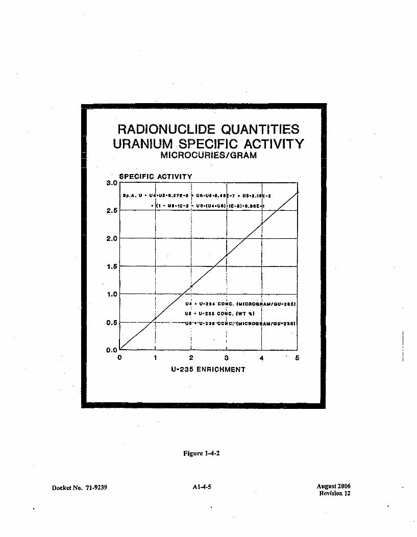
Figure 1-4-2 is constructed using the average values given above to calculate the specific activity ofuranium at various enrichments. The specific activity is calculated by multiplying the isotopicýconcentration by its specific activity. The basic equation used in these calculations is presented inFigure 1-4-2. The predicted specific activity at 5.0 Wt% 23SU enrichment is 2.8 uCi/gU. This calculatedvalue is conservative with respect to published values.
Docket No. 7 1-9239 A1-4-3 August 2006Revision 12
RADIONUCLIDE QUANTITIESURANIUM ISOTOPICS
U234 AND U236
-U234 MAX -' U234 NYO -- U234 MIN-6-U236 MAX -~-U286 AVG -- U23e MIN
1.6
14
12
10
8
6.
4
2
0
PPM ON A U235 BASIS (Thousands)
1986 1987 1988 1989 1990
YEAR
Figure 1-4-1
Docket No. 71-9239 A--A144 August 2006Revision 12
RADIONUCLIDE QUANTITIESURANIUM SPECIFIC ACTIVITY
MICROCURIES/GRAM
SPECIFIC ACTIVITY3.0
2.-6
2.0
1.5
1.0
0.5
0.0
ap.A. U - UJ..U$8 .2~?E-f UD.UG-6.48E -7 0 U6.2.11tE2
(I- US.IE-2 I Ua*(U40US6,'If-8)3.86E I
U4 U-234'CONC. (MICROGNAUIGU-235)
US* U-235 COiO. (WT %I
- l--25C1C.*AIRCýAI U221
0 1 2 3
U-235 ENRICHMENT
4
Figurc 1-4-2
Docket No. 7 1-9239 A--A14-5 August 2006Revision 12

APPENDIX 1-5FUEL ASSEMBLY PARAMETERS
Docket No. 71-9239 Al-5-1 August 2006Revision 12
FUEL ASSEMBLY PARAMETERS
The attached tables are the fuel assembly parameters for l4Xl14, 15X 15, 16X 16, 17X 17, and VVER-l1000fuel types to be transported in the MCC fuel shipping container. The parameters indicated are used in theCriticality Analysis section to support uncontained and contained fuel assembly calculations. Allparameters are used in the criticality analysis section except for thc fuel stack length which is assumed tobe infinite except in the 3D calculations performed for square lattice fuel involving IFBA and allVVER-1000 fuel assemblies in containers. Assembly reactivities, arc provided to indicate the highestreactivity fuel (1 7X 17 W-OFA) to be used in the HAC model for the criticality calculations. The tabulatedreactivity values assume an enrichment of 5 wt%, moderation by water to the most reactive credibleextent, and close reflection by water on all sides. Fuel assembly cross-sectional views are provided onWestinghousc Drawing 64811215, Sheet I of 1. The assemblies are identified by design origin withlocation identified for all fuel rods, instrument tubes (IT), and guide tubes (GT or thimbles). Theinstrument tube is a single tube centrally located and surrounded by the guide tubes.
Docket No. 71-9239 Al-5-3 August 2006Revision 12
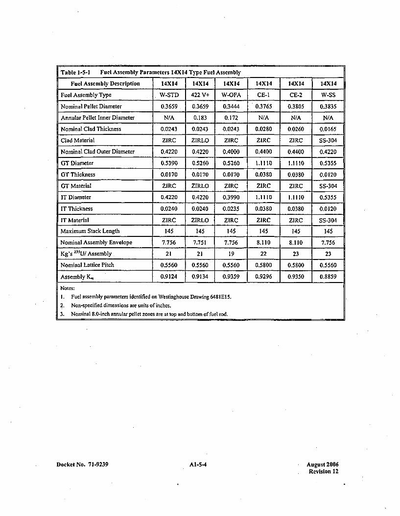
Table 1-5-1 Fuel Assembly Parameters 14X14 Type Fuel Assembly
Fuel Assembly Description 14X14 14X14 14X14 14X14 14X14 14X14
Fuel Assembly Type W-STD 422 V+ W-OFA CE-I CE-2 W-SS
Nominal Pellet Diameter 0.3659 0.3659 0.3444 0.3765 0.38,05 0.3835
Annular Pellet Inner Diameter N/A 0.183 0.172 N/A N/A N/A
Nominal Clad Thickness 0.0243 0.0243 0.0243 0.0280 0.0260 0.0 165
Clad Material ZIRC ZIRLO ZIRO ZIRC ZIRC SS-304
Nominal Clad Outer Diameter 0.4220 0.4220 0.4000 0.4400 0.4400 0.4220
GT Diameter 0.5390 0.5260- 0.5260 1.1110 1.1110 0.5355
GT Thickness 0.0170 0.0170 0.0170 0.0380 0.0380 0.0120
GT Material ZIRC ZIRLO ZIRC ZIRC ZIRC SS-304
IT Diameter 0.4220 0.4220 0.3990 1.1110 1.1110 0.5355
IT Thickness 0.0240 0.0240 0.0235 0.0380 0.0380 10.0 120
IT Material ZIRC ZIRLO ZIRC ZIRC ZIRC SS-304
Maximum Stack Length 145 145 145 145 145 145
Nominal Assembly Envelope 7.756 7.751 7.756 8.110 8.110 7.756
Kg's 135U/ Assembly . 21 21 19 22 23 23
Nominal Lattice Pitch 0.5560 0.5560 0.5560 0.5800 0.5800 0.5560
Assembly K. 0.9124 0.9134 0.9359 0.9296 0.9350 0.8859
Notes:1. Fuel assembly parameters identified on Westinghouse Drawing 64811315.
12. Non-specified dimensions are units of inches.3. Nominal 8.0-inch annular pellet zones are at top and bottom of fuel rod.
Docket No. 71-9239 Al-54 AI-5-4August 2006Revision 12
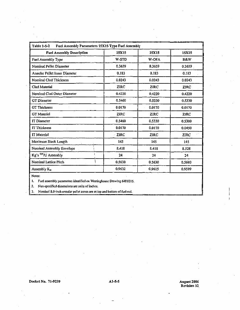
Table 1-5-2 Fuel Assembly Parameters I15X15 Type Fuel Assembly
Fuel Assembly Description 15X15 15X15 15XI5
Fuel Assembly Type W-STD W-OFA B&W
Nominal Pellet Diameter 0.3659 0.3659 0.3659
Annular Pellet Inner Diameter 0.183 0.183 0.183
Nominal Clad Thickness 0.0243 0.0243 0.0243
Clad Material ZIRC ZIRC Z1RC
Nominal Clad Outer Diameter 0.4220 0.4220 0.4220
GT Diameter 0.5460 0.5330 0.5330
GT T'hickness 0.0 170 0.0170 0.0170
GT Material ZIRC ZIRC ZIRC
IT Diameter 0.5460 0.5330 0.5300
IT Thickness 0.0170 0.0170 0.0450
IT Material ZIRC ZIRC ZIRC
Maximum Stack Length 145 145 145
Nominal Assembly Envelope 8.418 8.418 8.528
Kg's 2351U Assembly 24 24 24
rNominal Lattice Pitch .1 0.5630 0.5630 0.5680
Assembly K.~ 0.9632 0.9615 0.9599
Notes:1. Fuel assembly parameters identified on Westinghouse Drawing 6481E 15.2. Non-spccified dimensions are units of inches.3. Nominal 8.0-inch annular pellet zones are at top and bottom of fuel rod.
Docket No. 71-9239 Al-5-5 August 2006Revision 12

Table 1-5-3 Fuel Assembly Parameters 16XI6 Type Fuel Assembly
Fuel Assembly Description 16X16 16X16
Fuel Assembly Type W-STD CE
Nominal Pellet Diameter 0.3225 0.3250
Annular Pellet Inner Diameter 0.155 N/A
Nominal Clad Thickness 0.0225 0.0250
Clad Material ZIRC ZIRC
Nominal Clad Outer Diameter 0.3740 0.3820
GT Diameter 0.47 10 0.9800
GT Thickness 0.0180 0.0400
GT Material ZIRC ZIRC
IT Diameter 0.4710 0.9800
IT Thickness 0.0 180 0.0400
IT Material ZIRC ZIRC
Maximum Stack Length 145 151
Nominal Assembly Envelope 7.763 8.122
Kg'S 233U Assem bly 22 23
Nominal Lattice Pitch 0.4850 0.5060
Assembly K~. 0.9055 0.9302
Notes:1. Fuel assembly parameters identified on Westinghouse Drawing 64811El15.
2. 1 6X16 CE Fuel Design to be shipped only in MCC-4.
3. Non-specified dimensions are units of inches.
4. Nominal 8.0-inch annular pellet zones are at top and bottom of fuel rod.
Docket No. 71-9239 A1-5-6 August 2006Revision 12
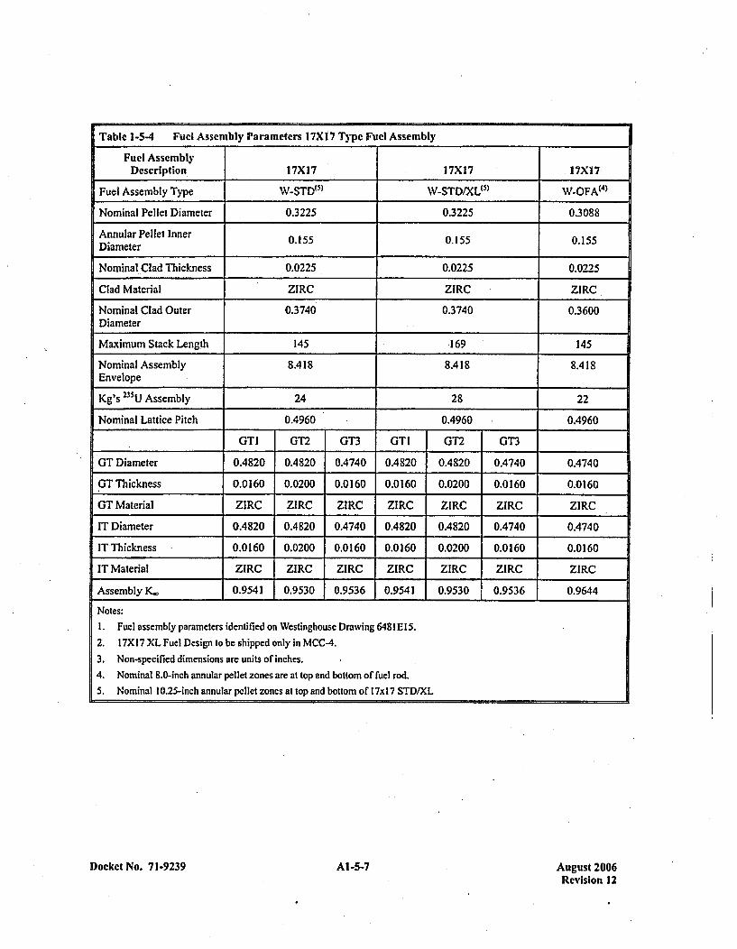
Table 1-5-4 Fuel Assembly Parameters 17XI 7 Type Fuel Assembly _______
Fuel AssemblyDescription 17X17 17X17 17Xl7
Fuel Assembly Type W-STD"5 ) W-STD/XL"5 ) WOFA(4 )
Nominal Pellet Diameter 0.3225 0.3225 0.3088
Annular Pellet Inner 0.155 0.155 0.155Diameter
Nominal-Clad Thickness 0.0225 0.0225 0.0225
Clad Material ZIRC ZIRC -ZIRC
Nominal Clad Outer 0.3740 0.3740 0.3600Diameter
Maximum Stack Length 145 169 145
Nominal Assembly 8A418 8.418 8.4 18Envelope
Kg's 235U Assembly 24 28 22
Nominal Lattice Pitch 0.4960 0.4960 0.4960
1GTI GT2 GT3 GTI GT2 GT3
OT Diameter 0.4820 0.4820 0.4740 0.48320 0.4 820 0.4740 0.474 0
GT Thickness 0.0160 0.0200 0.0160 0.0160 0.0200 0.0160 0.0160
GT Material ZIRC ZIRC ZIRC ZIRC Z1RC ZIRC ZIRC
IT Diameter 0.4820 0.4820 0.4740 0.4820 0.4820 0.4740 0.4740
IT Thickness 0.0160 0.0200 0.0160 10.0160 0.0200 0.0160 0.0160
IT Material ZIRC ZIRC ZIRC ZIRC _ZIRC Z1R.C ZIRC
Assembly K. 0.9541 0.9530 0.9536 0.954 1 0.9530 0.95 366 0,99644
Notes:1. Fuel assembly parameters identified on Westinghouse Drawing 641I El15.2. 17X 17 XL Fuel Design to be shipped only in MCC-4.3. Non-specified dimensions are units of inches.4. Nominal 8.0-inch annular pellet zones are at top and bottom of fuel rod.5. Nominal 10.25-inch annular pellet zones at top and bottom of 17x 17 STD/XL
Docket No. 7 1-9239 Al-5-7 August 2006Revision 12

Table 1-5-5 Fuel Assembly Parameters VVER-1 000 Typc Fuel Assembly
Fuel Assembly Description V'VER-1 000
Nominal Pellet Diameter 0.3088
Annular Pellet Inner Diameter 0.1550
Nominal Clad Thickness 0.0225
Clad Material ZIRC
Nominal Clad Outer Diameter 0.3600
GT Diameter 0.4740
GT Thickness 0.0 160
GT Material ZIRC
IT Diameter 0.4740
IT Thickness 0.0160
IT Material ZIRC
Maximum Stack Length 144
Kg 235U Assembly 26
Nominal Lattice Pitch 0.5020
Assembly K,ý 0.9432
Notes:I . Fuel assembly parameters identified on Westinghouse Drawing 6481 El15.2. VVER- 1000 fuel design to be shipped only in MCC-S containers.3. Non-specified dimensions are units orinches.
14. VVER-1000 fuel assembly with annular pellet zone 10 inches top and bottom.
Docket No. 7 1-9239 AI-5-8 Al -5-8August 2006Revision 12
APPENDIX 1-6ASSEMBLY NEUTRON ABSORBER SPECIFICATIONS
Docket No. 71-9239 Al-6-1 August 2006Revision 12
ASSEMBLY NEUTRON ABSORBER SPECIFICATIONS
1.1 INTEGRAL FUEL BURNABLE NEUTRON ABSORBERS (I FBA)
INTRODUCTION
In the Hypothetical Accident Condition (HAG) test of Integral Fuel Burnable Absorber rods, a conclusionwas drawn that indicated the ZrB32 maintained its relative design configuration. Therefore, two (2)undamaged fuel assemblies - having ZrB2 coated pcllets intact within zircaloy fuel rod cladding - in therelative MCC container design configuration, were modeled for the Nuclear Safety Analysis.
DESIGN
A zirconium diboride (ZrB2) coating is deposited onto the cylindrical portion of a uranium dioxide (U0 2)pellet by a sputtering system. This coating process is conducted in a cryogenicly pumped vacuumchamber housing a rotating drum. The coating process is conducted at a temperature range of1300-14707F for twelve (12) hours. Planar Magnetron cathodes mounted both within and outside of therotating drum permit coating of the cylindrical surface of the U02 Pellets nearly all around,simultaneously.
Each batch of pellets produced is identified as a specif ic coater lot. Extensive testing of each coater lot isnecessary from a quality standpoint to ensure (hat the ZrB2 has adhercd to the pellet.
INTEGRITY
In order to demonstrate that the effectiveness of the Zr132 coating will not be reduced under theHypothetical Accident Conditions (HAG) prescribed in IOCFR7l, a drop test, thermal test, and waterimmersion test were conducted using two simulated fuel rods..
The test consisted of dropping the fuel rods from a height of 30 feet onto a flat, horizontal, essentiallyunyielding surface; heating rods to a temperature of 1475*1F followed by water quenching; and immersionin water for at least 8 hours.
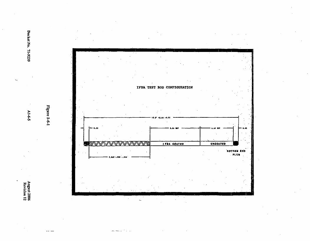
The test specimens consisted of 1 8.5 inch long fuel rods containing a (nominally) six (6) inch long stackof ZrB2 coated fuel pellets and a 4.2 inch long unco~ated fuel pellet stack in a (nominally) 0.360 inchdiameter tube. A nominal plenum length of 7.525 inches with a standard 4G helical spring was used tosimulate the hold down. The test rods were pressurized with helium to 200 psig, the standard pressure forIFBA rods.
Coated fuel stacks were weighed prior to rod fabrication. Afler welding, the rods were helium leak testedand the girth and seal welds were ultrasonically inspected to assure the integrity of the, welds. The pelletstacks were x-rayed, and the coated zone location was determined by active gamma scanning.Figure 1-6-1 illustrates the test rod configuration. Average boron loading on pellets was analyticallydetermined using coated pellets from the same lot as those used in the test rods.
Docket No. 71-9239 Al-6-3 August 2006Revision 12
The drop test consisted of dropping one test rod on the bottom (pellet) end, and a second rod on thehoiddown spring end, from a height of 30 feet onto a half (1/2) inch thick steel plate that rested on aconcrete floor. After the drop test, both rods were helium leak tested to confirm that the rod integrity wasnot lost; Subsequently, the test rods were placed in a muffle furnace preheated to 1475*F for 30 minutes.Although the average temperature at the center of the furnace was as specified (based on thermocoupleindications), the back end of the furnace was 150"F higher. This higher temperature caused the cladding.to balloon, which resulted in a creep rupture type failure of the cladding in a 2 inch section. Subsequentwater (68*F) immersion for a period of no less than 8 hours resulted in water ingress into the rods. Thecondition made the test more severe than that specified in IOCFR71 and, therefore, the results areconsidered to be conservative.
After completion of water immersion, both test rods were x-rayed to dctermhinc the condition of the pelletstacks. X-ray inspection showed that the pellet stacks were intact in both the test rods. In the first rod,dropped on the bottom (pellet) end, considerable pellet fragmentation was observed. In the second rod,dropped on the 'holddown spring end, the coated and uncoated stacks were intact with only a smallamount of fragmentation in the uncoated section.
Next, the first rod was gamma scanned to locate the ZrB2 coated pellet zone. Gamma scan resultsillustrated in Figure 1-6-2 showed that the drop, thermal, and water immersion tests did not affect theZrB2 coating adherence to the pellets. The coating effectively stayed in position. The differences in thedelayed gamma counts before and after the test (Figure 1-6-2) are due to normal equipment and testuncertainties. The second rod could not be properly gamma scanned because of problems encountered intransporting it through the gamma scanner due to its bowed condition.
The test rods were subsequently sectioned to remove the pellet stacks and perform ceramographicexamination of the coated pellets. Since the pellet stack in the second rod could be removed intact, thepellets were dried and weighed, and the weight was compared to the pre-test weight. Results are presentedin Table 1-6-1. Adherence of the ZrB2 coating to the pellet was determined from ceramography, andanalytical measurement of boron on tested and control pellets from the same coater lot. Table 1-6-2 showsa comparison of the measured boron loading on coated pellets from the test rods with that on pelletswhich had not undergone testing. The test results are within the normal process variability as defined inTable 1-6-3. A similar ceramographic comparison is illustrated in Figure 1-6-3.
The test results conclusively proved that the ZrB2 coating stayed on the pellets, and that the pellet stacks(although fragmented) did not move within the rod, thus demonstrating the effectiveness under thehypothetical accident conditions.
Docket No. 71-9239 Al1-6-4 August 2006Revision 12
C
zC
-J
'0
'C
IFBA'TEST ROD.CONFIGURATION
-t
0\
- 0.18
IF'A COATED* WIOOATED
S NDh
___________pegs *.S*e ..e,,*
SOTTOM. LUI
It It
0-~0~4 0%

GAMMA SCAN-OF IFBA TEST ROD #1RELATIVE COUNTS vs.
RELATIVE LENGTH
- BEFORE TEST -AFTER -TEST
C0
TS
0 20 40 60
LENGTHso 100 120
Figure 1-6-2
Docket No. 7 1-9239 A-Al-" August 2006Revision 12
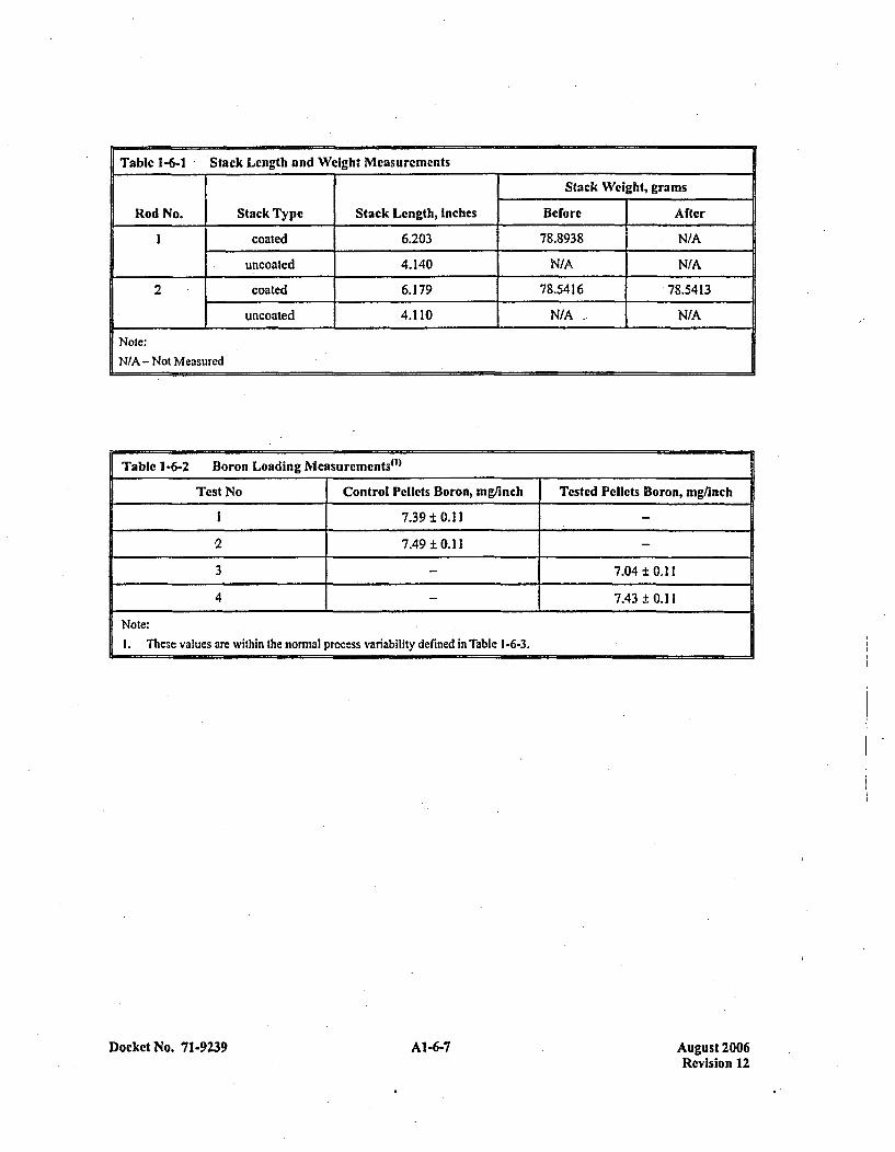
Table 1-6-1 Stack Length and Weight Measurements
Stack Weight, grams
Rod No. Stack Type Stack Length, Inches Before After
Icoated 6.203 78.8938 N/A
uncoated 4.140 NIA N/A
2 coated 6.179 78.5416 78.5413
uncoated 4.110 N/A N/A
Note:N/A - Not Measured
Table 1-6-2 Boron Loading Measurcments"l)
Test No Control Pellets Boron, mg/inch Tested Pellets Boron, mgrinch
1 7.39 ±0.11
*2 7.49 ±0.11
3 7.04 ±0.11
4 7.43 ±0.11
Note:1. These values are within the normal process variability defined in Table 1-6-3.
Docket No. 71-9239 Al -67 August 2006Revision 12

Table 1-6-3 IFBA Variability (Percent)
Item aTSPEc t OCE"1 CB Basis
Pellets 25 12 12 These values are on individual pellet weight gain datacollected over 3 years and on group pellet chemistry datarequired as part of the product specification.
Strings -10 7.0 inferred from the pellet distribution. These are conservativevalues since they assume no mixing during overturnoperation or due to the dimension differences between thefixtures and the receiving trays.
oaet 25 2.5 2.0 Each run is measured with a 96 pellet sample. The expectederror of this estimate is 1.2% so the true values will be lessthan estimated. The best estimate value accounts for mixingto ±i 3%.
Rods"( - 4.8 3.5 The standard deviations are estimated from the statisticalconvolution of the variability of the strings and thevariability of the coater. Gamma scanner results show thatthe standard deviation of the rods is less than 5% whichincludes the large uncertainty of the scanner.
Assembly 1.5 1.9 1.5 Assembly variability is measured for each contract. The rodchannels are checked before rod loading and, if necessary,rod mixing is used to ensure assemblies meet this criterion.
Notes:l.* Product specification of the standard deviation.
2. Conservative estimate of the standard deviation.3. Best estimate of the standard deviation.
4. (ao.,,.V +
Docket No. 7 1-9239 Al1-6-8 August 2006Revision 12
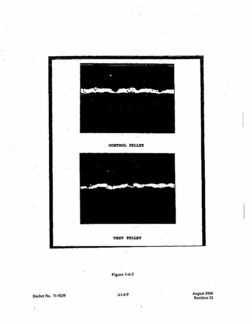
CONTROL PELLET
TEST PELLET
Figure 1-6-3
Docket No. 71-9239 A--Al-6-9 August 2006Revision 12

NUCLEONICS
IFBA Loadingz Uncertainty
The pellet coating process produces pellets that vary in the amount of ZrB2 coating deposited. Pellets onthc outside of the coating fixture receive less material than the ones on the inside because of shadowingby the fixture supports. Consequently, since there is no attempt to keep track of where the pellets end up,the result is a pseudo pellet variability. The specification calls for the standard deviation of the pelletloading to be less than 25%..Actually, the coaters produce material with a standard deviation of 12%.These values are based on several years worth of measurement s of individual pellets by a weight gaintechnique, and by continuing analyses of each coater run by chemical analysis.
While this pellet variability seems large, it does not result in large~ variability in either the IFBA rods or inthe assemblies containing lFBA. The reason is that there are large numbers of JFBA pellets in each rod(about 300) and still larger numbers in an assembly (greater than 10000). Thus, because of randommixing effects, the variability of rods or assemblies is slight.
Actually, mixing of pellets is not completely random and, consequently, the results of the mixing thatdoes occur is not quite as good as might be expected from The above. For one, the pellets from anindividual coater run are not thoroughly mixed so the effective mixing in a rod is decreased. Second, thepellets in a region (coaler run to coater run) are not thoroughly mixed so that the assemblies will tend tovary because the coaler runs vary.
Table 1-6-4 gives a description of the actual mixing process and conservatively estimates the lFBA rodvariability. The result is a standard deviation* of 4.8%. Gamma scan measurements of the rods show astandard deviation of 5%. For instance, the gamma scanner estimates the U-235 rod variability to be2.5%, whereas, from more accurate sources it is known to be less than 1%. The scanner precision isstatistical in nature and is therefore driven by the low count rate produced in the activation process.
A more important variability than the rods, is the variability of the -assembly loading. This is moreimportant because it affects the overall reactivity of the assembly. The variability of the rods only slightlyaffects the reactivity of the assembly because the statistical combination of rods with variable loadingtends to cancel the effect of high and low rods. (Note this is not true for strong poisons which can onlyhave reduced worth as a result of variability.)
Because assembly worth is important in reactor core design, the amount of boron in each assembly ismonitored. Each rod is assumed to have an amount of boron in it based on the coater run or runs it camefrom. The boron from each of the rods in the assembly is added and compared to the amount the assemblyshould contain. The standard deviation of the percentage differences between nominal and measuredvalues is calculated to assure it is less than 1.5% as defined in the product specification.
Because of coater run variability, this is a difficult value to meet and would be expected to be exceededoccasionally if steps were not taken to reduce the assembly variability. One step taken is to monitor rodsin channels before loading into assemblies. If the variability of the rods between channels is too great, therods in the channels are mixed to form a more uniform population. Since monitoring channels was begun,no contract has exceeded the 1.5% limit on assembly variability.
Docket No. 71-9239 Al-6-10 August 2006Revision 12
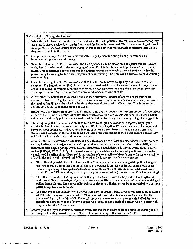
Table 1-6-4 Mixing Mechanisms
I . When the pellet fixtures from the coater are unloaded, the first operation is to get them onto a receiving tray.This tray is placed upside down on the fixture and the fixture is overturned. There is some mixing of rows inthis operation since frequently pellets end up on top of each other or roll to locations different than the onethey were in while in the coater.
2. Chipped or other reject pellets are removed at this stage by manufacturing. Filling the vacancies leftintroduces a slight amount of mixing.
3. Since the fixtures are 17 to 18 rows wide, and the trays they are to be placed on in the pellet cart are 25 rowswide, there has to be considerable rearranging of rows of pellets in this process to get the number of rows tomatch. This operation is done by hand and in a happenstance manner which is dictated by the state that theperson doing the mixing finds the receiving tray after overtumning. This .state will be different from overturningto overturning.
4. Once the pellets get on the 25 row trays about 150 pellets are removed by Quality Assurance (QA) forsampling. The largest portion (96) of these pellets are used to determine the average coater loading. Othersare used to check for hydrogen, coating adherence, etc. QA also removes any pellets that do not meet thevisual specification. Again, the vacancies introduced increase mixing slightly.
5. At this stage the pellets are in 20 inch strings on the pellet trays. For ease of analysis, these strings areassumed to have been together in the coater as a continuous string. This is a conservative assumption sincethe required handling (as described in the steps above) produces considerable mixing. This is the secondconservative assumption in the mixing analysis.
In addition, since these strings are about 20 inches long, they must contain at least one section of pellets froman end of the fixture or a section of pellets from next to one of the vertical support bars. This means that nostring can contain only pellets from t 'he middle of the fixture. No string can contain just high loading pellets.
6. The strings of pellets on these trays are then measured for length and loaded onto separate trays by thecollator for later loading into rods. Since a typical IFBA stack length is 120 inches and since the trays holdstacks of about 20 inches, it takes about 6 lengths of pellets from 6 different trays to make up one IFBAstack. Since the stacks on the trays are in no particular order with respect to their position in the coater theywill be loaded into rods in a pseudo random manner.
7. Assuming the mixing described above (but excluding the important additional mixing during the fixture overturnand tray loading operations), randomly loaded pellet strings that have a standard deviation of about 10%, takenfrom coater runs that are varying by about 2.5%, produce a rod population that is varying by about 5% in boroncontent [(I0fsqrt(6))2 +2.5;.4.82]. T'his sum of squares is permissible since the variability of the rods due to thevariability of the pellet strings [lI0/sqrt(6)] is independent of the variability of the rods due to the coater variabilityof 2.5%. This estimate that the rod variability is less than 5% is conservative for several reasons:
a. The pellet string variability will be less thani 10%. This number assumes no mixing of the pellets during theoverturn operation. Since much of the variability of the strings is the result of the low outside rows in thefixtures, any mixing of these pellets will reduce the variability of the strings. Since the pellet variability isabout 12%, the I 1/% pellet string variability assumption is conservative (there are about 50 pellets in a string).
b. The effective number of strings in a rod will be greater than 6. Since the tray and fixture length andwidth are different, the strings of pellets on a tray are not likely to be composed of a continuous string ofpellets from a fixture. Thus, most pellet strings on the trays will themselves be composed of two or morepellet strings from the fixtures.
c. The effective coater variability will be less than 2.5 %/. A coater mixing process was introduced in Marchof 1989 where any coater run outside :h 3% of nominal is mixed with another coater run so that theaverage of the two is within b+ 3%. The mixing process guarantees that approximately half of the pelletsin each rod come from each of the two coater runs. Thus, on a rod basis, the coater runs will effectivelyvary less than the 2.5% assumed.
8. Assembly variability is measured for each contract. The rod channels are checked before rod loading and, ifnecessary, rod mixing is used to ensure all assemblies meet the specification limit of 1.5%.
Docket No. 7 1-9239 A1-6-11I August 2006Revision 12

Anothcr step takcn to rcduce assembly variability is coatcr mixing. At the present time coater runs aremixed if they are more than 3% from thc contract nominal. They are mixed with another run so that thecombined run is within :L 3%. Credit for this is not taken because the specification does not require it.This is an in-house method of ensuring that the 1.5% assembly variability specification is met.
All of these factors which go into making up the assembly boron loading variability are given inTable 1-6-4. This table shows thc specification requirements on IFBA variability, a conservative estimateof these variabilities, and a best estimate value for the variabilities. The bases for the estimates is alsogiven.
The assembly variability is the pertinent result for criticality work. This variability is a specificationquantity and is measured on each contract to be below 1.5%. The boron content in the IFBA rods has beenreduced by 5% in analysis of the shipping container. This is conservative for two reasons. First, the5% value is much larger than the 1.5% limit times the one sided 95/95 uncertainty factor. Second, this isincluded as a bias by reducing the number of 1013 atoms in the assembly. If it were to be included as avariability (which it is) instead of as a bias, its resulting effect would be smaller because of statisticalconvolution with other variable factors of equal or larger magnitude.
Number densities calculated for 1013 concentration given above are further reduced 25% to provide an
additional safety margin.
Axial Reflector Modeling
Westinghouse' models shipping containers as infinite in length because this is convenient and slightly.conservative (since credit for axial leakage is ignored). However, since part-length poisons arc to be used,a full 3D model is needed rather than constructing a more conservative infinite model.
Table 1-6-5 shows the -composition of the material between the fuel stacks. The values in this tableassume that two assembly bottoms are lined up, even though assemblies always ride front to back on thetruck. This is a considerable conservatism because it excludes'the 7 inch plenum region (3 inch, if springcompression is assumed) from separating the two fuel stacks.
Table 1-6-5 defines a 5.08 inch distance from the fuel stack to the center line between two fuel stacks, or a10.16 inch axial spacing between fuel stacks. This is essentially an infinite distance between fuel stacks.This is conservative since the plenum space is excluded.
QUALITY ASSURANCE
IFBA Pellet ZrB2 Adherence
IFBA pellets are coated with zirconium diboride, ZrB2, using a Westinghouse patented and qualifiedsputtering process. This high temperature, high vacuum process applies a dense, mechanically adherentZrB2 coating to 17000 to 20000 pellets at a time during one coating cycle. The coating is applied to anominal thickness of 0.0004 inch as the pellets are rotated while held in a coating fixture bounded withwire.
Docket No. 71-9239 AI-6-12 August 2006Revision 12
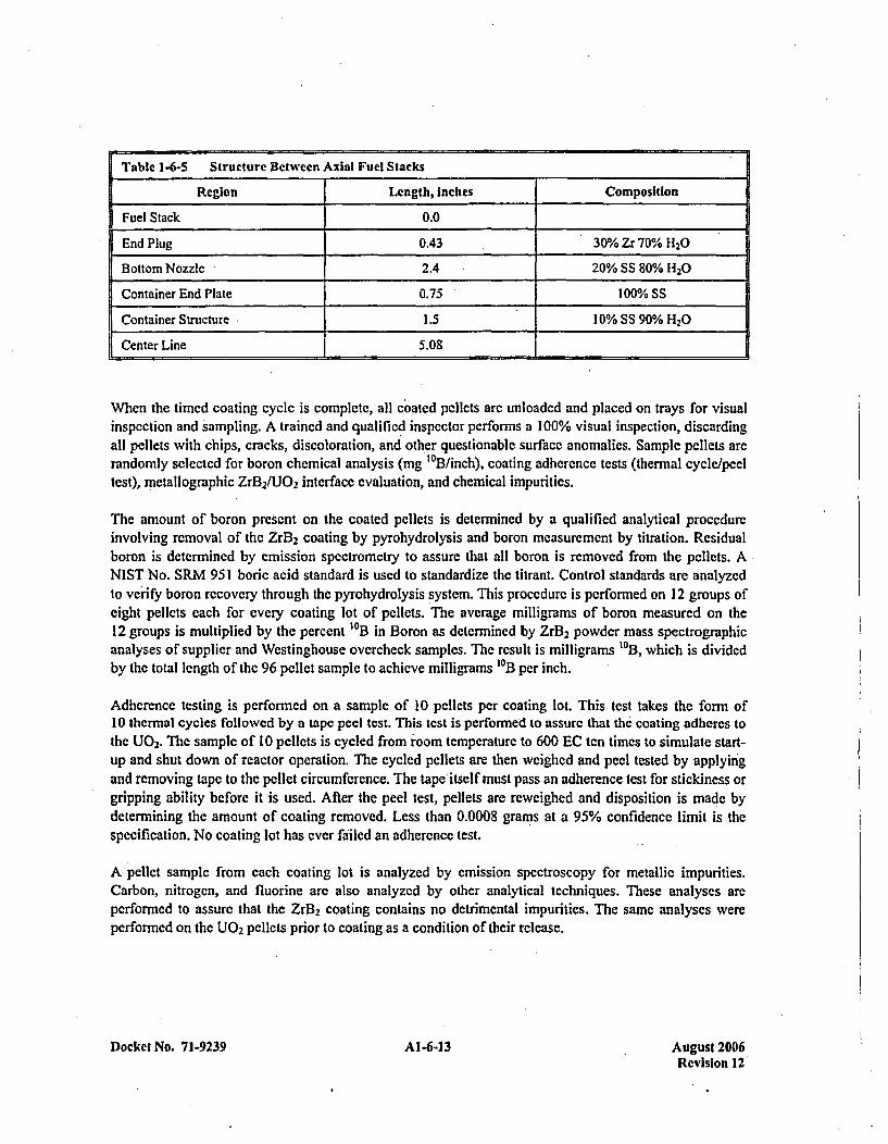
Table 1-6-5 Structure Between Axial Fuel Stacks
Region Length, inches Composition
Fuel Stack 0.0
End Plug 0.43 30% Zr 70% H20
Bottom Nozzle 2.4 20% SS 80% H,0
Container End Plate 0.75 100% SS
Container Structure 1.5 10% SS 90% H20
Center Line 5.08
When the timed coating cycle is complete, all coated pellets are unloaded and placed on trays for visualinspection and sampling. A trained and qualified inspector performs a 100% visual inspection, discardingall pellets with chips, cracks, discoloration, and other questionable surface anomalies. Sample pellets arerandomly selected for boron chemical analysis (mg '0B/inch), coating adherence tests (thermal cycle/peeltest), metallographic ZrB2/U0 2 interface evaluation, and chemical impurities.
The amount of boron present on the coated pellets is determined by a qualified analytical procedureinvolving removal of the Zrl3 2 coating by pyrohydrolysis and boron measurement by titration. Residualboron is determined by emission spectrometry to assure that all boron is removed from the pellets. ANIST No. SRM 951 boric acid standard is used to standardize thc titrant. Control standards are analyzedto verify boron recovery through the pyrohydrolysis system. This procedure is performed on 12 groups ofeight pellets each for every coating lot of pellets. The average milligrams of boron measured on the12 groups is multiplied by the percent 1OB in Boron as determined by ZrB2 powder mass spectrographicanalyses of supplier and Westinghouse overcheek samples. The result is milligrams 10B, which is dividedby the total length of the 96 pellet sample to achieve milligrams 10B per inch.
Adherence testing is performed on a sample of 10 pellets per coating lot. This test takes the form of10 thermal cycles followed by a tape peel test. This test is performed to assure that the' coating adheres tothe U0 2. The sample of 10 pellets is cycled from 'room temperature to 600 EC ten times to simulate start-up and shut down of reactor operation. The cycled pellets are then weighed and peel tested by applyingand removing tape to the pellet circumference. The tape itself must pass an adherence test for stickiness orgripping ability before it is used. After the peel test, pellets are reweighed and disposition is made bydetermining the amount of coating removed. Less than 0.0008 grams at a 95% confidence limit is thespecification. No coating lot has ever failed an adherence test.
A pellet sample from each coating lot is analyzed by emission spectroscopy for metallic impurities.Carbon, nitrogen, and fluorine are also analyzed by other analytical techniques. These analyses arcperformed to assure that the ZrB2 coating contains no detrimental impurities. The same analyses wereperformed on the U0 2 pellets prior to coating as a condition of their release.
Docket No. 71-9239 AI-6-13 August 2006Revision 12
IFBA Pellet Location In Fuel Rod
The next precaution taken to assure that ZrB2 coated pellets are present in the fuel is computerized,robotic stack collation. For each rod design, (three zone - natural/coated/natural, or five zone '-naturaL'enrichecd/coated/enriched/natural) a software program is loaded into a process control computer atthe pellet collation station. This program instructs a pair of robots. The robots are located inside a ring ofpellet tray carts which contain'the necessary pellet types to fabricate the desired rod design. At thecomputer's command one robot picks up the appropriate tray of pellcts (25 rows) and positions it so thatthe other robot may measure and remove the correct lengths of pcllets. The tray handling robot then putsthe tray back and proceeds to place another tray in position for pellet length measurements and removal.This process is repeated until 25 measured, and correctly zoned, pellet stacks 'arc located on specialcapture row trays for continued processing. It is important to note that there is no way for pellets to escapefrom the capture row trays once they are loaded.
After IFBA pellets are loaded into tubes, the resultant rods arc pressurized, seal welded, and inspected bypassive gamma scanning. The purpose of this inspection is to verify that correct uranium enrichment ispresent, and that no deviant uranium enrichment pellets arc mixed in with the stack.
The final inspection to assure that ZrB2 pellets are present as desired is a neutron activated gamma scan ofthe finished rods. This calibrated procedure is performed on 100% of all rods fabricated at Columbia. Thisinspection has the capability of discriminating a single coated pellet which may be mixed into anuncoated pellet zone. Each rod containing coated pellets is inspected* for correct zone lengths (natural,enriched, or coated) and plenum length. The active gamma scanner inspection is done by activating theuranium with neutrons as the rod passes by a Californium source. The resultant gamma activity ismeasured for each' zone and compared with standard rod activity levels recorded in a process controlcomputer.
IFBA Rod Location In Fuel Assembly
Boron bearing rods are known as Integral Fuel Burnable Absorber (IFBA) rods. There are four separateactions which assure that IFBA rods are in their correct positions within a fuel assembly.
The first step in assuring correct IFBA rod position in the assembly is in loading the magazine. Themagazine is a fixture 'used to stage rods prior to assembly loading. Templates are placed over the end ofthe magazine which will only permit rods to be loaded into certain p *ositions within the magazine.Templates have been prepared and are selected according to the drawing number of the particularassembly being loaded. The assembly drawing number specifies the particular pattern of JFBA type rodsto be used in the assembly. After loading IFBA type rods into the magazine, the template is removed andthe standard rods are inserted into the remaining positions in the magazine.
The second step in assuring correct IFBA rod position in the assembly is in the inspection of the loadedmagazine. The IFBA rods each have an identifying mark on the top end plug. Quality control (QC)Inspection verifies that the IFBA rods and the standard rods are in their correct positions based on a visualinspection of the top end plugs in the magazine.
Docket No. 71-9239 Al-6-14 August 2006Revision 12
Thc third step in assuring correct rod position in the assembly is the entry of assembly-rod data into theRod Accountability and Monitoring (RAMS) real-time computer system. The system is prc-loaded with alist of the correct assembly id's for that region, and the correct rod loading pattern for thc assemblies.Unique rod identifications arc scanned into the RAMS real-time system using barcode reader devices.Thc computer systcm records the correct pattern of standard and IFBA rods for each assembly. Itrecognizes the rod type scanned and compares the location for that rod with acceptable locations for rodsof that type. If the rod is in an acceptable location, the transaction accepts; if not, the transaction isrejected and the operator is instructed to check the pattern and make corrections if necessary. If anyalterations to the rods loaded in the magazine arc required, the corrected magazine is reinspected.
The fourth step in assuring correct rod position in the fuel assembly occurs when the data collected by thereal-time computer system is transmitted to the batch database and updated. As in the real-time system,rod patterns for each assembly are preloaded into the computer's memory. The rod location which comesin with each rod transaction is compared to the location table to determine if the rod type is correct forthat particular location. If the rod's position is correct, the transaction updates; if not, the transactionsuspends and a warning message is generated to alert the area engineers to investigate and resolve theproblem.
CONTROL OF CONTAINER USAGE
Verification that required assemblies in fact contain Integral Fuel Burnable Absorber (IFBA) rods is basedon procedural controls traceable to visual confirmation of the top end plug identification mark when theassembly is fabricated. Applicable process specifications, operating procedures, and quality controlinstructions contain explicit guidance on requirements for IFBA rods in assemblies to be placed in MCCcontainers that might not have the optional container neutron absorber plates installed.
Docket No. 71-9239 Al-6-15 Aueust 2006Revision 12
1.2 SILVER - INDIUM - CADMIUM ROD CONTROL CLUSTER NEUTRON ABSORBERS(RCCA)
INTRODUCTION
In the Hypothetical Accident Condition (HAG) test of Rod Control Cluster Absorber rods, a conclusionwas drawn that indicated the rods maintained their relative design configuration. Therefore, two (2)undamaged fuel assemblies - having RCCA rods intact within the assembly - in the relative MCCcontainer design conf iguration, were modeled for the Nuclear Safety Analysis.
DESIGN
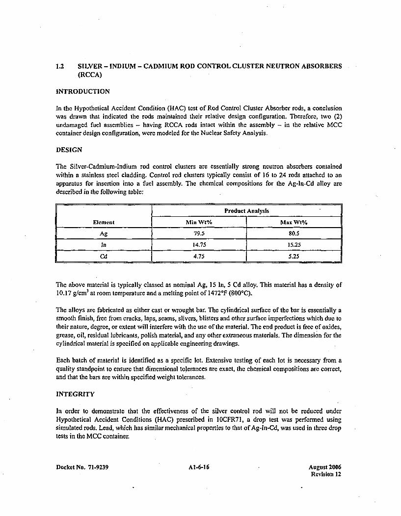
The Silver-Cadmium-Indiumn rod control clusters are essentially strong neutron absorbers containedwithin a stainless steel cladding. Control rod clusters typically consist of 16 to 24 rods attached to anapparatus for insertion into a fuel assembly. The chemical compositions for the Ag-In-Cd alloy aredescribed in the following table:
Product Analysis
Element Min Wt% Max Wt%
Ag 79.5 80.5
In 14.75 15.25
Cd 4.75 5.25
The above material is typically classed as nominal Ag, 15 In, 5 Cd alloy. This material has a density of10.17 g/CM 3 at room temperature and a melting point of 1472'F (800'C).
The alloys are fabricated as either east or wrought bar. The cylindrical surface of the bar is essentially asmooth finish, free from cracks, laps, seams, slivers, blisters and other surface imperfections which due totheir nature, degree, or extent will interfere with the use of the material. The end product is free of oxides,grease, oil, residual lubricants, polish material, and any other extraneous materials. The dimension for thecylindrical material is specified on applicable engineering drawings.
Each batch of material is identified as a specific lot. Extensive testing of each lot is necessary from aquality standpoint to ensure that dimensional tolerances are exact, the chemical compositions are correct,and that the bars are within specified weight tolerances.
INTEGRITY
In order to demonstrate that the effectiveness of the silver control rod will not be reduced underHypothetical Accident Conditions (HAC) prescribed in I OCFR7 1, a drop test was performed usingsimulated rods. Lead, which has similar mechanical properties to that of Ag-In-Cd, was used in three droptests in the MCC container.
Docket No. 71-9239 Al-6-16 August 2006Revision 12
The drop tests clearly indicated that the control rods will maintain their integrity and relative designconfiguration within the assembly. The thermal and mechanical properties of thc alloy clearly show thatthe rods would be effective neutron absorbers after a 1475OF thermal test coupled with water quenchingand immersion.
NUCLEONICS
The rod dimensions vary with the fuel design in which they are to be contained, however, the minimumdimensions are assumed in the nuclear design. These dimension arc 0.329 in. o.d. silver rod, in a0.367 in. o.d. stainless steel tube, with an absorber length of 142 in.
The dimensions on the silver rod described above arc used in the actual criticality model. This isacceptable since the fabrication tolerances are very strict for use in reactor environments. The minimumchemical compositions described in the above table are used in the actual criticality analysis. Numberdensities calculated from the minimum chemical compositions are further reduced 25% to provide anadditional safety margin. The actual number of absorber rods required for each assembly is described inthe Nuclear Safety Analysis.
QUALITY ASSURANCE
Each bar is inspected in accordance with written quality assurance procedures. Inspections conductedinclude visual appearance of the material finish, dimensions with calibrated equipment and weighing (castbars only).
Two bars per lot minimum are sampled at random and analyzed to ensure that the material is withinspecification tolerances. Lots consist of all bars of the sa'me nominal cross-section, condition and finishthat are produced from the same heat, processed in the same marnner, and presented for inspection at thesame time.
Samples are also taken to show that there is no chemical heterogeneity between final rods. All Samplesarc chemically or spectrographically examined. Traceability of each bar by heat is maintained throughpackaging and shipping.
The vendor who will fabricate the alloy bar has a quality assurance plan approved by Operations ProductAssurance. Vendors will be qualified in accordance with WCAP 7800.
CONTROL OF CONTAINER USAGE
Verification that required assemblies in fact contain Rod Control Cluster absorber (RCCA) rods is basedon procedural controls and visible confirmation of installation when the assembly is loaded into the, container. Applicable process specifications, operating procedures, and quality control instructionscontain explicit guidance on requirements for RCCA's in assemblies without sufficient Integral FuelBurnable Absorber (IFBA) rods to provide the required margin of safety, and/or in assemblies to beplaced in MCC containers that might not have the optional container neutron absorber plates installed.
Docket No. 71-9239 Al1-6-17 August 2006Revision 12
1.3. BOROSILICATE GLASS NEUTRON ABSORBERS (GLASS PYREX)
INTRODUCTION
In the Hypothetical Accident Condition (HAG) test of Borosilicate Glass Absorber rods, a conclusion wasdrawn that indicated the rods maintained their relative design configuration. Therefore, two (2)undamaged fuel assemblies - having Glass Pyrex rods intact within the assembly - in the relative MCCcontainer design configuration, were modeled for the Nuclear Safety Analysis.
DESIGN
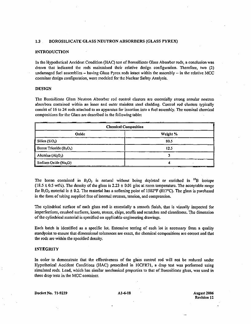
The Borosilicate Glass Neutron Absorber rod control clusters are essentially strong annular neutronabsorbers contained within an inner and outer stainless steel cladding. Control rod clusters typicallyconsist of 16 to 24 rods attached to an apparatus for insertion into a fuel assembly. The nominal chemicalcompositions for the Glass are described in the following table:
Chemical Composition
Oxide Weight %
[Silica (SiO2a) 80.5
Boron Trioxide (B20.3) 12.5
Alumina (A1203) 3Sodium Oxide (Na2O) 4
The boron contained in B203 is natural without being depleted or enriched in SOB isotope(18.5 ± 0.5 wt%). The density of the glass is 2.23 ± 0.01 glee at room temperature. The acceptable rangefor B203 material is ± 0.2. The material has a softening point of 1502*F (817*C). The glass is purchasedin the form of tubing supplied free of internal stresses, tension, and compression.
The cylindrical surface of each glass rod is essentially a smooth finish, that is visually inspected forimperfections, crushed surfaces, knots, stones, chips, scuffs and scratches and cleanliness. Thec dimensionof the cylindrical material is specified on applicable engineering drawings.
Each batch is identified as a specific lot. Extensive testing of each lot is necessary from a qualitystandpoint to ensure that dimensional tolerances are exact, the chemical compositions are correct and thatthe rods are within the specified density.
INTEGRITY
In order to demonstrate that the effectivcness of the glass control rod will not be reduced underHypothetical Accident Conditions (HAG) prescribed in I OCFR7 1, a drop test was performed usingsimulated rods. Lead, which has similar mechanical properties to that of Borosilicate glass, was used inthree drop tests in the MCC container.
Docket No. 7 1-9239 Al-6-18 August 2006Revision 12
Thc drop tests clearly indicated that the control rods will maintain their integrity and relative designconfiguration within the assembly. The thermal and mechanical propcrties of the glass cecarly show thatthe rods would be effective neutron absorbcrs after a 1475'F thermal test coupled with water quenchingand immersion.
NUCLEONICS
The rod dimensions vary with the fuel design in wvhich they are to be contained, however, the minimumdimensions are assumed in the nuclear design. These dimension are 0.336 in. and 0.190 in. inner andouter diameters, respectively, for the glass in a 0.381 in. o.d. stainless steel tube with an absorber length of142 in.
The dimensions on the glass rod described above arc used in the actual criticality model. This isacceptable since the fabrication tolerances are very strict for use in reactor environments. The minimumchemical compositions described in the above table are used in the actual criticality analysis. Theminimum B203 wt% of 12.3 is further reduced by 25% to provide for an additional safety margin. Theactual number of absorber rods required for each assembly is described in the Nuclear Safety Analysis.
QUALITY ASSURANCE
Each rod is inspected in accordance with written quality assurance procedures. Inspections conductedinclude visual appearance of the material finish, dimensions with calibrated equipment to a95% confidence level, and weighing for density verif ication.
One tube per lot minimum is sampled at random and analyzed to ensure that the B203 material is withinspecification tolerances. Lots consist of all tubes of the same nominal cross-section, condition and finishthat are produced from the same heat, processed in the same manner, and presented for inspection at thesame time.
All samples are chemically or spectrographically examined. Traceability of each tube by heat ismaintained through packaging and shipping.
The vendor who will fabricate the glass tube has a quality assurance plan approved by Operations ProductAssurance. Vendor will be qualified in accordance with WCAP 7800.
CONTROL OF CONTAINER USAGE
Verification that required assemblies in fact contain Glass Pyrex absorber rods is based on proceduralcontrols and visible confirmation of installation when the assembly is loaded into the container.Applicable process specifications, operating procedures, and quality control instructions contain explicitguidance on requirements for Glass Pyrex rods in assemblies without sufficient Integral Fuel BurnableAbsorber (IFBA) rods to provide the required margin of safety, and/or in assemblies to be placed in MCCcontainers that might not have the optional container neutron absorber plates installed.
Docket No. 71-9239 Al-6-19 August 2006Revision 12
1.4 WET ANNULAR BURNABLE NEUTRON ABSORBERS (WAABA)
INTRODUCTION
In the Hypothetical Accident Condition (HAG) test of Wet Annular Burnable Absorber rods, a conclusionwas drawn that indicated the rods maintained their relative design configuration. Therefore, two (2)undamaged fuel assemblies - having WABA rods intact within the assembly - in the relative MCCcontainer design configuration, were modeled for the Nuclear Safety Analysis.
DESIGN
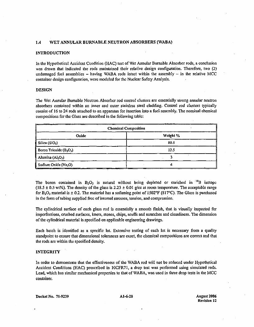
The Wet Annular Burnable Neutron Absorber rod control clusters arc essentially strong annular neutronabsorbers contained within an inner and outer stainless steel cladding. Control rod clusters typicallyconsist of 16 to 24 rods attached to an apparatus for insertion into a fuel assembly. The nominal chemicalcompositions for the Glass arc described in the following table:
Chemical Composition
Oxide Weight %
Silica (SiQ 2) 80.5
Boron Trioxide (13203) 12.5
Alumina (A1203) 3
Sodium Oxide (Na2,O) 4
The boron contained in B203 is natural without being depleted or enriched in "0B3 isotope(18.5 ± 0.5 wt%). The density of the glass is 2.23 ± 0.01 glee at room temperature. The acceptable rangefor B203 material is ± 0.2. The material has a softening point of 1502*F (817*C). The Glass is purchasedin the form of tubing supplied free of internal stresses, tension, and compression.
The cylindrical surface of each glass rod is essentially a smooth finish, that is visually inspected forimperfections, crushed surfaces, knots, stones, chips, scuffs and scratches and cleanliness. The dimensionof the cylindrical material is specified on applicable engineering drawings.
Each batch is identified as a specific lot. Extensive testing of each lot is necessary from a qualitystandpoint to ensure that dimensional tolerances are exact, the chemical compositions are correct and thatthe rods are within the specified density.
INTEGRITY
In order to demonstrate that the effectiveness of the WABA rod Will not be reduced under HypotheticalAccident Conditions (HAC) prescribed in Il'OCFR7I, a drop test was performed using simulated rods.Lead, which has similar mechanical properties to that of WABA, was used in three drop tests in the MCCcontainer.
Docket No. 7 1-9239 A 1-6-20 August 2006Revision 12
The drop tests clearly indicated that the control rods will maintain their integrity and relative designconfiguration within the assembly. The thermal and mechanical properties of the glass clcarly show thatthe rods wvill be effective neutron absorbers after a 1475*F thermal test coupled with water quenching andimmersion.
NUCLEONICS
The rod dimensions vary with the fuel design in which they are to be contained, however, the minimumdimensions are assumed in the nuclear design. These dimension are 0.336 in. and 0.190 in. inner andouter diamectrs, respectively, for the WABA in a 0.381 in. o.d. stainless steel tube with an absorber lengthof 142 in.
The dimensions on the WABA rod described above are used in the actual criticality model. This isacceptable since the fabrication tolerances arc very strict for use in reactor environments. The minimumchemical compositions described in the above table are used in the actual criticality analysis. Theminimum B20 3 wt% of 12.3 is further reduced by 25% to provide for an additional safety margin. Theactual number of absorber rods required for each assembly is described in the Nuclear Safety Analysis.
.QUALITY ASSURANCE
Each tube is inspected in accordance with written quality assurance procedures. Inspections conductedinclude visual appearance of the material finish, dimensions with calibrated cquipment to a95% confidence level, and weighing for density verification.
One tube per lot minimum is sampled at random and analyzed to ensure that the B203 material is withinspecification tolerances. Lots consist of all tubes of the same nominal cross-section, condition and finishthat are produced from the same heat, processed in the same manner, and presented for inspection at thesame time.
All samples are chemically or spectrographically examined. Traceability of each tube by heat ismaintained through packaging and shipping.
The vendor who will fabricate the WAf3A tubing has a quality assurance plan approved by OperationsProduct Assurance. Vendors will be qualified in accordance with WCAP 7800.
CONTROL OF CONTAINER USAGE
Verification that required assemblies in fact contain WABA absorber rods is based on procedural controlsand visible confirmation of installation when the assembly is loaded into the container. Applicableprocess specifications, operating procedures, and quality control instructions contain explicit guidance onrequirements for WABA rods in assemblies without sufficient Integral Fuel Burnable Absorber (IFBA)rods to provide the required margin of safety, and/or in assemblies to be placed in MCC containers thatmight not have the optional container neutron absorber plates installed.
Docket No. 71-9239 AI-6-21 August 2006Revision 12
APPENDIX 1-7GD20 3 NEUTRON ABSORBER PLATES SPECIFICATIONS
Docket No. 7 1-9239 Al-7-1 August 2006Revision 12

Gd2O3 NEUTRON ABSORBER PLATES SPECIFICATIONS
INTRODUCTION
Gadolinium oxide (Gd2O3A a strong neutron absorber, has been incorporated into an existing industrialccrmet (coating similar to porcelain) for usc as a neutron absorber plate. This cermet coating, whenapplied to a carbon steel base, possesses thc required nuclear and mechanical characteristics to pcrmit it tobc used in the MCC fuel shipping containers.
These cerrnets are mainly used in applications requiring heat resistant or chemical resistant coatings suchas jet exhausts or beat exchangers. Coating a steel base that provides shape and strength is a relativelysimple spraying and fusing process which can be performed in a matter of minutes using existingindustrial equipment and techniques.
NUCLEONICS
The most effective absorber plate possible is one which is essentially "black" and absorbs all neutronsdirected at it. The amount of Gd2O3 necessary to analytically achieve this characteristic is 0.020 gm/cm2.This value is elevated by 25% such that a minimum of 0.027 gm/cm 2 is Set as a design requirement. Thenumber densities used in the criticality calculations for the Gadolinia in the plate coating arc based on acoating density of 0.020 grams Gd2O3/CM 2. The effects of minor through-holes, to allow for handling andassembly clearance, and welding bum of the coating, have been evaluated and determined to have aninsignificant effect on the absorber function of the plates.
Vertical Gadolinium neutron absorber plates are permanently installed in all the MCC shippingcontainers; segmented horizontal plates are installed in those MCC-3 and MCC-4 containers used topackage fuel assemblies whose 235U enrichment is greater than 4.65 wt%, and in all MCC-5 containers.Once segmented horizontal plates are added to an MCC-3 or -4 container, the plates will remain in placein that container. Optional vee-shaped guided absorber plates will be used in the MCC-5 container, inaddition to the vertical and horizontal plates, when 235U enrichment of the VVER-1 000 assembly isgreater than 4.80 wt%.
Although the minimum required concentration of gadolinium oxide is shown to be 0.027 gm/cm2 , theoriginal KENO modeling was based on two layers of coating at 75% of this density; hence the designspecifications for all vertical plates, and the horizontal plates for the MCC-3 and MCC-4 container,require a minimum of 0.054 gm/cm2 . The MCC-5 horizontal and vee-shaped plates are modeled with onelayer of coating, or a minimum of 0.027 gm/cm2 .
DESIGN
The Hypothetical Accident Condition (HAC) as defined in I OCFR71I requires that suberiticality of fuelassemblies in the shipping containers be demonstrated after, in sequence, a 30-foot free drop of the loadedcontainer, puncture of the shell, exposure to 1475*F for 30 minutes and water immersion for 8 hours.
Since gadolinium oxide (Gd2O.3) is a refractory ceramic which is similar to aluminum oxide (A1203) orzirconium oxide (ZrO2), substitution of Gd2O3 for some or all of the A1203 or ZrO2 in the finished coating
Docket No. 71-9239 Al1-7-3 August 2006Revision 12

seemed reasonable. Through trial, a coating composition was arrived at which maximizcd the Gd2Q3
content while maintaining physical properties comparable to the basc cermet industrial coating. Sampleabsorber plate sections have demonstrated the coating's damage resistance to normnal abrasion, hightemperature (1475'F), thermal shock (water splash and quench), impact (30-foot free fall), and flexing.Gd2O3 absorber plates were also used in three 30-foot drop tests.
The vertical Gd2O3 absorber plate used in all MCC containers has approximate dimensions of 0.075" x7.25" x 160" (189" for the MCC-4 and MCC-5 containers). The thickness is composed of 20 gauge(0.035") steel with a combined Gadolinia and Alumina coating. The coating is on both sides of the plate,such that the. total coating contains at least 0.054 gm. Gd2O3/CM2 . The assembly is fabricated byoverlapping two sections of absorber plate and fusion welding the edges to produce a 160" (189" for XL)long assembly. The 160" assembly will weigh approximately 15 pounds. The vertical Gadoliniumn neutronabsorber plate is used as a permanent feature within all MCC fuel shipping containers.
The segmented horizontal Gd2O3 absorbcr plates arc designed such that they can be positioned beneaththe strongback between cross-member supports. The width of the horizontal plates is increased to8.75 inches for the MCC-3 and -4 containers and 9.25 inches for the MCC-5 container. Typical lengthsrange from 14.08 to 23.00 inches with corresponding weights of 1.9 to 3.1 pounds for the MCC-3'and -4containers and 2.0 to 3.3 pounds for the MCC-5 container. The thickness is composed of 20 gauge(0.035") steel with a combined Gadolinia and Alumina coating. The coating is on both sides of the platefor the MCC-3 and MCC-4, such that the total coating is at least 0.054 gm Gd 2O3/cm . The drawingrequirement for the MCC-5 is also 0.054 gmn/cm 2, although the KENO modeling only requires0.027 gm/cm2. The horizontal Gadolinium neutron absorber plate sections are used as an optional featurewithin the MCC-3 and -4 fuel shipping container, and as a permanent feature in the MCC-5 container.However, once an MCC-3 or -4 container has the horizontal plates installed, they will remain in thatcontainer permanently.
The horizontal vee-shaped Gd2O3 guided absorber plate used for the MCC-5 container is similar to thehorizontal plates in terms of segmented lengths; however, these plates are shaped to conform to thesurface of the VVER-1000 assembly and are positioned between the strongback and the assembly. Theguided absorber plates are positioned between the container internals grid support structure and below thefuel assembly; as such, they do- not support the weight of the fuel assembly. This vee-shaped guidedabsorber plate is thicker (0.060 inches) than the normal vertical and horizontal plates and is coated onlyon its underside with the normnal Gd2O3 loading of 0.027 gmn/cm 2 . The plate width is typically 9.24 inches,with a total Gd2O3 coated width of approximately 11.06 inches. Typical lengths range from 6.60 to15.48 inches with corresponding weights of 1.9 to 5.75 pounds. The Gadoliniumn neutron absorber guideplate sections are used as an optional feature within the MCC-5 shipping container. However, once anMCC-5 container has the guided absorber plates installed, they will remain in that container permanently.
INTEGRITY
Coatinji Flexibility
The absorber plates are restrained by the container internals once the plates are installed. One side of eachvertical pl 'ate faces a continuous sheet metal skin. The other side of each plate faces a ladder-like frame of1.5 inch square tubing spaced approximately every 20-24 inches. Consequently the plate may bow
Docket No. 71-9239 Docke No. 1-923 Augutl200Revision 12

approximately 1.5 inches at the most between any pair of square tubes. A simple simulation of theseconditions with a section of full-size absorber plate reveals no noticeable effect except for slightpermanent set of the steel backing. Horizontal plates are mounted in direct contact with the underside ofthe strongback, and cannot flex more than the strongback itself. The guided absorber plates are mountedto the top of the strongback, and cannot flex more than the strongback.
Improper handling of fabricated plates could cause coating damage. Small radius bends (approximately2") will cause the coating on the compression side of the Plate to crack locally and flake. Bends of4" radius have no noticeable effect on the coating surface or adherence to the metal base. Normalhandling can easily accommodate this restriction by usc of a strongback or manual support to preventsmall radius bends of the plate. Detection of possible coating damage by bending is simple. First, themetal backing will take a permanent set long before the coating is affected. Second, when damage occurs,it causes noticeable flaking and/or loss of material. Expecte d handling and service of the plates will notexceed their capability to flex without functional impairment.
Coating Impact Resistance
As part of the HAC, three MCC containers containing two plates each were subjected to 30-foot drops.Since the internals suspension system cannot absorb all internal energy, mechanical shock of the internalswill occur. Sample plates were also subjected to a 30-foot free drop onto 1/2 inch steel plate. The plateswere dropped, using guide wires, in the flat (plate width horizontal) and guillotine (plate width vertical)configurations. The flat configuration only slightly deformed the metal backing with no obvious coatingdamage. The guillotine configuration, where the plate dropped on edge, caused local deformation of theplate edge and random flaking of the coating edge up to 1/8" away from the plate edge. The bulk of thecoating was unaffected by the severe shock.
As part of the process specification, adhesion tests are performed on production plates to industrystandards. These tests allow a process check to verify the consistency of the coating process and thatproduction plates arc representative of sample performance.
These tests demonstrated that the coating is capable of withstanding impacts far greater than that expectedunder accident conditions in its protected location inside the MCC shipping container support frame.Gd2O3 plates present in the three drop tests described in Chapter 2 yielded no obvious coating damage.
Coatingt Abrasion Resistance
The absorber plates which are positioned within and under the support frame, and the guided absorberplates which are mounted on top of the strongback, a re not exposed to conditions where abnormalabrasion forces would occur. The edges of the plate do not need to be coated, and purposely are notcoated, although the spraying operation will tend to deposit material there. The bottom edge of thevertical absorber plate interfaces with the internals and bears the weight of the plate. Therefore, the edgesof the plates which have been coated and fused will be abraded to base metal to eliminate the generationof gadoliniumn bearing debris and its possible migration from the container during inspection, cleaning,painting, etc.
Docket No. 71-9239 Al-7-5 August 2006Revision 12
The sides of the plates sce negligible loads and broad contact areas. The coating is not easily affected bydistributed loads; a hard, sharp edge tool is necessary to visibly scar the coating surface.
The gadolinium absorber plates installed in containers which were subjected to a 30-ft. drop test werevisually -examined after a one year pcriod to verify that their condition was comparable to that of originalinstallation. There was no visible evidence of loss of coating. The coating is adcquately abrasion resistantto withstand its service environment and maintain its functional capabilities.
High Temperature lnte~nity
The HAC essentially requires the container and its contents to withstand 1475*F for 30 minutes andsubsequent cooldown. Commercially available materials were either inadequate as neutron absorbers ordeteriorate upon exposure to 1 475(F. The components of the coating are fused at approximately 1 530'Fduring processing. The sides of the plates are oriented vertically during processing; fusing of the coatingat these temperatures does not cause the material to flow from its applied configuration. The fusing ismore of a limited wetting condition where materials in intimate contact join as compared to brazing, forexample, where the braze wets the base material and flows under the effects of gravity and capillaryaction.
Sample plates were arranged in a muffle furnace to simulate their interface with the shipping containerinternals and each other. The purpose of the test was to verify that the plate's coating would not be alteredby contact with interfacing surfaces such that its functional characteristics were affected. Once arranged,the furnace was turned on, stabilized at I 475*F for three-and-one-half hours and then turned off. Thefurnace door was opened and the plates removed when the indicated temperature had dropped toapproximately 200'F. The plates were not noticeably altered in either ease from their pre-test condition.
IOCFR71 regulations specify exposure to an environment of 1475*F with an emissivity coefficient of0.9 and package absorption coefficient of 0.8. Consequently, the package is heated up to its maximumtemperature during the 30 minute period. Also, cooling of the package realistically begins as soon as theradiation environment is removed. The test performed is conservative since the plates were held at1475'F for the entire 30 minute period, as well as the subsequent three-hour period where natural coolingis permitted.
The plates were then individually heated to 1475'F', removed at that temperature and subjected to poured(room temperature) water on one side. The plates were again heated, removed and then quenched in abucket of room temperature water. The plates did not exhibit any noticeable cracks, flaking or separations.The plates' demonstrated resistance to thermal shock is similar to the industrial cermets and is adequatefor any thermal shock the plates could possibly experience in a shipping container.
These tests demonstrated that absorber plates are capable of meeting the required high temperatureaccident conditions as well as unlikely, severe thermal shock.
Water Exposure
The absorber plate coating, by its characteristic cermet nature, is essentially impervious to water exposurefor an eight-hour period. No formal tests are conducted.
Docket No. 71-9239 Al1-7-6 August 2006Revision 12
QUALITY ASSURANCE
The basic requirement is that at least the design amount of absorber material (O.027g/cm2) is present inany given area. This requires verification first that the absorber material is present and second that theminimum quantities have been deposited.
For all three types of plates, the cermet is composed of 32.5 wt% Gd2O3. The distribution of absorbermaterial in a unit thickness of the coating is assumed to be uniform because the extremely fine(1-10 microns) Gd2O3 powder and other powder coating components are combined in a water slurry andsprayed onto the metal backing. An analysis by X-ray fluorescence at Westinghouse ARD laboratories, asexpected, did not discover any areas in sample absorber plates. significantly deficient in Gd2O3 comparedto other areas (the equipment examined areas the diameter of a dime). This test is not performed onproduction samples or plates because the nature of the materials and process arc unlikely to cause anysegregation of materials and, as explained, there will be absorber material in excess of actual designminimum loadings.
Final verification that the neutron absorber Gd2O3 is actually in the coating (not A1203 or ZrO2 forexample), and present in acceptable concentrations, is made using verified standards and a portableelemental analyzer. The analyzer, using the X-ray fluorescence method, verifies that gadolinium is presentby measuring the energy of the fluorescing X-rays that arc uniquely characteristic of that element. Bycomparing the intensity of those X-rays to that of verified standards, it can be determined that theminimum density of 0.027 or 0.054 gm Gd2O3 cni 2 is indeed present.
Process control of the coating composition and minimum thickness will insure that the minimum designloading of Gd2O3 is applied to each plate. Use of the analyzer verifies the Gd2Q3 loading in the endproduct composition. The analyzer reading will be documented according to the bright yellowidentification number stenciled and fused into the coating of each plate.
The standards used to calibrate the elemental analyzer will have a master in Columbia archives for qualitycontrol standards. Preservation of the master standard will enable the plates' Gd2Q3 content to be checkedanytime in the future.
The vendor who will fabricate the absorber plates has a quality assurance plan approved by OperationsProduct Assurance. Vendors will be qualified in accordance to WCAP 8370.
CONTROL OF CONTAINER USAGE
For MCC containers, once an absorber plate, whether vertical, horizontal, or shaped, is installed, itremains permanently in that container. As each container receives plates, the documentation associatedwith that container is updated to show its current configuration, and the container is marked.' Containerselection for each contract's shipments is made based on the information contained in the 'permanentrecords, and is approved by the Manager of Nuclear Materials Management. The process specification,operating procedures, and quality control instructions contain explicit guidance on requireme 'nt~s for therequired plate verification and documentation at the time of plate installation. Additional control's exist inthe Fuel Assembly Packing area to assure that the correct containers are used. "Correct" means that the
Docket No. 71-9239 Al-7-7 August 2006Revision 12
container has at least the minimum allowable absorbers for the enrichment of the assemblies to beshipped; any container having more absorbers than requircd by the assembly enrichment may be used.
TECHNICAL JUSTIFICATION FOR REVISING THE ABSORBER PLATE INSPECTIONREQUIREMENTS
The justification for relaxing the absorber plate inspection requirements follows from the conclusions thatcan be drawn from the following observations. Supporting information, showing calculations fordetermining area density, and tables showing kcrr results for the various fuel assembly types, is included inthe next section.
Justification
I . For the design criteria for absorber plate coating:
a. The design minimum area density for Gd20 3 per absorber plate side is 0.027 glcm .
2. For the absorber coating actually applied:
a. The coating, 32.3 wt% Gd2O3 , was applied to an actual minimum thickness of 8.25 milsequivalent Gd2O3 per side.
b. The area density that 8.25 mils translates to is 0.0984 g-Gd 2O3/Cm .
c. -The total area density, therefore, for a double-sided absorber plate is 0. 1968 g-Gd 2O3/cm2.
3. For the absorber plates used in all Westinghouse calculations:
a. The area density used was 0.02 g-Gd 2O3/cm2. This corresponds to the theoretical "black"
density for Gd2O3 with respect to thermal neutrons.
b. The total area density, therefore, for the double-sided absorber plates used in the modelswas 0.04 g-Gd2O/km2.
C. This area density translates to a coating thickness of 1.67 mils.
4. Results from calculations for the double-sided absorber plates (0.02 g-Gd20 3/Cm2 area density perside; 0.04 g/cm 2 total) satisfy NRC requirements.
5. Calculations made for the most reactive fuel assembly type using single-sided absorber plates(0.02 g-Gd2O3/cm2 area density total) satisfy NRC requirements. Results indicate that kf:tij 0.95.
6. Therefore, because, by design, a single side of an absorber plate contains a Gd2O3 area density ofat least 0.027 /CM2, and because, by actual measurement during application, a single sidecontains an area density almost five times thicker than the "black" density (0.02 g-Gd2O3/CM2),Iand because, using approved Westinghouse models with absorber plates with Gd203 area
Docket No. 71-9239 Al1-7-8 August 2006Revision 12
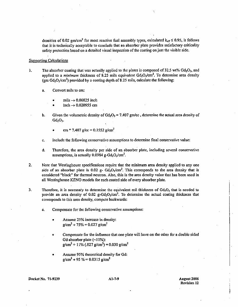
densities of 0.02 gm/cm 2 for most reactive fuel assembly typcs, calculated kdr •9 0.95, it followsthat it is technically acceptable to conclude that an absorber plate provides satisfactory criticalitysafety protection based on a detailed visual inspection of the coating on just the visible side.
Supporting Calculations
I The absorbcr coating that was actually applied to the plates is composed of 32.5 wt% Gd2O3, andapplied to a minimumi thickness of 8.25 mils equivalent Gd2O3/CM 2. To determine area density(gin Gd2Q 3/CM2) provided by a coating depth of 8.25 mils, calculate the following:
a. Convert mils to cm:
* mils -4 0.00825 inch* inch -> 0.020955 cm
b. Given the volumetric density of Gd 2O3 =7.407 gm/cc , determine the actual area density ofGd2O3.
* cm * 7.407 g/cc =0. 1552 g/cm 2
C. Include the following conservative assumptions to determine final conservative value:
d. Therefore, the area density per side of an absorber plate, including several conservativeassumptions, is actually 0.0984 g-Gd2Q3/CM2.
2. Note that Westinghouse specifications require that the minimum area density applied to any oneside of an absorber plate is 0.02 g- Gd2O3/CM 2. This corresponds to the area density that isconsidered "black" for thermal neutron. Also, this is the area density value that has been used inall Westinghouse KENO models for each coated side of every absorber plate.
3. Therefore, it is necessar'y to determine the equivalent mil thickness of Gd2O3 that is needed toprovide an area density of 0.02 g-Gd2 3/Oycn. To determine the actual coating thickness thatcorresponds to this area density, compute backwards:
6. Compensate for the following conservative assumptions:
* Assume 25% increase in density:g/cm2 +÷75% = 0.027 g/cm 2
o Compensate for the influence that one plate will have on the other for a double sidedGd absorber plate (-I 1%):g/cm2 + 11% (.027 g/cm2) = 0.030 g/cm 2
* Assume 95% theoretical density for Gd:g/cm 2 +95 % 0.0315 g/cm2
Docket No. 7929Al-7-9 Aueust 2006Revision 12
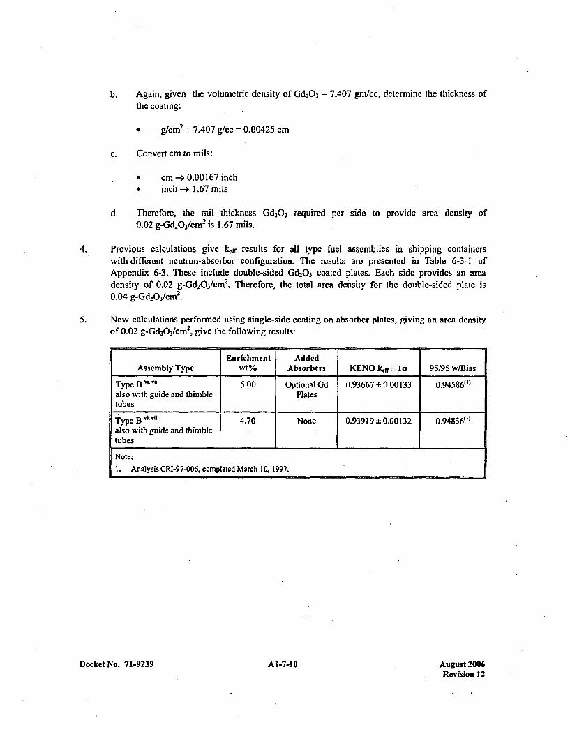
b. Again, given the volumetric density of Gd2O3 = 7.407 gm./cc, determine the thickness ofthe coating:
* g/cm2 +7.407 g/cc =0.00425 cm
C. Convert cm to mils:
0 cm -ý 0.00 167 inchinch --* 1.67 mnils
d. ,Thercforc, the mil thickness Gd2O3 required per side to provide area density of0.02 g-Gd 2O3/CM 2 is 1.67 mils.
4. Previous calculations give kf1f results for all type fuel assemblies in shipping containerswith different neutron-absorber configuration. The results are presented in Table 6-3-1 ofAppendix 6-3. These include double-sided Gd 2O3 coated plates. Each side provides an areadensity of 0.02 g-Gd 2O3 /cm 2. Therefore, the total area density for the double-sided plate is0.04 g-Gd 2Q3/CM2.
5. New calculations performed using single-side coating on absorber plates, giving an area densityof 0.02 g-Gd 2O3/CM , give the following results:
Entrichment AddedAssembly Type wt% Absorbers KENO Kfrrb Icy 95195 w~/Bias
Type B v' 5.00 Optional Gd 0.93667:F 0.00133 0.94586")~also with guide and thimble Platestubes
Type B V~ U4.70 None 0.93919:k 0.00132 0.94836(')also with guide and thimbletubes
Note:
L . Analysis CRI-97-006, completed March 10, 1997.
Docket No. 71-9239 Al1-7-10 August 2006Revision 12
APPENDIX 1-8DESIGN COMPARISON OF THE MCC-5 PACKAGE
TO THE MCC-4 PACKAGE
Docket No. 71-9239 Al-8-1 August 2006Revision 12
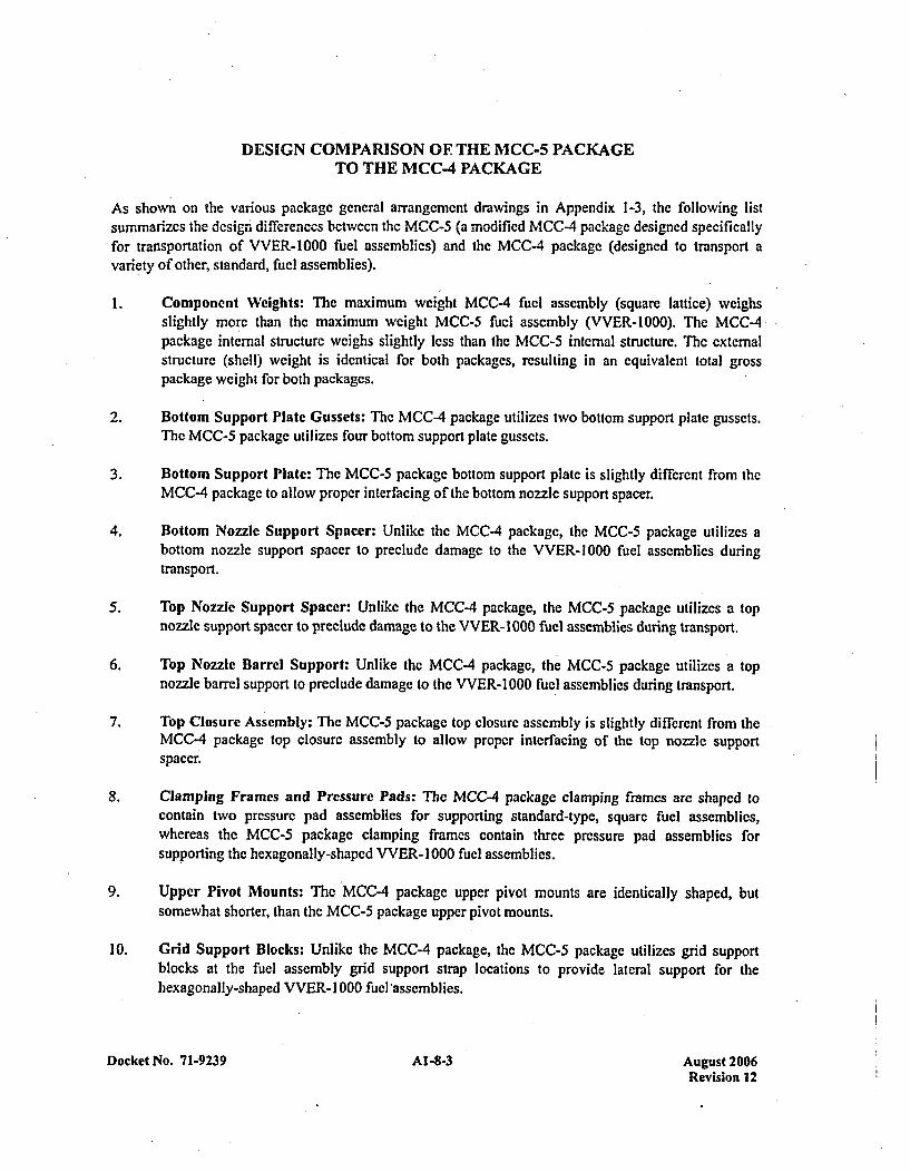
DESIGN COMPARISON OF THE MCC-5 PACKAGETO THE MCC-4 PACKAGE
As shown on the various package general arrangement drawings in Appendix 1-3, the following listsummarizes the dcsign differences betwecn the MCC-5 (a modified MCC-4 package designed specificallyfor transportation of VVER-1000 fuel assemblies) and the MCC-4 package (designed to transport avariety of other, standard, fuel assemblies).
1. Component Weights: The maximum weight MCC-4 fuel assembly (square lattice) weighsslightly more than the maximum weight MCC-5 fuel assembly (VVER-1000). The MCC-4package internal structurc weighs slightly less than the MCC-5 internal structure. The externalstructure (shell) weight is identical for both packages, resulting in an equivalent total grosspackage weight for both packages.
2. Bottom Support Plate Gussets: The MCC-4 package utilizes two bottom support plate gussets.The MCC-5 package utilizes four bottom support plate gussets.
3. Bottom Support Plate: The MCC-5 package bottom support plate is slightly different from theMCC-4 package to allow proper interfacing of the bottom nozzle support spacer.
4. Bottom Nozzle Support Spacer: Unlike the MCC-4 package, the MCC-5 package utilizes abottom nozzle support spacer to preclude damage to the VVER-1 000 fuel assemblies duringtransport.
5. Top Nozzle Support Spacer: Unlike the MCC-4 package, the MCC-5 package utilizes a topnozzle support spacer to preclude damage to the VVER-1000 fuel assemblies during transport.
6. Top Nozzle Barrel Support: Unlike the MCC-4 package, the MCC-5 package utilizes a topnozzle barrel support to preclude damage to the VVER-1000 fuel assemblies during transport.
7. Top Closure Assembly: The MCC-5 package top closure assembly is slightly different from theMCC-4 package top closure assembly to allow proper interfacing of the top nozzle supportspacer.
8. Clamping Frames and Pressure Pads: The MCC-4 package clamping frames are shaped tocontain two pressure pad assemblies for supporting standard-type, square fuel assemblies,whereas the MCC-S package clamping frames contain three pressure pad assemblies forsupporting the hexagonally-shaped VVER- 1000 fuel assemblies.
9. Upper Pivot Mounts: The MCC-4 package upper pivot mounts are identically shaped, butsomewhat shorter, than the MCC-5 package upper pivot mounts.
10. Grid Support Blocks: Unlike the MCC-4 package, the MCC-5 package utilizes grid supportblocks at the fuel assembly grid support strap locations to provide lateral support for thehexagonally-shaped VVER- 1000 fuel 'assemblies.
Docket No. 71-9239 Al -8-3 August 2006Revision 12
CHAPTER 2: STRUCTURAL EVALUATION
2.1 STRUCTURAL DESIGN
2.1.1 Discussion
The design of the MCC series of unirradiated fuel shipping containers is basically the same for all models.The fundamental differences between models arc length and weight. All containers consist of a containershell (base and cover) and an internals assembly. Positive closure of the shell base and cover isaccomplished by means of high strength bolts. The number of bolts is proportional to the length of thecontainer, thus maintaining the loading per boll at a nominal value that is well below the bolt's ultimatestrength. Both the shell design and bolts have been subjected to the drop conditions of I OCFR71 withoutfailure. Therefore, these dcsigns are more than adequate to withstand the loads experienced during normalconditions of transport. Sec the Westinghouse container drawings, for details of these designs, which areincluded as Appendix 1-3 to this application.
2.1.2 Design Criteria
The design of the MCC Series of containers complies with structural requirements of I OCFR7 I. This isaccomplished through the application of design criteria which permits no yielding of the container shellunder a static loading of 5 times the weight of the loaded package, and no yielding of the internalsassembly under static loadings of 6 times the expected maximum weight of the package contents.
The MCC container design has been demonstrated to comply with the hypothetical drop accidentconditions of IOCFR7l. An MCC container, loaded to 100 percent of expected maximum weight ofcontents, was subjected to the drop conditions. This drop test did not produce a configuration morereactive than that analyzed in the criticality evaluation.,
Since the containers arc fabricated from carbon steel, the following yield stress values arc used:
Tensile Yield Stress: 30000 psiShear Yield Stress: 15000 psiWeld Shear Yield: 13600 psi
2.2 WEIGHTS AND CENTERS OF GRAVITY
The weights and centers of gravity for the MCC containers are tabulated and presented in Appendix 2-2 tothis application.
2.3 MECHANICAL PROPERTIES OF MATERIALS
The structural materials used in the MCC series of containers consists of AlSl 1010-1020, ASTM A36,ASTM A240, and ASTM A283 steels. Mechanical properties for ASTM materials are found in therespective ASTM Specifications; mechanical properties for the AISI 1010-1020 material is section 2.1.2of this chapter. Material properties of the load suspension system are provided in Appendix 2-3 to thisapplication.
Docket No. 71-9239 2-1 August 2006Revision 12
2.4 GENERAL STANDARDS FOR ALL PACKAGES
2.4.1 Chemical and Galvanic Reactions
The MCC container is fabricated from structural steel, and the fuel assemblies arc fabricated fromstainless steels and zircaloy; thus, no potecntial exists for chemical or galvanic reactions to occur.
2.4.2 Positive Closure
The MCC container is positively closed by means of high strength bolts which require use of tools anddeliberate action to facilitate their removal. The number, type, and size of these bolts are provided on thedrawings included in Appcndix 1-3 to this application.
2.4.3 Lifting Devices
The lifting attachments that are a structural part of the MCC container shell are designed with a m ,inimumsafety factor of 4 against yielding when used to lift the loaded container in the intended manner.
2.4.4 Tiedown Devices
Tiedown attachments that are a structural part of the MCC container shell are designed to be capable ofwithstanding a static force applied to the center of gravity of the loaded container having:
1. A vertical component of 2 times the weight of the loaded container;
2. A horizontal component, along the transport vehicle forward direction, of 10 times the weight of
the loaded container; and,
3. A horizontal component, in the transverse direction, of 5 times the weight of the loaded container.
2.5 STANDARD FOR TYPE B AND LARGE QUANTITY PACKAGING
Not applicable.
2.6 NORMAL CONDITIONS OF TRANSPORT
The performance requirements specif ied in Subpart F of I OCFR7 1 for normal conditions of transport aremet by the MCC containers. This regulatory compliance is demonstrated in the following subsectionswhere each normal condition is addressed and shown to meet the applicable regulatory criteria. Detailedsupporting information can be found in Appendix 2-4.
2.6.1 Heat
Chapter 3 of this application concludes that the normal heat conditions specified in 1OCFR71.71(c)(1)will have negligible effects on the MCC containers.
Docket No. 71-9239 2-2 August 2006Revision 12
2.6.1.1 Summary of Pressures and Temperatures
*There is no pressure seal in the MCC ' containers. Therefore, therc is no pressure build up within thecontainer. The unirradiated fuel assemblies under the required IOCFR71 sun conditions developtempcratures of less than 200'F for the components of the MCC containers.
2.6.1.2 Differential Thermal Expansion
The differential thermal expansion for the MCC containers is negligible. The greatest differential isbetween the outer shell and the internals - 0. 188 inches. This differential creates very little stress as it isaccommodated by the vibration isolators. Details can bc found in Appcndix 2-4.
2.6.1.3 Stress Calculations
Due to the lack of hard restraints within the container and the fact that it docs not have pressure seals, thepackage will not develop any significant stresses due to normal conditions of transport for heat persection 71.7 1(c)(1) of IlOCFR7I1.
2.6.1.4 Comparison with Allowable Stresses
The heat conditions of IOCFR71.71(c)(l) do not Create any significant stresses within the package.
Therefore, allowable stress limits arc not exceeded.
2.6.2 Cold
The cold conditions specified will not adversely affect the performance of the package. Due to thematerials of construction and the dimensions of the material's cross section, brittle fracture is not aconcern.
2.6.3 Pressure
Since the package is not sealed against pressure, therc can not be any significant differential pressure.However, information presented in Appendix 2-4 demonstrates that the package could withstand thedifferential pressure described in IOCFR7 1.71 if the containers were sealed.
2.6.4 Vibration
Analyses presented in Appendix 2-4 demonstrate that the package has a sufficient margin of safety toresist the loads imposed by shock and vibration incident to normal conditions of transport perI OCFR7 1.71 (c)(5).
2.6.5 Water Spray
The water spray requirement of IOCFR71.71(c)(6) will have no effect on the MCC containers since theexterior is constructed of steel'.'
Docket No. 71-9239 2-3 Ativust 2006Revision 12
damage several positions wcre considered. The side drop with the top down was considered to cause thegreatest loads per clamp frame, which could cause a failure of the clamp frame, or the connections, in.such a manner that the fuel would be frec. The other condition that could have the same effect would bethe side drop on the cornecr of the clamp frames. To maximize the damage in this orientation, an obliquedrop that would create high loads due to slapdown was considered. The other orientation of interest wasthe side drop on the closure flange. This orientation would create the greatest loadings on the closureT-bolts. Failure of sufficient bolts to allow the bottom (containing internals) to separate from the coverwas the concern.
It is shown in Appendix 2-5 that for all orientations the containers have an adequate margin of safetyagainst either the fuel assemblies becoming free or the outer shell separating from the container. Thesemargins were confirmed by full-scale testing. The details of the evaluation and confirmatory testing canbe found in Appendix 2-5.
2.7.1.1 End Drop
The end drop does not impose any load on the MCC containers that will cause the fuel to separate fromthe clamp frames or separate the closure. Therefore, the end drop does not influence the criticality spacingof the package. Supporting evaluations can be found in Appendix 2-5. 1.
.2.7.1.2 Side Drops
2.7.1.2.1 Side Drop onto Container Top
The restraint of the fuel and the necessary spacing is maintained in this orientation. The clamp frame andsnubber assembly adequately hold the fuel and easily maintain the spacing. This is demonstrated in theevaluation shown in Appendix 2-5. 1. Confirmation of the evaluation is found in the testing of the packagedescribed in Appendix 2-5.3.
2.7.1.2.2 Side Drop with Slapdown onto Internal Clamp Frames
The oblique drop, which puts the greatest load onto the clamp frames, imparts significant damage on boththe external shell and the internals. This damage is localized, allowing redundancy in the container designto maintain restraint of the fuel in the clamp frame and within the external package. Details of thisevaluation are in Appendix 2-5.1. Justification of the impact angle is located in Appendix 2-5.2.Conf irmation testing results are in Appendix 2-5.3.
2.7.1.2.3 Side Drop onto Package Closure
The side drop onto the package closure imparts the greatest separation moments to the package closure.The evaluation in Appendix 2-5.1 demonstrates that the package closure has adequate margin to keep theouter shell together. Due to the construction of the package, various mechanisms apply loads to theclosure T-bolts during the impact. These arc evaluated in detail in Appendix 2-5.1. Confirmnation of theadequacy of the closure was demonstrated by full scale testing discussed in Appendix 2-5.3.
Docket No. 71-9239 2-5 August 2006Revision 12
2.7.1.3 Corner Drop
The comner drop event will impart loads into the container that will result only in localized damage thatdoes not influence the overall criticality spacing which is of concern. The actual loads imparted into thecomponents of concern are bounded by the side impacts and the oblique drop.
2.7.1.4 Oblique Drops
The results of the oblique drop evaluation are covered in Section 2.7.1.2.2..Details of the evaluation canbe found in Appendix 2-5.1. Justification for the angle of impact evaluated is in Appendix 2-5.2.Conformational testing results arc located in Appendix 2-5.3.
2.7.1.5 Summary of Results
The evaluations of the various drop orientations, and the resulting damage, demonstrates that thecontainers have adequate margin to maintain restraint of the fuel and integrity of the closure, to maintainspacing between adjacent fuel assemblies. Significant localized damage occurs that does not influence theoverall spacing. Further discussion of the damage can be found in Appendix 2-5.
2.7.2 Puncture:
Due to the localized nature of the puncture impact, the pin puncture will not change the ability of thecontainer to maintain the criticality spacing of the fuel assemblies. In addition, due to the redundancy inthe containers' design, any single component that could be destroyed by the puncture event, such as aclamp frame or connection, would not change the effectiveness of the package. Therefore, the punctureevent described in IlOCFR7I.73(2) is not a controlling condition for the MCC containers.
2.7.3 Thermal
The thermal evaluation of the MCC containers for the hypothetical accident heat condition is discussed inChaptcr 3.
2.7.3.1 Summary of Pressure and Temperatures
The accident case pressure is assumed to be 0 psig since the container is not sealed. The fuel rods aredesigned to withstand a maximum, temperature of 2,2007F without substantial damage. During theaccident fire condition, it is assumed that all combustible components arc burned away.
2.7.3.2 Differential Thermal Expansion
Because of the thin components and the isolation of the internal structure from the external structure, theaccident case thermal loads will not develop thermnal gradients of a sufficient magnitude to result insignificant thermal stress.
Docket No. 71-9239 2-6 August 2006Revision 12
2.7.3.3 Stress Calculations
Due to thc construction of the MCC containcrs, there arc no significant stresses developed by thc thermalgradients.
2.7.3.4 Comparison with Allowable Stresses
The negligible stresses are significantly lower than any of the allowable stresses.
2.7.4 Water Immersion
Since the MCC containers are not sealed against pressure, there will not be any significant differentialpressure with the water immersion loads defined in 1OCFR7J.73(5). The water immersion will have littleeffect on the container or payload.
2.7.5 Summary of Damage
The most significant damage to the package comes from the free drop and the thermal event. Portions ofthe clamp frames and closure T-bolts arc damaged and become ineffective. Since the system is highlyredundant, sufficient clamp frames and closure T-bolts remain intact in all cases to provide restraint of thefuel assemblies and maintain closure. Details of the damage to the packages from the drop events can befound in Appendix 2-5. It is assumed that the accident thermal load will burn away all combustiblematerial in the package, including the shock mounts. This assumption allows the interncal structure (withihe restrained fuel) to contact the outer shell, but remain within the outer shell. The upper and lowerexternal shell assemblies stay together, retaining the fuel inside. The gadolinium plates within the internalstructure will remain intact and maintain their relative position to the fuel.
2.8 SPECIAL FORM
Not applicable.
2.9 FUEL RODS
Fuel rod cladding is considered to provide containment of radioactive material under both normal andaccident test conditions. Discussion of this cladding, and its ability to maintain sufficient mechanicalintegrity to provide such containment, is described in Chapter 4, "Containment," of this application.
Docket No. 7 1-9239 2-7 Aurust 2006Revision 12
APPENDIX 2-1REFERENCES
Docket No. 71-9239 A2-1-1 August 2006Revision 12
REFERENCES
No documents referenced in the text of this section.
Docket No. 71-9239 A2-1-3 August 2006Revision 12
APPENDIX 2-2CONTAINER WEIGHTS AND CENTERS OF GRAVITY
Docket No. 71-9239 A2-2-1 August 2006Revision 12
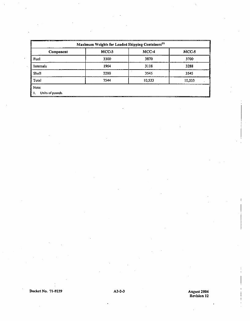
Maximum Weights for Loaded Shipping Contalncrs~l"
Component MCC-3 MCC-4 mCC-5
Fuel 3300 3870 3700
Internals 1964 3118 3288
Shell 2280 3545 3545
Total 7544 10,533 10,533
Note:
1. Units or'pounds.
Docket No. 71-9239 A-- uut20A2-2-3Revision 12
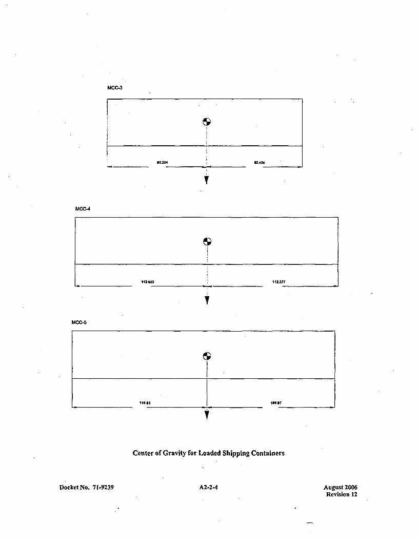
MCC-3
65.3242A26
MCC-4
113.623 112.377
MCC.5
Center of Gravity for Loaded Shipping Containers
A2-2-4Docket No. 71-9239 August 2006Revision 12
APPENDIX 2-3CONTAINER LOAD SUSPENSION SYSTEM
Docket No. 71-9239 A2-3-1 August 2006Revision 12
CONTAINER LOAD SUSPENSION SYSTEM
INTRODUCTION
The following information is taken from a report submitted by Lord Kincmatics' specifically written forthe shipping containers of a design quite similar to MCC serics containers. Because the load suspensionsystems are similar, the information is applied to the MCC-4 and MCC-3 shipping containcrs.
1.0 OBJECTIVE
1.1 The purpose of this report is to summarize the requirements, design and performance of ashipping container suspension system for Westinghouse Electric Company XL and conventional12 ft. nuclear fuel rod assemblies.
2.0 RECOMMENDATION
2.1 The suspension system consists of 24 pieces of Lord part number J-5735-64. There is no changein the suspension system made when used to transport the lighter weight 12 ft. nuclear fuelassemblies. A detailed tabulation of performance data is presented in the Attachment.
2.2 In order to not exceed the design goal shock fragility of 6 G's maximum, the maximum verticalflat drop height is 10" and the maximum rotational drop height is 24".
3.0 DISCUSSION
3.1 The sandwich mounts have a cylindrically shaped elastomer section made in Lord SPE Ielastomer. The nominal static radial or shear stiffness of J-5735-64 is 215 lb/in. The axial orcompression/tension stiffness is approximately 6.5 times the radial stiffness. SPE 1, like otherelastomers has dynamic stiffness characteristics quite difference from static stiffnesscharacteristics. The ratio of dynamic to static stiffness for the proposed mount is approximately1.3. All elastomers are inherently damped and SPE I is no exception. The resonanttransmissibility of J-5735-64 is approximately 6, resulting in a loss factor of 0.17. SPE I is aspecial purpose elastomer having an operating temperature range of -65*F to 1 60'F. Allelastomers exhibit a change in stiffness due to temperature variations. At -40'F, the lowestoperating temperature for this application, the proposed mount has a stiffness approximately1.7 times that at 70'F. At +160 0 F the proposed mount has a stiffness approximately 0.85 timesthat at 70*1F.
3.2 The suspension system consists of 12 pairs of J-5735-64 arranged along the bottom of thesuspended unit. Each mount supports an equal share of the total suspended weight in shear. Partnumber J-5735-64 was selected chiefly for logistics since Westinghouse Electric Company hasused this part in the past for other nuclear fuel rod assembly shipping containers. It is
Lord Kinematics, Shipping Container Suspension System for Westinghouse Electric Corporation XL and NuclearFuel Rod Assemblies, June 1, 1978.
Docket No. 71.9239 A2-3-3 Augyust 2006Revision 12
advantagcous to have pitch rotational and vertical translational natural frequencies that aredifference so that these two modes are not in phase. It should be noted that a shift in unit c.g.location longitudinally from the proposed location would result in pitch rotational/verticaltranslational coupling. The longitudinal mount spacing will result in a relatively high pitchrotational natural frequency less likely to be excited by normal transportation vibrationenvironments.
3.3 The computer analyses in the Attachment were per-formed on Lord's Six-Degree-of-Freedomshock program. The coordinate system used is located at the center of the gravity of thesuspended unit. This coordinate system consists of three mutually orthogonal axes obeying theright hand rule. The Z axis is directed vertically outward from the unit center of gravity. TheX axis extends longitudinally toward the forward end of the fuel rod assemblies. The Y axis liesin the horizontal plane containing the X axis and is directed in the lateral direction. The stiffnesscharacteristics of each mount is listed in addition to the direction cosine that each stiffnessdirection makes with the three coordinate axes.
K(l) and K(3) correspond to mount shear stiffness values and are parallel to X and Z axesrespectively. K(2) corresponds to the mount compression/tension stiffness value and is parallel tothe Y axis. The dynamic to static stiffness ration for each mount is listed in the printout. Eta is thelost factor of the elastomner and is approximately equal to the reciprocal. of resonanttransmissibility. The computer program does not use loss factor in the solution of systemresponse; consequently, viscous dampers having a damping ratio of .085 were added parallel toK(l), K(2), and K(3) at each mount location so that a damped response could be obtained. Itshould be noted that a dynamically equivalent 4 mount system was analyzed rather than the24 mount system since the computer program used is limited to a maximum number of12 mounts. The development of the dynamically equivalent system is presented in theAttachment.
Six undamped natural frequencies arc calculated and if the system is completely uncoupled, thefrequencies would correspond to the X, Y, Z translational and roll, pitch, yaw rotational naturalfrequencies. In order to depict the more complex coupled vibrational modes, a screw analogy isused for every frequency calculated, there is a corresponding point in space through which aninvariant axis passes.
This invariant axis is called a modal axis and its direction cosines are listed in the output. Thesuspended unit can rotate about this axis and simultaneously translate along it. The lead of screwindicates the distance in inches that the suspended unit travels parallel to the modal axis for onecomplete revolution about it. If the lead of screw is zero, the suspended unit simply rotates aboutthe modal axis. As the modal axis moves from the center of gravity to a point an infinite distanceaway from the center of gravity, the vibrational mode associated with that particular frequencychanges from pure rotational to pure translational provided that the lead of screw is zero.
The computer program calculates the system transient response to specified initial conditions atthe time of impact. System initial conditions for each shock test modeled are calculated in theAttachment. Displacements and accelerations of the suspended unit e.g. for discrete instants of
Docket No. 71-9239 A2-3-4 August 2006Revision 12
time arc calculated for a total duration of 0.3 seconds. Responscs arc calculated at -40'F, +70*F,and +160 0F.
The shipping container suspension system will limit the responsc of botb the XL and 12 ft.nuclear~ fuel. rod assemblies to approximately 6 G's wheni subjected to 10" vertical flat drops,7 fl/see end impacts, and 24" rotational drops. An examination of simulated shock response datafor the 12 ft. nuclear fuel rod assembly reveals a peak response of 6.18 G's at -400?F for a 10"vertical flat drop. The computer analyses are based upon assumed infinitely rigid structuresinterfacing with each mount. In general, structural. flexibility results in reduced unit accelerationssince some kinetic energy at impact is absorbed and dissipated by these structures before it can betransmitted through the mounts to the unit.
It should be noted that, an edgewise rotational drop was analyzed rather than a comerwiserotational drop. Typically, the edgewise rotational drop is a more severe test and produces largerdisplacements and accelerations than the cornerwise rotational drop.
lo. 7 1-9239 A2-3-5 August 2006Revision 12
Docket P~
ATTACHMENTDESIGN CRITERIA
Docket No. 7 1-9239 A2-3-7 August 2006Revision 12
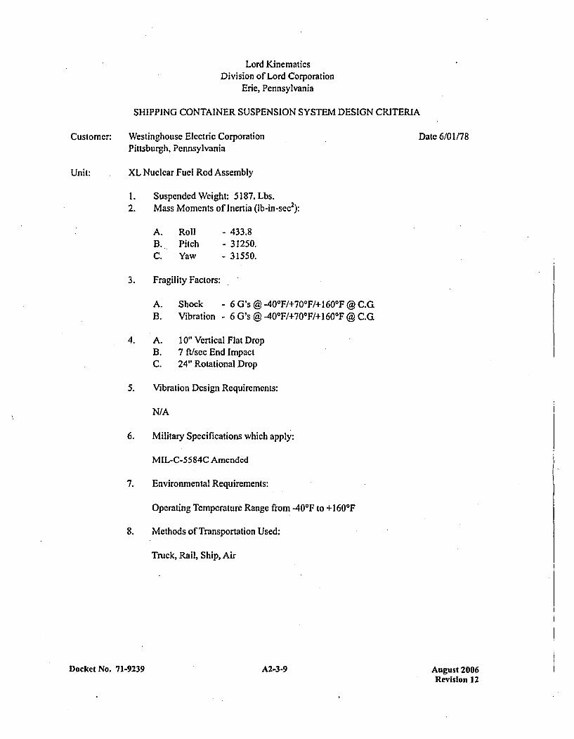
Lord KinematicsDivision of Lord Corporation
Erie, Pennsylvania
SHIPPING CONTAINER SUSPENSION SYSTEM DESIGN CRITERIA
Customer: Westinghouse Electric Corporation Date 6/01/78Pittsburgh, Pennsylvania
Unit: XL Nuclear Fuel Rod Assembly
I . Suspended Weight: 5187. Lbs.2. Mass Moments of Inertia (lb-insec 2):
A. Roll - 433.8B. Pitch - 31250.C. Yaw - 31550.
3. Fragility Factors:
A. Shock - 6 G's @ -40*F/+700F/+] 60'F @ C.G.B. Vibration - 6 G's @ -40'F/+70'F/+ 160*17 @ C.G.
4. A. 10" Vertical Flat DropB. 7 ft/sec End ImpactC. 24" Rotational Drop
5. Vibration Design Requirements:
N/A
6. Military Specifications which apply:
MIL-C-5584C Amended
7. Environmental Requirements:
Operating Temperature Range from -40'F to +160*17
8. Methods of Transportation Used:
Truck, Rail, Ship, Air
Docket No. 71-923 9 A2-3-9 August 2006Revision 12
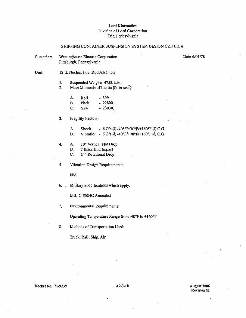
Lord KinematicsDivision of Lord Corporation
Eric, Pennsylvania
SHIPPING CONTAINER SUSPENSION SYSTEM DESIGN CRITERIA
Customer: Westinghouse Electric Corporation Date 6/01/78Pittsburgh, Pennsylvania
Unit: 12 ft. Nuclear Fuel Rod Assembly
1 . Suspended Weight: 4758. Lbs.2. Mass Moments of Inertia (lb-in-sec2 ):
A. Roll - 399B. Pitch - 22800.C. Yaw - 23030.
3. Fragility Factors:
A. Shock - 6 G's @ -400F/+700 F/+1600F @ C.G!B. Vibration - 6 G's @ -400 F/+70*F1+1600F @ C.G
4. A. 10" Vertical Flat DropB3. 7 ftlsec End Impact
C. 24" Rotational Drop
5. Vibration Design Requirements:
N/A
6. Military Specifications which apply:
MIL-C-5584C Amended
7. Environmental Requirements:
Operating Temperature Range from -40*1 to +160 0F
8. Methods of Transportation Used:
Truck, Rail, Ship, Air
Docket No. 7 1-9239 A2-3-10 August 2006Revision 12
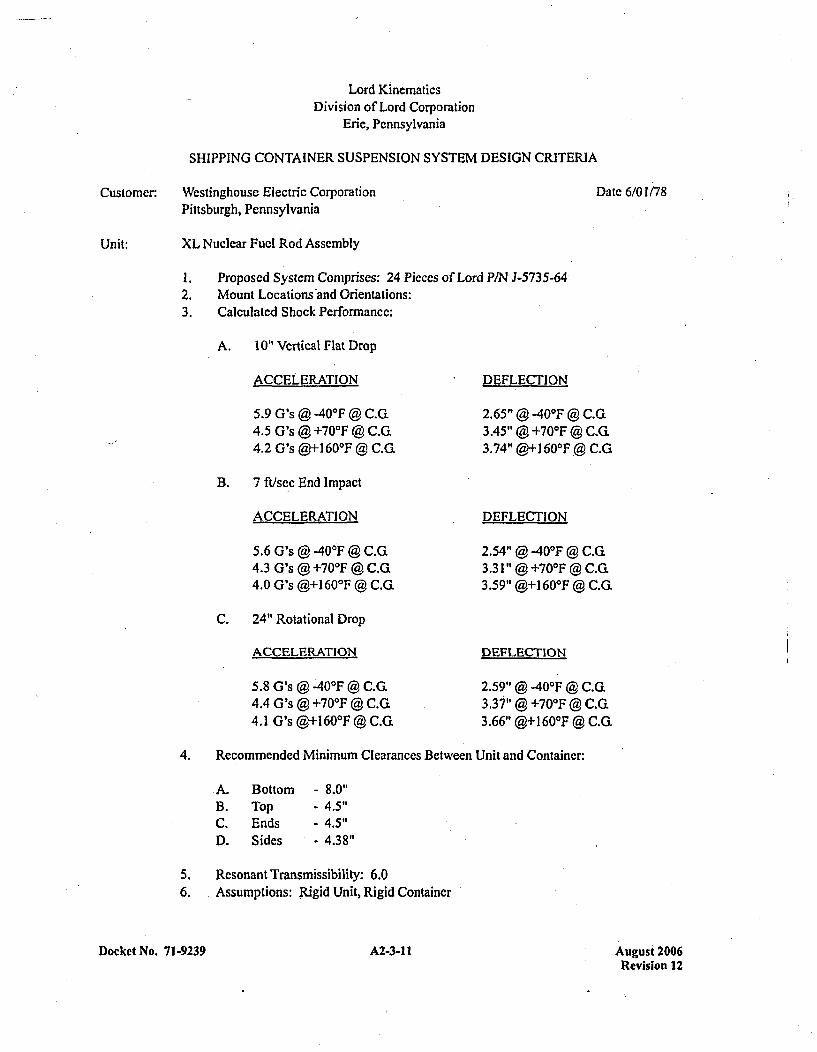
Lord KinematicsDivision of Lord Corporation
Erie, Pennsylvania
SHIPPING CONTAINER SUSPENSION SYSTEM DESIGN CRITERIA
Customer: Westinghouse Electric CorporationPittsburgh, Pennsylvania
Date 6/01/78
Unit: XL Nuclear Fuel Rod Assembly
I .2.3.
Proposed System Comprises: 24 Pieces of Lord PIN J-5735-64Mount Locations *and Orientations:Calculated Shock Performance:
A. 10" Vertical Flat Drop
ACCELERATION
5.9 G's @ -40*F @ C.G.4.5 G's @ +70-F @ C.G.4.2 G's @+l 60-F @ C.Q.
B. 7 fu/sec End Impact
ACCELERATION
5.6 G's @ -406F @ C.G14.3 G's @ +70'F @ C.G4.0 G's @+160'F @ C.Qi
C. 24" Rotational Drop
ACCELERATION
5.8 G's @ -40*F @ C.G4.4 G's @ +70-F @ C.Gi4.1 G's @+I 60TF @ C.G
DEFLECTION
2.65" @ -40-F @ C.G,3.45" @ +70-F @ C.G.3.74" @+1 60-F @ C.G
DEFLECTION
2.54" @ -40-F @ C.G,3.31 " @ +70-F @ C.G.3.59" @+160 0F @ C.G
DEFLECTION
2.59" @ -40-F @ C.GL3.37" @ +700F @ C.G3.66" @+1 60-F @ C.G.
4. Recommended Minimum Clearances Between Unit and Container:
.A. Bottom -8.0"
B. Top -4.5"
C. Ends -4.5"
D . Sides 4.38"
5. Resonant Transmissibility: 6.06. Assumptions: Rigid Unit, Rigid Container
Docket No. 71-9239 A2-3-11I August 2006Revision 12
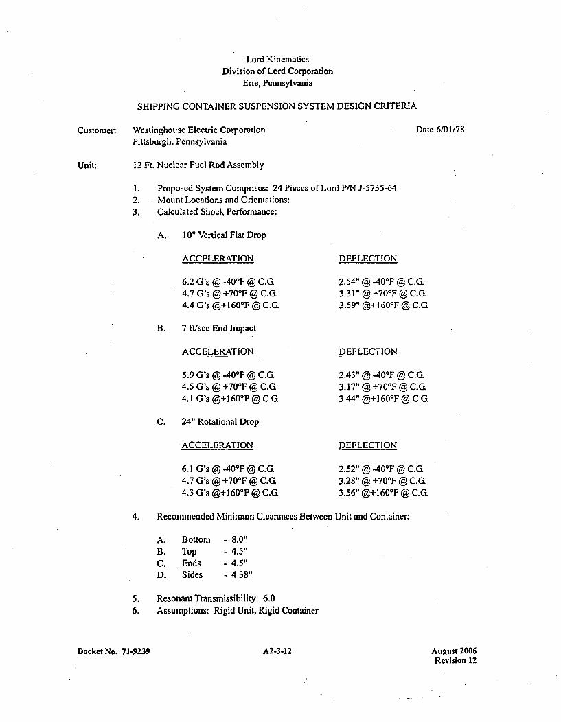
Lord KinematicsDivision of Lord Corporation
Erie, Pennsylvania
SHIPPING CONTAINER SUSPENSION SYSTEM DESIGN CRITERIA
Customer: Westinghouse Electric Corporation Date 6/01/78
Pittsburgh, Pennsylvania
Unit: 12 Ft. Nuclear Fuel Rod Assembly
I . Proposed System Comprises: 24 Pieccs of Lord P/N J-5735-642. Mount Locations and Orientations:3. Calculated Shock Performance:
ýA. 10" Vertical Flat Drop
ACCELERATION
6.2 G's @ -40"F @ C.G.4.7 G's @ +70'F @ C.G.4.4 G's @+I 60'F @ C.G,
DEFLECTION
2.54" @ -40-F @ C.G.3.31 " @ +70-F @ C.G3.5 9" @+1 60OF @ C.G.
B. 7 ft/sec End Impact
ACCELERATION
5.9 G's @ -40OF @ C.G.4.5 G's @ +70'F @ C.G.4.1 G's @+I 60'F @ C.G.
DEFLECTION
2.43- @ -40-F @ C.G.3.17" @ +70-F @ C.G.3.44" @+160-F @ C.Q.
C. 24" Rotational Drop
ACCELERATION
6.1 G's @ .40*F @ C.G.4.7 G's @ +70'F @ C.G.4.3 G's @+160'F @ C.G,
DEFLECTION
2.52" @ -40-F @ C.G,3.28" @ +70-F @ C.G.3.56" @+160-F @ C.G.
4. Recommended Minimum Clearances Between Unit and Container:
A. Bottom - 8.0"B. Top - 4.5 "C. ,Ends - 4.5 "D . Sides - 4.38"1
5. Resonant Transmissibility: 6.06. Assumptions: Rigid Unit, Rigid Container
Docket No. 71.9239 A2-3-12 August 2006Revision 12

APPENDIX 2-4CALCULATIONS AND EVALUATIONS RELATING TO ASSESSMENT
OF NORMAL CONDITIONS OF TRANSPORT
Docket No, 71-9239 A2-4-1 August 2006Revision 12
ASSESSMENT OF NORMAL CONDITIONS OF TRANSPORT
The MCC containers satisfy the performance requirements specified in Subpart F of IO0CFR7I for normalconditions of transport. This regulatory compliance is demonstratcd in the following subsections whereeach normal condition is addressed and shown to meet thc applicable regulatory criteria.
2-3.1 Heat
The thermal evaluation of the MCC containers for the normal heat condition specified in §71.71(c)(1) ispresented in this section. Since there is no internal heat generation, a maximum package temperature of2001F will be conservatively assumed.
2-3.1.1 Summary of Pressures and Temperatures
The MCC containers are limited to the transport of unirradiated, low enriched uranium, nuclear reactorcore assemblies. During normal conditions of transport, the container will not experience temperaturessignificantly above ambient tcmperaturc.'For the normal condition of. heat per §71.71(c)(1), the maximumtemperature of the MCC container components is less than 2001F.
The MCC containers are not designed to function as pressure vessels. The fuel assemblies do not generategasses which could pressurize the MCC container. In addition, the seal between the two halves of thecontainer is only a dust seal and is not a pressure seal. Therefore, the MCC containers will not experiencea pressure loading incident to normal transportation.
2-3.1.2 Differential Thermal Expansion
As discussed in Section 2-3.1.1, the outer shell of the MCC containers will operate at a maximumtemperature of less than 2007F during normal transportation. This temperature occurs in the outer shellswhich are isolated from the internal strongback structures by elastomcr vibration isolators. Because of thisisolation, no significant effects due to differential thermal expansion will occur between the internalstructures and the -outer shells.
For the outer shells, the stress due to insolation and 100*F still air is minimal since there arc noconstraints on the package. The amount of thermal growth which is expected is determined as follows:
AL = a(T 2 - TOP(L
where:
AL = Change in package length, in.
a = mean coefficient of thermal expansion=6.57 x 10O6 in/in - *F for carbon steel at 150'F
T2 = Maximum package temperature = 200*1F
Docket No. 71-9239 A2-4-3 Au2 ust 2006Revision 12
= Package initial temperature = 70*F (assumed)
L = Maximum overall package length = 220.0 in.
Solving the preceding equation yields a maximum outer shell thermal growth of 0. 188 in. This amount ofgrowth is easily accommodated by the vibration-isolators which separate the internal structures and theouter shells.
Based on the preceding results, differential thermal expansion is negligible for the MCC containercomponents.
2-3.1.3 Stress Calculations
The MCC containers are transported in a non-constrained, non-pressurized state. Therefore, the containers
will not develop any significant stresses due to normal conditions of transport for heat per §71.71(c)(1).
2-3.2 Cold
For the cold condition of §71.71(c)(2), a -40'F (-40'C) steady state ambient temperature will result in auniform temperature throughout the package since therc is no internal heat generation. Thc materials ofconstruction for the container are not adversely affected by this temperature condition.
Brittle fracture of the materials used in the MCC containers is not a concern. The critical component ofthe design (the clamp frame arms) is fabricated from ASTM A240 Type 304 austenitie stainless steelplate. This material does not undergo a ductile-to-brittle transition in the temperature range of interest andtherefore, is safe from brittle fracture. The clamp frame systems are also a redundant system. Redundantsystems are generally not* considered as fracture-critical components because multiple load paths exist. Inaddition, the thicknesses of the components which use non-austenitic materials are less than 0.4 in. PerNUREGICR- 18 15, brittle fracture of Category III materials (which the MCC containers fall under) whichare less than 0.4 in. in thickness is not a problem.
2-3.3 Pressure
The effect of the reduced external pressure of 3.5 psia (i.e., 11.2 psig internal pressure), per §71.71(c)(3),is evaluated for the outer shell of the containers. These calculations are very conservative considering theMCC containers are not pressure vessels and differential pressure states will not exist. In addition, theouter shell stiffening angles are conservatively ignored in the calculation. The bounding case used fordemonstration is the model MCC-3 container. The circumferential and longitudinal stresses, a, and OLrespectively, in the MCC-3 outer shell are calculated as:
PR PRac 0 2t
Docket No. 7 1-9239 A24-4 August 2006Revision 12
where:
P = 11.2 psig
R = 20-67 in,
t = 0.089 in.
Substituting the above values results in the following stress levels:
cy =2.60Oksi CF =1.30 ksi
These stress levels will have negligible effect on the outer steel shell which is fabricated from mild carbonsteel. Similar results exist for the MCC-4 container.
For the pressure condition of §71.71 (c)(4), the MCC container will bc exposed to an external pressure of5.3 psig. It can be easily demonstrated that the MCC-3 container can withstand this external pressure byconservatively assuming a thin-walled pressure vessel with a length equivalent to the longest span of theouter shell between circumferential stiffeners and neglecting the stiffening effect of the angle flangebetween the two halves of the outer body. For this analysis, the longest unsupported shell length occurs inthe middle of the container upper assembly. Per Code Case N-284, Section 111, Division 1, Class MC ofthe ASME Boiler and Pressure Vessel Code, the outer shell may be analyzed as a shell under axialcompression plus hoop compression. For this case (§ 1713. 1. 1(b)), the following interaction equation mustbe satisfied:
CO -05GheL C~ - I .
a$CL - 0.5 GheL kh. hL)
where:
Il$L = 'U(10-) - 0.033
OOS =P(R/t)[(FS)f(0.8)]
C7cL =(0.605)(tIR)E
C0hcL = - L(/)
Ch.L =[O.92/(MO - 0.636)]
P =5.3 psig
LO = Length of unstiffened shell 41.25 in.
Docket No. 71-9239 A2-4-5 August 2006Revision 12
cy = Tensile yield strength of shell =30,000 psi
= Young's Modulus = 29.0 x 10⁶ for carbon steel
R = Outer radius of shell = 20.62 in.
t = outer shcell thickness = 0.089 in.
FS =Factor of Safety =2.0
Solving the above interaction equation yields a value of 0.668, which satisfies Code Case N-284 for the§71.71(c)(4) pressure condition. Similar results are obtained for the MCC-4 container.
In summary, the MCC containers can easily withstand the reduced and increased pressure conditions of§71.71 (c).
2-3.4 Vibration
The shock mount system of the MCC containers is designed to limit the internal structure to a maximumshock load of 6 g's during normal transportation conditions. For this reason, a static 6 g design load isconservatively used to evaluate the MCC containers for stresses due to normal vibration loads per§71.71(c)(5).
The stresses in the container outer shells are conservatively calculated by evaluating the container as asimply supported beam supportcd at its ends, as shown in Figure 2-4-1. The mass of the package isassumed to be evenly distributed along its length. The circumferential shell stiffeners-arc conservativelyignored in these calculations. For the bounding case, the maximum gross weight of the MCC-3 container(WV) is 7,544 lbs. Assuming a uniform 6 g load over the length of the container, the bending stress (arb) inthe container outer shell is then:
ab shell
where:
M =6((o)L2/8 6WL/8
-Weight per unit length
L = Overall package length =192.0 in.
c = 20.625 in
,shell = nD4/64 =147,362 in4
D = Outer diameter of shell = 41.25 in.
Docket No. 7 1-9239 A2-4-6 August 2006Revision 12
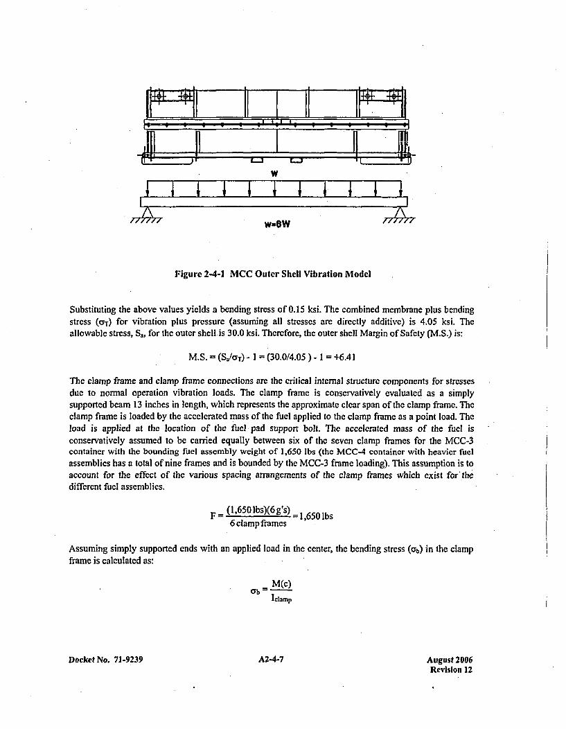
w
77#>77 17#>17w-eW
Figure 2-4-1 MCC Outer Shell Vibration Model
Substituting the above values yields a bending stress of 0.15 ksi. The combined membrane plus bendingstress (aT-) for vibration plus pressure (assuming all stresses arc directly additive) is 4.05 ksi. Theallowable stress, S., for the outer shell. is 30.0 ksi. Therefore, the outer shell Margin of Safety (M.S.) is:
M.S. = (S./coT) - I = (30.0/4.05 1 = +6.41
The clamp frame and clamp frame connections are the critical internal structure components for stressesdue to normal operation vibration loads. The clamp frame is conservatively evaluated as a simplysupported beam 13 inches in length, which represents the approximate clear span of the clamp frame. Theclamp frame is loaded by the accelerated mass of the fuel applied to the clamp frame as a point load. Theload is applied at the location of the fuel pad support bolt. The accelerated mass of the 'fuel isconservatively assumed to be carried equally between six of the seven clamp frames for the MCC-3container with the bounding fuel assembly weight of 1,650 lbs (the MCC-4 container with heavier fuelassemblies has a total of nine frames and is bounded by the MCC-3 frame loading). This assumption is toaccount for the effect of the various spacing arrangements of the clamp frames which exist for' thedifferent fuel assemblies.
F (1,650 lbs)(6 gs) =-1,5 6 b6clampframes 5 b
Assuming simply supported ends with an applied load in the center, the bending stress (cyb) in the clampframe is calculated as:
M(c)
Iclamp
Docket No. 71-9239 A24-7 A2-4-7August 2006Revision 12

where:
M =F(t/2)I2
C = 2.0/2 =1.0in.
I clamp =bh 3/l 2 =l.25(2)'/]l2 = 0.833 in4
where: b and h arc width and height of clamp frame cross section
= effective clamp frame span = 13.0 in.
Substituting the appropriate values in the above equation yields a bending stress of 6.44 ksi. Because theclamp frames can only be loaded, by inertia forces when the package is in the normal orientation, thisstrcss represents thc total stress on the clamp frame. No other loads arc combined with the vibration loadon the internal structure clamp frames.
The allowable bending stress (Sa) for the clamp frame is 30.0 ksi. Therefore the Margin of Safety is:
M.S. =(Sa/G;b) - I1 (30.0/6.44) - I + 3.66
The shear load, F,,, on the connection pins is conservatively assumed to be equal to the maximum appliedload of 1,650 lbs., and that the full load is carried by one connection. Based on an allowable shear yieldstress of 98.1 ksi (0.577 of minimum tensile yield stress for ASTM A564 Type 630 material), theallowable shear strength, F,, for the clamp frame connection pins in double shear is 18,129 lbs. Therefore,the connection pin Margin of Safety is:
M.S. =(F.IF,) - I = (18129/1650) - I = +9.99
The clamp frames connect into pivot mounts which in turn connect to the Unistrut channels attached tothe internal structure. The maximum tensile stress in the pivot mounts, due to vibration loads, will occurin the side pivot mount, which is slightly thinner than the upper pivot mount. The full reaction load of1,650 lbs. is conservatively assumed to carried by the lower pivot mount. The load, F, in each leg of thepivot mounts is then:
F .. = 160=825 lbs2
Assuming the load is distributed across the width of the connection pins, the bearing stress, aB, on thepivot mount is:
F
Docket No. 7 1.9239 A2-4-8 Augyust 20l06Revision 12
where:
AB3 = Bearing Area = (D)(w)
D =diameter of connection pin = 7/164in,
w = pivot mount bearing surface width = 0.365 in.
Solving for the bearing strcss yields a stress level of 5.17 ksi. The allowable bearing stress, Sa, in the pivotmounts is 30.0 ksi. Therefore, the pivot mount Margin of Safety is:
M.S. = (SdraB) - I1 (30.0/5.17) - I =+ 4.80
The load on each of the two Unistrut connection bolts is 825 lbs. This load conservatively assumes thatonly one pivot mount carries the vibration reaction load and that the load is equally distributed betweenthe two bolts connecting each pivot mount. The manufacturer's recommended allowable tensile load(Fb.lz) for the P-2381-5 Unistrut stud nuts is 2,000 lbs/stud. The Margin of Safety against pull-out of thetwo Unistrut bolts is then:
M.S. =(2)(Fb.I1)/(F) - I = 4000/825 - I =+ 3.85
2-3.5 Compression
Per. §71.7 1 (c)(9), packages which weigh up to 11,000 lbs. (5,000 kg) must be subjected, for a period of24 hours, to a compressive load applied uniformly to the top and bottom of the package in the position inwhich the package would normally be transported. The compressive load must be the greater of thefollowing: (i) The equivalent, of five times the weight of the package; or (ii) the equivalent of12.75 kilopascal (1.85 lbin 2) multiplied by the vertically projected area of the package.
For the MCC-4 container (bounding case), five times the weight of the package is 52,765 lbs. Theprojected area of the container, A,, is calculated as:
Ap = (Dinax)(Lmax)
where:
Dmax =Maximum overall package width =44.5 in.
L,,.= Maximum overall package length =226.0 in.
The projected area is calculated to be 10,057 in 2. Therefore, the total load for a pressure of 1.85 psi is:
Fp = (1.85)(10,057) =18,6051bs. < 5(W) = 52,7651lbs.
Therefore, the controlling load is five times the package weight. The package is transported in ahorizontal position, resting on the stacking frames on the bottom ends of the package. Therefore, the
Docket No. 71-9239 A2-4-9 August 2006Revision 12
maximum stress due to the compression load is a bcnding stress in the outer shell. The resulting stress inthe outer shell is conservatively evaluated by assuming the package acts as a simply supported beam. Thebending stress, Cyb, is then calculated as:
Ub=M(c)IshcII
where:
M = 5((o)L 2/8 =5WL/8 =1,490,611 in-lbs
L
C
(0
I Sh.II
- 226.0 in.
- 20.625 in.
- Load per unit length
- 147,362 in4
The calculated bending stress resulting from a compressive load per §71.71 (c)(9) is 0.21 ksi. Theallowable bending stress for the container shell is 30.0 ksi. Therefore, it can then be concluded that theMCC containers comply with the requirements of this subsection.
Docket No. 7 1-9239 A2-4-10 August 2006Revision 12
APPENDIX 2-5CALCULATIONS AND EVALUATIONS RELATING TO ASSESSMENT
'OF HYPOTHETICAL ACCIDENT CONDITIONS
Docket No. 71-9239 A2-5-1 August 2006Revision 12
APPENDIX 2-5.1CALCULATIONS
Docket No. 71-9239 A2-5.1-1 August 2006Revision 12
ASSESSMENT OF HYPOTHETICAL ACCIDENT CONDITIONS
Westinghouse MCC containers, when subjected to hypothetical accident conditions specified in §71.73,meet the performance criteria specified in Subpart E of I OCFR7l1. This compliance is demonstrated in thefollowing subsections where each accident condition is addressed and shown to meet the applicabledesign criteria previously discussed in Section 2.1.2 of the application.
As stated in Section 2.1.2 of the application, the post accident configuration cannot be more reactive thananalyzed in Section 6.0. To prevent it from becoming more reactive, the spacing between fuel assembliesfrom adjacent packages, when in parallel planes, must not be allowed to be reduced below eight (8)inches. This spacing is accomplished by ensuring that the fuel assemblies are restrained by the strongbackand that the outer shell remains intact. If the outer shell was separated from the package, the adjacent fuelpackage clamp frames could lay between the clamp frames of the adjacent package. The fuel spacing,when the fuel is corner-to-corner, can be slightly closer. The fuel must be restrained such that thegadolinium neutron absorber plates stay between the fuel bundles.
2-4.1 Free Drop
§71.73(c)(1) of Subpart F requires that a package withstand a drop from a height of 30-feet (9 meters)onto a flat, unyielding, horizontal surface. The package is to strike the surface in a position for whichmaximum damage is expected. Per §71.73(b), the initial temperature for the drop is to be the worst easeconstant ambient air temperature between -201F and W00F. Brittle fracture of the MCC containermaterials is not a critical issue through the temperature range of concern as shown in Section 2.6.2.Therefore, the worst case temperature condition for the drop test is I 000F. This section demonstratescompliance of the MCC containers, with the 30-foot drop test condition, by analysis and prototypetesting. The analyses presented determine the ability of. the containers to absorb the kinetic energyassociated with the 30-foot drop. The prototype testing is confirmation of the package's ability tomaintain a subcritical geometry following the 30-foot drop. The drop orientations considered in theanalyses and utilized for the prototype tests include the following:
*(Flat) side drop onto package top*Side drop with slapdown onto package clamp frames*(Flat) side drop onto package closure
For analytic purposes, the weights of the MCC-3 and MCC-4 containers are considered to be as shown inSection 1.2. 1. For purposes of this evaluation, the MCC-3 container, when loaded with its maximum fuelassembly weight of 3,300 lbs., is the bounding case and is utilized for demonstrating regulatorycompliance. (See the justification provided in Section 2-4.5.)
2-4.1.1 End Drop
The end drop is not a controlling orientation for the MCC containers to maintain a sub-critical geometry.For this orientation, the end of the MCC outer shell and the end supports of the internal strongback willcrush. Any residual kinetic energy will be absorbed by axial crushing of the fuel assemblies. Therefore,this axial damage will result in a less reactive geometry for criticality control. In addition, the criticalcomponents of the MCC containers, the clamp frames, are redundant (i.e., a single failure does not cause
Docket No. 71-9239 A2-5.1-3 August 2006Revision 12
a failure of the package to maintain a sub-critical geometry). Except for the gadolinium oxide absorberplates, the expected deformations and critical load paths of the side drops will be more crucial for theMCC container design to maintain a sub-critical geometry. Demonstration of the gadolinium oxideabsorber plates' ability to withstand the impact forces associated with the 30-foot drop events is discussedin Appendix 1-7. Additionally, the prototype containers which were utilized in the drop tests had thegadolinium oxide absorber plates instal led. The results of the drop tests are discussed in Appendix 2-5.3.
2-4.1.2 Side Drops
2-4.1.2.1 Side Drop onto Container Top
The internal structure of the MCC-3 container is attached to the outer shell by a series of shock mountswhich are intended to limit normal condition transportation events to below 6 g's. Since the shock mountsystem is relatively soft (with the shear stiffness of the combined shock mounts at 5,160 lbin), the systemwill not significantly affect the impact velocity of the internal structure. For conservatism, the internalstructure is assumed to impact the drop pad at full velocity. Because of the "softness" of the shock mountsystem, the outer shell and internal structure may be decoupled and will act independently during theimpact from the 30-foot accident drop events.
The deformation of the outer shell assembly due to the 30-foot accident drops is not of critical concern forthe function of the MCC containers. As previously discussed, the primary purpose of the MCC containeris to maintain a minimum spacing between adjacent packages for criticality control. Of critical concern isthe ability of the internial structure to absorb the energy of its aeccelerated mass without catastrophic failureor deformations which result in less than the allowable criticality spacing. The outer shell deformationsare calculated herein to verify the ability of the outer shell to fully absorb the kinetic energy of itsaccelerated mass due to the 30-foot drop without catastrophic failure.
Outer Shell Assembly Deformations
The kinetic energy associated with the outer shell assembly upon impact is:
Eshell = Wshefl(h)
where:
W~h.1I weight of the outer shell assembly 2,280 lbs.
h = drop height =30 feet (360 inches)
The kinetic energy of the outer shell is 820,800 in-lbs. This energy will be absorbed by the strain energyprimarily associated with the deformation of the 2-in. x 2-in. x ¼4-in, angle circumferential stiffeners(refer to Figure 2-5.1-1). The energy absorption of the outer shell skin (t =0.089 in.) is neglected in thiscalculation.
Docket No. 7 1-9239 A2-5.1-4 August 2006Revision 12
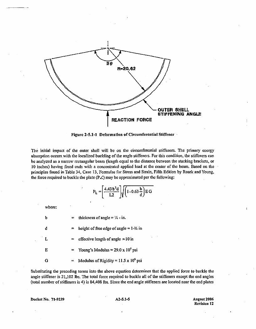
I
\~-OUTER SHELLSTIFFENING ANGLE
REACTION FORCE
Figure 2-5.1-1 Deformation of Circumferential Stiffener
The initial impact of the outer shell will be on the circumferential stiffeners. The primary energyabsorption occurs with the localized buckling of the angle stiffeners. For this condition, the stiffeners canbe analyzed as a narrow rectangular beam (length equal to the distance between the stacking brackets, or10 inches) having fixed ends with a concentrated applied load at the center of the beam. Based on theprinciples found in Table 34, Case 13, Formulas for Stress and Strain, Fifth Edition by Roark and Young,the force required to buckle the plate (P4) may be approximated per the following:
PL = [±.4bd ]ý (I -o.63JE G
where:
b = thickness of angle = 1/- in.
d = height of free edge of angle =I-114 in
L = effective length of angle = 10in
E = Young's Modulus = 29.0 x 10⁶ psi
G = Modulus of Rigidity =11.5 x 10⁶ psi
Substituting the preceding terms into the above equation determines that the applied force to buckle theangle stiffener is 21,102 lbs. The total force required to buckle all of the stiffeners except the end angles(total number of stiffeners is 4) is 84,408 lbs. Since the end angle stiffeners are located near the end plates
Docket No. 71-9239 A2-5.1-5 August 2006Revision 12
of the container, these stiffeners will tend to crush rather than buckle. The force associated with crushingof these angles is given by:
F L crush (2) a fl.w (A L)
where:
c~io- flow stress V ~2 (ay + oui,)
V2(30,000 + 54,000) = 42,000 psi
Az = angle crush area = (1/4)(10) = 2-'/2 in'
Substituting the above values yields a crushing force for the two end angle stiffeners of 210,000 lbs.Using the principle that force multiplied by distance equals energy, the total deformation which isrequired to absorbed the kinetic energy of the outer shell may be determined per the following:
cnush - EshellI 820,800 - 2.79 inches(4XPZ) FZ cr (4X21,102)+210,0700
The gross deformation is then equal to 8 ~hplus the angle leg length, or 4.54 inches. Therefore, the totalouter shell kinetic energy is absorbed by approximately 4-Y2 inches of deformation of the circumferentialstiffeners. Testing of a MCC-3 prototypic container has shown that the circumferential stiffeners deformapproxi mately 3-4 inches for the 30-foot drop onto the container top (refer to Appendix 2-5.3 for detailsof the drop tests). Si nce the deformed outer shell assembly is maintained around the fuel assemblies, theminimum separation distance to maintain a subcritical geometry is still in place.
Internal Assembly Deformations
As noted previously, the internal structure may be decoupled from the outer'shell assembly during theaccident drops. Therefore, the response of the internal structure to the 30-foot side drop is evaluated byassuming that the kinetic energy associated with mass of the internal structure is absorbed solely by thestrain energy of the internal structure deformations.
The kinetic energy associated with the internal structure assembly upon impact is:
Eitml= W~, inea (h)
where:
W jnten,,i = (internal structure + fuel assembly weight)=5,264 lbs
h = drop height =30 feet (360 inches)
Docket No. 71-9239 A2-5.1-6 August 2006Revision 12
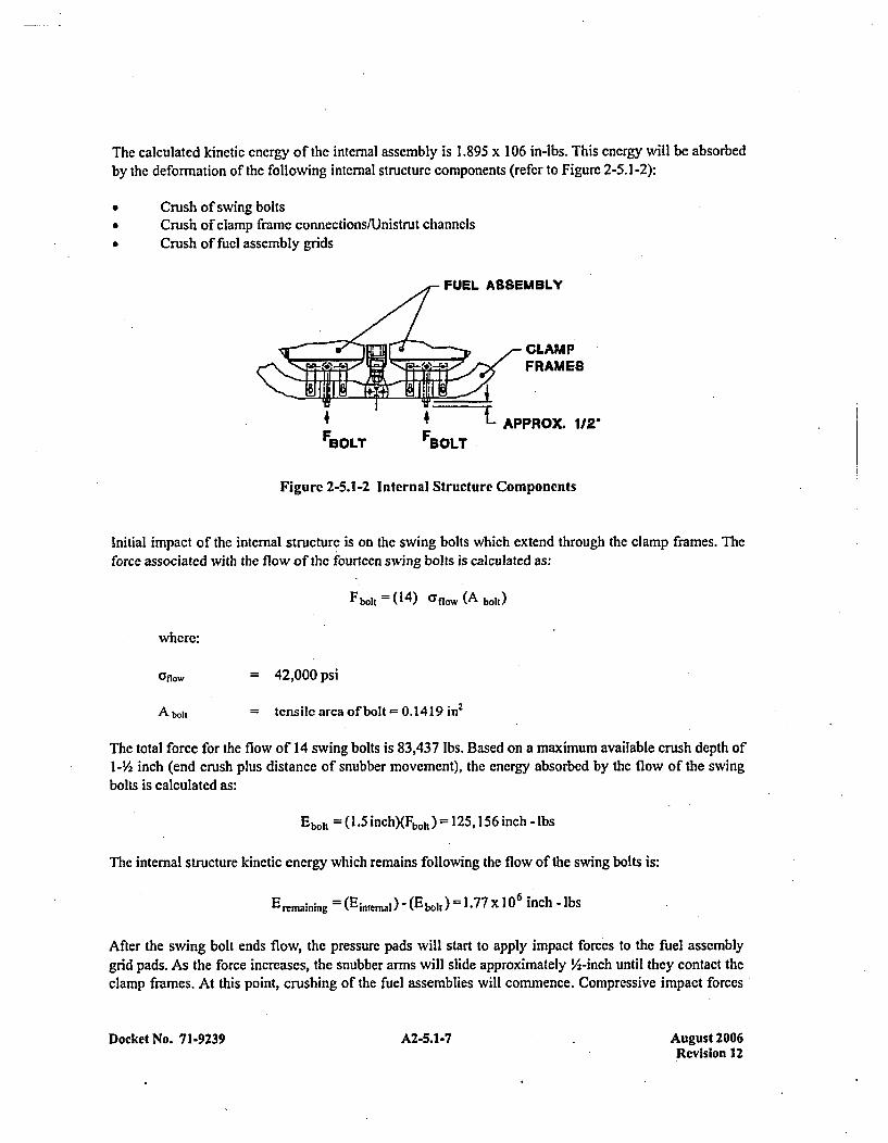
The calculated kinetic energy of the internal assembly is 1.895 x 10⁶ in-lbs. This energy will be absorbedby the deformation of the following internal structure components (refer to Figure 2-5.1-2):
* Crush of swing bolts* Crush of clamp frame connections/Unistrut channels* Crush of fuel assembly grids
FUEL ASSEMBLY
~YxCLAMP
4FBOLT FBOLT
Figure 2-5.1-2 Internal Structure Components
Initial impact of the internal structure is on the swing bolts which extend through the clamp frames. Theforce associated with the flow of the fourteeni swing bolts is calculated as:
FboIK (14) cflow (A bolt)
where:
= 42,000 psi
A bol = tensile area of bolt = 0.14 19 in 2
The total force for the flow of 14 swing bolts is 83,437 lbs. Based on a maximum available crush depth of1-Y/2 inch (end crush plus distance of snubber movement), the energy absorbed by the flow of the swingbolts is calculated as:
Ebolt = (1.5 inch)(FboIt) =125,156 inch - lbs
The internal structure kinetic energy which remains following the flow of the swing bolts is:
E remaining = (Eintemai) (Eii bolt 1.77 X 106 inch - lbs
After the swing bolt ends flow, thc pressure pads will start to apply impact forces to the fuel assemblygrid pads. As the force increases, the snubber arms will slide approximately 'A-inch until they contact theclamp frames. At this point, crushing of the fuel assemblies will commence. Compressive impact forces*
Docket No. 71-9239 A2-5.1-7 August 2006Revision 12
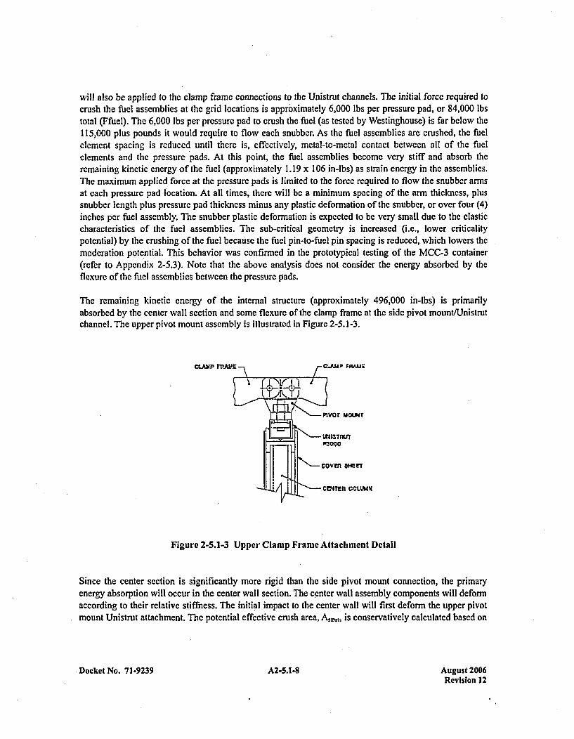
will also be applied to the clamp frame connections to the Unistrut channels. The initial forcc required tocrush the fuel assemblies at the grid locations is approximately 6,000 lbs per pressure pad, or 84,000 lbstotal (Ffuel). The 6,000 lbs per pressure pad to crush the fuel (as tested by Westinghouse) is far below the115,000 plus pounds it would require to flow each snubber. As the fuel assemblies are crushed, the fuelelement spacing is reduced until there is, cifectively, meta-l-to-metal contact between all of the fuelelements and the pressure pads. At this point, the fuel assemblies become very stiff and absorb theremaining kinetic energy of the fuel (approximately 1.19 x 10⁶ in-ibs) as strain energy in the assemblies.The maximum applied force at the pressure pads is limited to the force required to flow the snubber armsat each pressure pad location. At all times, there will be a minimum spacing of the arm thickness, plussnubber length plus pressure pad thickness minus any plastic deformation of the snubber, or over four (4)inches per fuel assembly. The snubber plastic deformation is expected to be very small due to the elasticcharacteristics of the fuel assemblies. The sub-critical geometry is increased (i.e., lower criticalitypotential) by the crushing of the fuel because the fuiel pin-to-fuel pin spacing is reduced, which lowers themoderation pote 'ntial. This behavior was confirmed in the prototypical testing of the MCC-3 container(refer to Appendix 2-5.3). Note that the above analysis does not consider the energy absorbed by theflexure of the fuel assemblies between the pressure pads.
The remaining kinetic energy of the internal structure (approximately 496,000 in-Ibs) is primarilyabsorbed by the center wall section and some flexure of the clamp frame at the side pivot rnountlUnistrutchannel. The upper pivot mount assembly is illustrated in Figure 2-5.1-3.
CLAM~P 1~rA' CLPJJP FRAM.E
Pivor mouir
cowtn am-n
* CVir~n COLUMN
Figure 2-5.1-3 Upper Clamp Frame Attachment Detail
Since the center section is significantly more rigid than the side pivot mount connection, the primaryenergy absorption will occur in the center wall section. The c 'enter wall assembly components will deformaccording to their relative stiffness. The initial impact to the center wall will first deform the upper pivotmount Uni strut attachment. The potential effective crush area, Asrt is conservatively calculated based on
Docket No. 71-9239 A2-5.1-8 August 2006Revision 12
the contact area with the pivot mount. The force associated with the flow of the Unistrut channels at theseven upper pivot mount locations (F,5,u) is calculated as:
F~trij = (7) (un..)(Asmnj)
where:
allow= 42,000 psi
Astrut= Unistrut effective crush area = 1.16 in 2
From this expression, the force associated with the deformation of the Unistrut channels is estimated to be341,040 lbs. The maximum available crush depth for the Unistrut channels is 'A-inch. Therefore, theenergy absorbed by the deflection of the upper Unistrut channel is calculated as:
Esru )(2.t !inchj 170,520 inch - lbs
The remaining kinetic energy of the internal structure will be absorbed primarily by elastic deformation ofthe main center wall. This kinetic cnergy, Ew.11 to be absorbed by the center wall deformation isapproximately 325,480 in-lbs. Because of the high compressive stiffness of the center wall section(estimated to be greater than 3.0 x 10⁷ lb/in), elastic and plastic deformations will completely absorb theremaining energy.
The force associated with the main center wall can conservatively be calculated by assuming an effectivewidth for the cover plates equal to the length of the pivot mount of 5.34 inches. The internal structurecenter wall is built around six columns fabricated from 1-1/2 in. x l-V2 in. x 1/4-in, rectangular tube, notincluding the end supports. The crush force of the center wall is calculated by distributing the strength ofthe six column supports in the center wall evenly to each- of the clamp frame locations. Therefore,assuming all deformation as plastic and an effective crushing length of 5.34 inches at each clamp framelocation, the center wall crush force, Fw. 1, is calculated as:
F,,.,, - (7)a flow, (A,ý.Ij)
where:
Cr flow= 42,000 psi
A wall =effective crush area of the center wall=A plate + A columns
A Platc = effective crush area of cover plates-5.34(0.18)(2) 1.92 in 2
A coun effective crush area of column supports= (6)(1.25)/7 =1.07 in 2
Docket No. 71-9239 A2-5.1 -9 August 2006Revision 12
Solving the above expression for the force in the wall yields a force of 879,060 lbs. The total deflection ofthe center wall can be calculated based on the remaining kinetic drop energy to be absorbed. The centerwall deflection is calculated as:
5wait32 - I*ýý=0.370 inches
The predicted deformation of the internal wall is acceptable because the clamp frames arc in compressionat the upper pivot mount. Note that the design of the frame at each pivot mount allows the clamp framesto move relative to the bail-lock and lower connecting pins. This movement allows the clamp frames tobear directly on the inner surface of the pivot mounts without applying shear load to either the ball-lock orconnecting pins, thus ensuring that the frames' connectivity to the internal strongback remains intact andcontinues to restrain the fuel. The center-wall structure further encapsulates the gadolinium plates, whichensures criticality control within the MCC package between adjacent fuel assemblies. The ability of thegadolinium absorption plates to withstand the impact of a 30-foot drop event have been demonstrated byprototypical testing (refer to Appendix 1-7).
As the previous calculations demonstrate, the kinetic energy of the 30 foot drop can be conservativelyabsorbed by the strain energy associated with the deflection of the internal structure components. Notethat the preceding analysis is conservative and that actual deformations will be significantly less thanpredicted here. This conservatism is due to the many different load paths which exist simultaneouslywithin the package and the elastic behavior of these paths.
The actual loadings which the internal supports will see during the drop can be approximated by lookingat the crush distance they will experience. As shown above, the total crush of the internals is over threeinches. This degree of deformation implies a inertial loading of under 200 g's, which is conservative whenconsidering the structure of the internals and the amount of elastic flexure in the system.
The center wall deformed very little in the actual drop (See Appendix 2-5.3). Stronger than minimumproperty materials in the test container, and other energy absorbing mechanisms, demonstrate the aboveanalysis to be conservative.
2-4.1.2.2 - Side Drop with Slapdown onto Internal Clamp Frames
The container is evaluated for an oblique drop with a slap down on the clamp frames. This orientationwill impart the greatest forces on the frames, and if failure, occurs, free the fuel. Since the frames areredundant (seven per fuel assembly), a minimum of five clamp frames per assembly would have to failcompletely to allow the fuel to move freely and potentially compromise the required spacing.
The impacts, both the initial and the slapdown will occur in localized area at both ends of the container.This will localize the damage but make it more extensive than seen in the above side drops.
Although the internal frame and fuel assemblies will generally behave independently from the outer shellassembly like the other drops evaluated, the concentrated impact area will cause some interaction. In thelocalized area more of the shell components will be deformed since the loads will not be spread out. Someof the outer shell components beneath the impact region of the internal structure will absorb energy from
Docket No. 7 1-9239 A2-5.1 -10 August 2006Revision 12
the internal structure as well as thc outer shell assembly. For this reason, the total energy of the systemwill bc evaluated below.
From the scoping analysis performed in Appendix 2-5.2, it has been determined that the containerorientation wvhich will impart the maximum inertia forces on the clamp frames is inclined 300' from thehorizontal plane. In addition, the container is rotated about its center axis 1350 clockwise (refer toFigure 2-5.1-4). This orientation results in direct impact on the comner of the clamp frames on the primaryimpact as well as the secondary impact. Due to its smaller material sizes, it is expected that the upper endof the internal structure (i.e., end opposite the rotational end) would sustain greater damage than the lowerend. Therefore, the orientation which maximum damage is expected would have the initial impact on theupper end of the internal structure. For this drop configuration, the total kinetic energy of the package(E,,bijque) will bc as follows:
l~obiqu ý MC[Hdrop +( LMCC sin 0) 3.08 X10 6 inch -lbs
where:
WMlCC = Gross weight of MCC-3 container = 7,544 lbs.
Lmcc = Overall Length of MCC-3 container 194.0 in.
Hdrop = Drop height = 360 in.
0 = Oblique angle = 300
Based on the scoping analysis of Appendix 2-5.2, the relative amount of energy which is absorbed foreach impact point can be determined. Basing the energy absorbed on the ratio of the impact forces, it isestimated that approximately 42% of Eobliquc will be absorbed by the initial (primary) impact, with theremainder of the kinetic energy absorbed by the deformation of the MCC container on the slapdown(secondary) impact. The energy absorption for each impact will be discussed separately.
Initial Impact
For the initial impact of the MCC container, the amount of energy which is estimated to be absorbed is1.294 x 106 -lbs. This energy (Einii.) absorbed by the following mechanisms:
0 Outer shell angle stiffener buckling* Crushing of outer shell angle stiffener
* Buckling of outer shell end plate* Straining of elastomer shock mounts by internal structure* Connecting pin failure for the upper'pressure bar
* Plastic hinge formation in angle corner assembly* Crushing of edge of angle comner assembly* Buckling of upper pressure bar
Docket No. 71-9239 A2-5.1-11 August 2006Revision 12
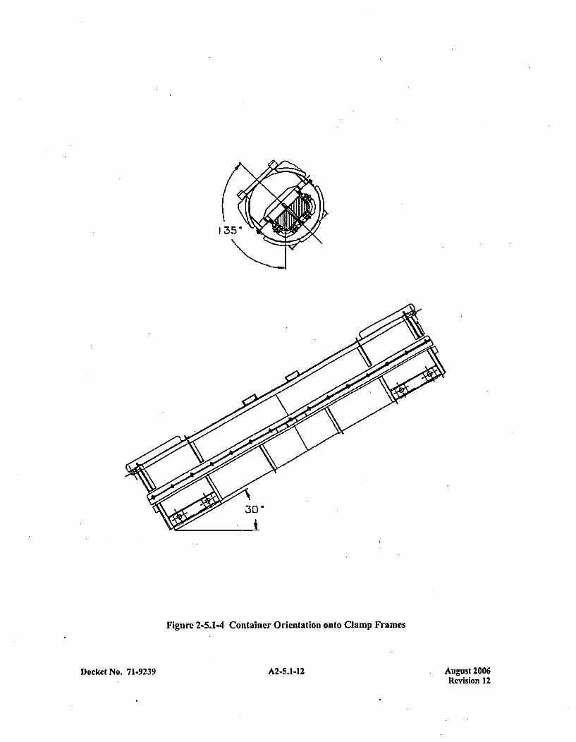
Figure 2-5.1-4 Container Orientation onto Clamp Frames
Docket No. 71-9239 A2-5.1-12 August 2006Revision 12
a Plastic hinge formation in end clamp framea Crushing of the end fuel assembly restraining bolts* Sliding of the fuel assembly nearest the impact point
The amount of energy which each of these mechanisms will absorb is dependent on their stiffness andtheir relative location. The following analyses provide an approximate energy distribution based onsimple calculations. The analyses is not intended to define the exact damage, but rather to demonstratethat these mechanisms have the capability to absorb the energy without significantly damaging the entirefuel assembly restraint system of the container.
The force require to buckle the outer shell 2-in. x 2-in. x ¼4-in, stiffener angle has been previouslyestimated to be 21,102 lbs (refer to §2-4.1.2.1). The minimum distance which this force can be appliedthrough is 7-in. Therefore, the energy associated with the buckling of the outer shell stiffner is:
Ebuckic (21,1 02)(7) = 147,714 inch - lbs
As buckling occurs, the vertical leg of the angle will crush. The maximum crush is equal to the leg lengthminus the material thickness. The width of the angle segment which will crush is estimated to beapproximately 20-in. Therefore, the energy for crushing the angle is expressed as follows:
0cuhC flow( 14 inch) (20 inches) 6 rs
where:
Oflow= 42,000 psi
5.bhs = leg length =1.75 in.
Solving for the crush energy yields 367,500 in-lbs. The total energy absorption of the stiffening angle is
then the sum of the two mechanisms:
EL =Ebuckle + Ecus = 515,2 14 inch - lbs
The buckling of the outer shell assembly end plate may be approximated by a fixed-edged plate with acompressive load applied uniformly. The critical unit buckling stress (cv,) for this ease is presentedTable 35, Case l Ob, Formulas for Stress and Strain. Fifth Edition by Roark and Young:
acr =K__t
where:
E = Young's Modulus = 29.0 x 10⁶ ps
t = thickness of end plate = 0.134 in.
Docket No. 71-9239 A2-5.1-13 August 2006Revision 12
r r = outer radius of plate = 20.62 in.
K = shapc factor = 7.22
v =Poisson's ratio = 0.3
Substituting the preceding values into the above expression yields a compressive unit strcss of 9,717 psi,which acts over the 20-inch length of the crush area. Therefore, the total force on the end plate is:
Fend = act, (20 inch) t =26,041 lbs
The energy absorbed by the end plate buckling through the crush distance of 7-in. is then:
Eenld = (7 inch)(F~fld)182,2871 inch - lbs
At the instant of impact, the eighteen elastomer shock mounts will be strained by the inertia of the internalstructure. From bench tests, it has been determined that the strain energy of a single shock mount isapproximately 1,750 in-lbs pcr inch of deflection. Therefore, the total strain energy of the shock mountsis:
E elastic = (I 8)( 1,750)8 nera = 220,500 inch -lbs
where:
5internal 7-in.
Following the straining of the elastomer shock mounts, the upper corner of the top closure assembly ofthe internal structure will impact the inside surface of the outer shell assembly. The top closure assemblycomponents which will deform and absorb energy consists of a 2-in. x 2-in. x 3/16-in, angle, a 1.5-in. x2.5-in. x '/4-in, tube, the upper 'A-in, diameter connecting pin, and the upper 1.0-in. x 1.5-in. x 13-'/4 in.pressure bar. The deformation and energy absorption of each of these separate pieces will be discussedindividually.
The initial failure of the top closure assembly is expected to be the connecting pin. This pin is loaded indouble shear for the drop orientation considered. Using the distortion energy theory, the maximum shearstress which will cause failure is 0.577 of the ultimate strength. Therefore, the failure load for the pin isexpressed as follows:
En= 2 [0.577(0r ulz{t) -E ]where:
CT~lt= 54,000 psi
d = pin diameter = '-in.
Docket No. 71-9239 A2-5.1-14 August 2006Revision 12
The resultant force required to fail the connecting pin is 12,245 lbs. This force will act through a distanceequal to the pin diametcr. Therefore, the energy absorption of the pin is:
EpnýFpin (dp1i ) = 6,123 inch - lbs
Following thc pin failure, the edge of the 2-in. x 2-in. x 3/16-in, angle will develop a plastic hinge as wellas crush through the thickness of the angle. For plastic hinge formation, the bending stress will be equalto the plastic hinge stress:
a plastic = (SF) a' y . Mipiastic
Z
where:
(TY= 30,000 psi
SF = Plastic hinge shape factor ft1.25 for angle
Mpiaslic =plastic hinge moment =Fpiastic (d)
Zz 0. 190 in 3
d effective moment arm 2.59 in.
Solving the above equation for the force required to form a plastic hinge gives a value of 2,751 lbs. Thisforce will act through a distance of approximately 1 -in., which will absorb:
E hing. Fhing, (1- inch) = 2,751 inch - lbs
The materials in the corner of the top closure assembly which will flow are the outer shell skin, therectangular tube, and the 2-in. x 2-in. x 3/16-in, angle with the 1-1/2 in. x 1-1/2 in. x V4-in, connection plates.The exact area of contact is dependent on the amount of flow and the impact angle. In addition, some ofthe material will bend out of the way rather than flow. For analytical purposes, an area of 3 in2, which isslightly larger than the cross sectional area of the tube plus the angle, is assumed to be the average contactarea. The crush depth (Srh is estimated to be approximately l-'/z in. Thus, the energy associated withthis material flowing/crushing is:
EnoW =0 flOn.(3 inch 2) 8c.,h = 23 1,714 inch -lbs
where:
Oflow42,000 psi
Docket No. 71-9239 A2-5.1-15 August 2006Revision 12
The total energy associated with the corner angle assembly is then:
Ecorner E -hinlge + E now = 234,465 inch - lbs
Buckling of the upper pressure bar can be determined from classical buckling expressions. Since theslenderness ratio of the pressure bar is low, the buckling force (FbuckI,:) will be based on the parabolic.formula:
Ebuckle =A Cry -K()-J
where:
CT= 30,000 psi
A Cross-sectional arca =1.5 in2
K =(a,12 )2( 1/ME)
E = Young's modulus = 29.0 x 10⁶ psi
I= unrestrained length of pressure bar =12.13 in.
k = radius of gyration of pressure bar = 0.434 in.
n = end-condition factor = 1.0 (fixed-fixed ends)
The calculated buckling force for the pressure bar is 44,307 lbs. This force will act through a distanceequal to the crush of the comner assembly or 1.5 in. Therefore, the energy absorbed will be:
Ebuckle =EbUCkIc 8 cruh = 66,461 inch - lbs
As the corner of the container collapses, the end clamp frame can be deformed. The clamp frame can bemodeled is an arch which is pinned and free to translate at the ends (refer to Figure 2-5.1-5). The freedomto translate at the ends is due to the relatively weak Unistrut stud nuts (when compared to the strength ofthe clamp frames). Therefore, ,the pivot mounts will provide little constraint and the frames will rotateabout the snubbers. Per Advanced Mechanics of Materials by Seely and Smith, the plastic bending stress(olgc in a curved beam (arch) can be expressed as follows:
-~lsi K M plastic
Docket No. 71-9239 A2-5.1-16 August 2006Revision 12

where:
Ulastic
SF
Mplastic
R
K
-SF cy 45,000 psi
-Shape factor for plastic hinge=1.5 for rectangular section
-Radius of frame curved section~5.47 in.
-Correction factor for curved beams1. 14 for inside surface (controlling)
-Section modulus for inner surface= 0.894 in'
=angle of curved frame section = 9000
Solving the above expression for the force required to develop a plastic moment in the clamp frame armyields a value of 1 8,253 lbs. This load is conservative compared to an actual test of the frame described inAppendix 2-5.4. This force will act through a distance of no less than 2-in. Therefore, the energyassociated with the plastic hinge formation in the clamp frame is:
Errame = Fpl~ic (5 fnsme) =37,046 inch - lbs
f,
WMTIOU
HIMC E
Figure 2-5.1-5 Clamp Frame Plastic Hinge Model
Docket No. 71-9239 A2-5.1-17 August 2006Revision 12
Performing a summation for the absorbed energy and subtracting this summation from the initial energyyields the remaining kinetic energy (Er) which must be absorbed:
Er =Endl-E En Elsi +Epin +Ecomcr +Ebuckle + Efrime)
From the above summation, the remaining energy which must be absorbed is 31,904 in-lbs. This energywill be absorbed by the buckling of the fucl restraining bolts and the sliding of the fuel assembly closestto the impact point. The sliding of the fuel assembly requires the overcoming of the pressure pad preloadforces times the frictional coefficient of the polyethylene sheeting-on-fuel grid spacer, which is assumedto be 0.35. Each pressurc pad is preloaded to a nominal value of 1,000 lbs., with fourteen pressure padsper assembly. Therefore, the energy absorbed by the frictional sliding per. linear inch of mnovemcnt of thefuel is:
Ef ct. = (1 4)(0.35)( 1,000) = 4,900 inch - lbs/inch
The force required to buckle the four fuel restraining bolts will be based on the parabolic bucklingformula for columns, since the slenderness ratio of the bolts is low:
Fb0I, = 4 [A( y, - 1
where:
Gy = 30,000 psi
A = cross-sectional bolt area = 0.14 19 in2
K =(cr/2p)2(l /nE)
E = Young's modulus =29.0 x 10⁶ psi
= maximum unrestrained length of bolts =4.5 in.
k = radius of gyration of bolt = 0.106 in.
n = end-condition factor = 1.2 (fixed-rounded ends)
From this expression, the force required to buckle the four fuel restraining bolts is 16,356 lbs. The totalforce required to slide the fuel and buckle the bolts is:
Ftouta = Fffi + Fblt = 21,156 lbs
Docket No. 71-9239 A2-5.1-1 8 August 2006Revision 12
The required deflection to absorb the rcmaining energy of the initial impact can now be determined:
S fel Er~ = 1.50 inches
Because the length of the fuel restraining bolts is larger than the required deflection, the fuel assemblywill not bottom out on the top closure assembly. Furthermore, this deflection does not have any adverseaffect on the ability of the container to provide the required spacing for criticality control.
Since the total deformation required to absorbed the energy from the initial impact is localized, the overallfunction of the MCC containers will not he impaired by this drop orientation.
Secondary Impact
For the secondary impact of the MCC container, the amount of energy which is estimated to be absorbedis 1.786 x 10⁶ in-lbs. This energy (Ec dy will be absorbed by the following mechanisms':
a Outer shell angle stiffener buckling* Crushing of 'outer shell angle stiffener0 Buckling of outer shell end plate0 Straining of elastomer shock mounts by internal structurea Crushing the edge of the bottom support and spacer plates* Plastic hinge formation in clamp frames* Crushing of the fuel assembly nearest the impact point* Crushing of swing bolts
For the slapdown impact, the MCC container will be nearly horizontal at the time of impact. However, forconservatism, it will be assumed that the container will be inclined at a slight angle (:t5O) from thehorizontal plane. This inclination will limit the amount of contact surface, and thus impart maximumdamage to the container due to the secondary impact. At a 50 angle, three angle stiffeners will beimpacted. The maximum amount of crush for the secondary impact wilt be based on the ratio of thesecondary and initial kinetic energies, times the initial crush:
A sc~~r secondary -- , A initial 9.66 inches
where:
Ainitial 7-in.
This crush will occur at the end of the outer shell assembly which contacts the impact surface. At theother two stiffener locations, which are 30-in, and 66-in, from the end stiffener angle, the amount of crushwill be equal to 6.60 in. and 2.93 in. respectively. The forced required to buckle an outer shell stiffener
Docket No. 71-9239 A2-5.1419 August 2006Revision 12

angle has been previously determined to be 21,102 lbs. The total energy associated with the buckling ofthe three angle stiffeners is then:
EZ buckle (21,1 02) (9.66 + 6.60 + 2.93) = 404,947 inch - lbs
The crushing of the angle stiffener will only occur at the end stiffener. The energy associated with thismechanism has been previously determined to bc 367,500 in-lbs. Therefore, the total energy absorbed bythe angle stiffeners will be the sum of the above:
EL =Ezbuckfing + Ez .h ~ 772,447 inch -lbs
The force associated buckling of the outer shell end plate has been determined for the initial impact. For
the secondary impact, the energy absorbed will be:
Eplate (9.66)(Fpiate) = 251,556 inch - lbs
The elastic strain energy of the elastomer shock mounts will be approximately equal to the initial impactenergy:
Elsi=(I 8)(1,750)8 in~a = 220,500 inch - lbs
where:
Sintetnal = 7-in.
The energy absorbed by the formation of a plastic hinge in the three clamp frames is different for eachframe since the container is inclined. It is estimated that the end clamp frame will deform a total of 3-in.,with the other two clamp frames having about a 'Ia-in, and I1-in, less deflection respectively. Therefore, theenergy absorbed will be:
E rmsý_Fplastic (3 +2.5 +2) =136,898 inch - lbs
where:
- =~i 18,253 lb.
Prior to the formation of the plastic hinge in the clamp frames, the fuel wrill be crus hed in the areas underthe pressure pads. The initial fuel assembly crush force per pad has been determined to be 6,000 l bs (seepage 6). Since only three clamp frames (six pressure pads total) will be affected in the secondary impact,the energy absorbed by the fuel crush will be:
Eu =(6)(6,000)(5 fuel) = 36,000 inch - lbs
Docket No. 71-9239 A2-5.1-20 August 2006Revision 12
where:
Btucl = -in.
Additional energy absorption will occur by the crushing of the ends of the swing bolts. From page 2.16,thc energy absorption per bolt has been estimated to 8,940 in-lbs. For the secondary impact event,approximately four of the swing bolts will be crushed. Therefore, the energy absorbed by the bolts is:
Eswing bolts =(4)(8,940) =35,760 inch - lbs
Following the energy absorption of the above mechanisms, the bottom support and spacer plates willimpact and crush, absorbing the remaining energy. The remaining energy to be absorbed (Er) will be:
E r = Esecondary -(E Z +E plate + Eelastic + Eframes +Erfuel + E swing boltss)
From this summation, it is found that the bottom support and spacer plates must absorb 369,557 in-lbs.The bottom support plate is a Yo-in. thick carbon steel plate while the spacer plate is a Y2-in, thickaustenitic stainless steel plate. The amount of material crush which will be required to absorb theremaining energy can be determined from the relative flow strengths of the two materials.
Volumectih ~Er =8.18inch 3
Yflwave
where:
Oflow avc (O.75/1.25)(aynoc.) + (O.5O/l.25)(oni0 55)=45,200 psi
Oflow = 42,000 psi (carbon steel)
Oflow = 50,000 psi (stainless steel)
Assuming a 450 impact on the support and spacer plates, the required crush depth to absorb the remainingenergy is approximately 2-'/2 inches. This depth of crush is highly localized and will have no effect on theability of the MCC containers to provide the required spacing to maintain a sub-critical geometry.
The above analyses demonstrate the capability of the container and payload to absorb the energy of theslapdown event without failing all of the clamp frames which restrain the fuel assemblies and provide therequired minimum spacing for criticality control. The analyses demonstrate that the kinetic energy can beabsorbed in localized areas of the container which correspond to the areas of impact. These areas, whichsustain substantial damage, do not compromise the restraint of the fuel assemblies and the subsequentrequired spacing. The localized areas of the container (i.e., the ends) will sustain !damage, leaving theundamaged areas of the container to restrain and maintain the spacing required for criticality control. Thecenter clamping frames and the outer shell will basically remain undamaged after the event, as the aboveanalyses indicate. This condition was confirmed by prototypic testing of the MCC-3 container. The
Docket No. 71-9239 A2-5.1 -21 August 2006Revision 12
testing, which is.discussed in Appendix 2-5.3, demonstrated much less damage than was predicted by theanalyses. The clamp frames on the initial impact end sustained very little damaged and did not deformed.This configuration left four of the seven frames fully capable to restrain the fuel an provide the requiredspacing. The outer shell closure, as expected, was not significantly damaged with the majority of the outershell fully intact to assist in maintaining the requircd spacing.
The reduced damage of the test unit indicates that the kinetic energy was dissipated by other means.Possible reasons for the differences include: 1) the material properties of the test unit were significantlystronger that the minimum values utilized in the analyses, and 2) more of the energy was dissipated inelastic flexure of the various components, such as the center wall, the cork fuel protectors, the variouscomponents of the strongback, the fuel assemblies, and the outer shell assembly. Any of thesemechanisms could affect the amount of damage and the subsequent forces experienced by thecomponents.
2-4.1.2.3 Side Drop onto Package Closure
The side drop onto the package closure evaluates the ability of the package to remain intact under themost severe conditions. The main purpose of the side drop onto the package closure is to ensure the topand bottom segments of the outer shell do not separate. The damage to the outer shell and internalstructurc is expected to be maximized in the side drop onto the packagc top and the side drop onto theclamp frames. The outer shell and internal structure's ability to fully absorb the kinetic energy of the30-foot drop has been demonstrated in the preceding sections. Therefore, the energy absorption capacityof the outer shell and internal structure will not be explicitly demonstrated again in this section.
The outer shell upper and lower segments are connected with thirty ( MCC-3) or fifty (MCC-4) '/2-in.T-bolts. The package closure failure mechanisms evaluated in this section include:
*Failure of the T-bolts*Failure of the shell connection flange
The fuel as stated earlier, is unrestrained. The middle arms remain fully intact to maintain spacing. Thedamaged areas will have crushed the fuel making it less reactive. The basic structure will remain intact,confining both the fuel and the gadolinium plate in the pre-drop geometry.
2-4.1.2.3.1 Side Impact on Closure
The MCC container response to a side impact is dependent on the stiffness of the outer shell. The ends ofthe container and the support cradle are much stiffer than the center section. Hence, the separation loadsfrom the outer container impact and the payload impact are not transmitted to the non-impacted side bolts(refer to Figure 2-5.1-6). The adequacy of the T-bolts -can be determined by looking at each section.
The adequacy of the T-bolts on the non-impacted center section of the container can be reviewed bydetermining the maximum load which can be transmitted to the T-bolts.
Docket No. 71-9239 A2-5.1-22 August 2006Revision 12
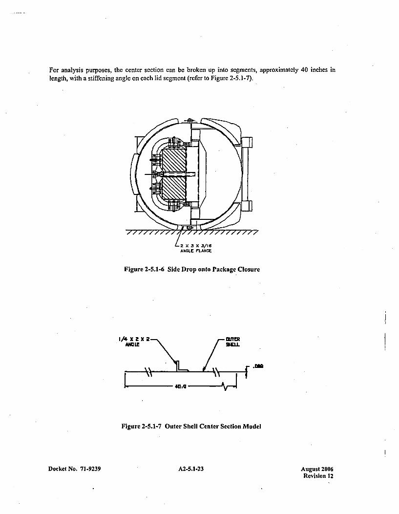
For analysis purposes, the center section can be broken up into segments, approximately 40 inches inlength, with a stiffening angle on each lid segment (rcfer to Figure 2-5.1-7).
*2 X 3 X .3/18ANGLE rLANGE
Figure 2-5.1-6 Side Drop onto Package Closure
1/4 X 2X 2 11!RA1UL! 96J.
Figure 2-5.1-7 Outer Shell Center Section Model
Docket No. 71-9239A2513Aust06 A2-5.1-23Revision 12

The cross sectional area is made up of a 0.089-in, plate and a 1/4x 2 x 2 angle. The moment of inertia forthis section (sin)is calculated to be:
I section = In + (Yn _ y) 2 (A.) + I piatc - + (y plate - y)2 (A plate)
(A )(ye) + (Ap at)(Ypiaie) 0. 175 inch(A total
where:
y centroid location of section
ya= centroid of angle = 0.669 in.
Yplatc = centroid of plate section = 0.0445 in.
Al Area of angle =0.94 in 2
Apat Arca of plate =3.56 in 2
Atta An, + Apat 4.50 in 2
In= Section Modulus of angle = 0.34 in4
Iplatc Section Modulus of plate = bh3/12 = 2.35 x 10⁻³ in4
Where b and h are the width and thickness of the plate
From the above expressions, lc,. is found to be 0.632 in4. The maximum transmitted load due to theimpact of the shell is determined from the maximum moment (MA) and the maximum tension force (TA),
using Table 17, Case 13 of Formulas for Stress and Strain. Fifth Edition by Roark and Young.
2
TA +-(K 4 )2
where:
R = Radius to Centroid =20.711 in.
w = weight per linear circumferential inch
K1 = 1+cz+j=1.0l73
Docket No. 71-9239 A2-5.1-24 August 2006Revision 12
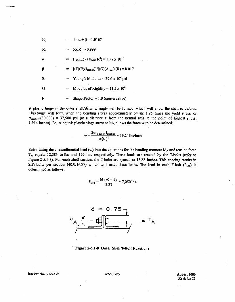
K2 K2~~ I-a1c+f=1.0167
K.4 = K2/K1=0.999
a = (cto)/(Aj~t,,j R2) = 3.27 x 10 -4
=[(F)(E)(1. 1100)]/[(G)(A10 .,.) (R) = 0.0 17
E =Young's Modulus = 29.0 x 10⁶ psi
G = Modulus of Rigidity = 11.5 x 10⁶
F = Shapc Factor = 1.0 (conservative)
A plastic hinge in the outer shelllstiffcner angle will be formed, which will allow the shell to deform.This hinge will form when the bending stress approximately equals 1.25 times the yield stress, orap. jc(30,000) = 37,500 psi (at a distancc c from the neutral axis to the point of highest stress,1.9 14 inches). Equating this plastic hinge strcss to MA allows the force w to bc determined:
W=2apatcsmo = 19.24 lbs/inch3c(R)2
Substituting the circumferential load (w) into thc equations for the ben 'ding moment MA and tension forceTA equals 12,383 in-lbs and 199 lbs. respectively. These loads are reacted by the T-bolts (refer toFigure 2-5.1-8). For each shell section, the T-bolts are spaced at 16.88 inches. This spacing results in2.37 bolts per section (40.0/16.88) which will react these loads. The load in each T-bolt (Pboh) isdetermined as follows:
Pbf MA/d;TA -7,050 lbs.
MA TA
Figure 2-5.1-8 Outer Shell T-Bolt Reactions
Docket No. 71-9239 A2-5.1-25 August 2006Revision 12

The T-bolts arc Y2,- 13 UNC threads andhavc a minimum tensile strength of 125.0 ksi. The bolt ultimatecapacity (PcaPacjty) is then:
Pcapacity =At (125,000) - 17,737 lb.
where:
A, Bolt tensile stress area =0.14 19 in2
The resultant Margin of Safety for the T-bolts is:
M.S. =(17,737/7,050) - I =+ 1.51
The maximum transmitted load would not change due to the application of the payload force. That forcewould still have to. be transmitted to the T-bolts by a similar mechanism. Since the transmittingmechanism is limiting, the T-bolts cannot be loaded additionally.
Center impact side T-bolts can be evaluated by reviewing the applied loads. Adjacent and perpendicular tothe sealing angle flange in the center portion arc two stiffening angles for the lid. There are no similarsections for the lower half. When the scaling flange is impacted, both the outer shell and the internalstructure apply a separation load to the scaling flange. Since the bare sealing flange strikes the impactsurface, the impact loads will be high.
The capacity of the T-bolts has been calculated above as 17,737 lbs. The capacity of the 0.3 1-in. x 2-in. x3-in, sealing flange angle to transmit the load to the T-bolt is found by equating the maximum appliedpotential bending stress to the plastic hinge stress of 45.0 ksi (1.5(30.0 ksi)). The resultant moment is thenreacted by a T-bolt.
MblVta - aplastic 'flangec
where:
Mbolt =Maximum applied potential momnent = Fb,1 1(d)
I flange = Moment of inertia for a 16.88 inch stay=1/12 (16.88)(.3 1)3 = 0.043 in
d = distance between bolt centerline and edge of sealing flange =0.75 in.
c = distance to extreme fiber = 0.3 1/2 = 0. 155 in.
Fb.11= Force in T-bolt, lbs.
Solving for Fboft produces a maximum potential force of 16,645 lbs. This applied potential force is close tothe minimal capacity of the T-bolt (16,645 lbs vs. 17,737 ibs). Because of the relative closeness of thesetwo values, there may be some bolt failures in center section on the impacted side. This condition was
Docket No. 71-9239 A2-5.1-26 August 2006Revision 12
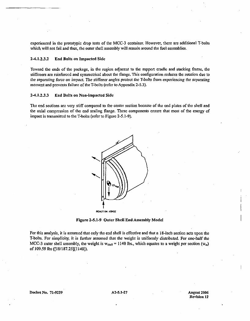
experienced in the prototypic drop tests of the MCC-3 container. However, there are additional T-boltswhich will not fail and thus, the outer shell assembly will remain around the fuel assemblies.
2-4.1.2.3.2 End Bolts on Impacted Side
Toward the ends of the package, in the region adjacent to the support cradle and stacking frame, thestiffeners are reinforced and symmetrical about the flange. This configuration reduces the rotation due tothe separating force on impact. The stiffener angles protect the T-bofls from experiencing the separatingmoment and prevents failure of the T-bolts (refer to Appendix 2-5.3).
2-4.1.2.3.3 End Bolts on Non-impacted Side
The end sections arc very stiff compared to the center section because of the end plates of the shell andthe axial compression of the end sealing flange. These components ensure that most of the energy ofimpact is transmitted to the T-bolts (refer to Figure 2-5.1-9).
fFREACII rucr=
Figure 2-5.1-9 Outer Shell End Assembly Model
For this analysis, it is assumed that only the end shell is effective and that a 18-inch section acts upon theT-bolts. For simplicity, it is further assumed that the weight is uniformly distributed. For one-half theMCC-3 outer shell assembly, the weight is wshclI = 1140 lbs., which equates to a weight per section(W)of 109.59 lbs ([] 8/1 87.25][1 140]).
Docket No. 71-9239 A2-5.1-27 Aueust 2006Revision 12
To estimate the impact force, it is assumed that the kinetic energy of the outer shell assembly is absorbedby the flow of the sealing flange. The amount of flange crush (8.,j is estimiated as follows:
c~flow Aflange
where:
Oflow = 42,000 psi
Aflangc =Flow area of upper and lower flanges
Ess- Kinetic Energy of section360(w,,) = 39,452 in-lbs
Based on the above values, the estimated sealing flange crush is 0.084 in. Ratioing this deflection to thedrop height gives the approximate g loading of the impact.
G impact - p=30=4,2868S T 0084
Although possible, this impact load is exceedingly high. Since other mechanisms may absorb kinteicenergy, such as bending of the angle, one-half of the above value will be used for calculation purposes(iLe., Gimpact = 2,143).
The T-bolt loads increase linearly from the initial contact point. The load in the T-bolts may be found bysumming moments about the impact point:
Fb.t34.5+2.5 (22.25'l (20.531 )(2) 1GmatwsFi01 [34.5 +(22)43.75)1 L[ R (ic )I
From the above equation, the T-bolt force (Fb.11) is found to be 21,531 lbs., which is larger than the T-boltcapacity. When adding in the force of the payload, the force on the T-bolts will be larger.
The upper shell will stay attached to the lower portion of the outer shell assembly of the container. TheT-bolts in the center will remain intact on the non-impacted side while the bolts toward the ends of theouter shell will maintain integrity on the impacted side.
2-4.1.3 Corner Drop
The primary function of the MCC container is to maintain the criticality spacing of the fuel. In accordancewith this purpose, the corner drop analysis is not a controlling drop orientation for the MCC container.The resulting deformnations and deceleration loadings of the side drop discussed in Section 2-4.1.2 boundthe corner drop results.
Docket No. 71-9239 A2-5.1-28 August 2006Revision 12
2-4.1.4 Oblique Drops
The primary function of the MCC package is to maintain the criticality spacing of the fuel. In accordanccwith this function, only the oblique drop which would cause the most severe slap-down effects on thepackage is evaluated. The resulting deformations and deceleration loadings of the side drop with slapdown onto the clamp frames is evaluated in Section 2-4.1.2.2.
2-4.1.5 Summary of Results
As discussed in the preceding sections, the MCC containers will survive the crucial 30-foot, accidentdrops. The containers arc expected to be damaged as the kinetic energy of the accident drops is absorbedby the strain energy associated with the deformation of the container. The internal structure and the outershell assembly are generally cxpectcd to act independently during the accident drops, each deforming toabsorb its own kinetic energy. This behavior is due to the very sofl shock mount system which connectsthe two separate components. Although damage is expected, failure of the container to remainsubstantially intact and provide the required spacing for criticality control will not occur. The fuel willmaintain its relative position in the structure and maintain the minimum required criticality spacing of8 inches for the crucial fuel orientation. The maximum deformation to the package components is4 inches which will occur during the 1350 orientation side drop. These results closely correlate with theresults recorded in the hypothetical accident tests performed on a prototypical MCC-3 container, which isdiscussed in Appendix 2-5.3.
Docket No. 71-9239 A2-5.1-29 August 2006Revision 12

APPENDIX 2-5.2EVALUATION OF DROP ANGLE
Docket No. 71-9239 A2-5.2-1 August 2006Revision 12
JUSTIFICATION OF OBLIQUE DROP ANGLE
The performance tests to demonstrate the structural adequacy of the Westinghouse MCC containers underthe hypothetical accident requirements of IOCFR7 1.73 requires that a specimen bc ablc to sustain a freefall from a height of 30-feet onto a flat, unyielding horizontal surface, striking the surface in a position forwhich maximum damage is expected. To comply with this requirement, it is necessary to evaluate whichorientation would possibly produce the maximum damage to and/or failure of the package. For the MCCcontainers, failure is defined as not providing adequate spacing or restraint to the fuel assemblies whichwould result in a criticality event. The most probable failure which would result in an unsafe criticalitygeometry is failure of the clamp frames which restrain thc fuel assemblies. To propagate this potentialfailure, the maximum forces from both the primary and secondary impacts would be required to apply theloads to the clamp frames.
At an inclined angle of 90' fro'm, the horizontal, the MCC container would be impacting the surface in thelongitudinal axis orientation. This orientation would potentially result in crushing the fuel and would notimpact any significant loads to all of the clamp frames. At 00, the package would not experience anyadditional impact loads from a secondary impact caused by rotational acceleration following a primaryimpact. Therefore, it is clear that in order to impart the greatest forces onto the clamp frames and normalto the fuel assemblies, the package must be orientated between 00 and 90' as measured from thehorizontal.
To determine which angle should be utilized in evaluation of the package, a simplistic model of the MCCinternal strongback structure was modeled using the Shipping Cask Analysis System (SCANS) program.The MCC SCANS model consisted only of the internal structure, since the MCC outer shell and theinternal structure can be decoupled (note that the impact angle for the internal structure will be slightlyless than the initial angle of the outer shell assembly). The SCANS model was then analyzed at variousorientations from 150 to 600, in increments of 150 using various linear stiffnesses for the "impact limiters"(i.e., the end clamp frame/attachment brackets/fuel bundle).
The results of the various computer runs of the SCANS model are summarized in Figure 2-5.2-1. Inreviewing this data, one can see that the vertical g's due to the primary impact increase as the packageinclination increases, for a specified stiffness. However, the vertical- g forces due to the secondary impactare very similar for the 15' and 300 orientations, but decrease as the angle is increased. Note that theactual MCC package will have a stiffness which is more represented by the lower stiffness value ratherthan the higher values.
For the above reasons, the total maximum vertical g forces which willI be imparted to the MCC clampframe will occur when the package is oriented approximately at the 30* orientation. Therefore, thisorientation was utilized in the MCC container evaluation for compliance to I OCFR7 1.73.
Docket No. 71-9239 A2-5.2-3 August 2006Revision 12
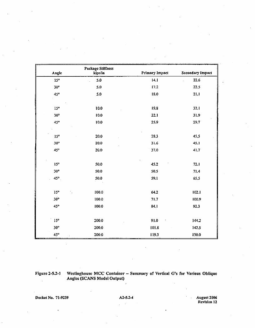
Package StiffnessAngle kips/fin Primary Impact Secondary Impact
150
300
450
150
300450
150
300
450
150
300
450
150
300
450
150
300
450
5.0
5.0
5.0
10.0
10.0
10.0
20.0
20.0
20.0
50.0
50.0
50.0
100.0
100.0
100.0
200.0
200.0
200.0
14.1
17.2
18.0
19.8
22.1
25.9
28.3
31.6
37.0
45.2
50.5
59.1
64.2
71.7
84.1
91.0
101.8
119.3
22.6
22.5
21.1
32.1
31.9
29.7
45.5
45.1
41.7
72.1
71.4
65.5
102.1
100.9
92.3
144.2
142.5
130.0
Figure 2-5.2-1 Westinghouse MCC Container - Summary of Vertical G's for Various ObliqueAngles (SCANS Model Output)
Docket No. 7 1-9239 A2-5.2-4 August 2006Revision 12
APPENDIX 2-5.3EVALUATION OF TEST RESULTS
A2-5.3-1 uut20Docket No. 71-9239Revision 12
TESTING OF THE MCC CONTAINER
INTRODUCTION
The MCC-3 container was drop tested to confirm the survivability of the container. Thrce accidentcondition tests were performcd on thrce separate containers. These tests were selected to demonstrate thecontainer's ability to mect the structural requirements following the accident events.
The tcsts demonstrated that the package would meet the following criteria:
I . -Integrity of clamp frames.2. Minimum spacing would be maintained.3. The outer shell assembly would remain around the internal structure.
The integrity of the clamp frames is required to ensure that the fuel asscmblies will maintain theirrelationship to the gadolinium plates and will maintain their spacing relative to other containers.
Minimum spacing is required to maintain a sub-critical geometry. The minimum required spacing is four(4) inches between the edge of a fuel assembly and the edge of another container holding fresh fuel in aplane parallel to the assembly - for a total minimum fuel-to-fuel separation of eight (8) inches.
The outer shell assembly must be maintained around the internal structure for spacing purposes, and toassure the contents can only be exposed to full-density water (flooding) moderation. Without the shell, theclamp frames and snubbers, which act as spacer blocks, could be placed adjacent to each other whichwould result in the required spacing not being maintained.
The three drop orientations chosen to demonstrate the container's ability to satisfy these conditions were:1) a side drop onto the package top; 2) a side drop with slapdown onto the internal clamp frames; and 3) aside drop onto the package closure. The side drop onto the package top loads up the frames and itsconnection points. It also attacks the snubbers and swing bolts. The. slapdown applies the maximum crushforce to the fuel, clamp frames, and connection points in localized areas. The drop onto the closureapplies the maximum load to the T-bolts which hold the two halves of the outer shell together.
PACKAGE CONFIGURATION
All drops were performed using an MCC-3 container with a modified payload. The payload weight wasincreased to ensure that the maximum load per clamp frame and per closure bolt would be tested. Theworst case condition not only bounded the possible configurations for the MCC-3 container, but alsobounds the MCC-4 container. (See the justification provided in Section 2-4.5.) Both fuel compartmentscontained simulated fuel assemblies. The weights of the dropped packages were 4,244 pounds for theempty package and 3,300 pounds for the fuel assemblies. The total weight of each test container was7,544 pounds.
DROP TEST FACILITIES
All three tests were performed at the Oak Ridge National Laboratory drop facility.
Docket No. 71.9239 A2-5.3-3 August 2006Revision 12
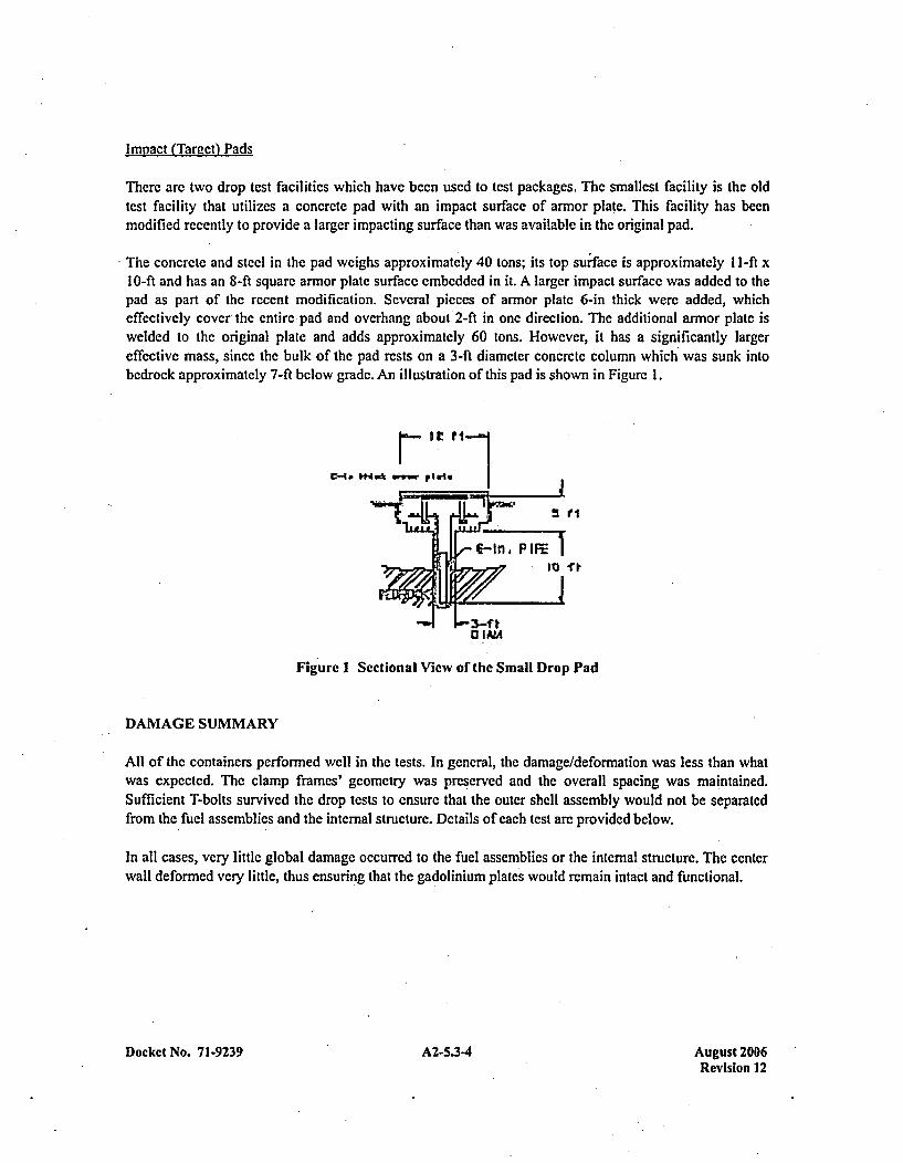
Impact (Target) Pads
Therc arc two drop test facilities which have been used to test packages. The smallest facility is the oldtest facility that utilizes a concrete pad with an impact surface of armor plate. This facility has beenmodified recently to provide a larger impacting surface than was available in the original pad.
The concrete and steel in the pad weighs approximately 40 tons; its top surface is approximately 1l-ft x10-ft and has an 8-ft square armor plate surface embedded in it. A larger impact surfacc was added to thepad as part of the recent modification. Several pieces of armor plate 6-in thick were added, whicheffectively cover- the entire* pad and overhang about 2-ft in one direction. The additional armor plate iswelded to the original plate and adds approximately 60 tons. However, it has a significantly largereffective mass, since the bulk of the pad rests on a 3-ft diameter concrete column which was sunk intobedrock approximately 7-ft below grade. An illustration of this pad is shown in Figure 1.
V- W & iwr#
[-In P I
Fig ure I Sectional View of the Small Drop Pad
DAMAGE SUMMARY
All of the containers performed well in the tests. In general, the damage/deformation was less than whatwas expected. The clamp frames' geometry was preserved and the overall spacing was maintained.Sufficient T-bolts survived the drop tests to ensure that the outer shell assembly would not be separatedfrom the fuel assemblies and the internal structure. Details of each test are provided below.
In all cases, very little global damage occurred to the fuel assemblies or the internal structure. The centerwall deformed very little, thus ensuring that the gadoliniumn plates would remain intact and functional.
Docket No. 71-9239 A2-5.3-4 August 2006Revision 12
SIDE DROP ONTO CONTAINER TOP
Refer to Figures 2-5.3-1 through 2-5.3-8.
T he container demonstrated an adequate margin of safety against loss of fuel retention. The overalldamage to the container was less than what was expected. The total deformation of the top cover wasapproximately 4-inches. There was a noticeable affect of the ends and stiffener angles. At the ends, thestiffener angle folded. In the center, the angles deformed more, but did not fold. The deformed shape ofthe angles was similar to flattening of an arch. It was very evident that the internal structure bottomed outby the imprints of the clamp frames on the top shell cover.
An interesting phenomenon which occurred was the localized shearing of the lid outer shell. The locationof one stiffener angle was offset slightly from a frame. The stiffener angle was driven in and the frameout, shearing the shell. This effect was a local occurrence which would be impossible to duplicate over thelength of the outer shell lid. In all cases, there are more clamp frames than stiffening angles.
The fuel restraint system held the fuel assemblies in position. All of the clamp frame connections retainedtheir connectivity to the strongback. There was only a slight deformation of one Unistrut channel at oneend. The snubbers limited the flow of the pressure pad swing bolts. Their undamaged presencedemonstrated that the required spacing would be maintained as long as the outer shell assembly remainedintact. The clamp frames did not noticeably deform. The fuel assemblies crushed approximately '/2 to
1-inch.
SIDE DROP WITH SLAPDOWN ONTO INTERNAL CLAMP FRAMES
Refer to Figures 2-5.3-9 through 2-5.3-18.
The container was dropped at an inclined angle of 300, relative to the horizontal plane, and was rotatedabout its longitudinal axis 1350 clockwise, to ensure that the impact point would occur on the comner ofthe fuel.'
Significant damage occurred to the outside of the container. The initial impact corner deformed inapproximately 6-inches. The slapdown corner deformed approximately 7-inches. The stacking supportangle was completely crushed and flattened on both ends. The internal structure impacted the outer shelland punched several holes in each of the comners.
Most of the kinetic energy on the initial impact end was absorbed by deforming the top closure assembly.The end fuel restraining bolts deformed significantly and one connecting pin was sheared. The end clampframe was only slightly deformed. The fuel assembly closest to the initial impact point was crushed verylittle.
The middle clamp frames were damaged very little, with only a slight crush and bending of the adjustableswing bolts. The center section of the fuel assembly had insignificant amount of crush.
As expected, the damage on the slapdown end was more significant. Three clamp frames were deformedinwardly with most of the damage occurring on the outer two. The bottom support structure punched
Docket No. 7 1-9239 A2-5.3-5 August 2006Revision 12
through the outer shell and struck the impact surface. This condition resulted in a relatively highg loading, but limited the deformation of the fuel. As can be sccn in the photographs, the end plate wasonly slightly damaged, indicating that a majority of the energy had already been absorbed. For thisreason, dropping the container with a revcrsal of the ends would not result in significantly more damage.Due to the deformation of thc clamp frames, the top pivot mount stud nuts partially pulled out of theUnistrut channel. This situation is not a concern because the fuel assemblies remained restrained by thefact that the connection to the adjacent frame remained intact. In addition, the undamaged center frameswould have provided sufficient restraint to maintain spacing even if the end frames had completely failed.The lower pivot mount connections remained connected, although there Was significant deformation ofthe Unistrut channel on the deformed clamp frames. The lower pivot mount connection on the mostseverely deformed frame remained attached to only one side of the Unistrut channel. The fuel assembliesunder the pressure pads were crushed approximately 'A. to I inch.
SIDE DROP ONTO PACKAGE CLOSURE
Refer to Figures 2-5.3-19 through 2-5..3-27.
The side drop onto the closure demonstrated the adequacy of the closure T-bolts. It is required for the topand bottom shells to stay connected to the internal structure inside. This is required to maintain thesub-criticality spacing since without the outer shell assembly, the clamp frames and snubbers, which actas spacers, could be located side-by-side, thus reducing thc spacing by one half. This is also required to.assure that contained fuel assemblies can only be exposed to full-density water moderation (flooding),and not to partial-density water moderation (sprays, etc.).
Fifteen of the thirty T-bolts either pulled through the shell sealing flange or failed in tension. None of theT-bolts failed in shear. The six guide pins, which have closer tolerances than the T-bolts, did not sheareither. The location of the T-bolt failures varied, depending on the construction of the container. On theimpact side, six bolts failed. The majority of these failures were in the center section where the shell hasthe minimum amount of reinforcement. The outer shell, with the internal shock mount bracket, deformedand applied a high bending moment in the closure flange area. This prying action was resisted by theT-bolts.until failure occurred. In general, this condition did not occur towards the ends where the majorreinforcement which would resist this bending moment is located. The bending of the shell wasdemonstrated by the fact that the center section of the container, which is loaded by the fuel assemblies,deformed downward about 2-Y2 inches on the non-impacted side, relative to the ends. The remainingT-bolts failed on the ends and towards the ends on the non-impacted side. These failures were the result ofthe stiff ends, and reinforcement in these locations, transmitting the separation load from the weight of theshell and payload, pushing the shell apart. The moment is reacted by the bolts on the far side of thecontainer.
By having two different mechanisms working in the container, catastrophic failure of fasteners is avoided.This behavior ensures that there is a large margin against having the outer shell assembly fail in such amanner that the internal structure will separate from the outer shell.
The internal structure impacted initially on the shock mounts and then rotated to spread the load betweenthe shock mounts and the frames contacting the external shell. The load on the shock mounts crushed themounting bracket such that the connecting bolts punched into the outer shell. The frames also indented
Docket No. 71-9239 A2-5.3-6 August 2006Revision 12
into the outer shell. The loads were sufficient to cause the trunnion block on the uprighting pivot to fail.Once this failed, the strongback and fuel assemblies slid out of the side swing bolt (different than theadjusting fuel swing bolts) connections and became free.
The impact on the frames, with the subsequent load transmittal to the center wall, as well as the non-impacted frames, caused some yielding in the Unistrut pivot mount connections to the center wall. All ofthe frames remained connected to the adjacent frame so that restraint of the fuel assemblies wasmaintained. The majority of the yielding of connections occurred in the center section where thedeformation of the outer container was the greatest, allowing the most deformnation of the internal tooccur. The center clamp frame pried its lower pivot mount connection out of the Unistrut channel. Thisfailure is due to a stiffening angle on the outer shell being located adjacent to the frame. During impact,the frame was driven -in and the frame out, shearing the shell, which allowed the frame to see a higherimpact than if the shell and angle were there to deform and soften the impact. Due to the redundant natureof the frames, this single failure does not prevent the package from fUhl ling its requirements.
The adjustable swing bolts were bent slightly. Th ere was very little damage to the frames or to thesnubber blocks. There was a small amount of crush to the fuel assembly of about '/z-inch, but nocompromise of the required spacing occurred..
Docket No. 7 1-9239 A2-5.3-7 August 2006Revision 12
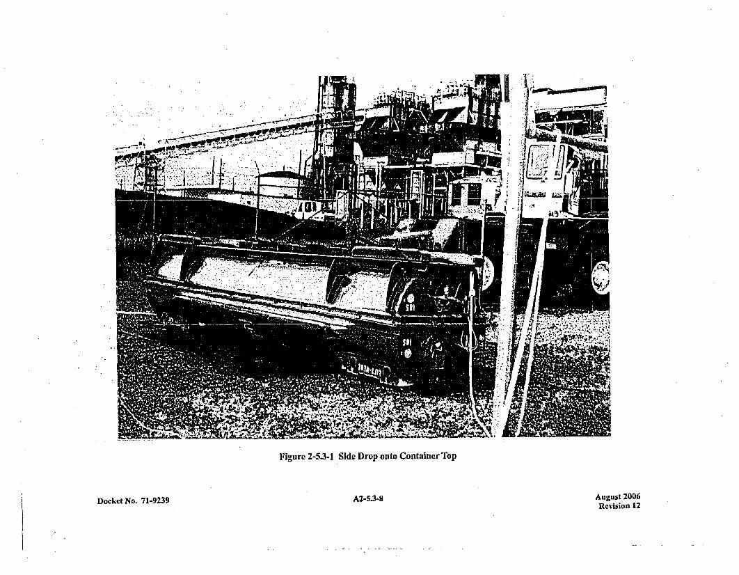
A+ ui
Figure 2-5.3-1 Side Drop onto Container Top
Docket No. 71-923 9AZ53 A2-5.3-8 August 2006Revision 12

Figure 2-5.3-2 Side Drop onto Container Top
Docket No. 7 1-9239 A2-5.3-9 August 2006Revision 12

Figure 2-5.3-3 Side Drop onto Container Top
Docket No. 71-9239 A2-5.3-10 August 2006Revision 12
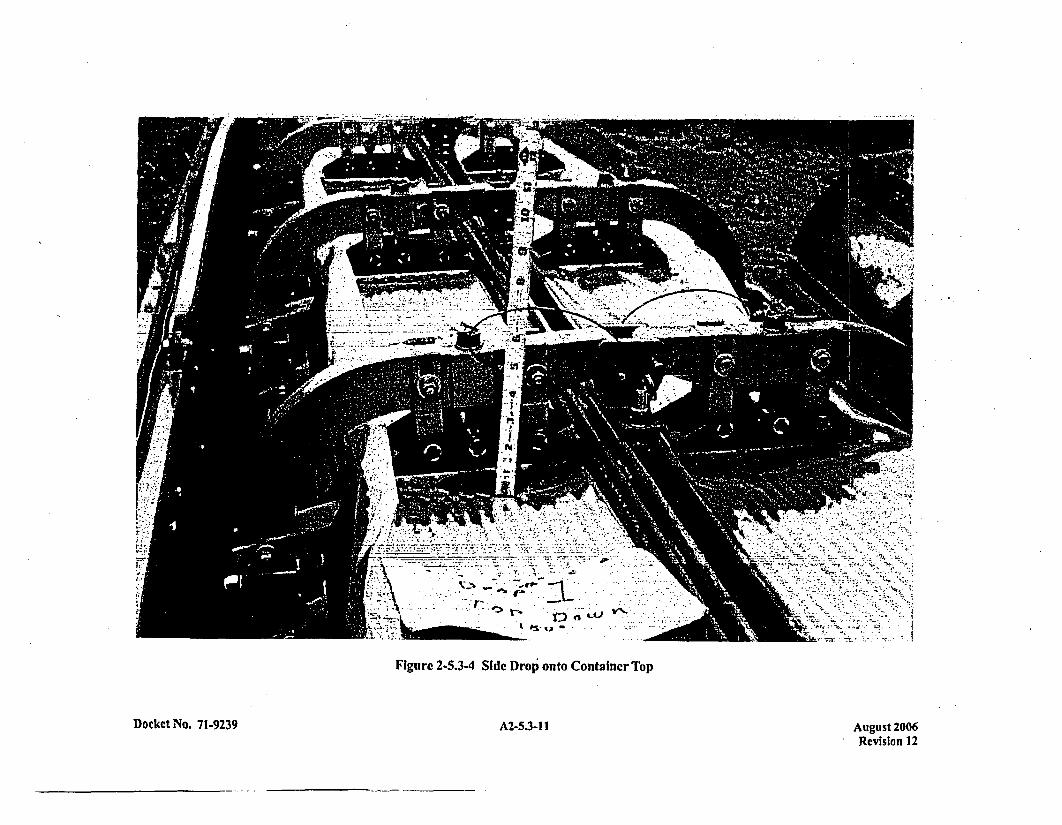
. f~
Figure 2-5.3-4 Side Drop' onto Container Top
Docket No. 71-9239 A2-5.3-1 1 August 2006Revision 12
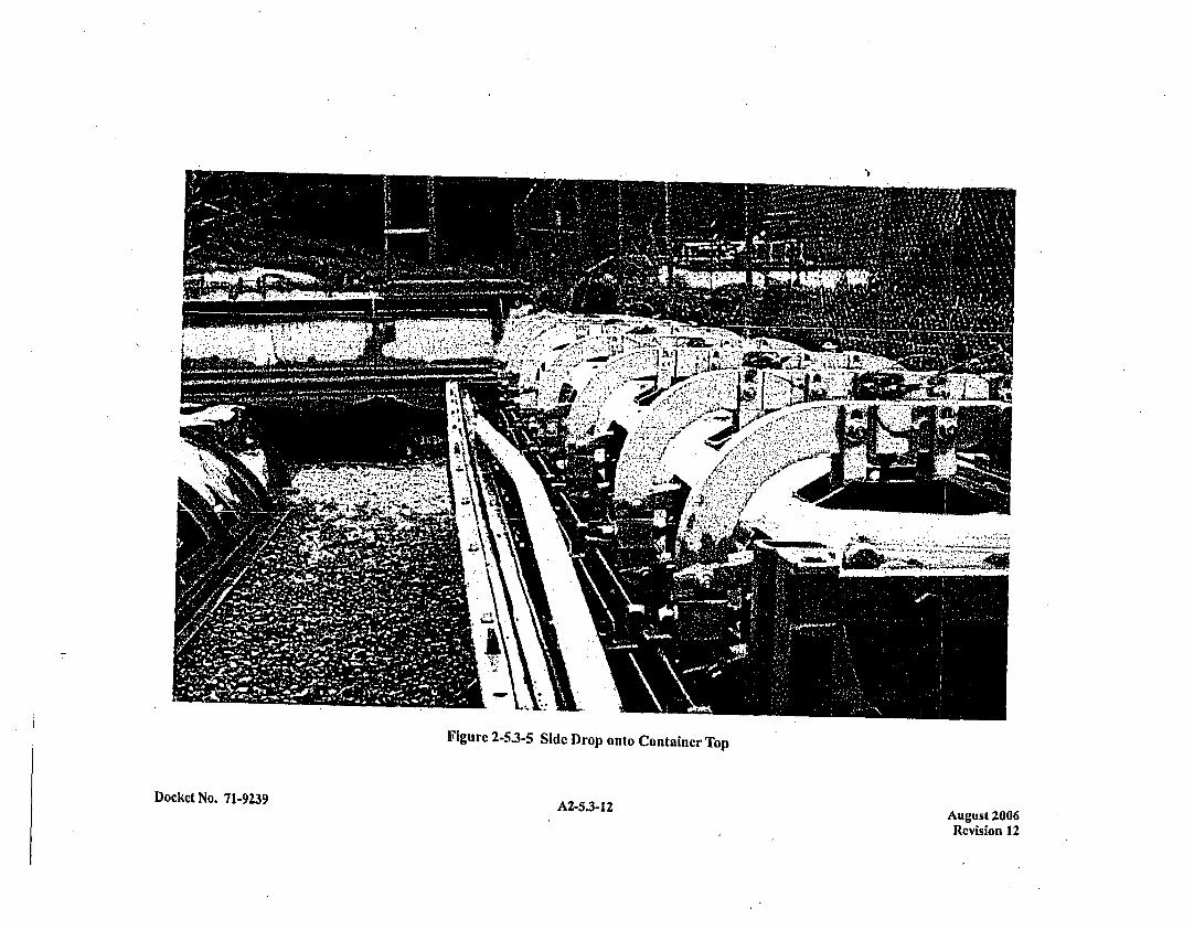
,V-."
Figure 2-5.3-5 Side Drop Onto Container Top
Docket No. 71-9239 A2-5.3-12 August 2006
Revision 12
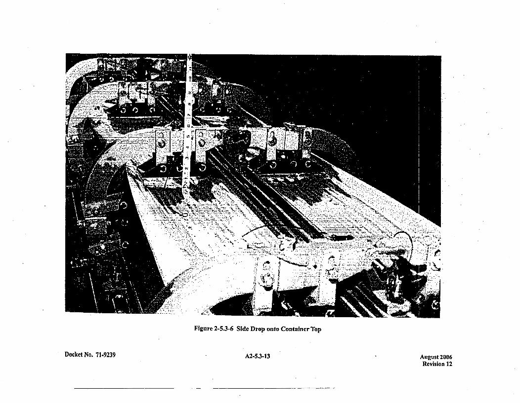
4. .~ * j.,.*
Figure 2-5.3-6 Side Drop onto Container Top
Docket No. 71-9239 A2-5.3-13 August 2006
Revision 12
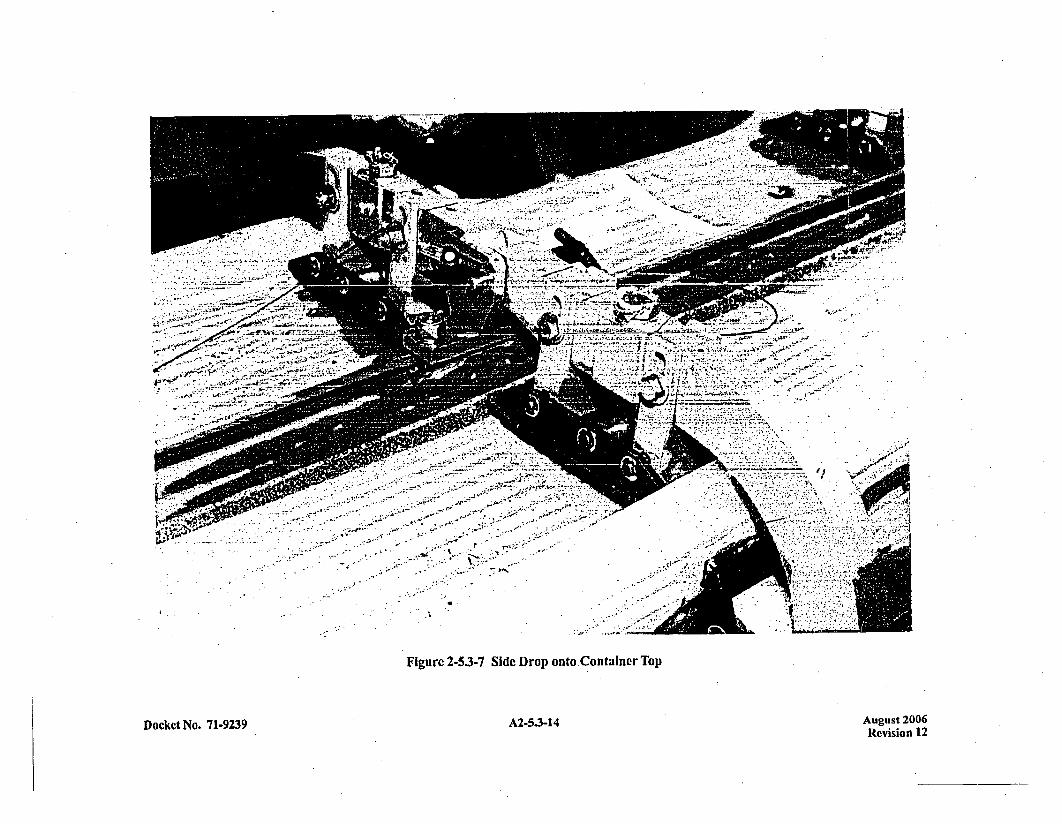
Figure 2-5.3-7 Side Drop onto.Container Top
Docket No. 71-9239A2534 A2-5.3-14 August 2006Revision 12
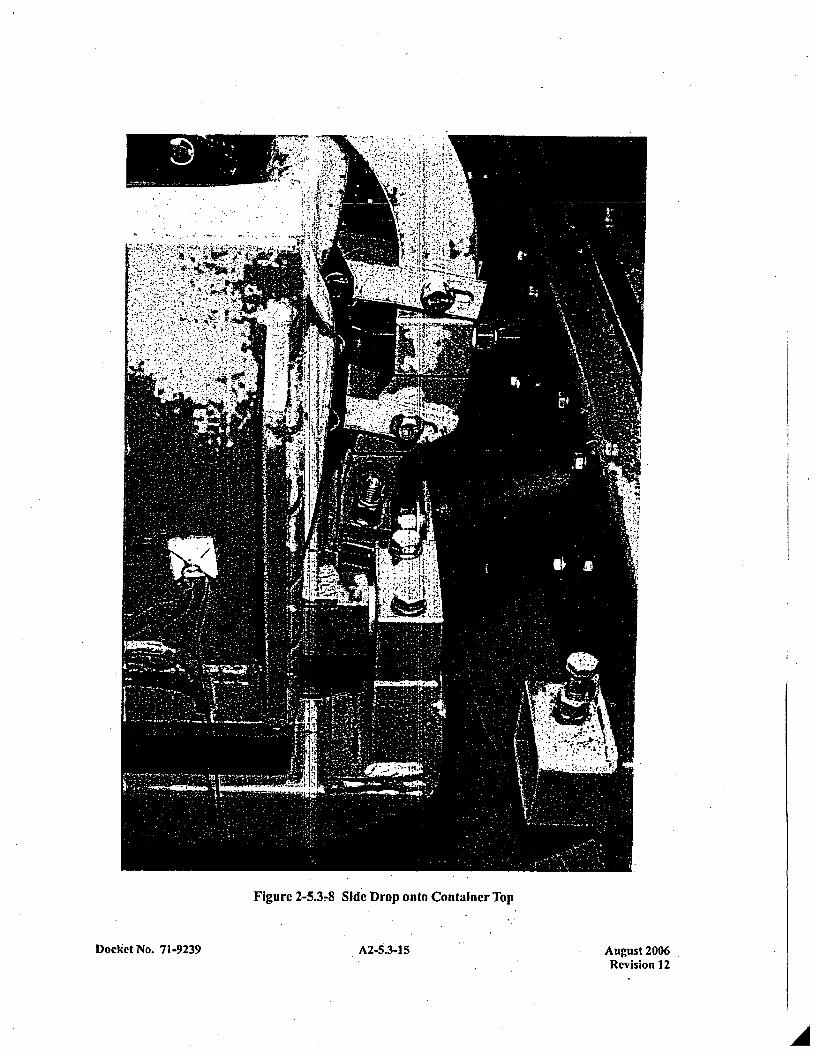
Figure 2-5.3r8 Side Drop onto Container Top
Docket No. 7 1-9239 A2-5.3-15 August 2006Revision 12
'A
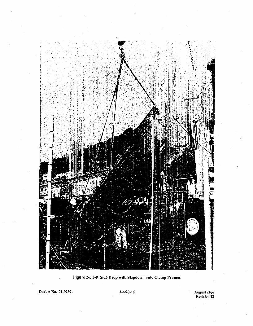
- *1
In
SiF j ~ 1J~ft
I ~
I.J
III']1j
I0
c-I
* k...
Figure 2-5.3-9 Side Drop with Slapdown onto Clamp Frames
Docket No. 71-9239 A2-5.3-16 August 2006Revision 12
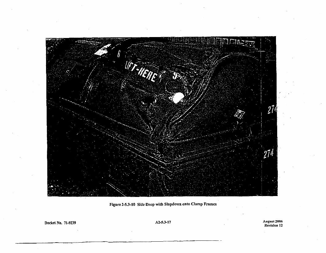
Figure 2-5.3-10 Side Drop with Slapdown onto Clamp Frames
Docket No. 71-9239 A2-5.3-17 August 2006Revision 12
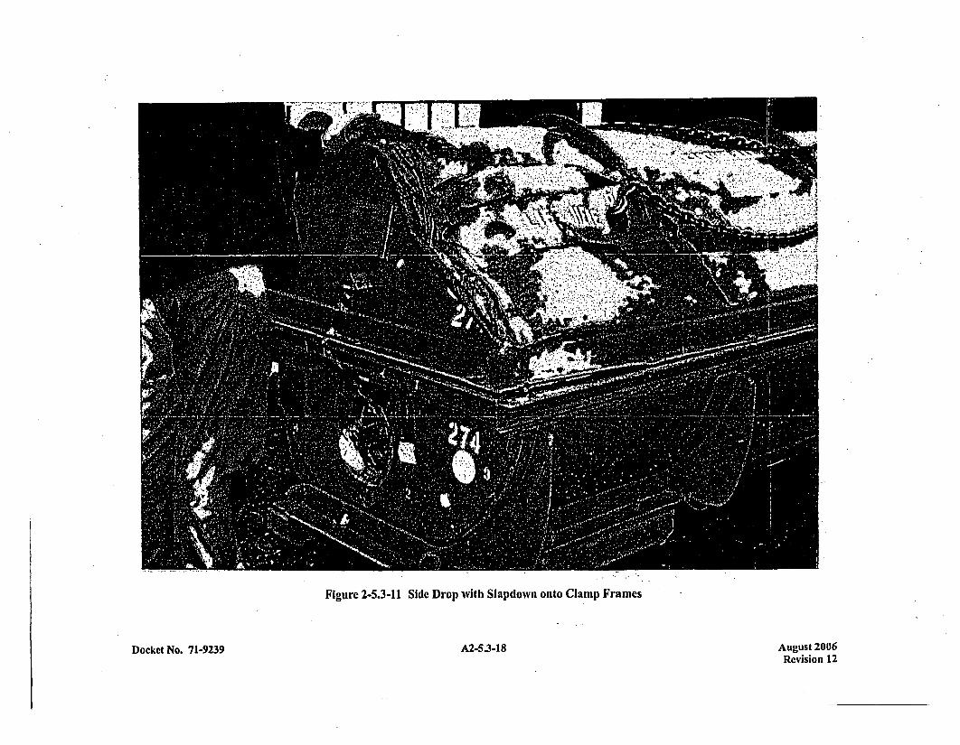
- j~7I7
Figure 2-5.3-11 Side Drop with Slapdown onto Cla Imp Frames
A2-5.3-18 August 2006Revision 12
Docket No. 71-9239
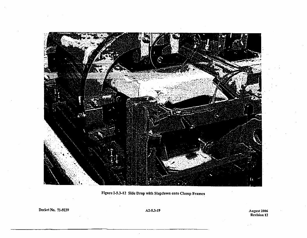
.3. .~,. .4,-
* $
's'. 4
t , Iq-
4i1
Figure 2-5.3-12 Side Drop with Slapdown onto Clamp Fram es
A2-5.3-19Docket No. 7 1-9239 August 2006Revision 12
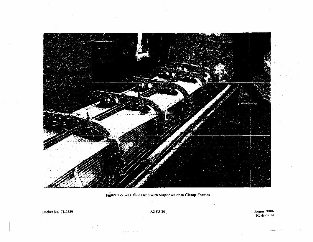
Fig .ure 2-5.3-13 Side Drop with Slapdown onto Clamp Franmes
Docket No. 71-9239 A2-5.3-20 August 2006Revisiou 12

r:
Figure 2-5.3-14 Side Drop with Slapdown onto Clamp Frames
Docket No. 71-9239 A2-5.3-21 August 2006Revision 12
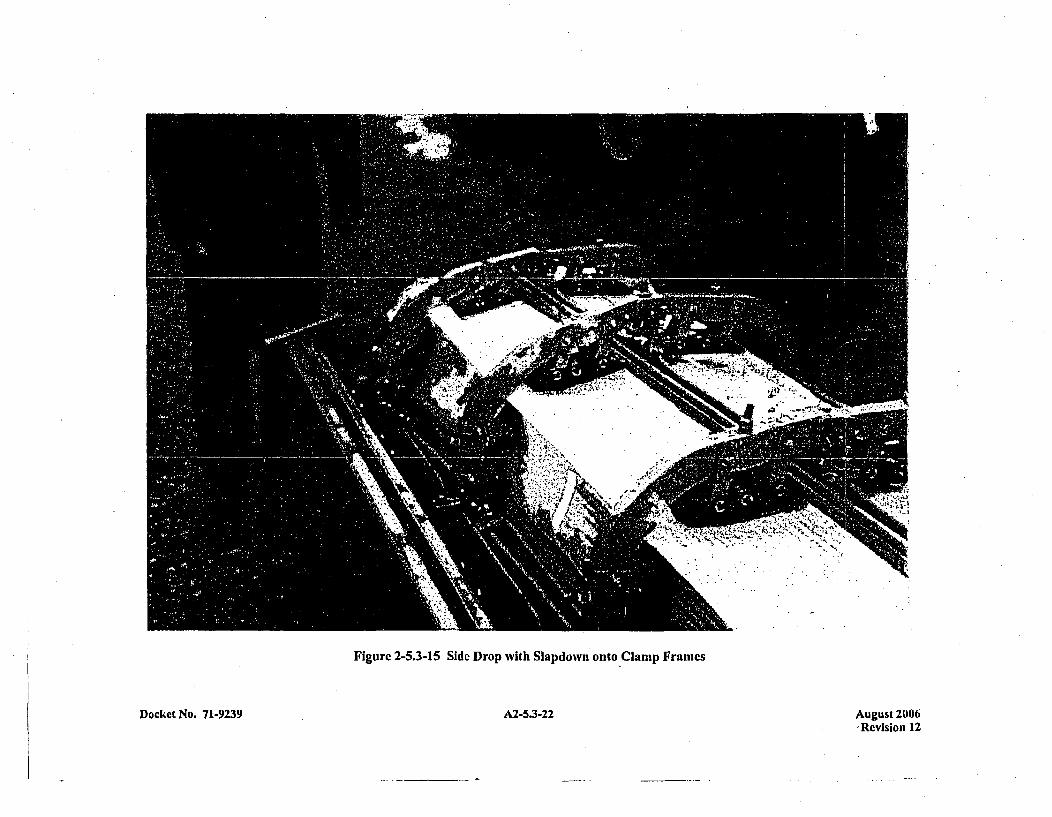
Figure 2-5.3-15 Side Drop with Slapdown onto Clamp Frames
Docket No. 71-9239 A2-5.3-22 August 2006'Revision 12
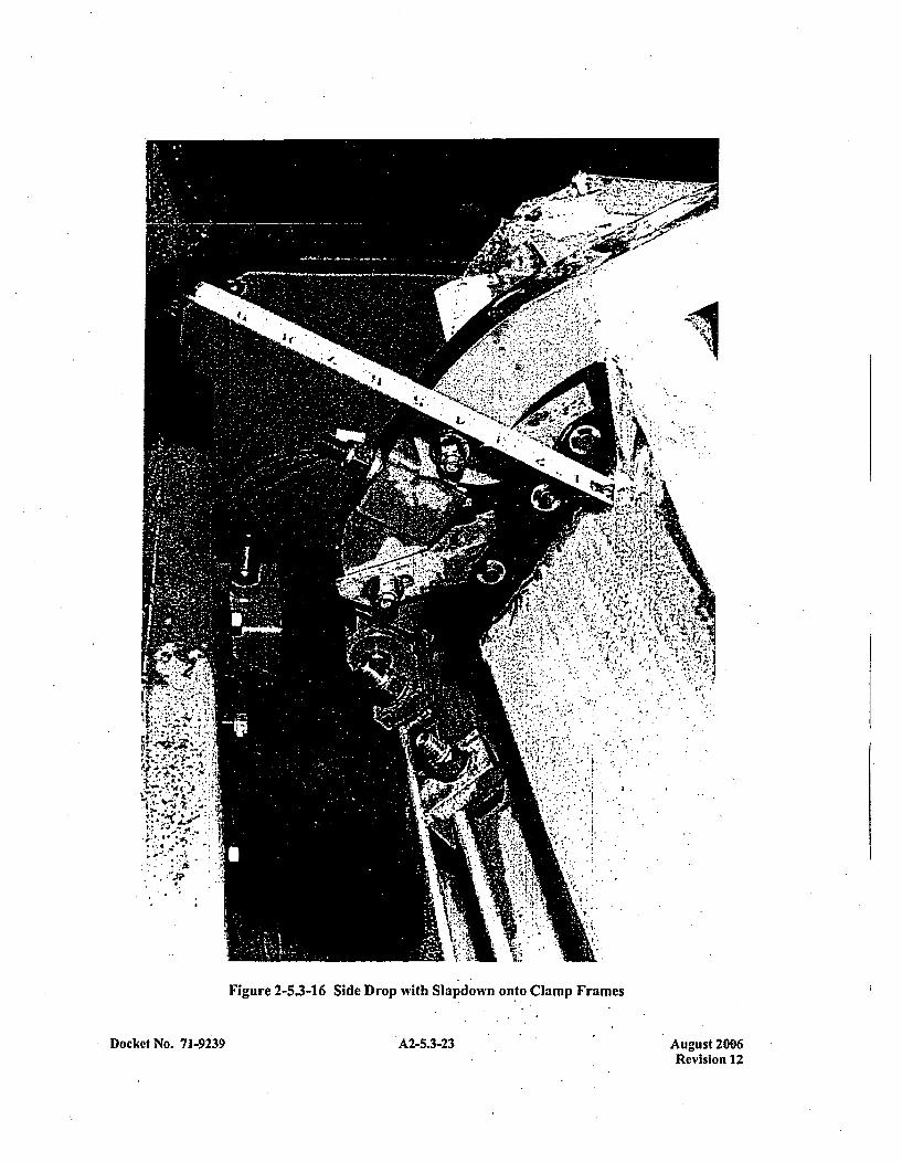
Figure 2-5.3-16 Side Drop with Slapdoiwn onto Clamp Frames
Docket No. 71-9239 A2-5.3-23 August 2096Revision 12
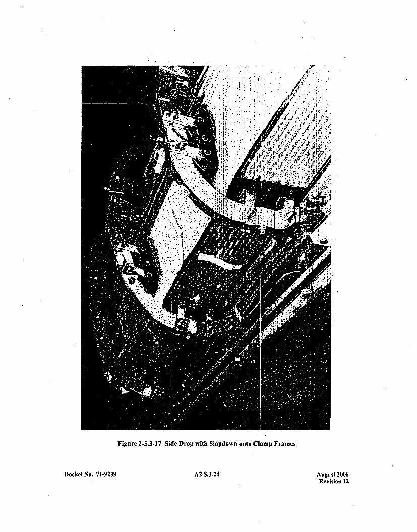
Figure 2-5.3-17 Side Drop with Slapdown onto Clamp Frames
Docket No. 71-9239 A2-5.3-24 August 2006Revision 12
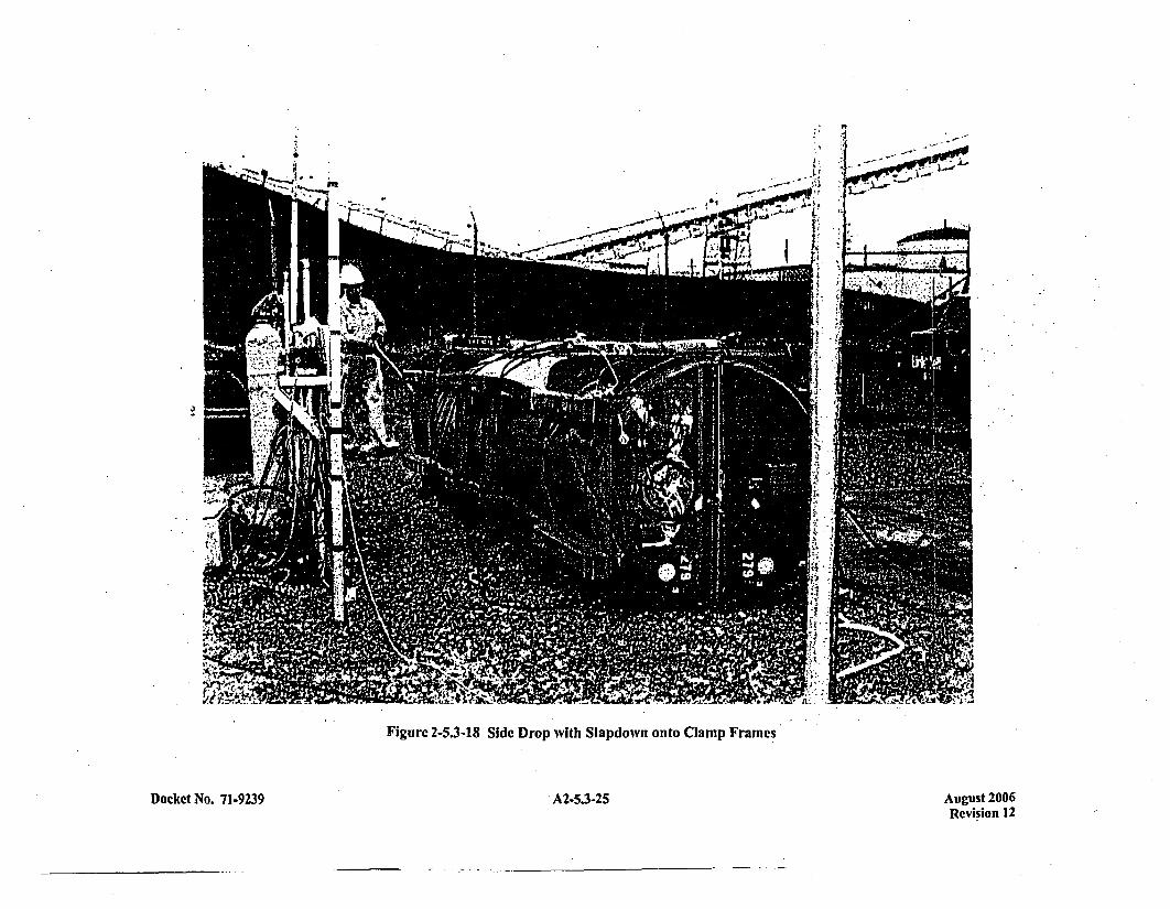
4Is
- II
Fiue25-8 ieDo ih lponotoCapFae
Docket No. 71-9239A2535 , A2-5.3-25 August 200 6
Revision 12
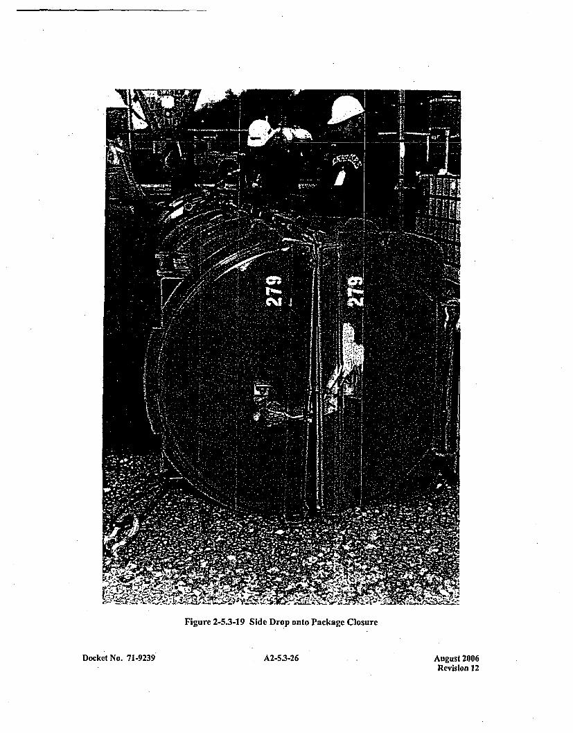
Figure 2-5.3-19 Side Drop onto Package Closure
A2-5.3-26Docket No. 71-9239 August 2006Revision 12

zt.-t; W
- W.
Figure 2-5.3-20 Side Drop onto Package Closure
Docket No. 71-9239 A2-5.3-27 Aupust 2006
Revision 12
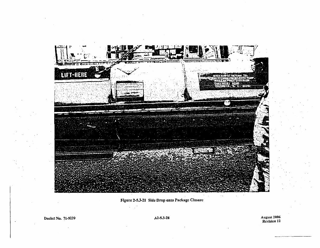
fflm ý ý ~ ~ I-o. .
Figure 2-5.3-21 Side Drop onto Package Closure
A2-5.3-28Docket No. 7 1-9239 August 2006Revision 12
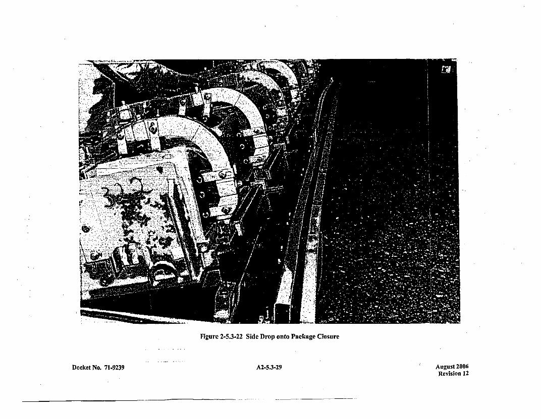
Figure 2-5.3-22 Side Drop onto Package Closure
Docket No. 71-9239 A2-5.3-29 August 2006Revision 12
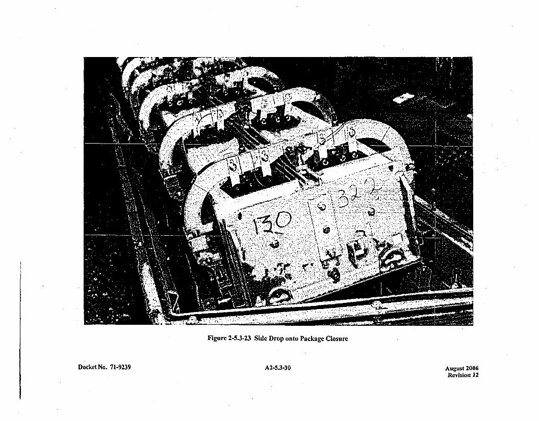
'0 ~
4O
'4~
I..0cJU0oIn
U
4:
U,
inUI-
0%0%0UU0
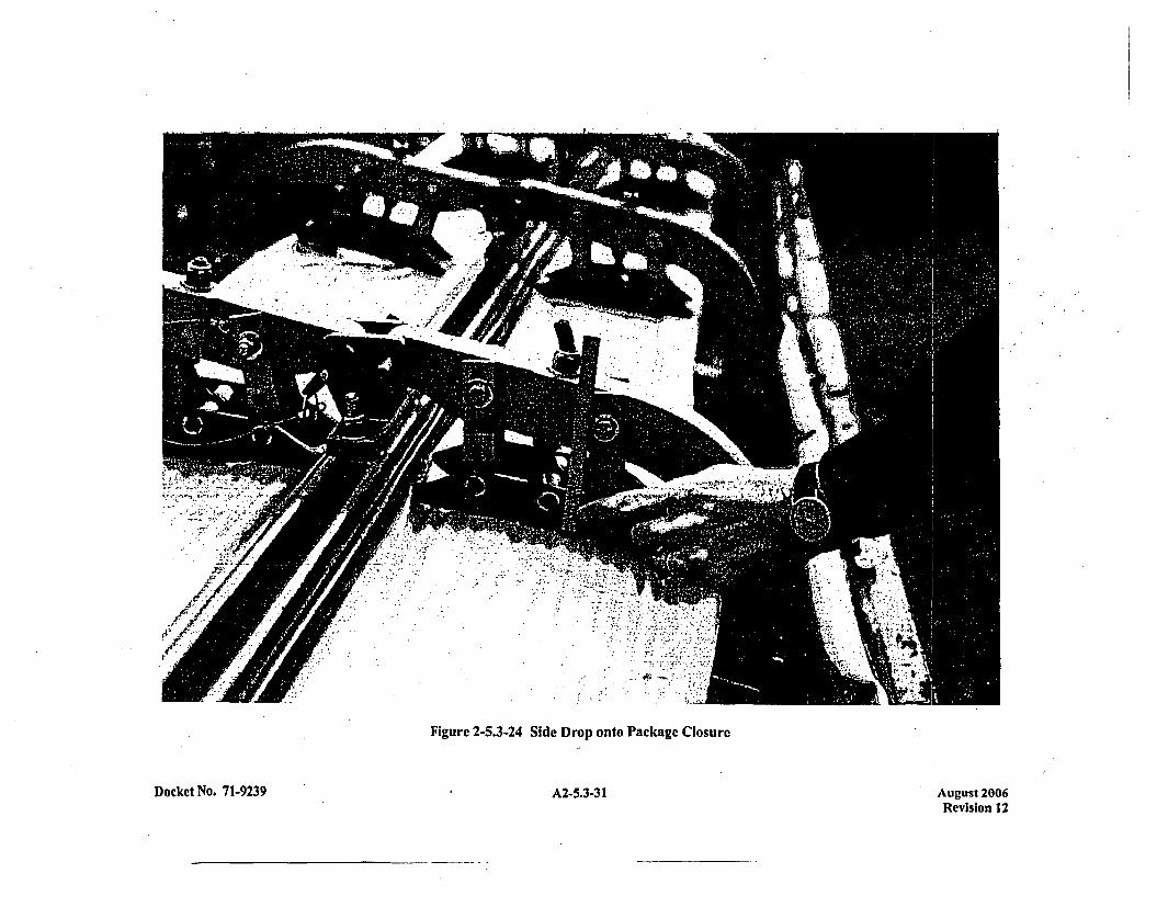
CA
t
o -
a-
ZA
ell
v~1~
a
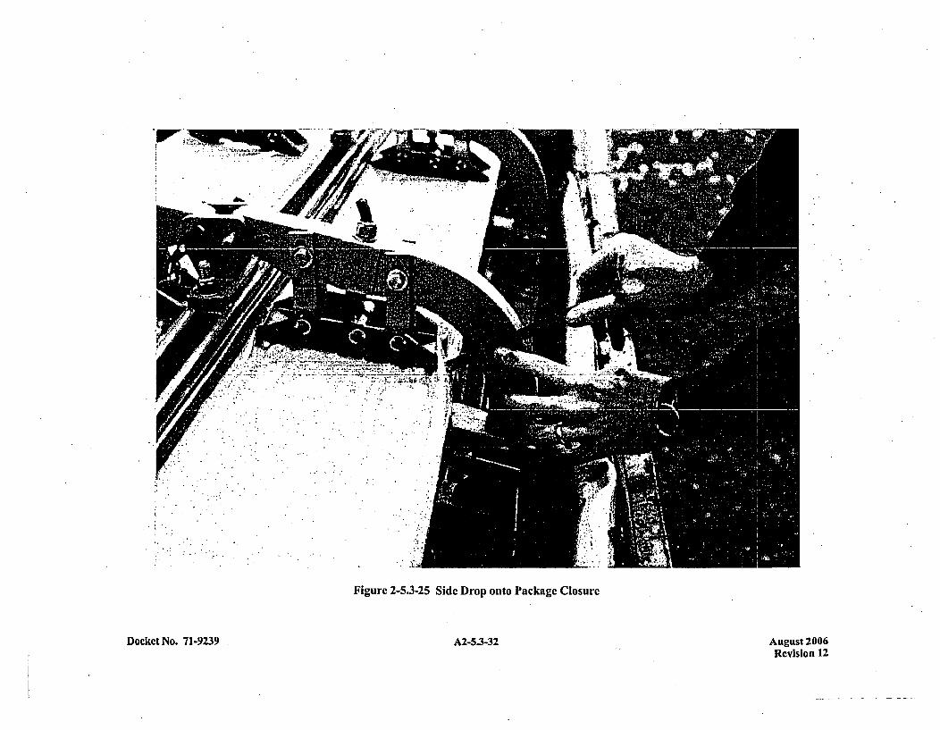
'0 ri
C
-
~~C
a
Ca
I-=U,
aUCa
CE
Cc
Ca
CE
Co en
C.
o614
Ca
'CIninInCa
6CCE
0%inM0%-SNSCa
Ca
C0

I> ~ji&~U
'0 t'l
~ -
Cq*4 0u~
v~
CU0CCa-Ue~i
a-
0%'.40%dzULi
C
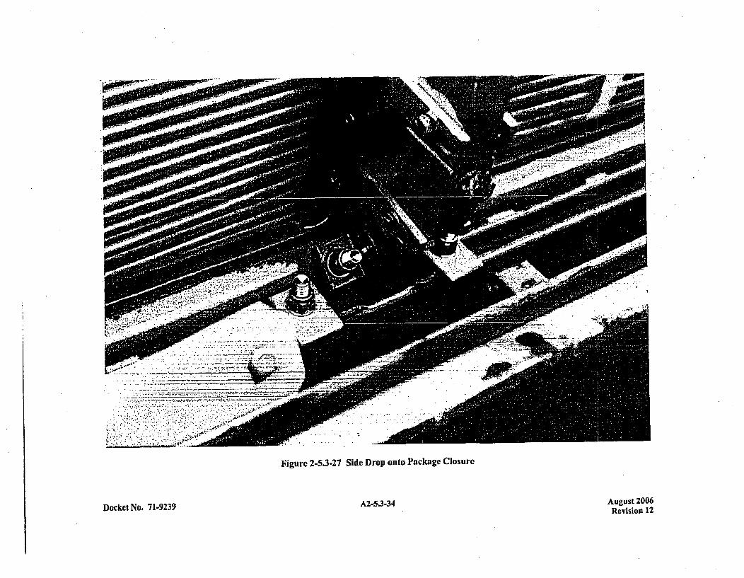
Figure 2-5.3-27 Side Drop onto Package Closure
Docket No. 71-9239 A2-5.3-34 August 2006Revision 12
APPENDIX 2-5.4CLAMPING FRAME COMPRESSION TEST RESULTS
Docket No. 71-9239 A2-5.4-1 August 2006-Revision 12
CLAMPING FRAME COMPRESSION TEST RESULTS
Figure 2-5.4-1 provides information for a clamping frame that was compression tested to ultimate failure.The frame was attached to a testing fixture with two 7/1691 clevis pins. A compressive load was applieduntil the pins failcd at a load of 44,500 lbs.
The pins were then removed and the clamping frame was tested by itself. Figure 2-5.4-2 shows that thisframe was compressively loaded until it failed due to bending. The ultimate applied load was 80,250 lbsand the total deflection was approximately 6.5 inches.
Docket No. 71-9239 A2-5.4-3 August 2006Revision 12
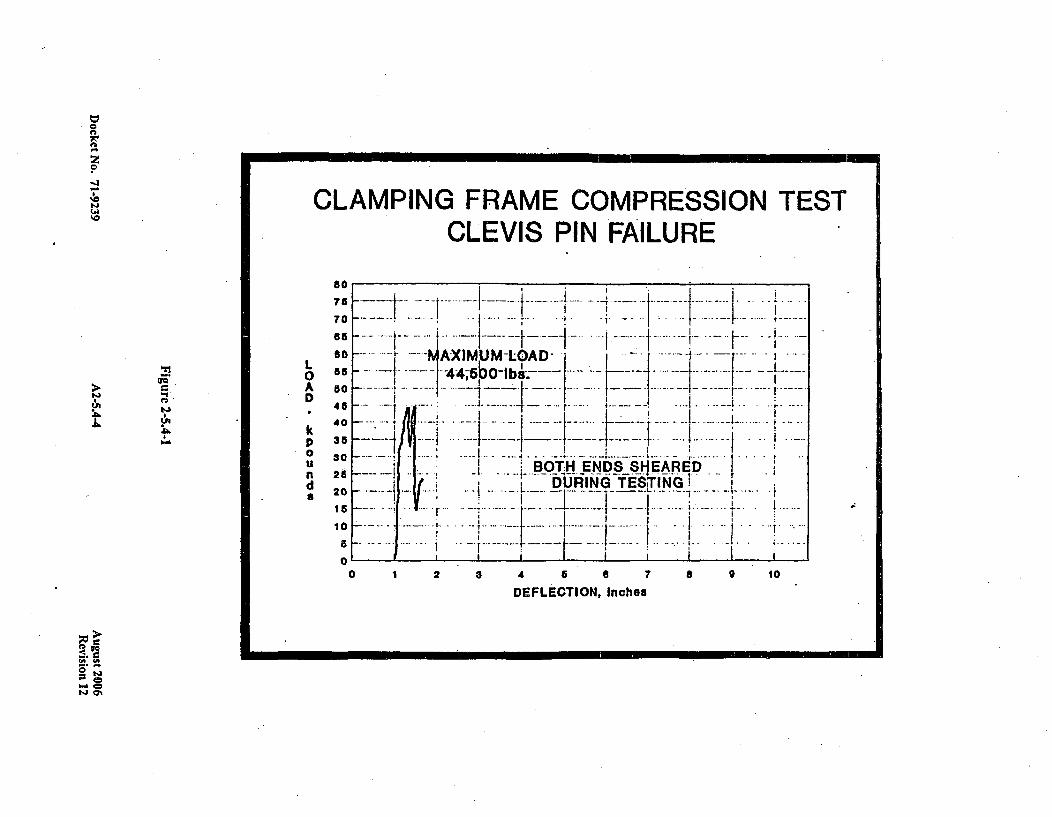
0
0
-J
N CLAMPING FRAME COMPRESSION TEST'CLEVIS PIN FAILURE
N
J~.
~1
US
L0
A
D
kp0U
d
80
75
7 0
ea
60
55
50
45
4 0
35
3025
20
15
10
5
0C
L.2 .- i.-..BOTH ENDS S-IEARED.-I ~ DURING TES~TING I-
I 2 3 4 5 a 7
DEFLECTION, Inchesa 0 10
aSA US
b~ON 0~
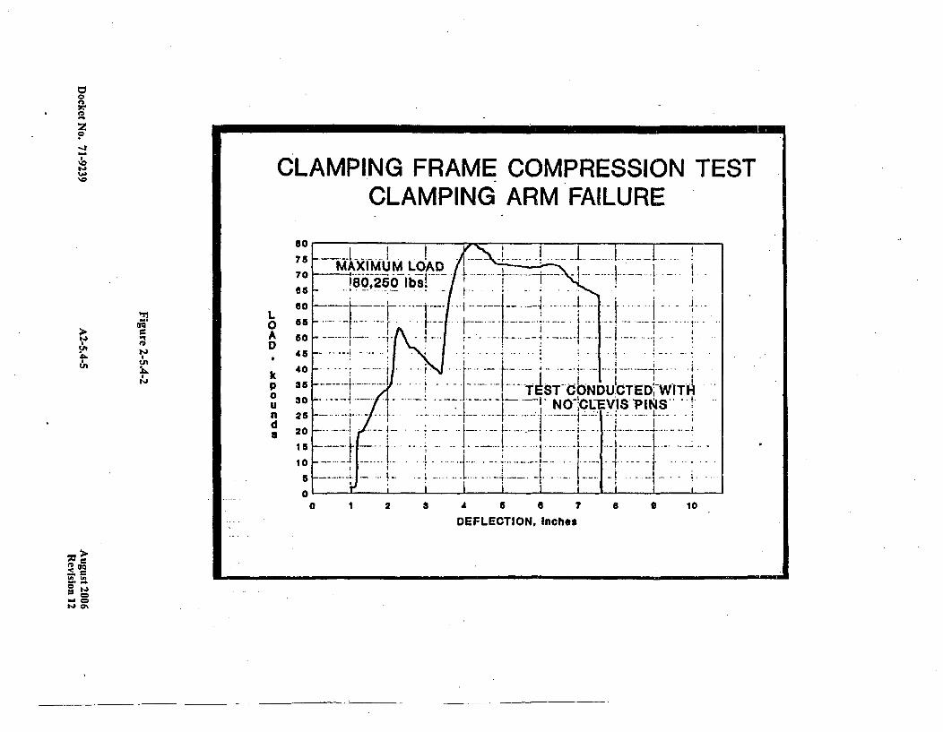
0C
C
~0
N
~0C LAMPING FRAME COMPRESSION TEST
CLAMPING ARM FAILURE
N
"I L0AD
kpaUnda
80
75
70
65
60
455
40
35
30
25
20
is
10
5
0
MAXIMUM LOAD ... ...
.. !80,250. . .
- -*- NO CUEVIS PIN~S j
0 1 2 3 A 6 a 7 6
DEFLECTION, Inches0 10
>.U
W0

APPENDIX 2-5.5MCC-3IMCC-4 BOUNDING CASE ASSESSMENT
Docket No. 71-9239 A2-5.5-1 August 2006Revision 12
MCC-3IMCC-4 BOUNDING CASE ASSESSMENT
With the exception of overall length and weight, the Westinghouse MCC-4 container is essentiallyidentical in design to thc MCC-3 container (see Appendix 2-2 for component weights). The followingsubsections provide justification for asserting the MCC-3 container is the bounding case for the MCC-4container for all tests.
2-4.5.1 Flat Side Drop onto Container Top
The clamping frames are shown in previous sections to be the main structural component for retaining thefuel assemblies in a flat side drop onto the container top. The tested MCC-3 container successfullyutilized seven clamping frames. to retain each fuel assembly (14 total clamping frames). The clampingframes resist a load equal to the weight of the fuel assemblies plus the weight of the internal structure. Forthe MCC-3, the static load per clamping frame is:
PMCC3 = (3,300 + 1,964) = 376 lbs/clamping frame14
The MCC-4 container utilizes a total of 20 clamping frames to retain the fuel assemblies (10 for each fuelassembly). The static load per clamping frame is:
PMCC4 = (3,870 + 3,118s) =349 lbs/clamping frame20
Thus, since the clamping frame design is identical for the two containers, it is readily seen that the
MCC-4 container represents a less critical case than the MCC-3 for a flat side drop onto the container top.
2-4.5.2 Side Drop with Slapdown onto Internal Clamp Frames
It was shown previously in Section 2-4.2 that a drop oriented 300 from horizontal represented the worstcase for the slapdown drop. This was bascd on a desire to maximize the package accelerations for boththe prim ary and secondary (slapdown) impact. The computer program SCANS is again utilized to providejustification that the MCC-3 container response bounds that of the MCC-4 for the slapdown test.
As demonstrated in Section 2-4.2, the SCANS model for the MCC-3 container consisted of a simplifiedcylinder of homogeneous mass representing the fuel assemblies and internal structure (seeFigure 2-5.5-1). The relative "softness" of the internal's shock m ount system allows the internal structure,including fuel assemblies, to accurately be decoupled from the package shell (i.e., the internals and shellact as separately impacting bodies) during an impact event. The dimensional .breakout used for the"impact limiter", "cap" and "body" is arbitrarily chosen to provide input values for SCANS.
Docket No. 71-9239 A2-5.5-3 August 2006Revision 12
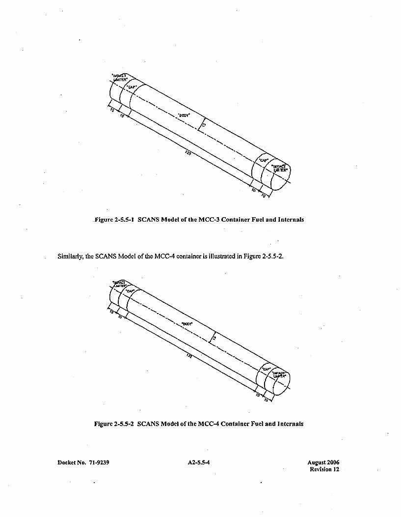
Figure 2-5.5-1 SCANS Model of the MCC-3 Container Fucl and Internals
Similarly, the SCANS Model of the MCC-4 container is illustrated in Figure 2-5.5-2.
Figure 2-5.5-2 SCANS Model of the MCC-4 Container Fuel and Internals
Docket No. 7 1-9239 A2-5.5-4 August 2006Revision 12
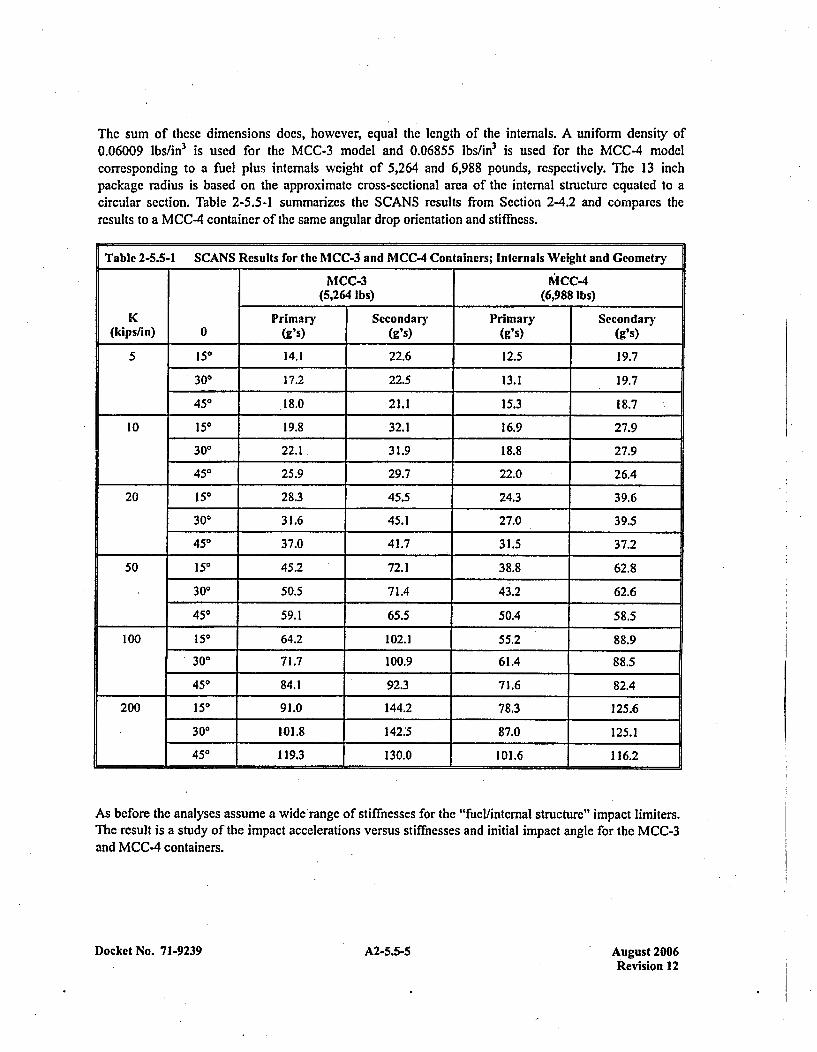
The sum of these dimensions does, however, equal the length of the internals. A uniform density of0.06009 lbs/in 3 is used for the MCC-3 model and 0.06855 lbs/in 3 is used for the MCC-4 modelcorresponding to a fuel plus internials weight of 5,264 and 6,988 pounds, respectively. The 13 inchpackage radius is based on the approximate cross-sectional area of the internal structure equated to acircular section. Table 2-5.5-1 summarizes the SCANS results from Section 2-4.2 and compares thercsults to a MCC-4 container of the same angular drop orientation and stiffness.
Table 2-5.5-1 SCANS Results for the MCC-3 and MCC-4 Containers; Internals Weight and Geometry
MCC-3 KICC-4(5,264 Ibs) (6,988 Ibs)
K Primary Secondary Primary Secondary(kips/in) 0 Wgs) (g's) Wgs) (g's)
5 150 14.1 22.6 12.5 19.7
300 17.2 22.5 13.1 19.7450 18021.1 15.3 18.7
10 150 19.8 32.1 16.9 27.9
300 22.1. 31.9 18.8 27.9
450 25.9 29.7 22.0 26.4
20 150 28.3 45.5 24.3 39.6
300 31.6 45.1 27.0 39.5450 37.0 41.7 31.5 37.2
50 150 45.2 72.1 38.8 62.8
300 50.5 71.4 43.2 62.6450 59.1 65.5 50.4 58.5
100 150 64.2 102.1 55.2 88.9
300 71.7 100.9 61.4 88.5450 84.1 92.3 71.6 82.4
200 150 91.0 144.2 78.3 125.6
300 101.8 142.5 87.0 125.1450 119.3 130.0 101.6 116.2
As before the analyses assume a wide range of stiffnesses for the "fuellintcmal structure" impact limiters.The result is a study of the impact accelerations versus stiffnesses and initial impact angle for the MCC-3and MCC-4 containers.
Docket No. 71-9239 A2-5.5-5 August 2006Revision 12
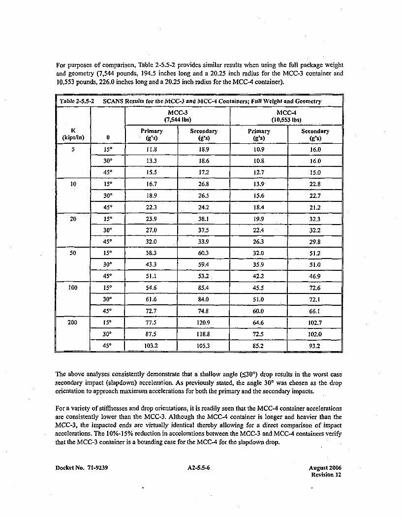
For purposes of comparison, Table 2-5.5-2 provides similar results when using the full package weightand geometry (7,544 pounds, 194.5 inches long and a 20.25 inch radius for the MCC-3 container and10,553 pounds, 226.0 inches long and a 20.25 inch radius for the MCC-4 container).
Table 2-5Y.5-2 SCANS Results for the MCC-3 and MCC-4 Containers; Full WIeight and Geometry
MCC-3 NICC-4(7,544 Ibs) (10,553 Ibs)
I K Primary Secondary Primary Secondary(kips/in) 0 (g's) (s)(g's) (g's)
5 150 11.8 18.9 10.9 16.0
300 13.3 18.6 10.8 16.0450 15.5 17.2 12.7 15.0
10 150 16.7 26.8 13.9' 22.8
300 18.9 26.5 15.6 22.7
450 22.3 24.2 18.4 21.2
20 150 23.9 38.1 19.9 32.3
300 27.0 37.5 22.4 .32.2450 32.0 33.9 26.3 29.8
10 50 38.3 60.3 32.0 51.2
300 43.3 59.4 35.9 51.0
450 51.1 53.2 42.2 46.9
100 150 54.6 85.4 45.5 72.6
300 61.6 84.0 51.0 72.1
450 72.7 74.8 60.0 66.1
200 150 77.5 120.9 64.6 102.7
300 87.5 118.8 72.5 102.0
E 450 103.2 105.3 85.2 .93.2
The above analyses consistently demonstrate that a shallow angle (:530*) drop results in the worst casesecondary impact (slapdown) acceleration. As previously stated, the angle 300 was chosen as the droporientation to approach maximum accelerations for both the primary and the secondary impacts.
For a variety of stiffuesses and drop orientations, it is readily seen that the MCC-4 container accelerationsare consistently lower than the MCC-3. Although the MCC-4 container is longer and heavier than theMCC-3, the impacted ends are virtually identical thereby allowing for a direct comparison of impactaccelerations. The 10%-I15% reduction in accelerations between the MCC-3 and MCC-4 containers verifythat the MCC-3 container is a bounding ease for the MCC-4 for the slapdown drop.
Docket No. 71-9239 A2-5.5-6 August 2006Revision 12
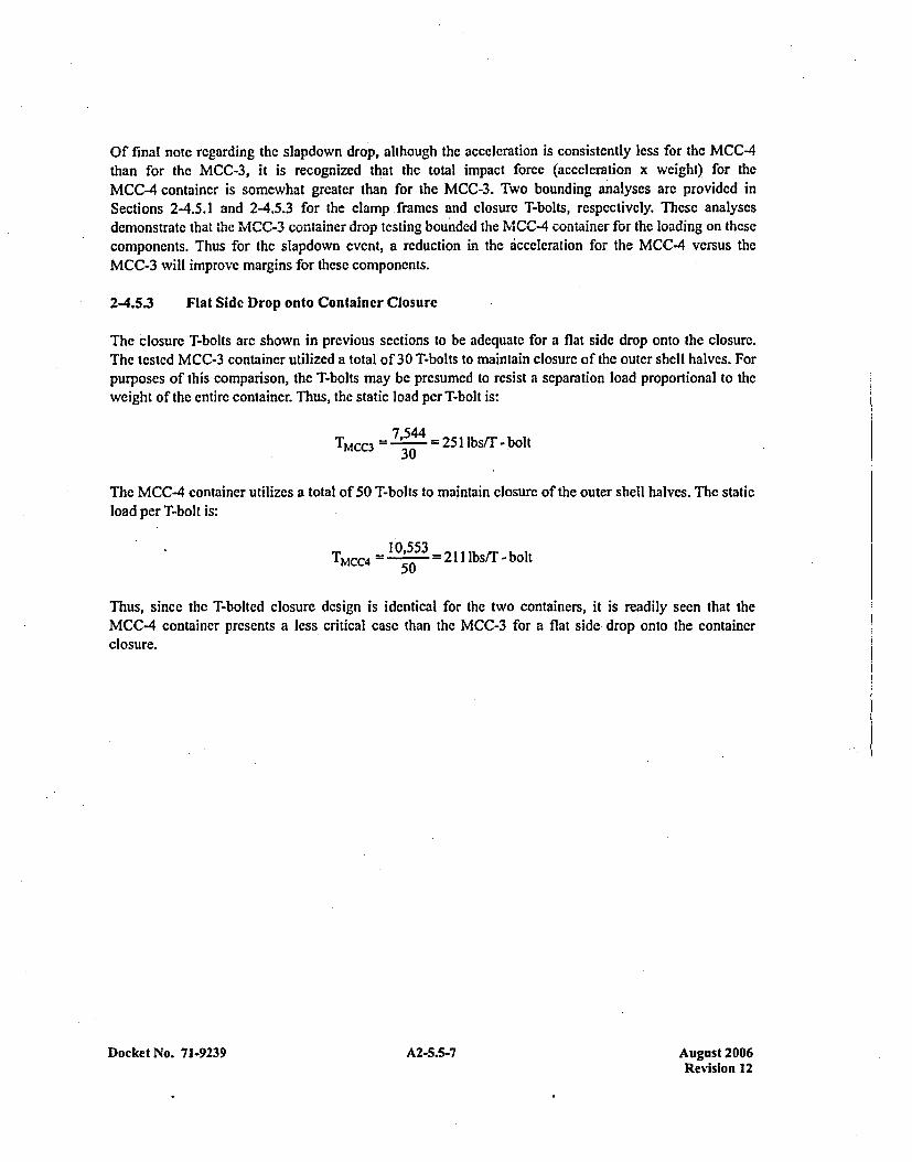
Of final note regarding the slapdown drop, although the accelcration is consistently less for the MCC-4than for the MCC-3, it is recognized that the total impact force (accelcration x weight) for theMCC-4 container is somewhat greatcr than for the MCC-3. Two bounding analyses arc provided inSections 2-4.5.1 and 2-4.5.3 for the clamp frames and closure T-bolts, respectively. These analysesdemonstrate *that the MCC-3 container drop testing bounded the MCC-4 container for the loading on thesecomponents. Thus for the slapdown event, a reduction in the acceleration for the MCC-4 versus theMCC-3 will improve margins for thesc components.
2-4.5.3 Flat Side Drop onto Container Closure
The Closure T-bolts are shown in previous sections to be adequate for a flat side drop onto the closure.The tested MCC-3 container utilized a total of 30 T-bolts to maintain closure of the outer shell halves. Forpurposes of this comparison, the T-bolts may be presumed to resist a separation load proportional to theweight of the entire container. Thus, the static load per T-bolt is:
TMcc3 =- 754_251lbs/T -bolt30
The MCC-4 container utilizes a total of 50 T-bolts to maintain closure of the outer shell halves. The staticload per T-bolt is:
TMCC4 =-1,53=2llbs/T -bolt50
Thus, since the T-bolted closure design is identical for the two containers, it is readily seen that theMCC-4 container presents a less critical case than the MCC-3 for a flat side drop onto the containerclosure.
Docket No. 71-9239 A2-5.5-7 August 2006Revision 12

APPENDIX 2-6STRUCTURAL CALCULATIONS AND EVALUATIONS
RELATING TO THE ASSESSMENT FORTRANSPORTATION OFVVER 1000 FUEL
Docket No. 71-9239 A2-6-1 August 2006Revision 12
STRUCTURAL CALCULATIONS AND EVALUATIONSRELATING TO THE ASSESSMENT FOR
TRANSPORTATION OF VVER 1000 FUEL
2-6.1 Introduction
The current MCC packaging configuration is designed to restrain two standard, Westinghouse, square-type fuel assemblies in a nuclear-safe: configuration during transportation. This appendix will demonstratethe structural adequacy of a slightly modified MCC package (hereinafter referred to as the MCC-5package) design to safely transport two hexagonal-type, VVER 1000, fuel assemblies. Figure 2-6-1,bclow, comparatively illustrates the two fuel assembly configurations.
As seen in Figure 2-6-1, shipment of the VVER 1000 fuel assemblies utilizes an MCC-5 package, whichis an MCC-4 package with the following relatively minor modifications to the *internials assembly:1) vee-shaped, rather than flat, fuel assembly bottom grid supports, 2) a somewhat taller top pivot mount,and 3) a different clamp ing frame assembly detail design. The use of the vee shaped fuel assembly bottomgrid supports only changes the internal structure's center of gravity slightly, without other significantstructural effects. Further, loss of the vee-shaped bottom grid support structure, located intermittentlyunder each of the VVER 1000 ' fuel assembly's grid spacers, is inconsequential because the fuelassemblies are still maintained within the confines of the clamping frames. Only the elongated (taller) toppivot mount and revised clamping frame assembly offer structural significance, the details of which arepresented in the following sections. These sections specifically demonstrate that the MCC packageclamping frame and associated end connections bound the revised design used to transport the VVER1000 fuel assemblies. Thus, the analyses and drop testing used to demonstrate the MCC package designare applicable and adequately address the MCC-5 configuration.
2-6.2 Demonstrating the Adequacy of the Revised Design
Comparative analyses were performed in order to show that the design and testing of the MCC packageclamping frame assembly and associated end connections bounds that of the MCC-5 design.
2-6.2.1 Physical Comparison of the Two Clamping Frame Designs
Figures 2-6-1 and 2-6-2 provide an illustrative comparison of the two clamping frame configurations. TheMCC-5 clamping frame assembly is approximately two inches taller than the standard MCC-3 andMCC-4 clamping frames. Further, the MCC-5 clamping frame assembly provides three pressure padsurfaces to restrain the hexagonally-shaped fuel instead of the normal two pressure pads.
2-6.2.2 Material Comparison of the Two Clamping Frame Designs
Both the MCC-4 and MCC-5 clamping frames are identically manufactured of ASTM A240, Type 304,stainless steel with a minimum tensile strength of 75,000 psi and a minimum -yield strength of 30,000 psi.Similarly, all other modified MCC-5 component materials are identical to their MCC-4 packagecounterparts (e.g., top pivot mounts, pressure pads, etc.).
Pocket No. 71-9239 A2-6-3 August 2006Revision 12
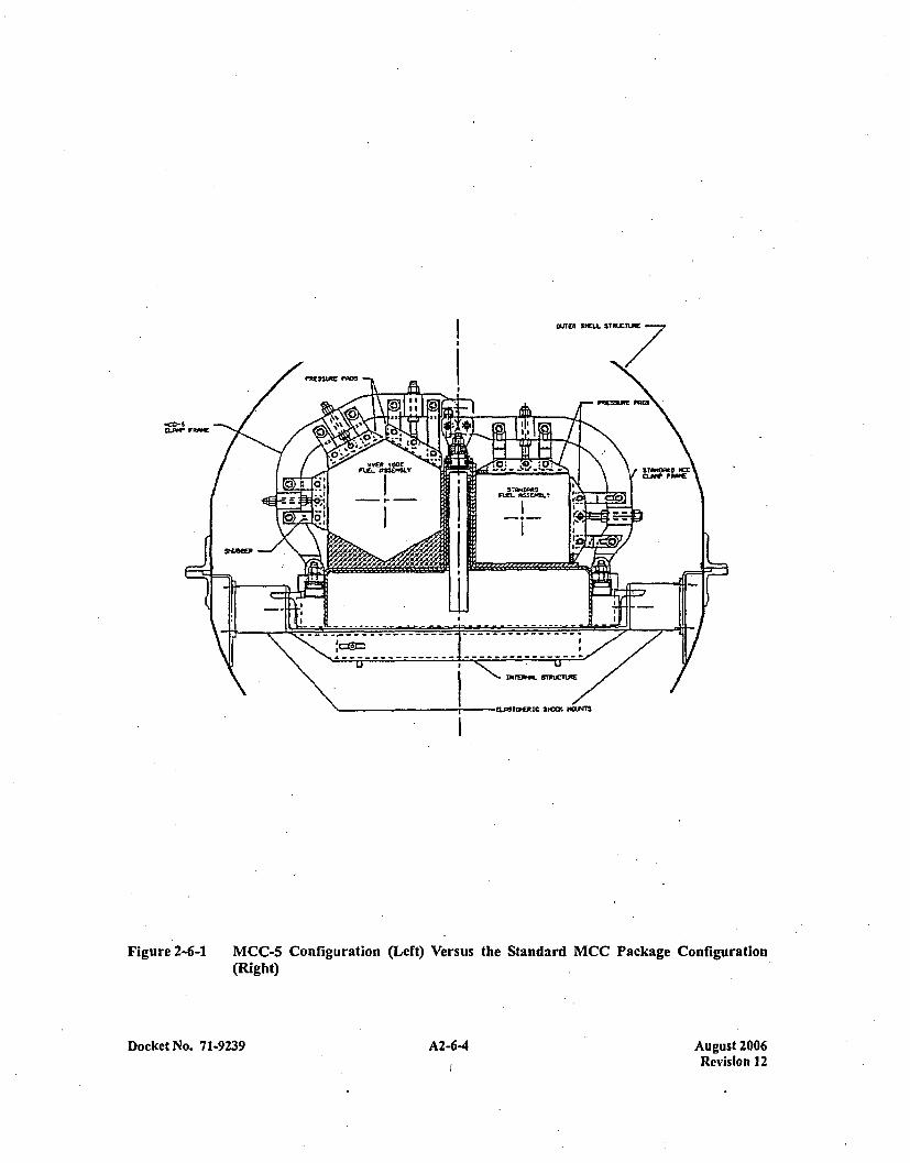
COFW FRAE
I
Figure 2-6-1 MCC-5 Configuration (Left) Versus the Standard MCC Package Configuration(Right)
Docket No. 71-9239 A2-64 A2-6.4August 2006Revision 12
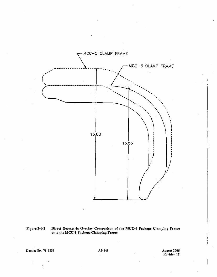
MCC-5 CLAMP FRAME
I
MCC-3 CLAMP FRAME
5%
S
SS S
S SS
S S
SS
S
I S
I II I
1 115.60I
13.56
Figure~~~~~~ ~ ~ ~ ~ ~ ~ 2--IietGoercOelyCmaisno h 4PcaeCapn rm
onto* thIC akgeCapn rm
Docket No. 7 1-9239 A2-6-5 AZ-6-5August 2006Revision 12
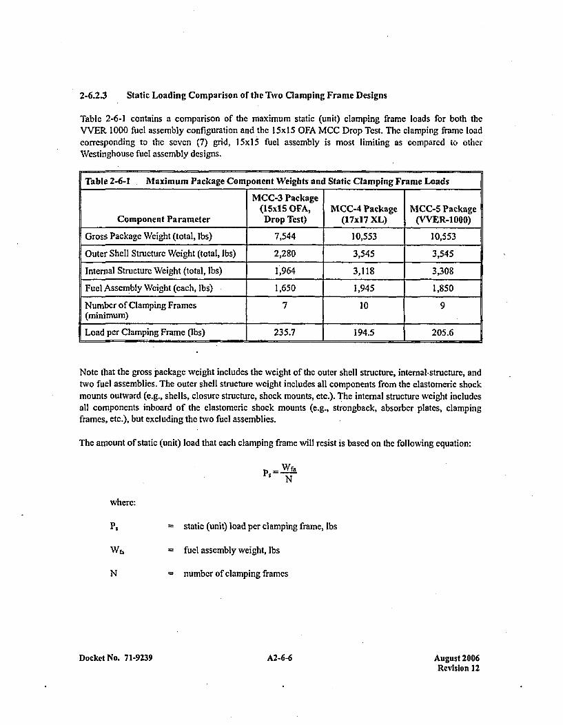
2-6.2.3 Static Loading Comparison or the Two Clamping Frame Designs
Table 2-6-1 contains a comparison of the maximum static (unit) clamping frame loads for both theVVER 1000 fuel assembly configuration and the 15x1 5 OFA MCC Drop Tcst. The clamping frame loadcorresponding to the seven (7) grid, 15x15ý fuel assemnbly is most limiting as compared to otherWestinghouse fuel assembly designs.
Table 2-6-1 .Maximum Package Component Weights and Static Clamping Frame Loads
MCC-3 Package(I15x1 5 OFA, MCC-4 Package MCC-5 Package
Component Parameter Drop Test) (17xI7 XL) (VVER-1000)
Gross Package Weight (total, Ibs) 7,544 10,553 10,553
Outer Shell Structure Weight (total, Ibs) 2,280 3,545 3,545
Internal Structure Weight (total, Ibs) 1,964 3,118 3,308
Fuel Assembly Weight (each, Ibs) 1,650 1,945 1,850
Number of Clamping Frames 7 10 9(minimum) ________________ _______
Load per Clamping Frame (Ibs) 235.7 194.5 205.6
Note that the gross package weight includes the weight of the outer shell structure, intemal-structure, andtwo fuel assemblies. The outer shell structure weight includes all components from the elastomeric shockmounts outward (e.g., shells, closure structure, shock mounts, etc.). The internal structure weight includesall components inboard of the elastomeric shock mounts (e.g., strongback, absorber plates, clampingframes, etc.), but excluding the two fuel assemblies.
The amount of static (unit) load that each clamping frame will resist is based on the following equation:
PS=Wf3-N
where:
P. = static (unit) load per clamping frame, lbs
N
= fuel assembly weight, lbs
= number of clamping frames
Docket No. 7 1-9239 A2-6-6 August 2006Revision 12

Then, for the Westinghouse I 5x] 5 OFA fuel assembly, the static (unit) load per clamp, PM, is:
PSM = 1,650 = 235.7 lbs7
and, for the VVER 1000 fuel assem bly, the static (unit) load per clamp, P~v, is:
P~v ý 80=205.6 lbs9
Thus, it can be readily seen here and in Table 2-6-1 that for the static (unit) load case, the load per clampframe is less for the MCC-5 configuration than for the maximum MCC-3 or MCC-4 configurations.
2-6.2.4 Dynamic (Free Drop) Loading Comparison of the Two Clamp Frame Designs
Drop testing demonstrated that the standard MCC clamping frame design was satisfactory in retaining themaximum weight fuel assemblies in a controlled configuration. Because of the high ductility of theASTM A240, Type 304, stainless steel clamping frames, a somewhat larger amount of plastic deformationwould have had to occur to exceed the ultimate elongation of the clamping frame material. Further, thepresence of the fuel assembly structure precludcs catastrophic plastic collapse of the clamping framestructure because clamping frame deformations are self-limiting as the fuel pins crush against each other.Drop testing also demonstrated that structural integrity of the upper and lower pivot mount connections(i.e., the pinned connections at each end of the clamping frames) to the clamping framc were maintained.
A dynamic-equivalent, analytic, free drop loading comparison of the two clamping frame designs,including upper and lower pivot mount connections, shall be made by utilizing the principle of loadlimiting, plastic bending of the clamping frame structure. The cross-section and basic shape of the MCC-3and MCC-4 clamping frame designs versus the MCC-5 clamping frame design is essentially identical.Thus, the ability of the clamping frame structures to plastically deform without failure during the freedrop events was established. Further, the clamping frame material's high ductility (the ultimate elongationof ASTM A240, Type 304, stainless steel is typically greater than 40%) assures that substantialdeformation could occur prior to failure of the clamping frame (note, again, that deformation of theclamping frame is deformation limited due to the presence of a fuel assembly. Therefore, the primarypoint of potential failure (i.e., failure resulting in the possible release of the fuel assemblies from acontrolled configuration) is at the clamping frame end connections, that is, the upper and lower pivotmounts.
A load limiting plastic "hinge" in the clamping frame structure shall be used as a simplifying means ofanalyzing the limiting forces in the upper and lower pivot mounts during the free drop event. In otherwords, the maximum forces in the upper, and lower pivot mounts for each clamping frame configurationwill be determined by idealizing a purely elastic-plastic, stress-strain curve illustrated in Figure 2-6-3.Note that for a rectangular cross-section in bending, the plastic moment is 1 1/2 times the yield strengthmoment.
Docket No. 71-9239 A2-6-7 August 2006Revision 12
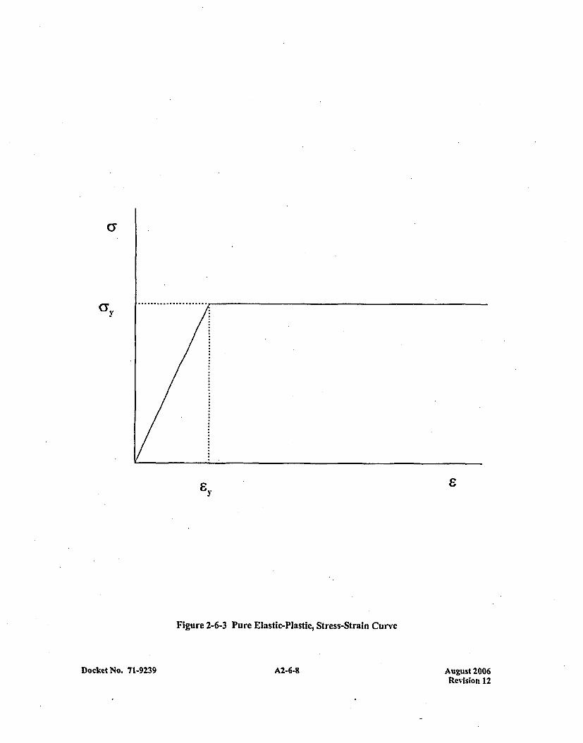
(3
& y
Figure 2-6-3 Pure Elastic-Plastic, Stress-Strain Curve
A2-6-8Docket No. 71-9239 August 2006Revision 12
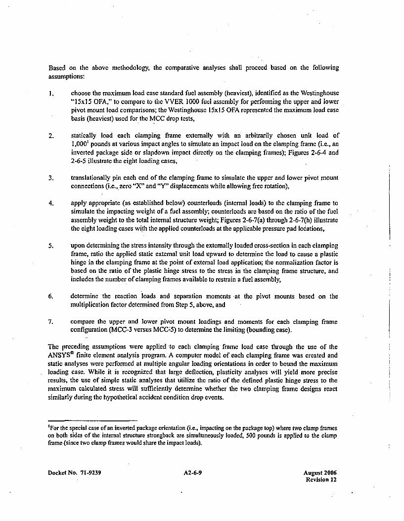
Based on the abovc methodology, the comparative analyses shall proceed bascd on *the followingassumptions:
1. choose the maximum load ease standard fuel assembly (heaviest), identified as the Westinghouse"I 5x1 5 OFA," to compare 'to the VVER 1000 fuel assembly for performing the upper and lowerpivot mount load comparisons; the Westinghouse I 5x 15 OFA represented the maximum load casebasis (heaviest) used for the MCC drop tests,
2. statically load each clamping frame externally with an arbitrarily chosen unit load of1,0001 pounds at various impact angles to simulate an impact load on the clamping frame (i.e., aninverted package side or slapdown impact directly on the clamping frames); Figures 2-6-4 and2-6-5 illustrate the eight loading cases,
3. translationally pin each end of the clamping frame to simulate the upper and lower pivot mountconnections (i.e., zero "Y' and "Y" displacements while allowing free rotation),
4. apply appropriate (as established below) counterloads (internal loads) to the clamping frame tosimulate the impacting weight of a fuel assembly; counterloads are based on the ratio of the fuelassembly weight to the total internal structure weight; Figures 2-6-7(a) through 2-6-7(h) illustratethe eight loading cases with the applied counterloads at the applicable pressure pad locations,
5. upon determining the stress intensity through the externally loaded cross-section in each clampingframe, ratio the applied static external unit load upward to determine the load to cause a plastichinge in the clamping frame at the point of external load application; the normalization factor isbased on the ratio of the plastic hinge stress to the stress in the clamping frame structure, andincludes the number of clamping frames available to restrain a fuel assembly,
6. determine the reaction loads and separation moments at the pivot mounts based on themultiplication factor determined from Step 5, above, and
7. compare the upper and lower pivot mount loadings and moments for each clamping frameconfiguration (MCC-3 versus MCC-5) to determine the limiting (bounding case).
The preceding assumptions were applied to each clamping frame load case through the use of theANSYSO' finite element analysis program. A computer model of each clamping frame was created andstatic analyses were performed at multiple angular loading orientations in order to bound the maximumloading case. While it is recognized that large deflection, plasticity analyses will yield more preciseresults, the use of simple static analyses that utilize the ratio of the defined plastic hinge stress to themaximum calculated stress will sufficiently determine whether the two clamping frame designs reactsimilarly during the hypothetical accident condition drop events.
'For the special case of an inverted package orientation (i.e., impacting on the package top) where two clamp frameson both sides of the internal structure strongback are simultaneously loaded, 500 pounds is applied to the clampframe (since two clamp frames would share the impact loads).
Docket No. 71-9239 A2-6-9 August 2006Revision 12
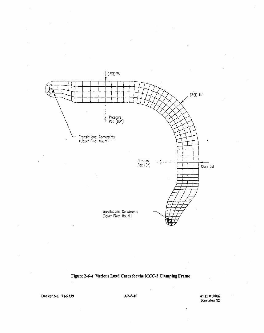
CASE 2Y
CAS E IM
ftPrcssure'ý- pcc (90,,)
TrcrnsIa'io-rc: Corstrdn'ks(Upper Pi-vO Y!O.-it')
Tra~islo~onc Constraints(Lowe., Nvot Llourt)
'cc (0)eCAS E 3M
Figure 2-6-4 Various Load Cases for the MCC-3 Clamping Frame
Docket No. 71-9239 A2-6-10 August 2006Revision 12
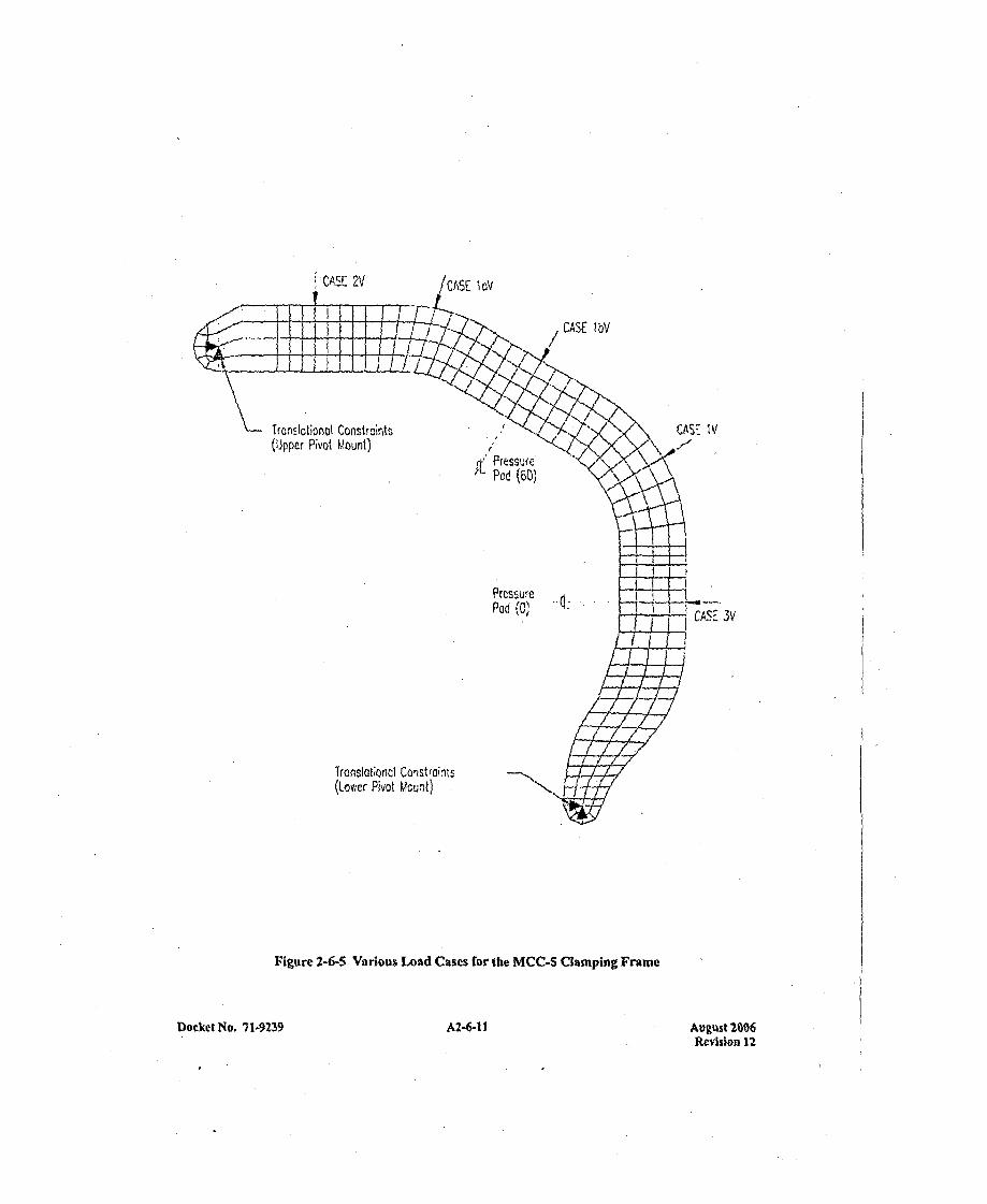
!,CASE 2V IaIov
CASE I bV
Tronslotionot Constromntt(Upper Pivot Mount)
CAS:- IV/
Pod P(6SU)
Frcs~ufePod (0) 14 CASE RV
(Lower Pivot Mcui-t) N
Figure 2-6-5 Various Load Cases for the MCC-S Clamping Framie
39 A2-6-1 1
August 26,ORevision 12
Docket No. 71-92

Two-dimensional, plane strcss (STIF42), static elements were chosen to represent each clamp frame. Thebasic thickness was specified as 1.25 inches. Details such as the pivot mount interface holes and pressurepad interface holes (notably the same size for both clamp frame designs) were ignored since their effectsare localized and considered negligible to the overall system's results. Internal loads arc assumed to travelthrough the pressure pad bolt centers and are applied as point loads.
Figures 2-6-4 and 2-6-5 illustrate the finite element models and various load orientations for thetwo clamping frames. Each load case was chosen based on the geometric configuration underconsideration. Cases 2M and 2V, representing an inverted (upside-down) impact on the package topthereby engaging two clamping frames simultaneously, use an applied external loading of 500 pounds; allother cases utilize 1,000 pounds.
The internal loads (counterloads) simulating the reaction of the fuel assemblies onto the clamping framesis based on the geometry of the clamping frame and the impacting orientation of the package. Thelocation, direction, and magnitude of the internal loads are determined considering:
I . the applied external load of 1,000 pounds (500 pounds for Cases 2M and 2V, i.e., an inverted(upside-down) drop orientation),
2. the fuel assembly and internal structure weights,
3. the angular orientation of the applied external unit load, and
4. the number and orientation of pressure pads carrying the internal load.
The following methodology is used to determine the internal forces (counterloads) for each clamping
frame and unit loading orientation
WtW-ýýa o f=i(Ft. Ffa or-t
where:
Ff, =applied internal force due to the fuel assembly, lbs
F, = total applied external -force, 1,000 lbs
WfA= fuel assembly weight, lbs=1,650 lbs for the maximum weight 15x15 OFA fuel assembly=1,850 lbs for the maximum wveight VVER 1000 fuel assembly
W,= total internal structure assembly weight W, + 2Wb,, lbs
Wi = internal structure weight, lbs=1,964 lbs for the maximum weight MCC-3 internal structure
= 3,308 lbs for the maximum weight MCC-5 internal structure
Docket No. 71-9239 A2-6-12 August 2006Revision 12
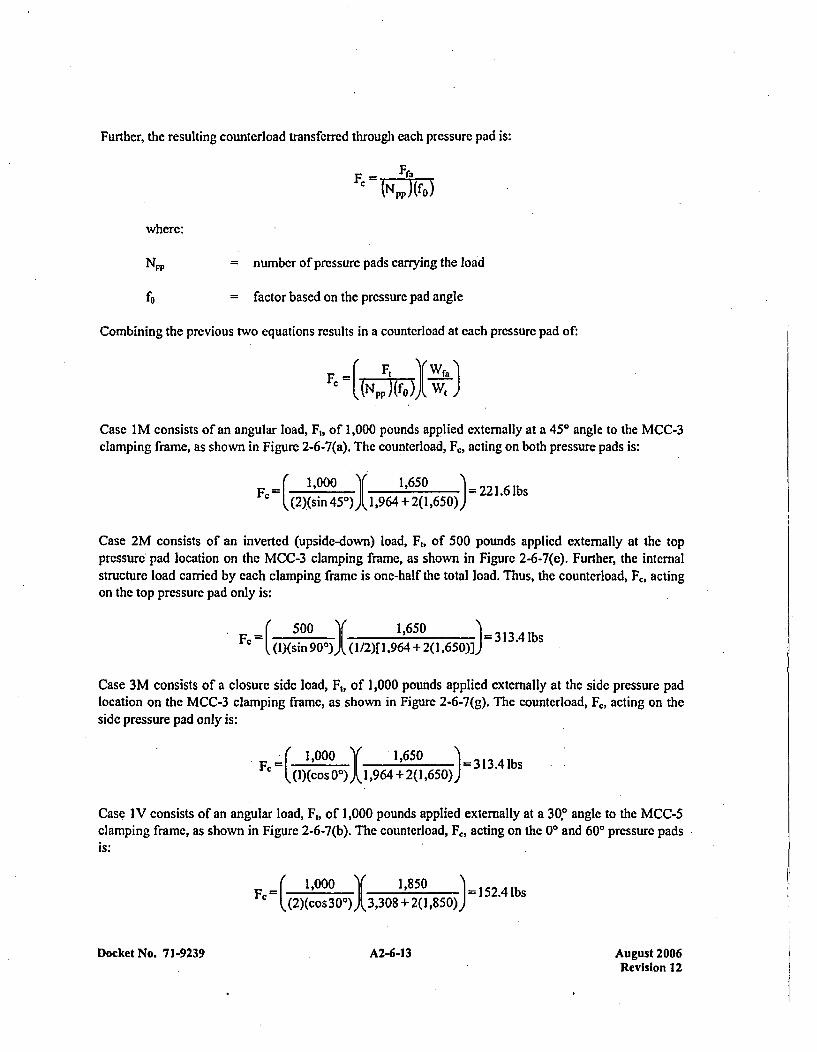
Further, the resulting counterload transferred through each pressure pad is:
where:
NpP number of pressure pads carrying the load
f= factor based on the pressure pad angle
Combining the previous two equations results in a counterload at each pressure pad of:
Fc( N(f) Wr
Case I M consists of an angular load, F,, of 1,000 pounds applied externally at a 450 angle to the MCC-3clamping frame, as shown in Figure 2-6-7(a). The counterload, F,, acting on both pressure pads is:
(c 1,000 1,65021. b((2)(sin 450) )Iý 1,964 + 2(1 ,650))D =22. b
Case 2M consists of an inverted (upside-down) load, F,, of 500 pounds applied externally at the toppressure pad location on the MCC-n3 clamping frame, as shown in Figure 2-6-7(e). Further, the internalstructure load carried by each clamping frame is one-half the total load. Thus, the counterload, F., actingon the top pressure pad only is:
C (l)(sin 9O0')I( (1/2)[ 1,964 +2(1,650)])=1. b
Case 3M consists of a closure side load, Ft, of 1,000 pounds applied externally at the side pressure padlocation on the MCC-3 clamping frame, as shown in Figure 2-6-7(g). The counterload, F,, acting on theside pressure pad only is:
Kc 1,000 "I' 1,650 =313.4 lbs(l(o (0 L~1,964 +2(1,650))
Case IV consists of an angular load, Ft, of 1,000 pounds applied externally at a 30T angle to the MCC-5clamping frame, as shown in Figure 2-6-7(b). The counterload, F,, acting on the 0' and 600 pressure padsis:
K=r 1,000 1,850 15.lb(2)(cos 300) )(3,308 + 2(1,850))
Docket No. 71-9239 A2-6-13 August 2006Revision 12
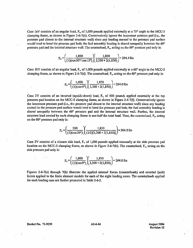
Case laV consists of an angular load, F,, of 1,000 pounds applied externally at a 750 angle to the MCC-5clamping frame, as shown in Figure 2-6-7(c). Conservatively ignore the innermost pressure pad (i.e., thepressure pad closest to the internal structure wall) since any loading normal to the pressure pad surfacewould tend to bend the pressure pad bolt; the fuel assembly loading is shared unequally between the 600pressure pad and the internal structure wall. The counterload, F., acting on the 600 pressure pad only is:
FeC=(' 1,000 _Y 1,850 "I -294.4 lbsI(1)(cos 30'/ cos 150) 1 3,308 + 2(1,850))
Case IbV consists of an angular load, F,, of 1,000 pounds applied externally at a 600 angle to the MCC-5clamping frame, as shown in Figure 2-6-7(d). The counterload, F,, acting on the 600 pressure pad only is:
Fe(( 1 'o )r ,3821,850) 264.0 lbs
Case 2V consists of an inverted (upside-down) load, F,, of 500 pounds applied externally at the toppressure pad location on the MCC-5 clamping frame, as shown in Figure 2-6-7(t). Conservatively ignorethe innermnost pressure pad (i.e., the pressure pad closest to the internal structure wall) since any loadingnormal to the pressure pad surface would tend to bend the pressure pad bolt; the fuel assembly loading isshared unequally between the 600 pressure pad and the internal structurc wall. Further, the internalstructurc load carried by each clamping frame is one-half the total load. Thus, the counterload, F,,, actingon the 600 pressure pad only is:
Fý= ( 500 1,850 -304.8 lbs
(J)(cos30'))A(1/2)[3,308 +21(1,850)])=
Case 3V consists of a closure side load, Ft, of 1,000 pounds applied externally at the side pressure padlocation on the MCC-5 clamping frame, as shown in Figure 2-6-7(h). The counterload, Fc, acting on theside pressure pad only is:
Fc r o 1,000 1,850 =264.0 lbs. (T1)(cos00) ý3,308 + 2(1,850))
Figures 2-6-7(a) through 7(h) illustrate the applied 'internal forces (counterloads) and external (unit)forces applied to the finite element models for each of the eight loading cases. The counterloads appliedfor each loading case arc further presented in Table 2-6-2.
Docket No. 7 1-9239 A2-6-14 August 2006Revision 12
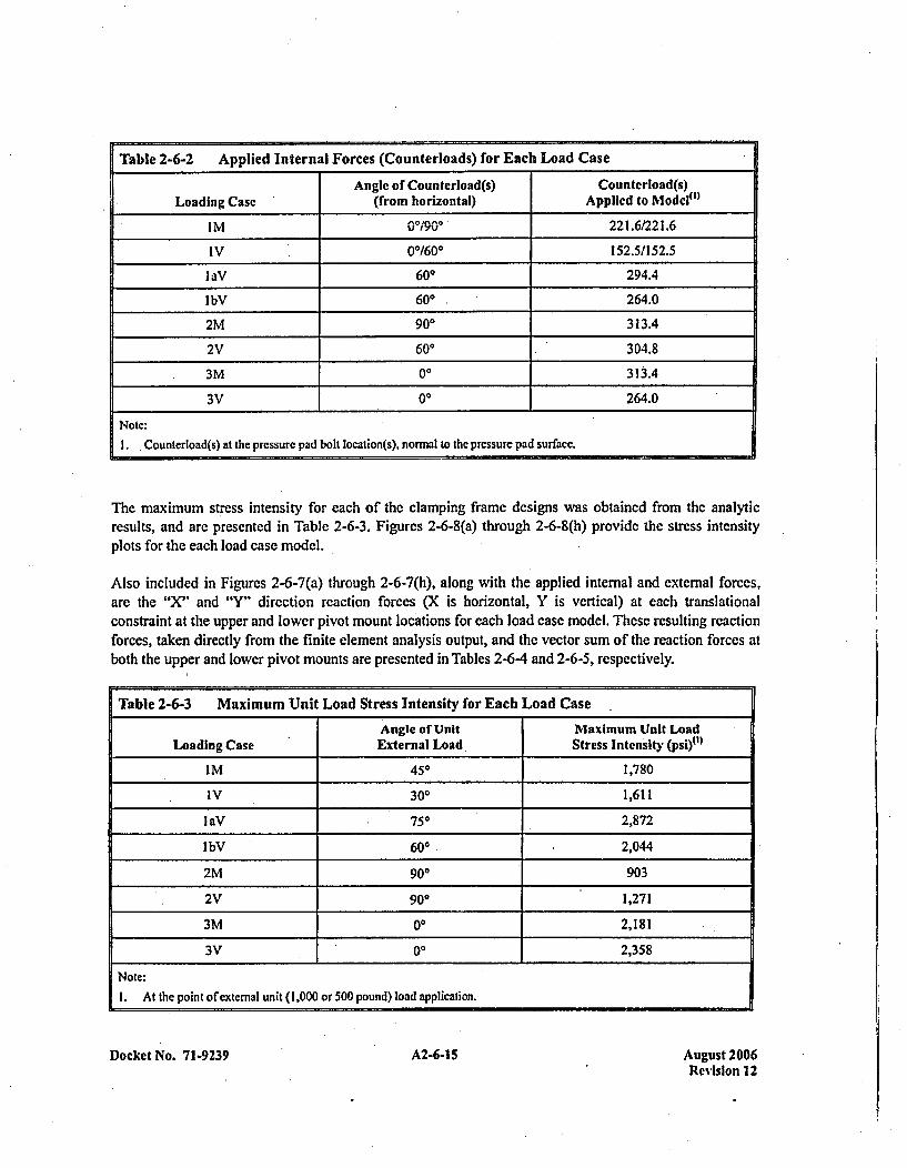
Table 2-6-2 Applied Internal Forces (Counterloads) for Each Load Case
Angle of Counterload(s) Counterload(s)Loading Case (from horizontal) Applied to Model")~
IM 00/,900 221.6/221.6
IV 00/600 152.5/152.5
IaV 600 294.4
lbV 600 264.0
2M 900 313.4
2V 600 304.8
3M 00 3134
3V 00 264.0
Note:
1.. Counterload(s) at the pressure pad bolt location(s), normal to the pressure pad surface.
The maximum stress intensity for each of the clamping frame designs was obtained from the analyticresults, and are presented in Table 2-6-3. Figures 2-6-8(a) through 2-6-8(h) provide the stress intensityplots for the each load case model.
Also included in Figures 2-6-7(a) through 2-6-7(h), along with the applied internal and external forces,are the "N' and "Y" direction reaction forces (X is horizontal, Y is vertical) at each translationalconstraint at the upper and lower pivot mount locations for each load case model. These resulting reactionforces, taken directly from the finite element analysis output, and the vector sum of the reaction forces atboth the upper and lower pivot mounts are presented in Tables 2-6-4 and 2-6-5, respectively.
Table 2-6-3 Maximum Unit Load Stress Intensity for Each Load Case
Angle of Unit Maximum Unit LoadLoading Case External Load Stress Intensity (psi)")~
IM 450 1,780
IV 300 1,611
laV 750 2,872
lbV 600 2,044
2M 900 903
2V 900 1,271
3M 00 2,181
3V 00 2,358
Note:
1. At the point of external unit (1,000 or 500 pound) load application.
Docket No. 7 1-9239 A2-6-15 August 2006Revision 12
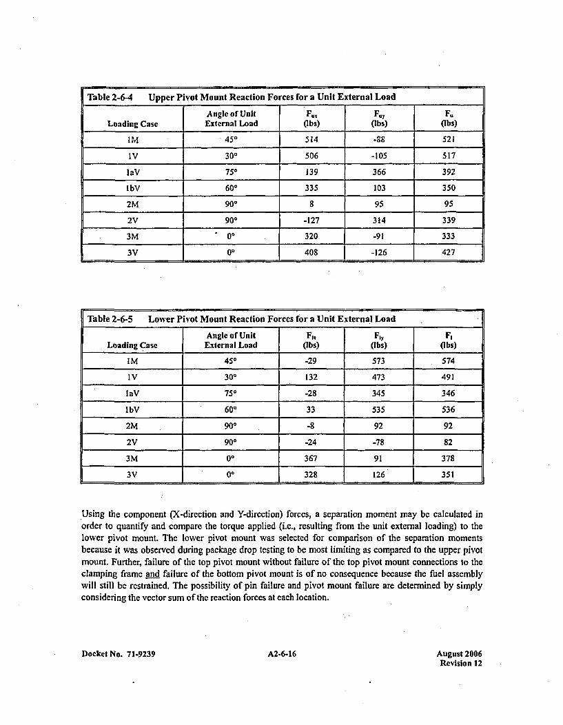
Table 2-6-4 Upper Pivot Mount Reaction Forces for a Unit External LoadAngle of Unit F., F0y F.
Loading Case External Load (Ibs) (Ibs) (ibs)
'M 450 514 -88 521
IV 300 506 -105 517
1eV 750 139 366 392
lbV 600 335 103 350
2M 900 8 95 95
2V 900 -127 314 339
3M 00 320 -91 333
3V 00 408 -126 427
Table 2-6-5 Lower Pivot Mount Reaction Forces for a Unit External Load
Angle of Unit Fl.Fl F,Leading Case External Load Ohbs) (Ibs) Ohbs)
IM 450 -29 573 574
IV 300 132 473 491
1eV 750 -28 345 346
lbV 600 33 535 536
2M, 900 -8 92 92
2V 900 -24 -78 82
3M 00 367 91 378
3V 00 1 328 1 126 1 351
Using the component (X-direction and Y-dircetion) forces, a separation moment may be calculated inorder to quantify and compare the torque applied (i.e., resulting from the unit external loading) to thelower pivot mount. The lower pivot mount was selected for comparison of the separation momentsbecause it was observed during package drop testing to be most limiting as compared to the Upper pivotmount. Further, failure of the top pivot mount without failure of the top pivot mount connections to theclamping frame and failure of the bottom pivot mount is of no consequence because the fuel assemblywill still be restrained. The possibility of pin failure and pivot mount failure are determined by simplyconsidering the vector sum of the reaction forces at each location.
Docket No. 71-9239Aust20 A2-6-16Revision 12
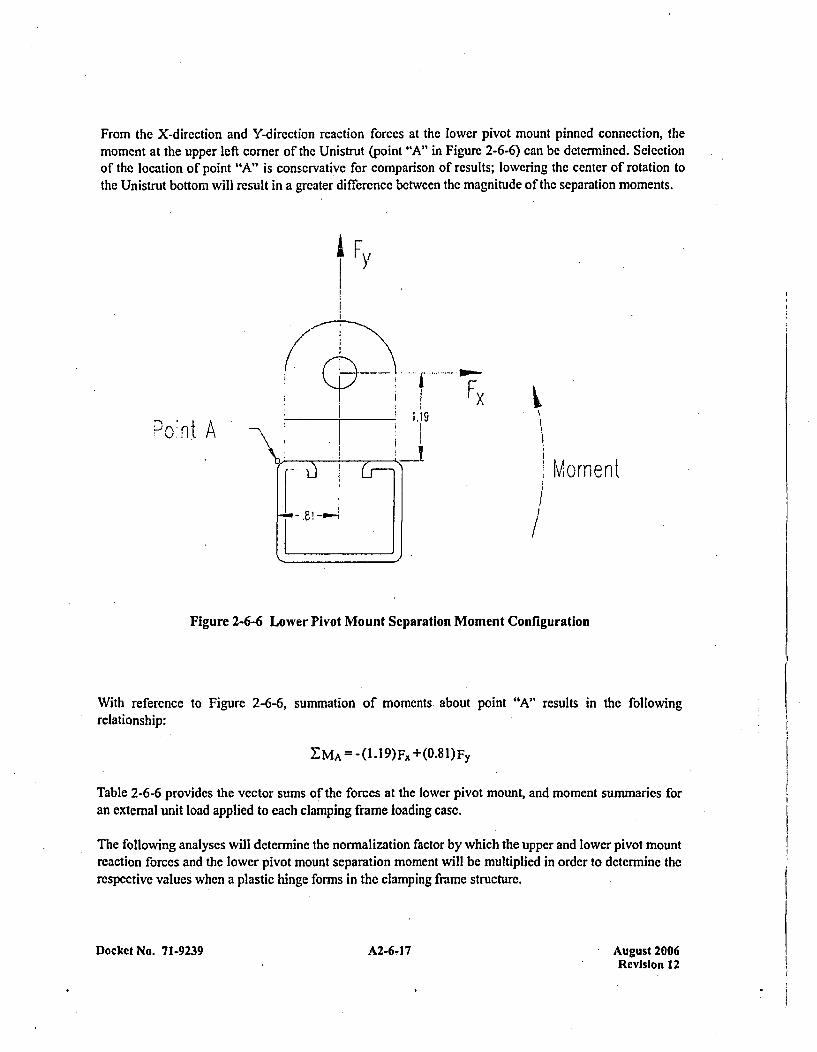
From the X-direction and Y-direction reaction forces at the lower pivot mount pinned connection, themoment at the upper left corner of the Unistrut (point "A" in Figure 2-6-6) can be determined. Selectionof the location of point "A" is conservative for comparison of results; lowering the center of rotation tothe Unistrut bottom will result in a greater differene between the magnitude of the separation moments.
I F
4
1.19aont A
Momnen t
Figure 2-6-6 Lower Pivot Mount Separation Moment Configuration
With reference to Figure 2-6-6, summation of moments. about point "A" results in the followingrelationship:
Table 2-6-6 provides the vector sums of the forces at the lower pivot mount, and moment summaries foran external unit load applied to each clamping frame loading case.
The following analyses will determine the normalization factor by which the upper and lower pivot mountreaction forces and the lower pivot mount separation moment will be multiplied in order to determine therespective values when a plastic hinge forms in the clamping frame structure.
Docket No. 71-9239 A2-6-17 Aueust 2006Revision 12
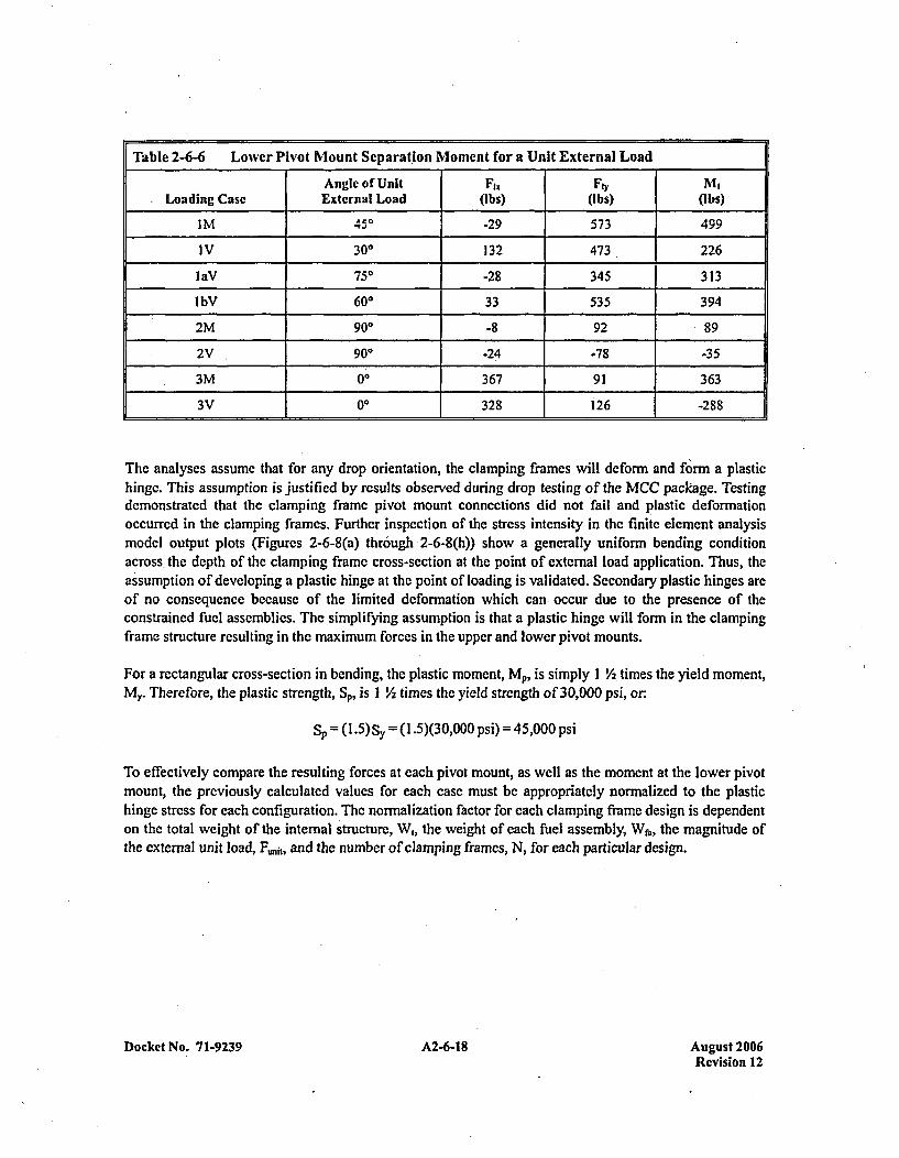
Table 2-6-6 Lower Pivot Mount Separation Moment for a Unit External Load
Angle of Unit 17,1 Fly MILoading Case External Load (I bs) (Ibs) (Ibs)
I M 450 -29 573 499
I V 300 132 473 226
laV 750 -28 345 313
lbV 600 33 535 394
2M 900 -8 92 *89
2V 900 -24 -78 -35
3M 00 367 91 363
3V 00 1 328 1 26 1 -288
The analyses assume that for any drop orientation, the clamping frames will deform and form a plastichinge. This assumption is justified by results observed during drop testing of the MCC package. Testingdemonstrated that the clamping frame pivot mount connections did not fail and plastic deformationoccurred in the clamping frames. Further inspection of the stress intensity in the finite element analysismodel output plots (Figures 2-6-8(a) through 2-6-8(h)) show a generally uniform bending conditionacross, the depth of the clamping frame cross-section at the point of external load application. Thus, theassumption of developing a plastic hinge at the point of loading is validated. Secondary plastic hinges areof no consequence because of the limited deformation which can occur due to the presence of theconstrained fuel assemblies. The simplifying assumption is that a plastic hinge will form in the clampingframe structure resulting in the maximum forces in the upper and lower pivot mounts.
For a rectangular cross-section in bending, the plastic moment, Mp, is simply 1 V2~ times the yield moment,
MY. Therefore, the plastic strength, S., is I V2 times the yield strength of 30,000 psi, or:
Sp= (I .5)Sy (1 .5)(30,000 psi) = 45,000 psi
To effectively compare the resulting forces at each pivot mount, as well as the moment at the lower pivotmount, the previously calculated values for each case must be appropriately normalized to the plastichinge stress for each configuration. The normalization factor for each clamping frame design is dependenton the total weight of the internal structure, W,, the weight of each fuel assembly, W&,, the magnitude ofthe external unit load, F.,t and the number of clamping frames, N, for each particular design.
Docket No. 71-9239 A2-6-18 August 2006Revision 12
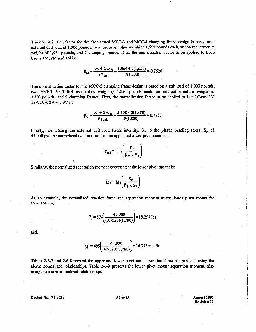
The normnalization factor for the drop tested MCC-3 and MCC-4 clamping frame design is based on aexternal unit load of 1,000 pounds, two fuel assemblies weighing 1,650 pounds each, an internal structureweight of 1,964 pounds, and 7 clamping frames. Thus, the normalization factor to be applied to LoadCases I M, 2M and 3M is:
13M W1 +2Wf, _1,964 +2(1,650) -0.75207 Funit 7(1,000)
The normalization factor for thc MCC-5 clamping frame dcsign is based on a unit load of 1,000 pounds,two VVER 1000 fuel assemblies weighing 1,850 pounds each, an internal structure weight of3,308 pounds, and 9 clamping frames. Thus, the normalization factor to be applied to Load Cases IV,I aV, I bV, 2V and 3V is:
Pv W + 2 Wfa - 3,308 +2(1,850) -0.77879 Funit 9(1,000)
Finally, normalizing the external unit load stress intensity, 5S., to the plastic bending stress, Sp, of45,000 psi, the normalized reaction force at the upper and lower pivot mounts is:
Fu, IFuji (PM'V SuJý
Similarly, the normalized separation moment occurring at the lower pivot mount is:
As an example, the normalized reaction force and separation moment at the lower pivot mount forCase IM are:
~r574( 45,000 =927b57((0.7520)(1 ,780)) 1,9 b
and,
-499( 45,000 1675i- b((0.7520)( 1,780)) =1675i-b
Tables 2-6-7 and 2-6-8 present the upper and lower pivot mount reaction force comparisons using theabove normalized relationships. Table 2-6-9 presents the lower pivot mount separation moment, alsousing the above normalized relationships.
Docket No. 71-9239 A2-6-19 August 2006Revision 12
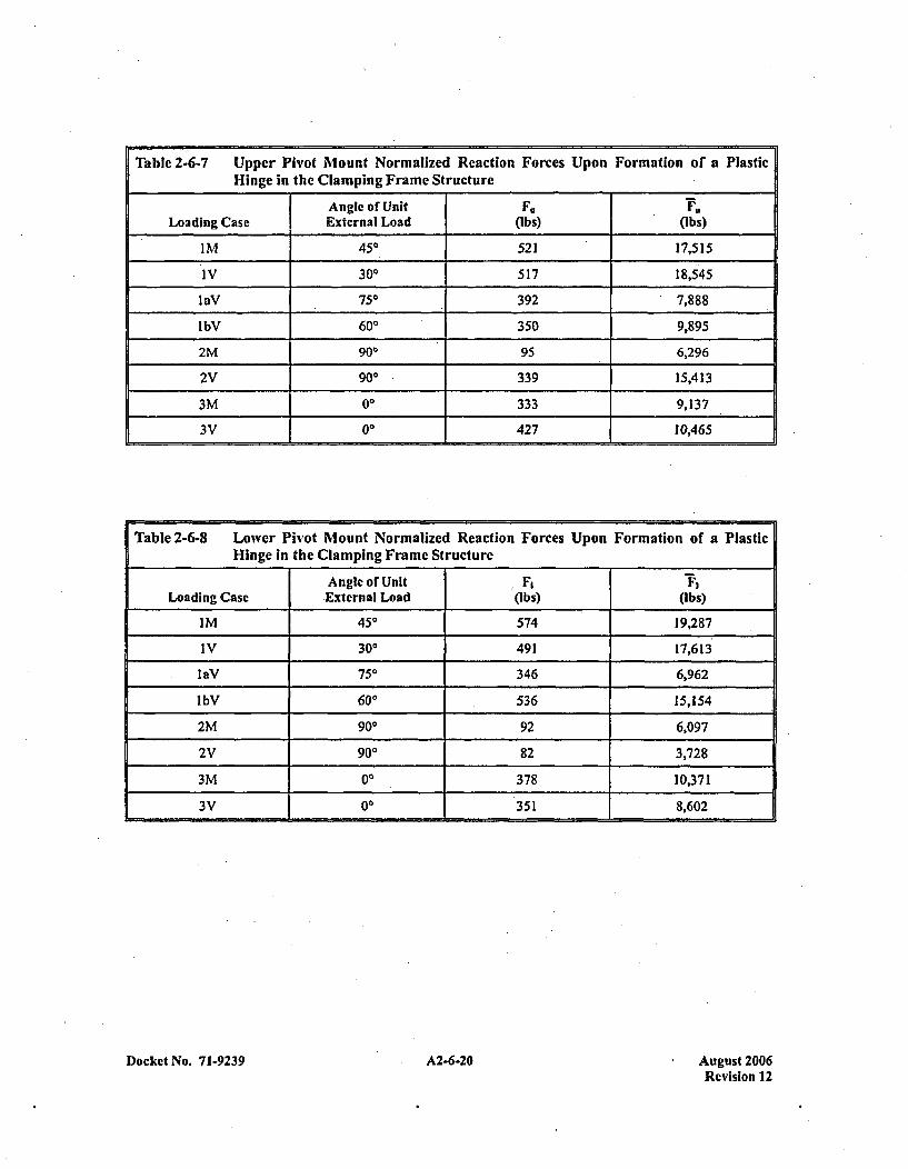
Table 2-6-7 Upper Pivot Mount Normalized Reaction Forces Upon Formation of a PlasticHinge in the Clamping Frame Structure
Angle of Unit F. Y.,Loading Case External Load (Ibs) (Ibs)
IM 450 521 17,515
IV 300 517 18,545
laV 750 392 7,888
lbV 600 350 9,895
2M 900 95 6,296
2V 900 339 15,413
3M 00 333 9,137
3V 00 1427 10,465
Table 2-6-8 Lower Pivot Mount Normalized Reaction Forces Upon Formation of a PlasticHinge in the Clamping Frame Structure
Anglecof Unit F, F,Loading Case External Load (Ibs) (Ibs)
IM 450 574 19,287
IV 300 491 17,613.
1eV 750 346 6,962
lbV 600 536 15,154
2M 900 92 6,097
2V 900 82 3,728
3M 00 378 10,371
3V 00 351 8,602
Docket No. 71-9239 A2-6-20 August 2006Revision 12
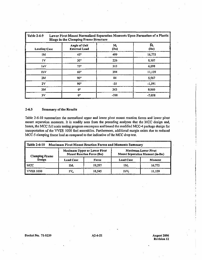
Table 2-6-9 Lower Pivot Mount Normalized Separation Moments Upon Formation of a PlasticHinge in the Clamping Frame Structure
Angle of Unit MLoading Case External Load (Ibs) (Ibs)
IM 450 499 16,775
IV 300 226 8,107
maV 750 313 6,298
lbV 600 394 11,139
2M 900 84 5,567
2V 900 -35 -1,591
3M 00 363 9,960
3V 100 -288 -7,058
2-6.3 Summary of the Results
Table 2-6-10 summarizes the normalized upper and lower pivot mount reaction forces and lower pivotmount separation moments. It is readily seen from the preceding analyses th iat the MCC design and,hence, the MCC full scale testing program encompass and bound the modified MCC-4 package design fortransportation of the VVER 1000 fuel assemblies. Furthermore, additional margin exists due to reducedMCC-5 clamping frame load as compared to that indicative of the MCC drop test.
Table 2-6-10 Maximum Pivot Mount Reaction Forces and Moments Summary
Maximum Upper or Lower Pivot Maximum Lower Pivot
Clamping Frame Mount Reaction Force (Ibs) Mount Separation Moment (in-Ibs)Design1 Load Case Force Load Case Mioment
MCC IM, 19,297 IM, 16,775
VVER 1000 1 V" 18,545 lbV1 .11,139
Docket No. 71-9239 A2-6-21 August 2006Revision 12
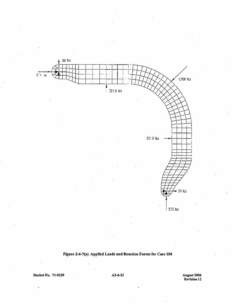
86 It's
1221.6 lbs
22*.6 lbs
29 lbs
573 lbs
Figure 2-6-7(a) Applied Loads and Reaction Forces for Case IM
Docket No. 71-9239 A2-6-22 August 2006Revision 12
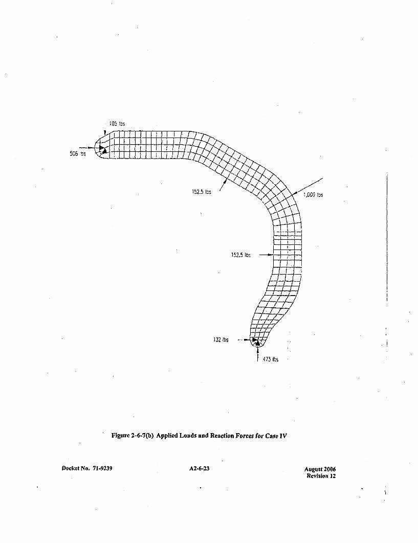
105 !bs
506 :ts
!000 fýS
152.55I.m
1 J2 IbS
Its
4 73 lbs
Figure 2-6-7(b) Applied Loads and Reaction Forces for Case IV
Docket No. 71-9239 A2-6-23 A2-6-23August 2006Revision 12
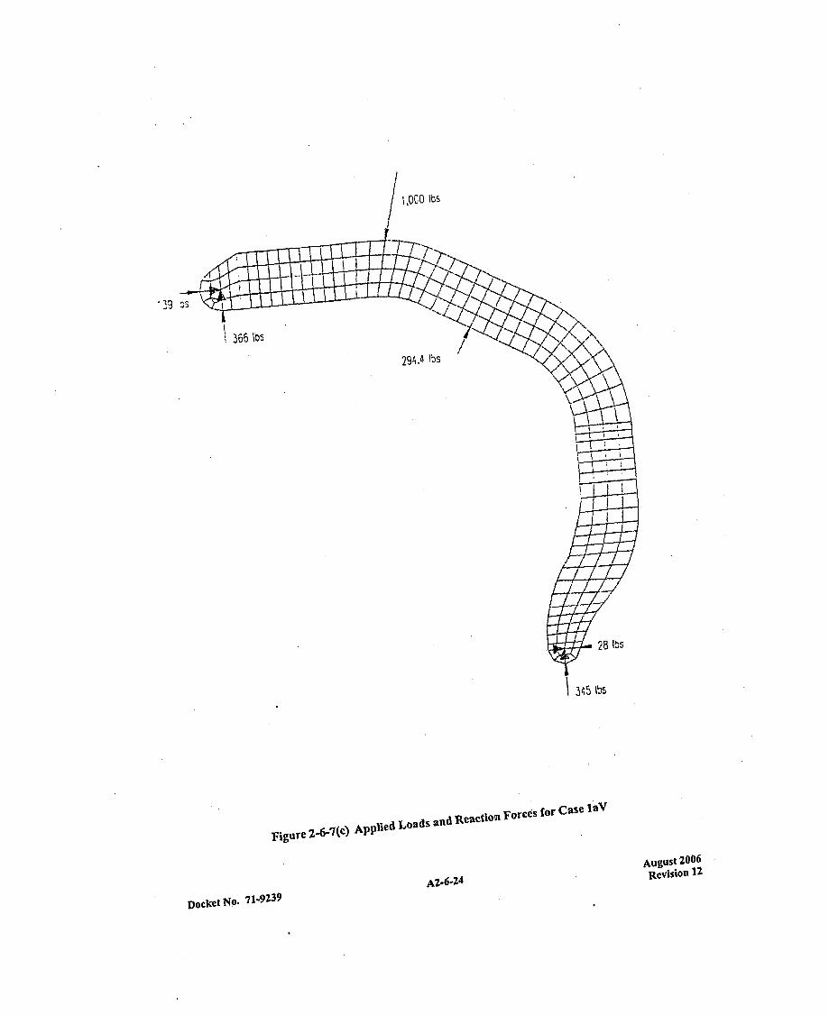
1 ,0C0 lbs
294.4 lbs
28 lbS
345 lbs
Figure 2 -6-7(c) Applied Loads and Reactionl Forces for Case IaV
Do~kt AZ6 2 4August 2006
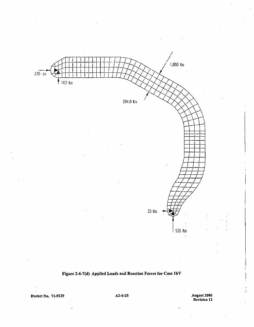
lbs
335 ý--
103 lbs
264.0 lbs
33 lbs
535 lb
Figure 2-6-7(d) Applied Loads and Reaction Forces for Case lbV
Docket No. 71.9239 265A2-6-25 August 2006Revision 12
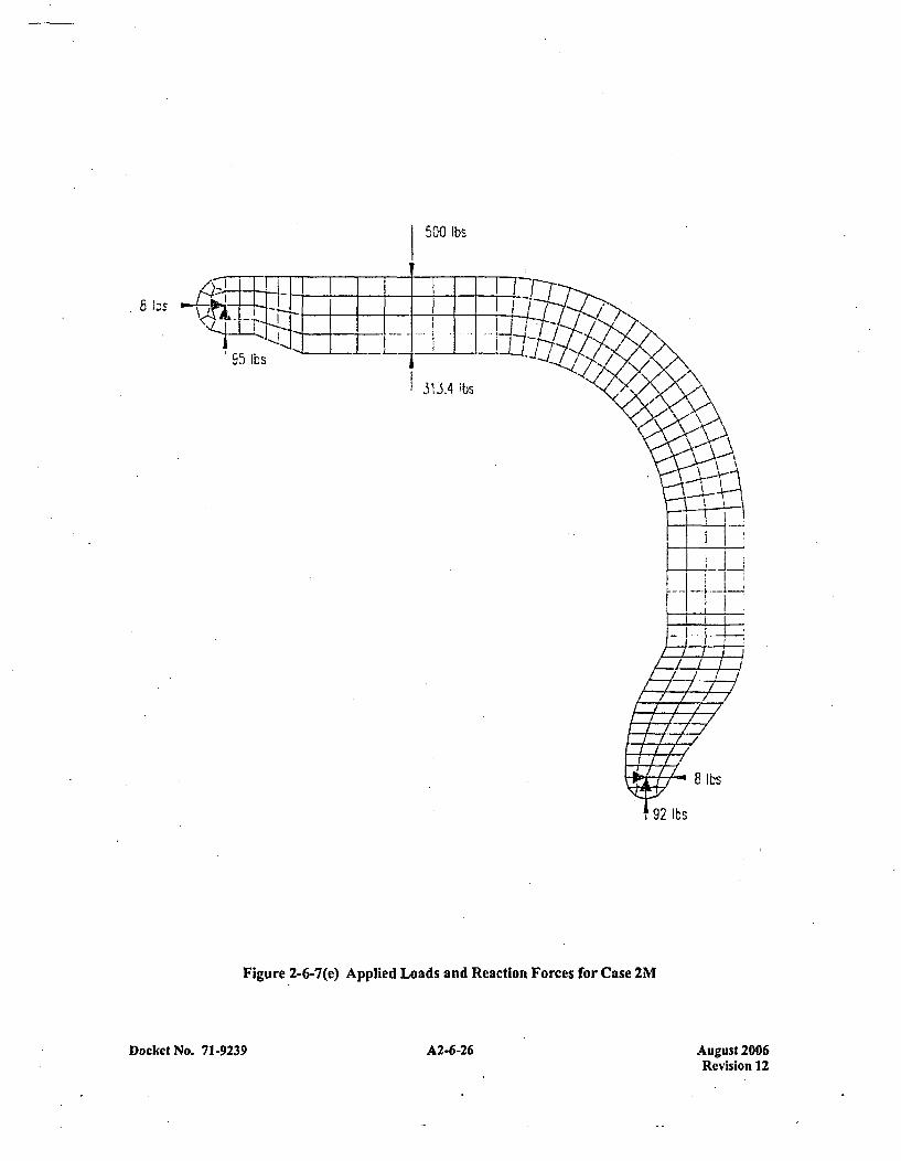
500 lbs
'95 lbs
313.4 lbs ,'
Figure 2-6-7(e) Applied Loads and Reaction Forces for Case 2M
8 lbs
2 lbs
Docket No. 71-9239 A2-6-26 August 2006Revision 1 2
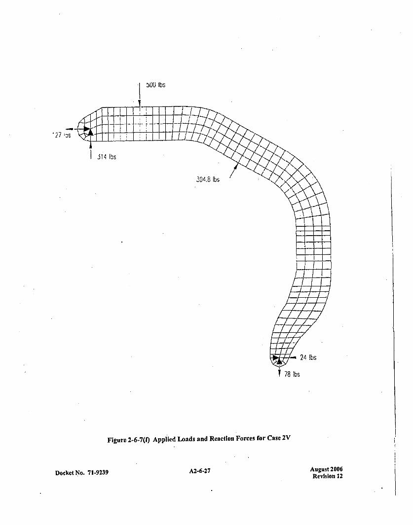
ý00 lbs
114 lbs
304.8 lbs
T78
Figure 2-6-7(f) Applied Loads and Reaction Forces for Case 2V
24 lbs
lbs
Docket No. 7 1-9239A267 A2-6-27 August 2006Revision 12
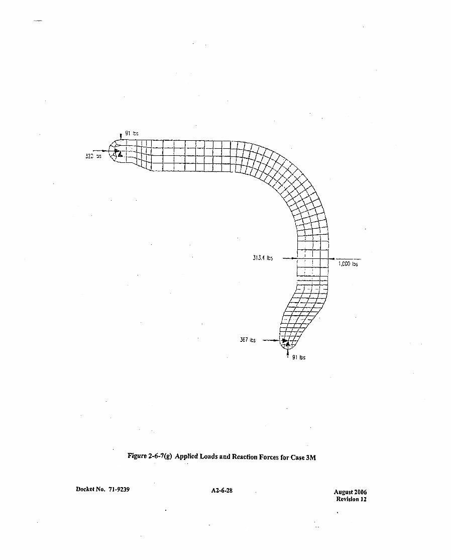
313.4 (bs
367 ibs
1,COO J~s
91 Ibs
Figure 2-6-7(g) Applied Loads and Reaction Forces for Case 3M
Docket No. 71-9239 A2-6-28 August 2006Revision 12
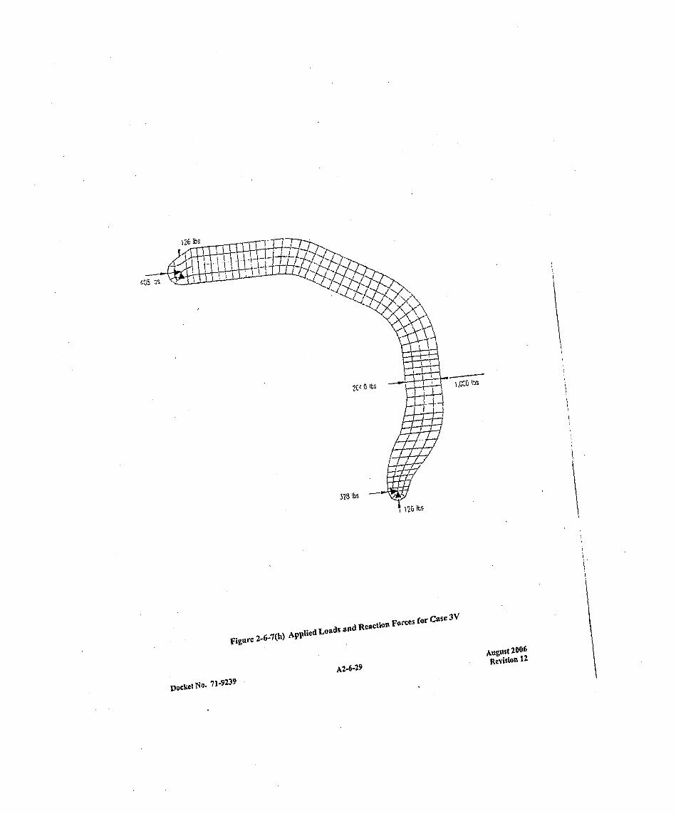
tt1.4
zVur .6-7(h) Applied 03sa.1
A2-6 2 9
August 2006
DOCNo. 71-9239
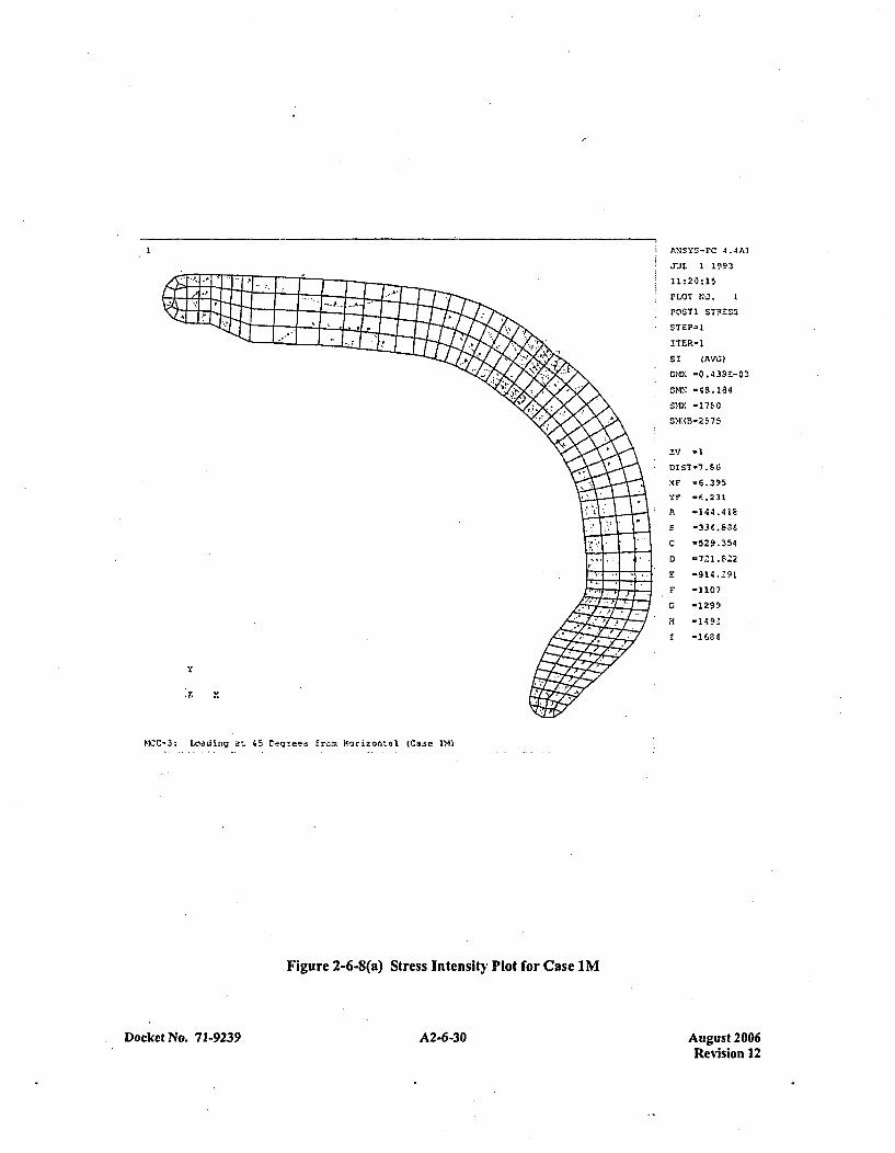
I ANSY-FC 4.4AI
.JUL 1 1993
11:20:15
M~OT NOI. I
P1'ST1 STFESS
ITER-1
sr (AVG~)
MIX: -0.43SE-03
SMN' -4S.184
S'Q -171-0
MINMB-2 575
ZV -1
XF -~6.395
Ya* -C.231
A -144.418
E 36.$
C -529.354
D -7221.S22
E -914.291
F -1107
G -I29
H -1492
r -111,64
Z
MCC-3: Loa3ding at. 45 Degrees frern Horizontal (Ca~se Ml
Figure 2-6-8(a) Stress Intensity Plot for Case 1M
Docket No. 7 1-9239 A2-6-30 August 2006Revision 12
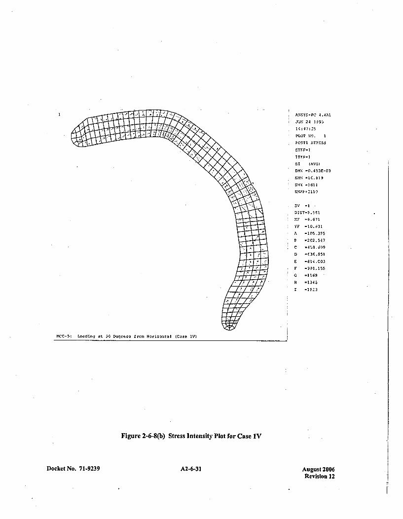
A.,SY-P.: 4.4A1
yJUN 24 IM9
14 :4 2 5
*PLOT NO. I
* OSTI STR.ESS
S1 (AVG)
DM% -0.453E-03
DIST-M.58
MFP -6.671
ST-10.031
C -45,9.i599
MCC-5:~~~~~~~~~ -0f.8a51D.qes rr Hr~~t1(as v
K--5 oaigFi30Dgues rem 2-6-(b)l StresItenst PltoVCse1
Docket No. 71-9239 A2-6-31 Aupust 200Revision 12
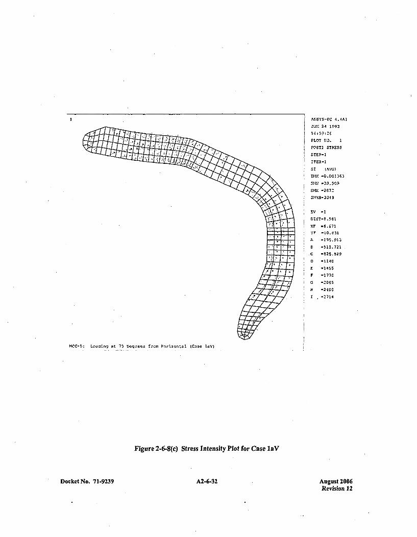
ANSYS-E'C 4.4AI
JUN 24 1993
PLOTr NO. I
POSTI STRESS
$TEP-1
ITER-1
S1 4AVG1)
DIV. -0.001363
S14N -3S.5091
SMY -2e7:!
5,M18-3 34 9
73V -1
Y--0. 31
A 795.A13
6 510.721
C -825.529
D -1140
E -1455
F -1770
C -'065
-~2400
I -'714
MCC-$: Loa~ding at 75 Degrees Ercrn Horizontal (C.3se laV)
Figure 2-6-8(c) Stress Intensity Plot for Case laV
ckct No. 71-9239 A2-6-32 Ausrust 201DoDo Revision 12

ANSY -P 4.4AI
JJI 24 1,*93
15:03:42
PLOT NO.
POS$TI STRESS
5TF~r*t
ITFF,3
ST (AVG)
S>IX -2144
DIST-8.5$1
Y F -10.631
A -1'6C.351
S *3M.9$
Q -03.6 19
D -825.253
r -1047
F -12F9
G -1490
H -1712
I -19Z'3
MICC- 5: Loa3ding at 60 Oogrees from Morizcntal (Case Ut-V)
Figure 2-6-8(d) Stress Intensity Plot for Case lbV
Docket No. 7 1-9239 A2-6-33 August 2006Revision 12
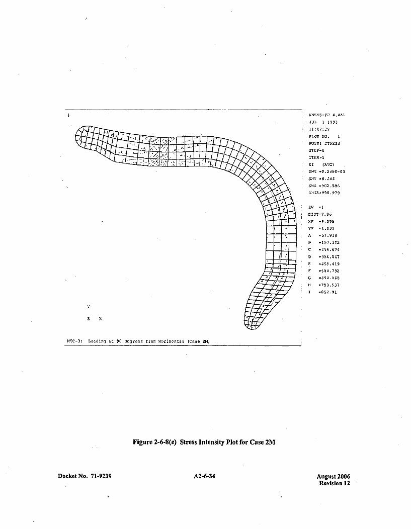
;N'YS-FO 4.4AI
JJL 1 1993
11:17:29
-7PLOT? NO. 1
POSTI STRESS3
STEP-t
ITER-1
DMX 0.26BE-03
SM.'. -8.243S'1X -9072.596
SX99.979
orSTý7.9iC
F -157.302
C -25E1.674
F -!ý54.792
H .753.537
1 -852.91
liCC-3: I~adinv at 90 D.eqreas from. Horizontal (Case 2M)
Figure 2-6-8(e) Stress Intensity Plot for Case 2M
Docket No. 7 1-9239 A2-6-34 August 200 6Revision 12
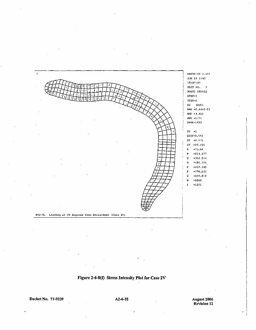
ANSYS PC 4.4AI
JJN 24 1993
15: 07: 07
PLOT N-.0 I
STEP-1
ITER-1
SI ( AVG
DMX 0 I.91F-C3
SKI: -3.421
SMX 1-1-71
'ZF -10 3
A -73.L,
P-214.677
C -355.514
E -O637.6Sl
F -106.02
1 -1201
MWC-5: Loading at 90 Degrees fromr H~orizontal (Case~ 2V)
Figure 2-6-8(1) Stress Intensity Plot for Case 2V
Docket No. 71-9239 A2-6-35 August 2006Revislon 12
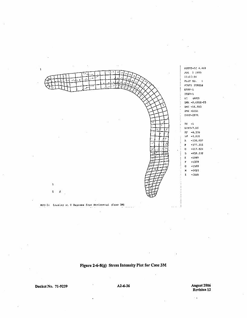
P:19r:4.4A1.YJL 1 1993
110:3.:54
PLOT' NC. 1
PnST1 STRZSZ~
ST (AVG)
SNM -I'X553
ZV -1
t.IST-7..56
A -136.8l07
1. -377.315
C -617.824
D -$,.59332
F. -1099.
F -1339
G -1590
H4 -1920
I -0.31
z
MCC-3: Loi...gatr' 0 Degrees from Horizonrtal {Case 3M)
Figure 2-6-8(g) Stress Intensity Plot for Case 3M
Docket No. 71-9239A263 A2-6-36 August 2006Revision 12
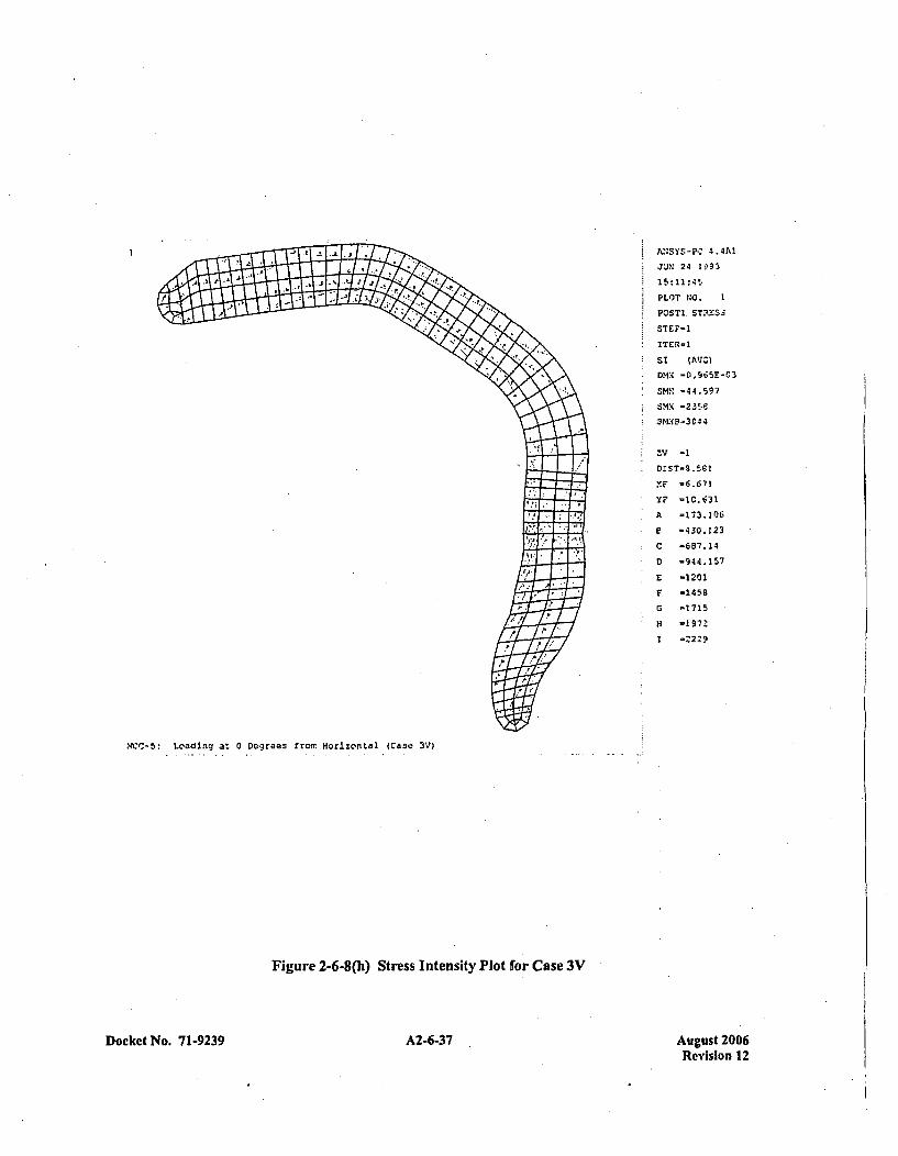
ANY-- 4.4Al
* JUN~ 24 1I93
PLO)T NO. 1
FO.STI STRESS
STEP-1
st (AVG)
DMX -0.965E-03
3 V -1
XF -1.715
* H -19763
A -173.10
MCC-5: ~~~~ ~ ~ ~ ~ E -430.1203.~e3 rr. oiznal(as V
Figure~~~~~~~ ---(h tr87.t1s4 Po frCae3
Docket No. 71-9239 A2-6-37 August 2006Revision 12
CHAPTER 3: THERMAL EVALUATION
The MCC container is limited to usc for transporting unirradiated, low enricficd uranium, nuclear reactorcore assemblies. Thercfore, thermal engineering design of the packaging, per se, is rnot necessary. The fuelrods, that contain the radioactive material, arc designed to withstand tempcratures of I 204*C (2200*F)without substantial damage. All combustible components of the container internals (e.g., the shockmounts) are postulated to have burned away for the criticality evaluation.
Docket No. 71-9239 3-1 August 2006Revision 12

APPENDIX 3-1REFERENCES
Docket No. 71-9239 A3.-1- August 2006Revision 12
REFERENCES
No documents referenced in the text of this section.
Docket No. 71-9239 A3-1-3 August 2006.Revision 12
CHAPTER 4: CONTAINMENT
4.1 CONTAINMENT BOUNDARY
The MCC container is limited to usC for transporting unirradiatcd, low enriched uranium, nuclear reactorcore assemblies. The radioactive material, bound in siniered pellets having very limited solubility, hasminimal propensity to suspend in air. These pellets arc further scaled into cladding, to form the fuel rodportion of each assembly. The principal containment boundary for the MCC container is the fuel rodcladding. Design and fabrication details for this cladding are given in Appendix 1-6 to this application.
4.2 REQUIREMENTS FOR NORMAL CONDITIONS OF TRANSPORT
The nature of the contained radioactive material, and the structural integrity of the fuel rod cladding andcontainer shell, are such that there will be no release of radioactivity under normal conditions of transport.
4.3 CONTAINMENT REQUIREMENTS FOR THE HYPOTHETICAL ACCIDENTCONDITION
The nature of the contained radioactive material, and the integrity of the fuel rod cladding and containershell,, are such that there will be no substantial release of radioactivity under hypothetical accidentconditions. It is estimated that, as a result of the puncture condition, the maximum radioactive materialreleased from damaged fuel rods might be some 450 equivalcnt ceramic pellets, which represents some4000 grams of uranium with a maximum specific activity of 2.8 x 10O6 c~urics/gram.
Docket No. 7 1.9239 4-1 August 2006Revision 12

APPENDIX 4-1REFERENCES
Docket No. 71-9239 A4-1-1 August 2006Revision 12
REFERENCES
No documents referenced in. the text of this section.
Docket No. 7 1-9239 A4-1-3 August 2006Revision 12
CHAPTER 5: SHIELDING EVALUATION
The MCC container is limited to use for transporting unirradiated, low enriched uranium, nuclear reactorcore assemblies. Therefore, shielding design of the packaging, per se, is not necessary. Typical maximumdose equivalent rates are- 21.0 millirem per hour, at any point on the cxternal surface of the container, and0.8 millircm per hour at one meter from the external surface of the container.
Docket No. 71-9239 5.1 August 2006Revision 12
APPENDIX 5-1REFERENCES
Docket No. 71-9239 A5-1-1 August 2006Revision 12
REFERENCES
No documents referenced in the text of this section.
Docket No. 71-9239 A5-1-3 August 2006Revision 12
CHAPTER 6: CRITICALITY EVALUATION
6.1 DISCUSSION AND RESULTS
The contents of an MCC container arc to be so 'limited that, for contained fuel assemblics having a 235u3
enrichment up to and including five weight-percent (5 wt% 235U), the limiting Kerr, with bias anduncertainties included at thc 95-percent confidence level, will not exceed 0.95 - in the most reactivecredible configuration, moderated by water to the most reactive credible extent, and closely reflected bywater on all sides. Also considered are the effects of fuel pin gap flooding and annular fuel blankets. Noconsideration of dispersible material is required, since the contents arc limited to clad ceramic fuel forms.
A primary objective of the criticality evaluation is to determine: (1) What is the limiting enrichment(wt% 235U3) for two fuel assemblies, without added assembly neutron absorbers, to be shipped in an MCCcontainer having only the permanent container neutron absorber plate. For assemblics having greater thanthis limiting enrichment, up to and including 5 wt% 235U, either additional assembly neutron absorbers(i.e., coated pellets or cluster absorber rods), or additional container neutron absorber plates, are options.Thus, a secondary objective of the criticality evaluation is to determine: (2) Whcn the additional assemblyneutron absorber option is selected, what is the minimum -number of additional absorber rods, perassembly, or when the additional container neutron absorber plate option is selected, what is the requirednature and placement of the additional plates.
Significant criticality engineering design features are incorporated into the MCC container to assure that,in the event of a transport accident, structural integrity is maintained, and the assemblies will remain in asubcritical geometry. These structural features arc presented in detail in Appendix 1-2. Briefly, the designassures that the container:
I . will not open along the closure flange,
2. internals will hold the contents in place,
3. neutron absorber plates will remain in place; and
4. will not experience any deformation (compression) which would serve to reduce the spacingbetween adjacent pairs of fuel assemblies to less than the limiting spacing value.
During normal conditions of transport, there will be a minimum of 12-inches of separation between the,contents of any two, containers. Any number of undamaged, unflooded MCC containers will besubcritical, since unmoderated uranium enriched to 5 wt% or less in 235U is subcritical in any quantity.under any conditions. Any number of undamaged but flooded containers will also have a Kcff less than orequal to 0.95, since 12-inches of water separation provides isolation between the contents of any twocontainers; and, if the water external to the container is removed, then the contents will also drain so thatthe array returns to the unmodcrated condition.
The Hypothetical Accident Condition array can be reduced to only two containers, crushed top-to-top,such that the spacing between the pairs of assemblies, aligned parallel to each other, will be reduced to8.178 inches (8 inches of water plus two shell thicknesses). This array is then assumed to be flooded
Docket No. 71.9239 6-1 August 2006Revision 12
(since drop tests have demonstrated that damaged containers remain substantially closed, exposure of thecontained assemblies to less than full density water is not considered credible; however, calculations arcincluded in Appendix 6-3 which show that suberiticality is also maintained at partial water densities). Theheavy structural members of the base and the internal component support structures of the container areassumed to provide sufficient spacing such that any other container(s) in the shipment would be isolatedfrom this combination by a minimum of 12-inches of water. Since only two containers will combine toform the HAC array with a Kf less than or equal to 0.95; and any isolatcd additional containers can onlyform similar isolated arrays, any number of the MCC containers will be subcritical under the HAG. Thatis, the number "N" of undamaged packages, with nothing between the packages, that would besubcritical; and, the number "N" of damaged packages, if each package were subjected to the HAG withinterspersed hydrogenous moderation, that would be subcritical - arc both equal to infinity.
The calculations were performed using the AMPX cross-section generation modules, NITAWL-S andXSDRNPMS, and the Monte Carlo code KENO-Va for reactivity determination. The requirement that thefuel be in assemblies in a fixed array assures that these calculations arc accurate and directly applicable.
Appendix 6-2 includes a sample KENO input deck and the calculated K(4 results of the uncontained fuelwith attributes identified in Appendix 1-5. Based on these results, the assemblies are classified intothree groups; Type A assemblies have uncontained K4's less than 0.936, which encompasses all the l4x14and 16x]6 assembly lattice designs; Type B assemblies have uncontaincd K4's greater than 0.936 andinclude all the 15x15 and 17x17 lattice designs; the Type C assembly is the VVER-1000 fuel assemblywhich has an uncontaincd K(4 of 0.9432.
Appendix 6-3 includes sample decks and calculations for contained Type A and B fuel assemblies. For theType A assemblies, the l4x14 OFA (optimized fuel assembly) is used exclusively for the containedcalculations since this assembly was shown to be the most reactive of the Type A designs. Thecalculations show that Type A assemblies can be shipped with enrichments up to 5.0 wt% without the useof additional assembly neutron absorbers or additional container neutron absorber plates.
For Type B assemblies, the 17x17 OFA is used exclusively for the contained calculations since 'thisassembly was shown to be more reactive than the other Type B designs. As with Type A assemblies,Type B assemblies can also be shipped without the use of additional neutron absorbers provided theenrichments are restricted to 4.65 wt% or less. For Type B assemblies with enrichments greater than4.65 wt%, additional neutron absorbers are required -with the exception of 17x.17 STD or l7x.17 XL thatrequire additional neutron absorbers with enrichments greater than 4.85 wt%. Any of the following typesand numbers of absorbers have been shown to be acceptable:
1. Assembly IFBA Rods: A minimum of 32 nominally (IX) loaded fuel rods are required in eachassembly, each with a minimum coating length of 108 inches. For increased IFBA loadings (1.5X,2X, etc.), the number of loaded fuel rods required can be reduced by the ratio of the increasedloading to the nominal loading.
2. Assembly Absorber Rods: A minimum of 4 absorber rods are required in each assembly. Therods can be Pyrex BA, WABA, or Ag-In-Cd designs with a minimum length of 1 08 inches. Therods must be positioned within the assemblies in a symmetric pattern about the assembly centerguide tube.
Docket No. 71-9239 6-2 August 2006Revision 12
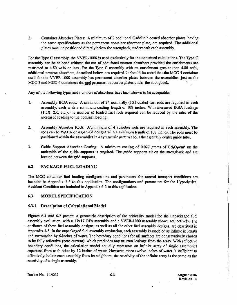
3. Container Absorber Plates: A minimum of 2 additional Gadolinia coated absorber plates, havingthe samc spccifications as the permanent containecr absorber plate, are required. The additionalplates must be positioned directly below the strongback, underneath each assembly.
For the Type C assembly, the VVER-1000 is used exclusively for the contained calcula 'tions. The TypecCassembly can be shipped wvithout the use of additional neutron absorbers provided the enrichments arcrestricted to 4.80 wt% or less. For the Type C assembly with an enrichment greater than 4.80 wt%,additional neutron absorbers, described below, are required. It should be noted that the MCC-5 containerused for the VVER-1000 assembly has permanent absorber plates between the assemblies, just as theMCC-3 and MCC-4 containers do, and permanent absorber plates under the strongback.
Any of the following types and numbers of absorbers have been shown to be acceptable:
I . Assembly IFBA rods: A minimum of 24 nominally (IX) coated fuel rods are required in eachassembly, each with a minimum coating length of 108 inches. With increased IFBA loadings(1.5X, 2X, etc.), the number of loaded fuel rods required can be reduced by the ratio of theincreased loading to the nominal loading.
2. Assembly Absorber Rods: A' minimum of 4 absorber rods are required in each assembly. Therods can be WABA or Ag-In-Cd designs with a minimum length of 108 inches. The rods must bepositioned within the assemblies in a symmetric pattern about the assembly center guide tube.
3. Guide Support Absorber Coating: A minimum coating of 0.027 grams of Gd2Oj3/CM 2 on theunderside of the guide supports is required. The guide supports sit on the strongback and arelocated between the grid supports.
6.2 PACKAGE FUEL LOADING
The MCC container fuel loading configurations and parameters for normal transport conditions areincluded in Appendix 1-5 to this application. The configurations and parameters for the HypotheticalAccident Condition are included in Appendix 6-3 to this application.
6.3 MODEL SPECIFICATION
6.3.1 Description of Calculational Model
Figures 6-1 and 6-2 present a geometric description of the criticality model for the unpackaged fuelassembly evaluation, with a 17x17 OFA assembly and a VVER-1000 assembly shown respectively. Theattributes of these fuel assembly designs, as well as all the other fuel assembly designs, are described inAppendix 1-5. In the unpackaged fuel assembly evaluation, each assembly is modeled as infinite in lengthand surrounded by 6-inches of water. The boundary conditions for all surfaces are conservatively chosento be fully reflective (zero current), which precludes any neutron leakage from the array. With reflectiveboundary conditions, the calculation model actually represents an infinite array of single assembliesseparated from each other by 12 inches of water. However, since twelve inches of water is sufficient toeffectively isolate each assembly from its neighbors, the reactivity of the infinite array is the same as thereactivity of a single assembly.
Docket No. 71-9239 6-3 August 2006Revision 12
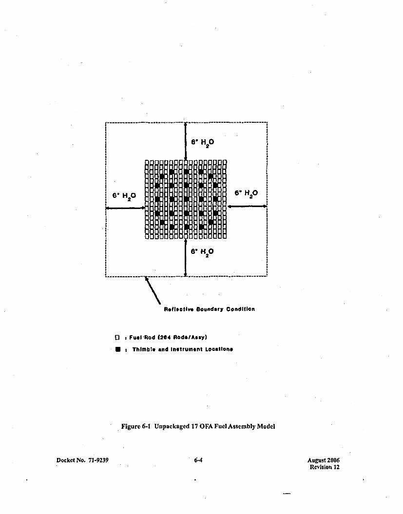
Reflective Boundary Condition
0 : Fuel Fld (264 Nod&/As my)
: Thimble and Instrument Locations
Figure 6-1 Unpackaged 17 OFA Fuel Assembly Model
Docket No. 71-9239 6-4 August 2006Revision 12
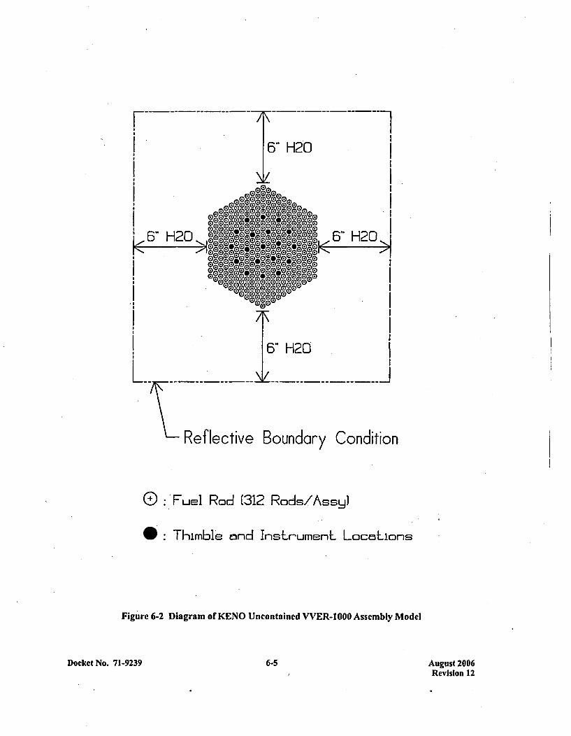
6" H20
g~Dg~~6" H20 2
Relctv o unay odii
n
0 :.Fuel Rod 1312 Rods/Assy)
0:Thimble ond Inshr'umenL LocnLions
Figure 6-2 Diagram of KENO Uncontained VVER-1000 Assembly Model
Docket No. 71-9239 6-5 August 2006Revision 12
The KENO calculational model based on Figure 6-1 uses only two geometry units to model. theunpackaged fuel assembly. One unit describes thc fuel rod ccll, which contains an explicit geometricrepresentation of a fuel pellet, gap, cladding, and surrounding water. The other unit describes the thimbletube ccll, which has water both inside and outside of the tube. The KENO calculation model based onFigure 6-2 uses five geometry units. The first two units describe the top and bottom of a fuel rod cell. Thenext two units describe the top and bottom of a modified thimble tube cell. The thimble tube ha s beenmodified to fit correctly into the fuel assembly array model. The last unit is an empty water cell used tocreate a square assembly array in KENO. The fuel rod cells and thimble tube cells are positioned in anarray to creatc a triangular pitch equal to the VVER- 1000 fuel assembly. In modeling the fuel, the U0 2atom density is calculated by assuming a U0 2 density that is 96.5% of theoretical (10.96 glee); pelletdensities actually encountered typically range from 94.5% to 95.5% of theoretical. No pellet dishingfraction or chamfering is modeled, which conservatively increases thc number of 235 U atoms by about1.2%, depending on the specific pellet type. No credit is taken for the presence of naturally occurring 234uor 23 ,nor is any credit taken for assembly structural material that does not extend the full. length of theassembly (i.e., grids, top and bottom nozzle, etc.). These combined assumptions result in a veryconservative model of a fuel assembly.
Figure 6-3 shows the package configuration for Normal Conditions of Transport for Square Lattice FuelAssemblies and Figure 6-4 shows the package configuration for Normal Conditions of Transport forVVER-1000 Fuel Assemblies. Since more than 6 inches of water is present bctwccn any asscmbly edgeand the interior surface of the package shell, the assemblies in any single container will be isolated fromthe assemblies in nearby containers by at least 12 inches of water. Therefore, similar to the unpackagedassemblies, the reactivity of an infinite array of packages under Normal Conditions of Transport would bethe same as the reactivity of any single package.
Figure 6-5 presents the Hypothetical Accident Conditions of Transport package configuration and itscriticality model for square lattice fuel. For the HAG, two crushed packages are aligned top-to-top suchthat an array of four assemblies is created, with the assemblies in the lower container separated from theassemblies in the upper container by 8 inches of water, To simplify the calculational model, reflectiveboundary (zero current) conditions are employed at the vertical centerline within the container and at thehorizontal interface between the lower and upper containers. In this way, the array of four assemblies isappropriately simulated, yet the model input is reduced to a representation of only one assembly. Forconservatism, reflective boundary conditions are also used at the outer edges of the two crushed packages,which precludes any neutron leakage from the array. Since at least 12 inches of water separates eachgrouping of four assemblies in this model, the results for the infinite array are the same as for a singlecluster of four assemblies. For certain higher enriched assemblies (Type B with enrichments greater than4.75 wt%), added neutron absorbers are used to maintain Kdr less than 0.95. The additional absorbers canbe placed within the assemblies (IFBA, Pyrex. BA, WABA, or Ag-In-Cd rods) or placed external to theassemblies as part of the container (Gd absorber plates). Each absorber type is described by a nominaldensity and ma nufacturing tolerance at the 95% confidence level. For calculational purposes, the modeledabsorber number densities are reduced from nominal by a factor to account for the 95% manufacturingtolerance, and by an additional 25% for added conservatism.
Docket No. 71-9239 6-6 August 2006Revision 12
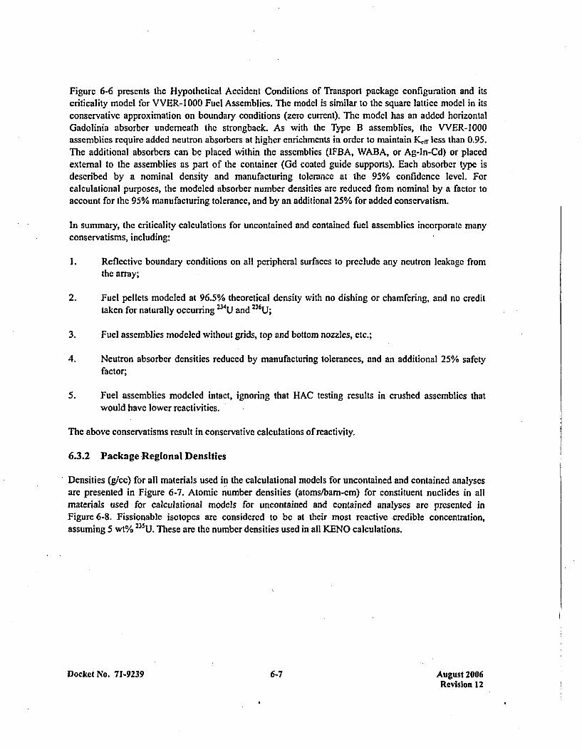
Figure 6-6 prescnts the Hypothetical Accident Conditions of Transport package configuration and itscriticality model for VVER-l1000 Fuel Assemblies. The model is similar to the square lattice model in itsconservative approximation on boundary conditions (zero current). The model has an added horizontalGadolinia absorber underneath the strongback. As with the Type B assemblies, the VVER-1000assemblies require added neutron absorbers at higher enrichments in order to maintain K1 ff less than 0.95.The additional absorbers can be placed within the assemblies (lFBA, WABA, or Ag-In-Cd) or placedexternal to the assemblies as part of the container (Gd coated guide supports). Each absorber type is.described by a nominal density and manufacturing tolerance at the 95% confidence level. Forcalculational purposes, the modeled absorber number densities are reduced from nominal by a factor toaccount for the 95% manufacturing tolerance, and by an additional 25% for added conservatism.
In summary, the criticality calculations for uncontained and contained fuel assemblies incorporate manyconservatisms, including:
1. Reflective boundary conditions on all peripheral surfaces to preclude any neutron leakage fromthe array;
2. Fuel pellets modeled at 96.5% theoretical density with no dishing or chamfering, and no credittaken for naturally occurring 234UJ and 236u
3. Fuel assemblies modeled without grids, top and bottom nozzles, etc.;
4. Neutron absorber densities reduced by manufacturing tolerances, and an additi onal 25% safetyfactor;
5. Fuel assemblies modeled intact, ignoring that 1-AC testing results in crushed assemblies thatwould have lower reactivities.
The above conservatisms result in conservative calculations of reactivity.
6.3.2 Package Regional Densities
,Densities (glee) for all materials used in the calculational models for uncontained and contained analysesare presented in Figure 6-7. Atomic number densities (atoms/barn-cm) for constituent nuclides in allmaterials used for calculational models for uncontained and contained analyses arc presented inFigure 6-8. Fissionable isotopes are considered to be at their most reactive credible concentration,assuming 5 wt% 235U. These are the number densities used in all KENO calculations.
Docket No. 71-9239 6-7 August 2006Revision 12
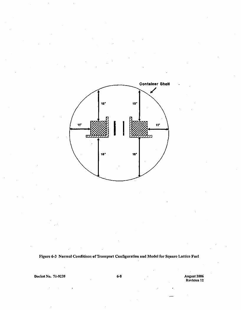
Container Shell
Figure 6-3 Normal Conditions of Transport Configuration and Model for Square Lattice Fuel
Docket No. 71-9239 -6-8 August 2006Revision 12
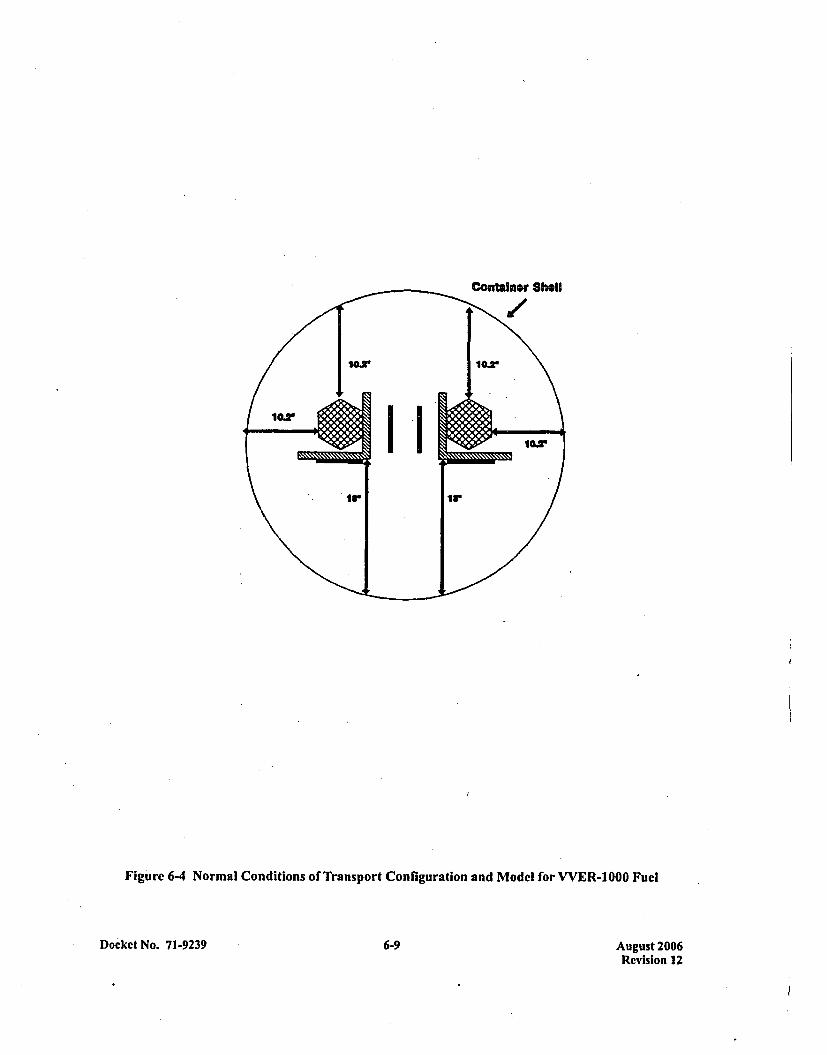
Figure 6-4 Normal Conditions of Transport Configuration and Model for VVER-1000 Fuel
Docket No. 71-9239 6-9 August 2006Revision 12
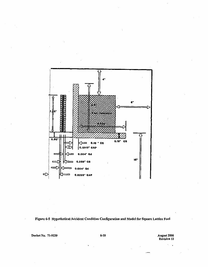
Figurc 6-5 Hypothetical Accident Condition Configuration and Model for Square Lattice Fuel
Docket No. 11-9239 6-10 August 2006Revision 12

VIEW A-ACKrizonk] DAD P1&.)l
GAD STEE
VIEW D-D[Vert*=]l GAD P66~)->1JK-- 0.004'
K- GAD1111 IBOTH SIDES)
0. 035*CARBON~STEEL
Figure 6-6 Hypothetical Accident Condition Configuration and Model For VVER-1 000 Assembly
Docket No. 71-9239 6-11 August 2006Revision 12
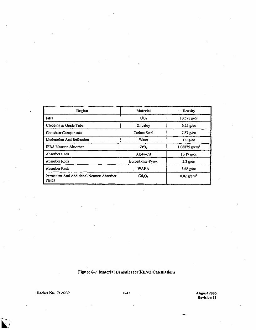
Region Material Density
Fuel U0, 10.576 glcc
Cladding & Guide Tube Zircaloy 6.55 g/cc
Container Components Carbon Steel 7.87 g/cc
Moderation And Reflection Water 1.0 g/cc
IFBA Neutron Absorber ZrB2 1.06875 g/cm2
Absorber Rods Ag-In-Cd 10. 17 g/cc
Absorber Rods Borosilicate-Pyrex 2.3 glcc:
Absorber Rods .WABA 3.68 g/cc
Permanent And Additional Neutron Absorber Gd2O3 0.02 g/Cnl 2
Plates
Figure 6-7 Material Densities for KENO Calculations
6-12Docket No. 71-9239 August 2006Revision 12
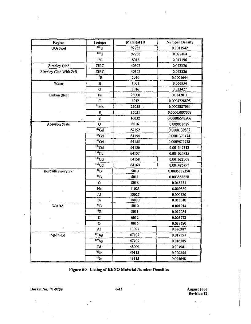
Region Isotope Material ID Number Density
U02 Fuel 235u 92235 0.001194223u92238 0.022404
160 8016 0.047196
Zircaloy Clad ZIRC 40302 0.043326
Zircaloy Clad With ZrB ZIRC 40302 0.0433261013 5010 0.0001644
Water H 1001 0,066854__________________ 0 8016 0.033427
Carbon Steel Fe 26000 0.0842011
C 6012 0.0004728898
SSMn 25055 0.0003 887064
P,1503! 0.00005807008
__________________ S 16032 0.00006642906
Absorber Plate 0 8016 0.0098 10529152Gd 64152 0.000013080715
4 Gd 64154 0.0001373474
'"5Gd 64155 0.0009 679722156 Cd 64156 0.001347313
1S7 Gd 64157 0.001026835
1SOGd 64158 0.00162200816OGd 64160 0.001425792
Borosilicate-Pyrex 1013 5010 0.0006837358
"B1 5011 0,003862628
0 8016 0.045331
Na 11023 0.000880
Al 13027 0.000680
Si 14000 0.018040
WABA 1013 5010 0.001914
"B1 5011 0.012084
C 6012 0.003772
0 8016 0.039580Al 13027 0.026387
Ag-In-Cd 107 Ag 47107 0.017551109A9 47109 0.016305
Cd 480 00 0.001941113In 49113 0.000254
"151n 49115 0,005648
Figure 6-8 Listing of KENO Material Number Densities
Docket No. 71-9239 6-13 August 2006Revision 12
6.4 CRITICALITY CALCULATION
6.4.1 Calculational or Experimental Method
The current Westinghouse design method, which insures the criticality safety of fuel assemblies in theshipping container, starts with 227 energy group cross-sections generated from ENDF/B-V data. AMPXsystem codes, NITAWL-S and XSDRNPMS, are used for cross-section library processing. TheNITAWL-S program performs the self-shielded resonance cross-section corrections that are appropriatefor each particular geometry (The Nordheim Integral Treatment is used). Energy and spatial weighting ofthe cross-sections arc performed by the XSDRNPMS program, which is a one-dimensional transporttheory code. XSDRNPMS cell models are generated for fuel cells and for representative absorber cells.Cross-sections for IFBA coated fuel are prepared by placing the 1013 material from the absorber in the cladregion of the cell.
Cross-sections for structural materials are obtained by introducing trace material amounts into themoderator region of the cell. This procedure does not produce any bias in the results due to the fineness ofthe energy group structure. These multigroup cross-section sets are then used as input to KENO Va, whichis a three dimensional Monte Carlo theory program designed for reactivity calculations.
6.4.2 Fuel Loading or Other Contents Loading Optimization
The geometric capabilities of KENO are used to provide essentially exact representations of actual fuelassembly and shipping container geometries. All uncontained assembly calculations are performed intwo dimensional geometry, which conservatively ignores the benefits of axial leakage. For containedType A fuel assemblies (14x14 and 16xI6 designs), calculations are also performed in two dimensions.For contained Type B assemblies (I 5x 15 and 17x 17 dcsigns), a conservative three dimensional geometryis used. The three dimensional calculations assume an active fuel stack height of 168 inches, which isconservative, since the majority of Type B fuel assembly designs are considerably shorter than168 inches. Reflection is used at the fuel axial centerline to minimize problem size and complexity.Within the container, 5.08 inches of water is modeled at the assembly end, followed by the thin containershell and a reflective boundary condition. For contained Type C fuel assemblies (VVER- 1000 design),calculations are performed with a conservative three dimensional geometry. The three dimensionalcalculations assume an active fuel stack height of 142.91 inches. Reflection is used a the fuel axialcenterline to minimize problem size and complexity. Within the~container, 6.0 inches of water is modeledat the assembly end, followed by the thin container shell and a reflective boundary conditions. Thisgeometry model conservatively ignores the benefits of additional spacing between the fuel rod plenumand the additional neutron absorption by the top and bottom assembly structure. Where applicable, fuelpin gap flooding and annular fuel blankets are included in the calculations. When additionalwithin-assembly neutron absorbers are required, the absorbers are modeled assuming an axial length of108 inches, centered about the axial assembly midplane. Typically, absorbers are significantly longer thanthe assumed 108 inch minimum, thereby adding additional conservatism. For JEBA absorbers, the 1013 ismodeled within the clad region of the fuel cell, which is consistent with the standard Westinghousereactor core design methodology.
Docket No. 71-9239 616-14 August 2006Revision 12
6.4.3 Criticality Results
Appendix 6-2 includes the KENO input decks and K,,f results for the Monte Carlo criticality analysis ofsingle fuel assemblies having attributes described in Appendix 1-5. Appendix 6-3 includes the KENOinput decks and K,,f results for the Monte Carlo criticality analyses of the MCC shipping container underinfinite array Normal Condition of Transport and Hypothetical Accident Conditions.
The Hypothetical Accident Condition evaluations were, performed assuming infinite array geometry,therefore these results bound the infinite array Normal Condition of Transport calculations.
For the MCC shipping container using permanent Gd2O3 absorber plates, under infinite arrayHypothetical Accident Conditions, it has been calculated that the final K,,r with bias and uncertainties atthe 95% confidence level is less than 0.95 for the following conditions:
1. Type A fuel assemblies (14xl4 and 16x16 designs) with maximum enrichments up to 5.0 wt%; or,
2. Type B fuel assemblies (15x15 and 17x17 designs) with maximum enrichments up to 4.65 wt%;or,
3. Type B fueLassemblics (15x]5 and 17x]7 designs) with maximum enrichments above 4.65 wt%with exception of 17xI7 XL or 17x17 STD designs with maximum enrichments above 4.85 wt%,up to 5.0 wt%, using one of the following additional absorber options:
a. Assembly IFBA Rods: A minimum of 32 nominally (IX) loaded fuel rods in eachassembly, each with a minimum coating length of 108 inches. For increased IFBA loadings(1 .5X, 2X, etc.), the number of loaded fuel rods required can be reduced by the ratio of theincreased loading to the nominal loading.
b. Assembly Absorber Rods: A minimum of 4 absorber rods in each assembly. The rods canbe Pyrex BA, WABA, or Ag-In-Cd designs with a minimum length of 108 inches. The rodsmust be positioned within the assemblies in a symmetric pattern about the assembly centerguide tube.
C. Container Absorber. Plates: A minimum of 2 -additional Gadolinia coated absorber plates,having the same specifications as the permanent container absorber plates, are required.The additional plates must be positioned directly on the strongback (top or bottom),underneath each assembly.
4. The Type C fuel assembly (VVER-1000) with maximum enrichments up to 4.8 wt%; or,
5. The Type C fuel assembly (VVER-1000) with maximum enrichments above 4.8 wt%, up to5.0 wt%, using one of the following additional absorber options:
a. Assembly IFBA rods: A minimum of 24 nominally (I X) coated fuel rods arc required ineach assembly, each with a minimum coating length of 108 inches. With increased lFBA
Docket No. 7 1-9239 6-15 August 2006Revision 12

loadings (L.X, 2X, etc.), the number of loaded fuel rods required can be reduced by the.ratio of thc increased loading to the nominal loading.
b. Assembly Absorber Rods: A minimum of 4 absorber rods are required in each assembly.The rods can be WABA or Ag-In-Cd designs with a minimum length of 108 inches. Therods must be positioned within the assemblies in a symmetric pattern about the assemblycenter guide tube.
c, Guide Plate Absorber Coating: A minimum coating of 0.027 grams of Gd2O3 per cm 2 onthe underside of the guide plates is required. The guide plates sit on the strongback and arelocated between the grid supports.
6.5 CRITICAL BENCHMARK EXPERIMENTS
6.5.1, Benchmark Experiments and Applicability
The criticality calculation method and cross-section values are verified by comparison with criticalexperiment data for fuel assemblies similar to those for which the shipping container is designed. Thisbenebmarking data is sufficiently diverse to establish that the method bias and uncertainty will apply to,shipping container conditions which include strong neutron absorbers and large water gaps.
A set of 32 critical experiments has been analyzed using the above method to demonstrate its applicabilityto criticality analysis and to establish the method bias and uncertainty. The benchmark experiments covera wide range of geometries, materials and enrichments; ranging from relatively low enriched (2.35, 2.46,and 4.31 wt%/), water moderated, oxide fuel arrays, separated by various materials (134C, aluminum, steel,water, etc) that simulate LWR fuel shipping and storage conditions; to dry, harder spectrum, uraniummetal cylinder arrays at high enrichments (93.2 wt%/), with various interspersed materials (Plexiglas andair). Comparison with these experiments demonstrates the wide range of applicability of the method.
6.5.2 Details of the Benchmark Calculations
All experiments were modeled without complication. Material densities and geometries were takendirectly from the references. No critical experiments were eliminated on the basis of anomalous results.
6.5.3 Results of the Benchmark Calculations
Descriptions and results of the 32 critical experiments as executed on a CRAY XMP computer areprovided in Figure 6-9; benchmark calculation statistics are given in Figure 6-10. These results arcappropriate for all calculations performed prior to January 1, 1994.
The 32 low enriched, water-moderated experiments result in an average KENO Va IQt- of 0.9933.Comparison with the average measured experimental Kff of 1.0007 results in a method bias of 0.0074.The standard deviation of the bias value is 0.0013 AK. The 95/95 one-sided tolerance limit factor for32 values is 2.20. Thus, there is a 95 percent probability with a 95 percent confidence level that theuncertainty in reactivity, due to the method, is not greater than 0.0029 AK.
Docket No. 71-9239 6-16 August 2006Revision 12
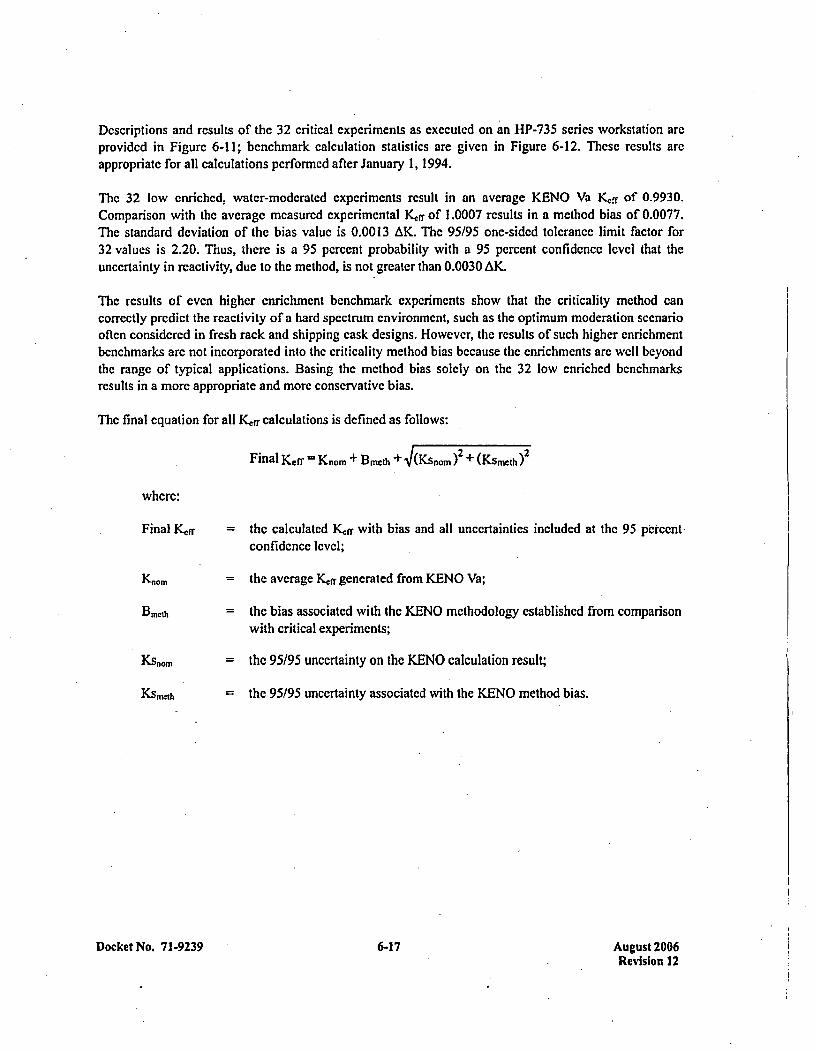
Descriptions and results of the 32 critical experiments as executed on an HP-735 series workstation arcprovided in Figure 6-11; benchmark calculation statistics are given in Figure 6-12. These results areappropriate for all calculations performed after January 1, 1994.
Thc 32 low enriched, water-moderated experiments result in an average KENO Va Kff of 0.9930.Comparison with the average measurcd experimental Kerr of 1.0007 results in a method bias of 0.0077.The standard deviation of the bias value is 0.00 13 AK. The 95/95 one-sided tolerance limit factor for32 values is 2.20. Thus, there is a 95 percent probability with a 95 percent confidence level that theuncertainty in reactivity, due to the method, is not greater than 0.0030 AK.
The results of even higher enrichment benchmark experiments show that the criticality method cancorrectly predict the reactivity of a hard spectrum environment, such as the optimum moderation scenariooften considered in fresh rack and shipping cask designs. However, the results of such higher enrichmentbenchmarks are not incorporated into the criticality method bias because the enrichments are well beyondthe range of typical applications. Basing the method bias solely on the 32 low enriched benchmarksresults in a more appropriate and more conservative bias.
The final equation for all Kerr calculations is defined as follows:
Final Keff = Kriom + Bmezh + V(Ksnom )2 + (KSme.th )2
where:
Final Kerr
Kiiom
BMCIh
KS nom
Ksmcth
= the calculated Kff with bias and all uncertainties included at the 95 percentconf idence level;
= the average Kcf generated from KENO Va;
= the bias associated with the KENO methodology established from comparisonwith critical experiments;
= the 95/95 uncertainty on the KENO calculation result;
=the 95/95 uncertainty associated with the KENO method bias.
Docket No. 71-9239 6-17 6-17 August 2006Revision 12
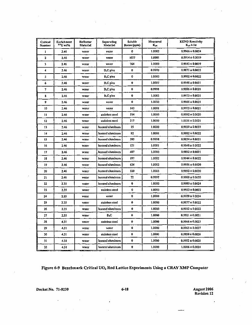
Critical Enrichment Reflector Separating Soluble Measured KENO Reactivity
Number Ilu Wt% Material Material Boren (ppm) Kdr a.~i
1 2.46 water water 0 1.0002 0.9966±* 0.0024
2 2.46 water water 1037 1.0001 0.9914 ±0.0019
3 2.46 water water 764 1.0000 0.9943 ± 0.00 19
4 2.46 water D4C pins 0 .0.9999 0.987 1 ± 0.0022
5 2.46 water i34C pins 0 1.0000 0.9902 ± 0.0022
6 2.46 water BXCpins 0 1.0097 0.9948 ±0.0021
7 2.46 water B4C pins 0 0.9998 0.9886 *0.0021
8 2.46 water B4C pins 0 1.0083 0.9973 * 00021
9 2.46 water water 0 1.0030 0.9966 0.0021
10 2.46 water water 143 1.0001I 0.9973 *0.0021
11 2.46 water stainless steel 514 1.13000 0.9992:k 0.0020
12 2.46 water stainless steel 217 1.0000 1.0031 ± 0.0021
13 2.46 water borated aluminum 15 1.0000 0.9939±* 0.0022
14 2.46 water boratcd aluminum 92 1.0001 0.9882:k 0.0022
15 2.46 water borated aluminum 395 0.9998 0.9854;t 0.0021
16 2.46 water borated aluminum 121 1.0001 0.9848 d: 0.0022
17 2.46 water borated aluminum 487 1.0000 0.9892 ± 0.0021
18 2.46 water borated aluminum 197 1.0002 0.9944 ± 0.0022
19 2.46 water borated aluminum 634 1.0002 0.9956:L 0.0020
20 2.46 water borated aluminum 320 1.0003 0.9893 ± 0.0020
21 2.46 water borated aluminum 72 0.9997 0.9900:t 0.0020
22 2.35 water boraled aluminum 0 1.0000 0.99801*0.0024
23 2.35 water stainless steel 0 1.0000 0.9933 ± 0.0022
24 2.35 water water 0 1.0000 0.9920 ± 0.0024
25 2.35 water stainless steel 0 1.0000 0.9877.+ 0.0022
26 2.35 water borated aluminum 0 1.0000 0.9912 *0.0022
27 2.35 water B4C 0 1.0000 0.9921 *0.0021
28 4.31 water stainless steel 0 1.0000 0.9968 *0.0023
29 4.31 water water 0 1.0000 0.9963:1: 0.0027
30 4.31 water stainless steel 0 1.0000 0.9950 ± 0.0026
31 4.31 water borated aluminum 0 1.0000 0.9952 * 0.0025
32 4.31 water borated aluminum 0 1.0000 1.0006 ± 0.0024
Figure 6-9 Benchmark Critical U0 2, Rod Lattice Experiments Using a CRAY XMP Computer
Docket No. 71-9239 6-18 August 2006Revision 12
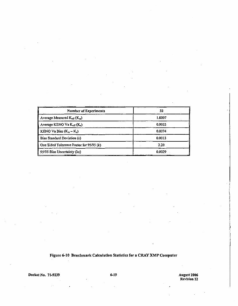
Number of Experiments 32
Average Measured Kef (K(m) 1.0007
Average KENO Va Kff (Ký,) 0.993 3
KENO Va Bias (K.~ - Kj) 0.0074
Bias Standard Deviation (s) 0.0013
One Sided Tolerance Factor for 95/95 (kc) 2.20
95195 Bias Uncertainty (Ics) 0.0029
Figurc 6-10 Benchmark Calculation Statistics for a CRAY XMP Computer
Docket No. 71-9239 6-19 August 2006Revision 12
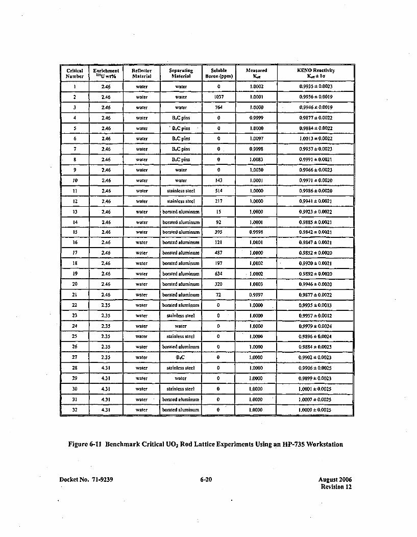
Critical Enrichment Reflector Separating Soluble Measured KENO ReactivityNumber 1311. wt% Material Material Boron (ppm) K.,r K.f* to
1 2.46 water water 0 1.0002 0.9935:t 0.0023
2 2.46 water water 1037 1.0001 0.9936 ± 0.00 19
3 2.46 water water 764 1.0000 0.9946.*0.0019
4 2.46 water B.C pins 0 0.9999 0.9877 * 0.0022
5 2A6 water B.C pins 0 1.0000 0.9884 ±0.0022
6 2.46 water B.C pins 0 1.0097 1.00 13 *0.0022
7 2.46 water B4C pins 0 0.9998 0.9957:1: 0.0023
8 2.46 water %~C pins 0 1.0083 0.9991 *0.0021
9 2.46 water water 0 1.0030 0.9966 * 0.0023
10 2.46 water water 143 1.0001 0.9971 * 0.0020
11 2.46 water stainless steel 514 1.0000 0.9986 * 0.0020
12 2.46 water stainless steel 217 1.0000 0.9941 ± 0.0021
13 2.46 water borated aluminum 15 1.0000 0.9923 :k 0.0022
14 2.46 water borated aluminum 92 1.0001 0.9885 ± 0.0021
15 2.46 water borated aluminum 395 0.9998 0.9842 * 0.0021
16 2.46 water borsted aluminum 121 1.0001 0.9847 ± 0.0021
17 2.46 water borated aluminum 487 1.0000 0.9852 ± 0.0020
Is 2.46 water borated aluminum 197 1.0002 0.9920 ± 0.0021
19 2.46 water barated aluminum 634 1.0002 0.9892 ± 0.0020
20 2.46 water borated aluminum 320 1.0003 0.9946 -,.0.0020
21 2.46 water borated aluminum 72 0.9997 0.9877 * 0.0022
22 2.35 water borated aluminum 0 1.0000 0.9935 ± 0.0013
23 2.35 water stainless steel 0 1.0000 0.9957:k0.00 12
24 2.35 water water 0 1.0000 0.9979:k 0.0024
25 2.35 water stainless steel 0 1.0000 0.9896+* 0.0024
26 2.35 water borated aluminum 0 1.0000 0.9884 * 0.0023
27 2.35 water B4C 0 1.0000 0.9902 ± 0.0023
28 4.31 water stainless steel 0 1 A0000 0.9906 ± 0.0025
29 4.31 water water 0 1.0000 0.9899 ± 0.0023
30 4.31 water stainless steel 0 1.0000 1.000 1 *0.0025
31 4.31 water borsted aluminum 0 1.0000 1.0007.+0.0025
32 4.31 water borated aluminum 0 1.0000 1.0009 -* 0.0025
Figure 6-11 Benchmark Critical U02 Rod Lattice Experiments Using an HP-735 Workstation
Docket No. 7 1-9239 6-20 August 2006Revision 12
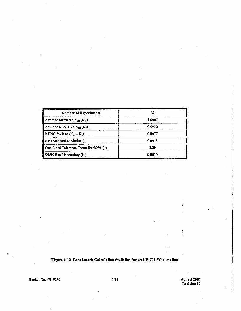
Number of Experiments 32
Average Measured Kerr (K.1 ) 1.0007
Average KENO Va Kfr (K,,) 0.9930
KENO Va Bias (K,,, - Kj) 0.0077
Bias Standard Deviation (s) 0.0013
One Sided Tolerance Factor for 95/95 (k) 2.20
95/95 Bias Uncertainty (ks) 0.0030
Figure 6-12 Benchmark Calculation Statistics for an HP-735 Workstation
Docket No. 71-9239 6-21 August 2006Revision 12
APPENDIX 6-1REFERENCES
.Docket No. 71-9239 A6-1-1 August 2006Revision 12
REFERENCES
I. Ford IIl, W. E., et. al.; CSRL-V: Processed ENDF/B-V 227-Neutron-Group and PointwiseCross-Section Libraries for Criticality Safcty, Reactor, and Shielding Studies; NUR.EG/CR-2306;June 1982.
2. Greene, N. M., et. al.; AMPX: A Modular Code System for Generating Coupled MultigroupNeutron-Gamma Libraries from ENDF/B; ORNL-TM-3706; March 1976.
3. Petrie, L. M., Landers, N. F.; KENO Va - An Improved Monte Carlo Criticality Program withSupergrouping; NUREG/CR-0200; December 1 984.N. M. Baldwin, "Critical ExperimentsSupporting Close Proximity Water Storage of Power Reactor Fuel," B&W- 1484-7, July 1979.
4. S. R. Bierman and E. D. Clayton, "Criticality Separation Between. Subcritical Clusters of2.35 wt% 235U Enriched U0 2, Rods in Water with Fixed Neutron Poisons," PNL-2438, PacificNorthwest Laboratory, October 1977.
5. S. R. Bierman and E. D. Clayton, "Criticality Experiments with Subcritical Clusters of 2.35 wt%and 4.31 wt%/ 235U Enriched U0 2 Rods in Water at a Water-to-Fuel Volume Ratio of 1.6,"PNL-33 14, Pacific Northwest Laboratory, July 1980.
6. S. R. Bierman and E. D. Clayton, "Critical Separation Between Subcritical Clusters of 4.29 wt%235U Enriched U0 2 Rods in Water with Fixed Neutron Poisons," PNL-2615, Pacific NorthwestLaboratory, August 1979.
7. J. T. Thomas, "Critical Three-Dimensional Arrays of U(93.2) Metal Cylinders," Nuclear Scienceand Engineering, Volume 52, pages 350-359, 1973.'
Docket No. 71-9239 A6-I-3 August 2006Revision 12
APPENDIX 6-2EVALUATION OF THE NUCLEAR CRITICALITY SAFETY OF
UNPACKAGED FUEL ASSEMBLIES
Docket No. 7 1-9239 A6-2-1 August 2006Revision 12
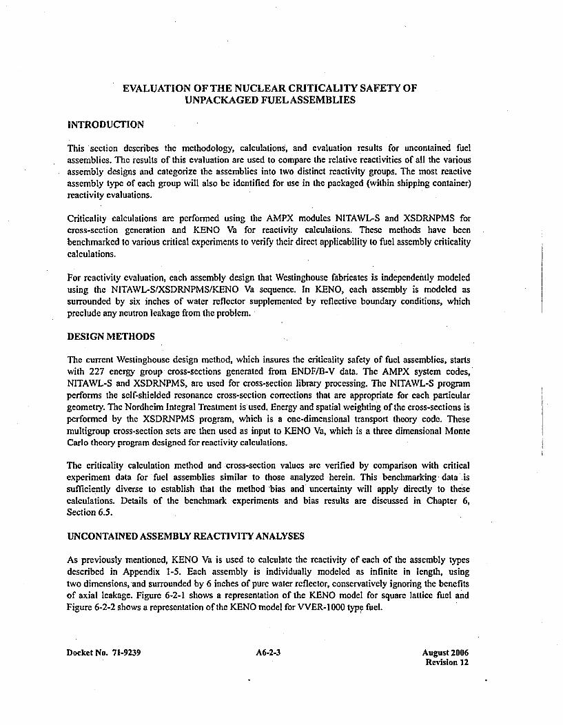
EVALUATION OF THE NUCLEAR CRITICALITY SAFETY OFUNPACKAGED FUEL ASSEMBLIES
INTRODUCTION
This section describes the methodology, calculations, and evaluation results for uncontaincd fuelassemblies. The results of this evaluation are used to compare the relative reactivities; of all the variousassembly designs and categorize the assemblies into two distinct reactivity groups. The most reactiveassembly type of each group will also be identified for use in the packaged (within shipping container)reactivity evaluations.
Criticality calculations are performed using the AMPX modules NiTAWL-S and XSDRNPMS forcross-section generation and KENO Va for reactivity calculations. These methods have beenbenchmarked to various critical experiments to verify their direct applicability to fuel assembly criticalitycalculations.
For reactivity evaluation, each assembly design that Westinghouse fabricates is independently modeledusing the NITAWL-S/XSDRNPMS/KENO Va sequence. In KENO, each assembly is modeled assurrounded by six inches of water reflector supplemented by reflective boundary conditions, whichpreclude any neutron leakage from the problem.
DESIGN METHODS
The current Westinghouse design method, which insures the criticality safety of fuel assemblies, startswith 227 energy group cross-sections generated from ENDF/B-V data. The AMPX system codes,'NITAWL-S and XSDRNPMS, arc used for cross-section library processing. The NITAWL-S programperforms the self-shielded resonance cross-section corrections that are appropriate for each particulargeometry. The Nordheim Integral Treatment is used. Energy and spatial weighting of the cross-sections isperformed by the XSDRNPMS program, which is a one-di 'mensional transport theory code. Thesemultigroup cross-section sets are then used as input to KENO Va, which is a three dimensional MonteCarlo theory program designed for reactivity calculations.
The criticality calculation method and cross-section values are verified by comparison with criticalexperiment data for fuel assemblies similar to those analyzed -herein. This benchmarking -data issufficiently diverse to establish that the method 'bias and uncertainty will apply directly to thesecalculations. Details of the benchmark experiments and bias results are discussed in Chapter 6,Section 6.5.
UNCONTAINED ASSEMBLY REACTIVITY ANALYSES
As previously mentioned, KENO Va is used to calculate the reactivity of each of the assembly typesdescribed in Appendix 1-5. Each assembly is individually modeled as infinite in length, usingtwo dimensions, and surrounded by 6 inches of pure water reflector, conservatively ignoring the benefitsof axial leakage. Figure 6-2-1 shows a representation of the KENO model for square lattice fuel andFigure 6-2-2 shows a representation of the KENO model for VVER- 1000 type fuel.
Docket No. 7 1-9239 A6-2-3 August 2006Revision 12
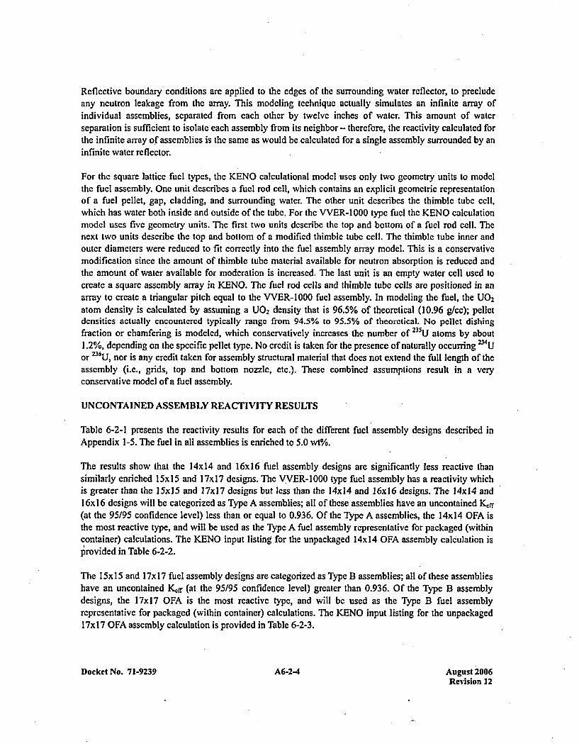
Reflective boundary conditions arc applied to the edges of the surrounding water reflector, to precludeany neutron leakage from the array. This modeling technique actually simulates an infinite array ofindividual assemblies, separated from each other by twelve inches of water. This amount of waterseparation is sufficient to isolate each assembly from its neighbor - therefore, the reactivity calculated forthe infinite array of assemblies is the same as would be calculated for a single assembly surrounded by aninfinite water reflector.
For the square lattice fuel types, the KENO calculational model uses only two geometry units to modelthe fuel assembly. One unit describes a fuel rod cell, which contains an explicit geometric representationof a fuel pellet, gap, cladding, and surrounding water. The other unit describes the thimble tube cell,which has water both inside and outside of the tube. For the VVER-1000 type fuel the KENO calculationmodel uses five geometry units. The first two units describe the top and bottom of a fuel rod cell. Thenext two units describe the top and bottom of a modified thimble tube cell. The thimble tube inner andouter diameters were reduced to fit correctly into the fuel assembly array model. This is a conservativemodification since the amount of thimble tube material available for neutron absorption is reduced andthe amount of water available for moderation is increased. The last unit is an empty water cell used tocreate a square assembly array in KENO. The fuel rod cells and thimble tube cells are positioned in anarray to create a triangular pitch equal to the VVER-1000 fuel assembly. In modeling the fuel, the U0 2atom density is calculated by assuming a U0 2 density that is 96.5% of theoretical (10.96 geec); pelletdensities actually encountered typically range from 94.5% to 95.5% of theoretical. No pellet dishingfraction or chamrfering is modeled, which conservatively increases the number of 235U atoms by about1.2%, depending on the specific pellet type. No credit is taken for the presence of naturally occurring 234Uor 236 U, nor is any credit taken for assembly structural material that does not extend the full length of theassembly (i.e., grids, top and bottom nozzle, etc.). These combined assumptions result in a veryconservative model of a fuel assembly.
UNCONTAINED ASSEMBLY REACTIVITY RES ULTS
Table 6-2-1 presents the reactivity results for each of the different fuel assembly designs described inAppendix 1 -5. The fuel in all assemblies is enriched to 5.0 wt%.
The results show that the 14x14 and 16x16 fuel assembly designs are significantly less reactive thansimilarly enriched 15x15 and P7x17 designs. The VVER-1000 type fuel assembly has a reactivity whichis greater than the ]5x]5 and ]7x]7 designs but less than the l4x14 and 16x16 designs. The 14x14 and16x 16 designs will be categorized as Type A assemblies; all of these assemblies have an uncontained Ký,T(at the 95/95 confidence level) less than or equal to 0.936. Of the Type A assemblies, the 14x14 OFA isthe most reactive type, and will be used as the Type A fuel assembly representative for packaged (withincontainer) calculations. The KENO input listing for the unpackaged 14xI4 OFA assembly calculation isprovided in Table 6-2-2.
The l5xlS and 17x17 fuel assembly designs are categorized as Type B assemblies; all of these assemblieshave an uncontained Kff (at the 95/95 confidence level) greater than 0.936. Of the Type B assemblydesigns, the 17x17 OFA is the most reactive type, and will be used as the Type B fuel assemblyrepresentative for packaged (within container) calculations. The KENO input listing for the unpackaged17x 17 OFA assembly calculation is provided in Table 6-2-3.
Docket No. 7 1-9239 A6-2-4 August 2006Revision 12
The VVER-1000 type fuel assembly design is categorized as the Type C assembly. This assembly has anuncontained Kdrf (at the 95195 confidence level) of 0.9432. It is also the only fuel assembly type which hasa triangular lattice. Packaged (within container) calculations for Type C fuel assemblies will use theVVER-1 000 type fuel assembly. The KENO input listing for the unpackaged VVER- 1000 type fuelassembly calculation is provided in Table 6-2-4.
Docket No. 71-9239 A6-2-5 August 2006Revision 12
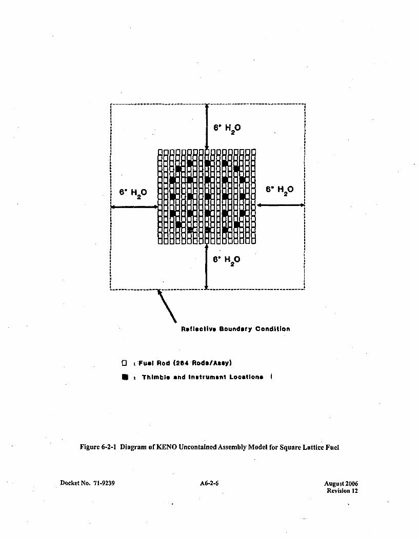
I6H20
6 20
I
6" H2 0
6H20
---------------------------- ------------------------------
Reflective Boundary Condition
o :-Fuel R od (264 -Rod$IAsay)
*:Thimble and Instrument Locations
Figure 6-2-1 Diagram of KENO Uncontained Assembly Model for Square Lattice Fuel
Docket No. 7 1-9239 A-- uut20A6-2-6Revision 12
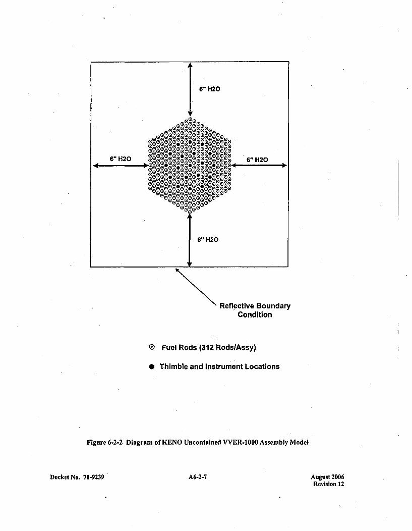
Reflective BoundaryCondition
G Fuel Rods (312 RodslAssy)
0 Thimble and Instrument Locations
Figure 6-2-2 Diagram of KENO Uncontained VVER-I 000 Assembly Model
Docket No. 7 1-9239 A6-2-7 August 2006Revision 12

Table 6-2-1 Reactivity Results for Uncontalned Assemblies
Lattice Fuci Type KENO I4,f I C 95/95 With Bias
14X 14 STD) 0.89718 0.00436 0.9124
(Type A) 422V+ 0.90226 0.00103 0.9 134
OFA 0.91967 0.00505 0.9359
CE! 0.91445 0.00436 0.9296
CE2 0.92051 0.00395 0.9350
SS 0.87071 0.00438 0.8859
16X16 STD) 0.89024 0.00444 0.9055(Type A) CE 0.9 1462 0.00464 0.9302
15XI5 STD) 0.94778 0.00453 0.9632
(Tp )OFA 0.94672 0.00409 0.9615
B &W 0.94447 0 .00455 0.9599
17XI7 GI0.93924 0.418 0.95414 2p ) T T 0.94144 0.00144 0.9523G30.94202 0.00152 0.9536
OFA 0.94935 0.00430 0.9644
VVER-1000 (Type C) 0.92790 0.00448 0.9432
Docket No. 71-9239 A6-2-8 August 2006Revision 12
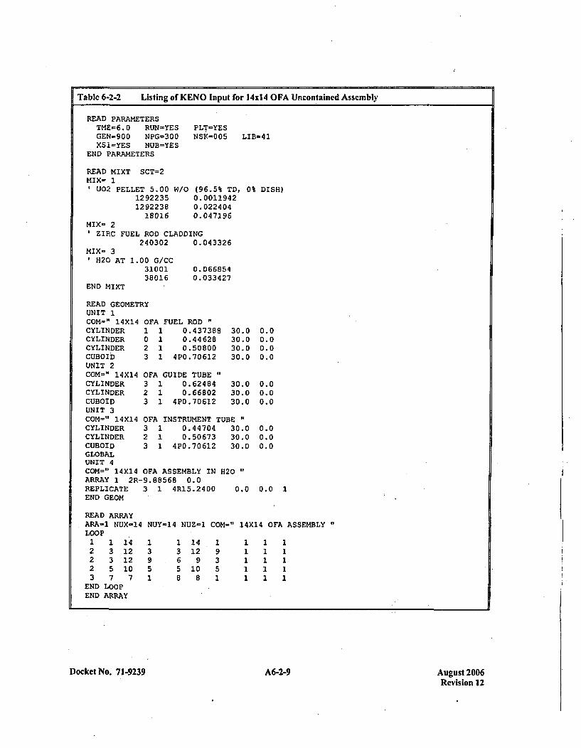
Table 6-2-2 Listing of KENO Input for 14x14 OFA Uncontained Assembly
READ PARAMETERSTME-6.0 RUN-YESGEN-900 NPG-300XS1=YES NUB=YES
END PARAMETERS
READ MIXT SCT=2MIX- 1
U02 PELLET 5.00 W112 92235129223818016
PLT-YESNSK=005 LIB=41
'0 (96.5% TD, 0% DISH)0.00119420. 022 4040.047196
MIX= 2ZIRC FUEL ROD CLADDING
240302 0.043326MIX- 3
'H20 AT
END MIXT
1.00 G/CC3100138016
0.0668540. 033 427
READ GEOMETRYUNIT 1COM=" 14X14 OFA FUEL RODCYLINDER 1 1 0.437388 30.4CYLINDER 0 1 0.44628 30.4CYLINDER 2 1 0.50800 30.4CUBOib 3 1 4P0.70612 30.4UNIT 2COM=" 14X14 OFA GUIDE TUBECYLINDER 3 1 0.62484 30.1CYLINDER 2 1 0.66802 30.(CUBOID 3 1 4P0.70612 30.(UNIT 3COM=" 14X14 OFA INSTRUMENT TUBE"CYLINDER 3 1 0.44704 30.(CYLINDER 2 1 0.50673 30.(CUBOID 3 1 4P0.70612 30.1GLOBALUNIT 4COM=" 14X14 OFA ASSEMBLY IN H420"ARRAY 1 2R-9.88568 0.0REPLICATE 3 1 4R15.2400 0.CEND GEOM
000
0
00
0.00.00.00.0
0.00.00.0
0.00.00.0
) 0.0 1
READ ARRAYARA-1 NUX-14 NUY-14 NUZ-1 COM-" 14X14 OFA ASSEMBLYLOOP
1 1 14 1 1 14 1 1 1 12 3 12 3 3 12 9 1 1 12 3 12 9 6 9 3 1 1 12 5 10 5 5 10 5 1 1 13 7 7 1 8 8 1 1 1 1
END LOOPEND ARRAY
Docket No.' 7 1-9239 A6-2-9 August 2006Revision 12
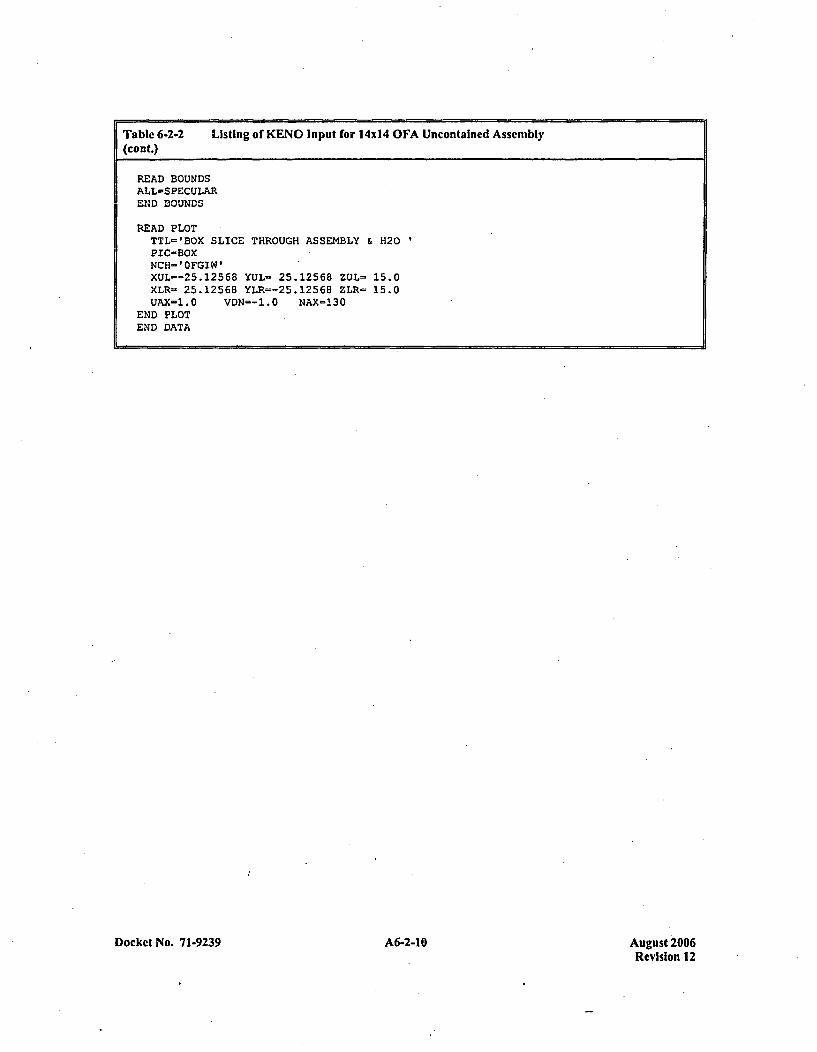
Table 6-2-2 Listing of KENO Input for 14014 OFA Uncontalned Assembly(cont.)
READ BOUNDSALL=SPECULAREND BOUNDS
READ PLOTTTL'IBOX SLICE THROUGH ASSEMBLY & H120PIC=BOXNCH ' OFGIW'XUL=-25.12568 YUL- 25.12568 ZUL= 15.0XLR- 25.12568 YLR=-25.1256B ZLR- 15.0UAX-1.0 VDN=-1.0 NAX-130
END PLOTED DATA
Docket No. 71-9239 A6-2-10Agst20Revision 12
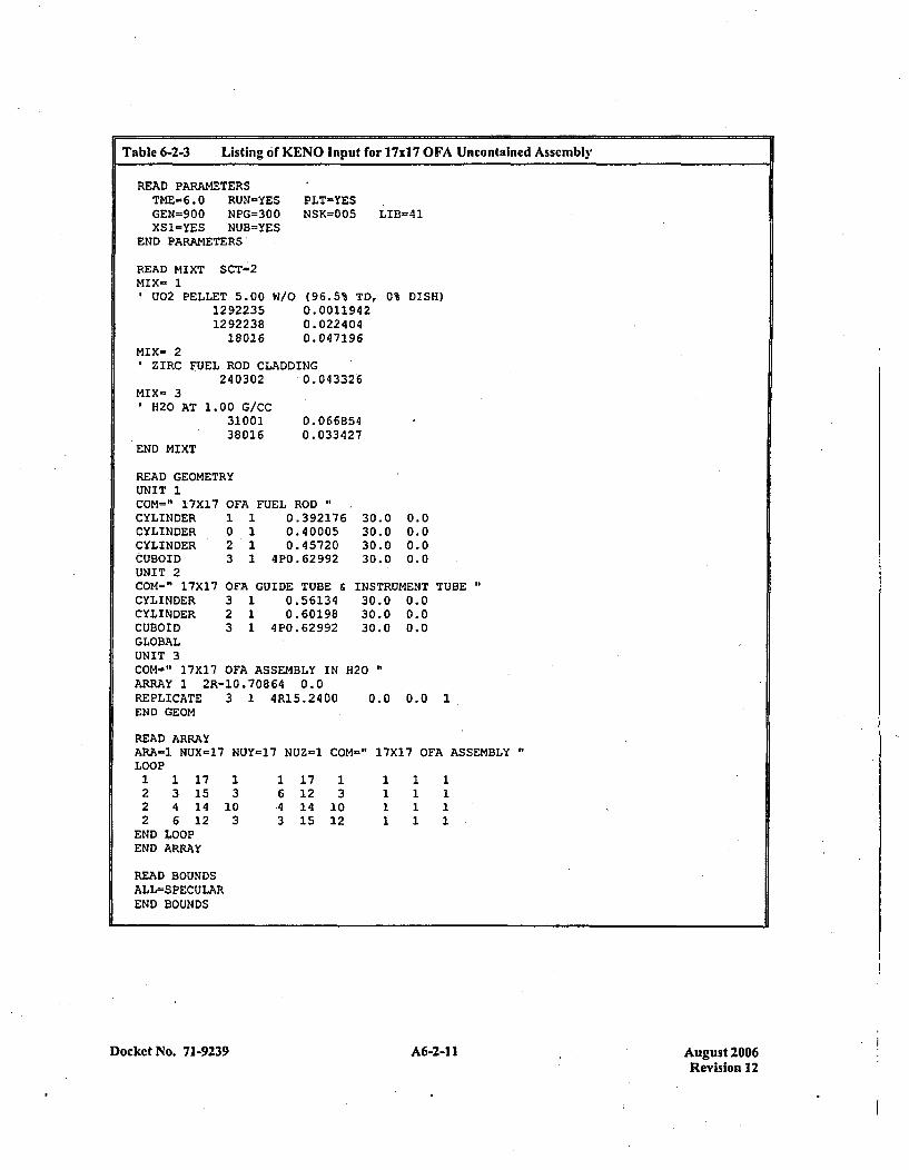
Table 6-2-3 Listing of KENO Input for 17xl7 OFA Uncontained AssemblyI
READ PARAMETERSTME-6.0 RUN-YESGEN=900 NPG=300XS1=YES NUB=YES
END PARAMETERS
READ MIXT SCT-2MIX= 1
002 PELLET 5.00 W1129223512 92238
18016
PLT=YESNSK=005 LIB-41
'0 (96.5% TD, 0% DISH)0.00119420. 022 4040.047196
MIX- 2ZIRC FUEL ROD CLADDING
240302 0.043326MIX- 3
' H20 AT
END MIXT
1.00 G/CC3100138016
0. 0668540. 033427
READ GEOMETRYUNIT 1COM=" 17X17 OFA FUEL RODCYLINDER 1 1 0.392176 30.iCYLINDER 0 1 0.40005 30.1CYLINDER 2 1 0.45720 30.1OUBOID 3 1 4P0.62992 30.1UNIT 2COM=" 17X17.OFA GUIDE TUBE &_INST]CYLINDER 3 1 0.56134 30.1CYLINDER 2 1 0.60198 30.1CUBOID 3 1 4P0.62992 30.1GLOBALUNIT 3COM-" 17X17 OFA ASSEMBLY IN H20ARRAY 1 2R-10.70864 0.0REPLICATE 3 1 4R15.2400 0.1END GEOM
00
0.00.00.00.0
RUMENT TUBE '
) 0.00 0.00 0.0
0 0.0 1
READ ARRAYARA-1 NUX=17 NUY-17 NUZ-1LOOP1 1 17 1 1 172 3 15 3 6 122 4 14 10 4 142 6 12 3 3 15
END LOOPEND ARRAY
COM-" 17X17 OFA ASSEMBLY "
13
1012
1111
1111
1111
READ BOUNDSALL=SPECULAREND BOUNDS
Docket No. 71-9239 A-- uut20A6-2-11Revision 12
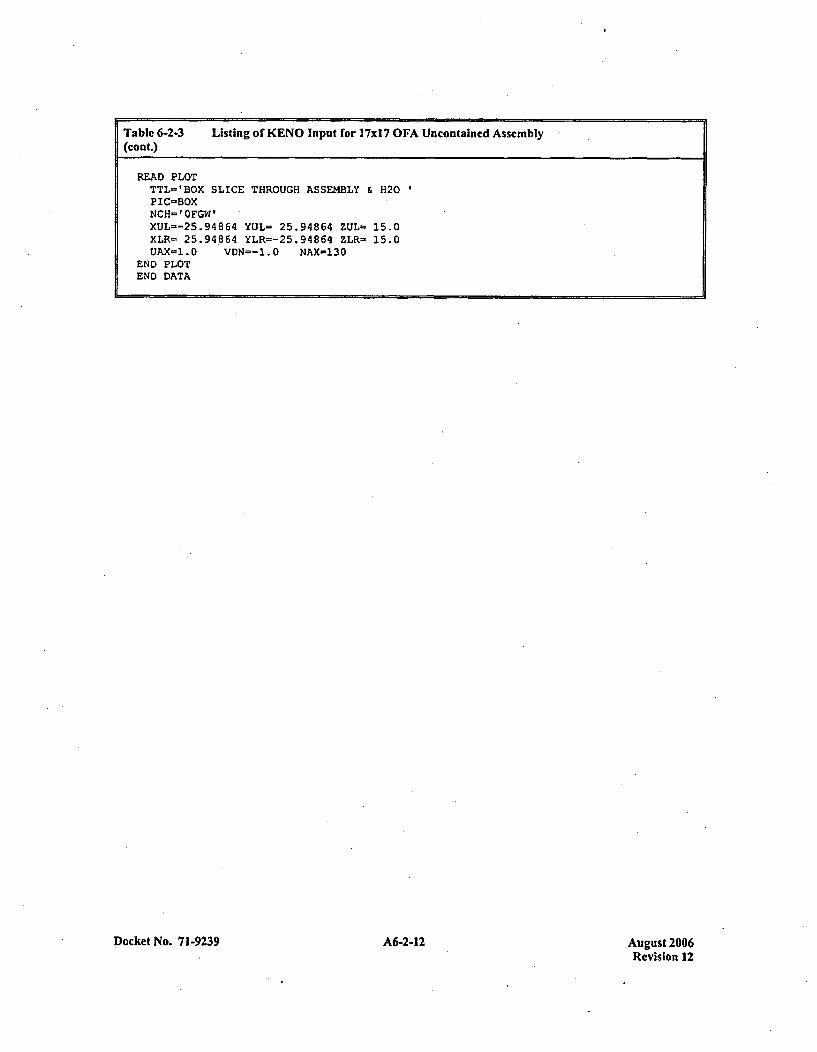
Table 6-2-3 Listing or KENO Input for 17xI 7 OFA Uncontaincd Assembly(cont.)
READ PLOTTTL-'BOX SLICE THROUGH ASSEMBLY & H20PIC-BOXNCH-'OFGW'XUL=-25.94864 YUL= 25.94864 ZUL- 15.0XLR- 25.94.864 YLR=-25.94864 ZLR- 15.0UAX-1.D VDN--1.O NAX-130
END PLOTEND DATA
Docket No. 7 1-9239 A6-2-12Au st20Revision 12
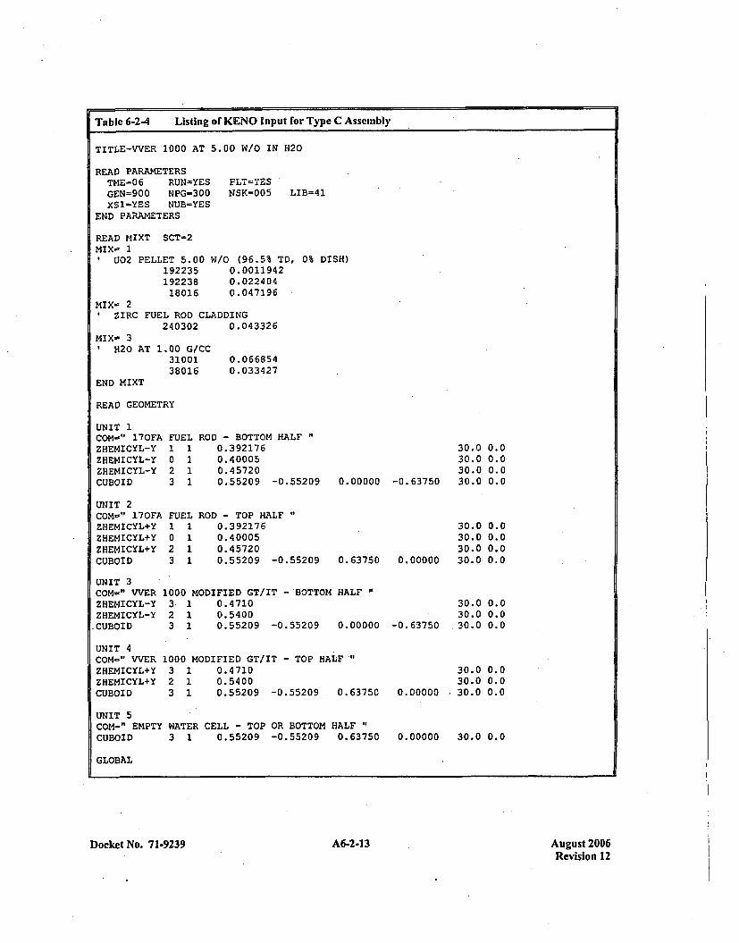
Table 6-2-4 Listing of K(ENO Input for Type C Assembly
TITLE-VVER 1000 AT 5.00 W/O IN H20
READ PARAMETERSTME=06 RUN-YES PLT=YES.GEN=900 NPG=300 NSK=005 LIB=41XS1-YES NUB=YES
END PARAMETERS
READ MIXT SCT=2MIX- 1
U02 PELLET 5.00192235192238
18016
W/o (96.5% TD, 0% DISH)0.001194 20.0224 040.047196
MIX- 2ZIRC FUEL ROD CLADDING
240302 0.043326MIXw 31 H20 AT 1.00 G/CC
3100138016
END MIXT
0.0668540.033427
READ GEOMETRY
UNIT 1COM-" 170FAZHEMICYL-YZHEt4ICYL-YZHEMICYL-YCUBOID
UNIT 2COM-" 170FAZHEMICYL+YZHEMICYL+YZHEMICYL+YCUBOID
FUEL1 10 12 13 1
FUEL1 10 12 13 1
ROD - BOTTOM HALF0.392 1760. 400050.457200.55209 -0.55209
ROD - TOP HALF0. 392 1760.4 00050. 457200.55209 -0.55209
30.0 0.030.0 0.030.0 0.030.0 0.00.00000 -0.63750
30.030.030.0
0.63750 0.00000 30.0
0.00.00.00.0
UNIT 3COM-" VVERZHEM4ICYL-YZHEMICYL-Y.CUBOID
UNIT 4COM-" VVERZHEMICYL+YZHEMICYL+YCUBOID
1000 MODIFIED GT/IT - BOTTOM HALF3 1 0.47102 1 0.54003 1 0.55209 -0.55209 0.00000
1000 MODIFIED GT/IT - TOP HALF`"3 1 0.47102 1 0.54003 1 0.55209 -0.55209 .0.63750
30.0 0.030.0 0.030.0 0.0-0. 63750
30.0 0.030.0 0.0
0.00000 -30.0 0.0
0.00000 30.0 0.0
UNIT 5COM-" EMPTY WATER CELL - TOP OR BOTTOM HALFCUBOID 3 1 0.55209 -0.55209 0.63750
GLOBAL
Docket No. 71-9239 A6-2-13 August 2006Revision 12
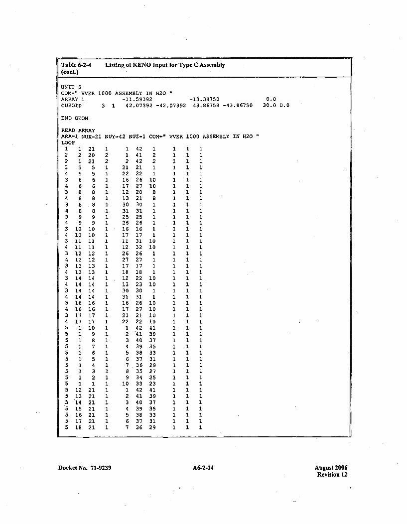
Table 6-2-4 Listing of KENO Input for Type C Assembly(cont.)
UNIT 6COM-" WVER 1000 ASSEMBLY IN H20ARRAY 1 -11.59392 -13.38750 0.0CUBOID 3 1 42.07392 -42.07392 43.86758 -43.86750 30.0 0.0
END GEOM
READ ARRAYARA=1 NUX=21 NUY=42 NUZ-1 COM'=" VVER 1000 ASSEMBLY IN H20LOOP1 1 21 1 1 42 1 1 1 12 2 20 2 1 41 2 1 1 12 1 21 2 2 42 2 1 1 13 5 5 1 21 21 1 1 1 14 5 5 1 22 22 1 1 1 13 6 6 1 16 26 10 1 1 14 6 6 1 17 27 10 1 1 13 8 8 1 12 20 *8 1 1 14 8 8 1 13 21 8 1 1 13 8 8 1 30 30 1 1 1 14 8 8 1 31 31 1 1 1 13 9 9 1 25 25 1 1 1 14 9 9 1 26 26 1 1 1 13 10 10 1 16 16 1 1 1 14 10 10 1 17 17 1 1 1 13 11 11 1 11 31 10 1 1 14 11 11 1 12, 32 10 1 1 13 12 12 1 26 26 1 1 1 14 12 12 1 27 27 1 1 1 13 13 13 1 17 17 1 1 1 14 13 13 1 18 18 1 1 1 13 14 14 1 12 22 10 1 1 14 14 14 1 13 23 10 1 1 13 14 14 1 30 30 1 1 1 14 14 14 1 31 31 1 1 1 13 16 16 1 16 26 10 1 1 14 16 16 1 17 27 10 1 1 13 17 17 1 21 21 10 1 1 14 17 17 1 22 22 10 1 1 15 1 10 1 1 42 41 1. 1 15 1 9 1 2 41 39 1 1 15 1 8 1 3 40 37 1 1 15 1 7 1 4 39 35 1 1 1.5 1 6 1 5 38 33 1 1 15 1 5 1 6 37 31 1 1 15 1 4 1 7 36 29 1 1 15 1 3 1 8 35 27 1 1 15 1 2 1 9 34 25 1 1 15 1 1 1 10 33 23 1 1 15 12 21 1 1 42 41 1 1 15 13 21 1 2 41 39 1 1 15 14 21 1 3 40 37 1 1 15 15 21 1 4 39 35 1 1 15 16 21 1 5 38 33 1 1 15 17 21 1 6 37 31 1 1 15 18 21 1 7 36 29 1 1 1
Docket No. 71-9239 A6-2-14 August 2006Revision 12
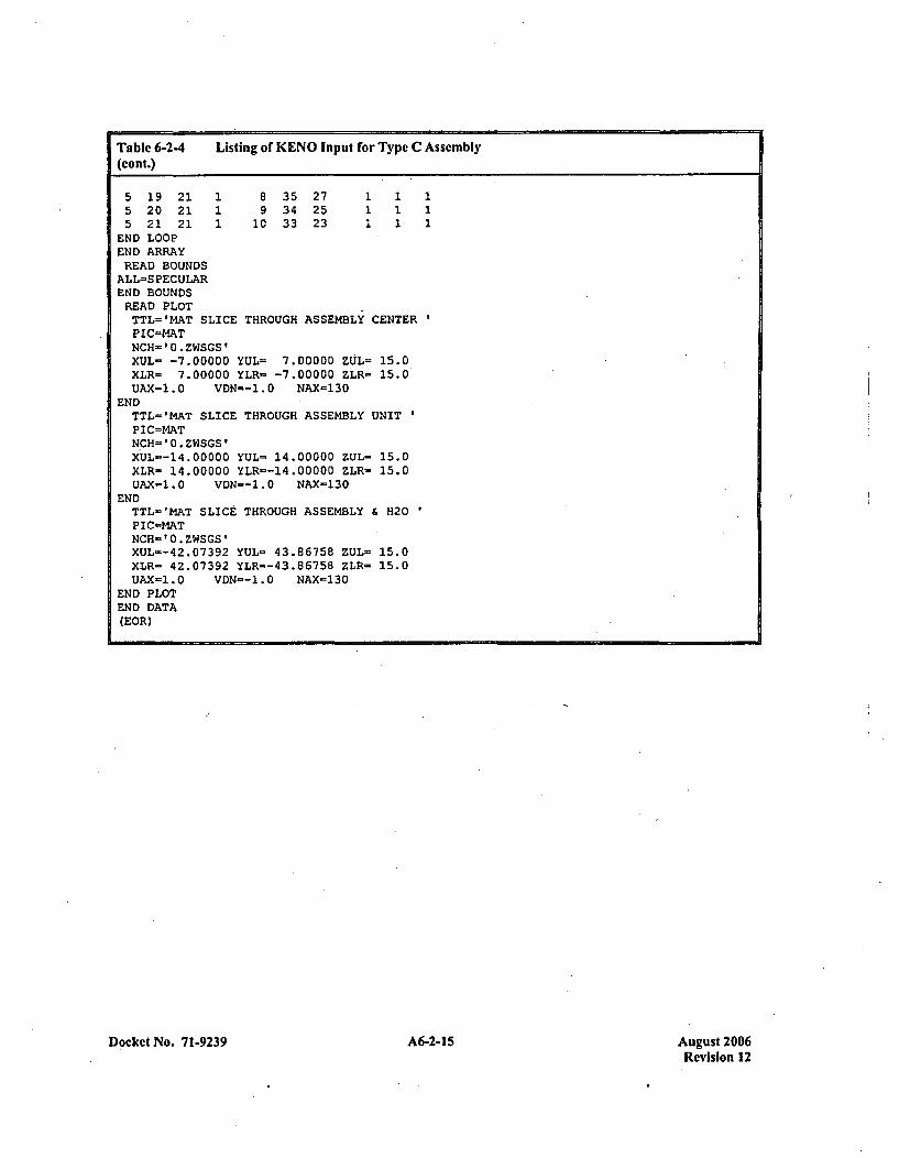
Table 6-2-4 Listing of KENO Input for Typc C Assembly(con t.)
5 19 21 1 8 35 27 1 12.5 20 21 1 9 34 25 1 1 15 21 21 1 10 33 23 1 1
END LOOPEND ARRAYREAD BOUNDS
ALL=S PECULAREND BOUNDSREAD PLOTTTL='MAT SLICE THROUGH ASSEMBLY CENTERPIC=NATNCH='0.ZWSGS'XUL- -7.00000 YUL= 7.00000 ZUL= 15.0XLR- 7.00000 YLR= -7.00000 ZLR- 15.0UAX=1.0 VDN--1.D NAX=130
ENDTTL='MAT SLICE THROUGH ASSEMBLY UNITPIC=MATNCH='0.ZWSGS'XtJL=-14.00000 YUL= 14.00000 ZUL- 15.0XLR= 14.00000 YLR=-14.00000 ZLR- 15.0UAX.=1.0 VDN=-1.O NAX-130
ENDTTL='MAT SLICE THROUGH ASSEMBLY & H20PIC=MATNCH='0.ZWSGS'XUL--42.07392 YUL= 43.86758 ZUL- 15.0XLR- 42.07392 YLR--43.86758 ZLR- 15.0UAX-1.0 VDN--1.0 NAX=130
END PLOTEND DATA(EOR)
Docket No. 71-9239 A6-2-1 5 August 2006Revision 12

APPENDIX 6-3EVALUATION OF THE NUCLEAR CRITICALITY SAFETY OF
SPACKAGED FUEL ASSEMBLIES
Docket No. 71-9239 A6-3-1 August 2006Revision 12
EVALUATION OF THE NUCLEAR CRITICALITY SAFETY OFPACKAGED FUEL ASSEMBLIES
INTRODUCTION
This section describes the methodology, calculations, and evaluation results for contained fuel assemblies.The results of this evaluation are used to define the basic enrichment limits for all the various fuelassembly designs, and to determine the requirements for using added neutron absorbers, when needed.(For economic reasons, an evaluation for shipping close-packed fuel rods in MCC containers is alsodescribed - in event a future amendment is pursued to enable such package use.)
Criticality of the fuel assemblies in the fuel shipping container is prevented by the design of the containerwhich limits fuel assembly interaction. Fuel assembly interaction is controlled by the fixed configurationof assemblies within the container and the permanent Gd2O3 neutron absorbers positioned between theassemblies. The design basis for preventing criticality is that, including uncertainties, there is a 95 percentprobability at a 95 percent confidence level that the effective neutron multiplication factor, K,,r, of theassembly array will be less than 0.95 for the Hypothetical Accident Condition (HAG) under credible fullyflooded and non-credible "optimum moderation" conditions. (Since drop tests have demonstrated thatdamaged containers remain substantially closed, exposure of the contained assemblies to less than fulldensity water is not considered credible).
The HAG model for the shipping container analysis is based on two flooded containers, crushcdtop-to-top, such that the two assemblies in one container arc separated from the two assemblies in theother container by eight inches of moderator. By applying reflective boundary conditions at the outeredges of this model, an infinite array of HAG container configurations is represented. The container shellsare assumed to be in place, with adjacent container shells in contact with each other.
DESIGN METHODS
The current Westinghouse design method, which insures the criticality safety of fuel assemblies, startswith 227 energy group cross-sections generated from ENDFI.B-V data. The AMPX system codes,NITAWL-S and XSDRNPMS, are used for cross-section library processing. The NITAWL-S programperforms the self-shielded resonance cross-section corrections that are appropriate for each particulargeometry. The Nordheim Integral Treatment is used. Energy and spatial weighting of the cross-sections isperformed by the XSDRNPMS program which is a one-dimensional transport theory code. Thesemultigroup cross-section sets are then used as input to KENO Va, which is a three dimensional MonteCarlo theory program designed for reactivity calculations.
The criticality calculation method and cross-section values are verified by comparison with criticalexperiment data for fuel assemblies similar to those, analyzed herein. This benchmarking data is.sufficiently diverse to establish that the method bias and uncertainty will apply directly to thesecalculations. Details of the benchmark experiments and bias results are, discussed in Chapter 6,Section 6.5.
Docket No. -71-9239 A6-3-3 August 2006Revision 12
ANALYSIS FOR TYPE A ASSEMBLIES
Type A fuel assemblies are those which have been shown in Appendix 6-2 to have an uncontained (singleassembly surrounded by water) reactivity, including biases and 95/95 uncertainties, of less than 0.936.Type A assemblies include all 14 X 14 and 16 X 16 fuel assembly designs, with attributes described inAppendix 1-5. The 14 X 14 Optimized Fuel Assembly (OFA) was identified as the most rcactive of thevarious Type A assemblies, hence it will be used for the Type A assembly container calculations presentedhe rein.
Figure 6-3-1 shows the geometry of the HAC which is modeled in KENO. For the Type A assemblies,KENO is used to provide an essentially exact two-dimensional geometric representation of the fuelassembly and shipping container. With two dimensions, the fuel assembly and container are assumed tobe infinitely long, which conservatively ignores the benefits of axial neutron leakage. As described in theintroduction, reflective boundary conditions are used at the edges of the two crushed containers topreclude any neutron leakage from the array. Using these boundary conditions is conservative since aninfinite array of crushed containers is simulated.
The KENO calculational model uses only two geometry units to model the fuel assembly. One unitdescribes a fuel rod cell, which contains an explicit geometric representation of a fuel pellet, gap,cladding, and surrounding water. The other unit describes the thimble tube cell, which has water bothinside and outside of the tube. In modeling the fuel, the U02 atom density is calculated by assuming aU0 2 density that is 96.5% of theoretical (10.96 Weec); pellet densities actually encountered typically rangefrom 94.5% to 95.5% of theoretical. No pellet dishing fraction or chamnfering is modeled, whichconservatively increases the number of 235U atoms by about 1.2%, depending on the specific pellet type.No credit is taken for the presence of naturally occurring ...4U or 116U , nor is any credit taken for assemblystructural material that does not extend the full length of the assembly (i.e., grids, top and bottom nozzle,etc.). These combined assumptions result in a very conservative model of a fuel assembly.
The shipping container material and structure which surrounds the fuel assembly is modeled in KENOusing three geometric units. The strongback, which is the 0.18 inch thick, 190 degree angled,ý carbon steelstructure to which the assembly is clamped, is modeled as two plates; a vertical plate an a horizontal.plate. The permanently mounted Gadolinia absorber sheet (0.035 inch carbon steel sheet coated withGd2O3 on both sides) is modeled as a single unit and positioned within the shipping container as shown inFigure 6-3-1.
With the top-crush accident assumed for the HAG, the fuel assemblies within the container are separatedfrom the outer container shell by 4 inches at the top, 8 inches at the sides and 15 inches at the bottom.Thus, when two containers are crushed top-to-top, the two assemblies in one container are separated fromthe two assemblies in the other container by eight inches of moderator. By applying reflective boundaryconditions at the outer edges of the containers, an infinite array of HAG container of configurations isrepresented. The container shells arc assumed to be in placc, with adjacent container shells in contact witheach other. To simplify the KENO model geometry, only half the shipping container is modeled with areflective boundary condition used at the vertical centerline.
Docket No. 7 1-9239 A6-3-4 August 2006Revision 12
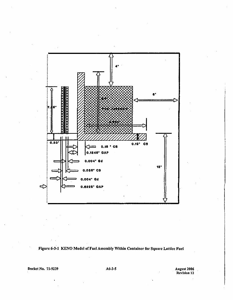
Figure 6-3-1 KENO Model of Fuel Assembly Within Container for Square Lattice Fuel
Docket No. 71-9239 A6-3-5 August 2006Revision 12

The results of the HAC evaluation for Typc A assemblies is presented in Table 6-3-1. The KENO inputdeck which was used for the calculation is given in Table 6-3-2. All tables showing KENO input decks areto be found at the end of this appendix.
ANALYSIS FOR TYPE B ASSEMBLIES.
Type B fuel assemblies are those which have been shown in Appendix 6-2 to have an uncontained (singleassembly surrounded by water) reactivity, including biases and 95/95 uncertainties, which is greater than0.936. Type B assemblies include all 15xl15 and 17x 17 fuel assembly designs, which attributes describedin Appendix 1-5. The 17x 17 Optimized Fuel Assembly (OFA) was identified as the most reactive of thevarious Type B assemblies, hence it will be used for the Type B assembly container calculations presentedherein.
Figure 6-3-1 shows the geometry of the HAG which is modeled in KENO. For the Type B assemblies,KENO is used to provide a conservative three-dimensional geometric representation of the fuel assemblyand shipping container. The three dimensional calculations assume an active fuel stack height of168 inches,. which is conservative since the majority Type B assembly designs 'are considerably shorterthan 168 inches. Reflection is used at the fuel axial centerlin'e to minimize problem size and complexity.At the fuel assembly end, 5.08 inches of water reflector is modeled, followed by the thin container shelland a reflective boundary condition. This is a conservative model since the container structural materialwhich exists in this area is replaced by pure water reflector and the spacing normally provided by the fuelrod plenum region (between 3 and 7 inches) is ignored.
As described in the introduction, reflective boundary conditions are used at the edges, of the two crushedcontainers to 'preclude any neutron leakage from the armay. Using these boundary conditions isconservative since an infinite array of crushed containers is simulated.
The KENO calculational model uses only two geometry units to model the fuel assembly. One unitdescribes a fuel rod cell, which contains an explicit geometric representation of a fuel pellet, gap,cladding, and surrounding water. The other unit describes the thimble tube cell, which has water bothinside and outside of the tube. In modeling the fuel, the U0 2 atom density is calculated by assuming aU0 2 density that is 96.5% of theoretical (10.96 glee); pellet densities actually encountered typically rangefrom 94.5% to 95.5% of theoretical. No pellet dishing fraction or chamrfering is modeled, which.conservatively increases the number of 23'U atoms by about 1.2% depending on the specific pellet type.No credit is taken for the presence of naturally occurrng 23Uor 236U, nor is any credit taken for assemblystructural material that does not extend the full length of the assembly (i.e., grips, top and bottom nozzle,etc.). These combined assumptions result in a very conservative model of a fuel assembly.
The shipping container material and structure which surrounds the fuel assembly is modeled in KENOusing three geometric units. The strongback, which is the 0.18 inch thick, 90 degree angled, carbon steelstructure to which the assembly is clamped, is modeled as two plates, a vertical plate and a horizontalplate. The permantently mounted Gadolinia absorber sheet (0.035 inch carbon steel sheet coated withGd203 on both sides) is modeled as a single unit and positioned within the shipping container as shown inFigure 6-3-1.
Docket No. 7 1-9239 A6-3-6 Auwust 2006Revision 12
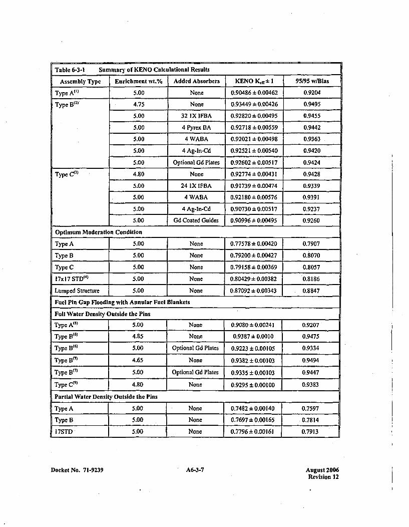
Table 6-3-1 Summary of KENO Caiculational Results
Assemnbly Type I Enrichment wvt.% Addcd Absorbers KENO (ff* 95195 W/Bias
Type A")t
Type Blt2)
5.00 None 0.904861~0.00462 0.9204
4.75 None 0.93449:b 0.00426 0.9495
5.00 32 IX IFBA 0.92820:k 0.00495 0.9455
5.00 4 Pyrex BA 0.92718:L 0.00559 0.9442
5.00 4 WABA 0.92021 ±- 0.00498 0.9363
5.00 4 Ag-In-Cd 0.92521 :L 0.00540 0.9420
5.00 Optional Gd P lates 0.92602:L 0.00517 0.9424
4.80 None 0.92774 ± 0.00431 0.9428
5.00 24 IX IFBA 0.9 1739 ± 0.00474 0.9339
5.00 4 WABA 0.92180:k0.00576 0.9391
5.00 4 Ag-In-Cd 0.907301~0.00517 0.9237
5.00 Gd Coated Guides 0.90996 ± 0.00495 0.9260
Type C(3)
Optimum Moderation Condition
Type A
Type B
5.00 None J0.775 78:h 0.00420 J 0.7 907
5.00 None [0.79200:k 0.00427 J 0.8070
5.00 None 0.79 158 -L 0.00369 j 0.8057Type C
I 7x 17 STD (4 ) 5.00 None 0.80429:h 0.003 82 0.8 186
Lumped Structure J 5.00 N one 0.87092 ± 0.00343 0.8 847
Fuel Pin Gap Flooding with Annular Fuel Blankets
Full Water Density Outside the Pins
Type Aý5 ) 5.00 None 0.9080:1:0.0024 1 0.9207
Type B(6) 4.85 None 0.9387 1 0.0010 0.9475
Type B (6) 5.00 Optional Gd Plates 0.9223 ± 0.00105 0.9334
Type B(7) 4.65 None 0.9382 ± 0.00103 0.9494
Type B (7 ) 5.00 Optional Gd Plates 0.9335 ± 0.00103 0.9447
Type 0t 9) 4.80 None 0.9295 ± 0.00100 0.9383
Partial Water Density Outside the Pins
Type A
Type B
5.00 None 0.7482 + 0.00140 0.7597
5.00 None 0.7697 dh 0.00165 .0.78 14
5.00 None 0.7796 ±: 0.00 161 0.791317STD
Docket No. 71-9239 A6-3-7 A6-3-7August 2006Revision 12
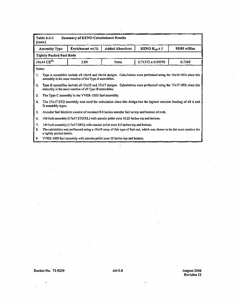
Table 6-3-1 Summary of KENO Calculational Results
(cont.)
Assembly Type 7 Enrichment wt.%6 Added Absorbers KENO Kdrb : 1 95/95 w/Bias
Tightly Packed Fuel Rods
14xl14 CE(" 5.00 None 0. 32~00260.7268
Notes:
1. Type A assemblies include all 14x 14 and 16x16 designs. Calculations were performed using the 14x14 OFA since this
assembly is the most reactive of the Type A assemblies.
2. Type B assemblies include all I 5x15 and 17x 17 designs. Calculations were performed using the 17x 17 OFA since thisassembly is the most reactive of all Type B assemblies.
3. The Type C assembly is the VVER-l1000 fuel asscmbly.
4. The l7x17 STD assembly was used for calculation since this design has the highest uranium loading of all A andB assembly types.
5. Annular fuel blankets consist of nominal 8.0 inches annular fuel at top and bottom of rods.
6. 168 Inch assembly (I 7x 17 STD/XL) with annular pellet zone 10.25 inches top and bottom.
7. 144 Inch assembly (I 7x1 7 OFA) with annular pellet zone 8.0 inches top and bottom.8. The calculation was performed using a l9xl9 array of this type or fuel rod, which was shown to be the most reactive for
a tightly packed lattice.
9. VVER-l 000 fuel assembly with annular pellet zone 10 inches top and bottom.
Docket No. 71-9239 A6-3-8 August 2006Revision 12

With the top-crush accidcnt assumed for the HAG, the fuel assemblies within the container are separatedfrom thc outer container shell by 4 inches at the top, 8 inches at the sides, 15 inches at the bottom, and5.08 inches at the ends. Thus, when two containers are crushed top-to-top, the two assemblies in onecontainer are separated from the two assemblies in the other container by eight inches of moderator. Byapplying reflective boundary conditions at the outer cdges of the containers, an 'infinite array of HAGcontainer of configurations; is represented. The container shells are assumed to be in place, with adjacentcontainer shells in contact with each other. To simplify the KENO model geometry, only half the shippingcontainer is modeled with a reflective boundary condition used at the vertical centerline between thetwo assemblies in one cask.
The results of the HAG evaluation for Type B' assemblies is presented in Table 6-3-1. The KENO inputdeck which was used for the calculation is given in Table 6-3-3.
ADDITIONAL NE UTRON ABSORBERS
Additional neutron absorbers are utilized in higher enrichment Type B assemblies to maintain K,,f lessthan the 0.95 criterion. Two different placements of absorbers are considered in this evaluation; within thefuel assembly and external to the fuel assembly. This evaluation determines the minimum number andrequired placement for each type of absorber. The Type B within-container fuel assembly model(developed in the previous section) is used here as a basis for the additional absorber evaluations. Usingthe most reactive Type B assembly to evaluate relative absorber worths is appropriate since the relativeworth of each absorber rod would be approximately the same, regardless of assembly type.
For the within-assembly absorber evaluation, four different types of absorbers are considered: IntegralFuel Burnable Absorbers (IFBA), Pyrex Burnable Absorber clusters, Wet Annular Burnable Absorber(WA13A) clusters, and Ag-In-Cd Absorber clusters. Each absorber type is described by a nominal densityand manufacturing tolerance at the 95% confidence level. For ealculational purposes, the modeledabsorber number densities arc reduced from nominal by a factor to account for the manufacturingtolerance, and by an extra 25% for added conservatism.
Each absorber was modeled assuming an axial length of 108 inches, centered about the assembly axialmidplane. Typically, absorbers are significantly longer than the assumed 108 inch minimum, therebyadding more conservatism to the model.
ABSORBER MODELING IN TYPE B ASSEMBLIES
Westinghouse IFBA with the 10B uniformly smeared in the clad region of the fuel rod in all its nuclearmodels. This is done for consistency, and because the difference in reactivity is slight. Ho1wever, for thoseappli cations where this could lead to non-conservative results, a bias is included to account for anydifference in reactivity.
The modeling effect of boron is slight because, as used with IFBA, it is not a strong absorber. The mainreason for this is that very little is used per rod, about 10% of the poison density in WABA, Pyrex, or agadolinium rod. ,For the comparison to gadolinium, the absorption cross section is also smaller by at leastanother factor of ten.
Docket No. 7 1-9239 A6-3-9 August 2006Revision 12
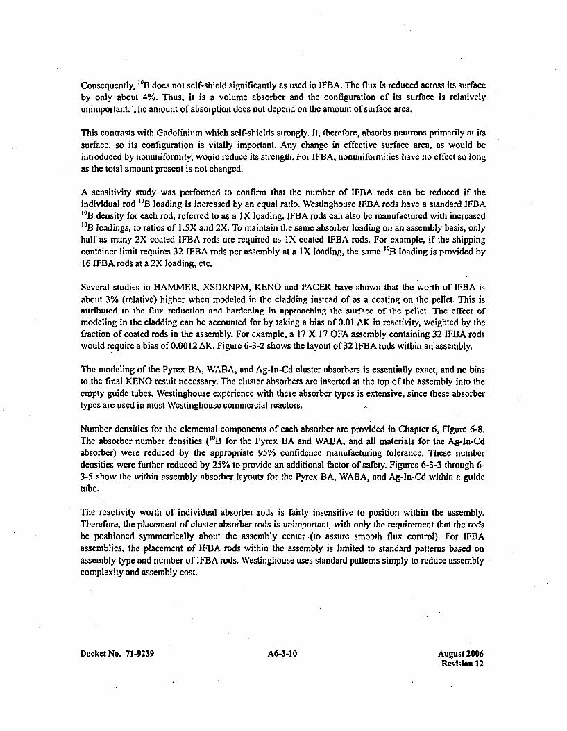
Consequently, 1013 does not self-shield significantly as used in IFBA. The flux is reduced across its surfaceby only about 4%. Thus, it is a volume absorbcr and the configuration of its surface is relativelyunimportant. The amount of absorption does not depend on the amount of surface area.
This contrasts with Gadolinium which self-shields strongly. It, therefore, absorbs neutrons primarily at itssurface, so its configuration is vitally important. Any change in effective surface area, as would beintroduced by nonuniformity, would reduce its strength. For IFBA, nonuniformitics have no effect so longas the total amount present is not changed.
A sensitivity study was performed to confirm that the number of IFBA rods can be reduced if theindividual rod 1013 loading is increased by an equal ratio. Westinghouse IFBA rods have a standard IFBA'013 density for each rod, referred to as a IX loading. IFBA rods can also bc manufactured with increased1013 loadings, to ratios of 1.5X and 2X. To maintain the same absorber loading on an assembly basis, onlyhalf as many 2X coated IFBA rods are required as IX coated IFBA rods. For example, if the shippingcontainer limit requires 32 IFBA rods per assembly at a I X loading, the same 1013 loading is provided by16 IFBA rods at a 2X loading, etc.
Several studies in HAMMER, XSDRNPM, KENO and PACER have shown that the worth of IFBA isabout 3% (relative) higher when modeled in the cladding instead of as a coating on the pellet. This isattributed to the flux reduction and hardening in approaching the surface of the pcllet. The effect ofmodeling in the cladding can be accounted for by taking a bias of 0.01 AK in reactivity, weighted by thefraction of coated rods in the assembly. For example, a 17 X 17 OFA assembly containing 32 IFBA rodswould require a bias of 0.0012 AK. Figure 6-3-2 shows the layout of 32 IFBA rods within an'assembly.
The modeling of the Pyrex, BA, WABA, and Ag-In-Cd cluster absorbers is essentially exact, and no biasto the final KENO result necessary. The cluster absorbers are inserted at the top of the assembly into theempty guide tubes. Westinghouse experience with these absorber typcs is extensive, since these absorbertypes are used in most Westinghouse commercial reactors.
Number densities for the elemental components of each absorber are provided in Chapter 6, Figure 6-8.The absorber number densities (10B3 for the Pyrex BA and WABA, and all materials for the Ag-In-Cdabsorber) were reduced by the appropriate 95% confidence manufacturing tolerance. These numberdensities were further reduced by 25% to provide an additional factor of safety. Figures 6-3-3 through 6-3-5 show the within assembly absorber layouts for the Pyrex BA, WABA, and Ag-in-Cd within a guidetube.
The reactivity worth of individual absorber rods is fairly insensitive to position within the assembly.Therefore, the placement of cluster absorber rods is unimportant, with only the requirement that the rodsbe positioned symmetrically about the assembly center (to assure smooth flux control). For IFBAassemblies, the placement of IFBA rods within the assembly is limited to standard patterns based onassembly type and number of IFBA rods. Westinghouse uses standard patterns simply to reduce assemblycomplexity and assembly cost.
Docket No. 71-9239 A6-3-10 August 2006Revision 12
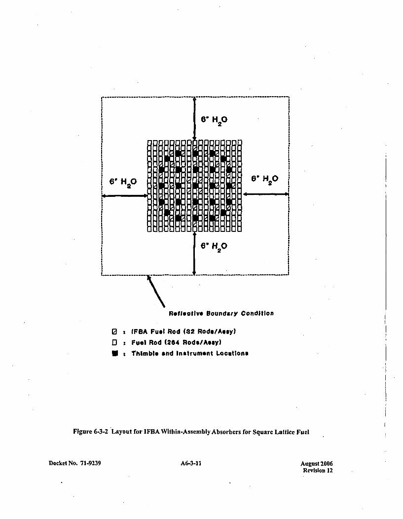
Reflective Boundary Condition
0 IFBA Fuel Rod (32 Rods/Ausy)
E) Fuel Rod (284 Rode/Assy)*:Thimble and Instrument Locations
Figure 6-3-2 Layout for IFBA Within-Assembly Absorbers for Square Lattice Fuel
Docket No. 7 1-9239 A6-3-11I August 2006Revision 12
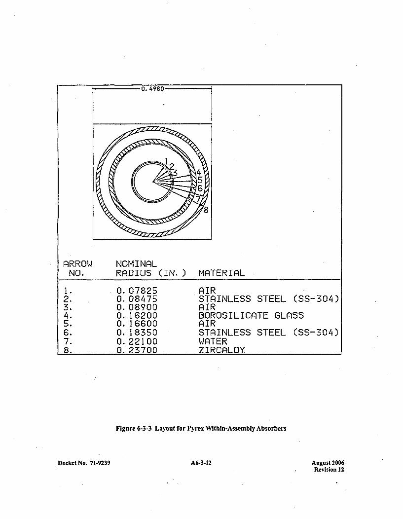
0. 4960-
AlRROWNO.
NOMINAlLRAlDIUS (IN.) MATERIAiL
I1. 0. 07825 AIR2. 0. 08475 STAINLESS STEEL (SS-304)3. 0. 08900 A~IR4. 0. 16200 BOROSILICAITE GLASS5. 0. 16600 A~IR6. 0. 18350 STA~INLESS STEEL (SS-304)7. 0. 22100 WAnTER8. 0. 23700 ZIRCALOY
Figure 6-3-3 Layout for Pyrcx Within-Assembly Absorbers
Docket No. 71-9239 A6-3-12 August 2006Revision 12
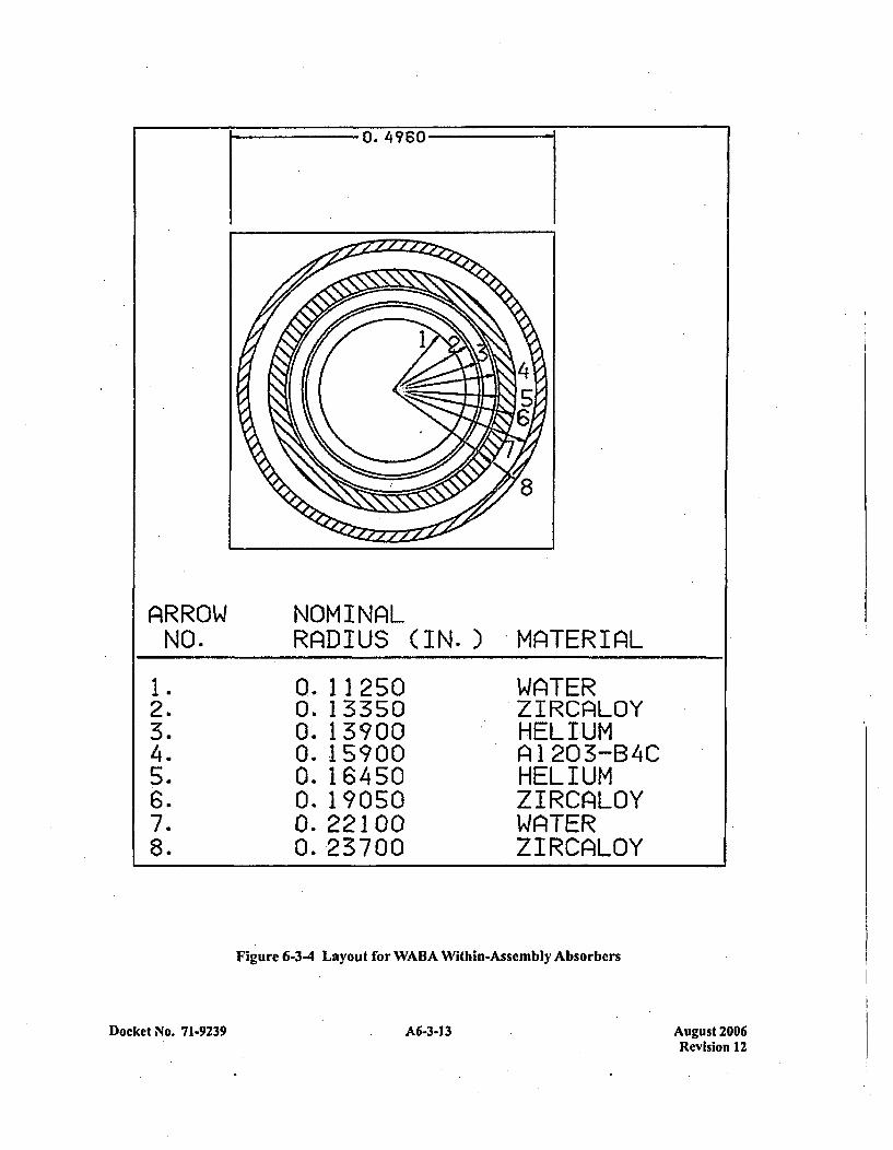
0. 4960
A~RROW NOMINAlLNO. RAlDIUS (IN.) 'MATERhIAL
1. 0.11250 WA~TER2. 0. 13350 ZIRCA~LOY3. 0. 13700 HELIUM4. 0. 15900 ri1203-B4C5. 0. 16450 HELIUM6. 0. 19050 ZIRCAiLOY7. 0. 22100 WA1TERý8. 0. 23700 ZIRCiAL0Y
Figure 6-3-4 Layout for WABA Within-Assembly Absorbers
Docket No. 71-9239 A6-3-13 August 2006Revision 12
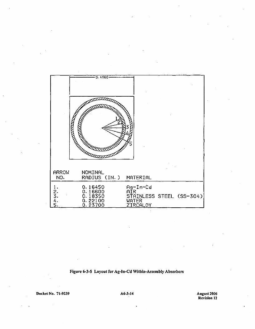
0. 4960-
AlRROW NOMINALNO, RADIUS (IN.) MAlTERIAL
1. 0. 16450 lig-In-td2. 0.16600 AIR3. 0. 18350 STAINLESS STEEL (SS-304)4. 0.22100 WATER5. 0. 23700 ZIRCALOY
Figure 6-3-5 Layout for Ag-In-Cd Within-Assembly Absorbers
Docket No. 71-9239 A6-3-14 August 2006Revision 12
One external assembly absorber was also evaluated. An additional Gd2O3 absorber plate, identical to thepermanently mounted absorbers already in place in the container, was positioned directly underneath thestrongback, centered within the assembly footprint. Unlike all the other Type B assembly evaluations, thiscalculation was performed in two dimensions, conservatively ignoring the benefits of axial leakage.Given the model's reflective-boundary at the vertical centerline between the assemblies within the cask,this model actually represents a Gd2O3 coating under the strongback, beneath each assembly.
The results of the additional absorber evaluations for Type B assemblies is presented in Table 6-3-1. TheKENO input decks which were used for the calculation arc given in Tables 6-3-4 through 6-3-8.
ANALYSIS FOR TH E TYPE C ASSEMBLY
The Type C assembly is the VVER-1000 type fuel assembly shown in Appendix 6-2 to have anuncontained ( single assembly surrounded by water) reactivity, including biases and 95/95 uncertainties,of 0.9432.
Figure 6-3-6 shows the geometry of the HAC which is modeled in KENO. For the Type C assembly,KENO is used to provide a conservative three-dimensional geometric representation of the fuel assemblyand shipping container. The three dimensional calculations assume an active fuel stack height of142.91 inches. Reflection is used at the fuel axial ccnterline to minimize problem size and complexity. Atthe fuel assembly end, 6.0 inches of water reflector is modeled, followed by the thin container shell and areflective boundary condition. This is a conservative model since the container structural material whichexists in this area is replaced by pure water reflector and the spacing normally provided by the fuel rodplenum region is ignored.
As described in the introduction, reflective boundary conditions are used at the edges of the two crushedcontainers to preclude any neutron leakage from the array. Using these boundary conditions isconservative since an infinite array of crushed containers is simulated.
The KENO calculation model uses five geometry units. The first two-units describe the top and bottom ofa fuel rod cell. The next two units describe the top and bottom of a modified thimablc tube cell. Thethimble tube inner and outer diameters were reduced to fit correctly into the fuel assembly array model.This is a conservative modification since the amount of thimble tube material available for neutron.absorption is reduced and the amount of water available for moderation is increased. The last unit is anempty water cell used to create a square assembly array in KENO. The fuel rod cells and thimble tubecells are positioned in an array to create a triangular pitch equal to the VVER-1000 fuel assembly. Inmodeling the fuel, the U0 2 atom density is calculated by assuming a U0 2 (corrected to 5.0 wt %) densitythat is 96.5% of theoretical (10.9547 gm/cc); pellet densities actually encountered typically range from94.5% to 95.5% of theoretical. No pellet dishing fraction or chamfering is modeled, which conservativelyincreases the number of 2135U atoms by about 1.2%, depending on the specific pellet type. No credit istaken for the presence of naturally occurring 234U or 236 U, nor is any credit taken for assembly structuralmaterial that does not extend the full length of the assembly (i.e., grids, top and bottom nozzle, etc.).These combined assumptions result in a very conservative model of a fuel assembly.
Docket No. 7 1-9239 A6-3-15 August 2006Revision 12
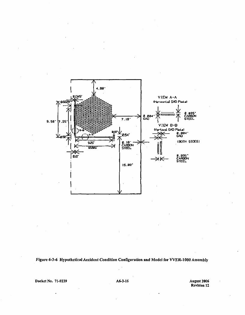
VIEW A-AHoizonLel GAD PaLot)
I_______ Ufl.004 CARBONwA' 1 STEEL
925'
Zia,
VIEW S-13(Ver-twal GAD P*Lot.)
a- 004'GAD((II (BOTH
U. 835*-~CARBON
S I DES)
Figure 6-3-6 Hypothetical Accident Condition Configuration and Model for VVER-1 000 Assemibly
Docket No. 71-9239 A6-3-16 August 2006Revision 12
The shipping container material and structure which surrounds the fuel assembly is modeled in KENOusing four geometric units. The strongback, which is the 0. 18 inch thick, 90 degree angled, carbon steelstructure to which the assembly is clamped, is modeled as two plates: a vertical plate and a horizontalplate. The permanently mounted vertical Gadoliniumn absorber sheet (0,035 inch carbon steel sheet coatedwith Gd2Q03 on both sides) is modeled as a single unit and positioned with the shipping container as shownin Figure 6-3-6. The permanently mounted horizontal Gadolinia absorber sheet (0.035 inch carbon steelsheet coated with Gd2O3 on the underside) is modeled sections and positioned directly underneath thehorizontal portion of the strongback as shown in Figure 6-3-6.
With the top-crush accident assumed for the HAC, the fuel assemblies within the container are separatedfrom the outer container shell by 4 inches at the top, 7.18 inches at the sides, 15 inches at the bottom, and6.0 inches at the ends. Thus, when two containers are crushed top-to-top, the two assemblies in onecontainer are separated from the two assemblies in the other container by eight inches of moderator. Byapplying reflective boundary conditions at the outer edges of the containers, an infinite array of HACcontainer configurations is represented. The container shells are assumed to be in place, with adjacentcontainer shells in contact with each other. To simplify the KENO model geometry only half the shippingcontainer, is modeled with a reflective boundary condition used at the vertical centerline between the twoassemblies in one cask.
The results of the HAC evaluation, for the Type C assembly is presented in Table 6-3-I1. The KENO inputdeck which was used for the calculation is given in Table 6-3-9.
ADDITIONAL HAC CALCULATION WITH WATER IN THE FUEL PIN GAP FOR THETYPE C ASSEMBLY
A calculation was performed for the HAC with full density water modeled in the gap between the fuelpellet and cladding. The KENO model used for this calculation is identical to the optimum moderationKENO model shown in Figure 6-3-9 with full density water considered both in and surrounding the fuelpins. The calculation resulted in a Kfr value of 0.9466, which includes biases and 95/95 uncertainties.This result shows that the Kff < 0.95 limit is met, even under conditions of water in the fuel pin gap. TheKENO input file which was used for this calculation is given in Table 6-3-17.
ADDITIONAL NEUTRON ABSORBERS FOR THE TYPE C ASSEMBLY
Additional neutron absorbers are utilized in higher enrichment the Type C assembly to maintain Kf lessthan the 0.95 criteria. Two different absorbers ~arc considered in this evaluation; within the fuel assemblyand external to the fuel assembly. This evaluation determines the minimum number and requiredplacement for each type of absorber. The Type C within-container fuel assembly model (developed in theprevious section) is used here as a basis for the additional absorber evaluations.
For the within-assembly absorber evaluation, three different types of absorber is considered: Integral FuelBurnable Absorbers (IFBA), WABA clusters, and Ag-In-Cd Absorber clusters. Each absorber type isdescribed by a nominal density and manufacturing tolerance at the 95% confidence level. Forcalculational purposes, the modeled absorber number densities are reduced from nominal by a factor toaccount for the manufacturing tolerance, and by an extra 25% for added conservatism. Each absorber wasmodeled assuming an axial length of 108 inches, centered about the assembly axial midplane. Typically,
Docket No. 71-9239 A6-3-17 August 2006Revision 12
absorbers are significantly longer than the assumed 108 minimum, thereby adding conservatism to themodel.
ABSORBER MODELING IN THE TYPE C ASSEMBLY
Westinghouse models IFBA with the '013 uniformly smeared in the clad region of the fuel rod in all itsnuclear models. This is done for consistency, and because the difference in reactivity is slight. However,for those applications where this could lead to non-conservative results, a bias is included to account forany difference in reactivity.
The modeling effect of boron is slight because, as used with IFBA, it is not a strong absorber. The mainreason for this is that very little is used per rod, about 10% of the poison density in WABA or agadolinium rod. For the comparison to gadolinium, thc absorption cross sections is also smaller by at ]eastanother factor of ten.
Consequently, 1013 does not self-shield significantly as used in IFBA. The flux is reduced across its surfaceby only about 4%. Thus, it is a volume absorber and the configuration of its surface is relativelyunimportant. The amount of absorption ýdoes not depend on the amount of surface area.
This contrasts with Gadolinium which self-shields strongly. It, therefore absorbs neutrons primarily at itssurface, so its configuration is vitally important. Any change in effective surface area, as would beintroduced by nonuniformity, would reduce its strength. For IFBA, nionuniformities have no effect so longas the total amount present is not changed.
A sensitivity study was performed to confirm that the number of IFBA rods can be reduced if theindividual rod 10B loading is increased by an equal ratio. Westinghouse IFBA rods have a standard IFBA"'B density for each rod, referred to as a IX loading. IFBA rods can also be manufactured with increased10B loadings, to ratios of 1 .5X and 2X. To maintain the same absorber loading on an assembly basis, only.half as many 2X coated IFBA rods are required as I X coated IFBA rods. For example, if the shippingcontainer limit requires 24 JEBA rods per assembly at a IX loading, the same "'B3 loading is provided by12 IFBA rods at a 2X loading, etc.
Several studies in HAMMER, XSDRNPM, KENO and PACER have shown that the worth of IFBA isabout 3% (relative) higher when modeled in the cladding instead of as a coating of the pellet. This isattributed to the flux reduction and hardening in approaching the surface of the pellet. The effect ofmodeling in the cladding can be accounted for by taking a bias of 0.01 AK in reactivity, weighted by thefraction of coated rods in the assembly. For example, a VVER-1000 assembly containing 24 IFBA rodswould require a bias of 0.0008. Figure 6-3-7 shows the layout of 24 IFBA rods within a VVER-O000assembly.
The modeling for the WABA and Ag-In-Cd cluster absorbers is essentially exact, and no bias to the finalKENO results is necessary. The cluster absorbers are inserted at the top of the assembly into the empty.guide tubes. Westinghouse experience with these absorber types is extensive, since these absorber typesare used in most Westinghouse commercial reactors.
Docket No. 71-9239 A6-3-18 August 2006Revision 12
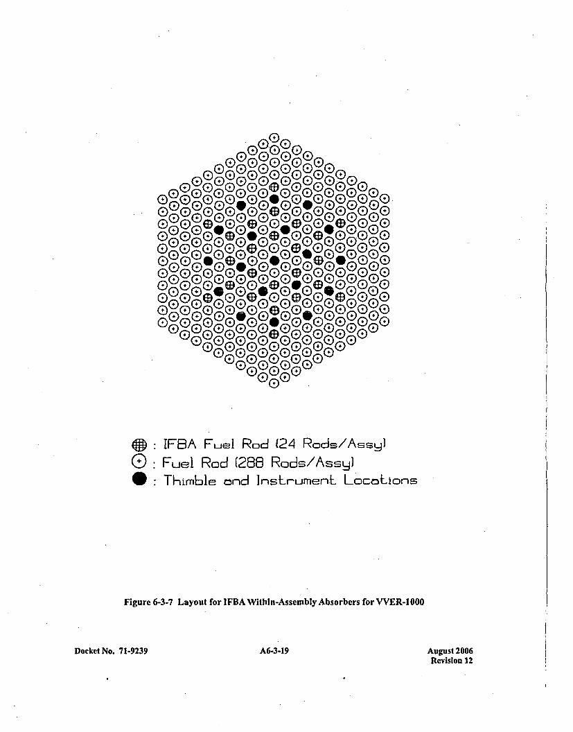
Gee®~I00h0
00000
G)~~ 0 G)0G 00G®0 )0G
IFAFe Rd(Z Rd/sy
0: Fu0 0o (26 Ro d E/A0s(D00Thmble690900900000L000ion
Fiur 0-- L 0ou fo (DB Wihn-seml Abobr for 0- 00
Doke No G193 G A6(.3G-)19 E
August 2006Revision 12
Number densitics for the elemental components of each absorber arc provided in Chapter 6, Figure 6-8.Thc absorber number densities (1oB for the WABA and all materials for the Ag-In-Cd absorber) werereduced by the appropriate 95% confidence manufacturing tolerance. These number densities were furtherreduced by 25% to provide an additional factor of safety. Figures 6-3-4 and 6-3-5 show the withinassembly absorber layout for the WABA and Ag-In-Cd with a guide tube.
The reactivity worth of individual absorber rods is fairly insensitive to position within the assembly.Therefore, the placement of cluster absorber rods is unimportant, with only the requirement that the rodsbe positioned symmetrically about the assembly center (to assure smoother flux control).
One external assembly absorber was also evaluated. An additional Gd2O3 absorber coating was added tothe guide plates which are positioned between the horizontal strongback and the fuel assembly. Theguided absorber plates are located between the container internals grid support blocks and below the fuelassembly. With this absorber in place, the horizontal gadolinium absorber was removed from the model.The guide plate is 0.060 inches of carbon steel thickness. The undersides of the guide plates are coatedwith a 0.027 gm/cm2 layer of Gd2O3. Unlike all ýthe other Type C assembly evaluations, this calculationwas performed without modeling the entire fuel stack length. The guided absorber plates areconservativcly modeled as 7.5 inches long followed by a 2.50 inch gap. Both ends of the model usereflective boundary conditions, conservatively ignoring the benefits of axial leakage. The model alsoapproximates the slant of the guide plate absorbers using a series of steppcd slabs. These slabsconservatively preserve the spacing bctwcen the guide plate and the assembly faces and the amount ofguide plate material present. This is a conservative modeling approximation of the guide plates since thereis more separation between the guide plate and assembly faces in the model and the positioning of theguide plate slabs is such that neutrons can leak from the assembly faces between the slabs (unlike the realsystem where the entire assembly face is exposed to the absorber). Finally, given the model's reflectiveboundary at the vertical centerline between the assemblies within the cask, this model actually representsa Gd2O3 coating underneath each assembly's guide plates.
The results of the additional absorber evaluations for the Type C assembly is presented in Table 6-3-1.The KENO input decks which were used for the calculations are given in Tables 6-3-10 through 6-3-13.
OPTIMUM MODERATION
Even though results of actual HAC drop tests have demonstrated that the shipping containers remainessentially intact (thus providing only for -ingress of full-density water), the problem has also beendeveloped to investigate reactivity under the non-credible Optimum moderation conditions. For thisevaluation, the most reactive Type A (14x14 OFA) and Type B (17x17 OFA) fuel assemblies areconsidered, as well as Type C (VVER-l000) and 17x]7 STANDARD fuel assembly. The 17x17STANDARD fuel assembly is considered because this assembly design has the highest uranium loadingof all the assembly types described in Appendix 1-5, and under optimum moderation conditions, theassembly type with the most 235U Will produce the highest reactivity.
The KENO model of the shipping container used in this optimum moderation evaluation is a modifiedversion of the model used to evaluate Type A, B, and C fuel assemblies under fully flooded conditions.For the optimum moderation evaluation, additional cask structure has been added to create a morerealistic representation of the actual shipping container. Under fully flooded conditions, this additional
Docket No. 7 1-9239 A6-3-20 August 2006Revision 12

structure can be ignored because its effect on reactivity is negligible (the full density water whichseparates the assemblies in the HAG geometry is sufficient by itself to absorb most of the neutronstraveling between assemblies). However, under optimum moderation conditions, the neutron mean freepath length becomes very long, increasing the neutronic coupling between fuel assemblies. In thisenvironment, the presence of additional cask structurc has a strong beneficial influence on cask reactivity,since the structure is a much better absorber than the low density water.
For the fully flooded evaluations, the KENO'model which is employed considers only the strongback andshell structures, ignoring over 75% (by weight) of the existing cask structure. For the optimummoderation evaluations, a more realistic model is employed which considers not only the strongback andshell structure, but other major full length components and the clamping frames as well for the MCC-3and MCC-4 casks. Clamping frames were not considered for the MCC-5 cask. The structure which isconsidered in these models still conseratively ignores more than 50% of the existing cask structure.
The additional structure which is added to the optimum moderation model is shown in Figure 6-3-8 forthe Type A and B fuel assembly models and Figure 6-3-9 for the Type C assembly model. Cask structuraldrawing numbers are provided, from which each additional structural component is referenced. To keepthe model as simple as possible, only major components are modeled. The model preserves the relativeshapes and positions of these added components as much as possible, although some were combinedand/or simplified to reduce complexity.
The optimum moderation model for Type A and B fuel assemblies is a 3D model which considers arepresentative 25 inch axial zone of the cask, with a single clamping frame centered within the zone. Atthe ends, reflecting boundary conditions are employed to preclude neutron leakage from the array. Thissimulates an infinitely long shipping container with a clamping frame every 25 inches. Figure 6-3-8.depicts this geometry layout. The optimum moderation model for the Type C fuel assembly is a 3D modelidentical to the full density moderation Type C fuel assembly model except for the additional caskstructure as shown in Figure 6-3-9.
Beyond the addition of the extra cask structure, the model employed for the optimum moderationevaluation is based on the same assumptions used for the fully-flooded HAG evaluations of the Type A,B, and C assemblies. With the top-crush accident assumed for the HAC, the fuel assemblies within thecontainer are separated from the outer container shell by 4 inches at the top, 8 inches at the sides, and15 inches at the bottom. Thus, when two containers are crushed top-to-top, the two assemblies inone container are separated from the two assemblies in the other container by eight inches of moderator.By applying reflective boundary conditions at the outer edges of the -containers, an infinite array of HAGconfigurations is represented. The container shells are assumed to be crushed into a square shape withadjacent container shells in contact with each other. This minimizes the overall distance betweenassemblies in adjacent containers, resulting in a conservative estimate of the HAG reactivity. With thisgeometry, the only area where optimum moderation water can exist is within each shipping container.
The infinite array geometry assumed in the model precludes any neutron leakage from the array. Underoptimum moderation conditions, a fast neutron spectrum is present, unlike the thermal spectrum createdby the strong moderation of full flooding. Fast neutrons have long mean free paths and are verysusceptible to leakage from the array. Ignoring neutron leakage under optimum moderation conditions isextremely conservative.
Docket No. 71-9239 631A6-3-21 August 2006Revision 12
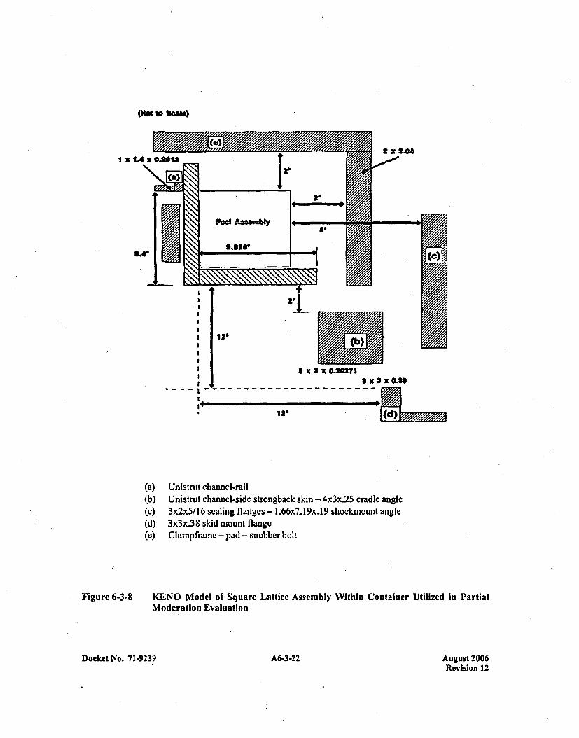
Ow to $*am)
I x
; 1 9 x 3 X.04
12' (d
(a)(b)(c)(d)(e)
Unistrut channel-railUnistrut channel-side strongback skin - 4x3x.25 cradle angle3x2x5/16 scaling flanges - 1.6607.19x. 19 shockmount angle3x3x.38 skid mount flangeClampframe - pad - snubber bolt
Figure 6-3-8 KENO Model of Square Lattice Assembly Within Container Utilized in PartialModeration Evaluation
19 A6-3-22 August 2006Revision 12
Docket No. 71-923
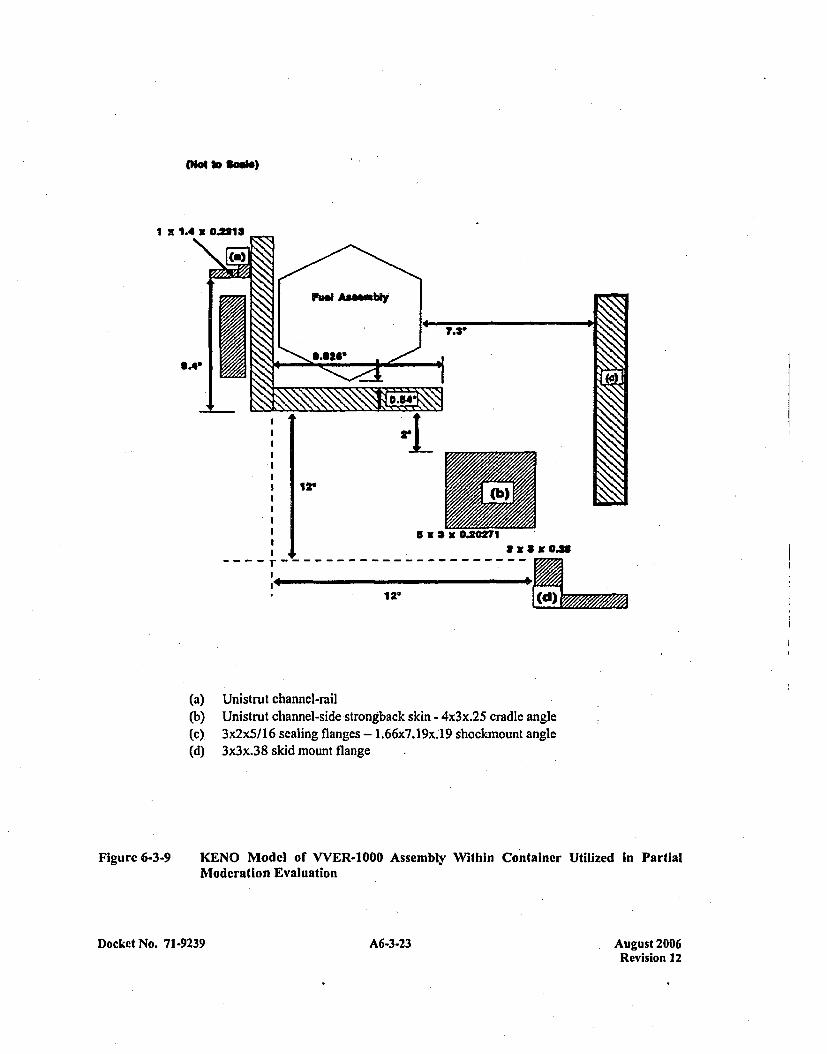
("a 10 Scae)
I Z
a x 3 NO0.3
12' d
(a)(b)(c).(d)
Unistrut channel-railUnistrut channel-side strongback skin - 4x3x.25 cradle angle3x2x5/16 sealing flanges - 1.66x7.19x.'19 shockmount angle3x3x.38 skid mount flange
Figure 6-3-9 KENO Model of WVER-1000 Assembly Within Container Utilized in PartialModeration Evaluation
Docket No. 71-9239 A6-3-23 A6-3-23August 2006Revision 12

The maximum reactivity results from each of the Type A, Typc B, Type C and 17x17 STANDARD fuelassemblies under optimum modcration HAG conditions are presented in Table 6-3-1. The variation ofreactivity with different optimum moderation water densities for each of the assembly types is shown inFigure 6-3-10. The KENO input deck which was used for the calculation is provided in Table 6-3-14.Note that significant margin exists to the optimum moderation Kcf limit, even with the use of a veryconservative shipping container model.
As a sensitivity study, an additional optimum moderation model was developed where all the additionalcask structure added in the above models was lumped into one rectangular component and positioned asfar from the fuel assemblies as possible. The geometry utilized for this case is depicted in Figure 6-3-11.The structure "lump"' size was chosen to closely match the volume of steel added by the extra modeledstructure, thereby preserving, the same conservative 1924 pound weight assumed in the above optimummoderation calculations. The KENO input deck used for this calculation is provided in Table 6-3-15. Theresultant Kff of this model is given in Table 6-3-1. The result shows that while the relative position of theadded structure is indeed important, the Kar limit is still satisfied even when the additional structure islumped and conservatively positioned to minimize interference with neutron interaction.
FUEL PIN GAP FLOODING WITH ANNULAR FUEL BLANKETS
This section considers the effect of flooding inside a fuel pin with full density water and outside the pinswith full and partial density water. Included in the analysis are annular pellet zones at the top and bottomof each assembly, in lengths of 8.0, 10.00, and 10.25 inches depending on fuel assembly type. All fuel isenriched to 5.0 W/o 235U with exception of VVER-1000 fuel that is enriched to 4.8 W/o 235U. The Mostreactive Type A (I14x 14 OFA) , Type B (I17x17 OFA), and TYPE C (VVER-l1000) fuel assemblies were,considered, as well as the 17x17 STANDARD (STD) and l7x17 STD/XL fuel assemblies. The l7x17STD fuel is considered under partial water density flooding since this assembly design has the highesturanium loading of all the assembly types described in Appendix 1-5; under optimum moderationconditions, the assembly type with the Most 235U will produce the highest reactivity. The KENO model ofthe shipping container used in the fuel pin gap flooding cases, with annular fuel zones top and bottom, is amodified version of the model used to evaluate fuel assemblies under optimum moderation conditions.For the fuel pin gap flooding evaluation, three-dimensional features were used to model the entire fuelstack length, including annular pellet zones.
The fuel pin gap flooding model considered for Type A, B, and C fuel assemblies is a 3D model whichconsiders half the length of the shipping container with a reflective boundary condition at the mid-plane.Seven clamping arms are modeled symmetrically about the shipping container mid-plane. Thisapproximation will have little effect on the overall reactivity of the model since the clamping arms arevery small (2 inches) relative to the arm ceniter-to-center spacing (25 inches). Additional steel componentsare also modeled here as in the optimum moderation cases. A Type B 168-inch length assembly is alsomodeled symmetrically with nine clamping arms.
Results are shown in Table 6-3-1 for water flooding at full density in both the fuel pin gap and annularfuel blanket annulus. These results show that the Kff- limit is met' for both Type A, B and C fuelassemblies under conditions of full density water flooding in the fuel pin gap and annulus and outsidethe pins. Input decks for the Type A, B and C fuel assembly models are listed in Tables 6-3-18, 6-3-19,and 6-3-28.
Docket No. 71-9239 A6-3-24 August 2006Revision 12

0.95
0.90
0.86
...... ....... .7 .....17-- SYTD
j4+ 1OFA~
...... ..(K0ff ......................0.75
0.70
1
.2V/5.. . .. . .. .. .. . .. . . . .. . . . .
0.600 0.01 0.02
Water
0.03 0.04 0.05
Density, gocc
0.08
Figure 6-3-10 Reactivity Versus Optimum Moderation Density MCC Optimum ModerationReactivity vs. Moderator Density
Docket No. 71.9239 A6-3-25 August 2006Revision 12
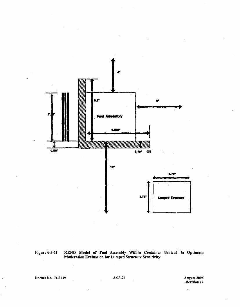
41
'3Ix 'S
Fuel A36.mbly
*Sw
0.13 C9
IV'
3.73.
-mw ftw
Figure 6-3-11 KENO Model of Fuel Assembly Within Container Utilized in OptimumModeration Evaluation for Lumped Structure Sensitivity
Docket No. 71-9239 A6-3-26 A 6-3.26August 2006-Revision 12
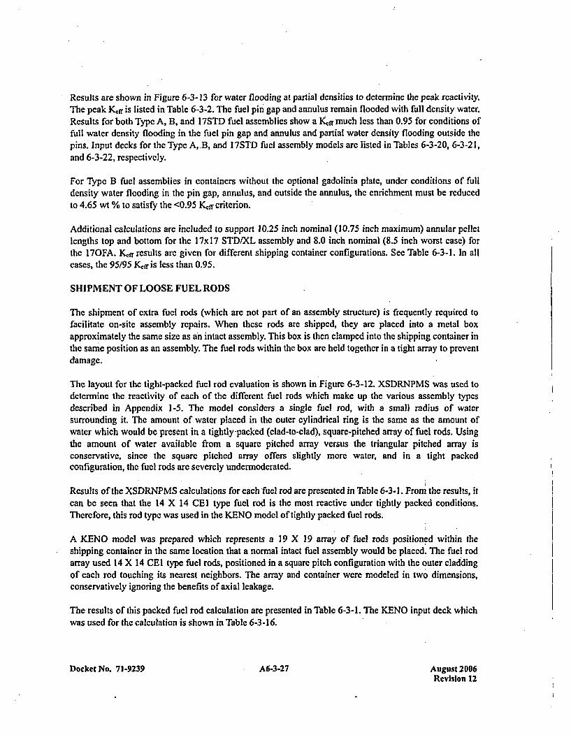
Results are shown in Figure 6-3-13 for water flooding at partial densities to determine the peak reactivity.The peak K,,ff is listed in Tablc 6-3-2. The fuel pin gap and annulus remain flooded with full density water.Results for both Type A, B, and I7STD fuel assemblies show a Kftr much less than 0.95 for conditions offull water density flooding in the fuel pin gap and annulus and partial water density flooding outside thepins. Input decks for the Type A,.B, and 17STD fuel assembly models arc listed in Tables 6-3-20, 6-3-21,and 6-3-22, respectively.
For Type B fuel assemblies in containers without the optional gadolinia plate, under conditions of fulldensity water flooding in the pin gap, annulus, and outside the annulus, the enrichment must be reducedto 4.65 wt % to satisfy the <0.95 K~ff criterion.
Additional calculations are included to support 10.25 inch nominal (10.75 inch maximum) annular pelletlengths top and bottom for the 17x 17 STD/XL assembly and 8.0 inch nominal (8.5 inch worst case) forthe I7OFA. Kfr results are given for different shipping container configurations. See Table 6-3-1. In allcases, the 95/95 Kerr is less than 0.95.
SHIPMENT OF LOOSE FUEL RODS
The shipment of extra fuel rods (which are not part of an assembly structure) is frequently required tofacilitate on-site assembly repairs. When these rods are shipped, they are placed into a metal boxapproximately the same size as an intact assembly. This box is then clamped into the shipping container inthe same position as an assembly. The fuel rods within the box are held together in a tight array to preventdamage.
The layout for the tight-packed fuel rod evaluation is shown in Figure 6-3-12. XSDRNPMS was used todetermine the reactivity of each of the different fuelC rods which make up the various assembly typesdescribed in Appendix 1-5. The model considers a single fuel rod, with a small radius of watersurrounding it. The amount of water placed in the outer cylindrical ring is the same as the amount ofwater which Would be present in a tightly-packed (clad-to-clad), square-pitched array of fuel rods. Usingthe amount of water available from a square pitched array versus the triangular pitched array isconservative, since the square pitched array offers slightly more water, and in a tight packedconfiguration, the fuel rods are severely undermodcrated.
Results of the XSDR.NPMS calculations for each fuel rod are presented in Table 6-3-1. From the results, itcan be seen that the 14 X 14 CEI type fuel rod is the most reactive under tightly packed conditions.Therefore, this rod type was used in the KENO model of tightly packed fuel rods.
A KENO model was prepared which represents a 19 X 19 array of fuel rods positioned within theshipping container in the same location that a normal intact fuel assembly would be placed. The fuel rodarray used 14 X 14 CEI type fuel rods, positioned in a square pitch configuration with the 0:uter claddingof each rod touching its nearest neighbors. The array and container were modeled in two dimensions,conservatively ignoring the benefits of axial leakage.
The results of this packed fuel rod calculation are presented in Table 6-3-I. The KENO input deck whichwas used for the calculation is shown in Table 6-3-16.
Docket No. 71-9239 A6-3-27 August 2006Revision 12
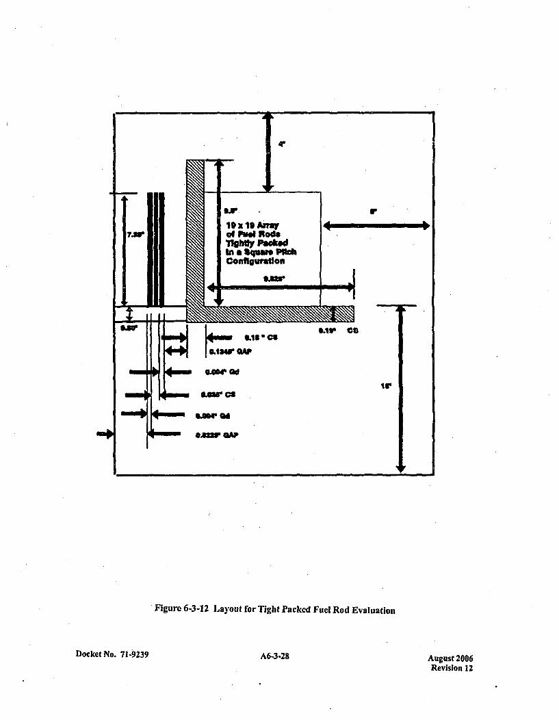
Figure 6-3-12 Layout for Tight Packed Fuel Rod Evaluation
Docket No. 71-9239 A6-3-28 August 2006Revision 12

KoffI
0.8
0.8
-14 OFA1-7 OFA
0.41
C_______________j ~17 ST
0 .0.01 0.,02 0.03 0.04 0.05 0.08
Water Dens*ty g/c
Figure 6-3-13 Reactivity vs. Optimum Moderation Density Full Dcnsity Water in Fuel Pin Gap
Docket No. 71-9239 A6-3-29 August 2006Revision 12
SUMMARY OF RESULTS AND LIMITS
For the MCC shipping container using permanent Gd2O3 absorber plates, under infinite arrayHypothetical Accident Conditions, it has been calculated that the final K&n- with bias and uncertainties atthe 95% confidence level is less than 0.95 for the following conditions:
1. Type A fuel assemblies (14x14 and 16x]6 designs) with maximum enrichments up to 5.0 wt%; or,
2. Type B fuel assemblies (I 5x1 5 and 17x 17 designs) with maximum enrichments up to 4.75 wt%;
or,
3. Type B fuel assemblies (15x]5 and l7x17 designs) with maximum enrichments above 4.75 wt%,up to 5.0 wt%, using one of the following additional absorber options.
a. Assembly IFBA rods: A minimum of 32 nominally (IX) coated fuel rods are required ineach assembly, each with a minimum coating length of 108 inches. With increased lFBAloading (1.5X, 2X, etc.), the number of loaded fuel rods required can be reduced by theration of the increased loading to the nominal loading.
b. Assembly Absorber Rods: A minimum of 4 absorber rods arc required in each assembly.The rods can be Pyrex BA, WABA, or Ag-In-Cd designs with a minimum length of108 inches. The rods must be positioned within the assemblies in a symmetric patternabout the assembly center guide tube.
C. Container Absorber Plates: A minimum of two Gadolinia coated absorber plates, havingthe same specifications as the permanent container absorber plate, are required. Theadditional plates are to be positioned on the strongback (top or bottom), underneath eachassembly.
4. The Type C fuel assembly with maximum enrichments up to 4.8 wt %; or,
5. The Type C fuel assembly with maximum enrichment above 4.8 wt %, up to 5.0 wt % using oneof the following additional absorber options:
a. Assembly IFBA rods: a minimum of 24 nominally (IX) coated fuel rods are required ineach assembly, each with a minimum coating length of 108 inches.
With increased IFBA loading (1.5X, 2X, etc.), the number of loaded fuel rods can bereduced by the ratio of the increased loading to the nominal loading.
b. Assembly Absorber Rods: a minimum of 4 absorber rods are required in each assembly.The rods can be WABA or Ag-In-Cd designs with a minimum length of 108 inches. Therods must be positioned within the assemblies in a symmetric pattern about the assemblycenter guide tube.
Docket No. 71-9239A630 A6-3-30 August 2006Revision 12
C. Guide Plate Absorber Coating: a minimum coating of 0.027 gins Gd2Q3'cm2 on theunderside of the guidc plates is required. The guide plates sit on the strongback and arelocated between the grid supports.
Table 6-3-1 presents the calculational results from KENO for each of the above limits.
Docket No. 71-9239 A6-3-31 August 2,006Revision 12
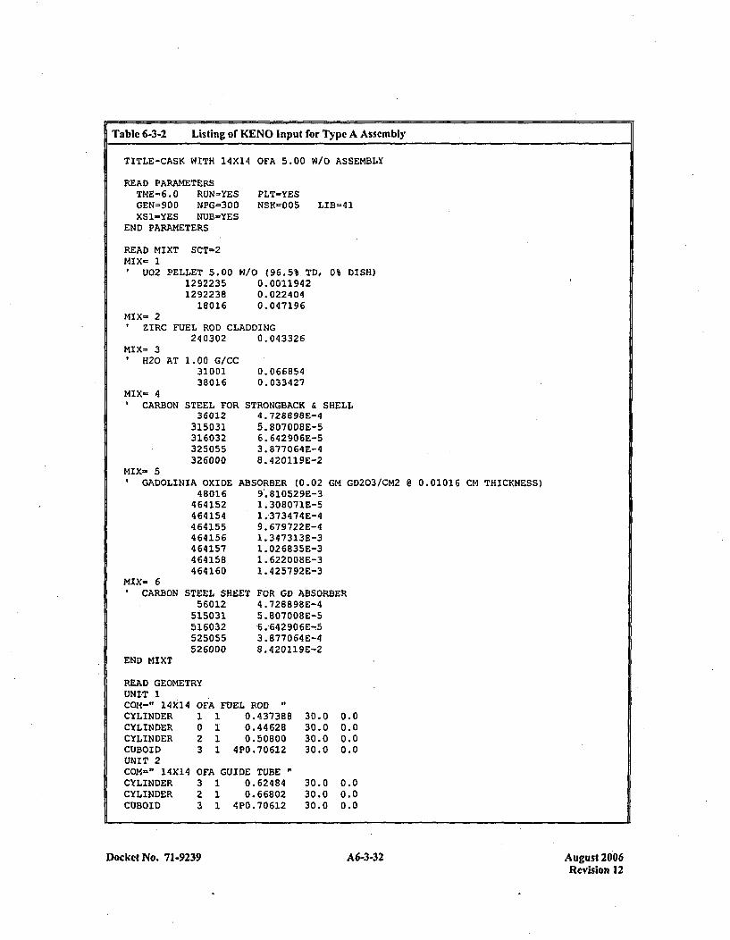
Table 6-3-2 Listing of KENO Input for Typc A Assembly
TITLE-CASK WITH 14X14 OFA 5.00 W/O ASSEMBLY
READ PARAMETERSTME=~6.0 RUN=YES PLT-YESGEN-900 NPG-300 NSK=005 LIB-41XS1-YES NUB-YES
END PARAMETERS
READ MIXT SCT-2MIX- 1
U02 PELLET 5.0012922351292238
18016
W/0 (96.5% TO, 0% DISH)0.00119420.0224040.047196
MIX- 2ZIRC FUEL ROD CLADDING
1 240302 0.043326
MIX= 3H20 AT 1.00 G/CC
3100138016
MIX- 4CARBON STEEL FOR
36012315031316032325055326000
0.0668540. 033427
STRONGEACK & SHELL4. 728898E-45. 807008E-56. 642 90 6E-53.8770 64E-48 .420119E-2
MIX- 5GADOLINIA OXIDE AB~
4 8016464152464154464155464156464157464158464160
MIX- 6CARBDN STEEL SHEET
56012515031516032525055526000
END MIXT
SORBER (0.029. 810529E-31. 308071E-51. 37 3474 E-49. 679722E-41. 347313E-31. 026835E-31. 622008E-31.425792 E-3
GM GD203/CM2 @ 0.01016 CM THICKNESS)
FOR GD ABSORBER4 .728898E-45. 80700BE-56 .642 906E-w53.877064 E-48.4 20119E-2
READ GEOMETRYUNIT 1CON=" 14X14 0~CYLINDER 1CYLINDER 0CYLINDER 2CUBOID 3UNIT 2CON-" 14X14 01CYLINDER 3CYLINDER 2CUBOID 3
FA FUEL ROD1 0.4373881 0.446281 0.508001 4P0.70612
FA GUIDE TUBE1 0.624841 0.668021 4PO.70612
30.030.030.030.0
30.030.030.0
0.00.00.00.0
0.00.00.0
Docket No. 71-9239 A6-3-32 A6-3-32August 2006Revision 12
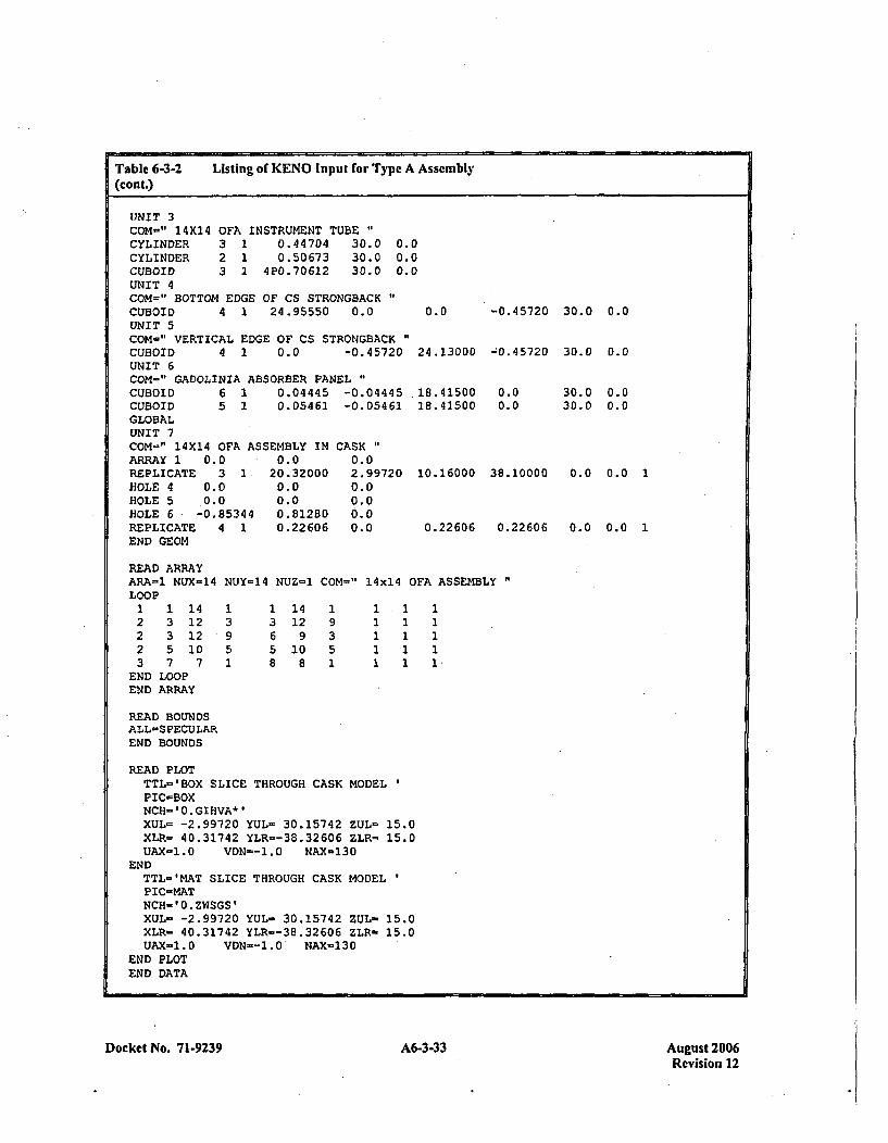
Table 6-3-2 Listing of KENO Input for Type A Assemb ly(cont.)
UNIT ~3COM-" 14X14CYLINDERCYLINDERCUBOID
OFA INSTRUMENT TUBE"3 1 0.44704 30.02 1 0.50673 30.03 1 4P0.70612 30.0
0.00.00.0
UNIT 4COM=" BOTTOM EDGE OF CS STRONGBACKCUBOID 4 1 24.95550 0.0 0.0UNIT 5COM-" VERTICAL EDGE OF CS STRONGBACKCUBOID 4 1 0.0 -0.45720 24.13000UNIT 6COM-" GADOLINIA ABSORBER PANELCUBOID 6 1 0.04445 -0.04445 .18.41500CUBOID 5 2 0.05461 -0.05461 18.41500GLOBALUNIT 7COM=" 14X14 OFA ASSEMBLY IN CASK"ARRAY 1 0.0 0.0 0.0REPLICATE 3 1. 20.32000 2.99720 10.16000HOLE 4 0.0 0.0 0.0HOLE 5 0.0 0.0 0.0HOLE 6 -0.85344 0.81280 0.0REPLICATE 4 1 0.22606 0.0 0.22606END GEOM
-0.45720 30.0 0.0
-;0.45720 30-0 n0A
0.00. 0
30.0 0.030.0 0.0
0.0 0.0 1
0.0 0.0 1
38.10000
0.22 606
READ ARRAYARA=1 NUX-14 NUY-14 NUZ-1 COM=" 14x14 OFA ASSEMBLYLOOP1 1 14 1 1 14 1 1 1 12 3 12 3 3 12 9 1 1 12 3 12 9 6 9 3 1 1 12 5 10 5 5 10 5 1 1 13 7 7 1 8 8 1 1 1 1
END LOOPEND ARRAY
READ BOUNDSALL-SPECULAREND BOUNDS
READ PLOTTTL-'BOX SLICE THROUGH CASK MODEL*PIC=BOXNCH='0.GIHVA*'XUL= -2.99720 YUL= 30.15742 ZUL- 15.0XLR= 40.31742 YLR=-38.32606 ZLR= 15.0UAX-1.0 VDN--1.0 NAX-130
ENDTTL='MAT SLICE THROUGH CASK MODELPIC-MATNCH-'0.ZWSGS'XUL- -2.99720 YUL- 30.15742 ZUL- 15.0XLR= 40.31742 YLR--38.32606 ZLR- 15.0UAX-1.0 VDN~-1.0 NAX-130
END PLOTEND DATA
Docket No. 71-9239 A6-3-33 August 2006Revision 12

Table 6-3-3 T~ble6-3-3 Listing of KENO Input for Type B Assembly
TITLE-3D CASK WITH 17X17 OFA 4.75 W/O ASSEMBLY
READ PARAMETERSTHE- 9.0 RUN-YES PLT-YESGEN=900 N4PG-300 NSK-005 LIB-41XSI-YES NUB-YES
END PARAMETERS
READ MIXT SCT-2MIX- 1
U)02 PELLET 4.7514 922 351492238
18016
W/O (96.5% TD, 0% DISH)0.00113450. 0224 630.047195
MIX= 2ZIRC FUEL ROD CLADDING
240302 0.043326MIX:- 3
H20 AT 1.00 G/CC3100138016
MIX- 4CARBON STEEL FOR
36012315031316032325055326000
0. 0668 540. 0334 27
q
STRONGBACK & SHELL4 .72889SE-45. 807008E-56. 642 90 6E-53. 8770 64 E-48. 42 0119E-2
GADOLINIA OXIDE AB~
4 80 16464152464154464155464156464157464158464160
MIX= 6CARBON STEEL SHEET
56012515031516032525055526000
END MIXT
SORBER (0.029. 810529E-31. 308071E-51. 373474E-49. 679722E-41.3473 13E-31. 026835E-31. 622008E-31 .425792E-3
GM GD203/CM2 @ 0.01016 CM THICKNESS)
FOR GD ABSORBER4 .728898E-45. 80700SE-56. 642906E-53. 877064 E-48. 420119E-2
READ GEOMETRYUNIT 1COM=" 17X17 01CYLINDER 1CYLINDER 0CYLINDER 2CUBOID 3UNIT 2COM-" 17X17 01CYLINDER 3CYLINDER 2CUBOID 3
FA FUEL ROD "
1 0.3921761 0.400051 0.457201 4P0.62992
.7A GUIDE TUBE1 0.561341 0.601981 4P0.62992
213.36213.36213.36213.36
0.00.00.00.0
INSTRUMENT TUBE"213.36 0.0213.36 0.0213.36 0.0
Docket No. 71-9239 A6-3-34 A6-3-34August 2006Revision 12
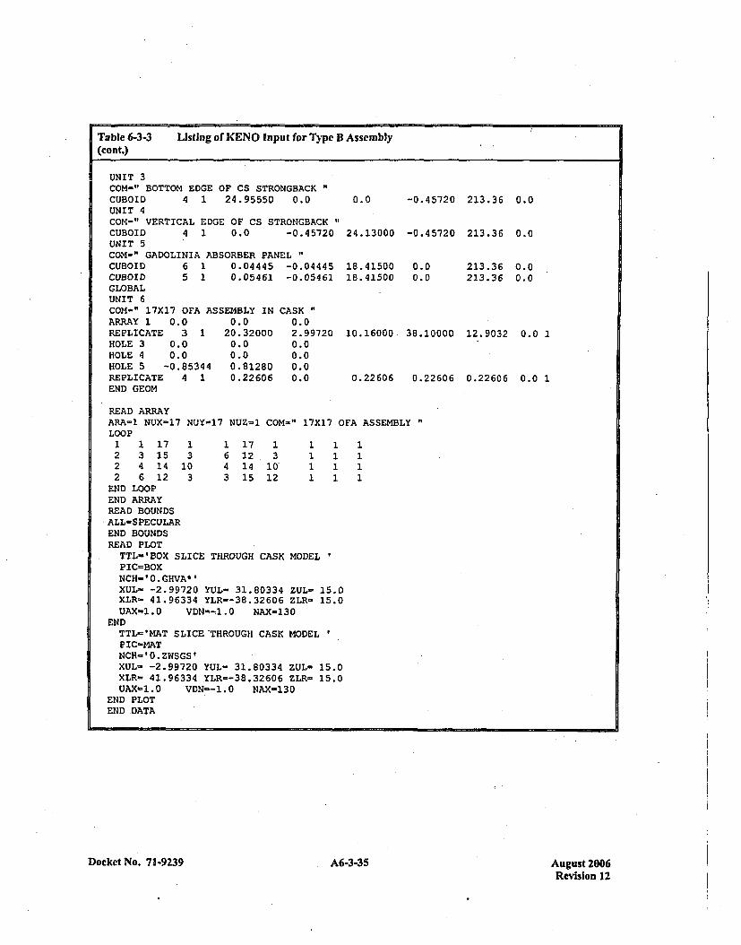
Table 6-3-3 Listing of KENO Input for Type B Assembly(cont.)
UNIT 3COM-" BOTTOM EDGE OF CS STRONGBACK"CUBOID 4 1 24.95550 0.0UNIT 4COM-" VERTICAL EDGE OF CS STRONGBACKCUBOID 4 1 0.0 -0.45720UNIT 5COM-" GADOLINIA ABSORBER PANELCUBOID 6 1 0.04445 -0.04445CUBOID 5 1 0.05461 -0.05461GLOBALUNIT 6COM-" 17X17 OFA ASSEMBLY IN CASKARRAY 1 0.0 0.0 0.0REPLICATE 3 1 20.32000 2.99720HOLE 3 0.0 0.0 0.0HOLE 4 0.0 0.0 0.0HOLE 5 -0.85344 0.81280 0.0REPLICATE 4 1 0.22606 0.0END GEOM
0.0 -0.45720 213.36 0.0
24.13000 -0.45720 213.36 0.0
213.36 0.0213.36 0.0
18.4150018.41500
0.00.0
10.16000 38.10000 12.9032 0.0 1
0.22606 0.22606 0.22606 0.0 1
READ ARRAYARA-1 NUX-~17 NUY-17 NUZ-.1 COM-" 17X17 0LOOP1 1 17 1 1 17 1 1 12 3 15 3 6 12, 3 1 12 4 14 10 4 14 10' 1 12 6 12 3 3 15 12 1 1
END LOOPEND ARRAYREAD BOUNDS'ALL-SPECULAR
END BOUNDSREAD PLOTTTL-'BOX SLICE THROUGH CASK MODELPIC-=BOXNCH-I0.GHVA*PXUL- -2.99720 YUL= 31.80334 ZUL- 15.0XLR- 41.96334 YLR=-38.32606 ZLR- 15.0UAX-1.0 VDN--1.0 NAX-130
ENDTTL-'MAT SLICE'THROUGH CASK MODELPIC-MATNCH-'0.ZWSGS'XUL-s -2.99720 YUL- 31.80334 ZUL- 15.0XLR- 41.96334 YLR=-38.32606 ZLR- 15.0UAX-1.0 VDN--1.0 WAX-130
END PLOTEND DATA
FA ASSEMBLY "
1111
Docket No. 71-9239A635Aust20 A6-3-35Revision 12

Table 6-3A4 Listing of KENO Input for Type B Assembly With Additional IFBA Absorbers
TITLE-CASK WITH 17X17 OFA 5.00 W10 ASSEMBLY - 32 IFBA
READ PARAMETERSTME.=6.0 RUN-'YESGEN-900 NPG-300XS1=YES NUB-YES
END PARAMETERS
PLT=YESNSK=005 LIB=41
READ MIXT SCT=2MIX- 1
U02 PELLET 5.0012922351292238
18016
w/o (96.5% TD, 0% DISH, NOBA)0.00119420.0224040.047196
MIX- 2ZIRC FUEL ROD CLADDING (NOBA)
240302 0.043326MIX- 3
H20 AT 1.00 G/CC3100138016
MIX- 4U02 PELLET 5.00 9
629223562 92238
68016
(NOBA)0.0668540. 033427
~/0 (96.5% TD, 0%0. 00119420. 0224 040. 047196
DISH, IFBA ROD)
B10*0.95*0.75)MIX_ 5
ZIRC FUEL ROD CLADDING (IFBA ROD,740302 0.04332675010 0.0001644
MIX- 6VH20OAT 1.00 G/CC
8100188016
MIX- 7I CARBON STEEL FOR
3 6012315031316032325055326000
MIX- 8GADOLINIA OXIDE
480164641524641544 64 155464156464157464158464160
MIX- 9CARBON STEEL SHE
5 6012515031516032525055526000
END MIXT
(IFBA ROD)0. 0668 540.033427
STRONGBACK & SHELL4 .728898E-45.807008E-56. 642906E-53. 877064E-48. 420219E-2
ABSORBER (0.02 GM GD203/CM2 @ 0.01016 CM THICKNESS)9. 810529E-31. 308 071E-52.373474E-4'9. 679722E-41. 347313E-31. 026835E-31.622008E-31. 425792E-3
:ET FOR GD ABSORBER4. 728898E-45. 807008E-56. 642 90 6E-53. 877064E-48. 420119E-2
Docket No. 71-9239 A6-3-36 August 2006Revision 12
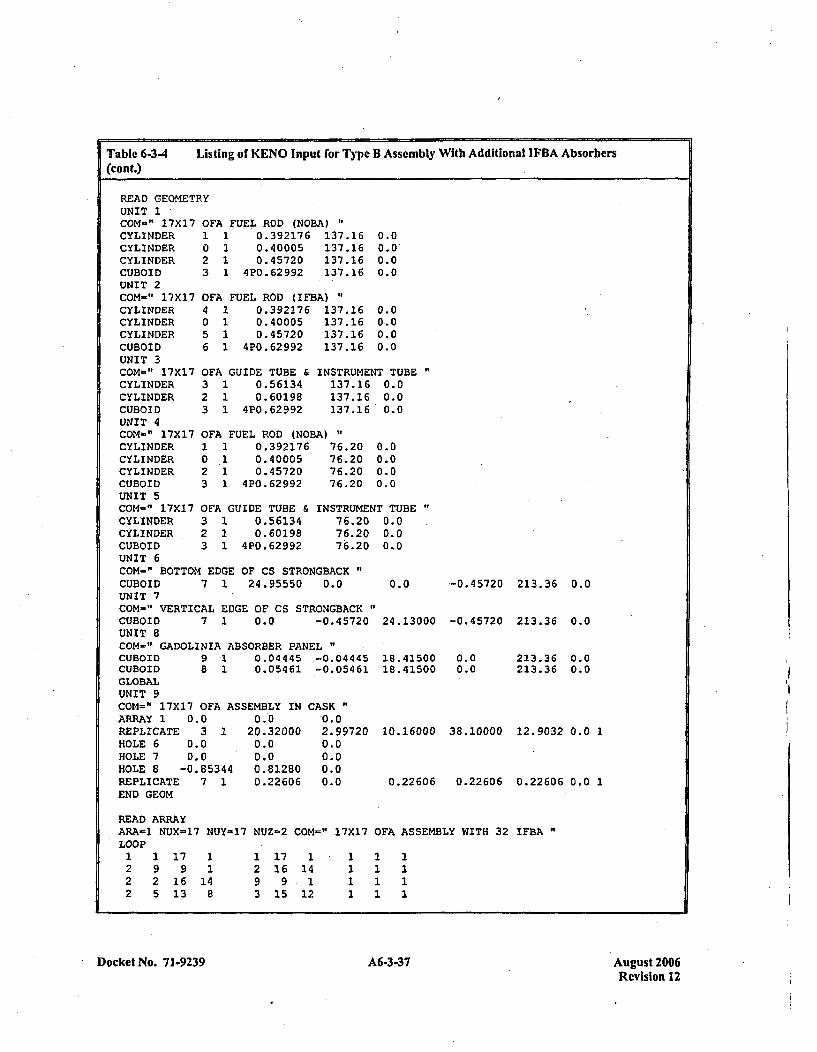
Table 6-3-4 Listing of KCENO Input for Type B Assembly With Additional I FBA Absorbers(cont.)
READ GEOMETRYUNIT 1COM-" 17X17 0~CYLINDER 1CYLINDER 0CYLINDER 2CUBOID 3UNIT 2COM-" 17X17 01CYLINDER 4CYLINDER 0CYLINDER 5CUBOID 6UNIT 3COM-" 17X17 01CYLINDER 3CYLINDER 2CUBOID 3UNIT 4COM-" 17X17 01CYLINDER 1CYLINDER 0CYLINDER 2CUBOID 3UNIT 5COM-" 17X17 0!
F'A FUEL ROD (NOBA) "1 0.392176 137.161 0.40005 137.161 0.45720 137.161 4P0.62992 137.16
FA FUEL ROD (IFBA)1 0.392176 137.161 0.40005 137.161 0.45720 137.161 4P0.62992 137.16
0.00.0~0.00.0
0.00.00.00.0
FA GUIDE TUBE & INsT:1 0.56134 131 0.60198 131 4P0.62992 13
,"A FUEL ROD (NOBA) "
1 0.392176 76.1 0.40005 761 0.45720 761 4P0.62992 76
RUMENT TUBE"7.16 0.07.16 0.07.16 0.0
.20
.20
.20
.20
0.00.00.00.0
;7A GUIDE TUBE & INSTRUMENT TUBE "
CYLINDER 3 1 0.56134 76.20 0.0CYLINDER 2 1 0.60198 76.20 0.0CUBOID 3 1 4P0.62992 76.20 0.0UNIT 6COM=" BOTTOM EDGE OF CS STRONGBACK"CUBOID 7 1 24.95550 0.0 0.0UNIT 7COM-" VERTICAL EDGE OF CS STRONGBACKCUBOID 7 1 0.0 -0.45720 24.13000UNIT 8COM-" GADOLINIA ABSORBER PANELCUBOID 9 1 0.04445 -0.04445 18.41500CUBOID 8 1 0.05461 -0.05461 18.41500GLOBALUNIT 9COM=" 17X17 OFA ASSEMBLY IN CASK"ARRAY 1 0.0 0.0 0.0REPLICATE 3 1 20.32000 2.99720 10.16000HOLE 6 0.0 0.0 0.0HOLE 7 0.0 0.0 0.0HOLE 8 -0.85344 0.81280 0.0REPLICATE 7 1 0.22606 0.0 0.22606END GEOM
-0.45720 213.36 0.0
-0.45720 213.36 0.0
0.00.0
213.36 0.0213.36 0.0
38.10000 12.9032 0.0 1
0.22606 0.22606 0.0 1
READ ARRAYARA=1 NUX-17 NUY=17 NUZ-2 COM=" 17X17 OFA ASSEMBLY WITH 32 IFBA"LOOP
1 1 17 1 1 17 1 1 1 12 9 9 1 2 16 14 1 1 12 2 16 14 9 9 1 1 1 12 5 13 8 3 15 12 1 1 1
Docket No. 71-9239 A6-3-37 August 2006Revision 12
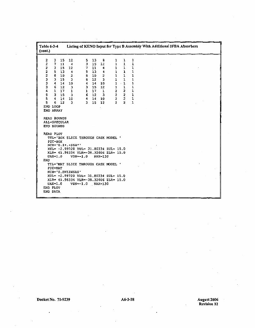
Table 6-3-4 Listing of KENO Input for Type B Assembly With Additional I FBA Absorbers(cont.)
2 3 15 12 5 13 8 1 1 12 7 11 4 3 15 12 1 1 12 3 15 12 7 11 4 1 1 1
*2 5 13 4 5 13 4 1 1 12 8 10 2 8 10 2 1 1 13 3 15 3 6 12 3 1 1 13 4 14 10 4 14 10 1 1 13 6 12 3 3 15 12 1 1 14 1 17 1 1 17 1 2 2 15 3 15 3 6 12 3 2 2 15 4 14 10 4 14 10 2 2 15 6 12 3 3 15 12 2 2 1
END LOOPEND ARRAY
READ BOUNDSALL-SPECULAREND BOUNDS
READ PLOTTTL-'BOX SLICE THROUGH CASK~ MODELPIC=BOXNCH-10.I+. +SSA*l
XUL= -2.99720 YUL= 31.80334 ZUL= 15.0XLR= 41.96334 YLR=-3B.32606 ZLR= 15.0UAX-1.0 VDN--1.O NAX=130
ENDTTL='MAT SLICE THROUGH CASK MODELPIC-MATNCH-'O.ZWIZWSAS'XUL- -2.99720 YUL- 31.80334 ZUL- 15.0XLR- 41.96334 YLR--3B.32606 ZLR- 15.0UAX=1.0 VDN--1.0 NAX=130
END PLOTEND DATA
Docket No. 7 1-9239 A6-3-38 August 2006Revision 12
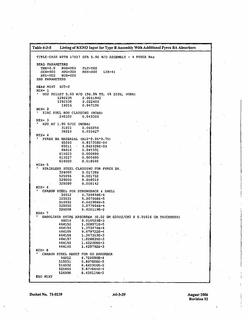
Table 6-3-5 Listing of KENO Input for Type B Assembly With Additional Pyrex BA AbsorbersI
TITLE-CASK WITH 17X17 OFA 5.00 W/O ASSEMBLY - 4 PYREX Bas
READ PARAMETERSTME-6.0 RUN-YESGEN-900 NPG-300XSI=YES NUB=YES
END PARAMETERS
PLT-YESNSK-005 LIB=41
READ MIXT SCT=2MIX- 1
U02 PELLET 5.0012922351292238
18016
W/o (96.5% TD, 0%0.00119420.0224040.047196
DISH, NOBA)
MIX- 2ZIRC FUEL ROD CLADDING (NOBA)
240302 0.043326MIX- 31H20 AT 1.00 G/CC
3100138016
MIX- 41PYREX BA MATERI.A
650106501168016
611023613027614000
L
MIX- SSTAINLESS STEEL CL
324 000525055326000328000
MIX- 6CARBON STEEL FOR S
3 60 12315031316032325055326000
MIX- 7GADOLINIA OXIDE AB~
48016464152464154464155464156464157464158464160
MIX- 8CARBON STEEL SHEET
56012515031516032525055526000
N'OBA)0.0668540.033427
(B1O*0. 95*0.75)6. 837 358E-043. 862628E-030. 04 53310.0008800. 0006800. 018 040
A~DDING FOR PYREX BA,0. 0173 860. 0017320. 058 0190. 008142
rRONGBACK & SHELL4 .728898E-45. 807008E-56. 642906E-53. 877064E-48. 420119E-2
SORBER (0.029. 810529E-31. 308071E-51. 3734 74 E-49. 679722E-41 .347313E-31. 026835E-31. 622008E-31.4257 92E-3
GM GD203/CM2 @ 0,.01016 CM THICKNESS)
FOR GD ABSORBER4 .728898E-45. 807008E-56. 642906E-53. 877064E-48. 420119E-2
END MIXT
Docket No. 71-9239A639Aust20 A6-3-39Revision 12
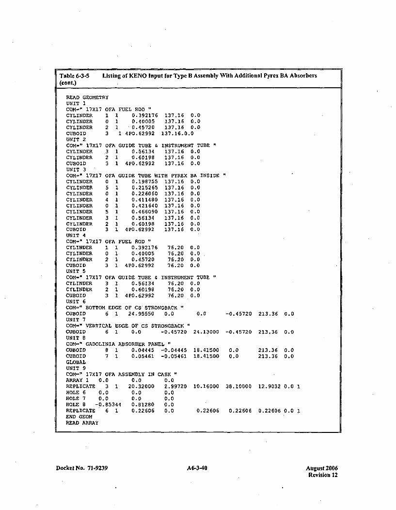
Table 6-3-S(cont.)
Listing of KENO Input for Type B Assembly With Additional Pyrex BA Absorbers
READ GEOMETRYUNIT 1COM-" 17X17 01CYLINDER 1CYLINDER 0CYLINDER 2CUBOID 3UNIT 2COM-" 17X17 01CYLINDER .CYLINDER 2CUBOID 3UNIT 3COM=" 17X17 01
FA FUEL ROD "
1 0.3921761. 0.400051 0.457201 4P0.62992
FA GUIDE TUBE &1 0.561341 0.601981 4P0.62992
137.16 0.0137.16 0.0137.16 0.0
137.16.0.0
INSTRUMENT TUBE137.16 0.0137.16 0.0137.16 0.0
FA GUIDE TUBE WITH PYREX BA INSIDE "
CYLINDERCYLINDERCYLINDERCYLINDERCYLINDERCYLINDERCYLINDERCYLINDERCUBOID
a50405323
111111111
0.1987550.2152650. 2260 600.4114800.4216400.4 660900.561340.60198
4P0 .62992
137.16137.16137.16137.16137.16137.16137.16137.16137.16
0.00.00.00.00.00.00.00.00.0
UNIT 4COM=" 17X17 OFA FUEL ROD "
CYLINDER 1 1 0.392176 76.20CYLINDER 0 1 0.40005 76.20CYLINDER 2 1 0145720 76.20CUBOID 3 1 4P0.62992 76.20UNIT 5COM-" 17X17 OFA GUIDE TUBE & INSTRUMEN~CYLINDER 3 1 0.56134 76.20CYLINDER 2 1 0.60198 76.20CUBOID 3 1 4P0.62992 76.20UNIT 6COM-" BOTTOM EDGE OF CS STRONGBACKCUBOID 6 1 24.95550 0.0UNIT 7COM-" VERTICAL EDGE OF CS STRONGBACKCUBOID 6 1 0.0 -0.45720UNIT 8COM-" GADOLINIA ABSORBER PANEL"CUBOID 8 1 0_04445 -0.04445CUBOID 7 1 0.054,61 -0.05461GLOBALUNIT 9
0.0
3.0
VTUBE
0.0
0.0 -0.45720 213.36 0.0
24.13000 -0.45720 213.36 0.0
18 .4150018.41500
0.00.0
213.36 0.0213.36 0.0
CON-" 17X17 OFA A~ARRAY 1 0.0REPLICATE 3 1HOLE 6 0.0HOLE 7 0.0HOLE 8 -0.85344REPLICATE 6 1END GEOMREAD ARRAY
SSEMBLY IN CASK0.0 0.0
20.32000 2.997200.0 0.00.0 0.00.81280 0.00.22606 0.0
10.16000 38.10000 12.9032 0.0 1
0.22606 0.22606 0.22606 0.0 1
Docket No. 71-9239 A6-3-40 August 2006Revision 12
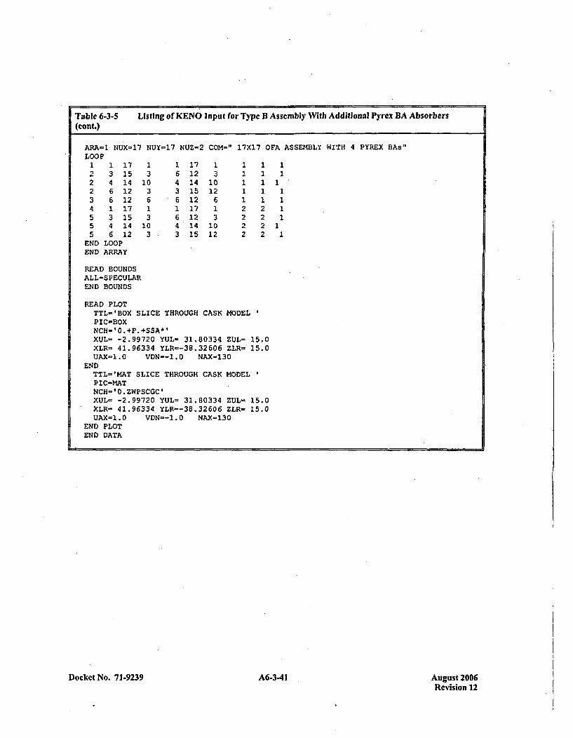
Table 6-3-5 Listing of KENO Input for Type B Assembly With Additional Pyrex BA Absorbers(cont.)
ARA-1 NUX-17 NUY-17 NUZ=-2 COM-~" 17X17 OFA ASSEMBLY WITH 4 PYREX BAs"LOOP1 1 17 1 1 17 1 1 1 12 3 15 3 6 12 3 1 1 12 4 14 10 4 14 10 1 112 6 12 3 3 15 12 1 1 13 6 12 6 *6 12 6 1 1 14 1 17 1 1 17 1 2 2 15 3 15 3 6 12 3 2 2 15 4 14 10 4 14 10 2 215 6 12 3 3 1512 2 2 1
END LOOPEND ARRAY
READ BOUNDSALL=SPECULAREND BOUNDS
READ PLOTTTL='BOX SLICE THROUGH CASK MODELPIC=BOXNCU-bO.+P.+SSA*IXUL= -2.99720 YUL- 31.80334 ZUL= 15.0XLR= 41.96334 YLR---38.32606 ZLR- 15.0UAX=1.0 VDN--1.0 NAX-130
ENDTTL-'MAT SLICE THROUGH CASK MODELPIC-MATNCH='0.ZWPSCGC'XUL- -2.99720 YUL= 31.80334 ZUL- 15.0XLR= 41.96334 YLR=-38.32606 ZLR- 15.0UAX=1.0 VDN--1.0 NAX=130
END PLOTEND DATA
Docket No. 71-9239 A6-3-41Au st20Revision 12
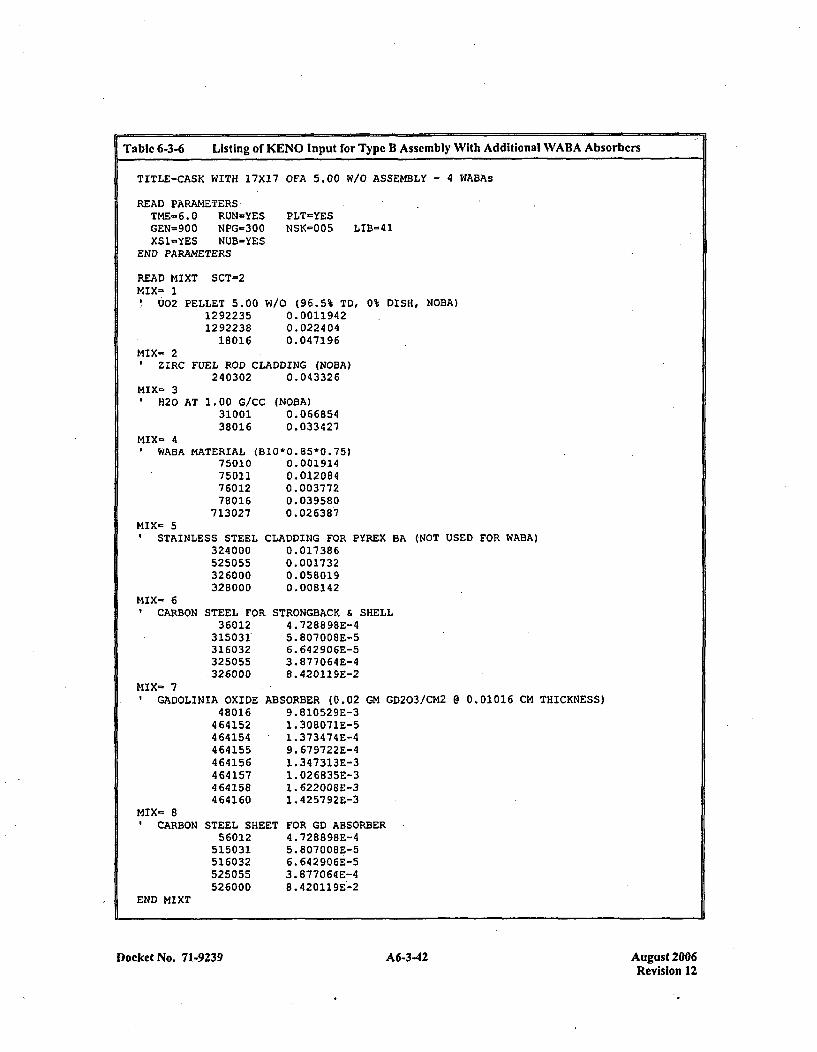
Table 6-3-6 Listing of KENO input for Type B Assembly With Additional WABA Absorbers
TITLE-CASK WITH 17X17 OFA 5.00 W/0 ASSEMBLY - 4 WABAs
READ PARAMETERS,TME-6.0 RUN-YESGEN-900 NPG-300XS1-YES NUB-YES
END PARAMETERS
PLT-YESNSK=005 LIB=41
READ MIXT SCT=2MIX- 1
002 PELLET 5.0012922351292238
18016
W/O (96.5% TD,0. 00119420. 0224 040.047196
0% DISH, NOBA)
MIX= 2ZIRC FUEL ROD CLADDING (NOBA)
240302 0.043326MIX- 3
f H20 AT 1.00 G/CC3100138016
(NOBA)0. 06 68540.033421
MIX- 4WABA M4ATERIAL (BIO-0.85-0.75)
75010 0.00191475D21 0.01208476012 0.00377278016 0.039580
713027 0.026387MIX- 5
STAINLESS STEEL324000525055326000328000
MIX= 6CARBON STEEL FOF
3 60 12* 315031*
316032325055.326000
MIX- 7GADOLINIA OXIDE
48016464152464154464155464156464157464158464160
MIX- 8CARBON STEEL SHE
56012515031516032525055526000
END MIXT
CLADDING FOR PYREX0. 017 3860. 0017 320. 0580190. 008142
BA (NOT USED FOR WABA)
STRONGBACK & SHELL4.728898E-45. 807008E-56. 642906E-53. 877064E-48. 420129E-2
ABSORBER (0.029. 81052 9E-31 .308071E-51. 373474 E-49. 679722E-41. 347313E-31. 026835E-31.62200 8E-31. 425792E-3
GM GD203/CM2 @ 0.01016 CM THICKNESS)
FOR GO ABSORBER4. 728898E-45.807008E-56. 642906E-53.8770 64E-48.420119E-2
Docket No. 71-9239 A6-3-42 August 2006Revision 12
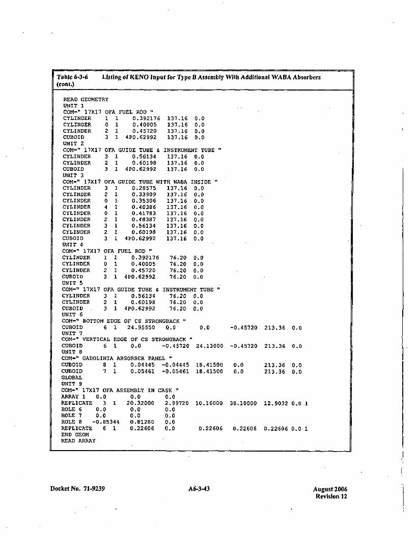
Table 6-3-6 Listing of KENO In put for Type B Assembly With Additional WABA Absorbers(coat.)
READ GEOMETRYUNIT 1Com-' 17X17 0CYLINDER ICYLINDER 0CYLINDER 2CUBOID 3UNIT 2COM-" 17X17 0~CYLINDER 3CYLINDER 2CUBOID 3UNIT 3COM-" 17X17 0!
FA FUEL ROD "
1 0.3921761 0.400051 0.457201 4P0.62992
FA GUIDE TUBE1 0.561341 0.60198.1 4P0.62992
137.16137.16137.16137. 16
0.00.00.00.0
INSTRUMENT TUBE137.16 0.0137.16 0.0137.16 0.0
F'A GUIDE TUBE WITH WABA INSIDE "'CYLINDER 3 1 0.28575 137.16CYLINDER 2 1 0.33909 137.16CYLINDER 0 1. 0.35306 137.16CYLINDER 4 1 0.40386 137.16CYLINDER 0 1 0.41783 137.16CYLINDER 2 1 0.48387 137.16CYLINDER 3 1 0.56134 137.16CYLINDER 2 1 0.60198 137.16CUBOID 3 1 4P0.62992 137.16UNIT 4COM-" 17X17 OFA FUEL RODCYLINDER 1 1 0.392176 76.20CYLINDER 0 1 0.40005 76.20CYLINDER 2 1 0.45720 76.20CUBOID 3 1 4P0.62992 76.20UNIT 5COM-" 17X17 OFA GUIDE TUBE & INSTRUMENCYLINDER 3 1 0.56134 76.20CYLINDER 2 1 0.60198 76.20CUBOID 3 1 4P0.62992 76.20UNIT 6COM-" BOTTOM EDGE OF CS STRONGBACKCUBOID 6 1 24.95550 0.0UNIT 7COM-" VERTICAL EDGE OF CS STRONGBACK"CUBOID 6 1 0.0 -0.45720UNIT 8COM-" GADOLINIA ABSORBER PANEL"
0.00.00.00.00.00.00.00.00.0
0.00.00.00.0
T TUBE0.00.00.0
0.0 -0.45720 213.36 0.0
24.13000 -0.45720 213.36 0.0
CUBOID 8 1CUBOID 7 1GLOBALUNIT 9COM-" 17X17 OFA A~ARRAY 1 0.0REPLICATE 3 1HOLE 6 0.0HOLE 7 0.0HOLE 8 -0.85344REPLICATE 6 1END GEOMREAD ARRAY
0.04445 -;0.04445 18.415000.05461 -0.05461 18.41500
0.00.0
213.36 0.0213.36 0.0
SSEMBLY IN0.0
20.320000.00.00. 812800.22 606
CASK"0.02. 997200.00.00.00.0
10.16000 38.100.00 12.9032 0.0 1
0.22606 0.22606 0.22606 0.0 1
Docket No. 71-9239A634Aust20 A6-343Revision 12
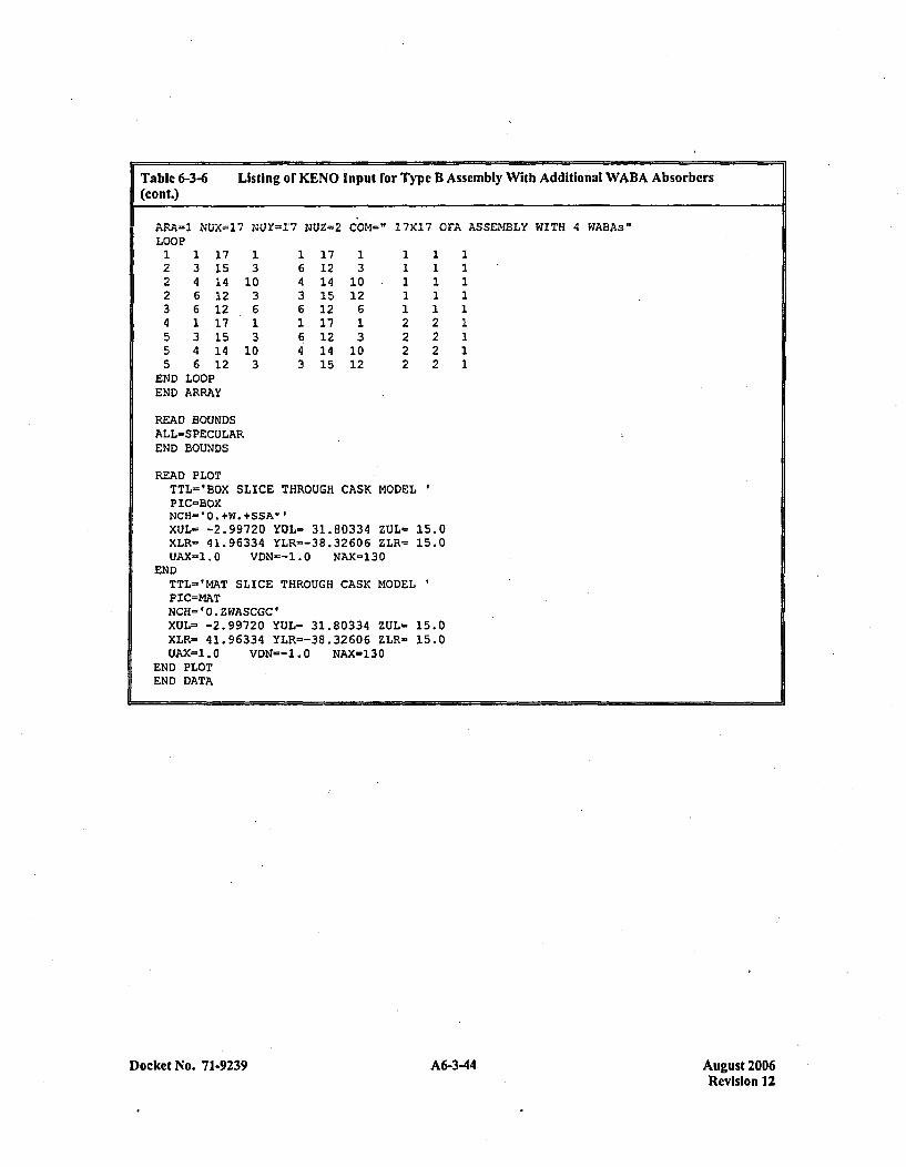
4 1 17 1 1 17 1 2 25 3 15 3 6 12 3 2 25 4 14 10 4 14 10 2 22 6 12 3 3 15 12 2 2
END LOOPEND ARRAY
READ BOUNDSALL-SPECULAREND BOUNDS
READ PLOTTTL='BOX SLICE THROUGH CASK MODELPIC=BOXNCH-'0.+W.+SSA*'XUL- -2.99720 YUL- 31.80334 ZUL= 15.0XLR= 41.96334 YLR=-38.32606 ZLR- 15.0UAX-1.0 VDN=-1.0 NAX=130
ENDTTL-'MAT SLICE THROUGH CASK MODELPIC=MhTNCR='0.ZWASCGC'XUL= -2.99720 YUL= 31.80334 ZUL- 15.0XLR= 41.96334 YLR--38.32606 ZLR- 15.0UAX=1.0 VDN-1.0 NAX-130
END PLOTEND DATA
Docket No. 7 1-9239 A6-3-44 August 2006Revision 12
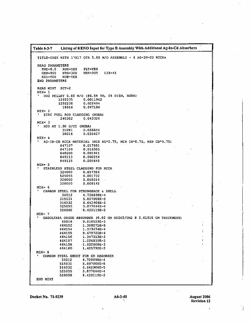
Table 6-3-7 Listing ci KENO Input for Type B Assembly With Additional Ag-in-Cd Absorbers
TITLE-CASK WITH 17X17 OFA 5.00 W/O ASSEMBLY - 4 AG-IN-CD RCCAs
READ PARAMETERSTME=6.0 RUN-YESGEN=900 NPG=300XS1=YES NUB=YES
END PARAMETERS
PLT-YESNSK=005 LIB=41
READ MIXT SCT-2MIX- 1
U02 PELLET 5.0012922351292238
18016
W10 (96.5% TD, 0% DISH, NOBA)0.00119420. 0224040. 047196
MIX= 2ZIRC FUEL ROD CLADDING (NOBA)
240302 0.043326MIX- 3
0H20 AT 1. 00 G/CC3100138016
(NOBA)0. 0668540. 0334 27
MIX- 4AG-IN-CD RCCA MATERIAL (MIN AG*0.75, MIN IN*0.75, MIN CD*0.75)
847107 0.017551847109 0.016305848000 0.001941849113 0.000254849115 0.005648
MIX- 5STAINLESS STEEL
324000525055326000328000
MIX- 6CARBON STEEL FOR
360 12315031316032325055326000
MIX- 7GADOLINIA OXIDE
48016464152464154464155464156464157464158464160-
CLADDING FOR RCCA0. 0173860. 0017320. 058 0190. 008142
STRONGBACK & SHELL4 .728898E-45. 807008E-56. 642906E-53.0877064E-48.42 0119E-2
ABSORBER (0.02 GM GD203/CM2 @ 0.01016 CM THICKNESS)9. 81052 9E-31. 308071E-51.3734-74E-49. 679722E-41 .347313E-31. 026835E-31. 622008E-31. 425792E-3
ET FOR GD ABSORBER4 .728898E-45. 807 00 BE-6. 642906E-53.8770 64E-48.420119E-2
MIX- 8CARBON
END MIXT
STEEL SHE56012
515031516032525055526000
Docket No. 71-9239 A6-345 A6-3-45August 2006Revision 12

Table 6-3-7(cont.)
Listing of KENO Input for Type B Assembly With Additional Ag-In-Cd Absorbers
READ GEOMETRYUNIT 1COM-" 17X17CYLINDERCYLINDERCYLINDERCUBOIDUNIT 2COM-" 17X17CYLINDERCYLINDERCUBOIDUNIT 3COM=" 17X17CYLINDERCYLINDERCYLINDERCYLINDERCYLINDERCUBOIDUNIT 4COM-" 17X1'7CYLINDERCYLINDERCYLINDERCUBOIDUNIT 5COM=" 17X17CYLINDERCYLINDERCUBOID
OFA FUEL ROD "
1 1 0.3921760 1 0.400052 1 0.457203 1 4P0.62992
OFA GUIDE TUBE &3 1 0.561342 1 0.601983 1 4P0.62992
137.16137.16137.16137.16
0.00.00.00.0
INSTRUMENT TUBE'137.16 0.0137.16 0.0137.16 0.0
OFA GUIDE TUBE WITH AG-IN-CD RCCA INSIDE4 1 0.41783 137.16 0.00 1 0.42164 137.16 0.05 1 0.46609 137.16 0.03 1 0.56134 137.16 0.02 1 0.60198 137.16 0.03 1 4P0.62992 137.16 0.0
OFA FUEL ROD "1 1 0.3921760 1 0.400052 1 0.457203 1 4P0.62992
OFA GUIDE TUBE&3 1 0.561342 1 0.601983 1 4P0.62992
76.2076.2076.2076.20
0.00.00.00.0
INSTRUMENT. TUBE76.20 0.076.20 0.076.20 0.0
UNIT 6COM-" BOTTOM EDGE OF CS STRONGBACXCUBOID 6 1 24.95550- 0.0 0.0UNIT 7COM-" VERTICAL EDGE OF CS STRONGBACKCUBOID 6 1 0.0 -0.45720 24.23000UNIT 8COM=" GADOLINIA ABSORBER PANELCUBOID 8 1 0.04445 -0.04445 18.41500CUBOID 7 1 0.05461 -0.05461 18.41500GLOBALUNIT 9
-0.45720 213.36 0.0
-0.45720 213.36 0.0
0.00.0
213.36 0.0213.36 0.0
COM-" 17X17 OFA ASSEMBLY INARRAY 1 0.0 0.0REPLICATE 3 1 20.32000HOLE 6 0.0 0.0HOLE 7 0.0 0.0HOLE 8 -0.85344 0.81280REPLICATE 6 1 0.22606END GEOMREAD ARRAY
CASK0.02. 997200.00.00.00.0
10.16000 38.10000 12.9032 0.0 1
0.22606 0.22606 0.22606 0.0 1
ARA=1 NUX=17 NUY-17 NUZ-2 COM=" 17X17 OFA ASSEMBLY WITH 4 RCCAS"LOOP1 1 17 1 1 17 1 1 1 12 3 15 3 6 12 3 1 1 12 4 14 10 4 14 10 1 1 1
Docket No. 71-9239 A6-3-46 August 2006Revision 12
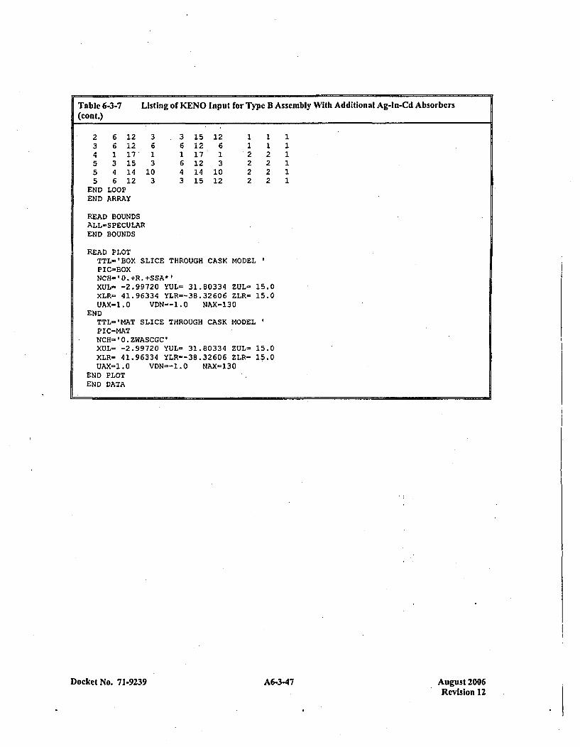
Table 6-3-7 Listing of KENO Input for Type B Assembly With Additional Ag-In-Cd Absorbers(cont.)
2 6 12 3 3 15 12 1 1 13 6 12 6 6 12 6 1 14 1 17' 1 1 17 1 *2 25 3 15 3 6 12 3 2 2 15 4 14 10 4 14 10 2 2 15 6 12 3 3 15 12 2 2 1
END LOOPEND ARRAY
READ BOUNDSALL-SPECULAREND BOUNDS
READ PLOTTTL-'EOX SLICE THROUGH CASK MODELPIC-BOXNCH=0O.+R.+SSA*lXUL- -2.99720 YUL= 31.80334 ZUL- 15.0XLR= 41.96334 YLR=-38.32606 ZLR= 15.0UAX=1.0 VDN=-1.0 NAX=130
ENDTTL-'MAT SLICE THROUGH CASK MODELPIC=MATNCH-'0.ZWASCGC'XUL- -2.99720 YUL- 31.80334 ZUL- 15.0XLR- 41.96334 YLR--38.32606 ZLR= 15.0UAX-1.0 VDN=-1.0 NAX=130
END PLOTEND DATA
Docket No. 71-9239 A6-3-47Au st20Revision 12
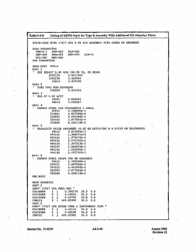
Table 6-3-8 Listing of KENO Input for Type B Assembly With Additional GD Absorbcr Plates
TITLE-CASK WITH 17X17 OFA 5.00 W/O ASSEMBLY WITH ADDED GD ABSORBER
READ PARAMETERSTME-6.0 RUN-YESGEN=900 NPG-300XS1-YES NUB=YES
END PARAMETERS
PLT-YESNSK=005 LIB-41
READ MIXT SCT-2MIX- 1
U02 PELLET 5.0012922351292238
18016
W10 (96.5% TD, 0% DISH)0.00119420.0224 040.047196
MIX- 2ZIRC FUEL ROD CLADDING
240302 0.043326MIX- 31H20
MIX- 49CARB
AT 1.00 G/CC3100138016
ON STEEL FOR36012315031316032325055326000
MIX- 5GADOLINIA OXIDE
48016464152464154464155464156464157464158464160
MIX- 6CARBON STEEL SHE
56012515031516032525055526000
0.0668540.033427
STRONGEACK & SHELL4 .728898E-45.807008E-56.642 906E-53. 877064E-48. 420119E-2
ABSORBER (0.02 GM GD203/CM2 @ 0.01016 CM THICKNESS)9. 81052 9E-31. 308071E-51 .373474E-49. 679722E-41. 347313E-31 .026835E-31. 622008E-31. 425792E-3
ET FOR GD ABSORBER4 .728898E-45. 807008E-56. 642906E-53.877064 E-48. 420119E-2
END MIXT
READ GEOMETRYUNIT 1COM-" 17X17 0~CYLINDER 1CYLINDER 0CYLINDER 2CUBOID 3UNIT 2COM=" 17X17 0~CYLINDER 3CYLINDER 2CUBOID 3
F'A FUEL ROD"1 0.3921761 0.40005,1 0.457201 420.62992
FA GUIDE TUBE1 0.561341 0.60198
1 420.62992
30.030.030.030.0
0.00.00.00.0
INSTRUMENT TUBE30.0 0.030.0 0.030.0 0.0
Docket No. 7 1-9239 634A6-348 August 2006Revision 12
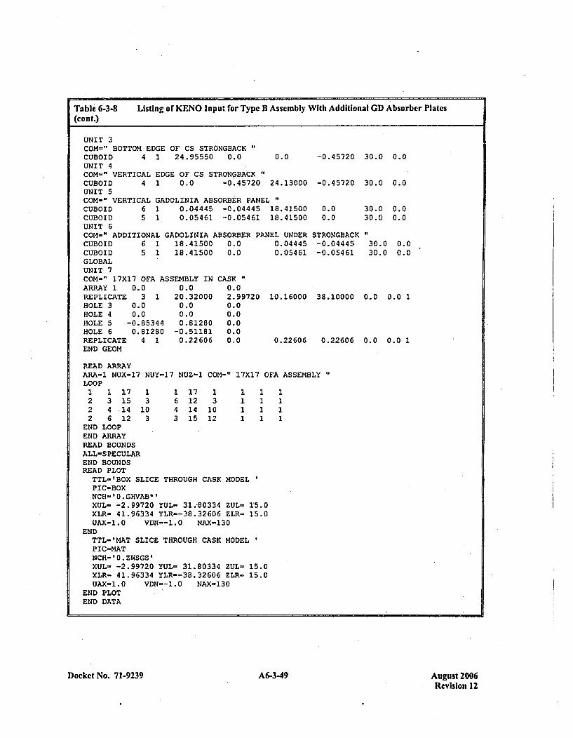
Table 6-3-8 Listing of KENO Input for Type B Assembly With Additional GD Absorber Plates(cont.)
UNIT 3COM-"~ BOTTOM EDGE OF CS STRONGBACKCUBOID 4 1 24.95550 0.0 0.0UNIT 4COM=" VERTICAL EDGE OF CS STRONGBACK"CUBOID 4 1 0.0 -0 .45720 24.13000UNIT 5COM-" VERTICAL GADOLINIA ABSORBER PANELCUBOID 6 1 0.04445 -0.04445 18.41500CUBOID 5 1. 0.05461 -0.05461 18.41500UNIT 6COM=" ADDITIONAL GADOLINIA ABSORBER PANEL UNDERCUBOID 6 1 18.41500 0.0 0.04445CUBOID 5 1 18.41500 0.0 0.05461GLOBALUNIT 7
-0.45720 30.0 0.0
-0.45720 30.0 0.0
0.00.0
STRONGBACK-0 .044 45-0.05461
30.0 0.030.0 0.0
300f .
30.0 0.0
30.0 0.01
0.0 0.0 1
COM-" 17X17 OFA ASSEMBLY IN CASKARRAY 1 0.0 0.0 0.0REPLICATE 3 1 20.32000 2.99720HOLE 3 0.0 0.0 0.0HOLE 4 0.0 0.0 0.0HOLE 5 -0.85344 0.81280 0.0HOLE 6 0.81280 -0.51181 0.0REPLICATE 4 1 0.22606 0.0END GEOM
10.16000 38.10000
0.22606 0.22606
READ ARRAYARA-1 NUX=17 NUY=17 NUZ=1 COM=" 17X17 OFA ASSEMBLYLOOP1 1 17 1 1 17 1 1 12 3 15 3 6 12 3 1 1 12 4 14 10 4 14 10 1 1 12 6 12 3 3 15 12 1 1 1
END LOOPEND ARRAYREAD BOUNDSALL-SPECULAREND BOUNDSREAD PLOTTTL-'BOX SLICE THROUGH CASK MODELPIC-BOXNCH=0O.GHVAB*lXUL- -2.99720 YUL- 31.,80334 ZUL- 1:5.0XLR- 41.96334 YLR=-38.32606 ZLR- 15.0UAX-1.0 VDN--1.0 NAX-130
ENDTTL='MAT SLICE THROUGH CASK MODELPIC=MATNCH='0.ZWSGS'XUL- -2.99720 YUL- 31.80334 ZUL- 15.0XLR= 41.96334 YLR=-38.32606 ZLR- 15.0UAX-i1.0 VDN--1.0 NAX-130
END PLOTEND DATA
Docket No. 71-9239 A6-3-49 August 2006Revision 12
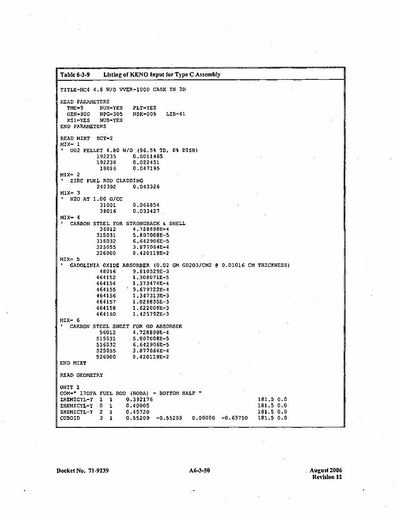
Table 6-3-9 Listing of KENO Input for Type C Assembly
TITLE-MC4 4.8 W/O VVER-1000 CASK IN 3D
READ PARAMETERSTME-9 RUN=YESGEN=900 NPG=305XSI-YES NUB-YES
END PARAMETERS
READ MIXT SCT-2MIXm 1
U02 PELLET 4.80192235192238
18016
PLT=YESNSK=005 LIB=41
W/O (96.5% TD, 0% DISH)0.00114 650. 0224 510.047195
MIX= 2ZIRC FUEL ROD CLADDING
240302 0.043326MIX= 30H20
MIX= 49CARB
AT 1.00 G/CC3100138016
ON STEEL FOR36012
315031316032325055326000
MIX= 5GADOLINIA OXIDE
48016464152464154464155464156464157464158464160
0.0668540.033427
STRONGBACK & SHELL4 .728898E-45. 807 008BE-56. 642 90 6E-53. 877064E-48. 420119E-2
ABSORBER (0.02 GM GD203/CM2 @ 0.01016 CM THICKNESS)9.810529E-31 .308071E-51 .373474E-4.9.67 9722E-41 .347313E-31 .026835E-31 .622008E-31. 425792E-3
ET FOR GD ABSORBER4. 728898E-4
6. 642 90 6E-53 .8770.64E-48 .420119E-2
MIX= 69CARBON STEEL SHE
5 6012515031516032525055526000
END I4IXT
READ GEOMETRY
UNIT 1COM=" 170FAZHEMICYL-YZHEMICYL-YZHEMICYL-YCUBOID
FUEL1 10 12 13 1
ROD (NOBA) - BOTTOM HALF0. 3921760. 400050.457200.55209 -0.55209 0.00000 -0.63750
181.5 0.0181.5 0.0181.5 0.0181.5 0.0
Docket No. 71-9239A635 A6-3-50 August 2006Revision 12
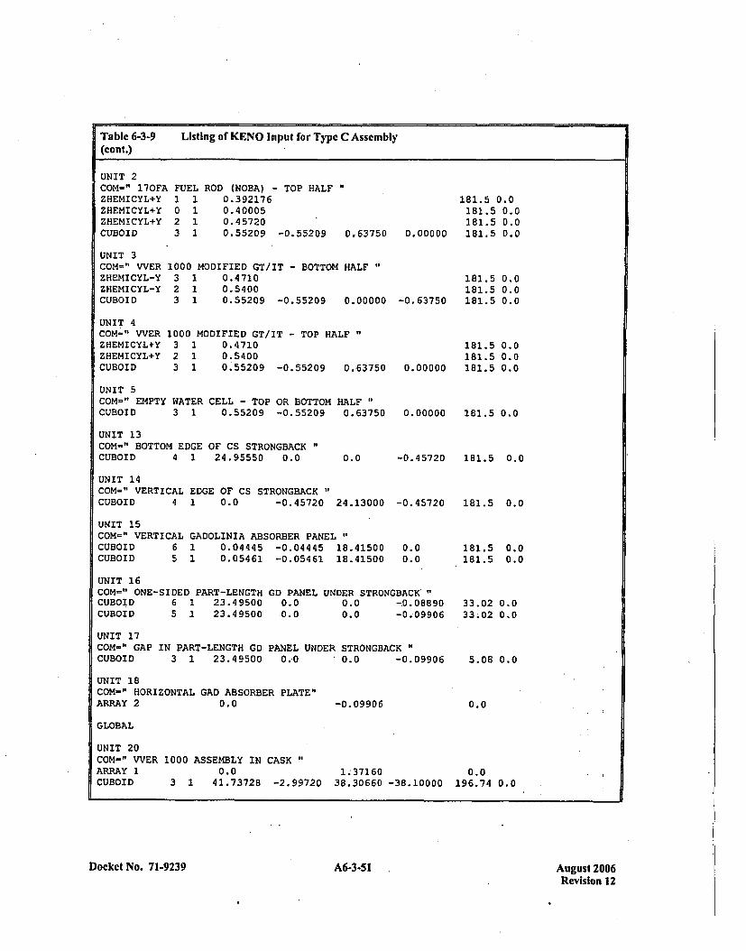
Table 6-3-9(cont.)
Listing of KENO Input for Type C Assembly
UNIT 2COM-" 170FAZHEMICYL+YZHEMICYL+YZHEMICYL+YCUBOID
FUEL1 10 12 13 1
ROD (NOBA) - TOP HALF0.3921760.400050.457200.55209 -0.55209 0.63750 0.00000
181.5 0.0181.5 0.0181.5 0.0181.5 0.0
181.5 0.0181.5 0.0181.5 0.0
UNIT 3COM=" WVERZHEMICYL-YZHEMICYL-YCUBOID
UNIT 4COM=" VVERZHEMI CYL+YZHEMI CYL+YCUBOID
1000 MODIFIED CT/IT - BOTTOM HALF'3 1 0.47102 1 0.54003 1 0.55209 -0.55209 0.00000
1000 MODIFIED CT/IT - TOP HALF3 1 0.47102 1 0.54003 1 0.55209 -0.55209 0.63750
-0. 63750
181.5181.5
0.00000 181.5
0.00.00.0
UNIT 5COM=" EMPTY WATER CELL - TOP OR BOTTOM HALFCUBOID 3 1 0.55209 -0.55209 0.63750
UNIT 13COM-" BOTTOM EDGE OF CS STRONGBACKCUBOID 4 1 24.95550 0.0
0.00000 181.5 0.0
-0.45720 181.5 0.00.0
UNIT 14COM=" VERTICAL EDGE OF CS STRONGBACKCUBOID 4 1 0.0 -0.45720 24.13000
UNIT 15COM=" VERTICAL GADOLINIA ABSORBER PANEL"CUBOID 6 1 0.04445 -0.04445 18.41500CUBOID 5 1 0.05461 -0.05461 18.41500
-0. 45720
0.00.0
UNIT 16COM=" ONE-SIDED PART-LENGTHCUBOID 6 1 23.49500CUBOID 5 1 23.49500
GD PANEL0.00.0
UNDER STRONGBACK'"0.0 -0.088900.0 -0.09906
181.5 0.0
181.5 0.0181.5 0.0
33.02 0.033.02 0.0
5.08 0.0
0.0
UNIT 17COM-" GAP IN PART-LENGTH GD PANEL UNDER STRONGBACKCUBOID 3 1 23.49500 0..0 10.0 -0.09906
UNIT 18COM=" HORIZONTAL GAD ABSORBER PLATE"ARRAY 2 0.0 -0. 09906
GLOBAL
UNIT 20COM=" WVERARRAY 1CUBOID
1000 ASSEMBLY IN CASK "
0.0 1.,37160 0.03 1 41.73728 -2.99720 38.30660 -38.10000 196.74 0.0
Docket No. 71-9239A635Aust20 A6-3-51Revision 12
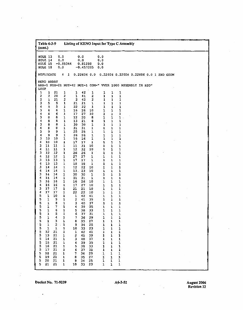
Table 6-3-9 Listing of KENO input for' Type C Assembly(con t.)
HOLE 13 0.0 0.0 0.0HOLE 14 0.0 0.0 0.0IHOLE 15 -0.85344 0.81280 0.0HOLE 18 0.0 -0.457205 0.0
REPLICATE 4 1 0.22606 0.0 0.22606 0.22606 0.22606 0.0 1 END GEOM
READ ARRAYARA-1 NUX=21 NUY-42 NUZ-~1 COM="' WER 1000 ASSEMBLY IN H20'LOOP1 1 21 1 1 42 1 1 1 12 2 20 2 1 41 2 1 1 12 1 21 2 2 42 2 1 1 13 5 5 1 21 21 1 1 1 14 5 5 1 22 22 1 1 1 13 6 6 1 16 26 10 1 1 14 6 6 1 17 27 10 1 1 13 8 8 1 12 20 8 1 1 14 8 8 1 13 21 8 1 1 13 8 8 1 30 30 1 1 1 14 8 8 1 31 31 1 1 1 13 9 9 1 25 25 1 1 1 14 9 9 1 26 26 1 1 1 13 10 10 1 16 16 1 1 1 14 10 10 1 17 17 1 1 1 13 11 11 1 11 31 10 1 1 14 11 11 1 12 32 10 1 1 13 12 12 1 26 26 1 1 1 14 12 12 1 27 27 1 1 1 13 13 13 1 17 17 1 1 1 14 13 13 1 18 18 1 1 1 13 14 14 1 12 22 10 1 1 14 14 14 1 13,23 10 1 1 13 14 14 1 30 30 1 1 1 14 14 14 1 31 31 1 1 1 13 16 16 1 16 26 10 1 1 14 16 16 1 17 27 10 1 1 13 17 17 1 21 21 10 1 1 14 17 17 1 22 22 10 1 1 15 1 10 1 1 42 41 1 1 15 1 9 1 2 41 39 1 1 15 1 8 1 3 40 37 1 1 .15 1 7 1 4 39 35 1 1 15 1 6 1 5 38 33 1 1 15 1 5 1 6 37 31 1 1 15 1 4 1 7 36 29 1 1 15 1 3 1 81 35 27 1 1 15 1 2.-1 9 34 25 1 1 15 1 1 1 10 33 23 1 1 15 12 21 1 1 42 41 1 1 15 13 21 1 2 41 39 1 1 15 14 21 1 3 40 37 1 1 15 15 21 1 4 39 35 1 1 15 16 21 1 5 38 33 1 1 15 17 21 1 6 37 31 1 1 15 18 21 1 7 36 29 1 1 15 19 21 1 8 35 27 1 1 15 20 21 1 9 34 25 1 1 15 21 21 1 10 33 23 1 1 1
Docket No. 71-9239 A6-3-52 Auvust 2006Revision 12
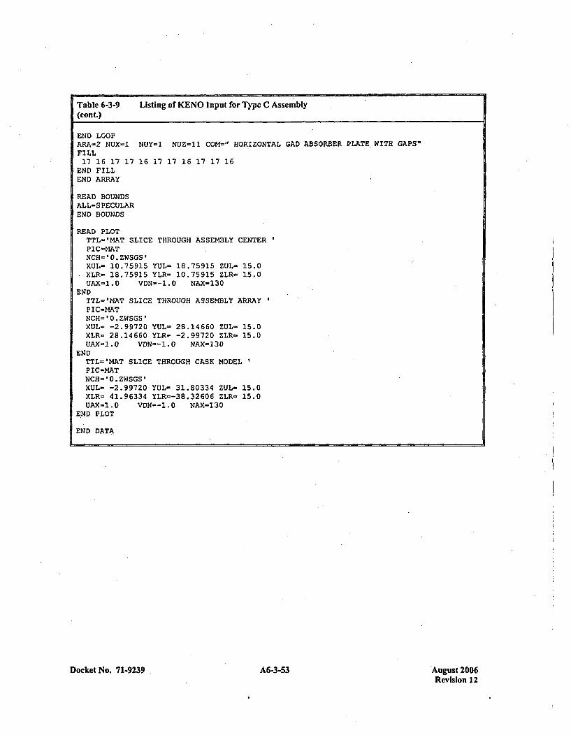
Table 6-3-9 Listing of KENO Input for Type C Assembly(con t.)
END LOOPARA=2 NUX=1 NUY-l NUZ-11 COM=' HORIZONTAL GAD ABSORBER PLATE. WITH GAPS'FILL17 16 17 17 16 17 17 16 17 17 16
END FILLEND ARRAY
READ BOUNDSALL-S PECULAREND BOUNDS
READ PLOTTTL'-'MAT SLICE THROUGH ASSEMBLY CENTERPIC-MATNCH-'O.ZWSGS'XUL- 10.75915 YUL= 18.75915 ZUL- 15.0XLR- 18.75915 YLR= 10.75915 ZLR- 15.0UAX-1.0 VDN--1.0 NAX-130
ENDTTL-'MAT SLICE THROUGH ASSEMBLY ARRAYPIC-MATNCH='0.ZWSGS'XUL= -2.99720 YUL- 28.14660 ZUL- 15.0XLR- 28.14660 YLR= -2.99720 ZLR= 15.0UAX-1.O VON--1.O NAX=130
ENDTTL='MAT SLICE THROUGH CASK MODELP IC-MATNCH=0O.ZWSGS'XUL= -2.99720 YUL- 31.80334 ZUL- 15.0XLR- 41.96334 YLR=-38.32606 ZLR- 15.0UAX-1.0 VDN--1.0 NAX=130
END PLOT
END DATA
Docket No. 71.9239 A6-3-53 August 2006Revision 12
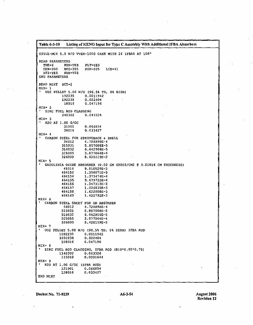
Table 6-3-10 Listing of KENO Input for Type C Assembly With Additional IFBA Absorbers
TITLE-MC4 5.0 W/O VVER-1000 CASK WITH 24 IFBAS AT 10811
READ PARAMETERSTHE- 6 RUN=YESGEN-900 NPG-305XS1=YES NUB-YES
END PARAMETERS
READ MIXT SCT-2MIX- 1#U02 PELLET 5.00 V~
PLT-YESNSK-005 LIB=41
~/0 (96.5% TD, 0% DISH)0. 00119420.0224040.047196
19223519223818016
MIX- 2ZIRC FUEL ROD CLADDING
240302 0.043326Mix- 39H20
MIX- 41CARB
AT 1.00 G/C(3100138016
ON STEEL FOE36012
315031316032325055326000
MIX- 5GADOLINIA OXIDE
480164641524641544641554641564641574641584 64 160
0.0668540. 033 427
STRONGBACK & SHELL4.72889BE-45. 807 00 8E-56. 642 90 6E-53. 877064E-48.42 0119E-2
ABSORBER (0.02 GM GD203/CM2 @ 0.01016 CM THICKNESS)9. 810 52 9E-3,1 .308071E-51. 373474E-49. 679722E-41.347313E-3,1. 026835E-31. 622 00 8E-31. 425792E-3
ET FOR GD ABSORBER4. 72889BE-45.807008E-56. 642906E-53. 87 706 4E-48 .420119E-2
W/O (96.5% TD, 0% DISH) IFBA ROD0. 00119420.0224 040. 047196
MIX- 60CARBON STEEL SHE
56012515031516032525055526000
MIX- 7I U02 PELLET 5.00
10922351092238108016
MIX= 8P IRC
MIX= 91 20 A
END MIXT
FUEL ROD CLADDING, IFBA ROD (510*0.95*0.75)1140302 0.043326115010 0.0001644
T 1.00 G/CC121001128016
(IFBA ROD)0.0668540. 0334 27
Docket No. 71-9239 A6-3-54 August 2006Revision 12
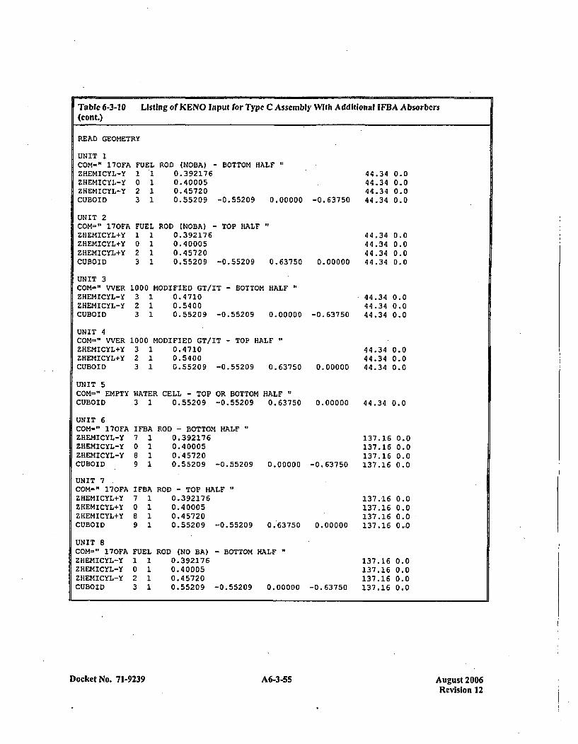
Table 6-3-10 Listing of KENO Input for Type C Assembly With Additional IFBA Absorbers(cont.)
READ GEOMETRY
UNIT 1COM-" 170FAZHEMICYL-YZHEMICYL-YZHEMICYL-YCUBOID
UNIT 2COM=" 170FAZHEMICYL+YZHEMICYL+YZHEMICYL+YCUBOID
FUEL1 *10 12 13 1
FUEL1 10 12 13 1
ROD (NOBA) - BOTTOM HALF0.3921760. 400050. 457200.55209 -0.55209 0.00000 -0.63750
ROD (NOBA) - TOP HALF0. 3921760. 400050. 457200.55209 -0.55209 0.63750
44.3444.3444.3444.34
44.3444..3444.3444.34
44.3444.3444.34
0.00.00.00.0
0.00.00.00.0
0.00.00.0
UNIT 3COM=" WVER 1000 MODIFIED GT/IT - BOTTOM HALF"ZHEMICYL-Y 3 1 0.4710ZHEMICYL-Y 2 1 0.5400CUBOID 3 1 0.55209 -0.55209 0.00000
0. 00000
-0. 63750
UNIT 4COM=" WVERZHEMICYL+YZHEMICYL+YCUBOID
1000 MODIFIED GT/IT - TOP HALF"3 1 0.47102 1 0.54003 1 0.55209 -0.55209 0.63750
44.34 0.044.34 0.044.34 0.00. 00000
UNIT 5COM=" EMPTY WATER CELL - TOP OR BOTTOM HALF"CUBOID 3 1 0.55209 -0.55209 0.63750 0.00000 44.34 0.0
UNIT 6COM-" 170FAZHEMICYL-YZHEMICYL-YZHEMICYL-YCUBOID
I FBA7 10128 19 1
ROD - BOTTOM HALF0.39217 60. 400050. 457200.55209 -0.55209 0.00000 -0.63750
UNIT 7,COM-" 170FAZHEMICYL+YZHEMICYL+YZHEMICYL+YCUBOID
137.16137.16137.16137.16
137.16137.16137.16137.16
0.00.00.00.0
0.00.00.00,~0
I FBA7 10 *18 19 1
FUEL1 10 12 13 1
ROD - TOP HALF"0.3 921760. 400050. 457200.55209 -0.55209 0.63750 0.00000
UNIT 8COM-" 170FAZHEMICYL-YZHEMICYL-YZHEMICYL-YCUBOID
ROD (NO BA)0. 3921760. 400050. 457200. 55209
- BOTTOM HALF "
137.16 0.0137.16 0.0137.16 0.0137.16 0.0-0. 55209 0.00000 -0.63750
Docket No. 71-9239A635Aust26 A6-3-55Revision 12
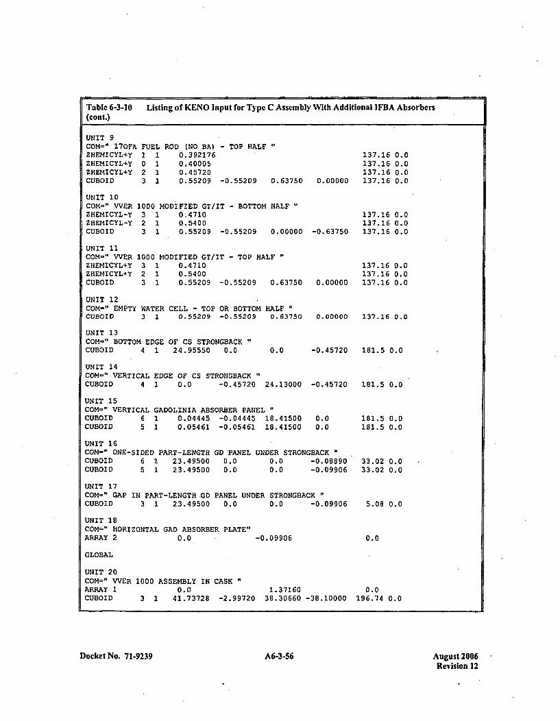
Table 6-3-10 Listing of KENO Input for Type C Assemnbly With Additional IFBA Absorbers(cont.)
UNIT 9COM=" 17OFAZHEMICYL+YZHEMICYL+YZHEMICYL+YCUBOID
FUEL ROD (NO BA) - TOP HALF1 1 0.3921760 1 0.400052 1 0.457203 1 0.55209 -0.55209 0.63750
137.16 0.0137.16 0.0137.16 0.0137.16 0.00.00000
UNIT 10COM-" VVERZHEMICYL-YZHEMICYL-Y.CUBOID
UNIT 11COM-" WVERZHEMICYL+YZHEMICYL+YCUBOID
1000 MODIFIED GT/IT - BOTTOM HALF3 1 0.47102 1 0.54003 1 0.55209 -0.55209 0.00000
1000 MODIFIED GT/IT - TOP HALF3 1 0.47102 1 0.54003 1 0.55209 -0.55209 0.63750
137.16137.16137.16-0. 63750
0.00.00.0
0.00.00.0
137.16137.16
0.00000 137.16
UNIT 12COM=" EMPTY WATER CELL - TOP OR BOTTOM HALFCUBOID 3 1 0.55209 -0.55209 0.63750
UNIT 13COM-" BOTTOM EDGE OF CS STRONGBACKCUBOID 4 1 24.95550 0.0
0.00000 137.26 0.0
-0.45720 181.5 0.00.0
UNIT 14COM-" VERTICAL EDGE OF CS STRONGBACKCUBOID 4 1 0.0 -0.45720 24.13000 -0. 45720
UNIT 15COM=" VERTICALCUBOID 6CUBOID 5
GADOLINIA ABSORBER PANEL "
1 0.04445 -0.04445 18.415001 0.05461 -0.05461 18.41500
0.00.0
UNIT 16COM-" ONE-SIDED PART-LENGTHCUBOID 6 1 23.49500CUBOID 5 1 23.49500
GD PANEL0.00.0
UNDER STRONGBACK "
0.0 -0.088900.0 -0.-09906
181.5 0.0
181.5 0.0181.5 0.0
33.02 0.033.02 0.0
5.08 0.0
0.0
UNIT 17,COM=" GAP IN PART-LENGTH GD PANEL UNDER STRONGBACKCUBOID 3 1 23.49500 0.0 0.0 .- 0.09906
UNIT 18COM=" HORIZONTAL GAD ABSORBER PLATE"ARRAY 2 0.0 -0. 09906
GLOBAL
UNIT 20COM=" VVER 1000 ASSEMBLY IN CASKARRAY 1 0.0 1.37160 0.0CUBOID 3 1 41.73728 -2.99720 38.30660 -38.10000 196.74 0.0
Docket No. 71-9239 A6-3-56 August 2006Revision 12
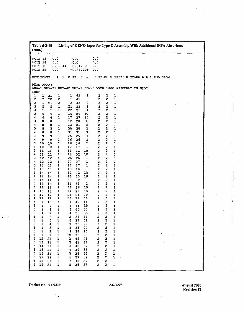
Table 6-3-10 Listing or KENO Input for Type C Assembly With Additional IFBA Absorbers(cont.)
HOLE 13 0.0 0.0 0.0HOLE 14 0.0 0.0 0.0HOLE 15 -0.85344 0.81280 0.0HOLE 18 0.0 -0.457205 0.0
REPLICATE 4 1 0.22606 0.0 0.22606 0.22606 0.22606 0.0 1 END GEOM
READ ARRAYAR.A=1 NUJX-21 NUY-42 NUZ-2 COM-" VVER 1000 ASSEMBLY IN H20"LOOP
1223434.3434343:4:34:3:4:3:423 14 33214213214213 14 155555555555215215215 1521521521521
12155668
8
99
10
121213131414L44L6
.7
.71111111111
.2
.3
.4
.5
.6
.7
.8
.9
2120215566888899
1010111112121313141414141616171710987654321
2121212121212121
1 421 412 42
.21 2122 2216 2617 2712 2013 2130 3031 3125 2526 2616 1617 1711 3112 3226 2627 2717 1718 1812 2213 2330 3031 3116 2617 2721 2122 221 422 413 404 39.5 386 377 368 359 34
10 331 422 413 404 395 386 377 368 35
122
1010
88I11111
1010
1111
101011
10101010413937353331292725234139373533312927
II
Docket No. 71-9239 A6-3-57 August 2006Revision 12
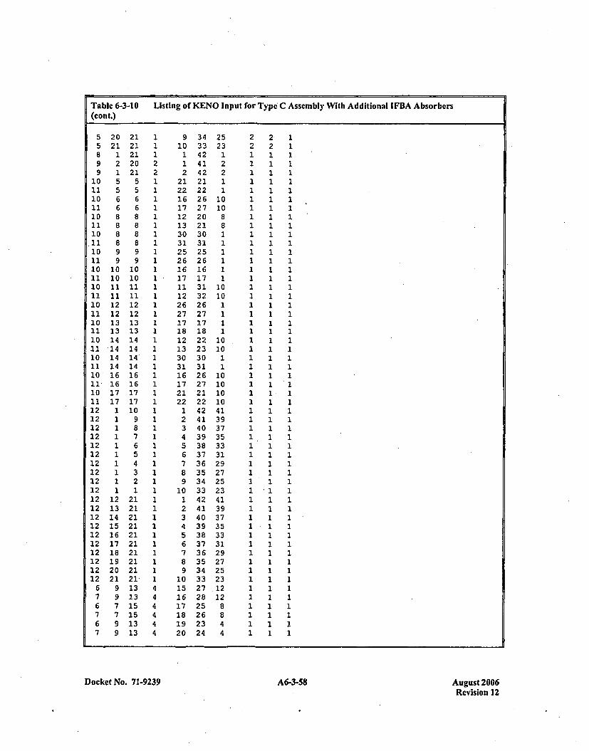
Table 6-3-10 Listing of KENO Input for Type C Assembly With Additional IFBA Absorbers(cont.)
5 20 21 1 9 34 25 2 2 15 21 21 1 10 33 23 2 2 18 1 21 1 1 42 1 1 1 19 2 20 2 1 41 2 1 1 19 1 21 2 2 42 2 1 1 1
10 5 5 1 21 21 1 1 1 111 5 5 1 22 22 1 1 1 110 6 6 1 16 26 10 1 1 111 6 6 1 17 27 10 1 1 110 8 8 1 12 20 8 1 1 111 8 8 1 13 21 8 1 1 110 8 8 1 30 30 1 1 1 111 8 8 1 31 31 1 1 1 110 9 9 1 25 25 1 1 1 111 9 9 1 26 26 1 1 1 110 10 10 1 16 16 1 1 1 1
10 10 10 1 17 17 10 1 1 11011 1010 1 17 317 10 1 1 111 11 11 1 12 32 10 1 1 110 12 12 1 26 26 1 1 1 111 12 12 1 27 27 1 1 1 110 13 13 1 17 17 1 1 1 111 13 13 1 18 18 1 1 1 110 14 14 1 12 22 10 1 1 121 14 14 1 13 23 10 1 1 110 14 14' 1 30 30 1 1 1 111 14 14 1 31 31 1 1 1 110 16 16 1 16 26 10 1 1 111 16 16 1 17 27 10 1 1 110 17 17 1 21 21 10 1 1 111 17 17 1 22 22 10 1 1 112 1 10 1 1 42 41 1 1 112 1 9 1 2 41 39 1 1 112 1 8 1 3 40 37 1 1 112 1 7 1 4 39 35 1 1 112 1 6 1 5 38 33 1 1 112 1 5 1 6 37 31 1 1 112 1 4 1 7 36 29 1 1 112 1 3 1 8 35 27 1 1 112 1 2 1 9 34 25 1 1 112 1 1 1 10 33 23 1 .1 112 12 21 1 1 42 41 1 1 112 13 21 1 2 41 39 1 1 112 14 21 1 3 40 37 1 1 112 15 21 1 4 39 35 1 1 112 16 21 1 5 38 33 1 1 112 17 21 1 6 37 31 1 1 112 18.21 1 7 36 29 1 1 112 19 21 1 8 35 27 1 1 112 20 21 1 9 34 25 1 1 112 21 21 1 10 33 23 1 1 1
6 9 13 4 15 27 .12 1 1 17 9 13 4 16 28 12 1 1 16 7 15 4 17 25 8 1 1 17 7 15 4 18 26 8 1 1 16 9 13 4 19 23 4 1 1 17 9 13 4 20 24 4 1 1 1
Docket No. 71-9239 A6-3-58 August 2006Revision 12
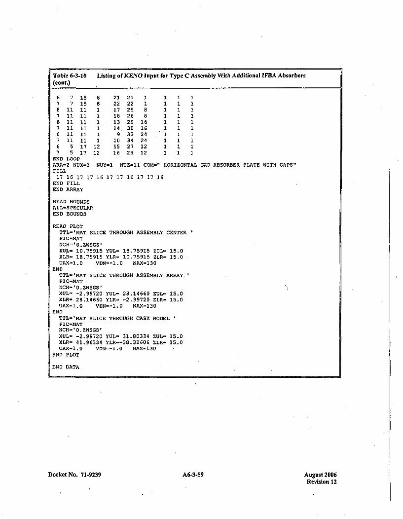
Table 6-3-10 Listing of KENO Input for Type C Assemnbly With Additional IFBA Absorbers(cont.)
6 7 15 8 21 21 1 1 1 17 7 15 8 22 22 1 1 1 16 11 11 1 17 25 8 1 1 17 11 11 1 18 26 8 1 1 16 11 11 1 13 29 16 1 1 17 11 11 1 14. 30 16 1 1 16 11 11 1 9 33 24 1 1 17 11 11 1 10 34 24 1 1 16 5 17 12 15 27 12 .1 1 17 5 17 12 16 28 12 1 1 1END LOOPARA=2 NUX=1 NUY=1 NUZ-11 COM-" HORIZONTAL GAD ABSORBER PLATE WITH GAPS"FILL17 16 17 17 16 17 17 16 17 17 16
END FILLEND ARRAY
READ BOUNDSALL=S PECULAREND BOUNDS
READ PLOTTTL='MAT SLICE THROUGH ASSEMBLY CENTERPIC-MATNCH='0.ZWSGS'XUL- 10.75915 YUL= 18.75915 ZUL- 15.0XLR= 18.75915 YLR- 10.75915 ZLR= 15.0UAX-1.0 VDN=--.0 NAX-130
ENDTTL='MAT SLICE THROUGH ASSEMBLY ARRAY.1PIC-MATNCH-'0. ZWSGS'XUL= -2.99720 YUL- 28.14660 ZUL- 15.0XLR= 28.14660 YLR- -2.99720 ZLR- 15.0UAX-1.0 VDN=--.0 NAX=130
ENDTTL-'MAT SLICE THROUGH CASK MODELPIC-MATNCH= '0.ZWSGS'XUL- -2.99720 YUL- 31.80334 ZUL= 15.0XLR= 41.96334 YLR=-38.32606 ZLR- 15.0UAX=1.0 VbN=-1.0 NAX-130
END PLOT
END DATA
Docket No. 7 1-9239 A6-3-59 August 2006Rev'ision 12
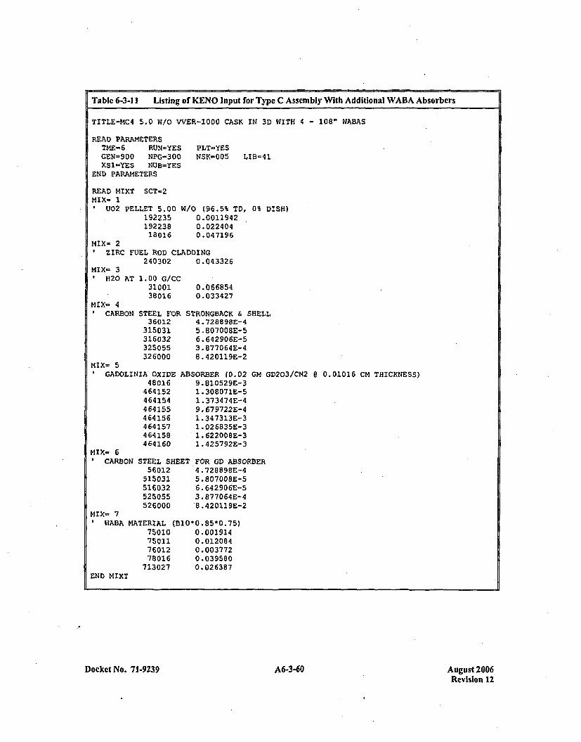
Table 6-3-11 Listing of KENO Input for Type C Assembly With Additional WABA Absorbers
TITLE-14C4 5.0 W1/0 VVER-1000 CASK IN 3D WITH 4 - 108" WABAS
READ PARAMETERSTME-6 RUN-YESGEN=900 NPG=300XS1-YES NUB=YES
END PARAMETERS
PLT-YESNSK-005 LIB=41
READ MIXT SCT-2MIX- 1
U02 PELLET 5.0019223519223818016
W/O (96.5% TD, 0% DISH)0.00119420.0224040.047196
MIX= 2ZIRC FUEL ROD CLADDING
240302 0.043326MIX- 3
11B20 AT 1.00 G/CC3100138016
MIX- 4CARBON STEEL FOR
36012315031316032325055326000
0.0668540.033427
STRONGBACK & SHELL4.*728898E-45.807008E-56. 642906E-53.877064E-48. 420119E-2
MIX- 5GADOLINIA OXIDE
48016464152464154464155464156464157464158464160
ABSORBER (D.029. 810529E-31. 308 07 1E-51 .373474E-49. 679722E-41. 34 7313E-312.026835E-31. 622008E-31.4257 92E-3
GM GD2O3/CM2 @ 0.01016 CM THICKNESS)
MIX- 61CARBON STEEL SHEET
5601251503151603252S055526000
FOR GD ABSORBER4 .728898E-45.80700BE-56. 642 90 6E-53. 877064E-4'8.420119E-2
MIX- 7WABA MATERIAL (B1O*0.85*0.75)
75010 0.00191475011 0.01208476012 0.00377278016 0.039580
713027 0.026387END MIXT
Docket No. 71-9239 A6-3-60 August 2006Revision 12
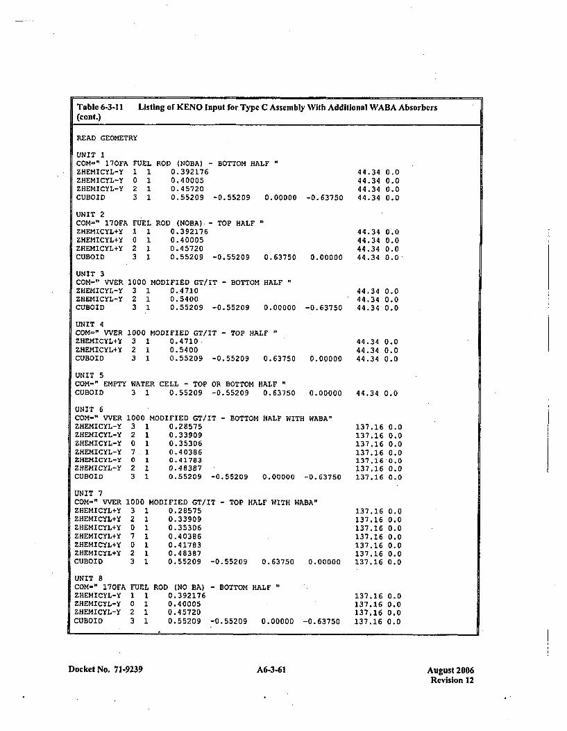
Table 6-3-11 Listing of KENO Input for Type C Assembly With Additional WABA Absorbers(cont.)
READ GEOMETRY
UNIT 1COM-" 170FA FUELZHEMICYL-Y 1 1ZHEMICYL-Y 0 1ZHEMICYL-Y 2 1CUBOID 3 1
UNIT 2COM=" 170FA FUELZHEMICYL+Y 1 1ZHEMICYL+Y 0 1ZHEMICYL+Y 2 1CUBOID 3 1
ROD (NOBA) - BOTTOM HALF0.3921760.400050.4 57200.55209 -0.55209 0.00000 -0.63750
44.34 0.044.34 0.044.34 0.044.34 0.0
ROD (NOBA) - TOP HALF0.3921760. 400050. 457200.55209 -0.55209 0.63750
44.34 0.044.34 0.044.34 0.0
0.00000 44.34 0.0
UNIT 3COM=" VVERZHEMICYL-YZHEMICYL-YCUBOID
UNIT 4COM-" WVERZHEMICYL+YZHEMICYL+YCUBOID
1000 MODIFIED GT/IT - BOTTOM HALF3 1 0.47102 1 0.54003 1 0.55209 -0.55209 0.00000
1000 MODIFIED GT/IT - TOP HALF3 1 0.47102 1 0.54003 1 0.55209 -0.55209 0.63750
-0. 63750
0. 000 00
44.34 0.044.34 0.044.34 0.0
44.34 0.044.34 0.044.34 0.0
UNIT 5COM=" EMPTY WATER CELL - TOP OR BOTTOM HALFCUBOID 3 1 0.55209 -0.55209 0.63750 0.00000 44.34 0.0
UNIT 6COM=" VVERZHEMICYL-YZHEMICYL-YZHEMICYL-YZHEMICYL-YZHEMICYL-YZHEMICYL-YCUBOID
1000 MODIFIED GT/IT - BOTTOM HALF WITH WABA"3 1 0.285752 1 0.339090 1 0.353067.1 0.403860 1 0.417832 1 0.483873 1 0.55209 -0.55209 0.00000 -0.63750
137.16137.16137.16137.16137.16137. 16137.16
UNIT 7COM-" VVERZHEMICYL+YZHEMICYL+YZHEMICYL+YZHEMICYL+YZHEMICYL+YZHEMICYL+YCUBOID
UNIT 8COM-" 170FAZHEMICYL-YZHEMICYL-YZHEMICYL-YCUBOID
1000 MODIFIED GT/IT - TOP HALF WITH WABA"3 1 0.285752 1 0.339090 1 0.353067 1 0.403860 1 0.417832 1 0.483873 1 0.55209 -0.55209 0.63750 0.'
0.00.00.00.00.00.00.0
0.00.00.00.00.00.00.0
137.16137.16137.16137.16137.16137..16
00000 137.16
FUEL1 10 12 13 1
ROD (NO BA) - BOTTOM HALF0.3921760. 400050.457200.55209 -0.55209 0.00000 -0.63750
137.16 0.0137.16 0.0137.16 0.0137.16 0.0
Docket No. 71-9239 631Aust20A6-3-61Revision 12
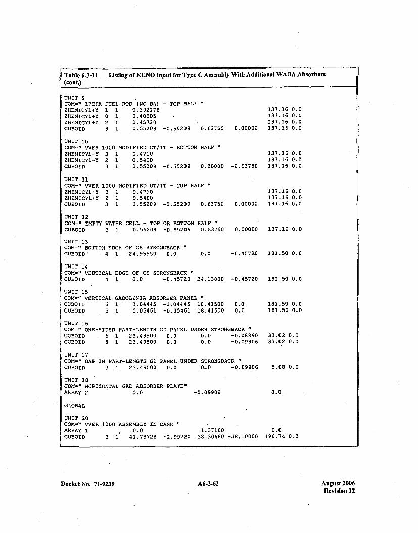
Table 6-3-11 Listing of KENO Input for Type C Assembly With Additional WABA Absorbers(cont.)
UNIT 9COM-"' 17OFAZHEMI CYL+YZHEMICYL+YZHEMICYL+YCUBOID
FUELI1I0 12 13 1
ROD (NO BA) - TOP HALF0.3921760.400050.457200.55209 -0.55209 0.63750
137.16137. 16137.16
0.00000 137.16
UNIT 10COM-" WVERZHEMICYL-YZHEMICYL-YCUBOID
UNIT 11COM-" WVERZIIEMICYL+YZHEMICYL+YCUBOID
1000 MODIFIED GT/IT - BOTTOM HALF3 1 0.47102 1 0.54003 1 0.55209 -0.55209 0.00000
1000 MODIFIED GT/IT - TOP HALF"3 1 0.47102 1 0.54003 1 0.55209 -0.55209 0.63750
-0. 63750
0. 00000
137.16137.16137.16
137.16137.16137.16
0.00.00.00.0
0.00.00.0
0.00.00.0
UNIT 12COM-" EMPTY WATER CELL - TOP OR BOTTOM HALFCUBOID 3 1 0.55209 -0.55209 0.63750
UNIT 13COM=" BOTTOM EDGE OF CS STRONGBACK"CUBOID 4 1 24.95550 0.0
0.00000 137.16 0.0
-0.45720 181.50 0.00.0
UNIT 14COM-" VERTICAL EDGE OF CS STRONGBACKCUBOID 4 1 0.0 -0.45720 24.13000
UNIT 15com-" VERTICAL GADOLINIA ABSORBER PANELCUBOID 6 1 0.04445 -0.04445 18.41500CUBOID 5 1 0.05461 -0.05461 18.41500
-0. 45720
0.00.0
UNIT 16COM=" ONE-SIDED PART-LENGTHCUBOID 6 1 23.49500CUBOID 5 1 23.49500
GD PANEL0.00.0
UNDER STRONGBACK "
0.0 -0.088900,.0 -0.09906
181.50 0.0
181.50 0.0181.50 0.0
33.02 0.033.02 0.0
5.08 0.0
0.0
UNIT 17COM=" GAP IN PART-LENGTH'GD PANEL UNDER STRONGBACK"CUBOID 3 1 23.49500 '0.0 0_0 -0.09906
UNIT 18COM=" HORIZONTAL GAD ABSORBER PLATE"ARRAY 2 0.0 -0. 09906
GLOBAL
UNIT 20COM=" WVERARRAY 1CUBOID
1000 ASSEMBLY IN CASK 10ý0.0 1.37160 0.0
3 1 41.73728 -2.99720 38.30660 -38.10000 196.74 0.0
Docket No. 71-9239 A6-3-62 August 2006Revision 12
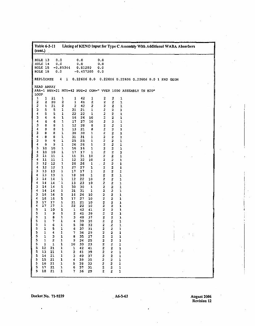
Table 6-3-11 Listing or KENO Input for Type C Assembly With Additional WABA Absorbers(cont.)
HOLE 13 0.0 0.0 0.0HOLE 14 0.0 0.0 0.0HOLE 15 -0.85344 0.81280 0.0HOLE 18 0.0 -0.457205 0.0
REPLICATE 4 1 0.22606 0.0 0.22606 0.22606 0.22606 0.0 1 END GEOM
READ ARRAYARA-1 NUX-21 .NUY-42 NtJZ=2 CON-" VVER 1000 ASSEMBLY IN H20"LOOP1 1 21 1 1 42 1 2 2 12 2 20 2 1 41 2 2 2 12 1 21 2 2 42 2 2 2 13 5 5 1 21 21 1 2 2 14 5 5 1 *22 22 1 2 2 13 6 6 1 16 26 10 2 2 14 6 6 1 17 27 10 2 2 13 8 8 1 12 20 8 2 2 14 8 8 1 13 21 8 2 2 13 8 8 1 30 30 1 2 2 14 8 8 1 31 31 1 2 2 13 9 9 1 25 25 1 2 2 14 9 9 1 26 26 1 2 2 13 10 10 1 16 16 1 2 2 14 10 10 1 17 17 1 2 2 13-11 11 1 11 31 10 2 2 14 11 11 1 12 32 10 2 2 13 12 12 1 26 26 1 .2 2 14 12 12 1 27 27 1 2 2 13 13 13 1 17 17 1 2 2 14 13 13 1 18 18 1 2 2 13 14 14 1 12 22 10 2 2 14 14 14 1 13 23 10 2 2 13 14 14 1 30 30 1 2 2 114 14 14 1 31 31 1 2 2 13 16 16 1 16 26 10 2 2 14 16 16 1 17 27 10 2 2 13 17 17 1 21 21 10 2 2 14 17 17 1 22 22 10 2 2 15 1 10 1 1 42 41 2 2 15 1 9 1 2 41 39 2 *2 .15 1 8 1 3 4-0 37 2 2 15 1 7 1 4 39 35 2 2 15 1 6 1 5 38 33 2 .2 1
5 1 5 1 6 37 31 2 2, 15 1 4 1 7 36 29 2 2 15 1 3 1 8 35 27 2 2 15 1 2 1 9 34 25 2 2 15 1 1 1 10 33 23 2 2. 15 12 21 1 1 42 41 2 2 15 13 21 1 2 41 39 2 2 15 14 21 1 3 40 37 2 2 15 15 21 1 4 39 35 2 2 15 16 21 1 5 38 33 2 2 15 17 21 1 6 37 31 2 2 15 18 21 1 7 36 29 2 2 1
Docket No. 71-9239 A6-3-63 August 2006Revision 12
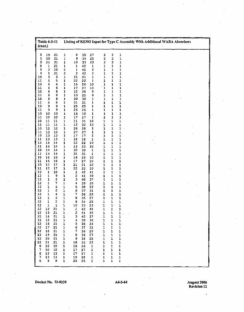
5 19 21 1 8 35 27 2 2 15 20 21 1 9 34 25 2 2 15 21 21 1 10 33 23 2 2 18 1 21 1 1 42 1 1 1 19 2 20 2 1 41 2 1 1 19 1 21 2 2 42 2 1 1 1
ý10 5 5 1 21 21 1 1 1 111'5 5 1 22 22 1 1 1 110 6 6 1 16 26 10 1 1 111 6 6 1 17 27 10 1 1 110 8 8 1 12 20 8 1 1 111 8 8 1 13 21 8 1 1 110 8 8 1 30 30 1 1 2 111 8 8 1 31 31 1 1 1 110 9 9 1 25 25 1 1 1 111 9 9 1 26 26 1 1 1 110 10 10 1 1ý616 1 1 1 111 10 10 1 17 17 1 1 1 110 11 11 1 11 31 10 1 1 111 11 11 1 12 32 10 1 1 110 12 12 1 26 26 1 1 1 111 12 12 1 27 27 1 1 1 110 13 13 1 17 17 1 1 1 111 13 13 1 18 18 1 1 1 110 14 .14 1 12 22 10 1 1 111 14 14 1 13 23 10 1 1 110 14 14 1 30 30 1 1 1 111 14 14 1 31 31 1 1 1 110 16 16 1 16 26 10 1 1 111 16 16 1 17 27 10 1 1 110 17 17 1 21 21 10 1 1 111 17 17 1 22 22 10 1 1 112 1 10 1 1 42 41 1 1 112 1 9 1 2 41 39 1 1 112 1 8 1 3 40 37 1 1 112 1 7 1 4 39 35 1 1 112 1 6 1 5 38 33 1 1 112 1 5 1 6 37 31 1 1 112 1 4 1 7 36 29 1 1 112 1 3 1 8 35 27 1 1 112 1 2 1 9 34 25 1 1 112 1 1 A 10 33 23 '1 1 -112 12 21 1 1. 42 41 1 1 112 13 21 1 2 41 39 1 1 112 14 21 1 3 40 37 1 1 112 15 21 1 4 39 35 1 1 112 16 21 1 5 38 33 1 1 112 17 21 1 6 37 31 1 1 112 18 21 1 7 36 29 1 1 112 19 21 1 8 35 27 1 1 112 20 21 1 9 34 25 1 1 112 21 21 1 10 33 23 1 1 1
6 10 10 1 16 16 1 1 1 17 10 10 1 17 17 1 1 1 16 13 13 1 17 17 1 1 1 17 13 13 1 18 18 1 1 1 16 9 9 1 25 25 1 1 1 1
)ocket No. 71-9239 A6-3-64Au st20IRevision 12
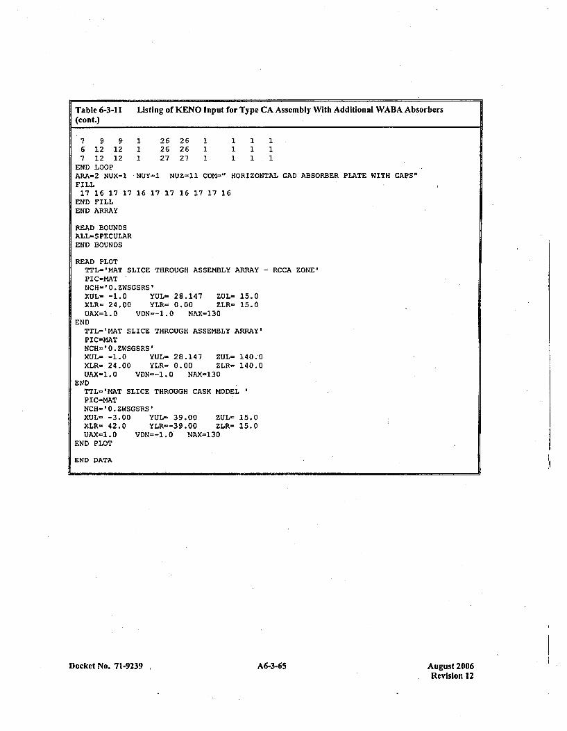
Table 6-3-11 Listing of KENO Input for Type CA Assembly With Additional WABA Absorbers(cont.)
7 9 9 1 26 26 1 1 1 16 12 12 1 26 26 1 1 1 17 12 12 1 27 27 1 1 1.1END LOOPARA-2 NUX=1 NUY=1 NUZs=11 COM=." HORIZONTAL GAD ABSORBER PLATE WITH GAPS"FILL17 16 17 17 16 17 17 16 17 17 16END FILLEND ARRAY
READ BOUNDSALL=S FEC ULAREND BOUNDS
READ PLOTTTL='MAT SLICE THROUGH ASSEMBLY ARRAY - RCCA ZONE'PIC=MATNCH-'0.ZWSGSRS'XUL- -1.0 YUL= 28.147 ZUL- 15.0XLR- 24.00 YLR= 0.00 ZLR- 15.0UAX=1.0 VDN--1.0 NAX-130
ENDTTL-'MAT SLICE THROUGH ASSEMBLY ARRAY'P IC-MATNCH= '0.ZWSGSRS'XUL= -1.0 YUL- 28.147 ZUL- 140.'0XLR- 24.00 YLR= 0.00 ZLR- 140.0UAX-1.0 VDN--1.O NAX-130
ENDTTL-'MAT SLICE THROUGH CASK MODELPIC=MATNCH'='0.ZWSGSRS'XUL- -3.00 YUL- 39.00 ZUL= 15.0XLR- 42.0 YLR=-39.00 ZLR- 15.0UAX-1.0 VDN=-1.0 NAX-130
END PLOT
END DATA
Docket No. 71-9239 635Aust20A6-3-65Revision 12
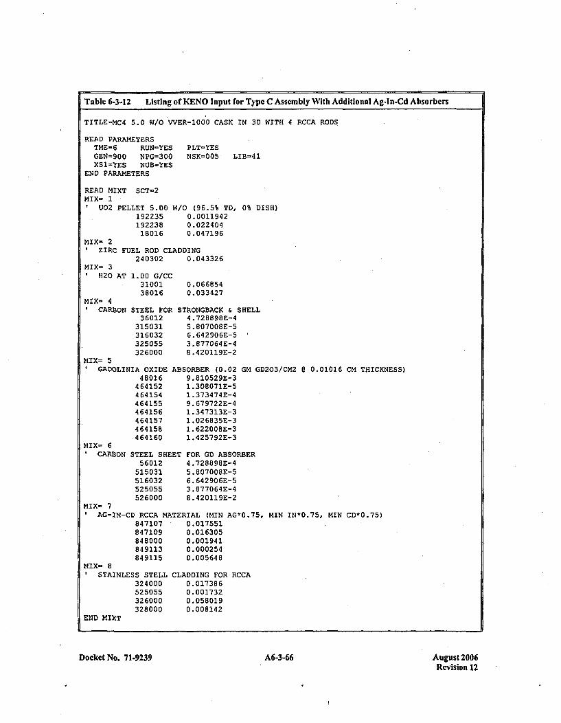
Table 6-3-12 Listing of KENO Input for Type C Assembly With Additional Ag-In-Cd Absorbers
TITLE-MC4 5.0 W/OWVER-100'0 CASK IN 3D WITH 4 RCCA RODS
READ PARAMETERSTME-6 RUJN-YESGEN=900 NPG=300XSI-'YES NUB-YES
END PARAMETERS
PLT-YESNSK=005 LIB=41
READ MIXT SCT=2mix- 1
O2PELLET 5.0019223519223818016
W/O (96.5% TD, 0% DISH)0.00119420.0224040.047196
MIX- 2ZIRC FUEL ROD CLADDING
240302 0.043326mix= :3
11H20
MIX= 41CAR]B
AT 1.00 G/CC31001:38016
ON STEEL FOR3 6012
315031316032325055326000
0. 0668 540.033427
STRONGBACK & SHELL4 .728898E-45.807008E-56. 642 90 6E-53.877064E-48 .420119E-2
ABSORBER (0.02 GM GD203/CM2 @ 0.01016 CM THICKNESS)9.81052 9E-31.308071E-51 .373474E-49. 679722E-41.347313E-31. 02 683 5E-31 .622008E-31. 425792E-3
MIX= 5GADOLINIA OXIDE
48016464152464154464155464156464157464158.464160
mix= 69CARBON STEEL SHEET
56012515031516032525055526000
FOR GD ABSORBER4 .728898E-45. 807008E-56. 642906E-53. 877064E-48.420119E-2
MIX- 7AG-IN-CD RCCA MATERIAL (MIN AG*0.75, MIN IN*0.75, MIN CD*D.75)
847107 0.017551847109 0.016305848000 0.001941849113 0.000254849115 0.005648
MIX- 8STAINLESS STELL
324000525055326000328000
END MIXT
CLADDING FOR RCCA0.01738 60.0017320.0580190.00814 2
Docket No. 7 1.9239 A6-3-66 August 2006Revision 12
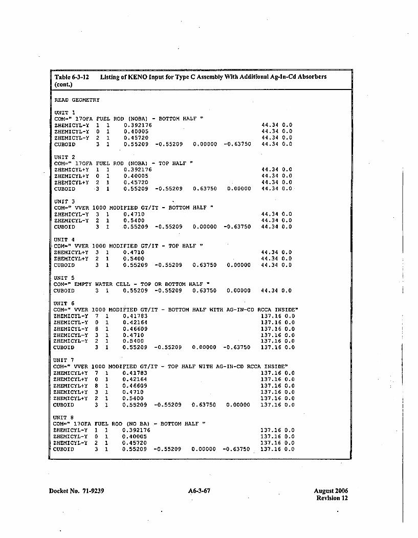
Table 6-3-12 Listing of KENO Input for Type C Assembly With Additional Ag-In-Cd Absorbers(cont.)
READ GEOMETRY
UNIT 1COM-" 170FAZHEMICYL-YZHEMICYL-YZHEMICYL-YCUBOID
UNIT 2COM-" 170FAZHEMICYL+YZHEMICYL+YZHEMICYL+YCUBOID
FUEL
2 13 1
FUEL1 10 12 1-3 1
ROD (NOBA) - BOTTOM HALF0.3 921760.400050.457200.55209 -0.55209 0.00000 -0.63750
44.34 0.044.34 0.044.34 0.044.34 0.0
ROD (NOBA) - TOP HALF0. 392 1760. 400050.457200.55209 -0.55209 0.63750
44.34 0.044.34 0.044.34 0.0
0.00000 44.34 0.0
UNIT 3COM-" VVERZHEMICYL-YZHEMICYL-YCUBOID
UNIT 4COM=" VVERZHEMICYL+YZHEMICYL+YCUBOID
1000 MODIFIED GT/IT - BOTTOM HALF3 1 0.4710*2 1 0.54003 1 0.55209 -0.55209 0.00000
1000 MODIFIED GT/IT - TOP HALF3 1 0.47102 1 0.54003 1 0.55209 -0.55209 0.63750
-0. 63750
0. 00000
44.34 0.0441.34 0.044.34 0.0
44.34 0.044.34 0.044.34 0.0
UNIT 5COM=" EMPTY WATER CELL - TOP OR BOTTOM HALFCUBOID 3 1 0.55209 -0.55209 0.63750 0.00000 44.34 0.0
UNIT 6COM=" VVERZHEMICYL-YZHEMICYL-YZHEMICYL-YZHEMICYL-YZHEMICYL-YCUBOID
1000 MODIFIED GT/IT - BOTTOM HALF WITH AG-IN-CD7 1 0.417830 1 0.421648 1 0.466093 1 0.47102 1 0.54003 1 0.55209 -0.55209 0.00000 -0.63750
RCCA INSIDE"137.16 0.0137.16 0.0137.16 0.0137.16 0.0137.16 0.0137.16 0.0
UNIT 7COM=" VVERZHEMICYL+YZHEMICYL+YZHEMICYL+YZHEMICYL+YZHEMICYL4YCUBOID
1000 MODIFIED GT/IT - TOP HALF WITH AG-IN-CD RCCA INSIDE"7 1 0.41783 137.16 0.00 1 0.42164 137.16 0.08 1 0.46609 137.16 0.03 1 0.4710 137.16 0.02 1 0.5400 137.16 0.03 1 0.55209 -0.55209 0.63750 0.00000 137.16 0.0
UNIT 8COM-" 170FAZHEMICYL-YZHEMICYL-YZHEMICYL-YCUBOID
FUEL11I0 12 13 1
ROD (NO BA),- BOTTOM HALF0.3921760. 400050.457200.55209 -0.55209 0.00000 -0.63750
137.16137.16137.16137.16
0.00.00.00.0
Docket No. 71-9239 A6-3-67 A6-3-67August 2006Revision 12
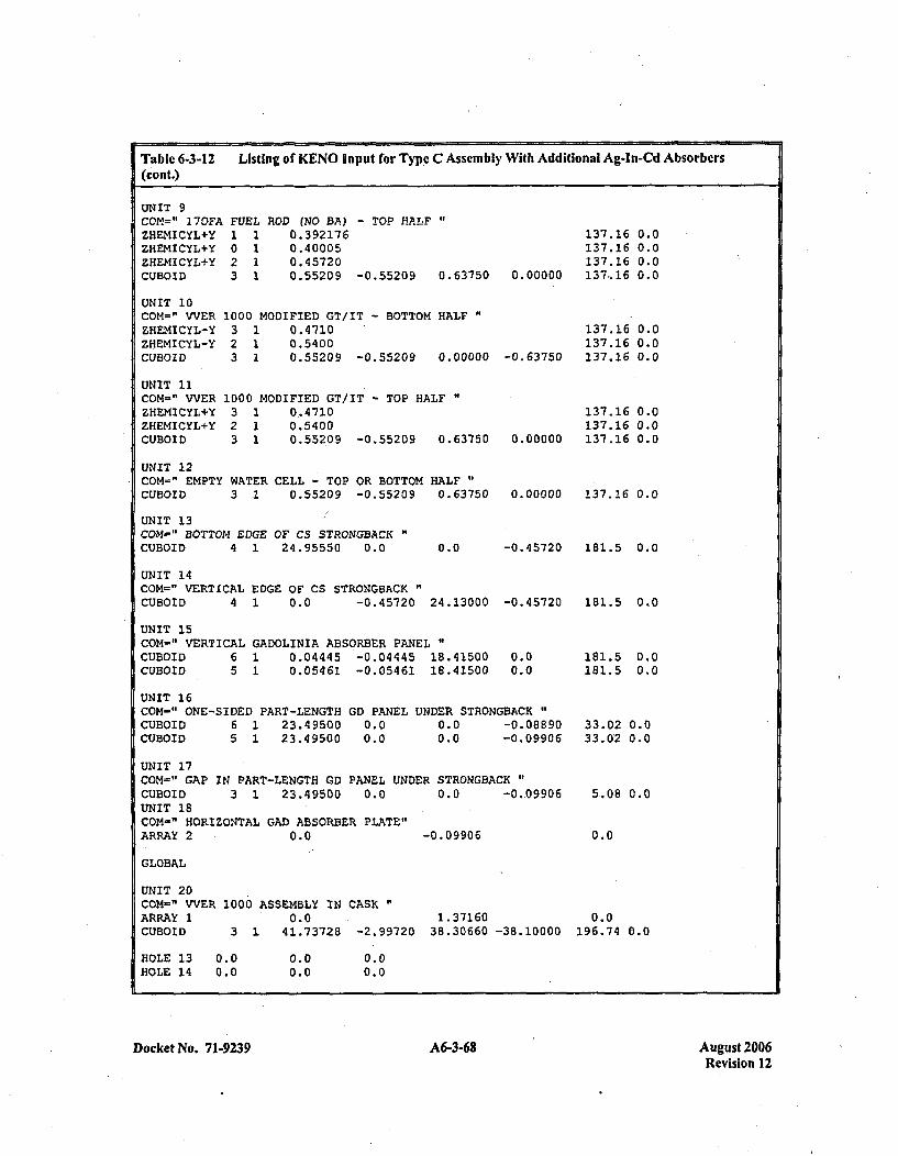
Table 6-3-12 Listing of KENO Input for Type C Assembly With Additional Ag-In-Cd Absorbers(cont.)
UNIT 9COM=" 170FA.ZHEMICYLI-YZHEMICYL+YZHEMICYL+YCUBOID
FUEL1 10 12 13 1
ROD (NO BA) - TOP HALF0. 3921760.400050. 457200.55209 -0.55209 0.63750 0.00000
137.16137.16137.16137,.16
137.16137.16137.16
0.00.00.00.0
0.00.00.0
UNIT 10COM=" VVERZHEMICYL-YZHEMICYL-YCUBOID
UNIT 11COM=" VVERZHEMICYL+YZHEMICYL+YICUBOID
1000 MODIFIED GT/IT - BOTTOM HALF3 1 0.47102 1 0.54003 1 0.55209 -0.55209 0.00000 -0.63750
1000 MODIFIED GT/IT - TOP HALF3 1 0.47102 1 0.54003 1 0.552,09 -0.55209 0.63750
UNIT 12COM=" EMPTY WATER CELL - TOP OR BOTTOM HALF"CUBOID 3 1 0.55209 -0.55209 0.63750
137.16 0.0137.16 0.0
0.00000 137.16 0.0
0.00000 137.16 0.0
-0.45720 1B1.5 0.0
UNIT 13COM=" BOTTOM EDGE OF CS STRONGBACKCUBOID 4 1 24.95550 0.0 0.0
UNIT 14COM=" VERTICAL EDGE OF CS STRONGBACKCUBOID 4 1 0.0 -0.45720 24.13000
UNIT 15COM-" VERTICAL GADOLINIA ABSORBER PANELCUBOID 6 1 0.04445 -0.04445 18.41500CUBOID 5 1 0.05461 -0.05461 18.41500
-0. 457 20
0.00.0
UNIT 16COM=' ONE-SIDED PART-LENGTHCUBOID 6 1 23.49500CUBOID 5 1 23.49500
GD PANEL0.00.0
UNDER STRONGBACK"0.0 -0.088900.0 -0.09906
181.5 0.0
181.5 0.0181.5 0.0
33.02 0.033.02 0.0
5.08 0.0
0.0
UNIT 17COM=" GAP IN PART-LENGTH GDPANEL UNDER STRONGBACKCUBOID 3 1 23.49500 0.0 0.0 -0-09906UNIT 18COM-" HORIZONTAL GAD ABSORBER PLATE"ARRAY 2 0.0 -0.09906
GLOBAL
UNIT 20COM-" VVER 1000 ASSEMBLY IN CASK~ARRAY 1 0.0 1.37160CUBOID 3 1 41.73728 -2.99720 38.30660 -38.10000
ROLE 13 0.0 0.0 0.0HOLE 14 0.0 0.0 0.0
0.0196.74 0.0
Docket No. 71-9239 A6-3-68 August 2006Revision 12
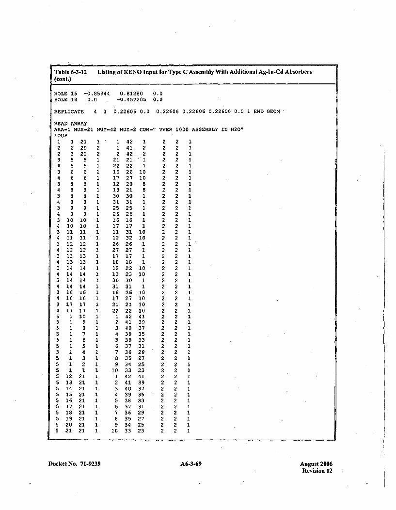
Table 6-3-12 Listing of KENO Input for Type C Assembly With Additional Ag-In-Cd Absorbers(cont.)
HOLE 15 -0.85344 0.81280 0.0HOLE 18 0.0 -0.457205 0.0
REPLICATE 4 1 0.22606 0.0 0.22606 0.22606 0.226 06 0.0 1 END GEOM
READ ARRAYARA-1 NUX=21 NUY-42 NUZ-2 COM-" WVER 1000 ASSEMBLY IN H20"LOOP1 1 21 1 1 42 1 2 2 12 2 20 2 1 41 2 2 2 12 1 21 2 2 42 2 2 2 13 5 5 1 21 21 1 2 2 14 5 5 1 22 22 1 2 2 13 6 6 1 16 26 10 2 2 14 6 6 1 17 27 10 2 2 13 8 8 1 12 20 8 2 2 14 B 8 1 13 21 8 2 2 13 8 8 1 30 30 1 2 2 14 8 8 1 31 31 1 2 2 13 9 9 1 25 25 1 2 2 14 9 9 1 26 26 1 2 2 13 10 10 1 16 16 1 2 2 14 10 10 1 17 17 1 2 2 13 11 11 1 11 31 10 2 2 14 11 11 1 12 32 10 2 2 13 12 12 1 26 26 1 2 2 .14 12 12 1 27 27 1 2 2 13 13 13 1 17 17 1 2 2 14 13 13 1 18 18 1 2 2 13 14 14 1 12 22 10 2 2 14 14 14 1 13 23 10 2 2 13 14 14 1 30 30 1 2 2 14 14 14 1 31 31 1 2 2 13 16 16 1 16 26 10 2 2 14 16 16 1 17 27 10 2 2 13 17 17 1 21 21 10 2 2 14 17 17 1 22 22 10 2 2 15 1 10 1 1 42 41 2 2 15 1 9 1 2 41 39 2 2 15 1 8 1 3 40 37 2 2 15 1 7 1 4 39 35 2 2 15 1 6 1 5 38 33 2 2 15 1 5 1 6 37 31 2 2 15 1 4 1 7 36 29 .2 2 15 1 3 1 8 35 27 2 2 15 1 2 1 9 34 25 2 2 15 1 1 1 10 33 23 2 2 15 12 21 1 1 42 41 2 2 15 13 21 1 2 41 39 2 2 15 14 21 1 3 40 37 2 2 15 15 21 1 4 39 35 2 2 15 16 21 1 5 38 33 2 2 15 17 21 1 6 37 31 2 2 15 18 21 1 7 36 29 2 2 15 19 21 1 B 35 27 2 2 15 20 21 1 9 34 25 2 2 15 21 21 1 10 33 23 2 2 1
Docket No. 7 1-9239 A6-3-69 August 2006Revision 12
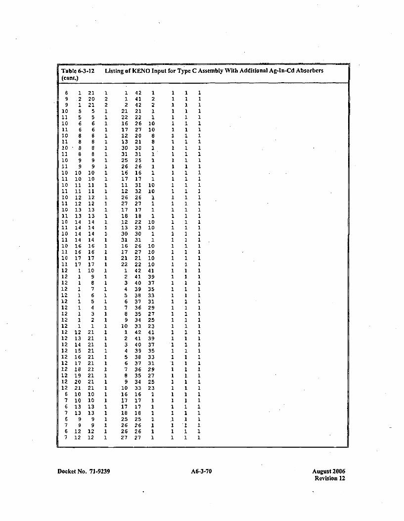
Table 6-3-12 Listing of KENO Input for Type C A(cont.)
8 1 21 1 1 42 1 1 1 19 2 20 2 1 41 2 1 1 19 1 21 2 2 42 2 1 1 1
10 5 5 1 21 21 1 1 1 111 5 5 1 22 22 1 1 1 110 6 6 1 16 26 10 1 1 111 6 6 1 17 27 10 1 1 110 8 8 1 12 20 8 1 1 111 8 8 1 13 21 8 1 1 110 8 8 1 30 30 2 1 1 111 8 8 1 31 31 1 1 1 110 9 9 1 25 25 1 1 1 111 9 9 1 26 26 1 1 1 110 10 10 1 16 16 1 1 1 111 10 10 1 17 17 1 1 1 110 11 11 1 11 31 10 1 1 111 11 11 1 12 32 10 1 1 110 12 12 1 26 26 1 1 1 111 12 12 1 27 27 1 1 1 110 13 13 1 17 17 1 1 1 111 13 13 1 18 18 1 1 1 110 14 14 1 .12 22 10 1 1 111 14 14 1 13 23 10 1 1 110 14 14 1 30 30 1 1 1 111 14 14 1 31 31 1 1 1 110 16 16 1 16 26 10 1 1 111 16 16 1 17 27 10 1 1 110 17 17 1 21 21 10. 1 1 111 17 17 1 22 22 10 1 1 112 1 10 1 1 42 41 1 1 112 1 9 1 2 41 39 1 1 112 1 8. 1 3 40 37 1 1 112 1 7 1 4 39 35 1 1 112 1 6 1 5 38 33 1 1 112 1 5 1 6 37 31 1 1 112 1 4 1 7 36 29 1 1 112 1 3 1 8 35 27 1 1 112 1 2 1 9 34 25 1 1 112 1 1 1 10 33 23 .1 1 112 12 21 1 1 42 41 1 1 112 13 21 1 2 41 39 1 1 112 14 21 1 3 40 37 1 1 112 15 21 1 4 39 35 1 1 112 16 21 1 5 38 33 1 1 112 17 21 1 6 37 31 1 1 112 18 21 1 7 36 29 1 1 112 19 21 1 8 35 27 1 1 112 20 21 1 9 34 25 1 1 112 21 21 1 10 33 23 1 1 1
6 10 10 1 16 16 1 1 1 17 10 10 1 17 17 1 1 1 16 13 13 1 17 17 1 1 1 17 13 13 1 18 18 1 1 1 16 9 9 1 25 25 1 1 1 17 9 9 1 26 26 1 1 '1 16 12 12 1 26 26 1 1 1 17 12 12 1 27 27 1 1 1 1
.sscmbly With Additional Ag-In-Cd Absorbers
Docket No. 71-9239 A6-3-70 August 2006-Revision 12

Table 6-3-12(cont.)
Listing of KENO Input for Type C Assembly With Additional Ag-In-Cd Absorbers
END LOOPARA-2 NUX-1 NUY-1 NUZ=11 COM=" HORIZONTAL GAD ABSORBERFILL17 16 17 17 16 17 17 16 17 17 16
END FILLEND ARRAY
READ BOUNDSALL=SPECULAREND BOUNDS
READ PLOTTTL-'MAT SLICE THROUGH ASSEMBLY ARRAY -RCCA ZONE'P IC-MATNCH='0.ZWSGSRS'XUL- -1.0 YUL= 28.147 ZUL- 15.0XLR- 24.00 YLR- 0.00 ZLR= 15.0UAX-l.0 VDN--1.0 NAX-130
ENDTTL='MAT SLICE THROUGH ASSEMBLY ARRAY'PIC-MATNCH='0.ZWSGSRS'XUL= -1.0 YUL- 28.147 ZUL- 140.0XLR- 24.00 YLR= 0.00 ZLR= 140.0UAX-l.0 VDN=-1.0 NAX-130
ENDTTL='MAT SLICE THROUGH CASK MODELPIC-MATNCH-10.ZWSGSRS'XUL- -3.00 YUL= 39.00 ZUL= 15.0XLR- 42.0 YLR--39.00 ZLR- 15.0UAX=1.O VDN--1.0 NAX-130
END PLOT
PLATE WITH GAPS"
END DATA
Docket No. 71-9239 A6-3-71 August 2006Revision 12

Table 6-3-13 Listing of KENO Input for Type C Assembly With Additional GD Coatcd Guide Supports
KENOVA, STMFN.JOB,JN=KENO,US-NAWDN,T-599,CL-SEOI.ACCOUNT,AC=NF02918, UPW-XXXXXXX.
DEST,DN= $OUT,AD=W3W*,NM-NEWMYER,TT'IvVER-1000 CASK AT 5.0 W/O GUIDE ABSORBER'.DEST,DN-FILMPR,AD=W3W,NM=NEWMYER,TT='VVER-1000 CASK AT 5.0 W/O GUIDE ABSORBER'.
** . ATTACH WORKING LIBRARY
ATTACH, DN=WORKLIB, PDN=CASKVVER100X0X1, ID-NACRIT.
* **ATTACH KENOVa CODE *
ATTACH, DN=KEN05A, PDN-KEN05A.
"'~REWIND INPUT AND COPY TO OUTPUT *
REWIND (DN=$ IN)COPYSD(I-$IN,0=$OUT)REWIND (DN=$ IN)
* *EXECUTE KENOVa *
KEN05A.
EXIT,U.
* **REWIND OUTPUT AND COPY TO FILMPR *
REWIND (DN=$OUT)COPYD (I.=$OUT, O=FILMPR)
CEOR)TITLE-MC4 5.0 W/O VVER-1000 CASK WITH GUIDE ABSORBER
READ PARAMETERSTME-"6 RUN-YES PLT-YESGEN'=900 NPG=305 NSK-005 LIB-41XS1-~YES NUB=YES
END PARAMETERS
READ MIXT SCT=2MIX- 1*U02 PELLET 5.00 W/O (96.5% TD, 0% DISH)
192235 0.0011942192238 0.02240418016 0.047196
MIX= 2ZIRC FUEL ROD CLADDING
240302 0.043326MIX- 3
H20 AT 1.00 G/CC31001 0.06685438016 0.033427
Docket No. 71-9239 A6-3-72 August 2006Revision 12
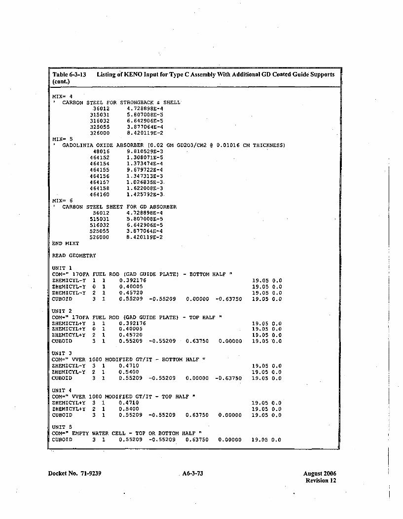
Table 6-3-13 Listing of KENO Input for Type C Assembly With Additional GD Coated Guide Supports(cont.)
MIX- 4ICARBON STEEL FOR
.36012315031316032325055326000
MIX- 5GADOLINIA OXIDE
48016464152464154464155464156464157464158464160
STRONGBACK & SHELL4. 728898E-45. 807008E-56. 642906E-53. 877064E-48. 420119E-2
ABSORBE R (0.02 GM GD203/CM2 @ 0.01016 CM THICKNESS)9.810529E-31 .308071E-51 .373474E-49. 679722E-41. 347313E-31. 026835E-3.1. 622008E-31 .425792E-3
ET FOR GD ABSORBER4.728898E-45. 80700BE-56. 642906E-53. 877064E-48. 420119E-2
mix= 61CARBON STEEL SHE
56012515031516032525055526000
HIEND MIXT
READ GEOMETRY
UNIT 1COM-" 170FAZHEMICYL-YZHEMICYL-YZHEMICYL-YCUBOID
UNIT 2COM-" 170FAZHEMICYL+YZHEMICYL+YZHEMICYL+YCUBOID
UNIT 3COM=" VVERZHEMICYL-YZHEMICYL-YCUBOID
UNIT 4COM=" WVERZHEMICYL+YZHEMICYL+YCUBOID
FUEL1 10 12 13 1
ROD (GAD GUIDE PLATE)0.3921760.400050. 457200.55209 -0.55209
- BOTTOM HALF "
0.00000 -0.63750
19.05 0.019.05 0.019.05 0.019.05 0.0
FUEL ROD (GAD GUIDE PLATE) - TOP HALF "
I023
1111
0. 3921760.400050. 457200.55209 -0.55209
19.05 0 0019.05 0.019.05 0.0
0.00000 19.05 0.00.63750
1000 MODIFIED GT/IT - BOTTOM HALF"3 1 0.47102 1 0.54003 1 0.55209 -0.55209 0.00000
1000 MODIFIED GT/IT - TOP HALF3 1 0.47102 1 0.54003 1 0.55209 -0.55209 0.63750
19.05 0.019.05 0.019.05 0.0-0.63750
19.05 0.019.05 0.0
0.00000 19..05 0.0
0.00000 19.05 0.0
UNIT 5COM-" EMPTY WATER CELL - TOP OR BOTTOM HALFCUBOID 3 1 0.55209 -0.55209 0.63750
Docket No. 71-9239 . A6-3-73 A6-3-73August 2006Revision 12
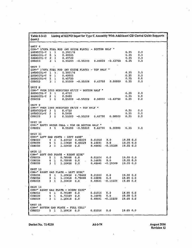
Table 6-3.13 Listing of KENO Input for Type C Assembly With Additional GD Coated Guide Supports(cont.)
UNIT 6COM='" 170FAZHEMICYL-YZHEMICYL-YZHEMICYL-YCUBOID
UNIT 7COM=" 170FAZHEMICYL+YZHEMICYL+YZHEMICYL+YCUBOID
FUEL ROD (NO GUIDE PLATE) - BOTTOM HALF "
I023
1111
0.3921760.400050.457200.55209 -0.55209
6.356.356.356.350.00000 -0.63750
FUELI1I0 12 13 1
ROD (NO GUIDE PLATE) - TOP HALF0.392176 6.350.40005 6.350.45720 6.350.55209 -0.55209 0.63750 0.00000 6.35
UNIT 8COM=" WVERZHEMICYL-YZHEMICYL-YCUBOID
UNIT 9COM-" VVERZHEMICYL+YZHEHICYL+YCUBOID
1000 MODIFIED GT/IT - BOTTOM-HALF"3 1 0.47102 1 0.54003 1 0.55209 -0.55209 0.00000
1000 MODIFIED GT/IT - TOP HALF3 1 0.47102 1 0.54003 1 0.55209 -0.55209 0.63750
0.00.00.00.0
0.00.00.00.0
0.00.00.0
0.00.00.0
0.0
6.356.356.35-0. 63750
6.356.35
0.00000 6.35
UNIT 10COM=" EMPTY WATER CELL - TOP OR BOTTOM HALFCUBOID 3 1 0.55209 -0.55209 0.63750 0.00000 6.35
UNIT 11COM-" LEFTCUBOIDCUBOIDCUBOID
UNIT 12COM-" LEFTCUBOIDCUBOIDCUBOID
UNIT 13COM-~" RIGHTCUBOIDCUBOID
,CUBOID
UNIT 14COM=" RIGHTCUBOIDCUBOIDCUBOID
GAD5
PLATE - LEFT1 1.104181 1.104181 1.10418
SIDE"0.402290. 402290.0
GAD PLATE - RIGHT SIDE"5 1 0.78668 0.06 1 0.78668 0.03 1 1.10418 0.0
GAD PLATE - LEFT SIDE"5 1 1.10418 0.786686 1 1.10418 0.786683 1 1.10418 0.0
GAD PLATE - RIGHT SIDE"5 1 0.70189 0.06 1 0.70189 0.03 1 1.10418 0.0
0. 010160. 168 910.48641
0. 010160.168 910. 48641
0. 010 1.60. 168 910. 48641
0. 010160. 168 910.48641
0.00.0
-0.15109
0.00.0
-0.15109
0.00.0
-0. 15 109
0.0
0.0-0.15109
19.05 0.019.05 0.019.05 0.0
19.0519.0519.05
19.0519.0519.05
19.0519.0519.05
0.00.00.0
0.00.00.0
0.00.00.0
UNIT 15COM-" BOTTOM GAD PLATE - FULL CELL"CUBOID 5 1 1.10418 0.0 0.01016 0.0 19.05 0.0
Docket No. 7 1-9239 A6-3-74 August 2006Revision 12
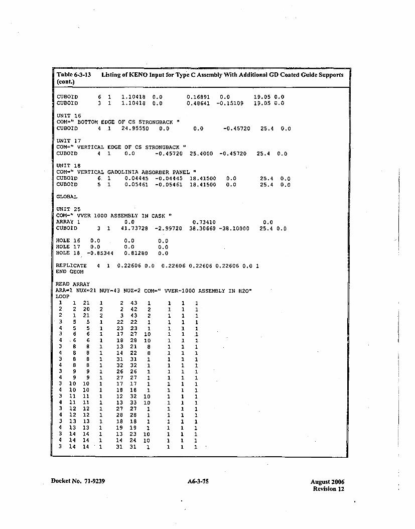
Table 6-3-13 Listing of KENO Input for Type C Assembly With Additional GD Coated Guide Supports(cont.)
CUBOIDCUBOID
6 1 1.10418 0.03 1 1.10418 0.0
0.16891 0.00.48641 -0.15109
19.05 0.019.05 0.0
UNIT 16COM-" BOTTOM EDGE OF CS STRONGBACK"CUBOID 4 -1 24.95550 0.0 0.0 -0.45720 25.4 0.0
UNIT 17COM=" VERTICAL EDGE OF CS STRONGBACK"CUBOID 4 1 0.0 -0.45720 25.4000 -0.45720
UNIT 18COM-" VERTICAL GADOLINIA ABSORBER PANELCUBOID 6. 1 0.04445 -0.04445 18.41500CUBOID 5 1 0.05461 -0.05461 18.41500
25.4 0.0
25.4 0.025.4 0.0
0.00.0
GLOBAL
UNIT 25COM-" WVERARRAY 1CUBOID
HOLE 16 0HOLE 17 0HOLE 18 -0
1000 ASSEMBLY IN CASK0.0
3 1 41.73728 -2.997200.73410
38.30660 -38.100000.0
25.4 0.0
1.0
1.85344
0.00.00.81280
0.00.00.0
REPLICATE 4 1 0.22606 0.0 0.22606 0.22606 0.22606 0.0 1END GEOM
READ ARRAYARA-3. NUX=21LOOP
1 1 212 2 202 1 213 5 54 5 53 6 64 ~6 63 8 84 8 83 8 84 8 83 9 94 9 93 10 104 10 103 11 114 11 113 12 124 12 123 13 134 13 133 14 144 14 143 14 14
NUY=43 NUZ-2 COM-" VVER-1000 ASSEMBLY IN H20"
223
222317181314313226271718121327281819131431
434243222327282122313226271718323327281819232431
122
1010
1010
1811
10101
1111111111
1 1111111111
111111111
1 1 1111I111111111
11
11
1 11111111111
1111111111
Docket No. 71-9239A635Aust20 A6-3-75Revision 12
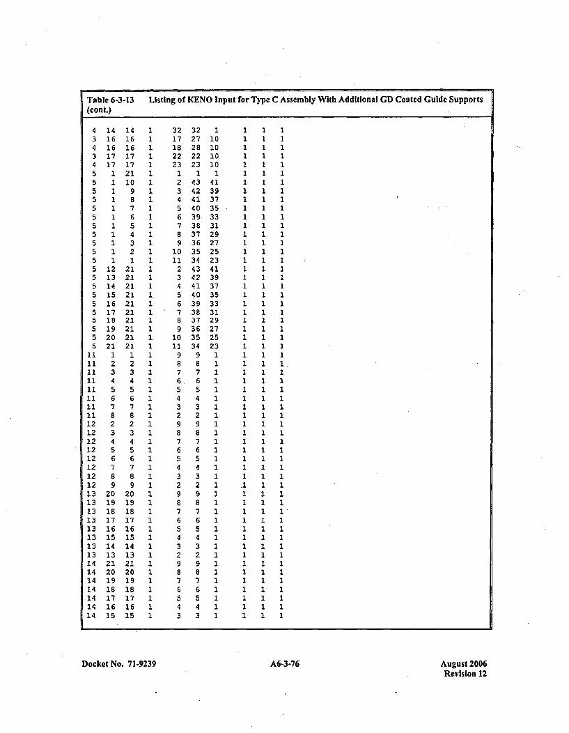
Table 6-3-13 Listing of KENO Input for Type C Assembly With Additional CD Coated Guide Supports(cont.)
1416161717
11111111111
12131415161718192021
12:34567823456789
201918171615141321201918171615
14161617172110
987654321
21212121212121212121
12:34567823456789
2019181716is141321201918171615
3227282223
14342414039.383736353443424140393837363534
9876543298765432987654329876543
Docket No. 71-9239 A6-3-76 August 2006Revision 12
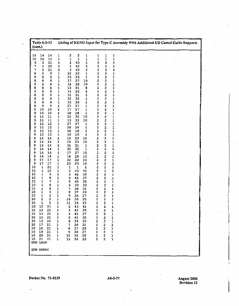
Table 6-3-13 Listing of KENO Input for Type C Assembly With Additional GD) Coated Guide Supports
(cont.)
14 14 14 1 2 2 1 1 1 115 10 12 1 1 1 1 1 1 116 1 21 1 2 43 1 2 2 1
7 2 20 2 2 42 2 2 2 17 1 21 2 3 43 2 2 2 18 5 5 1 22 22 1 2 2 19 5 5 1 23 23 1 2 2 18 6 6 1 17 27 10 2 2 19 6 6 1 18 28 10 2 2 1a 8 8 1 13 21 8 2 2 19 8 8 1 14 22 8 2 2 18 8 8 1 31 31 1 2 2 19 8 8 1 32 32 1 2 2 18 9 9 1 26 26 1 2 2 19 9 9 .1 27 27 1 2 2 18 10 10 1 17 17 1 2 2 19 10 10 1 18 18 1 2 2 18 11 11 1 12 32 10 2 2 19 11 11 1 13 33 10 2 2 18 12 12 1 27 27 1 2 2 19 12'12 1 28 28 1 2 2 18 13 13 1 18 18 1 2 2 19 13 13 1 19 19 1 2 2 18 14 14 1 13 23 10 2 2 19 14 14 1 14 24 10 2 2 18 14 14 1 31 31 1 2 2 19 14 14 1 32 32 1 2 2 18 16 16 1 17 27 10 2 2 19 16 16 1 18 28 10 2 2 18 17 17 1 22 22 10 2 2 19 17 17 1 23 23 10 2 2 1
10 1 21 1 1 1 1 2 2 110 1 10 1 2 43 41 2 2 110 1 9 1 3 42 39 2 2 110 1 8, 1 4 41 37 2 2 .110 1 7 1 5 40 35 2 2 110 1 6 1 6 39 33 2 2 110 1 5 1 7 38 31 2 2 110 1 4 1 8 37 29 2 2 110 1 3 1 9 36 27 2 2 110 1 2 1 10 35 25 2 2 110 1 1 1 11 34 *23 2 2 110 12 21 1 2 43 41 2 2 .110 13 21 1 3 42 39 2 2 110 14 21 1 4 41 37 2 2 110 15 21 1 5 40 35 2 2 110 16 21 1 6 39 33 2 2 110 17 21 1 7 38 31 2 2 110 18 21 1 8 37 29 .2 2 110 19 21 1 9 36 27 2 2 110 20 21 1 10 35 25 2 2 110 21 21 1 11 34 23 2 2 1END LOOP
END ARRAY
Docket No. 7 1-9239 A6-3-77 August 2006Revision 12
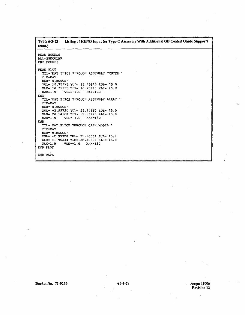
Table 6-3-13 Listing of KENO Input for Type C Assembly With Additional GD) Coated Guide Supports(cont.)
READ BOUNDSALL=SPECULAREND BOUNDS
READ PLOTTTL='MAT SLICE THROUGH ASSEM4BLY CENTERPIC=MATNCH-'0.ZWSGS'XUL- 10.75915 YUL- 18.75915 ZUL= 15.0XLR- 18.75915 YLR= 10.75915 ZLR- 15.0UAX=1.0 VDN--1.0 NAX-130
ENDTTL='MAT SLICE THROUGH ASSEMBLY ARRAYP IC-MATNCH-0O.ZWSGS'XUL= -2.99720 YUL- 28.14660 ZUL- 15.0XLR= 28.14660 YLR- -2.99720 ZLR= 15.0UAX-1.0 VDN--1.O NAX=130
ENDTTL-'MAT SLICE THROUGH CASK MODELPIC=MATNCH- * .ZWSGS'XUL- -2.99720 YUL- 31.80334 ZUL= 15.0XLR= 41.96334 YLR--38.32606 ZLR= 15.0UAX=1.O VDN--1.O NAX=130
END PLOT
END DATA
Docket No. 71-9239 A6-3-78 August 2006Revision 12
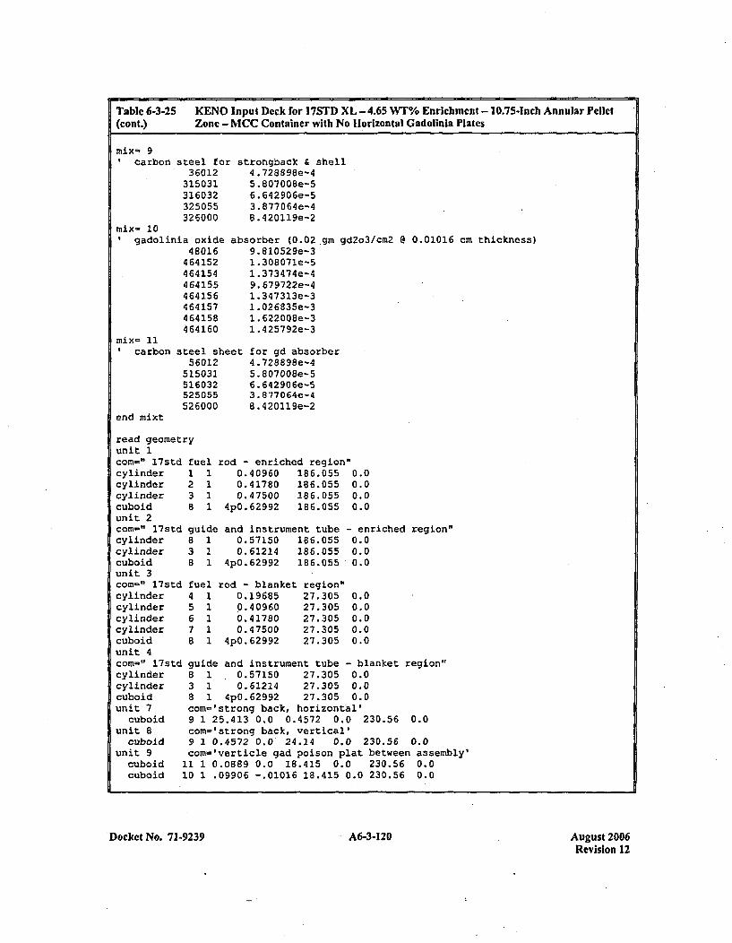
Table 6-3.25 KENO Input Deck for 17STD XL - 4.65 WT% Enrichment - 10.75-Inch Annular Pellet(cont.) Zone - MCC Container with No Horizontal Gadolinla Plates
mix- 9carbon steel fox
36012315031316032325055326000
mix- 10gadolinia oxide
48016464152464154464155464156464157464158464160
strongback & shell4 .728898e-45 .807008e-56. 642906e-53. 877064e-48 .420119e-2
absorber (0.02 gin9.810529e-31 .308071e-51 .373474e-49. 679722e-41. 347313e-31 .026835e-31. 622008e-31. 425792e-3
gd2o3/cm2 @ 0.01016 cm thickness)
Icarbon
end mixt
steel sheet56012
515031516032525055526000
for gd absorber4 .728898e-45 .807008e-56. 642906e-53. 877064e-48. 420119e-2
read geometryunit 1corn=" 17std fuelcylinder 1 1cylinder 2 1cylinder 3 1cuboid 8 1unit 2con-" l7std guidecylinder 8 1cylinder 3 1cuboid 8 1unit 3con-" l7std fuelcylinder 4 1cylinder 5 1cylinder 6 1cylinder 7 1cuboid 8 1unit 4con-" l7std guidecylinder 8 1cylinder 3 1cuboid 8 1unit 7 conm=
cuboid 9 1unit 8 con-
cuboid 9 1unit 9 com='
cuboid 11 1cuboid 10 1
rod - enriched region0.40960 186.0550.41780 186.0550.47500 186.055
4p0.62992 186.055
and instrument tube0.57150 186.0550.61214 186.055
4pO.629 92 186.055
0.00.00.00.0
- enriched region"0.00.00.0
0.00.00.00.00.0
rod - blanket0.19685.0.4 09600.417800. 47500
4p0. 62992
region"27. 30527.30527. 30527. 30527. 305
and instrument tube - blanket region"0.57150 27.305 0.00.61214 27.305 0.0
4p0.62992 27.305 0.0'strong back, horizontal'?5.413 0.0 0.4572 0.0 230.56 0.0'strong back, vertical'0.4572 0.0 24.24 0.0 230.56 0.0Iverticle gad poison plat between assembly'3.0889 0.0 18.415 0.0 230.56 0.0.09906 -.01016 18.415 0.0 230.56 0.0
.Docket No. 71-9239 A6-3-120 August 2006Revision 12
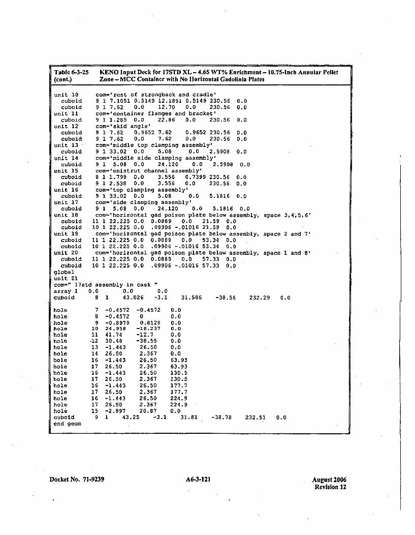
Table 6-3-25(cont.)
KENO Input Deck for 17STD XL - 4.65 WT% Enrichmnict - 10.75-Inch Annular PelletZone - MCC Container with No Horizontal Gadolinia Plates
unit 10cuboidcuboid
unit 11cuboid
unit. 12cuboidcuboid
unit 13cuboid
unit 14cuboid
unit 15cuboidcuboid
unit 16cuboid
unit 17
com-'rest of strongback and cradle'8 1 7.1051 0.5149 12.1851 0.5149 230.56 0.09 1 7.62 0.0 12.70 0.0 230.56 0.0com-'container flanges and bracket'9 1 1.285 0.0 22.86 0.0 230.56 0.0com-'skid angle'8 1 7.62 0.9652 7.62 0.9652 230.56 0.09 1 7.62 0.0 7.62 0.0 230.56 0.0com='middle top clamping assembly'9 1 33.02 0.0 5.08 0.0 2.5908 0.0com-'middle side clamping assembly'9 1 5.08 0.0 24.120 0.0 2.5908 0.0com-'unistrut channel assembly'8 1 1.799 0.0 3.556 0.7399 230.56 0.09 1 2.538 0.0 3.556 0.0 230.56 0.0com='top clamping assembly'9 1 33.02 0.0 5.08 0.0 5.1816 0.0com-'side clamping assembly'
cuboid 9 1 5.08 0.0unit 18 com-'horizontal ga
cuboid 11 1 22.225 0.0 0.cuboid 10 1 22.225 0.0 .0
unit 19 com='horizontal gacuboid 11 1 22.225 0.0 0.cuboid 10 1 22.225 0.0, .0
unit 20 com-'horizontal gacuboid 11 1 22.225 0.0 0.cuboid 10 1 22.225 0.0 .0
globalunit 21com-" 17std assembly in cask
24.120 0.0 5.1816 0.0d poison plate below assembly,0889 0.0 21.59 0.09906 -.01016 21.59 0.0-d poison plate below assembly,0889 0.0 53.34 0.09906 -.01016 53.34 0.0d poison plate below assembly,0889 0.0 57.33 0.09906 -.01016 57.33 0.0
space 3,4,t5, 6'
space 2 and 7'
space 1 and 8'
array 1 0.0cuboid 8
0.0 0.043.026 -3.11 31.586 -38.56 232.29 0.0
holeholeholeholeholeholeholeholeholeholeholeholeholeholeholeholeholecuboidend geom
789
2011.1213141617161716171617159
-0. 4572-0. 4572-0.8 97924.95841.7430.48-1.44326.-50-1.4432.6.50-1.44326.50-1.44326.50-1.44326.50-2.997
-0.457200. 8128
-18.237-12.7-38.5526.502,.36726.502.36726.502.36726.502.36726.502.36720.87
0.00.00.00.00.00.00.00.063.9363.93130.5130.5177.7177.7224.9224.90.0
1 43.25 -3.1 31.81 -38.78 232.51 0.0
Docket No. 71-9239 A6-3-121 August 2006Revision 12

Table 6-3-25 KENO Input Deck for 17STD XL - 4.65 WT% Enrichment - 10.75-Inch Annular Pellet(cont.) Zone - MCC Container with No Horizontal Gadohlnia Plates
read arrayara-1 nux-17 nuy=17 nuz'-2 com-', l7std assemblyloop1 1 17 1 1 17 1 1 1 12 3 15 3 6 12 3 1 1 12 4 14 10 4 14 10 1 1 12 6 12 3 3 15 12 1' 1 13 1 17 1 1 17 1 2 2 14 3 15 3 6 12 3 2 2 14 4 14 10 4 14 10 2 2 14 6 12 3 3 15 12 2 2 1
end loopend array
read boundsall=specularend bounds
read plotttl-lbox slice through cask'pic.~boxnch=' Ougiugiabcdefhjklmnop.'xul= -4.0 yul= 30.1 zul- 66.52xlr- 45.0 ylr- -40.0 zlr= 66.52uax=1.0 vdn=-1.0 nax=130 endttl~'box slice through cask'pic-na tnch-'Qu. z *u *z .sgs'
xul= -4.0 yul= 30.1 zu1- 66.52xlr= 45.0 ylr= -40.0 zlr- 66.52uax=l.0 vdn=-1.0 nax=130 endttl='box slice through assembly'pic~boxnch='Ougiugiabcdefhjklnnop.'Xul= 0.0 yul= 20.0 zul- 66.52xlr= 20.0 ylr= 0.0 zlr= 66.52uax=1.0 vdn=-1.0 nax=130 endtil-'mat slice through annular pellet'pic-matnch=' Ou. z *u *z .sgs'xul= 1.41 yul= 4.24 zul- 180.0xlr= 4.24 ylr- 1.41 zlr= 180.0uax=1.0 vdn=-1.0 nax=130 endttl-'mat slice'through annular pellet'pic=matnch=' Ou. z.u. z.sgs'Xul= -1.0 yul- 18.0 zul- 180.0xlr= -0.5 ylr= 0.0 zir- 180.0uax-1.0 vdn=-1.0 nax'-130 ndn-100 end
end plotend dataend
Docket No. 71-9239 A6-3-122 August 2006Revision 12
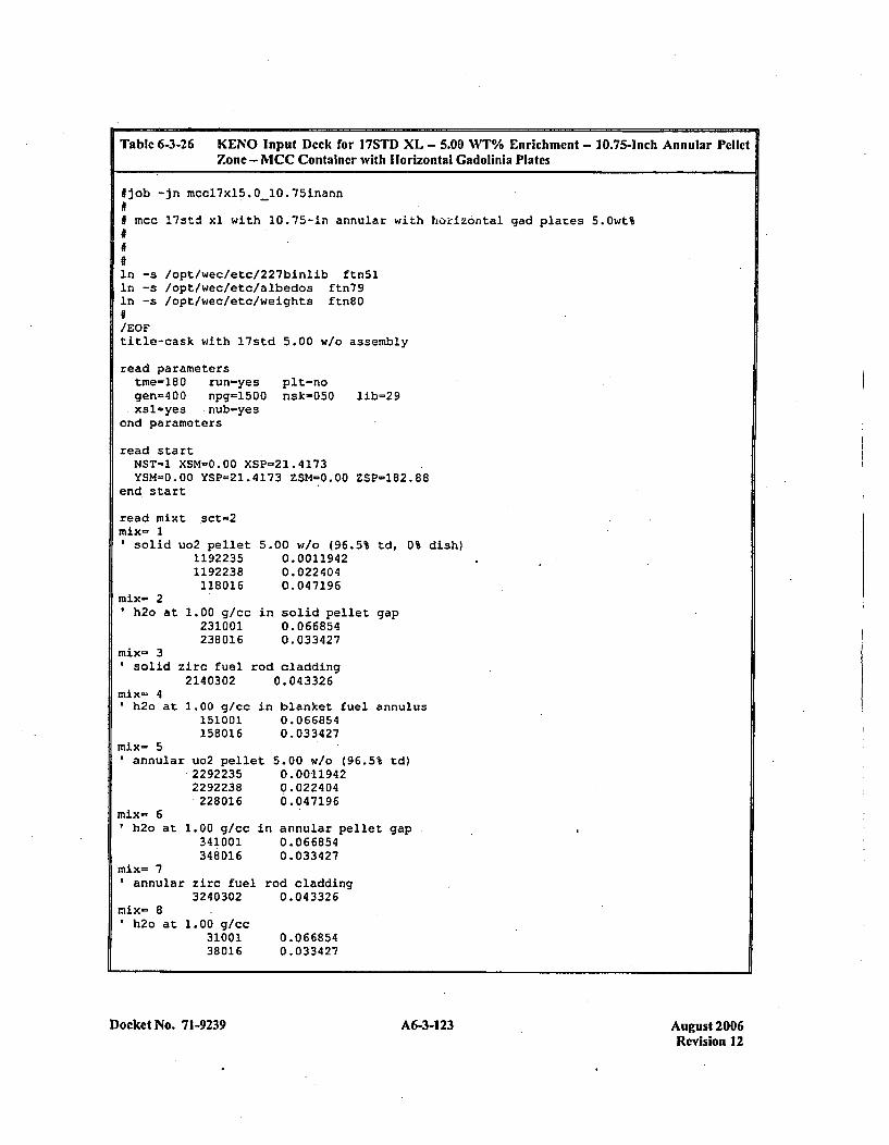
Table 6-3-26 K(ENO Input Deck for 17STD XL - 5.00 WT% Enrichment - 10.75-Inch Annular PelletZone - MCC Container with Horizontal Gadolinla Plates
#Ijob -in mccl7xl5.OlO0.75inann
# mcc l7std xl with 10.75-in annular with horizontal gad plates 5.Owt%
in -s /opt/wec/etc/227binlib fin~iIn -s /opt/wecfetc/albedos ftn79in -s /opt/wec/etc/weights ftn80
/EOFtitle-cask with l7std 5.00 w/o assembly
read parameterstme-180 run-yes plt-nogen=400 npg=1500 nsk-050 lib=29xsl-yes nub=yes
end parameters
read startNST-l XSM=0.O0 XSP-21.4173YSM-0.00 YSP=21.4173 ZSM=0.00 ZSP-182.88
end start
read mixt sct-2mix- 1
solid uo2 pellet 5.00 w/o (96.5% td, 0% dish)1192235 0.00119421192238 0.022404118016 0.047196
mix- 2h2o at 1.00 g/cc in solid pellet gap
231001 0.066854238016 0.033427
mix- 3' solid zirc fuel rod cladding
mi-4 2140302 0.043326
h2o at 1.00 g/cc in blanket fuel annulus151001 0.066854158016 0.033427
mix- 5*annular uo2 pellet 5.00 w/o (96.5% td)
.2292235 0.'00119422292238 0.022404
228016 6.047196mix- 6
h2o at 1.00 g/cc in annular pellet gap341001 0.066854348016 0.033427
mix= 7annular zirc: fuel rod cladding
3240302 0.043326mix= 8
h2o at 1.00 g/cc31001 0.06685438016 0.033427
Docket No. 71-9239 A6-3-123 August 2006Revision 12
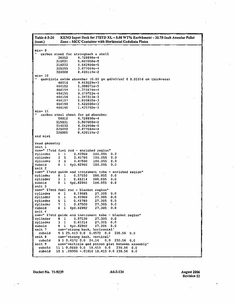
Table 6-3-26 KE NO Input Deck for 17STD XL -5.00 WT% Enrichment - 1.0.75-inch Annular Pellet(cont.) Zone - MCC Container with I orizontal Gadolinia Plates
mix= 9'carbon steel for
36012315031316032325055326000
mix= 10gadolinia oxide
480164 64 152464154464155464156464157464158464160
*strongback & shell4 .728898e-45 .807008e-56. 642 90 6e-53.877064e-48.420119e-2
absorber (0.02 gm.gd2o3/cm2 @ 0.01016 cm thickness)9. 81052 9e-31. 30 8071e-51. 373474e-49. 679722e-41. 34 7313e-31 .026835e-31. 622 00 8e-3'1.4257 92e-3
~et for gd absorber4. 728898e-45. 807008e-56. 642906e-53. 877064e-48 .420119e-2
carbon
end mixt
steel she56012
515031516032525055526000
read geometryunit 1con- " l7std ficylinder 1cylinder 2cylinder 3cuboid 8unit 2com-" l7std g~cylinder 8cylinder 3cuboid 8unit 3com-" l7std ftcylinder 4cylinder 5cylinder 6cylinder 7cubold 8unit 4
ue1 rod - enriched region1 0.40960 186.0551 0.41780 186.0551 0.47500 186.0551 4pO.62992 186.055
0.00.00.00.0
-enriched region"0.00.00.0
jide
1l1
and instrument tube0.57150 186.0550.61214 186.055
4p0.62992 186.055
rod - blanket region'0.19685 27.3050.40960 27.3050.41780 21.3050.47500 27.305
'JpO.62992 27.305
0.00.00.001..00..0
cc
cv
un
mn-" 17std guide and instrument tube - blanket region"linder 8 1 0.57150 27.305 0.0!linder 3 1 0.61214 27.305 0.0iboid 8 1 4p0.62992 27.305 0.0Lit 7 com-'strong back, horizontal'cuboid 9 1 25.413 0.0 0.4572 0.0 230.56 0.0~it 8 com-'strong back, vertical'cuboid 9 1 0.4572 0.0 24.14 0.0 230.56 0.0hit 9 com-'verticle gad poison plat between assembly'cuboid 11 1 0.0889 0.0 18.415 0.0 230.56 0.0cuboid 10 1 .09906 -.01016 18.415 0.0 230.56 0.0
Docket No. 71-9239 A6-3-124 August 2006Revision 12
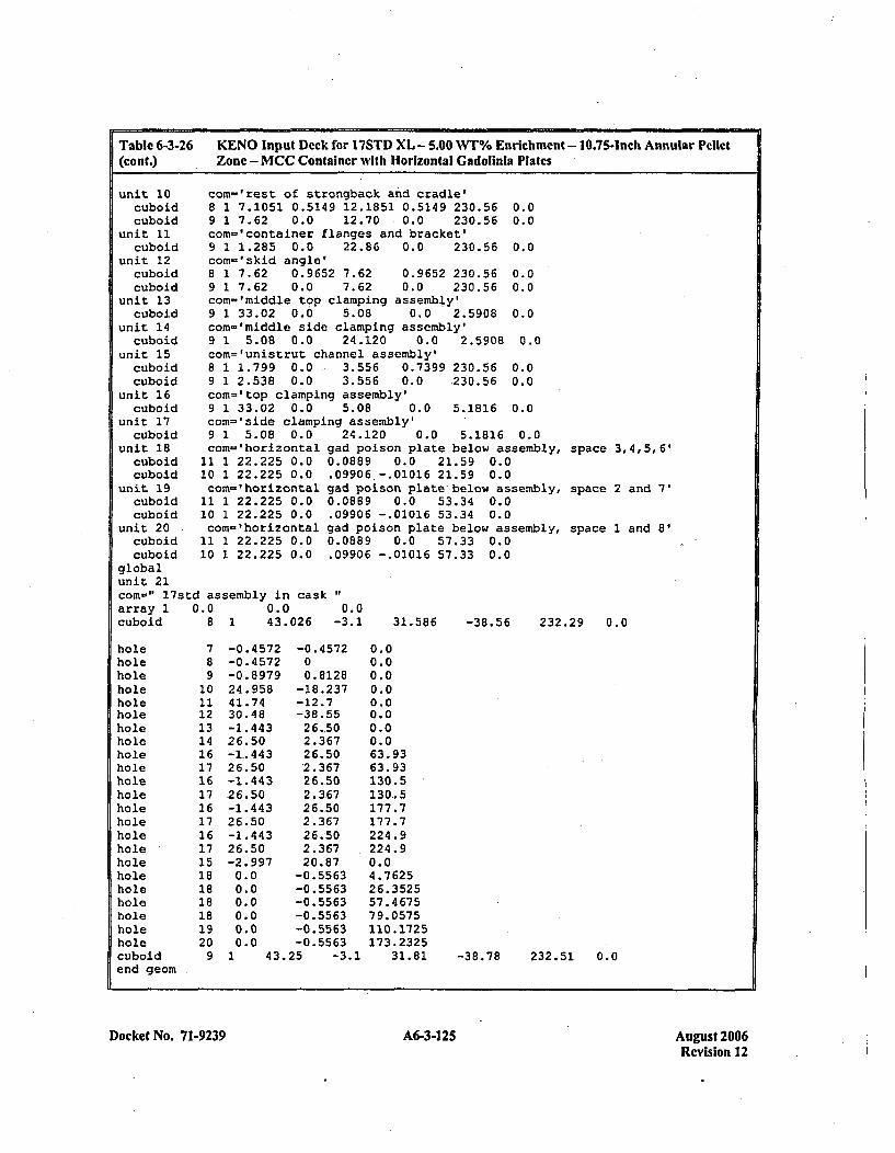
Table 6-3-26(cont.)
KENO Input Deck for 17STD XL - 5.00 WT% Enrichment - 10.75-Inch Annular PellctZone - MCC Container with Horizontal Gadolinla Plates
unit 10 com='rest of strongback and cradle'cuboid 8 1 7.1051 0.5149 12.1851 0.5149 230.56 0.0cuboid 9 1 7.62 0.0 12.70 0.0 230.56 0.0
unit 11 com='container flanges and bracket'cuboid 9 1 1.285 0.0 22.86 0.0 230.56 0.0
unit 12 com-'skid angle'cuboid 8 1 7.62 0.9652 7.62 0.9652 230.56 0.0cuboid 9 1 7.62 0.0 7.62 0.0 230.56 0.0
unit 13 com-'middle top clamping assembly'cuboid 9 1 33.02 0.0 5.08 0.0 '2.5908 0.0
unit 14 com-'middle side clamping assembly'cuboid 9 1 5.08 0.0 24.120 0.0 2.5908 0.0
unit 15 com='unistrut channel assembly'cuboid 8 1 1.799 0.0 , 3.556 0.7399 230.56 0.0cuboid 9 1 2.538 0.0 3.556 0.0 .230.56 0.0
unit 16 com='top clamping assembly'cuboid 9 1 33.02 0.0 5.08 0.0 5.1816 -0.0
unit 17 com-'side clamping assembly'cuboid 9 1 5.08 0.0 24.120 0.0 5.1816 0.0
unit 18 cozn-'horizontal gad poison plate below assembly,cuboid 11 1 22.225 0.0 0.0889 0.0 21.59 0.0cuboid 10 1 22.225 0.0 .09906 -.01016 21.59 0.0
unit 19 com='horizontal gad poison plate below assembly,cuboid 11 1 22.225 0.0 0.0889 0.0 53.34 0.0cuboid 10 1 22.225 0.0 .09906 -.01016 53.34 0.0
unit 20 com='horizontal gad poison plate below assembly,cuboid 11 1 22.225 0.0 0.0889 0.0 57.33 0.0cuboid 10 1 22.225 0.0 .09906 -.01016 57.33 0.0
globalunit 21corn-" 17std assembly in cask"array 1 0.0 0.0 0.0cuboid 8 1 43.026 -3.1 31.586 -38.56 232.
space 3,4,5,6'
space 2 and 7'
space 1 and 8'
.29 0.0
holeholeholeholeholeholeholeholeholeholeholIeholeholeholeholeholeholeholeholeholeholeholeholecuboidend geom
78910111213141617161716171617151818181819209
-0.4572 -0.4572-0.4572 0-0.8979 0.812824.958 -18.23741.74 -12.730.48 -38.55-1.443 26.5026.50 2.367-1.443 26.5026.50 '2.367-1.443 26.50.26.50 2.367-1.443 26.5026.50 2.367-1.443 26.5026.50 2.367-2.997 20.870.0 -0.55630.0 -0.55630.0 -0.55630.0 -0.55630.0 -0.55630.0 -0.55631 43.25 -3.1
0.00.00.00.00.00.00.00.063.9363.931:30.5130..5177.7177.7224.9224.90.04.762526. 352557.4 67579. 0575110.1725173.2325
31.81 -38.78 232.51 0.0
Docket No. 7 1-9239 A6-3-125 A6-3125August 2006Revision 12
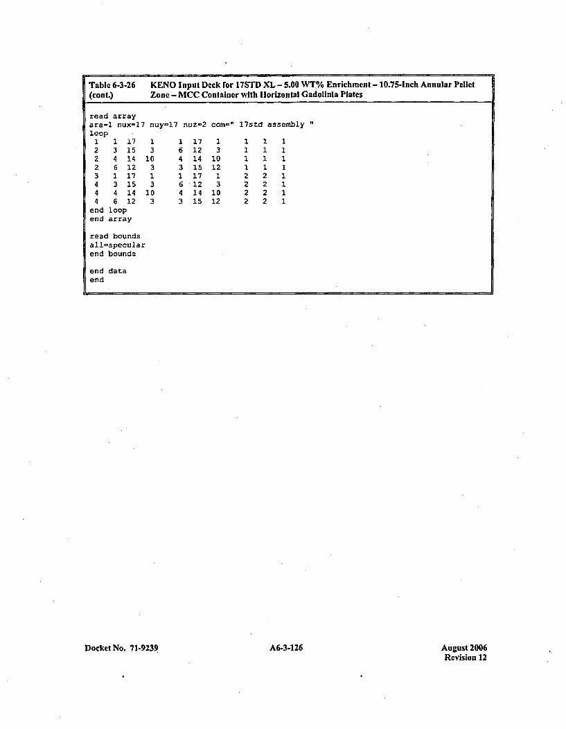
Table 6-3-26 KENO Input Deck for 17STD XL - 5.00 WT%/ Enrichment - 10.75-inch Annular Pellct(cont.) Zone - MCC Container with Horizontal Gadolinia Plates
read arrayara-1 nux=17 nuy=17 nuz-2 com-~" l7std assemblyloop1 1 17 1 1 17 1 1 1 12 3 15 3 6 12 3 1 1 12 4 14 10 4 14 10 1 1 12 6 12 3 3 15 12 1 1 13 1 17 1 1 17 1 2 2 14 3 15 3 6 12 3 2 2 14 4 14 10 4 14 10 2 2 14 6 12 3 3 15 12 2 2 1
end loopend array
read boundsal 1=specularend bounds
end dataend
Docket No. 7 1-9239 A6-3-126 August 2006Revision 12
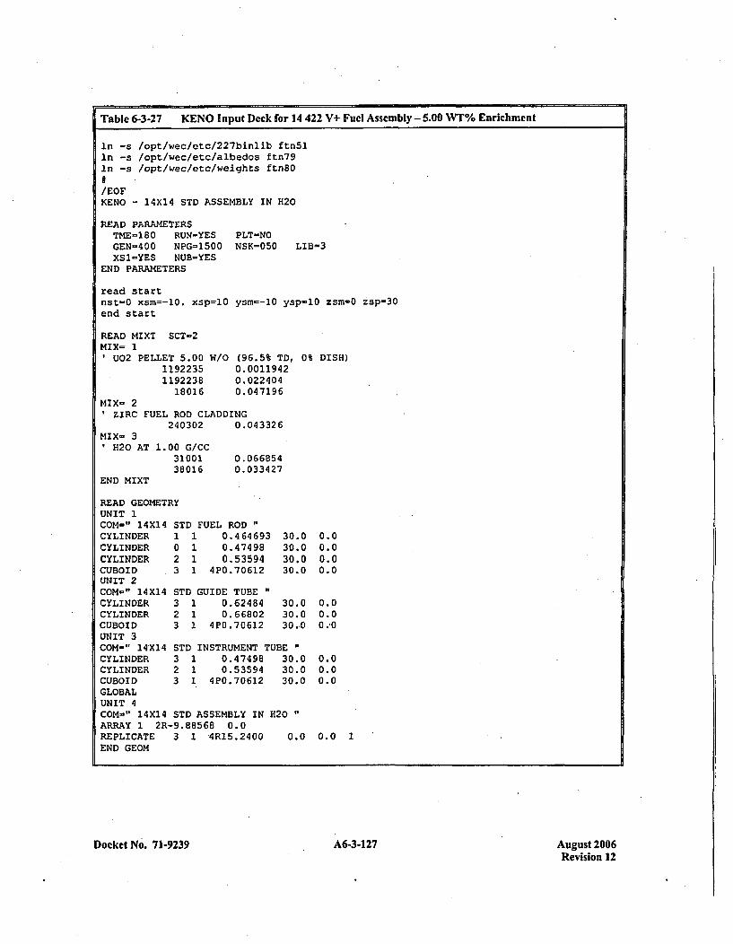
Table 6-3-27 KENO Input Dcck for 14 422 V+ Fuel Assembly - 5.00 W7% Enrichment
in -s /opt/wec/etc/227binlib ftn51In -s /opt/wec/etc/albedos ftn79In -s /opt/wec/etc/weights ftn80
/EOFKENO -14X14 STD ASSEMBLY IN H20
READ PARAMETERSTME-180 RUN=YEGEN-400 NPG=15XS1=YES NUB-YE
END PARAMETERS
read startnst=0 xsm--10. xspend start
READ MIXT SCT-2MIX- 1
U02 PELLET 5.0011922351192238
18016
:s PLT-NO00 NSK=050 LIB=3
=-10 ysm--10 ysp-lO zsm-0 zsp-3O
W/o (96.5% TD, 0% DISH)0. 00119420. 0224040.047196
MIX- 2ZIRC FUEL ROD CLADDING
240302 0.043326MIX- 3
11H20 AT
END MIXT
1. 00 G/CC3100138016
0.0668540. 033427
READ GEOMETRYUNIT 1COM-" 14X14 STD FUEL RODCYLINDER 1 1 0.464693 30.'CYLINDER 0 1 0.47498 30.1CYLINDER 2 1 0.53594 30.1CUBOID 3 1 4P0.70612 30.1UNIT 2COM-" 14X14 STD GUIDE TUBE"CYLINDER 3 1 0.62484 30.1CYLINDER 2 1 0.66802 30.1CUBOID 3 1 4P0.70612 30,1UNIT 3COM-" 14X1,4 STD INSTRUMENT TUBECYLINDER 3 1 0.47498 30.1CYLINDER 2 1 0.53594 30.(CUBOID 3 1 4P0.70612 30.(GLOBALUNIT 4COM=" 14X14 STD ASSEMBLY IN H120ARRAY 1 2R-9.88568 0.0REPLICATE 3 1 4R15.2400 0.(END GEOM
0000
002
00
0.00.00.00.0
0.0
0.00..0
0.0
13 0.0 1
Docket No. 71-9239 A6-3-127 August 2006Revision 12
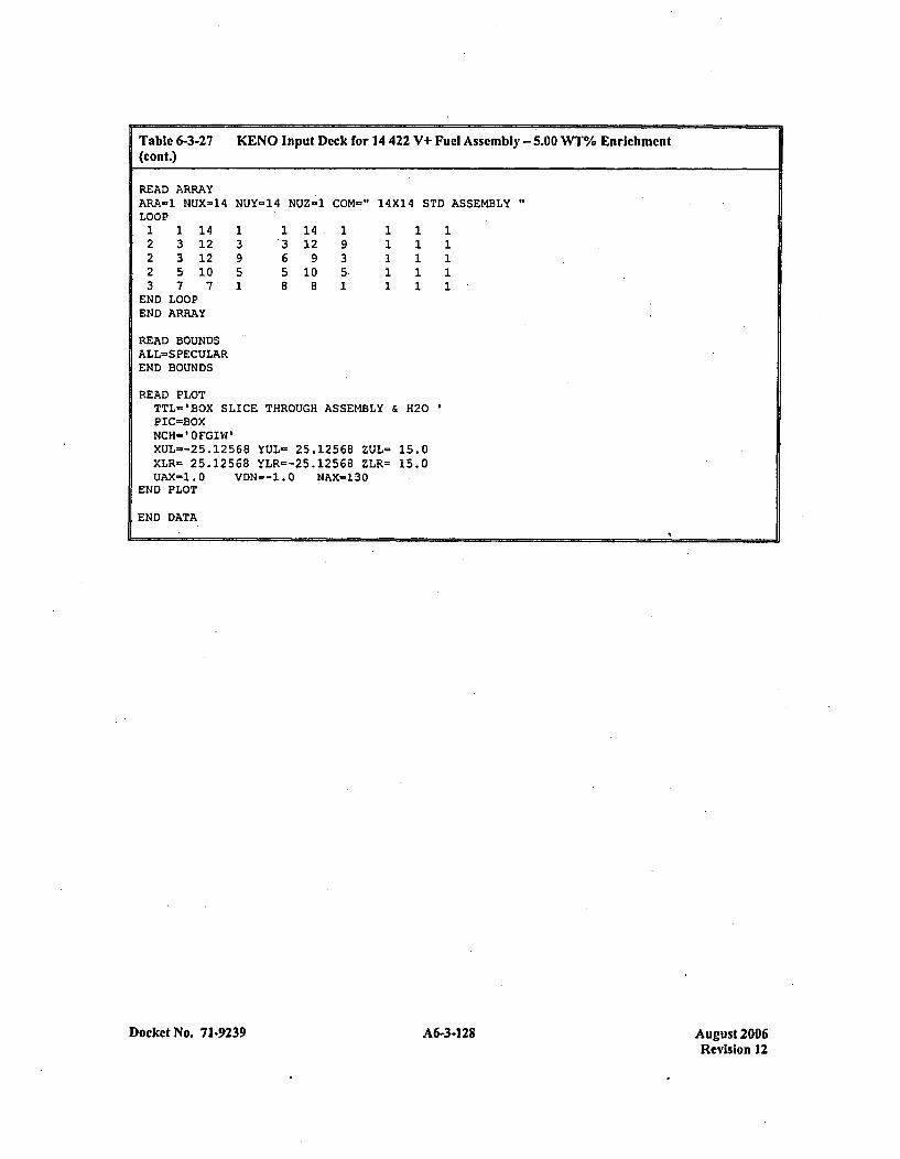
Table 6-3-27 KENO Input Deck for 14 422 V+ Fuel Assembly - 5.00 WT% Enrichment(cont.)
READ ARRAYARA-1 NUX-14 NUY-14 NUZ-1 COM=" 14X14 STD ASSEMBLYLOOP1 1 14 1 1 14. 1 1 1 12 3 12 3 3 12 9 1 1 12 3 12 9 6 9 3 1 1 12 5 10 5 5 10 5. 1 1 13 7 7 1 8 8 1 1 1 1
END LOOPEND ARRAY
READ BOUNDSALL=SPECULAREND BOUNDS
READ PLOTTTL-'BOX SLICE THROUGH ASSEMBLY & H120
ICOxNCH-' FGIW'XUL--25.12568 YUL= 25.12568 ZUL= 15.0XLR- 25.12568 YLR--25.1256B ZLR= 15.0UAX=1.0 VDN--1.0 NAX-130
END PLOT
END DATA,
Docket No. 71-9239 A6-34128Au st20Revision 12

Table 6-3-28 Input Deck for Table 17 Model with Flooded Pin Gap - Annular Pellet
TITLE-MC4.4.8 W/O SU-3 LTA CASK IN 3D238GROUPNDF5U02ZRH20CARBONSTEELARBMGD203
CARBONSTEELU02ZIRC4
1 DEN=10.582341.9685 2 0 1
67 DEN-10.588
LATTICECELL1.0 293 92235 4.81.0 2931.0 2931.0 2931 64000 2
.8016 3 5 1.0 2931.0 .2931.0 293 92235 4.81.0 293
92238 95.2
92238 95.2
ENDENDENDEND
ENDENDENDEND
ENDEND COMPTRIANGPITCH 1.27500 0.7844 1 3 0.9144 2 0.8001 3MORE DATA RES-=7 CYLINDER 0.39218 0.19685DAN (7)=0.37801673RES-8 CYLINDER 0.4572 0.40005DAN(8)-0.43692386 END MOREMCC-5 PACKAGE,SLJ NPP-3 CONTENTS AT 4.0 W/OREAD PARAMETERS
TME-400 RUN-YES GEN=450 NPG=2000 NSK-50 NUB=YESEND PARAMETERS
READ GEOMETRY
UNIT 1COM-" SU-3ZHEMICYL-YZHEMICYL-YZHEMICYL-YCUBOID
UNIT 2COM=" SU-3ZHEMICYL+YZHEMICYL+YZHEMICYL+YCUBOID
UNIT 3COM-" SU-3ZHEMICYL-YZHEMICYL-YCUBOID
LTA1323
LTA1323
FUEL ROD (NOBA) - BOTTOM HALF1 0.3921761 0.400051 0.457202 0.55240 -0.55240 0.00000
ROD1111
(NOBA) - TOP HALF0. 3921760. 400050.457200.55240 -0.55240 0.63750
-0.63750
0. 00000
-0. 63750
156.1156.1156.1156.1
156.1156.1156.1156.1
156.1156.1156.1
0.00.00.00.0
0.00.00.00.0
0.00.00.0
LTA MODIFIED GT/IT - BOTTOM HALF3 1 0.47102 1 0.54003 1 0.55240 -0.55240 0_00000
UNIT 4COM-" SU-3 LTAZHEMICYL+Y 3ZHEMICYL+Y 2CUBOID 3
MODIFIED GT/IT - TOP HALF1 0.47101 0.54001 0.55240 -0.55240 0.63750
156.1 0.0156.1 0.0
0.00000 156.1 0.0
0.00000 156.1 0.0
UNIT 5COM=" EMPTY WATER CELL - TOP OR BOTTOM HALFCUBOID 3 1 0.55240 -0.55240 0.63750
UNIT 6COM-" UNISTRUTCUBOID 3CUBOID 4
CHANNEL ASSEMBLY"1 1.799 0.01 2.539 0.0
3.5 0.7398 181.5 0.03.5 0.0 181.5 0.0
Docket No. 71-9239 A6-3-1 29 August 2006Revision 12
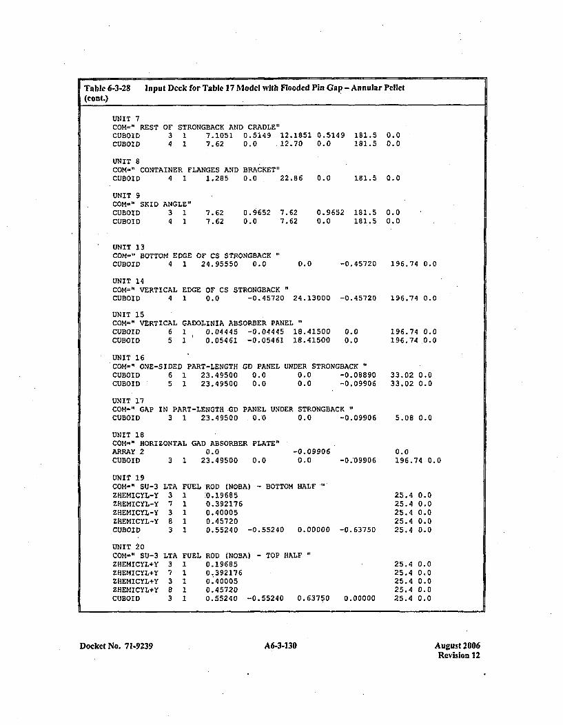
Table 6-3-28 In put Deck for Tablc 17 Model with Flooded Pin Gap - Annular Pellet(cont.)
UNIT 7COM=" RESTCUBOID
OF34
STRONGEACK AND CRADLE"1 7.1051 0.5149 12.1851 0.51491 7.62 0.0 .12.70 0.0
181.5 0.0181.5 0.0
UNIT 8COM=" CONTAINER FLANGES AND BRACKET'CUBOID 4 1 1.285 0.0
UNIT 9COM-' SKIDCUBOIDCUBDI D
22.86 0.0 181.5 0.0
7.62 0.9652 181.5 0.07.62 0.0 181.5 0.0
ANGLE"3 14 1
7.62 0.96527.62 0.0
UNIT 13COM-" BOTTOM EDGE OF CS STRONGBACKCUBOID 4 1 24.95550 0.0 0.0 -0.45720 196.74 0.0
UNIT 14COM=" VERTICAL EDGE OF CS STRONGBACK"CUBOID 4 1 0.0 -0.45720 24.13000 -0.45720
UNIT 15COM=" VERTICAL GADOLINIA ABSORBER PANELCOBOID 6 1 0.04445 -0.04445 18.41500CUBOID 5 1 '0.05461 -0.05461 18.41500
0.00.0
UNIT 16COM=" ONE-SIDED PART-LENGTHCUBOID 6 1 23.49500CUBOID 5 1 23.49500
196.74 0.0
196.74 0.0196.74 0.0
33.02 0.033.02 0.0
5.08 0.0
GD PANEL0.00.0
UNDER STRONGBACK "
0.0 -0.088900.0 -0.09906
UNIT 17COM=" GAP IN PART-LENGTH GD PANEL UNDER STRONGBACKCUBOID 3 1 23.49500 . 0.0 0.0 -0.09906
UNIT 18COM-" HORIZONTAL GAD ABSORBER PLATE"ARRAY 2CUBOID
0.03 1 23.49500 0.0
-0. 099060.0
0.0-0.'09906 196.74 0.0
UNIT 19COM-" SU-3ZHEMICYL-YZHEMICYL-YZHEMICYL-YZHEMICYL-YCUBOID
UNIT 20COM-" SU-3ZHEMICYL+YZHEMICYL+YZHEMICYL+YZHEMICYL+YCUBOID
LTA37383
LTA37383
FUEL11
FUEL
'ROD (NOBA) - BOTTOM HALF"''0. 196850.392 1760.400050.4 57200.55240 -0.55240 0.00000
.25.425.425.425.425.4-0. 63750
0.00.00.00.00.0
0.00.00.00.00.0
ROD (NOBA) - TOP HALF "f
0. 196850. 3921760.4 00050. 457200.55240 -0.55240 0.6
25.425.425.425.4
3750 0.00000 25.4
Docket No. 7 14239 A6-3-130 August 2006Revision 12
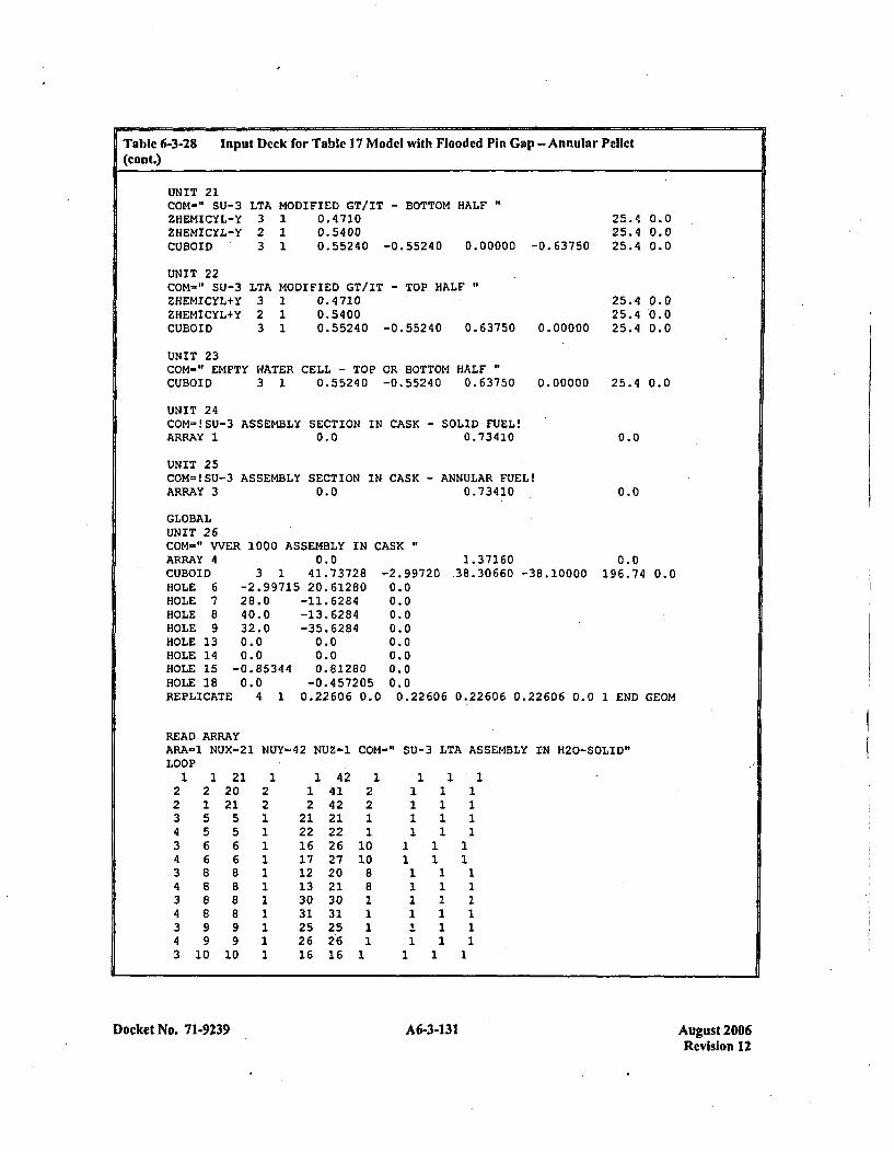
Table 6-3-28 input Deck for Table 17 Model with Flooded Pin Gap - Annular Pellet(cont.)
UNIT 21COM-" SU-3ZHEMICYL-YZHEMICYL-YCUBOID
UNIT 22COM-" SU-3ZHEMICYL+YtHEMICYL+YCUBOID
LTA MODIFIED GT/IT - BOTTOM HALF3 1 0.47102 1 0.54003 1 0.55240 -0.55240 0.00000
LTA MODIFIED GT/IT - TOP HALF3 1 0.47102 1 0.54003 1 0.55240 -0.55240 0.63750
25.4 0.025.4 0.025.4 0.0-0.63750
25.4 0.025.4 .0.0
0.00000 25.4 0.0
UNIT 23COM-" EMPTY WATER CELL - TOP OR BOTTOM HALFCUBOID 3 1 0.55240 -0.55240 0.63750 0.00000 25.4 0.0
UNIT 24COM=!SU-3 ASSEMBLY SECTION IN CASK - SOLID FUEL!ARRAY 1 0.0 0.73410 0.0
UNIT 25COM=!SU-3 ASSEMBLY SECTION IN CASK - ANNULAR FUEL!ARRAY 3 0.0 0.73410 0.0
GLOBALUNIT 26COM-" VVER 1000 ASSEMBLY IN CASKARRAY 4 0.0 1. 37160 0.0CUBOIDHOLE 6HOLE 7HOLE 8HOLE 9HOLE 13HOLE 14HOLE 15HOLE 18REPLICATI
3 1 41.73728-2.99715 20.6128028.0 -11.628440.0 -13.628432.0 -35.62840.0 0.00.0 0.0
-0.85344 0.812800.0 -0.457205
4 1 0.22606 0.1
-2.997200.00.00.00.00.00.00.00.0
38.30660 -38.10000 196.74 0.0
00.22606 0.22606 0.22606 0.0 1 END GEOM
READ ARRAYARA-1 NUX-21LOOP
NUY-42 NUZ-1 COM-" SU-3 LTA ASSEMBLY IN H20-SOLID1'
12
34343434343
21
566888899
10
2120215566
88
99
10
12
2
1 421 412 42
21 2122 2216 2617 2712 2013 2130 3031 3125 2526 2616 16
12
2010
88111
11 11 11 11 1
1111
1 1 1111
111
111
1 1 11 1 111
1
1 11
1
Docket No. 7 1-9239 A6-3-131 August 2006Revision 12
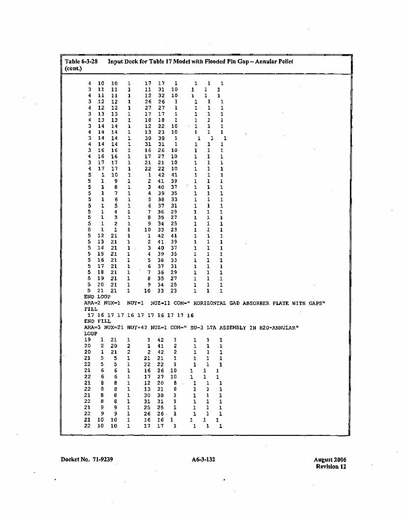
Table 6-3-28 Input Deck for Table 17 Model with Flooded Pin Gap - Annular Pellet(cont.)
4 10 103 11 114 11 113 .12 124 12 123 13 134 13 133 14 144 14 143 14 144 14 143 16 164 16 163 17 174 17 175 1 105 1 95 1 85 1 75 1 6515t5 1 45 1 35 1 25 1 15 12 215 13 215 14 215 15 215 16 215 17 215 18 215 19 215 20 215 21 21
END LOOP
17 17 111 31 1012 32 1026 26 127 27 117 17 118 18 112 22 1013 23 1030 30 131 31 116 26 1017 27 1021 21 1022 22 10
1 42 412 41 393 40 374 39 355 38 336 37 317 36 298 35 279 34 25
10 33 231 42 412 41 393 40 374 39 355 38 336 37 317 36 298 35 279 34 25
10 33 23
1 1 11 11 1
1 1 11 1 11 1 11 1 11 1 11 1 11 1
1 1 11 1 11 1 11 1 11 1 11 1 11 1 1
*1 1 11 1 11 1 11 1 11 1 11 1 11 1 11 .1 11 1 11 1 11 1 11 1 11 1 11 1 11 1 11 1 11 1 11 1 1
ARA-2 NUX'-1 NUY=1 NUZ-21 COM-." HORIZONTAL GAD ABSORBER PLATE WI'FILL17 16 17 17 16 17 17 16 17 17 16
END FILLARA=3 NtJX=21 NUY=42 NUZ-1 COM=" SU-3 LTA ASSEMBLY IN H20-ANNtJLAR",LOOP19 1 21 1 1 42 1 1 1 120 2 20 2 1 41 2 1 1 120 1 21 2 2 42 2 1 1 121 5 5 1 21 21 1 1 1 122 5 5 1 22 22. 1 1 1 121 6 6 1 16 26 10 1 1 122 6 6 1 17 27 10 1 1 121 8 8 1 12 20 8 1 1 122 8 8 1 13 21 8 1 1 121 8 8 1 30 30 1 1 1 122 8 8 1 31 31 1 1 1 121 9 9 1 25 25 1 1 1 122 9 9 1 26 26., 1 1 1 121 10 10 1 16 16 1 1 1 122 10 10 1 17 17 1 1 1 1
TH GAPS"
Docket No. 71-9239 A6-3-132 August 2006Revision 12
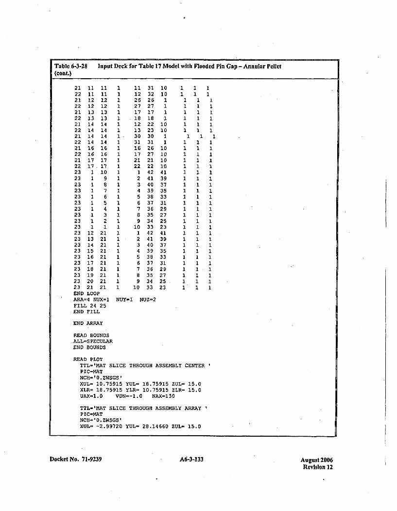
Table 6-3-28 Input Deck for Table 17 Model with Flooded Pin Gap -Annular Pellet(cont.)
21 11 1122 11 1121 12 1222 12 1221 13 1322 13 1321 14 1422 14 1421 14 1422 14 1421 16 1622 16 1621 17 1722 17.1723 1 1023 1 923 1 823 1 723 1 623 1 523 1 423 1 323 1 223 1 123 12 2123 13 2123 14 2123 15 2123 16 2123 17 2123 18 2123 19 2123 20 2123 21 21END LOOPARA=4 NUX=1FILL 24 25END FILL
END ARRAY
READ BOUNDS.ALL=SPECULAREND BOUNDS
11 31 1012 32 1026 26 127 27 117 17 1.18 18 112 22 1013 23 1030 30 131 31 116 26 1017 27 1021 21 1022 22 101 42 412 41 393 40 374 39 355 38 336 37 317 36 298 35 279 34 25
10 33 231 42 412 41 393 40 374 39 355 38 336 37 317 36 298 35 279 34 25
10 33 23
1 11 1
1 1 11 1 11 1 11 1 11 1 11 1 11 1
1 1 11 1 11 1 11 1 11 1 11 1 11 1 11 1 11 1 11 1 11 1 1.1 1 11 1 11 1 11 1 11 1 11 1 11 1 11 111 1 11 1 11 111 1 11 1 11 1 1
NUY-1 NUZ=2
READ PLOTTTL-'MAT SLICE THROUGH ASSEMBLY CENTERPIC-MATNCH-'0.ZWSGS'XUL= 10.75915 YUL- 18.75915 ZUL- 15.0XLR= 18.75915 YLR- 10.75915 ZLR- 15.0UAX=1.0 VbN--1.o NAX-130
TTL-'I4AT SLICE THROUGH ASSEMBLY ARRAYPIC-MATNCH-'0.ZWSGS'XUL= -2.99720 YUL= 28.14660 ZUL- 15.0
Docket No. 71-9239 A6-3-133 August 2006Revision 12
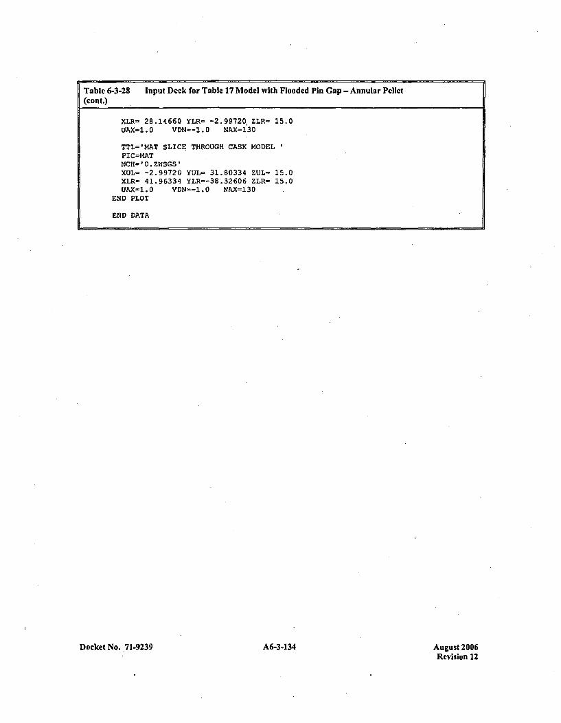
Table 6-3-28 Input Deck for Table 17 Model with Flooded Pin Gap -Annular Pellet(cont.)
XLR- 28.14660 YLR- -2.99720.ZLR- 15.0UAX-1.0 VDN--1.0 NAX=130
TTL='MAT SLICE THROUGH CASK MODELPIC=MATNCH- '0.ZWSGS'XUL= -2.99720 YUL- 31.80334 ZUL- 15.0XLR= 41.96334 YLR=-38'.32606 ZLR= 15.0UAX=1.0 VDN--1.0 NAX=130
END PLOT
END DATA
Docket No. 71-9239 A6-3-134 A6-3-134August 2006Revision 12
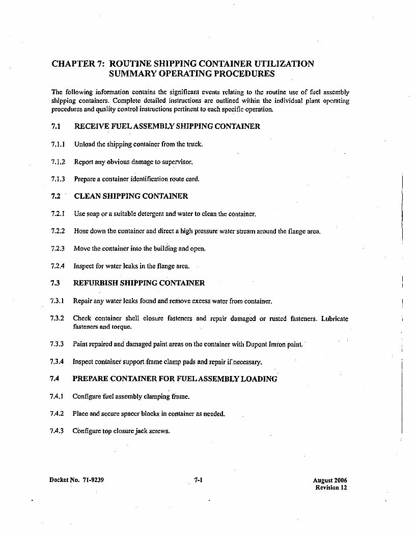
CHAPTER 7: ROUTINE SHIPPING CONTAINER UTILIZATIONSUMMARY OPERATING PROCEDURES
The following information contains the significant events relating to the routine use of fuel assemblyshipping containers. Complete detailed instructions are outlined within the individual plant operatingProcedurcs and quality control instructions pertinent to each specific operation.
7.1 RECEIVE FUEL ASSEMBLY SHIPPING CONTAINER
7.1.1 Unload the shipping container from the truck.
7.1.2 Report any obvious damage to supervisor.
7.1.3 Prepare a container identification route card.
7.2 CLEAN SHIPPING CONTAINER
7.2.1 Use soap or a suitable detcrgent and water to clean the container.
7.2.2 Hose down the container and direct a high pressure water stream around the flange area.
7.2.3 Move the container into the building and open.
7.2.4 Inspect for water leaks in the flange area.
7.3 REFURBISH SHIPPING CONTAINER
7.3.1 Repair any water leaks found and remove excess water from container.
7.3.2 Check container shell closure fasteners and repair damaged or rusted fasteners. Lubricatefasteners and torque.
7.3.3 Paint repaired and damaged paint~areas on the container with Dupont Imton paint.
7.3.4 Inspect container support~frame clamp pads and repair if necessary.
7.4 PREPARE CONTAINER FOR FUEL ASSEMBLY LOADING
7.4.1 Configure fuel assembly clamping frame.
7.4.2 Place and secure spacer blocks in container as needed.
7.4.3 Configure top closure jack screws.
Docket No. 7 1-9239 7-1 August 2006Revision 12
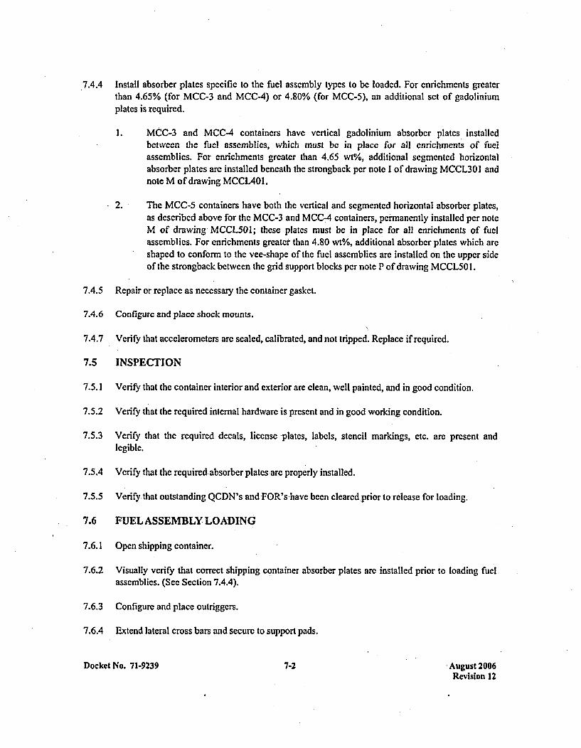
.44 Install absorber plates specific to the fuel assembly typcs to be loaded. For enrichments greaterthan 4.65% (for MCC-3 and MCC-4) or 4.80% (for MCC-5), an additional sct of gadoliniumplates is required.
1. MCC-3 and MCC-4 containers have vertical gadolinium absorber plates 'installedbetween the fuel assemblies, which must be in place for all enrichments of fuelassemblies. For enrichments greater than 4.65 wt%, additional segmented horizontalabsorber plates arc installed beneath the strongback per note I of drawing MCCL301 andnote M of drawing MCCL4Ol.
2. The MCC-5 containers have both the vertical and segmented horizontal absorber plates,as described above for the MCC-3 and MCC-4 containers, per~manently installed per noteM of drawing MCCL5Ol; these plates must be in place for all enrichments of fuelassemblies. For enrichments greater than 4.80 wt%, additional absorber plates which arcshaped to conform to the vee-shape of the fuel assemblies arc installed on the upper sideof the strongback between the grid support blocks per note P of drawing MCCL50 1.
7.4.5 Repair or replace as necessary the container gasket.
7.4.6 Configure and place shock mounts.
7.4.7 Verify that accelerometers are sealed, calibrated, and not tripped. Replace if required.
7.5 INSPECTION
7.5.1 Verify' that the container interior and exterior are clean, well painted, and in good condition.
7.5.2 Verify that the required internal hardware is present and in good working condition.
7.5.3 Verify that the required decals, license -plates, labels, stencil markings, etc. arc present andlegible.
7.5.4 Verify that the required absorber plates are properly installed.
7.5.5 Verify that outstanding QCDN's and FOR's have ýbeen cleared ,prior to release for loading.
7.6 FUEL ASSEMBLY LOADING
7.6.1 Open shipping container.
7.6.2 Visually verify that correct shipping container absorber plates are installed prior to loading fuelassemblies. (See Section 7.4.4).
7.6.3 Configure and place outriggers.
7.6.4 Extend lateral cross bars and secure to support pads.
Docket No. 71-9239 7-2 August 2006Revision 12

7.6.5 Run jacking nuts toward pressurc pads as far as possible.
7.6.6 Open clamping frames and top closure assemblies.-
7.6.7 Place and secure support frame in vertical position. Each. clamping frame on the support frameside to be loaded shall be opened as far as possible. The associated pressure pads shall beretracted as far as the jacking nut.
7.6.8 Place the fuel assembly in the support frame.
7.6.9 Adjust the alignment of bottom, middle and top clamping frames to associated fuel assemblygrids.
7.6.10 Close the bottom, middle and top clamping frames around the fuel assembly and tighten theframe fastener nuts.
7.6.11 Snug the bottom, middle and top clamping frame pressure pads against the fuel assembly grid inorder. The side pressure pad shall be snugged before the top pressure pad in each case.
7.6.12 Load the second fuel assembly in a similar manner.
7.6.13 Verify the absence of debris on and in the container shell lower subassembly. Remove debris as
required.
7.6.14 Release stabilizing bars and lock in storage position.
7.6.15 Lower support frame into horizontal position.
7.6.16 Release cross bars. Retract and lock in storage configuration.
7.6.17 Retract and secure the outriggers.
7.6.18 Close the remaining clamping frames around the fuel assembly and tighten their clamping framefastener nuts.
7.6.19 Pull plastic wrapper through the gap between pressure pads so ;that only a single layer enclosesthe grid.
7.6.20 Align pressure pads with grids such that grid springs are not visible along either long side of thepressure pad.
7.6.21 Torque the jacking nuts startin g with the bottom clamping frame and working up the fuelassembly.
7.6.22 Close and secure top closure assemblies.
Docket No. .71-9239 7-3 August 2006Revision 12

7.6.23 Check all fasteners and plastic wrapper for correct configuration.
7.6.24 Engage shock mount frame swing bolts with support frame clamp pads and tightcn nut until it is
"snug-tight." Turn nut an additional one-half turn.
7.7 INSPECTION
7.7.1 Verify that the fuel assemblies and core components have been released and the proper,component is being shipped with the assembly.
7.7.2 Verify that the plastic is installed correctly.
7.7.3 Verify that the enrichment of the fuel assemblies loaded into each container does not exceed the
applicable maximum permissible per Section 7.4.4.
7.7.4 Verify that the fuel assemblies arc properly oriented in the container.
7.7.5 Verify the number of shock mounts is correct and accelerometers are sealed, calibrated and nottripped.
-7.7.6 Verify that clamps, shock mount frame swing bolts, etc. are tightened.
7.7.7 Verify general cleanliness and absence of debris on container internals, fuel assembly, plasticwrapper, container flange and container shell lower subassembly prior to closing the container.
7.7.8 Verify placement and integrity of shipping container gasket.
7.8 CLOSE SHIPPING CONTAINER
7.8.1 Verify that the cover flange is free of debris and place cover on container.
7.8.2 Tighten container closure fasteners to secure cover.
7.8.3 Install one approved tamper proof security seal on each end of the container.
7.9 INSPECTION
7.9.1 Verify that the container lid is properly seated and all closure bolts are present.
7.9.2 Verify that outriggers are present.
7.10 TRUCK LOADING OF SHIPPING CONTAINERS
7.10.1 Place shipping container on trailer equipped to permit chaining down of container.
7.10.2 Center and place container lengthwise on trailer.
Docket No. 7 1-9239 7-4 Aueust 2006Revision 12
7.10.3 Secure containers to trailer bed with stops.
7.10.4 Chain containers to trailer using "Come along" tighteners and chains of 3/8 inch minimumdiameter.
7.11 REGULATORY
7.11.1 Conduct direct alpha surveys on both the containers and the accessible areas of the flatbed.
7.11.2 Perform the removable alpha and beta-gamma external smear surveys on both the containers andthe accessible areas of the flatbed. If any single alpha measurement exceeds 220 dpmn/l 00cm2 orbeta-gamma measurement exceeds 2200 dpm/100cm , notify Regulatory Engineering forinstructions on decontamination.
7.12 INSPECTION
7.12.1 Verify that containers are properly stacked and secured.
7.12.2 Verify that required Health Physics, Radioactive and any other placards or labels have bcen
properly placed.
7.12.3 Verify that two tamper proof security seals have been property placed on each container.
Docket No. 71-9239 7-5 August 2006Revision 12
APPENDIX 7-1REFERENCES
Docket No. 71-9239 A7-1-1 August 2006Revision 12
REFERENCES
No documents referenced in the text of this section.
Docket No. 71-9239 A7-1-3 August 2006Revision 12
CHAPTER 8: ACCEPTANCE TESTS, MAINTENANCE PROGRAM ANDRECERTIFICATION PROGRAM
8.1 ACCEPTANCE TESTS
MCC Shipping Containers may bc acquired by Wcs tinghousc as newly constructed containers, individualparts assembled on site into new containers or conversion of RCC to MCC containers. In each instance,all critical parts and materials are obtained from qualified suppliers. These suppliers are routinelyevaluated for compliance under the plant's quality surveillance program. Additionally, each container issubjected to both direct and statistical quality control inspections prior to first use. Should unacceptablecomponents be found, they arc replaced or repaired before the container is released for use.
8.2 MAINTENANCE PROGRAM
Every container is processed through routine refurbishment activities prior to each use. The specifics ofeach phase of the program are described below.
8.2.1 Clean the container and check for leaks.
8.2.2 Visually inspect the exterior and interior for obvious defects and repair or replace as necessary.
8.2.3 Inspect the cork surface and repair or replace as necessary.
8.2.4 Inspect the internal components and safety significant nuts, bolts, and pins, for obvious defectsand repair or replace as necessary.
8.2.5 Visually inspect the gadolinium absorber plates and corresponding tamper seal.
8.2.6 Visually inspect safety significant welds, flanges, and markings.
8.2.7 Q.C. Inspect and release prior to use.
.8.3 RECERTIFICATION PROGRAM
On a periodic basis (not to exceed five years), containers will be inspected to verify the existingconfiguration to drawing requirements. Quality control Instructions and Mechanical Operating Procedureswill define the specific inspection requirements. Safety related components as identified in approvedverification plans will be inspected for compliance to key drawings characteristics and for correctconfiguration on the container. A detailed visual inspection will be conducted of the visible side of thegadolinium absorber plates. Personnel will:
8.3.1 Visually inspect to verify that no more than seven (7) square inches total area of coating ismissing.
8.3.2 Verify no single area greater than one (1) square inch of coating is missing.
Docket No. 71.9239 8-1 August 2006Revision 12

8.3.3 Visually verify that the coating is not flaking off or blistering.
These plates will be repaired or rcplaced if defects are found.
Documentation relating to thcse inspections, repairs, part replacements, ctc. will be produced andsubsequently maintained via the existing plant records program.
Docket No. 71-9239 8-2 Aupust 2006Revision 12
APPENDIX 8-1REFERENCES
Docket No. 71-9239 A8-1-1 August 2006Revision 12
REFERENCES
No documents referenced in the text of this section.
Docket No. 7 1.9239 AS-1-3 August 2006Revision 12
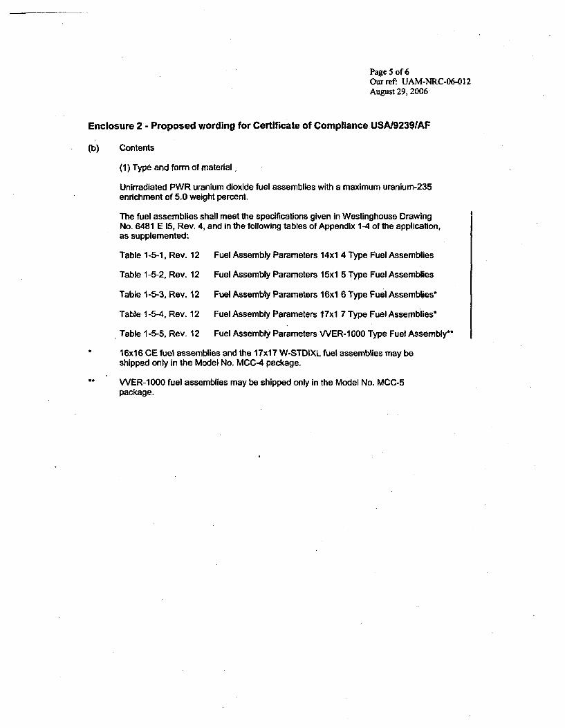
Page 5 of 6Our ref. UAM-NRC-06-01 2August 29, 2006
Enclosure 2 - Proposed wording for Certificate of Compliance USAl9239IAF
(b) Contents
(1) Type and form of material,
Unirradiated PWR uranium dioxide fuel assembli es with a maximum uranium-235enrichment of 5.0 weight percent.
The fuel assemblies shall meet the specifications given in Westinghouse DrawingNo. 6481 E 15, Rev. 4, and in the following tables of Appendix 1-4 of the application,as supplemented:
Table 1-5-1, Rev. 12 Fuel Assembly Parameters 14x1 4 Type Fuel Assemblies
Table 1-5-2, Rev. 12 Fuel Assembly Parameters 15xl 5 Type Fuel Assemblies
Table 1 -5-3, Rev. 12 Fuel Assembly Parameters 16xi 6 Type Fuel Assemblies*
Table 1-5-4, Rev. 12 Fuel Assembly Parameters 1 7xl 7 Type Fuel Assemblies*
Table 1-5-5, Rev. 12 Fuel Assembly Parameters WER-1000 Type Fuel Assembly"*
* 16x16 CE fuel assemblies and the `17x17 W-STDIXL fuel assemblies may beshipped only In the Model No. MCC-4 package.
** WER-1 000 fuel assemblies may be shipped only in the Model No. MCC-5package.
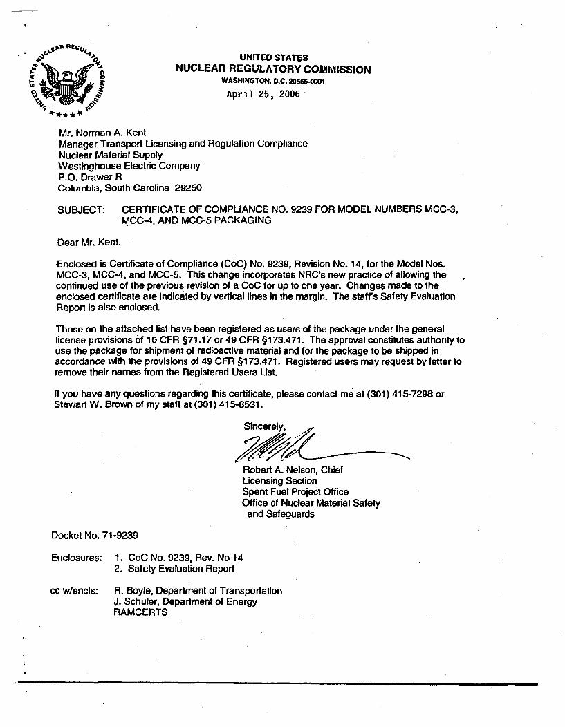
UNITED STATES50A NUCLEAR REGULATORY COMMISSION
WASHINGTON. D.C. 206554-000
April 25, 2006'
Mr. Norman A. KentManager Transport Licensing and Regulation ComplianceNuclear Material SupplyWestinghouse Electric CompanyP.O. Drawer RColumbia, South Carolina 29250
SUBJECT: CERTIFICATE OF COMPLIANCE NO. 9239 FOR MODEL NUMBERS MCC-3,.MCC-4, AND MCC-5 PACKAGING
Dear Mr. Kent:
Enclosed is Certificate of Compliance (CoC) No. 9239, Revision No. 14, for the Model Nos.MCC-3, MCC-4, and MCC-5. This change incorporates NRC's new practice of allowing thecontinued use of the previous revision of a CoC for up to one year. Changes made to theenclosed certificate are indicated by vertical lines In the margin. The staff's Safety EvaluationReport is also enclosed.
Those on the attached list have been registered as users of the package under the generallicense provisions o~f 10 CFR §71.17 or 49 CFR §173.471. The approval constitutes authority touse the package for shipment of radioactive material and for the package to be shipped inaccordance with the provisions of 49 CFR §173.471. Registered users may request by letter toremove their names from the Registered Users List.
If you have any questions regarding this certificate, please contact me at (301) 415-7298 orStewart W. Brown of my staff at (301) 415-8531.
Sincerely,
Robert A. Nelson, ChiefLicensing SectionSpent Fuel Project OfficeOffice of Nuclear Material Safety
and Safeguards
Docket No. 71-9239
Enclosures: 1. CoC No. 9239, Rev. No 142. Safety Evaluation Report
cc w/encls: R. Boyle, Department of TransportationJ. Schuler, Department of EnergyAAMCERTS
2. PREAMBLE
a. This certificate Is Issued to certify thai the package (packaging and contents) described In Item 5 below meets the applicable safety standards setlorih In Title 10. Code of Federal Regulations, Part 71, 'Packaging and Transportation of Radioadtive Material.'
b. This certificate does not relieve the consignor from compliance with any requirement of the regulatlions of the U.S. Department of Transportation orother applicable regulatory agencies. including the government ol any country through or Into which the package will be transported.
3. THIS CERTIFICATE IS ISSUED ON THE BASIS OF A SAFETY ANALYSIS REPORT OF THE PACKAGE DESIGN OR APPLICATION
a. ISSUED TO (Name and Addiress)
Westinghouse Electric CompanyLLC (WELCO)P.O. Box 355 ~Pittsburgh, PA 15230
4. CONYDMTON S
b. TITLE AND IDENTIFICATION OF REPORT OR APPLICATION
, .Vipstinghouse Electric Corporation applicationR=Qnfuary14, 2002, as supplemented.
1 Part 71, as applicaieAJlos specified below.
Packaging
(1) Model
00
(2) Descriptioh%/)
The MCC p lgesrThe packagig cnsiand an adjusta-§ uel eleme cito a 13-gauge c n selotrclosed with thirty T-bolts. The CC-4 andinch T-botts./
itm oxide fuel assemblies.juipped with a strongbacksembly is shock mountedMCC-3 container is.irs are closed with fifty '/6-
The MCC-3 and MCC-4 cotn-a~rn l equipped with vertical Gd203 neutronabsorber plates that are mounted on the center wall of the strongback. Additional horizontalGd2O3 neutron absorber plates. mnounted on the underside of the strongback, are required forthe contents as specified.
The MCC-5 container is~permanently equipped with both the vertical and horizontal Gd.0 3neutron absorber plates. Additional vee-shaped, guided Gd203 neutron absorber plates arerequired for the contents as specified.
Approximate dimensions of the MCC-3 packaging are 44-1/2 inches 0.0. by 194-1/2 incheslong. The gross weight of the packaging and contents is 7,544 pounds. The maximumweight of the contents is 3,300 pounds.
Approximate dimensions of the MCC-4 packaging are 44-1/2 inches O.D. by 226 incheslong. The gross weight of the packaging and contents is 10,533 pounds. The maximumweight of the contents is 3,870 pounds.
5. (a) Packaging (continued)
Approximate dimensions of the MCC-5 packaging are 44-1/2 inches O.D. by 226 incheslong. The gross weight of the. packaging and contents is 10,533 pounds. The maximumweight of the contents is 3,700 pounds.
(3) Drawings
The MCC-3 packaging is constructed in accordance with Westinghouse ElectricCorporation Drawing No. KCLi2 Sheets 1, 2, 3, and 4, Rev. 6.
The MCC-4 ý Jl osrutc __1 with Westinghouse ElectricCorporatiorkiGv ng No. MCCL4O1, Sheets I.-q3j, and 5, Rev. 9.
packaging is constructed in accori,iwtwing No. MCCL5O1, Sheets 1
Westinghouse ElectrickRev. 6.
(b)
T' 4g. 1, Rev. 10~V Fuel Assemtn)'arameters14x14 TAyVuel Assemblies
Table 1-4.2*ev.*. -t.s~e1'tsembly Parameters
' '1X15 Type Fuel Assemblies
Table 1-4.3, Rev. 10
Table 1-4.4, Rev. 10
Table 1-4.5, Rev. 10
Fuel Assembly Parameters16x16 Type Fuel Assemhblies'
Fuel Assembly Parameters17x1 7 Type Fuel Assemblies"
Fuel Assembly ParametersVVER-1000 Type Fuel Assembly"
*1 6x1 6 CE fuel assemblies and the 17xl 7 W-STD/XL fuel assemblies may beshipped only in the Model No. MCC-4 package.
VVER- 1000 fuel assemblies may be shipped only in the Model No. MCC-5package.
rr~ ~i1'NRC FORM 618 U.S. NUCLEAR REGULATORY COMMISSION
10 CA 71CERTIFICATE OF COMPLIANCEFOR RADIOACTIVE MATERIAL PACKAGES
1. CERTIFICATE NUMBER b. REVISION NUMBSER C. DOCKET NUMBER jd. PACKAaE m1ENTFC'ATION NUMBER PAGE PAGESII9239 I 14 71-9239 I USAt9239/AF 3 OF 41
5. (b) Contents (continued)
(2) Maximum quantity of material per package
Two (2) fuel assemblies
(c) Transport Index for Criticality Control (Criticality Safety Index)
Minimum transport index to be shown onlabel for nuclear criticality control.D A
.. r
6. ~ ~ ~ ~ wi (a o himnsof1x 1 516x16, and 17x1q semblies with U-235 enrichmentsof over 4.65 wt0% od . thrzna 10d0 t n absorber plates shall bepositionedl unde h each assembly. The horizontal a r plates shall be placedhorizontally on nderside of the strongback, as specifie t e respective drawings inCondition 5(a3 .. e MCC-3 and MCC-4 models.
(b) For shipm ~~of 17x1 ARD lattice fuel les (I 7x 11STD and 17x 17 XL) withU-235 enrikinents of o I/ t -~ horlzonfr~bd203 neutron absorberplates shaW~~ position reat c a -The horizqf absorber plates shallbe placed lWhrizonta o' e e - k c, as spe d in the respectivedrawings Irondi~ eMCC-3 -4 d~els.
7. For shipments of V9 ER-1 S e nts c er 4.80 wt*/o and up to5.0 wt%, a gide 3n so ed und ieath each assembly.The guided absor tes 4~jtesrnbcaspecified in the draw in Co ditio - tosdth t.gbca
8. Each fuel assembly must' Jnsheathed or e enclsd a nsealed plastic sheath whichmay not extend beyond the ~'s of the fuel assembly. The elV. of the sheath may not be folded ortaped in any manner that would p .. tfwof I dsitor out of the sheathed fuel assembly.
9. The dimensions, minimum Gd203 lading nooc tig specifications, and acceptance testing of theneutron absorber plates shal binacrnewth the GW203 Neutron Absorber PlatesSpecifications,0 Appendix 1-6, Rev. 10. of the application, as supplemented. The minimum Gd203coating areal density on the vertical and horizontal neutron absorber plates shall be0.054 g-Gd203/cm 2. The minimum Gd203 coating areal density on guided neutron absorber platesshall be 0.027 g-Gd2O3Icrn2.
10. In addition to the requirements of Subpart G of 10 CFR Part 71:
(a) Each package shall be prepared for shipment and operated in accordance with the "RoutineShipping Container Utilization Summary Operating Procedures," in Chapter 7 of theapplication, as supplemented; and
(b) Each package shall be tested and maintained in accordance with the "Acceptance Tests,Maintenance Program, and Recertification Program," in Chapter 8 of the application, assupplemented, and as specified in the respective drawings in Condition 5(a)(3) for theMCC-3, MCC-4, and MCC-5 models.
NRIC FORM 618 U.S. NUCLEAR REGULATORY COMMISSION1W8-20071 CERTIFICATE OF COMPLIANCE
10 CPA 71FOR RADIOACTIVE MATERIAL PACKAGES I1. aCERTIFICATE NUMBER b. REVISION NUMBER c. DOCKCET NUMBER d. PACKAGE IDENTIFICATION WNUMER IPAGE PAGES'I
9239 I 14 I 71 -29 I USA/9239/AF I4 OF 4j
11. The package authorized by this certificate is hereby approved for use under the general licenseprovisions of 10 CFR §71.17.,
12. Revisions Nos. 12 and 13 of this certificate may be used until March 31, 2007.
13. Expiration date: March 31, 2007.
REFERENCESWestinghouse Electric Corporation application dated f~bjuary 14, 2002.
I
I
Supplements dated: March 6, 2002,4
¼
V(p ~
COMMISSION
Date: ApriL( 2006 ()
* * * * 4;`
SAFETY EVALUATION REPORT
Docket No. 71-9239Model Nos. MCC-3, MCC-4, and MCC-5
Certificate of Compliance No. 9239Revision No. 14
SUMMARY
The U.S. Nuclear Regulatory Commission (NRC) staff (the staff) made a change toWestinghouse Electric Company's Certificate of Compliance (CoC) No. 9239. This changeincorporates the staff's new practice of allowing the continued use of the previous revision of aCoC for up to one year.
CoC No. 9239 has been amended to allow the use of CoC No. 9239, Revisions Nos. 12 and 13until April 30, 2007. The staff has determined that this change does not affect the ability of thepackage to meet the requirements of 10 CFR Part 71.
EVALUATION
Recently, the staff has adopted a new practice of allowing the continued use of previousrevisions of a CoC for a period up to one year after issuance of a new revision. The staff'sprevious practice was for the revised CoC to supersede, in its entirety, the previous revision ofthe CoC. The staff's new practice was adopted in response to industry representatives'statements. Industry representatives stated that once NRC has issued a CoC revision it maytake up to one year to receive necessary revalidlations from foreign governments for use of thepackaging in their country. Thus, during this revalidlation period the use of these packagescould be disrupted. The staff views this type of-change as administrative and does not affectthe ability of the package to meet the requirements of 10 CFR Part 71.
CONCLUSION
Certificate of Compliance No. 9239,hasibeen amended to include a~new Condition No. 12. Thisnew condition reads as follows:
12. Revisions Nos. 12 and 13 of this certificate may be useduntil March 31, 2007.
The staff has determined that this change does not affect *the ability of the package to meet therequirements of110 CFR Part 71.
Issued wish Certificate of Compliance No. 9239. Revision No. 14,
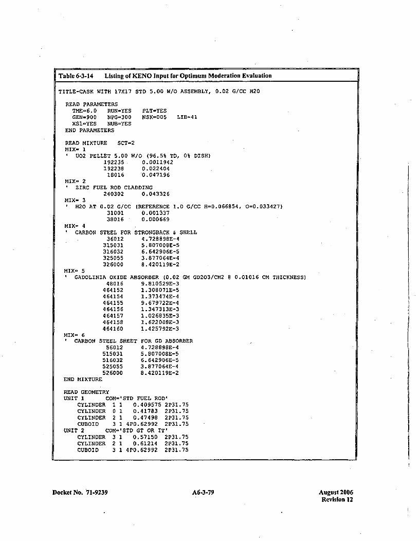
Table 6-3-14 Listing of KENO Input for Optimum Moderation Evaluation
TITLE-CASK WITH 17X17 STD, 5.00 W/O ASSEMBLY, 0.02 GICC H20
READ PARAMETERSTME=6.0 RUN-YES PLT=YESGEN-900 NPG-300 NSK-005 LIB-41XS1-YES NUB=YES
END PARAMETERS
READ MIXTURE SCT-MIX- 1
U02 PELLET 5.0019223519223818016.
'2
W10 (96.5% TD, 0% DISH)0.00119420. 0224 04'0.047196
MIX- 2ZIRC FUEL ROD CLADDING
240302 0.043326MIX- 3
H20 AT 0.02 G/CC3100138016
MIX- 4CARBON STEEL FOR
36012315031.316032325055326000
(REFERENCE 1.0 G/CC H-0.066854, 0=0.033427)0.0013370.000669
STRONGBACI( & SHELL4 .728898E-45. 807008E-56. 642906E-53 .877064E-48. 420119E-2
MIX- 5GADOLINIA OXIDE AB~
480 16464152464154464155464156464157464158464160
MIX- 6CARBON STEEL SHEET
56012515031516032525055526000
3ORBER (0.029. 810529E-31. 308071E-51 .373474E-49. 679722E-41. 347313E-31 .026835E-31.622 008E-31. 425792E-3
GM GD203/CM2 8 0.01016 CM THICKNESS)
FOR GD ABSORBER4 .72889SE-45. 807008E-56.642906E-53. 877064E-48. 420119E-2
END MIXTURE
READ GEOMETRYUNIT 1 OM='STD FUEL ROD'
CYLINDER 1 1 0.409575 2P31.75CYLINDER 0 1 0.41783 2P31.75CYLINDER 2 1 0.47498 2P31.75CUBOID 3 1 420.62992 2P31.75
UNIT 2 COM='STD GT OR IT'CYLINDER 3 1 0.57150 2P31.75CYLINDER 2 1 0.61214 2P31.75CUBOID 3 1 420.62992 2P31.75
Docket No. 71-9239 A6-3-79 August 2006Revision 12
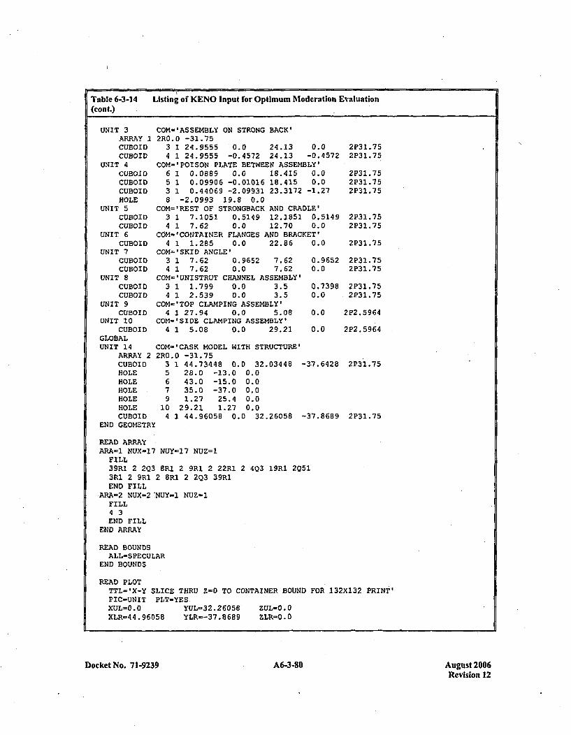
Table 6-3-14 Listing of KENO Input for Optimum Moderation Evaluation(cont.)
UNIT 3ARRAY :ICUBOIDCUBOID
UNIT 4CUBOIDCUBOIDCUBOIDHOLE
UNIT 5CUBOIDCOBOID
UNIT, 6CUBOID
UNIT 7CUBOIDCUBOID
UNIT 8CUBOIDCUBOID
UNIT 9CUBOID
UNIT 10CUBOID
GLOBALUNIT 14
ARRAY 2CUBOIDHOLEHOLEHOLEHOLEHOLECUBOID
END GEOMETR)
COM-'ASSEMBLY ON STRONG BACK'2R.0O -31.75
3 1 24.9555 '0.0 24.13 0.04 1 24.9555 -0.4572 24.13 -0.4572
COM-'POISON PLATE BETWEEN ASSEMBLY'6 1 0.0889 0.0 18.415 0.05 1 0.09906 -0.01016 18.415 0.03 1 0.44069 -2.09931 23.3172 -1.278 -2.0993 19.8 0.0
COM.'REST OF STRONGBACK AND CRADLE'3 1 7.1051 0.5149 12.1851 0.51494 1 7.62 0.0 12.70 0.0
COM-'COr4TAINER FLANGES AND BRACKET'
2P31.752P31.75
2P31.752P31.752P31.75
2P31.752P31 .75
4 1 1.285 0.0 22.86COM-'SKID ANGLE'
3 1 7.62 0.9652 7.624 1 7.62 0.0 7.62
COM='UNISTRUT CHANNEL ASSEMBLY'3 1 1.799 0.0 3.54 1 2.539 0.0 3.5
COM-'TOP CLAMPING ASSEMBLY'4 1 27.94 0.0 5.08
COM-"SIDE CLAMPING ASSEMBLY'.4 1 5.08 0.0 29.21
COM'='CASK MODEL WITH STRUCTURE'
0.0 2P31.75
0.96520.0
0.73980.0
2P31.752P31.75
2P31.752P31.75
0.0 222.5964
0.0 222.5964
2R0.35679
104
0 -31.751 44.73448 0.0 32.0344828.0 -13.0 0.043.0 -15.0 0.035.0 -37.0 0.01.27 25.4 0.0
29.21 1.27 0.01 44.96058 0.0 32.26058
-37.6428 2231.75
-37.8689 2231.75
READ ARRAYARA-1 NUX'.17 NUY-17 NUZ=l
FILL39RI 2 2Q3 BR1 2 9R1 2 22RI 2 403 19R1 2Q513R1 2 9R1 2 8R1 2 2Q3 39R1END FILL
ARA-2 NUX-2:NUY-1 NUZ-1FILL4 3END FILL
END ARRAY
READ BOUNDSALL-SPECULAR
END BOUNDS
READ PLOTTTL='X-Y SLICE THRU Z-0 TO CONTAINER BOUND FOR 132XI32 PRINT'PIC-UNIT PLT-YESXUL-0.0 YUL-32.26056 ZUL=O.0XLR=44.96058 YLR=-37.8689 ZLR='0.0
Docket No. 7 1-9239 A6-3-80 August 2006Revision 12
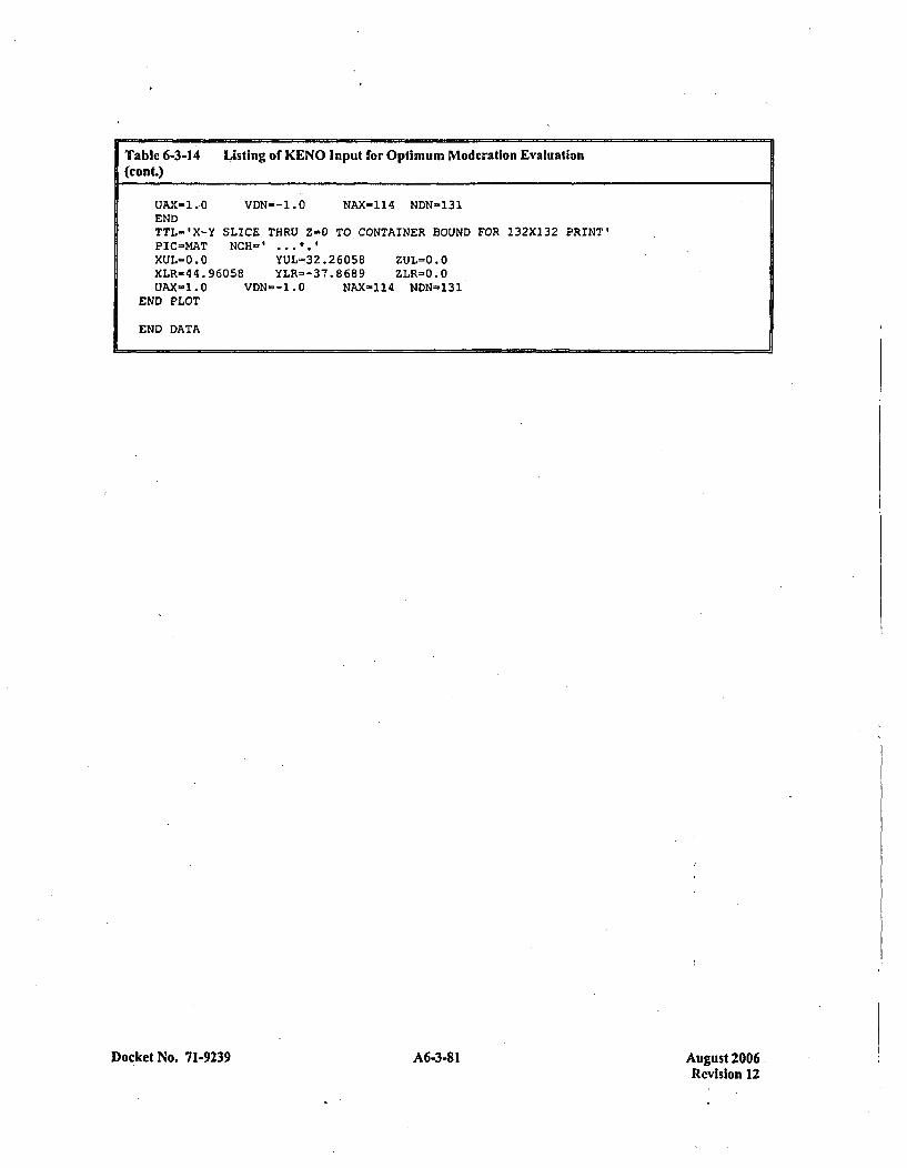
Table 6-3-14 Listing of KENO Input for Optimum Moderation Evaluation(cont.)
UAX-1.0 VDN--1.O NAX-114 NDN-131ENDTTL='X-Y SLICE THRU Z-0 TO CONTAINER BOUND FOR 132XI32 PRINT'PIC=MAT NCH-'.XUL=O.O YUL=32.26058 ZUL=O.OXLR-'14.96058 YLR=-37.8689 ZLR=O.OtJAX-1.O VDN--1.O NAX-.114 NDN-'131
END PLOT
END DATA
Docket No. 71-9239A638Aust20 A6-3-81Revision 12
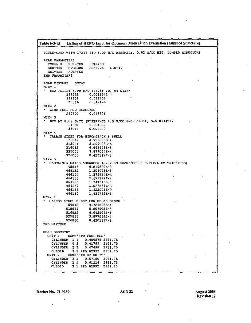
[ al -3-15 Listing of KENO Input for Optimum Moderation Evaluation (Lumped Structure)
TITLE-CASK WITH 17X17 STD 5.00 W/O ASSEMBLY, 0.02 G/CC H120, LUMPED STRUCTURE
READ PARAMETERSTME-6.0 RUN=YESGEN-900 NPG-300XS1=YES NUB-YES
END PARAMETERS
READ MIXTURE SCT-2MIX- 1
U02 PELLET 5.00 Wi19223519223818016
PLT=YESNSK=005 LIB=41
/0 (96.5% TD, 0% DISH)0.0011942'0. 0224 040. 047196
MIX= 2ZIRC FUEL ROD CLADDING
240302 0.043326MIX- 31 H20 AT 0.02 G/CC
3100138016
(1
MIX- 4CARBON STEEL FOR S'
36012315031316032325055326000
MIX- 5GADOLINIA OXIDE AB~
48016464152464154464155464156464157464158464160
MIX- 6CARBON STEEL SHEET
560125150315160325250555266000
END MIXTURE
REFERENCE 1.0 G/CC H-=0.066854, 0-0.033427)0.0013370. 000 669
1'RONGBACK & SHELL4 .728898E-45.80700BE-56. 642906E-53. 8770 64 E-48.420119E-2
SORBER (0.029. 810529E-31.308071E-51 .373474E-49. 679722E-41. 347313E-31. 026835E-31. 622008E-31.,425792E-3
GM GD203/CM2 @ 0.01016 CM THICKNESS)
FOR GD ABSORBER4 .728898E-45..807008E-56. 642906E-53. 8770 64E-48.420119E-2
READ GEOMETRYUNIT 1 COM='STD FUEL ROD'CYLINDER 1 1 0.409575 2P31.75CYLINDER 0 1 0.41783 2P31.75CYLINDER 2 1 0.47498 2P31.75CUBOID 3 1 420.62992 2P31.75
UNIT 2 COM-'STD GT OR IT'CYLINDER 3 1 0.57150 2P31.75CYLINDER 2 1 0.61214 2P31.75CUBOID 3 1 4P0.62992 2P31.75
Docket No. 71-9239 A6-3-82 August 2006Revision 12
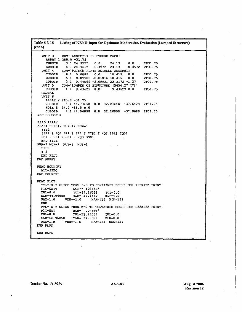
Table 6-3-15 Listing of KENO Input for Optimum Moderation Evaluation (Lumped Structure)(cont.)
UNIT 3ARRAY 1CUBOIDCUBOID
UNIT 4CUBOIDCUBOIDCUBOID
UNIT 5CUBOID
GLOBALUNIT 6
ARRAY 2CUBOIDHOLE 5CUBOID
END GEOM.ETR~
CON- 'ASSEMBLY ON STRON4G BACK'2R0.0 -31.75
3 1 24.9555 0.0 24.13 0.04 1 24.9555 -0.4572 24.13 -0.4572
COM-'POISON PLATE BETWEEN ASSEMBLY'6 1 0.0889 0.0 18.415 0.05 1 0.09906 -0.01016 18.415 0.03 1 0.44069 -2.09931 23.3172 -1.27
COM-'LUMPED CS STRUCTURE (5654.27 CC)'4 1 9.43629 0.0 9.43629 0.0
2P31 .752P31.75
2P31.752P31 .752P31 .75
2P3 1.75
2 P31. 75
2P31.75r
2R0.0 -31.753 1 44.73448 0.0
34.0 -36.0 0.04 1 44.,96058 0.0
32.03448 -37.6428
32.26058 -37.8689
READ ARRAYARA-1 NUX=17 NUY=17 NUZ-1
FILL39R1 2 2Q3 8R1 2 9R1 2 22RI 23R1 2 9R1 2 8R1 2 2Q3 39RIEND FILL
ARA-2. NUX-2 NUY-1 NUZ=1FILL4 3END FILL
END ARRAY
403 19R1 2Q51
READ BOUNDRYALL-SPEC
END BOUNDRY
READ PLOTTTL='X-Y SLICE THRU Z=0 TO CONTAINER BOUNDPIC-UNIT NCH=' 123456'XUL-0.0 YUL-32.26058 ZLJL=0.0XLR-44.96058 YLR--37.8689 ZLR-O.0UAX-1.0 VDN--1.0 NAX-114 NDN=131ENDTTL='X-Y SLICE THRU Z=0 TO CONTAINER BOUNDPIC-MAT NCH-" . .wsgp'XUL=0.0 YUL=~32.26058 ZUL-0.OýXLR-44.96058 YLR--37.8689 ZLR-0.0UAX-1.0 VDN--1.0 NAX=114 NDN=131
END PLOT
FOR 132X132 PRINT'
FOR 132XI32 PRINT'
END DATA
Docket No. 7 1-9239 A6-3-83 August 2006Revision 12
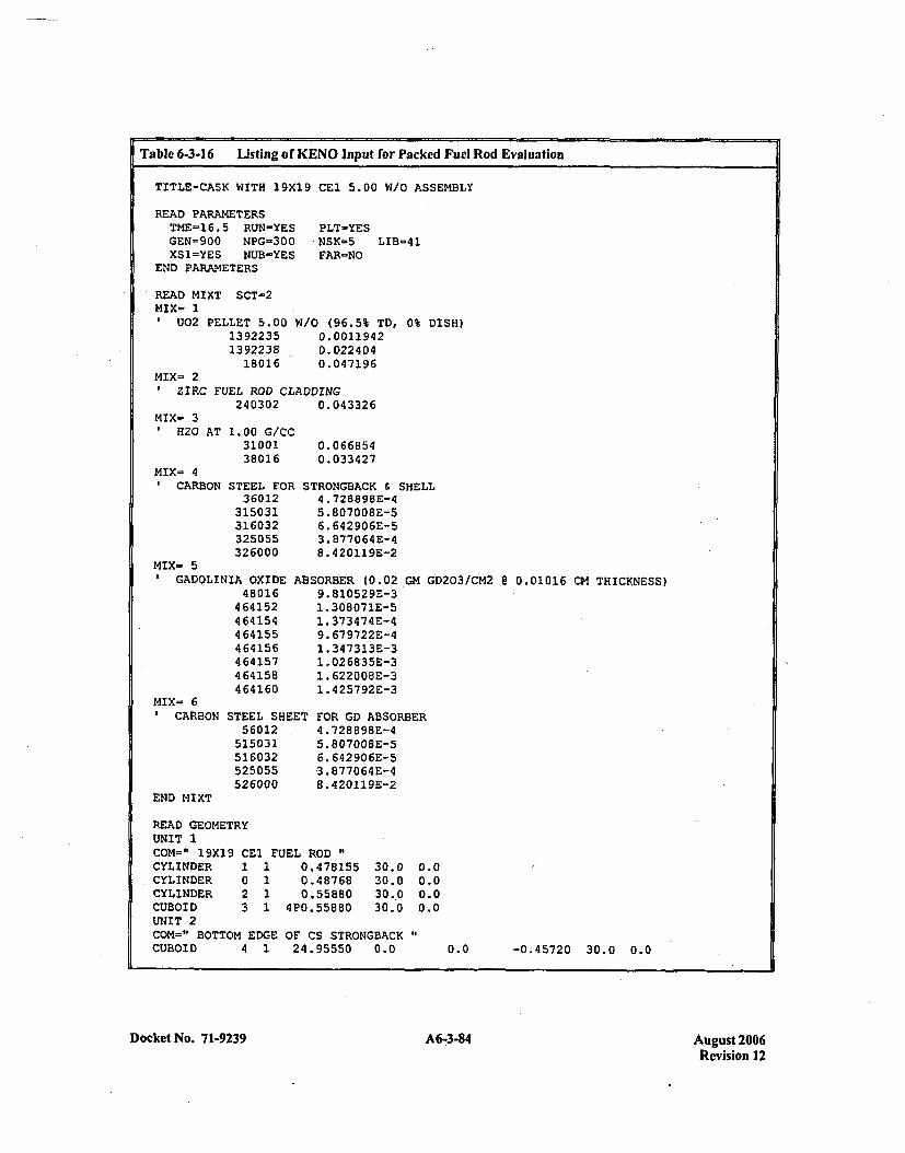
Table 6-3-16 Listing of KENO Input for Packed Fuel Rod Evaluation
TITLE-CASK WITH 19X19 CEl 5.00 W/O ASSEMBLY
READ PARAMETERSTME=16.5 RUN-YESGEN=900 NPG-300XS1=YES NUB=YES
END PARAMETERS
PLT-YES.NSK-5 LIB=41FAR=NO
READ MIXT SCT-2MIX= 1
u02 PELLET 5.0013922351392238
18016
W/O (96.5% TD, 0% DISH)0.00119420.0224040.047196
MIX- 2ZIRC FUEL ROD CLADDING
240302 0.043326MIX- 3
1 H20AT 1. 00 0/CC3100138016
MIX= 4CARBON STEEL FOR
3 60 12315031316032325055326000
M4IX- 5GADOLINIA OXIDE
480164641524641544 64155464156464157464158464160
MIX= 6*CARBON STEEL SHE
56012515031516032525055526000
END MIXT
0.0 668540. 0334 27
STRONGBACK & SHELL4. 72889SE-45.807008E-56. 642 90 6E-53. 877064 E-48. 420119E-2
ABSORBER (0.02 GM GD203/CM2 @ 0.01016 CM THICKNESS)9. 81052 9E-31. 308071E-51. 373474 E-49. 679722E-41 .347313E-31 .026835E-31. 622008E-31.425792E-3
ET FOR GD ABSORBER4 .728898E-45.807008E-56. 642906E-53. 877064E-48. 420119E-2
READ GEOMETRYUNIT 1COM=" 19X19 CEl FUEL RODCYLINDER 1 1 0.478155 30.0 0.0CYLINDER 0 1 0.48768 30.0 0.0CYLINDER 2 1 0.55880 30.0 0.0CUBOID 3 1 4P0.55880 30.0 0.0UNIT 2COM=" BOTTOM EDGE OF CS STRONGBACKCUBOID 4 1 24.95550 0.0 0.0 -0.45720 30.0 0.0
Docket No. 7 1-9239A638Aust20 A6-3-84Revision 12
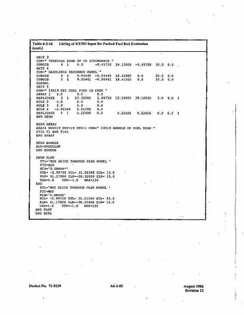
Table 6-3-16 Listing of KENO Input for Packed Fuel Rod Evaluation(cont.)
UNIT 3COM-" VERTICAL EDGE OF CS STRONGBACKCUBOID 4 1 0.0 -0.45720 24.13000UNIT 4CON-" GADOLINIA ABSORBER PANEL"CUBOID 6 1 0.04445 -0.04445 18.41500CUBOID, 5 1 0.05461 -0.05461 18.41500GLOBALUNIT 5COM-" 19X19 CEl FUEL PINS IN CASK"ARRAY 1 0.0 0.0 - 0.0REPLICATE 3 1 20.32000 2.99720 10.16000ROLE 2 0.0 0.0 0.0HOLE 3 0.0 0.0 0.0HOLE 4 -0.85344 0.81280 0.0REPLICATE 4 1 0.22606 0.0 0.22606END GEOM,
-0.45720 30.0 0.0
0.00.0
30.0 0.030.0 0.0
0.0 0.0138. 10000
0.22606 0.0 0.0 1
READ ARRAYARA-1 NUX-19 NUY=19 NUZ=1 COM-" 19X19FILL F1 END FILLEND ARRAY
BUNDLE OF FUEL RODS "
R.EAD BOUNDSALL-SPECULAREND BOUNDS
READ PLOTTTL='BOX SLICE THROUGH CASK MODELPIC=BOXNCH='0.GBHVA*'XUL- -2.99720 YUL- 31.01086 ZUL- 15.0XLR= 41.17086 YLR--38.32606 ZLR- 15.0UAX-1.0 VDN--1.0 NAX-130
ENDTTL='MAT SLICE THROUGH CASK MODELP IC-MATNCH- '0. ZWSGS'XUL- -2.99720 YUL- 31.01086 ZUL- 15.0XLR- 41.17086 YLR--38.32606 ZLR- 15.0UAX-1.0 VDN--1.O NAX-130
END PLOTEND DATA
Docket No. 7 1-9239 A6-3-85 August 2006Revision 12
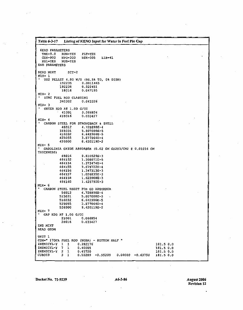
Table 6-3-17 Listing of KENO Input for Water in Fuel Pin Gap.
READ PARAMETERSTME=9.0 RUN=YESGEN=900 NPG-300XS1=YES NUB-YES
END PARAMETERS
PLT=YESNSK=005 LIB=41
READ MIXTMIX- 1
SCT=2
0 U02 PELLET 4.8019223519223818016
W/O (96.5% TD, 0% DISH)0.00114650.0224 510.047195
MIX= 2ZIRC FUEL ROD CLADDING
340302 0.043326MIX- 3
0OUTERI
MIX- 40CARBON
120 AT 1.00 G/CC41001 0.066854
418016 0.033427
STEEL FOR STRONGBACK & SHELL46012 4.728B9SE-4
315031 5.807008E-5416032 6.642906E'-5425055 3.877064E-4426000 8.420119E-2
MIX= 5IGADOLINIA OXIDE ABSORBER (0.02 GM GD203/CM2 e 0.01016 cm
THICKNESS)48016
464152464154464155464156464157464158464160
9. 810529E-31 .308071E-51. 373 47 4E-49. 679722E-41 .347313E-31 .026835E-ý31. 622008E-31. 42 5792E-3
MIX= 60 CARBONI
MIX- 70 GAP H20
END MIXTREAD GEOM
3TEEL SHEET56012
515031516032525055526000
FOR GD ABSORBER.4 .728896E-45.807008E-56. 642906E-53. 877064E-48. 420119E-2
AT 1.00 G/CC21001 0.06685428016 0.033427
UNIT 1COM-" 170FA FUELZHEMICYL-Y 1 1ZHEMICYL-Y 7 1ZHEMICYL-Y 2 1CUBOIO 3 1
ROD (NOBA) - BOTTOM HALF0. 3921760. 400050. 457200.55209 -0.55209 0.00000 -0.63750
181.5 0.0.181.5 0.0181.5 0.0181.5 0.0
'Docket No. 71-9239A636Aust20 A6-3-86Revision 12
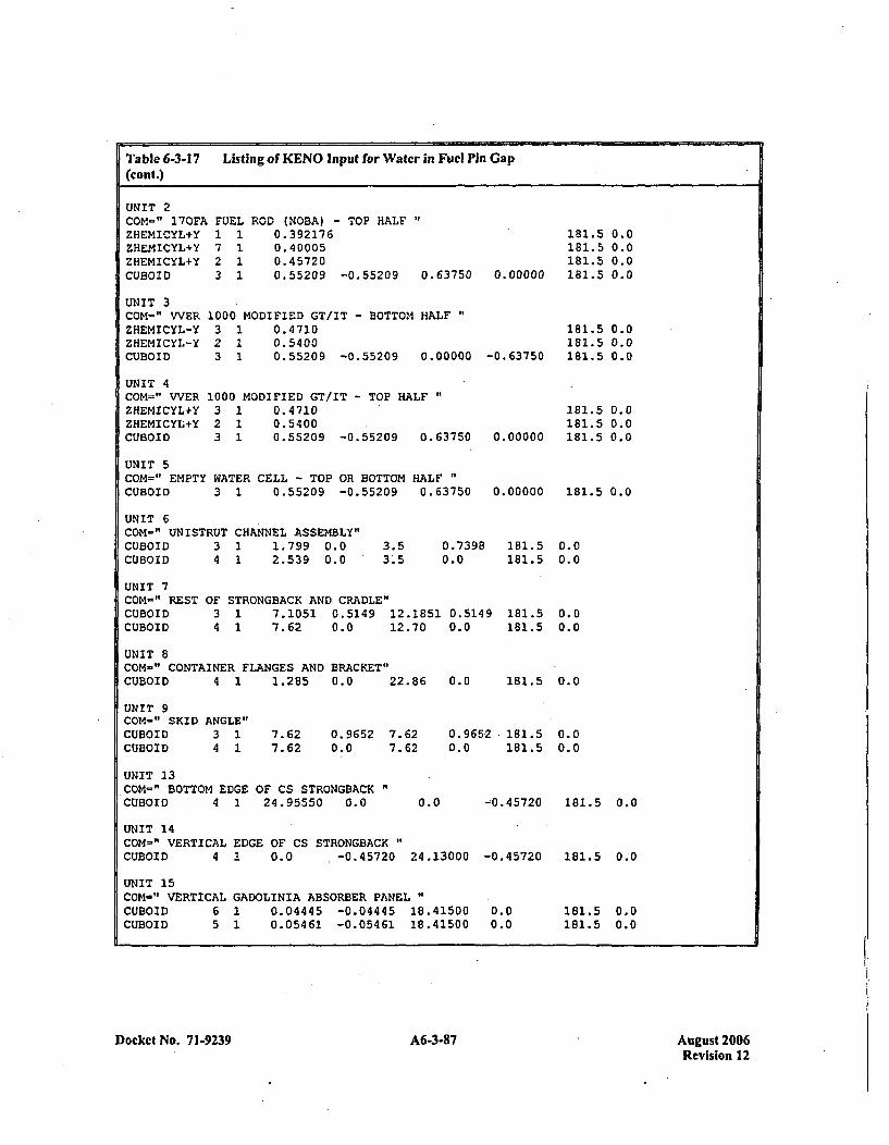
Table 6-3-17 Listing of KENO In put for Water in Fuel Pin Gap(cont.)
UNIT 2COM=" 17OFAZHEMICYL+YZHEMICYL*YZHEMICYL+YCUBOID
FUEL1 17 12 13 1
ROD (NOBA) - TOP HALF0.3921760.400050.457200.55209 -0.55209 0.63750 0.00000
181.5181.5
0.00.00.00.0
UNIT 3COM=" VVERZHEMICYL-YZHEMICYL-YCUBOID
UNIT 4COM=" VVERZHEMICYLtYZHEMICYL+YCtlBOID
1000 MODIFIED GT/IT - BOTTOM HALF3 1 0.47102 1 0.54003 1 0.55209 -0.55209 0.00000
1000 MODIFIED GT/IT - TOP HALF"3 1 0.47102 1 0.54003 1 0.55209 -0 .55209 0.63750
181.5 0.0181.5 0.0181.5 0.0-0. 637 50
181.5 0.0181.5 0.0
0.00000 181.5 0.0
0.00000 181.5 0.0
UNIT 5COM=" EMPTY WATER CELL - TOP OR BOTTOM HALFCUBOID 3 1 0.55209 -0.55209 0.63750
UNIT 6COM-" UNISTRUT CHANNEL ASSEMBLY"CUBOIDCUBOI D
3 1 1.799 0.04 1 2.539 0.0
3.5 0.7398 181.5 0.03.5 0.0 181.5 0.0
UNIT 7COM-"' RESTCUBOIDCUBOID
OF STRONGBACK AND CRADLE"3 1 7.1051 0.5149 12.1851 0.51494 1 7.62 0.0 12.70 0.0
181.5 0.0181.5 0.0
181.5 0.0
UNIT 8COM-" CONTAINER-FLANGES AND BRACKET"CUBOID 4 1 1.285 0.0 22.86 0.0
UNIT 9COM-" SKID ANGLE"CUBOID 31 7.62 0.96S2 7.62 0.9652 181.5 0.0CUBOID 4 1 7.62 0.0 7.62 0.0 181.5 0.0
UNIT 13COM=" BOTTOM EDGE OF CS STRONGBACKCUBOID 4 1 24.95550 0.0 0.0 -0.45720 181.5 0.0
UNIT 14COM=" VERTICAL EDGE OF CS STRONGBACK"CUBOID 4 1 0.0 -0.45720 24.13000
UNIT 15COM-" VERTICAL GADOLINIA ABSORBER PANELCUBOID 6 1 0.04445 -0.04445 18.41500CUBOID 5 1 0.05461 -0.05461 18.41500
-0.45720
0.00.0
181.5 0.0
181.5 0.0181.5 0.0
Docket No. 71-9239 A6-3-87 August 2006Revision 12

Table 6-3-17 Listing of KENO Input for Water in Fuel Pin Gap(cont.)
UNIT 16COM=" ONE-SIDED PART-LENGTHCUBOID 6 1 23.49500CUBOID 5 1 23.49500
GD PANEL0.00..0
UNDER STRONGBACK "F
0.0 -0.088900.0 -0.09906
UJNIT 17COM="' GAP IN PART-LENGTH GD PANEL UNDER STRONGBACK"CUBOID 3 1 23.49500 0.0 0.0 -0.09906
33.02 0.033.02 0.0
5.08 0.0
0.0
UNIT 18COM=" HORIZONTAL GAD ABSORBER PLATE"ARRAY 2 0.0 -0.09906
GLOBAL
UNIT 20COM-" VVERARRAY 1CUBOID
1000 ASSEMBLY IN CASK"0.0
3 1 41.73728 -2.997201.37160 0.0
38.30660 -38.10000 1961.74 0.0
HOLEHOLEHOLEHOLE
HOLEHOLEHOLEHOLE
6789
13141518
-2.99715 20.6128028.0 -11.628440.0 -13.628432.0 -568
0.00.00.00.0
0.00.00.00.0
0.00.0
-0. 853440.0
0.00.00. 81280
-0. 457205
REPLICATE 4 1 0.22606 0.0 0.22606 0.22606 0.22606 0.0 1END GEOM
READ ARRAYARA-1 NUX-21LOOP1 1 212 2 202 1 213 5 54 5 53 6 64 6 -63 8 84 8 83 8 84 8 83 9 94 9 93 10 104 10 103 11 114 11 113 12 124 12 123 13, 134 13 13
NUY-=42 NUZ=1 COM=" WVER 1000 ASSEMBLY IN H20"
122111111111111111111
12122
16171213303125261617111226271718
424142212226272021303125261617313226271718
122
101010
10
1111
11111111111I111111111
111111111111111111111
11I111111111111111111
Docket No. 71.9239 638A6-3-88 August 2006Revision 12
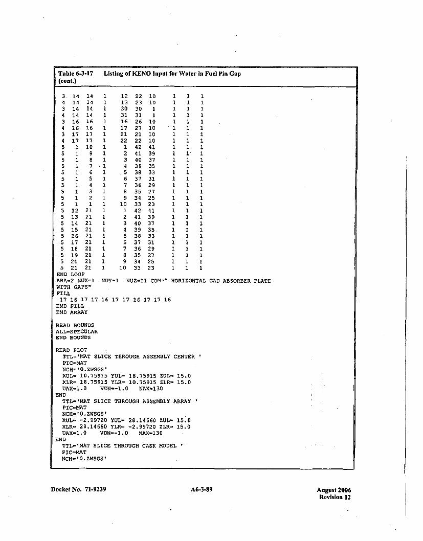
Table 6-3-17 Listing of KENO Input for Water In Fuel Pin Gap(con(.)
3. 144 143 144 143 164 163 174 175 15 15 15 15 15 15 15 15 15 15 125 135 145 155 165 175 185 195 205 21
END LOOP
14141414161617171098765432121212121212121212121
12133031161721221234
.56789
10123456789
10
22 1023 1030 131 126 1027 1021 1022 1042 4141 3940 3739 3538 3337 3136 2935 2734 2533 2342 4141 3940 3739 35.38 3337 3136 2935 2734 2533 23
111111111111
1111111
1111111
1 11 11*1
11
1 11 1 11 1 11 1 11 1 11 11 11 11 11 11 11 .11 11 11 11 11 1
111111111111
ARA-2 NUX-1 NUY-1 NUZ-11 COM-"WITH GAPS"FILL17 16 17 17 16 17 17 16 17 17 16
END FILLEND ARRAY
H!ORIZONTAL GAD ABSORBER PLATE
READ BOUNDSALL=S PECULAREND BOUNDS
READ PLOTTTL-'MAT SLICE THROUGH ASSEMBLY CENTER
PIC=MATNCH='0.ZWSGS'XUL- 10.75915 YUL- 18.75915 ZUL- 15.0
XLR= 18.75915 YLR= 10.75915 ZLR- 15.0UAX-l.0 VDN--1.O NAX-130
ENDTTL-'MAT SLICE THROUGH ASSEMBLY ARRAYPIC=MATNCH-0O.ZWSGS'XUL= -2.99720 YUL= 28.14660 ZUL- 15.0
XLR- 28.14660 YLR= -2.99720 ZLR- 15.0UAX=1.0 VDN--1.0 NAX-130
ENDTTL-'MAT SLICE THROUGH CASK MODEL
PIC-MATNCH-'0.ZWSGS'
Docket No. 71-9239 A6-3-89 August 2006Revision 12
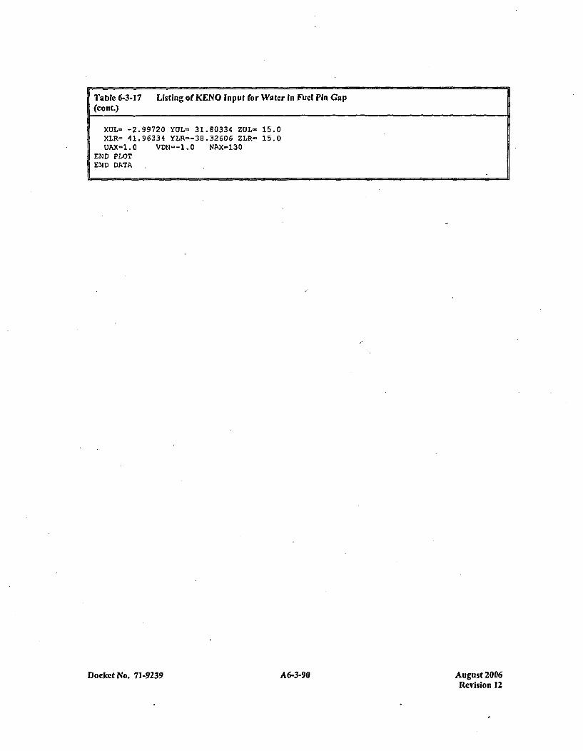
Table 6-3-17 Listing of KENO Input for Water In Fuel Pin Gap(cont.)
XUL-L -2.99720 YUL- 31.80334 ZUL- 15.0XLR= 41.96334 YLP.--38.32606 ZLR- 15.0UAX=1.0 VDN--1.0 NAX-130
END PLOTEND DATA
Docket No. 71-9239 A6-3-90 August 2006Revision 12
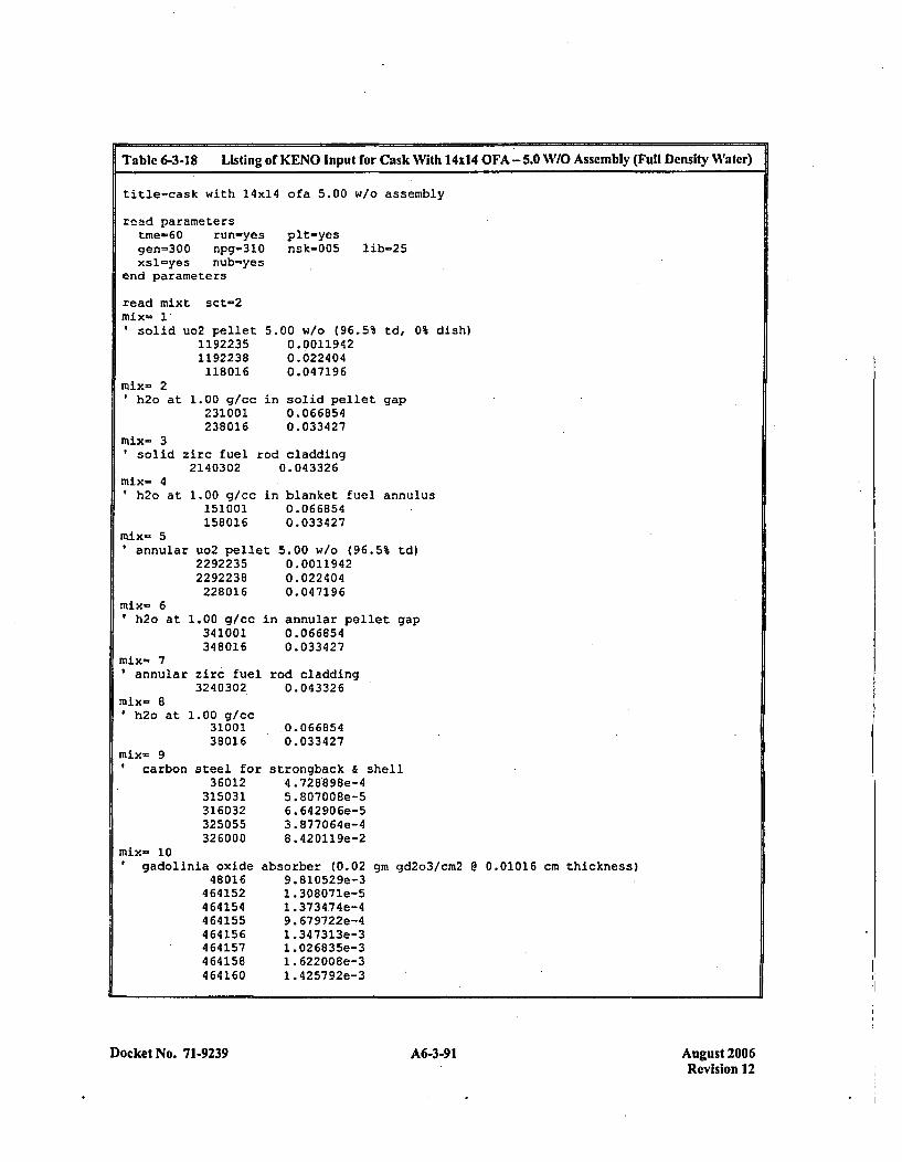
Table 6-3-18 Listing or KENO Input for Cask With 1 404 OFA - 5.0 WIO Assembly (Full Density Water)
title-cask with 14x14 ofa 5.00 w/o assembly
read parameterstine-60 run-yesgen=300 npg=310xsl-yes nub-yes
end parameters
pit-yesnsk-005 lib-25
read mixt sct-2mix= 1*Isolid uo2 pellet
11922351192238118016
1.00 g/cc231001238016
5.00 w/o (96.5% td, 0% dish)0.00119420.0224040.047196
in solid pellet gap0.0668540.033427
mix- 2'h2o at
mix- 3solid zirc fuel rod cladding
2140302 0.043326mix- 4' h2o at
mix- 51annular
mix- 6' h2o at
1.00 g/cc in blanket fuel annulus151001 0.066854158016 0.033427
uo2 pellet 5.00 w/o (96.5% td)2292235 0.00119422292238 0.022404228016 0.047196
1.00 g/cc in annular pellet gap341001 0.066854348016 0.033427
mix- 7annular zirc fuel rod cladding
3240302 0.043326nix- 8'h2o at 1.00 g/cc
3100138016
mix- 9carbon steel for
36012315031316032325055
ýmix- 10 360
gadolinia oxide48016
464152464154464155464156464157464158464160
.0.0668540. 03 3427
strongback & shell4 .728'898e-45.807008e-56.642906e-53. 877064e-48 .420119e-2
ibsorber (0.029.81052 9e-31 .308071e-51 .373474e-49. 679722e-41 .347313e-31. 026835e-31 .622008e-31.4257 92e-3
gm gd2o3/cm2 @ 0.01016 cm thickness)
Docket No. 7 1-9239 A6-3-91 August 2006Revision 12
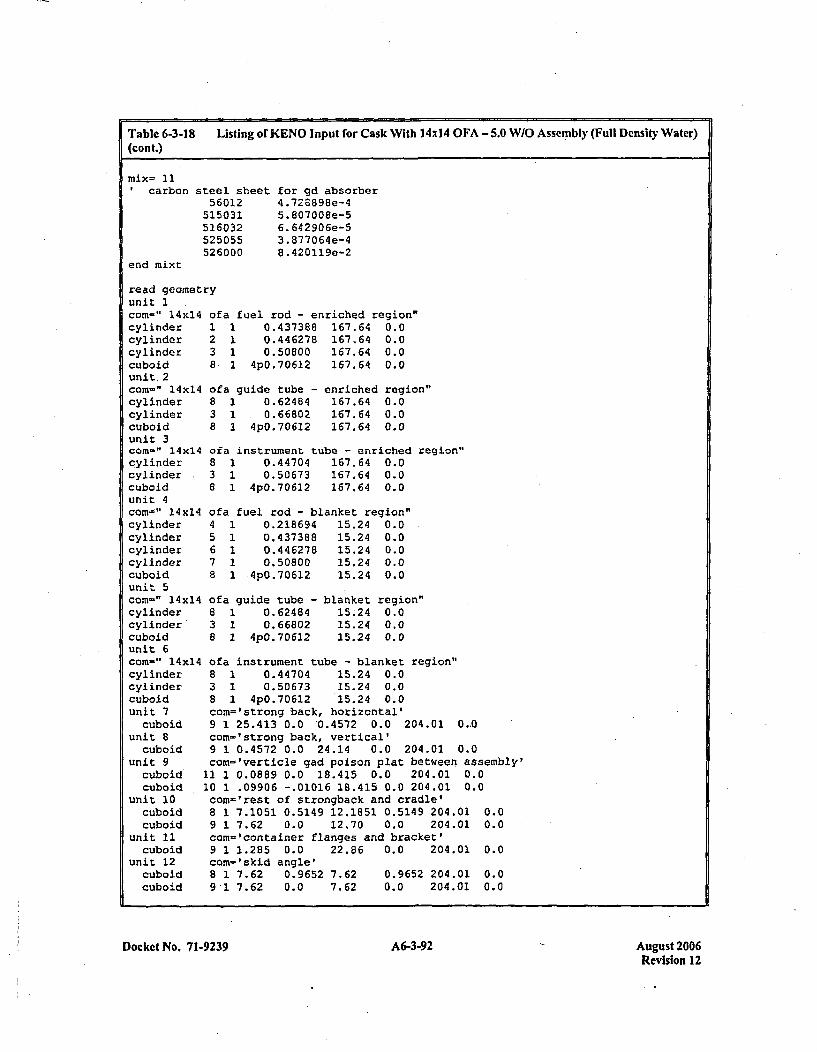
Table 6-3-18 Listing of KENO Input for Cask With 14X14 OFA -5.0 W/O Assembly (Full Density Water)(cont.)
'carbon
end mixt
steel sheet56012
515031526032525055526000
for gd absorber4 .728898e-45. 807008e-56. 642 90 6e-53.877064e-48 .420119e-2
read geometrunit 1corn-" 14x14cylindercylindercylindercuboidunit. 2com-=" 14x14cylindercylindercuboidunit 3corn-" 14x14cylindercylindercuboidunit 4com-~" 14x14cylindercylindercylindercylindercuboidunit 5com-" 14x14cylindercylinder*cuboidunit 6
-y
of a fuel rod - enriched region"1 1 0.437388 167.64 0.02 1 0.446278 167.64 0.03 1 0.50800 167.64 0.08ý 1 4p0.706l2 167.64 0.0
of a guide tube - enriched region"8 1 0.62484 167.64 0.03 1 .0.66802 167.64 0.08 1 4p0.70612 167.64 0.0
ofa instrument tube - enriched region"8 1 0.44704 167.64 0.03 1 0.50673 167.64 0.08 1 4p0.7O612 167.64 0.0
ofa fuel rod - blanket region"4 1 0.218694 15.24 0.05 1 0.437388 15.24 0.06 1 0.446278 15.24 0.07 1 0.50800 15.24 0.08 1 *4p0.706l2 15.24 0.0
0183a
~a guide tube -1 0.624841 0.668021 4p0.7 D6l2
blanket region"15.24 0.015.24 0.015.24 0.0
cc
ci
u2
uz
am-" 14x14 ofa instrument tube - blanket region"ylinder 8 1 0.44704 15.24 0.0ylinder 3 1 0.50673 15.24 0.0uboid 8 1 4p0.70612 15.24 0.0nlit 7 con='strong back, horizontal'cuboid 9 1 25.413 0.0 '0.4572 0..0 .204.01 0.-0nit 8 corn='strong back, vertical'cuboid 9 1 0.4572 0.0 24.14 0.0 204.01 0.0nit 9 com='verticle gad poison plat betw~een assembly'cuboid 11 1 0.0889 0.0 18.415 0.0 204.01 0.0cuboid 10 1 .09906 -.01016 18.415 0.0 204.01 0.0
unit 10cuboidcuboid
unit 11cuboid
unit 12cuboidcuboid
com-='rest of strongback and cradle'8 1 7.1051 0.5149 12.1851 0.5149 204.01 0.09 1 7.62 0.0 12.70 0.0 204.01 0.0con-'container flanges and bracket'9 1 1.285 0.0 22.86 0.0 204.01 0.0com-'skid angle'8 1 7.62 0.9652 7.62 0.9652 204.01 0.09 1 7.62 0.0 7.62 0.0 204.01 0.0
Docket No. 71-9239 A6-3-92 August 2006Revision 12
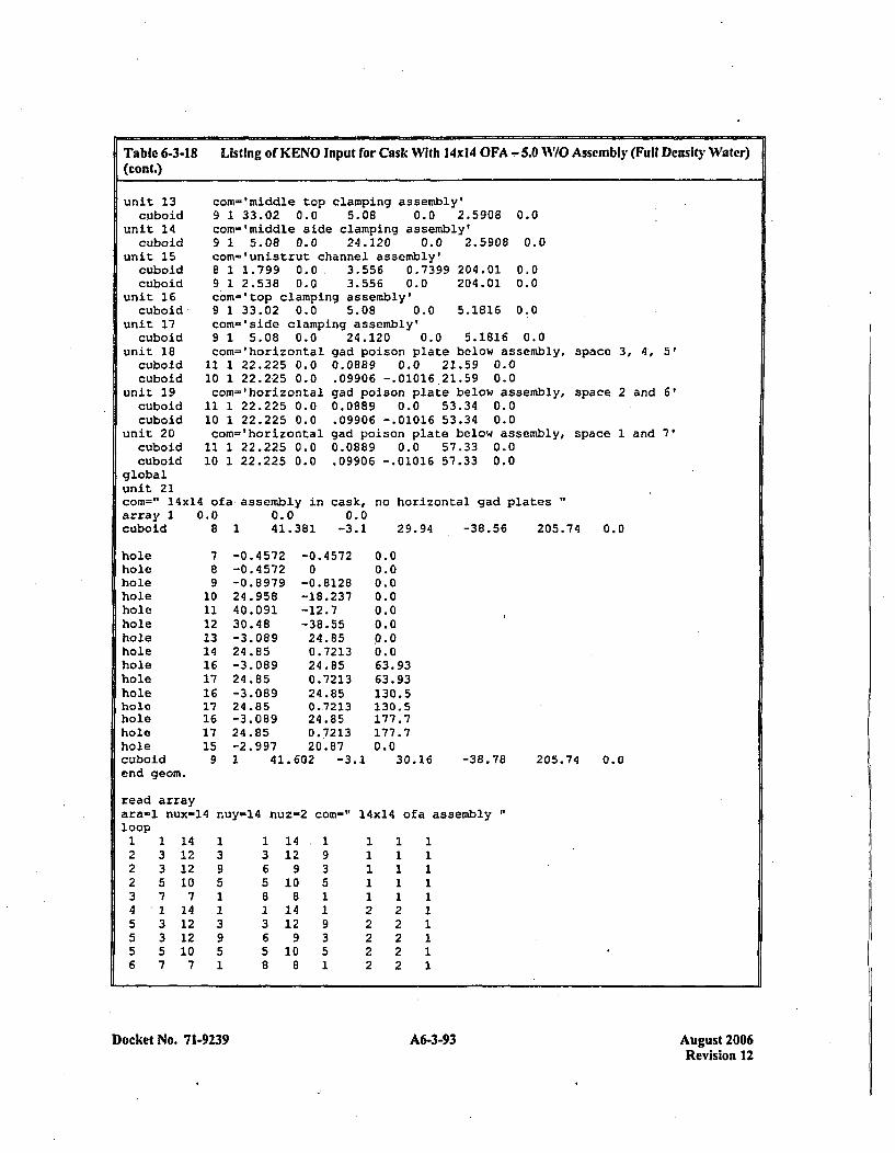
Table 6-3-18 Listing of KENO Input for Cask With 10x14 OFA - 5.0 117O Assembly (Full Density Water)(Cont.)
unit 13cuboid
unit 14cuboid
unit 15cuboidcuboid
unit 16cuboid
unit 17
com='middle top clamping assembly'9 1 33.02 0.0 5.08 0.0 2.5908 0.0com='iniddle side clamping assembly'9 1 5.08 0.0 24.120 0.0 2.5908 0.0com-'unistrut channel assembly'8 1 1.7.99 0.0 3.556 0.7399 204.01 0.09 1 2.538 0.0 3.556 0.0 204.01 0.0com='top clamping assembly'9 1 33.02 0.0 5.08 0.0 5.1816 0.0com-"side clamping assembly'
cuboid 9 1 5.08 0.0unit 18 com='horizontalcuboid 11 1 22.225 0.0cuboid 10 1 22.225 0.0
unit 29 com=lhorizontalcuboid 11 1 22.225 0.0cuboid 10 1 22.225 0.0
unit 20 com='horizontalcuboid 11 1 22.225 0.0cuboid 10 1 22.225 0.0
globalunit 21com=" 14x14 ofa assembly inarray 1 0.0 0.0cuboid 8 1 41.381
24.120 0.0 5.1816 0.0gad poison plate below assembly,0.0889 0.0 21.59 0.0.09906 -.01016 21.59 0.0gad poison plate below assembly,0.0889 0.0 53.34 0.0.09906 -.01016 53.34 0.0gad poison plate below assembly,0.0889 0.0 57.33 0.0.09906 -.01016 57.33 0.0
cask, no horizontal gad plates0.0
-3.1 29.94 -38.56 205.
apace 3, 4, 5'
space 2 and 6'
space 1 and 7'
74 0.0
holeholeholeholeholeholeholeholeholeholeholeholeholeholeholecuboidend geom.
7891011121314161716171617159
-0.4 572-0. 4572-0. 897924.95840.09130.48-3.08 924.85-3.08924.85-3.0 8924 .85-3.0 8924.85-2.9971 41.
-0. 45720
-0.8128-18.237-12.7-38.5524.850.721324.850.721324.850.721324.850.721320.87
602 -3.1
0.00.00.00.00.00.0.0.00.063.9363.93130.5130.5177.7177.70.0
30.16 -36.78 205.74 0.0
read arrayara-l nux-14 huy-14 nuz-2 con-" 14x14 ofa assembly"loop1222345556
1335713357
141212107141212107
1395
3951
1365813658
14129
10814129108
1935
9351
21
222
1 1
2
22
111111111
Docket No. 71-9239 Afi-3-93 August 2006Revision 12

Table 6-3-18 Listing or KENO Input for Cask With 14xI4 OFA - 5.0 W/O Assembly (Full Density Water)(cont.)
end loopend array
read boundsal 1-specularend bounds
read plotttl-'box slice through cask'plc-boxnch='Ougiugiabcdefhjklmnop.'ýxul- -4.0 yul= 30.1 zul- 66.52xlr- 45.0 ylr- -40.0 zir- 66.52uax=l.0 vdn=-l.0 nax=l30 endttl'lbox slice through cask'plc-matnch='Ou.z.u.z.sgs'xul- -4.0 yul- 30.1 zul- 66.52xlr= 45.0 ylr- -40.0 zir= 66.52uax=1.0 vdn=-l.0 nax=130 endttl-'box slice through assembly'Pic-boxnch- 'Ougiugiabcdefhjklmnop.1xul= 0.0 yul- 20.0 zul= 66.52xlr= 20.0 ylr- 0.0 zlr- 66.52uax-l.0 vdn--1.0 nax-130 endttl-'inat slice through annular pellet'pi c-matnch ' Ou. z *u.z. sgs'xul= 1.41 yul= 4.24 zul- 180.0xlr- 4.24 ylr= 1.41 zlr= 180.0uax=l.0 Vdn--1.0 nax-130 endttl-'mat slice through annular pellet'plc-matnch='Ou.z.u.Z.sg5'xul- -1.0 yul= 18.0 zul- 180.0xlr- -0.5, ylr- 0.0 zlr= 180.0uax=1.0 vdn=-l.0 nax-230 ndn-100 end
end plot
end dataend
Docket No. 7 1-9239 A6-3-94 August 2006Revision 12
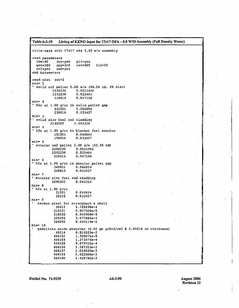
ITable 6-3-19 Listing of KENO Input for 17xI 7 OFA -5.0 W/O Assembly (Full Density Water)
title-cask with 17x17 ofa 5.00 w/o assembly
read parameterstme=60 run=yes plt-yesgen=300 npg-310 nsk-005 lib-25xsl-yes nub-yes
end parameters
read mixt sct-2mix- 1*solid
mix- 21h2o at
io2 pellet11922351192238118016
1.00 g/cc231001238016
5.00 w/o (96.5% td, 0% dish)0.00119420.0224040. 04 7196
in solid pellet gap0.0668540.033427
mix- 3solid zirc fuel rod cladding
2140302 0.043326mix- 4
h2o at 1.00 g/cc151001158016
mix- 5annular uo2 pelle
22922352292238228016
mix- 6h2o at 1.00 g/cc
341001348016
mix- 7annular zirc fuel
3240302
in blanket fuel annulus0.0668540.033427
t 5.00 w/o (96.5% td)0. 00119420.0224040.04 7196
in annular pellet gap0.0668540.033427
rod cladding0.043326
0.0668540.033427
strongback .& shell4 .728898e-45..807008e--56 .64 2906Se-53.877064e-48 .420119e-2
mix= 81h2o at 1. 00 g/cc
31100138016
mix- 9I carbon steel for
36012315031316032325055326000
mix- 10gadolinia oxide
48016464152464154464155464156464157464158464160
absorber (0.029 .810529e-31 .308071e-51. 37347 4e-49. 679722e-41 .347313e-31 .026835e-31. 622008e-31 .425792e-3
gm gd2o3/cm2 8 0.01016 cm thickness)
Docket No. 7 1-9239 639Au st20A6-3-95Revision 12

Table 6-3-19 Listing of KENO Input for l7xl7 OFA - 5.0 W/O Assembly (Full Density Water)(cont.)
Icarbon
end mixt
steel sheet56012
515031516032525055526000
for gd absorber4,.728898e-45. 8070086-56. 642 90 6e-53 .877064e-48 .420119e-2
read geometunit 1corn-" 17x17cylindercylindercylindercuboidunit 2corn-" 17xl7cylindercylindercuboidunit 3corn-" 17x11cylindercylindercylindercylindercuboidunit 4corn-" 17x17cylindercylindercuboidunit 7
cuboidunit 8
cuboidunit 9
cuboidcuboid
unit 10cuboidcuboid
unit 11cuboid
unit 12cuboidcuboid
unit 13cuboid
unit 14cuboid
unit 15cuboidcuboid
unit 16cuboid
*ry
238
838
fa fuel rod - enriched region"1 0.392176 167.64 0.01 0.40005 167.64 0.01 0.45720 167.64 0.01 4pO.62992 167.64 0.0
fa guide and instrument1 0.56134 167.642 0.60198 167.641 4pO.62992 167.64
tube -
0.00.00.0
enriched region"
ofa fuel rod - blanket region"4 1 0.19685 15.24 0.05 1 0.392176 15.24 0.06 1 0.40005 15.24 0.07 1 0.45720 15.24 0.08 1 4p0.62992 15.24 0.0
ofa gui de and instrument tube - blanket region"8 1 0.56134 15.24 0.03 1 0.60198 15.24 0.08 1 4p0.62992 15.24 0.0com='strong back, horizontal'9 1 25.413 0.0 0.4572 0.0 204.01 0.0com='strong back, vertical'9 1 0.4572 0.0 24.14 0.0 204.01 0.0com= 'verticle gad poison plat between assembly'
11 1 0.0889 0.0 18.415 0.0 204.01 0.010 1 .09906 -.01016 18.415 0.0 204.01 0.0com='rest of strongback and cradle'8 1 7.1051 0.5149 12.1851 0.5149 204.01 0.09 1 7.62 0.0 12.70 0.0 204.01 0.0com='container flanges and bracket'9 1 1.285 0.0 22.86 0.0 204.01 0.0com='skid angle'8 1 7.62 0.9652 7.62 0.9652 204.01 0.09 1 7.62 0.0 7.62 0.0 204.01 0.0com-'rniddle top clamping assembly'9 1 33.02 0.0 5.08 0.0 2.5908 0.0com='middle side clamping assembly'9 1 5.08 0.0 24.120 0.0 2.5908 0.0com-'unistrut channel assembly'8 1 1.799 0.0 3.556 0.7399 204.01 0.09 1 2.538 0.0 3.556 0.0 204.01 0.0com-'top clamping assembly'9 1 33.02 0.0 5.08 0.0 5.1816 0.0
Docket No. 7 1.9239 A6-3-96 August 2006Revision 12
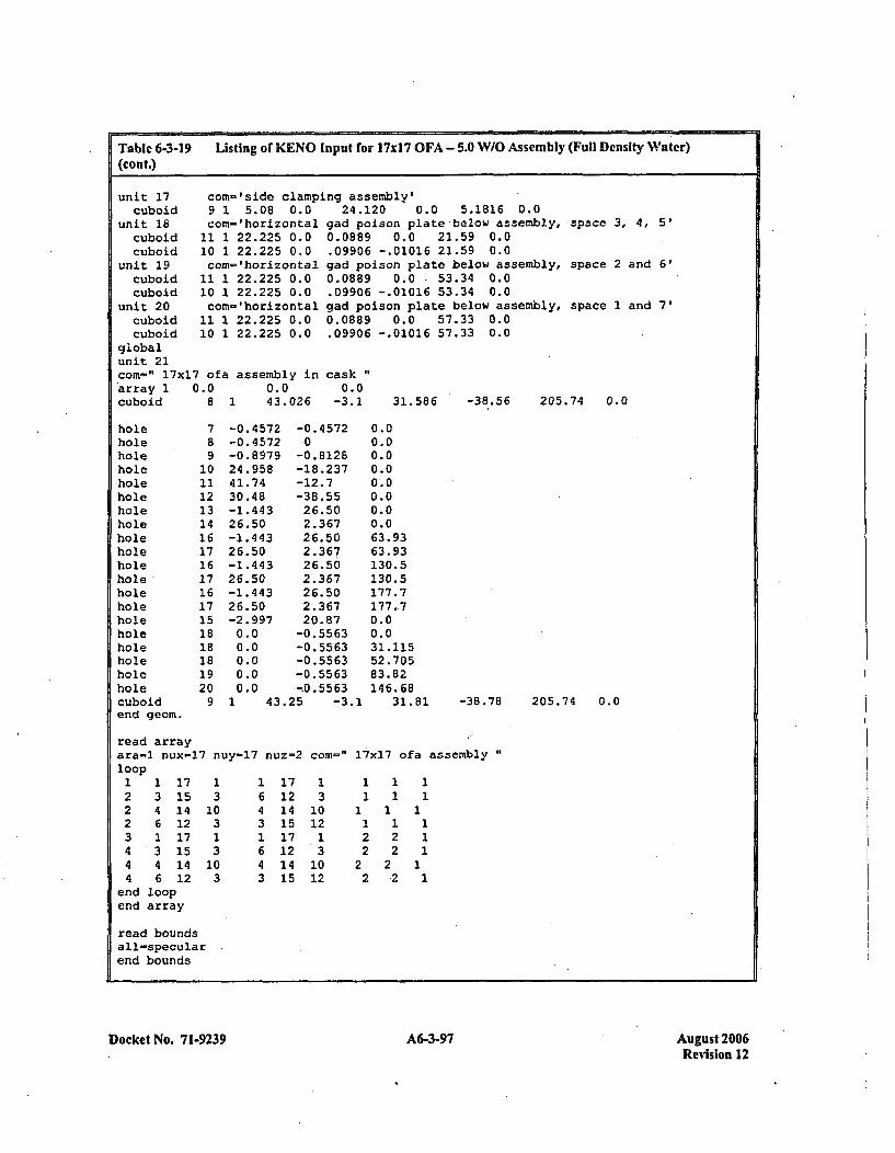
Table 6-3-19 Listing of KENO Input for 17xI7 OFA - 5.0 W/O Assembly (Full Density Water)
(Cont.)
unit 17 conv='side clamping assembly'cuboid
unit 16cuboidcuboid
unit 19cuboidcuboid
unit 20cuboidcuboid
9 1 5.08 0.0corn-' horizontal
11 1 22.225 0.010 1 22.225 0.0com= 'horizontal
11 1 22.225 0.010 1 22.225 0.0com='horizontal
11 1 22.225 0.010 1 22.225 0.0
24.120 0.0 5.1816 0.0gad poison plate below assembly,0.0889 0.0 21.59 0.0.09906 -.01016 21.59 0.0gad poison plate below assembly,0.0889 0.0 -53.34 0.0.09906 -.01016 53.34 0.0gad poison plate below assembly,0.0889 0.0 57.33 0.0.09906 -.01016 57.33 0.0
cask0.0
-3.1 31.586 -38.56 205
space 3, 4, 5'
space 2 and 6'
space 1 and 7'
globalunit 21com-" 17x17 ofa assembly inarray 1 0.0cuboid 8
0.043. 0261 .74 0.0
holeholeholeholeholeholeholeholeholeholeholeholeholeholeholeholeholeholeholeholecuboidend geom.
78910111213141617161716171518181819209
-0.4572-0. 4572-0.8 97924.95841.7430.48-1.44326.50-1.44326.50-1.44326.50-1.44326.50-2.9970.00.00.00.00.0
-0.4 572
-0.8128-18.237-12.7-38.5526.502.36726.502.36726.502.36726.502.36720.87-0. 5563-0.5563-0. 5563-0.55 63---0.5563
0.00.00.00.00.00.00.00.063.9363.93130.5130.5177.7177.70.00.031.11552. 70583.82146.68
1 43.25 -3.1 31.81 -38.78 205.74 0.0
read arrayara-1 nux-17 nuy=17 nuz-2loop1 1 17 1 1 172 3 15 3 6 122 4 14 10 4 142 6 12 3 3 153 1 17 1 1 174 3 15 3 6 124 4 14 10 4 144 6 12 3 3 15
end loopend array
corn-" 17x17 ofa assembly "1
13
1012131012
2 2 12 2 122
2,2
11
read boundsall-specularend bounds
Docket No. 7 1-9239 A6-3-97 August 2006Revision 12
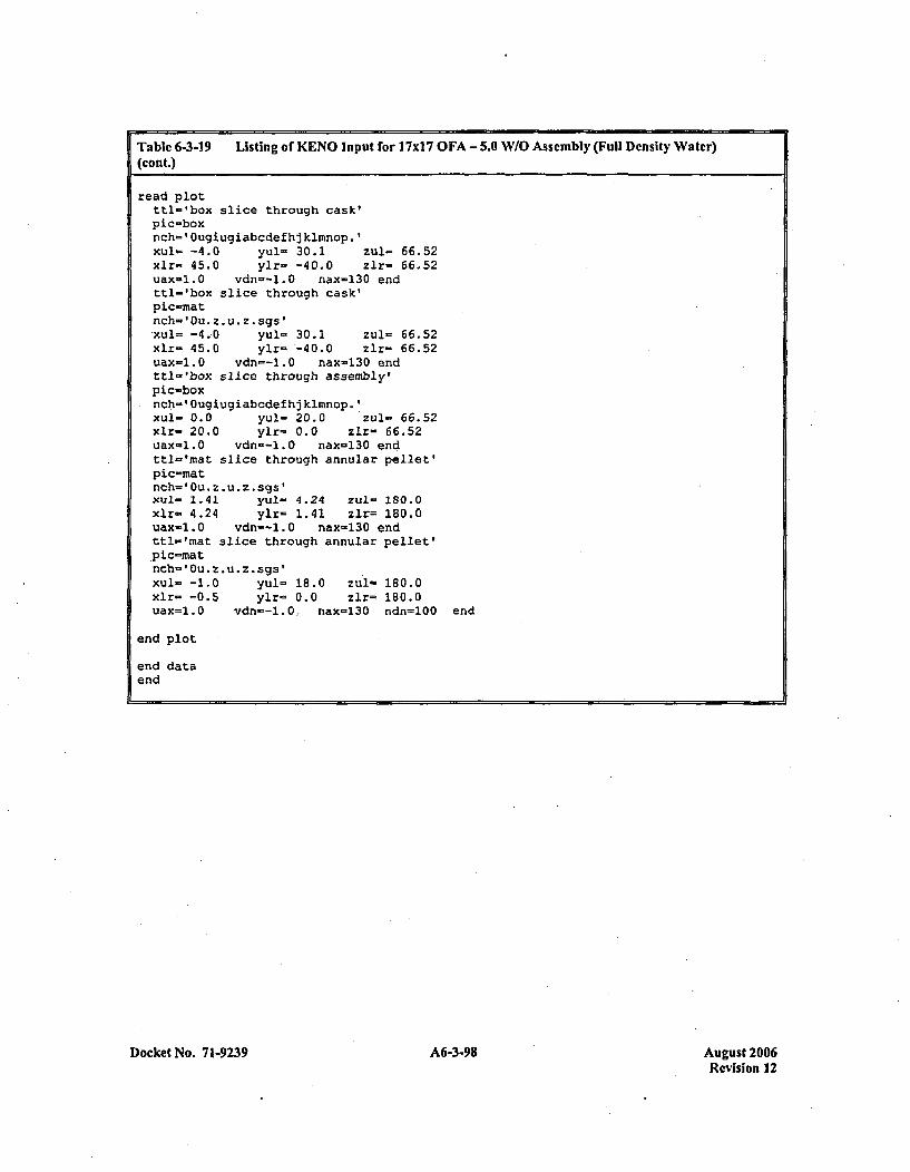
Table 6-3-19(cont.)
Listing of KENO input for 17x17 OFA - 5.0 W/O Assembly (Full Density Water)
read plotttl-'box slice through cask'pic-boxnch'= 'Ougiugiabcdefhj kimnop.'xul'= -4.0 yul- 30.1 zul- 66.52xlr- 45.0 ylr= -40.0 zlr= 66.52uax=1.0 vdn=--.0 nax-130 endttl-'box slice through cask'pic-matinch-' Ou. * u*z . sgs'xul.. -4.0 yul= 30.1 zul- 66.52xlr- 45.0 ylr- -40.0 zlr= 66.52uax=l.0 vdn--l.0 nax-130 endttl-'box slice through assembly'pic-boxnch-' Ougiugiabcdefhj kimnop.'xul- 0.0 yul- 20.0 zul- 66.52xlr- 20.0 ylr- 0.0 zlr= 66.52uax-l.0 vdn--l.0 nax-130 endttl-'mat slice through annular pellet'pic-matnch=' Ou. z. u*z . sgs'xul- 1.41 yul- 4.24 zul- 180.0xlr= 4.24 ylr- 1.41 zlr= 180.0uax-1.0 vdn--1.0 nax-130 endttl-'mat slice through annular pellet'.pic-matnch-' Ou. z *u *z .sgs'
Xul= -1.0 yul= 18.0 zul- 180.0xlr= -0.5 ylr= 0.0 zlr= 180.0uax=1.0 vdn=-1.0, nax=130 ndn=100en
end plot
end dataend
end
Docket No. 71-9239 A6-3-98 August 2006Revision 12
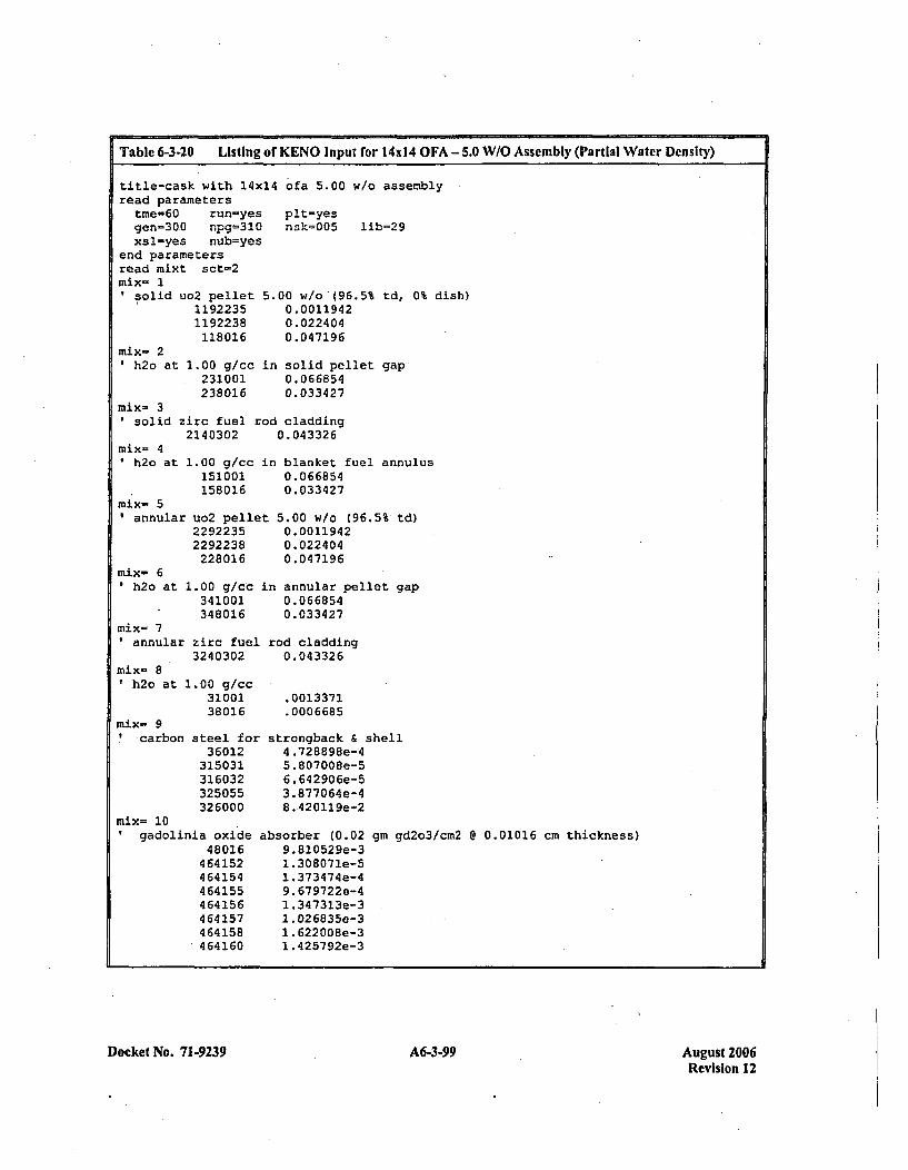
Table 6-3-20 Li!sting of KENO Input for 14x14 OFA - 5.0 W/O Assembly (Partial Water Density)
title-cask with 14x14 ofa 5.00 w/o assemblyread parameters
tme=60 run-yes pit-yesgen=300 npg=3lO nsk=005 lib-29xsl=yes nub=yes
end parametersread mixt sct-2mix- 1'solid uo2 pellet 5.00 w/o (96.5% td, 0% d:ish)
mix- 2'h2o at
11922351192238118016
1.00 g/cc231001238016
0.00119420. 0224 040. 047196
in solid pellet gap0. 0668540.033427
mix- 3solid zirc fuel rod cladding
2140302 0.043326mix- 4*h2o at
mix- 51annular
mix- 6' h2o at
1.00 g/cc in blanket fuel annulus151001 0.066854158016 0.033427
uo2 pellet 5.00 w/o (96.5%' td)2292235 0.00119422292238 0.022404228016 0.047196
1.O0 glcc in annular pellet gap341001 0.066854348016 0.033427
mix- 7*annular zirc fuel rod cladding
3240302 0.043326mix- 8*h2o at 1.00 g/cc
31001 .001337138016 .0006685
mix- 9'carbon steel for strongback & shell
36012 4.728898e-4315031 5.807008e-5316032 6.642906e-5325055 3.877064e-4326000 8.420119e-2
mix= 10gadolinia oxide
48016464152464154464155464156464257464158464160
absorber (0.029.82052 9e-31 .308071e-51 .373474e-49. 679722e-41 .347323e-31. 026835e-31. 622008e-31. 425792e-3
gm gd2o3/cm2 e 0.01016 cm thickness)
Docket No. 71-9239 A6-3-99 August 2006Revision 12
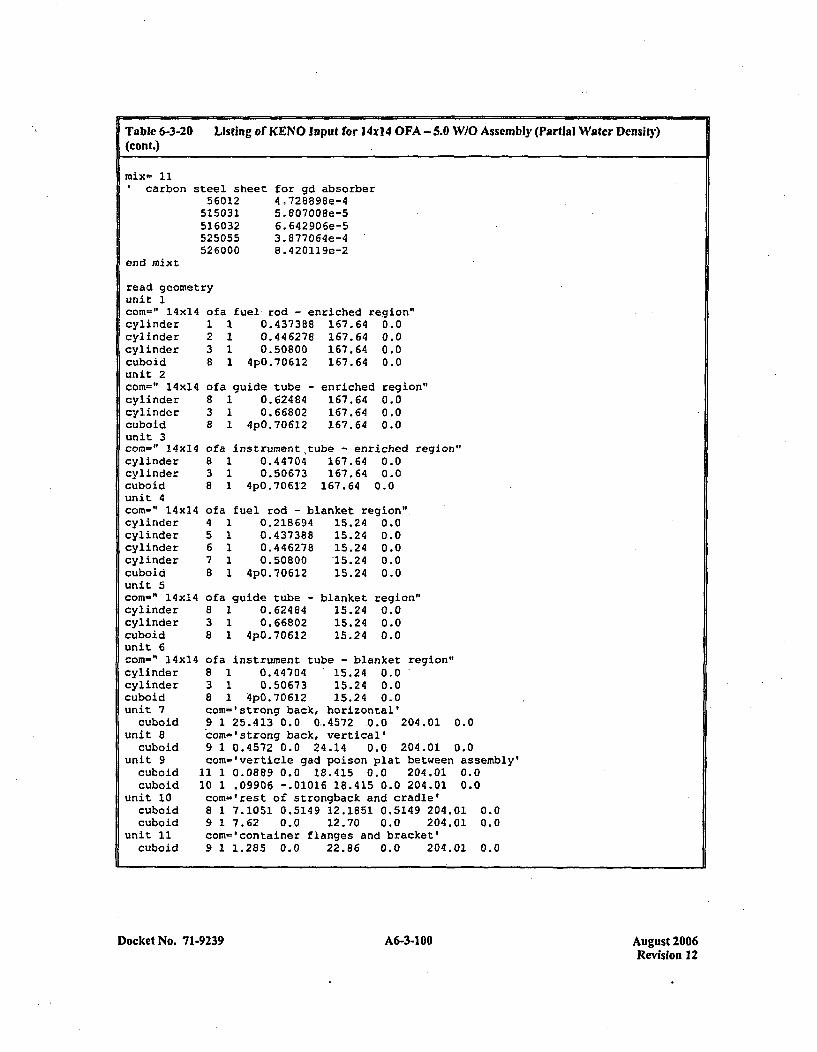
Table 6-3-20 Listing of KENO input for l4x14 OFA -5.0 W/O Assembly (Partial Water Density)(cont.)
'carbon
end znixt
steel sheet56012
515031516032525055526000
for gd absorber4 .728898e-45.807C08e-56. 642906e-53.877064e-48.420119e-2
read geonelunit Icorn=" 14xl4cylindercylindercylindercuboidunit 2corn-" l4xl4cylindercylindercuboidunit 3corn=" 14x14~cylindercylindercuboidunit 4com=" 14xl4cylindercylindercylindercylindercuboidunit 5corn-" 14xl4cylindercylindercuboidunit 6corn-" 14x14cylindercylindercuboidunit 7
cuboidunit 8
cuboidunit 9
cuboidcuboid
unit 10cuboidcuboid
unit 11cuboid
try
of
1238
I01838
I01838
of045678
ofa38
~a fuel rod - enriched region"1 0.4373B8 167.64 0.01 0.446278 167.64 0.01 0.50800 167.64 0.01 4pO.7O612 167.64 0.0
~a guide tube -1 0.624841 0.668021 4p0 .70612
enriched region"167.64 0.0167.64 0.0167.64 0.0
"a instrument ~tube - enriched region"1 0.44704 167.64 0.01 0.50673 167.64 0.01 4pO.7O612 167.64 0.0
"a fuel rod - blanket region",1 0.218694 15.24 0.01 0.437388 15.24 0.01 0.446278 15.24 0.01 0.50800 -15.24 0.01 4pO.7O6l2 15.24 0.0
~a guide tube -1 0.624841 0.668021 4pO.70612
blanket15.2415.2415.24
region"0.00.00.0
ofa instrument tube - blanket region"8 1 0.44704 15.24 0.03 1 0.50673 15.24 0.08 1 4p0 .7O612 15.24 0.0com-'strong back, horizontal'9 1 25.413 0.0 0-.4572 .0.0 204.01 0.0com-'.strong back, vertical'9 1 0.4572 0.0 24.14 0.0 204.01 0.0com-'verticle gad poison plat between assembly'
11 1 0.0889 0.0 18.415 0.0 204.01 0.010 1 .09906 -.01016 18.415 0.0 204.01 0.0com='rest of strongback and cradle'8 1 7.1051 0.5149 12.1851 0.5149 204.01 0.09 1 7.62 0.0 12.70 0.0 204.01 0.0com='container flanges and bracket'9 1 1.285 0.0 22.86 0.0 204.01 0.0
Docket No. 71-9239 A6-3-100 A6-3-100August 2006Revision 12
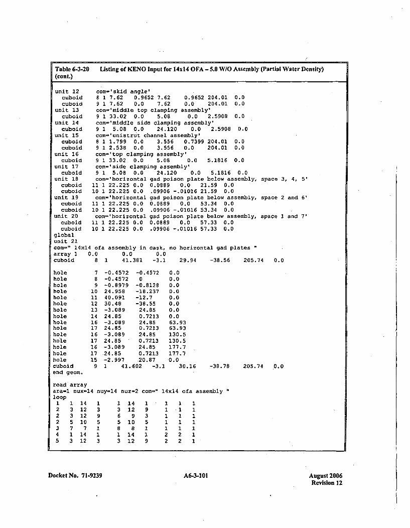
Table 6-3-20(cont.)
Listing of KENO Input for 14014 OFA - 5.0 W/O Assembly (Partial Water Density)
unit 12cuboidcuboid
unit 13cuboid
unit 14cuboid
unit 15cuboidcuboid
unit 16cuboid
unit 17cuboid
unit 18cuboidcuboid
unit 19cuboidcuboid
unit 20cuboidcuboid
corn-'skid angle'8 1 7.62 0.9652 7.62 0.9652 204.01 0.09 1 7.62 0.0 7.62 0.0 204.01 0.0corn-'middle top clamping assembly'9 1 33.02 0.0 5.08 0.0 2.5908 0.0corn='middle side clamping assembly'9 1 5.08 0.0 24.120 0.0 2.5908 0.0com-'unistrut channel assembly'8 1 1.799 0.0 3.556 0.7399 204.01 0.09 1 2.538 0.0 3.556 0.0 204.01 0.0com-Itop clamping assembly'9 1 33.02 0.0 5.08 0.0 5.1816 0.0com-'side clamping assembly'9 1 5.08 0.0con-' horizontal
11 1 22.225 0.010 1 22.225 0.0con- 'horizontal
11 1 22.225 0.010 1 22.225 0.0com='horizontal
11 1 22.225 0.010 1 22.225 0.0
24.120 0.0 5.1816 0.0gad poison plate below assembly, space 3, 4, 5'0.0889 0.0 21.59 0.0.09906 -.01016 21.59 0.0gad poison plate below assembly, space 2 and 6'0.0889 0.0 53.34 0.0.09906 -.01016 53.34 0.0gad poison plate below assembly, space 1 and 7'0.0889 0.0 57.33 0.0.09906 -.01016 57.33 0.0
cask, no horizontal gad plates0.0
-3.1 29.94 -38.56 205.74 0.0
globalunit 21corn-" 14x14 ofa assembly inarray 1 0.0 0.0cuboid 8 1 41.381
holeholeholeholeholeholeholeholeholeholeholeholeholehole.holecuboidend geom.
7891011121314161716171617159
-0.4 572-0.4572-0. 897924.95840.09130.48-3.08 924.85-3.08924.85-3.08924.85-3.08 9.24.85-2.997
-0.4 5720
-0.8128-18.237-12.7-38.5524.850.721324.850.721324.850.721324.850.7213.20.87
0.00.00.00.00.00.00.00.063.9363.93130.5130.5177.7177.70.0
30.16 -38.78 205.74 .0..0I 41.-602 -3.1
read arrayara-l nux-14 nuy-14 nuz-2 corn-" 14x14 ofa assembly"loop
1 1 14 1 1 14 1 -1 1 12 3 12 3 3 12 9 1 1 12 3 12 9 6 9 3 1 1 12 5 10 5 5 10 5 1 1 13 7 7 1 8 8 1 1 1 14 1 14 1 15 3 12 3 3
1412
19
22
2 12 1
Docket No. 7 1-9239 A6-3-101 August 2006Revision 12
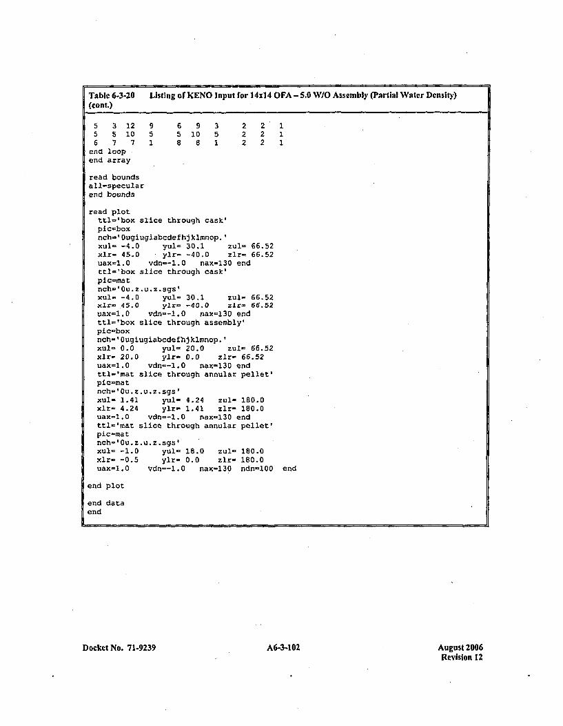
Table 6-3-20 Listing of KENO Input for 14x1 4 OFA - 5.0 W/O Assembly (Partial Water Density)(cont.)
5 3 12 9 6 9 3 2 2 15 5 10 5 5 10 5 2 2 16 7 7 1 8 8 1 2 2 1
end loopend array
read boundsall-specularend bounds
read plotttl='box slice through cask'pics-boxnch=' 0uqiugiabcdefh~klmnop.1xul= -4.0 yul= 30.1 zul= 66.52xlr- 45.0 ylr- -40.0 zir-z66.52uax=1.0 vdn--l.0 nax-130 endttl-'box slice through cask'pic-matnch-' Ou. z *u *z . gs'xul- -4.0 yul- 30.1 zul- 66.52xlr-,45.0 ylr- -40.0 zlr- 66.52uax-l.0 vdn--1.0 nax-130 endttl='box slice through assembly'plc-boxnch-' Ougiugiabcdefhjklmnop.'Xul= 0.0 yul- 20.0 zul- 66.52xlr- 20.0 ylr- 0.0 zlr- 66.52uax=1.0 vdn=-1.0 nax-130 endttl-'mat slice through annular pellet'plc-matnch-'Cu. z *u *z .sgs'xul- 1.41 yul- 4.24 zul- 180.0xlr= 4.24 ylr= 1.41 zir= 180.0uax=1.0 vdn--l.0 nax-130 endttl-'mat slice through annular pellet'plc-matinch-' Cu. z *u *z .sgs'Xul- -1.0 yul- 18.0 zul- 180.0xlr- -0.5 ylr- 0.0 zlr- 180.0uax=1.0 vdr=-l.0 nax-130 ndn-100 end
end plot
end dataend
Docket No. 71-9239 A6-3-102 August 2006Revision 12

Table 6-3-21 Listing of KENO Input for M717 OFA - 5.0 W/O Assembly (Partial Water Density)
title-cask with 17x17 ofa 5.00 w/o assembly
read parameterstme-60 run-yes pit-yesgen=300 npg-310 nsk-005 lib=29xsl-yes nub=yes
end parameters
read mixt sct-2mix- 1I soli
mix- 2'h2o
d uo2 pellet11922351192238118016
at 1.00 g/cc231001238016
5.00 w/o (96.5%0.00119420.0224040. 047196
td, 0% dish)
in solid pellet gap0.0668540.033427
mix- 3solid zirc fuel rod cladding
2140302 0.043326mix- 4
h2o at
mix- 5*annular
mix- 61h2o at
1.00 g/cc151001158016
uo2 pelle'229223522 9223 8228016
1.00 g/cc341001348016
mix- 7annular zirc fuel
3240302
in blanket fuel annulus0. 0668 540. 0334 27
t 5.00 w/o (96.5% td)0. 00119420. 0224 040. 04 7196
im annular pellet gap0. 06 68540. 0334 27
rod cladding0. 04 3326
.0013371
.0006685
strongback & shell,'4..728898e-45.807008e-56. 642 90 6e-53. 877064e-48 .420119e-2
mix- 8.h2o atI
mix- 9'carbon
100 g/cc3100138016
steel for.36012315031316032325055326000
mix- 10gadolinia oxide
48016464152464154464155464156464157464158464160
absorber (0.029. 81052 9e-31. 30807le-51. 3734 74e-49. 679722e-41 .347313e-31 .026835e-31.622008e-31.425792e-3
gm gd2o3/cm2 @ 0.01016 cm thickness)
Docket No. 7 1.9239 A6-3-1 03 August 2006Revision 12
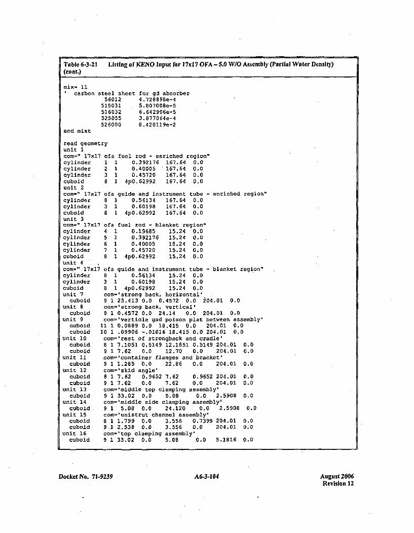
Tablc 6-3-21 Listing of KENO Input for 17r1 7 OFA - 5.0 W/O Assembly (Partial Water Density)(Cont.)
'carbon
end mixt
steel sheet56012
515031516032525055526000
for gd absorber4 .728898e-45.807008e-56.642906e-53. 8770 64 e-48.4 20119e-2
read geomelunit 1comn=" 17x1cylindercylindercylindercuboidunit 2comn-" 17x1cylindercylindercuboidunit 3corn-" 17x1cylindercylindercylindercylindercuboidunit 4com=" 17x1lcylindercylindercuboidunit 7
cuboidunit 8
cuboidunit 9
cuboidcuboid
unit 10cuboidcuboid
unit 21cuboid
unit 12cuboidcuboid
unit 13cuboid
unit 14cuboid
unit 15cuboidcuboid
unit 16cuboid
try
7o1238
7 o:838
fa fuel rod - enriched region"1 0.392176 167.64 0.01 0.40005 167.64 0.01 0.45720 167.64 0.01 4pO.62992 167.64 0.0
fa guide and instrument tube1 0.56134 167.64 0.01 0.60198 167.64 0.01 4p0.62992 167.64 0.0
- enriched region"
7 ofa fuel rod - blanket region"4 1 0.19685 15.24 0.05 2 0.392176 15.24 0.06 1 0.40005 15.24 0.07 1 0.45720 '15.24 0.08 1 4p0.62992 15.24 0.0
7 ofa guide and instrument tube -blanket region"8 1 0.56134 15.24 0.03 1 0.60198 15.24 0.08 1 4pO.62992 15.24 0.0com~'strong back, horizontal'9 1 25.413 0.0 0.4572 0.0 204.01 0.0com-'strong back, vertical'9 1 0.4572 0.0 24.14 0.0 204.01 0.0coni='verticle gad poison plat between assembly'
11 1 0.0889 0.0 18.415 0.0 204.01 0.010 1 .09906 -.01016 18.415 0.0 204.01 0.0com-'rest of strongback and cradle'8 1 7.1051 0.5149 12.1851 0.5149 204.01 0.09 1 7.62 0.0 12.70 0,.0 204.01 0.0com='container flanges and bracket'9 1 1.285 .0.0 22.86 0.0 204.01 0.0com-'skid angle'8 1 7.62 0.9652 7.62 0.9652 204.01 0.09 1 7.62 0.0 7.62 0.0 204.01 0.0com-'middle top clamping assembly'9 1 33.02 0.0 5.08 0.0 2.5908 0.0corn='middle side clamping assembly'9 1 5.08 0.0 24.120 0.0 2.5908 0.0com='unistrut channel assembly'8 1 1.799 0.0 3.556 0.7399 204.01 0.09.1 2.538 0.0 3.556 0.0 204.01 0.0com-'top clamping assembly'9 1 33.02 0.0 5.08 0.0 5.1816 0.0
Docket No. 71-9239 A6-3-104 August 2006Revision 12
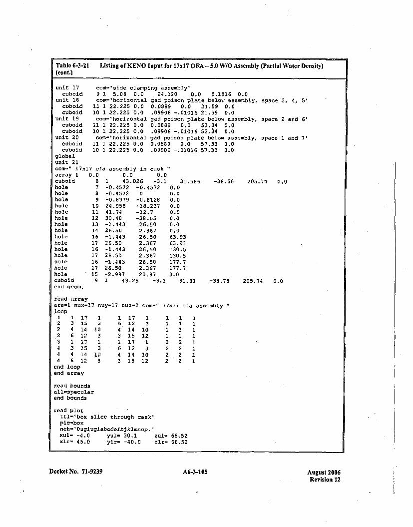
Table 6-3-21 Listing of KENO Input for 17xI7 OFA - 5.0 W/O Assembly (Partial Water Density)(cont.)
unit 17 com='side clamping assembly'cuboid 9 1 5.08 0.0 24.120 0.0 5.1816 0.0
unit 18 con-'horizontal gad poison plate below assembly,cuboid 11 1 22.225 0.0 0.0889 0.0 21.59 0.0cuboid 10 1 22.225 0.0 .09906 -.01016 21.59 0.0
unit 19 com='horizontal gad poison plate below assembly,cuboid 11 1 22.225 0.0 0.0889 0.0 53.34 0.0cuboid 10 1 22.225 0.0 .09906 -.01016 53.34 0.0
unit 20 com-'horizontal gad poison plate below assembly,cuboid 11 1 22.225 0.0 0.0889 0.0 57.33 0.0cuboid 10 1 22.225 0.0 .09906 -.01016 57.33 0.0
space .3, 4. 5'
space 2 and 6'
space 1 and 7'
globalunit 21comn-" 17x17 of a assembly in caskarray 1 0.0 0.0 0.0cuboid 8holeholeholeholeholeholeholeholeholeholeholeholeholeholeholecuboid
7891011121314161716171617159
1 43.026-0.4572 -0,-0.4572 '0-0.8979 -024.958 -1i41.74 -1~30.48 -31-1.443 2126.50 2.-1.443 2426.50 2.-1.443 2126.50 2.-1.443 2126.50 2.-2.997 2(
-3. 1 31.586 -38.56 205.74 0.0.4 572
.81288.237
8.556.50.3676.50.3676.50.3676.50.367).87
0.00.00.00.00.00.00.00.063.9363.93130.5130.5177.7177.70.0,
1 43.25 -3.1 31.81 -38.78 205.74 0.0end geom.
read arrayara-1 nux-17 nuy-17 nuz-2 con-"loop
17x17 ofa assembly"
2 3 1~2 4 1i*2 6 1~3 1 1.4 3 1~4 4 1'4 6 1
end looplend array
75
4
1310313103
16431643
1712141517121415
13
1012131012
2
22
1
22
11111111
read boundsýall-specularend bounds
read plotttl'lbox slice through cask'pic-boxnch- 'Ougiugiabcdefhjklmnop.'xul- -4.0 yul- 30.1xlr= 45.0 ylr- -40.0
zul- 66.52zlr= 66.52
Docket No. 71-9239 A6-3-1 05 August 2006Revision 12
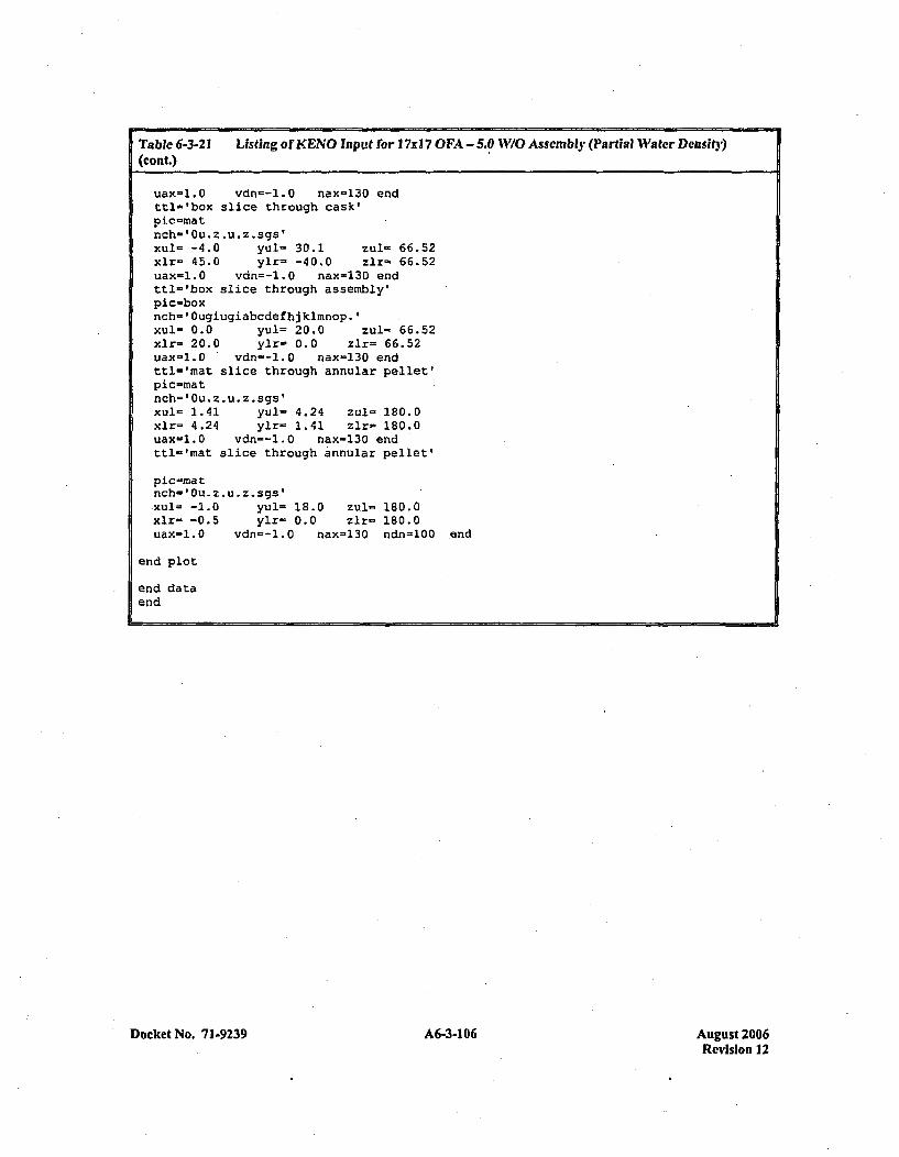
Table 6-3-21 Listing of KENO Input for I7xI 7 OFA - 5.0 W/O Assembly (Partial Water Densit3y)(cont.)
uax=1.0 vdn=-l.0 nax-130 endttl='box slice through cask'pic-matnch='Ou. * u *z .sgs'xul= -4.0 yul= 30.1 zul- 66.52xlr- 45.0 ylr= -40.0 zlr- 66.52uax-l.0 vdn=-l.0 nax=130 endttl'lbox slice through assembly'pic=boxnch-'Ougiugiabcdefhj kimnop.'Xul- 0.0 yul= 20.0 zul= 66.52xlr= 20.0 ylr- 0.0 zlr= 66.52uaxc=l.0 vdn--l.0 nax-130 endttl='mat slice through annular pellet'pic-mratnch=' Ou. z.u. z.sgs'xul= 1.41 yul= 4.24 zul- 180.0xlr= 4.24 ylr= 1.41 zlr- 180.0uax-1.0 vdn=-l.0 nax=130 endttl-'mat slice through annular pellet'
pic-matnch'1Ou.z.u.z.sgs'Xul- -1.0 yul= 18.0 zul- 180.0xlr- -0.5 ylr- 0.0 zlr- 180.0uax-l.0 vdn=-1.0 nax=130 ndn=100 end
end plot
end dataend
Docket No. 71-9239 A6-3-106 August 2006Revision 12
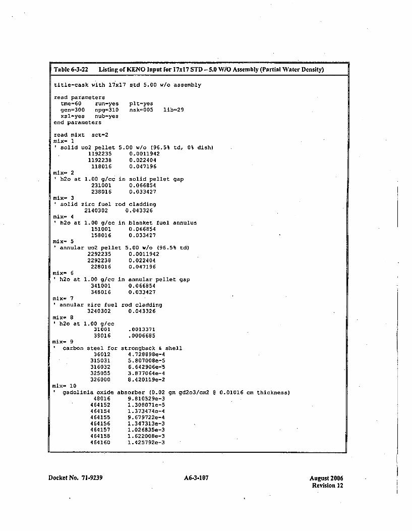
Table 6-3-22 Listing of KENO Input for 17M1 STD - 5.0 W/O Assembly (Partial Water Density)
title-cask with 17x17 s~td 5.00 w/o assembly
read parameterstme=60 run-yesgen=300 npg=310xsl-yes nub=yes
end parameters
read mixi sct=2mix- 1
plt=yesnsk-005 lib=29
*solid
mix- 21h2o at
.uo2 pellet11922351192238118016
1.00 g/cc231001238016
5.00 w/o (96.5% td, 0% dish)0. 00119420. 0224040.047196
in solid pellet gap0. 0668540.033427
mix- 3solid zirc fuel rod cladding
2140302 0.043326mix- 4*h2o at
mix- 51 annular
mix- 6'h2o at
1.00 g/cc in blanket fuel annulus151001 0.066854158016 0.033427
uo2 pellet 5.00 w/o (96.5% td)2292235 0.00119422292238 0.022404228016 0.047196
1.00 g/cc in annular pellet gap341001 0.066854348016 0.033427
mix- 7annular zirc fuel rod cladding
3240302 0.043326mix- 81h2o at
mix- 9'carbon
L.00 g/cc3100138016
steel foz3 60 12
315031316032325055326000
.0013371
.0006685
strongback & shell4 .728898e-45. 807.008e-56. 642906e-:53. 877064e-48. 420119e-2
absorber (0.02 gm gd2o3/cm2 8 0.01016 cm thickness)9.810529e-3I. 308071e-51.373474e-49. 679722e-41.347313e-31 .026835e-31. 622008e-31.425792e-3
mix- 10gadolinia oxide
48016464152464154464155464156464157464158464160
Docket No. 71-9239 A-- 7Ags20A6-3-107Revision 12

Table 6-3-22 Listing of KENO Input for 17x1 7 STD - 5.0 W/O Assembly (Partial Watcr Density)(cont.)
'carbon
end mixt
steel sheet56012
515031516032525055526000
for gd absorber4 .728898e-45..807008e-56. 642906e-53. 877064e-48. 4201,19e-2
read geomelunit Icom=" l7xVcylindercylindercylindercuboidunit 2com-,' l7xVcylindercylindercuboidunit 3corn-" l7xFcylindercylindercylindercylindercuboidunit 4corn-" l7x17cylindercylindercuboidunit 7
cuboidunit 8
cuboidunit 9
cuboidcuboid
unit 10cuboidcuboid
unit 11cuboid
unit 12cuboidcuboid
unit 13cuboid
unit 14cuboid
unit 15cuboidcuboid
unit 16cuboid
try
7 s11238
7 st838
td fuel rod - enriched region"1 0.409575 167.64 0.01 0.41783 167.64 0.01 0.47498 167.64 0.01 4p0.62992 167.64 0.0
:d guide and instrument tube -1 0.57150 167.64 0.01 0.61214 167.64 0.01 4p0.62992 167.64 0.0
enriched region"
7 std fuel rod - blanket region"4 1 0.19685 15.24 0.05 1 0.409575 15.24 0.06 1 0.41783 15.24 0.07 1 0.47498 15.24 0.08 1 4 pO. 6 2992 15.24 0.0
std guide and instrument tube - blanket region"8 1 0.57150 15.24 0.03 1 0..61214 15.24 0.08 1 .4pO.62992 15.24 0.0comn-'strong back, horizontal'9 1 25.413 0.0 0.4572 0.0 204.01 0.0com-'strong back, vertical'9 1 0.4572 0.0 24.14 0.0 204.01 0.0com-'verticle gad poison plat between assembly'
11 1 0.0889 0.0 18.415 0.0 204.01 0.0ý10 1 .09906 -.01016 18.415 0.0 204.01 0.0com='rest of strongback and cradle'8 1 7.1051 0.5149 12.1851 0.5149 204.01 0.09 1 7.62 0.0 12.70 0.0 204.01 0.0com-'container flanges and bracket'9 1 1.285 0.0 22.86 0.0 204.01 0.0com-'skid angle'8 1 7.62 0.9652 7.62 0.9652 204.01 0.09 1 7.62 0.0 7.62 0.0 204.01 0.0com-'rniddle top clamping assembly'9 1 33.02 0.0 5.08 0.0 2.5908- 0.0con-'middle side clamping assembly'9 1 5.08 0.0 24.120 0.0 2.5908 0.0com-'unistrut channel assembly'8 1 1.799 0.0 3.556 0.7399 204.01 0.09 1 2.538 0.0 3.556 0.0 204.01 0.0com-'top clamping assembly'9 1 33.02 0.0 5.08 0.0 5.1816 0.0
Docket No. 71-9239 A6-3-108 August 2006Revision 12
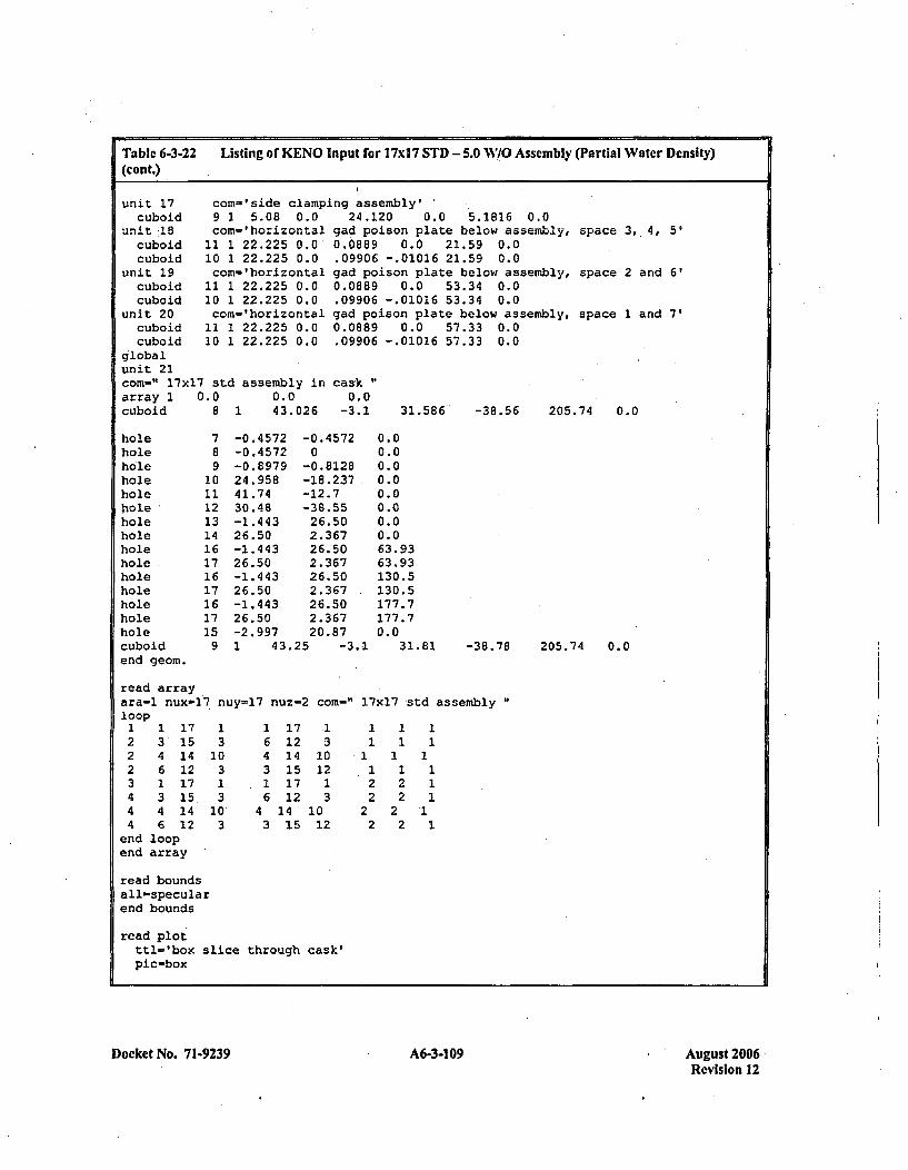
Table 6-3-22 Listing of KENO Input for 17xI17 STD - 5.0 WI/O Assembly (Partial Water Density)(cont.)
unit 17 coxn-'side clamping assembly'cuboid 9 1 5.08 0.0 24.120 0.0 5.1816 0.0
unit-18 com='horizontal gad poison plate below assembly,cuboid 11 1 22.225 0.0 0.0889 0.0 21.59 0.0cuboid 10 1 22.225 0.0 .09906 -.01016 21.59 0.0
unit 19 com='horizontal gad poison plate below assembly,cuboid 11 1 22.225 0.0 0.0889 0.0 53.34 0.0cuboid 10 1 22.225 0.0 .09906 -.01016 53.34 0.0
unit 20 com='horizontal gad poison plate below assembly,cuboid 11 1 22.225 0.0 0.0889 0.0 57.33 0.0cuboid 10 1 22.225 0.0 .09906 -.01016 57.33 0.0
globalunit 21com=" 17x17 std assembly in cask
space 3, 4, 5'
space 2 and 6'
space 1 and 7'
array 1 0.0cuboid 8
0.0 0.043.026 -3.11 31.586' -38.56 205.74 0.0
holeboleholeholeholeholeholeholeholeholeholeholeholeholeholecuboidend geom.
789
1011.12131416171617161715
9
-0.4572-0. 4 572-0.897924.95841.7430.48-1.44326.50-1.44326.50-1.44326.50-1.44326.50-2.997
-0. 45720-0. 8128-18.237-12.7-38.5526.502.36726.502.36726.502.36726.502.36720.87
0.00.00.00.00.00.00.00.063.9363.93130.5130.5177.7177.70.0
I 43.25 -3.1 31.81 -38.78 205.74 0.0
read arrayara-l nux-17. nuy=17 nuz=2 com-"1 17xl7,std assembly"loop
1 1 12 3 1~2 4 12 6 13 1 1~4 3 1~4 4 1.4 6 1:
end loopend array
75
275
2
13
10313
10~3
164316
43
1712141517121415
13
1012
13
1012
1
22
1
22
11
1111
1I
read boundsall-specularend bounds
read plotttl-'box slicepic-box
through cask'
Docket No. 71-9239 A6-3-109 A6-31 09August 2006Revision 12
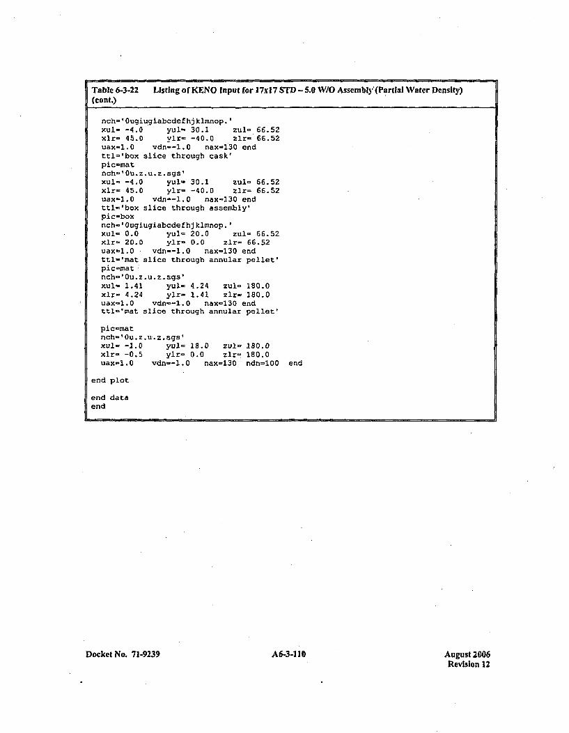
Table 6-3-22 Listing of KENO Input for 17xI7 STD - 5.0 W/O Asscmnbly'(Partial Water Density)(cont.)
nch=' Ougiu~giabcdefhj kimnop.'xul- -4.0 yul'= 30.1 zu1- 66.52xlr- 45.0 ylr- -40.0 zir- 66.52uax-l.0 vdn=--.0 naxl130 endttl-'box slice through cask'pic-matnch=' Ou . z *u z .sgs'xul=. -4.0 yul- 30.1 zul= 66.52xlr- 45.0 ylr- -40.0 zlr= 66.52uax-1.0 vdn--l.0 nax=130 endttl..'box slice through assembly'Pic-boxnch=' Ougiugiabcdefhj kimnop.'xul- 0.0 yul'= 20.0 zul- 66.52xlr- 20.0 ylr- 0.0 zlr= 66.52uax-l.0 vdn--1.0 nax-130 endttl-'mat slice through annular pellet,pic-matnch-'0u. z. u*z . sgs1xul- 1.41 yul= 4.24 zul- 180.0xlr- 4.24 ylr- 1.41 zir- 180.0uax-l.0 vdn--l.O nax-130 endttl-'mat slice through annular pellet'
pic-matnch='Ou.z.u.z.sgs'xul= -1.0 yul- 18.0 zul- 180.0xlr- -0.5 ylr- 0.0 zlr= 180.0uax=1.0 vdn--l.0 nax-130 ndn=100 end
end plot
end dataend
Docket No. 71.9239 A6-3-110 August 2006Revision 12
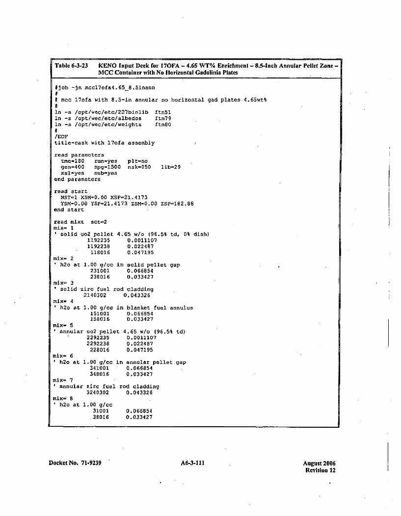
Table 6-3-23 KENO Input Deck for 170FA - 4.65 WT% Enrichment -'8.5-Inch Annular Pellet Zone -MCC Container with No Horizontal Gadolinia Plates
fjob -jn mccl7ofa4.65-8.5inann
j mcc l7ofa with 8.5-in annular no horizontal
In -s /opt/wec/etc/227binlib ftn5lIn -s /opt/wec/etc/aibedos ftn79ln -s /6pt/wec/etc/weights ftn80
/EOFtitle-cask with l7of a assembly
read parametersime-iBO run-yes pit-nogen=400 npg=1500 nsk-050 iib-29xsl-yes nub=yes
end parameters
gad plates 4.65wt%
read startI4ST-1 XSM=0.00 XSP-21.4173YSM-0.00 YSP=21.4l73 ZSM-0.00 ZSP-182.88
end start
read mixt sct-2mix- 1Isoli.d uo2 pellet
11922351192238118016
at 1.00 g/cc231001238016
4.65 w/o (96.5% td, 0% dish)0.00111070.0224 870.047195
in solid pellet gap0.0668540.033427
mix- 2'h2o
mix= 3solid zirc fuel rod cladding
2140302 0.043326mix- 4'h2o at
mix- 5annular
mix- 61h2o at 1
1.00 g/cc in blanket fuel annulus151001 0.066854158016 0.033427
uo2 pellet 4.65 w/o (96.5% td)2292235 0.00111072292238 0.022487228016 0_047195
.00 g/cc in annular pellet gap341001 0.066854348016 0.033427
mix- 7annular zirc fuel rod cladding
3240302 0.043326mix-. 8
h2o at 1.00 g/cc3100138016
0.0668540.033427
Docket No. 71-9239' A6-3-1 11 August 2006Revision 12
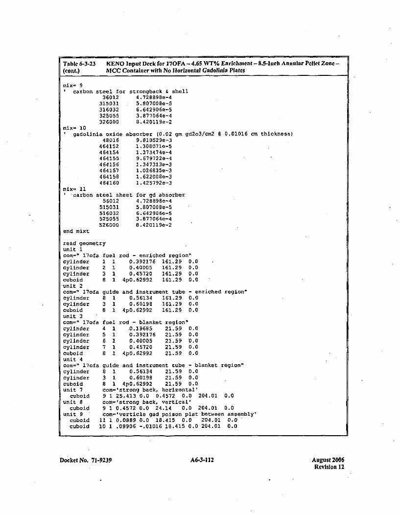
Table 6-3-23 KENO Input Dcck for 1 70FA - 4.65 WT% Enrichment - 8.5-Inch Annular Pellet Zone -
(conit.) MCC Container with No Horizontal Cadolinla Plates
mix- 9'carbon steel for
36012315031316032325055326000
strongback & shell4 .728898e-45. 80700S8e-56.642906e-53. 877 06 4e-48. 420119e-2
mi~x= 10gadolinia oxide
48016464152464154464155464156464157464158464160
absorber (0.029. 81052 9e-31 .308071e-51 .373474e-49. 679722e-41.34 7313e-31 .026835e-31. 622 00 8e-31. 425792e-3
gmn gd2o3/cin2 @ 0.01016 cm thickness)
' carbon
end mixt
steel sheet56012
515031516032525055526000
for gd absorber4.728898e-45. 80700 Be-S6. 642906e-53. 87706 4e-48.420119e-2
read geometryunit 1comn-" l7ofa ftcylinder Icylinder 2cylinder 3cuboid 8unit 2com=" l7ofa gicylinder 8cylinder 3cuboid 8unit 3com=" l7ofa ftcylinder 4cylinder 5cylinder 6cylinder 7cuboid 8unit 4
~el1
1d11
1
ieI1
rod - enriched region"0.392176 161.29 0.00.40005 161.29 0.00.45720 161.29 0.0
4pO.62992 161.29 0.0
and instrument tube0.56134 161.290.60198 161.29
4pO.62992 161.29
rod - blanket,0.196850.3921760.400050,45720
4p0. 62992
region"21.5921.5921.5921.5921.59
- enriched region"0.00.00.0
0.00.00.00.00.0
ci
ul
om=" 17ofa guide and instrument tube - blanket region"ylinder 8 1 0.56134 21.59 0.0y'1inder 3 1 0.60198 21.59 0.0.iboid 8 1 4pO. 62992 21.59 0.0nit 7 com='strong back, horizontal'cuboid 9 1 25.413 0.0 0.4572 0.0 204.01 0.-0
nlit 8 com=lstrong back, vertical'cuboid 9 1 0.4572 0.0 24.14 0.0 204.01 0.0
niit 9 ' com='verticle gad poison plat between assembly'cuboid 11 1 0.0889 0.0 18.415 0.0 204.01 0.0cuboid 10 1 .09906 -.01016 18.415 0.0 204.01 0.0
Docket No. 71-9239 A6-3-112 August 2006Revision 12
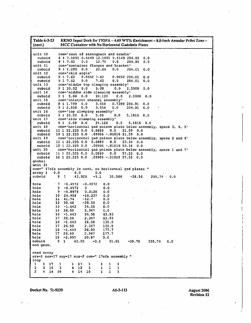
Table 6-3-23(cont.)
KENO Input Deck for 170FA -4.65 WT% Enrichment -8.5-Inch Annular Pellet Zone -MCC Container wvith No Horizontal Gadolinia Plates
unit 10cuboidcuboid
unit. 11cuboid
unit 12cuboidcuboid
unit 13cuboid
unit 14cuboid
unit 15cuboidcuboid
unit 16cuboid
unit 17cuboid
unit 18cuboidcuboid
unit 19cuboidcuboid
unit 20cuboidcuboid
com-'rest of strongback and cradle'8 1 7.1051 0.5149 12.1851 0.5149 204.01 0.09 1 7.62 0.0. 12.70 0.0 204.01 0.0com='container flanges and bracket'9 1 1.285 0.0 22.86 0.0 204.01 0.0com-'skid angle'8 1 7.62 0.9652 7.62 0.9652 204.01 0.09 1 7.62 0.0 *7.62 0.0 204.01 0.0con-'middle top clamping assembly'9 1 33.02 0.0 5.08 0.0 2.5908 0.0com-'middle side clamping assembly'9 1 5.08 0.0 24.120 0.0 2.5908 0.0con='unistrut channel assembly'8 1 1.799 0.0 3.556 0.7399 204.01 0.09 1 2.538 0.0 3.556 0.0 204.01 0.0com='top clamping assembly'9 1 33.02 0.0 5.08 0.0 5.1816 0.0con-'side clamping assembly'9 1 5.08 0.0con-' horizontal
11 1 22.225 0.010 1 22.225 0.0corn-'horizontal
11 1 22.225 0.010 1 22.225 0.0con- 'horizontal
11 1 22.225 0.010 1 22.225 0.0
24.120 0.0 5.1816 0.0gad poison plate below assembly,0.0889 0.0 21.59 0.0.09906 -.01016 21.59 0.0gad poison plate below assembly,0.0889 0.0 53.34 0.0.09906 -.01016 53.34 0.0gad poison plate below assembly,0.0889 0.0 57.33 0.0.09906 -.01016 57.33 0.0
space 3, 4, 5'
space 2 and 6'
space 1 and 7'
globalunit 21con-" l7ofa assembly in cask, no horizontalarray 1 0.0 0.0 0.0cuboid 8 1 43.026 -3.1 31.586
gad plates
-38.56 205.74 0.0
hole 7 -0.4572 -0.4572 0.0hole 8 -0.4572 0 0.0hole 9 -0.8979 0.8128 0.0hole 10 24.958 -18.237 0.0hole 21 41.74 -12.7 0.0hole 12 30.48 -38.55 0.0'hole. 13 -1.443 26.50 0.0hole 14 .26.50 2.367 0.0hole 16 -1.443 26.50 63.93,hole 17 26.50 2.367 .63.93hole 16 -1.443 26.50 130.5hole 17 26.50 2.367 130.5hole 16 -1.443 26.50 177.7hole 17 26.50 2.367 177.7hole 15 -2.997 20.87 0.0cuboid 9 1 43.25 -3.1 31.81 -31end geom.
read arrayara-l nux=17 nuy-17 nuz-2 com-" 17ofa assemblyloop1 1 17 1 1 17 1 1 1 12 3 15 3 6 12 3 1 1 12 4 14 10 4 14 10 1 1 1
8.78 205.74 0.0
Docket No. 71-9239A6313Aust20 A6-3-113Revision 12
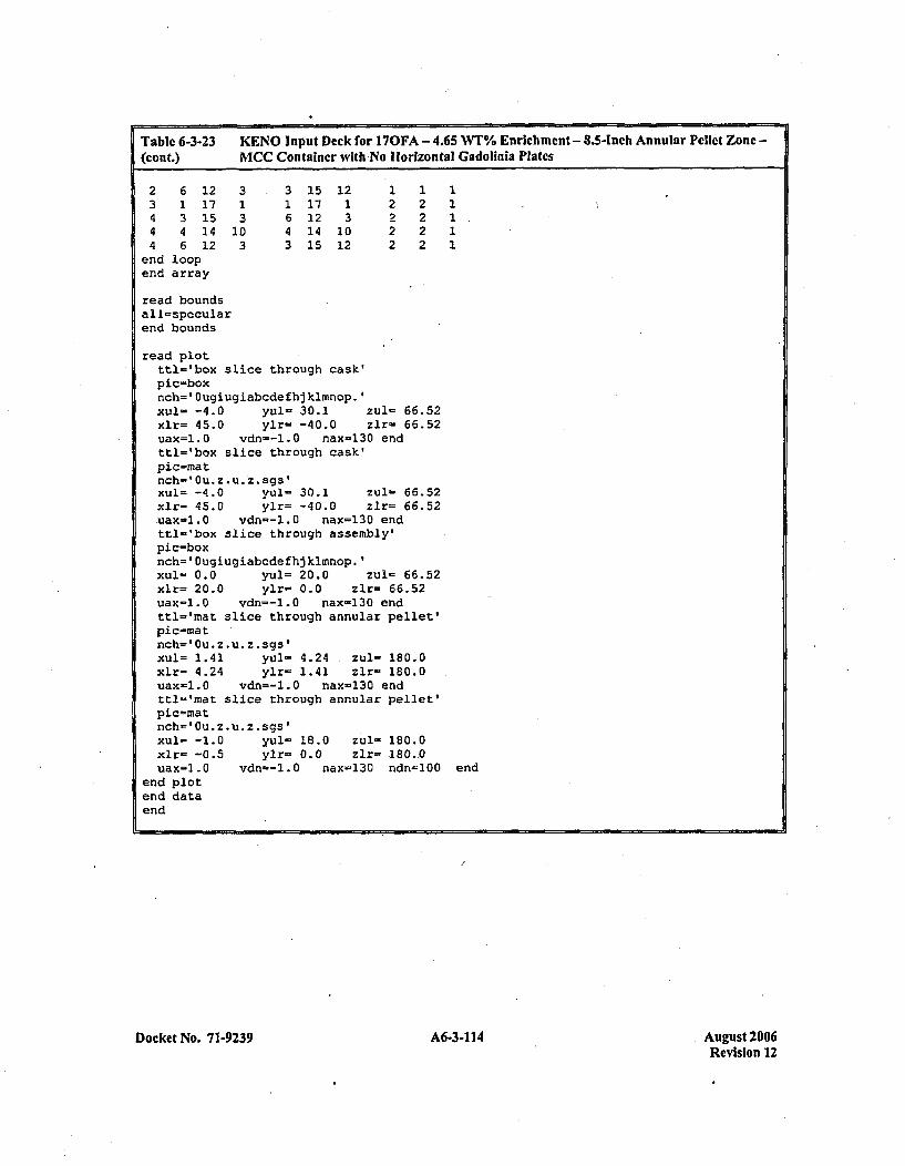
Table 6-3-23 KENO Input Deck for 170FA - 4.65 WT% Enrichment - 8.5-Inch Annular Pellet Zone -(cant.) MCC Container with No Horizontal Gadolinia Plates
2 6 12 3 3 15 12 1 1 13 1 17 1 1 17 1 2 2 14 3 15 3 6 12 3 2 2 1.4 4 14 10 4 14 10 *2 2 14 6 12 3 3 15 12 2 2 1
end loopend array
read boundsall=specularend bounds
read plotttl-'box slice through cask'pic=boxnch=' Ougiugiabcdefhj kimnop.'xul= -4.0 yul= 30.1 zulu 66.52xlr= 45.0 ylr= -40.0 zlr= 66.52uax=1.0 vdn--l.0 nax=130 endttl='box slice through cask'pic-znatnch-' Ou. z *u *z. sgsfxul= -4.0 yul- 30.1 zul- 66.52xlr= 45.0 ylr= -40.0 zlr- 66.52,uax=l. 0 vdn--l.0 nax=130 endttl-'box slice through assembly'pic=boxnch=' Ougiugiabcde fhj klmnop.'Xul- 0.0 yul= 20.0 zu1- 66.52xlr= 20.0 ylr- 0.0 zlr= 66.52uax-1.0 vdn=-1.0 nax-130 endttl='rnat slice through annular pellet'pic=matInch=' Ou. z *u *z . gs'xul- 1.41 yuls. 4.24 ,zul- 180.0xlr= 4.24 ylr- 1.41 zlr- 180.0uax-l.0 vdn--l.0 nax-130 endttl='mat slice through annular pellet'pic=matnch='Ou.z.u.z.sgs'
xlr- -0.5 ylr= 0.0 zlr= 180-0uax=l.0 vdn--l.0 nax-130 ndn=100 end
end plotend dataend
Docket No. 71-9239 A6-3-1 14 August 2006Revision 12
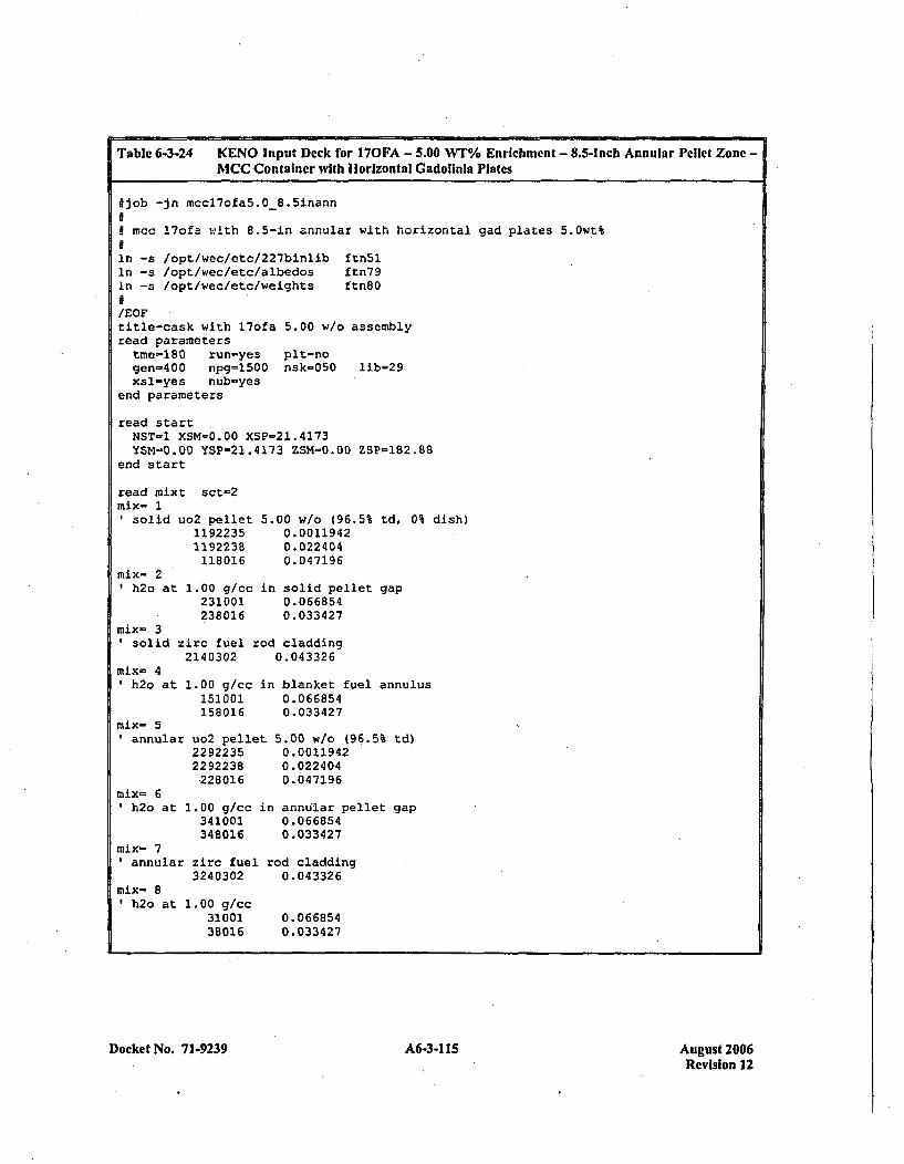
Table 6-3-24 KENO Input Deck for 170FA - 5.00 WT% Enrichment - 8.5-Inch Annular Pellet Zone -1*1CC Container with Horizontal Gadolinla Plates
#job -in mccl7ofa5.0-8.5inann0# mcc l7ofa with 8.5-in annular with horizontal gad plates S.Owt%
In -s /opt/wec/etc/227binlib ftn5lIn -s /opt/wec/etc/albedos ftn79In -s /opt/wec/etc/weights ftn8O
/EOFtitle-cask with l7ofa 5.00 w/o assemblyread parameterstme-180 run-yes pit-nogen-400 npg=1500 nsk-050 lib=29xsl-yes nub-yes
end parameters
read startNST-1 XSM-0.00 XSP-21.4173YSM-0.00 YSP-21.4173 ZSM-0.00 ZSP-182.88
end start
read mixt sct=2mix- 1
solid uo2 pellet11922351192238118016
mix- 2h2o at 1.00 gfcc
231001238016
5.00 w/o (96.5% td, 0% dish)0.00119420.0224040.04 7196
in solid pellet gap0. 066 8540.033427
nix- 3solid zirc fuel rod cladding
2140302 0.043326mix- 4
h2o at 1.00 gfcc151001158016
mix- 51annular
mix= 6'h2o at I
uo2 pelle22922352292238228016
.00 g/cc341001348016
in blanket fuel annulus0.0 668540. 0334 27
0.00119420.0224040.047196
in annular pellet gap0.0668540.033427
mix- 7annular zirc fuel rod cladding
3240302 0.043326mix- 8
h2o at 1.00 g/cc3100138016
0. 06 68540.033427
Docket No. 7 1-9239 A6-3-115 A6-31 15August 2006Revision 12
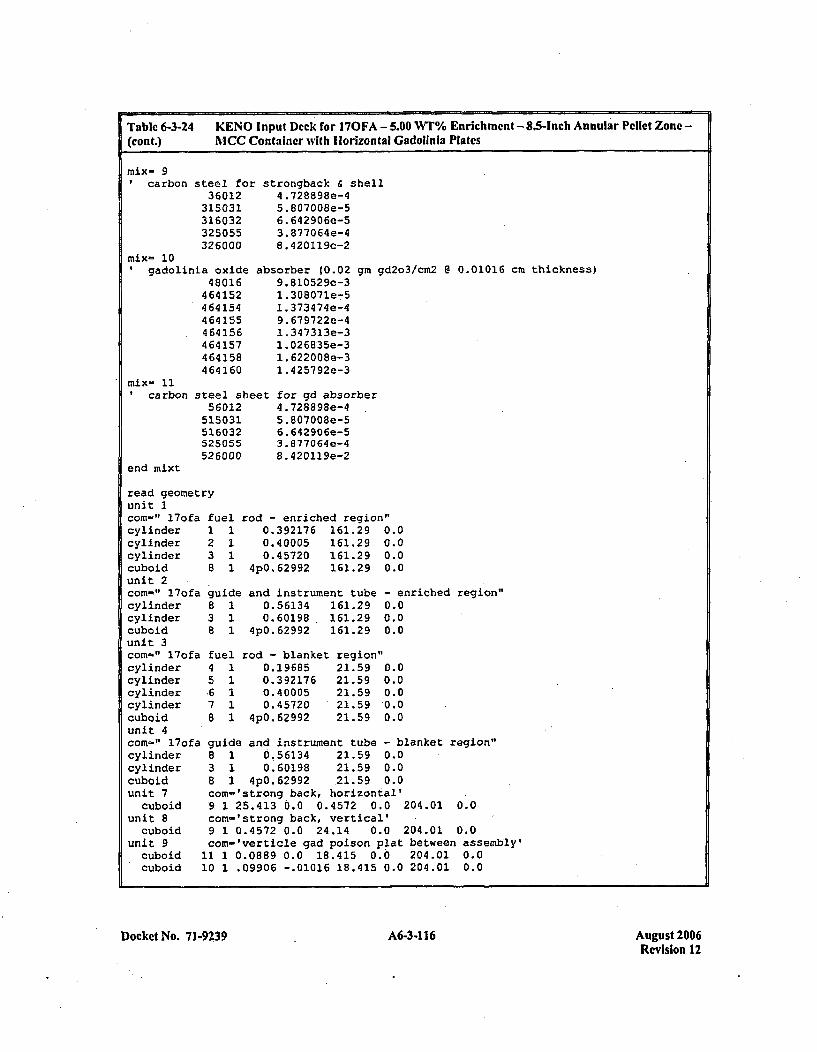
Tablc 6-3-24(cont.)
KENO Input Deck for 170FA - 5.00 WT% Enrichment - 8.5-Inch Annular Pellet Zone -
AICC Container with Horizontal Gadolinia Plates
mix- 97carbon steel for
36012315031316032325055326000
strongback & shell4 .728898e-45. 80 7008e-56.,642906e-53.877064e-48. 420119e-2
mix- 10gadolinia oxide
48016464152464154464155464156464157464158464160
absorber (0.029.810529e-31. 308071e-51. 373474e-49. 679722e-41. 347313e-31. 026835e-31.622 008e-31. 425792e-3
gm gd2o3/cm2 @ 0.01016 cm thickness)
tcarbon
end mixt
steel sheet56012
515031516032525055526000
for gd absorber4.728898e-45.807008e-56. 642906e-53.877064e-48.420119e-2
read geometryunit 1com=" l7ofa fuelcylinder 1 1cylinder 2 1cylinder 3 1cuboid 8 1unit 2com=" l7ofa guidicylinder 8 1cylinder 3 1cuboid 8 1unit 3com-" l7ofa fuelcylinder 4 1cylinder 5 1cylinder .6 1cylinder 7 1cuboid 8 1unit 4com-If l7ofa guid'cylinder 8 1cylinder 3 1cuboid 8 1unit 7 com-
cuboid 9 1unit 8 com=
cuboid 9 1unit 9 com-
cuboid 11 1cuboid 10 1
rod - enriched region"0.392176 161.29 0.00.40005 161.29 0.00.45720 161.29 0.0
4pO.62992 161.29 0.0
e and instrument tube0.56134 161.290.60198 161.29
4pO.62992 161.29
- enriched region"0.00.00.0
rod - blanket0.196850. 392 1760. 400050.45720
4p0.62992
region"21.59 0.021.59 0.021.59 0.021.59 0.021.59 0.0
eand instrument tube - blanket region'0.56134 21.59 0.00.60198 21.59 0.0
4pO.62992 21.59 0.0'strong back, horizontal'25.413 0.0 0.4572 0.0 204.01 0.0'strong back, vertical'0.4572 0.0 24.14 0.0 204.01 0.0'verticle gad poison plat between assembly'0.0889 0.0 18.415 0.0 204.01 0.0.09906 -.01016 18.415 0.0 204.01 0.0
Docket No. 71-9239 A6-3-1 16 August 2006Revision 12
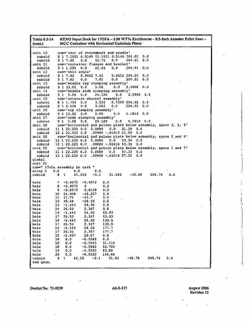
Table 6-3-24(cont.)
KENO Input Deck for 170FA - 5.00 WT%/ Enrichment - 8.5-inch Annular Pellet Zone -
MCC Container with Horizontal Cadolinia Plates
unit 10cuboidcuboid
unit 11cuboid
unit 12cuboidcuboid
unit 13cuboid
unit 14cuboid
unit 15cuboidcuboid
unit 16cuboid
unit 17
coin-' zest of strongback and cradle'8 1 7.1051 0.5149 12.1851 0.5149 204.01 0.09 1 7.62 0.0 12.70 0.0 204.01 0.0com='container flanges and bracket'9 1 1.285 0.0 22.86 0.0 204.01 0.0com-'skid angle'8 1 7.62 0.9652 7.62 0.9652 204.01 0.09 1 7.62 0.0 7.62 0.0 204.01 0.0com-'middle top clamping assembly'9 1 33.02 0.0 5.08 0.0 2.5908 0.0com-'middle side clamping assembly'.9 1 5.08 0.0 24.120 0.0 2.5908 0.0com-'unistrut channel assembly'8 1 1.799 0.0 3.556 0.7399 204.01 0.09 1 2.538 0.0 3.556 0.0 204.01 0.0com='top clamping assembly'9 1 33.02 0.0 5.08 0.0 5.1816 0.0.com='side clamping assembly'
cuboid 9 1 5.08 0.0unit 18 com='horizontal ga
cuboid 11 1 22.225 0.0 0.cuboid 10 1 22.225 0.0 .0
unit 19 com-'horizontal gacuboid 11 1 22.225 0.0 0.cuboid 10 1 22.225 0.0 .0
unit 20 com='horizontal ga'cuboid 11 1 22.225 0.0 0.cuboid 10 1 22.225 0.0 .0
global.unit 21com-" l7ofa assembly in cask
24.120 0.0 5.1816 0.0d poison plate below assembly,0889 0.0 21.59 0.09906 -.01016 21.59 0.0d poison plate below assembly,0889 0.0 53.34 0.09906 -.01016 53.34 0.0d poison plate below assembly,0889 0.0 57.33 0.09906 -.01016 57.33 0.0
space 3, 4, 5'
space 2 and 6'
space 1 and 7'
array 1 0.0cuboid 8
0.0 0.043.026 -3.11 31.586 -38.56 205.74 0.0
holeholeholeholeholeholeholeholeholeholeholeholeholeholeholeholeholeholeholeholecuboidend geom.
78910111213141617161716171518181819209
-0. 4572-0. 4572-0.897 924.95841.7430.48-1.44326.50-1.443.26. 50-1.44326.50-1.44326.50-2.9970.00.00.00.00.0
-0.4 57200.8128
-18.237-12.7-38.5526.502.36726.502.36726.502.36726.502.36720.87
-0.5563-0. 5563-0. 5563-0. 5563-0. 55 63
0.00.00.00.00.00.00.00.063.9363.93130.5130.5177.7177.70.00.031.11552.70583.82146.68
1 43.25 -3.1 31.81 -38.78 205.74 0.0
Docket No. 71-9239 A6-3-1 17 August 2006Revision 12
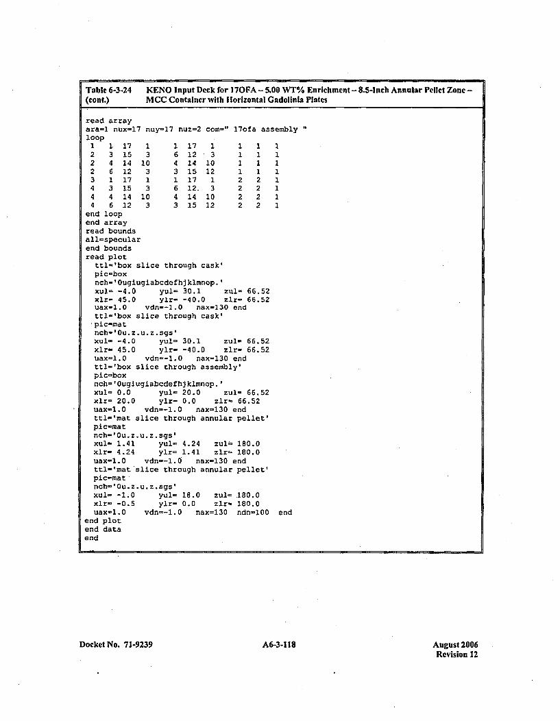
Table 6-3-24 KENO Input Dcck for 1 70FA - 5.00 WT% Enrichment - 8.5-Inch Annular Pellct Zone -(cont.) MCC Container with I orizontal Gadolinia Plates
read arrayara-1 nux-17 nuy-17 nuz-2 corn-" l7ofa assembly"loop1 1. 17 1 1 17 1 1 1 12 3 15 3 6 12 3 1 1 12 4 14 10 4 14 10 1 1 12 6 12 3 3 15 12 1 1 13 1 17 1 1 17 1 2 2 14 3 15 3 6 12. 3 2 2 14 4 14 10 4 14 10 2 2 14 6 12 3 3 15 12 2 2 1
end loopend arrayread boundsall=specularend boundsread plot
ttl='box slice through cask'pic-boxrich-' Ougiugiabcdefhj klmnop.'xul- -4.0 yul= 30.1 zul= 66.52xlr- 45.0 ylr- -40.0 zlr- 66.52uax-1.0 vdn--1.O nax-130 endttl-'box slice through cask'ýpic-rnatnch- 'Ou. z . u z .sgs'xul- -4.0 yul= 30.1 zul- 66.52xlr= 45.0 ylr- -40.0 zir- 66.52uax=1.O vdn=-1.0 nax=130 end,ttl-'box slice through assembly'pic-boxnch ' Ougiugiabcdefhj klmnop.'Xul- 0.0 yul- 20.0 zul- 66.52xlr- 20.0 ylr= 0.0 zlr- 66.52uax-1.0 vdn--1.0 nax-130 endtt1-'mat slice through annular pellet'pic-matnch- 'Ou. z. u *z .sgs'xul= 1.41 yul= 4.24 zuls= 180.0xlr- 4.24 yir- 1.41 zlr-. 180.0uax-1.0 vdn--l.O nax-130 endttl='mat slice through annular pellet'pic=matnch-'Ou.z.u. z.sgs'Xui= -1.0 yul= 18.0 zul= 180.0xlr= -0.5 yir- 0.0 zir- 180.0uax-1.0 vdn=-1.0 nax=130 ndn-100 end
end plotend dataend
Docket No. 7 1-9239 A6-3-118 August 2006Revision 12
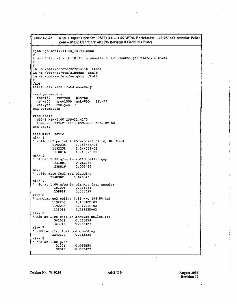
Table 6-3-25 KENO Input Deck for 17STD XL - 4.65 WTZ Enrichment - 10.75-Inch Annular PelletZone - MCC Container with No Horizontal Gadolinia Plates
fjob -jn mccl7xl4.65-10.75inann09 mcc 1 7std x1 with 10.75-in annular no horizontal
in -s /opt/wec/etc/227binlib ftn5lIn -s /opt/wec/etc/albedos ftn79In -s /opt/wec/etc/weights ftn80
/EOFtitle-cask with l7std assembly
read parameterstme-l80 run-yes pit-nogen-400 npg=1500 nsk=050 lib=29xsl-yes ,nub-yes
end parameters
read startNST-I. XSM=0.00 XSP-21.4173YSM-0.00 YSP=21.4173 ZSM-0.00 ZSP-182.88
end start
gad plates 4.85wt%
read mixt sct-2mix--IIsoli
mix- 2'h2o
d uo2 pellet11922351192238118016
at 1.00 g/cc231001238016
4.85'w/o (96.5% td, 0% dish)1. 1584SE-032.24 406E-024 .71982E-02
in solid pellet gap0.0668540.033427
mix- 3Usolid zirc fuel rod claddingII2140302 0.043326
mix= 4Ih2o at
mix- 51annular
mix- 61h2o at
1.00 g/cc in blanket fuel annulus151,001 0.066854158016 0.033427
uo2 pellet 4.85 w/o (96.5% td)1192235 1.15848E-031192238 2.24406E-02118016 4.71982E-02
1.00 g/cc in annular pellet gap341001 0.066854348016 0.033427
mix- 7annular zirc fuel rod cladding
3240302 0.043326mix- 8
h2o at 1.00 gfcc31001 0.06685438016 0.033427
Docket No. 71-9239 A6-3-1 19. August 2006Revision 12