production part approval process (ppap)
TRANSCRIPT
PRODUCTION PARTAPPROVAL PROCESS
(PPAP)
Production Part Approval Process (PPAP)First Edition Issued February, 1993
Second Edition, 1st Printing, February, 1995, 2nd Printing, July, 1995Third Edition, September, 1999, 2nd Printing, August, 2000
Copyright © 1993, © 1995, © 1997, © 1999, © 2000DaimlerChrysler Corporation, Ford Motor Company, General Motors Corporation
The Second Edition, 2nd Printing, July, 1995 edition is obsolete February 1, 2000unless otherwise specified by your customer
Further copies are obtainable from AIAG at 01-248-358-3003 orCarwin Continuous (UK) in Europe 44-1-708-861333
FOREWORD TO THE THIRD EDITION
The Production Part Approval Process (PPAP) Third Edition was issued to incorporate a number of revisionswhich include:
• Use of “auditable” language and a format consistent with QS-9000 to support third party auditing;
• A reordering of the PPAP requirements aligned with the typical process flow;
• Revision of “Preliminary Process Capability Requirements”, now called “Initial Process Studies”, toprovide for the use of either Cpk or Ppk, depending on the amount and type of data available, consistentwith our Statistical Process Control reference manual;
• Clarification of when customer notification and/or submission is required;
• The prior IASG QS-9000 Sanctioned Interpretations specific to PPAP;
• A Truck OEM-Specific Instructions;
• Requirements for bulk material, including a Bulk Material-Specific Appendix;
• Tire Industry-Specific Appendix;
• An enhanced glossary of terms.
The actual changes of the previous PPAP text are minimal, and evolutionary. While the additions haveincreased the size of the document, they provide greater clarification of PPAP requirements and allowapplication of PPAP requirements to a broader community of users.
Current training modules sanctioned by DaimlerChrysler, Ford and General Motors have been revised toincorporate these changes.
Acknowledgments are due to the DaimlerChrysler, Ford and GM Supplier Quality Requirements Task Force(Hank Gryn, Dan Reid and Steve Walsh), Michael Schons from DaimlerChrysler, Carol Myers and RudyPomper from General Motors, Paul Norkevicius from Ford, Patricia Messenger from the ChemicalManufacturers Association, Joseph Muscedere from the AIAG Truck and Heavy Equipment Group, andSteve Butcher from the Rubber Manufacturers Association.
The PPAP Third Edition obsoletes the Second Edition effective February 1, 2000 unless otherwise specifiedby your customer.
September, 1999
i

ii
February, 1995
FOREWORD TO THE SECOND EDITION
This document is the second edition of the Chrysler, Ford and General Motors Production Part ApprovalProcess (PPAP) procedure. It represents a refinement of the original PPAP procedure based on input fromrepresentatives at each of these companies. In particular, it includes recommendations by the companies’European affiliates that will facilitate implementation of PPAP and QS-9000 in Europe.
The second edition of PPAP, February 1995, does not revise the production parts approval process. Achange summary has been provided as Appendix E. Document control requirements mandate that theFebruary, 1993, edition of PPAP is obsolete effective September 1, 1995.
While this procedure is intended to cover all situations normally occurring during the part approvalprocess, there may be questions that arise during implementation. These questions should be directed toyour customer’s part approval activity. If you are uncertain how to contact the parts approval activity, thebuyer in your customer’s Purchasing activity can assist you.
As an aid to suppliers in implementing PPAP, all of the forms required by the procedure are available ondiskette and permit entry of all necessary data. Diskettes are available from AIAG at (248) 358-3003.
Please note the customer-specific information in Appendices B, C, and D. These appendices clarify eachcustomer’s individual requirements.
The PPAP document represents the efforts of the Chrysler, Ford and General Motors subcommitteemembers, B. Ray Daugherty and Robert Panczyk (Chrysler), Stephen Walsh (Ford), and Timothy O’Brienand Dennis Whitman (General Motors). The subcommittee gratefully acknowledges the contributions ofmany employees in their respective companies, without whose assistance and continuing support theprocedure could not be effectively implemented.
iii

iv
FOREWORD TO THE FIRST EDITION
This Procedure was developed by the Quality and Part Approval staffs at Chrysler, Ford, and General Mo-tors, working under the auspices of the Automotive Division of the American Society for Quality Control(ASQC) and the Automotive Industry Action Group (AIAG).
The ASQC/AIAG Task Force charter is to standardize the reference manuals, procedures, reporting for-mats, and technical nomenclature used by Chrysler, Ford, and General Motors in their respective supplierquality systems. Accordingly, this Procedure should be used by suppliers in the submission of productionparts for approval to any of these companies.
In the past, Chrysler, Ford, and General Motors each had their own procedures for reviewing supplier sub-missions of production parts for customer approval (initial samples). Differences between these threeprocesses resulted in additional demands on supplier resources. To improve upon this situation, Chrysler,Ford, and General Motors agreed to develop, and, through AIAG, distribute this Procedure. The workgroup responsible for the Procedure was led by Rad Smith of Ford’s Corporate Quality Office.
While this Procedure is intended to cover all situations normally occurring during the sample submissionprocess, there will be questions that arise during this process. These questions should be directed to yourcustomer’s part approval activities. If you are uncertain as to how to contact the parts approval activity,the buyer in your customer’s Purchasing office can help.
Please note the customer-specific information in Appendices B, C, and D. These appendices clarify eachcustomer’s individual requirements.
The Task Force gratefully acknowledges: the leadership and commitment of Vice Presidents Thomas T.Stallkamp at Chrysler, Norman F. Ehlers at Ford, and J. Ignasio Lopez de Arriortua of General Motors;the assistance of the AIAG in the development, production, and distribution of the Procedure; and theguidance of the Task Force principals Russ Jacobs (Chrysler), Steve Walsh (Ford) and Dan Reid (GeneralMotors), Radley Smith and the assistance of the ASQC Automotive Reading Team. This team, led byTripp Martin (Peterson Spring), reviewed the Manual for technical content and accuracy and made valu-able contributions to the form and content. Since the Manual was developed to meet specific needs of theautomotive industry, the ASQC voluntary standards process defined by ASQC policies and procedureswas not used in its development.
v
February, 1993
Introduction................................................................................................................................... 1
Section I
I.1 General ................................................................................................................................................................... 2
I.2 PPAP Process Requirements ................................................................................................................................. 2
I.2.1 Significant Production Run ..................................................................................................................... 2I.2.2 PPAP Requirements ................................................................................................................................. 2
I.2.2.1 Design Records ............................................................................................................................ 3I.2.2.2 Engineering Change Documents ................................................................................................. 3I.2.2.3 Engineering Approval .................................................................................................................. 3I.2.2.4 Design Failure Mode and Effects Analysis (Design FMEA) ........................................................ 4I.2.2.5 Process Flow Diagrams ............................................................................................................... 4I.2.2.6 Process Failure Mode And Effects Analysis (Process FMEA) ..................................................... 4I.2.2.7 Dimensional Results .................................................................................................................... 4I.2.2.8 Records of Material/Performance Test Results ............................................................................ 5
I.2.2.8.1 Material Test Records .......................................................................................................... 5I.2.2.8.2 Performance Test Records ................................................................................................... 5
I.2.2.9 Initial Process Studies .................................................................................................................. 6I.2.2.9.1 General ................................................................................................................................ 6I.2.2.9.2 Quality Indices ..................................................................................................................... 6I.2.2.9.3 Acceptance Criteria ............................................................................................................. 7I.2.2.9.4 Unstable Processes .............................................................................................................. 7I.2.2.9.5 Processes With One-Sided Specifications or Non-Normal Distributions ........................... 7I.2.2.9.6 Strategy When Acceptance Criteria Are Not Satisfied ........................................................ 8
I.2.2.10 Measurement System Analysis Studies ......................................................................................... 8I.2.2.11 Qualified Laboratory Documentation .......................................................................................... 8I.2.2.12 Control Plan ................................................................................................................................. 8I.2.2.13 Part Submission Warrant (PSW) .................................................................................................. 9
I.2.2.13.1 Part Weight (Mass) .............................................................................................................. 9I.2.2.14 Appearance Approval Report ....................................................................................................... 9I.2.2.15 Bulk Material Requirements Checklist ....................................................................................... 10I.2.2.16 Sample Production Parts ............................................................................................................ 10I.2.2.17 Master Sample ........................................................................................................................... 10I.2.2.18 Checking Aids ............................................................................................................................. 10I.2.2.19 Customer-Specific Requirements ............................................................................................... 10
I.3 Customer Notification and Submission Requirements ...................................................................................... 11I.3.1 Customer Notification ........................................................................................................................... 11I.3.2 Submission to Customer ........................................................................................................................ 12I.3.3 Situations Where Customer Notification Is Not Required .................................................................... 13
I.4 Submission To Customer - Levels Of Evidence .................................................................................................. 15I.4.1 Submission Levels ................................................................................................................................ 15
I.5 Part Submission Status ........................................................................................................................................ 17I.5.1 General ................................................................................................................................................... 17I.5.2 Customer PPAP Status ........................................................................................................................... 17
I.5.2.1 Full Approval ............................................................................................................................. 17I.5.2.2 Interim Approval ........................................................................................................................ 17I.5.2.3 Rejected ..................................................................................................................................... 17
vi
TABLE OF CONTENTS
I.6 Record Retention ................................................................................................................................................. 17
Section II
II.1 DaimlerChrysler Corporation-Specific Instructions ......................................................................................... 19
II.2 Ford-Specific Instructions ................................................................................................................................... 24
II.3 General Motors-Specific Instructions ................................................................................................................ 34
II.4 Truck OEM-Specific Instructions ....................................................................................................................... 46
Appendices
Appendix A: Completion of the Part Submission Warrant ....................................................................................... 52Part Submission Warrant ..................................................................................................................... 53- Indexed Form ................................................................................................................................ 53- Blank Form ................................................................................................................................... 54
Appendix B: Completion of the Appearance Approval Report ................................................................................. 56Appearance Approval Report .............................................................................................................. 57- Indexed Form ................................................................................................................................ 57- Blank Form ................................................................................................................................... 58
Appendix C: Dimensional Report ............................................................................................................................. 61
Appendix D: Material Test Report ............................................................................................................................ 63
Appendix E: Performance Test Report ..................................................................................................................... 65
Appendix F: Bulk Material - Specific Requirements ............................................................................................... 67
Appendix G: Tire Industry - Specific Requirements ................................................................................................ 85
Glossary ....................................................................................................................................................................... 87
vii
Table of Contents (Continued)

viii
1
INTRODUCTION
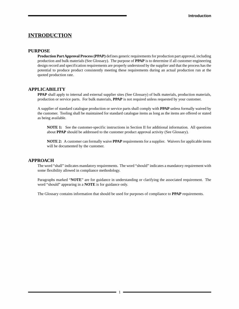
PURPOSEProduction Part Approval Process (PPAP) defines generic requirements for production part approval, includingproduction and bulk materials (See Glossary). The purpose of PPAP is to determine if all customer engineeringdesign record and specification requirements are properly understood by the supplier and that the process has thepotential to produce product consistently meeting these requirements during an actual production run at thequoted production rate.
APPLICABILITYPPAP shall apply to internal and external supplier sites (See Glossary) of bulk materials, production materials,production or service parts. For bulk materials, PPAP is not required unless requested by your customer.
A supplier of standard catalogue production or service parts shall comply with PPAP unless formally waived bythe customer. Tooling shall be maintained for standard catalogue items as long as the items are offered or statedas being available.
NOTE 1: See the customer-specific instructions in Section II for additional information. All questionsabout PPAP should be addressed to the customer product approval activity (See Glossary).
NOTE 2: A customer can formally waive PPAP requirements for a supplier. Waivers for applicable itemswill be documented by the customer.
APPROACHThe word “shall” indicates mandatory requirements. The word “should” indicates a mandatory requirement withsome flexibility allowed in compliance methodology.
Paragraphs marked “NOTE” are for guidance in understanding or clarifying the associated requirement. Theword “should” appearing in a NOTE is for guidance only.
The Glossary contains information that should be used for purposes of compliance to PPAP requirements.
Introduction
SECTION I
I. 1 GENERAL
The supplier shall obtain full approval (See I.5.2.1) from the customer product approval activity for:
1. a new part or product (i.e., a specific part, material, or color not previously supplied to the specific customer).
2. correction of a discrepancy on a previously submitted part.
3. product modified by an engineering change to design records, specifications, or materials.
4. any situations required by Section I.3.
NOTE: If there is any question concerning the need for production part approval, contact the responsible customerproduct approval activity.
I.2 PPAP PROCESS REQUIREMENTS
I.2.1 Significant Production Run
For production parts, product for PPAP shall be taken from a significant production run. This production run shall befrom one hour to eight hours of production, and with the specific production quantity to total a minimum of 300consecutive parts, unless otherwise specified by the authorized customer quality representative.
This run shall be manufactured at the production site using the tooling, gaging, process, materials, and operators fromthe production environment. Parts from each unique production process, e.g. duplicate assembly line and/or work cell,each position of a multiple cavity die, mold, tool or pattern, shall be measured and representative parts tested.
For bulk materials: No specific number of “parts” is required. If a sample is required to be submitted, it shall be takenin a manner as to assure that it represents “steady-state” operation of the process.
NOTE: For bulk material, production histories of current products may often be used to estimate the initialprocess capability or performance of new and similar products. In cases where no production history of a similarbulk material product or technology exists, a containment plan may be put into effect until sufficient productionhas demonstrated capability or performance.
I.2.2 PPAP Requirements
The supplier shall meet all specified requirements, e.g. design record, specifications, and for bulk material, the BulkMaterial Requirements Checklist (see I.2.2.15 and Appendix F). Any results that are outside specification are cause forthe supplier not to submit the parts, documentation and/or records. Every effort shall be made to correct the process sothat all design record requirements are met. If the supplier is unable to meet any of these requirements, the customershall be contacted for determination of appropriate corrective action.
2
Inspection and testing for PPAP shall be performed by a qualified laboratory (See QS-9000, Third Edition, cl. 4.10.6).Commercial/independent test laboratories used shall be accredited facilities (see QS-9000, Third Edition, cl. 4.10.7,and 4.11.2.b.1). When a commercial laboratory is used, the supplier shall submit the test results on the laboratoryletterhead, or the normal laboratory report format. The name of the laboratory that performed the tests, and the date (s)of the tests, and the standards used to run the tests shall be indicated. Blanket statements of conformance areunacceptable for any test results.
The supplier shall have the applicable items and records (See QS-9000, Third Edition, cl. 4.16), listed below, for eachpart, or family of parts, regardless of the part submission level. These records (I.2.2.1 – 15 and 19 if any) shall be in aPPAP part file, or referenced in such file and be readily available. The items below (I.2.2.16 - 18) shall be readilyavailable for customer use in PPAP.
The supplier shall obtain prior approval (see QS-9000, Third Edition, cl. 4.16) from the customer product approvalactivity for exceptions or deviations to PPAP requirements.
NOTE 1: The supplier may, upon special arrangement, have tests performed by the customer’s laboratories.
NOTE 2: All I.2.2 items or records may not necessarily apply to every customer part number from everysupplier. For example, some parts do not have appearance requirements, and others do not have colorrequirements. In order to determine with certainty which items must be included, consult the design record,e.g. part print, the relevant Engineering documents or specifications, and your customer responsible partapproval activity.
I.2.2.1 Design Records
The supplier shall have all design records for the saleable product, including design records for components or detailsof the saleable product. Where the design record, e.g. CAD/CAM math data, part drawings, specifications, is inelectronic format, e.g. math data, the supplier shall produce a hard copy (e.g. pictorial, geometric dimensioning &tolerancing [GD&T] sheets, drawing) to identify measurements taken.
NOTE 1: For any saleable product, part or component, there will only be one design record, regardless of whohas design-responsibility. The design record may reference other documents making them part of the designrecord.
NOTE 2: For bulk materials, the design records may include identification of raw materials, formulations,processing steps and parameters, and final product specifications or acceptance criteria. If dimensional resultsdo not apply, then CAD/CAM requirements are also not applicable.
I.2.2.2 Any authorized Engineering Change documents
The supplier shall have any authorized engineering change documents not yet recorded in the design record butincorporated in the product, part or tooling.
I.2.2.3 Engineering Approval, when required
Where specified by the design record, the supplier shall have evidence of customer engineering approval.
NOTE: For bulk materials, this requirement is satisfied by a signed ‘Engineering Approval’ line item on theBulk Material Requirements Checklist (Appendix F) and/or inclusion on a customer maintained list of approvedmaterials.
3
Section I
I.2.2.4 Design Failure Mode and Effects Analysis (Design FMEA), if the supplier is design responsible. SeePotential Failure Mode and Effects Analysis reference manual.
The supplier shall have a Design FMEA developed in accordance with, and compliant to, QS-9000 Third Editionrequirements for parts or materials for which they are design-responsible. For bulk materials, a Design Matrix (SeeAppendix F), when required by the Bulk Material Requirements Checklist (see I.2.2.15), shall be prepared prior todeveloping the Design FMEA.
NOTE: For bulk materials, Design FMEA rankings (Severity, Occurrence, Detection) as discussed in AppendixF, may be utilized to provide proper differentiation of risk factors.
I.2.2.5 Process flow diagrams
The supplier shall have a process flow diagram in supplier-specified format that clearly describes the production processsteps and sequence, as appropriate and meets the specified customer needs, requirements and expectations (see AdvancedProduct Quality Planning and Control Plan reference manual). For bulk materials, an equivalent to a Process FlowDiagram is a Process Flow Description.
NOTE: Process flow diagrams for ‘families’ of similar parts are acceptable if the new parts have been reviewedfor commonality.
I.2.2.6 Process Failure Mode and Effects Analysis (Process FMEA). See Potential Failure Mode and EffectsAnalysis reference manual.
The supplier shall have a Process FMEA developed in accordance with, and compliant with QS-9000 Third Editionrequirements.
NOTE: A single Design or Process FMEA may be applied to a process manufacturing a family of similar partsor materials. For bulk materials, see Appendix F for a severity, occurrence, and detection ranking system toprovide proper differentiation of risk factors.
I.2.2.7 Dimensional results
The supplier shall provide evidence that dimensional verifications required by the design record and the Control Planhave been completed and results indicate compliance with specified requirements. The supplier shall have dimensionalresults for each unique manufacturing process, e.g. cells or production lines and all cavities, molds, patterns or dies (seeI.2.2.13).
The supplier shall indicate the date of the design record, change level, and any authorized engineering change documentnot yet incorporated in the design record to which the part was made.
The supplier shall identify one of the parts measured as the master sample (See I.2.2.17).
The supplier shall record the change level, drawing date, supplier name and part number on all auxiliary documents(e.g. supplementary layout results sheets, sketches, tracings, cross sections, CMM inspection point results, geometricdimensioning and tolerance sheets, or other auxiliary drawings used in conjunction with the part drawing). Copies ofthese auxiliary materials shall accompany the dimensional results according to the Retention/Submission RequirementsTable. A tracing shall be included when an optical comparator is necessary for inspection.
4
NOTE 1: All dimensions (except reference dimensions), characteristics, and specifications as noted on thedesign record and Control Plan should be listed in a convenient format with the actual results recorded. TheDimensional Results form in Appendix C, or a checked print where the results are legibly written on a partdrawing including cross-sections, tracings, or sketches as applicable may be utilized for this purpose.
NOTE 2: Dimensional results typically do not apply to bulk materials.
I.2.2.8 Records of material / performance test results
The supplier shall have records of material and/or performance test results for tests specified on the design record orControl Plan.
I.2.2.8.1 Material Test Results
The supplier shall perform tests for all part(s) and product material(s) when chemical, physical, or metallurgicalrequirements are specified by the design record or Control Plan.
All tests required by the design record and related specifications should be listed in a convenient format alongwith the quantity tested and the actual results of each test. Also indicate any authorized engineering changedocuments that have not yet been incorporated in the design record.
The material test report (See Appendix D) shall indicate the:
• design record change level of the parts tested, and the number, date, and change level of the specificationsto which the part was tested;
• date on which the testing took place;
• material subcontractor’s name and, when required by your customer, their supplier code number for thematerial from the customer-approved subcontractor list.
For products with customer-developed material specifications and a customer-approved subcontractor list, thesupplier shall procure materials and/or services (e.g. painting, plating, heat-treating) from subcontractors on thatlist.
I.2.2.8.2 Performance Test Results
The supplier shall perform tests for all part(s) or product material(s) when performance or functional requirementsare specified by the design record or Control Plan.
The test report shall indicate:
• the design record change level of the parts tested, the number, date, and change level of the specificationsto which the part was tested;
• any authorized engineering change documents that have not yet been incorporated in the design record;• the date on which the testing took place.
NOTE: Results for all tests required by the design record or related specifications should be listed in anunderstandable format and include the quantity tested. The Performance Test Results form in Appendix Emay be used for this purpose.
5
Section I


18

SECTION II
II.1 DaimlerChrysler Corporation-Specific Instructions
Unless superseded by specific written direction from the DaimlerChrysler Corporation Procurement and Supplyrepresentative or by engineering drawing and specification requirements the following instructions apply.
II.1.1 SUBMISSION LEVELS
Suppliers designated by DaimlerChrysler Corporation as “self-certified” are to follow the guidelines for SubmissionLevel 1. All others are to follow the guidelines for Submission Level 2 unless otherwise instructed by your ComponentProcurement and Supplier Quality representative. When conducting a bulk material PPAP, use conventions as detailedin Section I in this manual.
II.1.2 SUBMISSION
All suppliers submitting their PSW’s for PRODUCTION PARTS designated for use at all DaimlerChrysler Corporationfacilities must follow the directions as found on the DaimlerChrysler Corporation Supply Partner Information Network,(SPIN), on the World Wide Web. This information can be accessed from the PRISM Home Page. Click on PPAPBusiness Processes.
• All suppliers providing material for any DaimlerChrysler PILOT build must submit a PSW utilizing the directionsfound in the DaimlerChrysler Corporation Supply Partner Information Network, (SPIN), on the World WideWeb. This information can be accessed from the PRISM Home Page. Click on PPAP Business Processes.
• Suppliers must submit their PSW’s per table I.3.1 in this manual as required by DaimlerChrysler’s “ForeverRequirements” as well as PSW’s for new and modified parts.
II.1.3 CHECKING AIDS
Checking aids must be submitted when required to perform the dimensional inspection of the part being submitted.Contact your DaimlerChrysler Corporation part approval representative to determine if this requirement can be waived.
II.1.4 APPEARANCE APPROVAL REQUIREMENTS
The supplier must complete the Appearance Approval Report if the design records include any appearance features(e.g.. Color, Grain, Finish, Appearance Standards, or Mastering Standards). Prior to submission with the Warrant, thesupplier must obtain a DaimlerChrysler Corporation Design Office approval signature on the Appearance ApprovalReport.
NOTE: Both Interior and Exterior parts are included in the Appearance Approval Report procedure.
Suppliers of external sheet metal body panels must follow DaimlerChrysler Corporate Procedure 90-57 for surfaceappearance review.
19
Section II - DaimlerChrysler Specific Instructions

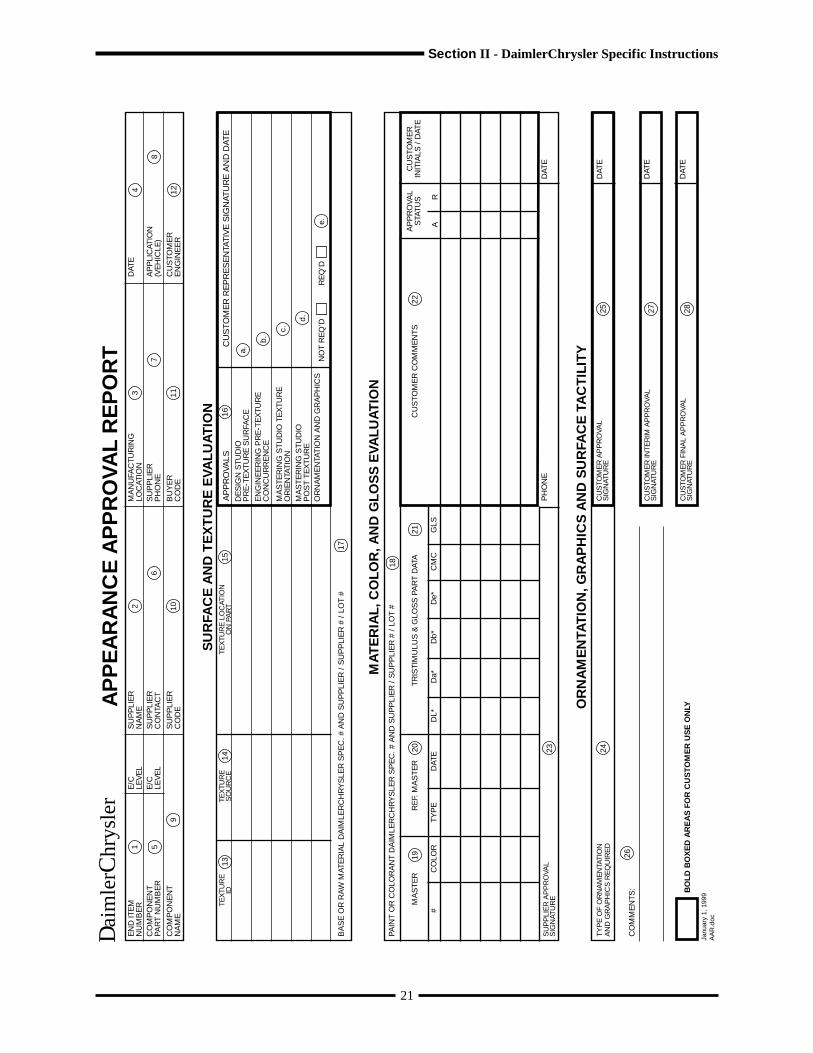
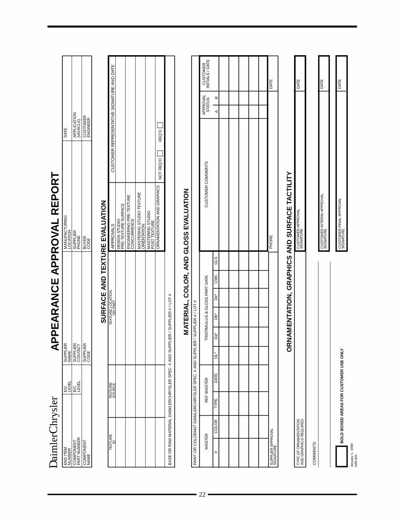
COMPLETION OF THE APPEARANCE APPROVAL REPORT
1) End Item Number: Engineering released part number and engineering change level.2) Supplier Name: Enter component and end item suppler.3) Manufacturing Location: Location where part was manufactured or assembled.4) Date: Date of submission.5) Component Part Number: Engineering released component part number.6) Supplier Contact: Supplier representative responsible for submission.7) Supplier Phone Number: Supplier contact phone number.8) Application (Vehicle): List model year(s) and vehicles in which part is used.9) Component Name: Enter the component part name.10) Supplier Code: DaimlerChrysler assigned code for supplier location where the part was manufactured or assembled.11) Buyer Code: Enter the code for specific buyer of end item.12) Customer Engineer: Enter the name of the DaimlerChrysler Release Engineer responsible for the part being submitted.13) Texture ID: Enter DaimlerChrysler identification number of texture (when applicable).14) Texture Source: Enter name and location of texturing source (when applicable).15) Texture Location on Part: Enter area(s) of grain(s) delineation (when applicable).16) Surface and Texture Evaluation (when applicable):
a) DaimlerChrysler Design Office manager (or designated representative) approval of pre-textured surface.b) DaimlerChrysler Release / Product Engineer authorization to proceed with texture.c) DaimlerChrysler Design Office mastering studios designated representative authorization to proceed, including a
signed part.d) DaimlerChrysler Design Office mastering studios designated representative post texture approval
Note: Texturing can not proceed without authorized signatures in 16a, 16b, and 16c.e) DaimlerChrysler Design Office manager (or designated rep.) decision as to ornamentation and graphics approval
requirements.17) Base or Raw Material DaimlerChrysler Spec. # and Supplier / Supplier # / Lot # : Enter DaimlerChrysler material
specification code, supplier name, supplier product code, and lot number of the material used to make the submittedpart.
18) Paint or Colorant DaimlerChrysler Spec. # and Supplier / Supplier # / Lot # : Enter DaimlerChrysler Paint orColorant Spec. #, supplier name, supplier product code, and lot number of the material used to make the submitted part.
19) Master # and Color: Enter full master identification and color number as released by DaimlerChrysler. (Refer to TrimRelease).
20) Ref. Master Type and Date: Enter reference master type and date as supplied by DaimlerChrysler for visual direction.21) Tristimulus and Gloss Part Data: List numerical (colorimeter) data of submission part as compared to the customer-
authorized master. Enter gloss data using 60-degree geometry measuring equipment.22) Customer Comments / Approval Status / Initials / Date: Customer comments regarding color and gloss disposition
and/or color direction. Customer will indicate whether the color and gloss are accepted (A) or rejected (R), initial anddate the form. Note: Final approval signature is still required.
23) Supplier Signature, Phone Number & Date: Supplier designated representative accountable for the certification thatthe submitted parts and document information is accurate and meets all the requirements specified.
24) Type of Ornamentation, Graphics Required and Surface Tactility: Name / process type – cluster graphics, badges,labels, etc. / pad transfer, hot stamp, lithograph, heat transfer, silk screen, laser etch, soft touch feel, etc.
25) Customer Approval Signature & Date: Design Office designated rep. Approval of identified ornamentation, graphicsand surface tactility.
26) Comments: General comments of importance to be initialed and dated.27) Customer Interim Approval Signature: DaimlerChrysler Design Office Interim approval of end item or component
part. Allows IAA usage at this submission level.28) Customer Final Approval Signature: DaimlerChrysler Design Office Final approval of end item or component part.
ALL SIGNATURES AND DATES (areas 16 (if applicable), 22, 25 (if applicable) & 27)MUST BE COMPLETED FOR FULL AAR APPROVAL.
THE AREAS INSIDE THE BOLD LINES ARE FOR CUSTOMER USE ONLY
20

21
EN
D IT
EM
NU
MB
ER
CO
MP
ON
EN
TPA
RT
NU
MB
ER
CO
MP
ON
EN
TN
AM
E
E/C
LEV
EL
SU
PP
LIE
RN
AM
EE
/CLE
VE
LS
UP
PLI
ER
CO
NTA
CT
SU
PP
LIE
RC
OD
E
MA
NU
FAC
TUR
ING
LOC
ATIO
NS
UP
PLI
ER
PH
ON
E
BU
YE
RC
OD
E
DAT
E
AP
PLI
CAT
ION
(VE
HIC
LE)
CU
STO
ME
RE
NG
INE
ER
CU
STO
ME
R R
EP
RE
SE
NTA
TIV
E S
IGN
ATU
RE
AN
D D
ATE
AP
PR
OVA
LSTE
XTU
RE
LO
CAT
ION
ON
PA
RT
TEX
TUR
ES
OU
RC
ETE
XTU
RE
IDD
ES
IGN
STU
DIO
PR
E-T
EX
TUR
E S
UR
FAC
E
EN
GIN
EE
RIN
G P
RE
-TE
XTU
RE
CO
NC
UR
RE
NC
E
MA
STE
RIN
G S
TUD
IO T
EX
TUR
EO
RIE
NTA
TIO
NM
AS
TER
ING
STU
DIO
PO
ST
TEX
TUR
EO
RN
AM
EN
TATI
ON
AN
D G
RA
PH
ICS
BA
SE
OR
RA
W M
ATE
RIA
L D
AIM
LER
CH
RY
SLE
R S
PE
C. #
AN
D S
UP
PLI
ER
/ S
UP
PLI
ER
# /
LO
T #
13
1 5
9
1415
2
6
10
3
7
11
4
8
12
16
a.
b.
c.
d.
NO
T R
EQ
’D
RE
Q’D
e.
SU
RFA
CE
AN
D T
EX
TU
RE
EVA
LUA
TIO
N
MA
TE
RIA
L, C
OLO
R, A
ND
GLO
SS
EVA
LUA
TIO
N
OR
NA
ME
NTA
TIO
N, G
RA
PH
ICS
AN
D S
UR
FAC
E T
AC
TIL
ITY
17
PAIN
T O
R C
OLO
RA
NT
DA
IMLE
RC
HR
YS
LER
SP
EC
. # A
ND
SU
PP
LIE
R /
SU
PP
LIE
R #
/ L
OT
#
MA
STE
RR
EF.
MA
STE
RTR
ISTI
MU
LUS
& G
LOS
S P
AR
T D
ATA
18
1920
21
#C
OLO
RTY
PE
DAT
ED
L*D
a*D
b*
De*
CM
CG
LS
CU
STO
ME
R C
OM
ME
NTS
AP
PR
OVA
LS
TATU
SC
US
TOM
ER
INIT
IALS
/ D
ATE
22
AR
23S
UP
PLI
ER
AP
PR
OVA
LS
IGN
ATU
RE
TYP
E O
F O
RN
AM
EN
TATI
ON
AN
D G
RA
PH
ICS
RE
QU
IRE
D24
PH
ON
ED
ATE
DAT
E
DAT
E
DAT
E
CU
STO
ME
R A
PP
RO
V AL
SIG
NAT
UR
E
CU
STO
ME
R IN
TER
IM A
PP
RO
V AL
SIG
NAT
UR
E
CU
STO
ME
R F
INA
L A
PP
RO
V AL
SIG
NAT
UR
E
25 27 28
CO
MM
EN
TS:
26
BO
LD B
OX
ED
AR
EA
S F
OR
CU
ST
OM
ER
US
E O
NL YA
PP
EA
RA
NC
E A
PP
RO
VAL
RE
PO
RT
Janu
ary
1, 1
999
AA
R.d
oc
Section II - DaimlerChrysler Specific Instructions
Dai
mle
r Chr
ysle
r

22
EN
D IT
EM
NU
MB
ER
CO
MP
ON
EN
TPA
RT
NU
MB
ER
CO
MP
ON
EN
TN
AM
E
E/C
LEV
EL
SU
PP
LIE
RN
AM
EE
/CLE
VE
LS
UP
PLI
ER
CO
NTA
CT
SU
PP
LIE
RC
OD
E
MA
NU
FAC
TUR
ING
LOC
ATIO
NS
UP
PLI
ER
PH
ON
E
BU
YE
RC
OD
E
DAT
E
AP
PLI
CAT
ION
(VE
HIC
LE)
CU
STO
ME
RE
NG
INE
ER
CU
STO
ME
R R
EP
RE
SE
NTA
TIV
E S
IGN
ATU
RE
AN
D D
ATE
AP
PR
OVA
LSTE
XTU
RE
LO
CAT
ION
ON
PA
RT
TEX
TUR
ES
OU
RC
ETE
XTU
RE
IDD
ES
IGN
STU
DIO
PR
E-T
EX
TUR
E S
UR
FAC
E
EN
GIN
EE
RIN
G P
RE
-TE
XTU
RE
CO
NC
UR
RE
NC
E
MA
STE
RIN
G S
TUD
IO T
EX
TUR
EO
RIE
NTA
TIO
NM
AS
TER
ING
STU
DIO
PO
ST
TEX
TUR
EO
RN
AM
EN
TATI
ON
AN
D G
RA
PH
ICS
BA
SE
OR
RA
W M
ATE
RIA
L D
AIM
LER
CH
RY
SLE
R S
PE
C. #
AN
D S
UP
PLI
ER
/ S
UP
PLI
ER
# /
LO
T #
NO
T R
EQ
’D
RE
Q’D
SU
RFA
CE
AN
D T
EX
TU
RE
EVA
LUA
TIO
N
MA
TE
RIA
L, C
OLO
R, A
ND
GLO
SS
EVA
LUA
TIO
N
OR
NA
ME
NTA
TIO
N, G
RA
PH
ICS
AN
D S
UR
FAC
E T
AC
TIL
ITY
PAIN
T O
R C
OLO
RA
NT
DA
IMLE
RC
HR
YS
LER
SP
EC
. # A
ND
SU
PP
LIE
R /
SU
PP
LIE
R #
/ L
OT
#
MA
STE
RR
EF.
MA
STE
RTR
ISTI
MU
LUS
& G
LOS
S P
AR
T D
ATA
#C
OLO
RTY
PE
DAT
ED
L*D
a*D
b*
De*
CM
CG
LS
CU
STO
ME
R C
OM
ME
NTS
AP
PR
OVA
LS
TATU
SC
US
TOM
ER
INIT
IALS
/ D
ATE
AR
SU
PP
LIE
R A
PP
RO
VAL
SIG
NAT
UR
E
TYP
E O
F O
RN
AM
EN
TATI
ON
AN
D G
RA
PH
ICS
RE
QU
IRE
D
PH
ON
ED
ATE
DAT
E
DAT
E
DAT
E
CU
STO
ME
R A
PP
RO
V AL
SIG
NAT
UR
E
CU
STO
ME
R IN
TER
IM A
PP
RO
V AL
SIG
NAT
UR
E
CU
STO
ME
R F
INA
L A
PP
RO
V AL
SIG
NAT
UR
E
CO
MM
EN
TS: BO
LD B
OX
ED
AR
EA
S F
OR
CU
ST
OM
ER
US
E O
NL YA
PP
EA
RA
NC
E A
PP
RO
VAL
RE
PO
RT
Janu
ary
1, 1
999
AA
R.d
oc
Dai
mle
r Chr
ysle
r

II.1.5 SUPPLIER REQUEST FOR PRODUCT CHANGE
The Supplier Request for Product Change (SRPC) provides suppliers the opportunity to obtain specification relief forminor dimensional and/or standard variations that do not affect performance, assembly, quality, durability, warranty,customer satisfaction or cost.
The SRPC is not a means to avoid making the parts “to print.” The supplier is expected to make every effort to resolvediscrepancies before resorting to an SRPC. All SRPCs should be written and approved prior to presenting the Warrant.Contact the respective DaimlerChrysler Corporation part approval activity for copies of the SRPC form and completeinstructions on its use. Identify the approved SRPC (as SRPC#XXXX) in the Additional Engineering Change line ofthe Warrant.
II.1.6 INTERIM APPROVAL
II.1.6.1 INTERIM APPROVAL AUTHORIZATIONS
The Interim Approval Authorization (IAA) is a procedure to enable suppliers to meet production part submission datesand plant production requirements for late design changes. In these cases, the supplier will receive authorization fromDaimlerChrysler Corporation through the Interim Approval Authorization (IAA) document. Parts to specification aresupplied through the use of the IAA process until permanent tool/process parts are approved and available to meetproduction requirements.
Once parts are available from the permanent tooling/process, a new submission is required.
II.1.7 DaimlerChrysler Corporation Procurement and Supply Representative
All references to “customer” pertain to the DaimlerChrysler Procurement and Supply representative. The “customerproduct approval activity” pertains to DaimlerChrysler Corporation Powertrain, Stamping, and Component operationreceiving facilities.
II.1.8 Third Party Laboratories
When DaimlerChrysler Corporation specifies the use of a third party laboratory, that laboratory must be approved byDaimlerChrysler Corporation or accredited through either an ILAC or APLAC member, e.g. American Association forLaboratory Accreditation (A2LA), the Standards Council of Canada (SCC) or the Laboratory Accreditation Bureau (L-A-B).
23
Section II - DaimlerChrysler Specific Instructions

24
II.2 Ford-Specific Instructions
II.2.1 Part Approval Activity - For external suppliers this refers to the Ford Supplier Technical AssistanceOffice (STA) of, or representing, the customer. Internal operations should contact their responsible ap-proval activity or the FAO Quality Office.
II.2.2 ES (Engineering Specification) - This is the Ford designation for the performance tests referred to in thebody of this document.
II.2.3 Substance Use Restrictions - A statement indicating conformance with Ford Engineering Material Speci-fication WSS-M99P9999-A1 is required on the material test report. (This specification is available fromMaterials Engineering). This specification results from regulations of the countries where Ford does busi-ness. These regulations apply equally to Ford and its suppliers. Therefore, this specification does not addany requirements, but does require the supplier to verify conformance with the specification and withrelevant regulations in the country of manufacture and the country of the Ford receiving location.
Suppliers self-certify conformance to this specification and are not required to provide supporting testdata.
NOTE: Plastic Parts Marking - suppliers of plastic parts are encourage to mark plastic (polymeric) partswith the appropriate ISO symbols to designate the type of polymer and filler/reinforcer used to fabricatethe part (further information is provided in Ford material specification E-4 available on-line at https://web.keyinfo.ford.com/manuals/index.html and https://web.keyinfo.ford.com/supply/docs/e4.pdf). Affectedsuppliers are requested to indicate compliance on the PSW form, as appropriate.
II.2.4 Interim Approvals - When non-conformances on a production part submission are identified, the STAengineer shall contact the buyer and product engineer following local procedures. If the product engineerallows use of product affected by the non-conformance, product engineering shall initiate (and approve) an“alert” in the WERS system, specifying the time period or quantity for which the non-conforming productcan be used. The supplier shall enter the alert number on the PSW form under “Additional EngineeringChanges”. Once parts are available from the permanent tooling/process, a new part submission war-rant (PSW) is required. Should incomplete or in-process test data result in an “alert”, a new PSW isrequired upon availability of completed test data.
II.2.5 Control Plans - Shall be developed by the supplier and be available for review by the customer as early aspossible and in any case prior to the production part submission date. Control Plans must include allCritical and Significant characteristics. Product Engineering and Part approval activity signatory approvalis required on Control Plans for Control Item ( ) products and for products so designated by ProductEngineering (e.g., with an ES specifically requiring this approval). Some Ford quality activities may re-quest that a copy of the approved Control Plan be attached to the Part Submission Warrant and forwardedto the customer part approval activity.
II.2.6 Appearance Item Approvals - All parts having appearance criteria (*) shall be reviewed by the FordDesign Quality Office. The completed Appearance Approval Report (form CFG01002) shall accompanythis submission. After approval signatures have been obtained from the designated Ford Design Qualityrepresentative, the form shall be included with Warrant.
(*) NOTE: All interior, exterior, luggage compartment, and select underhood components which arevisible to the customer. Appearance approval included but is not limited to overall appearance, color,texture, and gloss.
Refer to the Corporate Design Decorative Component Approval Process manual for detailed instructions.
∆

25
Section II - Ford Specific Instructions
For additional information, contact: Ford Design Quality, Ford Motor Company, Product DevelopmentCenter, Mail Drop 533, PO Box 2110, Dearborn, MI, 48123; fax: 313-594-7705.
II.2.7 Part Submission Level - For external suppliers, PPAP submission level is controlled by the Ford STACommodity Engineer based on Q1 status, correct PPAP usage/submittal, critical nature of components andproduct concerns. When conducting a bulk material PPAP, use conventions as detailed in Section I in thismanual.
NOTE: It is important that suppliers designated as Level 2-5 account for any additional time that maybe required to obtain STA approval, when providing PSW promise date (If the STA Engineer is un-available to approve the PPAP in a timely manner, the supplier should contact the STA Program Man-ager who may assign another engineer to disposition the PSW; for bulk materials, contact the RawMaterials STA Manager).
Internal operations should contact their responsible approval activity or the FAO Quality Office regardingPPAP submission level.
II.2.8 Manage the Change - The supplier shall develop and implement a process to manage change to ensurethat any product (either revised or new) affected by revisions in design and process shall continue to meetall applicable specifications. A copy of the Supplier Checklist/Approval for Managing Change is providedfor guidance on page 30.
All design changes shall be clearly described and reference the WERS Engineering Notice number underthe “Additional Engineering Changes” on the PSW form. Questions regarding this requirement should bereviewed with the using Ford facility.
The customer using facility may request full or partial PPAP documentation from the supplier in address-ing specific product related concerns - supplier data shall be readily available upon request.
All post Job #1 changes (e.g., running changes, new supplier sourcing, revised supplier manufacturinglocation, etc.) shall obtain functional approval from the customer using facility prior to shipping of produc-tion quantities.
NOTE: At Vehicle Operation facilities contact the Plant Vehicle Team (PVT) for functional approval.
If the component is used at multiple Ford facilities, then all using facilities must provide functional ap-proval (a using facility may opt to waive functional approval in certain cases). Functional approval isprovided at the bottom of the PSW form under “For Customer Use Only”. Questions concerning the needfor functional approval should be directed to the using Ford facilities.
II.2.9 Family of Parts - Suppliers are permitted to submit multiple part numbers (same family of parts) on asingle PSW with all part specifics (e.g., prefix, base, suffix) clearly noted on the PSW.
II.2.10 Labeling Requirement - Suppliers to Ford European facilities are required to affix orange labels (FormEU 3441, minimum A5 size) on all four sides of the packaging for all shipments of new or changed productto each using Ford facility. Powertrain suppliers are required to include their unique supplier generatedPSW number on each label of the PSW shipment (ongoing shipments are excluded from this requirement).
II.2.11 Run at Rate - Run at rate is an integral part of the sample submission (PSW) for suppliers and whichprovides the basis to extract capability data and inspection layout data. All production tooling shall be inplace and running at full production feeds and speeds, using all regular production direct and indirectpersonnel and support systems (QS-9000, Section II, Ford-Specific Requirements)

26
II.2.12 Qualified Laboratory Documentation - Laboratory scope and documentation requirements (PPAP,Section I.2.2.11) are not applicable to Ford suppliers.
II.2.13 Supplier Request for Engineering Approval (SREA) - The SREA procedure applies to all internal andexternal suppliers without on-line WERS capability. Ford product engineering approval of a SREA isrequired prior to implementing the change. Once Ford product engineering determines that the change isfeasible and a SREA is required, the supplier will complete and submit the SREA, Form 1638, to theresponsible product engineer.
Once approval is granted, a copy of the approved SREA shall be included in the PSW submission; powertrainsuppliers shall also provide a copy of the approved SREA to the using customer facility.
Process ChangesThe supplier is empowered to implement process changes without issuing and obtaining SREA ap-proval with the following exceptions:
- Change in heat treat, plating/coating and solderability.- Changes to the manufacture of supplier-designed electronic components (capacitors, resistors, in-
tegrated circuits and similar components).- Re-location of product to a different manufacturing location.
These exceptions will be waived once a supplier achieves Full Service Supplier status or is releasedfrom the SREA requirement by the responsible design activity.
Changes to the process of control item ( ) parts or emission components always require issuance ofa SREA. No waivers apply for these components.
• Ford reserves the right to require that additional process changes be subject to SREA submission basedon each supplier’s performance in managing the change process. Suppliers are responsible for imple-menting this procedure with subcontractors.
• Refer to the following flow diagram for the elements of the SREA process.
∆

27
SUPPLIER REQUEST FOR ENGINEERING APPROVAL (SREA)
▼
▼
▼
▼
▼
▼▼
▼
CONTROLITEM OR
EMISSIONCOMPONENT
?
BLACKBOX
DESIGN?
(REQUIREMENT GUIDELINES)
DESIGNPROCESSREVIEW WITHENGINEERING
FORAPPROVAL IN
WERS
▼
NO
YES
YES
YES
FULLSERVICE
SUPPLIER?
SREAWAIVED ?
NO
FULLSERVICESUPPLIER
?
YES
▼
YES
NO
NO
NO YES
YESSREA
WAIVED?
PRE-DESIGNATED
PROCESS*?
(SREA APPROVAL PROCESS)
YES
NO
YES
NO
NO
*CHANGE IN HEAT TREAT, PLATING/COATING, SOLDERABILITY CHANGE IN MANUFACTURE OF ELECTRONIC COMPONENTS RELOCATION OF PRODUCT TO ALTERNATE MANUFACTURING LOCATION
▼
YESNO SREAAPPROVED
?
ADDITIONALINFORMATION
REQUIRED?
SUPPLIER SUBMITS SREA TORESPONSIBLE FORD
ENGINEER FOR DISPOSITION(15 DAY TURN-AROUND)
FEASIBLE?
SUPPLIER CONTACTSFORD ENGINEERING TOOBTAIN PRELIMINARY
FEASIBILITY APPROVAL
SREA REQUIRED
DO NOT IMPLEMENTCHANGE
DISTRIBUTE TOAFFECTED ACTIVITIES
AND SUPPLIER
NO
▼
▼
▼
▼
▼▼
▼
▼
▼
▼
▼
▼
▼
▼
SUPPLIER WANTS TOMAKE A DESIGN ORPROCESS CHANGE
SUPPLIER TOMANAGE THE
CHANGEACCORDING TO
PPAP ANDISSUE PSW
OBTAINFUNCTIONAL
APPROVAL
▼
Section II - Ford Specific Instructions
YES

II.2.14 PSW Submission Process - The following table sumarizes submission practices and methods for notify-ing the appropriate Ford system of completion of the PSW:
Suppliers on DDL (Direct Data Link) shall enter their PSW approval into appropriate Ford PSWtracking system (EASI, CMMS Parts Progress, ELECT) per table below. Non-DDL suppliers shallfollow local practices required to accommodate differing Ford systems to facilitate proper entry.
PPAPLevel SUPPLIER
STA ENGINEER APPROVAL OF PSW DATA PACKAGE
DATA ENTRY OFAPPROVAL
Level 1DDL
Non-DDL
- Prepare PPAP data package/selfapprove.
- Assign unique number to each PSW *- Provide sample parts/PSW to usingFord facilities for functional approval/waiver.
- Fax copy of PSW to using powertrainplant when parts are shipped *
- Enter approval in Ford System.- Maintain the completed PPAP datapackage on file.
- Prepare PPAP data package/selfapprove.
- Assign unique number to each PSW *- Provide sample parts/PSW to usingFord facilities for functional approval/waiver.
- Fax copy of PSW to using powertrainplant when parts are shipped *
- Contact FAO Production Purchasingand report PPAP data packageapproval status.
- Maintain the completed PPAP datapackage on file.
STA approval of PSW datapackage is not required. Supplierself certifies (supplier submissionnot required)
STA approval of PSW datapackage is not required. Supplierself certifies (supplier submissionnot required)
Supplier enters in Fordsystem.
FAO ProductionPurchasing entersapproval, per localpractice.
Level 2-5DDL
- Prepare PPAP data package.- Get STA approval.- Assign unique number to each PSW *- Provide sample parts/PSW to using
Ford facilities for functional approval/waiver.
- Fax copy of PSW to using powertrainplant when parts are shipped *
- Enter approval in Ford system after STAapproval of PPAP data package.
- Maintain the completed PPAP datapackage on file.
28
- STA approves PPAP datapackage/sign warrant.
- STA returns PPAP datapackage to supplier.
Supplier enters in Fordsystem after STAapproval of PPAP datapackage.

29
PPAPLevel SUPPLIER
STA ENGINEER APPROVAL OF PSW DATA PACKAGE
DATA ENTRY OFAPPROVAL
- Prepare PPAP data package.- Get STA approval.- Assign unique number to each PSW *- Provide sample parts/PSW to using
Ford facilities for functionalapproval/waiver.
- Fax copy of PSW to using powertrainplant when parts are shipped *
- Contact FOA Production Purchasingand report PPAP data package approvalstatus.
- Maintain the completed PPAP datapackage on file.
* applies only to suppliers to powertrain operations
NOTE: JAGUAR IS EXEMPTED FROM THIS PROCESS.
PSW SUBMISSION LOCAL PRACTICES
Supplier or STA Engineer will handle approved warrant per local practices below:
Purchase Orders Issued in North AmericaPurchase Orders Issued in
Europe
PTO Vehicle Operations All Operations
NON-DDL SUPPLIERS:- Fax (or hand deliver to onsite drop box)
copy of the approved warrant to TimingAnalyst.
- Analyst enters approval.
NOTE: Supplier must allow for STAapproval timing, where required, in SamplePromise Date.
NON-DDL SUPPLIERS:- Notify Material Follow-up Analyst when
PPAP data package is approved.
- Analyst will enter approval in the FordPPAP tracking software.
- Send copy of ApprovedWarrant to Buyer.
- Buyer enters PPAP datapackage approval.
- Buyer files copy of Warrant.
- STA approves PPAP datapackage/sign warrant.
- STA returns PPAP data packageto supplier.
FAO ProductionPurchasing entersapproval, per localpractice after STAapproval of PPAP datapackage.
Section II - Ford Specific Instructions
Non-DDL
30
SUPPLIER CHECKLIST/APPROVAL for MANAGING CHANGE
Supplier Name Part Name Part Number
Mfg. Location Code Vehicle Lines Affected Ford Plants Affected
Change Description
ANY ITEMS NOT REQUIRED, PLEASE EXPLAIN: Reqd. Complete Date Comments
1. Engineering and Manufacturing Disciplines:
Layout/Detail/Assy Drawings
Tolerance Stack-Up
Installation Drawings
Reliability Methods
Process Sheets
Engineering Specification
Material Specification
Supplier Component DFMEA
Supplier System DFMEA
Ford Component DFMEA
Ford System DFMEA
Process Flow Chart
Supplier Component PFMEA
Supplier System PFMEA
Ford Component PFMEA
Ford System PFMEA
Ford SDS Update
DV/PV/IP Test
Vehicle Test
Operator Instruction Sheets
Tool & Gage Revisions
Gage R&R Study
Control Plan
Production Trial Run
Sub-Supplier Affect
Service Parts
2. Ford Feasibility Review
Ford Design Engineer Approval
SREA
CR/CR
Alert
PSW
Ford Plant Functional Approval Use Part Submission Warrant (PSW) under “Customer Use Only”
Purchase Order
3. Approvals
Engineering Manager: Quality Manager:
Production Manager: Plant Manager:
31
EMISSION CONTROLCODE NUMBER
(SEE FORM74-107)
CONTROL ITEMAFFECTED
YES NO
SUPPLIER REQUEST FOR ENGINEERING APPROVAL
PRODUCT ENGINEERING TO COMPLETE
INTERCHANGEABILITY AFFECTED
ASSEMBLY YES NO
COMPONENTS YES NO
WILL INCORPORATION OF CHANGEAFFECT SHIPPING SCHEDULE?
YES NO
TIME REQ’D TO INCORPORATE CHANGEAFTER APPROVAL
SIGNATURE _____________________________SUPPLIER REPRESENTATIVE
PIECE COST AFFECTED YES NO
IF YES, COST EFFECT $
TOOLING OR FACILITY CHANGES REQUIRED YES NO
IF YES, COST EFFECT $
APPROVED* RELEASE ACTION REQ’D, NOTICE # __________________________________________________________________ REJECTED
BY DATE CONCURRED BY DATE SIGNATURE __________________________________ SIGNATURE__________________________________
EFFECT OF CHANGE:
FORD AND/OR SUPPLIER PART NAME AND PART NUMBER OF ASSEMBLY AND ITS COMPONENTS
SUPPLIER NAME AND ADDRESS
BLANKET APPROVAL GRANTED FOR SUBSEQUENT CHANGES WHICH ARE SAME AS DESCRIBED ABOVE
YES NO
SUPPLIER CHECKLIST ATTACHED?
YES NO
SAMPLE OF CHANGED COMPONENT REQUIRED
YES NO
REASON FOR REJECTION OR QUALIFYING CONDITIONS OF ACCEPTANCE:
REVIEWED BY:
SQA ____________________________________ DATE ________________ PURCHASING____________________________________DATE __________________________
CEGJUL 92 (Previous editions may NOT be used)
* This approval is granted upon the understanding that it is advisory in nature and in no manner changes the Sellersoriginal responsibility for insuring that all characteristics, designated in the applicable engineering specifications and/orinherent in the samples as originally tested and approved, are maintained. Seller accepts full responsibility for the changesor types of changes listed above; and should such changes result in less satisfactory performance than experienced withthe originally approved item, Seller will fully reimburse the Buyer for all expenses incurred to correct the deficiency.
1638
SUPPLIER TO COMPLETE
DESCRIPTION OF CHANGE: DESIGN COMPOSITION WEIGHT PROCESSING
DATE ___________________________________ 19 ________
Section II - Ford Specific Instructions
32
FORD GLOSSARY
Critical ( ) Critical ( ) characteristics are those product requirements (dimensions, performance tests)Characteristics or process parameters that can affect compliance with government regulations or safe vehicle/
product function, and which require specific supplier, assembly, shipping, or monitoringand are included on Control Plans.
SREA The process that provides for two-way communication between the component supplier andthe responsible Ford product engineering activity through which the supplier requestsconcurrence for certain process related changes.
33
Section II - Ford Specific Instructions
GM
II.3 General Motors Specific Instructions
II.3.1 Applicability
This procedure is applicable to production, service, and unitized service parts, raw materials purchased by or contractedto GM. It also applies to all commodities supplied by external independent suppliers, GM Allied and Affiliated suppliers,plus all commodities supplied to these suppliers (e.g., subcontractors and third tier suppliers). Please note that for bulk,raw, or indirect material, it is the Procuring Division’s decision whether PPAP is required. When conducting a bulkmaterial PPAP, use conventions as detailed in Section I in this manual.
II.3.2 Requirements For Part Approval
II.3.2.1 PSW Form (CFG-1001) (see I.2.2.13)
1. The supplier shall use one warrant per customer part number.2. GM does not require the purchase order number (item #7).3 Enter Buyer name, and/or Buyer Code, if known (item #15).4. The Supplier Code referred to on the PSW and on the Appearance Approval Report is the full code assigned to the
manufacturing location on the purchasing order.5. The PSW shall be complete, legible and accurate. Warrants will not be accepted that have the following fields in
error:Part Number item 2Engineering Drawing Change Level item 4Weight item 8Supplier Code item 11Supplier Address item 12Reason for Submission item 17Supplier Authorized Signature item 22
6. The supplier should include an EWO number with the engineering change level on the warrant.
II.3.2.2 Appearance Approval Report (see I.2.2.14)
1. Appearance Approval Report (AAR) (CFG-1002) for parts with color, grain, gloss or textiles
NOTE: AAR is not required for surface quality of body in white (BIW) parts. Refer to the General MotorsNorth America Surface Buyoff Procedure for Surface Requirements of BIW parts.
2. Appearance Approval may occur concurrently with part inspection and testing.
II.3.2.3 Sample Product (see I.2.2.16)
If submitting for Level 2 or 3, the supplier shall submit two sample parts unless otherwise specified by the procuringDivision. For multiple processes, two sample parts per process e.g. two parts per cavity, tool, cells, assembly lines arerequired unless otherwise specified by the procuring division. The sample parts do not have to be the same part(s) that
34
were dimensionally measured and documented on the marked drawing or check sheet. All sample parts should belabeled with part number, change level, and supplier name.
II.3.2.4 Design Records (see I.2.2.1)
1. A marked drawing can be used for a full PPAP submission provided the drawing is signed by the product engineer,has an EWO number and is dated.
2. All Supplier design records shall be GM approved.3. The supplier shall furnish evidence of conformance to print specifications of each detail component when requested.4. For CAD parts that are databanked, the current level in the GM design databank is the inspection referee. The
source of the data shall be provided with change level and date.
II.3.2.5 Material, Performance and Durability test results (see I.2.2.8)
1. When Material, Validation, Performance, Durability, Reliability, or other engineering requirements are on thedesign record, approval can occur in two ways.a) The supplier gets approval prior to PPAP and submits evidence of approval.b) The supplier submits the test data or results with the PPAP submission. Note that an additional drawing may
be required by the procuring division.2. All Laboratory data shall be less than one year old at the time of initial submission. Previously approved test data
shall be updated (less than one year old) if part performance, material, reliability, durability or validation is affectedby an engineering change. The updated test data shall be included in the PPAP submission for the engineeringchange.
3. A GM-E364 form is required where the note “ Engineering Approval required” or the stamp “Engineering sourceapproval for functional performance” is checked “yes” and found on the drawing or design record (see I.2.2.3)
II.3.2.6 Control Plans (see I.2.2.12)
GM requires suppliers to document and submit (depending on submission level) their Pre-Launch Control Plan. Forinformation on the Pre-Launch Control Plan, see section 3.7 of the Chrysler, Ford, General Motors Advanced ProductQuality Planning and Control Plan reference manual. General Motors General Procedure GP-12 “Early ProductionContainment” proceduralizes the Pre-Launch Control Plan. All parts requiring production part approval (PPAP) shallalso comply with GP-12 Early Production Containment.
Whenever a supplier is required to submit a Production Control Plan, they shall also submit a Pre-Launch ControlPlan, as defined by GP-12.
II.3.2.7 Initial Process Study (see I.2.2.9)
The minimum required acceptance criteria for the PPAP initial study shall be a Cpk or Ppk of 1.67.
II.3.3 Customer Notification of Supplier-Initiated Changes
NOTE: The following does not include initial submissions, engineering changes, or changesdescribed in Table I.3.3.:
35
Section II - GM Specific Instructions
1. The supplier shall review the proposed change with the procuring division prior to implementation to obtainconcurrence per the division’s local practice.
2. Sufficient information shall be provided to explain the detailed reason for the submission. Attachments areencouraged.
3. Level 1 submission should be checked.4. GM will review the warrant and determine if the warrant is acceptable. If the warrant is acceptable the supplier
shall receive the standard supplier notification authorizing shipment. If additional information or a higher submissionis required, the supplier shall be notified by the procuring division.
5. For submissions other than “Initial Submission” and “Engineering Change(s)” sufficient information shall beprovided to explain the detailed reason for the submission. Additional attachments are encouraged.
II.3.4 Situations Where Customer Notification is not Required
1. For item 1, table I.3.3, the supplier shall notify GM per II.3.3 Customer Notification of Supplier Initiated Changes.2. Resubmission is not required for a design record update that reflects a change that was previously approved per a
dated marked print with an EWO number and engineering signature per section I.2.2.2 and/or I.2.2.3.
II.3.5 Submission Levels (see I.4.1)
1. Suppliers are not required to maintain full documentation from their subcontractors if they have decision criteriaand a process in place to establish the level of evidence required from their subcontractors, and the appropriatelevel of evidence on file at their location. Upon a Procuring Division’s request for Production Part ApprovalDocumentation, suppliers must comply within a reasonable period of time.
2. ATTENTION SUPPLIERS TO GENERAL MOTORS EUROPE: Level 2 shall be the default level for allsubmissions to General Motors Europe, unless specifically advised otherwise by the responsible part approvalactivity.
II.3.6 Part Submission Status
A. Full Approval (see I.5.2.1)
1. Part meets all requirements as outlined on the GM approved drawing and in accordance with PPAP.2. Drawing must be fully released or is a marked drawing accompanied by an EWO, product engineer’s signature
and date.3. Multiple cavity tools can achieve full approval on individual cavities provided the cavity being submitted meets all
the requirements outlined in the PPAP manual. Each submission for a multiple cavity tool must specify the cavityand/or cavities that are being submitted for full approval.
B. Interim Approval (I.5.2.2)
1. If a part is not a “full approval”, the Interim Approval will authorize the shipment to the customer. The status“Interim Approval” indicates the customer’s decision to use the part without Full Approval.
2. All Interim Approvals require a corrective action plan. The Interim Recovery Worksheet (GM 1411), which hasbeen developed for this purpose, is to be completed with the supplier.
3. If an extension is required, the GM 1411 must be re-issued and the interim date changed.4. All Interim Approvals require the part number to be classified A, B, C, D, or E as follows:
36
GM
Class A: Parts are produced using 100% production tooling and meet design record specifications. However, notall production approval requirements have been met.
Examples:1. A capability study has been performed on less than 300 pieces and in the judgment of the SQE, satisfactory
stability and capability has not been achieved. The supplier shall implement temporary containmentactions until capability is achieved.
2. Documentation improvements required. Examples include DFMEA, PFMEA, Process Flow Diagramand Process Control Plan.
3. Part only lacks formal PPAP processing for statusing. Parts and data have been reviewed by the SQE andthere is no indication of non-conformances.
4. Testing has not yet been completed and in the judgment of the appropriate engineer, usage of the partsdoes not pose a significant risk to customer dissatisfaction e.g. Long term material tests, long term functionaltest, environmental exposure etc. (Engineering signature is required).
5. Part and drawing do not match and a part change is not desired or anticipated. The interim worksheetmust specify the differences between the part and the specification. The interim worksheet must documenta commitment and date for the specification to be changed. (Engineer’s signature required.)
Class B: Parts are produced using 100% production tooling and require rework to meet design record specificationsas explained on the GM 1411 form.
Examples:1. Parts have been produced not following the documented production process on the process flow diagram.
Examples include trimming, sanding, buffing, etc. The process flow diagram includes any temporaryoperations except inspection. Added inspection alone should not be considered rework, but insteaddocumented in the GP-12 plan and/or the process flow diagram and process control plan.
Class C: Parts are not produced using 100% production tooling and/or production processes, but meet designrecord specifications as explained on the GM 1411 form.
Examples:1. Parts have been produced using additional, substitute or temporary tooling.2. Parts have not been manufactured completely at the production site/environment.
NOTE: If low volume tools are intended to meet current production needs submit for full productionapproval.
Class D: Parts do not meet design record specifications as explained on the GM 1411 form.
Examples:1. Dimensional, material validation/functional testing or appearance characteristics that do not met design
record requirements but will not impact vehicle assembly or customer satisfaction. Product engineersignature is required.
Class E: Parts do not meet design record specifications as explained on the GM 1411 form. Vehicles with ClassE parts require retrofit to make them saleable.
Examples:1. Dimensional, material validation/functional testing or appearance characteristics that do not meet design
record requirements and will impact vehicle assembly or customer satisfaction. Product engineer signatureis required.
2. Incomplete testing with high probability of failure and/or failed performance/functional material testing.Parts require retrofit for saleable status. Product engineer signature required.
37
Section II - GM Specific Instructions
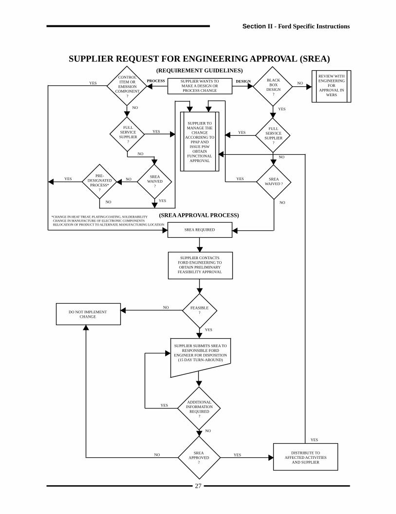
38
3. Incomplete FMVSS testing.
C. Rejected (see I.5.2.3)
The part or associated documentation does not meet specified requirements. A resubmission shall be required. Shipmentof parts is not permitted.
D. Reciprocity of part submission status within GM
1. Production approval status from one GM Division applies to all GM. Suppliers do not need to reevaluate thepart or resubmit documentation, solely because the part will be used by another GM location. A copy of thewarrant and the document signifying approval must be supplied to the new using division. The new usingdivision reserves the right to review the PPAP information upon request.
2. Parts may be requested for a production trial run (PTR).3. Interim approval granted by one division does not automatically guarantee authorization to ship to other GM
locations.
II.3.7 Packaging and Labels
Each sample submission to General Motors shall be packaged separately and identified with the General Motors“Sample Submission for Production Approval” label, GM Form 1387. The information required on the label shall beadded by the supplier prior to shipment. When several submissions are to be shipped in one larger container, a “SampleSubmission for Production Approval” label, with only the “To” and “From” portion completed, shall be attached to thecontainer at the upper right hand corner, visible from two sides. Each sample submission inside the larger containershall be packaged and labeled as specified. Parts and paperwork shall be packaged together.
GM
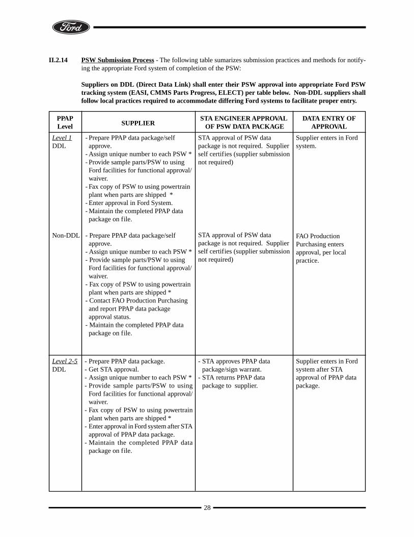
39
INTERIM RECOVERYWORKSHEET
(GM 1411)
Section II - GM Specific Instructions
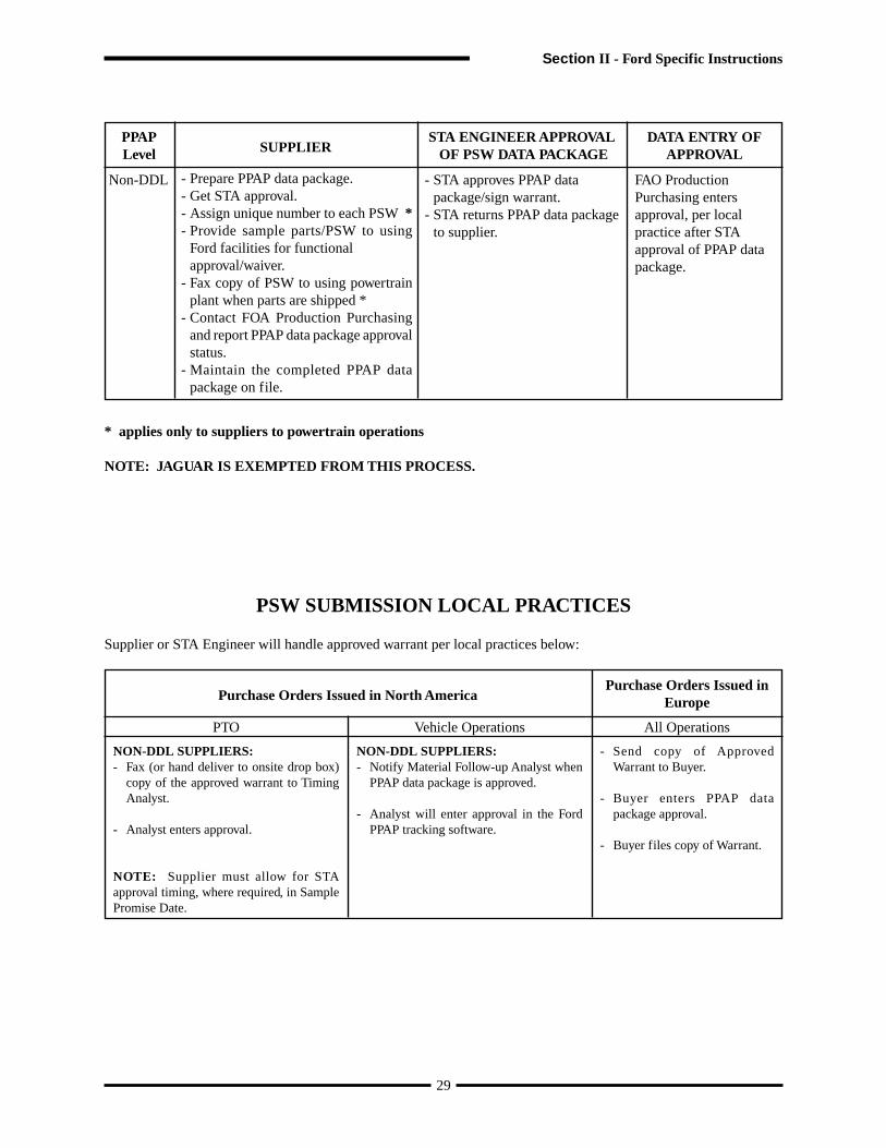
40
COMPLETION OF THE INTERIM RECOVERY WORKSHEETDetailed Instructions for completion of Interim Recovery Worksheet (GM 1411)
Items 13 to 17, and item 19 are for customer PPAP group use only. For all other items, supplier must provide appropriate information in order to obtain interim approval.
1. Supplier Name: Name assigned to manufacturing location2. Supplier Code: Supplier assigned DUNS number of the manufacturing location.3. Resubmission date: New promise date or PPAP submission date. The supplier’s commitment date to have the Corrective Action Plan item(s)
completed and resubmitted to the PPAP group. Part Readiness tracks the re-submission date for follow-up when required. There-submission date must be prior to the interim expiration date.
4. Interim Expire Date: The expiration date is the last acceptable date of shipment of the part under this Interim Approval status report.5. Application: List programs where the part number is used.6. Part Name: Engineering released finished end item name.7. Part Number: GM 8 Digit Part Number submitted for PPAP.8. EWO#: Engineering Work Order number, of the associated PPAP submission that authorizes print changes.9. ECL: Engineering Change Level of the associated PPAP submission.10. ECL date: Date of engineering change level submitted.11. Submission Level: Submission Level 1 - 5. Enter submission level determined by the procuring division.12. KG Wt: Enter the actual weight in kilograms to three decimal places.13. Sample Number: The number of samples received under that part # for a given Duns location.14. Inspector/SQE: Customer use only. Inspector/SQE initials.15. Additional Sample: Additional sample parts required, specified by the metrology/PPAP lab.16. PKG#: Package number assigned to the submission. Generated by GQTS.17. Interim #: Interim number assigned by the procuring division to track interim submissions.18. Interim Class: Type interim class or circle the appropriate interim class, A B C D E.
Class A - Parts are produced using 100% production tooling and meet design record specifications. However not all productionapproval requirements have been met.Examples:1. A capability study has not been completed: A capability study of less than 300 pieces and in the judgment of the SQE,
satisfactory stability and capability has been achieved.2. Documentation improvements required. Examples include DFMEA, PFMEA, Process Flow Diagram, and Process
Control Plan.3. Part only lacks formal PPAP processing for statusing. Parts and data have been reviewed by the SQE and there is no
indication of non-conformances.4. Testing has not yet been completed and in the judgment of the appropriate engineer, usage of the parts does not pose a
significant risk to customer dissatisfaction e.g. Long term material performance tests, long term functional test,environmental exposure etc. ( Engineer signature required).
5. Part and drawing do not match and a part change is not desired or anticipated. The interim worksheet must specify thedifferences between the part and the specification. The interim worksheet must document a commitment and date forthe specification to be changed. (Engineer’s signature required.)
Class B - Parts are produced using 100% production tooling and require rework to meet design record specifications.Examples:1. Parts have been produced not following the documented production process on the Process Flow Diagram. Examples
include trimming, sanding, buffing, etc. Process Flow Diagram includes any temporary operations except inspection.Added inspection alone should not be considered rework but, instead, documented in the GP-12 plan and/or the ProcessFlow Diagram and the Process Control Plan.
Class C - Parts are produced using non-production tooling and/or process but, meet design record specifications.Examples:1. Parts have been produced using additional, substitute, or temporary tooling.2. Parts have not been manufactured completely at the production site/environment.3. Note: If low volume tools are intended to meet current production needs submit for a full PPAP approval.Class D - Parts do not meet design record specifications.Example:1. Dimensional, Material validation/functional testing or appearance characteristics that do not meet design record
requirements but will not impact vehicle assembly or customer satisfaction. (Product engineer and/or Assembly plantsignature is required)
Class E - Parts do not meet design record specifications. Vehicles with class E parts require retrofit to make them saleable.Examples:1. Dimensional, material or appearance characteristics that do not meet design record requirements and will impact
vehicle assembly and/or customer requirements. (Product Engineer and/or Assembly plant signature is required.)2. Incomplete testing with a high probability of failure and/or a failed performance/functional material testing. Part
requires retrofit for saleable status. (Product Engineer and/or Assembly Plant signature is required.)3. Incomplete FMVSS testing.
19. Status: Enter appropriate letter (A= Approved, I= Interim required, N= Not Made).20. Brief Reasons: Provide a brief reason for requesting an interim approval. Where applicable specify if tooling modifications or other
modifications were made.21. Issues /Action Plan(s): List all issues applicable, and use additional sheets if necessary. For non-grained parts, submit on Less Finish part number. For
color /Gloss issues submit on color part number. Provide a corrective action plan with date of completion, when requesting forapproval
22. GP-12: Describe how Early Production Containment will be used to document countermeasures offsetting interim issues listed on theGM1411 (interim recovery worksheet). If GP-12 is not used to document countermeasures an explanation is required.
23. Supplier: Required supplier authorized signature from responsible supplier official to ensure compliance to the information provided forInterim approval, legibly print or type name, title and include phone and fax number.
24. Customer Approvals: Obtain appropriate signatures from customer for areas of concern. Suppliers must have SQE’s approval for all interim classesand release engineer’s approval for interim D and E. Requirements are subjected to change and may vary for each procuringdivision. ask SQE for details.
Attach Part Submission Warrant with Customer approvals in order to have interim processed and send to processing group. Interim Approvals canbe obtained in person, fax, mail or via E-mail.
GM
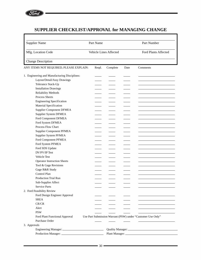
41
Section II - GM Specific Instructions
INTERIM RECOVERY WORKSHEET (GM 1411)GM
CUSTOMER APPROVALS: SIGNATURE NAME (Print) PHONE DATE
SUPPLIER QUALITY ENGINEER:PRODUCT ENGINEER (DRE):LAB/MATERIAL ENGINEER:APPEARANCE/PAINT ENGINEER:OTHER (Buyer, Assembly Plant, etc.):
SUPPLIER NAME:
SUPPLIER CODE:
RESUBMISSION DATE:
INTERIM EXPIRE DATE:
APPLICATION:
PART NAME:
PART #:
SUBMISSION LEVEL: KG Wt:
SAMPLE #: INSP/SQE: ADD. SAMPLE: PKG: Interim#
EWO#:
ECL: DATE:
INTERIM CLASS (Type interim class or circle for manual entry):
STATUS: Type or fill in appropriate status (A=Approved, I = Interim, N = Not made).
DIM: APP: LAB: PROCESS: ENG:
A B C D E
BRIEF REASONS (116 characters max.):
ISSUES: (List DIM, APP, LAB, Process, tooling, capacity,o r start-up issues) ACTION PLANS (provide with date of completion)
WHERE APPLICABLE, ARE INTERIM ISSUES ADDRESSED ON THE GP-12 PLAN? (e.g. rework, temporary operations)
(Please explain below):
SUPPLIER (Authorized signature): PHONE:
NAME & TITLE: (Print) FAX:PART SUBMISSION WARRANT MUST BE INCLUDED WITH CUSTOMER APPROVALS IN ORDER TO PROCESS YOUR REQUEST AND SEND TO THE PROCURING DIVISION.
Cus
tom
erS
upp
lier
Cus
tom
erS
upp
lier
1
2
3
4
5
6
7
8
9 10
11 12
13 14 15 16 17
18
19
20
21
22
23
24
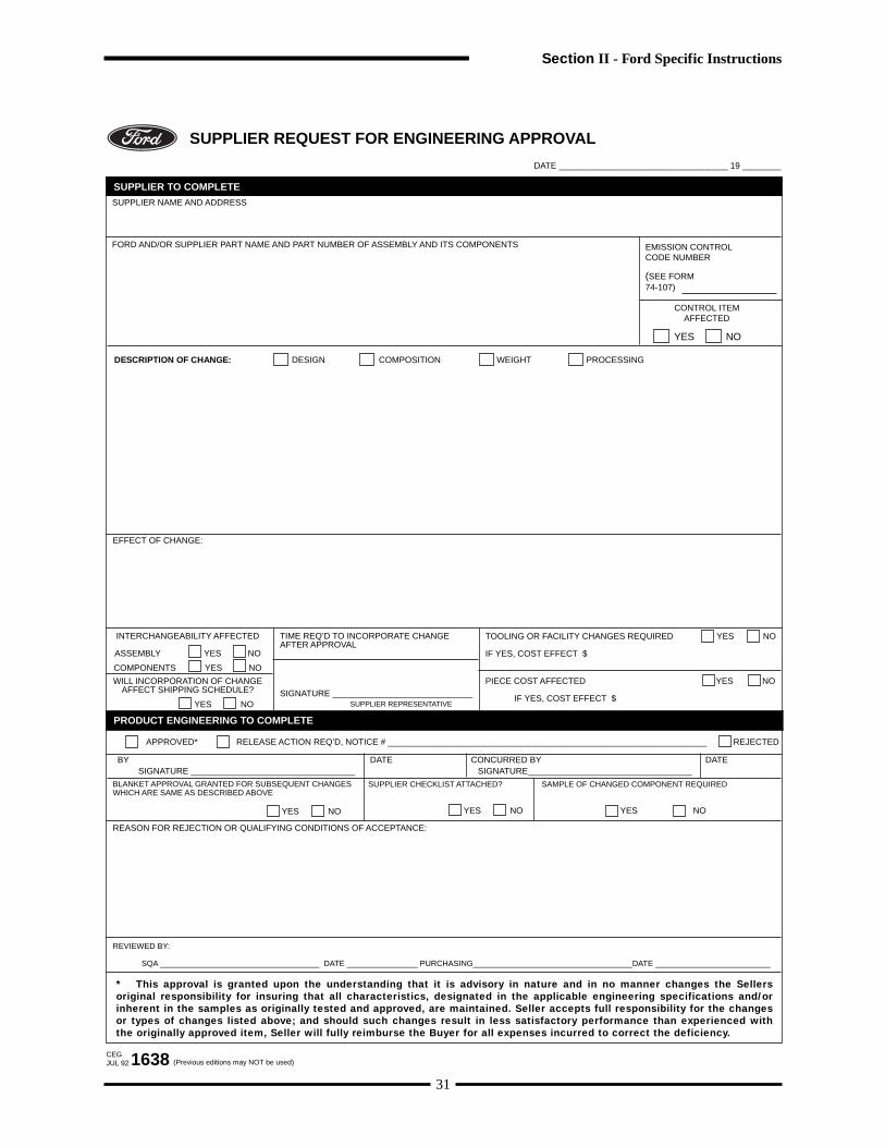
42
GM
INTERIM RECOVERY WORKSHEET (GM 1411)GM
CUSTOMER APPROVALS: SIGNATURE NAME (Print) PHONE DATE
SUPPLIER QUALITY ENGINEER:PRODUCT ENGINEER (DRE):LAB/MATERIAL ENGINEER:APPEARANCE/PAINT ENGINEER:OTHER (Buyer, Assembly Plant, etc.):
SUPPLIER NAME:
SUPPLIER CODE:
RESUBMISSION DATE:
INTERIM EXPIRE DATE:
APPLICATION:
PART NAME:
PART #:
SUBMISSION LEVEL: KG Wt:
SAMPLE #: INSP/SQE: ADD. SAMPLE: PKG: Interim#
EWO#:
ECL: DATE:
INTERIM CLASS (Type interim class or circle for manual entry):
STATUS: Type or fill in appropriate status (A=Approved, I = Interim, N = Not made).
DIM: APP: LAB: PROCESS: ENG:
A B C D E
BRIEF REASONS (116 characters max.):
ISSUES: (List DIM, APP, LAB, Process, tooling, capacity,o r start-up issues) ACTION PLANS (provide with date of completion)
WHERE APPLICABLE, ARE INTERIM ISSUES ADDRESSED ON THE GP-12 PLAN? (e.g. rework, temporary operations)
(Please explain below):
SUPPLIER (Authorized signature): PHONE:
NAME & TITLE: (Print) FAX:PART SUBMISSION WARRANT MUST BE INCLUDED WITH CUSTOMER APPROVALS IN ORDER TO PROCESS YOUR REQUEST AND SEND TO THE PROCURING DIVISION.
Cus
tom
erS
upp
lier
Cus
tom
erS
upp
lier
43
Section II - GM Specific Instructions

GM
44
COMPLETION OF THE ENGINEERING SOURCE APPROVAL FOR FUNCTIONAL PERFORMANCE
1. Part number GM 8 Digit Part Number submitted for PPAP.
2. Supplier Name Name assigned to manufacturing location.
3. Part name Engineering released finished end item name.
4. Duns Code Supplier assigned duns number of the manufacturing location.
5. Application List of programs where the part number is used.
6. ECL Engineering change level of the associated PPAP submission.
7. EWO Engineering work order number of the associated PPAPsubmission authorizing print changes.
8. Drawing Number Drawing number on which part number appears.
9. Revision Date Date of revision drawing that is being submitted.
10. Part meets engineering requirements Indicate if the part meets all engineering requirements. If notrefer to section IV on this form.
11. Comments Provides area to make comments if desired.
12. Parts not meeting engineering requirements Parts that do not meet the requirements shall not use the GM-E364. The supplier shall clearly document the nonconformances on the GM 1411 and follow the interim approvalprocess. The Supplier shall obtain engineering signatures on theGM 1411 form.
13. GM Product Engineer Print product engineer or design release engineer’s name.
14. Phone Number Product/design release engineer phone number.
15. Signature Product/design release engineer signature.
16. Date The date the product/design release engineer signs the GM-E364.
17. Code Product/design release engineer code.
45
I. Part Number (s): Supplier:
Part Name: Duns Code:
Application: ECL: EWO:
Drawing Number: Revision Date:
II. The Part Meets All Engineering Performance Requirements. (e.g., Sub System
Tech. Spec., Comp. Tech. Spec., Solar, Validation) Yes
III. Comments:
IV. Part not meeting all engineering requirements specified above (section III).
Must be submitted on the GM1411 interim worksheet (the GM-E364 form
does not apply).
V. GM Product Engineer: Phone Number:
Date:
Supplier ➾ GM Engineer (DRE) ➾ Supplier ➾ SQE/Part Approval Activity
(Print)
(Signature)
(Code)
Engineering Source Approval for Functional Performance
1 2
3 4
5 6 7
8 9
10
11
12
13 14
15 16
17
Section II - GM Specific Instructions
46
I. Part Number (s): Supplier:
Part Name: Duns Code:
Application: ECL: EWO:
Drawing Number: Revision Date:
II. The Part Meets All Engineering Performance Requirements. (e.g., Sub System
Tech. Spec., Comp. Tech. Spec., Solar, Validation) Yes
III. Comments:
IV. Part not meeting all engineering requirements specified above (section III).
Must be submitted on the GM1411 interim worksheet (the GM-E364 form
does not apply).
V. GM Product Engineer: Phone Number:
Date:
Supplier ➾ GM Engineer (DRE) ➾ Supplier ➾ SQE/Part Approval Activity
(Print)
(Signature)
(Code)
Engineering Source Approval for Functional Performance
GM
II.4 Truck OEM-Specific Instructions
This truck specific section was developed to define those PPAP requirements, which are unique to subscribing NorthAmerican Heavy Truck OEMs. When completing PPAPs for the subscribing truck OEMs, this section will be applicable.This section of PPAP was developed by Automotive Industry Action Group (AIAG) in conjunction with the Truck andHeavy Equipment Group (THEG).
PPAP PROCESS REQUIREMENTS
II.4.1 Significant Production Run (see I.2.1)
The purpose of the production trial run is to ensure the effectiveness of the manufacturing process by running productionproducts off of production tools, materials, equipment, cycle times, and environments while using production operators,gages, and other production methods. It is imperative that adequate quantities of parts be manufactured during this runto sufficiently sample, test, and thoroughly try out the production process (at rate) prior to full production. Since partsfrom the production trial run must be used to inspect and test for the initial sample submission, it is mandatory thatproduction processes and environments be used for this trial run. It is also mandatory to insure that sufficient quantitiesof parts are run for preliminary process capability studies and for validation testing.
Since production trial runs in the truck industry are typically small, it is recommended that a maximum number ofproduction parts be run during the trial run to insure production has ample time to prove out the process, while yieldingsufficient quantities of parts to perform process capability studies. It is recognized that sample sizes as small as 30pieces may be utilized for preliminary process capability studies. Sample sizes must be discussed and agreed to earlyin the APQP process.
If projected volumes are so low that 30 samples are not attainable prior to production, interim PPAP approval may begranted. A dimensional report with 100% inspection on special characteristics is required during the interim period.Once the 30 production samples are produced, measured and the quality index calculated and accepted, then the interimapproval is changed to full approval.
II.4.2 Dimensional and Test Results Clarification (see I.2.2.7 and I.2.2.8)
Checked prints are not accepted within the truck industry. The supplier shall submit, as part of the PPAP package, acopy of the drawing with each dimension, test, and or specification identified with a unique number. These uniquenumbers shall be entered onto the dimensional or test results sheet as applicable, and actual results entered onto theappropriate sheets. The supplier shall also identify print zone for each numbered characteristic as applicable.
II.4.3 Initial Process Studies - General (see I.2.2.9)
Due to the fact that small production trial runs are common in the truck industry, the supplier shall use the guidelinesdescribed in II.4.1 above to maximize the number of parts run during the production trial run in order to have as manyparts as possible available to inspect for capability studies. Truck manufacturers require a minimum of 30 productionpieces be studied for preliminary process capability.
47
Section II - Truck OEM Specific Instructions
When the customer specifies special characteristics and the estimated annual usage is less than 500 pieces, the suppliershall document in their control plan that they will either:
• perform 100% inspection and record the resultsOR
• conduct an initial process capability study with a minimum of 30 production pieces and maintain SPC controlcharts of the characteristics during production.
For special characteristics that can be studied using variable data, the supplier shall utilize one of the following techniquesto study the stability of the process:
• X-Bar and R Charts, n=5, plot minimum 6 subgroups
OR
• Individual X - Moving Range, plot minimum 30 data points
When performing the initial short term study, data shall be plotted from consecutive parts taken from the productiontrial run. These studies could be augmented or replaced by long term results from the same or similar process run onthe same equipment with prior customer concurrence.
II.4.4 Acceptance Criteria for Initial Study (see I.2.2.9.3)
For initial process capability studies using 30 to 300 parts, the supplier shall use the following as acceptance criteria forevaluating initial process study results for processes that appear stable:
For attribute features contact customer for appropriate sample size and statistical method.
48
II.4.5 Measurement System Analysis Studies (see I.2.2.10)
The supplier shall have Measurement System Analysis studies, e.g. gage R&R, bias, linearity, stability studies, for allgages and equipment used to measure special product characteristics or special process parameters. MeasurementSystem Analysis studies for gage families is not acceptable.
Where the Customer has a long termMinimum Capability Requirement of:
The Short Term (30 Piece Capability Study)Minimum Acceptance Criteria is:
≥ 1.33≥ 1.79≥ 2.24
≥ 1.00≥ 1.33≥ 1.67
49
II.4.6 Special Characteristic Requirements
SAFETY AND/OR GOVERNMENT RELATED PART OR CHARACTERISTICS
CUSTOMER TERM SYMBOL
Mack Trucks, Inc. Key Control Characteristics (KCC)
Navistar Key Control Characteristics (KCC)KCC
M
PACCAR QA Codes (1,2,3 or 4) inside symbol in titleblock
Kenworth
or -
Peterbilt
or -
Freightliner Key CharacteristicsK
Volvo Trucks N.A. QA Codes (1 or 2) inside symbol in title block [1] or [2]
Western Star Refer to Western Star Part Drawings
IMPORTANT PERFORMANCE, FIT OR APPEARANCE CHARACTERISTICS
CUSTOMER TERM SYMBOL
Mack Trucks Key Control Characteristics (KCC)
M
Navistar Key Control Characteristics (KCC)KCC
PACCAR Critical Characteristic (C) or Signif icantCharacteristic (S)
C S
Freightliner Key CharacteristicsK
Volvo Trucks N.A. Consequence Class [1] [2] or [3]
Western Star Refer to Western Star Part Drawings
Section II - Truck OEM Specific Instructions
II.4.7 Part Submission WarrantSuppliers to subscribing truck OEMs shall use the PSW form below instead of the PSW form in Appendix A. (see nextpage for North American Truck Industry PSW Form). The North American Truck Industry PSW form is the sameas the automotive PSW except for the declaration statement, which is worded more properly for the truck industry.Instructions for completing the form are the same as described on page 52.
50
Part Name Part Number
Safety and/orGovernment Regulation Yes No Engineering Drawing Change Level Dated
Additional Engineering Changes Dated
Shown on Drawing No. Purchase Order No. Weight kg
Checking Aid No. Engineering Change Level Dated
SUPPLIER MANUFACTURING INFORMATION SUBMISSION INFORMATION
Supplier Name & Supplier Code
Street Address
City/State/Postal Code
Dimensional Materials/Functional Appearance
Customer Name/Division
Buyer/Buyer Code
Application
SUBMISSION RESULTS
The results for dimensional measurements material and functional tests appearance criteria statistical process package
These results meet all drawing and specification requirements:
Mold / Cavity / Production Process
Yes NO (If “NO” – Explanation Required)
DECLARATIONI hereby affirm that the samples represented by this certification are representative of our parts, have been made to the applicable customer�drawings and specifications, and are made from the specified materials on regular production tooling with no operations other than the regular�production process. I also certify that documented evidence of such compliance is on file and available for review.
EXPLANATION/COMMENTS:
Print Name Title Phone No.
Supplier Authorized Signature Date
FOR CUSTOMER USE ONLY (IF APPLICABLE)
ApprovedPart Warrant Disposition: Rejected
Customer Name Customer Signature Date
Part Submission Warrant
J u l y1 9 9 9 TAG-1001
FAX No.
1 2 3 4 5 6 7 8 9 10 11 12 13 14 15 16 17 18 19
Interim Approval
ApprovedPart Functional Approval:
Waived
(Circle)
North American Truck Industry
REASON FOR SUBMISSIONInitial Submission Change to Optional Construction or Material
Engineering Change(s) Sub-Supplier or Material Source Change
Tooling: Transfer, Replacement, Refurbishment, or additional Change in Part Processing
Tooling Inactive > than 1 yearCorrection of Discrepancy Parts Produced at Additional Location
Other – please specify
REQUESTED SUBMISSION LEVEL (Check one)
Level 1 – Warrant only (and for designated appearance items, an Appearance Approval Report) submitted to customer.
Level 2 – Warrant with product samples and limited supporting data submitted to customer.
Level 3 – Warrant with product samples and complete supporting data submitted to customer.
Level 4 – Warrant and other requirements as defined by customer.
Level 5 – Warrant with product samples and complete supporting data reviewed at supplier's manufacturing location.
TS
�
Note:� Does this part contain any restricted or reportable substances.��� Yes��� No�� �� Are plastic parts identified with appropriate ISO marking codes��� Yes��� No
1 2
3 4
5
6
9
7 8
10
11
12
13
14
15
16
17
18
19
20
21
22
�
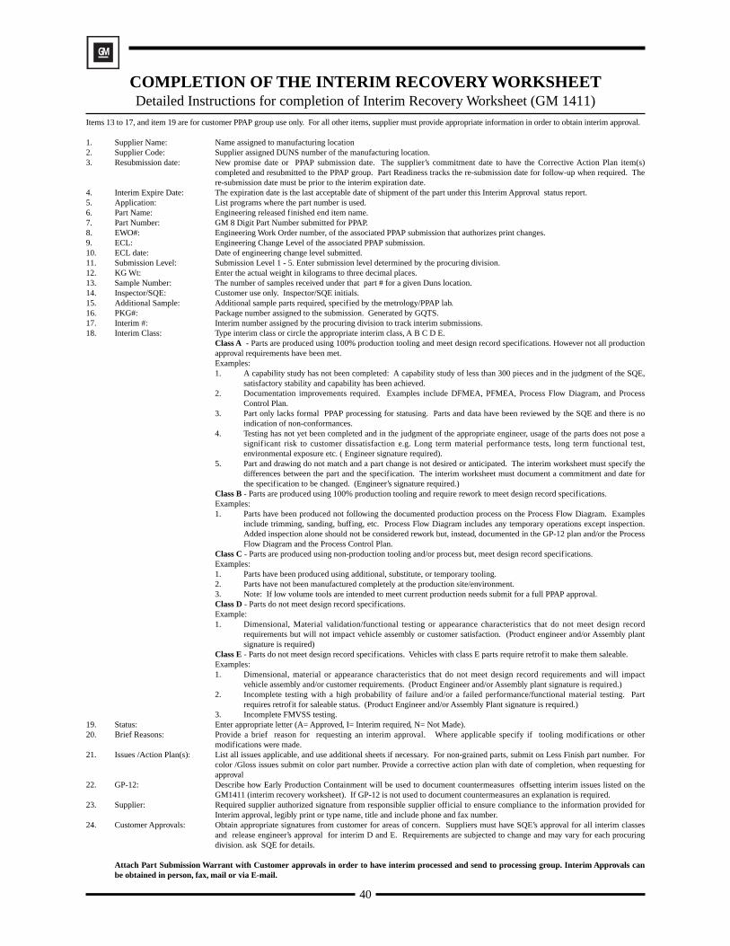
51
Part Name Part Number
Safety and/orGovernment Regulation Yes No Engineering Drawing Change Level Dated
Additional Engineering Changes Dated
Shown on Drawing No. Purchase Order No. Weight kg
Checking Aid No. Engineering Change Level Dated
SUPPLIER MANUFACTURING INFORMATION SUBMISSION INFORMATION
Supplier Name & Supplier Code
Street Address
City/State/Postal Code
Dimensional Materials/Functional Appearance
Customer Name/Division
Buyer/Buyer Code
Application
SUBMISSION RESULTS
The results for dimensional measurements material and functional tests appearance criteria statistical process package
These results meet all drawing and specification requirements:
Mold / Cavity / Production Process
Yes NO (If “NO” – Explanation Required)
DECLARATIONI hereby affirm that the samples represented by this certification are representative of our parts, have been made to the applicable customer�drawings and specifications, and are made from the specified materials on regular production tooling with no operations other than the regular�production process. I also certify that documented evidence of such compliance is on file and available for review.
EXPLANATION/COMMENTS:
Print Name Title Phone No.
Supplier Authorized Signature Date
FOR CUSTOMER USE ONLY (IF APPLICABLE)
ApprovedPart Warrant Disposition: Rejected
Customer Name Customer Signature Date
J u l y1 9 9 9 TAG-1001
FAX No.
Interim Approval
ApprovedPart Functional Approval:
Waived
Part Submission Warrant North American Truck Industry
1 2 3 4 5 6 7 8 9 10 11 12 13 14 15 16 17 18 19
(Circle)
REASON FOR SUBMISSIONInitial Submission Change to Optional Construction or Material
Engineering Change(s) Sub-Supplier or Material Source Change
Tooling: Transfer, Replacement, Refurbishment, or additional Change in Part Processing
Tooling Inactive > than 1 yearCorrection of Discrepancy Parts Produced at Additional Location
Other – please specify
REQUESTED SUBMISSION LEVEL (Check one)
Level 1 – Warrant only (and for designated appearance items, an Appearance Approval Report) submitted to customer.
Level 2 – Warrant with product samples and limited supporting data submitted to customer.
Level 3 – Warrant with product samples and complete supporting data submitted to customer.
Level 4 – Warrant and other requirements as defined by customer.
Level 5 – Warrant with product samples and complete supporting data reviewed at supplier's manufacturing location.
�
Note:� Does this part contain any restricted or reportable substances.��� Yes��� No�� �� Are plastic parts identified with appropriate ISO marking codes��� Yes��� No
Section II - Truck OEM Specific Requirements
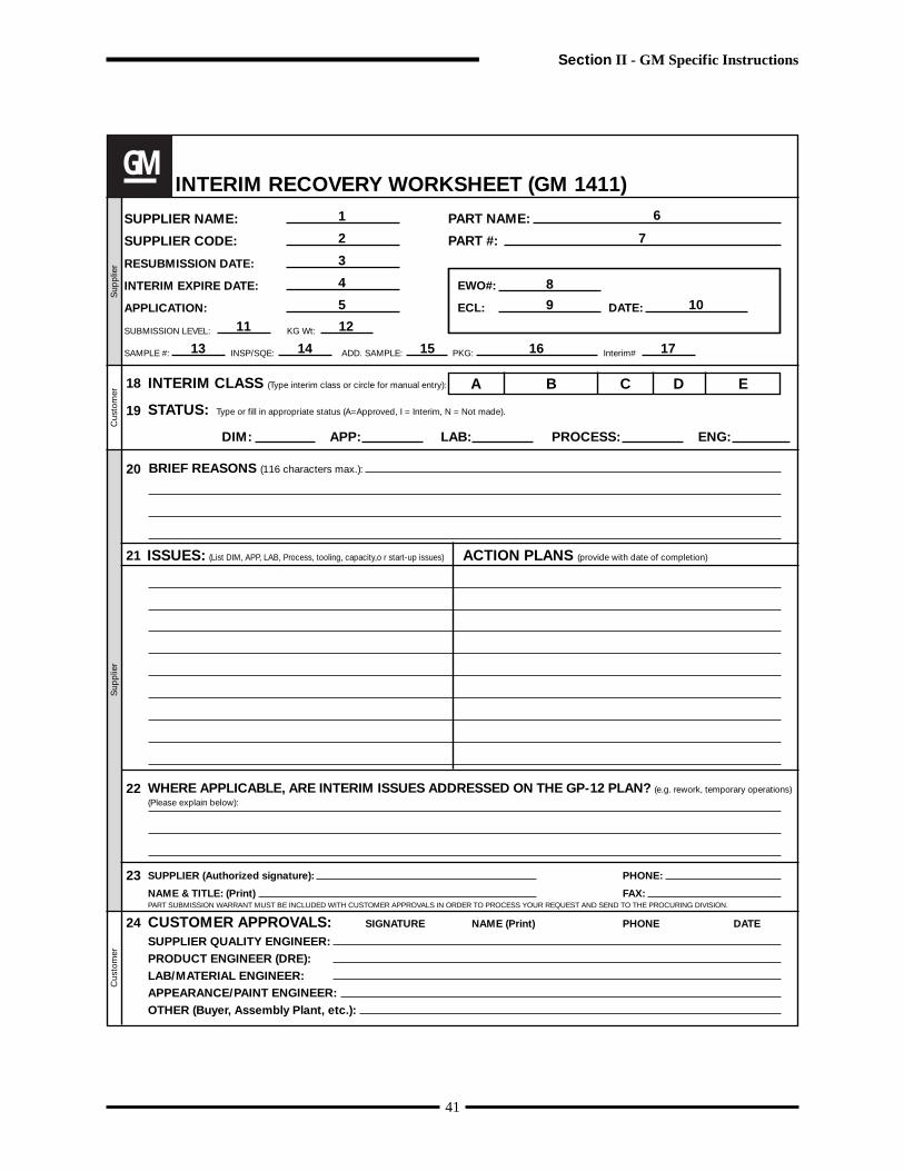
52
Appendix A
Completion of the Part Submission Warrant
PART INFORMATION1. Part Name and 2. Customer part number: Engineering released finished end item part name and number.
3. Safety/Regulated Item: “Yes” if so indicated on part drawing, otherwise “No”.
4. Engineering Change Level & Approval Date: Show change level and date for submission.
5. Additional Engineering Changes: List all authorized engineering changes not yet incorporated on thedrawing but which are incorporated in the part.
6. Shown on Drawing Number: The design record that specifies the customer part number being submitted.
7. Purchase Order Number: Enter this number as found on the purchase order.
8. Part Weight: Enter the actual weight in kilograms to four decimal places.
9. Checking Aid No. Enter the checking aid number, if one is used for dimensional inspection, and,
10. Its Engineering Change Level and Approval Date.
SUPPLIER MANUFACTURING INFORMATION11. Supplier Name & Supplier Code: Show the code assigned to the manufacturing location on the purchase
order.
12. Supplier Manufacturing Address: Show the complete address of the location where the product wasmanufactured.
SUBMISSION INFORMATION13. Submission type: Check box(es) to indicate type of submission.
14. Customer Name: Show the corporate name and division or operations group.
15. Buyer Name: and Buyer Code: Enter the buyer’s name and code.
16. Application: Enter the model year, vehicle name, or engine, transmission, etc.
REASON FOR SUBMISSION17. Check the appropriate box. Add explanatory details in the “other” section.
REQUESTED SUBMISSION LEVEL18. Identify the submission level requested by your customer.
SUBMISSION RESULTS19. Check the appropriate boxes for dimensional, material tests, performance tests, appearance evaluation, and
statistical data.20. Check the appropriate box. If “no”, enter explanation in “comments” below.
DECLARATION21. Comments: Provide any explanatory details on the submission results; additional information may be attachedas appropriate.
22. The responsible supplier official, after verifying that the results show conformance to all customer requirementsand that all required documentation is available shall approve the declaration and provide Title, Phone Number,and Fax Number.
FOR CUSTOMER USE ONLY Leave blank.
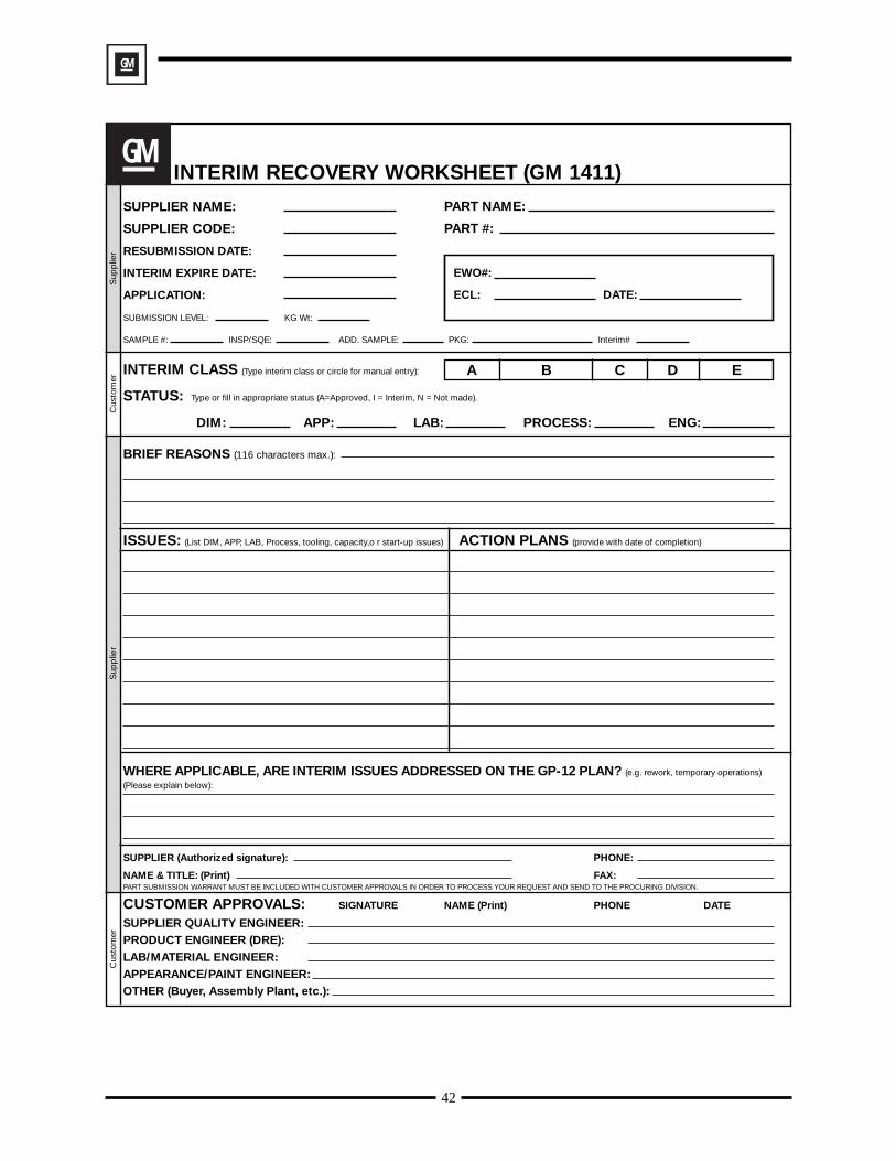
Part Name Part Number
Safety and/orGovernment Regulation Yes No Engineering Drawing Change Level Dated
Additional Engineering Changes Dated
Shown on Drawing No. Purchase Order No. Weight (kg)
Checking Aid No. Engineering Change Level Dated
SUPPLIER MANUFACTURING INFORMATION SUBMISSION INFORMATION
Supplier Name & Supplier Code
Street Address
City State Zip
Dimensional Materials/Functional Appearance
Customer Name/Division
Buyer/Buyer Code
Application
SUBMISSION RESULTS
The results for dimensional measurements material and functional tests appearance criteria statistical process package
These results meet all drawing and specification requirements:
Mold / Cavity / Production Process
Yes NO (If “NO” – Explanation Required)
DECLARATIONI hereby affirm that the samples represented by this warrant are representative of our parts, have been made to the applicable�Production Part Approval Process Manual 3rd Edition Requirements. I further warrant these samples were�produced at the production rate of / 8 hours. I have noted any deviations from this declaration below.
EXPLANATION/COMMENTS:
Print Name Title Phone No.
Supplier Authorized Signature Date
FOR CUSTOMER USE ONLY (IF APPLICABLE)
ApprovedPart Warrant Disposition: Rejected
Customer Name Customer Signature Date
J u l y1 9 9 9 CFG-1001
FAX No.
Other
ApprovedPart Functional Approval:
Waived
Part Submission Warrant DaimlerChrysler Ford General Motors
The original copy of this document shall remain at the suppliers location�while the part is active (see Glossary).
Optional: customer tracking�number: #
1 2
3 4
5
6
9
7 8
10
11
12
13
14
15
16
17
18
19
20
21
22
REASON FOR SUBMISSIONInitial Submission Change to Optional Construction or Material
Engineering Change(s) Sub-Supplier or Material Source Change
Tooling: Transfer, Replacement, Refurbishment, or additional Change in Part Processing
Tooling Inactive > than 1 yearCorrection of Discrepancy Parts Produced at Additional Location
Other – please specify
REQUESTED SUBMISSION LEVEL (Check one)
Level 1 – Warrant only (and for designated appearance items, an Appearance Approval Report) submitted to customer.
Level 2 – Warrant with product samples and limited supporting data submitted to customer.
Level 3 – Warrant with product samples and complete supporting data submitted to customer.
Level 4 – Warrant and other requirements as defined by customer.
Level 5 – Warrant with product samples and complete supporting data reviewed at supplier's manufacturing location.
SUBMISSION RESULTS
�
Note:� Does this part contain any restricted or reportable substances� �� Yes ��� No� � � Are plastic parts identified with appropriate ISO marking codes �� Yes ��� No
53
Appendices
DaimlerChrysler

Part Name Part Number
Safety and/orGovernment Regulation Yes No Engineering Drawing Change Level Dated
Additional Engineering Changes Dated
Shown on Drawing No. Purchase Order No. Weight (kg)
Checking Aid No. Engineering Change Level Dated
SUPPLIER MANUFACTURING INFORMATION SUBMISSION INFORMATION
Supplier Name & Supplier Code
Street Address
City State Zip
Dimensional Materials/Functional Appearance
Customer Name/Division
Buyer/Buyer Code
Application
REASON FOR SUBMISSIONInitial Submission Change to Optional Construction or Material
Engineering Change(s) Sub-Supplier or Material Source Change
Tooling: Transfer, Replacement, Refurbishment, or additional Change in Part Processing
Tooling Inactive > than 1 yearCorrection of Discrepancy Parts Produced at Additional Location
Other – please specify
REQUESTED SUBMISSION LEVEL (Check one)
Level 1 – Warrant only (and for designated appearance items, an Appearance Approval Report) submitted to customer.
Level 2 – Warrant with product samples and limited supporting data submitted to customer.
Level 3 – Warrant with product samples and complete supporting data submitted to customer.
Level 4 – Warrant and other requirements as defined by customer.
Level 5 – Warrant with product samples and complete supporting data reviewed at supplier's manufacturing location.
SUBMISSION RESULTS
The results for dimensional measurements material and functional tests appearance criteria statistical process package
These results meet all drawing and specification requirements:
Mold / Cavity / Production Process
Yes NO (If “NO” – Explanation Required)
DECLARATIONI hereby affirm that the samples represented by this warrant are representative of our parts, have been made to the applicable�Production Part Approval Process Manual 3rd Edition Requirements. I further warrant these samples were�produced at the production rate of / 8 hours. I have noted any deviations from this declaration below.
EXPLANATION/COMMENTS:
Print Name Title Phone No.
Supplier Authorized Signature Date
FOR CUSTOMER USE ONLY (IF APPLICABLE)
ApprovedPart Warrant Disposition: Rejected
Customer Name Customer Signature Date
J u l y1 9 9 9 CFG-1001
FAX No.
�
Other
�
ApprovedPart Functional Approval:
Waived
Part Submission Warrant DaimlerChrysler Ford General Motors
The original copy of this document shall remain at the suppliers location�while the part is active (see Glossary).
Optional: customer tracking�number: #
Note:� Does this part contain any restricted or reportable substances.��� Yes��� No�� �� Are plastic parts identified with appropriate ISO marking codes��� Yes��� No
54
DaimlerChrysler
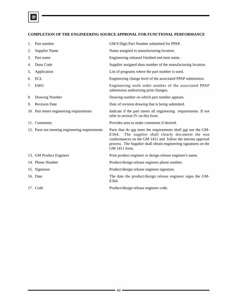
Appendices
55
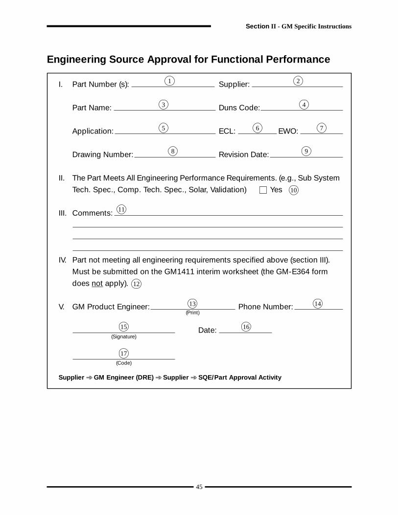
Appendix B
Completion of the Appearance Approval ReportNote: DaimlerChrysler Appearance Approval Requirements (See II.1.4)
1. Customer part number: Engineering released customer part number.
2. Drawing Number: Use the number of the drawing on which the part is shown if different from thepart number.
3. Application: Enter the model year(s) and vehicle or other program on which the part is used.
4. Part Name: Use the finished part name on the part drawing.
5. Buyer Code: Enter the code for specific buyer of part.
6/7. E/C Level & Date: Engineering change level and E/C date for this submission.
8. Supplier Name: Supplier responsible for submission (include subcontractor if applicable).
9. Manufacturing Location: Location where part was manufactured or assembled.
10. Supplier Code: Customer-assigned code for supplier location where the part was manufactured orassembled.
11. Reason for Submission: Check box(es) explaining the reason for this submission.
12. Supplier Sourcing & Texture Information: List all first surface tools, graining source(s), graintype(s), and grain and gloss masters used to check part.
13. Pre-Texture Evaluation: To be completed by customer representative (not used by GM).
14. Color Suffix: Use alphanumeric or numeric color identification.
15. Tristimulus Data: List numerical (colorimeter) data of submission part as compared to the customer-authorized master.
16. Master Number: Enter alphanumeric master identification (not used by Ford).
17. Master Date: Enter the date on which the master was approved.
18. Material Type: Identify first surface finish and substrate (i. e.: paint/ABS).
19. Material Source: Identify first surface and substrate suppliers. Example: Redspot/Dow.
20. Color Evaluation, Hue, Value, Chroma, Metallic Brilliance & Gloss: Visual assessment by customer.
21. Color Shipping Suffix: Color part number suffix or color number.
22. Part Disposition: To be determined by customer (approved or rejected).
23. Comments: General comments by the supplier or customer (optional).
24. Supplier Signature, Phone No. & Date: Supplier certification that the document information isaccurate and meets all requirements specified.
25. Customer Representative Signature & Date: Customer approval signature.
THE AREAS INSIDE THE BOLD LINES ARE FOR CUSTOMER USE ONLY.
56
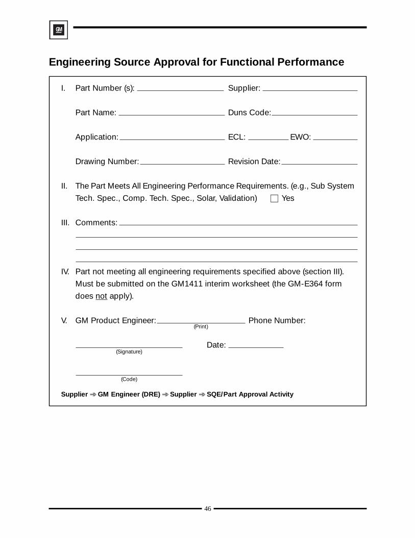
57
PAR
TN
UM
BE
R
PAR
TN
AM
E
SU
PP
LIE
RN
AM
E
RE
AS
ON
FO
RS
UB
MIS
SIO
NPA
RT
SU
BM
ISS
ION
WA
RR
AN
TP
RE
TE
XTU
RE
DR
AW
ING
NU
MB
ER
BU
YE
RC
OD
EE
/C L
EV
EL
DAT
E
AP
PLI
CAT
ION
(VE
HIC
LES
)
SU
PP
LIE
RC
OD
E
OTH
ER
SP
EC
IAL
SA
MP
LEFI
RS
T P
RO
DU
CTI
ON
SH
IPM
EN
TR
E-S
UB
MIS
SIO
NE
NG
INE
ER
ING
CH
AN
GE
MA
NU
FAC
TUR
ING
LOC
ATIO
N
SU
PP
LIE
R S
OU
RC
ING
AN
D T
EX
TUR
E IN
FOR
MA T
ION
AP
PE
AR
AN
CE
EVA
LUA
TIO
N
PR
E-T
EX
TUR
EE
VALU
ATIO
N
CO
RR
EC
TA
ND
PR
OC
EE
DC
OR
RE
CT
AN
DR
ES
UB
MIT
AP
PR
OV
ED
TO
TEX
TUR
E
CU
STO
ME
RR
EP
RE
SE
NTA
TIV
ES
IGN
ATU
RE
AN
D D
ATE
CO
LOR
EVA
LUA
TIO
N
CO
LOR
SU
FFIX
MA
STE
RN
UM
BE
RM
AS
TER
DAT
EM
ATE
RIA
LTY
PE
MAT
ER
IAL
SO
UR
CE
TRIS
TIM
ULU
S D
ATA
HU
EVA
LUE
CH
RO
MA
GLO
SS
MET
ALL
ICB
RIL
LIA
NC
EPA
RT
DIS
PO
SIT
ION
CO
LOR
SH
IPP
ING
SU
FFIX
SU
PP
LIE
RS
IGN
ATU
RE
CO
MM
EN
TS
PH
ON
E N
O.
DAT
EC
US
TOM
ER
RE
PR
ES
EN
TATI
VE
SIG
NAT
UR
ED
ATE
Sep
t. 19
99 C
FG
-100
2
DL*
Da*
Db
*D
E*
CM
CR
ED
YE
LG
RN
BLU
LIG
HT
DA
RK
GR
AYC
LEA
NH
IGH
LOW
HIG
HLO
W
AP
PE
AR
AN
CE
AP
PR
OVA
L R
EP
OR
T1
23
5 9
6/7
10
4 8
11
1213
14
13
1516
1718
1920
2122
23 2525
Appendices
58
PAR
TN
UM
BE
R
PAR
TN
AM
E
SU
PP
LIE
RN
AM
E
RE
AS
ON
FO
RS
UB
MIS
SIO
NPA
RT
SU
BM
ISS
ION
WA
RR
AN
TP
RE
TE
XTU
RE
DR
AW
ING
NU
MB
ER
BU
YE
RC
OD
EE
/C L
EV
EL
DAT
E
AP
PLI
CAT
ION
(VE
HIC
LES
)
SU
PP
LIE
RC
OD
E
OTH
ER
SP
EC
IAL
SA
MP
LEFI
RS
T P
RO
DU
CTI
ON
SH
IPM
EN
TR
E-S
UB
MIS
SIO
NE
NG
INE
ER
ING
CH
AN
GE
MA
NU
FAC
TUR
ING
LOC
ATIO
N
SU
PP
LIE
R S
OU
RC
ING
AN
D T
EX
TUR
E IN
FOR
MA T
ION
AP
PE
AR
AN
CE
EVA
LUA
TIO
N
PR
E-T
EX
TUR
EE
VALU
ATIO
N
CO
RR
EC
TA
ND
PR
OC
EE
DC
OR
RE
CT
AN
DR
ES
UB
MIT
AP
PR
OV
ED
TO
TEX
TUR
E
CU
STO
ME
RR
EP
RE
SE
NTA
TIV
ES
IGN
ATU
RE
AN
D D
ATE
CO
LOR
EVA
LUA
TIO
N
CO
LOR
SU
FFIX
MA
STE
RN
UM
BE
RM
AS
TER
DAT
EM
ATE
RIA
LTY
PE
MAT
ER
IAL
SO
UR
CE
TRIS
TIM
ULU
S D
ATA
HU
EVA
LUE
CH
RO
MA
GLO
SS
MET
ALL
ICB
RIL
LIA
NC
EPA
RT
DIS
PO
SIT
ION
CO
LOR
SH
IPP
ING
SU
FFIX
SU
PP
LIE
RS
IGN
ATU
RE
CO
MM
EN
TS
PH
ON
E N
O.
DAT
EC
US
TOM
ER
RE
PR
ES
EN
TATI
VE
SIG
NAT
UR
ED
ATE
Sep
t. 19
99 C
FG
-100
2
DL*
Da*
Db
*D
E*
CM
CR
ED
YE
LG
RN
BLU
LIG
HT
DA
RK
GR
AYC
LEA
NH
IGH
LOW
HIG
HLO
W
AP
PE
AR
AN
CE
AP
PR
OVA
L R
EP
OR
T
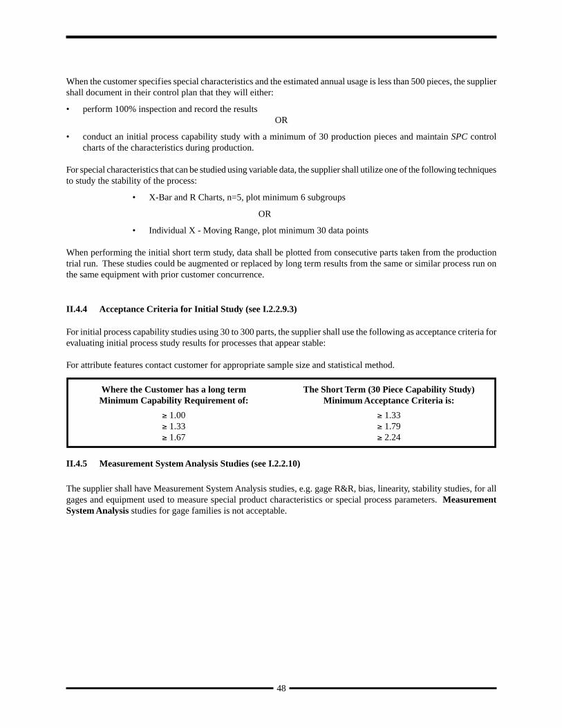
59
Appendices
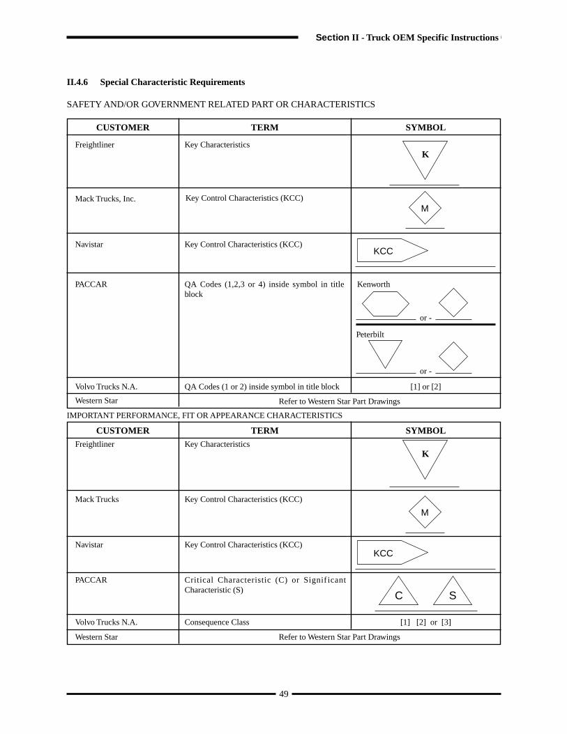
60
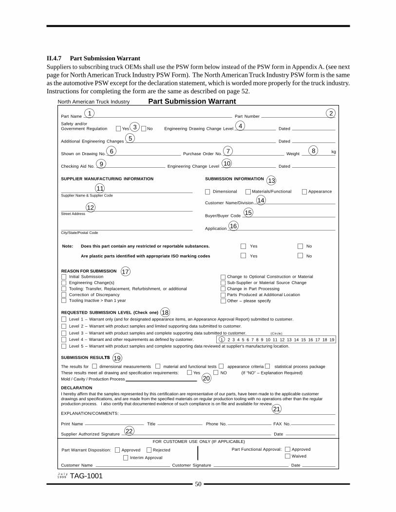
Production Part Approval —Dimensional Results Page of Pages
SUPPLIER PART NUMBER
NAME OF INSPECTION FACILITY PART NAME
ITEM DIMENSION/SPECIFICATION SUPPLIER MEASUREMENT RESULTS OK NOTOK
SIGNATURE TITLE DATECFG-1003M a y1995
Appendix C
61
Production Part Approval—Dimensional ResultsDaimlerChrysler
Appendices
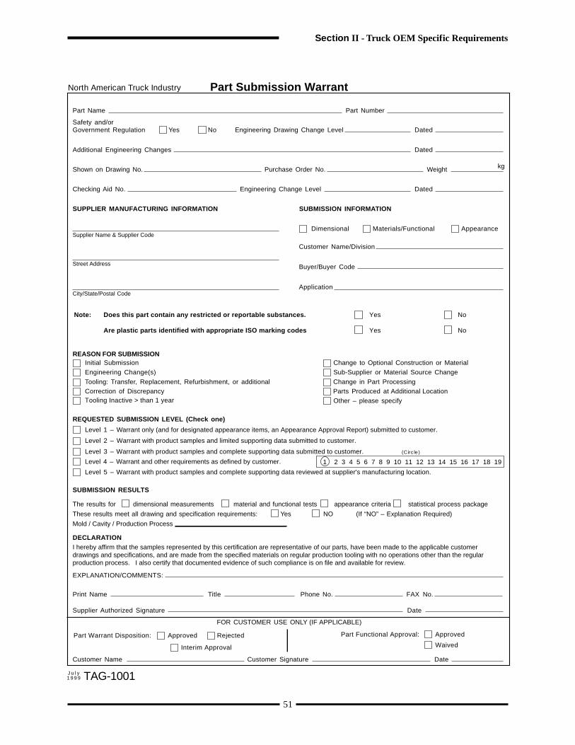
62
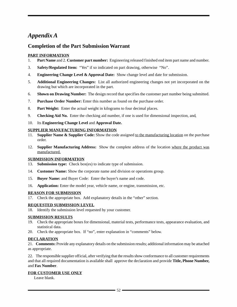
Production Part Approval —Material Test Results Page of Pages
SUPPLIER PART NUMBER
NAME OF LABORATORY PART NAME
TYPE OFTEST
MATERIAL SPEC. NO./DATE/SPECIFICATION SUPPLIER TEST RESULTS OK NOTOK
SIGNATURE TITLE DATEM a y1995 CFG-1004
Appendix D
63
Production Part Approval—Material Test ResultsDaimlerChrysler
Appendices
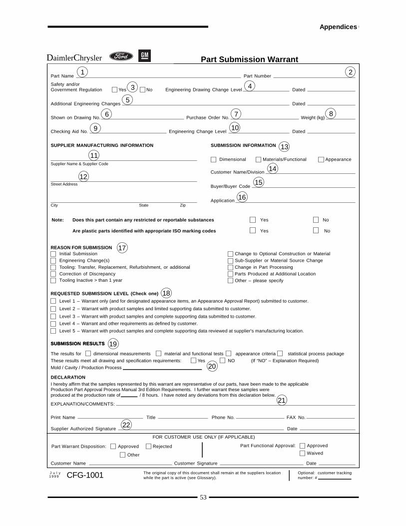
64
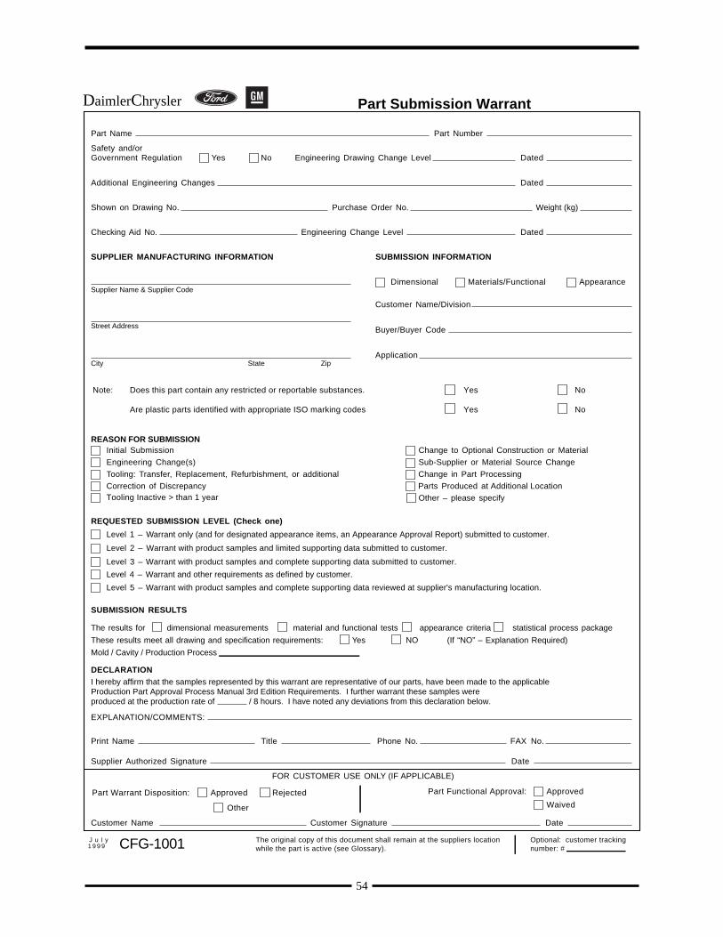
65
Appendix E
SUPPLIER
NAME OF LABORATORY
PART NUMBER
PART NAME
REF.NO.
TESTFREQ.
QTY.TESTED
REQUIREMENTS SUPPLIER TEST RESULTS AND TEST CONDITIONS OK NOTOK
SIGNATURE TITLE DATECFG-1005
Production Part Approval—Performance Test Results Page of Page
Appendices
Daimler Chrysler
May1995

66
Appendix F
Bulk Material - Specific Requirements
F.1 Introduction
A supplier of bulk materials shall comply with the requirements in this Appendix or use guidance herein for clarificationof PPAP. This document is a minimum requirement and may be supplemented at the discretion of the supplier and/orthe customer.
F.2 Applicability
OEM PPAP approval of a bulk material eliminates the need to complete PPAP for that material at other levels in thesupply chain.
Suppliers are responsible for applying PPAP to their subcontractors of ingredients which have supplier-designatedspecial characteristics.
Examples of bulk material include, but are not limited to: adhesives and sealants (solders, elastomers); chemicals(rinses, polishes, additives, treatments, colors/pigments, solvents); coatings (top coats, undercoats, primers, phosphates,surface treatments); engine coolants (antifreeze); fabrics; film and film laminates; ferrous and non-ferrous metals(bulk steel, aluminum, coils, ingots); foundry (sand/silica, alloying materials, other minerals/ores); fuels and fuelcomponents; glass and glass components; lubricants (oils, greases, etc.); monomers, pre-polymers and polymers (rubbers,plastics, resins and their precursors); and performance fluids (transmission, power steering, brake, refrigerant).
F.3 Customer Plant Connection
F.3.1 Customer’s Responsibilities
The customer plant connection is a shared responsibility between the bulk material supplier and the customer. Thisconnection defines the interaction of specific customer plant processing steps with Special Characteristics and finalproduct attributes of the bulk material. This interaction is especially significant when bulk materials undergo chemicalor physical transformation(s). Three key components of the Customer Plant Connection are the development of aCustomer Process Matrix (SEE FOLLOWING EXAMPLE), determination of Special Characteristics from the CustomerProcess Matrix, and the preparation of a Control Plan which systematically directs corrective actions. For bulk materials,conducting the steps outlined in this “Customer Plant Connection” is highly recommended.
NOTE: It is not the intent of PPAP to compromise proprietary information.
F.3.2 Customer Plant Connection - Clarification
The following is applicable to materials that are transformed from bulk (e.g. wet can of paint) to final product (e.g.cured paint film). This may not be applicable to all bulk materials (i.e. washer fluid, engine oil, etc.). It is recognizedby the supplier that it is their responsibility to deliver the product to the customer with the characteristics of the bulkmaterial per supplier and customer agreement.
The impact of the transformation of bulk materials by the customer plant on final product attributes may be accountedfor in the customer’s application process. During the transformation from bulk product to final product, both bulkproduct characteristics and final product attributes may be impacted by customer process controls.
67
Appendices
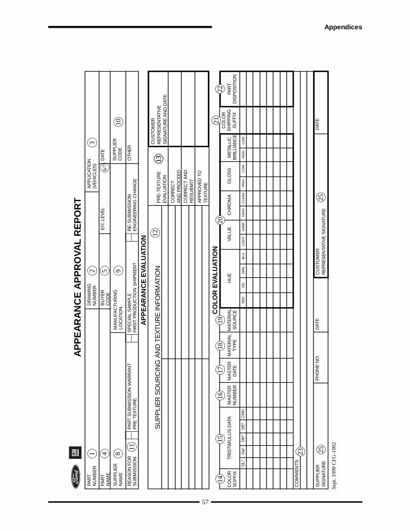
PPAP does not require a Process FMEA or Control Plan for the customer process. Since the product is frequently twoproducts (bulk and finished), there is a shared responsibility for the final product attribute. For example, percent solidsand viscosity of a bulk coating which impacts the final coating’s film build attribute, may be affected by the customer’smix room percent solvent reduction. The percent reduction process parameter may therefore be controlled to aid incontrol of film build. The process steps at customer plants may be matrixed versus the Special Characteristics (determinedjointly by supplier and customer). Where high impact is evident, those process steps may be analyzed by the ProcessFMEA methodology.
The Special Characteristics may then be determined, and be included in a Control Plan for the customer process. Thesespecial control characteristic items may be monitored and continuously improved.
F.3.3 Customer Plant Connection - Guidelines
The following is a recommended set of guidelines for the customer plant when implementing process controls for bulkmaterials.
1. Assemble cross-functional teams of customer personnel for each customer process area. Include appropriatesupplier representatives on each team.
2. Select Champions for each team - these are the customer process owners (i.e. chief process engineer, areasupervisor, etc.).
3. Define critical customer handling, application steps and process parameters in each area.4. Review the supplier’s Design Matrix and Design FMEA items for application functions which have been
designated as Special Characteristics. Also review the desired final product attributes for items needingcontrol.
5. From #4, develop a list of Special Characteristics and Attributes.6. Construct a Customer Process Matrix, using #3 as the top, and #5 as the side of a matrix.7. Perform a Customer Process FMEA, focusing on the high impact customer process areas which impact the
Special Characteristics. (Do the PFMEA per Appendix F).8. Determine Special Characteristics from the Customer Process Matrix and PFMEA (e.g. paint fluid flow,
gun distance, etc.).9. Prepare a Control Plan for each affected customer process area. The plan (utilize DaimlerChrysler, Ford,
GM APQP guidelines) might contain at a minimum all process steps containing Special Characteristics.10. Monitor and record all Special Characteristics by appropriate means (control charts, checklists, etc.).11. Ensure stability of Special Characteristics and continuously improve where possible.
Customer Process Matrix Example
68
Customer Handling, Application Steps and Process Parameters
Special Char.& Attributes
paint %reduc-tion
paintfluidflow
gunatomair
gun fanair
guncap
gundist-ance
gunwashbox
boothtemp
boothhum-idity
baketemp
Dirt Check 1 1 2 2 3 1 3 1 3 1
Film Build 3 3 2 2 2 3 1 1 1 1
Sags 2 3 2 2 1 3 1 1 1 2
Popping 2 3 3 2 1 2 1 3 1 3
Peel 3 2 3 2 2 2 1 1 2 2
Hiding 1 3 1 1 1 3 1 1 1 1
Adhesion 1 1 1 1 1 1 1 1 1 3
Impact Ratings: 3= High, 2= Medium, 1= Low

F.4 Part Submission Warrant (CFG-1001) [see I.2.2.13]
A Part Submission Warrant shall be prepared and submitted for approval when required by the customer. If a customeragrees that PPAP is not required, no warrant needs to be prepared. The information required by the Submission Warrantwhich does not apply to bulk material (i.e. part weight, dimensional measurement) does not need to be provided.
For those suppliers that have been classified as “self certifying” by a specific customer, submission of a warrant signedonly by the supplier shall be evidence of PPAP approval, unless the supplier is advised otherwise. For all other suppliers,evidence of PPAP approval shall be a warrant signed by both the customer and supplier or other customer approvaldocuments.
F.5 Design Matrix
F.5.1 Introduction
Bulk material suppliers generally deal with the chemistry and functionality of the product being designed. Use of thesesuggestions will arrive at the same end point of a completed Design FMEA, but with greater applicability to bulkmaterials. For bulk materials, a Design Matrix, when required, shall be prepared prior to developing the Design FMEA.The Design Matrix determines the complex interactions of formula ingredients, ingredient characteristics, productcharacteristics, process constraints, and conditions for customer use. High impact items can then be effectively analyzedin the Design FMEA.
F.5.2 Design Matrix – Elaboration
This matrix correlates customer expectations with the product design items.
Construct the Design Matrix referring to the example which will follow:1. Along the horizontal axis, list the Functions (Desired Attributes/Potential Failure Modes).2. Along the vertical axis, list the design items as Potential Causes (Category/Characteristics) :
Formula IngredientsIngredient CharacteristicsProduct CharacteristicsProcess ConstraintsConditions for Use (customer process constraints)
3. For each design item, enter the current robust threshold range levels and units.4. Correlate the potential causes to the potential failure modes using a number, letter, or symbol representing the
impact or strength of the relationship. Ask what would happen if a potential cause item is allowed to go under orover its robust minimum or maximum, respectively.
5. After completion of the rankings in the Design Matrix, review the category/characteristics for a preliminaryassessment of Special Characteristics. Designate any Special Characteristics in column 1.
6. The high negative impact potential causes are transferred to the Design FMEA for analysis.
69
Appendices

70
DE
SIG
N M
AT
RIX
— G
EN
ER
IC P
AIN
T E
XA
MP
LE
NE
GA
TIV
E IM
PAC
T O
N C
US
TO
ME
R E
XP
EC
T AT
ION
S:
HIG
H=
3; M
ED
=2;
LO
W=
1; N
ON
E=
0; U
NK
NO
WN
=?
Pro
duc
t C
ode/
Des
crip
tion:
xxR
-yyy
yy B
asec
oat
Pai
ntP
roje
ct #
: 000
01
PO
TE
NT
IAL
CA
US
ES
FUN
CT
ION
- D
ES
IRE
D A
TT
RIB
UT
ES
(P
OT
EN
TIA
L FA
ILU
RE
MO
DE
S)
Prelim. Special Characteristics
FAILURE
ROBUST THRESHOLD RANGE
UNITS
APPEARANCE
PERFORMANCE
PROCESSABILITY
ENVIRONMENTAL
Good Gloss / Image / Peel
No Telegraphing
No Pinholing
No Mudcracking
Dirt / Seed Free
Crater Free
Good Color Match
Good Accelerated Durability
Good Florida Durability
Good Chip Resistance
Good Crack Resistance
Good Delamination Resistance
Good Repair Adhesion
Good FMVSS (Windshield Adh)
Good Sag Resistance
Workable Visc/Atomization
Good Shelf Stability
Good Circulation Stability
Stable Rheology
Ne Edge Pull
Good Hiding Latitude
Good Overspray Compatibility
Good Repair Processability
Low/Acceptable VOC
Low/Acceptable Odor
HAPS Compliant
Form
ula
Ing
red
ient
sR
esin
Aun
der
40%
Bin
der
Sol
ids
31
11
11
02
32
11
11
21
12
21
01
11
11
over
50%
“3
11
11
10
22
12
11
12
11
22
10
11
11
1
Res
in B
und
er25
%B
ind
er S
olid
s1
13
11
11
12
31
12
21
11
11
10
12
11
1
over
35%
“1
11
12
11
22
21
11
21
12
22
10
11
11
1
Cro
sslin
ker
und
er20
%B
ind
er S
olid
s1
23
11
21
22
31
22
21
11
22
10
22
12
2
over
30%
“1
21
11
11
22
21
31
21
11
31
10
11
13
1
SP
Rhe
olog
y C
ontr
ol A
dd
itive
und
er0.
50%
Tota
l Sol
ids
11
31
11
01
11
11
11
32
23
32
11
11
11
over
2.5%
“1
11
11
11
11
11
11
12
11
22
21
11
11
1
Col
or D
isp
ersi
on-B
und
er1.
00%
Tota
l Sol
ids
11
11
21
32
12
11
22
11
11
11
31
11
11
over
2.00
%“
21
11
11
11
13
11
11
11
11
11
11
11
11
Sol
vent
Dun
der
5%Fo
rmul
a W
gt.
31
22
12
01
11
11
11
12
11
22
02
21
11
over
15%
“2
11
11
11
11
11
11
13
21
22
30
21
32
3
Alc
ohol
Sol
vent
und
er2%
Form
ula
Wgt
.1
11
11
11
11
11
11
11
13
32
11
21
11
1
und
er4%
“1
11
11
11
11
11
11
11
11
11
11
31
22
3
Ing
red
ient
Cha
ract
eris
tics
Res
ign
A-V
isco
sity
und
er30
%P
oise
(#1
@ 5
0)3
21
11
20
11
11
11
11
22
22
11
11
10
1
over
40%
“2
11
11
11
11
11
11
11
32
13
11
21
10
1
SP
Cro
sslin
ker-
Imin
o (-
NH
) %un
der
1%%
Mol
ar C
omp
.1
11
11
10
12
22
22
21
11
11
10
22
00
0
over
10%
“1
11
13
21
12
33
22
31
11
11
10
31
11
1
Pro
duc
t C
hara
cter
isti
csS
PV
isco
sity
und
er30
sec
#4 F
ord
Cup
22
11
12
21
11
11
11
33
23
23
12
11
01
over
40 s
ec“
11
11
11
31
11
11
11
23
13
11
11
11
01
SP
% N
V S
olid
sun
der
57%
%N
.V. @
110
ºC1
11
21
11
11
11
11
12
22
22
21
21
31
1
over
61%
“1
11
11
11
11
11
11
12
23
22
21
11
11
1
Res
istiv
ityun
der
0.01
meg
aohm
s2
11
00
20
00
00
00
01
31
11
10
21
11
1
over
0.15
“1
11
00
30
00
00
00
01
31
11
10
21
11
1
Pro
cess
Co
nstr
aint
s
Bat
ch M
ixin
g Te
mp
und
er70
ººF
11
11
22
21
11
11
11
11
32
31
12
11
01
over
110º
“2
11
13
32
22
12
11
21
13
13
11
31
11
1
Co
ndit
ions
fo
r U
se
Flas
h Ti
me
bef
ore
Cle
arun
der
1m
inut
es3
13
21
12
11
11
11
13
00
00
21
11
11
0
over
3“
21
21
11
31
11
11
11
20
00
01
11
12
10
SP
Fina
l Bak
e Te
mp
.ov
er25
0ººF
21
11
00
33
33
22
32
10
00
01
11
31
11
und
er27
5º“
31
11
11
32
23
32
33
10
00
01
11
32
31
CA
TE
GO
RY
/C
HA
RA
CT
ER
IST
ICS

71
F.6 Special Characteristics
F.6.1 Introduction
If product characteristics/attributes can have normal variation resulting in movement outside their design-intendedrobust range which results in significant impact, they are designated special, and must be controlled by specialcontrols.
Special Characteristics - Clarification Table
Difference# Clarification Example
1 Special Characteristicsand/or Key Product andKey ControlCharacteristics
For Bulk Materials, a frequent occurrenceis a transformation from bulk material tofinal product.
The differences between bulk productcharacteristics (features of the suppliedproduct) and the final attributes (featuresof the transformed product) should beunderstood.
During the design phase, the productcharacteristics can be controls for finalproduct attributes. (This does not implythat they are control characteristics).During manufacture of the bulk material,process parameters are the controlcharacteristics.
During transformation from bulk productto final product, both bulk productcharacteristics and final product attributescan be controlled by customer processcontrol characteristics.
Illustrations of the flow of materialsthrough final product follow (e.g. % solidsResin A, % UVA intended). These are notnecessarily intended to be SpecialCharacteristics.
Examples of product characteristics are:viscosity, % NV Solids, % Resin “A”.Examples of final product attributes are:appearance, film build, FMVSS safety,durability.
Examples of manufacturing processparameters (control characteristics) are:temperature, pressure, mix rate, testprotocol.
Examples of customer transformationprocess parameters (controlcharacteristics) are: fluid flow,temperature/humidity, air pressure.
The supplier may choose to use “S”(Safety), or “sp” (special), or “K” (Key),etc.
The customer designated shield, delta,diamond, etc. will be used when requiredper customer identification.
2 Symbols for customer-identified SpecialCharacteristics
The suppliers may designate their owninternal symbols to designate SpecialCharacteristics in their working documents.
For customer-designated/identified SpecialCharacteristics, the customer-specificsymbols will be used for required customerdocumentation and required shippinglabels.
Appendices
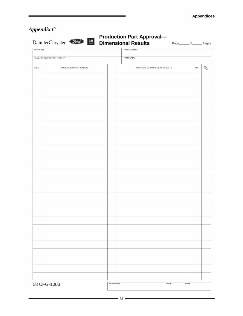
F.6.2 Special Characteristics - Elaboration
For clarif ication purposes, the following f igure is intended to demonstrate the flow of potential specialcharacteristics through the supply chain.
Illustration of the flow of materials through final product:
F.7 Design FMEA (see I.2.2.4)
F.7.1 Effects of Failure and Severity Rankings
The following two steps provide an alternative method for identifying the Potential Effects of Failure and assigning aSeverity Ranking.
List Effects of Failure• Consumer Effects - General terms identifying the loss experienced by the ultimate user of the product (e.g. the
car buyer).• Customer Effects - General terms identifying the loss experienced by the intermediate user of your product
(e.g. the vehicle manufacturer).Assign a Severity Ranking to each Effect• See the Severity Definition and Evaluation Criteria in the Potential Failure Mode and Effects Analysis
reference manual.
Item A (Paint) Item B (Paint) Item C (Sealant)
Subcontractor (Tier II)Bulk Product Characteristic(Raw Material)
% Solids Resin “A”
Subcontractor (Tier II)Bulk Product Characteristic(Raw Material)
Purity Assay of UVA
Subcontractor (Tier II)Bulk Product Characteristic(Raw Material)
Polymer Viscosity
Subcontractor (Tier II)Mfg. Control Characteristic
Resin Synthesis Temperature
Subcontractor (Tier II)Mfg. Control Characteristic
Final Reaction Hold Time
Subcontractor (Tier II)Mfg. Control Characteristic
End-Blocker Feed Rate
Supplier (Tier I)Bulk Product Characteristic
Paint Viscosity
Supplier (Tier I)Bulk Product Characteristic
% UVA intended
Supplier (Tier I)Bulk Product Characteristic
% Polymer in Sealant
Supplier (Tier I)Mfg. Control Characteristic
Tank Mix Rate
Supplier (Tier I)Mfg. Control Characteristic
Scale Calibration
Supplier (Tier I)Mfg. Control Characteristic
Polymer Feed Rate
Customer TransformationControl Characteristic
% Solvent Reduction
Customer TransformationControl Characteristic
Fluid Flow (for film build)
Customer TransformationControl Characteristic
Extruder Bead Size
Final Product Attibute
Film Build; Free of Sags
Final Product Attibute
Excellent Durability
Final Product Attibute
Leak Free Sealant
72

• The goal for each of the items that multiply to arrive at the Risk Priority Number is to differentiate between theitems in that category. The following figure provides a guideline for severity rankings. If your situation onlyuses a small portion of the scale then develop your own scale to improve the differentiation. If your situationis greater than two tiers back from the final consumer, then the guideline figure should be adjusted to reflectthe effects that will be felt by your customer’s customer.
73
Effects of Failure and Severity Rankings:
Stakeholder Effects of Failure Severity
Consumer(e.g. vehicle buyer)
Owner Safety Problem 10
Major Owner Dissatisfaction (Loss of Owner Loyalty) 8
Moderate Owner Dissatisfaction (Inconvenience) 6
Minor Owner Dissatisfaction (Annoyance) 4
Plant Safety Problem 10
Possible Recall 9
Line Stoppage 8
Warranty Costs 7
Scrap 7
Regulatory Penalty 7
Moderate Rework (e.g. < 20% or moderate repair) 5
Plant Dissatisfaction 4
Minor Rework (e.g. < 10% or simple repair) 3
Customer(e.g. vehiclemanufacturer)
F.7.2 Potential Cause(s)/Mechanisms of Failure and Design Matrix
From the Design Matrix (if used), list the high negative impact characteristics as the Potential Causes/Mechanisms ofFailure which are associated with Potential Failure Modes.
Mechanisms are generally described as over or under a certain threshold. These thresholds define the boundaries of theproduct approval and subsequent requirements for change notification.
F.7.3 Likelihood of Occurrence Rankings
The following step provides an alternate method for assigning Occurrence ratings.
Rank Occurrence - the ranking scale in the Potential Failure Mode and Effects Analysis manual is difficult torelate to bulk materials and generally results in very low numbers with little differentiation in the ultimate risk.The following matrix is recommended as a replacement. It evaluates the frequency of occurrence based uponobserved evidence the formulator has in the design.
Appendices

Occurrence Matrix:
74
Formulation OccurrenceRanking
FREQUENCY
Type of Evidence LOW MODERATE HIGH
Actual Experience
Similar Experience
Assumption
No Background
1
2
3
4
5
6
7
8
9
10
Actual Experience: Obtained from appropriate experimentation on the specific final productand the potential failure mode.
Similar Experience: Based upon similar products or processes and the potential failure mode.Assumption: Based upon a clear understanding of the chemical impact of the material
and the potential failure mode.
Frequency ranking clarifications:
· High is defined as – Repeated failures
· Moderate is defined as – Occasional failures
· Low is defined as – Relatively few failures
F.7.4 Current Design Controls
Design Control: Supplementing the Failure Mode Effects and Analysis manual, bulk material design controls mayalso include:
· Designed Experiments (DOE’s) - List experiment #’s
· Customer validation tests and trial runs - e.g. gravelometer panels, fender sprayouts (list customer reference #’s).
· Test protocols - list Test Methods, Standard Operating Procedures, etc.
· Variation of subcontractor specifications.
· Formulating practice robust ranges.
Design controls identified by a number should be available so that the relevant content of that control can be understood.
F.7.5 Likelihood of Detection Rankings
The next step provides an alternate method for assigning Detection rankings.
Rank Detection - the ranking scale in the Potential Failure Mode and Effects Analysis manual is difficult torelate to bulk materials and generally results in very low numbers with little differentiation in the ultimate risk.The following matrix may be used. It evaluates the Detection as the ability of the current Design Control toactually detect a cause of failure and/or failure mode based upon the assessed R&R’s percent of specificationrange and the quality of evidence.

F.8 Process FMEA (see I.2.2.6)
Process FMEA Ranking Tables
75
SEVERITY RANKINGS
Severity of Effect Ranking
Very High: Potential failure mode may result in a field failure (9), or constitute a safety hazard ornoncompliance with a government regulation (10).
High: High degree of customer dissatisfaction due to the nature of the failure. May cause seriousdisruption to subsequent processing of the product or result in the product failing to meet its salesspecifications. Will result in a customer complaint and product return. Failure is likely to be detectedduring the customer’s final product testing.
Moderate: Failure causes some customer dissatisfaction and may result in a customer complaint orlimitation on shelf life. The customer may need to make modifications or adjustments to their process toaccommodate the material. The problem is likely to be detected as part of an incoming inspection orprior to use (4). The problem will be detected during processing (5). The problem will be detected insubsequent processing steps (6).
Low: Failure causing only a slight customer annoyance. Customer will notice only a slight deteriorationor inconvenience with the product or processing of the product.
Minor: Reasonable to expect that the minor nature of this failure would not cause any real effect on theproduct or its processing by the customer. Customer will probably not even notice the failure.
9 - 10
7 - 8
4 - 6
2 - 3
1
Detection by DesignControl
Testing Method R&R
Quality of Evidence < 30% 30% - 100% > 100%
DOE (Response SurfaceAnalysis)
Screening Experiments
Assumption/Experience
No Evidence
1
3
5
2
4
6
7
8
9
10
DOE (Response Surface Analysis): Symmetric design space analyzed with appropriate statistical tools.Screening Experiments: Screening design or ladder evaluation strategically set to develop DOE.Assumption/Experience: Information/data based upon similar products or processes.
NOTE: The above R&R limits are suggested unless otherwise agreed upon by the customer and the supplier.R&R calculations can initially be based using design matrix thresholds.
Detection Matrix:
Appendices
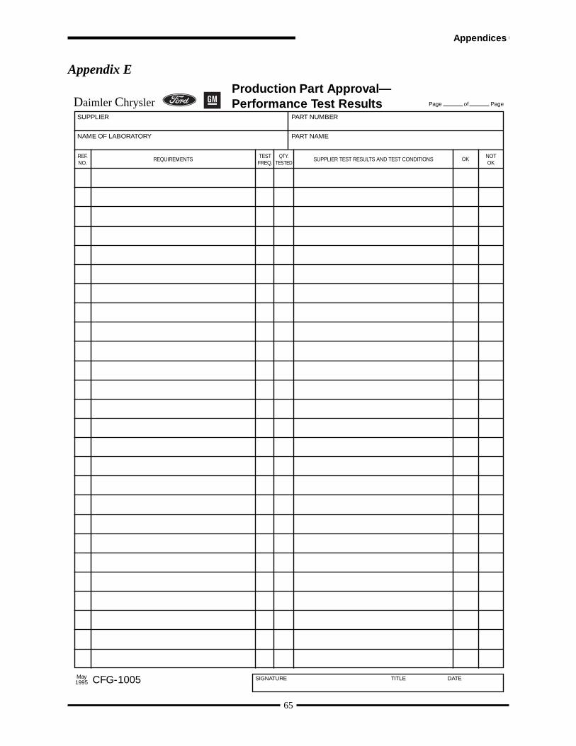
F.9 Control Plan (see I.2.2.12)
F.9.1 Introduction
The Bulk Material Control Plan serves as a mechanism to:• Highlight Special Product/ Process Characteristics and their controls• Link together sources of control methods, instructions and specification / tolerance limits and reference them
in one document
Additionally, this control plan is not intended to recreate specification and/or tolerance limits that exist in other controlsources such as batch tickets, work instructions and testing protocols.
F.9.2 Control Plan - Elaboration
Refer to the control plan format found in the Advanced Product Quality Planning and Control Plan referencemanual.
• Prototype (when required) - A listing of tests, evaluations and their associated specifications/tolerances usedto assess an experimental or developmental formulation. This may be the only control plan that is productspecific.
• Pre-launch - Documentation of the product/process control characteristics, process controls affecting SpecialCharacteristics, associated tests, and measurement systems employed during product scale up and prior to
76
Frequency of Failure Ranking
9 - 10
7 - 8
4 - 6
3
2
OCCURRENCE RANKINGS
Very High: Failure is almost inevitable. Additional process steps are developed to deal with the failures.
High: Similar processes have experienced repeated failures. The process is not in statistical control.
Moderate: Similar processes have experienced occasional failures, but not in major proportions. Processis in statistical control.
Low: Similar processes have experienced isolated failures.
Very Low: Almost identical processes have experienced only isolated failures.
Remote: Failure is unlikely. No failures ever associated with almost identical processes. The process is instatistical control.
1
Likelihood and Location in the Process the Defect is Detected Ranking
10
9
7 - 8
5 - 6
3 - 4
DETECTION RANKINGS
1 -2
Absolute Certainty of Non-Detection: Controls will not or cannot detect the existence of the defect.
Very Low: Supplier controls probably will not detect the existence of the defect, but the defect may bedetected by the customer.
Low: Controls may detect the existence of the defect, but detection may not occur until packaging isunderway.
Moderate: Controls likely to detect the existence of the failure, but not until lot acceptance testing hasbeen completed. Tests with a higher degree of variability will have the higher ranking.
High: Controls have a good chance of detecting the existence of the defect before the manufacturingprocess has been completed. In-Process testing is used to monitor the manufacturing process.
Very High/Early: Controls will almost certainly detect the existence of the defect before the productmoves onto the next step in its manufacturing process. Important raw materials are controlled viasupplier specifications.

normal production.• Production - Documentation of the product/process control characteristics, process controls affecting Special
Characteristics, associated tests, and measurement systems employed during normal production. Additionalitems may be included at the Supplier’s discretion.
Pre-launch and production control plans may be applied to a family of products or specific processes.
F.10 Initial Process Studies For Special Characteristics (see I.2.2.9)
The manufacture of bulk materials consists of industries which span a variety of production processes, from highvolume products to specialty products produced in small quantities no more than once or twice per year. Often theproduction process is completed or already in place before sufficient samples can be tested. By the time the product ismade again, personnel and/or equipment may have changed. Also, these processes have numerous input variables,many control variables, and a variety of product variations. There are non-linearities - meaning for example thatdoubling the change in a particular input does not necessarily double the change in the output. The effects and relationshipsbetween all these variables and controls are also not usually known without error. Multiple processes are usuallyinterconnected, sometimes with feedback loops. There are also timing considerations and delays in reaction time.Further, measurement of component variables are generally less precise than measurements of component parts, suchthat in many cases correlated variables must be used.
F.11 Measurement System Analysis (MSA) Studies (see I.2.2.10)
Bulk materials often require further processing after sampling in order to make a measurement.
Measurements are often destructive in nature and this prevents retesting the same sample.
Measurement variability is often much larger for properties important in the process industries (e.g. viscosity andpurity) than it is for properties measured in mechanical industries (e.g. dimensions). Measurement may account for50% or more of the total observed variation.
Standardized test methods (e.g. ASTM, AMS, ISO) are often followed. The supplier need not reverify bias, linearity,stability, and Gage R&R.
MSA studies are not required where standardized tests are used, however it is still important for the supplier to understandthe measurement component of variation in the test methods used.
Customer agreement on the actual requirements for MSA for either non-standard test methods or “new-to-supplier”test methods should be obtained during the planning phase.
Any MSA studies should be applied to each test method associated with Special Characteristics, and not to eachindividual product measured by the test method. Therefore, the MSA studies should be conducted as broadly aspossible across all products which use a particular test method. If the resulting variability is unacceptable, then eitherthe studies should be conducted on a narrower class of products or action should be taken to improve the test method.
77
Appendices
78
Bulk Materials Requirements Checklist Project:
Required /Target Date
Primary Responsibility
Customer SupplierComments /Conditions
Approvedby / date
Product Design and Development Verification
Design Matrix
Design FMEA
Special Product Characteristics
Design Records
Prototype Control Plan
Appearance Approval Report
Master Sample
Test Results
Dimensional Results
Checking Aids
Engineering Approval
Process Design and Development Verification
Process Flow Diagrams
Process FMEA
Special Process Characteristics
Pre-launch Control Plan
Production Control Plan
Measurement System Studies
Interim Approval
Product and Process Validation
Initial Process Studies
Part Submission Warrant (CFG-1001)
Elements to be completed as needed
Customer Plant Connection
Change Documentation
Subcontractor Considerations
Plan agreed to by: Name Company/Title/Date
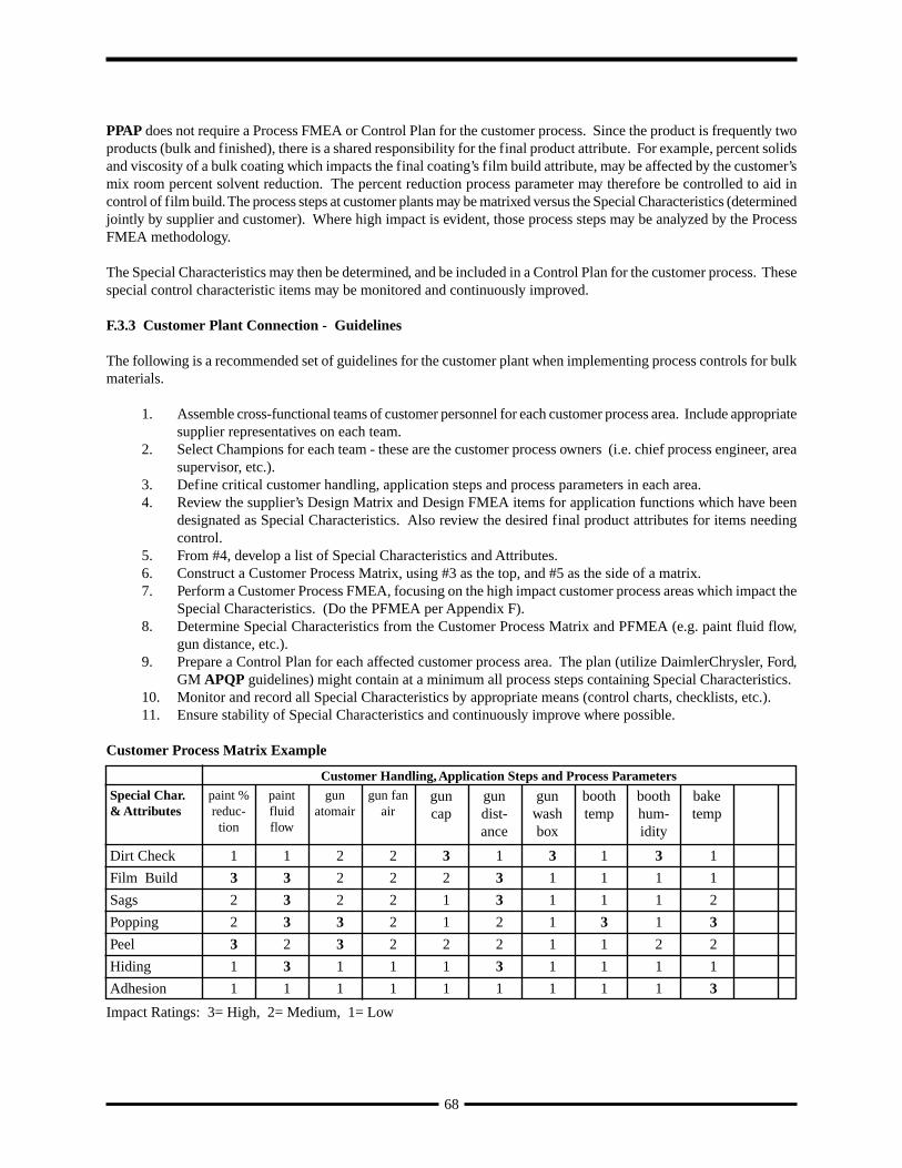
F.12 Bulk Materials Requirements Checklist (see I.2.2.15)
Use the Bulk Materials Requirements Checklist as follows:
· Required/Target Date: For each item listed in the checklist either enter a target date for completion of theelement or enter “NR” for Not Required.
· Primary Responsibility - Customer: Identify by name or function the individual who will review and approvethe element.
· Primary Responsibility - Supplier: Identify by name or function the individual who will assemble and assurethe completeness of the element to be reviewed.
· Comments / Conditions: Identify any qualifying information or references to attached documents that providespecific information regarding the element. For example, this may include specific formats to be used for theDesign Matrix or acceptable tolerances for Measurement System Analysis (MSA) studies.
· Approved by: Enter the initials of the Customer representative who has reviewed and accepted the element.
· Plan agreed to by: Identify the individuals who made and agreed upon the project plan.
F.13 Master Sample (see I.2.2.17)
F.13.1 Introduction
The requirements for master sample or equivalent should be agreed by the customer and supplier.
Physical Sample: Some bulk materials are stable and unchanging over an extended period of time (e.g. they donot significantly change physical or chemical composition, if properly stored, for decades). In this case, a physicalsample will serve as a Master Sample.
Analytical Sample Record: Other bulk materials change with time, but can be precisely quantified by appropriateanalytical techniques. In this case the analytical record (e.g. Ultra-Violet or Infra-Red spectra “fingerprint”,Atomic Absorption or Gas Chromatographic-Mass Spectrometric analysis) is an appropriate Master Sample.
Manufacturing Sample Record: When bulk materials can not be distinctly identified or change over time, amanufacturing sample record should be generated. The record should include the information required tomanufacture a “normal production size” run (lot or batch), according to the final “Production Control Plan”supporting the PSW. This record provides an “audit trail” to the information which may be stored in variousdocuments and or electronic systems. The following is the basic information suggested to accomplish this task:
· The quantity of product produced.· The important performance results.· The raw materials utilized (including manufacturer, Lot # and important properties records).· The critical equipment required to manufacture the bulk material.· Analytical sample records, as described above, on the material as produced.· Batch ticket used to manufacture the bulk material.
79
Appendices
80
Paint Mfg Master Sample Record - Batch/Lot Mfg. Record
BatchMFG. LOCATION: MFG. DATE: Number
Product Code: Product Name: FormulaDate:
Lbs/Gals Req’d.:
Equip. ID.:
TESTING INFORMATION
Name Test Method Specifications
Wt/Gallon TM001 10.50 - 10.70
% Non Volatile TM004 57 - 61%
Viscosity TM003 30 - 40 Secs
Ingredients Amt. Amt. Loaded Lot/Tank # Date/Time OperatorInitials
Add in order, with mixing
Resin A 1000 Lbs. 999 Lbs. AB345 12/5/97 9.35 AM
Resin B 500 Lbs. 501 Lbs. CD678 12/5/97 10.00 AM
Control temperature of mix. Not to exceed 105º F. Temperature recorded = Initials
Crosslinker 100 Lbs. 100 Lbs. AC250 12/5/97 10.25 AM
FILLING INSTRUCTIONS
Containers
Filtering
Labeling
Plant #1 12/5/97 1X97
xxR-yyyyy Basecoat White Basecoat
1/18/971000 Gals.
Mixer #2
250 Gal Tote
25 Micron Bag
Per contract
F.13.2 Paint Manufacturing Master Sample Record - Examples
The following figures show examples of paint manufacturing master records:
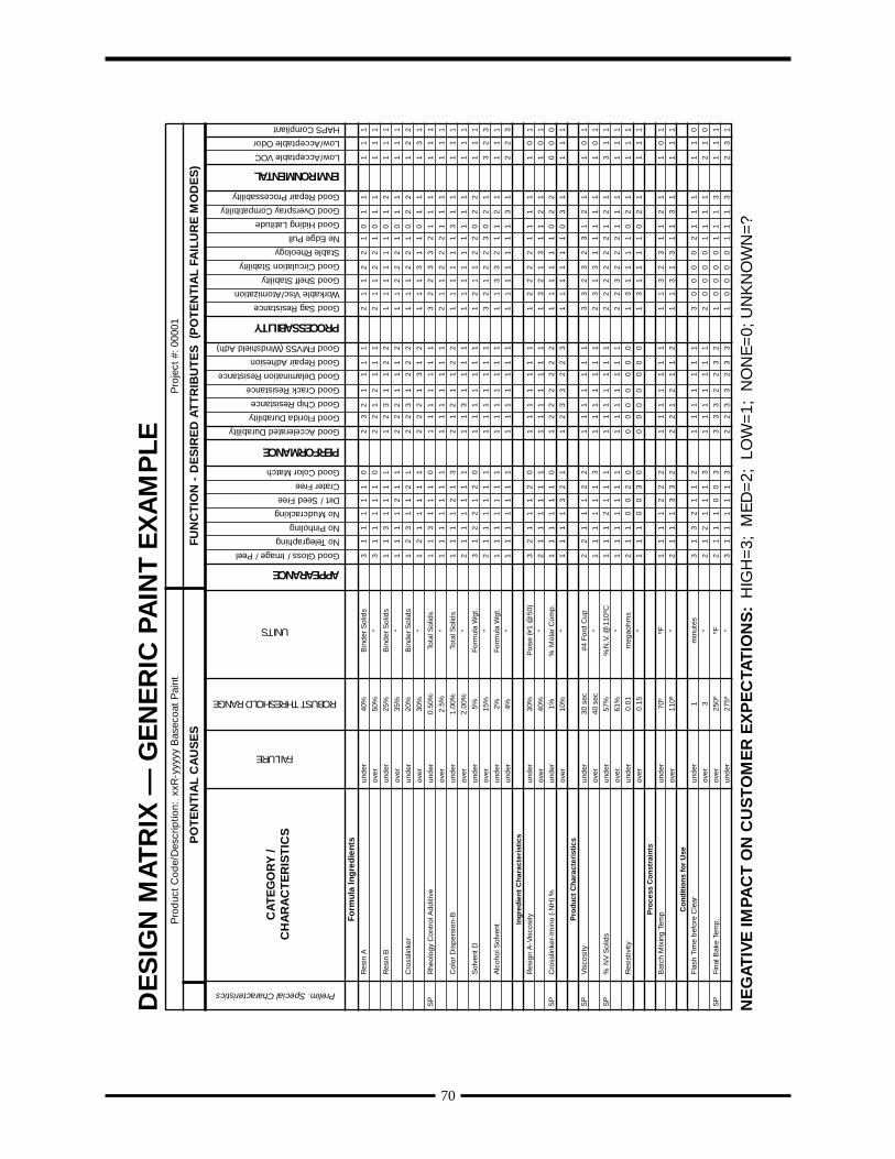
81
Paint Mfg Master Sample Record - Product Test Results
Product Code: xxR-yyyyy Product Name: White BasecoatManufacturing location: Plant #1
Date Batch # Batch SizeWt/Gallon
TM001% non Volatile
TM004ViscosityTM003
Initials Remarks
Gallons 10.50 - 10.70
12/5/97 1X97 1000
57 - 61% 30 - 40 Secs
10.59 59.6 34 Ok
Certificate of AnalysisMaterial Name: Filmformer Resin Lot/Batch #: AB345
Material Code: Resin A
Specification Requirements
Property Min. Max. Lot/Batch
Result
% Non Volatile 57% 61% 58.8%
(TM004)
pH 7 7.3 7.2
(TM005)
Certification Signature:
Date:
Paint Mfg Master Sample Record - Certificate of Analysis Ingredients
Appendices
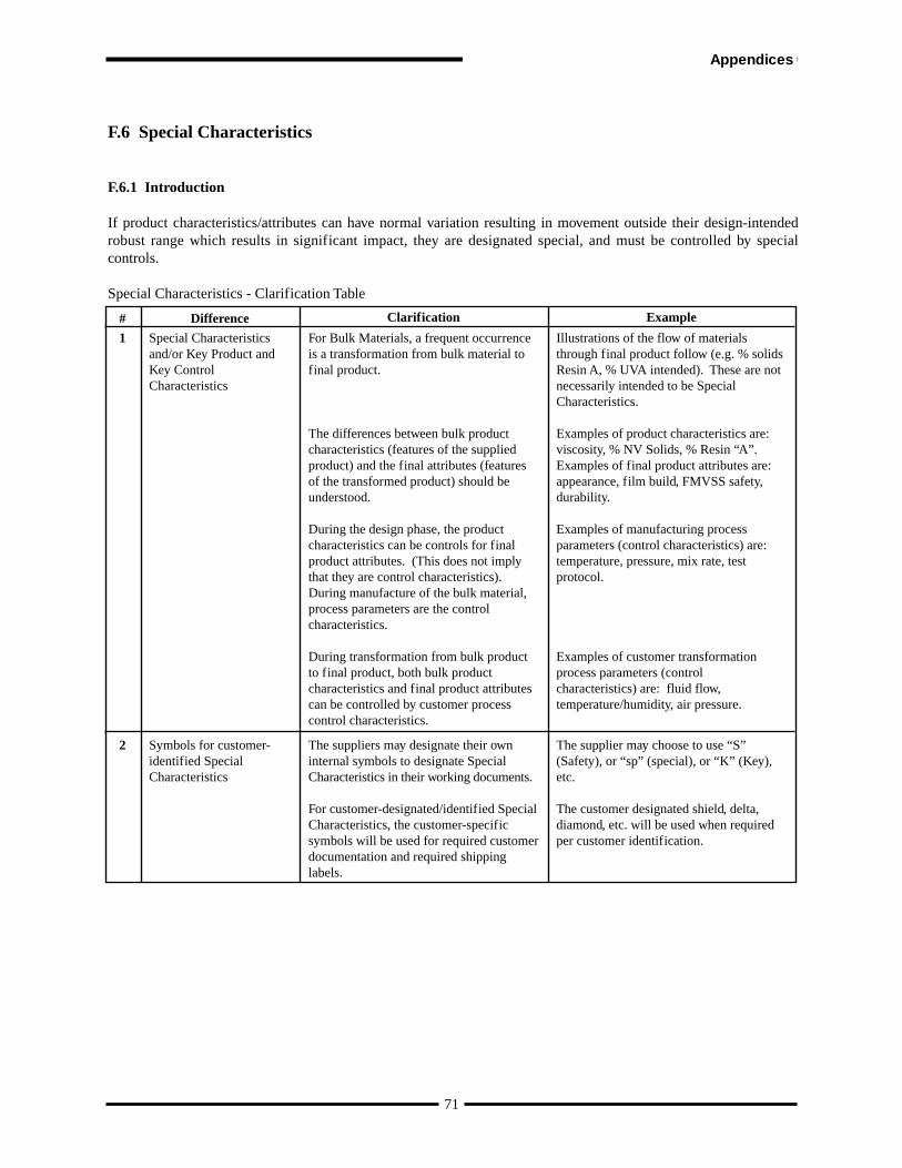
COMPLETION OF THE BULK MATERIAL INTERIM APPROVAL FORM
1. SUPPLIER NAME: Name assigned to Supplier’s manufacturing location
2. PRODUCT NAME: Supplier’s designated name for the product—as identified in the Customer’s EngineeringRelease Documents
3. SUPPLIER CODE: Code (D.U.N.S. # or equivalent) assigned to the manufacturing location as shown on theCustomer’s purchase order
4. ENG. SPEC.: Customer’s identified Specification through which the product is approved and released
5. MANUF. SITE: Physical address of the manufacturing location as shown on the Customer’s purchase order
6. PART #: Customer’s Part Number
7. ENG. CHANGE #: Formula Revision Level or number identifying the formula
8. FORMULA DATE: Engineering Release Date of the formula identified in item #7
9. RECEIVED DATE: Customer Use Only
10. RECEIVED BY: Customer Use Only (Customer Representative)
11. SUBMISSION LEVEL: Submission Level (1-5) that Supplier is required to submit to as defined by the Customer
12. EXPIRATION DATE: Date that the Interim Approval expires
13. TRACKING CODE: Customer Use Only
14. RE-SUBMISSION DATE: Date supplier will resubmit for production approval
15. STATUS: For each item, enter appropriate code (NR — Not Required, A — Approved, I — Interim)
16. SPECIFIC QUANTITY OF MATERIAL AUTHORIZED: Utilized when Interim Approval specifies a specificquantity of volume of product
17. PRODUCTION TRIAL AUTHORIZATION: Customer’s Engineering Release authorizing the use of the productin the Customer’s facility
18. REASON(S) FOR INTERIM APPROVAL: Indicate reason for Interim Request
19. ISSUES TO BE RESOLVED, EXPECTED COMPLETION DATE: For each item marked as “I” in #15, provideexplanatory details regarding problem issues and furnish a date for problem resolution
20. ACTIONS TO BE ACCOMPLISHED DURING INTERIM PERIOD, EFFECTIVE DATE: What is being doneto ensure defective product is contained, date when the action was implemented and Exit Criteria necessary toend need for continuing the action or its individual elements
21. PROGRESS REVIEW DATE: Update on progress of problem resolution, generally the midpoint from issuanceto expiration of the interim period
22. DATE MATERIAL DUE TO PLANT: Date material is due to Customer’s site
23. WHAT ACTIONS ARE TAKING PLACE TO ENSURE THAT FUTURE SUBMISSIONS WILL CONFORMTO ALL PPAP REQUIREMENTS BY THE SAMPLE PROMISE DATE? Why won’t this happen again?
24. SUPPLIER: Responsible and Authorized Supplier official to ensure compliance to the above mentioned actionsand dates
25. PRODUCT ENG.: Product Engineer’s signature, printed name, phone number and date
26. MATERIALS ENG.: Material Engineer’s signature, printed name, phone number and date
27. QUALITY ENG.: Quality Engineer’s signature, printed name, phone number and date
28. INTERIM APPROVAL NUMBER: Customer Use Only.
82
F.14 Interim Approval (see I.5.2.2)
Most products will achieve full approval prior to initial use. In cases where full approval cannot be obtained, a “BulkMaterial Interim Approval” may be granted. A form is shown on page 83; other forms may be used.
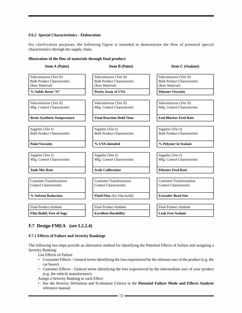
83
BULK MATERIAL INTERIM APPROVAL FORMSUPPLIER NAME: PRODUCT NAME:
SUPPLIER CODE: ENG. SPEC.:
MANUF. SITE: PART #:
ENG. CHANGE #: FORMULA DATE:
RECEIVED DATE: RECEIVED BY:
SUBMISSION LEVEL: EXPIRATION DATE:
TRACKING CODE: RE-SUBMISSION DATE:
STATUS: (NR - Not Required, A - Approved, I - Interim)
Design Matrix: DFMEA: Special Product Characteristics: Engineering Approval:
Control Plans: PFMEA: Special Process Characteristics: Process Flow Diagram:
Test Results: Process Studies: Dimensional Results: Master Sample:
Measurement Systems Studies: Appearance Approval Report:
SPECIFIC QUANTITY OF MATERIAL AUTHORIZED (IF APPLICABLE):
PRODUCTION TRIAL AUTHORIZATION #:
REASON(S) FOR INTERIM APPROVAL:
ISSUES TO BE RESOLVED, EXPECTED COMPLETION DATE(CLASSIFY AS ENGINEERING, DESIGN, PROCESS, OR OTHER):
ACTIONS TO BE ACCOMPLISHED DURING INTERIM PERIOD, EFFECTIVE DATE:
PROGRESS REVIEW DATE: DATE MATERIAL DUE TO PLANT:WHAT ACTIONS ARE TAKING PLACE TO ENSURE THAT FUTURE SUBMISSIONS WILL CONFORMTO BULK MATERIAL PPAP REQUIREMENTS BY THE SAMPLE PROMISE DATE?
SUPPLIER (AUTHORIZED SIGNATURE) PHONE:
(PRINT NAME) DATE:
CUSTOMER APPROVALS (as needed): PHONE DATE
PRODUCT ENG. (SIGNATURE)
(PRINT NAME)
MATERIALS ENG. (SIGNATURE)
(PRINT NAME)
QUALITY ENG. (SIGNATURE)
(PRINT NAME)
INTERIM APPROVAL NUMBER:
Appendices
1
3
5
7
9
11
13
2
4
6
8
10
12
14
15
16
17
18
19
20
21 22
23
24
25
26
27
28
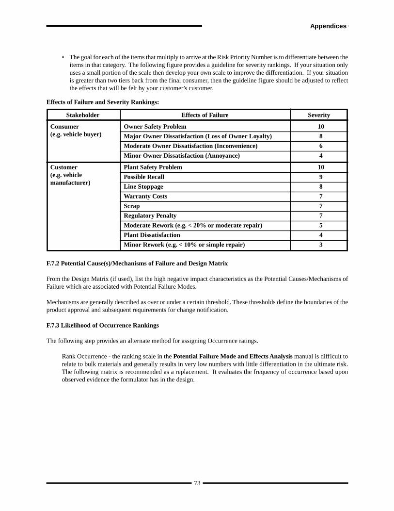
84
BULK MATERIAL INTERIM APPROVAL FORMSUPPLIER NAME: PRODUCT NAME:
SUPPLIER CODE: ENG. SPEC.:
MANUF. SITE: PART #:
ENG. CHANGE #: FORMULA DATE:
RECEIVED DATE: RECEIVED BY:
SUBMISSION LEVEL: EXPIRATION DATE:
TRACKING CODE: RE-SUBMISSION DATE:
STATUS: (NR - Not Required, A - Approved, I - Interim)
Design Matrix: DFMEA: Special Product Characteristics: Engineering Approval:
Control Plans: PFMEA: Special Process Characteristics: Process Flow Diagram:
Test Results: Process Studies: Dimensional Results: Master Sample:
Measurement Systems Studies: Appearance Approval Report:
SPECIFIC QUANTITY OF MATERIAL AUTHORIZED (IF APPLICABLE):
PRODUCTION TRIAL AUTHORIZATION #:
REASON(S) FOR INTERIM APPROVAL:
ISSUES TO BE RESOLVED, EXPECTED COMPLETION DATE(CLASSIFY AS ENGINEERING, DESIGN, PROCESS, OR OTHER):
ACTIONS TO BE ACCOMPLISHED DURING INTERIM PERIOD, EFFECTIVE DATE:
PROGRESS REVIEW DATE: DATE MATERIAL DUE TO PLANT:WHAT ACTIONS ARE TAKING PLACE TO ENSURE THAT FUTURE SUBMISSIONS WILL CONFORMTO BULK MATERIAL PPAP REQUIREMENTS BY THE SAMPLE PROMISE DATE?
SUPPLIER (AUTHORIZED SIGNATURE) PHONE:
(PRINT NAME) DATE:
CUSTOMER APPROVALS (as needed): PHONE DATE
PRODUCT ENG. (SIGNATURE)
(PRINT NAME)
MATERIALS ENG. (SIGNATURE)
(PRINT NAME)
QUALITY ENG. (SIGNATURE)
(PRINT NAME)
INTERIM APPROVAL NUMBER:
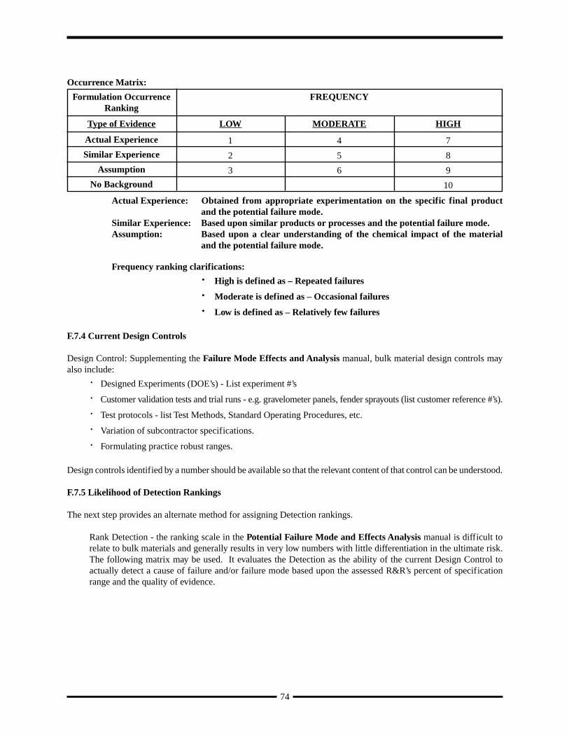
Appendix G
TIRE INDUSTRY - SPECIFIC REQUIREMENTS
G.1 INTRODUCTION AND APPLICABILITYA supplier of tires shall comply with the requirements of PPAP and use this appendix as guidance for clarification ofrequirements. These guidelines are based on existing approved practices between the tire supplier and the OEM.
Design tests used by each OEM to select tire construction (technical approval), reduces the need to repeat all testsduring PPAP. Specific PPAP confirmation tests are specified by each OEM.
G.2 GUIDELINES FOR PPAP PROCESS REQUIREMENTS (REFERENCE SECTION I.2)
Significant Production Run (I.2.1)
Unless otherwise specified by the OEM, the size of the production run for the PPAP parts is to be determined by thesupplier. Current industry practice requires a minimum of 30 tires. The typical development of a new tire designinvolves multiple builds of a small quantity of tires. Most designs are basic to the supplier’s process. For the tireindustry, PPAP is typically completed with an initial mold or molds, and well in advance of customer requirements forlarge volume production. PPAP is not required for additional molds that are brought on line in the approved productionprocess; however, for additional molds, the supplier’s internal certification criteria and documentation are utilized.
The PPAP for the tire industry typically is derived from 1 to 8 hours of tire curing from the approved productionprocess as specified in the supplier’s control plan. Subsequent parts from duplicate assembly lines for volume productionare not required to be represented in the PPAP sample, nor are additional PPAP submissions required.
The above definition for Significant Production Run applies to subsequent sections of I.2.
Tire industry practice defines tooling as a tire mold. This definition of tooling applies to all sections of PPAP.
Part Weight (Mass) (Reference I.2.2.13.1)
The tire industry practice is to weigh a specified number of PPAP tires to two (2) significant decimals (xx.xx). Theaverage is reported on the PSW to four (4) decimals (xx.xxxx).
Appearance Approval Report (AAR) (Reference I.2.2.14)
Tires are not an appearance item for the OEMs, consequently the AAR requirement is not applicable.
Material Test Results (Reference I.2.2.8.1)
Testing is applicable only to finished tires and not to raw materials. Tire industry practice does not require chemical,physical or metallurgical testing.
Process Flow Diagrams (Reference I.2.2.5)
Process flow diagrams may be generic for families of similar parts.
Process Failure Mode and Effects Analysis (Reference I.2.2.6)
Tire industry practice is to have a generic process FMEA for a family of similar parts.
Design Failure Mode and Effects Analysis (Reference I.2.2.4)
Tire industry practice is to have a generic design FMEA for a family of similar parts.
85
Appendices
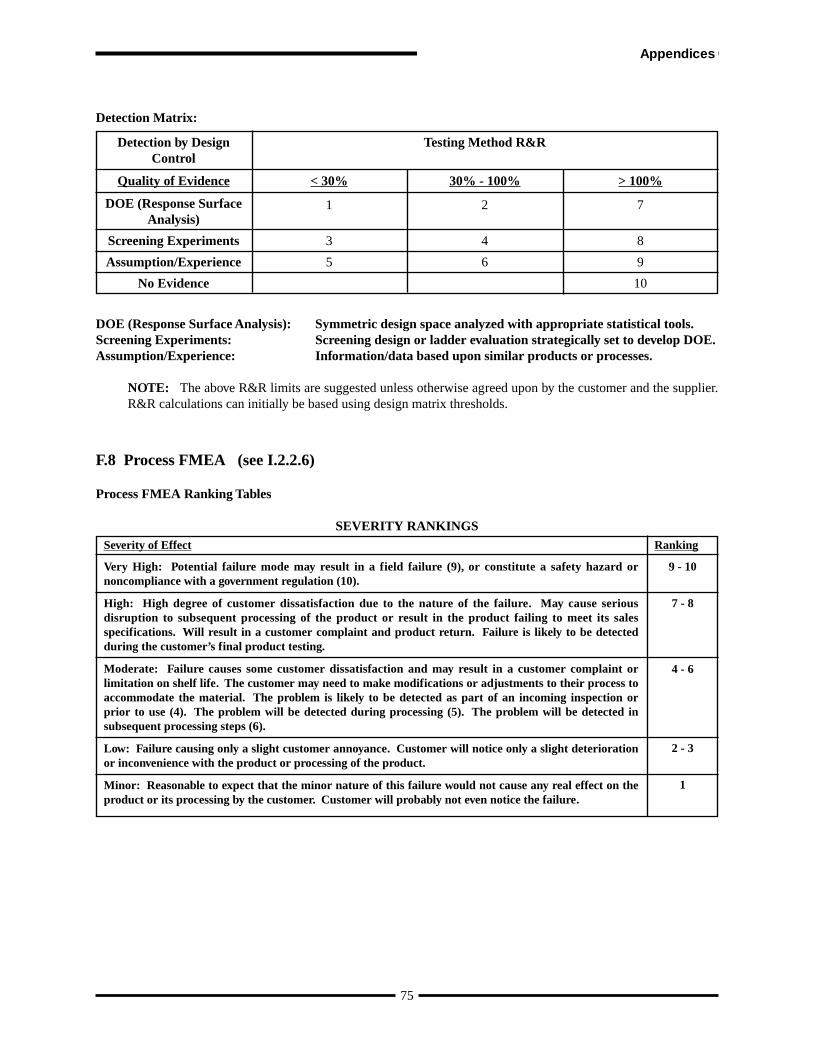
Control Plan (Reference I.2.2.12)
Industry practice is to have control plans for “families” of similar parts. Tire industry practice does not require customerreview and approval of control plans unless otherwise specified.
General (Reference I.2.2.9.1)
Tire industry practice is that customers and suppliers have designated uniformity and balance as Special Characteristics.
Measurement System Analysis Studies (Reference I.2.2.10)
In the tire industry, where the testing is destructive in nature, the measurement system analysis studies are limited to theequipment measurement system, rather than product repeatability or reproducibility.
Master Sample (Reference I.2.2.17)
Tire industry practice does not require retention of master sample.
Checking Aids (Reference I.2.2.18)
Checking aids are not required for the tire industry.
G.3 SUBMISSION TO CUSTOMER - LEVELS OF EVIDENCE (REFERENCE I.4)
Retention/Submission Requirements (Reference Table I.4.1)
Records of items submitted (S) and retained (R) are maintained at appropriate locations designated by the supplier.
86
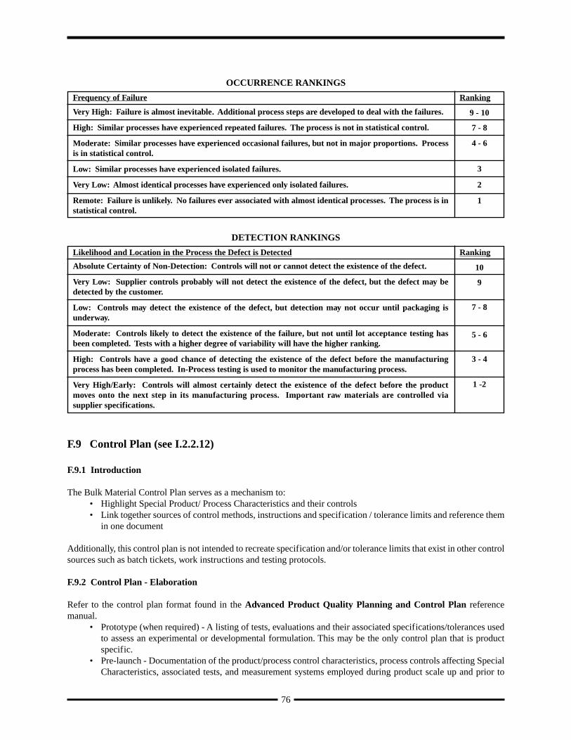
GLOSSARY
For additional related definitions, Refer to the Statistical Process Control reference manual, Measurement SystemsAnalysis reference manual, and QS-9000, Third Edition.
ACCREDITED LABORATORY is one that has been reviewed and approved by a nationally-recognized accreditationbody [e.g. American Association for Laboratory Accreditation (A2LA) or the Standards Council of Canada (SCC)] fortest laboratory accreditation to ISO/IEC Guide 25 or its replacement, or national equivalent.
ACTIVE PART is one currently being supplied to the customer for original equipment or service applications. Thepart remains active until tooling scrap authorization is given by the appropriate customer activity. For parts with nocustomer-owned tooling or situations where multiple parts are made from the same tool, written confirmation from thecustomer Purchasing activity is required to deactivate a part.
NOTE: For bulk material, “active part” refers to the bulk material contracted, not the parts that are subsequentlyproduced from that material.
AGREEMENT - used only for bulk material PPAP herein and refers to a situation where the customer and supplierunderstand the boundaries of an issue without requiring signatures or records documenting the specifics.
APPEARANCE ITEM is a product that is visible once the vehicle is completed. Certain customers will identifyappearance items on the engineering drawings. In these cases, special approval for appearance (color, grain, texture,etc.) is required prior to production part submission.
APPROVED is used in PPAP to mean that the parts, materials and/or related documentation or records submitted to,or reviewed by, the customer meet all customer requirements. After full or interim approval, the supplier is authorizedto ship product as directed by the customer. For bulk material PPAP only: 1) “approval” requires a signature or recordof a verbal approval; 2) Any record of verbal approval shall include the date, scope of the approval, the name of thecustomer representative granting the approval, and the name of the supplier representative involved; 3) The term“customer agreement” does not require signatures or records.
APPROVED DRAWING is an engineering drawing signed by the engineer and released through the customer’s system.
APPROVED MATERIALS are materials governed either by industry standard specifications (e.g. SAE, ASTM,DIN, ISO) or by customer specifications.
APPROVED SOURCE LIST is a list of suppliers and sub-suppliers that have been found to be acceptable to thecustomer. Utilizing product from an approved sub-supplier does not relieve the direct supplier of responsibility for thequality of that product.
ATTRIBUTES DATA are qualitative data that can be counted for recording and analysis. Examples include thepresence or absence of a required label, the installation of all required fasteners. Attributes data are not acceptable forproduction part submissions unless variables data cannot be obtained.
BULK MATERIAL is a substance (e.g. non-dimensional solid, liquid, gas) such as adhesives, sealants, chemicals,coatings, fabrics, lubricants, etc. A bulk material may become production material if issued a customer production partnumber (PRODUCTION MATERIAL).
87
Glossary
BULK MATERIAL REQUIREMENTS CHECKLIST defines the customer PPAP requirements for bulk material.(See Appendix F).
CAD/CAM MATH DATA is a form of design record by which all dimensional information necessary to define aproduct is conveyed electronically. When this design record is used, the supplier is responsible for obtaining a drawingto convey results of dimensional inspection.
CALIBRATION is a set of operations which compare values taken from a piece of inspection, measuring and testequipment or a gage to a known standard under specified conditions.
CAPABILITY is the total range of inherent variation in a stable process. (see Statistical Process Control referencemanual)
CHECKED PRINT is a released engineering drawing with actual measurement results recorded by the supplieradjacent to each drawing dimension and other requirements.
CONFORMANCE means that the part or material meets the customer’s specifications and requirements.
CONTROL - see STATISTICAL CONTROL
CONTROL CHARTS - see Statistical Process Control reference manual.
CONTROL PLANS are written descriptions of the system for controlling production parts or bulk materials andprocesses. They are written by suppliers to address the important characteristics and engineering requirements of theproduct. Each part must have a Control Plan, but in many cases, “family” Control Plans can apply to a number of partsproduced using a common process. Refer to Advanced Product Quality Planning and Control Plan referencemanual and QS-9000 Section II for customer-specific requirements.
CRITICAL CHARACTERISTIC: Ford definition: Critical characteristics are those product requirements (dimensions,performance tests) or process parameters that can affect compliance with government regulations or safe vehicle/product function and which require specific supplier, assembly, shipping, or monitoring and inclusion on ControlPlans. Critical characteristics are identified with the inverted delta symbol.
CRITICAL CHARACTERISTIC: GM definition: See Key Product Characteristics.
CUSTOMER is the activity that has contracted to buy the product.
CUSTOMER PRODUCT APPROVAL ACTIVITY is the customer location assigned responsibility for supplierPPAP approval.
NOTE: Some customers assign this responsibility geographically, while others use the procuring division.
DESIGN-INTENDED ROBUST RANGE are limits within which parameters may be allowed to vary while stillensuring that a product complies with fitness for use requirements.
DESIGN RECORD is the part drawing, specifications, and/or electronic (CAD) data used to convey informationnecessary to produce a product.
DOCUMENTATION is material (typically paper or electronic) defining the process to be followed, e.g. qualitymanual, operator instructions, graphics, pictorials.
88
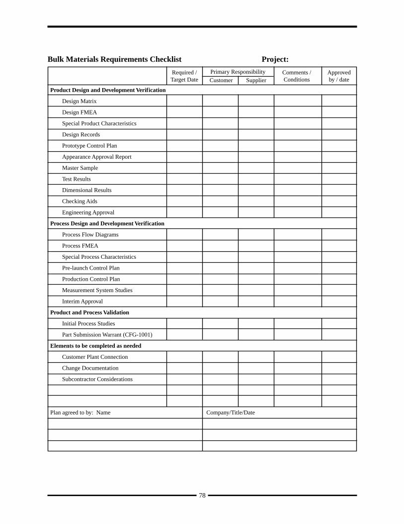
ENVIRONMENT is defined as all of the process conditions surrounding or affecting the manufacture and quality ofa part or product. Environment will vary for each site, but generally includes: housekeeping, lighting, noise, HVAC,ESD controls, and safety hazards relating to housekeeping. See Production Environment.
FAILURE MODE AND EFFECTS ANALYSIS (FMEA) is systematized technique which identifies and ranks thepotential failure modes of a design or manufacturing process in order to prioritize improvement actions. Refer toPotential Failure Modes and Effects Analysis reference manual.
FULL APPROVAL used in PPAP to indicate that the part or production material meets all customer specifications andrequirements. The supplier is therefore authorized to ship production quantities of the part or material subject toreleases from the customer scheduling activity.
GAGE REPEATABILITY AND REPRODUCIBILITY (Gage R&R) - Refer to the Measurement System Analysisreference manual.
INITIAL PROCESS STUDY is a short-term study conducted to obtain early information on the performance of newor revised processes relative to internal or customer requirements. In many cases, preliminary studies should be conductedat several points in the evolution of new processes (e.g., at the equipment or tooling subcontractor’s plant, after installationat the supplier’s plant). These studies should be based on as many measurements as possible. When utilizing X-Barand R charts, at least twenty-five subgroups (minimum of four pieces per subgroup) are required to obtain sufficientdata for decision making. When this amount of data is not available, control charts should be started with whatever datais available. (Refer to the Statistical Process Control reference manual.)
INITIAL SAMPLE is a term previously used for production part submissions.
INTERIM APPROVAL used in PPAP to permit shipment of products for a specified time period or quantity. Sincenot all customers allow interim approvals, consult your responsible customer product approval activity.
KEY CONTROL CHARACTERISTICS (KCCs) are those process parameters for which variation must be controlledaround a target value to ensure that a significant characteristic is maintained at its target value. KCCs require ongoingmonitoring per an approved Control Plan and should be considered as candidates for process improvement.
KEY DESIGN CHARACTERISTICS (DaimlerChrysler Corporation) - Toleranced and measurable characteristicsof a part, system, and/or assembly which may have an adverse or degrading effect on the function, quality, or reliabilityof that part or system if an out of tolerance condition occurs. A Shield symbol is used to designate a key designcharacteristic on components, systems or assemblies that have a safety or regulatory designation. On all other componentsor systems, the key design characteristics are designated by the Diamond symbol. Good judgment should be used whendesignating key design characteristics, as some designs have more robustness than others or the manufacturing processmay not be susceptible to variation.
KEY PROCESS CHARACTERISTICS (DaimlerChrysler Corporation) - Key Process characteristics are measurableelements of the process used to manufacture or assemble a component or system that have significant impact on thefunction, quality and/or reliability of that component or system. With a process characteristic, an actual element of theprocess is measured, as opposed to a Key Design Characteristic where the measurement is taken at the component orassembly.
KEY PRODUCT CHARACTERISTIC (KPC) are those product features that affect subsequent operations, productfunction, or customer satisfaction. KPCs are established by the customer engineer, quality representative, and supplierpersonnel from a review of the Design and Process FMEAs and must be included by the supplier in the Control Plan.Any KPCs included in customer-released engineering requirements are provided as a starting point and do not affectthe supplier’s responsibility to review all aspects of the design, manufacturing process, and customer application and todetermine additional KPCs.
89
Glossary
LABORATORY is a test facility that may include chemical, metallurgical, dimensional, physical, electrical, reliabilitytesting or test validation.
LABORATORY SCOPE is quality record containing the following:• the specific tests, evaluations and calibrations a supplier laboratory has the ability and competency to perform• a list of the equipment which it uses to perform the above• a list of the methods and standards to which it performs the above.
MARKED PRINT is an engineering drawing modified, signed and dated by the customer engineer (the engineeringchange number must be included).
MEASUREMENT SYSTEM ANALYSIS STUDIES - Refer to the Measurement System Analysis reference manual.
PART SUBMISSION WARRANT is an industry-standard document required for all newly-tooled or revised productsin which the supplier confirms that inspections and tests on production parts show conformance to customer requirements.
PERISHABLE TOOLS are drill bits, cutters, inserts, etc. used to produce a product and which are consumed in theprocess.
PROCESS is a combination of people, equipment, methods, materials, and environment that produces output, a givenproduct or service. A process can involve any aspect of a business.
PROCESS FLOW DIAGRAM depicts the flow of materials through the process, including any rework or repairoperations.
PRODUCTION ENVIRONMENT is the manufacturing location within the production site which includes theproduction tooling, gaging, process, materials, operators, environment, and process settings, e.g. feeds, speeds, cycletimes, pressures, temperatures, quoted line rate. Environment is defined as all of the process conditions surrounding oraffecting the manufacture and quality of a part or product. Environment will vary for each site, but generally includes:housekeeping, lighting, noise, HVAC, ESD controls, and safety hazards relating to housekeeping.
PRODUCTION MATERIAL is material which has been issued a production part number by the customer and isshipped directly to the customer.
PRODUCTION PART is manufactured at the production site using the production tooling, gaging, process, materials,operators, environment, and process settings, e.g., feeds/speeds/cycle times/pressures/temperatures.
PRODUCTION PART APPROVAL SUBMISSION is based on specified quantities of production parts or productionmaterials taken from the significant production run made with production tooling, processes, and cycle times. Theseparts or materials submitted for production part approval are to be verified by the supplier as meeting all specifiedrequirements from the design record.
QUALITY INDICES are defined herein as either Cpk or Ppk for purposes of PPAP. See the Statistical ProcessControl reference manual.
QUALITY PLANNING is a structured process for defining the methods (i.e., measurements, tests) that will be usedin the production of a specific product or family of products (i.e., parts, materials). Quality planning embodies theconcepts of defect prevention and continuous improvement as contrasted with defect detection (see Advanced ProductQuality Planning and Control Plan reference manual).
90

QUALITY RECORD is documented evidence that the supplier’s processes were executed according to the qualitysystem documentation, e.g. test results, internal audit results, calibration data, and which records the results. See QS-9000, cl. 4.16.
REGULAR PRODUCTION TOOLING is the tooling with which the manufacturer intends to produce productionproduct.
REJECTED used in PPAP to mean that the production part submission and/or documents did not meet the customer’srequirements. The supplier must correct the production process and a make a new submission. (Advise the customer’sPurchasing activity of the date when corrected parts will be available.) Do not ship production parts until the customerapproves the corrected parts. The customer may withhold tooling payments until part approval is obtained.
REMOTE LOCATION is a location at which production processes do not occur, e..g. does not fit the definition givenfor Site, but which support such sites.
REPEATABILITY AND REPRODUCIBILITY (R&R) Refer to Measurement System Analysis reference manual.
SAFETY CHARACTERISTICS (DaimlerChrysler Corporation Definition) are specifications which require specialmanufacturing control to assure compliance with DaimlerChrysler Corporation or government vehicle safetyrequirements.
SALEABLE PRODUCT - generally refers to the product specified on the contract between the supplier and customer.
SELF-CERTIFYING SUPPLIER - is a supplier that an authorized customer representative has designated as “self-certifying,” which means that the supplier submits the PSW (e.g. Level 1 PPAP) to the customer, but the response fromthe customer is not necessary. This designation is to be documented. The PSW submittal from a self-certifyingsupplier results in a simultaneous “approval” status by the customer for that submittal, which may not be a “fullapproval.”
SIGNIFICANT PRODUCTION RUN is manufacture of a lot consisting of a minimum of 300 consecutive pieces, orother quantity as agreed to by the customer product approval activity, and from a minimum of one hour of productionfrom the production environment.
SITE is defined as a supplier or subcontractor location at which value-added processes occur. “Site” also includesdistributors of parts manufactured by other companies. External locations which only stage material for onward shipment,indirect material suppliers or assembly plants are not included. Providers of bulk or raw materials should contact theirprocuring division buyer to determine if their material is considered to be production material.
SPECIAL CHARACTERISTICS - see Critical Characteristic or Key Product Characteristic. Reference individualTruck Supplier Quality requirements for their definition. For bulk materials, see Appendix F.
SPECIFICATIONS are engineering requirements for judging the acceptability of a part or bulk material characteristic.For the production part approval process, every feature of the product as identified by engineering specifications mustbe measured. Actual measurement and test results are required. Specifications should not be confused with controllimits which represent “the voice of the process”.
STABLE PROCESSES are processes that are in statistical control. Variation in the output of a stable process arisesonly from common causes. A stable process is predictable. For initial process studies performed prior to productionpart submission, tests for stability may not be as rigorous as those used for ongoing processes.
91
Glossary
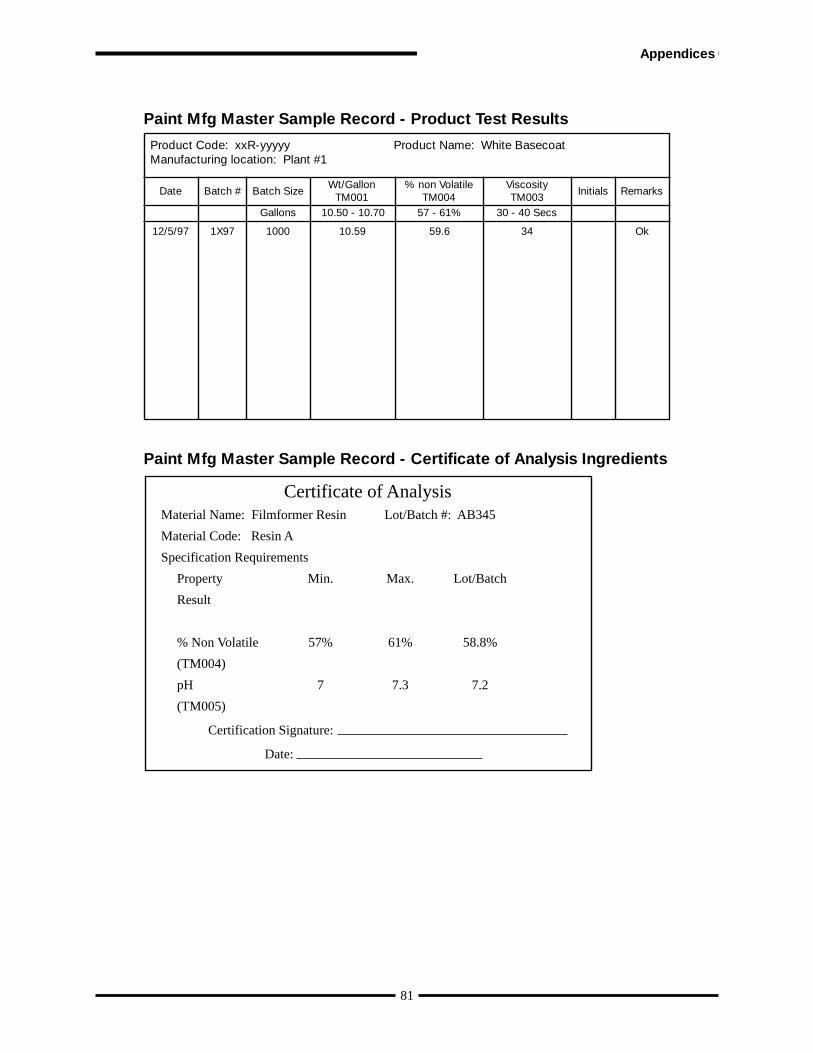
SUBCONTRACTORS are defined as providers of production materials, or production or service parts, directly to asupplier to DaimlerChrysler Corporation, Ford, General Motors or other customers requiring this document. Alsoincluded are providers of heat treating, painting, plating or other finishing services.
SUPPLIERS are defined as providers of: a) production materials, b) production or service parts, or c) heat treating,plating, painting or other finishing services, directly to DaimlerChrysler Corporation, Ford, or General Motors or othercustomers requiring this document, e.g. Heavy Truck OEMs.
STATISTICAL CONTROL is the condition of a process from which all special causes of variation have been eliminatedand only common causes remain. Statistical control is evidenced on a control chart by the absence of points beyond thecontrol limits and by the absence of any non-random patterns or trends. (STATISTICAL CONTROL is a descriptiveterm for a STABLE PROCESS.)
SUBMISSION LEVEL refers to the level of evidence required for production part submission (reference I.4.1 of thisdocument).
TOOL is defined as the portion of process machinery which is specific to a component or sub-assembly. Tools (ortooling) are used in process machinery to transform raw material into a finished part or assembly.
TOOLING MAINTENANCE is the periodic sharpening, polishing, or other servicing of a tool. This maintenancewill not significantly affect the dimensions or other characteristics of the product produced by the tool. (contrasts withTOOLING REFURBISHMENT)
TOOLING REFURBISHMENT is the major overhaul of a tool. Refurbishment can affect dimensions or othercharacteristics of the product produced by the tool. Production part approval submission of product made with refurbishedtools is required before such product may be shipped to the customer.
VALIDATION is confirmation by examination and provision of objective evidence that the particular requirements forspecific intended use are fulfilled.
VARIABLES DATA are quantitative results where measurements are used for analysis. Examples include the diameterof a bearing journal in millimeters, the closing effort of a door in newtons, the concentration of an electrolyte inpercent, and the torque of a fastener in newton-meters.
VERIFICATION is confirmation by examination and provision of objective evidence that specified requirementshave been fulfilled.
WARRANT - see Part Submission Warrant.
92