aircraft noise: the major sources, modelling capabilities, and reduction possibilities
TRANSCRIPT
Berichts.-Nr.: IB 224-2015 A 110
Verfasser: Lothar Bertsch1,2, Dick G. Simons², and Mirjam Snellen²
Titel: Aircraft Noise: The major sources, modelling capabilities, and
reduction possibilities
Datum: März 2015
Auftraggeber:
Auftrags-Nr.:
Angebot Nr.:
Der Bericht umfaßt: 29 Seiten einschl. 7 Tabellen 7 Bildern 23 Literaturstellen
Vervielfältigung und Weitergabe dieser Unterlagen sowie Mitteilung ihres Inhalts an Dritte, auch auszugsweise, nur mit Genehmigung des Auftraggebers
Deutsches Zentrum Für Luft- und Raumfahrt e. V.
1) DLR, Institut für Aerodynamik und Strömungstechnik, Bunsenstraße 10, D - 37073 Göttingen
2) Section Aircraft Noise and Climate Effects, Delft University of Technology, 2629 HS, Kluyverweg 1, Delft, The Netherlands

Aircraft Noise: The major sources, modelling capabilities, and
reduction possibilities
Übersicht: In October 2014, the first ”Joint DLR & TU Delft Aviation Noise Workshop” was organized. This publication is the executive summary of this event. Overall, 38 invited participants from industry, academia, and research institutions have discussed the specific topic of this first 3 day workshop, i.e ”Aircraft Noise Reduction at the Source”. Four specific tasks were formulated in order to address the problem, i.e. (1) identification of main aircraft noise sources on-board of a given reference vehicle, (2) assessment of simulation capabilities for noise prediction, (3) identification and assessment of promising noise reduction concepts for the reference vehicle, and (4) integration of these measures on-board of the reference vehicle. The major noise sources on-board of the reference vehicle as identified by the participants could have been reduced significantly if selected measures are installed on-board. These proposed measures promise to reduce the system noise by 8 dB along a take-off and by 10 dB along an approach flight. Yet, the almost 65% reduction in perceived noise as specified by ACARE’s Flight Path 2050 could not be achieved. The most effective measure has been identified as structural shielding of engine noise emission.
Deutsches Zentrum
für Luft- und Raumfahrt e.V.
Institut für Aerodynamik und Strömungstechnik Göttingen
Institutsleiter: (Prof. Dr. A. Dillmann) Abteilungsleiter: (Prof. Dr. M. Raffel)
Verfasser: (Dr. L. Bertsch) (Prof. Dr. D.G. Simons) (Assoc. Prof. Dr. M. Snellen)
Datum: 17.03.15 Abteilung: Bericht:
Bearbeitet: LB 22417 224–2015 A 110
Abstract
In October 2014, the first "Joint DLR & TU Delft Aviation Noise Workshop" was or-ganized. This publication is the executive summary of this event. Overall, 38 invitedparticipants from industry, academia, and research institutions have discussed the spe-cific topic of this first 3 day workshop, i.e. "Aircraft Noise Reduction at the Source".The concept of the workshop was to avoid the usual presentation marathon but enabledetailed discussions. The invited participants with their various educational, cultural,and working backgrounds have been assigned into work groups to work on specificand predefined tasks. Four specific tasks were formulated in order to address the prob-lem, i.e. (1) identification of main aircraft noise sources on-board of a given referencevehicle, (2) assessment of simulation capabilities for noise prediction, (3) identificationand assessment of promising noise reduction concepts for the reference vehicle, and (4)integration of these measures on-board of the reference vehicle.The major noise sources on-board of the reference vehicle as identified by the partici-pants could have been reduced significantly if selected measures are installed on-board.These proposed measures promise to reduce the system noise by 8 dB along a take-offand by 10 dB along an approach flight. Yet, the almost 65% reduction in perceived noiseas specified by ACARE’s Flight Path 2050 could not be achieved. The most effectivemeasure has been identified as structural shielding of engine noise emission.Overall, the workshop can be understood as the first attempt to establish a new andactive network for international cooperation in the field of aircraft noise.

Contents
1 Introduction 4
2 Identification of main aircraft noise sources (Task 1) 82.1 Detailed description of task . . . . . . . . . . . . . . . . . . . . . . . . . . . 8
2.2 Summary of results . . . . . . . . . . . . . . . . . . . . . . . . . . . . . . . . 8
3 Assessment of simulation capabilities (Task 2) 133.1 Detailed description of task . . . . . . . . . . . . . . . . . . . . . . . . . . . 13
3.1.1 Summary of results . . . . . . . . . . . . . . . . . . . . . . . . . . . . 13
4 Identification and assessment of promising noise reduction concepts (Task 3) 174.1 Detailed description of task . . . . . . . . . . . . . . . . . . . . . . . . . . . 17
4.2 Summary of results . . . . . . . . . . . . . . . . . . . . . . . . . . . . . . . . 17
5 Integration of reduction concepts into new low-noise vehicle (Task 4) 19
6 Summary & Conclusion 22
2
3
Nomenclature
ANoPP Overall aircraft noise simulation tool, NASAANOTEC ANOTEC consulting, aircraft noise technologyASRI Aircraft Strength Research Institute, ChinaARI Aerodynamics Research Institute, ChinaAzB Overall aircraft noise simulation tool, DLRCAA Computational AeroacousticsCFD Computational Fluid DynamicsDNS Direct Numerical SimulationDFS Deutsche Flugsicherung GmbH, German air navigation service providerDLR German Aerospace CenterEPNL Effective Perceived Noise Level [EPNdB]EMPA Swiss Federal Laboratories for Materials Science and TechnologyFLULA Overall aircraft noise simulation tool, EMPAHEIDI Engine noise simulation tool, DLRIESTA Overall aircraft noise simulation tool, ONERAINM Integrated Noise Module, simulation tool, FAAJAXA Japan Aerospace Exploration AgencyLES Large Eddy SimulationNASA National Aeronautics and Space Administration, USANLR National Aerospace Laboratory, NetherlandsMTU MTU Aero Engines, company, GermanyONERA French Aerospace Research AgencyOASPL (Overall) sound pressure level, [dB]UPACS-LES CFD/CAA code, JAXAU-RANS Unsteady Reynolds Averaged Navier StokesPANAM Overall aircraft noise simulation tool, DLRPIANO Computational Aeroacoustics tool, DLRProfan Airframe noise simulation tool, DLRPropnoise Propeller noise prediction tool, DLRRWTH RWTH Aachen UniversitysonAIR Overall aircraft noise simulation tool, EMPASOPRANO Overall aircraft noise simulation tool, ANOTECSTAPES Airport noise exposure simulation tool, EUROCONTROLSPL (non or A-weighted) Sound Pressure Level, [dB] or [dBA]TAS True Air Speed [m/s]
1 Introduction
In October 2014 the workshop "Aircraft Noise Reduction at the Source" was held inMeisdorf, Germany. The event was organized jointly by DLR and the Delft University ofTechnology.
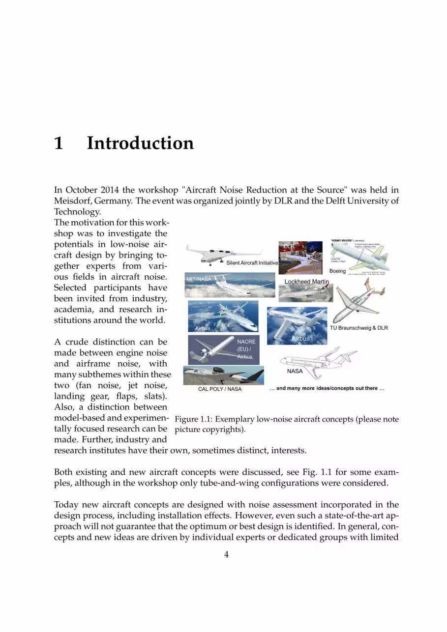
Figure 1.1: Exemplary low-noise aircraft concepts (please notepicture copyrights).
The motivation for this work-shop was to investigate thepotentials in low-noise air-craft design by bringing to-gether experts from vari-ous fields in aircraft noise.Selected participants havebeen invited from industry,academia, and research in-stitutions around the world.
A crude distinction can bemade between engine noiseand airframe noise, withmany subthemes within thesetwo (fan noise, jet noise,landing gear, flaps, slats).Also, a distinction betweenmodel-based and experimen-tally focused research can bemade. Further, industry andresearch institutes have their own, sometimes distinct, interests.
Both existing and new aircraft concepts were discussed, see Fig. 1.1 for some exam-ples, although in the workshop only tube-and-wing configurations were considered.
Today new aircraft concepts are designed with noise assessment incorporated in thedesign process, including installation effects. However, even such a state-of-the-art ap-proach will not guarantee that the optimum or best design is identified. In general, con-cepts and new ideas are driven by individual experts or dedicated groups with limited
4
1. Introduction 5
experience in other fields than their main expertise. This can result in only componentwise optimization and only little or no improvement at a system level will be achieved.In addition, the various simulation tools that are applied have different fidelity, limita-tions, and accuracy.
Therefore, the relevant questions and problems for the workshop participants wereidentified as the following.
• Are individual technologies still "low-noise" if installed on-board of the aircraft?(e.g. are leading edge devices as tested in a wind-tunnel really low-noise on-board?)
• How good are our predictions?(e.g. is neglecting mean flow for shielding problems allowed?)
• Have we considered all relevant noise sources and major interactions?(e.g. is flap side edge noise important?)
• What about the influence of "realistic" flight operation?(e.g. what is the effect of engine thrust correction and/or speed increase?)
• What about counteracting effects?(e.g. what is the effect of additional drag and weight of a new low-noise high-liftsystem?)
• What about the overall vehicle noise at a system level?(e.g. is flying at higher altitudes always better?)
In order to be able to answer these questions, a broad ("holistic") assessment methodol-ogy and active exchange with various experts become essential. Involvement of expertsfrom different disciplines with various backgrounds (e.g. academia vs. industry, cul-tural and educational differences) is mandatory.
In order to answer the above mentioned questions, the workshop attendants were as-signed to work on the four tasks as listed in Tab. 1.1.
Task Description1 Identification of main aircraft noise sources on-board of reference vehicle2 Assessment of simulation capabilities3 Identification and assessment of promising noise reduction concepts4 Integration into a new low-noise vehicle concept
Table 1.1: Short description of the four workshop tasks
1. Introduction 6
The following scenario and limitations were predefined: the reference aircraft is an ex-isting vehicle, i.e. a conventional, single-aisle, tube-and-wing, medium-range transportaircraft as depicted in Fig. 1.2 (predicted market share of 70% by 2030, see Refs. [2, 3]).Also, the developed new low-noise technology should be available in 2030 at TechnicalReadiness Level of 5-6. The overall goal for this 2030 scenario is a reduction in perceivednoise level (with respect to the reference aircraft) of 65% per flight operation as proposedby the Advisory Council for Aviation Research and Innovation in Europe (ACARE) intheir "Flightpath 2050"1. This corresponds to approximately 12 dB reduction in overallsound pressure level (OASPL) or a level 35 EPNdB cumulative below Chapter 42.In the subsequent chapters of this paper, the four tasks are described in more detail,including the major results of the workshop per task.
The workshop was not a traditional conference, i.e. fully filled with presentations. Ba-sically, such a presentation marathon was avoided by dedicating most of the time to ac-tive participation in groups working on the four tasks above. Five groups were formed,based on background and research interest (e.g. focus more on airframe noise or enginenoise) and mixed members from academia, research institutions, and industry, wherewe tried to separate direct colleagues. The five groups worked in parallel on the fourtasks. In plenary sessions the results of the five groups were discussed per task. In theplenary sessions, individual ideas and concepts of each group were discussed with theaim to find common ground, and to identify the best ideas and most promising con-cepts. To ensure maximum uniformity in the outcomes of the individual groups, theparticipants were provided with templates for documenting their discussion results.In total, there were 38 participants out of 10 countries (China, France, Germany, Italy,Japan, Netherlands, Spain, Switzerland, UK and US). In Tab. 1.2 the participating insti-tutions are listed.
Industry University Research institutionsANOTEC Consulting Georgia Institute of Technology ASRIAirbus Peking University ARIDFS Roma Tre University Bauhaus LuftfahrtMTU RWTH EMPARolls-Royce Southampton DLR
University of Tokyo JAXATU Braunschweig NASATU Delft NLRTU Muenchen ONERATU Stuttgart
Table 1.2: The workshop participants’ institutions
1For more information, visit http://www.acare4europe.com/sria/flightpath-2050-goals2According to ICAO Annex 16.

1. Introduction 7
Figure 1.2: Reference vehicle layout for the workshop tasks (see Ref. [1]).
2 Identification of main aircraft noisesources (Task 1)
2.1 Detailed description of task
Task 1 comprises the identification of the main noise sources on-board existing aircraft,i.e. the reference vehicle as depicted in Fig. 1.2, was used as an example case. Partici-pants were asked to identify the main sources (airframe or engine noise) along typicalflight segments (approach / departure / cruise), taking into account whether sourcesare classical, parasitic, or due to installation effects. Also the spectral (tonal or broad-band contribution, low or high frequency) and directional characteristics had to be indi-cated. For each source, the relevant parameters, both operational (flight condition) andgeometrical, had to be specified. If possible, the importance of each parameter had tobe ranked.
2.2 Summary of results
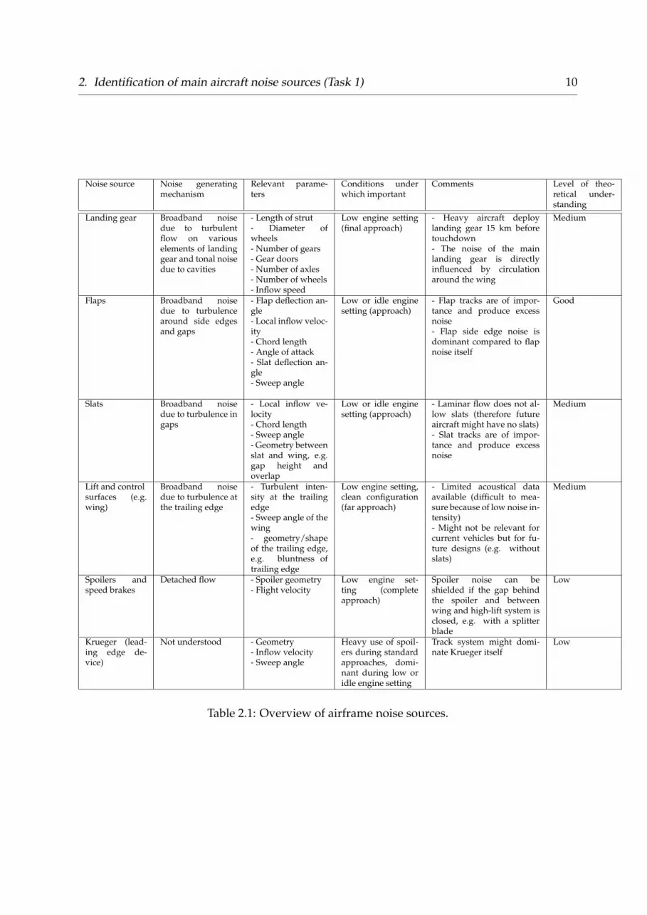
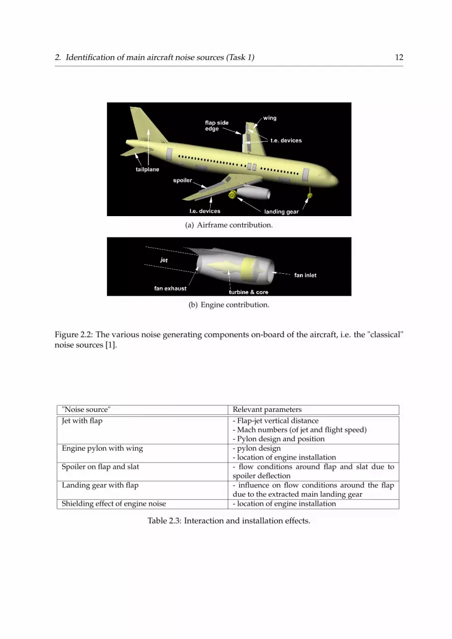
The workshop participants identified the following classical aircraft noise sources, seeTabs. 2.1 and 2.2. Also the noise generating mechanism (including the relevant parame-ters in descending order of importance) and the departure and approach conditions un-der which these noise sources are important are also indicated, see Fig. 2.1. Finally, thelevel of theoretical understanding was estimated. A distinction is made between noisesources due to the airframe, see Fig. 2.2(a), and engine noise sources, see Fig. 2.2(b).
8

2. Identification of main aircraft noise sources (Task 1) 9
altit
ude
[m]
flap/
slat
[°]
0
500
1000
1500
2000
0
10
20
30
40
altitudeflapslatgear
distance [m]
TA
S [m
/s]
thru
st [k
N]
0 5000 10000 15000 200000
50
100
150
50
100
150
200
TASthrust
(a) Standard departure flights.
altit
ude
[m]
flap/
slat
[°]
0
500
1000
1500
2000
0
10
20
30
40altitudeflapslatgear
distance [m]
TA
S [m
/s]
thru
st [k
N]
-40000 -30000 -20000 -10000 050
100
150
0
50
100
TASthrust
(b) Standard approach flights.
Figure 2.1: Typical and representative operating conditions along departure and approachflights; flight data was recorded during a 2006 fly-over noise campaign by DLR [4].
2. Identification of main aircraft noise sources (Task 1) 10
Noise source Noise generatingmechanism
Relevant parame-ters
Conditions underwhich important
Comments Level of theo-retical under-standing
Landing gear Broadband noisedue to turbulentflow on variouselements of landinggear and tonal noisedue to cavities
- Length of strut- Diameter ofwheels- Number of gears- Gear doors- Number of axles- Number of wheels- Inflow speed
Low engine setting(final approach)
- Heavy aircraft deploylanding gear 15 km beforetouchdown- The noise of the mainlanding gear is directlyinfluenced by circulationaround the wing
Medium
Flaps Broadband noisedue to turbulencearound side edgesand gaps
- Flap deflection an-gle- Local inflow veloc-ity- Chord length- Angle of attack- Slat deflection an-gle- Sweep angle
Low or idle enginesetting (approach)
- Flap tracks are of impor-tance and produce excessnoise- Flap side edge noise isdominant compared to flapnoise itself
Good
Slats Broadband noisedue to turbulence ingaps
- Local inflow ve-locity- Chord length- Sweep angle- Geometry betweenslat and wing, e.g.gap height andoverlap
Low or idle enginesetting (approach)
- Laminar flow does not al-low slats (therefore futureaircraft might have no slats)- Slat tracks are of impor-tance and produce excessnoise
Medium
Lift and controlsurfaces (e.g.wing)
Broadband noisedue to turbulence atthe trailing edge
- Turbulent inten-sity at the trailingedge- Sweep angle of thewing- geometry/shapeof the trailing edge,e.g. bluntness oftrailing edge
Low engine setting,clean configuration(far approach)
- Limited acoustical dataavailable (difficult to mea-sure because of low noise in-tensity)- Might not be relevant forcurrent vehicles but for fu-ture designs (e.g. withoutslats)
Medium
Spoilers andspeed brakes
Detached flow - Spoiler geometry- Flight velocity
Low engine set-ting (completeapproach)
Spoiler noise can beshielded if the gap behindthe spoiler and betweenwing and high-lift system isclosed, e.g. with a splitterblade
Low
Krueger (lead-ing edge de-vice)
Not understood - Geometry- Inflow velocity- Sweep angle
Heavy use of spoil-ers during standardapproaches, domi-nant during low oridle engine setting
Track system might domi-nate Krueger itself
Low
Table 2.1: Overview of airframe noise sources.

2. Identification of main aircraft noise sources (Task 1) 11
Noise source Noise generating mecha-nism
Relevant parame-ters
Conditions un-der which im-portant
Comments Level oftheoreticalunder-standing
Fan -Thickness and loadingnoise- Interaction rotor-stator- Stator vane- Struts- Fan-intake interaction,e.g. engine inlet or pylons- Tonal noise due to shockcells on blades (harmonic)- Shock cell interactionwith nacelle (not a har-monic sequence)
- Inlet geometry- Number of blades- Number of vanes- Fan pressure ratio- Relative Tip Machnumber- Inlet flow distor-tion, e.g. due toan angle of attack ordue to a pylon infront of the engineinlet
Always - For current engines both tonesand broadband noise important.The broadband contribution be-comes more important for fu-ture designs- Buzzsaw (tonal) is relevant- Fan noise increases due to in-creased inflow distortion by en-gine installation- Fan noise is reduced due to lin-ing- Fan noise can be subject to sig-nificant noise shielding due tostructural elements
- Mediumfor tones- Low forbroadbandcontribu-tion
Jet - Turbulent mixing- Shock noise (only incruise condition)
- Velocity differ-ences between thestreams, i.e. free,core, and bypassstream- Temperature- Nozzle diameter- Nozzle type
Take-off Jet noise is a distributed sourcebehind engine
- Good(undersubsonicconditions)- Medium(undersonic condi-tions)
Combustion - Mainly broadband noise- Direct contribution dueto the expansion of the gasmixture in the combustionchamber- Indirect noise contribu-tion due to the convec-tion of non-uniformitiesthrough pressure gradi-ents in the turbine
- Temperature- Pressure ratio- Combustor type(lean, rich)
- Approach- Departure af-ter thrust cut-back- Side-line
Becomes more important sinceall other sources are being re-duced
Low
Turbine Tonal and broadbandnoise (due to same mecha-nism as fan noise genera-tion)
- Number of blades- Number of vanes- Mach number- Shaft speed- axial stage spacing- Number of stages- Exit area- Shaft power
Mainly ap-proach andthen departureafter thrustcutback
- Becomes more complex due tomulti-stage design- Haystacking might be of im-portance, i.e. a characteristicspectral broadening effect of tur-bine tones due to the jet shearlayer
Low-Medium
Compressor Tonal and broadbandnoise similar to fan
Same as fan Departure afterthrust cutbackand approach
Medium
Table 2.2: Overview of engine noise sources.
In Tab. 2.3 we list possible interaction and installation effects, including the relevantdriving parameters. In general, the theoretical understanding of the correspondingnoise generating and/or the noise shielding effects is low.
2. Identification of main aircraft noise sources (Task 1) 12
(a) Airframe contribution.
(b) Engine contribution.
Figure 2.2: The various noise generating components on-board of the aircraft, i.e. the "classical"noise sources [1].
"Noise source" Relevant parametersJet with flap - Flap-jet vertical distance
- Mach numbers (of jet and flight speed)- Pylon design and position
Engine pylon with wing - pylon design- location of engine installation
Spoiler on flap and slat - flow conditions around flap and slat due tospoiler deflection
Landing gear with flap - influence on flow conditions around the flapdue to the extracted main landing gear
Shielding effect of engine noise - location of engine installation
Table 2.3: Interaction and installation effects.
3 Assessment of simulationcapabilities (Task 2)
3.1 Detailed description of task
Concerning the state-of-the-art modelling capabilities of aircraft noise, in task 2 the fol-lowing questions were addressed:
• What are the modelling techniques for the various noise sources obtained fromtask 1?
• What are the available simulation capabilities?
• What tools have been developed and applied already?
• What are the main applications of these tools?
In addition, task 2 should have also addressed the most urgent gaps in simulation ca-pabilities:
• Can industry provide a wish-list for future simulation developments?
• What accuracy is required?
However, this second topic was hardly covered during the workshop. For this specifictask, the discussion groups were formed based on the participants’ expertise, i.e. modeldevelopers and software users.
3.1.1 Summary of results
It was proposed to distinguish four different approaches within the current full rangeof modelling capabilities. A well-known distinction is that of Farassat [5], by whichthe following 4 different approaches are distinguished (specifically derived for airframenoise but in principal applicable to engine noise as well):
13
3. Assessment of simulation capabilities (Task 2) 14
• Fully numerical, where the source and propagation are simulated simultaneouslyin one time-dependent Computational Fluid Dynamics (CFD) and ComputationalAeroacoustics (CAA) run. These type of simulations require the computationaldomain to be large enough for both capturing the sound source regions and thepropagation of the sound to the receiver.
• A CFD step combined with application of the acoustic analogy, i.e. the source and prop-agation are simulated in two different steps. The aerodynamic flow is calculatedfirst for the region where the origins of the sound are expected to be located. Basedon post processing the aerodynamic field results, the sound sources are calculated,e.g. using Lighthill’s acoustic analogy [6, 7]. The term analogy refers here to themethod of capturing processes in the flow that are capable to generate sound by asound source term that can then be used for calculating the acoustic propagation.This second type is based on the assumption that there is no feedback from theacoustic field on the turbulence.
• Fully analytical. This group comprises all approaches where both the flow andacoustic field are derived analytically. The source model is some combination ofmonopoles, dipoles and quadrupoles, based on the flow characteristics and ob-ject geometry. The sound at the receiver location is typically calculated from theGreen’s function.
• Semi-empirical. Methods in this class are based on databases containing measuredacoustic data, either from component wind-tunnel tests or from full-scale aircraftand for varying operational conditions.
This classification was discussed during the workshop. The outcome was to retainclasses 1 and 2 conform Farassat [5], but to redefine class 3 as semi-analytical, as theknown models that are based on analytical approaches are often combined with someother approach. Class 4 was split in two, i.e. 4a, which was denoted as the class offully empirical methods, and 4b, containing the fast (semi-empirical) scientific approaches.Class 4a is solely based on measurements, whereas for class 4b a combination is madebetween acoustic data for those elements in the calculation for which no analytical ornumerical tools are available, and analytical or numerical methods for the remainingsteps, i.e. a physics-based approach1.
The various exiting methodologies and tools as developed or applied by the workshopparticipants are summarised in Fig. 3.1. The tools listed in Fig. 3.1 are explained in moredetail in Tab. 3.1.
1This is according to the classification as specified in Ref. [16].

3. Assessment of simulation capabilities (Task 2) 15
Figure 3.1: The existing methodologies and tools (middle column). For the direct numericalsimulation (DNS), Large Eddy Simulation (LES) and unsteady RANS approaches (U-RANS)various tools are used which are not further specified. In the left column one finds the noisesources identified in task 1 (under each noise source the current available modelling method-ologies from the middle column are indicated). The right column indicates the applications thatare possible with each tool.
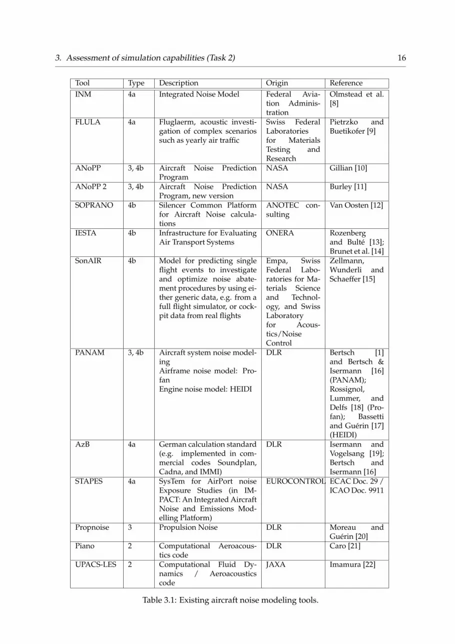
3. Assessment of simulation capabilities (Task 2) 16
Tool Type Description Origin ReferenceINM 4a Integrated Noise Model Federal Avia-
tion Adminis-tration
Olmstead et al.[8]
FLULA 4a Fluglaerm, acoustic investi-gation of complex scenariossuch as yearly air traffic
Swiss FederalLaboratoriesfor MaterialsTesting andResearch
Pietrzko andBuetikofer [9]
ANoPP 3, 4b Aircraft Noise PredictionProgram
NASA Gillian [10]
ANoPP 2 3, 4b Aircraft Noise PredictionProgram, new version
NASA Burley [11]
SOPRANO 4b Silencer Common Platformfor Aircraft Noise calcula-tions
ANOTEC con-sulting
Van Oosten [12]
IESTA 4b Infrastructure for EvaluatingAir Transport Systems
ONERA Rozenbergand Bulté [13];Brunet et al. [14]
SonAIR 4b Model for predicting singleflight events to investigateand optimize noise abate-ment procedures by using ei-ther generic data, e.g. from afull flight simulator, or cock-pit data from real flights
Empa, SwissFederal Labo-ratories for Ma-terials Scienceand Technol-ogy, and SwissLaboratoryfor Acous-tics/NoiseControl
Zellmann,Wunderli andSchaeffer [15]
PANAM 3, 4b Aircraft system noise model-ingAirframe noise model: Pro-fanEngine noise model: HEIDI
DLR Bertsch [1]and Bertsch &Isermann [16](PANAM);Rossignol,Lummer, andDelfs [18] (Pro-fan); Bassettiand Guérin [17](HEIDI)
AzB 4a German calculation standard(e.g. implemented in com-mercial codes Soundplan,Cadna, and IMMI)
DLR Isermann andVogelsang [19];Bertsch andIsermann [16]
STAPES 4a SysTem for AirPort noiseExposure Studies (in IM-PACT: An Integrated AircraftNoise and Emissions Mod-elling Platform)
EUROCONTROL ECAC Doc. 29 /ICAO Doc. 9911
Propnoise 3 Propulsion Noise DLR Moreau andGuérin [20]
Piano 2 Computational Aeroacous-tics code
DLR Caro [21]
UPACS-LES 2 Computational Fluid Dy-namics / Aeroacousticscode
JAXA Imamura [22]
Table 3.1: Existing aircraft noise modeling tools.
4 Identification and assessment ofpromising noise reduction concepts(Task 3)
4.1 Detailed description of task
This task concerned the identification and assessment of promising noise reduction con-cepts. The following issues were addressed:
• Which new technologies or systems are known to result in noise reduction (thenoise sources obtained from task 1 are considered)?
• What are the implications when installed on-board of the aircraft?
• What is the operational impact, e.g. is it effective only in slow flight when theengines are idle?
4.2 Summary of results
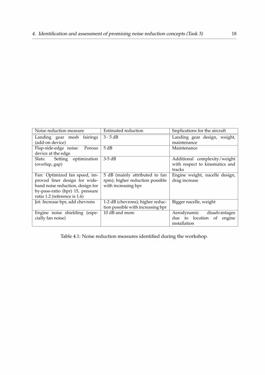
Tab. 4.1 gives the overview of all discussed noise reducing measures and the implicationfor the aircraft.
17
4. Identification and assessment of promising noise reduction concepts (Task 3) 18
Noise reduction measure Estimated reduction Implications for the aircraftLanding gear mesh fairings(add-on device)
3 - 5 dB Landing gear design, weight,maintenance
Flap-side-edge noise: Porousdevice at the edge
5 dB Maintenance
Slats: Setting optimization(overlap, gap)
3-5 dB Additional complexity/weightwith respect to kinematics andtracks
Fan: Optimized fan speed, im-proved liner design for wide-band noise reduction, design forby-pass-ratio (bpr) 15, pressureratio 1.2 (reference is 1.6)
5 dB (mainly attributed to fanrpm); higher reduction possiblewith increasing bpr
Engine weight, nacelle design,drag increase
Jet: Increase bpr, add chevrons 1-2 dB (chevrons); higher reduc-tion possible with increasing bpr
Bigger nacelle, weight
Engine noise shielding (espe-cially fan noise)
10 dB and more Aerodynamic disadvantagesdue to location of engineinstallation
Table 4.1: Noise reduction measures identified during the workshop.
5 Integration of reduction conceptsinto new low-noise vehicle (Task 4)
The objective of this task was to identify the most promising low-noise technologies andconcepts and how to integrate these on-board of the reference aircraft.
The noise source contributions for the reference vehicle are depicted in Fig. 5.1 for ap-proach and in Fig. 5.2 departure. The noise source contributions on the ground areevaluated for two typical and representative observer locations. Depicted are PANAMsimulation results [1]. The vehicle is simulated under typical operating conditions alongapproach and departure, respectively. Along the simulated flight path, observer loca-tions that are typically subject to increased community noise annoyance have been se-lected. The approach observer is approx. 7 km prior touch-down whereas the departureobserver is located approx. 3 km after take-off.Applying the selected noise measures as identified in Tab. 4.1, the ground noise impactcan be significantly reduced. It is assumed, that airframe noise contributions can be re-duced by the maximum as identified by the experts. This is a 5 dB level reduction foreach source, i.e. landing gear, flap-side edge, and leading edge noise contribution. Fur-thermore, jet noise can be reduced by 6 dB1 and modifications to the fan can yield noiselevel reductions in the order of 10 dB2. Obviously, the reduction of one individual noisesource contribution will yield another dominating noise source so that all measureshave to be implemented simultaneously. Finally, for the selected operating conditionsand at the corresponding representative observer location, an overall level reduction of8.5 dB along the take-off and 6.2 dB along the approach can be achieved. Yet, it hasto be mentioned, that the landing gear remains as the dominating noise source for theapproach case. If the gear is not deployed, a level reduction of almost 10 dB is predictedalong the approach case. Take-off noise is still dominated by fan noise contribution evenafter application of the measures as identified in Tab. 4.1. Exploitation of noise shield-ing effects promises further significant noise reduction to the fan noise impact on theground. So overall, it can be concluded, that the technology as identified by the work-
1Here it is assumed, that a 2 dB reduction is achieved due to nozzle modification and additional 4 dBreduction due to an increase in BPR.
2It is assumed, that 10 dB reduction are achievable due to increased BPR, a reduced fan rpm, andadvanced fan design.
19

5. Integration of reduction concepts into new low-noise vehicle (Task 4) 20S
PL
[d
BA
]
airc
raft
to
tal
airf
ram
e to
tal
trai
ling
ed
ge
eng
ine
tota
l
fan
jet
(lea
din
g e
dg
e)
lan
din
g g
ear
5 dB
(a) Reference vehicle.S
PL
[d
BA
]
airc
raft
to
tal
airf
ram
e to
tal
(tra
ilin
g e
dg
e)
eng
ine
tota
l
fan
jet
(lea
din
g e
dg
e)
lan
din
g g
ear
5 dB
(b) Ref. with installed measures.
Figure 5.1: Typical take-off noise source ranking.
shop participants would not fully meet the first workshop goal, which is a 12-13 dBreduction of the maximum A-weighted sound pressure level for each flight operation,i.e. along approach and departure.The certification noise in EPNdB is usually dominated by tonal fan noise contribution.Applying the identified measures to the fan noise contribution, i.e. including shield-ing, promises significant reduction of the tonal fan noise. It can be concluded, that theEPNL at the certification points could be significantly reduced. The selected level reduc-tions for each measure might not yet reach the order of 35 EPNdB cummulative belowChapter 43 as specified as another workshop goal, but it gets close. In conclusion, theidentified measures promise to reduce the underlying noise sources significantly but donot reach the ACARE goals.
3According to ICAO Annex 16.

5. Integration of reduction concepts into new low-noise vehicle (Task 4) 21S
PL
[d
BA
]
airc
raft
to
tal
airf
ram
e to
tal
trai
ling
ed
ge
eng
ine
tota
l
fan
(jet
)
lead
ing
ed
ge
lan
din
g g
ear
5 dB
(a) Reference vehicle.
SP
L [
dB
A]
airc
raft
to
tal
airf
ram
e to
tal
trai
ling
ed
ge
eng
ine
tota
l
fan
(jet
)
lead
ing
ed
ge
lan
din
g g
ear
5 dB
(b) Ref. with installed measures.
Figure 5.2: Typical approach noise source ranking.
6 Summary & Conclusion
A workshop was organized by DLR and TU Delft in order to bring together expertsfrom industry, academia, and research institutions. The participants were organizedinto working groups in order to allow for detailed discussions and avoid a presenta-tion marathon. Within the working group, the experts had to work on predefined tasksin order to (1) identify the existing noise sources on-board of a given reference vehi-cle, (2) identify available and still missing simulation capabilities, (3) identify possiblemeasures to reduce these noise contributions, and finally (4) evaluate the impact of thereduction measures if applied to the reference vehicle.
Classical dominating noise sources have been assessed and parameters identified, thatdominate their inherent noise generation. For the airframe noise sources, it can be con-cluded, that good to medium understanding and data is available for most sources.Yet, spoilers and speed brakes as well as Krueger leading edge devices are not yet fullyunderstood. These sources require more detailed investigation in the near future. Espe-cially, because spoilers are heavily used along so-called "low-noise" or steep approachprocedures while their impact on the overall ground noise is still unknown. Kruegerdevices on the other hand might become very important if laminar-flow wings are stillof interest for future aircraft1.
With respect to the engine noise sources, it should be noted, that more emphasis shouldbe put on the so-called core noise sources, i.e. combuster and turbine. Since significantlevel reductions seem achievable for the jet and fan noise, the core noise sources willremain as dominating noise sources in the future. Therefore, detailed research on thesesources will become essential in the future.Another very interesting noise source has been identified by the participants. Thecounter-rotating open rotor concept (CROR) is very promising with respect to a reduc-tion in fuel consumption compared to a conventional 2015 turbofan engine2. The noisegeneration is very complex and not yet fully understood. The CROR concept wouldeasily fill up a separate and dedicated workshop, hence was not in the scope of this
1Krueger flaps are very promising high-lift devices for laminar wings because they keep the wingsurface protected from insect and dirt impact, therefore keep them clean.
2A reduction in fuel consumption in the order of 10% seems possible.
22
6. Summary & Conclusion 23
event. Yet, the industry participants indicated confindence that the noise levels of anadvanced CROR design will meet the restrictions of Chapter 43.
The importance of advanced simulation capabilities for overall noise prediction is ac-centuated by the fact that most organizations and institutions run their own softwaredevelopments in that area. An important step to further improve the overall noiseprediction is the combination of methods with different fidelity. Interfaces betweenoverall system noise prediction tools and measured data or high-fidelity simulation ap-proaches, e.g. CAA, promises to be an essential step towards more reliable simulationresults.
The identified measures to reduce known noise sources are listed in Tab. 4.1. Appli-cation of these measures on-board of the reference vehicle promises a significant noisereduction of 6.2 dB and 8.5 dB along approach and departure, respectively. The re-duction along the approach can be futher improved to ≈ 10 dB without the gear de-ployed. Yet, the identified measures to the reference vehicle do not reach the order of12 dB OASPL reduction which corresponds to 35 EPNdB cummulative below Stage 4 asspecified in the ACARE goals. Advanced vehicle concepts with engine noise shieldingpromise even higher level reductions for the specific noise source subject to shielding,therefore might help to finally come close to the ACARE goals, see Ref. [23].
Another problem that has been identified during the workshop is the lack of an ap-propriate noise metric. Available metrics, e.g. EPNL at the certification points, will notalways do the job. By simply considering the certification points, other significant flightsegments are not accounted for. For example, it is a known fact that community noiseannoyance is dominating along the common approach path towards any major airport.Yet, this situation is still far away from any certification point, hence not even consid-ered for a "conventional" noise assessment.
The workshop participants have filled out an anonymous survey about the workshopafter the event. For this survey, special attention was put on the concept of the work-shop, i.e. avoid presentation marathon but enable detailed discussions. All of the par-ticipants gave the concept 8-10 points with 10 being the highest grade. Furthermore,the participants indicated that they would not have been able to draw such an "holistic"overview on aircraft noise, i.e. the major sources, modelling capabilities, and reductionpossibilities, by themselves. The presented event was the first "Joint DLR & TU DelftAviation Noise Workshop". For more information on follow-up events, the interestedreader is referred to directly contact the editors.
3According to ICAO Annex 16.

6. Summary & Conclusion 24
Acknowledgments
The authors greatly acknowledge the contribution of the invited participants. The work-shop attendants in alphabetical order are: Eckhard Anton (RWTH Aachen University,Germany); Jason Blinstrub (DLR, Germany); Dominik Broszat (MTU, Germany); CaseyBurley (NASA Langley, USA); Bao Chen (Aerodynamics Research Institute - ARI, China);Jan Delfs (DLR and TU Braunschweig, Germany); Philipp Ernstberger (Airbus De-fense and Space GmbH, Germany); Roland Ewert (DLR, Germany); Sebastien Guerin(DLR, Germany); Andrew Hahn (NASA Langley, USA); Michaela Herr (DLR, Ger-many); Fredi Holste (Rolls-Royce, Germany); Xun Huang (Peking University, China);Umberto Iemma (Roma Tre University, Italy); Taro Imamura (University of Tokyo, Japan);Hernando Jimenez (Georgia Institute of Technology, USA); Carsten Liersch (DLR, Ger-many); Partrice Malbequi (ONERA, France); Luis Meliveo (Anotec Consulting, Spain);Mitsuhiro Murayama (JAXA, Japan); Yan Qun (Aircraft Strength Reserach Institute -ASRI, China); Johann Reichenberger (Airbus Defense and Space GmbH, Germany);Karl-Stéphane Rossignol (DLR, Germany); Abhishek Sahai (RWTH Aachen University,Germany); Laurent Sanders (ONERA, France); Reinhold Schaber (MTU, Germany); Ste-fan Schwanke (DFS, Germany); Arne Seitz (Bauhaus Luftfahrt, Germany); ChristianStanger (University of Stuttgart, Germany); Russell Thomas (NASA Langley, USA); Fe-lix Will (TU Munich, Germany); Rik Wijntjes (NLR, Netherlands); Christoph Zellmann(EMPA, Switzerland); Xin Zhang (University of Southampton, GB); Thomas Zill (DLR,Germany).
Finally, the authors would like to express their gratitude towards Andreas Dillmann,head of the DLR Institute of Aerodynamics and Flow Technology in Goettingen, forsupporting these extracurricular activities and for a financial contribution.
Bibliography
[1] L. Bertsch: Noise Prediction within Conceptual Aircraft Design, DLR Forschungs-bericht, ISRN DLR-FB–2013-20, 2013
[2] Airbus Company: Airbus Market Forecast 2011-2030, online pdf,http://www.airbus.com/company/market/forecast/ (accessed 09 January 2012)
[3] Boeing Company: Boeing Current Market Outlook 2011-2030, online version,http://www.boeing.com/commercial/cmo/ (accessed 12 January 2012)
[4] M. Pott-Pollenske, W. Dobrzynski, H. Buchholz, S. Guérin, G. Saueressig, andU.Finke: Airframe Noise Characteristics from Flyover Measurements and Predictions,12th AIAA/CEAS Aeroacoustics Conference (27th AIAA Aeroacoustics Confer-ence), May 2006, Cambridge, Massachusetts, USA
[5] F. Farassat, J.H. Casper: Towards an Airframe Noise Prediction Methodology: Survey ofCurrent Approaches, AIAA-2006-0210, 44th AIAA Aerospace Sciences Meeting andExhibit, Reno, Nevada, January 9-12, 2006
[6] M.J. Lighthill: On sound generated aerodynamically I. General theory, Proceedings ofthe Royal Society of London, Series A, Mathematical and Physical Sciences, 1951,pp. 564-587
[7] M.J. Lighthill: On Sound Generated Aerodynamically II. Turbulence as a Source of Sound,Proceedings of the Royal Society of London, Series A, Mathematical and PhysicalSciences, 1954, DOI: 10.1098/rspa.1954.0049r
[8] J.R. Olmstead, G.G. Fleming, J.M. Gulding, C.J. Roof, P.J. Gerbi, and A.S.Rapoza:Integrated Noise Model (INM) Version 6.0 Technical Manual, U.S. Departmentof Transportation Federal Aviation Administration, Report No. FAA-AEE-02-01,January 2002, Washington, D.C., USA
[9] S. Pietrzko and R. Buetikofer: FLULA - Swiss Aircraft noise prediction program, Inno-vation in Acoustics and Vibration, Annual Conference of the Australian AcousticalSociety, 13-15 November 2002, Adelaide, Australia
25
BIBLIOGRAPHY 26
[10] R.E. Gillian: Aircraft Noise Prediction Program User’s Manual, NASA Langley Re-search Center, 1982
[11] C. Burley, L. Lopez: ANOPP2: Progress Update, NASA Spring Acoustics TechnicalWorking Group, presentation, April 21-22 2011, Cleveland, OH
[12] N. Van Oosten: SOPRANO Presentation (PDF), SOPRANO Workshop, 21 - 22 June2007, Madrid, Spain
[13] Y. Rozenberga, J. Bultéb: Fast Aircraft Noise Prediction Including Installation Effects forthe Evaluation of Air Transport Systems, paper in08-0342, 37th International Congressand Exposition on Noise Control Engineering (inter-noise 2008), 26 - 29 October2008, Shanghai, China
[14] M. Brunet, T. Chaboud and N. Huynh: Environmental Impact Evaluation of Air Trans-port Systems Through Physical Modeling and Simulation, AIAA-2009-6936, 9th AIAAAviation Technology, Integration, and Operations Conference (ATIO), September2009, Hilton Head Island, South Carolina, USA
[15] C. Zellmann, J. M. Wunderli, and B. Schaeffer: sonAIR - data acquisition for a nextgeneration aircraft noise simulation model, Proceedings of Internoise, 15-18 Sept. 2013,Innsbruck, Austria
[16] L. Bertsch and U. Isermann: Noise prediction toolbox used by the DLR aircraft noiseworking group, In: Proceedings of Internoise, 15-18 Sept. 2013, Innsbruck, Austria
[17] A. Bassetti and S. Guérin: Semi Empirical Jet Noise Modelling for Cabin Noise Predic-tion - Acoustic Loads in the Geometric Near Field, 17th AIAA/CEAS AeroacousticsConference (32nd AIAA Aeroacoustics Conference), June 2011, Portland, Oregon,USA
[18] K.-S. Rossignol, M. Lummer, and J. Delfs: Validation of DLR’s sound shielding pre-diction tool using a novel sound source, 15th AIAA/CEAS Aeroacoustics Conference(30th AIAA Aeroacoustics Conference), May 2009, Miami, Florida, USA
[19] U. Isermann and B. Vogelsang: AzB and ECAC Doc.29-Two best-practice European air-craft noise prediction models, Noise Control Engineering Journal, Volume 58, Number4, 1 July 2010, pp. 455-461(7)
[20] A. Moreau and S. Guérin: Development and application of a new procedure for fan noiseprediction, AIAA 2010-4034, 16th AIAA/CEAS Aeroacoustics Conference (33rdAIAA Aeroacoustics Conference), May 2010, Colorado Springs, CO, USA
[21] S. Caro: Review CEAS-ASC highlights 2006, Journal of sound and vibration, 304,2007, pp. 421-449

BIBLIOGRAPHY 27
[22] T. Imamura: Category 7 - Aeroacoustic Simulations around 30P30N - JAXA’s Result,Workshop on Benchmark Problems for Airframe Noise Computations - II (BANC-II), June 7-8, 2012, Colorado Springs
[23] Y. Guo, C.L. Nickol, and R.H. Thomas: Noise and Fuel Burn Reduction Potential of anInnovative Subsonic Transport Configuration, AIAA 2014-0257, AIAA SciTech, 52ndAerospace Sciences Meeting, 13-17 January 2014, National Harbor, Maryland