advances in uranium refining and conversion
TRANSCRIPT

IAEA-TECDOC-420
PROCEEDINGS OF A TECHNICAL COMMITTEE MEETINGON ADVANCES IN URANIUM REFINING AND CONVERSION
ORGANIZED BY THEINTERNATIONAL ATOMIC ENERGY AGENCY
AND HELD »N VIENNA, 7-10 APRIL 1986
A TECHNICAL DOCUMENT ISSUED BY THEINTERNATIONAL ATOMIC ENERGY AGENCY, VIENNA, 198?

The IAEA does not normally maintain stocks of reports in this series.However, microfiche copies of these reports can be obtained from
IN IS ClearinghouseInternationa! Atomic Energy AgencyWagramerstrasse 5P.O. Box 100A-1400 Vienna, Austria
Orders should be accompanied by prepayment of Austrian Schillings 100,-in the form of a cheque or in the form of IAEA microfiche service couponswhich may be ordered separately from the I MIS Clearinghouse.

ADVANCES IN URANIUM REFINING AND CONVERSIONIAEA, VIENNA, 1987IAEA-TECDOC-420
Printed by the IAEA in AustriaMay 1987

FOREWORDOne of the most important steps in the Nuclear Fuel Cycle is the
Uranium Refining and conversion which goes from the yellow-cake to threedifferent products: uranium dioxide (UO ), natural metallic uranium (U)and uranium hexafluoride (UF ) . Although its added value is small, may6be 2-4% of the total cost of front-end, it is decisive for producing fuelfor both types of reactors: natural uranium (Magnox and Candu) andenriched uranium (LWR). In this step of the cycle the uraniumhexafluoride is produced which is very important for the enrichment ofuranium.
The total volume of this industry, at the present time, is nearly of40,000t U per year and at the end of the present century it would havereached the 60.000t U/a level.
The Agency held an Advisory Group meeting on the production ofyellowcake and uranium fluorides in Paris, June 1979 and its proceedingswere published in 1980. During these seven years, significantimprovements have been made in technology and in equipment for theuranium refining and conversion, particularly from the environmental,safety and economic viewpoints. The refining and conversion ofreprocessed uranium that can be extracted by treating irradiated fuelbecome equally important for recycling recovered fuel.
In response to the growing interest in these topics, the IAEAconvened a Technical Committee Meeting on "Advances in Uranium Refiningand Conversion" at its Headquarters from April 7 to 10, 1986 with theattendance of 37 experts from 21 countries. This Technical Documentcontains the 20 papers presented during the meeting.
The Agency wishes to thank all the scientists, engineers andinstitutions who contributed to this Meeting with their papers and theirparticipation. Special thanks are due to the Chairmen, Messrs. H. Page(U.K.), A.W. Ashbrook (Canada), R. Faron (France), E. Leyser (FederalRepublic of Germany), A.G.M. Jackson (South Africa), I.S. Chang (Republicof Korea) and J.A. Vercellone (Argentina). The officers of the IAEA,responsible for the organization of the meeting, was Mr. M. Ugajin andfor editing the document was Mr. J.L. Rojas of the Nuclear Materials andFuel Cycle Technology Section.

EDITORIAL NOTE
In preparing this material for the press, staff of the International Atomic Energy Agencyhave mounted and paginated the original manuscripts as submitted by the authors and givensome attention to the presentation.
The views expressed in the papers, the statements made and the general style adopted arethe responsibility of the named authors. The views do not necessarily reflect those of the govern-ments of the Member States or organizations under whose auspices the manuscripts were produced.
The use in this book of particular designations of countries or territories does not imply anyjudgement by the publisher, the IAEA, as to the legal status of such countries or territories, oftheir authorities and institutions or of the delimitation of their boundaries.
The mention of specific companies or of their products or brand names does not imply anyendorsement or recommendation on the part of the IAEA.
Authors are themselves responsible for obtaining the necessary permission to reproducecopyright material from other sources.

CONTENTS
PART I — RECENT ADVANCES IN THE REFINING OF FRESH URANIUM MATERIALS
The refining and conversion of uranium yellowcake to uranium dioxide anduranium hexafluoride fuels in Canada: Current processes.......................................... 9A. W. Ashbrook
Recent advances and present status of uranium refining in India..................................... 21N. Swaminathan, S.M. Rao, A.K. Sridharan, M. Sampath,V. Suryanarayanan, V. K. Kansal
Operating experience of a pilot plant for the production of uranium dioxide fromuranium ore concentrate................................................................................... 29M. Shabbir
Purification and conversion of uranium from iron and thorium containing deposits.............. 43H. Movaseghi, N. Meissami
Development of a technology to make UO2 starting from "yellowcake"refined with amines in a sulphuric environment... . . . . . . . . . . . . . . . . . . . . . . . . . . . . . . . . . . . . . . . . . . . . . . . . . . . 49J.A. Vercellone
Status of uranium refining and conversion process technology in Korea.. . . . . . . . . . . . . . . . . . . . . . . . . . . 637.5. Chang, S.T. Hwang, J.H. Park
Research and development of UF6 conversion in Japan now and subjects in future. . . . . . . . . . . . . . 81Y. Hashimoto, L Iwala, T. Nagasaki
Experience in yellowcake refining and its conversion to uranium tetrafluorideat IPEN-CNEN/SP... . . . . . . . . . . . . . . . . . . . . . . . . . . . . . . . . . . . . . . . . . . . . . . . . . . . . . . . . . . . . . . . . . . . . . . . . . . . . . . . . . . . . . . . 103A. Abrao
Conversion of non-nuclear grade feedstock to UF4 . . . . . . . . . . . . . . . . . . . . . . . . . . . . . . . . . . . . . . . . . . . . . . . . . . . . . . IllA.A. Ponelïs, M.N. Slabber, C.H.E. Zimmer
The conversion from uranium tetrafluoride info hexafluoride in a verticalfluorization reactor . . . . . . . . . . . . . . . . . . . . . . . . . . . . . . . . . . . . . . . . . . . . . . . . . . . . . . . . . . . . . . . . . . . . . . . . . . . . . . . . . . . . . . . . . . 141Zhang Zhi-Hua, Chao Le-Bao
The solvent-containing resin for removing uranium from effluent of refining process........... 149Zhu Chang-en, Zhou De-yu
Waste management in the refining and conversion of uranium in Canada....... . . . . . . . . . . . . . . . . . . . 157A.W. Ashbrook
The regulation of uranium refineries and conversion facilities in Canada.......................... 167J. P. Didyk
Conversion of uranium ore concentrates and reprocessed uranium to nuclear fuelintermediates at BNFL SpringfieldsPart A: Uranium ore concentrates....................................................................... 185H. Page
PART II — REFINING OF IRRADIATED URANIUM MATERIALS
Conversion of uranium ore concentrates and reprocessed uranium to nuclear fuelintermediates at BNFL SpringfieldsPart B: Reprocessed uranium............................................................................. 207//. Page

Nitrox process: A process developed by COMURHEX of continuous denitration................ 223R. Romano
Recent developments in the purification of uranium recovered from irradiated materials....... 231P. de Regge, G. Collard, A. Daniels, D. Huys, L. Sannen
The reprocessed uranium conversion: ten years of operation of COMURHEX.... . . . . . . . . . . . . . . . 245R. Faron
Problems due to impurities in uranium recovered from the reprocessing ofused LWR fuel, from the point of view of recycling. . . . . . . . . . . . . . . . . . . . . . . . . . . . . . . . . . . . . . . . . . . . . . . . 255E. Leyser
Conversion of reprocessed uranium in Japan.. . . . . . . . . . . . . . . . . . . . . . . . . . . . . . . . . . . . . . . . . . . . . . . . . . . . . . . . . . . . 267/. Yasuda, Y, Miyamoto, T. Mochiji
Panel Discussion.. . . . . . . . . . . . . . . . . . . . . . . . . . . . . . . . . . . . . . . . . . . . . . . . . . . . . . . . . . . . . . . . . . . . . . . . . . . . . . . . . . . . . . . . . ..... 279
List of Participants.. . . . . . . . . . . . . . . . . . . . . . . . . . . . . . . . . . . . . . . . . . . . . . . . . . . . . . . . . . . . . . . . . . . . . . . . . . . . . . . . . . . . . . . . . . . . 283

PARTIRECENT ADVANCES
IN THEREFINING OF FRESH URANIUM MATERIALS

THE REFINING AND CONVERSION OF URANIUMYELLOWCAKE TO URANIUM DIOXIDE ANDURANIUM HEXAFLUORIDE FUELS IN CANADA:CURRENT PROCESSES
A.W. ASHBROOKEldorado Resources Ltd,Ottawa, Ontario, Canada
Abstract
In Canada, uranium yellowcake is now ref ined at Blind River and
the uranium trioxide produced is shipped 500 kin south to Port Hope
where it is converted to uranium dioxide and hexafluoride fuels.
There have been some s ignif icant changes in the processes used
in these new plants. Perhaps the most significant is the product ion
of uranium te t raf luor ide f rom uranium trioxide using a "wet"process. In this paper the current processing methods are reviewed,
with special emphasis on changes from the previous methods.
INTRODUCTION
Eldorado Resources Ltd . has operated uranium r e f i n i n gfac i l i t i e s at Port Hope, Onta r io , since 1942. It was not.however, unt i l 1955 that solvent extract ion was used to producenuclear grade u ran ium t r ioxide . In 1958 the production ofuranium dioxide was commenced to provide fuel for domesticCANDU reactors . Conversion fac i l i t i es were added in 1970 toproduce u r a n i u m h e x a f l u o r i d e for export.
In 1975 a decision was made to build a new r e f in ing andconversion f ac i l i t y in the Port Hope area . The outcome was.however, that a new r e f i n e r y was built at Blind River innorthern Ontar io (some 500 km north of Port Hope) and a newuran ium hexaf luor ide plant built at the existing Port Hopefacil i ty. The Blind River ref inery came on-streara in 1983 andthe Port Hope conversion f ac i l i t y in 1984.
Today, in Canada , u r a n i u m yellowcake is r e f ined at Blind Riverand the u ran ium t r iox ide produced is shipped 500 km south toPort Hope where it is converted to u ran ium dioxide andhexaf luor ide fue l s .

UO3 Powderlo Port Hop« I___
j NmogenOndes 10
! Acid Recovery
Fig. I. Refining of UraniumYellcwcake to UO,
Acid Recycle lo Mill Recyclej lo Digestion
Tnick-

There have been some significant changes in the processes usedin these new plants. Perhaps the most significant is theproduction of uranium tetrafluoride from uranium trioxide usinga ''wet'' process. In this paper the current processingmethods are reviewed, with special emphasis on changes from theprevious methods.
THE REFINING PROCESS
The refining of uranium yellowcakes (concentrates) to nucleargrade uranium trioxide (UO3) at the Blind River facility ofERL is shown schematically in Figure 1. It varies little fromthe process used previously at Port Hope. The component stepsin this process are:
o weighing, sampling, analysing and blending of theconcentrates
o digestion of the concentrates in nitric acido purification of the digested concentrates by solvent
extractiono evaporation of the pure uranyl nitrate solution
resulting from solvent extraction to uranyl nitratehexahydrate (UNH)
o denitration of the UNH to produce UO3o recovery of nitric acid from the SX raffinate byevaporation with sulphuric acid
o recycle of the concentrated raffinate to uranium millso shipping UO3 to Port Hope
Each of the above component parts of the process is brieflydescribed below.Weighing and sampling, etc.This is generally the normal approach taken in the industry.An auger sampling technique was adopted for the BRR. althoughboth auger and falling stream methods had been employed at PortHope.DigestionConcentrates are dumped from the drums and fed to digestiontanks in a continuous two-tank cascade system. Dissolution iswith concentrated (13M) nitric acid to produce a slurrycontaining about 400 kg m~-* U at a free acid concentration ofless than 2M. Solids concentration in the slurry is normallyless than 1 per cent, and is comprised largely of silica.Phosphoric acid may be added at this stage to reduce thoriumextraction in the solvent extraction circuit.The two-tank system operates continuously and feeds four hold(feed) tanks, which then feed the solvent extraction circuit.Off-gases from digestion - largely nitrogen oxides - are fedthrough a venturi scrubber, and the resultant liguor returns tothe digestion tanks. Non-condensibles go to the nitric acidrecovery circuit (see below).
11

Solvent ExtractionThis circuit differs from that employed previously at the PortHope facility in that it uses Mixco (Oldshue-Rushton) - ratherthan pulse - columns, which are arranged in two paralleltrains. Each train contains 3 columns, one each forextraction, scrubbing and stripping.Dimensions of the extraction columns are 11.3 m in height and1.1 m in diameter. The scrub and strip columns are smaller,being 9.0 m in height and 1.1 m in diameter. To reducesntrainment carryover between columns, solvent settling tanksare employed. These also provide for some surge capacity inthe circuit.The digestion feed is contacted with a solvent comprising 22vol per cent tributylphosphate (TBP) in a saturated hydrocarbondiluent - ISOPAR M. The O/A ratio used in extraction is about4, and at a temperature of approximately 60°C.Scrubbing of impurities from the loaded solvent occurs in thesecond column, and is achieved using water at an O/A ratio of15. Scri-b liquor is recycled.Finally, the uranium is stripped from the solvent phase, againwith water but at an O/A ratio of 1.2, to produce a pure uranylnitrate solution normally referred to as OK liquor.As in all solvent extraction processes used in the refining ofuranium, there is a need to maintain solvent purity. A bleed(-10%) of stripped solvent is treated with a sodiuia carbonatesolution prior to recycle to extraction. After contacting withthe carbonate solution the aqueous and solvent phases areseparated by centrifuges. The solvent phase is returned to theextraction circuit, while the aqueous phase containing theimpurities is acidified and the resultant organic (non-soluble)product is filtered on a pre-coat pressure tube filter.Evaporation of the OK LiquorThe OK liquor resulting from stripping the purified uraniumfrom the solvent normally contains about 100 kg m~3 ofuranium. This is evaporated and concentrated to some1200 kg m~3 uranium (uranyl nitrate hexahydrate, UNH) in athree-stage evaporator. Evaporation is achieved in the firstsiage by steam heating. In the second and third stages.overhead steam from the preceding stage is used as the energysource. After the third stage the steam is condensed, and usedas the strip water in the solvent extraction circuit.Product from the third evaporator stage, molten UNH. iscontained in a heated tank which feeds the denitration pots.DenitrationDenitration of the UNH to 003 is carried out in heavy-walled,semi-spherical vessels stirred by an agitator. This is thesame technology employed previously at the Port Hope facility.

The UNH is fed continuously to the denitration pots (currently12 in all) where it is thermally decomposed at about 280°C toUO3. The reaction products, nitrogen oxides, acid, andwater, are scrubbed to condense water and acid. The scrubbedvapors then go to absorbers to produce nitric acid.Raffinate Treatment and RecycleRaffinate from the solvent extraction circuit accounts foralmost all o£ the wastes generated at the BRR. It is recycled,after treatment, to uranium mills at Elliot Lake, some 50 kmnorth of the Refinery. Because of the importance of raffinaterecycle, a special circuit was installed in the BRR.Raffinate from the solvent extraction circuit contains nitratesalts and impurities from the uranium concentrates. It isnecessary to remove nitric acid, and this is achieved byevaporation of the raffinate with the addition of sulphuricacid to decompose nitrate salts and produce sulphates andnitric acid.From the extraction column in the solvent extraction circuitthe raffinate is pumped to hold tanks where it is settled, andthen pumped to a raffinate evaporation circuit comprising threeevaporation stages. Partial evaporation in the first stage iseffected in a shell and tube heat exchanger employing theexcess heat in the overheads from the third stage of the OKliquor boildown evaporator. Vapors from this stage (dilutenitric acid) go to the first nitric acid concentrator.In the second stage of raffinate evaporation, sulphuric acid isadded resulting in the conversion of nitrates into nitric acidwaich is sent to the second concentrator for recovery. In thefinal stage of evaporation, the concentrated raffinate is drawnoff into tanks at a density of between 1.6 and 1.7 kg ns~3.Generally the sulphuric acid concentration is about 450 g/L,nitrate content less than 1 per cent, and contains uranium at1-3 kg ra~3.The concentrated raffinate is transferred to tank trucks andtransported to the uranium mills at Elliot Lake to beintroduced into the milling circuits. Here, the sulphuric acidin the raffinate contributes to the dissolution of ore, and theuranium in the raffinate is recovered in the mill. Impuritiesin the raffinate go with the mill tailings to the tailings pond.Nitric Acid RecoveryRecovery of nitric acid in the BRR is achieved in two acidabsorbers and two acid concentrators, each set operating inparallel.Off-gases from the concentrate digester and denitration fumescrubbers pass through the acid absorbers where, in contactwith water, nitric acid is produced. Uncondensed nitrogenoxide from the absorbers enter a catalytic converter whichconverts the NOX to nitrogen and water before exhaust toatmosphère. The aqueous (dilute nitric acid) phase from each
13

o—o-^^=^ ^—^ F'suiter
Fig. 2. Conversion of UO_ to UF,

acid absorber, together with vapors from the second and thirdstage raffinate evaporators, is sent to the acidconcentrators. Here, the nitric acid is concentrated to about13M. which is then returned to the digestion stage.Uranium Trioxide TransportationThe 1103 product from the refinery is shipped to Port Hope in10t tote bins. Each bin is filled from two denitration pots(concurrently), and is sampled continuously. Bins stand onload cells during filling, and are accurately weighed prior toshipping.After analysis of the sample for each tote bin, they areshipped to Port Hope on a specially designed flat-bed truck,which hauls three bins, or about 30t (net) of 1103 (39 grossweight).
THE CONVERSION PROCESSES
The processes used for the conversion of 003 to both UFgand UÛ2 are shown schematically in Figures 2 and 3. Themajor difference in conversion carried out in the newconversion facility at Port Hope (UFgW) is the use of a"wet-way" process for the production of UF4. Developed byEldorado, the process provides several advantages over the dryprocess employed in the east UF$ plant, which was broughton-stream in 1970.
Off-Gas Off-Gas
AqueousAmmonia
AmmoniumDiuranate AmmoniumSlurry Nitrate
for Fertilizer
J
Blended UOa in Drumsto Canadian Fuel Fabricators
Fig. 3. Conversion of UO3 to U02 Fuel Powder
15

COMPONENT STEPS IN THE CONVERSION OF UP3 TO UF6A schematic of the UF^ process is shown in Figure 2. Thecomponent steps in this process comprise:
o UC>3 receivingo conversion of UO^ to UC>2o conversion of UC>2 to UF4o conversion of UF4 to UF5o hydrogen fluoride recoveryo effluent treatment
Each unit process is described briefly below.UO3 Receiving/Feeding1103 is shipped from Blind River to Port Hope in 10t totebins. When received at Port Hope, the cover caps are replacedby valves. The tote bin is then inverted over the receivingscrew conveyer and emptied by gravity. The screw conveyersfeed a bucket elevator, which conveys the 1103 to a primaryfeed surge hopper, through a tramp screen to remove lumps.Material passing the screen is fed. via a surge hopper, to apulveriser and thence via a bucket elevator to the final 1103feed hopper.UO3 to UO?Pulverised 1103 from the final feed hopper is screw fed tofluid beds in which the reduction to UO2 occurs. Hydrogen isused as the reducing gas. The UC>2 product is then conveyedthrough a cooling screw to a feed hopper.UO2 to UF4UÛ2 is fed via screw conveyers into a series of threereaction tanks. Here the UO2 is slurried with hydrofluoricacid to convert it to UF4. The conversion is carried outcontinuously in a series of three tanks in a cascade process atabout 90°C. Product slurry from the last tank is fed to adrum drier where the UF4 is dried, and the aqueous HF drivenoff and the vapors scrubbed to recover dilute HF solution.This is returned to the UF4 reaction tanks. From the drumdrier the UF4 is calcined to remove the remaining water.UF4 to UF6UF4 is transported to the fluorination process via screwconveyers and discharged into a bucket elevator. The elevatorcarries the UF4 to the eighth floor, where it is dischargedto a tramp screen to remove 7 1/8" material. After screeningthe UF4 falls to a surge bin. From here, it is fed via screwconveyers to both the flame reactor and the clean-up reactorsurge bins.Flame reactors are fed from screw feeders, which also maintaina seal against the flame reactor pressure. UF4 and fluorine(pre-heated to 450°C) are reacted at the UF4 powder
16

dispersers at the top of the reactor. Most of the reaction ofUF4 with F2 occurs in the top 2m of the reactor, at455-549°C. under a positive pressure of some 2kPa.Unreacted products and ash fall to the bottom of the reactorsand are collected in heated ash cans. These are changed asrequired. After cooling for several months the material isrecycled to the flame reactors.Product UF6. containing small amounts of UF4. HF andnon-condensible gases and particulates leaves the reactorthrough primary sintered metal filters to secondary filters.Particulate matter from the filters is collected in ash cans.Filtered UFg is then fed to cold traps where it is separatedfrom HF and ¥2 which is routed to the clean-up reactors.In the clean-up reactors excess UF4 is reacted with the gasesfrom the UF£ cold traps in a manner similar to that of theflame reactors, and operate at about 400°C. Products fromthe clean-up reactors (UF6 gas, unreacted UF4 and ash) aredischarged by a screw conveyer to seal hoppers, where UFg, HFand non-condensibles is drawn through clean-up reactor primaryand secondary filters, the gases going to the cold traps.Unreacted UF4 is then fed to the flame reactors.UF5 collected in the primary and secondary cold traps isheated and fed to the final cold traps, from where it goes tocylinder filling.Fluorine ProductionFluorine is produced by the electrolysis of anhydrous HF inKHF2 in 12,000 amp cells with individual rectifiers, in theusual way.Fluorine is collected in a surge drum, and is then compressedthrough sintered monel demisters to the feed drum, and thenceto the flame reactors. Hydrogen produced in the electrolysisgoes to a surge drum, through demisters and compressors, and isscrubbed of HF in a water scrubber. The scrubbed hydrogen thenpasses through a potassium hydroxide seal pot to atmosphere.Hydrogen Fluoride RecoveryOne of the major reasons for adopting the "wet-way" UF4process was its ability to recover and reuse HF. This not onlyreduced operating costs but also the amount of waste beinggenerated. The main HF recovery system employs water scrubbingof HF-containing gaseous streams. The general scheme is shownin Figure 4.
17

ooA4MOW HF UO, F,
Polit»! StilWH« Willi
DO, F,
faul!
^
^
1
sJw«t«
PtöCrtl Wtlff
!HF MCYCLE 10
«XWC N
1
t1
AQUKUI NF ,
1
'
^~
' 1
KO
•HFV«o«
K
^_ /UtwniMKovH^ 1
1
1
i
1
1
r" T ^
M CM***
. i5H SCMJBMMQ
i 'C«IH«
U^«OH(KF 1 1, COJ
«K l——i
H«
Fig. 4. HF Recovery System

Effluent TreatmentThe overall effluent treatment process is divided into fourfunctional areas -
o uranium recovery and equipment cleaningo fluoride and carbonate removalo potassium hydroxide regeneration and storageo area fume removal and scrubbing
These areas are shown schematically in Figure 5.Conversion of UO^ to UO2Uranium trioxide from the Blind River refinery is dissolved innitric acid to produce a uranyl nitrate solution of about200 g/L U (Figure 3). This solution is precipitated withanhydrous ammonia to produce an ammonium diuranate (ADU)slurry. The ADU is separated by centrifugation» and the wetsolid is dried using a Weismont drier.After drying, the JJDU is fed to rotary kilns where it isreduced to UO2 by hydrogen (cracked ammonia). The productU(>2 is packaged for shipment to fuel fabricators for fuelpellet production and encapsulation into fuel bundles for CANDUreactors.The ammonium diuranate produced in the ADU step is evaporatedto 550-600 g/L ammonium nitrate and sold locally as afertiliser.
19

e<4-l
20

RECENT ADVANCES AND PRESENT STATUSOF URANIUM REFINING IN INDIA
N. SWAMINATHAN, S.M. RAO, A.K. SRIDHARAN,M. SAMPATHNuclear Fuel Complex,Hyderabad
V. SURYANARAYANAN, V.K. KANSALBhabha Atomic Research Centre,Bombay
India
Abstract
The present requirement of reactor grade natural uranium-di-oxide and metalfor power and research reactors are met by indigenous production. The purity of thefinal product is achieved by solvent extraction process using Tri butyl-phosphate.This involves handling of large quantities of slurry and pulping, filtration andevaporation operations. The calcination and reduction are carried out in rotaryfurnaces which are more amenable for smaller scale of operations.
An extraction unit has been developed for uranium extraction directly fromslurries, thus eliminating a number of process steps that are normally involvedwith the conventional perforated plate pulsed columns. Developmental efforts werealso directed towards the studies on recovery of Uranium by Ammonium-Uranyl-Carbonate (AUC) route & calcination of AUC & reduction of UCL (obtained by ADUroute) in the fluidized bed reaction systems.
This paper brings out the process developments, which have taken place inIndia in the recent past, that would make the refining operations much more simplerard adoptable for larger scale of operations.
INTRODUCTIONIndia, like other countries in the world, has followed the conventional route
for refining of Uranium to get the reactor grade Uranium-dl-Oxide and metal. Therefining process essentially involves purification by selective extraction ofuranium using tri-butyl-phosphate (TBP), precipitation as ammonium-di-uranate andsubsequent calcination and reduction to U0„ followed by stabilization undercontrolled conditions to enable it to be handled in open atmosphere. The U0~powderthus obtained, is finally pulverized and blended to get a homogeneous product, freefrom agglomerates ard suitable for pelletizing. A flowsheet of the process, start-ing from yellow cake, is given in fig.i. For making the metal, the UQ~ is hydro-fLuorinated and the UF, is reduced with magnesium.
For extraction of uranium from crude uranyl nitrate solution, perforatedplatej pulsed columns are used which are operable with clear filtered solution,However, magnesia used at earlier stage of precipitation of yellow cake, has beenleading to fine silica particulates being carried over to the filtered solution,This gives rise to some operating problems in the extraction columns. The siliciousmaterial accumulates at the interphase, resulting in entrainment in the extractphase. The pipe lines, sieve -plates, valves and even the column heads getdeposited with silica resulting in frequent cleaning and washing operations.Further, the cake obtained after filtration of crude uranyl nitrate solutioncontains appreciable amount of soluble uranium. The cake has, therefore, to bepulped and filtered three to four times to recover uranium and for decontamination
21

MAGNESIUM DlURANATECONCENTRATES
NITRIC ACID
URANYL NITR/l
CRUDE URANY
TBP DILUTED __ ».WITH KEROSENE
PURE URANYL
AQUEOUS AMMONIA-*-
1DISSOLUTION ^
iTE SLURRY ^
AGING
|
FILTRATION , ———
L NITRATE I
I— —— — —— — - I —————— fSOLVENT —— —
EXTRATION I
N/TRÄTE ,.
AMMONIUM DlURANATE 1PRECIPITATION f
URANIUMSOLUTION
CAKE ^REPULP.MG ACT1V
f- CAUSTIC SODAÏAFFINÂTE r pppr^TATinw ACTIV
| SODIUM NITRA1
AMMONIUM. NITRATE
E CAKE
i »t^ WA^TE I" DISPOSAL!
rr 'h T
— ' 1ADU CAKE
AMMONIA
T| C*ACKfaiN 2 f H2 ,.
DRYING ANDCALCINATION
U03 |
REDUCTION U02"
STABILISATIONPULVERISATIONAND STORAGE
Fig.l. Production of nuclear grade uranium oxide.
of the cake to satisfactory levels- The leach liquor, thus obtained, isconcentrated by evaporation and then taken for extraction along with the mainstream.
In view of the above problems, there was a long felt need to evolve a systemwhere the slurry can directly be processed. A new extraction unit has beendeveloped by the Process Development Group of Nuclear Fuel Complex (NFC) forextraction of uranium directly from such slurry [1] which will be discussed indetail in the text.
Presently the pure uranyl nitrate solution is precipitated with ammonia asammonium di-uranate. The precipitate thus obtained is amorphous in nature andleads to formation of agglomerates during its further processing. It was realisedthat if uranium is precipitated as ammonium uranyl carbonate the precipitate wouldbe crystalline in nature with better flow characteristics and amenable for adoptingfluidized bed operations for the subsequent stages of processing. Development workcarried out in this regard at Nuclear Fuel Complex is also described in this paper.
As mentioned earlier, the calcination and reduction operations for theajononium-diuranate are presently carried out in rotary furnaces. Efforts were alsodirected towards the development of fluidized bed reactor system in view of itsobvious advantages for reduction of DO., to U0~. The work carried out in this aspectat the Chemical Engineering Division of Bhabha Atomic Research Centre is alsocovered.A CONIKACTDR FOR EXTRACTING URANIUM DIRECTLY FSOM SLURRIES
The development of this contractor for extraction,directly from a slurry, wascarried out in three steps. Experiments were carried out on a single stage unitfirst, then a pilot scale solvent extraction unit with seven stages was designedand operated for about one year (1). The salient features of the unit are :
i) It has neither any moving part nor any control valve in the slurryline,
22

il) air lift pump is used for inter stage aqueous transfer and also formixing the aqueous and organic phases for mass transfer,
iii) organic flow takes place by naturally available hydraulic gradient,iv) high organic/aqueous ratio is maintained to ensure aqueous phase
dispersal and minimum entrainment loss of solvent in the raffinate.Experiments with slurry containing as high as 15% solids were conducted on
the pilot scale unit with no operating problems, though the solid content in thecrude slurry obtained after dissolution of the yellow cake is of much lower order.
Based on these experiments, a plant scale unit capable of handling about 350Iph of aquous slurry and 700 Iph of solvent was designed, fabricated and commissioned.The unit is in operation for more than one and a half years (2).Description and operation
The schematic diagram of the newly developed slurry extractor unit and theflow arrangement are given in fig.2. The plant scale unit also consists of sevenstages. Each stage has a mixer, disengagement section and settling tank. Thedisengagement sections have been provided with mist eliminators with their exhaustconnected to a common exhaust header. The slurry feed is metered and fed at theextract end while the raffinate is pumped out in metered quantity at the other end.The aqueous stream is transferred from stage to stage by air lift pump from extractend to raffinate end, while the organic flows from raffinate end to extract endcounter currently by gravity. The overall level difference in the 7 stage settlingtanks is about 300 mm.
CTjrfAq ) £> 700 LUS/hour (Or Q)
('hour ["'S 4700 Llrs/hour ( O ' g )
U.ECE.NJ)
Fig.2. Schematic diagram of slurry extraction system (U.O.P)
23

D I U B A N A T E
NOTE_;- AJA OPERATION;. S H O W N m THE BLOCK ( Chom d o t t e d ) AREELIMINATED SY THE SINGLE OPERATION OF SLUSRV EXTRACTIONFig.3. Solvent extraction of uranium.
Lean solvent is admitted at the seventh stage at the desired flow ratethrough a rotameter to get about 85 to 90% saturation of the solvent with respectto uranium. Slurry feed is checked for uranium concentration, free acidity andpercentage of solid before it is admitted to the slurry extractor. Stageefficiency of the order of 85 to 907« has been achieved, though the contact time isof the order of a few seconds.
350 Iph of feed is admitted at the extract end which gets mixed with about3500 Iph of recirculated solvent from the first stage. The mixed phase is pumpedinto the disengagement section by the first stage air lift pump. The air from thedisengagement section is vented out through the mist eliminator. Ihe mixed phase,then,flows into the settling tank through a tangential entry. Organic getsseparated from the mixed phase, rises to the top and flows out of the settler.
24

From this, 700 Iph overflows as an extract while the rest (about 3500 Iph) getsrecycled and comes in contact with the fresh slurry.
Similarly about 4200 Iph of clear organic flows out from the top of thesecond stage settling tank by the suction of the second stage air lift pump. Outof this 700 Iph flows upward into the first stage settling tank through the downcorner due to gravity. The down comer has been sized such that the upwardvelocity of the organic is low enough to permit the aqueous flow downwards. About3500 Ihp of organic along with 350 Iph of aqueous from second stage settling tankis pumped to the third stage disengagement section and then to the settling tankand thus the flow continues. A clear cat interphase is allowed only in the laststage settling tank where the raffinate is withdrawn from the bottom by an airliftarrangement. The recycle rate of organic at each stage is very important forefficient operation of the systems. The organic recirculation flow is controlledsuch that 0/A ratio is always more than 10:1 in mixing stages. Operatingconditions remain stable once the flow pattern is set in each stage. Fig.3 givesthe operations involved in the conventional process that are eliminated by thenewly developed slurry extraction unit.
Advantages
i) The slurry can directly be extracted without any filtration, repeatedpulping and evaporation of wash liquor; thus a huge saving on labour,handling operations and energy.
ii) Uranium in the raffinate is controlled to the permissible level and nofurther treatment is necessary.
iii) The system can be operated over a wide range of plant capacity.iv) No moving parts are involved and so practically no maintenance and operation
is more reliable.v) The unit can be stopped and restarted at will without disturbing the
equillibrium.vi) As the number of operations are grossly reduced the plant is compact and
neat.vii) Huge energy saving and also saving in space and civil work.viii) Air borne activity at the mist eliminator exhaust duct is well within the
permissible limit.
AMgNIUM ORANYL CARBONATE (AUC) PROCESS FOR REOOVERY OF URANIUM FROM PURE URANYLNITRATE SOLUTION
In view of the excellent flowability of powder by carbonate route, itsamenability to fluidized bed operations and single stage pelletization, anexperimental set up was installed and operated to study the process parameters.
The schematic diagram of the process steps involved is shown in fig.4 forprecipitation of AUC from pure uranyl-nitrate.Ammonia, carbon di-oxide and air werepassed through the uranyl nitrate solution, which was also added continuously inthe mix tank,. The solution was stirred and also continuously recirculated througha circulation pump. The mix-tank was provided with internal steam heating coilsand temperature of about 60°C to 70°C was maintained in the tank. The pH wascontrolled between 8 and 8.5. Uranyl nitrate solution with uranium concentrationof 100 gm/1 and 200 gm/1 were used. The AUC slurry was continuously withdrawn fromthe recirculation stream filtered in pan filters and dried in tray driers.
25

UNH
AUCPRECIPATION
-OFF GAS
CALCINATION REACTOR
OFF-GAS H2-»-N2
cm a
"lREDUCTIONREACTOR U02 PRODUCT
X3ÖO
P R E H E A T E H
Fig. 4. AUC route for préparation of l>0_.
The dried AUC powder was calcined in 75 mm dia fluidized bed reactor.Temperature in the range of 600 to 650 °C was maintained in the bed and N« gasvelocity of 3 to 5 cm/sec, was used. The studies were conducted with powder feedrate from 5 to 16 kg/hr. The 'JO powder was subsequently reduced in rotary furnace,The UO~ , thus obtained, was observed to have better tap density and required onlysingle stage palletization. The pellets were also of better finish and theiracceptability was better.
However, the process variables need further studies for large scaleoperations and to obtain the UÖ„ powder of acceptable and consistent metallurgicalcharacteristics suitable for sintering.
FLUIDIZED BED REDUCTION OF URANIUM TRI-OXIDE TO URANIUM PI-OXIDERotary furnace is presently being used for reduction of uranium trioxide to
uranium oxide and for hydrofluorination of the dioxide. As the fluidized bedreactor offers a more efficient and compact system, studies were conducted toevaluate various operating parameters and to assess the feasibility of itsreplacing the presently employed rotary furnace for reduction operation (andsubsequently for hydrofluorination as well).
The Uranium tri -oxide powder (UOo) used was composed of extremely fineparticles, the average particle size being about 19 /u. The loose packing densitywas 2.2 gm/cc and the tap density was 2.6 gm/cc approximately. The composition ofthe powder varied somewhat with different feed stocks used for differentexperimental runs (may be because of variations in ADU - calcination conditions).A powder composition with 0/U ratio of about 2.75 could be taken as the average.
A 75 mm diameter glass column was used for determining the fluidizationcharacteristics of the UO., powder. The data thus obtained, formed the basisfor the selection of operating gas velocity range and bed height for reductionreactor. A sintered porous metal disc (20 /u mean pore size) was used as the gasdistributor for these studies and subsequent reduction trials.Description and Operations (3)
The reduction reaction with hydrogen is exothermic and the rate of reactionbecomes significant only at temperatures about 350°C and, therefore, the final runs
26

were conducted in the operating temperature range cf ASu^C to 600°C where thereaction rate is quite high and mass transfer becomes the controlling factor.
Fig.5 shows the schematic diagram of the experimental set up employed forthe fluidized bed reduction trials. The reactor was a 75 mm N.B. pipe with a 150mm disengagement section at the top. The l£U powder was admitted in the bed abovethe distributor while the product discharge was by bed overflow. The reactor wasprovided with suitable heating and temperature control arrangement. The IX roductreceiver was a cylindrical vessel equipped with porous metal filters. The feed gas,a mixture of (-L and N~ in the ratio 3 : 1 was preheated to about 300 to 350°Cbefore it was admitted to the reactor.
Once the steady state operation had been achieved a few pouder samples werewithdrawn from the product overflow line for determination of 0/U ratio such thatthey are not exposed to the atmospheric air. In certain trial runs no on-linesamples were drawn and the U0~ powder produced was directly hydrofluorinated inrotary furnace reactor. The amount of UO~F~ formed in the UF, product was taken asa measure of the conversion efficiency in tne fluidized bed réduction reactor.
Table 1 shows a summary of a few of the trial runs conducted. Samples forthe first three runs were analysed by online sampling( 0/U determination) while theproduct for the last two runs was directly hydrofluorinated and analysed for l3QjF~content.
The results obtained from these preliminary trial runs look to be encouraging.However, more studies are required before the process can be adopted for productionoperation.
OFF-GAS
MOTOR
FEEDPOWDER
W\AA/VV\AA/vHBUNKER
FF GAS
Fig.5. FLuidized bed reduction set-up.
27

Table - l
Run No.
12345
Average IXUfeed rate(kg/hr.)
8101068
Total gasFeed rate(1/m)
283532.525.528
Feed gasH»/N„molarratio
3:13:13:13:13:1
Feed gasvelocity(cm/sec)
5.67.06.35.15.6
Bed-Temp.<°C)
430-460450-600550-600550-600500-600
Productcomposition(Wt U02)
86.88499.599.599.5
Hydrogenexcess
7.
71.473.161.510671.4
Acknowledgement
The authors convey their sincere thanks to Shri R.K. Garg, Director, ChemicalEngineering Group, BARC and Shri K. Balaramamoorthy, Chief Executive, NFC for theirkeen interest and constant encouragement for these studies.
References
1. "A new solvent extractor for slurries"by N. Swaminathan and S.M. Rao, Nuclear Fuel Complex, Hyderabadto be published
2. "Solvent extraction of Uranium from Uranyl nitrate slurry"by S.M. Rao, A.K. Sridharan, M. Sampath and N. Swaminathan,Nuclear Fuel Complex, Hyderabad
3. "Fluidized bed reduction of U03"by V. Suryanarayanan - A BARC internal report
28

OPERATING EXPERIENCE OF A PILOT PLANTFOR THE PRODUCTION OF URANIUM DIOXIDEFROM URANIUM ORE CONCENTRATE
M. SHABBIRPakistan Atomic Energy Commission,Islamabad, Pakistan
Abstract
Pakistan's heavy-water moderated power reactor (CANDU TYPE )is fuelled with natural uranium dioxide. Chemically pure, compact-able and sinterable uranium dioxide powder is required to suit theproduction of reactor grade fuel pellets.
A pilot plant for the production of natural uranium dioxidefrom the indigenous uranium ore concentrate to meet the CANDU fuelspecifications has been established. This paper concerns with theoperating experiences of the pilot plant.
1. INTRODUCTION
Uranium dioxide (U ) powder for the production of fuelpellets with density close to the theoretical, is produced fromthe ammonium diuranate or ammonium uranyl carbonate. In the early
studies refining of yellow cake by solvent extraction and theproduction of small quantities of UÛ2 for laboratory studies
from ammonium diuranate was reported [1]. Since then the studies
were further extended to produce natural uranium dioxide, suitablefor the fuel fabrication for Karachi Nuclear Power Plant (KANUPP).
Various studies have been reported on the influence ofprecipitation, calcination and reduction conditions on the sinter-abilitv of 1102 powder [2,3], These unit operations influence thephysical properties of U02 nowder (i.e. surface area, bulk densitv,
29

tap density and particle size). These physical properties affectthe sintered density of U02 fuel pellets.
The physical properties of IJ02 powder have been controlledbv optimisation of the process and operations parameters at eachstage. Equally important is the chemical purity of U02 powder foineutron economy.
In the present studies the parameters for the extraction ofuranium by using TBP-Kerosene mixture, subsequent precipitation,calcination and reduction processes have been optimised. (JO2 powderso produced has been used for the reactor grade pellet production.
2. MATERIAL SPECIFICATIONSSpecifications of the uranium dioxide powder include require-
ment of chemical purity and sinterability. The chemical purity ofU02 required for the KANUPP fuel is given in Table-I. Impurities likeboron, cadmium and gadolinium are highly deleterious due to theirhigher neutron absorption cross section areas i.e. 755; 2,550 and46,000 barns respectively. Equivalent boron content (EBC) of U02powder impurities is determined and the total EBC shall not be >1.2.
Anionic impurities e.g. carbon and fluorine are also undes-irable and have marked effect in the fabrication of fuel pelletsand their subsequent irradiation.
30

TABLE-I The Permissible Impurities Level in U02 Powder forKANUPP Fuel Fabrication.
Impurity Max. Level in ppir, U basisM 25B 0.3C 200Ca 50Cd 0. 2Cr 15C.-IV
Though the physical properties of powders are nowwell founded and their maximum and minimum limits havebeen laid down but their requirement varies with thefuel manufacturer. Nevertheless the acceptability ofpowder is entirely based on the "Sintering PerformanceTest". The powder characterization and the "performancetest" are given in Table-II.
31

A. Characterization
TABLE-II. Natural U02 Powder Characterization and Performance Test.
Parameter Required range1. Surface area m2/g 5.0- 7.52. Moisture (Wt.l) 0.4 max.3. 0/U ratio-corrected for 2.07 - 2.14
moisture4. Bulk density (g/cm3) 0.75 - 1.255. Tap density' (g/cm3) 1.75 - 2.156. Fisher Particle sizef^n) 0.8 - 1.27.Qrsen density (e/cm3)a) inside die at 2?6 MN/nv5 5.6 - 6.0
b) out of die at 276 MN/m3 5.1 - 5.48. Compressibility factor at
276 MN/m3 1.8 -2.29.Biggest particle size CD-80 0.015" max.
B. Performance TestA total of 10 test pellets shall be cold pressed at 276 MN/m2
(40,000 Psi) with a dwell time of 30 seconds maximum at pressurewithout addition of any binder or lubricant to a density of5.1 - 5.4 g/cm3 with a variation of not more than ±0.05 g/cm3
from the average.
The pellets shall be fired in an atmosphere of H? of disso-ciated NH, for two hrs. at 1650 ± 2S°C. The temperature profileshall have a gradient of :00°-300°C. The pellets shall give asinter density of more than 10.53 g/m3 (96% TDS). Average sin-tered density variatic.'. siu'il not be more than ± 0.05 g/cm3.
3. PROCESS DESCRIPTION3.1 Dissolution
Stainless steel dissolvers fitted with paddle type agitatorsare used to dissolve yellow cake (Y.C.) and uranium dioxidepellets. The pellets before dissolution are preheated at a temp-
32

erature of 350-400°C for about 12 hours. Heating and coolingjackets have been provided for steam heating and cold watercirculation. The dissolved uranium in the form of uranylnitrate solution is filtered through a plate and frame filterpress. The feed solution i.e. crude uranyl nitrate preparedfor the extraction step contains 300 ± 10 g/1 of uranium and3±0.1 N free acidity.
3.2 Solvent ExtractionA battery of columns have been used for extraction, scrubbingand stripping. For pulsation of the column, oulsating pumpsof variable stroke length and frequency have been used. Thesolutions to the column are fed through proportionating feeddosing pumps.
The operational parameters are as follows :a) Extraction Parameters
- Solvent composition 301 TBP + 70% Kerosene oil- Flow rate of solvent to 3:1crude uranyl nitrate
- Pulse amplitude 14 - cm- Pulse frequency 12 c/min
b) Scrubbing Parameters- Flow rate of uranium orga- 12:1 approxnie to 4 N HNO-7 solution.
- Pulse amplitude 11 cm- Pulse frequency 12 c/min.
c) Re-extraction(Stripping) Parameters- Flow rate of U-organic 1 : 1complex to BMW
- Pulse amplitude 13-14 cm.- Pulse frequency 12 c/min.Refined uranyl nitrate (UNH) solution so obtained is fed to
the precipitation vessels for the production of ammonium diuran-ate (ADU).
33

3.3 PrecipitationPhvsical properties of U0~ Powder are dependent upon theprecipitation conditions. The influence of precipitationparameters is discussed in section 4.
Process/operating parameters have been studied andoptimsed; the values are given as below:-
- Precipitation temperature 50°C- Percent uranium precipitation 50±5
(piI 3.5) 1st stage- Percent uranium precipitation 50±5
(pH 7.2) 2nd stage
The ADD slurry is fed to the thickner and subsequentlyfiltered usirig rotary drum vaccum fliters(RDVF). ADU isthen transferred to the repulper, slurry so obtained isagain filtered by DRVF. ADU cake is dried at 120°C andground to (-) 10 mesh.
3.4 Conversion of ADU to UC>3.ADU is fed to "hree zone furnace. Each zone is controlledby independent neat ing circuit. The temperature of firstzone is kept at 260 °C, second zone at 270 °C and third zoneat 280 °C. The residence time of powder is kept one hour.
3.5 Calcination of U03 to U30gOrange oxide (U03) is conveted to UsOg. The calcination temperature is 530 - 550 °C. This temperature gives U700 which flowsJ O
smoothly when fed to the reduction furnace.
3.6 Reduction of u Og to U02
ILOg is fed to a rotary type furnace with a provision to supplydissociated ammonia (N2 + 3H2) mixture) stream. The powder isreduced at a temperature of 625 - 650°C.
34

The powder (UCU) so obtained is hihgly pyrophoric and has tobe stabilised. Stabilization is done by the addition of dry iceinto UC>2 Powder [4] . Partial pressure of oxygen in an inertatmosphere of solid/gaseous carbon dioxide leads to the formationof UJDr, monolayer on the U0? Powder. The powder once stabilisedis very stable towards oxidation. The reduction temperature hasa direct bearing on the physical properties of the UCU Powder.This aspect is discussed in section 4.
4. DISCUSSION4.1 Extraction of Uranium
In the solvent extraction section the free acidity of crudeuranyl nitrate solution has marked influence on the extractionefficiency. The extraction efficiency decreases with the decreaseof free acidity. The results of studies under pilot plant condi-tions have been given in Fig. 1. It has been observed that thefree acidity > 3 N results in the uptake of deleterious impuri-ties into the organic complex e.g. boron, cadmium, gadoliniumetc. [5].
The uranium concentration of feed solution also affects the extrac-tion efficiency. The optimum uranium content in the feed solution isfound to be 300 g/1. Further increase of uranium in feed solutionleads to increase uranium in raffinate.
The throughput has also a bearing on the extraction efficiency.Throughput will have to be increased, keeping the capacity of thecolumn in view. Such that the extraction efficinecy is maintained andthe ratio of organic to acqueous flows is such that the uranium is instochiometric balance. The organic to aqueous ratio found optimumfor the operation is 3 : 1.
35

J 98.0 -
c 9M -
96.0 -
9S.O
FIGURE
2.5 3.0 3.5
Free Acidity —
Percent Extraction Efficiency Versus Free Acidity.
Scrubbing of the uranium organic complex is essential for theremoval of left over impurities. The strength of nitric acid had tobe kept more than 3 N to prevent transfer of uranium into aqueousphase. Nevertheless the practice of scrubbing with UNH solution ispreferred [6]. This is advantageous in further increasing the uraniumconcentration in the loaded organic. Increasing the uranium saturationof the solvent results in reducing co-extration of impurities[7].The main disadvantage is the loss of refined UNH solution and inhandling of aqueous obtained from the scrubbing column. For scrubbing4N nitric acid solution is being used.
Re-extraction(stripping) of uranium has been effectively accomplishedin the columns by keeping the U-organic complex and DMW. It has beenobserved that the increase in temperature to 60CC enhances the effi-ciency of stripping [8].
36

4.2 Precipitation of ADU from UNHPrecipitation step for the production of ADU has a bearing on the phy-sical properties of uranium dioxide produced for the nuclear fuels.
The size of ADU crystallites > and agglomerates decreases withincreasing pH. Precipitation at pH >7 gives ADU of very fineparticle size, which poses difficulty in settling and filteration.The settling rate in second stage at pH 7.1±0.1 is given in Fig.2.The settling rates are an index to sintered density. Lower thesettling rate of ADU slurry higher the sintered density of UO^prepared from it. This ADU on reduction of U02 gives powder whichis difficult to process but sinter to high sinter densities.
85
60 -
55 -
! I I i i 1 I I j [
0 W 0.2 03 at as 06 a? 08 09 ID U 12 U
Settling Rate (mm/sec) —————•-
FIGURE 2 : Settling Rate of ADU in 2nd Stage at pH 7ltQli50'C
37

On the other hand ADU precipitated at low pH i.e. 3.5 givescourse particles and agglomerates. The UCL powder produced fromthis ADU is less pyrophoric and easily compactable but gives lowsintered densities(Table-III). Such a powder is not suited forfuel pellet fabrication as such. This type of powder has to beball milled/micronised to get good results.
TABLE-III. Effect of PERCENT Precipitation at 1st Stage on the PhysicalCharacteristics of UCU Powders and Sintered Densities.
UraniumPercentPrecipitation*
506070
Physical Characteristics ofU02** Powders
Bulk Densityg/cm3
1.15 -1.25 -1.30 -
1.251.301.40
Tap Densityg/cm3
1.85-2.102.00-2.152.10-2.30
Surface AreamVg4.5 - 7.03.5 - 5.03.0 - 4.0
SinteredDensityg/cm3
10,5-10.610.3-10.410.2-10.3
* Precipitation Temperature 50°C** Reduction Temperature 625°-650°C
To achieve a balance, two stage precipitation is preferred[2]. This gives a blend of coarse and fine crystallites thatfilter easily. The second stage precipitation of pH 7.1 ±0.1also ensures that all the uranium is recovered from the solution.U0? powder obtained from the ADU gives intermediate surface
L*
area and other physical properties. UCL so produced is not highl>pyropharic but needs stabilisation and sinters to very highsintered densities e.g. greater than 96% of theoretical.
v
38

4.3 Conversion of ADU to U02
This step has been carried out in three stages :-
a) Conversion of ADU tob) Calcination of U03 toc) Reduction of U308 to U02It is ensured that each material in step a & b is completely
converted. The process parameters are adjusted to get smoothflowing material in the electrical resistance furnaces.
Care is taken to avoid micro and macro-sintering in steps(a)and (b). Such pre-sintering would tend to reduce the surface areaof the final product i.e. UCU. The temperature of calciner is alsovery important factor in determining the physical properties of theU02 Powder.
The most important step is the reduction of l Og to U09. Thisstep is carried out in the reducing environment of either hydrogenor dissociated ammonia. The surface area of U07 powder independentof the parent ADU is governed by the reduction temperature. Higherreduction temperature results in lowering of surface area, whereas,lower reduction temperature increases it as shown in Table-lV. On
TABLE-IV. Effect of Reduction Temperature on SurfaceArea of UCu Powder
Reduction Temperature
625630640650
6533
.0
.0
.5
.0
SurfacCm2
- 7.0- 6.0- 4.5- 4.0
e Area/g)
39

the other hand, high temperature of calcination and reductionwill increase bulk and tap densities, whereas, low temperaturewill decrease their values. High reduction temperatures resultin presintering of the crystallites present in UCU agglomerates.It has been observed that powder reduced at high temperaturei.e. > 650°C manifests marked decrease in surface area, thissupports the view point of gross pre-sintering of the finestaking place in the powder.
4.4 Influence of Physical Parameters on the SinteringCharacteristics of UC^ PowdersThe powders are characterised generally for the following:
a) Surface areab) Bulk densityc) Tap densityd) Particle sizee) Compactability factor
The range of these physical parameters is given in Table-II.
The acceptability of powder is not only based on the physicalcharacteristics but on its performance on sintering (performancetest) as mentioned in Table-II.
In general powders with high surface area, low bulk andtap densities and small particle size sinter to high densi-ties. But there are process and economic constraints e.g.powders with high surface area are difficult to compact andhandle. Powders with high bulk and tap densities sinter tolow sintered densities but are fairly good in compaction.Powders with particle size >1.2pn tend to yield pellets oflow sinter-density, such powders would need ball milling/
40

micronising for use in pellet fabrication. Thus the cost forthe entire pellet fabrication is obviously a polydimensionalfunction. It is therefore necessary not to optimise the proce-ss parameters at each step of U02 processing but to corelate themonotonous function of the cost as well [9]. The specifica-tions are thus based on a compromise iiy process contraints,product requirement as well as economic considerations.
5. CONCLUSIONBy using indigenous yellow cake and recycled material,uraniumdioxide to meet the KANUPP requirements has been successfullyproduced. The observations during the operations conformedwith the information already available in litrature [1 - 9].
6- ACKNOWLEDGEMENT
The author is thankful to N.K.Qazi, M.T. Qureshi andN.A.Chughtai for the experimental and technical work andM.Salim for the valuable suggestions and discussions forthe preparation of the manuscript.
REFERENCES
1. M. Yunus, A. Muzaffar, M.T. Oureshi, N.K. Qazi, J.R. Khan,N.A. Chughtai and S.M.H. Zaidi, "Production of Yellow Cakeand Uranium Fluorides", Proc. Adv. Group Meeting, Paris5-8 June, 1979 (P-329).
2. J. Janov, P.G. Alfredson and Y.K. Vilkaitis, "The Influenceof Precipitation Conditions on the Properties of AmmoniumDiuranate and Uranium Dioxide Powders", AAEC/E220, May, 1971.
3. P.G. Alfredson and J. Janov, "Investigation of Batch-TrayCalcination-Reduction of Ammonium Diuranate to UraniumDioxide", AAEC/TM 599, August, 1971.
41

4. W.T. Bourns and L.C. Watson, AECL 1312, 1961.5. A. Muzaffar, M.T. Qureshi, N.K. Qazi, J.R. Khan, N.A. Chughtai
and S.M.H. Zaidi, "Production of Nuclear Grade UC>2 Powder",Internal Report, NMD, PINSTECH, 1978.
6. J.E. Littlechild, "Operational Development of a Uranium OreSolution Extraction Plant", I. Chem. E. Symp. Series, No. 26,107-110, 1967.
7. P.G. Alfredson, "Production of Yellow Cake and Uranium Fluorides",Proc. Adv. Group Meeting, Paris 5-8 June, 1979 (P-149).
8. P.G. Alfredson, E.G. Charlton, R.K. Ryan and V.K. Vilkaitis,"Pilot Plant Development of Processes for the Production ofPurified Uranyl Nitrate Solutions", AAEC/E 344, January, 1975.
9. U.Runfors, "The Influence of Powder Characteristics on Processand Product Parameters in U02 Pelletization", AE-415, April, 1971(Sewden).
42

PURIFICATION AND CONVERSION OF URANIUMFROM IRON AND THORIUM CONTAINING DEPOSITS
H. MOVASEGHI, N. MEISSAMIAtomic Energy Organization of Iran,Teheran, Islamic Republic of Iran
Abstract
Acid leaching of uranium deposits isnot a selective process. Sulfuric acid solubilizeshalf or more of the thorium depending on the mineralogy ofthis element. Tn uranium recovery by solvent extrac-
tion process, uranium is separated from thorium by anorganic phase consisting of 10 vol% tributylphosphate (TBP)in kerosin diluent. Provided that the aaueous phaseis saturated with ammonium nitrate and pH of the solutionis lowered to 0.5 with sulfuric acid. In other wordsthe separation o^ uranium and thorium depends on theway that the relative distributions of the two materialsbetween aqueous solutions and TBP vary with sulfuricacid concentration. Under these conditions theextraction of iron(III) into TBP drastically diminishesto a tolerable level. Uranium can be stripped fromthe organic phase by distilled water,denitrated anddelivered for electrolytic reduction. Uranium can beprecipitated as uranium tetrafluoride by the reactionbetween uranous and hydrofluoric acid. Thorium islater recovered from the waste leach liqour afterremoval of sulfate ions.
43

INTRODUCTION
In uranium purification with tributylphosphatefrom nitric acid solutions, ferric ion and thoriumcan accompany uranium ( VI ) to the organic phasein significant amounts and may appear as majorimpurities. The high iron contamination in uraniumconcentrate is undesirable, because it interfereswith enrichment of uranium. The allowable amountof thorium in uranium concentrate according withthe specifications established by differentconversion plants is shown in table ( I ) .
Table ( I )
The product quality of the salable yellow cake accordingwith the specifications established by the conversion plants
( 1 ) .
Britishnuclearfuel(UK )
Conurhex
( FRANCE )
Eldorado
(CANADA)
Alliedchemicals
(USA)
KerrMe Gee
(USA)
U 40
Th n.a
60
n.a
50
2.0
75
0.15
( Î ) limits with penalties for exceeding values.
An enormous amount of work has gone into the
development of extractive methods for uranium
to meet the problems which have ar izen in the
60
2.0
44

extraction of uranium from ores, the purificationof uranium and the recovery of uranium fromreprocessing stage. Solvent extraction by TBP haslong been applied as a means of separatingnumerous elements from uranium in nitrate solutions.In this method uranium is effectively separatedfrom thorium and iron employing TBP in a properextraction conditions.
EXPERIMENTAL
The raw material is the sulfuric acid leachsolution from thorium and iron containing deposits.The deposits lack the presence of considerableamounts of many spesific elements such as molybde-num, titanium, vanadium and boron. Leach solutionis saturated with ammonium nitrate and the ?H of thesolution is lowered to 0.5 by the addition of sulfu-ric acid. Uranium is fractionated away from thor-ium and iron by 10 vol% TBP in kerosin diluent.Thorium can be recovered from the waste leach liquor,öfter removal of sulfate ions by barium nitrate andusing 30 voll TBP/diluent. Uranium is stripped fromthe organic phase by distilled water and deliveredfor electrolytic reduction.
The solution of uranyl nitrate is denitrated bymeans of sulfuric acid, crystals of uranyl sulfate,UO,. (SO.) 0, 3H,0 is obtained. A solution of 100 gU/12. 4 2. Cf 4and 35% hydrofuoric acid is reduced electrolyticallin a single compartment cell heated in a bath over
45

90 C. The masking effect of fluoride ion decreasesreoxidation rate of U (IV ) on the anode. Graphiteis used as anode and rrionel-400 as cathode. current
2density is about 0.5 Am/cm and potential 6-7 volts.
The solution is stirred vigorously. The currentefficiency is about 20% and the recovery of uraniumis more than 95%.
DISCUSSIONThe fractionation of uranium ( VI ) depends on
the concentration of uncomplexed TBP in the organicphase. Thus one of the most important variablesis the degree of solvent saturation with uraniumwhich is more strongly complexed by TBP than ironand thorium. Thorium is successfully masked bythe addition of sulfuric acid.Using no membrane and complex cell causes decrease
in current efficiency. The anode is renewed aftereach electrolysis in order to prevent crumblingof graphite. Stirring is continued for one hourafter the current is stoped. Very filtrable andwashable particles of UF4, 0.75H,,O precipitatedand studied by X-ray diffraction spectra.
Hydrated uranium tetrafluoride grains grow to70-100 micro meters and kept suspended in theelectrolytic cell. The hydrated uranium tetrafluorideproduced contains no significant impurities of Al,B, Ca, Fe, Th, Mo, V and Ti because the traces ofthese elements are further removed at uraniumtetrafluoride precipitation stage.
46

References
[l] Morrison, G.H, Fraiser. H, Solvent Extractionin Analytical Chemistry, Wiley, New York 1965,p.88.
[2] Chiang, P.T., US patent Doc. 4/255/392/A,Int. C122B 60/02, 1981.
[3] Marshall, W. Nuclear Power Technology,vol.2, Claredon press, Oxford 1983,P.398.
[4] Peacefull uses of atomic energy, CN, UN.,vol 4, 1985, P/534.
[5] Takenaka, S. Kawate, H., Uranium OreProcessing, IAEA, Vienna, 1976.
47

DEVELOPMENT OF A TECHNOLOGY TO MAKE UO2STARTING FROM "YELLOWCAKE" REFINED WITHAMINES IN A SULPHURIC ENVIRONMENT
J.A. VERCELLONEAtomic Energy Commission,Cordoba, Argentina
Abstract
The development carried out at a pilot scale certifies theadvantage of purifying "yellow cake" by tertiary amines and toobtain AUTC nuclear purity through direct precipitating elution
Furthermore, this product being adequately conditioned in itsmother liquor as well as straightly reduced in a batch furnaceby dissociated ammonia produces an UÜ2 free flowing meeting thestandard specifications required for nuclear fuel used at Atucha I.
The second stage of this technology is in way of being optimized,although sintered densities of 10,40 and 10,60 g/cm3 are obtainedwe are still having problems with the grain growing in thepellets which we are at the present time trying to improve itby adjusting the sintering heat treatment.
We want to make acquainted that starting from sulphuric solutionsof ore treatment it is possible, with the same technology andwithout intermediate precipitation, get an AUTC nuclear purityof same characteristics as the one obtained through the formermethodology.
49

F ABRI CAB I L I T Y OF AUTC (Ammonium Uranyl Tricarbonate) ANDNUCLEAR PURITY STARTING FROM ADU TREATMENT IN A SULPHURIC
ENVIRONMENT TERTIARY AMINES AND STRAIGHT PRECIPITATING ELUTION.
Operative Technique
The ADU produced at the Concentration Plants with a standardanalysis is hereunder shown:
U-jOg according to dry sample 85,74 %S04= 1,76 V205 < 0,05P2°5 0,8 C03 0,37Fe 1,18 Zr < 0,1Si02 1,28Mo < 0,03
The same is delayed in water and then attacked with concentratedsulphuric solution (S04H2) , so as to obtain a final solutionof about 150 g/1 of Uranium having a pH of 1,2 to 1,3 and aF.D.R. Powder Oxyreducer higher than 400 mV. From this motherliquor which is previously filtered through a vacuum filter,an aliquot part is taken and diluted in water and raffinatecoming from the Solvent Plant. This concentration is hereadjusted to 20 g/1 of uranium and its pH reaches the value of1,3. Being the same arranged and filtered through a line filterit meets the requirements to enter in the Process of Extractionthrough Solvents.
b) Extraction_throu_2h Solvents ProcessA five stages battery of mixers-settlers of the compact typecontacts now the impure Uranyl Sulphate solution with a tertiaryamines solution (Alamine 336 or Adogen 364) 0,1 M with the
50

aggregate of Isodecanol 3% in Volume and so doing the passageof uranium from the aqueous phase to the organic phase isaccomplished.
Amines solution is in this way enriched in U with a concentra-tion of about 7 g/1 , the raffinate which comes out from thePlant after passing through a safety decanter has an uraniumconcentration < 10 ppm (lower than ten parts per million);the 50-60 % of same is recycled in order to condition theliquids in stage a) . What is left runs to the Effluents areato be then neutralized, concentrated and recuperated as crystalized ammonium sulphate SO
The solution of amines charged with uranium is also washed inmixers-settlers performed in two stages of reverse current ofSO4U02 PN pH = 1,5 solution which is then being sent to décantation. Once this has been completed its joining to the followingstage is produced.
[2 R3 N^orq + [H2 S04] ^aq org
2(R3NH)2 S04]org< + [U02(S04)3]= [(R3NH)4 UO2 ( S04 ) 3 ] Qrg _ + 2SO4
[(R3NH)4 U02(S04)3J + [5 (NH4)2 CC>3 ] HT [(NH4 ) 4 U02 etc.
The present operation is performed in batch as follows:
A measured quantity of Uranium amine saturated solution isfirst added and that is maintained to a temperature of 45°C,then a measured quantity of ammonium carbonate solution and
51

AUTC analysis produced at CFC
Elements
Ag 0 ,05-0 ,5
Al < 25ter
B < 0,2
C < 100
Ca 25
Cd < 0,1
Co < 1
Cr 10 - 25
C u 1 - 3
Dy < 0,0 3
Eu < 0 , 0 3
Fe < 10 - 50
Gd 0 , 0 3
In < 1
Mg 3 - 1 0
Mn < 2
Mo < 4
Ni < 4 - 20
Pb < 5
Si < 30
T i 7 - 1 5
V < 10
Zn < 20
S 3 0 - 5 0
B < 0,2
52

ammonium sulphate saturated in Uranium are added having thesedetermined concentrations and being as well heated to 45°C.The pH has to be here controlled to the value of 9. Allthese are stirred for a time of 30 minutes letting it thendrawn off for 30 minutes to favor good crystallization.
d) Crystals arrangements
With the 70% of the mother liquor previously separated fromthe organic solution in a special decanter disposition ofcrystals is achieved. A stirring of this precipitation duringa tune of 120 minutes obtaining, in so doing, worn out edgespreparing the structure of the future UC>2 with free flowingcharacteristics.
e) Filtering_and_washing_gf_AyTC
Filtering is put through a centrifuge machine and the washingis in two stages performed. In the first stage the materialis washed with 20% ammonium bicarbonate solution saturatedfirst in uranium and then with methanol that in addition tomoving out any organic solution traces that might be leftkept back favors crystal deshydration, this allows the AUTCto have a moisture not higher than 0,5 %.
53

SPECTROGRAPHIC ANALYSIS OF AN UO2 SAMPLE.CFC POWDER - U02 PLANT NATIONAL TECHNOLOGYIt was accomplished by the Chemistry Department -Management of Chemistry Processes and CFC Laboratory
Elements SpecifRBU
SiCdB
ÇaAgFeMnCrNiAl
Mg
Cu
MoCO
D;ND:
pg/gU 1001
0,2100
2
1005020050505025506
DetectedNo Detected
Lot 1M 326
= 50< 0,1 ND< 0,1 D
10-25
< 0,05 D
15-502 D
< 10 D< 4 D
5-15
< 1 D
< 1 D
< 4 D< 1 ND
Lot 2M 333
30-40< 0,1 ND< 0,1 D< 10 D
< 0,05 D
15-25< 2 D< 10 D< 4 D< 5 D
< 1 D< 1 D
< 4 D< 1 ND
Lot 3M 337
< 30 D<0,1 ND
<0, 1 D
<10 D
<0,05 D
15-25< 2 D<10 D< 4 D< 5 D
< 1 D
< 1 D
< 4 D< 1 D
Lot 4M 343
= 30< 0,1 ND
< 0,1 D
< 10 D
< 0,05 D
25< 2 D< 10 D
< 4 D
< 5 D
< 1 D< 1 D
< 1 D
< 4 D
f) Conversion to U02
The conversion to IX^ stage has here always been carriedout in a tray furnace. The characteristics of the opera-
tions has in general terms been performed as follows:
Racks of four trays are loaded with an AUTC height of1,5 cm each; they are then introduced in the vestibule
54

without heating staying in nitrogen atmosphere for someminutes. Then they are carried to the heating area at atempérature of 700°c being them submitted to an alternativetreatment for a period of 20 minutes in dissociated ammonia(NH-j) ; then 40 minutes in Nitrogen (No) and again for 20minutes in dissociated ammonia. Racks are transferred toa cooling area at a temperatura of. 120°C and the same saidtreatment in equal times as at the heating area is thengiven. From here they are taken to a cooling area with atemperature of 70-BO°C and passing finally to a passivearea where the oxygen-uranium rate is adjusted with anitrogen treatment being they then put into hermetic con-tainers (drums).
Physical characteristics of_UC>2 powder
Test
LG 3LG19LG24-1LG36-1
Apparentdensity g/cc
1,801,881,861,80
Flowingsec.
1,001,101,101,10
SpecificsurphasemVg5,595,425,626,76
Rate0/U
2,122,092,102,15
Moisture
0,230,180,200,26
The following are the latest results obtained with thepellets sintered at 1700°C in dry hydrogen atmosphere with2 m-vh volume and a pressure of 30 milibars in an experimen-tal furnace.
55

RESULTS OBTAINED IN AN EXPERIMENTAL FURNACE
AT COMPLEJO FABRIL CORDOBA (ARGENTINA)
Test N°
LG 311
II
M
ii
ti
LG 19M
If
ft
11
LG 24-1tl
11
II
II
LG 36-1DKn
Pressuret/cm2
3,43,343,634,084,304,603,043,714,234,975,923,113,784,234,525,043,564,234,374,52
Density in,green g/cm^
5,375,475,585,675,735,795,335,545,695,805,975,345,565,705,795,905,425,615,655,67
Sintereddensity g/cm2
10,3210,4310,5010,5610,5810,6010,1710,4010,5010,5810,6210,3510,4910,5510,5810,6210,4310,5510,5710,58
. External characteristics of pellets: good
. Internal porosity of pellets: good
. Size : Specified
. Grain size in crossed section of pellets:- external area : 8 y- central area : 70 P
56

RESULTS OBTAINED IN A PRODUCTION FURNACEAT CENTRO ATOMICO EZEIZA
Green pellets have been obtained through the pressingprocess at Complejo Fabril Cordoba. From two different lotsa number of ten green pellets each at its correspondingworking pressure have been separated. Half of this materialfrom each group has been sintered at Complejo Fabril Cordobaattaining the results shown in the preceding table, whilethe other half has been sintered in the Production Furnaceat Centro Atomico Ezeiza with the following results:
Test N°
LG 24-1It
ri
n
ti
LG 36ft
It
fl
Pressuret/cm2
3,113,78
4,234,525,04
3,564,234,374,52
Density ingreen c/cm3
5,345,565,705,795,90
5,425,615,655,67
Sintereddensity g/cm2
10,4610,5010,5210,5310,50
10,4910,5410,5410,56
. External characteristics of pellets: good
. Internal porosity of pellets: good
. Size : Specified
. Grain size in crossed section of pellets:- external area : 11,9 \V- central area : 12,5 p
57

At this time . '- is being intended to change sintering condi-tions in order to obtain sintering densities at a lower compact-ing pressure and procure a better grain growing of the sinteredpellets.
g) Çf.coyer_Y_of„Reagents §nd_Effluents
As it is said in b) the 50-60 % of raffinâtes sulfuric solutionthat comes out from the Extraction through Solvents Plant isrecovered to uranyl sulfate (SO. UOp); the remainder of thisliqueur is used to neutralize the mothers liqueur from AUTCcrystallization that have to be put away from the circuit dueto its high sulfate content. Furthermore, all acid vapors orammoniacal vapors coining out of the process and which areabsorbed in different absorption towers are added to thesesolutions, being uranium drawn out through Precipitation asADU and solutions where uranium has already been removed arebeing concentrated getting ammonium sulfate as final productfertilizing quality (S04(NH )2 (it meets IRAM ArgentineSpecifications N° 22410 - CDU 631.841.1).
REQUIREMENTS Unit
Ammoniacal NitrogenSulphurFree acidity expressedas sulphuric acid g/100 G(H2S04)MoistureCaught in sieverIRAM 850/ vSieved IRAM 450 p
Min Max
20,523,4
0,1
1
1530
58

Standard analysis of ammonium sulfate carried out at C.F.C.
REQUIREMENTS Unit Obtained Results
Ammoniacal NitrogenSulphurFree acidity expressedas sulphuric acid(H2S04)MoistureCaught in SieverIRAM 850/ v"Sieved IRAM 450 y
g/100 G
21,0324,03
0,08
0,6
1728
We have arrived to this alternative since Safety Specifica-tions applied in the Argentine Republic do not allow liqueurswith sulfates higher than 400 mg/1 to be vacated, and becausefrom an analysis estimate cost performed in advance offersignificant savings in the operation cost that if calciumoxides were used to neutralize the same liqueurs.
h) A_future outlook_of„this_Methodolog_i;
According to tests which have been carried out and opportunitelyinformed, the present methodology intends to obtain, startingfrom impure solutions, AUTC which meet Nuclear Purity Specifica-tions. This means that the possibilities offered by the sulfuricleaching treatment of ores appropiately clarified, filtered andconditioned are very promissory and there exists the certainpossibility that an AUTC nuclear purity may directly be obtained,it means without the previous step through ADU precipitation.
59

Représentât ive_aQalYS i s_for_liguors_to_be_ treated
U308 ——————— 1,80 g/lFe ——————— 11,90 "Cu ——————— 5,25 "pH ——————— 1,40 "P. O.K. —— — — - 500 mv
From these liquors purified by amines was AUTC obtained whichrepresentative analysis in three main impurities: Silex, Ironand Copper gave the following results being the remainingimpurities in according to Nuclear Purity Specifications;
SX _ — _ _ _ _ — _ 30 ppm
Fe — ——— — -- 80 ppnCu ---- —— — - 20 ppm
Quality Control, Radioprotection and Safety Specificationstaking into account during operation at a Pilot Plant
ontrol
The Section responsible for the Quality control at Conple^oFabril Cordoba, with activities based on verifying the fulfil-ment of Proceeding Manuals, Chemistry and Physics LaboratoryManual, Inspection and Testing Plan, Operating Manual, Commissionsand Functions Manual, as well as others, is at the present timepreparing the "Quality Control Manual" that will govern theQuality Control Program and to which Plants will have to obey.
60

H20
ADUl l f H20
D1SOLUTION ADU
fR AFIN AT..E.
DILUTION
SOLVENTE X T R A C T I O N
f
PRECIPITATINGE L U C T I O N
C R I S T A L SARRANGEMENTS
FILTERING ANDWASHING A U T C
CONVERSIONTO U02
MOTHERLIQUOR
ABSORPTIONT O W E R S
NEUTRAL IZAT ION
Jl
PRECIP ITATIONA D U
F ILTRAT ION
CONCENTRATION
FILTRATION
S04I
ATU
Flow-sheet of the process.
6 i /4 l

STATUS OF URANIUM REFINING AND CONVERSIONPROCESS TECHNOLOGY IN KOREA
I.S. CHANG, S.T, HWANG, J.H. PARKConversion Process Research Division,Korea Advanced Energy Research Institute,Daejun, Choong-Nam,Republic of Korea
Abstract
The nuclear grade uranyl nitrate solution is prepared fromyellow cake in the purification pilot plant, at Korea Advanced EnergyInstitute(KAERI), Korea. This pilot plant has several 15 cm diameterpulsed columns which perform a series of extraction, scrubbing andstripping processes in ehe air pulsation mode. In the pulsedextraction column, the crude uranyl nitrate solution of 2N free-acidity get in contact counter-currently with the dispersed phaseof 40% TBP/dodecane mixture. The uranyl nitrate is then extractedinto the organic phase and subsequently reextracted into the aque-ous phase to yield a purified uranyl nitrate solution in thestripping column. The final uranyl nitrate solution thus producedis well within a nuclear grade purity and the small uranium contentin the raffinate aqueous phase and the stripped organic phase, lessthan 10 ppm and 100 ppm respectively, shows that all the processesin the plant are satisfactory. Moreover, Mo content of 1500 ppmin the yellow cake is reduced down to less than 1 ppm in the puri-fied uranyl nitrate solution.
For the production of sinterable U0„ powder, ammonium uranylcarbonate (AUC) is precipitated in the saturated ammonium carbonatesolution using nulcear grade uranyl nitrate solution together withammonia and carbon dioxide gases.
The free-flowing and granular type AUC powder is then convertedinto sinterable U0„ powder by reaction with hydrogen gas in afluidized bed reactor.
All parameters, which can control 0/U ratio, flowability, tapdensity, specific surface area, pore size and its distribution,have been studied.
63

1. INTRODUCTION
The construction of nuclear power plant in Korea startedwith Kori NO. 1 nuclear reactor 1971 and increased rapidly throughthe oil crisis in 1970's. As of 1986, 5 nuclear power reactorsare in operation and 4 more reactors are under construction.
Along with increased nuclear power generation, Korean govern-ment undertook the project for the localization of nuclear fuelmanufacturing technology. The policy of Korean government forthe nuclear fuel is that nuclear fuel for pressurized waterreactor(PWR) will be manufactured using transfered technologyfrom foreign fuel vendors, and fuels for Wolsung reactor(CANDU)will be produced by KAERI using domestically developed conver-sion and fabrication technology. KAERI has established aconversion and fabrication research laboratories in 1979 and1978, respectively, to develop the fuel manufacturing technologyand to train man-power in the field of nuclear fuel. Utilizingthis facilities and accumulated experience in fuel manufactu-ring, the development of Wolsung nuclear reactor fuel was startedin 1981.In September 1984, 24 fuel bundles made by KAERI using RBU-U02powder(West Germany) were loaded in Wolsung reactor and weredischarged after successful performance.In November 1985, another 24 fuel bundles using KAERI-U0„ powderare loaded again in Wolsung reactor and are under burn-up.
Therefore, we believe that the technology development for
the CANDU type nuclear fuel manufacturing was successfully ful-
filled and we plan to expand the capacities of conversion and
fabrication facilities in order to supply all the the fuels needed
for Wolsung reactor by ourselves.
2. DESCRIPTION OF PROCESSES
The processes of the pilot plant at KAERI are consisted of
two parts; first, a 20 kg-U/hr (100 ton-U/yr) capacity of dis-
solution, filtration and purification, second, a 25 ton-U/yr
64

capacity of U0„ powder production. The block diagram of uranium
refining and conversion processes is shown in Fig.l.
Fig.l, Block diagram of uranium refining and conversion processes.
65

3. DISSOLUTION AND FILTRATION
It takes about 2.0-2.5 hours for each operation in dissolution.
First, about a 250 1 of 10 N HNO„ is introduced into the dissolver
and preheated up to 50-60 C and then slowly added U_00. The tem-J O
perature of the dissolver should be kept at 70-80 C while paying
attention to the temperature rising due to the exothermic reaction.The final free acidity is controlled to 3.5-2.0 N and the final
uranium concentration becomes about 900 g-U/1. During the dis-
solution the emitted NOX gas is scrubbed with about 10 % NaOH in
a packed column, and end point is chosen at about pH 10 in NaOHsolution, and then uranium recovery or waste treatment process
is used according to the degree of the uranium content. The
dissolved uranyl nitrate solution is aged for 2 hours at 95 C
for silica aging and proceeded to the filtering system to remove
the insoluble materials.Two set of rotary filters are used for filtration. The first
filter is for the removal of the slurry in the aged solution andsecond filter for the recovery of the uranium contained in thefirst filter cake and treated as a repulped slurry. The uranyl
nitrate solution from the first filter becomes almost clarified.At this stage, the uranium concentration is about 350 g-U/1
and free acidity about 1.5-2.0 N (1). The cake from the second
filter, after estimating the uranium content, is used for theuranium recovery or treated as waste through the neutralization
step. The neutralization is carried out with lime.
66
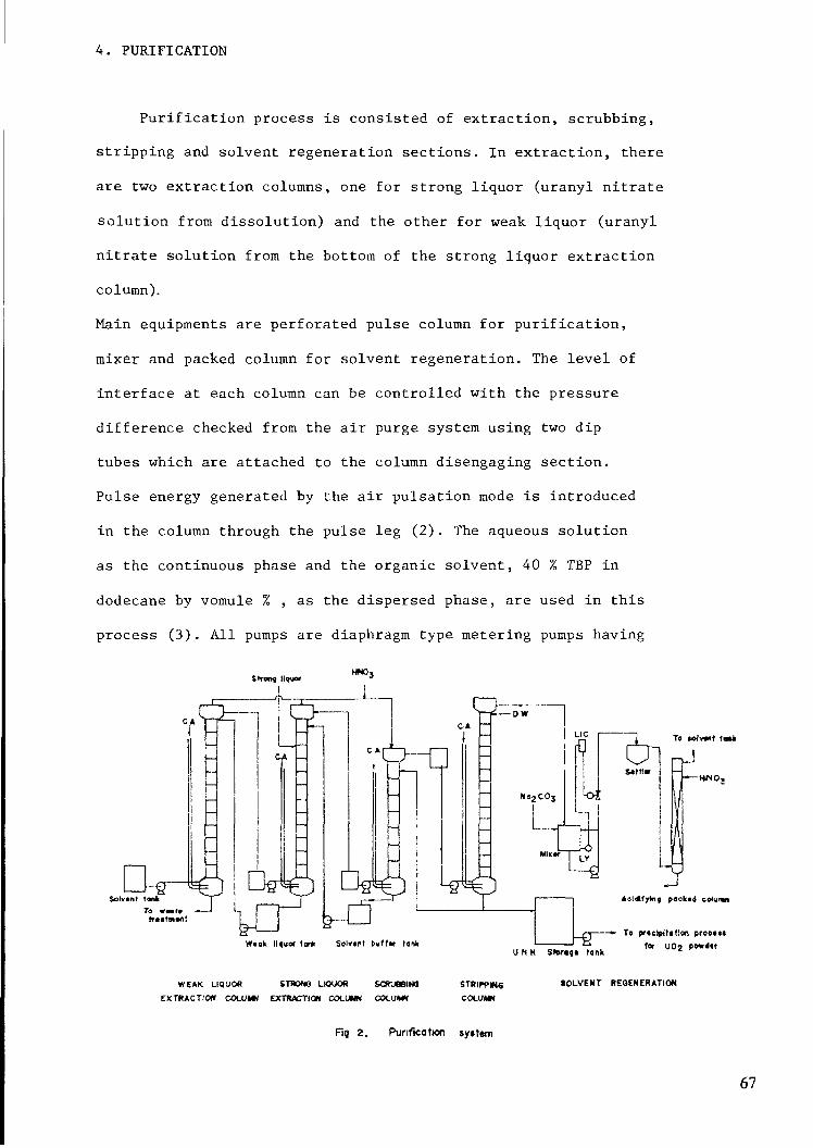
4. PURIFICATION
Purification process is consisted of extraction, scrubbing,
stripping and solvent regeneration sections. In extraction, thereare two extraction columns, one for strong liquor (uranyl nitrate
solution from dissolution) and the other for weak liquor (uranylnitrate solution from the bottom of the strong liquor extractioncolumn).
Main equipments are perforated pulse column for purification,
mixer and packed column for solvent regeneration. The level ofinterface at each column can be controlled with the pressure
difference checked from the air purge system using two dip
tubes which are attached to the column disengaging section.
Pulse energy generated by the air pulsation mode is introduced
in the column through the pulse leg (2) . The aqueous solution
as the continuous phase and the organic solvent, 40 % TBP in
dodecane by vomule % , as the dispersed phase, are used in this
process (3). All pumps are diaphragm type metering pumps having
Strong liquorUNO,
TO MiVMf «0*k
Solvant tankTO WMt*
W«ok liquor tar* Solnnt buff«- lank
WEAK LIQUOR STRONG LIQUOR SCRUBBING
EXTRACTION COLUMN EXTRACTION COLUMN COLUMN
U N H Storifi tank
packed column
~•- To prtclpitftfon prooi««far UOj pe*«'«r
STRIPP «sCOLUMN
tOLVENT REGENERATION
Fig 2. Purification system
67

a good accuracy and explosion- and acid-proof. Each column
diameter is 15 cm, effective height for both extraction columns
6 m each, scrubbing column 4 m, and stripping column 7 m. The
overall diagram is shown in Fig.2.
4-1. Extraction
The aqueous "strong liquor" solution produced through dis-
solution and filtration processes which contained 350 g-U/1
and 1.5-2.0 N of free acidity, is fed to the top of the strong
liquor extraction column. This aqueous solution flows center-
currently with the organic solvent. The slightly loaded solvent
from the top of the weak liquor extraction column is fed to
the bottom of the strong liquor extraction column through
the pulsation leg. The aqueous solution from the bottom of the
strong liquor extraction column is fed to the top of the weak
liquor extraction column, and fresh organic solvent which is
pre-equilibrated with nitric acid is entered into bottom of
this column. Two flows are also contacted counter-currently
each other. The dispersed phase hold-up appears a parabolic
distribution along the column axis and shows a maximum at 1/3
position from the bottom of the column and the overall mean hold-
up is about 10%. The uranium concentration of the loaded TBP from
strong liquor extraction column is about 145 g-U/1 corresponding
to about 90 % of its capacity, and the uranium content of the
raffinate(liquid waste) from weak liquor column is dropped down
below 20 ppm.The control element in the extraction process is molyb-
denum content, which is contained about 1500 ppm in yellow cake
68

as shown in Table 1. The amount of Mo content in the pure uranyl
nitrate solution which is bottom product of the stripping
column is checked every 4 hours. The uranium concentration of the
loaded TBP from the top of the two extraction columns is conti-
nuously determined by recording the data with densimeter installed
at the top of the column and converting into concentration withthe known value of the solution density. Samples are taken from
the sampling points along the column axis and local hold-up and
the uranium concentration between two phases are determined from
these samples. The uranium content in the raffinate is also
checked every 4 hours interval.
Table 1 Compansion of impurit ies in purif ied UN solutionand nuclear grade UC^ powder.
U
Ho
Fe
Si
Ca
Mg
Cu
Ni
Cr
Mn
B
Pb
„ , , , Pun-iedYel low cakeUN so lu t ion
135g-U7C
*0 15 0 73
*C 35 10
*0 40 10
1C
4 1
1
5
5
1
0 1
0 3
Nuclear grade
UOj powder
*87
2
20
10
2
2
20
5
11
1
0 2
1
* Unit • percent, others ppm based on U
69

4-2.Scrubbing
The loaded TBP from the extraction step is scrubbed usinga part of the stripped uranyl nitrate solution. Because of 1500
ppm of Mo content, the acidity of scrubbing solution is adjustedup to 4 N by adding 15 N HNO„ solution through the top of the
column. The flow rate of the scrubbing solution is about 10 %
of that of the loaded TBP and aqueous solution from the bottomof this column is recycled to the strong liquor extraction column.
In each phase, uranium concentration coming out of column top andbottom is kept nearly the same as the inlet concentration and the
overall mean hold-up in the column is controlled up to 10 %.
4-3. Stripping
The demineralized water is used as the stripping solution and
the flow rate is adjusted to maintain the uranium concentration
of 130-135 g-U/1 in the pure uranyl nitrate solution. In order to
keep the operation temperature about 50-55 C, the demineralizedwater and loaded TBP are preheated to 65 C and 55 C, respectively,
and is fed into the column top and bottom. The uranium concen-
tration in the uranyl nitrate solution from the column is cons-
tantly determined by the measurement of the density and the Mo
content is analyzed every 4 hours. Particularly, when the uranium
concentration of the product is over 140 g-U/1, uranium content in
the stripped TBP is increased by gram-order. In addition, the
stripped TBP solution coming out of the top of the column passes
the coalescencer filled with the teflon wool in order to remove
the very fine particles of aqueous phase entrained with organic
70

phase. The purity of uranyl nitrate solution is well agreed with
the nuclear grade of the U0„ powder and Table 1 shows the com-
parison of the feed materials and purified uranyl nitrate solution
with the nuclear grade U0„ powder.
4-4. Solvent regeneration
In the solvent regeneration process, about 8 % (wt) sodium
carbonate solution is contacted with the stripped TBP solvent
in order to remove all impurities. The flow rate of the sodium
carbonate solution is about 10 % of that of solvent and two
phases are mixed by recirculation using centrifugal pump and
then sent to the settler through the teflon wool (4), The sol-
vent is contacted conter-currently with 2 N nitric acid solution
in the packed column in order to acidify. The aqueous solution
from the packed column is used as weak liquor, and acidified
organic solvent is recycled to the weak liquor extraction
column. The sodium carbonate solution used for regeneration is
treated with the sodium hydroxide solution to recover the uranium.
5. EVAPORATION/CONCENTRATION OF URANYL NITRATE SOLUTION
In this process, the concentration of the uranyl nitrate
solution from the solvent extraction increases from 130 g-U/1 to420 g-U/1. The evaporator is a cylindrical form with 40 cm in
diameter and has a teflon lining in order to prevent the intake
of impurities possibly generated from the cylinder wall and has
an internal electric heater as the heating source.The solution temperature is controlled at 103 C and the solu-
tion is kept evaporated at higher concentration without boiling,
71

and one batch operation is terminated by the density measurement
of the uranium nitrate solution.
The advantages obtained from concentration/evaporation as follows;
-Possible control of particle characteristics such as size
distribution of the final U0„ powder.
-Smaller scale equipments, that is, smaller capacities of AUC
precipitator, filtration receiver or storage tank because
of the decreased volume of the uranium solution to handle.
For instance, when a 420 g-U/1 solution is used instead of
a 130 g-U/1 uranium nitrate solution, then the AUC precipi-
tator 's volume becomes 60-1 instead of 140 1.
-Reduction of gas and power consumption.It is better to keep constant ammonium carbonate concentra-
tion in the mother liquor to obtain the constant precipita-
tion conditions. As a result, the amount of ammonia and car-
bon dioxide is decreased to about 30 %.
-Reduction of liquid waste.
6. AUC PRECIPITATION
In this process AUC is prepared by the reaction of C0„ and
NH_ with the uranium nitrate solution according to the total
reaction equation;
2NH.NO-4 J
The precipitator made from stainless steel, is a cylindrical formwith 40 cm in diameter and the slurry is circulated from the bottom
part of the precipitator to the central part by using the pump.
72

Carbon dioxide and ammonia gases are introduced into solution
through circulation lines. The precipitation is carried out
batchwisely and preceeded as following three steps;
-Preheating; In order to obtain ammonium carbonate solutionand to raise the temperature up to 58 C, g'ases are fed intothe precipitator. Solution is heated with both heat of re-action and external hot water circulation.-Uranyl nitrate solution feeding; AUC particles are producedat 58 C while feeding uranyl nitrate solution together with
ammonia and carbon dioxide gases. Crystals deposit at thegas nozzle and often plug the gas feeding line. In this case
the distilled water is automatically injected through nozzle
and wash them out according to the pressure built in thegas lines.
-Cooling; For easy handling of AUC slurry and for the
reduction of uranium content in the mother liquor, thereaction solution is cooled down to below 20 C and further-more ammonia and carbon dioxide gases are introduced.
One AUC particle is calcined and reduced to one UO particle (5)
in the AUC conversion process, the particle size distribution
and shape of U0„ particles depend completely on AUC particles.
Consequently, granular shape of AUC particles, that is, granu-lation is essential for this AUC conversion process. Hence, it is
very important to control the size and shape of AUC particlesin the precipitation.
-Morphology; One of the advantages of the AUC conversion
process is the excellent flowability of U0„ powder, whichhas granular shape. The excellent granulation is mainly
due to attrition of AUC particle edges by external circu-
73

lation. During the precipitation, the long AUC crystals
(shown in Fig.3), having the ratio of length to diameter
over 1:10, are generated depending on pH but these are not
desirable products. It is necessary to control the ratio
1:1 to 1:3 , possibly with wide range of pH values between
7.8 and 10.
-Size distribution; As it is known(6), the size distribution
depends on the desupersaturation rate from the showering
point in the earlier stage of precipitation. The operation
parameters for the rate control are temperature, gas feed
rate, operation time, and uranium concentration in the
uranyl nitrate solution, but the easiest way to control
the rate is uranium concentration itself. As a result,
420 g-U/1 of solution is used in this process.
1QO IS HOÖS Q !
Fig.3.Scanning electron micrograph of AUC crystal( X 3,000)
74

7. FILTRATION
AUC particles produced from the precipitation process are
separated from the mother liquor and dried. The average AUC
Particle size is about 40 /im, which is relatively large, so simplevacuum filter can be used. In order to increase drying rate,
methyl alcohol is used as washing solution.
8. CALCINATION AND REDUCTION
The AUC particles are converted into the UO particles byreaction with hydrogen gas in a fluidized bed reactor according
to the following equation;
This fluidized bed reactor is 17 cm in diameter and 220 cm
in height. The AUC powder are fed from the hopper using the
vibrating feeder at the top of the bed. In order to prevent the
loss of the UO powder, a catridge filter was used and back-
flushed every 20 minutes. The calcination and reduction is con-
sisted of the following three steps;
-AUC feeding; The reaction occurs at 520°C with 13 % ofhydrogen and 87 % of steam atmosphere and the temperature
can be adjusted by feeding rate of AUC powder. In this
step, either hydrogen concentration or temperature changes
within 10 % doesn't significantly influence the powdercharacteristics .
-Pyrohydro lysis; The U0„ powders are only treated in the
atmosphere of steam in this step. This treatment influences
75

significantly on the U0„ powder characteristics and it
is the step to control the tap density, specific surface
area, pore size and its distribution together with time
and temperature. The tap density changes virsus time at
650 C are shown in Fig.4.
0)C11•a
O.Q.
3.2 -
3.1
3.0
2.9
2.8
20 40 60 80Pvrohvdrolvsis time, rnin
Fig. 4. Tapped densitv change of UCH powdersMS pyrohydrolysis time.
-Reduction; This step is for the lowering 0/U ratio to
2.0 from 2.2 resulted from the pyrohydrolysis step.
The UO particle characteristics affect mainly on the sinterability.2For instance,specific surface area gives great deal of effect on
the sintered density as shown in Fig.5. Accordingly, it is very
important to control and adjust the characteristics of the U02 pow-
der, possibly in this step. However, these characteristics are in-
terrelated each other and it is impossible to adjust independently,
76

10.6
BO
>•>
3 10.4WcT)
uV
<uQ. 10.2
5 lo.o
Compacting pressure» 2.8ton/ctn2
• 4ton/cm
_L. _L4 5 6 7
Specific surface area U(>2 powder, m2
Fig. 5. Relationship between surface area of UC>2 powderand sintered density of pellets.
Fig.6. Scanning electron micrograph of UO powder( X 20,000)
77

that is, a smaller tap der^ity means a large pore in U0„ particles
and also leads to increase in specific surface area. This inter-
relationship can be explained by the change of a monocrystalline
to a polycrystalline U0„ particle. As shown in Fig.6, U0„ particle
has a great number of small crystallites. The larger the size ofthe crystallite, the bigger the tap density, and the smaller thespecific surface area. Consequently, the crystallite size must becontrolled for the sinterable U0„ powders.
9. STABILIZATION
This step is the partial oxidation process of U0„ to have
a stable oxidized film on the U0„ particle surface (7) and increase
of the ratio of 0/U in the controlled oxygen atmosphere. Since the
0/U ratio of U0„ powders is varied with 0„ concentration,
temperature and time, 0/U ratio can not be controlled only by the
operation parameters. That is, specific surface area should first
be controlled.
10. URANIUM RECOVERY
The filtrate contains 600-800 ppm of uranium, because_ i i
CO- ions tend easily to form complex ions with U0„ ions in the
mother liquor (8). Hence, it is essential to eliminate CO, ions
in order to recover uranium from the filtrate. The filtrate is
heated up to 98°C ,with stirring, to remove C0„ . The finalsolution pH turns to about 9 with precipitation of ammonium di-
uranate(ADU). The uranium content of final liquid waste becomes
below 2 ppm.
78

11. CONCLUSION
The project to localize uranium refining and conversion
technologies, as a part of HWR fuel manufacturing»has been suc-
cessfully completed throughout the in-file test, out-of-file
test and even through the actual irradiation in a commercialpower reactor. This accumulated technologies and experiences will
help us to expand our capacity in order to supply all the fuels
for the Weisung reactor in the near future.
REFERENCES
(1) Ashbrook, A.W., Uranium refining and conversion practicein the Western World; An overview,(1982)
(2) Srinivasan,N., Kumar,S.V., BARC (1972) 589
(3) Ferez, A., "Duconcentre d'uranium a l'hexafluorure",Proceedings of an Advisory Group Meeting, Paris, 5-8 June(1979) 201-228
(4) Leroy,P., Etude du solvent 30 % TBP-dodecane, SCC1-71,(1966)
(5) Assmann, H., Mathieu, V., AED-conf-76-194-007Paper presented on May 5, 1976 at the 78th Annual Meeting
of the American Ceramic Society, Cincinnati, Ohio.
(6) AIChE Sym. Ser. 68(121), (1972) 8-20Desupersaturation of seeded citric acid solution in a
stirred vessel.
(7) Sonndermann, T., J. Nucl. Mater., 106(1-82)45-52
(8) Chernyaev, 1.1., "Complex Compounds of Uranium"Israel Program for Scientific Translation, Jerusalem,(1966)
79

RESEARCH AND DEVELOPMENT OF UF6CONVERSION IN JAPAN NOW AND SUBJECTSIN FUTURE
Y. HASHIMOTO, I. IWATA, T. NAGASAKIPower Reactor and Nuclear
Fuel Development Corporation,Tokyo, Japan
Abstract
PNC is engaging the f o l l o w i n g R&D'S of UF6 conversion.
(D R i f i n i n g and Conversion P i l o t Plant (200TU/Y) w h i c h produces UF6 from u r a n i u mconcentrates by the PNC process
(D IJFs conversion of reprocessed u r a n i u m (4TU/Y) by dry process
PNC has accoumulated many i m p o r t a n t experiments and been making manyimprovements.
We have to solve the f o l l o w i n g subjects to commercialize the UFs conversion infuture.
© The h i g h cost's problem owing to small domestic UF6 market(D Adaption of the most appropriate process for Japan's demand
These subjects w i l l be solved by c o m b i n i n g reprocessing, conversion and
enrichment f a c i l i t i e s at the same site to reduce total fuel cycle cost.
We are w i l l i n g to c o n t r i b u t e the world's UF 6 conversion industry by d e v e l o p i n g
the latest technology.
81

1. 1 n t r oduct i on
O r i g i n a l l y PNC process was d e v e l o p e d for the m e t a l f u e l p r o d u c t i o n in Japan,
w h i c h produces UF 4 d i r e c t l y from o r e w i t h o u t t h e y e l l o w cake p r o d u c t i o n .W i t h the d e v e l o p m e n t of the L i g h t Hater Reactor w h i c h uses s l i g h t l y e n r i c h e d
u r a n i u m , the feed m a t e r i a l UF 6 became needed to produce a f t e r LF 4 p r o d u c t i o n
process.So that PNC started to d e v e l o p the succeeding process in 1976 and then
succeed to produce UF6.
Based on these success, PNC started to construct the (jFe c o n v e r s i o n p i l o tp l a n t of 200T/year in 1979 to promote f u r t h e r i n d u s t r i a l i z a t i o n and s u p p l y UF S
to the enrichment p i l o t plant on the same site.T h i s p l a n t was i m p r o v e d to produce UF 6 not o n l y from ore but from the y e l l o w
cake w h i c h is the current m a t e r i a l in the w o r l dFrom the o p e r a t i o n , we found the m e r i t s of the PNC process f r o m y e l l o w cake
and w i t h e n r i c h m e n t plant.On the other hand, w i t h the start up of Tokai Reprocessing plant, it became
needed to develop the r e c y c l i n g t e c h n o l o g y of reprocessed u r a n i u m to LWR
t h r o u g h UF 6 conversion and e n r i c h m e n t .So that the conversion test f a c i l i t y (CTF - ÏÏ ) of reprocessed u r a n i u m was
constructed in the same plant.
From the tests of CTF-- fl , we found the merit in co-conversion w i t h
reprocessed and n a t u r a l u r a n i u m .
The reseach and development of UF 6 conversion by PNC process before the p i l o tp l a n t construction has already been reported at the p r e v i o u s I A E A A d u i s o r y GroupMeeting h e l d in Paris in 1980 C 1 ) , therefore we w i l l report here the
experiences at the pilot plant of PNC process and CTF- D of reprocessedu r a n i u m and the f u t u r e subjects.
82

2. UFe c o n v e r s i o n in Japan now.
The f o l l o w i n g d e v e l o p m e n t has been c a r r i e d out in Japan
(1) The p i l o t p l a n t test of r e f i n i n g and c o n v e r s i o n© Feeds '• Y e l l o w cake in the w o r l d and d o m e s t i c ore.
@ Process : PNC process (see Fig-1)(3) Capacity : 200tu/year
® Start up : March 1982
(H2S04)'
(HCI)
(N32C031
URANIUM CONCENTRATE
DISSOLUTION
AMINE EXTRACTION
UO2S04
ELECTROLYTIC REDUCTION
U(S04)2
<HF)—— HYDROFLUORINATINGPRECIPITATION
UF4 -nH20
T(N2) DEHYDRATION
JUF4
(F2)——[FLUORINE FLUORINATIONJ
UF6
(H2S04)u
Fig.1 REFINING AND CONVERSIONPILOT PLANT
83

(2) The U F s c o n v e r s i o n test for r e p r o c e s s e d u r a n i u m .
(CTF- Ï Ï )( D F e e d s : r e p r o c e s s e d u r a n i u m , U 0 3 ( U 2 3 5 b e l o w 1 .6%)
© P r o c e s s : c o n v e n t i o n a l d r y p r o c e s s (See F i g - 2 )
© C a p a c i t y : 2 .4 k g u / h r
@ S t a r t up : M a r c h 1982
A t h e m e ( 2 ) w i l l b e r e p o r t e d i n a n o t h e r s e s s i o n .
REPROCESSED URANIUM UO3
<H20)-
(H2)-
(HF}-
GRINDING AND CLASSIFICATION
HYDRATION
U03-nH20
DEHYDRAT10N AND REDUCTIONrU02
HYDROFLUORINATION
(F2)— FLUORINE FLUOR1NATION
UF6
Fig-2 CONVERSION OF REPROCESSEDURANIUM
3. The experiences and i m p r o v e m e n t s of the Ri fin ing andC o n v e r s i o n p i l o t plant.
(1) Process flow (See Fig-3)
The PNC process consists of the f o l l o w i n g steps.
Dissolusion with sulfunc acid (See Fig-3)
84

H2SÛ4 (recycled)
Uranium IConcentrate
n [I (U02SCM
Filter Extraction3 steps
Dissolution Tank
Washing Stripping || Scrubbing)2 steps 7 steps
Raffinate U : 1mg/JToElectrolytic Liquid wasteReduction treatment60~100gu/fU02S04UO2Cl2H2S04
Fig-3 URANIUM CONCENTRATE DISSOLUTION ANDAMINE EXTRACTION
Yellow cake is dissolved w i t h sulfunc acid, then the residue is
f i l t r a t e d out.
) A m i n e extraction (See Fig-3)
Dissolued u r a n i u m is extracted into t r i - n - o c t y l a m i n e s o l v e n t , selected
from i m p u r i r i e s , by f o r m i n g n e g a t i v e complex ion [ U02 (504)3!The equipment consists of 4 stage extracting, 2 stage scrubbing, 7 stage
s t r i p p i n g and 2 stage solvent s c r u b b i n g m i x e r settlers.
D E l e c t r o l y t i c R e d u c t i o n (See Fig-4)Uranyl (U022*) so l u t i o n is reduced into uranous (U4*) s o l u t i o n by the
e l e c t r o l y t i c method.E l e c t r o l y t i c c e l l is separated into an anode room and a cathode room by
an anion exchange membrane.
Sulfunc acid is anolyte and u r a n y l sulphate is catholyte.

60~100gu/£UOjSCuUOzC'z
O2 H2SCU
U02S04
H2°S2042 Electrolytic
II Reduction cell
YÎ tElectrode H20 uo
î iU(SO<ih , UCU60~100gu/{
Electrolytic reaction
+ ) 2H20-»4H++02+2e~
. Electrode
Ion-ExchangeMembrane
H2S04
/•Electrode
,-Ion-Exchangemembrane
1 To HydrofluonnationU(SO„)2UCU
Fsg-4 ELECTROLYTIC REDUCTION
Hydrogen ion produced at anode passes t h r o u g h the membrane and reduces
U02S04 into U(S04)2 at cathode.
) H y d r o f l u o r t n a t i ng p r e c i p i t a t i o n (See Fig~5)
Uranous S o l u t i o n is p r e c i p i t a t e d to hydrated u r a n i u m tetraf 1 uor ide
ÜF« • nH20 w i t h h y d r o f l u o r i c acid in a reactor vessel of 8 c u b i c meter madeof teflon coated f i b e r - r e i n f o r c e d plastic.
) Dehydration (See Fig-5)
Hydrated u r a n i u m t e t r a f l u o r ide UF« -nH 20 is dehydrated in a flu idized-bed
reactor of 35cm diameter w i t h N^ gas.
) F l u o r i n e f l u o r i n a t i o n (See Fig-6)
Dehydrated UF« is converted to UF6 gas w i t h F2 gas, and then UF6 gas iscooled and trapped in cold traps.
86

jj=>— '-————*>To liquid waste treatment
To Vent
90'CHYDRO-FluorinationPrecipitator
U(SCM
Heated Air
fj f-2 Fluorination
Dryer
Fig-5 HYDROFLUORINATION AND DEHYDRATION
UF4UFe gas
\
Cold Trap
NaF trapLJ A|2p3
To Vent
N2gas
-5'C —3U'C 100'C
Fan-H F gas H2 + HF gasFluid DedFiuorinator
1 gas
H F Electrolyisis Cell
HF
Scrubber I
To Vent
Scrubber
Fig-6 Fa FLUORÎNATION
The fluorinator is'a f luidized-bed reactor of 40cii diameter.
) L i q u i d waste treatment (See Fig-7)
The following l i q u i d waste ib discharged from the process.
1) R a f f i n e l e from awine extractor c o n t a i n i n g H2S04 and i m p u r i t i e s .2) Solvent scrubbing waste c o n t a i n i n g Sodium carbonate Na2C03.3) Hydrof1uorination waste containing H2S04, HC1, HF and U.
87

EXTRACTION 1 I SOLVENT SCRUBBING I j HYDROFLU
RaffH2S
1 1 2S04* U
nate M^ ^^ ,04 [ACID R
rCa(OH>2 T| H2S04
1......._ y nr
Recycle
CaS
DischargeU<0 09ppm
*I DtCARBONATION 1
>O< 1
CaF:
- —— 1 URANIUM ADSORBING I- —————— FLUO
URINATION DEHYDRAHON
F2 FLUORINATIONu£, F2 PRODUCTIONru l
ECOVERY
HQ AlkalineScrubbing
NaFU
r ———— Ca(OH>2
PRECIPITATION
F 7ppm U Ippm
RINE ADSORBING
Chelating ion-exchanger " Chelating ion-exchanger
Fig-7 WASTE TREATMENT
4) A l k a l i n e scrubbing waste in d e h y d r a t i o n and F z f l u o r i n a t i o n processc o n t a i n i n g NaF and U
Raffinate is treated w i t h Ca(OH)2 to remove c o n t a i n i n g H 2SO« and
i m p u r i t i e s by p r e c i p i t a t i n g as CaSO« etc
Hydrofluor mat ing waste is evaporated to recover H 2SO< and U r a n i u m
Vapour c o n t a i n i n g HF and HC1 is condensed and used to decarbonate the
solvent scrubbing waste
The decarbonated waste and a l k a l i n e s c r u b b i n g waste is treated w i t hCa(OH)2 to remove c o n t a i n i n g f l u o r i n e and u r a n i u m as p r e c i p i t a t e d CaF2
roughly, then small amount of residual F, U in waste is removed byc h e l a t i n g ion-exchange adsorbing resin for d i s c h a r g i n g from f a c i l i t y
88

(2) S p e c i f i c a t i o n of i m p u r i t i e s in u r a n i u m concenrate
The s p e c i f i c a t i o n of i m p u r i t i e s in feed u r a n i u m concenrate is d e t e r m i n e d by
d e c o n t a m i n a t i o n factor in erch process and DOE s p e c i f i c a t i o n of product UF6.
The PNC process has 3 p u r i f i c a t i o n steps as follows.
CD A m i n e x t r a c t i o n © UF4 p r e c i p i t a t i o n (D F2 f 1 u o r m a t ion.
The d e c o n t a m i n a t i o n factors and u r a n i u m concenrate s p e c i f i c a t i o n d e r i v e dfrom them is shown in t a b l e - 1
The elements w h i c h decrease the e f f i c i e n c y of e l e c t r o l y t i c r e d u c t i o n ares p e c i f i e d f u r t h e r s t r i c t l y , but t h i s is not fatal.
The l i m i t e d i m p u r i t i e s are n o b l e metals of Cu, Ag, etc. and t r a n s i t i o n
metals of Fe, Co, Ni, etc.
Since Co3, PCU, Cl d i s t u r b the a m i n e e x t r a c t i o n and As is strict r e g u l a t e d
e n v i r o n m e n t a l m a t e r i a l , these m a t e r i s l s a r e s t r i c t l y specified.
T a b l e 2 and 3 show the i m p u r i t i e s s p e c i f i c a t i o n of converters in the
world. [ 2 3 .
Severe materials in the PNC process are PO,, Cl, F, Mo, C02 and As.
89

Table-1 DECONTAMINATION FACTORS OF EACHSTEP IN PNC PROCESS AND URANIUMCONCENTRATE'S (U C ) SPECIFICATION
estimated va ue
mpur tyelements
LUu2
aer
£CCOLOLJUO
U.
SbNbRuTaTiC-MoWVCaMgThZrNaK
z
guDQLJ
ZoK-U
~XLJ
FeNiCoAgCuErCIFPO*C03
r i AsLJIHO
3Si
UFeSpec
1 ppm/U
"»
1 t1 «
10 71 41 41 4
>
|1
Total300
,.5
100NON
50
NON
8
Deconta~i na on factor
j^Ex'ract on
( 1 4001
\ 8 000)( 28 000)( 8 000)
1 20030 000
2 7( 3 000)
8021 000
650 0003 300
501 8001 300
28 600878 000
UFa*" Prec Dicatcn
1 100)( 100)( 1 000)1 100)
1 000( 1 4)
1 200" 200
2004
44526
1002050
2 000400
210 i 20001 000
51 200
1 4004 200
00 37 800
1 3001 300
(10 000)CO 900)
1(10 000)(10 000)15 000
4 000•'OO
C-,
v Fluor nat on2ppm/U43
( DI 1)( 1)( 1)1 ')( )
703
(100)(100)
206000
' 00)(100)
100!(100!
1111
( Di )
Uranium
Conc°ntrate bSpec
NONNONNONNOMNONNON4 500NON
96 000NONNONNONN0\NONNONNON
NON
2 1001 000
25 000^
\ 10 000
0 00010 03015 000
i 000NOM
i ) S 02 15 000
Table-2 COMPARISON OF CONVERTERS' MAXIMUMALLOWABLE SPECIFICATION LIMITS
(MAXIMUM PERCENTAGES)Constituent
Vanadium (V)Phosphorus (P)Halogens (C! Br 1)Flourme (F)Molybdenum (Mo)Sulfur (S)Iron (Fe)Arsenic {As}Carbonate (COaiCalcium (Ca)Boron (B)Silicon (SOMagnesium iMg)Thorium (Th)Zirconium (Zr)HN03 Insoluable
UraniumExîractabie Organic
MaterialWater (HaOiSodium (Na)Potassium (K)Titanium (TOSulfates (S04)
PNC9 61 OIPO4)
1 01 00 45
————
0 11 5
————
8 O(SiCh)——————__
'5 0——————
——
A lied0 751 000 100 100 30
12 001 000 100 501 000 102 500 50————__
__
5 007 503 000 05——
Kerr VlcGee0 850 700 500 15O 754 502 002 003 001 500 151 501 502 500 50__
0 10
7 50————————
BNFt0 701 000 300 300 6O————2 5O4 005 001 008 00————0 50__
__
15 00————————
Comurhex0 301 000 250 300 60— ———
2 503 005 000 205 OO————
2 00
0 10
0 10
10 0015 00
————
10 00
Eldorado0 850 700 300 200 45———
2 003 001 500 20————
2 50——
0 10
0 10
b 00——————
10 50
90

Table-3 COMPARISON OF CONVERTERS' IMPURITYSPECIFICATION LIMITS WITHOUT SURCHARGE
(MAXIMUM PERCENTAGES)Constituent
Vanadium (V)Phosphorus (P)Halogens (CI Br 1)Flounne (F)Molybdenum (Mo)Sulfur (S)Iron (Fe)Arsenic (As}Carbonate (COj)Calcium (Ca)Boron (B)Silicon (SOMagnesium (Mg)Thorium { Th)Zirconium (Zr)IIN03 Insoluable
UraniumExtractable Organic
MaterialWater (HiO)Sodium (Na}Potassium (K)Titanium (Ti)Sul'ates (SCu)
PNC1 00 3(PO4)0 31CD0 3(f-~)0 1
————
0 050 5
————
4 OISiOz)——————__
__
10 0———————
Allied0 100 100 050 010 103 000 150 050 200 050 0050 500 02
— ———__
__
2 000 500 200 01
——
Keir-McGee0 10O 350 2b0 150 153 501 501 002 001 000 151 001 002 000 50
0 10
0 10
7 50————————
BNFL0 200 500 100 010 20————1 002 001 000 2O4 00————0 10_
_
10 00———————
Comurhex——————
0 150 20
————
1 002 001 00
————————
0 20__
__
——1 00
—————
Eldordoo0 100 350 250 150 15————1 002 001 000 15
——— —
2 00——
0 10
0 10
5 00——————
10 50
(3) The p u r i t y of p r o d u c t L'
We converted the typ i c a l u r a n i u m concentrate in the world as follows
©
(DP i n g x i a n g r e f i n a r y in c h i n a , U0 2 type.Ranger m i n e i n A u s t r a l a r i a , U308 type.
Key lake m i n e in Canada, U308 typeAkouta m i n e i n N i g e r , M D U , S O U type
The i m p u r i t i e s in these u r a n i u m concentrate is shown in t a b l e 4, and amongthese, the Akouta' s u r a n i u m concentrate c o n t a i n s Mo and almost i m p u r i t i e s the
most.
So, the p u r i t y of UF 6 product converted from A k o u t a 1 s u r a n i u m concentrateis shown in table 5, and it satisfies the DOE s p e c i f i c a t i o n
91

Table-4 IMPURITY CONCENTRATE OF FEED URANIUM(PPM)
Impurity
VP
CI.Br.l
F
Mo
SFeAs
C03
Ca
SlO2
MgThZr
NaKTi
SpecStandard10,0003,0003,0003,0001,000——
5005,000
40,000——
——
——
Maximum96,00010,00010,00010,0004,500——
1,00015,000
80,000——
——
——
CHINAPingxiang
5170
7!
30——
701
1001060
520
50 4
10<1
AustraliaRanger
660380
301
103,7001,100
<1
1,000Q
1,5001,000
20170400<5
CANADAKey lake
<r 107
27
250^3.000
100170
1100
2,20023
Q A
23013<5
NigerAkouta3,3002.9001 ,500
1402,400——
<100
2,000
5,8002,900
47,700
15,2001.000
Table-5 IMPURITY CONCENTRATE OF PRODUCT UFePPM/U
Impurity
A!
Ca
Cd
CuK
Mg
Mn
Na
Ni
Pb
Zn
P
Si
Ti
Mo
V
Feed U
(Akouta)
1,700
2,000
.-5
<5
1,000
2,900
300
15,200
<10
<10
56
2,900
5,800
2,400
3,300
Dissolving
Solution
1,600
1,300
<1 0
7.7
552
3,100
217
19,700
3 01
6 7
16.9
——
101
1,800
482
Stripping
Solution
38.3
45.5
<0.3
<0 6
3.9
12 2
1.9
495
0 66
0.56
5 644
0.2
2.5
800
<5
UF4
3.4
26 2
<0 2
< 0 4
5 5
0 2
<0 2
1 51
2 3
<0 2
0 38
0.5
<0 2
< 1.0
< 1.0
<4
UF6
5 48
1 85
<.0 2
<0 2
3 6
0 52
<0 2
1 21
0 33
<0.2
4 4
0 5
<0 2
<1 0
<1 0
<1
DOE spec
>
Total
,
SOOppm
/U
50
100
1 0
1 4
1 4
92

(4) Loss of u r a n iurn
The possible o u t l e t s of u r a n i u m from the PNC process are as follows.
® R a f f i n a t e in c i m i n e x t r a c t i o n
(D So l v e n t s c r u b b i n g waste.
(3) H y d r o f 1 u o r i n a t i ng waste.
® Off gas from the UF6 cold traps.
There is very few u r a n i u m loss from the e x t r a t i o n process CD, (D.Hydrof 1 uor i nat i ng waste ® contains 10% u r a n i u m w h i c h is recovered by an
evaporator w i t h H 2SU4 to recycle to u r a n i u m concenrate d i s s o l u s i o n process.
Therefore there is no loss of u r a n i u m in t h i s process ©.UF$ gas in off gas @ is recovered by Nap c h e m i c a l traps now, but NaF is
expensive.
So we are now g o i n g to construct a water scrubber w h i c h absorbs UFS gas inoff gas to recycle u r a n i u m .
(5) The process economy
The m a i n expendetures on the present process are as follows.
CD Steam for acid recovery
® H y d r o f l u o r i n e® Na3 C03 for solvent's scrubbing@ N2 gas for f l u i d i z i n g inert gas.
© HC1 for stripr-ing.
® NaF pellet for UF6 recovery.
93

URANIUM CONCENTRATE
H2SCU
N32CO3
ELECTROLYTICREDUCTION
Discharge
UF6
Fig-8 ADVANCED PNC PROCESS
Therefore PNC has d e v e l o p e d the e c o n o m i c a l h y d r o f l u o r i n e and u r a n i u m
recovery method w h i c h reduces the Q, ® and ®.As shown in fig-8, t h i s advanced process treats the waste c o n t a i n i n g F, Cl,
SO«, Na, U • etc and recovers HF and U by p r e c i p i t a t i o n and d i s s o l u t i o n and
evaporation, therefore t h i s process does not generate the s o l i d waste w h i c h
raises the cost by strage.We w i l l demonstrate t h i s advanced process by the p i l o t plant in this year.We are performing another improvements as follows.
® N2 gas recycle@ I'Fs recovery by a water scrubber to replace NaF traps.© Impurities removal by ion-exchange res:,i to replace amine solvent
extract ion.
94

The concept ® is d e r i v e d from the m e r i t s of the PNC process w h i c h has an
u n i q u e excess p u r i f i c a t i o n process that is U F 4 p r e c i p i t a t i o n .
Therefore a m i n e e x t r a c t i o n can be r e p l a c e d by more rough and cheap i m p u r i t y
r e m o v a l method l i k e i o n exchange w h i c h removes o n l y t h e i m p u r i t i e s w h i c h c a nnot be removed a f t e r and d i s t u r b s , a f t e r process.
In the case of UF 6 c o n v e s i o n by the PNC process the concept of u r a n i u m
e x t r a c t i o n s h o u l d be i m p r o v e d by the concept of s m a l l amount of i m p u r i t i e s
r e m o v a l w h i c h l e a d s t o compact, cheap e q u i p m e n t s a n d o p e r a t i o n cost.
(6) Features of the PNC process
As d e s c r i b i n g above, the m e r i t s and d e m e r i t s of the PNC process are
s u m m a r i z e d as follows.
(Merits)
® T r i p l e p u r i f i c a t i o n
1) A m i n extraction 2) hydrofluor mat ing p r e c i p i t a t i o n
3) F2 f l u o r m a t i o n
(2) Easy to control the wet process u n t i l UF4 p r e c i p i t a t i o n because of
homogen ious low temperature system.
© A c t i v e r e a c t i v i t y of U F 4 p r e c i p i t a t e w h i c h s i m p l i f i e s the next F 2
fiuormation process.
@ Easy to rec y c l e the f l u o r i d e waste.
© Easy to produce m e t a l at m i n e site.
(Demerits)© Large space occupation of the equipments with low concentrated solusion
system.© Many k i n d s of waste and large amount of waste.
95
We are d e v e l o p i n g the r e c y c l i n g system of waste and the compact e q u i p m e n t s
for wet process l i k e pulse c o l u m n extractor etc, and we w i l l overcome these
demer its in future.
4. The subjects of UFs c o n v e r s i o n to c o m m e r c i a l i z ein Japan.
[ 1 ] Needs
The c o m m e r c i a l i z i n g plans of nuclear fuel cycle in Japan are as follows.
© Reprocessing p l a n t (at S h i m o k i t a )capacity : 800tli/yearstart up : 1995
(2) E n r i c h m e n t p l a n t (at S h i m o k i t a )Capacity up of 150TSWU, year by year, from 1991 to 2000.
The f i n a l capacity is 1500tSWU/year.
Therefore the demand of UF 6 c o n v e r s i o n w i l l grow large on near 1995.
[2] The problems in domestic i n d u s t r i a l i z a t i o n
There are 5 c o m m e r c i a l converters in the world w i t h c a p a c i t y of52,290tU/year w h i c h is s u r f i c i e n t to supply world's demands, and conversior,
p r i c e is cheap.As shown in Fig-9, the conversion price depends on the p l a n t scale l a r g e l y .The world's converter w i t h the p l a n t scale of about 10,OOOtU/year can
afford the conversion service on the cheap p r i c e of 7 $/kgU (1.3 m i l l i o n e s yen/tU>, but on the domestic case w i t h the demand of 200 til/year, the price w i l lbe 11.1 $/kgU (2.0 m i l l i o n s yen/tU) and it seems better to depends upon the
96

1995 2000
3.5-
co
c05
Co
CDO
Co
Q)
Cou
Year of Demand generation
The Merit of Domestic
1.5-
1000 5000 10000
PLANT SCALE [TU/YEAR]
Fig-9 CONVERSION PRICE AND PLANT SCALE
world's converter's s e r v i c e .But as shown below and Fig-10 the conversion price of uranium concentrate i
is cheap and c o m p a r a b l e w i t h the t r a n s p o r t a t i o n p r i c e or the interest of
excess u r a n i u m p r e p a r a t i o n d u r i n g UF 6 t r a n s p o r t a t i o n etc.
Terms Pr ice ( m i l l i o n yen/tU)
(D Transportation of UF6 to Japan 0.3(2) Transportation of reprocessed u r a n i u m from Japan 0.8
to fore ign converter's
© UF6 c y l i n d e r 0.3@ The interest of excess u r a n i u m p r e p a r a t i o n d u r i n g the 0.3
period from conversion to e n r i c h m e n t (about 3 months)
97

DOMESTIC CONVERSION FOREIGN CONVERSION
JAPAN-
Uranium mine
-JAPAN-
II IMOKITA-
Fig-10
On the case of c o n v e r s i o n of reprocessed u r a n i u m , there are no s u p p l i e r int h e w o r l d except C O M L R H E X w i t h s m a l l c a p a c i t y o f a b o u t 2 5 0 Tonsil/year a n d w i t h
about s i x t i m e s o f n a t u r a l u r a n i u m c o n v e r s i o n .
On the case of domestic conversion, these expense can cut down and t o t a l
economy can be a c h i e v e d .
3] The p o l i c y to c o m m e r c i a l i z e the U F G c o n v e r s i o n .
The f o l l o w i n g p o l i c y is necessary to c o m m e r c i a l i z e the l F B c o n v e r s i o n in
Japan.
CD Make a strong c o m b i n a t i o n w i t h e n r i c h m e n t to cut down
1) t r a n s p o r t a t i o n cost
2) excess uranium preparation
98

3) excess t i m e loss just l i k e t r a n s p o r t a t i o n period.
4) excess job l i k e UF6 a n a l y s i s .
5) excess man power just l i k e managemeut.
6) excess f a c i l i t y just l i k e u t i l i t y .
© C o m b i n e w i t h the t a i l UF 6 c o n v e r s i o n to recover the f l u o r i n e and thec y l i n d e r s and cut down c h e m i c a l s and m a t e r i a l cost.
® C o m b i n e also w i t h UU 2 conversion of e n r i c h e d u r a n i u m to cut down the same
costs as (D and @
@ D i l u t e the reprocessed u r a n i u m w i t h the n a t u r a l u r a n i u m to compensate the
f o l l o w i n g demerits o w i n g to the e x c u s i v e conversion.
1) scale d e m e r i t
2) h i g h r -ray a c t i v i t y by U232 daughter
3) batch treatment by heterogeneous e n r i c h e d u r a n i u m .4) c r i t i c a l l i m i t a t i o n by the e n r i c h e d u r a n i u m over 1% U235
By the one pack construction of related planes as above, the f o l l o w i n g
economy can be achieved, in the case of domestic 1JF 6 conversion.
Case Sav i ng cost ( m i l l i o n yens/ton U)
© N a t u r a l Uran ium 0.9(2) Reprocessed U r a n i u m 1.7
Therefore the establishment of the domestic conversion saves the total fuel
cycle cost in Japan. (See Fig-9).
But these saving is effective only for the domestic demand.The f o l l o w i n g technology should be developed to construct the economical
conversion plant.
99

(D F l u o r i n e r e c o v e r y from UFG
© M i x e d c o n v e r s i o n of n a t u r a l and reprocessed u r a n i u m .
I f t h e A V L I S i s i n d u s t r i a l i z e d i n f u t u r e , t h e m e r i t o f t h e P N C process for
metal p r o d u c t i o n w i l l b e r e c o g n i z e d , s c i n c e a l m o s t m i l l s a t m i n e s i t f c a n b eexchanged the process e a s i l y to the PNC process because they h a v e anune
e x t r a c t i o n process a l r e a d y .
But the f o l l o w i n g technology should be d e v e l o p e d to reconstruct economical
r i f i n i n g plant of D m e t a l at m i n e site.
CD H y d r o f l u o r i n e recovery from the process, UF< to metal.
@ E c o n o m i c a l f u e l b a t t e r y for e l e c t r o l y t i c r e d u c t i o n .
PNC is d e v e l o p i n g the h y d r o f l u o r i n e recovery t e c h n o l o l g y © now, and f u e l
battery w i l l be economical in f u t u r e , so the m i n e - s i t e P\C process may be
h o p e f u l in future.
5. Conclusions
The PNC process has been demonstrated by the p i l o t plant.
The p u r i t y of product U F 6 s a t i s f i e d the DOE s p e c i f i c a t i o n , even w i t h the
worst feed just l i k e Akouta's uranium c> centrale.
The u r a n i u m lose was n e g l i g i b l e small, but u r a n i u m recovery systems l i k e MaFtraps are b e i n g improved to economical system l i k e water scrubber.
We found that the non-sludge treatment of f l u o r i d e waste improves, the
economy of chemicals, power and steam.The more advanced process is b e i n g developed.The m i n e - s i t e PNC process w i l l g a i n advantages in the f u t u r e Laser e n r i c h m e n t
system.
100

The c o n v e r s i o n of reprocessed u r a n i u m by dry c o n v e n t i o n a l process has beentested an d t h e i m p r o v e d scale up e q u i p m e n t s h a v e been d e v e l o p e d .
T h e d o m e s t i c c o n v e r s i o n p l a n t w i l l c o n v e r t p r i n c i p a l l y t h e reprocessed
u r a n i u m .
lo construct the economical conversion system in (apan, the L F e conversion
p l a n t s h o u l d b e c o m b i n e d w i t h e n r i c h m e n t , t a i l U F 6 c o n v e r s i o n a n d e n r i c h e d U F C
r e c o n v e s i o n p l a n t , etc. a n d h y d r o f l u o r i n e r e c o v e r i n g t e c h n o l o g y s h o u l d b ed e v e l o p e d .
W e a r e w i l l i n g t o c o n t r i b u t e t h e w o r l d ' s IIF S c o n v e r s i o n i n d u s t r y b y
d e v e l o p i n g t h e latest t e c h n o l o g y .
References
; 1 ) S. TAKENAKA, T. N A G A S A K I , "Studies for p r o d u c i n g UF6 from L F « - n H 2 0 in
Japan" P R O D U C T I O N OP Y E L L O W CAKE AND U R A N I U M F L U O R 1 D E S (Proc. A d v i s o r y
Group M e e t i n g P a r i s June 1979) IAEA, V i e n n a (1980) 309.
C2) Fuel-trac, N o v e m b e r 1977 N u c l e a r Assurance C o r p o r a t i o n .
101

EXPERIENCE IN YELLOWCAKE REFINING AND ITSCONVERSION TO URANIUM TETRAFLUORIDE ATIPEN-CNEN/SP
A. ABRAOInstitute de Pesquisas Energéticas e Nucleares,Comissao Nacional de Energfa Nuclear,Sao Paulo, Brazil
Abstract
This paper will focus the experience acquired duringthe operation of a pulsed columns solvent extraction pilotplant in the purification of a yellowcake produced from theindustrial treatment of monazite sand. Special care was devo-ted to the rare earths elements, thorium and zirconium decon.tamination. Intermediate product is an uranium trioxide obtained by dewattering and thermal decomposition of diuranateand its con- arsion to uranium tetrafluoride.
The experience developed and the establishment ofthe quality control procedures to follow up all steps on bothpilot unities as an important support to the technical workis emphasised.
1. INTRODUCTION
As contribution to the national program for developping atomic energy for peaceful uses, headed by theBrazilian Nuclear Energy Commission (CNEN), the Institutede Pesquisas Energéticas e Nucleares (IPEN), S.Paulo, hasgiven a great deal of effort concerning a systematic develo£ment of research for the establishment of the technology ofuranium and thorium. The program is very much dedicated tothe education and training of chemists and engineers, and tothe production of some nuclear material for further metal_lurgic work and fabrication of fuel elements for researchreactors.
In this paper we summarize the main activities onthe purification of uranium raw concentrates and their conve_r_sion into nuclear grade compounds. The design and assemblageof pilot facilities for pure ammonium diuranate (ADU), ur£nium tetrafluoride and uranyl nitrate (UN) and its furtherdenitration to trioxide are discussed.
The development and adaptation of analytical pro cedures and their applicability as an important support to thetechnical work and the quality control of the abovementionednuclear grade materials is emphasied as well.
103

2. THE FIRST YELLOWCAKE
The first yellowcake that we work with since severalyears is a sodium diuranate (SOU) produced from the industrialprocessing of monazite sand [1]. The chemical treatment forbreaking up monazite sand by alkaline process has been in pra£tice in Brazil (S.Paulo) since 1948 on an industrial scale [2].The production capacity is about 3000 metric tons of monaziteper year for the production of thorium, rare earth chlorides(2000 tons) and phosphate as the main products. After decontami_nated from radium and its descendents by coprecipitation withbarium sulphate the rare earth chlorides are commercialized.Thorium is stocked mainly as a crude hydroxide (thorium sludge). Uranium is recovered as a by-produtct in the form ofsodium diuranate.
The main impurities considered in this yellow cake aresodium, phosphate, silica, iron and, of course, thorium andrare earth elements (RE). Great concern was given to the decontamination of thorium and rare earths. In Table I is presenteda representative composition of this SOU,
TABLE I - CHEMICAL COMPOSITION OF SODIUM DIURANATE
ELEMENT %
U as U00QB 3 8
CuVMoAsP as PO,S as SO,_ 4FHalogensTh as ThO„Rare EarthsSm + Eu + Gd + DyFeCdPbTiSi as SiO„Na as Na^O
79.50.00020.0010.0040.00050.010.31.50.020.0153.0*0.20.02 max.0.10.0070.00150.00151.49.2
* Variable from 0.3 to 8.0%
As the abovementioned SDU at the monazite plant isonly dewatered at 110-120°C and usually contains some organicmater, as a not controlled impurity, before its dissolution theyellowcake is calcined at 450°C during two hours. This trea_tment was introduced in the flow-sheet to avoid evolution ofNOX gases. We worked with this uranium concentrate for severalyears, as it was the unique raw material at hand.
104

3. A NEW YELLOWCAKE
Recently a second yellowcake could be used. It camefrom the Poços de Caldas Industrial Complex, at Poços de Caldas,Minas Gérais State. This industrial plant is owned and operatedby NUCLEBRAS. The yellowcake is an ammonium diuranate of verygood quality. The unique difficulty we had to cope with is thepresence of zirconium contamination. After its dissolution withnitric acid, the clear uranyl nitrate solution was treated forthe removal of the great majority of zirconium. It is clearthat this yellowcake could not be calcined, otherwise it willbe convert into uranium oxide which solubilization will gen_erate high evolution of NOX gases and the installation is notready to absorve them.
4. DISSOLUTION OF YELLOWCAKE
The initial step is the dissolution of the concentratewith nitric acid for the obtaintion of a clear uranyl nitrate.During the dissolution the gross amount of silica is removed bydehidration of silicious acid. The dissolution is accomplishedinto a stainless steel reactor of 300 L capacity in a batchwisefashion. The yellowcake is poured direct and slowly into thenitric acid. After all the yellow cake was introduced its digestion is made with 2M HNO., at 90-100°C for the complete flocullïtion of silica.
If zirconium is present, the uranyl nitrate is treatedwith controlled amount of phosphoric acid. Both silica and zi_rconyl phosphate are separated together. The hot pulp is filt_ered into a canvas filter and the residue thoroughly washed forthe removal of soluble uranyl nitrate. The filtered uranyl n_iträte solution has a concentration of 475 g U/L and after coc>led is adjusted to 200 g U/L and IM HNO,, previously to the so_lvent extraction. Sodium or ammonium nitrate, not less than IMused as salting cut agent is formed during the dissolution. Inthe case of the SDU produced from the monazite sand the troublesome presence of Th and RE is minimized by the controlled add^tion of sodium sulfate [3,4].5. TSF EXTRACTION PILOT PLANT FOR PURIFICATION OF URANIUM
A pilot plant facility set up for the purification of uranylnitrate is based on the conventional liquid-liquid extractiontechnique using three pulsed columns for the extraction, scrub-bing and stripping, respectively. The facility and its equipment, operational flow-sheet, performance and gained experiencewere published [5,6]. The facility comprises a section for thesafety opening of the drums and for the dissolution of theyellowcake. The organic phase is a (v/v) 35% TBP-varsol. Thethree columns have perforated plates of about 23% area. The e_xtraction is accomplished in coutercurrent using an organic toaqueous ration of 2.2 to 1. The loaded organic phase containing135 g U/L leaves the extraction column and is admited to thescrubbing columnn where it i s scrubbed with 0.2M HNO- in anorganic/aqueous phases ratio of 1:1. The washed organic phase
105

(110-115 g U/L) is stripped with water using and aqueous/organicratio of 1.6 to 1, resulting an uranyl nitrate solution of70-105 g U/L. The third column can be steam heated and operatedat 40-60°C resulting in an uranyl solution of mean 100 g U/L value. This solution is filtered through a celite layer for thecoalescence os small droplets of TBP and then forced into alayer of pure diluent to remove the last traces of TBP,
6. PRECIPITATION OF AMMONIUM DIURANATE (ADU)
The pilot plant is equipped to perform the precipitation ina batchwise way, into a 500 L reactor, and as continuous operation as well. The pure uranyl nitrate solution (100 g U/L) isheated to about 60°C and the ADU is obtained by bubbling _luted anhydrous NE gas. The final pH can be controlled to va_lues raging from 4,0 to 7,5 for ADU to be send to the UF7 unityor to pH about 10 (excess NH_) , if the ADU is directed to c_eramie grade U0„ pellets. For the batchwise precipitation the ADUis dewatered into a vacuum canvas filter and has an umidity ranging from 45 to 50%.
In the continuous precipitation using one step reaction thereactor (027 cm x 100 cm, 56L) is fed with uranyl nitrate at arate of 1 . 2-2. OL/min, heated at 50 C, and NH~ bubbled at a raceof 60-80 L/min. The final pH is usually about 10 (excess NH_) ,The slurry of ADU is deposited in the bottom of the continuousfilter and is sucked by Vacuum into the rotating drum. The cakeleaves the drum with about 50% umidity, the thickness of thelayer ranging from 2.5 to 3.5 mm.
7. TR10XIDE FACILITYA facility for the conversion of ADU to UOo curr.prises a
continuous, electrically heated, belt furnace. The ADU is fed directly from the rotating filter to the stainless steel conveyorbelt moving inside the furnace with zones having different temperatures, the gradient ranging from 110° to 500°C. The final product is an UO-^ oxide used as feeding material for the tetrafluoride plant or sent to further conversion to ceramic grade diox^ide. The residence time during the dewatering is 2-3 hours.8. TREATMENT OF AQUEOUS EFFLUENTS
The uranium purification pilot plant gives rise to somesolutions containing uranium, thorium, rare earths, iron and titanium, the main stream coming from the extraction column. Alleffluents are collected and treated with sodium hydroxide. Theprecipitate is filtered out and returned to the dissolution se_£tion with nitric acid and sent to the extraction again.
9. TETRAFLUORIDE PILOT PLANTAfter some previous work [7,8] a pilot plant facility to
acquire the necessary technology on the UF^ production for futheruses in the reduction to U metal and preparation of UFg, was setup [9]. The establishment of this unity had the collaboration andtechnical assistance from the International Atomic Energy Agency(IAEA) .
106

The starting material is UO-^, reduced to UC>2 by crackedNHg and the use of anhydrous hydrogenfluoride for the conversionto UF^. During some operation of this pilot the process of obtaintion of UO^ was changed in the sense that the ADU precipitateat pH 7.5 for ceramic grade was calcined to VO^ in the contjinuous belt furnace and then pellotized in spheres of about 4-6mm, dried again and used as feed material in the L reactor. Thisnew type of UOo exhibeted excellent mechanical properties, Nowadays we changed once more to the use of directly UOo produced asflakes of 3-4 mm thickness by filtration of ADU in the vacuum ro_tating filter and dried and calcined in the moving belt conveyor. This type of UO-^ exhibeted excellent mechanical properties.This trioxide is contacted with anhydrous hydrogen fluoride forthe conversion to UF^. The green salt produced is of good qua.lity, assessing a minimum of 95% UF^, ~~
10- WET WAY UF, PREPARATION
A bench scale facility for preparation of uranium tetr_afluoride via aqueous conversion of UÛ2 powder with hydrofluoricacid is under experimental test. The dioxide is obtained in thedry moving bed reactor that has been in operation also for theUO? production as well. The UOj is reduced again by hydrogen g_enerated by ammonia cracking. A second UÛ2 type is produced bydirect reduction of ADU in a moving belt furnace with hydrogen.
The conversion of both type of U0_ with hydrofluoricacid is quite simple and effective, the tetr?.fluoride being fi_l_tered using a vacuum canvas filter and dried stepwise, first at110-120°C and then at higher temperature. The quality of thisgreen salt for uranium reduction or hexafluoride preparation isunder investigation, the first results being promissor.
11. DENITRATION OF URANYL NITRATE
Development studies on a fluidized bed process for con-version of uranyl nitrate solution to uranium trioxide and reco-very of nitric acid is under investigation. A pilot plant isbeing set up comprising an unity for concentration of uranyl ni_träte solution from 100 g U/L to about 900 g U/L, followed bydenitration of the melteded uranyl nitrate to UO.,. This new uni_ty has the first test scheduled for second semester 1986,
12. QUALITY CONTROL
Mention will be made for some procedures specially d^veloped to assist the pilot plant work. A rapid routine determlnation of uranium content in uranyl solution is done by gamma-ray spectrometry [10], using the 2^5u 185 Kev photopeak. A pr£cedure was outlined for the direct determination of U content ofuranyl nitrate-TBP-organic phase [11]. The thermogravimetric bjshavior of ADU samples, and specially the pyrophoricity grade ofUÛ2 powders and their 0/U ratio in UC - powder and pellets wasdeveloped [12]. The analytical control of UF, was made by se_quential analysis of the most probable products existing withthe tetrafluoride [13]. The determination of microquantities of
107

B in highly pure uranium and thorium compounds is done throughthe extraction of the colored complex of BF. -monomethyl tnionine[14,15]. 4
-* t°C
Am
660
970
340
<0 490 610 730620 90O
.1000
960 *OOG
170
THERMOGRAVIMETRIC CURVES OF URANIUM DIOXIDE [12](A) U0,; (normal) obtained by reduction of
U3UQ in H, at 770°C.
(B) DO (pyrophoric) obtained by directreduction of ADU in II- at 770 C.
A procedure for the separation and concentration of extremely low amounts of thorium and rare earths from uranyl solutions was developped based upon the sorption of those elementsfrom solutions containing 0,3M HF into a small column of alumina [16]. Using this technique the individual RE have been analysed by emission spectrography [17]. A semiquantitative rout_i_ne spectrometric method was outlined for the direct determine^tion of 18 elements in uranium compounds, including UF,., usinggallium oxide and sodium fluoride. Vanishing small amounts ofRE in uranium are determined by fluorescende spectrometry afterseparation into an alumina column [18], Zirconium is analysedby direct spectrof luor:'metric determination in uranyl chlorideusing morin [19] and spectrophotometrically with chloroanilicacid [20].
108
Procedures for the determination of the composition ofthe cell electrolyte were developed based on the alkalimetricdetermination of HF and the total determination of free hydrofluoric acid liberated after percolation on a strong cationicion-exchange resin, H-form, and on the determination of meltingpoint of the mixture. The presence of residual HF in uraniumhexafluoride is determined after its hydrolysis and measurementof total uranium and total hydrofluoric acid.
REFERENCES
[1] BRIL & KRUMHOLZ P. Producäo de öxido de tôrio nucleamientepuro. Sao Paulo, Institute de Energia Atômica, dez. 1965.(IEA-115).
[2] KRUMHOLZ, P. and GOTTENKER, F. The extraction of thorium 'and uranium from monazite. In: United Nations, New York,Proceedings of the international conference on the Pe_aceful Uses of Atomic Energy, held in Geneva 8 August 20August 1955, 4-8: Production technology of the material 'used for nuclear energy. New York, 1956, p.126-8.
[3] BRIL, K.J. & KRUMHOLZ, P. Production of nuclearly pure uranium study on the decontamination of uranium from thoriumand rare earths by extraction with tributylphosphate in:INTERAMERICAN NUCLEAR ENERGY COMMISSION. Proceedings ofthe 3rd Interamerican symposium on the peaceful applications of nuclear energy, Rio de Janeiro, 1960. Washington,D.C., Pan American Union, 1961. p.37-59.
[4] BRIL & KRUMHOLZ, P, Urn processo industrial de produçâo deurânio nuclearraente puro. Säo Paulo, ORQUIMA, Lab. Pesqui-sas, 1960. (LPO-9).
[5] FRANÇA JR., J.M. Usina piloto de purificaçào de urânio peloprocesso de colunas pulsadas em operaçao no Institute deEnergia Atômica, Sâo Paulo, Institute de Energia Atômica,out. 1972, (IEA-277).
[6] FRANÇA JR., J.M. & MESSANO, J. Dimensionamento de colunas 'pulsadas industrials na purificaçào de urânio para finsnucleares, pelo metodo do HTU indireto. Sâo Paulo, Institu_to de Energia Atômica, maio 1974, (IEA-343).
[7] CUSSIOi, FILHO, A. & ABRÂO, A, Tecnologia para a preparaçlode tetrafluoreto de urlnio por fluoridretaçao de U0„ obti-do de diuranato de amonio. Sâo Paulo, Institute de EnergiaAtômica, ja. 1975. (IEA-379).
[8] RIBAS, A.G.S. and ABRÂO, A. Preparaçâo de U0„ apropriado pa.ra obtençâo de UF.. S.Paulo, Institute de Energia Atômica,nov. 1973 (IEA-318).
[91 FRANÇA JR. J.M. Unidade piloto de tetrafluoreto de urânio 'pelo processo de leito môvel em operaçao no IEA, Säo Paulo,Institute de Energia Atômica, jan. 1975. (IEA-381).
109

[10] ABRÂO, A. & TAMURA, H. Routine radiometric determination ofuranium by gamina-ray spectrometry. Sao Paulo, Instituto deEnergia Atômica, ago. 1968. (IEA-170).
[11] FEDERGRUN, L. & ABRÂO, A. Determinaçâo espectrofotométri_ça direta de urlnio na fase orgânica fosfato de n-tributilo-nitrato de uranilo. Sao Paulo, Instituto de EnergiaAtÔmica, jul. 1971. (IEA-242).
[12] ABRÂO, A. Thermogravimetric behavior of some uranium coinpounds;application to 0/U ratio determination, Sao Paulo,Instituto de Energia AtÔmica, ago, 1965. (IEA-105),
[13] FEDERGRUN, L. & ABRÂO, A. Determinaçâo dos conteûdos deUO„F2 de U02 e de UF^ em tetrafluoreto de urânio. SaoPaulo, Instituto de Energia AtÔmica, maio 1974.(IEA-341).
[14] FEDERGRUN, L. & ABRÂO, A. Determinaçâo espectrofotométri_ça de boro em sulfato de tôrio. Sao Paulo, Instituto deEnergia Atômica, jun. 1976. (IEA-420),
[15] FEDERGRUN, L. & ABRÂO, A. Determinaçâo espectrofotométri_ça de boro em urânio, alumînio e magnesio: extraçao detetrafluoreto de monometiltionina. Sao Paulo, Institutode Energia AtÔmica, jun. 1968. (IEA-165).
[16] ABRÂO, A. Chromatographie separation and concentrationof thorium and rare earths from uranium using alumina-hydrofluoric acid. Preparation of carrier-free radio_thorium and contribution to the fission rare earths.SaoPaulo, Instituto de Energia Atômica, jun, 1970.(1EA-217).
[17] LORDELLO, A.R. Determinaçâo espectroquimica dos elementoslantanldeos em compostos de urânio, via separaçao cromatografica em coluna de alumina-acido fluoridrico. SaoPaulo, 1972. [Master Thesis],
[18] CAZOTTI, R.I. & ABRÄO, A. Spectrofluorimetric determina-« tion of rare earths in U after separation and concentra
tion of total lanthanides onto an alumina column, SaoPaulo, Instituto de Energia Atômica, jun, 1973,(IEA-295),
[19] CAZOTTI, R.I. et alii. Determinaçâo espectrofluorimétri-ca direta de microquantidades de zircônio em urlnio.SaoPaulo, Instituto de Energia Atômica, fev.1976.(IEA-401).
[20] FLOH, B. et alii. Separaçao de zircônio por extraçao emmeio cloridrico corn tri-n-octilamina e sua determinaçaoespectrofotométrica corn âcido cloroanîlico. Sao Paulo,Instituto de Energia AtÔmica, ago.1976. (IEA-427).
110

CONVERSION OF NON-NUCLEAR GRADE FEEDSTOCKTO UF4
A.A. PONELIS, M.N. SLABBER, C.H.E. ZIMMERAtomic Energy Corporation of South Africa Ltd,Pretoria, South Africa
Abstract
The South African Conversion route is based on the directfeed of ammonium di-uranate produced by any one of a number ofdifferent mines. The physical and chemical characteristics ofthe feedstock can thus vary considerably and influence theconversion rate as well as the final UFV product purity.
The UF, conversion reactor is a Moving Bed Reactor(MBR) with countercurrent flow of the reacting gas phases.
Initial problems to continuously operate the MBR weremostly concerned with the physical nature of the U0„ feedparticles. Different approaches to eventually obtain a suc-cessful MBR are discussed. Besides obtaining UCL feed par-ticles with certain physical attributes, the chemical impuri-ties also have an effect on the operability of the MBR.
The influence of the feedstock variables on the reductionand hydrofluorination rates after calcining has largely beendetermined from laboratory and pilot studies.
The effect of chemical impurities such as sodium andpotassium on the sinterability of the reacting particles andtherefore the optimum temperature range in the MBR is alsodiscussed.
Confirmation of the effect of sodium and potassium impu-rities on the conversion rate has been obtained from largescale reactor operation.
11

1. INTRODUCTION
1.1 General
The South African process is based on the conversion toUF, of the sulphate ADU produced by the mines, followed by aUF, flame reactor and subsequent purification of the UF,-by distillation.
In this paper the history of the conversion steps is tra-ced, the present experiences and development regarding the im-pure feedstock is discussed and the future development outli-ned.
1.2 The four nuclear sectors
Four independent groups are responsible for the variousaspects of nuclear material production.
These four are:
i) the gold producing mines that produce sulphateADU as a by-product,
ii) the Nuclear Fuels Corporation of SA (NUFCOR)which produces Uranium Oxide Concentrates for export and alsohandles the transport of ADU slurry to the Atomic Energy Cor-poration of SA, Limited (AEC),
iii) the AEC which converts ADU to UF, and then en-riches this material, and
iv) the Electricity Supply Commission (ESCOM) whichgenerates electric power and also operates the Koeberg NuclearPower Station.
112

A few comments regarding each activity will clarify theAEG's responsibility.
Up to 17 uranium extraction plants are operated by va-rious gold mines. The processing of the uranyl sulphate andsubsequent ADU precipitation and filtration is dependent onthe specific mine's requirements [1].
The clearing house of ADU is NUFCOR and the NUFCOR planthas produced uranium oxide concentrates for export since 1953.A wealth of experience has been builc up at this plant, whichhas made a significant contribution to the AEC conversionplant.
1.3 The AEC operations
The AEC is sited at Valindaba and produces enriched ura-nium. A pilot plant has been used for initial UF, produc-tion and development work but this will be shut down during1986.
A bigger UF, conversion plant for the production ofsuitable UF, for the AEC enrichment plant has been built andwill be commissioned during 1986.
The raw material inputs to the plant are ADU from themines, CaF9 and sulphuric acid for HF and the subsequentF2 production. The ADU o U03> the U03 to UF4 theUF, to UF, followed by UF, distillation steps then pro-duce a suitable UF, for the enrichment plant. (See Figures1 and 2).
113

Fig. l Schematic representation of ADU to UF, production,
UF6 CRYSTALLIZE RSPRIMARY SFCl JDARY
— -fsCRUPETR I
FLUORIC CELLS
Fig. 2 Schematic representation of UF, to UF, production.
114

This paper emphasizes the ADU to UF, process steps, al-though the restrictions or requirements set by the ADU proper-ties or UF., specifications are also mentioned.
2. UF4 CONVERSION HISTORY
2 ,1 Initial objectives
The AEG utilizes a moving bed reactor (MBR) for the con-version of U00 to UF,. In the first section of the reac-3 4tor UCL is reduced to UCL by means of NH„ and in thesecond the UCL is hydrofluorinated to UF, by means of HF.The gas and solids flow countercurrently in the reactor.
The following description of how the process was develo-ped must be seen in the light of the non-nuclear grade ADU andthus the impure UCL used as feedstock. It was known thatsuccessful commercial conversion had been obtained with a MBRbut with nitrate based and nuclear pure feedstock. It was notalways clear during development work whether adverse effectssuch as sintering or unreactivity were caused by certain impu-rities (say Na, K, Ca, etc.) or by the sulphate content.
It was at first thought that the initial purificationsteps of ADU were expensive and that simple UF,- distillationat the tail-end was more cost effective. Environmental fac-tors relating to effluent treatment of a possible TBP plantfor ADU purification also influenced the initial decision toopt for tail-end purification. However, as the cost of theUF,- is high, any processing steps must minimise UF, losses.
In order to obtain UF,- suitable for enrichment at theoAEG distillation is utilized to reduce the volatile fluoridessuch as MoF,,.o
115
2.2 Process development
The South African UF, conversion background can arbi-trarily be divided into four periods.
2.2.1 The first period (- December 1972)
NUFCQR originally carried out feasibility studies to de-termine whether South African material could be converted in aMBR. During these initial studies emphasis was placed on theADU preparation conditions such as precipitation pH, precipi-tation temperature arid precipitation rate, as well as the al-lowable sulphate content. A limit of 4 % sulphate in the ADUwas specified and ADU preparation conditions were established.Since the ADU precipitation particle size determines the suc-cess of conversion to UF, the specification requires that50 % of the particles be greater than about 5 - 1 0 ym. Preci-pitation conditions at the mines are therefore as follows: atemperature between 30 and 40 °C, a uranium concentration inthe mother liquor of between 7 and 9 g/£, a residence time ofabout 17 to 24 minutes and a pH between 7,0 and 7,4.
Furthermore the filterability prior to drying and calci-ning is important and the ADU slurry density is specified to3be between 1300 and 1450 kg/m at delivery.
Additional studies to correlate the ADU precipitationparticle size, specific surface area of the U0„, U0~ pow-der bulk density and operational conditions such as tempera-ture were unsuccessful.
However about 20 tonnes of UF, was successfully produ-ced by NUFCOR and it was decided to proceed with this process
116

2.2.2 The second period (1973 - December 1982)
During this period a pilot UF, reactor was constructedand commissioned at the AEG. Empirical studies to correlatethermogravimetric analysis with reactor operation were unsuc-cessful.
The feed U0„ was material as produced by the drier-calciner. Various configurations to the ADD extruder weremade in an attempt to produce acceptable U0~ feed particles.Also various mechanical devices were introduced into the UF.4reactor to aid bed movement but the effect of the mechanicalaids was to cause powdering of the UCL/UCL particles withsubsequent unpredictability of bed movement.
Although the reactor runs were unsuccessful, valuableexperience was gained in the operation of drier-calcinerduring this period.
2.2.3 The third period (1983 - July 1985)
At the beginning of 1983 it was apparent that the UF,reactor required U0~ feedstock of a better physical (mecha-nical) quality.
A compactor (pelletizer) was acquired to obtain UCLfeed particles with a predictable sieve analysis.
Table I shows a typical sieve analysis. It can be seenthat about 90 % of the UCL feed has particles greater than4,75 mm.
Also, all mechanical aids to bed movement were removedand the reactor converted to a conventional MBR.
17

TABLE I
Typical 00,, feed ,,article sieve analysis for UF, reactor
Size(mm)
Mass (%)
>9,5
20
6,7 - 9,5
48
4 ,75 - 6,7
23
3,35 - 4 ,75
7
2,36 - 3,36
2
In addition to the acquisition of the compactor, a detai-led semi-empirical laboratory study was undertaken to investi-gate the effect of sodium and potassium on the sintering cha-racteristics of the UCL - UCL - UF, particles.
During the pilot reactor runs from April 1985 toJuly 1985 the compacted U0~ feed was used and the Na and Kcontent checked. In addition, some of the previously unsuc-cessful operating conditions were changed. The reductiontemperature was kept to about 700 °C and the hydrofluorinationtemperature profile in the reactor limited to about 600 °C atthe exit where 100 % HF was introduced. T; •- "F was notdiluted with nitrogen, as had previously been the case tocounteract the high reactivity of the sulphate material.
TABLE II
Summary of UF, pilot reactor runs for April to July 1985
Total runtime to shutdown - 1562 hoursOperating time - 80 %Downtime - 20 %UF, produced - 63 tonnes
UF. content4 >90 80 - 90 70-80 60 - 70 50 - 60 40 - 50 <40
Amount of material (%) 26 39 15
118

Typical results of these runs are presented in Table II.From this table it can be seen that about 70 % of the materialhad a conversion of greater than 70 % to UF,. Additionaldiscussion follows in Section 4.
2.2.4 The fourth period (August 1985 -)
The pilot reactor runs established the required UCLparticle size distribution and the correct reactor operatingprocedures. Together with knowledge obtained from empiricallaboratory studies on "good" ADU feedstock the commercialconversion plant reactor could be re-evaluated and modified.
Whereas the pilot reactor had a throughput of about45 kg/h (U0~) the production reactor's throughput isapproximately 175 kg/h. Typical residence times are 11 and 7hours respectively.
The reactor is constructed of two materials: the reduc-tion section of Stainless Steel 309 and the hydrofluorinationsection of Monel 400.
The reactor is equipped with vibrators that are intermit-tently switched on to facilitate bed movement.
The production reactor was successfully commissioned andhas produced UF, similar in quality to the pilot reactor.
3. RESEARCH AND DEVELOPMENT
There are two main requirements for a MBR to operate suc-cessfully for high UF- yields.
119

Firstly the solid bed must move consistently withoutblocking or channelling. To satisfy this requirement the feedUOo particles must comply with the specified sieve analysis.
Secondly the individual particle must be porous, reac-tive, have low sinterability, have a wide operating tempera-ture range and must not powder easily.
The ADU feed and drier calciner operating conditionsdetermine the feed characteristics of the U0„ compactor.The UCL compactor operation determines to a large extent theparticle characteristics.
Laboratory investigations were principally aimed at theADU calcining conditions to obtain U00 with low IL00 and+ J J 8NH, content. In addition, detailed investigations werecarried out into the effects of the impurities Na and K on thereactivity and consequently on the temperature range which theUCL-UCL-UF, particle could withstand. Reduced reactivi-ty can be caused by a reduced specific surface area (sinteringby forming of a low melting point NaF eutectic or collapsingof pore structure) or by formation of sodium or potassiumfluorides on which the product gases such as water adsorp morestrongly, preventing a higher reaction rate.
The relative contributions of these factors to reducedreactivity has not yet been established and thus cannot bequantified at present.
3.1 U00 productionj —————————
3.1.1 Plant operation
In order to obtain U00 with a low U000 and ammoniumO J O
content the operating conditions presented in Table III arenormally used.
120

TABLE III
Typical drier-calciner operational conditions
U0_ production rate
Drier - air inlet temperatureair outlet temperatureresidence timeADD thickness on beltair flowrate
Calciner - air inlet temperatureair outlet temperatureresidence timeUCL thickness on beltair flowrate
160kg/h
290 °C65 °C1 hour30 mm2,4 ton/h
410 °C290 °C1 hour30 mm2,4 ton/h
Typical ADU properties from 6 mines are given in TableIV. The resultant U03 has properties as shown in Table V.From this table it can be seen that the U0„ feed particletypically has a porosity (e ) of about 60 % with a specific
2surface area (SSA) of about 20 m /g.These tables form the basis of further discussions.
TABLE IV
ADU Properties of materials investigated
Material
Mine
1
2
3
4
5
6
pH
7,6
7,5
7,0
7,6
Moisture
(%)35,0
34,4
27,8
40,2
SG
1,30
1,40
1,28
1,37
Dp50(um)
9,6
8,6
9,2
6,4
2,0
4,0
Total SO^
(%)
3,74
2,60
1,93
0,81
Total U
(%)
71
73
74
73
121

TABLE V
DO, Properties of materials investigated
MaterialMine1234
567
8i
Total U
(%)8080818179788182
soj-(%)
3,102, A31,971,041,260,5900,5
U3°8(%)
2, A
1,16,1A, A3,76,58, A5,6
Na
(ug/gU)3072151256120022097
523
K(Ug/gU)
111AO3565581777066168328
Na+K(Ug/gU)
Al21250781A
12777286265851
V30"3(kg/m3)2,012,102,052,061,992,082,082,21
CP
0,670,570,660,660,530,650,630,57
SSA
(n>2/g)18,319,017,318,318,79,217,720,8
3.1.2 Thermal decomposition of U00
Since the thermal history of feedstock UCL determinesthe amount of other oxides, and therefore reactivity charac-teristics? it is necessary
(a) during plant operation to keep operating conditionsclosely controlled, and
(b) for investigation purposes to have repeatable charac-teristics.
A typical mine-produced material (Mine 8, Table V) withmedium-high Na+K was thermally decomposed in air for periodsof one hour to obtain equilibrium with atmospheric oxygen.
Figure 3 (curve A) shows the fourfold reduction in speci-fic surface area (SSA) between 500 and 700 °C. The accompa-nying curve B shows the oxygen to uranium ratio (0/U) change.At an 0/U ratio of about 2,7 a phase change occurs and the SSAchange coincides with this change.
122

3O _
O/URATIO
SSA(m2 /g)
- 5
100 300 5OOTEMPERATURE i°o
700 9OO
Fig. 3 Thermal decomposition of UO, in air.
A few comments pertaining to curve A are relevant.
It is known that the reduction rate is directly propor-tional to the feedstock SSA [2]. Therefore feedstock UCLwhich has been heated to about 700 °C prior to reduction willhave substantially lower reactivity.
Further, if rapid reduction occurs on the outer crust oflarge non-porous particles in the reactor, inner particle tem-peratures will rise, leading to decreased SSA with subsequentmore difficult reduction at later stages in the reductionzone.
The loss of SSA is an indication of sintering and is in-dependent of the gas composition but is a temperature sensi-tive phenomenon.
123

Preliminary tests in a nitrogen atmosphere indicate thatthe SSA first increases between 400 - 500 °C before decrea-sing at higher temperatures.
Similar curves are being drawn up for materials contai-ning different quantities of Na+K, and also in an inert at-mosphere.
3. 2 Particle reactivity investigation (Na-fK)
It is known that sodium and potassium have deleteriouseffects during reduction [3] and hydrofluorination [4]. La-boratory studies were and are being conducted on two levels.Firstly empirical tests were developed to check material forpossible plant conversion, primarily to determine the effectsof different Na+K contents.
Since "good material" conversion characteristics areknown both from the plant and the laboratory, the results ofthese tests are then used for comparative rather than quanti-tive purposes.
Secondly, reaction rate ki'netic studies are being conduc-ted with both thermogravimetric analysis and small static bedsin order to obtain rate equations for development of a reactormodel. The reactor modelling is based on solving the reactionkinetics differential equations for the particles without sin-tering effects (Appendix). Later studies will include thesintering effect followed by full modelling of the entirereactor.
3.2.1 Static bed tests - method
In order to obtain comparative results on widely diffe-ring materials the following empirical method was developedfor laboratory use.
124

A sample of sieved U0~ with a mesh size between 2,36and 3,36 mm is obtained from the plant compacted material.The sample of about 5 g is spread as a single layer of parti-cles on a grid contained within a tube. The tube is heated inan oven to obtain the required bulk reaction temperature.
For all the reduction and hydrofluorination tests theUO,, is first converted to lUCL in a nitrogen atmosphereat 650 °C for 60 minutes. The sample is then taken to thereduction temperature for NH~ reduction followed by thehydrofluorination temperature for hydrofluorinating with HF.
3.2.1.1 Reduction tests
After the sample is taken to the test reduction tempera-ture from the 650 °C level, it is reduced with NHL for only6 minutes. Since the determination of the UO^ content isdifficult to establish directly the sample is then hydrofluo-rinated at 550 °C for a period of 20 minutes to ensure com-plete hydrofluorination of all UCL. The amount of UF,formed is then an indication of the UCL obtained duringreduction.
This test is carried out for a specific material at thefollowing reduction temperatures: 600, 620, 640, 660 and680 °C.
This series of tests is then repeated for the other mate-rials.
The results of the reduction tests are presented inFigure A.
125

ICO
80
60
% UR
40
.— _ —
. ———— —————————
— ——
MATERIAL
1234567
Na. K (jjq/gll)
41212507814
I1777286265
TEST CONDITIONS
REDUCTION TIME 6mlnsHYDROFLUORINATION
TIME 20mins
HYDROFLUORINATIONTEMP
GPAJ4ULE SIZE «2,36mm-3,36mm
55O*C
600 620REDUCTION
640TEMPERATURE co
66O 660
Fig. 4 Optimum reduction temperature.
3.2.1.2 Hydrofluorination tests
These tests were similar to the reduction tests exceptthat complete reduction without sintering was ensured byreducing at 600 °C for a longer period (30 minutes).
Subsequent hydrofluorination is then carried out for ashorter period (10 minutes) at 450 °C. To obtain a curve fora specific material the test is repeated with fresh samples at500, 550, 600, 650 and 700 °C to obtain an "optimum" tempera-ture profile for hydrofluorination. The entire sequence isthen repeated for another material.
The results are shown in Figure 5.
126

lOO
80
60
_ _ _
————— ——— — ——
— —
MATERIAL
1
2
34
567
No« K (pg/gU)
41212507814
127772B6265
TEST CONDITIONS
REDUCTION TEMPREDUCTION TIME
HYDROFLUORINATIONTIME
GRANULE SIZE
600"C30mlni
lOmlns
«2.36mm-3,36mm
450 5OO 55OHYDROFLUORINATION TEMP ces
600 650 TOO
Fig. 5 Optimum hydrofluorination temp.
3.2.2 Static bed tests - temperature dependence
3.2.2.1 Reduction
Two main conclusions emerge from the temperature conver-sion curves for the different materials (Figure 4).
The materials with a low Na+K content have a wider tempe-rature range in which reduction can occur and will thereforeconvert more easily in a MBR with moderate channelling.
The materials with a high Na+K content have a lowerconversion and narrower effective temperature range.
It must be pointed out that these temperatures areaverage oven temperatures and cannot be related directly toreactor bed measured values.
127

3.2.2.2 Hydrofluorination
Hydrofluorination temperature curves (Figure 5) indicatea similar pattern to that of the reduction tests. Materialswith a low Na-fK value have both a wider temperature range(450 °C to 650 °C) and higher UF, conversion (80 % to100 %).
The materials with a high Na-t-K value (5, 6) have a narrowtemperature range (550 °C to 650 °C) and a low UF^ yield(60 % to 70 %).
3.2.2.3 Preliminary conclusions
For both figures 4 and 5 the increasing UF^ yield atlow temperatures result from kinetic considerations. At thehigh temperatures the particle reactivity decreases due toincreased sintering and/or a decrease in available surfacearea.
Table IV shows that the difficult materials (5, 6) have alow ADU precipitation particle size (2-4 ym), whereas thebetter materials have a 50 % precipitation particle diametergreater than 6 to 10 ym.
Besides this complicating factor, Table V indicates thatthe materials with higher Na+K have a lower sulphate content.
Increased reactivity during reduction and hydrofluorina-tion of materials with low sulphate levels (up to 700 ppm) isknown [4].
A test material (number 7) was prepared to check if thesame Na+K with zero sulphate would behave in accordance with
128

sulphate or Na+K rankings. This material (Na+K = 265 yg/gU)behaved very similarly to material 2 (Na+K = 212 ug/gU). SeeTable V and Figures 4 and 5.
At the higher temperatures the UF, yield for all thematerials decreased. (Figures 4 and 5).
This decreased reactivity due to increased Na+K is known[4], but the main problem in laboratory tests is to obtaindata which can be reliably used for interpretation of plantoperations.
From a MBR point of view the wider and higher the tempe-rature conversion profiles, the better the material which willbe converted in the plant (Figures 4 and 5).
This means that materials 3 and 4 would reduce betterthan material 6 which has a high Na+K content.
Furthermore, these temperature conversion profiles givean indication of the temperature excursions the reactor cansustain. This indication of an allowable temperature excur-sion is, of course, more pertinent in the reduction reaction,since the hydrofluorination reaction is reversible and isconducted countercurrently, and has a reasonable residencetime.
3.2.3 Particle reactivity - Na+K rate dependence
In order to compare the effect of Na+K, the rates ofhydrofluorination of the different materials at the "optimum"hydrofluorination temperature of approximately 550 °C weredetermined for an average particle size of 2,86 mm.
129

The rate constant fits a first order reaction rate and isshown in Figure 6.
It can be seen that the increased amounts of Na+K reducethe reaction rate considerably.
0.6O
0-50
O4O
_cE 030
O20
040
0.00
MATERIAL73456
Na+K(pg^U)265507814
12777286
TEST CONDITIONSREDUCTION TiME 30MNSREDUCTION TEMP 600
HF TEMP 550°C
°C
-In (l-XKk.t
40 80 120
Na+K(;jgmol/gU)
160
Fig. 6 Hydrofluorination rate as a factor of Na -f- K.
3.2.4 Particle reactivity - size dependence
Figures 4 and 5 were obtained from tests carried out onmaterial of about 2,86 mm particle size.
Preliminary results on the zero order rate constant forreduction show the particle size dependence in Figure 7.
The bulk of material in the reactor feed has a sizegreater than 5 mm (Table I) and experimental data will beobtained in this particle size range.
200
130

It appears from Figure 7 that the preliminary resultsfrom the thermobalance give far higher reaction rates. Thestatic bed test parameters are being checked to obtain betterammonia circulation and closer temperature measurement of thelayer.
030
025
O20
0.15
0.10
Q05
0.00
MATERIAL 7.TEST CONDITIONSHF TIME 20minsHF TEMP 400-cREDUCTION TEMP 60o«c
X - k . TTHERMOBALANCE
STATIC BED000 1.00 2.0O 300 4.OO 5.OO 6.00 7.00 8.00 9.00
Dp (mm)
Fig. 7 Reduction rate on thermobalance and static bed.
Since a thermobalance run is comparatively fast, it wouldbe useful to correlate these results with the static bed andfinally with plant operating conditions.
The particle size dependency of the hydrofluorinationreaction must still be carried out.
10.00
4. UF4 REACTOR RUNS
As indicated in an earlier section and Table II the UF,pilot reactor runs were relatively successful in terms ofreactor availability and UF, yield.
131

O 200 40O 600 800
TEMP -AXIAL TEMP PROFILEro
eooMAXIMUM
REDUCTIONTEMPERATURE
TOO
600
500
P R O D U C TC O N T E N T(%) "0
20
MAXIMUMHYDRO FLUORINATION TEMP
OFF 0*3
i rfREDUCTIONSECTION
l, 3m
COO.INOSECTION
1.4m T
C7
-NM3
-HZ
OFF 3*3
* HFSECTION
2,3 r.
rTIME
UF4 REACTOR
AXIALTEMPERATUR:- jPROFILE
MNE 6(No.K- 7286
SCO 4QO 600 800
TEMPERATURE >c*i
f'ig- 8 Pilot reactor run with high Na + K (Mine 6).
The reactor run with material 6, high in Na+K, (7286Ug/gU) is depicted in Figure 8.
From the static bed tests (Figure 4) for material 6 it isclear that sintering or loss of reactivity during reductionwill set in at 650 - 700 °C. This is borne out by the factthat the reduction temperature could not be sustained in thereactor (Figure 8). Note also that the UF, conversion waslow and the high IKLF« content indicates incompletereduction.
Also shown in the figure is a typical reactor temperatureprofile at a given moment. The typical sharp reductiontemperature vs reactor length indicates a narrow leactionfront.
132

o 200 loo 600 aooTE**-CCI
TEMPERATURE CO
Fig. 9 Pilot reactor run with low Na + K (Mine 7).
In contrast, a reactor run with material low in Na-t-K(Mine 7) is shown in Figure 9. Despite a varying maximumreduction temperature, a high yield of UF, was obtained. Atypical reactor temperature profile is also given. In thiscase the bread reduction temperature front is in contrast tothe sharp reduction reaction zone seen in materials containinghigh Na+K.
5. UF,, FLAME REACTOR AND PURIFICATIONo
The UF, material produced thus far at the AEG has beenof a variable quality and the operating requirements for theflame reactor have to a reasonable extent been determined.
After the UF^ powder has reacted with F~ the UFA isfiltered and condensed. These steps reduce the non-volatilefluoride impurities. Typical changes in impurity levelobtained so far are reflected in Table VI.
133

TABLE VI
Typical impurity levels of non-volatile fluorides in UF,produced from UF, before distillation in comparison with theEnrichment Plant feed Specification.
Element
CuMn
Ni
CoFePbZnMgCa
Compound
CuF2MnF_NiF~CoF2FeF2PbF2ZnF2MgF2CaF2
Bpt
>1000>1000>1000>1100>11001293150022602500
UF4 UF6Enrich=mentSpec
(Ug/gU)
483325011
1260429182
1054
<0,4<0,2<0,6<0,520,0<i,o0,3
14,054,0
5,403S607,100,6450,004,00
14,003,60
14,00
TABLE VII
Typical flag element impurity levels in UF, produced fromUF, before distillation in comparison with the EnrichmentPlant feed Specification
Element
BW
MoVCrThBiKNa
Compound
BF3WF6MoF, oVF5
Cr02F2ThF4BiF3KPNaF
Bpt
-1001835111200200100015001700
UF4Enrich=mentSpec.
(ug/gU)
-3162423-3,5
390470
-0,75,51,216-0,50,330
0,117,10
11,000,11140,710,21--
134

Since the more volatile fluorides such as WF, . MoF,D Dand VF_ flow with the UF, a distillation step is requiredfor purification.
These impurities have been used as flag compounds fordistillation design. Typical values of these compounds areshown in Table VII. It must be noted that these results, whichwere obtained during development of the distillation, are notconsistent. However, it can be seen that in general the UF,is close to enrichment feed material quality.
6. CONCLUSIONS AND FUTURE DEVELOPMENT
The compilation of an ADU specification ensuring that ahigh UF, conversion is obtained with minimum distillation ofthe resultant UF, product is in progress.
To convert mine-produced ADU, the contributory effects ofspecific surface area, impurity levels of sodium, potassiumand sulphate must be quantified. A reaction kinetic modellingstudy of the UF, reactor has been commenced to achieve thesegoals.
7. ACKNOWLEDGEMENTS
The authors wish to express their appreciation to the AECfor the opportunity of submitting this paper, and also to theoperations and analytical staff for their contributions to thework. Special mention is made of "J F Kruger, R Viljoen,D Mitchell, B J Steynberg, Dr A G M Jackson andDr W A Odendaal. (Appendix)
135

APPENDIX
MODELLING OF THE REDUCTION AND FLUORINATION OF URANIUMPARTICLES
1. SIMULATION APPROACH
(a) From the pore size distribution (PSD), assumingideal cylindrical pores, the catalyst particle is discretizedinto groups of pore geometries. (Fifteen for this example).
(b) The behaviour of each of these groups of poresare simulated and the global conversion of U0„ to productscalculated.
(c) The finally reduced particle is simulated simi-larly for the more extensive fluorination reaction.
(d) The mechanism of sintering is fairly ill descri-bed in literature and experimental data (to be collected) willbe employed to define the relationship between the par-ticle temperature and the sintering activity.
2. MODEL
2.1 Reduction reaction
(a) The reaction is assumed to take place in the poreaccording to
k'AU03 = /dCNH3
136

PRODUCT
Rr R'
Fig. 10 Definition of pore parameters.
(b) The differential equation describing the reduc-tion reaction in the pore is shown in Figure 10.
2 2'ARL*4> *P*6d/Q KI, *p
ds2 l+c}52s'p*(p-l)
with
CNH,e = ; s =L
— • A -L ' RL ~ RNH,
k'RD ; P = 11R
k-R__JDu
and the boundary conditions
4> = l, s = 0 and 0' = 0, s = 1.(Side reactions are not included in this briefnote).
137

2- 2 Fluor ina t ion reaction
The more simple model for the equilibrium reaction inthe particle, postulates the pore reaction model as
°'5 Sd Z. f\ r\ i~t 1 lir,\J U i /____D . 2. .Z r rj i Z _____4_T
. 2 RL K ^-,0 ^TTnds c C HF U02
with AnT = L /RRL P P
d)2 = R 2-k-Snn /Dp U02 p
e = CHF/C°HF
S. = surface area of il
K = equilibrium constant
and 6 = l,s = 0 and 6' = 0, s = 1.
(This differential equation is solved for the HFreaction only and the other side fluorination reactions areevaluated on an ad-hoc basis according to the kinetic dataavailable.)
3.0 PRELIMINARY RESULTS
Based on kinetic data obtained from Harrington andRuehle and also Gmelin, the differential equations were solvedfor two particle sizes but no compensation was made for thesintering effect. The results are depicted in Figure 11.
138

too
090 -
080 -
070 -
060 -
050 -
CONVERSION0 4 0
CALCULATION TIME INTERVALS ooisPSD DlSCRETIZED INTO 15 INTER-VALS0
100
REACTION TIME is»
Fig. 11 Conversion profile for UO-, U0„, UoO„.
REFERENCES
[1] COLBORN, R.P., et al, "Uranium Refining in South Africa",Production of Yellow Cake and Uranium Fluorides (Proc.Adv. Group Meeting, Paris 1979), IAEA, Vienna (1980) 229.
[2] NOTZ, K.J., MENDEL, M.G., X-Ray and kinetic study of thehydrogen reduction of y-U03, J. Inorg. Nucl. Chem. 14(1960) 55.
[3] GMELIN, "Gmelin Handbuch der Anorganishen Chemie", Uran,Nummer 55, C2. Springer-Verlag, Berlin Heidelberg,(1978) 217.
[4] HARRINGTON AND RUEHLE, "Uranium Production Technology",Van Nostrand, (1959).
139

THE CONVERSION FROM URANIUM TETRAFLUORÏ7>EINTO HEXAFLUORIEE IN A VERTICAL FLUORIZATIONREACTOR
ZHANG ZHI-HUA, CHAO LE-BAOBureau of Nuclear Fuels,Beijing, China
Abstract
Experiments conducted in a vertical fluorization reactor of200 mm. diaoeter for converting u r a n i u m tetrafluoride or tri-uraniuiB octa-oxide into uranium hexaf]uoride are reviewed.A brief acouot of the process flow sheet» major equipmentsemployed and operations procedures', is presented. Theadvantages of euch a reactor are discussed.It is concluded that such a vertical fluorization reactorposesses certain advantages over conventional fluorizationequipments. It can be employed, nut only for the conversion ofuranium l e t r a f l u o r i d e into u r a n i u m hexafluoride, but also forthe d i r e c t transposition of t r i - u r a n i u m octa-oxide intou r a n i u œ hexa-fluoride. Even t r i - u r a n i u m octa-oxide w i t h lo*concentration, of itf y can be effectively converted intoh e x a f l u o r i d e by using t h i s technique. II is hereby claimedthat the verticil reactor in question can serve as a
l fluor iy.ation reactor with, good adaptability.
Introduction
The product JOD of uranium hcxa fluoridc is a very importantlin K in the processing and conversion of nuclear fuels. "Fixed bedreactors- horizontal aSi tat ing reactors, fluidr/.ation reactors, flamereactors etc. have been employed for this purpose, w i t h f l u i d u a l i o nreactors and flame reactors being currently used in many nuclear fuelplants. Selection of the appropriate reactor for the production ofuranium h e x a f i u o r i d e from uranius tetrafluoride and/or t r i - u r a n i u mocta-oxide depends very much upon the characteristics of the reactionas well as upon the safety measures demanded. In general.the fiuoriza-tion of *ii i-uranium octa-oxide is usually carried out in a series ofsmall-sized horizontal a g i t a t i n g reactors. For years, as a result ofcontinuous experimentation and innovation,a new model vertical fluori-zation reactor, specially designed to envelope the major advantages ofmost conventional reactors mentioned above, has eventually come intoexistence. Experimental results of the conversion of uraniumtetrafluoride and/or tri-uranium octa-oxide into uranium hexafluoride
141

in a vertical fluorization reactor of 200 mm diameter has proven thatthe productivity of the reactor is comparatively h i g h » with excellentdirect yields of metal and comparatively low residue. Furthermore,thereactor itself is structurally sisple, relatively lo? cost» easy tooperate and easy to maintain. It is also observed that the verticalreactor is adaptable to most raw ssterials,adaptable to the conversionof uranium tetmluoride into u r a n i u œ hexafluoride as »ell as to thatof tri-uraniuip octs-oxide i n t o hexafluoride.
Description of Flo» Sheet and Process Equipants
Preheated and pressurized fluorine g&c is passed into a gasdistributor located at the bottom of the vertical reactor.At the sa»e time- uraniu» tetrafluoridc or triuraniun oota- oxideis fed into the reactor through a feeder and a feeding pipe. Thegas and the s o l i d feed meet countcrcurrcntb
F=\
UP.UP;
Fig. l Plot Sheet of Fluorization
1—Buffering Tank:2—Cleaner;3—Pressurizer!4—BafferiDf Tank;5—Prebeater!6—Vertical Fluorization Reactor;7—Feeding Pipe!8—Feeder!§—Hopper !
10—Filtering Trap:11—Sla« Collector
inside the reactor and the feed is converted into u r a n i u « hcxsfiuoridc.The outer s h e l l of the reactor is e l e c t r i c a l l y heated to provide thetemperature needed for the reaction to proceed. A continuous stream ofcompressed air is introduced between the shell wall of the reactor andthe electrical heating device to cool down the »all tesperature.Functioning of the electrical heating device and cool ing syste» isautomatically controled through necessary instrusentation. Reactor gas.
142

composed of UFç, , N2- 02. HF etc, is directed into the f i l t e r i n gtrap to remove solid dust entrapped and proceeds to the condensingsystem (not shown in Fig. 1) , where entrained uranium tiexafluoride isrecovered. The f i l t e r i n g trap is p e r i o d i c a l l y blown w i t h flourine gasto effect a lowering in its resistance to flow. Slag foned during thereaction accumulates at the trttoa of the reacting zone and is dumpedinto the connecting slag collector by i n v e r t i n g the turnable gasdistributor. Reactor gas is œonitored and analysed by automatic gasChromatograph)1.
Referring to Fig. 1, it w i l l be noticed that the major pieces ofequipments employed in the experimental systeu are as followslverticalfluorization reactor, pressurizer, feeding device for solid feeds,electrical heating device and f i l t e r i n g trap.
The vertical reactor of 200 DI diameter (Fig. 2) is made of Monelalloy.Five temperature measuring tappings, with thermocouples inserted,are located along the length of the reactor body to register thetemperatures at the corresponding sections of the reactor . Thepressurizer is fundamentally a diaphragn compressor.The feeding systemfor solid raw material is composed of a hopper, a feeder and feedingpipe. The feeder is d r i v e n by a v a r i a b l e speed motor, a l l o w i n g remoteand automatic control of feeding rate ia the central control rooi. Thereactor gas f i l t e r i n g trap is of inserted design, so that it may bei n s t a l l e d at the top of the reactor to a l l o w d i r e c t d r o p p i n g of theblown dust into the m a i n body of the reactor for further reaction. Thee l e c t r i c a l healing device is d i v i d e d into five d i f f e r e n t sections of
_nr-AA! i i ,X
f
1 — Inlet for Elenenlal Fluorine \2,—Gas Distributor;3—Main Body of reactor:4—FeedinS Pipe!5—Filtering Trap.
Fig. 2 Vertical Flaoriwtion Reactor
143

equal power supply. A gas d i s t r i b u t o r is located at the bottoi of thereactor to ensure even d i s t r i b u t i o n of the gas stream w i t h i n thereactor. Us d i s t r i b u t i n g plate is -made fron Monel alloy. Elemental.Fluorine is pressurized through the diaphragn compressor beforeentering the reactor.
The operation procedure begins w i t h the switching on theelectrical heating eleaents to allow the temperature w i t h i n thereactor to rise to a pre-set value. Then, elemental fluorine is-introduced for a few minutes. After that» switch on the feeder motor,letting in a pre-set amount of uranium t e t r a f l u o r i d e or tri-uraniuisocta-oxide i n t e r m i t t e n t l y » to i n i t i a t e ' i g n i t i o n ' for the chemicalreaction. As soon as the temperature of the reactor body reaches acertain value» feed in uraniua tetraflucride or t r i - u r a n i u n octa-oxidecontinuously» and the system w i l l be directed to c o n t i n u o u s processing.During the course of continuous operation»the rate of f l o w of flourinegas in respect to the amount of uranium tetrafluoride or tri-uraniumocta-oxide fed is closely adjusted in accordance with indications ofanalytical results showo by the gas Chromatograph.Results and Discussions1. Raw Materials
The two species of feed are ^ed in the experiment oce is refineduraniua tetraflaoride and tne °^neT tri-araniui octa-oxide. The tri-uraniua octa-oxide is a purified product froa waste c o n t a i n i n g u r a n i u min u r a n i u m enrichment plants. Evidently, the two species aredifferent in t h e i r ' respective p|ysical and cneœical properties» hencedifferent technological parameters have to be eiployed for theirprocessing, yet the r e s u l t i n g products obtained are both of e x t r e m e l yh i g h q u a l i t y . For u r o n i u n t e l r a f l u o r i d e » the d i r e c t ' r i e l d of netal isover 99.5* w i t h 0.02—Ü.05X residue; and. for Iri-uraniun octa-oxide»the' respective figures are above 97X and 0.5X, Evidently, such av e r t i c a l fluoriiation reactor proves to be very w e l l adapted to theprocessing either raw materials» w i t h steady proceedings. Hence, it ishereby daisied that such a vertical fluoriz,at ion reactor can be usedfor the two different purposes advantageously.
2- Reaction Temperature
Reaction tenperature is. of course» one of the importantparameters for the reaction of urlanius tetrafluoride or .tri-uraiumocta-oxide with elemental fluorine to form nraniuœ hexafluoride» as itis well acknowledged that the reaction rate of any cheiiical reactiondepends very ouch on its reaction teœperatore. /U roon temperature»araniui tetrafluoride reacts rather slowly with eleeenta] fluorine. It
144

is found that only at temperatures over ZoO^C. would the reactionproceed at a significantly faster rate. In the temperature range of250 -SOO'c.» the rate of fluorization is apparently independent ofreaction temperature. It is pointed out that at 250°C. the interactionof tetrafluoride and elemental fluorine is a very complex- process.Intermediate products such as \^^j> l^Pg, ^5 etc- are formed. Furtherfluorization of these indteriediates leads to the formation of uraniumhexafluoride. It is suggested that such interaediate products are mostunstable and tends to 'sinter' wi t h i n a certain temperature range.Further heating , such intermediate products can occ«rd i s p u t a t i o n reactions» forming uraniua tetrafluoride and uraniumbexafliioride. The rate of dissiutation holds a linear r e l a t i o n s h i p w i t hreaction temperature. Consequently, a h i g h e r reaction temperature notonly would favor an. increase in the rate of fluorization but alsowould p r«mule Hie t u t e of d l s m u l n t i o n . This would mcnn lossintermediate products formed, shorter existence of such i n t c r m c d i l cproducts In the reaction and c l l u i n a t l o n of t h e i r 'sintering' . As anatter of fact. it Is observed that at températures above 'J5()°G,'sintering' of Intermediate products can be essentially avoided.
Howcvcr.it must bo pointed out that though an increase in reactiontemperature does favor the processing o f - t h e fluorlzfltion. too h i g h atemperature is regarded as inappropriate. This is p a r t i c u l a r l y truedealing with the fluorization of tri-uranium oeta-oxide, which ishigiiîy exothermic,otherwise unforeseen' operating probleis iay coneinto existence.-Furthermore, extreiely h i g h teiperatures are capableof accelerating corrosive effects to the reactor» and are detcrious tothe l i f e of the reactor.
The principal rule for the choice of reaction temperatures for theflnorization of uraniura tetrafluoride and /or tri-uraniua octa-oxidein a vertical reactor should be as follows! select the lowest possibletemperature but be sure that the rale of fluorization reaction iscomparatively high at this chosen temperature. Experinental resultshas indicated that when appropriate temperatures are chosen» the rateof fluorization can be optimized and 'sintering' of intermediateproducts can be avoided. Furthermore, the exothermic behaioar of theflcorization of tri-uranium octa-oxide can be kept under control, thuseliminating possible operating problens. Vith appropriate teiperaturesunder control, the operating process with proceed steadily and keepingthe reactor wall temperature w i l l not be of any problei.it is observedthat with appropriate reaction temperature chosen, the experimentalreactor does not shown any significant corrosion duringan extended period of repeated experiaentation. This happens to be aprominent advantage for employing a vertical fluorization reactor,which is seldom attained by a flame reactor or a horizontal agitatingreactor.
145

3. Loss of Element«! Fluorine
In a vertical fluorizatlon reactor, the solid feed drops down fro»the top of the reactor and elc»cnt«l fluorine enters the reactor atits bottoi part through a gas distributor. Solid feeds of uraniuatctrafluoride or tri-uraniui octa-oxide f a l l down the lain bodyof the reactor by gravity and follow a comparatively evenlydistributed path. At the same tiie» elemental fluorine flows upeountercurrcntly and evenly distributed by passing through the gasdistributor. Consequently» bolter autual contact between the twophases w i t h i n the reactor can be «aterialized. Purtheriore, excesselemental fluorine w i l l be able to have contact with fresh uranimtetrafluoride at the feeding systea located near the top of thereactor- This would §ean that a vertical reactor can operateefficiently with mininui excess elemental fluorine. It has beenproven in our experiaents that only about 5X excess eleaentalfluorine is necessary for the siiooth operation of a single verticalfluorization reactor to ensure excellent conversion of uraniuatetrafluoride. for tri-uranim octa-oxide» the corresponding figureis around 7X. Evidently» this can never be achieved with a flaiereactor» which calls for an excess elemental fluorine of over25%. The saae goes true with a single fluorization reactor» whichrequires more than 1QX excess fluorine. Less fluorine lost is there-fore claiied to be another advantage for vertical flaorizatiooreactors.4. Anount of Slag and Productivity of the Reactor
It has already been aentioned before that the conversion ofuraniui tetrafluonJe and tri-uraniun octa-oxide into hexafluoride in« vottu'a! rciH'ior gives sl:igc of I'.ilZ I). IttX and not any more ihnnI). hX respectively. l i l h a flasc realtor of.the same diameter, slagforicd »ould amount to 1-ÜX. The amount of slag foricd d u r i n g thereaction process would unavoidably be reflected in the direct f i e l dof notai attained, and is an important i n d i c a t i o n of the operationalefficiency of a reactor, in this respect, it is conspicuous enoughthat vertical reactors prove to be highly advantageous.
Low slag foriation in a vertical reactor is credited, f i r s t ofa l l , to the structural design of the reactor. Countercurrent flow ofsolid feed and elemental fluorine provides excellent conditions forbetter and thorough reaction to be taken place. Unconverted inter-mediate products would fall onto the the gas distributor at thebotton and are reacted upon by freshly introduced elemental fluorine;further promotion of its conversion into hexafluoride is henceeffected. Of course, steady operation for an extended period isanother reason for low slag foriation.
146
ïitb t h i s i n n o v a t i v e structural design» handy to operate and easyto get steady operation, the reactor claims to have rather highproductivity. For a 200 nun diaaeter reactor of this design»4000-5000 kg/œj . h. of uraniun hexafluoride can be attained.
The achievement of higher p r o d u c t i v i t y can be explained asfollows. First, the structural design of the vertical reactor canconduct out reaction heat- froa 'the reactor under predeterminedconditions and allows handy and steady operation. Secondly» increasingthe rate of gas flow is possible with such a design. Furthermore,solid feed of appropriate particle size reacts rapidly with elementalfluorine at the bed teaperature to forn intermediate products» whichwould further react w i t h elemental fluorine to give uraniuisfeexafluoride» concurrently with the disoutation reactions at h i g htempératures. It is noticed that intermediate products react w i t helemental fluorine d u r i n g their fall onto the bottom d i s t r i b u t o r » andsince the p a r t i c l e si'/.s and the s p e c i f i c g r a v i t y of such Intermediateproducts are much greater and higher than the o r i g i n a l s o l i d feeds,higher rates of las Mo» are allowd. Of course, the rate of gas flowshould be controlled to be greater than that required for thefluorization of the o r i g i n a l solid feed, but below that which wouldcause entrapment by the gas. An increase in the rate of gas floww i t h i n the reactor would aean an increase aaount of elementalf l u o r i n e inside the reactor body, which in turn would bring about anincrease in p r o d u c t i v i t y for the reactor.
5. Special Features Concerning tie Fluorization of U CL.There are certain special probleis that should be taken care of
wïien dealing with the fluorization of tri-uraniu« octa-oxide. Exten-sive heat of reaction foned during the fluorization of tri-uraniuaocta-oxide must, be conducted out of the systea otherwise the- reactorbody » i l l be ruined. Furtberaore, since tri-uranium octa-oxide is arecovered by-product froi uraniui enrichment. It involves 5~l)of various enrichneat» Safety aeasures nust be attended to duringits fluorization. Both of these problems have ibeen successfullyattended to in our experiments.
Conclusion
Experimental results attained prove that converting nraniuBtetrafluohde or tri-uraniaa octa-oxide into oraniui hexaflouride ina vertical fluorization reactor under pre-deterœined conditions ishighly advantageous in many respects. Low loss io eleiental fluorine»low slag and high direct y i e l d of aetal» cosparable to those attained
147

lith horizontal agitating reactors, are claiœed. High productivitycofflparable to flaue reactors is also evidenced. Sinple structuraldesign» bandy to operate, easy to œaintain, less floor space occupied»lot c a p i t a l cost, excellent a d p l a b i l i l y for processing different ra»»«terials nre other a d d i t i o n a l advantages clilned. Vertical flaoriza-tion reactors are'Borei advanced than horirontal agitating andfltttdUation reactors, and they cotparable to flaae retctors.
Extended periods of repealed cxperiucntalion has proven that thetechnique of converting uraniu» tetrafluoride or trl-uraniui octa-oxidc into uranium hexafluoride ic a v e r t i c a l fluorizalion reactor is»ost reliable. The reactor i t s e l f and its operation are technicallyproven. The technique can be successfully transplanted in cowercialpractice.
References
ZHANO IHI-HUA THE CONVERSION FROM URANIUMTETRAFLUOR lDK INTO HEXAFLUORIDEIN A VRT1CAL PLUORI7.ATION REACTOR
'CHINESE-JOURNAL OP NUCLEARSCIENCE AND ENGINEERING*Vol.2, 1982.1
148

THE SOLVENT-CONTAINING RESIN FOR REMOVINGURANIUM FROM EFFLUENT OF REFINING PROCESS
ZHU CHANG-EN, ZHOU DE-YUBeijing Research Institute
of Uranium Ore Processing,Beijing, China
Abstract
Two types of solvent-containing resin (CL—5209 andCL-5401) have been prepared by suspension polymerization ofmonomers in the presence of active Components. The activecomponents are dialkyl alkyl phosphonate (for CL—5209) andtrialkyl phosphine oxide (for CL-54Ü1) respectively. Uraniumin dilute nitric acid or acidic nitrate solution can beadsorbed selectively and efficiently with these resins.Losses of these active components in water are less than4 ppiii. Because of these characters, these resins can be usedto remove uranium from effluents of refining process, suchas the raffinate from TBP extraction stage, the filtratefrom precipitation stage, etc. The concentration of uraniumin the raffinate treated with CL-5209 or CL-5401 column islower than 0.05 mg/L. Ammonium carbonate solution can beused as eluant for loaded column. Water may also be used forélution of loaded CL-5209. Uranium in the eluate may berecovered by precipitation or by recycling the eluate intothe feed solution of TBP extraction stage.
The chemical concentrates produced by uranium oreprocessing plants and the various uranium-containing wastesfrom the production of metallic uranium fuel elements anduranium dioxide ceramic fuel elements contain so manyimpurities that it is necessary to refine these materials.TBP extraction process is commonly used for refining. Thewaste liquor from this refining process consists mainly ofthe raffinate of the TBP extraction stage and the filtratefrom the precipitation stage. This effluent contains about0-3 N_ H+, 5-200 mgU/L, 0.1-3 _N NO^ and many differentimpurities. In general , uranium in this effluent should beremoved at first. The uranium concentration can be decreasedto a value of less than 0.05 mg/L by neutralizing the
149

ei'flueul with ammonium hydroxide loi lowed by udso rptioii withsilica gel. The disadvantage oi' this procedure is that ahighly radio-active solid uuste containing nrani inn isproduced. An ion exchange rosins me incapable ol' adsorbinguranium from dilute nitric acid solution. Cation exchangeresins have a poor selectivity lor uranium. So theseion—exchangers are unsuitable for the treatment of theefiluent mentioned above, it is » e l l known that someneutral esters of the acids of phosphorus, ul/^o pliosphlneoxides, can extract uranium from nitric acid solutionselectively and effectively. However, the uraniumconcentration in the effluent is so low that solventextraction technique« cannot be used economically forremoving uranium. H.Kroebel and A.Meyer reported tiiat asolvent-containing resin was prepared by adding anextractant to a mixture of monovisiyl a«d polyvinylcompounds and by carrying out the suspension polymerizationin the presence of the extractant. They called the resinobtained by this way as Levextrel resin and took example bya TBP-coiitaining Levextrel type resin to describe itscharacteristics -ti-7}. A detailed description of thestructure and characteristics of the Levextrel resin wasgiven by H.W.Kauczor and A.Meyer X8l. Some authors haveinvestigated the possibility of applying the TBP-containingLevextrel resin to nuclear fuel reprocessing {9-iiJ. ATOP—containing resin CL—TBP similar to Levextrel resin wasprepared in our research institute and its ability toadsorb uranium was determined. The results showed that thisresin had a saturation capacity ol' 148 mgU/g resin in asolution of 5 _N nitric acid and Ü.Ö gU/L. As theconcentratiOUR of nitric acid and uranium »ere lowered,however, the saturation capacity of the resin for uraniumdecreased considerably. The active component in the resin,TBP, shows a high solubility in water (about 400 mg/L), sothis resin is unsuitable for the treatment of the effluentfrom refining process. It is known that dialkyl alkylphosphonate and trialkyl phosphine oxide exhibit a muchhigher ability to extract uranium from nitric acid solutions
150

than that of trialkyl phosphate. Moreover, the solubilityof these compounds in water decrease considerably with theincrease of their molecular weights. Based on these facts,two types of solvent-containing resins were developed in ourresearch institute and named as CL-5209 and CL-5401respectively.
1. PREPARATION AND THE CHARACTERISTICS OF CL-5209 ANDCL-5401
The so called 5209 is a dialkyl alkyl phosphonate, inwhich the total number of the carbon atoms in the three alkylgroups is no less than 22. 5401 is a trialkyl phosphineoxide, in which the alkyl group is Cg-Cg, mainly Cy. Theyboth were synthesized in our research institute.
An organic phase of styrène, divinylbenzene, initiatorand the extractant (5209 or 5401) was added to a polyvinylalcohol solution. The mixture "was heated with stirring for30 rain, to a temperature of 80 C, left at this temperaturefor a period of 10 hours. After cooling, the aqueous phasewas seperated off and the resulting bead polymer, i.e.solvent-containing resin, was washed with water and driedat 60°C.
The properties of the solvent-containing resin aredependent on the dosages of divinj1 benzene and extractant.When the amount of divinyl benzerio is less than lOfo of thetotal amount of the monomers, considerable amount oT theextractant can swelled into the matrix of the styrène-diviiiyl benzene copolvmer, resulting in decreasing adsorptionrate. It is evident that tiie content of the extractant inthe resin should be as high as possible so as to obtain asolvent-containing resin with high capacity. Too muchextrtictant in the resin, however, would give riwe todecrease the mechanical stability of the resin.
The general characteristics of CL-5209 and CL-5401are shown in TA13LE 1.
151

TABLE 1. General Characteristics of Solvent-containing resins
Active componentActive component content, *t/oParticle size, meshBulk density, g/mLSpecific gravity
CL-5209
520960
20-600.58
CL-5401
540150
20-600.55
less than 1
2. UKHAV10RS OF CL-5UOy AN«) CL-5401 IN U1UNJUMARSOIU'TION AND EhUJ'H/N
Ü.I, Adsorption rat«0.5 g of sol vent—coutaini iig resin mid 50 «iL of uranium
solution (1.16 gU/L, 1 N_ UN03) nere added into a 100-mLground—glass stoppered flush and the flask was .shakenvigorously. Samples were taken at different contact time of10, 30, 60 and 120 win., respectively. The remaining uraniumconcentration in these samples were analysed. Thereby theuranium adsorption capacity of the resins at differentcontact time could be calculated. The adsorption curves ofCL-5209 and CL-5401 for uranium ure shown in F1G.1 byplotting the uranium adsorption capacity of the resin ugainstthe contact time. F1U.1 indicates that both oi' the resinshave a high adsorption rate for uranium.
2.2. Relationship between uranium adsorption capacityof the resin and uranium concentration in aqueoussolutions with different concentrations of nitricacid
20 mL of uranium solution (1 gU/L, 1 JSI, 0.5 ^J or 0,1 N^HNOg) and a certain amount of resin were added into an100-mL of ground-glass stoppered flask. Al'ter shaking lor twohours,samples were taken f î om the .solution to determine theremaining uranium value. Tuut is the uranium concentration in
152

o aa -Ha. nrt «u t.fl iO
4 U 00 80Contact time, min
100 120
F1G.1. Adsorption curves of sol vent—containing resins
the aqueous solution in equilibrium. Thereby the uruniumadsorption capacity of the resin could be calculated.FIGs.ei, 3 and 4 show the relationship between the uruniumadsorption capacity of CL-5209 and the uranium concentrationin the aqueous solution ( 1 N., 0.5 _N and 0.1 _N HNOß) inequilibrium respectively. Some results with CL-54Ü1 andCL-TBP are also given in FlGs.2 and 4 for comparison.
FIG.2 indicates that CL-TBP cannot adsorb uraniumeffectively from an 1 ÎJ HNOy solution. On the contrary,CL—5209 and CL-5401 exhibit a high ability to adsorb uraniumin such a solution.
00
FIG. 2.
x£a!0.r}uc0
-pOiL,Offl
T3-<!
am0>ubo\DMa
50
40
30
20
10
0
* CL-5401
/
L-5ÜÜ9
O/
. / CL-TbP/ AO
/,
0 ü.ü 0.4 0.6 O.Ö 1.0 1.2Equil ibrium co' cntration of uraniumin solution, gU/L
Relationship between adsorption capacity of the resinand equil ibrium concentration of uranium in 1 ÎJ HNOosolution
153

J-iü.3 indicates that CL-5209 can adsorb uraniumeffectively from 0.5 N. ILNOy solution.
Flu.4 indicates that CL-5209 is no longer effectivelor adsorption of uranium from 0.1 ]S HNOß solution. However,CL-5401 is still a good adsorbent for uranium in such adilute nitric acid solution.
FIG.3.
u aai Ha, nö vy u
on•a
faU
50
40
M JO
20
10k
0
L-5209
0 0.2 0.4 0.6 Q.8 1.0 1.2Equi l ib r ium concent râ t jon of u r n n i u min so lu t ion , gU/L
Relationship between adsorption capacity of the resinand equilibrium concentration of uranium in 0.5 ]S[
solution
o a•i HO. 91d S)o t.C buo "^,
on-a
60
50
40
JO
20
10
0
* CL-5401
JL-5209
0 0.2 Ü.4 0.6 0.8 1.0 1.2E q u i l i b r i u m concen t ra t ion of ur/ iniumin solut ion, gU/L.
F1G.4. Relationship between adsorption capacity of the resinand equilibrium concentration ol uranium in 0.1 N^HN03 solution
154
2.3. Elution of uranium from loaded resinThe uranium-loaded CL-5209 could be eluted with water.
8 bed volumes of eluant were needed to complete elution at aflow rate of 1-1.5 bed volumes per hour, in this case,tailing was somewhat observed. When a 5/"o ammonium carbonatesolution was used to elute the uranium-loaded CL-5209, notailing was found.
Water was ineffective for eluting uranium fromCL—5401. A 5fo ammonium carbonate solution was used for thispurpose. 5 bed volumes of eluant were needed to complete theelution.
2.4. Treatment of uranium—bearing effluentThe effluent (200 n^U/L, 2 N. HN03) from refining
process was treated with a column loaded with 20 Lg CL—54Ü1.A total of 12 m of effluent was passed through this column.After this treatment the uranium concentration iii theraffinate was less than 0.05 uig/L. \ 5% ammonium carbonatesolution was used as eluant. Uranium in the eluate obtainedcould be recovered by recycling the eluate into the feedsolution of the TBP extraction stage or precipitated asuranium carbonate by boiling the eluate. After filtration ordécantation, uranium carbonate so obtained was recycled toTBP extraction stage.
3. LOSSES OF THE ACTIVE COMPONENT
CL-5209 resin was contact with water thoroughly. Then5209 concentration in the aqueous phase was analysed by gas-liquid chromatography. The result indicated that the loss of5209 in water was 4 mg/L.
Put 0.5 g CL-5401 into 10 L of water and made themcontact each other thoroughly. Then the uranium adsorptioncapacity of the resin was determined with uranium saturationmethod. The result showed that the uranium adsorptioncapacity of the resin so treated was only 6.7J& less than thevalue of the untreated resin. According to this result theloss of 5401 in water could be calculated as 1.7 mg/L.
155

Based on the characterist ics described above, we
suggest that CL-5209 and CL-5401 should be applicable to the
removal of uranium from e f f luen ts of refining process.
REFERENCES
KBOEBELjIl. , et al . , üer . O f f e n . 2,162,951 (1973).
X2) KftOEBEL,Jl. , et al . , Ger. Offen . 2,244,300 (1974).
X3Ï KfiOEBELjH. , et al . , üer. O f f e n . 2,244,323 (1974).
£4) KBUEBEL,Jl. , et al . , ürit. 1,407,257 ( l97ö) .
KBOEBEL,R., et al . , US. 3 ,9ÜO,762 (1976).
KJlüEBELjH. , et al . , Proc. Int. Solvent Extraction
Conf. Lyon (1974) 2095,X7l KHOEHEl , , l l . , et u.1 . , l i iat . Chem. Eng. Symp. Serie«
Ko. 42, Hvdrometa l lu rgy ( l97ö) 24.
X8X KAUCZOI l ,H .W. , et al . , Hjdrometal lurg/ 3^ (1978) Ü5.
OUHSENFEL1J,W. , et al . , Kerntechnik JJ3 (1976) 258.
OC1ISENFELD,W. , et al . , Heaktortag., XFachvortr .1
(1977) 381.
ALFOIlUjC.E. , et al . , lleport 1978,IIFF-2770, CONF-780452-1.
156

WASTE MAN/ EMENT IN THE REFINING ANDCONVERSION OF URANIUM IN CANADA
A.W. ASHBROOKEldorado Resources Ltd,Ottawa, Ontario,Canada
Abstract
Eldorado Resources Limited has operated uranium refiningfacilities at Port Hope. Ontario, since 1942. It was not.however, until 1955 that solvent extraction was used to producenuclear grade uranium trioxide. In 1958 the production ofuranium dioxide was commenced to provide fuel for the domesticCANDU reactors. Conversion facilities were added in 1970 toproduce uranium hexafluoride for export.In 1975 a decision was made to build a new refining andconversion facility in the Port Hope area. The outcome was,however, that a new refinery was built at Blind River innorthern Ontario (some 500 km north of Port Hope) and a newuranium hexafluoride plant built at the existing Port Hopefacility. The Blind River refinery came on-stream in 1983, andthe Port Hope conversion plant in 1984.Today, in Canada, uranium yellowcake is refined at Blind Riverand the uranium trioxide produced is shipped 500 km south toPort Hope where it is converted to uranium dioxide and uraniumhexafluoride.Process wastes from the Port Hope facility have been since 1956and continue to be buried in a licenced waste management sitesome 16 km from Port Hope. There is no waste management siteavailable to the Blind River refinery, nor is one planned.Because of the increasing need to better manage process wastes,and to reduce their production. Eldorado embarked on a majorprogram to reduce the amount of waste produced, to reduce theamount requiring burial, and to maximise recycle and reuse ofthese materials.This paper addresses the approach, the successes or otherwise,that Eldorado has had in this endeavor. Since its inception,the program has resulted in achieving more than an 85 percentreduction in the wastes requiring burial, through the recycleof materials to other industries and by instituting processmodifications which limit waste production. Initiatives toreduce still further the need for burial are being activelypursued.
157

1. INTRODUCTION
Process wastes arising from the refining and conversion ofuranium yellowcake to uranium hexafluoride and uranium dioxidefuels have, in the past, been buried at two waste managementsites near to Port Hope. The first site is at Welcome, some2 km from Port Hope, and was used between 1948 and 1955. Thesecond site is at Port Granby. some 16 km west of Port Hope.This site has been used since 1956. and is still in use today.Both sites are licenced, and are maintained and operated inaccordance with the requirements of the Atomic Energy ControlBoard.Over the last 5 years or so. Eldorado has developed a majorprogram to both reduce the amount of waste produced in itsoperations and to recycle as much of the waste as possible. Todate, the program has achieved over 85 per cent reduction inthe wastes requiring burial, by recycling wastes to otherindustry and by instituting a number of process modificationswhich limit waste production.
TABLE 1
TYPICAL CHARACTERISTICS OF RAFFINATE
Constituent____________________Concentration (q/L)Uranium 2Thorium 6Nitrate (as N) 11Ammonia (as N) 4Phosphate (as P) 17Sulphuric acid 450Silica (as SiO2> 19Organics 0.5Iron 2Aluminum 15Copper 0.1Density 1600Radium-226 150 pCi/L
158

2. WASTE GENERATION
2 . l RaffinateThe major waste produced by Eldorado results from the refiningof yellowcake to nuclear grade 003. The refining processconsists of digesting the yellowcake in concentrated nitricacid and purifying the resultant solution by solvent extraction(SX), using tributyl phosphate in a kerosene solution. Uraniumis selectively transferred to the organic phase in theextraction step while the impurities in the yellowcake remainin the aqueous phase. This is heated with sulphuric acid todrive off the nitric acid which is recovered and re-used.The concentrated waste, called raffinate, is an inevitablewaste product of uranium refining. It is produced at a rate ofabout 500 kg per 1000 kg of uranium refined. A typicalanalysis of currently produced raffinate is given in Table 1.
Since 1955. when 003 production began at Port Hope. Eldoradohas used a number of raffinate disposal methods. Initially, aneutralized and filtered solution was discharged into LakeOntario. This practice ceased in 1968 and was replaced bydisposal of neutralized raffinate at a licenced wastemanagement site. More recently, the burial of liquid waste washalted and a dry limed raffinate was buried at the wastemanagement site or stored in drums at the refinery. All thesethree disposal methods had major shortcomings. Consequently.development work was carried out on the recycle of raffinate toa uranium mill for the recovery of the residual uranium and useof the sulphuric acid in the mill process. This recycle hadthe added advantage of consolidating the waste from milling andrefining at one site.
2 .2 Calcium FluorideMost of the 1103 produced in the refining process is convertedinto uranium hexafluoride (UFg). the feed material foruranium enrichment plants. About 78 per cent of the uraniumrefined by Eldorado is converted to UFß. Since the Canadiannuclear program uses natural uranium, all UFg production isexported. Figure 1 shows a simplified flowsheet of theconversion process currently employed at Port Hope.
To Atmospheret
J Scrubbers J-
Llm«Ir——*——t l r-—«—-, Calcium
-I Filler "-• FiuondeI——T——J Sludg.
I i.———KOH—— ...——J
UOj. Reduction 11 FluonnaliOnto UO, [| to UF„ IKIuonnationl
to UFb fFiller I Cold
Traps
tH,
tHF
FIGURE 1: CONVERSION OPERATIONS
159

Pure UO3 is first reduced to UC>2 with hydrogen. The UC>2is then fed to aqueous reactors where it is reacted withaqueous hydrogen fluoride to produce UF4. Reactor off-gas,containing uranium and hydrogen fluoride, is scrubbed in packedtower columns with a potassium hydroxide solution. UF4 fromthe hydrofluorination reactors is dried and reacted withfluorine to produce UF6. The gaseous UF6 is filteredbefore being cooled and condensed as solid UF6 in cold taps.Off-gases are collected and scrubbed with KOH. Finally, theUF6 is melted and transferred to 9- or 13-tonne shippingcylinders.
All gases leaving the UFg conversion process are scrubbedwith KOH solutions to reduce HF and other gaseous andparticulate constituents to levels below emission guidelines.The KOH solutions from the scrubbers are reacted with lime toconvert potassium fluoride to KOH and to precipitate thefluoride as insoluble calcium fluoride. Filters remove thecalcium fluoride, producing a sludge of about 35% moisture.This calcium fluoride sludge is the major waste product fromthe UFs conversion process. It is produced at a rate ofabout 500 kg for each 100G kg of uranium converted to UFg. Atypical composition of the sludge is given in Table 2.
TABLE 2TYPICAL COMPOSITION OF CALCIUM FLUORIDE SLUDGE
Constituent_________________Concentration (% by weight)H O
£>
CaFKOHCaC03Ca(OH)2Uranium
3526115
230.02
Since UFg production began in 1970, the calcium fluoridesludge has been transported to a licenced waste management sitefor burial in trenches.2. 3 Ammonium NitrateEldorado also converts refined uranium into ceramic gradeuranium dioxide (UO2) powder. The powder is shipped toCanadian fabricators to produce fuel pellets for use in CANDUreactors. About 22 per cent of the uranium refined by Eldoradois converted toRefined uranium is converted to ceramic IK>2 by precipitatingammonium diuranate (ADU) from a solution of uranyl nitrate withaqueous ammonium hydroxide at about 80°C. The ADU is
160

separated from the ammonium nitrate solution by filtration orby a centrifuge system. This ammonium nitrate solution is themajor waste product from UC>2 conversion. The ammoniumdiuranate is first dried and then reduced to UC>2 in rotarykilns. The waste ammonium nitrate solution is concentrated byevaporation. About 800 kg of ammonium nitrate solution areproduced for each 1000 kg of uranium converted to UC>2. Atypical chemical analysis of the solution is given in Table 3.
TABLE 3
TYPICAL CHARACTERISTICS OF AMMONIUM NITRATE SOLUTION
Constituent_________________________ConcentrationNitrogen 255 g/LpH 8.3Uranium 0.003 g/LRadium-226 1 pCi/LDensity 1250 g/L
When UÜ2 conversion first began in 1962, and until 1974, theammonium nitrate waste solution was disposed of with theraffinate from the solvent extraction refining process.Between 1974 and the fall of 1977. the ammonium nitratesolution was disposed of at a licenced waste management site,separately from the raffinate.2.4 GarbageIn addition to process wastes (raffinate, calcium fluoride andammonium nitrate), the refining and conversion of uraniumproduces miscellaneous garbage. This consists ofnon-combustible wastes which are contaminated or have thepotential for low levels of radioactive contamination.All garbage is currently buried at a licenced waste managementsite. The amount of garbage buried annually is about500 tonnes.Combustible garbage is reduced to ash in an incinerator whichwas installed at Port Hope in 1979. Ash production is about25 tonnes annually, and all ash is buried at the wastemanagement site.2.5 Scrap MetalRefining and conversion operations at Port Hope have resultedin substantial quantities of scrap metal. This scrap metalconsists of carbon steel, stainless steel, copper and
161

aluminum. The material is in the form of piping, sheeting andfabricated items. Past disposal practice for scrap metal wasburial with other contaminated garbage at the licenced wastemanagement area.In 1980, however. Eldorado developed a proposal which wouldallow scrap metal to be recycled through conventional channelsStringent requirements are enforced on the recycling program,namely:
- no visible uranium exists on the scrap metal.- all scrap metal has a radiation level of less than500 uRem per hour on contact; and
- the scrap material is transported directly from Eldoradoto the mill facility where remelting occurs.
3. WASTE MANAGEMENT PROGRAMS
3.1 Waste MinimizationEldorado's primary objective with respect to waste managementis to reduce the amount of wastes which require burial at awaste management site. Significant progress has been madesince 1975 in achieving this goal, despite expansion of thefacilities which will almost triple the company's processingcapacity.The systematic decrease in wastes buried during the period1977-1985 is shown in Figure 2.
12.000
10,000
8,000
6,000
2,000
HaSILS fiUBJULaLJafiUUEE
On1975 1976 1977 1978 1979 1S80 1981 1982 1983 1981) 1935
FIGURE 2
Ammonium nitrate burial ceased after 1977. when it was sold asa fertiliser in the local area.
162

Raffinate recycle to uranium mills was begun in 1978 with atrial program, and continued thereafter.For the last four years a program to recycle calcium fluoridewaste to steel mills, as a fluxing agent, has been underway.Problems have been encountered with respect to the amount ofuranium in the waste (<200 ppm). Thus while the federalregulatory body (AECB) considers <200 ppm uranium to berecyclable to a steel mill, the provincial regulatory agencyconsiders this to be too high. Process modifications are beingdeveloped to reduce the uranium content to allow recycle as aflux material. If this can be achieved, the only requirementfor waste management at Port Hope will be for non-combustiblegarbage and incinerator ash. Currently, the calcium fluorideis sent for burial at a licenced waste management site.The overall progress in reducing waste quantities is shown inFigure 3 where the total amount of wastes buried is expressedas a proportion of the uranium processed at the refinery. In1977. over 2 Kg of waste was buried at the Port Granby wastemanagement site for each kilogram of uranium processed. Thishas been reduced to about 0.5 kg/kg U. Continued operation ofrecycling and minimization programs could further reduce thisto 0.05 kg/kg U.
2.1
2.0
1.6
1.2
0,1
WASTES BURIED. PORT HOPF. AS «F1IMCTIOH OF UMHU1K RFFINFH
1975 1976 1977 1978 1979 Ï 9 8 0 1 9 8 1 190 1983 1981 1985
FIGURE 3
The successful reduction in the amount of wastes requiringburial has been achieved by vigorous pursuit of two wastemanagement strategies, namely:
- develop new processes which minimize waste production; and- identify uses for process wastes which allow their
recycling to other industries.
163

3.2 Process ModificationsDevelopment of new processes which minimize or eliminate wastegeneration is the preferred waste management strategy.The new UFc processing method, called the "wet-way" process,uses aqueous hydrofluoric acid to produce UF4 from UC>2 inplace of gaseous HF in the original process. This provides fora more efficient use of HF and also allows process off-gases tobe scrubbed with water instead of KOH solution. The dilute HFsolution, which results from water scrubbing, can be recycledto the "wet-way" process. (In the original process, waterscrubbing was not practicable because there was no use fordilute HF solutions.) Some KOH scrubbing is still necessarywith the "wet-way" process, but because most of the HF isremoved during the water pre-scrub, the volume of calciumfluoride is reduced by at least 75 per cent to less than 100 kgper 1000 kg UFg. compared to the previous "dry-way" process.Since conversion of 1103 to UFg first began at Port Hope in1970. fluoride emissions have been controlled by scrubbingprocess off-gases with KOH. The scrubbing process results inthe need to dispose of a calcium fluoride sludge. Figure 4shows the increasing amount of sludge produced in 1979-82 as afunction of the corresponding UFg production. Over thisperiod there was an increase in sludge production above whatmight be expected because of increased UFg production. Infact, the increased calcium fluoride sludge generation is aresult of improvements in air emission control. Figure 5 showsthe relationship between the amount of sludge and ar arbitraryair quality index over the period from 1975 to present. (Thehigher the air quality index the greater the fluorideemissions.) The improvement in air quality in recent years hasbeen at the expense of an increase in calcium fluoride sludgegeneration.
CALCIU&f LlDfiUE PfflffllCÜ) JS AEUHCLL
1.0 -
0.8 -
0 6
0.1
0.2
1978 1979 1980 1981 1982 1983 1984 1985
FIGURE 4
164

08-
06-
04
02
FIGURE 5:
RELATIONSHIP BETWEEN WASTEPRODUCTION AND AIR QUALITY
3.3 Waste Recycling to Other IndustriesWhere it is not possible to eliminate a particular waste,recycling to other industries avoids the need to bury waste ata licenced waste management site. Three wastes - ammoniumnitrate, raffinate and scrap metal - are currently beingrecycled.The substantial increase in the amount of wastes being recycledis shown in Figure 6. The recycling program began with thelocal use of ammonium nitrate as fertiliser in 1978. Theprogram has been so successful that the demand exceeds thesupply. Eldorado's fertiliser contains less uranium and radiumthan most commercial fertilisers.
ilLi BLLIULD 111ata imusi«i[s
7,yy; n;a 19/9 1983 i9&t Ha$ FIGURE 6
The recycling of raffinate to uranium mills in Ontario beganwith two test programs in 1978 and 1979. Currently, allraffinate produced at Blind River is recycled to uranium millsin Elliot Lake.3.4 SummaryOver the past 5 years or so. the amount of waste fromEldorado's refining and conversion operations requiring wastemanagement (bxirial) has been reduced by almost 80 per cent.Once the objective of recycling calcium fluoride is in place,over 95 per cent of what were previously considered wastes willhave become by-products, used commercially in other operations.
165

THE REGULATION OF URANIUM REFINERIES ANDCONVERSION FACILITIES IN CANADA
J.P. DIDYKDirectorate of Fuel Cycle
and Materials Regulation,Atomic Energy Control Board,Ottawa, Ontario,Canada
Abstract
The nuclear regulatory process as it applies to uranium refineries andconversion facilities in Canada is reviewed.
In the early 1980s, Eldorado Resources Limited proposed to construct and operatenew facilities for refining yellowcake and for the production of uraniumhexafluoride (UF ). These projects were subject to regulation by the AtomicEnergy Control Board. A description of the Atomic Energy Control Board'scomprehensive licensing process covering all stages of siting, construction,operation and eventual decommissioning of nuclear facilities is traced as it wasapplied to the Eldorado projects. The Atomic Energy Control Board's concernwith occupational health and safety, with public health and safety and withprotection of the environment so far as it affects public health and safety isemphasized.
Some regulatory difficulties encountered during the project's development whichled to opening up of the licensing process to public input and closercoordination of regulatory activities with other provincial and federalregulatory agencies are described.
The Board's regulatory operational compliance program for U refineries andconversion facilities is summarized.
1. INTRODUCTIONIn passing the Atomic Energy Control Act1 In 1946, the Parliament of Canadadeclared atomic energy to be of national interest and therefore under theexclusive jurisdiction of the federal government. The Atomic Energy ControlBoard (AECB) was created to administer the Act which provides for the controland supervision of the development, application and use of atomic energy. Underthe provisions of the Act, the Board issued the Atomic Energy ControlRegulations^ which determine the authorization and supervision regime
167

~ >jD&
pi
£jO
Z5-m
uJu_i9o
O«
ïEa
or Q-
lift
* *
g*
S • «
K- * »
|i
K
IIfi
ciy•ullIIl 1Ïii
£|
CB1 )
l
IifnSi** s
i'ü!«
1Ï«Ï
RsSg
i^-
C«|s-
I s*•
•;s1
1 n
iEE
IIIhIi
3cT!s_COx:Oo-r-J
^T3NC.00l-oioC3
,—tOcouOO!_0)
Wo• HEo
168

applicable to all nuclear facilities. The Board has chosen to issue onlygeneral, skeletal regulations; specific regulatory requirements are appliedthrough the licensing process.
2. STRUCTURE OF THE AECBThe AECB is an organization consisting of a Board of five members and asupporting technical and administrative staff of approximately 265 persons. Inthe following text, the "Board" means the five-member Board and the "AECB" meansthe organization and its staff. (See Figure 1).
Various Divisions of the AECB's Directorate of Fuel Cycle and MaterialsRegulation are responsible for regulating mines and uranium mills, refineriesand conversion plants, fuel fabrication plants, heavy water plants, radioactivewaste management facilities, transportation and packaging, and the use ofradioisotopes . The Fuel and Heavy Water Plant Division (FWD) has responsibilityfor uranium refinery and conversion plant licensing and compliance activities.Most licensing assessment and review work and facility inspections are carriedout by project officers of the FWD who are mainly "generalists". They arecomplemented by staff specialists in radiation protection, quality assurance anda variety of engineering disciplines.
Not involved in licensing but reporting separately to the Board are two advisorygroups, the Advisory Committee on Radiological Protection and the AdvisoryCommittee on Nuclear Safety.
3. SAFETY PRINCIPLES AND OBJECTIVESOver the course of the AECB's existence safety principles and objectives havebeen developed that underlie its regulations and licensing practices. TheBoard's Advisory Committee on Nuclear Safety has produced a document , whichwas endorsed by the Board, on the safety objectives for nuclear activities.
The underlying concept is that the primary responsibility for achieving a highstandard of safety resides with the licensee. The regulatory agency in turn isresponsible for providing the objectives for nuclear safety and the guidelinesfor their application as well as for auditing industry's performance. Thisapproach leads to the regulatory body having to determine how effectively thesafety objectives are being achieved.
4. LICENSING PROCESSThe licensing process is the means by which the AECB gains assurance that anuclear facility will be sited, designed, constructed, commissioned and operatedin compliance with safety criteria and requirements established by the AECB.
169

This assurance is achieved by establishing communication with the applicant atan early stage in the project and maintaining surveillance over allsafety-related activities in each phase of the project's develot lient from theinitial conceptual design of the facility through to its mature operation. Theintent is to identify points of contention at as early a stage as possible toavoid situations where the applicant will find it economically difficult to makechanges required by AECB staff.
4.1 Licensing StagesFor all nuclear facilities, the Board has established distinct administrativesteps for the implementation of its authority. (Sec Figure 2). These consist ofsite acceptance which includes a public information program, approval toconstruct and a licence to operate. The applicant oust convince the Board i-idetailed written submissions that the plant will meet the health, safety andsecurity requirements of the Regulations. Details for these subi i ssior.s arcnormally available in the fore of guidelines.
3 CONSTFUCIICN APPROVAL
5' SPE CLOSURE
I) APPROVAL IN STAGES
2) BURDEN OF PROOF ON THE APPLICANT
INSPECTION AT ALL STAGES
OINT R1VIEW BY REGULATORY AGENCIES
17C

Although the nuclear industry is subject to federal jurisdiction through theAtomic Energy Control Act, it has to be realized that a nuclear facilityoperating within a geographical location in a certain province of Canada, hassome impact on that province and therefore provincial regulatory agencies dohave a legitimate concern with regard to the operation of the facility.
In recognition of this joint interest, the Board has established a jointregulatory process. This means that the Board, as a lead agency, invites allregulatory agencies, federal and provincial, whose area of responsibility couldbe impacted on by the proposed nuclear facility to participate in a consultativeregulatory process. This process ensures that legitimate concerns of anyagency, federal or provincial, are considered in the regulatory process and arereflected in the licence in the form of a condition or requirement. Figure 3outlines a Joint Regulatory Process chart as it might apply to a Site Assessmentsituation.
Health & WelfareCanada
Submission of SltejApplication to AECBj
AECB LicensingDivision
ProvincialLabour
Seller andPressure Vessel]
ProvincialHealth
ProvincialEnvironment
_LSite Assessment
Site Acceptedby IRC
AECB Decisionon Site Approval
Applicant toAddress Concerns
AECB Security& Safeguards
Fig.3. Joint Regulatory Process Chart.
171

In many cases, the applicant may be required by an environmental agency toprepare an environmental impact statement and submit it to a formal hearing orreview process. The imoact statement normally includes the type of informationrequired by the AECB for site acceptance and can be submitted for that purpose.If a hearing is required by another agency the AECB withholds any siteacceptance until the results of the hearing are available and evaluated.
4.1.1 Site AcceptanceThe basic objectives at the Site Acceptance stage are to establish theconceptual design of the facility and to determine whether it is possible todesign, construct, and operate the facility on the proposed site to meet thesafety objectives and requirements established by the AECB. The primarydocumentation required is a Site Evaluation Report providing a summarydescription of the proposed facility and its impact on the environmentincluding information on land use, present and predicted population,principal sources and movement of water, water usage, meteorologicalconditions, seismology and local geology.
During this phase of the licensing process, the applicant is required toannounce publicly his intentions to construct the facility and to holdpublic information meetings at which the public can express its views andquestion the applicant's representatives.
A. 1.2 Construction ApprovalPrior to granting a Construction Approval the AECB must be assured that thedesign is such that the AECB safety principles and requirements will be metand that the plant will be built to appropriate standards. In order to dothis, it is necessary that the design be sufficiently advanced to enablesafety analyses to be performed and their results assessed.
Construction will only be authorized once the design and safety analysisprograms have progressed to the point that, in the judgment of the AECB, nofurther 'significant' design changes will be required.
4.1,3 Operating LicenceBefore issuing an Operating Licence the AECB must be assured, primarily,that the plant, as built, conforms to the design submitted and approved, andthat the plans for operation are satisfactory. The requirements includesubmission of a Final Safety Report, completion of a previously approvedcommissioning program, and approval of operating policies and principles.
172

5. AECB L I C E N S I N G OF ELDORADO RESOURCES LIMITED FACILITIES
FOR uo3 AND UF6 PRODUCTION5 . 1 BackgroundEldorado Resources Limited, a federal Crown corporation, has been mining andrefining first radium and then uranium for 50 years. At present the Blind Riverrefinery, in Blind River, Ontario, processes yellowcake concentrates fromuranium mines in Canada and other countries to produce UO^ • In Port Hope,Ontario, the UOß is further processed to uranium dioxide (UÛ2 ) fuel forCANDU reactors and also to uranium hexafluoride (UFß) for export.
In light of a growing world-wide demand for UF^ in the mid 1970s, Eldoradoproposed to build a second uranium refinery in Ontario with a capacity of 9,000tonnes per year of uranium as UF^. Eldorado began the process of selecting asite for a new Ontario uranium refinery in 1975. By 1976, a long list ofpotential sites had been narrowed to four.
5.2 Environmental Review ProcessesOf the four Ontario sites studied, the site at Port Granby (20 km from PortHope) was chosen by Eldorado for development of a refinery. Over the followingyear a detailed Environmental Impact Statement (EIS)-5 was prepared andsubmitted to a panel set up by the federal government's Environmental Assessmentand Review Process (EARP). Following technical and public review of the EIS,the Port Granby refinery proposal was the subject of two rounds of publichearings. The Atomic Energy Control Board participated in the hearings,providing technical analysis on Eldorado's proposal and explaining the Board'sregulatory process to the panel. In early 1978 the panel concluded that therefinery itself and the refinery processes could be environmentally acceptableon an appropriate site if a number of conditions were met. The Port Granbysite, however, was found to be unacceptable for a variety of reasons related toair quality, waste management, land use and social impacts.
Following the rejection of the Port Granby proposal, Eldorado identifiedpotential sites in each of the Port Hope (Hope Township), Sudbury and BlindRiver areas of Ontario. The Hope Township site ranked highest in Eldorado'sconsideration. Following environmental hearings on all the sites, the Panel'sreport^ was issued in February, 1979, concluding that all three sites could beacceptable for the project. In July, 1979, it was announced that the FederalCabinet had concurred with Eldorado's selection of Hope Township as thepreferred site for the Ontario refinery. Site preparation work began in early •1980 but was suspended when the Federal Cabinet (of a newly elected government)
173

reviewed the earlier decision and determined that the refinery should be locatedat Blind River. Eldorado then proposed that the UO-j production facility besited at Blind River but that the UF^ conversion facility be sited on the oldPort Hope Plant property.
Eldorado publicly announced its proposals and the site applications for AECBapproval of the Blind River refinery7 and the Port Hope UF6 conversionfacility** were filed on September and October, 1980, respectively. Withrespect to the subject of environmental assessment, Eldorado chose not to submitthe new proposal to the EARP process. The Board staff indicated that aspecific environmental assessment process (non public hearing process) would benecessary and that this would be part of the Board's joint regulatory process.
The Blind River site although changed slightly from the original site proposed,did not present a problem to the AECB, the general area having been extensivelyreviewed by regulatory agencies and accepted by the EARP Panel. The Port Hopesite, however, had not been subjected to any environmental assessment processand further, it did not provide for a "buffer zone", an area surrounding anuclear facility which is under the control of a licensee.
LLETTER-OF-INTENT
Public Environmental Hearing;Process Format !
AECB RequiredPublic Meeting Format
AECB Evaluationof EIS
Formation ofIRC
Participation inHearings
Site Applicationto AECB
Panel AcceptsProposed Site
Review and Assessmentof Site Application
Site Applicationto AECB
Acceptance of Site Application______bv IRC_______
Preparation ofBoard Member Document
\(AECB Decision onSite Approval
Fig.4. Site Approval Licensing Process Chart,
174

Figure 4 shov the difference in the two approaches (public environmentalhearing vs AECB public meeting format with joint regulatory review).
5.3 Licensing of the Blind River RefineryIP. September I960, Eldorado applied formally to the AECB for approval to sitethe Blind River refinery on a 253 hectare site in the town of Blind River,Ontario. Board staff considered Eldorado's change froœ the original proposal.
5.3.1 Site AssessmentThe regulatory reviews of the Eldorado Site Application' and otherdocuments presented to the AECB and the Interagency Review Committee,identified a nussber of deficiencies in the reports and requests for furtherclarification were submitted to Eldorado. Eldorado's responses to theserequests were evaluated and considered acceptable by the AECB staff and IRC.The AECB staff recommended to the Menbers of the Board, i r. January, 19S1,that site approval should be given.
5.3.1.1 Public InterventionFollowing the government's decision that Eldorado establish a uraniumrefinery at Blind River, Ontario, some members cf the public, from theccw~ of Blind River and surrounding area, claimed that the eranges inEldorado's plan-ing warranted new public hearings. Conversely the Boardstaff believed that the change in site location wa r= not sufficientlysignificant to require that a new public hearing be carried out.
Ir. November, 1980. the Board received a submission from the Blind Riverand District Concerned Citizens Association reviewing Eldorado's siteapplication. Although a number of their concerns had merit and vereconsidered by Board staff in its evaluation, no new technical concernswere identified which would alter the Board staff position. At itsJanuary, 1981 meeting, the Board agreed to receive representatives fromtwo groups. These groups were strongly opposed to nuclear energy ingeneral and to the establishment of the Blind River refinery inparticular.
After hearing the groups' presentations, the Board decided to defer adecision on site approval to allow staff an opportunity to study lastminute submissions and to discuss the concerns in person with all groupsin the Blind River area. The AECB attended a series of meetings withvarious public groups including local government elected officials. TheAECB made presentations on the Board's mandate, the refinery licensing
175

review procedures and the issues of air and water quality, radioactivewastes and radiat ion e f f e c t s , as well as responding to questions andlistening to public concerns. Following these meetings, the AECB s t a f f
concluded that no new information bearing on mat te rs of heal th , s a f e t y ,
securi ty or the environment had been presented which would alter its
original recommendation that the site be approved for the purposes
in tended.
In mid-February, 1981, the AECB announced that it had approved
Eldorado's application to site a uranium trioxide r e f ine ry near Bl ind
River, Ontario.
Some details on the public par t ic ipat ion and input during the course of
the Blind River ref inery site evaluation process is presented here to
provide an indication of the extent to which the AECB's licensingprocess has become a more open one. In 1970, when an UF^ Plant in
Port Hope was licensed to operate almost no public information was made
available on the AECB approvals and no public part icipat ion in the
licensing process was contemplated .
5.3.2 Construct ion Author iza t ion and Opera t ing LicenceIn February, 1981, Eldorado applied for Const ruct ion Author iza t ion to
build the re f inery . Information was presented to the AECB on fac i l i ty design
and layout, process description, safety programs, accident analysis,
emergency procedures and quali ty control programs for design, procurement
and construction. Eldorado ' s application and supporting information was
reviewed by the AECB s taff and by member agencies of the Interagency Review
Committee. (See Figure 5).
It was noted that the ref inery was designed to recycle as many wastes
streams as possible and to minimize the number of discharge points. This
design approach combined with monitoring and control programs proposed by
Eldorado would enable detection and corrective action to be taken to limitthe effects of upset situations to the environment.
A detailed accident analysis indicated that no credible scenarios wereidentified which did not have acceptable design features included to
mitigate their consequences.
176

Meeting withApplicant
Submission ofConstruction Application
to the AECB
Review and Assessmentof Construction Appllcatior
Construction ApplicationApproved by IRC
Approval of DesignCriteria andDesign ControlProgram
AECB Decision onConstruction Application
Fig.5. C o n s t r u c t i o n Approva l Licensing Process .
Construction Authorization for the construction of the uranium trioxide re f inery
in Blind River , Ontario, was granted by the Board in July, 1981.
In August , 1983, construction and commissioning of the refinery having been
completed, the AECB granted Eldorado an operating licence. Leading up to this
approval, the AECB Btaf f had reviewed all the necessary commissioning reports on
all major safety and environmental control systems and found the systems were in
satisfactory condition for start-up. As well, radiat ion protect ion procedures
for the plant were reviewed and some changes made as requested by the AECB
s t a f f . A Derived Release Limit (DRL) document was prepared by Eldorado and
reviewed by the AECB s t a f f . The plant design allows the plant to operate at
less than 1% of the DRLs.
5.4 Licensing of the Port Hope UFg FacilitiesIn October, I960, Eldorado applied formally to the AECB for approval to expand
the uranium hexafluoride conversion facilities to include a new plant with an
annual capacity of 9,000 metric tons of uranium, in the town of Port Hope
adjacent to its existing Port Hope faci l i ty . An Interagency Review Commit tee ,
consisting of the AECB, Health and Welfare Canada, Environment Canada and the
Ontario Ministry of the Environment, was formed to review Eldorado's
application.
177

5.4.1 Site AssessmentA document "Application to the Atomic Energy Control Board for Site Approval- Port Hope UF6 Facilities Expansion, October 1980"8, was submitted tothe AECB and IRC in support of the site approval application. The documentwas based on the AECB requirements and guidelines specified in the AtomicEnergy Control Board licensing documents.
Some of the significant issues identified are presentee' below.
1. The regulatory agencies agreed that if the proposed site was accepted,future approvals for the operation of the new UF^ Plant would becontingent upon the existence of a clearly defined waste management plan.
Eldorado proposed to design the new facilities to reduce the quantity ofwastes to a minimum. For example, a new process incorporated into thedesign of the new UF^ facility allows recycle and recovery ofhydrofluoric acid and an eight-fold reduction in CaF2 generated. Eldoradohad also made significant progress in the recovery and recycling of wastematerials.
2. The lack of a large "buffer zone" was of concern to the IRC andtherefore, the conceptual design of the facility was reviewed to ensurethat appropriate design measures were proposed to compensate for the smallbuffer zone available and to ensure that the public would not be exposed tounacceptable levels of radiation and hazardous substances during normal andupset processing conditions.
Eldorado proposed to incorporate a number of technical features into theplant design which would give an increased measure of confidence in itsability to contain releases as follows:
- all effluent gas scrubbers and dust collectors will be installedinside the structure of the operating plant,- secondary scrubbers will be installed to handle upset or emergencysituations,- all HF unloading from railcars will be carried out in an enclosed andventilated building. No transfer of HF to the processing areas willtake place without secondary containment,- all liquid UFg handling (filling of shipping containers and samplingoperations) will take place in autoclaves and inside the processingbuildings,
178

- emergency electric power maintains the operation of key emissioncontrol systems.
Eldorado had designed additional environmental and engineering features intothe proposed UFt facility to provide an adequate margin of in-plant safetysystems, without reliance on the "buffer zone".
5.4.1.1 Public InformationEldorado satisfactorily met the AECB's requirements for conducting apublic information program. This program culminated with the holding oftwo public meetings in Port Hope in November and December, 1980. Ingeneral, the Port Hope public responded favourably to the idea of theEldorado facilities being expanded in their town.
In July, 1981 the AECB approved the Port Hope site based on arecommendation from the AECB staff. The Board required Eldorado tocarry out some further studies on the atmospheric dispersion modellinginformation presented in its application for site approval, as well asstudies of groundwater flow on the site, as conditions of the approval.
5.4.2 Construction AuthorizationIn December, 1981, Eldorado submitted an application10 to the AECBrequesting approval to construct the proposed facility. The AECB staff andthe IRC assessed the information presented by Eldorado to assure thereviewers that the design of the proposed facility would meet the safety andenvironmental requirements of the AECB and other regulatory agencies.
In April, 1982 Eldorado was granted partial approval to proceed with theplant construction. Eldorado was directed not to proceed with work on theHF unloading and storage area until further review on these facilities wascarried out.
As well as the review of Eldorado's construction application ^ by theAECB and IRC, the AECB and Environment Canada contracted with engineeringconsultants to review Eldorado's proposed methods of bulk handling andstorage of HP and NH^ and to review the submitted accident analysis forpossible omissions of significant events.
In May, 1982, after consideration of all of the information made availableto it, the Board staff recommended that Construction Authorization begranted for all those remaining plant components which were not covered in
179

the partial construction approval granted in April, 1982. The AECB agreedto grant this approval.
5.4.3 Technical Considerations of the Regulatory Review
5.4.3.1 Siting ConsiderationsA number of issues were identified in the review of Eldorado's SitingApplication which required satisfactory completion or further studies tobe carried out in order to obtain additional design information to allowfor a complete evaluation of Eldorado's proposal to construct thefacility. The following summarizes some of the more significantissues :
(a) The review of the atmospheric dispersion modelling used in theSite Application® led to the conclusion that the modelling may notbe appropriate to the Port Hope site. Eldorado was requested tocarry out validation tests and a sensitivity analysis to show thatthe atmospheric dispersion modelling information presented in theSite Application was valid for the Pore Hope area.
Eldorado performed the requested work and Board staff concluded thatthe information contained in the study was adequate to satisfy therequirement of model validation and sensitivity analysis of theatmospheric dispersion modelling used.
o(b) The Site Application did not contain sufficient informationto substantiate the claims that the groundwater flow from theproposed plant site was not in a southwest direction towards theTown of Port Hope's Water Treatment facility which contains a numberof underground water storage chambers.
Eldorado was requested to conduct a further study to determine thegroundwater flow direction.
The results of the study were used to determine whether additionalcontainment facilities were required on the plant site and the typeof contingency plans and monitoring programs to be developed forplant operation.
5.4.3.2 Construction ReviewThe Eldorado Construction Application was reviewed with particularemphasis placed on the design criteria, engineering design and proposed
180

operation of those pieces of equipment and systems which have thegreatest potential to cause significant releases of radioactive andtoxic non-radioactive substances to the workplace and publicenvironment. The plant safety systems were assessed to ensure thatadequate design criteria were used in their design to mitigate theeffects of normal and abnormal plant operations. Also, the QualityAssurance programs for the design, procurement and construction phasesof the project were assessed to ensure that the necessary controls werebeing implemented.
The following is a brief summary of the major items reviewed:
a) The gaseous effluent treatment system for the new UF^ facilityconsists of a series of large potassium hydroxide scrubbers and anumber of dust collection systems. The scrubbing systems, designedfor high efficiency fluoride removal, are arranged such that theycan be operated in several series and parallel configurations toallow for plant upsets and to permit on-line preventativemaintenance programs to be conducted.
In order to provide additional containment in the event of anaccident, the HF storage building, ?2 Cell maintenance area andthe UFg product handling areas have separate, independentventilation systems.
Eldorado had proposed an abatement system which should be able toadequately control air emissions.
b) The UF^ product handling operations of the facility arelocated in areas physically segregated from the other plantprocesses. The UFc transport cylinders are filled in an area withits own emergency ventilation system and all sampling of hot UF^cylinders is done in autoclaves.
c) The design of the HF unloading and storage facility was a majorreview item for Board staff. Eldorado had proposed to build an HFfacility which incorporates a structure to totally enclose twostorage tanks, a below grade emergency storage tank and the rail carunloading station. This structure is ventilated and any HFemissions are scrubbed before release to the environment.
181
5.4.4 Operating LicenceBy May, 1984 Eldorado had successfully commissioned all the utilities, majorprocess areas of the plant, and safety systems and requested authorizationto proceed with start-up of the plant 'to produce UF^« A positiverecommendation was made to the Board and the operating licence was approved.An operating licence containing nineteen conditions of operation was issuedto Eldorado, on May 28, 1984, to operate the new UF6 Plant in Port Hope.
5.4.4.1 Technical Considerations(a) Board staff conducted a design audit of the process safety systemsand considered them acceptable.
(b) During the construction phase, audits of quality assurance on theliquid HF, ?2 &as distribution and liquid UFg storage and handlingsystem were carried out by the AECB staff and Ministry of Consumer andCommercial Relations (MCCR) staffs. All of these systems were jointlyapproved and accepted by the MCCR and AECB staff.
(c) AECB staff reviewed commissioning data and documentation related toall safety systems. A detailed review of environmental monitoringprocedures was conducted and accepted by the Ontario Ministry of theEnvironment and Environment Canada staffs.
(d) Eldorado prepared detailed operational quality assurance manuals andprocedures to control and maintain minimum standards on allsafety-related aspects of plant operations. In addition, a program hadbeen set-up for in-service inspection to minimize the probability offailure of piping and equipment.
(e) Detailed emergency procedures have been prepared by Eldorado andreviewed by Board staff and found to be acceptable.
(f) A derived release limit document was prepared and included data onthe plant emissions and discharges. This was reviewed by Board staffand is considered acceptable. Eldorado was obliged, as a condition oflicence, to maintain the airborne uranium emissions from the total PortHope facility to less than 10% of the sum of the weighted DRL's, basedon weekly averages. A gamma component was later added to the DRLcontrol equation.
182

(g) Board staff reviewed the operator training program for the plant andconsidered it acceptable, including the training and operating procedurefor the anhydrous HF acid storage area.
It was on the basis of this comprehensive review and assessment that theAECB staff recommended thet ERL be permitted to commence operation ofthe plant to produce UF^-
6. AECB Licensing Compliance and SurveillanceCompliance and surveillance of the licensee operations is carried out todetermine whether the requirements of the Atomic Energy Control regulations andthe conditions specified in the facility licence are being met. Issues anditems relating to compliance are reviewed and assessed by the assigned projectofficer with assistance froa specialists in other divisions within the AECB andoutside agencies. Staff from provincial agencies may be, in some cases,appointed AECB inspectors for purposes of inspecting the licensees' facilitiesand for auditing the licensees' monitoring results- These inspections are doneon behalf of these agencies themselves although reference may be made to theAECB licence. The AECB staff exercises a senior auditing function in caseswhere other agencies are involved.
Compliance reviews, assessments and recommendations by AECB staff and outsideagencies are submitted to the AECB for consideration in taking regulatory actionand as factors during licence renewal periods.
References
1. Atomic Energy Control Act 1946, as amended 1954. RSC 1970 c A-19.2. AEC Regulations CRC 1978 c 365, as amended SOR/78-58, SOR/79-422.3. A Proposed Statement on Safety Objectives for Nuclear Activities in Canada,
ACNS-2, June 1981, AECB INFO-0055.4. AECB Licensing Document No. 35, Fuel Facility Licensing, Part I - Regulatory
Policy and Licensing Procedures, February, 1985.- AECB Licensing Document No. 35A, Guide To The Licensing of UraniumRefineries and Chemical Conversion Facilities, September, 1978.
5. Environmental Impact Assessment, The Port Granby Project, Eldorado NuclearLimited, September 1977.
6. Report of the Environmental Assessment Panel, Eldorado uranium HexafluorideRefinery, Ontario, Federal Environmental Assessment Review Office,Government of Canada, February 1979.
Î83

7. Environmental Tnpact Statement for a Uranium Hexafluoride Refinery, BlindRiver, Eldorado Nuclear Limited, September 1978, prepared byJames F. MacLaren Limited.- Application to the Atomic Energy Control Board for Site Approval, BlindRiver Refinery, Eldorado Nuclear Limited, September 1980.
8. Application to the Atomic Energy Control Board for Site Approval, Port HopeUF^ Facilities Expansion, Eldorado Nuclear Limited, October 1980.
9. Application to the Atomic Energy Control Board for Construction Approval,Blind River Refinery, Eldorado Nuclear Limited, February 1981.
10. Application to the Atomic Energy Control Board for Construction Approval,Port Hope UF^ Facilities Expansion, Eldorado Nuclear Limited,November 1981.
184

CONVERSION OF URANIUM ORE CONCENTRATESAND REPROCESSED URANIUM TO NUCLEAR FUELINTERMEDIATES AT BNFL SPRINGFIELDSPart A: Uranium ore concentrates
H.PAGESpringfields Works,British Nuclear Fuels pic,Preston, Lancashire,United Kingdom
Abstract
Uranium processing has been carried out at the Springfields
Works of B N F L for 40 years. During that time some 85,000 t U
equivalent of uranium ore concentrate and in excess of
15,000 t U equivalent of uranium recovered from spent fuel
reprocessing have been converted to nuclear fuel or nuclear
fuel intermediates at Springfields. This paper describeshow the conversion facilities have evolved in response to
changes in factors such as market demand, feed and product
specifications, industrial hygiene and environmental constraints,
regulatory practices etc. Comments on the adaptation which
will be necessary to deal with anticipated changes in the
nuclear fuel cycle are provided.
1. I N T R O D U C T I O N
From its Headquarters at Risley, near Warrington, in
the north west of England, British Nuclear Fuels pic ( B N F L )
co-ordinates the activities of its three operating divisionswhich between them provide a comprehensive range of nuclear
fuel cycle services. The activities of the three divisions
are summarised as follows:
i. The manufacture of nuclear fuel at the Springfields
Works of BNFL near Preston in Lancashire is the responsibility
of Fuel Division.
ii. The enrichment of uranium at the Capenhurst Works
of BNFL near Chester is the responsibility of Enrichment Division.
185

in. The reprocessing of irradiated fuel at the Sellafield
Works of BNFL in Cumbria is the responsibility of Reprocessing
Operations Division which is also responsible for operatingtwo Magnox type nuclear power stations, one at Chapelcross
and the other at Sellafield.
The aim of this part of the paper (Part A) is to describe
current technology for converting uranium ore concentrates
( U O C ) to nuclear fuel intermediates at Sprmgfields and to
comment on recent or proposed changes in this technology.The conversion of reprocessed uranium at Sprmgfields is
dealt with m Part B.
In order to put UOC conversion technology into thecontext of Sprmgfields site activities as a whole it is useful
to summarise the main site activities which are:
1. Conversion of UOC to natural uranium tetrafluoride (UF ),
2. Conversion of Magnox reactor depleted uranium ( V i D b )
to reactor depleted U F , .
3. Conversion of
a . Natural UF, to uranium hexafluonde ( U F , ) for4 oenrichment at overseas enrichment plants or at Capenhurst
b. Reactor depleted UF, to MDL UF, for enrichment
at Capenhurst.
4. Reduction of
a. Natural UF. to uranium metal for fabrication of
Magnox fuel elements for UK, Italian and Japanese reactors.
b. Tails depleted UF to tails depleted uranium metal
for non-nuclear applications.
5. Conversion of enriched UF, to ceramic grade uranium
dioxide ( U O - , ) for fuel fabrication plants at Sprmgfieldsand overseas.
6. Fabrication of oxide fuel assemblies for Advanced Gas
Cooled Reactors ( A G R ) and Light Water Reactors (PWR and
BWR) .7. Manufacture of cladding components for Magnox and
AGR fuel elements.8. Recovery of uranium values in residues recycled from
uranium conversion and fuel manufacturing activities.
186

2. UOC CONVERSION PROCESSES. RECENT AND PROPOSEDDEVELOPMENTS
Brief descriptions of the principal conversion processes
as they now exist are provided in order to put recent develop-
ments into appropriate context.
2.1 Conversion of UOC to Pure Uranyl NitrateThe uranium purification process at Springfields is
based on continuous dissolution, filtration and solvent extractionin a nitric acid medium using counter current box mixersettler contactors and a 20% TBP/OK solvent. The existingtechnology has evolved over a period of 30 or more years
by the replacement, refurbishment or stretching of equipment
originally installed to meet the demands of the first UK civilreactor programme (Magnox) . Since that time some 85,000 t U
of uranium ore concentrates representing a wide
variety of Yellow Cake types and origins have been
processed through the purification plants. The flexibilityof the process with respect to accommodation of the wide
range in Yellow Cake quality has been and is still such asto provide little if any incentive for introducing fundamentalchanges.
2.2 Conversion of Pure Uranyl Nitrate to Uranium Trioxide
In all essential respects the Springfields process for
producing natural uranium trioxide ( U O , ) is similar to that which
was later adopted at Sellafield for producing MDU depleted U O - .
A description of the Springfields process follows.
\The physical and chemical properties of the uranium
trioxide feed to the UP production process have
a crucial bearing on the performance of that process, andsome comments on these properties and their origin is relevant.
UO- is prepared from pure uranyl nitrate by a two-
stage continuous process comprising climbing film evaporation
followed by fluidised bed denitration. The essential features
of this process are summarised below.
187

The product of the purification stage, pure uranyl
nitrate, is pumped to the tube side of the first of four long-
tube natural circulation evaporation units in series. The
liquor level in each of the four evaporator stages is maintained
at approximately /o of the tube height by automatic control
of the liquor flow into each stage. Discharge of concentrated
uranyl nitrate product from the last stage, which operatesunder vacuum ( < ~ 3 5 0 mm Hg abs ) , is automatically controlled
so as to maintain a concentration of approximately 110% w/v 'U'
using boiling point elevation to signal product s trength.
Variation of evaporator throughput is achieved by variation
of the steam pressure applied to the first evaporation stage
over the range 3-5 K g m / c m 2 .
Steam condensate from the first evaporation stage andthe condensed vapour from the other three stages are used
for pre-heating the feed liquor before the mixed condensâtes
are recycled to the filtration and purification stages.
The thermal conservation resulting from the four-stage
evaporation and condensate/feed heat exchange is such that
the amount of water evaporated is triple the quantity of
steam used for evaporation.
The molten product of the evaporator is then denitrated
in a fluidised bed reactor to give uranium trioxide in the
form of a free flowing granular powder.
The demtration reactor is a vertical cylinder w i t h a
conical base through which protrude 21 fluidising air nozzles .
The reactor charge, a bed of UO, fluidised on hot air, is
maintained at 300°C by electrical heating elements in tubes
through the cone base and in jackets around the walls of
the cylinder. Molten uranyl nitrate is pumped into the
fluidised bed via a spray gun located above the internal
heating elements and 3! below the surface of the fluidisedbed. The UO., particulates formed within the bed are removed
continuously by the overflow from the surface and pneumatically
transported to storage hoppers via a lift pot acting as a
seal between the reactor and storage hopper. The fluidising
188

air and gaseous reaction products, steam and oxides of nitrogen,
are routed via sintered stainless steel filters to the nitric
acid recovery plant which consists of a pre-absorption
condenser and a series arrangement of six absorption towers
stacked with stoneware rings. Water is fed to the last
absorption tower at a rate calculated to produce a final acid
strength of 40% w/w H NO., which is blended with purchased
acid for use at the dissolution stage. The final traces of
oxides of nitrogen are removed from the acid absorptionplant exhaust by scrubbing in a tower irrigated by a 10% w/v
solution of caustic soda.
The reliability and availability of the principal items
of process plant in the UN to UO., sequence, most of which
are constructed of AISI grade 321 stainless steel, has been
such that all of these items are still in regular use aftermore than 20 years of operation. Over that time the production
capacity of the denitration units has been stretched considerably
in uprating exercises involving increase of bed height and
heat transfer surface to allow for increase of electrical power
rating irom 300 Kw to 800 Kw. At the higher ratings the
heat flux is such that precise and extensive monitoring and
control of heat transfer surface temperature is required
to avoid damage to the product or overheating of the reactorbarrel.
The evaporation/demtration uprat ing exercise has now
been completed to the stage at which the total Springfields
capacity is 11,000 t U /year with an option to increase to
12,500 t L /year when justif ied by demand.
The product of the denitration stage, of which upwards
of 100,000 t U has been made to date, is a free-flowing powder
with properties typical of those listed in the following table:
189

Typical Properties of DO-, Produced by Fluidised BedDenitration
Crystalline form
Appearance
Mean particle diameter
Tap densityAngle of repose
Specific surface areaSodium content
NO content
Moisture content
Tf or Type III oxide
Aggregates of onion skintype particles
130 microns
4 .5 g /cc
40°
0.1 to 0.2 m 2 / g10 ppm 'U' basis0 . 5 % w / w
0.05% w / w
2.3 The Rotary Kiln Uranium Tetrafluoride (UF )Production ProcessFor approximately 30 years fluidised bed technology
was used at the reduction and hydrofluorination stages of
uranium tetrafluoride manufacture, both natural and depleted,
at Springfields. Following the successful introduction of
rotary kiln technology in 1978 it was decided that the less
economic and more hazardous fluidised bed plant should be
phased out and replaced by a second kiln plant which isnow under construction and scheduled for commissioning
in 1987.
2.3.1 Hydration of Uranium Trioxide.
The volume expansion which occurs when a UO, particle
is subsequently converted to UF. can create the situation
where the rate of the hydrofluorination reaction is limited
by the diffusion of gases to and from the UO,, -> UF reaction
site unless the precursor UO, particle has sufficient innate
open pore volume to accommodate the expansion. In the
case of the high density, low surface area UO, particles
prepared by fluid bed denitration, the required open pore
volume is easily obtained by reaction of the UO, with water
under conditions which lead to rapid and complete formationof the uranium trioxide dihydrate and a significant expansion
in particle volume. Subsequent decomposition of the dihydrate
then yields a particle with a lattice expanded sufficiently
190

to accommodate the volume change in the conversion of
UO3 to U F 4 .
UO, produced in the denitrator is transported pneumatically
to one of a pair of feed hoppers from whence it is fed to
the hydrator at a controlled rate co-currently with the
stoichiometric quantity of water. The hydrator is a jacketed
stainless steel trough agitated by an interrupted screw conveyor.
Precise control of residence times and temperatures in specified
sections of the hydrator ensures the formation of the required
hydrate which discharges into the feed hopper for the next
stage as a dry free-f lowing powder with properties typicalof those listed in the following table.
Typical Properties of Uranium Tnoxide Dihydrate
Mean particle diameter 200 microns
Density 2.7 to 3.0 g / cc
Angle of repose 65°
Specific surface area 4 to 6 m 2 / g(a f te r decomposition at 450°C)
2 . 3 . 2 The Conversion of UO, to L F..
Early in the study of the dryway reduction and
hydrofluorination reaction it became evident that temperatures
high enough to cause sintering or solid surface modification
could readily be attained at localised sites of the reacting
solid. This effect occurs during the reduction reaction and
in the initial stages of the hydrofluorination reaction. In
either case the result can be incomplete conversion at the
hydrofluorination stage due to what is frequently termed
deactivation. Factors which have an important bearing on
the deactn ation process are the rates of heat release and
heat removal from the reacting particle. The former is a
function of factors which influence the rate of reaction,
le temperature, reactant concentrations, surface properties,etc, whereas the latter is dependant on heat transfer by
conduction within the particle and by convection and radiation
from the particle within the reacting mass. Interaction of
these variables calls for very careful control of reaction
191

conditions to ensure reproducible production of high grade
U F - , a level of control which has been achieved in the rotary
kiln form of contactor.
2 .3 .3 Common Features of the Rotary Kilns.
Each rotary kiln system can be considered as comprising:
i. A powder feed and off-gas filtration hopper
ii. A rotating kiln barrel
iii. A powder discharge hopper
The powder feed hopper also contains the offgas filter
clusters for removal of particulates from the exhaust before
its discharge to the condenser and scrubber system. An
automatic valve and fan sited in the exhaust gas line downstream
of the scrubber controls the pressure in the kiln at ^ 15 mbar g.
The kiln barrels are supported at each end on riding
rings resting on roller bearings and can be driven at speeds
in the range 1 to 8 rpm by one of a pair of electric motors,
or, in an emergency, by a diesel powered motor.
Axial and radial movement of powder within the kiln
is a function of rotational speed, kiln angle, volume throughput,
the properties of the powder and the number, size and shape
of the internal flights and dam rings. The influence of
these and other variables such as reactant composition and
temperature are optimised to ensure production of a product
suitable in all respects for downstream processing. Control
of the reaction temperature profile, which is of vital significance
in this regard, is achieved by a combination of electrical
heating, forced air cooling and comprehensive and precise
monitoring of element, kiln wall and reactant temperatures.
Seal assemblies designed to prevent egress of the kiln
contents are located at the powder feed and discharge ends
where leak detection instrumentation is also sited. Continuousmeasurement of kiln alignment and seal condition is carried
out to maximise seal life.
192

The contents of the powder discharge hoppers are
periodically transported pneumatically on N-, to the feed
hoppers at the next stage of the process.
Kiln bed thickness by diametrical gamma scanning, and
residence time distributions, by radioactive tracer injections,
have been determined on both kilns for a variety of operating
conditions. This type of information has been helpful indesigning a dynamic simulation model which takes account
of the major process variables and considers, in particular,
reaction rates, powder transport mechanisms and all aspects
of heat transfer and kiln temperature control.
2 . 3 . 4 Reduction of Uranium Trioxide.
Metered quantities of hydrogen and UO, hydrate are
contacted counter-currently in a stainless steel rotary kiln
and by precise control of the temperature and concentration
of reactants complete conversion to UO,, : > achieved withoutCt
loss of activity.
The hydrate feed rate is regulated by a screw feeder
at the hydrate hopper outlet which maintains the hopper
contents at a constant level to establish a positive seal between
the kiln and the hydrator. The gas space in the hydrate
hopper is continuously monitored to detect and respond to
hydrogen levels about a preset value.
Exhaust gas from the reduction kiln, containing steam,
excess hydrogen, nitrogen and traces of nitrogen oxides
is discharged to atmosphere via a condenser, scrubber and
flame arrestor.
The typical U07 product of the reduction kiln has anCj
oxygen : uranium ratio of 2 .02 and a specific surface area
of 3 m 2 / g .
2 .3 .5 Hydrofluorination of Uranium Dioxide.
Metered quantities of liquid anhydrous hydrofluoric
acid are vaporised at "•>20°C and fed into an inconel rotary
193

kiln where it is contacted counter-currently with metered
quantities of UO2 to produce high grade UF (>98% U F 4 )at a high AHF usage efficiency ( ^ 9 5 % ) . To prevent thermaldamage to the basic particle leading to deactivation, incomplete
conversion or in extreme cases, sintering of the bulk material,
careful profiling of the reactant temperatures from the powder
fed to the powder discharge ends of the kiln is essential.
The hydrofluorination kiln exhaust gas containing steam,
nitrogen and excess HF is routed to a water cooled monel
condenser and the condensate (10-15% w/w HF) collected
in rubber lined mild steel tanks before on site blending forresale to the trade. The incondensibles are scrubbed with
caustic soda solution before discharge to atmosphere.
The materials of construction for the main items of equipment
at the rotary kiln hydrofluorination stage are mild steel,
Inconel, Monel and rubber lined mild steel. Polyvinylidene
fluoride pipework and valves are used for dilute hydrofluoric
acid handling in the liquid phase. By comparison with the
fluid bed route the elimination of the need for HF recycling
and lower temperatures and pressures involved in the kiln
route has virtually eliminated the corrosion of nickel based
alloys which is a prominent feature of the older route to
U F4'
2.4 Conversion of Uranium Tetrafluoride to UraniumHexa fluorideUranium hexafluoride ( U F , ) , both natural and Magnox
reactor depleted, has been produced at Springfields for
more than 20 years by the reaction of UF. with F? in fluidised
bed reactors. Two UF, production units are currently available:
The first, commissioned in 1968, has a capacity of 3 ,000 t Uper year and a second larger unit, commissioned in 1974
has a capacity of 6,500 t U per year. To date, more than
60,000 t U as UF, has been produced, most of which onbehalf of overseas utilities. The provision of a third unit,
for conversion of uranium arising from the reprocessing
of irradiated oxide fuel is discussed in Part B of this paper.
194

2.4.1 Fluorine Production.Descriptions of the Springfields facilities for fluorine
production are given in a number of previous publications
[Refs 1 , 2 ] . Fluorine is produced by the electrolysis of
AHF in the fused salt K F 2 H F at 85-90°C in mild steel ceUsusing amorphous carbon anodes and water cooled mild steel
cathodes. The most recent increment of fluorine capacity
was provided by the introduction of 12 KVa cells to augment
the 5 KVa cells originally installed.
Because the economics of UF, production are largelydetermined by the costs of fluorine generation considerable
development effort has been focussed on this area. Short
term development work has been aimed at improving the
reliability of cell components and has led to the introductionof fine grain structure porous carbon anodes with improvedcompatibility with molten fluoride systems. Longer term
development work is concerned with optimisation of electrode
properties and cell geometries to minimise inefficient currentusage. The prime target is the reduction of anode over
voltage which is uniquely high for commercial electrolytic systems.
2 . 4 . 2 UF, Production.D
UF is fed at a controlled rate into an inert fluidisedbed of calcium fluoride which serves to dispense rapidlythe highly exothermic reaction heat and so prevent thepossibility of the sintering of feed UF and the formation
of undesirable intermediate reaction products. The bed
is maintained at ^450°C in a monel reactor fluidised witha mixture of nitrogen and fluorine and operating at a negative
pressure. The fluorine reacts instantaneously with the UF
to form gaseous uranium hexafluoride, which is first filtered
to remove entrained solids and then condensed. The incondensiblegases containing nitrogen and unused fluorine are recycled,
using a reciprocating compressor, to the base of the reactor
where fresh fluorine is introduced at a rate equivalent toits usage. Control of reaction temperature within the desired
range is achieved by a combination of electric muff heating
or forced air cooling.
195

Hexafluoride is removed from the condenser by liquefaction
and gravity run off into the appropriate transit cylinder
from where a gassing back operation is performed to eliminatelight gas contamination. A bank of four condensers is providedto operate as cooling or liquefying units in turn using a
fluorocarbon liquid at -40°C when on primary or back up
cooling duties and fluorocarbon vapour at 90°C for liquefactionof U F , .o
In recent years attention at the UF, production stagehas been centred on issues concerning containment of HFor UF. releases. Modifications have been made at the UF.o bfilling stations so that all filling and sampling operationscan be carried out remotely and operators are located ina specially constructed control corridor physically isolatedfrom the filling station. No other operations are permitted
in the filling station area whilst cylinder filling is in progress.
In the event of a release of UF, within the confinesbof the filling station a hex release shutdown and alarm procedure
would be activated either by an operator or automaticallyby a UF, leak detector. The automatic shutdown and alarmprocedure shuts off the filling station ventilation system,closes the cylinder valve and the condenser liquid run off
valve and sounds alarms at the Hex Plant Control Panel and
the Works Emergency Control Centre which is quickly ableto muster trained resources to deal with UF, leaks.b
As a final measure, both the UF, Filling Station and HF
Stock Room will be coupled to a spray tower which can bebrought into use in an emergency.
2.5 Reduction of Uranium Tetrafluoride to Uranium Metal
The continuing requirement for uranium metal fuel for the
UK Magnox reactor programme has meant that uranium metalhas remained an important nuclear fuel intermediate at
Springfields since the start of the site. Now that thereis a revival of interest in uranium metal production as a
consequence of the atomic vapour laser isotope separation
196

programmes being pursued in the U S A , France and elsewhere
it is appropriate to include some comments on the development
and current status of the uranium metal production stage
at Springfields.
2.5.1 Development of the UF. Reduction Process.
In common with mcst other countries at the time, theUK first produced massive uranium metal billets by reduction
of loose charges of mixtures of UF and calcium chips or
turnings
UF4 + 2Ca -> 2CaF2 + U + 134 Kcal.
For economic reasons magnesium was then considered as
a reducing agent despite the unfavourable heat of reaction
UF4 + 2Mg -> MgF 2 + U + 82 Kcal.
The loose charge method, suitable for the calcium reduction
process, was unsuitable for magnesium reduction since the
temperature immediately following reduction would be less
than the slag melting point ( ^ 1450°C) at the operatingscale proposed and slag metal separation would not be possible,
It was therefore necessary to select a process and equipment
which would allow for increasing the heat content of the
charge before onset of reaction. A programme of developmentwork in the early 1950s which addressed features such as
the following:
i. charge density, which should be as high as possible
to ensure maximum thermal conductivity, facilitating maximum
preheating and minimum heat loss during the reaction
ii. charge geometry, which should be designed to
avoid premature local ignition before adequate preheating
of the whole charge
iii. excess magnesium requirements
iv. choice of reactor containment
197

led to the introduction of the first plant scale production
process in 1954. This process forms the basis of the magnesiumreduction plant in use today for production of both natural
and tails depleted uranium billets. To date approximately
40,000 t U has been produced at Springfields.
2.5 .2 Description of the UF4 Reduction Process.
Pelleting of the U F . / M g MixturePneumatically conveyed or drummed UF. and drummed
magnesium raspings are charged to separate hoppers onthe pelleting press. From these hoppers the reactants are
fed directly to their respective weighing machineswhere approximately 3 kg UF. and 0.5 kg magnesium are
automatically and precisely weighed out. In accordance with
a predetermined programme, the contents of each weighingmachine are dispensed into one of six rotating mixing buckets
located around the periphery of a horizontal wheel whichis keyed into a vertical shaft. The continuously
rotating buckets are indexed 60° at a time until the completelymixed contents of each bucket are discharged into the die
hopper of a 200 ton hydraulic press and the empty bucketsreturn to the filling station to begin a new pellet mixing
cycle.
From the die hopper the UF. /magnes ium mixture is
fed to the hydraulic press which produces cylindrical pelletsapproximately 5" diameter x 3^ / 4 " high (125mm x 85 mm)
at a pressure of about 10 tons/cm2 and at a rate of 4-5
pellets per minute. At the end of each pellet cycle the press
die is sprayed with lubricant to ensure easy removal of the
subsequent pellet.
Reduction of UF^Mg PelletsPellets containing pure magnesium swarf are blended
with pellets containing Magnox (a magnesium alloy) swarfarisings from the Component Manufacturing Plant, in an
appropriate ratio to give the desired reduction batch size,
generally about 350 kg U.
198

The pellets are then loaded into the internalreactor assembly which consists essentially of a graphitelined stainless steel catchpot supporting a spigotted graphite
liner. Pellets of U F . / M g are layered around the inside wall
of the liner and the charge built up by the addition of linersand pellets until the complete charge has been assembled.
The assembly is then sealed into a stainless steel reactorand pressure tested.
After pressure testing the reactor is charged to a preheated
electric furnace and the lid is connected to the pressure
relief and service lines. For approximately 75% of the pre-
ignition heat soaking period the reactor is evacuated to remove
moisture which would otherwise interfere with the effectiveness
of the reduction. For the remainder of the heat soak periodthe reactor is padded with argon gas to a pressure of 0.7
to 1.0 bar above atmospheric [Refs 3 , 4 ] . After approximately
100 minutes heat soaking the charge fires with a noticeablepressure increase. The furnace is then switched off and
the reactor assembly allowed to cool for one hour before
disconnection and removal to the cooling bay. Twenty fourhours later the reactor is broken down to yield a billet which
proceeds to the uranium casting plant, a magnesium fluoride
slag which is crushed and recycled for recovery of uranium
values and reactor components such as liners and catch potswhich are recycled within the reduction plant.
The combination of high quality UF. feed «1% of both
UO2 and U O 2 F 2 ) and pelleted reactants yields a high qualitybillet product with a metal recovery efficiency of 97% orgreater.
While the main activities in the reduction plant are concerned
with uranium billet production for the Magnox nuclear reactor
programme recently introduced variations on the basic reduction
process theme include:
i. uranium alloy production by co-reduction with
the appropriate alloying compound
199

ii. adjustment to the change in feed material fromfluidised bed UF4 to rotary kiln U F .
2.6 Alternative Routes to UF.
i. Although all the major Yellow Cake converters are
still using traditional dry route conversion technology atthe front end of the fuel cycle the expensive chemicals
( H N O 3 . A H F ) and the high temperature energy intensive
steps involved are sufficient incentive to revive interest
in more direct wet routes to UF. incorporating electrolyticreduction.
Some recent development work at Springfields hasconcentrated attention on the electrolytic reduction of uranium (v i )
to uranium (iv) in both sulphate and mixed fluoride/sulphate
systems. Highly efficient reduction can be achieved in both
systems although the flexibility of the sulphate system is
limited by the well established low solubilities of uranium ( iv )sulphate. The definition of the conditions required to achieve
high solubility of uranium ( i v ) in the fluoride sulphate system
offers prospects for efficient and economic wet route UF.
processes. This development has potential for applications
not only in conventional Yellow Cake conversion but also
for the conversion of uranium arising from the reprocessing
of irradiated oxide fuels.
ii. A renewal of interest in processes for reduction
of tails depleted UF, to UF. to satisfy the increasing demand
for depleted uranium for laser enrichment ana for non-nuclear
uses, has prompted a revival of development work on thefluidised bed route from UF, to UF . The early results
from this work look very promising.
3. RADIOACTIVE DISCHARGES AND ENVIRONMENTALMONITORING
3.1 Liquid Radioactive EffluentVirtually all of the radioactivity in the liquid effluent
discharged from the Springfields site stems from purification
stage raffinate which is neutralised with lime slurry before
200

discharge into the tidal estuary of the River Ribble sometwo miles from the site [Ref 5]. Control of this dischargeis subject to the provisions of the Radioactive SubstancesAct (1960) and is in accordance with a Certificate of Authorisation
granted jointly by the Department of Environment and the
Ministry of Agriculture, Fisheries and Food. The Authorisationimposes limitations and conditions relating to the methodsof disposal and quantities permitted to be discharged, the
samples to be taken and analysed, and the records to bekept. In order to demonstrate compliance with theAuthorisation the combined site effluent is continuously sampled
and analysed for total alpha and total beta.
3.1.1 Liquid Radioactive Effluent Discharges.In the most recent 12 months period reported [Ref 5]
the alpha discharge was 0.8 TBq (21.6 Ci) and the betadischarge was 152 TBq (4,100 Ci). Both the alpha andbeta activity discharges are from the non-uranium membersof the decay chain and represented 6% and 34% of the respective
authorised limits.
3.1.2 Environmental Impact.In outline, BNFL's policy on radioactive effluent management
is to operate well within statutory requirements and to keep
any radiation exposure as low as reasonably achievable ( A L A R A ) .An important consequence of this policy is that discharges
are limited so that the committed dose equivalent to a
representative member of the critical group should be nogreater than 0.5 mSv, related to each year of operation.
In the Springfields case the critical group are people living
in house boats moored in the Ribbie estuary. For the most
recent 12 month period for which a report is available analysis
of silt samples showed that the annual dose to the critical
group attributable to Springfields discharges was 0.003 mSv,
predominantly from Pa.
3.1.3 Raffinate Treatment Proposals.
The interest shown in recent years by potential licensees
of the BNFL conversion process has prompted development
201

of a raffinate treatment process for use in situations wherethe prevailing regulations or the plant location would call
for removal of activity before discharge of raff inate.
Evaluation of the candidate processes, initially from
a theoretical stand point and then by a programme of laboratory
scale experiments led to the conclusion that a viable process
for purification plant raff inate decontamination would comprise:
i. selective solvent extraction of thorium isotopes
and immobilisation of the radioactive extract as an active
solid residue for eventual disposal.
and ii. treatment of the radioactively decontaminated raifinate
to immobilise the heavy metals as a non-radioactive solid
residue for disposal a L a municipal site.
For a notional 10,000 t U per year UF, conversion plant
using a UOC feed model which reflects the whole range of
impurities likely to be encountered in the future it can be
predicted that a r a f f ina te treatment plant on the lines of
that out l ined, would generate about 55 t per year of a radioactive
sludge.
A pilot plant for progressing the next stage of the
raff inate treatment development programme will be brought
into operation in 1987.
3.2 Airborne Radioactive Eff luent
Elimination of particulate uranium from the gaseous
discharge of UOC conversion plants is effected by a combination
of primary filters or cyclones backed up by absolute filters.
All such discharges are via stacks of the appropriate height
which are sampled on a continuous or regular programmed
basis and which are regulated in accordance with a Certificateof Authorisation. The alpha activity discharges consists
almost entirely of uranium and are accompanied by an effectively
equal beta activity from uranium daughters.
202

3.2.1 Airborne Discharges.The airborne discharge from the whole of the Springfields
site for the most recently reported 12 month period was
0,001 TBq (0 .03 Ci) .
^ • ' Solid Radioactive EffluentSolid radioactive effluent from Springfields consists
of inactive or lightly contaminated and mainly incombustiblewastes such as incinerator ash, building rubble, glassware
scrap metal and ore processing residues. This effluent is
disposed of in accordance with a Certificate of Authorisation
granted jointly by the Department of Environment and the
Ministry of Agriculture Fisheries and Food.
In the most recently reported 12 month period the discharge
amounted to 0.04 TBq in 11,650 t of solid effluent.
SUMMARYSpringfields Works, which was the first factory to operate
in the UK atomic energy programme will, in a few months
time, be celebrating the 40th anniversary of its start-up.
Since that time in addition to meeting approximately
15% of current world demand for UF, conversion;b
i. Springfields has produced 3^ million Magnox fuel
;nts and 1 I » million AGR fuel pins;
roughly equal to 600 million tons of coal
elements and 1 I » million AGR fuel pins; an energy equivalent
ii. Springfields IDR technology either directly or
under licence has produced a significant proportion of the
ceramic grade uranium dioxide currently used in nuclearfuel fabrication throughout the world.
BNFL believes that the experience gained in the pastcoupled with the results of the ongoing in house researchand development provides a good technology base for dealing
with the problems and opportunities which have to be faced
in the future.
203

REFERENCES
[1] R O G A N , H. "Production scale processes and plants in the
United Kingdom - The conversion of uranium oreconcentrates to nuclear grade uranium hexafluori.de and toenriched uranium dioxide". IAEA Study Group Meeting onthe Facilities and Technology needed for Nuclear FuelManufacture. August 1972.
[2] PAGE, H. "United Kingdom experience of production ofuranium fluorides". Proceedings of an IAEA Advisory Group
Meeting, Paris, June 1979.
[3] WILLIAMS, A .E . "UK Patent Specification No 780,974,5 March 1954.
(4] D U X B U R Y , D., et al, UK Patent Specification No 933,436,22 January 1959.
[5J BNFL. Annual Report on Radioactive Discharges andMonitoring of the Environment 1984.
204

PART nREFINING OF IRRADIATED
URANIUM MATERIALS

CONVERSION OF URANIUM ORE CONCENTRATESAND REPROCESSED URANIUM TO NUCLEAR FUELINTERMEDIATES AT BNFL SPRINGFIELDSPart B: Reprocessed uranium
H. PAGESpringfields Works,British Nuclear Fuels pic,Preston, Lancashire,United Kingdom
Abstract
Some 25,000 t U as UO have been recovered from irradiated•J
uranium metal fuel (Magnox) since reprocessing, began at theSellafield Works of BNFL more than 30 years ago. More than15,000 t U equivalent of this reactor depleted uranium have beenconverted to uranium hexafluoride at Springfields Works.
This paper summarises past experience of converting reprocesseduranium to UF, and the changes which will be encountered in theofuture.
1. I N T R O D U C T I O N
Some 25,000 t U as UO_ have been recovered from
irradiated uranium metal fuel (Magnox) since reprocessing
began at the Sellafield Works of BNFL more than 30 years
ago. More than 15,000 t U equivalent of this reactor
depleted uranium, at U levels of less than 0.711% have
been converted to uranium hexafluoride at Springfields Works
and subsequently enriched at the BNFL diffusion plantsor Urenco Centrifuge plant at Capenhurst. This sourceof enriched uranium accounts for 75% of the AGR fuel made
to date and its reactor performance has been equal to thatof fuel derived from non-irradiated uranium.
In the early 1990s uranium originating from thereprocessing of irradiated oxide fuel ( A G R and LWR) willemerge from the THORP reprocessing plant at Sellafield.
207

In order to return this uranium to the nuclear fuel cycleplants will be provided at Springfields Works which will:
a. convert the uranium to UF, suitable for feeding
to diffusion or centrifuge plants
and b. convert the product of the enrichment plants into
finished AGR or PWR fuel assemblies.
This paper summarises past experience of converting
reprocessed uranium to UF, and the changes which will be
encountered in the future.
2. CONVERSION OF U R A N I U M RECOVERED FROM THEREPROCESSING OF IRRADIATED M A G N O X FUEL
2.1 Process Description and Operating Experience
The process plant used for converting, to U F , , pureuranyl nitrate generated by the reprocessing of irradiated
Magnox fuel has traditionally been similar to that used forconverting pure uranyl nitrate derived from uranium ore
concentrates. This process plant has been fully describedin previous papers [Refs 1,2 ] and consisted essentially
of the following principal stages:
i. continuous evaporation of pure uranyl nitrate
in multi-effect climbing film evaporators
a. continuous denitration of molten uranyl nitratehexahydrate in a single stage fluidised bed to produce uranium
trioxide
iii. batch wise reduction and hydrofluorination in single*>
stage fluidised beds to produce uranium tetrafluoride
iv. continuous fluorination of uranium tetrafluoride
in a single stage fluidised bed to produce uranium hexafluoride.
208

In the early years of conversion of reprocessed Magnox
depleted uranium ( M D U ) the feed to the Springfields
conversion sequence consisted of MDU pure uranyl nitrate
at approximately 250 g U /l and with " U concentrations
of 0.4 to 0 .6%. This liquor was transported from Sellafield
to Springfields in stainless steel road tankers and then
fed to one of the UN -> U F processing lines in the FluidisedBed Plant. However, shortly after the start up of the
2nd Uranium Plant at Springfields, evaporation and denitrationuni ts , identical to those developed at Springfields wereinstalled at SeUafield. Since 1964 all MDU U0_ has been
produced at the reprocessing site and, after appropriateunder cover storage in 50 gallon mild steel drums, is
transported by road to Springfields for conversion to U F , .
Following the successful introduction of the first Rotary
Kiln UF Plant at Springfields a second such plant is now
under construction to replace the fluidised bed reductionand hydrofluorination stages which have recently been phased
out for reasons of economy and safety. Future MDU processingcampaigns will therefore incorporate rotary kiln technologyinstead of fluidised bed technology in the long established
UO, to UF, conversion sequence.
Whilst the majority of the MDU UCL produced at SeUafieldhas been enriched at the Capenhurst diffusion plants for
subsequent processing into AGR fuel, smaller quantities
at lower enrichments were diverted to stock prior to the
recent closure of the diffusion plants. This stock is currently
being fed to the U R E N C O centrifuge plants as will arisingsof UF, from future MDU conversion campaigns.
Although most of the BNFL experience of conversionof MDU relates to eventual use of the uranium in AGR fuela small quantity of pseudo-natural uranium has been produced
from blends of reprocessed MDU and urai.ium derived from
the reprocessing of irradiated oxide fuel. Blending of
the two components as uranyl nitrate was carried out atSpringfields and the pseudo-natural liquor was then converted
209

to uranium billets via the conventional UN to metal sequence
described previously. No unforeseen problems were encountered
in Magnox fuel manufacture nor in the subsequent second
irradiation cycle of the pseudo-natural uranium metal.
^• Health Physics and Safety Considerations
2.2 .1 Origins of the Radiological Hazards.
In the Springfields process sequence from UO, to
UF, the main radiological hazard arises from the possibility
of uranium dust inhalation, a hazard which can be exacerbated
by the presence of trace quantities of transuranic elements
when MDU is being converted. These elements, although
present in an insignificant amount by mass, could by virtue
of their high specific activity, constitute a significant proportion
of the Derived Air Concentration ( D A C ) of the activity in air.
To ensure that the proportion of the DAC taken up by the
transuranic elements is kept within levels which do not
constitute a major problem, it is the practice to define a
limiting transuranic specification which is related to the
uranium.
The presence of residual fission products in the MDU
can also lead to unacceptable external radiation levels unlesscontrolled. Experience has shown that radiation levels
of up to 15 millirem per hour at the surface of drums orreaction vessels can be tolerated without significant exposureof personnel. This level has been prescribed as the limitingradiation level acceptable in the Springfields conversion
sequence -
The main radionuclides of interest to the plants in
the UO, to UF, sequence when converting MDU are:
Transuranic elements Plutonium. NeptuniumResidual, fission products Ruthenium
The concentration of Th, the decay product of232 U, in MDU derived from the reprocessing of the relatively
210

low burn-up Magnox fuel is below the level at which Health
Physics problems became significant.
2 . 2 . 2 Health Physics arid Safety Experience.
UO3 to UF1 StagesNo significant air contamination or external exposure
dose rate problems were encountered at the fluidised bed
UO, to UF. stages where all powder transport and reacting
systems were completely enclosed. For the same reasonsno difficulties are anticipated at the rotary kiln UO~ to
UF. stages during future MDU conversion campaigns.
UF^ to UF& Stage
Virtually all the trace plutonium and ruthenium present
in the original feed UO, is retained on the calcium fluoride
particulate solids which are from time to time removed f T omthe fluidised bed system in the form of reactor residuesor reactor filter residues. An important consequence of
this feature is that the UF. to UF, reaction acts as a very
effective decontamination stage for these nuclides.
During MDU conversion campaigns solid residues are
removed from the fluidised bed reactor system in accordance
with well developed techniques, operated under Health andSafety Department supervision, involving temporary containment,
pressure suit respiratory and contamination protection,
and control of radiation exposure. The residues are sealedin small mild steel drums and, after appropriate storage
238to allow for the equilibriation of the short lived U daughterswhich are also removed at the UF. to UF, stage, the residues
are transported to a Company disposal site.
General CommentsThe concentrations of transuranic alpha emitters in
uranium recovered from the reprocessing operation are sufficientlylow as to have only limited radiological impact on the conversionstages at Springfields.
211

Much the same comment applies to the principal fission99product contaminants, Te a long half-life soft beta emitter
and Ru a short half-life gamma emitter (via its daughters).
In the case of MDU feed material interim storage of
the UO, product of the reprocessing plant and appropriate
campaign scheduling effectively eliminated the radiologicalimpact of Ru on the UO, to UF, conversion stages.
2.3 Product Quality
More than 15,000 t of MDU has been processed through
the conversion stages at Springfields. Of chief concernwas the residual fission product concentration and the transuranicalpha activity.
A number of campaigns have been specially carried
out at Springfields converting UO, with very high levels
of transuranic alpha activity, essentially due to neptunium.It was found that most of the neptunium content could beremoved and prevented from entering an enrichment plant.
The primary mode of neptunium removal was again shownto be adsorption on calcium fluoride in the fluidised bedreactor system. Residual neptunium was removed in specialtraps and further decontamination took place during the
vaporisation from the UF, transit cylinders when feeding
the enrichment plant. These experiments have demonstrated
the specification requirements for uranium products of
reprocessing plants for conversion to UF, for supply to
enrichment plants.
3. CONVERSION OF U R A N I U M RECOVERED FROM THEREPROCESSING OF I R R A D I A T E D OXIDE FUEL ( A G R . L W R )
3.1 Health Physics and Safety ConsiderationsIn addition to the naturally occurring isotopes of uranium,
U, U and U, other uranium isotopes are producedin nuclear fuel during and after irradiation. These are
principally 2 3 2U, 233U and 236U of which 2 3 2U has the greatest
potential for impact on the Health Physics aspects of the conversion.
212

As previously mentioned the resultant low levels of
U in the relatively low burn-up Magnox fuel meant that
the Health Physics implications of MDU conversion wereassociated principally with residual transuranic alpha emitterssuch as plutonium and neptunium and residual fission products
such as ruthenium.
However BNFL are currently planning to construct
at Springfields a new dedicated plant for the conversion
of the oxide reprocessed uranium (ORP) which will be produced
as UO, in the Thermal Oxide Reprocessing Plant ( T H O R P )
at Sellafield. It is intended that the Springfields conversion
plant will be available coincident with the commissioningof THORP in the early 1990s. It is envisaged that shortly
afterwards a comprehensive fuel manufacturing facility will be
provided at Springfields to produce AGR and PWR fuel from ORPUF, enriched in U R E N C O centrifuge plants.
3.1.1 Characteristics of ORP Uranium.
Some of the implications for the proposed conversionplant for handling ORP uranium from the reprocessing of
higher burn up AGR and LWR oxide fuel are discussed
below by comparing the principal differences between ORP
uranium and non-irradiated or natural uranium ( N I U ) .
232 ..___Uranium
This isotope which does not exist in natural uraniumcan be formed by a number of routes (Fig 1) and it can
be seen that all the principal uranium isotopes are potential
sources of U following irradiation. The U concentration
in ORP uranium depends on several factors including:
i. The elapsed time between the hex vaporisation stage
of fuel manufacture and the start of irradiation
ii. The fuel burn up
iii. The cooling time before reprocessing
„, <. .. f 232,, 234., 235T1 , 236T7iv. The concentrations of U, U, U and U
before irradiation.
2!3

232Thn, 2n
.. /
230Th
^ ————— —— —— -..,....—. L
n, Y
U
n , 2n
7 A V 777"bu n,T s 237,,
n,r
231Th
231Pa
n,r
236Np
236Pu
237n, 2n
Np
FIGURE l Production Routes for 232U
Typical concentrations of U in ORP uranium are232 Ua few parts per billion on a total uranium basis.
has a 72 year half-life and is the parent of a complex decay228chain (Fig 2). The immediate daughter Th has a half-life
of 1.9 years which is much greater than the half lives ofsubsequent daughters, these being of the order of minutes
090or days. Th therefore controls the concentrations ofall daughters as a function of time from the point when228Th is separated from its parent by chemical or vaporisation
228processes. The build up of Th with time from separation
from the parent U is illustrated by the table:
Time since separation
1 month1 year
4 years10 years
% of Equilibrium
33383
100
214

71.1 yr
228Th1.91 yr
I224DRa
3.66 day
I220.,Rn
55.6 sec
216Po0.15 se
212Pb
10.64 hr 60.55 min 0 .305 us
361
3.07 min {!>, V Stable
FIGURE 2 Decay of 232U
T T Q
At equilibrium the activity of Th is equal to the232activity of U as are the activities of each of the subsequent
daughters although as Rn is a noble gas its concentrationand that of subsequent daughters is affected by the containment
of the material and its chemical form. The annual limit232of intake of U is therefore more restrictive than for
U, U and U due to the presence of the short liveddaughters which are bone seekers with long body retention
times.
232 208One of the U daughters, Tl emits very penetrating
2.6 MeV gamma radiation which represents an additional,
independent radiological hazard. For example, the ingrowth
of this daughter reaches a maximum after a decade of storage,
215

at which point the gamma dose rate from the ORP uranium
can be two orders of magnitude greater than that of non-
irradiated uranium. Since .-.eparation from the gamma emitting
daughters can occur at a number of steps in the sequence
UO, to finished fuel the increase in gamma dose rate is
influenced by the time interval between these steps.
234T,uranium
This isotope constitutes 0 .005% of non-irradiated uranium
and is concentrated during each enrichment process. Typical
concentrations in ORP are 0 . 0 2 % , increasing to 0.13% after
further enrichment. The main cause for concern is the
2-3 fold rise in specific alpha activity which is of particular
significance because of the potential consequences with
respect to airborne activity.
235T 1Uranium
The mean discharge U concentration from oxide
reactors is expected to be about 0 .9% and the range aboutthis mean is expected to be 0.6 - 1.2.
236.,Uranium
This isotope does not occur naturally and is produced
from U by neutron capture. It functions mainly as a
neutron poison, requiring extra enrichment and thus imposing
an economic penalty on the ORP fuel cycle.
Transuranic Alpha EmittersThese are produced during irradiation and arise from
neutron capture and decay chains. They comprise essentially
the residual traces of neptunium and plutonium after the
reprocessing operation and both isotopes are present inthe ORP uranium at sufficiently low concentrations to have
limited impact.
Fission ProductsThese are principally the traces of ruthenium and technetium
remaining in the ORP uranium after reprocessing. Ru
is a short half life (1 Year) isotope which increases the
216

99gamma activity of the uranium (via its daughter) . Tc
is a long half life soft beta emitter.
3.1.2 Health Physics Aspects of ORP Conversion FiantDesign.
Detailed study of the Health Physics implications of
introducing ORP uranium into the Springfields conversion process
led to the conclusion that the consequences of the increased
U concentrations would be:
i. a more restrictive airborne contamination limit
due to the alpha emitting daughters
and ii. an increased gamma dose rate due to the 2.6 MeV
gamma emitting Tl daughter.
To ensure that the external plus internal radiation
dose uptake satisfied statutory requirements and was consistent
with BNFL policy guidelines it would be necessary to make
extensive use of shielding and remote handling equipment
in the conversion process. Backfitting of existing equipment
was ruled out and following a full scale plant trial, it was
decided to provide a dedicated plant for the conversion
of ORP UO-j to U F , .3 D
The choice of the fluidised bed route for the
production of ORP UF, means that the majority ofthe non-uranic impurities will be removed by adsorption
on the calcium fluoride bed material. All of the residual
plutonium and uranium decay products and most of the
ruthenium and neptunium will be immobilised in the fluidised
bed residues which will require special handling arrangements
for their removal, storage and eventual disposal. Similar
arrangements will be provided to deal with the residues
generated in the transit cylinder washing facility and those
arising from neptunium and plutonium traps.
217
3 . 2 ORP Uranium Conversion. BNFL's Intent ions
3.2.1 Project Assessment.BNFL had two principal objects in mind when evaluating
the recycling of ORP uranium to finished AGR or PWR assemblies:
i. to ensure that the radiation dose uptake was consistent
with BNFL policy guidelines and within statutory limits
and ii. to ensure that the economic case for recycle of
ORP uranium was sufficiently attractive to persuade utilities
to adopt recycling as soon as possible.
Consideration of the Health Physics implications of
recycling indicated that, by comparison with non-irradiated
uranium extra costs would be involved because of the additional
plant complexity associated with the extra shielding, containmentand handling constraints. Nevertheless, despite substantial
processing cost premiums compared with non-irradiateduranium, there is a strong economic incentive to recycle.
Early in the project evaluation exercise consideration
was given to the possibility of blending ORP uranium withnon-irradiated uranium at some stage in the overall sequence,
pure uranyl nitrate to finished fuel. However as this would
require all the downstream plant to accommodate ORP derived
feedstock the concept of blending was rejected in favourof the segregation concept. Segregation permits ORP uraniumto be confined to the minimum volume of processing equipment,
and is particularly well suited to the URENCO centrifuge
enrichment technology which can accommodate modules designed
specifically to handle reprocessed uranium.
It is now BNFL's intention to construct a new segregated
conversion facility at Springfields which will come on stream
coincident with the commissioning of THORP at Sellafield in
the early 1990s. It is envisaged that shortly afterwards a fuel
manufacturing facility designed to process ORP uranium from
enriched UF, through to finished AGR and PWR fuel will be
commissioned.
218

3.2 .2 ORP Uranium Conversion Technology.
The reference design of the conversion facility atSpringfields has the following characteristics:
i. The 650 t U per year unit will be broadly compatiblewith the average output of THORP and will be brought on lineat the same time.
ii. The conversion unit will accept feed UO., containing235a maximum U content of 1.3%. This specification will
embrace more than 95% of THORP product and was arrived
at by balancing the cost of separative work lost by blending
against the increased unit costs of the geometrically more235restricted plants able to accommodate higher U assays.
iii. The plant will be designed to limit the average
annual effective dose equivalent (ie the summation of external
and internal radiation doses) received by plant personnel
to not more than 0.5 rem (5 mSv) per year.
Uranyl Nitrate Evaporation and Denitration
The evaporation and denitration of the pure uranyl
nitrate produced in the uranium purification section of THORPwill be carried out at Sellafield in plant incorporated into
the THORP complex.
235After any necessary U assay adjustment the uranylnitrate liquor will be fed into a geometrically safe singlestage continuous evaporator. The concentrated uranylnitrate evaporator product, at ~ 1000g U / I , will then becontinuously denitrated at 300°C in a geometrically safe
electrically heated fluidised bed reactor. The UO_ productof the denitration stage, a free flowing powder, will be
precooled during transport from the denitrator to storagehoppers and will then be drummed off for transport to
Springfields.
Conversion of ORP UO to UF,
The ORP conversion plant will differ from the UF,oplant described briefly in the previous paper in that:
219

i. all process equipment such as hoppers, reactors,
condensers, cold traps, scrubbers etc will be of geometrically
safe design
ii. there will be extensive use of shielding, containment
and remote handling equipment appropriate to the increased
radiological hazards previously discussed. A particular
example of this increased hazard when processing high
Durn up ORP uranium will be the problem of handling calcium
fluoride reactor residues in which will be concentrated the
residual transuranic alpha emitters and fission products
together with the decay daughters of the uranium isotopes
notably U
iii. An appropriately shielded dedicated facility will
be provided for the periodic washing of UF, cylinders in
the ORP transport cycle. The washing facility will also
contain equipment for immobilising the gamma emitting solid
residues, mainly U daughters, removed from the cylinders
during each washing cycle.
3.3 Uranium Recycle and Effluent Disposal
3.3.1 Enriched Uranium Residues Recovery Plant, E U R R P ,
Enriched uranium containing residues of many types
arise from the diverse range of processing operations carried
out at Springfields. These residues have hitherto been
recovered in a mass controlled, batch operated plant.
A new plant has recently been installed and commissioned
based on safe by shape equipment. The new plant which will
also be available for treatment of enriched ORP recycles
is to be used to process residues in the 1 to 5% enrichment
range and has improved in line storage facilities to meet
current standards of uranium accounting. Where possible
the recovery processes are continuous. Another key feature
of the new recovery plant is that it has been designedto give very low air contamination levels in all operator
areas, and this has been achieved by putting virtually
all the equipment into cubicles.
220

The processes used are essentially similar to thoseused in the existing plant, standard wet processes beingused for dirty residues and dry processes for clean residues.
The principal end product is pure uranium dioxide.
The essential steps in the recovery process are pre-
treatment of impure residues followed by dissolution in
nitric acid. The impure uranyl nitrate is purified by solvent
extraction using pulsed sieve plate columns, one for extractionand strip, and a second for back-wash.
Ammonium diuranate ( A D U ) is precipitated from the
pure UN solution and filtered off . The ADU is then calcinedto produce U _ 0 0 which can then be reduced to U0 0 . Uncontam-
J O 6
inated clean residues can also be integrated into the overallrecovery process by means of oxidation or oxidation/reduction
processes involving belt furnaces.
This residue recovery plant is a major addition to
the facilities at Springfields. The plant overall has dimensions
of 60 metres by 53 metres. It is capable of dealing with
40-70 tU of enriched residues per year depending on the
purity and enrichment of the feed streams.
3 .3 .2 Enriched ORP Residues Recycle.
Solid residues from the ORP fuel fabrication processes,
such as reject pellets, grinding sludges, etc will be scheduled
for recovery in E U R R P at the optimum time with respect
to ingrowth of u U daughters and the subsequent return of
the recovered ORP uranium to an ORP fuel manufac tu r ing
campaign.
3.3.3 ORP Liquid Effluent.
It is intended that the E U R R P ra f f ina te stream arising
from treatment of ORP residues will be decontaminated on a
campaign basis in a dedicated facility on the lines of those
proposed for the UOC purification plant raffinate described in
the previous paper. After such treatment the liquid effluent
will be suitable for discharge to the local estuary.

3.3.4 ORP Solid Effluent.The ORP solid eff luent , at the forecast scale of operations
will amount to less than 50 t bulk per year of Intermediate
Level Waste. These arisings will be disposed of at one of
the controlled NIREX sites.
4. S U M M A R Y
BNFL has considerable experience of recycling reprocessed
uranium into new fuel. Shortly after the THORP reprocessingplant comes into operation in the early 1990s BNFL intends to
be able to offer a comprehensive recycle service comprisingconversion, enrichment and fuel fabrication or ORP uranium.
REFERENCES
[1] R O G A N , H. "Production scale processes and plants in the
United Kingdom - The conversion of uranium ore
concentrates to nuclear grade uranium hexafluoride and to
uranium dioxide". IAEA Study Group Meeting on the
Facilities and Technology needed for Nuclear Fuel
Manufacture, August 1972.
[2] PAGE, H. "United Kingdom experience of production ofuranium fluorides". Proceedings of an IAEA Advisory
Group Meeting, Paris, June 1979.
222

NITROX PROCESS: A PROCESS DEVELOPED BYCOMURHEX OF CONTINUOUS DENITRATION
R. ROMANOMalvési Plant,COMURHEX,Narbonne, France
Abstract
COMURHEX(subsidiary of PECHINEY) has developpedsince 1982 a process to obtain sinterable oxydesby direct denitration of uranyl nitrate.This process can be used to produce mixed sinte-rable powder of UO2/PuO2.Some experiments were made and proved the feasi-bility of the Nitrox process.The paper resumes the advantages of the Nitroxprocess and gives some experimental details.
Recycling to the energy line of the plutoniumoriginating from spent fuels reprocessing requires thedevelopment of processes for the preparation ofcomposite U02/PuO-i powders of characteristicsappropriate to the manufacture of sintered pellets.Additionally, and as always where plutonium is beinghandled, the various powder preparation operations haveto be designed to curtail as far as possible theformation of gaseous effluents or contaminated liguids,the decontamination of which is seen as expensive.Again, plutonium is one of the "sensitive" materials,the use, possession and shipment of which are subjectto extremely severe regulations intended to ensurecomplete control over utilisation.Based on these considerations, the Comurhex company (amember of the Pechiney Group) has developed the Nitroxprocess, a new method of manufacture of composite U02/Pu02 powders by direct thermal denitration of a uranyland plutonium nitrates solution.
I - MIXED U / Pu FUELS IN THE "LIGHT WATER" REACTORFUEL CYCLE
Reprocessing the spent fuels from light water reactorswill make it possible to recycle weakly enricheduranium (ca. 0.9% U 235) and plutonium.
223

The plutonium produced, if recycled in its entirety,could be used to produce some 10 to 15% of fuelrequirements.It may be estimated that in 1995 and beyond some 2 000metric tons per annum (tpa) of "light water" spentfuels could be reprocessed worldwide. Under theseconditions, reprocessing would yield the plutoniumpotentially sufficient for the manufacture of 200 to300 tpa of composite fuels.The recycling stakes are therefore substantial and haveattracted the interest of the firms in the fuel cycleindustry.
II - MANUFACTURE OF COMPOSITE FUELOn leaving the reprocessing stage, the recyclableuranium and plutonium are in the form of nitric acidsolutions.Two principal types of process have therefore beendeveloped with a view to the production from nitratesolutions of the mixed UO2/Pu02 powder suitable forthe manufacture of the sintered pellets.The first route corresponds to the separate preparationof the two ÜO2 and PuO2 powders, of characteristicssuch that on mixing they will yield the mixedUO2/PuO2 powder ready for pelleting and sintering.Mixing is very frequently a two-stage process ; aninitial "master" powder is prepared at high PuO2 con-centration and the U02/PuO2 mix then adjusted byaddition of UO2 powder.In the second route, the mixed powder is prepareddirectly by coprecipitation of the uranium andplutonium salts from the mixed nitrates solution.These two process series exhibit certain shortcomings :
The production of mixed powders by mixing PuO2and UO2 demands very precise adjustment of theparticle sizes of the two powdered oxides. Thistype of process involves grinding operations whichgenerate polluting aerosols. Account also has to betaken, when these aerosols deposit on walls, of whathappens to the americium 241, which exhibits verysubstantial alpha-activity.Processes employing coprecipitation more often thannot entail aqueous effluents which require to bedecontaminated.
224

After production of the powder by one or other process,the operations of pelleting, sintering and loading ofrods can be carried out in an environment technologi-cally suited to the handling of plutonium.
Ill - THE NITROX PROCESS
This continuous process, developed between 1982 and1985 by the Comurhex company, basically consists ofpreparing the mixed U02/PuO2 powder by direct thermaldenitration of a suitably adjusted solution of uranyland plutonium nitrates.The main process stages are represented below :
Uranium nitrate soin.] { Plutonium nitrate soin.f Pu/U mixing and adjustment[Concentration by evaporation]^Crystallisation by cooling
{Dehydration and denitration under vacuum j[. Calcination
————i————.• Reduction |
UO2/Pu02 powder ready foruse I
After mixing the nitrate solutions in the chosen ratioof Pu/(U + Pu), they are taken down to a concentrationof some 1 20O grams U -f- Pu métal/litre.The concentrated solution is then crystallised bycooling.The nitrate powder so obtained is dehydrated and thendenitrated at reduced pressure.The mixture of oxides obtained can then be calcined andreduced.The characteristics of the U02/PU02 powder obtaineddepend on temperature and oressure values in the courseof the dehydration, denitration and calcinationoperations and on the duration of the heating steps.Main features of the process are described here after :The main step in the process is that of denitration anddehydration. This operation is conducted using a
225

combination of pressure and temperature calculated toobviate melting of the nitrates at the denitrationstage (cf. Fig. 1).Operating conditions must at all times be below theequilibrium curve.An example is given of a pilot operation under whichdehydration/denitration operations were carried out inthree stages. Main experimental data are tabulatedbelow :
A - Dehydration and denitration
Temp. Durationsteps( °C ) (hrs )
20 1.5260 1.5400 1.5
Specific surfaceof oxidesO/M ratio
îi i
UO3
32 ml/g3.079
Ü03 + 6% Pu (Pu02)
40 ml/g2.955
B - Calcination and reduction
CalcinationReductionO/MBET surfaceDensity
UO21 hr - 600°C1 hr - 600°C
2.1026.2 ml/g1.7 g/cc
UO2 - PuO21 hr - 525°C2 hr - 700°C
2.0736.5 ml/g2.4 g/cc
C - Sintering
Pelletising pressureCrude densitySintered density
UO23.549%96%
Ü02 - Pu023.552%94%
226

penmentai graphbtained by ATG.
% H20 in the material
HUH
Fig. l.

IV - PRINCIPAL ADVANTAGES OF THE PROCESS
The process presents several substantial advantages,viz :
Competitive operating costsGood control of environmental factorsOperating safetyEase of operationFlexibility and adaptability to the various feed-stocks employed and finished products sought.Good final product quality and reproducibility.
Competitive operating and capital costsThe process flowsheet down to the powder for sinteringis straightforward and involves few essential equip -ment.All the plant and equipment employed is normallyavailable in industry and necessitates small specialadaptation. The process eliminates or reduces theimpact of a number of costly operations exis-ting with competing processes, such as : adjustmentof U/Pu concentrations ; particle size reduction ; Puinventory questions ; the problems of treating liquideffluents and of aerosol contamination.
Additionally, the process comprises a single step ofproduction of sinterable powder, leading directly tothe mixed UO2/Pu02 powder ; it therefore eliminatesthe independent stages of production of U02 and Pu02powders which are generally indispensable in processesemploying the UQ2/PuO2 powder mix.
Good control of environmental factorsThe process generates no aqueous effluents since itnecessitates neither filtration nor washing.Nor does it generate any plutonium- or uranium-bearingaerosols since it entails no grinding or micronising,in contrast to a number of other processes.The oxides of nitrogen and water vapour produced by thedenitration operation are recombined as concentratednitric acid and can therefore be recycled.
228

Operating safetya) As regards problems of criticality, all theinitial part of the process (evaporation and crystal-lisation) can be carried out under conditions offavourable geometry.The dehydration/denitration furnace can be controlledby mass or geometry, the remainder of the process beingcarried out in the absence of water.Also worth noting is that the process does not involvetransit via a "master" mix of high Pu content and thatas from the nitrate solution stage the uranium anaplutonium can be mixed in the concentrations requiredin the finished fuel.b) The Pu inventory is easy to establish, being bycontrol of concentration in nitrate solution.c) The problems of shipment of the Pu feedstock can bevery much simplified since the Nitrox process can takethe uranium and plutonium in separate or premixednitrate solutions. Mixing can take place as from thereprocessing plant, thereby avoiding the problemsassociated with the shipment of Pu on its own.
d) Also deserving of mention is that in this processthe plutonium can remain in solution and be convertedto oxide only at the stage of production of the mixedpowder. In this way, its chemical purification toremove americium can be carried out just prior to use.
Ease of operationa) Adjustment of U/Pu concentrations can be carriedout in a single step at the nitrate solution stage.b) The process can be employed to obtain sinterablepowders of substantial Pu content, up to 25% and evenbeyond.c) Trials carried out have shown that the parametersyielding the sinterable composite powder are easy tocontrol.What is involved is maintaining a heating programme byadjustment of temperature and pressure, these beingeasier to control than chemical parameters (pH etc.) orphysical parameters (particle size distributionsobtained by grinding operations) which it is essentialto set under certain rival processes.d) The powder obtained before pelleting and sinteringexhibits good fluidity and, moreover, high density (ofthe order of 2.5 to 2.8 kg/dm3), thus facilitating thepelleting operation.
229

e) Compacting is carried out at relatively lowpressures (of the order of 3 t/cm2).f) Sintering is effected at the usual temperatures.g) The pellets obtained have a good mechanical
strength.
Flexibility and adaptability to various feedstocksemployed and finished products soughtAs regards feedstocks, it is possible in this processto employ uranium and plutonium nitrates either mixedor separate.As for the sinterable powder, this can be prepared soas to meet various sintering procedures.The solubility in concentrated nitric acid of thesintered pellets obtained is excellent ; solutionefficiencies of better than 99.95% have been obtainedon non-irradiated pellets.Also, the composite material, at every stage of theproduction process, is soluble in nitric acid, thusguaranteeing easy recycling of production rejects andfurther enhancing the advantages of initial mixing ofthe two liquid nitrates.
ReproducibilityIt should be noted that the reproducibility of thecharacteristics of the pellets is excellent, by virtueof the simplicity of the,process of production of thesinterable powder and the ease with which theparameters determining these characteristics can becontrolled.
V - CONCLUSIONThe Nitrox process constitues an important and originalstep forward in the preparation of composite powders.Economically well placed, it resolves the delicateproblems of plutonium-bearing aerosols or effluents.Its flexibility makes it possible to envisage its usejust as easily at the reprocesssing plant stages as atany other site.The Nitrox process thus plays a part in completing thefuel cycle and in ensuring safety in handling theplutoniferous materials arising from reprocessing.
230

RECENT DEVELOPMENTS IN THE PURIFICATIONOF URANIUM RECOVERED FROM IRRADIATEDMATERIALS
P. DE REGGE, G. COLLARD, A. DANIELS,D. HUYS, L. SANNENNuclear Chemistry Department,Studiecentrum voor Kernenergie (SCK/CEN),Mol, Belgium
Abstract
Experience is reported on the recovery of hiqhlv enricheduraniun fron tarqets irradiated for the production of isotopes formedical use. The raw material consists of uranates on filter tex-tures, paper tissues and plastic bags. The uranium is leached outby nitric acid ; organic material is destroyed by hydrogen perox-ide and the filtered solution is fed into a Purex-type extractioncycle. Uranium is extracted with tributylphosphate dissolved indodecane. The extraction cycle using mixer-settlers consists ofeight decontamination stages, eight scrubbing stages and twelvestripping stages.The decontaminated uranium is further handled outside the shieldedfacility in a qlove-box. Using tenoyltrifluoroacetone as an ex-tractant the zirconium, niobium and plutonium quantities stillpresent with the uranium are removed until the final productspecifications are reached. The uranium is finally precipitatedfrom a buffered ammonium acetate solution in the form of uraniumperoxide, which is filtered off and calcined at 850 °C to U_00.J OThe final product meets the specifications for recycling into thetargets with respect to its residual radioactivity (less than 2600Bq/g), to its plutonium content (less than 1 ppm) and to its totalimpurities with a boron equivalent of less than 1 ppm.Presently about 2440 g of uranium have been treated in five cam-paigns. The chemical yield of the wet chemical operations isaround 96 percent including sampling for product characterisationsand analyses.
1. INTRODUCTION
For the production of "Mo, 131I and 133Xe radioisotopes,highly enriched uranium targets are irradiated in different reac-tors by the Belgian National Institute for Radioelements (IRE),The targets typically consist of 4.2 g uranium metal with an 235Uenrichment of 89 to 93 % clad into about 30 g of aluminium in atubular form. The targets are reprocessed shortly after their
231

irradiation at IRE by dissolution in a mixture of sodium hydroxideand sodium nitrate. This operation provokes the liberation ofxenon in the gaseous form and the dissolution of iodine and molyb-denum as I~ and MoO^2" respectively [ l] . The uranium and most ofthe other fission products are left as a precipitate of hydroxidesor uranates of undefined composition. The precipitate is filteredand washed on a glass-fiber filter. The filters are then collectedinto a polyethylene bag and some paper tissues used for cleaningthe dissolution and filtration equipment are added. After treat-ment of about 140 g of uranium the material is stored in a stain-less steel container and transported to SCK/CEN Mol. Over a fewyears of operation about 4.5 kg of highly enriched uranium hasbeen accumulated and its recovery and recycling into the processwere considered. This decision was based on economical reasons aswell as on inventory and supply considerations. The proceduresused to recycle and purify this material and the experience there-by obtained are reported in this paper.
2. CHARACTERISTICS OF RAW AND FINISHED PRODUCTS
The raw material obtained from IRE in a stainless steel con-tainer typically consists of about 160 g of sodium uranate with an235U content of 130 g, packed together with 35 g of glass fiberfilters, about 80 g of paper tissues and 20 g of polyethyleneDecay heat and radiolysis during storage usually transform thewhole content into a brown-coloured adherent residue whose trans-fer from the container is only possible with spoons and scrapers.The characteristics of the end product, U000, are well-defined :o o
- combined total impurities should not exceed 2500 ppm with alimit of 500 ppm for any element and specific lower limits forelements with high boron equivalence ;
- the beta and gamma emitting impurities should not exceed 2600 Bqper gram of uranium ;
- the plutonium content should be less than 1 ppm and spontaneousfissions due to transplutonium elements should not exceed1500 min"1 .
3. PROCESS FLOW SHEET
Taking into account the characteristics of the feed materialand the associated radioactivity levels a first extraction cyclebased on the Purex process and carried out in a shielded cell wasconsidered. Because of the high enrichment of the uranium and the
232

restricted quantities of material involved, small mixer-settlerbatteries of critically safe geometry were chosen to form theheart of the extraction system.The capacity of the nixer-settler batteries being 500 ml hour"1and the aqueous to organic phase flow ratio in the stripping (HC)section being set at 1.43, an organic phase flow rate (HCP) of 200ml h"1 is obtained [2]. This flow ratio is the determining factorbecause a single organic phase passes all three of the batteries.The decontamination battery is operated at a high loading factorusing 30 % TSP in dodecâne and tolerates a concentration of 80 gI"1 in the organic phase and an aqueous phase acidity of 3.5 to 4N. This leads to an active feed flow rate (HAF) of 50 ml h"1. Inpractice the feed concentration (HAF) is lower at about 230 g l"1uraniun and the organic phase is loaded to 58 g l"1. The resultingthroughput of the installation is then 12 to 13 g h"1. The scrub-bing flow rate (HAS) was calculated from the condition that theorganic to total aqueous flow rate should exceed 1.85 (for 2.5l/kg U in HAS). This results in a scrubbing flow rate of 40 nlh"1 . Actually 50 ml h"1 are used at an acidity of 1.5 N to removezirconium and niobium fission products. A split scrubbing phasewith two different acidities has been considered but has not beenimplemented. The characteristics of this flow sheet are presentedin table I.
TABLE I : Flow sheet characteristics for the decontamination cycle
Stream
Code
Flow (mlh'i }
U cone. (M)
U cone, (gl"1 )
H+(M)
TBP (vol.?)
1
HAF
50
1.35
320
4
-
2
HAS
40 (50)
-
-
3(1.5)
-
3
HAX
200
-
-
-
30
4
HAW
90
-
--
3.6(2.7)
-
5
HAP
200
0.34
80
0.05
30
6
HCX
285
-
-
0.01
-
7
HCP
285
0.237
56
0.01
-
8
HCW
200
-
-
-
30
Operation of this process requires additionnai equipment such asdosing pumps and storage tanks of the appropriate capacities. Theyare shown on figure 1. The combined aqueous stream leaving thedecontamination battery (HAW) is continuously evaporated, thedistillate being low-level aqueous waste. Similarly the uraniumproduct solution is continuously concentrated to reach a finalvolume of about 2.5 liter. This solution containing the decontami-nated uranium is transferred from the shielded facility into a
233

O!
O-
O)
(T3X3er(OOJo>o+JoföS--(->XLJÜCT)
234

glove box for further purification, oarticularly from zirconiumand plutonium. Therefore batch extractions with snail volumes ofxylene containing 0.5 M tenoyl trifl uoroacetone are carried out.For this operation and also in view of the final precipitation,packing and shipment of the uraniun the solution is subdivided inquantities containing about 130 g U. After the phase separationand when satisfactory decontamination is achieved, the uranium isprecipitated as uranium peroxide in a buffered ammonium acetatesolution. The precipitate is washed, filtered and calcined to
4. EQUIPMENT
4.1. Hot cell equipmentAll equipment for the dissolution, the clarification and the
first extraction cycle is mounted on a working surface of 200 x 65cm in a cell shielded with 15 cm of lead. The manipulations arecarried out with three pairs of masterslave manipulators on 3working positions. An overhead crane of 250 kg load capacity and aservice area behind the working table are also provided.The dissolver equipment consists of a dissolution vessel and off-gas treatment limited to a condenser and sodium hydroxide washingbottles connected to a vacuum pump.The extraction equipment consists of three sets of mixer settlerswith 8 stages for the extraction and scrubbing operations and 12stages for the stripping operation. Storage tanks are providedfor feed solutions, reagents and effluents of the extraction oper-ation. Two continuous evaporators are provided for the concentra-tion of high level linuid waste and for the uranium product solu-tion. Liquid transport from and to the storage tanks is done byvacuum or air lifts. Only one pump is installed into the shieldedcell for supplying the high active feed solution to the firstmixer settler battery.
4.2. Glove box equipmentThe glove box equipment consists of ordinary laboratory scale
instrumentation for the mixing, batch extraction, precipitationand filtration operations. Final conversion to IL00 is carried out
j oin a furnace using silica crucibles.
5. SEQUENCE OF OPERATIONS
The sequence of operations for the recovery of the uranium isgiven in the following paragraphs.
235

5.1. High active feed preparation
The raw materials obtained from IRE are stored in stainlesssteel containers and have the composition given in section 2.figure 2 shows a block diagram of the feed preparation procedure.Most of the uranium is recovered by leaching the raw material with9 M nitric acid. Insoluble material, glass fibers and plastic areretained in a basket, transferred onto a 2.2 u, filter paper andthoroughly washed. After drying this residue is transferred backto the initial stainless steel container. Tests on a few contain-ers have shown that the residue contains less than 2 % of theuranium ; systematic gannaspectrometric measurements of the resi-dues are being carried out to verify their uraniun content using1!+1+Ce-Pr as an indicator of fissile material.
HNO, 1,5 I9 M
UOj
SOLUTION
U TARGET . FP . PuPAPER « POLYETHYLENE
«0 - 200 g
DISSOLUTION IN NITRIC ACIDHNOj 9M
HLTRATON AND WASHING OFTHE RESIDUAL CAKE
UOj
PARTIAL EVAPORATION
_LDESTRUCTION OF ORGANICS
AT BOILING TEMPERATURE
FLTRATtON - WASHING
FEED ADJUSTEMENT
HAF FEED
WASHINGBOTTLE
CONOENSORff » Pu
30V.0,5 I
HjO
Fig. 2. Block diagram of the HAF preparation from the uraniumtarget
236

To destroy the organic material in solution, hydrogen peroxide isadded and the mixture is boiled. The solution is then filtered asecond time through a 0.4 ^n nucleopore filter. For criticalityreasons the quantities that can be treated in a single operationare limited to 550 g 235y which corresponds to the combined solu-tion obtained from four to five raw naterial containers. The finaluraniun concentrations and nitric acid molarity are then adjustedrespectively to 0.9 M and 3.5 to 4 M by evaporation or addition ofconcentrated nitric acid. Typically 2.5 liter of feed solution isthen obtained and stored in the high active feed tank. This feedpreparation phase is the critical step in the whole of the proce-dure and particularly the leaching and filtration phases are rela-tively slow. The characteristics of the feed solution are given intable II.
TABLE II : Characteristics of the Process SolutionsTypical values of current runs
Volume ( m l )U g r1
Pu mg T1
i ^Ce Bq l-1
l l f L Pr Bq T1
1 3 7 Cs Bq l""1
1 0 6 R u Bq T1
1 2 5Sb Bq l'19 5 Zr Bq T1
9 5 N b Bq T1
1 5"*Eu Bq T1
HAF
Feed So lu t i on
2100259
251.19 lu12
1.19 1012
1.94 1010
5.62 1010
4.07 109
n . d .n .d .n . d .
HCPDecontamina ted
Product Solution
2475214
14n.d.n.d.n .d .3.36 10«n .d .2.71 1061.15 106
2.53 105
F i n a l U r a n i u mS o l u t i o n
2475214< 1
n . d .n .d .n .d .
- 2 . 0 0 106
n . d .~ 3.00 Iff«
1.15 106
2.53 105
n.d. not determined.
5.2. Solvent extraction purification
The solvent extraction operation is carried out on a conti-nuous basis usually lasting 50 hours for the actual production,preceded and followed by 8 hours for respectively battery equili-bration and clean-out. The reagents are fed through dosing punpsfrom the supplies outside the shielded cell and the process isoperated according to the flow sheet described in section 3 andshown in figure 3. The high active waste solution is evaporated atabout 100 ml h"1 . Radiolysis products and organic remnants aregradually destroyed when they are fed into the boiling acid and nofoaminq or violent reactions have been observed. The volume reduc-tion factor is limited because of the presence of significant
237

(STRIP SOLUTIONHNOj VH M
<:)280 ml IT1
6SCRUB SOLUTIONHNOj 1.5 M
50 ml . h'1
ao SCRUBBING
0
a
HCWORGANICWASTE
STRIPPINGUJLJ
t DISTILLATEU.W
' ——— EVAPORATION
0
i
C
50ml h"1
HAFU/Pu/FPHNO, 3,5-4.5 M
50-55 ml h'1
a
« . EXTRACTION
0
i
(CONCENTRATE]1 HCP U 1
TBP/OODECAHE
200 ml h"1
DISTILLATELLW
1 ———— EVAPORATION
CONCENTRATEHLW
Fig. 3. Flow sheet of the liquid-liquid extraction process for thegross purification of uraniun
quantities of sodium in the feed solution which eventually cris-tallises as sodium nitrate. Therefore regular transfers to the HAWstorage are carried out to avoid clogging of the system. Radio-lysis and formation of gas locks has been observed in the feedlines and an outqassinq device has been installed between the HAFfeed tank and the pump.The high organic phase loading avoids crud formation at the phaseboundaries and suppresses fission oroduct coextraction [3]. Noparticular problems have been observed in this section. To favourthe decontamination fron zirconium-niobiun in the scrubbing batte-ry, it is operated at 54 °C.The uranium product solution is continuously evaporated and con-centrated to reach a concentration of about l H of uraniuin.Initially considerable foaming was observed in this evaporator asradiolysis products accumulate and acidity increases. The evapora-tor is now initially loûded with a small quantity of concentratednitric acid and organic material is now destroyed immediately inthe boiling acid. Thereby foaming has been completely avoided.To reduce the fire risk s during the extraction campaigns theshielded cell is maintained under nitrogen atmosphere. The charac-teristics of the product uranium solution are given in table II.Since no particular attention has been paid to plutonium untilthis stage, it is codecontaminated and coextracted with the ura-nium to a large extent.
238

5.3. Zirconium and plutonium removal
The solution as obtained from the evaporator does not meetyet the radiochenical and chemical purity specifications but issufficiently decontaminated to be handled without shielding in aglove-box. Considerable purification is still obtained at theprecipitation stage but zirconium and plutonium will coorecipitatequantitatively. Therefore a batch extraction procedure is appliedto reach the desired specifications for those elements prior tothe precipitation. The flowsheet of this operation is shown infigure 4.
3 x 100 ml TTA3 BATCH EXTRACTION
WITH TTA
VALENCY ADJUSTMENT OFBY OXCO-REDUCTION CYCLESAND PH AQJUSTEMENT TO 0
HYDROXYLAHINE
NjNOj
.2-x 59 ml TTA
2 BATCH EXTRACTIONWITH TTA
BUFFERING AT PH= 2.8
PRECIPITATION OF U04
FtTRATION/WASHWGDRYING
CALCINATION AT ISO • C
JL
Fig. 4. Block diagram of the final purification of U
The extraction is carried out with 0.5 M tenoyltrifluoroacetone(TTA) dissolved in xylene. Three extractions are carried out at avolume ratio aqueous/organic of about 10 in a batch extractioninstallation to remove essentially all of the zirconium. The plu-tonium valency is then carefully adjusted to PiA* using hydroxyl-
239

aminé-nitrate and sodium nitrite ; the acidity is reduced to lessthan l N and plutonium is quantitatively extracted v/ith 2 batchextractions (TTA/xylene) in a volume ratio of 20 to 1.The characteristics of the solution after this extraction stageare also presented in table II.
5.4. Uranium precipitation as peroxide
Precipitation of the uranium as peroxide has been selected becauseof the excellent removal fron soluble and hydrolysable cationsthat can be achieved in this procedure. Different operationalnodes have been reported in the literature [4][5].Taking into account the characteristics of the solution and thesettling and filtration of the precipitate, the following proce-dure has been developed. The uranyl nitrate solution is bufferedwith ammonium acetate until a pH of 2.8 is reached.Usually a few grams of an orange-red precipitate are formed atthis stage containing a small quantity of uranium (30 to 35 weightX). The solution is filtered and uranium is now precipitated bythe slow addition of hydrogen peroxide until about 1.2 ml/g U arereached. During this operation the pH decreases again and reachesa final value around 1.2. The bright yellow precipitate is allowedto settle and washed several times by décantation using a washingliquor containing ammonium nitrate, ammonium acetate buffer andexcess hydrogen peroxide. The precipitate is then easily filteredon a 7 |j.m filter paper. A final washing with water removes thewashing liquor salts. The precipitate is dried at moderate temper-ature and transferred into a silica beaker. It is then convertedto U 0 by heating in air at 850 °C during 16 hours.3 8
5.5. Chemical yield and material balance
The quantities of uranium in a single stainless steel con-tainer are not well defined in spite of its high enrichment andthe associated value. On the average, the total quantity in anumber of containers corresponds roughly to the declared values byIRE. The first measurement concerning the chemical yield of theprocess is made in the clarified HAF solution. Sampling for con-centration and free acid determinations before and after the de-contamination cycle consume 4 to 6 g of uranium. The high activewaste solution typically contains less than 3 g of uranium and theother waste streams contain négligeable quantities as shown intable III.The chemical yield of the decontamination cycle in the shieldedcell is thus around 98.5 %. About 2 g of uranium is lost to theTTA/xylene solution and 3 to 4 g into the orange-red precipitate.
240

TABLE III : Waste Stream Characteristics
Stream
Vol urne (ml )
U mg l-i
Pu mg l"1
""Ce Bq T1
l""Pr Bq T1
1 3 7Cs Bq T1
1 0 6 R u Bei r1
125 Sb Bq T1
9 5 Z r Bq T1
9 5 N b Bq l"1
D i s t i l l a t eHAF
6850
2.7
0.0021
1.50 107
1.50 107
6.5 105
2.44 106
7.6 IQ5
n .d .
n . d .
D i s t i l l a t eU product
14 500
10.4
0.0006
8.4 106
8.4 106
5.4 105
3.9 105
8.9 icy*n .d .
n . d .
O r g a n i cPhase
HCP
11 050
97
0.035
2.6 106
2.6 10«
n.d.
9.2 106
1.18 105
6.7 105
6.3 105
HAW
2800
< 1300
< 1
1.33 1012
1.38 1012
3.9 101°
7.0 101°
n.d.
n . d .
n . d .
n.d. not determined.
Filtrates and washing liquors contain typically less than 0.2 g ofuranium. Sampling of the final product further consumes 3 to 4 gso that the net chemical yield of the operation is around 96 %.The overall material balance is hampered by the uncertainty on theraw materials and the inaccuracy of the volume measurements insome storage thanks in the shielded cell.
6. CHARACTERISTICS OF THE END PRODUCT
The characteristics of the end products in the differentcampaigns are not identical due to small procès adjustments car-ried out as a result of earlier experience. Particularly the con-ditions for the scrubbing stage, the plutonium removal and theperoxide precipitation have been modified with respect to theirinitial values and yielded considerable improvement of the endproduct purity. The characteristics as they are now achieved aresummarised below.
6.1. Product stoechiometry and enrichment
The uraniun content of the converted oxide is typically with-in 0.3 % of the theoretical value of 0.8466 for a product with
241

this isotopic composition. The 235U content is around 92 weightpercent. The 23l*li content of 0.70 weight percent is extremelyuseful for the process analyses before decontamination becausethey can be based on alphaspectronetric measurements of 231+U.
6.2. Radiochemical purity
Presently a radiochemical purity better than the specified2600 Bq/g L) is achieved. The earlier batches however showed resi-dual activities of 95Nb (up to 3200 Bq/g), 106Ru (up to 500 Bq/q),I25sb (up to 1200 Bq/g), 137Cs and i^Ce (both up to 3900 Bq/g)and 151*Eu (up to 1100 Bq/g), Plutonium concentrations up to 60 ppmin the earlier batches have now been lowered to less than 1 ppm.Transolutonium elements are undetectable in the final product. Thethorium content is variable and ranges from 10 to 60 ppm.
6.3. Chemical purity
The chemical purity fulfills all specifications and only afew elements exceeding 10 ppm are detected by spark source mossspectrometry. Most important in the earlier batches was zirconiunat 400 to 500 ppm but current batches range below 10 ppm.Similarly the residual phosphate content has been lowered from 80ppm to about 5 ppm. Chlorine ranges from 5 to 70 ppn and, ratherunexpectedly, sulfur is systematically present in quantitiesaround from 50 to 150 ppm. The origin of this sulfur contaminationis not clear at this moment but could come from radiolysis ofTTA.
The total boron equivalency of all chemical contaminants does notexceed 1 ppm boron equivalent whereas the recommended specifica-tion is set at 2.5 ppm.An example of a specification sheet accompanying each productbatch is given in table IV.
242

TABLE IV : Typical End Product Specifications
Uranium batch UT4-020
231* U/U
236 u/u
238U AJ
Atom percent
0.706
92.199
0.690
6.405
Atomic Weight : 235.237
W e i g h t U,0„ : 151.46 oJ O
Weight % U : 84.54 g
Uranium : 128.044 g
Impurities
Radioactive—— - — -- Bq/g U
95Zr < 185
95Nb < 1110
1Q6Ru < 315
l 3 7Cs < 85
UtCe-Pr < 370
15"Eu < 1130
Actinides
Pu < 1
Th 1.1
Chemical
LiBMaAl
SiPÇaTi
VCrMnFe
CoNiCuZn
AgSnBaPb
SClKZr
/ 1 1|J y / y U
(1 a = ± 50 %)
< 0.0020.0830.612.0
0.221.61.10.030
< 0.0010.0790,0130.89
0.0720.560.0060.096
0.0472.4
< 0.010< 0.10
535.8
182.6
7. CONCLUSION
The experience has shown that highly enriched uranium can berecycled and converted from irradiated targets into nuclear gradebase material with relatively simple means. By one single Purex-based extraction cycle, followed by specific chemical separationtechniques for the removal of plutonium and some residual fissionproducts, decontamination factors in the range of 105 to 106 areobtained. Further purification is achieved by the precipitation ofuranium with hydrogen peroxide in well-specified conditions where-by an easily filterable precipitate is obtained. Up to now about2.5 kg of this material have been processed without particular
243

difficulties and with a chemical yield of about 95 %. About halfof the losses are due to sampling and analytical waste. Unrecover-able quantities discarded to the process waste are below 0.5percent.
REFERENCES
[1] SALACZ J., "Reprocessing of Irradiated 235U for the produc-tion of 95Mo, 1 3 1I, 133Xe radioisétopes", revue IRE, ^9, 3(1985), 22.
[2] "Purex Technical Manual", HW 31000 (1955).
[3] OCHSENFELD W., BAUMGARTNER F., BAUDE U., BLEYL HJ., ERTEL D.and KOCH G., "Experience with the reprocessing of LVR, Purecycle and FBR-fuel in the MILLI facility" KFK-renort 2558 ;Proc. Internat. Solvent Extraction Conf., Toronto, (September1977).
[4] CURTIS M.H., "Continuous Uranium Peroxide Precipitation",ISO-report 207 (1966).
[5] GARNER E.L., MACHLAN L.A., SHIELDS VI.R., "Uranium IsotooicStandard Reference materials" NBS special publication 260-27(1971).
244

THE REPROCESSED URANIUM CONVERSION:TEN YEARS OF OPERATION OF COMURHEX
R. FARONPierrelatte Plant,COMURHEX,Pierrelatte, France
Abstract
This facility was in the middle of the 1960 a pilot plantto convert UF6 to sinterable U02.In the 1970 this plant after some modification was rede-signed and provided for the conversion of UNH coming fromLWR to UF6. At the end of 1985, 1300 t/U has been convertedand delivered to enrichment plants.The conversion of reprocessed uranium from light waterreactors is :
- slightly enriched 0,9 % to 2,25 %- contains impurities
During the conversion process COMURHEX has to eliminatenot only chemical but radiochemical impurities otherwisethe material would never meet the specification forre-enrichment.In this paper we are looking the main impurities anddecontamination effect of the COMURHEX process.
I - HISTORICAL1. S l igh t ly depleted uranyl n i t ra te to UF6(see Fig 1).
Since 1970, COMURHEX has converted about 10.000 t/Uof reprocessed uranyl ni t ra te coming from the Frenchgraphi te-gas reactors. T h i s is s l igh t ly depleteduranium and, provided some precautions are taken,it can be converted in a normal conversion p lan t .
1.1. Hight ly enriched uran ium hexafluoride to U02.In 1967 this facility has been built for the"deconversion" of nightly enriched UF6 to producesinterable U02.
245

UNH
uMlMl
»«.y mvcMtou.tm , i« v.
Fig.l. Uranium from reprocessing.
Capacity : few kg U/hTotal production : 1967-1970 200 kg UProcess : wet process (see Fig 1)
1.2. Slightly enriched uranium hexafluoride to U021969-1970 deconversion by wet process of UF6slightly enriched 3,5 % 235
Capacity : 8 kg U/hTotal production 60 t/U
1.3. Slightly enriched uranyl nitrate to U02 (see Fig 2.3.)In the 1970 the facility is modified for the conversionof reprocessed uranyl nitrate in UF4 and erectionof a fluorination plant to convert UF4 to UF6.Capacity.originally the capacity was 200 t U/Y(30 kg U/h) in 1986 the capacity is around 400 t/U/Y(60 kg U/h).
2 - PROCESS DESCRIPTIONUNH UF4 After acceptance of uranyl nitrate bycontrolling,. Chemical elements (U contained, and impurities). Radiochemical activity (a ß y)
246

7 T" V*.l. I y'e.tY r7n f,\T.rI kLJ
Fig .2 . Conversion of UNH to UF .
Fig.3. Conversion of UF. to UF , .& 4 6
247

2.1. UNH is pumped into a precipitation tank where itreacts with ammonia solution to give ADU ammoniadiuranate.This reaction is controlled by temperature and pHmeasurements.
2.2. The second step is a filtration with a vacum filterwhere the excess liquid is drained and ADU is fedinto a mixer. Because the thixotropic property of ADUit is possible to pump the ADU sludge by means ametering pump into the following step.
2.3. Calcination Reduction ADU -» U02This drying, calcination and reduction is made in arotary kiln heated by electrical furnace, in a firstpart of the rotary kiln ADU is dried, the second stepconsists in a transformation into U03 and U03 isreduced into U02 by a countercurrent of hydrogenobtained from the cracking of ammonia temperaturealong this rotary kiln is from 130° C to 650° C atthe exit.
2.4. HydrofluorinationFrom the first rotary kiln U02 is introduced to asecond rotary kiln through an intermediate air tightvalve, after the rotary kiln,hydrofluorination iscompleted into a screw. HF is introduced at the endof the screw.Through an air tight valve UF4 is collected into drumsbefore the fluorination step.
2.5. Fluorination UF4 -> UF6After grinding UF4 is fed into a flame reactor bymeans of a dosing screw to control the ratio betweenUF4 and fluorine, in order to obtain a maximum effi-ciency a fluorine excess is necessary but the effi-ciency of fluorination is not 100 % and small quantitieof unburnt product is collected into a drum asU02 F2, U2 F9, U4 F17 UF5. UF6 is filtered by meansof sintered "monel filters" (10 y porosity) unburntmaterials are recycled at the top of the flame reactoruntil the accumulated dust reaches a radiation levelof 500 u Rem.After filtering the purified UF6 passes through two coldtraps assembled in line and will be solidified at -40°C.As soon as the capacity of a cold trap is reached thecoolant is switched off and a heating liq u i d secures
>48

the melting of UF6 which is drained into an appro-priate transportation container.
3 COMURHEX Experience in Reprocessed Uranium3.1 COMURHEX, in its Pierrelatte plant, has been converting
reprocessed uranium from light water fuel elements since1972. Since then, more than 40 batches have been conver-ted representing a total of 1300 T,These batches comprised fuel elements from various burn-ups from 15 000 to 33 000 MW/d/t. Before reprocessingthese fuel elements have been stored in cooling poolsduring 3 to 6 years.The initial enrichment level (U 235) of these fuelswas from 2 to 4 %. Consequently we have different typesof reprocessed uranium :
- U 235 content between 0,7 and 2 %- U 232 content between 0,03 and 0,15 ppm compared
to U 235- U 236 content between 0,135 and 0,435 % compared to U235
Through these various batches, COMURHEX has acquired alarge experience in this field and we have recently madea general study about the characteristics of the diffe-rent batches.This study has proved that the U 232 content is a func-tion of both burn-up and cooling time before retreat-ment \ but the measurements seem to be always under thetheoretical values.Example : The isotopic composition of a LWR fuel elementafter a 3 years cooling for a 33 000 Mto/d/T burn-up.
Isotope % in weightU 232 10-7 (100 ppb/U 235)U 233 IQ'6 (l ppm/U 235)U 234 0,02U 235 0,09U 236 0,4
3.2 Moreover, reprocessed U. has a, ß, y activities.
The a activity comes in general from the transura-rrian elements, Np, Pu, Am, Cm, but essentially plutoniumand neptunium 237.
349

The ß activity comes essentially fron ruthenium 105 which givesvolatil fluorfdes and oxyfluorides with a complex beha-viour during the fuel cycle.The y activity comes essentially from thallium 206, daughterproduct of the U 232 with a short life.
3.3.Influence of the various isotopic composition of uranium.- U 232 is a filiation product of Pu 236 and has daughter
products with a ß y activities.Up to now, the DOE specifications U 232 gives a limitof 0,110 ppm (U 232/U 2 3 5 ) . This value will change inthe future due to increasing cooling periods and higherburn-ups. Therefore, it is necessary to adapt the levelof U 232 in enricher's specification. We think thisvalue could be 3 times higher than the current level today thisspecification is studied by AST M Nuclear Comittee.We'll have to take into account in the fuel cycle(conversion, enrichment, fuel fabrication) of thechanging in the U 232 filiation products. The first ofthem, thorium 228 (period 1,91/year) produces a nonvolatil fluoride that can be filtered from UF6.
- U 233 in reprocessed uranium remains at an extremelylow concentration and far below the enrichment speci-fications.
- U 236 follows the increasing burn-ups. As soon as theburn-up reaches 33 000 MW/d/T, concentration of exreprocessing U. reaches and even overpasses 50 % ofU 235.This isotope has a high cross section and helps togenerate within the reactor artificial isotopes suchas neptunium 237 and U 232.Moreover, it is a neutronic poison that needs in LWRan overenrichment in U 235.This overenrichment is around 0,5 % of supplementaryU 235 by 1 % of U 236.
- Finally, U 234 interferes in radiochemical activity ofreprocessed uranium and is also, but at a lower degree,a neutronic poison.
4 - DECONTAMINATION EFFECT OF THE PROCESS4.1. First it is obvious that the conversion of the uranyl
nitrate solution into UF6 does not carry out any varia-tion of the isotopic assay of uranium. It is the reason
250

why the specifications concerning the mïnor isotopes ofuranium are the same in the uranyl nitrate solution andUF6.
4.2. The decontamination effect of the process can concernonly the metallic impurities or the radiochemicalimpurities (No comments about metallic impurities)-In the first step of conversion, from uranyl nitratesolution into UF4, no purification effect can be noticedAll the impurities are co-precipitated with the uranium.All the chemical compounds have approximately the samebehaviour as uranium.In the second step, that means during the fluorinationof the UF4 into UF6, we can notice a considerable effectof decontamination.
4.3. g activityThe ratio elements must be divided into two groups :The transuranian elements as Np, Pu which give alpharadiations can be removed from the UF6. These compoundsform hexafluorides at the highest valency with physicalproperties close to UF6, but the kinetic of fluorinationis very low specially for Pu and they are not stable inabsence of a fluorine atmosphere. They are inclined toconvert into a lower valency, as a solid product. So,the main part of them are found in the ash or dustwhich are collected at the bottom of the flame reactoror filter.In any case, if a small amount of them can be found inthe liquid UF6, they can be separated by filtering theliquid i)F6 through a 2 microns filter of sintered monelalloy, before filling the container.
4.4.ß and y activit iesThe fission products as Ru, Tc (Zr, Nb, Cs) or thefiliation products as Th (Pa ...) give beta and gammaradiations. Their behaviour is quite different, accor-ding to the vapor pressure.The f luorides of ru then ium and technecium have approxi-mately the same vapor pressure as UF6. For them, nos ign i f i can t deco-factor is noticed.
For the other elements, the f luo r ides are not volat i leand they are are collected wi th the dust .
4.5. Starting with an alpha activity of 15.000 dpm at theentry of the process, the output material is close to
251

150 dpm, that means a factor of decontamination of about100. The beta and gamma activities are reduced in a lowerproportion (factor 2 to 4).The process, as developed by COMURHEX, is able to convertand purify up to 400 t per year of reprocessed uranium,at a maximum U5 content of 2.25 % and produces an outputmaterial fullfilling today's requirements of the enrich-ment plants.Though the yield of the process for a more 10 tons amountcan be fixed at around 99,5 % with respect of the uraniumbalance, about 1 % of the uranium is bound to the dustoutput. This output of 1 % uranium in the dust is thetribute, we have to pay to improve the quality of theUF6 during the conversion.In short, according to the amount, this means an immediateuranium recovering of 98 to 98,5 % UF6 and a 1 % dust pro-duction.Concerning the dusts, it seems now that the best solutionconsists of a specific and appropriate treatment of thewastes in order to store them definitively in good condi-tions.
5 - URANYL NITRATE SOLUTION ACCEPTABLE BY COMURHEX5.1. Usually the reference specifications are ASTM, but some of
them must be defined accurately. COMURHEX's propositionscan give some informations about the sentence "values agreedbetween purchaser and manufacturer" after an experience ofmore 1000 tons, and concerning only the alpha, beta andgamma activities.
5.2. a activityAs starting point, we are considering that the contaminationof the air in the workshops must be, in any case, lower than75-76 p Ci/m3 of air. For natural uranium the limit is120 pCi/m3 of air.
To get this value, the alpha activity must be limited andcalculated from three groups of elements.The a activity of the transuranium elements as Pu 238,Pu 239-242 and Np 237 must not exceed 11.000 dpm. The acti-vity of U 232 must be less than 46.300 dpm and the a activi-ty for Am 241 - Cm 241 - 242 and all the daughter productsof U 232 underneath 25.000 dpm (Th 228, Ra 224, Rn 220,Po 216, Bi 212, Tl 208).

In the calculation of the greatest admissible concentration,the weights of each group represent :
60 % for U element25 % for transuranian7 % for U 2328 % for daughter products of U 232 and Am plus Cm.
5 . 3 .3 and y activityIn order to protect more efficiently the workers against theradiations, we want to limit the total activity, due to thefission products to 30 u Ci/kg U.
Ci /kg U for gamma activity and 17 y Ci /kg U for activity)The uranyl nitrate solutions delivered until now by La Hagueare respecting these specifications.In these conditions, we are able to assure the announcedyield of conversion with an acceptable conversion cost.
6 - CONCLUSIONCOMURHEX intention is to build up a new production facil ity atPierrelatte plant with a nominal capacity of 1000/1200 tons Uper year : UREX 2000.COMURHEX has already established a detailed engineering studyfor this new facility and has been able to realise a pre-feasibility study.
253 /Z

PROBLEMS DUE IX .MPURITIES IN URANIUMRECOVERED FROM THE REPROCESSING OF USEDLVVR FUEL, FROM THE POINT OF VIEWOF RECYCLING
E. LEYSERDeutsche Geselischaft für Wiederaufarbeitung
von Kernbrennstoffen mbH (DWK),Hannover, Federal Republic of Germany
Abstract
Specific impurities contained in uranium recovered from reprocessing of usedLWR fuel create problems at the diverse stages of the fuel cycle when it isrecycled via reenrichment. These impurities are mainly fission products andactinides.They cause either handling problems (radiologie protection of personnel) ortechnical problems (such as neutron absorption by u ).236
A brief review of the impurities is given together with the problems theycreate.
Product specifications are briefly discussed, and suggestions as to desirablefurther purification (if it is possible) are made, among them proposed changesof specifications presently being discussed within RSTM.
It is most important, if further purification is considered necessary, to findthe stage of the cycle where this can be done under the best economicalconditions.
1. Introduction
Reprocessing of used LWR fuel yields two products: plutonium and recoveredwuranium. The amount of this uranium is about 95 /o of the original fuel
uranium fed into the reactor. Depending upon initial enrichment and burnup,its contents of U ,. can be substantially higher than that of natural235
Wuranium (0.8 to 0.9 /o U approximately). In this case, it containsvaluable separative work and can be recycled to an advantage viareenrichment.
255

However, this recovered uranium contains impurities which are not - or onlyin extremely small traces - contained in natural uranium. These are mainlyfission products and actinides, as well as impurities remaining from thedissolution of the fuel during reprocessing (elements contained in fuelcladding or provenient from process chemicals).These impurities may cause two types of problems:- handling problems, due mainly to radiological protection of the handling
personnel, but also environmental problems- problems caused to reactor operation due chiefly to neutron absorbing
effects.
The present paper gives a brief review of the relevant impurities whichcannot be further separated by reprocessing, the main problems they cause,and suggestions as to desirable further purification which may chieflyintervene during conversion to UF,.bCurrent product specifications ar.d proposals to change them are alsodiscussed in short.
2. Specific impurities in recovered uranium and the problems they create.
2.2.1 Activity of fission products
Current specifications compare fission product j3 and -y activity withthe activity of aged natural uranium. The latter is natural uraniumwhich has been purified so as to remove decay products and which hasbeen stored for 1 month at least in order to reach an equilibrium ofshort lived decay products Th , Pa and Th .
The activities of such aged natural uranium are (related to 1 gram ofheavy metal): 4a : 0.68 v Ci/gHM (2.52 . 10 Bq/gHH)
4ß : 0.68 v Ci/gHM (2.52 . 10 Bq/gHM)3y : 0.16 v Ci/gHM (5.92 . 10 Bq/gHM)
The ratio of fission product activities in used LWR fuel to that of agednatural uranium gives an indication of decontamination factors requiredfrom a reprocessing plant for fission products. The following tableshows some typical decontamination factors (DF) for three current LWRburnups and cooling times of 1 and 2 years before reprocessing:
256

Burnup(MWd/kgHM)
303640
Cooling time 1 yearDP (ß)
2.0 + 62.1 + 62.3 +6
DF (T)
5.1 + 66.8 + 68.0 + 6
Cooling time 2yearsDF (ß)
1.0 + 61.1 + 61.17 +6
DF (Y)
3.0 + 64.0 + 64.8 + 6
Decontamination factors thus vary between 1.10 and 8.10 .In general, modern reprocessing plants have a DF of about 10 forfission products (this is not specific for each nuclide).Thus for fuelwith burnups of 40000 MWd/kg and only one year cooling time, reprocesseduranium is within specifications concerning fission product activity.Following isotopes are worthwhile to be mentioned separately:
This isotope contributes to both the ß and Y activity of the UNHand is difficult to separate within the Purex process. As it forms anon volatile fluoride, it will mainly cause a problem in theconversion plant. However with long cooling time before reprocessing(the German WAV-plant Is planned to reprocess fuel with a cooling timeof 7 years), the problem vanishes.
- Te 105 a)99 v 1/2This long lived ß-emitter shows a tendency to follow the uraniumproduct. Due to the volatility of TcF (Re.fig.1), it is carried6through the conversion process and may create emission problems in theenrichment plant.
Ru 106 (T = 368 d)This isotope contributes largely to the ß and y activity of UNH.However, long cooling periods strongly reduce the problem. Thevolatility of RuF, is lower than that of UF by a factor of about310 (Re.fig.l). This means that a further strong decontamination
takes place during conversion. Here it may contribute to wasteproblems.
257

10
-1C» -50 50 100 150 200 250Temperature! °C )
Fig. i: Vapour pressures of v o l a t i l e fluoric! es
2.2.2 Transuranlc a activity
Transuranic isotopes are limited in UNH by a total admissible aactivity of 15000 dprn/gU (disintegrations per minute per gram ofuranium).In UF at present a limit of 1500 dpm/gU is admitted. However, this6value is considered to be too high at present. The reason is thatespecially NpF, and PuF have a similar degree of volatility to that6 6of UF (Re, fig. 1). In contact with metallic surfaces they decay6easily to the non volatile tetrafluorides and thus create problems tothe enrichment plant. There it seems that they are deposited mainlywithin the feed system, but presumably also within the centrifuges. Thiswould cause an accumulation problem in the long run
1)According to a private information from Uranit.
258

Following transuranic isotopes should be mentioned separately:
- NP237(T 1/2 - 2-l°& a)As this isotope is chemically very similar to uranium, it is difficultto separate it by the Purex process. It mainly contributes totransuranic a activity in UNH and causes problems in the enrichmentplant (see above).
- Plutonium(T 1/2= PU238 = 8?"7 a/PU239 = 2"4 -" o"6 "6 'W^These 3 Pu isotopes also contribute to a large extent to the aactivity of UKH and cause problems in the enrichment plant (see above).
- Americiura and Curium(T : An\ = 433 a ''Am = 7.4 . 10 a/Cm = 163 d/Cm = 18.1 a)244These isotopes contribute to some extent to the a activity of UNH.Furthermore, Arc.*, concentration increases with cooling time (due toß-decay of P"^.-,)- The Cm isotopes decay relatively fast.In order to fulfill the specification of 1500 dpra/gu for totaltransuranic a activity, the reprocessing plant must have a commondecontamination factor of about 10 for Pu, Am and Cm.
Experience at the Karlsruhe pilot reprocessing plant (w- > has shownthe following distribution of transuranic <* activity in »tfH:
Np: 60 %Pu: 34 %Am and Cm: 6 %.
Thus efforts should concentrate mainly on th^ removal of Np,
2.2.3 Uranium isotopes
As uranium isotopes cannot be separated by chemical means, the problemsthey may cause can only be mastered by a judicious choice of recyclingstrategy. This may change in future with the availability of laserenrichment, »nich has the capacity to remove isotopes specifically.
259

Following uranium isotopes should be mentioned:
- U 232 1/2U has a strong radiological effect due especially to strongemission of decay product Tl . This may affect all stages of208recycling and particularly enrichment, the first decay product Th
Z/Öbeing deposited as a solid fluoride.
This is evident from the decay series of U232"
228^
72yi
1.91yr
22«„R»3.61d
220__ «t 215,R»i —» f208
55»ec
0.14S•ec
Pb10.6h
60Kin
3.1•In
Pb
•tab!«
The current specification limit for U is 0.11 pprc /U , whichis very stringent and would be reached by used fuel according topresent burnup and initial enrichment standards after 7 years ofcooling time (Re. fig. 2).
i:o.
rt •-•CM
11. oa 31. •• M.M M. 41. M 44. M 4«. M 4>
10 a5 a Ccooling t ime)
—i——i——i——i—n——i——i——i——i——i——i——i——i——i——i——i——i——TJ4.00 M.M ».«• 40. «I 41.M 44. M 44.04 •«.» M.M 11
Burnup in M W d / k »
Amount of U-.,, par t ic les as a f u n c t i o n of burnup and initial U«-,, enrichment
Basis Origen P « 36 KW/kg cooling times 5 to 10 years
Fig. 2
260

- u a)233 Vl 1/2 *•" " -This isotope is mentioned in specifications. However, due to its lowconcentration, it has practically no influence on the cycle.
- U 105 a)234 v' 1/2 ""In natural uranium this isotope has a concentration of about 0.0055 %.After burnup, it is about 0.013 %. U__ mainly is a problem in fuel234manufacturing, as it contributes about 80 % of the uranium aactivity.
U236 (T 1/2 a)U is mainly created in the reactor through neutron absorption of236U . Fig. 3 shows the U concentration as function of burnup235 236and residual U,-,- contents. It causes no problems during processingsteps, but is a neutron absorber and thus must be compensated for by ahigher U^every % U
enrichment if the material is to be recycled. Forin the recovered uranium, the U enrichment must be236 235
0.15 % higher than for equivalent natural uranium fuel.0.5 H
Parameter:Burnup (MWd/kp.)
0.3-
0.2-
0.1-
Initial enrichnent
Fie. 3:• — 2 ._,236
0 1 2,Residual enrichment: U-,,/U (V. ,235 tot /ojcontents as a function of residual U
3 3.2
enrichment for PWR fuel
261

3. Specifications and suggestions for their modification and for furtherpurification of reprocessed uranium.
Problems concerning specifications of recovered LVR uranium have been amatter of concern for several years. In some cases the" are so stringent asto make U recycling nearly impossible in future (e. g. U ), in othercases they are too "generous" and should thus be lowered (e. g. aactivity, Tc ).In general, the current standard of modern LVR reprocessing plants is such,that further purification of the product uranium could only be achieved atvery high costs. It is thus important to see whether such furtherpurification cannot - where required - be carried out more economically atother stages of the fuel cycle.
3.1 Elements and isotopes forming volatile fluoridesThese elements are carried on into the VFf. The problem will thus beDwith the enricher and the fuel manufacturer. Nuclides forming volatilefluorides are divided into two groups:a) Nuclides specified in relation to U : Cr, Mo, Va, W, U , U :.o-> 233 232
CrMoVVaU233U232
US-DOEUNH specs
3000 ppm/U500500500500
0.11 "
US-DOEUF specs6
1500 ppm/U200200200500
0.11
ASTM proposalsfor UF specs6
no change««N
W
0.3 - 0.5 PPm/U235
Current experience with WAK reprocessing plant shows that for all nuclides(except ^), values in UNH can be kept to the values specified forUF , which are roughly half the values specified for UNH,o
concerning U , it has been proposed within ASTM to go from 0.11ppm/U to 0.3 ppm/U , lately even to 0.5 ppm/U . The lattervalue would allow to recycle uranium with original enrichments of 4 % andburnup up to 50.000 MWd/tHM (Re. Eig. 2). This high concentration ofU232 could cause problems due to decay products. However, sublimating6UF, from one container to the other, or feeding into a plant
262

(enrichment, fuel manufacturing), will segregate most of the decayproducts which form non volatile fluorides (Re. 2.2.3). They would thencreate a radwaste problem with the rinsing solution for the UF, cylinders.6
b) Nuclides specified in relation to total uranium: Sb; Br; (C, P, Si);total halogenides; Nb, Ru, S, Ta, Ti.No problems have been encountered so far with these elements, and thereis no suggestion to change the current specifications.
3.2 Elements forming non volatile fluorides (As, A.1, Ba, Be, Bi, Cd, Ca, Cm,Fe, K, Li, Mg, Mn, Na, Ni, Pb, Sn, Sr, Th, Zn, Zr).No problems are known with these elements except for Zr (Re. 2.2.1).
3.3 Boron equivalent (B, Cd, Co, Eu, Gd, Li, Sm).The total Boron equivalent of 8 ppm/U presents no difficulties.
3.4 Transuranic a activity.The generally admitted TRU a activity is of 15000 dpm/gU in UNH and1500 dpra/gU in UF (before enrichment),tot 6However, enrichers find the value for UF too high, and US-DOE proposed6to go down to 25 dpm/gU in UF . This seeras unrealistic, as it istot 6practically on the analytical threshold.On the other hand, conversion has a DF for TRU-isotopes which is largerthan 10, and effective filters are known to reduce them further (forexample Ni wool). Discussions are going on within ASTM, and it seems thata value around 200 dpm/gU in UF, could be agreed upon.
tOt DReductions of o. activity in UNH would be uneconomical, as they wouldmake necessary very costly supplementary purification systems in thereprocessing plant.
3.5 ß and Y activities of fission products
a) if not less than75 % of total f.p.activity is due toRu isotopes
b)if less than 75 %of total f.p.activity is dueto Ru isotopes
US-DOE UNH specs.
T(yCi/kgU)
320
160
ß(yCi/kgU)
1360
680
US-DOE UF6 specs
Y(yCi/kgU)
32
ß(wCi/kgU)
68
263

The only problem encountered here is Tc (Re. 2.2.1), which had notbeen specified separately in the old US-DOE specifications. In 1978 arecommendation was issued by US-DOE to limit Tc in UF- (Before6enrichment) to 0.4 ppm/U. It seems that conversion can remove a large partof Tc, as the volatile TcFr (which is carried through into the UF , Re6 6fig. 1) is rather unstable and forms to an important extent non volatilecompounds. Reprocessing could admit a limit of 8 ppm/u in UNK. Reductionof Tc in UF would relieve the enrichment plant. This problem is still
Dbeing discussed within ASTM.
3.6 Specifications for reenriched "JF 2)It is of interest within the cycle to consider the specifications set upby the fuel manufacturer for reenriched UF concerning recovered LWR6uranium. These specifications are meant for uranium reenriched to amaximum of 5 % U .
3.6.1 Elements forming volatile fluorids:a) Nuclides specified in relation to U :
CrMoVVa
RBU specs
1000100010001000
No problem is expected with these values as compared to UF6specifications before enrichment, as the absolute concentration of theimpurities would remain unchanged in the worst case (that is, they wouldall be carried into the enriched product), whereas the Uconcentration will raise by a factor of 3 to 5 in average. In reality,at least part of the impurities will go into the tails stream.
b) Nuclides specified in relation to total uranium.In sum, they should not excède 300 ppm/U.
2)
No problems should arise here, as a great part of the impurities will gointo the tails stream.
According to a communication from RBU.
264

3.6.2 Uranium isotopes~U232: 2° ng/s<JThis means that uranium with a U content of about 0.5 ppm/U
^*3 £before enrichment could be used.
w~U234: 0-13 /'° ° tota^- uranium.This is based upon current experience and will cause no problems.
3.6.3 Kuclides forming non volatile fluoridesIn sum they should not excède 300 ppm of total uranium. This causes noproblems.
3.6.4 Transuranic isotopesThe a activity of these should not excède 25 Bq/gU. This is the sameas 1500 dpm/gU and is equivalent to current UF, specifications before6enrichment.
3.6.5 Fission productsß activity shall not excède 1000 Bq/gU (leading nuclides are: Tc ,CS137'This is equivalent to 27 yCi/kgU, or a factor of about 2.5 times lessthan current UF specifications before enrichment. An equivalent6decontamination must thus occur during enrichment.
3.6.6 ThThis isotope is specified to 8.4 . 10 yAs it is the first decay product of U and is deposited as a solidfluoride mainly in the enrichment plant, this means that recovereduranium should not be stored for more than a few months after enrichmentbefore going on to fuel manufacturing.
4. Experience with uranium recycling in FRG
So far about 200 kg of uranium recovered from reprocessing have beenreenriched and recycled in FRG. They were contained in 108 pins of a fuelassembly loaded into the reactor of the Obrigheim power station in 1983. Nomajor problems occurred during the processing. It must however be statedthat the uranium used for this project (it came from the reactor ofGundremmingen A power station, which was shut down in 1977) had onlyreached burnups of about 18000 MVd/tU. Fuel manufacturing was alsouncritical, however handling of recovered uranium with higher contents ofU „_ decay products may make it necessary to shield parts of the process.
«O-J
265

It also was seen that part of the impurities (mainly U decay products£, O £,
and possibly to some extent fission products) went into the AUC filteringsolutions, which may cause a radwaste problem to some extent.
In order to demonstrate the recycling of uranium at an industrial scale, aprogramme has been initiated to recycle 8 complete fuel assemblies in thereactor of Keckarwestheira power plant. To this effect, some 13 tons ofuranium recovered by reprocessing used fuel of the Neckarwestheira plant atLa Hague were converted to UF at the COMURHEX plant in Pierrelatte and6reenriched av the URENCO plant in Alraelo. Currently 4 fuel assemblies arebeing manufactured by RBU in Hanau; they are scheduled to be loaded intothe reactor in July this year. About 7 tons of uranium will be recoveredfrom the current reprocessing of Neckarwestheim fuel at the WAXreprocessing facility near Karlsruhe. They are scheduled to be converted byCOWRHEX in spring of this year, reenriched by URENCO in summer and autumnand then shipped to RBU for fuel manufacturing. A second batch of 4 fuelassemblies will be loaded into Neckarwestheim reactor in 1987.
The original fuel from which the uranium was recovered had reached burnupsof about 30 to 33 GWd/tU, with cooling times of 2 to 3 years beforereprocessing.
5. Conclusions
Uranium recovered from reprocessing of used LVR fuel can be recycled viareenrichment. However, some of the impurities it contains create problems,so it will be necessary to reduce them.The standards reached by modern reprocessing plants would make a furtherpurification of UNH solutions so costly as to seriously compromise theeconomic advantages of recycling. However, further purification can beperformed quite effectively and at relatively low costs at other stages ofthe fuel cycle, chiefly at the conversion stage. Transfer of products(mainly UF,) from one container to another or feeding into facilities6also achieves effective purification for certain isotopes.
These matters will have to be investigated carefully by countries wishingto choose the reprocessing and recycling alternative for their used fuel.
266

CONVERSION OF REPROCESSED URANIUM IN JAPAN
I. YASUDA, Y. MIYAMOTO, T. MOCHIJINingyo-Toge Works,Power Reactor and Nuclear
Fuel Development Corporation,Tomata-gun, Okayama-ken,Japan
Abstract
In 1981 Power R e a c t o r and \ ; u c l e a r F u e l D e v e l o -p m e n t C o r p o r a t i o n (PNC) c o n s t r u c t e d t h e C o n v e r s i o nTest P a c i l i t y - n (CÏF-II) i n o r d e r t o d e v e l o p t h ec o n v e r s i o n process of reprocessed u r a n i u m a n d to o b t a i nthe s c a 1 e - u p d a t a and t e c h n i c a l k n o w - h o w s w h i c h w i l lb e p r a c t i c a l l y a p p l i e d t he p l a n of a p i l o t o r a comm-e r c i a l c o n v e r s i o n p l a n t i n Japan,
T h e f a c i l i t y w h i c h c o n v e r t s t h e reprocessed U Q 3to U F s has the c a p a c i t y to c o n v e r t 4 tons of U peryear. The U 0 3 produced by the f l u i d i z e d - b e d d e n i t r -ator in the r e p r o c e s s i n g p l a n t in T o k a i Works, P\C,is used as a s t a r t i n g m a t e r i a l . The process of theCTF-n co n s i s t s of m a i n l y U 0 3 h y d r a t i o n , d e h y d r a t i o na n d r e d u c t i o n , h y d r o f l u o r i n a t i o n a n d F 2 f l u o r i n a t i o nsect i ons.
The m a i n items researched by the f a c i l i t y areas f o l l o w s :
(1) I n v e s t i g a t i n g the b e h a v i o r s of the f i s s i o n p r o -ducts such as Ru and Zr and the t r a n s u r a n i ce l e m e n t s such as Pu and N p c o n t a i n e d v e r y s m a l la m o u n t s i n t h e reprocessed u r a n i u m , a n d separa-t i n g those elements from u r a n i u m .
(2) I m p r o v i n g the c h e m i c a l r e a c t i v i t y of reprocessedu r a n i u m p r e p a r e d b y t h e f l u i d i z e d - b e d d e n i t r a t o r .The f a c i l i t y has c o n v e r t e d a p p r o x i m a t e l y 5 tons
0; besides the f o l l o w i n g s h a v e become c l e a r :(1) The c h e m i c a l r e a c t i v i t i e s in r e d u c t i o n , h y d r o f -
l u o r i n a t i o n , a n d F a f l u o r i n a t i o n a r e i m p r o v e dby h y d r a t i o n of U 0 3.(2) B o t h a m o u n t s of F. P and T R U c o n t a i n i n g in p r o d u c tÜ F s are less t h a n these in the s p e c i f i c a t i o n oft h e u r a n i u m e n r i c h m e n t p i l o t p l a n t i n PNC.
1 . I N T R O D U C T I O NT h e e s t a b l i s h m e n t o f t h e n u c l e a r f u e l c y c l e
u s i n g reprocessed u r a n i u m a n d p u r i f i e d p l u t o n i u m c a nu s e e f f i c i e n t l y u r a n i u m resources a n d c o n s i d e r a b l yb e decreased t h e q u a n t i t y o f y e l l o w cake i m p o r t e d i n t oJapan. in Japan it has a p r e s s i n g need to d e v e l o pand a c c o m p l i s h the r e c y c l e u t l i z a t i o n of reprocessedu r a n i u m i n t o LSR, because ma n y L W R s are s m o o t h l yopérât ing in Japan.
267

T h e reprocessed u r a n i u m w o u l d b e u l l i z e d i n t h enear f u t u r e as the LWR f u e l after f a b r i c a t i o n f o l l o w i n gc o n v e r s i o n and e n r i c h m e n t , and a l s o as the ATR f u e lm i x e d w i t h p l u t o n i urn.
P N C i s d e v e l o p i n g t o u t l i z e b o t h t h e f u e l sdescribed above at CTF- n in the N i n g y o - T o g e Worksa n d t h e T o k a i Korks. T h e m a i n researchs b e i n g c a r r i e dout at CTF- U are as f o l l o w s :(1) I m p r o v e m e n t of the c h e m i c a l r e a c t i v i t y of UOo.
The low reaction rates, p a r t i c u r a l l y a lowerh y d r o f l uor i nat i on rate, are g i v e n as the m a i nc h a r a c t e r i s t i c s of the U 0 3 p r o d u c e d by thef l u i d i z e d bed d e n i t r a t o r . Therefore, weneed to i m p r o v e the c h e m i c a l r e a c t i v i t y ofreprocessed UOs.
(2) I n v e s t i g a t i o n s of the b e h a v i o r s and thee l i m i n a t i o n o f t h e r a d i o a c t i v e i m p u r i t i e s .T h e reprocessed u r a n i u m i s p u r i f i e d e n o u g hand its r a d i o a c t i v i t y is n e a r l y the same asn u t u r a l u r a n i u m . However, t h e reprocessedu r a n i u m c o n t a i n s t h e very s m a l l q u a n t i t i e sof r a d i o a c t i v e i m p u l i t i e s , such as F. P andTRÜ. I t is known that these i m p u r i t i e saccompany w i t h u r a n i u m o r r e m a i n i n t h ef a c i l i t i e s i n c o n v e r s i o n process. T h ec o n f i r m i n g t h e b e h a v i o r s o f t h e i m p u r i t i e sa n d t h e e l i m i n a t i n g t h e i m p u r i t i e s from t h ereprocessed UOs are very i m p o r t a n t to esta-b l i s h the U F s c o n v e r s i o n process and tooperate t h e f o l l o w i n g u r a n i u m e n r i c h m e n tf ac i l 111 es.
In 1981, the CTF-n was constracted in orderto solve those p r o b l e m s , to o b t a i n a s c a l e - u p d a t aand t e c h n i c a l know-hows, and the m a n y d a t a r e g a r d i n gthose d e s c r i b e d a b o v e are b e i n g o b t a i n e d at present.The data w i l l c o n s i d e r a b l y c o n t r i b u t e to the p l a n ofa p i l o t or a c o m m e r c i a l c o n v e r s i o n p l a n t in Japan.
2 . O U T L I N E OF THE CTF-ÏÏ
The CTF- ÏÏ c o n v e r t s the reprocessed UOo w h i c his produced by the fl u i d ized-bed d e n i t r a t o r in ther eprocessing p l a n t in Tokai Works, PNC. The CTF-IIhas the capacity to c o n v e r t 10 m o i s U/hr(4 tons U/y)and has converted a p p r o x i m a t e l y 5 tons U since thehot r u n n i n g . The process of the CTF-n is dry process,w h i c h consists o f m a i n l y h y d r a t i o n , d e h y d r a t i o n a n dr e d u c t i o n , h y d r o f l u o r i n a t i o n and F 2 f l u o r i n a t i o nsections. F i g u r e 1 shows the flow sheet of tnec o n v e r s i o n process, and i n t h e o u t l i n e o f t h e c o n v e r s i o nprocess every section as f o l l o w s w i l l be d e s c r i v e d .
268

Hydroduorlnauon
—*• To -it* ihscrubbcf
i Muormoitoochemical trap "t
NoF chomical A'jO? r~J—•Second cold »op ,rap chomical trop
Fust cold tiap
j (luormaJorr KOH nlXjIi sauLiLxir
Uranturn enrichment pîanl
! Ash recatvor
UFjCyhnd«
F L O W S H E E T O F R E P R O C E S S E D U R A N I U M C O N V E R S I O N P R O C E S S
F I G. 1
(1) G r i n d i n g and c l a s s i f i c a t i o nThe feed bus is c h arged i n t o the feed t a n k
from a I'Oa c o n t a i n e r by a p n e u m a t i c c o n v e y o r . Thenthe U0 3 is c h a r g e d i n t o the g r i n d e r and the n e x tv i b r a t i o n s i e v e from the feed tank t h r o u g h t h e screwfeeder. The p r o d u c e d UCU is put i n t o a p r o d u c th o p p e r w h i c h is also used as a feed h o p p e r of theh y d r a t i o n process. The powder sizes of the b0 3 isa p p r o x i m a t e l y 10Q,wm to 200/^m. On the other hand,the over-sized powder is r e t u r n e d to the feed tankfrom the r e c y c l e h o p p e r by a p n e u m a t i c c o n v e y o r .
(2) H y d r a t i o nThe feed UOs powder is c h a r g e d i n t o the h y d r a t o r
from the feed hopper t h r o u g h a r o t a r y v a l v e . As theI)03 is s t i r r e d w i t h water at a c o n s t a n t feed rate,the UOa changes i n t o the UQs hydrate. The p r o d u c tU0 3 hydrate is put i n t o the product hopper w h i c h isalso used as a feed h o p p e r of the d e h y d r a t i o n andr e d u c t i o n process. The r e a c t i o n e q u a t i o n is asfo l lows:
U0 nH 20a t r o o m t e m p e r a t u r e L'0 3-nH
269
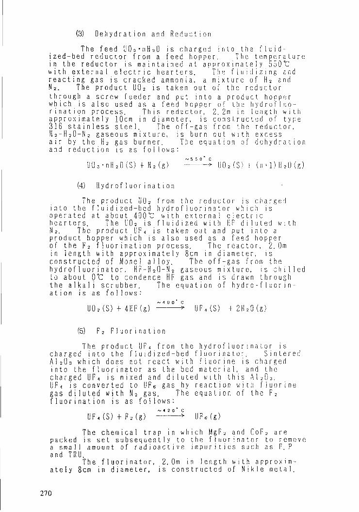
(3) D e h y d r a t i o n and R e d u c t i o nThe feed U 0 3 • n H 2 0 is c h a r g e d i n t o the f l u i d -
ized-bed r e d u c t o r from a feed h o p p e r . The t e m p e r a t u r ein the r e d u c t o r is m a i n t a i n e d at a p p r o x i m a t e l y 550 °Cw i t h e x t e r n a l e l e c t r i c hearters. T h e f i u i d i z i n g a n dr e a c t i n g gas is cracked a m m o n i a , a m i x t u r e of Ha andN 2. The p r o d u c t U0 2 is t a k e n out of the r e d u c t o rt h r o u g h a screw feeder and put i n t o a p r o d u c t h o p p e rw h i c h i s also used as a feed h o p p e r of the h y d r o f i u o -r i n a t i o n process. T h i s r e d u c t o r , 2.2m i n l e n g t h w i t ha p p r o x i m a t e l y 10cm in d i a m e t e r , i s c o n s t r u c t e d o f t y p e316 s t a i n l e s s steel. The o f f - g a s f r o m the r e d u c t o r ,H a - H a O - N a gaseous m i x t u r e , i s b u r n o u t w i t h excessair by the Ha gas b u r n e r . The e q u a t i o n of d e h y d r a t i o nand r e d u c t i o n is as f o l l o w s :
U Ö 3 - n H 2 0 ( S ) + H2 (g) :illl4 U0a (s) f (n-1) H20(g)
(4) H y d r o f l u o r i n a t i o nThe p r o d u c t U0 2 from the r e d a c t o r is charged
i n t o t h e M u i d i z e d - b e d h y d r o f l u o r i n a t o r w h i c h i so p e r a t e d a t about 400°C w i t h e x t e r n a l e l e c t r i chearters. The U 0 a is f l u i d i z e d w i t h H F d i l u t e d w i t hN 2. The p r o d u c t U F « is taken out and put i n t o ap r o d u c t hopper w h i c h is a l s o used as a feed h o p p e rof the F 2 f l u o r i n a t i o n process. The r e a c t o r , 2.0mi n l e n g t h w i t h a p p r o x i m a t e l y 8 c m i n d i a m e t e r , i sconstructed of Monel a l l o y . The off-gas from theh y d r o f l u o r i n a t o r , H F - H 2 Q - N 2 gaseous m i x t u r e , i s c h i l l e dto a b o u t 0°C to condence H F gas and is d r a w n t h r o u g hthe a l k a l i scrubber. The e q u a t i o n of h y d r o - f 1 u o r i n -ation is as follows:
U02(S) 4- 4HF(g) : ^ UF<(S) + 2H2Q(g)
(5) F2 F l u o r i n a t i o nThe p r o d u c t U F < f r o m the h y d r o f l u o r i n a t o r is
charged into the f l u i d i z e d - b e d f l u o r i n a t o r . S i n t e r e dA 1 2 0 3 w h i c h does not react w i t h f l u o r i n e is c h a r g e di n t o t h e f l u o r i n a t o r a s t h e b e d m a t e r i a l , a n d t h echarged U F < is m i x e d and d i l u t e d w i t h t h i s A1 a0a.U F « is converted to UFe gas by r e a c t i o n w i t h f l u o r i n egas d i l u t e d w i t h N 2 gas. The e q u a t i o n of the F 2f l u o r i n a t i o n is as f o l l o w s :
UF<(S) + F2(g) > UF6(g)The c h e m i c a l t r a p in w h i c h M g F 2 and CoF 2 are
packed is set s u b s e q u e n t l y to the f l u o r i n a t o r to r e m o v ea s m a l l amount of r a d i o a c t i v e i m p u r i t i e s such as F. Pand TRU.T h e f l u o r i n a t o r , 2.0m i n l e n g t h w i t h a p p r o x i m -a t e l y 8cm in d i a m e t e r , is c o n s t r u c t e d of N i k l e m e t a l .
270

A f t e r r e a c t i o n , l F 6 gas is c o o l e d and t r a p p e di n t w o c o l d t r a p s i n scries. T h e f i r s t c o l d t r a p i scooled at a b o u t 0 °C and the second at a b o u t -30°C.The off gases from the c o l d traps c o n t a i n a s m a l lq u a n t i t y of UFs and F 2. Those gases, t h e r e f o r e , aret r e a t e d by the N a P c h e m i c a l t r a p , the A l 2 0 j c h e m i c a ltrap, a n d t h e a i k d l i s c i u b b e r t o r e m o v e U F 6 gas, F 2gas, a n d t h e r e s i d u a l g a s i n a s m a l l a m o u n t , respect-i v e l y .
The s o l i d U F s t r a p p e d in the c o l d t r a p s isw a r m e d w i t h hot w d t e r up to a b o u t 8 0 °C to l i q u e f yand the l i q u e f i e d I! F G is put i n t o a 12B c y l i n d e r .
Some n o n - v o l a t i l e f l u o r i d e s r e m a i n i n t h ef l u i d i z e d - b e d t o g e t h e r w i t h A 1 203 and r e m o v e d i n t ot h e a s h r e c e i v e r a t r e g u l a r i n t e r v a l s .
3 . THE RESULTS OF E X P E R I M E N T S
3 . 1 I m p r o v i n g t h e c h e m i c a l r e a c t i v i t i e s(1) H y d r a t ionI t occured a t t i m e s i n t h e o p e r a t i o n t h a t t h e
f i n e powder in the h y d r a t o r aggregates to grow up tothe l a r g e p a r t i c l e s as same as s e v e r a l c e n t i m e t e r si n d i a m e t e r . T o s o l v e t h e p r o b l e m , t h e o p e r a t i n gfactors, w a t e r feed speed, the r a t i o of U03 to w a t e ra n d s t i r r i n g speed, were c h a n g e d , a n d t h e o p t i m a lc o n d i t i o n were d e t e r m i n e d . T h e h y d r a t o r i s o p e r a t i n gs m o o t h l y u n d e r t h e o p t i m a l c o n d i t i o n a t present.
I t w a s i d e n t i f i e d b y means o f x-ray d i f f r a c t i o nt h a t the UOs h y d r a t e p r o d u c e d at room t e m p e r a t u r e h adthe c r y s t a l forms of U 0 3-2H 20 and/or UQ 3-0.8H 20.W h e n the U Q 3 w h i c h had a s u r f a c e area of a p p r o x i m a t e l y0. 5rrf/g was h y d r a t e d , the s u r f a c e area of the UCUh y d r a t e i n c r e a s e d to a p p r o x i m a t e l y 3mVg g r e a t e r t h a nthat of the U03. F i g u r e 2 shows the increase of thesurface area caused by the c h a n g e from UOa to UCUhydrate.
(2) D e h y d r a t i o n and R e d u c t i o nThe fl u i d i zed-bed r e d u c t o r was o p e r a t e d s m o o t h l y
for a long period. The p r o d u c t i o n rate was a p p r o x i -m a t e l y 2. 5kg-li/hr in the c o n t i n u o u s o p e r a t i o n . Ther e a c t i o n r e a c t i v i t y was a l m o s t p e rfect and the 0/Ur a t i o of p r o d u c t 1J02 was a b o u t 2.05. The h y d r o g e ngas u t i l i z a t i o n e f f i c i e n c y was as low as a p p r o x i m a t e l y45%, because the a m o u n t of h y d r o g e n gas s u p p l i e d wast w i c e o f t h e s t o i c h i o m e t r y . T h e e x p e r i m e n t a l c o n d i -t i o n s in the f l u i d i zed-bed r e d u c t o r , the f l u i d i z i n gp r o p e r t i e s a n d p o w d e r p r o p e r t i e s a r e s u m m a r i z e d i nT a b l e I .
271

bo
X
"6
2 3
II Y D R A T I 0 N T I M E ( h r )
F I G . 2 T I M E D E P E N D E N C E O F S U R F A C E A R E A
TABLE. I EXPERIMENTAL CONDITIONS
\-•V
DEHYDRATION& REDUCTION
HYDROFLUOR1NATION
F2 FLÜOR1 NATION
REACTIONTEMP
(t)
550
400
420
FLUIDIZÎNGVELOCITY(en/sec)
15.0
23.0
10.0
INLET GASVOLUME
(Vol/o)
45 (H,)
50 (HF)
30 (F2)
IIOLD-UPTIME INREACTOR(hr)
4
3
0.3
POWDER PROPERTIESSURFACEAREA(rn'/g)
2.90
AVERAGEPOWDER SIZE(Aim)200. 8
BULKDENSITY(g/cc)2.52
u03nH204.49 180.0 3.51
U020.98 197.4 3.01
UF<i
T h e k i n e t i c c u r v e s m e a s u r e d t h e r e l a t i o n b e t w e e nt h e r e d u c t i o n t i m e a n d t h e r e d u c t i o n r a t i o s o f t h eU O s and the U0 3 h y d r a t e s by d i f f e r e n t i a l t h e r m a la n a l y s i s (DTA) are shown in F i g . 3 . As shown in F i g . 3 ,the r e a c t i o n r a t i o s of the U0 3 h y d r a t e s are h i g h e rt h a n that of the U03.
(3) H y d r o f l u o r i n a t i o nT h e f l u i d i z e d - b e d h y d r o f l u o r i n a t o r h a s been
operated w i t h no t r o u b l e s . The p r o d u c t i o n rate wasa p p r o x i m a t e l y 2.3kg-U/hr i n t h e c o n t i n u o u s t r e a t m e n t .The h y d r o f l u o r i n a t i on r e a c t i v i t y was as h i g h as appr-o x i m a t e l y 95%. The h y d r o f l u o r i n e g a s u t i l i z a t i o ne f f i c i e n c y was a p p r o x i m a t e l y 90%. The e x p e r i m e n t a lc o n d i t i o n s are s u m m a r i z e d in T a b l e I .
272

100
90
70
60
50
40
30
20
10
C O N D I T I O NT E M P E R A T U R E 550tI N I E T H 2 V O L 3 0 %
• P R E - H Y O R A T Î O V ( 0 4m' / g )* P O S T - H Y D R A T I O N (3 Om1 / g)A P O S T - H Y D R A T I O V ( 3 5m'/ g )
60 7010 20 30 40 50R E A C T I O N r i M E ( m i n )
FIG 3 T I K E D E P E N D E N C E OF R E D U C T I O N R A T I O 3Y M E A N S 0^ D T A
T h e k i n e t i c c u r v e s m e a s u r e d t h e r e l a t i o n b e t w e e nthe r e a c t i o n t i n e and the r e a c t i o n r a t i o s by DTA areshown in Fig.4. The r e a c t i o n of the UQ 2 d e r i v e d f r o mthe Ü 0 3 h y d r a t e s is r a p i d and c o m p l e t e c o m p a r e d w i t ht h ? t of the U 0 2 p r e p a r e d by the d i r e c t r e d u c t i o n off l u i d i zed-bed lids.
(4) F 2 f l u o r i n a t i o nThe p
u s i n g the UFt h e h y d r o f l uIn the case,as h i g h as at h e p r o d u c t iU F « w h i c h w al u o r i n a t i o nc o n d i t i o n s aThe re f f i c i e n c y aare h i g h e r tat 420 °C.quant i ty ofthan t h a t i n
r o d u c i i o n r a t4 w h i c h was po r i n a t i o n r a tt h e f l u o r i n e
p p r o x i m a t e 1 yon rate of ths p r o d u c e d wir a t i o was undre sunimar i zedeact ion ratet 370 °C of t hhan those ofT h i s fact mayUQ 2 in the UFU F 4 p r o d u c e d
e of the F 2 f l u o r i n a t i o nr o d u c e d w i t h o v e r 90% of10 was a p p r o x i m a t e l y 2. Ikg-u/hr.u t i l i z a t i o n e f f i c i e n c y w a s
99% at 420°C. H o w e v e r ,e F 2 f l u o r i n a t i o n u s i n g theth u n d e r 90% of the h y d r o f -er 80%. Tne e x p e r i m e n t a li n Tab le I .a n d f l u o r i n a t i o n u t i l i z a t i o ne U F 4 p r o d u c e d by PNC-processthe UF 4 p r o d u c e d by CTF-ÏÏ,m a i n l y b e due to the s m a l l e r4 p r o d u c e d by PN'C-processby CTF-n .
273

100
90
60
50
40
30
20
10
C O N D I T I O NT E M P E R A T U R E 400tINLET HF VOL 30%
• P R E - I I Y D R A T I O N (0 4m'/ g )* POST-!l': DRAT ION (3 UmV g)A POS T - H Y D R A T I O N (3 5m1 / g )
10 20 30 4Û 50REACTION T[WE (-'n)
60 70
FiG 4 T I M E D E P E N D E N C E OF HYOROHUOR ! KA^I (LN P4TIO BY MEANS OF D T A
T h e k i n e t i c c u r v e s measured t h e r et h e r e a c t i o n t i m e a n d t h e r e a c t i o n r a t i o sshown in Fig. 5.
at ion betweenby D T A are
M a i n results o f t h e a b o v e e x p e r i m e n t s , d e h y d r -a t i o n and r e d u c t i o n , h y d r o f l u o r i n a t i o n and P 2 f l u o r i -n a t i o n , a r e shown i n T a b l e U .
3.2 i n v e s t i g a t eof the radng the b e h a v i o r s ando a c t i v e i m p u r i t i e s .
the e l i m i n a 1 1 n ;
A s m a l l a m o u n t o f r a d i o a c t i v e i m p u r i t i e sc o n t a i n e d in reprocessed DG3 such as F. P and T R Ub e h a v e w i t h u r a n i u m to the b F 4 form in s p i t e o ( thechanges o f t h e u r a n i u m f o r m s i n d r y process. Mostof these i m p u r i t i e s ctiange to these f l u o r i d e s in thef l u i d i zed-bed f l u o r i n a t o r . Some of these f l u o r i d e sh a v i n g t h e lower b o i l i n g p o i n t t e m p e r a t u r e than thatof F 2 f l u o r i n a t i o n t e m p e r a t u r e w o u l d b e h a v e w i t h ü P 6.However, i n p r a c t i c a l o p e r a t i o n , t h e w h o l e q u a n t i t yo f these f l u o r i d e s i n a f l u i d i z e d - b e d f l u o r i n a t o r ,such as R u F s, SbFs, N p F s and PuF s, does not a l w a y sbehave w i t h UF G. I t i s i n f e r r e d that these f l u o r i d e s
274

100 -
e—•<
ce.CD
Ü F , P R O D U C E D I N C T F - Ï ÏU F , P R O D U C E D B Y
P N C - P R O C E S :
C O N D I T I O NT E M P E R A T U R E 400"CI N L E T F j V O L 3 0 %
10 20 30 40 50 60 70
R E A C T I O N T Ï M E ( n i n )
F I G , 5 T I M E D E P E N D E N C E O F F 2 F L U O R I N A T I O N R A T I O B ï M E A N S O F D . T . A
TABLE. Ü RESULTS OF C O N T I N U O U S TREATMENT
"\\
DEHYDRATION& REDUCTION
HYDRGFLUORINATIDN
F2 FLUORINAT1DN
CHEMICAL REACTIVITY(96) _
100
95
100
OPERATING RATE(kg-u/hr)
2.5
2.3
2.1
GAS UTILIZATIONEFFICIENCY(%)
44 (Hj)
90 (HF)
99 (F2)
275

w o u l d rema in in a f l u o rr e d u c t e d to these lowerof PuF 6, as an e x a m p l e ,
n a t o r as a s o l i dva 1 ency states,is as f o i l ows:
PuFs(g) UR«(S) PuF<(S)
due to beT h e b e h a v
UF6(g)
or
f l u o r i d e s g a s released from t h e f l u o r i n a t o rt h e subsequent c h e m i c a l t r a p packed w i t h
C e F < ,
Theis trapped byM g F 2 and CoF2.The non v o l a t i l e f l u o r i d e s , such as, S r F zA m F 3 and CniFo, a l m o s t r e m a i n in the f l u i d i zed-bedf l u o r i n a t o r , a n d i s r e m o v e d t o g e t h e r w i t h t h e b e dm a t e r i a l , A l a O a , as a waste at r e g u l a r i n t e r v a l s .
W e h a v e i n v e s t i g a t e d m a i n l y t h e b e h a v i o r s o fPu and Np in p2 f l u o r i n a t i o n . The r e s u l t s are asf o l l o w s :
(1) In s p i t e of the /er y s m a l l q u a n t i t y of Pui n U O o , P u i n Ü 0 3 i s s u f f i c i e n t l y s e p a r a t e dfrom UFs by the f l u id ized-bed f l u o r i n a t o rand the c h e m i c a l trap. The amount of Puc o n t a i n i n g in UFs is u n d e r 50 dpm/g-U.The v a l u e is less t h a n the l i m i t e d v a l u e o fthe lowest d e t e c t i o n of a l p h a c o u n t i n ga n a l y s i s .
(2) The b e h a v i o r of Np is somewhat u n c e r t a i n ,because of the large e r r o r of a n a l y s i s .However, i n s p i t e o f t h e l a r g e e r r o r , i tw o u l d be c e r t a i n that the r e m o v a l r a t i o ofN p by the c h e m i c a l trap is a l i t t l e lov, ert h a n the v a l u e in the l i t e r a t u r e [ 2 ] .
(3) Because the a m o u n t s of F. P and TRU c o n t a i n i n ,i n U O s a r e v e r y s m a l l q u a n t i t i e s , these b e -h a v i o r s a r e u n c e r t a i n . These c o n t e n t s i nU F 6 are less t h a n these v a l u e s in the spec-i f i c a t i o n o f t h e u r a n i u m e n r i c h m e n t p i l o tp l a n t in PNC. The c h e m i c a l data of repre-s e n t a t i v e s a m p l e a n d t h e s p e c i f i c a t i o n a r eshown in T a b l e DI .
TABLE I ANALYSIS RESULTS AND SPECIFICATIONS OF F. P AND TRU
ITEM
F. P
TRÜ
ANALYSIS RESULTS
Zr 95 < 10- 3Nb 95 < lu'3Rul03 < 1Q-3Rul06 < IO-2Csl37 < IO-3Cel44 < 1Ö'3
TOTAL < 0 OlSjuCi/g-UNp < 150Pu < 50Am < 100Cm < 50
TOTAl < 350dpm/g-lj
SPECIFICATIONS
The total activtyof the maximum gammarays emitted from95Zr, 3SNb, ""Ru,'"Ru, 131Cs, and"4Ce is0 05j"Ci/g-U
The total activityof the maximum alpharays emitted fromNp, Pu, Am, and Cm is1500dpm/g-U
276

4 . C O N C L U S I O NT h e f u n d a m e n t a l d a t a a n d t e c h n i c a l know-hows
a r e b e i n g o b t a i n e d b y t h e CTF-ÏÏ o p e r a t i o n , a n d t h ei n i t i a l object i s b e i n g n e a r l y reached.T h e f a c i l i t y w o u l d b e scaled u p i n t h e nearf u t u r e , and after the o p e r a t i o n of the e x p a n d e df a c i l i t y d u r i n g a c e r t a i n p e r i o d , the p l a n o f ac o m m e r c i a l c o n v e r s i o n p l a n t w o u l d b e s t a r t e d .
R E F E R E N C E S
[ 1 ] N A K A I . T . , S A I T O . N . , 1 S H 1 M O R ! , T . , " P l u t o n i u m " ,C o m p l e t e b o o k s o f I n o r g a n i c C h e m i s t r y , X V Ï Ï - 2( 1 9 6 7 ) 1 9 5 .
[ 2 ] W . R . G o l l i h e r , e t a l , U . S . P a t e n t , 3 , 615, 2 6 7 ( 1 9 7 1 )

PANEL DISCUSSION
(Summarized by H. Page, U.K.)
In his opening statement to the Technical Committee Meeting onAdvances in Uranium Refining and Conversion, Mr. J.L. Zhu, Director ofthe Division of Nuclear Fuel Cycle, remarked that the contents of thepapers scheduled for presentation indicated that, there had beenconsiderable innovation at the front end of the nuclear fuel cycle in anincreasing number of Member States since the previous conference in Parisin June 1979, despite the recent slowing down of nuclear power plantconstruction. By the end of the conference it had become quite evidentto all participants that this was indeed the case.
While it can be seen that the major uranium supply/processingcountries continue to refine and modify their traditional conversionprocesses in response to changes in market demand, feed and productspecification, environmental constraints, regulatory practices etc.,several other interesting developments have recently emerged.
Self sufficiency in fuel production is evidently one of the recenttrends in the nuclear fuel cycle policy of an increasing number of MemberStates. This accounts for the launching of the many new laboratory andpilot scale projects described at the conference and explains theextensive research and development effort aimed at production of uraniumfuel cycle intermediates, such as fluorides, metal and oxides, suitablefor processing to nuclear fuel by Member States for their home basednuclear reactors. In a growing number of cases Member States are movinginto nuclear fuel cycles which do not involve uranium enrichment.
An important issue, not only to the front end of the nuclear fuelcycle but to the cycle as a whole, concerns the fate of the uranium andplutonium recovered from the reprocessing of irradiated fuel. MemberStates without indigenous uranium and concerned about the economics offuture" fuel cycles based on "natural" uranium are showing a great deal ofinterest in recycling reprocessed irradiated uranium (REPU) back into thefuel cycle either in routes involving enrichment or as mixeduranium/plutonium oxide fuels (MOX).
279

A further development with potential for significant impact ontraditional uranium conversion technology by the middle of the nextdecade is atomic vapour laser isotope separation (AVLIS) and existingconverters accustomed to providing uranium hexafluoride as the feed toenrichment facilities will need to keep in close touch with the progressof this technology which requires a feed of uranium metal.
However, while the technical options for uranium refining andconversion differ from country to country depending on criteria such asfor example:
i) the types of nuclear reactor systems involved;ii) the availability of natural uranium or other nuclear fuel
resources
there remain, nevertheless, certain common features of the refining andconversion processes which are relevant to the industry as a whole andwhich merit inclusion in the agendas of future meetings of the TechnicalCommittee.
In addition to future developments in the principal conversionprocess technologies, examples of issues of common interest identified asappropriate for future consideraton include:
1. Technology for refinery raffinate treatment and reagent recycleaimed at process economy and reduction of environmental impact;
2. The influence of factors such as equipment design and operatingparameters on scale-up from laboratory to pilot plant to industrial scale;
3. The production, characterisation and quality control of nuclear fuelprecursors such as uranium dioxide, in relation to the subsequentperformance of the nuclear fuel;
4. Provision of opportunity for coordinated discussion, involving bothfregulators and operators on the methodology of the authorisation and
control of radioactive and toxic effluent from uranium refining andconversion facilities;
280

5. The recycling of uranium recovered from the reprocessing ofirradiated oxide fuels.
Already a number of utilities have contracted for the reprocessingof oxide fuels and significant quantities of recovered uranium willbecome available for reuse at the beginning of the 1990's. Factorsinfluencing decisions regarding recycling or storage of this material ofinterest to existing converters will include:
i. The evaluation of existing experience involving reprocesseduranium in:
a. conversion to uranium hexafluoride (UF )o
b. enrichment of UF.6
c. reconversion of UF, and fuel fabrication6
d. irradiation of fuel containing recycled uranium
ii. The prediction of the total quantities of and specification forthe uranium which will arise from reprocessing operations. The
232levels of transuranic elements, fission products, U andits daughters will be important in this context.
iii. The definition of feed and product specification for each stagein the sequence, reprocessed uranium to finished fuel.
iv. An assessment of the consequences of the foregoing on existingplants, processes and practices.
v. An evaluation of the comparative costs of fuel prepared fromnatural and recycled uranium.
In summary, there was general agreement amongst all participantsthat the Technical Committee Meeting had been a valuable forum forcooperation and information exchange between the Member States on therapidly changing technologies at the front end of the nuclear fuel cycle.
28!

However, in contrast to the historical situation where the majoruranium converters interfaced only with uranium suppliers and uraniumenrichers the emergence of reprocessed uranium as a new factor in thefuel cycle had highlighted the need for a forum involving reprocessor,convertor, enricher, fuel fabricator and reactor operator to giveeffective consideration to the features of the closed fuel cycle whichnow have potential for impacting on each participant. The existingTechnical Committee on uranium refining and conversion was not anappropriate forum for this purpose sad the Division of Nuclear Fuel Cyclewas invited to consider establishing such a forum.
The 1986 Technical Committee fleeting closed with a recommendationthat the rapid rate of innovation in the fields of refining, conversionand nuclear fuel intermediate production technology would justify theconvening of the next meeting in 3 years time in the Autumn of 1989.
282

LIST OF PARTICIPANTS
ALGERIA
Boualia, A.
ARGENTINA
Vercellone, Jose A.
AUSTRALIA
Bull, P.S.
BELGIUM
De Regge, P.P.M.H.
BRAZIL
Abrao, A.
CANADAAshbrook, A„W.
Didyk, J.P.
THE PEOPLE'S REPUBLIC OF CHINA
Chao, Lebao
Zhu, Chang-En
Commissariat aux Energies Nouvelles2, Boulevard Frantz FanonAlger, Algeria
Jose Rogue Fune<- 1593Cerro de las RosasCordoba 5,009argentin».
Counsellor, Atomic EnergyThe Embassy in AustriaMattiellistrasse 2-4/IIIA-1G40 Vienna
Studiecentrum voor KernenergiaBoeretang, 200B-2400 Mol, Belgium
ïnstit'ito de PesquisasEnergéticas e NuclearesCaiza Postal 11.049-PinheirosCidade Universitaria05508 - Sao Paulo - SP, Brazil
Eldorado Resources Ltd.400-255 Albert St.Ottawa, Ontario,KIP 6A9 CanadaAtomic Energy Control Board ofCanadaP.O. Box 1046 OttawaK1P5S9 Canada
Bureau of Nuclear FuelsP.O. Box 2102-10BeijingThe People's Republic of ChinaBeijing Research Instituteof Uranium Ore ProcessingP.O. Box 234Beijing,The People's Republic of China
283

ARAB REPUBLIC OF EGYPT
El-Hazek, N.M.T.
FRANCE
Rigo, L.
Faron, R.
Nuclear Materials CorporationEl Maadi Kattamiya RoadMaadi Post Office Box 530Cairo, Arab Republic of Egypt
Compagnie Générale des MatièresNucléaires (COGEMA)Service des Usines et de la Compta-
bilité des Matières de Base2, Rue Paul Dautier, B.P. No. 478141 Velizy Villacoublay, FranceCOMURHEXTour ManhattanCEDEX 21-92087Paris La Défense, France
FEDERAL REPUBLIC OF GERMANY
Becker, B.
Leyser, E.
Wehner, E.L.
Sondermann, T.
INDIAKansal, V.R.
ISLAMIC REPUBLIC OF IRAN
Gharib, A.G.
Reaktor-Brennelement Union GmbHPostfach 11 00 60D-6450 Hanau 11Germany, F.R.Deutsche Gesellschaft fürWiederaufarbeitung vonKernbrennstoffen mbH (DWK)Hamburger Allee 4D-3000 Hannover lGermany, F.R.NUKEM GmbHRodenbacher Chaussee 6Postfach 11 OO 80D-6450 Hanau 11Federal Republic of GermanyReaktor Brennelement Union GmbHPostfach 110060D-6450 Hanau 11Federal Republic of Germany
BHABHA Atomic Research CenterTrombay, Bombay - 40O085India
Atomic Energy Organization of IranFuel Department of AEOIP.O. Box 11365-8486Teheran, Iran
284

Kamali, J.
IRAQ
Abdul Fatah, A.M.A.
JAPAN
Mochiji, T.
Atomic Energy Organization of IranEsfahan Nuclear Technology CenterP.O. Box 81465/1589Esfahan, IranP.O. Box 11365-8486Teheran, Iran
Department of Chemical EngineeringCollege of EngineeringBaghdad UniversityJadriya, Baghdad, Iraq
Milling and Ore Processing DivisionNingyo-Toge WorksPower Reactor and Nuclear FuelDevelopment CorporationKamisaibara-muraTomata-gunOkayama-ken708-06 Japan
KOREA. Republic ofChang, I.S.
PAKISTAN
Shabbir, M.
SOUTH AFRICA
Jackson, A.G.M.
Ponelis, A.A.
Roux, A.J.A.
Korea Advanced EnergyResearch InstituteP.O. Box, Daeduk-DanjiChoong-NamRepublic of Korea 300-31
Pakistan Atomic Energy Commission(PAEC)P.O. Box 1114Islamabad, Pakistan
Atomic Energy Corporation ofSouth Africa LimitedP.O. Box 4587Pretoria 0001South Africa
Atomic Energy Corporation ofSouth Africa LimitedP.O. Box 4587Pretoria OO01South AfricaAtomic Energy Corporation ofSouth Africa LimitedP.O. Box 4587Pretoria OO01South Africa
285

SOUTH AFRICA (cont.)
Scholtz, T.E.
Tiltmann, D.E.
Venter, C.J.H.
SWEDENLindholm, H.I.
TURKEY
Ipekoglu, B.
U.K.Bleasdale, P.A.
Labaton, V.Y.
Page, H.
Todd, R.
Atomic Energy Corporation ofSouth Africa, LimitedP.O. Box 4587Pretoria 0001South AfricaAtomic Energy Corporation ofSouth Africa LimitedPrivate Bag X256Pretoria 0001South Africa
Atomic Energy Corporation ofSouth Africa LimitedP.O. Box 4587Pretoria 0001South Africa
Swedish Nuclear Fuel and WasteManagement Co.Box 5864S-102 48 Stockholm, Sweden
Cefcmece Nuclear Research andTraining CenterP.O. Box No. 1 HavaalaniIstambul, Turkey
Ministry of DefenceMR (NUC) 1Building 10 C35The MearingsBurghfieldNR. Reading RG3 3RP, U.K.
British Nuclear Fuels picFleming HouseRisley, WarringtonCheshire, WA3 6AS, U.K.
BNFL (British Nuclear Fuels pic)Springfields WorksSalwick, PrestonLancashire PR4 OKJ, U.K.Nuclear Installation InspectorateSt. Peter's HouseBalliol RoadBootle, Merseyside, L20 3LZU.K.
286

Webster, R. K. Authority FuelProcessing Directorate (UKAEA)B 10, AERE HARWELLOXON 0X11 ORA, U.K.
YUGOSLAVIA
Tolic, A. Institute for NuclearTechnology and Other MineralRaw MaterialsBeograd, Yugoslavia
ORGANIZATION
INTERNATIONAL ATOMIC ENERGY AGENCY (IAEA)
Ajuria, S. Division of Nuclear Fuel CycleRojas, J.L. Division of Nuclear Fuel CycleUgajin, M. (Scientific Secretary) Division of Nuclear Fuel Cycle
287