ada operations contact info
TRANSCRIPT
Intro
ADA Operations Contact Info
1
Todd Grugel ph: 651-366-3531 email: [email protected]
Joe Zilka ph: 651-366-3311 email: [email protected]
Harvey Unruh ph: 651-216-2912 email: [email protected]
http://www.dot.state.mn.us/ada/construction.html
Curb Ramp Construction
2017
MnDOT ADA Training
Module I

3
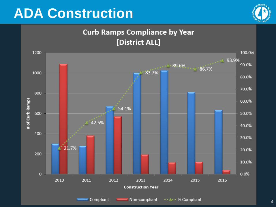
ADA Construction
Construction Lessons Learned
4
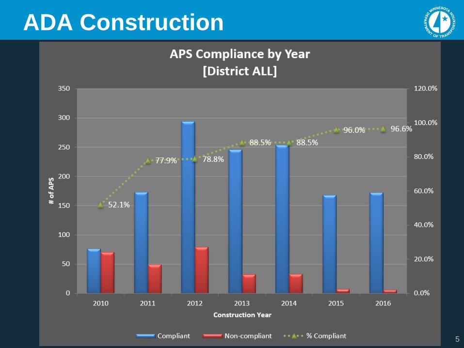
ADA Construction
5
ADA Construction
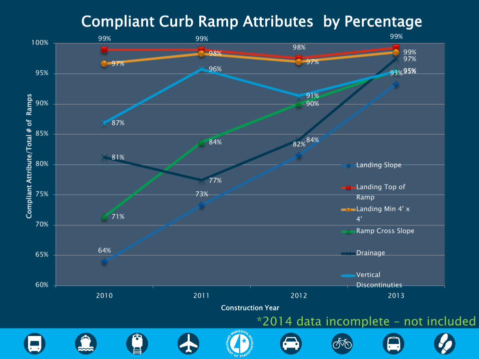
64%
73%
82%
93%
99% 99%
98%
99%
97%
98%
97%
99%
71%
84%
90%
95%
81%
77%
84%
97%
87%
96%
91%
95%
60%
65%
70%
75%
80%
85%
90%
95%
100%
2010 2011 2012 2013
Com
pliant
Att
ribute
/T
ota
l #
of
Ram
ps
Construction Year
Compliant Curb Ramp Attributes by Percentage
Landing Slope
Landing Top of
Ramp
Landing Min 4' x
4'
Ramp Cross Slope
Drainage
Vertical
Discontinuties
*2014 data incomplete – not included
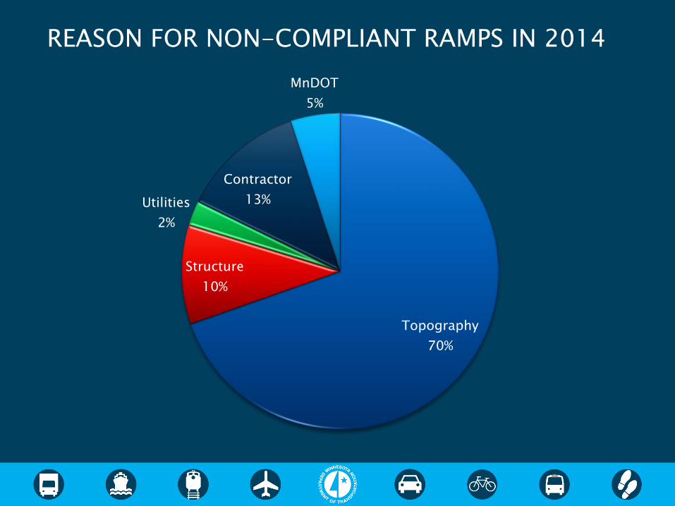
Topography
70%
Structure
10%
Utilities
2%
Contractor
13%
MnDOT
5%
REASON FOR NON-COMPLIANT RAMPS IN 2014
8
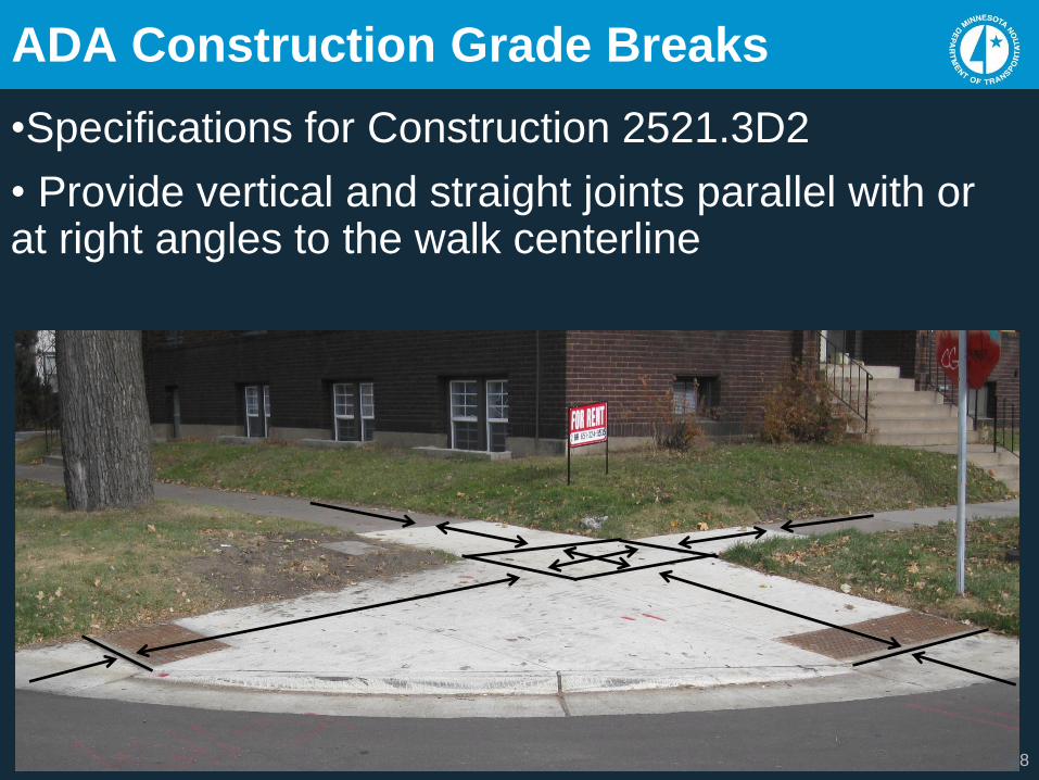
ADA Construction Grade Breaks
•Specifications for Construction 2521.3D2
• Provide vertical and straight joints parallel with or at right angles to the walk centerline
9
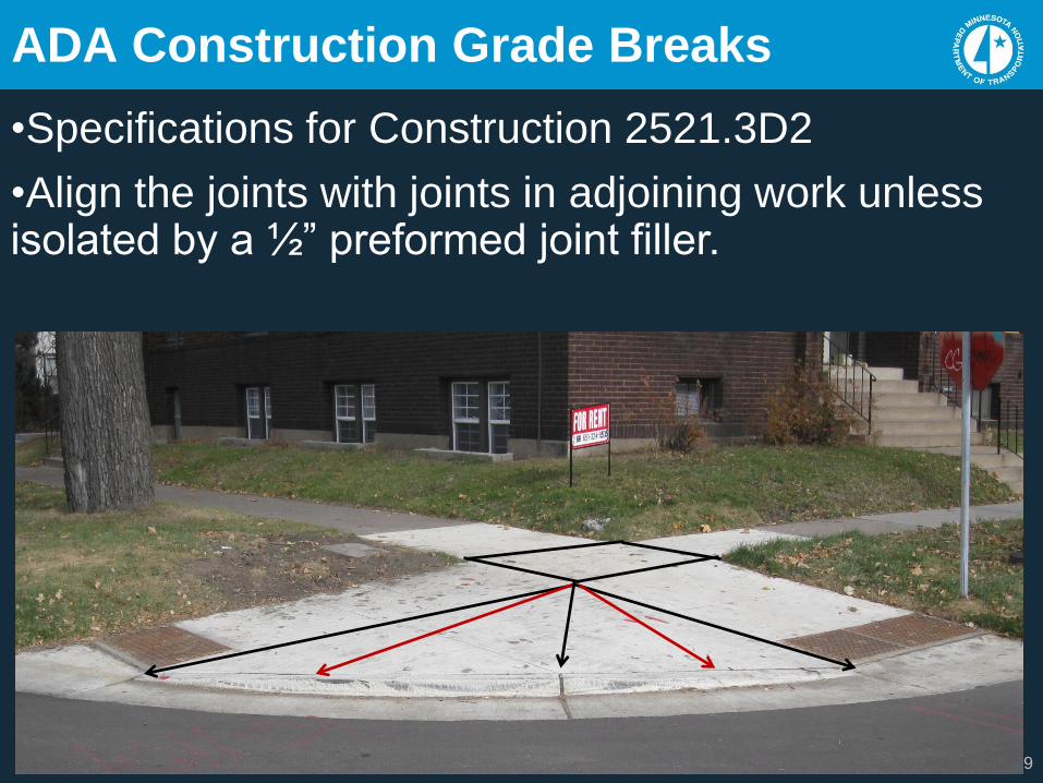
ADA Construction Grade Breaks
•Specifications for Construction 2521.3D2
•Align the joints with joints in adjoining work unless isolated by a ½” preformed joint filler.

10
ADA Construction Grade Breaks
Exceeds 3/16” max
Design grade break in front of PB
Contraction joints shall be constructed along all grade breaks in the PAR ( See Notes Standard Plans sheets 1 & 2 )
11
ADA Construction Grade Breaks
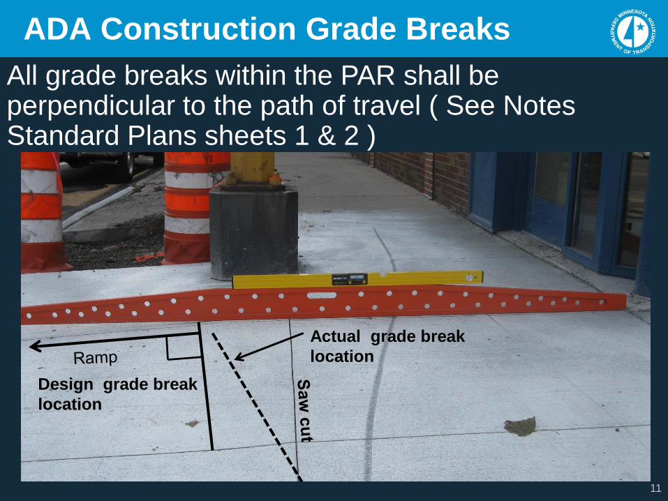
All grade breaks within the PAR shall be perpendicular to the path of travel ( See Notes Standard Plans sheets 1 & 2 )
Actual grade break
location
Design grade break
location

12
ADA Construction Grade Breaks
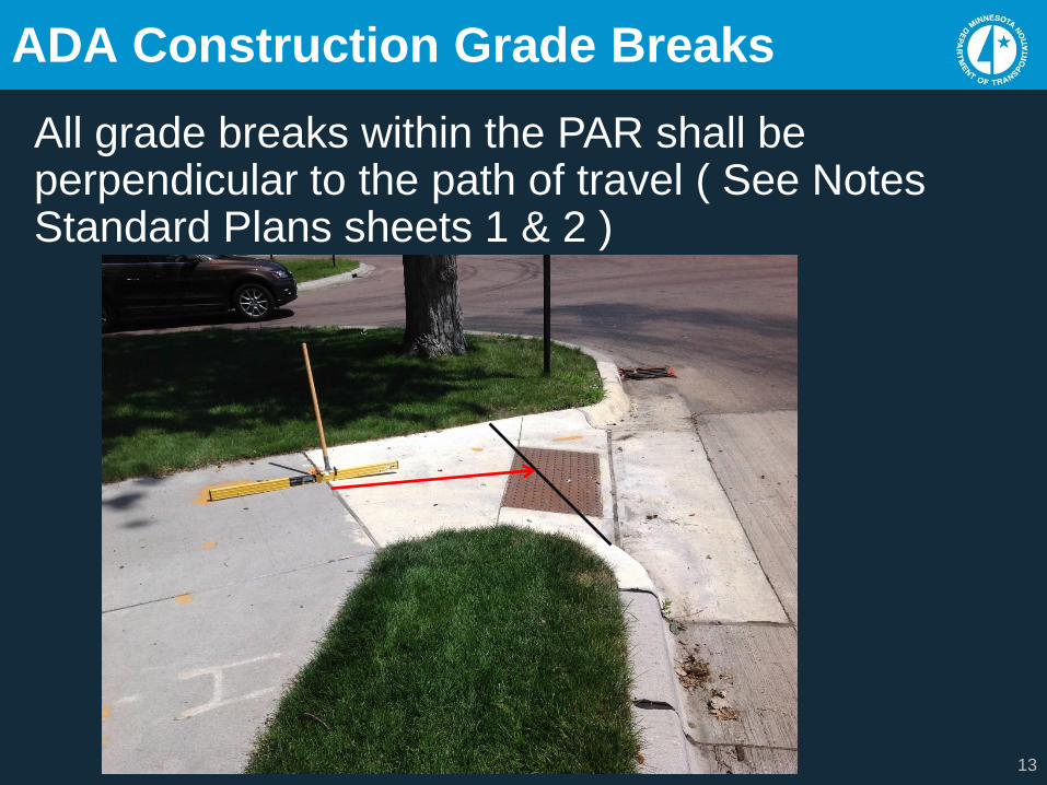
All grade breaks within the PAR shall be perpendicular to the path of travel ( See Notes Standard Plans sheets 1 & 2 )
13
ADA Construction Grade Breaks
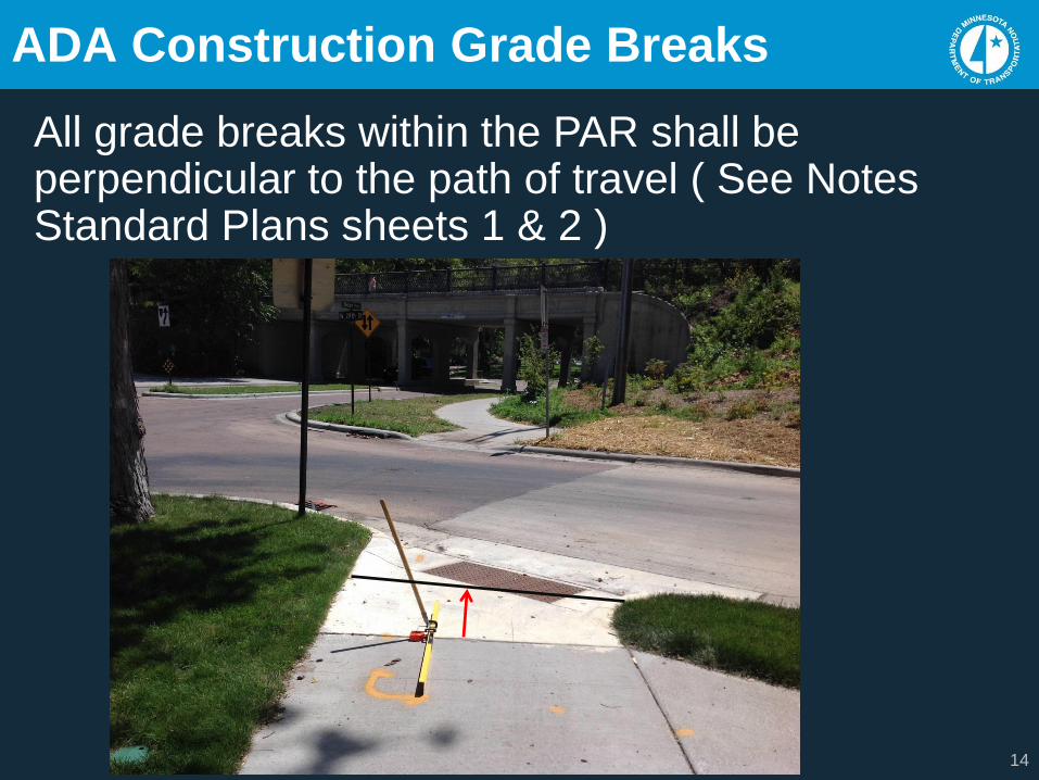
All grade breaks within the PAR shall be perpendicular to the path of travel ( See Notes Standard Plans sheets 1 & 2 )
14
ADA Construction Grade Breaks
All grade breaks within the PAR shall be perpendicular to the path of travel ( See Notes Standard Plans sheets 1 & 2 )
15
ADA Construction Grade Breaks
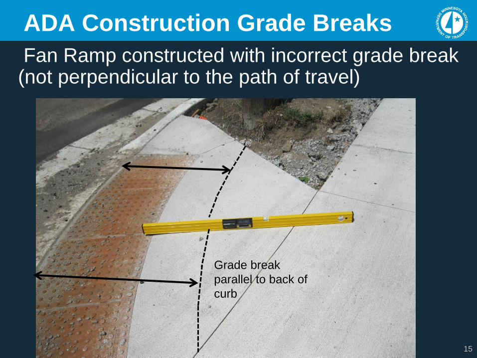
Fan Ramp constructed with incorrect grade break (not perpendicular to the path of travel)
Grade break
parallel to back of
curb
16
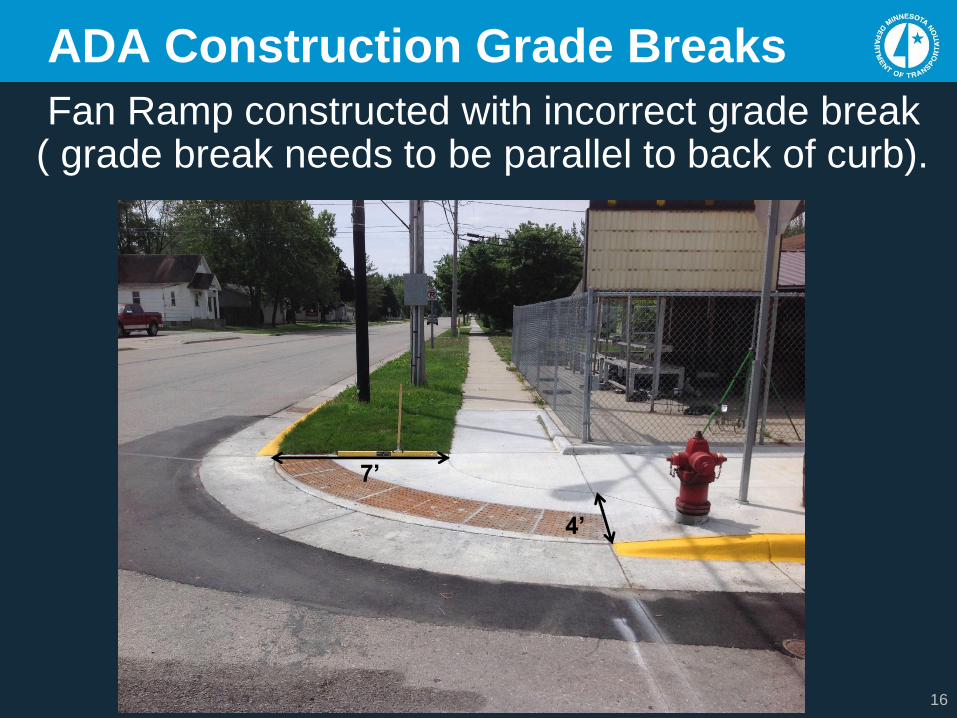
ADA Construction Grade Breaks
Fan Ramp constructed with incorrect grade break ( grade break needs to be parallel to back of curb).
7’
4’
17
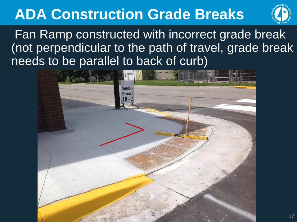
ADA Construction Grade Breaks
Fan Ramp constructed with incorrect grade break (not perpendicular to the path of travel, grade break needs to be parallel to back of curb)
18
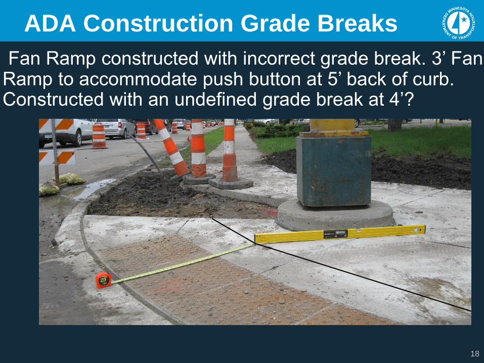
ADA Construction Grade Breaks
Fan Ramp constructed with incorrect grade break. 3’ Fan Ramp to accommodate push button at 5’ back of curb. Constructed with an undefined grade break at 4’?
19
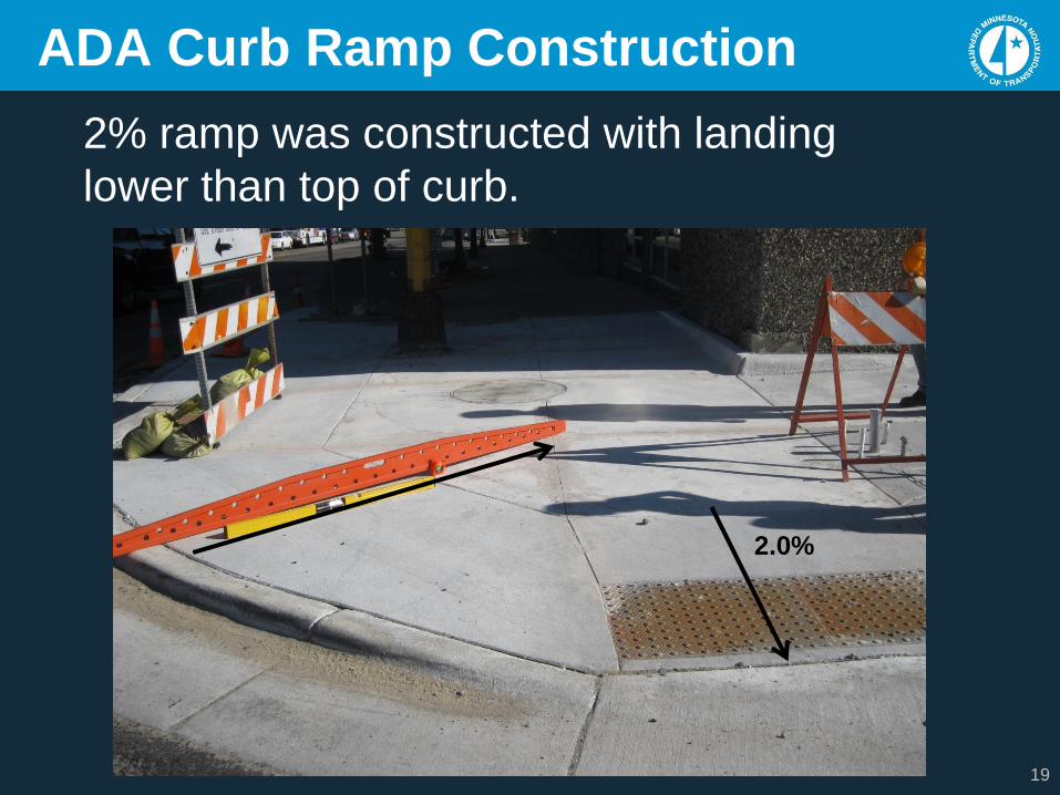
ADA Curb Ramp Construction
2% ramp was constructed with landing
lower than top of curb.
2.0%
20
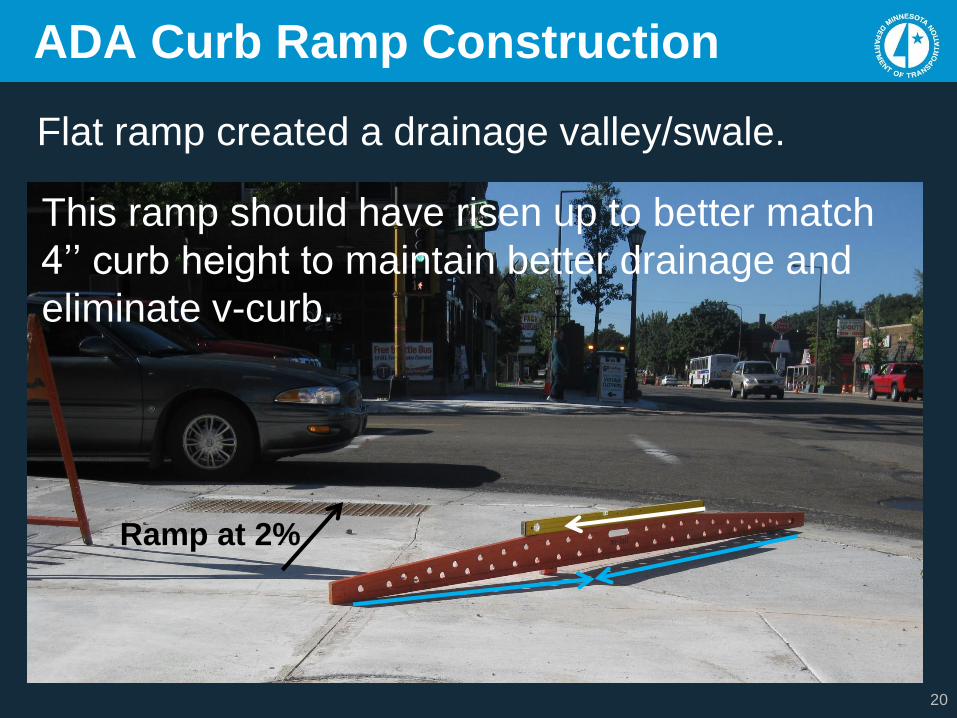
ADA Curb Ramp Construction
Ramp at 2%
Flat ramp created a drainage valley/swale.
This ramp should have risen up to better match
4’’ curb height to maintain better drainage and
eliminate v-curb.
21
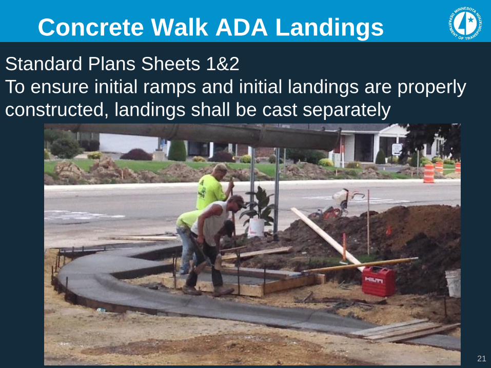
Concrete Walk ADA Landings
Standard Plans Sheets 1&2
To ensure initial ramps and initial landings are properly
constructed, landings shall be cast separately
22
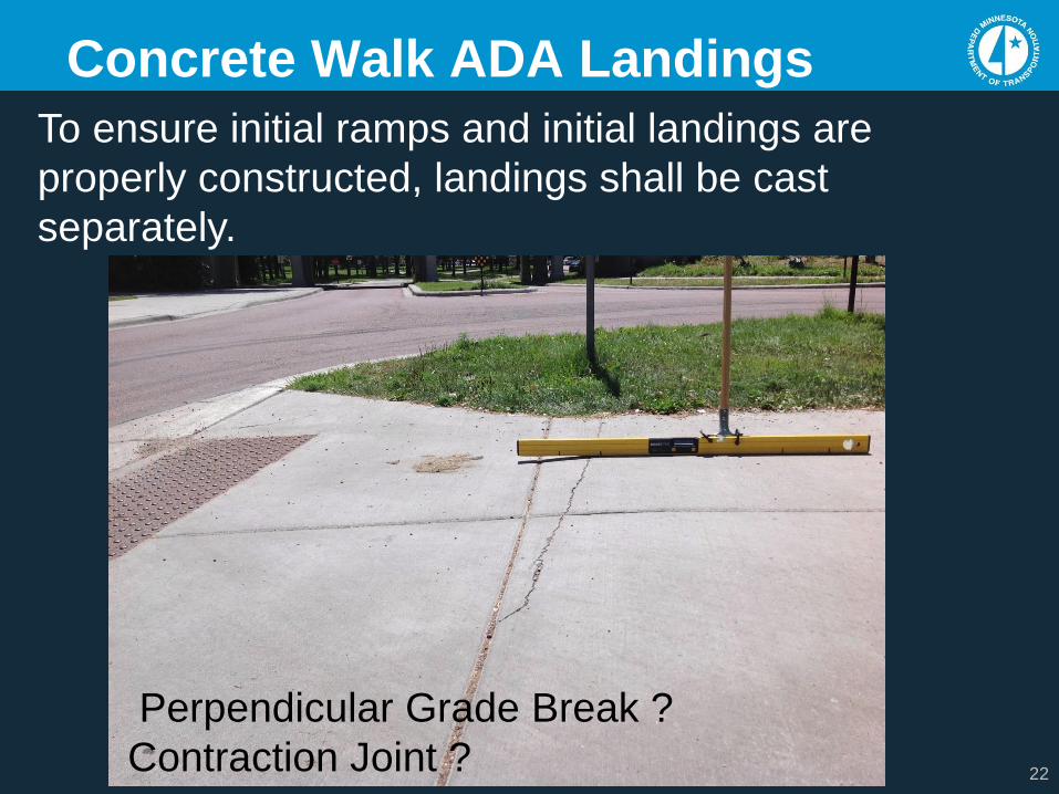
Concrete Walk ADA Landings
To ensure initial ramps and initial landings are
properly constructed, landings shall be cast
separately.
Perpendicular Grade Break ?
Contraction Joint ?
23
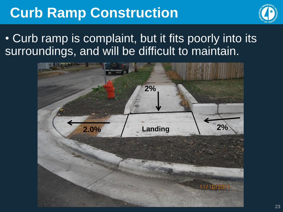
Curb Ramp Construction
• Curb ramp is complaint, but it fits poorly into its surroundings, and will be difficult to maintain.
2%
Landing2.0% 2%
24
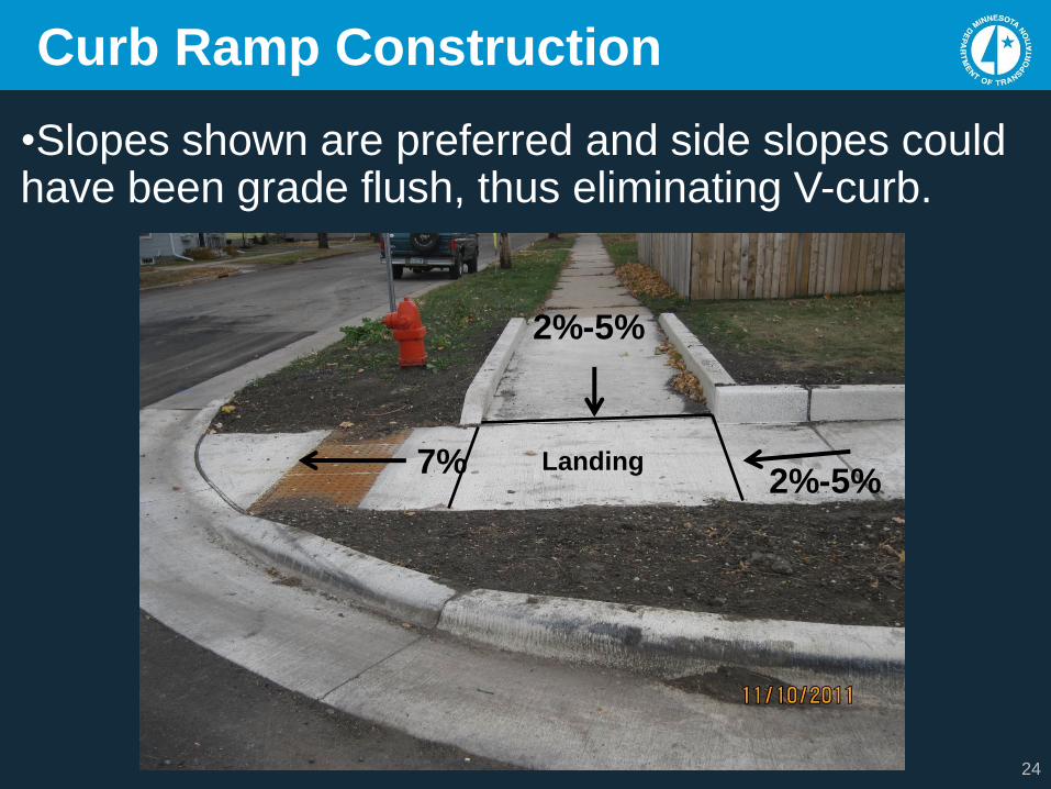
Curb Ramp Construction
•Slopes shown are preferred and side slopes could have been grade flush, thus eliminating V-curb.
Landing7%
2%-5%
2%-5%
25
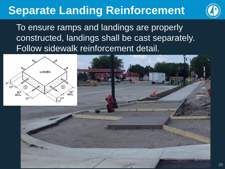
Separate Landing Reinforcement
To ensure ramps and landings are properly
constructed, landings shall be cast separately.
Follow sidewalk reinforcement detail.
26
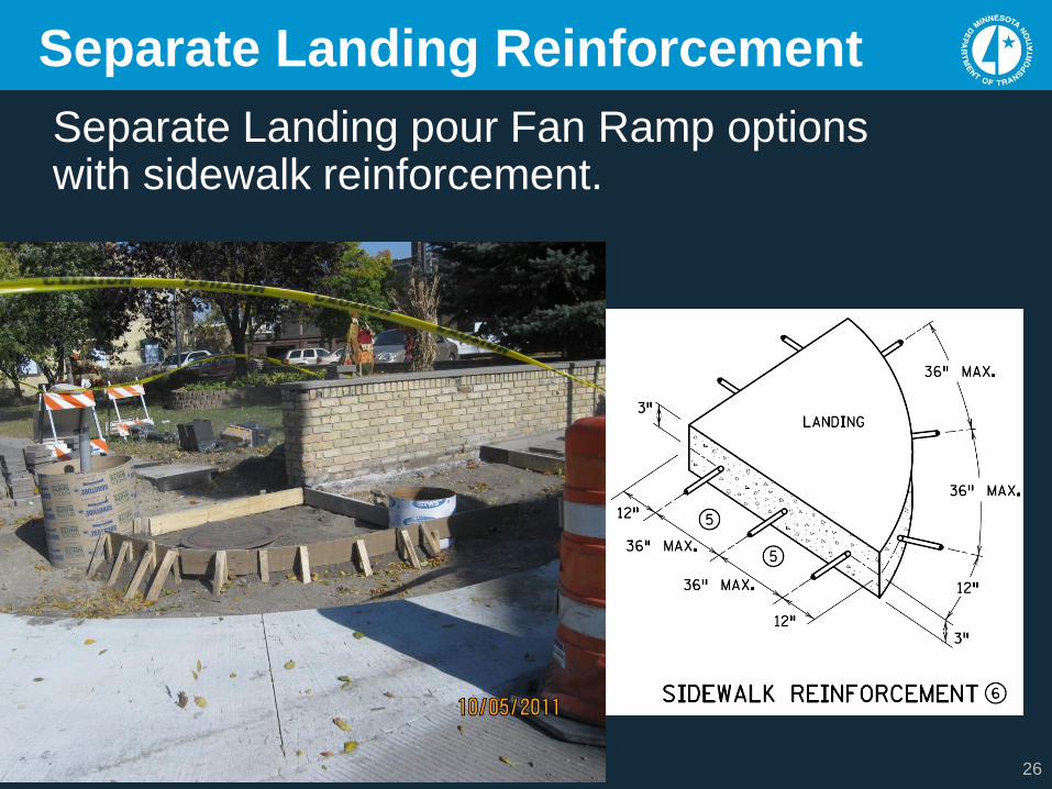
Separate Landing Reinforcement
Separate Landing pour Fan Ramp options with sidewalk reinforcement.
Standard Plans 2017
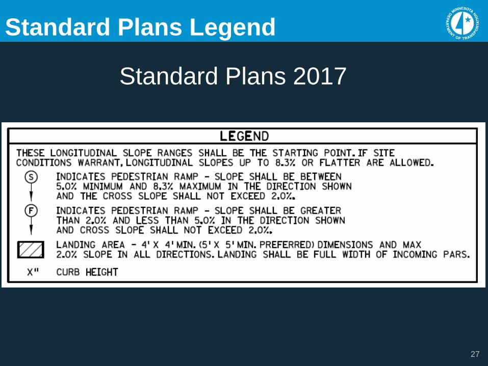
Standard Plans Legend
27
28
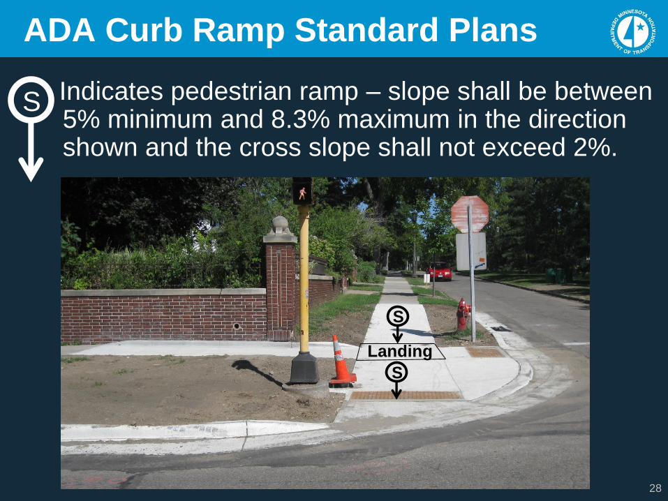
ADA Curb Ramp Standard Plans
Indicates pedestrian ramp – slope shall be between 5% minimum and 8.3% maximum in the direction shown and the cross slope shall not exceed 2%.
Landing
S
S
S
29
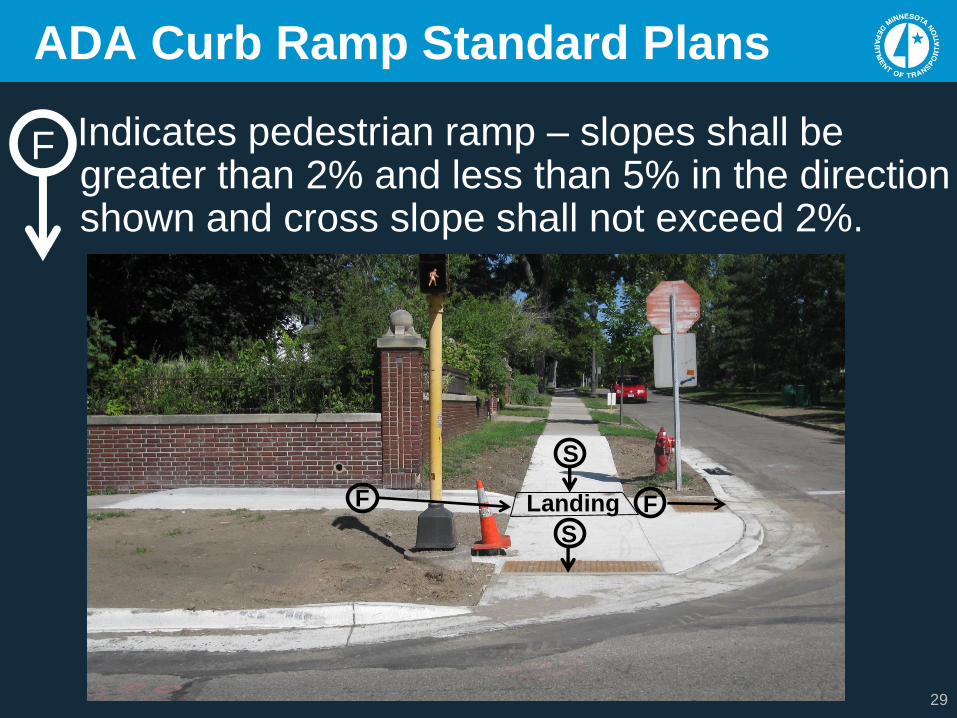
ADA Curb Ramp Standard Plans
Indicates pedestrian ramp – slopes shall be greater than 2% and less than 5% in the direction shown and cross slope shall not exceed 2%.
LandingF F
F
S
S
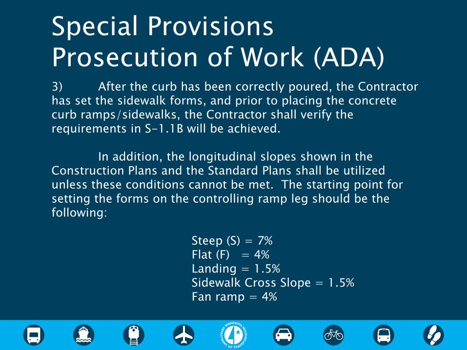
3) After the curb has been correctly poured, the Contractor has set the sidewalk forms, and prior to placing the concrete curb ramps/sidewalks, the Contractor shall verify the requirements in S-1.1B will be achieved.
In addition, the longitudinal slopes shown in the Construction Plans and the Standard Plans shall be utilized unless these conditions cannot be met. The starting point for setting the forms on the controlling ramp leg should be the following:
Steep (S) = 7%Flat (F) = 4%Landing = 1.5%Sidewalk Cross Slope = 1.5%Fan ramp = 4%
Special Provisions Prosecution of Work (ADA)
31
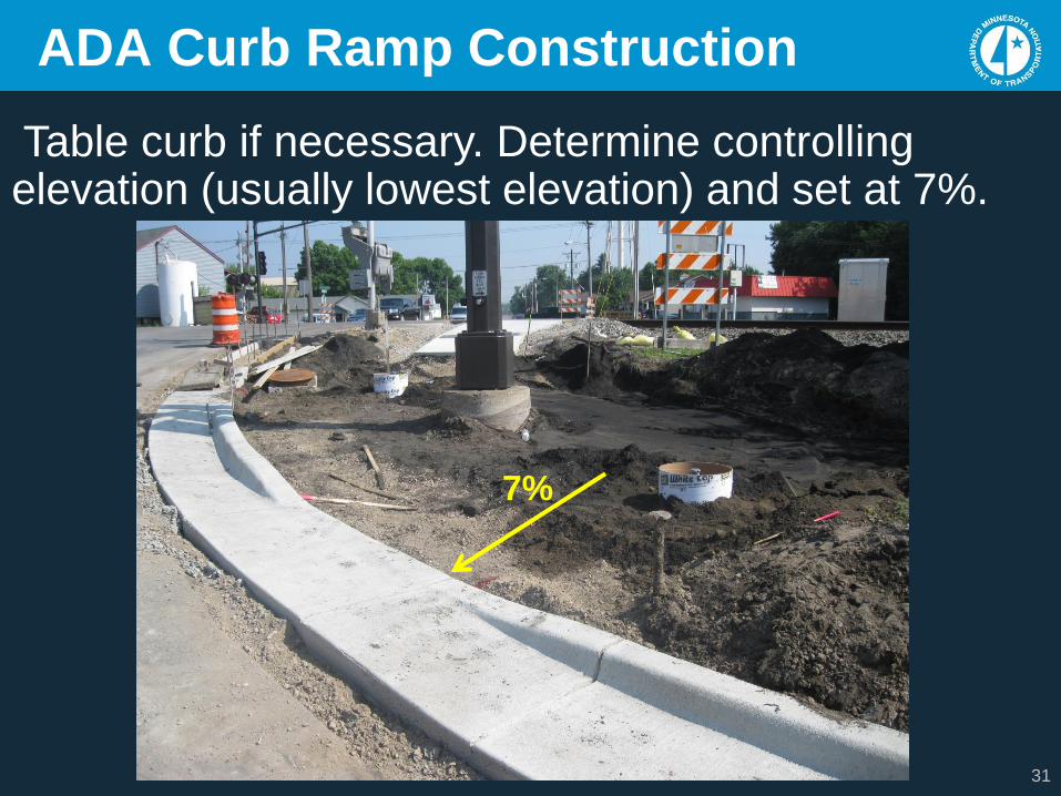
ADA Curb Ramp Construction
Table curb if necessary. Determine controlling elevation (usually lowest elevation) and set at 7%.
7%
32
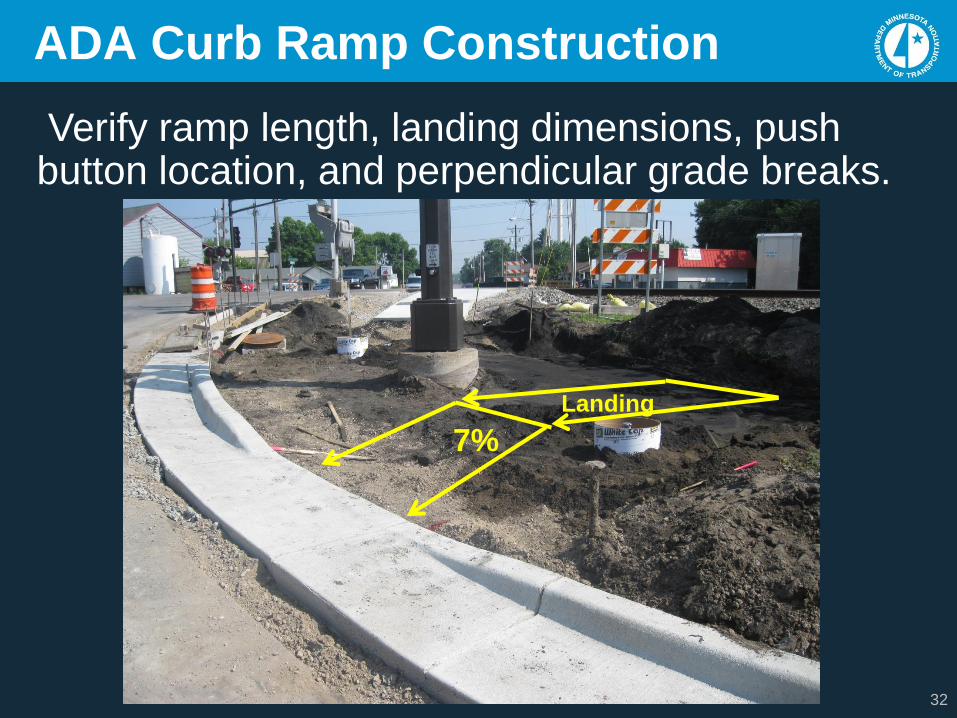
ADA Curb Ramp Construction
Verify ramp length, landing dimensions, push button location, and perpendicular grade breaks.
7%
Landing
33
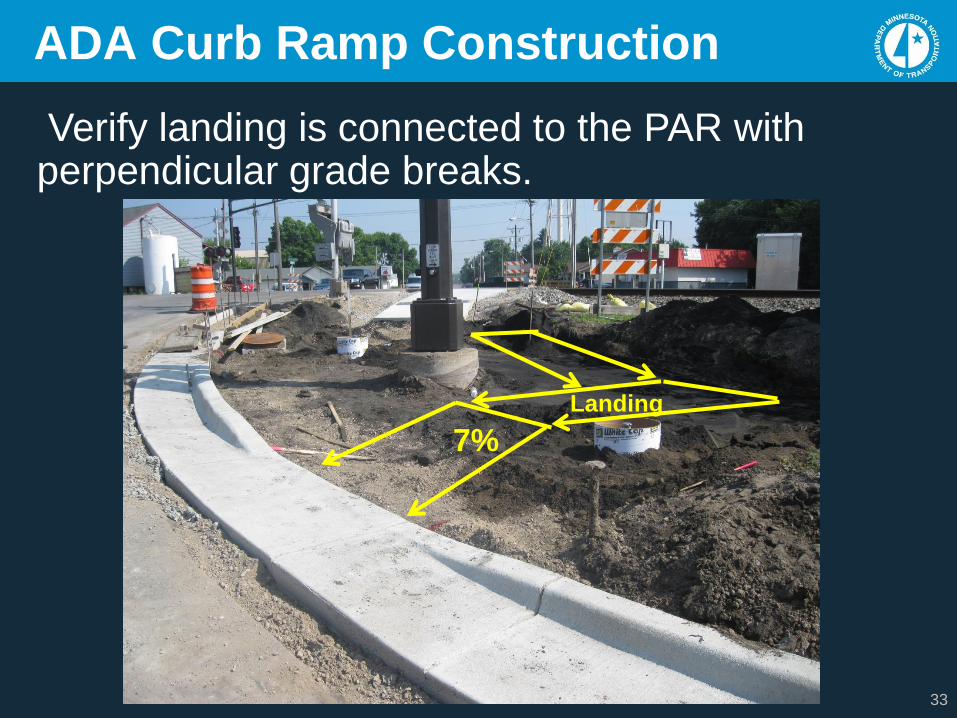
ADA Curb Ramp Construction
Verify landing is connected to the PAR with perpendicular grade breaks.
7%
Landing
34
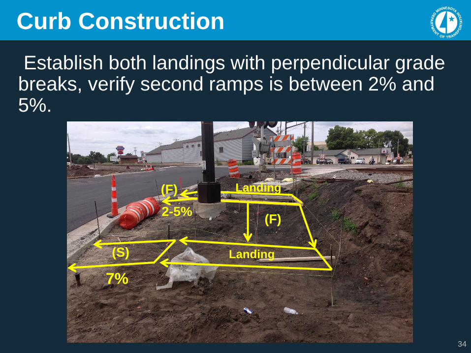
Curb Construction
Establish both landings with perpendicular grade breaks, verify second ramps is between 2% and 5%.
7%
Landing
2-5%(F)
Landing
(F)
(S)
35
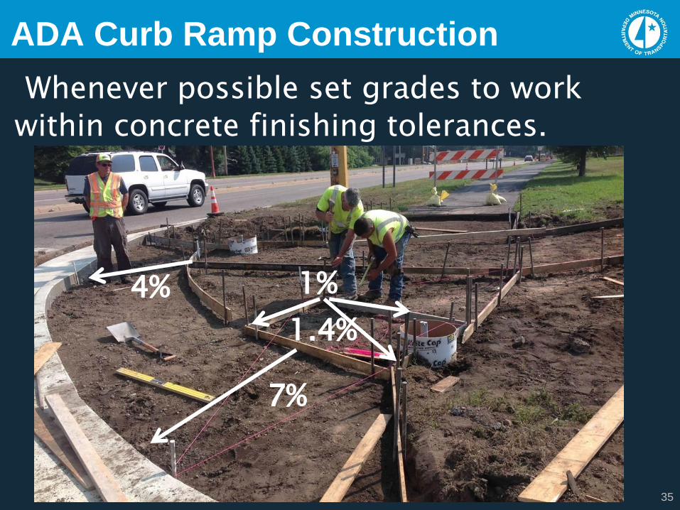
ADA Curb Ramp Construction
Whenever possible set grades to work
within concrete finishing tolerances.
7%
1%4%
1.4%
36
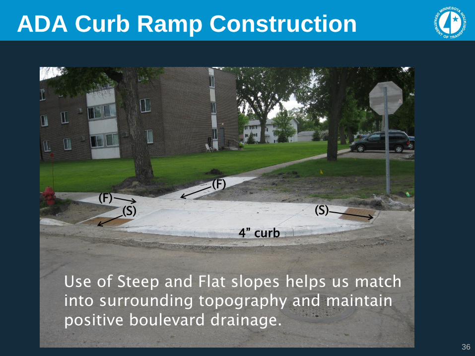
ADA Curb Ramp Construction
(S)
(F)(F)
(S)
4” curb
Use of Steep and Flat slopes helps us match into surrounding topography and maintain positive boulevard drainage.
37
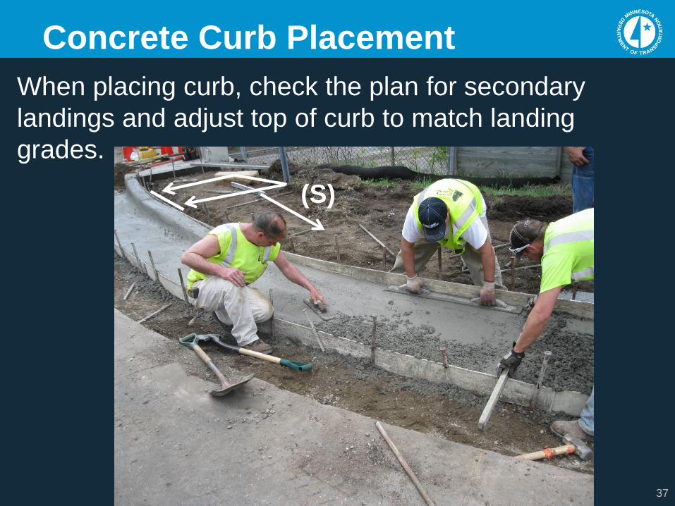
Concrete Curb Placement
When placing curb, check the plan for secondary
landings and adjust top of curb to match landing
grades.
(S)
38
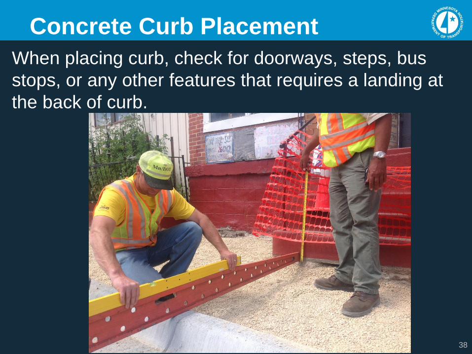
Concrete Curb Placement
When placing curb, check for doorways, steps, bus
stops, or any other features that requires a landing at
the back of curb.
39
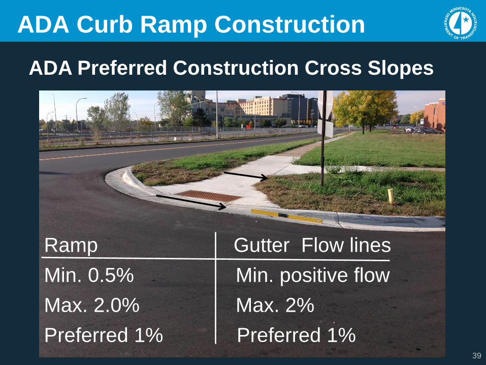
ADA Curb Ramp Construction
Ramp Gutter Flow lines
Min. 0.5% Min. positive flow
Max. 2.0% Max. 2%
Preferred 1% Preferred 1%
ADA Preferred Construction Cross Slopes
40
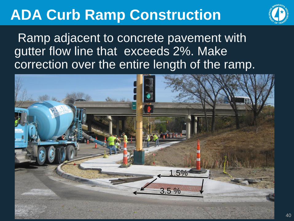
ADA Curb Ramp Construction
1.5%
3.5 %
Ramp adjacent to concrete pavement with gutter flow line that exceeds 2%. Make correction over the entire length of the ramp.
41
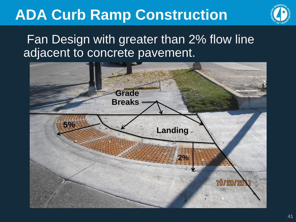
Landing5%
Grade Breaks
ADA Curb Ramp Construction
2%
Fan Design with greater than 2% flow line adjacent to concrete pavement.
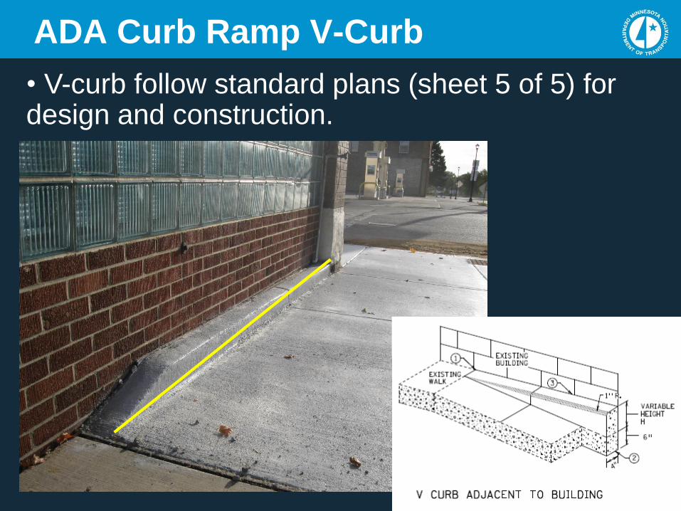
ADA Curb Ramp V-Curb
• V-curb follow standard plans (sheet 5 of 5) for design and construction.
42
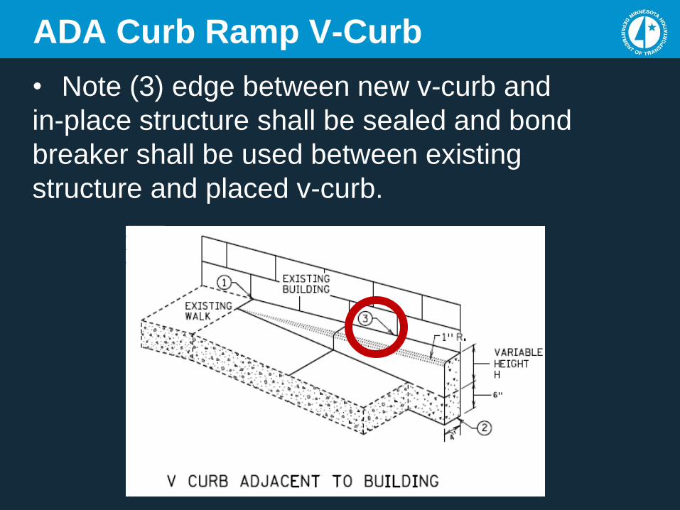
ADA Curb Ramp V-Curb
• Note (3) edge between new v-curb and
in-place structure shall be sealed and bond
breaker shall be used between existing
structure and placed v-curb.
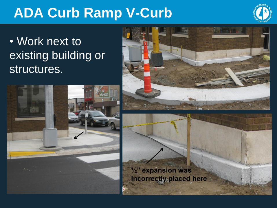
ADA Curb Ramp V-Curb
• Work next to
existing building or
structures.
½’’ expansion was
Incorrectly placed here
45
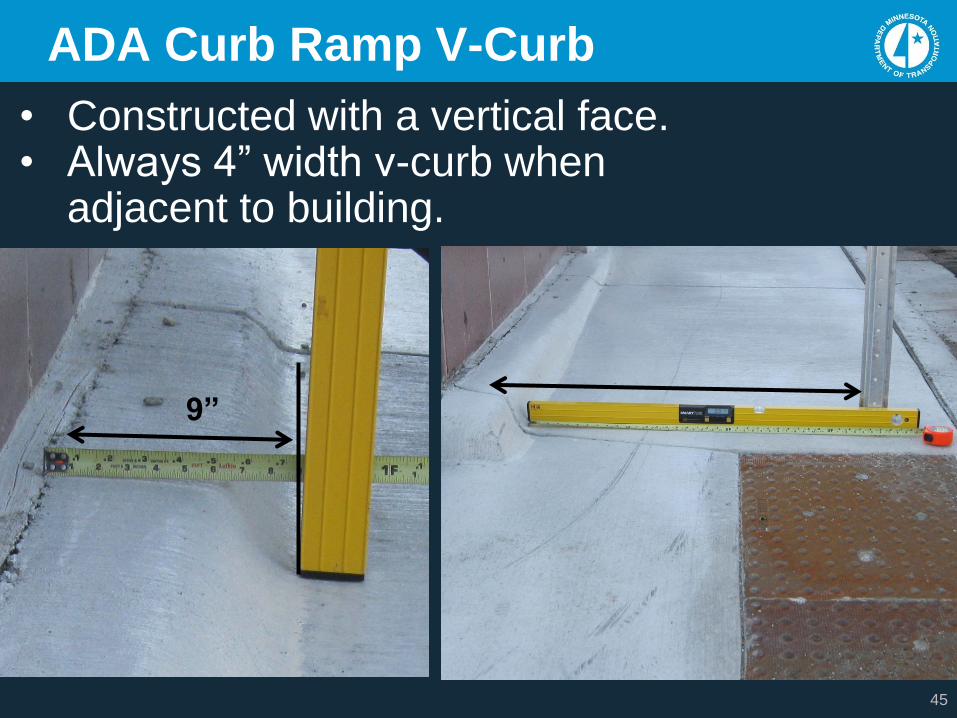
ADA Curb Ramp V-Curb
• Constructed with a vertical face.• Always 4” width v-curb when
adjacent to building.
9”
46
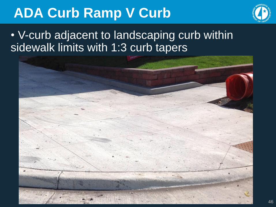
ADA Curb Ramp V Curb
• V-curb adjacent to landscaping curb within sidewalk limits with 1:3 curb tapers
47
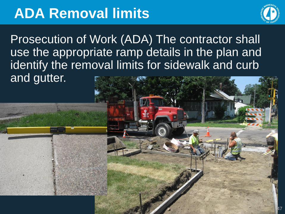
ADA Removal limits
Prosecution of Work (ADA) The contractor shall use the appropriate ramp details in the plan and identify the removal limits for sidewalk and curb and gutter.
48
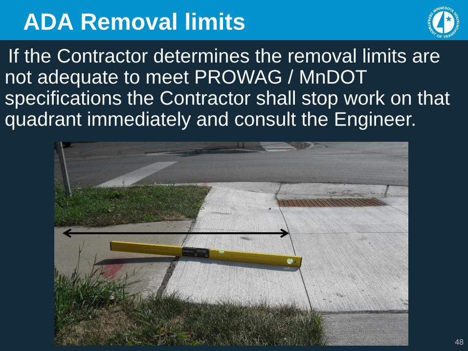
ADA Removal limits
If the Contractor determines the removal limits are not adequate to meet PROWAG / MnDOTspecifications the Contractor shall stop work on that quadrant immediately and consult the Engineer.
49
ADA Removal limits
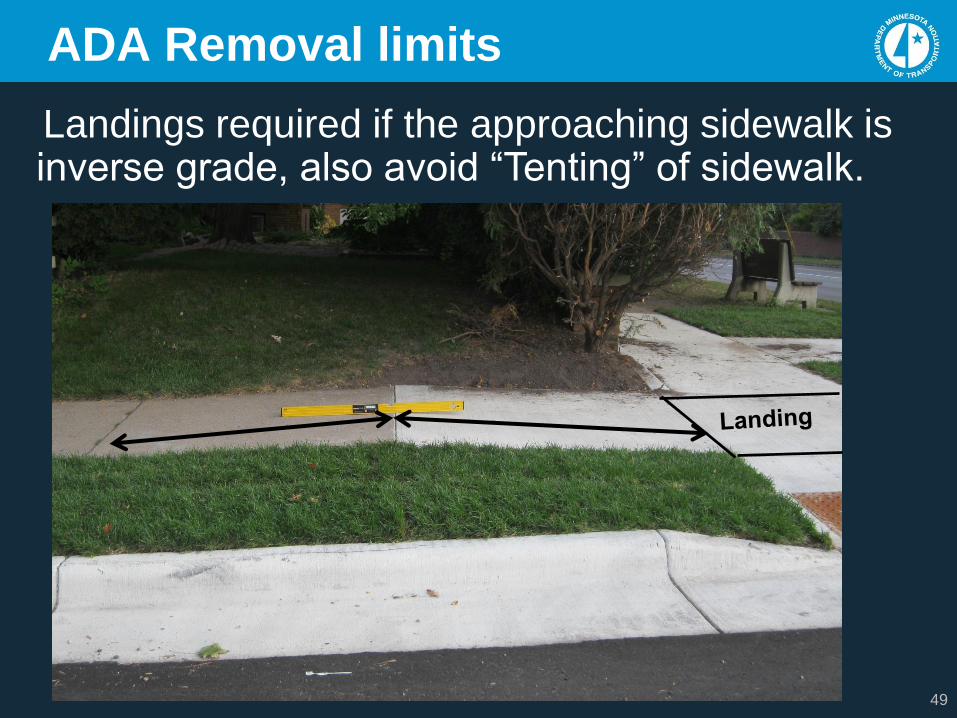
Landings required if the approaching sidewalk is inverse grade, also avoid “Tenting” of sidewalk.
50
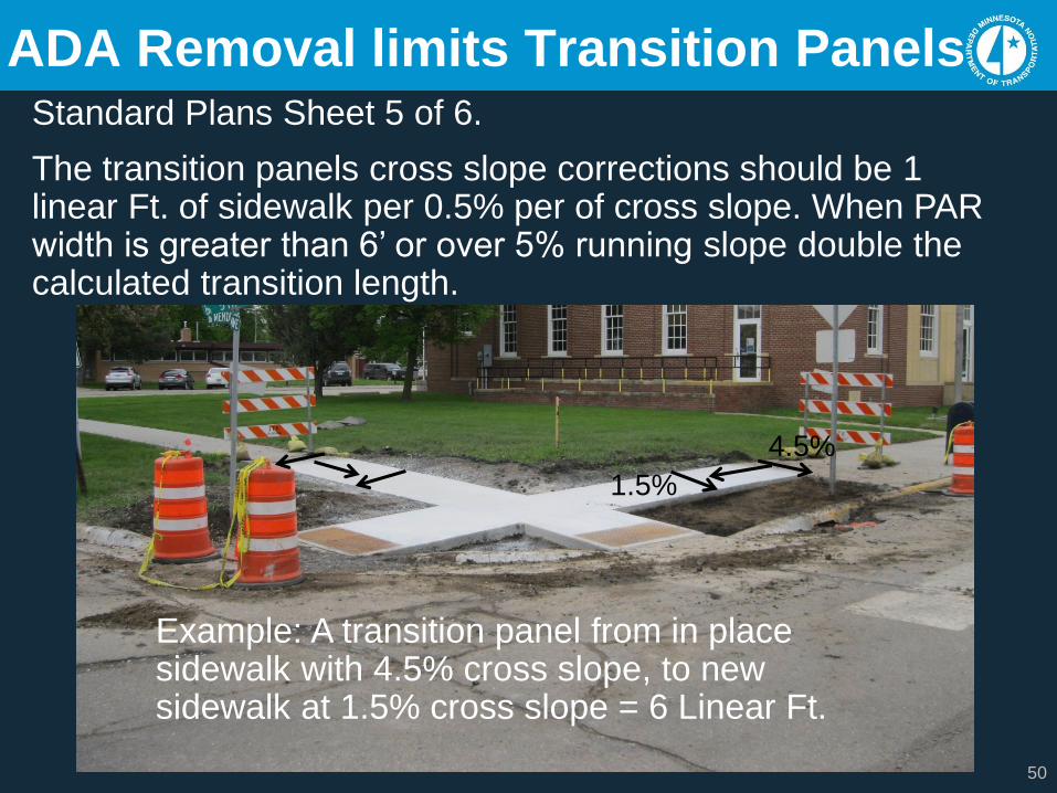
ADA Removal limits Transition Panels Standard Plans Sheet 5 of 6.
The transition panels cross slope corrections should be 1 linear Ft. of sidewalk per 0.5% per of cross slope. When PAR width is greater than 6’ or over 5% running slope double the calculated transition length.
Example: A transition panel from in place sidewalk with 4.5% cross slope, to new sidewalk at 1.5% cross slope = 6 Linear Ft.
1.5%
4.5%
51
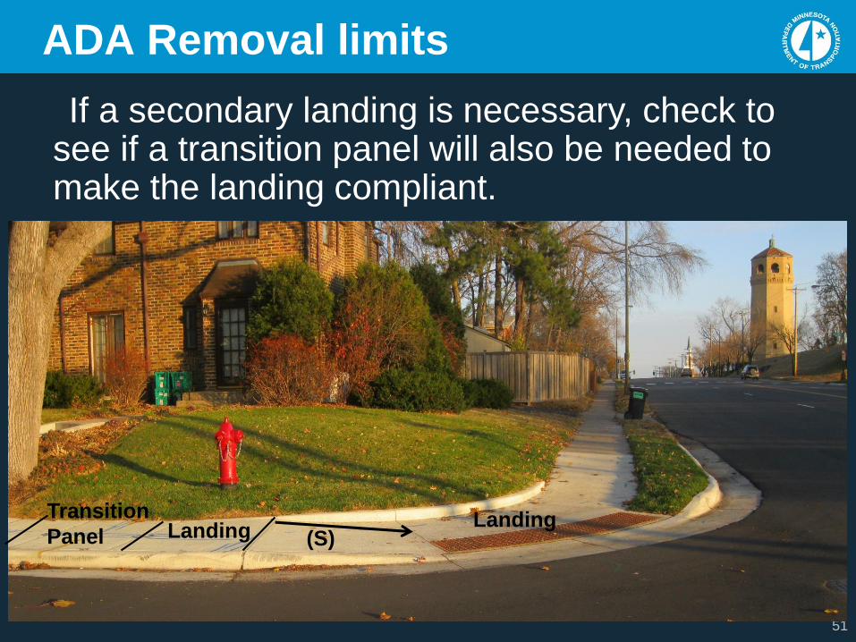
ADA Removal limits
If a secondary landing is necessary, check to see if a transition panel will also be needed to make the landing compliant.
LandingLanding
Transition
Panel (S)
52
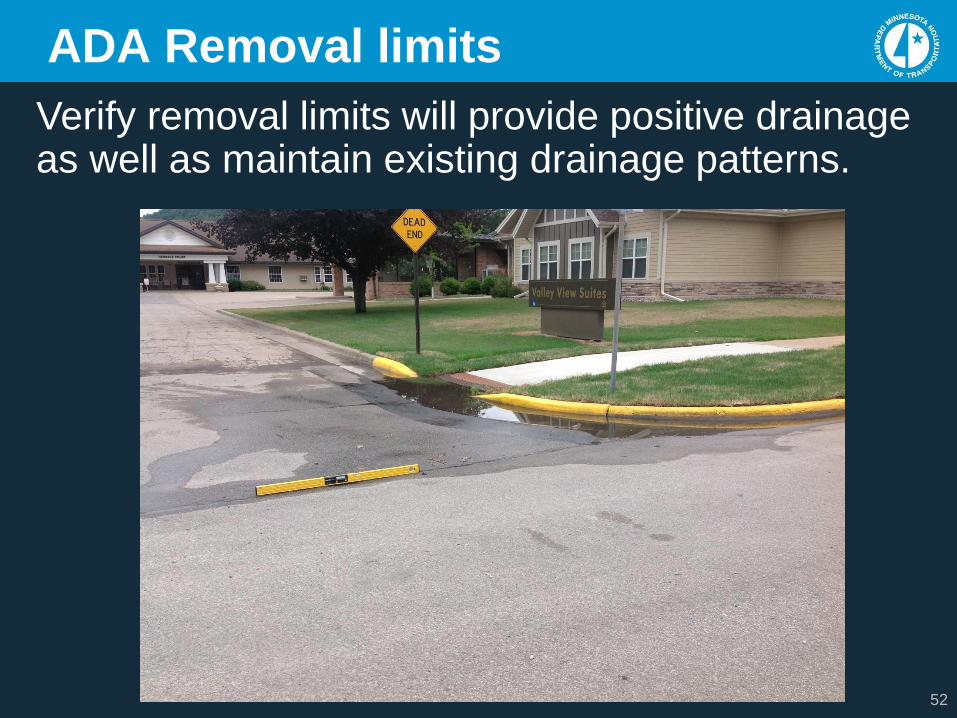
ADA Removal limits
Verify removal limits will provide positive drainage as well as maintain existing drainage patterns.
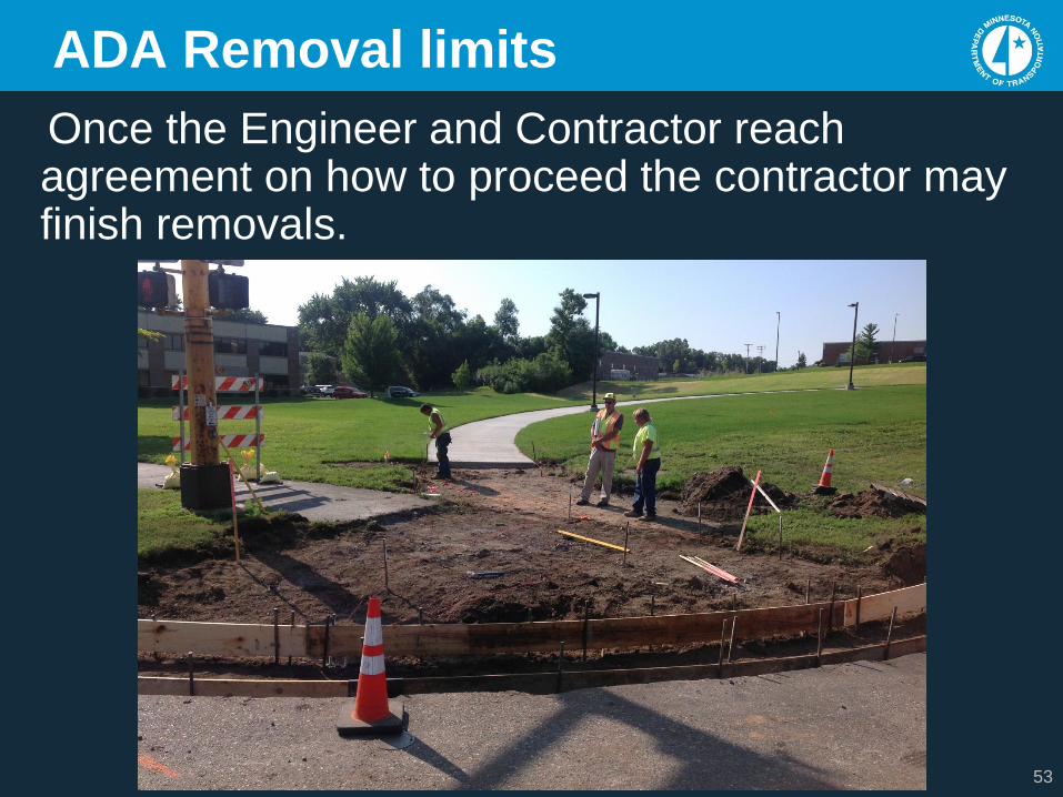
53
ADA Removal limits
Once the Engineer and Contractor reach agreement on how to proceed the contractor may finish removals.
54
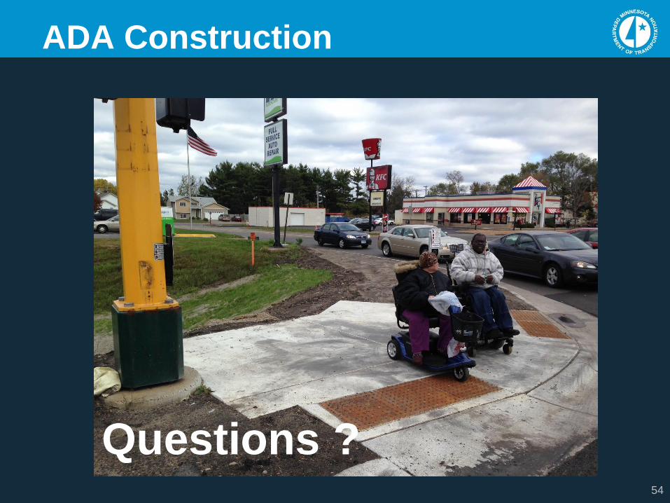
ADA Construction
Questions ?