accurate control position of belt drives under acceleration
TRANSCRIPT
International Journal of Control, Automation, and Systems Vol. 1, No. 4, December 2003 474
Accurate Control Position of Belt Drives under Acceleration
and Velocity Constraints
T.S.S. Jayawardene, Masatoshi Nakamura, and Satoru Goto
Abstract: Belt drives provide freedom to position the motor relative to the load and this phenomenon enables reduction of the robot arm inertia. It also facilitates quick response when employed in robotics. Unfortunately, the flexible dynamics deteriorates the positioning accuracy. Therefore, there exists a trade-off between the simplicity of the control strategy to reject time varying disturbance caused by flexibility of the belt and precision in performance. Resonance of the system further leads to vibrations and poor accuracy in positioning. In this paper, accurate positioning of a belt driven mechanism using a feed-forward compensator under maximum acceleration and velocity constraints is proposed. The proposed method plans the desired trajectory and modifies it to compensate delay dynamics and vibration. Being an off-line method, the proposed method could be easily and effectively adopted to the existing systems without any modification of the hardware setup. The effectiveness of the proposed method was proven by experiments carried out with an actual belt driven system. The accuracy of the simulation study based on numerical methods was also verified with the analytical solutions derived. Keywords: Belt drives, high-speed positioning, trajectory planning, velocity and acceleration constraints, vibration restraint.
1. INTRODUCTION
Numerous applications of position controlling devices using servoing technique and transmission of energy through belt drives are practiced in the industry. Belt drive is a simple, lightweight, low cost power transmission system. These qualities are particularly noticeable in relation to moderately large distances. At the same time, wheel alignment is not so critical in belt drives and it is inherently much quieter. It is capable of absorbing shock loads and thus isolates vibrations of the load from the motor. This phenomenon, in turn, tends to pose the problem of poor positioning. The key underlying objective of such belt drives is to reduce the manipulator mass and inertia, thus allowing the servos to be mounted on the stationary base. Belt drives provide flexibility in situating the motor relative to the load, allowing
for high speed positioning. They can be found in lightweight robot arms and linear actuators such as positioning tables. However, the flexible dynamics of the belt poses tracking problems and an inability to take corrective/compensative measures in relation to position design and force controller. Closed loop servoing might lead to stability problems. Even though accuracy of the end position is high in PID control, the tracking accuracy is often quite poor, since there is no direct compensation for friction and inertial forces. This phenomenon can be even worse in the presence of the flexible dynamics of belt drives. Due to sluggish response in positioning, belt drives could cause substantial vibrations.
Compensation of the effects of flexibility in belt driven systems was addressed by Robert B Gorbert et al. [1] with a dancing bar mechanism. The Modified taught data method for industrial mechatronic servo systems to achieve accurate contour control performance was introduced by Goto et al. [2] and used to improve system response in order to minimize tracking errors. Adaptive high precision control of positioning tables was experimented by Weiping Li et al. [3]. As the approach was based on adaptive principles, this method compelled replacement of existing PID controllers with adaptive controllers, which is inconvenient in practice. Lee et al. [4, 5] investigated the use of frequency reshaped linear quadratic control in order to develop a low cost intelligent integrated belt driven manipulator, which
__________ Manuscript received February 18, 2003; revised July 6,
2003; accepted August 4, 2003. Recommended by Editorial Board member Kyong Su Yi under the direction of Editor Keum-Shik Hong. The authors would like to acknowledge Professor N. Kyura, Kinki University and Dr. N. Egashira, Kurume National College of Technology, Japan, for their constructive comments.
T.S.S. Jayawardene, Masatoshi Nakamura and Satoru Goto are with the Department of Advanced Systems Control Engineering, Graduate School of Science and Engineering, Saga University Honjomachi, Saga 840-8502, Japan (e-mails: {jaya,nakamura,goto}@cntl.ee.saga.ac.jp).
International Journal of Control, Automation, and Systems Vol. 1, No. 4, December 2003 475
combines the linear quadratic optimal control with frequency response methods.
Though historical pioneering work on model construction for a single joint manipulator is found in the book on robotics by Fu et al. [6], it is limited to rigid link geared industrial robot manipulators. An integrated view of robust control manipulators is presented by Sage et al. in [7] referring to a wide range of classical papers, and a selection of contemporary papers. Though a little attention has been paid to flexible joints considering the tortional phenomenon between gears and load in [7], the flexible belt drives have not been under discussion. A mathematical view on the vibration of belts and belt drives is provided by S. Abrate in [8]. In historical researches, consideration of the realistic and application oriented industrial constraints viz. acceleration and velocity constraints with belt driven servoing systems have not yet been sufficiently addressed.
The proposed method in this research is based on off-line trajectory planning under maximum velocity and acceleration constraints. It also includes compensation of it for delay dynamics and vibrations. As the existing models used by previous researchers were inadequate in their precise representation of dynamics, especially at higher velocities, a model for a belt driven system was being constructed. The detail of that derivation is also furnished. However, a close similarity between the derived model and the fourth order model in [9] can be observed. Being an off-line trajectory and not in need of any significant change in hardware setup, this could be effectively and conveniently applied to servo based positioning control systems. In addition, the underlying simplicity as well as effectiveness of the proposed method enhances its importance from the point of view of implementation. The proposed method is experimentally tested with a cogged belt driven apparatus equipped with an industrial servo prime mover. The cogged belt driven system allows trajectories to be tested with high acceleration to obtain details relating to velocity, whereas the synchronous belts cause difficulties due to the rapid varying sequences of reference input. The simulation results obtained with numerical techniques are compatible with the analytical solutions derived.
2. METHOD
2.1. Problem statement Two pulleys with equal radius are coupled with a
flexible cogged belt drive. One pulley is directly connected to the motor, while the other one is connected to the load. Two lightweight tension pulleys are devised to change the initial tension of the belt drive.
The optimum performance should be realized under the following constraints: 1. joint acceleration constraint 2. angular velocity constraint
The joint acceleration constraint states that
max( ) ,r t r t≤ ∀ (1)
where ( )r t and maxr denote the acceleration of the objective trajectory and its maximum limit. Since the axis of rotation is vertical and the motion is one-dimensional (in a horizontal plane), there exists a linear relationship between the joint torque and the joint acceleration. The torque constraint is imposed by the hardware and it refers to the power amplifier current rating. The torque saturation of the servo drive concisely governs the above acceleration constraint.
In most practical circumstances, as emphasized by Munasinghe et. al. [11] for industrial manipulators, maximum velocity is determined by the application itself and seldom by the limitation of the servo system. If the operation is limited by a velocity constraint, within the entire operation, the angular velocity should not exceed the maximum allowable angular velocity as constrained by
max( ) ,r t r t≤ ∀ (2)
where ( )r t and maxr represent the velocity at time t and the maximum velocity of the objective trajectory, respectively. The objective of trajectory planning is to realize the target joint coordinate accurately within a minimum time in a reliable manner (with high repeatability) subject to the above velocity and acceleration constraints given by (1) and (2), while minimizing the tracking error and considering the flexible dynamics of belt drives to avoid vibrations. In achieving the above objectives, the exact dynamic representation of the belt driven system under concern over a wider velocity span is crucial and essential.
It has been pointed out by several researchers that the control system performance might be quite different in low-speed and high-speed motions. At lower speeds some models are exact in representation but manifest poor performance at higher velocities due to the inherent limitations of assumptions made at the derivation of models. However, the making of realistic and practical assumptions concerning the simplicity of the model is unavoidable. Under the most practical constraints and at higher velocities, derivation of a dynamic model representing the flexible dynamics of belt drives remains unanswered, while dynamic models are well established for rigid link manipulators.
International Journal of Control, Automation, and Systems Vol. 1, No. 4, December 2003 476
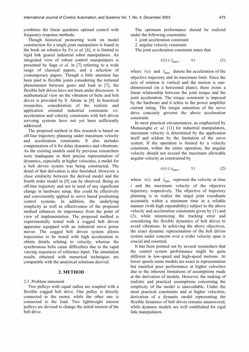
2.2. Modeling In order to achieve the desirable joint trajectory in
the minimum possible time, the joint should achieve its maximum acceleration until it reaches its maximum joint velocity (ta refers to Fig. 1), subsequently move with maximum joint velocity (till ta+tc) and ultimately decelerate at maximum deceleration so that it rests at the target destination (at ta+tc+td). In other words, joint achieves the maximum acceleration, which is directly and linearly correlated to joint torque, unless the joint moves at its maximum velocity. The associated minimum time, objective velocity profile is depicted in Fig. 1. The objective acceleration profile could be written as:
max max
max
max max
( )( ) and ( ) 0
0( ) and ( ) 0.
A r t rA r t r r t
A r t r r t=
≤ >= − ≤ <
(3)
Almost all industrial robot arms are kinematically
controlled, and the models for robot manipulators are well established and found in Goto et al. [2]. The most popular first order and second order dynamic representations of servo systems seem to be incapable of adapting directly to belt driven systems as the reaction dynamics of the belt cannot be readily incorporated. Therefore, the derivation of a model considering the flexible dynamics of belt drives has also been addressed in this paper. The establishment of a model excogitating the flexible dynamics of belt drives is carried out under the following three most applicable and practical assumptions.
1. The inertia and the friction of tension pulleys are negligible;
2. The mass of the belt is negligible and the belt has insignificant bending rigidity; and,
3. Belt drive operates within the linear elastic range of the belt.
The torques experienced by the motor pulley are the effective torque generated by the motor, motor initial torque, and the reaction torque of the belt. Under the torques stated above, the motor pulley attains its equilibrium. The effective torque exerted by the servomotor is equal to the torque generated by
the motor due to the servoing action less the reaction torque due to back emf. Therefore, the effective motor torque, Mτ is given by ( ) ,g g
M p v M v MK K u Kτ θ θ= − − where u , pK , g
vK and Mθ represent the input to the servo system, position loop gain, velocity gain of the servo amplifier and the position of the motor, respectively.
The inertia torque on the motor due to the mass of the rotational part of the motor and coupled pulley
Iτ is expressed by I M MJτ θ= , where MJ is the moment of inertia of the rotor including the motor pulley.
When the motor pulley rotates in the direction indicated in Fig. 2, the upper belt segment increases its tension whereas the lower segment reduces its tension by equal amount due to the differential angular motion of the motor pulley and load pulley. Hence the tangential effective force on either pulley, T1-T2 is equal to twice the change in belt tension owing to motion
1 2 2 ( ),M LT T kr θ θ− = − (4) where k, r and Lθ represent the linear coefficient of belt drive elasticity, radius of either pulley and position of the load, respectively. Therefore the reaction torque of the belt on either pulley Rτ is described by ( )R L M LKτ θ θ= − where LK represents the angular coefficient of elasticity of the belt. Considering the equilibrium of torques on the motor pulley, the governing relationship among the input u, motor position Mθ and load position Lθ in Laplace domain can be expressed by
2( ) [ ] ( )
( ).
g g gp v M v p v L M
L L
K K U s J s K s K K K s
K s
θ
θ
= + + +
−(5)
The load pulley is driven by the tension of the belt
Fig. 1. Objective velocity profile.
Fig. 2. Flexible belt drive.
International Journal of Control, Automation, and Systems Vol. 1, No. 4, December 2003 477
Fig. 4. Trajectory generation criterion.
whereas the load experiences viscous damping torque and inertia torque, under which it achieves equilibrium. The equilibrium of the load pulley can be represented mathematically in s domain by
2( ) [ ] ( ),L M L L L LK s J s D s K sθ θ= + + (6) where LJ and LD are the load inertia and the viscous damping coefficient of the load, respectively. Combining the relationships stated in (5) and (6), it is possible to derive the transfer functions
( ) ( ) / ( )M MG s s U sθ= and ( ) ( ) / ( )L LG s s U sθ= as follows:
2
4 3 24 3 2 1 0
,g g g
P v L p v L p v LM
K K J s K K D s K K KG
a s a s a s a s a
+ +=
+ + + + (7)
where
0
1
2
3
4
,
,
,
,,
gL p v
g gp v L L v L L
g gp v L L M v L L L
gv L L M
M L
a K K K
a K K D K K K D
a K K J K J K D J K
a K J D Ja J J
=
= + +
= + + +
= +
=
and
4 3 24 3 2 1 0
,g
p v LL
K K KG
a s a s a s a s a=
+ + + + (8)
where
0
1
2
3
4
,
,
,
,.
gL p v
g gp v L L v L L
g gp v L L M v L L L
gv L L M
M L
a K K K
a K K D K K K D
a K K J K J K D J K
a K J D Ja J J
=
= + +
= + + +
= +
=
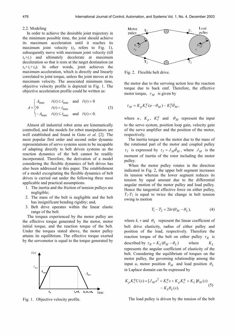
The model derived is illustrated in the sections of the servomotor and flexible belt drive of Fig. 3. In
addition, Fig. 3 briefly demonstrates the control strategy. 2.3. Strategy
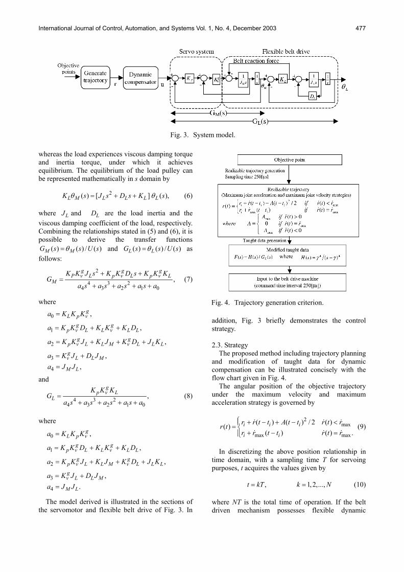
The proposed method including trajectory planning and modification of taught data for dynamic compensation can be illustrated concisely with the flow chart given in Fig. 4.
The angular position of the objective trajectory under the maximum velocity and maximum acceleration strategy is governed by
2
max
max max
( ) ( ) / 2 ( )( )( ) ( ) .
i i i
i i
r r t t A t t r t rr tr r t t r t r
+ − + − <= + − =
(9)
In discretizing the above position relationship in
time domain, with a sampling time T for servoing purposes, t acquires the values given by
, 1,2,...,t kT k N= = (10)
where NT is the total time of operation. If the belt driven mechanism possesses flexible dynamic
Fig. 3. System model.
International Journal of Control, Automation, and Systems Vol. 1, No. 4, December 2003 478
characteristics, the system has two degrees of freedom, but only one control input; the angular position of the motor. Therefore, the input to the system should be compensated for flexible dynamics and delay dynamics, as the PID controller inherently experiences tracking errors. In order to respond to the rapid changing sequences of input trajectory with minimum tracking error, dynamic compensation is essential. This is accomplished with a feed-forward dynamic compensator as illustrated in Fig. 3.
The dynamics of the feed-forward compensator can be explained by
( ) ( ) / ( ),LF s H s G s= (11)
where ( )H s is the desirable dynamic filter, whose dynamics are characterized by
4 4( ) /( ) ,H s sγ γ= − (12) where γ is the location of four coincident poles.
Such generated trajectory with the maximum joint acceleration and maximum joint velocity strategies is subsequently compensated for delay dynamics and flexible dynamics so as to minimize tracking error and achieve vibration restraint. The tracking error is directly correlated with the location of the system poles. The higher the magnitudes of the negative poles are, the faster the response of the system. Further, considerably small sampling time supports the restrained vibrations of the belt drives. To implement the lesser sampling time, the system must possess ‘quick response’ characteristics associated with the fast decaying nature of the control inputs. By introducing a feed-forward compensator for a ‘semi closed loop’ system, the poles of the compensated system should be relocated such that the zeros of the compensator exactly cancel off the undesired poles, which deteriorate the performance of the original system. This is accomplished with the compensator having a transfer function given by (11). 2.4. Analytical solutions
Using the numerical techniques (recursive iteration) the belt driven system is simulated for the model given in Fig. 3 using the modified taught data input u(t). In parallel, system dynamics was analytically solved for the taught data input, and the exact solution for the joint position coordinates was obtained to confirm the numerical robustness of the simulation.
The reference input u(t), used for servoing is a time-based input with zero order hold sequence having variable marginal magnitudes. It can be decomposed into a summation of time-shifted step input series with variable step size. Therefore, the
modified taught data can be written as:
1
( ) ( ) [( ) ],k
iu t s iT w k i T
== ∆ −∑ (13)
where ( ) ( ) (( 1) )s iT u iT u i t∆ = − − , ( 1)kT t k T≤ ≤ + , T is the sampling time and w is the unit step function. If the system is excited with u(t), motor angular position ( )M tθ and the load position coordinates
( )L tθ could be expressed with
1 2( ) ( )1 2
( ) 21 3 1
( ){1( )
sin( 1 ( ) )},L
t iT t iTk
M t iTi L
u iT A e A et
A e t iT
α α
ξωθ
ω ξ φ
− − − −
− −=
∆ + +=
+ − − +∑
(14) where ( 1)kT t k T≤ ≤ + , 1 3 4/(4 )g a a= ,
3 2 2 22 2 1 2 3 0 3 1 4 0 2 4(2 9 27 27 72 ) ,g a a a a a a a a a a a= − + + −
2 32 1 3 0 4 24( 3 12 )l a a a a a g= − − + + ,
3 2 22 1 2 3 0 3 1 4 0 2 42 9 27 27 72m a a a a a a a a a a a= − + + − ,
3c m l= + , 232 1 3 0 4 42( 3 12 ) / 3n a a a a a a c= − + ,
2 2 31 3 4 2 4 4( ) /(4 ) (2 / 3 ) /( 23 )p a a a a n c a= − + + ,
3 3 22 3 4 2 3 4 1 4/ 4 / 8 /p a a a a a a a= − + − ,
2 2 31 3 4 2 4 4 2 1/(2 ) 2 /(3 ) /( 23 ) /(4 ),q a a a a n c a p p= − − − −
2 2 32 3 4 2 4 4 2 1/(2 ) 2 /(3 ) /( 23 ) /(4 ),q a a a a n c a p p= − − − +
1 1 1 10.5 0.5g p qα = − − − , 2 1 1 10.5 0.5g p qα = − − + , 2 2 21 1 1 1 20.25( )L g g p g qω = − + + ,
1 1( 0.5 ) / Lg pξ ω= − , 2
1 2 1 1 1 0 1 2 1 1( ) /{( )( 2 )},L LA b b bα α α α α ξω α ω= + + − + +2
2 2 2 1 2 0 2 1 2 2( ) /{( )( 2 )},L LA b b bα α α α α ξω α ω= + + − + +
1 2( ),C A A= − +2
0 1 2 1 1 2 2/( ) ( / / ) ,LD a A Aα α α α ω= + + 2 2 2
3 ( ) /L LA C D Cξω ω= + − ,
-1 21 tan {( 1 ) /( )},L LC D Cφ ξ ω ξω= − −
and
1 2( ) ( )1 2
( ) 21 3 2
( ){1( )
sin( 1 ( ) )},L
t iT t iTk
M t iTi L
u iT B e B et
B e t iT
α α
ξωθ
ω ξ φ
− − − −
− −=
∆ + +=
+ − − +∑
(15)
where ( 1) ,kT t k T≤ ≤ + 2
1 0 1 2 1 1/{( )( 2 )}L LB a α α α ξω α ω= − + + , 2
2 0 2 1 2 2/{( )( 2 )}L LB a α α α ξω α ω= − + + ,
1 2( )E B B= − + ,
International Journal of Control, Automation, and Systems Vol. 1, No. 4, December 2003 479
20 1 2 1 1 2 2/( ) ( / / ) LL a B Bα α α α ω= + + ,
2 2 23 ( ) /L LB E L Eξω ω= + − , and
-1 22 tan {( 1 ) /( )}.L LE L Eφ ξ ω ξω= − −
3. RESULTS
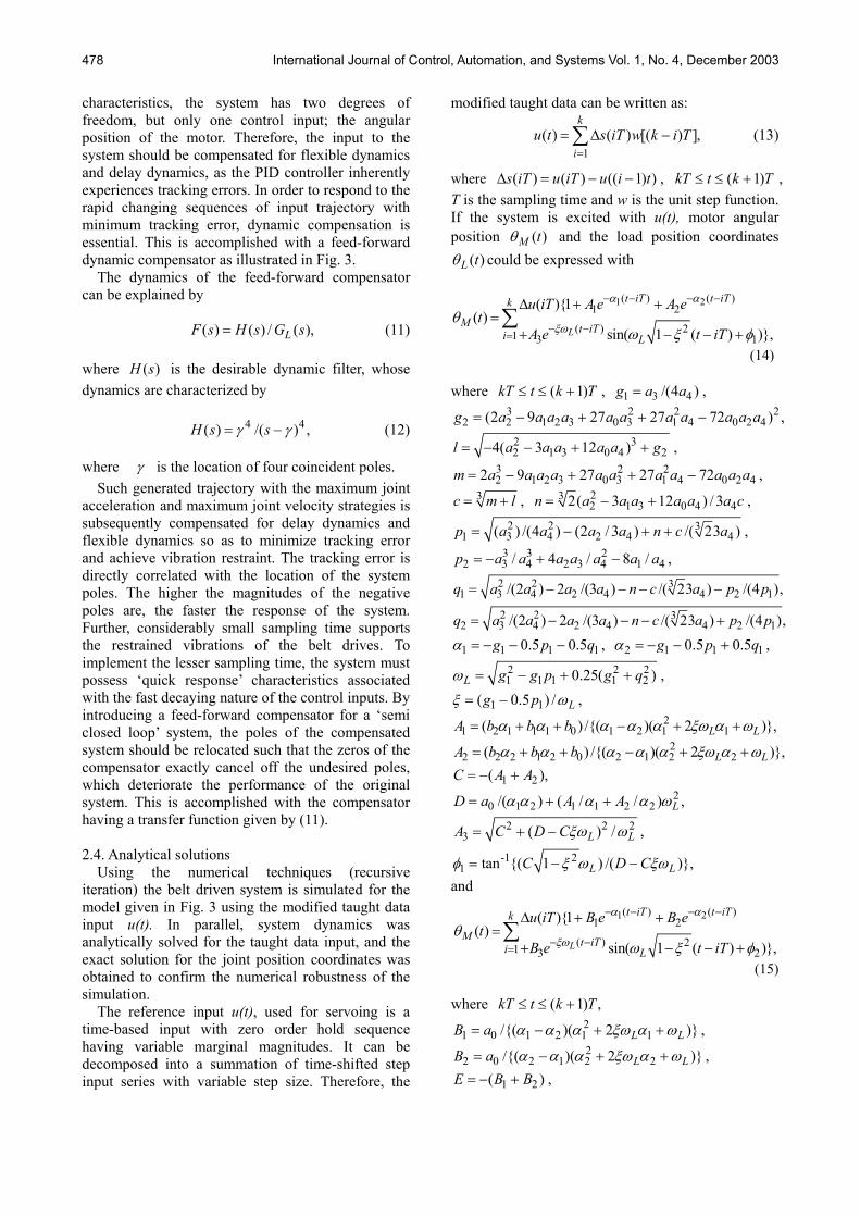
3.1. Conditions for simulation and experiment The schematic of the experimental setup is
illustrated in Fig. 5. A servomotor drives the load with a cogged belt drive and the servomotor is actuated with a current/voltage controller that implements torque control according to the PID control algorithm.
The modified taught data for servoing is fed to the servo controller with the aid of COSMOS, which interfaces the digital data with the analog servo controller. COSMOS is equipped with multi-channel A/D and D/A converters, 16MB memory and a digital counter. COSMOS is not only acting as an interface, but also as a data logger to support fast servoing with a sampling time as small as 125[ ]sµ . An optical laser sensor coupled with the amplification unit is employed to monitor the actual position and these
data are also logged onto the computer through COSMOS. The objective trajectory is calculated in the joint coordinate space and the maximum angular
(a) Experimental setup.
(b) Schematic diagram.
Fig. 5. Experimental equipment.
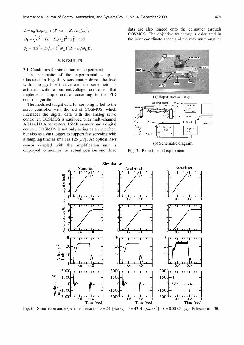
Fig. 6. Simulation and experiment results: 224 [ / ], 4314 [ / ], 0.00025 [ ], Poles are at -130.r rad s r rad s T s= = =
International Journal of Control, Automation, and Systems Vol. 1, No. 4, December 2003 480
velocity (joint velocity) constraint is set to 24 [rad/s] while the maximum acceleration is set to 4314 [rad/s2]. The values of position loop gain (Kp), servo amplifier velocity gain constant ( g
vK ), angular spring constant of belt referring to motor pulley (KL), and viscous damping coefficient of the load (DL) are 15[1/s], 0.0023 [kgm2/s], 0.0513 [kN/rad] and 5.2355X10⁻⁴ [Ns/rad], respectively. Four coincident poles of the desirable dynamic filter are located at -130. The experiment and simulation were carried out for an angular span of 6.28 [rad]. 3.2. Simulation and experimental results
The velocity profile of the objective trajectory is shown in Fig. 1 and the same trajectory together with dynamic compensation is used for both the experiment and the simulation. Simulation and experimental results are given in Fig. 6. The simulation results from two approaches together with experimental results obtained for that objective profile are illustrated in Fig. 6. The first two columns show the simulation results based upon numerical methods and analytical methods, whereas the third column indicates the experimental results. In order to eliminate noise in the acceleration profile of the experiment, acceleration data is obtained by filtering the original data with a fourth order Chebyshew IIR low pass filter of 100Hz.
A significant spike could be noticed in the motor velocity profile of the proposed model during change in acceleration, which is expected with the belt reaction torque. The magnitude of the spike and the quantification aspect of the motor velocity spike of the proposed model are almost in accordance with the results obtained in the experiment, and hence prove the validity of the model.
The spikes present in the velocity profile at the points of acceleration change in the experimental results could also be noticed in the simulation. The position profile of the simulation is completely consistent with the experimental results. The result of the numerical simulation is exactly consistent with that of the analytical approach, and hence substantiates the numerical robustness and stability of the employed recursive iteration technique. As the experiment and simulation results are in exact agreement, the validity of the proposed simulation model is asserted, though it is extensively simplified and linear.
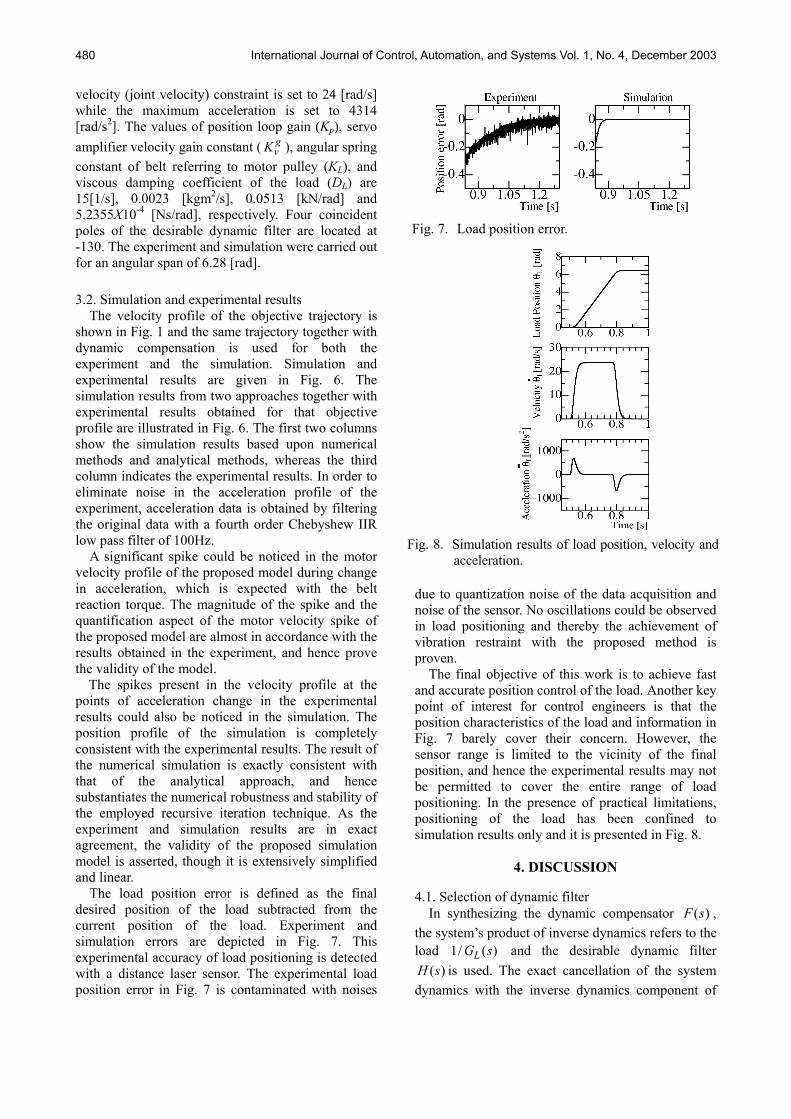
The load position error is defined as the final desired position of the load subtracted from the current position of the load. Experiment and simulation errors are depicted in Fig. 7. This experimental accuracy of load positioning is detected with a distance laser sensor. The experimental load position error in Fig. 7 is contaminated with noises
due to quantization noise of the data acquisition and noise of the sensor. No oscillations could be observed in load positioning and thereby the achievement of vibration restraint with the proposed method is proven.
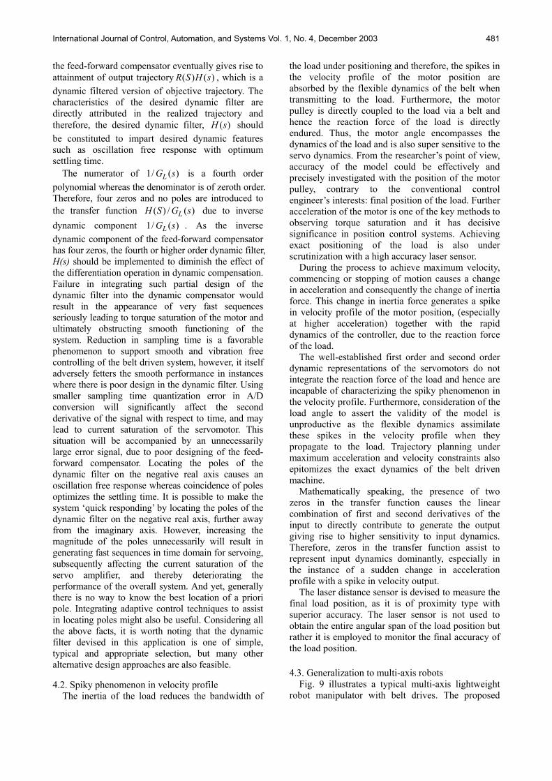
The final objective of this work is to achieve fast and accurate position control of the load. Another key point of interest for control engineers is that the position characteristics of the load and information in Fig. 7 barely cover their concern. However, the sensor range is limited to the vicinity of the final position, and hence the experimental results may not be permitted to cover the entire range of load positioning. In the presence of practical limitations, positioning of the load has been confined to simulation results only and it is presented in Fig. 8.
4. DISCUSSION
4.1. Selection of dynamic filter In synthesizing the dynamic compensator ( )F s ,
the system’s product of inverse dynamics refers to the load 1/ ( )LG s and the desirable dynamic filter
( )H s is used. The exact cancellation of the system dynamics with the inverse dynamics component of
Fig. 7. Load position error.
Fig. 8. Simulation results of load position, velocity and
acceleration.
International Journal of Control, Automation, and Systems Vol. 1, No. 4, December 2003 481
the feed-forward compensator eventually gives rise to attainment of output trajectory ( ) ( )R S H s , which is a dynamic filtered version of objective trajectory. The characteristics of the desired dynamic filter are directly attributed in the realized trajectory and therefore, the desired dynamic filter, ( )H s should be constituted to impart desired dynamic features such as oscillation free response with optimum settling time.
The numerator of 1/ ( )LG s is a fourth order polynomial whereas the denominator is of zeroth order. Therefore, four zeros and no poles are introduced to the transfer function ( ) / ( )LH S G s due to inverse dynamic component 1/ ( )LG s . As the inverse dynamic component of the feed-forward compensator has four zeros, the fourth or higher order dynamic filter, H(s) should be implemented to diminish the effect of the differentiation operation in dynamic compensation. Failure in integrating such partial design of the dynamic filter into the dynamic compensator would result in the appearance of very fast sequences seriously leading to torque saturation of the motor and ultimately obstructing smooth functioning of the system. Reduction in sampling time is a favorable phenomenon to support smooth and vibration free controlling of the belt driven system, however, it itself adversely fetters the smooth performance in instances where there is poor design in the dynamic filter. Using smaller sampling time quantization error in A/D conversion will significantly affect the second derivative of the signal with respect to time, and may lead to current saturation of the servomotor. This situation will be accompanied by an unnecessarily large error signal, due to poor designing of the feed-forward compensator. Locating the poles of the dynamic filter on the negative real axis causes an oscillation free response whereas coincidence of poles optimizes the settling time. It is possible to make the system ‘quick responding’ by locating the poles of the dynamic filter on the negative real axis, further away from the imaginary axis. However, increasing the magnitude of the poles unnecessarily will result in generating fast sequences in time domain for servoing, subsequently affecting the current saturation of the servo amplifier, and thereby deteriorating the performance of the overall system. And yet, generally there is no way to know the best location of a priori pole. Integrating adaptive control techniques to assist in locating poles might also be useful. Considering all the above facts, it is worth noting that the dynamic filter devised in this application is one of simple, typical and appropriate selection, but many other alternative design approaches are also feasible.
4.2. Spiky phenomenon in velocity profile
The inertia of the load reduces the bandwidth of
the load under positioning and therefore, the spikes in the velocity profile of the motor position are absorbed by the flexible dynamics of the belt when transmitting to the load. Furthermore, the motor pulley is directly coupled to the load via a belt and hence the reaction force of the load is directly endured. Thus, the motor angle encompasses the dynamics of the load and is also super sensitive to the servo dynamics. From the researcher’s point of view, accuracy of the model could be effectively and precisely investigated with the position of the motor pulley, contrary to the conventional control engineer’s interests: final position of the load. Further acceleration of the motor is one of the key methods to observing torque saturation and it has decisive significance in position control systems. Achieving exact positioning of the load is also under scrutinization with a high accuracy laser sensor.
During the process to achieve maximum velocity, commencing or stopping of motion causes a change in acceleration and consequently the change of inertia force. This change in inertia force generates a spike in velocity profile of the motor position, (especially at higher acceleration) together with the rapid dynamics of the controller, due to the reaction force of the load.
The well-established first order and second order dynamic representations of the servomotors do not integrate the reaction force of the load and hence are incapable of characterizing the spiky phenomenon in the velocity profile. Furthermore, consideration of the load angle to assert the validity of the model is unproductive as the flexible dynamics assimilate these spikes in the velocity profile when they propagate to the load. Trajectory planning under maximum acceleration and velocity constraints also epitomizes the exact dynamics of the belt driven machine.
Mathematically speaking, the presence of two zeros in the transfer function causes the linear combination of first and second derivatives of the input to directly contribute to generate the output giving rise to higher sensitivity to input dynamics. Therefore, zeros in the transfer function assist to represent input dynamics dominantly, especially in the instance of a sudden change in acceleration profile with a spike in velocity output.
The laser distance sensor is devised to measure the final load position, as it is of proximity type with superior accuracy. The laser sensor is not used to obtain the entire angular span of the load position but rather it is employed to monitor the final accuracy of the load position. 4.3. Generalization to multi-axis robots
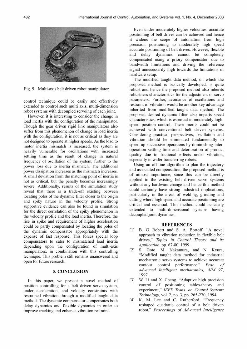
Fig. 9 illustrates a typical multi-axis lightweight robot manipulator with belt drives. The proposed
International Journal of Control, Automation, and Systems Vol. 1, No. 4, December 2003 482
control technique could be easily and effectively extended to control such multi axis, multi-dimension robot systems with decoupled servoing of each joint.
However, it is interesting to consider the change in load inertia with the configuration of the manipulator. Though the gear driven rigid link manipulators also suffer from this phenomenon of change in load inertia with the configuration, it is not as critical as they are not designed to operate at higher speeds. As the load to motor inertia mismatch is increased, the system is heavily vulnerable for oscillations with increased settling time as the result of change in natural frequency of oscillation of the system, further to the power loss due to inertia mismatch. The additional power dissipation increases as the mismatch increases. A small deviation from the matching point of inertia is not as critical, but the penalty becomes increasingly severe. Additionally, results of the simulation study reveal that there is a trade-off existing between locating poles of the dynamic filter closer to the origin and spiky nature in the velocity profile. Strong supportive evidence can also be found in simulation for the direct correlation of the spiky phenomenon in the velocity profile and the load inertia. Therefore, the rise in spike and requirement of higher acceleration could be partly compensated by locating the poles of the dynamic compensator appropriately with the expense of fast response. This forces special loop compensators to cater to mismatched load inertia depending upon the configuration of multi-axis manipulators, in combination with this controlling technique. This problem still remains unanswered and open for future research.
5. CONCLUSION
In this paper, we present a novel method of position controlling for a belt driven servo system, under acceleration, and velocity constraints with restrained vibration through a modified taught data method. The dynamic compensator compensates both delay dynamics and flexible dynamics in order to improve tracking and enhance vibration restraint.
Even under moderately higher velocities, accurate positioning of belt drives can be achieved and hence it widens the scope of automation from high precision positioning to moderately high speed accurate positioning of belt drives. However, flexible and delay dynamics cannot be completely compensated using a priory compensator, due to bandwidth limitations and driving the reference signal unnecessarily high towards the limitations of hardware setup.
The modified taught data method, on which the proposed method is basically developed, is quite robust and hence the proposed method also inherits robustness characteristics for the adjustment of servo parameters. Further, avoidance of oscillations and restraint of vibration would be another key advantage inherited from modified taught data method. The proposed desired dynamic filter also imparts speed characteristics, which is essential in moderately high-speed position control. These merits could not be achieved with conventional belt driven systems. Considering practical perspectives, oscillation and vibration should be eliminated fundamentally to speed up successive operations by diminishing inter-operation settling time and deterioration of product quality due to frictional effects under vibration, especially in wafer transferring robots.
Using an off-line algorithm to plan the trajectory and associated compensation, the proposed method is of utmost importance, since this can be directly applied to the existing belt driven servo systems without any hardware change and hence this method could certainly have strong industrial implications, particularly in the areas of welding, grinding and cutting where high speed and accurate positioning are critical and essential. This method could be easily extended to multi-dimensional systems having decoupled joint dynamics.
REFERENCES [1] B. G. Robert and S. A. Bortoff, “A novel
approach to vibration reduction in flexible belt drives,” Topics in Control Theory and its Application, pp. 67-80, 1999.
[2] S. Goto, M. Nakamura, and N. Kyura, “Modified taught data method for industrial mechatronic servo systems to achieve accurate contour control performance,” Proc. of advanced Intelligent mechatronics, AIM 97, 1997.
[3] W. Li and X. Cheng, “Adaptive high precision control of positioning tables-theory and experiment,” IEEE Trans. on Control Systems Technology, vol. 2, no. 3, pp. 265-270, 1994.
[4] K. M. Lee and C. Rutherford, “Frequency reshaped quadratic control of a belt driven robot,” Proceedings of Advanced Intelligence
Fig. 9. Multi-axis belt driven robot manipulator.
International Journal of Control, Automation, and Systems Vol. 1, No. 4, December 2003 483
Mechatronic, AIM 97, 1997. [5] K. M. Lee and C. Rutherford, “Frequency
reshaped quadratic control of a Low-Cost human level performance belt driven robot,” IEEE Transactions on Mechatronic vol. 9, pp. 95-110, 1999.
[6] K. S. Fu, R. C. Gonzalez, and C. S. G. Lee, Robotics: Control, Sensing, Vision, and Intelligence, McGraw-Hill, 1987.
[7] H. G. Sage, M. F. de Mathelin, and E. Ostertag, “Robust control of robot manipulators: a survey,” International Journal of Control, vol. 72, pp. 1498-1522, 1999.
T.S.S. Jayawardene was born in Matara, Sri Lanka, in November 1970. He received the B.Sc. (Eng.) degree in Electronics and Telecommunications and the M.Sc. in Operations Research from the University of Moratuwa in 1996 and 2003, respectively. From October
1996 to April 1997 he served as an Instructor in the Department of Electronics and Telecommunication Engineering, and then as a Lecturer since April 1997 in the Department of Textile & Clothing Technology, Faculty of Engineering, University of Moratuwa. Currently, he is continuing his Ph.D. in the Department of Advanced Systems Control Engineering, Saga University, Japan. His research interests include manipulator control, intelligent control techniques, mathematical modeling and optimization. Mr. Jayawardene is a member of the Society of Instrument and Control Engineers in Japan, a founding member of the Applied Statistics Association, Sri Lanka, and a member of the Institute of Engineers Sri Lanka.
Masatoshi Nakamura was born in Fukuoka, Japan, in 1943. He received the B.S., M.S. and Ph.D. degrees in Electrical Engineering from Kyushu University, in 1967, 1969 and 1974, respectively. From 1973 to 1974, he was a Research Associate in Kyushu University. Since 1974, he has been
with the Faculty of Science and Engineering, Saga University, where he is currently a Professor in the Department of Advanced Systems Control Engineering. His research interests include system control theory and its applications, particularly in the fields of power system control, thermal flow control, robotics and biomedical engineering. Professor Nakamura is a senior member of IEEE, a Fellow of the Society of Instrument and Control Engineers of Japan, a member of the Robotics Society of Japan, and a member of the Institute of Systems Control and Information of Japan.
[8] S. Abrate, “Vibrations of belts and belt drives,” Mechanism and Machine Theory, vol. 27, pp. 645-659, 1992.
[9] M. Nakamura, S. Goto, and N. Kyura, Mechatronic servo system control, Morikita Shuppan, 1998 (in Japanese).
[10] Boldor Electric Company, Motion Control Application Notes, Baldor Electric Company, 1999.
[11] S. R. Munasinghe, M. Nakamura, S. Aoki, S. Goto, and N. Kyura, “High speed precise control of robot arm with assigned speed under torque constraint by trajectory generation in joint coordinates,” Proceeding of SMC 99, pp. 854-859, 1999.
Satoru Goto was born in Fukuoka, Japan, in 1966. He received the B.S. and M.S. degrees in Applied Physics from Osaka University, Osaka, Japan in 1988 and 1990, respectively, and his Ph.D. degree from Osaka University in 1995. Since 1990, he has been with the Faculty of Science
and Engineering, Saga University, Saga, Japan, where he was a Research Associate from 1990 to 1996, Lecturer from 1996 to 1998 and Associate Professor since 1998, in the Department of Advanced Systems Control Engineering. His research interests include control theory and its applications to actual systems. Dr. Goto is a member of the Society of Instrument and Control Engineers in Japan, the Robotics Society of Japan and the Institute of Systems, Control and Information of Japan.