motion & drives - servo systems
TRANSCRIPT

Cat. No. I561-E1-03
USER’S MANUAL
SMARTSTEP 2 SERIES
R88M-G@(Servomotors)
R7D-BP@(Servo Drives)
SERVOMOTORS/SERVO DRIVES

Trademarks and Copyrights
•
OMRON, 2008All rights reserved. No part of this publication may be reproduced, stored in a retrieval system, or transmitted, in anyform, or by any means, mechanical, electronic, photocopying, recording, or otherwise, without the prior written permis-sion of OMRON.
No patent liability is assumed with respect to the use of the information contained herein. Moreover, because OMRON isconstantly striving to improve its high-quality products, the information contained in this manual is subject to changewithout notice. Every precaution has been taken in the preparation of this manual. Nevertheless, OMRON assumes noresponsibility for errors or omissions. Neither is any liability assumed for damages resulting from the use of the informa-tion contained in this publication.
Product names and system names in this manual are trademarks or registered trademarks of their respective companies.
1
Introduction
IntroductionThank you for choosing the SMARTSTEP 2 Series. This User’s Manual describes installation/wiring methods and parameter setting procedures required for the operation of the SMARTSTEP 2 Series as well as troubleshooting and inspection methods.
Intended ReadersThis manual is intended for the following personnel. Those with knowledge of electrical systems (a qualified electrical engineer or the equivalent) as follows:
Personnel in charge of introducing FA equipmentPersonnel in charge of designing FA systemsPersonnel in charge of managing FA systems and facilities
NOTICEThis manual contains information necessary to ensure safe and proper use of the SMARTSTEP 2 Series and its peripheral devices. Please read this manual thoroughly and understand its contents before using the products. Please keep this manual handy for future reference. Make sure this User’s Manual is delivered to the actual end user of the products.
Read and Understand this ManualPlease read and understand this manual before using the product. Please consult your OMRON representative if you have any questions or comments.
Warranty and Limitations of Liability
WARRANTY
OMRON's exclusive warranty is that the products are free from defects in materials and workmanship for a period of one year (or other period if specified) from date of sale by OMRON.
OMRON MAKES NO WARRANTY OR REPRESENTATION, EXPRESS OR IMPLIED, REGARDING NON-INFRINGEMENT, MERCHANTABILITY, OR FITNESS FOR PARTICULAR PURPOSE OF THE PRODUCTS. ANY BUYER OR USER ACKNOWLEDGES THAT THE BUYER OR USER ALONE HAS DETERMINED THAT THE PRODUCTS WILL SUITABLY MEET THE REQUIREMENTS OF THEIR INTENDED USE. OMRON DISCLAIMS ALL OTHER WARRANTIES, EXPRESS OR IMPLIED.
LIMITATIONS OF LIABILITY
OMRON SHALL NOT BE RESPONSIBLE FOR SPECIAL, INDIRECT, OR CONSEQUENTIAL DAMAGES, LOSS OF PROFITS OR COMMERCIAL LOSS IN ANY WAY CONNECTED WITH THE PRODUCTS, WHETHER SUCH CLAIM IS BASED ON CONTRACT, WARRANTY, NEGLIGENCE, OR STRICT LIABILITY.
In no event shall the responsibility of OMRON for any act exceed the individual price of the product on which liability is asserted.
IN NO EVENT SHALL OMRON BE RESPONSIBLE FOR WARRANTY, REPAIR, OR OTHER CLAIMS REGARDING THE PRODUCTS UNLESS OMRON'S ANALYSIS CONFIRMS THAT THE PRODUCTS WERE PROPERLY HANDLED, STORED, INSTALLED, AND MAINTAINED AND NOT SUBJECT TO CONTAMINATION, ABUSE, MISUSE, OR INAPPROPRIATE MODIFICATION OR REPAIR.
2
Application Considerations
Disclaimers
SUITABILITY FOR USE
OMRON shall not be responsible for conformity with any standards, codes, or regulations that apply to the combination of products in the customer's application or use of the products.
At the customer's request, OMRON will provide applicable third party certification documents identifying ratings and limitations of use that apply to the products. This information by itself is not sufficient for a complete determination of the suitability of the products in combination with the end product, machine, system, or other application or use.
The following are some examples of applications for which particular attention must be given. This is not intended to be an exhaustive list of all possible uses of the products, nor is it intended to imply that the uses listed may be suitable for the products:
• Outdoor use, uses involving potential chemical contamination or electrical interference, or conditions or uses not described in this manual.
• Nuclear energy control systems, combustion systems, railroad systems, aviation systems, medical equipment, amusement machines, vehicles, safety equipment, and installations subject to separate industry or government regulations.
• Systems, machines, and equipment that could present a risk to life or property.
Please know and observe all prohibitions of use applicable to the products.
NEVER USE THE PRODUCTS FOR AN APPLICATION INVOLVING SERIOUS RISK TO LIFE OR PROPERTY WITHOUT ENSURING THAT THE SYSTEM AS A WHOLE HAS BEEN DESIGNED TO ADDRESS THE RISKS, AND THAT THE OMRON PRODUCTS ARE PROPERLY RATED AND INSTALLED FOR THE INTENDED USE WITHIN THE OVERALL EQUIPMENT OR SYSTEM.
PROGRAMMABLE PRODUCTS
OMRON shall not be responsible for the user's programming of a programmable product, or any consequence thereof.
CHANGE IN SPECIFICATIONS
Product specifications and accessories may be changed at any time based on improvements and other reasons.
It is our practice to change model numbers when published ratings or features are changed, or when significant construction changes are made. However, some specifications of the products may be changed without any notice. When in doubt, special model numbers may be assigned to fix or establish key specifications for your application on your request. Please consult with your OMRON representative at any time to confirm actual specifications of purchased products.
DIMENSIONS AND WEIGHTS
Dimensions and weights are nominal and are not to be used for manufacturing purposes, even when tolerances are shown.
3

PERFORMANCE DATA
Performance data given in this manual is provided as a guide for the user in determining suitability and does not constitute a warranty. It may represent the result of OMRON's test conditions, and the users must correlate it to actual application requirements. Actual performance is subject to the OMRON Warranty and Limitations of Liability.
ERRORS AND OMISSIONS
The information in this manual has been carefully checked and is believed to be accurate; however, no responsibility is assumed for clerical, typographical, or proofreading errors, or omissions.
4
Precautions for Safe Use
Precautions for Safe UseTo ensure safe and proper use of the SMARTSTEP 2 Series and its peripheral devices, read the “Precautions for Safe Use” and the rest of the manual thoroughly to acquire sufficient knowledge of the devices, safety information, and precautions before using the products.
Make sure this User’s Manual is delivered to the actual end users of the products.
Please keep this manual close at hand for future reference.
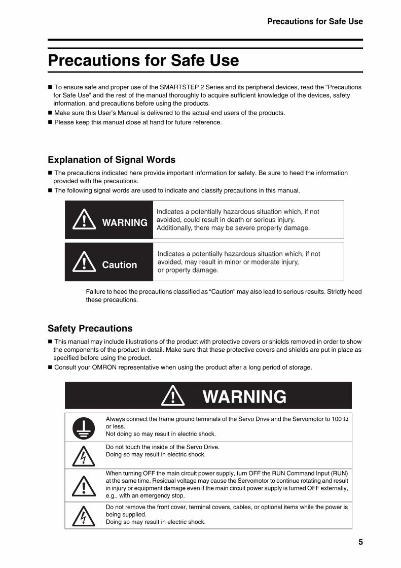
Explanation of Signal WordsThe precautions indicated here provide important information for safety. Be sure to heed the information provided with the precautions.
The following signal words are used to indicate and classify precautions in this manual.
Failure to heed the precautions classified as “Caution” may also lead to serious results. Strictly heed these precautions.
Safety PrecautionsThis manual may include illustrations of the product with protective covers or shields removed in order to show the components of the product in detail. Make sure that these protective covers and shields are put in place as specified before using the product.
Consult your OMRON representative when using the product after a long period of storage.
Always connect the frame ground terminals of the Servo Drive and the Servomotor to 100 Ω or less.Not doing so may result in electric shock.
Do not touch the inside of the Servo Drive.Doing so may result in electric shock.
When turning OFF the main circuit power supply, turn OFF the RUN Command Input (RUN) at the same time. Residual voltage may cause the Servomotor to continue rotating and result in injury or equipment damage even if the main circuit power supply is turned OFF externally, e.g., with an emergency stop.
Do not remove the front cover, terminal covers, cables, or optional items while the power is being supplied.Doing so may result in electric shock.
WARNING
Caution
Indicates a potentially hazardous situation which, if not avoided, could result in death or serious injury. Additionally, there may be severe property damage.
Indicates a potentially hazardous situation which, if not avoided, may result in minor or moderate injury, or property damage.
WARNING
5
Precautions for Safe Use
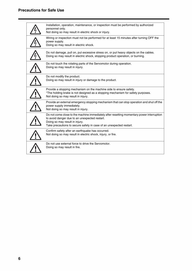
Installation, operation, maintenance, or inspection must be performed by authorized personnel only.Not doing so may result in electric shock or injury.
Wiring or inspection must not be performed for at least 15 minutes after turning OFF the power supply.Doing so may result in electric shock.
Do not damage, pull on, put excessive stress on, or put heavy objects on the cables.Doing so may result in electric shock, stopping product operation, or burning.
Do not touch the rotating parts of the Servomotor during operation.Doing so may result in injury.
Do not modify the product.Doing so may result in injury or damage to the product.
Provide a stopping mechanism on the machine side to ensure safety.*The holding brake is not designed as a stopping mechanism for safety purposes.Not doing so may result in injury.
Provide an external emergency stopping mechanism that can stop operation and shut off the power supply immediately.Not doing so may result in injury.
Do not come close to the machine immediately after resetting momentary power interruption to avoid danger due to an unexpected restart.Doing so may result in injury.Take precautions to secure safety in case of an unexpected restart.
Confirm safety after an earthquake has occurred.Not doing so may result in electric shock, injury, or fire.
Do not use external force to drive the Servomotor. Doing so may result in fire.
6
Precautions for Safe Use
Storage and Transportation Precautions
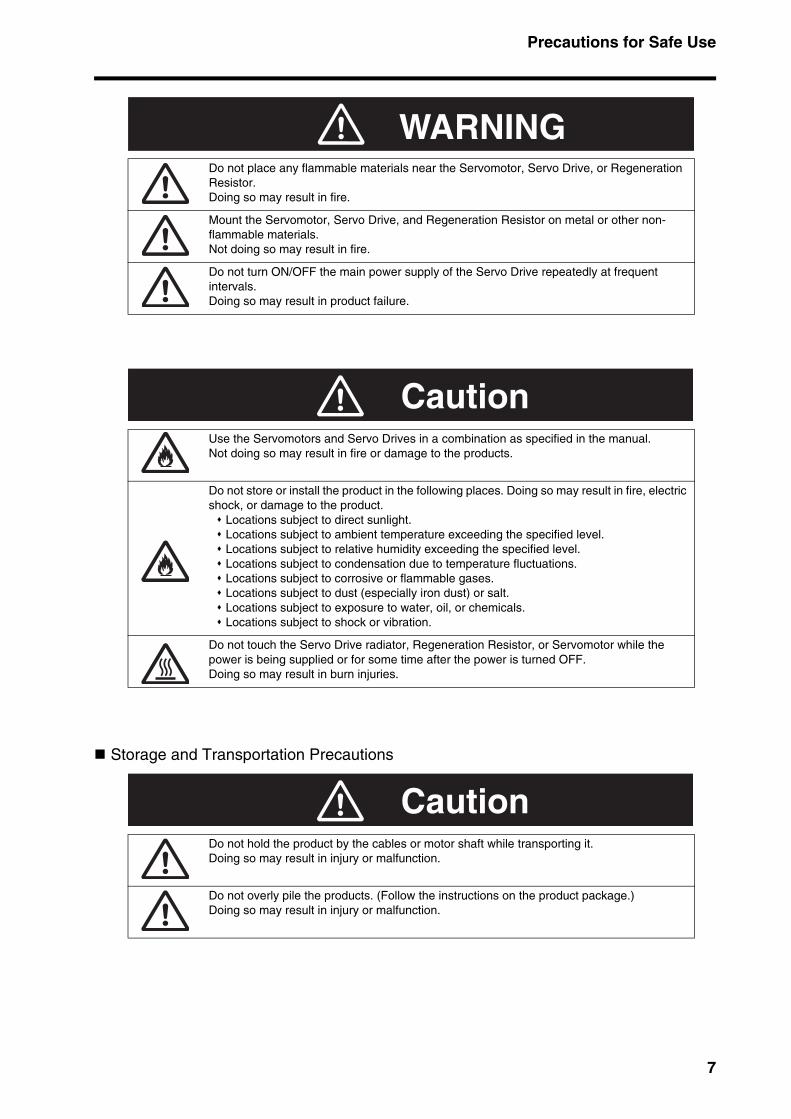
Do not place any flammable materials near the Servomotor, Servo Drive, or Regeneration Resistor. Doing so may result in fire.
Mount the Servomotor, Servo Drive, and Regeneration Resistor on metal or other non-flammable materials. Not doing so may result in fire.
Do not turn ON/OFF the main power supply of the Servo Drive repeatedly at frequent intervals. Doing so may result in product failure.
Use the Servomotors and Servo Drives in a combination as specified in the manual.Not doing so may result in fire or damage to the products.
Do not store or install the product in the following places. Doing so may result in fire, electric shock, or damage to the product.
Locations subject to direct sunlight. Locations subject to ambient temperature exceeding the specified level. Locations subject to relative humidity exceeding the specified level. Locations subject to condensation due to temperature fluctuations. Locations subject to corrosive or flammable gases. Locations subject to dust (especially iron dust) or salt. Locations subject to exposure to water, oil, or chemicals. Locations subject to shock or vibration.
Do not touch the Servo Drive radiator, Regeneration Resistor, or Servomotor while the power is being supplied or for some time after the power is turned OFF.Doing so may result in burn injuries.
Do not hold the product by the cables or motor shaft while transporting it. Doing so may result in injury or malfunction.
Do not overly pile the products. (Follow the instructions on the product package.)Doing so may result in injury or malfunction.
WARNING
Caution
Caution
7
Precautions for Safe Use
Installation and Wiring Precautions
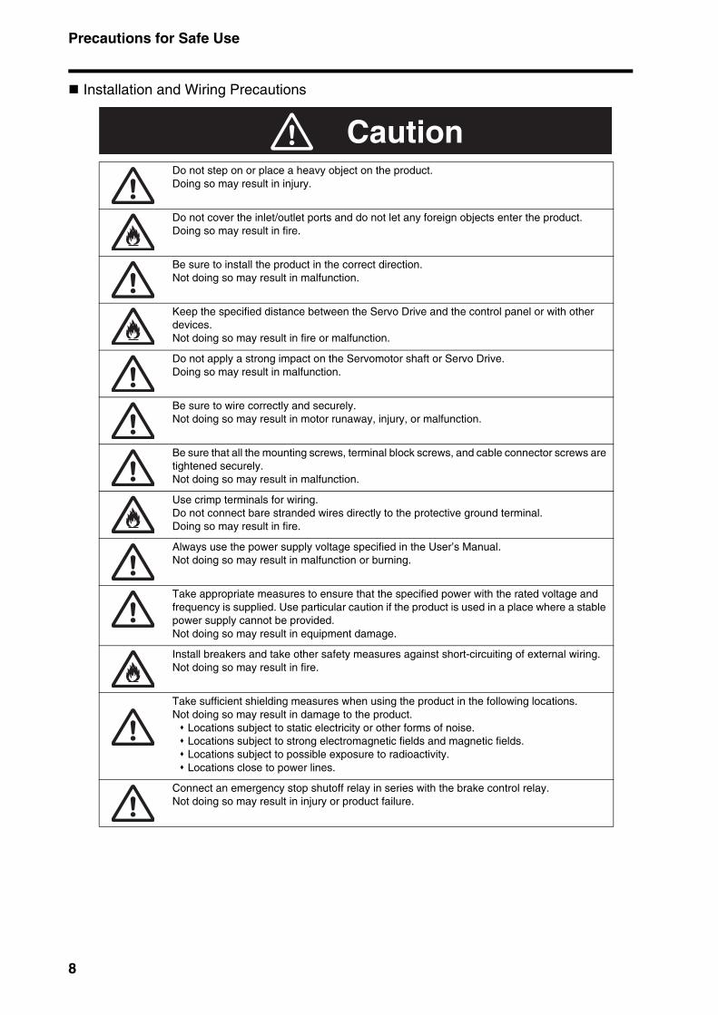
Do not step on or place a heavy object on the product.Doing so may result in injury.
Do not cover the inlet/outlet ports and do not let any foreign objects enter the product.Doing so may result in fire.
Be sure to install the product in the correct direction.Not doing so may result in malfunction.
Keep the specified distance between the Servo Drive and the control panel or with other devices.Not doing so may result in fire or malfunction.
Do not apply a strong impact on the Servomotor shaft or Servo Drive.Doing so may result in malfunction.
Be sure to wire correctly and securely.Not doing so may result in motor runaway, injury, or malfunction.
Be sure that all the mounting screws, terminal block screws, and cable connector screws are tightened securely.Not doing so may result in malfunction.
Use crimp terminals for wiring.Do not connect bare stranded wires directly to the protective ground terminal. Doing so may result in fire.
Always use the power supply voltage specified in the User’s Manual.Not doing so may result in malfunction or burning.
Take appropriate measures to ensure that the specified power with the rated voltage and frequency is supplied. Use particular caution if the product is used in a place where a stable power supply cannot be provided.Not doing so may result in equipment damage.
Install breakers and take other safety measures against short-circuiting of external wiring.Not doing so may result in fire.
Take sufficient shielding measures when using the product in the following locations. Not doing so may result in damage to the product.
Locations subject to static electricity or other forms of noise. Locations subject to strong electromagnetic fields and magnetic fields. Locations subject to possible exposure to radioactivity. Locations close to power lines.
Connect an emergency stop shutoff relay in series with the brake control relay. Not doing so may result in injury or product failure.
Caution
8

Precautions for Safe Use
Operation and Adjustment Precautions
Maintenance and Inspection Precautions
Confirm that no adverse effects will occur in the system before performing the test operation.Not doing so may result in equipment damage.
Check that the newly set parameters function properly before the actual operation.Not doing so may result in equipment damage.
Do not make any extreme adjustments or setting changes.Doing so may result in injury.
Check for the proper operation of the Servomotor separately from the mechanical system before connecting it to the machine.Not doing so may cause injury.
When an alarm occurs, remove the cause, reset the alarm after confirming safety, and then resume operation.Not doing so may result in injury.
Do not use the built-in brake of the Servomotor for ordinary braking.Doing so may result in malfunction.
Do not operate the Servomotor connected to a load that exceeds the applicable load inertia.Doing so may result in malfunction.
Resume operation only after transferring to the new Unit the contents of the data required for operation restart.Not doing so may result in equipment damage.
Do not dismantle or repair the product.Doing so may result in electric shock or injury.
Caution
Caution
9
Precautions for Safe Use
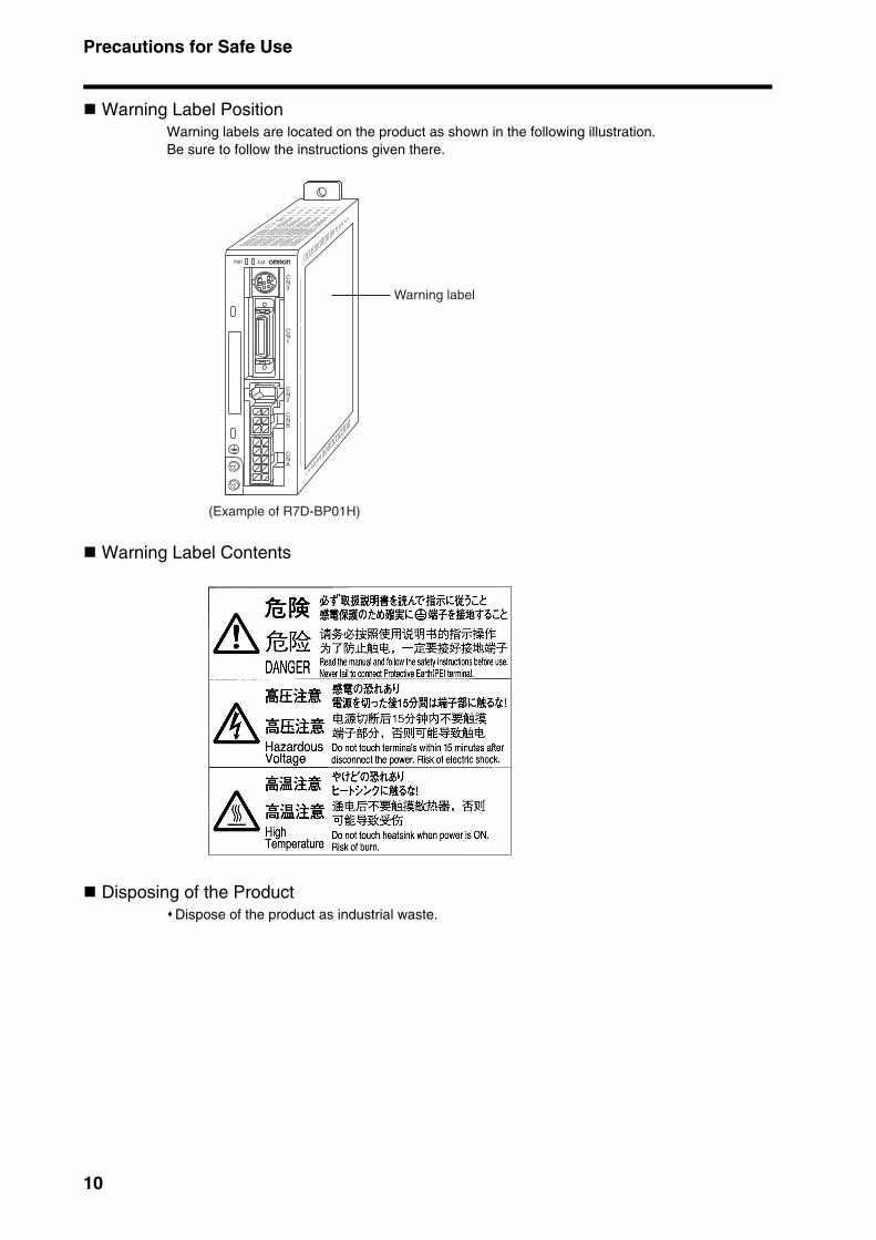
Warning Label PositionWarning labels are located on the product as shown in the following illustration.Be sure to follow the instructions given there.
Warning Label Contents
Disposing of the ProductDispose of the product as industrial waste.
Warning label
(Example of R7D-BP01H)
PWR ALM
CN3
CN1
CN2
CNB
CNA
10
Items to Check When Unpacking
Items to Check When UnpackingCheck the following items after removing the product from the package.
Has the correct product been delivered?Has the product been damaged in shipping?
Accessories Provided with Product
Safety Precautions document × 1
No connectors or mounting screws are provided. They have to be prepared by the user.Should you find any problems (missing parts, damage to the Servo Drive, etc.), please contact your local sales representative or OMRON sales office.
Understanding Model Numbers
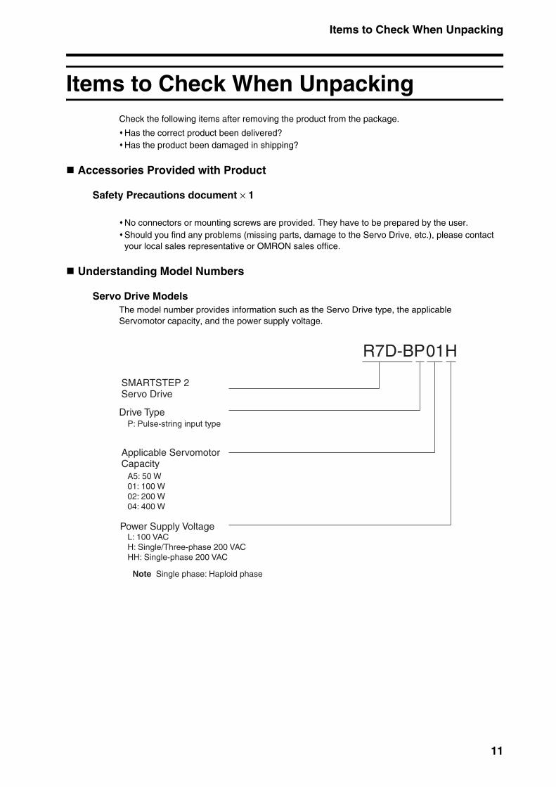
Servo Drive ModelsThe model number provides information such as the Servo Drive type, the applicableServomotor capacity, and the power supply voltage.
R7D-BP01H
SMARTSTEP 2Servo Drive
Applicable Servomotor Capacity
Power Supply Voltage
Drive TypeP: Pulse-string input type
A5: 50 W01: 100 W02: 200 W04: 400 W
L: 100 VACH: Single/Three-phase 200 VACHH: Single-phase 200 VAC
Note Single phase: Haploid phase
11
Items to Check When Unpacking
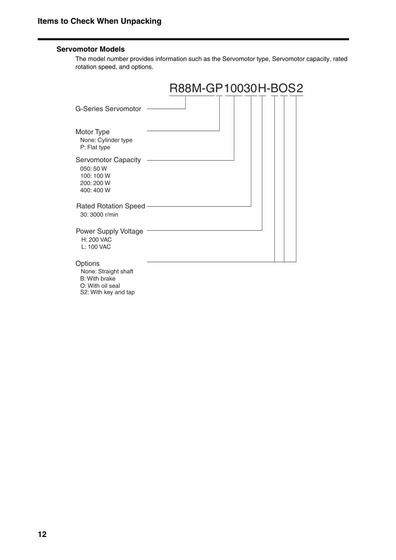
Servomotor Models The model number provides information such as the Servomotor type, Servomotor capacity, rated rotation speed, and options.
R88M-GP10030H-BOS2
Servomotor Capacity
Rated Rotation Speed
Motor Type
P: Flat type
050: 50 W100: 100 W200: 200 W400: 400 W
30: 3000 r/min
None: Cylinder type
Power Supply VoltageH: 200 VACL: 100 VAC
OptionsNone: Straight shaftB: With brakeO: With oil seal
G-Series Servomotor
S2: With key and tap
12
13
About this Manual
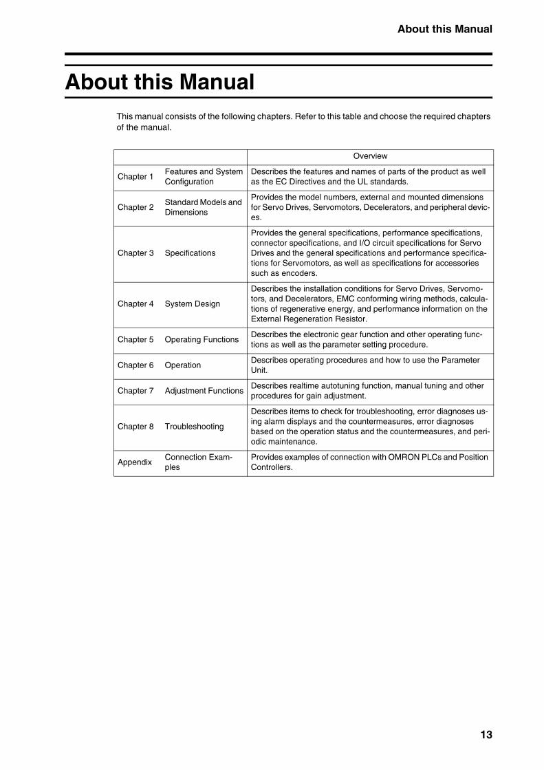
About this ManualThis manual consists of the following chapters. Refer to this table and choose the required chapters of the manual.
Overview
Chapter 1Features and SystemConfiguration
Describes the features and names of parts of the product as well as the EC Directives and the UL standards.
Chapter 2Standard Models and Dimensions
Provides the model numbers, external and mounted dimensions for Servo Drives, Servomotors, Decelerators, and peripheral devic-es.
Chapter 3 Specifications
Provides the general specifications, performance specifications, connector specifications, and I/O circuit specifications for Servo Drives and the general specifications and performance specifica-tions for Servomotors, as well as specifications for accessories such as encoders.
Chapter 4 System Design
Describes the installation conditions for Servo Drives, Servomo-tors, and Decelerators, EMC conforming wiring methods, calcula-tions of regenerative energy, and performance information on the External Regeneration Resistor.
Chapter 5 Operating FunctionsDescribes the electronic gear function and other operating func-tions as well as the parameter setting procedure.
Chapter 6 OperationDescribes operating procedures and how to use the Parameter Unit.
Chapter 7 Adjustment FunctionsDescribes realtime autotuning function, manual tuning and other procedures for gain adjustment.
Chapter 8 Troubleshooting
Describes items to check for troubleshooting, error diagnoses us-ing alarm displays and the countermeasures, error diagnoses based on the operation status and the countermeasures, and peri-odic maintenance.
AppendixConnection Exam-ples
Provides examples of connection with OMRON PLCs and Position Controllers.
CONTENTS
Introduction .................................................................................. 1
Precautions for Safe Use............................................................. 5
Items to Check When Unpacking ................................................ 11
About this Manual ........................................................................ 13
Chapter 1 Features and System Configuration
1-1 Overview ................................................................................................. 1-11-2 System Configuration.............................................................................. 1-21-3 Names of Parts and Functions................................................................ 1-31-4 System Block Diagrams .......................................................................... 1-51-5 Applicable Standards .............................................................................. 1-6
Chapter 2 Standard Models and Dimensions
2-1 Standard Models ..................................................................................... 2-12-2 External and Mounted Dimensions ......................................................... 2-13
Chapter 3 Specifications
3-1 Servo Drive Specifications ...................................................................... 3-13-2 Servomotor Specifications ...................................................................... 3-163-3 Decelerator Specifications ...................................................................... 3-263-4 Cable and Connector Specifications ....................................................... 3-303-5 Servo Relay Units and Cable Specifications........................................... 3-533-6 Parameter Unit Specifications................................................................. 3-783-7 External Regeneration Resistors Specifications ..................................... 3-793-8 Reactor Specifications ............................................................................ 3-80
Chapter 4 System Design
4-1 Installation Conditions ............................................................................. 4-14-2 Wiring ...................................................................................................... 4-104-3 Wiring Conforming to EMC Directives..................................................... 4-184-4 Regenerative Energy Absorption ............................................................ 4-33
Chapter 5 Operating Functions
5-1 Position Control ....................................................................................... 5-15-2 Internally Set Speed Control ................................................................... 5-45-3 Forward and Reverse Drive Prohibit ....................................................... 5-75-4 Encoder Dividing ..................................................................................... 5-85-5 Electronic Gear ....................................................................................... 5-95-6 Brake Interlock ........................................................................................ 5-115-7 Gain Switching ........................................................................................ 5-135-8 Torque Limit ............................................................................................ 5-155-9 Overrun Limit........................................................................................... 5-165-10 User Parameters ..................................................................................... 5-17
14

CONTENTS
Chapter 6 Operation6-1 Operational Procedure.............................................................................6-16-2 Preparing for Operation ...........................................................................6-26-3 Using the Parameter Unit ........................................................................6-46-4 Trial Operation .........................................................................................6-23
Chapter 7 Adjustment Functions
7-1 Gain Adjustment ......................................................................................7-17-2 Realtime Autotuning ................................................................................7-37-3 Autotuning................................................................................................7-87-4 Disabling the Automatic Gain Adjustment Function.................................7-137-5 Manual Tuning .........................................................................................7-15
Chapter 8 Troubleshooting
8-1 Error Processing ......................................................................................8-18-2 Alarm Table .............................................................................................8-38-3 Troubleshooting .......................................................................................8-58-4 Overload Characteristics (Electronic Thermal Function) .........................8-168-5 Periodic Maintenance ..............................................................................8-17
15

Chapter 1
Features and System Configuration
1-1 Overview .............................................................1-1Overview of the SMARTSTEP 2 Series...................................1-1
Features of the SMARTSTEP 2 Series....................................1-1
1-2 System Configuration........................................1-2
1-3 Names of Parts and Functions .........................1-3Servo Drive Part Names ..........................................................1-3
Servo Drive Functions..............................................................1-4
1-4 System Block Diagrams ....................................1-5
1-5 Applicable Standards ........................................1-6EC Directives ...........................................................................1-6
UL/cUL Standards....................................................................1-6
1-1 Overview
1
Fea
ture
s an
d S
yste
m C
on
fig
ura
tio
n
1Features and System Configuration
1-1 Overview
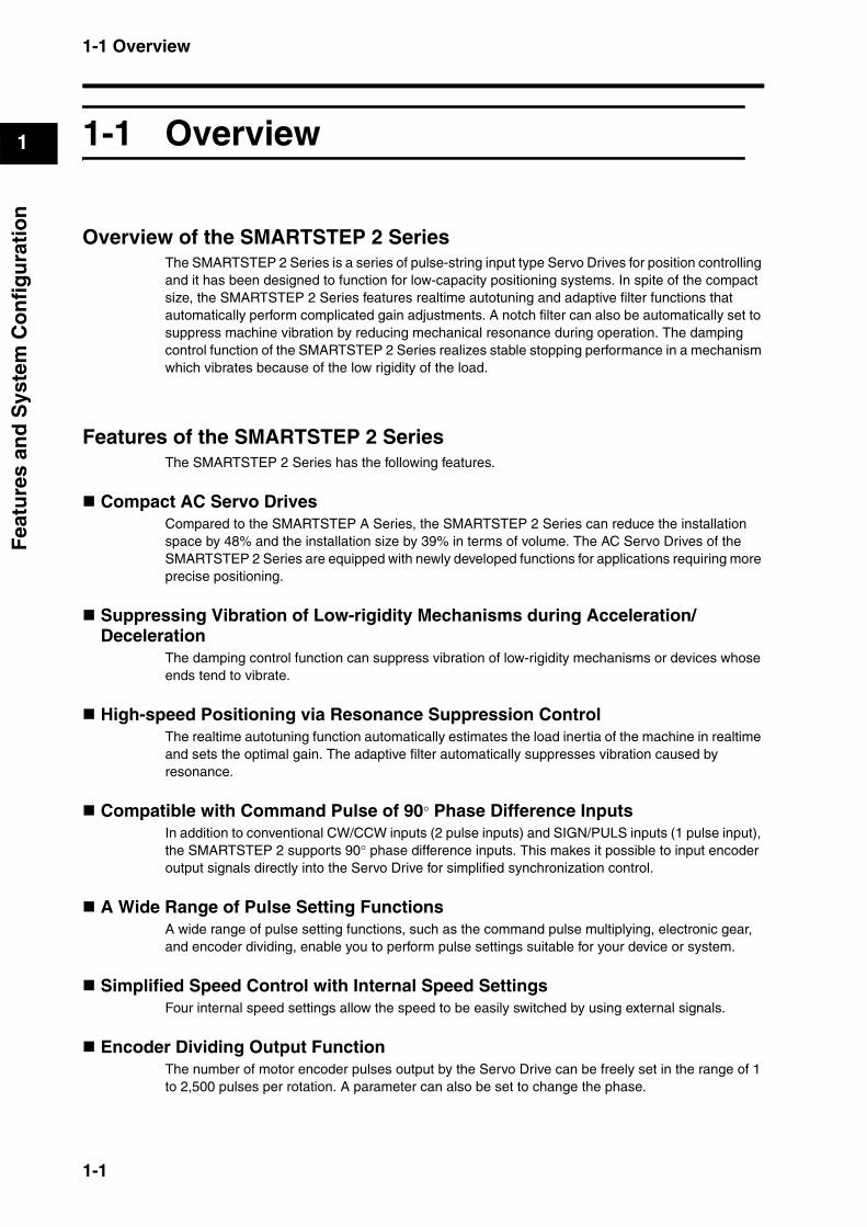
Overview of the SMARTSTEP 2 SeriesThe SMARTSTEP 2 Series is a series of pulse-string input type Servo Drives for position controlling and it has been designed to function for low-capacity positioning systems. In spite of the compact size, the SMARTSTEP 2 Series features realtime autotuning and adaptive filter functions that automatically perform complicated gain adjustments. A notch filter can also be automatically set to suppress machine vibration by reducing mechanical resonance during operation. The damping control function of the SMARTSTEP 2 Series realizes stable stopping performance in a mechanism which vibrates because of the low rigidity of the load.
Features of the SMARTSTEP 2 SeriesThe SMARTSTEP 2 Series has the following features.
Compact AC Servo DrivesCompared to the SMARTSTEP A Series, the SMARTSTEP 2 Series can reduce the installation space by 48% and the installation size by 39% in terms of volume. The AC Servo Drives of the SMARTSTEP 2 Series are equipped with newly developed functions for applications requiring more precise positioning.
Suppressing Vibration of Low-rigidity Mechanisms during Acceleration/Deceleration
The damping control function can suppress vibration of low-rigidity mechanisms or devices whose ends tend to vibrate.
High-speed Positioning via Resonance Suppression ControlThe realtime autotuning function automatically estimates the load inertia of the machine in realtime and sets the optimal gain. The adaptive filter automatically suppresses vibration caused by resonance.
Compatible with Command Pulse of 90° Phase Difference Inputs In addition to conventional CW/CCW inputs (2 pulse inputs) and SIGN/PULS inputs (1 pulse input), the SMARTSTEP 2 supports 90° phase difference inputs. This makes it possible to input encoder output signals directly into the Servo Drive for simplified synchronization control.
A Wide Range of Pulse Setting FunctionsA wide range of pulse setting functions, such as the command pulse multiplying, electronic gear, and encoder dividing, enable you to perform pulse settings suitable for your device or system.
Simplified Speed Control with Internal Speed SettingsFour internal speed settings allow the speed to be easily switched by using external signals.
Encoder Dividing Output FunctionThe number of motor encoder pulses output by the Servo Drive can be freely set in the range of 1 to 2,500 pulses per rotation. A parameter can also be set to change the phase.
1-1

1-2 System Configuration
1
Fea
ture
s an
d S
yste
m C
on
fig
ura
tio
n
1-2 System Configuration
INPUT
AC100-240V
L2/N
L1
NC
NC
SYSMAC PLC + Position Control Unit with pulse-string output
SYSMACCJ1/CS1/C-SeriesProgrammable Controller
Position Control UnitCJ1W-NC113/213/413CJ1W-NC133/233/433CS1W-NC113/213/413CS1W-NC133/233/433C200HW-NC113/213/413
Pulse string
SYSMAC PLC with pulse output functions
SYSMAC CJ1M
SYSMAC CP1H/CP1L
Flexible Motion Controller with Pulse I/O
FQM1-MMP22
SMARTSTEP 2 Servo DriveR7D-BP@
OMNUC G-Series Servomotor R88M-G@/-GP@
1-2
1-3 Names of Parts and Functions
1
Fea
ture
s an
d S
yste
m C
on
fig
ura
tio
n
1-3 Names of Parts and Functions
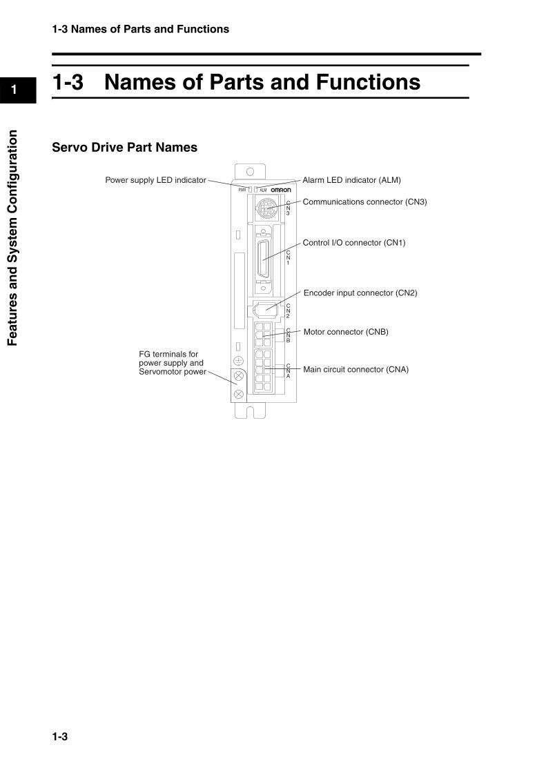
Servo Drive Part Names
CN1
CN2
CNA
CNB
CN3
PWR ALM
Encoder input connector (CN2)
Motor connector (CNB)
Communications connector (CN3)
Alarm LED indicator (ALM)Power supply LED indicator
FG terminals forpower supply andServomotor power Main circuit connector (CNA)
Control I/O connector (CN1)
1-3
1-3 Names of Parts and Functions
1
Fea
ture
s an
d S
yste
m C
on
fig
ura
tio
n
Servo Drive Functions
Power Supply LED Indicator (PWR)
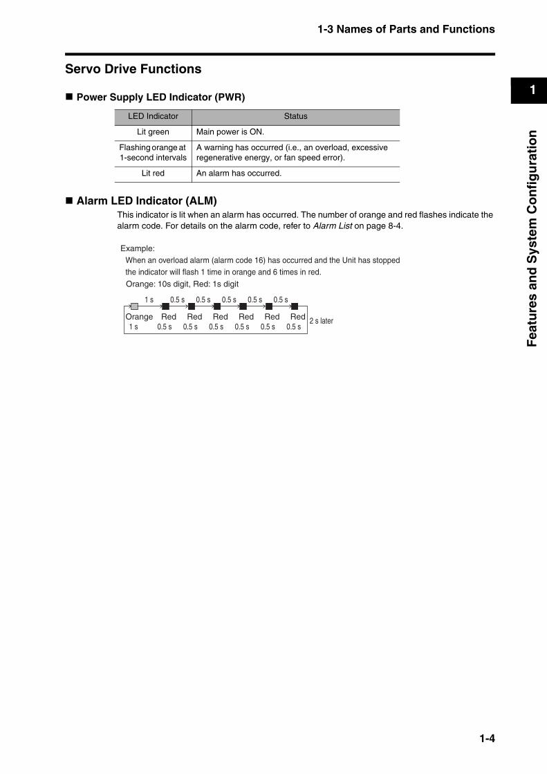
Alarm LED Indicator (ALM)This indicator is lit when an alarm has occurred. The number of orange and red flashes indicate the alarm code. For details on the alarm code, refer to Alarm List on page 8-4.
LED Indicator Status
Lit green Main power is ON.
Flashing orange at 1-second intervals
A warning has occurred (i.e., an overload, excessive regenerative energy, or fan speed error).
Lit red An alarm has occurred.
Orange: 10s digit, Red: 1s digit
Example:When an overload alarm (alarm code 16) has occurred and the Unit has stoppedthe indicator will flash 1 time in orange and 6 times in red.
Orange1 s
Red0.5 s
0.5 s1 s
Red0.5 s
Red0.5 s
Red0.5 s
Red0.5 s
Red0.5 s
0.5 s 0.5 s 0.5 s 0.5 s
2 s later
1-4
1-4 System Block Diagrams
1
Fea
ture
s an
d S
yste
m C
on
fig
ura
tio
n
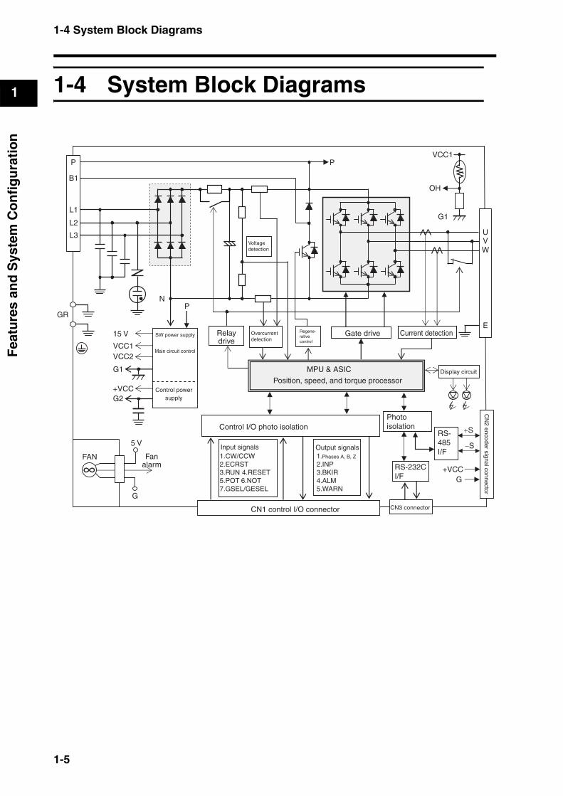
1-4 System Block Diagrams
P
B1
L1
L2
L3
GR
N
15 V
VCC1VCC2
G1
+VCCG2
FAN
5 V
G
P
Voltage detection
Overcurrent detection
Regene-rative control
MPU & ASIC
Position, speed, and torque processor
Control I/O photo isolation
Input signals1.CW/CCW2.ECRST3.RUN 4.RESET5.POT 6.NOT7.GSEL/GESEL
1.Phases A, B, Z
2.INP3.BKIR4.ALM5.WARN
G+VCC
RS-485I/F
+S
−S
CN
2 encoder signal connector
Display circuit
CN3 connector
RS-232CI/F
E
UVW
P
G1
OH
VCC1
SW power supply
Main circuit control
Control power supply
Relay drive
Gate drive Current detection
CN1 control I/O connector
Fan alarm
Photo isolation
Output signals
1-5

1-5 Applicable Standards
1
Fea
ture
s an
d S
yste
m C
on
fig
ura
tio
n
1-5 Applicable Standards
EC Directives
Note To conform to the EMC Directives, the Servomotor and Servo Drive must be installed under the conditions described in 4-3 Wiring Conforming to EMC Directives.
UL/cUL Standards
EC Directive Product Applicable standards Comments
Low Voltage Directive
AC Servo Drive EN 50178 Safety requirements for elec-tronic equipment for measure-ment, control, or laboratory use
AC Servomotor IEC 60034-1 Rotating electric machines
EMC Directive
AC Servo Drive and AC Servomotor
EN 55011 class A group1
Radio disturbance limits and measurement methods of in-
dustrial, scientific, and medical radio-frequency equipment
EN 61000-6-2 Electromagnetic compatibility (EMC): Immunity standard for
industrial environments
Standard Product Applicable standards File number
UL Standard AC Servo Drive UL 508C E179149
AC Servomotor UL1004-1 E331224
CSA standard AC Servo Drive CSA22.2 No. 14 E179149
AC Servomotor CSA22.2 No. 100 E331224
1-6

Chapter 2
Standard Models and Dimensions
2-1 Standard Models ................................................2-1Servo Drives ............................................................................2-1
Servomotors.............................................................................2-1
Parameter Unit .........................................................................2-2
Servo Drive-Servomotor Combinations ...................................2-2
Decelerators.............................................................................2-4
Accessories and Cables ..........................................................2-8
2-2 External and Mounted Dimensions ................2-13Servo Drives ..........................................................................2-13
Servomotors...........................................................................2-15
Parameter Unit Dimensions ...................................................2-18
Decelerator Dimensions.........................................................2-19
External Regeneration Resistor Dimensions .........................2-27
Reactor Dimensions...............................................................2-28
DIN Rail Mounting Unit Dimensions.......................................2-29
2-1 Standard Models
2
Sta
nd
ard
Mo
del
s an
d D
imen
sio
ns
2Standard Models and Dimensions
2-1 Standard Models
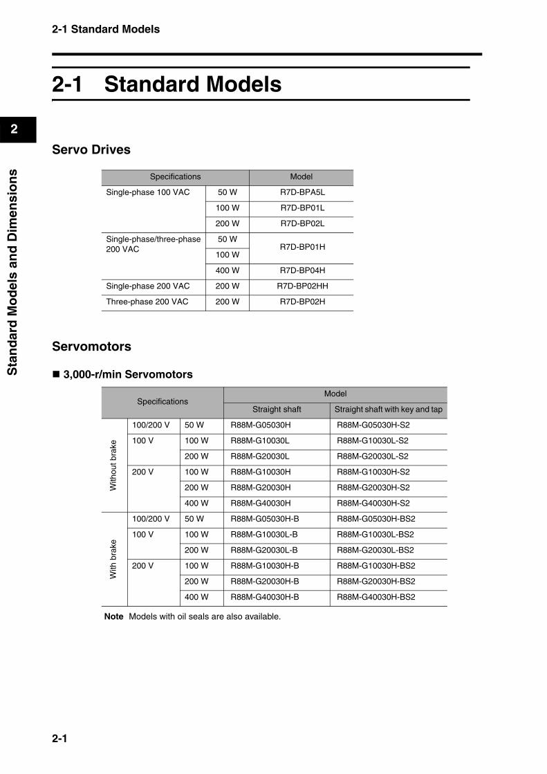
Servo Drives
Servomotors
3,000-r/min Servomotors
Note Models with oil seals are also available.
Specifications Model
Single-phase 100 VAC 50 W R7D-BPA5L
100 W R7D-BP01L
200 W R7D-BP02L
Single-phase/three-phase 200 VAC
50 W R7D-BP01H
100 W
400 W R7D-BP04H
Single-phase 200 VAC 200 W R7D-BP02HH
Three-phase 200 VAC 200 W R7D-BP02H
SpecificationsModel
Straight shaft Straight shaft with key and tap
With
out b
rake
100/200 V 50 W R88M-G05030H R88M-G05030H-S2
100 V 100 W R88M-G10030L R88M-G10030L-S2
200 W R88M-G20030L R88M-G20030L-S2
200 V 100 W R88M-G10030H R88M-G10030H-S2
200 W R88M-G20030H R88M-G20030H-S2
400 W R88M-G40030H R88M-G40030H-S2
With
bra
ke
100/200 V 50 W R88M-G05030H-B R88M-G05030H-BS2
100 V 100 W R88M-G10030L-B R88M-G10030L-BS2
200 W R88M-G20030L-B R88M-G20030L-BS2
200 V 100 W R88M-G10030H-B R88M-G10030H-BS2
200 W R88M-G20030H-B R88M-G20030H-BS2
400 W R88M-G40030H-B R88M-G40030H-BS2
2-1
2-1 Standard Models
2
Sta
nd
ard
Mo
del
s an
d D
imen
sio
ns
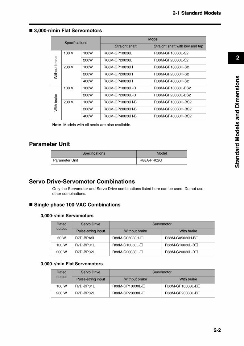
3,000-r/min Flat Servomotors
Note Models with oil seals are also available.
Parameter Unit
Servo Drive-Servomotor CombinationsOnly the Servomotor and Servo Drive combinations listed here can be used. Do not useother combinations.
Single-phase 100-VAC Combinations
3,000-r/min Servomotors
3,000-r/min Flat Servomotors
SpecificationsModel
Straight shaft Straight shaft with key and tap
With
out b
rake
100 V 100W R88M-GP10030L R88M-GP10030L-S2
200W R88M-GP20030L R88M-GP20030L-S2
200 V 100W R88M-GP10030H R88M-GP10030H-S2
200W R88M-GP20030H R88M-GP20030H-S2
400W R88M-GP40030H R88M-GP40030H-S2
With
bra
ke
100 V 100W R88M-GP10030L-B R88M-GP10030L-BS2
200W R88M-GP20030L-B R88M-GP20030L-BS2
200 V 100W R88M-GP10030H-B R88M-GP10030H-BS2
200W R88M-GP20030H-B R88M-GP20030H-BS2
400W R88M-GP40030H-B R88M-GP40030H-BS2
Specifications Model
Parameter Unit R88A-PR02G
Rated output
Servo Drive Servomotor
Pulse-string input Without brake With brake
50 W R7D-BPA5L R88M-G05030H-@ R88M-G05030H-B@
100 W R7D-BP01L R88M-G10030L-@ R88M-G10030L-B@
200 W R7D-BP02L R88M-G20030L-@ R88M-G20030L-B@
Rated output
Servo Drive Servomotor
Pulse-string input Without brake With brake
100 W R7D-BP01L R88M-GP10030L-@ R88M-GP10030L-B@
200 W R7D-BP02L R88M-GP20030L-@ R88M-GP20030L-B@
2-2

2-1 Standard Models
2
Sta
nd
ard
Mo
del
s an
d D
imen
sio
ns
Single-phase 200-VAC Combinations
3,000-r/min Servomotors
3,000-r/min Flat Servomotors
Three-phase 200-VAC Combinations
3,000-r/min Servomotors
3,000-r/min Flat Servomotors
Rated output
Servo Drive Servomotor
Pulse-string input Without brake With brake
50 W R7D-BP01H
R88M-G05030H-@ R88M-G05030H-B@
100 W R88M-G10030H-@ R88M-G10030H-B@
200 W R7D-BP02HH R88M-G20030H-@ R88M-G20030H-B@
400 W R7D-BP04H R88M-G40030H-@ R88M-G40030H-B@
Rated output
Servo Drive Servomotor
Pulse-string input Without brake With brake
100 W R7D-BP01H R88M-GP10030H-@ R88M-GP10030H-B@
200 W R7D-BP02HH R88M-GP20030H-@ R88M-GP20030H-B@
400 W R7D-BP04H R88M-GP40030H-@ R88M-GP40030H-B@
Rated output
Servo Drive Servomotor
Pulse-string input Without brake With brake
50 W R7D-BP01H
R88M-G05030H-@ R88M-G05030H-B@
100 W R88M-G10030H-@ R88M-G10030H-B@
200 W R7D-BP02H R88M-G20030H-@ R88M-G20030H-B@
400 W R7D-BP04H R88M-G40030H-@ R88M-G40030H-B@
Rated output
Servo Drive Servomotor
Pulse-string input Without brake With brake
100 W R7D-BP01H R88M-GP10030H-@ R88M-GP10030H-B@
200 W R7D-BP02H R88M-GP20030H-@ R88M-GP20030H-B@
400 W R7D-BP04H R88M-GP40030H-@ R88M-GP40030H-B@
2-3
2-1 Standard Models
2
Sta
nd
ard
Mo
del
s an
d D
imen
sio
ns
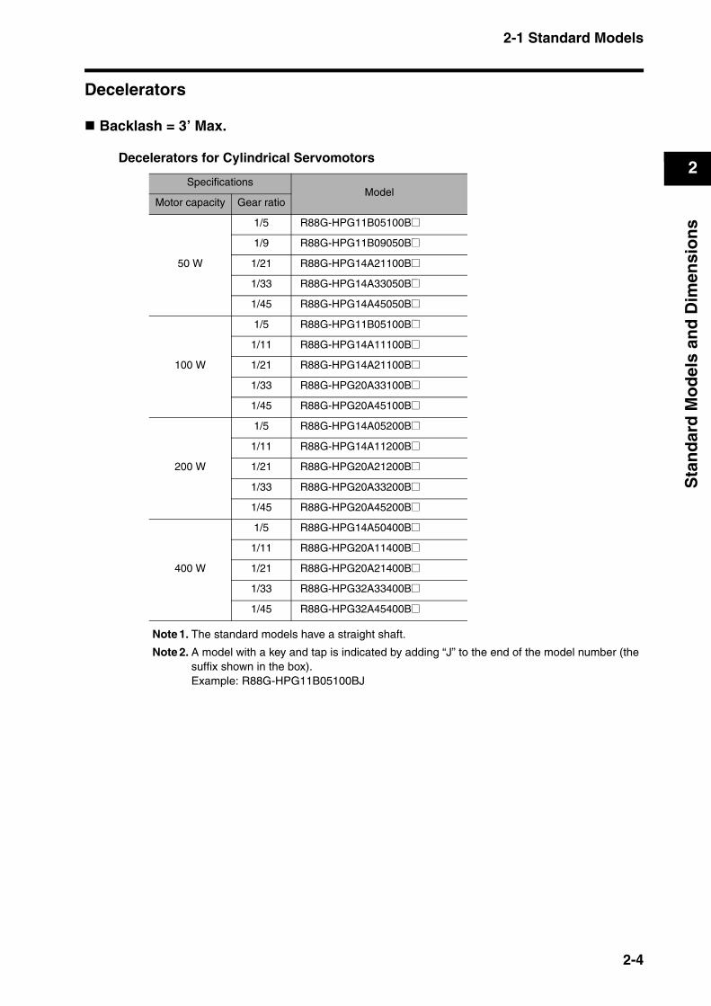
Decelerators
Backlash = 3’ Max.
Decelerators for Cylindrical Servomotors
Note 1. The standard models have a straight shaft.
Note 2. A model with a key and tap is indicated by adding “J” to the end of the model number (the suffix shown in the box).Example: R88G-HPG11B05100BJ
SpecificationsModel
Motor capacity Gear ratio
50 W
1/5 R88G-HPG11B05100B@
1/9 R88G-HPG11B09050B@
1/21 R88G-HPG14A21100B@
1/33 R88G-HPG14A33050B@
1/45 R88G-HPG14A45050B@
100 W
1/5 R88G-HPG11B05100B@
1/11 R88G-HPG14A11100B@
1/21 R88G-HPG14A21100B@
1/33 R88G-HPG20A33100B@
1/45 R88G-HPG20A45100B@
200 W
1/5 R88G-HPG14A05200B@
1/11 R88G-HPG14A11200B@
1/21 R88G-HPG20A21200B@
1/33 R88G-HPG20A33200B@
1/45 R88G-HPG20A45200B@
400 W
1/5 R88G-HPG14A50400B@
1/11 R88G-HPG20A11400B@
1/21 R88G-HPG20A21400B@
1/33 R88G-HPG32A33400B@
1/45 R88G-HPG32A45400B@
2-4

2-1 Standard Models
2
Sta
nd
ard
Mo
del
s an
d D
imen
sio
ns
Decelerator for Flat Servomotors
Note 1. The standard models have a straight shaft.
Note 2. A model with a key and tap is indicated by adding “J” to the end of the model number (the suffix shown in the box).Example: R88G-HPG11B05100PBJ
SpecificationsModel
Motor capacity Gear ratio
100 W
1/5 R88G-HPG11B05100PB@
1/11 R88G-HPG14A11100PB@
1/21 R88G-HPG14A21100PB@
1/33 R88G-HPG20A33100PB@
1/45 R88G-HPG20A45100PB@
200 W
1/5 R88G-HPG14A05200PB@
1/11 R88G-HPG20A11200PB@
1/21 R88G-HPG20A21200PB@
1/33 R88G-HPG20A33200PB@
1/45 R88G-HPG20A45200PB@
400 W
1/5 R88G-HPG20A05400PB@
1/11 R88G-HPG20A11400PB@
1/21 R88G-HPG20A21400PB@
1/33 R88G-HPG32A33400PB@
1/45 R88G-HPG32A45400PB@
2-5
2-1 Standard Models
2
Sta
nd
ard
Mo
del
s an
d D
imen
sio
ns
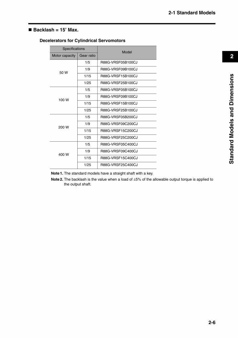
Backlash = 15’ Max.
Decelerators for Cylindrical Servomotors
Note 1. The standard models have a straight shaft with a key.
Note 2. The backlash is the value when a load of ±5% of the allowable output torque is applied to the output shaft.
SpecificationsModel
Motor capacity Gear ratio
50 W
1/5 R88G-VRSF05B100CJ
1/9 R88G-VRSF09B100CJ
1/15 R88G-VRSF15B100CJ
1/25 R88G-VRSF25B100CJ
100 W
1/5 R88G-VRSF05B100CJ
1/9 R88G-VRSF09B100CJ
1/15 R88G-VRSF15B100CJ
1/25 R88G-VRSF25B100CJ
200 W
1/5 R88G-VRSF05B200CJ
1/9 R88G-VRSF09C200CJ
1/15 R88G-VRSF15C200CJ
1/25 R88G-VRSF25C200CJ
400 W
1/5 R88G-VRSF05C400CJ
1/9 R88G-VRSF09C400CJ
1/15 R88G-VRSF15C400CJ
1/25 R88G-VRSF25C400CJ
2-6
2-1 Standard Models
2
Sta
nd
ard
Mo
del
s an
d D
imen
sio
ns
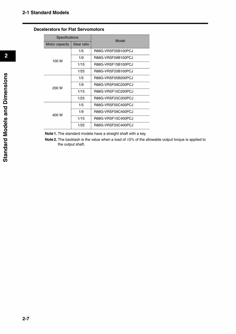
Decelerators for Flat Servomotors
Note 1. The standard models have a straight shaft with a key.
Note 2. The backlash is the value when a load of ±5% of the allowable output torque is applied to the output shaft.
SpecificationsModel
Motor capacity Gear ratio
100 W
1/5 R88G-VRSF05B100PCJ
1/9 R88G-VRSF09B100PCJ
1/15 R88G-VRSF15B100PCJ
1/25 R88G-VRSF25B100PCJ
200 W
1/5 R88G-VRSF05B200PCJ
1/9 R88G-VRSF09C200PCJ
1/15 R88G-VRSF15C200PCJ
1/25 R88G-VRSF25C200PCJ
400 W
1/5 R88G-VRSF05C400PCJ
1/9 R88G-VRSF09C400PCJ
1/15 R88G-VRSF15C400PCJ
1/25 R88G-VRSF25C400PCJ
2-7

2-1 Standard Models
2
Sta
nd
ard
Mo
del
s an
d D
imen
sio
ns
Accessories and Cables
Encoder Cables (for CN2)
Servomotor Power Cables (for CNB)
Brake Cables
Specifications Model
Standard Cables (connectors attached) 3 m R88A-CRGB003C
5 m R88A-CRGB005C
10 m R88A-CRGB010C
15 m R88A-CRGB015C
20 m R88A-CRGB020C
Robot Cables (connectors attached) 3 m R88A-CRGB003CR
5 m R88A-CRGB005CR
10 m R88A-CRGB010CR
15 m R88A-CRGB015CR
20 m R88A-CRGB020CR
Specifications Model
Standard Cables (connectors attached) 3 m R7A-CAB003S
5 m R7A-CAB005S
10 m R7A-CAB010S
15 m R7A-CAB015S
20 m R7A-CAB020S
Robot Cables (connectors attached) 3 m R7A-CAB003SR
5 m R7A-CAB005SR
10 m R7A-CAB010SR
15 m R7A-CAB015SR
20 m R7A-CAB020SR
Specifications Model
Standard Cables 3 m R88A-CAGA003B
5 m R88A-CAGA005B
10 m R88A-CAGA010B
15 m R88A-CAGA015B
20 m R88A-CAGA020B
Robot Cables 3 m R88A-CAGA003BR
5 m R88A-CAGA005BR
10 m R88A-CAGA010BR
15 m R88A-CAGA015BR
20 m R88A-CAGA020BR
2-8
2-1 Standard Models
2
Sta
nd
ard
Mo
del
s an
d D
imen
sio
ns
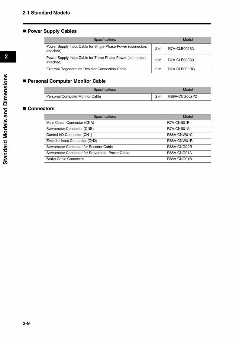
Power Supply Cables
Personal Computer Monitor Cable
Connectors
Specifications Model
Power Supply Input Cable for Single-Phase Power (connectors attached)
2 m R7A-CLB002S2
Power Supply Input Cable for Three-Phase Power (connectors attached)
2 m R7A-CLB002S3
External Regeneration Resistor Connection Cable 2 m R7A-CLB002RG
Specifications Model
Personal Computer Monitor Cable 2 m R88A-CCG002P2
Specifications Model
Main Circuit Connector (CNA) R7A-CNB01P
Servomotor Connector (CNB) R7A-CNB01A
Control I/O Connector (CN1) R88A-CNW01C
Encoder Input Connector (CN2) R88A-CNW01R
Servomotor Connector for Encoder Cable R88A-CNG02R
Servomotor Connector for Servomotor Power Cable R88A-CNG01A
Brake Cable Connector R88A-CNG01B
2-9
2-1 Standard Models
2
Sta
nd
ard
Mo
del
s an
d D
imen
sio
ns
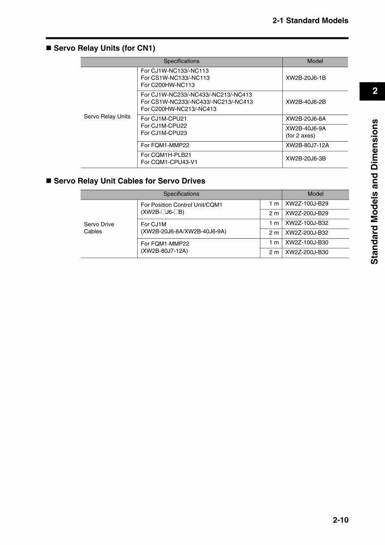
Servo Relay Units (for CN1)
Servo Relay Unit Cables for Servo Drives
Specifications Model
Servo Relay Units
For CJ1W-NC133/-NC113For CS1W-NC133/-NC113For C200HW-NC113
XW2B-20J6-1B
For CJ1W-NC233/-NC433/-NC213/-NC413For CS1W-NC233/-NC433/-NC213/-NC413For C200HW-NC213/-NC413
XW2B-40J6-2B
For CJ1M-CPU21For CJ1M-CPU22For CJ1M-CPU23
XW2B-20J6-8A
XW2B-40J6-9A(for 2 axes)
For FQM1-MMP22 XW2B-80J7-12A
For CQM1H-PLB21For CQM1-CPU43-V1
XW2B-20J6-3B
Specifications Model
Servo Drive Cables
For Position Control Unit/CQM1(XW2B-@J6-@B)
1 m XW2Z-100J-B29
2 m XW2Z-200J-B29
For CJ1M (XW2B-20J6-8A/XW2B-40J6-9A)
1 m XW2Z-100J-B32
2 m XW2Z-200J-B32
For FQM1-MMP22(XW2B-80J7-12A)
1 m XW2Z-100J-B30
2 m XW2Z-200J-B30
2-10
2-1 Standard Models
2
Sta
nd
ard
Mo
del
s an
d D
imen
sio
ns
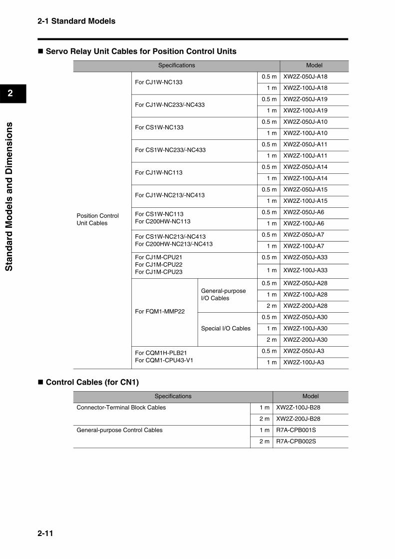
Servo Relay Unit Cables for Position Control Units
Control Cables (for CN1)
Specifications Model
Position Control Unit Cables
For CJ1W-NC1330.5 m XW2Z-050J-A18
1 m XW2Z-100J-A18
For CJ1W-NC233/-NC4330.5 m XW2Z-050J-A19
1 m XW2Z-100J-A19
For CS1W-NC1330.5 m XW2Z-050J-A10
1 m XW2Z-100J-A10
For CS1W-NC233/-NC4330.5 m XW2Z-050J-A11
1 m XW2Z-100J-A11
For CJ1W-NC1130.5 m XW2Z-050J-A14
1 m XW2Z-100J-A14
For CJ1W-NC213/-NC4130.5 m XW2Z-050J-A15
1 m XW2Z-100J-A15
For CS1W-NC113For C200HW-NC113
0.5 m XW2Z-050J-A6
1 m XW2Z-100J-A6
For CS1W-NC213/-NC413For C200HW-NC213/-NC413
0.5 m XW2Z-050J-A7
1 m XW2Z-100J-A7
For CJ1M-CPU21For CJ1M-CPU22For CJ1M-CPU23
0.5 m XW2Z-050J-A33
1 m XW2Z-100J-A33
For FQM1-MMP22
General-purpose I/O Cables
0.5 m XW2Z-050J-A28
1 m XW2Z-100J-A28
2 m XW2Z-200J-A28
Special I/O Cables
0.5 m XW2Z-050J-A30
1 m XW2Z-100J-A30
2 m XW2Z-200J-A30
For CQM1H-PLB21For CQM1-CPU43-V1
0.5 m XW2Z-050J-A3
1 m XW2Z-100J-A3
Specifications Model
Connector-Terminal Block Cables 1 m XW2Z-100J-B28
2 m XW2Z-200J-B28
General-purpose Control Cables 1 m R7A-CPB001S
2 m R7A-CPB002S
2-11
2-1 Standard Models
2
Sta
nd
ard
Mo
del
s an
d D
imen
sio
ns
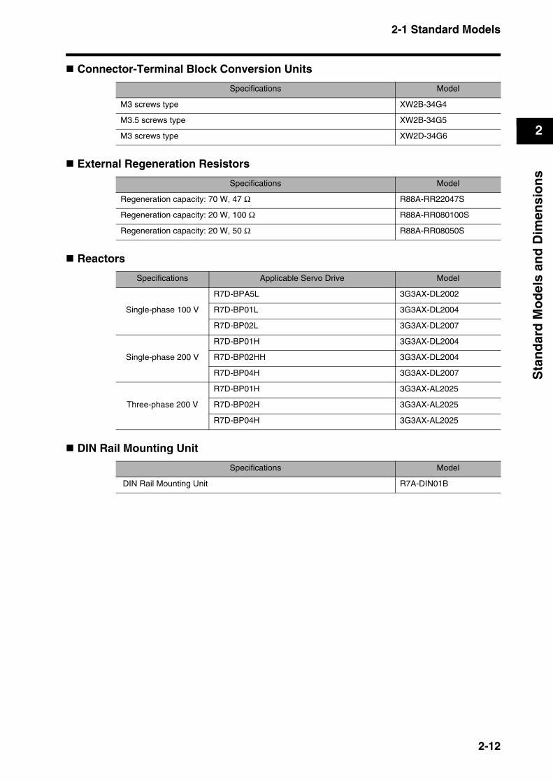
Connector-Terminal Block Conversion Units
External Regeneration Resistors
Reactors
DIN Rail Mounting Unit
Specifications Model
M3 screws type XW2B-34G4
M3.5 screws type XW2B-34G5
M3 screws type XW2D-34G6
Specifications Model
Regeneration capacity: 70 W, 47 Ω R88A-RR22047S
Regeneration capacity: 20 W, 100 Ω R88A-RR080100S
Regeneration capacity: 20 W, 50 Ω R88A-RR08050S
Specifications Applicable Servo Drive Model
Single-phase 100 V
R7D-BPA5L 3G3AX-DL2002
R7D-BP01L 3G3AX-DL2004
R7D-BP02L 3G3AX-DL2007
Single-phase 200 V
R7D-BP01H 3G3AX-DL2004
R7D-BP02HH 3G3AX-DL2004
R7D-BP04H 3G3AX-DL2007
Three-phase 200 V
R7D-BP01H 3G3AX-AL2025
R7D-BP02H 3G3AX-AL2025
R7D-BP04H 3G3AX-AL2025
Specifications Model
DIN Rail Mounting Unit R7A-DIN01B
2-12
2-2 External and Mounted Dimensions
2
Sta
nd
ard
Mo
del
s an
d D
imen
sio
ns
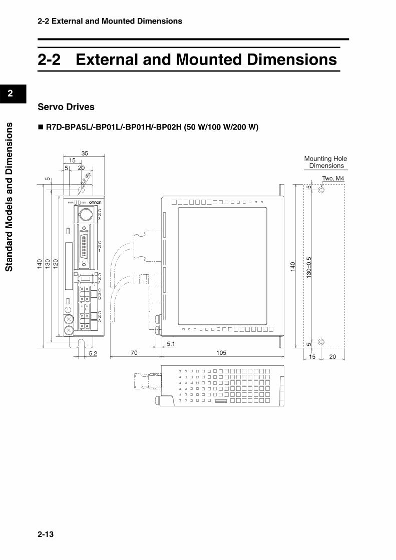
2-2 External and Mounted Dimensions
Servo Drives
R7D-BPA5L/-BP01L/-BP01H/-BP02H (50 W/100 W/200 W)
Two, M4
CN1
CN2
CNB
CNA
CN3
ALMPWR
5.1
5.2 105
35
5.2
dia.
20
130
120
140
155
5
140
130±
0.5
55
15 2070
Mounting Hole Dimensions
2-13
2-2 External and Mounted Dimensions
2
Sta
nd
ard
Mo
del
s an
d D
imen
sio
ns
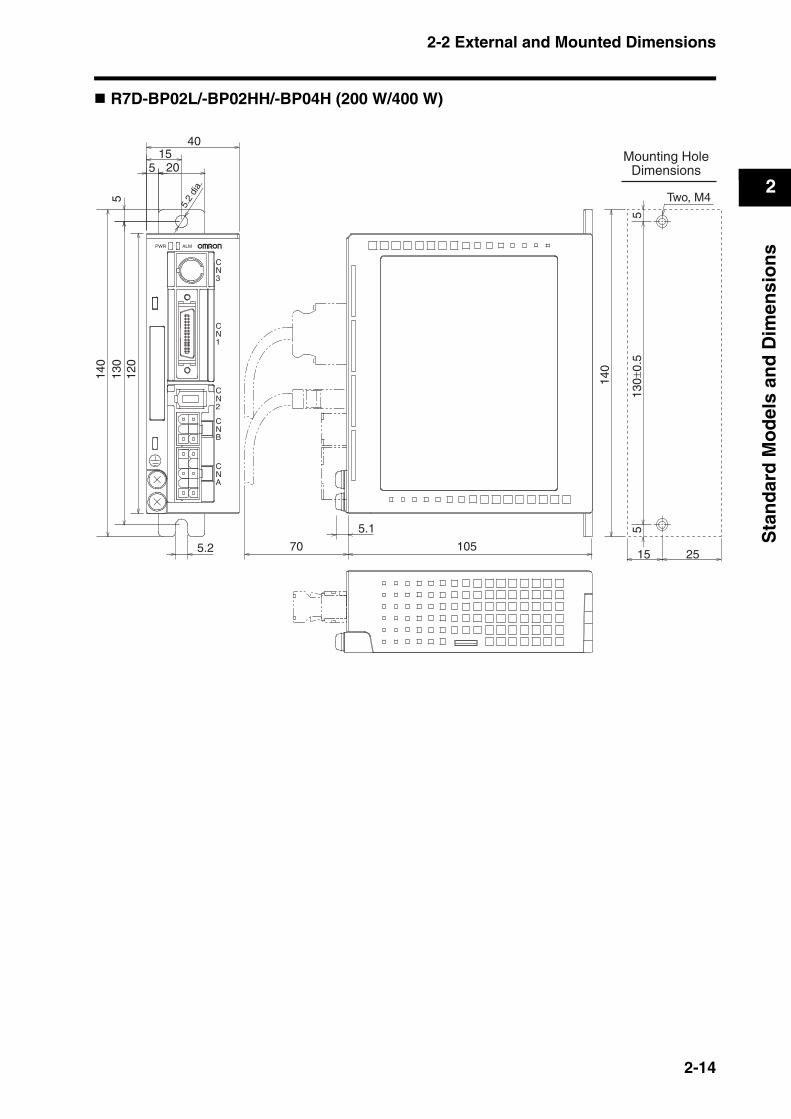
R7D-BP02L/-BP02HH/-BP04H (200 W/400 W)
CN1
CN2
CNB
CNA
CN3
ALMPWR
5.1
5.2 105
40
5.2
dia.
20
130
120
140
155
5
140
130±
0.5
Two, M4
55
15 2570
Mounting HoleDimensions
2-14
2-2 External and Mounted Dimensions
2
Sta
nd
ard
Mo
del
s an
d D
imen
sio
ns
Servomotors
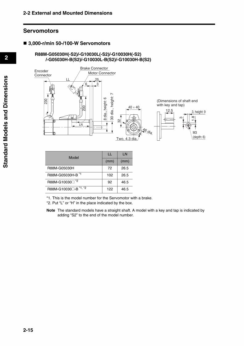
3,000-r/min 50-/100-W Servomotors
R88M-G05030H(-S2)/-G10030L(-S2)/-G10030H(-S2)/-G05030H-B(S2)/-G10030L-B(S2)/-G10030H-B(S2)
*1. This is the model number for the Servomotor with a brake.*2. Put “L” or “H” in the place indicated by the box.
Note The standard models have a straight shaft. A model with a key and tap is indicated by adding “S2” to the end of the model number.
ModelLL LN
(mm) (mm)
R88M-G05030H 72 26.5
R88M-G05030H-B *1 102 26.5
R88M-G10030@ *2 92 46.5
R88M-G10030@-B *1, *2 122 46.5
3, height: 9
M3(depth: 6)
3
1.8
12.5
(Dimensions of shaft end with key and tap)23
0
200
36LL 25
32
40 × 40
LN
Motor ConnectorEncoderConnector
8 di
a., h
eigh
t: 6
46 dia.
Two, 4.3 dia.
30 d
ia.,
heig
ht: 7
Brake Connector
2-15
2-2 External and Mounted Dimensions
2
Sta
nd
ard
Mo
del
s an
d D
imen
sio
ns
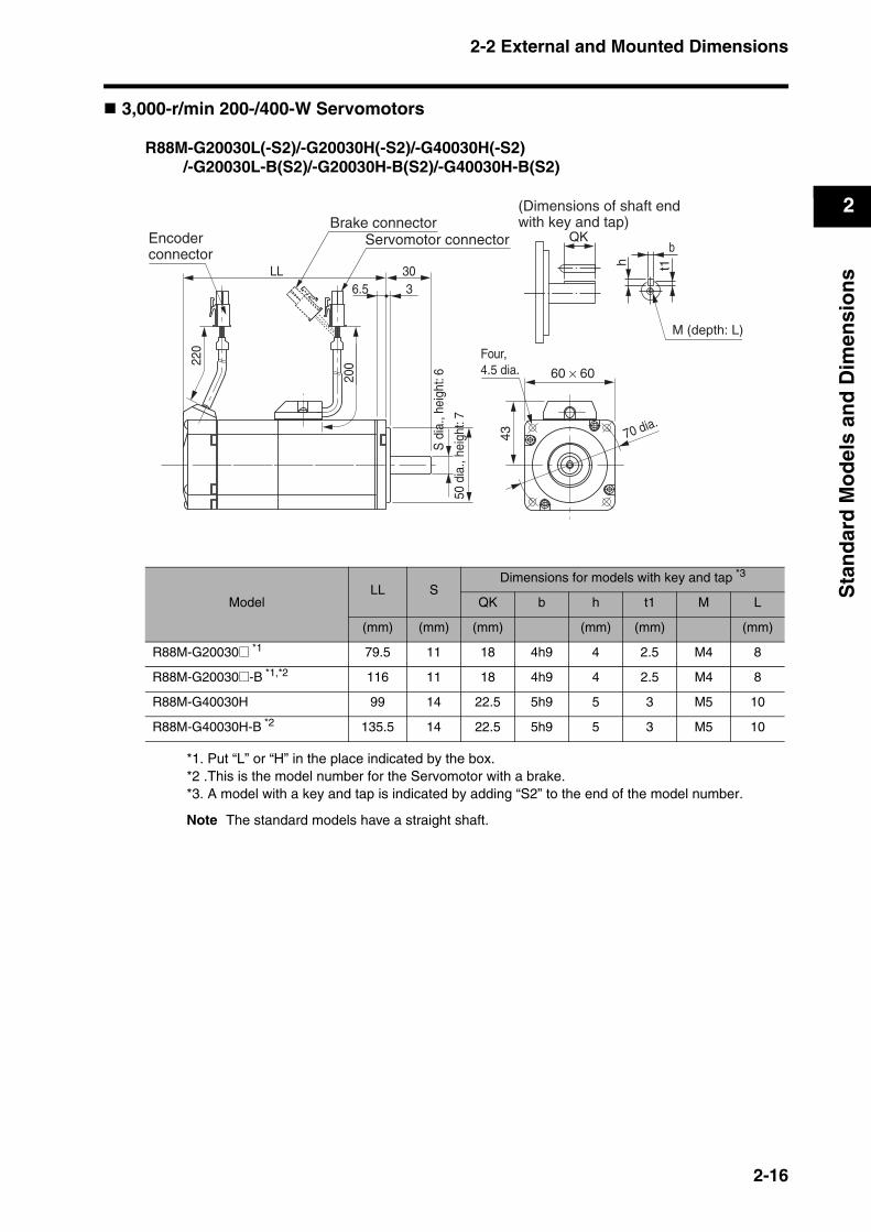
3,000-r/min 200-/400-W Servomotors
R88M-G20030L(-S2)/-G20030H(-S2)/-G40030H(-S2)/-G20030L-B(S2)/-G20030H-B(S2)/-G40030H-B(S2)
*1. Put “L” or “H” in the place indicated by the box.*2 .This is the model number for the Servomotor with a brake.*3. A model with a key and tap is indicated by adding “S2” to the end of the model number.
Note The standard models have a straight shaft.
ModelLL S
Dimensions for models with key and tap *3
QK b h t1 M L
(mm) (mm) (mm) (mm) (mm) (mm)
R88M-G20030@ *1 79.5 11 18 4h9 4 2.5 M4 8
R88M-G20030@-B *1,*2 116 11 18 4h9 4 2.5 M4 8
R88M-G40030H 99 14 22.5 5h9 5 3 M5 10
R88M-G40030H-B *2 135.5 14 22.5 5h9 5 3 M5 10
220
200
36.5LL 30
S d
ia.,
heig
ht: 6
50 d
ia.,
heig
ht: 7
60 × 60
70 dia.
QK
(Dimensions of shaft end with key and tap)
Four, 4.5 dia.
43
b
h t1
M (depth: L)
Brake connectorServomotor connectorEncoder
connector
2-16
2-2 External and Mounted Dimensions
2
Sta
nd
ard
Mo
del
s an
d D
imen
sio
ns
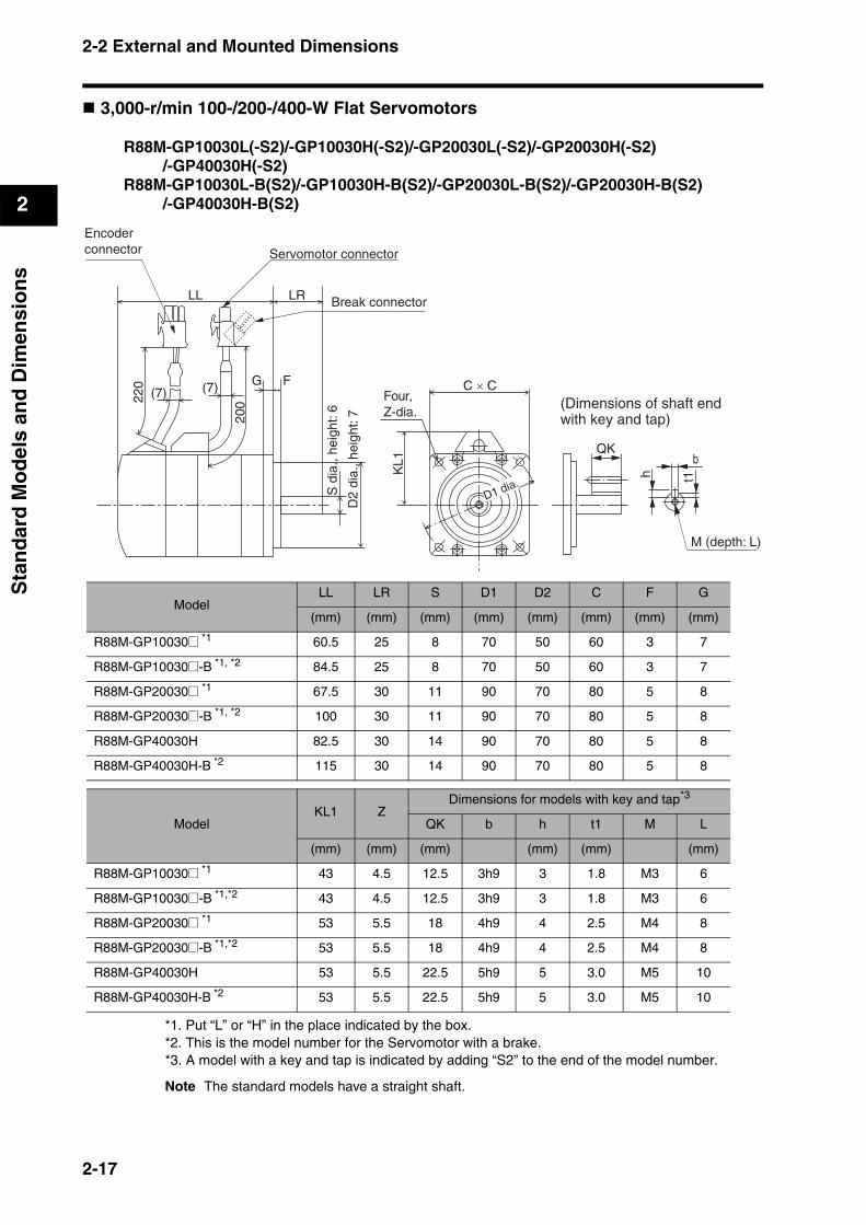
3,000-r/min 100-/200-/400-W Flat Servomotors
R88M-GP10030L(-S2)/-GP10030H(-S2)/-GP20030L(-S2)/-GP20030H(-S2)/-GP40030H(-S2)
R88M-GP10030L-B(S2)/-GP10030H-B(S2)/-GP20030L-B(S2)/-GP20030H-B(S2)/-GP40030H-B(S2)
*1. Put “L” or “H” in the place indicated by the box.*2. This is the model number for the Servomotor with a brake.*3. A model with a key and tap is indicated by adding “S2” to the end of the model number.
Note The standard models have a straight shaft.
LL LR
FG
20022
0
D2
dia.
, hei
ght:
7
KL1
S d
ia.,
heig
ht: 6
C × CFour, Z-dia.
(7) (7)
Encoder connector
QK
(Dimensions of shaft endwith key and tap)
b
h t1
M (depth: L)
Servomotor connector
Break connector
D1 dia.
ModelLL LR S D1 D2 C F G
(mm) (mm) (mm) (mm) (mm) (mm) (mm) (mm)
R88M-GP10030@ *1 60.5 25 8 70 50 60 3 7
R88M-GP10030@-B *1, *2 84.5 25 8 70 50 60 3 7
R88M-GP20030@ *1 67.5 30 11 90 70 80 5 8
R88M-GP20030@-B *1, *2 100 30 11 90 70 80 5 8
R88M-GP40030H 82.5 30 14 90 70 80 5 8
R88M-GP40030H-B *2 115 30 14 90 70 80 5 8
ModelKL1 Z
Dimensions for models with key and tap*3
QK b h t1 M L
(mm) (mm) (mm) (mm) (mm) (mm)
R88M-GP10030@ *1 43 4.5 12.5 3h9 3 1.8 M3 6
R88M-GP10030@-B *1,*2 43 4.5 12.5 3h9 3 1.8 M3 6
R88M-GP20030@ *1 53 5.5 18 4h9 4 2.5 M4 8
R88M-GP20030@-B *1,*2 53 5.5 18 4h9 4 2.5 M4 8
R88M-GP40030H 53 5.5 22.5 5h9 5 3.0 M5 10
R88M-GP40030H-B *2 53 5.5 22.5 5h9 5 3.0 M5 10
2-17
2-2 External and Mounted Dimensions
2
Sta
nd
ard
Mo
del
s an
d D
imen
sio
ns
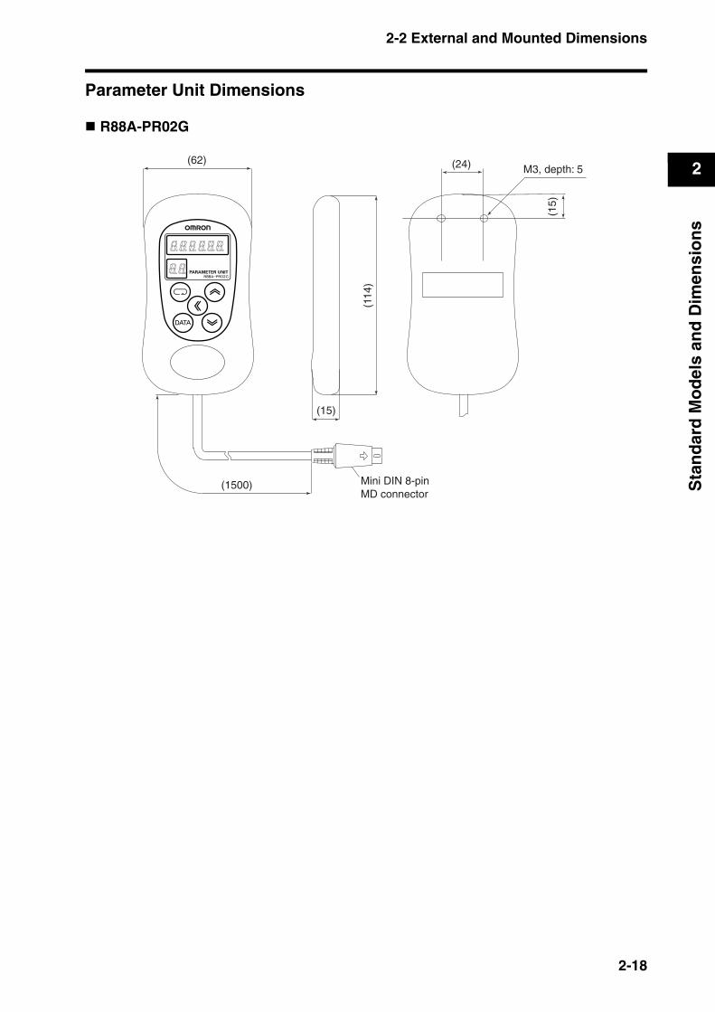
Parameter Unit Dimensions
R88A-PR02G
Mini DIN 8-pinMD connector
(62) (24)
(15)
(1500)
M3, depth: 5
(114
)
(15)
2-18
2-2 External and Mounted Dimensions
2
Sta
nd
ard
Mo
del
s an
d D
imen
sio
ns
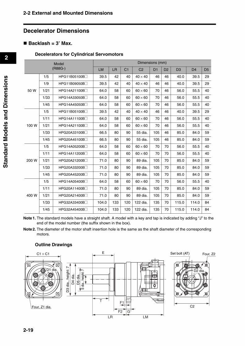
Decelerator Dimensions
Backlash = 3’ Max.
Decelerators for Cylindrical Servomotors
Note 1. The standard models have a straight shaft. A model with a key and tap is indicated by adding “J” to the end of the model number (the suffix shown in the box).
Note 2. The diameter of the motor shaft insertion hole is the same as the shaft diameter of the corresponding motors.
Outline Drawings
Model(R88G-)
Dimensions (mm)
LM LR C1 C2 D1 D2 D3 D4 D5
50 W
1/5 HPG11B05100B@ 39.5 42 40 40 × 40 46 46 40.0 39.5 29
1/9 HPG11B09050B@ 39.5 42 40 40 × 40 46 46 40.0 39.5 29
1/21 HPG14A21100B@ 64.0 58 60 60 × 60 70 46 56.0 55.5 40
1/33 HPG14A33050B@ 64.0 58 60 60 × 60 70 46 56.0 55.5 40
1/45 HPG14A45050B@ 64.0 58 60 60 × 60 70 46 56.0 55.5 40
100 W
1/5 HPG11B05100B@ 39.5 42 40 40 × 40 46 46 40.0 39.5 29
1/11 HPG14A11100B@ 64.0 58 60 60 × 60 70 46 56.0 55.5 40
1/21 HPG14A21100B@ 64.0 58 60 60 × 60 70 46 56.0 55.5 40
1/33 HPG20A33100B@ 66.5 80 90 55 dia. 105 46 85.0 84.0 59
1/45 HPG20A45100B@ 66.5 80 90 55 dia. 105 46 85.0 84.0 59
200 W
1/5 HPG14A05200B@ 64.0 58 60 60 × 60 70 70 56.0 55.5 40
1/11 HPG14A11200B@ 64.0 58 60 60 × 60 70 70 56.0 55.5 40
1/21 HPG20A21200B@ 71.0 80 90 89 dia. 105 70 85.0 84.0 59
1/33 HPG20A33200B@ 71.0 80 90 89 dia. 105 70 85.0 84.0 59
1/45 HPG20A45200B@ 71.0 80 90 89 dia. 105 70 85.0 84.0 59
400 W
1/5 HPG14A05400B@ 64.0 58 60 60 × 60 70 70 56.0 55.5 40
1/11 HPG20A11400B@ 71.0 80 90 89 dia. 105 70 85.0 84.0 59
1/21 HPG20A21400B@ 71.0 80 90 89 dia. 105 70 85.0 84.0 59
1/33 HPG32A33400B@ 104.0 133 120 122 dia. 135 70 115.0 114.0 84
1/45 HPG32A45400B@ 104.0 133 120 122 dia. 135 70 115.0 114.0 84
C1 × C1 E
C2
Set bolt (AT) Four, Z2
Four, Z1 dia.
D3
dia.
, hei
ght:
7
D4
dia.
D5
dia.
S di
a., h
eigh
t: 7
T F1
F2
LR
G
LM
D2 dia.D1 dia.
2-19
2-2 External and Mounted Dimensions
2
Sta
nd
ard
Mo
del
s an
d D
imen
sio
ns
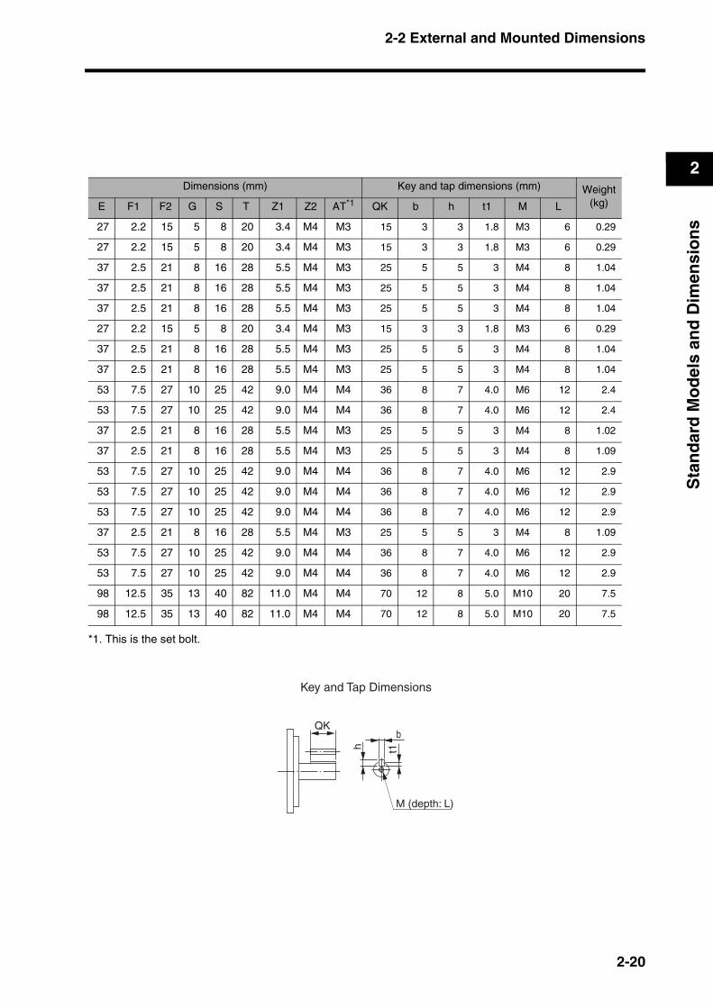
*1. This is the set bolt.
Dimensions (mm) Key and tap dimensions (mm) Weight(kg)E F1 F2 G S T Z1 Z2 AT*1 QK b h t1 M L
27 2.2 15 5 8 20 3.4 M4 M3 15 3 3 1.8 M3 6 0.29
27 2.2 15 5 8 20 3.4 M4 M3 15 3 3 1.8 M3 6 0.29
37 2.5 21 8 16 28 5.5 M4 M3 25 5 5 3 M4 8 1.04
37 2.5 21 8 16 28 5.5 M4 M3 25 5 5 3 M4 8 1.04
37 2.5 21 8 16 28 5.5 M4 M3 25 5 5 3 M4 8 1.04
27 2.2 15 5 8 20 3.4 M4 M3 15 3 3 1.8 M3 6 0.29
37 2.5 21 8 16 28 5.5 M4 M3 25 5 5 3 M4 8 1.04
37 2.5 21 8 16 28 5.5 M4 M3 25 5 5 3 M4 8 1.04
53 7.5 27 10 25 42 9.0 M4 M4 36 8 7 4.0 M6 12 2.4
53 7.5 27 10 25 42 9.0 M4 M4 36 8 7 4.0 M6 12 2.4
37 2.5 21 8 16 28 5.5 M4 M3 25 5 5 3 M4 8 1.02
37 2.5 21 8 16 28 5.5 M4 M3 25 5 5 3 M4 8 1.09
53 7.5 27 10 25 42 9.0 M4 M4 36 8 7 4.0 M6 12 2.9
53 7.5 27 10 25 42 9.0 M4 M4 36 8 7 4.0 M6 12 2.9
53 7.5 27 10 25 42 9.0 M4 M4 36 8 7 4.0 M6 12 2.9
37 2.5 21 8 16 28 5.5 M4 M3 25 5 5 3 M4 8 1.09
53 7.5 27 10 25 42 9.0 M4 M4 36 8 7 4.0 M6 12 2.9
53 7.5 27 10 25 42 9.0 M4 M4 36 8 7 4.0 M6 12 2.9
98 12.5 35 13 40 82 11.0 M4 M4 70 12 8 5.0 M10 20 7.5
98 12.5 35 13 40 82 11.0 M4 M4 70 12 8 5.0 M10 20 7.5
QK
Key and Tap Dimensions
b
h t1
M (depth: L)
2-20
2-2 External and Mounted Dimensions
2
Sta
nd
ard
Mo
del
s an
d D
imen
sio
ns
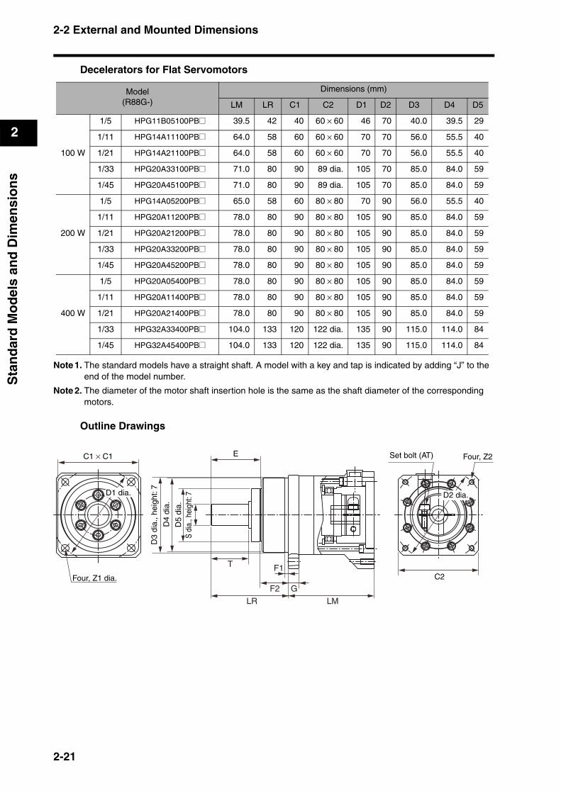
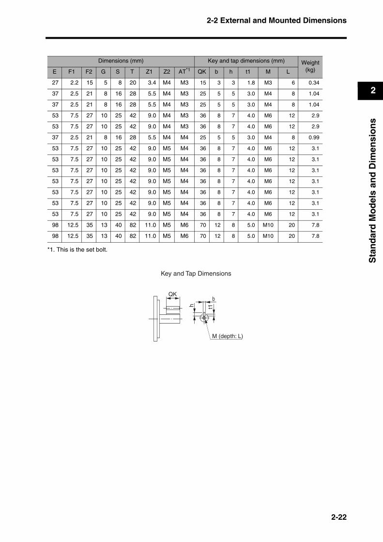
Decelerators for Flat Servomotors
Note 1. The standard models have a straight shaft. A model with a key and tap is indicated by adding “J” to the end of the model number.
Note 2. The diameter of the motor shaft insertion hole is the same as the shaft diameter of the corresponding motors.
Outline Drawings
Model(R88G-)
Dimensions (mm)
LM LR C1 C2 D1 D2 D3 D4 D5
100 W
1/5 HPG11B05100PB@ 39.5 42 40 60 × 60 46 70 40.0 39.5 29
1/11 HPG14A11100PB@ 64.0 58 60 60 × 60 70 70 56.0 55.5 40
1/21 HPG14A21100PB@ 64.0 58 60 60 × 60 70 70 56.0 55.5 40
1/33 HPG20A33100PB@ 71.0 80 90 89 dia. 105 70 85.0 84.0 59
1/45 HPG20A45100PB@ 71.0 80 90 89 dia. 105 70 85.0 84.0 59
200 W
1/5 HPG14A05200PB@ 65.0 58 60 80 × 80 70 90 56.0 55.5 40
1/11 HPG20A11200PB@ 78.0 80 90 80 × 80 105 90 85.0 84.0 59
1/21 HPG20A21200PB@ 78.0 80 90 80 × 80 105 90 85.0 84.0 59
1/33 HPG20A33200PB@ 78.0 80 90 80 × 80 105 90 85.0 84.0 59
1/45 HPG20A45200PB@ 78.0 80 90 80 × 80 105 90 85.0 84.0 59
400 W
1/5 HPG20A05400PB@ 78.0 80 90 80 × 80 105 90 85.0 84.0 59
1/11 HPG20A11400PB@ 78.0 80 90 80 × 80 105 90 85.0 84.0 59
1/21 HPG20A21400PB@ 78.0 80 90 80 × 80 105 90 85.0 84.0 59
1/33 HPG32A33400PB@ 104.0 133 120 122 dia. 135 90 115.0 114.0 84
1/45 HPG32A45400PB@ 104.0 133 120 122 dia. 135 90 115.0 114.0 84
C1 × C1 E
C2
Set bolt (AT) Four, Z2
Four, Z1 dia.
D3
dia.
, hei
ght:
7
D4
dia.
D5
dia.
S di
a., h
eigh
t: 7
T F1
F2
LR
G
LM
D2 dia.D1 dia.
2-21
2-2 External and Mounted Dimensions
2
Sta
nd
ard
Mo
del
s an
d D
imen
sio
ns
*1. This is the set bolt.
Dimensions (mm) Key and tap dimensions (mm) Weight(kg)E F1 F2 G S T Z1 Z2 AT*1 QK b h t1 M L
27 2.2 15 5 8 20 3.4 M4 M3 15 3 3 1.8 M3 6 0.34
37 2.5 21 8 16 28 5.5 M4 M3 25 5 5 3.0 M4 8 1.04
37 2.5 21 8 16 28 5.5 M4 M3 25 5 5 3.0 M4 8 1.04
53 7.5 27 10 25 42 9.0 M4 M3 36 8 7 4.0 M6 12 2.9
53 7.5 27 10 25 42 9.0 M4 M3 36 8 7 4.0 M6 12 2.9
37 2.5 21 8 16 28 5.5 M4 M4 25 5 5 3.0 M4 8 0.99
53 7.5 27 10 25 42 9.0 M5 M4 36 8 7 4.0 M6 12 3.1
53 7.5 27 10 25 42 9.0 M5 M4 36 8 7 4.0 M6 12 3.1
53 7.5 27 10 25 42 9.0 M5 M4 36 8 7 4.0 M6 12 3.1
53 7.5 27 10 25 42 9.0 M5 M4 36 8 7 4.0 M6 12 3.1
53 7.5 27 10 25 42 9.0 M5 M4 36 8 7 4.0 M6 12 3.1
53 7.5 27 10 25 42 9.0 M5 M4 36 8 7 4.0 M6 12 3.1
53 7.5 27 10 25 42 9.0 M5 M4 36 8 7 4.0 M6 12 3.1
98 12.5 35 13 40 82 11.0 M5 M6 70 12 8 5.0 M10 20 7.8
98 12.5 35 13 40 82 11.0 M5 M6 70 12 8 5.0 M10 20 7.8
QK
Key and Tap Dimensions
b
h t1
M (depth: L)
2-22

2-2 External and Mounted Dimensions
2
Sta
nd
ard
Mo
del
s an
d D
imen
sio
ns
Backlash = 15’ Max.
Decelerators for Cylindrical Servomotors
Note 1. The standard models have a straight shaft with a key.
Note 2. The diameter of the motor shaft insertion hole is the same as the shaft diameter of the corresponding motors.
Outline Drawings
Model(R88G-)
Dimensions (mm)
LM LR C1 C2 D1 D2 D3 D4 E3 F G
50 W
1/5 VRSF05B100CJ 67.5 32 40 52 46 60 50 45 10 3 6
1/9 VRSF09B100CJ 67.5 32 40 52 46 60 50 45 10 3 6
1/15 VRSF15B100CJ 78.0 32 40 52 46 60 50 45 10 3 6
1/25 VRSF25B100CJ 78.0 32 40 52 46 60 50 45 10 3 6
100 W
1/5 VRSF05B100CJ 67.5 32 40 52 46 60 50 45 10 3 6
1/9 VRSF09B100CJ 67.5 32 40 52 46 60 50 45 10 3 6
1/15 VRSF15B100CJ 78.0 32 40 52 46 60 50 45 10 3 6
1/25 VRSF25B100CJ 78.0 32 40 52 46 60 50 45 10 3 6
200 W
1/5 VRSF05B200CJ 72.5 32 60 52 70 60 50 45 10 3 10
1/9 VRSF09C200CJ 89.5 50 60 78 70 90 70 62 17 3 8
1/15 VRSF15C200CJ 100.0 50 60 78 70 90 70 62 17 3 8
1/25 VRSF25C200CJ 100.0 50 60 78 70 90 70 62 17 3 8
400 W
1/5 VRSF05C400CJ 89.5 50 60 78 70 90 70 62 17 3 8
1/9 VRSF09C400CJ 89.5 50 60 78 70 90 70 62 17 3 8
1/15 VRSF15C400CJ 100.0 50 60 78 70 90 70 62 17 3 8
1/25 VRSF25C400CJ 100.0 50 60 78 70 90 70 62 17 3 8
LM
G
LR
T
F
E3
C2 × C2C1 × C1
Four, Z1
D1 dia.
D4
dia.
S d
ia.,
heig
ht: 6 D2 dia.
D3
dia.
, hei
ght:
7
Four, Z2 (effective depth: L)
2-23
2-2 External and Mounted Dimensions
2
Sta
nd
ard
Mo
del
s an
d D
imen
sio
ns
Dimensions (mm) Key dimensions (mm) Weight(kg)
Model(R88G-)S T Z1 Z2 AT*1
*1. This is the set bolt.
L QK b h t1
12 20 M4 M5 M3 12 16 4 4 2.5 0.55 VRSF05B100CJ 1/5
50 W12 20 M4 M5 M3 12 16 4 4 2.5 0.55 VRSF09B100CJ 1/9
12 20 M4 M5 M3 12 16 4 4 2.5 0.70 VRSF15B100CJ 1/15
12 20 M4 M5 M3 12 16 4 4 2.5 0.70 VRSF25B100CJ 1/25
12 20 M4 M5 M3 12 16 4 4 2.5 0.55 VRSF05B100CJ 1/5
100 W12 20 M4 M5 M3 12 16 4 4 2.5 0.55 VRSF09B100CJ 1/9
12 20 M4 M5 M3 12 16 4 4 2.5 0.70 VRSF15B100CJ 1/15
12 20 M4 M5 M3 12 16 4 4 2.5 0.70 VRSF25B100CJ 1/25
12 20 M4 M5 M4 12 16 4 4 2.5 0.72 VRSF05B200CJ 1/5
200 W19 30 M4 M6 M4 20 22 6 6 3.5 1.70 VRSF09C200CJ 1/9
19 30 M4 M6 M4 20 22 6 6 3.5 2.10 VRSF15C200CJ 1/15
19 30 M4 M6 M4 20 22 6 6 3.5 2.10 VRSF25C200CJ 1/25
19 30 M4 M6 M4 20 22 6 6 3.5 1.70 VRSF05C400CJ 1/5
400 W19 30 M4 M6 M4 20 22 6 6 3.5 1.70 VRSF09C400CJ 1/9
19 30 M4 M6 M4 20 22 6 6 3.5 2.10 VRSF15C400CJ 1/15
19 30 M4 M6 M4 20 22 6 6 3.5 2.10 VRSF25C400CJ 1/25
QK
b
h
t1
Key DimensionsSet bolt (AT)
2-24
2-2 External and Mounted Dimensions
2
Sta
nd
ard
Mo
del
s an
d D
imen
sio
ns
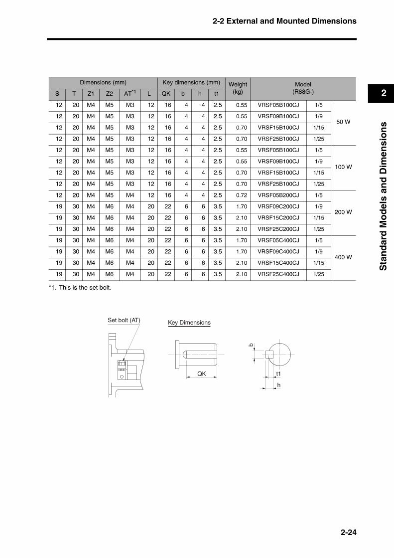
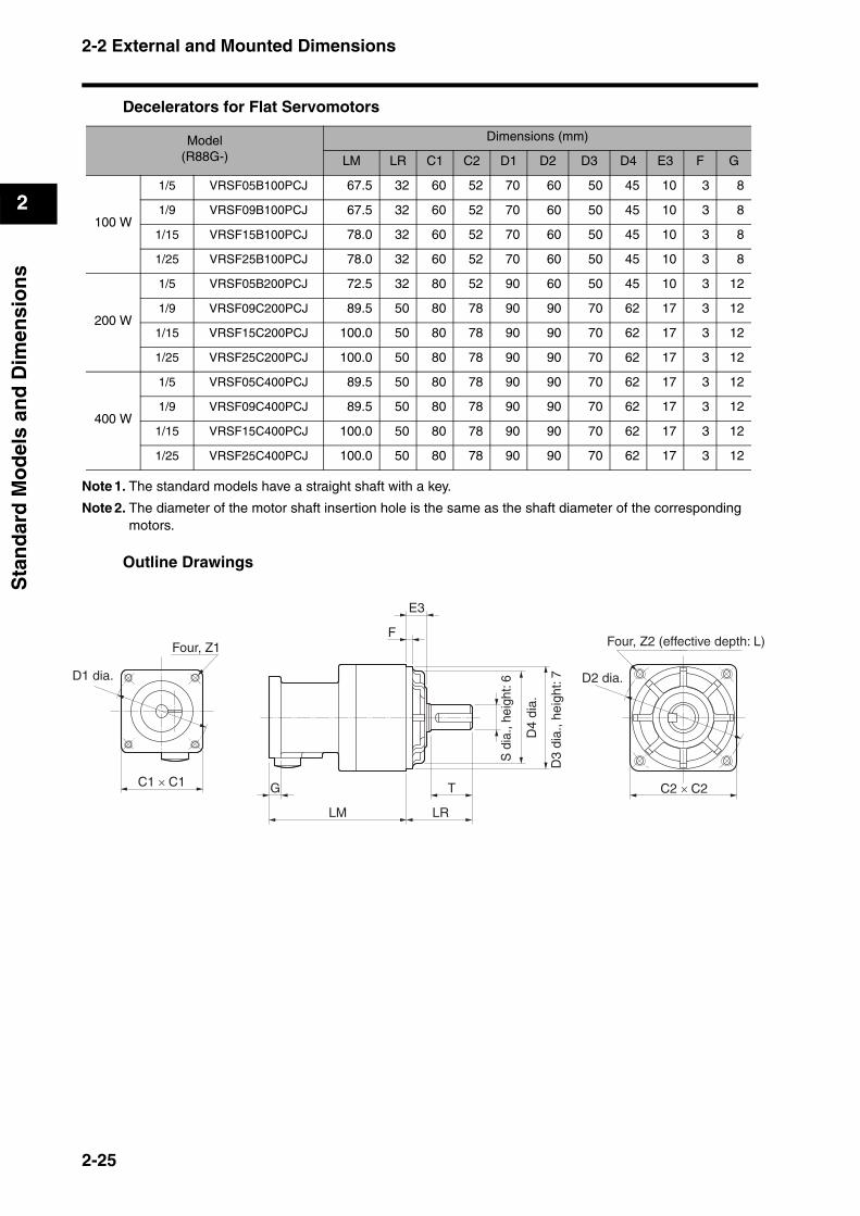
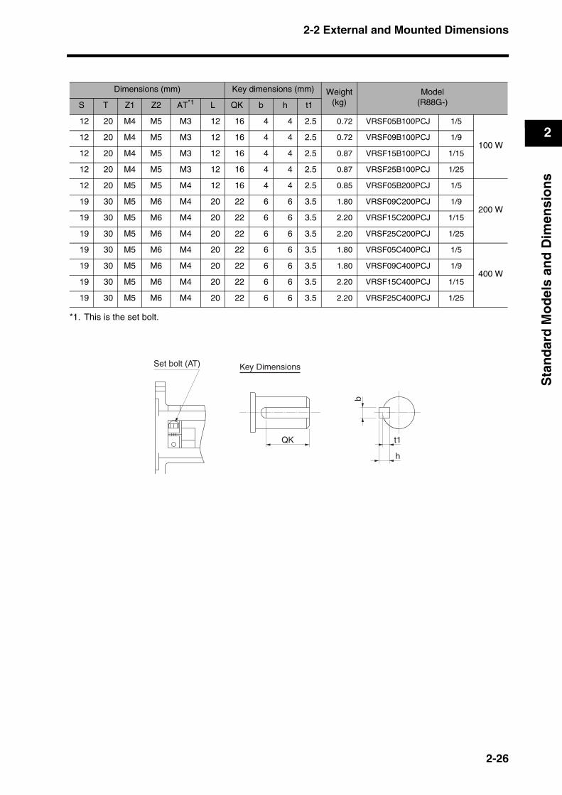
Decelerators for Flat Servomotors
Note 1. The standard models have a straight shaft with a key.
Note 2. The diameter of the motor shaft insertion hole is the same as the shaft diameter of the corresponding motors.
Outline Drawings
Model(R88G-)
Dimensions (mm)
LM LR C1 C2 D1 D2 D3 D4 E3 F G
100 W
1/5 VRSF05B100PCJ 67.5 32 60 52 70 60 50 45 10 3 8
1/9 VRSF09B100PCJ 67.5 32 60 52 70 60 50 45 10 3 8
1/15 VRSF15B100PCJ 78.0 32 60 52 70 60 50 45 10 3 8
1/25 VRSF25B100PCJ 78.0 32 60 52 70 60 50 45 10 3 8
200 W
1/5 VRSF05B200PCJ 72.5 32 80 52 90 60 50 45 10 3 12
1/9 VRSF09C200PCJ 89.5 50 80 78 90 90 70 62 17 3 12
1/15 VRSF15C200PCJ 100.0 50 80 78 90 90 70 62 17 3 12
1/25 VRSF25C200PCJ 100.0 50 80 78 90 90 70 62 17 3 12
400 W
1/5 VRSF05C400PCJ 89.5 50 80 78 90 90 70 62 17 3 12
1/9 VRSF09C400PCJ 89.5 50 80 78 90 90 70 62 17 3 12
1/15 VRSF15C400PCJ 100.0 50 80 78 90 90 70 62 17 3 12
1/25 VRSF25C400PCJ 100.0 50 80 78 90 90 70 62 17 3 12
LM
G
LR
T
F
E3
C2 × C2C1 × C1
Four, Z1
D1 dia.
D4
dia.
S d
ia.,
heig
ht: 6 D2 dia.
D3
dia.
, hei
ght:
7
Four, Z2 (effective depth: L)
2-25
2-2 External and Mounted Dimensions
2
Sta
nd
ard
Mo
del
s an
d D
imen
sio
ns
Dimensions (mm) Key dimensions (mm) Weight(kg)
Model(R88G-)S T Z1 Z2 AT*1
*1. This is the set bolt.
L QK b h t1
12 20 M4 M5 M3 12 16 4 4 2.5 0.72 VRSF05B100PCJ 1/5
100 W12 20 M4 M5 M3 12 16 4 4 2.5 0.72 VRSF09B100PCJ 1/9
12 20 M4 M5 M3 12 16 4 4 2.5 0.87 VRSF15B100PCJ 1/15
12 20 M4 M5 M3 12 16 4 4 2.5 0.87 VRSF25B100PCJ 1/25
12 20 M5 M5 M4 12 16 4 4 2.5 0.85 VRSF05B200PCJ 1/5
200 W19 30 M5 M6 M4 20 22 6 6 3.5 1.80 VRSF09C200PCJ 1/9
19 30 M5 M6 M4 20 22 6 6 3.5 2.20 VRSF15C200PCJ 1/15
19 30 M5 M6 M4 20 22 6 6 3.5 2.20 VRSF25C200PCJ 1/25
19 30 M5 M6 M4 20 22 6 6 3.5 1.80 VRSF05C400PCJ 1/5
400 W19 30 M5 M6 M4 20 22 6 6 3.5 1.80 VRSF09C400PCJ 1/9
19 30 M5 M6 M4 20 22 6 6 3.5 2.20 VRSF15C400PCJ 1/15
19 30 M5 M6 M4 20 22 6 6 3.5 2.20 VRSF25C400PCJ 1/25
QK
b
h
t1
Key DimensionsSet bolt (AT)
2-26
2-2 External and Mounted Dimensions
2
Sta
nd
ard
Mo
del
s an
d D
imen
sio
ns
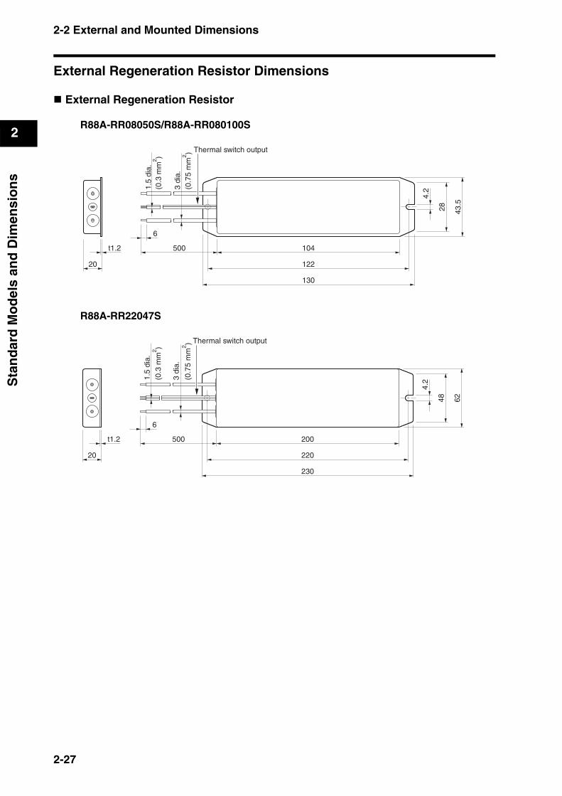
External Regeneration Resistor Dimensions
External Regeneration Resistor
R88A-RR08050S/R88A-RR080100S
R88A-RR22047S
20
t1.2 104
122
130
43.5
28
4.2
6
1.5
dia.
(0.3
mm
2 )
(0.7
5 m
m2 )
3 di
a.
Thermal switch output
500
20
t1.2 200
220
230
6248
4.2
6
Thermal switch output
500
1.5
dia.
(0.3
mm
2 )
(0.7
5 m
m2 )
3 di
a.
2-27
2-2 External and Mounted Dimensions
2
Sta
nd
ard
Mo
del
s an
d D
imen
sio
ns
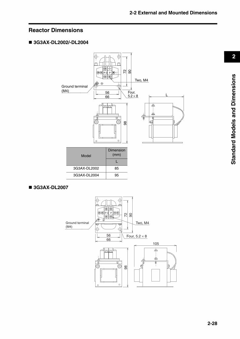
Reactor Dimensions
3G3AX-DL2002/-DL2004
3G3AX-DL2007
Model
Dimension(mm)
L
3G3AX-DL2002 85
3G3AX-DL2004 95
Ground terminal (M4)
6656
72 90
Four, 5.2 × 8
Two, M4
98
L
Ground terminal (M4)
Four, 5.2 × 8
Two, M4
6656
72 90
105
98
2-28
2-2 External and Mounted Dimensions
2
Sta
nd
ard
Mo
del
s an
d D
imen
sio
ns
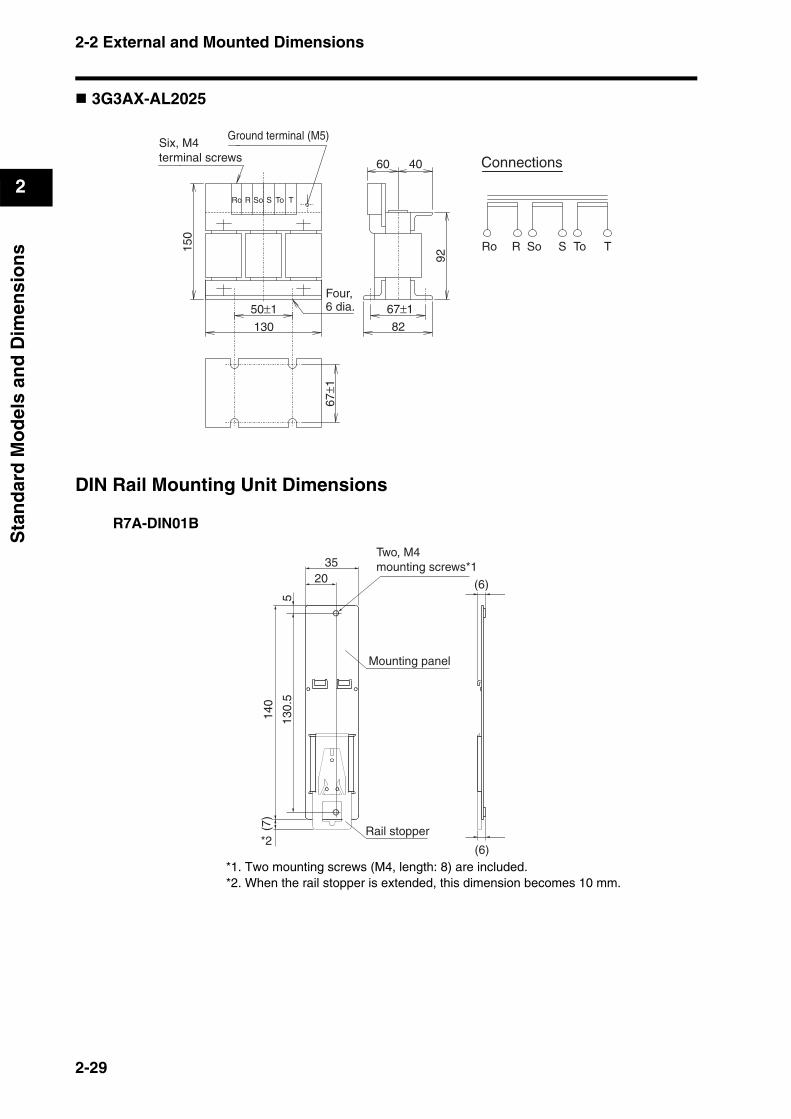
3G3AX-AL2025
DIN Rail Mounting Unit Dimensions
R7A-DIN01B
*1. Two mounting screws (M4, length: 8) are included.*2. When the rail stopper is extended, this dimension becomes 10 mm.
Six, M4 terminal screws
Ground terminal (M5)
50±1Four, 6 dia.
130
67±1
82
92
150
Ro R So S To T
60 40
67±1
Connections
Ro R So S To T
35Two, M4 mounting screws*1
Mounting panel
Rail stopper
(6)
(6)
20
513
0.5
140
(7)
*2
2-29
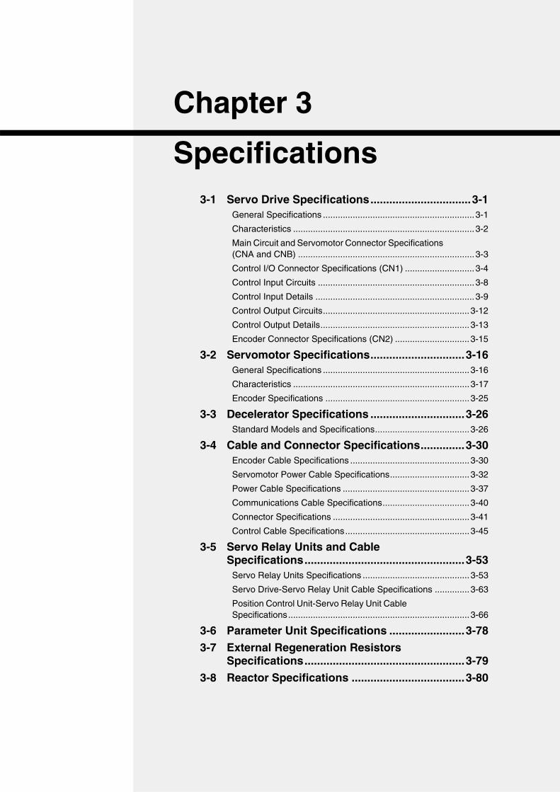
Chapter 3
Specifications3-1 Servo Drive Specifications................................3-1
General Specifications .............................................................3-1
Characteristics .........................................................................3-2
Main Circuit and Servomotor Connector Specifications (CNA and CNB) .......................................................................3-3
Control I/O Connector Specifications (CN1) ............................3-4
Control Input Circuits ...............................................................3-8
Control Input Details ................................................................3-9
Control Output Circuits...........................................................3-12
Control Output Details............................................................3-13
Encoder Connector Specifications (CN2) ..............................3-15
3-2 Servomotor Specifications..............................3-16General Specifications ...........................................................3-16
Characteristics .......................................................................3-17
Encoder Specifications ..........................................................3-25
3-3 Decelerator Specifications ..............................3-26Standard Models and Specifications......................................3-26
3-4 Cable and Connector Specifications..............3-30Encoder Cable Specifications ................................................3-30
Servomotor Power Cable Specifications................................3-32
Power Cable Specifications ...................................................3-37
Communications Cable Specifications...................................3-40
Connector Specifications .......................................................3-41
Control Cable Specifications..................................................3-45
3-5 Servo Relay Units and Cable Specifications...................................................3-53
Servo Relay Units Specifications ...........................................3-53
Servo Drive-Servo Relay Unit Cable Specifications ..............3-63
Position Control Unit-Servo Relay Unit Cable Specifications.........................................................................3-66
3-6 Parameter Unit Specifications ........................3-78
3-7 External Regeneration Resistors Specifications...................................................3-79
3-8 Reactor Specifications ....................................3-80
3-1 Servo Drive Specifications
3
Sp
ecif
icat
ion
s
3Specifications
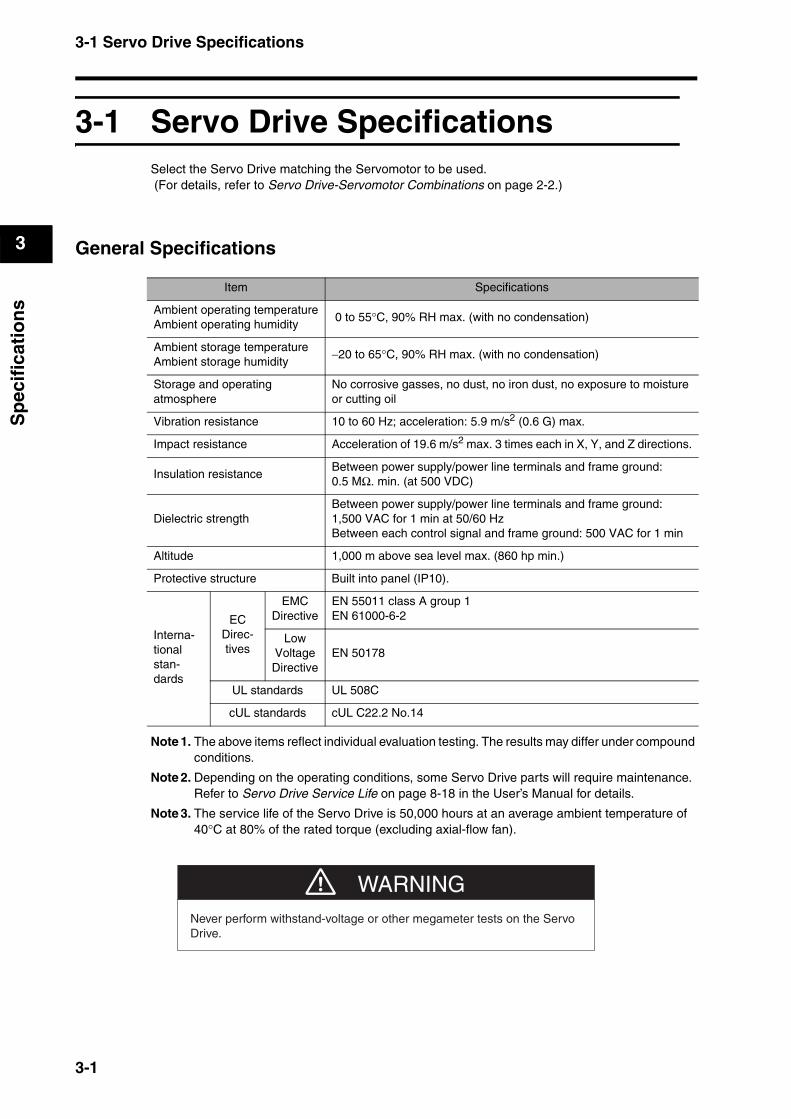
3-1 Servo Drive SpecificationsSelect the Servo Drive matching the Servomotor to be used. (For details, refer to Servo Drive-Servomotor Combinations on page 2-2.)
General Specifications
Note 1. The above items reflect individual evaluation testing. The results may differ under compound conditions.
Note 2. Depending on the operating conditions, some Servo Drive parts will require maintenance.Refer to Servo Drive Service Life on page 8-18 in the User’s Manual for details.
Note 3. The service life of the Servo Drive is 50,000 hours at an average ambient temperature of 40°C at 80% of the rated torque (excluding axial-flow fan).
Item Specifications
Ambient operating temperatureAmbient operating humidity
0 to 55°C, 90% RH max. (with no condensation)
Ambient storage temperatureAmbient storage humidity
−20 to 65°C, 90% RH max. (with no condensation)
Storage and operating atmosphere
No corrosive gasses, no dust, no iron dust, no exposure to moisture or cutting oil
Vibration resistance 10 to 60 Hz; acceleration: 5.9 m/s2 (0.6 G) max.
Impact resistance Acceleration of 19.6 m/s2 max. 3 times each in X, Y, and Z directions.
Insulation resistanceBetween power supply/power line terminals and frame ground: 0.5 MΩ. min. (at 500 VDC)
Dielectric strengthBetween power supply/power line terminals and frame ground: 1,500 VAC for 1 min at 50/60 HzBetween each control signal and frame ground: 500 VAC for 1 min
Altitude 1,000 m above sea level max. (860 hp min.)
Protective structure Built into panel (IP10).
Interna-tional stan-dards
ECDirec-tives
EMC Directive
EN 55011 class A group 1EN 61000-6-2
Low Voltage Directive
EN 50178
UL standards UL 508C
cUL standards cUL C22.2 No.14
WARNINGNever perform withstand-voltage or other megameter tests on the Servo Drive.
3-1
3-1 Servo Drive Specifications
3
Sp
ecif
icat
ion
s
Characteristics
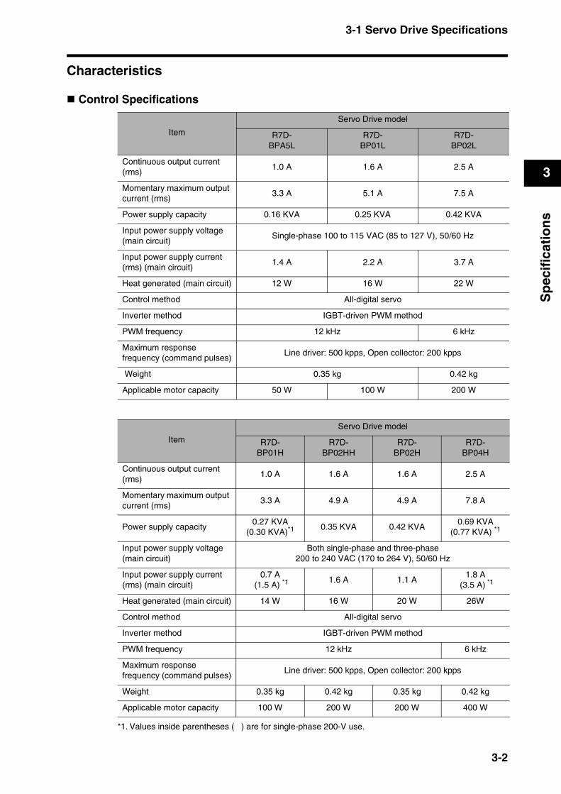
Control Specifications
Item
Servo Drive model
R7D-BPA5L
R7D-BP01L
R7D-BP02L
Continuous output current (rms)
1.0 A 1.6 A 2.5 A
Momentary maximum output current (rms)
3.3 A 5.1 A 7.5 A
Power supply capacity 0.16 KVA 0.25 KVA 0.42 KVA
Input power supply voltage (main circuit)
Single-phase 100 to 115 VAC (85 to 127 V), 50/60 Hz
Input power supply current (rms) (main circuit)
1.4 A 2.2 A 3.7 A
Heat generated (main circuit) 12 W 16 W 22 W
Control method All-digital servo
Inverter method IGBT-driven PWM method
PWM frequency 12 kHz 6 kHz
Maximum response frequency (command pulses)
Line driver: 500 kpps, Open collector: 200 kpps
Weight 0.35 kg 0.42 kg
Applicable motor capacity 50 W 100 W 200 W
Item
Servo Drive model
R7D-BP01H
R7D-BP02HH
R7D-BP02H
R7D-BP04H
Continuous output current (rms)
1.0 A 1.6 A 1.6 A 2.5 A
Momentary maximum output current (rms)
3.3 A 4.9 A 4.9 A 7.8 A
Power supply capacity0.27 KVA
(0.30 KVA)*10.35 KVA 0.42 KVA
0.69 KVA(0.77 KVA) *1
Input power supply voltage (main circuit)
Both single-phase and three-phase 200 to 240 VAC (170 to 264 V), 50/60 Hz
Input power supply current (rms) (main circuit)
0.7 A (1.5 A) *1
1.6 A 1.1 A1.8 A
(3.5 A) *1
Heat generated (main circuit) 14 W 16 W 20 W 26W
Control method All-digital servo
Inverter method IGBT-driven PWM method
PWM frequency 12 kHz 6 kHz
Maximum response frequency (command pulses)
Line driver: 500 kpps, Open collector: 200 kpps
Weight 0.35 kg 0.42 kg 0.35 kg 0.42 kg
Applicable motor capacity 100 W 200 W 200 W 400 W
*1. Values inside parentheses ( ) are for single-phase 200-V use.
3-2
3-1 Servo Drive Specifications
3
Sp
ecif
icat
ion
s
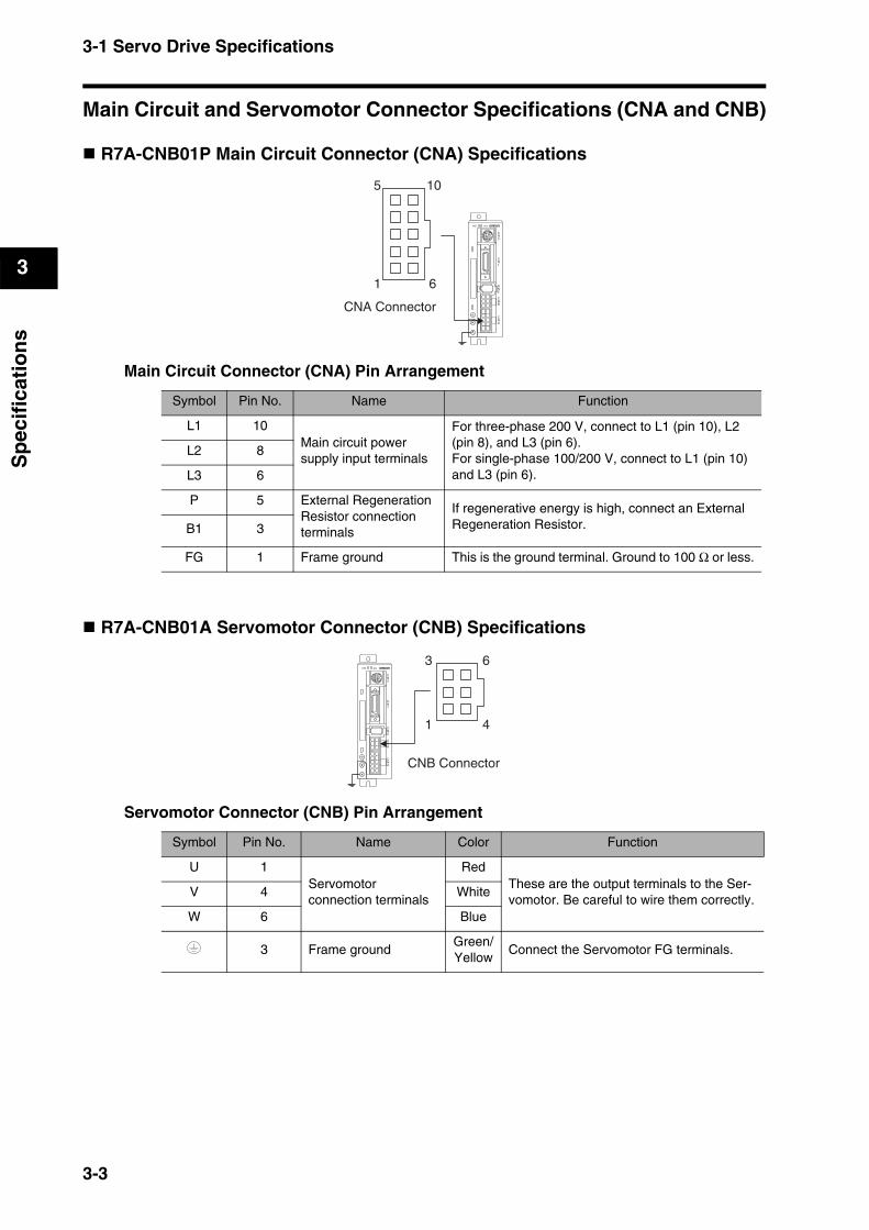
Main Circuit and Servomotor Connector Specifications (CNA and CNB)
R7A-CNB01P Main Circuit Connector (CNA) Specifications
Main Circuit Connector (CNA) Pin Arrangement
R7A-CNB01A Servomotor Connector (CNB) Specifications
Servomotor Connector (CNB) Pin Arrangement
Symbol Pin No. Name Function
L1 10Main circuit power supply input terminals
For three-phase 200 V, connect to L1 (pin 10), L2 (pin 8), and L3 (pin 6).For single-phase 100/200 V, connect to L1 (pin 10) and L3 (pin 6).
L2 8
L3 6
P 5 External Regeneration Resistor connection terminals
If regenerative energy is high, connect an External Regeneration Resistor.B1 3
FG 1 Frame ground This is the ground terminal. Ground to 100 Ω or less.
Symbol Pin No. Name Color Function
U 1Servomotor connection terminals
RedThese are the output terminals to the Ser-vomotor. Be careful to wire them correctly.
V 4 White
W 6 Blue
3 Frame groundGreen/Yellow
Connect the Servomotor FG terminals.
CNA Connector
5 10
1 6
CN1
CN2
CNA
CNB
CN3
PWR ALM
CNB Connector
CN1
CN2
CNA
CNB
CN3
PWR ALM
3 6
1 4
3-3

3-1 Servo Drive Specifications
3
Sp
ecif
icat
ion
s
Control I/O Connector Specifications (CN1)
Control I/O Signal Connections and External Signal Processing
4.7 kΩ
4.7 kΩ
4.7 kΩ
4.7 kΩ
4.7 kΩ
4.7 kΩ
4.7 kΩ
.
BKIR
Brake InterlockMaximum operatingvoltage: 30 VDCMaximum OutputCurrent: 50 mA DC
RUN Command Input
25
+CW
−CW
+CCW
−CCW
22
23
24
Reversepulse
Forwardpulse
21
9
2RUN
124VIN12 to 24 VDC
Frame groundFGShell, 26
Z-phase Output(open collector output)
10
11
/ALM
14
Z
GND
Alarm Output
13
INP
OGND
PositioningCompletedOutput
RESET 3
Alarm Reset Input
ECRST 4
Deviation CounterReset Input
Gain SwitchInput
GSEL 5
GESEL 6
Electronic GearSwitch Input
Reverse DriveProhibit Input
Forward DriveProhibit Input
NOT 7
POT 8
−Z
+Z
−B
+B
−A
+A
20
19
17
18
16
15
12 WARN
Warning Output
Encoder A-phase Output
Encoder B-phase Output
Encoder Z-phase Output
220 Ω
220 Ω
Line driver outputConforms to EIA RS-422A(Load resistance: 220 Ω min.)
3-4
3-1 Servo Drive Specifications
3
Sp
ecif
icat
ion
s
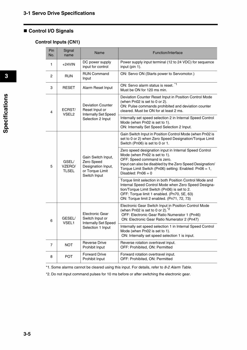
Control I/O Signals
Control Inputs (CN1)
Pin No.
Signal name
Name Function/Interface
1 +24VINDC power supply input for control
Power supply input terminal (12 to 24 VDC) for sequence input (pin 1).
2 RUNRUN Command Input
ON: Servo ON (Starts power to Servomotor.)
3 RESET Alarm Reset InputON: Servo alarm status is reset. *1
Must be ON for 120 ms min.
*1. Some alarms cannot be cleared using this input. For details, refer to 8-2 Alarm Table.
4ECRST/VSEL2
Deviation Counter Reset Input or Internally Set Speed Selection 2 Input
Deviation Counter Reset Input in Position Control Mode (when Pn02 is set to 0 or 2).ON: Pulse commands prohibited and deviation counter cleared. Must be ON for at least 2 ms.
Internally set speed selection 2 in Internal Speed Control Mode (when Pn02 is set to 1).ON: Internally Set Speed Selection 2 Input.
5GSEL/
VZERO/TLSEL
Gain Switch Input, Zero Speed Designation Input, or Torque Limit Switch Input
Gain Switch Input in Position Control Mode (when Pn02 is set to 0 or 2) when Zero Speed Designation/Torque Limit Switch (Pn06) is set to 0 or 1.
Zero speed designation input in Internal Speed Control Mode (when Pn02 is set to 1).OFF: Speed command is zero.Input can also be disabled by the Zero Speed Designation/Torque Limit Switch (Pn06) setting: Enabled: Pn06 = 1, Disabled: Pn06 = 0
Torque limit selection in both Position Control Mode and Internal Speed Control Mode when Zero Speed Designa-tion/Torque Limit Switch (Pn06) is set to 2.OFF: Torque limit 1 enabled. (Pn70, 5E, 63)ON: Torque limit 2 enabled. (Pn71, 72, 73)
6GESEL/VSEL1
Electronic Gear Switch Input or Internally Set Speed Selection 1 Input
Electronic Gear Switch Input in Position Control Mode (when Pn02 is set to 0 or 2).*2
OFF: Electronic Gear Ratio Numerator 1 (Pn46) ON: Electronic Gear Ratio Numerator 2 (Pn47)
*2. Do not input command pulses for 10 ms before or after switching the electronic gear.
Internally set speed selection 1 in Internal Speed Control Mode (when Pn02 is set to 1). ON: Internally set speed selection 1 is input.
7 NOTReverse Drive Prohibit Input
Reverse rotation overtravel input.OFF: Prohibited, ON: Permitted
8 POTForward Drive Prohibit Input
Forward rotation overtravel input.OFF: Prohibited, ON: Permitted
3-5
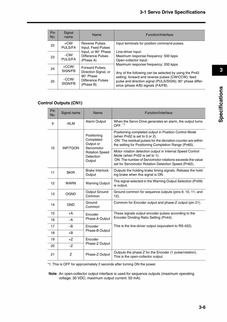
3-1 Servo Drive Specifications
3
Sp
ecif
icat
ion
s
Control Outputs (CN1)
Note An open-collector output interface is used for sequence outputs (maximum operating voltage: 30 VDC; maximum output current: 50 mA).
Pin No.
Signal name
Name Function/Interface
22+CW/
PULS/FAReverse Pulses Input, Feed Pulses Input, or 90° Phase Difference Pulses (Phase A)
Input terminals for position command pulses.
Line-driver input: Maximum response frequency: 500 kppsOpen-collector input:Maximum response frequency: 200 kpps
Any of the following can be selected by using the Pn42 setting: forward and reverse pulses (CW/CCW); feed pulse and direction signal (PULS/SIGN); 90° phase differ-ence (phase A/B) signals (FA/FB).
23−CW/
PULS/FA
24+CCW/
SIGN/FBForward Pulses, Direction Signal, or 90° Phase Difference Pulses (Phase B)
25−CCW/
SIGN/FB
Pin No.
Signal name Name Function/Interface
9 /ALMAlarm Output When the Servo Drive generates an alarm, the output turns
OFF. *1
*1. This is OFF for approximately 2 seconds after turning ON the power.
10 INP/TGON
Positioning Completed Output or Servomotor Rotation Speed Detection Output
Positioning completed output in Position Control Mode (when Pn02 is set to 0 or 2). ON: The residual pulses for the deviation counter are within the setting for Positioning Completion Range (Pn60).
Motor rotation detection output in Internal Speed Control Mode (when Pn02 is set to 1). ON: The number of Servomotor rotations exceeds the value set for Servomotor Rotation Detection Speed (Pn62).
11 BKIRBrake Interlock Output
Outputs the holding brake timing signals. Release the hold-ing brake when this signal is ON.
12 WARN Warning OutputThe signal selected in the Warning Output Selection (Pn09) is output.
13 OGNDOutput Ground Common
Ground common for sequence outputs (pins 9, 10, 11, and 12).
14 GNDGround Common
Common for Encoder output and phase-Z output (pin 21).
15 +A Encoder Phase-A Output
These signals output encoder pulses according to the Encoder Dividing Ratio Setting (Pn44).
This is the line-driver output (equivalent to RS-422).
16 −A
17 −B Encoder Phase-B Output
18 +B
19 +Z Encoder Phase-Z Output
20 −Z
21 Z Phase-Z OutputOutputs the phase Z for the Encoder (1 pulse/rotation).This is the open-collector output.
3-6
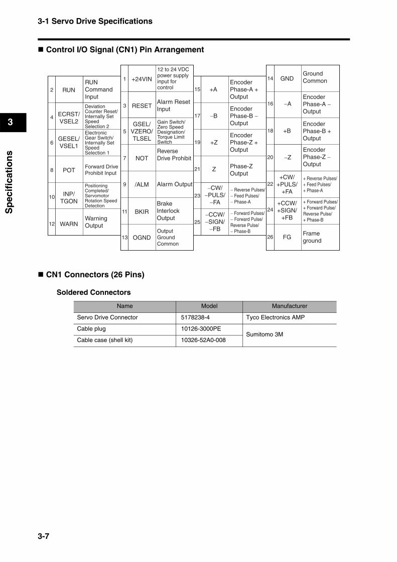
3-1 Servo Drive Specifications
3
Sp
ecif
icat
ion
s
Control I/O Signal (CN1) Pin Arrangement
CN1 Connectors (26 Pins)
Soldered Connectors
Name Model Manufacturer
Servo Drive Connector 5178238-4 Tyco Electronics AMP
Cable plug 10126-3000PESumitomo 3M
Cable case (shell kit) 10326-52A0-008
+24VIN
2
4
6
8
10
12
14
16
18
20
22
24
OGND
1
3
5
7
9
11
13
15
17
19
21
23
25
26
RUN
RESETECRST/VSEL2 GSEL/
VZERO/TLSELGESEL/
VSEL1
NOT
POT
/ALM
INP/TGON
WARN
BKIR
+A
−B
+Z
Z
−CW/−PULS/
−FA
−CCW/−SIGN/
−FB
GND
−A
+B
−Z
+CW/+PULS/
+FA
+CCW/+SIGN/
+FB
FG
RUNCommand Input
Forward Drive Prohibit Input
WarningOutput
Alarm ResetInput
ReverseDrive Prohibit
Alarm Output
BrakeInterlockOutput
Output GroundCommon
Encoder Phase-A + Output
EncoderPhase-B −Output
EncoderPhase-Z +Output
Phase-ZOutput
GroundCommon
EncoderPhase-A − Output
EncoderPhase-B + Output
EncoderPhase-Z −Output
Frameground
Deviation Counter Reset/Internally Set Speed Selection 2
12 to 24 VDC power supply input for control
Electronic Gear Switch/Internally Set Speed Selection 1
Gain Switch/Zero Speed Designation/Torque Limit Switch
− Reverse Pulses/− Feed Pulses/− Phase-A
+ Reverse Pulses/+ Feed Pulses/+ Phase-A
+ Forward Pulses/+ Forward Pulse/Reverse Pulse/+ Phase-B
− Forward Pulses/− Forward Pulse/Reverse Pulse/− Phase-B
Positioning Completed/Servomotor Rotation Speed Detection
3-7
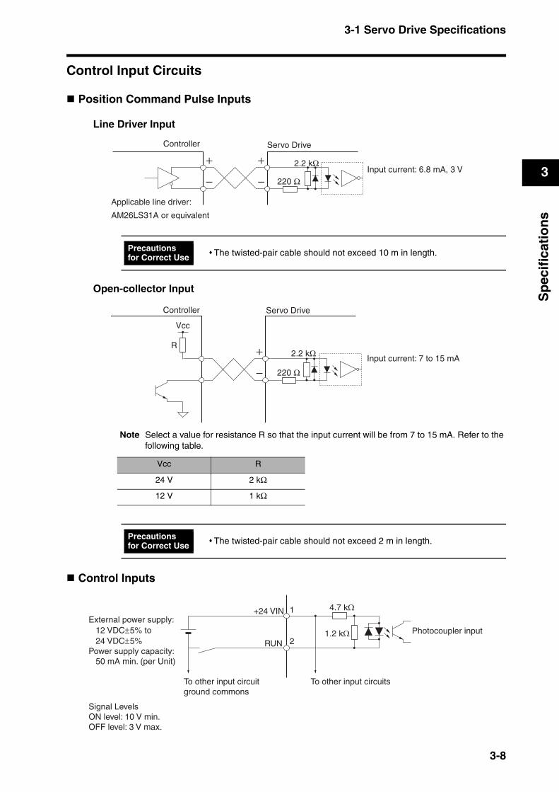
3-1 Servo Drive Specifications
3
Sp
ecif
icat
ion
s
Control Input Circuits
Position Command Pulse Inputs
Line Driver Input
Open-collector Input
Note Select a value for resistance R so that the input current will be from 7 to 15 mA. Refer to the following table.
Control Inputs
The twisted-pair cable should not exceed 10 m in length.
Vcc R
24 V 2 kΩ
12 V 1 kΩ
The twisted-pair cable should not exceed 2 m in length.
2.2 kΩInput current: 6.8 mA, 3 V
Servo DriveController
Applicable line driver:
AM26LS31A or equivalent
220 Ω
Precautions for Correct Use
Vcc
R2.2 kΩ
Input current: 7 to 15 mA
Servo DriveController
220 Ω
Precautions for Correct Use
1.2 kΩ
+24 VIN
Signal LevelsON level: 10 V min.OFF level: 3 V max.
External power supply: 12 VDC±5% to 24 VDC±5%Power supply capacity: 50 mA min. (per Unit)
Photocoupler input
RUN 2
1 4.7 kΩ
To other input circuit ground commons
To other input circuits
3-8

3-1 Servo Drive Specifications
3
Sp
ecif
icat
ion
s
Control Input DetailsDetails on the input pins for the CN1 connector are described here.
RUN Command Input (RUN)
Pin 2: RUN Command Input (RUN)
FunctionThis input turns ON the power drive circuit for the main circuit of the Servo Drive. The Servomotor cannot operate without the input of this signal (i.e., servo-OFF status).The RUN Command Input is enabled approximately 2 seconds after the power supply is turned ON.After turning ON the RUN Command Input, wait for a minimum of 100 ms to lapse before inputting pulses or a speed command.
Alarm Reset Input
Pin 3: Alarm Reset Input (RESET)
FunctionPin 3 is the external reset signal input for Servo Drive alarms. (The alarms are reset when this signal is input.)Eliminate the cause of the alarm before resuming operation. To prevent danger, turn OFF the RUN Command Input first, then input the alarm reset signal.Resetting is performed after the Alarm Reset Input is kept ON for 120 ms or longer.Some alarms cannot be cleared using the Alarm Reset Input. For details, refer to 8-2 Alarm Table.
Deviation Counter Reset/Internally Set Speed Selection 2 Input
Pin 4: Deviation Counter Reset/Internally Set Speed Selection 2 Input (ECRST/VSEL2)
Function: Deviation Counter ResetPin 4 is the Deviation Counter Reset Input (ECRST) in Position Control Mode (when Pn02 is set to 0 or 2).When the deviation counter reset signal turns ON, the value of the deviation counter will be reset and the position loop will be disabled.Input the reset signal for 2 ms minimum. The counter may not be reset if the signal is too short.
Function: Internally Set Speed Selection 2Pin 4 is the Internally Set Speed Selection 2 Input (VSEL2) in Internal Speed Control Mode (when Pn02 is set to 1).Four speeds can be selected by using pin 4 in combination with the Internally Set Speed Selection 1 Input (VSEL1).
3-9
3-1 Servo Drive Specifications
3
Sp
ecif
icat
ion
s
Gain Switch/Zero Speed Designation/Torque Limit Switch Input
Pin 5: Gain Switch/Zero Speed Designation/Torque Limit Switch Input (GSEL/VZERO/TLSEL)
Function: Gain SwitchPin 5 is the Gain Switch Input (GSEL) when Pn02 is set to 0 or 2 (Position Control Mode) and the Zero Speed Designation/Torque Limit Switch (Pn06) is set to anything other than 2.The Gain Switch Input (GSEL) switches between PI and P operation, or between gain 1 and gain 2.When the Gain Switch Input Operating Mode Selection (Pn30) is set to 0, this input switches between PI and P operation. When Pn30 is set to 1 and the Gain Switch Setting (Pn31) is set to 2, this input switches between gain 1 and gain 2.Gain 1 includes the Position Loop Gain (Pn10), Speed Loop Gain (Pn11), Speed Loop Integration Time Constant (Pn12), Speed Feedback Filter Time Constant (Pn13), and Torque Command Filter Time Constant (Pn14).Gain 2 includes the Position Loop Gain 2 (Pn18), Speed Loop Gain 2 (Pn19), Speed Loop Integration Time Constant 2 (Pn1A), Speed Feedback Filter Time Constant 2 (Pn1B), and Torque Command Filter Time Constant 2 (Pn1C).
Function: Zero Speed DesignationPin 5 is the Zero Speed Designation Input (VZERO) when Pn02 is set to 1 (Internal Speed Control Mode) and the Zero Speed Designation/Torque Limit Switch (Pn06) is set to anything other than 2.When Zero Speed Designation Input (VZERO) is OFF, the speed command is zero. Turn ON the Zero Speed Designation Input (VZERO) for normal operation.Zero Speed Designation Input (VZERO) is enabled when the Zero Speed Designation/Torque Limit Switch (Pn06) is set to 1, and disabled when Pn06 is set to 0.
Function: Torque Limit SwitchPin 5 is the Torque Limit Switch Input (TLSEL) in both Position Control Mode and Internal Speed Control Mode when the Zero Speed Designation/Torque Limit Switch (Pn06) is set to 2.This input switches the Overspeed Detection Level, Torque Limit, and Deviation Counter Overflow Level parameters.When the input is OFF, torque limit 1 (Pn70, Pn5E, Pn63) is enabled, and when the input is ON, torque limit 2 (Pn71, Pn72, Pn73) is enabled.
Electronic Gear Switch/Internally Set Speed Selection 1 Input
Pin 6: Electronic Gear Switch/Internally Set Speed Selection 1 Input (GESEL/VSEL1)
Function: Electronic Gear SwitchPin 6 is the Electronic Gear Switch Input (GESEL) in Position Control Mode (when Pn02 is set to 0 or 2).The numerator setting for the electronic gear can be switched between Electronic Gear Ratio Numerator 1 and Electronic Gear Ratio Numerator 2.When the input is turned OFF, Electronic Gear Ratio Numerator 1 (Pn46) is enabled, and when the input is turned ON, Electronic Gear Ratio Numerator 2 (Pn47) is enabled.It takes 1 to 5 ms to switch the electronic gear after the Gear Switch input changes. Therefore, do not input a command pulse for 10-ms before and after switching.
3-10

3-1 Servo Drive Specifications
3
Sp
ecif
icat
ion
s
Function: Internally Set Speed Selection 1Pin 6 is the Internally Set Speed Selection 1 Input (VSEL1) in Internal Speed Control Mode (when Pn02 is set to 1).Four speeds can be selected by using pin 6 in combination with the Internally Set Speed Selection 2 Input (VSEL2).
Reverse Drive Prohibit/Forward Drive Prohibit Input
Pin 7: Reverse Drive Prohibit Input (NOT)Pin 8: Forward Drive Prohibit Input (POT)
FunctionsThese inputs prohibit forward and reverse operation (overtravel).When an input is ON, operation is possible in that direction.These inputs can be disabled using the setting of Drive Prohibit Input Selection (Pn04).The motor will stop according to the setting of the Stop Selection for Drive Prohibition Input (Pn66).
Reverse Pulse/Forward Pulse, Feed Pulse/Direction Signal, 90° Phase Difference Signal (Phase A/Phase B)
Pin 22: +Reverse Pulse (+CW), +Feed Pulse (+PULS), or +Phase A (+FA)Pin 23: −Reverse Pulse (−CW), −Feed Pulse (−PULS), or −Phase A (−FA)Pin 24: +Forward Pulse (+CCW), +Direction Signal (+SIGN), or +Phase B (+FB)Pin 25: −Forward Pulse (−CCW), −Direction Signal (−SIGN), or −Phase B (−FB)
FunctionsThe functions of these signals depend on the setting of the Command Pulse Mode (Pn42).
If the photocoupler LED is turned ON, each signal will go high as shown above.
Setting Command pulse mode Input pins Servomotor forward command Servomotor reverse command
0 or 290° phase difference
signals
22: +FA23: −FA24: +FB25: −FB
Line driver: t1 ≥ 2 µsOpen collector: t1 ≥ 5 µs
1Reverse pulse/forward
pulse
22: +CW23: −CW24: +CCW25: −CCW
Line driver: t2 ≥ 1 µsOpen collector: t2 ≥ 2.5 µs
3Feed pulse/direction
signal
22: +PULS23: PULS24: SIGN25: −SIGN
Line driver: t2 ≥ 1 µsOpen collector: t2 ≥ 2.5 µs
t1 t1 t1 t1
t1 t1t1 t1
Phase A
Phase B
t2 t2
t2
t2
t2
Low
Low
t2
High Lowt2t2
t2 t2 t2 t2
t2
3-11
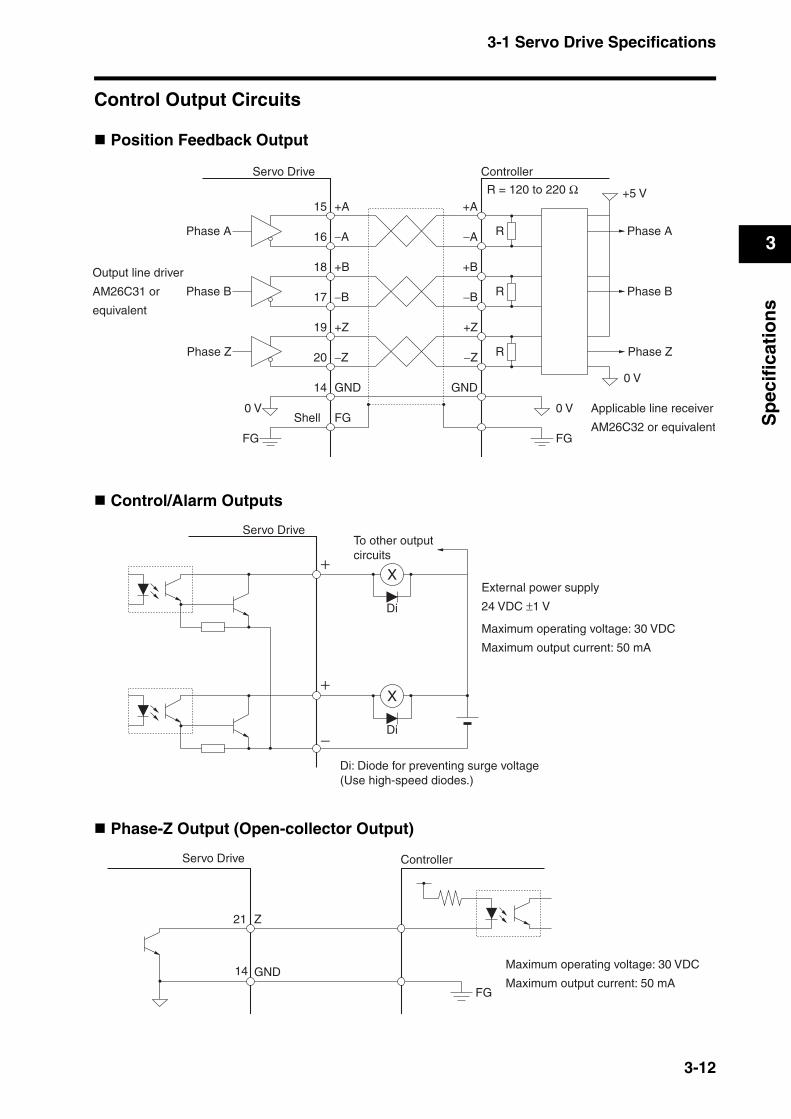
3-1 Servo Drive Specifications
3
Sp
ecif
icat
ion
s
Control Output Circuits
Position Feedback Output
Control/Alarm Outputs
Phase-Z Output (Open-collector Output)
ControllerServo Drive
+A15
−A16
+B18
−B17
+Z19
−Z20
GND14
FGShell
+A
−A
+B
−B
+Z
−Z
GND
Phase A
Phase B
Phase Z
Phase A
Phase B
Phase Z
Output line driver
AM26C31 or
equivalent
FG
0 V
R = 120 to 220 Ω
R
R
R
FG
0 V
0 V
+5 V
Applicable line receiver
AM26C32 or equivalent
Servo Drive
External power supply
24 VDC ±1 V
X
Di
To other outputcircuits
Maximum operating voltage: 30 VDC
Maximum output current: 50 mA
Di: Diode for preventing surge voltage (Use high-speed diodes.)
X
Di
Servo Drive
Maximum operating voltage: 30 VDC
Maximum output current: 50 mA
Controller
FG
GND
Z21
14
3-12
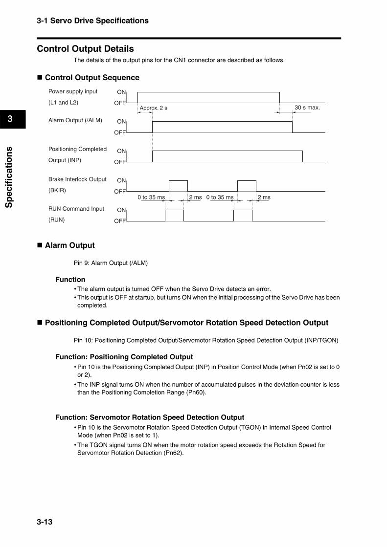
3-1 Servo Drive Specifications
3
Sp
ecif
icat
ion
s
Control Output DetailsThe details of the output pins for the CN1 connector are described as follows.
Control Output Sequence
Alarm Output
Pin 9: Alarm Output (/ALM)
FunctionThe alarm output is turned OFF when the Servo Drive detects an error.This output is OFF at startup, but turns ON when the initial processing of the Servo Drive has been completed.
Positioning Completed Output/Servomotor Rotation Speed Detection Output
Pin 10: Positioning Completed Output/Servomotor Rotation Speed Detection Output (INP/TGON)
Function: Positioning Completed OutputPin 10 is the Positioning Completed Output (INP) in Position Control Mode (when Pn02 is set to 0 or 2).
The INP signal turns ON when the number of accumulated pulses in the deviation counter is less than the Positioning Completion Range (Pn60).
Function: Servomotor Rotation Speed Detection OutputPin 10 is the Servomotor Rotation Speed Detection Output (TGON) in Internal Speed Control Mode (when Pn02 is set to 1).
The TGON signal turns ON when the motor rotation speed exceeds the Rotation Speed for Servomotor Rotation Detection (Pn62).
Power supply input
(L1 and L2)
Alarm Output (/ALM)
Positioning Completed
Output (INP)
Brake Interlock Output
(BKIR)
RUN Command Input
(RUN)
ON
OFF
ON
OFF
ON
OFF
ON
OFF
ON
OFF
Approx. 2 s 30 s max.
0 to 35 ms 2 ms 0 to 35 ms 2 ms
3-13
3-1 Servo Drive Specifications
3
Sp
ecif
icat
ion
s
Brake Interlock Output
Pin 11: Brake Interlock Output (BKIR)
FunctionThe external brake timing signal is output.This output is turned ON to release the external brake.
Warning Output
Pin 12: Warning Output (WARN)
FunctionPin 12 outputs the warning signal selected in the Warning Output Selection (Pn09).
Feedback Output
Pin 15: Encoder Phase A+ Output (+A)Pin 16: Encoder Phase A− Output (−A)Pin 17: Encoder Phase B− Output (−B)Pin 18: Encoder Phase B+ Output (+B)Pin 19: Encoder Phase Z+ Output (+Z)Pin 20: Encoder Phase Z− Output (−Z)
FunctionThis signal outputs encoder pulses according to the Encoder Divider Setting (Pn44).Line-driver output (equivalent to RS-422).The output logic can be reversed with Encoder Output Direction Switch (Pn45).
Phase-Z Output
Pin 21: Phase-Z Output (Z)Pin 14: Ground Common (GND)
FunctionPin 21 is the open-collector output for the phase-Z signal.The encoder phase Z is output.One pulse is output for each rotation.
3-14
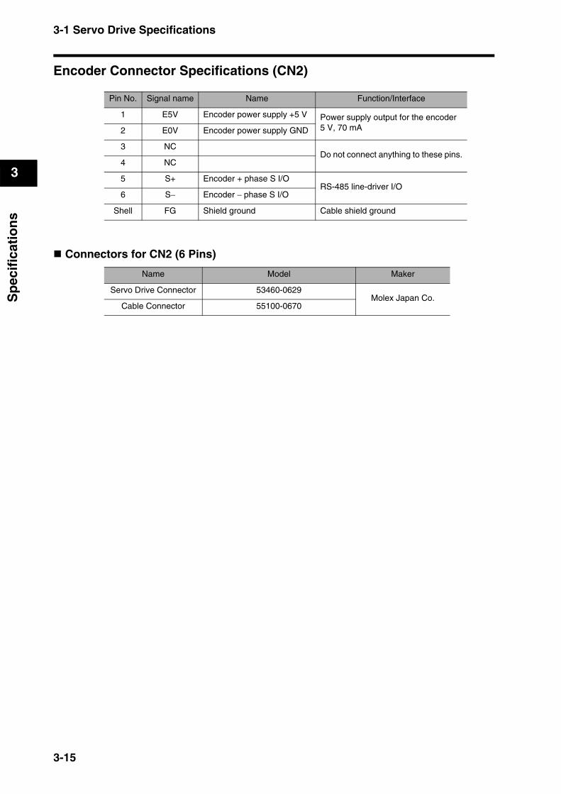
3-1 Servo Drive Specifications
3
Sp
ecif
icat
ion
s
Encoder Connector Specifications (CN2)
Connectors for CN2 (6 Pins)
Pin No. Signal name Name Function/Interface
1 E5V Encoder power supply +5 V Power supply output for the encoder 5 V, 70 mA2 E0V Encoder power supply GND
3 NCDo not connect anything to these pins.
4 NC
5 S+ Encoder + phase S I/ORS-485 line-driver I/O
6 S− Encoder − phase S I/O
Shell FG Shield ground Cable shield ground
Name Model Maker
Servo Drive Connector 53460-0629Molex Japan Co.
Cable Connector 55100-0670
3-15
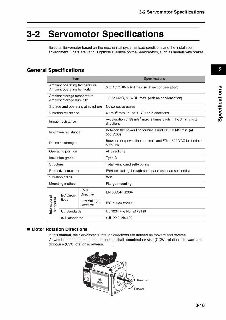
3-2 Servomotor Specifications
3
Sp
ecif
icat
ion
s
3-2 Servomotor SpecificationsSelect a Servomotor based on the mechanical system’s load conditions and the installation environment. There are various options available on the Servomotors, such as models with brakes.
General Specifications
Motor Rotation DirectionsIn this manual, the Servomotors rotation directions are defined as forward and reverse.Viewed from the end of the motor’s output shaft, counterclockwise (CCW) rotation is forward and clockwise (CW) rotation is reverse.
Item Specifications
Ambient operating temperatureAmbient operating humidity
0 to 40°C, 85% RH max. (with no condensation)
Ambient storage temperatureAmbient storage humidity
−20 to 65°C, 85% RH max. (with no condensation)
Storage and operating atmosphere No corrosive gases
Vibration resistance 49 m/s2 max. in the X, Y, and Z directions
Impact resistanceAcceleration of 98 m/s2 max. 3 times each in the X, Y, and Z directions
Insulation resistanceBetween the power line terminals and FG: 20 MΩ min. (at 500 VDC)
Dielectric strengthBetween the power line terminals and FG: 1,500 VAC for 1 min at 50/60 Hz
Operating position All directions
Insulation grade Type B
Structure Totally-enclosed self-cooling
Protective structure IP65 (excluding through-shaft parts and lead wire ends)
Vibration grade V-15
Mounting method Flange-mounting
Inte
rnat
iona
lst
anda
rds
EC Direc-tives
EMC Directive
EN 60034-1:2004
Low Voltage Directive
IEC 60034-5:2001
UL standards UL 1004 File No. E179189
cUL standards cUL 22.2, No.100
Forward
Reverse
3-16
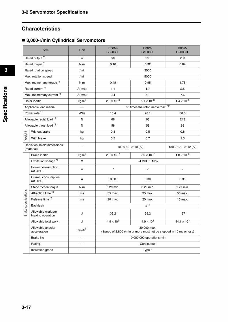
3-2 Servomotor Specifications
3
Sp
ecif
icat
ion
s
Characteristics
3,000-r/min Cylindrical Servomotors
Item UnitR88M-
G05030HR88M-
G10030LR88M-
G20030L
Rated output *1 W 50 100 200
Rated torque *1 N·m 0.16 0.32 0.64
Rated rotation speed r/min 3000
Max. rotation speed r/min 5000
Max. momentary torque *1 N·m 0.48 0.95 1.78
Rated current *1 A(rms) 1.1 1.7 2.5
Max. momentary current *1 A(rms) 3.4 5.1 7.6
Rotor inertia kg·m2 2.5 × 10⁻⁶ 5.1 × 10⁻⁶ 1.4 × 10⁻⁵
Applicable load inertia --- 30 times the rotor inertia max. *2
Power rate *1 kW/s 10.4 20.1 30.3
Allowable radial load *3 N 68 68 245
Allowable thrust load *3 N 58 58 98
Wei
ght Without brake kg 0.3 0.5 0.8
With brake kg 0.5 0.7 1.3
Radiation shield dimensions (material)
--- 100 × 80 × t10 (Al) 130 × 120 × t12 (Al)
Bra
ke s
peci
ficat
ions
Brake inertia kg·m2 2.0 × 10⁻⁷ 2.0 × 10⁻⁷ 1.8 × 10⁻⁶
Excitation voltage *4 V 24 VDC ±10%
Power consumption (at 20°C)
W 7 7 9
Current consumption (at 20°C)
A 0.30 0.30 0.36
Static friction torque N·m 0.29 min. 0.29 min. 1.27 min.
Attraction time *5 ms 35 max. 35 max. 50 max.
Release time *5 ms 20 max. 20 max. 15 max.
Backlash ±1°
Allowable work per braking operation
J 39.2 39.2 137
Allowable total work J 4.9 × 10³ 4.9 × 10³ 44.1 × 10³
Allowable angular acceleration
rad/s2 30,000 max.(Speed of 2,800 r/min or more must not be stopped in 10 ms or less)
Brake life --- 10,000,000 operations min.
Rating --- Continuous
Insulation grade --- Type F
3-17
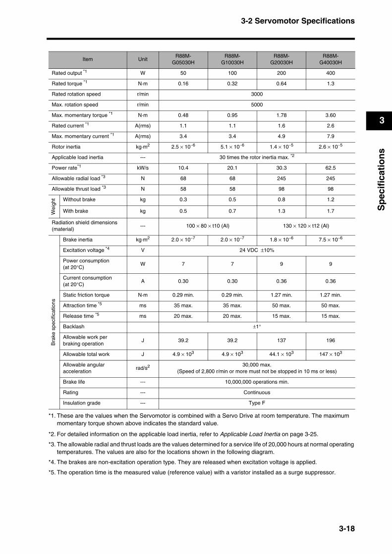
3-2 Servomotor Specifications
3
Sp
ecif
icat
ion
s
Item UnitR88M-
G05030HR88M-
G10030HR88M-
G20030HR88M-
G40030H
Rated output *1 W 50 100 200 400
Rated torque *1 N·m 0.16 0.32 0.64 1.3
Rated rotation speed r/min 3000
Max. rotation speed r/min 5000
Max. momentary torque *1 N·m 0.48 0.95 1.78 3.60
Rated current *1 A(rms) 1.1 1.1 1.6 2.6
Max. momentary current *1 A(rms) 3.4 3.4 4.9 7.9
Rotor inertia kg·m2 2.5 × 10⁻⁶ 5.1 × 10⁻⁶ 1.4 × 10⁻⁵ 2.6 × 10⁻⁵
Applicable load inertia --- 30 times the rotor inertia max. *2
Power rate*1 kW/s 10.4 20.1 30.3 62.5
Allowable radial load *3 N 68 68 245 245
Allowable thrust load *3 N 58 58 98 98
Wei
ght Without brake kg 0.3 0.5 0.8 1.2
With brake kg 0.5 0.7 1.3 1.7
Radiation shield dimensions (material)
--- 100 × 80 × t10 (Al) 130 × 120 × t12 (Al)
Bra
ke s
peci
ficat
ions
Brake inertia kg·m2 2.0 × 10⁻⁷ 2.0 × 10⁻⁷ 1.8 × 10⁻⁶ 7.5 × 10⁻⁶
Excitation voltage *4 V 24 VDC ±10%
Power consumption (at 20°C)
W 7 7 9 9
Current consumption (at 20°C)
A 0.30 0.30 0.36 0.36
Static friction torque N·m 0.29 min. 0.29 min. 1.27 min. 1.27 min.
Attraction time *5 ms 35 max. 35 max. 50 max. 50 max.
Release time *5 ms 20 max. 20 max. 15 max. 15 max.
Backlash ±1°
Allowable work per braking operation
J 39.2 39.2 137 196
Allowable total work J 4.9 × 10³ 4.9 × 10³ 44.1 × 10³ 147 × 103
Allowable angular acceleration
rad/s2 30,000 max.(Speed of 2,800 r/min or more must not be stopped in 10 ms or less)
Brake life --- 10,000,000 operations min.
Rating --- Continuous
Insulation grade --- Type F
*1. These are the values when the Servomotor is combined with a Servo Drive at room temperature. The maximum momentary torque shown above indicates the standard value.
*2. For detailed information on the applicable load inertia, refer to Applicable Load Inertia on page 3-25.
*3. The allowable radial and thrust loads are the values determined for a service life of 20,000 hours at normal operating temperatures. The values are also for the locations shown in the following diagram.
*4. The brakes are non-excitation operation type. They are released when excitation voltage is applied.
*5. The operation time is the measured value (reference value) with a varistor installed as a surge suppressor.
3-18

3-2 Servomotor Specifications
3
Sp
ecif
icat
ion
s
3,000-r/min Flat Servomotors
Item UnitR88M-
GP10030LR88M-
GP20030L
Rated output *1 W 100 200
Rated torque *1 N·m 0.32 0.64
Rated rotation speed r/min 3,000
Max. rotation speed r/min 5,000
Max. momentary torque *1 N·m 0.85 1.86
Rated current *1 A(rms) 1.6 2.5
Max. momentary current *1 A(0-p) 6.9 10.5
Rotor inertia kg·m2 9.0 × 10⁻⁶ 3.4 × 10⁻⁵
Applicable load inertia --- 20 times the rotor inertia max.*2
Power rate *1 kW/s 11.4 12.0
Allowable radial load *3 N 68 245
Allowable thrust load *3 N 58 98
Wei
ght Without brake kg 0.65 1.3
With brake kg 0.90 2.0
Radiation shield dimensions (material)
--- 130 × 120 × t10 (Al) 170 × 160 × t12 (Al)
Bra
ke s
peci
ficat
ions
Brake inertia kg·m2 3.0 × 10⁻⁶ 9.0 × 10⁻⁶
Excitation voltage *4 V 24 VDC ±10%
Power consumption (at 20°C)
W 7 10
Current consumption (at 20°C)
A 0.29 0.41
Static friction torque N·m 0.29 min. 1.27 min.
Attraction time *5 ms 50 max. 60 max.
Release time *5 ms 15 max. 15 max.
Backlash ±1°
Allowable work per braking operation
J 137 196
Allowable total work J 44.1 × 10³ 147 × 103
Allowable angular acceleration
rad/s210,000 max.
(Speed of 950 r/min or more must not be stopped in 10 ms or less)
Brake life --- 10,000,000 operations min.
Rating --- Continuous
Insulation grade --- Type F
Center of shaft (LR/2)
Radial load
Thrust load
3-19

3-2 Servomotor Specifications
3
Sp
ecif
icat
ion
s
Item UnitR88M-
GP10030HR88M-
GP20030HR88M-
GP40030H
Rated output *1
*1. These are the values when the Servomotor is combined with a Servo Drive at room temperature. The maximum momentary torque shown above indicates the standard value.
W 100 200 400
Rated torque*1 N·m 0.32 0.64 1.3
Rated rotation speed r/min 3000
Max. rotation speed r/min 5000
Max. momentary torque*1 N·m 0.90 1.82 3.60
Rated current *1 A(rms) 1.0 1.6 4.4
Max. momentary current *1 A(0-p) 4.3 6.8 18.6
Rotor inertia kg·m2 9.0 × 10⁻⁶ 3.4 × 10⁻⁵ 6.4 × 10⁻⁵
Applicable load inertia --- 20 times the rotor inertia max.*2
*2. For detailed information on the applicable load inertia, refer to Applicable Load Inertia on page 3-25.
Power rate*1 kW/s 11.4 11.8 25.5
Allowable radial load *3
*3. The allowable radial and thrust loads are the values determined for a service life of 20,000 hours at normal operating temperatures. The values are also for the locations shown in the following diagram.
N 68 245 245
Allowable thrust load*3 N 58 98 98
Wei
ght Without brake kg 0.7 1.3 1.8
With brake kg 0.9 2.0 2.5
Radiation shield dimensions (material)
--- 130 × 120 × t10 (Al) 170 × 160 × t12 (Al)
Bra
ke s
peci
ficat
ions
Brake inertia kg·m2 3.0 × 10⁻⁶ 9.0 × 10⁻⁶ 9.0 × 10⁻⁶
Excitation voltage *4
*4. The brakes are non-excitation operation type. They are released when excitation voltage is applied.
V 24 VDC ±10%
Power consumption (at 20°C)
W 7 10 10
Current consumption (at 20°C)
A 0.29 0.41 0.41
Static friction torque N·m 0.29 min. 1.27 min. 1.27 min.
Attraction time *5
*5. The operation time is the measured value (reference value) with a varistor installed as a surge suppressor.
ms 50 max. 60 max. 60 max.
Release time*5 ms 15 max. 15 max. 15 max.
Backlash ±1°
Allowable work per braking operation
J 137 196 196
Allowable total work J 44.1 × 10³ 147 × 103 147 × 103
Allowable angular acceleration
rad/s2 10,000 max.(Speed of 950 r/min or more must not be stopped in 10 ms or less)
Brake life --- 10,000,000 operations min.
Rating --- Continuous
Insulation grade --- Type F
3-20
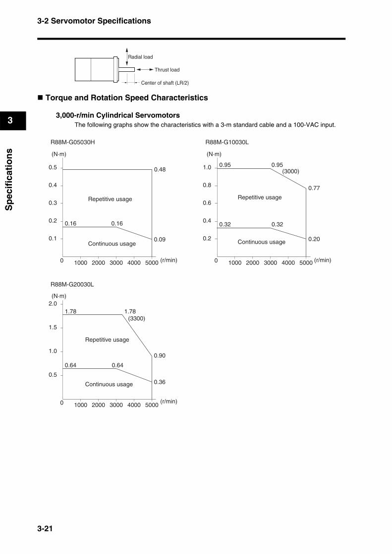
3-2 Servomotor Specifications
3
Sp
ecif
icat
ion
s
Torque and Rotation Speed Characteristics
3,000-r/min Cylindrical ServomotorsThe following graphs show the characteristics with a 3-m standard cable and a 100-VAC input.
Center of shaft (LR/2)
Radial load
Thrust load
0.1
1000 2000 3000 4000 50000
0.2
0.3
0.4
0.5
(N·m)
(N·m)
(N·m)
(r/min)
(r/min)
(r/min)
0.2
1000 2000 3000 4000 50000
0.4
0.6
0.8
1.0
R88M-G05030H R88M-G10030L
Continuous usage
Repetitive usage
0.48
0.160.16
0.09
0.77
0.95
0.32
0.20
0.32
0.5
1000 2000 3000 4000 50000
1.0
1.5
2.0
R88M-G20030L
Continuous usage
Repetitive usage
0.90
1.78
0.36
0.640.64
Continuous usage
Repetitive usage
(3300)1.78
0.95(3000)
3-21
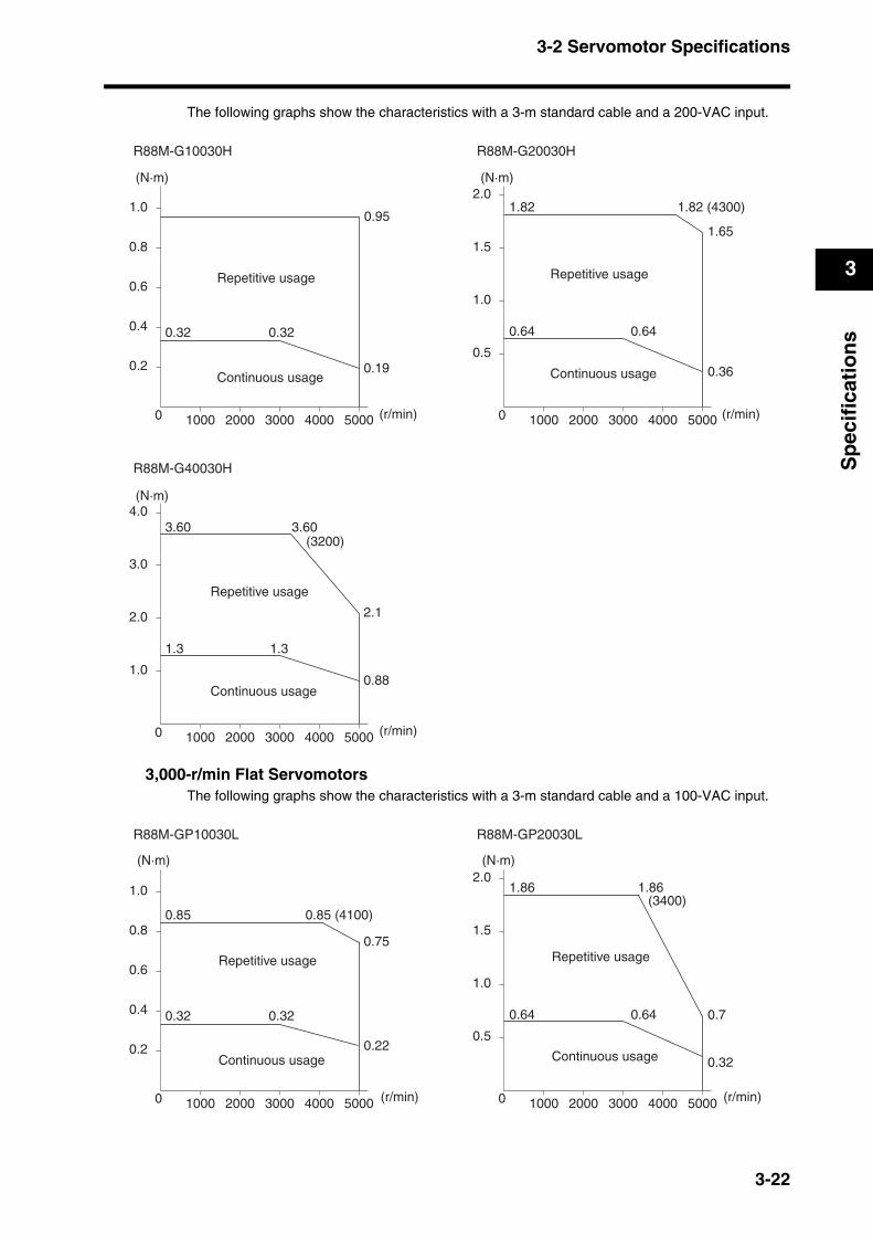
3-2 Servomotor Specifications
3
Sp
ecif
icat
ion
s
The following graphs show the characteristics with a 3-m standard cable and a 200-VAC input.
3,000-r/min Flat ServomotorsThe following graphs show the characteristics with a 3-m standard cable and a 100-VAC input.
0.2
1000 2000 3000 4000 50000
0.4
0.6
0.8
1.0
(N·m)
(N·m)
(N·m)
(r/min)
(r/min)
(r/min)
0.5
1000 2000 3000 4000 50000
1.0
1.5
2.0
R88M-G10030H R88M-G20030H
Continuous usage
Repetitive usage
0.95
0.320.32
0.19
1.65
1.82 (4300)
0.64
0.36
0.64
1.0
1000 2000 3000 4000 50000
2.0
3.0
4.0
R88M-G40030H
Continuous usage
Repetitive usage
2.1
3.60
0.88
1.31.3
Continuous usage
Repetitive usage
(3200)3.60
1.82
0.2
1000 2000 3000 4000 50000
0.4
0.6
0.8
1.0
0.5
1000 2000 3000 4000 50000
1.0
1.5
2.0
R88M-GP10030L R88M-GP20030L
0.85
0.320.32
0.22
0.7
1.86
0.64
0.32
0.64
1.86(3400)
0.85 (4100)
0.75
(N·m) (N·m)
(r/min) (r/min)
Continuous usage
Repetitive usage
Continuous usage
Repetitive usage
3-22
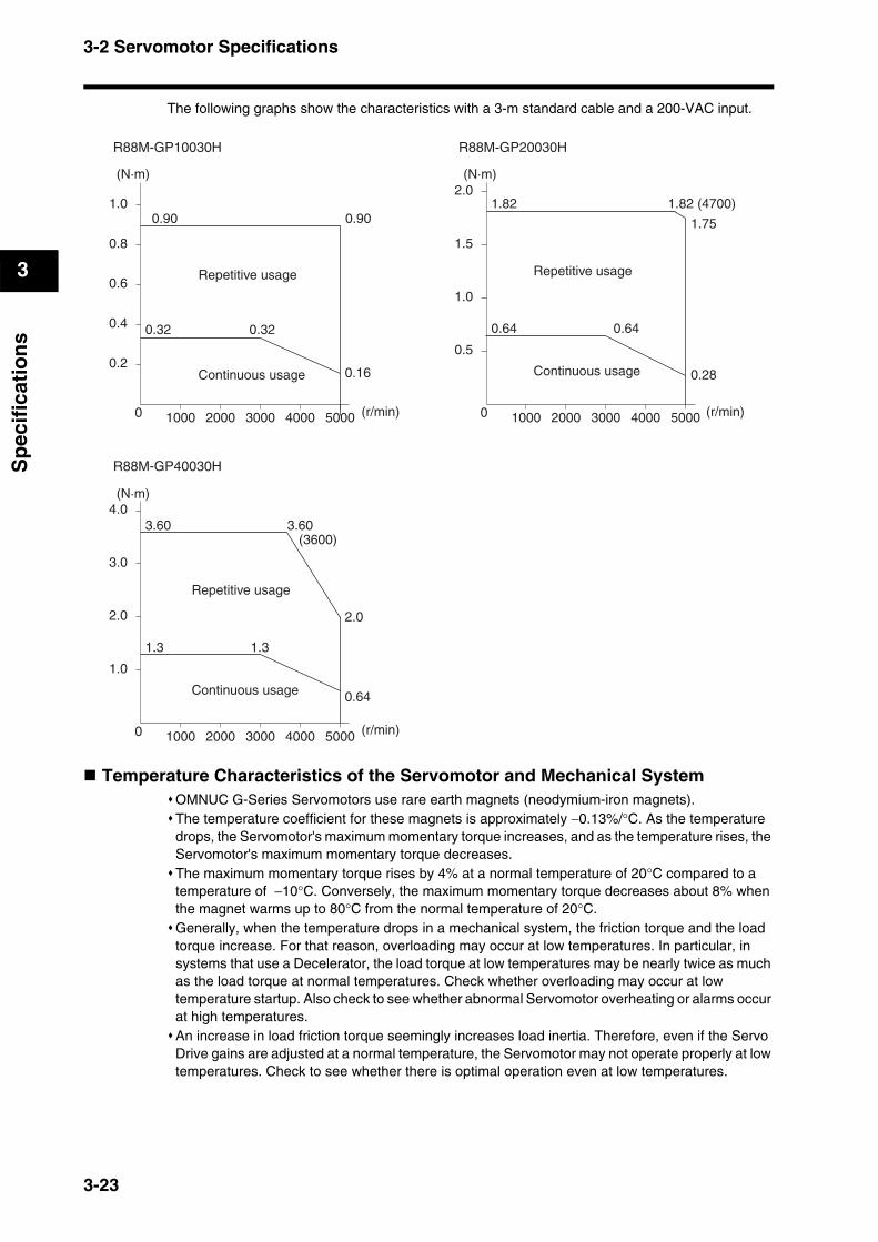
3-2 Servomotor Specifications
3
Sp
ecif
icat
ion
s
The following graphs show the characteristics with a 3-m standard cable and a 200-VAC input.
Temperature Characteristics of the Servomotor and Mechanical SystemOMNUC G-Series Servomotors use rare earth magnets (neodymium-iron magnets).The temperature coefficient for these magnets is approximately −0.13%/°C. As the temperature drops, the Servomotor's maximum momentary torque increases, and as the temperature rises, the Servomotor's maximum momentary torque decreases.The maximum momentary torque rises by 4% at a normal temperature of 20°C compared to a temperature of −10°C. Conversely, the maximum momentary torque decreases about 8% when the magnet warms up to 80°C from the normal temperature of 20°C.Generally, when the temperature drops in a mechanical system, the friction torque and the load torque increase. For that reason, overloading may occur at low temperatures. In particular, in systems that use a Decelerator, the load torque at low temperatures may be nearly twice as much as the load torque at normal temperatures. Check whether overloading may occur at low temperature startup. Also check to see whether abnormal Servomotor overheating or alarms occur at high temperatures.An increase in load friction torque seemingly increases load inertia. Therefore, even if the Servo Drive gains are adjusted at a normal temperature, the Servomotor may not operate properly at low temperatures. Check to see whether there is optimal operation even at low temperatures.
0.2
1000 2000 3000 4000 50000
0.4
0.6
0.8
1.0
0.5
1000 2000 3000 4000 50000
1.0
1.5
2.0
R88M-GP10030H R88M-GP20030H
0.90
0.320.32
0.16
1.75
1.82 (4700)
0.64
0.28
0.64
1.0
1000 2000 3000 4000 50000
2.0
3.0
4.0
R88M-GP40030H
2.0
3.60
0.64
1.31.3
(3600)3.60
1.820.90
(N·m)
(N·m)
(N·m)
(r/min)
(r/min)
(r/min)
Continuous usage
Repetitive usage
Continuous usage
Repetitive usage
Continuous usage
Repetitive usage
3-23

3-2 Servomotor Specifications
3
Sp
ecif
icat
ion
s
Use Cylindrical Servomotors in the ranges shown in the following graphs. Using outside of these ranges may cause the Servomotor to generate heat, which could result in encoder malfunction.
Precautions for Correct Use
20
10 20 30 400
40
60
80
100
Rated Torque Ratio (%)
50 W (Without Oil Seal)
10 20 30 400Ambient temperature
Rated Torque Ratio (%)
50 W (With Oil Seal)
Ambient temperature
20
40
60
80
100With brake
95%
60%70%
With brake
Without brake
20
10 20 30 400
40
60
80
100
Rated Torque Ratio (%)
100 W (Without Oil Seal)
10 20 30 400Ambient temperature
Rated Torque Ratio (%)
100 W (With Oil Seal)
Ambient temperature
20
40
60
80
100With brake
95%
75%70%
With brake
Without brake
3-24
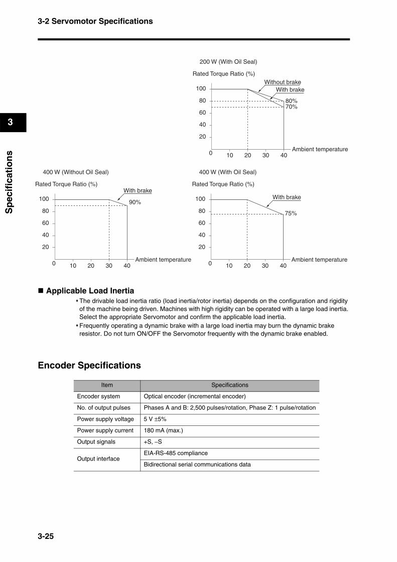
3-2 Servomotor Specifications
3
Sp
ecif
icat
ion
s
Applicable Load InertiaThe drivable load inertia ratio (load inertia/rotor inertia) depends on the configuration and rigidity of the machine being driven. Machines with high rigidity can be operated with a large load inertia. Select the appropriate Servomotor and confirm the applicable load inertia.Frequently operating a dynamic brake with a large load inertia may burn the dynamic brake resistor. Do not turn ON/OFF the Servomotor frequently with the dynamic brake enabled.
Encoder Specifications
10 20 30 400Ambient temperature
Rated Torque Ratio (%)
200 W (With Oil Seal)
20
40
60
80
100
80%70%
With brakeWithout brake
20
10 20 30 400
40
60
80
100
Rated Torque Ratio (%)
400 W (Without Oil Seal)
10 20 30 400Ambient temperature
Rated Torque Ratio (%)
400 W (With Oil Seal)
Ambient temperature
20
40
60
80
100With brake
90%
75%
With brake
Item Specifications
Encoder system Optical encoder (incremental encoder)
No. of output pulses Phases A and B: 2,500 pulses/rotation, Phase Z: 1 pulse/rotation
Power supply voltage 5 V ±5%
Power supply current 180 mA (max.)
Output signals +S, −S
Output interfaceEIA-RS-485 compliance
Bidirectional serial communications data
3-25
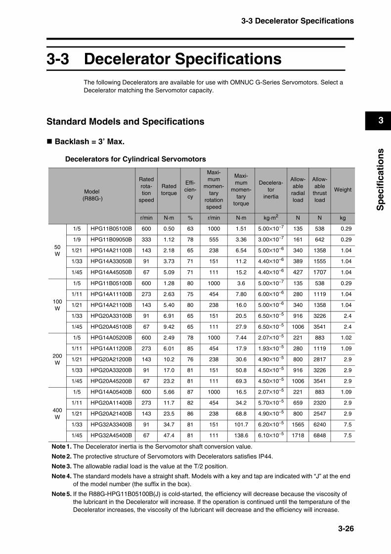
3-3 Decelerator Specifications
3
Sp
ecif
icat
ion
s
3-3 Decelerator SpecificationsThe following Decelerators are available for use with OMNUC G-Series Servomotors. Select a Decelerator matching the Servomotor capacity.
Standard Models and Specifications
Backlash = 3’ Max.
Decelerators for Cylindrical Servomotors
Model (R88G-)
Ratedrota-tion
speed
Ratedtorque
Effi-cien-
cy
Maxi-mum
momen-tary
rotation speed
Maxi-mum
momen-tary
torque
Decelera-tor
inertia
Allow-ableradial load
Allow-able
thrust load
Weight
r/min N·m % r/min N·m kg·m2 N N kg
50W
1/5 HPG11B05100B 600 0.50 63 1000 1.51 5.00×10⁻⁷ 135 538 0.29
1/9 HPG11B09050B 333 1.12 78 555 3.36 3.00×10⁻⁷ 161 642 0.29
1/21 HPG14A21100B 143 2.18 65 238 6.54 5.00×10⁻⁶ 340 1358 1.04
1/33 HPG14A33050B 91 3.73 71 151 11.2 4.40×10⁻⁶ 389 1555 1.04
1/45 HPG14A45050B 67 5.09 71 111 15.2 4.40×10⁻⁶ 427 1707 1.04
100W
1/5 HPG11B05100B 600 1.28 80 1000 3.6 5.00×10⁻⁷ 135 538 0.29
1/11 HPG14A11100B 273 2.63 75 454 7.80 6.00×10⁻⁶ 280 1119 1.04
1/21 HPG14A21100B 143 5.40 80 238 16.0 5.00×10⁻⁶ 340 1358 1.04
1/33 HPG20A33100B 91 6.91 65 151 20.5 6.50×10⁻⁵ 916 3226 2.4
1/45 HPG20A45100B 67 9.42 65 111 27.9 6.50×10⁻⁵ 1006 3541 2.4
200W
1/5 HPG14A05200B 600 2.49 78 1000 7.44 2.07×10⁻⁵ 221 883 1.02
1/11 HPG14A11200B 273 6.01 85 454 17.9 1.93×10⁻⁵ 280 1119 1.09
1/21 HPG20A21200B 143 10.2 76 238 30.6 4.90×10⁻⁵ 800 2817 2.9
1/33 HPG20A33200B 91 17.0 81 151 50.8 4.50×10⁻⁵ 916 3226 2.9
1/45 HPG20A45200B 67 23.2 81 111 69.3 4.50×10⁻⁵ 1006 3541 2.9
400W
1/5 HPG14A05400B 600 5.66 87 1000 16.5 2.07×10⁻⁵ 221 883 1.09
1/11 HPG20A11400B 273 11.7 82 454 34.2 5.70×10⁻⁵ 659 2320 2.9
1/21 HPG20A21400B 143 23.5 86 238 68.8 4.90×10⁻⁵ 800 2547 2.9
1/33 HPG32A33400B 91 34.7 81 151 101.7 6.20×10⁻⁵ 1565 6240 7.5
1/45 HPG32A45400B 67 47.4 81 111 138.6 6.10×10⁻⁵ 1718 6848 7.5
Note 1. The Decelerator inertia is the Servomotor shaft conversion value.
Note 2. The protective structure of Servomotors with Decelerators satisfies IP44.
Note 3. The allowable radial load is the value at the T/2 position.
Note 4. The standard models have a straight shaft. Models with a key and tap are indicated with “J” at the end of the model number (the suffix in the box).
Note 5. If the R88G-HPG11B05100B(J) is cold-started, the efficiency will decrease because the viscosity of the lubricant in the Decelerator will increase. If the operation is continued until the temperature of the Decelerator increases, the viscosity of the lubricant will decrease and the efficiency will increase.
3-26
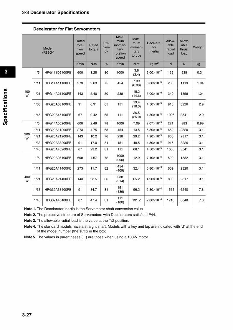
3-3 Decelerator Specifications
3
Sp
ecif
icat
ion
s
Decelerator for Flat Servomotors
Model (R88G-)
Ratedrota-tion
speed
Ratedtorque
Effi-cien-
cy
Maxi-mum
momen-tary
rotationspeed
Maxi-mum
momen-tary
torque
Decelera-tor
inertia
Allow-able
radial load
Allow-able
thrust load
Weight
r/min N·m % r/min N·m kg·m2 N N kg
100W
1/5 HPG11B05100PB 600 1.28 80 10003.6
(3.4)5.00×10⁻⁷ 135 538 0.34
1/11 HPG14A11100PB 273 2.63 75 4547.39
(6.98)6.00×10⁻⁶ 280 1119 1.04
1/21 HPG14A21100PB 143 5.40 80 23815.2
(14.6)5.00×10⁻⁶ 340 1358 1.04
1/33 HPG20A33100PB 91 6.91 65 15119.4
(18.3)4.50×10⁻⁵ 916 3226 2.9
1/45 HPG20A45100PB 67 9.42 65 11126.5
(25.0)4.50×10⁻⁵ 1006 3541 2.9
200W
1/5 HPG14A05200PB 600 2.49 78 1000 7.09 2.07×10⁻⁵ 221 883 0.99
1/11 HPG20A11200PB 273 4.75 68 454 13.5 5.80×10⁻⁵ 659 2320 3.1
1/21 HPG20A21200PB 143 10.2 76 238 29.2 4.90×10⁻⁵ 800 2817 3.1
1/33 HPG20A33200PB 91 17.0 81 151 48.5 4.50×10⁻⁵ 916 3226 3.1
1/45 HPG20A45200PB 67 23.2 81 111 66.1 4.50×10⁻⁵ 1006 3541 3.1
400W
1/5 HPG20A05400PB 600 4.67 721000(900)
12.9 7.10×10⁻⁵ 520 1832 3.1
1/11 HPG20A11400PB 273 11.7 82454
(409)32.4 5.80×10⁻⁵ 659 2320 3.1
1/21 HPG20A21400PB 143 23.5 86238
(214)65.2 4.90×10⁻⁵ 800 2817 3.1
1/33 HPG32A33400PB 91 34.7 81151
(136)96.2 2.80×10⁻⁴ 1565 6240 7.8
1/45 HPG32A45400PB 67 47.4 81111
(100)131.2 2.80×10⁻⁴ 1718 6848 7.8
Note 1. The Decelerator inertia is the Servomotor shaft conversion value.
Note 2. The protective structure of Servomotors with Decelerators satisfies IP44.
Note 3. The allowable radial load is the value at the T/2 position.
Note 4. The standard models have a straight shaft. Models with a key and tap are indicated with “J” at the end of the model number (the suffix in the box).
Note 5. The values in parentheses ( ) are those when using a 100-V motor.
3-27
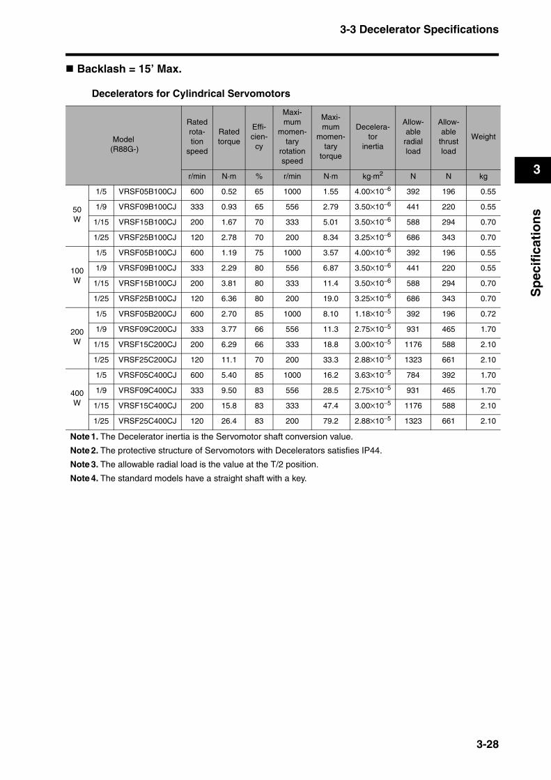
3-3 Decelerator Specifications
3
Sp
ecif
icat
ion
s
Backlash = 15’ Max.
Decelerators for Cylindrical Servomotors
Model (R88G-)
Ratedrota-tion
speed
Ratedtorque
Effi-cien-
cy
Maxi-mum
momen-tary
rotationspeed
Maxi-mum
momen-tary
torque
Decelera-tor
inertia
Allow-able
radial load
Allow-able
thrust load
Weight
r/min N·m % r/min N·m kg·m2 N N kg
50W
1/5 VRSF05B100CJ 600 0.52 65 1000 1.55 4.00×10⁻⁶ 392 196 0.55
1/9 VRSF09B100CJ 333 0.93 65 556 2.79 3.50×10⁻⁶ 441 220 0.55
1/15 VRSF15B100CJ 200 1.67 70 333 5.01 3.50×10⁻⁶ 588 294 0.70
1/25 VRSF25B100CJ 120 2.78 70 200 8.34 3.25×10⁻⁶ 686 343 0.70
100W
1/5 VRSF05B100CJ 600 1.19 75 1000 3.57 4.00×10⁻⁶ 392 196 0.55
1/9 VRSF09B100CJ 333 2.29 80 556 6.87 3.50×10⁻⁶ 441 220 0.55
1/15 VRSF15B100CJ 200 3.81 80 333 11.4 3.50×10⁻⁶ 588 294 0.70
1/25 VRSF25B100CJ 120 6.36 80 200 19.0 3.25×10⁻⁶ 686 343 0.70
200W
1/5 VRSF05B200CJ 600 2.70 85 1000 8.10 1.18×10⁻⁵ 392 196 0.72
1/9 VRSF09C200CJ 333 3.77 66 556 11.3 2.75×10⁻⁵ 931 465 1.70
1/15 VRSF15C200CJ 200 6.29 66 333 18.8 3.00×10⁻⁵ 1176 588 2.10
1/25 VRSF25C200CJ 120 11.1 70 200 33.3 2.88×10⁻⁵ 1323 661 2.10
400W
1/5 VRSF05C400CJ 600 5.40 85 1000 16.2 3.63×10⁻⁵ 784 392 1.70
1/9 VRSF09C400CJ 333 9.50 83 556 28.5 2.75×10⁻⁵ 931 465 1.70
1/15 VRSF15C400CJ 200 15.8 83 333 47.4 3.00×10⁻⁵ 1176 588 2.10
1/25 VRSF25C400CJ 120 26.4 83 200 79.2 2.88×10⁻⁵ 1323 661 2.10
Note 1. The Decelerator inertia is the Servomotor shaft conversion value.
Note 2. The protective structure of Servomotors with Decelerators satisfies IP44.
Note 3. The allowable radial load is the value at the T/2 position.
Note 4. The standard models have a straight shaft with a key.
3-28
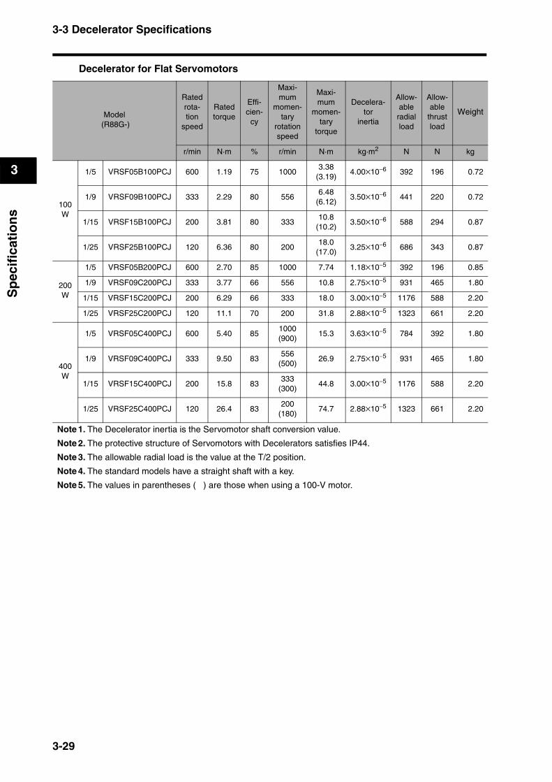
3-3 Decelerator Specifications
3
Sp
ecif
icat
ion
s
Decelerator for Flat Servomotors
Model (R88G-)
Ratedrota-tion
speed
Ratedtorque
Effi-cien-
cy
Maxi-mum
momen-tary
rotationspeed
Maxi-mum
momen-tary
torque
Decelera-tor
inertia
Allow-ableradial load
Allow-able
thrust load
Weight
r/min N·m % r/min N·m kg·m2 N N kg
100W
1/5 VRSF05B100PCJ 600 1.19 75 10003.38
(3.19)4.00×10⁻⁶ 392 196 0.72
1/9 VRSF09B100PCJ 333 2.29 80 5566.48
(6.12)3.50×10⁻⁶ 441 220 0.72
1/15 VRSF15B100PCJ 200 3.81 80 33310.8
(10.2)3.50×10⁻⁶ 588 294 0.87
1/25 VRSF25B100PCJ 120 6.36 80 20018.0
(17.0)3.25×10⁻⁶ 686 343 0.87
200W
1/5 VRSF05B200PCJ 600 2.70 85 1000 7.74 1.18×10⁻⁵ 392 196 0.85
1/9 VRSF09C200PCJ 333 3.77 66 556 10.8 2.75×10⁻⁵ 931 465 1.80
1/15 VRSF15C200PCJ 200 6.29 66 333 18.0 3.00×10⁻⁵ 1176 588 2.20
1/25 VRSF25C200PCJ 120 11.1 70 200 31.8 2.88×10⁻⁵ 1323 661 2.20
400W
1/5 VRSF05C400PCJ 600 5.40 851000(900)
15.3 3.63×10⁻⁵ 784 392 1.80
1/9 VRSF09C400PCJ 333 9.50 83556
(500)26.9 2.75×10⁻⁵ 931 465 1.80
1/15 VRSF15C400PCJ 200 15.8 83333
(300)44.8 3.00×10⁻⁵ 1176 588 2.20
1/25 VRSF25C400PCJ 120 26.4 83200
(180)74.7 2.88×10⁻⁵ 1323 661 2.20
Note 1. The Decelerator inertia is the Servomotor shaft conversion value.
Note 2. The protective structure of Servomotors with Decelerators satisfies IP44.
Note 3. The allowable radial load is the value at the T/2 position.
Note 4. The standard models have a straight shaft with a key.
Note 5. The values in parentheses ( ) are those when using a 100-V motor.
3-29
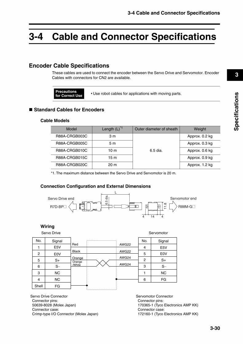
3-4 Cable and Connector Specifications
3
Sp
ecif
icat
ion
s
3-4 Cable and Connector Specifications
Encoder Cable SpecificationsThese cables are used to connect the encoder between the Servo Drive and Servomotor. Encoder Cables with connectors for CN2 are available.
Standard Cables for Encoders
Cable Models
Connection Configuration and External Dimensions
Wiring
Use robot cables for applications with moving parts.Precautions for Correct Use
Model Length (L)*1 Outer diameter of sheath Weight
R88A-CRGB003C 3 m
6.5 dia.
Approx. 0.2 kg
R88A-CRGB005C 5 m Approx. 0.3 kg
R88A-CRGB010C 10 m Approx. 0.6 kg
R88A-CRGB015C 15 m Approx. 0.9 kg
R88A-CRGB020C 20 m Approx. 1.2 kg
*1. The maximum distance between the Servo Drive and Servomotor is 20 m.
6.5
dia.
4144
11.8
L
Servomotor end
R88M-G@
Servo Drive end
R7D-BP@
AWG22
AWG24
AWG24
E5V
E0V E0V
NC
S+
NC
S−
S+
NC
S−
1 4
2 5
5 2
6 3
3 1
4 6
No.
Servo Drive Servomotor
Shell
Signal No. Signal
Servo Drive ConnectorConnector pins:50639-8028 (Molex Japan)Connector case:Crimp-type I/O Connector (Molex Japan)
Servomotor ConnectorConnector pins:170365-1 (Tyco Electronics AMP KK)Connector case:172160-1 (Tyco Electronics AMP KK)
AWG22
FG
FG
E5VRed
Black
OrangeOrange/White
3-30

3-4 Cable and Connector Specifications
3
Sp
ecif
icat
ion
s
Robot Cables for Encoders
Cable Models
Connection Configuration and External Dimensions
Wiring
Model Length (L)*1 Outer diameter of sheath Weight
R88A-CRGB003CR 3 m
7.5 dia.
Approx. 0.2 kg
R88A-CRGB005CR 5 m Approx. 0.4 kg
R88A-CRGB010CR 10 m Approx. 0.8 kg
R88A-CRGB015CR 15 m Approx. 1.1 kg
R88A-CRGB020CR 20 m Approx. 1.5 kg
*1. The maximum distance between the Servo Drive and Servomotor is 20 m.
4144
11.8
L
Servo Drive end Servomotor end
R88M-G@R7D-BP@
7.5
dia.
AWG24
AWG24
AWG24
E5V
E0V E0V
NC
NC
NC
1 4
2 5
5 2
6 3
3 1
4 6
No. No.AWG24
FG
FG
E5V
AWG24
AWG24
Servo Drive Servomotor
Signal Signal
Shell
S+
S−
Servomotor ConnectorConnector pins:170365-1 (Tyco Electronics AMP KK)Connector case:172160-1 (Tyco Electronics AMP KK)
Servo Drive ConnectorConnector pins:50639-8028 (Molex Japan)Connector case:Crimp-type I/O Connector (Molex Japan)
S+
S−
Blue/Black
Blue/Red
Pink/Red
Orange/RedOrange/Black
Pink/Black
3-31
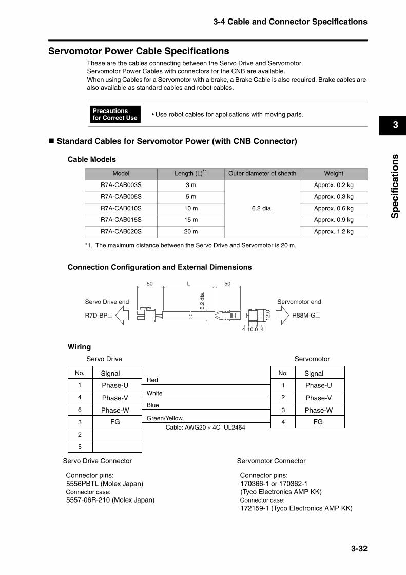
3-4 Cable and Connector Specifications
3
Sp
ecif
icat
ion
s
Servomotor Power Cable SpecificationsThese are the cables connecting between the Servo Drive and Servomotor.Servomotor Power Cables with connectors for the CNB are available.When using Cables for a Servomotor with a brake, a Brake Cable is also required. Brake cables are also available as standard cables and robot cables.
Standard Cables for Servomotor Power (with CNB Connector)
Cable Models
Connection Configuration and External Dimensions
Wiring
Use robot cables for applications with moving parts.Precautions for Correct Use
Model Length (L)*1 Outer diameter of sheath Weight
R7A-CAB003S 3 m
6.2 dia.
Approx. 0.2 kg
R7A-CAB005S 5 m Approx. 0.3 kg
R7A-CAB010S 10 m Approx. 0.6 kg
R7A-CAB015S 15 m Approx. 0.9 kg
R7A-CAB020S 20 m Approx. 1.2 kg
*1. The maximum distance between the Servo Drive and Servomotor is 20 m.
50 50L
10.0
12.0
4 4
6.2
dia.
Servomotor end
R88M-G@
Servo Drive end
R7D-BP@
Red
White
Blue
Green/Yellow
Cable: AWG20 × 4C UL2464
1
No.
4
6
3
2
5
1
No.
4
3
2
Servo Drive Connector
Connector pins:5556PBTL (Molex Japan)Connector case:5557-06R-210 (Molex Japan)
Signal
Phase-U
Phase-V
Phase-W
FG
Servo Drive Servomotor
Signal
Phase-U
Phase-V
Phase-W
FG
Servomotor Connector
Connector pins:170366-1 or 170362-1(Tyco Electronics AMP KK)Connector case:172159-1 (Tyco Electronics AMP KK)
3-32
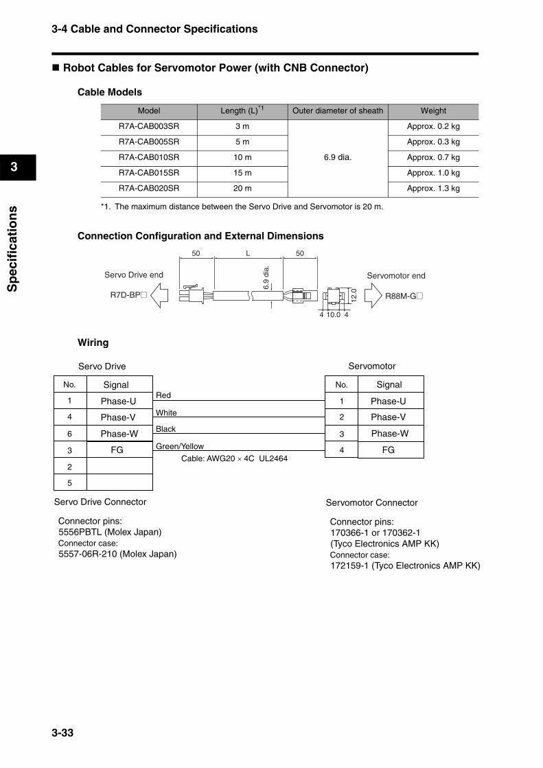
3-4 Cable and Connector Specifications
3
Sp
ecif
icat
ion
s
Robot Cables for Servomotor Power (with CNB Connector)
Cable Models
Connection Configuration and External Dimensions
Wiring
Model Length (L)*1 Outer diameter of sheath Weight
R7A-CAB003SR 3 m
6.9 dia.
Approx. 0.2 kg
R7A-CAB005SR 5 m Approx. 0.3 kg
R7A-CAB010SR 10 m Approx. 0.7 kg
R7A-CAB015SR 15 m Approx. 1.0 kg
R7A-CAB020SR 20 m Approx. 1.3 kg
*1. The maximum distance between the Servo Drive and Servomotor is 20 m.
50 50L
10.0
12.0
4 4
6.9
dia.
Servo Drive end Servomotor end
R88M-G@R7D-BP@
1
No.
4
6
3
2
5
1
No.
4
3
2
FG FG
Servo Drive Servomotor
Signal Signal
Phase-U Phase-U
Phase-V Phase-V
Phase-W Phase-W
Red
White
Black
Green/Yellow
Cable: AWG20 × 4C UL2464
Servo Drive Connector
Connector pins:5556PBTL (Molex Japan)Connector case:5557-06R-210 (Molex Japan)
Servomotor Connector
Connector pins:170366-1 or 170362-1(Tyco Electronics AMP KK)Connector case:172159-1 (Tyco Electronics AMP KK)
3-33

3-4 Cable and Connector Specifications
3
Sp
ecif
icat
ion
s
Standard Cables for Brakes
Cable Models
Connection Configuration and External Dimensions
Wiring
Model Length (L)*1 Outer diameter of sheath Weight
R88A-CAGA003B 3 m
5.4 dia.
Approx. 0.1 kg
R88A-CAGA005B 5 m Approx. 0.2 kg
R88A-CAGA010B 10 m Approx. 0.4 kg
R88A-CAGA015B 15 m Approx. 0.6 kg
R88A-CAGA020B 20 m Approx. 0.8 kg
*1. The maximum distance between the Servo Drive and Servomotor is 20 m.
50 50L
5.6
12.0
10.0
5.4
dia.
Servomotor end
R88M-G@
Servo Drive end
R7D-BP@
No.
A
B
Signal
Brake
BrakeM4 crimpterminal
Black
BrownCable: AWG20 × 2C UL2464
Servo Drive Servomotor
Servomotor ConnectorConnector pins:170366-1 or 170362-1(Tyco Electronics AMP KK)Connector case:172157-1(Tyco Electronics AMP KK)
3-34

3-4 Cable and Connector Specifications
3
Sp
ecif
icat
ion
s
Robot Cables for Brakes
Cable Models
Connection Configuration and External Dimensions
Wiring
Model Length (L)*1 Outer diameter of sheath Weight
R88A-CAGA003BR 3 m
6.1 dia.
Approx. 0.1 kg
R88A-CAGA005BR 5 m Approx. 0.2 kg
R88A-CAGA010BR 10 m Approx. 0.4 kg
R88A-CAGA015BR 15 m Approx. 0.7 kg
R88A-CAGA020BR 20 m Approx. 0.9 kg
*1. The maximum distance between the Servo Drive and Servomotor is 20 m.
5.612
.0
10.0
50 50L6.
1 di
a.
Servomotor end
R88M-G@
Servo Drive end
R7D-BP@
No.
A
B
Signal
Brake
BrakeM4 crimpterminal
Black
WhiteCable: AWG20 × 2C UL2464
Servo Drive Servomotor
Servomotor ConnectorConnector pins:170366-1 or 170362-1(Tyco Electronics AMP KK)Connector case:172157-1(Tyco Electronics AMP KK)
3-35

3-4 Cable and Connector Specifications
3
Sp
ecif
icat
ion
s
Resistant to Bending of Robot CablesUse Robot Cable that can withstand at least 20 million bends to the minimum bending radius (R) given below or larger.
Note 1. The service life data for resistant to bending is based on test data. Use it for reference only, and provide sufficient allowance.
Note 2. This value is the number of bends when electricity is conducted through the conductors that will not result in cracking or damage to an extent that would affect the functionality of the sheath. Broken shield strands may occur.
Note 3. If a bending radius smaller than the minimum bending radius is used, it may result in mechanical damage or ground fault damage due to insulation breakdown. If it is necessary to use a bending radius smaller than the minimum bending radius, consult with your OMRON representative.
Encoder Cables
@@@: 003 to 020
Power Cables
@@@: 003 to 020
Brake Cables
@@@: 003 to 020
Moving Bend Test
*1. Encoder cable: 30 to 50 m only Stroke: 550 mm, 50 times/min
Model Minimum bending radius (R)
R88A-CRGA@@@CR 45 mm
Model Minimum bending radius (R)
R7A-CAB@@@SR 45 mm
Model Minimum bending radius (R)
R88A-CAGA@@@BR 45 mm
Stroke:750 mm
Bending radius (R)
30 times/min
3-36
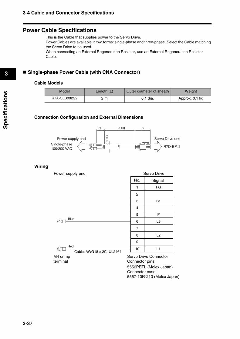
3-4 Cable and Connector Specifications
3
Sp
ecif
icat
ion
s
Power Cable SpecificationsThis is the Cable that supplies power to the Servo Drive. Power Cables are available in two forms: single-phase and three-phase. Select the Cable matching the Servo Drive to be used. When connecting an External Regeneration Resistor, use an External Regeneration Resistor Cable.
Single-phase Power Cable (with CNA Connector)
Cable Models
Connection Configuration and External Dimensions
Wiring
Model Length (L) Outer diameter of sheath Weight
R7A-CLB002S2 2 m 6.1 dia. Approx. 0.1 kg
50 502000
6.1
dia.
Single-phase 100/200 VAC R7D-BP@
Servo Drive endPower supply end
No.
1
2
Signal
Servo Drive ConnectorConnector pins:5556PBTL (Molex Japan)Connector case:5557-10R-210 (Molex Japan)
Power supply end Servo Drive
M4 crimpterminal
3
4
5
6 L3
7
8
9
10 L1
L2
P
B1
FG
Cable: AWG18 × 2C UL2464
Blue
Red
3-37
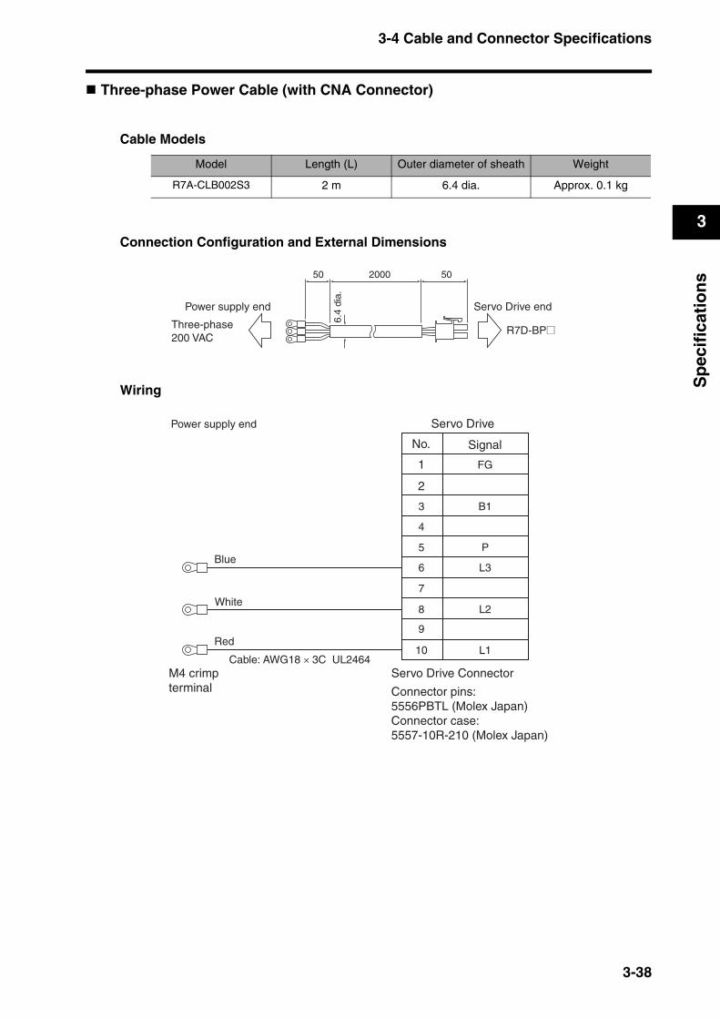
3-4 Cable and Connector Specifications
3
Sp
ecif
icat
ion
s
Three-phase Power Cable (with CNA Connector)
Cable Models
Connection Configuration and External Dimensions
Wiring
Model Length (L) Outer diameter of sheath Weight
R7A-CLB002S3 2 m 6.4 dia. Approx. 0.1 kg
50 502000
6.4
dia.
Power supply end
Three-phase 200 VAC
Servo Drive end
R7D-BP@
No.
1
2
Signal
Servo Drive Connector
Connector pins:5556PBTL (Molex Japan)Connector case:5557-10R-210 (Molex Japan)
Power supply end Servo Drive
M4 crimpterminal
3
4
5
6 L3
7
8
9
10 L1
L2
P
B1
FG
Cable: AWG18 × 3C UL2464
Blue
White
Red
3-38
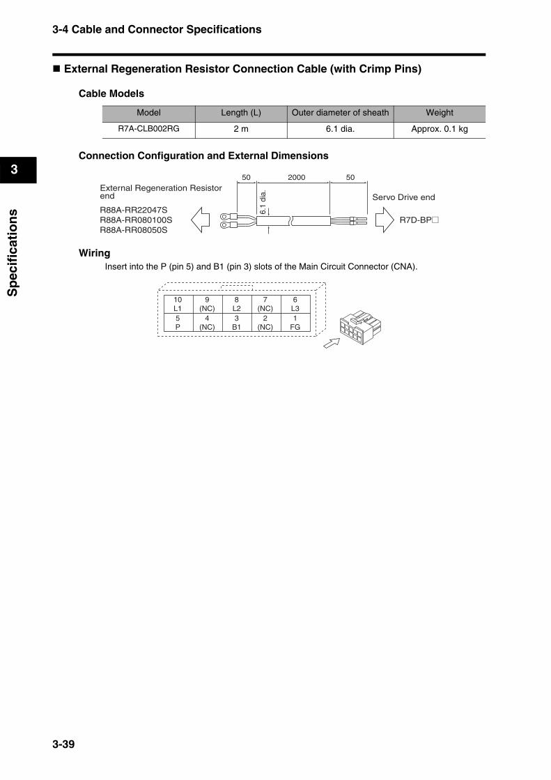
3-4 Cable and Connector Specifications
3
Sp
ecif
icat
ion
s
External Regeneration Resistor Connection Cable (with Crimp Pins)
Cable Models
Connection Configuration and External Dimensions
WiringInsert into the P (pin 5) and B1 (pin 3) slots of the Main Circuit Connector (CNA).
Model Length (L) Outer diameter of sheath Weight
R7A-CLB002RG 2 m 6.1 dia. Approx. 0.1 kg
50 502000
6.1
dia.
External Regeneration Resistor end
R88A-RR22047SR88A-RR080100SR88A-RR08050S
Servo Drive end
R7D-BP@
10L1
9(NC)
8L2
7(NC)
6L3
5P
4(NC)
3B1
2(NC)
1FG
3-39
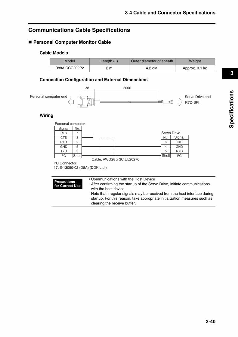
3-4 Cable and Connector Specifications
3
Sp
ecif
icat
ion
s
Communications Cable Specifications
Personal Computer Monitor Cable
Cable Models
Connection Configuration and External Dimensions
Wiring
Model Length (L) Outer diameter of sheath Weight
R88A-CCG002P2 2 m 4.2 dia. Approx. 0.1 kg
Communications with the Host DeviceAfter confirming the startup of the Servo Drive, initiate communications with the host device. Note that irregular signals may be received from the host interface during startup. For this reason, take appropriate initialization measures such as clearing the receive buffer.
R7D-BP@
Personal computer end Servo Drive end
Signal
Signal
Personal computer
Shell ShellCable: AWG28 x 3C UL20276
Servo Drive
PC Connector17JE-13090-02 (D8A) (DDK Ltd.)
Precautions for Correct Use
3-40

3-4 Cable and Connector Specifications
3
Sp
ecif
icat
ion
s
Connector Specifications
Main Circuit Connector (R7A-CNB01P)The Main Circuit Connector connects to the Servo Drive’s Main Circuit Connector (CNA).
Dimensions
11.6
10.7
19.6
3.5
8.5
6.3
16.822.2
2.7 2.74.2
4.2
9.6
3
5.4
Connector pins:5556PBTL (Molex Japan)Connector case:5557-10R-210 (Molex Japan)
3-41

3-4 Cable and Connector Specifications
3
Sp
ecif
icat
ion
s
Servomotor Connector (R7A-CNB01A)The Servomotor Connector connects to the Servo Drive’s Servomotor Connector (CNB).
Dimensions
Control I/O Connector (R88A-CNW01C)This Connector connects to the Control I/O Connector (CN1) of the Servo Drive. Use this Connector when preparing a control cable yourself.
Dimensions
11.6
10.7
19.6
3.5
8.5
6.3
8.413.8
2.7 2.74.2
4.2
9.6
3
5.4
Connector pins:5556PBTL (Molex Japan)Connector case:5557-06R-210 (Molex Japan)
37.2
39
t = 14
Connector plug: 10126-3000PE (Sumitomo 3M)Connector case: 10326-52A0-008 (Sumitomo 3M)
3-42
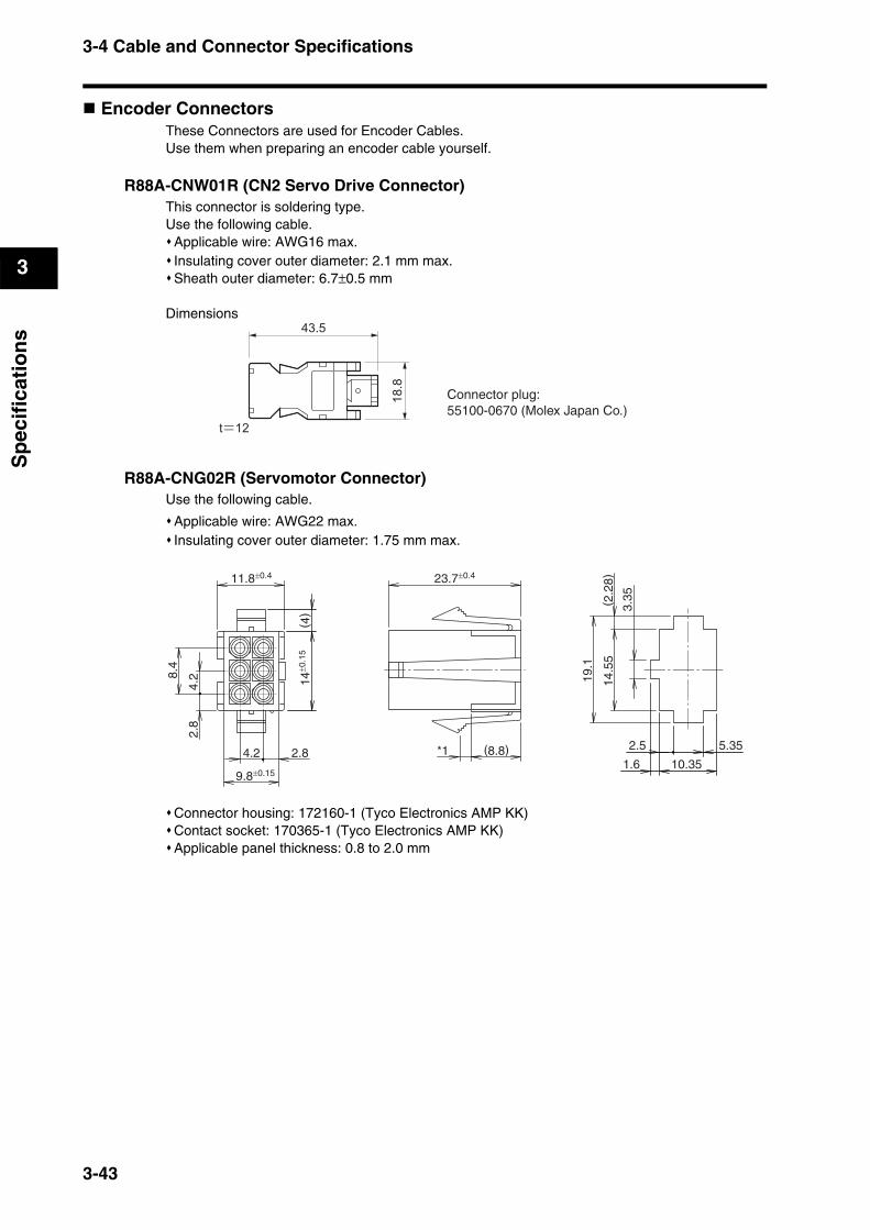
3-4 Cable and Connector Specifications
3
Sp
ecif
icat
ion
s
Encoder ConnectorsThese Connectors are used for Encoder Cables. Use them when preparing an encoder cable yourself.
R88A-CNW01R (CN2 Servo Drive Connector)This connector is soldering type. Use the following cable.
Applicable wire: AWG16 max.Insulating cover outer diameter: 2.1 mm max.Sheath outer diameter: 6.7±0.5 mm
Dimensions
R88A-CNG02R (Servomotor Connector)Use the following cable.
Applicable wire: AWG22 max.Insulating cover outer diameter: 1.75 mm max.
Connector housing: 172160-1 (Tyco Electronics AMP KK)Contact socket: 170365-1 (Tyco Electronics AMP KK)Applicable panel thickness: 0.8 to 2.0 mm
Connector plug: 55100-0670 (Molex Japan Co.)
14±0
.15
( 4)
10.351.6
2.5 5.35
14.5
5( 2
.28)
3.35
19.1
8.4
11.8±0.4 23.7±0.4
9.8±0.15
2.84.2
2.8
4.2
(8.8)*1
3-43
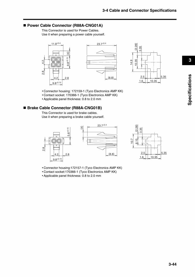
3-4 Cable and Connector Specifications
3
Sp
ecif
icat
ion
s
Power Cable Connector (R88A-CNG01A)This Connector is used for Power Cables. Use it when preparing a power cable yourself.
Connector housing: 172159-1 (Tyco Electronics AMP KK)Contact socket: 170366-1 (Tyco Electronics AMP KK)Applicable panel thickness: 0.8 to 2.0 mm
Brake Cable Connector (R88A-CNG01B)This Connector is used for brake cables. Use it when preparing a brake cable yourself.
Connector housing:172157-1 (Tyco Electronics AMP KK)Contact socket:170366-1 (Tyco Electronics AMP KK)Applicable panel thickness: 0.8 to 2.0 mm
10.351.6
2.5 5.35
10.3
5( 2
.28)
3.35
14.9
23.7±0.4
9.8±0
.15
( 4)
11.8±0.4
9.8±0.15
2.84.2
2.8
4.2
(8.8)
10.351.6
2.5 5.35
6.15
( 2.2
8)
3.35
10.7
23.7±0.4
(8.8)
5.6±0
.15
9.8±0.15
2.84.2
2.8
( 4)
3-44
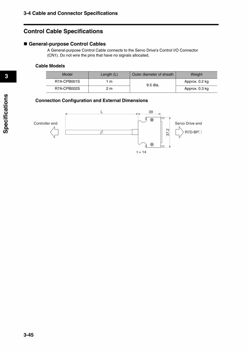
3-4 Cable and Connector Specifications
3
Sp
ecif
icat
ion
s
Control Cable Specifications
General-purpose Control CablesA General-purpose Control Cable connects to the Servo Drive's Control I/O Connector(CN1). Do not wire the pins that have no signals allocated.
Cable Models
Connection Configuration and External Dimensions
Model Length (L) Outer diameter of sheath Weight
R7A-CPB001S 1 m9.5 dia.
Approx. 0.2 kg
R7A-CPB002S 2 m Approx. 0.3 kg
Controller end Servo Drive end
R7D-BP@
L
37.2
39
t = 14
3-45
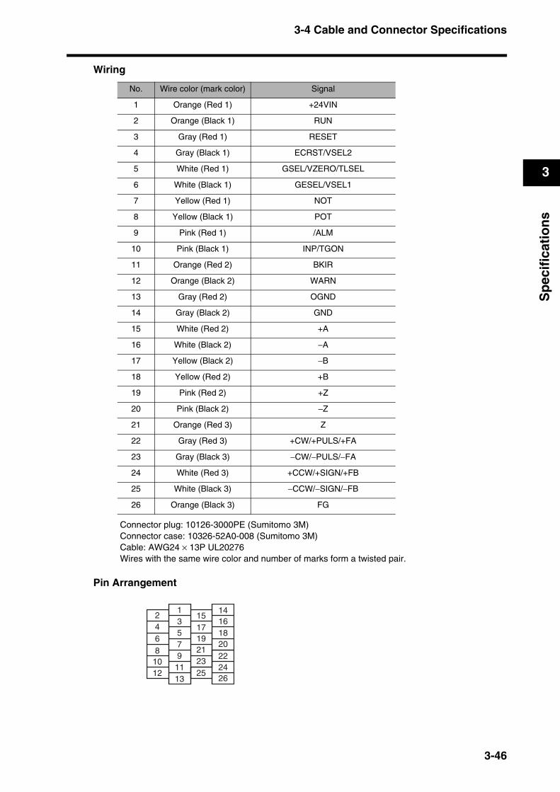
3-4 Cable and Connector Specifications
3
Sp
ecif
icat
ion
s
Wiring
Connector plug: 10126-3000PE (Sumitomo 3M)Connector case: 10326-52A0-008 (Sumitomo 3M)Cable: AWG24 × 13P UL20276Wires with the same wire color and number of marks form a twisted pair.
Pin Arrangement
No. Wire color (mark color) Signal
1 Orange (Red 1) +24VIN
2 Orange (Black 1) RUN
3 Gray (Red 1) RESET
4 Gray (Black 1) ECRST/VSEL2
5 White (Red 1) GSEL/VZERO/TLSEL
6 White (Black 1) GESEL/VSEL1
7 Yellow (Red 1) NOT
8 Yellow (Black 1) POT
9 Pink (Red 1) /ALM
10 Pink (Black 1) INP/TGON
11 Orange (Red 2) BKIR
12 Orange (Black 2) WARN
13 Gray (Red 2) OGND
14 Gray (Black 2) GND
15 White (Red 2) +A
16 White (Black 2) −A
17 Yellow (Black 2) −B
18 Yellow (Red 2) +B
19 Pink (Red 2) +Z
20 Pink (Black 2) −Z
21 Orange (Red 3) Z
22 Gray (Red 3) +CW/+PULS/+FA
23 Gray (Black 3) −CW/−PULS/−FA
24 White (Red 3) +CCW/+SIGN/+FB
25 White (Black 3) −CCW/−SIGN/−FB
26 Orange (Black 3) FG
2468
1012
13579
1113
151719212325
14161820222426
3-46
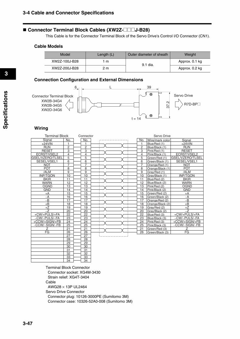
3-4 Cable and Connector Specifications
3
Sp
ecif
icat
ion
s
Connector Terminal Block Cables (XW2Z-@@@J-B28)This Cable is for the Connector Terminal Block of the Servo Drive's Control I/O Connector (CN1).
Cable Models
Connection Configuration and External Dimensions
Wiring
Terminal Block Connector Connector socket: XG4M-3430 Strain relief: XG4T-3404Cable AWG28 × 13P UL2464Servo Drive Connector Connector plug: 10126-3000PE (Sumitomo 3M) Connector case: 10326-52A0-008 (Sumitomo 3M)
Model Length (L) Outer diameter of sheath Weight
XW2Z-100J-B28 1 m9.1 dia.
Approx. 0.1 kg
XW2Z-200J-B28 2 m Approx. 0.2 kg
39
37.2
t = 14
6
Servo DriveConnector Terminal BlockXW2B-34G4XW2B-34G5XW2D-34G6
R7D-BP@
L
Terminal Block
112 23 34 45 56 67 78 89 9
10 1011 1112 1213 1314 1415 1516 1617 1718 1819 1920 20
5
1234
89
1011
67
1314
12
Wire/mark colorConnector Servo Drive
No.No.No.Signal+24VIN
+CW/+PULS/+FA−CW/−PULS/−FA
+CCW/+SIGN/+FB
RUN
OGND
BKIR
/ALM
FG
WARN
ECRST/VSEL2
Signal
−CCW/−SIGN/−FBZ
GND
INP/TGON
21
22232425
262728293031323334
21
22232425
262728293031323334
151617181920222324252126
−Z+Z+B−B−A+A
POTNOT
SESEL/VSEL1GSEL/VZERO/TLSEL
RESET
+24VIN
+CW/+PULS/+FA−CW/−PULS/−FA
+CCW/+SIGN/+FB
RUN
OGND
BKIR
/ALM
FG
WARN
ECRST/VSEL2
−CCW/−SIGN/−FBZ
GND
INP/TGON
−Z+Z+B−B−A+A
POTNOT
SESEL/VSEL1GSEL/VZERO/TLSEL
RESET
Blue/Red (1)Blue/Black (1)Pink/Red (1)Pink/Black (1)Green/Red (1)Green/Black (1)Orange/Red (1)Orange/Black (1)Gray/Red (1)Gray/Black (1)Blue/Red (2)Blue/Black (2)Pink/Red (2)Pink/Black (2)Green/Red (2)Green/Black (2)Orange/Red (2)Orange/Black (2)Gray/Red (2)Gray/Black (2)Blue/Red (3)Blue/Black (3)Pink/Red (3)Pink/Black (3)Green/Red (3)Green/Black (3)
3-47
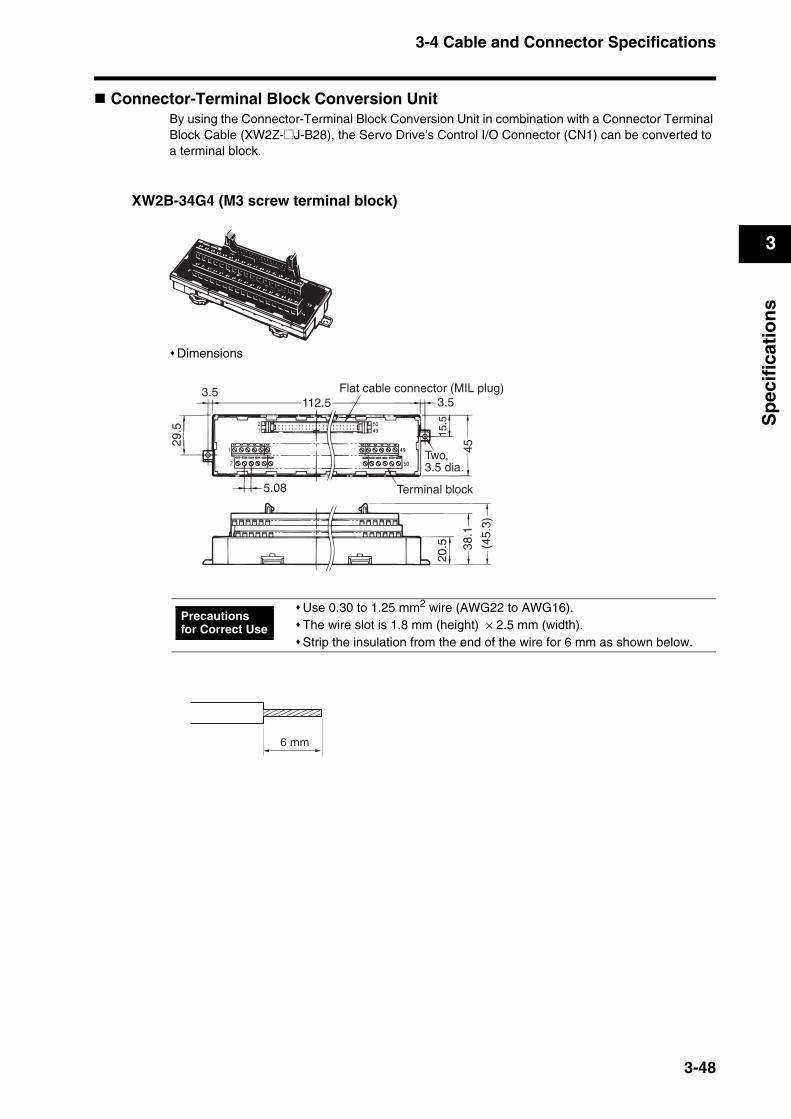
3-4 Cable and Connector Specifications
3
Sp
ecif
icat
ion
s
Connector-Terminal Block Conversion UnitBy using the Connector-Terminal Block Conversion Unit in combination with a Connector Terminal Block Cable (XW2Z-@J-B28), the Servo Drive's Control I/O Connector (CN1) can be converted to a terminal block.
XW2B-34G4 (M3 screw terminal block)
Dimensions
Use 0.30 to 1.25 mm2 wire (AWG22 to AWG16).The wire slot is 1.8 mm (height) × 2.5 mm (width).Strip the insulation from the end of the wire for 6 mm as shown below.
3.5
29.5
Flat cable connector (MIL plug)3.5112.5
45
15.5
Two, 3.5 dia.
Terminal block5.08
20.5 38
.1
(45.
3)
Precautions for Correct Use
6 mm
3-48
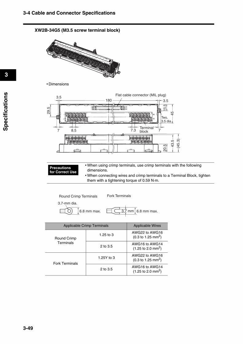
3-4 Cable and Connector Specifications
3
Sp
ecif
icat
ion
s
XW2B-34G5 (M3.5 screw terminal block)
Dimensions
When using crimp terminals, use crimp terminals with the following dimensions.When connecting wires and crimp terminals to a Terminal Block, tighten them with a tightening torque of 0.59 N·m.
Applicable Crimp Terminals Applicable Wires
Round Crimp Terminals
1.25 to 3AWG22 to AWG16(0.3 to 1.25 mm2)
2 to 3.5AWG16 to AWG14(1.25 to 2.0 mm2)
Fork Terminals
1.25Y to 3AWG22 to AWG16(0.3 to 1.25 mm2)
2 to 3.5AWG16 to AWG14(1.25 to 2.0 mm2)
Flat cable connector (MIL plug)3.5
29.5
7 8.5 7.3 7Terminalblock
Two,3.5 dia.
15.5
45
3.5
20.5 43
.5
(45.
3)
180
Precautions for Correct Use
Round Crimp Terminals Fork Terminals
6.8 mm max. 3.7 mm
3.7-mm dia.
6.8 mm max.
3-49
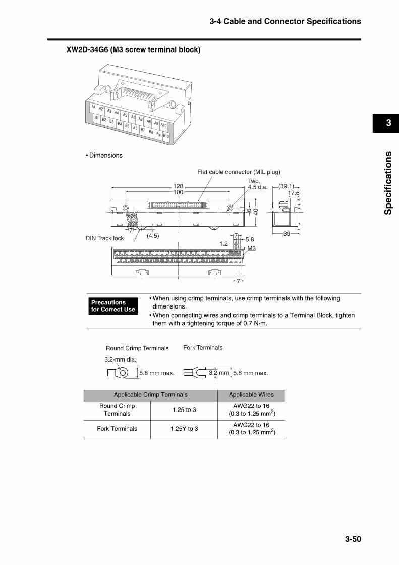
3-4 Cable and Connector Specifications
3
Sp
ecif
icat
ion
s
XW2D-34G6 (M3 screw terminal block)
Dimensions
When using crimp terminals, use crimp terminals with the following dimensions.When connecting wires and crimp terminals to a Terminal Block, tighten them with a tightening torque of 0.7 N·m.
Applicable Crimp Terminals Applicable Wires
Round Crimp Terminals
1.25 to 3AWG22 to 16
(0.3 to 1.25 mm2)
Fork Terminals 1.25Y to 3AWG22 to 16
(0.3 to 1.25 mm2)
A1 A2 A3 A4 A5 A6 A7 A8 A9 A10
B1 B2 B3 B4 B5 B 6 B7 B8 B9 B10
DIN Track lock
Flat cable connector (MIL plug)
Two, 4.5 dia.
406
39
(39.1)17.6
7
7
5.81.2
M3
7(4.5)
128100
Precautions for Correct Use
Round Crimp Terminals Fork Terminals
5.8 mm max. 3.2 mm
3.2-mm dia.
5.8 mm max.
3-50
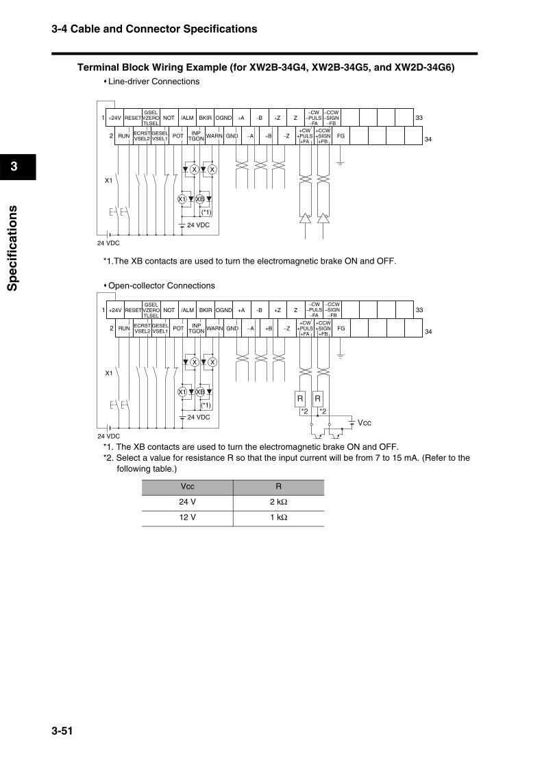
3-4 Cable and Connector Specifications
3
Sp
ecif
icat
ion
s
Terminal Block Wiring Example (for XW2B-34G4, XW2B-34G5, and XW2D-34G6)Line-driver Connections
*1.The XB contacts are used to turn the electromagnetic brake ON and OFF.
Open-collector Connections
*1. The XB contacts are used to turn the electromagnetic brake ON and OFF.*2. Select a value for resistance R so that the input current will be from 7 to 15 mA. (Refer to the
following table.)
Vcc R
24 V 2 kΩ
12 V 1 kΩ
RUN
1
2
33
34FG
24 VDC
X1 XB
X1
ECRSTVSEL2
RESET
GESELVSEL1
GSELVZEROTLSEL
NOT
POT
/ALM
INPTGON
BKIR
WARN
OGND
GND
+A
−A +B
−B +Z
−Z
Z
+CW+PULS
+FA
−CW−PULS
−FA+CCW+SIGN
+FB
−CCW−SIGN
−FB
X X
+24V
(*1)
24 VDC
RUN
1
2
33
34FG
X1 XB
ECRSTVSEL2
RESET
GESELVSEL1
GSELVZEROTLSEL
NOT
POT
/ALM
INPTGON
BKIR
WARN
OGND
GND
+A
−A +B
-B +Z
−Z
Z
+CW+PULS
+FA
+CCW+SIGN
+FB
X X
R R
*2 *2
Vcc
24 VDC
X1
24 VDC
−CW−PULS
−FA
−CCW−SIGN
−FB+24V
(*1)
3-51
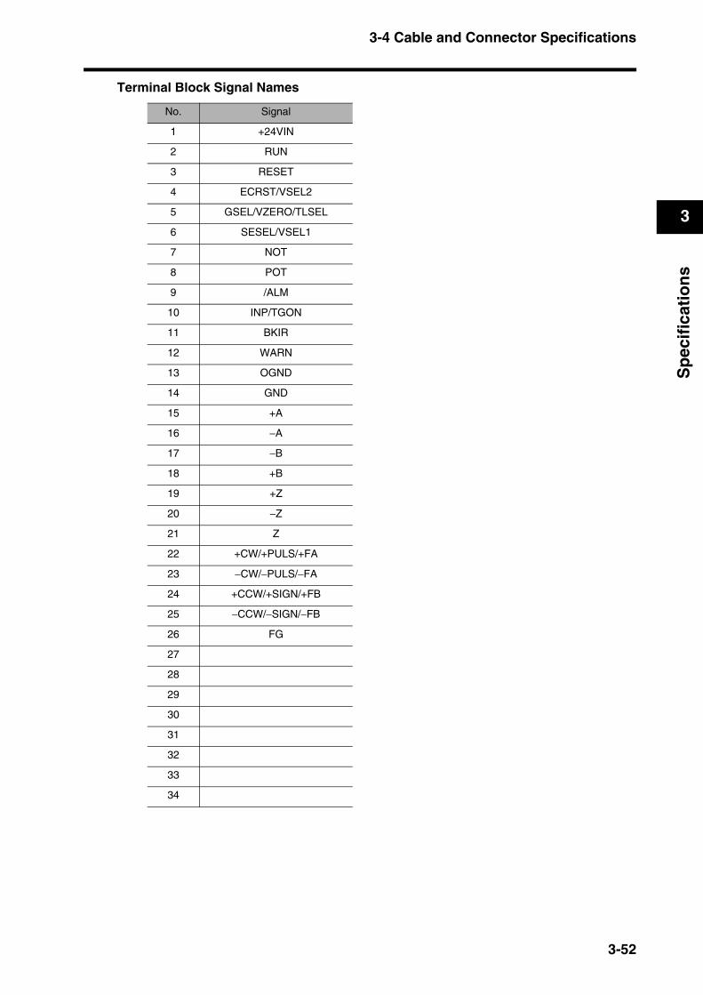
3-4 Cable and Connector Specifications
3
Sp
ecif
icat
ion
s
Terminal Block Signal Names
No. Signal
1 +24VIN
2 RUN
3 RESET
4 ECRST/VSEL2
5 GSEL/VZERO/TLSEL
6 SESEL/VSEL1
7 NOT
8 POT
9 /ALM
10 INP/TGON
11 BKIR
12 WARN
13 OGND
14 GND
15 +A
16 −A
17 −B
18 +B
19 +Z
20 −Z
21 Z
22 +CW/+PULS/+FA
23 −CW/−PULS/−FA
24 +CCW/+SIGN/+FB
25 −CCW/−SIGN/−FB
26 FG
27
28
29
30
31
32
33
34
3-52
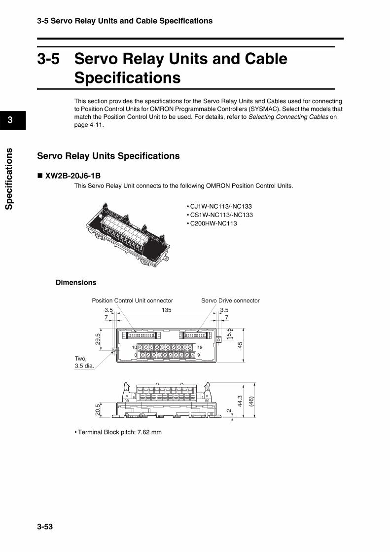
3-5 Servo Relay Units and Cable Specifications
3
Sp
ecif
icat
ion
s
3-5 Servo Relay Units and Cable SpecificationsThis section provides the specifications for the Servo Relay Units and Cables used for connecting to Position Control Units for OMRON Programmable Controllers (SYSMAC). Select the models that match the Position Control Unit to be used. For details, refer to Selecting Connecting Cables on page 4-11.
Servo Relay Units Specifications
XW2B-20J6-1BThis Servo Relay Unit connects to the following OMRON Position Control Units.
Dimensions
Terminal Block pitch: 7.62 mm
CJ1W-NC113/-NC133CS1W-NC113/-NC133C200HW-NC1130
1
2
3
4
5
6
7
8
9
10
11
12
13
14
15
16
17
18
19
29.5
73.5
73.5135
15.5
45
20.5 44
.3
2
0
10
9
19
Two, 3.5 dia.
Position Control Unit connector Servo Drive connector
(46)
3-53

3-5 Servo Relay Units and Cable Specifications
3
Sp
ecif
icat
ion
s
Wiring
*1. The XB contacts are used to turn ON/OFF the electromagnetic brake.
*2. Do not connect unused terminals.
*3. The 0 V terminal is internally connected to the common terminals.
*4. Applicable crimp terminal: R1.25-3 (round with open end).
XW2B-40J6-2BThis Servo Relay Unit connects to the following OMRON Position Control Units.
Dimensions
Terminal Block pitch: 7.62 mm
CJ1W-NC213/-NC233/-NC413/-NC433CS1W-NC213/-NC233/-NC413/-NC433C200HW-NC213/-NC413
0 V
RUN ALM BKIR10
0
19
9RESET ALMCOM FG
24 VDC
X1 XB
24 VDC
X1
(*1)
+24 V CWlimit
CCWlimit
Common Common CommonCommon Common Externalinterrupt
Emer-gency stop
Origin prox-imity
01
23
4
5
6
7
8
9
10
11
12
13
14
15
16
17
18
19
20
21
22
23
24
25
26
27
28
29
30
31
32
33
34
35
36
37
38
39
29.5
73.5
Two,3.5 dia.
180 3.57
45
15.5
0
20
19
39
20.5 44
.3
2
X-axis Servo Drive connector
Y-axis Servo Drive connectorPosition Control Unit connector
(46)
3-54

3-5 Servo Relay Units and Cable Specifications
3
Sp
ecif
icat
ion
s
Wiring
*1. The XB and YB contacts are used to turn ON/OFF the electromagnetic brake.
*2. Do not connect unused terminals.
*3. The 0 V terminal is internally connected to the common terminals.
*4. Applicable crimp terminal: R1.25-3 (round with open end).
XW2B-20J6-3BThis Servo Relay Unit connects to the following OMRON Programmable Controllers.
Dimensions
Terminal Block pitch: 7.62 mm
CQM1H-PLB21(Pulse I/O Board for CQM1H-CPU51/CPU61)CQM1-CPU43-V1
20
0
39
19FG
X1 XB
24 VDC
Y1 YB
24 VDC
X1 Y1
(*1) (*1)
0 V
24 VDC
+24 V X-axisRUN
X-axisALM
X-axisRESET
X-axisALMCOM
Y-axisRESET
Y-axisALMCOM
X-axisBKIR
Y-axisALM
Y-axisBKIR
Common Common Common Common Common Common Common Common Common
X/Y-axis emergency stop
X-axis origin proximity
Y-axis external interrupt
X-axis CW limit
X-axis CCW limit
Y-axisRUN
Y-axis origin proximity
Y-axis CW limit
Y-axis CCW limit
X-axis external interrupt
0
1
2
3
4
5
6
7
8
9
10
11
12
13
14
15
16
17
18
19
29.5
73.5
Two,3.5 dia.
73.5135
15.5
45
20.5 44
.3
2
0
10
9
19
(46)
CQM1 connector Servo Drive connector
3-55
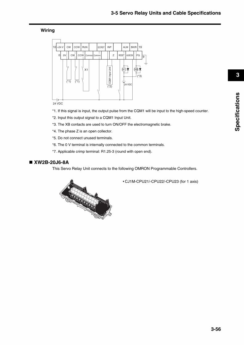
3-5 Servo Relay Units and Cable Specifications
3
Sp
ecif
icat
ion
s
Wiring
*1. If this signal is input, the output pulse from the CQM1 will be input to the high-speed counter.
*2. Input this output signal to a CQM1 Input Unit.
*3. The XB contacts are used to turn ON/OFF the electromagnetic brake.
*4. The phase Z is an open collector.
*5. Do not connect unused terminals.
*6. The 0 V terminal is internally connected to the common terminals.
*7. Applicable crimp terminal: R1.25-3 (round with open end).
XW2B-20J6-8AThis Servo Relay Unit connects to the following OMRON Programmable Controllers.
CJ1M-CPU21/-CPU22/-CPU23 (for 1 axis)
0V
CW CCW RUN INP ALM BKIR10
0
19
9CW Z RESET ALMCOM FG
24 VDC
X1 XB
24 VDC
X1
ECRST
CCW
+24 V
Common Common
CQ
M1
Inpu
t Uni
t
(*2)
(*3)
(*1) (*1)
0
1
2
3
4
5
6
7
8
9
10
11
12
13
14
15
16
17
18
19
3-56
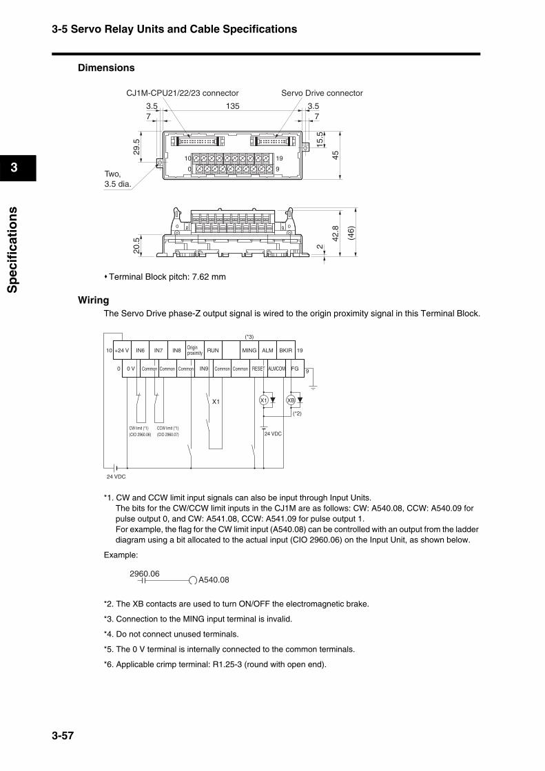
3-5 Servo Relay Units and Cable Specifications
3
Sp
ecif
icat
ion
s
Dimensions
Terminal Block pitch: 7.62 mm
WiringThe Servo Drive phase-Z output signal is wired to the origin proximity signal in this Terminal Block.
*1. CW and CCW limit input signals can also be input through Input Units.The bits for the CW/CCW limit inputs in the CJ1M are as follows: CW: A540.08, CCW: A540.09 for pulse output 0, and CW: A541.08, CCW: A541.09 for pulse output 1.For example, the flag for the CW limit input (A540.08) can be controlled with an output from the ladder diagram using a bit allocated to the actual input (CIO 2960.06) on the Input Unit, as shown below.
Example:
*2. The XB contacts are used to turn ON/OFF the electromagnetic brake.
*3. Connection to the MING input terminal is invalid.
*4. Do not connect unused terminals.
*5. The 0 V terminal is internally connected to the common terminals.
*6. Applicable crimp terminal: R1.25-3 (round with open end).
29.5
73.5
Two,3.5 dia.
73.5135
15.5
45
20.5 42
.8
2
0
10
9
19
CJ1M-CPU21/22/23 connector Servo Drive connector
(46)
0 V
RUN ALM BKIR10
0
19
9RESET ALMCOM FG
24 VDC
X1 XB
24 VDC
X1
MINGIN6 IN7 IN8
IN9
(*2)
+24 V Originproximity
Common Common Common Common Common
(*3)
CW limit (*1)(CIO 2960.06)
CCW limit (*1)(CIO 2960.07)
2960.06A540.08
3-57
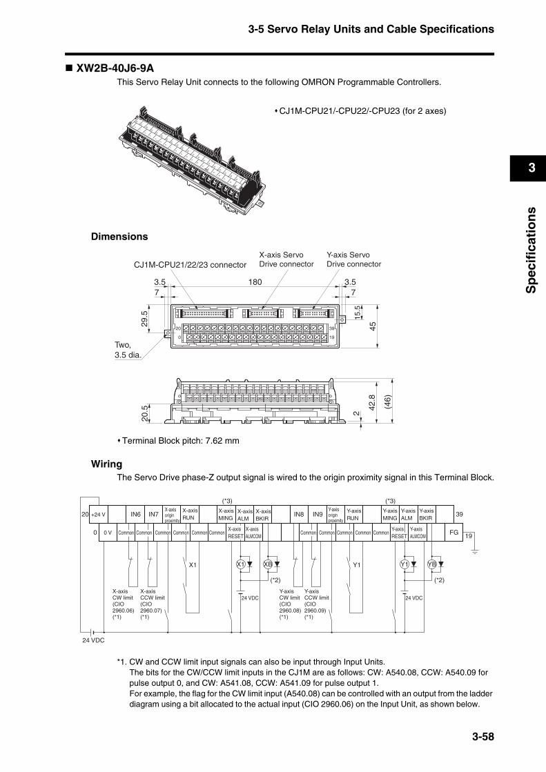
3-5 Servo Relay Units and Cable Specifications
3
Sp
ecif
icat
ion
s
XW2B-40J6-9AThis Servo Relay Unit connects to the following OMRON Programmable Controllers.
Dimensions
Terminal Block pitch: 7.62 mm
WiringThe Servo Drive phase-Z output signal is wired to the origin proximity signal in this Terminal Block.
*1. CW and CCW limit input signals can also be input through Input Units.The bits for the CW/CCW limit inputs in the CJ1M are as follows: CW: A540.08, CCW: A540.09 for pulse output 0, and CW: A541.08, CCW: A541.09 for pulse output 1.For example, the flag for the CW limit input (A540.08) can be controlled with an output from the ladder diagram using a bit allocated to the actual input (CIO 2960.06) on the Input Unit, as shown below.
CJ1M-CPU21/-CPU22/-CPU23 (for 2 axes)
01
23
4
5
6
7
8
9
10
11
12
13
14
15
16
17
18
19
20
21
22
23
24
25
26
27
28
29
30
31
32
33
34
35
36
37
38
39
29.5
73.5
Two,3.5 dia.
180 3.57
45
15.5
0
20
19
39
20.5 42
.8
2
X-axis ServoDrive connector
Y-axis ServoDrive connectorCJ1M-CPU21/22/23 connector
(46)
20
0
39
19FG
X1 XB
24 VDC
Y1 YB
24 VDC
X1 Y1
IN6 IN7 IN8 IN9
(*2) (*2)
(*3) (*3)
X-axisCW limit(CIO 2960.06)(*1)
X-axisCCW limit(CIO2960.07)(*1)
Y-axisCW limit(CIO2960.08)(*1)
Y-axisCCW limit(CIO2960.09)(*1)
0 V
24 VDC
+24 VX-axisRUN
X-axisALM
X-axisRESET
X-axisALMCOM
Y-axisRESET
Y-axisALMCOM
X-axisBKIR
Y-axisALM
Y-axisMING
X-axisMING
Y-axisBKIR
Common Common Common Common Common Common CommonCommonCommonCommon Common
X-axis origin proximity
Y-axisRUN
Y-axis origin proximity
3-58

3-5 Servo Relay Units and Cable Specifications
3
Sp
ecif
icat
ion
s
Example:
*2. The XB and YB contacts are used to turn ON/OFF the electromagnetic brake.
*3. Connection to the MING input terminal is invalid.
*4. Do not connect unused terminals.
*5. The 0 V terminal is internally connected to the common terminals.
*6. Applicable crimp terminal: R1.25-3 (round with open end).
XW2B-80J7-12AThis Servo Relay Unit connects to the following OMRON ProgrammableController.
Dimensions
FQM1-MMP22
2960.06A540.08
1604.5 dia.
100 90
41.7
15.930.7
X-axis Servo Drive
Servo Drivephase Bselectionswitch
Y-axis Servo DriveController general-purpose I/O
Controller special I/O
Signal selection switch
3-59
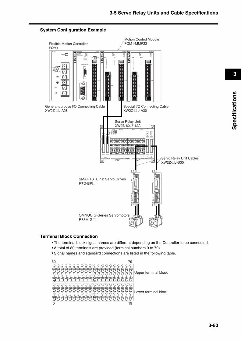
3-5 Servo Relay Units and Cable Specifications
3
Sp
ecif
icat
ion
s
System Configuration Example
Terminal Block ConnectionThe terminal block signal names are different depending on the Controller to be connected.A total of 80 terminals are provided (terminal numbers 0 to 79).Signal names and standard connections are listed in the following table.
General-purpose I/O Connecting CableXW2Z-@J-A28
Special I/O Connecting CableXW2Z-@ J-A30
Servo Relay UnitXW2B-80J7-12A
Flexible Motion ControllerFQM1
Motion Control ModuleFQM1-MMP22
Servo Relay Unit CablesXW2Z-@J-B30
SMARTSTEP 2 Servo DrivesR7D-BP@
OMNUC G-Series ServomotorsR88M-G@
FLEXIBLEMOTIONCONTROLLER
RDYRUNERR
PRPHLCOMM1COMM2
PERIPHERAL
PORT
ON OFF
CM002
2
CN1
RS422
1
40391
2
MMP22
2
CN2
CN1
1
12 4039
2526
IN OUT
01234567891011
01234567
RDYRUNERR
A1B1A2B2
MMA22
2
CN2
CN1
1
12 4039
2526
IN OUT
01234567891011
01234567
RDYRUNERR
A1B1A2B2
NC
NC
INPUT
AC100-240V
L2/N
L1
PA202
POWER
CN1
CN2
CNA
CNB
CN3
POWER ALM
CN1
CN2
CNA
CNB
CN3
POWER ALM
79600 1 2 3 4 5 6 7 8 9 0 1 2 3 4 5 6 7 8 9
0 1 2 3 4 5 6 7 8 9 0 1 2 3 4 5 6 7 8 9
0 1 2 3 4 5 6 7 8 9 0 1 2 3 4 5 6 7 8 9
0 1 2 3 4 5 6 7 8 9 0 1 2 3 4 5 6 7 8 9
190
Upper terminal block
Lower terminal block
3-60
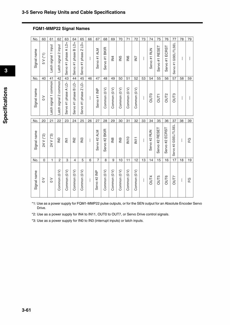
3-5 Servo Relay Units and Cable Specifications
3
Sp
ecif
icat
ion
s
FQM1-MMP22 Signal Names
*1: Use as a power supply for FQM1-MMP22 pulse outputs, or for the SEN output for an Absolute Encoder Servo Drive.
*2: Use as a power supply for IN4 to IN11, OUT0 to OUT7, or Servo Drive control signals.
*3: Use as a power supply for IN0 to IN3 (interrupt inputs) or latch inputs.
No. 60 61 62 63 64 65 66 67 68 69 70 71 72 73 74 75 76 77 78 79
No. 40 41 42 43 44 45 46 47 48 49 50 51 52 53 54 55 56 57 58 59
0 V
OU
T0
OU
T1
OU
T2
OU
T3
---
---
---
---
Com
mon
(0
V)
Com
mon
(0
V)
Com
mon
(0
V)
Com
mon
(0
V)
Com
mon
(0
V)
Latc
h si
gnal
2 c
omm
on
Ser
vo #
1 ph
ase
A L
D−
Ser
vo #
1 ph
ase
B L
D−
Ser
vo #
1 ph
ase
Z L
D−
Ser
vo #
1 IN
P
Sig
nal n
ame
Sig
nal n
ame
5 V
(*1
)
Latc
h si
gnal
1 in
put
Latc
h si
gnal
1 c
omm
on
Latc
h si
gnal
2 in
put
Ser
vo #
1 ph
ase
A L
D+
Ser
vo #
1 ph
ase
B L
D+
Ser
vo #
1 ph
ase
Z L
D+
Ser
vo #
1 A
LM
Ser
vo #
1 B
KIR
Ser
vo #
1 R
UN
Ser
vo #
1 R
ES
ET
Ser
vo #
1 E
CR
ST
Ser
vo #
1 G
SE
L/T
LSE
L
IN4
IN5
IN6
IN7
---
---
---
---
No. 20 21 22 23 24 25 26 27 28 29 30 31 32 33 34 35 36 37 38 39
No. 0 1 2 3 4 5 6 7 8 9 10 11 12 13 14 15 16 17 18 19
0 V
OU
T4
OU
T5
OU
T6
OU
T7
---
---
---
---
IN8
IN9
IN10
IN11
0 V ---
FG
IN0
IN1
IN2
IN3
---
FG
Com
mon
(0
V)
Com
mon
(0
V)
Com
mon
(0
V)
Com
mon
(0
V)
Com
mon
(0
V)
Com
mon
(0
V)
Com
mon
(0
V)
Com
mon
(0
V)
Com
mon
(0
V)
Ser
vo #
2 IN
P
Sig
nal n
ame
Sig
nal n
ame
24 V
(*2
)
24 V
(*3
)
Ser
vo #
2 A
LM
Ser
vo #
2 B
KIR
Ser
vo #
2 R
UN
Ser
vo #
2 R
ES
ET
Ser
vo #
2 E
CR
ST
Ser
vo #
2 G
SE
L/T
LSE
L
3-61
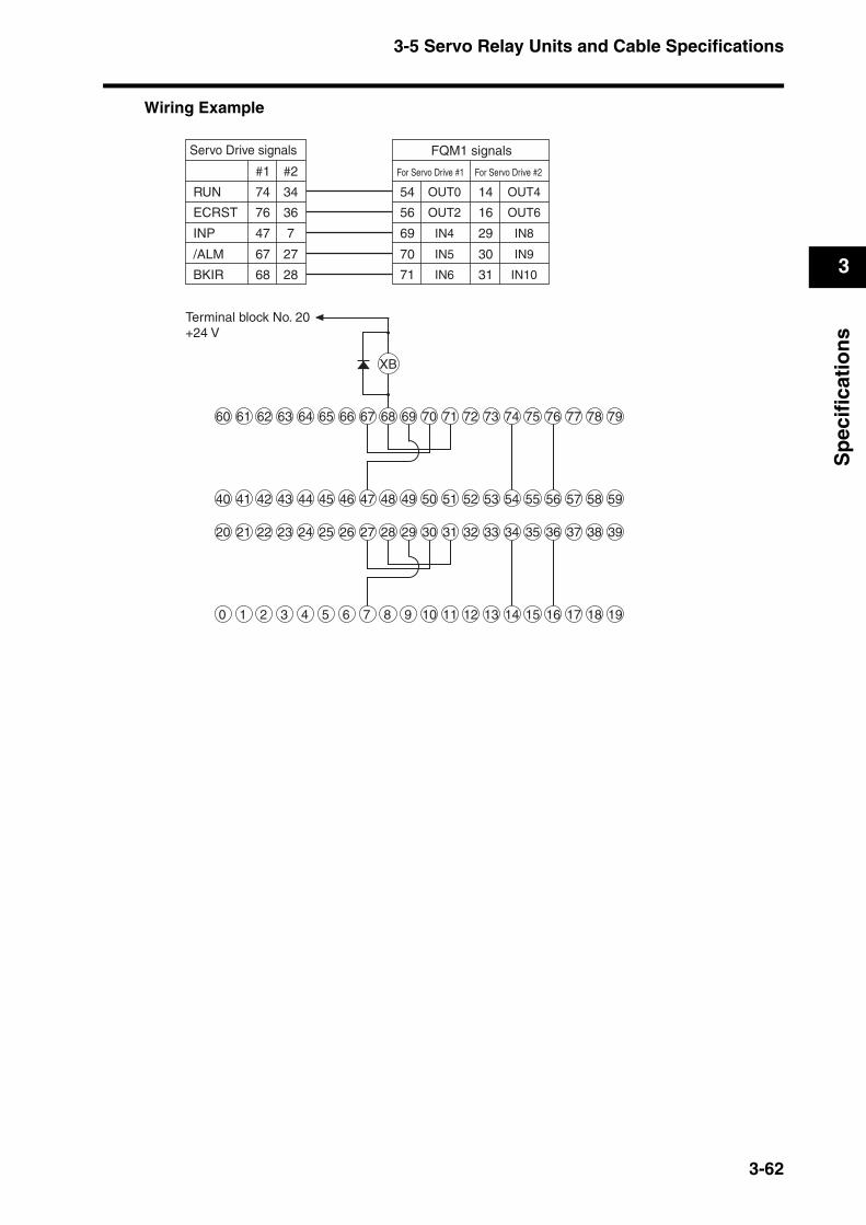
3-5 Servo Relay Units and Cable Specifications
3
Sp
ecif
icat
ion
s
Wiring Example
Servo Drive signals
RUN
ECRST
INP
/ALM
BKIR
#1 #2
74
76
47
67
68
34
36
7
27
28
FQM1 signals
For Servo Drive #1 For Servo Drive #2
54
56
69
70
71
14
16
29
30
31
OUT0
OUT2
OUT4
OUT6
IN4
IN5
IN6
IN8
IN9
IN10
60 61 62 63 64 65 66 67 68 69 70 71 72 73 74 75 76 77 78 79
40 41 42 43 44 45 46 47 48 49 50 51 52 53 54 55 56 57 58 59
20 21 22 23 24 25 26 27 28 29 30 31 32 33 34 35 36 37 38 39
0 1 2 3 4 5 6 7 8 9 10 11 12 13 14 15 16 17 18 19
XB
Terminal block No. 20+24 V
3-62
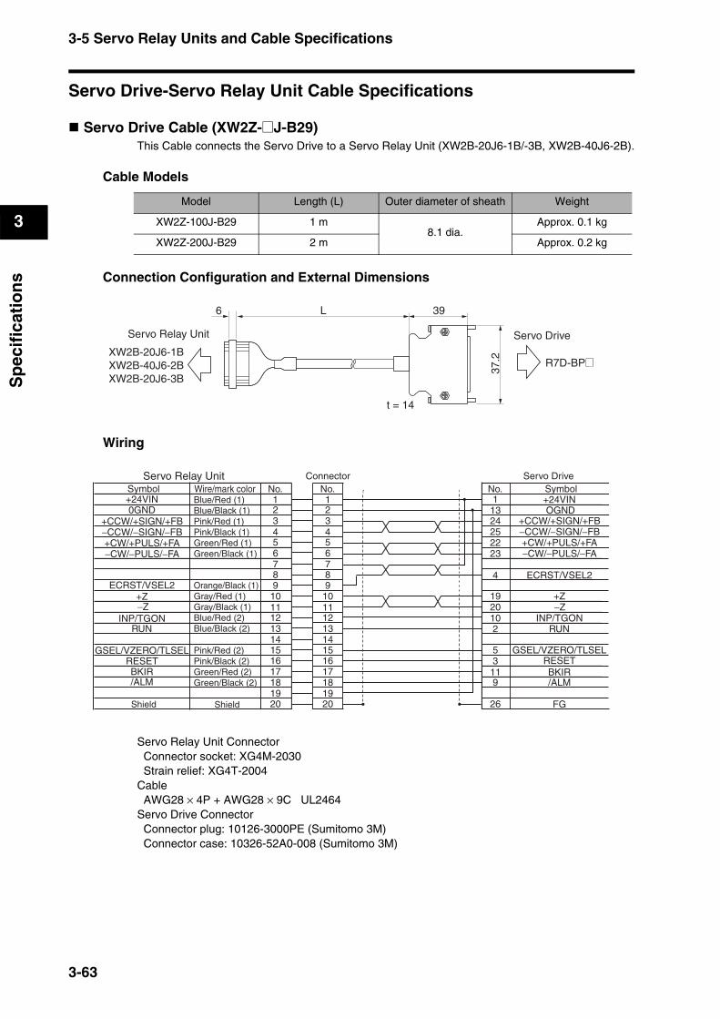
3-5 Servo Relay Units and Cable Specifications
3
Sp
ecif
icat
ion
s
Servo Drive-Servo Relay Unit Cable Specifications
Servo Drive Cable (XW2Z-@J-B29)This Cable connects the Servo Drive to a Servo Relay Unit (XW2B-20J6-1B/-3B, XW2B-40J6-2B).
Cable Models
Connection Configuration and External Dimensions
Wiring
Servo Relay Unit Connector Connector socket: XG4M-2030 Strain relief: XG4T-2004Cable AWG28 × 4P + AWG28 × 9C UL2464Servo Drive Connector Connector plug: 10126-3000PE (Sumitomo 3M) Connector case: 10326-52A0-008 (Sumitomo 3M)
Model Length (L) Outer diameter of sheath Weight
XW2Z-100J-B29 1 m8.1 dia.
Approx. 0.1 kg
XW2Z-200J-B29 2 m Approx. 0.2 kg
39
37.2
t = 14
6
Servo DriveServo Relay Unit
XW2B-20J6-1BXW2B-40J6-2BXW2B-20J6-3B
R7D-BP@
L
112 23 34 45 56 67 78 89 9
10 1011 1112 1213 1314 1415 1516 1617 1718 1819 1920 20
+24VIN
RUN
0GND
BKIR/ALM
1
2223
2425
4
2019
2
13
11
10
9
No.No.No.+24VIN
+CW/+PULS/+FA−CW/−PULS/−FA
+CCW/+SIGN/+FB
RUN
OGND
BKIR/ALM
FG
ECRST/VSEL2
−CCW/−SIGN/−FB
−Z+Z
INP/TGON
GSEL/VZERO/TLSELRESET
53
26
+CW/+PULS/+FA−CW/−PULS/−FA
+CCW/+SIGN/+FB
ECRST/VSEL2
−CCW/−SIGN/−FB
+Z
INP/TGON
GSEL/VZERO/TLSELRESET
−Z
Servo Relay Unit
Shield
Wire/mark colorConnector Servo Drive
SymbolSymbolBlue/Red (1)Blue/Black (1)Pink/Red (1)Pink/Black (1)Green/Red (1)Green/Black (1)
Orange/Black (1)Gray/Red (1)Gray/Black (1)Blue/Red (2)Blue/Black (2)
Pink/Red (2)Pink/Black (2)Green/Red (2)Green/Black (2)
Shield
3-63
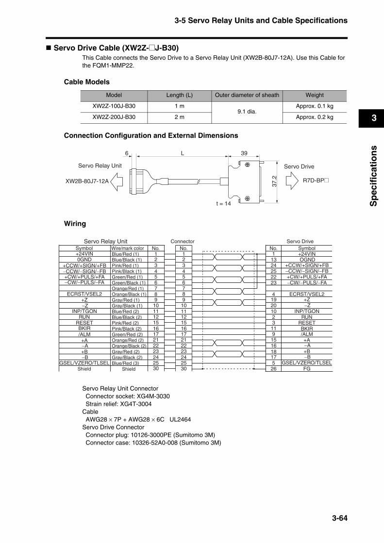
3-5 Servo Relay Units and Cable Specifications
3
Sp
ecif
icat
ion
s
Servo Drive Cable (XW2Z-@J-B30)This Cable connects the Servo Drive to a Servo Relay Unit (XW2B-80J7-12A). Use this Cable for the FQM1-MMP22.
Cable Models
Connection Configuration and External Dimensions
Wiring
Servo Relay Unit Connector Connector socket: XG4M-3030 Strain relief: XG4T-3004Cable AWG28 × 7P + AWG28 × 6C UL2464Servo Drive Connector Connector plug: 10126-3000PE (Sumitomo 3M) Connector case: 10326-52A0-008 (Sumitomo 3M)
Model Length (L) Outer diameter of sheath Weight
XW2Z-100J-B30 1 m9.1 dia.
Approx. 0.1 kg
XW2Z-200J-B30 2 m Approx. 0.2 kg
39
37.2
t = 14
6
Servo DriveServo Relay Unit
XW2B-80J7-12A R7D-BP@
L
112 23 34 45 56 67 7
89 9
10 1011
12 12
16 1617 1721 2122 22
24 2425 25
+24VIN
RUN
0GND
BKIR/ALM
1
2223
2425
4
2019
2
13
11
10
9
No.No.No.+24VIN
RUN
OGND
BKIR/ALM
FG
11
8
+CW/+PULS/+FA−CW/−PULS/−FA
+CCW/+SIGN/+FB
ECRST/VSEL2
−CCW/−SIGN/−FB
−Z+Z
INP/TGON
GSEL/VZERO/TLSEL
RESET
+A
+B−A
−B
3
151618175
26
1515
2323
30 30
+CW/+PULS/+FA−CW/−PULS/−FA
+CCW/+SIGN/+FB
ECRST/VSEL2
−CCW/−SIGN/−FB
−Z+Z
INP/TGON
GSEL/VZERO/TLSEL
RESET
+A
+B−A
−B
Servo Relay Unit
Shield
Wire/mark colorConnector Servo Drive
SymbolSymbolBlue/Red (1)Blue/Black (1)Pink/Red (1)Pink/Black (1)Green/Red (1)Green/Black (1)Orange/Red (1)Orange/Black (1)Gray/Red (1)Gray/Black (1)Blue/Red (2)Blue/Black (2)Pink/Red (2)Pink/Black (2)Green/Red (2)Orange/Red (2)Orange/Black (2)Gray/Red (2)Gray/Black (2)Blue/Red (3)
Shield
3-64

3-5 Servo Relay Units and Cable Specifications
3
Sp
ecif
icat
ion
s
Servo Drive Cable (XW2Z-@J-B32)This Cable connects the Servo Drive to a Servo Relay Unit (XW2B-20J6-8A, XW2B-40J6-9A).
Cable Models
Connection Configuration and External Dimensions
Wiring
Servo Relay Unit Connector Connector socket: XG4M-2030 Strain relief: XG4T-2004Cable AWG28 × 4P + AWG28 × 9C UL2464Servo Drive Connector Connector plug: 10126-3000PE (Sumitomo 3M) Connector case: 10326-52A0-008 (Sumitomo 3M)
Model Length (L) Outer diameter of sheath Weight
XW2Z-100J-B32 1 m8.1 dia.
Approx. 0.1 kg
XW2Z-200J-B32 2 m Approx. 0.2 kg
39
37.2
t = 14
6
Servo DriveServo Relay Unit
XW2B-20J6-8AXW2B-40J6-9A
R7D-BP@
L
112 23 34 45 56 67 78 89 9
10 1011 1112 1213 1314 1415 1516 1617 1718 1819 1920 20
+24VIN
RUN
0GND
BKIR/ALM
1
2223
2425
4
2019
2
13
11
10
9
No.No.No.+24VIN
+CW/+PULS/+FA−CW/−PULS/−FA
+CCW/+SIGN/+FB
RUN
OGND
BKIR/ALM
FG
ECRST/VSEL2
−CCW/−SIGN/−FB
−Z+Z
INP/TGON
GSEL/VZERO/TLSELRESET
53
26
+CW/+PULS/+FA−CW/−PULS/−FA
+CCW/+SIGN/+FB
ECRST/VSEL2
−CCW/−SIGN/−FB
+Z
INP/TGON
GSEL/VZERO/TLSELRESET
−Z
Servo Relay Unit
Shield
Wire/mark colorConnector Servo Drive
SymbolSymbolBlue/Red (1)Blue/Black (1)Pink/Red (1)Pink/Black (1)Green/Red (1)Green/Black (1)
Gray/Red (1)Gray/Black (1)Blue/Red (2)Blue/Black (2)Orange/Black (1)Pink/Red (2)Pink/Black (2)Green/Red (2)Green/Black (2)
Shield
3-65

3-5 Servo Relay Units and Cable Specifications
3
Sp
ecif
icat
ion
s
Position Control Unit-Servo Relay Unit Cable Specifications
Position Control Unit Cable (XW2Z-@J-A3)This Cable connects a Programmable Controller (CQM1H-PLB21, CQM1-CPU43-V1) to a Servo Relay Unit (XW2B-20J6-3B).
Cable Models
Connection Configuration and External Dimensions
Wiring
Model Length (L) Outer diameter of sheath Weight
XW2Z-050J-A3 50 cm7.5 dia.
Approx. 0.1 kg
XW2Z-100J-A3 1 m Approx. 0.1 kg
L
25
639
32.2
t = 15
CQM1
CQM1H-PLB21CQM1-CPU43-V1
Servo Relay Unit
XW2B-20J6-3B
No.12345678910111213141516
No.1512
13
14
31
456
Servo Relay Unit
Cable: AWG28 × 4P + AWG28 × 4C
CQM1
Hood cover
3-66

3-5 Servo Relay Units and Cable Specifications
3
Sp
ecif
icat
ion
s
Position Control Unit Cable (XW2Z-@J-A6)This Cable connects a Position Control Unit (CS1W-NC113, C200HW-NC113) to a Servo Relay Unit (XW2B-20J6-1B).
Cable Models
Connection Configuration and External Dimensions
Wiring
Model Length (L) Outer diameter of sheath Weight
XW2Z-050J-A6 50 cm8.0 dia.
Approx. 0.1 kg
XW2Z-100J-A6 1 m Approx. 0.1 kg
38
L 647
83
t = 11
Position Control Unit
CS1W-NC113C200HW-NC113
Servo Relay Unit
XW2B-20J6-1B
No.Position Control Unit
A1A2
A8
A6
A10
A16A14A24A12
A21
A23
A22
A19
A20
Servo Relay Unit
Cable: AWG28 × 4P + AWG28 × 10C
No.123456789
1011121314151617181920212223242526
Crimp terminal
3-67
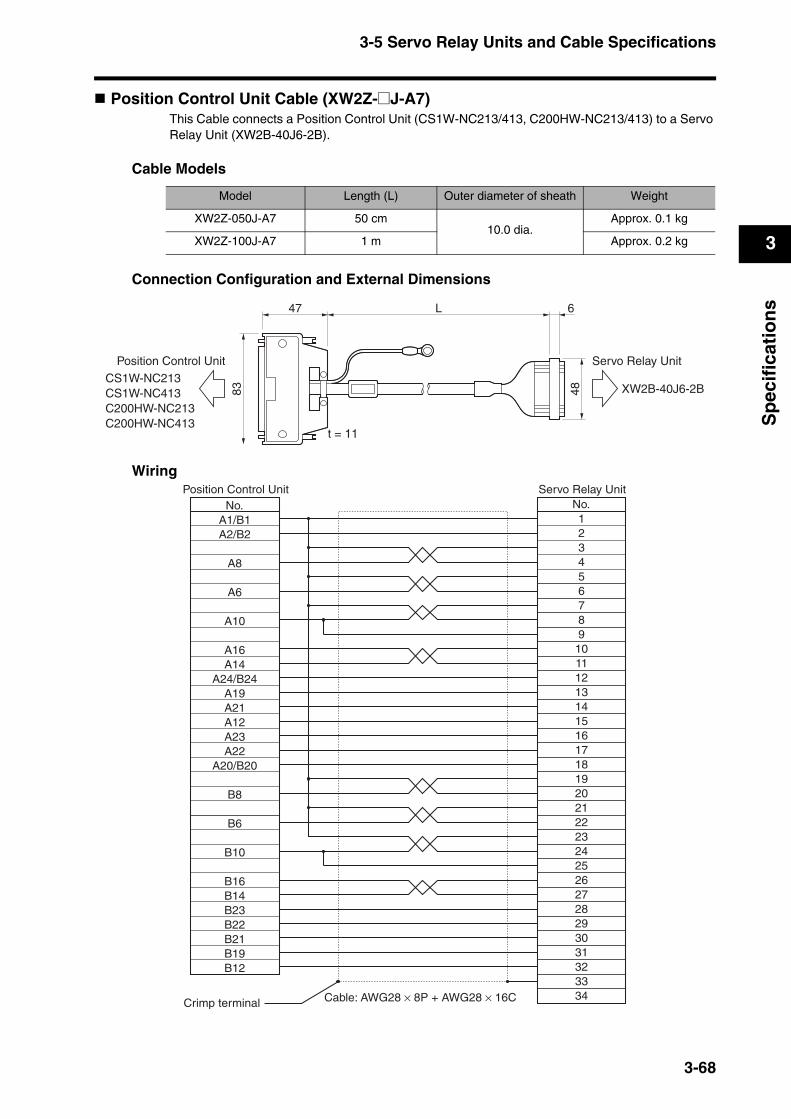
3-5 Servo Relay Units and Cable Specifications
3
Sp
ecif
icat
ion
s
Position Control Unit Cable (XW2Z-@J-A7)This Cable connects a Position Control Unit (CS1W-NC213/413, C200HW-NC213/413) to a Servo Relay Unit (XW2B-40J6-2B).
Cable Models
Connection Configuration and External Dimensions
Wiring
Model Length (L) Outer diameter of sheath Weight
XW2Z-050J-A7 50 cm10.0 dia.
Approx. 0.1 kg
XW2Z-100J-A7 1 m Approx. 0.2 kg
48
L 647
83
t = 11
Position Control UnitCS1W-NC213CS1W-NC413C200HW-NC213C200HW-NC413
Servo Relay Unit
XW2B-40J6-2B
Servo Relay Unit
Cable: AWG28 × 8P + AWG28 × 16C
No.123456789
10111213141516171819202122232425262728293031323334
No.Position Control Unit
A1/B1A2/B2
A8
A6
A10
A16A14
A24/B24A19A21A12A23A22
A20/B20
B8
B6
B10
B16B14B23B22B21B19B12
Crimp terminal
3-68
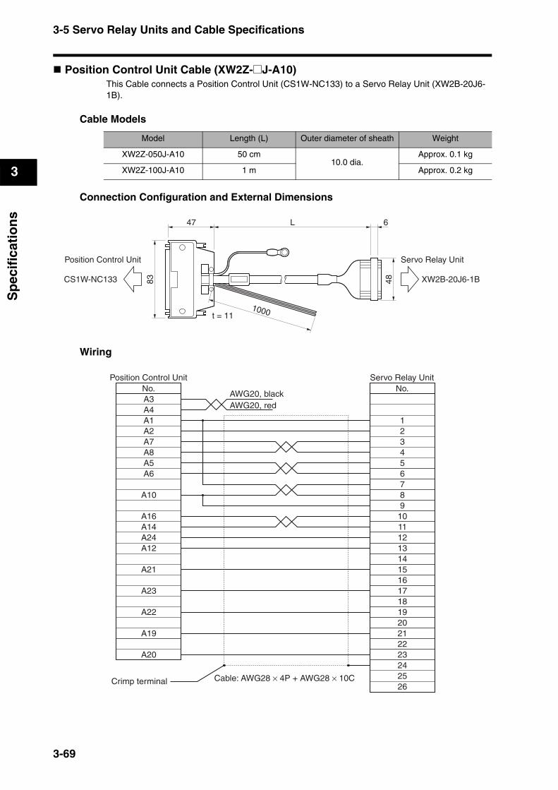
3-5 Servo Relay Units and Cable Specifications
3
Sp
ecif
icat
ion
s
Position Control Unit Cable (XW2Z-@J-A10)This Cable connects a Position Control Unit (CS1W-NC133) to a Servo Relay Unit (XW2B-20J6-1B).
Cable Models
Connection Configuration and External Dimensions
Wiring
Model Length (L) Outer diameter of sheath Weight
XW2Z-050J-A10 50 cm10.0 dia.
Approx. 0.1 kg
XW2Z-100J-A10 1 m Approx. 0.2 kg
48
L 647
83
t = 111000
Position Control Unit
CS1W-NC133
Servo Relay Unit
XW2B-20J6-1B
Servo Relay Unit
Cable: AWG28 × 4P + AWG28 × 10C
No.
123456789
1011121314151617181920212223
26
No.Position Control Unit
A1A2A7A8A5A6
A10
A24A12
A21
A23
Crimp terminal
2425
A20
A19
A22
A3A4
AWG20, blackAWG20, red
A16A14
3-69
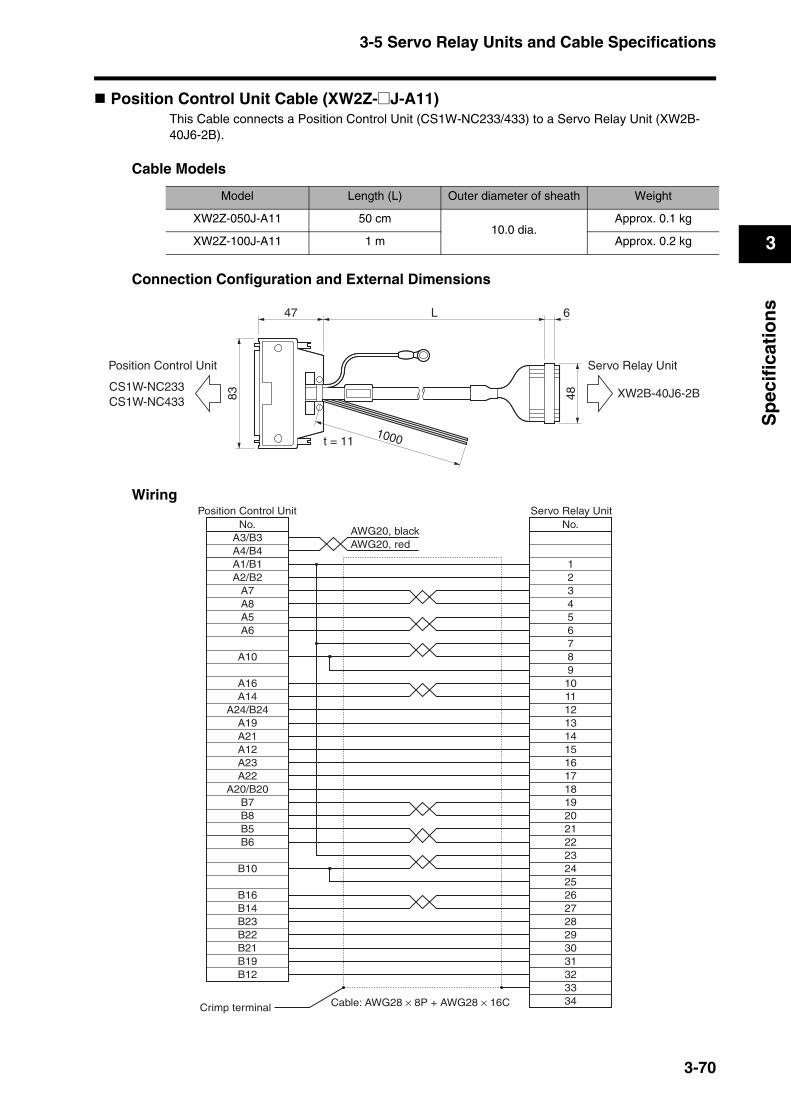
3-5 Servo Relay Units and Cable Specifications
3
Sp
ecif
icat
ion
s
Position Control Unit Cable (XW2Z-@J-A11)This Cable connects a Position Control Unit (CS1W-NC233/433) to a Servo Relay Unit (XW2B-40J6-2B).
Cable Models
Connection Configuration and External Dimensions
Wiring
Model Length (L) Outer diameter of sheath Weight
XW2Z-050J-A11 50 cm10.0 dia.
Approx. 0.1 kg
XW2Z-100J-A11 1 m Approx. 0.2 kg
48
L 647
83
t = 111000
Position Control Unit
CS1W-NC233CS1W-NC433
Servo Relay Unit
XW2B-40J6-2B
Servo Relay Unit
Cable: AWG28 × 8P + AWG28 × 16C
No.
12345678910111213141516171819202122232425262728293031323334
No.Position Control Unit
A1/B1A2/B2
A8A7
A6A5
A10
A14A24/B24
A19A21A12A23A22
A20/B20
B8
B6
B7
B5
B10
B14B23B22B21B19B12
Crimp terminal
A3/B3A4/B4
AWG20, blackAWG20, red
A16
B16
3-70

3-5 Servo Relay Units and Cable Specifications
3
Sp
ecif
icat
ion
s
Position Control Unit Cable (XW2Z-@J-A14)This Cable connects a Position Control Unit (CJ1W-NC113) to a Servo Relay Unit (XW2B-20J6-1B).
Cable Models
Connection Configuration and External Dimensions
Wiring
Model Length (L) Outer diameter of sheath Weight
XW2Z-050J-A14 50 cm10.0 dia.
Approx. 0.1 kg
XW2Z-100J-A14 1 m Approx. 0.2 kg
L 6
38
t = 11
500
Position Control Unit
CJ1W-NC113
Servo Relay Unit
XW2B-20J6-1B
20J6-1B
CJ1W-NC113
No.Position Control Unit
A1A2
A8
A6
A9
A14A12A20A11
A17
A19
A18
A15
A16
Servo Relay Unit
Cable: AWG28 × 4P + AWG28 × 10C
No.123456789
1011121314151617181920212223242526
Crimp terminal
3-71

3-5 Servo Relay Units and Cable Specifications
3
Sp
ecif
icat
ion
s
Position Control Unit Cable (XW2Z-@J-A15)This Cable connects a Position Control Unit (CJ1W-NC213/413) to a Servo Relay Unit (XW2B-40J6-2B).
Cable Models
Connection Configuration and External Dimensions
Wiring
Model Length (L) Outer diameter of sheath Weight
XW2Z-050J-A15 50 cm10.0 dia.
Approx. 0.1 kg
XW2Z-100J-A15 1 m Approx. 0.2 kg
L 6t = 11
500
48
Position Control Unit
CJ1W-NC213CJ1W-NC413
Servo Relay Unit
XW2B-40J6-2B
40J6-2B
CJ1W-NC213/NC413
Servo Relay Unit
Cable: AWG28 × 8P + AWG28 × 16C
No.12345678910111213141516171819202122232425262728293031323334
No.Position Control Unit
A1/B1A2/B2
A8
A6
A9
A14A12
A20/B20A15A17A11A19A18
A16/B16
B8
B6
B9
B14B12B19B18B17B15B11
Crimp terminal
3-72

3-5 Servo Relay Units and Cable Specifications
3
Sp
ecif
icat
ion
s
Position Control Unit Cable (XW2Z-@J-A18)This Cable connects a Position Control Unit (CJ1W-NC133) to a Servo Relay Unit (XW2B-20J6-1B).
Cable Models
Connection Configuration and External Dimensions
Wiring
Model Length (L) Outer diameter of sheath Weight
XW2Z-050J-A18 50 cm10.0 dia.
Approx. 0.1 kg
XW2Z-100J-A18 1 m Approx. 0.2 kg
L 6
38
t = 11
500
1000
Position Control Unit
CJ1W-NC133
Servo Relay Unit
XW2B-20J6-1B
20J6-1B
CJ1W-NC133
Servo Relay Unit
Cable: AWG28 × 4P + AWG28 × 10C
No.
123456789
1011121314151617181920212223
26
No.Position Control Unit
A1A2A7A8A5A6
A9
A20A11
A17
A19
Crimp terminal
2425
A16
A15
A18
A3A4
AWG20, blackAWG20, red
A14A12
3-73
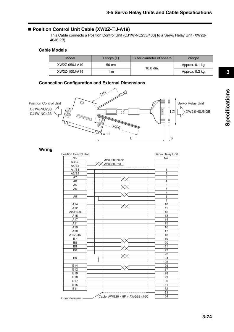
3-5 Servo Relay Units and Cable Specifications
3
Sp
ecif
icat
ion
s
Position Control Unit Cable (XW2Z-@J-A19)This Cable connects a Position Control Unit (CJ1W-NC233/433) to a Servo Relay Unit (XW2B-40J6-2B).
Cable Models
Connection Configuration and External Dimensions
Wiring
Model Length (L) Outer diameter of sheath Weight
XW2Z-050J-A19 50 cm10.0 dia.
Approx. 0.1 kg
XW2Z-100J-A19 1 m Approx. 0.2 kg
L 6t = 11
500
48
1000
CJ1W-NC233/NC433
40J6-2B
Position Control Unit
CJ1W-NC233CJ1W-NC433
Servo Relay Unit
XW2B-40J6-2B
Servo Relay Unit
Cable: AWG28 × 8P + AWG28 ×16C
No.
12345678910111213141516171819202122232425262728293031323334
No.Position Control Unit
A1/B1A2/B2
A8A7
A6A5
A9
A12A20/B20
A15A17A11A19A18
A16/B16
B8
B6
B7
B5
B9
B12B19B18B17B15B11
Crimp terminal
A3/B3A4/B4
AWG20, blackAWG20, red
A14
B14
3-74
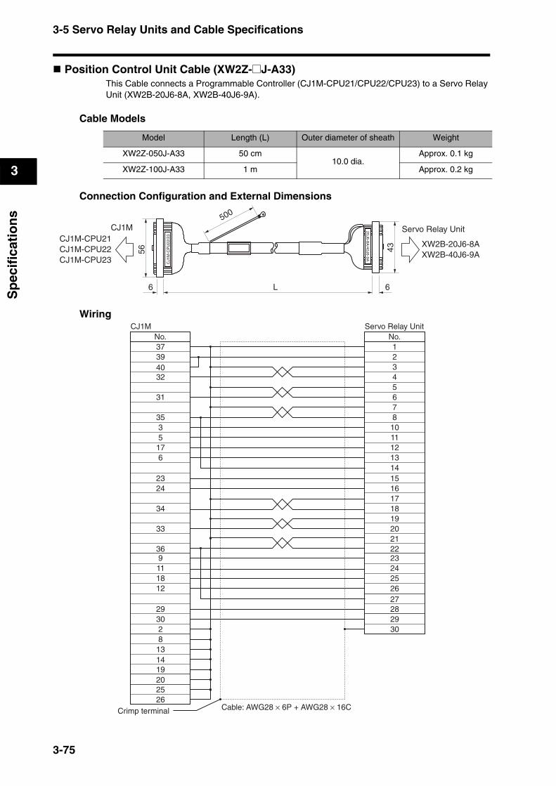
3-5 Servo Relay Units and Cable Specifications
3
Sp
ecif
icat
ion
s
Position Control Unit Cable (XW2Z-@J-A33)This Cable connects a Programmable Controller (CJ1M-CPU21/CPU22/CPU23) to a Servo Relay Unit (XW2B-20J6-8A, XW2B-40J6-9A).
Cable Models
Connection Configuration and External Dimensions
Wiring
Model Length (L) Outer diameter of sheath Weight
XW2Z-050J-A33 50 cm10.0 dia.
Approx. 0.1 kg
XW2Z-100J-A33 1 m Approx. 0.2 kgC
J1M
-CP
U22
/23
20J6-8A/40J6-9A
L
500
43
66
56
Servo Relay Unit
XW2B-20J6-8AXW2B-40J6-9A
CJ1MCJ1M-CPU21CJ1M-CPU22CJ1M-CPU23
No.3739
32
31
35
5176
2324
33
34
No.12345678
10111213
1516171819202122232425
2930
28
3
36
111812
29302813
40
9
1419202526
2627
14
CJ1M Servo Relay Unit
Cable: AWG28 × 6P + AWG28 × 16CCrimp terminal
3-75
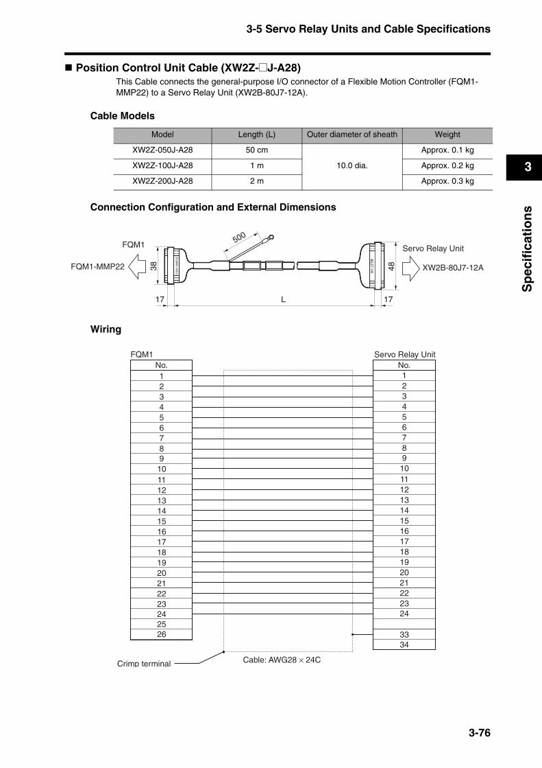
3-5 Servo Relay Units and Cable Specifications
3
Sp
ecif
icat
ion
s
Position Control Unit Cable (XW2Z-@J-A28)This Cable connects the general-purpose I/O connector of a Flexible Motion Controller (FQM1-MMP22) to a Servo Relay Unit (XW2B-80J7-12A).
Cable Models
Connection Configuration and External Dimensions
Wiring
Model Length (L) Outer diameter of sheath Weight
XW2Z-050J-A28 50 cm
10.0 dia.
Approx. 0.1 kg
XW2Z-100J-A28 1 m Approx. 0.2 kg
XW2Z-200J-A28 2 m Approx. 0.3 kg
L 1717
38
FQM1
FQM1-MMP22
500
48
Servo Relay Unit
XW2B-80J7-12A
FQ
M1-
MM
P22 80J7-1A
No. No.12345678
11121314151617181920212223
34
24
910
33
12345678
1112131415161718192021222324
910
2526
FQM1 Servo Relay Unit
Cable: AWG28 × 24CCrimp terminal
3-76
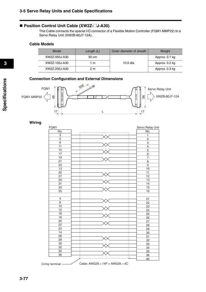
3-5 Servo Relay Units and Cable Specifications
3
Sp
ecif
icat
ion
s
Position Control Unit Cable (XW2Z-@J-A30)This Cable connects the special I/O connector of a Flexible Motion Controller (FQM1-MMP22) to a Servo Relay Unit (XW2B-80J7-12A).
Cable Models
Connection Configuration and External Dimensions
Wiring
Model Length (L) Outer diameter of sheath Weight
XW2Z-050J-A30 50 cm
10.0 dia.
Approx. 0.1 kg
XW2Z-100J-A30 1 m Approx. 0.2 kg
XW2Z-200J-A30 2 m Approx. 0.3 kg
L 1717
56
Servo Relay Unit
XW2B-80J7-12A
500
48
FQM1
FQM1-MMP22
80J7-1A
FQ
M1-
MM
P22
No.FQM1
35911
17
21
15
19
13
2729313335
10
4
Servo Relay Unit
Cable: AWG28 × 14P + AWG28 × 4C
No.12345678
111213141516
21222324
27
30
28
31323334
29
Crimp terminal
25
16
6
12
202224142628303234
910
2526
353640
23
18
36
3-77
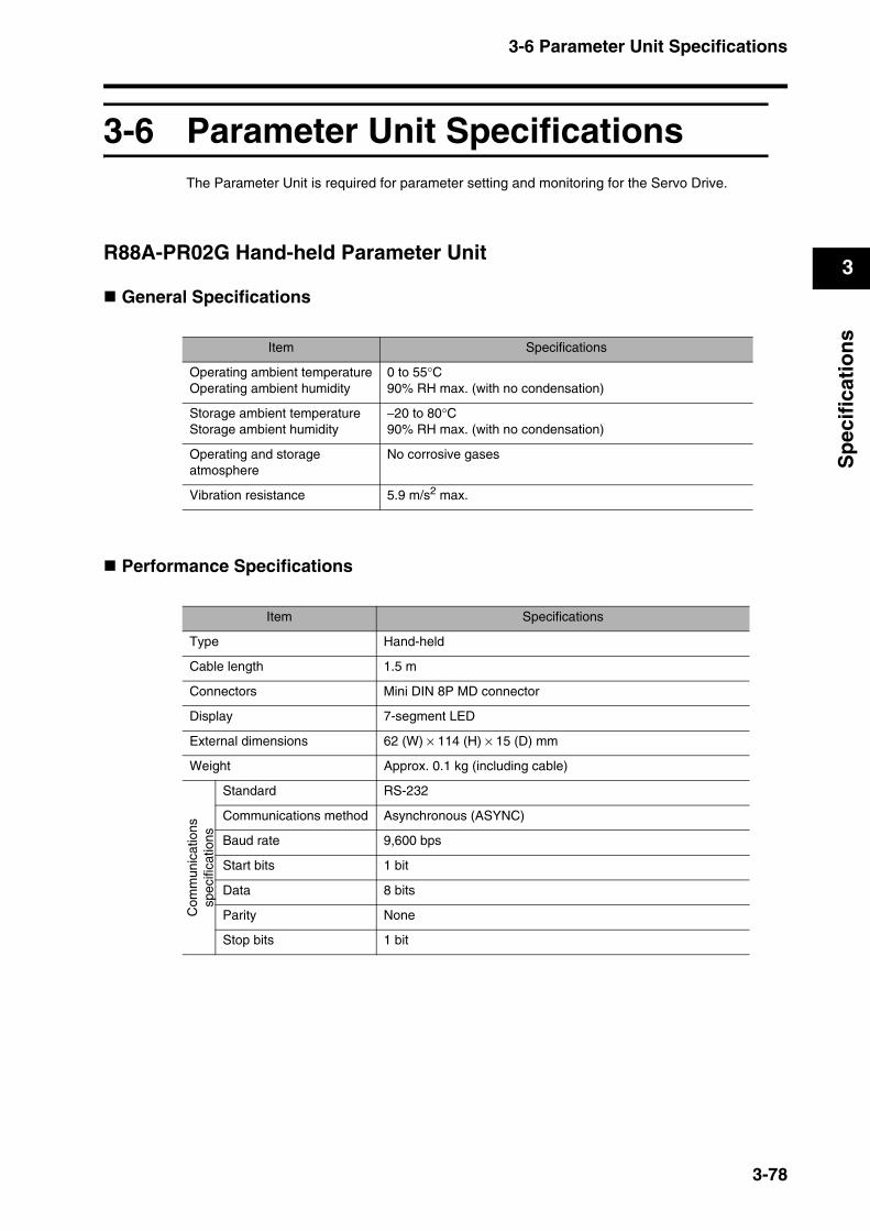
3-6 Parameter Unit Specifications
3
Sp
ecif
icat
ion
s
3-6 Parameter Unit SpecificationsThe Parameter Unit is required for parameter setting and monitoring for the Servo Drive.
R88A-PR02G Hand-held Parameter Unit
General Specifications
Performance Specifications
Item Specifications
Operating ambient temperatureOperating ambient humidity
0 to 55°C90% RH max. (with no condensation)
Storage ambient temperatureStorage ambient humidity
−20 to 80°C90% RH max. (with no condensation)
Operating and storage atmosphere
No corrosive gases
Vibration resistance 5.9 m/s2 max.
Item Specifications
Type Hand-held
Cable length 1.5 m
Connectors Mini DIN 8P MD connector
Display 7-segment LED
External dimensions 62 (W) × 114 (H) × 15 (D) mm
Weight Approx. 0.1 kg (including cable)
Com
mun
icat
ions
spec
ifica
tions
Standard RS-232
Communications method Asynchronous (ASYNC)
Baud rate 9,600 bps
Start bits 1 bit
Data 8 bits
Parity None
Stop bits 1 bit
3-78
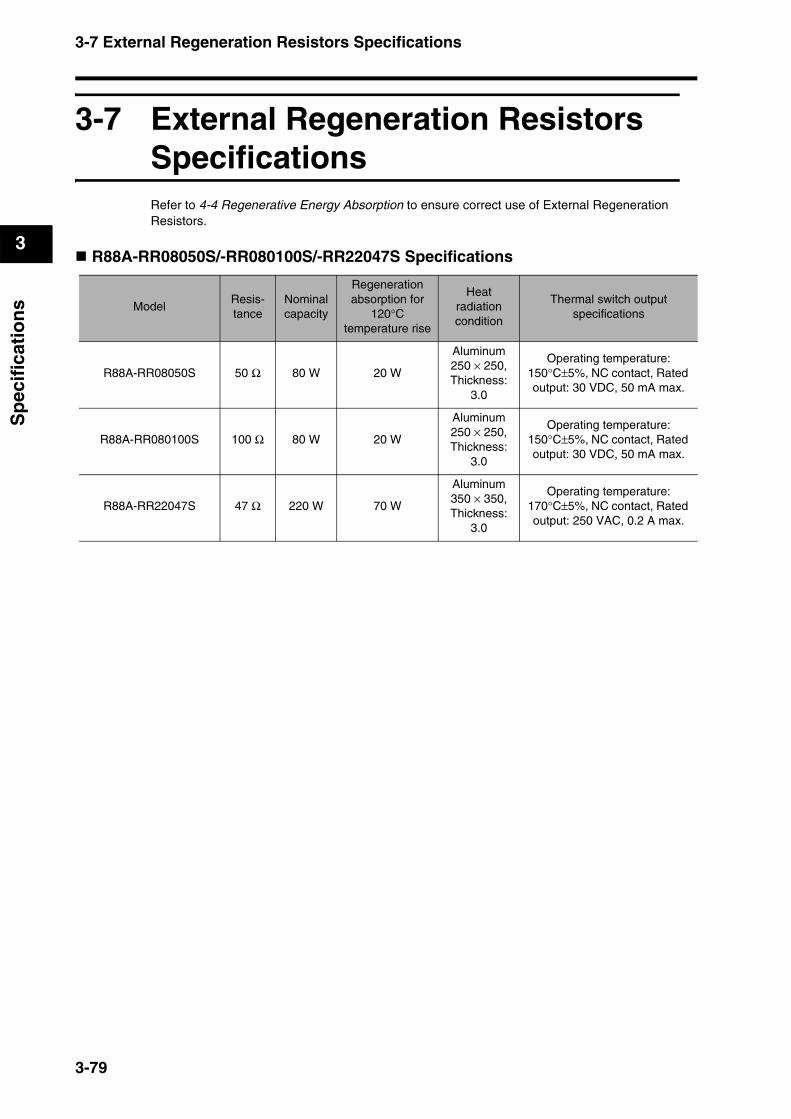
3-7 External Regeneration Resistors Specifications
3
Sp
ecif
icat
ion
s
3-7 External Regeneration Resistors SpecificationsRefer to 4-4 Regenerative Energy Absorption to ensure correct use of External Regeneration Resistors.
R88A-RR08050S/-RR080100S/-RR22047S Specifications
ModelResis-tance
Nominal capacity
Regeneration absorption for
120°Ctemperature rise
Heatradiationcondition
Thermal switch outputspecifications
R88A-RR08050S 50 Ω 80 W 20 W
Aluminum 250 × 250, Thickness:
3.0
Operating temperature: 150°C±5%, NC contact, Rated output: 30 VDC, 50 mA max.
R88A-RR080100S 100 Ω 80 W 20 W
Aluminum 250 × 250, Thickness:
3.0
Operating temperature: 150°C±5%, NC contact, Rated output: 30 VDC, 50 mA max.
R88A-RR22047S 47 Ω 220 W 70 W
Aluminum 350 × 350, Thickness:
3.0
Operating temperature: 170°C±5%, NC contact, Rated output: 250 VAC, 0.2 A max.
3-79
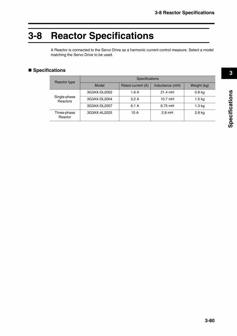
3-8 Reactor Specifications
3
Sp
ecif
icat
ion
s
3-8 Reactor SpecificationsA Reactor is connected to the Servo Drive as a harmonic current control measure. Select a model matching the Servo Drive to be used.
Specifications
Reactor typeSpecifications
Model Rated current (A) Inductance (mH) Weight (kg)
Single-phase Reactors
3G3AX-DL2002 1.6 A 21.4 mH 0.8 kg
3G3AX-DL2004 3.2 A 10.7 mH 1.0 kg
3G3AX-DL2007 6.1 A 6.75 mH 1.3 kg
Three-phase Reactor
3G3AX-AL2025 10 A 2.8 mH 2.8 kg
3-80


Chapter 4
System Design4-1 Installation Conditions ......................................4-1
Servo Drives ............................................................................4-1
Servomotors.............................................................................4-3
Decelerators.............................................................................4-6
4-2 Wiring ................................................................4-10Connecting Cables.................................................................4-10
Selecting Connecting Cables.................................................4-11
Peripheral Device Connection Examples...............................4-14
Main Circuit Wiring.................................................................4-16
4-3 Wiring Conforming to EMC Directives ...........4-18Wiring Method........................................................................4-18
Control Panel Structure..........................................................4-20
Selecting Connection Components........................................4-22
4-4 Regenerative Energy Absorption ...................4-33Calculating the Regenerative Energy ....................................4-33
Servo Drive Regenerative Energy Absorption Capacity ........4-35
Absorbing Regenerative Energy with an External Regeneration Resistor ...........................................................4-35
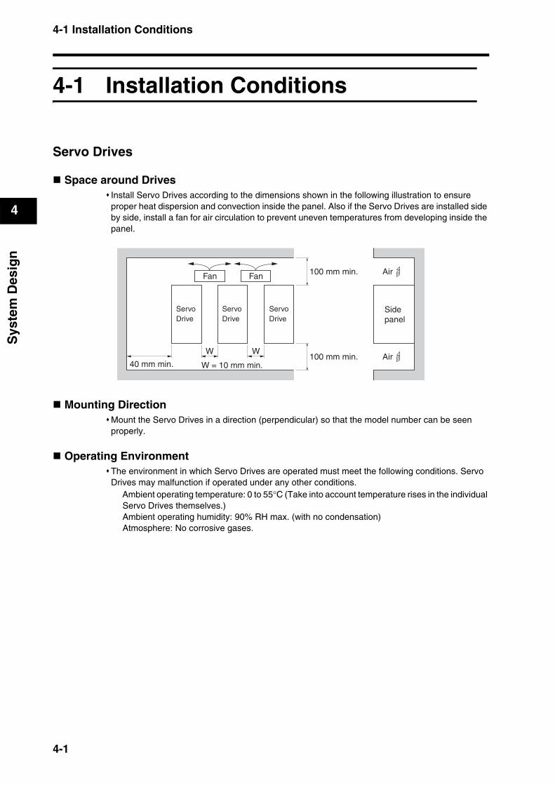
4-1 Installation Conditions
4
Sys
tem
Des
ign
4System Design
4-1 Installation Conditions
Servo Drives
Space around DrivesInstall Servo Drives according to the dimensions shown in the following illustration to ensure proper heat dispersion and convection inside the panel. Also if the Servo Drives are installed side by side, install a fan for air circulation to prevent uneven temperatures from developing inside the panel.
Mounting DirectionMount the Servo Drives in a direction (perpendicular) so that the model number can be seen properly.
Operating EnvironmentThe environment in which Servo Drives are operated must meet the following conditions. Servo Drives may malfunction if operated under any other conditions.
Ambient operating temperature: 0 to 55°C (Take into account temperature rises in the individual Servo Drives themselves.)Ambient operating humidity: 90% RH max. (with no condensation) Atmosphere: No corrosive gases.
ServoDrive
ServoDrive
ServoDrive
Sidepanel
W
40 mm min.
W
100 mm min.
100 mm min.
Air
Air
Fan Fan
W = 10 mm min.
4-1
4-1 Installation Conditions
4
Sys
tem
Des
ign
Ambient Temperature ControlServo Drives should be operated in environments in which there is minimal temperature rise to maintain a high level of reliability.Temperature rise in any Unit installed in a closed space, such as a control box, will cause the Servo Drive’s ambient temperature to rise. Use a fan or air conditioner to prevent the Servo Drive’s ambient temperature from exceeding 55°C.Servo Drive surface temperatures may rise to as much as 30°C above the ambient temperature. Use heat-resistant materials for wiring, and keep its distance from any devices or wiring that are sensitive to heat.The service life of a Servo Drive is determined by the temperature around the internal electrolytic capacitors. The service life of an electrolytic capacitor is affected by a drop in electrostatic capacity and an increase in internal resistance, which can result in overvoltage alarms, malfunctioning due to noise, and damage to individual elements.If a Servo Drive is operated at the ambient temperature of 55°C with the rated torque output and rated rotation speed, its service life is expected to be approximately 28,000 hours (excluding axial-flow fan). A drop of 10°C in the ambient temperature will double the expected service life.
Keeping Foreign Objects Out of UnitsPlace a cover over the Units or take other preventative measures to prevent foreign objects, such as drill filings, from getting into the Units during installation. Be sure to remove the cover after installation is complete. If the cover is left on during operation, Servo Drive’s heat dissipation is blocked, which may result in malfunction.Take measures during installation and operation to prevent foreign objects such as metal particles, oil, machining oil, dust, or water from getting inside of Servo Drives.
4-2
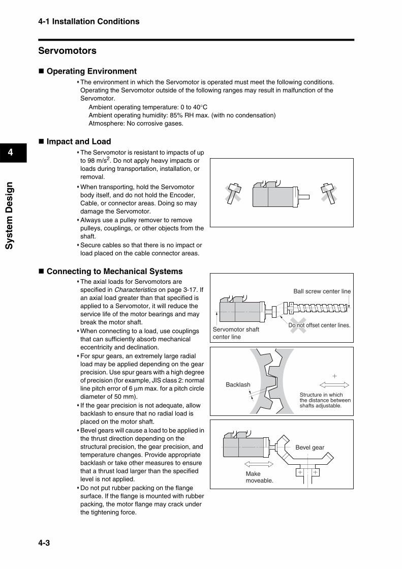
4-1 Installation Conditions
4
Sys
tem
Des
ign
Servomotors
Operating EnvironmentThe environment in which the Servomotor is operated must meet the following conditions. Operating the Servomotor outside of the following ranges may result in malfunction of the Servomotor.
Ambient operating temperature: 0 to 40°CAmbient operating humidity: 85% RH max. (with no condensation)Atmosphere: No corrosive gases.
Impact and LoadThe Servomotor is resistant to impacts of up to 98 m/s2. Do not apply heavy impacts or loads during transportation, installation, or removal.
When transporting, hold the Servomotor body itself, and do not hold the Encoder, Cable, or connector areas. Doing so may damage the Servomotor.Always use a pulley remover to remove pulleys, couplings, or other objects from the shaft.Secure cables so that there is no impact or load placed on the cable connector areas.
Connecting to Mechanical SystemsThe axial loads for Servomotors are specified in Characteristics on page 3-17. If an axial load greater than that specified is applied to a Servomotor, it will reduce the service life of the motor bearings and may break the motor shaft.When connecting to a load, use couplings that can sufficiently absorb mechanical eccentricity and declination.For spur gears, an extremely large radial load may be applied depending on the gear precision. Use spur gears with a high degree of precision (for example, JIS class 2: normal line pitch error of 6 µm max. for a pitch circle diameter of 50 mm).If the gear precision is not adequate, allow backlash to ensure that no radial load is placed on the motor shaft.Bevel gears will cause a load to be applied in the thrust direction depending on the structural precision, the gear precision, and temperature changes. Provide appropriate backlash or take other measures to ensure that a thrust load larger than the specified level is not applied.Do not put rubber packing on the flange surface. If the flange is mounted with rubber packing, the motor flange may crack under the tightening force.
Makemoveable.
Bevel gear
Structure in whichthe distance betweenshafts adjustable.
Backlash
Servomotor shaftcenter line
Ball screw center line
Do not offset center linesDo not offset center lines.Do not offset center lines.
4-3
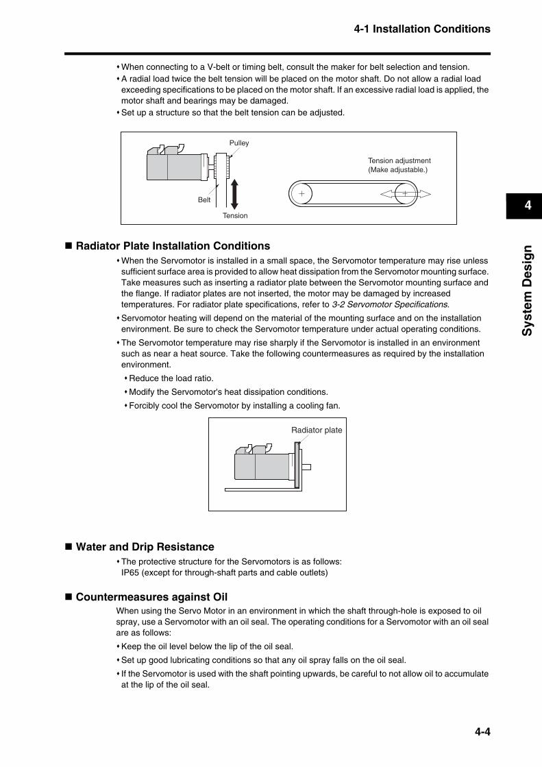
4-1 Installation Conditions
4
Sys
tem
Des
ign
When connecting to a V-belt or timing belt, consult the maker for belt selection and tension.A radial load twice the belt tension will be placed on the motor shaft. Do not allow a radial load exceeding specifications to be placed on the motor shaft. If an excessive radial load is applied, the motor shaft and bearings may be damaged.Set up a structure so that the belt tension can be adjusted.
Radiator Plate Installation ConditionsWhen the Servomotor is installed in a small space, the Servomotor temperature may rise unless sufficient surface area is provided to allow heat dissipation from the Servomotor mounting surface. Take measures such as inserting a radiator plate between the Servomotor mounting surface and the flange. If radiator plates are not inserted, the motor may be damaged by increased temperatures. For radiator plate specifications, refer to 3-2 Servomotor Specifications.
Servomotor heating will depend on the material of the mounting surface and on the installation environment. Be sure to check the Servomotor temperature under actual operating conditions.
The Servomotor temperature may rise sharply if the Servomotor is installed in an environment such as near a heat source. Take the following countermeasures as required by the installation environment.
Reduce the load ratio.
Modify the Servomotor's heat dissipation conditions.
Forcibly cool the Servomotor by installing a cooling fan.
Water and Drip ResistanceThe protective structure for the Servomotors is as follows:IP65 (except for through-shaft parts and cable outlets)
Countermeasures against OilWhen using the Servo Motor in an environment in which the shaft through-hole is exposed to oil spray, use a Servomotor with an oil seal. The operating conditions for a Servomotor with an oil seal are as follows:
Keep the oil level below the lip of the oil seal.
Set up good lubricating conditions so that any oil spray falls on the oil seal.
If the Servomotor is used with the shaft pointing upwards, be careful to not allow oil to accumulate at the lip of the oil seal.
Pulley
Belt
Tension
Tension adjustment(Make adjustable.)
Radiator plate
4-4
4-1 Installation Conditions
4
Sys
tem
Des
ign
Oil SealThe Servomotor oil seal dimensions are given below. The expected service life of an oil seal is approximately 5,000 hours. The actual life depends on the application conditions and environment. Oil seal installation and replacement are treated as repair work. For inquiries, consult your OMRON representative.
When using the Servomotor in an environment where the Servomotor shaft will be exposed to oil, select a Servomotor with an oil seal.
PrecautionsKeep the oil level below the oil seal.
The Oil Seal is made of rubber and may burn if it is used in an environment where it is subjected to no oil at all. Always use the Servomotor in an environment with a suitable amount of oil.
Install the Servomotor so that oil does not accumulate around the oil seal.
Other PrecautionsTake measures to protect the shaft from corrosion. The shafts are coated with anti-corrosion oil when shipped, but anti-corrosion oil or grease should also be applied when connecting the shaft to a load.
Motor model Shaft diameter (mm)
Outer diameter (mm)
Width (mm)
R88M-G05030L/H 8.9 17 4
R88M-G10030L/H 8.9 17 4
R88M-G20030L/H 14 28 4
R88M-G40030H 14 28 4
R88M-GP10030L/H 8.9 22 4
R88M-GP20030L/H 14 28 4
R88M-GP40030H 14 28 4
WARNINGDo not apply commercial power directly to the Servomotor.Doing so may result in fire.
Do not dismantle or repair the product.Doing so may result in electric shock or injury.
4-5
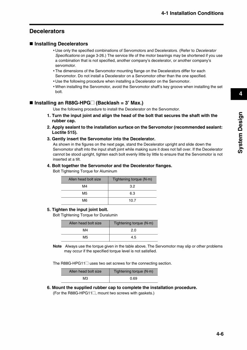
4-1 Installation Conditions
4
Sys
tem
Des
ign
Decelerators
Installing DeceleratorsUse only the specified combinations of Servomotors and Decelerators. (Refer to Decelerator Specifications on page 3-26.) The service life of the motor bearings may be shortened if you use a combination that is not specified, another company’s decelerator, or another company’s servomotor.The dimensions of the Servomotor mounting flange on the Decelerators differ for each Servomotor. Do not install a Decelerator on a Servomotor other than the one specified.Use the following procedure when installing a Decelerator on the Servomotor.When installing the Servomotor, avoid the Servomotor shaft’s key groove when installing the set bolt.
Installing an R88G-HPG@ (Backlash = 3’ Max.)Use the following procedure to install the Decelerator on the Servomotor.
1. Turn the input joint and align the head of the bolt that secures the shaft with the rubber cap.
2. Apply sealant to the installation surface on the Servomotor (recommended sealant: Loctite 515).
3. Gently insert the Servomotor into the Decelerator.As shown in the figures on the next page, stand the Decelerator upright and slide down the Servomotor shaft into the input shaft joint while making sure it does not fall over. If the Decelerator cannot be stood upright, tighten each bolt evenly little by little to ensure that the Servomotor is not inserted at a tilt.
4. Bolt together the Servomotor and the Decelerator flanges.Bolt Tightening Torque for Aluminum
5. Tighten the input joint bolt. Bolt Tightening Torque for Duralumin
Note Always use the torque given in the table above. The Servomotor may slip or other problems may occur if the specified torque level is not satisfied.
The R88G-HPG11@ uses two set screws for the connecting section.
6. Mount the supplied rubber cap to complete the installation procedure. (For the R88G-HPG11@, mount two screws with gaskets.)
Allen head bolt size Tightening torque (N·m)
M4 3.2
M5 6.3
M6 10.7
Allen head bolt size Tightening torque (N·m)
M4 2.0
M5 4.5
Allen head bolt size Tightening torque (N·m)
M3 0.69
4-6
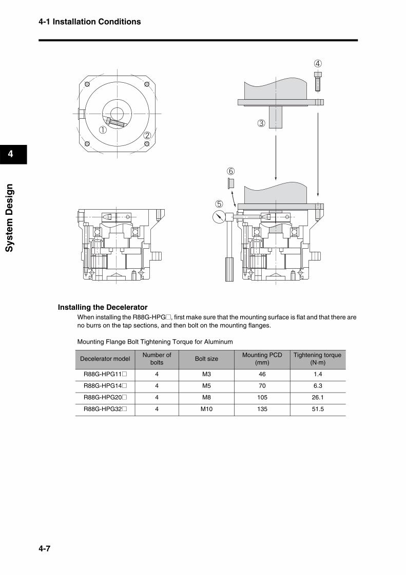
4-1 Installation Conditions
4
Sys
tem
Des
ign
Installing the DeceleratorWhen installing the R88G-HPG@, first make sure that the mounting surface is flat and that there are no burrs on the tap sections, and then bolt on the mounting flanges.
Mounting Flange Bolt Tightening Torque for Aluminum
Decelerator model Number of
boltsBolt size
Mounting PCD (mm)
Tightening torque (N·m)
R88G-HPG11@ 4 M3 46 1.4
R88G-HPG14@ 4 M5 70 6.3
R88G-HPG20@ 4 M8 105 26.1
R88G-HPG32@ 4 M10 135 51.5
4-7
4-1 Installation Conditions
4
Sys
tem
Des
ign
Installing an R88G-VRSF@ (Backlash = 15’ Max.)Use the following procedure to install the Decelerator to the Servomotor.
1. Turn the input joint and align the head of the bolt that secures the shaft with the rubber cap.Make sure the set bolts are loosened.
2. Gently insert the Servomotor into the Decelerator. As shown in the figures on the next page, stand the Decelerator upright and slide down the Servomotor shaft into the input shaft joint while making sure it does not fall over. If the Decelerator cannot be stood upright, tighten each bolt evenly little by little to ensure that the Servomotor is not inserted at a tilt.
3. Bolt together the Servomotor and the Decelerator flanges. Bolt Tightening Torque
4. Tighten the input joint bolt. Bolt Tightening Torque
Note Always use the torque given in the table above. Sliding or other problems may occur if the specified torque level is not satisfied.
5. Mount the supplied rubber cap to complete the installation procedure.
Allen head bolt size Tightening torque (N·m)
M4 3.0
M5 5.8
M6 9.8
Allen head bolt size Tightening torque (N·m)
M3 1.5
M4 3.5
M5 7.1
4-8

4-1 Installation Conditions
4
Sys
tem
Des
ign
Installing the DeceleratorWhen installing the R88G-VRSF@, first make sure that the mounting surface is flat and that there are no burrs on the tap sections, and then bolt on the mounting flanges.
Mounting Flange Bolt Tightening Torque for Aluminum
Using Another Company’s Decelerator (Reference Information)If the system configuration requires another company's decelerator to be used in combination with an OMNUC G-Series Servomotor, select the decelerator so that the load on the motor shaft (i.e., both the radial and thrust loads) is within the allowable range.(Refer to Characteristics on page 3-17 for details on the allowable loads for the motors.) Also, select the decelerator so that the allowable input rotation speed and allowable input torque of the decelerator are not exceeded.
Decelerator modelR88G-VRSF
Number of bolts
Bolt sizeMounting PCD
(mm)Tightening
torque (N·m)
B frame 4 M5 60 5.8
C frame 4 M6 90 9.8
4-9
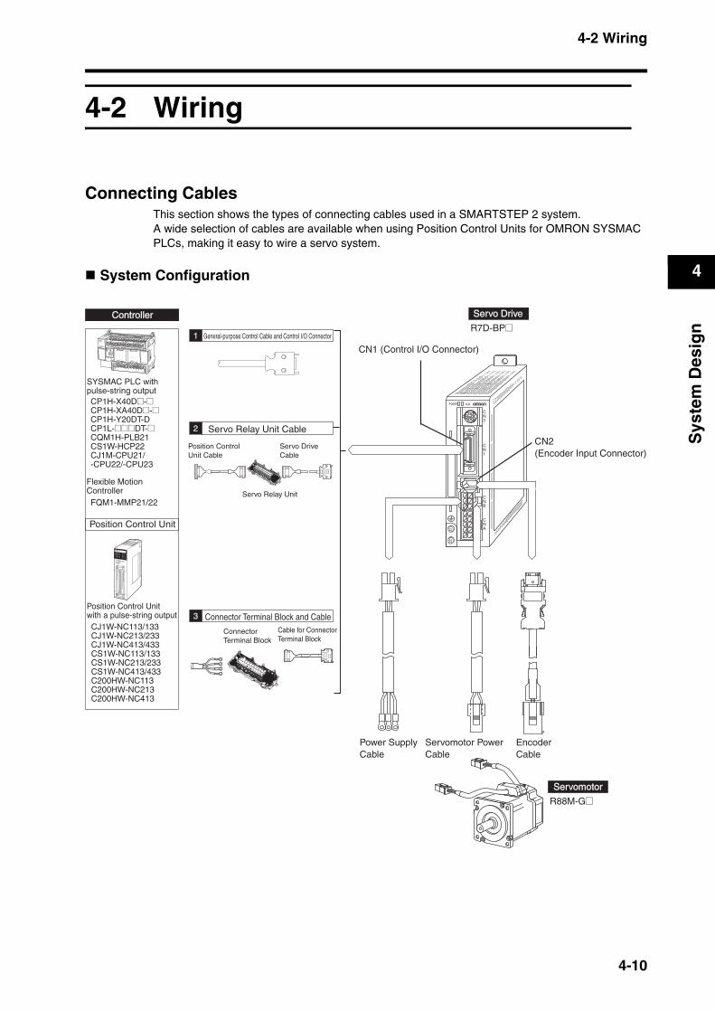
4-2 Wiring
4
Sys
tem
Des
ign
4-2 Wiring
Connecting CablesThis section shows the types of connecting cables used in a SMARTSTEP 2 system.A wide selection of cables are available when using Position Control Units for OMRON SYSMAC PLCs, making it easy to wire a servo system.
System Configuration
CNA
CNB
CN2
CN1
CN3
POWER ALM
NC413
MACHINENo.
RUNERROR
SENSDATA
XYZU
CN1 CN2
A24
A1
B24
B1
PERIPHERAL
SYSMACCP1H IN
BATTERY
AC100-240V 0CH
1CH
101CH
100CHDC24V 0.3AOUTPUT
EXP
L1 L2/N COM 01 03 05 07 09 11 01 03 05 07 09 11
00 02 04 06 08 10 00 02 04 06 08 10
00 01 02 03 04 06 00 01 03 04 06
COM COM COM COM 05 07 COM 07 COM 05 07
PERIPHERAL
OUT
POWERERR/ALMBKUP
RUN
INH
PRPHL
Servo Relay Unit
Servo DriveCable
Cable for ConnectorTerminal Block
Position ControlUnit Cable
ConnectorTerminal Block
Flexible Motion Controller
Servomotor Power Cable
2
General-purpose Control Cable and Control I/O Connector
Servo Relay Unit Cable
1
3 Connector Terminal Block and Cable
0
1
2
3
4
5
6
7
8
9
10
11
12
13
14
15
16
17
18
19
SerServo Dro Drivive
CN2(Encoder Input Connector)
CN1 (Control I/O Connector)
R7D-BP@
EncoderCable
ControllerController
Position Control Unit
CJ1W-NC113/133CJ1W-NC213/233CJ1W-NC413/433CS1W-NC113/133CS1W-NC213/233CS1W-NC413/433C200HW-NC113C200HW-NC213C200HW-NC413
Position Control Unitwith a pulse-string output
SYSMAC PLC withpulse-string outputCP1H-X40D@-@CP1H-XA40D@-@CP1H-Y20DT-DCP1L-@@@DT-@CQM1H-PLB21CS1W-HCP22CJ1M-CPU21/-CPU22/-CPU23
SerServomotoromotor
R88M-G@
Power SupplyCable
FQM1-MMP21/22
4-10

4-2 Wiring
4
Sys
tem
Des
ign
Selecting Connecting Cables
Encoder Cables (CN2)
Servomotor Power Cables (CNB)
Brake Cables
Power Supply Cables (CNA)
Name Model Comments
Standard Cables for Encoders
R88A-CRGB@@@C
The @@@ digits in the model number indicate the cable length (3 m, 5 m, 10 m, 15 m, or 20 m).Example model number for a 3-m cable:R88A-CRGB003C
Robot Cables for Encoders
R88A-CRGB@@@CR
The @@@ digits in the model number indicate the cable length (3 m, 5 m, 10 m, 15 m, or 20 m).Example model number for a 3-m cable:R88A-CRGB003CR
Name Model Comments
Standard Cables for Servomotor Power
R7A-CAB@@@S
The @@@ digits in the model number indicate the cable length (3 m, 5 m, 10 m, 15 m, or 20 m).Example model number for a 3-m cable:R7A-CAB003S
Robot Cables for Servomotor Power
R7A-CAB@@@SR
The @@@ digits in the model number indicate the cable length (3 m, 5 m, 10 m, 15 m, or 20 m).Example model number for a 3-m cable:R7A-CAB003SR
Name Model Comments
Standard Cables for Brakes
R88A-CAGA@@@B
The @@@ digits in the model number indicate the cable length (3 m, 5 m, 10 m, 15 m, or 20 m).Example model number for a 3-m cable: R88A-CAGA003B
Robot Cables for Brakes
R88A-CAGA@@@BR
The @@@ digits in the model number indicate the cable length (3 m, 5 m, 10 m, 15 m, or 20 m).Example model number for a 3-m cable: R88A-CAGA003BR
Name Model Comments
Cable for Single-phase Power Supply Input
R7A-CLB002S2 Cable length: 2 m
Cable for Three-phase Power Supply Input
R7A-CLB002S3 Cable length: 2 m
Cable for Connecting to External Regeneration Resistor
R7A-CLB002RG Cable length: 2 m
4-11
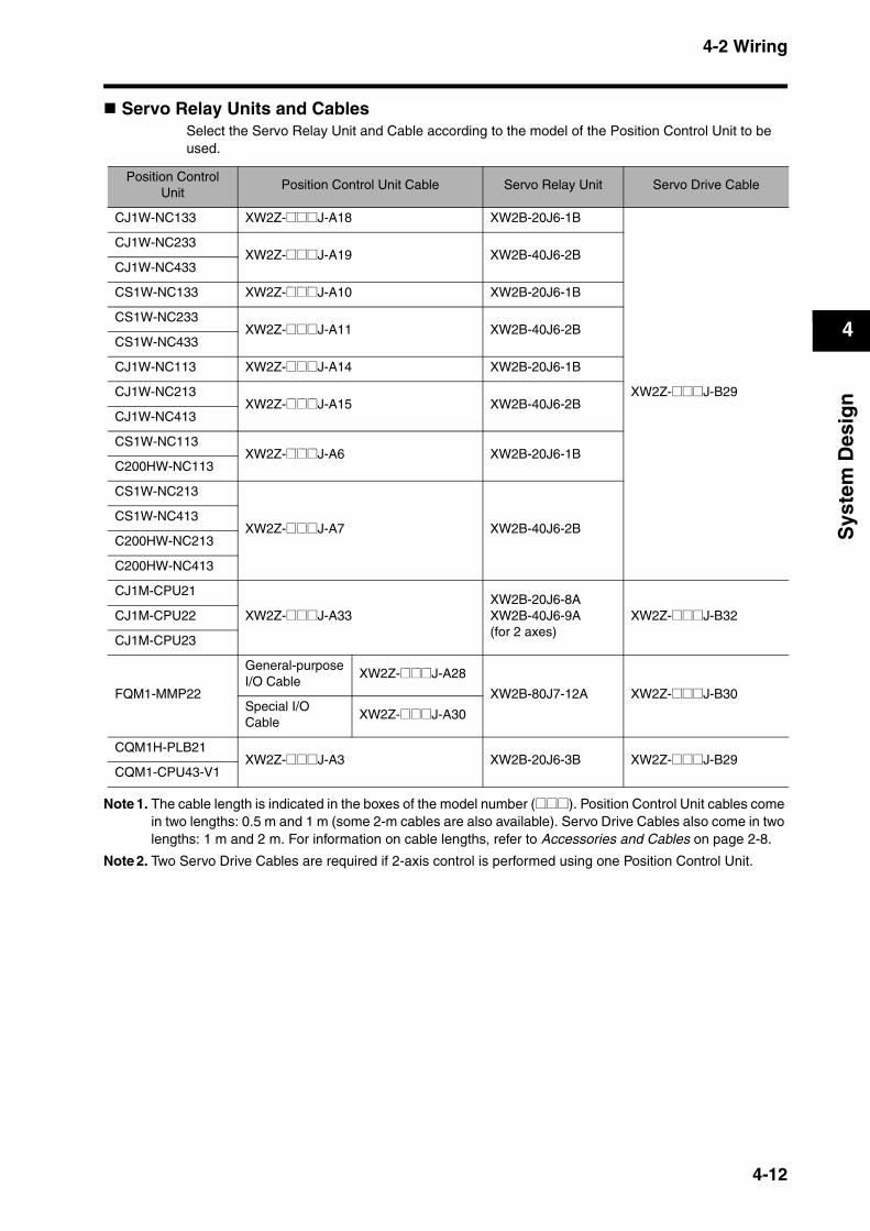
4-2 Wiring
4
Sys
tem
Des
ign
Servo Relay Units and CablesSelect the Servo Relay Unit and Cable according to the model of the Position Control Unit to be used.
Note 1. The cable length is indicated in the boxes of the model number (@@@). Position Control Unit cables come in two lengths: 0.5 m and 1 m (some 2-m cables are also available). Servo Drive Cables also come in two lengths: 1 m and 2 m. For information on cable lengths, refer to Accessories and Cables on page 2-8.
Note 2. Two Servo Drive Cables are required if 2-axis control is performed using one Position Control Unit.
Position Control Unit
Position Control Unit Cable Servo Relay Unit Servo Drive Cable
CJ1W-NC133 XW2Z-@@@J-A18 XW2B-20J6-1B
XW2Z-@@@J-B29
CJ1W-NC233XW2Z-@@@J-A19 XW2B-40J6-2B
CJ1W-NC433
CS1W-NC133 XW2Z-@@@J-A10 XW2B-20J6-1B
CS1W-NC233XW2Z-@@@J-A11 XW2B-40J6-2B
CS1W-NC433
CJ1W-NC113 XW2Z-@@@J-A14 XW2B-20J6-1B
CJ1W-NC213XW2Z-@@@J-A15 XW2B-40J6-2B
CJ1W-NC413
CS1W-NC113XW2Z-@@@J-A6 XW2B-20J6-1B
C200HW-NC113
CS1W-NC213
XW2Z-@@@J-A7 XW2B-40J6-2BCS1W-NC413
C200HW-NC213
C200HW-NC413
CJ1M-CPU21
XW2Z-@@@J-A33XW2B-20J6-8AXW2B-40J6-9A (for 2 axes)
XW2Z-@@@J-B32CJ1M-CPU22
CJ1M-CPU23
FQM1-MMP22
General-purposeI/O Cable
XW2Z-@@@J-A28
XW2B-80J7-12A XW2Z-@@@J-B30Special I/O Cable
XW2Z-@@@J-A30
CQM1H-PLB21XW2Z-@@@J-A3 XW2B-20J6-3B XW2Z-@@@J-B29
CQM1-CPU43-V1
4-12
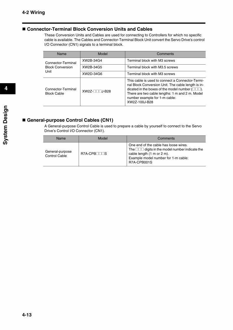
4-2 Wiring
4
Sys
tem
Des
ign
Connector-Terminal Block Conversion Units and CablesThese Conversion Units and Cables are used for connecting to Controllers for which no specific cable is available. The Cables and Connector-Terminal Block Unit convert the Servo Drive's control I/O Connector (CN1) signals to a terminal block.
General-purpose Control Cables (CN1)A General-purpose Control Cable is used to prepare a cable by yourself to connect to the Servo Drive’s Control I/O Connector (CN1).
Name Model Comments
Connector-Terminal Block Conversion Unit
XW2B-34G4 Terminal block with M3 screws
XW2B-34G5 Terminal block with M3.5 screws
XW2D-34G6 Terminal block with M3 screws
Connector-Terminal Block Cable
XW2Z-@@@J-B28
This cable is used to connect a Connector-Termi-nal Block Conversion Unit. The cable length is in-dicated in the boxes of the model number (@@@). There are two cable lengths: 1 m and 2 m. Model number example for 1-m cable: XW2Z-100J-B28
Name Model Comments
General-purpose Control Cable
R7A-CPB@@@S
One end of the cable has loose wires. The @@@ digits in the model number indicate the cable length (1 m or 2 m).Example model number for 1-m cable: R7A-CPB001S
4-13
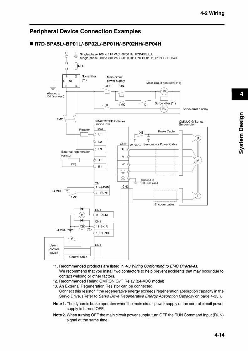
4-2 Wiring
4
Sys
tem
Des
ign
Peripheral Device Connection Examples
R7D-BPA5L/-BP01L/-BP02L/-BP01H/-BP02HH/-BP04H
*1. Recommended products are listed in 4-3 Wiring Conforming to EMC Directives.We recommend that you install two contactors to help prevent accidents that may occur due to contact welding or other factors.
*2. Recommended Relay: OMRON G7T Relay (24-VDC model)*3. An External Regeneration Resistor can be connected.
Connect this resistor if the regenerative energy exceeds regeneration absorption capacity in the Servo Drive. (Refer to Servo Drive Regenerative Energy Absorption Capacity on page 4-35.).
Note 1. The dynamic brake operates when the main circuit power supply or the control circuit power supply is turned OFF.
Note 2. When turning OFF the main circuit power supply, turn OFF the RUN Command Input (RUN) signal at the same time.
Noise filter(*1)
(Ground to100 Ω or less.)
(Ground to100 Ω or less.)
Main-circuit power supply
Main-circuit contactor (*1)
Surge killer (*1)
Servo error display
SMARTSTEP 2-Series Servo Drive
Usercontroldevice
Control cable
Servomotor Power Cable24 VDC
Reactor
External regenerationresistor
(*2)
Encoder cable
Brake Cable
24 VDC
Single-phase 100 to 115 VAC, 50/60 Hz: R7D-BP@@LSingle-phase 200 to 240 VAC, 50/60 Hz: R7D-BP01H/-BP02HH/-BP04H
OMNUC G-Series Servomotor
R T
NFB
1 2
3 4
E NF
OFF
X
ON
1MC X
1MC
PL
L1
L2
CN1
X
W
V
U
B
M
CN2
XB
P
B1
/ALM9X
CN1
0GND
BKIR11
13
CN1
XB
(*3)
L3
RUN
+24VIN1
2
CN1
1MC
CNA
CNB
E
1MC
24 VDC
4-14
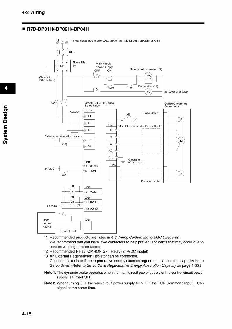
4-2 Wiring
4
Sys
tem
Des
ign
R7D-BP01H/-BP02H/-BP04H
*1. Recommended products are listed in 4-3 Wiring Conforming to EMC Directives.We recommend that you install two contactors to help prevent accidents that may occur due to contact welding or other factors.
*2. Recommended Relay: OMRON G7T Relay (24-VDC model)*3. An External Regeneration Resistor can be connected.
Connect this resistor if the regenerative energy exceeds regeneration absorption capacity in the Servo Drive. (Refer to Servo Drive Regenerative Energy Absorption Capacity on page 4-35.)
Note 1. The dynamic brake operates when the main circuit power supply or the control circuit power supply is turned OFF.
Note 2. When turning OFF the main circuit power supply, turn OFF the RUN Command Input (RUN) signal at the same time.
SMARTSTEP 2-SeriesServo Drive
Reactor
External regeneration resistor
Brake Cable
Noise filter(*1)
(Ground to100 Ω or less.)
(Ground to100 Ω or less.)
Main-circuit power supply
Main-circuit contactor (*1)
Surge killer (*1)
Servo error display
Usercontroldevice
Control cable
Servomotor Power Cable24 VDC
24 VDC (*2)
(*3)
Encoder cable
24 VDC
Three-phase 200 to 240 VAC, 50/60 Hz: R7D-BP01H/-BP02H/-BP04H
OMNUC G-SeriesServomotor
R T
NFB
1 2 3
4
E NF
OFF
X
ON
1MC X
1MC
PL
L1
L2
CN1
X
W
V
U
B
E
M
CN2
XB
P
B1
/ALM9X
CN1
0GND
BKIR11
13
CN1
XB
L3
RUN
+24VIN1
2
CN1
1MC
S
5 6
CNA
CNB
1MC
4-15
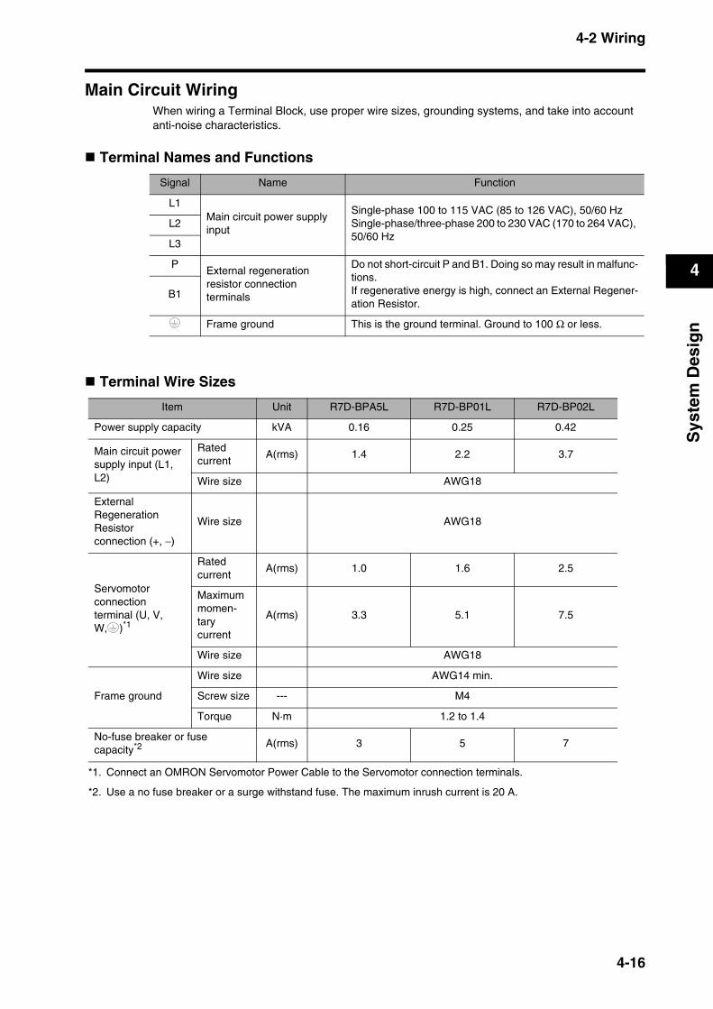
4-2 Wiring
4
Sys
tem
Des
ign
Main Circuit WiringWhen wiring a Terminal Block, use proper wire sizes, grounding systems, and take into account anti-noise characteristics.
Terminal Names and Functions
Terminal Wire Sizes
Signal Name Function
L1Main circuit power supply input
Single-phase 100 to 115 VAC (85 to 126 VAC), 50/60 HzSingle-phase/three-phase 200 to 230 VAC (170 to 264 VAC), 50/60 Hz
L2
L3
PExternal regeneration resistor connection terminals
Do not short-circuit P and B1. Doing so may result in malfunc-tions.If regenerative energy is high, connect an External Regener-ation Resistor.
B1
Frame ground This is the ground terminal. Ground to 100 Ω or less.
Item Unit R7D-BPA5L R7D-BP01L R7D-BP02L
Power supply capacity kVA 0.16 0.25 0.42
Main circuit power supply input (L1, L2)
Ratedcurrent
A(rms) 1.4 2.2 3.7
Wire size AWG18
External Regeneration Resistor connection (+, −)
Wire size AWG18
Servomotor connection terminal (U, V, W, )*1
*1. Connect an OMRON Servomotor Power Cable to the Servomotor connection terminals.
Ratedcurrent
A(rms) 1.0 1.6 2.5
Maximummomen-tarycurrent
A(rms) 3.3 5.1 7.5
Wire size AWG18
Frame ground
Wire size AWG14 min.
Screw size --- M4
Torque N·m 1.2 to 1.4
No-fuse breaker or fuse capacity*2
*2. Use a no fuse breaker or a surge withstand fuse. The maximum inrush current is 20 A.
A(rms) 3 5 7
4-16

4-2 Wiring
4
Sys
tem
Des
ign
Wire Size and Allowable Current (Reference)The following table shows the allowable current when there are three power supply wires.Use a current below these specified values.
600-V Heat-resistant Vinyl Wire (HIV)
Item Unit R7D-BP01H R7D-BP02HH R7D-BP02H R7D-BP04H
Power supply capacity kVA0.27
(0.3)*10.35 0.42
0.69(0.77)*1
Main circuit power supply input (L1, L2)
Ratedcurrent
A(rms)0.7
(1.5)*11.6 1.1
1.8(3.5)*1
Wire size AWG18
External Regeneration Resistor connection (+, −)
Wire size AWG18
Servomotor connection terminal (U, V, W, )*2
Ratedcurrent
A(rms) 1.0 1.6 1.6 2.5
Maximummomen-tarycurrent
A(rms) 3.3 4.9 4.9 7.8
Wire size AWG18
Frame ground
Wire size AWG14 min.
Screw size --- M4
Torque N·m 1.2 to 1.4
No-fuse breaker or fuse capacity*3 A(rms) 3 2
5(7)*1
*1. Values in parentheses ( ) are for using single-phase 200 V.
*2. Connect an OMRON Servomotor Power Cable to the Servomotor connection terminals.
*3. Use a no fuse breaker or a surge withstand fuse. The maximum inrush current is 20 A.
AWG size
Nominal cross-
sectional area (mm2)
Configura-tion
(wires/mm2)
Conductiveresistance
(Ω/km)
Allowable current (A) for ambient temperature
30°C 40°C 50°C
20 0.5 19/0.18 39.5 6.6 5.6 4.5
--- 0.75 30/0.18 26.0 8.8 7.0 5.5
18 0.9 37/0.18 24.4 9.0 7.7 6.0
16 1.25 50/0.18 15.6 12.0 11.0 8.5
14 2.0 7/0.6 9.53 23 20 16
4-17

4-3 Wiring Conforming to EMC Directives
4
Sys
tem
Des
ign
4-3 Wiring Conforming to EMC DirectivesConformance to the EMC Directives (EN55011 class A group 1 (EMI) and EN61000-6-2 (EMS)) can be ensured by wiring under the conditions described below. These conditions are for conformance of the SMARTSTEP-2 products to the EMC Directives.EMC-related performance of these products, however, will vary depending on the configuration, wiring, and other conditions of the equipment in which the products are installed. The EMC conformance of the system as a whole must be confirmed by the customer.
The following are the requirements for EMC Directive conformance.
The Servo Drive must be installed in a metal case (control panel). (The Servomotor does not, however, have to be covered with a metal plate.)Noise filters and surge absorbers must be installed on power supply lines.Shielded cables must be used for all I/O signal lines and encoder lines. (Use tin-plated, mild steel wires for the shielding.)All cables, I/O wiring, and power lines connected to the Servo Drive must have clamp filters installed. The shields of all cables must be directly connected to a ground plate.
Wiring Method
Note For models with a single-phase power supply input (R7D-BP@@L/-BP01H/BP02HH/-BP04H), the main input power supply terminals are L1 and L3.
Ground the motor’s frame to the machine ground when the motor is on a movable shaft.Use a ground plate for the frame ground for each Unit, as shown in the above diagrams, and ground to a single point.Use ground lines with a minimum thickness of 3.5 mm2, and arrange the wiring so that the ground lines are as short as possible.No-fuse breakers, surge absorbers, and noise filters should be positioned near the input terminal block (ground plate), and I/O lines should be separated and wired at the shortest distance.
NFL3
AC powersupply
L1L2
UVW
CN2CN1
TB: Switch boxServomotor ON rotation command
SMSingle-phase100 VAC
SG
FC
FC
FC
FC
SDCNA CNB
(a) (b) (c)
(d)
(e)
(f)
(g)
(h)
(Ground to 100 Ω or less.)
4-18
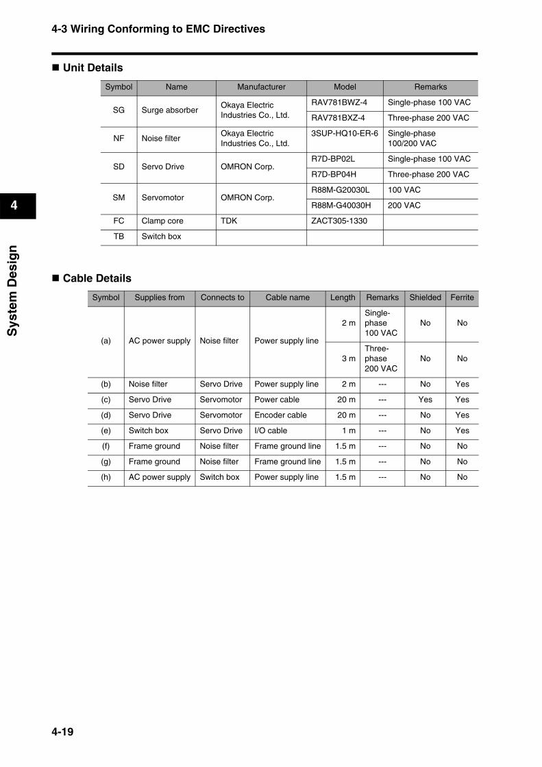
4-3 Wiring Conforming to EMC Directives
4
Sys
tem
Des
ign
Unit Details
Cable Details
Symbol Name Manufacturer Model Remarks
SG Surge absorberOkaya Electric Industries Co., Ltd.
RAV781BWZ-4 Single-phase 100 VAC
RAV781BXZ-4 Three-phase 200 VAC
NF Noise filterOkaya Electric Industries Co., Ltd.
3SUP-HQ10-ER-6 Single-phase 100/200 VAC
SD Servo Drive OMRON Corp.R7D-BP02L Single-phase 100 VAC
R7D-BP04H Three-phase 200 VAC
SM Servomotor OMRON Corp.R88M-G20030L 100 VAC
R88M-G40030H 200 VAC
FC Clamp core TDK ZACT305-1330
TB Switch box
Symbol Supplies from Connects to Cable name Length Remarks Shielded Ferrite
(a) AC power supply Noise filter Power supply line
2 mSingle-phase 100 VAC
No No
3 mThree-phase 200 VAC
No No
(b) Noise filter Servo Drive Power supply line 2 m --- No Yes
(c) Servo Drive Servomotor Power cable 20 m --- Yes Yes
(d) Servo Drive Servomotor Encoder cable 20 m --- No Yes
(e) Switch box Servo Drive I/O cable 1 m --- No Yes
(f) Frame ground Noise filter Frame ground line 1.5 m --- No No
(g) Frame ground Noise filter Frame ground line 1.5 m --- No No
(h) AC power supply Switch box Power supply line 1.5 m --- No No
4-19
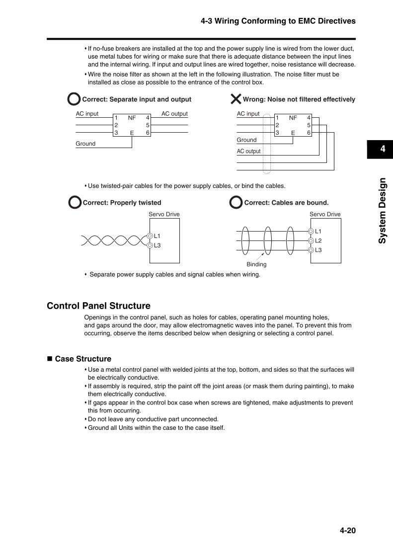
4-3 Wiring Conforming to EMC Directives
4
Sys
tem
Des
ign
If no-fuse breakers are installed at the top and the power supply line is wired from the lower duct, use metal tubes for wiring or make sure that there is adequate distance between the input lines and the internal wiring. If input and output lines are wired together, noise resistance will decrease.
Wire the noise filter as shown at the left in the following illustration. The noise filter must be installed as close as possible to the entrance of the control box.
Use twisted-pair cables for the power supply cables, or bind the cables.
Separate power supply cables and signal cables when wiring.
Control Panel StructureOpenings in the control panel, such as holes for cables, operating panel mounting holes,and gaps around the door, may allow electromagnetic waves into the panel. To prevent this from occurring, observe the items described below when designing or selecting a control panel.
Case StructureUse a metal control panel with welded joints at the top, bottom, and sides so that the surfaces will be electrically conductive.If assembly is required, strip the paint off the joint areas (or mask them during painting), to make them electrically conductive.If gaps appear in the control box case when screws are tightened, make adjustments to prevent this from occurring.Do not leave any conductive part unconnected.Ground all Units within the case to the case itself.
Correct: Separate input and output Wrong: Noise not filtered effectively
NF123
456E
NF123
456E
AC input AC input
GroundGround
AC output
AC output
Correct: Properly twisted Correct: Cables are bound.
Servo Drive Servo Drive
L1L1
L2
L3L3
Binding
4-20

4-3 Wiring Conforming to EMC Directives
4
Sys
tem
Des
ign
Door StructureUse a metal door.Use a water-draining structure where the door and case fit together, and leave no gaps. (Refer to the diagrams below.)Use a conductive gasket between the door and the case, as shown in the diagrams below. (Refer to the diagrams below.) Strip the paint off the sections of the door and case that will be in contact with the conductive gasket (or mask them during painting), so that they will be electrically conductive.The door may warp and gaps may appear between the door and case when screws are tightened. Be sure that no gaps appear when tightening screws.
Case
Door
Control panel
Door (interior view)
A
B
Cross-sectional view of A–B
Oil-resistant gasket
Conductive gasket
Door
Oil-resistant gasket Conductive gasket
4-21
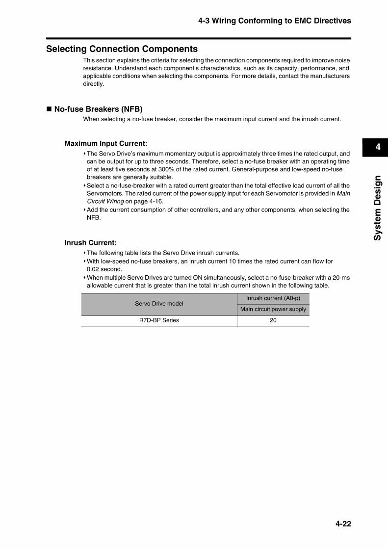
4-3 Wiring Conforming to EMC Directives
4
Sys
tem
Des
ign
Selecting Connection ComponentsThis section explains the criteria for selecting the connection components required to improve noise resistance. Understand each component’s characteristics, such as its capacity, performance, and applicable conditions when selecting the components. For more details, contact the manufacturers directly.
No-fuse Breakers (NFB)When selecting a no-fuse breaker, consider the maximum input current and the inrush current.
Maximum Input Current:The Servo Drive’s maximum momentary output is approximately three times the rated output, and can be output for up to three seconds. Therefore, select a no-fuse breaker with an operating time of at least five seconds at 300% of the rated current. General-purpose and low-speed no-fuse breakers are generally suitable.Select a no-fuse-breaker with a rated current greater than the total effective load current of all the Servomotors. The rated current of the power supply input for each Servomotor is provided in Main Circuit Wiring on page 4-16.Add the current consumption of other controllers, and any other components, when selecting the NFB.
Inrush Current:The following table lists the Servo Drive inrush currents.With low-speed no-fuse breakers, an inrush current 10 times the rated current can flow for 0.02 second.When multiple Servo Drives are turned ON simultaneously, select a no-fuse-breaker with a 20-ms allowable current that is greater than the total inrush current shown in the following table.
Servo Drive modelInrush current (A0-p)
Main circuit power supply
R7D-BP Series 20
4-22
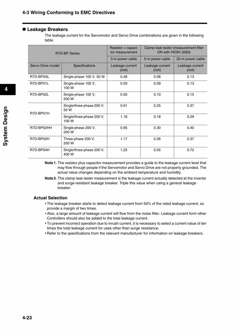
4-3 Wiring Conforming to EMC Directives
4
Sys
tem
Des
ign
Leakage BreakersThe leakage current for the Servomotor and Servo Drive combinations are given in the following table.
Note 1. The resistor plus capacitor measurement provides a guide to the leakage current level that may flow through people if the Servomotor and Servo Drive are not properly grounded. The actual value changes depending on the ambient temperature and humidity.
Note 2. The clamp leak tester measurement is the leakage current actually detected at the inverter and surge-resistant leakage breaker. Triple this value when using a general leakage breaker.
Actual SelectionThe leakage breaker starts to detect leakage current from 50% of the rated leakage current, so provide a margin of two times. Also, a large amount of leakage current will flow from the noise filter. Leakage current form other Controllers should also be added to the total leakage current.To prevent incorrect operation due to inrush current, it is necessary to select a current value of ten times the total leakage current for uses other than surge resistance.Refer to the specifications from the relevant manufacturer for information on leakage breakers.
R7D-BP Series
Resistor + capaci-tor measurement
Clamp leak tester (measurement filter ON with HIOKI 3283)
5-m power cable 5-m power cable 20-m power cable
Servo Drive model Specifications Leakage current (mA)
Leakage current (mA)
Leakage current (mA)
R7D-BPA5L Single-phase 100 V, 50 W 0.48 0.08 0.13
R7D-BP01L Single-phase 100 V, 100 W
0.59 0.09 0.13
R7D-BP02L Single-phase 100 V, 200 W
0.50 0.10 0.15
R7D-BP01H
Single/three-phase 200 V, 50 W
0.91 0.25 0.37
Single/three-phase 200 V, 100 W
1.18 0.18 0.29
R7D-BP02HH Single-phase 200 V,200 W
0.95 0.30 0.40
R7D-BP02H Three-phase 200 V, 200 W
1.17 0.26 0.37
R7D-BP04H Single/three-phase 200 V, 400 W
1.25 0.55 0.72
4-23

4-3 Wiring Conforming to EMC Directives
4
Sys
tem
Des
ign
Surge AbsorbersUse surge absorbers to absorb lightning surge voltage or abnormal voltage from power supply input lines.When selecting surge absorbers, take into account the varistor voltage, the allowable surge current, and the energy.For 200-VAC systems, use surge absorbers with a varistor voltage of 620 V.The surge absorbers shown in the following table are recommended.
Note 1. Refer to the manufacturers’ documentation for operating details.
Note 2. The surge immunity is for a standard impulse current of 8/20 µs. If pulses are wide, either decrease the current or change to a larger-capacity surge absorber.
Dimensions
Equalizing Circuits
Maker ModelMax. limit
voltage
Surgeimmunity
Type Remarks
OkayaElectric
IndustriesCo., Ltd.
R·A·V-781BWZ-4700 V ±20%
2500 A
Block
Single-phase 100/200 VAC
R·A·V-781BXZ-4700 V ±20%
2500 AThree-phase
200 VAC
200
28
41
4.5
4.2 dia.4.2 dia.
115.
528
.5
5.5
1128
.520
028
41
4.5
Single-phase BWZ Series Three-phase BXZ Series
Single-phase BWZ Series Three-phase BXZ Series
4-24
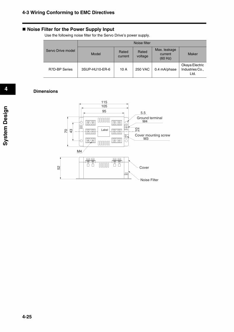
4-3 Wiring Conforming to EMC Directives
4
Sys
tem
Des
ign
Noise Filter for the Power Supply InputUse the following noise filter for the Servo Drive’s power supply.
Dimensions
Servo Drive model
Noise filter
ModelRatedcurrent
Rated voltage
Max. leakage current(60 Hz)
Maker
R7D-BP Series 3SUP-HU10-ER-6 10 A 250 VAC 0.4 mA/phaseOkaya Electric Industries Co.,
Ltd.
105
5.5
4370
52
10
95
Ground terminalM4
Cover mounting screw M3
Cover
Noise Filter
M4
Label
115
4-25
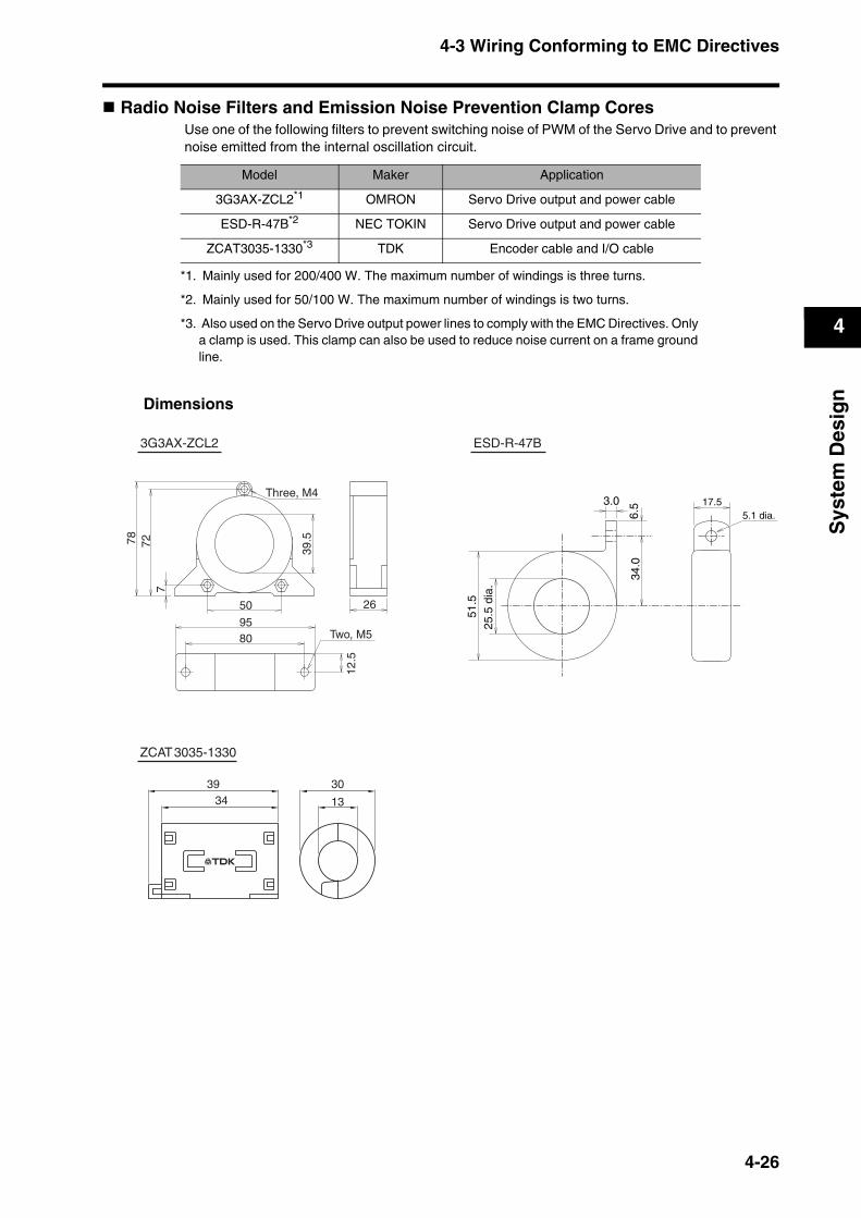
4-3 Wiring Conforming to EMC Directives
4
Sys
tem
Des
ign
Radio Noise Filters and Emission Noise Prevention Clamp CoresUse one of the following filters to prevent switching noise of PWM of the Servo Drive and to prevent noise emitted from the internal oscillation circuit.
Dimensions
Model Maker Application
3G3AX-ZCL2*1
*1. Mainly used for 200/400 W. The maximum number of windings is three turns.
OMRON Servo Drive output and power cable
ESD-R-47B*2
*2. Mainly used for 50/100 W. The maximum number of windings is two turns.
NEC TOKIN Servo Drive output and power cable
ZCAT3035-1330*3
*3. Also used on the Servo Drive output power lines to comply with the EMC Directives. Only a clamp is used. This clamp can also be used to reduce noise current on a frame ground line.
TDK Encoder cable and I/O cable
Two, M5
Three, M4
95
26
78
80
12.5
72
50
7
39.5
3G3AX-ZCL2
51.5
25.5
dia
.17.5
5.1 dia.3.0
6.5
34.0
ESD-R-47B
34 13
3039
ZCAT3035-1330
4-26
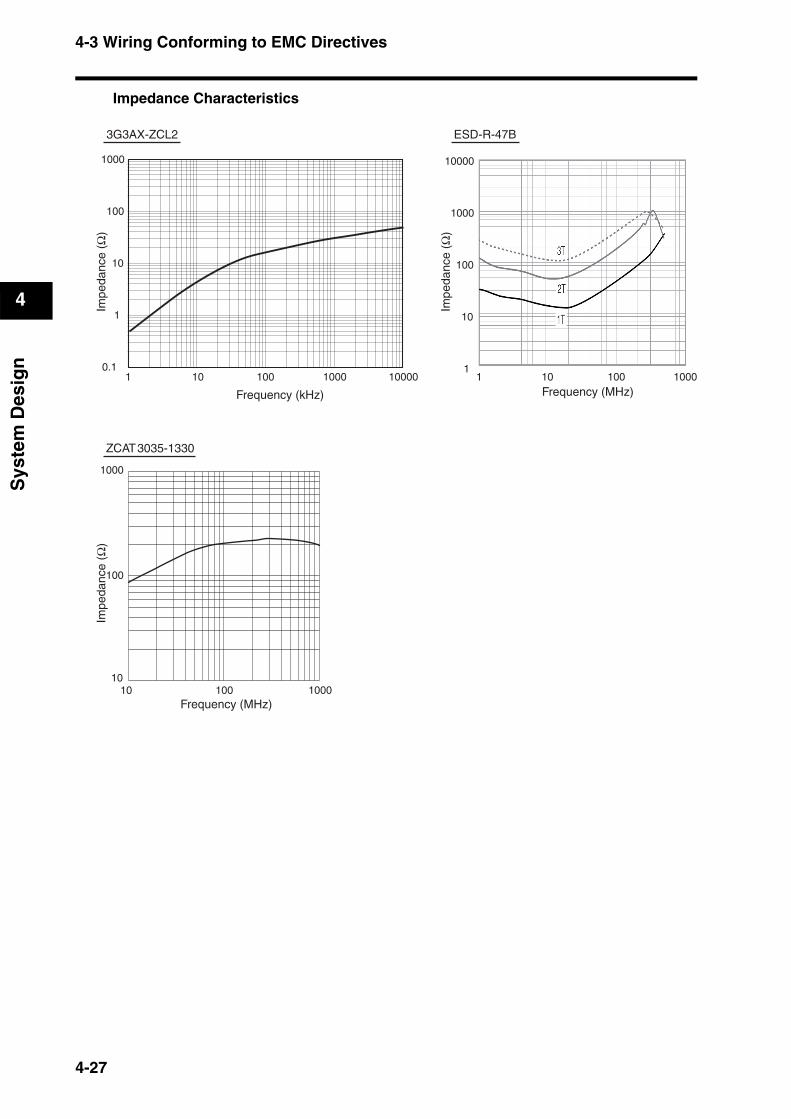
4-3 Wiring Conforming to EMC Directives
4
Sys
tem
Des
ign
Impedance Characteristics
10 100 10000
1000
100
10
1
0.1
Frequency (kHz)
Impe
danc
e (Ω
)Im
peda
nce
(Ω)
Impe
danc
e (Ω
)
1 1000
10000
1000
100
10
110 100Frequency (MHz)
1 1000
3G3AX-ZCL2 ESD-R-47B
ZCAT3035-1330
10 100Frequency (MHz)
1000
1000
100
10
4-27

4-3 Wiring Conforming to EMC Directives
4
Sys
tem
Des
ign
Surge SuppressorsInstall surge suppressors for loads that have induction coils, such as relays, solenoids, brakes, clutches, etc.The following table shows the types of surge suppressors and recommended products.
Note Thyristors and varistors are made by the following companies. Refer to manufacturers’ documentation for details on these components. Thyristors: Ishizuka Electronics Co. Varistors: Ishizuka Electronics Co., Matsushita Electric Industrial Co.
ContactorsSelect contactors based on the circuit's inrush current and the maximum momentary phase current.The Servo Drive inrush current is covered in the preceding explanation of no-fuse breaker selection, and the maximum momentary phase current is approximately twice of the rated current.We recommend that you install two contactors to help prevent accidents that may occur due to contact welding or other factors.
Type Features Recommended products
Diode
Diodes are used for relatively small loads when the reset time is not an issue, such as relays.At power shutoff, the surge voltage is the lowest, but the reset time becomes longer.Used for 24/48-VDC systems.
Use a fast-recovery diode with a short reverse recovery time(e.g., RU2 of Sanken Electric Co., Ltd.).
Thyristor or varistor
Thyristors and varistors are used for loads when induction coils are large, as in electro-magnetic brakes, solenoids, etc., and when reset time is an issue. The surge voltage at power shutoff is approximately 1.5 times the varistor voltage.
Select the varistor voltage as follows:24 VDC system: Varistor V0 39 V100 VDC system: Varistor V0 200 V100 VAC system: Varistor V0 270 V200 VAC system: Varistor V0 470 V
Capacitor + resistor
The capacitor and resistor dissipate and ab-sorb the surge at power shutoff. The reset time can be shortened by selecting the ap-propriate capacitor and resistance values.
Okaya Electric Industries Co., Ltd. XEB12002 0.2 µF - 120 Ω XEB12003 0.3 µF - 120 Ω
4-28

4-3 Wiring Conforming to EMC Directives
4
Sys
tem
Des
ign
Improving Encoder Cable Noise ResistanceTake the following steps during wiring and installation to improve the encoder’s noise resistance.
Always use the specified Encoder Cables.If cables are joined midway, be sure to use connectors and do not remove more than 50 mm of the cable insulation. In addition, always use shielded cables.Do not coil cables. If cables are long and coiled, mutual induction and inductance will increase and cause malfunctions. Always use cables fully extended.When installing noise filters for Encoder Cables, use clamp filters. The following table shows the recommended clamp filters.
Do not place the Encoder Cable with the following cables in the same duct.Control Cables for brakes, solenoids, clutches, and valves.
Dimensions
Impedance Characteristics
For information on the TDK clamp filter (ZCAT3035-1330), refer to Radio Noise Filters and Emission Noise Prevention Clamp Cores on page 4-26.
Maker Product name Model Specifications
NEC TOKIN Clamp filter ESD-SR-250 For cable diameter up to 13 mm
TDK Clamp filter ZCAT3035-1330 For cable diameter up to 13 mm
31.5
~13 dia.
31.6
38.0
ESD-SR-250
10000
1000
100
10
1
Impe
danc
e(Ω
)
10 100Frequency(MHz)
1 1000
ESD-SR-250
4-29
4-3 Wiring Conforming to EMC Directives
4
Sys
tem
Des
ign
Improving Control I/O Signal Noise ResistancePositioning can be affected and I/O signal errors can occur if control I/O is influenced by noise.
Use completely separate power supplies for the control power supply (especially 24 VDC) and for the external operation power supply. In particular, do not connect the two power supply ground wires.
Install a noise filter on the primary side of the control power supply.If Servomotors with brakes are used, do not use the same 24-VDC power supply for both the brakes and the control I/O. Additionally, do not connect the ground wires. Connecting the ground wires may cause I/O signal errors.Keep the power supply for pulse commands and deviation counter reset input lines separated from the control power supply as far apart as possible. In particular, do not connect the two power supply ground lines.We recommend using line drivers for the pulse command output.Always use twisted-pair shielded cable for the pulse command and deviation counter reset signal lines, and connect both ends of the shield to frame grounds.If the control power supply wiring is long, noise resistance can be improved by adding 1-µF laminated ceramic capacitors between the control power supply and ground at the Servo Drive input section or the controller output section.For open-collector specifications, keep the length of wires to within two meters.
Selecting Other Parts for Noise ResistanceThis section explains the criteria for selecting other connection components required to improve noise resistance. Understand each component’s characteristics, such as its capacity, performance, and applicable conditions when selecting the components. For more details, contact the manufacturers directly.
4-30

4-3 Wiring Conforming to EMC Directives
4
Sys
tem
Des
ign
Noise Filters for the Power Supply InputUse a noise filter to attenuate external noise and reduce noise emitted from the Servo Drive.Select a noise filter with a rated current that is at least two times greater than the effective load current (the rated current of the main circuit power supply input given in Main Circuit Wiring on page 4-16).
Note 1. To attenuate noise at low frequencies below 200 kHz, use an isolation transformer and a noise filter.
Note 2. To attenuate noise at high frequencies over 30 MHz, use a ferrite core and a high-frequency noise filter with a feed through capacitor.
Note 3. If multiple Servo Drives are connected to a single noise filter, select a noise filter with a rated current at least two times the total rated current of all the Servo Drives.
Noise Filters for Servomotor OutputUse noise filters without built-in capacitors on the Servomotor output lines.Select a noise filter with a rated current at least two times the Servo Drive’s continuous output current.The following table shows the recommended noise filters for Servomotor output.
Note 1. Servomotor output lines cannot use the same noise filters for power supplies.
Note 2. Typical noise filters are made for power supply frequencies of 50/60 Hz. If these noise filters are connected to the PWM output of the Servo Drive, an extremely large (about 100 times larger) leakage current will flow through the noise filter’s condenser and the Servo Drive could be damaged.
Maker Model Rated current Applicable standards Remarks
NEC TOKIN
GT-2050 5 A
UL, CSA, VDE, TUV Single-phaseGT-2100 10 A
GT-2150 15 A
GT-2200 20 A
HFP-2153 15 AUL, CSA, TUV Three-phase
HFP-2303 30 A
Okaya Electric Industries Co., ltd.
SUP-EW5-ER-6 5 A
UL, cUL, SEMKO
Single-phase
SUP-EW10-ER-6 10 A
SUP-EW15-ER-6 15 A
SUP-EW20-ER-6 20 A
SUP-EW30-ER-6 30 A
3SUP-HU10-ER-6 10 AThree-phase
3SUP-HU20-ER-6 20 A
TDK
ZRCS2006-00S 6 A
UL, CSA, NEMKO Single-phaseZRCS2010-00S 10 A
ZRCS2020-00S 20 A
ZRCS2030-00S 30 A
Maker Model Rated current Remarks
OMRON3G3AX-NF001 6 A
For inverter output3G3AX-NF002 12 A
4-31
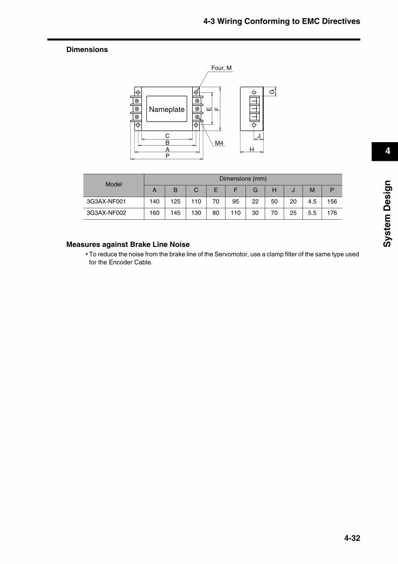
4-3 Wiring Conforming to EMC Directives
4
Sys
tem
Des
ign
Dimensions
Measures against Brake Line Noise To reduce the noise from the brake line of the Servomotor, use a clamp filter of the same type used for the Encoder Cable.
ModelDimensions (mm)
A B C E F G H J M P
3G3AX-NF001 140 125 110 70 95 22 50 20 4.5 156
3G3AX-NF002 160 145 130 80 110 30 70 25 5.5 176
Four, M
M4CBAP
E F
J
H
G
Nameplate
4-32
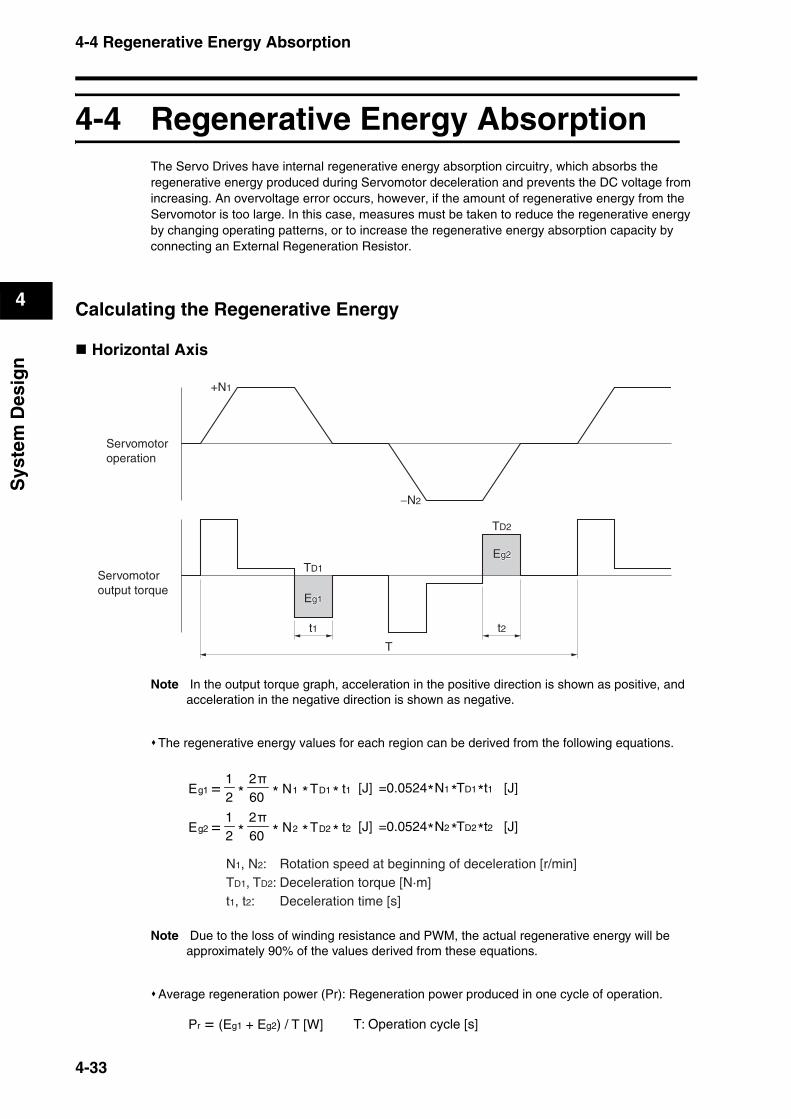
4-4 Regenerative Energy Absorption
4
Sys
tem
Des
ign
4-4 Regenerative Energy AbsorptionThe Servo Drives have internal regenerative energy absorption circuitry, which absorbs the regenerative energy produced during Servomotor deceleration and prevents the DC voltage from increasing. An overvoltage error occurs, however, if the amount of regenerative energy from the Servomotor is too large. In this case, measures must be taken to reduce the regenerative energy by changing operating patterns, or to increase the regenerative energy absorption capacity by connecting an External Regeneration Resistor.
Calculating the Regenerative Energy
Horizontal Axis
Note In the output torque graph, acceleration in the positive direction is shown as positive, and acceleration in the negative direction is shown as negative.
The regenerative energy values for each region can be derived from the following equations.
Note Due to the loss of winding resistance and PWM, the actual regenerative energy will be approximately 90% of the values derived from these equations.
Average regeneration power (Pr): Regeneration power produced in one cycle of operation.
Servomotoroperation
Servomotoroutput torque
+N1
−N2
TD1
TD2
t1 t2
T
Eg1g1Eg1
Eg2g2Eg2
1112
21
t1TNE Dg =60* * * * [J] =0.0524 N1 TD1 t1 [J]* * *
2222
21
t2TNE Dg =60* * * * [J] =0.0524 N2 TD2 t2 [J]* * *
N1, N2: Rotation speed at beginning of deceleration [r/min]TD1, TD2: Deceleration torque [N·m]t1, t2: Deceleration time [s]
Pr = (Eg1 + Eg2) / T [W] T: Operation cycle [s]
4-33
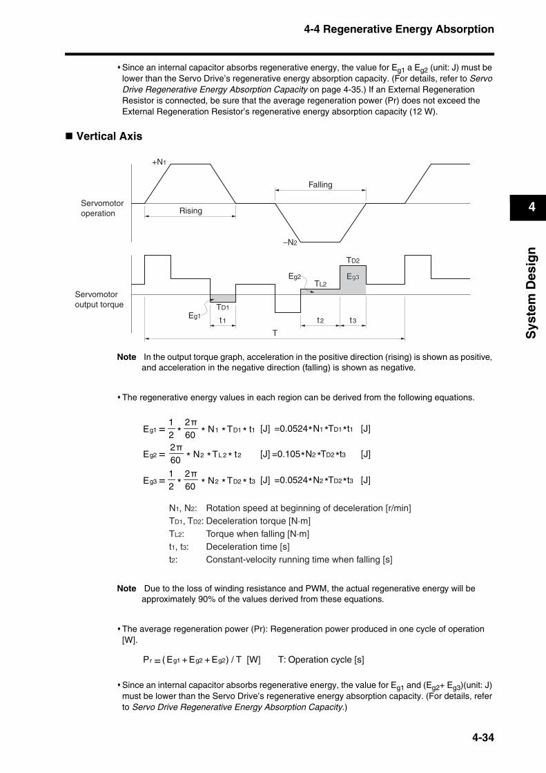
4-4 Regenerative Energy Absorption
4
Sys
tem
Des
ign
Since an internal capacitor absorbs regenerative energy, the value for Eg1 a Eg2 (unit: J) must be lower than the Servo Drive’s regenerative energy absorption capacity. (For details, refer to Servo Drive Regenerative Energy Absorption Capacity on page 4-35.) If an External Regeneration Resistor is connected, be sure that the average regeneration power (Pr) does not exceed the External Regeneration Resistor’s regenerative energy absorption capacity (12 W).
Vertical Axis
Note In the output torque graph, acceleration in the positive direction (rising) is shown as positive, and acceleration in the negative direction (falling) is shown as negative.
The regenerative energy values in each region can be derived from the following equations.
Note Due to the loss of winding resistance and PWM, the actual regenerative energy will be approximately 90% of the values derived from these equations.
The average regeneration power (Pr): Regeneration power produced in one cycle of operation [W].
Since an internal capacitor absorbs regenerative energy, the value for Eg1 and (Eg2+ Eg3)(unit: J) must be lower than the Servo Drive’s regenerative energy absorption capacity. (For details, refer to Servo Drive Regenerative Energy Absorption Capacity.)
Servomotoroperation
Servomotoroutput torque
+N1
−N2
t1 t2 t3
T
Eg1
Eg3g3Eg3
Rising
Falling
TD2
TL2
TD1
Eg2
1112
21
t1TNE Dg =60* * * * [J] =0.0524 N1 TD1 t1 [J]* * *
2232
21
t3TNE Dg =60* * * * [J] =0.0524 N2 TD2 t3 [J]* * *
22222
tTNE Lg =60 * * * [J] =0.105 N2 TD2 t3 [J]* * *
N1, N2: Rotation speed at beginning of deceleration [r/min]TD1, TD2: Deceleration torque [N·m]TL2: Torque when falling [N·m]t1, t3: Deceleration time [s]t2: Constant-velocity running time when falling [s]
2Eg1Eg=Pr ( + ) / T [W] T: Operation cycle [s]2Eg+
4-34
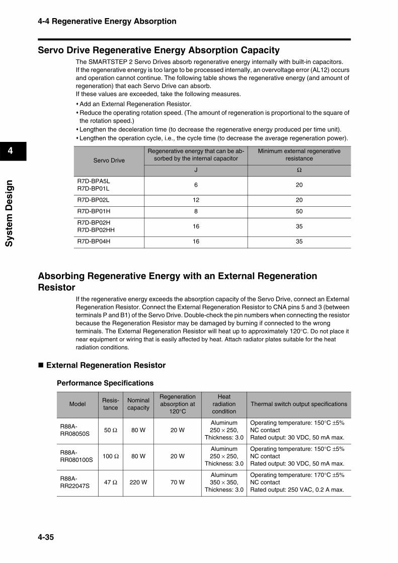
4-4 Regenerative Energy Absorption
4
Sys
tem
Des
ign
Servo Drive Regenerative Energy Absorption CapacityThe SMARTSTEP 2 Servo Drives absorb regenerative energy internally with built-in capacitors.If the regenerative energy is too large to be processed internally, an overvoltage error (AL12) occurs and operation cannot continue. The following table shows the regenerative energy (and amount of regeneration) that each Servo Drive can absorb. If these values are exceeded, take the following measures.
Add an External Regeneration Resistor.Reduce the operating rotation speed. (The amount of regeneration is proportional to the square of the rotation speed.)Lengthen the deceleration time (to decrease the regenerative energy produced per time unit).Lengthen the operation cycle, i.e., the cycle time (to decrease the average regeneration power).
Absorbing Regenerative Energy with an External Regeneration Resistor
If the regenerative energy exceeds the absorption capacity of the Servo Drive, connect an External Regeneration Resistor. Connect the External Regeneration Resistor to CNA pins 5 and 3 (between terminals P and B1) of the Servo Drive. Double-check the pin numbers when connecting the resistor because the Regeneration Resistor may be damaged by burning if connected to the wrong terminals. The External Regeneration Resistor will heat up to approximately 120°C. Do not place it near equipment or wiring that is easily affected by heat. Attach radiator plates suitable for the heat radiation conditions.
External Regeneration Resistor
Performance Specifications
Servo Drive
Regenerative energy that can be ab-sorbed by the internal capacitor
Minimum external regenerative resistance
J Ω
R7D-BPA5LR7D-BP01L
6 20
R7D-BP02L 12 20
R7D-BP01H 8 50
R7D-BP02HR7D-BP02HH
16 35
R7D-BP04H 16 35
ModelResis-tance
Nominalcapacity
Regenerationabsorption at
120°C
Heatradiation condition
Thermal switch output specifications
R88A-RR08050S
50 Ω 80 W 20 WAluminum 250 × 250,
Thickness: 3.0
Operating temperature: 150°C ±5%NC contactRated output: 30 VDC, 50 mA max.
R88A-RR080100S
100 Ω 80 W 20 WAluminum 250 × 250,
Thickness: 3.0
Operating temperature: 150°C ±5%NC contactRated output: 30 VDC, 50 mA max.
R88A-RR22047S
47 Ω 220 W 70 WAluminum 350 × 350,
Thickness: 3.0
Operating temperature: 170°C ±5%NC contactRated output: 250 VAC, 0.2 A max.
4-35
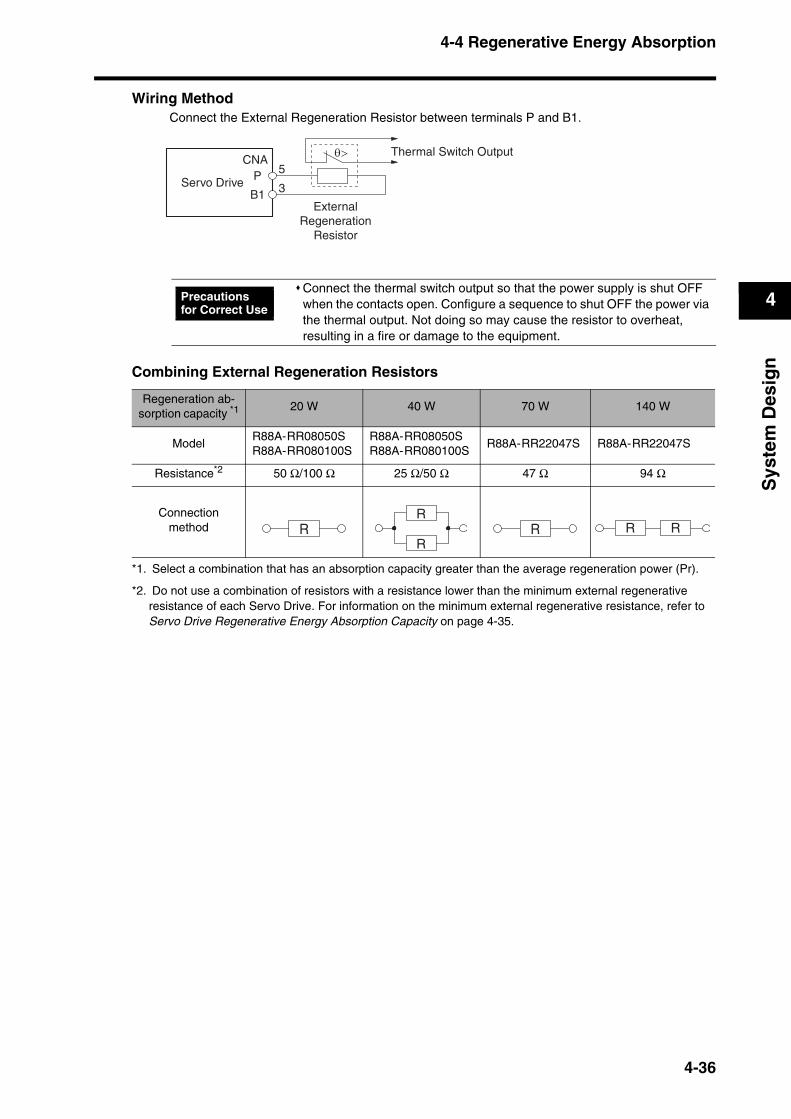
4-4 Regenerative Energy Absorption
4
Sys
tem
Des
ign
Wiring MethodConnect the External Regeneration Resistor between terminals P and B1.
Combining External Regeneration Resistors
Connect the thermal switch output so that the power supply is shut OFF when the contacts open. Configure a sequence to shut OFF the power via the thermal output. Not doing so may cause the resistor to overheat, resulting in a fire or damage to the equipment.
Regeneration ab-sorption capacity *1
*1. Select a combination that has an absorption capacity greater than the average regeneration power (Pr).
20 W 40 W 70 W 140 W
ModelR88A-RR08050SR88A-RR080100S
R88A-RR08050SR88A-RR080100S
R88A-RR22047S R88A-RR22047S
Resistance*2
*2. Do not use a combination of resistors with a resistance lower than the minimum external regenerative resistance of each Servo Drive. For information on the minimum external regenerative resistance, refer to Servo Drive Regenerative Energy Absorption Capacity on page 4-35.
50 Ω/100 Ω 25 Ω/50 Ω 47 Ω 94 Ω
Connection method
P
B1
5
3
CNAθ> Thermal Switch Output
Servo Drive
ExternalRegeneration
Resistor
Precautions for Correct Use
RR
RR R R
4-36

Chapter 5
Operating Functions5-1 Position Control .................................................5-1
High-Response Position Control vs. Advanced Position Control .....................................................................................5-1
Parameters Requiring Settings ................................................5-1
Related Parameters .................................................................5-2
Parameter Block Diagram for Position Control Mode ..............5-3
5-2 Internally Set Speed Control .............................5-4Parameters Requiring Settings ................................................5-4
Related Parameters .................................................................5-4
Selecting the Internally Set Speeds .........................................5-5
Operation .................................................................................5-5
Parameter Block Diagram for Internally Set Speed Control Mode ........................................................................................5-6
5-3 Forward and Reverse Drive Prohibit ................5-7Parameters Requiring Settings ................................................5-7
Operation .................................................................................5-7
5-4 Encoder Dividing................................................5-8Parameters Requiring Setting..................................................5-8
Operation .................................................................................5-8
5-5 Electronic Gear...................................................5-9Parameters Requiring Settings ................................................5-9
Operation .................................................................................5-9
Related Parameter.................................................................5-10
5-6 Brake Interlock .................................................5-11Parameters Requiring Setting................................................5-11
Operation ...............................................................................5-11
5-7 Gain Switching .................................................5-13Parameters Requiring Setting................................................5-13
Related Parameters ...............................................................5-14
5-8 Torque Limit .....................................................5-15Parameters Requiring Setting................................................5-15
Related Parameters ...............................................................5-15
5-9 Overrun Limit....................................................5-16Parameters Requiring Settings ..............................................5-16
Operation ...............................................................................5-16
5-10 User Parameters...............................................5-17Setting and Checking Parameters .........................................5-17
Parameter List........................................................................5-20
Parameter Details ..................................................................5-32

5-1 Position Control
5
Op
erat
ing
Fu
nct
ion
s
5Operating Functions
5-1 Position ControlPositioning can be performed according to the pulses input into the pulse-string inputs (CN1-22 to 25).The Servomotor rotates using the value of the pulse-string inputs multiplied by the value of the electronic gear (Pn46, Pn47, Pn4A, and Pn4B). SMARTSTEP2 Series Servo Drives have two position control modes: high-response position control and advanced position control. Select the mode better suited for your operational conditions.
High-Response Position Control vs. Advanced Position ControlThe two position control modes have the following differences.
The Notch Filter 1 Frequency, Vibration Frequency, and Realtime Autotuning Mode Selection cannot be used at the same time in high-response position control mode. The parameter entered first will be given priority.
Example: When the Realtime Autotuning Mode Selection is set, the Servo Drive will be forcibly set to 1500 (disabled), even if the Notch Filter 1 Frequency is input.
The adaptive filter will be disabled under high-response position control. To use the adaptive filter, select the advanced position control mode.
Parameters Requiring Settings
Notch Filter 1 Frequency (Pn1D)
Vibration Frequency (Pn2B)
Realtime Autotun-ing Mode Selec-
tion (Pn21)
Adaptive Filter Table Number Display (Pn2F)
High-Response Position Control
Conditional Conditional Conditional Disabled
Advanced Position Control
Enabled Enabled Enabled Enabled
ParameterNo.
Parameter name Explanation Reference
Pn02Control Mode Selection
Select a control mode for position control (setting: 0 or 2).Page 5-33
Pn42Command Pulse Mode
Set to match the command pulse form of the controller.Page 5-49
Pn46Electronic Gear Ratio Numerator 1
Set the pulse rate for command pulses and Servomotor travel amount.
The maximum value of the calculated numerator is 2,621,440.
Page 5-50Pn4AElectronic Gear Ratio Numerator Exponent
Pn4BElectronic Gear Ratio Denominator
Pn60Positioning Completion Range
The Positioning Completed Output (INP) turns ON when the number of pulses in the deviation counter is equal to or less than the setting of this parameter.
Page 5-55
Electronic Gear Ratio Numerator 1 (Pn46) x 2 Electronic Gear Ratio Numerator Exponent (Pn4A)
Electronic Gear Ratio Denominator (Pn4B)
5-1
5-1 Position Control
5
Op
erat
ing
Fu
nct
ion
s
Related ParametersThe main functions provided by the parameters related to position control are described in the following table.
Reference The Control Mode Selection (Pn02) is set as follows.
To perform position control, select 0 (high-response position control) or 2 (advanced position control) for the control mode.
Setting Control mode
0 High-Response Position Control
1 Internally Set Speed Control
2 Advanced Position Control
Function Explanation Reference
Gain Switching
The Gain Switching Input (GSEL) is used when the Zero Speed Designation/Torque Limit Switch (Pn06) is set to a value other than 2. The Gain Switching Input is used to switch between PI and P operation or to switch between gain 1 and gain 2.
Page 5-13
Torque Limit Switch
The Torque Limit Switch Input (TLSEL) is used when the Zero Speed Desig-nation/Torque Limit Switch (Pn06) is set to 2. The following parameters are switched: Overspeed Detection Level, Torque Limit, and Deviation Counter Overflow Level.
Page 5-15
Damping ControlDamping control can be used to reduce vibration when using a low-rigidity mechanism or equipment whose ends tend to vibrate.
Page 7-23
Realtime Autotuning
Autotuning automatically estimates the load inertia of the machine in realtime and sets the optimal gain. The adaptive filter automatically suppresses vibra-tion caused by resonance.
Page 7-3
5-2
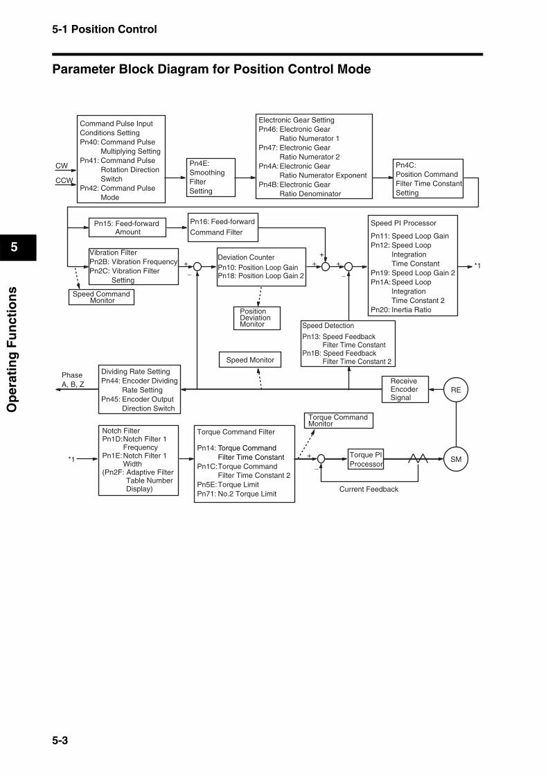
5-1 Position Control
5
Op
erat
ing
Fu
nct
ion
s
Parameter Block Diagram for Position Control Mode
CW
CCW
++
++
+
Command Pulse Input Conditions SettingPn40: Command Pulse Multiplying SettingPn41: Command Pulse Rotation Direction SwitchPn42: Command Pulse Mode
Electronic Gear SettingPn46: Electronic Gear Ratio Numerator 1Pn47: Electronic Gear Ratio Numerator 2Pn4A: Electronic Gear Ratio Numerator ExponentPn4B: Electronic Gear Ratio Denominator
Pn4E:Smoothing FilterSetting
Pn4C:Position CommandFilter Time ConstantSetting
Pn15: Feed-forward Amount
Pn16: Feed-forward
Command Filter
RE
SM
Dividing Rate SettingPn44: Encoder Dividing Rate SettingPn45: Encoder Output Direction Switch
PhaseA, B, Z
Speed Monitor
Torque Command Monitor
Speed Detection
Pn13: Speed Feedback Filter Time Constant
Pn1B: Speed Feedback Filter Time Constant 2
Torque PI Processor
Current Feedback
Receive Encoder Signal
−
−
−
Notch FilterPn1D: Notch Filter 1 FrequencyPn1E: Notch Filter 1 Width(Pn2F: Adaptive Filter
Table Number Display)
Torque Command Filter
Pn14: Torque Command Filter Time ConstantPn1C: Torque Command Filter Time Constant 2
*1
*1
Speed PI Processor
Pn11: Speed Loop GainPn12: Speed Loop Integration Time ConstantPn19: Speed Loop Gain 2Pn1A: Speed Loop Integration Time Constant 2Pn20: Inertia RatioPosition
Deviation Monitor
Deviation CounterPn10: Position Loop GainPn18: Position Loop Gain 2
Vibration FilterPn2B: Vibration FrequencyPn2C: Vibration Filter
Setting
Speed Command Monitor
Pn5E: Torque LimitPn71: No.2 Torque Limit
5-3

5-2 Internally Set Speed Control
5
Op
erat
ing
Fu
nct
ion
s
5-2 Internally Set Speed ControlThe speed of the Servomotor can be controlled using the speeds set in the No. 1 to 4 Internal Speed Setting parameters.
After the RUN Command Input (RUN) is turned ON and then the Zero Speed Designation Input (VZERO) is turned ON, the Servomotor will accelerate according to the Soft Start Acceleration Time (Pn58). When the Zero Speed Designation Input (VZERO) is turned OFF, the Servomotor will decelerate to a stop according to the Soft Start Deceleration Time (Pn59).
Switching between the internally set speeds is controlled by the Internally Set Speed Selection 1 and 2 Inputs (VSEL1: CN1-6, VSEL2: CN1-4).
Parameters Requiring Settings
Related ParametersThe main functions provided by the parameters related to Internally Set Speed Control are described in the following table.
ParameterNo.
Parameter name Explanation Reference
Pn02Control Mode Selection
Select the control mode for internally set speeds (setting: 1).Page 5-33
Pn06
Zero-speed Designation/Torque Limit Switch
Always enable the zero-speed designation when internally set speeds are used (setting: 1).
Page 5-34
Pn53No. 1 Internal Speed Setting
Set the internally set speeds (r/min). The settings can be made from −20,000 to 20,000 r/min. Be sure to set the speeds within the allowable range of rotation speed of the Servomotor.
Page 5-53
Pn54No. 2 Internal Speed Setting
Pn55No. 3 Internal Speed Setting
Pn56No. 4 Internal Speed Setting
Pn58Soft Start Acceleration Time
Set the acceleration time for Internally Set Speed Control. Set the time (setting × 2 ms) until 1,000 r/min is reached.
Page 5-53
Pn59Soft Start Deceleration Time
Set the deceleration time for Internally Set Speed Control. Set the time (setting × 2 ms) until operation stops from 1,000 r/min.
Function Explanation Reference
Torque Limit Switch
The Torque Limit Switch Input (TLSEL) is used when the Zero Speed Desig-nation/Torque Limit Switch (Pn06) is set to 2. The following parameters are switched: Overspeed Detection Level, Torque Limit, and Deviation Counter Overflow Level.
Page 5-15
Zero Speed Detection
The Zero Speed Detection Signal will be output if the speed of the Servomotor falls below the setting of this parameter. The Warning Output Selection (Pn09) must be set to 1 to use this function.
Page 5-55
Motor Rotation Detection
The Servomotor Rotation Speed Detection Output (TGON) will be output if the speed of the Servomotor exceeds the setting of this parameter.
Page 5-56
5-4
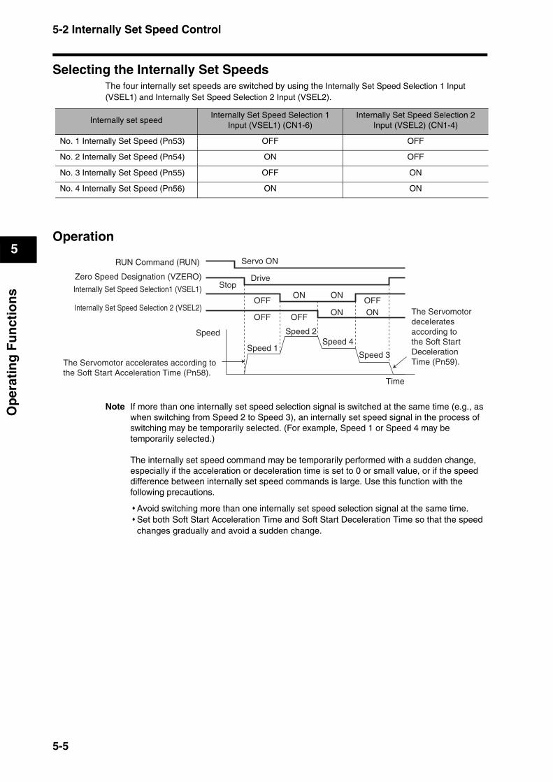
5-2 Internally Set Speed Control
5
Op
erat
ing
Fu
nct
ion
s
Selecting the Internally Set SpeedsThe four internally set speeds are switched by using the Internally Set Speed Selection 1 Input (VSEL1) and Internally Set Speed Selection 2 Input (VSEL2).
Operation
Note If more than one internally set speed selection signal is switched at the same time (e.g., as when switching from Speed 2 to Speed 3), an internally set speed signal in the process of switching may be temporarily selected. (For example, Speed 1 or Speed 4 may be temporarily selected.)
The internally set speed command may be temporarily performed with a sudden change, especially if the acceleration or deceleration time is set to 0 or small value, or if the speed difference between internally set speed commands is large. Use this function with the following precautions.
Avoid switching more than one internally set speed selection signal at the same time.Set both Soft Start Acceleration Time and Soft Start Deceleration Time so that the speed changes gradually and avoid a sudden change.
Internally set speedInternally Set Speed Selection 1
Input (VSEL1) (CN1-6)Internally Set Speed Selection 2
Input (VSEL2) (CN1-4)
No. 1 Internally Set Speed (Pn53) OFF OFF
No. 2 Internally Set Speed (Pn54) ON OFF
No. 3 Internally Set Speed (Pn55) OFF ON
No. 4 Internally Set Speed (Pn56) ON ON
RUN Command (RUN)
Zero Speed Designation (VZERO)
Internally Set Speed Selection1 (VSEL1)
Internally Set Speed Selection 2 (VSEL2)
Speed
Time
Servo ON
StopDrive
Speed 1
Speed 2
Speed 3
Speed 4
The Servomotor accelerates according tothe Soft Start Acceleration Time (Pn58).
The Servomotor decelerates according tothe Soft Start Deceleration Time (Pn59).
OFF OFF
OFFON ON
ON ON
OFF
5-5
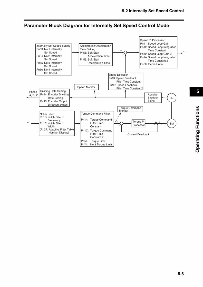
5-2 Internally Set Speed Control
5
Op
erat
ing
Fu
nct
ion
s
Parameter Block Diagram for Internally Set Speed Control Mode
+
+
Internally Set Speed SettingPn53: No.1 Internally Set SpeedPn54: No.2 Internally Set SpeedPn55: No.3 Internally Set SpeedPn56: No.4 Internally Set Speed
Acceleration/DecelerationTime SettingPn58: Soft Start Acceleration TimePn59: Soft Start Deceleration Time
Speed PI ProcessorPn11: Speed Loop GainPn12: Speed Loop Integration Time ConstantPn19: Speed Loop Gain 2Pn1A: Speed Loop Integration Time Constant 2Pn20: Inertia Ratio
RE
SM
Dividing Rate SettingPn44: Encoder Dividing Rate SettingPn45: Encoder Output Direction Switch
PhaseA, B, Z
Speed Monitor
Torque CommandMonitor
Speed DetectionPn13: Speed Feedback
Filter Time ConstantPn1B: Speed Feedback
Filter Time Constant 2
Torque PI Processor
Current Feedback
Receive EncoderSignal
−
−
Torque Command Filter
Pn14: Torque Command Filter Time Constant
Pn1C: Torque Command Filter Time Constant 2
Pn5E: Torque LimitPn71: No.2 Torque Limit
*1
*1
Notch FilterPn1D: Notch Filter 1 FrequencyPn1E: Notch Filter 1 Width(Pn2F: Adaptive Filter Table
Number Display)
5-6
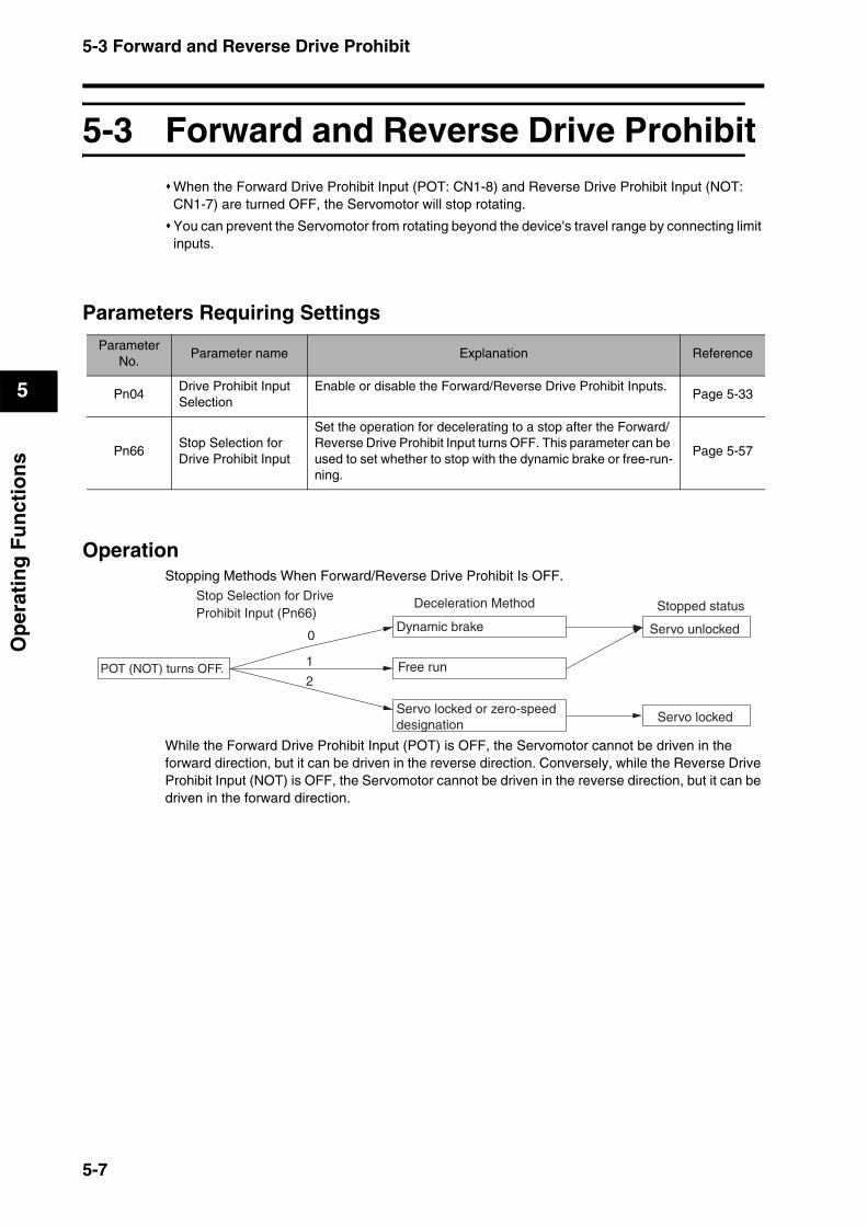
5-3 Forward and Reverse Drive Prohibit
5
Op
erat
ing
Fu
nct
ion
s
5-3 Forward and Reverse Drive ProhibitWhen the Forward Drive Prohibit Input (POT: CN1-8) and Reverse Drive Prohibit Input (NOT: CN1-7) are turned OFF, the Servomotor will stop rotating.
You can prevent the Servomotor from rotating beyond the device's travel range by connecting limit inputs.
Parameters Requiring Settings
OperationStopping Methods When Forward/Reverse Drive Prohibit Is OFF.
While the Forward Drive Prohibit Input (POT) is OFF, the Servomotor cannot be driven in the forward direction, but it can be driven in the reverse direction. Conversely, while the Reverse Drive Prohibit Input (NOT) is OFF, the Servomotor cannot be driven in the reverse direction, but it can be driven in the forward direction.
ParameterNo.
Parameter name Explanation Reference
Pn04Drive Prohibit Input Selection
Enable or disable the Forward/Reverse Drive Prohibit Inputs.Page 5-33
Pn66Stop Selection for Drive Prohibit Input
Set the operation for decelerating to a stop after the Forward/Reverse Drive Prohibit Input turns OFF. This parameter can be used to set whether to stop with the dynamic brake or free-run-ning.
Page 5-57
POT (NOT) turns OFF.
Deceleration Method Stopped status
2
Servo locked or zero-speed designation
1
0Dynamic brake
Free run
Servo unlocked
Servo locked
Stop Selection for Drive Prohibit Input (Pn66)
5-7
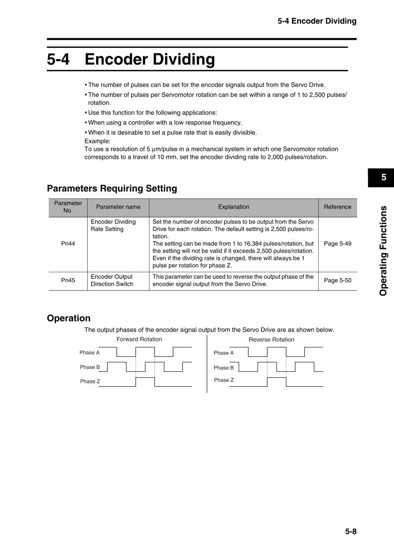
5-4 Encoder Dividing
5
Op
erat
ing
Fu
nct
ion
s
5-4 Encoder DividingThe number of pulses can be set for the encoder signals output from the Servo Drive.
The number of pulses per Servomotor rotation can be set within a range of 1 to 2,500 pulses/rotation.
Use this function for the following applications:
When using a controller with a low response frequency.
When it is desirable to set a pulse rate that is easily divisible.Example:To use a resolution of 5 µm/pulse in a mechanical system in which one Servomotor rotation corresponds to a travel of 10 mm, set the encoder dividing rate to 2,000 pulses/rotation.
Parameters Requiring Setting
OperationThe output phases of the encoder signal output from the Servo Drive are as shown below.
ParameterNo.
Parameter name Explanation Reference
Pn44
Encoder Dividing Rate Setting
Set the number of encoder pulses to be output from the Servo Drive for each rotation. The default setting is 2,500 pulses/ro-tation.The setting can be made from 1 to 16,384 pulses/rotation, but the setting will not be valid if it exceeds 2,500 pulses/rotation.Even if the dividing rate is changed, there will always be 1 pulse per rotation for phase Z.
Page 5-49
Pn45Encoder Output Direction Switch
This parameter can be used to reverse the output phase of the encoder signal output from the Servo Drive.
Page 5-50
Forward Rotation Reverse Rotation
Phase APhase A
Phase B
Phase Z
Phase B
Phase Z
5-8
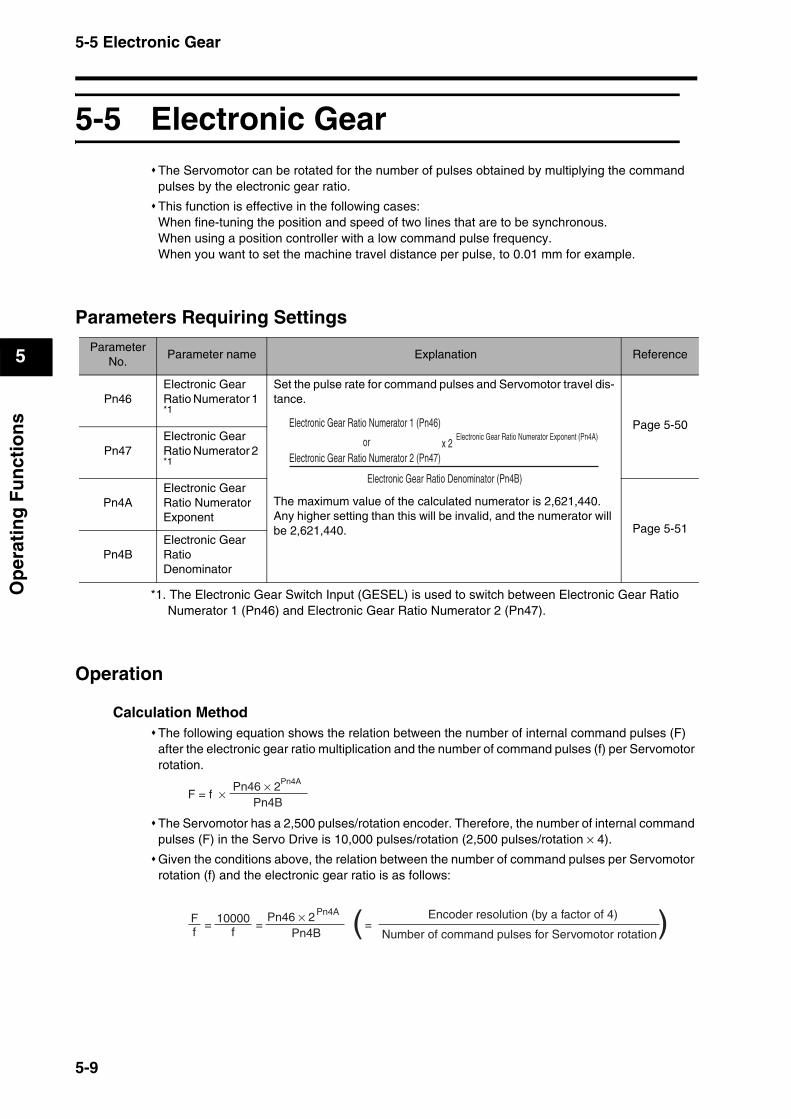
5-5 Electronic Gear
5
Op
erat
ing
Fu
nct
ion
s
5-5 Electronic GearThe Servomotor can be rotated for the number of pulses obtained by multiplying the command pulses by the electronic gear ratio.
This function is effective in the following cases:When fine-tuning the position and speed of two lines that are to be synchronous.When using a position controller with a low command pulse frequency.When you want to set the machine travel distance per pulse, to 0.01 mm for example.
Parameters Requiring Settings
*1. The Electronic Gear Switch Input (GESEL) is used to switch between Electronic Gear Ratio Numerator 1 (Pn46) and Electronic Gear Ratio Numerator 2 (Pn47).
Operation
Calculation MethodThe following equation shows the relation between the number of internal command pulses (F) after the electronic gear ratio multiplication and the number of command pulses (f) per Servomotor rotation.
The Servomotor has a 2,500 pulses/rotation encoder. Therefore, the number of internal command pulses (F) in the Servo Drive is 10,000 pulses/rotation (2,500 pulses/rotation × 4).
Given the conditions above, the relation between the number of command pulses per Servomotor rotation (f) and the electronic gear ratio is as follows:
ParameterNo.
Parameter name Explanation Reference
Pn46Electronic Gear Ratio Numerator 1 *1
Set the pulse rate for command pulses and Servomotor travel dis-tance.
The maximum value of the calculated numerator is 2,621,440. Any higher setting than this will be invalid, and the numerator will be 2,621,440.
Page 5-50
Pn47Electronic Gear Ratio Numerator 2 *1
Pn4AElectronic Gear Ratio Numerator Exponent
Page 5-51
Pn4BElectronic Gear Ratio Denominator
Electronic Gear Ratio Denominator (Pn4B)
x 2Electronic Gear Ratio Numerator Exponent (Pn4A)
Electronic Gear Ratio Numerator 1 (Pn46)
orElectronic Gear Ratio Numerator 2 (Pn47)
F = f ×Pn4B
Pn46 × 2Pn4A
=Pn4B
Pn46 × 2Pn4AFf
10000f
= ( )=Encoder resolution (by a factor of 4)
Number of command pulses for Servomotor rotation
5-9
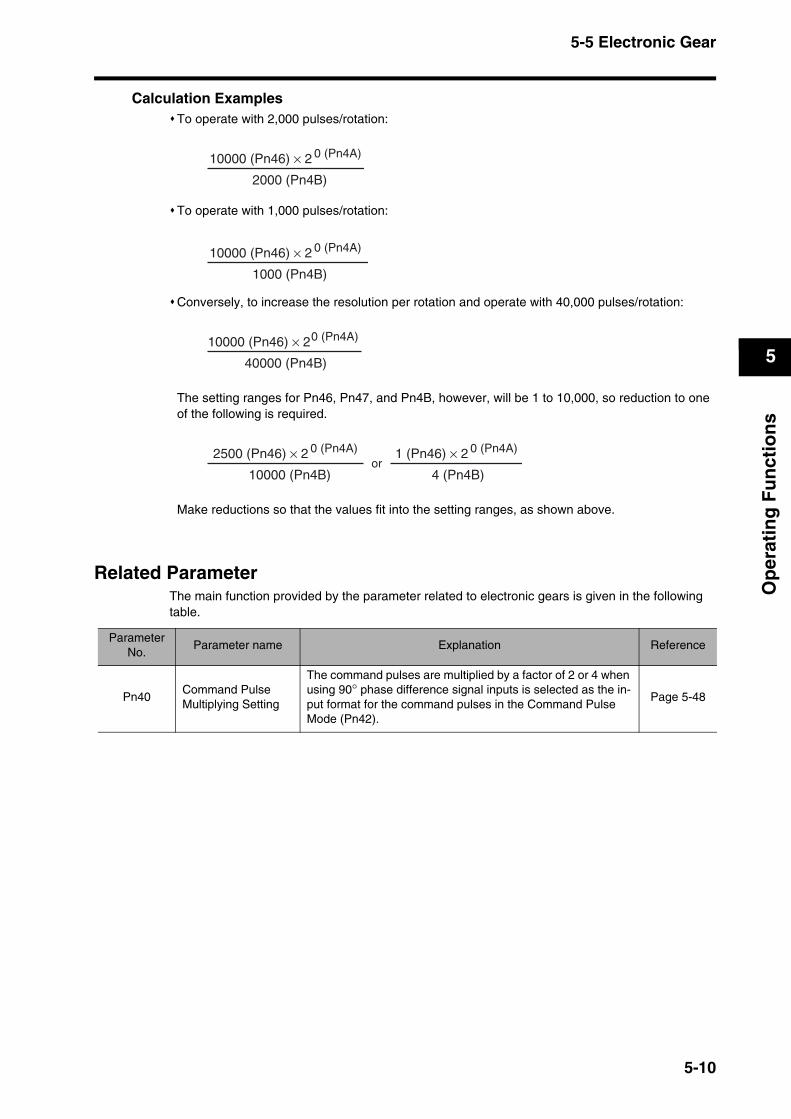
5-5 Electronic Gear
5
Op
erat
ing
Fu
nct
ion
s
Calculation ExamplesTo operate with 2,000 pulses/rotation:
To operate with 1,000 pulses/rotation:
Conversely, to increase the resolution per rotation and operate with 40,000 pulses/rotation:
The setting ranges for Pn46, Pn47, and Pn4B, however, will be 1 to 10,000, so reduction to one of the following is required.
Make reductions so that the values fit into the setting ranges, as shown above.
Related ParameterThe main function provided by the parameter related to electronic gears is given in the following table.
10000 (Pn46) × 2 0 (Pn4A)
2000 (Pn4B)
10000 (Pn46) × 2 0 (Pn4A)
1000 (Pn4B)
10000 (Pn46) × 20 (Pn4A)
40000 (Pn4B)
2500 (Pn46) × 2 0 (Pn4A)
10000 (Pn4B)
1 (Pn46) × 2 0 (Pn4A)
4 (Pn4B)or
ParameterNo.
Parameter name Explanation Reference
Pn40Command Pulse Multiplying Setting
The command pulses are multiplied by a factor of 2 or 4 when using 90° phase difference signal inputs is selected as the in-put format for the command pulses in the Command Pulse Mode (Pn42).
Page 5-48
5-10
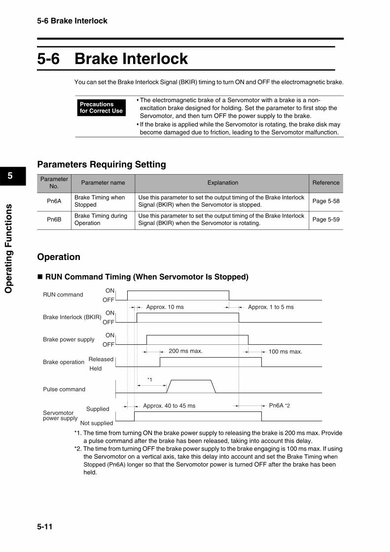
5-6 Brake Interlock
5
Op
erat
ing
Fu
nct
ion
s
5-6 Brake InterlockYou can set the Brake Interlock Signal (BKIR) timing to turn ON and OFF the electromagnetic brake.
Parameters Requiring Setting
Operation
RUN Command Timing (When Servomotor Is Stopped)
*1. The time from turning ON the brake power supply to releasing the brake is 200 ms max. Provide a pulse command after the brake has been released, taking into account this delay.
*2. The time from turning OFF the brake power supply to the brake engaging is 100 ms max. If using the Servomotor on a vertical axis, take this delay into account and set the Brake Timing when Stopped (Pn6A) longer so that the Servomotor power is turned OFF after the brake has been held.
The electromagnetic brake of a Servomotor with a brake is a non-excitation brake designed for holding. Set the parameter to first stop the Servomotor, and then turn OFF the power supply to the brake.If the brake is applied while the Servomotor is rotating, the brake disk may become damaged due to friction, leading to the Servomotor malfunction.
ParameterNo.
Parameter name Explanation Reference
Pn6ABrake Timing when Stopped
Use this parameter to set the output timing of the Brake Interlock Signal (BKIR) when the Servomotor is stopped.
Page 5-58
Pn6BBrake Timing during Operation
Use this parameter to set the output timing of the Brake Interlock Signal (BKIR) when the Servomotor is rotating.
Page 5-59
Precautions for Correct Use
RUN commandON
OFF
ON
OFF
ON
OFF
Brake Interlock (BKIR)
Brake power supply
Brake operation
Pulse command
Servomotor power supply
Released
Held
Supplied
Not supplied
100 ms max.
Approx. 10 ms
200 ms max.
Approx. 40 to 45 ms
Approx. 1 to 5 ms
*1
Pn6A *2
5-11

5-6 Brake Interlock
5
Op
erat
ing
Fu
nct
ion
s
RUN Command, Errors, and Power Supply Timing (When Servomotor Is Rotating)
*1. This time is the shorter value of either the setting for the Brake Timing during Operation (Pn6B) or the time it takes until the Servomotor rotation speed drops to 30 r/min or lower. Depending on the holding time of the power supply, this time may be shorter than the value set in Pn6B.
ON
OFF
ON
OFF
ON
OFF
ON
OFF
Power supply
RUN command
Alarm output (/ALM)
Bbrake interlock (BKIR)
Servomotor power supply
Supplied
Not supplied
*1
Approx. 1 to 5 ms
5-12

5-7 Gain Switching
5
Op
erat
ing
Fu
nct
ion
s
5-7 Gain SwitchingIn Position Control Mode, you can switch between PI (proportional and integral) operation and P (proportional) operation, or between gain 1 and gain 2.
With PI/P operation switching, the repulsion to external forces applied to the load can be weakened by eliminating the integral of the speed deviation (i.e., the difference between the speed command and speed feedback).
Gain 1/gain 2 switching is effective in the following cases:Reducing the gain to suppress vibration caused by changes in load inertia during operation.Reducing the gain to suppress vibration due to an increase in speed.Increasing responsiveness by increasing the gain during operation.Increasing servo lock rigidity by increasing the gain when stopping.Reducing the gain to suppress vibration when stopping.
Parameters Requiring Setting
*1. These settings are disabled when the Gain Switch Setting (Pn31) is set to always use gain1 or gain 2 or set to the Gain Switching Input (CN1-5).
ParameterNo.
Parameter name Explanation Reference
Pn30Gain Switching Input Operating Mode Selection
Select whether to use PI/P operation switching or gain 1/gain 2 switching in Position Control Mode.
Page 5-44
Pn31 Gain Switch Setting Select the condition for switching between gain 1 and gain 2. Page 5-44
Pn32 Gain Switch Time *1Set the delay time from the moment the condition set in the Gain Switch Setting (Pn31) is not met until returning to gain 1.
Page 5-46Pn33Gain Switch Level Setting *1
Set the judgment level for switching between gain 1 and gain 2. The unit for the setting depends on the condition set in the Gain Switch Setting (Pn31).
Pn34Gain Switch Hysteresis Setting
Set the hysteresis width above and below the judgment level set in the Gain Switch Level Setting (Pn33).
Pn35Position Loop Gain Switching Time
When switching between gain 1 and gain 2 is enabled, set the phased switching time only for the position loop gain at gain switching.
Page 5-47
5-13
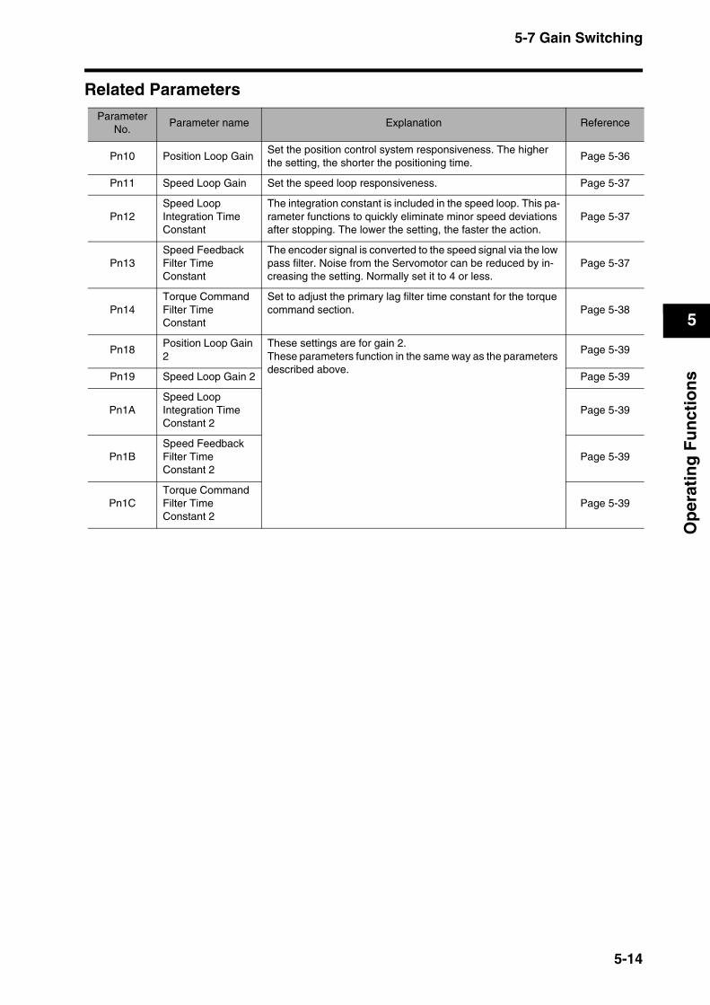
5-7 Gain Switching
5
Op
erat
ing
Fu
nct
ion
s
Related ParametersParameter
No. Parameter name Explanation Reference
Pn10 Position Loop GainSet the position control system responsiveness. The higher the setting, the shorter the positioning time.
Page 5-36
Pn11 Speed Loop Gain Set the speed loop responsiveness. Page 5-37
Pn12Speed Loop Integration Time Constant
The integration constant is included in the speed loop. This pa-rameter functions to quickly eliminate minor speed deviations after stopping. The lower the setting, the faster the action.
Page 5-37
Pn13Speed Feedback Filter Time Constant
The encoder signal is converted to the speed signal via the low pass filter. Noise from the Servomotor can be reduced by in-creasing the setting. Normally set it to 4 or less.
Page 5-37
Pn14Torque Command Filter Time Constant
Set to adjust the primary lag filter time constant for the torque command section. Page 5-38
Pn18Position Loop Gain 2
These settings are for gain 2.These parameters function in the same way as the parameters described above.
Page 5-39
Pn19 Speed Loop Gain 2 Page 5-39
Pn1ASpeed Loop Integration Time Constant 2
Page 5-39
Pn1BSpeed Feedback Filter Time Constant 2
Page 5-39
Pn1CTorque Command Filter Time Constant 2
Page 5-39
5-14

5-8 Torque Limit
5
Op
erat
ing
Fu
nct
ion
s
5-8 Torque LimitThis function limits the output torque of the Servomotor.
This function is effective in the following cases:Pressing a moving part of a machine (such as a bending machine) against a workpiece with a constant force.Protecting the Servomotor and mechanical system from excessive force or torque.
The Warning Output Selection (Pn09) can be set to output an alarm to the Warning Output (WARN) when the torque limit function is enabled.
Two torque limits can be set and you can switch between them. To switch the torque limit setting, enable the Torque Limit Switch Input (TLSEL) in the Zero Speed Designation/Torque Limit Switch (Pn06).
Parameters Requiring Setting
*1. Values exceeding the default setting cannot be set. The default setting depends on the combination of the Servomotor and Servo Drive.
*2. The Overspeed Detection Level Setting (Pn70) will function only when torque limit switching function is enabled.
Related ParametersThe following parameters must be set to use torque limit switching function.
*1. Values exceeding the default setting cannot be set. The default setting depends on the combination of Servomotor and Servo Drive.
*2. The No. 2 Overspeed Detection Level Setting (Pn73) will function only when torque limit switching function is enabled.
Parameter No.
Parameter name Explanation Reference
Pn5E Torque Limit *1Set the torque limit as a percentage of the maximum torque of the Servomotor.
Page 5-54
Pn63Deviation Counter Overflow Level
Set the alarm detection level for deviation counter overflow.Page 5-56
Pn70Overspeed Detection Level Setting *2
An overspeed alarm will occur if the Servomotor rotation speed exceeds the setting of this parameter. Page 5-60
Parameter No.
Parameter name Explanation Reference
Pn71 No. 2 Torque Limit *1 These parameters are set when using the No. 2 torque limit. These parameters function in the same way as the parameters described above.
Page 5-60Pn72
No. 2 Deviation Counter Overflow Level
Pn73No. 2 Overspeed Detection Level Setting *2
5-15
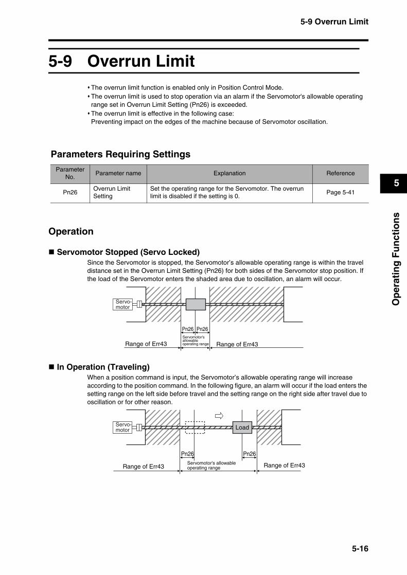
5-9 Overrun Limit
5
Op
erat
ing
Fu
nct
ion
s
5-9 Overrun LimitThe overrun limit function is enabled only in Position Control Mode.The overrun limit is used to stop operation via an alarm if the Servomotor's allowable operating range set in Overrun Limit Setting (Pn26) is exceeded.The overrun limit is effective in the following case:Preventing impact on the edges of the machine because of Servomotor oscillation.
Parameters Requiring Settings
Operation
Servomotor Stopped (Servo Locked)Since the Servomotor is stopped, the Servomotor’s allowable operating range is within the travel distance set in the Overrun Limit Setting (Pn26) for both sides of the Servomotor stop position. If the load of the Servomotor enters the shaded area due to oscillation, an alarm will occur.
In Operation (Traveling)When a position command is input, the Servomotor’s allowable operating range will increase according to the position command. In the following figure, an alarm will occur if the load enters the setting range on the left side before travel and the setting range on the right side after travel due to oscillation or for other reason.
ParameterNo.
Parameter name Explanation Reference
Pn26Overrun Limit Setting
Set the operating range for the Servomotor. The overrun limit is disabled if the setting is 0.
Page 5-41
Pn26
Range of Err43 Range of Err43
Pn26
Servo- motor
Servomotor's allowable operating range
Load
Pn26 Pn26
Range of Err43 Range of Err43
Servo- motor
Servomotor's allowable operating range
5-16
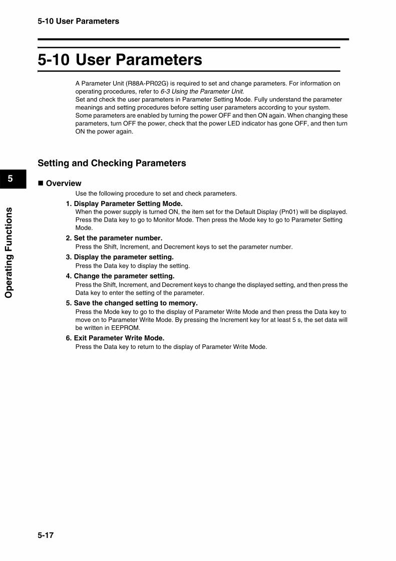
5-10 User Parameters
5
Op
erat
ing
Fu
nct
ion
s
5-10 User ParametersA Parameter Unit (R88A-PR02G) is required to set and change parameters. For information on operating procedures, refer to 6-3 Using the Parameter Unit.Set and check the user parameters in Parameter Setting Mode. Fully understand the parameter meanings and setting procedures before setting user parameters according to your system. Some parameters are enabled by turning the power OFF and then ON again. When changing these parameters, turn OFF the power, check that the power LED indicator has gone OFF, and then turn ON the power again.
Setting and Checking Parameters
OverviewUse the following procedure to set and check parameters.
1. Display Parameter Setting Mode.When the power supply is turned ON, the item set for the Default Display (Pn01) will be displayed. Press the Data key to go to Monitor Mode. Then press the Mode key to go to Parameter Setting Mode.
2. Set the parameter number.Press the Shift, Increment, and Decrement keys to set the parameter number.
3. Display the parameter setting.Press the Data key to display the setting.
4. Change the parameter setting.Press the Shift, Increment, and Decrement keys to change the displayed setting, and then press the Data key to enter the setting of the parameter.
5. Save the changed setting to memory.Press the Mode key to go to the display of Parameter Write Mode and then press the Data key to move on to Parameter Write Mode. By pressing the Increment key for at least 5 s, the set data will be written in EEPROM.
6. Exit Parameter Write Mode.Press the Data key to return to the display of Parameter Write Mode.
5-17

5-10 User Parameters
5
Op
erat
ing
Fu
nct
ion
s
Operating Procedures
1. Displaying Parameter Setting Mode
2. Setting the Parameter Number
3. Displaying the Parameter Setting
4. Changing the Parameter Setting
Key opera-tion
Display example Explanation
The item set for the Default Display (Pn01) is displayed.
Press the Data key to display Monitor Mode.
Press the Mode key to display Parameter Setting Mode.
Key operation Display example Explanation
Use the Shift, Increment, and Decrement keys to set the parameter num-ber.If the parameter number is too high, you can change the parameter number faster by using the Shift key to change the digit. The decimal point will flash for the digit that can be set.
Key operation Display example Explanation
Press the Data key to display the setting of the parameter.
Key operation Display example Explanation
Use the Shift, Increment, and Decrement keys to change the setting.
Press the Data key to save the new setting.
rk k k k k0k
Uknk_kskpkd.
pknk_krk0k0.
pknk_k k1k0.
k k k k4k0.
k k k1k0k0.
k k k1k0k0.
5-18

5-10 User Parameters
5
Op
erat
ing
Fu
nct
ion
s
5. Saving the New Setting to Memory
6. Returning to the Display of Parameter Write Mode
Key operation Display example Explanation
Press the Mode key to display Parameter Write Mode.
Press the Data key to move on to Parameter Write Mode.
Press the Increment key for at least 5 s.
The bar indicator will appear.
Writing will start. (This display will appear only momentarily.)
This display indicates a normal completion. In addition to “Finish,” either or may be displayed.
If is displayed, writing has been completed normally, but some of the changed parameters will be enabled only after the power is turned ON again. Turn OFF the Servo Drive power supply and then turn it ON again.If is displayed, there is a writing error. Write the data again.
ekek_kskektk
ekekpk k k-.
ekekpk k-k-.
-k-k-k-k-k-.
sktkakrktk k
f i n i s h .
reset . e r r o r .
r e s e t .
e r r o r .
Key operation Display example Explanation
Press the Data key to return to the display of Parameter Write Mode.ekek_kskektk
5-19
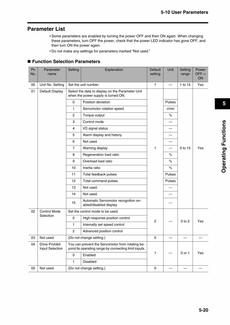
5-10 User Parameters
5
Op
erat
ing
Fu
nct
ion
s
Parameter ListSome parameters are enabled by turning the power OFF and then ON again. When changing these parameters, turn OFF the power, check that the power LED indicator has gone OFF, and then turn ON the power again.
Do not make any settings for parameters marked “Not used.”
Function Selection Parameters
PnNo.
Parameter name
Setting Explanation Default setting
Unit Settingrange
Power OFF→
ON
00 Unit No. Setting Set the unit number. 1 --- 1 to 15 Yes
01 Default Display Select the data to display on the Parameter Unit when the power supply is turned ON.
1 0 to 15 Yes
0 Position deviation Pulses
1 Servomotor rotation speed r/min
2 Torque output %
3 Control mode ---
4 I/O signal status ---
5 Alarm display and history ---
6 Not used. ---
7 Warning display ---
8 Regeneration load ratio %
9 Overload load ratio %
10 Inertia ratio %
11 Total feedback pulses Pulses
12 Total command pulses Pulses
13 Not used. ---
14 Not used. ---
15Automatic Servomotor recognition en-abled/disabled display
---
02 Control Mode Selection
Set the control mode to be used.
2 --- 0 to 2 Yes0 High-response position control
1 Internally set speed control
2 Advanced position control
03 Not used. (Do not change setting.) 0 --- --- ---
04 Drive Prohibit Input Selection
You can prevent the Servomotor from rotating be-yond its operating range by connecting limit inputs.
1 --- 0 or 1 Yes0 Enabled
1 Disabled
05 Not used. (Do not change setting.) 0 --- --- ---
5-20
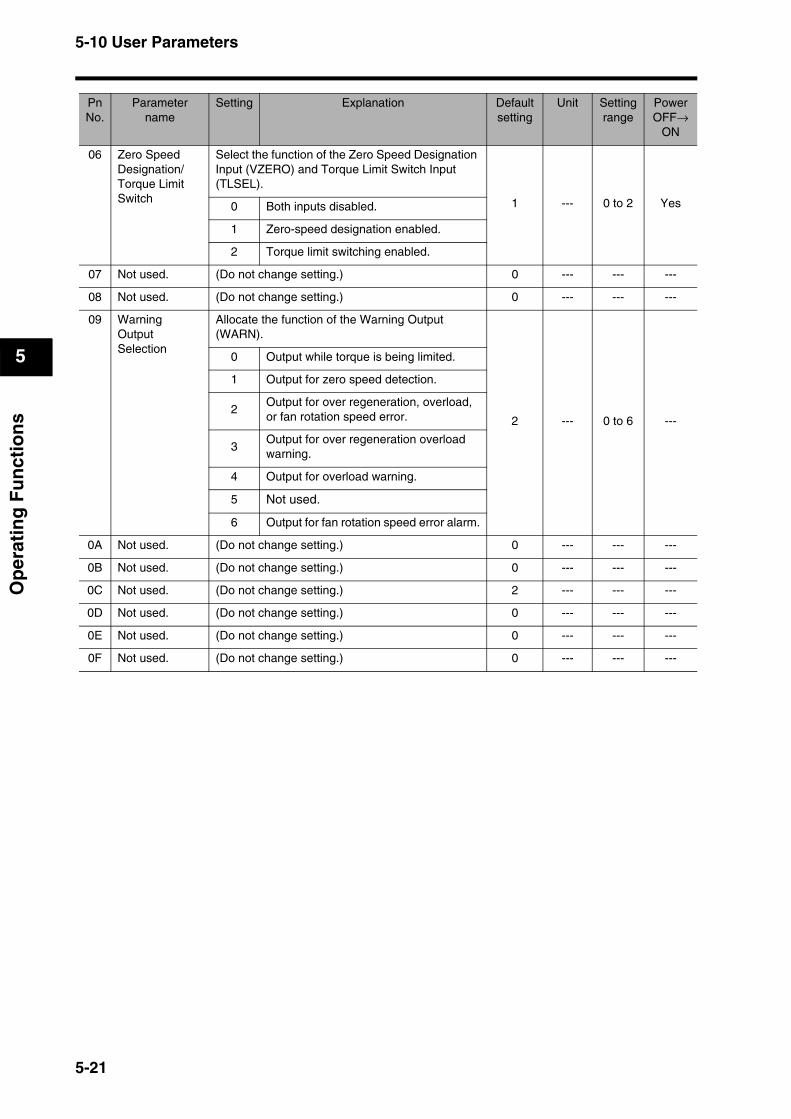
5-10 User Parameters
5
Op
erat
ing
Fu
nct
ion
s
06 Zero Speed Designation/ Torque Limit Switch
Select the function of the Zero Speed Designation Input (VZERO) and Torque Limit Switch Input (TLSEL).
1 --- 0 to 2 Yes0 Both inputs disabled.
1 Zero-speed designation enabled.
2 Torque limit switching enabled.
07 Not used. (Do not change setting.) 0 --- --- ---
08 Not used. (Do not change setting.) 0 --- --- ---
09 Warning Output Selection
Allocate the function of the Warning Output (WARN).
2 --- 0 to 6 ---
0 Output while torque is being limited.
1 Output for zero speed detection.
2Output for over regeneration, overload, or fan rotation speed error.
3Output for over regeneration overload warning.
4 Output for overload warning.
5 Not used.
6 Output for fan rotation speed error alarm.
0A Not used. (Do not change setting.) 0 --- --- ---
0B Not used. (Do not change setting.) 0 --- --- ---
0C Not used. (Do not change setting.) 2 --- --- ---
0D Not used. (Do not change setting.) 0 --- --- ---
0E Not used. (Do not change setting.) 0 --- --- ---
0F Not used. (Do not change setting.) 0 --- --- ---
PnNo.
Parameter name
Setting Explanation Default setting
Unit Settingrange
Power OFF→
ON
5-21
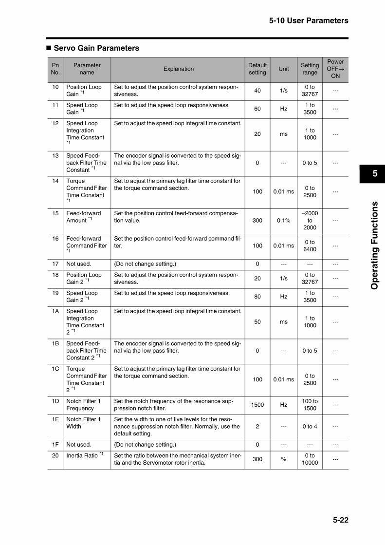
5-10 User Parameters
5
Op
erat
ing
Fu
nct
ion
s
Servo Gain Parameters
PnNo.
Parameter name
ExplanationDefaultsetting
UnitSettingrange
Power OFF→
ON
10 Position Loop Gain *1
Set to adjust the position control system respon-siveness.
40 1/s0 to
32767---
11 Speed Loop Gain *1
Set to adjust the speed loop responsiveness.60 Hz
1 to 3500
---
12 Speed Loop Integration Time Constant *1
Set to adjust the speed loop integral time constant.
20 ms1 to
1000---
13 Speed Feed-back Filter Time Constant *1
The encoder signal is converted to the speed sig-nal via the low pass filter. 0 --- 0 to 5 ---
14 Torque Command Filter Time Constant *1
Set to adjust the primary lag filter time constant for the torque command section.
100 0.01 ms0 to
2500---
15 Feed-forward Amount *1
Set the position control feed-forward compensa-tion value. 300 0.1%
−2000 to
2000---
16 Feed-forward Command Filter *1
Set the position control feed-forward command fil-ter. 100 0.01 ms
0 to 6400
---
17 Not used. (Do not change setting.) 0 --- --- ---
18 Position Loop Gain 2 *1
Set to adjust the position control system respon-siveness.
20 1/s0 to
32767---
19 Speed Loop Gain 2 *1
Set to adjust the speed loop responsiveness.80 Hz
1 to 3500
---
1A Speed Loop Integration Time Constant 2 *1
Set to adjust the speed loop integral time constant.
50 ms1 to
1000---
1B Speed Feed-back Filter Time Constant 2 *1
The encoder signal is converted to the speed sig-nal via the low pass filter. 0 --- 0 to 5 ---
1C Torque Command Filter Time Constant 2 *1
Set to adjust the primary lag filter time constant for the torque command section.
100 0.01 ms0 to
2500---
1D Notch Filter 1 Frequency
Set the notch frequency of the resonance sup-pression notch filter.
1500 Hz100 to 1500
---
1E Notch Filter 1 Width
Set the width to one of five levels for the reso-nance suppression notch filter. Normally, use the default setting.
2 --- 0 to 4 ---
1F Not used. (Do not change setting.) 0 --- --- ---
20 Inertia Ratio *1 Set the ratio between the mechanical system iner-tia and the Servomotor rotor inertia.
300 %0 to
10000---
5-22
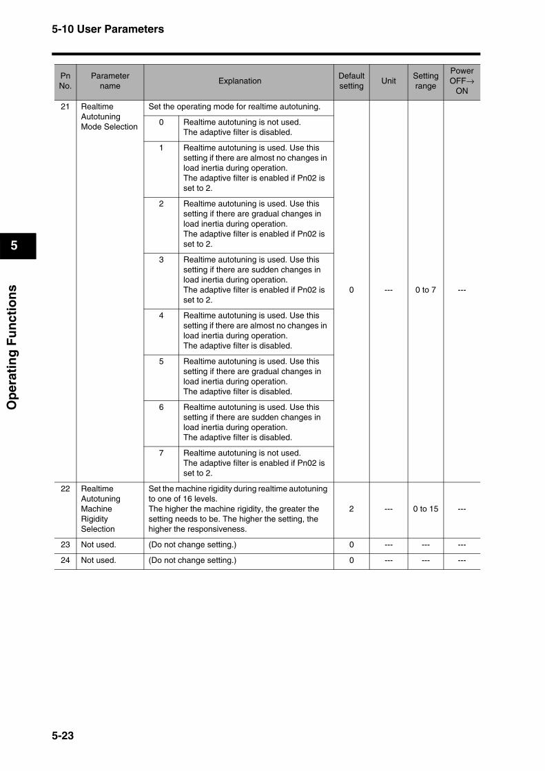
5-10 User Parameters
5
Op
erat
ing
Fu
nct
ion
s
21 Realtime Autotuning Mode Selection
Set the operating mode for realtime autotuning.
0 --- 0 to 7 ---
0 Realtime autotuning is not used.The adaptive filter is disabled.
1 Realtime autotuning is used. Use this setting if there are almost no changes in load inertia during operation.The adaptive filter is enabled if Pn02 is set to 2.
2 Realtime autotuning is used. Use this setting if there are gradual changes in load inertia during operation.The adaptive filter is enabled if Pn02 is set to 2.
3 Realtime autotuning is used. Use this setting if there are sudden changes in load inertia during operation.The adaptive filter is enabled if Pn02 is set to 2.
4 Realtime autotuning is used. Use this setting if there are almost no changes in load inertia during operation.The adaptive filter is disabled.
5 Realtime autotuning is used. Use this setting if there are gradual changes in load inertia during operation.The adaptive filter is disabled.
6 Realtime autotuning is used. Use this setting if there are sudden changes in load inertia during operation.The adaptive filter is disabled.
7 Realtime autotuning is not used.The adaptive filter is enabled if Pn02 is set to 2.
22 Realtime Autotuning Machine Rigidity Selection
Set the machine rigidity during realtime autotuning to one of 16 levels.The higher the machine rigidity, the greater the setting needs to be. The higher the setting, the higher the responsiveness.
2 --- 0 to 15 ---
23 Not used. (Do not change setting.) 0 --- --- ---
24 Not used. (Do not change setting.) 0 --- --- ---
PnNo.
Parameter name
ExplanationDefaultsetting
UnitSettingrange
Power OFF→
ON
5-23
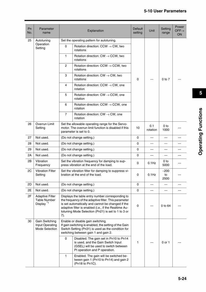
5-10 User Parameters
5
Op
erat
ing
Fu
nct
ion
s
25 Autotuning Operation Setting
Set the operating pattern for autotuning.
0 --- 0 to 7 ---
0 Rotation direction: CCW → CW, two rotations
1 Rotation direction: CW → CCW, two rotations
2 Rotation direction: CCW → CCW, two rotations
3 Rotation direction: CW → CW, two rotations
4 Rotation direction: CCW → CW, one rotation
5 Rotation direction: CW → CCW, one rotation
6 Rotation direction: CCW → CCW, one rotation
7 Rotation direction: CW → CW, one rotation
26 Overrun Limit Setting
Set the allowable operating range for the Servo-motor. The overrun limit function is disabled if this parameter is set to 0.
100.1
rotation0 to
1000---
27 Not used. (Do not change setting.) 0 --- --- ---
28 Not used. (Do not change setting.) 0 --- --- ---
29 Not used. (Do not change setting.) 0 --- --- ---
2A Not used. (Do not change setting.) 0 --- --- ---
2B Vibration Frequency
Set the vibration frequency for damping to sup-press vibration at the end of the load.
0 0.1Hz0 to
5000---
2C Vibration Filter Setting
Set the vibration filter for damping to suppress vi-bration at the end of the load. 0 0.1Hz
−200 to
2500---
2D Not used. (Do not change setting.) 0 --- --- ---
2E Not used. (Do not change setting.) 0 --- --- ---
2F Adaptive Filter Table Number Display *1
Displays the table entry number corresponding to the frequency of the adaptive filter. This parameter is set automatically and cannot be changed if the adaptive filter is enabled (i.e., if the Realtime Au-totuning Mode Selection (Pn21) is set to 1 to 3 or 7).
0 --- 0 to 64 ---
30 Gain Switching Input Operating Mode Selection
Enable or disable gain switching.If gain switching is enabled, the setting of the Gain Switch Setting (Pn31) is used as the condition for switching between gain 1 and gain 2.
1 --- 0 or 1 ---0 Disabled. The gain set in Pn10 to Pn14
is used, and the Gain Switch Input (GSEL) will be used to switch between PI operation and P operation.
1 Enabled. The gain will be switched be-tween gain 1 (Pn10 to Pn14) and gain 2 (Pn18 to Pn1C).
PnNo.
Parameter name
ExplanationDefaultsetting
UnitSettingrange
Power OFF→
ON
5-24
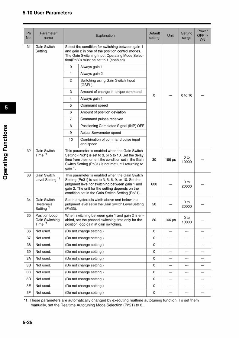
5-10 User Parameters
5
Op
erat
ing
Fu
nct
ion
s
*1. These parameters are automatically changed by executing realtime autotuning function. To set them manually, set the Realtime Autotuning Mode Selection (Pn21) to 0.
31 Gain Switch Setting
Select the condition for switching between gain 1 and gain 2 in one of the position control modes.The Gain Switching Input Operating Mode Selec-tion(Pn30) must be set to 1 (enabled).
0 --- 0 to 10 ---
0 Always gain 1
1 Always gain 2
2 Switching using Gain Switch Input (GSEL)
3 Amount of change in torque command
4 Always gain 1
5 Command speed
6 Amount of position deviation
7 Command pulses received
8 Positioning Completed Signal (INP) OFF
9 Actual Servomotor speed
10 Combination of command pulse input and speed
32 Gain Switch Time *1
This parameter is enabled when the Gain Switch Setting (Pn31) is set to 3, or 5 to 10. Set the delay time from the moment the condition set in the Gain Switch Setting (Pn31) is not met until returning to gain 1.
30 166 µs0 to
10000---
33 Gain Switch Level Setting *1
This parameter is enabled when the Gain Switch Setting (Pn31) is set to 3, 5, 6, 9, or 10. Set the judgment level for switching between gain 1 and gain 2. The unit for the setting depends on the condition set in the Gain Switch Setting (Pn31).
600 ---0 to
20000---
34 Gain Switch Hysteresis Setting *1
Set the hysteresis width above and below the judgment level set in the Gain Switch Level Setting (Pn33).
50 ---0 to
20000---
35 Position Loop Gain Switching Time *1
When switching between gain 1 and gain 2 is en-abled, set the phased switching time only for the position loop gain at gain switching.
20 166 µs0 to
10000---
36 Not used. (Do not change setting.) 0 --- --- ---
37 Not used. (Do not change setting.) 0 --- --- ---
38 Not used. (Do not change setting.) 0 --- --- ---
39 Not used. (Do not change setting.) 0 --- --- ---
3A Not used. (Do not change setting.) 0 --- --- ---
3B Not used. (Do not change setting.) 0 --- --- ---
3C Not used. (Do not change setting.) 0 --- --- ---
3D Not used. (Do not change setting.) 0 --- --- ---
3E Not used. (Do not change setting.) 0 --- --- ---
3F Not used. (Do not change setting.) 0 --- --- ---
PnNo.
Parameter name
ExplanationDefaultsetting
UnitSettingrange
Power OFF→
ON
5-25

5-10 User Parameters
5
Op
erat
ing
Fu
nct
ion
s
Position Control Parameters
PnNo.
Parameter name
ExplanationDefaultsetting
UnitSettingrange
Power OFF→
ON
40 Command Pulse Multiplying Setting
The command pulses are multiplied by a factor of 2 or 4 when using 90° phase difference signal inputs is selected as the input format for the command pulses in the Command Pulse Mode (Pn42).
4 --- 1 to 4 Yes1Multiply by 2.
2
3Multiply by 4.
4
41 Command Pulse Rotation Direction Switch
Set the Servomotor rotation direction for the com-mand pulse input.
0 --- 0 to 3 Yes
0The Servomotor rotates in the direction specified by the command pulse.
1 The Servomotor rotates in the opposite direction from the direction specified by the command pulse.2
3The Servomotor rotates in the direction specified by the command pulse.
42 Command Pulse Mode
Set the input format of the pulse sent as input com-mands to the Servo Drive from the position control-ler.
1 --- 0 to 3 Yes
090° phase difference (phases A and B) signal inputs
1 Forward pulse and reverse pulse inputs
290° phase difference (phases A and B) signal inputs
3Feed pulse input and forward/reverse sig-nal
43 Not used. (Do not change setting.) 0 --- --- ---
44 Encoder Dividing Rate Setting
Set the number of encoder pulses to be output from the Servo Drive for each rotation.The setting can be made from 1 to 16,384 pulses/rotation, but the setting will not be valid if it exceeds 2,500 pulses/rotation.
2500 Pulses1 to
16384Yes
45 Encoder OutputDirection Switch
Set to reverse the logic of encoder pulses output from the Servo Drive.
0 --- 0 or 1 Yes0 Positive logic
1 Negative logic
46 Electronic Gear Ratio Numerator 1
Set the pulse rate for command pulses and Servo-motor travel distance. 10000 ---
1 to 10000
---
47 Electronic Gear Ratio Numerator 2
10000 ---1 to
10000---
48 Not used. (Do not change setting.) 0 --- --- ---
49 Not used. (Do not change setting.) 0 --- --- ---
Electronic Gear Ratio Denominator (Pn4B)
x 2Electronic Gear Ratio Numerator Exponent (Pn4A)
Electronic Gear Ratio Numerator 1 (Pn46)
orElectronic Gear Ratio Numerator 2 (Pn47)
5-26
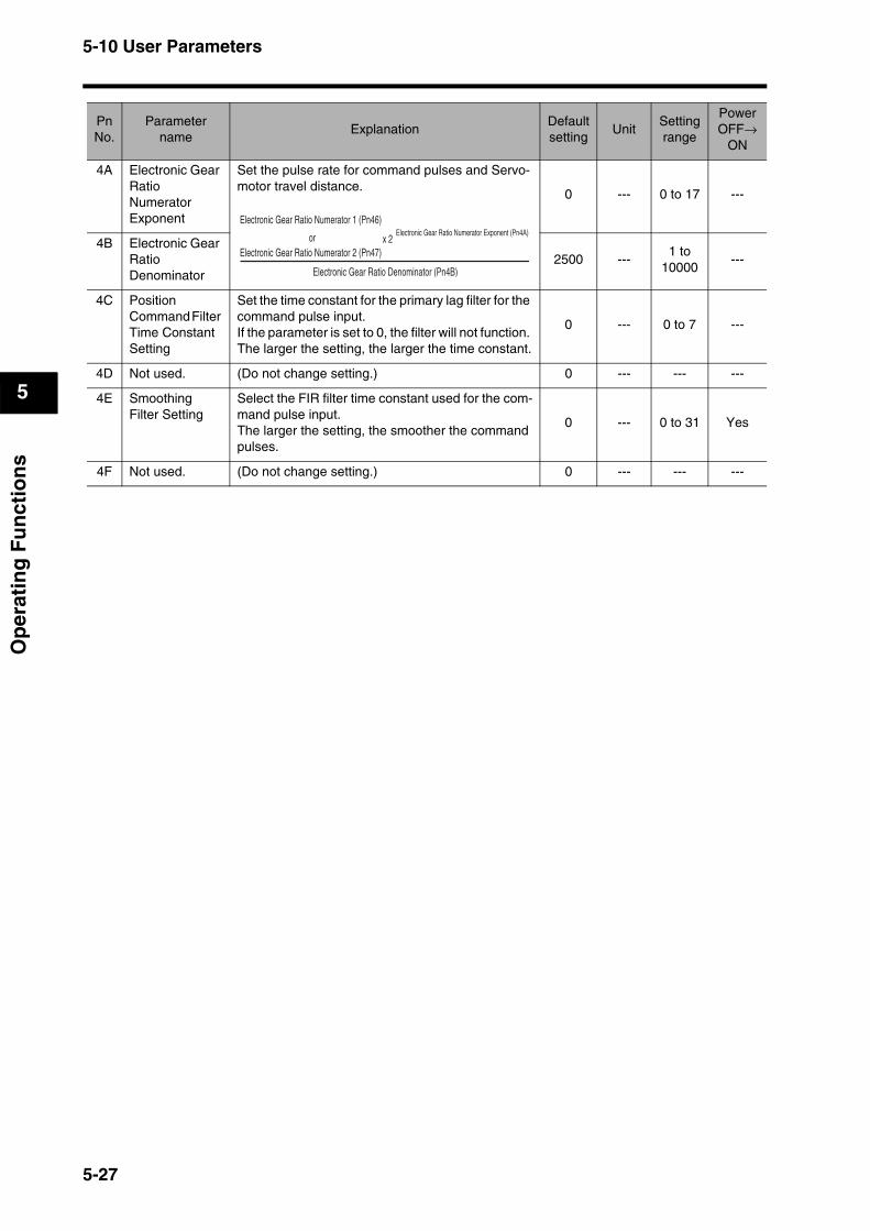
5-10 User Parameters
5
Op
erat
ing
Fu
nct
ion
s
4A Electronic Gear Ratio Numerator Exponent
Set the pulse rate for command pulses and Servo-motor travel distance.
0 --- 0 to 17 ---
4B Electronic Gear Ratio Denominator
2500 ---1 to
10000---
4C Position Command Filter Time Constant Setting
Set the time constant for the primary lag filter for the command pulse input.If the parameter is set to 0, the filter will not function. The larger the setting, the larger the time constant.
0 --- 0 to 7 ---
4D Not used. (Do not change setting.) 0 --- --- ---
4E Smoothing Filter Setting
Select the FIR filter time constant used for the com-mand pulse input.The larger the setting, the smoother the command pulses.
0 --- 0 to 31 Yes
4F Not used. (Do not change setting.) 0 --- --- ---
PnNo.
Parameter name
ExplanationDefaultsetting
UnitSettingrange
Power OFF→
ON
Electronic Gear Ratio Denominator (Pn4B)
x 2Electronic Gear Ratio Numerator Exponent (Pn4A)
Electronic Gear Ratio Numerator 1 (Pn46)
orElectronic Gear Ratio Numerator 2 (Pn47)
5-27
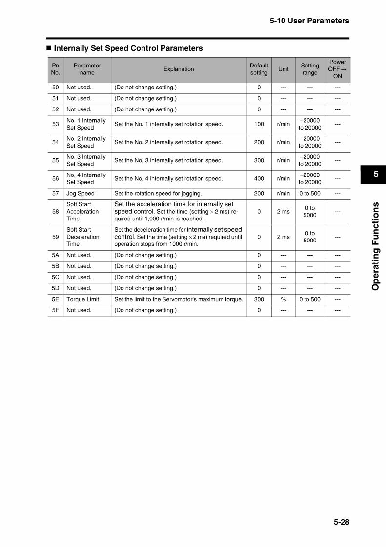
5-10 User Parameters
5
Op
erat
ing
Fu
nct
ion
s
Internally Set Speed Control Parameters
PnNo.
Parameter name
ExplanationDefaultsetting
UnitSettingrange
Power OFF →
ON
50 Not used. (Do not change setting.) 0 --- --- ---
51 Not used. (Do not change setting.) 0 --- --- ---
52 Not used. (Do not change setting.) 0 --- --- ---
53No. 1 Internally Set Speed
Set the No. 1 internally set rotation speed. 100 r/min−20000
to 20000---
54No. 2 Internally Set Speed
Set the No. 2 internally set rotation speed. 200 r/min−20000
to 20000---
55No. 3 Internally Set Speed
Set the No. 3 internally set rotation speed. 300 r/min−20000
to 20000---
56No. 4 Internally Set Speed
Set the No. 4 internally set rotation speed. 400 r/min−20000
to 20000---
57 Jog Speed Set the rotation speed for jogging. 200 r/min 0 to 500 ---
58Soft Start Acceleration Time
Set the acceleration time for internally set speed control. Set the time (setting × 2 ms) re-quired until 1,000 r/min is reached.
0 2 ms0 to
5000---
59Soft Start Deceleration Time
Set the deceleration time for internally set speed control. Set the time (setting × 2 ms) required until operation stops from 1000 r/min.
0 2 ms0 to
5000---
5A Not used. (Do not change setting.) 0 --- --- ---
5B Not used. (Do not change setting.) 0 --- --- ---
5C Not used. (Do not change setting.) 0 --- --- ---
5D Not used. (Do not change setting.) 0 --- --- ---
5E Torque Limit Set the limit to the Servomotor’s maximum torque. 300 % 0 to 500 ---
5F Not used. (Do not change setting.) 0 --- --- ---
5-28
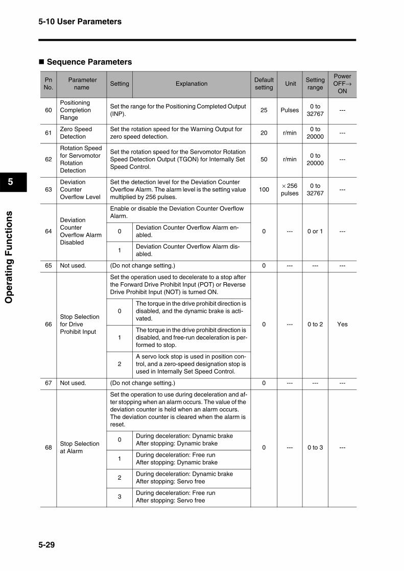
5-10 User Parameters
5
Op
erat
ing
Fu
nct
ion
s
Sequence Parameters
PnNo.
Parameter name
Setting ExplanationDefaultsetting
UnitSettingrange
Power OFF→
ON
60Positioning Completion Range
Set the range for the Positioning Completed Output (INP).
25 Pulses0 to
32767---
61Zero Speed Detection
Set the rotation speed for the Warning Output for zero speed detection.
20 r/min0 to
20000---
62
Rotation Speed for Servomotor Rotation Detection
Set the rotation speed for the Servomotor Rotation Speed Detection Output (TGON) for Internally Set Speed Control.
50 r/min0 to
20000---
63Deviation Counter Overflow Level
Set the detection level for the Deviation Counter Overflow Alarm. The alarm level is the setting value multiplied by 256 pulses.
100× 256 pulses
0 to 32767
---
64
Deviation Counter Overflow Alarm Disabled
Enable or disable the Deviation Counter Overflow Alarm.
0 --- 0 or 1 ---0Deviation Counter Overflow Alarm en-abled.
1Deviation Counter Overflow Alarm dis-abled.
65 Not used. (Do not change setting.) 0 --- --- ---
66Stop Selection for Drive Prohibit Input
Set the operation used to decelerate to a stop after the Forward Drive Prohibit Input (POT) or Reverse Drive Prohibit Input (NOT) is turned ON.
0 --- 0 to 2 Yes
0The torque in the drive prohibit direction is disabled, and the dynamic brake is acti-vated.
1The torque in the drive prohibit direction is disabled, and free-run deceleration is per-formed to stop.
2A servo lock stop is used in position con-trol, and a zero-speed designation stop is used in Internally Set Speed Control.
67 Not used. (Do not change setting.) 0 --- --- ---
68Stop Selection at Alarm
Set the operation to use during deceleration and af-ter stopping when an alarm occurs. The value of the deviation counter is held when an alarm occurs. The deviation counter is cleared when the alarm is reset.
0 --- 0 to 3 ---0
During deceleration: Dynamic brakeAfter stopping: Dynamic brake
1During deceleration: Free runAfter stopping: Dynamic brake
2During deceleration: Dynamic brakeAfter stopping: Servo free
3During deceleration: Free runAfter stopping: Servo free
5-29

5-10 User Parameters
5
Op
erat
ing
Fu
nct
ion
s
69Stop Selection with Servo OFF
Set the operation to use during deceleration and af-ter stopping and set the deviation counter status when the RUN Command Input (RUN) is turned OFF.
0 --- 0 to 7 ---
0During deceleration: Dynamic brakeAfter stopping: Dynamic brake Deviation counter: Cleared
1During deceleration: Free runAfter stopping: Dynamic brakeDeviation counter: Cleared
2During deceleration: Dynamic brakeAfter stopping: Servo freeDeviation counter: Cleared
3During deceleration: Free runAfter stopping: Servo freeDeviation counter: Cleared
4During deceleration: Dynamic brakeAfter stopping: Dynamic brakeDeviation counter: Hold
5During deceleration: Free runAfter stopping: Dynamic brakeDeviation counter: Hold
6During deceleration: Dynamic brakeAfter stopping: Servo freeDeviation counter: Hold
7During deceleration: Free runAfter stopping: Servo freeDeviation counter: Hold
6ABrake Timing When Stopped
When the Servomotor is stopped and the RUN Command Input (RUN) is turned OFF, the Brake In-terlock Signal (BKIR) will turn OFF, and the Servo-motor will turn OFF after the time set for this parameter elapses (i.e., setting × 2 ms).
10 2 ms0 to 100
---
6BBrake Timing during Operation
When the Servomotor is operating and the RUN Command Input (RUN) is turned OFF, the Servo-motor will decelerate to reduce speed, and the Brake Interlock Signal (BKIR) will turn OFF after a set time (i.e., setting × 2 ms) has elapsed.BKIR will also turn OFF if the speed drops to 30 r/min or lower before the set time elapses.
50 2 ms0 to 100
---
PnNo.
Parameter name
Setting ExplanationDefaultsetting
UnitSettingrange
Power OFF→
ON
5-30

5-10 User Parameters
5
Op
erat
ing
Fu
nct
ion
s
6CRegeneration Resistor Selection
Set this parameter to 1 or 2 if an external gener-ation resistor is mounted.
0 --- 0 to 3 ---
0
The external regeneration processing cir-cuit will not operate. Regenerative energy will be processed with the built-in capaci-tor.
1
An External Regeneration Resistor is used, and an External Regeneration Re-sistor overload alarm (alarm code 18) will occur when the resistance exceeds 10% of the operating limit.
2An External Regeneration Resistor is used, but an External Regeneration Re-sistor overload alarm will not occur.
3
The external regeneration processing cir-cuit will not operate. Regenerative energy will be processed with the built-in capaci-tor.
6D Not used. (Do not change setting.) 0 --- --- ---
6E Not used. (Do not change setting.) 0 --- --- ---
6F Not used. (Do not change setting.) 0 --- --- ---
70Overspeed Detection Level Setting
Set the No. 1 overspeed detection level when torque limit switching is enabled in the Zero-speed Designation/Torque Limit Switch (Pn06).
0 r/min0 to
6000---
71No. 2 Torque Limit
Set the No. 2 torque limit when torque limit switch-ing is enabled in the Zero-speed Designation/Torque Limit Switch (Pn06).
100 %0 to 500
---
72No. 2 Deviation Counter Overflow Level
Set the No. 2 deviation counter overflow level when torque limit switching is enabled in the Zero-speed Designation/Torque Limit Switch (Pn06).
100× 256 pulses
1 to 32767
---
73
No. 2 Overspeed Detection Level Setting
Set the No. 2 overspeed detection level when torque limit switching is enabled in the Zero-speed Designation/Torque Limit Switch (Pn06).
0 r/min0 to
6000---
74 Not used. (Do not change setting.) 0 --- --- ---
75 Not used. (Do not change setting.) 0 --- --- ---
76 Not used. (Do not change setting.) 0 --- --- ---
77 Not used. (Do not change setting.) 0 --- --- ---
78 Not used. (Do not change setting.) 0 --- --- ---
79 Not used. (Do not change setting.) 0 --- --- ---
7A Not used. (Do not change setting.) 0 --- --- ---
7B Not used. (Do not change setting.) 0 --- --- ---
7C Not used. (Do not change setting.) 0 --- --- ---
7D Not used. (Do not change setting.) 0 --- --- ---
7E Not used. (Do not change setting.) 0 --- --- ---
7F Not used. (Do not change setting.) 0 --- --- ---
PnNo.
Parameter name
Setting ExplanationDefaultsetting
UnitSettingrange
Power OFF→
ON
5-31
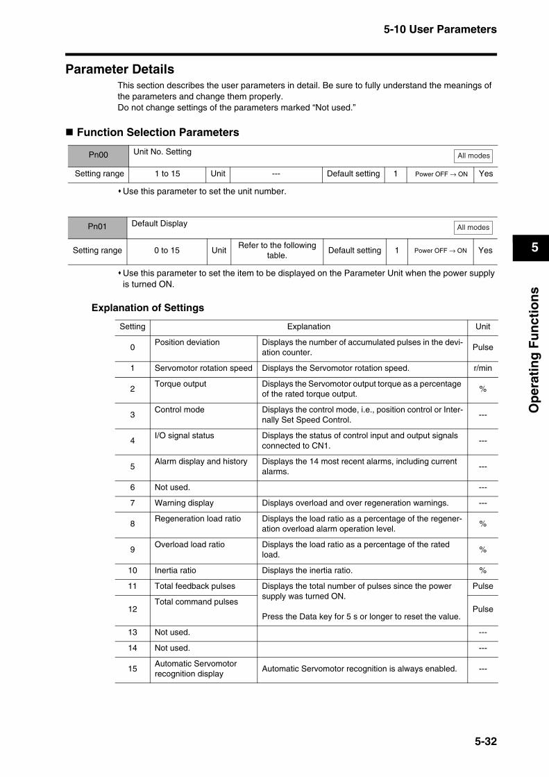
5-10 User Parameters
5
Op
erat
ing
Fu
nct
ion
s
Parameter DetailsThis section describes the user parameters in detail. Be sure to fully understand the meanings of the parameters and change them properly. Do not change settings of the parameters marked “Not used.”
Function Selection Parameters
Use this parameter to set the unit number.
Use this parameter to set the item to be displayed on the Parameter Unit when the power supply is turned ON.
Explanation of Settings
Pn00 Unit No. Setting
Setting range 1 to 15 Unit --- Default setting 1 Power OFF → ON Yes
All modes
Pn01 Default Display
Setting range 0 to 15 UnitRefer to the following
table.Default setting 1 Power OFF → ON Yes
All modes
Setting Explanation Unit
0Position deviation Displays the number of accumulated pulses in the devi-
ation counter.Pulse
1 Servomotor rotation speed Displays the Servomotor rotation speed. r/min
2Torque output Displays the Servomotor output torque as a percentage
of the rated torque output.%
3Control mode Displays the control mode, i.e., position control or Inter-
nally Set Speed Control. ---
4I/O signal status Displays the status of control input and output signals
connected to CN1.---
5Alarm display and history Displays the 14 most recent alarms, including current
alarms.---
6 Not used. ---
7 Warning display Displays overload and over regeneration warnings. ---
8Regeneration load ratio Displays the load ratio as a percentage of the regener-
ation overload alarm operation level.%
9Overload load ratio Displays the load ratio as a percentage of the rated
load.%
10 Inertia ratio Displays the inertia ratio. %
11 Total feedback pulses Displays the total number of pulses since the power supply was turned ON.
Press the Data key for 5 s or longer to reset the value.
Pulse
12Total command pulses
Pulse
13 Not used. ---
14 Not used. ---
15Automatic Servomotor recognition display
Automatic Servomotor recognition is always enabled. ---
5-32
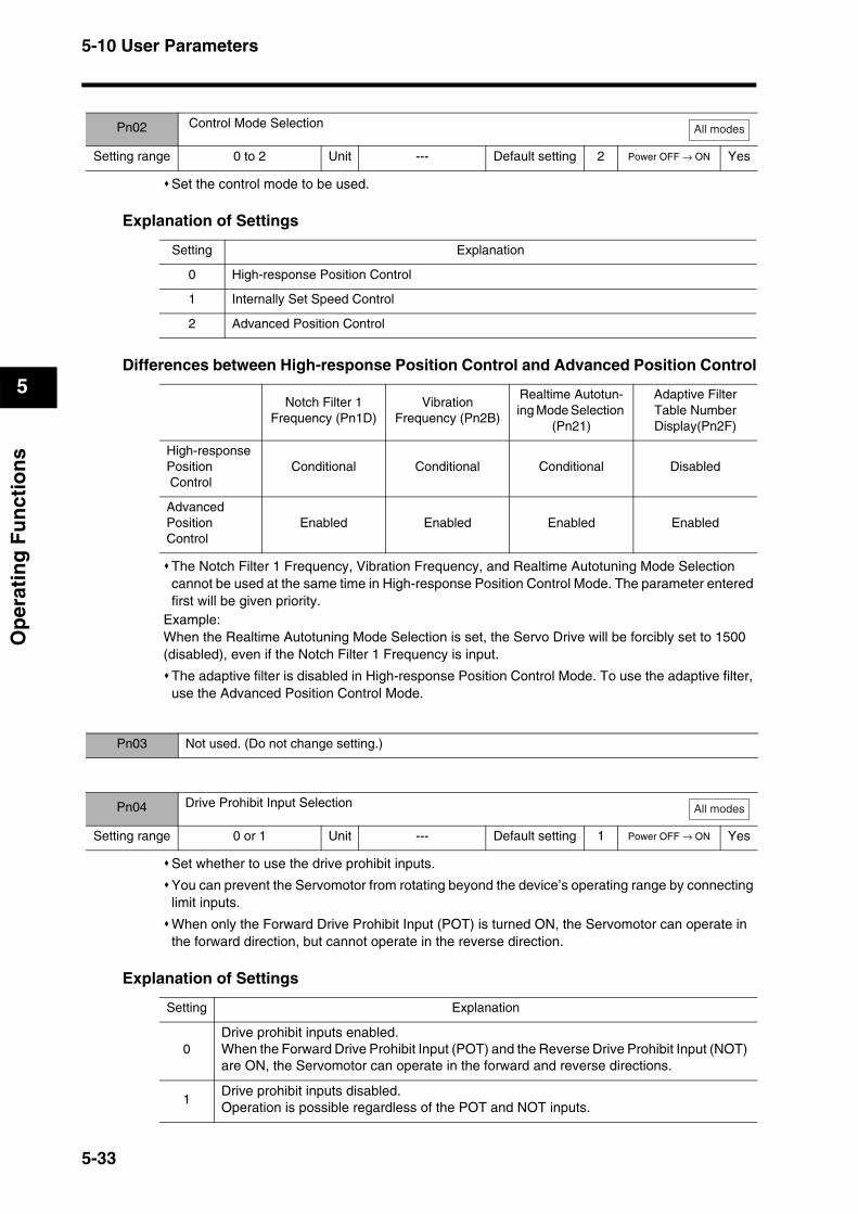
5-10 User Parameters
5
Op
erat
ing
Fu
nct
ion
s
Set the control mode to be used.
Explanation of Settings
Differences between High-response Position Control and Advanced Position Control
The Notch Filter 1 Frequency, Vibration Frequency, and Realtime Autotuning Mode Selection cannot be used at the same time in High-response Position Control Mode. The parameter entered first will be given priority.
Example:When the Realtime Autotuning Mode Selection is set, the Servo Drive will be forcibly set to 1500 (disabled), even if the Notch Filter 1 Frequency is input.
The adaptive filter is disabled in High-response Position Control Mode. To use the adaptive filter, use the Advanced Position Control Mode.
Set whether to use the drive prohibit inputs.
You can prevent the Servomotor from rotating beyond the device’s operating range by connecting limit inputs.
When only the Forward Drive Prohibit Input (POT) is turned ON, the Servomotor can operate in the forward direction, but cannot operate in the reverse direction.
Explanation of Settings
Pn02 Control Mode Selection
Setting range 0 to 2 Unit --- Default setting 2 Power OFF → ON Yes
All modes
Setting Explanation
0 High-response Position Control
1 Internally Set Speed Control
2 Advanced Position Control
Notch Filter 1Frequency (Pn1D)
Vibration Frequency (Pn2B)
Realtime Autotun-ing Mode Selection
(Pn21)
Adaptive Filter Table Number Display(Pn2F)
High-response Position Control
Conditional Conditional Conditional Disabled
Advanced Position Control
Enabled Enabled Enabled Enabled
Pn03 Not used. (Do not change setting.)
Pn04 Drive Prohibit Input Selection
Setting range 0 or 1 Unit --- Default setting 1 Power OFF → ON Yes
All modes
Setting Explanation
0Drive prohibit inputs enabled.When the Forward Drive Prohibit Input (POT) and the Reverse Drive Prohibit Input (NOT) are ON, the Servomotor can operate in the forward and reverse directions.
1Drive prohibit inputs disabled.Operation is possible regardless of the POT and NOT inputs.
5-33
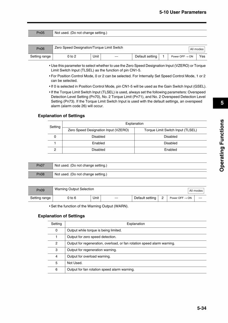
5-10 User Parameters
5
Op
erat
ing
Fu
nct
ion
s
Use this parameter to select whether to use the Zero Speed Designation Input (VZERO) or Torque Limit Switch Input (TLSEL) as the function of pin CN1-5.
For Position Control Mode, 0 or 2 can be selected. For Internally Set Speed Control Mode, 1 or 2 can be selected.
If 0 is selected in Position Control Mode, pin CN1-5 will be used as the Gain Switch Input (GSEL).
If the Torque Limit Switch Input (TLSEL) is used, always set the following parameters: Overspeed Detection Level Setting (Pn70), No. 2 Torque Limit (Pn71), and No. 2 Overspeed Detection Level Setting (Pn73). If the Torque Limit Switch Input is used with the default settings, an overspeed alarm (alarm code 26) will occur.
Explanation of Settings
Set the function of the Warning Output (WARN).
Explanation of Settings
Pn05 Not used. (Do not change setting.)
Pn06 Zero Speed Designation/Torque Limit Switch
Setting range 0 to 2 Unit --- Default setting 1 Power OFF → ON Yes
All modes
SettingExplanation
Zero Speed Designation Input (VZERO) Torque Limit Switch Input (TLSEL)
0 Disabled Disabled
1 Enabled Disabled
2 Disabled Enabled
Pn07 Not used. (Do not change setting.)
Pn08 Not used. (Do not change setting.)
Pn09 Warning Output Selection
Setting range 0 to 6 Unit --- Default setting 2 Power OFF → ON ---
All modes
Setting Explanation
0 Output while torque is being limited.
1 Output for zero speed detection.
2 Output for regeneration, overload, or fan rotation speed alarm warning.
3 Output for regeneration warning.
4 Output for overload warning.
5 Not Used.
6 Output for fan rotation speed alarm warning.
5-34
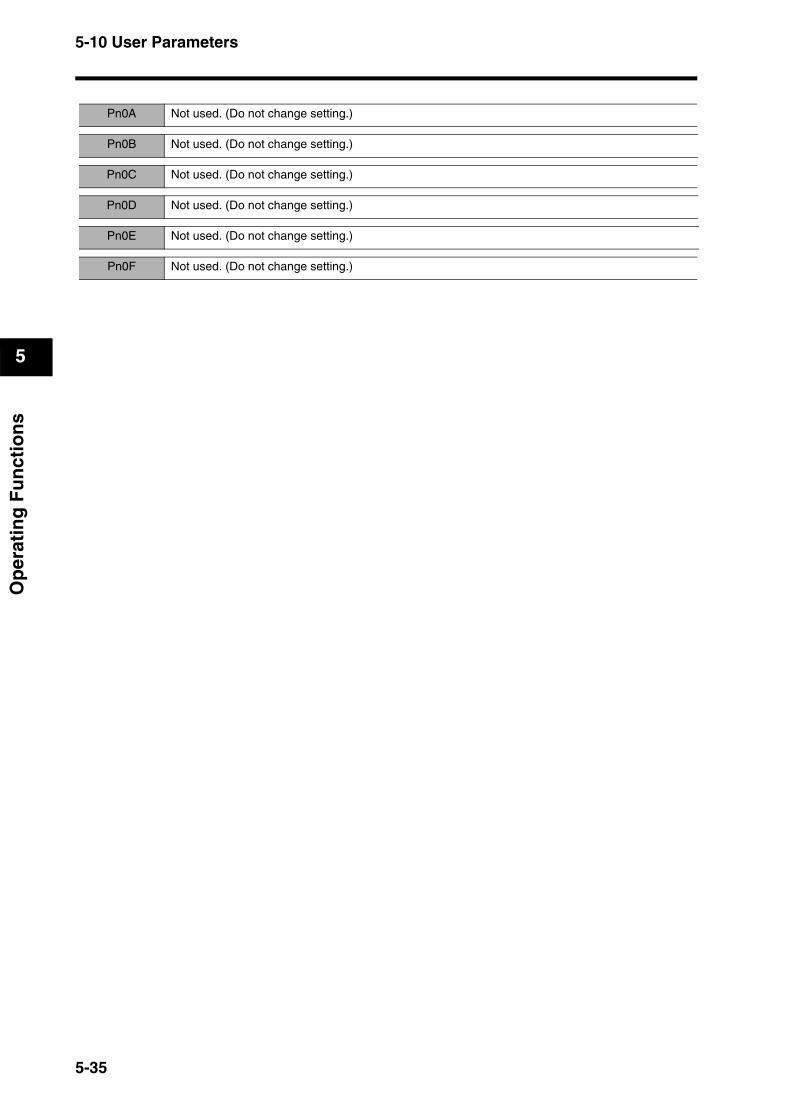
5-10 User Parameters
5
Op
erat
ing
Fu
nct
ion
s
Pn0A Not used. (Do not change setting.)
Pn0B Not used. (Do not change setting.)
Pn0C Not used. (Do not change setting.)
Pn0D Not used. (Do not change setting.)
Pn0E Not used. (Do not change setting.)
Pn0F Not used. (Do not change setting.)
5-35
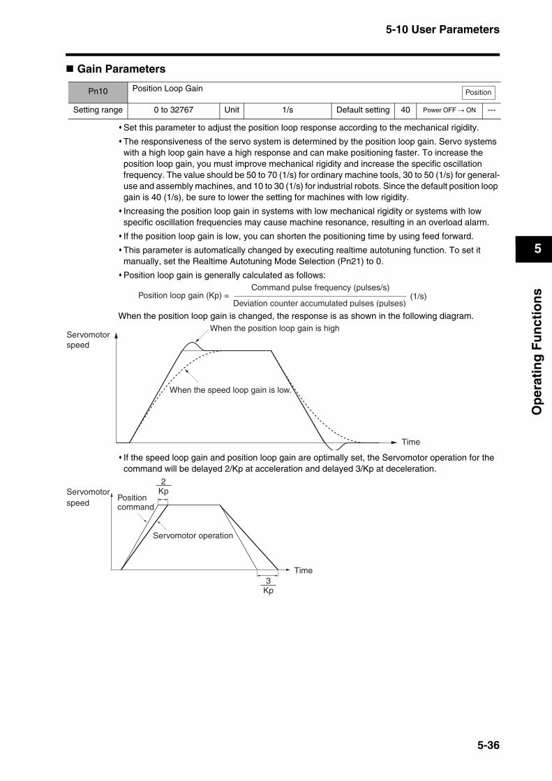
5-10 User Parameters
5
Op
erat
ing
Fu
nct
ion
s
Gain Parameters
Set this parameter to adjust the position loop response according to the mechanical rigidity.
The responsiveness of the servo system is determined by the position loop gain. Servo systems with a high loop gain have a high response and can make positioning faster. To increase the position loop gain, you must improve mechanical rigidity and increase the specific oscillation frequency. The value should be 50 to 70 (1/s) for ordinary machine tools, 30 to 50 (1/s) for general-use and assembly machines, and 10 to 30 (1/s) for industrial robots. Since the default position loop gain is 40 (1/s), be sure to lower the setting for machines with low rigidity.
Increasing the position loop gain in systems with low mechanical rigidity or systems with low specific oscillation frequencies may cause machine resonance, resulting in an overload alarm.
If the position loop gain is low, you can shorten the positioning time by using feed forward.
This parameter is automatically changed by executing realtime autotuning function. To set it manually, set the Realtime Autotuning Mode Selection (Pn21) to 0.
Position loop gain is generally calculated as follows:
When the position loop gain is changed, the response is as shown in the following diagram.
If the speed loop gain and position loop gain are optimally set, the Servomotor operation for the command will be delayed 2/Kp at acceleration and delayed 3/Kp at deceleration.
Pn10 Position Loop Gain
Setting range 0 to 32767 Unit 1/s Default setting 40 Power OFF → ON ---
Position
Command pulse frequency (pulses/s)
Deviation counter accumulated pulses (pulses)(1/s)Position loop gain (Kp) =
When the position loop gain is high
When the speed loop gain is low.
Time
Servomotorspeed
Kp3
Kp2
Servomotor speed
Time
Position command
Servomotor operation
5-36
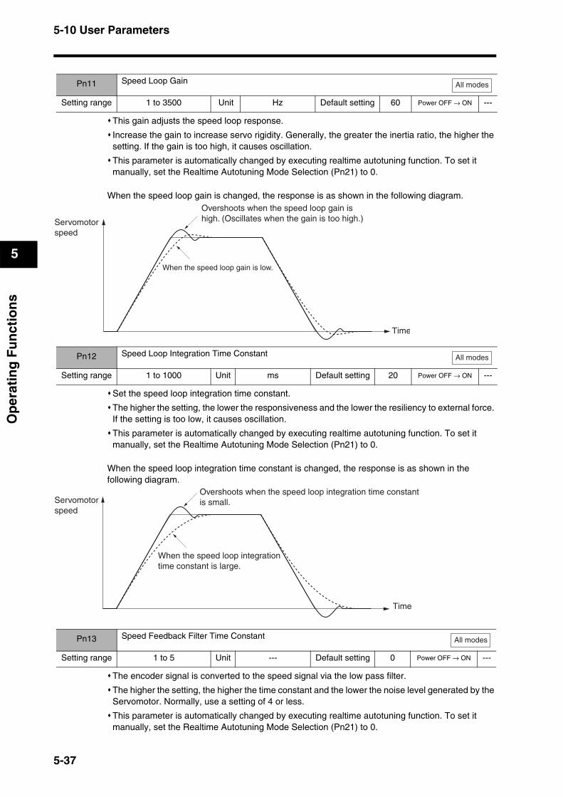
5-10 User Parameters
5
Op
erat
ing
Fu
nct
ion
s
This gain adjusts the speed loop response.
Increase the gain to increase servo rigidity. Generally, the greater the inertia ratio, the higher the setting. If the gain is too high, it causes oscillation.
This parameter is automatically changed by executing realtime autotuning function. To set it manually, set the Realtime Autotuning Mode Selection (Pn21) to 0.
When the speed loop gain is changed, the response is as shown in the following diagram.
Set the speed loop integration time constant.
The higher the setting, the lower the responsiveness and the lower the resiliency to external force. If the setting is too low, it causes oscillation.
This parameter is automatically changed by executing realtime autotuning function. To set it manually, set the Realtime Autotuning Mode Selection (Pn21) to 0.
When the speed loop integration time constant is changed, the response is as shown in the following diagram.
The encoder signal is converted to the speed signal via the low pass filter.
The higher the setting, the higher the time constant and the lower the noise level generated by the Servomotor. Normally, use a setting of 4 or less.
This parameter is automatically changed by executing realtime autotuning function. To set it manually, set the Realtime Autotuning Mode Selection (Pn21) to 0.
Pn11 Speed Loop Gain
Setting range 1 to 3500 Unit Hz Default setting 60 Power OFF → ON ---
All modes
Overshoots when the speed loop gain ishigh. (Oscillates when the gain is too high.)Servomotor
speed
When the speed loop gain is low.
Time
Pn12 Speed Loop Integration Time Constant
Setting range 1 to 1000 Unit ms Default setting 20 Power OFF → ON ---
All modes
Pn13 Speed Feedback Filter Time Constant
Setting range 1 to 5 Unit --- Default setting 0 Power OFF → ON ---
Time
Overshoots when the speed loop integration time constant is small.
When the speed loop integrationtime constant is large.
Servomotorspeed
All modes
5-37
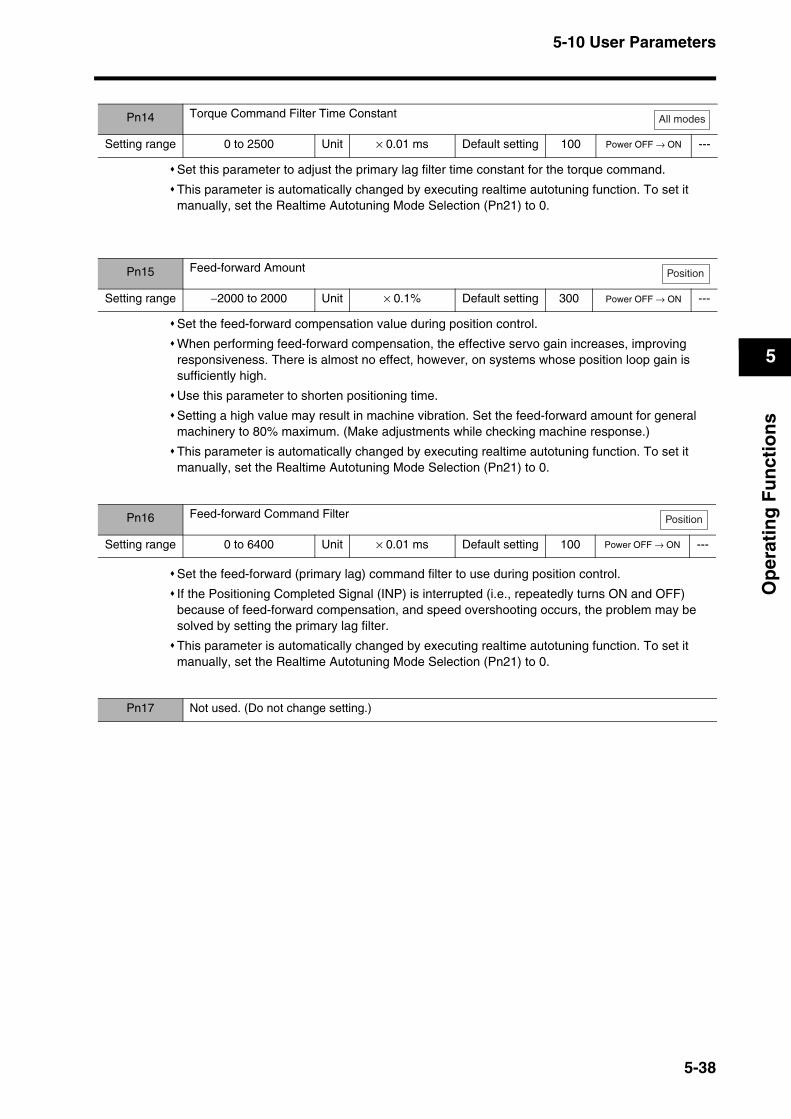
5-10 User Parameters
5
Op
erat
ing
Fu
nct
ion
s
Set this parameter to adjust the primary lag filter time constant for the torque command.
This parameter is automatically changed by executing realtime autotuning function. To set it manually, set the Realtime Autotuning Mode Selection (Pn21) to 0.
Set the feed-forward compensation value during position control.
When performing feed-forward compensation, the effective servo gain increases, improving responsiveness. There is almost no effect, however, on systems whose position loop gain is sufficiently high.
Use this parameter to shorten positioning time.
Setting a high value may result in machine vibration. Set the feed-forward amount for general machinery to 80% maximum. (Make adjustments while checking machine response.)
This parameter is automatically changed by executing realtime autotuning function. To set it manually, set the Realtime Autotuning Mode Selection (Pn21) to 0.
Set the feed-forward (primary lag) command filter to use during position control.
If the Positioning Completed Signal (INP) is interrupted (i.e., repeatedly turns ON and OFF) because of feed-forward compensation, and speed overshooting occurs, the problem may be solved by setting the primary lag filter.
This parameter is automatically changed by executing realtime autotuning function. To set it manually, set the Realtime Autotuning Mode Selection (Pn21) to 0.
Pn14 Torque Command Filter Time Constant
Setting range 0 to 2500 Unit × 0.01 ms Default setting 100 Power OFF → ON ---
All modes
Pn15 Feed-forward Amount
Setting range −2000 to 2000 Unit × 0.1% Default setting 300 Power OFF → ON ---
Position
Pn16 Feed-forward Command Filter
Setting range 0 to 6400 Unit × 0.01 ms Default setting 100 Power OFF → ON ---
Position
Pn17 Not used. (Do not change setting.)
5-38

5-10 User Parameters
5
Op
erat
ing
Fu
nct
ion
s
These parameters are for the gain and time constants selected when gain switching is enabled in the Gain Switching Input Operating Mode Selection (Pn30).The gain is switched according to the condition set in the Gain Switch Setting (Pn31).
If the mechanical system inertia changes greatly or if you want to change the responsiveness while the Servomotor is rotating and stopped, you can achieve the appropriate control by setting the gains and time constants beforehand for each condition, and switch between them according to the condition.
These parameters are automatically changed by executing realtime autotuning function. To set them manually, set the Realtime Autotuning Mode Selection (Pn21) to 0.
Gain switching function is enabled only for position control. For Internally Set Speed Control, operation will be performed using gain 1 (Pn11, Pn12, Pn13, and Pn14).
Set the notch frequency of the resonance suppression notch filter.
Set this parameter to approximately 10% lower than the resonance frequency of the mechanical system.
The notch filter function will be disabled if this parameter is set to 1500.
Set the width to one of five levels for the resonance suppression notch filter.
Increasing the setting increases the width.
Normally, use the default setting.
Pn18 Position Loop Gain 2
Setting range 0 to 32767 Unit 1/s Default setting 20 Power OFF → ON ---
Pn19 Speed Loop Gain 2
Setting range 1 to 3500 Unit Hz Default setting 80 Power OFF → ON ---
Pn1A Speed Loop Integration Time Constant 2
Setting range 1 to 1000 Unit ms Default setting 50 Power OFF → ON ---
Pn1B Speed Feedback Filter Time Constant 2
Setting range 0 to 5 Unit --- Default setting 0 Power OFF → ON ---
Pn1C Torque Command Filter Time Constant 2
Setting range 0 to 2500 Unit × 0.01 ms Default setting 100 Power OFF → ON ---
Pn1D Notch Filter 1 Frequency
Setting range 100 to 1500 Unit Hz Default setting 1500 Power OFF → ON ---
Position
All modes
All modes
All modes
All modes
All modes
Pn1E Notch Filter 1 Width
Setting range 0 to 4 Unit --- Default setting 2 Power OFF → ON ---
All modes
Pn1F Not used. (Do not change setting.)
5-39

5-10 User Parameters
5
Op
erat
ing
Fu
nct
ion
s
Set the mechanical system inertia (load inertia at the Servomotor shaft) as a percentage of the Servomotor rotor inertia.
This parameter is automatically changed by executing autotuning.
This parameter is automatically changed by executing realtime autotuning function. To set it manually, set the Realtime Autotuning Mode Selection (Pn21) to 0.
When realtime autotuning is performed, the estimated inertia ratio is saved in EEPROM every 30 minutes.
If the inertia ratio is set correctly, the setting unit for Speed Loop Gain (Pn11) and Speed Loop Gain 2 (Pn19) will be Hz. If the Inertia Ratio (Pn20) is set larger than the actual value, the setting for speed loop gain will increase. If the inertia ratio is set smaller than the actual value, the setting for speed loop gain will decrease.
Set the operating mode for realtime autotuning.
The higher the setting value is (e.g., 3 or 6), the faster the response is to a change in inertia during operation. Operation, however, may become unstable depending on the operating pattern. Normally, set the parameter to 1 or 4.
To enable the adaptive filter, the Control Mode Selection (Pn02) must be set to 2 (advanced position control).
The adaptive filter table entry number display will be reset to 0 if the adaptive filter is disabled.
Changes to this parameter are enabled when the Servo status shifts from OFF to ON.
The Notch Filter 1 Frequency (Pn1D) and Vibration Frequency (Pn2B) must be disabled if realtime autotuning function is used with the Control Mode Selection (Pn02) set to 0 (high-response position control).
Explanation of Settings
Pn20 Inertia Ratio
Setting range 0 to 10000 Unit % Default setting 300 Power OFF → ON ---
All modes
Pn21 Realtime Autotuning Mode Selection
Setting range 0 to 7 Unit --- Default setting 0 Power OFF → ON ---
All modes
Setting Realtime autotuning Degree of change in load inertia during operation Adaptive filter
0 Not used. --- Disabled
1
Used.
There is almost no change.Enabled
(Pn02 = 2)2 There are gradual change.
3 There are sudden changes.
4 There is almost no change.
Disabled5 There are gradual changes.
6 There are sudden changes.
7 Not used. ---Enabled
(Pn02 = 2)
5-40
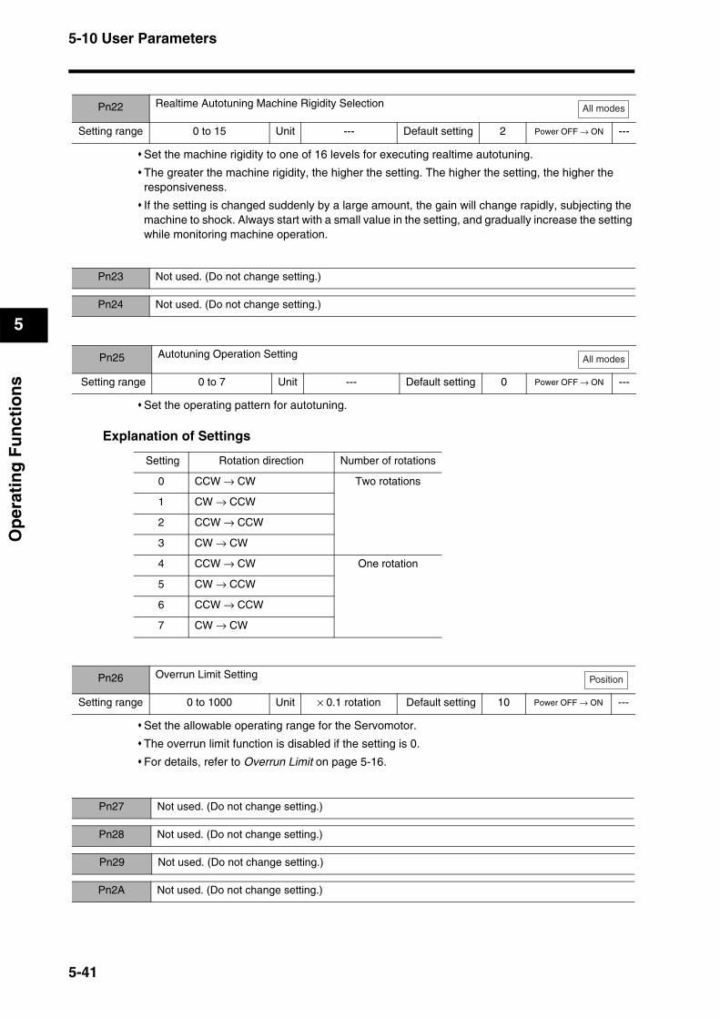
5-10 User Parameters
5
Op
erat
ing
Fu
nct
ion
s
Set the machine rigidity to one of 16 levels for executing realtime autotuning.
The greater the machine rigidity, the higher the setting. The higher the setting, the higher the responsiveness.
If the setting is changed suddenly by a large amount, the gain will change rapidly, subjecting the machine to shock. Always start with a small value in the setting, and gradually increase the setting while monitoring machine operation.
Set the operating pattern for autotuning.
Explanation of Settings
Set the allowable operating range for the Servomotor.
The overrun limit function is disabled if the setting is 0.
For details, refer to Overrun Limit on page 5-16.
Pn22 Realtime Autotuning Machine Rigidity Selection
Setting range 0 to 15 Unit --- Default setting 2 Power OFF → ON ---
All modes
Pn23 Not used. (Do not change setting.)
Pn24 Not used. (Do not change setting.)
Pn25 Autotuning Operation Setting
Setting range 0 to 7 Unit --- Default setting 0 Power OFF → ON ---
All modes
Setting Rotation direction Number of rotations
0 CCW → CW Two rotations
1 CW → CCW
2 CCW → CCW
3 CW → CW
4 CCW → CW One rotation
5 CW → CCW
6 CCW → CCW
7 CW → CW
Pn26 Overrun Limit Setting
Setting range 0 to 1000 Unit × 0.1 rotation Default setting 10 Power OFF → ON ---
Position
Pn27 Not used. (Do not change setting.)
Pn28 Not used. (Do not change setting.)
Pn29 Not used. (Do not change setting.)
Pn2A Not used. (Do not change setting.)
5-41
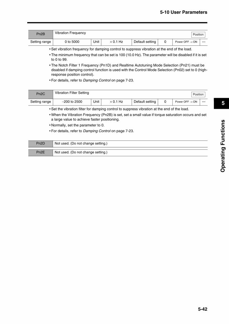
5-10 User Parameters
5
Op
erat
ing
Fu
nct
ion
s
Set vibration frequency for damping control to suppress vibration at the end of the load.
The minimum frequency that can be set is 100 (10.0 Hz). The parameter will be disabled if it is set to 0 to 99.
The Notch Filter 1 Frequency (Pn1D) and Realtime Autotuning Mode Selection (Pn21) must be disabled if damping control function is used with the Control Mode Selection (Pn02) set to 0 (high-response position control).
For details, refer to Damping Control on page 7-23.
Set the vibration filter for damping control to suppress vibration at the end of the load.
When the Vibration Frequency (Pn2B) is set, set a small value if torque saturation occurs and set a large value to achieve faster positioning.
Normally, set the parameter to 0.
For details, refer to Damping Control on page 7-23.
Pn2B Vibration Frequency
Setting range 0 to 5000 Unit × 0.1 Hz Default setting 0 Power OFF → ON ---
Position
Pn2C Vibration Filter Setting
Setting range −200 to 2500 Unit × 0.1 Hz Default setting 0 Power OFF → ON ---
Position
Pn2D Not used. (Do not change setting.)
Pn2E Not used. (Do not change setting.)
5-42
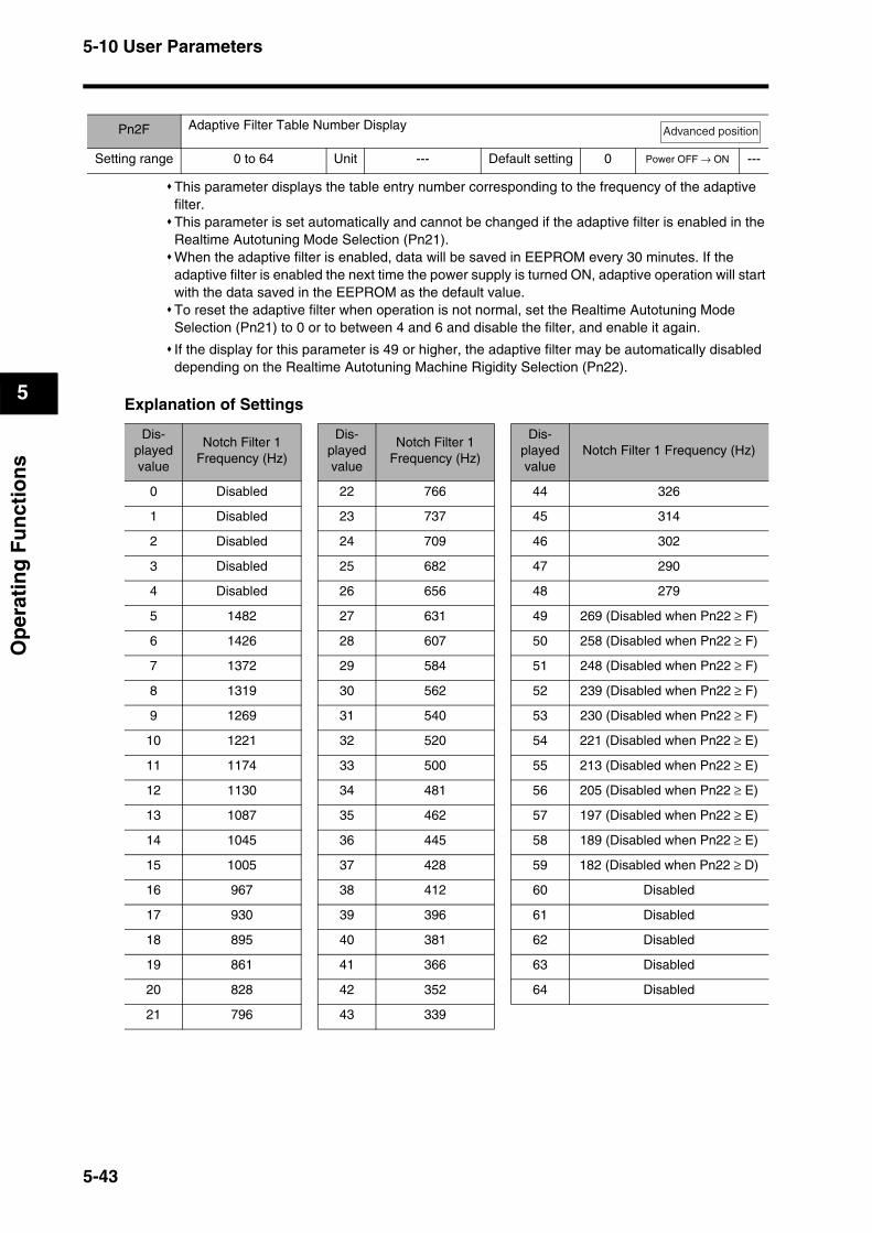
5-10 User Parameters
5
Op
erat
ing
Fu
nct
ion
s
This parameter displays the table entry number corresponding to the frequency of the adaptive filter.This parameter is set automatically and cannot be changed if the adaptive filter is enabled in the Realtime Autotuning Mode Selection (Pn21).When the adaptive filter is enabled, data will be saved in EEPROM every 30 minutes. If the adaptive filter is enabled the next time the power supply is turned ON, adaptive operation will start with the data saved in the EEPROM as the default value. To reset the adaptive filter when operation is not normal, set the Realtime Autotuning Mode Selection (Pn21) to 0 or to between 4 and 6 and disable the filter, and enable it again.
If the display for this parameter is 49 or higher, the adaptive filter may be automatically disabled depending on the Realtime Autotuning Machine Rigidity Selection (Pn22).
Explanation of Settings
Pn2F Adaptive Filter Table Number Display
Setting range 0 to 64 Unit --- Default setting 0 Power OFF → ON ---
Advanced position
Dis-played value
Notch Filter 1 Frequency (Hz)
Dis-played value
Notch Filter 1 Frequency (Hz)
Dis-played value
Notch Filter 1 Frequency (Hz)
0 Disabled 22 766 44 326
1 Disabled 23 737 45 314
2 Disabled 24 709 46 302
3 Disabled 25 682 47 290
4 Disabled 26 656 48 279
5 1482 27 631 49 269 (Disabled when Pn22 ≥ F)
6 1426 28 607 50 258 (Disabled when Pn22 ≥ F)
7 1372 29 584 51 248 (Disabled when Pn22 ≥ F)
8 1319 30 562 52 239 (Disabled when Pn22 ≥ F)
9 1269 31 540 53 230 (Disabled when Pn22 ≥ F)
10 1221 32 520 54 221 (Disabled when Pn22 ≥ E)
11 1174 33 500 55 213 (Disabled when Pn22 ≥ E)
12 1130 34 481 56 205 (Disabled when Pn22 ≥ E)
13 1087 35 462 57 197 (Disabled when Pn22 ≥ E)
14 1045 36 445 58 189 (Disabled when Pn22 ≥ E)
15 1005 37 428 59 182 (Disabled when Pn22 ≥ D)
16 967 38 412 60 Disabled
17 930 39 396 61 Disabled
18 895 40 381 62 Disabled
19 861 41 366 63 Disabled
20 828 42 352 64 Disabled
21 796 43 339
5-43
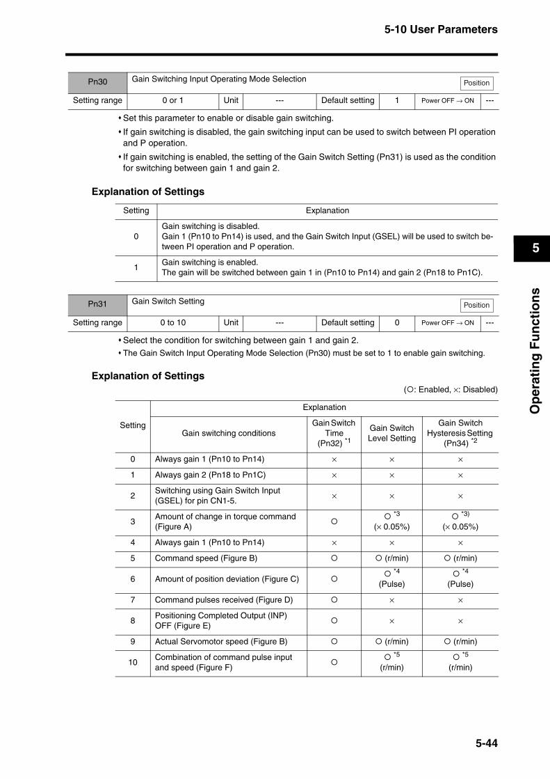
5-10 User Parameters
5
Op
erat
ing
Fu
nct
ion
s
Set this parameter to enable or disable gain switching.
If gain switching is disabled, the gain switching input can be used to switch between PI operation and P operation.
If gain switching is enabled, the setting of the Gain Switch Setting (Pn31) is used as the condition for switching between gain 1 and gain 2.
Explanation of Settings
Select the condition for switching between gain 1 and gain 2.The Gain Switch Input Operating Mode Selection (Pn30) must be set to 1 to enable gain switching.
Explanation of Settings( : Enabled, ×: Disabled)
Pn30 Gain Switching Input Operating Mode Selection
Setting range 0 or 1 Unit --- Default setting 1 Power OFF → ON ---
Position
Setting Explanation
0Gain switching is disabled. Gain 1 (Pn10 to Pn14) is used, and the Gain Switch Input (GSEL) will be used to switch be-tween PI operation and P operation.
1Gain switching is enabled.The gain will be switched between gain 1 in (Pn10 to Pn14) and gain 2 (Pn18 to Pn1C).
Pn31 Gain Switch Setting
Setting range 0 to 10 Unit --- Default setting 0 Power OFF → ON ---
Position
Setting
Explanation
Gain switching conditionsGain Switch
Time (Pn32) *1
Gain Switch Level Setting
Gain Switch Hysteresis Setting
(Pn34) *2
0 Always gain 1 (Pn10 to Pn14) × × ×
1 Always gain 2 (Pn18 to Pn1C) × × ×
2Switching using Gain Switch Input (GSEL) for pin CN1-5.
× × ×
3Amount of change in torque command (Figure A)
*3
(× 0.05%) *3)
(× 0.05%)
4 Always gain 1 (Pn10 to Pn14) × × ×
5 Command speed (Figure B) (r/min) (r/min)
6 Amount of position deviation (Figure C) *4
(Pulse) *4
(Pulse)
7 Command pulses received (Figure D) × ×
8Positioning Completed Output (INP) OFF (Figure E)
× ×
9 Actual Servomotor speed (Figure B) (r/min) (r/min)
10Combination of command pulse input and speed (Figure F)
*5
(r/min) *5
(r/min)
5-44
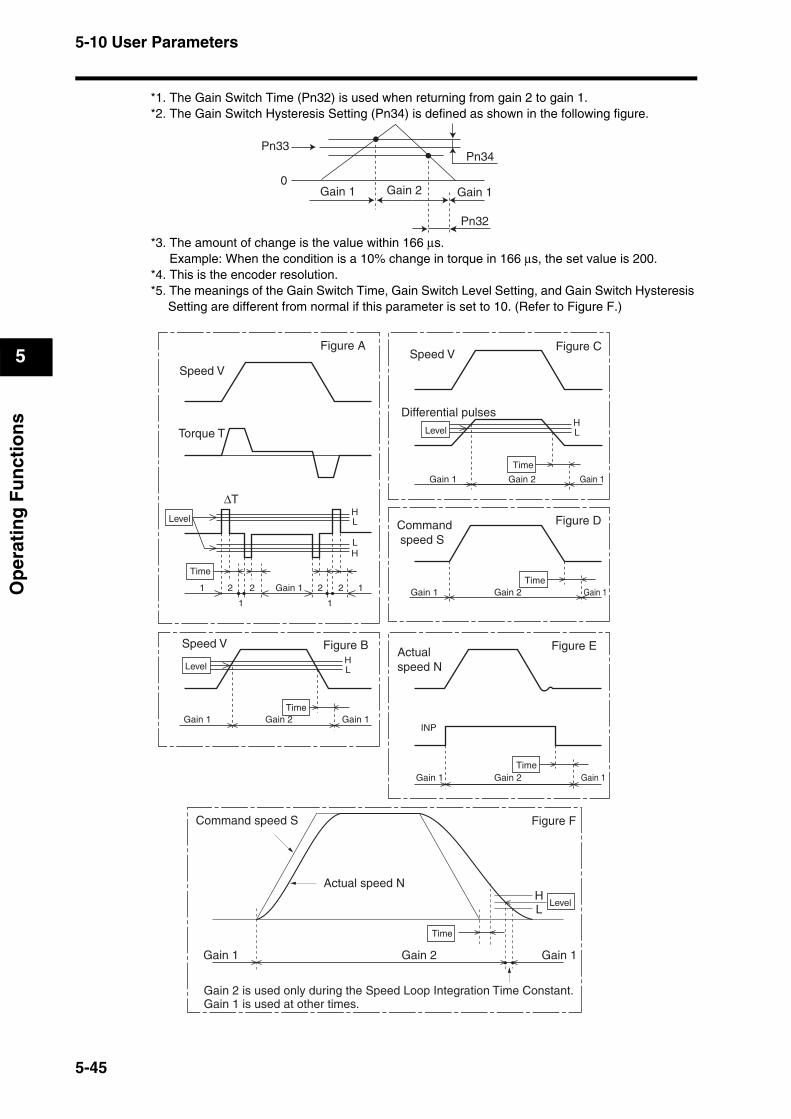
5-10 User Parameters
5
Op
erat
ing
Fu
nct
ion
s
*1. The Gain Switch Time (Pn32) is used when returning from gain 2 to gain 1.*2. The Gain Switch Hysteresis Setting (Pn34) is defined as shown in the following figure.
*3. The amount of change is the value within 166 µs.Example: When the condition is a 10% change in torque in 166 µs, the set value is 200.
*4. This is the encoder resolution.*5. The meanings of the Gain Switch Time, Gain Switch Level Setting, and Gain Switch Hysteresis
Setting are different from normal if this parameter is set to 10. (Refer to Figure F.)
Pn33Pn34
0
Pn32
Gain 1 Gain 1Gain 2
HL
HL
HL
HL
Figure A
Speed V
Torque T
∆T
Level
Time
1
1
2 2 2 2
1
1Gain 1
Figure CSpeed V
Gain 1 Gain 1Gain 2
Differential pulsesLevel
Time
Figure D Command speed S
Gain 1 Gain 1Gain 2Time
Figure E Actual speed N
INP
Gain 1 Gain 1Gain 2Time
Figure BSpeed V
Level
Gain 1 Gain 1Gain 2Time
Gain 1 Gain 2
Actual speed N
Time
LevelHL
Gain 1
Gain 2 is used only during the Speed Loop Integration Time Constant.
Figure F
Gain 1 is used at other times.
Command speed S
5-45
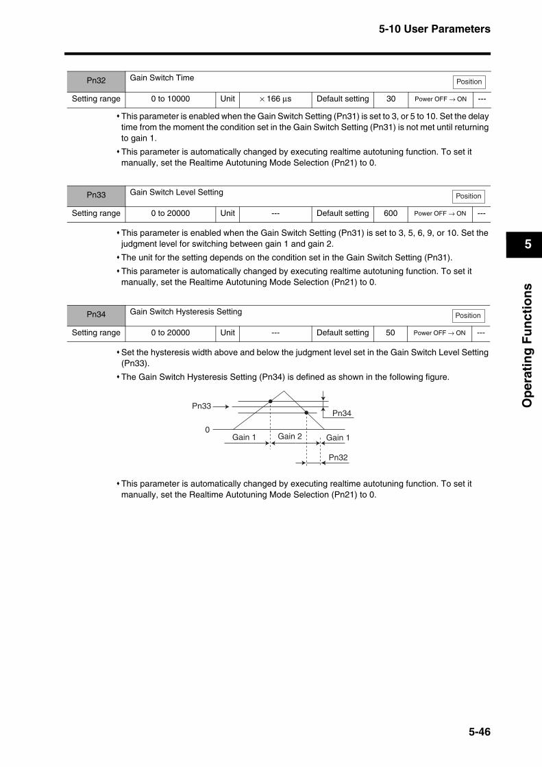
5-10 User Parameters
5
Op
erat
ing
Fu
nct
ion
s
This parameter is enabled when the Gain Switch Setting (Pn31) is set to 3, or 5 to 10. Set the delay time from the moment the condition set in the Gain Switch Setting (Pn31) is not met until returning to gain 1.
This parameter is automatically changed by executing realtime autotuning function. To set it manually, set the Realtime Autotuning Mode Selection (Pn21) to 0.
This parameter is enabled when the Gain Switch Setting (Pn31) is set to 3, 5, 6, 9, or 10. Set the judgment level for switching between gain 1 and gain 2.
The unit for the setting depends on the condition set in the Gain Switch Setting (Pn31).
This parameter is automatically changed by executing realtime autotuning function. To set it manually, set the Realtime Autotuning Mode Selection (Pn21) to 0.
Set the hysteresis width above and below the judgment level set in the Gain Switch Level Setting (Pn33).
The Gain Switch Hysteresis Setting (Pn34) is defined as shown in the following figure.
This parameter is automatically changed by executing realtime autotuning function. To set it manually, set the Realtime Autotuning Mode Selection (Pn21) to 0.
Pn32 Gain Switch Time
Setting range 0 to 10000 Unit × 166 µs Default setting 30 Power OFF → ON ---
Position
Pn33 Gain Switch Level Setting
Setting range 0 to 20000 Unit --- Default setting 600 Power OFF → ON ---
Pn34 Gain Switch Hysteresis Setting
Setting range 0 to 20000 Unit --- Default setting 50 Power OFF → ON ---
Position
Position
Pn33Pn34
0
Pn32
Gain 1 Gain 1Gain 2
5-46
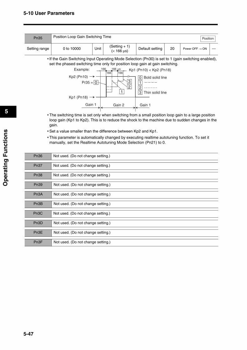
5-10 User Parameters
5
Op
erat
ing
Fu
nct
ion
s
If the Gain Switching Input Operating Mode Selection (Pn30) is set to 1 (gain switching enabled), set the phased switching time only for position loop gain at gain switching.
The switching time is set only when switching from a small position loop gain to a large position loop gain (Kp1 to Kp2). This is to reduce the shock to the machine due to sudden changes in the gain.
Set a value smaller than the difference between Kp2 and Kp1.
This parameter is automatically changed by executing realtime autotuning function. To set it manually, set the Realtime Autotuning Mode Selection (Pn21) to 0.
Pn35 Position Loop Gain Switching Time
Setting range 0 to 10000 Unit(Setting + 1)(× 166 µs)
Default setting 20 Power OFF → ON ---
Position
Kp1 (Pn10) < Kp2 (Pn18)
00
1
12 2
3
3
Pr35 =
Kp2 (Pn10)
166166 166
166 µs
Kp1 (Pn18)
Example:
Bold solid line
Thin solid line
Gain 1 Gain 2 Gain 1
Pn36 Not used. (Do not change setting.)
Pn37 Not used. (Do not change setting.)
Pn38 Not used. (Do not change setting.)
Pn39 Not used. (Do not change setting.)
Pn3A Not used. (Do not change setting.)
Pn3B Not used. (Do not change setting.)
Pn3C Not used. (Do not change setting.)
Pn3D Not used. (Do not change setting.)
Pn3E Not used. (Do not change setting.)
Pn3F Not used. (Do not change setting.)
5-47
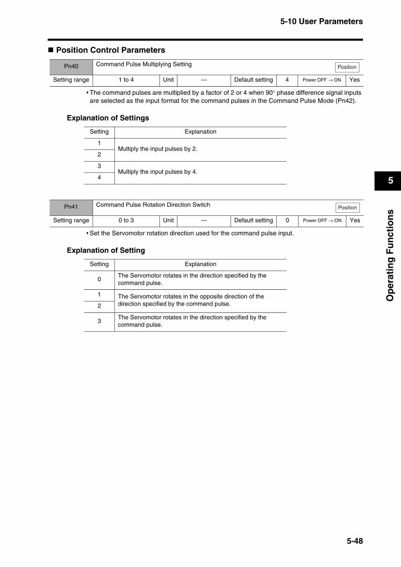
5-10 User Parameters
5
Op
erat
ing
Fu
nct
ion
s
Position Control Parameters
The command pulses are multiplied by a factor of 2 or 4 when 90° phase difference signal inputs are selected as the input format for the command pulses in the Command Pulse Mode (Pn42).
Explanation of Settings
Set the Servomotor rotation direction used for the command pulse input.
Explanation of Setting
Pn40 Command Pulse Multiplying Setting
Setting range 1 to 4 Unit --- Default setting 4 Power OFF → ON Yes
Position
Setting Explanation
1Multiply the input pulses by 2.
2
3Multiply the input pulses by 4.
4
Pn41 Command Pulse Rotation Direction Switch
Setting range 0 to 3 Unit --- Default setting 0 Power OFF → ON Yes
Position
Setting Explanation
0The Servomotor rotates in the direction specified by the command pulse.
1 The Servomotor rotates in the opposite direction of the direction specified by the command pulse.2
3The Servomotor rotates in the direction specified by the command pulse.
5-48

5-10 User Parameters
5
Op
erat
ing
Fu
nct
ion
s
Set the input format of the pulse inputs sent as commands to the Servo Drive from the position controller.
Explanation of Setting
Set the number of encoder pulses to be output from the Servo Drive for each rotation.
The setting can be made from 1 to 16,384 pulses, but the setting will not be valid if it exceeds 2,500 pulses. (Any setting that exceeds the encoder resolution will be invalid.)
Even if the dividing rate is changed, there will always be 1 pulse per rotation for phase Z.
Pn42 Command Pulse Mode
Setting range 0 to 3 Unit --- Default setting 1 Power OFF → ON Yes
Position
Setting Command pulse mode Servomotor forward command Servomotor reverse command
0 or 2
90° phase difference (phases A and B)
signal inputs
Line driver: t1 ≥ 2 µs Open collector: t1 ≥ 5 µs
1
Forward pulse and reverse pulse inputs
Line driver: t2 ≥ 1 µsOpen collector: t2 ≥ 2.5 µs
3
Feed pulse input and forward/reverse signal
Line driver: t2 ≥ 1 µsOpen collector: t2 ≥ 2.5 µs
t1 t1 t1 t1
t1 t1t1 t1
Phase A
Phase B
t2 t2
t2
t2
t2
Low
Low
t2
High Lowt2t2
t2 t2 t2 t2
t2
Pn43 Not used. (Do not change setting.)
Pn44 Encoder Dividing Rate Setting
Setting range 1 to 16384 Unit Pulse Default setting 2500 Power OFF → ON Yes
All modes
5-49
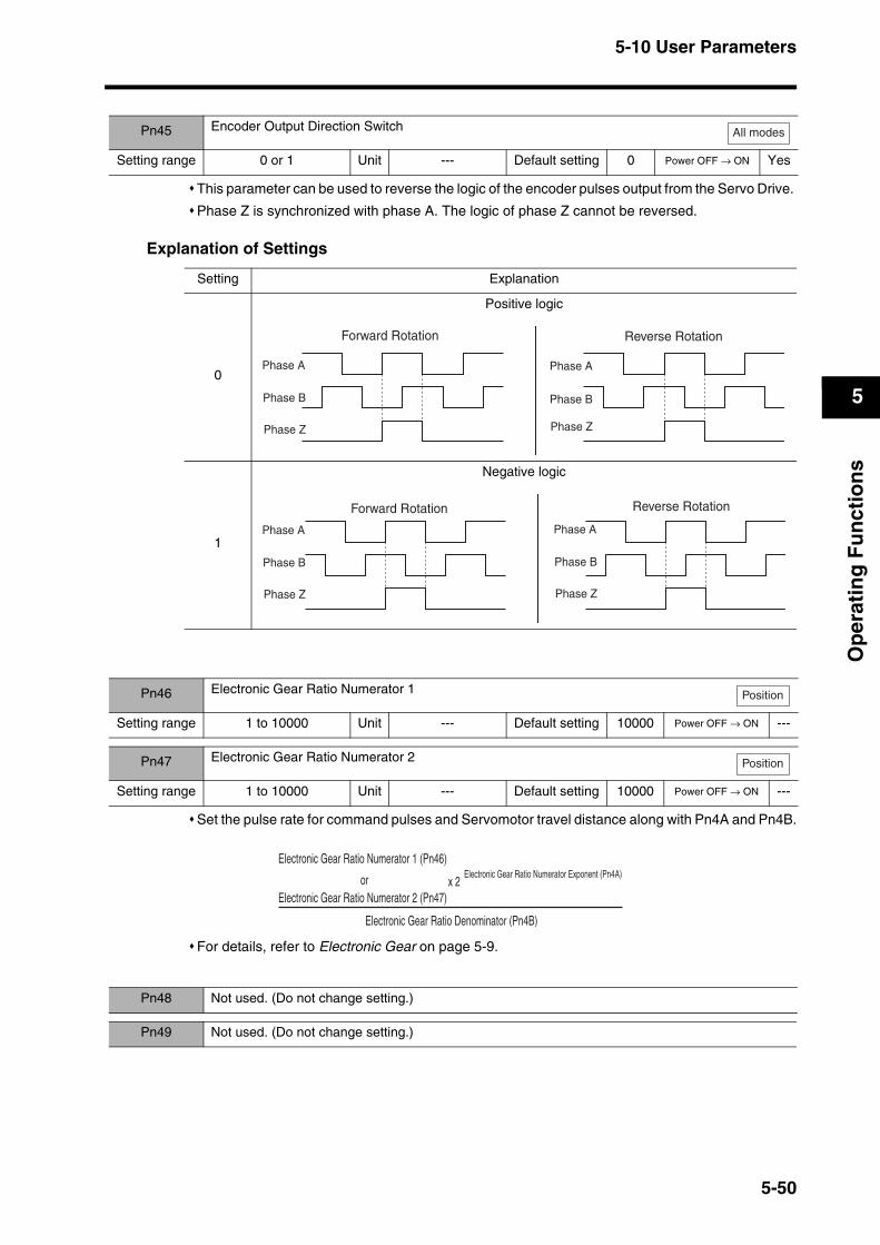
5-10 User Parameters
5
Op
erat
ing
Fu
nct
ion
s
This parameter can be used to reverse the logic of the encoder pulses output from the Servo Drive.
Phase Z is synchronized with phase A. The logic of phase Z cannot be reversed.
Explanation of Settings
Set the pulse rate for command pulses and Servomotor travel distance along with Pn4A and Pn4B.
For details, refer to Electronic Gear on page 5-9.
Pn45 Encoder Output Direction Switch
Setting range 0 or 1 Unit --- Default setting 0 Power OFF → ON Yes
All modes
Setting Explanation
0
Positive logic
1
Negative logic
Forward Rotation Reverse Rotation
Phase APhase A
Phase B
Phase Z
Phase B
Phase Z
Forward Rotation Reverse Rotation
Phase A
Phase B
Phase Z
Phase A
Phase B
Phase Z
Pn46 Electronic Gear Ratio Numerator 1
Setting range 1 to 10000 Unit --- Default setting 10000 Power OFF → ON ---
Pn47 Electronic Gear Ratio Numerator 2
Setting range 1 to 10000 Unit --- Default setting 10000 Power OFF → ON ---
Position
Position
Electronic Gear Ratio Denominator (Pn4B)
x 2Electronic Gear Ratio Numerator Exponent (Pn4A)
Electronic Gear Ratio Numerator 1 (Pn46)
orElectronic Gear Ratio Numerator 2 (Pn47)
Pn48 Not used. (Do not change setting.)
Pn49 Not used. (Do not change setting.)
5-50

5-10 User Parameters
5
Op
erat
ing
Fu
nct
ion
s
Set the pulse rate for command pulses and Servomotor travel distance along with Pn46 and Pn47
For details, refer to Electronic Gear on page 5-9.
Set the time constant for the primary lag filter for command pulse inputs.
If the command pulses are erratic, the normal countermeasure is to reduce the stepping movement of the Servomotor.
Explanation of Settings
Pn4A Electronic Gear Ratio Numerator Exponent
Setting range 0 to 17 Unit --- Default setting 0 Power OFF → ON ---
Position
Pn4B Electronic Gear Ratio Denominator
Setting range 1 to 10000 Unit --- Default setting 2500 Power OFF → ON ---
Position
Electronic Gear Ratio Denominator (Pn4B)
x 2Electronic Gear Ratio Numerator Exponent (Pn4A)
Electronic Gear Ratio Numerator 1 (Pn46)
orElectronic Gear Ratio Numerator 2 (Pn47)
Pn4C Position Command Filter Time Constant Setting
Setting range 0 to 7 Unit --- Default setting 0 Power OFF → ON ---
Position
Setting Explanation
0 No filter
1 Time constant: 0.2 ms
2 Time constant: 0.6 ms
3 Time constant: 1.3 ms
4 Time constant: 2.6 ms
5 Time constant: 5.3 ms
6 Time constant: 10.6 ms
7 Time constant: 21.2 ms
Pn4D Not used. (Do not change setting.)
5-51
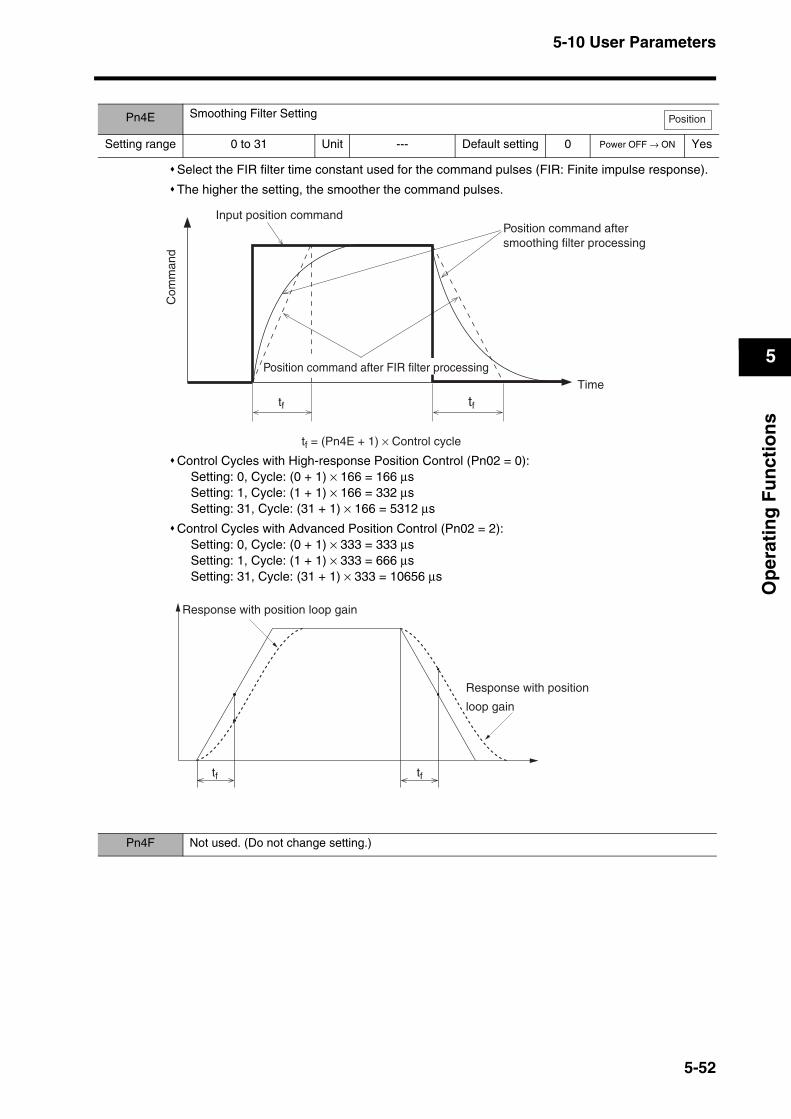
5-10 User Parameters
5
Op
erat
ing
Fu
nct
ion
s
Select the FIR filter time constant used for the command pulses (FIR: Finite impulse response).
The higher the setting, the smoother the command pulses.
Control Cycles with High-response Position Control (Pn02 = 0):Setting: 0, Cycle: (0 + 1) × 166 = 166 µsSetting: 1, Cycle: (1 + 1) × 166 = 332 µsSetting: 31, Cycle: (31 + 1) × 166 = 5312 µs
Control Cycles with Advanced Position Control (Pn02 = 2):Setting: 0, Cycle: (0 + 1) × 333 = 333 µsSetting: 1, Cycle: (1 + 1) × 333 = 666 µsSetting: 31, Cycle: (31 + 1) × 333 = 10656 µs
Pn4E Smoothing Filter Setting
Setting range 0 to 31 Unit --- Default setting 0 Power OFF → ON Yes
Position
tf = (Pn4E + 1) × Control cycle
Input position command
tf
Position command after smoothing filter processing
tf
TimePosition command after FIR filter processing
Com
man
d
tf tf
Response with position loop gain
Response with position
loop gain
Pn4F Not used. (Do not change setting.)
5-52
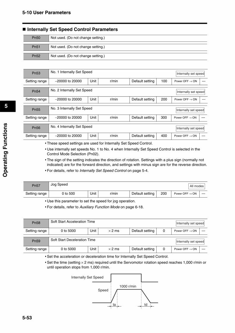
5-10 User Parameters
5
Op
erat
ing
Fu
nct
ion
s
Internally Set Speed Control Parameters
These speed settings are used for Internally Set Speed Control.
Use internally set speeds No. 1 to No. 4 when Internally Set Speed Control is selected in the Control Mode Selection (Pn02).
The sign of the setting indicates the direction of rotation. Settings with a plus sign (normally not indicated) are for the forward direction, and settings with minus sign are for the reverse direction.
For details, refer to Internally Set Speed Control on page 5-4.
Use this parameter to set the speed for jog operation.
For details, refer to Auxiliary Function Mode on page 6-18.
Set the acceleration or deceleration time for Internally Set Speed Control.
Set the time (setting × 2 ms) required until the Servomotor rotation speed reaches 1,000 r/min or until operation stops from 1,000 r/min.
Pn50 Not used. (Do not change setting.)
Pn51 Not used. (Do not change setting.)
Pn52 Not used. (Do not change setting.)
Pn53 No. 1 Internally Set Speed
Setting range −20000 to 20000 Unit r/min Default setting 100 Power OFF → ON ---
Pn54 No. 2 Internally Set Speed
Setting range −20000 to 20000 Unit r/min Default setting 200 Power OFF → ON ---
Internally set speed
Internally set speed
Pn55 No. 3 Internally Set Speed
Setting range −20000 to 20000 Unit r/min Default setting 300 Power OFF → ON ---
Internally set speed
Pn56 No. 4 Internally Set Speed
Setting range −20000 to 20000 Unit r/min Default setting 400 Power OFF → ON ---
Internally set speed
Pn57 Jog Speed
Setting range 0 to 500 Unit r/min Default setting 200 Power OFF → ON ---
All modes
Pn58 Soft Start Acceleration Time
Setting range 0 to 5000 Unit × 2 ms Default setting 0 Power OFF → ON ---
Pn59 Soft Start Deceleration Time
Setting range 0 to 5000 Unit × 2 ms Default setting 0 Power OFF → ON ---
Internally set speed
Internally set speed
ta td
Internally Set Speed
Speed1000 r/min
5-53
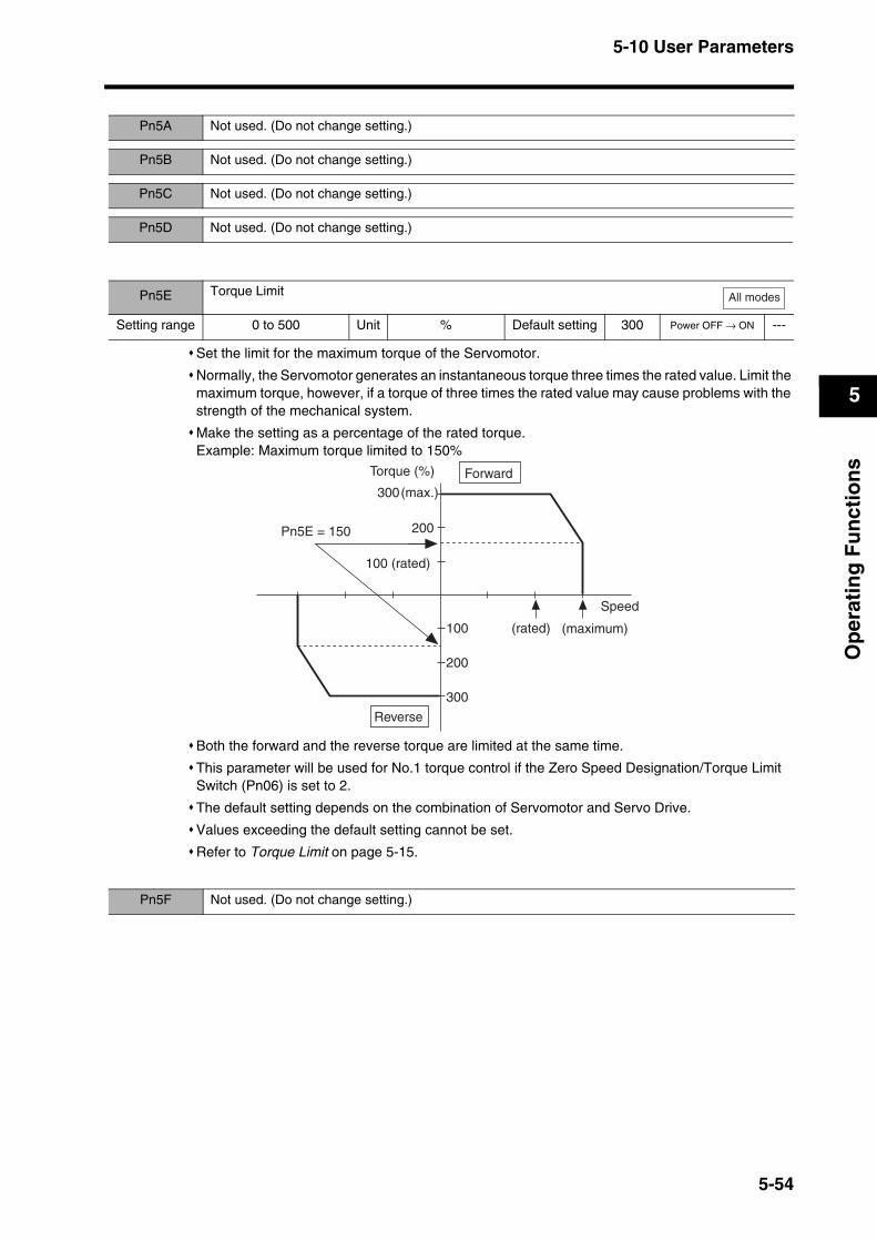
5-10 User Parameters
5
Op
erat
ing
Fu
nct
ion
s
Set the limit for the maximum torque of the Servomotor.
Normally, the Servomotor generates an instantaneous torque three times the rated value. Limit the maximum torque, however, if a torque of three times the rated value may cause problems with the strength of the mechanical system.
Make the setting as a percentage of the rated torque.Example: Maximum torque limited to 150%
Both the forward and the reverse torque are limited at the same time.
This parameter will be used for No.1 torque control if the Zero Speed Designation/Torque Limit Switch (Pn06) is set to 2.
The default setting depends on the combination of Servomotor and Servo Drive.
Values exceeding the default setting cannot be set.
Refer to Torque Limit on page 5-15.
Pn5A Not used. (Do not change setting.)
Pn5B Not used. (Do not change setting.)
Pn5C Not used. (Do not change setting.)
Pn5D Not used. (Do not change setting.)
Pn5E Torque Limit
Setting range 0 to 500 Unit % Default setting 300 Power OFF → ON ---
All modes
Speed
200
100 (rated)
(rated)100
200
300
Torque (%)
300(max.)
Reverse
Forward
Pn5E = 150
(maximum)
Pn5F Not used. (Do not change setting.)
5-54
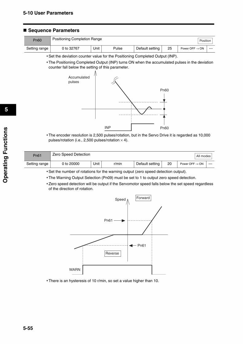
5-10 User Parameters
5
Op
erat
ing
Fu
nct
ion
s
Sequence Parameters
Set the deviation counter value for the Positioning Completed Output (INP).
The Positioning Completed Output (INP) turns ON when the accumulated pulses in the deviation counter fall below the setting of this parameter.
The encoder resolution is 2,500 pulses/rotation, but in the Servo Drive it is regarded as 10,000 pulses/rotation (i.e., 2,500 pulses/rotation × 4).
Set the number of rotations for the warning output (zero speed detection output).
The Warning Output Selection (Pn09) must be set to 1 to output zero speed detection.
Zero speed detection will be output if the Servomotor speed falls below the set speed regardless of the direction of rotation.
There is an hysteresis of 10 r/min, so set a value higher than 10.
Pn60 Positioning Completion Range
Setting range 0 to 32767 Unit Pulse Default setting 25 Power OFF → ON ---
Position
Accumulated pulses
Pn60
Pn60INP
Pn61 Zero Speed Detection
Setting range 0 to 20000 Unit r/min Default setting 20 Power OFF → ON ---
All modes
Speed
Reverse
WARN
Pn61
Pn61
Forward
5-55
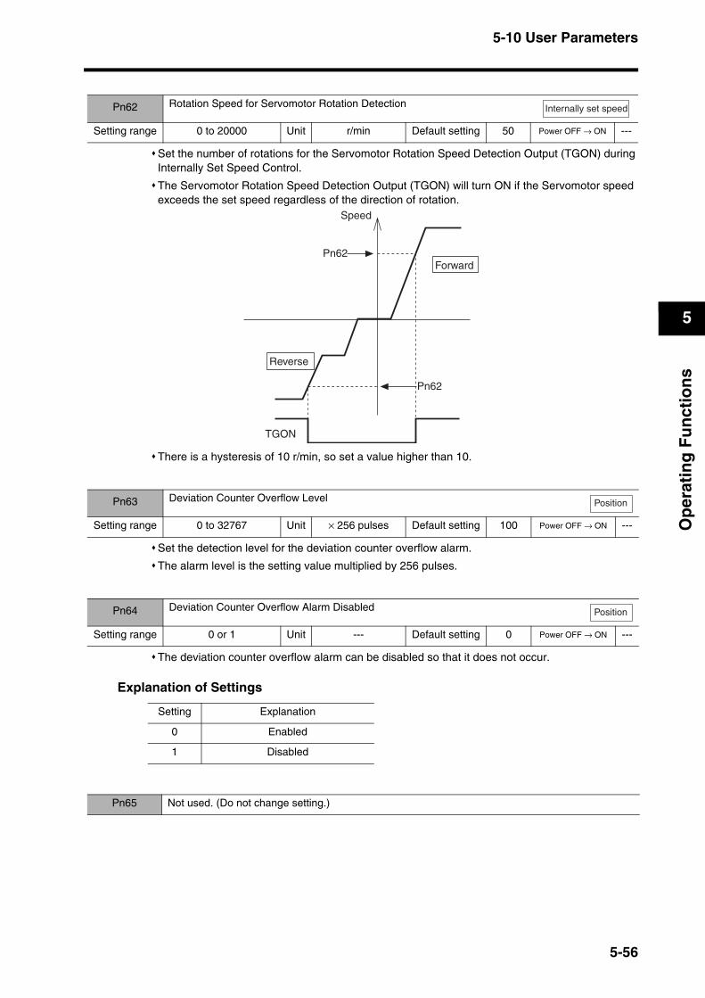
5-10 User Parameters
5
Op
erat
ing
Fu
nct
ion
s
Set the number of rotations for the Servomotor Rotation Speed Detection Output (TGON) during Internally Set Speed Control.
The Servomotor Rotation Speed Detection Output (TGON) will turn ON if the Servomotor speed exceeds the set speed regardless of the direction of rotation.
There is a hysteresis of 10 r/min, so set a value higher than 10.
Set the detection level for the deviation counter overflow alarm.
The alarm level is the setting value multiplied by 256 pulses.
The deviation counter overflow alarm can be disabled so that it does not occur.
Explanation of Settings
Pn62 Rotation Speed for Servomotor Rotation Detection
Setting range 0 to 20000 Unit r/min Default setting 50 Power OFF → ON ---
Internally set speed
Speed
Reverse
TGON
ForwardPn62
Pn62
Pn63 Deviation Counter Overflow Level
Setting range 0 to 32767 Unit × 256 pulses Default setting 100 Power OFF → ON ---
Position
Pn64 Deviation Counter Overflow Alarm Disabled
Setting range 0 or 1 Unit --- Default setting 0 Power OFF → ON ---
Position
Setting Explanation
0 Enabled
1 Disabled
Pn65 Not used. (Do not change setting.)
5-56
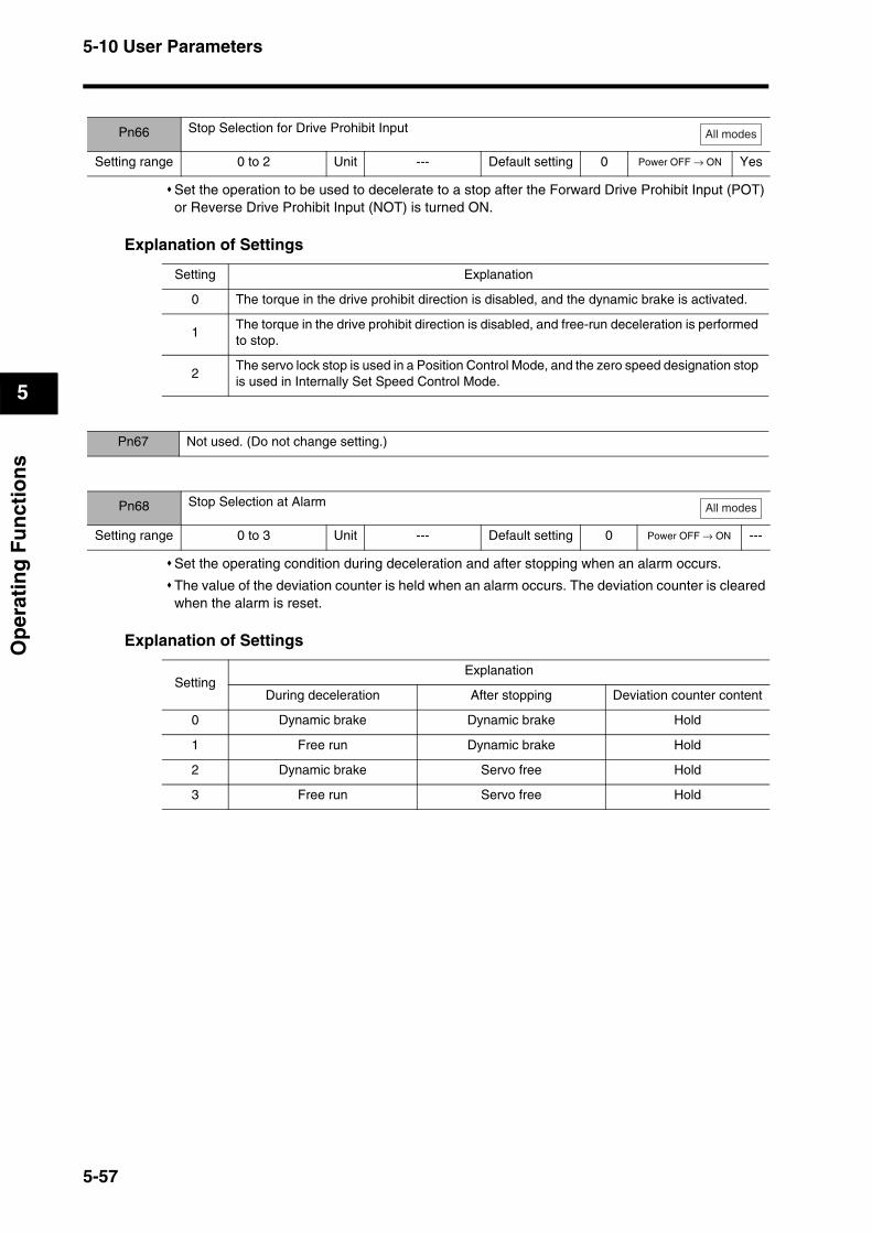
5-10 User Parameters
5
Op
erat
ing
Fu
nct
ion
s
Set the operation to be used to decelerate to a stop after the Forward Drive Prohibit Input (POT) or Reverse Drive Prohibit Input (NOT) is turned ON.
Explanation of Settings
Set the operating condition during deceleration and after stopping when an alarm occurs.
The value of the deviation counter is held when an alarm occurs. The deviation counter is cleared when the alarm is reset.
Explanation of Settings
Pn66 Stop Selection for Drive Prohibit Input
Setting range 0 to 2 Unit --- Default setting 0 Power OFF → ON Yes
All modes
Setting Explanation
0 The torque in the drive prohibit direction is disabled, and the dynamic brake is activated.
1The torque in the drive prohibit direction is disabled, and free-run deceleration is performed to stop.
2The servo lock stop is used in a Position Control Mode, and the zero speed designation stop is used in Internally Set Speed Control Mode.
Pn67 Not used. (Do not change setting.)
Pn68 Stop Selection at Alarm
Setting range 0 to 3 Unit --- Default setting 0 Power OFF → ON ---
All modes
SettingExplanation
During deceleration After stopping Deviation counter content
0 Dynamic brake Dynamic brake Hold
1 Free run Dynamic brake Hold
2 Dynamic brake Servo free Hold
3 Free run Servo free Hold
5-57

5-10 User Parameters
5
Op
erat
ing
Fu
nct
ion
s
Set the operation during deceleration and after stopping as well as the deviation counter status when the RUN Command Input (RUN) turns OFF.
Explanation of Settings
When the RUN Command Input is turned OFF while the Servomotor is stopped, the Brake Interlock Signal (BKIR) will turn OFF, and the Servo will turn OFF after the time set for this parameter (setting × 2 ms) elapses.
Make the setting as follows to prevent the machine (workpiece) from moving or falling due to the delay in the brake operation (tb).
Brake timing when stopped (setting × 2 ms) ≥ tb
Pn69 Stop Selection with Servo OFF
Setting range 0 to 7 Unit --- Default setting 0 Power OFF → ON ---
All modes
SettingExplanation
During deceleration After stopping Deviation counter content
0 Dynamic brake Dynamic brake Clear
1 Free run Dynamic brake Clear
2 Dynamic brake Servo free Clear
3 Free run Servo free Clear
4 Dynamic brake Dynamic brake Hold
5 Free run Dynamic brake Hold
6 Dynamic brake Servo free Hold
7 Free run Servo free Hold
Reference Dynamic Brake at Power OFFBy default, the dynamic brake of the Servo Drive will be engaged when the main circuit power is turned OFF. For this reason, it feels slightly heavier to rotate the Servomotor shaft manually than in servo free status. To release the dynamic brake, disconnect the wirings (U, V, W) from the Servomotor. Be sure to reconnect these wirings before restoring the power.
Pn6A Brake Timing When Stopped
Setting range 0 to 100 Unit × 2 ms Default setting 10 Power OFF → ON ---
All modes
RUN command (RUN)
Brake interlock(BKIR)
Actual braking
Servomotor ON/OFF status
Released Hold
ON
Hold
OFF
Pn6A
tbReleased
5-58
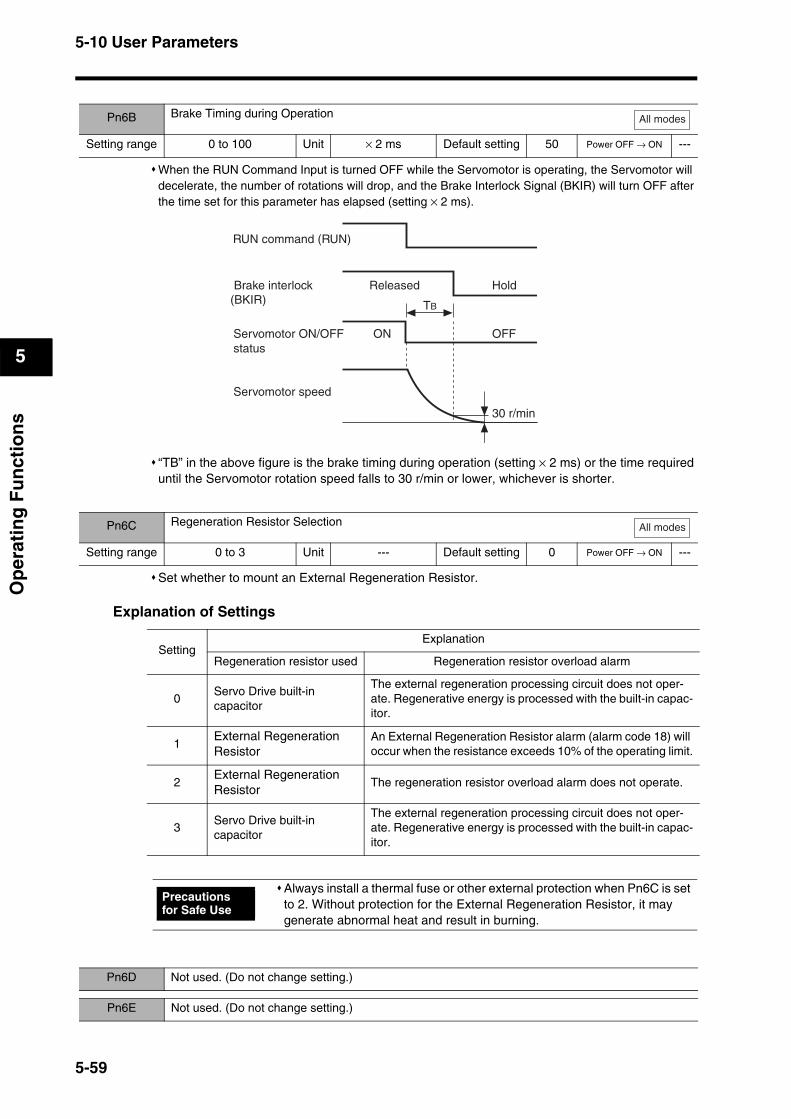
5-10 User Parameters
5
Op
erat
ing
Fu
nct
ion
s
When the RUN Command Input is turned OFF while the Servomotor is operating, the Servomotor will decelerate, the number of rotations will drop, and the Brake Interlock Signal (BKIR) will turn OFF after the time set for this parameter has elapsed (setting × 2 ms).
“TB” in the above figure is the brake timing during operation (setting × 2 ms) or the time required until the Servomotor rotation speed falls to 30 r/min or lower, whichever is shorter.
Set whether to mount an External Regeneration Resistor.
Explanation of Settings
Pn6B Brake Timing during Operation
Setting range 0 to 100 Unit × 2 ms Default setting 50 Power OFF → ON ---
All modes
TB
RUN command (RUN)
Brake interlock(BKIR)
Servomotor speed
Released Hold
Servomotor ON/OFF status
ON OFF
30 r/min
Pn6C Regeneration Resistor Selection
Setting range 0 to 3 Unit --- Default setting 0 Power OFF → ON ---
All modes
SettingExplanation
Regeneration resistor used Regeneration resistor overload alarm
0Servo Drive built-in capacitor
The external regeneration processing circuit does not oper-ate. Regenerative energy is processed with the built-in capac-itor.
1External Regeneration Resistor
An External Regeneration Resistor alarm (alarm code 18) will occur when the resistance exceeds 10% of the operating limit.
2External Regeneration Resistor
The regeneration resistor overload alarm does not operate.
3Servo Drive built-in capacitor
The external regeneration processing circuit does not oper-ate. Regenerative energy is processed with the built-in capac-itor.
Always install a thermal fuse or other external protection when Pn6C is set to 2. Without protection for the External Regeneration Resistor, it may generate abnormal heat and result in burning.
Precautions for Safe Use
Pn6D Not used. (Do not change setting.)
Pn6E Not used. (Do not change setting.)
5-59
5-10 User Parameters
5
Op
erat
ing
Fu
nct
ion
s
Set the No. 1 overspeed detection level when torque limit switching is enabled in the setting of the Zero Speed Designation/Torque Limit Switch (Pn06).
When the No. 1 torque limit is selected, an overspeed error will occur if the rotation speed of the Servomotor exceeds the setting.
This parameter is disabled when torque limit switching is disabled.
Set the No. 2 torque limit when torque limit switching is enabled in the setting of the Zero Speed Designation/Torque Limit Switch (Pn06).
This parameter is disabled when torque limit switching is disabled.
Refer to Torque Limit on page 5-54 for information on setting details.
Set the No. 2 deviation counter overflow level when torque limit switching is enabled in the setting of the Zero Speed Designation/Torque Limit Switch (Pn06).
This parameter is disabled when torque limit switching is disabled.
Refer to Deviation Counter Overflow Level on page 5-56 for information on setting details
Set the No. 2 overspeed detection level when torque limit switching is enabled in the setting of the Zero Speed Designation/Torque Limit Switch (Pn06).
When No. 2 torque limit is selected, an overspeed error will occur if the rotation speed of the Servomotor exceeds the setting.
This parameter is disabled when torque limit switching is disabled.
to
Pn6F Not used. (Do not change setting.)
Pn70 Overspeed Detection Level Setting
Setting range 0 to 6000 Unit r/min Default setting 0 Power OFF → ON ---
Pn71 No. 2 Torque Limit
Setting range 0 to 500 Unit % Default setting 100 Power OFF → ON ---
Pn72 No. 2 Deviation Counter Overflow Level
Setting range 1 to 32767 Unit × 256 pulse Default setting 100 Power OFF → ON ---
Pn73 No. 2 Overspeed Detection Level
Setting range 0 to 6000 Unit r/min Default setting 0 Power OFF → ON ---
All modes
All modes
All modes
All modes
Pn74 Not used. (Do not change setting.)
Pn7F Not used. (Do not change setting.)
5-60

Chapter 6
Operation6-1 Operational Procedure ......................................6-1
6-2 Preparing for Operation.....................................6-2Items to Check Before Turning ON the Power.........................6-2
Turning ON Power ...................................................................6-2
Checking Displays ...................................................................6-3
6-3 Using the Parameter Unit ..................................6-4Names of Parts and Functions.................................................6-4
Display When Power Is Turned ON .........................................6-5
Changing the Mode..................................................................6-6
Monitor Mode ...........................................................................6-7
Parameter Setting Mode ........................................................6-15
Parameter Write Mode...........................................................6-16
Autotuning Mode....................................................................6-17
Auxiliary Function Mode.........................................................6-18
Copy Mode.............................................................................6-20
6-4 Trial Operation..................................................6-23Preparation for Trial Operation ..............................................6-23
Trial Operation .......................................................................6-23
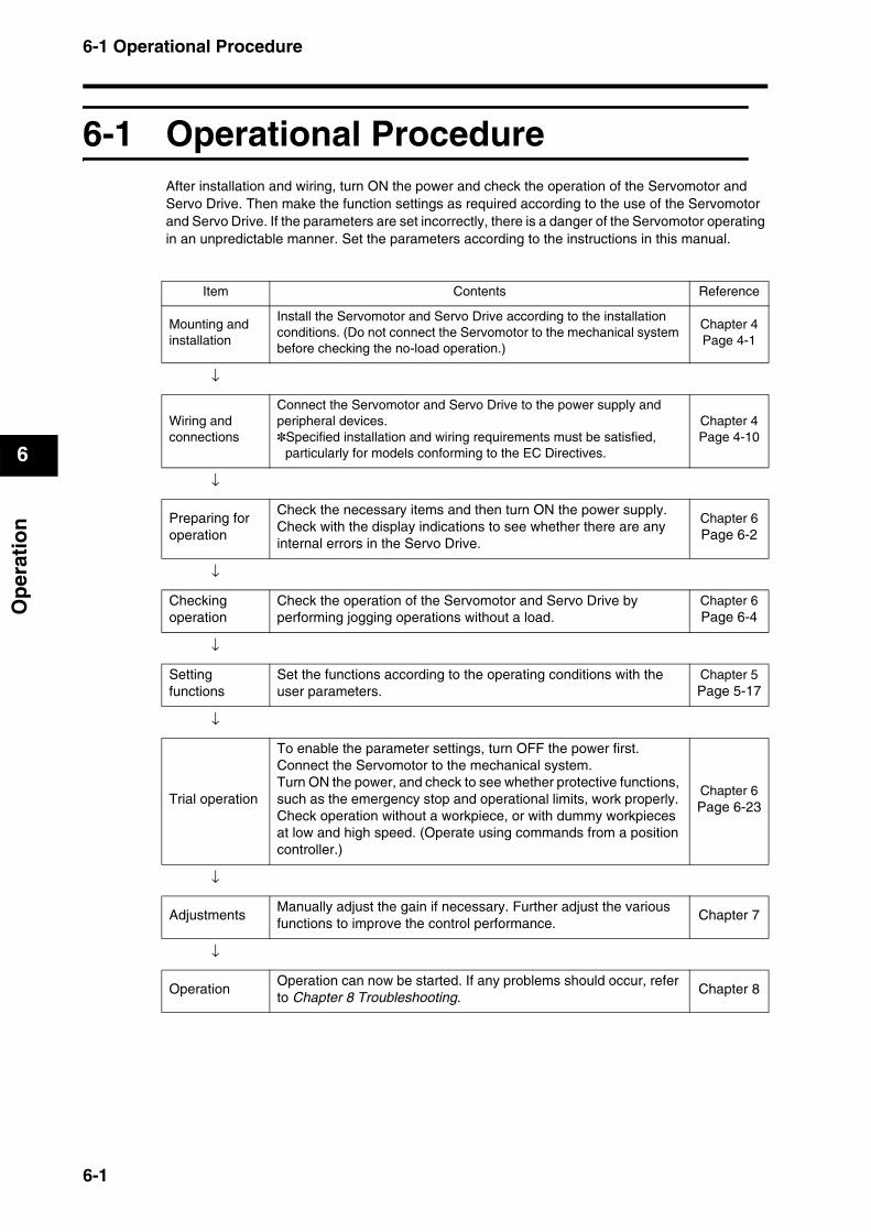
6-1 Operational Procedure
6
Op
erat
ion
6Operation
6-1 Operational ProcedureAfter installation and wiring, turn ON the power and check the operation of the Servomotor and Servo Drive. Then make the function settings as required according to the use of the Servomotor and Servo Drive. If the parameters are set incorrectly, there is a danger of the Servomotor operating in an unpredictable manner. Set the parameters according to the instructions in this manual.
↓
↓
↓
↓
↓
↓
↓
Item Contents Reference
Mounting and installation
Install the Servomotor and Servo Drive according to the installation conditions. (Do not connect the Servomotor to the mechanical system before checking the no-load operation.)
Chapter 4Page 4-1
Wiring and connections
Connect the Servomotor and Servo Drive to the power supply and peripheral devices. *Specified installation and wiring requirements must be satisfied,
particularly for models conforming to the EC Directives.
Chapter 4Page 4-10
Preparing for operation
Check the necessary items and then turn ON the power supply.Check with the display indications to see whether there are any internal errors in the Servo Drive.
Chapter 6Page 6-2
Checking operation
Check the operation of the Servomotor and Servo Drive by performing jogging operations without a load.
Chapter 6Page 6-4
Setting functions
Set the functions according to the operating conditions with the user parameters.
Chapter 5Page 5-17
Trial operation
To enable the parameter settings, turn OFF the power first. Connect the Servomotor to the mechanical system.Turn ON the power, and check to see whether protective functions, such as the emergency stop and operational limits, work properly. Check operation without a workpiece, or with dummy workpieces at low and high speed. (Operate using commands from a position controller.)
Chapter 6Page 6-23
AdjustmentsManually adjust the gain if necessary. Further adjust the various functions to improve the control performance.
Chapter 7
OperationOperation can now be started. If any problems should occur, refer to Chapter 8 Troubleshooting.
Chapter 8
6-1
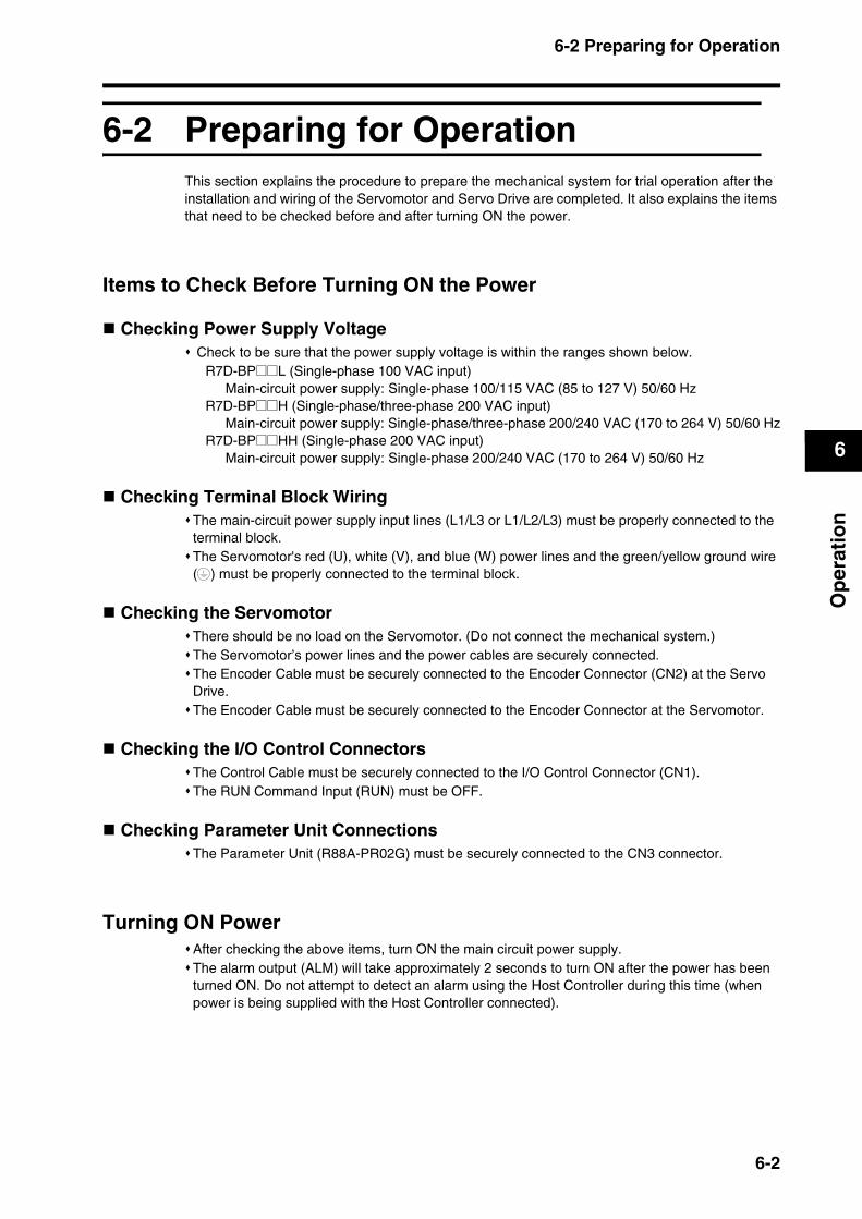
6-2 Preparing for Operation
6
Op
erat
ion
6-2 Preparing for OperationThis section explains the procedure to prepare the mechanical system for trial operation after the installation and wiring of the Servomotor and Servo Drive are completed. It also explains the items that need to be checked before and after turning ON the power.
Items to Check Before Turning ON the Power
Checking Power Supply Voltage Check to be sure that the power supply voltage is within the ranges shown below.
R7D-BP@@L (Single-phase 100 VAC input)Main-circuit power supply: Single-phase 100/115 VAC (85 to 127 V) 50/60 Hz
R7D-BP@@H (Single-phase/three-phase 200 VAC input)Main-circuit power supply: Single-phase/three-phase 200/240 VAC (170 to 264 V) 50/60 Hz
R7D-BP@@HH (Single-phase 200 VAC input)Main-circuit power supply: Single-phase 200/240 VAC (170 to 264 V) 50/60 Hz
Checking Terminal Block WiringThe main-circuit power supply input lines (L1/L3 or L1/L2/L3) must be properly connected to the terminal block.The Servomotor's red (U), white (V), and blue (W) power lines and the green/yellow ground wire ( ) must be properly connected to the terminal block.
Checking the ServomotorThere should be no load on the Servomotor. (Do not connect the mechanical system.)The Servomotor’s power lines and the power cables are securely connected.The Encoder Cable must be securely connected to the Encoder Connector (CN2) at the Servo Drive.The Encoder Cable must be securely connected to the Encoder Connector at the Servomotor.
Checking the I/O Control ConnectorsThe Control Cable must be securely connected to the I/O Control Connector (CN1).The RUN Command Input (RUN) must be OFF.
Checking Parameter Unit ConnectionsThe Parameter Unit (R88A-PR02G) must be securely connected to the CN3 connector.
Turning ON PowerAfter checking the above items, turn ON the main circuit power supply.The alarm output (ALM) will take approximately 2 seconds to turn ON after the power has been turned ON. Do not attempt to detect an alarm using the Host Controller during this time (when power is being supplied with the Host Controller connected).
6-2
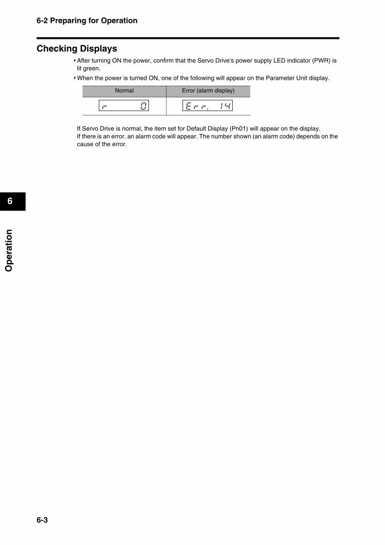
6-2 Preparing for Operation
6
Op
erat
ion
Checking DisplaysAfter turning ON the power, confirm that the Servo Drive's power supply LED indicator (PWR) is lit green.
When the power is turned ON, one of the following will appear on the Parameter Unit display.
If Servo Drive is normal, the item set for Default Display (Pn01) will appear on the display.If there is an error, an alarm code will appear. The number shown (an alarm code) depends on the cause of the error.
Normal Error (alarm display)
rk k k k k0k ekrkr. k1k4k
6-3
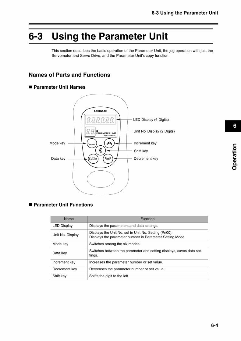
6-3 Using the Parameter Unit
6
Op
erat
ion
6-3 Using the Parameter UnitThis section describes the basic operation of the Parameter Unit, the jog operation with just the Servomotor and Servo Drive, and the Parameter Unit's copy function.
Names of Parts and Functions
Parameter Unit Names
Parameter Unit Functions
Name Function
LED Display Displays the parameters and data settings.
Unit No. DisplayDisplays the Unit No. set in Unit No. Setting (Pn00).Displays the parameter number in Parameter Setting Mode.
Mode key Switches among the six modes.
Data keySwitches between the parameter and setting displays, saves data set-tings.
Increment key Increases the parameter number or set value.
Decrement key Decreases the parameter number or set value.
Shift key Shifts the digit to the left.
LED Display (6 Digits)
Unit No. Display (2 Digits)
Mode key Increment key
Shift key
Decrement keyData key
6-4
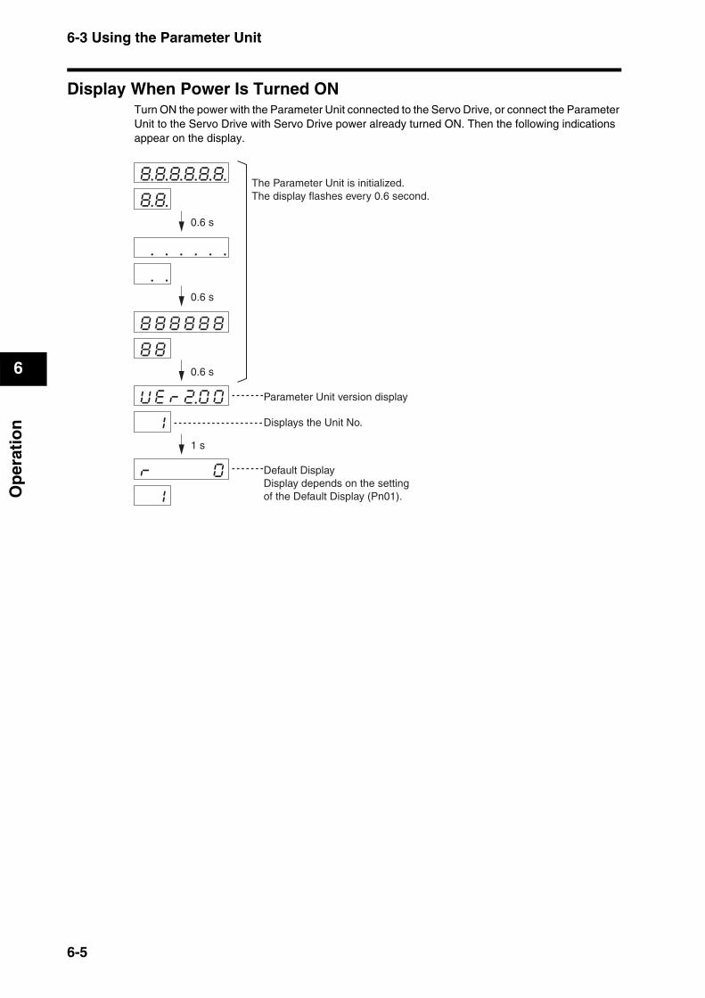
6-3 Using the Parameter Unit
6
Op
erat
ion
Display When Power Is Turned ONTurn ON the power with the Parameter Unit connected to the Servo Drive, or connect the Parameter Unit to the Servo Drive with Servo Drive power already turned ON. Then the following indications appear on the display.
. . . . . .
. .
8.8.8.8.8.8.
8.8.
8k8k8k8k8k8
8k8
Ukekrk2.0k0
k1
rk k k k k0
k1
The Parameter Unit is initialized. The display flashes every 0.6 second.
Parameter Unit version display
Displays the Unit No.
Default DisplayDisplay depends on the settingof the Default Display (Pn01).
0.6 s
0.6 s
0.6 s
1 s
6-5

6-3 Using the Parameter Unit
6
Op
erat
ion
Changing the Mode
rk k k k k0
k1
Uknk_kskpkd.
Uknk_kikdkc.
pknk_krk0k0.
pknk_k k7kf.
ekek_kskekt
aktk_knkok1.
aktk_knkokf.
fknk_kakckl.
fknk_kjkokg.
fknk_keknkc.
ckfk_kak2kc.
ckfk_kck2ka.
rk k k k k0
rksk-k2k3k2
k k k k k1.
k k k k k0.
ekekpk k k-.
aktkuk k k-.
akcklk k k-.
jkokgk k k-.
eknkck k k-.
ak2kck k k-.
ck2kak k k-.
Parameters Unitdefault display
Mon
itor
Par
amet
er
Set
ting
Par
amet
er
Writ
eA
utot
unin
gA
uxili
ary
Fun
ctio
nC
opy
6-6
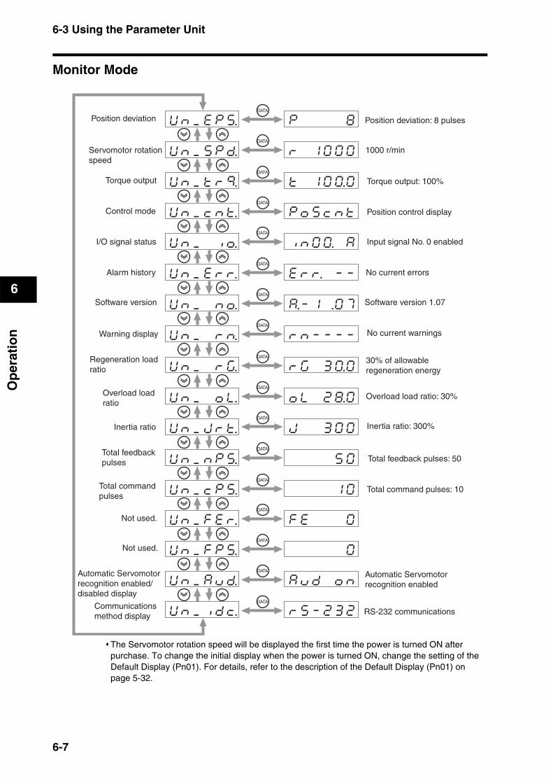
6-3 Using the Parameter Unit
6
Op
erat
ion
Monitor Mode
The Servomotor rotation speed will be displayed the first time the power is turned ON after purchase. To change the initial display when the power is turned ON, change the setting of the Default Display (Pn01). For details, refer to the description of the Default Display (Pn01) on page 5-32.
Uknk_kekpks.k
Uknk_kskpkd.k
Uknk_ktkrkq.k
Uknk_kcknkt.k
Uknk_k kiko.k
Uknk_kekrkr.k
Uknk_k knko.k
Uknk_k krkn.k
Uknk_k krkg.k
Uknk_k kokl.k
Uknk_kjkrkt.k
Uknk_knkpks.k
Uknk_kckpks.k
Uknk_kfkekr.k
Uknk_kfkpks.k
Uknk_kakukd.k
Uknk_kikdkc.k
pk k k k k8k
rk k1k0k0k0k
tk k1k0k0.0k
pkokskcknktk
iknk0k0. kak
ekrkr. k-k-k
a.-k1k .0k7k
rknk-k-k-k-k
rkgk k3k0.0k
oklk k2k8.0k
jk k k3k0k0k
k k k k5k0k
k k k k1k0k
fkek k k k0k
k k k k k0k
akukdk koknk
rksk-k2k3k2k
Position deviation
Servomotor rotationspeed
Position deviation: 8 pulses
1000 r/min
RS-232 communications
Torque output
Control mode
I/O signal status
Alarm history
Software version Software version 1.07
Warning display
Regeneration loadratio
Overload loadratio
Inertia ratio
Total feedbackpulses
Total commandpulses
Not used.
Not used.
Automatic Servomotorrecognition enabled/disabled display
Communicationsmethod display
Torque output: 100%
Position control display
Input signal No. 0 enabled
No current errors
No current warnings
30% of allowableregeneration energy
Overload load ratio: 30%
Inertia ratio: 300%
Total feedback pulses: 50
Total command pulses: 10
Automatic Servomotorrecognition enabled
6-7
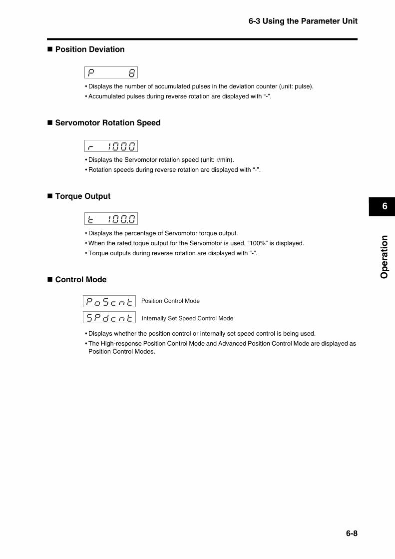
6-3 Using the Parameter Unit
6
Op
erat
ion
Position Deviation
Displays the number of accumulated pulses in the deviation counter (unit: pulse).
Accumulated pulses during reverse rotation are displayed with “-”.
Servomotor Rotation Speed
Displays the Servomotor rotation speed (unit: r/min).
Rotation speeds during reverse rotation are displayed with “-”.
Torque Output
Displays the percentage of Servomotor torque output.
When the rated toque output for the Servomotor is used, “100%” is displayed.
Torque outputs during reverse rotation are displayed with “-”.
Control Mode
Displays whether the position control or internally set speed control is being used.
The High-response Position Control Mode and Advanced Position Control Mode are displayed as Position Control Modes.
pk k k k k8k
rk k1k0k0k0k
tk k1k0k0.0k
pkokskcknkt
skpkdkcknktk Internally Set Speed Control Mode
Position Control Mode
6-8
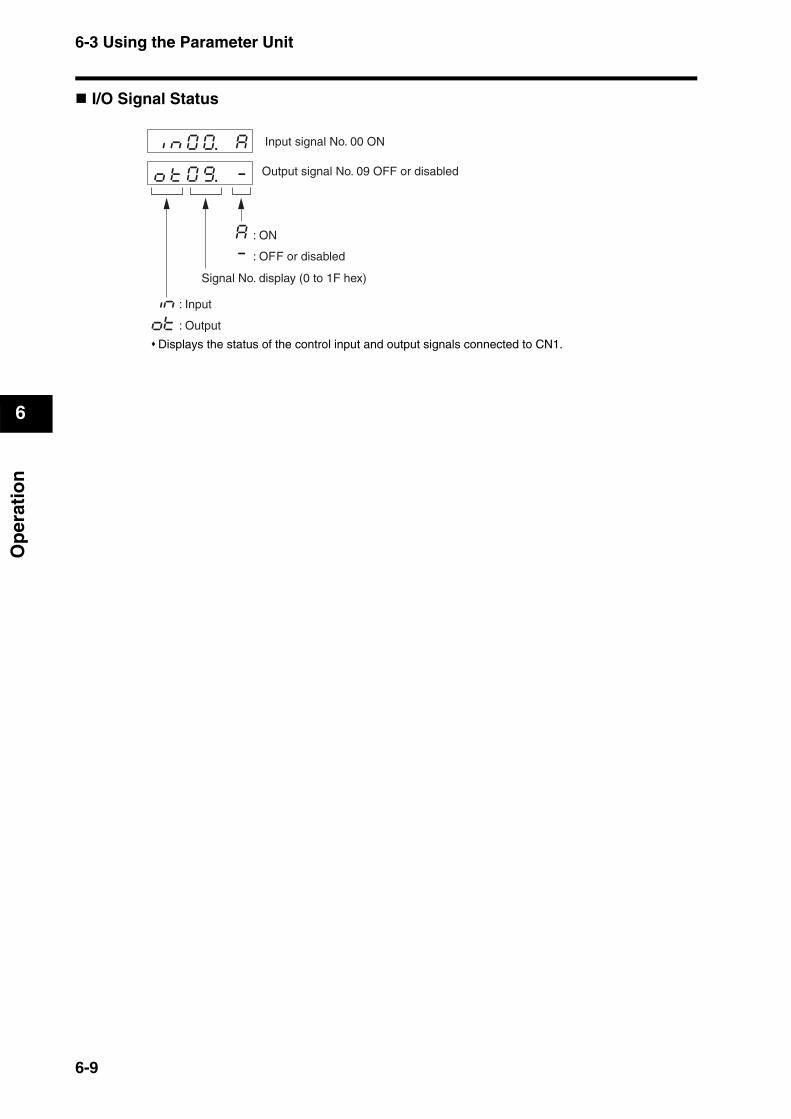
6-3 Using the Parameter Unit
6
Op
erat
ion
I/O Signal Status
Displays the status of the control input and output signals connected to CN1.
iknk0k0. ka
oktk0k9. k-k
in
ot
a : ON
- : OFF or disabled
Input signal No. 00 ON
Output signal No. 09 OFF or disabled
Signal No. display (0 to 1F hex)
: Input
: Output
6-9

6-3 Using the Parameter Unit
6
Op
erat
ion
Input Signals
CN1
FunctionSignal No.
Symbol NamePin No.
00 RUN RUN Command 2If the RUN signal turns ON, a Servo lock oc-curs, and is displayed.
01 RESET Alarm Reset 3If the RESET signal turns ON, the alarm is re-set, and is displayed.
02 NOT Reverse Drive Prohibit 7 If the Drive Prohibit Input Selection (Pn04) is set to disable the prohibit inputs (setting 1), “-” is displayed. If Pn04 is set to enable the prohibit inputs (set-ting 0), the Servomotor stops and is displayed when the POT signal turns OFF.
03 POT Forward Drive Prohibit 8
04 Not used.
05 VZEROZero Speed Designation
5
The Servomotor stops and is displayed if this signal turns OFF when the Zero Speed Designation/Torque Limit Switch (Pn06) is set to 1.
06 GESELElectronic Gear Switch
6If the GESEL signal turns ON, the Electronic Gear Ratio Numerator 2 is enabled, and is displayed.
07 to 08
Not used.
09 GSEL Gain Switch 5
When the Gain Switching Input Operating Mode Selection (Pn30) is set to 0 and the GSEL signal turns OFF, PI operation is en-abled and “-” is displayed.
0A ECRSTDeviation Counter Reset
4Used to reset the deviation counter.When the ECRST signal turns ON, is displayed.
0B Not used.
0C VSEL1Internally Set Speed Selection 1
6When VSEL1 and VSEL2 are ON, is displayed.
0D VSEL2Internally Set Speed Selection 2
4
0E to 1F
Not used.
aa
aa
aa
aa
aa
aa
aa
6-10
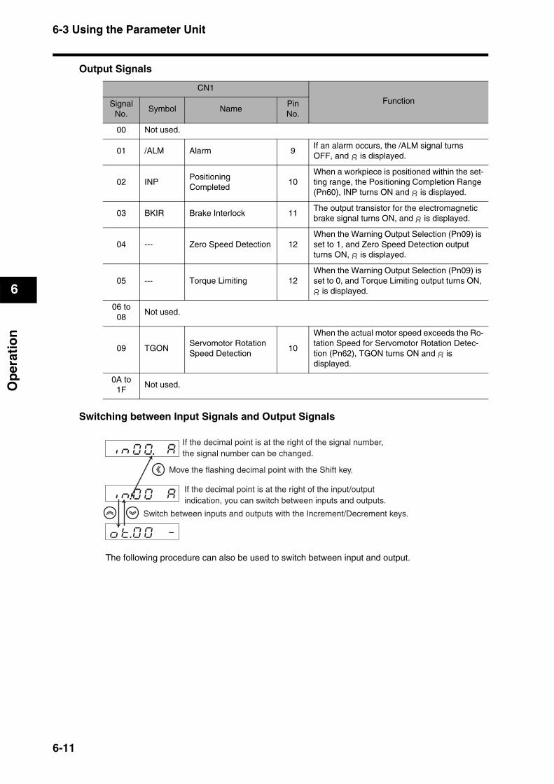
6-3 Using the Parameter Unit
6
Op
erat
ion
Output Signals
Switching between Input Signals and Output Signals
The following procedure can also be used to switch between input and output.
CN1
FunctionSignal No.
Symbol NamePin No.
00 Not used.
01 /ALM Alarm 9If an alarm occurs, the /ALM signal turnsOFF, and is displayed.
02 INPPositioning Completed
10When a workpiece is positioned within the set-ting range, the Positioning Completion Range (Pn60), INP turns ON and is displayed.
03 BKIR Brake Interlock 11The output transistor for the electromagnetic brake signal turns ON, and is displayed.
04 --- Zero Speed Detection 12When the Warning Output Selection (Pn09) is set to 1, and Zero Speed Detection output turns ON, is displayed.
05 --- Torque Limiting 12When the Warning Output Selection (Pn09) is set to 0, and Torque Limiting output turns ON,
is displayed.
06 to 08
Not used.
09 TGONServomotor Rotation Speed Detection
10
When the actual motor speed exceeds the Ro-tation Speed for Servomotor Rotation Detec-tion (Pn62), TGON turns ON and is displayed.
0A to 1F
Not used.
a
aa
aa
aa
aaa
aa
iknk0k0. ka
ikn.0k0k kak
okt.0k0k k-k
If the decimal point is at the right of the signal number,the signal number can be changed.
Move the flashing decimal point with the Shift key.
If the decimal point is at the right of the input/outputindication, you can switch between inputs and outputs.
Switch between inputs and outputs with the Increment/Decrement keys.
6-11
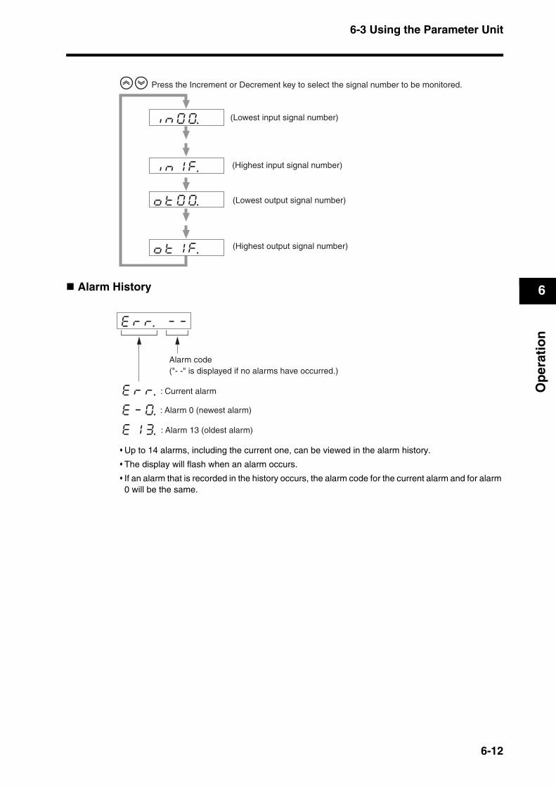
6-3 Using the Parameter Unit
6
Op
erat
ion
Alarm History
Up to 14 alarms, including the current one, can be viewed in the alarm history.
The display will flash when an alarm occurs.
If an alarm that is recorded in the history occurs, the alarm code for the current alarm and for alarm 0 will be the same.
iknk1kf. kk
iknk0k0. k
oktk0k0. k
oktk1kf. k
Press the Increment or Decrement key to select the signal number to be monitored.
(Lowest input signal number)
(Highest input signal number)
(Lowest output signal number)
(Highest output signal number)
ekrkr. k-k-
ekrkr.
ek-k0.
ek1k3.
Alarm code("- -" is displayed if no alarms have occurred.)
: Current alarm
: Alarm 0 (newest alarm)
: Alarm 13 (oldest alarm)
6-12
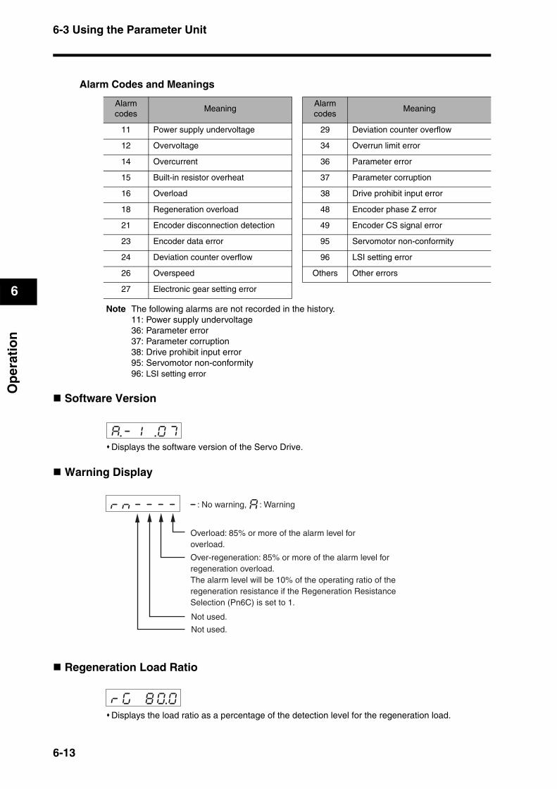
6-3 Using the Parameter Unit
6
Op
erat
ion
Alarm Codes and Meanings
Note The following alarms are not recorded in the history.11: Power supply undervoltage36: Parameter error37: Parameter corruption38: Drive prohibit input error95: Servomotor non-conformity96: LSI setting error
Software Version
Displays the software version of the Servo Drive.
Warning Display
Regeneration Load Ratio
Displays the load ratio as a percentage of the detection level for the regeneration load.
Alarm codes
MeaningAlarm codes
Meaning
11 Power supply undervoltage 29 Deviation counter overflow
12 Overvoltage 34 Overrun limit error
14 Overcurrent 36 Parameter error
15 Built-in resistor overheat 37 Parameter corruption
16 Overload 38 Drive prohibit input error
18 Regeneration overload 48 Encoder phase Z error
21 Encoder disconnection detection 49 Encoder CS signal error
23 Encoder data error 95 Servomotor non-conformity
24 Deviation counter overflow 96 LSI setting error
26 Overspeed Others Other errors
27 Electronic gear setting error
a.-k1k .0k7k
rknk-k-k-k- - a : No warning, : Warning
Overload: 85% or more of the alarm level foroverload.
Over-regeneration: 85% or more of the alarm level for regeneration overload.The alarm level will be 10% of the operating ratio of the regeneration resistance if the Regeneration Resistance Selection (Pn6C) is set to 1.
Not used.
Not used.
rkgk k8k0.0
6-13
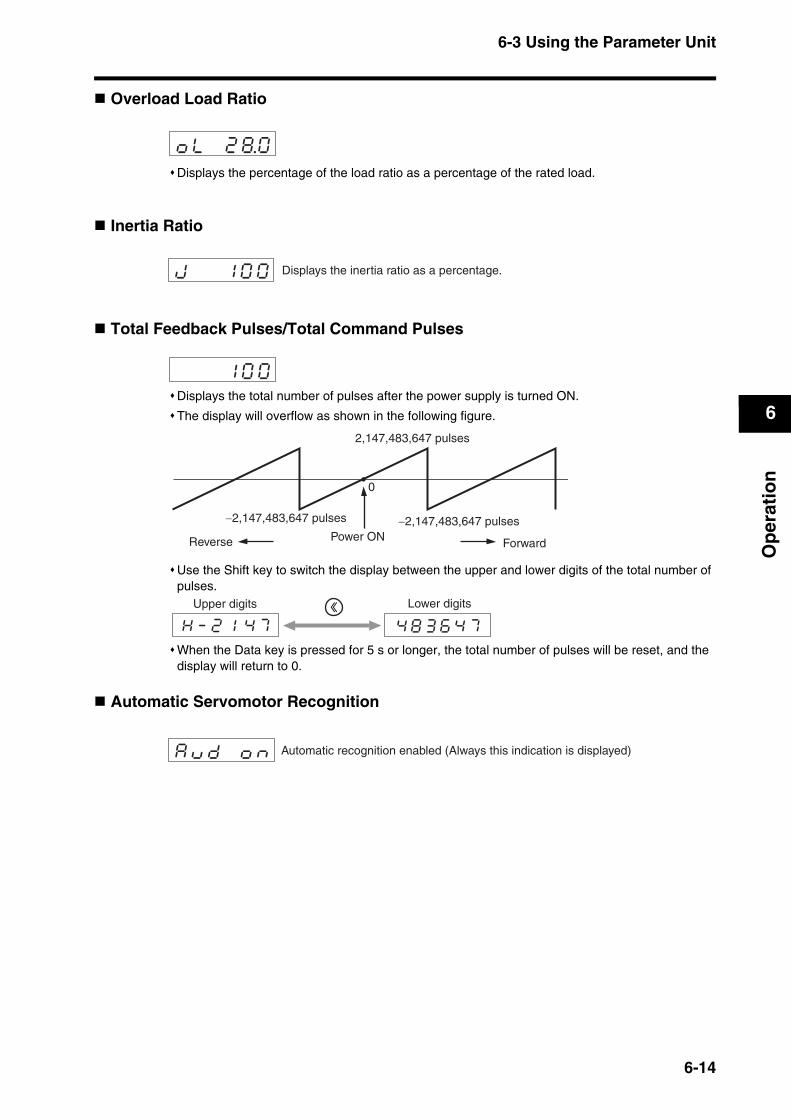
6-3 Using the Parameter Unit
6
Op
erat
ion
Overload Load Ratio
Displays the percentage of the load ratio as a percentage of the rated load.
Inertia Ratio
Total Feedback Pulses/Total Command Pulses
Displays the total number of pulses after the power supply is turned ON.
The display will overflow as shown in the following figure.
Use the Shift key to switch the display between the upper and lower digits of the total number of pulses.
When the Data key is pressed for 5 s or longer, the total number of pulses will be reset, and the display will return to 0.
Automatic Servomotor Recognition
oklk k2k8.0
jk k k1k0k0 Displays the inertia ratio as a percentage.
k k k1k0k0
0
2,147,483,647 pulses
Reverse Power ON
−2,147,483,647 pulses −2,147,483,647 pulses
Forward
Upper digits Lower digits
Hk-k2k1kk4k7 4k8k3k6k4k7
akukdk kokn Automatic recognition enabled (Always this indication is displayed)
6-14
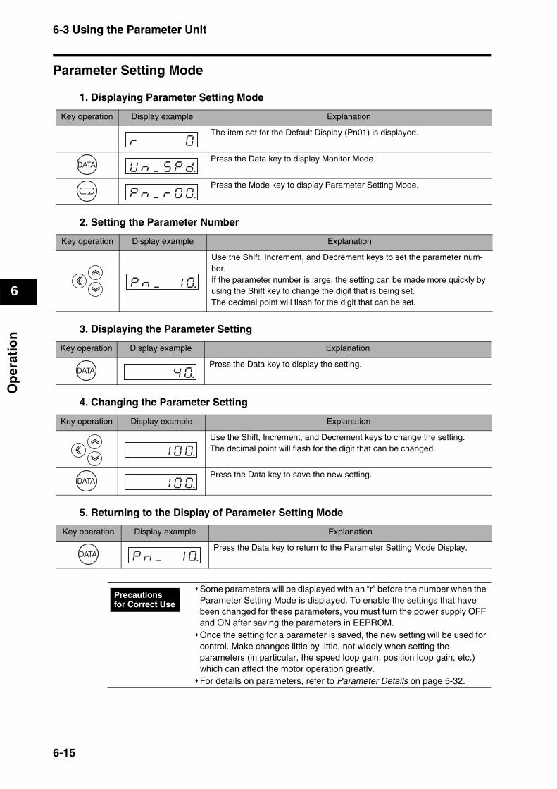
6-3 Using the Parameter Unit
6
Op
erat
ion
Parameter Setting Mode
1. Displaying Parameter Setting Mode
2. Setting the Parameter Number
3. Displaying the Parameter Setting
4. Changing the Parameter Setting
5. Returning to the Display of Parameter Setting Mode
Key operation Display example Explanation
The item set for the Default Display (Pn01) is displayed.
Press the Data key to display Monitor Mode.
Press the Mode key to display Parameter Setting Mode.
rk k k k k0k
Uknk_kskpkd.
pknk_krk0k0.
Key operation Display example Explanation
Use the Shift, Increment, and Decrement keys to set the parameter num-ber.If the parameter number is large, the setting can be made more quickly by using the Shift key to change the digit that is being set.The decimal point will flash for the digit that can be set.
pknk_k k1k0.
Key operation Display example Explanation
Press the Data key to display the setting. k k k k4k0.
Key operation Display example Explanation
Use the Shift, Increment, and Decrement keys to change the setting.The decimal point will flash for the digit that can be changed.
Press the Data key to save the new setting.
k k k1k0k0.
k k k1k0k0.
Key operation Display example Explanation
Press the Data key to return to the Parameter Setting Mode Display.pknk_k k1k0.
Some parameters will be displayed with an “r” before the number when the Parameter Setting Mode is displayed. To enable the settings that have been changed for these parameters, you must turn the power supply OFF and ON after saving the parameters in EEPROM.Once the setting for a parameter is saved, the new setting will be used for control. Make changes little by little, not widely when setting the parameters (in particular, the speed loop gain, position loop gain, etc.) which can affect the motor operation greatly.For details on parameters, refer to Parameter Details on page 5-32.
Precautions for Correct Use
6-15
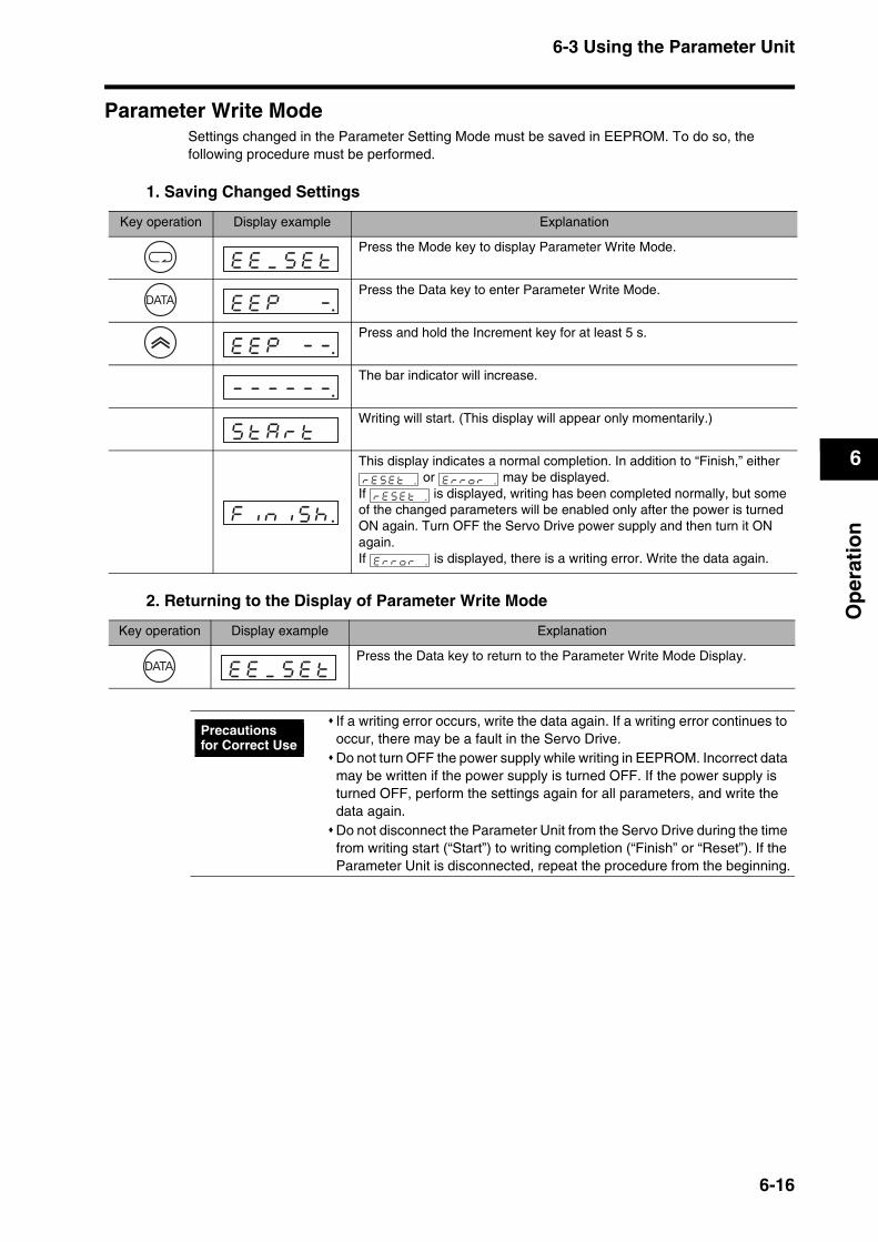
6-3 Using the Parameter Unit
6
Op
erat
ion
Parameter Write ModeSettings changed in the Parameter Setting Mode must be saved in EEPROM. To do so, the following procedure must be performed.
1. Saving Changed Settings
2. Returning to the Display of Parameter Write Mode
Key operation Display example Explanation
Press the Mode key to display Parameter Write Mode.
Press the Data key to enter Parameter Write Mode.
Press and hold the Increment key for at least 5 s.
The bar indicator will increase.
Writing will start. (This display will appear only momentarily.)
This display indicates a normal completion. In addition to “Finish,” either or may be displayed.
If is displayed, writing has been completed normally, but some of the changed parameters will be enabled only after the power is turned ON again. Turn OFF the Servo Drive power supply and then turn it ON again.If is displayed, there is a writing error. Write the data again.
ekek_kskektk
ekekpk k k-.
ekekpk k-k-.
-k-k-k-k-k-.
sktkakrktk k
f i n i s h .
reset . e r r o r .
r e s e t .
e r r o r .
Key operation Display example Explanation
Press the Data key to return to the Parameter Write Mode Display.ekek_kskektk
If a writing error occurs, write the data again. If a writing error continues to occur, there may be a fault in the Servo Drive.Do not turn OFF the power supply while writing in EEPROM. Incorrect data may be written if the power supply is turned OFF. If the power supply is turned OFF, perform the settings again for all parameters, and write the data again.Do not disconnect the Parameter Unit from the Servo Drive during the time from writing start (“Start”) to writing completion (“Finish” or “Reset”). If the Parameter Unit is disconnected, repeat the procedure from the beginning.
Precautions for Correct Use
6-16

6-3 Using the Parameter Unit
6
Op
erat
ion
Autotuning ModeFor details on autotuning, refer to 7-3 Autotuning. This section describes only the operating procedure.
1. Displaying Autotuning Mode
2. Executing Autotuning
3. Returning to the Display of Autotuning Mode
Key operation Display example Explanation
The item set for the Default Display (Pn01) is displayed.
Press the Data key to display Monitor Mode.
Press the Mode key three times to display Autotuning Mode.
rk k k k k0k
Uknk_kskpkd.
aktk_knkok1.
Key operation Display example Explanation
Press the Data key to enter Autotuning Mode.
Press and hold the Increment key until “Start” is displayed.The bar indicator will increase when the key is pressed for 5 s or longer.
The bar indicator will increase.
The Servomotor will start, and autotuning will begin.
This display indicates a normal completion.If is displayed, a tuning error has occurred.
aktkuk k k-.
aktkuk k-k-.
-k-k-k-k-k-.
sktkakrktk k
f i n i s h . error .
Key operation Display example Explanation
Press the Data key to return to the Autotuning Mode Display.aktk_knkok1.
Do not remove the Parameter Unit from the Servo Drive during the time from Start to Finish. If the Parameter Unit is removed during autotuning, repeat the procedure from the beginning.Always save each gain value changed with autotuning in EEPROM so that the data is not lost when the power is turned OFF.If an autotuning error occurs, the values for each gain will return to the value before executing autotuning.
Precautions for Correct Use
6-17
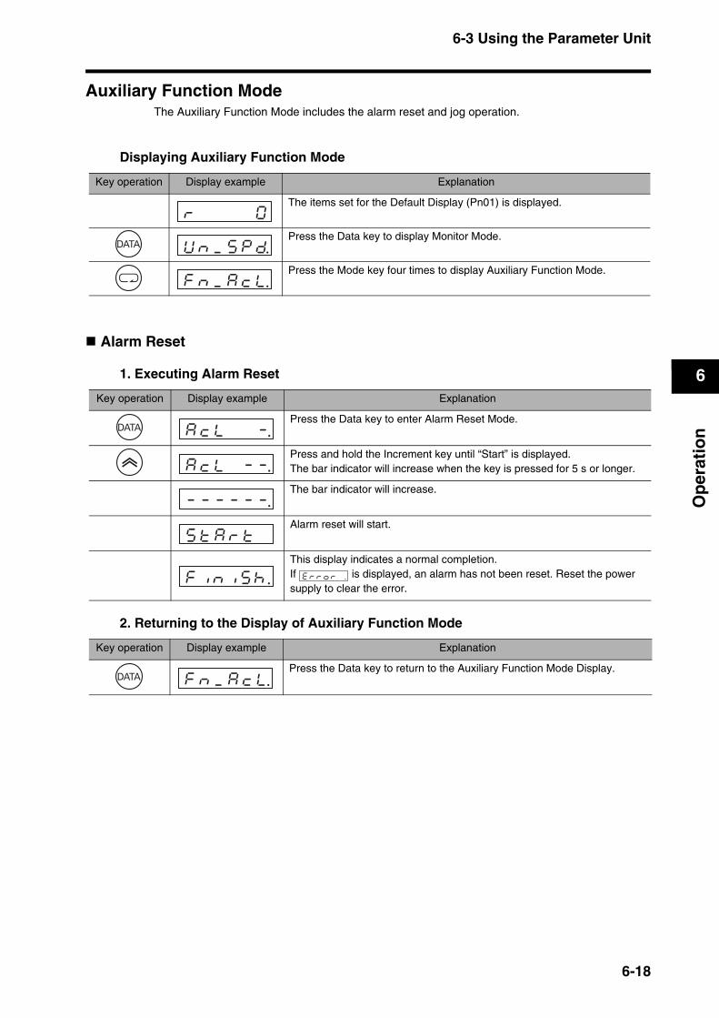
6-3 Using the Parameter Unit
6
Op
erat
ion
Auxiliary Function ModeThe Auxiliary Function Mode includes the alarm reset and jog operation.
Displaying Auxiliary Function Mode
Alarm Reset
1. Executing Alarm Reset
2. Returning to the Display of Auxiliary Function Mode
Key operation Display example Explanation
The items set for the Default Display (Pn01) is displayed.
Press the Data key to display Monitor Mode.
Press the Mode key four times to display Auxiliary Function Mode.
rk k k k k0k
Uknk_kskpkd.
fknk_kakckl.
Key operation Display example Explanation
Press the Data key to enter Alarm Reset Mode.
Press and hold the Increment key until “Start” is displayed.The bar indicator will increase when the key is pressed for 5 s or longer.
The bar indicator will increase.
Alarm reset will start.
This display indicates a normal completion.If is displayed, an alarm has not been reset. Reset the power supply to clear the error.
akcklk k k-.
akcklk k-k-.
-k-k-k-k-k-.
sktkakrktk k
f i n i s h . error .
Key operation Display example Explanation
Press the Data key to return to the Auxiliary Function Mode Display.fknk_kakckl.
6-18
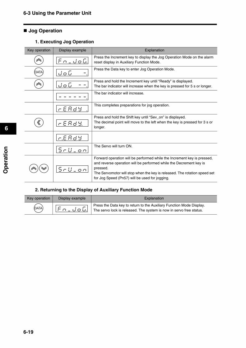
6-3 Using the Parameter Unit
6
Op
erat
ion
Jog Operation
1. Executing Jog Operation
2. Returning to the Display of Auxiliary Function Mode
Key operation Display example Explanation
Press the Increment key to display the Jog Operation Mode on the alarm reset display in Auxiliary Function Mode.
Press the Data key to enter Jog Operation Mode.
Press and hold the Increment key until “Ready” is displayed.The bar indicator will increase when the key is pressed for 5 s or longer.
The bar indicator will increase.
This completes preparations for jog operation.
Press and hold the Shift key until “Sev_on” is displayed.The decimal point will move to the left when the key is pressed for 3 s or longer.
The Servo will turn ON.
Forward operation will be performed while the Increment key is pressed, and reverse operation will be performed while the Decrement key is pressed.The Servomotor will stop when the key is released. The rotation speed set for Jog Speed (Pn57) will be used for jogging.
fknk_kjkokg.
jkokgk k k-.
jkokgk k-k-.
-k-k-k-k-k-.
rkekakdkyk .
rkekakdky. k
r.ekakdkyk k
skrkUk_koknk
skrkUk_koknk
Key operation Display example Explanation
Press the Data key to return to the Auxiliary Function Mode Display.The servo lock is released. The system is now in servo free status.fknk_kjkokg.
6-19
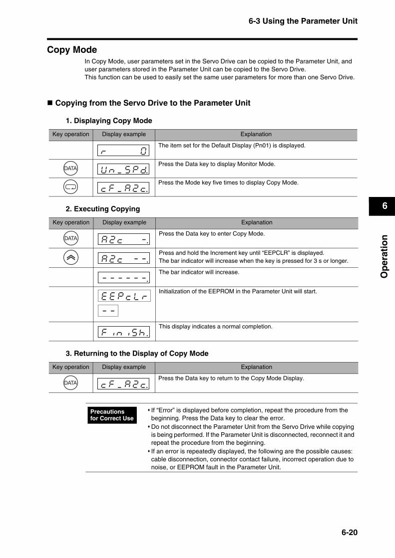
6-3 Using the Parameter Unit
6
Op
erat
ion
Copy ModeIn Copy Mode, user parameters set in the Servo Drive can be copied to the Parameter Unit, and user parameters stored in the Parameter Unit can be copied to the Servo Drive.This function can be used to easily set the same user parameters for more than one Servo Drive.
Copying from the Servo Drive to the Parameter Unit
1. Displaying Copy Mode
2. Executing Copying
3. Returning to the Display of Copy Mode
Key operation Display example Explanation
The item set for the Default Display (Pn01) is displayed.
Press the Data key to display Monitor Mode.
Press the Mode key five times to display Copy Mode.
rk k k k k0k
Uknk_kskpkd.
ckfk_kak2kc.
Key operation Display example Explanation
Press the Data key to enter Copy Mode.
Press and hold the Increment key until “EEPCLR” is displayed.The bar indicator will increase when the key is pressed for 3 s or longer.
The bar indicator will increase.
Initialization of the EEPROM in the Parameter Unit will start.
This display indicates a normal completion.
ak2kck k k-.
ak2kck k-k-.
-k-k-k-k-k-.
ekekpkcklkr
-k-
f i n i s h .
Key operation Display example Explanation
Press the Data key to return to the Copy Mode Display.ckfk_kak2kc.
If “Error” is displayed before completion, repeat the procedure from the beginning. Press the Data key to clear the error.Do not disconnect the Parameter Unit from the Servo Drive while copying is being performed. If the Parameter Unit is disconnected, reconnect it and repeat the procedure from the beginning.If an error is repeatedly displayed, the following are the possible causes: cable disconnection, connector contact failure, incorrect operation due to noise, or EEPROM fault in the Parameter Unit.
Precautions for Correct Use
6-20
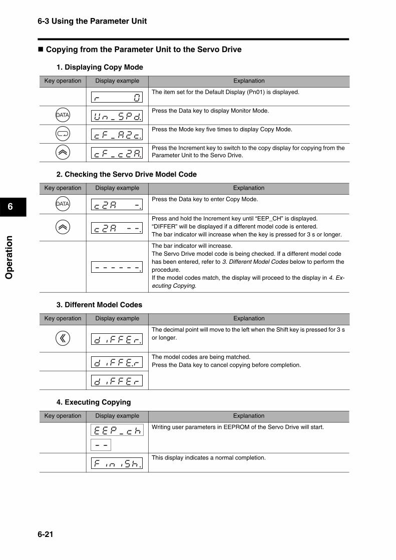
6-3 Using the Parameter Unit
6
Op
erat
ion
Copying from the Parameter Unit to the Servo Drive
1. Displaying Copy Mode
2. Checking the Servo Drive Model Code
3. Different Model Codes
4. Executing Copying
Key operation Display example Explanation
The item set for the Default Display (Pn01) is displayed.
Press the Data key to display Monitor Mode.
Press the Mode key five times to display Copy Mode.
Press the Increment key to switch to the copy display for copying from the Parameter Unit to the Servo Drive.
rk k k k k0k
Uknk_kskpkd.
ckfk_kak2kc.
ckfk_kck2ka.
Key operation Display example Explanation
Press the Data key to enter Copy Mode.
Press and hold the Increment key until “EEP_CH” is displayed.“DIFFER” will be displayed if a different model code is entered.The bar indicator will increase when the key is pressed for 3 s or longer.
The bar indicator will increase.The Servo Drive model code is being checked. If a different model code has been entered, refer to 3. Different Model Codes below to perform the procedure.If the model codes match, the display will proceed to the display in 4. Ex-ecuting Copying.
ck2kak k k-.
ck2kak k-k-.
-k-k-k-k-k-.
Key operation Display example Explanation
The decimal point will move to the left when the Shift key is pressed for 3 s or longer.
The model codes are being matched.Press the Data key to cancel copying before completion.
dkikfkfkekr.
dkikfkfke.r
dkikfkfkekr
Key operation Display example Explanation
Writing user parameters in EEPROM of the Servo Drive will start.
This display indicates a normal completion.
ekekpk_kckh
-k-
f i n i s h .
6-21
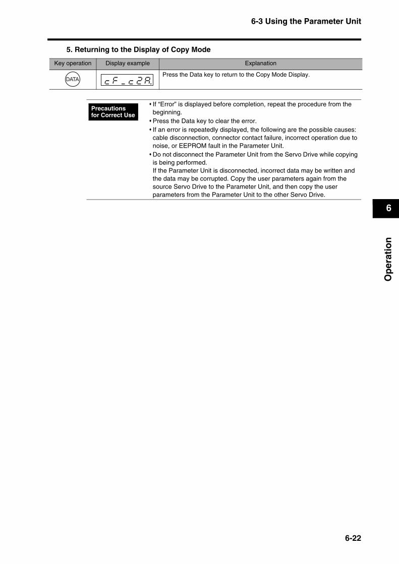
6-3 Using the Parameter Unit
6
Op
erat
ion
5. Returning to the Display of Copy Mode
Key operation Display example Explanation
Press the Data key to return to the Copy Mode Display.ckfk_kck2ka.
If “Error” is displayed before completion, repeat the procedure from the beginning.Press the Data key to clear the error.If an error is repeatedly displayed, the following are the possible causes: cable disconnection, connector contact failure, incorrect operation due to noise, or EEPROM fault in the Parameter Unit.Do not disconnect the Parameter Unit from the Servo Drive while copying is being performed. If the Parameter Unit is disconnected, incorrect data may be written and the data may be corrupted. Copy the user parameters again from the source Servo Drive to the Parameter Unit, and then copy the user parameters from the Parameter Unit to the other Servo Drive.
Precautions for Correct Use
6-22
6-4 Trial Operation
6
Op
erat
ion
6-4 Trial OperationWhen you have finished installation, wiring, Servomotor/Servo Drive jog operation, and user parameter setting, perform trial operation.The main purpose of trial operation is to confirm that the servo system operates electrically correctly. Make sure that the host position controller and all peripheral devices are connected, and turn ON the power. Then perform trial operation at low speed to confirm the operation. Next, perform actual run patterns to confirm that the system works properly.
Preparation for Trial Operation
Turning OFF the PowerSome parameters are enabled by turning OFF the power and turning it ON again. First turn OFF the main circuit power.
Preparing for Turning OFF the ServomotorIn order that the Servomotor can be immediately turned OFF if an abnormality occurs in the machine, set up the system so that the power and the RUN Command Input can be turned OFF.
Trial Operation1. Operating without a Load
Turn ON the power to the main circuit and peripheral devices, and then turn ON the RUN Command Input.Check that the Servomotor is in Servo ON status.Send the command to start the Servomotor from the host position controller, and check that the Servomotor operates properly according to the command. (Check that the Servomotor is rotating in the correct direction and the rotation speed and amount of rotation are as specified by the command.)
2. Mechanical System ConnectionTurn OFF the power.
Firmly connect the Servomotor shaft to the load (i.e., the mechanical system). Tighten screws and make sure they are not loose.
Turn ON the power.
3. Low-speed Operation with Actual Load ConnectedSend a low speed command from the host position controller to start the Servomotor. (The definition of “low speed” depends on the mechanical system, but a rough estimate is 1/10 to 1/5 of normal operating speed.)
Check the following items.a) Are the emergency stop and over load switch operating correctly?b) Is the operating direction of the machine correct?
If an error occurs during the trial operation, refer to Chapter 8 Troubleshooting to eliminate the cause. Then ensure safety and resume operation. If the machine vibrates when starting or stopping, refer to Chapter 7 Adjustment Functions and perform the gain adjustment first.
Precautions for Correct Use
6-23
6-4 Trial Operation
6
Op
erat
ion
c) Are the operating sequences correct?d) Are there any abnormal sounds or vibration?
If vibration occurs when starting or stopping the machine, refer to Chapter 7 Adjustment Functions, and adjust the gain.
e) Is any error (or alarm) generated?If anything abnormal occurs, refer to Chapter 8 Troubleshooting and take the appropriate countermeasures.
4. Regular Pattern OperationOperate the Servomotor in a regular pattern and check the following items.a) Is the operating speed correct?b) Is the load torque almost equivalent to the measured value?c) Are the positioning points correct?d) When an operation is repeated, is there any discrepancy in positioning?e) Are there any abnormal sounds or vibration?
If vibration occurs when starting or stopping the machine, refer to Chapter 7 Adjustment Functions, and adjust the gain.
f) Is the Servomotor or the Servo Drive abnormally overheating?g) Is any error (or alarm) generated?
If anything abnormal occurs, refer to Chapter 8 Troubleshooting and take the appropriate countermeasures.
5. Trial Operation CompletedPerforming the above completes the trial operation. Next, adjust the gain to improve control performance.
6-24

Chapter 7
Adjustment Functions7-1 Gain Adjustment ................................................7-1
Purpose of the Gain Adjustment ..............................................7-1
Gain Adjustment Methods........................................................7-1
Gain Adjustment Procedure.....................................................7-2
7-2 Realtime Autotuning ..........................................7-3Realtime Autotuning Setting Method .......................................7-3
Operating Procedures..............................................................7-4
Adaptive Filter ..........................................................................7-5
Automatically Set Parameters..................................................7-6
7-3 Autotuning ..........................................................7-8Autotuning Setting Method.......................................................7-8
Automatically Set Parameters................................................7-11
7-4 Disabling the Automatic Gain Adjustment Function ............................................................7-13
Disabling Realtime Autotuning...............................................7-13
Disabling the Adaptive Filter ..................................................7-14
7-5 Manual Tuning..................................................7-15Function Differences in Control Modes..................................7-15
Basic Adjustment Procedures................................................7-16
Gain Switching Function ........................................................7-19
Machine Resonance Control..................................................7-21
Damping Control ....................................................................7-23
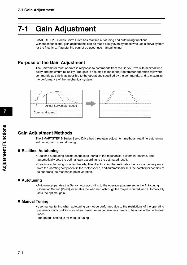
7-1 Gain Adjustment
7
Ad
just
men
t F
un
ctio
ns
7Adjustment Functions
7-1 Gain AdjustmentSMARTSTEP 2-Series Servo Drive has realtime autotuning and autotuning functions.With these functions, gain adjustments can be made easily even by those who use a servo system for the first time. If autotuning cannot be used, use manual tuning.
Purpose of the Gain AdjustmentThe Servomotor must operate in response to commands from the Servo Drive with minimal time delay and maximum reliability. The gain is adjusted to make the Servomotor operation follow the commands as strictly as possible to the operations specified by the commands, and to maximize the performance of the mechanical system.
Gain Adjustment MethodsThe SMARTSTEP 2-Series Servo Drive has three gain adjustment methods: realtime autotuning, autotuning, and manual tuning.
Realtime AutotuningRealtime autotuning estimates the load inertia of the mechanical system in realtime, and automatically sets the optimal gain according to the estimated result.
Realtime autotuning includes the adaptive filter function that estimates the resonance frequency from the vibrating component in the motor speed, and automatically sets the notch filter coefficient to suppress the resonance point vibration.
Autotuning Autotuning operates the Servomotor according to the operating pattern set in the Autotuning Operation Setting (Pn25), estimates the load inertia through the torque required, and automatically sets the optimal gain.
Manual TuningUse manual tuning when autotuning cannot be performed due to the restrictions of the operating pattern or load conditions, or when maximum responsiveness needs to be obtained for individual loads.The default setting is for manual tuning.
Actual Servomotor speed
Command speed
7-1

7-1 Gain Adjustment
7
Ad
just
men
t F
un
ctio
ns
Gain Adjustment Procedure
Reference Gain Adjustment and Machine RigidityThe specific vibration (resonance frequency) of the mechanical system has alarge impact on the gain adjustment. The servo system responsiveness cannot be set high for machines with a low resonance frequency (low machine rigidity). Check the following items to increase mechanical system rigidity.Lay the foundation firmly and set up a machine so that it does not wobble.Use a Decelerator with minimal backlash.Use couplings of a type with high rigidity and designed for servo systems.Use a wide timing belt, and use a tension within the allowable axial load for the Servomotor.
NoOperation OK?
Write in EEPROM
Adaptive filter
Set realtime autotuning
Autotuning
Operation OK?
Yes
Begin adjustment
Yes
Yes
YesNo
No
No
No
(Default settings)
Adjustment completed
Turn OFF automatic adjustment
Manual tuning
Basic adjustment
Damping control
Gain switch
Machine resonance suppression
Contact OMRON
Operation OK?
Realtimeautotuning
Yes
Turn OFF automatic adjustment
Use automaticadjustment?
Command inputpossible?
7-2

7-2 Realtime Autotuning
7
Ad
just
men
t F
un
ctio
ns
7-2 Realtime AutotuningRealtime autotuning estimates the load inertia of the machine in realtime, and automatically sets the optimal gain according to the estimated load inertia. The adaptive filter automatically suppresses vibration caused by resonance. In the default settings realtime autotuning is disabled. Refer to the following procedures to enable realtime autotuning.
Realtime Autotuning Setting Method 1. Stopping the Servomotor
Turn OFF the RUN Command Input (RUN) to the Servomotor. The Servomotor will stop.
2. Realtime Autotuning Mode Selection (Pn21)Pn21 Setting
When the degree of load inertia change is high, set the value to 3 or 6.
Enable the adaptive filter if the load inertia change is affected by resonance.
3. Normal Operation Turn ON the RUN Command Input (RUN) and run the machine as usual.
Realtime autotuning may not function properly under the conditions described in the following table. If realtime autotuning does not function properly, use autotuning or manual tuning.
Precautions for Correct Use
Conditions under which realtime autotuning does not function properly
Load inertia If the load inertia is less than 3 times the rotor inertia. If the load inertia is more than 20 times the rotor inertia. If the load inertia changes quickly, i.e., in less than 10 seconds.
Load If the machine rigidity is extremely low. If there is backlash or play in the system. If the static friction torque is greater than the dynamic friction torque.
Operating pattern
If the Servomotor is continuously run at a low speed below 100 r/min. If the acceleration/deceleration is gradual at less than 2000 r/min in 1 s. For abrupt operations, e.g., if the speed or acceleration condition is met in less than 40 ms.
If the acceleration/deceleration torque is unbalanced and smaller compared to the viscous friction torque.
Setting Realtime Autotuning Degree of change in load inertia during operation
Adaptive filter
0 Not used --- Disabled
1
Used
Almost no change in load inertiaEnabled(Pn02 = 2)
2 Gradual changes in load inertia
3 Sudden changes in load inertia
4 Almost no change in load inertia
Disabled5 Gradual changes in load inertia
6 Sudden changes in load inertia
7 Not used --- Enabled(Pn02 = 2)
7-3
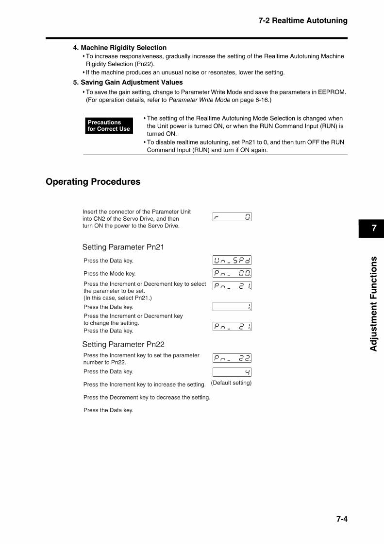
7-2 Realtime Autotuning
7
Ad
just
men
t F
un
ctio
ns
4. Machine Rigidity SelectionTo increase responsiveness, gradually increase the setting of the Realtime Autotuning Machine Rigidity Selection (Pn22).If the machine produces an unusual noise or resonates, lower the setting.
5. Saving Gain Adjustment ValuesTo save the gain setting, change to Parameter Write Mode and save the parameters in EEPROM. (For operation details, refer to Parameter Write Mode on page 6-16.)
Operating Procedures
The setting of the Realtime Autotuning Mode Selection is changed when the Unit power is turned ON, or when the RUN Command Input (RUN) is turned ON.To disable realtime autotuning, set Pn21 to 0, and then turn OFF the RUN Command Input (RUN) and turn if ON again.
Precautions for Correct Use
pknk_k k2k2.
pknk_k k2k1.
pknk_k k2k1.
pknk_k k0k0.
Uknk_kskpkdk
rk k k k k0k
4
1.
Setting Parameter Pn21
Press the Data key.
Press the Mode key.
Press the Increment or Decrement key to selectthe parameter to be set. (In this case, select Pn21.)
Press the Data key.
Press the Increment or Decrement key to change the setting.Press the Data key.
Setting Parameter Pn22Press the Increment key to set the parameter number to Pn22.
Press the Data key.
Press the Increment key to increase the setting.
Press the Decrement key to decrease the setting.
Press the Data key.
(Default setting)
Insert the connector of the Parameter Unit into CN2 of the Servo Drive, and then turn ON the power to the Servo Drive.
7-4
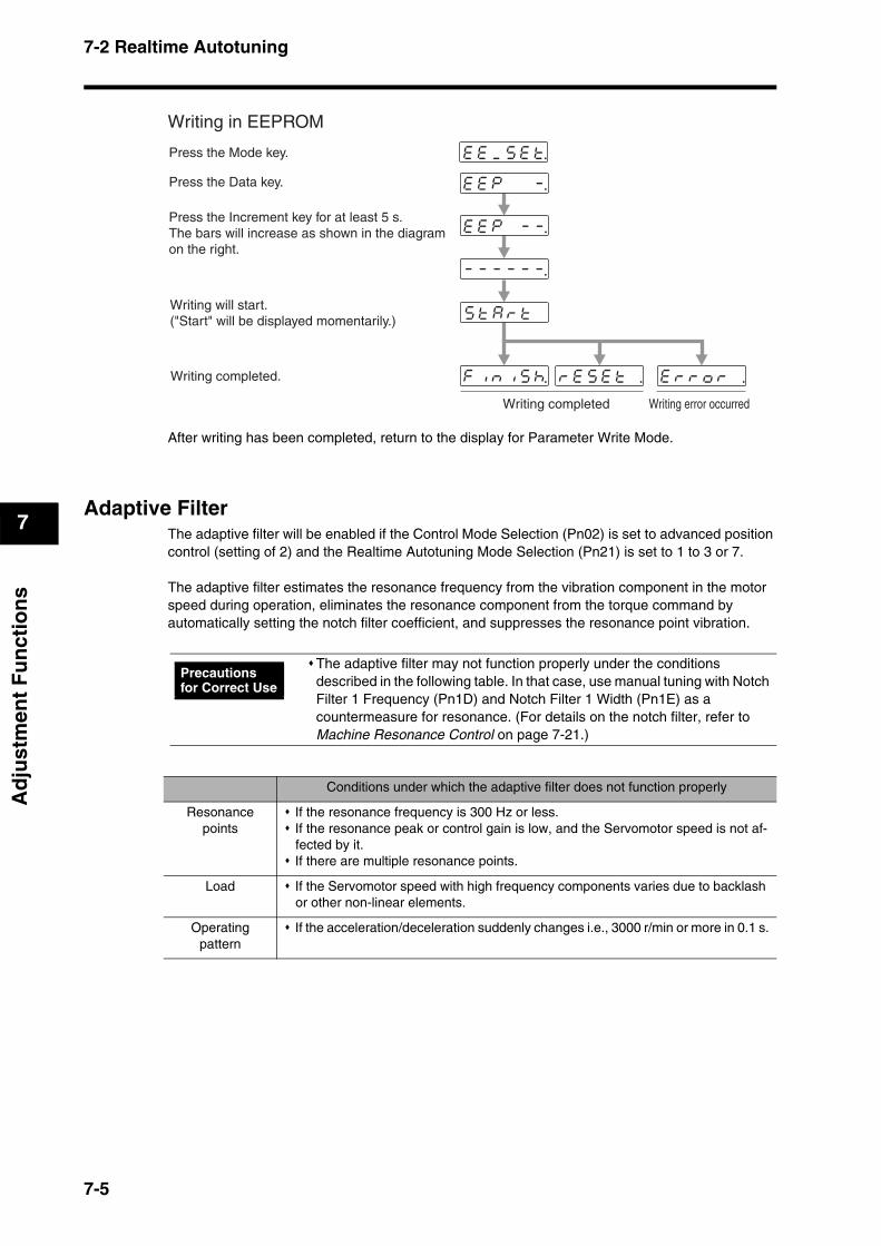
7-2 Realtime Autotuning
7
Ad
just
men
t F
un
ctio
ns
After writing has been completed, return to the display for Parameter Write Mode.
Adaptive FilterThe adaptive filter will be enabled if the Control Mode Selection (Pn02) is set to advanced position control (setting of 2) and the Realtime Autotuning Mode Selection (Pn21) is set to 1 to 3 or 7.
The adaptive filter estimates the resonance frequency from the vibration component in the motor speed during operation, eliminates the resonance component from the torque command by automatically setting the notch filter coefficient, and suppresses the resonance point vibration.
The adaptive filter may not function properly under the conditions described in the following table. In that case, use manual tuning with Notch Filter 1 Frequency (Pn1D) and Notch Filter 1 Width (Pn1E) as a countermeasure for resonance. (For details on the notch filter, refer to Machine Resonance Control on page 7-21.)
ekekpk k-k-.
ekek_kskekt.
rkekskektk .
ekekpk k k-.
ekrkrkokrkkkk.fkiknkikskh.
sktkakrktk
-k-k-k-k-k-.
Writing in EEPROM
Press the Mode key.
Press the Data key.
Press the Increment key for at least 5 s. The bars will increase as shown in the diagram on the right.
Writing will start.("Start" will be displayed momentarily.)
Writing completed.
Writing completed Writing error occurred
Precautions for Correct Use
Conditions under which the adaptive filter does not function properly
Resonance points
If the resonance frequency is 300 Hz or less.If the resonance peak or control gain is low, and the Servomotor speed is not af-fected by it.If there are multiple resonance points.
Load If the Servomotor speed with high frequency components varies due to backlash or other non-linear elements.
Operating pattern
If the acceleration/deceleration suddenly changes i.e., 3000 r/min or more in 0.1 s.
7-5
7-2 Realtime Autotuning
7
Ad
just
men
t F
un
ctio
ns
Automatically Set ParametersWhen realtime autotuning is enabled, the following parameters will be set automatically.Parameters that are set automatically cannot be changed manually.
The following parameters are set automatically. (The settings will not change even if realtime autotuning is executed.)
Parameter No.(Pn No.)
Parameter name
10 Position Loop Gain
11 Speed Loop Gain
12 Speed Loop Integration Time Constant
13 Speed Feedback Filter Time Constant
14 Torque Command Filter Time Constant
18 Position Loop Gain 2
19 Speed Loop Gain 2
1A Speed Loop Integration Time Constant 2
1B Speed Feedback Filter Time Constant 2
1C Torque Command Filter Time Constant 2
20 Inertia Ratio
2F Adaptive Filter Table Number Display
(Pn No.) Parameter name Set value
15 Feed-forward Amount 300
16 Feed-forward Command Filter 50
30 Gain Switching Input Operating Mode Selection 1
31 Gain Switch Setting 10
32 Gain Switch Time 30
33 Gain Switch Level Setting 50
34 Gain Switch Hysteresis Setting 33
35 Position Loop Gain Switching Time 20
7-6
7-2 Realtime Autotuning
7
Ad
just
men
t F
un
ctio
ns
An unusual noise or resonance may occur right after turning ON the first RUN Command Input (RUN) after the power ON, or when the setting of the Realtime Autotuning Machine Rigidity Selection (Pn22) is increased. Usually, the noise or resonance may continue until the load inertia is estimated, or the adaptive filter stabilizes. If the unusual noise or resonance stops immediately, there is no problem. However, if the unusual noise or resonance occurs for more than three reciprocating operations, perform the following measures in any order you can.
(1) Save the parameter settings when the machine operated normally to EEPROM.
(2) Decrease the setting of the Realtime Autotuning Machine Rigidity Selection (Pn22).
(3) Set the Realtime Autotuning Mode Selection (Pn21) to 0 to disable the adaptive filter. Then, enable realtime autotuning again. (Refer to Disabling Realtime Autotuning on page 7-13 for information on inertia estimation, resetting adaptive operations, and disabling realtime autotuning.)
(4) Set Notch Filter 1 Frequency (Pn1D) and Notch Filter 1 Width (Pn1E) manually. (For information on notch filters, refer to Machine Resonance Control on page 7-21.)
After an unusual noise or resonance occurred, the setting of the Inertia Ratio (Pn20) or Adaptive Filter Table Number Display (Pn2F) may have been changed to an extreme value. Perform the above measures as well. Among the realtime autotuning results, the Inertia Ratio (Pn20) and Adaptive Filter Table Number Display (Pn2F) parameters are automatically saved to EEPROM every 30 minutes. Realtime autotuning will use this data as the default settings when the power is turned ON.
Precautions for Correct Use
7-7
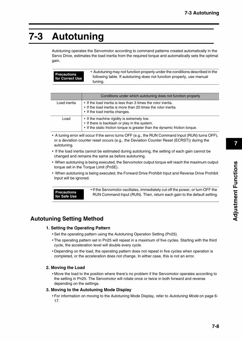
7-3 Autotuning
7
Ad
just
men
t F
un
ctio
ns
7-3 AutotuningAutotuning operates the Servomotor according to command patterns created automatically in the Servo Drive, estimates the load inertia from the required torque and automatically sets the optimal gain.
A tuning error will occur if the servo turns OFF (e.g., the RUN Command Input (RUN) turns OFF), or a deviation counter reset occurs (e.g., the Deviation Counter Reset (ECRST)) during the autotuning.
If the load inertia cannot be estimated during autotuning, the setting of each gain cannot be changed and remains the same as before autotuning.
When autotuning is being executed, the Servomotor output torque will reach the maximum output torque set in the Torque Limit (Pn5E).
When autotuning is being executed, the Forward Drive Prohibit Input and Reverse Drive Prohibit Input will be ignored.
Autotuning Setting Method 1. Setting the Operating Pattern
Set the operating pattern using the Autotuning Operation Setting (Pn25).
The operating pattern set in Pn25 will repeat in a maximum of five cycles. Starting with the third cycle, the acceleration level will double every cycle.
Depending on the load, the operating pattern does not repeat in five cycles when operation is completed, or the acceleration does not change. In either case, this is not an error.
2. Moving the LoadMove the load to the position where there’s no problem if the Servomotor operates according to the setting in Pn25. The Servomotor will rotate once or twice in both forward and reverse depending on the settings.
3. Moving to the Autotuning Mode DisplayFor information on moving to the Autotuning Mode Display, refer to Autotuning Mode on page 6-17.
Autotuning may not function properly under the conditions described in the following table. If autotuning does not function properly, use manual tuning.
Precautions for Correct Use
Conditions under which autotuning does not function properly
Load inertia If the load inertia is less than 3 times the rotor inertia.If the load inertia is more than 20 times the rotor inertia.If the load inertia changes.
Load If the machine rigidity is extremely low.If there is backlash or play in the system.If the static friction torque is greater than the dynamic friction torque.
If the Servomotor oscillates, immediately cut off the power, or turn OFF the RUN Command Input (RUN). Then, return each gain to the default setting.
Precautions for Safe Use
7-8
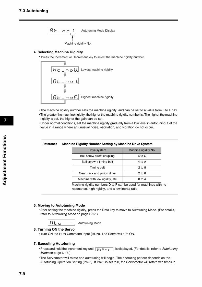
7-3 Autotuning
7
Ad
just
men
t F
un
ctio
ns
4. Selecting Machine Rigidity
The machine rigidity number sets the machine rigidity, and can be set to a value from 0 to F hex.The greater the machine rigidity, the higher the machine rigidity number is. The higher the machine rigidity is set, the higher the gain can be set.Under normal conditions, set the machine rigidity gradually from a low level in autotuning. Set the value in a range where an unusual noise, oscillation, and vibration do not occur.
5. Moving to Autotuning ModeAfter setting the machine rigidity, press the Data key to move to Autotuning Mode. (For details, refer to Autotuning Mode on page 6-17.)
6. Turning ON the ServoTurn ON the RUN Command Input (RUN). The Servo will turn ON.
7. Executing AutotuningPress and hold the Increment key until is displayed. (For details, refer to Autotuning Mode on page 6-17.)
The Servomotor will rotate and autotuning will begin. The operating pattern depends on the Autotuning Operation Setting (Pn25). If Pn25 is set to 0, the Servomotor will rotate two times in
Reference Machine Rigidity Number Setting by Machine Drive System
aktk_knkok1.
Machine rigidity No.
Autotuning Mode Display
aktk_knkok1. kk
aktk_knkok0.
aktk_knkokf.
Press the Increment or Decrement key to select the machine rigidity number.
Highest machine rigidity
Lowest machine rigidity
Machine rigidity numbers D to F can be used for machines with no resonance, high rigidity, and a low inertia ratio.
Drive system Machine rigidity No.
Ball screw direct coupling 6 to C
Ball screw + timing belt 4 to A
Timing belt 2 to 8
Gear, rack and pinion drive 2 to 8
Machine with low rigidity, etc. 0 to 4
aktkuk k k-. Autotuning Mode
sktkakrktk k
7-9

7-3 Autotuning
7
Ad
just
men
t F
un
ctio
ns
both forward and reverse for approximately 15 seconds. This will be repeated up to 5 cycles. It is not an error if the Servomotor stops before cycling 5 times.
Repeat step 4 (Selecting Machine Rigidity) to step 7 (Executing Autotuning) until satisfactory responsiveness can be obtained.
8. Saving the Gain SettingsWhen system responsiveness is satisfactory, move to Parameter Write Mode and save the settings in EEPROM so they will not be lost. (For details on operations, refer to Parameter Write Mode on page 6-16.)
To save the new settings, move to Parameter Write Mode and save the parameters in EEPROM.
Autotuning Operation WaveformThe following figure illustrates how the operation waveform will appear when autotuning is executed. The waveform will be distorted immediately after the execution, but will gradually smooth out.
Execute autotuning when a load is connected. If autotuning is executed without a load (i.e., Servomotor/Servo Drive only) the Inertia Ratio (Pn20) will be 0.A tuning error will occur if any of the following conditions occur while autotuning is being executed.
(1) If an error occurs. If the Servo is turned OFF, e.g., the RUN Command Input (RUN) is turned OFF. If the deviation counter is reset, e.g., using the Deviation Counter Reset Input (ECRST). If auto tuning is executed near a limit sensor.
(2) If the inertia or load is too large and the output torque becomes saturated.
(3) If oscillation occurs and tuning cannot be performed correctly.If a tuning error occurs, the setting of each gain parameter will return to the value before tuning was executed. Except for times when an error occurs, the Servomotor will not stop.Depending on the load, the message does not appear and oscillation may occur.
Precautions for Correct Use
error .
7-10

7-3 Autotuning
7
Ad
just
men
t F
un
ctio
ns
Automatically Set ParametersThe following parameters will be set automatically according to the autotuning machine rigidity number selected.
PnNo.
Parameter name Machine Rigidity No.
0 1 2 3 4 5 6 7
10 Position Loop Gain 27 32 39 48 63 72 90 108
11 Speed Loop Gain 15 18 22 27 35 40 50 60
12 Speed Loop Integration Time Constant 37 31 25 21 16 14 12 11
13 Speed Feedback Filter Time Constant 0 0 0 0 0 0 0 0
14 Torque Command Filter Time Constant 152 126 103 84 65 57 45 38
18 Position Loop Gain 2 31 38 46 57 73 84 105 126
19 Speed Loop Gain 2 15 18 22 27 35 40 50 60
1A Speed Loop Integration Time Constant 2 1000 1000 1000 1000 1000 1000 1000 1000
1B Speed Feedback Filter Time Constant 2 0 0 0 0 0 0 0 0
1C Torque Command Filter Time Constant 2 152 126 103 84 65 57 45 38
20 Inertia Ratio Estimated load inertia ratio
PnNo.
Parameter name Machine Rigidity No.
8 9 A B C D E F
10 Position Loop Gain 135 162 206 251 305 377 449 557
11 Speed Loop Gain 75 90 115 140 170 210 250 310
12 Speed Loop Integration Time Constant 9 8 7 6 5 4 4 3
13 Speed Feedback Filter Time Constant 0 0 0 0 0 0 0 0
14 Torque Command Filter Time Constant 30 25 25 25 25 25 25 25
18 Position Loop Gain 2 157 188 241 293 356 440 524 649
19 Speed Loop Gain 2 75 90 115 140 170 210 250 310
1A Speed Loop Integration Time Constant 2 1000 1000 1000 1000 1000 1000 1000 1000
1B Speed Feedback Filter Time Constant 2 0 0 0 0 0 0 0 0
1C Torque Command Filter Time Constant 2 30 25 20 16 13 11 10 10
20 Inertia Ratio Estimated load inertia ratio
Reference The parameter default values are set according to the machine rigidity number. The parameter settings are automatically changed when autotuning is executed.
7-11
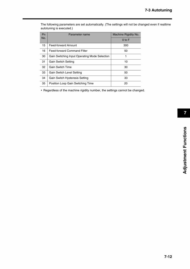
7-3 Autotuning
7
Ad
just
men
t F
un
ctio
ns
The following parameters are set automatically. (The settings will not be changed even if realtime autotuning is executed.)
Regardless of the machine rigidity number, the settings cannot be changed.
PnNo.
Parameter name Machine Rigidity No.
0 to F
15 Feed-forward Amount 300
16 Feed-forward Command Filter 50
30 Gain Switching Input Operating Mode Selection 1
31 Gain Switch Setting 10
32 Gain Switch Time 30
33 Gain Switch Level Setting 50
34 Gain Switch Hysteresis Setting 33
35 Position Loop Gain Switching Time 20
7-12

7-4 Disabling the Automatic Gain Adjustment Function
7
Ad
just
men
t F
un
ctio
ns
7-4 Disabling the Automatic Gain Adjustment FunctionThis section explains how to disable realtime autotuning and the adaptive filter. These functions are enabled by default.
Disabling Realtime AutotuningBy setting the Realtime Autotuning Mode Selection (Pn21) to 0 or 7, the automatic estimation of the Inertia Ratio (Pn20) will stop and realtime autotuning will be disabled.
However, the estimated results of the Inertia Ratio (Pn20) will remain. If the Pn20 value is obviously incorrect, perform autotuning or set the calculated value manually after disabling realtime autotuning.
When disabling the automatic adjustment function, the RUN Command Input (RUN) must be turned OFF.
To enable the Realtime Autotuning Mode Selection (Pn21), turn OFF the RUN Command Input (RUN), and then turn it back ON.
Precautions for Correct Use
Precautions for Correct Use
7-13
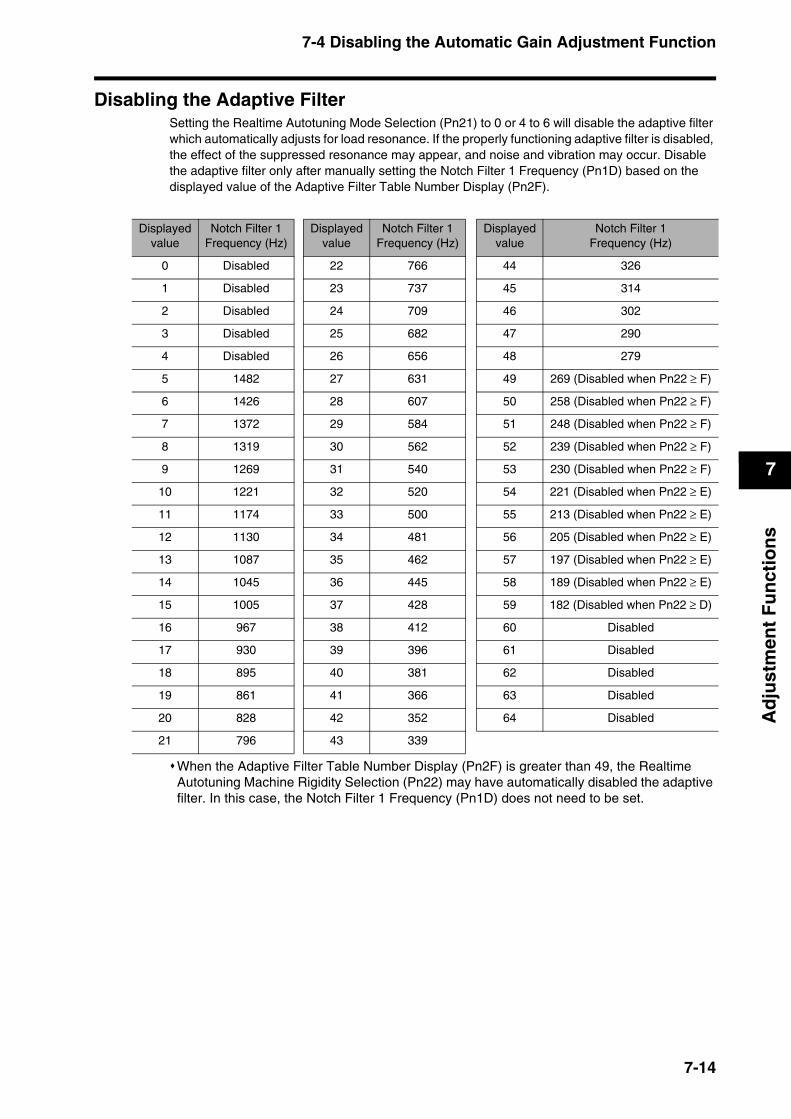
7-4 Disabling the Automatic Gain Adjustment Function
7
Ad
just
men
t F
un
ctio
ns
Disabling the Adaptive FilterSetting the Realtime Autotuning Mode Selection (Pn21) to 0 or 4 to 6 will disable the adaptive filter which automatically adjusts for load resonance. If the properly functioning adaptive filter is disabled, the effect of the suppressed resonance may appear, and noise and vibration may occur. Disable the adaptive filter only after manually setting the Notch Filter 1 Frequency (Pn1D) based on the displayed value of the Adaptive Filter Table Number Display (Pn2F).
When the Adaptive Filter Table Number Display (Pn2F) is greater than 49, the Realtime Autotuning Machine Rigidity Selection (Pn22) may have automatically disabled the adaptive filter. In this case, the Notch Filter 1 Frequency (Pn1D) does not need to be set.
Displayedvalue
Notch Filter 1Frequency (Hz)
Displayedvalue
Notch Filter 1Frequency (Hz)
Displayedvalue
Notch Filter 1Frequency (Hz)
0 Disabled 22 766 44 326
1 Disabled 23 737 45 314
2 Disabled 24 709 46 302
3 Disabled 25 682 47 290
4 Disabled 26 656 48 279
5 1482 27 631 49 269 (Disabled when Pn22 ≥ F)
6 1426 28 607 50 258 (Disabled when Pn22 ≥ F)
7 1372 29 584 51 248 (Disabled when Pn22 ≥ F)
8 1319 30 562 52 239 (Disabled when Pn22 ≥ F)
9 1269 31 540 53 230 (Disabled when Pn22 ≥ F)
10 1221 32 520 54 221 (Disabled when Pn22 ≥ E)
11 1174 33 500 55 213 (Disabled when Pn22 ≥ E)
12 1130 34 481 56 205 (Disabled when Pn22 ≥ E)
13 1087 35 462 57 197 (Disabled when Pn22 ≥ E)
14 1045 36 445 58 189 (Disabled when Pn22 ≥ E)
15 1005 37 428 59 182 (Disabled when Pn22 ≥ D)
16 967 38 412 60 Disabled
17 930 39 396 61 Disabled
18 895 40 381 62 Disabled
19 861 41 366 63 Disabled
20 828 42 352 64 Disabled
21 796 43 339
7-14
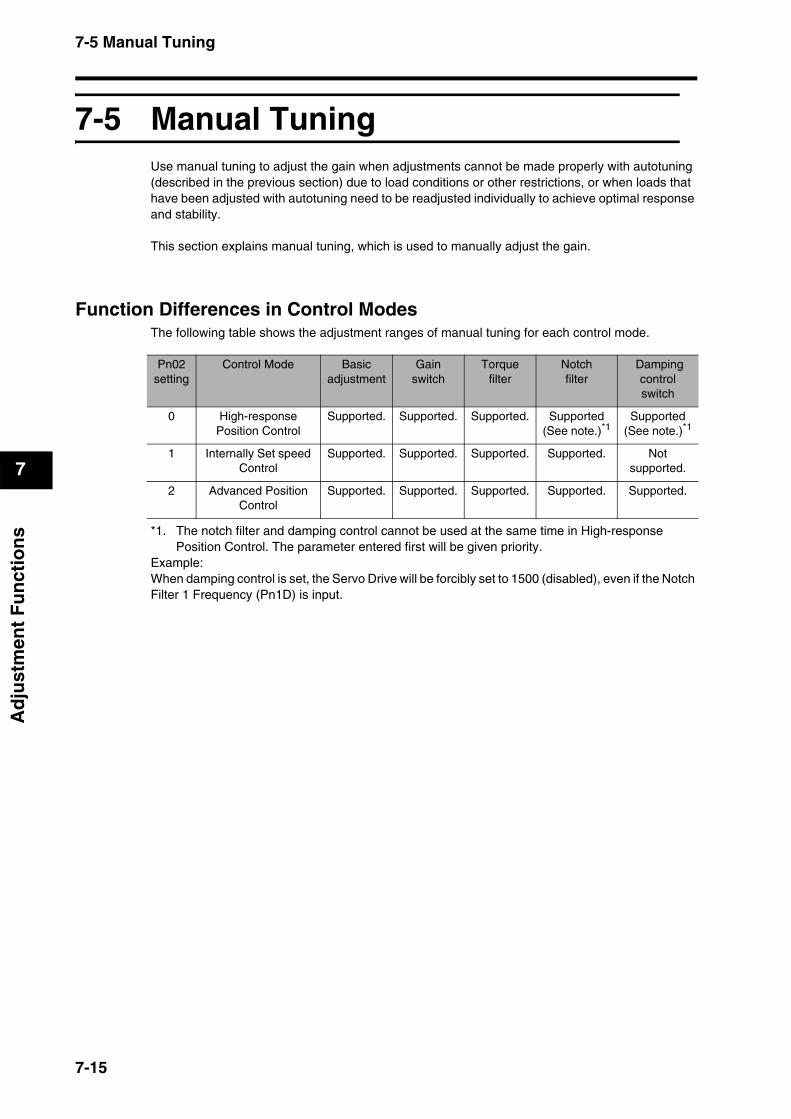
7-5 Manual Tuning
7
Ad
just
men
t F
un
ctio
ns
7-5 Manual TuningUse manual tuning to adjust the gain when adjustments cannot be made properly with autotuning (described in the previous section) due to load conditions or other restrictions, or when loads that have been adjusted with autotuning need to be readjusted individually to achieve optimal response and stability.
This section explains manual tuning, which is used to manually adjust the gain.
Function Differences in Control ModesThe following table shows the adjustment ranges of manual tuning for each control mode.
*1. The notch filter and damping control cannot be used at the same time in High-response Position Control. The parameter entered first will be given priority.
Example:When damping control is set, the Servo Drive will be forcibly set to 1500 (disabled), even if the Notch Filter 1 Frequency (Pn1D) is input.
Pn02setting
Control Mode Basicadjustment
Gain switch
Torquefilter
Notchfilter
Damping control switch
0 High-response Position Control
Supported. Supported. Supported. Supported(See note.)*1
Supported(See note.)*1
1 Internally Set speed Control
Supported. Supported. Supported. Supported. Not supported.
2 Advanced Position Control
Supported. Supported. Supported. Supported. Supported.
7-15
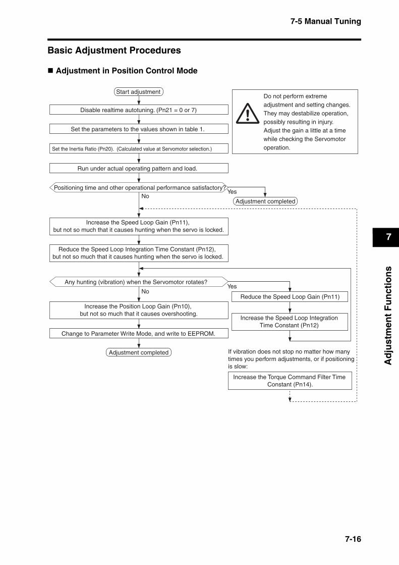
7-5 Manual Tuning
7
Ad
just
men
t F
un
ctio
ns
Basic Adjustment Procedures
Adjustment in Position Control Mode
Change to Parameter Write Mode, and write to EEPROM.
Start adjustment
YesNo
Adjustment completed
Disable realtime autotuning. (Pn21 = 0 or 7)
Set the parameters to the values shown in table 1.
Set the Inertia Ratio (Pn20). (Calculated value at Servomotor selection.)
Run under actual operating pattern and load.
Positioning time and other operational performance satisfactory?
Adjustment completed
Increase the Speed Loop Gain (Pn11), but not so much that it causes hunting when the servo is locked.
Reduce the Speed Loop Integration Time Constant (Pn12), but not so much that it causes hunting when the servo is locked.
Any hunting (vibration) when the Servomotor rotates?
NoReduce the Speed Loop Gain (Pn11)
Increase the Speed Loop Integration Time Constant (Pn12)
Increase the Position Loop Gain (Pn10), but not so much that it causes overshooting.
Yes
If vibration does not stop no matter how many times you perform adjustments, or if positioning is slow:
Increase the Torque Command Filter Time Constant (Pn14).
Do not perform extreme adjustment and setting changes. They may destabilize operation, possibly resulting in injury.Adjust the gain a little at a time while checking the Servomotor operation.
7-16
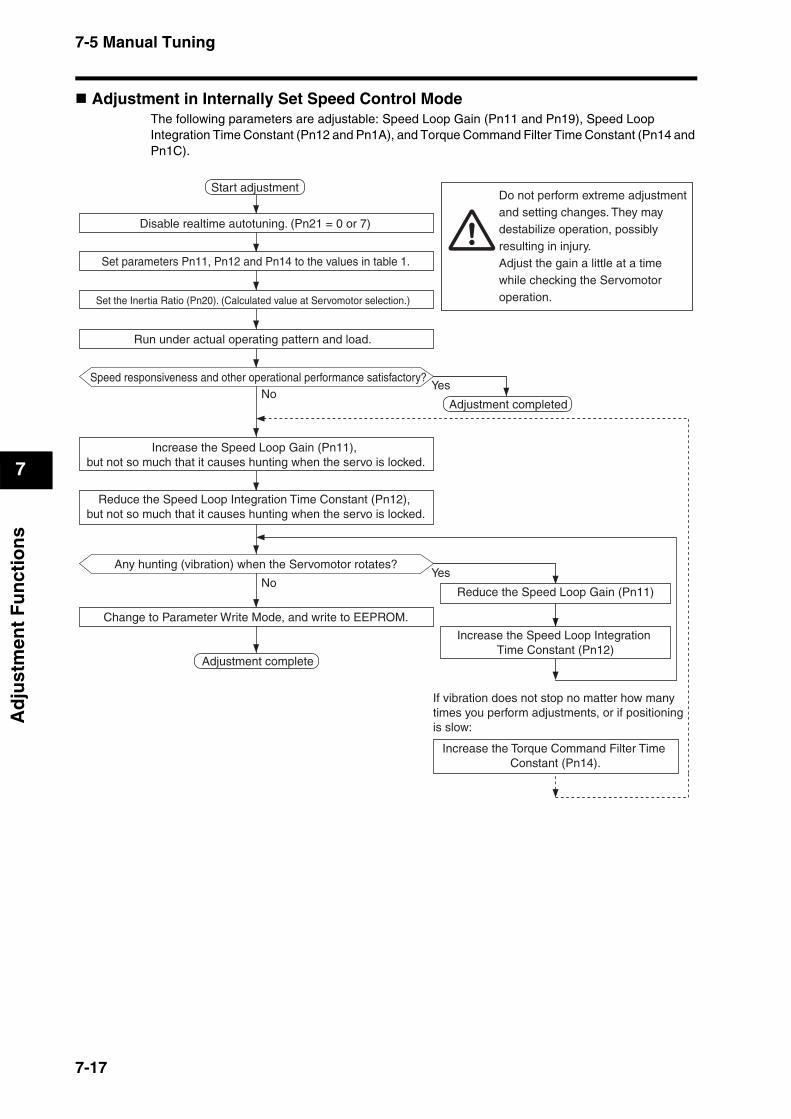
7-5 Manual Tuning
7
Ad
just
men
t F
un
ctio
ns
Adjustment in Internally Set Speed Control Mode The following parameters are adjustable: Speed Loop Gain (Pn11 and Pn19), Speed Loop Integration Time Constant (Pn12 and Pn1A), and Torque Command Filter Time Constant (Pn14 and Pn1C).
Change to Parameter Write Mode, and write to EEPROM.
Start adjustment
YesNo
Adjustment complete
Disable realtime autotuning. (Pn21 = 0 or 7)
Set parameters Pn11, Pn12 and Pn14 to the values in table 1.
Set the Inertia Ratio (Pn20). (Calculated value at Servomotor selection.)
Run under actual operating pattern and load.
Speed responsiveness and other operational performance satisfactory?
Adjustment completed
Increase the Speed Loop Gain (Pn11), but not so much that it causes hunting when the servo is locked.
Reduce the Speed Loop Integration Time Constant (Pn12), but not so much that it causes hunting when the servo is locked.
Any hunting (vibration) when the Servomotor rotates?
NoReduce the Speed Loop Gain (Pn11)
Increase the Speed Loop Integration Time Constant (Pn12)
Yes
If vibration does not stop no matter how manytimes you perform adjustments, or if positioning is slow:
Increase the Torque Command Filter Time Constant (Pn14).
Do not perform extreme adjustment and setting changes. They may destabilize operation, possibly resulting in injury.Adjust the gain a little at a time while checking the Servomotor operation.
7-17
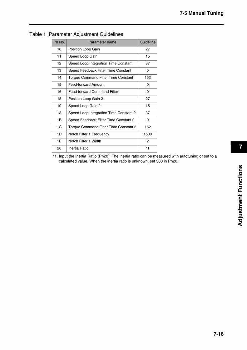
7-5 Manual Tuning
7
Ad
just
men
t F
un
ctio
ns
*1. Input the Inertia Ratio (Pn20). The inertia ratio can be measured with autotuning or set to a calculated value. When the inertia ratio is unknown, set 300 in Pn20.
Table 1 :Parameter Adjustment Guidelines
Pn No. Parameter name Guideline
10 Position Loop Gain 27
11 Speed Loop Gain 15
12 Speed Loop Integration Time Constant 37
13 Speed Feedback Filter Time Constant 0
14 Torque Command Filter Time Constant 152
15 Feed-forward Amount 0
16 Feed-forward Command Filter 0
18 Position Loop Gain 2 27
19 Speed Loop Gain 2 15
1A Speed Loop Integration Time Constant 2 37
1B Speed Feedback Filter Time Constant 2 0
1C Torque Command Filter Time Constant 2 152
1D Notch Filter 1 Frequency 1500
1E Notch Filter 1 Width 2
20 Inertia Ratio *1
7-18
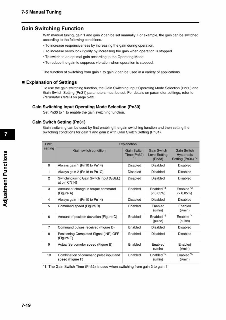
7-5 Manual Tuning
7
Ad
just
men
t F
un
ctio
ns
Gain Switching FunctionWith manual tuning, gain 1 and gain 2 can be set manually. For example, the gain can be switched according to the following conditions.
To increase responsiveness by increasing the gain during operation.
To increase servo lock rigidity by increasing the gain when operation is stopped.
To switch to an optimal gain according to the Operating Mode.
To reduce the gain to suppress vibration when operation is stopped.
The function of switching from gain 1 to gain 2 can be used in a variety of applications.
Explanation of SettingsTo use the gain switching function, the Gain Switching Input Operating Mode Selection (Pn30) and Gain Switch Setting (Pn31) parameters must be set. For details on parameter settings, refer to Parameter Details on page 5-32.
Gain Switching Input Operating Mode Selection (Pn30)Set Pn30 to 1 to enable the gain switching function.
Gain Switch Setting (Pn31)Gain switching can be used by first enabling the gain switching function and then setting the switching conditions for gain 1 and gain 2 with Gain Switch Setting (Pn31).
*1. The Gain Switch Time (Pn32) is used when switching from gain 2 to gain 1.
Pn31setting
Explanation
Gain switch condition Gain Switch Time (Pn32)
*1
Gain Switch Level Setting
(Pn33)
Gain Switch Hysteresis
Setting (Pn34) *2
0 Always gain 1 (Pn10 to Pn14) Disabled Disabled Disabled
1 Always gain 2 (Pn18 to Pn1C) Disabled Disabled Disabled
2 Switching using Gain Switch Input (GSEL) at pin CN1-5
Disabled Disabled Disabled
3 Amount of change in torque command (Figure A)
Enabled Enabled *3
(× 0.05%)Enabled *3
(× 0.05%)
4 Always gain 1 (Pn10 to Pn14) Disabled Disabled Disabled
5 Command speed (Figure B) Enabled Enabled(r/min)
Enabled(r/min)
6 Amount of position deviation (Figure C) Enabled Enabled *4
(pulse)Enabled *4
(pulse)
7 Command pulses received (Figure D) Enabled Disabled Disabled
8 Positioning Completed Signal (INP) OFF (Figure E)
Enabled Disabled Disabled
9 Actual Servomotor speed (Figure B) Enabled Enabled(r/min)
Enabled(r/min)
10 Combination of command pulse input and speed (Figure F)
Enabled Enabled *5
(r/min)Enabled *5
(r/min)
7-19

7-5 Manual Tuning
7
Ad
just
men
t F
un
ctio
ns
*2. The Gain Switch Hysteresis Setting (Pn34) is defined as shown in the following figure.
*3. The amount of change is the value within 166 µs.Example: When the condition is a 10% change in torque in 166 µs, the set value is 200.
*4. This is the encoder resolution value.*5. The meanings of the Gain Switch Time, Gain Switch Level Setting, and Gain Switch Hysteresis
Setting are different from normal if this parameter is set to 10. (Refer to Figure F.)
Pn33Pn34
0
Pn32
Gain 1 Gain 1Gain 2
HL
HL
HL
HL
Figure A
Speed V
Torque T
∆T
Level
Time
1
1
2 2 2 2
1
1Gain 1
Figure CSpeed V
Gain 1 Gain 1Gain 2
Differential pulsesLevel
Time
Figure D Command speed S
Gain 1 Gain 1Gain 2Time
Figure E Actual speed N
INP
Gain 1 Gain 1Gain 2Time
Figure BSpeed V
Level
Gain 1 Gain 1Gain 2Time
Gain 1 Gain 2
Actual speed N
Time
LevelHL
Gain 1
Gain 2 is used only during the Speed Loop Integration Time Constant.
Figure F
Gain 1 is used at other times.
Command speed S
7-20

7-5 Manual Tuning
7
Ad
just
men
t F
un
ctio
ns
Machine Resonance Control When machine rigidity is low, shaft torsion may cause resonance, leading to vibration or noise, thus not allowing the gain to be set high. In this case, the resonance can be suppressed by using the two filter types.
Torque Command Filter Time Constant (Pn14, Pn1C) The filter time constant is set to attenuate the resonance frequency. The cut-off frequency can be calculated using the following equation.
Notch Filter
Adaptive Filter (Pn21, Pn2F) By using the adaptive filter, the Servo Drive can suppress vibration of loads with various resonance points for each machinery, which conventional notch filters or torque command filters were unable to cope with. Enable the adaptive filter by selecting advanced position control (2) for the Control Mode Selection (Pn02) and setting the Realtime Autotuning Mode Selection (Pn21) to 1 to 3 or 7.
Notch Filter 1 (Pn1D, Pn1E)Adjust the notch frequency of the notch filter according to the machine resonance frequency.
Pn No. Parameter name Explanation
21 Realtime Autotuning Mode Selection
The adaptive filter is enabled when this parameter is set to 1 to 3, or 7.
2F Adaptive Filter Table Number Display
Displays the table entry number corresponding to the frequency of the adaptive filter.*1
The setting of this parameter cannot be changed.
*1. For information on table entry numbers and frequency, refer to Disabling the Adaptive Filter on page 7-14.
Cut-off frequency (Hz) fc = 2πT
1=
2π × Parameter setting × 10-5
1
7-21
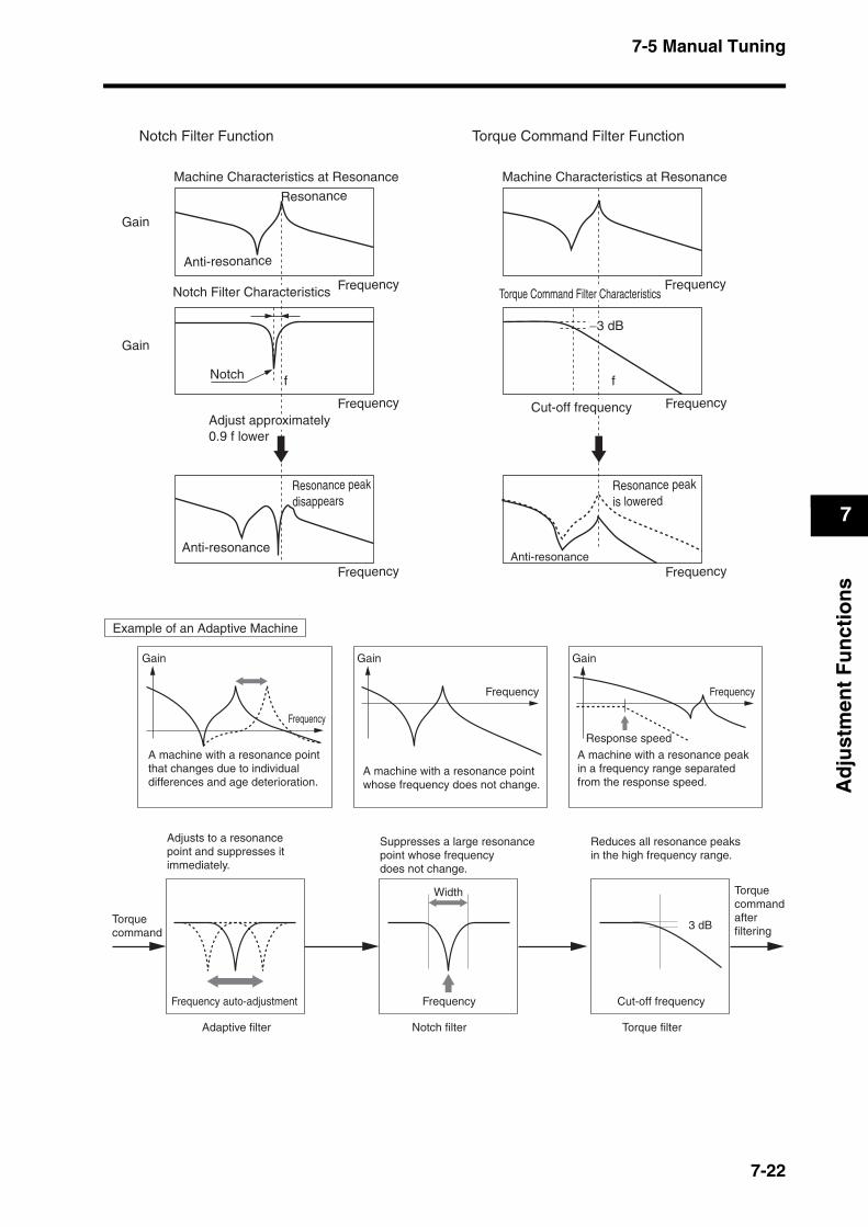
7-5 Manual Tuning
7
Ad
just
men
t F
un
ctio
ns
Notch
Frequency
Frequency
Anti-resonance
Gain
Gain
Anti-resonance
Frequency
Resonance peakdisappears
ResonanceMachine Characteristics at Resonance
f
Adjust approximately0.9 f lower
Frequency
Frequency
Anti-resonanceFrequency
Resonance peakis lowered
Machine Characteristics at Resonance
f
−3 dB
Cut-off frequency
Notch Filter Characteristics Torque Command Filter Characteristics
Notch Filter Function Torque Command Filter Function
Torquecommand
Gain
Frequency
Adaptive filter
Frequency auto-adjustment Frequency
Response speed
Width
Notch filter
Suppresses a large resonance point whose frequency does not change.
Cut-off frequency
3 dB
Torque filter
Torque commandafter filtering
Reduces all resonance peaks in the high frequency range.
Example of an Adaptive Machine
A machine with a resonance point that changes due to individual differences and age deterioration.
Gain
Frequency
A machine with a resonance point whose frequency does not change.
Gain
Frequency
A machine with a resonance peak in a frequency range separated from the response speed.
Adjusts to a resonance point and suppresses it immediately.
7-22

7-5 Manual Tuning
7
Ad
just
men
t F
un
ctio
ns
Damping ControlWhen the machine end vibrates, damping control removes the vibration frequency component from the command and suppresses vibration.
Current command
Position/Speed control
Position Command
M
E
Servo Drive
Feedback pulses
LoadDampingfilter
Motor
Ball screw
Movement
Position change sensor monitors vibration
Vibrating end
Machine stand
Driver
Position controller
Sets end vibration frequency
Torquecom-mand
Precautions for Correct Use
The following conditions must be met to use damping control.
Stop operation before changing parameters.Under the following conditions, damping control may not operate properly or may have no effect.
Conditions under which damping control operates
Control Mode The Position Control Mode must be used. If the Control Mode Selection (Pn02) is set to 0, realtime autotuning and notch filter 1 must be disabled in High-Response Position Control.
If the Control Mode Selection (Pn02) is set to 2, Advanced Position Control Mode is used.
Conditions under which the effect of damping control is inhibited
Load When forces other than commands, such as external forces, cause vibration.
When the difference between the resonance frequency andanti-resonance frequency is large.
When the vibration frequency is large (more than 100 Hz).
7-23
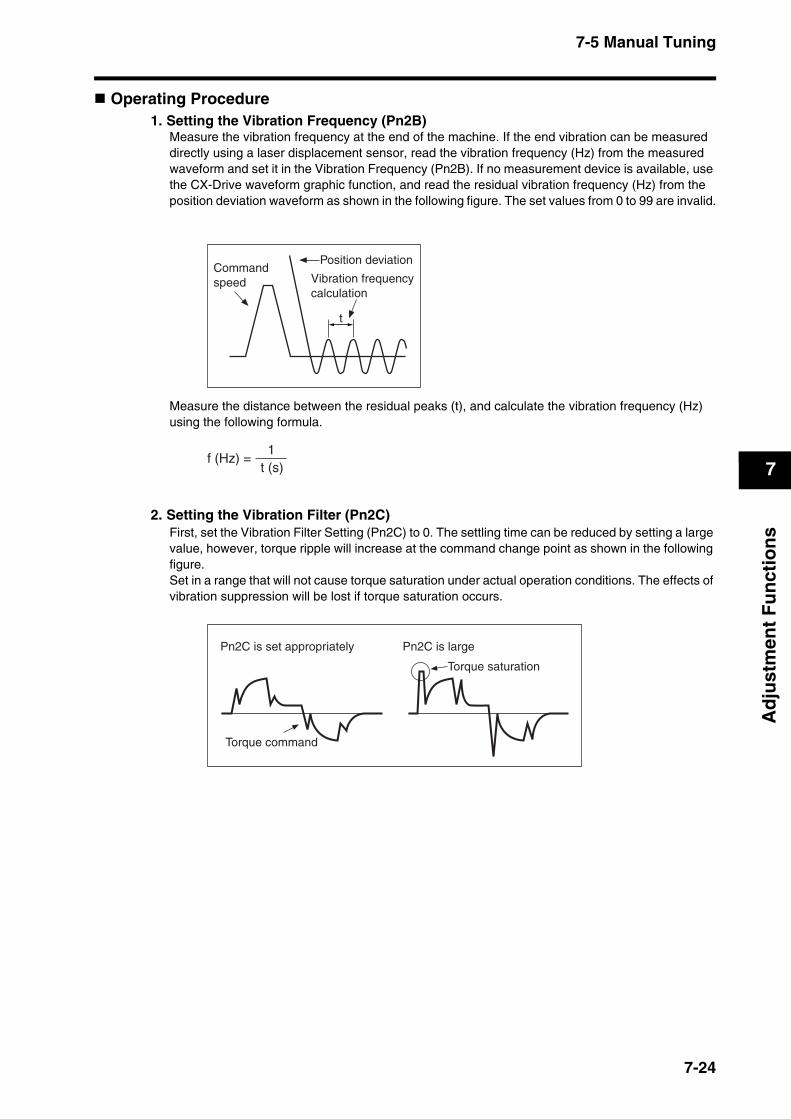
7-5 Manual Tuning
7
Ad
just
men
t F
un
ctio
ns
Operating Procedure 1. Setting the Vibration Frequency (Pn2B)
Measure the vibration frequency at the end of the machine. If the end vibration can be measured directly using a laser displacement sensor, read the vibration frequency (Hz) from the measured waveform and set it in the Vibration Frequency (Pn2B). If no measurement device is available, use the CX-Drive waveform graphic function, and read the residual vibration frequency (Hz) from the position deviation waveform as shown in the following figure. The set values from 0 to 99 are invalid.
Measure the distance between the residual peaks (t), and calculate the vibration frequency (Hz) using the following formula.
2. Setting the Vibration Filter (Pn2C)First, set the Vibration Filter Setting (Pn2C) to 0. The settling time can be reduced by setting a large value, however, torque ripple will increase at the command change point as shown in the following figure.Set in a range that will not cause torque saturation under actual operation conditions. The effects of vibration suppression will be lost if torque saturation occurs.
Command speed
Position deviation
Vibration frequency calculation
t
f (Hz) = t (s)1
Torque command
Torque saturation
Pn2C is largePn2C is set appropriately
7-24

Chapter 8
Troubleshooting8-1 Error Processing ................................................8-1
Preliminary Checks When a Problem Occurs..........................8-1
Precautions When Troubleshooting.........................................8-2
Replacing the Servomotor and Servo Drive.............................8-2
8-2 Alarm Table.........................................................8-3Alarm Indicator on the Servo Drive ..........................................8-3
Alarm List .................................................................................8-4
8-3 Troubleshooting.................................................8-5Points to Check........................................................................8-5
Error Diagnosis Using the Displayed Alarm Codes .................8-6
Error Diagnosis Using the Operating Status ..........................8-12
8-4 Overload Characteristics (Electronic Thermal Function) ........................8-16
Overload Characteristics Graphs...........................................8-16
8-5 Periodic Maintenance ......................................8-17Servomotor Service Life.........................................................8-17
Servo Drive Service Life ........................................................8-18
8-1 Error Processing
8
Tro
ub
lesh
oo
tin
g
8Troubleshooting
8-1 Error ProcessingThis section explains preliminary checks required to determine the cause of problems that might occur and cautions for the problems.
Preliminary Checks When a Problem OccursThis section explains the preliminary checks and analytical tools required to determine the cause of problems that might occur.
Checking the Power Supply VoltageCheck the voltage at the power supply input terminals.Main-circuit Power Supply Input Terminals (L1, (L2), L3)
R7D-BP@@L: Single-phase 100 to 115 VAC (85 to 127 V), 50/60 HzR7D-BP02HH: Single-phase 200 to 240 VAC (170 to 264 V), 50/60 HzR7D-BP@@H: Single-phase/three-phase 200 to 240 VAC (170 to 264 V), 50/60 HzR7D-BP02H: Three-phase 200 to 240 VAC (170 to 264 V), 50/60 Hz
If the voltage is outside of this range, there is a risk of operation failure. Be sure to supply the power correctly.
Check the voltage for the sequence input power supply: Within the range of 11 to 25 VDC (+24 VIN terminal (pin CN1-1)).If the voltage is outside of this range, there is a risk of operation failure. Be sure to supply the power correctly.
Checking Whether an Alarm Has OccurredCheck the alarm LED indicator on the front of the Servo Drive to see whether an alarm has occurred, or check the alarm code on the Parameter Unit.
When an alarm has occurred:Check the status of the alarm LED indicator (ALM) and evaluate the problem based on the alarm indicated.
Check the alarm code and perform analysis based on the alarm code information.
When an alarm has not occurred:Make an analysis according to the problem.
Note In either case, refer to 8-3 Troubleshooting for details.
8-1
8-1 Error Processing
8
Tro
ub
lesh
oo
tin
g
Precautions When TroubleshootingWhen checking and verifying I/O after a problem has occurred, the Servomotor/Servo Drive may suddenly start to operate or stop, so always use the following precautions.You should assume that anything not described in this manual is not possible with this product.
PrecautionsDisconnect the cable before checking for wire breakage. Even if you test conduction with the cable connected, test results may not be accurate due to conduction via bypassing circuit.If the encoder signal is lost, the Servomotor may run away, or an error may occur. Be sure to disconnect the Servomotor from the mechanical system before checking the encoder signal.When performing tests, first check that there are no persons in the vicinity or inside the equipment, and that the equipment will not be damaged even if the Servomotor runs away. Before performing the tests, verify that you can immediately stop the machine using an emergency stop even if the Servomotor runs away.
Replacing the Servomotor and Servo DriveUse the following procedure to replace the Servomotor or Servo Drive.
Replacing the Servomotor1. Replace the Servomotor.2. Perform machine origin position alignment (for position control).
When the Servomotor is replaced, the Servomotor’s origin position (phase Z) may deviate, so origin alignment must be performed.Refer to the Position Controller’s operation manual for details on performing origin alignment.
Replacing the Servo Drive1. Copy the parameters.
Use the copy function of the Parameter Unit to copy all the parameter settings to the Parameter Unit. Alternatively, use the Parameter Unit to display all the parameter settings and write them down.
2. Replace the Servo Drive.3. Set the parameters.
Use the copy function of the Parameter Unit to transfer all the saved parameters to the Servo Drive. Alternatively, use the Parameter Unit to set all the parameters.
8-2
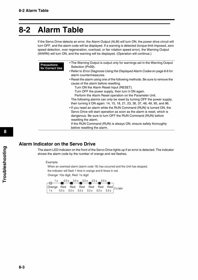
8-2 Alarm Table
8
Tro
ub
lesh
oo
tin
g
8-2 Alarm TableIf the Servo Drive detects an error, the Alarm Output (ALM) will turn ON, the power drive circuit will turn OFF, and the alarm code will be displayed. If a warning is detected (torque limit imposed, zero speed detection, over regeneration, overload, or fan rotation speed error), the Warning Output (WARN) will turn ON, and the warning will be displayed. (Operation will continue.)
Alarm Indicator on the Servo DriveThe alarm LED indicator on the front of the Servo Drive lights up if an error is detected. The indicator shows the alarm code by the number of orange and red flashes.
The Warning Output is output only for warnings set in the Warning Output Selection (Pn09).Refer to Error Diagnosis Using the Displayed Alarm Codes on page 8-6 for alarm countermeasures.Reset the alarm using one of the following methods. Be sure to remove the cause of the alarm before resetting.
Turn ON the Alarm Reset Input (RESET).Turn OFF the power supply, then turn it ON again.Perform the Alarm Reset operation on the Parameter Unit.
The following alarms can only be reset by turning OFF the power supply, then turning it ON again: 14, 15, 18, 21, 23, 36, 37, 48, 49, 95, and 96.If you reset an alarm while the RUN Command (RUN) is turned ON, the Servo Drive will start operation as soon as the alarm is reset, which is dangerous. Be sure to turn OFF the RUN Command (RUN) before resetting the alarm.If the RUN Command (RUN) is always ON, ensure safety thoroughly before resetting the alarm.
Precautions for Correct Use
Orange: 10s digit, Red: 1s digit
Example:When an overload alarm (alarm code 16) has occurred and the Unit has stopped, the indicator will flash 1 time in orange and 6 times in red.
Orange1 s
Red0.5 s
0.5 s1 s
Red0.5 s
Red0.5 s
Red0.5 s
Red0.5 s
Red0.5 s
0.5 s 0.5 s 0.5 s 0.5 s
2 s later
8-3

8-2 Alarm Table
8
Tro
ub
lesh
oo
tin
g
Alarm List
Alarmcode
Error detection function Detection details and cause of errorAlarmreset
possible
11Power supply undervoltage
The DC voltage of the main circuit fell below the specified value.Yes
12 Overvoltage The DC voltage of the main circuit is abnormally high. Yes
14 OvercurrentOvercurrent flowed to the IGBT. Servomotor power line ground fault or short circuit.
No
15 Built-in resistor overheat The resistor in the Servo Drive is abnormally overheating. No
16 OverloadOperation was performed with torque significantly exceeding the rat-ed level for several seconds to several tens of seconds.
Yes
18 Regeneration overloadThe regeneration energy exceeded the processing capacity of the regeneration resistor.
No
21Encoder disconnection detected
The encoder wiring is disconnected. No
23 Encoder data error Data from the encoder is abnormal. No
24Deviation counter overflow
The number of accumulated pulses in the deviation counter exceed-ed the setting in the Deviation Counter Overflow Level (Pn63).
Yes
26 Overspeed
The Servomotor exceeded the maximum number of rotations. If the torque limit function was used, the Servomotor’s rotation speed exceeded the settings in the Overspeed Detection Level Setting (Pn70 and Pn73).
Yes
27Electronic gear setting error
The setting in Electronic Gear Ratio Numerator 1 (Pn46) or Electron-ic Gear Ratio Numerator 2 (Pn47) is not appropriate.
Yes
29Deviation counter overflow
The number of accumulated pulses for the deviation counter exceeded 134,217,728.
Yes
34 Overrun limit errorThe Servomotor exceeded the allowable operating range set in the Overrun Limit Setting (Pn26).
Yes
36 Parameter errorData in the parameter saving area was corrupted when data was read from the EEPROM at power ON.
No
37 Parameter corruptionThe checksum didn’t match when data was read from the EEPROM at power on.
No
38 Drive prohibit input errorThe forward drive prohibit and reverse drive prohibit inputs are both turned OFF.
Yes
44 Encoder counter error 1 The encoder detected an error in the counter. No
45 Encoder counter error 2 The encoder detected an error in the counter. No
48 Encoder phase Z error A phase-Z pulse was not detected regularly. No
49 Encoder CS signal error A logic error of the CS signal was detected. No
95Servomotor non-conformity
The combination of the Servomotor and Servo Drive is not appropri-ate.The encoder was not connected when the power supply was turned ON.
No
96 LSI setting errorExcessive noise caused the LSI setting not to be completed proper-ly.
No
Others Other errorsThe Servo Drive’s self-diagnosis function detected an error in the Servo Drive.
No
8-4

8-3 Troubleshooting
8
Tro
ub
lesh
oo
tin
g
8-3 TroubleshootingIf an error occurs in the machine, determine the error conditions from the alarm indicator and operating status, identify the cause of the error, and take appropriate countermeasures.
Points to Check
CNA
CNB
CN2
CN1
CN3
PWR ALM
Is the couplingloose?
Servo-motor
Is the electromagnetic brake operating?
Is there any unusual noise coming from the Servomotor?
Is the connector disconnected?
Is the power supply LED indicator (PWR)lit red or orange?
Is the LED indicator flashing?
Is the wiring to CN1 correct? Is it disconnected?
Is the wiring to CN2 correct? Is it disconnected?
Host position controller
Is the connecting section disconnected (wire breaking or faulty connection)? Is the wiring correct?
Has the power supply voltage changed? Is the correct voltage being input? Are the connecting parts loose?
Ma-chine
8-5
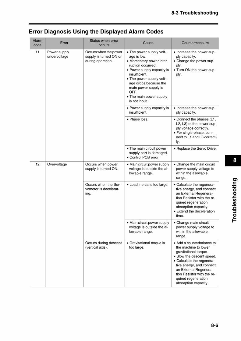
8-3 Troubleshooting
8
Tro
ub
lesh
oo
tin
g
Error Diagnosis Using the Displayed Alarm CodesAlarmcode
ErrorStatus when error
occursCause Countermeasure
11 Power supply undervoltage
Occurs when the power supply is turned ON or during operation.
• The power supply volt-age is low.
• Momentary power inter-ruption occurred.
• Power supply capacity is insufficient.
• The power supply volt-age drops because the main power supply is OFF.
• The main power supply is not input.
• Increase the power sup-ply capacity.
• Change the power sup-ply.
• Turn ON the power sup-ply.
• Power supply capacity is insufficient.
• Increase the power sup-ply capacity.
• Phase loss. • Connect the phases (L1, L2, L3) of the power sup-ply voltage correctly.
• For single-phase, con-nect to L1 and L3 correct-ly.
• The main circuit power supply part is damaged.
• Control PCB error.
• Replace the Servo Drive.
12 Overvoltage Occurs when power supply is turned ON.
• Main circuit power supply voltage is outside the al-lowable range.
• Change the main circuit power supply voltage to within the allowable range.
Occurs when the Ser-vomotor is decelerat-ing.
• Load inertia is too large. • Calculate the regenera-tive energy, and connect an External Regenera-tion Resistor with the re-quired regeneration absorption capacity.
• Extend the deceleration time.
• Main circuit power supply voltage is outside the al-lowable range.
• Change main circuit power supply voltage to within the allowable range.
Occurs during descent (vertical axis).
• Gravitational torque is too large.
• Add a counterbalance to the machine to lower gravitational torque.
• Slow the descent speed.• Calculate the regenera-
tive energy, and connect an External Regenera-tion Resistor with the re-quired regeneration absorption capacity.
8-6

8-3 Troubleshooting
8
Tro
ub
lesh
oo
tin
g
14 Overcurrent Occurs when the Servo Drive is turned ON.
• Control PCB error • Replace the Servo Drive.
• Servomotor power line is short-circuited or ground-faulted between phases.
• Repair the short-circuited or ground-faulted wire.
• Measure the insulation resistance at the Servo-motor and, if there is a short-circuit, replace the Servomotor.
• Miswiring between phase U, V, or W and ground.
• Correct the wiring.
• Servomotor winding is burned out.
• Measure the wire wound resistance, and if the winding is burned out, re-place the Servomotor.
• The relay for the dynamic brake has been conse-quently welded.
• Do not frequently input the RUN Command In-put.
• Do not operate the sys-tem by turning the Servo Drive ON and OFF.
• Servomotor non-confor-mity
• Use a Servomotor that is appropriate for use with the Servo Drive.
• The pulse input timing is too fast.
• Wait 100 ms min. before inputting pulses after turning ON the RUN Command Input (RUN).
• The resistor in the Servo Drive is abnormally over-heating.
• Reduce the ambient tem-perature of the Servo Drive to 55°C or lower.
• If the relay does not click when the power supply is turned ON, replace the Servo Drive.
16 Overload Occurs when the Servo Drive is turned ON.
• There is an error in the Servomotor wiring (e.g., the wiring or the contacts are faulty).
• Wire the Servomotor Power Cable correctly.
• The electromagnetic brake is ON.
• Reset the brake.
• The Servo Drive is faulty. • Replace the Servo Drive.
Occurs during opera-tion.
• The actual torque ex-ceeds the rated torque.
• The starting torque ex-ceeds the maximum torque.
• Review the load condi-tions and operating con-ditions.
• Review the Servomotor capacity.
• An unusual noise oscilla-tion or vibration is caused by faulty gain adjustment.
• Adjust the gain correctly.
• The Servo Drive is faulty. • Replace the Servo Drive.
Alarmcode
ErrorStatus when error
occursCause Countermeasure
8-7
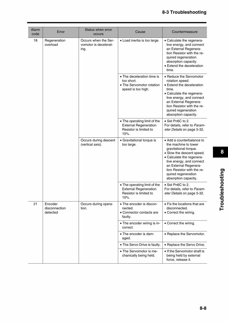
8-3 Troubleshooting
8
Tro
ub
lesh
oo
tin
g
18 Regeneration overload
Occurs when the Ser-vomotor is decelerat-ing.
• Load inertia is too large. • Calculate the regenera-tive energy, and connect an External Regenera-tion Resistor with the re-quired regeneration absorption capacity.
• Extend the deceleration time.
• The deceleration time is too short.
• The Servomotor rotation speed is too high.
• Reduce the Servomotor rotation speed.
• Extend the deceleration time.
• Calculate the regenera-tive energy, and connect an External Regenera-tion Resistor with the re-quired regeneration absorption capacity.
• The operating limit of the External Regeneration Resistor is limited to 10%.
• Set Pn6C to 2.For details, refer to Param-eter Details on page 5-32.
Occurs during descent (vertical axis).
• Gravitational torque is too large.
• Add a counterbalance to the machine to lower gravitational torque.
• Slow the descent speed.• Calculate the regenera-
tive energy, and connect an External Regenera-tion Resistor with the re-quired regeneration absorption capacity.
• The operating limit of the External Regeneration Resistor is limited to 10%.
• Set Pn6C to 2.For details, refer to Param-eter Details on page 5-32.
21 Encoder disconnection detected
Occurs during opera-tion.
• The encoder is discon-nected.
• Connector contacts are faulty.
• Fix the locations that are disconnected.
• Correct the wiring.
• The encoder wiring is in-correct.
• Correct the wiring.
• The encoder is dam-aged.
• Replace the Servomotor.
• The Servo Drive is faulty. • Replace the Servo Drive.
• The Servomotor is me-chanically being held.
• If the Servomotor shaft is being held by external force, release it.
Alarmcode
ErrorStatus when error
occursCause Countermeasure
8-8
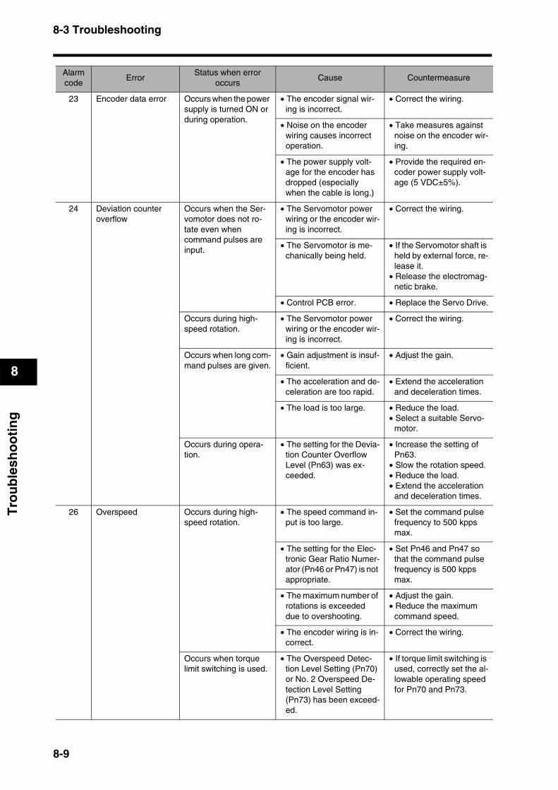
8-3 Troubleshooting
8
Tro
ub
lesh
oo
tin
g
23 Encoder data error Occurs when the power supply is turned ON or during operation.
• The encoder signal wir-ing is incorrect.
• Correct the wiring.
• Noise on the encoder wiring causes incorrect operation.
• Take measures against noise on the encoder wir-ing.
• The power supply volt-age for the encoder has dropped (especially when the cable is long.)
• Provide the required en-coder power supply volt-age (5 VDC±5%).
24 Deviation counter overflow
Occurs when the Ser-vomotor does not ro-tate even when command pulses are input.
• The Servomotor power wiring or the encoder wir-ing is incorrect.
• Correct the wiring.
• The Servomotor is me-chanically being held.
• If the Servomotor shaft is held by external force, re-lease it.
• Release the electromag-netic brake.
• Control PCB error. • Replace the Servo Drive.
Occurs during high-speed rotation.
• The Servomotor power wiring or the encoder wir-ing is incorrect.
• Correct the wiring.
Occurs when long com-mand pulses are given.
• Gain adjustment is insuf-ficient.
• Adjust the gain.
• The acceleration and de-celeration are too rapid.
• Extend the acceleration and deceleration times.
• The load is too large. • Reduce the load.• Select a suitable Servo-
motor.
Occurs during opera-tion.
• The setting for the Devia-tion Counter Overflow Level (Pn63) was ex-ceeded.
• Increase the setting of Pn63.
• Slow the rotation speed.• Reduce the load.• Extend the acceleration
and deceleration times.
26 Overspeed Occurs during high-speed rotation.
• The speed command in-put is too large.
• Set the command pulse frequency to 500 kpps max.
• The setting for the Elec-tronic Gear Ratio Numer-ator (Pn46 or Pn47) is not appropriate.
• Set Pn46 and Pn47 so that the command pulse frequency is 500 kpps max.
• The maximum number of rotations is exceeded due to overshooting.
• Adjust the gain.• Reduce the maximum
command speed.
• The encoder wiring is in-correct.
• Correct the wiring.
Occurs when torque limit switching is used.
• The Overspeed Detec-tion Level Setting (Pn70) or No. 2 Overspeed De-tection Level Setting (Pn73) has been exceed-ed.
• If torque limit switching is used, correctly set the al-lowable operating speed for Pn70 and Pn73.
Alarmcode
ErrorStatus when error
occursCause Countermeasure
8-9
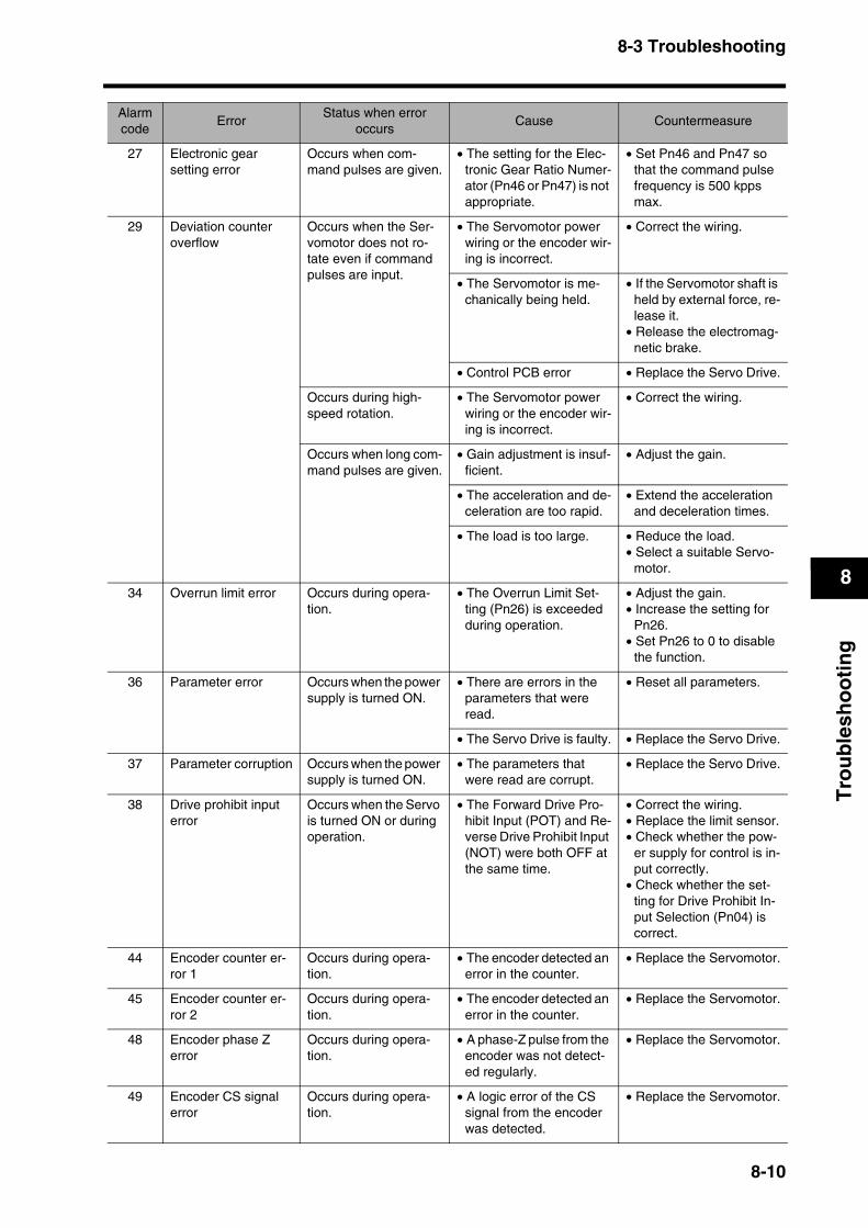
8-3 Troubleshooting
8
Tro
ub
lesh
oo
tin
g
27 Electronic gear setting error
Occurs when com-mand pulses are given.
• The setting for the Elec-tronic Gear Ratio Numer-ator (Pn46 or Pn47) is not appropriate.
• Set Pn46 and Pn47 so that the command pulse frequency is 500 kpps max.
29 Deviation counter overflow
Occurs when the Ser-vomotor does not ro-tate even if command pulses are input.
• The Servomotor power wiring or the encoder wir-ing is incorrect.
• Correct the wiring.
• The Servomotor is me-chanically being held.
• If the Servomotor shaft is held by external force, re-lease it.
• Release the electromag-netic brake.
• Control PCB error • Replace the Servo Drive.
Occurs during high-speed rotation.
• The Servomotor power wiring or the encoder wir-ing is incorrect.
• Correct the wiring.
Occurs when long com-mand pulses are given.
• Gain adjustment is insuf-ficient.
• Adjust the gain.
• The acceleration and de-celeration are too rapid.
• Extend the acceleration and deceleration times.
• The load is too large. • Reduce the load.• Select a suitable Servo-
motor.
34 Overrun limit error Occurs during opera-tion.
• The Overrun Limit Set-ting (Pn26) is exceeded during operation.
• Adjust the gain.• Increase the setting for
Pn26.• Set Pn26 to 0 to disable
the function.
36 Parameter error Occurs when the power supply is turned ON.
• There are errors in the parameters that were read.
• Reset all parameters.
• The Servo Drive is faulty. • Replace the Servo Drive.
37 Parameter corruption Occurs when the power supply is turned ON.
• The parameters that were read are corrupt.
• Replace the Servo Drive.
38 Drive prohibit input error
Occurs when the Servo is turned ON or during operation.
• The Forward Drive Pro-hibit Input (POT) and Re-verse Drive Prohibit Input (NOT) were both OFF at the same time.
• Correct the wiring.• Replace the limit sensor.• Check whether the pow-
er supply for control is in-put correctly.
• Check whether the set-ting for Drive Prohibit In-put Selection (Pn04) is correct.
44 Encoder counter er-ror 1
Occurs during opera-tion.
• The encoder detected an error in the counter.
• Replace the Servomotor.
45 Encoder counter er-ror 2
Occurs during opera-tion.
• The encoder detected an error in the counter.
• Replace the Servomotor.
48 Encoder phase Z error
Occurs during opera-tion.
• A phase-Z pulse from the encoder was not detect-ed regularly.
• Replace the Servomotor.
49 Encoder CS signal error
Occurs during opera-tion.
• A logic error of the CS signal from the encoder was detected.
• Replace the Servomotor.
Alarmcode
ErrorStatus when error
occursCause Countermeasure
8-10
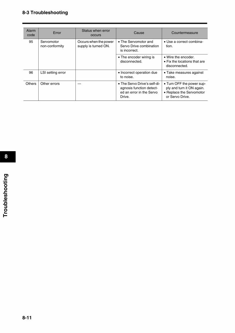
8-3 Troubleshooting
8
Tro
ub
lesh
oo
tin
g
95 Servomotor non-conformity
Occurs when the power supply is turned ON.
• The Servomotor and Servo Drive combination is incorrect.
• Use a correct combina-tion.
• The encoder wiring is disconnected.
• Wire the encoder.• Fix the locations that are
disconnected.
96 LSI setting error • Incorrect operation due to noise.
• Take measures against noise.
Others Other errors --- • The Servo Drive’s self-di-agnosis function detect-ed an error in the Servo Drive.
• Turn OFF the power sup-ply and turn it ON again.
• Replace the Servomotor or Servo Drive.
Alarmcode
ErrorStatus when error
occursCause Countermeasure
8-11
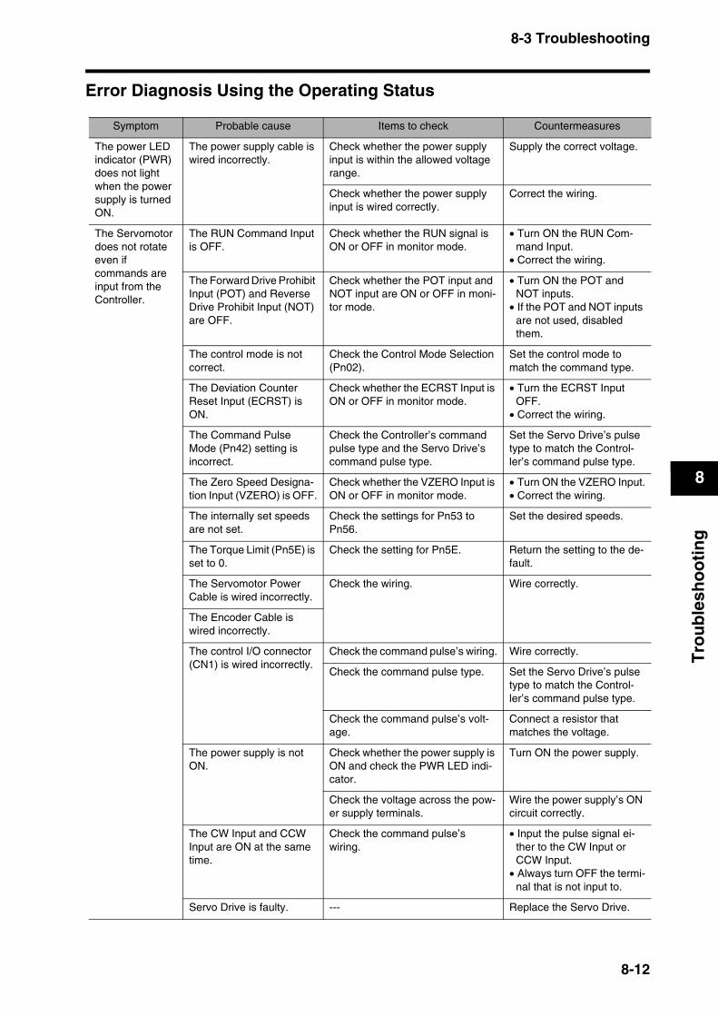
8-3 Troubleshooting
8
Tro
ub
lesh
oo
tin
g
Error Diagnosis Using the Operating Status
Symptom Probable cause Items to check Countermeasures
The power LED indicator (PWR) does not light when the power supply is turned ON.
The power supply cable is wired incorrectly.
Check whether the power supply input is within the allowed voltage range.
Supply the correct voltage.
Check whether the power supply input is wired correctly.
Correct the wiring.
The Servomotor does not rotate even if commands are input from the Controller.
The RUN Command Input is OFF.
Check whether the RUN signal is ON or OFF in monitor mode.
• Turn ON the RUN Com-mand Input.
• Correct the wiring.
The Forward Drive Prohibit Input (POT) and Reverse Drive Prohibit Input (NOT) are OFF.
Check whether the POT input and NOT input are ON or OFF in moni-tor mode.
• Turn ON the POT and NOT inputs.
• If the POT and NOT inputs are not used, disabled them.
The control mode is not correct.
Check the Control Mode Selection (Pn02).
Set the control mode to match the command type.
The Deviation Counter Reset Input (ECRST) is ON.
Check whether the ECRST Input is ON or OFF in monitor mode.
• Turn the ECRST Input OFF.
• Correct the wiring.
The Command PulseMode (Pn42) setting is incorrect.
Check the Controller’s command pulse type and the Servo Drive’s command pulse type.
Set the Servo Drive’s pulse type to match the Control-ler’s command pulse type.
The Zero Speed Designa-tion Input (VZERO) is OFF.
Check whether the VZERO Input is ON or OFF in monitor mode.
• Turn ON the VZERO Input.• Correct the wiring.
The internally set speeds are not set.
Check the settings for Pn53 to Pn56.
Set the desired speeds.
The Torque Limit (Pn5E) is set to 0.
Check the setting for Pn5E. Return the setting to the de-fault.
The Servomotor Power Cable is wired incorrectly.
Check the wiring. Wire correctly.
The Encoder Cable is wired incorrectly.
The control I/O connector (CN1) is wired incorrectly.
Check the command pulse’s wiring. Wire correctly.
Check the command pulse type. Set the Servo Drive’s pulse type to match the Control-ler’s command pulse type.
Check the command pulse’s volt-age.
Connect a resistor that matches the voltage.
The power supply is not ON.
Check whether the power supply is ON and check the PWR LED indi-cator.
Turn ON the power supply.
Check the voltage across the pow-er supply terminals.
Wire the power supply’s ON circuit correctly.
The CW Input and CCW Input are ON at the same time.
Check the command pulse’swiring.
• Input the pulse signal ei-ther to the CW Input or CCW Input.
• Always turn OFF the termi-nal that is not input to.
Servo Drive is faulty. --- Replace the Servo Drive.
8-12
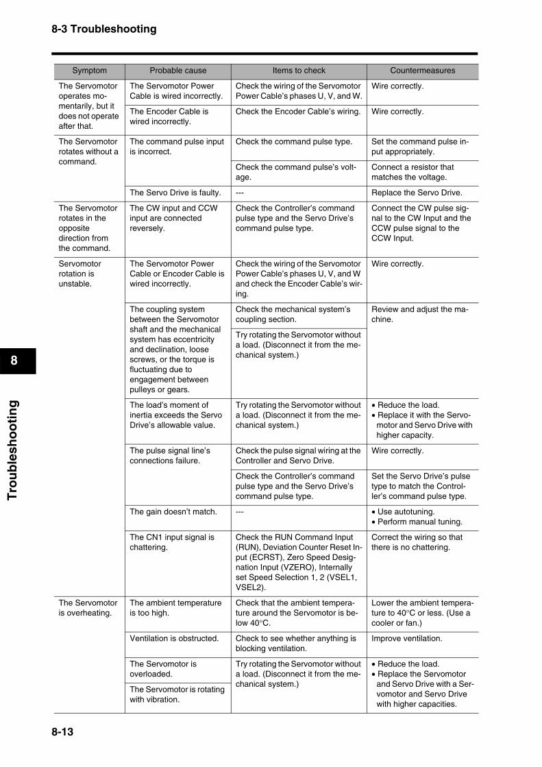
8-3 Troubleshooting
8
Tro
ub
lesh
oo
tin
g
The Servomotor operates mo-mentarily, but it does not operate after that.
The Servomotor Power Cable is wired incorrectly.
Check the wiring of the Servomotor Power Cable’s phases U, V, and W.
Wire correctly.
The Encoder Cable is wired incorrectly.
Check the Encoder Cable’s wiring. Wire correctly.
The Servomotor rotates without a command.
The command pulse input is incorrect.
Check the command pulse type. Set the command pulse in-put appropriately.
Check the command pulse’s volt-age.
Connect a resistor that matches the voltage.
The Servo Drive is faulty. --- Replace the Servo Drive.
The Servomotor rotates in the opposite direction from the command.
The CW input and CCW input are connected reversely.
Check the Controller’s command pulse type and the Servo Drive’s command pulse type.
Connect the CW pulse sig-nal to the CW Input and the CCW pulse signal to the CCW Input.
Servomotor rotation is unstable.
The Servomotor Power Cable or Encoder Cable is wired incorrectly.
Check the wiring of the Servomotor Power Cable’s phases U, V, and W and check the Encoder Cable’s wir-ing.
Wire correctly.
The coupling system between the Servomotor shaft and the mechanical system has eccentricity and declination, loose screws, or the torque is fluctuating due to engagement between pulleys or gears.
Check the mechanical system’s coupling section.
Review and adjust the ma-chine.
Try rotating the Servomotor without a load. (Disconnect it from the me-chanical system.)
The load’s moment of inertia exceeds the Servo Drive’s allowable value.
Try rotating the Servomotor without a load. (Disconnect it from the me-chanical system.)
• Reduce the load.• Replace it with the Servo-
motor and Servo Drive with higher capacity.
The pulse signal line’s connections failure.
Check the pulse signal wiring at the Controller and Servo Drive.
Wire correctly.
Check the Controller’s command pulse type and the Servo Drive’s command pulse type.
Set the Servo Drive’s pulse type to match the Control-ler’s command pulse type.
The gain doesn’t match. --- • Use autotuning.• Perform manual tuning.
The CN1 input signal is chattering.
Check the RUN Command Input (RUN), Deviation Counter Reset In-put (ECRST), Zero Speed Desig-nation Input (VZERO), Internally set Speed Selection 1, 2 (VSEL1, VSEL2).
Correct the wiring so that there is no chattering.
The Servomotor is overheating.
The ambient temperature is too high.
Check that the ambient tempera-ture around the Servomotor is be-low 40°C.
Lower the ambient tempera-ture to 40°C or less. (Use a cooler or fan.)
Ventilation is obstructed. Check to see whether anything is blocking ventilation.
Improve ventilation.
The Servomotor is overloaded.
Try rotating the Servomotor without a load. (Disconnect it from the me-chanical system.)
• Reduce the load.• Replace the Servomotor
and Servo Drive with a Ser-vomotor and Servo Drive with higher capacities.
The Servomotor is rotating with vibration.
Symptom Probable cause Items to check Countermeasures
8-13
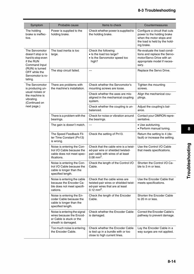
8-3 Troubleshooting
8
Tro
ub
lesh
oo
tin
g
The holding brake is ineffec-tive.
Power is supplied to the holding brake.
Check whether power is supplied to the holding brake.
Configure a circuit that cuts power to the holding brake when the motor stops and the load is held by the hold-ing brake.
The Servomotor doesn’t stop or is hard to stop even if the RUN Command Input (RUN) is turned OFF while the Servomotor is ro-tating.
The load inertia is too large.
Check the following:• Is the load too large?• Is the Servomotor speed too
high?
Re-evaluate the load condi-tions and replace the Servo-motor/Servo Drive with an appropriate model if neces-sary.
The stop circuit failed. --- Replace the Servo Drive.
The Servomotor is producing un-usual noises or the machine is vibrating. (Continued on next page.)
There are problems with the machine’s installation.
Check whether the Servomotor’s mounting screws are loose.
Tighten the mounting screws.
Check whether the axes are mis-aligned in the mechanical coupling system.
Align the mechanical cou-plings.
Check whether the coupling is un-balanced.
Adjust the coupling’s bal-ance.
There is a problem with the bearings.
Check for noise or vibration around the bearings.
Contact your OMRON repre-sentative.
The gain is doesn’t match. --- • Use autotuning.• Perform manual tuning.
The Speed Feedback Fil-ter Time Constant (Pn13) is wrong.
Check the setting of Pn13. Return the setting to 4 (de-fault) or increase the setting.
Noise is entering the Con-trol I/O Cable because the cable does not meet spec-ifications.
Check that the cable wire is a twist-ed-pair wire or shielded twisted-pair cable with wires of at least 0.08 mm2.
Use the Control I/O Cable that meets specifications.
Noise is entering the Con-trol I/O Cable because the cable is longer than the specified length.
Check the length of the Control I/O Cable.
Shorten the Control I/O Ca-ble to 3 m or less.
Noise is entering the cable because the Encoder Ca-ble does not meet specifi-cations.
Check that the cable wires are twisted-pair wires or shielded twist-ed-pair wires that are at least 0.12 mm2.
Use the Encoder Cable that meets specifications.
Noise is entering the En-coder Cable because the cable is longer than the specified length.
Check the length of the Encoder Cable.
Shorten the Encoder Cable to 20 m or less.
Noise is entering the signal wires because the Encod-er Cable is stuck or the sheath is damaged.
Check whether the Encoder Cable is damaged.
Correct the Encoder Cable’s pathway to prevent damage.
Too much noise is entering the Encoder Cable.
Check whether the Encoder Cable is tied up in a bundle with or too close to high current lines.
Lay the Encoder Cable in a way surges are not applied.
Symptom Probable cause Items to check Countermeasures
8-14
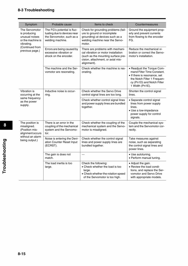
8-3 Troubleshooting
8
Tro
ub
lesh
oo
tin
g
The Servomotor is producing unusual noises or the machine is vibrating.(Continued from previous page.)
The FG’s potential is fluc-tuating due to devices near the Servomotor, such as a welding machine.
Check for grounding problems (fail-ure to ground or incomplete grounding) at devices such as a welding machine near the Servo-motor.
Ground the equipment prop-erly and prevent currents from flowing to the encoder FG.
Errors are being caused by excessive vibration or shock on the encoder.
There are problems with mechani-cal vibration or motor installation (such as the mounting surface pre-cision, attachment, or axial mis-alignment).
Reduce the mechanical vi-bration or correct the Servo-motor’s installation.
The machine and the Ser-vomotor are resonating.
Check whether the machine is res-onating.
• Readjust the Torque Com-mand Filter Time Constant.
• If there is resonance, set the Notch Filter 1 Frequen-cy (Pn1D) and Notch Filter 1 Width (Pn1E).
Vibration is occurring at the same frequency as the power supply.
Inductive noise is occur-ring.
Check whether the Servo Drive control signal lines are too long.
Shorten the control signal lines.
Check whether control signal lines and power supply lines are bundled together.
• Separate control signal lines from power supply lines.
• Use a low-impedance power supply for control signals.
The position is misaligned. (Position mis-alignment occurs without an alarm being output.)
There is an error in the coupling of the mechanical system and the Servomo-tor.
Check whether the coupling of the mechanical system and the Servo-motor is misaligned.
Couple the mechanical sys-tem and the Servomotor cor-rectly.
Noise is entering the Devi-ation Counter Reset Input (ECRST).
Check whether the control signal lines and power supply lines are bundled together.
Take measures against noise, such as separating the control signal lines and power lines.
The gain is does not match.
--- • Use autotuning.• Perform manual tuning.
The load inertia is too large.
Check the following:• Check whether the load is too
large.• Check whether the rotation speed
of the Servomotor is too high.
• Adjust the gain.• Review the load condi-
tions, and replace the Ser-vomotor and Servo Drive with appropriate models.
Symptom Probable cause Items to check Countermeasures
8-15
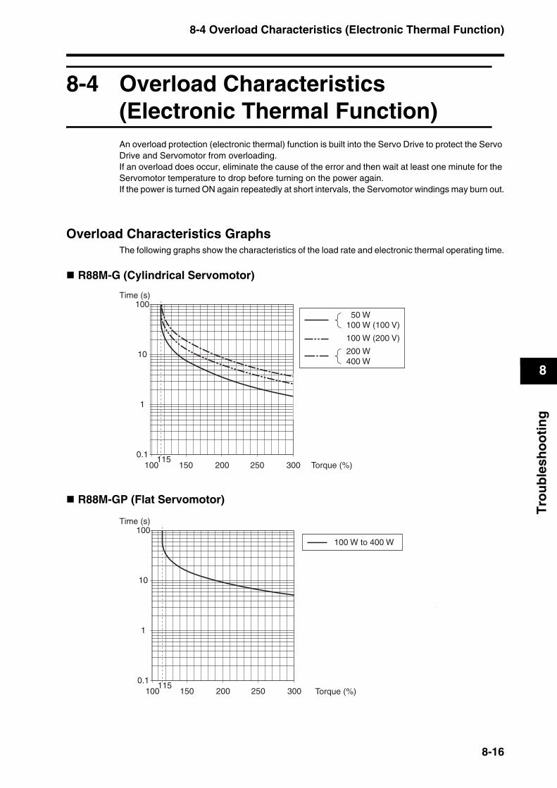
8-4 Overload Characteristics (Electronic Thermal Function)
8
Tro
ub
lesh
oo
tin
g
8-4 Overload Characteristics (Electronic Thermal Function)An overload protection (electronic thermal) function is built into the Servo Drive to protect the Servo Drive and Servomotor from overloading.If an overload does occur, eliminate the cause of the error and then wait at least one minute for the Servomotor temperature to drop before turning on the power again.If the power is turned ON again repeatedly at short intervals, the Servomotor windings may burn out.
Overload Characteristics GraphsThe following graphs show the characteristics of the load rate and electronic thermal operating time.
R88M-G (Cylindrical Servomotor)
R88M-GP (Flat Servomotor)
50 W100 W (100 V)
100 W (200 V)
200 W400 W
1000.1
1
10
100
150 200 250 300 Torque (%)115
Time (s)
100 W to 400 W
100115
0.1
1
10
100
150 200 250 300
Time (s)
Torque (%)
8-16
8-5 Periodic Maintenance
8
Tro
ub
lesh
oo
tin
g
8-5 Periodic MaintenanceThe Servomotor and Servo Drive contain many components and will function fully only when each of the individual components operates properly. Some of the electrical and mechanical components require maintenance depending on application conditions. Periodic inspection and part replacement are necessary to ensure the proper long-term operation of the Servomotor and Servo Drive. (quotes from The Recommendation for Periodic Maintenance of a General-purpose Inverter published by JEMA)The periodic maintenance cycle depends on the installation environment and application conditions of the Servomotor and Servo Drive. Recommended maintenance times are listed below for reference in determining actual maintenance schedules.
Servomotor Service LifeThe service life for components is listed below.
Bearings: 20,000 hoursDecelerator: 20,000 hoursOil seal: 5,000 hoursEncoder: 30,000 hours
These values presume an ambient Servomotor operating temperature of 40°C, shaft loads within the allowable range, rated operation (rated torque and rated r/min), and install as described in this manual.
You can request replacement of the bearings, Decelerator, Oil Seal, or encoder as repair work.
If timing pulleys are belt driven, the radial loads during operation (rotation) are as twice as the static loads. Consult with the belt and pulley manufacturers and adjust designs and system settings so that the Servomotor’s allowable shaft load is not exceeded even during operation. If a Servomotor is used under a shaft load exceeding the allowable limit, the Servomotor shaft may break and the bearings may burn out.
When requesting a repair or inspection, separate the Servomotor and Decelerator, and make a separate request for each product.
CautionResume operation only after transferring all data required for operation to the new Unit. Not doing so may result in damage to the product.
Do not dismantle or repair the product. Doing so may result in electric shock or injury.
8-17
8-5 Periodic Maintenance
8
Tro
ub
lesh
oo
tin
g
Servo Drive Service LifeThe service life of the Servo Drive is provided below.Consult with your OMRON representative to determine whether or not components need to be replaced.
Aluminum electrolytic capacitors: 50,000 hours, at an ambient Servo Drive operating temperature of 40°C, 80% of the rated operation output (rated torque), installed as described in this manual.
Axial fan: 30,000 hours, at an ambient Servo Drive operating temperature of 40°C and an ambient humidity of 65% RH.When using the Servo Drive in continuous operation, use a fan or air conditioner to maintain an ambient operating temperature of 40°C or lower.We recommend that the ambient operating temperature be lowered and the power ON time be reduced as much as possible to lengthen the service life of the Servo Drive.The service life of aluminum electrolytic capacitors is greatly affected by the ambient operating temperature. Generally, an increase of 10°C in the ambient operating temperature will reduce the capacitor life by 50%.Aluminum electrolytic capacitors deteriorate even if the Servo Drive is stored with no power supplied. If the Servo Drive is not used for a long time, we recommend a periodic inspection and part replacement in five years.If the Servomotor or Servo Drive is not used for a long time, or if they are used under conditions worse than those described above, a periodic inspection of five years is recommended.
8-18


Connection Examples ................................. Appendix-1
Appendix
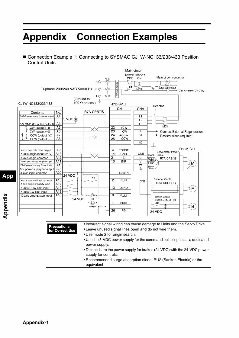
App
Ap
pen
dix
C
Appendix
Appendix Connection Examples
Connection Example 1: Connecting to SYSMAC CJ1W-NC133/233/433 Position Control Units
0-V power supply for output
24-V power supply for outputs
Reactor
Servomotor PowerCable
R7A-CAB@S
Main circuit power supply
Main circuit contactor
Servo error displaySurge suppressor
J1W-NC133/233/433 R7D-BP@
R88M-G@
Contents5-VDC power supply (for pulse output)
5-V GND (for pulse output)
X-axis dev. cntr. reset output
X-axis origin input (24 V)X-axis origin commonX-axis positioning complete input
X-axis input common
X-axis external interrupt input
X-axis origin proximity input
X-axis CCW limit inputX-axis CW limit inputX-axis emerg. stop input
X-a
xis
puls
e ou
tput
RedWhiteBlueGreen/Yellow
Noi
se fi
lter
3-phase 200/240 VAC 50/60 Hz
(Ground to 100 Ω or less.)
Connect External Regeneration Resistor when required.
R7A-CPB@S
CW (output (+))CW (output (−))CCW (output (+))CCW (output (−))
Encoder Cable
R88A-CRGB@C
Brake CableR88A-CAGA@B
+CW−CW
ECRST
+24VIN
+CCW−CCW
5 VDC
24 VDCX1
24 VDC
24 VDC
XB
No.CN1 CNA
A4
A32223
4142110
1
2
13
9
11
L1L2
UVW
GND
INP
RUN
0GND
/ALM
FG
Z
A9A13A12A11
A20
A15A17A19A18A16
CN2
M
EX1
XB
BBKIR
A5A6A7A8 25
24
A1A2
CNB
L3
PB1
26
R
T
MC1
NFB ONOFF
X1MC1 PLS
MC1
SUP
X1
Incorrect signal wiring can cause damage to Units and the Servo Drive.Leave unused signal lines open and do not wire them.Use mode 2 for origin search.Use the 5-VDC power supply for the command pulse inputs as a dedicated power supply.Do not share the power supply for brakes (24 VDC) with the 24-VDC power supply for controls.Recommended surge absorption diode: RU2 (Sanken Electric) or the equivalent
Precautions for Correct Use
Appendix-1

App
Ap
pen
dix
Connection Example 2: Connecting to SYSMAC CJ1W-NC113/213/413 Position Control Units
No.CN1 CNA
A1
A2
232425
4142110
1
2
13
9
11
22
L1L2
UVW
GND
INP
RUN
0GND
/ALM
FG
Z
A8A7
A6A5
A9A13A12A11
A20
A15A17A19A18A16
CN2
M
EX1
XB
24 VDC
24 VDC
24 VDC
BBKIR
CNB
L3
24 VDC
XB
B1P
26
X1
CJ1W-NC113/213/413
Contents24-V power supply for outputs
0-V input (for output)
X-axis dev. cntr. reset output
X-axis origin input (24 V)X-axis origin commonX-axis positioning complete input
X-axis input common
ECRST
CCW (with a resistor)
CCW (without a resistor)
CW (with a resistor)
CW (without a resistor)
3-phase 200/240 VAC 50/60 Hz
X-a
xis
puls
e ou
tput
X-axis external interrupt input
X-axis origin proximity input
X-axis CCW limit inputX-axis CW limit inputX-axis emerg. stop input
Noi
se fi
lter
(Ground to 100 Ω or less.) ReactorR7D-BP@
Connect External Regeneration Resistor when required.
R7A-CPB@S
Servomotor Power Cable
R7A-CAB@S
R88M-G@
+CW−CW
+24VIN
RedWhiteBlueGreen/Yellow
+CCW−CCW
Encoder Cable
R88A-CRGB@C
Brake CableR88A-CAGA@B
R
T
NFB ONOFF
X1 MC1
MC1
PLS X1
SUP
MC1
Main circuit power supply
Main circuit contactor
Servo error displaySurge suppressor
Incorrect signal wiring can cause damage to Units and the Servo Drive.Leave unused signal lines open and do not wire them.Use mode 2 for origin search.Use the 24-VDC power supply for the command pulse inputs as a dedicated power supply.Do not share the power supply for brakes (24 VDC) with the 24-VDC power supply for controls.Recommended surge absorption diode: RU2 (Sanken Electric) or the equivalent
Precautions for Correct Use
Appendix-2

App
Ap
pen
dix
Connection Example 3: Connecting to SYSMAC CS1W-NC133/233/433 Position Control Units
ECRST
ReactorCS1W-NC133/233/433 R7D-BP@
Noi
se fi
lter
3-phase 200/240 VAC 50/60 Hz
R7A-CPB@S
0-V power supply for output24-V power supply for outputs
Contents5-VDC power supply (for pulse output)
5-V GND (for pulse output)
X-axis dev. cntr. reset output
X-axis origin input (24 V)X-axis origin commonX-axis positioning complete input
X-axis input common
X-axis external interrupt input
X-axis origin proximity input
X-axis CCW limit inputX-axis CW limit inputX-axis emerg. stop input
X-a
xis
puls
e ou
tput CW (output (+))
CW (output (−))CCW (output (+))CCW (output (−))
Servomotor Power Cable
R7A-CAB@S
R88M-G@
+CW−CW
+24VIN
RedWhiteBlueGreen/Yellow
+CCW−CCW
Encoder Cable
R88A-CRGB@C
Brake CableR88A-CAGA@B
(Ground to 100 Ω or less.)
Connect External Regeneration Resistor when required.
No.CN1 CNA
A4
A32223
4142110
1
2
13
9
11
L1L2
UVW
GND
INP
RUN
0GND
/ALM
FG
Z
A10A15A14A12
A24
A19A21A23A22A20
CN2
M
EX1
XB
5 VDC
24 VDC
24 VDC
BBKIR
A5A6A7A8 25
24
A1A2
CNB
L3
PB1
26
X1
24 VDC
XB
R
T
MC1
NFB ONOFF
X1 MC1PL
S
SUP
X1
MC1
Main circuit power supply
Main circuit contactor
Servo error displaySurge suppressor
Incorrect signal wiring can cause damage to Units and the Servo Drive.Leave unused signal lines open and do not wire them.Use mode 2 for origin search.Use the 5-VDC power supply for the command pulse inputs as a dedicated power supply.Do not share the power supply for brakes (24 VDC) with the 24-VDC power supply for controls.Recommended surge absorption diode: RU2 (Sanken Electric) or the equivalent
Precautions for Correct Use
Appendix-3
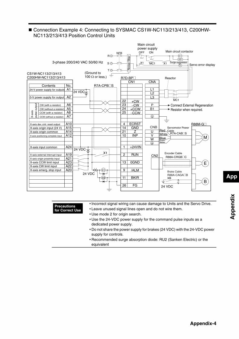
App
Ap
pen
dix
Connection Example 4: Connecting to SYSMAC CS1W-NC113/213/413, C200HW-NC113/213/413 Position Control Units
No.CN1 CNA
A1
A2
232425
4142110
1
2
13
9
11
22
L1L2
UVW
GND
INP
RUN
0GND
/ALM
FG
Z
A8A7
A6A5
A10A15A14A12
A24
A19A21A23A22A20
CN2
M
EX1
XB
24 VDC
24 VDC
24 VDC
BBKIR
CNB
L3
PB1
26
X1
24 VDC
XB
ECRST
CS1W-NC113/213/413C200HW-NC113/213/413
3-phase 200/240 VAC 50/60 Hz
Noi
se fi
lter
R7D-BP@
R7A-CPB@S
R88M-G@
Contents24-V power supply for outputs
0-V power supply for output
X-axis dev. cntr. reset output
X-axis origin input (24 V)X-axis origin commonX-axis positioning complete input
X-axis input common
CCW (with a resistor)
CCW (without a resistor)
CW (with a resistor)
CW (without a resistor)
X-a
xis
puls
e ou
tput
X-axis external interrupt input
X-axis origin proximity input
X-axis CCW limit inputX-axis CW limit inputX-axis emerg. stop input
Servomotor Power Cable
R7A-CAB@S
+CW−CW
+24VIN
RedWhiteBlueGreen/Yellow
+CCW−CCW
Encoder Cable
R88A-CRGB@C
(Ground to 100 Ω or less.)
Connect External Regeneration Resistor when required.
Reactor
Brake CableR88A-CAGA@B
R
T
NFB ONOFF
X1 MC1
MC1
PLS X1
SUP
MC1
Main circuit power supply
Main circuit contactor
Servo error displaySurge suppressor
Incorrect signal wiring can cause damage to Units and the Servo Drive.Leave unused signal lines open and do not wire them.Use mode 2 for origin search.Use the 24-VDC power supply for the command pulse inputs as a dedicated power supply.Do not share the power supply for brakes (24 VDC) with the 24-VDC power supply for controls.Recommended surge absorption diode: RU2 (Sanken Electric) or the equivalent
Precautions for Correct Use
Appendix-4

App
Ap
pen
dix
Connection Example 5: Connecting to SYSMAC CP1H-Y20DT-D
CN1 CNA
232425
4
10
1
2
13
9
11
22
L1L2
UVWGND
INP
RUN
0GND
/ALM
FG
Z
CN2
M
E
X1
XB
24 VDC
24 VDC
BBKIR
1421
CNB
L3
PB1
26
Output terminal blockCW0+CW0−CCW0+CCW0−
Origin search 0 (CIO 0101.02)24-VDC input terminal (+)
COM (CIO 0101.00 to 0101.03)
Input terminal block
ECRST
24-VDC input terminal (−)
Pulse 0 origin input signal (CIO 0001.03)
COM (CIO 0000)
Pulse 0 origin proximity input signal (CIO 0001.05)
CP1H-Y20DT-D R7D-BP@
Noi
se fi
lter
3-phase 200/240 VAC 50/60 Hz
R7A-CPB@S
R88M-G@Servomotor Power Cable
R7A-CAB@S
+CW−CW
+24VIN
RedWhiteBlueGreen/Yellow
+CCW−CCW
Encoder Cable
R88A-CRGB@C
Pul
se
outp
ut 0
(Ground to 100 Ω or less.)
Connect External Regeneration Resistor when required.
Reactor
Brake CableR88A-CAGA@B
X1
24 VDC
XB
S
R
T
NFB ONOFF
X1 MC1
MC1
PL
SUP
MC1
X1
Main circuit power supply
Main circuit contactor
Servo error displaySurge suppressor
Incorrect signal wiring can cause damage to Units and the Servo Drive.Leave unused signal lines open and do not wire them.Do not share the power supply for brakes (24 VDC) with the 24-VDC power supply for controls.Recommended surge absorption diode: RU2 (Sanken Electric) or the equivalent
Precautions for Correct Use
Appendix-5
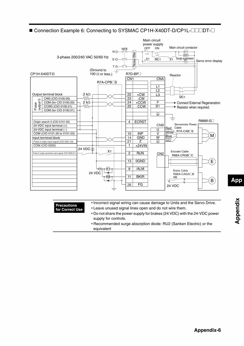
App
Ap
pen
dix
Connection Example 6: Connecting to SYSMAC CP1H-X40DT-D/CP1L-@@@DT-@
CN1 CNA
232425
4
10
1
2
13
9
11
22
L1L2
UVWGND
INP
RUN
0GND
/ALM
FG
Z
CN2
M
E
X1
XB
24 VDC
24 VDC
BBKIR
1421
CNB
L3
PB1
26
2 kΩ
2 kΩ
ECRST
CP1H-X40DT-D R7D-BP@
Noi
se fi
lter
3-phase 200/240 VAC 50/60 Hz
R7A-CPB@S
R88M-G@
Output terminal blockCW0 (CIO 0100.00)COM (for CIO 0100.00)CCW0 (CIO 0100.01)COM (for CIO 0100.01)
Origin search 0 (CIO 0101.02)24-VDC input terminal (+)
COM (CIO 0101.00 to 0101.03)
Input terminal block
24-VDC input terminal (−)
Pulse 0 origin input signal (CIO 0001.03)
COM (CIO 0000)
Pulse 0 origin proximity input signal (CIO 0000.01)
Servomotor Power Cable
R7A-CAB@S
+CW−CW
+24VIN
RedWhiteBlueGreen/Yellow
+CCW−CCW
Encoder Cable
R88A-CRGB@C
Pul
se
outp
ut 0
(Ground to 100 Ω or less.)
Connect External Regeneration Resistor when required.
Reactor
Brake CableR88A-CAGA@B
X1
24 VDC
XB
S
R
T
NFB ONOFF
X1 MC1
MC1
PL
SUP
X1
MC1
Main circuit power supply
Main circuit contactor
Servo error displaySurge suppressor
Incorrect signal wiring can cause damage to Units and the Servo Drive.Leave unused signal lines open and do not wire them.Do not share the power supply for brakes (24 VDC) with the 24-VDC power supply for controls.Recommended surge absorption diode: RU2 (Sanken Electric) or the equivalent
Precautions for Correct Use
Appendix-6
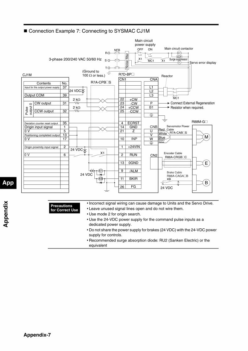
App
Ap
pen
dix
Connection Example 7: Connecting to SYSMAC CJ1M
No.CN1 CNA
37
0 V
392223
41421
1
2
13
9
11
L1L2
UVW
GND
RUN
0GND
/ALM
FG
Z
3515
13
2
6 CN2
M
E
X1
XB
24 VDC
24 VDC
BBKIR
31
32 2524
0 V 17
CNB
24 VDC
0 V
10 INP
L3
PB1
26
2 kΩ
2 kΩ
ContentsInput for the output power supply
Output COM
Deviation counter reset output
Origin input signal
Positioning completed output
Origin proximity input signal
ECRST
CW output
CCW output
CJ1M
3-phase 200/240 VAC 50/60 Hz
Noi
se fi
lter
R7D-BP@
R7A-CPB@S
R88M-G@
Pul
se
outp
ut 0
Servomotor Power Cable
R7A-CAB@S
+CW−CW
+24VIN
RedWhiteBlueGreen/Yellow
+CCW−CCW
Encoder Cable
R88A-CRGB@C
(Ground to 100 Ω or less.)
Connect External Regeneration Resistor when required.
Reactor
Brake CableR88A-CAGA@B
X1
24 VDC
XB
S
R
T
NFB ONOFF
X1MC1
MC1
PLX1
SUP
MC1
Main circuit power supply
Main circuit contactor
Servo error displaySurge suppressor
Incorrect signal wiring can cause damage to Units and the Servo Drive.Leave unused signal lines open and do not wire them.Use mode 2 for origin search.Use the 24-VDC power supply for the command pulse inputs as a dedicated power supply.Do not share the power supply for brakes (24 VDC) with the 24-VDC power supply for controls.Recommended surge absorption diode: RU2 (Sanken Electric) or the equivalent
Precautions for Correct Use
Appendix-7
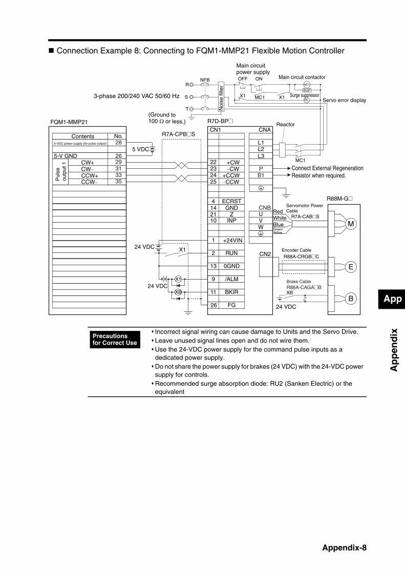
App
Ap
pen
dix
Connection Example 8: Connecting to FQM1-MMP21 Flexible Motion Controller
Reactor
Brake CableR88A-CAGA@B
CN1 CNA
25
2223
4142110
1
2
13
9
11
24
L1L2
UVW
GND
INP
RUN
0GND
/ALM
FG
Z
CN2
M
E
X1
XB
5 VDC
BBKIR
No.
24 VDC
CNB
28
2629313335
24 VDC
5-V GND L3
ECRST
PB1
26
X1
24 VDC
XB
Contents5-VDC power supply (for pulse output)
CW+CW−CCW+CCW−
FQM1-MMP21
3-phase 200/240 VAC 50/60 Hz
Noi
se fi
lter
R7D-BP@
R7A-CPB@S
R88M-G@
Pul
se
outp
ut 1
Servomotor Power Cable
R7A-CAB@S
+CW−CW
+24VIN
RedWhiteBlueGreen/Yellow
+CCW−CCW
Encoder Cable
R88A-CRGB@C
(Ground to 100 Ω or less.)
Connect External Regeneration Resistor when required.
R
T
NFB ONOFF
X1 MC1
MC1
S X1
SUP
MC1
PL
Main circuit power supply
Main circuit contactor
Servo error displaySurge suppressor
Incorrect signal wiring can cause damage to Units and the Servo Drive.Leave unused signal lines open and do not wire them.Use the 24-VDC power supply for the command pulse inputs as a dedicated power supply.Do not share the power supply for brakes (24 VDC) with the 24-VDC power supply for controls.Recommended surge absorption diode: RU2 (Sanken Electric) or the equivalent
Precautions for Correct Use
Appendix-8

App
Ap
pen
dix
Connection Example 9: Connecting to SYSMAC CPM2CCPU Unit with 10 inputs and outputsAn example of a transistor output (sink model).
CN1 CNA
25
2223
4142110
1
2
13
9
11
24
L1L2
UVW
GND
INP
RUN
0GND
/ALM
FG
Z
CN2
M
E
24 VDC
BBKIR
CNB
No.24 V A10
A9
A1
A2
X1
XB24 VDC
24 VDC
L3
PB1
26
2 kΩ
2 kΩ
ECRST
COM (−)
OUT 00 CW pulse output
OUT 01 CCW pulse output
CPM2C-10C@DTC-D
3-phase 200/240 VAC 50/60 Hz
Noi
se fi
lter
R7D-BP@
R7A-CPB@S
R88M-G@
Contents
Servomotor Power Cable
R7A-CAB@S
+CW−CW
+24VIN
RedWhiteBlue
+CCW−CCW
Encoder Cable
R88A-CRGB@C
Green/Yellow
(Ground to 100 Ω or less.)
Connect External Regeneration Resistor when required.
Reactor
Brake CableR88A-CAGA@B
X1
24 VDC
XB
S
R
T
NFB ONOFF
X1 MC1
MC1
X1
SUP
PL
MC1
Main circuit power supply
Main circuit contactor
Servo error displaySurge suppressor
Incorrect signal wiring can cause damage to Units and the Servo Drive.Leave unused signal lines open and do not wire them.Use the 24-VDC power supply for the command pulse inputs as a dedicated power supply.Do not share the power supply for brakes (24 VDC) with the 24-VDC power supply for controls.Recommended surge absorption diode: RU2 (Sanken Electric) or the equivalent
Precautions for Correct Use
Appendix-9

Index
Numerics
3,000-r/min Flat Servomotors .................................... 2-23,000-r/min Servomotors ........................................... 2-190-degree Phase Difference Signal......................... 3-11
A
adaptive filter .................................................... 7-5, 7-14alarm LED indicator ................................................... 1-4alarm output...................................................... 3-13, 6-2alarm reset input........................................................ 3-9ALM .................................................................. 3-13, 6-2applicable load inertia.............................................. 3-25autotuning.................................................................. 7-8
B
BKIR ...................................................... 3-14, 5-58, 5-59Brake Cables ............................................................. 2-8Brake Interlock....................................... 3-14, 5-58, 5-59
C
CCW........................................................................ 3-11clamp cores ............................................................. 4-26Connector-Terminal Block Cables......... 2-11, 3-47, 4-13Connector-Terminal Block Conversion Unit ............ 3-48Connector-Terminal Block Conversion Units.. 2-12, 4-13contactors ................................................................ 4-28Control I/O Connectors..................................... 2-9, 3-42Copy Mode .............................................................. 6-20CW........................................................................... 3-11
D
damping control ....................................................... 7-23Decelerators
backlash = 15 arcminutes max. ......................... 2-6Cylindrical Servomotors ............................. 2-6
dimensions ....................................... 2-23specifications .................................... 3-28
Flat Servomotors........................................ 2-7dimensions ....................................... 2-25specifications .................................... 3-29
installation .................................................. 4-8backlash = 3 arcminutes max. ........................... 2-4
Cylindrical Servomotors ............................. 2-4dimensions ....................................... 2-19specifications .................................... 3-26
Flat Servomotors........................................ 2-5dimensions ....................................... 2-21specifications .................................... 3-27
installation .................................................. 4-6Deviation Counter Reset Input .................................. 3-9DIN Rail Mounting Unit ............................................ 2-12
dimensions....................................................... 2-29Direction Signal ....................................................... 3-11
E
EC Directives............................................................. 1-6ECRST ...................................................................... 3-9electronic gear .................................................. 5-9, 5-50
Electronic Gear Switch ............................................ 3-10EMC Directives........................................................ 4-18Encoder Cables ....................................... 2-8, 3-30, 4-29Encoder Connectors................................................ 3-15encoder dividing ............................................... 5-8, 5-49Encoder Input Connector (CN2) ................................ 2-9encoder specifications ............................................. 3-25External Regeneration Resistor Connection Cables 3-39External Regeneration Resistors........... 2-12, 2-27, 4-35
dimensions....................................................... 2-27specifications ................................................... 3-79
F
Feed Pulse .............................................................. 3-11feedback output ....................................................... 3-14Forward Drive Prohibit Input........................... 3-11, 5-33Forward Pulse ......................................................... 3-11
G
Gain Switch ............................................................. 3-10General-purpose Control Cables........... 2-11, 3-45, 4-13GESEL..................................................................... 3-10GSEL....................................................................... 3-10
I
INP.................................................................. 3-13, 5-55internally set speed control........................................ 5-4Internally Set Speed Selection 1 ............................. 3-10Internally Set Speed Selection 2 ............................... 3-9
J
jog operation............................................................ 6-19
L
leakage breakers ..................................................... 4-23
M
Main Circuit Connector .............................. 2-9, 3-3, 3-41motor rotation directions .......................................... 3-16
N
NFB ......................................................................... 4-22noise filters for power supply input ................. 4-25, 4-31noise filters for Servomotor output........................... 4-31noise resistance....................................................... 4-30non-fuse breakers.................................................... 4-22NOT................................................................ 3-11, 5-33notch filters .............................................................. 7-21
O
oil seal ....................................................................... 4-5overrun limit .................................................... 5-16, 5-41
Index
P
Parameter Unit .......................................... 2-2, 3-78, 6-4dimensions....................................................... 2-18specifications ................................................... 3-78
Personal Computer Monitor Cables ................. 2-9, 3-40phase-Z output ........................................................ 3-14position control .......................................................... 5-1Positioning Completed Output........................ 3-13, 5-55POT ................................................................ 3-11, 5-33Power Cables
specifications ................................................... 3-37single-phase............................................. 3-37three-phase .............................................. 3-38
Power Supply Cables ....................................... 2-9, 4-11power supply LED indicator....................................... 1-4PULS ....................................................................... 3-11PWR .......................................................................... 1-4
R
R7A-CMB01A............................................................ 3-3R7A-CNB01A .......................................................... 3-42R7A-CNB01P ................................................... 3-3, 3-41radio noise filters ..................................................... 4-26Reactors .................................................................. 2-12
dimensions....................................................... 2-28specifications ................................................... 3-80
realtime autotuning.................................................... 7-3regenerative energy................................................. 4-33RESET....................................................................... 3-9Reverse Drive Prohibit Input........................... 3-11, 5-33Reverse Pulse ......................................................... 3-11Robot Cables for Brakes ......................................... 4-11Robot Cables for Encoders ..................................... 4-11Robot Cables for Servomotor Power....................... 4-11RUN........................................................................... 3-9RUN Command Input ................................................ 3-9
S
Servo Drives .............................................................. 2-1characteristics .................................................... 3-2dimensions....................................................... 2-13general specifications ........................................ 3-1
Servo Relay Units........................................... 2-10, 4-12Position Control Unit Cables ............................ 2-11
specifications............................................ 3-66Servo Drive Cables .......................................... 2-10
specifications................................... 3-63, 3-65Servomotor Connectors............................. 2-9, 3-3, 3-42Servomotor Power Cables......................................... 2-8
specifications ................................................... 3-32Servomotor Rotation Speed Detection Output 3-13, 5-56Servomotors .............................................................. 2-1
3,000-r/min Flat Servomotorscharacteristics .......................................... 3-19dimensions ............................................... 2-17torque and rotation speed characteristics 3-22
3,000-r/min Servomotorscharacteristics .......................................... 3-17dimensions ............................................... 2-15torque and rotation speed characteristics 3-21
general specifications ...................................... 3-16SIGN........................................................................ 3-11Standard Cables for Brakes .................................... 4-11
Standard Cables for Encoders ................................ 4-11Standard Cables for Servomotor Power.................. 4-11surge absorbers....................................................... 4-24surge suppressors ................................................... 4-28
T
TGON ............................................................. 3-13, 5-56TLSEL...................................................................... 3-10torque limit ...................................................... 5-15, 5-54Torque Limit Switch ................................................. 3-10
U
UL standards ............................................................. 1-6
V
VSEL1 ..................................................................... 3-10VSEL2 ....................................................................... 3-9VZERO ............................................................. 3-10, 5-4
W
WARN............................................................. 3-14, 5-34warning output ................................................ 3-14, 5-34
X
XW2B-20J6-1B........................................................ 3-53XW2B-20J6-3B........................................................ 3-55XW2B-20J6-8A........................................................ 3-56XW2B-40J6-2B........................................................ 3-54XW2B-40J6-9A........................................................ 3-58XW2B-80J7-12A...................................................... 3-59XW2Z-_J-A10 .......................................................... 3-69XW2Z-_J-A11 .......................................................... 3-70XW2Z-_J-A14 .......................................................... 3-71XW2Z-_J-A15 .......................................................... 3-72XW2Z-_J-A18 .......................................................... 3-73XW2Z-_J-A19 .......................................................... 3-74XW2Z-_J-A28 .......................................................... 3-76XW2Z-_J-A3 ............................................................ 3-66XW2Z-_J-A30 .......................................................... 3-77XW2Z-_J-A33 .......................................................... 3-75XW2Z-_J-A6 ............................................................ 3-67XW2Z-_J-A7 ............................................................ 3-68XW2Z-_J-B29 .......................................................... 3-63XW2Z-_J-B30 .......................................................... 3-64XW2Z-_J-B32 .......................................................... 3-65
Z
Zero Speed Designation................................... 3-10, 5-4


R-1
Revision History
A manual revision code appears as a suffix to the catalog number on the front and back covers of the manual.
The following table outlines the changes made to the manual during each revision. Page numbers refer tothe previous version.
Revision code Date Revised content
01 January 2008 Original production
02 July 2008 Pages 3-26, 3-27, 3-28: Changes made to decelerator specificationsPages 2-8, 3-31, 3-33, 3-35, 4-10: Robot cables added.Pages 1-4, 1-5, 2-9, 2-13, 2-17, 2-19, 2-23, 2-25, 2-28, 3-4, 3-8, 3-11, 3-12, 3-16, 3-24, 3-25, 3-30, 3-31, 3-36, 3-37, 3-39, 3-41, 3-42, 3-50, 3-53, 3-55, 3-57, 3-59, 3-77, 3-78, 4-13, 4-14, 4-18, 4-25, 4-28, 4-29, 4-35, 5-1, 5-3, 5-6, 5-14, 5-58, 6-1, 6-7, 6-10, 6-11, 6-13, 7-10, 7-11, 7-15, A-1, A-2, A-3, A-4, A-5, A-6, A-7, A-8, A-9: Minor changes
03 December 2011 Pages 1-6, 2-4, 2-5, 2-19, 2-21, 2-23, 2-25, 3-2, 3-17, 3-18, 3-19,3-20, 3-26, 3-27, 3-28, 3-29, 3-36, 3-50, 4-5, 4-6, 4-13, 4-14, 4-15, 4-27, 5-5, 5-10, 5-29, 5-57, 6-13, 8-4, 8-6, and 8-17: Minor changes made.Page 3-35: Resistant to Bending of Robot Cables added.Page 4-4: Radiator plate installation conditions added and description of Oil Seal changed.Page 5-5: Note added below graphic.Pages 8-4 and 8-10: Alarm codes 44 and 45 added.Appendices 1 through 9: Diagram around MC contacts changed.
Cat. No. I561-E1-03
Revision code
Terms and Conditions of Sale1. Offer; Acceptance. These terms and conditions (these "Terms") are deemed
part of all quotes, agreements, purchase orders, acknowledgments, price lists,catalogs, manuals, brochures and other documents, whether electronic or inwriting, relating to the sale of products or services (collectively, the "Products")by Omron Electronics LLC and its subsidiary companies (“Omron”). Omronobjects to any terms or conditions proposed in Buyer’s purchase order or otherdocuments which are inconsistent with, or in addition to, these Terms.
2. Prices; Payment Terms. All prices stated are current, subject to change with-out notice by Omron. Omron reserves the right to increase or decrease priceson any unshipped portions of outstanding orders. Payments for Products aredue net 30 days unless otherwise stated in the invoice.
3. Discounts. Cash discounts, if any, will apply only on the net amount of invoicessent to Buyer after deducting transportation charges, taxes and duties, and willbe allowed only if (i) the invoice is paid according to Omron’s payment termsand (ii) Buyer has no past due amounts.
4. Interest. Omron, at its option, may charge Buyer 1-1/2% interest per month orthe maximum legal rate, whichever is less, on any balance not paid within thestated terms.
5. Orders. Omron will accept no order less than $200 net billing. 6. Governmental Approvals. Buyer shall be responsible for, and shall bear all
costs involved in, obtaining any government approvals required for the impor-tation or sale of the Products.
7. Taxes. All taxes, duties and other governmental charges (other than generalreal property and income taxes), including any interest or penalties thereon,imposed directly or indirectly on Omron or required to be collected directly orindirectly by Omron for the manufacture, production, sale, delivery, importa-tion, consumption or use of the Products sold hereunder (including customsduties and sales, excise, use, turnover and license taxes) shall be charged toand remitted by Buyer to Omron.
8. Financial. If the financial position of Buyer at any time becomes unsatisfactoryto Omron, Omron reserves the right to stop shipments or require satisfactorysecurity or payment in advance. If Buyer fails to make payment or otherwisecomply with these Terms or any related agreement, Omron may (without liabil-ity and in addition to other remedies) cancel any unshipped portion of Prod-ucts sold hereunder and stop any Products in transit until Buyer pays allamounts, including amounts payable hereunder, whether or not then due,which are owing to it by Buyer. Buyer shall in any event remain liable for allunpaid accounts.
9. Cancellation; Etc. Orders are not subject to rescheduling or cancellationunless Buyer indemnifies Omron against all related costs or expenses.
10. Force Majeure. Omron shall not be liable for any delay or failure in deliveryresulting from causes beyond its control, including earthquakes, fires, floods,strikes or other labor disputes, shortage of labor or materials, accidents tomachinery, acts of sabotage, riots, delay in or lack of transportation or therequirements of any government authority.
11. Shipping; Delivery. Unless otherwise expressly agreed in writing by Omron:a. Shipments shall be by a carrier selected by Omron; Omron will not drop ship
except in “break down” situations.b. Such carrier shall act as the agent of Buyer and delivery to such carrier shall
constitute delivery to Buyer;c. All sales and shipments of Products shall be FOB shipping point (unless oth-
erwise stated in writing by Omron), at which point title and risk of loss shallpass from Omron to Buyer; provided that Omron shall retain a security inter-est in the Products until the full purchase price is paid;
d. Delivery and shipping dates are estimates only; ande. Omron will package Products as it deems proper for protection against nor-
mal handling and extra charges apply to special conditions.12. Claims. Any claim by Buyer against Omron for shortage or damage to the
Products occurring before delivery to the carrier must be presented in writingto Omron within 30 days of receipt of shipment and include the original trans-portation bill signed by the carrier noting that the carrier received the Productsfrom Omron in the condition claimed.
13. Warranties. (a) Exclusive Warranty. Omron’s exclusive warranty is that theProducts will be free from defects in materials and workmanship for a period oftwelve months from the date of sale by Omron (or such other period expressedin writing by Omron). Omron disclaims all other warranties, express or implied.(b) Limitations. OMRON MAKES NO WARRANTY OR REPRESENTATION,EXPRESS OR IMPLIED, ABOUT NON-INFRINGEMENT, MERCHANTABIL-
ITY OR FITNESS FOR A PARTICULAR PURPOSE OF THE PRODUCTS.BUYER ACKNOWLEDGES THAT IT ALONE HAS DETERMINED THAT THEPRODUCTS WILL SUITABLY MEET THE REQUIREMENTS OF THEIRINTENDED USE. Omron further disclaims all warranties and responsibility ofany type for claims or expenses based on infringement by the Products or oth-erwise of any intellectual property right. (c) Buyer Remedy. Omron’s sole obli-gation hereunder shall be, at Omron’s election, to (i) replace (in the formoriginally shipped with Buyer responsible for labor charges for removal orreplacement thereof) the non-complying Product, (ii) repair the non-complyingProduct, or (iii) repay or credit Buyer an amount equal to the purchase price ofthe non-complying Product; provided that in no event shall Omron be responsi-ble for warranty, repair, indemnity or any other claims or expenses regardingthe Products unless Omron’s analysis confirms that the Products were prop-erly handled, stored, installed and maintained and not subject to contamina-tion, abuse, misuse or inappropriate modification. Return of any Products byBuyer must be approved in writing by Omron before shipment. Omron Compa-nies shall not be liable for the suitability or unsuitability or the results from theuse of Products in combination with any electrical or electronic components,circuits, system assemblies or any other materials or substances or environ-ments. Any advice, recommendations or information given orally or in writing,are not to be construed as an amendment or addition to the above warranty.See http://www.omron247.com or contact your Omron representative for pub-lished information.
14. Limitation on Liability; Etc. OMRON COMPANIES SHALL NOT BE LIABLEFOR SPECIAL, INDIRECT, INCIDENTAL, OR CONSEQUENTIAL DAMAGES,LOSS OF PROFITS OR PRODUCTION OR COMMERCIAL LOSS IN ANYWAY CONNECTED WITH THE PRODUCTS, WHETHER SUCH CLAIM ISBASED IN CONTRACT, WARRANTY, NEGLIGENCE OR STRICT LIABILITY.Further, in no event shall liability of Omron Companies exceed the individualprice of the Product on which liability is asserted.
15. Indemnities. Buyer shall indemnify and hold harmless Omron Companies andtheir employees from and against all liabilities, losses, claims, costs andexpenses (including attorney's fees and expenses) related to any claim, inves-tigation, litigation or proceeding (whether or not Omron is a party) which arisesor is alleged to arise from Buyer's acts or omissions under these Terms or inany way with respect to the Products. Without limiting the foregoing, Buyer (atits own expense) shall indemnify and hold harmless Omron and defend or set-tle any action brought against such Companies to the extent based on a claimthat any Product made to Buyer specifications infringed intellectual propertyrights of another party.
16. Property; Confidentiality. Any intellectual property in the Products is the exclu-sive property of Omron Companies and Buyer shall not attempt to duplicate itin any way without the written permission of Omron. Notwithstanding anycharges to Buyer for engineering or tooling, all engineering and tooling shallremain the exclusive property of Omron. All information and materials suppliedby Omron to Buyer relating to the Products are confidential and proprietary,and Buyer shall limit distribution thereof to its trusted employees and strictlyprevent disclosure to any third party.
17. Export Controls. Buyer shall comply with all applicable laws, regulations andlicenses regarding (i) export of products or information; (iii) sale of products to“forbidden” or other proscribed persons; and (ii) disclosure to non-citizens ofregulated technology or information.
18. Miscellaneous. (a) Waiver. No failure or delay by Omron in exercising any rightand no course of dealing between Buyer and Omron shall operate as a waiverof rights by Omron. (b) Assignment. Buyer may not assign its rights hereunderwithout Omron's written consent. (c) Law. These Terms are governed by thelaw of the jurisdiction of the home office of the Omron company from whichBuyer is purchasing the Products (without regard to conflict of law princi-ples). (d) Amendment. These Terms constitute the entire agreement betweenBuyer and Omron relating to the Products, and no provision may be changedor waived unless in writing signed by the parties. (e) Severability. If any provi-sion hereof is rendered ineffective or invalid, such provision shall not invalidateany other provision. (f) Setoff. Buyer shall have no right to set off any amountsagainst the amount owing in respect of this invoice. (g) Definitions. As usedherein, “including” means “including without limitation”; and “Omron Compa-nies” (or similar words) mean Omron Corporation and any direct or indirectsubsidiary or affiliate thereof.
Certain Precautions on Specifications and Use1. Suitability of Use. Omron Companies shall not be responsible for conformity
with any standards, codes or regulations which apply to the combination of theProduct in the Buyer’s application or use of the Product. At Buyer’s request,Omron will provide applicable third party certification documents identifyingratings and limitations of use which apply to the Product. This information byitself is not sufficient for a complete determination of the suitability of the Prod-uct in combination with the end product, machine, system, or other applicationor use. Buyer shall be solely responsible for determining appropriateness ofthe particular Product with respect to Buyer’s application, product or system.Buyer shall take application responsibility in all cases but the following is anon-exhaustive list of applications for which particular attention must be given:(i) Outdoor use, uses involving potential chemical contamination or electricalinterference, or conditions or uses not described in this document.(ii) Use in consumer products or any use in significant quantities. (iii) Energy control systems, combustion systems, railroad systems, aviationsystems, medical equipment, amusement machines, vehicles, safety equip-ment, and installations subject to separate industry or government regulations. (iv) Systems, machines and equipment that could present a risk to life or prop-erty. Please know and observe all prohibitions of use applicable to this Prod-uct. NEVER USE THE PRODUCT FOR AN APPLICATION INVOLVING SERIOUSRISK TO LIFE OR PROPERTY OR IN LARGE QUANTITIES WITHOUTENSURING THAT THE SYSTEM AS A WHOLE HAS BEEN DESIGNED TO
ADDRESS THE RISKS, AND THAT THE OMRON’S PRODUCT IS PROP-ERLY RATED AND INSTALLED FOR THE INTENDED USE WITHIN THEOVERALL EQUIPMENT OR SYSTEM.
2. Programmable Products. Omron Companies shall not be responsible for theuser’s programming of a programmable Product, or any consequence thereof.
3. Performance Data. Data presented in Omron Company websites, catalogsand other materials is provided as a guide for the user in determining suitabil-ity and does not constitute a warranty. It may represent the result of Omron’stest conditions, and the user must correlate it to actual application require-ments. Actual performance is subject to the Omron’s Warranty and Limitationsof Liability.
4. Change in Specifications. Product specifications and accessories may bechanged at any time based on improvements and other reasons. It is our prac-tice to change part numbers when published ratings or features are changed,or when significant construction changes are made. However, some specifica-tions of the Product may be changed without any notice. When in doubt, spe-cial part numbers may be assigned to fix or establish key specifications foryour application. Please consult with your Omron’s representative at any timeto confirm actual specifications of purchased Product.
5. Errors and Omissions. Information presented by Omron Companies has beenchecked and is believed to be accurate; however, no responsibility is assumedfor clerical, typographical or proofreading errors or omissions.
OMRON CANADA, INC. • HEAD OFFICEToronto, ON, Canada • 416.286.6465 • 866.986.6766 • www.omron247.com
OMRON ELECTRONICS DE MEXICO • HEAD OFFICEMéxico DF • 52.55.59.01.43.00 • 001.800.556.6766 • [email protected]
OMRON ELECTRONICS DE MEXICO • SALES OFFICEApodaca, N.L. • 52.81.11.56.99.20 • 001.800.556.6766 • [email protected]
OMRON ELETRÔNICA DO BRASIL LTDA • HEAD OFFICESão Paulo, SP, Brasil • 55.11.2101.6300 • www.omron.com.br
OMRON ARGENTINA • SALES OFFICECono Sur • 54.11.4783.5300
OMRON CHILE • SALES OFFICESantiago • 56.9.9917.3920
OTHER OMRON LATIN AMERICA SALES54.11.4783.5300
OMRON INDUSTRIAL AUTOMATION • THE AMERICAS HEADQUARTERSSchaumburg, IL USA • 847.843.7900 • 800.556.6766 • www.omron247.com
OMRON EUROpE B.V. • Wegalaan 67-69, NL-2132 JD, Hoofddorp, The Netherlands. • Tel: +31 (0) 23 568 13 00Fax: +31 (0) 23 568 13 88 • www.industrial.omron.eu
Cat. No. I561-E1-03 12/11 Note: Specifications are subject to change. © 2011 Omron Electronics LLC Printed in U.S.A.