ac servo minas e series catalog
TRANSCRIPT
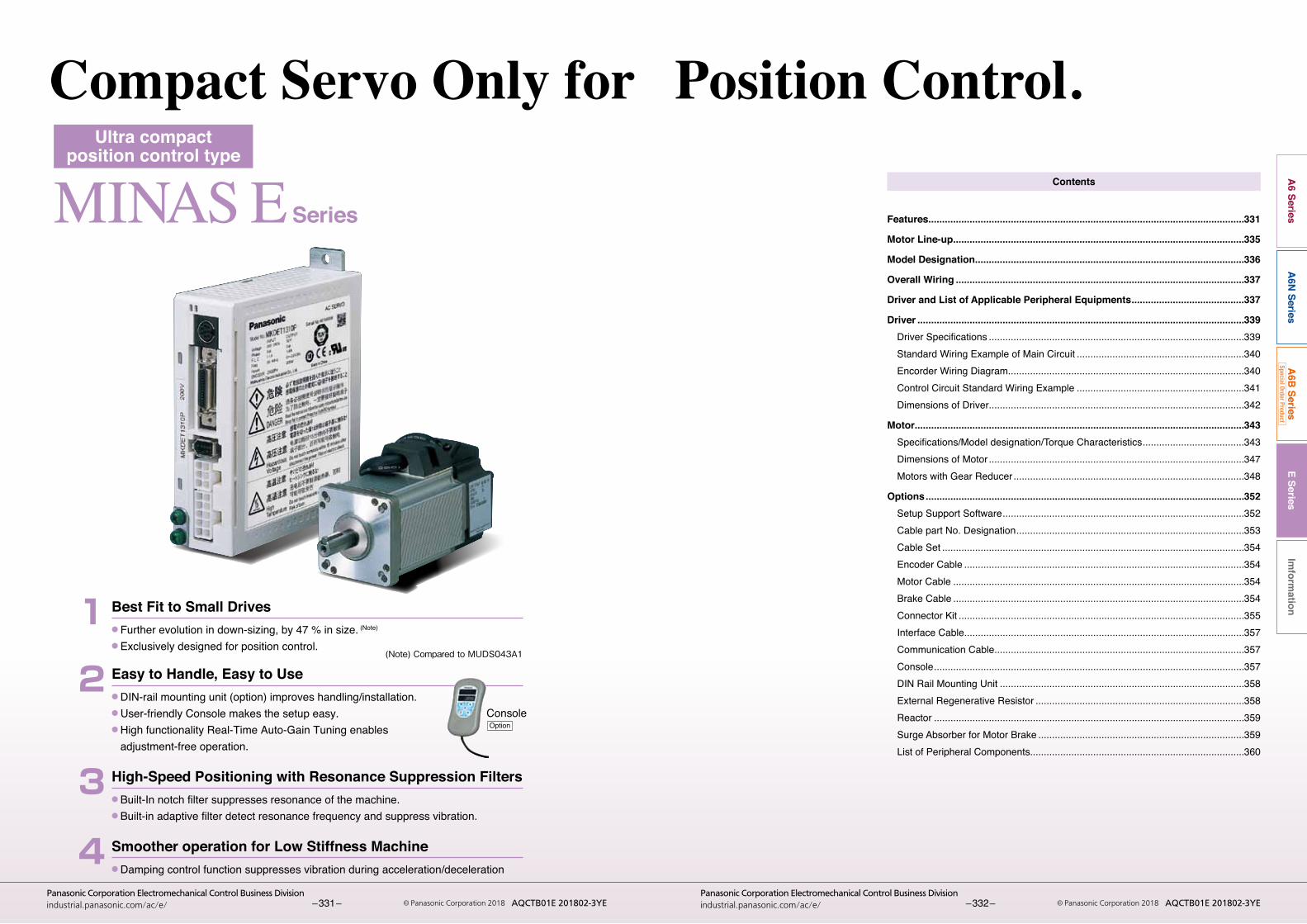
MINAS E Series
Ultra compactposition control type
● Further evolution in down-sizing, by 47 % in size. (Note)
● Exclusively designed for position control.
Best Fit to Small Drives1
● Built-In notch filter suppresses resonance of the machine.● Built-in adaptive filter detect resonance frequency and suppress vibration.
High-Speed Positioning with Resonance Suppression Filters3
● Damping control function suppresses vibration during acceleration/deceleration
Smoother operation for Low Stiffness Machine4
● DIN-rail mounting unit (option) improves handling/installation.● User-friendly Console makes the setup easy.● High functionality Real-Time Auto-Gain Tuning enables
adjustment-free operation.
Easy to Handle, Easy to Use2
Compact Servo Only for Position Control.
(Note) Compared to MUDS043A1
ConsoleOption
E SeriesIm
formation
A6 Series
A6N
SeriesA
6B Series
Special Order Product
– 331 –Panasonic Corporation Electromechanical Control Business Division
industrial.panasonic.com/ac/e/ © Panasonic Corporation 2018 AQCTB01E 201802-3YE – 332 –Panasonic Corporation Electromechanical Control Business Division
industrial.panasonic.com/ac/e/ © Panasonic Corporation 2018 AQCTB01E 201802-3YE
Contents
Features...................................................................................................................331
Motor Line-up ..........................................................................................................335
Model Designation ..................................................................................................336
Overall Wiring .........................................................................................................337
Driver and List of Applicable Peripheral Equipments .........................................337
Driver .......................................................................................................................339 DriverSpecifications .............................................................................................339 Standard Wiring Example of Main Circuit .............................................................340 Encorder Wiring Diagram......................................................................................340 Control Circuit Standard Wiring Example .............................................................341 Dimensions of Driver.............................................................................................342
Motor ........................................................................................................................343 Specifications/Modeldesignation/TorqueCharacteristics .....................................343 Dimensions of Motor .............................................................................................347 Motors with Gear Reducer ....................................................................................348
Options ....................................................................................................................352 Setup Support Software ........................................................................................352 Cable part No. Designation ...................................................................................353 Cable Set ..............................................................................................................354 Encoder Cable ......................................................................................................354 Motor Cable ..........................................................................................................354 Brake Cable ..........................................................................................................354 Connector Kit ........................................................................................................355 Interface Cable......................................................................................................357 Communication Cable...........................................................................................357 Console .................................................................................................................357 DIN Rail Mounting Unit .........................................................................................358 External Regenerative Resistor ............................................................................358 Reactor .................................................................................................................359 Surge Absorber for Motor Brake ...........................................................................359 List of Peripheral Components..............................................................................360
E SeriesIm
formation
A6 Series
A6N
SeriesA
6B Series
Special Order Product
– 333 –Panasonic Corporation Electromechanical Control Business Division
industrial.panasonic.com/ac/e/ © Panasonic Corporation 2018 AQCTB01E 201802-3YE – 334 –Panasonic Corporation Electromechanical Control Business Division
industrial.panasonic.com/ac/e/ © Panasonic Corporation 2018 AQCTB01E 201802-3YE
SeriesMINAS E
1. Easy to Handle, Easy to Use 3. Further Flexibility and Multiplicity
2. Further Reduction of Vibration
High-functionality Real-Time Auto-Gain Tuning (Note 1)
● Offers real automatic gain tuning for low and high stiffness machineswithacombinationofanadaptivefilter.
● Supports the vertical axis application where the load torque is different in rotational direction.
Adaptive filter (Note1)
● Makes the notch filter frequency automatically follow the machine resonance frequency in real-time auto-gain tuning.
●Suppressionof “Judder”noiseof themachine,whichis caused by variation of the machines or resonance frequency due to aging, can be expected.
DIN-rail mounting unit (option)
● DIN-rail mounting unit allows parallel mounting with small control devices such as PLC.
● Easy to mount and easy to dismount.
Notch filter (Note1)
●1-channelnotchfilter isequipped in thedriver indepen-dentfromadaptivefilter.
●Eachof2filterscansetupfrequencyandnotchwidth,and frequency in 1Hz unit. Suppression of "Judder" noise of the machine which has multiple resonance points can be expected.
Console (Option)
● You can set up parameters, copy and make a JOG run.● Convenient for maintenance at site.● Refer to P.357, Options.
Command control modes●Offers2commandmodes,“Positioncontrol”and“Internal
velocitycontrol”.● You can make a 4-speed running at preset values with
parameter at internal velocity control mode.
Inrush current suppressing function● Inrush suppressing resistor, which prevent the circuit
breaker shutdown of the power supply caused by inrush current at power-on, is equipped in this driver.
● Prevents unintentional shutdown of the power supply circuit breaker in multi axis application and does not give load to the power line.
Regeneration discharging function● Discharges the regenerative energy with external resis-
tor, where energy is generated while stopping the load with large moment of inertia, or use in up-down opera-tion, and is returned to the driver from the motor.
● No regenerative resistor is installed in the driver.● It is highly recommended to install an external regenera-
tive resistor (option).
Built-in dynamic brake● You can select the dynamic brake action which short the
servo motor windings of U, V and W, at Servo-OFF, CW/CCW over- travel inhibition, power shutdown and trip.
● You can select the action sequence depending on the machine requirement.
Setup support software (Option)
●With the setup support software, “PANATERM” viaRS232 / RS485 communication port, you can monitor the running status of the driver and set up parameters.
Note) Refer to P.352 for setup support software.
Key-way shaft and tapped shaft end● Easy pulley attachment and easy maintenance● Attache screw to the tapped shaft to prevent key or pul-
ley from being pulled out.
Wave-form graphic function●Withthesetupsupportsoftware,“PANATERM”,youcan
monitorthe“Commandspeed”,“Actualspeed”,“Torque”,“Positiondeviation”and“Positioningcompletesignal”.
● Helps you to analyze the machine and shorten the setup time.
Note) Refer to P.352 for setup support software.
Frequency analyzing function●Youcanconfirmtheresponsefrequencycharacteristics
of total machine mechanism including the servo motor withthesetupsupportsoftware,“PANATERM”.
● Helps you to analyze the machine and shorten the setup time.
Note) Refer to P.352 for setup support software.
Torque limit switching function● You can select 2 preset torque limit value from external
input.● Use this function for tension control or press-hold control.
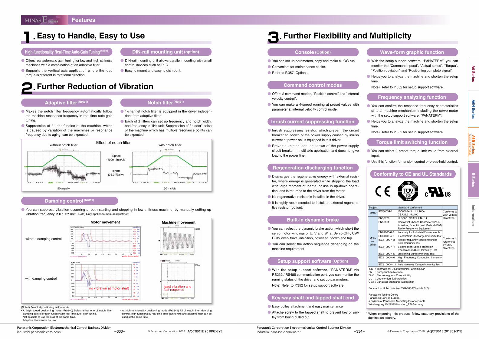
Damping control (Note1)
● You can suppress vibration occurring at both starting and stopping in low stiffness machine, by manually setting up vibration frequency in 0.1 Hz unit. Note) Only applies to manual adjustment
Effect of notch filter with notch filterwithout notch filter
50 ms/div 50 ms/div
Speed(1000 r/min/div)
Torque(33.3 %/div)
without damping control
with damping control
Motor movement Machine movement5004003002001000−100−200−300−400−500
500400300200100
0−100−200−300−400−500
400320240160800−80−160−240−320−400
actual speed (r/min)
500
400
300
200
100
0
−100
−200
−300
−400
−500
実速度(r/min)
torque [%]
20
16
12
8
4
0
−4
−8
−12
−16
−20
400
320
240
160
80
0
−80
−160
−240
−320
−400
torque [%]
command speed (r/min)0.1 0.2 0.3 0.4 0.5 0.6 0.7 [s]
0.1 0.2 0.3 0.4 0.5 0.6 0.7 [s]
position deviaton [pulse]
position deviaton [pulse]command speed (r/min)
no vibration at motor shaft least vibration and fast response
(Note1) Select at positioning action mode.•Athighspeedpositioningmode(Pr02=0)Selecteitheroneofnotch filter,
damping control or high-functionality real-time auto- gain tuning. Not possible to use them all at the same time. Adaptivefiltercannotbeused.
•Athigh-functionalitypositioningmode(Pr02=1)Allofnotch filter,dampingcontrol,high-functionalityreal-timeauto-gaintuningandadaptivefiltercanbeused at the same time.
* When exporting this product, follow statutory provisions of the destination country.
Conformity to CE and UL Standards
Subject Standard conformed
Motor IEC60034-1 IEC60034-5 UL1004 CSA22.2 No.100
Conforms to Low-Voltage Directives
Motor and
driver
EN50178 UL508C CSA22.2 No.14EN55011 Radio Disturbance Characteristics of
Industrial,ScientificandMedical(ISM)Radio-Frequency Equipment
Conforms to references by EMC Directives
EN61000-6-2 Immunity for Industrial EnvironmentsEC61000-4-2 Electrostatic Discharge Immunity TestIEC61000-4-3 Radio Frequency Electromagnetic
Field Immunity TestIEC61000-4-4 Electric High-Speed Transition
Phenomenon/Burst Immunity TestIEC61000-4-5 Lightening Surge Immunity TestIEC61000-4-6 High Frequency Conduction Immunity
TestIEC61000-4-11 Instantaneous Outage Immunity Test
IEC : International Electrotechnical CommissionEN : Europaischen NormenEMC : Electromagnetic CompatibilityUL : Underwriters LaboratoriesCSA : Canadian Standards Association
Pursuant to at the directive 2004/108/EC,article 9(2)
Panasonic Testing CentrePanasonic Service Europe,a division of Panasonic Marketing Europe GmbHWinsbergring 15,22525 Hamburg,F.R.Germany
Features
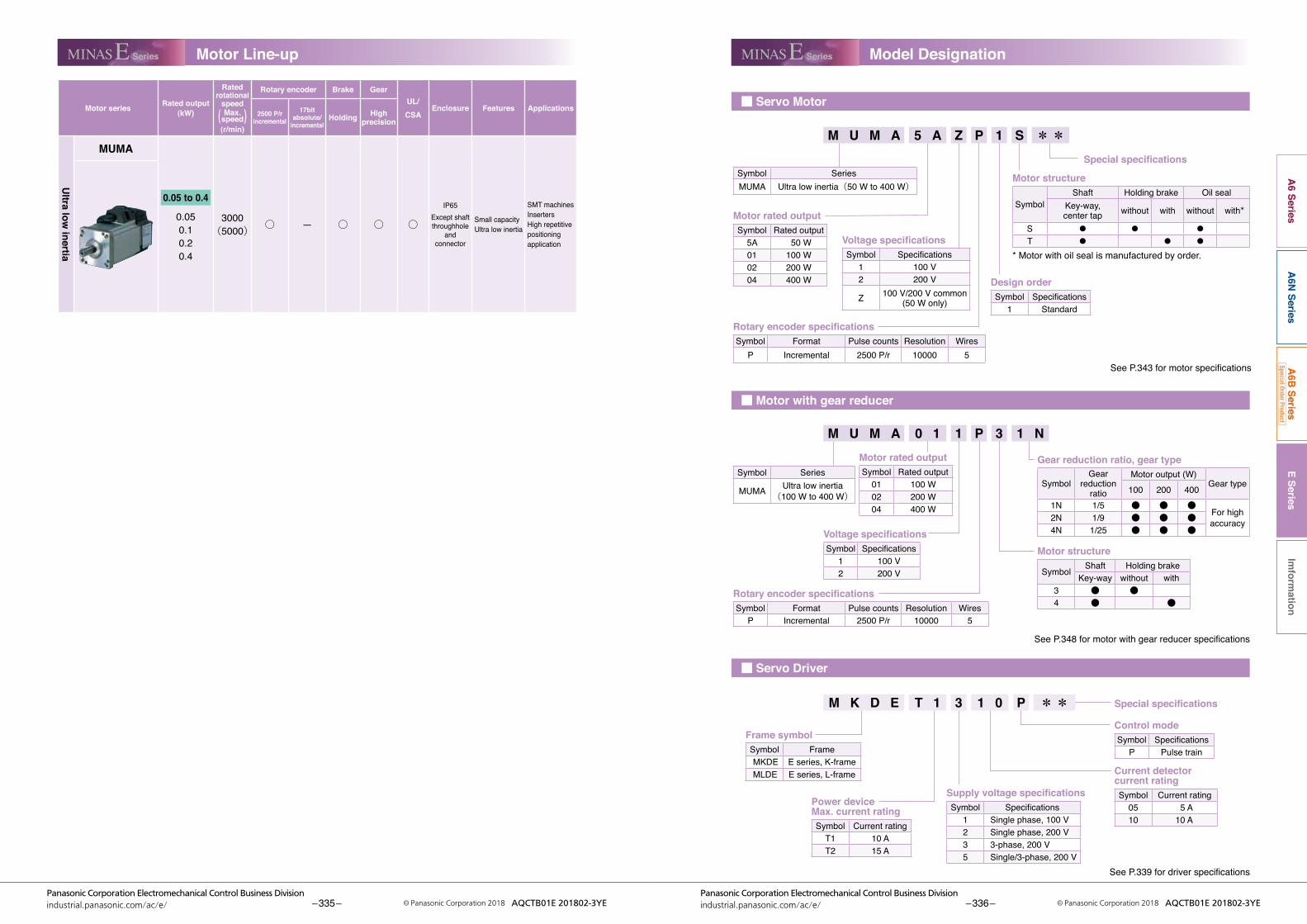
■ Servo Motor
■ Motor with gear reducer
■ Servo Driver
E SeriesIm
formation
A6 Series
A6N
SeriesA
6B Series
Special Order Product
– 335 –Panasonic Corporation Electromechanical Control Business Division
industrial.panasonic.com/ac/e/ © Panasonic Corporation 2018 AQCTB01E 201802-3YE – 336 –Panasonic Corporation Electromechanical Control Business Division
industrial.panasonic.com/ac/e/ © Panasonic Corporation 2018 AQCTB01E 201802-3YE
SeriesMINAS E SeriesMINAS E
Motor series Rated output (kW)
Rated rotational
speed
( Max. speed)(r/min)
Rotary encoder Brake GearUL/CSA
Enclosure Features Applications2500 P/r
incremental17bit
absolute/ incremental
Holding High precision
Ultra low
inertia
MUMA
0.05 to 0.4
0.050.10.20.4
3000(5000) ○ — ○ ○ ○
IP65Except shaft throughhole
andconnector
Small capacity Ultra low inertia
SMT machines InsertersHigh repetitive positioning application
M U M A 5 A Z P 1 S * *
Motor rated outputSymbol Rated output
5A 50 W01 100 W02 200 W04 400 W
Special specifications
Motor structure
SymbolShaft Holding brake Oil seal
Key-way,center tap without with without with*
S ● ● ●
T ● ● ●
* Motor with oil seal is manufactured by order.
SeeP.343formotorspecifications
SeeP.348formotorwithgearreducerspecifications
SeeP.339fordriverspecifications
Rotary encoder specificationsSymbol Format Pulse counts Resolution Wires
P Incremental 2500 P/r 10000 5
Voltage specificationsSymbol Specifications
1 100 V2 200 V
Gear reduction ratio, gear type
SymbolGear
reductionratio
Motor output (W)Gear type100 200 400
1N 1/5 ● ● ●For high accuracy2N 1/9 ● ● ●
4N 1/25 ● ● ●
Motor structure
Symbol Shaft Holding brakeKey-way without with
3 ● ●4 ● ●
Rotary encoder specificationsSymbol Format Pulse counts Resolution Wires
P Incremental 2500 P/r 10000 5
Voltage specificationsSymbol Specifications
1 100 V2 200 V
Z 100 V/200 V common(50 W only)
M U M A 0 1 1 P 3 1 N
Frame symbolSymbol FrameMKDE E series, K-frameMLDE E series, L-frame
Power device Max. current ratingSymbol Current rating
T1 10 AT2 15 A
Supply voltage specificationsSymbol Specifications
1 Single phase, 100 V2 Single phase, 200 V3 3-phase, 200 V5 Single/3-phase, 200 V
Current detector current ratingSymbol Current rating
05 5 A10 10 A
Control modeSymbol Specifications
P Pulse train
Special specificationsM K D E T 1 3 1 0 P * *
Symbol SeriesMUMA Ultra low inertia(50 W to 400 W)
Motor rated outputSymbol Rated output
01 100 W02 200 W04 400 W
Design orderSymbol Specifications
1 Standard
Symbol Series
MUMA Ultra low inertia(100 W to 400 W)
Motor Line-up Model Designation

E SeriesIm
formation
A6 Series
A6N
SeriesA
6B Series
Special Order Product
– 337 –Panasonic Corporation Electromechanical Control Business Division
industrial.panasonic.com/ac/e/ © Panasonic Corporation 2018 AQCTB01E 201802-3YE – 338 –Panasonic Corporation Electromechanical Control Business Division
industrial.panasonic.com/ac/e/ © Panasonic Corporation 2018 AQCTB01E 201802-3YE
SeriesMINAS E
• Wiring of main circuitCircuit Breaker (MCCB)Protects the power lines.Shuts off the circuit when overcurrent passes.
Noise Filter (NF)Prevents external noise from the power lines. And reduces an effect of the noise generated by the servo driver.
Magnetic Contactor (MC)Turns on/off the main power of the servo driver.Surge absorber to be used together with this.
Reactor (L)Reduces harmonic current of the main power.
MotorDriverOptionRecommended equipmentsParts customer to prepare
ALM CODESTATUS
X6
X5X5
X4
X3
X1
Regenerativeresistor(option)
Encoder cable
Motor cable
Brake cable
Power supply forbrake DC24 V
Personal Computer
Connector for power supply connection, (DV0P2870)
Setup support software“PANATERM” (DV0P4460)
PC communication cable(DV0P1960)
Connector for external equipment (DV0P0770)or interface cable (DV0P0800)
Controller
Console(DV0P4420)
Ground(Earth)
MS
■ Table of Part Numbers and Options
Powersupply
Output(W)
2500P/r, Incremental Option
Motor Note) 1 Rating/Spec.(page) Driver
Dimensions
( Frame symbol) Encoder Cable
Note) 2Motor Cable
Note) 2Brake Cable
Note) 2
External Regenerative
ResistorReactor Noise
Filter
Singlephase100 V
50 MUMA5AZP1 □ 343 MKDET1105P 342(K)
MFECA0**0EAM MFMCA0**0AEB MFMCB0**0GET
DV0P2890DV0P227
DV0P4160
100 MUMA011P1 □ 343 MKDET1110P 342(K)200 MUMA021P1 □ 343 MLDET2110P 342(L) DV0P228
Single phase200 V
50 MUMA5AZP1 □ 345 MKDET1505P 342(K)
DV0P2891 DV0P220
100 MUMA012P1 □ 345 MKDET1505P 342(K)200 MUMA022P1 □ 345 MLDET2210P 342(L)400 MUMA042P1 □ 345 MLDET2510P 342(L)
3-phase200 V
50 MUMA5AZP1 □ 345 MKDET1505P 342(K)100 MUMA012P1 □ 345 MKDET1505P 342(K)200 MUMA022P1 □ 345 MKDET1310P 342(K)
400 MUMA042P1 □ 345MLDET2510P
342(L)MLDET2310P
Note)1 Motormodelnumbersuffix:□ S : Key way with center tap, without brake T : Kew way with center tap, with brakeNote) 2 ** represents cable length. For details, refer to P.353.
■ List of recommended peripheral equipments
Powersupply
Motor Power capacity
(at rated output )
Circuit Breaker(Rated current) Noise Filter
Magnetic Contactor
( ContactComposition)
Wire diameter(L1, L2, L3, U, V and W)Series Output
Singlephase,100 V
MUMA
50 W 0.3 kVA(5 A)
DV0P4160
10 A(3P+1a)
0.75 mm2 to 0.85 mm2
AWG18
100 W 0.4 kVA200 W 0.5 kVA (10 A)
Singlephase,200 V
50 W0.3 kVA
(5 A) 15 A(3P+1a)
100 W200 W 0.5 kVA400 W 0.9 kVA (10 A)
3-phase200 V
50 W0.3 kVA
(5 A) 10 A(3P+1a)
100 W200 W 0.5 kVA400 W 0.9 kVA (10 A)
*Selectthesingleand3-phasecommonspecificationscorrespondingtothepowersupplies.● To conform to EC Directives, install a circuit breaker which conforms to IEC and UL Standards (Listed, marked) between
noisefilterandpowersupply.●Fordetailsofthenoisefilters,referto370.<Remarks>•Useacopperconductorcableswith temperatureratingof60˚Corhigherformainpowerconnectorandgroundterminal wiring.
Use a cable for ground with diameter of 2.0 mm2 (AWG14) or larger.
■ Carrying pageOptions Part No. Carrying
page
Console DV0P4420 357Setup Support Software,PANATERM
JapaneseDV0P4460 352
EnglishRS232 Communication Cable (for Connection with PC) DV0P1960 357
Interface Cable DV0P0800 357Connector Kit for Interface DV0P0770 356Connector Kit for Motor and Encoder DV0P3670 355Connector Kit for Driver Power Supply DV0P2870 355Encoder Cable MFECA0 ** 0EAM 354Motor Cable MFMCA0 ** 0AEB 354Brake Cable MFMCB0 ** 0GET 354Cable Set (3 m) (Note 3) DV0P37300 354Cable Set (5 m) (Note 3) DV0P39200 354DIN Rail Mount Unit DV0P3811 358External RegenerativeResistor
100 V 50Ω10W DV0P2890358
200 V 100Ω10W DV0P2891
Reactor 100 V DV0P227359DV0P228
200 V DV0P220Noise Filter DV0P4160 370
Surge AbsorberSingle phase 100 V, 200 V DV0P4190 3703-phase 200 V DV0P1450
Ferrite core DV0P1460 370
(Note 3) Cable set (3 m) contains, 1) Interface cable: DV0P0800 2) Encoder cable (3 m) : MFECA0030EAM 3) Motor cable (3 m) : MFMCA0030AEB 4) Connector kit for driver power supply connection : DV0P2870 Cable set (5 m) contains, 1) Interface cable: DV0P0800 2) Encoder cable (5 m) : MFECA0050EAM 3) Motor cable (5 m) : MFMCA0050AEB 4) Connector kit for driver power supply connection : DV0P2870
Overall Wiring/ Driver and List of Applicable Peripheral Equipments
to P.343to P.339to P.352
Pin-5 and Pin-3 of CN POWER•Connectanexternalregenerative resistor (option) between P(pin-5) and B(pin-3) of connector, CN X1, when regenerative energy is large. (Refer to P.358 for regenerative resistor.)

Standard Wiring Example of Main Circuit
Encorder Wiring Diagram
■ 3-Phase, 200 V ■ Single Phase, 100 V / 200 V
powersupply
(Molex Inc.)
(Molex Inc.)5557-10R-210
5557-06R-210
(Tyco Electronics Japan G.K.)172167-1 172159-1
Use a reactor for 3-phase in case of single phase, 200V.
Servo motor
2
0 V
+5 V
1
4
5
3
6
Case
5
4
1
2
3
6
Twisted pair
Junction cable
(Tyco Electronics Japan G.K.)172160-1172168-1
(Tyco Electronics Japan G.K.)
Motor side Driver side
White
Light blue
Purple
Shield wire
Black 0V
+5V
0V
+5V
TX/RX
TX/RX
FG
0V
+5V
(NC)
TX/RX
FG
CN X4
TX/RX
Noise filter
Noise filter
Motor
9
3568
3641
10
ALM+
L2L3PB
U
MC
MCCB
ALMOFF
VWE
L1
Coil surge suppression units
ALM-
CN X1
CN X3
CN X5
13
L
ONMC
ALM
Insulated DC12 V to 24 V
(±5 %)
+−
1234
P
PN
N
powersupply
(Molex Inc.)
(Molex Inc.)5557-10R-210
5557-06R-210
(Tyco Electronics Japan G.K.)172167-1 172159-1
Motor
9
356
3641
10
ALM+
L2L3PB
U
MC
MCCB
ALMOFF
VWE
L1
Coil surge suppression units
ALM-
CN X1
CN X3
CN X5
13
L
ONMC
ALM
Insulated DC12 V to 24 V
(±5 %)
+−
1234
P
PN
N
RedWhite or Yellow
Green/YellowBlack
RedWhite or Yellow
Green/YellowBlack
Regulator
BasicSpecifications
Input power
Single phase, 100 V Single phase, 100 V to 115 V +10 %–15 % 50 Hz/60 Hz
Single phase, 200 V Single phase, 200 V to 240 V +10 %–15 % 50 Hz/60 Hz
3-phase, 200 V 3-phase, 200 V to 240 V +10 %–15 % 50 Hz/60 Hz
Environment
Temperature Operating:0˚Cto55˚C,Storage:–20˚Cto65˚C(Max.temperatureguarantee80˚Cfor72hours<Nomaltemperature>)
Humidity Both operating and storage : 90 %RH or less (free from condensation) Altitude 1000 m or lowerVibration 5.88 m/s2 or less, 10 Hz to 60 Hz (No continuous use at resonance frequency)
Withstand voltage Should be 1500 VAC (Sensed current: 20 mA) for 1 minute between Primary and Ground.Control method IGBT PWM Sinusoidal wave driveEncoder feedback 2500 P/r (10000 resolution) incremental encoder
Control
signal
Input 7 inputs (1) Servo-ON, (2) Alarm clear and other inputs vary depending on the control mode.
Output 4 outputs (1) Servo alarm, (2) Alarm, (3) Release signal of external brake and other outputs vary depending on the control mode.
Pulse signal
Input 2 inputs Supports both line driver I/F and open collector I/F.
Output 4 outputs Feed out the encoder pulse (A, B and Z-phase) in line driver. Z-phase pulse is also feed out in open collector.
Communication function RS232 1 : 1 communication to a host with RS232 interface is enabled.
Display LED (1) Status LED (STATUS), (2) Alarm code LED (ALM-CODE)
Regeneration No built-in regenerative resistor (external resistor only)
Dynamic brake Built-in
Control mode 3 modes of (1) High-speed position control, (2) Internal velocity control and (3) High-functionality positioning control are selectable with parameter.
Functions
Position control
Control input (1) CW over-travel inhibition, (2) CCW over-travel inhibition, (3) Deviation counter clear, (4) Gain switching, (5) Electronic gear switching
Control output (1) Positioning complete (In-position)
Pulse input
Max. command pulse frequency Line driver : 500 kpps, Open collector : 200 kpps
Type of input pulse train Differential input. Selectable with parameter, ((1) CW/CCW, (2) A and B-phase, (3) Command and Direction)
Electronic gear
(Division/Multiplicationof command pulse ) Setup of electronic gear ratio Setup range of (1-10000) × 2(0-17)/(1-10000)
Smoothingfilter PrimarydelayfilterorFIRtypefilterisselectabletothecommandinput.
Internal speed control
Control input (1) CW over-travel inhibition, (2) CCW over-travel inhibition, (3) Selection 1 of internal command speed, (4) Selection 2 of internal command speed, (5) Speed zero clamp
Control output (1) Speed arrival (at-speed)
Internal speed command Internal 4-speed is selectable with control input.
Soft-start/down function Individual setup of acceleration and deceleration are enabled, with 0 s to 10 s/1000 r/min. Sigmoid acceleration/deceleration is also enabled.
Zero-speed clamp 0-clamp of internal speed command with speed zero clamp input is enabled.
Com
mon
Auto-gain tuning
Real-time Estimates the load inertia in real-time in actual operation and sets up the gain automatically corresponding to the machine stiffness. Useable at (1) High-response position control, (2) Internal speed control and (3) High-functionality position control.
Normal modeEstimates the load inertia with an action command inside of the driver, and sets up the gain automatically corresponding to setup of the machine stiffness. Useable at (1) High-response position control, (2) Internal speed control and (3) High-functionality position control.
Masking of unnecessary input
Masking of the following input signal is enabled. (1) Over-travel inhibition, (2) Speed zero clamp, (3) Torque limit switching
Division of encoder feedback pulse 1 P/r to 2500 P/r (encoder pulses count is the max.).
Protective function
Hardware error Over-voltage, under-voltage, over-speed over-load, over-heat, over-current and encoder error etc.
Software error Excess position deviation, command pulse division error, EEPROM error etc.
Traceability of alarm data Traceable up to past 14 alarms including the present one.
Damping control function Manual setup with parameter
Setup
Manual Console
Setup support software PANATERM (Supporting OS : Windows98, Windows ME, Windows2000, and WindowsXP)
When you make your own junction cable for encoder (Refer to P.355, P.356 "Options" for connector.) 1) Refer the wiring diagram. 2) Use the twisted pair wire with shield, with core diameter of 0.18 mm2 (AWG24) or larger, with higher
bending resistance. 3) Use the twisted pair wire for the corresponding signal and power supply. 4) Shielding Connect the shield of the driver to the case of CN X4. Connect the shield of the motor to Pin-6.
E SeriesIm
formation
A6 Series
A6N
SeriesA
6B Series
Special Order Product
E Series E Series
– 339 –Panasonic Corporation Electromechanical Control Business Division
industrial.panasonic.com/ac/e/ © Panasonic Corporation 2018 AQCTB01E 201802-3YE – 340 –Panasonic Corporation Electromechanical Control Business Division
industrial.panasonic.com/ac/e/ © Panasonic Corporation 2018 AQCTB01E 201802-3YE
Driver Specifications Wiring DiagramStandard Wiring Example of Main Circuit/Encorder Wiring Diagram

Fig. 1 This fig. shows the usage of an external control signal power supply.You need to install an resistor R for current limit corresponding to VDC.
* Pay attention in case of CW, CCW pulse line.
Refer to Fig. 1 in case of open collector input
Command pulse input
14.7 kΩ
COM+
PULS2SIGN1SIGN2GNDOA+OA-OB+OB-OZ+OZ-
CZ
2322
2425
14151617
20
21
1819
PULS1SRV-ONA-CLR
CLGAINDIVCWL
CCWL
ALM
COIN
BRKOFF
WARNCOM–
VDC
12 V to 24 V
FG
23456
8
9
10
11
1213
26
Deviation counter clear inputGain switching/Torque limit switching inputCommand division/multiplication switching
CCW over-travel inhibition input7CW over-travel inhibition input
Divider
A-phase output
B-phase output
Z-phase output
Z-phase output (open collector)
Servo alarm output
Positioning complete output
Brake release output
Warning output(Select with Pr09)
Alarm clear input
Servo-ON input
VDC12 V24 V
Spec. of R1 kΩ1/2 W2 kΩ1/2 W
22 PULS1
23 PULS2
VDC −1.5R+220 ≒10 mA
220 Ω
220 Ω
VDC
R
24 SIGN1
2514
SIGN2220 Ω
R
220 Ω
330 Ω
330 Ω
330 Ω
CN X5
14.7 kΩ
COM+
PULS2SIGN1SIGN2GNDOA+OA-OB+OB-OZ+OZ-
CZ
2322
242514151617
20
21
1819
PULS1SRV-ONA-CLRINTSPD2ZEROSPDINTSPD1
CWLCCWL
ALM
COIN
BRKOFF
WARNCOM–
VDC
12 V to 24 V
FG
23456
8
9
10
11
1213
26
Internal command velocity selection 2 inputSpeed zero clamp input/Torque limit switching input/Zero speedInternal command velocity selection 1 input
CCW over-travel inhibition input7CW over-travel inhibition input
Divider
A-phase output
B-phase output
Z-phase output
Z-phase output (open collector)
Servo alarm output
Achived speed output
Brake release output
Warning output(Select with Pr09)
Alarm clear input
Servo-ON input220 Ω
220 Ω
330 Ω
330 Ω
330 Ω
CN X5
GND
Frame K
Frame L
Mass: 0.35 kg
Mass: 0.40 kg
[unit: mm]
[unit: mm]
Connector symbolCNX1CNX3CNX4CNX5
ManufacturerMolex Inc.Molex Inc.Molex Inc.
Sumitomo 3M
Connector type5569-06A25569-10A253460-062110226-52A11L(or equivalent)
Connector (Driver side)
Connector symbolCNX1CNX3CNX4CNX5
ManufacturerMolex Inc.Molex Inc.Molex Inc.
Sumitomo 3M
Connector type5569-06A25569-10A253460-062110226-52A11L(or equivalent)
Connector (Driver side)
x1
x3
x4
x5
x6
STATUS ALM CODE
105
3515205
140
130
5
120
5.2
ø5.2
x1
x3
x4
x5
x6
STATUS ALM CODE
Connector for communication
Connector for control signal connection
Connector for motor connection, CN X3
Connector for main circuit connection, CN X1
Connector for communication
Connector for control signal connection
Connector for motor connection, CN X3
Connector for main circuit connection, CN X1
Connector for encoder connection, CN X4
Earthterminal screws
Earthterminal screws
x1
x3
x4
x5
x6
STATUS ALM CODE
105
4015205
140
130
5
120
5.2
ø5.2
x1
x3
x4
x5
x6
STATUS ALM CODE
Connector for encoder connection, CN X4
Air current(from
bottom to top)
Air current(from
bottom to top)
Name plate
Name plate
4.21
(75)
4.21
(75)
CN X 5 Wiring Example at Position Control Mode
CN X 5 Wiring Example at Internal Velocity Control Mode
E SeriesIm
formation
A6 Series
A6N
SeriesA
6B Series
Special Order Product
E Series E Series
– 341 –Panasonic Corporation Electromechanical Control Business Division
industrial.panasonic.com/ac/e/ © Panasonic Corporation 2018 AQCTB01E 201802-3YE – 342 –Panasonic Corporation Electromechanical Control Business Division
industrial.panasonic.com/ac/e/ © Panasonic Corporation 2018 AQCTB01E 201802-3YE
Dimensions of DriverControl Circuit Standard Wiring ExampleWiring Diagram

AC100 V
Duringassembly
Duringoperation
Environment
Radial load P-direction (N)
Thrust load A-direction (N)
Thrust load B-direction (N)
Radial load P-direction (N)
Thrust load A-direction (N)
Thrust load B-direction (N)
Permissible load
Brake specifications (This brake will be released when it is energized. Do not use this for braking the motor in motion.)
Protective enclosure rating
Resolution per single turn
Moment of inertiaof rotor (×10–4 kg·m2)
Without brake
With brake
Note)3
MUMA
3000
5000
30 times or less
2500 P/r
Incremental
10000
IP65 (except rotating portion of output shaft and lead wire end)
85 %RH or lower (free from condensing)
Indoors (no direct sunlight), free from corrosive gas, inflammable gas, oil mist and dust
1000 m or lower
49 m/s2 or less
DC 1 V or more
DV 24 V ±10 %
0.29
25
20 (30)
0.26
147
88
117
68
58
58
1.27
50
15 (100)
0.36
392
147
196
245
98
98
No limit Note)2
No limit Note)2
0.4 (0.6) 0.5 (0.7)
Without option
DV0P2890
5AZP1□
MKDET1105P
Frame K
011P1□
MKDET1110P
Note)1
0.3
50
0.16
0.48
1.0
4.3
0.4
100
0.32
0.95
1.6
6.9
0.032
0.036
0.96 (1.36)
Frame L
021P1□
MLDET2110P
0.5
200
0.64
1.91
2.5
11.7
0.10
0.13
0.021
0.026
Frame symbol
Model No.
Rotary encoder specifications
Applicable driver
Power supply capacity (kVA)
Rated output (W)
Rated torque (N.m)
Momentary Max. peak torque (N.m)
Rated current (Arms)
Max. current (Ao-p)
Motor model
Regenerative brake frequency(times/min)
Rated rotational speed (r/min)
Max. rotational speed (r/min)
Recommended moment of inertia ratio of the load and the rotor
Ambient temperature
Ambient humidity
Installation location
Altitude
Vibration resistance
Static friction torque (N . m)
Engaging time (ms)
Releasing time (ms) Note)4
Exciting current (DC) (A)
Releasing voltage
Exciting voltage
Mass (kg), ( ) represents holding brake type
0 ˚C to 40 ˚C (free from freezing), Storage : –20 ˚C to 65 ˚C(Max.temperature guarantee 80 ˚C for 72 hours <nomal humidity>)
A
B
Thrust load (A, B) direction
Radial load (P) direction
L
L/2P
Without
oilsealW
ithoilseal
Without
oilsealW
ithoilseal
Without
oilsealW
ithoilseal
ambient temperature [˚C]
ambient temperature [˚C]
vers
us ra
ted
torq
ue (%
)ve
rsus
rate
d to
rque
(%)
with brake
*Continuous torque/temperature
*Continuous torque/temperaturewithout brake
M U M A 5 A Z P 1 Se.g.)
SymbolP
Symbol
MUMA
SeriesUltra low inertia(50 W to 200 W)
FormatIncremental
Pulse counts2500 P/r
Resolution10000
Wires5
Symbol5A0102
Rated output 50 W100 W200 W
Rotary encoder specifications
Motor rated output
Motor structure
Design order1 : Standard
Symbol1
Z
Specifications100 V
100/200 V(50 W only)
Voltage specifications
MUMA5AZP1□
0.25
0 1000 2000 3000 4000 5000
0.5 906070
0 10 20 30 40
100
0.25
0 1000 2000 3000 4000 5000
0.5 906070
0 10 20 30 40
100
MUMA011P1□
95
507075
0 10 20 30 40
100
0.5
0 1000 2000 3000 4000 5000
1.0
95
507075
0 10 20 30 40
100
0.5
0 1000 2000 3000 4000 5000
1.0
MUMA021P1□
1.0
0 1000 2000 3000 4000 5000
2.0 90807050
0 10 20 30 40
100
1.0
0 1000 2000 3000 4000 5000
2.0 90807050
0 10 20 30 40
100
(0.48)
(0.16)
(0.48)
(0.16)
(1.91)
(0.95)
(0.32)
(0.95)
(0.32)
(0.64)
(1.91)
(0.64)
Shaft
Motor
torque[N·m]
Peak-run range
rotational speed [r/min] ambient temperature [˚C]
Continuous-run range
vers
us ra
ted
torq
ue (%
) *Continuous torque/temperature
*Continuous torque/temperature
vers
us ra
ted
torq
ue (%
)
torque[N·m]
Peak-run range
rotational speed [r/min] ambient temperature [˚C]
with brake
without brake
Continuous-run range
vers
us ra
ted
torq
ue (%
)
Peak-run range
rotational speed [r/min] ambient temperature [˚C]
torque[N·m]
*Continuous torque/temperature
Continuous-run range
vers
us ra
ted
torq
ue (%
)
Peak-run range
rotational speed [r/min] ambient temperature [˚C]
torque[N·m]
*Continuous torque/temperature
with brake
without brake
Continuous-run range
rotational speed [r/min]
torque[N·m]
Peak-run range
Continuous-run range
rotational speed [r/min]
torque[N·m]
Peak-run range
Continuous-run range
*When you lower the torque limit setup (Pr5E and 5F), running range at high speed might be lowered as well.
Torque
rotational speedContinuous running range
Running range (Torque limit setup : 300 %)
Running range (Torque limit setup : 200 %)
Running range (Torque limit setup : 100 %)
Symbol
ST
without with withwithoutShaft Holding brake Oil seal
Key-way, center tap
Model Designation
Torque Characteristics [at AC100 V of power voltage (Dotted line represents the torque at 10 % less supply voltage.)]
For motor dimensions, refer to P.347, and for the diver, refer to P.342.
E SeriesIm
formation
A6 Series
A6N
SeriesA
6B Series
Special Order Product
E Series
– 343 –Panasonic Corporation Electromechanical Control Business Division
industrial.panasonic.com/ac/e/ © Panasonic Corporation 2018 AQCTB01E 201802-3YE – 344 –Panasonic Corporation Electromechanical Control Business Division
industrial.panasonic.com/ac/e/ © Panasonic Corporation 2018 AQCTB01E 201802-3YE
Motor Specifications
Note)1. Regenerativebrakefrequencyrepresentsthefrequencyofthemotor'sstopsfrom the rated speed with deceleration without load.• If the load isconnected, frequencywillbedefinedas1/(m+1),wherem=
(load moment of inertia) / (rotor moment of inertia).•When themotor speedexceeds the ratedspeed, regenerativebrake
frequency is in inverse proportion to the square of (running speed/rated speed).
•PowersupplyvoltageisAC115V(at100Vofthemainvoltage). If the supply voltage fluctuates, frequency is in inverse proportion to the
square of (Running supply voltage/115) relative to the value in the table.•When regenerationoccurs continuosly suchcasesas running speed
frequently changes or vertical feeding, consult us or a dealer. 2. If the effective torque is within the rated torque, there is no limit in regenera-
tive brake. 3. Consult us or a dealer if the load moment of inertia exceeds the specified
value. 4. Specifiedreleasingtimeisobtainedwiththeuseofsurgeabsorberforbrake
(Z15D151 by SEMITEC Corporation or equivalent). ( ) represents the actually measured value using a diode (200 V, 1 A or
equivalent)
100 V MUMA 50 W to 200 W [Low inertia Small drives]

AC200 V
MKDET1505P
Duringassembly
Duringoperation
Environment
Radial load P-direction (N)
Thrust load A-direction (N)
Thrust load B-direction (N)
Radial load P-direction (N)
Thrust load A-direction (N)
Thrust load B-direction (N)
Permissible load
Brake specifications (This brake will be released when it is energized. Do not use this for braking the motor in motion.)
Resolution per single turn
Ambient temperature
Ambient humidity
Installation location
Altitude
Vibration resistance
Without brake
With brake
Note)3
MUMA
3000
5000
30 times or less
IP65 (except rotating portion of output shaft and lead wire end)
85 %RH or lower (free from condensing)
Indoors (no direct sunlight), free from corrosive gas, inflammable gas, oil mist and dust
1000 m or lower
49 m/s2 or less
DC 1 V or more
DV 24 V ±10 %
0.29
25
20 (30)
0.26
147
88
117
68
58
58
No limit Note)2
No limit Note)2
0.4 (0.6) 0.5 (0.7) 1.5 (1.9)
Without option
DV0P2891
Applicable driver
Motor model 5AZP1□
Frame KFrame KFrame L Frame L
012P1□
MLDET2310P
042P1□
Note)1
0.3
50
0.16
0.48
1.0
4.3
0.3
100
0.32
0.95
1.0
4.3
0.9
400
1.3
3.8
2.5
11.7
0.17
0.20
2500 P/r
Incremental
10000
1.27
50
15 (100)
0.36
392
147
196
245
98
98
0.96 (1.36)
MKDET1310P
MLDET2510PMKDET2210P
022P1□
0.5
200
0.64
1.91
1.6
7.5
0.10
0.13
0.032
0.036
0.021
0.026
Frame symbol
Model No.
Power supply capacity (kVA)
Rated output (W)
Rated torque (N . m)
Momentary Max. peak torque (N . m)
Rated current (Arms)
Max. current (Ao-p)
Rated rotational speed (r/min)
Max. rotational speed (r/min)
Recommended moment of inertia ratio of the load and the rotor
Rotary encoder specifications
Protective enclosure rating
Static friction torque (N . m)
Engaging time (ms)
Releasing time (ms) Note)4
Exciting current (DC) (A)
Releasing voltage
Exciting voltage
Moment of inertiaof rotor(×10–4 kg·m2)
Regenerative brakefrequency (times/min)
Mass (kg), ( ) represents holding brake type
0 ˚C to 40 ˚C (free from freezing), Storage : –20 ˚C to 65 ˚C(Max.temperature guarantee 80 ˚C for 72 hours <nomal humidity>)
Model Designation
Torque Characteristics [at AC200 V of power voltage (Dotted line represents the torque at 10 % less supply voltage.)]
A
B
Thrust load (A, B) direction
Radial load (P) direction
L
L/2P
Without
oilsealW
ithoilseal
Without
oilsealW
ithoilseal
Without
oilsealW
ithoilseal
Without
oilsealW
ithoilseal
e.g.)
SymbolP
Symbol
MUMA
SeriesUltra low inertia(50 W to 400 W)
FormatIncremental
Pulse counts2500 P/r
Resolution10000
Wires5
Rotary encoder specifications
Motor rated output
Motor structure
Design order1 : Standard
Symbol2
Z
Specifications200 V
100/200 V(50 W only)
Voltage specifications
Shaft
Motor
*When you lower the torque limit setup (Pr5E and 5F), running range at high speed might be lowered as well.
Torque
rotational speedContinuous running range
Running range (Torque limit setup : 300 %)
Running range (Torque limit setup : 200 %)
Running range (Torque limit setup : 100 %)
Symbol
ST
without with withwithoutShaft Holding brake Oil seal
Key-way, center tap
M U M A 5 A Z P 1 S
Symbol5A010204
Rated output 50 W100 W200 W400 W
MUMA5AZP1□ MUMA012P1□
0.25
0 1000 2000 3000 4000 5000
0.5 906070
0 10 20 30 40
100
0.25
0 1000 2000 3000 4000 5000
0.5 906070
0 10 20 30 40
100
95
507075
0 10 20 30 40
100
0.5
0 1000 2000 3000 4000 5000
1.0
95
507075
0 10 20 30 40
100
0.5
0 1000 2000 3000 4000 5000
1.0
MUMA022P1□
90807050
0 10 20 30 40
100
1.0
0 1000 2000 3000 4000 5000
2.0
90807050
0 10 20 30 40
100
1.0
0 1000 2000 3000 4000 5000
2.0
MUMA042P1□
907550
0 10 20 30 40
100
2.0
0 1000 2000 3000 4000 5000
4.0
907550
0 10 20 30 40
100
2.0
0 1000 2000 3000 4000 5000
4.0
(0.48)
(0.16)
(0.48)
(0.16)
(1.91)
(0.64)
(1.91)
(0.64)
(0.95)
(0.32)
(0.95)
(0.32)
(3.8)
(1.3)
(3.8)
(1.3)
ambient temperature [˚C]
Peak-run range
Continuous-run range
vers
us ra
ted
torq
ue (%
)
torque[N . m]
*Continuous torque/temperature
rotational speed [r/min]
with brake
without brake
with brake
without brake
ambient temperature [˚C]
ambient temperature [˚C]
ambient temperature [˚C]
Peak-run range
Continuous-run range
Peak-run range
Continuous-run range
Peak-run range
Continuous-run range
vers
us ra
ted
torq
ue (%
)ve
rsus
rate
d to
rque
(%)
vers
us ra
ted
torq
ue (%
)
torque[N . m]
torque[N . m]
torque[N . m]
*Continuous torque/temperature
*Continuous torque/temperature
*Continuous torque/temperature
rotational speed [r/min]
rotational speed [r/min]
rotational speed [r/min]
Peak-run range
ambient temperature [˚C]
Continuous-run range
vers
us ra
ted
torq
ue (%
)
torque[N . m]
*Continuous torque/temperature
rotational speed [r/min]
with brake
without brake
ambient temperature [˚C]
Peak-run range
Continuous-run range
vers
us ra
ted
torq
ue (%
)
torque[N . m]
*Continuous torque/temperature
rotational speed [r/min]
ambient temperature [˚C]
Peak-run range
Continuous-run range
vers
us ra
ted
torq
ue (%
)
torque[N . m]
*Continuous torque/temperature
rotational speed [r/min]
ambient temperature [˚C]
Peak-run range
Continuous-run range
vers
us ra
ted
torq
ue (%
)
torque[N . m]
*Continuous torque/temperature
rotational speed [r/min]
For motor dimensions, refer to P.347, and for the driver, refer to P.342.Note) Driver for 50 W and 100 W has a common power supply of single phase and 3-phase 200 V. Driver for 200 W, the upper row is the power supply of 3-phase 200 V, and lower is the power supply of single-phase 200 V. Driver for 400 W, the upper row is the power supply of 3-phase 200 V, and lower is the common power supply of single-phase and 3-phase 200 V.
E SeriesIm
formation
A6 Series
A6N
SeriesA
6B Series
Special Order Product
E Series
– 345 –Panasonic Corporation Electromechanical Control Business Division
industrial.panasonic.com/ac/e/ © Panasonic Corporation 2018 AQCTB01E 201802-3YE – 346 –Panasonic Corporation Electromechanical Control Business Division
industrial.panasonic.com/ac/e/ © Panasonic Corporation 2018 AQCTB01E 201802-3YE
Motor Specifications
Note)1. Regenerativebrakefrequencyrepresentsthefrequencyofthemotor'sstopsfrom the rated speed with deceleration without load.• If the load isconnected, frequencywillbedefinedas1/(m+1),wherem=
(load moment of inertia) / (rotor moment of inertia).•When themotor speedexceeds the ratedspeed, regenerativebrake
frequency is in inverse proportion to the square of (running speed/rated speed).
•PowersupplyvoltageisAC240V(at200Vofthemainvoltage). If the supply voltage fluctuates, frequency is in inverse proportion to the
square of (Running supply voltage/240) relative to the value in the table.•When regenerationoccurs continuosly suchcasesas running speed
frequently changes or vertical feeding, consult us or a dealer. 2. If the effective torque is within the rated torque, there is no limit in regenera-
tive brake. 3. Consult us or a dealer if the load moment of inertia exceeds the specified
value. 4. Specifiedreleasingtimeisobtainedwiththeuseofsurgeabsorberforbrake
(Z15D151 by SEMITEC Corporation or equivalent). ( ) represents the actually measured value using a diode (200 V, 1 A or
equivalent)
200 V MUMA 50 W to 400 W [Low inertia Small drives]

* Dimensions are subject to change without notice. Contact us or a dealer for the latest information
LL
LF
LR
LE
(7) (7)
200
220
LH
φLB
h7
φSh
6
Encoderconnector
LC
φLA
4-φLZ
Motor connector
Brake connector
LW
KW
TP
KHR
H
LK
(Key way dimensions)
MUMA series (Ultra low inertia)
5A□P1□ 01□P1□ 02□P1□ 04□P1□
2500 P/r
Incremental
2500 P/r
Incremental
2500 P/r
Incremental
2500 P/r
Incremental
MUMA50 W 100 W 200 W 400 W
Motor modelMotor output
Mass (kg)
Connector/Plug specifications
Without brakeWith brake
Without brake With brake
L L
24848224227343.414
12.53h93
6.2M3 × 6 (depth)
0.400.60
24848224227343.414
12.53h93
6.2M3 × 6 (depth)
0.500.70
301170506037434.520184h94
8.5M4 × 8 (depth)
0.961.36
301470506037434.525
22.55h9511
M5 × 10 (depth)1.51.9
75.5107
92.5124
96129
123.5156.5
L RS
L AL BL CL EL FL HL ZLWL KK WK HRHTP
<Cautions>Reduce the moment of inertia ratio if high speed response operation is required.Read the Instruction Manual carefully and understand all precautions and remarks before using the products.
Rotary encoder specifications
[Unit: mm]
[Unit: mm]
Key way
MINAS E Series Motors with Gear Reducer
Efficiency of the gear reducer shows the following inclination in relation to output torque and rotational speed.Reduction
ratioType of reducer
For high precision
100 200 400Motor output (W)
output torque rotational speed
effic
ienc
y
effic
ienc
y
1/ 51/ 91/25
e.g.) M U M A 0 1 1 P 3 1 N
SymbolP
Symbol
MUMA
SeriesLow inertia
(100 to 400 W)
FormatIncremental
Pulse counts2500 P/r
Pulse counts10000
Wire5
Symbol010204
Rated output100 W200 W400 W
Rotary encoder specifications
Motor rated output
Motor structure
Symbol
34
Shaftwithout withKey-wayHolding brake
Motor types with gear reducer
Symbol
1N2N4N
Type of reducer
For Highprecision
100 200Reduction
ratio 400Motor output
Symbol12
Specifications100 V200 V
Voltage specifications
1/ 51/ 91/25
BacklashComposition of gear
Gear efficiencyRotational direction at output shaft (of reducer)
Composition of gearMounting method
Permissible moment of inertia of the load (conversion to the motor shaft)
Protective structureAmbient temperature
Ambient humidityVibration resistanceImpact resistance
Motor series
Gear reducer
MUMA3 minutes or smaller (initial value) at output shaft of the reducer
Planetary gear65 % to 85 %
Same direction as the motor output shaftPlanetary gear
Flange mounting
10 times or smaller than rotor moment of inertia of the motor
IP44 (at gear reducer)0 ˚C to 40 ˚C
85 %RH (free from condensation) or less49 m/s2 or less (at motor frame)
98 m/s2 or less
Environment
Motor Types with Gear Reducer
Model No. Designation
Specifications of Motor with Gear Reducer
refer to Options, P.355, P.356.
E SeriesIm
formation
A6 Series
A6N
SeriesA
6B Series
Special Order Product
E Series E Series
– 347 –Panasonic Corporation Electromechanical Control Business Division
industrial.panasonic.com/ac/e/ © Panasonic Corporation 2018 AQCTB01E 201802-3YE – 348 –Panasonic Corporation Electromechanical Control Business Division
industrial.panasonic.com/ac/e/ © Panasonic Corporation 2018 AQCTB01E 201802-3YE
Dimensions of Motor Motors with Gear ReducerMotor Types/ Model No. Designation SpecificationsMUMA 50 W to 400 W
Dimensions of Motor
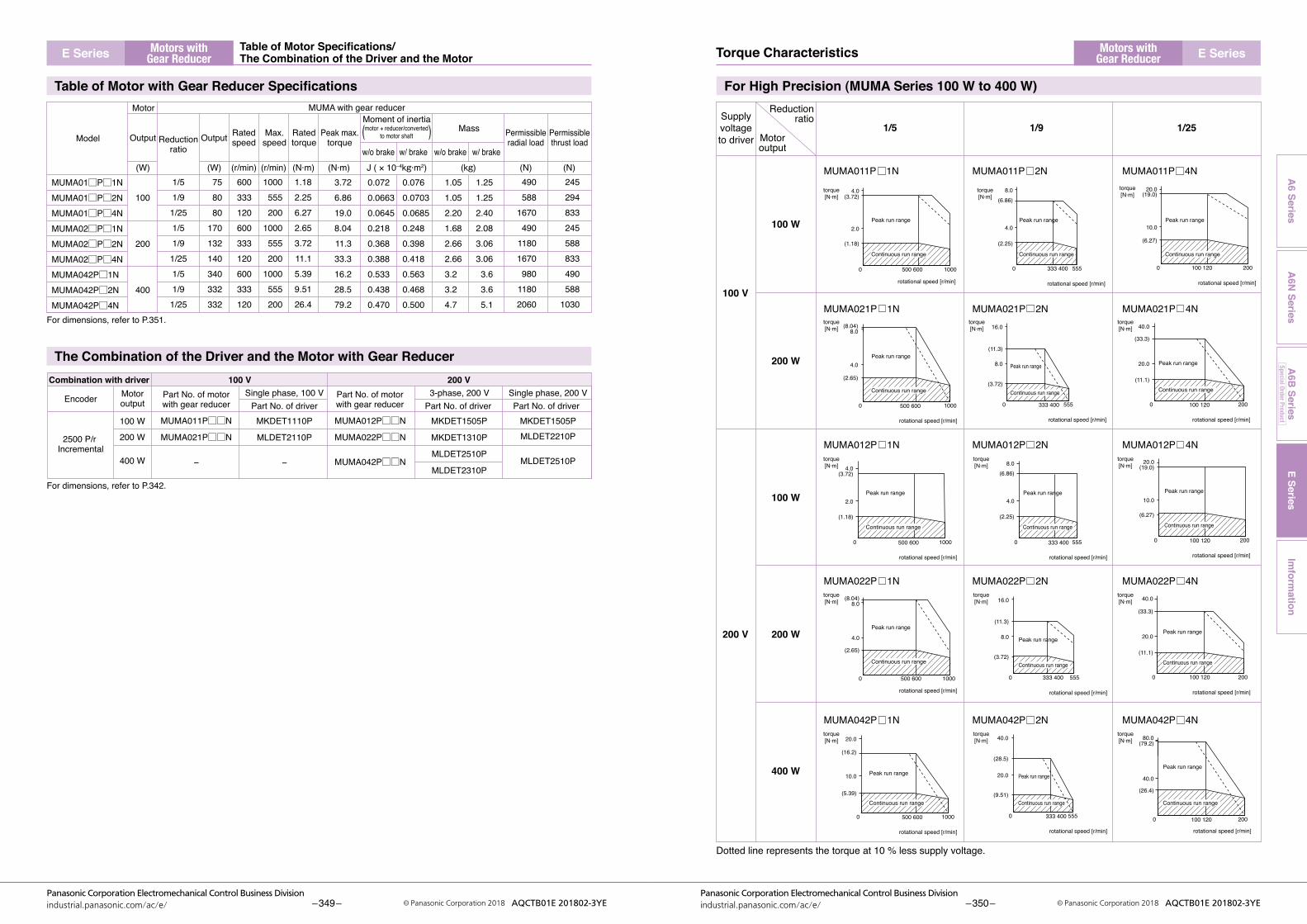
Model Output Output
Motor MUMA with gear reducer
Reductionratio
Ratedspeed
Ratedtorque
Peak max.torque
Max.speed
Moment of inertia( )w/o brake w/ brake w/o brake w/ brake
Mass Permissibleradial load
Permissiblethrust load
(W) (W) (r/min) (r/min) (N·m) (N·m) J ( × 10–4kg·m2) (kg) (N) (N)
100
200
400
758080
170132140340332332
600333120600333120600333120
1000555200
1000555200
1000555200
1/51/91/251/51/91/251/51/91/25
1.182.256.272.653.7211.15.399.5126.4
490588
1670490
11801670980
11802060
245294833245588833490588
1030
0.0720.06630.06450.2180.3680.3880.5330.4380.470
0.0760.07030.06850.2480.3980.4180.5630.4680.500
1.051.052.201.682.662.663.23.24.7
1.251.252.402.083.063.063.63.65.1
3.726.8619.08.0411.333.316.228.579.2
Encoder Single phase, 100 VPart No. of motorwith gear reducer Part No. of driver
Part No. of motorwith gear reducer Part No. of driver Part No. of driver
Motoroutput
2500 P/r Incremental
Combination with driver
MUMA011P□□N
MUMA021P□□N
−
MKDET1110P
MLDET2110P
−
MKDET1505P
MKDET1310P
MLDET2510P
MLDET2310P
MUMA012P□□N
MUMA022P□□N
MUMA042P□□N
100 W
200 W
400 W
3-phase, 200 V100 V 200 V
Single phase, 200 V
MKDET1505PMLDET2210P
MLDET2510P
MUMA01□P□1NMUMA01□P□2NMUMA01□P□4NMUMA02□P□1NMUMA02□P□2NMUMA02□P□4NMUMA042P□1NMUMA042P□2NMUMA042P□4N
motor + reducer/convertedto motor shaft
Peak run range
0 500 600 1000
rotational speed [r/min]
4.0torque[N·m]
torque[N·m]
torque[N·m]
torque[N·m]
torque[N·m]
torque[N·m]
torque[N·m]
torque[N·m]
torque[N·m]
torque[N·m]
torque[N·m]
torque[N·m]
torque[N·m]
torque[N·m]
torque[N·m](3.72)
2.0
(1.18)
Continuous run range
0 100 120 200
rotational speed [r/min]
20.0(19.0)
10.0
(6.27)
0 333 400 555
rotational speed [r/min]
8.0(6.86)
4.0
(2.25)
0 500 600 1000
rotational speed [r/min]
(8.04)8.0
4.0
(2.65)
0 333 400 555
rotational speed [r/min]
16.0
(11.3)
8.0
(3.72)
0 100 120 200
rotational speed [r/min]
40.0
(33.3)
20.0
(11.1)
0 500 600 1000
rotational speed [r/min]
(8.04)8.0
4.0
(2.65)
0 100 120 200
rotational speed [r/min]
40.0
(33.3)
20.0
(11.1)
0 333 400 555
rotational speed [r/min]
16.0
(11.3)
8.0
(3.72)
0 500 600 1000
rotational speed [r/min]
20.0
(16.2)
10.0
(5.39)
0 333 400 555
rotational speed [r/min]
40.0
(28.5)
20.0
(9.51)
0 100 120 200
rotational speed [r/min]
80.0(79.2)
40.0
(26.4)
0 500 600 1000
rotational speed [r/min]
4.0(3.72)
2.0
(1.18)
0 333 400 555
rotational speed [r/min]
8.0(6.86)
4.0
(2.25)
0 100 120 200
rotational speed [r/min]
20.0(19.0)
10.0
(6.27)
Supplyvoltageto driver
Reductionratio
1/5
MUMA011P 1N MUMA011P 2N MUMA011P 4N
MUMA021P 1N MUMA021P 2N MUMA021P 4N
MUMA012P 1N MUMA012P 2N MUMA012P 4N
MUMA022P 1N MUMA022P 2N MUMA022P 4N
MUMA042P 1N MUMA042P 2N MUMA042P 4N
1/9 1/25Motoroutput
100 W
100 V
200 V
100 W
200 W
200 W
400 W
Dotted line represents the torque at 10 % less supply voltage.
Peak run range
Continuous run range
Peak run range
Continuous run range
Peak run range
Continuous run range
Peak run range
Continuous run range
Peak run range
Continuous run range
Peak run range
Continuous run range
Peak run range
Continuous run range
Peak run range
Continuous run range
Peak run range
Continuous run range
Peak run range
Continuous run range
Peak run range
Continuous run range
Peak run range
Continuous run range
Peak run range
Continuous run range
Peak run range
Continuous run range
Table of Motor with Gear Reducer Specifications For High Precision (MUMA Series 100 W to 400 W)
The Combination of the Driver and the Motor with Gear Reducer
For dimensions, refer to P.351.
For dimensions, refer to P.342.
E SeriesIm
formation
A6 Series
A6N
SeriesA
6B Series
Special Order Product
E Series E Series
– 349 –Panasonic Corporation Electromechanical Control Business Division
industrial.panasonic.com/ac/e/ © Panasonic Corporation 2018 AQCTB01E 201802-3YE – 350 –Panasonic Corporation Electromechanical Control Business Division
industrial.panasonic.com/ac/e/ © Panasonic Corporation 2018 AQCTB01E 201802-3YE
Motors withGear Reducer
Motors withGear ReducerTorque CharacteristicsTable of Motor Specifications/
The Combination of the Driver and the Motor
100 W
200 W
400 W
MUMA01□P□1N
MUMA01□P□2N
MUMA01□P□4N
MUMA02□P□1N
MUMA02□P□2N
MUMA02□P□4N
MUMA042P□1N
MUMA042P□2N
MUMA042P□4N
1 / 5
1 / 9
1/25
1 / 5
1 / 9
1/25
1 / 5
1 / 9
1/25
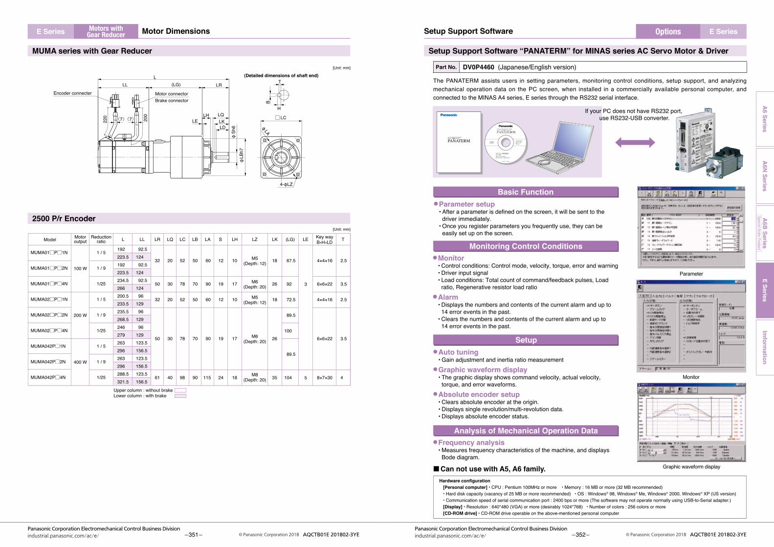
192223.5192223.5234.5266200.5233.5235.5268.5246279263296263296288.5321.5
92.5124 92.5124 92.5124 96129 96129 96129123.5156.5123.5156.5123.5156.5
3
5
32
50
32
50
61
20
30
20
30
40
52
78
52
78
98
50
70
50
70
90
60
90
60
90
115
12
19
12
19
24
10
17
10
17
18
2.5
3.5
2.5
3.5
4
M5(Depth: 12)
M6(Depth: 20)
M5(Depth: 12)
M6(Depth: 20)
M8(Depth: 20)
4×4×16
6×6×22
4×4×16
6×6×22
8×7×30
18
26
18
26
35
67.5
92
72.5
89.5
100
89.5
104
Reductionratio L LL LR LQ LC LB LA S LH LZ LK (LG) LE Key way
B×H×LD TMotoroutputModel
Upper column : without brakeLower column : with brake
(LG)
LKLD
LLL LR
LQLE
φSh
6φ
LBh7
LH
220
Encoder connecter Motor connector
200
Brake connector
φ LA
□LC
4-φLZ
(7)(7)
H
B
T(Detailed dimensions of shaft end)
[Unit: mm]
[Unit: mm]
MUMA series with Gear Reducer
2500 P/r Encoder
Setup Support Software “PANATERM” for MINAS series AC Servo Motor & Driver
Part No. DV0P4460 (Japanese/English version)
The PANATERM assists users in setting parameters, monitoring control conditions, setup support, and analyzing mechanical operation data on the PC screen, when installed in a commercially available personal computer, and connected to the MINAS A4 series, E series through the RS232 serial interface.
●Monitor• Control conditions: Control mode, velocity, torque, error and warning • Driver input signal • Load conditions: Total count of command/feedback pulses, Load
ratio, Regenerative resistor load ratio●Alarm
• Displays the numbers and contents of the current alarm and up to 14 error events in the past.• Clears the numbers and contents of the current alarm and up to 14 error events in the past.
●Auto tuning• Gain adjustment and inertia ratio measurement
●Graphic waveform display• The graphic display shows command velocity, actual velocity,
torque, and error waveforms.●Absolute encoder setup
• Clears absolute encoder at the origin. • Displays single revolution/multi-revolution data. • Displays absolute encoder status.
●Frequency analysis• Measures frequency characteristics of the machine, and displays
Bode diagram.
Basic Function
Monitoring Control Conditions
Setup
Analysis of Mechanical Operation Data
Parameter
Monitor
Graphic waveform display
SETUP SUPPORT SOFTWAREセットアップ支援ソフトウェア
PANATERM
Hardware configuration [Personal computer] ・ CPU : Pentium 100MHz or more ・ Memory : 16 MB or more (32 MB recommended)・ Hard disk capacity (vacancy of 25 MB or more recommended) ・ OS : Windows® 98, Windows® Me, Windows® 2000, Windows® XP (US version)・ Communication speed of serial communication port : 2400 bps or more (The software may not operate normally using USB-to-Serial adapter.) [Display] ・ Resolution : 640*480 (VGA) or more (desirably 1024*768) ・ Number of colors : 256 colors or more [CD-ROM drive] ・ CD-ROM drive operable on the above-mentioned personal computer
■Can not use with A5, A6 family.
●Parameter setup• After a parameter is defined on the screen, it will be sent to the
driver immediately.• Once you register parameters you frequently use, they can be
easily set up on the screen.
If your PC does not have RS232 port, use RS232-USB converter.
E SeriesIm
formation
A6 Series
A6N
SeriesA
6B Series
Special Order Product
E Series E Series
– 351 –Panasonic Corporation Electromechanical Control Business Division
industrial.panasonic.com/ac/e/ © Panasonic Corporation 2018 AQCTB01E 201802-3YE – 352 –Panasonic Corporation Electromechanical Control Business Division
industrial.panasonic.com/ac/e/ © Panasonic Corporation 2018 AQCTB01E 201802-3YE
OptionsMotors withGear Reducer Setup Support SoftwareMotor Dimensions
Cable Set (3 m) Cable Set (5 m)
Part No. DV0P373001) Interface cable : DV0P08002) Encoder cable (3 m) : MFECA0030EAM3) Motor cable (3 m) : MFMCA0030AEB4) Connector kit for driver power supply connection : DV0P2870
Part No. DV0P392001) Interface cable : DV0P0800 2) Encoder cable (5 m) : MFECA0050EAM 3) Motor cable (5 m) : MFMCA0050AEB 4) Connector kit for driver power supply connection : DV0P2870
Encoder Cable
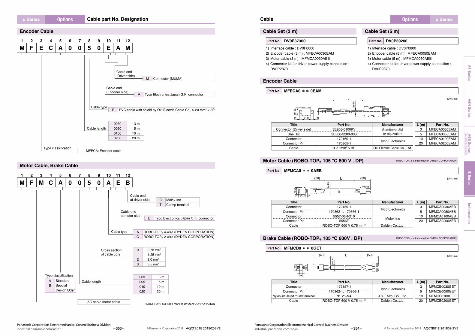
Part No. MFECA0 ** 0EAM
[Unit: mm]
L
(ø6.
5)
(14)
(11.
8)
(4) (4)
Title Part No. Manufacturer L (m) Part No.Connector (Driver side) 3E206-0100KV Sumitomo 3M
or equivalent3 MFECA0030EAM
Shell kit 3E306-3200-008 5 MFECA0050EAMConnector 172160-1 Tyco Electronics 10 MFECA0100EAM
Connector Pin 170365-1 20 MFECA0200EAMCable 0.20 mm2 × 3P Oki Electric Cable Co., Ltd.
Motor Cable (ROBO-TOP® 105 ℃ 600 V . DP) ROBO-TOP® is a trade mark of DYDEN CORPORATION
Part No. MFMCA0 ** 0AEB
[Unit: mm]
(50) (50)L
(φ11
)
(10.0)
(12.
0)
(4) (4)
Title Part No. Manufacturer L (m) Part No.Connector 172159-1 Tyco Electronics 3 MFMCA0030AEB
Connector Pin 170362-1, 170366-1 5 MFMCA0050AEBConnector 5557-06R-210 Molex Inc 10 MFMCA0100AEB
Connector Pin 5556T 20 MFMCA0200AEBCable ROBO-TOP 600 V 0.75 mm2 Daiden Co.,Ltd.
Brake Cable (ROBO-TOP® 105 ℃ 600V . DP) ROBO-TOP® is a trade mark of DYDEN CORPORATION
Part No. MFMCB0 ** 0GET
[Unit: mm]
(φ9.
8)
(40) (50)L
(5.6)
(12.
0)
(10.
0)
Title Part No. Manufacturer L (m) Part No.Connector 172157-1 Tyco Electronics 3 MFMCB0030GET
Connector Pin 170362-1, 170366-1 5 MFMCB0050GETNylon insulated round terminal N1.25-M4 J.S.T Mfg. Co., Ltd. 10 MFMCB0100GET
Cable ROBO-TOP 600 V 0.75 mm2 Daiden Co.,Ltd. 20 MFMCB0200GET
M1
F2
E3
C4
A5
06
07
58
09
E10
A11
M12
M1
F2
M3
C4
A5
06
07
58
09
A10
E11
B12
Connector (MUMA)M
3 m5 m
10 m20 m
0030005001000200
PVC cable with shield by Oki Electric Cable Co., 0.20 mm2 × 3PE
MFECA: Encoder cable
Cable end (Driver side)
Cable type
Cable length
Type classification
Molex Inc.Clamp terminal
BT
Tyco Electronics Japan G.K. connectorE
3 m5 m
10 m20 m
003005010020
ROBO-TOP® 4-wire (DYDEN CORPORATION)ROBO-TOP® 2-wire (DYDEN CORPORATION)
AG
AC servo motor cable
Cable end at driver side
Cable end at motor side
Cable type
Cable length
0.75 mm2
1.25 mm2
2.0 mm2
3.5 mm2
0123
Cross section of cable core
StandardSpecialDesign Oder
AB
Type classification
…
Tyco Electronics Japan G.K. connector
Cable end (Encoder side) A
ROBO-TOP® is a trade mark of DYDEN CORPORATION
Encoder Cable
Motor Cable, Brake Cable
E SeriesIm
formation
A6 Series
A6N
SeriesA
6B Series
Special Order Product
Options OptionsE Series E Series
– 353 –Panasonic Corporation Electromechanical Control Business Division
industrial.panasonic.com/ac/e/ © Panasonic Corporation 2018 AQCTB01E 201802-3YE – 354 –Panasonic Corporation Electromechanical Control Business Division
industrial.panasonic.com/ac/e/ © Panasonic Corporation 2018 AQCTB01E 201802-3YE
CableCable part No. Designation

● Pinconfigurationofencodercablejunction
1NC4+5V
2TX/RX
50V
3TX/RX
6FG
● Pinconfigurationofmotorpowercablejunction
2 V 4 E
1 U 3 W
● PinconfigurationofmatingconnectortoCNX3connector
4 V 1 U
5 (NC)2
(NC)
6 W 3 E
<Cautions>1. Theabovepinconfigurationisshownwhenviewedfromtheterminalinsertingdirection.Makeacorrectwiringby
checking the stamped pin numbers on the connector itself.2. Refer to P.340 for wiring and connection.
Connector Kit for Interface
Part No. DV0P0770
● Parts composition Title Part No. Number Manufacturer Note
Connector 10126-3000PE 1 Sumitomo 3Mor equivalent
For connector, CN X5(26 pins)Connector cover 10326-52A0-008 1
● PinconfigurationofconnectorCNX5(26pins)(viewedfromthesolderingside)
14GND
16OA–
18OB–
20OZ–
22PULS1
24SIGN1
26FG
15OA+
17OB+
19OZ+
21CZ
23PULS2
25SIGN2
1COM+
3A-CLR
7CWL
9ALM
11BRK- OFF
13COM–
2SRV- ON
4CL
8CCWL
10COIN
12WARN
6DIV
INTSPD1INTSPD2
5GAIN
ZEROSPD
<Cautions>1. Make a correct wiring by checking the stamped pin numbers on the connector itself. 2. Refer to P.341 for symbols and functions of the above signals.
Connector Kit for Power Supply Connection
Part No. DV0P2870
● Parts compositionTitle Part No. Number Manufacturer Note
Connector (10 pins) 5557-10R-210 1 Molex Inc. For connector, CN X1(10 pins)Connector pin 5556PBTL 6
● PinconfigurationofconnectorCNX1
● Recommended manual crimping tool (to be prepared by customer)
Part No. Cable material57026-5000 UL100757027-5000 UL1015
6 L31 E
7 (NC)2
(NC)
8 L23 B
9 (NC)4
(NC)
10 L1 5 P
<Cautions>1. The above pin disposition is shown when viewed from the terminal inserting direction. Make a correct wiring by
checking the stamped pin numbers on the connector itself.2. Refer to P.340 for wiring and connection. 3. Do not connect anything to pins marked "NC".
Connector Kit for Motor/Encoder Connection
Part No. DV0P3670 (Incremental 2500 pulse, 5-wire)
This option is required when you make your own encoder cable and motor cable. (Brake cable is required for brake.)
● Parts compositionTitle Part No. Number Manufacturer Note
Connector (Driver side) 3E206-0100 KV 1 Sumitomo 3Mor equivalent
For connector, CN X4(6 pins)Shell kit 3E306-3200-008 1
Connector (6 pins) 172160-1 1 Tyco Electronics For junction to encoder cable(6 pins)Connector pin 170365-1 6
Connector (4 pins) 172159-1 1 Tyco Electronics For junction to motor power cable(4 pins)Connector pin 170366-1 4
Connector (6 pins) 5557-06R-210 1 Molex Inc. For connector, CN X3(6 pins)Connector pin 5556PBTL 4
<Remarks>We may use parts equivalent to the above for shell and connector cover.
● PinconfigurationofconnectorCNX4plug
CaseFG
1 +5V3 +5V5 Tx/Rx
2 0V4 0V6 Tx/Rx
● Recommended manual crimping tool (to be prepared by customer)Title Part No. Manufacturer Cable material
For encoder cable junction 755330-1 Tyco Electronics —For motor power cable junction 755331-1
For Connector CN X3 57026-5000 Molex Inc. UL100757027-5000 UL1015
<Remarks>1. The above pin configuration is shown when viewed from the pin-soldering direction. Make a correct wiring by
checking the stamped pin numbers on the connector itself.2. Connect the shield of the wire to the case (FG) without fail. 3. For wiring and connection, refer to P.340.
E SeriesIm
formation
A6 Series
A6N
SeriesA
6B Series
Special Order Product
OptionsE Series
– 355 –Panasonic Corporation Electromechanical Control Business Division
industrial.panasonic.com/ac/e/ © Panasonic Corporation 2018 AQCTB01E 201802-3YE – 356 –Panasonic Corporation Electromechanical Control Business Division
industrial.panasonic.com/ac/e/ © Panasonic Corporation 2018 AQCTB01E 201802-3YE
Connector KitE Series
DIN Rail Mounting Unit
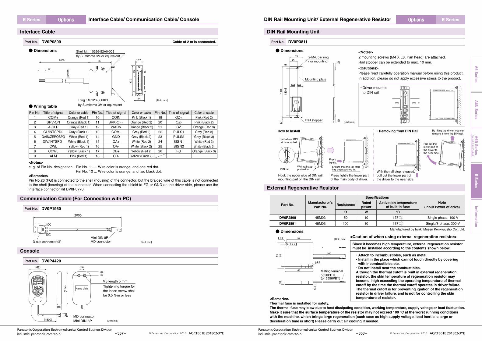
Part No. DV0P3811
● Dimensions
130.
55
140
(7)
2035 2-M4, bar ring
(for mounting)
Mounting plate
Rail stopper
(6)
(6)
<Notes>2 mounting screws (M4 X L8, Pan head) are attached.Rail stopper can be extended to max. 10 mm.<Cautions>Please read carefully operation manual before using this product. In addition, please do not apply excessive stress to the product.
[Unit: mm]
Part where DIN rail is mounted
DIN railWith rail stop pushed in
Hook the upper side of DIN rail mounting part on the DIN rail.
With the rail stop released, pull out the lower part of the driver to the near side.
By lifting the driver, you can remove it from the DIN rail.
Pull out the lower part of the driver to the near side.
Press lightly the lower part of the main body of driver.
Presslightly.
Ensure that the rail stop has been pushed in.
• Driver mounted to DIN rail
• How to Install • Removing from DIN Rail
x1
x3
x4
x5
x6
STATUS ALM CODE
External Regenerative Resistor
Part No. Manufacturer's Part No.
SpecificationsNote
(Input Power of drive)Resistance Rated power
Activation temperature of built-in fuse
Ω W ℃DV0P2890 45M03 50 10 137 +3
−2 Single phase, 100 VDV0P2891 45M03 100 10 137 +3
−2 Single/3-phase, 200 VManufactured by Iwaki Musen Kenkyuusho Co., Ltd.● Dimensions
Mating terminal5556PBTL(or 5556PBT)
φ4.3
φ4.3
57
300
65
5210
60
t0.6
[Unit: mm]
<Remarks>Thermal fuse is installed for safety.The thermal fuse may blow due to heat dissipating condition, working temperature, supply voltage or load fluctuation. Make it sure that the surface temperature of the resistor may not exceed 100 ℃ at the worst running conditions with the machine, which brings large regeneration (such case as high supply voltage, load inertia is large or deceleration time is short) Please carry out air cooling if needed.
Interface Cable
Part No. DV0P0800 Cable of 2 m is connected.
● Dimensions
113 26
14
37.2
2000
50
39
Shell kit : 10326-52A0-008by Sumitomo 3M or equivalent
Plug : 10126-3000PEby Sumitomo 3M or equivalent
12.7
14
(φ10.9)
[Unit: mm]
● Wiring table
Pin No.123456789
Title of signalCOM+
SRV-ONA-CLR
CL/INTSPD2GAIN/ZEROSPDDIV/INTSPD1
CWLCCWLALM
Color or cableOrange (Red 1)
Orange (Black 1)Gray (Red 1)
Gray (Black 1)White (Red 1)
White (Black 1)Yellow (Red 1)
Yellow (Black 1)Pink (Red 1)
Pin No.101112131415161718
Title of signalCOIN
BRK-OFFWARNCOM-GNDOA+OA-OB+OB-
Color or cablePink (Black 1)
Orange (Red 2)Orange (Black 2)
Gray (Red 2)Gray (Black 2)White (Red 2)
White (Black 2)Yellow (Red 2)
Yellow (Black 2)
Pin No.1920212223242526
Title of signalOZ+OZ-CZ
PULS1PULS2SIGN1SIGN2
FG
Color or cablePink (Red 2)
Pink (Black 2)Orange (Red 3)
Gray (Red 3)Gray (Black 3)White (Red 3)
White (Black 3)Orange (Black 3)
<Notes>e. g. of Pin No. designation : Pin No. 1 ..... Wire color is orange, and one red dot. Pin No. 12 ... Wire color is orange, and two black dot.<Remarks>Pin No.26 (FG) is connected to the shell (housing) of the connector, but the braided wire of this cable is not connected to the shell (housing) of the connector. When connecting the shield to FG or GND on the driver side, please use the interface connector Kit DV0P0770.
Communication Cable (For Connection with PC)
Part No. DV0P1960
2000
D-sub connector 9PMini-DIN 8PMD connector [Unit: mm]
Console
Part No. DV0P4420
Name plate
(62)
(15)
(24)
M3 length 5 mm
(15)
(114
)
(1500)MD connector Mini DIN-8P
Tightening torque for the insert screw shall be 0.5 N·m or less
[Unit: mm]
<Caution of when using external regeneration resistor> Since it becomes high temperature, external regeneration resistor must be installed according to the contents shown below.
・ Attach to incombustibles, such as metal.・ Install in the place which cannot touch directly by covering
with incombustibles etc.・ Do not install near the combustibles.Although the thermal cutoff is built in external regeneration resistor, the skin temperature of regeneration resistor may become high exceeding the operating temperature of thermal cutoff by the time the thermal cutoff operates in driver failure.The thermal cutoff is for preventing ignition of the regeneration resistor in driver failure, and is not for controlling the skin temperature of resistor.
E SeriesIm
formation
A6 Series
A6N
SeriesA
6B Series
Special Order Product
Options OptionsE Series E Series
– 357 –Panasonic Corporation Electromechanical Control Business Division
industrial.panasonic.com/ac/e/ © Panasonic Corporation 2018 AQCTB01E 201802-3YE – 358 –Panasonic Corporation Electromechanical Control Business Division
industrial.panasonic.com/ac/e/ © Panasonic Corporation 2018 AQCTB01E 201802-3YE
DIN Rail Mounting Unit/ External Regenerative ResistorInterface Cable/ Communication Cable/ Console

List of Peripheral Components
Manufacturer Tel No. / Home Page Peripheral components
Panasonic Corporation Eco Solutions Company http://panasonic.net/es/ Circuit breaker
Panasonic CorporationAutomotive & Industrial Systems Company http://panasonic.net/id/ Surge absorber
Switch, Relay
Iwaki Musen Kenkyusho Co., Ltd. +81-44-833-4311http://www.iwakimusen.co.jp/
Regenerative resistor
SEMITEC Corporation +81-3-3621-2703http://www.semitec.co.jp/english2/
Surge absorberfor motor brake
TDK Corporation +81-3-5201-7229http://www.global.tdk.com/ Ferrite core
Okaya Electric Industries Co. Ltd. +81-3-4544-7040http://www.okayaelec.co.jp/english/index.html
Surge absorberNoisefilter
Sumitomo 3M +81-3-5716-7290http:/solutions.3m.com/wps/portal/3M/ja_JP/WW2/Country/
ConnectorTyco Electronics Japan G.K. +81-44-844-8052http://www.te.com/ja/home.html
Japan Molex Inc. +81-462-65-2313http://www.molex.co.jp
DYDEN CORPORATION +81-3-5805-5880 http://www.dyden.co.jp/english/index.htm Cable
* The above list is for reference only. We may change the manufacturer without notice.
Reactor
Frame symbol of driver
Power supply specifications Rated output Part No. Fig.
MKDE
Single phase, 100 V
50 W to 100 W DV0P227 1
Single phase, 200 V
50 W to 100 W
DV0P220 23-phase, 200 V 50 W to
200 W
MLDE
Single phase, 100 V 200 W DV0P228 1
Single phase, 200 V
200 W to 400 W DV0P220 2
3-phase, 200 V 400 W
[Unit: mm]
Part No. A B C D E(Max) F G H I Inductance(mH)
Rated current
(A)
Fig.1DV0P227 55±0.7 80±1 66.5±1 110 Max 90 41±2 55±2 4-5φ×10 M4 4.02 5DV0P228 55±0.7 80±1 66.5±1 110 Max 95 46±2 60±2 4-5φ×10 M4 2 8
Fig.2 DV0P220 65±1 125±1 (93) 136 Max 155 70+3/−0 85±2 4-7φ×12 M4 6.81 3
Harmonic restraintHarmonic restraint measures are not common to all countries. Therefore, prepare the measures that meet the requirements of the destination country.When installing a product for Japan, refer to the instruction manual available on our website.
【Panasonic Corporation, Motor Business Unit web site】
industrial.panasonic.com/ac/e/
<Remarks> When using a reactor, be sure to install one reactor to one servo driver.
■ Recommended components
Surge Absorber for Motor Brake
MotorSurge absorber for motor brake
Part No. (Manufacturer's) Manufacturer
MUMA 50 W to 400 W Z15D151 SEMITEC Corporation
Fig.1 Fig.2
C
B
A(Mounting pitch)
A
D
6-I
R S T
NP
X Y Z
G4-H
H
E
F(Mounting pitch)
F
F: Center-to-center distance on slotted hole
F: Center-to-center distance on outer circular arc
E
FG
F
A
4-H
AB
C D
4-H
4-I
E SeriesIm
formation
A6 Series
A6N
SeriesA
6B Series
Special Order Product
Options OptionsE Series E Series
– 359 –Panasonic Corporation Electromechanical Control Business Division
industrial.panasonic.com/ac/e/ © Panasonic Corporation 2018 AQCTB01E 201802-3YE – 360 –Panasonic Corporation Electromechanical Control Business Division
industrial.panasonic.com/ac/e/ © Panasonic Corporation 2018 AQCTB01E 201802-3YE
List of Peripheral ComponentsReactor/ Surge Absorber for Motor Brake

MEMO
– 361 –Panasonic Corporation Electromechanical Control Business Division
industrial.panasonic.com/ac/e/ © Panasonic Corporation 2018 AQCTB01E 201802-3YE

E SeriesIm
formation
A6 Series
A6N
SeriesA
6B Series
Special Order Product
– 362 –Panasonic Corporation Electromechanical Control Business Division
industrial.panasonic.com/ac/e/ © Panasonic Corporation 2018 AQCTB01E 201802-3YE
Contents
A6 Family.................................................................................................................363 EU Directives/ Conformity to UL Standards/ KC ...................................................363
Composition of Peripheral Equipments.................................................................365
E Series ...................................................................................................................369 Compliance to EU and EMC Directives ................................................................369
Composition of Peripheral Components ...............................................................370
Conformity to UL Standards ..................................................................................370
Motor Capacity Selection Software ......................................................................371 AC Servo Motor Capacity Selection Software ......................................................371
Option Selection Software for AC Servo Motor .....................................................371
Guide to the International System of Units (SI) ...................................................372
Selecting Motor Capacity.......................................................................................374
Request Sheet for Motor Selection .......................................................................380
Connection Between Driver and Controller .........................................................388 Connection Between A6 Family Driver and Controller ..........................................388
Replacing Old Model Servo Driver with MINAS A6 series ....................................393
Connection Between E Series Driver and Controller ............................................397
Index .........................................................................................................................402
SalesOfficeofOverseas ..........................................................................................416
Information
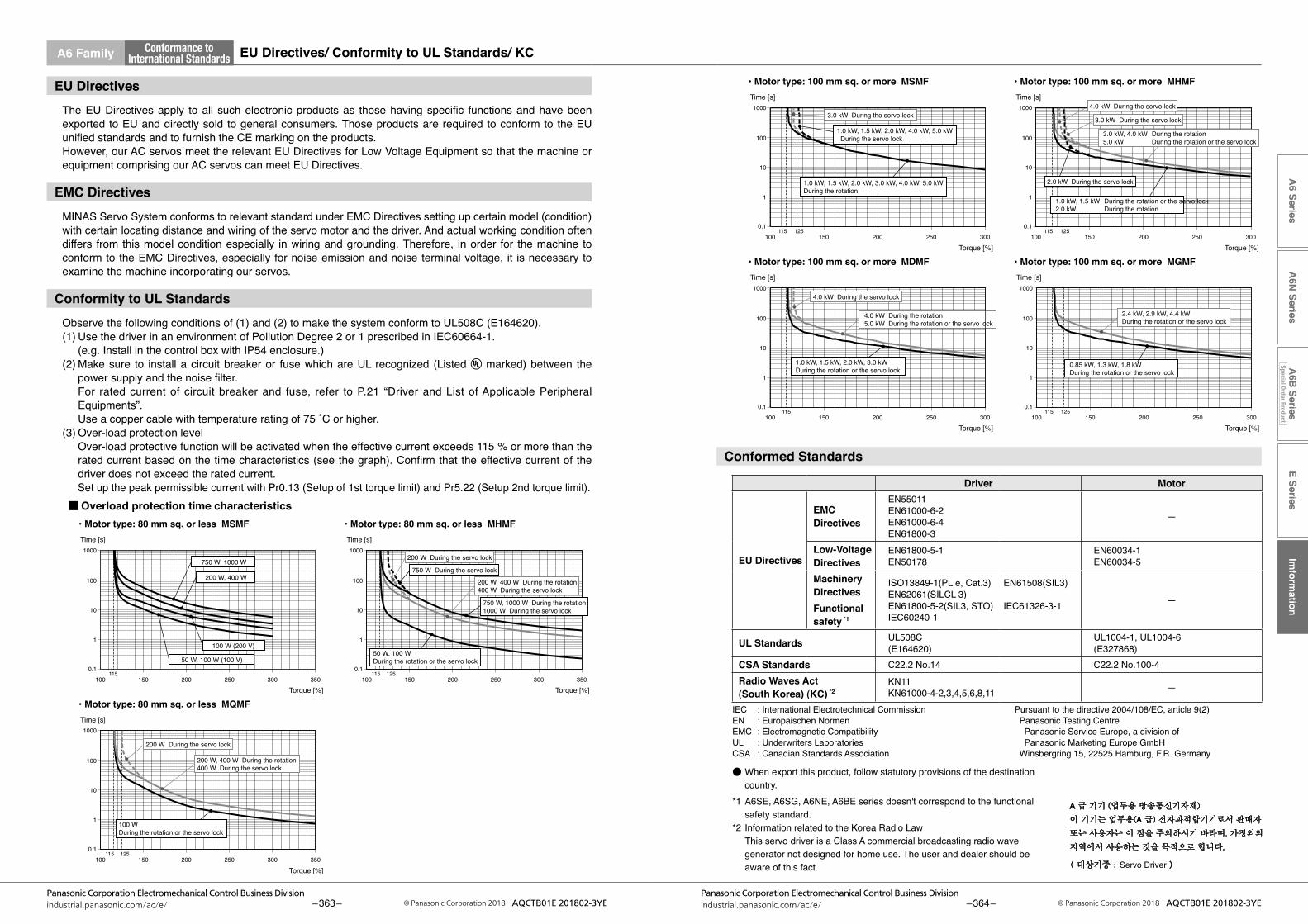
E SeriesIm
formation
A6 Series
A6N
SeriesA
6B Series
Special Order Product
– 363 –Panasonic Corporation Electromechanical Control Business Division
industrial.panasonic.com/ac/e/ © Panasonic Corporation 2018 AQCTB01E 201802-3YE – 364 –Panasonic Corporation Electromechanical Control Business Division
industrial.panasonic.com/ac/e/ © Panasonic Corporation 2018 AQCTB01E 201802-3YE
A6 Family Conformance toInternational Standards EU Directives/ Conformity to UL Standards/ KC
EU DirectivesTheEUDirectivesapply toall suchelectronicproductsas thosehavingspecific functionsandhavebeenexported to EU and directly sold to general consumers. Those products are required to conform to the EU unifiedstandardsandtofurnishtheCEmarkingontheproducts.However, our AC servos meet the relevant EU Directives for Low Voltage Equipment so that the machine or equipment comprising our AC servos can meet EU Directives.
EMC DirectivesMINAS Servo System conforms to relevant standard under EMC Directives setting up certain model (condition) with certain locating distance and wiring of the servo motor and the driver. And actual working condition often differs from this model condition especially in wiring and grounding. Therefore, in order for the machine to conform to the EMC Directives, especially for noise emission and noise terminal voltage, it is necessary to examine the machine incorporating our servos.
Conformity to UL StandardsObserve the following conditions of (1) and (2) to make the system conform to UL508C (E164620).(1) Use the driver in an environment of Pollution Degree 2 or 1 prescribed in IEC60664-1. (e.g. Install in the control box with IP54 enclosure.)(2) Make sure to install a circuit breaker or fuse which are UL recognized (Listed marked) between the
powersupplyandthenoisefilter. For rated current of circuit breaker and fuse, refer to P.21 “Driver andList ofApplicablePeripheral
Equipments”. Useacoppercablewithtemperatureratingof75˚Corhigher.(3) Over-load protection level Over-load protective function will be activated when the effective current exceeds 115 % or more than the
ratedcurrentbasedonthetimecharacteristics(seethegraph).Confirmthattheeffectivecurrentofthedriver does not exceed the rated current.
Set up the peak permissible current with Pr0.13 (Setup of 1st torque limit) and Pr5.22 (Setup 2nd torque limit).
Time [s]
■
Torque [%]
Torque [%]
Torque [%]
Time [s]
• Motor type: 100 mm sq. or more MDMF
Time [s]
• Motor type: 100 mm sq. or more MSMF
• Motor type: 100 mm sq. or more MGMF
0.1
100
10
1
1000
100115
150 200 250 3000.1
100
10
1
1000
100115 125
150 200 250 300
0.1
100
10
1
1000
100115 125
150 200 250 300
Torque [%]
Time [s]
• Motor type: 100 mm sq. or more MHMF
0.1
100
10
1
1000
100115 125
150 200 250 300
1.0 kW, 1.5 kW, 2.0 kW, 3.0 kWDuring the rotation or the servo lock
4.0 kW During the servo lock
3.0 kW During the servo lock
1.0 kW, 1.5 kW, 2.0 kW, 4.0 kW, 5.0 kW During the servo lock
1.0 kW, 1.5 kW, 2.0 kW, 3.0 kW, 4.0 kW, 5.0 kWDuring the rotation
0.85 kW, 1.3 kW, 1.8 kWDuring the rotation or the servo lock
4.0 kW During the rotation5.0 kW During the rotation or the servo lock
2.4 kW, 2.9 kW, 4.4 kWDuring the rotation or the servo lock
3.0 kW During the servo lock
2.0 kW During the servo lock
1.0 kW, 1.5 kW During the rotation or the servo lock2.0 kW During the rotation
4.0 kW During the servo lock
3.0 kW, 4.0 kW During the rotation5.0 kW During the rotation or the servo lock
Conformed Standards
Driver Motor
EU Directives
EMC Directives
EN55011EN61000-6-2EN61000-6-4EN61800-3
—
Low-VoltageDirectives
EN61800-5-1EN50178
EN60034-1EN60034-5
MachineryDirectivesFunctionalsafety *1
ISO13849-1(PL e, Cat.3) EN61508(SIL3) EN62061(SILCL 3) EN61800-5-2(SIL3, STO) IEC61326-3-1 IEC60240-1
—
UL Standards UL508C(E164620)
UL1004-1, UL1004-6(E327868)
CSA Standards C22.2 No.14 C22.2 No.100-4Radio Waves Act(South Korea) (KC) *2
KN11 KN61000-4-2,3,4,5,6,8,11 —
IEC : International Electrotechnical CommissionEN : Europaischen NormenEMC : Electromagnetic CompatibilityUL : Underwriters LaboratoriesCSA : Canadian Standards Association
Pursuant to the directive 2004/108/EC, article 9(2) Panasonic Testing Centre Panasonic Service Europe, a division of Panasonic Marketing Europe GmbH Winsbergring 15, 22525 Hamburg, F.R. Germany
● When export this product, follow statutory provisions of the destination country.
*1A6SE,A6SG,A6NE,A6BEseriesdoesn'tcorrespondtothefunctionalsafety standard.
*2 Information related to the Korea Radio Law This servo driver is a Class A commercial broadcasting radio wave
generator not designed for home use. The user and dealer should be aware of this fact. Servo Driver
Time [s]
■Overload protection time characteristics
Torque [%]
Torque [%]
Time [s]
Torque [%]
• Motor type: 80 mm sq. or less MSMF
Time [s]
• Motor type: 80 mm sq. or less MQMF
• Motor type: 80 mm sq. or less MHMF
0.1
100
10
1
1000
100115
150 200 250 300 350
0.1
100
10
1
1000
150 200 250 300 350
0.1
100
10
1
1000
100115 125
100115 125
150 200 250 300 350
750 W, 1000 W
50 W, 100 WDuring the rotation or the servo lock
200 W, 400 W During the rotation400 W During the servo lock
100 WDuring the rotation or the servo lock
200 W, 400 W
100 W (200 V)
50 W, 100 W (100 V)
200 W During the servo lock
750 W During the servo lock
200 W, 400 W During the rotation400 W During the servo lock
200 W During the servo lock
750 W, 1000 W During the rotation1000 W During the servo lock
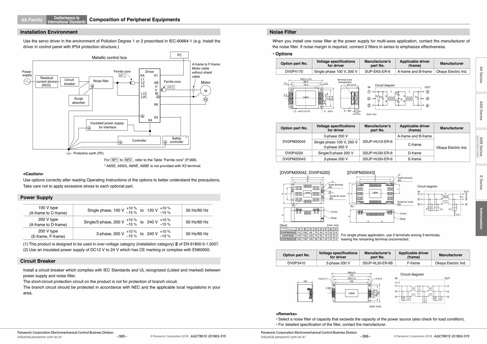
E SeriesIm
formation
A6 Series
A6N
SeriesA
6B Series
Special Order Product
A6 Family
– 365 –Panasonic Corporation Electromechanical Control Business Division
industrial.panasonic.com/ac/e/ © Panasonic Corporation 2018 AQCTB01E 201802-3YE – 366 –Panasonic Corporation Electromechanical Control Business Division
industrial.panasonic.com/ac/e/ © Panasonic Corporation 2018 AQCTB01E 201802-3YE
Conformance toInternational Standards Composition of Peripheral Equipments
Noise FilterWhenyouinstallonenoisefilteratthepowersupplyformulti-axesapplication,contactthemanufacturerofthenoisefilter.Ifnoisemarginisrequired,connect2filtersinseriestoemphasizeeffectiveness.• Options
Option part No. Voltage specifications for driver
Manufacturer'spart No.
Applicable driver (frame) Manufacturer
DV0P4170 Single phase 100 V, 200 V SUP-EK5-ER-6 A-frame and B-frame Okaya Electric Ind.
[Unit: mm]
Label
Terminal cover (transparent)
2 – ø4.5
R Cx CxCy
L L
Cy
2 – ø4.5 x 6.75
53.1±1.0
100.0 ± 2.088.075.0 5.0
12.0
10.0
50.0
60.0
7.0
2.0
(11.6)(13.0)
6 – M4
2
1 3
4
Circuit diagramIN OUT
Option part No. Voltage specifications for driver
Manufacturer'spart No.
Applicable driver (frame) Manufacturer
DV0PM200423-phase 200 V
3SUP-HU10-ER-6A-frame and B-frame
Okaya Electric Ind.Single phase 100 V, 200 V
3-phase 200 V C-frame
DV0P4220 Single/3-phase 200 V 3SUP-HU30-ER-6 D-frameDV0PM20043 3-phase 200 V 3SUP-HU50-ER-6 E-frame
A B C D E F G H115DV0PM20042
[DV0PM20042, DV0P4220] [DV0PM20043]
105 95 70 43 10 52 5.5145DV0P4220 135 125 70 50 10 52 5.5165DV0PM20043 136 165 90 80 40 54 5.5
Label
ABC H
10 F
EDG
Earth terminalM4
M4
Screw for coverM3
Cover
Body
4
5
1
2
63
Circuit diagram
L1
Cx1
IN OUT
R Cx1
Cy1
[Size] [Unit: mm]
Label
A
CB
H
M5
E
F
D
Earth terminalM4
Screw for coverM3
G
Cover
Body
For single phase application, use 2 terminals among 3 terminals, leaving the remaining terminal unconnected.
Option part No. Voltage specifications for driver
Manufacturer'spart No.
Applicable driver (frame) Manufacturer
DV0P3410 3-phase 200 V 3SUP-HL50-ER-6B F-frame Okaya Electric Ind.
[Unit: mm]
Circuit diagramIN OUT
286±3.0
1502-ø5.5 x 7 2-ø5.5
6-6M
270255±1.0
240
120
90±1
.0(18)
(13)
Label
1
2
3
4
5
6
<Remarks>•Selectanoisefilterofcapacitythatexceedsthecapacityofthepowersource(alsocheckforloadcondition).•Fordetailedspecificationofthefilter,contactthemanufacturer.
Installation EnvironmentUse the servo driver in the environment of Pollution Degree 1 or 2 prescribed in IEC-60664-1 (e.g. Install the driver in control panel with IP54 protection structure.)
Metallic control box
Controller
Insulated power supply for interface
Power supply
Surgeabsorber
Noise filter
Ferrite core
Protective earth (PE)
L1
U
X4
XA
XB
X1
X6
M
RE
NF2VW
L2L3
L1CL2C
Ferrite core
Driver
Motor
A-frame to F-frame:Motor cablewithout shieldcable
Safetycontroller
*
X3
Circuit breaker
PC
Residualcurrent device
(RCD)
NF1
<Caution>Use options correctly after reading Operating Instructions of the options to better understand the precautions. Take care not to apply excessive stress to each optional part.
Power Supply
100 V type(A-frame to C-frame) Single phase, 100 V
+10 %–15 % to 120 V
+10 %–15 % 50 Hz/60 Hz
200 V type(A-frame to D-frame) Single/3-phase, 200 V
+10 %–15 % to 240 V
+10 %–15 % 50 Hz/60 Hz
200 V type(E-frame, F-frame) 3-phase, 200 V
+10 %–15 % to 240 V
+10 %–15 % 50 Hz/60 Hz
(1) This product is designed to be used in over-voltage category (installation category) Ⅲ of EN 61800-5-1:2007.(2) Use an insulated power supply of DC12 V to 24 V which has CE marking or complies with EN60950.
Circuit BreakerInstall a circuit breaker which complies with IEC Standards and UL recognized (Listed and marked) between powersupplyandnoisefilter.The short-circuit protection circuit on the product is not for protection of branch circuit.The branch circuit should be protected in accordance with NEC and the applicable local regulations in your area.
For NF1 to NF2 ,refertotheTable“Ferritecore”(P.368).* A6SE, A6SG, A6NE, A6BE is not provided with X3 terminal.
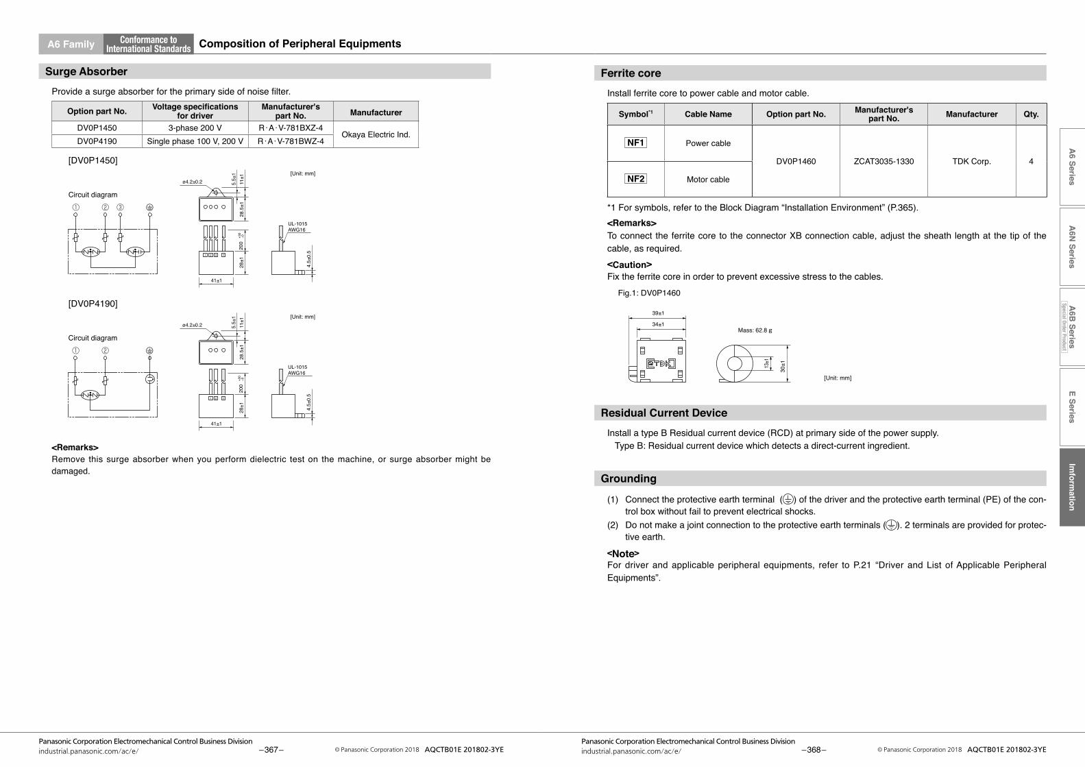
E SeriesIm
formation
A6 Series
A6N
SeriesA
6B Series
Special Order Product
A6 Family
– 367 –Panasonic Corporation Electromechanical Control Business Division
industrial.panasonic.com/ac/e/ © Panasonic Corporation 2018 AQCTB01E 201802-3YE – 368 –Panasonic Corporation Electromechanical Control Business Division
industrial.panasonic.com/ac/e/ © Panasonic Corporation 2018 AQCTB01E 201802-3YE
Conformance toInternational Standards Composition of Peripheral Equipments
Surge AbsorberProvideasurgeabsorberfortheprimarysideofnoisefilter.
Option part No. Voltage specifications for driver
Manufacturer'spart No. Manufacturer
DV0P1450 3-phase 200 V R・A・V-781BXZ-4Okaya Electric Ind.
DV0P4190 Single phase 100 V, 200 V R・A・V-781BWZ-4
Circuit diagram
Circuit diagram
1
ø4.2±0.2
41±1
UL-1015AWG16
28±1
5.5±
111
±128
.5±1
4.5±
0.520
0+3
0−0
2 3
① ② ③
[DV0P1450]
[DV0P4190]
ø4.2±0.2
41±1
UL-1015AWG16
28±1
5.5±
111
±128
.5±1
4.5±
0.5
200
+30
−0
1 2
[Unit: mm]
[Unit: mm]
① ②
<Remarks>Remove this surge absorber when you perform dielectric test on the machine, or surge absorber might be damaged.
Ferrite coreInstall ferrite core to power cable and motor cable.
Symbol*1 Cable Name Option part No. Manufacturer'spart No. Manufacturer Qty.
NF1 Power cable
DV0P1460 ZCAT3035-1330 TDK Corp. 4
NF2 Motor cable
*1 For symbols, refer to the Block Diagram “Installation Environment” (P.365).<Remarks>To connect the ferrite core to the connector XB connection cable, adjust the sheath length at the tip of the cable, as required.<Caution>Fix the ferrite core in order to prevent excessive stress to the cables.
39±1
34±1
30±113
±1
Mass: 62.8 g
Fig.1: DV0P1460
[Unit: mm]
Residual Current DeviceInstall a type B Residual current device (RCD) at primary side of the power supply. Type B: Residual current device which detects a direct-current ingredient.
Grounding
(1) Connect the protective earth terminal ( ) of the driver and the protective earth terminal (PE) of the con-trol box without fail to prevent electrical shocks.
(2) Do not make a joint connection to the protective earth terminals ( ). 2 terminals are provided for protec-tive earth.
<Note>For driver and applicable peripheral equipments, refer to P.21 “Driver andList ofApplicablePeripheralEquipments”.
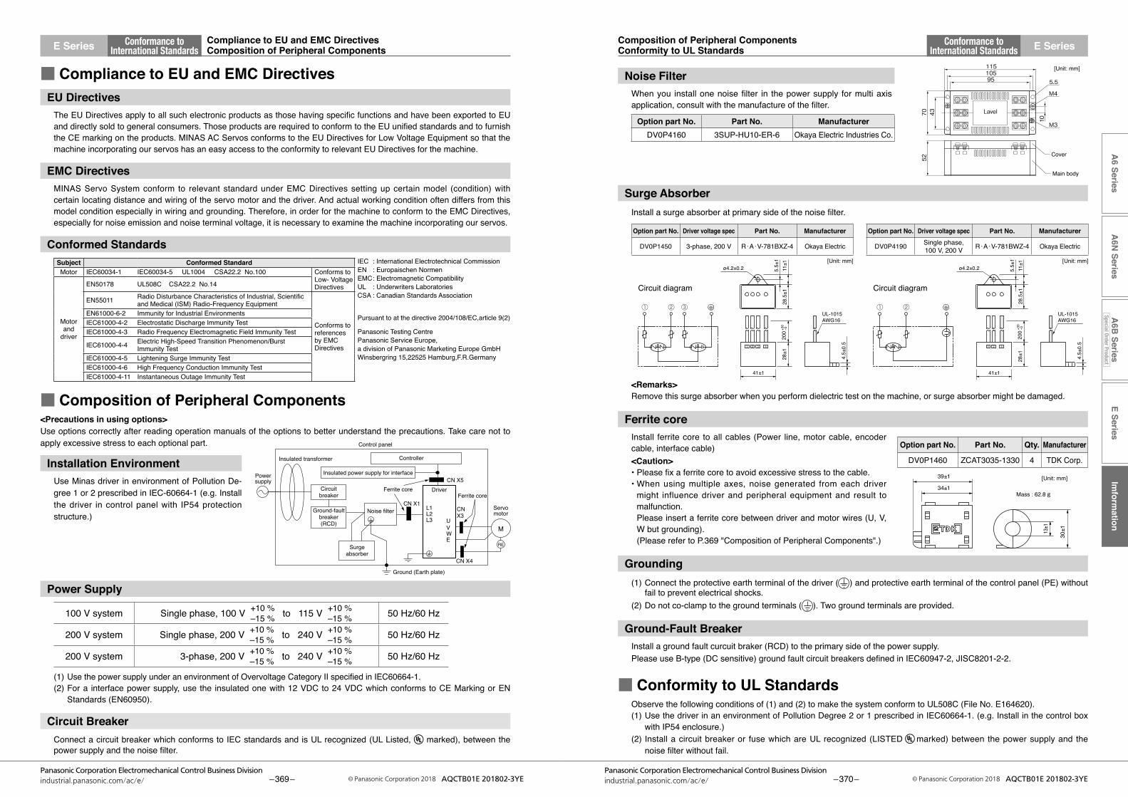
E SeriesIm
formation
A6 Series
A6N
SeriesA
6B Series
Special Order Product
– 369 –Panasonic Corporation Electromechanical Control Business Division
industrial.panasonic.com/ac/e/ © Panasonic Corporation 2018 AQCTB01E 201802-3YE – 370 –Panasonic Corporation Electromechanical Control Business Division
industrial.panasonic.com/ac/e/ © Panasonic Corporation 2018 AQCTB01E 201802-3YE
Conformance toInternational Standards
Conformance toInternational Standards
Composition of Peripheral ComponentsConformity to UL Standards
Compliance to EU and EMC DirectivesComposition of Peripheral Components E SeriesE Series
Noise FilterWhenyou installonenoisefilter in thepowersupply formultiaxisapplication,consultwiththemanufactureofthefilter.
Option part No. Part No. ManufacturerDV0P4160 3SUP-HU10-ER-6 Okaya Electric Industries Co.
115
70 43
10
10595
M4
52
5.5
M3
Cover
Main body
Lavel
[Unit: mm]
Surge AbsorberInstallasurgeabsorberatprimarysideofthenoisefilter.
① ② ③
Circuit diagram Circuit diagram
① ②
1
ø4.2±0.2
41±1
UL-1015AWG16
28±1
5.5±
111
±128
.5±1
4.5±
0.5
200+3
0−0
2 3
ø4.2±0.2
41±1
UL-1015AWG16
28±1
5.5±
111
±128
.5±1
4.5±
0.5
200+3
0−0
1 2
[Unit: mm][Unit: mm]
<Remarks>Remove this surge absorber when you perform dielectric test on the machine, or surge absorber might be damaged.
Ferrite coreInstall ferrite core to all cables (Power line, motor cable, encoder cable, interface cable)<Caution>•Pleasefixaferritecoretoavoidexcessivestresstothecable.•Whenusingmultipleaxes,noisegenerated fromeachdriver
might influence driver and peripheral equipment and result to malfunction.
Please insert a ferrite core between driver and motor wires (U, V, W but grounding).
(Please refer to P.369 "Composition of Peripheral Components".)
Grounding(1) Connect the protective earth terminal of the driver ( ) and protective earth terminal of the control panel (PE) without
fail to prevent electrical shocks.(2) Do not co-clamp to the ground terminals ( ). Two ground terminals are provided.
Ground-Fault BreakerInstall a ground fault curcuit braker (RCD) to the primary side of the power supply.PleaseuseB-type(DCsensitive)groundfaultcircuitbreakersdefinedinIEC60947-2,JISC8201-2-2.
■ Conformity to UL StandardsObserve the following conditions of (1) and (2) to make the system conform to UL508C (File No. E164620). (1) Use the driver in an environment of Pollution Degree 2 or 1 prescribed in IEC60664-1. (e.g. Install in the control box
with IP54 enclosure.) (2) Install a circuit breaker or fuse which are UL recognized (LISTED marked) between the power supply and the
noisefilterwithoutfail.
■ Compliance to EU and EMC DirectivesEU DirectivesTheEUDirectivesapplytoallsuchelectronicproductsasthosehavingspecificfunctionsandhavebeenexportedtoEUanddirectlysoldtogeneralconsumers.ThoseproductsarerequiredtoconformtotheEUunifiedstandardsandtofurnishthe CE marking on the products. MINAS AC Servos conforms to the EU Directives for Low Voltage Equipment so that the machine incorporating our servos has an easy access to the conformity to relevant EU Directives for the machine.
EMC DirectivesMINAS Servo System conform to relevant standard under EMC Directives setting up certain model (condition) with certain locating distance and wiring of the servo motor and the driver. And actual working condition often differs from this model condition especially in wiring and grounding. Therefore, in order for the machine to conform to the EMC Directives, especially for noise emission and noise terminal voltage, it is necessary to examine the machine incorporating our servos.
Conformed StandardsSubject Conformed Standard IEC : International Electrotechnical Commission
EN : Europaischen NormenEMC : Electromagnetic CompatibilityUL : Underwriters LaboratoriesCSA : Canadian Standards Association
Pursuant to at the directive 2004/108/EC,article 9(2)
Panasonic Testing CentrePanasonic Service Europe,a division of Panasonic Marketing Europe GmbHWinsbergring 15,22525 Hamburg,F.R.Germany
Motor IEC60034-1 IEC60034-5 UL1004 CSA22.2 No.100 Conforms to Low- Voltage Directives
Motor and
driver
EN50178 UL508C CSA22.2 No.14
EN55011 RadioDisturbanceCharacteristicsofIndustrial,Scientificand Medical (ISM) Radio-Frequency Equipment
Conforms to references by EMC Directives
EN61000-6-2 Immunity for Industrial EnvironmentsIEC61000-4-2 Electrostatic Discharge Immunity TestIEC61000-4-3 Radio Frequency Electromagnetic Field Immunity Test
IEC61000-4-4 Electric High-Speed Transition Phenomenon/Burst Immunity Test
IEC61000-4-5 Lightening Surge Immunity TestIEC61000-4-6 High Frequency Conduction Immunity TestIEC61000-4-11 Instantaneous Outage Immunity Test
■ Composition of Peripheral Components<Precautions in using options>Use options correctly after reading operation manuals of the options to better understand the precautions. Take care not to apply excessive stress to each optional part.
Installation EnvironmentUse Minas driver in environment of Pollution De-gree 1 or 2 prescribed in IEC-60664-1 (e.g. Install the driver in control panel with IP54 protection structure.)
Control panel
Controller
Insulated power supply for interfacePowersupply
Surgeabsorber
Noise filter
Ferrite core
Ground (Earth plate)
L1
U
CN X5
CN X1CN X3
CN X4
M
RE
VWE
L2L3
Ferrite core Driver
Servomotor
Circuitbreaker
Insulated transformer
Ground-faultbreaker(RCD)
Power Supply
100 V system Single phase, 100 V +10 %–15 % to 115 V
+10 %–15 % 50 Hz/60 Hz
200 V system Single phase, 200 V +10 %–15 % to 240 V
+10 %–15 % 50 Hz/60 Hz
200 V system 3-phase, 200 V +10 %–15 % to 240 V
+10 %–15 % 50 Hz/60 Hz
(1) UsethepowersupplyunderanenvironmentofOvervoltageCategoryIIspecifiedinIEC60664-1.(2) For a interface power supply, use the insulated one with 12 VDC to 24 VDC which conforms to CE Marking or EN
Standards (EN60950).
Circuit BreakerConnect a circuit breaker which conforms to IEC standards and is UL recognized (UL Listed, marked), between the powersupplyandthenoisefilter.
39±1
34±1
30±113
±1
Mass : 62.8 g
[Unit: mm]
Option part No. Driver voltage spec Part No. Manufacturer
DV0P1450 3-phase, 200 V R・A・V-781BXZ-4 Okaya Electric
Option part No. Driver voltage spec Part No. Manufacturer
DV0P4190 Single phase,100 V, 200 V R・A・V-781BWZ-4 Okaya Electric
Option part No. Part No. Qty. Manufacturer
DV0P1460 ZCAT3035-1330 4 TDK Corp.

SI unit
Table1: Basic unit Table 2: Auxiliary unit
Table 3 : Derived unit with proper name
Table 4 : Unit combined with SI unit
Table 5 : Prefix(Multiples of 10)
Other derived unit
Derived unit
Table1: Basic unit
LengthWeightTime
CurrentThermodynamic temperatureAmount of substanceLuminous intensity
meterkilogramsecondamperekelvinmol
candela
mkgsAK
molcd
Quantity Name of unit Symbol of unitTable 2: Auxiliary unit
QuantityPlane angleSolid angle
Name of unitradian
steradian
Symbol of unitradsr
Table 3: Major derived unit with proper nameQuantity Name Symbol of
unitDerivation from basic unit,
auxiliary unit or other derived unitFrequencyForcePressure, StressEnergy, Work, Amount of heatAmount of work, Work efficiency, Power, Electric powerElectric charge, Amount of electricityElectric potential, Potential difference, Voltage, Electromotive forceElectrostatic capacity, CapacitanceElectric resistanceElectric conductanceMagnetic fluxMagnetic flux density, Magnetic inductionInductanceDegree centigrade (Celsius)Luminous fluxIlluminance
hertznewtonpascaljoulewattcoulombvoltfaradohmsiemensweberteslahenrydegree centigrade (Celsius) / degreelumenlux
1 Hz = 1 s–1
1 N = 1 kg•m/s2
1 Pa = 1 N/m2
1 J = 1 N•m1 W = 1 J/s1 C = 1 A•s1 V = 1 J/C1 F = 1 C/V1 Ω = 1 V/A1 S = 1 Ω–1
1 Wb = 1 V•s1 T = 1 Wb/m2
1 H = 1 Wb/At ˚C = (t+273.15) K1 lm = 1 cd•sr1 lx = 1 lm/m2
HzNPaJWCVFΩS
WbTH˚Clmlx
QuantityTable 4: Unit combined with SI unit
Time
Plane angle
Volume
Weight
Nameminute
hour
day
degree
minute
second
liter
ton
Symbol of unitmin
h
d
˚
'
"
l, L
t
Multiples poweredto unit
1018
1015
1012
109
106
103
102
1010-1
10-2
10-3
10-6
10-9
10-12
10-15
10-18
Name SymbolPrefix
EPTGMkhdadcmμnpfa
exapetateragiga
megakilo
hectodecadecicentimilli
micronanopico
femtoatto
Table 5: Prefix
E SeriesIm
formation
A6 Series
A6N
SeriesA
6B Series
Special Order Product
– 371 –Panasonic Corporation Electromechanical Control Business Division
industrial.panasonic.com/ac/e/ © Panasonic Corporation 2018 AQCTB01E 201802-3YE – 372 –Panasonic Corporation Electromechanical Control Business Division
industrial.panasonic.com/ac/e/ © Panasonic Corporation 2018 AQCTB01E 201802-3YE
Guide to the International System of Units (SI) Motor Capacity Selection Software Organization of the System of Units AC Servo Motor Capacity Selection Software
Option Selection Software for AC Servo Motor
Details of motorOnce the motor is selected, specifications of the motor and driver, and details of reason for determination are displayed and may be printed out.
We have prepared PC software to enable fast, easy, and correct option selection, a complicated job without the software.
• Two procedures for option selection 1. Selection according to driver series and motor type
Suitable option can be selected by selecting driver series, motor type and motor specification through pulldown menu.
2. Entry of model numberIf you know the model number based on the servo motor and driver currently used, enter the model number.
Result of selectionTab sheet specific to each of option model numbers is used for easier identification of the desired option.
Driver series
Motor type
Tab
Model number input area
Motor specification
* When you are using the motor capacity selection software, simply press [Option Selection] tab and the screen as shown right will appear.
AC Servo Motor Capacity Selection SoftwareWe have prepared PC software “M-SELECT” for AC servo motor capacity selection. Consult our sales representative or authorized distributor.
• Three-step selection 1. Select components and specified values
Select appropriate mechanical parameter items and fill them with parameter values derived from the real machine. To simulate the target machine as practical as possible, use maximum number of parameters available.
3. Select the motorWhen the data required in step 1 and 2 above have been input, the software lists the motors, which will be appropriate to use with your machine. Select the motor that is best suitable for your machine application.
Option Selection Software for AC Servo Motor
2. Enter operation patternInput the planned operation pattern that will contain [speed and rotation standard] or [absolute position standard] with optional settings such as S-acceleration/deceleration.
Please download from our web site and use after install to the PC.https://industrial.panasonic.com/ww/products/motors-compressors/fa-motors/ac-servo-motors/minas-a5-panaterm

Note (1) Applicable to liquid pressure. Also applicable to atmospheric pressure of meteorological data, when “bar” is used in international standard.(2) Applicable to scale or indication of blood pressure manometers.(3) “˚C” can be substituted for “K”.
Quantity
LengthAcceleration
Frequency Revolving speed, Number of revolutions
WeightMass
Weight flow rateMass flow rateSpecific weight
Density Specific volume
LoadForce
Moment of forcePressure
Stress
Elastic modulus
Energy, Work
Work efficiency, Power
Viscosity Kinetic viscosity
Thermodynamic temperatureTemperature interval
Amount of heat Heat capacity
Specific heat, Specific heat capacityEntropy
Specific entropyInternal energy (Enthalpy)
Specific internal energy (Specific enthalpy)Heat flux
Heat flux densityThermal conductivity
Coefficient of thermal conductivity Intensity of magnetic field
Magnetic fluxMagnetic flux density
μ (micron)GalG
c/s, crpmkgf–kgf/s
–kgf/m3
–m3/kgfkgfkgfdynkgf •mkgf/cm2
at (Engineering atmospheric pressure)atm (Atmospheric pressure)
mH2O, mAqmmHg
Torrkgf/mm2
kgf/cm2
kgf/m2
kgf •mergkgf •m/s
PSPPStK
degcal
cal/˚Ccal/ (kgf •˚C)
cal/Kcal/ (kgf •K)
calcal/kgfcal/h
cal/ (h •m2)cal/ (h •m •˚C)cal/ (h •m2•˚C)
OeMx
Gs,G
μmm/s2
m/s2
Hzs–1 or min–1, r/min
–kg–kg/s
–kg/m3
m3/kgNNN
N・mPa, bar (1) or kgf/cm2
PaPaPa
Pa or mmHg (2)
PaPa or N/m2
Pa or N/m2
Pa or N/m2
J (joule)J
W (watt)W
Pa•smm2/s
K (kelvin)K (3)
JJ/K (3)
cal/ (kgf •K)(3)
J/KJ/(kg •K)
JJ/kgW
W/m2
W/ (m •K) (3)
W/ (m2•K) (3)
A/mWb (weber)
T (tesla)
•
1 μ = 1 μm (micrometer)1 Gal = 10–2 m/s2
1 G = 9.80665 m/s2
1 c/s = Hz1 rpm = 1 min–1
Same value
Same value
Same value
Same value1 kgf = 9.80665 N1 kgf = 9.80665 N1 dyn = 10–5 N1 kgf •m = 9.806 N •m1 kgf/cm2 = 9.80665 x 10⁴ Pa = 0.980665 bar1 at = 9.80665 x 10⁴ Pa1 atm = 1.01325 x 10⁵ Pa1 mH2O = 9.80665 x 10³ Pa1 mmHg = 133.322 Pa
1 kgf/mm2 = 9.80665 x 10⁶ Pa =9.80665 x 10⁶ N/m2
1 kgf/cm2 = 9.80665 x 10⁴ Pa = 9.80665 x 10⁴ N/m2
1 kgf/m2 = 9.80665 Pa = 9.80665 N/m2
1 kgf/cm2 = 9.80665 x 10⁴ N/m2
1 kgf •m = 9.80665 J1 erg = 10–7 J1 kgf •m/s = 9.80665 W1 PS = 0.7355 kW1 P = 0.1 Pa•s10–2 St = 1 mm2/s1 K = 1 K1 deg = 1 K1 cal = 4.18605 J1 cal/˚C = 4.18605 J/K1 cal/ (kgf •˚C) = 4.18605 J/ (kg •K)1 cal/K = 4.18605 J/K1 cal/ (kgf •K) = 4.18605 J/ (kg •K)1 cal = 4.18605 J1 cal/kgf = 4.18605 J/kg1 kcal/h = 1.16279 W1 kcal/ (h •m2) = 1.16279 W/m2
1 kcal/ (h •m •˚C) = 1.16279 W/ (m •K)1 kcal/ (h •m2•˚C) = 1.16279 W/ (m2•K)1 Oe = 103 / (4π) A/m1 Mx = 10–8 Wb1 Gs = 10–4 T
Symbol ofconventional unit
Symbol of SI unit andcompatible unit Conversion value
1. Definition of mechanism to be driven by motor. Define details of individual mechanical components (ball screw length, lead and pulley diameters, etc.)
<Typical mechanism> Ball screw mechanism Belt mechanism Rack & pinion, etc.
2. Definition of operating pattern. Acceleration/deceleration time, Constant-velocity time, Stop time, Cycle time, Travel distance
Note) Selection of motor capacity significantly varies depending on the operating pattern. The motor capacity can be reduced if the acceleration/deceleration time and stop time are set
as long as possible.
3. Calculation of load inertia and inertia ratio. Calculate load inertia for each mechanical component. (Refer to "General inertia calculation method"
described later.) Divide the calculated load inertia by the inertia of the selected motor to check the inertia ratio. For calculation of the inertia ratio, note that the catalog value of the motor inertia is expressed as "× 10–4 kg•m2".
4. Calculation of motor velocity Calculate the motor velocity from the moving distance, acceleration / deceleration time and
constant-velocity time.
5. Calculation of torque Calculate the required motor torque from the load inertia, acceleration/deceleration time and
constant-velocity time.
6. Calculation of motor Select a motor that meets the above 3 to 5 requirements.
Time
VelocityTravel distance (slashed area)
Stop timeDecelerationtime
Cycle time
Accelerationtime
Constant-velocity time
E SeriesIm
formation
A6 Series
A6N
SeriesA
6B Series
Special Order Product
– 373 –Panasonic Corporation Electromechanical Control Business Division
industrial.panasonic.com/ac/e/ © Panasonic Corporation 2018 AQCTB01E 201802-3YE – 374 –Panasonic Corporation Electromechanical Control Business Division
industrial.panasonic.com/ac/e/ © Panasonic Corporation 2018 AQCTB01E 201802-3YE
Selecting Motor CapacityGuide to the International System of Units (SI) Major Compatible Unit Flow of Motor Selection
Flow of Motor Selection

J = J1 + ( ) 2 J2
3. Inertia and inertia ratioInertia is like the force to retain the current moving condition. Inertia ratio is calculated by dividing load inertia by rotor inertia. Generally, for motors with 750 W or lower capacity, the inertia ratio should be “20” or less. For motors with 1000 W or higher capacity, the inertia ratio should be “10” or less. If you need quicker response, a lower inertia ratio is required. For example, when the motor takes several seconds in acceleration step, the inertia ratio can be further increased.
J =81 WD2 [kg •m2]
J =121 W (a2 + b2) [kg •m2]
J =81 W(D2 + d2) [kg •m2]
n2n1
J =41 WD2 [kg •m2]
W : Weight [kg]
D : Outer diameter [m]
W : Weight [kg] D : Outer diameter [m] d : Inner diameter [m]
J =81 WD2 + WS2 [kg •m2]
W : Weight [kg] D : Outer diameter [m] S : Distance [m]
J = JB + 4π 2
W • P2[kg •m2]
W : Weight [kg] P : LeadJB : J of ball screw
J =481 W(3D2 + 4L2) [kg •m2]
W : Weight [kg] D : Outer diameter [m] L : Length [m]
Shape
General inertia calculation method
Disk
J calculation formula Shape J calculation formula
W : Weight [kg]
a, b, c : Side length [m]
n1 : A rotational speed of a shaft [ r/min]n2 : A rotational speed of b shaft [ r/min]
J =31 WL2 [kg •m2]
[kg •m2]
W : Weight [kg]
L : Length [m]
W : Workpiece weight on conveyor [kg]
D : Drum diameter [m]
Inertia on shaft "a"
* Excluding drum J
Prism
Straight rod
Reduction gear
Conveyor
Hollow cylinder
Uniform rod
Separated rod
Ball screw
If weight (W [kg]) is unknown, calculate it with the following formula: Weight W[kg]=Density [kg/m3] x Volume V[m3] Density of each material Iron =7.9 x 10³ [kg/m3] Aluminum =2.8 x 10³ [kg/m3] Brass =8.5 x 10³ [kg/m3]
D
WD
P
WF
a b
cD
L/2L/2
aJ 1
J 2n2
n1
b
L
D
d
S
D
( )
1. Torque (1) Peak torque
Indicate the maximum torque that the motor requires during operation (mainly in acceleration and deceleration steps). The reference value is 80% or less of the maximum motor torque. If the torque is a negative value, a regenerative discharge resistor may be required.
(2) Traveling torque, Stop holding torque Indicates the torque that the motor requires for a long time. The reference value is 80% or less of the rated motor torque. If the torque is a negative value, a regenerative discharge resistor may be required.
Traveling torque calculation formula for each mechanism
Ball screw mechanism
Belt mechanism
(3) Effective torqueIndicates a root-mean-square value of the total torque required for running and stopping the motor per unit time. The reference value is approx. 80% or less of the rated motor torque.
2. Motor velocity Maximum velocity
Maximum velocity of motor in operation: The reference value is the rated velocity or lower value.When the motor runs at the maximum velocity, you must pay attention to the motor torque and temperature rise. For actual calculation of motor velocity, see "Example of motor selection" described later.
Tf=2π
P (μgW+F )
tc
WD
F
P
WF
Traveling torque
W : Weight [kg] P : Lead [m] F : External force [N]
: Mechanical efficiencyμ : Coefficient of frictiong : Acceleration of gravity 9.8[m/s2]
T f=2π
D (μgW+F )Traveling torque
W : Weight [kg] P : Pulley diameter [m] F : External force [N]
: Mechanical efficiencyμ : Coefficient of frictiong : Acceleration of gravity 9.8[m/s2]
Ta2 x ta + Tf2 x tb + Td2 x tdTrms =
Ta : Acceleration torque [N •m]Tf : Traveling torque [N •m]Td : Deceleration torque [N •m]
ta : Acceleration time [s]tb : Constant-velocity time [s]td : Deceleration time [s]
tc : Cycle time [s] (Run time + Stop time)
E SeriesIm
formation
A6 Series
A6N
SeriesA
6B Series
Special Order Product
– 375 –Panasonic Corporation Electromechanical Control Business Division
industrial.panasonic.com/ac/e/ © Panasonic Corporation 2018 AQCTB01E 201802-3YE – 376 –Panasonic Corporation Electromechanical Control Business Division
industrial.panasonic.com/ac/e/ © Panasonic Corporation 2018 AQCTB01E 201802-3YE
Selecting Motor Capacity Description on the Items Related to Motor Selection
Description on the Items Related to Motor Selection
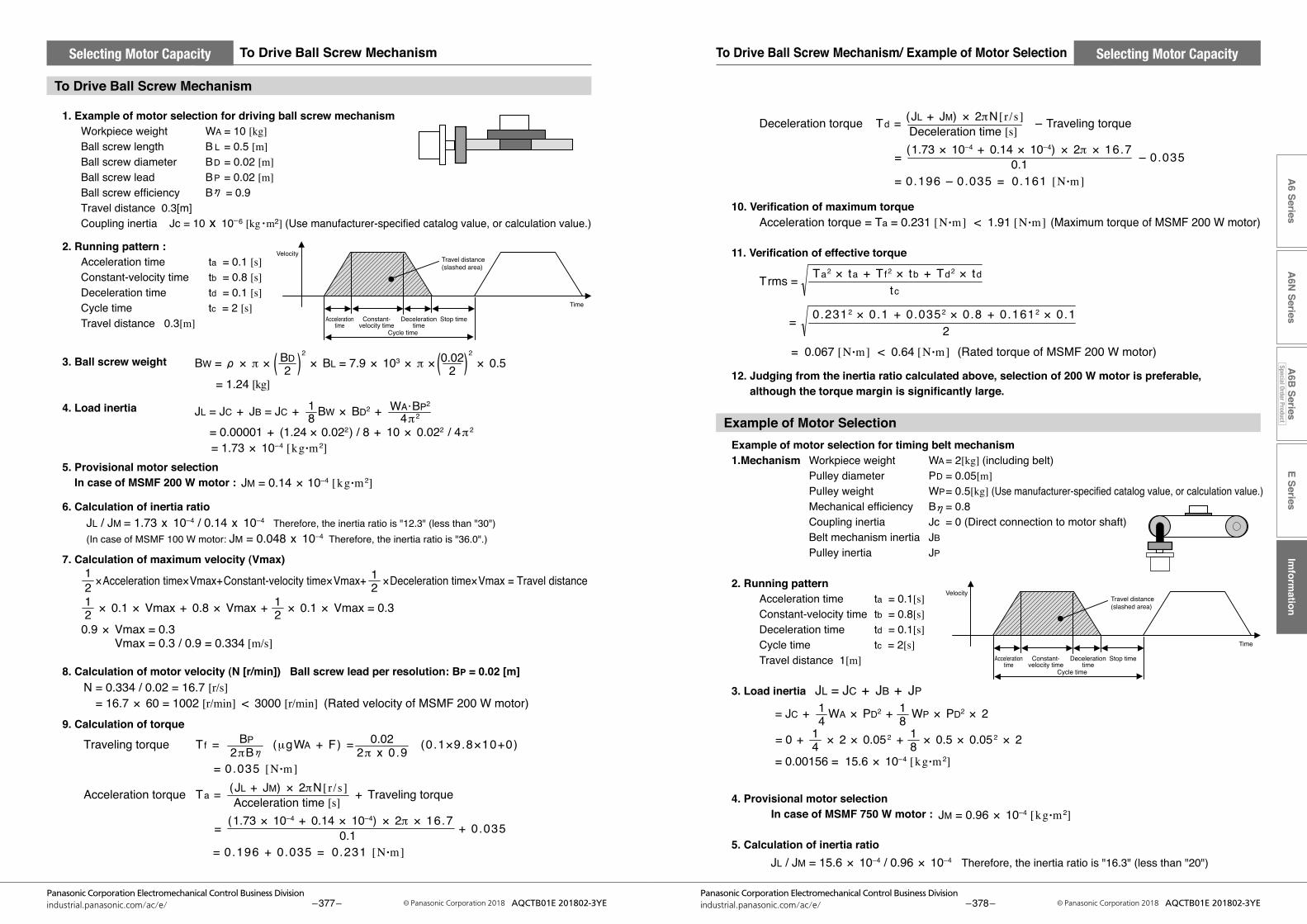
= 0.00001 + (1.24 × 0.022) / 8 + 10 × 0.022 / 4π 2
= 1.73 × 10⁻⁴ [kg •m 2]
21
21
JL = JC + JB = JC + BW × BD2 + 81
4π 2WA •BP2
1. Example of motor selection for driving ball screw mechanism Workpiece weight WA = 10 [kg] Ball screw length B L = 0.5 [m] Ball screw diameter BD = 0.02 [m] Ball screw lead BP = 0.02 [m] Ball screw efficiency B = 0.9 Travel distance 0.3[m] Coupling inertia Jc = 10 x 10–6 [kg •m2] (Use manufacturer-specified catalog value, or calculation value.)
2. Running pattern : Acceleration time ta = 0.1 [s] Constant-velocity time tb = 0.8 [s] Deceleration time td = 0.1 [s] Cycle time tc = 2 [s] Travel distance 0.3[m]
3. Ball screw weight
4. Load inertia
5. Provisional motor selection In case of MSMF 200 W motor :
6. Calculation of inertia ratio
7. Calculation of maximum velocity (Vmax)
8. Calculation of motor velocity (N [r/min]) Ball screw lead per resolution: BP = 0.02 [m]
9. Calculation of torque
BW = × π × 2 × BL = 7.9 × 10³ × π ×
2 × 0.5
= 1.24 [kg]2
BD2
0.02
JL / JM = 1.73 x 10⁻⁴ / 0.14 x 10⁻⁴ Therefore, the inertia ratio is "12.3" (less than "30")(In case of MSMF 100 W motor: JM = 0.048 x 10⁻⁴ Therefore, the inertia ratio is "36.0".)
×Acceleration time×Vmax+Constant-velocity time×Vmax+ ×Deceleration time×Vmax = Travel distance
21
21 × 0.1 × Vmax + 0.8 × Vmax + × 0.1 × Vmax = 0.3
0.9 × Vmax = 0.3 Vmax = 0.3 / 0.9 = 0.334 [m/s]
N = 0.334 / 0.02 = 16.7 [r/s] = 16.7 × 60 = 1002 [r/min] < 3000 [r/min] (Rated velocity of MSMF 200 W motor)
Traveling torque Tf = (μgWA + F) = (0.1×9.8×10+0)
= 0.035 [N •m] 2πB
BP2π x 0.9
0.02
Acceleration torque Ta = + Traveling torque
= + 0.035
= 0.196 + 0.035 = 0.231 [N •m]
Acceleration time [s] (JL + JM) × 2πN [ r /s]
0.1(1.73 × 10⁻⁴ + 0.14 × 10–4) × 2π × 16.7
Time
VelocityTravel distance (slashed area)
Stop timeDecelerationtime
Cycle time
Accelerationtime
Constant-velocity time
JM = 0.14 × 10⁻⁴ [kg •m 2]
10. Verification of maximum torque
11. Verification of effective torque
12. Judging from the inertia ratio calculated above, selection of 200 W motor is preferable, although the torque margin is significantly large.
Example of motor selection for timing belt mechanism 1.Mechanism Workpiece weight WA = 2[kg] (including belt) Pulley diameter PD = 0.05[m] Pulley weight WP = 0.5[kg] (Use manufacturer-specified catalog value, or calculation value.) Mechanical efficiency B = 0.8 Coupling inertia Jc = 0 (Direct connection to motor shaft) Belt mechanism inertia JB Pulley inertia JP
2. Running pattern Acceleration time ta = 0.1[s] Constant-velocity time tb = 0.8[s] Deceleration time td = 0.1[s] Cycle time tc = 2[s] Travel distance 1[m]
3. Load inertia JL = JC + JB + JP
4. Provisional motor selection In case of MSMF 750 W motor :
5. Calculation of inertia ratio
Deceleration torque Td = – Traveling torque
= – 0.035
= 0.196 – 0.035 = 0.161 [N •m]
Deceleration time [s] (JL + JM) × 2πN [ r /s]
0.1(1.73 × 10⁻⁴ + 0.14 × 10–4) × 2π × 16.7
Acceleration torque = Ta = 0.231 [N •m] < 1.91 [N •m] (Maximum torque of MSMF 200 W motor)
tc
Ta2 × ta + Tf2 × tb + Td2 × tdTrms =
20.2312 × 0.1 + 0.0352 × 0.8 + 0.1612 × 0.1 =
= 0.067 [N •m] < 0.64 [N •m] (Rated torque of MSMF 200 W motor)
Time
VelocityTravel distance (slashed area)
Stop timeDecelerationtime
Cycle time
Accelerationtime
Constant-velocity time
= 0 + × 2 × 0.052 + × 0.5 × 0.052 × 2
= 0.00156 = 15.6 × 10⁻⁴ [kg •m 2]
= JC + WA × PD2 + WP × PD2 × 241
41
81
81
JM = 0.96 × 10⁻⁴ [kg •m 2]
JL / JM = 15.6 × 10⁻⁴ / 0.96 × 10⁻⁴ Therefore, the inertia ratio is "16.3" (less than "20")
E SeriesIm
formation
A6 Series
A6N
SeriesA
6B Series
Special Order Product
– 377 –Panasonic Corporation Electromechanical Control Business Division
industrial.panasonic.com/ac/e/ © Panasonic Corporation 2018 AQCTB01E 201802-3YE – 378 –Panasonic Corporation Electromechanical Control Business Division
industrial.panasonic.com/ac/e/ © Panasonic Corporation 2018 AQCTB01E 201802-3YE
Selecting Motor CapacitySelecting Motor Capacity To Drive Ball Screw Mechanism/ Example of Motor SelectionTo Drive Ball Screw Mechanism
To Drive Ball Screw Mechanism
Example of Motor Selection
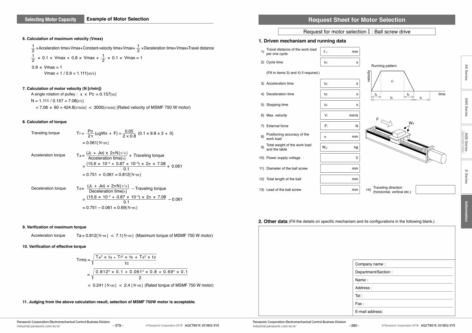
6. Calculation of maximum velocity (Vmax)
7. Calculation of motor velocity (N [r/min]) A single rotation of pulley :
8. Calculation of torque
Traveling torque
Acceleration torque
Deceleration torque
9. Verification of maximum torque
Acceleration torque
10. Verification of effective torque
11. Judging from the above calculation result, selection of MSMF 750W motor is acceptable.
×Acceleration time×Vmax+Constant-velocity time×Vmax+ ×Deceleration time×Vmax=Travel distance
N = 1.111 / 0.157 = 7.08[r/s] = 7.08 × 60 = 424.8[r/min] < 3000[r/min] (Rated velocity of MSMF 750 W motor)
21
21
× 0.1 × Vmax + 0.8 × Vmax + × 0.1 × Vmax = 121
Tf = (μgWA + F) = (0.1 × 9.8 × 3 + 0)2 × 0.80.05
2 PD
21
0.9 × Vmax = 1 Vmax = 1 / 0.9 = 1.111[m/s]
= 0.061[N •m]
Ta = + Traveling torque
Ta = 0.812[N •m] < 7.1[N •m] (Maximum torque of MSMF 750 W motor)
Acceleration time[s](JL + JM) x 2πN [ r /s]
= + 0.061
= 0.751 + 0.061 = 0.812[N •m]0.1
(15.6 × 10⁻⁴ + 0.87 × 10–4) × 2π × 7.08
Td = – Traveling torqueDeceleration time[s](JL + JM) × 2πN [ r /s]
= – 0.061
= 0.751 – 0.061 = 0.69[N •m]0.1
(15.6 × 10⁻⁴ + 0.87 × 10–4) × 2π × 7.08
tcTa2 × ta + Tf2 × tb + Td2 × tdTrms =
20.8122 × 0.1 + 0.0612 × 0.8 + 0.692 × 0.1 =
= 0.241 [N •m] < 2.4 [N •m] (Rated torque of MSMF 750 W motor)
π × PD = 0.157[m]
E SeriesIm
formation
A6 Series
A6N
SeriesA
6B Series
Special Order Product
– 379 –Panasonic Corporation Electromechanical Control Business Division
industrial.panasonic.com/ac/e/ © Panasonic Corporation 2018 AQCTB01E 201802-3YE – 380 –Panasonic Corporation Electromechanical Control Business Division
industrial.panasonic.com/ac/e/ © Panasonic Corporation 2018 AQCTB01E 201802-3YE
Selecting Motor Capacity Example of Motor Selection
ta tdt0 ts
FWA
Running pattern
time
velo
city
1
Request Sheet for Motor Selection
Request for motor selectionⅠ: Ball screw drive1. Driven mechanism and running data
2. Other data (Fillthedetailsonspecificmechanismanditsconfigurationsinthefollowingblank.)
Company name :
Department/Section :
Name :
Address :
Tel :
Fax :
E-mail address:
1) Travel distance of the work load per one cycle ℓ1: mm
2) Cycle time to: s
(Fill in items 3) and 4) if required.)
3) Acceleration time ta: s
4) Deceleration time td: s
5) Stopping time ts: s
6) Max. velocity V: mm/s
7) External force F: N
8) Positioning accuracy of the work load ± mm
9) Total weight of the work load and the table WA: kg
10) Power supply voltage V
11) Diameter of the ball screw mm
12) Total length of the ball mm
13) Lead of the ball screw mm 14) Traveling direction(horizontal, vertical etc.)

E SeriesIm
formation
A6 Series
A6N
SeriesA
6B Series
Special Order Product
– 381 –Panasonic Corporation Electromechanical Control Business Division
industrial.panasonic.com/ac/e/ © Panasonic Corporation 2018 AQCTB01E 201802-3YE – 382 –Panasonic Corporation Electromechanical Control Business Division
industrial.panasonic.com/ac/e/ © Panasonic Corporation 2018 AQCTB01E 201802-3YE
ta tdt0 ts
F WA
D2(W2)
D1(W1)
WM
L1
Running pattern
time
velo
city 1
Request Sheet for Motor Selection
Request for motor selection Ⅱ : Timing pulley + Ball screw drive1. Driven mechanism and running data
2. Other data (Fillthedetailsonspecificmechanismanditsconfigurationsinthefollowingblank.)
Company name :
Department/Section :
Name :
Address :
Tel :
Fax :
E-mail address:
1) Travel distance of the work load per one cycle ℓ1: mm
2) Cycle time to: s
(Fill in items 3) and 4) if required.)
3) Acceleration time ta: s
4) Deceleration time td: s
5) Stopping time ts: s
6) Max. velocity V: mm/s
7) External force F: N
8) Positioning accuracy of the work load ± mm
9) Total weight of the work load and the table WA: kg
10) Power supply voltage V
11) Diameter of the ball screw mm
12) Total length of the ball screw mm
13) Lead of the ball screw mm
14) Traveling direction(horizontal, vertical etc.)
Motor side Ball screw side
15) Diameter of the pulley D1: mm D2: mm
16) Weight of the pulley W1: kg W2: kg
(or item 17) and 18))
17) Width of the pulley L1: mm
18) Material of the pulley
19) Weight of the belt WM: kg
ta tdt0 ts
FWA
W1
L1
D1
Running pattern
time
velo
city 1
Request Sheet for Motor Selection
Request for motor selection Ⅲ : Belt drive1. Driven mechanism and running data
2. Other data (Fillthedetailsonspecificmechanismanditsconfigurationsinthefollowingblank.)
Company name :
Department/Section :
Name :
Address :
Tel :
Fax :
E-mail address:
1) Travel distance of the work load per one cycle ℓ1: mm
2) Cycle time to: s
(Fill in items 3) and 4) if required.)
3) Acceleration time ta: s
4) Deceleration time td: s
5) Stopping time ts: s
6) Max. velocity V: mm/s
7) External force F: N
8) Positioning accuracy of the work load ± mm
9) Total weight of the work load WA: kg
10) Power supply voltage V
11) Weight of the belt WM: kg
12) Diameter of the driving pulley D1: mm
13) Total weight of the pulley W1: kg
(or item 14) and 15))
14) Width of the pulley L1: mm
15) Material of the pulley
16) Traveling direction(horizontal, vertical etc.)
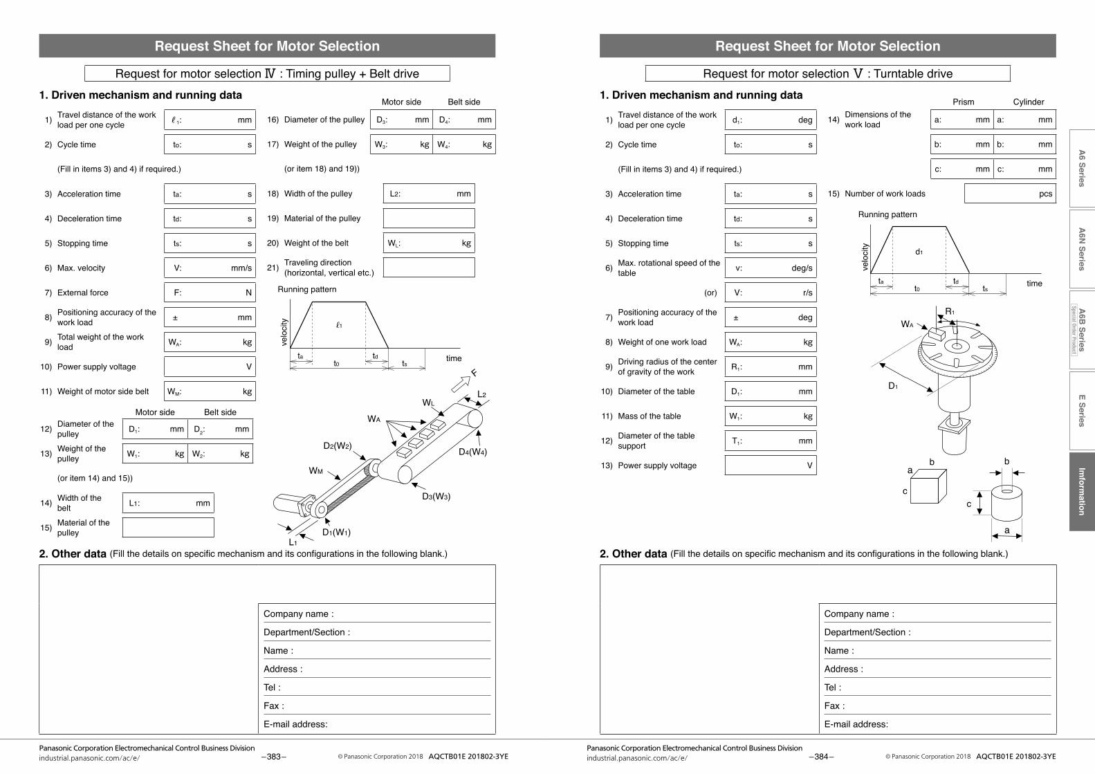
E SeriesIm
formation
A6 Series
A6N
SeriesA
6B Series
Special Order Product
– 383 –Panasonic Corporation Electromechanical Control Business Division
industrial.panasonic.com/ac/e/ © Panasonic Corporation 2018 AQCTB01E 201802-3YE – 384 –Panasonic Corporation Electromechanical Control Business Division
industrial.panasonic.com/ac/e/ © Panasonic Corporation 2018 AQCTB01E 201802-3YE
ta tdt0 ts
L1
L2
WM
WL
WA
D2(W2)
D3(W3)
D4(W4)
F
D1(W1)
Running pattern
time
velo
city 1
Request Sheet for Motor Selection
Request for motor selection Ⅳ : Timing pulley + Belt drive1. Driven mechanism and running data
2. Other data (Fillthedetailsonspecificmechanismanditsconfigurationsinthefollowingblank.)
Company name :
Department/Section :
Name :
Address :
Tel :
Fax :
E-mail address:
1) Travel distance of the work load per one cycle ℓ1: mm
2) Cycle time to: s
(Fill in items 3) and 4) if required.)
3) Acceleration time ta: s
4) Deceleration time td: s
5) Stopping time ts: s
6) Max. velocity V: mm/s
7) External force F: N
8) Positioning accuracy of the work load ± mm
9) Total weight of the work load WA: kg
10) Power supply voltage V
11) Weight of motor side belt WM: kg
Motor side Belt side
12) Diameter of the pulley D1: mm D2: mm
13) Weight of the pulley W1: kg W2: kg
(or item 14) and 15))
14) Width of the belt L1: mm
15) Material of the pulley
Motor side Belt side
16) Diameter of the pulley D3: mm D4: mm
17) Weight of the pulley W3: kg W4: kg
(or item 18) and 19))
18) Width of the pulley L2: mm
19) Material of the pulley
20) Weight of the belt WL: kg
21) Traveling direction(horizontal, vertical etc.)
D1
b b
cc
a
a
WA
R1
ta tdt0 ts
d1
Running pattern
time
velo
city
Request Sheet for Motor Selection
Request for motor selection Ⅴ : Turntable drive1. Driven mechanism and running data
2. Other data (Fillthedetailsonspecificmechanismanditsconfigurationsinthefollowingblank.)
Company name :
Department/Section :
Name :
Address :
Tel :
Fax :
E-mail address:
1) Travel distance of the work load per one cycle d1: deg
2) Cycle time to: s
(Fill in items 3) and 4) if required.)
3) Acceleration time ta: s
4) Deceleration time td: s
5) Stopping time ts: s
6) Max. rotational speed of the table v: deg/s
(or) V: r/s
7) Positioning accuracy of the work load ± deg
8) Weight of one work load WA: kg
9) Driving radius of the center of gravity of the work R1: mm
10) Diameter of the table D1: mm
11) Mass of the table W1: kg
12) Diameter of the table support T1: mm
13) Power supply voltage V
Prism Cylinder
14) Dimensions of the work load a: mm a: mm
b: mm b: mm
c: mm c: mm
15) Number of work loads pcs

E SeriesIm
formation
A6 Series
A6N
SeriesA
6B Series
Special Order Product
– 385 –Panasonic Corporation Electromechanical Control Business Division
industrial.panasonic.com/ac/e/ © Panasonic Corporation 2018 AQCTB01E 201802-3YE – 386 –Panasonic Corporation Electromechanical Control Business Division
industrial.panasonic.com/ac/e/ © Panasonic Corporation 2018 AQCTB01E 201802-3YE
Running pattern
time
velo
city
ta tdt0 ts
bb
cc
WA
D1
L1WM
D2(W2)
R1
D3(W3)
aa
d1
Request Sheet for Motor Selection
Request for motor selection Ⅵ : Timing pulley + Turntable drive1. Driven mechanism and running data
2. Other data (Fillthedetailsonspecificmechanismanditsconfigurationsinthefollowingblank.)
Company name :
Department/Section :
Name :
Address :
Tel :
Fax :
E-mail address:
1) Travel distance of the work load per one cycle d1: deg
2) Cycle time to: s
(Fill in items 3) and 4) if required.)
3) Acceleration time ta: s
4) Deceleration time td: s
5) Stopping time ts: s
6) Max. rotational speed of the table v: deg/s
(or) V: r/s
7) Positioning accuracy of the work load ± deg
8) Weight of one work load WA: kg
9) Driving radius of the center of gravity of the work R1: mm
10) Diameter of the table D1: mm
11) Mass of the table W1: kg
12) Diameter of the table support T1: mm
13) Power supply voltage V
(Prism) (Cylinder)
14) Dimension of the work load a: mm a: mm
b: mm b: mm
c: mm c: mm
15) Number of work loads pcs
Motor side Turntable side
16) Diameter of the pulley D2: mm D3: mm
17) Weight of the pulley W2: kg W3: kg
(or item 18) and 19))
18) Width of the pulley L1: mm
19) Material of the pulley
20) Weight of the belt WM: kg
Running pattern
time
velo
city
ta tdt0 ts
F
L1
D1(W1)
1
Request Sheet for Motor Selection
Request for motor selection Ⅶ : Roller feed drive1. Driven mechanism and running data
2. Other data (Fillthedetailsonspecificmechanismanditsconfigurationsinthefollowingblank.)
Company name :
Department/Section :
Name :
Address :
Tel :
Fax :
E-mail address:
1) Travel distance of the work load per one cycle ℓ1: mm
2) Cycle time to: s
(Fill in items 3) and 4) if required.)
3) Acceleration time ta: s
4) Deceleration time td: s
5) Stopping time ts: s
6) Max. velocity v: mm/s
7) External pulling force F: N
8) Positioning accuracy of the work load ± mm
9) Number of rollers pcs
10) Power supply voltage V
11) Diameter of the roller D1: mm
12) Mass of the roller W1: kg
(or item 13) and 14))
13) Width of the roller L1: mm
14) Material of the roller
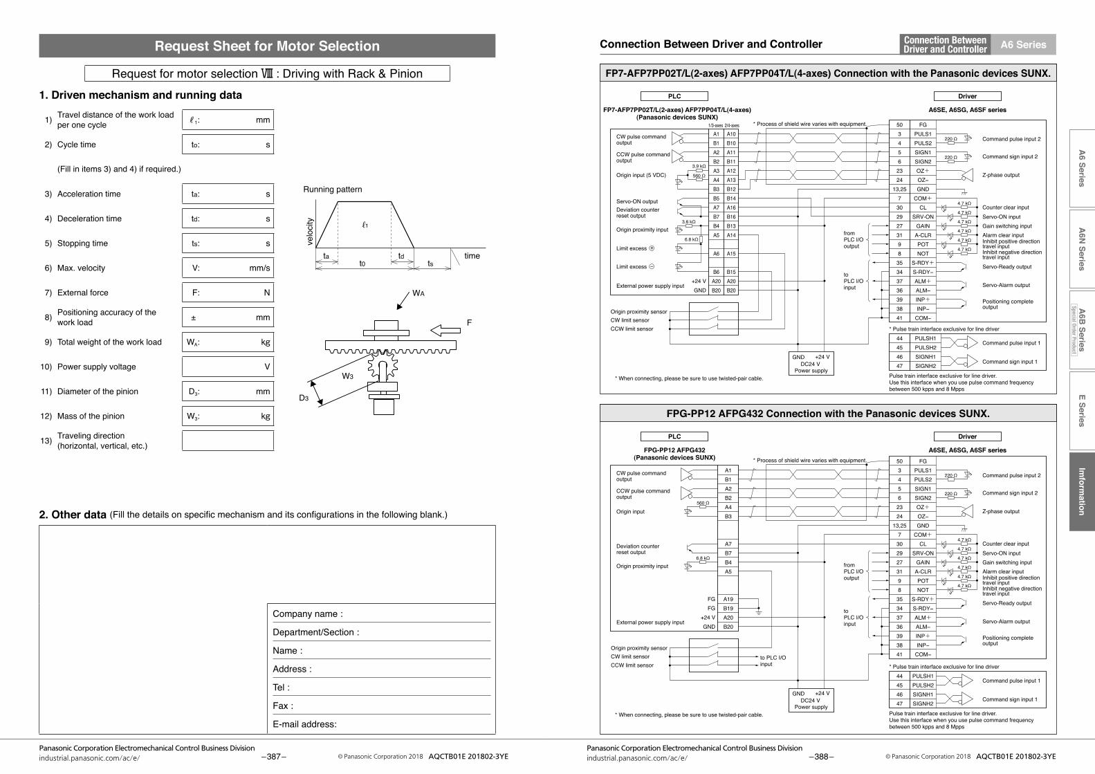
E SeriesIm
formation
A6 Series
A6N
SeriesA
6B Series
Special Order Product
– 387 –Panasonic Corporation Electromechanical Control Business Division
industrial.panasonic.com/ac/e/ © Panasonic Corporation 2018 AQCTB01E 201802-3YE – 388 –Panasonic Corporation Electromechanical Control Business Division
industrial.panasonic.com/ac/e/ © Panasonic Corporation 2018 AQCTB01E 201802-3YE
A6 SeriesConnection BetweenDriver and ControllerConnection Between Driver and Controller
Running pattern
time
velo
city
ta tdt0 ts
D3
W3
F
WA
1
Request Sheet for Motor Selection
Request for motor selection Ⅷ : Driving with Rack & Pinion1. Driven mechanism and running data
2. Other data (Fillthedetailsonspecificmechanismanditsconfigurationsinthefollowingblank.)
Company name :
Department/Section :
Name :
Address :
Tel :
Fax :
E-mail address:
1) Travel distance of the work load per one cycle ℓ1: mm
2) Cycle time to: s
(Fill in items 3) and 4) if required.)
3) Acceleration time ta: s
4) Deceleration time td: s
5) Stopping time ts: s
6) Max. velocity V: mm/s
7) External force F: N
8) Positioning accuracy of the work load ± mm
9) Total weight of the work load WA: kg
10) Power supply voltage V
11) Diameter of the pinion D3: mm
12) Mass of the pinion W3: kg
13) Traveling direction(horizontal, vertical, etc.)
CW limit sensorOrigin proximity sensor
CCW limit sensor
CW limit sensorOrigin proximity sensor
CCW limit sensor
GND +24 VDC24 V
Power supply
GND +24 VDC24 V
Power supply
Command pulse input 1
Command sign input 1
Command pulse input 2
Counter clear inputServo-ON input
Servo-Ready output
Servo-Alarm output
Positioning complete output
Alarm clear input
Z-phase output
Command sign input 2
Gain switching input
Inhibit negative direction travel input
Inhibit positive direction travel input
CW pulse command output
CCW pulse command output
Origin input (5 VDC)
Servo-ON outputDeviation counter reset output
External power supply input
Origin proximity input
Limit excess +
Limit excess −
CW pulse command output
CCW pulse command output
Origin input
Deviation counter reset output
External power supply input
Origin proximity input
A6SE, A6SG, A6SF series
503456
2324
13,257
3029273198
35343736393841
FGPULS1PULS2SIGN1SIGN2OZ+OZ−GND
COM+CL
SRV-ONGAIN
A-CLRPOTNOT
S-RDY+S-RDY−ALM+ALM−INP+INP−
COM−
* Process of shield wire varies with equipment.
220 Ω
+24 VGND
* Pulse train interface exclusive for line driver
Pulse train interface exclusive for line driver. Use this interface when you use pulse command frequency between 500 kpps and 8 Mpps
* When connecting, please be sure to use twisted-pair cable.
* When connecting, please be sure to use twisted-pair cable.
FP7-AFP7PP02T/L(2-axes) AFP7PP04T/L(4-axes) Connection with the Panasonic devices SUNX.
Command pulse input 2
Counter clear inputServo-ON input
Servo-Ready output
Servo-Alarm output
Positioning complete output
Alarm clear input
Z-phase output
Command sign input 2
Gain switching input
Inhibit negative direction travel input
Inhibit positive direction travel input
44454647
PULSH1PULSH2SIGNH1SIGNH2
Command pulse input 1
Command sign input 1
FP7-AFP7PP02T/L(2-axes) AFP7PP04T/L(4-axes)(Panasonic devices SUNX)
220 Ω
4.7 kΩ
560 Ω
3.9 kΩ
3.6 kΩ
6.8 kΩ
4.7 kΩ
4.7 kΩ
4.7 kΩ
4.7 kΩ
4.7 kΩ
fromPLC I/O output
toPLC I/O input
A1B1A2B2A3A4B3B5A7B7B4A5
A6
B6A20B20
A10B10A11B11A12A13B12B14A16B16B13A14
A15
B15A20B20
1/3-axes 2/4-axes
A6SE, A6SG, A6SF series503456
2324
13,257
3029273198
35343736393841
FGPULS1PULS2SIGN1SIGN2OZ+OZ−GND
COM+CL
SRV-ONGAIN
A-CLRPOTNOT
S-RDY+S-RDY−ALM+ALM−INP+INP−
COM−
* Process of shield wire varies with equipment.
220 Ω
FGFG
+24 VGND
* Pulse train interface exclusive for line driver
Pulse train interface exclusive for line driver. Use this interface when you use pulse command frequency between 500 kpps and 8 Mpps
FPG-PP12 AFPG432 Connection with the Panasonic devices SUNX.
44454647
PULSH1PULSH2SIGNH1SIGNH2
PLC
FPG-PP12 AFPG432(Panasonic devices SUNX)
220 Ω
4.7 kΩ
560 Ω
6.8 kΩ
4.7 kΩ
4.7 kΩ
4.7 kΩ
4.7 kΩ
4.7 kΩ
fromPLC I/O output
toPLC I/O input
to PLC I/O input
A1B1A2B2A4B3
A7B7B4A5
A19B19A20B20
PLC Driver
Driver
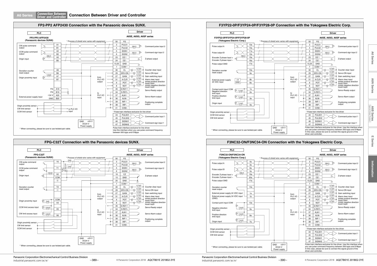
E SeriesIm
formation
A6 Series
A6N
SeriesA
6B Series
Special Order Product
– 389 –Panasonic Corporation Electromechanical Control Business Division
industrial.panasonic.com/ac/e/ © Panasonic Corporation 2018 AQCTB01E 201802-3YE – 390 –Panasonic Corporation Electromechanical Control Business Division
industrial.panasonic.com/ac/e/ © Panasonic Corporation 2018 AQCTB01E 201802-3YE
A6 Series Connection BetweenDriver and Controller Connection Between Driver and Controller
DC24 V Power supply
GND +24 V
Command pulse input 2
Counter clear inputServo-ON input
Servo-Ready output
Servo-Alarm output
Positioning complete output
Alarm clear input
Z-phase output
Command sign input 2
Gain switching input
Inhibit negative direction travel input
Inhibit positive direction travel input
CW limit sensorOrigin proximity sensor
CCW limit sensor
CW limit sensorOrigin proximity sensor
CCW limit sensor
CW pulse command output
CCW pulse command output
Origin input
Deviation counter reset output
External power supply input
Origin proximity input
CW pulse command output
CCW pulse command output
Origin input
Deviation counter reset output
Origin proximity input
CCW limit excess input
CW limit excess input
FP2-PP2 AFP2430 Connection with the Panasonic devices SUNX.
FP2-PP2 AFP2430(Panasonic devices SUNX)
Driver
A6SE, A6SG, A6SF series
220 Ω
FPG-C32T Connection with the Panasonic devices SUNX.
FPG-C32T(Panasonic devices SUNX)
220 Ω
4.7 kΩ
4.7 kΩ
4.7 kΩ
4.7 kΩ
4.7 kΩ
4.7 kΩ
fromPLC I/O output
toPLC I/O input
Y0
Y1
X2COM+
Y2−
COMX3
X5
X6
○
○
* Process of shield wire varies with equipment.
FGFG
+24 VGND
fromPLC I/O output
toPLC I/O input
to PLC I/O input
A1B1A2B2A5B5
A6B6A7B7
A19B19A20B20
1.6 kΩ
220 Ω
5.6 kΩ
5.6 kΩ
3 kΩ
5.6 kΩ
5034561913257302927319835343736393841
FGPULS1PULS2SIGN1SIGN2
CZGNDGND
COM+CL
SRV-ONGAINA-CLRPOTNOT
S-RDY+S-RDY−ALM+ALM−INP+INP−
COM−
* When connecting, please be sure to use twisted-pair cable.
* When connecting, please be sure to use twisted-pair cable.
GND +24 VDC24 V
Power supply
Command pulse input 1
Command sign input 1
Command pulse input 2
Counter clear inputServo-ON input
Servo-Ready output
Servo-Alarm output
Positioning complete output
Alarm clear input
Z-phase output
Command sign input 2
Gain switching input
Inhibit negative direction travel input
Inhibit positive direction travel input
A6SE, A6SG, A6SF series
5034562324
13,257302927319835343736393841
FGPULS1PULS2SIGN1SIGN2OZ+OZ−GND
COM+CL
SRV-ONGAINA-CLRPOTNOT
S-RDY+S-RDY−ALM+ALM−INP+INP−
COM−
220 Ω
* Pulse train interface exclusive for line driver
Pulse train interface exclusive for line driver. Use this interface when you use pulse command frequency between 500 kpps and 8 Mpps
44454647
PULSH1PULSH2SIGNH1SIGNH2
220 Ω
4.7 kΩ
4.7 kΩ
4.7 kΩ
4.7 kΩ
4.7 kΩ
4.7 kΩ
DriverPLC
PLC
* Process of shield wire varies with equipment.2 kΩ
2 kΩ2 kΩ
2 kΩ
DC24 V Power supply
GND +24 V
DC24 V Power supply
GND +24 V
CCW limit sensorOrigin proximity sensor
CW limit sensor
CCW limit sensorOrigin proximity sensor
CW limit sensor
Pulse output A
Pulse output B
Origin input
Deviation counter reset output
Contact point input COM
External power supply 24 VDC inputExternal power supply 24 VDC input (GND)
Negative direction limit input
Positive direction limit input
Encoder Z-phase input +Encoder Z-phase input –
F3YP22-0P/F3YP24-0P/F3YP28-0P Connection with the Yokogawa Electric Corp.
F3YP22-0P/F3YP24-0P/F3YP28-0P(Yokogawa Electric Corp.)
fromPLC I/O output
toPLC I/O input
13a14a11a12a15a16a17a
10a9a
8b8a
1a2a
3a
4a7.4 kΩ
7.4 kΩ
7.4 kΩ
240 Ω
* Process of shield wire varies with equipment.
+VGND
F3NC32-ON/F3NC34-ON Connection with the Yokogawa Electric Corp.
F3NC32-ON/F3NC34-ON(Yokogawa Electric Corp.)
fromPLC I/O output
toPLC I/O input
4a3a6a5a
19a20a17a
14a
1a1b
13a
9a
8a
7a7.4 kΩ
7.4 kΩ
7.4 kΩ
240 Ω
* Process of shield wire varies with equipment.
* When connecting, please be sure to use twisted-pair cable.
* When connecting, please be sure to use twisted-pair cable.
Command pulse input 1
Command sign input 1
Command pulse input 2
Counter clear inputServo-ON input
Servo-Ready output
Servo-Alarm output
Positioning complete output
Alarm clear input
Z-phase output
Command sign input 2
Gain switching input
Inhibit negative direction travel input
Inhibit positive direction travel input
A6SE, A6SG, A6SF series503456
2324
13,257
3029273198
35343736393841
FGPULS1PULS2SIGN1SIGN2OZ+OZ−GND
COM+CL
SRV-ONGAIN
A-CLRPOTNOT
S-RDY+S-RDY−ALM+ALM−INP+INP−
COM−
220 Ω
* Pulse train interface exclusive for line driver
Pulse train interface exclusive for line driver. Use this interface when you use pulse command frequency between 500 kpps and 8 MppsIn this case, please be sure to connect the signal ground of the driver and controller.
44454647
PULSH1PULSH2SIGNH1SIGNH2
220 Ω
4.7 kΩ
4.7 kΩ
4.7 kΩ
4.7 kΩ
4.7 kΩ
4.7 kΩ
Driver
PLC
PLC
Pulse output GND
Pulse output A
Pulse output B
Origin input
Deviation counter reset output
Contact point input COM
External power supply 24 VDC input
Negative direction limit inputPositive direction limit input
Encoder Z-phase input +Encoder Z-phase input –
Pulse output GND
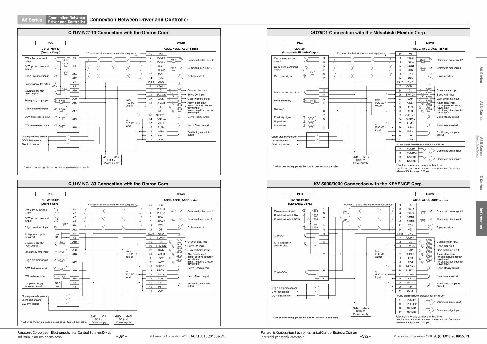
E SeriesIm
formation
A6 Series
A6N
SeriesA
6B Series
Special Order Product
– 391 –Panasonic Corporation Electromechanical Control Business Division
industrial.panasonic.com/ac/e/ © Panasonic Corporation 2018 AQCTB01E 201802-3YE – 392 –Panasonic Corporation Electromechanical Control Business Division
industrial.panasonic.com/ac/e/ © Panasonic Corporation 2018 AQCTB01E 201802-3YE
A6 Series Connection BetweenDriver and Controller Connection Between Driver and Controller
CCW limit sensorOrigin proximity sensor
CW limit sensor
CCW limit sensorOrigin proximity sensor
CW limit sensor
DC24 V Power supply
DC5 V Power supply
GND +24 VGND +5 V
CW pulse command output
CCW pulse command output
Origin line driver input
Power supply for output
Deviation counter reset output
Emergency stop input
Origin proximity input
CCW limit excess input
CW limit excess input
CW pulse command output
CCW pulse command output
Origin line driver input
Deviation counter reset output
24 V power supply for output
Emergency stop input
Origin proximity input
CCW limit over input
CW limit over input
5 V power supplyfor pulse output
CJ1W-NC113 Connection with the Omron Corp.
+VGND
CJ1W-NC133 Connection with the Omron Corp.
CJ1W-NC133(Omron Corp.)
* Process of shield wire varies with equipment.CJ1W-NC113(Omron Corp.)
1.6 kΩ
fromPLC I/O output
toPLC I/O input
A6
A8
A14A12A1A2A10
A20A16
A17
A19
A18
150 Ω
1.6 kΩ
1.6 kΩ
4.7 kΩ
4.7 kΩ
4.7 kΩ
4.7 kΩ
fromPLC I/O output
toPLC I/O input
A5A6A7A8A14A12A1A2A10
A20A16
A17
A19
A18A3A4
4.7 kΩ
4.7 kΩ
4.7 kΩ
4.7 kΩ
150 Ω
* Process of shield wire varies with equipment.
GND+V
+VGND
1.6 kΩ
* When connecting, please be sure to use twisted-pair cable.
* When connecting, please be sure to use twisted-pair cable.
Command pulse input 2
Counter clear inputServo-ON input
Servo-Ready output
Servo-Alarm output
Positioning complete output
Alarm clear input
Z-phase output
Command sign input 2
Gain switching input
Inhibit negative direction travel input
Inhibit positive direction travel input
A6SE, A6SG, A6SF series5034562324
13,257302927319835343736393841
FGPULS1PULS2SIGN1SIGN2OZ+OZ−GND
COM+CL
SRV-ONGAINA-CLRPOTNOT
S-RDY+S-RDY−ALM+ALM−INP+INP−
COM−
220 Ω
220 Ω
4.7 kΩ
4.7 kΩ
4.7 kΩ
4.7 kΩ
4.7 kΩ
4.7 kΩ
Driver
Command pulse input 2
Counter clear inputServo-ON input
Servo-Ready output
Servo-Alarm output
Positioning complete output
Alarm clear input
Z-phase output
Command sign input 2
Gain switching input
Inhibit negative direction travel input
Inhibit positive direction travel input
A6SE, A6SG, A6SF series5034562324
13,257302927319835343736393841
FGPULS1PULS2SIGN1SIGN2OZ+OZ−GND
COM+CL
SRV-ONGAINA-CLRPOTNOT
S-RDY+S-RDY−ALM+ALM−INP+INP−
COM−
220 Ω
220 Ω
4.7 kΩ
4.7 kΩ
4.7 kΩ
4.7 kΩ
4.7 kΩ
4.7 kΩ
DriverPLC
PLC
GND +24 VDC24 V
Power supply
CW limit sensorOrigin proximity sensor
CCW limit sensor
CW limit sensorOrigin proximity sensor
CCW limit sensor
CW pulse command output
CCW pulse command output
Zero point signal
Deviation counter clear
Common
Proximity signalUpper limitLower limit
Drive unit ready
Origin sensor inputX axis limit switch CWX axis limit switch CCW
X axis CW
X sxis deviation counter clear
X axis CCW
* Process of shield wire varies with equipment.
QD75D1 Connection with the Mitsubishi Electric Corp.
QD75D1(Mitsubishi Electric Corp.)
300 Ω
fromPLC I/O output
toPLC I/O input
151617189
10
13141211
67312
* Process of shield wire varies with equipment.
KV-5000/3000 Connection with the KEYENCE Corp.
KV-5000/3000(KEYENCE Corp.)
fromPLC I/O output
toPLC I/O input
134
141516
19
26
36
40
4.7 kΩ
4.7 kΩ
4.3 kΩ
4.7 kΩ
2 kΩ
2 kΩ
4.3 kΩ
4.3 kΩ
4.3 kΩ
1.2 kΩ
* When connecting, please be sure to use twisted-pair cable.
* When connecting, please be sure to use twisted-pair cable.
Command pulse input 1
Command sign input 1
Command pulse input 2
Counter clear inputServo-ON input
Servo-Ready output
Servo-Alarm output
Positioning complete output
Alarm clear input
Z-phase output
Command sign input 2
Gain switching input
Inhibit negative direction travel input
Inhibit positive direction travel input
A6SE, A6SG, A6SF series503456
2324
13,257
3029273198
35343736393841
FGPULS1PULS2SIGN1SIGN2OZ+OZ−GND
COM+CL
SRV-ONGAIN
A-CLRPOTNOT
S-RDY+S-RDY−ALM+ALM−INP+INP−
COM−
220 Ω
* Pulse train interface exclusive for line driver
Pulse train interface exclusive for line driver. Use this interface when you use pulse command frequency between 500 kpps and 8 Mpps
44454647
PULSH1PULSH2SIGNH1SIGNH2
220 Ω
4.7 kΩ
4.7 kΩ
4.7 kΩ
4.7 kΩ
4.7 kΩ
4.7 kΩ
Driver
GND +24 VDC24 V
Power supply
GND +24 VDC24 V
Power supply
PLC
PLC

E SeriesIm
formation
A6 Series
A6N
SeriesA
6B Series
Special Order Product
– 393 –Panasonic Corporation Electromechanical Control Business Division
industrial.panasonic.com/ac/e/ © Panasonic Corporation 2018 AQCTB01E 201802-3YE – 394 –Panasonic Corporation Electromechanical Control Business Division
industrial.panasonic.com/ac/e/ © Panasonic Corporation 2018 AQCTB01E 201802-3YE
A6 Series Connection BetweenDriver and Controller Replacing Old Model Servo Driver with MINAS A6 series
For easier replacement of old driver (MINAS X/XX/V series) with A6 series, use the interface conversion connector.
Driver
36-pin36-pin
Oldmodel
Hostcontroller
Driver
50-pin36-pin 50-pin
Currentmodel
36-pin → 50-pinConversion cable
DV0P4120DV0P4121
〈36-pin → 50-pin〉 〈50-pin → 50-pin〉
Hostcontroller
Oldmodel
Hostcontroller
Driver
50-pin50-pin 50-pin
50-pin
Currentmodel
Hostcontroller
Driver
50-pin
50-pin → 50-pinConversion cable
DV0P4130DV0P4131DV0P4132
Whenselectingthecable,refertothetablebelowbecausethepartnumberofthecableisspecifictothecontrolmode of the old model.
Old model Control mode Conversion cable part No. Conversion wiring table
X seriesXX series(36-pin)
Position/velocity control DV0P4120P.394
Torque control DV0P4121
V series(50-pin)
Position control DV0P4130P.395
Velocity control DV0P4131
Torque control DV0P4132 P.396
* For external dimensions, refer to P.290.
Conversion Wiring Table
Pin No. on Old Model
DV0P4120 DV0P4121
Pin No. on Current Model
Signal Name Symbol
Pin No. on Current Model
Signal Name Symbol
1 23 Z-phase output OZ+ 23 Z-phase output OZ+
2 24 Z-phase output OZ– 24 Z-phase output OZ–
3 13 Signal ground GND 13 Signal ground GND
4 19 Z-phase output CZ 19 Z-phase output CZ
5 4 Command pulse input 2 PULS2 4 Command pulse input 2 PULS2
6 3 Command pulse input 2 PULS1 3 Command pulse input 2 PULS1
7 6 Command pulse sign input 2 SIGN2 6 Command pulse sign input 2 SIGN2
8 5 Command pulse sign input 2 SIGN1 5 Command pulse sign input 2 SIGN1
9 33 Command pulse inhibition input INH 33 Command pulse inhibition input INH
10 26 Speed zero clamp input ZEROSPD 26 Speed zero clamp input ZEROSPD
11 7 Power supply for control signal (+) COM+ 7 Power supply for control signal (+) COM+
12 29 Servo-ON input SRV-ON 29 Servo-ON input SRV-ON
13 30 Deviation counter clear input CL 30 Deviation counter clear input CL
14 14 Speed command input SPR NC
15 15 Signal ground GND 15 Signal ground GND
16 43 Speed monitor output SP 43 Speed monitor output SP
17 25 Signal ground GND 25 Signal ground GND
18 50 Frame ground FG 50 Frame ground FG
19 21 A-phase output OA+ 21 A-phase output OA+
20 22 A-phase output OA- 22 A-phase output OA-
21 48 B-phase output OB+ 48 B-phase output OB+
22 49 B-phase output OB– 49 B-phase output OB–
23 NC NC
24 NC NC
25 39 Positioning complete output Speed arrival output
COIN+ AT-SPEED+ 39 Positioning complete output
Speed arrival output COIN+ AT-SPEED+
26 37 Servo-Alarm output ALM+ 37 Servo-Alarm output ALM+
27 35 Servo-Ready output S-RDY+ 35 Servo-Ready output S-RDY+
28
34 Positioning complete output (–) Speed arrival output (–)
COIN– AT-SPEED– 34 Positioning complete output (–)
Speed arrival output (–)COIN– AT-SPEED–
36 Servo-Alarm output (–) ALM– 36 Servo-Alarm output (–) ALM–
38 Servo-Ready output (–) S-RDY– 38 Servo-Ready output (–) S-RDY–
41 Power supply for control signal (–) COM– 41 Power supply for control signal (–) COM–
29 8 CW over-travel inhibit input CWL 8 CW over-travel inhibit input CWL
30 9 CCW over-travel inhibit input CCWL 9 CCW over-travel inhibit input CCWL
31 31 Alarm clear input A-CLR 31 Alarm clear input A-CLR
32 32 Control mode switching input C-MODE 32 Control mode switching input C-MODE
33 18 CW direction torque limit input CWTL 18 CW direction torque limit input CWTL
34 16 CCW direction torque limit input CCWTL 14 Torque command input TRQR
35 17 Signal ground GND 17 Signal ground GND
36 42 Torque monitor output IM 42 Torque monitor output IM
*“NC”isnoconnect.
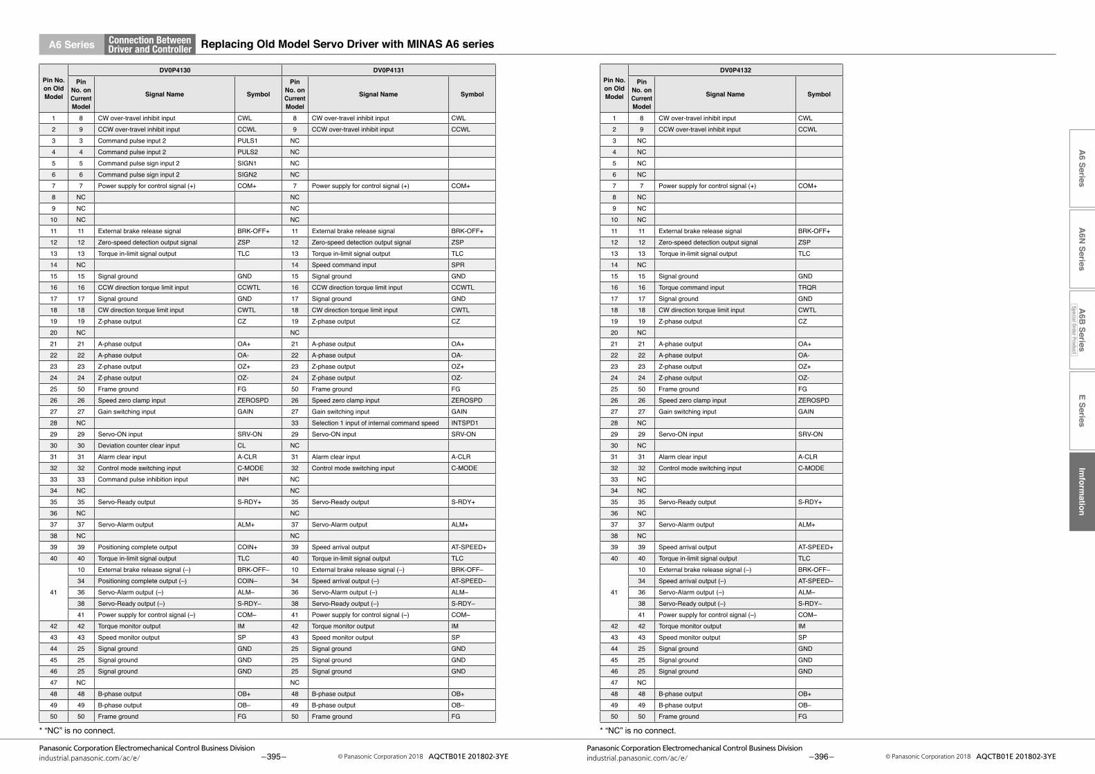
E SeriesIm
formation
A6 Series
A6N
SeriesA
6B Series
Special Order Product
– 395 –Panasonic Corporation Electromechanical Control Business Division
industrial.panasonic.com/ac/e/ © Panasonic Corporation 2018 AQCTB01E 201802-3YE – 396 –Panasonic Corporation Electromechanical Control Business Division
industrial.panasonic.com/ac/e/ © Panasonic Corporation 2018 AQCTB01E 201802-3YE
A6 Series Connection BetweenDriver and Controller Replacing Old Model Servo Driver with MINAS A6 series
Pin No. on Old Model
DV0P4130 DV0P4131
Pin No. on Current Model
Signal Name Symbol
Pin No. on Current Model
Signal Name Symbol
1 8 CW over-travel inhibit input CWL 8 CW over-travel inhibit input CWL2 9 CCW over-travel inhibit input CCWL 9 CCW over-travel inhibit input CCWL3 3 Command pulse input 2 PULS1 NC4 4 Command pulse input 2 PULS2 NC5 5 Command pulse sign input 2 SIGN1 NC6 6 Command pulse sign input 2 SIGN2 NC7 7 Power supply for control signal (+) COM+ 7 Power supply for control signal (+) COM+8 NC NC9 NC NC10 NC NC11 11 External brake release signal BRK-OFF+ 11 External brake release signal BRK-OFF+12 12 Zero-speed detection output signal ZSP 12 Zero-speed detection output signal ZSP13 13 Torque in-limit signal output TLC 13 Torque in-limit signal output TLC14 NC 14 Speed command input SPR15 15 Signal ground GND 15 Signal ground GND16 16 CCW direction torque limit input CCWTL 16 CCW direction torque limit input CCWTL17 17 Signal ground GND 17 Signal ground GND18 18 CW direction torque limit input CWTL 18 CW direction torque limit input CWTL19 19 Z-phase output CZ 19 Z-phase output CZ20 NC NC21 21 A-phase output OA+ 21 A-phase output OA+22 22 A-phase output OA- 22 A-phase output OA-23 23 Z-phase output OZ+ 23 Z-phase output OZ+24 24 Z-phase output OZ- 24 Z-phase output OZ-25 50 Frame ground FG 50 Frame ground FG26 26 Speed zero clamp input ZEROSPD 26 Speed zero clamp input ZEROSPD27 27 Gain switching input GAIN 27 Gain switching input GAIN28 NC 33 Selection 1 input of internal command speed INTSPD129 29 Servo-ON input SRV-ON 29 Servo-ON input SRV-ON30 30 Deviation counter clear input CL NC31 31 Alarm clear input A-CLR 31 Alarm clear input A-CLR32 32 Control mode switching input C-MODE 32 Control mode switching input C-MODE33 33 Command pulse inhibition input INH NC34 NC NC35 35 Servo-Ready output S-RDY+ 35 Servo-Ready output S-RDY+36 NC NC37 37 Servo-Alarm output ALM+ 37 Servo-Alarm output ALM+38 NC NC39 39 Positioning complete output COIN+ 39 Speed arrival output AT-SPEED+40 40 Torque in-limit signal output TLC 40 Torque in-limit signal output TLC
41
10 External brake release signal (–) BRK-OFF– 10 External brake release signal (–) BRK-OFF–34 Positioning complete output (–) COIN– 34 Speed arrival output (–) AT-SPEED–36 Servo-Alarm output (–) ALM– 36 Servo-Alarm output (–) ALM–38 Servo-Ready output (–) S-RDY– 38 Servo-Ready output (–) S-RDY–41 Power supply for control signal (–) COM– 41 Power supply for control signal (–) COM–
42 42 Torque monitor output IM 42 Torque monitor output IM43 43 Speed monitor output SP 43 Speed monitor output SP44 25 Signal ground GND 25 Signal ground GND45 25 Signal ground GND 25 Signal ground GND46 25 Signal ground GND 25 Signal ground GND47 NC NC48 48 B-phase output OB+ 48 B-phase output OB+49 49 B-phase output OB– 49 B-phase output OB–50 50 Frame ground FG 50 Frame ground FG
*“NC”isnoconnect.
Pin No. on Old Model
DV0P4132
Pin No. on Current Model
Signal Name Symbol
1 8 CW over-travel inhibit input CWL2 9 CCW over-travel inhibit input CCWL3 NC4 NC5 NC6 NC7 7 Power supply for control signal (+) COM+8 NC9 NC10 NC11 11 External brake release signal BRK-OFF+12 12 Zero-speed detection output signal ZSP13 13 Torque in-limit signal output TLC14 NC15 15 Signal ground GND16 16 Torque command input TRQR17 17 Signal ground GND18 18 CW direction torque limit input CWTL19 19 Z-phase output CZ20 NC21 21 A-phase output OA+22 22 A-phase output OA-23 23 Z-phase output OZ+24 24 Z-phase output OZ-25 50 Frame ground FG26 26 Speed zero clamp input ZEROSPD27 27 Gain switching input GAIN28 NC29 29 Servo-ON input SRV-ON30 NC31 31 Alarm clear input A-CLR32 32 Control mode switching input C-MODE33 NC34 NC35 35 Servo-Ready output S-RDY+36 NC37 37 Servo-Alarm output ALM+38 NC39 39 Speed arrival output AT-SPEED+40 40 Torque in-limit signal output TLC
41
10 External brake release signal (–) BRK-OFF–34 Speed arrival output (–) AT-SPEED–36 Servo-Alarm output (–) ALM–38 Servo-Ready output (–) S-RDY–41 Power supply for control signal (–) COM–
42 42 Torque monitor output IM43 43 Speed monitor output SP44 25 Signal ground GND45 25 Signal ground GND46 25 Signal ground GND47 NC48 48 B-phase output OB+49 49 B-phase output OB–50 50 Frame ground FG
*“NC”isnoconnect.

E SeriesIm
formation
A6 Series
A6N
SeriesA
6B Series
Special Order Product
– 397 –Panasonic Corporation Electromechanical Control Business Division
industrial.panasonic.com/ac/e/ © Panasonic Corporation 2018 AQCTB01E 201802-3YE – 398 –Panasonic Corporation Electromechanical Control Business Division
industrial.panasonic.com/ac/e/ © Panasonic Corporation 2018 AQCTB01E 201802-3YE
E Series Connection BetweenDriver and Controller Connection Between Driver and Controller
FP2-PP2 AFP2430(Panasonic devices SUNX)
FPG-C32T(Panasonic devices SUNX)
toPLC I/O input
220 Ω
220 Ω
4.7 kΩ
4.7 kΩ
4.7 kΩ
4.7 kΩ
4.7 kΩ
4.7 kΩ
2223242521
1414253879
10
11
12
13
PULS1PULS2SIGN1SIGN2
CZ
GNDCOM+
CLSRV-ONGAIN/TCA-CLRCCWLCWLALM
COIN
BRKOFF
WARN
COM−
toPLC I/O input
* Process of shield wire varies with equipment.
FGFG
+24 VGND
fromPLC I/O output
to PLC I/O input
A1B1A2B2A5B5
A6B6A7B7
A19B19A20B20
1.6 kΩ
220 Ω
fromPLC I/O output
Y0
Y1
X2COM+
Y2−
COMX3
X5
X6
○
○
5.6 kΩ
5.6 kΩ
3 kΩ
5.6 kΩ
* When connecting, please be sure to use twisted-pair cable.
* When connecting, please be sure to use twisted-pair cable.
FP2-PP2 AFP2430 Connection with the Panasonic devices SUNX.
FPG-C32T Connection with the Panasonic devices SUNX.
MINAS E series
220 Ω
220 Ω
4.7 kΩ
4.7 kΩ
4.7 kΩ
4.7 kΩ
4.7 kΩ
4.7 kΩ
2223242519201414253879
10
11
12
13
PULS1PULS2SIGN1SIGN2OZ+OZ−GND
COM+CL
SRV-ONGAIN/TCA-CLRCCWLCWLALM
COIN
BRKOFF
WARN
COM−
Warning output
Brake release output
CW pulse command input
Counter clear inputServo-ON input
Servo-Alarm output
Positioning complete output
Alarm clear input
Z-phase output
CCW pulse command input
CW over-travel prohibit input
CCW over-travel prohibit input
Driver
MINAS E series
Driver
Gain switching/Torque limit switching input
Warning output
Brake release output
CW pulse command input
Counter clear inputServo-ON input
Servo-Alarm output
Positioning complete output
Alarm clear input
Z-phase output
CCW pulse command input
CW over-travel prohibit input
CCW over-travel prohibit input
Gain switching/Torque limit switching input
DC24 V Power supply
GND +24 V
CW limit sensorOrigin proximity sensor
CCW limit sensor
CW limit sensorOrigin proximity sensor
CCW limit sensor
CW pulse command output
CCW pulse command output
Origin input
Deviation counter reset output
Origin proximity input
CCW limit excess input
CW limit excess input
CW pulse command output
CCW pulse command output
Origin input
Deviation counter reset output
External power supply input
Origin proximity input
GND +24 VDC24 V
Power supply
PLC
PLC
* Process of shield wire varies with equipment.2 kΩ
2 kΩ2 kΩ
2 kΩ
MINAS E series
PLC
FPG-PP12 AFPG432(Panasonic devices SUNX)
MINAS E series* Process of shield wire varies with equipment.
FGFG
+24 VGND
560 Ω
6.8 kΩfromPLC I/O output
to PLC I/O input
A1B1A2B2A4B3
A7B7B4A5
A19B19A20B20
* Process of shield wire varies with equipment.
220 Ω
220 Ω
4.7 kΩ
4.7 kΩ
4.7 kΩ
4.7 kΩ
4.7 kΩ
4.7 kΩ
fromPLC I/O output
toPLC I/O input
2223242519201414253879
10
11
12
13
PULS1PULS2SIGN1SIGN2OZ+OZ−GND
COM+CL
SRV-ONGAIN/TCA-CLRCCWLCWLALM
COIN
BRKOFF
WARN
COM−
toPLC I/O input
+24 VGND
FP7-AFP7PP02T/L(2-axes) AFP7PP04T/L(4-axes)(Panasonic devices SUNX)
3.6 kΩ
A1B1A2B2A3A4B3B5A7B7B4A5
A6
B6A20B20
A10B10A11B11A12A13B12B14A16B16B13A14
A15
B15A20B20
1/3-axes 2/4-axes
* When connecting, please be sure to use twisted-pair cable.
* When connecting, please be sure to use twisted-pair cable.
FP7-AFP7PP02T/L(2-axes) AFP7PP04T/L(4-axes) Connection with the Panasonic devices SUNX.
FPG-PP12 AFPG432 Connection with the Panasonic devices SUNX.
6.8 kΩ
560 Ω
3.9 kΩ
Warning output
Brake release output
CW limit sensorOrigin proximity sensor
CCW limit sensor
CW limit sensorOrigin proximity sensor
CCW limit sensor
GND +24 VDC24 V
Power supply
GND +24 VDC24 V
Power supply
CW pulse command input
Counter clear inputServo-ON input
Servo-Alarm output
Positioning complete output
Alarm clear input
Z-phase output
CCW pulse command input
CW over-travel prohibit input
CCW over-travel prohibit inputLimit excess +
Limit excess −
CW pulse command output
CCW pulse command output
Origin input (5 VDC)
Servo-ON outputDeviation counter reset output
External power supply input
Origin proximity input
CW pulse command output
CCW pulse command output
Origin input
Deviation counter reset output
External power supply input
Origin proximity input
Driver
DriverPLC
Gain switching/Torque limit switching input
220 Ω
220 Ω
4.7 kΩ
4.7 kΩ
4.7 kΩ
4.7 kΩ
4.7 kΩ
4.7 kΩ
2223242519201414253879
10
11
12
13
PULS1PULS2SIGN1SIGN2OZ+OZ−GND
COM+CL
SRV-ONGAIN/TCA-CLRCCWLCWLALM
COIN
BRKOFF
WARN
COM−
Warning output
Brake release output
CW pulse command input
Counter clear inputServo-ON input
Servo-Alarm output
Positioning complete output
Alarm clear input
Z-phase output
CCW pulse command input
CW over-travel prohibit input
CCW over-travel prohibit input
Gain switching/Torque limit switching input

E SeriesIm
formation
A6 Series
A6N
SeriesA
6B Series
Special Order Product
– 399 –Panasonic Corporation Electromechanical Control Business Division
industrial.panasonic.com/ac/e/ © Panasonic Corporation 2018 AQCTB01E 201802-3YE – 400 –Panasonic Corporation Electromechanical Control Business Division
industrial.panasonic.com/ac/e/ © Panasonic Corporation 2018 AQCTB01E 201802-3YE
E Series Connection BetweenDriver and Controller Connection Between Driver and Controller
PLC
CJ1W-NC113(Omron Corp.)
CJ1W-NC133(Omron Corp.)
+VGND
CWパルス指令出力
CCWパルス指令出力
原点ラインドライバ入力
出力用電源
偏差カウンタリセット出力
非常停止入力
原点近傍入力
CCWリミットオーバ入力
CWリミットオーバ入力
* Process of shield wire varies with equipment.
1.6 kΩ
fromPLC I/O output
A6
A8
A14A12A1A2
A10
A20A16
A17
A19
A18
150 Ω
1.6 kΩ
1.6 kΩ
4.7 kΩ
4.7 kΩ
4.7 kΩ
4.7 kΩ
fromPLC I/O output
A5A6A7A8
A14A12A1A2
A10
A20A16
A17
A19
A18A3A4
4.7 kΩ
4.7 kΩ
4.7 kΩ
4.7 kΩ
150 Ω
* Process of shield wire varies with equipment.
GND+V
+VGND
1.6 kΩ
toPLC I/O input
toPLC I/O input
* When connecting, please be sure to use twisted-pair cable.
* When connecting, please be sure to use twisted-pair cable.
CJ1W-NC113 Connection with the Omron Corp.
CJ1W-NC133 Connection with the Omron Corp.
CCW limit sensorOrigin proximity sensor
CW limit sensor
CCW limit sensorOrigin proximity sensor
CW limit sensor
DC24 V Power supply
DC5 V Power supply
GND +24 VGND +5 V
CW pulse command output
CCW pulse command output
Origin line driver input
Power supply for output
Deviation counter reset output
Emergency stop input
Origin proximity input
CCW limit excess input
CW limit excess input
CW pulse command output
CCW pulse command output
Origin line driver input
Deviation counter reset output
24 V power supply for output
Emergency stop input
Origin proximity input
CCW limit over input
CW limit over input
5 V power supplyfor pulse output
GND +24 VDC24 V
Power supply
MINAS E series
220 Ω
220 Ω
4.7 kΩ
4.7 kΩ
4.7 kΩ
4.7 kΩ
4.7 kΩ
4.7 kΩ
2223242519201414253879
10
11
12
13
PULS1PULS2SIGN1SIGN2OZ+OZ−GND
COM+CL
SRV-ONGAIN/TCA-CLRCCWLCWLALM
COIN
BRKOFF
WARN
COM−
Warning output
Brake release output
CW pulse command input
Counter clear inputServo-ON input
Servo-Alarm output
Positioning complete output
Alarm clear input
Z-phase output
CCW pulse command input
CW over-travel prohibit input
CCW over-travel prohibit input
Driver
Gain switching/Torque limit switching input
PLC
MINAS E series
MINAS E series
fromPLC I/O output
* Process of shield wire varies with equipment.
fromPLC I/O output
* Process of shield wire varies with equipment.
toPLC I/O input
toPLC I/O input
13a14a11a12a15a16a17a
10a9a
8b8a
1a2a
3a
4a7.4 kΩ
7.4 kΩ
7.4 kΩ
240 Ω
+VGND
4a3a6a5a19a20a17a
14a
1a1b
13a
9a
8a
7a7.4 kΩ
7.4 kΩ
7.4 kΩ
240 Ω
* When connecting, please be sure to use twisted-pair cable.
* When connecting, please be sure to use twisted-pair cable.
F3YP22-0P/F3YP24-0P/F3YP28-0P Connection with the Yokogawa Electric Corp.
F3NC32-ON/F3NC34-ON Connection with the Yokogawa Electric Corp.
DC24 V Power supply
GND +24 V
DC24 V Power supply
GND +24 V
CCW limit sensorOrigin proximity sensor
CW limit sensor
CCW limit sensorOrigin proximity sensor
CW limit sensor
Pulse output A
Pulse output B
Origin input
Deviation counter reset output
Contact point input COM
External power supply 24 VDC inputExternal power supply 24 VDC input (GND)
Negative direction limit input
Positive direction limit input
Encoder Z-phase input +Encoder Z-phase input –Pulse output GND
Pulse output A
Pulse output B
Origin input
Deviation counter reset output
Contact point input COM
External power supply 24 VDC input
Negative direction limit inputPositive direction limit input
Encoder Z-phase input +Encoder Z-phase input –
Pulse output GND
F3YP22-0P/F3YP24-0P/F3YP28-0P(Yokogawa Electric Corp.)
F3NC32-ON/F3NC34-ON(Yokogawa Electric Corp.)
220 Ω
220 Ω
4.7 kΩ
4.7 kΩ
4.7 kΩ
4.7 kΩ
4.7 kΩ
4.7 kΩ
2223242519201414253879
10
11
12
13
PULS1PULS2SIGN1SIGN2OZ+OZ−GND
COM+CL
SRV-ONGAIN/TCA-CLRCCWLCWLALM
COIN
BRKOFF
WARN
COM−
Warning output
Brake release output
CW pulse command input
Counter clear inputServo-ON input
Servo-Alarm output
Positioning complete output
Alarm clear input
Z-phase output
CCW pulse command input
CW over-travel prohibit input
CCW over-travel prohibit input
Gain switching/Torque limit switching input
220 Ω
220 Ω
4.7 kΩ
4.7 kΩ
4.7 kΩ
4.7 kΩ
4.7 kΩ
4.7 kΩ
2223242519201414253879
10
11
12
13
PULS1PULS2SIGN1SIGN2OZ+OZ−GND
COM+CL
SRV-ONGAIN/TCA-CLRCCWLCWLALM
COIN
BRKOFF
WARN
COM−
Warning output
Brake release output
CW pulse command input
Counter clear inputServo-ON input
Servo-Alarm output
Positioning complete output
Alarm clear input
Z-phase output
CCW pulse command input
CW over-travel prohibit input
CCW over-travel prohibit input
Gain switching/Torque limit switching input
Driver
Driver
PLC
PLC

E SeriesIm
formation
A6 Series
A6N
SeriesA
6B Series
Special Order Product
– 401 –Panasonic Corporation Electromechanical Control Business Division
industrial.panasonic.com/ac/e/ © Panasonic Corporation 2018 AQCTB01E 201802-3YE – 402 –Panasonic Corporation Electromechanical Control Business Division
industrial.panasonic.com/ac/e/ © Panasonic Corporation 2018 AQCTB01E 201802-3YE
E Series Connection BetweenDriver and Controller Connection Between Driver and Controller Index
(Alphabetical Order)
DV0PM20102 Connector kit: RS485, 232 291DV0PM20103 Connector kit: Safety 291DV0PM24581 Connector kit for motor/encoder connection 296DV0PM24582 Connector kit for motor/encoder connection 296DV0PM24583 Connector kit for motor/encoder connection 297DV0PM24584 Connector kit for motor/encoder connection 298DV0PM24585 Connector kit for motor/encoder connection 297DV0PM24586 Connector kit for motor/encoder connection 298DV0PM24587 Connector kit for motor/encoder connection 297DV0PM24588 Connector kit for motor/encoder connection 298DV0PM24589 Connector kit for motor/encoder connection 297DV0PM24590 Connector kit for motor/encoder connection 298DV0PM24610 Daisy Chain 307
MADLPart No. Title Page
MADLN01NE A6NE series driver: A-frame 319,320MADLN01SE A6SE series driver: A-frame 35,36MADLN01SG A6SG series driver: A-frame 35,36MADLN05NE A6NE series driver: A-frame 319,320MADLN05SE A6SE series driver: A-frame 35,36MADLN05SG A6SG series driver: A-frame 35,36MADLN11NE A6NE series driver: A-frame 319,320MADLN11SE A6SE series driver: A-frame 35,36MADLN11SG A6SG series driver: A-frame 35,36MADLN15NE A6NE series driver: A-frame 319,320MADLN15SE A6SE series driver: A-frame 35,36MADLN15SG A6SG series driver: A-frame 35,36MADLT01NF A6NF series driver: A-frame 317,318MADLT01SF A6SF series driver: A-frame 33,34MADLT05NF A6NF series driver: A-frame 317,318MADLT05SF A6SF series driver: A-frame 33,34MADLT11NF A6NF series driver: A-frame 317,318MADLT11SF A6SF series driver: A-frame 33,34MADLT15NF A6NF series driver: A-frame 317,318MADLT15SF A6SF series driver: A-frame 33,34
MBDLPart No. Title Page
MBDLN21NE A6NE series driver: B-frame 319,320MBDLN21SE A6SE series driver: B-frame 35,36MBDLN21SG A6SG series driver: B-frame 35,36MBDLN25NE A6NE series driver: B-frame 319,320MBDLN25SE A6SE series driver: B-frame 35,36MBDLN25SG A6SG series driver: B-frame 35,36MBDLT21NF A6NF series driver: B-frame 317,318MBDLT21SF A6SF series driver: B-frame 33,34MBDLT25NF A6NF series driver: B-frame 317,318MBDLT25SF A6SF series driver: B-frame 33,34
MCDLPart No. Title Page
MCDLN31NE A6NE series driver: C-frame 319,320MCDLN31SE A6SE series driver: C-frame 35,36MCDLN31SG A6SG series driver: C-frame 35,36MCDLN35NE A6NE series driver: C-frame 319,320MCDLN35SE A6SE series driver: C-frame 35,36MCDLN35SG A6SG series driver: C-frame 35,36MCDLT31NF A6NF series driver: C-frame 317,318MCDLT31SF A6SF series driver: C-frame 33,34MCDLT35NF A6NF series driver: C-frame 317,318MCDLT35SF A6SF series driver: C-frame 33,34
MDDLPart No. Title Page
MDDLN45NE A6NE series driver: D-frame 319,320MDDLN45SE A6SE series driver: D-frame 35,36MDDLN45SG A6SG series driver: D-frame 35,36MDDLN55NE A6NE series driver: D-frame 319,320MDDLN55SE A6SE series driver: D-frame 35,36MDDLN55SG A6SG series driver: D-frame 35,36MDDLT45NF A6NF series driver: D-frame 317,318
DV0PPart No. Title Page
DV0PPart No. Title Page
DV0P0770 Connector kit for external peripheral equipment 324,356DV0P0800 Interface cable 324,357DV0P1450 Surge absorber (3-phase) 367,370DV0P1460 Ferrite core 368DV0P1960 Communication cable 357DV0P220 Reactor 304,359DV0P221 Reactor 304DV0P222 Reactor 304DV0P223 Reactor 304DV0P224 Reactor 304DV0P225 Reactor 304DV0P227 Reactor 304,359DV0P228 Reactor 304,359DV0P2870 Connector kit for power supply connection 355DV0P2890 External regenerative resistor 358DV0P2891 External regenerative resistor 358DV0P2990 Battery for absolute encoder 302DV0P3410 Noisefilter 366DV0P3670 Connector kit for motor/encoder connection 355DV0P37300 Cable set (3 m) 354DV0P3811 DIN rail mounting unit 358DV0P39200 Cable set (5 m) 354DV0P4120 Interface conversion cable 393DV0P4121 Interface conversion cable 393DV0P4130 Interface conversion cable 393DV0P4131 Interface conversion cable 393DV0P4132 Interface conversion cable 393DV0P4160 Noisefilter 370DV0P4170 Noisefilter 366DV0P4190 Surge absorber (Single phase) 367,370DV0P4220 Noise Filter 366DV0P4280 Externalregenerativeresistor:50Ω25W 305DV0P4281 Externalregenerativeresistor:100Ω25W 305DV0P4282 Externalregenerativeresistor:25Ω50W 305DV0P4283 Externalregenerativeresistor:50Ω50W 305DV0P4284 Externalregenerativeresistor:30Ω100W 305DV0P4285 Externalregenerativeresistor:20Ω130W 305DV0P4290 Connector kit for motor/encoder connection 294DV0P4310 Connector kit for motor/encoder connection 299DV0P4320 Connector kit for motor/encoder connection 300DV0P4330 Connector kit for motor/encoder connection 299DV0P4340 Connector kit for motor/encoder connection 300DV0P4350 Interface connector 292DV0P4360 Interface cable 290DV0P4420 Console 357DV0P4430 Battery box 302
DV0P4460 Setupsupportsoftware“PANATERM”for MINAS series AC servo motor & driver 352
DV0PM20010 Connector Kit: Encoder 292DV0PM20026 Connector kit: External scale 292
DV0PM20032 Connector for power supply input connection (A-frame to D-frame (Single row type)) 293
DV0PM20033 Connector for power supply input connection (A-frame to D-frame (Double row type)) 293
DV0PM20034 Connector for motor connection (A-frame to D-frame) 294
DV0PM20035 Connector kit for motor/encoder connection 295DV0PM20036 Connector kit for motor/encoder connection 299DV0PM20037 Connector kit for motor/encoder connection 300DV0PM20038 Connector kit for motor/encoder connection 299DV0PM20039 Connector kit for motor/encoder connection 300DV0PM20040 Connector kit for motor/brake connection 301DV0PM20042 Noisefilter 366DV0PM20043 Noisefilter 366
DV0PM20044 Connector for power supply input connection(E-frame) 293
DV0PM20045 Connector for regenerative resistor(E-frame 200 V/400 V common 293
DV0PM20046 Connector for motor connection(E-frame 200 V/400 V common) 294
DV0PM20047 Reactor 304DV0PM20094 Safety by-pass plug 291DV0PM20100 Mounting bracket for A-frame and B-frame 303DV0PM20101 Mounting bracket for C-frame and D-frame 303
QD75D1(Mitsubishi Electric Corp.) * Process of shield wire varies with equipment.
300 Ω
fromPLC I/O output
15161718910
13141211
67312
4.7 kΩ
4.7 kΩ
4.7 kΩ
4.7 kΩ
toPLC I/O input
* When connecting, please be sure to use twisted-pair cable.
QD75D1 Connection with the Mitsubishi Electric Corp.
220 Ω
220 Ω
4.7 kΩ
4.7 kΩ
4.7 kΩ
4.7 kΩ
4.7 kΩ
4.7 kΩ
2223242519201414253879
10
11
12
13
PULS1PULS2SIGN1SIGN2OZ+OZ−GND
COM+CL
SRV-ONGAIN/TCA-CLRCCWLCWLALM
COIN
BRKOFF
WARN
COM−
Warning output
Brake release output
CW pulse command input
Counter clear inputServo-ON input
Servo-Alarm output
Positioning complete output
Alarm clear input
Z-phase output
CCW pulse command input
CW over-travel prohibit input
CCW over-travel prohibit input
Gain switching/Torque limit switching input
MINAS E series
Driver
CW limit sensorOrigin proximity sensor
CCW limit sensor
CW pulse command output
CCW pulse command output
Zero point signal
Deviation counter clear
Common
Proximity signalUpper limitLower limit
Drive unit ready
GND +24 VDC24 V
Power supply
PLC
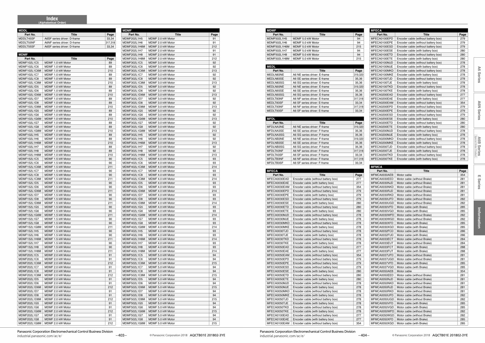
E SeriesIm
formation
A6 Series
A6N
SeriesA
6B Series
Special Order Product
Index(Alphabetical Order)
– 403 –Panasonic Corporation Electromechanical Control Business Division
industrial.panasonic.com/ac/e/ © Panasonic Corporation 2018 AQCTB01E 201802-3YE – 404 –Panasonic Corporation Electromechanical Control Business Division
industrial.panasonic.com/ac/e/ © Panasonic Corporation 2018 AQCTB01E 201802-3YE
MDMFPart No. Title Page
MDDLPart No. Title Page
MFECA0100EPD Encoder cable (without battery box) 279MFECA0100EPE Encoder cable (without battery box) 279MFECA0100ESD Encoder cable (without battery box) 279MFECA0100ESE Encoder cable (with battery box) 280MFECA0100ETD Encoder cable (without battery box) 280MFECA0100ETE Encoder cable (with battery box) 280MFECA0100MJD Encoder cable (without battery box) 278MFECA0100MJE Encoder cable (with battery box) 278MFECA0100MKD Encoder cable (without battery box) 278MFECA0100MKE Encoder cable (with battery box) 278MFECA0100TJD Encoder cable (without battery box) 278MFECA0100TJE Encoder cable (with battery box) 278MFECA0100TKD Encoder cable (without battery box) 278MFECA0100TKE Encoder cable (with battery box) 278MFECA0200EAD Encoder cable (without battery box) 277MFECA0200EAE Encoder cable (with battery box) 277MFECA0200EAM Encoder cable (without battery box) 354MFECA0200EPD Encoder cable (without battery box) 279MFECA0200EPE Encoder cable (without battery box) 279MFECA0200ESD Encoder cable (without battery box) 279MFECA0200ESE Encoder cable (with battery box) 280MFECA0200ETD Encoder cable (without battery box) 280MFECA0200ETE Encoder cable (with battery box) 280MFECA0200MJD Encoder cable (without battery box) 278MFECA0200MJE Encoder cable (with battery box) 278MFECA0200MKD Encoder cable (without battery box) 278MFECA0200MKE Encoder cable (with battery box) 278MFECA0200TJD Encoder cable (without battery box) 278MFECA0200TJE Encoder cable (with battery box) 278MFECA0200TKD Encoder cable (without battery box) 278MFECA0200TKE Encoder cable (with battery box) 278
MFMCAPart No. Title Page
MFMCA0030AEB Motor cable 354MFMCA0030EED Motor cable (without Brake) 281MFMCA0030NJD Motor cable (without Brake) 281MFMCA0030NKD Motor cable (without Brake) 281MFMCA0030RJD Motor cable (without Brake) 281MFMCA0030RKD Motor cable (without Brake) 281MFMCA0030UFD Motor cable (without Brake) 282MFMCA0030UGD Motor cable (without Brake) 282MFMCA0030VFD Motor cable (with Brake) 285MFMCA0030VGD Motor cable (with Brake) 285MFMCA0030WFD Motor cable (without Brake) 282MFMCA0030WGD Motor cable (without Brake) 282MFMCA0030XFD Motor cable (with Brake) 285MFMCA0030XGD Motor cable (with Brake) 285MFMCA0032FCD Motor cable (with Brake) 286MFMCA0032FUD Motor cable (with Brake) 286MFMCA0033ECT Motor cable (without Brake) 284MFMCA0033EUT Motor cable (without Brake) 284MFMCA0033FCT Motor cable (with Brake) 288MFMCA0033FUT Motor cable (with Brake) 288MFMCA0037UFD Motor cable (without Brake) 281MFMCA0037UGD Motor cable (without Brake) 281MFMCA0037VFD Motor cable (with Brake) 285MFMCA0037VGD Motor cable (with Brake) 285MFMCA0050AEB Motor cable 354MFMCA0050EED Motor cable (without Brake) 281MFMCA0050NJD Motor cable (without Brake) 281MFMCA0050NKD Motor cable (without Brake) 281MFMCA0050RJD Motor cable (without Brake) 281MFMCA0050RKD Motor cable (without Brake) 281MFMCA0050UFD Motor cable (without Brake) 282MFMCA0050UGD Motor cable (without Brake) 282MFMCA0050VFD Motor cable (with Brake) 285MFMCA0050VGD Motor cable (with Brake) 285MFMCA0050WFD Motor cable (without Brake) 282MFMCA0050WGD Motor cable (without Brake) 282MFMCA0050XFD Motor cable (with Brake) 285MFMCA0050XGD Motor cable (with Brake) 285
MDMF502L1H5 MDMF 5.0 kW Motor 94MDMF502L1H6 MDMF 5.0 kW Motor 94MDMF502L1H6M MDMF 5.0 kW Motor 215MDMF502L1H7 MDMF 5.0 kW Motor 94MDMF502L1H8 MDMF 5.0 kW Motor 94MDMF502L1H8M MDMF 5.0 kW Motor 215
MEDLPart No. Title Page
MEDLN83NE A6 NE series driver: E-frame 319,320MEDLN83SE A6 SE series driver: E-frame 35,36MEDLN83SG A6 SG series driver: E-frame 35,36MEDLN93NE A6 NE series driver: E-frame 319,320MEDLN93SE A6 SE series driver: E-frame 35,36MEDLN93SG A6 SG series driver: E-frame 35,36MEDLT83NF A6 NF series driver: E-frame 317,318MEDLT83SF A6 SF series driver: E-frame 33,34MEDLT93NF A6 NF series driver: E-frame 317,318MEDLT93SF A6 SF series driver: E-frame 33,34
MFDLPart No. Title Page
MFDLNA3NE A6 NE series driver: F-frame 319,320MFDLNA3SE A6 SE series driver: F-frame 35,36MFDLNA3SG A6 SG series driver: F-frame 35,36MFDLNB3NE A6 NE series driver: F-frame 319,320MFDLNB3SE A6 SE series driver: F-frame 35,36MFDLNB3SG A6 SG series driver: F-frame 35,36MFDLTA3NF A6 NF series driver: F-frame 317,318MFDLTA3SF A6 SF series driver: F-frame 33,34MFDLTB3NF A6 NF series driver: F-frame 317,318MFDLTB3SF A6 SF series driver: F-frame 33,34
MFECAPart No. Title Page
MFECA0030EAD Encoder cable (without battery box) 277MFECA0030EAE Encoder cable (with battery box) 277MFECA0030EAM Encoder cable (without battery box) 354MFECA0030EPD Encoder cable (without battery box) 279MFECA0030EPE Encoder cable (with battery box) 279MFECA0030ESD Encoder cable (without battery box) 279MFECA0030ESE Encoder cable (with battery box) 280MFECA0030ETD Encoder cable (without battery box) 280MFECA0030ETE Encoder cable (with battery box) 280MFECA0030MJD Encoder cable (without battery box) 278MFECA0030MJE Encoder cable (with battery box) 278MFECA0030MKD Encoder cable (without battery box) 278MFECA0030MKE Encoder cable (with battery box) 278MFECA0030TJD Encoder cable (without battery box) 278MFECA0030TJE Encoder cable (with battery box) 278MFECA0030TKD Encoder cable (without battery box) 278MFECA0030TKE Encoder cable (with battery box) 278MFECA0050EAD Encoder cable (without battery box) 277MFECA0050EAE Encoder cable (with battery box) 277MFECA0050EAM Encoder cable (without battery box) 354MFECA0050EPD Encoder cable (without battery box) 279MFECA0050EPE Encoder cable (without battery box) 279MFECA0050ESD Encoder cable (without battery box) 279MFECA0050ESE Encoder cable (with battery box) 280MFECA0050ETD Encoder cable (without battery box) 280MFECA0050ETE Encoder cable (with battery box) 280MFECA0050MJD Encoder cable (without battery box) 278MFECA0050MJE Encoder cable (with battery box) 278MFECA0050MKD Encoder cable (without battery box) 278MFECA0050MKE Encoder cable (with battery box) 278MFECA0050TJD Encoder cable (without battery box) 278MFECA0050TJE Encoder cable (with battery box) 278MFECA0050TKD Encoder cable (without battery box) 278MFECA0050TKE Encoder cable (with battery box) 278MFECA0100EAD Encoder cable (without battery box) 277MFECA0100EAE Encoder cable (with battery box) 277MFECA0100EAM Encoder cable (without battery box) 354
MDMF202L1H5 MDMF 2.0 kW Motor 91MDMF202L1H6 MDMF 2.0 kW Motor 91MDMF202L1H6M MDMF 2.0 kW Motor 212MDMF202L1H7 MDMF 2.0 kW Motor 91MDMF202L1H8 MDMF 2.0 kW Motor 91MDMF202L1H8M MDMF 2.0 kW Motor 212MDMF302L1C5 MDMF 3.0 kW Motor 92MDMF302L1C6 MDMF 3.0 kW Motor 92MDMF302L1C6M MDMF 3.0 kW Motor 213MDMF302L1C7 MDMF 3.0 kW Motor 92MDMF302L1C8 MDMF 3.0 kW Motor 92MDMF302L1C8M MDMF 3.0 kW Motor 213MDMF302L1D5 MDMF 3.0 kW Motor 92MDMF302L1D6 MDMF 3.0 kW Motor 92MDMF302L1D6M MDMF 3.0 kW Motor 213MDMF302L1D7 MDMF 3.0 kW Motor 92MDMF302L1D8 MDMF 3.0 kW Motor 92MDMF302L1D8M MDMF 3.0 kW Motor 213MDMF302L1G5 MDMF 3.0 kW Motor 92MDMF302L1G6 MDMF 3.0 kW Motor 92MDMF302L1G6M MDMF 3.0 kW Motor 213MDMF302L1G7 MDMF 3.0 kW Motor 92MDMF302L1G8 MDMF 3.0 kW Motor 92MDMF302L1G8M MDMF 3.0 kW Motor 213MDMF302L1H5 MDMF 3.0 kW Motor 92MDMF302L1H6 MDMF 3.0 kW Motor 92MDMF302L1H6M MDMF 3.0 kW Motor 213MDMF302L1H7 MDMF 3.0 kW Motor 92MDMF302L1H8 MDMF 3.0 kW Motor 92MDMF302L1H8M MDMF 3.0 kW Motor 213MDMF402L1C5 MDMF 4.0 kW Motor 93MDMF402L1C6 MDMF 4.0 kW Motor 93MDMF402L1C6M MDMF 4.0 kW Motor 214MDMF402L1C7 MDMF 4.0 kW Motor 93MDMF402L1C8 MDMF 4.0 kW Motor 93MDMF402L1C8M MDMF 4.0 kW Motor 214MDMF402L1D5 MDMF 4.0 kW Motor 93MDMF402L1D6 MDMF 4.0 kW Motor 93MDMF402L1D6M MDMF 4.0 kW Motor 214MDMF402L1D7 MDMF 4.0 kW Motor 93MDMF402L1D8 MDMF 4.0 kW Motor 93MDMF402L1D8M MDMF 4.0 kW Motor 214MDMF402L1G5 MDMF 4.0 kW Motor 93MDMF402L1G6 MDMF 4.0 kW Motor 93MDMF402L1G6M MDMF 4.0 kW Motor 214MDMF402L1G7 MDMF 4.0 kW Motor 93MDMF402L1G8 MDMF 4.0 kW Motor 93MDMF402L1G8M MDMF 4.0 kW Motor 214MDMF402L1H5 MDMF 4.0 kW Motor 93MDMF402L1H6 MDMF 4.0 kW Motor 93MDMF402L1H6M MDMF 4.0 kW Motor 214MDMF402L1H7 MDMF 4.0 kW Motor 93MDMF402L1H8 MDMF 4.0 kW Motor 93MDMF402L1H8M MDMF 4.0 kW Motor 214MDMF502L1C5 MDMF 5.0 kW Motor 94MDMF502L1C6 MDMF 5.0 kW Motor 94MDMF502L1C6M MDMF 5.0 kW Motor 215MDMF502L1C7 MDMF 5.0 kW Motor 94MDMF502L1C8 MDMF 5.0 kW Motor 94MDMF502L1C8M MDMF 5.0 kW Motor 215MDMF502L1D5 MDMF 5.0 kW Motor 94MDMF502L1D6 MDMF 5.0 kW Motor 94MDMF502L1D6M MDMF 5.0 kW Motor 215MDMF502L1D7 MDMF 5.0 kW Motor 94MDMF502L1D8 MDMF 5.0 kW Motor 94MDMF502L1D8M MDMF 5.0 kW Motor 215MDMF502L1G5 MDMF 5.0 kW Motor 94MDMF502L1G6 MDMF 5.0 kW Motor 94MDMF502L1G6M MDMF 5.0 kW Motor 215MDMF502L1G7 MDMF 5.0 kW Motor 94MDMF502L1G8 MDMF 5.0 kW Motor 94MDMF502L1G8M MDMF 5.0 kW Motor 215
MDDLT45SF A6SF series driver: D-frame 33,34MDDLT55NF A6NF series driver: D-frame 317,318MDDLT55SF A6SF series driver: D-frame 33,34
MDMFPart No. Title Page
MDMF102L1C5 MDMF 1.0 kW Motor 89MDMF102L1C6 MDMF 1.0 kW Motor 89MDMF102L1C6M MDMF 1.0 kW Motor 210MDMF102L1C7 MDMF 1.0 kW Motor 89MDMF102L1C8 MDMF 1.0 kW Motor 89MDMF102L1C8M MDMF 1.0 kW Motor 210MDMF102L1D5 MDMF 1.0 kW Motor 89MDMF102L1D6 MDMF 1.0 kW Motor 89MDMF102L1D6M MDMF 1.0 kW Motor 210MDMF102L1D7 MDMF 1.0 kW Motor 89MDMF102L1D8 MDMF 1.0 kW Motor 89MDMF102L1D8M MDMF 1.0 kW Motor 210MDMF102L1G5 MDMF 1.0 kW Motor 89MDMF102L1G6 MDMF 1.0 kW Motor 89MDMF102L1G6M MDMF 1.0 kW Motor 210MDMF102L1G7 MDMF 1.0 kW Motor 89MDMF102L1G8 MDMF 1.0 kW Motor 89MDMF102L1G8M MDMF 1.0 kW Motor 210MDMF102L1H5 MDMF 1.0 kW Motor 89MDMF102L1H6 MDMF 1.0 kW Motor 89MDMF102L1H6M MDMF 1.0 kW Motor 210MDMF102L1H7 MDMF 1.0 kW Motor 89MDMF102L1H8 MDMF 1.0 kW Motor 89MDMF102L1H8M MDMF 1.0 kW Motor 210MDMF152L1C5 MDMF 1.5 kW Motor 90MDMF152L1C6 MDMF 1.5 kW Motor 90MDMF152L1C6M MDMF 1.5 kW Motor 211MDMF152L1C7 MDMF 1.5 kW Motor 90MDMF152L1C8 MDMF 1.5 kW Motor 90MDMF152L1C8M MDMF 1.5 kW Motor 211MDMF152L1D5 MDMF 1.5 kW Motor 90MDMF152L1D6 MDMF 1.5 kW Motor 90MDMF152L1D6M MDMF 1.5 kW Motor 211MDMF152L1D7 MDMF 1.5 kW Motor 90MDMF152L1D8 MDMF 1.5 kW Motor 90MDMF152L1D8M MDMF 1.5 kW Motor 211MDMF152L1G5 MDMF 1.5 kW Motor 90MDMF152L1G6 MDMF 1.5 kW Motor 90MDMF152L1G6M MDMF 1.5 kW Motor 211MDMF152L1G7 MDMF 1.5 kW Motor 90MDMF152L1G8 MDMF 1.5 kW Motor 90MDMF152L1G8M MDMF 1.5 kW Motor 211MDMF152L1H5 MDMF 1.5 kW Motor 90MDMF152L1H6 MDMF 1.5 kW Motor 90MDMF152L1H6M MDMF 1.5 kW Motor 211MDMF152L1H7 MDMF 1.5 kW Motor 90MDMF152L1H8 MDMF 1.5 kW Motor 90MDMF152L1H8M MDMF 1.5 kW Motor 211MDMF202L1C5 MDMF 2.0 kW Motor 91MDMF202L1C6 MDMF 2.0 kW Motor 91MDMF202L1C6M MDMF 2.0 kW Motor 212MDMF202L1C7 MDMF 2.0 kW Motor 91MDMF202L1C8 MDMF 2.0 kW Motor 91MDMF202L1C8M MDMF 2.0 kW Motor 212MDMF202L1D5 MDMF 2.0 kW Motor 91MDMF202L1D6 MDMF 2.0 kW Motor 91MDMF202L1D6M MDMF 2.0 kW Motor 212MDMF202L1D7 MDMF 2.0 kW Motor 91MDMF202L1D8 MDMF 2.0 kW Motor 91MDMF202L1D8M MDMF 2.0 kW Motor 212MDMF202L1G5 MDMF 2.0 kW Motor 91MDMF202L1G6 MDMF 2.0 kW Motor 91MDMF202L1G6M MDMF 2.0 kW Motor 212MDMF202L1G7 MDMF 2.0 kW Motor 91MDMF202L1G8 MDMF 2.0 kW Motor 91MDMF202L1G8M MDMF 2.0 kW Motor 212
MFECAPart No. Title Page
MDMFPart No. Title Page
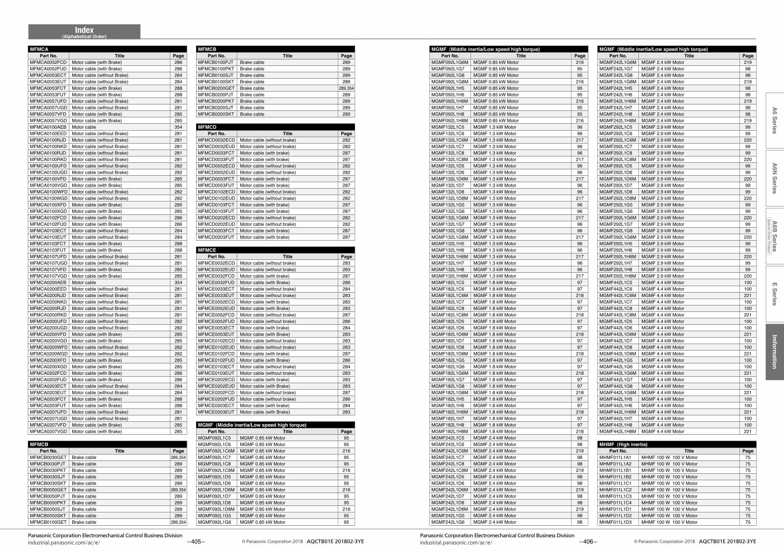
E SeriesIm
formation
A6 Series
A6N
SeriesA
6B Series
Special Order Product
Index(Alphabetical Order)
– 405 –Panasonic Corporation Electromechanical Control Business Division
industrial.panasonic.com/ac/e/ © Panasonic Corporation 2018 AQCTB01E 201802-3YE – 406 –Panasonic Corporation Electromechanical Control Business Division
industrial.panasonic.com/ac/e/ © Panasonic Corporation 2018 AQCTB01E 201802-3YE
MGMF (Middle inertia/Low speed high torque)Part No. Title Page
MGMF (Middle inertia/Low speed high torque)Part No. Title Page
MFMCBPart No. Title Page
MFMCAPart No. Title Page
MGMF242L1G6M MGMF 2.4 kW Motor 219MGMF242L1G7 MGMF 2.4 kW Motor 98MGMF242L1G8 MGMF 2.4 kW Motor 98MGMF242L1G8M MGMF 2.4 kW Motor 219MGMF242L1H5 MGMF 2.4 kW Motor 98MGMF242L1H6 MGMF 2.4 kW Motor 98MGMF242L1H6M MGMF 2.4 kW Motor 219MGMF242L1H7 MGMF 2.4 kW Motor 98MGMF242L1H8 MGMF 2.4 kW Motor 98MGMF242L1H8M MGMF 2.4 kW Motor 219MGMF292L1C5 MGMF 2.9 kW Motor 99MGMF292L1C6 MGMF 2.9 kW Motor 99MGMF292L1C6M MGMF 2.9 kW Motor 220MGMF292L1C7 MGMF 2.9 kW Motor 99MGMF292L1C8 MGMF 2.9 kW Motor 99MGMF292L1C8M MGMF 2.9 kW Motor 220MGMF292L1D5 MGMF 2.9 kW Motor 99MGMF292L1D6 MGMF 2.9 kW Motor 99MGMF292L1D6M MGMF 2.9 kW Motor 220MGMF292L1D7 MGMF 2.9 kW Motor 99MGMF292L1D8 MGMF 2.9 kW Motor 99MGMF292L1D8M MGMF 2.9 kW Motor 220MGMF292L1G5 MGMF 2.9 kW Motor 99MGMF292L1G6 MGMF 2.9 kW Motor 99MGMF292L1G6M MGMF 2.9 kW Motor 220MGMF292L1G7 MGMF 2.9 kW Motor 99MGMF292L1G8 MGMF 2.9 kW Motor 99MGMF292L1G8M MGMF 2.9 kW Motor 220MGMF292L1H5 MGMF 2.9 kW Motor 99MGMF292L1H6 MGMF 2.9 kW Motor 99MGMF292L1H6M MGMF 2.9 kW Motor 220MGMF292L1H7 MGMF 2.9 kW Motor 99MGMF292L1H8 MGMF 2.9 kW Motor 99MGMF292L1H8M MGMF 2.9 kW Motor 220MGMF442L1C5 MGMF 4.4 kW Motor 100MGMF442L1C6 MGMF 4.4 kW Motor 100MGMF442L1C6M MGMF 4.4 kW Motor 221MGMF442L1C7 MGMF 4.4 kW Motor 100MGMF442L1C8 MGMF 4.4 kW Motor 100MGMF442L1C8M MGMF 4.4 kW Motor 221MGMF442L1D5 MGMF 4.4 kW Motor 100MGMF442L1D6 MGMF 4.4 kW Motor 100MGMF442L1D6M MGMF 4.4 kW Motor 221MGMF442L1D7 MGMF 4.4 kW Motor 100MGMF442L1D8 MGMF 4.4 kW Motor 100MGMF442L1D8M MGMF 4.4 kW Motor 221MGMF442L1G5 MGMF 4.4 kW Motor 100MGMF442L1G6 MGMF 4.4 kW Motor 100MGMF442L1G6M MGMF 4.4 kW Motor 221MGMF442L1G7 MGMF 4.4 kW Motor 100MGMF442L1G8 MGMF 4.4 kW Motor 100MGMF442L1G8M MGMF 4.4 kW Motor 221MGMF442L1H5 MGMF 4.4 kW Motor 100MGMF442L1H6 MGMF 4.4 kW Motor 100MGMF442L1H6M MGMF 4.4 kW Motor 221MGMF442L1H7 MGMF 4.4 kW Motor 100MGMF442L1H8 MGMF 4.4 kW Motor 100MGMF442L1H8M MGMF 4.4 kW Motor 221
MHMF (High inertia)Part No. Title Page
MHMF011L1A1 MHMF 100 W 100 V Motor 75MHMF011L1A2 MHMF 100 W 100 V Motor 75MHMF011L1B1 MHMF 100 W 100 V Motor 75MHMF011L1B2 MHMF 100 W 100 V Motor 75MHMF011L1C1 MHMF 100 W 100 V Motor 75MHMF011L1C2 MHMF 100 W 100 V Motor 75MHMF011L1C3 MHMF 100 W 100 V Motor 75MHMF011L1C4 MHMF 100 W 100 V Motor 75MHMF011L1D1 MHMF 100 W 100 V Motor 75MHMF011L1D2 MHMF 100 W 100 V Motor 75MHMF011L1D3 MHMF 100 W 100 V Motor 75
MGMF092L1G6M MGMF 0.85 kW Motor 216MGMF092L1G7 MGMF 0.85 kW Motor 95MGMF092L1G8 MGMF 0.85 kW Motor 95MGMF092L1G8M MGMF 0.85 kW Motor 216MGMF092L1H5 MGMF 0.85 kW Motor 95MGMF092L1H6 MGMF 0.85 kW Motor 95MGMF092L1H6M MGMF 0.85 kW Motor 216MGMF092L1H7 MGMF 0.85 kW Motor 95MGMF092L1H8 MGMF 0.85 kW Motor 95MGMF092L1H8M MGMF 0.85 kW Motor 216MGMF132L1C5 MGMF 1.3 kW Motor 96MGMF132L1C6 MGMF 1.3 kW Motor 96MGMF132L1C6M MGMF 1.3 kW Motor 217MGMF132L1C7 MGMF 1.3 kW Motor 96MGMF132L1C8 MGMF 1.3 kW Motor 96MGMF132L1C8M MGMF 1.3 kW Motor 217MGMF132L1D5 MGMF 1.3 kW Motor 96MGMF132L1D6 MGMF 1.3 kW Motor 96MGMF132L1D6M MGMF 1.3 kW Motor 217MGMF132L1D7 MGMF 1.3 kW Motor 96MGMF132L1D8 MGMF 1.3 kW Motor 96MGMF132L1D8M MGMF 1.3 kW Motor 217MGMF132L1G5 MGMF 1.3 kW Motor 96MGMF132L1G6 MGMF 1.3 kW Motor 96MGMF132L1G6M MGMF 1.3 kW Motor 217MGMF132L1G7 MGMF 1.3 kW Motor 96MGMF132L1G8 MGMF 1.3 kW Motor 96MGMF132L1G8M MGMF 1.3 kW Motor 217MGMF132L1H5 MGMF 1.3 kW Motor 96MGMF132L1H6 MGMF 1.3 kW Motor 96MGMF132L1H6M MGMF 1.3 kW Motor 217MGMF132L1H7 MGMF 1.3 kW Motor 96MGMF132L1H8 MGMF 1.3 kW Motor 96MGMF132L1H8M MGMF 1.3 kW Motor 217MGMF182L1C5 MGMF 1.8 kW Motor 97MGMF182L1C6 MGMF 1.8 kW Motor 97MGMF182L1C6M MGMF 1.8 kW Motor 218MGMF182L1C7 MGMF 1.8 kW Motor 97MGMF182L1C8 MGMF 1.8 kW Motor 97MGMF182L1C8M MGMF 1.8 kW Motor 218MGMF182L1D5 MGMF 1.8 kW Motor 97MGMF182L1D6 MGMF 1.8 kW Motor 97MGMF182L1D6M MGMF 1.8 kW Motor 218MGMF182L1D7 MGMF 1.8 kW Motor 97MGMF182L1D8 MGMF 1.8 kW Motor 97MGMF182L1D8M MGMF 1.8 kW Motor 218MGMF182L1G5 MGMF 1.8 kW Motor 97MGMF182L1G6 MGMF 1.8 kW Motor 97MGMF182L1G6M MGMF 1.8 kW Motor 218MGMF182L1G7 MGMF 1.8 kW Motor 97MGMF182L1G8 MGMF 1.8 kW Motor 97MGMF182L1G8M MGMF 1.8 kW Motor 218MGMF182L1H5 MGMF 1.8 kW Motor 97MGMF182L1H6 MGMF 1.8 kW Motor 97MGMF182L1H6M MGMF 1.8 kW Motor 218MGMF182L1H7 MGMF 1.8 kW Motor 97MGMF182L1H8 MGMF 1.8 kW Motor 97MGMF182L1H8M MGMF 1.8 kW Motor 218MGMF242L1C5 MGMF 2.4 kW Motor 98MGMF242L1C6 MGMF 2.4 kW Motor 98MGMF242L1C6M MGMF 2.4 kW Motor 219MGMF242L1C7 MGMF 2.4 kW Motor 98MGMF242L1C8 MGMF 2.4 kW Motor 98MGMF242L1C8M MGMF 2.4 kW Motor 219MGMF242L1D5 MGMF 2.4 kW Motor 98MGMF242L1D6 MGMF 2.4 kW Motor 98MGMF242L1D6M MGMF 2.4 kW Motor 219MGMF242L1D7 MGMF 2.4 kW Motor 98MGMF242L1D8 MGMF 2.4 kW Motor 98MGMF242L1D8M MGMF 2.4 kW Motor 219MGMF242L1G5 MGMF 2.4 kW Motor 98MGMF242L1G6 MGMF 2.4 kW Motor 98
MFMCB0100PJT Brake cable 289MFMCB0100PKT Brake cable 289MFMCB0100SJT Brake cable 289MFMCB0100SKT Brake cable 289MFMCB0200GET Brake cable 289,354MFMCB0200PJT Brake cable 289MFMCB0200PKT Brake cable 289MFMCB0200SJT Brake cable 289MFMCB0200SKT Brake cable 289
MFMCDPart No. Title Page
MFMCD0032ECD Motor cable (without brake) 282MFMCD0032EUD Motor cable (without brake) 282MFMCD0033FCT Motor cable (with brake) 287MFMCD0033FUT Motor cable (with brake) 287MFMCD0052ECD Motor cable (without brake) 282MFMCD0052EUD Motor cable (without brake) 282MFMCD0053FCT Motor cable (with brake) 287MFMCD0053FUT Motor cable (with brake) 287MFMCD0102ECD Motor cable (without brake) 282MFMCD0102EUD Motor cable (without brake) 282MFMCD0103FCT Motor cable (with brake) 287MFMCD0103FUT Motor cable (with brake) 287MFMCD0202ECD Motor cable (without brake) 282MFMCD0202EUD Motor cable (without brake) 282MFMCD0203FCT Motor cable (with brake) 287MFMCD0203FUT Motor cable (with brake) 287
MFMCEPart No. Title Page
MFMCE0032ECD Motor cable (without brake) 283MFMCE0032EUD Motor cable (without brake) 283MFMCE0032FCD Motor cable (with brake) 287MFMCE0032FUD Motor cable (with Brake) 286MFMCE0033ECT Motor cable (without brake) 284MFMCE0033EUT Motor cable (without brake) 283MFMCE0052ECD Motor cable (with brake) 283MFMCE0052EUD Motor cable (with Brake) 283MFMCE0052FCD Motor cable (without brake) 287MFMCE0052FUD Motor cable (without brake) 286MFMCE0053ECT Motor cable (with brake) 284MFMCE0053EUT Motor cable (with Brake) 283MFMCE0102ECD Motor cable (without brake) 283MFMCE0102EUD Motor cable (without brake) 283MFMCE0102FCD Motor cable (with brake) 287MFMCE0102FUD Motor cable (with Brake) 286MFMCE0103ECT Motor cable (without brake) 284MFMCE0103EUT Motor cable (without brake) 283MFMCE0202ECD Motor cable (with brake) 283MFMCE0202EUD Motor cable (with Brake) 283MFMCE0202FCD Motor cable (without brake) 287MFMCE0202FUD Motor cable (without brake) 286MFMCE0203ECT Motor cable (with brake) 284MFMCE0203EUT Motor cable (with Brake) 283
MGMF (Middle inertia/Low speed high torque)Part No. Title Page
MGMF092L1C5 MGMF 0.85 kW Motor 95MGMF092L1C6 MGMF 0.85 kW Motor 95MGMF092L1C6M MGMF 0.85 kW Motor 216MGMF092L1C7 MGMF 0.85 kW Motor 95MGMF092L1C8 MGMF 0.85 kW Motor 95MGMF092L1C8M MGMF 0.85 kW Motor 216MGMF092L1D5 MGMF 0.85 kW Motor 95MGMF092L1D6 MGMF 0.85 kW Motor 95MGMF092L1D6M MGMF 0.85 kW Motor 216MGMF092L1D7 MGMF 0.85 kW Motor 95MGMF092L1D8 MGMF 0.85 kW Motor 95MGMF092L1D8M MGMF 0.85 kW Motor 216MGMF092L1G5 MGMF 0.85 kW Motor 95MGMF092L1G6 MGMF 0.85 kW Motor 95
MFMCA0052FCD Motor cable (with Brake) 286MFMCA0052FUD Motor cable (with Brake) 286MFMCA0053ECT Motor cable (without Brake) 284MFMCA0053EUT Motor cable (without Brake) 284MFMCA0053FCT Motor cable (with Brake) 288MFMCA0053FUT Motor cable (with Brake) 288MFMCA0057UFD Motor cable (without Brake) 281MFMCA0057UGD Motor cable (without Brake) 281MFMCA0057VFD Motor cable (with Brake) 285MFMCA0057VGD Motor cable (with Brake) 285MFMCA0100AEB Motor cable 354MFMCA0100EED Motor cable (without Brake) 281MFMCA0100NJD Motor cable (without Brake) 281MFMCA0100NKD Motor cable (without Brake) 281MFMCA0100RJD Motor cable (without Brake) 281MFMCA0100RKD Motor cable (without Brake) 281MFMCA0100UFD Motor cable (without Brake) 282MFMCA0100UGD Motor cable (without Brake) 282MFMCA0100VFD Motor cable (with Brake) 285MFMCA0100VGD Motor cable (with Brake) 285MFMCA0100WFD Motor cable (without Brake) 282MFMCA0100WGD Motor cable (without Brake) 282MFMCA0100XFD Motor cable (with Brake) 285MFMCA0100XGD Motor cable (with Brake) 285MFMCA0102FCD Motor cable (with Brake) 286MFMCA0102FUD Motor cable (with Brake) 286MFMCA0103ECT Motor cable (without Brake) 284MFMCA0103EUT Motor cable (without Brake) 284MFMCA0103FCT Motor cable (with Brake) 288MFMCA0103FUT Motor cable (with Brake) 288MFMCA0107UFD Motor cable (without Brake) 281MFMCA0107UGD Motor cable (without Brake) 281MFMCA0107VFD Motor cable (with Brake) 285MFMCA0107VGD Motor cable (with Brake) 285MFMCA0200AEB Motor cable 354MFMCA0200EED Motor cable (without Brake) 281MFMCA0200NJD Motor cable (without Brake) 281MFMCA0200NKD Motor cable (without Brake) 281MFMCA0200RJD Motor cable (without Brake) 281MFMCA0200RKD Motor cable (without Brake) 281MFMCA0200UFD Motor cable (without Brake) 282MFMCA0200UGD Motor cable (without Brake) 282MFMCA0200VFD Motor cable (with Brake) 285MFMCA0200VGD Motor cable (with Brake) 285MFMCA0200WFD Motor cable (without Brake) 282MFMCA0200WGD Motor cable (without Brake) 282MFMCA0200XFD Motor cable (with Brake) 285MFMCA0200XGD Motor cable (with Brake) 285MFMCA0202FCD Motor cable (with Brake) 286MFMCA0202FUD Motor cable (with Brake) 286MFMCA0203ECT Motor cable (without Brake) 284MFMCA0203EUT Motor cable (without Brake) 284MFMCA0203FCT Motor cable (with Brake) 288MFMCA0203FUT Motor cable (with Brake) 288MFMCA0207UFD Motor cable (without Brake) 281MFMCA0207UGD Motor cable (without Brake) 281MFMCA0207VFD Motor cable (with Brake) 285MFMCA0207VGD Motor cable (with Brake) 285
MFMCBPart No. Title Page
MFMCB0030GET Brake cable 289,354MFMCB0030PJT Brake cable 289MFMCB0030PKT Brake cable 289MFMCB0030SJT Brake cable 289MFMCB0030SKT Brake cable 289MFMCB0050GET Brake cable 289,354MFMCB0050PJT Brake cable 289MFMCB0050PKT Brake cable 289MFMCB0050SJT Brake cable 289MFMCB0050SKT Brake cable 289MFMCB0100GET Brake cable 289,354
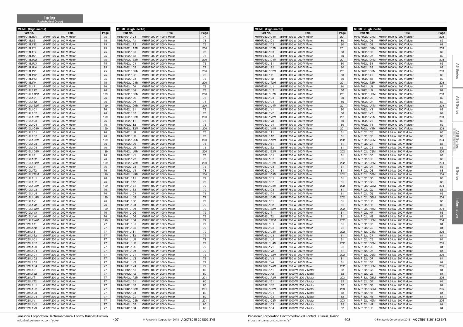
E SeriesIm
formation
A6 Series
A6N
SeriesA
6B Series
Special Order Product
Index(Alphabetical Order)
– 407 –Panasonic Corporation Electromechanical Control Business Division
industrial.panasonic.com/ac/e/ © Panasonic Corporation 2018 AQCTB01E 201802-3YE – 408 –Panasonic Corporation Electromechanical Control Business Division
industrial.panasonic.com/ac/e/ © Panasonic Corporation 2018 AQCTB01E 201802-3YE
MHMF (High inertia)Part No. Title Page
MHMF (High inertia)Part No. Title Page
MHMF (High inertia)Part No. Title Page
MHMF (High inertia)Part No. Title Page
MHMF092L1C4M MHMF 1000 W 200 V Motor 203MHMF092L1D1 MHMF 1000 W 200 V Motor 82MHMF092L1D2 MHMF 1000 W 200 V Motor 82MHMF092L1D2M MHMF 1000 W 200 V Motor 203MHMF092L1D3 MHMF 1000 W 200 V Motor 82MHMF092L1D4 MHMF 1000 W 200 V Motor 82MHMF092L1D4M MHMF 1000 W 200 V Motor 203MHMF092L1S1 MHMF 1000 W 200 V Motor 82MHMF092L1S2 MHMF 1000 W 200 V Motor 82MHMF092L1S2M MHMF 1000 W 200 V Motor 203MHMF092L1T1 MHMF 1000 W 200 V Motor 82MHMF092L1T2 MHMF 1000 W 200 V Motor 82MHMF092L1T2M MHMF 1000 W 200 V Motor 203MHMF092L1U1 MHMF 1000 W 200 V Motor 82MHMF092L1U2 MHMF 1000 W 200 V Motor 82MHMF092L1U2M MHMF 1000 W 200 V Motor 203MHMF092L1U3 MHMF 1000 W 200 V Motor 82MHMF092L1U4 MHMF 1000 W 200 V Motor 82MHMF092L1U4M MHMF 1000 W 200 V Motor 203MHMF092L1V1 MHMF 1000 W 200 V Motor 82MHMF092L1V2 MHMF 1000 W 200 V Motor 82MHMF092L1V2M MHMF 1000 W 200 V Motor 203MHMF092L1V3 MHMF 1000 W 200 V Motor 82MHMF092L1V4 MHMF 1000 W 200 V Motor 82MHMF092L1V4M MHMF 1000 W 200 V Motor 203MHMF102L1C5 MHMF 1.0 kW 200 V Motor 83MHMF102L1C6 MHMF 1.0 kW 200 V Motor 83MHMF102L1C6M MHMF 1.0 kW 200 V Motor 204MHMF102L1C7 MHMF 1.0 kW 200 V Motor 83MHMF102L1C8 MHMF 1.0 kW 200 V Motor 83MHMF102L1C8M MHMF 1.0 kW 200 V Motor 204MHMF102L1D5 MHMF 1.0 kW 200 V Motor 83MHMF102L1D6 MHMF 1.0 kW 200 V Motor 83MHMF102L1D6M MHMF 1.0 kW 200 V Motor 204MHMF102L1D7 MHMF 1.0 kW 200 V Motor 83MHMF102L1D8 MHMF 1.0 kW 200 V Motor 83MHMF102L1D8M MHMF 1.0 kW 200 V Motor 204MHMF102L1G5 MHMF 1.0 kW 200 V Motor 83MHMF102L1G6 MHMF 1.0 kW 200 V Motor 83MHMF102L1G6M MHMF 1.0 kW 200 V Motor 204MHMF102L1G7 MHMF 1.0 kW 200 V Motor 83MHMF102L1G8 MHMF 1.0 kW 200 V Motor 83MHMF102L1G8M MHMF 1.0 kW 200 V Motor 204MHMF102L1H5 MHMF 1.0 kW 200 V Motor 83MHMF102L1H6 MHMF 1.0 kW 200 V Motor 83MHMF102L1H6M MHMF 1.0 kW 200 V Motor 204MHMF102L1H7 MHMF 1.0 kW 200 V Motor 83MHMF102L1H8 MHMF 1.0 kW 200 V Motor 83MHMF102L1H8M MHMF 1.0 kW 200 V Motor 204MHMF152L1C5 MHMF 1.5 kW 200 V Motor 84MHMF152L1C6 MHMF 1.5 kW 200 V Motor 84MHMF152L1C6M MHMF 1.5 kW 200 V Motor 205MHMF152L1C7 MHMF 1.5 kW 200 V Motor 84MHMF152L1C8 MHMF 1.5 kW 200 V Motor 84MHMF152L1C8M MHMF 1.5 kW 200 V Motor 205MHMF152L1D5 MHMF 1.5 kW 200 V Motor 84MHMF152L1D6 MHMF 1.5 kW 200 V Motor 84MHMF152L1D6M MHMF 1.5 kW 200 V Motor 205MHMF152L1D7 MHMF 1.5 kW 200 V Motor 84MHMF152L1D8 MHMF 1.5 kW 200 V Motor 84MHMF152L1D8M MHMF 1.5 kW 200 V Motor 205MHMF152L1G5 MHMF 1.5 kW 200 V Motor 84MHMF152L1G6 MHMF 1.5 kW 200 V Motor 84MHMF152L1G6M MHMF 1.5 kW 200 V Motor 205MHMF152L1G7 MHMF 1.5 kW 200 V Motor 84MHMF152L1G8 MHMF 1.5 kW 200 V Motor 84MHMF152L1G8M MHMF 1.5 kW 200 V Motor 205MHMF152L1H5 MHMF 1.5 kW 200 V Motor 84MHMF152L1H6 MHMF 1.5 kW 200 V Motor 84MHMF152L1H6M MHMF 1.5 kW 200 V Motor 205MHMF152L1H7 MHMF 1.5 kW 200 V Motor 84MHMF152L1H8 MHMF 1.5 kW 200 V Motor 84
MHMF042L1C4M MHMF 400 W 200 V Motor 201MHMF042L1D1 MHMF 400 W 200 V Motor 80MHMF042L1D2 MHMF 400 W 200 V Motor 80MHMF042L1D2M MHMF 400 W 200 V Motor 201MHMF042L1D3 MHMF 400 W 200 V Motor 80MHMF042L1D4 MHMF 400 W 200 V Motor 80MHMF042L1D4M MHMF 400 W 200 V Motor 201MHMF042L1S1 MHMF 400 W 200 V Motor 80MHMF042L1S2 MHMF 400 W 200 V Motor 80MHMF042L1S2M MHMF 400 W 200 V Motor 201MHMF042L1T1 MHMF 400 W 200 V Motor 80MHMF042L1T2 MHMF 400 W 200 V Motor 80MHMF042L1T2M MHMF 400 W 200 V Motor 201MHMF042L1U1 MHMF 400 W 200 V Motor 80MHMF042L1U2 MHMF 400 W 200 V Motor 80MHMF042L1U2M MHMF 400 W 200 V Motor 201MHMF042L1U3 MHMF 400 W 200 V Motor 80MHMF042L1U4 MHMF 400 W 200 V Motor 80MHMF042L1U4M MHMF 400 W 200 V Motor 201MHMF042L1V1 MHMF 400 W 200 V Motor 80MHMF042L1V2 MHMF 400 W 200 V Motor 80MHMF042L1V2M MHMF 400 W 200 V Motor 201MHMF042L1V3 MHMF 400 W 200 V Motor 80MHMF042L1V4 MHMF 400 W 200 V Motor 80MHMF042L1V4M MHMF 400 W 200 V Motor 201MHMF082L1A1 MHMF 750 W 200 V Motor 81MHMF082L1A2 MHMF 750 W 200 V Motor 81MHMF082L1A2M MHMF 750 W 200 V Motor 202MHMF082L1B1 MHMF 750 W 200 V Motor 81MHMF082L1B2 MHMF 750 W 200 V Motor 81MHMF082L1B2M MHMF 750 W 200 V Motor 202MHMF082L1C1 MHMF 750 W 200 V Motor 81MHMF082L1C2 MHMF 750 W 200 V Motor 81MHMF082L1C2M MHMF 750 W 200 V Motor 202MHMF082L1C3 MHMF 750 W 200 V Motor 81MHMF082L1C4 MHMF 750 W 200 V Motor 81MHMF082L1C4M MHMF 750 W 200 V Motor 202MHMF082L1D1 MHMF 750 W 200 V Motor 81MHMF082L1D2 MHMF 750 W 200 V Motor 81MHMF082L1D2M MHMF 750 W 200 V Motor 202MHMF082L1D3 MHMF 750 W 200 V Motor 81MHMF082L1D4 MHMF 750 W 200 V Motor 81MHMF082L1D4M MHMF 750 W 200 V Motor 202MHMF082L1S1 MHMF 750 W 200 V Motor 81MHMF082L1S2 MHMF 750 W 200 V Motor 81MHMF082L1S2M MHMF 750 W 200 V Motor 202MHMF082L1T1 MHMF 750 W 200 V Motor 81MHMF082L1T2 MHMF 750 W 200 V Motor 81MHMF082L1T2M MHMF 750 W 200 V Motor 202MHMF082L1U1 MHMF 750 W 200 V Motor 81MHMF082L1U2 MHMF 750 W 200 V Motor 81MHMF082L1U2M MHMF 750 W 200 V Motor 202MHMF082L1U3 MHMF 750 W 200 V Motor 81MHMF082L1U4 MHMF 750 W 200 V Motor 81MHMF082L1U4M MHMF 750 W 200 V Motor 202MHMF082L1V1 MHMF 750 W 200 V Motor 81MHMF082L1V2 MHMF 750 W 200 V Motor 81MHMF082L1V2M MHMF 750 W 200 V Motor 202MHMF082L1V3 MHMF 750 W 200 V Motor 81MHMF082L1V4 MHMF 750 W 200 V Motor 81MHMF082L1V4M MHMF 750 W 200 V Motor 202MHMF092L1A1 MHMF 1000 W 200 V Motor 82MHMF092L1A2 MHMF 1000 W 200 V Motor 82MHMF092L1A2M MHMF 1000 W 200 V Motor 203MHMF092L1B1 MHMF 1000 W 200 V Motor 82MHMF092L1B2 MHMF 1000 W 200 V Motor 82MHMF092L1B2M MHMF 1000 W 200 V Motor 203MHMF092L1C1 MHMF 1000 W 200 V Motor 82MHMF092L1C2 MHMF 1000 W 200 V Motor 82MHMF092L1C2M MHMF 1000 W 200 V Motor 203MHMF092L1C3 MHMF 1000 W 200 V Motor 82MHMF092L1C4 MHMF 1000 W 200 V Motor 82
MHMF021L1V4 MHMF 200 W 100 V Motor 77MHMF022L1A1 MHMF 200 W 200 V Motor 78MHMF022L1A2 MHMF 200 W 200 V Motor 78MHMF022L1A2M MHMF 200 W 200 V Motor 200MHMF022L1B1 MHMF 200 W 200 V Motor 78MHMF022L1B2 MHMF 200 W 200 V Motor 78MHMF022L1B2M MHMF 200 W 200 V Motor 200MHMF022L1C1 MHMF 200 W 200 V Motor 78MHMF022L1C2 MHMF 200 W 200 V Motor 78MHMF022L1C2M MHMF 200 W 200 V Motor 200MHMF022L1C3 MHMF 200 W 200 V Motor 78MHMF022L1C4 MHMF 200 W 200 V Motor 78MHMF022L1C4M MHMF 200 W 200 V Motor 200MHMF022L1D1 MHMF 200 W 200 V Motor 78MHMF022L1D2 MHMF 200 W 200 V Motor 78MHMF022L1D2M MHMF 200 W 200 V Motor 200MHMF022L1D3 MHMF 200 W 200 V Motor 78MHMF022L1D4 MHMF 200 W 200 V Motor 78MHMF022L1D4M MHMF 200 W 200 V Motor 200MHMF022L1S1 MHMF 200 W 200 V Motor 78MHMF022L1S2 MHMF 200 W 200 V Motor 78MHMF022L1S2M MHMF 200 W 200 V Motor 200MHMF022L1T1 MHMF 200 W 200 V Motor 78MHMF022L1T2 MHMF 200 W 200 V Motor 78MHMF022L1T2M MHMF 200 W 200 V Motor 200MHMF022L1U1 MHMF 200 W 200 V Motor 78MHMF022L1U2 MHMF 200 W 200 V Motor 78MHMF022L1U2M MHMF 200 W 200 V Motor 200MHMF022L1U3 MHMF 200 W 200 V Motor 78MHMF022L1U4 MHMF 200 W 200 V Motor 78MHMF022L1U4M MHMF 200 W 200 V Motor 200MHMF022L1V1 MHMF 200 W 200 V Motor 78MHMF022L1V2 MHMF 200 W 200 V Motor 78MHMF022L1V2M MHMF 200 W 200 V Motor 200MHMF022L1V3 MHMF 200 W 200 V Motor 78MHMF022L1V4 MHMF 200 W 200 V Motor 78MHMF022L1V4M MHMF 200 W 200 V Motor 200MHMF041L1A1 MHMF 400 W 100 V Motor 79MHMF041L1A2 MHMF 400 W 100 V Motor 79MHMF041L1B1 MHMF 400 W 100 V Motor 79MHMF041L1B2 MHMF 400 W 100 V Motor 79MHMF041L1C1 MHMF 400 W 100 V Motor 79MHMF041L1C2 MHMF 400 W 100 V Motor 79MHMF041L1C3 MHMF 400 W 100 V Motor 79MHMF041L1C4 MHMF 400 W 100 V Motor 79MHMF041L1D1 MHMF 400 W 100 V Motor 79MHMF041L1D2 MHMF 400 W 100 V Motor 79MHMF041L1D3 MHMF 400 W 100 V Motor 79MHMF041L1D4 MHMF 400 W 100 V Motor 79MHMF041L1S1 MHMF 400 W 100 V Motor 79MHMF041L1S2 MHMF 400 W 100 V Motor 79MHMF041L1T1 MHMF 400 W 100 V Motor 79MHMF041L1T2 MHMF 400 W 100 V Motor 79MHMF041L1U1 MHMF 400 W 100 V Motor 79MHMF041L1U2 MHMF 400 W 100 V Motor 79MHMF041L1U3 MHMF 400 W 100 V Motor 79MHMF041L1U4 MHMF 400 W 100 V Motor 79MHMF041L1V1 MHMF 400 W 100 V Motor 79MHMF041L1V2 MHMF 400 W 100 V Motor 79MHMF041L1V3 MHMF 400 W 100 V Motor 79MHMF041L1V4 MHMF 400 W 100 V Motor 79MHMF042L1A1 MHMF 400 W 200 V Motor 80MHMF042L1A2 MHMF 400 W 200 V Motor 80MHMF042L1A2M MHMF 400 W 200 V Motor 201MHMF042L1B1 MHMF 400 W 200 V Motor 80MHMF042L1B2 MHMF 400 W 200 V Motor 80MHMF042L1B2M MHMF 400 W 200 V Motor 201MHMF042L1C1 MHMF 400 W 200 V Motor 80MHMF042L1C2 MHMF 400 W 200 V Motor 80MHMF042L1C2M MHMF 400 W 200 V Motor 201MHMF042L1C3 MHMF 400 W 200 V Motor 80MHMF042L1C4 MHMF 400 W 200 V Motor 80
MHMF011L1D4 MHMF 100 W 100 V Motor 75MHMF011L1S1 MHMF 100 W 100 V Motor 75MHMF011L1S2 MHMF 100 W 100 V Motor 75MHMF011L1T1 MHMF 100 W 100 V Motor 75MHMF011L1T2 MHMF 100 W 100 V Motor 75MHMF011L1U1 MHMF 100 W 100 V Motor 75MHMF011L1U2 MHMF 100 W 100 V Motor 75MHMF011L1U3 MHMF 100 W 100 V Motor 75MHMF011L1U4 MHMF 100 W 100 V Motor 75MHMF011L1V1 MHMF 100 W 100 V Motor 75MHMF011L1V2 MHMF 100 W 100 V Motor 75MHMF011L1V3 MHMF 100 W 100 V Motor 75MHMF011L1V4 MHMF 100 W 100 V Motor 75MHMF012L1A1 MHMF 100 W 200 V Motor 76MHMF012L1A2 MHMF 100 W 200 V Motor 76MHMF012L1A2M MHMF 100 W 200 V Motor 199MHMF012L1B1 MHMF 100 W 200 V Motor 76MHMF012L1B2 MHMF 100 W 200 V Motor 76MHMF012L1B2M MHMF 100 W 200 V Motor 199MHMF012L1C1 MHMF 100 W 200 V Motor 76MHMF012L1C2 MHMF 100 W 200 V Motor 76MHMF012L1C2M MHMF 100 W 200 V Motor 199MHMF012L1C3 MHMF 100 W 200 V Motor 76MHMF012L1C4 MHMF 100 W 200 V Motor 76MHMF012L1C4M MHMF 100 W 200 V Motor 199MHMF012L1D1 MHMF 100 W 200 V Motor 76MHMF012L1D2 MHMF 100 W 200 V Motor 76MHMF012L1D2M MHMF 100 W 200 V Motor 199MHMF012L1D3 MHMF 100 W 200 V Motor 76MHMF012L1D4 MHMF 100 W 200 V Motor 76MHMF012L1D4M MHMF 100 W 200 V Motor 199MHMF012L1S1 MHMF 100 W 200 V Motor 76MHMF012L1S2 MHMF 100 W 200 V Motor 76MHMF012L1S2M MHMF 100 W 200 V Motor 199MHMF012L1T1 MHMF 100 W 200 V Motor 76MHMF012L1T2 MHMF 100 W 200 V Motor 76MHMF012L1T2M MHMF 100 W 200 V Motor 199MHMF012L1U1 MHMF 100 W 200 V Motor 76MHMF012L1U2 MHMF 100 W 200 V Motor 76MHMF012L1U2M MHMF 100 W 200 V Motor 199MHMF012L1U3 MHMF 100 W 200 V Motor 76MHMF012L1U4 MHMF 100 W 200 V Motor 76MHMF012L1U4M MHMF 100 W 200 V Motor 199MHMF012L1V1 MHMF 100 W 200 V Motor 76MHMF012L1V2 MHMF 100 W 200 V Motor 76MHMF012L1V2M MHMF 100 W 200 V Motor 199MHMF012L1V3 MHMF 100 W 200 V Motor 76MHMF012L1V4 MHMF 100 W 200 V Motor 76MHMF012L1V4M MHMF 100 W 200 V Motor 199MHMF021L1A1 MHMF 200 W 100 V Motor 77MHMF021L1A2 MHMF 200 W 100 V Motor 77MHMF021L1B1 MHMF 200 W 100 V Motor 77MHMF021L1B2 MHMF 200 W 100 V Motor 77MHMF021L1C1 MHMF 200 W 100 V Motor 77MHMF021L1C2 MHMF 200 W 100 V Motor 77MHMF021L1C3 MHMF 200 W 100 V Motor 77MHMF021L1C4 MHMF 200 W 100 V Motor 77MHMF021L1D1 MHMF 200 W 100 V Motor 77MHMF021L1D2 MHMF 200 W 100 V Motor 77MHMF021L1D3 MHMF 200 W 100 V Motor 77MHMF021L1D4 MHMF 200 W 100 V Motor 77MHMF021L1S1 MHMF 200 W 100 V Motor 77MHMF021L1S2 MHMF 200 W 100 V Motor 77MHMF021L1T1 MHMF 200 W 100 V Motor 77MHMF021L1T2 MHMF 200 W 100 V Motor 77MHMF021L1U1 MHMF 200 W 100 V Motor 77MHMF021L1U2 MHMF 200 W 100 V Motor 77MHMF021L1U3 MHMF 200 W 100 V Motor 77MHMF021L1U4 MHMF 200 W 100 V Motor 77MHMF021L1V1 MHMF 200 W 100 V Motor 77MHMF021L1V2 MHMF 200 W 100 V Motor 77MHMF021L1V3 MHMF 200 W 100 V Motor 77
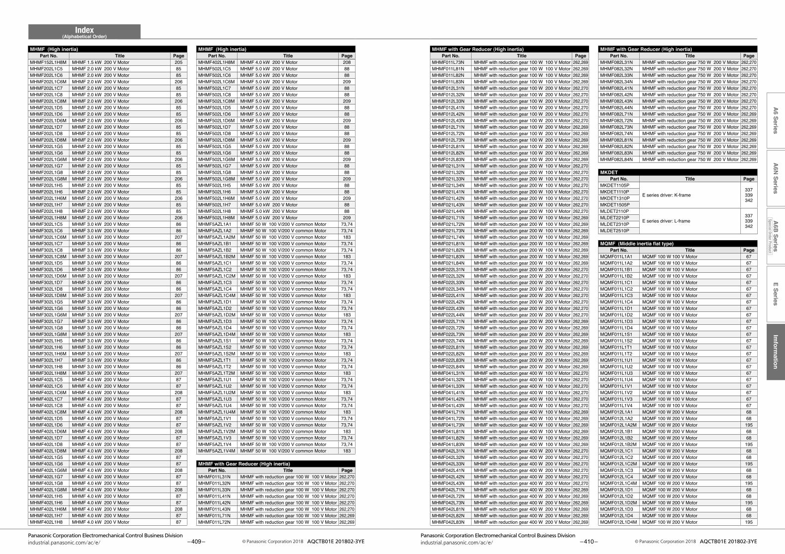
E SeriesIm
formation
A6 Series
A6N
SeriesA
6B Series
Special Order Product
Index(Alphabetical Order)
– 409 –Panasonic Corporation Electromechanical Control Business Division
industrial.panasonic.com/ac/e/ © Panasonic Corporation 2018 AQCTB01E 201802-3YE – 410 –Panasonic Corporation Electromechanical Control Business Division
industrial.panasonic.com/ac/e/ © Panasonic Corporation 2018 AQCTB01E 201802-3YE
MHMF with Gear Reducer (High inertia)Part No. Title Page
MHMF with Gear Reducer (High inertia)Part No. Title Page
MHMF (High inertia)Part No. Title Page
MHMF082L31N MHMF with reduction gear 750 W 200 V Motor 262,270MHMF082L32N MHMF with reduction gear 750 W 200 V Motor 262,270MHMF082L33N MHMF with reduction gear 750 W 200 V Motor 262,270MHMF082L34N MHMF with reduction gear 750 W 200 V Motor 262,270MHMF082L41N MHMF with reduction gear 750 W 200 V Motor 262,270MHMF082L42N MHMF with reduction gear 750 W 200 V Motor 262,270MHMF082L43N MHMF with reduction gear 750 W 200 V Motor 262,270MHMF082L44N MHMF with reduction gear 750 W 200 V Motor 262,270MHMF082L71N MHMF with reduction gear 750 W 200 V Motor 262,269MHMF082L72N MHMF with reduction gear 750 W 200 V Motor 262,269MHMF082L73N MHMF with reduction gear 750 W 200 V Motor 262,269MHMF082L74N MHMF with reduction gear 750 W 200 V Motor 262,269MHMF082L81N MHMF with reduction gear 750 W 200 V Motor 262,269MHMF082L82N MHMF with reduction gear 750 W 200 V Motor 262,269MHMF082L83N MHMF with reduction gear 750 W 200 V Motor 262,269MHMF082L84N MHMF with reduction gear 750 W 200 V Motor 262,269
MKDETPart No. Title Page
MKDET1105P
E series driver: K-frame337339342
MKDET1110PMKDET1310PMKDET1505PMLDET2110P
E series driver: L-frame337339342
MLDET2210PMLDET2310PMLDET2510P
MQMF (Middle inertia flat type)Part No. Title Page
MQMF011L1A1 MQMF 100 W 100 V Motor 67MQMF011L1A2 MQMF 100 W 100 V Motor 67MQMF011L1B1 MQMF 100 W 100 V Motor 67MQMF011L1B2 MQMF 100 W 100 V Motor 67MQMF011L1C1 MQMF 100 W 100 V Motor 67MQMF011L1C2 MQMF 100 W 100 V Motor 67MQMF011L1C3 MQMF 100 W 100 V Motor 67MQMF011L1C4 MQMF 100 W 100 V Motor 67MQMF011L1D1 MQMF 100 W 100 V Motor 67MQMF011L1D2 MQMF 100 W 100 V Motor 67MQMF011L1D3 MQMF 100 W 100 V Motor 67MQMF011L1D4 MQMF 100 W 100 V Motor 67MQMF011L1S1 MQMF 100 W 100 V Motor 67MQMF011L1S2 MQMF 100 W 100 V Motor 67MQMF011L1T1 MQMF 100 W 100 V Motor 67MQMF011L1T2 MQMF 100 W 100 V Motor 67MQMF011L1U1 MQMF 100 W 100 V Motor 67MQMF011L1U2 MQMF 100 W 100 V Motor 67MQMF011L1U3 MQMF 100 W 100 V Motor 67MQMF011L1U4 MQMF 100 W 100 V Motor 67MQMF011L1V1 MQMF 100 W 100 V Motor 67MQMF011L1V2 MQMF 100 W 100 V Motor 67MQMF011L1V3 MQMF 100 W 100 V Motor 67MQMF011L1V4 MQMF 100 W 100 V Motor 67MQMF012L1A1 MQMF 100 W 200 V Motor 68MQMF012L1A2 MQMF 100 W 200 V Motor 68MQMF012L1A2M MQMF 100 W 200 V Motor 195MQMF012L1B1 MQMF 100 W 200 V Motor 68MQMF012L1B2 MQMF 100 W 200 V Motor 68MQMF012L1B2M MQMF 100 W 200 V Motor 195MQMF012L1C1 MQMF 100 W 200 V Motor 68MQMF012L1C2 MQMF 100 W 200 V Motor 68MQMF012L1C2M MQMF 100 W 200 V Motor 195MQMF012L1C3 MQMF 100 W 200 V Motor 68MQMF012L1C4 MQMF 100 W 200 V Motor 68MQMF012L1C4M MQMF 100 W 200 V Motor 195MQMF012L1D1 MQMF 100 W 200 V Motor 68MQMF012L1D2 MQMF 100 W 200 V Motor 68MQMF012L1D2M MQMF 100 W 200 V Motor 195MQMF012L1D3 MQMF 100 W 200 V Motor 68MQMF012L1D4 MQMF 100 W 200 V Motor 68MQMF012L1D4M MQMF 100 W 200 V Motor 195
MHMF011L73N MHMF with reduction gear 100 W 100 V Motor 262,269MHMF011L81N MHMF with reduction gear 100 W 100 V Motor 262,269MHMF011L82N MHMF with reduction gear 100 W 100 V Motor 262,269MHMF011L83N MHMF with reduction gear 100 W 100 V Motor 262,269MHMF012L31N MHMF with reduction gear 100 W 200 V Motor 262,270MHMF012L32N MHMF with reduction gear 100 W 200 V Motor 262,270MHMF012L33N MHMF with reduction gear 100 W 200 V Motor 262,270MHMF012L41N MHMF with reduction gear 100 W 200 V Motor 262,270MHMF012L42N MHMF with reduction gear 100 W 200 V Motor 262,270MHMF012L43N MHMF with reduction gear 100 W 200 V Motor 262,270MHMF012L71N MHMF with reduction gear 100 W 200 V Motor 262,269MHMF012L72N MHMF with reduction gear 100 W 200 V Motor 262,269MHMF012L73N MHMF with reduction gear 100 W 200 V Motor 262,269MHMF012L81N MHMF with reduction gear 100 W 200 V Motor 262,269MHMF012L82N MHMF with reduction gear 100 W 200 V Motor 262,269MHMF012L83N MHMF with reduction gear 100 W 200 V Motor 262,269MHMF021L31N MHMF with reduction gear 200 W 100 V Motor 262,270MHMF021L32N MHMF with reduction gear 200 W 100 V Motor 262,270MHMF021L33N MHMF with reduction gear 200 W 100 V Motor 262,270MHMF021L34N MHMF with reduction gear 200 W 100 V Motor 262,270MHMF021L41N MHMF with reduction gear 200 W 100 V Motor 262,270MHMF021L42N MHMF with reduction gear 200 W 100 V Motor 262,270MHMF021L43N MHMF with reduction gear 200 W 100 V Motor 262,270MHMF021L44N MHMF with reduction gear 200 W 100 V Motor 262,270MHMF021L71N MHMF with reduction gear 200 W 100 V Motor 262,269MHMF021L72N MHMF with reduction gear 200 W 100 V Motor 262,269MHMF021L73N MHMF with reduction gear 200 W 100 V Motor 262,269MHMF021L74N MHMF with reduction gear 200 W 100 V Motor 262,269MHMF021L81N MHMF with reduction gear 200 W 100 V Motor 262,269MHMF021L82N MHMF with reduction gear 200 W 100 V Motor 262,269MHMF021L83N MHMF with reduction gear 200 W 100 V Motor 262,269MHMF021L84N MHMF with reduction gear 200 W 100 V Motor 262,269MHMF022L31N MHMF with reduction gear 200 W 200 V Motor 262,270MHMF022L32N MHMF with reduction gear 200 W 200 V Motor 262,270MHMF022L33N MHMF with reduction gear 200 W 200 V Motor 262,270MHMF022L34N MHMF with reduction gear 200 W 200 V Motor 262,270MHMF022L41N MHMF with reduction gear 200 W 200 V Motor 262,270MHMF022L42N MHMF with reduction gear 200 W 200 V Motor 262,270MHMF022L43N MHMF with reduction gear 200 W 200 V Motor 262,270MHMF022L44N MHMF with reduction gear 200 W 200 V Motor 262,270MHMF022L71N MHMF with reduction gear 200 W 200 V Motor 262,269MHMF022L72N MHMF with reduction gear 200 W 200 V Motor 262,269MHMF022L73N MHMF with reduction gear 200 W 200 V Motor 262,269MHMF022L74N MHMF with reduction gear 200 W 200 V Motor 262,269MHMF022L81N MHMF with reduction gear 200 W 200 V Motor 262,269MHMF022L82N MHMF with reduction gear 200 W 200 V Motor 262,269MHMF022L83N MHMF with reduction gear 200 W 200 V Motor 262,269MHMF022L84N MHMF with reduction gear 200 W 200 V Motor 262,269MHMF041L31N MHMF with reduction gear 400 W 100 V Motor 262,270MHMF041L32N MHMF with reduction gear 400 W 100 V Motor 262,270MHMF041L33N MHMF with reduction gear 400 W 100 V Motor 262,270MHMF041L41N MHMF with reduction gear 400 W 100 V Motor 262,270MHMF041L42N MHMF with reduction gear 400 W 100 V Motor 262,270MHMF041L43N MHMF with reduction gear 400 W 100 V Motor 262,270MHMF041L71N MHMF with reduction gear 400 W 100 V Motor 262,269MHMF041L72N MHMF with reduction gear 400 W 100 V Motor 262,269MHMF041L73N MHMF with reduction gear 400 W 100 V Motor 262,269MHMF041L81N MHMF with reduction gear 400 W 100 V Motor 262,269MHMF041L82N MHMF with reduction gear 400 W 100 V Motor 262,269MHMF041L83N MHMF with reduction gear 400 W 100 V Motor 262,269MHMF042L31N MHMF with reduction gear 400 W 200 V Motor 262,270MHMF042L32N MHMF with reduction gear 400 W 200 V Motor 262,270MHMF042L33N MHMF with reduction gear 400 W 200 V Motor 262,270MHMF042L41N MHMF with reduction gear 400 W 200 V Motor 262,270MHMF042L42N MHMF with reduction gear 400 W 200 V Motor 262,270MHMF042L43N MHMF with reduction gear 400 W 200 V Motor 262,270MHMF042L71N MHMF with reduction gear 400 W 200 V Motor 262,269MHMF042L72N MHMF with reduction gear 400 W 200 V Motor 262,269MHMF042L73N MHMF with reduction gear 400 W 200 V Motor 262,269MHMF042L81N MHMF with reduction gear 400 W 200 V Motor 262,269MHMF042L82N MHMF with reduction gear 400 W 200 V Motor 262,269MHMF042L83N MHMF with reduction gear 400 W 200 V Motor 262,269
MHMF152L1H8M MHMF 1.5 kW 200 V Motor 205MHMF202L1C5 MHMF 2.0 kW 200 V Motor 85MHMF202L1C6 MHMF 2.0 kW 200 V Motor 85MHMF202L1C6M MHMF 2.0 kW 200 V Motor 206MHMF202L1C7 MHMF 2.0 kW 200 V Motor 85MHMF202L1C8 MHMF 2.0 kW 200 V Motor 85MHMF202L1C8M MHMF 2.0 kW 200 V Motor 206MHMF202L1D5 MHMF 2.0 kW 200 V Motor 85MHMF202L1D6 MHMF 2.0 kW 200 V Motor 85MHMF202L1D6M MHMF 2.0 kW 200 V Motor 206MHMF202L1D7 MHMF 2.0 kW 200 V Motor 85MHMF202L1D8 MHMF 2.0 kW 200 V Motor 85MHMF202L1D8M MHMF 2.0 kW 200 V Motor 206MHMF202L1G5 MHMF 2.0 kW 200 V Motor 85MHMF202L1G6 MHMF 2.0 kW 200 V Motor 85MHMF202L1G6M MHMF 2.0 kW 200 V Motor 206MHMF202L1G7 MHMF 2.0 kW 200 V Motor 85MHMF202L1G8 MHMF 2.0 kW 200 V Motor 85MHMF202L1G8M MHMF 2.0 kW 200 V Motor 206MHMF202L1H5 MHMF 2.0 kW 200 V Motor 85MHMF202L1H6 MHMF 2.0 kW 200 V Motor 85MHMF202L1H6M MHMF 2.0 kW 200 V Motor 206MHMF202L1H7 MHMF 2.0 kW 200 V Motor 85MHMF202L1H8 MHMF 2.0 kW 200 V Motor 85MHMF202L1H8M MHMF 2.0 kW 200 V Motor 206MHMF302L1C5 MHMF 3.0 kW 200 V Motor 86MHMF302L1C6 MHMF 3.0 kW 200 V Motor 86MHMF302L1C6M MHMF 3.0 kW 200 V Motor 207MHMF302L1C7 MHMF 3.0 kW 200 V Motor 86MHMF302L1C8 MHMF 3.0 kW 200 V Motor 86MHMF302L1C8M MHMF 3.0 kW 200 V Motor 207MHMF302L1D5 MHMF 3.0 kW 200 V Motor 86MHMF302L1D6 MHMF 3.0 kW 200 V Motor 86MHMF302L1D6M MHMF 3.0 kW 200 V Motor 207MHMF302L1D7 MHMF 3.0 kW 200 V Motor 86MHMF302L1D8 MHMF 3.0 kW 200 V Motor 86MHMF302L1D8M MHMF 3.0 kW 200 V Motor 207MHMF302L1G5 MHMF 3.0 kW 200 V Motor 86MHMF302L1G6 MHMF 3.0 kW 200 V Motor 86MHMF302L1G6M MHMF 3.0 kW 200 V Motor 207MHMF302L1G7 MHMF 3.0 kW 200 V Motor 86MHMF302L1G8 MHMF 3.0 kW 200 V Motor 86MHMF302L1G8M MHMF 3.0 kW 200 V Motor 207MHMF302L1H5 MHMF 3.0 kW 200 V Motor 86MHMF302L1H6 MHMF 3.0 kW 200 V Motor 86MHMF302L1H6M MHMF 3.0 kW 200 V Motor 207MHMF302L1H7 MHMF 3.0 kW 200 V Motor 86MHMF302L1H8 MHMF 3.0 kW 200 V Motor 86MHMF302L1H8M MHMF 3.0 kW 200 V Motor 207MHMF402L1C5 MHMF 4.0 kW 200 V Motor 87MHMF402L1C6 MHMF 4.0 kW 200 V Motor 87MHMF402L1C6M MHMF 4.0 kW 200 V Motor 208MHMF402L1C7 MHMF 4.0 kW 200 V Motor 87MHMF402L1C8 MHMF 4.0 kW 200 V Motor 87MHMF402L1C8M MHMF 4.0 kW 200 V Motor 208MHMF402L1D5 MHMF 4.0 kW 200 V Motor 87MHMF402L1D6 MHMF 4.0 kW 200 V Motor 87MHMF402L1D6M MHMF 4.0 kW 200 V Motor 208MHMF402L1D7 MHMF 4.0 kW 200 V Motor 87MHMF402L1D8 MHMF 4.0 kW 200 V Motor 87MHMF402L1D8M MHMF 4.0 kW 200 V Motor 208MHMF402L1G5 MHMF 4.0 kW 200 V Motor 87MHMF402L1G6 MHMF 4.0 kW 200 V Motor 87MHMF402L1G6M MHMF 4.0 kW 200 V Motor 208MHMF402L1G7 MHMF 4.0 kW 200 V Motor 87MHMF402L1G8 MHMF 4.0 kW 200 V Motor 87MHMF402L1G8M MHMF 4.0 kW 200 V Motor 208MHMF402L1H5 MHMF 4.0 kW 200 V Motor 87MHMF402L1H6 MHMF 4.0 kW 200 V Motor 87MHMF402L1H6M MHMF 4.0 kW 200 V Motor 208MHMF402L1H7 MHMF 4.0 kW 200 V Motor 87MHMF402L1H8 MHMF 4.0 kW 200 V Motor 87
MHMF402L1H8M MHMF 4.0 kW 200 V Motor 208MHMF502L1C5 MHMF 5.0 kW 200 V Motor 88MHMF502L1C6 MHMF 5.0 kW 200 V Motor 88MHMF502L1C6M MHMF 5.0 kW 200 V Motor 209MHMF502L1C7 MHMF 5.0 kW 200 V Motor 88MHMF502L1C8 MHMF 5.0 kW 200 V Motor 88MHMF502L1C8M MHMF 5.0 kW 200 V Motor 209MHMF502L1D5 MHMF 5.0 kW 200 V Motor 88MHMF502L1D6 MHMF 5.0 kW 200 V Motor 88MHMF502L1D6M MHMF 5.0 kW 200 V Motor 209MHMF502L1D7 MHMF 5.0 kW 200 V Motor 88MHMF502L1D8 MHMF 5.0 kW 200 V Motor 88MHMF502L1D8M MHMF 5.0 kW 200 V Motor 209MHMF502L1G5 MHMF 5.0 kW 200 V Motor 88MHMF502L1G6 MHMF 5.0 kW 200 V Motor 88MHMF502L1G6M MHMF 5.0 kW 200 V Motor 209MHMF502L1G7 MHMF 5.0 kW 200 V Motor 88MHMF502L1G8 MHMF 5.0 kW 200 V Motor 88MHMF502L1G8M MHMF 5.0 kW 200 V Motor 209MHMF502L1H5 MHMF 5.0 kW 200 V Motor 88MHMF502L1H6 MHMF 5.0 kW 200 V Motor 88MHMF502L1H6M MHMF 5.0 kW 200 V Motor 209MHMF502L1H7 MHMF 5.0 kW 200 V Motor 88MHMF502L1H8 MHMF 5.0 kW 200 V Motor 88MHMF502L1H8M MHMF 5.0 kW 200 V Motor 209MHMF5AZL1A1 MHMF 50 W 100 V/200 V common Motor 73,74MHMF5AZL1A2 MHMF 50 W 100 V/200 V common Motor 73,74MHMF5AZL1A2M MHMF 50 W 100 V/200 V common Motor 183MHMF5AZL1B1 MHMF 50 W 100 V/200 V common Motor 73,74MHMF5AZL1B2 MHMF 50 W 100 V/200 V common Motor 73,74MHMF5AZL1B2M MHMF 50 W 100 V/200 V common Motor 183MHMF5AZL1C1 MHMF 50 W 100 V/200 V common Motor 73,74MHMF5AZL1C2 MHMF 50 W 100 V/200 V common Motor 73,74MHMF5AZL1C2M MHMF 50 W 100 V/200 V common Motor 183MHMF5AZL1C3 MHMF 50 W 100 V/200 V common Motor 73,74MHMF5AZL1C4 MHMF 50 W 100 V/200 V common Motor 73,74MHMF5AZL1C4M MHMF 50 W 100 V/200 V common Motor 183MHMF5AZL1D1 MHMF 50 W 100 V/200 V common Motor 73,74MHMF5AZL1D2 MHMF 50 W 100 V/200 V common Motor 73,74MHMF5AZL1D2M MHMF 50 W 100 V/200 V common Motor 183MHMF5AZL1D3 MHMF 50 W 100 V/200 V common Motor 73,74MHMF5AZL1D4 MHMF 50 W 100 V/200 V common Motor 73,74MHMF5AZL1D4M MHMF 50 W 100 V/200 V common Motor 183MHMF5AZL1S1 MHMF 50 W 100 V/200 V common Motor 73,74MHMF5AZL1S2 MHMF 50 W 100 V/200 V common Motor 73,74MHMF5AZL1S2M MHMF 50 W 100 V/200 V common Motor 183MHMF5AZL1T1 MHMF 50 W 100 V/200 V common Motor 73,74MHMF5AZL1T2 MHMF 50 W 100 V/200 V common Motor 73,74MHMF5AZL1T2M MHMF 50 W 100 V/200 V common Motor 183MHMF5AZL1U1 MHMF 50 W 100 V/200 V common Motor 73,74MHMF5AZL1U2 MHMF 50 W 100 V/200 V common Motor 73,74MHMF5AZL1U2M MHMF 50 W 100 V/200 V common Motor 183MHMF5AZL1U3 MHMF 50 W 100 V/200 V common Motor 73,74MHMF5AZL1U4 MHMF 50 W 100 V/200 V common Motor 73,74MHMF5AZL1U4M MHMF 50 W 100 V/200 V common Motor 183MHMF5AZL1V1 MHMF 50 W 100 V/200 V common Motor 73,74MHMF5AZL1V2 MHMF 50 W 100 V/200 V common Motor 73,74MHMF5AZL1V2M MHMF 50 W 100 V/200 V common Motor 183MHMF5AZL1V3 MHMF 50 W 100 V/200 V common Motor 73,74MHMF5AZL1V4 MHMF 50 W 100 V/200 V common Motor 73,74MHMF5AZL1V4M MHMF 50 W 100 V/200 V common Motor 183
MHMF with Gear Reducer (High inertia)Part No. Title Page
MHMF011L31N MHMF with reduction gear 100 W 100 V Motor 262,270MHMF011L32N MHMF with reduction gear 100 W 100 V Motor 262,270MHMF011L33N MHMF with reduction gear 100 W 100 V Motor 262,270MHMF011L41N MHMF with reduction gear 100 W 100 V Motor 262,270MHMF011L42N MHMF with reduction gear 100 W 100 V Motor 262,270MHMF011L43N MHMF with reduction gear 100 W 100 V Motor 262,270MHMF011L71N MHMF with reduction gear 100 W 100 V Motor 262,269MHMF011L72N MHMF with reduction gear 100 W 100 V Motor 262,269
MHMF (High inertia)Part No. Title Page
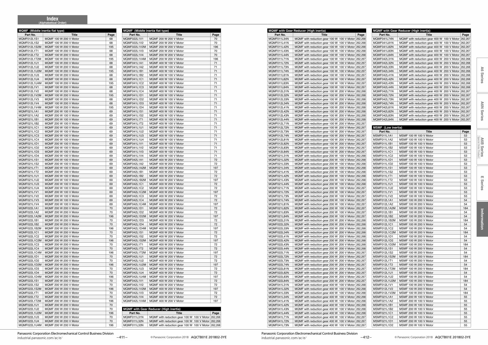
E SeriesIm
formation
A6 Series
A6N
SeriesA
6B Series
Special Order Product
Index(Alphabetical Order)
– 411 –Panasonic Corporation Electromechanical Control Business Division
industrial.panasonic.com/ac/e/ © Panasonic Corporation 2018 AQCTB01E 201802-3YE – 412 –Panasonic Corporation Electromechanical Control Business Division
industrial.panasonic.com/ac/e/ © Panasonic Corporation 2018 AQCTB01E 201802-3YE
MQMF with Gear Reducer (High inertia)Part No. Title Page
MQMF with Gear Reducer (High inertia)Part No. Title Page
MQMF (Middle inertia flat type)Part No. Title Page
MQMF (Middle inertia flat type)Part No. Title Page
MQMF041L74N MQMF with reduction gear 400 W 100 V Motor 262,267MQMF041L81N MQMF with reduction gear 400 W 100 V Motor 262,267MQMF041L82N MQMF with reduction gear 400 W 100 V Motor 262,267MQMF041L83N MQMF with reduction gear 400 W 100 V Motor 262,267MQMF041L84N MQMF with reduction gear 400 W 100 V Motor 262,267MQMF042L31N MQMF with reduction gear 400 W 200 V Motor 262,268MQMF042L32N MQMF with reduction gear 400 W 200 V Motor 262,268MQMF042L33N MQMF with reduction gear 400 W 200 V Motor 262,268MQMF042L34N MQMF with reduction gear 400 W 200 V Motor 262,268MQMF042L41N MQMF with reduction gear 400 W 200 V Motor 262,268MQMF042L42N MQMF with reduction gear 400 W 200 V Motor 262,268MQMF042L43N MQMF with reduction gear 400 W 200 V Motor 262,268MQMF042L44N MQMF with reduction gear 400 W 200 V Motor 262,268MQMF042L71N MQMF with reduction gear 400 W 200 V Motor 262,267MQMF042L72N MQMF with reduction gear 400 W 200 V Motor 262,267MQMF042L73N MQMF with reduction gear 400 W 200 V Motor 262,267MQMF042L74N MQMF with reduction gear 400 W 200 V Motor 262,267MQMF042L81N MQMF with reduction gear 400 W 200 V Motor 262,267MQMF042L82N MQMF with reduction gear 400 W 200 V Motor 262,267MQMF042L83N MQMF with reduction gear 400 W 200 V Motor 262,267MQMF042L84N MQMF with reduction gear 400 W 200 V Motor 262,267
MSMF (Low inertia)Part No. Title Page
MSMF011L1A1 MSMF 100 W 100 V Motor 53MSMF011L1A2 MSMF 100 W 100 V Motor 53MSMF011L1B1 MSMF 100 W 100 V Motor 53MSMF011L1B2 MSMF 100 W 100 V Motor 53MSMF011L1C1 MSMF 100 W 100 V Motor 53MSMF011L1C2 MSMF 100 W 100 V Motor 53MSMF011L1D1 MSMF 100 W 100 V Motor 53MSMF011L1D2 MSMF 100 W 100 V Motor 53MSMF011L1S1 MSMF 100 W 100 V Motor 53MSMF011L1S2 MSMF 100 W 100 V Motor 53MSMF011L1T1 MSMF 100 W 100 V Motor 53MSMF011L1T2 MSMF 100 W 100 V Motor 53MSMF011L1U1 MSMF 100 W 100 V Motor 53MSMF011L1U2 MSMF 100 W 100 V Motor 53MSMF011L1V1 MSMF 100 W 100 V Motor 53MSMF011L1V2 MSMF 100 W 100 V Motor 53MSMF012L1A1 MSMF 100 W 200 V Motor 54MSMF012L1A2 MSMF 100 W 200 V Motor 54MSMF012L1A2M MSMF 100 W 200 V Motor 184MSMF012L1B1 MSMF 100 W 200 V Motor 54MSMF012L1B2 MSMF 100 W 200 V Motor 54MSMF012L1B2M MSMF 100 W 200 V Motor 184MSMF012L1C1 MSMF 100 W 200 V Motor 54MSMF012L1C2 MSMF 100 W 200 V Motor 54MSMF012L1C2M MSMF 100 W 200 V Motor 184MSMF012L1D1 MSMF 100 W 200 V Motor 54MSMF012L1D2 MSMF 100 W 200 V Motor 54MSMF012L1D2M MSMF 100 W 200 V Motor 184MSMF012L1S1 MSMF 100 W 200 V Motor 54MSMF012L1S2 MSMF 100 W 200 V Motor 54MSMF012L1S2M MSMF 100 W 200 V Motor 184MSMF012L1T1 MSMF 100 W 200 V Motor 54MSMF012L1T2 MSMF 100 W 200 V Motor 54MSMF012L1T2M MSMF 100 W 200 V Motor 184MSMF012L1U1 MSMF 100 W 200 V Motor 54MSMF012L1U2 MSMF 100 W 200 V Motor 54MSMF012L1U2M MSMF 100 W 200 V Motor 184MSMF012L1V1 MSMF 100 W 200 V Motor 54MSMF012L1V2 MSMF 100 W 200 V Motor 54MSMF012L1V2M MSMF 100 W 200 V Motor 184MSMF021L1A1 MSMF 200 W 100 V Motor 55MSMF021L1A2 MSMF 200 W 100 V Motor 55MSMF021L1B1 MSMF 200 W 100 V Motor 55MSMF021L1B2 MSMF 200 W 100 V Motor 55MSMF021L1C1 MSMF 200 W 100 V Motor 55MSMF021L1C2 MSMF 200 W 100 V Motor 55MSMF021L1D1 MSMF 200 W 100 V Motor 55MSMF021L1D2 MSMF 200 W 100 V Motor 55
MQMF011L34N MQMF with reduction gear 100 W 100 V Motor 262,268MQMF011L41N MQMF with reduction gear 100 W 100 V Motor 262,268MQMF011L42N MQMF with reduction gear 100 W 100 V Motor 262,268MQMF011L43N MQMF with reduction gear 100 W 100 V Motor 262,268MQMF011L44N MQMF with reduction gear 100 W 100 V Motor 262,268MQMF011L71N MQMF with reduction gear 100 W 100 V Motor 262,267MQMF011L72N MQMF with reduction gear 100 W 100 V Motor 262,267MQMF011L73N MQMF with reduction gear 100 W 100 V Motor 262,267MQMF011L74N MQMF with reduction gear 100 W 100 V Motor 262,267MQMF011L81N MQMF with reduction gear 100 W 100 V Motor 262,267MQMF011L82N MQMF with reduction gear 100 W 100 V Motor 262,267MQMF011L83N MQMF with reduction gear 100 W 100 V Motor 262,267MQMF011L84N MQMF with reduction gear 100 W 100 V Motor 262,267MQMF012L31N MQMF with reduction gear 100 W 200 V Motor 262,268MQMF012L32N MQMF with reduction gear 100 W 200 V Motor 262,268MQMF012L33N MQMF with reduction gear 100 W 200 V Motor 262,268MQMF012L34N MQMF with reduction gear 100 W 200 V Motor 262,268MQMF012L41N MQMF with reduction gear 100 W 200 V Motor 262,268MQMF012L42N MQMF with reduction gear 100 W 200 V Motor 262,268MQMF012L43N MQMF with reduction gear 100 W 200 V Motor 262,268MQMF012L44N MQMF with reduction gear 100 W 200 V Motor 262,268MQMF012L71N MQMF with reduction gear 100 W 200 V Motor 262,267MQMF012L72N MQMF with reduction gear 100 W 200 V Motor 262,267MQMF012L73N MQMF with reduction gear 100 W 200 V Motor 262,267MQMF012L74N MQMF with reduction gear 100 W 200 V Motor 262,267MQMF012L81N MQMF with reduction gear 100 W 200 V Motor 262,267MQMF012L82N MQMF with reduction gear 100 W 200 V Motor 262,267MQMF012L83N MQMF with reduction gear 100 W 200 V Motor 262,267MQMF012L84N MQMF with reduction gear 100 W 200 V Motor 262,267MQMF021L31N MQMF with reduction gear 200 W 100 V Motor 262,268MQMF021L32N MQMF with reduction gear 200 W 100 V Motor 262,268MQMF021L33N MQMF with reduction gear 200 W 100 V Motor 262,268MQMF021L34N MQMF with reduction gear 200 W 100 V Motor 262,268MQMF021L41N MQMF with reduction gear 200 W 100 V Motor 262,268MQMF021L42N MQMF with reduction gear 200 W 100 V Motor 262,268MQMF021L43N MQMF with reduction gear 200 W 100 V Motor 262,268MQMF021L44N MQMF with reduction gear 200 W 100 V Motor 262,268MQMF021L71N MQMF with reduction gear 200 W 100 V Motor 262,267MQMF021L72N MQMF with reduction gear 200 W 100 V Motor 262,267MQMF021L73N MQMF with reduction gear 200 W 100 V Motor 262,267MQMF021L74N MQMF with reduction gear 200 W 100 V Motor 262,267MQMF021L81N MQMF with reduction gear 200 W 100 V Motor 262,267MQMF021L82N MQMF with reduction gear 200 W 100 V Motor 262,267MQMF021L83N MQMF with reduction gear 200 W 100 V Motor 262,267MQMF021L84N MQMF with reduction gear 200 W 100 V Motor 262,267MQMF022L31N MQMF with reduction gear 200 W 200 V Motor 262,268MQMF022L32N MQMF with reduction gear 200 W 200 V Motor 262,268MQMF022L33N MQMF with reduction gear 200 W 200 V Motor 262,268MQMF022L34N MQMF with reduction gear 200 W 200 V Motor 262,268MQMF022L41N MQMF with reduction gear 200 W 200 V Motor 262,268MQMF022L42N MQMF with reduction gear 200 W 200 V Motor 262,268MQMF022L43N MQMF with reduction gear 200 W 200 V Motor 262,268MQMF022L44N MQMF with reduction gear 200 W 200 V Motor 262,268MQMF022L71N MQMF with reduction gear 200 W 200 V Motor 262,267MQMF022L72N MQMF with reduction gear 200 W 200 V Motor 262,267MQMF022L73N MQMF with reduction gear 200 W 200 V Motor 262,267MQMF022L74N MQMF with reduction gear 200 W 200 V Motor 262,267MQMF022L81N MQMF with reduction gear 200 W 200 V Motor 262,267MQMF022L82N MQMF with reduction gear 200 W 200 V Motor 262,267MQMF022L83N MQMF with reduction gear 200 W 200 V Motor 262,267MQMF022L84N MQMF with reduction gear 200 W 200 V Motor 262,267MQMF041L31N MQMF with reduction gear 400 W 100 V Motor 262,268MQMF041L32N MQMF with reduction gear 400 W 100 V Motor 262,268MQMF041L33N MQMF with reduction gear 400 W 100 V Motor 262,268MQMF041L34N MQMF with reduction gear 400 W 100 V Motor 262,268MQMF041L41N MQMF with reduction gear 400 W 100 V Motor 262,268MQMF041L42N MQMF with reduction gear 400 W 100 V Motor 262,268MQMF041L43N MQMF with reduction gear 400 W 100 V Motor 262,268MQMF041L44N MQMF with reduction gear 400 W 100 V Motor 262,268MQMF041L71N MQMF with reduction gear 400 W 100 V Motor 262,267MQMF041L72N MQMF with reduction gear 400 W 100 V Motor 262,267MQMF041L73N MQMF with reduction gear 400 W 100 V Motor 262,267
MQMF022L1V1 MQMF 200 W 200 V Motor 70MQMF022L1V2 MQMF 200 W 200 V Motor 70MQMF022L1V2M MQMF 200 W 200 V Motor 196MQMF022L1V3 MQMF 200 W 200 V Motor 70MQMF022L1V4 MQMF 200 W 200 V Motor 70MQMF022L1V4M MQMF 200 W 200 V Motor 196MQMF041L1A1 MQMF 400 W 100 V Motor 71MQMF041L1A2 MQMF 400 W 100 V Motor 71MQMF041L1B1 MQMF 400 W 100 V Motor 71MQMF041L1B2 MQMF 400 W 100 V Motor 71MQMF041L1C1 MQMF 400 W 100 V Motor 71MQMF041L1C2 MQMF 400 W 100 V Motor 71MQMF041L1C3 MQMF 400 W 100 V Motor 71MQMF041L1C4 MQMF 400 W 100 V Motor 71MQMF041L1D1 MQMF 400 W 100 V Motor 71MQMF041L1D2 MQMF 400 W 100 V Motor 71MQMF041L1D3 MQMF 400 W 100 V Motor 71MQMF041L1D4 MQMF 400 W 100 V Motor 71MQMF041L1S1 MQMF 400 W 100 V Motor 71MQMF041L1S2 MQMF 400 W 100 V Motor 71MQMF041L1T1 MQMF 400 W 100 V Motor 71MQMF041L1T2 MQMF 400 W 100 V Motor 71MQMF041L1U1 MQMF 400 W 100 V Motor 71MQMF041L1U2 MQMF 400 W 100 V Motor 71MQMF041L1U3 MQMF 400 W 100 V Motor 71MQMF041L1U4 MQMF 400 W 100 V Motor 71MQMF041L1V1 MQMF 400 W 100 V Motor 71MQMF041L1V2 MQMF 400 W 100 V Motor 71MQMF041L1V3 MQMF 400 W 100 V Motor 71MQMF041L1V4 MQMF 400 W 100 V Motor 71MQMF042L1A1 MQMF 400 W 200 V Motor 72MQMF042L1A2 MQMF 400 W 200 V Motor 72MQMF042L1A2M MQMF 400 W 200 V Motor 197MQMF042L1B1 MQMF 400 W 200 V Motor 72MQMF042L1B2 MQMF 400 W 200 V Motor 72MQMF042L1B2M MQMF 400 W 200 V Motor 197MQMF042L1C1 MQMF 400 W 200 V Motor 72MQMF042L1C2 MQMF 400 W 200 V Motor 72MQMF042L1C2M MQMF 400 W 200 V Motor 197MQMF042L1C3 MQMF 400 W 200 V Motor 72MQMF042L1C4 MQMF 400 W 200 V Motor 72MQMF042L1C4M MQMF 400 W 200 V Motor 197MQMF042L1D1 MQMF 400 W 200 V Motor 72MQMF042L1D2 MQMF 400 W 200 V Motor 72MQMF042L1D2M MQMF 400 W 200 V Motor 197MQMF042L1D3 MQMF 400 W 200 V Motor 72MQMF042L1D4 MQMF 400 W 200 V Motor 72MQMF042L1D4M MQMF 400 W 200 V Motor 197MQMF042L1S1 MQMF 400 W 200 V Motor 72MQMF042L1S2 MQMF 400 W 200 V Motor 72MQMF042L1S2M MQMF 400 W 200 V Motor 197MQMF042L1T1 MQMF 400 W 200 V Motor 72MQMF042L1T2 MQMF 400 W 200 V Motor 72MQMF042L1T2M MQMF 400 W 200 V Motor 197MQMF042L1U1 MQMF 400 W 200 V Motor 72MQMF042L1U2 MQMF 400 W 200 V Motor 72MQMF042L1U2M MQMF 400 W 200 V Motor 197MQMF042L1U3 MQMF 400 W 200 V Motor 72MQMF042L1U4 MQMF 400 W 200 V Motor 72MQMF042L1U4M MQMF 400 W 200 V Motor 197MQMF042L1V1 MQMF 400 W 200 V Motor 72MQMF042L1V2 MQMF 400 W 200 V Motor 72MQMF042L1V2M MQMF 400 W 200 V Motor 197MQMF042L1V3 MQMF 400 W 200 V Motor 72MQMF042L1V4 MQMF 400 W 200 V Motor 72MQMF042L1V4M MQMF 400 W 200 V Motor 197
MQMF with Gear Reducer (High inertia)Part No. Title Page
MQMF011L31N MQMF with reduction gear 100 W 100 V Motor 262,268MQMF011L32N MQMF with reduction gear 100 W 100 V Motor 262,268MQMF011L33N MQMF with reduction gear 100 W 100 V Motor 262,268
MQMF012L1S1 MQMF 100 W 200 V Motor 68MQMF012L1S2 MQMF 100 W 200 V Motor 68MQMF012L1S2M MQMF 100 W 200 V Motor 195MQMF012L1T1 MQMF 100 W 200 V Motor 68MQMF012L1T2 MQMF 100 W 200 V Motor 68MQMF012L1T2M MQMF 100 W 200 V Motor 195MQMF012L1U1 MQMF 100 W 200 V Motor 68MQMF012L1U2 MQMF 100 W 200 V Motor 68MQMF012L1U2M MQMF 100 W 200 V Motor 195MQMF012L1U3 MQMF 100 W 200 V Motor 68MQMF012L1U4 MQMF 100 W 200 V Motor 68MQMF012L1U4M MQMF 100 W 200 V Motor 195MQMF012L1V1 MQMF 100 W 200 V Motor 68MQMF012L1V2 MQMF 100 W 200 V Motor 68MQMF012L1V2M MQMF 100 W 200 V Motor 195MQMF012L1V3 MQMF 100 W 200 V Motor 68MQMF012L1V4 MQMF 100 W 200 V Motor 68MQMF012L1V4M MQMF 100 W 200 V Motor 195MQMF021L1A1 MQMF 200 W 100 V Motor 69MQMF021L1A2 MQMF 200 W 100 V Motor 69MQMF021L1B1 MQMF 200 W 100 V Motor 69MQMF021L1B2 MQMF 200 W 100 V Motor 69MQMF021L1C1 MQMF 200 W 100 V Motor 69MQMF021L1C2 MQMF 200 W 100 V Motor 69MQMF021L1C3 MQMF 200 W 100 V Motor 69MQMF021L1C4 MQMF 200 W 100 V Motor 69MQMF021L1D1 MQMF 200 W 100 V Motor 69MQMF021L1D2 MQMF 200 W 100 V Motor 69MQMF021L1D3 MQMF 200 W 100 V Motor 69MQMF021L1D4 MQMF 200 W 100 V Motor 69MQMF021L1S1 MQMF 200 W 100 V Motor 69MQMF021L1S2 MQMF 200 W 100 V Motor 69MQMF021L1T1 MQMF 200 W 100 V Motor 69MQMF021L1T2 MQMF 200 W 100 V Motor 69MQMF021L1U1 MQMF 200 W 100 V Motor 69MQMF021L1U2 MQMF 200 W 100 V Motor 69MQMF021L1U3 MQMF 200 W 100 V Motor 69MQMF021L1U4 MQMF 200 W 100 V Motor 69MQMF021L1V1 MQMF 200 W 100 V Motor 69MQMF021L1V2 MQMF 200 W 100 V Motor 69MQMF021L1V3 MQMF 200 W 100 V Motor 69MQMF021L1V4 MQMF 200 W 100 V Motor 69MQMF022L1A1 MQMF 200 W 200 V Motor 70MQMF022L1A2 MQMF 200 W 200 V Motor 70MQMF022L1A2M MQMF 200 W 200 V Motor 196MQMF022L1B1 MQMF 200 W 200 V Motor 70MQMF022L1B2 MQMF 200 W 200 V Motor 70MQMF022L1B2M MQMF 200 W 200 V Motor 196MQMF022L1C1 MQMF 200 W 200 V Motor 70MQMF022L1C2 MQMF 200 W 200 V Motor 70MQMF022L1C2M MQMF 200 W 200 V Motor 196MQMF022L1C3 MQMF 200 W 200 V Motor 70MQMF022L1C4 MQMF 200 W 200 V Motor 70MQMF022L1C4M MQMF 200 W 200 V Motor 196MQMF022L1D1 MQMF 200 W 200 V Motor 70MQMF022L1D2 MQMF 200 W 200 V Motor 70MQMF022L1D2M MQMF 200 W 200 V Motor 196MQMF022L1D3 MQMF 200 W 200 V Motor 70MQMF022L1D4 MQMF 200 W 200 V Motor 70MQMF022L1D4M MQMF 200 W 200 V Motor 196MQMF022L1S1 MQMF 200 W 200 V Motor 70MQMF022L1S2 MQMF 200 W 200 V Motor 70MQMF022L1S2M MQMF 200 W 200 V Motor 196MQMF022L1T1 MQMF 200 W 200 V Motor 70MQMF022L1T2 MQMF 200 W 200 V Motor 70MQMF022L1T2M MQMF 200 W 200 V Motor 196MQMF022L1U1 MQMF 200 W 200 V Motor 70MQMF022L1U2 MQMF 200 W 200 V Motor 70MQMF022L1U2M MQMF 200 W 200 V Motor 196MQMF022L1U3 MQMF 200 W 200 V Motor 70MQMF022L1U4 MQMF 200 W 200 V Motor 70MQMF022L1U4M MQMF 200 W 200 V Motor 196
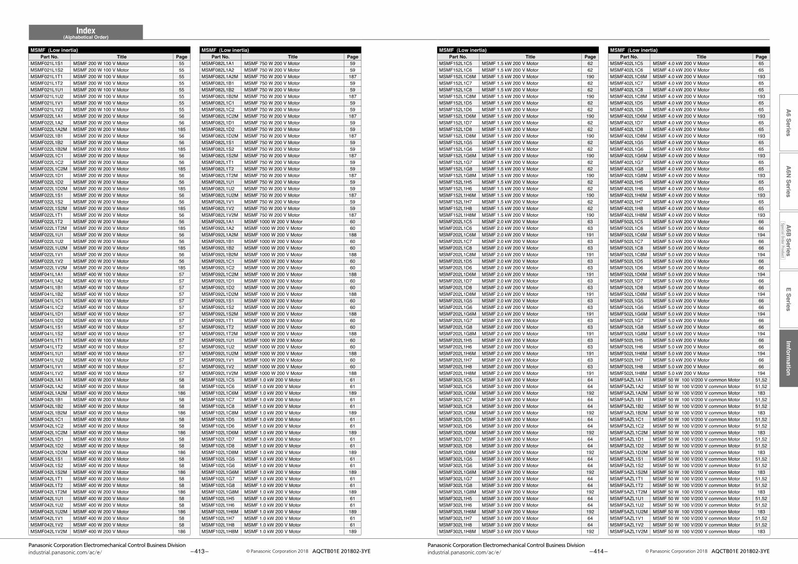
0Part No. Title Page
E SeriesIm
formation
A6 Series
A6N
SeriesA
6B Series
Special Order Product
Index(Alphabetical Order)
– 413 –Panasonic Corporation Electromechanical Control Business Division
industrial.panasonic.com/ac/e/ © Panasonic Corporation 2018 AQCTB01E 201802-3YE – 414 –Panasonic Corporation Electromechanical Control Business Division
industrial.panasonic.com/ac/e/ © Panasonic Corporation 2018 AQCTB01E 201802-3YE
MSMF (Low inertia)Part No. Title Page
MSMF (Low inertia)Part No. Title Page
MSMF (Low inertia)Part No. Title Page
MSMF402L1C5 MSMF 4.0 kW 200 V Motor 65MSMF402L1C6 MSMF 4.0 kW 200 V Motor 65MSMF402L1C6M MSMF 4.0 kW 200 V Motor 193MSMF402L1C7 MSMF 4.0 kW 200 V Motor 65MSMF402L1C8 MSMF 4.0 kW 200 V Motor 65MSMF402L1C8M MSMF 4.0 kW 200 V Motor 193MSMF402L1D5 MSMF 4.0 kW 200 V Motor 65MSMF402L1D6 MSMF 4.0 kW 200 V Motor 65MSMF402L1D6M MSMF 4.0 kW 200 V Motor 193MSMF402L1D7 MSMF 4.0 kW 200 V Motor 65MSMF402L1D8 MSMF 4.0 kW 200 V Motor 65MSMF402L1D8M MSMF 4.0 kW 200 V Motor 193MSMF402L1G5 MSMF 4.0 kW 200 V Motor 65MSMF402L1G6 MSMF 4.0 kW 200 V Motor 65MSMF402L1G6M MSMF 4.0 kW 200 V Motor 193MSMF402L1G7 MSMF 4.0 kW 200 V Motor 65MSMF402L1G8 MSMF 4.0 kW 200 V Motor 65MSMF402L1G8M MSMF 4.0 kW 200 V Motor 193MSMF402L1H5 MSMF 4.0 kW 200 V Motor 65MSMF402L1H6 MSMF 4.0 kW 200 V Motor 65MSMF402L1H6M MSMF 4.0 kW 200 V Motor 193MSMF402L1H7 MSMF 4.0 kW 200 V Motor 65MSMF402L1H8 MSMF 4.0 kW 200 V Motor 65MSMF402L1H8M MSMF 4.0 kW 200 V Motor 193MSMF502L1C5 MSMF 5.0 kW 200 V Motor 66MSMF502L1C6 MSMF 5.0 kW 200 V Motor 66MSMF502L1C6M MSMF 5.0 kW 200 V Motor 194MSMF502L1C7 MSMF 5.0 kW 200 V Motor 66MSMF502L1C8 MSMF 5.0 kW 200 V Motor 66MSMF502L1C8M MSMF 5.0 kW 200 V Motor 194MSMF502L1D5 MSMF 5.0 kW 200 V Motor 66MSMF502L1D6 MSMF 5.0 kW 200 V Motor 66MSMF502L1D6M MSMF 5.0 kW 200 V Motor 194MSMF502L1D7 MSMF 5.0 kW 200 V Motor 66MSMF502L1D8 MSMF 5.0 kW 200 V Motor 66MSMF502L1D8M MSMF 5.0 kW 200 V Motor 194MSMF502L1G5 MSMF 5.0 kW 200 V Motor 66MSMF502L1G6 MSMF 5.0 kW 200 V Motor 66MSMF502L1G6M MSMF 5.0 kW 200 V Motor 194MSMF502L1G7 MSMF 5.0 kW 200 V Motor 66MSMF502L1G8 MSMF 5.0 kW 200 V Motor 66MSMF502L1G8M MSMF 5.0 kW 200 V Motor 194MSMF502L1H5 MSMF 5.0 kW 200 V Motor 66MSMF502L1H6 MSMF 5.0 kW 200 V Motor 66MSMF502L1H6M MSMF 5.0 kW 200 V Motor 194MSMF502L1H7 MSMF 5.0 kW 200 V Motor 66MSMF502L1H8 MSMF 5.0 kW 200 V Motor 66MSMF502L1H8M MSMF 5.0 kW 200 V Motor 194MSMF5AZL1A1 MSMF 50 W 100 V/200 V common Motor 51,52MSMF5AZL1A2 MSMF 50 W 100 V/200 V common Motor 51,52MSMF5AZL1A2M MSMF 50 W 100 V/200 V common Motor 183MSMF5AZL1B1 MSMF 50 W 100 V/200 V common Motor 51,52MSMF5AZL1B2 MSMF 50 W 100 V/200 V common Motor 51,52MSMF5AZL1B2M MSMF 50 W 100 V/200 V common Motor 183MSMF5AZL1C1 MSMF 50 W 100 V/200 V common Motor 51,52MSMF5AZL1C2 MSMF 50 W 100 V/200 V common Motor 51,52MSMF5AZL1C2M MSMF 50 W 100 V/200 V common Motor 183MSMF5AZL1D1 MSMF 50 W 100 V/200 V common Motor 51,52MSMF5AZL1D2 MSMF 50 W 100 V/200 V common Motor 51,52MSMF5AZL1D2M MSMF 50 W 100 V/200 V common Motor 183MSMF5AZL1S1 MSMF 50 W 100 V/200 V common Motor 51,52MSMF5AZL1S2 MSMF 50 W 100 V/200 V common Motor 51,52MSMF5AZL1S2M MSMF 50 W 100 V/200 V common Motor 183MSMF5AZL1T1 MSMF 50 W 100 V/200 V common Motor 51,52MSMF5AZL1T2 MSMF 50 W 100 V/200 V common Motor 51,52MSMF5AZL1T2M MSMF 50 W 100 V/200 V common Motor 183MSMF5AZL1U1 MSMF 50 W 100 V/200 V common Motor 51,52MSMF5AZL1U2 MSMF 50 W 100 V/200 V common Motor 51,52MSMF5AZL1U2M MSMF 50 W 100 V/200 V common Motor 183MSMF5AZL1V1 MSMF 50 W 100 V/200 V common Motor 51,52MSMF5AZL1V2 MSMF 50 W 100 V/200 V common Motor 51,52MSMF5AZL1V2M MSMF 50 W 100 V/200 V common Motor 183
MSMF152L1C5 MSMF 1.5 kW 200 V Motor 62MSMF152L1C6 MSMF 1.5 kW 200 V Motor 62MSMF152L1C6M MSMF 1.5 kW 200 V Motor 190MSMF152L1C7 MSMF 1.5 kW 200 V Motor 62MSMF152L1C8 MSMF 1.5 kW 200 V Motor 62MSMF152L1C8M MSMF 1.5 kW 200 V Motor 190MSMF152L1D5 MSMF 1.5 kW 200 V Motor 62MSMF152L1D6 MSMF 1.5 kW 200 V Motor 62MSMF152L1D6M MSMF 1.5 kW 200 V Motor 190MSMF152L1D7 MSMF 1.5 kW 200 V Motor 62MSMF152L1D8 MSMF 1.5 kW 200 V Motor 62MSMF152L1D8M MSMF 1.5 kW 200 V Motor 190MSMF152L1G5 MSMF 1.5 kW 200 V Motor 62MSMF152L1G6 MSMF 1.5 kW 200 V Motor 62MSMF152L1G6M MSMF 1.5 kW 200 V Motor 190MSMF152L1G7 MSMF 1.5 kW 200 V Motor 62MSMF152L1G8 MSMF 1.5 kW 200 V Motor 62MSMF152L1G8M MSMF 1.5 kW 200 V Motor 190MSMF152L1H5 MSMF 1.5 kW 200 V Motor 62MSMF152L1H6 MSMF 1.5 kW 200 V Motor 62MSMF152L1H6M MSMF 1.5 kW 200 V Motor 190MSMF152L1H7 MSMF 1.5 kW 200 V Motor 62MSMF152L1H8 MSMF 1.5 kW 200 V Motor 62MSMF152L1H8M MSMF 1.5 kW 200 V Motor 190MSMF202L1C5 MSMF 2.0 kW 200 V Motor 63MSMF202L1C6 MSMF 2.0 kW 200 V Motor 63MSMF202L1C6M MSMF 2.0 kW 200 V Motor 191MSMF202L1C7 MSMF 2.0 kW 200 V Motor 63MSMF202L1C8 MSMF 2.0 kW 200 V Motor 63MSMF202L1C8M MSMF 2.0 kW 200 V Motor 191MSMF202L1D5 MSMF 2.0 kW 200 V Motor 63MSMF202L1D6 MSMF 2.0 kW 200 V Motor 63MSMF202L1D6M MSMF 2.0 kW 200 V Motor 191MSMF202L1D7 MSMF 2.0 kW 200 V Motor 63MSMF202L1D8 MSMF 2.0 kW 200 V Motor 63MSMF202L1D8M MSMF 2.0 kW 200 V Motor 191MSMF202L1G5 MSMF 2.0 kW 200 V Motor 63MSMF202L1G6 MSMF 2.0 kW 200 V Motor 63MSMF202L1G6M MSMF 2.0 kW 200 V Motor 191MSMF202L1G7 MSMF 2.0 kW 200 V Motor 63MSMF202L1G8 MSMF 2.0 kW 200 V Motor 63MSMF202L1G8M MSMF 2.0 kW 200 V Motor 191MSMF202L1H5 MSMF 2.0 kW 200 V Motor 63MSMF202L1H6 MSMF 2.0 kW 200 V Motor 63MSMF202L1H6M MSMF 2.0 kW 200 V Motor 191MSMF202L1H7 MSMF 2.0 kW 200 V Motor 63MSMF202L1H8 MSMF 2.0 kW 200 V Motor 63MSMF202L1H8M MSMF 2.0 kW 200 V Motor 191MSMF302L1C5 MSMF 3.0 kW 200 V Motor 64MSMF302L1C6 MSMF 3.0 kW 200 V Motor 64MSMF302L1C6M MSMF 3.0 kW 200 V Motor 192MSMF302L1C7 MSMF 3.0 kW 200 V Motor 64MSMF302L1C8 MSMF 3.0 kW 200 V Motor 64MSMF302L1C8M MSMF 3.0 kW 200 V Motor 192MSMF302L1D5 MSMF 3.0 kW 200 V Motor 64MSMF302L1D6 MSMF 3.0 kW 200 V Motor 64MSMF302L1D6M MSMF 3.0 kW 200 V Motor 192MSMF302L1D7 MSMF 3.0 kW 200 V Motor 64MSMF302L1D8 MSMF 3.0 kW 200 V Motor 64MSMF302L1D8M MSMF 3.0 kW 200 V Motor 192MSMF302L1G5 MSMF 3.0 kW 200 V Motor 64MSMF302L1G6 MSMF 3.0 kW 200 V Motor 64MSMF302L1G6M MSMF 3.0 kW 200 V Motor 192MSMF302L1G7 MSMF 3.0 kW 200 V Motor 64MSMF302L1G8 MSMF 3.0 kW 200 V Motor 64MSMF302L1G8M MSMF 3.0 kW 200 V Motor 192MSMF302L1H5 MSMF 3.0 kW 200 V Motor 64MSMF302L1H6 MSMF 3.0 kW 200 V Motor 64MSMF302L1H6M MSMF 3.0 kW 200 V Motor 192MSMF302L1H7 MSMF 3.0 kW 200 V Motor 64MSMF302L1H8 MSMF 3.0 kW 200 V Motor 64MSMF302L1H8M MSMF 3.0 kW 200 V Motor 192
MSMF (Low inertia)Part No. Title Page
MSMF082L1A1 MSMF 750 W 200 V Motor 59MSMF082L1A2 MSMF 750 W 200 V Motor 59MSMF082L1A2M MSMF 750 W 200 V Motor 187MSMF082L1B1 MSMF 750 W 200 V Motor 59MSMF082L1B2 MSMF 750 W 200 V Motor 59MSMF082L1B2M MSMF 750 W 200 V Motor 187MSMF082L1C1 MSMF 750 W 200 V Motor 59MSMF082L1C2 MSMF 750 W 200 V Motor 59MSMF082L1C2M MSMF 750 W 200 V Motor 187MSMF082L1D1 MSMF 750 W 200 V Motor 59MSMF082L1D2 MSMF 750 W 200 V Motor 59MSMF082L1D2M MSMF 750 W 200 V Motor 187MSMF082L1S1 MSMF 750 W 200 V Motor 59MSMF082L1S2 MSMF 750 W 200 V Motor 59MSMF082L1S2M MSMF 750 W 200 V Motor 187MSMF082L1T1 MSMF 750 W 200 V Motor 59MSMF082L1T2 MSMF 750 W 200 V Motor 59MSMF082L1T2M MSMF 750 W 200 V Motor 187MSMF082L1U1 MSMF 750 W 200 V Motor 59MSMF082L1U2 MSMF 750 W 200 V Motor 59MSMF082L1U2M MSMF 750 W 200 V Motor 187MSMF082L1V1 MSMF 750 W 200 V Motor 59MSMF082L1V2 MSMF 750 W 200 V Motor 59MSMF082L1V2M MSMF 750 W 200 V Motor 187MSMF092L1A1 MSMF 1000 W 200 V Motor 60MSMF092L1A2 MSMF 1000 W 200 V Motor 60MSMF092L1A2M MSMF 1000 W 200 V Motor 188MSMF092L1B1 MSMF 1000 W 200 V Motor 60MSMF092L1B2 MSMF 1000 W 200 V Motor 60MSMF092L1B2M MSMF 1000 W 200 V Motor 188MSMF092L1C1 MSMF 1000 W 200 V Motor 60MSMF092L1C2 MSMF 1000 W 200 V Motor 60MSMF092L1C2M MSMF 1000 W 200 V Motor 188MSMF092L1D1 MSMF 1000 W 200 V Motor 60MSMF092L1D2 MSMF 1000 W 200 V Motor 60MSMF092L1D2M MSMF 1000 W 200 V Motor 188MSMF092L1S1 MSMF 1000 W 200 V Motor 60MSMF092L1S2 MSMF 1000 W 200 V Motor 60MSMF092L1S2M MSMF 1000 W 200 V Motor 188MSMF092L1T1 MSMF 1000 W 200 V Motor 60MSMF092L1T2 MSMF 1000 W 200 V Motor 60MSMF092L1T2M MSMF 1000 W 200 V Motor 188MSMF092L1U1 MSMF 1000 W 200 V Motor 60MSMF092L1U2 MSMF 1000 W 200 V Motor 60MSMF092L1U2M MSMF 1000 W 200 V Motor 188MSMF092L1V1 MSMF 1000 W 200 V Motor 60MSMF092L1V2 MSMF 1000 W 200 V Motor 60MSMF092L1V2M MSMF 1000 W 200 V Motor 188MSMF102L1C5 MSMF 1.0 kW 200 V Motor 61MSMF102L1C6 MSMF 1.0 kW 200 V Motor 61MSMF102L1C6M MSMF 1.0 kW 200 V Motor 189MSMF102L1C7 MSMF 1.0 kW 200 V Motor 61MSMF102L1C8 MSMF 1.0 kW 200 V Motor 61MSMF102L1C8M MSMF 1.0 kW 200 V Motor 189MSMF102L1D5 MSMF 1.0 kW 200 V Motor 61MSMF102L1D6 MSMF 1.0 kW 200 V Motor 61MSMF102L1D6M MSMF 1.0 kW 200 V Motor 189MSMF102L1D7 MSMF 1.0 kW 200 V Motor 61MSMF102L1D8 MSMF 1.0 kW 200 V Motor 61MSMF102L1D8M MSMF 1.0 kW 200 V Motor 189MSMF102L1G5 MSMF 1.0 kW 200 V Motor 61MSMF102L1G6 MSMF 1.0 kW 200 V Motor 61MSMF102L1G6M MSMF 1.0 kW 200 V Motor 189MSMF102L1G7 MSMF 1.0 kW 200 V Motor 61MSMF102L1G8 MSMF 1.0 kW 200 V Motor 61MSMF102L1G8M MSMF 1.0 kW 200 V Motor 189MSMF102L1H5 MSMF 1.0 kW 200 V Motor 61MSMF102L1H6 MSMF 1.0 kW 200 V Motor 61MSMF102L1H6M MSMF 1.0 kW 200 V Motor 189MSMF102L1H7 MSMF 1.0 kW 200 V Motor 61MSMF102L1H8 MSMF 1.0 kW 200 V Motor 61MSMF102L1H8M MSMF 1.0 kW 200 V Motor 189
MSMF021L1S1 MSMF 200 W 100 V Motor 55MSMF021L1S2 MSMF 200 W 100 V Motor 55MSMF021L1T1 MSMF 200 W 100 V Motor 55MSMF021L1T2 MSMF 200 W 100 V Motor 55MSMF021L1U1 MSMF 200 W 100 V Motor 55MSMF021L1U2 MSMF 200 W 100 V Motor 55MSMF021L1V1 MSMF 200 W 100 V Motor 55MSMF021L1V2 MSMF 200 W 100 V Motor 55MSMF022L1A1 MSMF 200 W 200 V Motor 56MSMF022L1A2 MSMF 200 W 200 V Motor 56MSMF022L1A2M MSMF 200 W 200 V Motor 185MSMF022L1B1 MSMF 200 W 200 V Motor 56MSMF022L1B2 MSMF 200 W 200 V Motor 56MSMF022L1B2M MSMF 200 W 200 V Motor 185MSMF022L1C1 MSMF 200 W 200 V Motor 56MSMF022L1C2 MSMF 200 W 200 V Motor 56MSMF022L1C2M MSMF 200 W 200 V Motor 185MSMF022L1D1 MSMF 200 W 200 V Motor 56MSMF022L1D2 MSMF 200 W 200 V Motor 56MSMF022L1D2M MSMF 200 W 200 V Motor 185MSMF022L1S1 MSMF 200 W 200 V Motor 56MSMF022L1S2 MSMF 200 W 200 V Motor 56MSMF022L1S2M MSMF 200 W 200 V Motor 185MSMF022L1T1 MSMF 200 W 200 V Motor 56MSMF022L1T2 MSMF 200 W 200 V Motor 56MSMF022L1T2M MSMF 200 W 200 V Motor 185MSMF022L1U1 MSMF 200 W 200 V Motor 56MSMF022L1U2 MSMF 200 W 200 V Motor 56MSMF022L1U2M MSMF 200 W 200 V Motor 185MSMF022L1V1 MSMF 200 W 200 V Motor 56MSMF022L1V2 MSMF 200 W 200 V Motor 56MSMF022L1V2M MSMF 200 W 200 V Motor 185MSMF041L1A1 MSMF 400 W 100 V Motor 57MSMF041L1A2 MSMF 400 W 100 V Motor 57MSMF041L1B1 MSMF 400 W 100 V Motor 57MSMF041L1B2 MSMF 400 W 100 V Motor 57MSMF041L1C1 MSMF 400 W 100 V Motor 57MSMF041L1C2 MSMF 400 W 100 V Motor 57MSMF041L1D1 MSMF 400 W 100 V Motor 57MSMF041L1D2 MSMF 400 W 100 V Motor 57MSMF041L1S1 MSMF 400 W 100 V Motor 57MSMF041L1S2 MSMF 400 W 100 V Motor 57MSMF041L1T1 MSMF 400 W 100 V Motor 57MSMF041L1T2 MSMF 400 W 100 V Motor 57MSMF041L1U1 MSMF 400 W 100 V Motor 57MSMF041L1U2 MSMF 400 W 100 V Motor 57MSMF041L1V1 MSMF 400 W 100 V Motor 57MSMF041L1V2 MSMF 400 W 100 V Motor 57MSMF042L1A1 MSMF 400 W 200 V Motor 58MSMF042L1A2 MSMF 400 W 200 V Motor 58MSMF042L1A2M MSMF 400 W 200 V Motor 186MSMF042L1B1 MSMF 400 W 200 V Motor 58MSMF042L1B2 MSMF 400 W 200 V Motor 58MSMF042L1B2M MSMF 400 W 200 V Motor 186MSMF042L1C1 MSMF 400 W 200 V Motor 58MSMF042L1C2 MSMF 400 W 200 V Motor 58MSMF042L1C2M MSMF 400 W 200 V Motor 186MSMF042L1D1 MSMF 400 W 200 V Motor 58MSMF042L1D2 MSMF 400 W 200 V Motor 58MSMF042L1D2M MSMF 400 W 200 V Motor 186MSMF042L1S1 MSMF 400 W 200 V Motor 58MSMF042L1S2 MSMF 400 W 200 V Motor 58MSMF042L1S2M MSMF 400 W 200 V Motor 186MSMF042L1T1 MSMF 400 W 200 V Motor 58MSMF042L1T2 MSMF 400 W 200 V Motor 58MSMF042L1T2M MSMF 400 W 200 V Motor 186MSMF042L1U1 MSMF 400 W 200 V Motor 58MSMF042L1U2 MSMF 400 W 200 V Motor 58MSMF042L1U2M MSMF 400 W 200 V Motor 186MSMF042L1V1 MSMF 400 W 200 V Motor 58MSMF042L1V2 MSMF 400 W 200 V Motor 58MSMF042L1V2M MSMF 400 W 200 V Motor 186

E SeriesIm
formation
A6 Series
A6N
SeriesA
6B Series
Special Order Product
– 415 –Panasonic Corporation Electromechanical Control Business Division
industrial.panasonic.com/ac/e/ © Panasonic Corporation 2018 AQCTB01E 201802-3YE – 416 –Panasonic Corporation Electromechanical Control Business Division
industrial.panasonic.com/ac/e/ © Panasonic Corporation 2018 AQCTB01E 201802-3YE
Index(Alphabetical Order)
MUMA (Low inertia MINAS E series Motor)Part No. Title Page
MUMA011P1S MUMA 100 W 100 V Incremental encoder 343,347MUMA011P1T MUMA 100 W 100 V Incremental encoder 343,347MUMA012P1S MUMA 100 W 200 V Incremental encoder 345,347MUMA012P1T MUMA 100 W 200 V Incremental encoder 345,347MUMA021P1S MUMA 200 W 100 V Incremental encoder 343,347MUMA021P1T MUMA 200 W 100 V Incremental encoder 343,347MUMA022P1S MUMA 200 W 200 V Incremental encoder 345,347MUMA022P1T MUMA 200 W 200 V Incremental encoder 345,347MUMA042P1S MUMA 400 W 200 V Incremental encoder 345,347MUMA042P1T MUMA 400 W 200 V Incremental encoder 345,347
MUMA5AZP1S MUMA 50 W 100 V/200 V common Incremental encoder
343,345347
MUMA5AZP1T MUMA 50 W 100 V/200 V common Incremental encoder
343,345347
MUMA (MINAS E series Motor with gear reducer)Part No. Title Page
MUMA011P31N
MUMA with reduction gear 100 W 100 V Incremental encoder
348,351MUMA011P32N 348,351MUMA011P34N 348,351MUMA011P41N 348,351MUMA011P42N 348,351MUMA011P44N 348,351MUMA012P31N
MUMA with reduction gear 100 W 200 V Incremental encoder
348,351MUMA012P32N 348,351MUMA012P34N 348,351MUMA012P41N 348,351MUMA012P42N 348,351MUMA012P44N 348,351MUMA021P31N
MUMA with reduction gear 200 W 100 V Incremental encoder
348,351MUMA021P32N 348,351MUMA021P34N 348,351MUMA021P41N 348,351MUMA021P42N 348,351MUMA021P44N 348,351MUMA022P31N
MUMA with reduction gear 200 W 200 V Incremental encoder
348,351MUMA022P32N 348,351MUMA022P34N 348,351MUMA022P41N 348,351MUMA022P42N 348,351MUMA022P44N 348,351MUMA042P31N
MUMA with reduction gear 400 W 200 V Incremental encoder
348,351MUMA042P32N 348,351MUMA042P34N 348,351MUMA042P41N 348,351MUMA042P42N 348,351MUMA042P44N 348,351
U.S.A Panasonic Industrial Devices Sales Company of America[Salesoffice]
New Jersey Two Riverfront Plaza, 7th Floor Newark, NJ 07102-5490 U.S.A
+1-800-228-2350
—
Brazil Panasonic do Brazil[Salesoffice]
Sao PauloAvenida do Cafe, 277 Torre A-8 Andar Jabaquara ZIP Code: 04311-900 Sao Paulo SP Brazil
+55-11-3889-4022
+55-11-3889-4103
Germany
Panasonic Industry Europe GmbH [Salesoffice][European Headquarter]
Munich
Robert-Koch-Strasse 100, 85521 Ottobrunn, Germany
+49 89-45354-0+49-89-4535-41-550
e-mail https://eu.industrial.panasonic.com/about-us/contact-us
Web site https://eu.industrial.panasonic.com/products/motors-compressors-pumps
Panasonic Electric Works Europe AG [Salesoffice][European Headquarter]
Munich
Robert-Koch-Strasse 100, 85521 Ottobrunn, Germany
+49 (0) 89 45354-1000+49 (0) 89 45354-2111
e-mail [email protected]
Web site https://panasonic-electric-works.com/eu/servo-drives-and-motors.htm
Panasonic Electric Works Europe AG [Subsidiary]
Munich
Robert-Koch-Strasse 100, 85521 Ottobrunn, Germany
+49 (0) 89 45354-1000+49 (0) 89 45354-2111
e-mail [email protected]
Web site https://panasonic-electric-works.com/de/servoantriebe-servomotoren.htm
ghv Vertriebs-GmbH [Distributors]
Munich
AmSchammacherFeld47D-85567Grafingb. Munich
+49(0)-80-92/81-89-0+49(0)-80-92/81-89-99
e-mail [email protected] site https://www.ghv.de/
FrancePanasonic Electric Works Sales Western Europe B.V.[Salesoffice]
Verrières-Le-Buisson
8/10, rue des Petits Ruisseaux 91370 VERRIЀRESLEBUISSON
+33(0)160135757+31(0)160135758
e-mail [email protected]
Web site https://www.panasonic-electric-works.com/fr/servosystemes-et-servomoteurs.htm
Italy
Panasonic Electric Works Italia srl[Subsidiary]
Verona
Via del Commercio 3-5 (Z.I.Ferlina), 37012 Bussolengo (VR), Italy
+39-045-6752711+39-045-6700444
e-mail [email protected]
Web site https://www.panasonic-electric-works.com/it/servoazionamenti-e-motori.htm
Lenze Italia S.r.l.[Distributors]
MilanoViale Tibaldi, 7 20136 Milano
+39-02-270-98-1+39-02-270-98-290
e-mail [email protected] site http://www.lenze.com/it-it
United Kingdom
Panasonic Electric Works UK Ltd.[Salesoffice]
Milton Keynes
Sunrise Parkway, Linford Wood Milton Keynes, MK14 6LF United Kingdom
+44(0)1908231 555+44(0)1908231 599
e-mail [email protected]
Web site https://www.panasonic-electric-works.com/uk/servo-drives-and-motors.htm
Lenze Limited [Distributors]
BedfordPriory Business Park, Bedford, MK44 3WH.
+44-1234-7532-00+44-1234-7532-20
e-mail [email protected] site http://www.lenze.com/en-gb/about-lenze/lenze-in-united-kingdom
Austria Panasonic Electric Works Austria GmbH[Salesoffice]
Biedermannsdorf
Josef Madersperger Strasse 2, 2362 Biedermannsdorf (Vienna), Austria
+43(0)2236-26846-7+43(0)2236-46133
e-mail [email protected]
Web site https://www.panasonic-electric-works.com/at/servoantriebe-servomotoren.htm
PolskaPanasonic Electric Works Polska sp. z.o.o.[Salesoffice]
Warszawaul.Wołoska9a,02-583Warszawa
+48(0)22338-11-33+48(0)22338-12-00
e-mail [email protected] site https://www.panasonic-electric-works.com/pl/serwonapedy.htm
NederlandPanasonic Electric Works Sales Western Europe B.V. [Salesoffice]
PJ Best
De Rijn 4 (Postbus 211), 5684 PJ Best, Nederland
+31(0)499372727+31(0)499372185
e-mail [email protected]
Web site https://panasonic-electric-works.com/be/servosystemes-et-servomoteurs.htm
Country Company Name[Category] City Address
TEL
FAX
[Panasonic Sales Office of Motors] (February.01.2018)
Sales Office

E SeriesIm
formation
A6 Series
A6N
SeriesA
6B Series
Special Order Product
00 00A6 Family A6 FamilyX X
– 417 –Panasonic Corporation Electromechanical Control Business Division
industrial.panasonic.com/ac/e/ © Panasonic Corporation 2018 AQCTB01E 201802-3YE – 418 –Panasonic Corporation Electromechanical Control Business Division
industrial.panasonic.com/ac/e/ © Panasonic Corporation 2018 AQCTB01E 201802-3YE
KoreaPanasonic Industrial Devices Sales Korea Co., Ltd. (PIDSKR)[Salesoffice]
Seoul 6F DONG-IL Tower 38, Teheran-ro 114-gil, Gangnam-gu, Seoul, 135-851, Korea
+82-2-795-9600
+82-2-2052-1053
TaiwanPanasonic Industrial Devices Sales Taiwan Co.,Ltd.[Salesoffice]
Taipei 12F, No.9, SongGao Rd., Taipei 110, Taiwan, R.O.C.
+886-2-2757-1900
+886-2-2757-1977
Southeast Asia
Panasonic Industrial Devices Sales Asia [Salesoffice]
Singapore No.3 Bedok South Road Singapore 469269+65-6390-3718+65-9435-6844
Singapore Intermech Machinery Pte.Ltd.[Distributors]
Singapore
2 Woodlands Sector 1 #03-25, Woodlands Spectrum 1 Singapore 738068
+65-6751-5088+65-6759-2122
e-mail [email protected] site http://www.intermech.com.sg
Malaysia Panamech (Penang) Sdn. Bhd.[Distributors]
Penang
18, Persiaran Mahsuri 1/2, Sunway Tunas, Penang, 11900
+60-4-645-1635+60-4-645-1639
e-mail [email protected] site http://panamech.com.my
Thailand
Premier Automation Center Co.,Ltd. [Distributors]
Bangkok
87, Soi Lakrabang 30, Ladkrabang, Ladkrabang, Bangkok 10520
+66-2181-2299+66-2181-2288
e-mail [email protected] site http://www.premier-ac.co.th
JW Tech Co., Ltd.[Distributors]
Bangkok
697 Soi Senavilla Village, Nawamin RD Klongchan, Bangkapi, Bangkok 10240
+66-2733-7702+66-2733-7703
e-mail [email protected] site http://www.jwtech.co.th
Sang Chai Meter Co., Ltd.[Distributors]
Bangkok
888 Phaholyothin Road, Samsennai, Phayathai, Bangkok 10120
+66-2299-3333+66-2299-3000
e-mail [email protected] site https://www.sangchaimeter.com
Indonesia
PT. Handal Yesindo Sejahtera [Distributors]
SurabayaJl. Raya Kutisari 8A, Surabaya 60291
+62-31-843-8844+62-31-841-4333
e-mail [email protected] site http://www.handalyesindo.com
PT.Riasarana Electrindo[Distributors]
JakartaJl. Prof. Dr. Latumenten Grogol Permai blok D No. 8-15 Jakarta 11460
+62-21-564-9178+62-21-566-7405
Web site http://www.risacorps.com
Vietnam
Pavina Corporation[Distributors]
Ho Chi Minh
005 C1 Ly Thuong Kiet Blog, Vinh Vien Street, Ward 07, District 11, Ho Chi Minh
+84-8-39554457+84-8-39550033
e-mail [email protected] site http://sieuthitudong.com
KSMC Co., Ltd.[Distributors]
Ha Noi
A10-No 06B, HH6, Viet Hung Urban Area, Long Bien, Ha Noi
+84-4-38771700+84-4-38770229
e-mail [email protected] site http://ksmc.com.vn
Philippines MovaflexDesignsUnlimited,Inc.[Distributors]
Manila136 Calbayog Street, Mandaluyong City, Metro Manila 1552
+63-2-998-3881+63-2-633-7526
e-mail [email protected]
Australia Motion Technologies Pty. Ltd.[Distributors]
Sydney
24/22-30 Northumberland Road, Caringbah, NSW, 2229
+61-2-9524-4782+61-2-9525-3878
e-mail [email protected] site http://www.motiontech.com.au
Country Company Name[Category] City Address
TEL
FAX
Czech Republic Panasonic Electric Works Czech s.r.o.[Salesoffice]
BrnoVeveří3163/111,61600Brno,Czech
+420(0)541217001+420(0)541217101
e-mail [email protected] site https://www.panasonic-electric-works.com/cz/servomotory.htm
Spain Panasonic Electric Works Espana S.A.[Subsidiary]
Madrid
Barajas Park, San Severo 20, 28042 Madrid, Spain
+34-91-329-0937+34-91-329-2976
e-mail [email protected]
Web site https://www.panasonic-electric-works.com/es/servoaccionamientos-y-motores.htm
Romania C.I.T. Automatizari SRL[Distributors]
Bucuresti
sos. Bucuresti, nr.63, Ciorogirla, Ilfov, RO-077055, ROMANIA
+40-21-255-0543+40-21-255-0544
e-mail [email protected] site http://www.citautomatizari.ro
Hungary Panasonic Electric Works Hungary [Salesoffice]
Budapest
Neumann J. u. 1., 1117 Budapest, Hungary +36(0)19998926+36(0)19998927
e-mail [email protected]
Web site https://www.panasonic-electric-works.com/eu/servo-drives-and-motors.htm
Switzerland Panasonic Electric Works Schweiz AG[Salesoffice]
Rotkreuz
Grundstrasse 8, 6343 Rotkreuz, Schwitzerland
+41(0)417997054+31(0)417997055
e-mail [email protected]
Web site https://www.panasonic-electric-works.com/ch/fr/servosystemes-et-servomoteurs.htm
Russia EFO Ltd.[Distributors]
St.Petersburg
15ANovolitovskayastr.,office44194100St.Petersburg, Russia
+7-8123278654+7-8123201819
e-mail [email protected] site http://www.efo.ru
Turkey
Savior Kontrol Otomasyon[Distributors]
Istanbul
DES Sanayi Sitesi 102 Sk. B-06 Blok No: 6-8 34776YukarıDudulluÜmraniyeİstanbulTurkey
+90-216-466-3683
+90-216-466-3685e-mail [email protected]
Web site http://www.savior.com.tr
BOSTEK TEKNOLOJI GELISTIRME VE ROBOT SIST.SAN.TIC.A.S[Distributors]
Izmir
10042 SOK.NO:10 A.O.S.B CIGLI-IZMIR, TURKEY
+90 232 433 8515+90 232 433 8881
e-mail [email protected] site http://www.bostek.com.tr
China
Panasonic Industrial Devices Sales (Hong Kong) Co.,Ltd. (PIDSHK)[Salesoffice]
Hong kongTop Floor, South Wing, ChinaChem Gloden Plaza, 77 Mody Road, S.T.S. East, Kowloon, HongKong
+852-2529-7322
+852-2598-9743
Panasonic Industrial Devices Sales (China) Co.,Ltd. (PIDSCN)[Salesoffice]
ShanghaiFloor 6, China Insurance Building, 166 East Road LuJiaZui PuDong New District, Shanghai, China
+86-21-3855-2442
+86-21-3855-2375Panasonic Industrial Devices Sales (China) Co.,Ltd. (PIDSCN)[Salesoffice]
Shenzhen 8/F, Tower Three, Kerry Plaza, 1-1 Zhongxinsi Road, Futian District, Shenzhen, China
+86-755-8255-8791
—
India
Panasonic India Industrial Division (HeadOffice)[Salesoffice]
Delhi 12th Floor, Ambience Tower, Ambience Island, NH-8, Gurgaon, Haryana 122002
+91-124-4751300
+91-124-4751333Panasonic India Industrial Division (Bangalore Branch)[Salesoffice]
BengaluruJ.P Chambers 2nd Floor, #276/22-1, 46th Cross, 5th Block, Jayanagar, Bengaluru, Karnataka-560041
+91-80-6576-0014
—
Lubi Electronics[Distributors]
Ahmedabad
Sardar Patel Ring Road, Near Karai Gam Patia, Nana Chiloda, Gandhinagar, Gujarat 382330
+91-79-3984-5300
+91-79-3984-5599e-mail [email protected]
Web site http://www.lubielectronics.com
Luna Bearings[Distributors]
Mumbai
No.59, 2nd Floor, Moiz Manzil, Bibijan Street,Mumbai, Maharashtra 400003
+91-22-4078-6110+91-22-2342-7773
e-mail [email protected] site http://www.lunabearings.com
Vashi Electricals[Distributors]
Mumbai
A-6, Shree Ganesh Complex, Behind Gupta Compound, Dapode Road, Mankoli Naka, Bhiwandi, Mumbai, Maharashtra 421305
+91-25-2266-1600
+91-25-2266-1620e-mail [email protected]
Web site http://www.vashielectricals.com
Country Company Name[Category] City Address
TEL
FAX
Sales Office