access control manager admin guide - avigilon
TRANSCRIPT
Admin GuideAccess Control Manager™ Software
Version 6.16.0

© 2016- 2021, Avigilon Corporation. All rights reserved. AVIGILON, the AVIGILON logo, AVIGILONCONTROL CENTER, ACC, ACCESS CONTROL MANAGER, ACM and ACM VERIFY are trademarks of AvigilonCorporation. HID, HID GLOBAL, APERIO and VERTX are trademarks or registered trademarks of HID Global,ASSA ABLOY AB, or its affiliate(s) in the US and other countries. Allegion, ENGAGE technology and Schlageare trademarks of Allegion plc, its subsidiaries and/or affiliates in the United States and other countries. Linuxis a registered trademark of Linus Torvald in the US and other countries. Firefox is a trademark of the MozillaFoundation in the US and other countries. Other names or logos mentioned herein may be the trademarks oftheir respective owners. The absence of the symbols ™ and ® in proximity to each trademark in thisdocument or at all is not a disclaimer of ownership of the related trademark. Avigilon Corporation protectsits innovations with patents issued in the United States of America and other jurisdictions worldwide (seeavigilon.com/patents). Unless stated explicitly and in writing, no license is granted with respect to anycopyright, industrial design, trademark, patent or other intellectual property rights of Avigilon Corporation orits licensors.
This document has been compiled and published using product descriptions and specifications available atthe time of publication. The contents of this document and the specifications of the products discussedherein are subject to change without notice. Avigilon Corporation reserves the right to make any suchchanges without notice. Neither Avigilon Corporation nor any of its affiliated companies: (1) guarantees thecompleteness or accuracy of the information contained in this document; or (2) is responsible for your useof, or reliance on, the information. Avigilon Corporation shall not be responsible for any losses or damages(including consequential damages) caused by reliance on the information presented herein.
Avigilon Corporationavigilon.com
PDF-ACM-ADM-6.16.0-A
Revision: 1 - EN
20210128
2
Revisions
ACMRelease Description
ACM 6.16,February 2021
Support for SALTO server and doors:
l Installation
l SALTO Door Installation on page 292
l Editing Tokens — Update Required and Re-edition Required onpage 300
l Supported External Systems on page 410
l Note update in Adding Panels on page 156
l Note update in Adding Doors on page 215
l Door Modes on page 192
l Note update in Deleting Doors on page 192
l Note update in Adding Schedules (Intervals in Schedules) on page 378
l Note updates in Adding Holidays on page 380
l SALTO server-related delegations in Permissions and Rights onpage 457
l Operation
l Canceling Keys on page 302
l Downloading All Tokens on page 302
l Note update in Restoring Backups on page 351
l Troubleshooting
l Door Events on page 484
l Panel and Schedule Events on page 488
l SALTO Key Events on page 488Other updates:
l Name Server field description in Replication and Failover Requirements onpage 330 and 1. Preparing Appliances for Replication and Failover onpage 332
Revisions 3
ACMRelease Description
Release 6.14,November 2020
Never Expire field added to Role pages:
l Roles - Role: Edit page on page 82
Certificate delegations that can be assigned to the ACM Super Admin user role:
l Custom certificate-related delegations in Permissions and Rights on page 457
l Configuring Remote Authentication Using SSL Certificates on page 393
Maximum number of supported collaborations:
l Supported Collaborations on page 371
Release 6.12,October 2020
User Forms in identity management for ACM Super Admin users:
l User Forms Overview on page 385
l Adding an Identity on page 60
l Editing an Identity on page 71
SSL certificate signing request and certificate upload for ACM Admin users:
l SSL Certificates Overview on page 355
l System Events on page 489
Token Status description:
l Identities - Token Edit page on page 72
Release 6.10,September 2020
Support for Allegion Schlage® offline Wi-Fi locks:
l Offline Wi-Fi Mode Installation on page 286
l Viewing Gateway or Offline Wi-Fi Lock Status on page 290
l Updating Lock Firmware on page 290
l Deleting Offline Wi-Fi Locks on page 291
l "Door has been added event" in Door Events on page 484
l Schlage WiFi Door Communication Interval and Site for Schlage WiFi Locksfields in System Settings - General page on page 396
Support for Custom Schedule in IP/PoE mode devices:
l Adding Doors on page 215
FIPS 140-2 cryptographic module re-certification:
l Appendix: pivCLASS Configuration on page 490
Revisions 4
ACMRelease Description
Release 6.8,August 2020
Support for Control, LEB, NDEB, RU, and RM wireless devices by a single gateway:
l IP/PoE Mode Installation on page 277
l Troubleshooting on page 484
FIPS 201-2 certification:
l Appendix: pivCLASS Configuration on page 490
Release 6.6, June2020
Support for IP (PoE or 410-IP) mode gateway and wireless locks:
l IP/PoE Mode Installation on page 277
l Viewing Gateway or Offline Wi-Fi Lock Status on page 290
New outputs table:
l Monitor - Dashboard on page 45
Support for activate.avigilon.com:
l Adding a License on page 358
Release 6.4,February 2020
New inputs table:
l Monitor - Dashboard on page 45
New Max Days Stored field and relabeled Max Stored Transactions field (previouslyStored Transactions):
l Editing Appliance Settings on page 325 , 1. Preparing Appliances forReplication and Failover on page 332
Other updates:
l New procedure: Triggering Door Lockdown By Panic Button or Red Card onpage 440
l End Day/Time field functionality ends at end of minute and not beginning ofminute: Overriding Door Modes and Schedules on page 443, Modifying anOverride on page 446
l Note describing Escape and Return state in SimonsVoss wireless lockssuperseding the ACM lockdown priority operation: Configuring SimonsVossWireless Locks on page 209, Priority Situations on page 429
l Internet Explorer replaced by Microsoft Edge as supported browser:Capturing and Uploading Photos of an Identity on page 63
l Obsolete 'Add New Appliance' button and 'Appliance: Add page' removed
Revisions 5
ACMRelease Description
Release 6.2,November 2019
Support for mandatory password change for the default admin user on first login tothe ACM system:
l Logging In on page 23
Support for saving an identity export to the local drive:
l Adding a Collaboration on page 363, Supported Collaborations on page 371,Previewing the General Identity Collaboration Log on page 373, Extracting aCSV Zip File on page 374
Support for new subpanels table:
l Monitor - Dashboard on page 45
Support for Mercury Security LP-series 4502 model doors, panels, firmware,identities, PIV and PIV-I tokens, and embedded pivCLASS Authentication Module(PAM) and auxiliary authentication module (AAM):
l Appendix: pivCLASS Configuration on page 490
Other updates:
l Complete OSDP reader configuration in ACM software before physicallyconnecting them: Reader Templates on page 138
Revisions 6
Table of Contents
Revisions 3
Introduction 23
Logging In 23
Initial Setup 24
Accepting the End User License Agreement 24
Upgrading Your License Format 24
Adding a License 25
Online Licensing 25
Offline Licensing 25
Changing the Administrator Password 26
Creating a Super Admin Identity 26
Monitoring 28
Monitoring Events 28
Pause/Resume Events 29
Clear Events 29
View Live Video 30
View Recorded Video 30
Create Event Notes 30
View Event Notes 31
View Event Instructions 31
View Event Identity Details 32
View Event History 32
Change Events List Settings 32
Reconnect to Events List 33
Searching for Events and Alarms 33
View Camera (Search) 34
View Recorded Video (Search) 34
Create Event Notes (Search) 35
View Event Notes (Search) 35
View Event Instructions (Search) 36
View Event Identity Details (Search) 36
View Event History (Search) 36
Change Transactions List Settings 37
Monitor Alarms 37
7
Acknowledge Alarms 38
View Live Video (Alarms) 39
View Recorded Video (Alarms) 39
Create Event Notes (Alarms) 40
View Event Notes (Alarms) 40
View Event Instructions (Alarms) 41
View Event Identity Details (Alarms) 41
View Event History (Alarms) 41
Change Alarms List Settings 42
Monitor - Verification screen 42
Verifying Identities at Doors 43
Verification Events List 44
Monitor - Dashboard 45
Status Colors 46
Device Status 47
Installing, Uninstalling and Deleting Panels and Subpanels 48
Viewing, Masking and Unmasking Inputs 48
Viewing, Activating and Deactivating Outputs 48
Searching Panel, Subpanel, Input and Door Names 49
Saving Door Filters 49
Controlling Doors 49
Accessing Web Interface of Power Panels 50
Monitor Screen - Map Templates page 51
Using a Map 51
Adding Maps 54
Monitor Intrusion Panels 54
Monitor Intrusion Panel Status 54
Monitor Intrusion Panel Areas 55
Monitor Intrusion Panel Points 57
Monitor Intrusion Panel Outputs 58
Identities 59
Searching for an Identity 59
Adding an Identity 60
Assigning Roles to Identities 61
Assigning Tokens to Identities 62
Assigning Groups to Identities 63
Capturing and Uploading Photos of an Identity 63
8
Creating Badges for Identities 68
Timed Access 69
Adding Timed Access to an Identity 70
Editing Timed Access 70
Deleting Timed Access 71
Editing an Identity 71
Identities - Token Edit page 72
Managing Roles 76
Configuring Roles 76
Adding a Role 76
Editing a Role 77
Assigning an Access Group to a Role 77
Assigning Delegations to a Role 78
Assigning Routing Groups to a Role 78
Assigning Roles 79
Deleting a Role 79
Roles - Role Search page 79
Roles - Role: Add page 81
Roles - Role: Edit page 82
Roles - Access Groups page 83
Roles - Delegate page 83
Roles - Routing page 84
Roles - Assign Roles page 84
Roles - Access page 85
Roles - Audit page 85
Configuring Policies 85
Adding a Policy 86
Editing a Policy 86
Deleting a Policy 87
Policies list 87
Policies - Policy Add page 87
Policies - Policy: Add page 88
Policies - Mercury Security page 88
Policies - Input page 92
Policies - Output page 92
Policies - Audit page 93
Configuring Groups 93
9
Adding a Group 94
Editing a Group 94
Assigning Policies to Groups 95
Assigning Members to Groups 95
Creating a Hardware Group for Routing 96
Using Policies to Override Hardware Settings 97
Performing an Identity or Template Batch Update 97
Scheduling an Identity or Door Batch Update 98
Deleting a Group 99
Groups list 99
Groups - Group Add page 99
Groups - Group Edit page 99
Groups - Policies page 100
Groups - Members page 100
Groups - Audit page 101
Managing Door Access 101
Adding an Access Group 101
Editing an Access Group 102
Deleting an Access Group 102
Access Groups - Example 103
Assigning an Access Group to a Role 103
Access Groups list 104
Access Groups - Access Group Add page 104
Access Groups - Access Group: Edit page 105
Access Groups - Access page 106
Access Groups - Audit page 106
Managing Access in the Application 107
Adding a Delegation 107
Editing a Delegation 108
Adding a Delegation to a Role 108
Deleting a Delegation 108
Delegations list 109
Delegations - Delegation: Edit page 109
Managing a Partitioned ACM System 110
Planning a Partitioned System 111
Configuring a Partitioned ACM System 113
Adding a Partition 113
10
Editing a Partition 114
Deleting a Partition 114
Partitions - List 114
Partitions - Add page 115
Partitions - Partition Edit page 115
Assigning Partitions to ACM Operators and Entities 116
Routing Events to the Monitor Screen 117
Adding a Routing Group 117
Editing a Routing Group 118
Assigning a Routing Group to a Role 119
Deleting a Routing Group 119
Routing Groups list 120
Routing Groups - Add page 120
Routing Groups - Schedule page 120
Routing Groups - Event Types page 121
Routing Groups - Groups page 121
Managing Elevator Access 122
Adding an Elevator Access Level 122
Editing an Elevator Access Level 123
Assigning an Elevator Access Level to an Access Group 123
Deleting an Elevator Access Level 123
Elevator Access Levels list 124
Elevator Access Levels - Add page 124
Elevator Access Levels - Elevator Access Level: Edit page 124
Reports 126
Reports - Generating Reports 126
Reports - Report Preview 126
Reports - Editing 127
Reports - Editing Audit Log and Transaction Reports 128
Reports - Creating Custom Reports 129
Reports - Creating Custom Audit Log and Transaction Reports 130
Physical Access 131
Templates Overview 131
Door Templates 132
Door Templates - Batch Update 133
Door Templates list page 133
11
Door Templates - Add page 134
Door Templates - Door Template: Edit page 136
Door Templates - Batch Update 138
Reader Templates 138
Reader Templates list page 139
Reader Template: Add page 139
Reader Template: Edit page 142
Input Templates 145
Input Templates list page 146
Input Template: Add page 146
Input Template: Edit page 148
Output Templates 149
Output Templates list page 150
Output Template: Add page 150
Output Template: Edit page 151
Wiring Templates 152
Wiring Templates list page 153
Wiring Template: Add page 153
Wiring Template: Edit page 155
Configuring Panels 156
Searching for Panels 156
Adding Panels 156
Configuring the Mercury Security MS Bridge Solution 159
Batch Creating Subpanels on a New Mercury Panel 160
Subpanel: Batch Create page 161
Subpanel: Batch Edit Details page 162
Subpanel: Batch Name Doors or Subpanel: Batch Create Summary page 163
Adding HID VertX® Subpanels 163
Adding Mercury Security Panels 163
Subpanel - Add page 164
Subpanel: Batch Add page (VertX®) 165
Editing Panels 165
Editing HID® VertX® Panels 165
Editing Mercury Security Panels 165
Panel Card Formats 166
Resetting Anti-Passback from the Panel 166
Downloading Parameters 166
12
Downloading Tokens 167
Lenel Panel Support 167
Resetting Doors Connected to a Subpanel 167
Updating Panel Firmware 168
Updating Panel Time 169
SALTO Panel Status 169
SALTO Panel Configuration 169
Deleting Panels 170
Configuring Subpanels 170
Adding a Subpanel 170
Editing Subpanels 172
Inputs 172
Output Operating Modes 173
Outputs 173
Deleting Subpanels 174
Macros 174
Adding Macros 175
Editing Macros 175
Deleting Macros 175
Assigning Macros 176
Assigning a Macro to a Trigger 176
Assigning a Macro to a Macro 176
Assigning a Macro to a Door 176
Sorting Macros 176
Triggers 177
Adding Triggers 177
Editing Triggers 177
Deleting Triggers 177
Configuring Doors 178
Searching for Doors 179
Advanced Filtering on the Doors List 179
Controlling Doors 179
Adding Doors 180
Adding Simple Macros 190
Editing Doors 190
Doors - Editing VertX® Doors 191
Doors - Editing Mercury Security Doors 191
13
Deleting Doors 192
Door Modes 192
Access Types 193
Anti-Passback 194
Anti-Passback Modes 194
Setting Up Anti-Passback 196
Two-Person Minimum Occupancy and Single Door Configuration 197
Granting a Free Pass 199
Global Anti-Passback 199
Global Anti-Passback Modes 200
Interlocks 201
Adding Interlocks 203
Editing Interlocks 203
Configuring Locks 203
Configuring Assa Abloy Aperio® Wireless Lock Technology 203
Configuring Allegion Schlage AD400 Series Locks 204
Configuring Allegion Schlage LE Series Locks 205
Configuring Allegion Schlage NDE Series Locks 207
Configuring SimonsVoss Wireless Locks 209
Doors list 213
Adding Doors 215
Doors - VertX® New Parameters page 225
Doors - Mercury Security New Parameters page 227
Doors - Door: Edit Screen 231
Door: Edit page (VertX® ) 231Parameters tab (VertX® ) 231Operations tab (VertX®) 233Hardware tab (VertX®) 236
Reader Edit page (VertX®) 238
Input Edit page (VertX®) 239
Output Edit page (VertX®) 240Cameras tab (VertX®) 240Events tab (VertX® doors) 242
Doors - Creating Local Events for VertX® Doors 243Access tab (VertX® ) 244Transactions tab (VertX® ) 245
Door: Edit page (Mercury Security) 245Parameters tab (Mercury Security) 245
14
Operations tab (Mercury Security) 249Hardware tab (Mercury Security) 253
Reader Edit page (Mercury Security) 256
Input Edit page (Mercury Security) 259
Output Edit page (Mercury Security) 260Elev tab (Mercury Security) 260Cameras tab (Mercury Security) 260
Configuring and Viewing Live Video Stream 263
Overview 263
Configuring Live Video Stream 263Interlocks tab (Mercury Security Doors) 264
Interlocks Add page 265
Interlock Edit page 267Events tab (Mercury Security doors) 268
Doors - Creating Local Events for Mercury Security Doors 269Access tab (Mercury Security) 270Transactions tab (Mercury Security) 271
Doors - Access page 271
Configuring ACM Verify™ Virtual Doors 271
Adding an ACM Verify Door 272
Parameters tab (Avigilon) 272
Paired Devices 274
Prerequisites for Pairing Devices 274
Precautions for Paired ACM Verify Stations 274
Pairing a Device 275
Using ACM Verify 276
IP/PoE Mode Installation 277
Supported Devices 277
Step 1: Creating an ENGAGE Site 278
Step 2: Configuring Gateways for IP Wireless Locks 279
Step 3: Configuring IP Wireless Devices 280
Step 4: Configuring Locking Operation 281
Applying Door Commands 283
Door Scheduling By Batch Job (Specification) 283
Viewing Gateway or Offline Wi-Fi Lock Status 283
Viewing Door Status and Events 284
Updating Gateway and Offline Wi-Fi Lock Firmware 286
15
Generating Reports 286
Offline Wi-Fi Mode Installation 286
Supported Devices 287
Step 1: Creating an ENGAGE Site 287
Step 2: Setting Up Communication to Offline Wi-Fi Locks 288
Step 3: Configuring Offline Wi-Fi Lock Operation 289
Viewing Gateway or Offline Wi-Fi Lock Status 290
Updating Lock Firmware 290
Deleting Offline Wi-Fi Locks 291
SALTO Door Installation 292
Prerequisites 292
Understanding SALTO and ACM Door Configuration 294
Supported Devices 295
Step 1: Connecting to a SALTO Server 296
Step 2: Configuring the SALTO Server 296
Step 3: Syncing Doors with the SALTO Server 297
Step 4: Installing and Configuring Doors 297
Step 5: Creating Identities and Tokens 299
Editing Tokens — Update Required and Re-edition Required 300
Canceling Keys 302
Downloading All Tokens 302
Configuring Areas 302
Adding Areas 304
Editing Areas 304
Deleting Areas 304
EOL Resistance 304
Adding EOL Resistance for Mercury Input Points 304
Adding EOL Resistance for VertX® Input Points 305
Editing EOL Resistance for Mercury Input Points 305
Editing EOL Resistance for VertX® Input Points 305
Mercury LED Modes - List page 305
Editing LED Modes (Mercury Security) 306
Mercury Security LED Mode Table page 306
LED Modes for Mercury Security 307
Configuring Card Formats 310
Issue Level Numbering 310
Adding Card Formats 311
16
Editing Card Formats 311
Deleting Card Formats 312
Card Formats - Add page 312
Configuring ACM System Events 315
Searching for ACM System Events 315
Customizing ACM System Events 315
Assigning Priority Colors to ACM System Events 316
Global Actions 317
Adding Global Actions 318
Editing Global Actions 318
Global Actions - Action Types 318
Deleting Global Actions 319
Global Actions - Intrusion Linkages and Actions 319
Intrusion panel alarm due to an event in the System 319
Disable and enable doors from keypad 319
Disarm Alarm on Access Grant with restricted authorities 320
Global Linkages - Introduction 320
Adding Global Linkages 321
Editing Global Linkages 321
Mustering 321
Mustering - Requirements 321
Mustering - Creating a Dashboard 322
Mustering - Using the Dashboard 323
Mustering - Manually Moving Identities 324
Managing Appliances 325
Editing Appliance Settings 325
Deleting an Appliance 325
Configuring Replication and Failover 326
Failover/Redundancy Feature 327
Automatic failover 327
Manual failover and failback 327
Recommended System Architecture 328
System Architecture for Replication 328
System Architecture for Redundancy 329
Replication and Failover Requirements 330
1. Preparing Appliances for Replication and Failover 332
Setting Up the Primary Appliance 332
17
Setting Up Additional Appliances 333
2. Setting Up Replication Between Appliances 334
Enabling Replication on the Primary Appliance 334
Enabling Replication on the Second Peer or Standby Appliance 335
3. Adding a Replication Subscription 336
Testing Replication 339
Checking the Appliance Replication Status 339
Testing Two-Way Replication 341
4. Setting Up Failover 342
Configuring Email Notifications for Replication Events 344
Removing Replication and Failover 345
Failing Over and Failing Back 345
Automatic Failover 346
Manual Failover 346
Failback 347
Monitoring Transactional Replication to Hot Standby 348
Configuring Network Connections 348
Configuring Ethernet Ports 348
Adding Ethernet Routes 349
Enabling Serial Ports 349
Backups 350
Backing Up System Data 350
Manually Backing Up Data 351
Restoring Backups 351
Restoring Backups From Other Backup Events 352
Logs 353
Accessing Appliance Logs 354
Software Updates 354
Updating the Appliance Software 354
SSL Certificates Overview 355
Supported Standards 356
Viewing the SSL Certificate 356
Creating an SSL Certificate 356
Creating a Certificate Signing Request 357
Uploading an SSL Certificate 358
Appliances - About page 358
Adding a License 358
18
Online Licensing 358
Offline Licensing 359
Removing a License 359
Online Licensing 359
Offline Licensing 360
Upgrading Your License Format 361
Viewing the End User License Agreement 361
Appliances - About page 361
Managing Collaborations 363
Adding a Collaboration 363
Adding an Events XML Collaboration 364
Collaborations - Events XML Definitions 366
Collaborations - Events XML Example 369
Editing a Collaboration 371
Supported Collaborations 371
Running a Collaboration 372
Previewing the General Identity Collaboration Log 373
Extracting a CSV Zip File 374
Deleting a Collaboration 375
Assigning an Event Type to a Collaboration 375
Setup & Settings 377
Schedules and Holidays Overview 377
Schedules 377
Holidays 378
Adding Schedules (Intervals in Schedules) 378
Editing Schedules 379
Deleting Schedules 379
Adding Holidays 380
Editing Holidays 380
Deleting Holidays 381
Examples 381
Example 1: Part-Day Holiday 381
Example 2: Additional Access Time 381
Event Types - Introduction 382
Adding Event Types 385
Editing Event Types 385
19
Deleting Event Types 385
User Forms Overview 385
Adding and Customizing Tabs with User Forms 386
Assigning Tabs to Identities with User Forms 387
Editing User Forms 388
Deleting User Forms 388
User Defined Fields - Introduction 388
Adding a Field for User Forms, Tabs and Lists 389
Adding and Assigning Tabs to Identities with User Fields 389
Adding User Defined Fields to Tabs 390
User Defined Fields - Deleting Fields 390
User Defined Tabs - Deleting 390
User Lists - Introduction 391
Adding Items to a List 391
User Lists - Editing Items 391
User Lists - Deleting Items 392
System Settings - Introduction 392
Remote Authentication - Introduction 392
Configuring Remote Authentication Using SSL Certificates 393
About Certificate Pinning 393
Requirements for Using Pinned Certificates 394
Requirements for Using Trusted Certificates 394
Pinning or Trusting Certificates in the ACM System 395
Enabling Remote Authentication for ACM Client Users 395
System Settings - General page 396
System Settings - Remote Authentication page 399
System Settings - External Domains list 400
System Settings - External Domains Add page 401
System Settings - External Domain: Edit page 401
System Settings - Certificates list 402
Certificate Upload page 403
Badge Templates and the Badge Designer 403
Using the Badge Designer 404
Badge Templates list 410
External Systems Overview 410
Supported External Systems 410
Adding External Systems 411
20
Editing External Systems 412
Editing an ENGAGE Site 412
Deleting External Systems 412
External Systems - Integrating an ACM Appliance into an ACC™ Site 413
External Systems - Defining the Badge Camera for the System 415
Bosch Intrusion Panels 415
Adding a Bosch Intrusion Panel 415
Editing a Bosch Intrusion Panel 416
Synchronizing Bosch Intrusion Panels 417
Deleting a Bosch Intrusion Panel 417
Viewing Bosch Intrusion Panel Areas 417
Viewing Bosch Intrusion Panel Points 418
Viewing Bosch Intrusion Panel Outputs 418
Viewing Bosch Intrusion Panel Users 418
Assigning Bosch Intrusion Panel Users to Identities 419
Supported Bosch Intrusion Panels 420
External Systems - ViRDI 423
External Systems - ViRDI System Settings 423
Maps - Introduction 424
Maps - Creating and Editing a Map 424
Maps - Linking Maps 425
Using a Map 426
Priority Situations 429
Planning Priority Door Policies 430
Priority Door Policies, Global Actions, and Modes 431
Priority Door Policies and Emergencies 431
Configuring a Secure High-Priority Emergency Response 432
Testing a Secure Priority Emergency Response in the ACM System 435
Activating the High-Priority Emergency Response 436
During a High-Priority Situation 436
Deactivating a Priority Door Policy 437
Limitations of Priority Global Actions 438
Priority Hierarchy 439
Triggering Door Lockdown By Panic Button or Red Card 440
Overriding Door Modes and Schedules 443
Adding an Override 443
21
Accessing the List of Overrides 445
Monitoring Overrides 445
Modifying and Deleting Overrides 446
Modifying an Override 446
Setting Personal Preferences 448
Changing the Password in My Account 448
Scheduling Batch Jobs 448
Generating a Batch Report 448
Applying an Identity Profile to a Group Using a Job Specification 450
Applying a Door Template to a Group Using a Job Specification 452
Scheduling a Global Action 454
Setting Batch Door Modes 455
Permissions and Rights 457
Troubleshooting 484
Events 484
Door Events 484
Control Lock Events 486
RU and RM Device Events 487
Panel and Schedule Events 488
SALTO Key Events 488
System Events 489
User Events 489
Appendix: pivCLASS Configuration 490
Overview 490
Prerequisites 490
Enabling FIPS 140-2 Encryption on ACM Appliances 490
Enabling Large Encoded Card Format and Embedded Authorization on Panels 491
Updating Firmware 491
Adding Doors 492
Adding Reader Templates 492
Assigning Large Encoded Formats to Panels 493
Viewing Identities and Tokens 493
Monitoring Events 493
Glossary 494
22
Introduction
This guide provides an overview of the Admin role as defined in the Avigilon Access Control Manager(ACM) software. This guide is meant to be used and referred to by those assigned the role of an Adminwithin the ACM software.
The Admin role oversees the ACM system. They are responsible for monitoring and maintaining the ACMsystem. For more information, see Permissions and Rights on page 457.
Note: This guide does not define the role of an Admin on all sites. Please contact your SystemAdministrator for more details.
Logging In
You can log in to the ACM system from any web browser that has access to the same network.
1. Open your preferred browser.
2. In the address bar, enter the IP address of your ACM appliance.
3. Enter your username in the Login field.
4. Enter your password in the Password field.
5. Click the Sign in button.
The application's Home page is displayed.
Note: If you are logging in to the ACM application for the first time, the default password forthe admin username must be changed. In addition, if you are performing a system upgrade,the default password for the admin username must be changed if it was not changedpreviously.
Tip: To change your password after initial installation, see Changing the Password in MyAccount on page 448 and Changing the Administrator Password on page 26. Forinformation about the Password Strength Enforced field, see Password Strength Enforcedon page 399.
Introduction 23
Initial Setup
After installing your ACM appliance, complete the following recommended setup procedures:
Accepting the End User License Agreement
Before you can use the ACM system, you must accept the End User License Agreement.
1. In the top-right, select > Appliance.
2. In the About tab, click View End User License Agreement Terms and Conditions.
3. Review the license agreement then select the checkbox.
4. Click Submit.
Now you can license and configure the ACM system.
Upgrading Your License Format
The ACM 6 license format is different from previous versions. If you upgraded from ACM 5.12.2 to ACM6.0.0 or later, you will need to upgrade your license format in order to add new licenses.
Note: If your system is licensed for more than the maximum number of readers, you will not beeligible for an upgrade license. You can continue using your existing system, or contact sales to addmore features.
If you do not upgrade your license format, you can continue to use your existing features. However, you willnot be able to license new features.
Important: If you use the replication and failover features of the ACM system and you choose toupgrade the license format you must upgrade the license format on both the primary and standbyACM appliances. Replication features, including failover, will not function if the license format is notthe same on both appliances. Complete the following steps on both appliances.
1. In the top-right, select >Appliance.
2. In the About tab, click Download Upgrade File.
3. Email the .bin file to [email protected]. You will receive a response in 1-2 business dayswith an Activation ID for each feature you have. You can continue to use the ACM appliance duringthis time.
Initial Setup 24
4. After you receive the Activation IDs, follow the procedure in Adding a License on page 358. You willonly need to enter one of the Activation IDs to automatically license the system for all features yourdevice is entitled to.
Adding a License
When you first install an ACM 6 system, you will need to license the system to use its features. Addadditional licenses to access new features as required.
If you do not already have a license, purchase one from Avigilon.
Online LicensingIf you have Internet access, use online activation. Otherwise, see Offline Licensing below.
1. In the top-right, select > Appliance.
2. In the About tab, click Add License.
3. In the Add Licenses dialog, enter your Activation IDs.
l Click Add ID to add additional Activation IDs.
l Click Remove Last ID to clear the last Activation ID entered.
4. Click Activate Licenses.
Offline LicensingOffline licensing involves transferring files between a computer running the ACM system and a computerwith Internet access.
In the ACM system:
1. In the top-right, select >Appliance.
2. In the About tab, click Add License.
3. In the Add Licenses dialog, select the Manual tab.
4. Enter your Activation IDs.
l Click Add ID to add additional Activation IDs.
l Click Remove Last ID to clear the last Activation ID entered.
5. Click Save File... and select where you want to save the .key file. You can rename the file asrequired.
6. Copy the .key file to a computer with Internet access.
In a browser:
1. Go to activate.avigilon.com.
2. Click Choose File and select the .key file.
3. Click Upload. A capabilityResponse.bin file should download automatically.
Adding a License 25
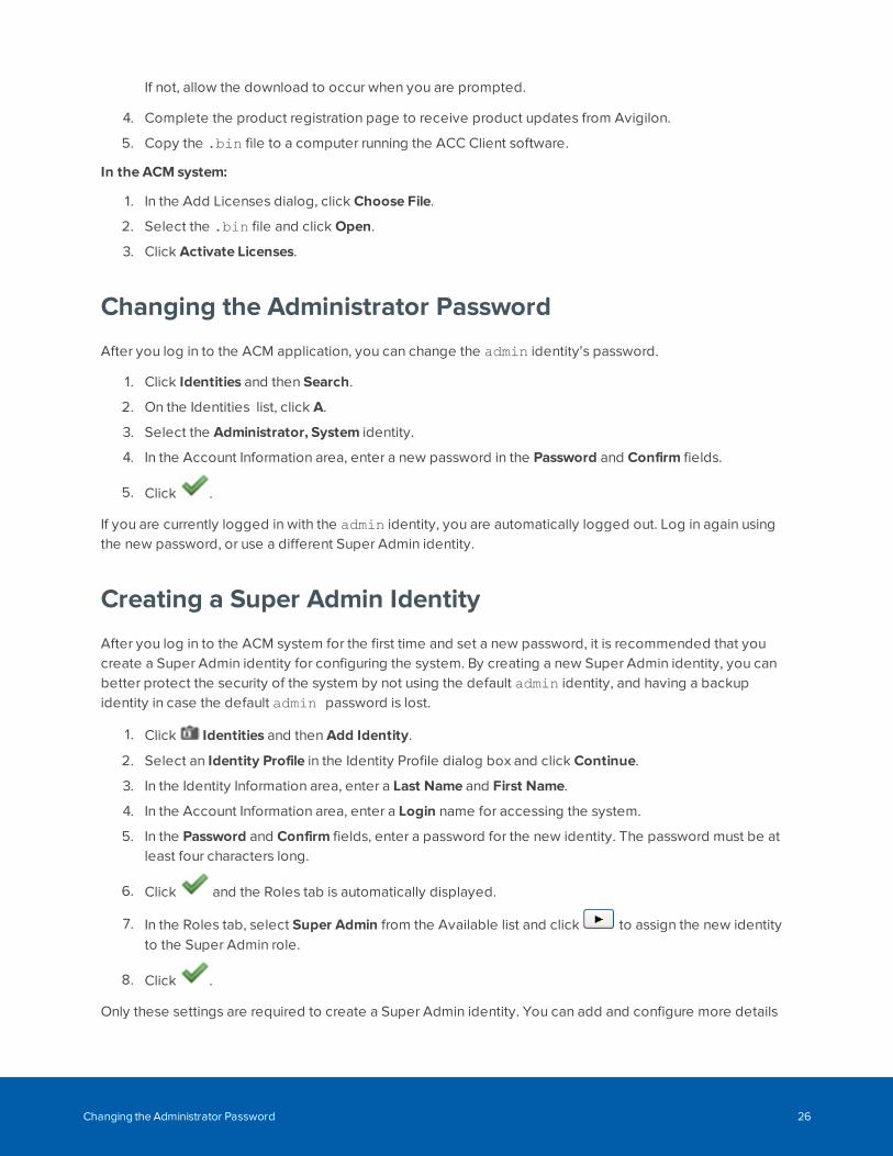
If not, allow the download to occur when you are prompted.
4. Complete the product registration page to receive product updates from Avigilon.
5. Copy the .bin file to a computer running the ACC Client software.
In the ACM system:
1. In the Add Licenses dialog, click Choose File.
2. Select the .bin file and click Open.
3. Click Activate Licenses.
Changing the Administrator Password
After you log in to the ACM application, you can change the admin identity's password.
1. Click Identities and then Search.
2. On the Identities list, click A.
3. Select the Administrator, System identity.
4. In the Account Information area, enter a new password in the Password and Confirm fields.
5. Click .
If you are currently logged in with the admin identity, you are automatically logged out. Log in again usingthe new password, or use a different Super Admin identity.
Creating a Super Admin Identity
After you log in to the ACM system for the first time and set a new password, it is recommended that youcreate a Super Admin identity for configuring the system. By creating a new Super Admin identity, you canbetter protect the security of the system by not using the default admin identity, and having a backupidentity in case the default admin password is lost.
1. Click Identities and then Add Identity.
2. Select an Identity Profile in the Identity Profile dialog box and click Continue.
3. In the Identity Information area, enter a Last Name and First Name.
4. In the Account Information area, enter a Login name for accessing the system.
5. In the Password and Confirm fields, enter a password for the new identity. The password must be atleast four characters long.
6. Click and the Roles tab is automatically displayed.
7. In the Roles tab, select Super Admin from the Available list and click to assign the new identityto the Super Admin role.
8. Click .
Only these settings are required to create a Super Admin identity. You can add and configure more details
Changing the Administrator Password 26

for the account.
Creating a Super Admin Identity 27
Monitoring
The Monitoring screen gives you access to view all events and alarms in the system. It also allows you toview and control connected hardware. An event occurs for changes in the software or hardware. Forexample, when a user accesses a door. An alarm occurs when the system detects an unusual event. Forexample, a forced door. Hardware can be controlled to grant or restrict access to an area. For example, adoor can be disabled to deny access to a hazardous area.
Note: If you do not have the correct delegations, you may not be able to access some of thefollowing pages. See your System Administrator for details.
Monitoring Events
Events are defined as any activity that is reported between the ACM appliance and the hardware itoversees. An event includes all alarms, but not all events are alarms. Events can include changes inconfiguration, a report on door access, adding a new badge holder to the system, and more. In other words,any transfer of data within the system is an event.
To view the events:
1. Select Monitor > Events.
2. Click any of the following buttons:
Note: Some of the buttons are disabled until you select an event that includes the relevant details.
l Pause button — Pauses the flow of events that are displayed on the page.
The flow of events does not actually stop, the system simply pauses the display of live updates untilyou click Resume.
l Resume button — Restarts the flow of events that are displayed on the page.
This button only appears when the flow of events is paused.
l Clear button — Temporarily clear all events from the screen. New events automatically begin topopulate the list. To restore the cleared events, refresh the page.
l Live Video button — Displays live video that is associated with the selected event.
l Recorded Video button — Displays recorded video that is associated with the selected event.
l Notes button — Enter a new note or displays any previously saved notes for the selected event.
l Instructions button — Displays any instructions that should be completed when the event occurs.The instructions were added when the event was created.
Monitoring 28
l Identity button — Displays details about the person that triggered the selected event.
l History button — Displays a detailed history of this event.
l Save Settings button — Saves your current settings for this page. For example, the columns and orderfor this page.
l Select Columns button — Choose the information that you want displayed.
Check the box for each column that you want to see, and clear the box for each column that you wanthidden.
Click and drag the columns to move them into the order you want.
l Reconnect button — Reconnects to the appliance.
This button only appears if your browser has become disconnected from the appliance and an erroris displayed.
Pause/Resume EventsThe display of live event updates can be paused. This allows you to view and investigate a specific eventwithout having to search for it. Once the event has been reviewed, the display of live event updates can beresumed.
Follow the steps below to pause and resume events.
1. Click Monitor to access the Monitor Events page. For more detail see Monitoring Events on theprevious page.
2. Click Pause to pause the flow of events that are displayed on the page.
The flow of events does not actually stop, the system simply pauses the display of live updates untilyou click Resume (this button only appears when the flow of events is paused).
3. Click Resume to restart the flow of events that are displayed on the page.
The list of events will resume updating.
Clear EventsFollow the steps below to clear all displayed events.
1. Click Monitor to access the Monitor Events page.
2. Click Clear to temporarily clear all events from the screen.
The list will be cleared. New events automatically begin to populate the list.
Note: This does not delete the events, it just removes the existing events from the view. Torestore the cleared events, refresh the page.
Pause/Resume Events 29
View Live VideoLive video that is associated with a selected event can be displayed from the Monitoring Events page. Forexample, if an unusual event occurs, the live video can be viewed to observe the event and determine ifany actions need to be taken.
Follow the steps below to view live video.
1. Click Monitor. The Monitor Events page displays (for more information, see Monitoring Events onpage 28).
2. Select an event from the list.
Only events or alarms with an icon will have video.
3. Click Live Video to display live video that is associated with the selected event. (This button onlydisplays if video is available for this event.)
The Monitor Screen - Live Video window displays. View the live video in this window.
If the window does not display any video in the image panel, you may need to change your browsersettings to allow the display of insecure or mixed content. For more information, see the Help files foryour browser.
View Recorded VideoRecorded video that is associated with a selected event can be displayed from the Monitoring Eventspage. For example, if an unusual event occurred the previous day, the recorded video can be viewed toobserve event and determine if any actions need to be taken.
Follow the steps below to view live video.
1. Click Monitor. The Monitor Events page displays (for more information, see Monitoring Events onpage 28).
2. Select an event from the list.
Only events or alarms with an icon will have video.
3. Click Recorded Video to display recorded video that is associated with the selected event. (Thisbutton only displays if video is available for this event.)
The Monitor Screen - Recorded Video window displays. View the video in this window.
If the window does not display any video in the image panel, you may need to change your browsersettings to allow the display of insecure or mixed content. For more information, see the Help files foryour browser.
Create Event NotesNotes can be added and viewed for all events that occur in the system. For example, if an observation ismade on an event, a note can be made for that event.
Follow the steps below to create event notes.
View Live Video 30
1. Click Monitor to access the Monitor Events page.
2. Select the event that you want to create notes for.
3. Click Notes to create notes for the selected event.
The Monitor Screen - Notes Window will display.
4. Enter text in the NewNote field.
5. Click to save the new note.
The note will display in the list below the NewNote section. The date, Operator and note will displayin this list.
6. Close the dialog box.
View Event NotesNotes that are associated with an event can be displayed from the Monitor Events page. For example, ifanother user created a note for an event, you can view the note to get more information about the event.
Follow the steps below to view event notes.
1. Click Monitor to access the Monitor Events page (for more information, see Monitoring Events onpage 28).
2. Select the event that you want to view notes for. (Events with notes will display with in the Iconcolumn.)
3. Click Notes to view notes for the selected event. (Alternatively clicking will do the same thing.)
The Monitor Screen - Notes Window will display. Existing notes will display as a list below the NewNote section. The date, Operator and note will display in this list.
View Event InstructionsInstructions can be viewed for a selected event. The instructions tell the operator what actions need to betaken when the event occurs. For example, if a user is denied access to a certain area, the action may be toreview their identity, and determine if they have permission to access the area.
Follow the steps below to view event instructions. The instructions were added when the event wascreated.
1. Click Monitor to access the Monitor Events page (for more information, see Monitoring Events onpage 28).
2. Select the event that you want to view instructions for. (Events with instructions will display within the Icon column.)
3. Click Instructions to view instructions for the selected event.
The Monitor Screen - Instructions Window will display. View the instructions in the table that displays.
View Event Notes 31
4. Close the window to return to the Monitor Events page.
View Event Identity DetailsFollow the steps below to view event identity details.
1. Click Monitor to access the Monitor Events page (for more information, see Monitoring Events onpage 28).
2. Select the event that you want to view identity details for.
3. Click Identity to view identity details for the selected event.
The Monitor Screen - Identity Window will display.
4. View the details (e.g. Last Name, First Name, Title, etc.).
5. Close the window to return to the Monitor Events page.
View Event HistoryFollow the steps below to view event history.
1. Click Monitor to access the Monitor Events page (for more information, see Monitoring Events onpage 28).
2. Select the event that you want to view history for.
3. Click History to view history for the selected event.
The Monitor Screen - History Window will display.
4. View the history details.
5. Close the window to return to the Events list.
Change Events List SettingsFollow the steps below to change the settings of the events list.
1. Click Monitor to access the Monitor Events page.
The list displays in date order, with the most recent events at the top of the list.
2. If you want to re-sort the order of the list:
l Click in the heading of the column to sort by (e.g. Priority). The list will sort in ascending orderbased on that column (e.g. ascending order of priority).
l To change the sort order to descending, click the column heading again.
3. If you want to re-sort the order of the columns, click on the column you want to move then drag anddrop this to it's new location.
4. If you want to add or remove columns, click Select Columns and:
l Click beside the Column name of any columns to be added so that a check mark displays.
l Click beside the Column name of any column to be deleted so that a check mark no longerdisplays.
View Event Identity Details 32
5. Click Save Settings if you want to save the new settings.
A message box displays with the message ACM Notification. Successfully saved.'.
Reconnect to Events ListFollow the steps below to reconnect to the ACM appliance.
1. Click Monitor to access the Monitor Events page (for more information, see Monitoring Events onpage 28).
If your browser loses connectivity with ACM appliance the Reconnect button displays.
2. Click Reconnect to reconnect.
Searching for Events and Alarms
The number of alarms and event transactions can total into the thousands depending on the level of activityin your system. To find specific events, you can perform a search.
Searching for specific events allows you to easily find an event in the system. For example, searching forevents can be used in situations where more information is needed on an event thought to be unusual orsuspicious. Once an event has been found, information such as recorded video, or notes can be viewed.
1. Select Monitor > Search.
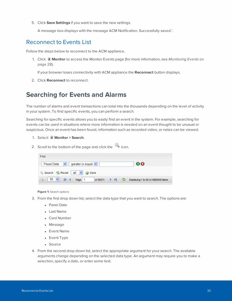
2. Scroll to the bottom of the page and click the icon.
Figure 1: Search options
3. From the first drop down list, select the data type that you want to search. The options are:
l Panel Date
l Last Name
l Card Number
l Message
l Event Name
l Event Type
l Source
4. From the second drop down list, select the appropriate argument for your search. The availablearguments change depending on the selected data type. An argument may require you to make aselection, specify a date, or enter some text.
Reconnect to Events List 33
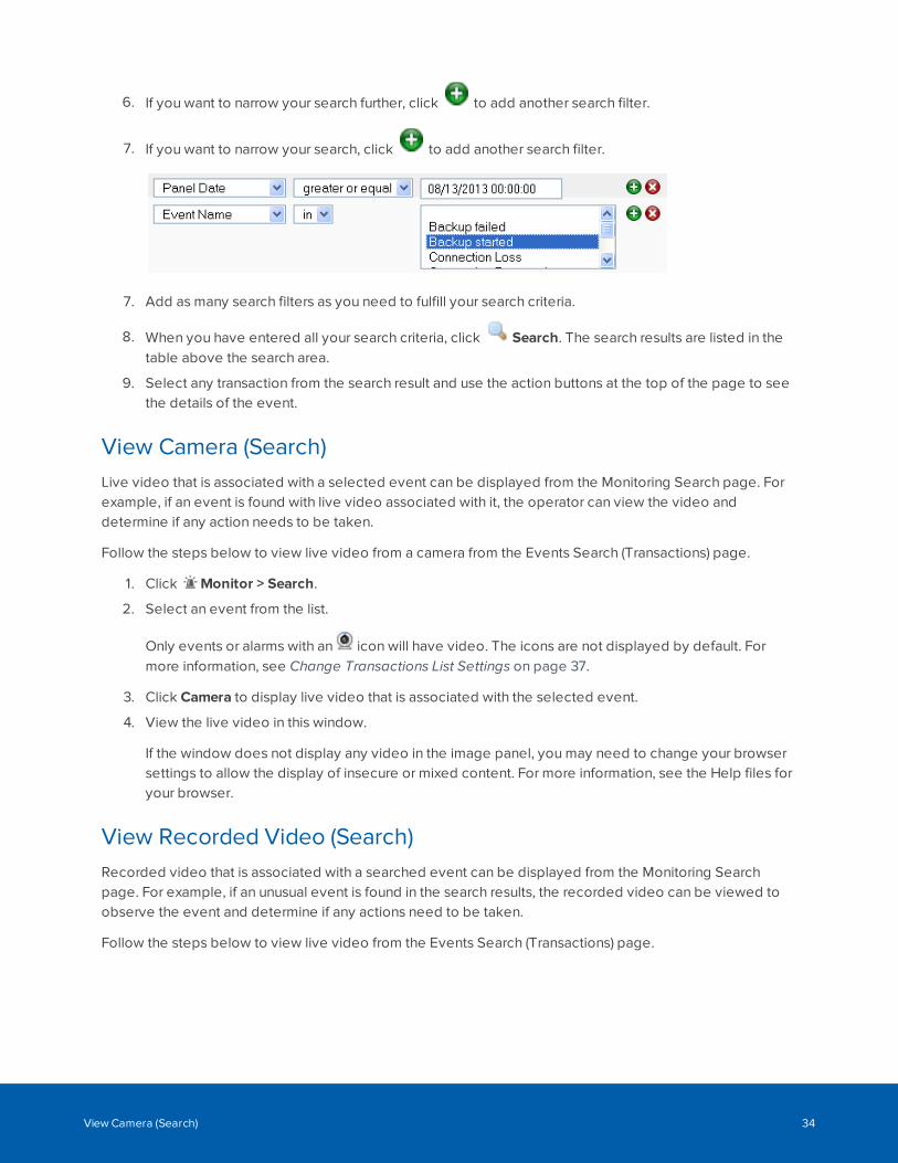
6. If you want to narrow your search further, click to add another search filter.
7. If you want to narrow your search, click to add another search filter.
7. Add as many search filters as you need to fulfill your search criteria.
8. When you have entered all your search criteria, click Search. The search results are listed in thetable above the search area.
9. Select any transaction from the search result and use the action buttons at the top of the page to seethe details of the event.
View Camera (Search)Live video that is associated with a selected event can be displayed from the Monitoring Search page. Forexample, if an event is found with live video associated with it, the operator can view the video anddetermine if any action needs to be taken.
Follow the steps below to view live video from a camera from the Events Search (Transactions) page.
1. Click Monitor > Search.
2. Select an event from the list.
Only events or alarms with an icon will have video. The icons are not displayed by default. Formore information, see Change Transactions List Settings on page 37.
3. Click Camera to display live video that is associated with the selected event.
4. View the live video in this window.
If the window does not display any video in the image panel, you may need to change your browsersettings to allow the display of insecure or mixed content. For more information, see the Help files foryour browser.
View Recorded Video (Search)Recorded video that is associated with a searched event can be displayed from the Monitoring Searchpage. For example, if an unusual event is found in the search results, the recorded video can be viewed toobserve the event and determine if any actions need to be taken.
Follow the steps below to view live video from the Events Search (Transactions) page.
View Camera (Search) 34
1. Click Monitor > Search.
2. Select an event from the list.
Only events or alarms with an icon will have video. The icons are not displayed by default. Formore information, see Change Transactions List Settings on page 37.
3. Click Recorded Video to display recorded video that is associated with the selected event.
Note: An event with recorded video associated with it may display an error message if therecorded video is no longer available on the video recorder.
4. View the video in this window.
If the window does not display any video in the image panel, you may need to change your browsersettings to allow the display of insecure or mixed content. For more information, see the Help files foryour browser.
Create Event Notes (Search)Notes can be added and viewed for all events that occur in the system. For example, if an observation ismade on an event, a note can be created for that event.
Follow the steps below to create event notes from the Events Search (Transactions) page.
1. Click Monitor > Search.
2. Select the event that you want to create notes for.
3. Click Notes to create notes for the selected event.
The Monitor Screen - Notes Window will display.
4. Enter text in the NewNote field.
5. Click to save the new note.
The note will display in the list below the NewNote section. The date, Operator and note will displayin this list.
6. Close the dialog box.
View Event Notes (Search)Notes that are associated with an event can be displayed from the Monitor Search page. For example, if anevent is found with an associated note, you can view the note to get more information about the selectedevent.
Follow the steps below to view event notes from the Events Search (Transactions) page.
Create Event Notes (Search) 35
1. Click Monitor > Search.
2. Select the event that you want to view notes for.
3. Click Notes to view notes for the selected event.
The Monitor Screen - Notes Window will display. Existing notes will display as a list below the NewNote section. The date, Operator and note will display in this list.
View Event Instructions (Search)Instructions can be viewed for a selected event. The instructions tell the operator what actions need to betaken when the event occurs. For example, if a user is denied access to a certain area, the action may be toreview their identity, and determine if they have permission to access the area.
Follow the steps below to view event instructions from the Events Search (Transactions) page. Theinstructions were added when the event was created.
1. Click Monitor > Search.
2. Select the event that you want to view instructions for.
3. Click Instructions to view instructions for the selected event.
The Monitor Screen - Instructions Window will display.
4. Close the window to return to the Events Search (Transactions) page.
View Event Identity Details (Search)Follow the steps below to view event identity details from the Events Search (Transactions) page.
1. Click Monitor > Search.
2. Select the event that you want to view identity details for.
3. Click Identity to view identity details for the selected event.
The Monitor Screen - Identity Window will display.
4. View the details (e.g. Last Name, First Name, Title, etc.).
5. Close the window to return to the Events Search (Transactions) page.
View Event History (Search)Follow the steps below to view event history from the Events Search (Transactions) page.
1. Click Monitor > Search.
2. Select the event that you want to view history for.
3. Click History to view history for the selected event.
The Monitor Screen - History Window will display.
4. View the history details.
5. Close the window to return to the Events Search (Transactions) page.
View Event Instructions (Search) 36
Change Transactions List SettingsThe events list shows a default set of fields for each event. You may want to add columns to this list.
For example, if you want to search this list to see if an event occurred on a door that has a camera
associated with it, add the icons column. This column displays a next to any event from a door that has acamera associated with it.
Follow the steps below to change the settings of the events list.
1. Click Monitor > Search.
The list displays in date order, with the most recent events at the top of the list.
2. If you want to re-sort the order of the list:
l Click in the heading of the column to sort by (e.g. Priority). The list will sort in ascending orderbased on that column (e.g. ascending order of priority).
l To change the sort order to descending, click the column heading again.
3. If you want to re-sort the order of the columns, click on the column you want to move then drag anddrop this to it's new location.
4. If you want to add a column, hover the mouse over any column heading and:
a. Click the down arrow that is displayed.
b. Click the checkbox for each column you want to add.
5. Click Save Settings if you want to save the new settings.
A message box displays with the message 'ACM Notification. Successfully saved.'.
Monitor Alarms
Alarms that occur in the system are listed in the Monitor Alarms page as they occur (accessed throughselecting Monitor > Alarms).
An alarm occurs when the system senses an unusual event such as a forced or held door. Each alarm needsto be reviewed and responded to. Information on the alarm can be viewed, along with any available video.After an alarm has been acknowledged, it is moved to the list of acknowledged alarms. This list allows usersto view past alarms and clear them from the system.
To review and acknowledge alarms, select one or more alarms from the Unacknowledged Alarms list thenclick one of the following buttons:
Note: Some of the buttons are disabled until you select an event that includes the relevant details.
Change Transactions List Settings 37
l Acknowledge — Click this button to acknowledge one or more selected alarms. The selected alarmsare moved to the Acknowledged Alarms list.
l Acknowledge All — Click this button to acknowledge all alarms that are currently active andunacknowledged.
l Live Video — Click this button to display live video associated with the selected alarm.
l Recorded Video — Click this button to display recorded video associated with the selected alarm.
l Notes — Click this button to enter a new note or display any previously saved notes for the selectedevent.
l Instructions — Click this button to display any instructions that should be completed when the alarmoccurs. The instructions were added when the event was created.
l Identity — Click this button to display details about the person that triggered the selected alarm.
l History — Click this button to display a detailed history of this alarm.
l Save Settings — Click this button to save your current settings for this page. For example, thecolumns and order for this page.
l Sound Off — Click this button to mute any alarm noises on the device used to monitor Alarms.
When sound is muted, the button changes to Sound On. Click this button to turn the sound back on.
l Select Columns — Click this button then choose the information that you want displayed.
Check the box for each column that you want to see, and clear the box for each column that you wanthidden.
After an alarm has been acknowledged, the alarm is added to the Acknowledged Alarms list. You can clearthe alarms from the list as needed.
Note: Some of the buttons are disabled until you select an event that includes the relevant details.
l Clear — Click this button to clear one or more acknowledged alarms from the list.
l Clear All — Click this button to clear all alarms from the Acknowledged Alarms list.
l Select Columns — Click this button then choose the information that you want displayed.
Check the box for each column that you want to see, and clear the box for each column that you wanthidden.
Acknowledge AlarmsWhen an alarm occurs in the system, an action must be taken. Once the alarm is resolved, it must beacknowledged. This tells the other users of the system that the alarm has been dealt with and is not aproblem.
Follow the steps below to acknowledge alarms.
Acknowledge Alarms 38
1. Click Monitor > Alarms.
2. To acknowledge a single alarm:
l Select the alarm in the Unacknowledged Alarms list.
l Click Acknowledge. The alarm will move to the Acknowledged Alarms list.
3. To acknowledge multiple alarms:
l Select the first alarm in the Unacknowledged Alarms list.
l If the alarms to be acknowledged are consecutive in the list, click on the first entry, then holdSHIFT down and click on the last entry.
l If the alarms to be acknowledged are not consecutive, click on the first entry, then hold CTRLdown and click on each entry.
l Click Acknowledge. The alarms will move to the Acknowledged Alarms list.
4. To acknowledge all alarms, click Acknowledge All. The alarms will move to the AcknowledgedAlarms list.
View Live Video (Alarms)Live video that is associated with a selected alarm can be displayed from the Monitoring Alarms page. Forexample, if an alarm occurs, the live video can be viewed to observe the alarm and determine if any actionsneed to be taken.
Follow the steps below to view live video from the Monitor Alarms page.
1. Click Monitor > Alarms. For more information see Monitor Alarms on page 37.
2. Select an alarm from the list.
Only events or alarms with an icon will have video.
3. Click Live Video to display live video that is associated with the selected alarm. This button onlydisplays if video is available for this alarm.
The Monitor Screen - Live Video window displays. View the live video in this window.
If the window does not display any video in the image panel, you may need to change your browsersettings to allow the display of insecure or mixed content. For more information, see the Help files foryour browser.
View Recorded Video (Alarms)Recorded video that is associated with a selected alarm can be displayed from the Monitoring Alarms page.For example, if an alarm occurred the previous day, recorded video can be viewed to observe the alarmand determine if any further actions need to be taken.
Follow the steps below to view recorded video from the Monitor Alarms list.
View Live Video (Alarms) 39
1. Click Monitor > Alarms. The Monitor Alarms page displays (for more information see MonitorAlarms on page 37).
2. Select an event from the list.
Only events or alarms with an icon will have video.
3. Click Recorded Video to display live video that is associated with the selected event. (This buttononly displays if video is available for this event.)
The Monitor Screen - Recorded Video window displays. View the video in this window.
If the window does not display any video in the image panel, you may need to change your browsersettings to allow the display of insecure or mixed content. For more information, see the Help files foryour browser.
Create Event Notes (Alarms)Notes can be added and viewed for all alarms that occur in the system. For example, if an observation oraction is made on an alarm, a note can be created to document the details.
Follow the steps below to create event notes from the Monitor Alarms page.
1. Click Monitor > Alarms. The Monitor Alarms page displays. For more information see MonitorAlarms on page 37.
2. Select the event that you want to create notes for.
3. Click Notes to create notes for the selected event.
The Monitor Screen - Notes Window will display.
4. Enter text in the NewNote field.
5. Click to save the new note.
The note will display in the list below the NewNote section. The date, Operator and note will displayin this list.
6. Close the dialog box.
View Event Notes (Alarms)Notes that are associated with an alarm can be displayed from the Monitor Alarms page. For example, ifanother user created a note for an alarm, you can view the note to get more information about the alarm.
Follow the steps below to view event notes from the Monitor Alarms page.
1. Click Monitor > Alarms. The Monitor Alarms page displays. For more information see MonitorAlarms on page 37.
2. Select the event that you want to view notes for. Events with notes will display with in the Iconcolumn.
Create Event Notes (Alarms) 40
3. Click Notes to view notes for the selected event. Alternatively clicking will do the same thing.
The Monitor Screen - Notes Window will display. Existing notes will display as a list below the NewNote section. The date, Operator and note will display in this list.
4. Close the dialog box to return to the Monitor Alarms page.
View Event Instructions (Alarms)Instructions can be viewed for a selected alarm. The instructions tell the operator what actions need to betaken when the alarm occurs. For example, if an alarm occurred, the instruction could be to investigate thealarm and write a note describing the situation.
Follow the steps below to view event instructions from the Monitor Alarms page. The instructions wereadded when the event was created.
1. Click Monitor > Alarms to access the Monitor Alarms page displays. For more information seeMonitor Alarms on page 37.
2. Select the event that you want to view instructions for. (Events with instructions will display within the Icon column.)
3. Click Instructions to view instructions for the selected event.
The Monitor Screen - Instructions Window will display. View the instructions in the table that displays.
4. Close the window to return to the Monitor Alarms page.
View Event Identity Details (Alarms)Follow the steps below to view event identity details from the Monitor Alarms page.
1. Click Monitor > Alarms. The Monitor Alarms page displays. For more information see MonitorAlarms on page 37.
2. Select the event that you want to view identity details for.
3. Click Identity to view identity details for the selected event.
The Monitor Screen - Identity Window will display.
4. View the details (e.g. Last Name, First Name, Title, etc.).
5. Close the window to return to the Monitor Alarms page.
View Event History (Alarms)Follow the steps below to view event history from the Monitor Alarms page.
View Event Instructions (Alarms) 41
1. Click Monitor > Alarms to access the Monitor Alarms page. For more information see MonitorAlarms on page 37.
2. Select the event that you want to view history for.
3. Click History to view history for the selected event.
The Monitor Screen - History Window will display.
4. View the history details.
5. Close the window to return to the Monitor Alarms page.
Change Alarms List SettingsFollow the steps below to change the settings of the alarms lists on the Monitor Alarms page.
1. Click Monitor > Alarms to access the Monitor Alarms page. For more information see MonitorAlarms on page 37.
The list displays in date order, with the most recent events at the top of the list.
2. If you want to re-sort the order of the list:
l Click in the heading of the column to sort by (e.g. Priority). The list will sort in ascending orderbased on that column (e.g. ascending order of priority).
l To change the sort order to descending, click the column heading again.
3. If you want to re-sort the order of the columns, click on the column you want to move then drag anddrop this to it's new location.
4. If you want to add or remove columns, click Select Columns and do the following:
l Click beside the Column name of any columns to be added so that a check mark displays.
l Click beside the Column name of any column to be deleted so that a check mark no longerdisplays.
5. If you want to change the sound settings:
l If the sound is on, click Sound Off to turn the sound off.
l If the sound is off, click Sound On to turn the sound on.
6. Click Save Settings if you want to save the new settings.
A message box displays with the message ACM Notification. Successfully saved.'
Note: To reset default settings, select > Clear Custom Layouts. This resets all customized lists
to their default setting.
Monitor - Verification screen
When you click Monitor > Verification, the Verification page is displayed.
Change Alarms List Settings 42
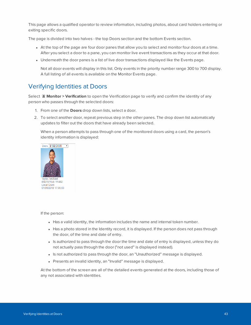
This page allows a qualified operator to review information, including photos, about card holders entering orexiting specific doors.
The page is divided into two halves - the top Doors section and the bottom Events section.
l At the top of the page are four door panes that allow you to select and monitor four doors at a time.After you select a door to a pane, you can monitor live event transactions as they occur at that door.
l Underneath the door panes is a list of live door transactions displayed like the Events page.
Not all door events will display in this list. Only events in the priority number range 300 to 700 display.A full listing of all events is available on the Monitor Events page.
Verifying Identities at DoorsSelect Monitor > Verification to open the Verification page to verify and confirm the identity of anyperson who passes through the selected doors:
1. From one of the Doors drop down lists, select a door.
2. To select another door, repeat previous step in the other panes. The drop down list automaticallyupdates to filter out the doors that have already been selected.
When a person attempts to pass through one of the monitored doors using a card, the person'sidentity information is displayed:
If the person:
l Has a valid identity, the information includes the name and internal token number.
l Has a photo stored in the Identity record, it is displayed. If the person does not pass throughthe door, of the time and date of entry.
l Is authorized to pass through the door the time and date of entry is displayed, unless they donot actually pass through the door ("not used" is displayed instead).
l Is not authorized to pass through the door, an "Unauthorized" message is displayed.
l Presents an invalid identity, an "Invalid" message is displayed.
At the bottom of the screen are all of the detailed events generated at the doors, including those ofany not associated with identities.
Verifying Identities at Doors 43
Verification Events ListFollow the steps below to add doors to monitor on the Verification page.
1. Click Monitor > Verification. The Verification page displays. For more information see Monitor -Verification screen on page 42.
This page has two sections - doors and an events list. For more information on the doors display seeVerifying Identities at Doors on the previous page. The events list displays in date order, with themost recent events at the top of the list.
Note: Not all door events will display in this list. Only events in the priority number range 300to 700 display. A full listing of all events is available on the Monitor Events page.
2. If you want to clear a single event from the list, select the event and click Clear. To clear all events,click Clear all.
3. If you want to re-sort the order of the list:
l Click in the heading of the column to sort by (e.g. Priority). The list will sort in ascending orderbased on that column (e.g. ascending order of priority).
l To change the sort order to descending, click the column heading again.
4. If you want to re-sort the order of the columns, click on the column you want to move then drag anddrop this to it's new location.
5. If you want to add or remove columns, click Select Columns and:
l Click beside the Column name of any columns to be added so that a check mark displays.
l Click beside the Column name of any column to be deleted so that a check mark no longerdisplays.
6. Click Save Settings if you want to save the new settings.
A message box displays with the message 'ACM Notification. Successfully saved.'.
Note: Saving the settings only saves the column configuration. The doors selected forverification will need to be selected each time you return to the page.
Note: To reset default settings, select > Clear Custom Layouts. This resets all customized lists
to their default setting.
Verification Events List 44
Monitor - Dashboard
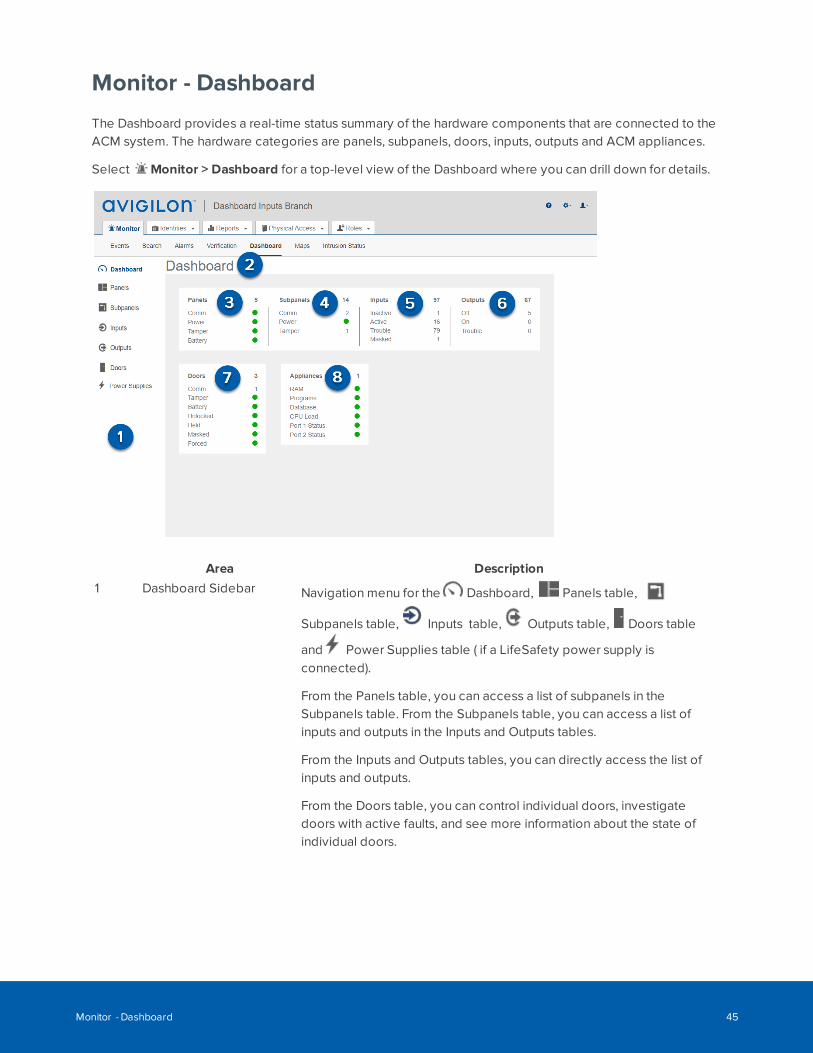
The Dashboard provides a real-time status summary of the hardware components that are connected to theACM system. The hardware categories are panels, subpanels, doors, inputs, outputs and ACM appliances.
Select Monitor > Dashboard for a top-level view of the Dashboard where you can drill down for details.
Area Description1 Dashboard Sidebar Navigation menu for the Dashboard, Panels table,
Subpanels table, Inputs table, Outputs table, Doors table
and Power Supplies table ( if a LifeSafety power supply isconnected).
From the Panels table, you can access a list of subpanels in theSubpanels table. From the Subpanels table, you can access a list ofinputs and outputs in the Inputs and Outputs tables.
From the Inputs and Outputs tables, you can directly access the list ofinputs and outputs.
From the Doors table, you can control individual doors, investigatedoors with active faults, and see more information about the state ofindividual doors.
Monitor - Dashboard 45
Area Description2 Dashboard Displays a summary of hardware faults or unexpected input and output
state changes as they occur. As the status of hardware componentschanges, the status indicators on the Dashboard change color. Formore information, see Status Colors below.
The total number of connected hardware components (installed anduninstalled) is displayed above a real-time fault or status list. For panels,subpanels, inputs and doors, the number of installed components ineach fault state is displayed. If no faults occur, their status is green. Foroutputs, the numbers indicate the number of installed outputs in eachstate. When no components are displayed in a state, the status is eithergreen or 0.
3 Panels Displays a summary of the fault state of the installed panels. Click thenumber next to the fault to drill down to the details of the fault in thePanels table, which is filtered to display only the panels with that fault.
4 Subpanels Displays a summary of the fault state of the installed subpanels. Clickthe number next to the fault to drill down to the details of the fault in theSubpanels table, which is filtered to display only subpanels with thatfault.
5 Inputs Displays the total number of inputs in each state. Click the number nextto the state to drill down to the Inputs table, which is filtered to displayonly inputs with that state.
6 Outputs Displays the total number outputs in each state. Click the number nextto the state to drill down to the Outputs table, which is filtered to displayonly inputs with that state.
7 Doors Displays the summary of the fault state of the installed doors. Click thenumber next to the fault to drill down to the Doors table, which isfiltered to display only alarms with that fault.
8 Appliances When no issues occur in the ACM appliance items, their status is green.Hover the mouse over each status indicator to see more details. Forexample, "RAM free 45%" displays for the RAM status.
Status ColorsStatus colors identify the health of the different devices in the system. The status colors represent thefollowing states:
Status Colors 46
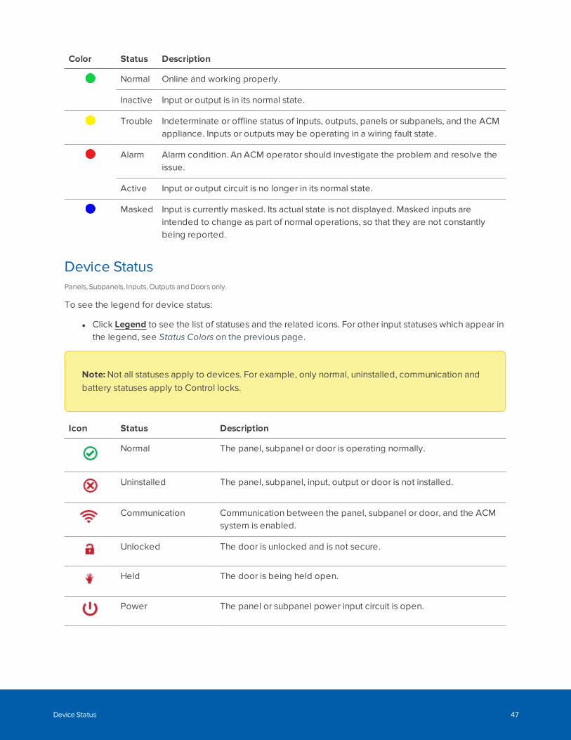
Color Status Description
Normal Online and working properly.
Inactive Input or output is in its normal state.
Trouble Indeterminate or offline status of inputs, outputs, panels or subpanels, and the ACMappliance. Inputs or outputs may be operating in a wiring fault state.
Alarm Alarm condition. An ACM operator should investigate the problem and resolve theissue.
Active Input or output circuit is no longer in its normal state.
Masked Input is currently masked. Its actual state is not displayed. Masked inputs areintended to change as part of normal operations, so that they are not constantlybeing reported.
Device StatusPanels, Subpanels, Inputs, Outputs and Doors only.
To see the legend for device status:
l Click Legend to see the list of statuses and the related icons. For other input statuses which appear inthe legend, see Status Colors on the previous page.
Note: Not all statuses apply to devices. For example, only normal, uninstalled, communication andbattery statuses apply to Control locks.
Icon Status Description
Normal The panel, subpanel or door is operating normally.
Uninstalled The panel, subpanel, input, output or door is not installed.
Communication Communication between the panel, subpanel or door, and the ACMsystem is enabled.
Unlocked The door is unlocked and is not secure.
Held The door is being held open.
Power The panel or subpanel power input circuit is open.
Device Status 47
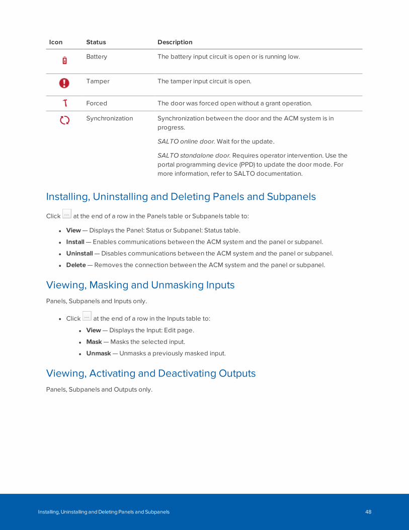
Icon Status Description
Battery The battery input circuit is open or is running low.
Tamper The tamper input circuit is open.
Forced The door was forced open without a grant operation.
Synchronization Synchronization between the door and the ACM system is inprogress.
SALTO online door. Wait for the update.
SALTO standalone door. Requires operator intervention. Use theportal programming device (PPD) to update the door mode. Formore information, refer to SALTO documentation.
Installing, Uninstalling and Deleting Panels and Subpanels
Click at the end of a row in the Panels table or Subpanels table to:
l View — Displays the Panel: Status or Subpanel: Status table.
l Install — Enables communications between the ACM system and the panel or subpanel.
l Uninstall — Disables communications between the ACM system and the panel or subpanel.
l Delete — Removes the connection between the ACM system and the panel or subpanel.
Viewing, Masking and Unmasking InputsPanels, Subpanels and Inputs only.
l Click at the end of a row in the Inputs table to:
l View — Displays the Input: Edit page.
l Mask — Masks the selected input.
l Unmask — Unmasks a previously masked input.
Viewing, Activating and Deactivating OutputsPanels, Subpanels and Outputs only.
Installing, Uninstalling and Deleting Panels and Subpanels 48
1. Click the name of the panel and subpanel to display the Outputs table.
Or click Outputs on the Dashboard home page.
2. Click at the end of a row in the Outputs table to:
l View — View the Output: Edit page.
l On — Power the output. If the output is a door, it activates the circuit.
l Off — Turn off the power to the output. If the output is a door, it deactivates the circuit.
l Pulse — Alternately activate and deactivate the output. The pulse interval is determined bythe output’s settings.
Searching Panel, Subpanel, Input and Door NamesPanels, Subpanels, Inputs and Doors only.
1. Use any (or all) of the following to define your search:
l Enter your search term in the Search... field. Use any series of letters and numbers to searchfor the panels you want to see.
l If known, select the Device Status.
l If known, select the Appliance the panel is connected to.
l If known, select the Group the panel is included in.
2. Click OK. The list is filtered to show the results of your search.
Saving Door FiltersMany facilities require the control and monitoring of dozens, even hundreds, of doors simultaneously. Thiscan result in a crowded listing page. You can search for specific doors to narrow the list of doors, filter thecolumns for specific values, and create and save custom filters. You can then sort the results using any onecolumn.
1. Click Advanced Filters in the upper-right corner.
2. Select filters:
l Alarms — Includes the alarms from the list of alarms.
l Masked — Includes the masks from the list of masks.
l Normal — Includes all properly functioning doors.
l Door Mode — Includes the list of door modes.
To unselect all selected filters, click Unselect All.
3. To save the selected filters, select Remember Filters.
4. Click OK.
Controlling DoorsWhile you are monitoring the system, you may sometimes need to override the default door settings to
Searching Panel, Subpanel, Input and Door Names 49
allow a visitor access to an area, or unlock a door in an emergency situation. You can control doors from theDashboard:
1. Check the checkbox for each door you want to control. Or click All to select all doors or None todeselect all doors.
2. For one or more doors, select:
l Door Action dropdown and then:
l Disable — Stops the door from operating and allow no access.
l Unlock — Unlocks the door. The door will remain unlocked until the Restore commandis issued, or until another change of state is directed, either via operator override orscheduled action.
l Locked No Access — Locks the door. This door will remain locked until the Restorecommand is issued, or until another change of state is directed, either via operatoroverride or scheduled action.
l Grant — Momentarily grants access to the door to permit a single-time entry.
l Restore — Resets the door mode to its configured value.
l Door Mode and then choose how access is controlled at the door.
For more information, see Door Modes on page 192.
l Forced dropdown and then:
l Mask Forced — Masks the Door Forced Open alarm for the door. The status colorchanges to blue and is no longer included in any alarm subtotal.
l Unmask Forced — Unmasks the Door Forced Open alarm for this door.
l Held dropdown and then:
l Mask Held — Masks the Door Held Open alarm for the door. The status color changesto blue and is no longer included in any alarm subtotal.
l Unmask Held — Unmasks the Door Held Open alarm for the door.
l Installed dropdown and then:
l Install — Installs a door. Enables communications between the door and theACM system.
l Uninstall — Uninstalls a door. Disables communications between the door and theACM system.
l Delete — Removes the connection between the door and the ACM system.
Accessing Web Interface of Power PanelsWhen LifeSafety power panels are installed in your ACM system, you can access the web interface of thepanel to view the panel's current status or its event log, and edit its configuration.
Accessing Web Interface of Power Panels 50
l Click the name of the LifeSafety power panel to display the panel details.
l The (installed) or (uninstalled) status of the panel is read-only and cannot be changed.
l Click a command:
l Status — Displays the current status of the LifeSafety panel.
l Log — Displays the log of events and alarms recorded by the LifeSafety panel.
l Edit — Displays the browser page for the remotely connected panel. Edit the configuration asrequired.
Monitor Screen - Map Templates page
When you click Monitor > Maps, the Map Templates page displays. This page lists all the maps that havebeen added to the system.
Feature Description
Add MapTemplate
Click this button to add a new map template.
Name The name of the map template.
A list of all the configured maps is displayed. Also included in the list are configuredMustering dashboards.
Click the name of the map template to display the configured map or dashboard.
Using a MapAfter a map has been configured, access it from the Monitor page and use it as a quick visual reference toall the items that may be installed in a facility.
From the map, you can:
l Monitor the status of hardware items: doors, panels, subpanels, inputs and outputs.
l Control doors.
l Keep track of identities as they arrive at muster stations from the Mustering dashboard.
The following indicators are displayed on the map as events occur :
l : A green bar indicates the hardware item is operating normally.
l : A red square indicates the hardware item is in an alarm state. The counter in the squareshows the number of unacknowledged events.
l : A solid blue disk indicates an active override is in effect on the door. A hollow blue
Monitor Screen - Map Templates page 51
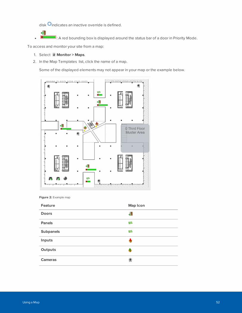
disk indicates an inactive override is defined.
l : A red bounding box is displayed around the status bar of a door in Priority Mode.
To access and monitor your site from a map:
1. Select Monitor > Maps.
2. In the Map Templates list, click the name of a map.
Some of the displayed elements may not appear in your map or the example below.
Figure 2: Example map
Feature Map Icon
Doors
Panels
Subpanels
Inputs
Outputs
Cameras
Using a Map 52
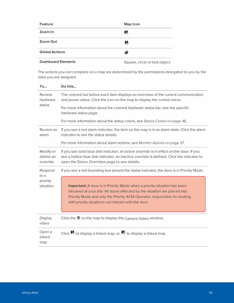
Feature Map Icon
Zoom In
ZoomOut
Global Actions
Dashboard Elements Square, circle or text object
The actions you can complete on a map are determined by the permissions delegated to you by theroles you are assigned.
To... Do this...
Reviewhardwarestatus
The colored bar below each item displays an overview of the current communicationand power status. Click the icon on the map to display the control menu.
For more information about the colored hardware status bar, see the specifichardware status page.
For more information about the status colors, see Status Colors on page 46.
Review analarm
If you see a red alarm indicator, the item on the map is in an alarm state. Click the alarmindicator to see the status details.
For more information about alarm actions, see Monitor Alarms on page 37.
Modify ordelete anoverride
If you see solid blue disk indicator, an active override is in effect on the door. If yousee a hollow blue disk indicator, an inactive override is defined. Click the indicator toopen the Doors: Overrides page to see details.
Respondto aprioritysituation
If you see a red bounding box around the status indicator, the door is in Priority Mode.
Important: A door is in Priority Mode when a priority situation has beendeclared at your site. All doors affected by the situation are placed intoPriority Mode and only the Priority ACM Operator, responsible for dealingwith priority situations can interact with the door.
Displayvideo
Click the on the map to display the Camera Video window.
Open alinkedmap
Click to display a linked map, or to display a linked map.
Using a Map 53
To... Do this...
Monitorthedashboard
If there is a Mustering dashboard configured on the map, it may appear as a line of textor as a shape with text inside.
The dashboard displays the number of identities in the area and may include the nameof the area. In Example map on page 52, the dashboard is the gray square.
Click the dashboard to see a list of all the identities that are in the area. Click outsidethe pop-up dialog to hide the identities list. Click the First Name or Last Name to viewthe identity.
Adding MapsFollow the steps below to add maps.
1. Click Monitor > Maps. The Map Templates (Monitor) list displays.
2. Click Add Map Template.
The Map Template: Add page displays.
3. Enter a name for the Map in the Name field.
4. To:
l Upload a file, select File and click Browse then select the file to upload in the Choose File toUpload dialog box and click Open.
l Create a blank canvas, select Blank Canvas.
5. To resize the image, enter resizing proportions in the Re-size To fields.
6. Click to save the map.
The Map Template: Edit page displays.
Monitor Intrusion Panels
The following procedures relate to monitoring Bosch intrusion panels.
Monitor Intrusion Panel StatusThe intrusion panel status displays the current status of all connected intrusion panels. For example, if thepower and communications of the intrusion panel is normal, the Online status will be displayed and amessage will appear when you hover over the power and communications icons.
To monitor intrusion panel status:
Adding Maps 54
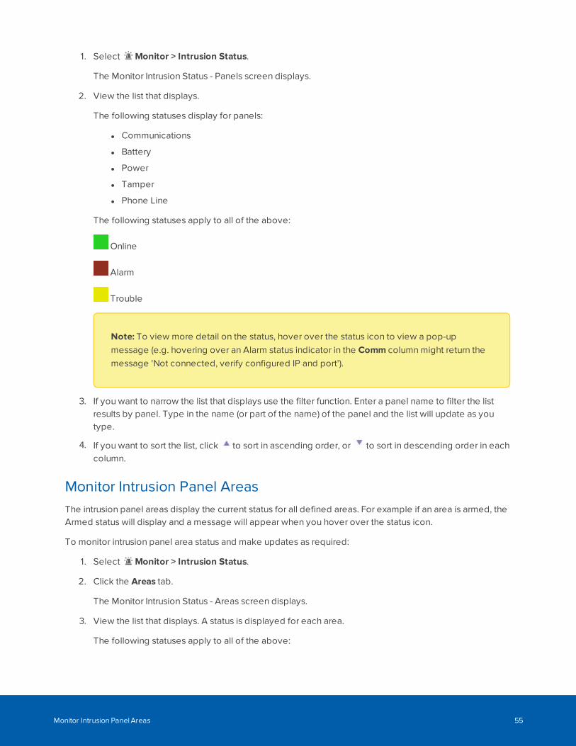
1. Select Monitor > Intrusion Status.
The Monitor Intrusion Status - Panels screen displays.
2. View the list that displays.
The following statuses display for panels:
l Communications
l Battery
l Power
l Tamper
l Phone Line
The following statuses apply to all of the above:
Online
Alarm
Trouble
Note: To view more detail on the status, hover over the status icon to view a pop-upmessage (e.g. hovering over an Alarm status indicator in the Comm column might return themessage 'Not connected, verify configured IP and port').
3. If you want to narrow the list that displays use the filter function. Enter a panel name to filter the listresults by panel. Type in the name (or part of the name) of the panel and the list will update as youtype.
4. If you want to sort the list, click to sort in ascending order, or to sort in descending order in eachcolumn.
Monitor Intrusion Panel AreasThe intrusion panel areas display the current status for all defined areas. For example if an area is armed, theArmed status will display and a message will appear when you hover over the status icon.
To monitor intrusion panel area status and make updates as required:
1. Select Monitor > Intrusion Status.
2. Click the Areas tab.
The Monitor Intrusion Status - Areas screen displays.
3. View the list that displays. A status is displayed for each area.
The following statuses apply to all of the above:
Monitor Intrusion Panel Areas 55
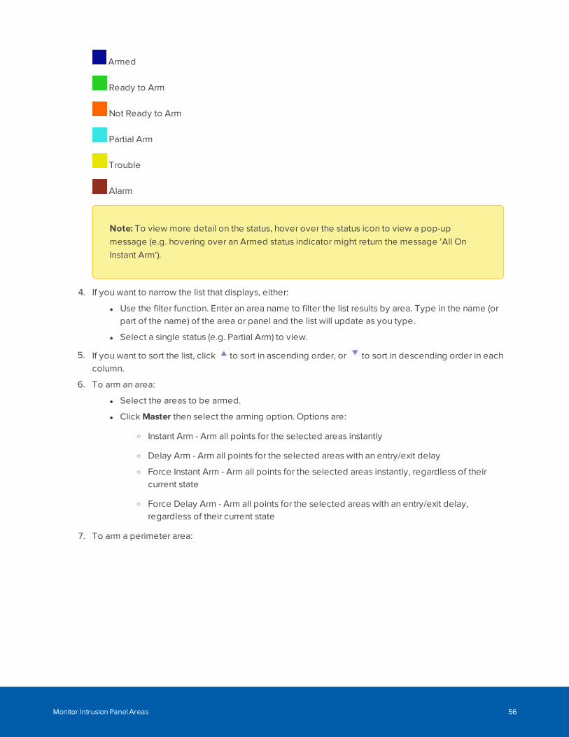
Armed
Ready to Arm
Not Ready to Arm
Partial Arm
Trouble
Alarm
Note: To view more detail on the status, hover over the status icon to view a pop-upmessage (e.g. hovering over an Armed status indicator might return the message 'All OnInstant Arm').
4. If you want to narrow the list that displays, either:
l Use the filter function. Enter an area name to filter the list results by area. Type in the name (orpart of the name) of the area or panel and the list will update as you type.
l Select a single status (e.g. Partial Arm) to view.
5. If you want to sort the list, click to sort in ascending order, or to sort in descending order in eachcolumn.
6. To arm an area:
l Select the areas to be armed.
l Click Master then select the arming option. Options are:
o Instant Arm - Arm all points for the selected areas instantly
o Delay Arm - Arm all points for the selected areas with an entry/exit delay
o Force Instant Arm - Arm all points for the selected areas instantly, regardless of theircurrent state
o Force Delay Arm - Arm all points for the selected areas with an entry/exit delay,regardless of their current state
7. To arm a perimeter area:
Monitor Intrusion Panel Areas 56
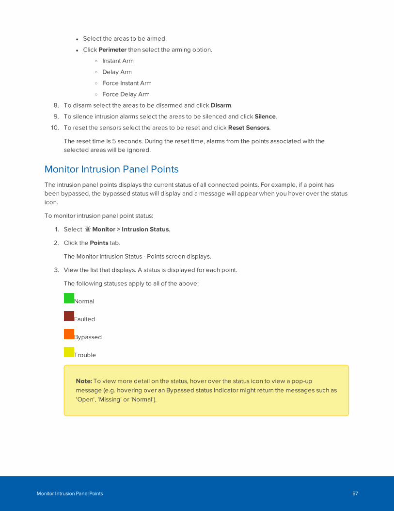
l Select the areas to be armed.
l Click Perimeter then select the arming option.
o Instant Arm
o Delay Arm
o Force Instant Arm
o Force Delay Arm
8. To disarm select the areas to be disarmed and click Disarm.
9. To silence intrusion alarms select the areas to be silenced and click Silence.
10. To reset the sensors select the areas to be reset and click Reset Sensors.
The reset time is 5 seconds. During the reset time, alarms from the points associated with theselected areas will be ignored.
Monitor Intrusion Panel PointsThe intrusion panel points displays the current status of all connected points. For example, if a point hasbeen bypassed, the bypassed status will display and a message will appear when you hover over the statusicon.
To monitor intrusion panel point status:
1. Select Monitor > Intrusion Status.
2. Click the Points tab.
The Monitor Intrusion Status - Points screen displays.
3. View the list that displays. A status is displayed for each point.
The following statuses apply to all of the above:
Normal
Faulted
Bypassed
Trouble
Note: To view more detail on the status, hover over the status icon to view a pop-upmessage (e.g. hovering over an Bypassed status indicator might return the messages such as'Open', 'Missing' or 'Normal').
Monitor Intrusion Panel Points 57
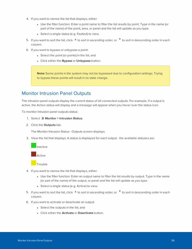
4. If you want to narrow the list that displays, either:
l Use the filter function. Enter a point name to filter the list results by point. Type in the name (orpart of the name) of the point, area, or panel and the list will update as you type.
l Select a single status (e.g. Faulted) to view.
5. If you want to sort the list, click to sort in ascending order, or to sort in descending order in eachcolumn.
6. If you want to bypass or unbypass a point:
l Select the point (or points) in the list, and
l Click either the Bypass or Unbypass button.
Note: Some points in the system may not be bypassed due to configuration settings. Tryingto bypass these points will result in no state change.
Monitor Intrusion Panel OutputsThe intrusion panel outputs display the current status of all connected outputs. For example, if a output isactive, the Active status will display and a message will appear when you hover over the status icon.
To monitor intrusion panel outputs status:
1. Select Monitor > Intrusion Status.
2. Click the Outputs tab.
The Monitor Intrusion Status - Outputs screen displays.
3. View the list that displays. A status is displayed for each output - the available statuses are:
Inactive
Active
Trouble
4. If you want to narrow the list that displays, either:
l Use the filter function. Enter an output name to filter the list results by output. Type in the name(or part of the name) of the output, or panel and the list will update as you type.
l Select a single status (e.g. Active) to view.
5. If you want to sort the list, click to sort in ascending order, or to sort in descending order in eachcolumn.
6. If you want to activate or deactivate an output:
l Select the outputs in the list, and
l Click either the Activate or Deactivate button.
Monitor Intrusion Panel Outputs 58
Identities
The Identities screen gives you access to all tokens and operators of the system. An identity is added to thesystem when a new user needs access to the site. For example, when a person is hired. Access to a site maybe physical access to an area or access to the ACM system to manage the site.
Physical access to the site allows a user to access areas and doors. Access to the ACM system allows usersto manage the site, such as adding users or monitoring events.
For a user to have access to the system or physical access to the site, they must have an identity.
l If the user requires access to the system, they are issued a login and password. This allows the userto access areas of the system. The areas of the system the user has access to depends on their role.
l If a user requires physical access to the site, they are issued a token. The token gives the userphysical access to the site. This allows the user to access areas on the site. The areas the user hasaccess to depends on their role in the system.
Note: If you do not have the correct delegations, you may not be able to access some of thefollowing pages. See your System Administrator for details.
Searching for an Identity
Use Identity Search to find an identity.
1. Fill out the following fields:
l Last Name field.
l (Optional) First Name and/ or Internal Number fields.
l (Optional) Group field.
Blank entries will return all identities.
Note: SALTO identities only. First Name and Last Name are required.
2. Add other search criteria.
a. Search Field drop down list.
b. Search Value field.
c. Click Add Criteria to add another search field and value.
To clear all fields, click Clear Search.
To remove a search row, click Remove.
Identities 59
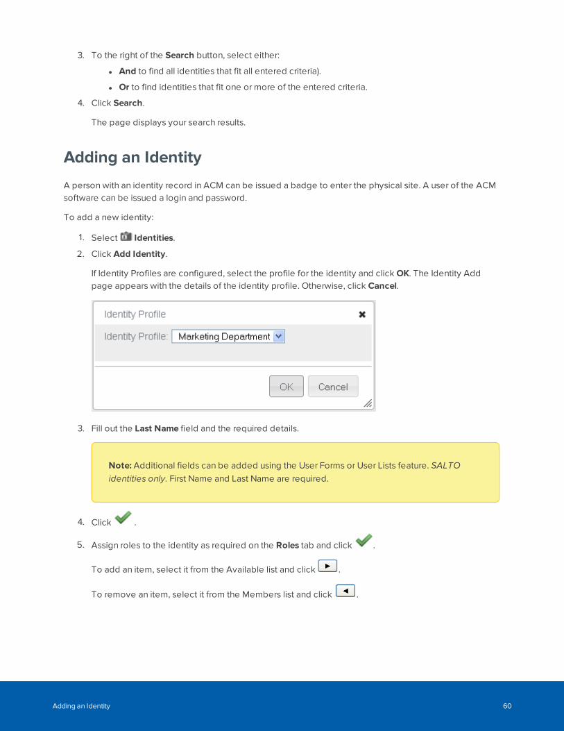
3. To the right of the Search button, select either:
l And to find all identities that fit all entered criteria).
l Or to find identities that fit one or more of the entered criteria.
4. Click Search.
The page displays your search results.
Adding an Identity
A person with an identity record in ACM can be issued a badge to enter the physical site. A user of the ACMsoftware can be issued a login and password.
To add a new identity:
1. Select Identities.
2. Click Add Identity.
If Identity Profiles are configured, select the profile for the identity and click OK. The Identity Addpage appears with the details of the identity profile. Otherwise, click Cancel.
3. Fill out the Last Name field and the required details.
Note: Additional fields can be added using the User Forms or User Lists feature. SALTOidentities only. First Name and Last Name are required.
4. Click .
5. Assign roles to the identity as required on the Roles tab and click .
To add an item, select it from the Available list and click .
To remove an item, select it from the Members list and click .
Adding an Identity 60
Tip: Use Shift + Click to select items in sequence. Use Ctrl + Click to select individual items.
6. Enter the token details as required on the Tokens tab.
By default the Download checkbox is selected, which downloads the token to the connected panelsand associated doors. SALTO identities only. Click the Download button, which downloads the tokento the SALTO server and door.
When you are finished, click .
7. Add more details about the identity on the following tabs:
l Roles: Assigns a role to this identity.
l Tokens : Creates a token for the identity.
l Groups: Assigns the identity to a group.
l Capture: Takes a photo of the user.
l Photos: Uploads an existing photo of the user.
l Badge: Assigns a badge to the user.
l Timed Access: Assigns timed access to the user.
l Access: View the identity's access privileges including roles, access groups and doors.
l Transactions: View transactional data associated with the identity.
l Audit: View a log of all the changes that have been made to this identity.
The default Enrollment Operator role does not have access to this tab. Contact your SystemAdministrator for more details.
Note: The labels of the built-in tabs, such as Identity and Tokens, may be renamed by yourSystem Administrator. A custom form or User Defined Tabs with User Defined Fields may beadded at the end of the list.
Assigning Roles to Identities
A role defines what a user has access to. For identities to have access to the system or physical access tothe site, they must be assigned a role. Each role contains access groups and/or delegations. Access groupsallow a user to have physical access to the site. Delegations allow a user to have access to the system. Theuser will be assigned a role depending on their position in the organization.
To assign roles to an identity:
Assigning Roles to Identities 61
1. Click Identities.
2. From the Identities Search page, perform a search for an identity.
For more information, see Searching for an Identity on page 59.
3. Click on the name of the identity you want to edit.
4. Select the Roles tab.
5. From the Available list, select all the roles that you want to assign to the user, then click .
The role is added to the Members list to show that it is now assigned.
To remove a role from the user, select the role from the Members list, then click .
Note: You can select multiple items by using the Ctrl or Shift key.
6. Click .
Assigning Tokens to Identities
Mercury Security and HID doors only.
Tokens are used to authenticate individuals and allow or deny them physical access to your site. Tokens areassigned to personnel identity records along with access cards, biometric data such as fingerprints, orconnected devices such as smartphones with apps that can be presented for authentication at readers.
To further restrict access, identities can be assigned to specific roles within your site.
To create tokens and assign them to an identity:
1. Select Identities > Identities.
2. Search for an identity.
For more information, see Searching for an Identity on page 59.
3. Click the name of the identity you want to edit.
4. Select the Tokens tab.
5. If only one token has been defined, the Token: Edit page appears.
If more than one token has been defined, the Tokens list appears. Click Add Token.
6. Enter the details as required.
7. Click and then to return to the identity search.
8. Click Download to download the token to the connected panels and associated doors.
Assigning Tokens to Identities 62
9. To assign this token to a badge, select the Badge tab.
10. From the Badge Token drop down list, select the internal number you want to assign to the badge.
11. Click .
Assigning Groups to Identities
Groups are used to group physical and/or system components. Groups are assigned to identities primarilyfor batch updates. For example, if all the badges are close to expiry and they are assigned to the samegroup, the expiration date can be extended through a batch job.
To assign groups to an identity:
1. Click Identities.
2. From the Identities Search page, perform a search for an identity.
For more information, see Searching for an Identity on page 59.
3. Click on the name of the identity you want to edit.
4. Select the Groups tab.
5. From the Available list, select all the groups that you want to add the user to, then click .
The group is added to the Members list to show that the user is now a member.
To remove a user from a group, select the group from the Members list, then click .
Note: You can select multiple terms by using the Ctrl or Shift key.
6. Click .
Capturing and Uploading Photos of an Identity
Capture or upload photos of a person from the Photos tab on a person's Identity page. Then you can selecta photo from this page to appear on that person's Identity page or printed on an access badge.
Captured photo: A photograph taken by a badge camera connected to your computer and to the ACMsystem, and saved in the ACM system. Captured photos are in JPG format.
Uploaded photo: A graphics file in JPG, PNG, or or GIF format that you upload from any location yourcomputer can access and save in the ACM system. Typically, you would upload a JPG file for accessbadges.
Assigning Groups to Identities 63
Note: The Microsoft Edge web browser supports only the uploading of JPG files. Do not attempt toupload any other file format if you are using the ACM client in the Microsoft Edge web browser.
Photos saved in the ACM system can be cropped, resized, and rotated to meet the standardizedrequirements of the badge templates defined in your system.
You can use two types of cameras as a badge camera to capture a photo:
l Local Camera — Any camera connected directly to your computer or built into your computer ormonitor.
l IP-based camera — Any IP-based camera previously connected to your network and added to yourACM system.
Before you can:
l Use a camera to capture photos, you must specify the badge camera you want to use in your userprofile. For more information, see External Systems - Defining the Badge Camera for the System onpage 415.
l Generate and print a badge, at least one badge template must be defined in your system.
After a photo has been added to the Photos tab of an identity, you can edit the photo to suit therequirements of your badge templates. Then you can create a badge with that photo. For more information,see Creating Badges for Identities on page 68.
Capturing a photo
1. There are two ways to access the Capture page:
l From the Identities Search page, click from the Image Capture column.
l From the Identities Search page, click on the name of an identity, select the Photos tab, thenclick Capture a Photo.
2. If you are using:
a. A local camera that you have not used before, this page will not appear unless you allow yourweb browser to access your camera. The first time you access the Capture page, you areprompted to allow your browser to access your local camera. Click Allow.
b. An IP-based camera and the camera requires authentication, this page will not appear until youhave entered your login credentials.
Enter a user name and password, then click OK.
The Capture page appears, with the live preview from the camera showing on the right.
3. Click Capture.
The page refreshes to show the captured photo on the left and the live preview on the right.
A cropping overlay is imposed over the photo, The aspect ratio of the overlay is determined by thevalues set on the System Settings page for Badge Template Photo Height and Badge Template
Capturing and Uploading Photos of an Identity 64
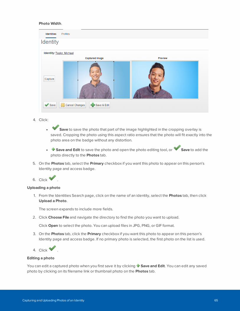
Photo Width.
4. Click:
l Save to save the photo that part of the image highlighted in the cropping overlay issaved. Cropping the photo using this aspect ratio ensures that the photo will fit exactly into thephoto area on the badge without any distortion.
l Save and Edit to save the photo and open the photo editing tool, or Save to add thephoto directly to the Photos tab.
5. On the Photos tab, select the Primary checkbox if you want this photo to appear on this person'sIdentity page and access badge.
6. Click .
Uploading a photo
1. From the Identities Search page, click on the name of an identity, select the Photos tab, then clickUpload a Photo.
The screen expands to include more fields.
2. Click Choose File and navigate the directory to find the photo you want to upload.
Click Open to select the photo. You can upload files in JPG, PNG, or GIF format.
3. On the Photos tab, click the Primary checkbox if you want this photo to appear on this person'sIdentity page and access badge. If no primary photo is selected, the first photo on the list is used.
4. Click .
Editing a photo
You can edit a captured photo when you first save it by clicking Save and Edit. You can edit any savedphoto by clicking on its filename link or thumbnail photo on the Photos tab.
Capturing and Uploading Photos of an Identity 65
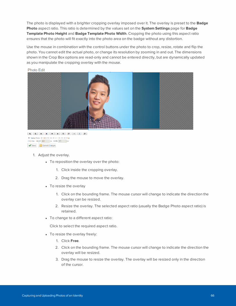
The photo is displayed with a brighter cropping overlay imposed over it. The overlay is preset to the BadgePhoto aspect ratio. This ratio is determined by the values set on the System Settings page for BadgeTemplate Photo Height and Badge Template Photo Width. Cropping the photo using this aspect ratioensures that the photo will fit exactly into the photo area on the badge without any distortion.
Use the mouse in combination with the control buttons under the photo to crop, resize, rotate and flip thephoto. You cannot edit the actual photo, or change its resolution by zooming in and out. The dimensionsshown in the Crop Box options are read-only and cannot be entered directly, but are dynamically updatedas you manipulate the cropping overlay with the mouse.
1. Adjust the overlay.
l To reposition the overlay over the photo:
1. Click inside the cropping overlay.
2. Drag the mouse to move the overlay.
l To resize the overlay
1. Click on the bounding frame. The mouse cursor will change to indicate the direction theoverlay can be resized.
2. Resize the overlay. The selected aspect ratio (usually the Badge Photo aspect ratio) isretained.
l To change to a different aspect ratio:
Click to select the required aspect ratio.
l To resize the overlay freely:
1. Click Free.
2. Click on the bounding frame. The mouse cursor will change to indicate the direction theoverlay will be resized.
3. Drag the mouse to resize the overlay. The overlay will be resized only in the directionof the cursor.
Capturing and Uploading Photos of an Identity 66
l To rotate the overlay:
1. Click outside the current overlay.
2. Drag the mouse to draw a new overlay.
l To replace the overlay:
1. Click outside the current overlay.
2. Drag the mouse to draw a new overlay.
2. Adjust the photo.
l To enlarge or reduce the photo:
Use the + and - magnifier control buttons to adjust the photo size in stepped increments.
l To reposition the photo:
Use the up, down, left and right control buttons to adjust the photo position in steppedincrements.
l To rotate the photo:
1. Use the counterclockwise circular arrow to rotate the photo to the left by 90°.
2. Use the clockwise circular arrow to rotate the photo to the right by 90°.
l To flip the photo:
1. Use the horizontal double-ended control button to flip the photo left to right.
2. Use the vertical double-ended control button to flip the photo top to bottom.
l To reset the photo:
Use the reset control button to cancel your changes and revert the photo to its previouslysaved version.
3. Save the photo:
Click .
The Photos tab is displayed with the saved photo.
When you save the photo, that part of the image highlighted in the cropping overlay is saved.
Note: The saved photo replaces the original photo. The original photo cannot be restored.
Specifying the Primary photo
If you have several photos saved on the Photos tab, the first photo is used on that person's Identity pageand is selected by default for the access badge. To use another photo instead, select the Primary checkboxof the photo you want.
Deleting a photo
To delete a photo from the Photos tab:
Capturing and Uploading Photos of an Identity 67
1. Click .
2. Click .
Creating Badges for Identities
Badges are identification cards that are used to verify a user's identity or association to an organization.Badges may also be used as access cards if they are printed directly on the person's RFID badge.
Note: Before you can print a badge, you must connect a badge printer to the network andconfigure it. For instructions on how to configure your badge printer, refer to the printer's userguide.
To create a badge for a user:
1. Click Identities.
2. From the Identities list, click on the name of the identity you want to edit.
3. Select the Badge tab.
4. From the Badge Photo drop down list, select a photo for this badge.
Only the photos that have been previously uploaded or captured for this identity appear in this list.
5. From the Badge Token drop down list, select the token you want to associate with this badge.
Only the tokens that have been previously defined for this user appear in this list.
6. From the Badge Template drop down list, select the badge template that you want to use for thisbadge.
Only the badge templates that have been previously defined appear in this list.
7. Click .
8. To print the badge, click Create Badge.
The badge appears in a preview window.
9. Click Print.
Note: When printing the badge, ensure that the Header and Footer settings are turned off or set toblank.
Creating Badges for Identities 68
Timed Access
Timed access allows you to schedule access to a specific set of doors or access groups for one badge-holder identity. It is useful for providing temporary restricted access to your site for visitors, contractors,temporary employees, and so on.
Use timed access:
l By door to provide short-term restricted access to your site for visitors, contractors, temporaryemployees, and so on; for example, to allow a contractor to access only the doors needed to accessthe work site. Each timed access applied to a door adds a new access level to the panel attached tothe door, and panels are restricted to a maximum of 254 access level entries. There is a risk thatoveruse of this feature without deleting entries can cause the number of access levels on a heavilyused door, such as a front door, to exceed this maximum.
l By access group to provide groups of badge-holders access to specific areas for restricted times; forexample to access canteen areas during meal hours, or parking garages during the working day. Therisk of access levels accumulating is much reduced by using access groups.
Note: All timed access deletions must be done manually. There is no automatic clean-up of timedaccess entries.
To find a timed access entry for an identity:
1. Click Identities.
2. Search for the identity. For more detail refer to Searching for an Identity on page 59.
3. Click on the name of the identity. The Identity: Edit page displays.
4. Click on the Timed Access tab.
To add a new timed access entry for an identity:
1. Find the timed access entry for the identity.
2. Click on the Timed Access tab.
3. Complete the fields on the tab. Refer to the guidelines above to select the appropriate timed accesstype.
4. Click Add.
The newly added timed access entry is added to the timed access list. If the timeframe for an entry iscurrently active it will display in green. Timeframes for timed access are not checked againstschedules. If a timed access entry is displayed in green but is not working, check any relatedschedules.
Note: You cannot edit a timed access entry. To change the details of an entry, delete the timedaccess entry and add a new one.
Timed Access 69
To delete a timed access entry for an identity:
1. Find the timed access entry for the identity.
2. Click on the Timed Access tab.
3. View the timed access list.
4. Click to delete the related timed access entry.
5. Click OK when the message 'Are you sure you want to delete <name>' displays.
The message 'Successfully deleted the timed access entry <name>' displays.
Note: All deletions must be done manually. There is no automatic clean-up of timed access entries.
Adding Timed Access to an IdentityTo add a new timed access entry for an identity:
1. Click Identities.
2. Search for the identity. For more information see Searching for an Identity on page 59.
3. Click on the name of the identity.
4. Click on the Timed Access tab.
5. Complete the following fields:
l Name
l Type
l Appliance (this defaults)
l Available/Members
l Start Day/Time
l End Day/Time
l Schedule (if doors are selected as the Type)
6. Click Add.
The newly added timed access entry will display in the timed access list. If the timeframe for an entryis currently active it will display in green. Timeframes for timed access are not checked againstschedules. If a timed access entry is displayed in green but is not working, check any relatedschedules.
Editing Timed AccessThere is no functionality to edit a timed access entry. If you want to change the details of an entry, then:
Adding Timed Access to an Identity 70
l Delete the timed access entry. For more detail, refer to Deleting Timed Access below.
l Add a new timed access entry. For more detail, refer to Adding Timed Access to an Identity on theprevious page.
Deleting Timed AccessTo delete a timed access entry:
1. Click Identities.
2. Search for the identity. For more detail refer to Searching for an Identity on page 59.
3. Click on the name of the identity.
4. Click on the Timed Access tab.
5. View the timed access list.
6. Click to delete the related timed access entry.
7. Click OK when the message 'Are you want to delete <name>' displays.
The message 'Successfully deleted the timed access entry <name>' displays.
Note: All deletions must be done manually. There is no automatic clean-up of timed access entries.
Editing an Identity
An identity must be edited when user information changes. For example if a user changes roles, theiridentity would need to reflect this. If the role is not updated, the user would not be able to access areasrequired for their new role.
To edit an existing identity:
1. Click Identities.
2. Search on the Identity Search screen, then click on the identity you want to edit.
3. Navigate through the tabbed pages and make the required changes.
l Identity: The identity details.
l Roles: Assigns a role to this identity.
l Tokens : Creates a token for the identity.
l Groups: Assigns the identity to a group.
l Capture: Takes a photo of the user.
l Photos: Uploads an existing photo of the user.
l Badge: Assigns a badge to the user.
l Timed Access: Assigns timed access to the user.
Deleting Timed Access 71
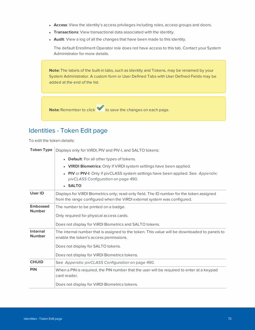
l Access: View the identity's access privileges including roles, access groups and doors.
l Transactions: View transactional data associated with the identity.
l Audit: View a log of all the changes that have been made to this identity.
The default Enrollment Operator role does not have access to this tab. Contact your SystemAdministrator for more details.
Note: The labels of the built-in tabs, such as Identity and Tokens, may be renamed by yourSystem Administrator. A custom form or User Defined Tabs with User Defined Fields may beadded at the end of the list.
Note: Remember to click to save the changes on each page.
Identities - Token Edit pageTo edit the token details:
Token Type Displays only for ViRDI, PIV and PIV-I, and SALTO tokens:
l Default: For all other types of tokens.
l VIRDI Biometrics: Only if ViRDI system settings have been applied.
l PIV or PIV-I: Only if pivCLASS system settings have been applied. See Appendix:pivCLASS Configuration on page 490.
l SALTO
User ID Displays for ViRDI Biometrics only; read-only field. The ID number for the token assignedfrom the range configured when the ViRDI external system was configured.
EmbossedNumber
The number to be printed on a badge.
Only required for physical access cards.
Does not display for ViRDI Biometrics and SALTO tokens.
InternalNumber
The internal number that is assigned to the token. This value will be downloaded to panels toenable the token's access permissions.
Does not display for SALTO tokens.
Does not display for ViRDI Biometrics tokens.
CHUID See Appendix: pivCLASS Configuration on page 490.
PIN When a PIN is required, the PIN number that the user will be required to enter at a keypadcard reader.
Does not display for ViRDI Biometrics tokens.
Identities - Token Edit page 72
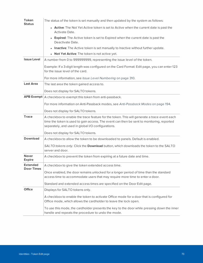
TokenStatus
The status of the token is set manually and then updated by the system as follows:
l Active: The Not Yet Active token is set to Active when the current date is past theActivate Date.
l Expired: The Active token is set to Expired when the current date is past theDeactivate Date.
l Inactive: The Active token is set manually to Inactive without further update.
l Not Yet Active: The token is not active yet.
Issue Level A number from 0 to 999999999, representing the issue level of the token.
Example: If a 3-digit length was configured on the Card Format: Edit page, you can enter 123for the issue level of the card.
For more information, see Issue Level Numbering on page 310.
Last Area The last area the token gained access to.
Does not display for SALTO tokens.
APB Exempt A checkbox to exempt this token from anti-passback.
For more information on Anti-Passback modes, see Anti-Passback Modes on page 194.
Does not display for SALTO tokens.
Trace A checkbox to enable the trace feature for the token. This will generate a trace event eachtime the token is used to gain access. The event can then be sent to monitoring, reportedseparately, and used in global I/O configurations.
Does not display for SALTO tokens.
Download A checkbox to allow the token to be downloaded to panels. Default is enabled.
SALTO tokens only. Click the Download button, which downloads the token to the SALTOserver and door.
NeverExpire
A checkbox to prevent the token from expiring at a future date and time.
ExtendedDoor Times
A checkbox to give the token extended access time.
Once enabled, the door remains unlocked for a longer period of time than the standardaccess time to accommodate users that may require more time to enter a door.
Standard and extended access times are specified on the Door Edit page.
Office Displays for SALTO tokens only.
A checkbox to enable the token to activate Office mode for a door that is configured forOffice mode, which allows the cardholder to leave the lock open.
To use this mode, the cardholder presents the key to the door while pressing down the innerhandle and repeats the procedure to undo the mode.
Identities - Token Edit page 73

SetLockdown
Displays for SALTO tokens only. SALTO standalone doors only. A checkbox to enablelockdown mode for a door that has a lock that can support manual lockdown. For moreinformation about lockdown in the SALTO system, refer to SALTO systems documentation.
To use this mode, the cardholder presents the key to the door's inside reader and repeatsthe procedure to undo the mode.
OverridePrivacy
Displays for SALTO tokens only.
A checkbox to allow the cardholder to access a door locked from the inside at any time.
OverrideLockdown
Displays for SALTO tokens only.
A checkbox to allow the person to access a door closed from the inside during lockdownstate.
AuditOpenings
Displays for SALTO tokens only.
SALTO standalone doors only. A checkbox to audit the use of keys in standalone doors.Audits automatically occur in online doors.
EnableRevalidation
Displays for SALTO tokens only.
A checkbox to specify a period for revalidating a key before it becomes invalid. To makethe token valid again, the cardholder can present the token to the online wall reader at anytime.
For example, a key requires revalidation every seven days, if the update period is set to 7days. If the key is used on the third day, the update period is reset. If the key is not used forover seven days, the key becomes invalid.
Pin exempt A checkbox to exempt this token from PIN entry at a keypad card reader.
Does not display for SALTO tokens.
Use/ Loseexempt
A checkbox to prevent this token from expiring if you know the identity will return after anextended period of inactivity.
Does not display for SALTO tokens.
Issue Date The date the token was issued. Click in the field to use the calendar.
ActivateDate
The activation date for the token. Click in the field to use the calendar.
DeactivateDate
The deactivation date for the token. Click in the field to use the calendar.
Last Door The last door the token was used to gain access.
Last Used The last time the token was used to gain access.
To perform other actions:
Download Click this button to download this token to all connected panels.
Identities - Token Edit page 74
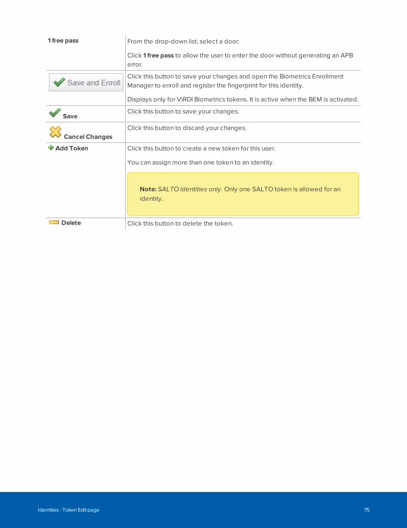
1 free pass From the drop-down list, select a door.
Click 1 free pass to allow the user to enter the door without generating an APBerror.
Click this button to save your changes and open the Biometrics EnrollmentManager to enroll and register the fingerprint for this identity.
Displays only for ViRDI Biometrics tokens. It is active when the BEM is activated.
SaveClick this button to save your changes.
Cancel ChangesClick this button to discard your changes.
Add Token Click this button to create a new token for this user.
You can assign more than one token to an identity.
Note: SALTO identities only. Only one SALTO token is allowed for anidentity.
Delete Click this button to delete the token.
Identities - Token Edit page 75
Managing Roles
The Roles feature allows you to define the access control permissions and application permissions that areavailable in the system. After roles are defined they can be assigned to identities, depending on the type ofaccess control or application functions they are permitted to have.
When you select Roles, the following options are displayed:
l Roles — Displays the Roles list, the starting page for this feature.
l Policies — Displays the Policies list.
l Groups — Displays the Groups list.
l Access Groups — Displays the Access Groups list.
l Delegations — Displays the Delegations list.
l Partitions — Displays the Partitions list.
l Routing Groups — Displays the Routing Groups list.
l Elevator Access Levels — Displays the Elevator Access Levels list.
Configuring Roles
A role is a container for all the permissions an ACM operator needs in the ACM system to perform a specificfunction in the organization. Each role can include access groups, delegations, routing groups, and role-assignment privileges.
l An access group contains all the doors and elevator access levels that a badge holder needs toaccess.
l A delegation is a list of permissions for the functionality within the ACM system that allows an ACMoperator to configure settings and monitor events.
l A routing group allows an ACM operator to monitor specific event types and hardware components.
l Within the role, you can also specify which roles an operator can assign to other people.
After you have defined access groups, delegations, routing groups, and role-assignment privileges, you canassign them to the appropriate roles, and then assign the roles to identities in the system.
Adding a RoleA Role defines a set of permissions in the ACM application that allow users to perform specific functions.
Define your required access groups, delegations, and routing groups before you configure roles.
To add a new role:
Managing Roles 76
1. Click Roles.
2. Click Add Role.
3. Enter a name for the role.
4. Complete the remainder of the page with the required details.
5. Click .
The Role Edit screen is displayed.
6. Select the Access Groups tab to assign access groups to the role.
7. Select the Delegate tab to assign delegations to the role.
8. Select the Routing tab to assign routing groups to the role.
9. Select the Asgn Roles tab to specify role-assignment privileges. Operators with this role can onlyassign the specified roles in this list to other people in the system.
10. Select the Access tab to view access groups, doors, and identities associated with this role.
11. Select the Audit tab to view a log of all the changes that have been made to this role.
12. Click .
Editing a RoleTo edit an existing role:
1. Click Roles.
2. From the Roles list, click on the role you want to edit.
3. Navigate through the tabbed pages and edit the details as required. The tabbed pages include:
l Role Edit: use this page to edit general settings for the role.
l Access Groups: use this page to assign access groups to the role.
l Delegate: use this page to assign delegations to the role.
l Routing: use this page to assign routing groups to the role.
l Asgn Roles: use this page to specify role-assignment privileges. Operators with this role canonly assign the specified roles in this list to other people in the system.
l Access: use this page to view access groups, doors, and identities associated with this role.
l Audit: use this page to view a log of all the changes that have been made to this role.
Note: Remember to click to save the changes on each page.
Assigning an Access Group to a RoleYou must assign an access group to a role to make it effective.
Editing a Role 77
1. Click Roles > Roles.
2. Select the Access Groups tab.
3. Select the access groups that you want to add to the role.
To add an item, select it from the Available list and click .
To remove an item, select it from the Members list and click .
Tip: Use Shift + Click to select items in sequence. Use Ctrl + Click to select individual items.
4. Click .
All the people with this role now have the access permissions defined by the access group.
Assigning Delegations to a RoleTo assign delegations to a role:
1. From the Roles drop-down menu, select Delegations.
2. From the list of roles on the Delegations panel, click on the role you want to edit.
3. From the Available list, select all the delegations that should be part of the role then click .
The delegation is added to the Members list to show that it is now part of the role.
To remove a delegation from the role, select the delegation from the Members list and click .
Tip: You can select multiple terms by using the Ctrl or Shift key and move them with oneclick.
4. Click .
Assigning Routing Groups to a RoleTo assign routing groups to a role:
1. Click Roles.
2. From the Roles list, click on the role you want to edit.
3. Select the Routing tab.
4. From the Available list, select all the routing groups that should be part of the role, then click .
The routing group is added to the Members list to show that it is now part of the role.
Assigning Delegations to a Role 78
Toremoveanroutinggroupfromtherole,selecttheroutinggroupfromtheMemberslist,thenclick .
Note: You can select multiple terms by using the Ctrl or Shift key.
5. Click .
Assigning RolesThe Asgn Roles tab allows you to authorize members of this role to assign specified roles to other users.
To specify these permissions:
1. Click Roles.
2. From the Roles list, click on the role you want to edit.
3. Select the Asgn Roles tab.
4. From the Available list, select all the roles you want to allow members of this role to assign to others,
then click .
The role is added to the Members list.
To remove a role from the list, select the role from the Members list, then click .
Note: You can select multiple terms by using the Ctrl or Shift key.
5. Click .
Deleting a RoleTo delete an existing role:
1. Select Roles.
2. From the Roles list, click beside the role that you want to delete.
3. When the confirmation message is displayed, click OK.
Roles - Role Search pageWhen you select Roles from the task bar, the Roles screen is displayed.
The first page you see is the Role Search page. Select the Roles tab to return to this page. This page lists allthe roles that have been configured in the system.
Assigning Roles 79
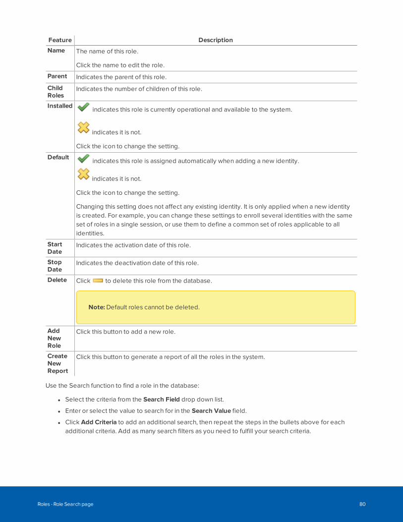
Feature Description
Name The name of this role.
Click the name to edit the role.
Parent Indicates the parent of this role.
ChildRoles
Indicates the number of children of this role.
Installed indicates this role is currently operational and available to the system.
indicates it is not.
Click the icon to change the setting.
Default indicates this role is assigned automatically when adding a new identity.
indicates it is not.
Click the icon to change the setting.
Changing this setting does not affect any existing identity. It is only applied when a new identityis created. For example, you can change these settings to enroll several identities with the sameset of roles in a single session, or use them to define a common set of roles applicable to allidentities.
StartDate
Indicates the activation date of this role.
StopDate
Indicates the deactivation date of this role.
Delete Click to delete this role from the database.
Note: Default roles cannot be deleted.
AddNewRole
Click this button to add a new role.
CreateNewReport
Click this button to generate a report of all the roles in the system.
Use the Search function to find a role in the database:
l Select the criteria from the Search Field drop down list.
l Enter or select the value to search for in the Search Value field.
l Click Add Criteria to add an additional search, then repeat the steps in the bullets above for eachadditional criteria. Add as many search filters as you need to fulfill your search criteria.
Roles - Role Search page 80
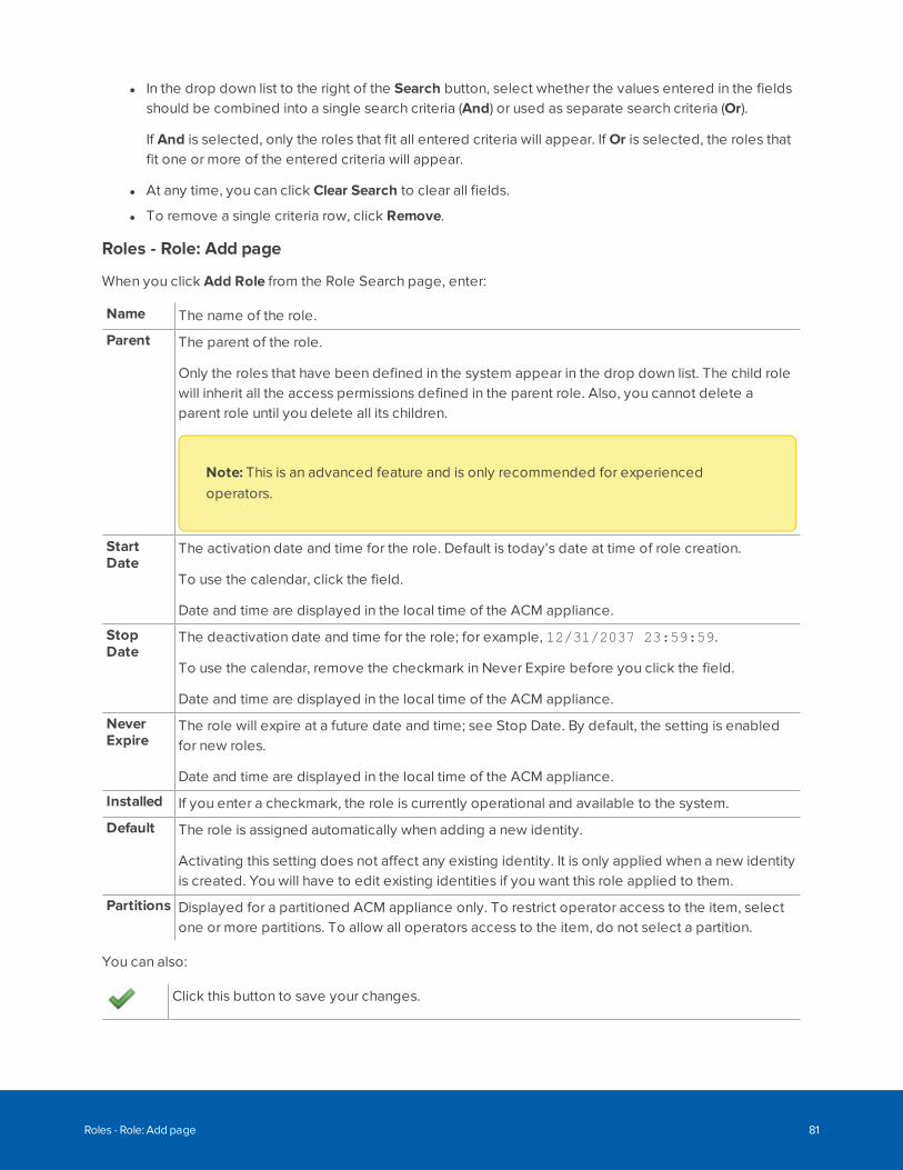
l In the drop down list to the right of the Search button, select whether the values entered in the fieldsshould be combined into a single search criteria (And) or used as separate search criteria (Or).
If And is selected, only the roles that fit all entered criteria will appear. If Or is selected, the roles thatfit one or more of the entered criteria will appear.
l At any time, you can click Clear Search to clear all fields.
l To remove a single criteria row, click Remove.
Roles - Role: Add page
When you click Add Role from the Role Search page, enter:
Name The name of the role.
Parent The parent of the role.
Only the roles that have been defined in the system appear in the drop down list. The child rolewill inherit all the access permissions defined in the parent role. Also, you cannot delete aparent role until you delete all its children.
Note: This is an advanced feature and is only recommended for experiencedoperators.
StartDate
The activation date and time for the role. Default is today's date at time of role creation.
To use the calendar, click the field.
Date and time are displayed in the local time of the ACM appliance.
StopDate
The deactivation date and time for the role; for example, 12/31/2037 23:59:59.
To use the calendar, remove the checkmark in Never Expire before you click the field.
Date and time are displayed in the local time of the ACM appliance.
NeverExpire
The role will expire at a future date and time; see Stop Date. By default, the setting is enabledfor new roles.
Date and time are displayed in the local time of the ACM appliance.
Installed If you enter a checkmark, the role is currently operational and available to the system.
Default The role is assigned automatically when adding a new identity.
Activating this setting does not affect any existing identity. It is only applied when a new identityis created. You will have to edit existing identities if you want this role applied to them.
Partitions Displayed for a partitioned ACM appliance only. To restrict operator access to the item, selectone or more partitions. To allow all operators access to the item, do not select a partition.
You can also:
Click this button to save your changes.
Roles - Role: Add page 81
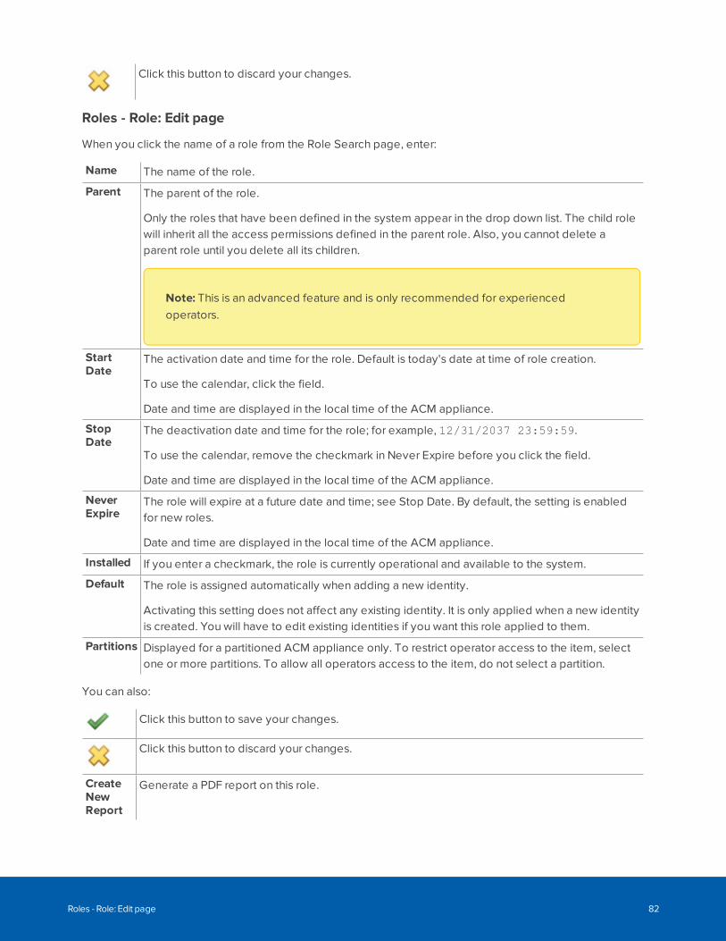
Click this button to discard your changes.
Roles - Role: Edit page
When you click the name of a role from the Role Search page, enter:
Name The name of the role.
Parent The parent of the role.
Only the roles that have been defined in the system appear in the drop down list. The child rolewill inherit all the access permissions defined in the parent role. Also, you cannot delete aparent role until you delete all its children.
Note: This is an advanced feature and is only recommended for experiencedoperators.
StartDate
The activation date and time for the role. Default is today's date at time of role creation.
To use the calendar, click the field.
Date and time are displayed in the local time of the ACM appliance.
StopDate
The deactivation date and time for the role; for example, 12/31/2037 23:59:59.
To use the calendar, remove the checkmark in Never Expire before you click the field.
Date and time are displayed in the local time of the ACM appliance.
NeverExpire
The role will expire at a future date and time; see Stop Date. By default, the setting is enabledfor new roles.
Date and time are displayed in the local time of the ACM appliance.
Installed If you enter a checkmark, the role is currently operational and available to the system.
Default The role is assigned automatically when adding a new identity.
Activating this setting does not affect any existing identity. It is only applied when a new identityis created. You will have to edit existing identities if you want this role applied to them.
Partitions Displayed for a partitioned ACM appliance only. To restrict operator access to the item, selectone or more partitions. To allow all operators access to the item, do not select a partition.
You can also:
Click this button to save your changes.
Click this button to discard your changes.
CreateNewReport
Generate a PDF report on this role.
Roles - Role: Edit page 82
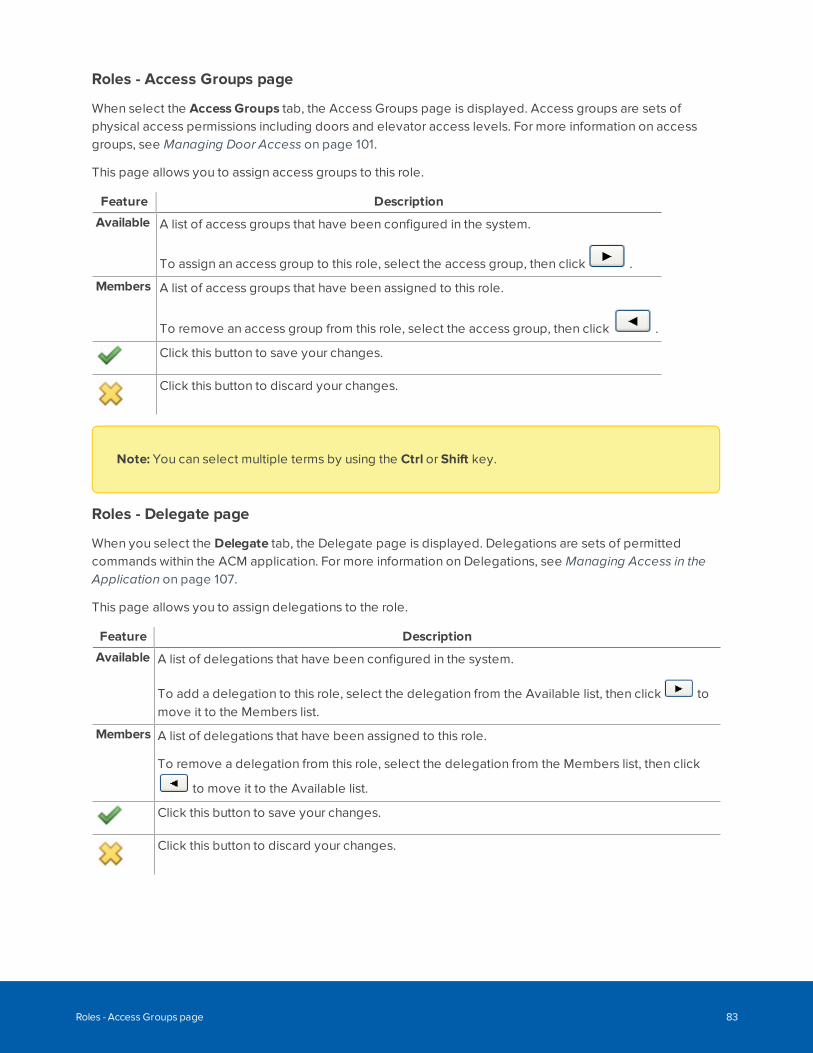
Roles - Access Groups page
When select the Access Groups tab, the Access Groups page is displayed. Access groups are sets ofphysical access permissions including doors and elevator access levels. For more information on accessgroups, see Managing Door Access on page 101.
This page allows you to assign access groups to this role.
Feature Description
Available A list of access groups that have been configured in the system.
To assign an access group to this role, select the access group, then click .
Members A list of access groups that have been assigned to this role.
To remove an access group from this role, select the access group, then click .
Click this button to save your changes.
Click this button to discard your changes.
Note: You can select multiple terms by using the Ctrl or Shift key.
Roles - Delegate page
When you select the Delegate tab, the Delegate page is displayed. Delegations are sets of permittedcommands within the ACM application. For more information on Delegations, see Managing Access in theApplication on page 107.
This page allows you to assign delegations to the role.
Feature Description
Available A list of delegations that have been configured in the system.
To add a delegation to this role, select the delegation from the Available list, then click tomove it to the Members list.
Members A list of delegations that have been assigned to this role.
To remove a delegation from this role, select the delegation from the Members list, then click
to move it to the Available list.
Click this button to save your changes.
Click this button to discard your changes.
Roles - Access Groups page 83
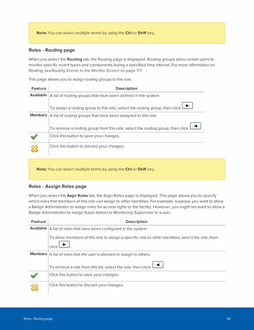
Note: You can select multiple terms by using the Ctrl or Shift key.
Roles - Routing page
When you select the Routing tab, the Routing page is displayed. Routing groups allow certain users tomonitor specific event types and components during a specified time interval. For more information onRouting, seeRouting Events to the Monitor Screen on page 117.
This page allows you to assign routing groups to the role.
Feature Description
Available A list of routing groups that have been defined in the system.
To assign a routing group to this role, select the routing group, then click .
Members A list of routing groups that have been assigned to this role.
To remove a routing group from this role, select the routing group, then click .
Click this button to save your changes.
Click this button to discard your changes.
Note: You can select multiple terms by using the Ctrl or Shift key.
Roles - Assign Roles page
When you select the Asgn Roles tab, the Asgn Roles page is displayed. This page allows you to specifywhich roles that members of this role can assign to other identities. For example, suppose you want to allowa Badge Administrator to assign roles for access rights to the facility. However, you might not want to allow aBadge Administrator to assign Super Admin or Monitoring Supervisor to a user.
Feature Description
Available A list of roles that have been configured in the system.
To allow members of this role to assign a specific role to other identities, select the role, then
click .
Members A list of roles that the user is allowed to assign to others.
To remove a role from this list, select the role, then click .
Click this button to save your changes.
Click this button to discard your changes.
Roles - Routing page 84
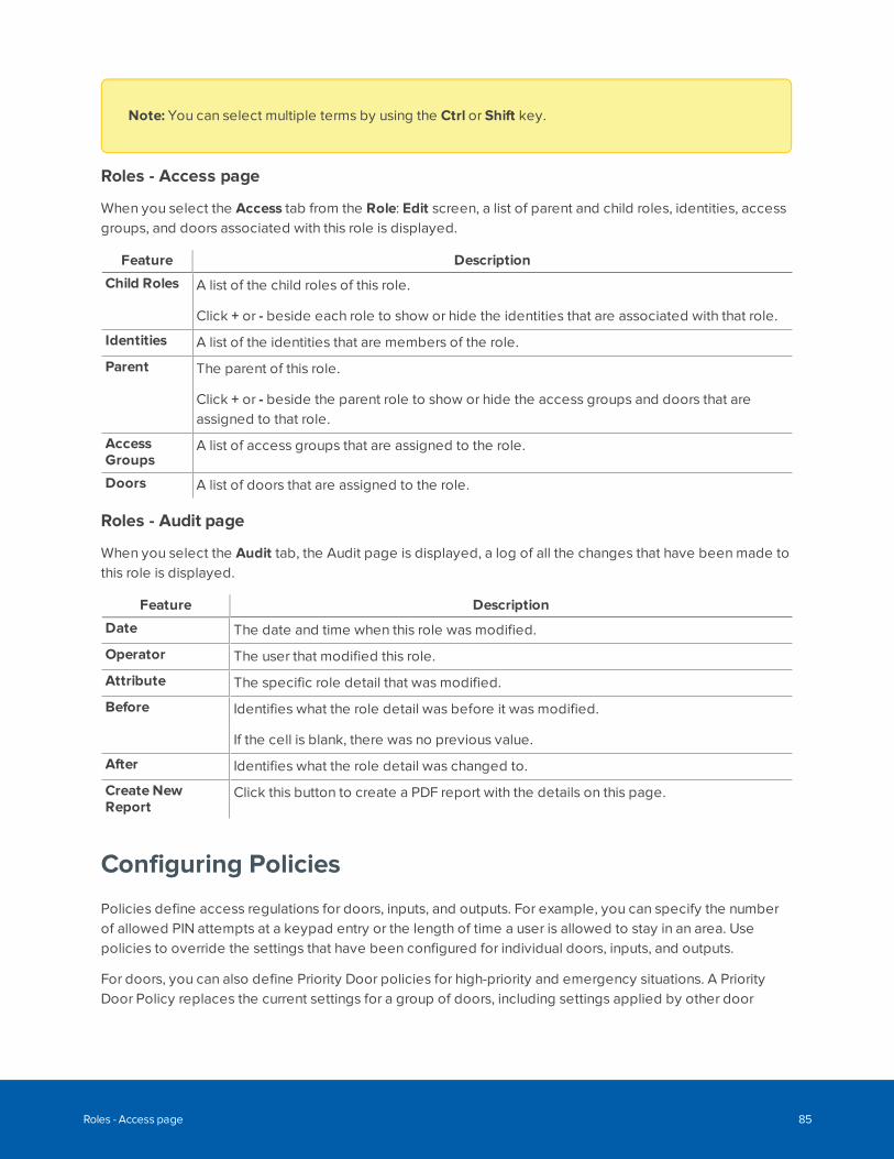
Note: You can select multiple terms by using the Ctrl or Shift key.
Roles - Access page
When you select the Access tab from the Role: Edit screen, a list of parent and child roles, identities, accessgroups, and doors associated with this role is displayed.
Feature Description
Child Roles A list of the child roles of this role.
Click + or - beside each role to show or hide the identities that are associated with that role.
Identities A list of the identities that are members of the role.
Parent The parent of this role.
Click + or - beside the parent role to show or hide the access groups and doors that areassigned to that role.
AccessGroups
A list of access groups that are assigned to the role.
Doors A list of doors that are assigned to the role.
Roles - Audit page
When you select the Audit tab, the Audit page is displayed, a log of all the changes that have been made tothis role is displayed.
Feature Description
Date The date and time when this role was modified.
Operator The user that modified this role.
Attribute The specific role detail that was modified.
Before Identifies what the role detail was before it was modified.
If the cell is blank, there was no previous value.
After Identifies what the role detail was changed to.
Create NewReport
Click this button to create a PDF report with the details on this page.
Configuring Policies
Policies define access regulations for doors, inputs, and outputs. For example, you can specify the numberof allowed PIN attempts at a keypad entry or the length of time a user is allowed to stay in an area. Usepolicies to override the settings that have been configured for individual doors, inputs, and outputs.
For doors, you can also define Priority Door policies for high-priority and emergency situations. A PriorityDoor Policy replaces the current settings for a group of doors, including settings applied by other door
Roles - Access page 85
policies, priority and non-priority global actions, job specifications, and macros.
Priority-enabled policies are intended to support the emergency operating procedures at your site,including potentially life-threatening situations (such as fires, tornadoes, earthquakes, physical attacks), andhazardous situations (such as chemical spills, gas leaks, explosions). These policies require specialpermissions to configure, and use specific options to operate. For more information, see Priority Situationson page 429 and Triggering Door Lockdown By Panic Button or Red Card on page 440.
Policies are enabled through the Groups feature. After you have created a policy, you must assign it to agroup of hardware components to make it effective. All users and security devices that are assigned to thegroup are affected by the policies that are in the group.
A policy is in effect when it is installed on the ACM appliance.
Adding a PolicyTo add a new policy:
1. Select Roles > Policies.
2. Click Add New Policy.
The Policy Add page appears.
3. Fill out the Name field.
4. Select the hardware types that you want to override. The options include Door, Input, and Output.
5. Click .
When the page refreshes, the Policy Edit screen is displayed.
6. Depending on the options you selected on the Policy Add page, this screen may have any of thefollowing tabbed pages:
l Select the Mercury tab to override settings for doors that are connected to a Mercury Securitypanel.
l Select the Input tab to override settings for inputs.
l Select the Output tab to override settings for outputs.
Editing a PolicyTo edit an existing policy:
1. Select Roles > Policies.
The Policies list appears.
2. Click on the policy you want to edit.
The Policy Edit screen appears.
Adding a Policy 86
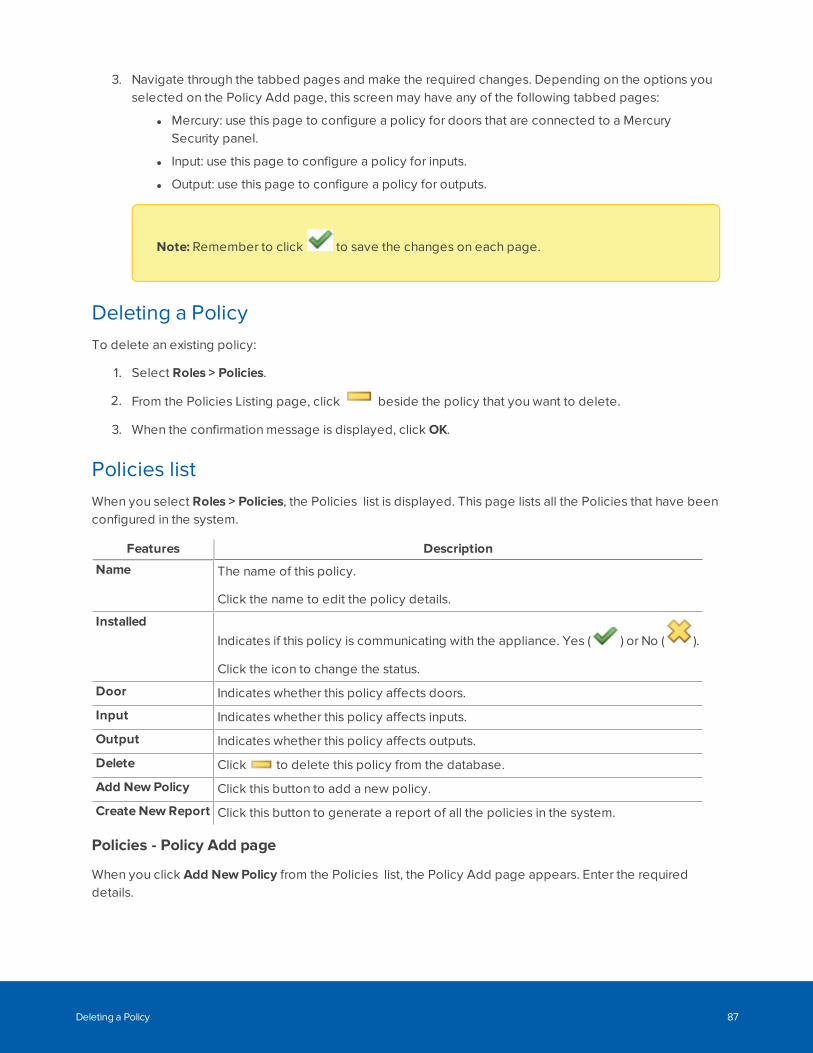
3. Navigate through the tabbed pages and make the required changes. Depending on the options youselected on the Policy Add page, this screen may have any of the following tabbed pages:
l Mercury: use this page to configure a policy for doors that are connected to a MercurySecurity panel.
l Input: use this page to configure a policy for inputs.
l Output: use this page to configure a policy for outputs.
Note: Remember to click to save the changes on each page.
Deleting a PolicyTo delete an existing policy:
1. Select Roles > Policies.
2. From the Policies Listing page, click beside the policy that you want to delete.
3. When the confirmation message is displayed, click OK.
Policies listWhen you select Roles > Policies, the Policies list is displayed. This page lists all the Policies that have beenconfigured in the system.
Features Description
Name The name of this policy.
Click the name to edit the policy details.
InstalledIndicates if this policy is communicating with the appliance. Yes ( ) or No ( ).
Click the icon to change the status.
Door Indicates whether this policy affects doors.
Input Indicates whether this policy affects inputs.
Output Indicates whether this policy affects outputs.
Delete Click to delete this policy from the database.
Add New Policy Click this button to add a new policy.
Create New Report Click this button to generate a report of all the policies in the system.
Policies - Policy Add page
When you click Add New Policy from the Policies list, the Policy Add page appears. Enter the requireddetails.
Deleting a Policy 87
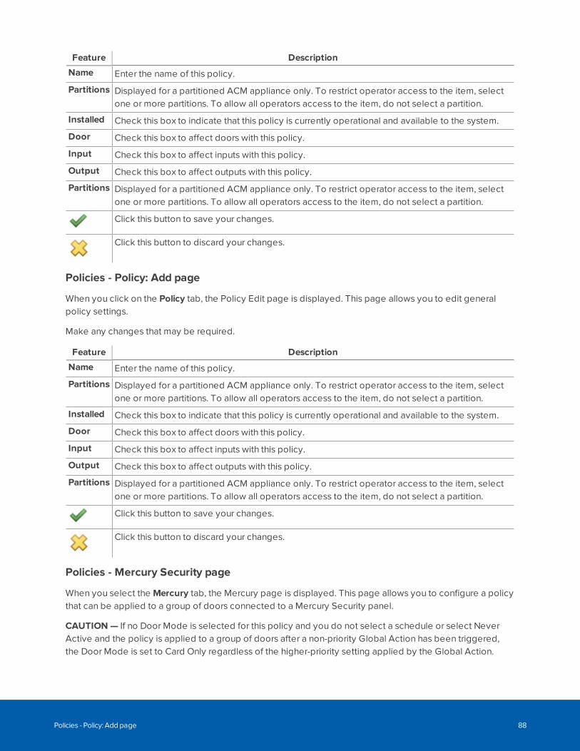
Feature Description
Name Enter the name of this policy.
Partitions Displayed for a partitioned ACM appliance only. To restrict operator access to the item, selectone or more partitions. To allow all operators access to the item, do not select a partition.
Installed Check this box to indicate that this policy is currently operational and available to the system.
Door Check this box to affect doors with this policy.
Input Check this box to affect inputs with this policy.
Output Check this box to affect outputs with this policy.
Partitions Displayed for a partitioned ACM appliance only. To restrict operator access to the item, selectone or more partitions. To allow all operators access to the item, do not select a partition.
Click this button to save your changes.
Click this button to discard your changes.
Policies - Policy: Add page
When you click on the Policy tab, the Policy Edit page is displayed. This page allows you to edit generalpolicy settings.
Make any changes that may be required.
Feature Description
Name Enter the name of this policy.
Partitions Displayed for a partitioned ACM appliance only. To restrict operator access to the item, selectone or more partitions. To allow all operators access to the item, do not select a partition.
Installed Check this box to indicate that this policy is currently operational and available to the system.
Door Check this box to affect doors with this policy.
Input Check this box to affect inputs with this policy.
Output Check this box to affect outputs with this policy.
Partitions Displayed for a partitioned ACM appliance only. To restrict operator access to the item, selectone or more partitions. To allow all operators access to the item, do not select a partition.
Click this button to save your changes.
Click this button to discard your changes.
Policies - Mercury Security page
When you select the Mercury tab, the Mercury page is displayed. This page allows you to configure a policythat can be applied to a group of doors connected to a Mercury Security panel.
CAUTION — If no Door Mode is selected for this policy and you do not select a schedule or select NeverActive and the policy is applied to a group of doors after a non-priority Global Action has been triggered,the Door Mode is set to Card Only regardless of the higher-priority setting applied by the Global Action.
Policies - Policy: Add page 88
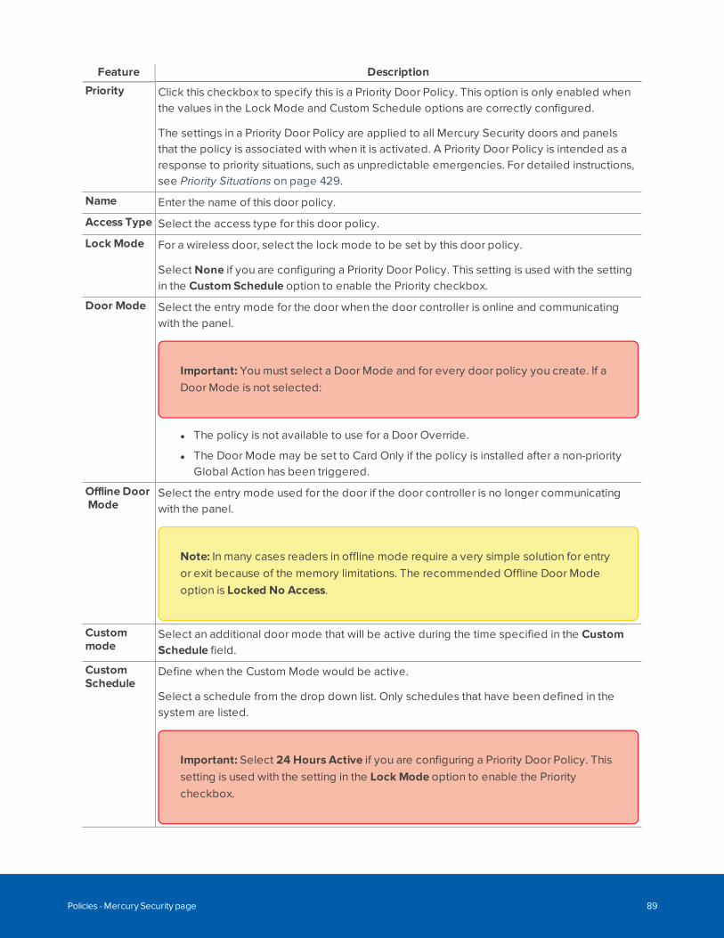
Feature Description
Priority Click this checkbox to specify this is a Priority Door Policy. This option is only enabled whenthe values in the Lock Mode and Custom Schedule options are correctly configured.
The settings in a Priority Door Policy are applied to all Mercury Security doors and panelsthat the policy is associated with when it is activated. A Priority Door Policy is intended as aresponse to priority situations, such as unpredictable emergencies. For detailed instructions,see Priority Situations on page 429.
Name Enter the name of this door policy.
Access Type Select the access type for this door policy.
Lock Mode For a wireless door, select the lock mode to be set by this door policy.
Select None if you are configuring a Priority Door Policy. This setting is used with the settingin the Custom Schedule option to enable the Priority checkbox.
Door Mode Select the entry mode for the door when the door controller is online and communicatingwith the panel.
Important: You must select a Door Mode and for every door policy you create. If aDoor Mode is not selected:
l The policy is not available to use for a Door Override.
l The Door Mode may be set to Card Only if the policy is installed after a non-priorityGlobal Action has been triggered.
Offline DoorMode
Select the entry mode used for the door if the door controller is no longer communicatingwith the panel.
Note: In many cases readers in offline mode require a very simple solution for entryor exit because of the memory limitations. The recommended Offline Door Modeoption is Locked No Access.
Custommode
Select an additional door mode that will be active during the time specified in the CustomSchedule field.
CustomSchedule
Define when the Custom Mode would be active.
Select a schedule from the drop down list. Only schedules that have been defined in thesystem are listed.
Important: Select 24 Hours Active if you are configuring a Priority Door Policy. Thissetting is used with the setting in the Lock Mode option to enable the Prioritycheckbox.
Policies - Mercury Security page 89
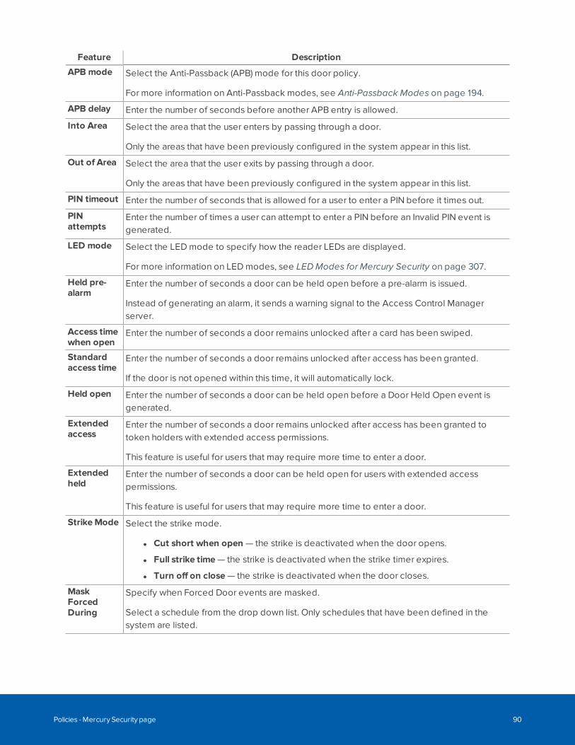
Feature Description
APB mode Select the Anti-Passback (APB) mode for this door policy.
For more information on Anti-Passback modes, see Anti-Passback Modes on page 194.
APB delay Enter the number of seconds before another APB entry is allowed.
Into Area Select the area that the user enters by passing through a door.
Only the areas that have been previously configured in the system appear in this list.
Out of Area Select the area that the user exits by passing through a door.
Only the areas that have been previously configured in the system appear in this list.
PIN timeout Enter the number of seconds that is allowed for a user to enter a PIN before it times out.
PINattempts
Enter the number of times a user can attempt to enter a PIN before an Invalid PIN event isgenerated.
LED mode Select the LED mode to specify how the reader LEDs are displayed.
For more information on LED modes, see LED Modes for Mercury Security on page 307.
Held pre-alarm
Enter the number of seconds a door can be held open before a pre-alarm is issued.
Instead of generating an alarm, it sends a warning signal to the Access Control Managerserver.
Access timewhen open
Enter the number of seconds a door remains unlocked after a card has been swiped.
Standardaccess time
Enter the number of seconds a door remains unlocked after access has been granted.
If the door is not opened within this time, it will automatically lock.
Held open Enter the number of seconds a door can be held open before a Door Held Open event isgenerated.
Extendedaccess
Enter the number of seconds a door remains unlocked after access has been granted totoken holders with extended access permissions.
This feature is useful for users that may require more time to enter a door.
Extendedheld
Enter the number of seconds a door can be held open for users with extended accesspermissions.
This feature is useful for users that may require more time to enter a door.
StrikeMode Select the strike mode.
l Cut short when open — the strike is deactivated when the door opens.
l Full strike time — the strike is deactivated when the strike timer expires.
l Turn off on close — the strike is deactivated when the door closes.
MaskForcedDuring
Specify when Forced Door events are masked.
Select a schedule from the drop down list. Only schedules that have been defined in thesystem are listed.
Policies - Mercury Security page 90
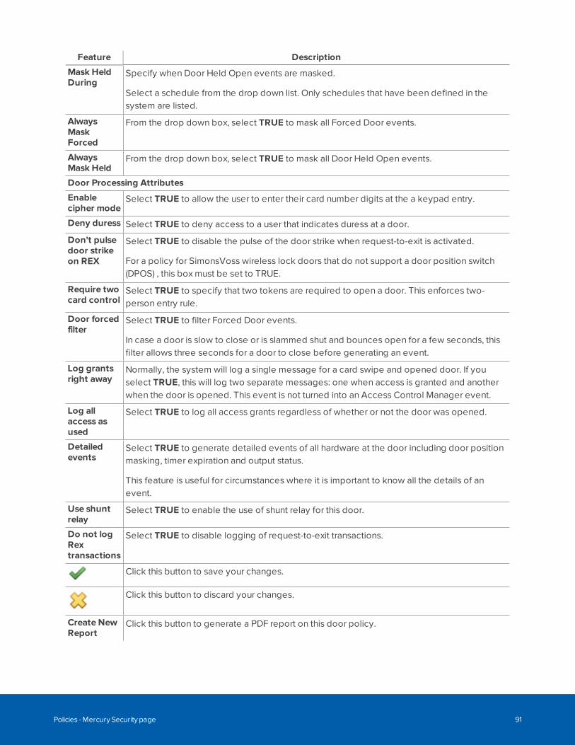
Feature Description
Mask HeldDuring
Specify when Door Held Open events are masked.
Select a schedule from the drop down list. Only schedules that have been defined in thesystem are listed.
AlwaysMaskForced
From the drop down box, select TRUE to mask all Forced Door events.
AlwaysMask Held
From the drop down box, select TRUE to mask all Door Held Open events.
Door Processing Attributes
Enablecipher mode
Select TRUE to allow the user to enter their card number digits at the a keypad entry.
Deny duress Select TRUE to deny access to a user that indicates duress at a door.
Don't pulsedoor strikeon REX
Select TRUE to disable the pulse of the door strike when request-to-exit is activated.
For a policy for SimonsVoss wireless lock doors that do not support a door position switch(DPOS) , this box must be set to TRUE.
Require twocard control
Select TRUE to specify that two tokens are required to open a door. This enforces two-person entry rule.
Door forcedfilter
Select TRUE to filter Forced Door events.
In case a door is slow to close or is slammed shut and bounces open for a few seconds, thisfilter allows three seconds for a door to close before generating an event.
Log grantsright away
Normally, the system will log a single message for a card swipe and opened door. If youselect TRUE, this will log two separate messages: one when access is granted and anotherwhen the door is opened. This event is not turned into an Access Control Manager event.
Log allaccess asused
Select TRUE to log all access grants regardless of whether or not the door was opened.
Detailedevents
Select TRUE to generate detailed events of all hardware at the door including door positionmasking, timer expiration and output status.
This feature is useful for circumstances where it is important to know all the details of anevent.
Use shuntrelay
Select TRUE to enable the use of shunt relay for this door.
Do not logRextransactions
Select TRUE to disable logging of request-to-exit transactions.
Click this button to save your changes.
Click this button to discard your changes.
Create NewReport
Click this button to generate a PDF report on this door policy.
Policies - Mercury Security page 91
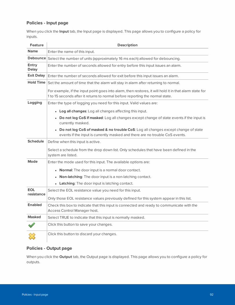
Policies - Input page
When you click the Input tab, the Input page is displayed. This page allows you to configure a policy forinputs.
Feature Description
Name Enter the name of this input.
Debounce Select the number of units (approximately 16 ms each) allowed for debouncing.
EntryDelay
Enter the number of seconds allowed for entry before this input issues an alarm.
Exit Delay Enter the number of seconds allowed for exit before this input issues an alarm.
Hold Time Set the amount of time that the alarm will stay in alarm after returning to normal.
For example, if the input point goes into alarm, then restores, it will hold it in that alarm state for1 to 15 seconds after it returns to normal before reporting the normal state.
Logging Enter the type of logging you need for this input. Valid values are:
l Log all changes: Log all changes affecting this input.
l Do not log CoS if masked: Log all changes except change of state events if the input iscurrently masked.
l Do not log CoS of masked & no trouble CoS: Log all changes except change of stateevents if the input is currently masked and there are no trouble CoS events.
Schedule Define when this input is active.
Select a schedule from the drop down list. Only schedules that have been defined in thesystem are listed.
Mode Enter the mode used for this input. The available options are:
l Normal: The door input is a normal door contact.
l Non-latching: The door input is a non-latching contact.
l Latching: The door input is latching contact.
EOLresistance
Select the EOL resistance value you need for this input.
Only those EOL resistance values previously defined for this system appear in this list.
Enabled Check this box to indicate that this input is connected and ready to communicate with theAccess Control Manager host.
Masked Select TRUE to indicate that this input is normally masked.
Click this button to save your changes.
Click this button to discard your changes.
Policies - Output page
When you click the Output tab, the Output page is displayed. This page allows you to configure a policy foroutputs.
Policies - Input page 92
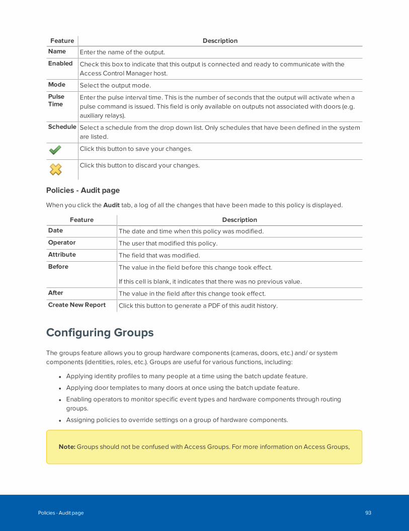
Feature Description
Name Enter the name of the output.
Enabled Check this box to indicate that this output is connected and ready to communicate with theAccess Control Manager host.
Mode Select the output mode.
PulseTime
Enter the pulse interval time. This is the number of seconds that the output will activate when apulse command is issued. This field is only available on outputs not associated with doors (e.g.auxiliary relays).
Schedule Select a schedule from the drop down list. Only schedules that have been defined in the systemare listed.
Click this button to save your changes.
Click this button to discard your changes.
Policies - Audit page
When you click the Audit tab, a log of all the changes that have been made to this policy is displayed.
Feature Description
Date The date and time when this policy was modified.
Operator The user that modified this policy.
Attribute The field that was modified.
Before The value in the field before this change took effect.
If this cell is blank, it indicates that there was no previous value.
After The value in the field after this change took effect.
Create New Report Click this button to generate a PDF of this audit history.
Configuring Groups
The groups feature allows you to group hardware components (cameras, doors, etc.) and/ or systemcomponents (identities, roles, etc.). Groups are useful for various functions, including:
l Applying identity profiles to many people at a time using the batch update feature.
l Applying door templates to many doors at once using the batch update feature.
l Enabling operators to monitor specific event types and hardware components through routinggroups.
l Assigning policies to override settings on a group of hardware components.
Note: Groups should not be confused with Access Groups. For more information on Access Groups,
Policies - Audit page 93
see Managing Door Access on page 101.
Adding a GroupTo add a new group:
1. Select Roles > Groups.
2. Click Add NewGroup.
The Group Add page appears.
3. Fill out the Name field.
4. Click .
When the page refreshes, the Group Edit screen is displayed.
5. Navigate through the tabbed pages and edit the details as required. The tabbed pages include:
l Group: use this page to rename the group and select partitions
l Policies: use this page to assign policies to the group.
l Members: use this page to add components to the group.
l Audit: use this page to view a log of all the changes that have been made to this group.
Editing a GroupTo edit an existing group:
1. Select Roles > Groups.
The Groups list is displayed.
2. Click the name of the group you want to edit.
The Group Edit page appears.
3. Navigate through the tabbed pages and make the required changes. The tabbed pages include:
l Group: use this page to edit the group name and view the current policies and members in thegroup.
l Policies: use this page to select the policies in the group.
l Members: use this page to select the components in the group.
l Audit: use this page to view a log of all the changes that have been made to this group.
Note: Remember to click to save the changes on each page.
Adding a Group 94
Assigning Policies to GroupsTo assign policies to a group:
1. Select Roles > Groups.
The Groups list is displayed.
2. From the Groups list, click on the name of the group you want to edit.
The Group Edit page appears.
3. Select the Policies tab.
4. From the Available list, select all the policies that you want to assign to the group, then click .
The policy is added to the Members list to show that it is now assigned.
To remove a policy from the group, select the policy from the Members list, then click .
Note: You can select multiple terms by using the Ctrl or Shift key.
5. Click .
Assigning Members to GroupsA group can contain any number of members. Members of a group can be hardware items (cameras, doors,etc) and/or system items (identities, roles, etc).
To assign members to a group:
1. Select Roles > Groups.
The Groups list is displayed.
2. From the Groups list, click on the name of the group you want to edit.
The Group Edit page appears.
3. Select the Members tab.
4. From the Type drop down list, select the type of item you want to add to the group.
Once you select a type, the relevant items will appear in the Available window.
NOTE: If there are ten or more entries in the list in the Available window, a standard Search willdisplay - this can be used to narrow the list. If there are more than 2,000 entries then an AdvancedSearch will display to enable you to narrow the list.
5. From the Available list, select all the items that you want to assign as members of the group, then
click .
Assigning Policies to Groups 95
The item is added to the Members list to show that it is now assigned.
To remove a item from the group, select the item from the Members list, then click .
Note: You can select multiple terms by using the Ctrl or Shift key.
6. Click .
Creating a Hardware Group for RoutingTo use routing groups, you must create a group that contains the event sources of interest. The eventsources must be hardware components. For more information on routing groups, see Routing Events to theMonitor Screen on page 117.
1. Select Roles > Groups.
The Groups list is displayed.
2. Click Add NewGroup.
The Group Add page is displayed.
3. Fill out the Name field.
4. Select a partition for the hardware group.
This is important for routing if you do not want operators in different partitions to see this hardwaregroup.
5. Click .
The Group Edit screen is displayed.
6. Select the Members tab.
7. From the Type drop-down list, select a type of hardware component.
Note: Do not select Identity or Role, since they are not routable.
8. Select the hardware components that you want to add to the group.
9. Repeat the previous two steps if you want to add different types of hardware components to thegroup.
10. Click .
Creating a Hardware Group for Routing 96
Using Policies to Override Hardware Settings1. Select Roles > Policies.
2. Create a policy. For more information on how to create a policy, see Adding a Policy on page 86.
3. Select Roles > Groups.
The Groups list is displayed.
4. Click Add NewGroup.
The Group Add page appears.
5. Fill out the Name field, then click .
When the page refreshes, the Group Edit screen is displayed.
6. Select the Policies tab.
7. Select the policy that you want to assign to the group, then click .
8. Select the Members tab.
9. From the Type drop-down list, select a type of hardware component.
Note: Do not select Identity or Role, since they will not be affected by the policy.
10. Select the hardware components that you want to override, then click .
The hardware in the group are now overridden by the specified policy.
Performing an Identity or Template Batch UpdateThe Batch Update feature on the Roles page allows you to assign an identity profile to a group of identities,or a door template to a group of doors from the same manufacturer. This is useful for applying new ormodified standard settings to a group of identities or doors.
WARNING — There is a risk of losing a door template batch update report due to blocked pop-ups in yourweb browser. When a door template batch update is performed on a group of doors, a report is generatedthat you can save to your local system. If pop-ups from the ACM client are blocked by your web browser,the report cannot be saved. Your web browser will notify you that the pop-up is blocked, and offer you theoption to unblock the pop-up. To save the report (and all future reports), you must enable pop-ups in yourweb browser from your ACM client. For instructions on how to enable pop-ups, refer to the Help files foryour web browser.
Using Policies to Override Hardware Settings 97
1. Select Roles > Groups.
The Groups list is displayed.
2. From the Batch Update column, click beside the group of identities or group of doors that youwant to update.
The Batch Update dialog box pops up.
3. From the drop-down list, choose the identity profile or door template you want to apply to membersof this group.
Only the identity profiles or door templates previously defined by the system appear in this list.
4. Click .
Note: If you are doing a door template batch update on a group of doors, you will either beprompted to save the report generated by the system (if pop-ups from the ACM client areunblocked) or your web browser will notify you that the pop-up has been blocked.
All members in this group now have the field values defined by the identity profile or door template.
Scheduling an Identity or Door Batch UpdateTo schedule a batch update:
1. Select Roles > Groups.
The Groups list is displayed.
2. Click from the Scheduler column.
The Job Specification - General dialog box displays.
3. Fill out the details as required.
4. Click Next.
The Job Specification - Schedule dialog box displays.
5. From the drop down list, specify how often you want this update to occur.
Depending on the value you select, additional fields appear.
6. Fill out the details as required.
7. Click Next.
The Job Specification - Summary dialog box displays.
8. Click Submit to schedule this job.
The job is scheduled.
Scheduling an Identity or Door Batch Update 98
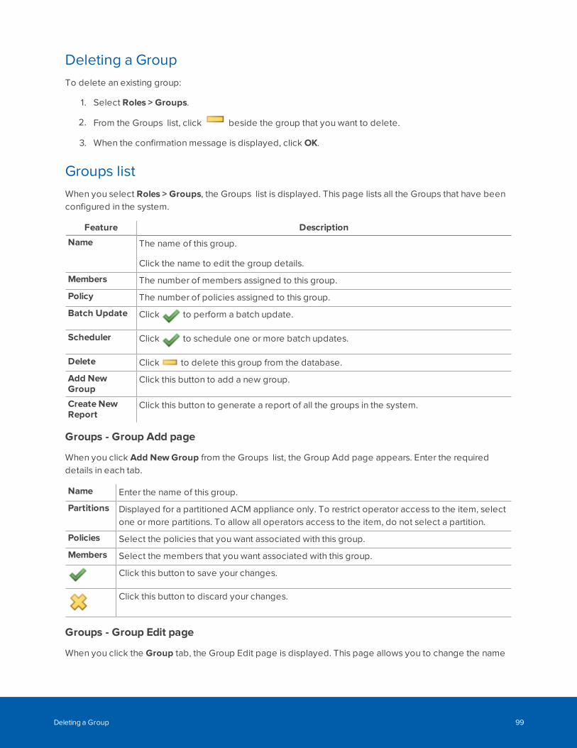
Deleting a GroupTo delete an existing group:
1. Select Roles > Groups.
2. From the Groups list, click beside the group that you want to delete.
3. When the confirmation message is displayed, click OK.
Groups listWhen you select Roles > Groups, the Groups list is displayed. This page lists all the Groups that have beenconfigured in the system.
Feature Description
Name The name of this group.
Click the name to edit the group details.
Members The number of members assigned to this group.
Policy The number of policies assigned to this group.
Batch Update Click to perform a batch update.
Scheduler Click to schedule one or more batch updates.
Delete Click to delete this group from the database.
Add NewGroup
Click this button to add a new group.
Create NewReport
Click this button to generate a report of all the groups in the system.
Groups - Group Add page
When you click Add NewGroup from the Groups list, the Group Add page appears. Enter the requireddetails in each tab.
Name Enter the name of this group.
Partitions Displayed for a partitioned ACM appliance only. To restrict operator access to the item, selectone or more partitions. To allow all operators access to the item, do not select a partition.
Policies Select the policies that you want associated with this group.
Members Select the members that you want associated with this group.
Click this button to save your changes.
Click this button to discard your changes.
Groups - Group Edit page
When you click the Group tab, the Group Edit page is displayed. This page allows you to change the name
Deleting a Group 99
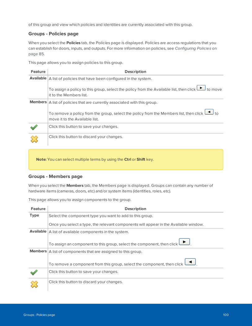
of this group and view which policies and identities are currently associated with this group.
Groups - Policies page
When you select the Policies tab, the Policies page is displayed. Policies are access regulations that youcan establish for doors, inputs, and outputs. For more information on policies, see Configuring Policies onpage 85.
This page allows you to assign policies to this group.
Feature Description
Available A list of policies that have been configured in the system.
To assign a policy to this group, select the policy from the Available list, then click to moveit to the Members list.
Members A list of policies that are currently associated with this group.
To remove a policy from the group, select the policy from the Members list, then click tomove it to the Available list.
Click this button to save your changes.
Click this button to discard your changes.
Note: You can select multiple terms by using the Ctrl or Shift key.
Groups - Members page
When you select the Members tab, the Members page is displayed. Groups can contain any number ofhardware items (cameras, doors, etc) and/or system items (identities, roles, etc).
This page allows you to assign components to the group.
Feature Description
Type Select the component type you want to add to this group.
Once you select a type, the relevant components will appear in the Available window.
Available A list of available components in the system.
To assign an component to this group, select the component, then click .
Members A list of components that are assigned to this group.
To remove a component from this group, select the component, then click .
Click this button to save your changes.
Click this button to discard your changes.
Groups - Policies page 100
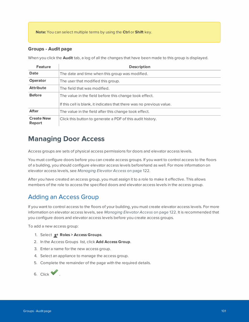
Note: You can select multiple terms by using the Ctrl or Shift key.
Groups - Audit page
When you click the Audit tab, a log of all the changes that have been made to this group is displayed.
Feature Description
Date The date and time when this group was modified.
Operator The user that modified this group.
Attribute The field that was modified.
Before The value in the field before this change took effect.
If this cell is blank, it indicates that there was no previous value.
After The value in the field after this change took effect.
Create NewReport
Click this button to generate a PDF of this audit history.
Managing Door Access
Access groups are sets of physical access permissions for doors and elevator access levels.
You must configure doors before you can create access groups. If you want to control access to the floorsof a building, you should configure elevator access levels beforehand as well. For more information onelevator access levels, see Managing Elevator Access on page 122.
After you have created an access group, you must assign it to a role to make it effective. This allowsmembers of the role to access the specified doors and elevator access levels in the access group.
Adding an Access GroupIf you want to control access to the floors of your building, you must create elevator access levels. For moreinformation on elevator access levels, see Managing Elevator Access on page 122. It is recommended thatyou configure doors and elevator access levels before you create access groups.
To add a new access group:
1. Select Roles > Access Groups.
2. In the Access Groups list, click Add Access Group.
3. Enter a name for the new access group.
4. Select an appliance to manage the access group.
5. Complete the remainder of the page with the required details.
6. Click .
Groups - Audit page 101
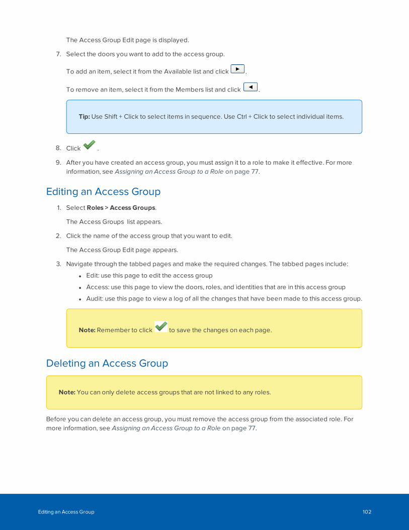
The Access Group Edit page is displayed.
7. Select the doors you want to add to the access group.
To add an item, select it from the Available list and click .
To remove an item, select it from the Members list and click .
Tip: Use Shift + Click to select items in sequence. Use Ctrl + Click to select individual items.
8. Click .
9. After you have created an access group, you must assign it to a role to make it effective. For moreinformation, see Assigning an Access Group to a Role on page 77.
Editing an Access Group1. Select Roles > Access Groups.
The Access Groups list appears.
2. Click the name of the access group that you want to edit.
The Access Group Edit page appears.
3. Navigate through the tabbed pages and make the required changes. The tabbed pages include:
l Edit: use this page to edit the access group
l Access: use this page to view the doors, roles, and identities that are in this access group
l Audit: use this page to view a log of all the changes that have been made to this access group.
Note: Remember to click to save the changes on each page.
Deleting an Access Group
Note: You can only delete access groups that are not linked to any roles.
Before you can delete an access group, you must remove the access group from the associated role. Formore information, see Assigning an Access Group to a Role on page 77.
Editing an Access Group 102
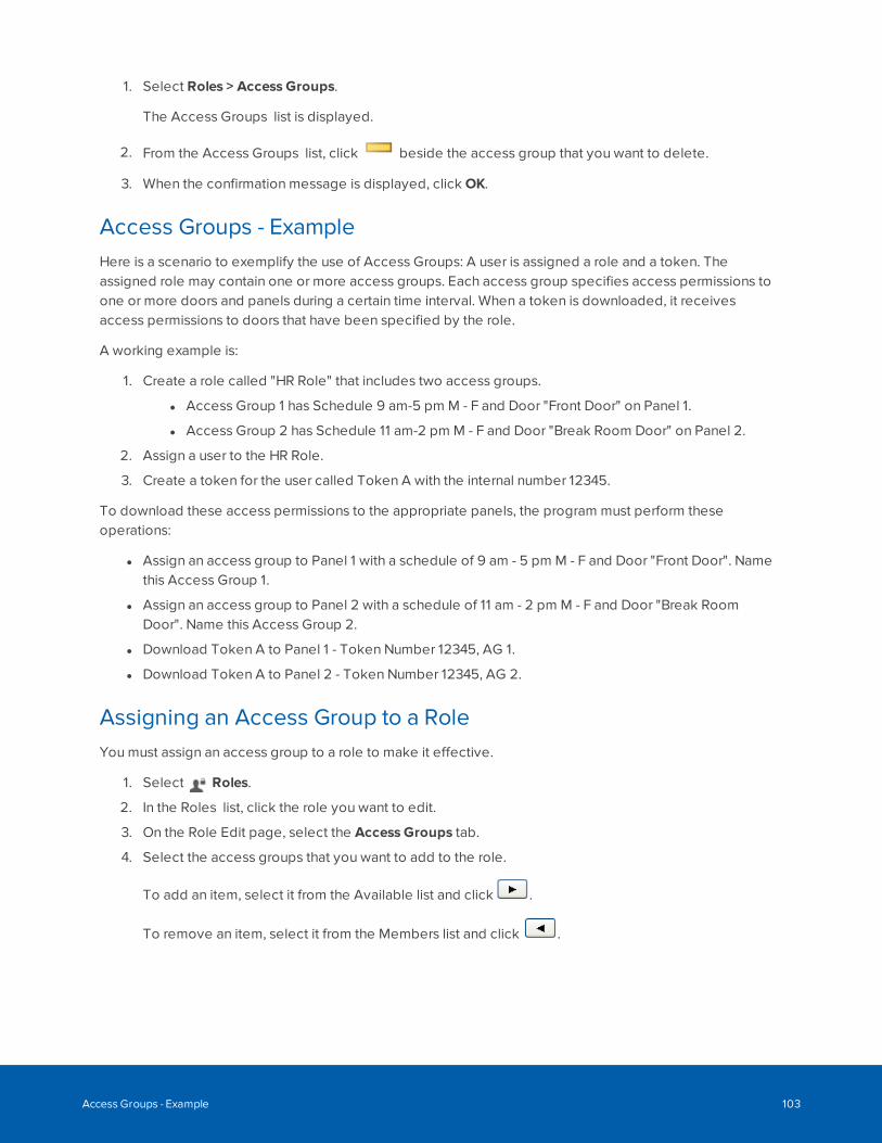
1. Select Roles > Access Groups.
The Access Groups list is displayed.
2. From the Access Groups list, click beside the access group that you want to delete.
3. When the confirmation message is displayed, click OK.
Access Groups - ExampleHere is a scenario to exemplify the use of Access Groups: A user is assigned a role and a token. Theassigned role may contain one or more access groups. Each access group specifies access permissions toone or more doors and panels during a certain time interval. When a token is downloaded, it receivesaccess permissions to doors that have been specified by the role.
A working example is:
1. Create a role called "HR Role" that includes two access groups.
l Access Group 1 has Schedule 9 am-5 pm M - F and Door "Front Door" on Panel 1.
l Access Group 2 has Schedule 11 am-2 pm M - F and Door "Break Room Door" on Panel 2.
2. Assign a user to the HR Role.
3. Create a token for the user called Token A with the internal number 12345.
To download these access permissions to the appropriate panels, the program must perform theseoperations:
l Assign an access group to Panel 1 with a schedule of 9 am - 5 pm M - F and Door "Front Door". Namethis Access Group 1.
l Assign an access group to Panel 2 with a schedule of 11 am - 2 pm M - F and Door "Break RoomDoor". Name this Access Group 2.
l Download Token A to Panel 1 - Token Number 12345, AG 1.
l Download Token A to Panel 2 - Token Number 12345, AG 2.
Assigning an Access Group to a RoleYou must assign an access group to a role to make it effective.
1. Select Roles.
2. In the Roles list, click the role you want to edit.
3. On the Role Edit page, select the Access Groups tab.
4. Select the access groups that you want to add to the role.
To add an item, select it from the Available list and click .
To remove an item, select it from the Members list and click .
Access Groups - Example 103
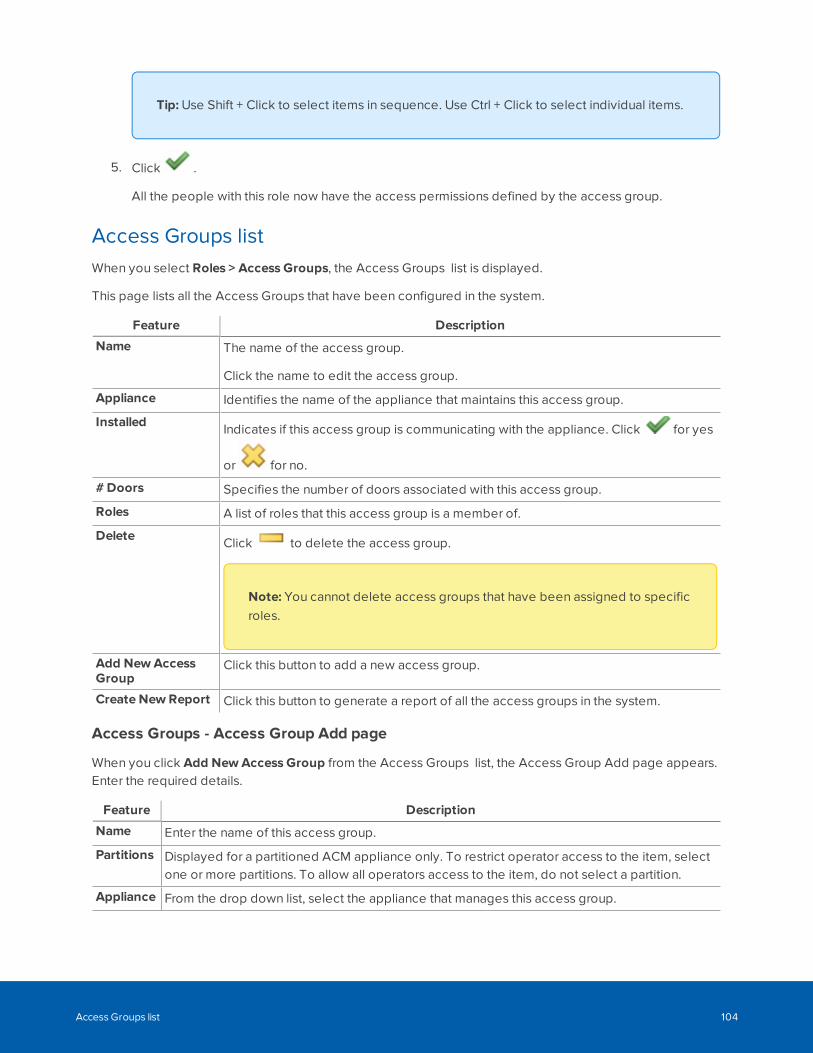
Tip: Use Shift + Click to select items in sequence. Use Ctrl + Click to select individual items.
5. Click .
All the people with this role now have the access permissions defined by the access group.
Access Groups listWhen you select Roles > Access Groups, the Access Groups list is displayed.
This page lists all the Access Groups that have been configured in the system.
Feature Description
Name The name of the access group.
Click the name to edit the access group.
Appliance Identifies the name of the appliance that maintains this access group.
Installed Indicates if this access group is communicating with the appliance. Click for yes
or for no.
# Doors Specifies the number of doors associated with this access group.
Roles A list of roles that this access group is a member of.
Delete Click to delete the access group.
Note: You cannot delete access groups that have been assigned to specificroles.
Add NewAccessGroup
Click this button to add a new access group.
Create New Report Click this button to generate a report of all the access groups in the system.
Access Groups - Access Group Add page
When you click Add NewAccess Group from the Access Groups list, the Access Group Add page appears.Enter the required details.
Feature Description
Name Enter the name of this access group.
Partitions Displayed for a partitioned ACM appliance only. To restrict operator access to the item, selectone or more partitions. To allow all operators access to the item, do not select a partition.
Appliance From the drop down list, select the appliance that manages this access group.
Access Groups list 104
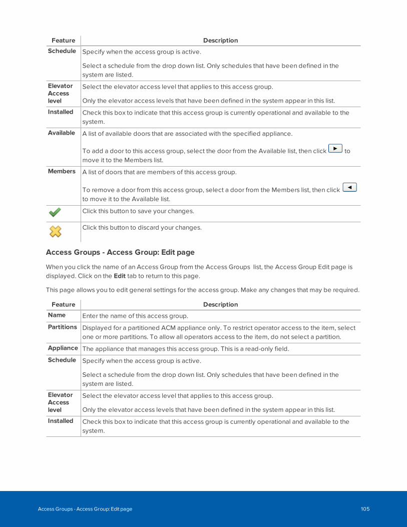
Feature Description
Schedule Specify when the access group is active.
Select a schedule from the drop down list. Only schedules that have been defined in thesystem are listed.
ElevatorAccesslevel
Select the elevator access level that applies to this access group.
Only the elevator access levels that have been defined in the system appear in this list.
Installed Check this box to indicate that this access group is currently operational and available to thesystem.
Available A list of available doors that are associated with the specified appliance.
To add a door to this access group, select the door from the Available list, then click tomove it to the Members list.
Members A list of doors that are members of this access group.
To remove a door from this access group, select a door from the Members list, then clickto move it to the Available list.
Click this button to save your changes.
Click this button to discard your changes.
Access Groups - Access Group: Edit page
When you click the name of an Access Group from the Access Groups list, the Access Group Edit page isdisplayed. Click on the Edit tab to return to this page.
This page allows you to edit general settings for the access group. Make any changes that may be required.
Feature Description
Name Enter the name of this access group.
Partitions Displayed for a partitioned ACM appliance only. To restrict operator access to the item, selectone or more partitions. To allow all operators access to the item, do not select a partition.
Appliance The appliance that manages this access group. This is a read-only field.
Schedule Specify when the access group is active.
Select a schedule from the drop down list. Only schedules that have been defined in thesystem are listed.
ElevatorAccesslevel
Select the elevator access level that applies to this access group.
Only the elevator access levels that have been defined in the system appear in this list.
Installed Check this box to indicate that this access group is currently operational and available to thesystem.
Access Groups - Access Group: Edit page 105
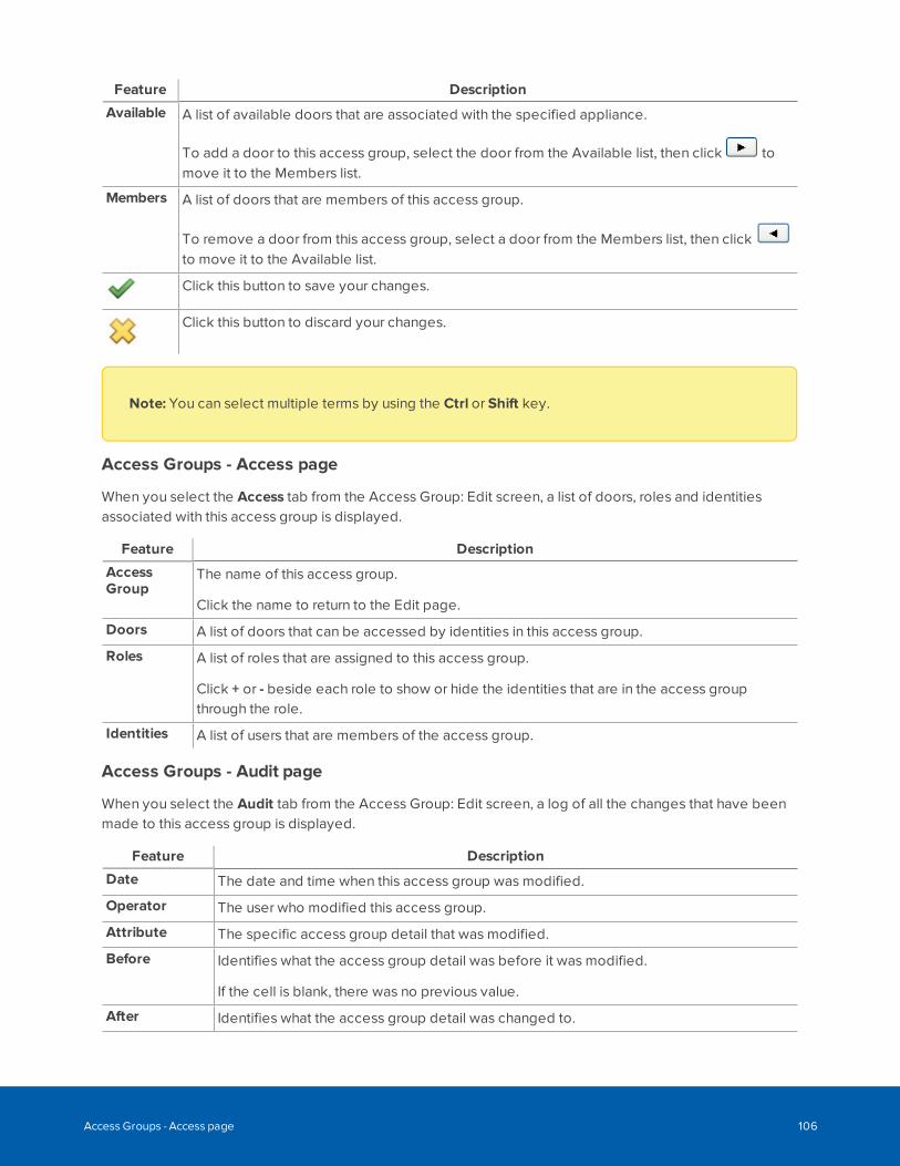
Feature Description
Available A list of available doors that are associated with the specified appliance.
To add a door to this access group, select the door from the Available list, then click tomove it to the Members list.
Members A list of doors that are members of this access group.
To remove a door from this access group, select a door from the Members list, then clickto move it to the Available list.
Click this button to save your changes.
Click this button to discard your changes.
Note: You can select multiple terms by using the Ctrl or Shift key.
Access Groups - Access page
When you select the Access tab from the Access Group: Edit screen, a list of doors, roles and identitiesassociated with this access group is displayed.
Feature Description
AccessGroup
The name of this access group.
Click the name to return to the Edit page.
Doors A list of doors that can be accessed by identities in this access group.
Roles A list of roles that are assigned to this access group.
Click + or - beside each role to show or hide the identities that are in the access groupthrough the role.
Identities A list of users that are members of the access group.
Access Groups - Audit page
When you select the Audit tab from the Access Group: Edit screen, a log of all the changes that have beenmade to this access group is displayed.
Feature Description
Date The date and time when this access group was modified.
Operator The user who modified this access group.
Attribute The specific access group detail that was modified.
Before Identifies what the access group detail was before it was modified.
If the cell is blank, there was no previous value.
After Identifies what the access group detail was changed to.
Access Groups - Access page 106
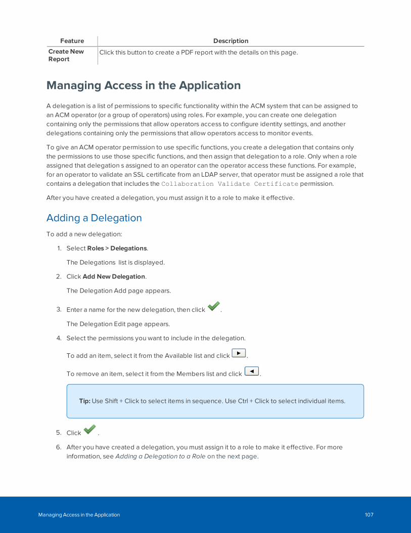
Feature Description
Create NewReport
Click this button to create a PDF report with the details on this page.
Managing Access in the Application
A delegation is a list of permissions to specific functionality within the ACM system that can be assigned toan ACM operator (or a group of operators) using roles. For example, you can create one delegationcontaining only the permissions that allow operators access to configure identity settings, and anotherdelegations containing only the permissions that allow operators access to monitor events.
To give an ACM operator permission to use specific functions, you create a delegation that contains onlythe permissions to use those specific functions, and then assign that delegation to a role. Only when a roleassigned that delegation s assigned to an operator can the operator access these functions. For example,for an operator to validate an SSL certificate from an LDAP server, that operator must be assigned a role thatcontains a delegation that includes the Collaboration Validate Certificate permission.
After you have created a delegation, you must assign it to a role to make it effective.
Adding a DelegationTo add a new delegation:
1. Select Roles > Delegations.
The Delegations list is displayed.
2. Click Add NewDelegation.
The Delegation Add page appears.
3. Enter a name for the new delegation, then click .
The Delegation Edit page appears.
4. Select the permissions you want to include in the delegation.
To add an item, select it from the Available list and click .
To remove an item, select it from the Members list and click .
Tip: Use Shift + Click to select items in sequence. Use Ctrl + Click to select individual items.
5. Click .
6. After you have created a delegation, you must assign it to a role to make it effective. For moreinformation, see Adding a Delegation to a Role on the next page.
Managing Access in the Application 107
Editing a DelegationTo edit an existing delegation:
1. Select Roles > Delegations.
The Delegations list appears.
2. Click the name of the delegation you want to edit.
The Delegation Edit page appears.
3. Make the required changes.
4. Click .
Adding a Delegation to a RoleYou must assign a delegation to a role to make it effective.
1. Click Roles.
The Roles list is displayed.
2. From the Roles list, click on the role you want to edit.
The Role Edit screen appears.
3. Select the Delegate tab.
4. Select the delegations that you want to add to the role.
To add an item, select it from the Available list and click .
To remove an item, select it from the Members list and click .
Tip: Use Shift + Click to select items in sequence. Use Ctrl + Click to select individual items.
5. Click .
All the people with this role now have the access permissions defined by the delegation.
Deleting a DelegationTo delete an existing delegation:
Editing a Delegation 108
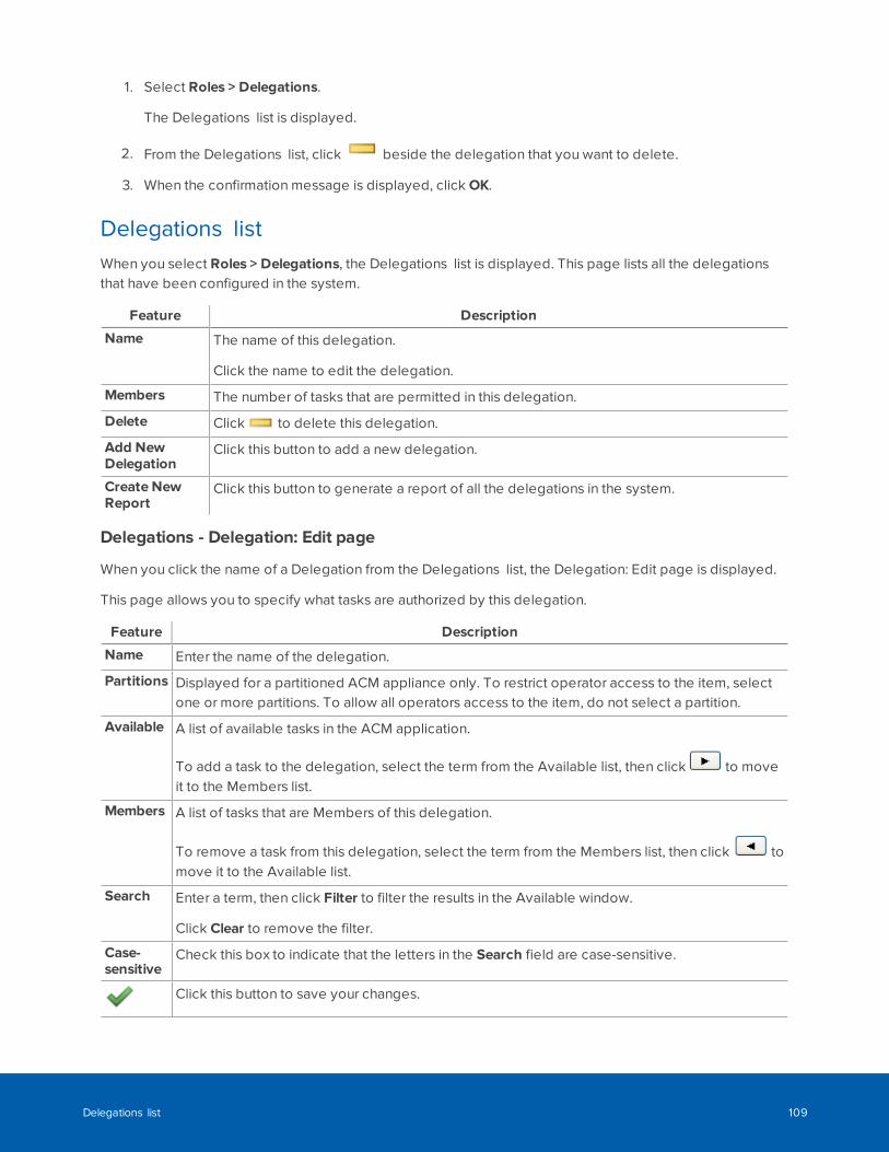
1. Select Roles > Delegations.
The Delegations list is displayed.
2. From the Delegations list, click beside the delegation that you want to delete.
3. When the confirmation message is displayed, click OK.
Delegations listWhen you select Roles > Delegations, the Delegations list is displayed. This page lists all the delegationsthat have been configured in the system.
Feature Description
Name The name of this delegation.
Click the name to edit the delegation.
Members The number of tasks that are permitted in this delegation.
Delete Click to delete this delegation.
Add NewDelegation
Click this button to add a new delegation.
Create NewReport
Click this button to generate a report of all the delegations in the system.
Delegations - Delegation: Edit page
When you click the name of a Delegation from the Delegations list, the Delegation: Edit page is displayed.
This page allows you to specify what tasks are authorized by this delegation.
Feature Description
Name Enter the name of the delegation.
Partitions Displayed for a partitioned ACM appliance only. To restrict operator access to the item, selectone or more partitions. To allow all operators access to the item, do not select a partition.
Available A list of available tasks in the ACM application.
To add a task to the delegation, select the term from the Available list, then click to moveit to the Members list.
Members A list of tasks that are Members of this delegation.
To remove a task from this delegation, select the term from the Members list, then click tomove it to the Available list.
Search Enter a term, then click Filter to filter the results in the Available window.
Click Clear to remove the filter.
Case-sensitive
Check this box to indicate that the letters in the Search field are case-sensitive.
Click this button to save your changes.
Delegations list 109
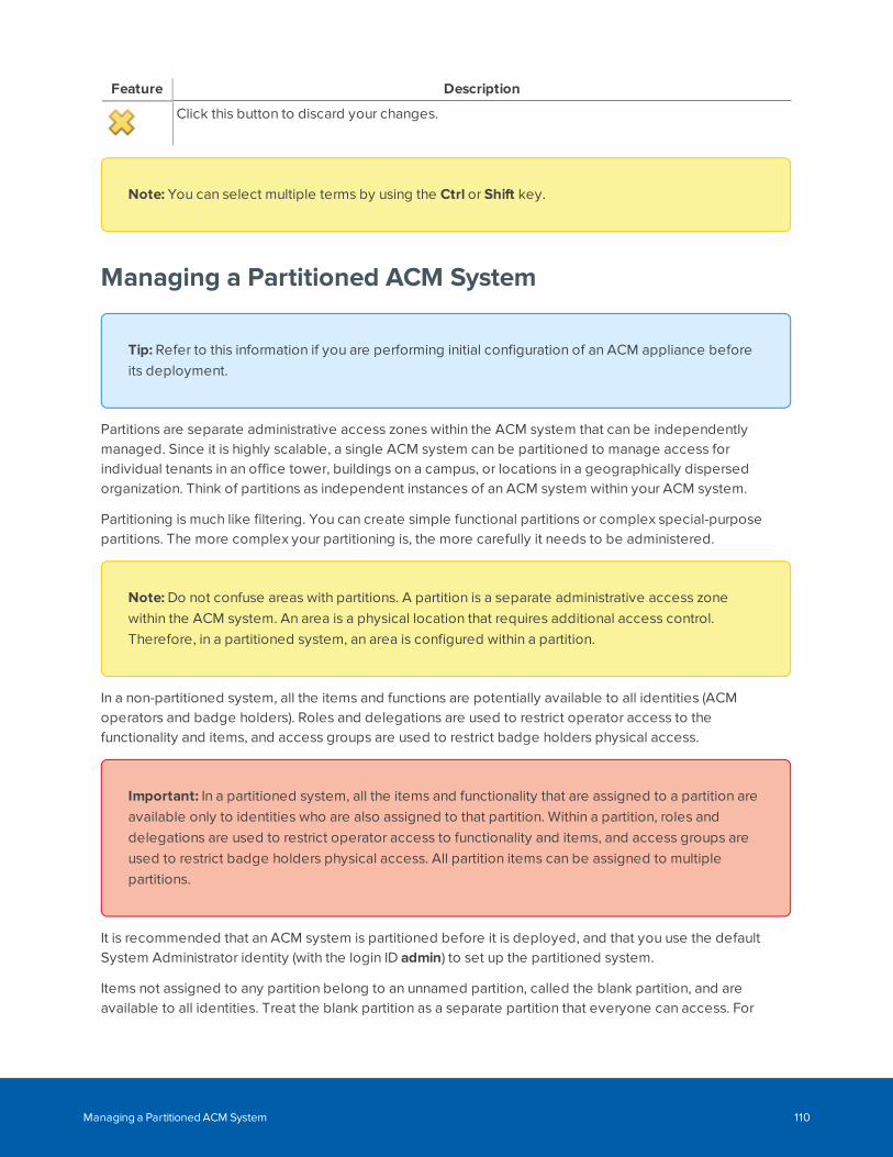
Feature Description
Click this button to discard your changes.
Note: You can select multiple terms by using the Ctrl or Shift key.
Managing a Partitioned ACM System
Tip: Refer to this information if you are performing initial configuration of an ACM appliance beforeits deployment.
Partitions are separate administrative access zones within the ACM system that can be independentlymanaged. Since it is highly scalable, a single ACM system can be partitioned to manage access forindividual tenants in an office tower, buildings on a campus, or locations in a geographically dispersedorganization. Think of partitions as independent instances of an ACM system within your ACM system.
Partitioning is much like filtering. You can create simple functional partitions or complex special-purposepartitions. The more complex your partitioning is, the more carefully it needs to be administered.
Note: Do not confuse areas with partitions. A partition is a separate administrative access zonewithin the ACM system. An area is a physical location that requires additional access control.Therefore, in a partitioned system, an area is configured within a partition.
In a non-partitioned system, all the items and functions are potentially available to all identities (ACMoperators and badge holders). Roles and delegations are used to restrict operator access to thefunctionality and items, and access groups are used to restrict badge holders physical access.
Important: In a partitioned system, all the items and functionality that are assigned to a partition areavailable only to identities who are also assigned to that partition. Within a partition, roles anddelegations are used to restrict operator access to functionality and items, and access groups areused to restrict badge holders physical access. All partition items can be assigned to multiplepartitions.
It is recommended that an ACM system is partitioned before it is deployed, and that you use the defaultSystem Administrator identity (with the login ID admin) to set up the partitioned system.
Items not assigned to any partition belong to an unnamed partition, called the blank partition, and areavailable to all identities. Treat the blank partition as a separate partition that everyone can access. For
Managing a Partitioned ACM System 110
badge holders, use the blank partition to contain the doors to common areas, which might include buildingentrances, parking garages, elevators, and the like, which all badge holders can access. For ACM operators,use the blank partition to contain the common items, which any operator can configure.
Tip: Alternatively, you can create dedicated common partitions , which might be more practical fora geographically dispersed partitioned ACM system, and keep the blank partition empty.
When configuring an:
l Identity–Assigning an ACM operator to one or more partitions restricts the operator to items in theirassigned partitions and those not assigned to any partition. Not assigning an operator to any partitionrestricts the operator to items not assigned to any partition.
l Item–Assigning an item to a partition restricts who can see or edit the item to ACM operatorsassigned to that partition. If you assign all partitions to an item, the item can be viewed by alloperators EXCEPT those not assigned to any partition. If you do not select a partition, any ACMoperator can edit the item.
After partitions are configured, the Partition drop-down menu appears as a configuration option for anyobject that can be assigned to a partition.
Planning a Partitioned SystemIdeally, plan how to partition your ACM system before you deploy it. It is much easier to deploy a partitionedsystem and then provision it than it is to add partitions to an already deployed system and reconfigure it allover again. If partitioning is not properly planned out and tested before it is operational, there is a risk thatitems may be hidden (inaccessible) to the users that need them to do their jobs properly.
Some of the considerations you should keep in mind when planning your partitions:
l Centralize control.
Always use the default system administrator identity to set up partitions. This identity always has fullaccess to all partitions.
l Limit ACM operator access to partitions.
Only allow the ACM operators who are responsible for access control operations within a partitionpermission to access that partition. To enforce this:
l Create a custom admin role for the ACM operator identities assigned to administer a partition.Configure this role and its delegations so that the system administrator of a partition isprevented from creating partitions or assigning themselves to other partitions.
l Create custom roles with the required delegations for ACM operator identities assigned otherresponsibilities in a partition. Configure these roles to include only the delegations needed.The default roles (such as monitoring, or enrollment operator) can also be used, as they arepreconfigured with the necessary delegations.
Planning a Partitioned System 111
For example, to create an enrollment operator who , ensure that
l Create identity records for ACM operators restricted to specific partitions so that they cannotview or change their own identity records. Configure the operator's identity record(Identities>Identity) so that it is not visible to any partition that includes them as an operator(Roles>Partitions).
Important: If you are partitioning roles or delegations, ensure that the operators assigned tothose roles and delegations also have access to the partitions.
l Keep partitions as simple as possible.
Avoid shared items within more than one partition. Ideally, set up each partition so that its physicalinfrastructure is completely separate from the other partitions. For example, no door should be inmore than one partition. A partition should consist of only the items that need to be managed withinthat partition.
Some examples are:
l Doors and elevators shared by two tenants on the same floor. Create a separate partition forthe shared doors and elevators and assign it to both tenants. The ACM operator for eithertenant can configure the doors in that shared partition and each operator can allow badgeholders to access doors in their own partition plus in the shared partition.
l A geographically dispersed ACM system with remote offices. Create a partition for eachremote office. The default system administrator can access all partitions and manage theentire system, and a local ACM system administrator at each remote office can manage theiroffices' partition. Badge holders who need access to more than one remote office can then beassigned to the partitions of the remote offices they need to access.
Tip: If you must have partitions with duplicate items, such as doors shared by two tenants, beaware of some of the complications that administrators or other operators with access tosome (but not all) partitions may encounter when modifying partitions. For example, you mayexperience problems if you have to change the configuration of your partitions as tenantsmove in or out, or increase or decrease their floorspace.
l Manage the blank partition carefully.
The blank partition contains items not assigned to any partition.
Any identity or item not assigned to a partition is defined by default to the blank partition, and isrestricted to that partition. For example, badge holders restricted to the blank partition can only opendoors in the blank partition. However, badge holders assigned to one or more partitions can opendoors in the partitions to which they are assigned and in the blank partition. Similarly, ACM operatorsrestricted to the blank partition can only configure items in the blank partition. However, operatorsassigned to one or more partitions can configure items in the partitions to which they are assigned
Planning a Partitioned System 112
and in the blank partition.
In a partitioned system, there will be a limited number of badge-holders who can access all the partitions,such as concierge, security, service, and maintenance personnel. These personnel should be assigned to allpartitions in their identity record. Regardless of whether the system is partitioned, there should also be atleast one other ACM operator assigned the SuperAdmin role, as a backup for the default SystemAdministrator account for the ACM system.
Configuring a Partitioned ACM SystemIt is recommended that you partition your ACM system before it is operational at your site, and that you usethe default System Administrator identity (with the login ID admin) to set up the partitioned system.
Use the following workflow to set up your partitioned ACM system:
1. Determine how many partitions you need.
2. Create a custom delegation based on the Admin delegation that excludes the Identities New andIdentities Edit delegations. For example Partition Admin Deleg.
3. Create a custom role that includes the new delegation. For example Partition Admin.
4. For each planned partition, create a new identity in the ACM system and assign it the Partition Adminrole. This identity will be assigned to the partition as its local administrator.
5. Create each partition and add the identity of its local system administrator to the partition. Both thedefault system administrator and the local partition administrator identities can manage this partition.
6. Test the partitions you created before your ACM system is deployed. At the very least, eachpartition's ACM operators should enroll a sample set of badge holders and monitor them as theyaccess the partitioned site.
After you have partitioned the system, you can use routing groups. For more information on routing groups,see Routing Events to the Monitor Screen on page 117.
Adding a Partition
This is a basic procedure on how to add a partition. For a more advanced procedure on how to partition theACM system, see Configuring a Partitioned ACM System above.
Tip: It is recommended that you use the default Admin account to set up partitions.
To add a new partition:
1. Select Roles > Partitions.
The Partitions list is displayed.
2. Click Add New Partition.
The Partition Add page appears.
Configuring a Partitioned ACM System 113
3. Enter a name for the new partition, then click .
The Partition Edit page appears.
4. Select the operators that you want to include in the partition.
To add an item, select it from the Available list and click .
To remove an item, select it from the Members list and click .
Tip: Use Shift + Click to select items in sequence. Use Ctrl + Click to select individual items.
5. Click .
The Partitions field now appears as a configuration option for most system settings.
Editing a Partition
To edit an existing partition:
1. Select Roles > Partitions.
The Partitions list appears.
2. Click the name of the partition you want to edit.
The Partition Edit page appears.
3. Make the required changes.
For a more advanced procedure on how to partition the ACM system, see Configuring a PartitionedACM System on the previous page.
4. Click .
Deleting a Partition
To delete an existing partition:
1. Select Roles > Partitions.
2. From the Partitions list, click beside the partition that you want to delete.
3. When the confirmation message is displayed, click OK.
Partitions - ListWhen you select Roles > Partitions, the Partitions list is displayed. This page lists all partitions that havebeen configured in the system.
Editing a Partition 114
Feature Description
Name The name of this partition.
Click the name to edit the partition.
Members The number of users that have access to this partition.
Delete Click to delete this partition.
Add NewPartition
Click this button to add a new partition.
Create NewReport
Click this button to generate a report of all the partitions in the system.
Partitions - Add page
To add a new partition:
1. Select Roles > Partitions.
2. Click Add New Partition.
The Partition Add page appears.
3. Enter the name of this partition.
4. Click .
The Partition Edit page appears.
5. From the Available list, select the users that should have access to the partition, then click .
The users are added to the Members list to show that they have access to the partition.
To remove users from the partition, select the users from the Members list and click .
Note: You can select multiple terms by using the Ctrl or Shift key.
Partitions - Partition Edit page
When you click the name of a Partition from the Partitions list, the Partition Edit page is displayed.
This page allows you to add users to the partition.
Feature Description
Name Enter the name of this partition.
Available A list of users in the system. Only users with login credentials appear in this list.
To add a user to this partition, select the user from the Available list, then click to move itto the Members list.
Partitions - Add page 115
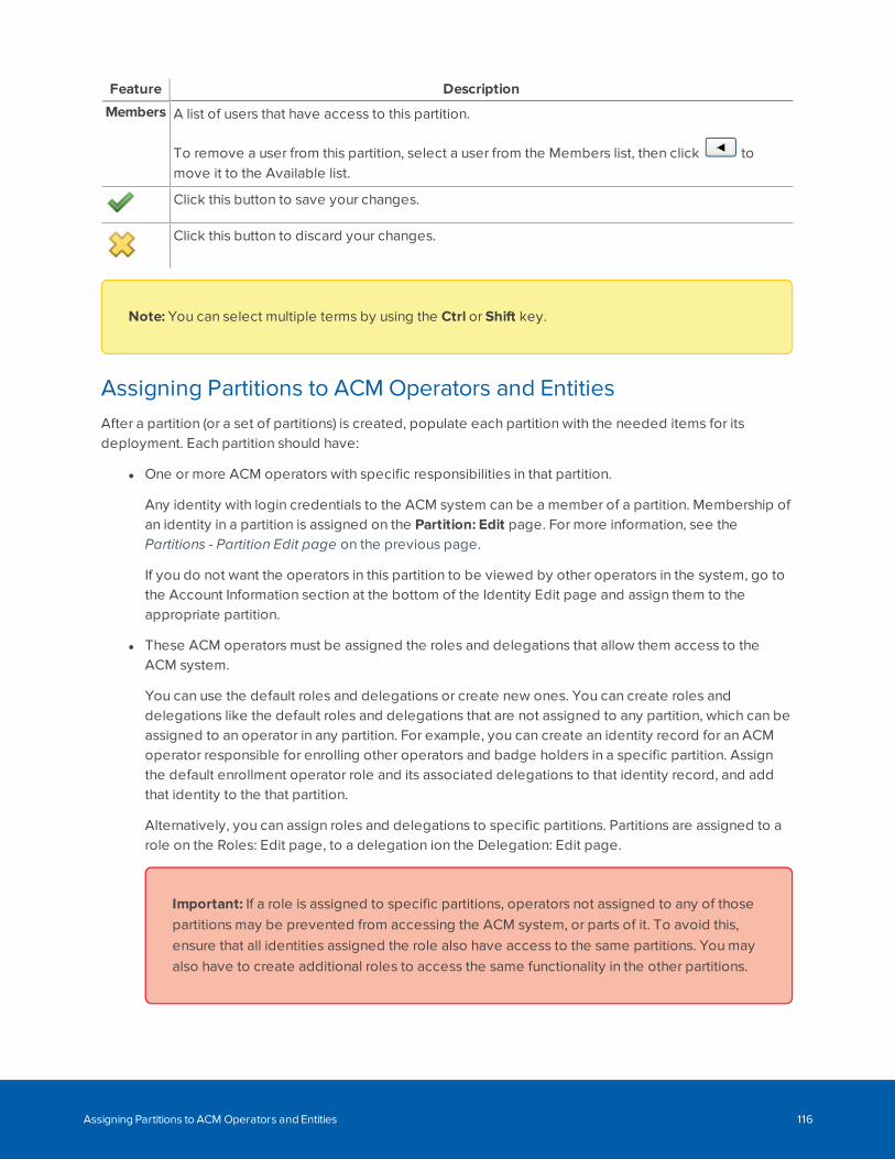
Feature Description
Members A list of users that have access to this partition.
To remove a user from this partition, select a user from the Members list, then click tomove it to the Available list.
Click this button to save your changes.
Click this button to discard your changes.
Note: You can select multiple terms by using the Ctrl or Shift key.
Assigning Partitions to ACM Operators and EntitiesAfter a partition (or a set of partitions) is created, populate each partition with the needed items for itsdeployment. Each partition should have:
l One or more ACM operators with specific responsibilities in that partition.
Any identity with login credentials to the ACM system can be a member of a partition. Membership ofan identity in a partition is assigned on the Partition: Edit page. For more information, see thePartitions - Partition Edit page on the previous page.
If you do not want the operators in this partition to be viewed by other operators in the system, go tothe Account Information section at the bottom of the Identity Edit page and assign them to theappropriate partition.
l These ACM operators must be assigned the roles and delegations that allow them access to theACM system.
You can use the default roles and delegations or create new ones. You can create roles anddelegations like the default roles and delegations that are not assigned to any partition, which can beassigned to an operator in any partition. For example, you can create an identity record for an ACMoperator responsible for enrolling other operators and badge holders in a specific partition. Assignthe default enrollment operator role and its associated delegations to that identity record, and addthat identity to the that partition.
Alternatively, you can assign roles and delegations to specific partitions. Partitions are assigned to arole on the Roles: Edit page, to a delegation ion the Delegation: Edit page.
Important: If a role is assigned to specific partitions, operators not assigned to any of thosepartitions may be prevented from accessing the ACM system, or parts of it. To avoid this,ensure that all identities assigned the role also have access to the same partitions. You mayalso have to create additional roles to access the same functionality in the other partitions.
Assigning Partitions to ACM Operators and Entities 116
The same is also true of delegations.
l All of the entities, such as doors and related infrastructure (policies, groups, access groups, routinggroups, and elevator access levels), within the partition's scope that allow badge holders physicalaccess to the site.
Membership of any entity in a partition is assigned in its edit page. Navigate to the entity's edit pageand select the partition, or partitions, from the Partitions drop-down list.
An empty, or blank, Partition field for any entity has a specific meaning. An entity not assigned to anypartition can be viewed by all ACM operators, including those not assigned to a partition. However, as soonas any entity (which could be a badge holder, an operator, a door, or any logical entity such as an accessgroup) is assigned to a partition, it can only be viewed by operators assigned to that partition. An entityassigned to more than one partition can be viewed by operators assigned to any of those partitions. Whenan entity is assigned to all partitions, it can be viewed by all operators except operators not assigned to anypartitions.
For example, identity records with a blank partition field can be viewed by any ACM operator. However,identity records with one or more partitions assigned to them can only be viewed by ACM operators withaccess to any of those partitions. If you assign an ACM operator to a partition, their identity record can onlybe viewed by other operators assigned to that partition. Similarly, for badge holders assigned to a partition,their identity records can only be viewed by operators assigned to that partition and their access privilegesare restricted to the reader and doors in that partition (plus readers and doors not in any partition).
Routing Events to the Monitor Screen
A routing group controls which events are routed to an operator's Monitor screen. This is achieved byspecifying event types and event sources in the routing group. Only those event types that originate fromthe specified event sources will be routed. This is an advanced feature that requires the use of partitions,groups, and roles, and should only be configured by an experienced operator.
For example, a lobby security guard may only need to monitor people who access the building through thefront door during regular work hours, but they would not need to know about system activity in the ACMapplication. You can use a routing group to ensure that the security guard only sees events related to thelobby area.
You must set up partitions and groups before you can use routing groups. For more information on partitions,see Managing a Partitioned ACM System on page 110. For more information on groups, see ConfiguringGroups on page 93.
After you have created a routing group, you must assign it to a role to make it effective.
Adding a Routing GroupTo add a new routing group:
Routing Events to the Monitor Screen 117
1. Configure partitions for the routing group. For more information on configuring partitions, seeConfiguring a Partitioned ACM System on page 113.
2. Create a hardware group that contains the event sources of interest. For more information on creatinga hardware group for routing, see Creating a Hardware Group for Routing on page 96.
3. If you want to route events for specific time intervals, set up one or more schedules. For moreinformation on adding a schedule, see Adding Schedules (Intervals in Schedules) on page 378.
4. Select Roles > Routing Groups.
The Routing Groups list is displayed.
5. Click Add New Routing Group.
The Routing Group Add page is displayed.
6. Enter a name for the routing group.
7. Complete the remainder of the page with the required details.
Important: Select the appropriate partition for this routing group.
8. Click .
9. Select the Event Types tab.
10. Select the event types that you want to route.
To add an item, select it from the Available list and click .
To remove an item, select it from the Members list and click .
Tip: Use Shift + Click to select items in sequence. Use Ctrl + Click to select individual items.
When you're finished, click .
11. Select the Groups tab.
12. Select the group of hardware components that you want to route.
13. Click .
14. After you have created a routing group, you must assign it to a role to make it effective. For moreinformation, see Assigning a Routing Group to a Role on the next page.
Editing a Routing GroupTo edit an existing routing group:
Editing a Routing Group 118
1. Select Roles > Routing Groups.
The Routing Groups list appears.
2. Click on the routing group you want to edit.
The Routing Group Edit screen appears.
3. Navigate through the tabbed pages and make the required changes. The tabbed pages include:
l Schedule: use this page to edit the routing group settings, including the name and schedule
l Event Types: use this page to select the event types that you want to route
l Groups: use this page to select the groups of event sources that you want to route
Note: Remember to click to save the changes on each page.
Assigning a Routing Group to a RoleYou must assign a routing group to a role to make it effective.
1. Click Roles.
2. From the Roles list, click on the role you want to edit.
The Role Edit screen appears.
3. Select the Routing tab.
4. Select the routing groups that you want to add to the role.
To add an item, select it from the Available list and click .
To remove an item, select it from the Members list and click .
Tip: Use Shift + Click to select items in sequence. Use Ctrl + Click to select individual items.
5. Click .
All the operators with this role can now monitor the events defined by the routing group.
Deleting a Routing GroupTo delete an existing routing group:
1. Select Roles > Routing Groups.
2. From the Routing Groups list, click beside the routing group that you want to delete.
3. When the confirmation message is displayed, click OK.
Assigning a Routing Group to a Role 119
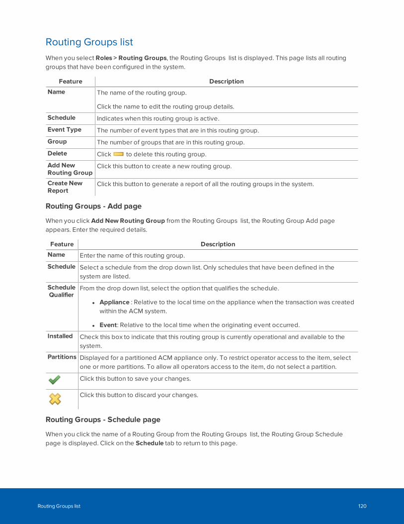
Routing Groups listWhen you select Roles > Routing Groups, the Routing Groups list is displayed. This page lists all routinggroups that have been configured in the system.
Feature Description
Name The name of the routing group.
Click the name to edit the routing group details.
Schedule Indicates when this routing group is active.
Event Type The number of event types that are in this routing group.
Group The number of groups that are in this routing group.
Delete Click to delete this routing group.
Add NewRouting Group
Click this button to create a new routing group.
Create NewReport
Click this button to generate a report of all the routing groups in the system.
Routing Groups - Add page
When you click Add New Routing Group from the Routing Groups list, the Routing Group Add pageappears. Enter the required details.
Feature Description
Name Enter the name of this routing group.
Schedule Select a schedule from the drop down list. Only schedules that have been defined in thesystem are listed.
ScheduleQualifier
From the drop down list, select the option that qualifies the schedule.
l Appliance : Relative to the local time on the appliance when the transaction was createdwithin the ACM system.
l Event: Relative to the local time when the originating event occurred.
Installed Check this box to indicate that this routing group is currently operational and available to thesystem.
Partitions Displayed for a partitioned ACM appliance only. To restrict operator access to the item, selectone or more partitions. To allow all operators access to the item, do not select a partition.
Click this button to save your changes.
Click this button to discard your changes.
Routing Groups - Schedule page
When you click the name of a Routing Group from the Routing Groups list, the Routing Group Schedulepage is displayed. Click on the Schedule tab to return to this page.
Routing Groups list 120
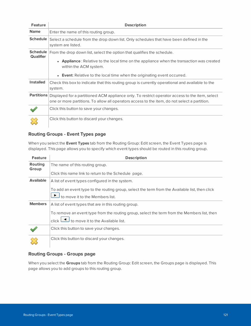
Feature Description
Name Enter the name of this routing group.
Schedule Select a schedule from the drop down list. Only schedules that have been defined in thesystem are listed.
ScheduleQualifier
From the drop down list, select the option that qualifies the schedule.
l Appliance : Relative to the local time on the appliance when the transaction was createdwithin the ACM system.
l Event: Relative to the local time when the originating event occurred.
Installed Check this box to indicate that this routing group is currently operational and available to thesystem.
Partitions Displayed for a partitioned ACM appliance only. To restrict operator access to the item, selectone or more partitions. To allow all operators access to the item, do not select a partition.
Click this button to save your changes.
Click this button to discard your changes.
Routing Groups - Event Types page
When you select the Event Types tab from the Routing Group: Edit screen, the Event Types page isdisplayed. This page allows you to specify which event types should be routed in this routing group.
Feature Description
RoutingGroup
The name of this routing group.
Click this name link to return to the Schedule page.
Available A list of event types configured in the system.
To add an event type to the routing group, select the term from the Available list, then click
to move it to the Members list.
Members A list of event types that are in this routing group.
To remove an event type from the routing group, select the term from the Members list, then
click to move it to the Available list.
Click this button to save your changes.
Click this button to discard your changes.
Routing Groups - Groups page
When you select the Groups tab from the Routing Group: Edit screen, the Groups page is displayed. Thispage allows you to add groups to this routing group.
Routing Groups - Event Types page 121
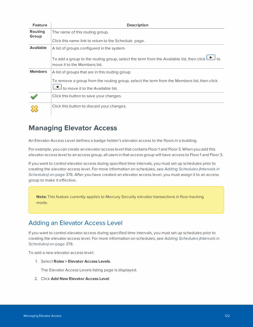
Feature Description
RoutingGroup
The name of this routing group.
Click this name link to return to the Schedule page.
Available A list of groups configured in the system.
To add a group to the routing group, select the term from the Available list, then click tomove it to the Members list.
Members A list of groups that are in this routing group.
To remove a group from the routing group, select the term from the Members list, then click
to move it to the Available list.
Click this button to save your changes.
Click this button to discard your changes.
Managing Elevator Access
An Elevator Access Level defines a badge holder's elevator access to the floors in a building.
For example, you can create an elevator access level that contains Floor 1 and Floor 3. When you add thiselevator access level to an access group, all users in that access group will have access to Floor 1 and Floor 3.
If you want to control elevator access during specified time intervals, you must set up schedules prior tocreating the elevator access level. For more information on schedules, see Adding Schedules (Intervals inSchedules) on page 378. After you have created an elevator access level, you must assign it to an accessgroup to make it effective.
Note: This feature currently applies to Mercury Security elevator transactions in floor trackingmode.
Adding an Elevator Access LevelIf you want to control elevator access during specified time intervals, you must set up schedules prior tocreating the elevator access level. For more information on schedules, see Adding Schedules (Intervals inSchedules) on page 378.
To add a new elevator access level:
1. Select Roles > Elevator Access Levels.
The Elevator Access Levels listing page is displayed.
2. Click Add New Elevator Access Level.
Managing Elevator Access 122
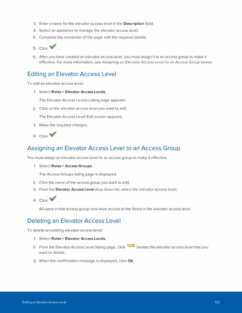
3. Enter a name for the elevator access level in the Description field.
4. Select an appliance to manage the elevator access level.
5. Complete the remainder of the page with the required details.
5. Click .
6. After you have created an elevator access level, you must assign it to an access group to make iteffective. For more information, see Assigning an Elevator Access Level to an Access Group below.
Editing an Elevator Access LevelTo edit an elevator access level:
1. Select Roles > Elevator Access Levels.
The Elevator Access Levels Listing page appears.
2. Click on the elevator access level you want to edit.
The Elevator Access Level Edit screen appears.
3. Make the required changes.
4. Click .
Assigning an Elevator Access Level to an Access GroupYou must assign an elevator access level to an access group to make it effective.
1. Select Roles > Access Groups.
The Access Groups listing page is displayed.
2. Click the name of the access group you want to edit.
3. From the Elevator Access Level drop down list, select the elevator access level.
4. Click .
All users in that access group now have access to the floors in the elevator access level.
Deleting an Elevator Access LevelTo delete an existing elevator access level:
1. Select Roles > Elevator Access Levels.
2. From the Elevator Access Level listing page, click beside the elevator access level that youwant to delete.
3. When the confirmation message is displayed, click OK.
Editing an Elevator Access Level 123
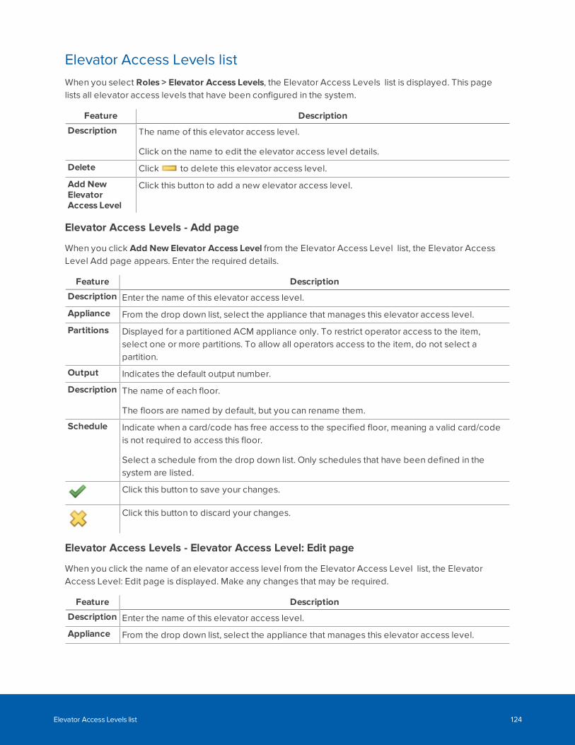
Elevator Access Levels listWhen you select Roles > Elevator Access Levels, the Elevator Access Levels list is displayed. This pagelists all elevator access levels that have been configured in the system.
Feature Description
Description The name of this elevator access level.
Click on the name to edit the elevator access level details.
Delete Click to delete this elevator access level.
Add NewElevatorAccess Level
Click this button to add a new elevator access level.
Elevator Access Levels - Add page
When you click Add New Elevator Access Level from the Elevator Access Level list, the Elevator AccessLevel Add page appears. Enter the required details.
Feature Description
Description Enter the name of this elevator access level.
Appliance From the drop down list, select the appliance that manages this elevator access level.
Partitions Displayed for a partitioned ACM appliance only. To restrict operator access to the item,select one or more partitions. To allow all operators access to the item, do not select apartition.
Output Indicates the default output number.
Description The name of each floor.
The floors are named by default, but you can rename them.
Schedule Indicate when a card/code has free access to the specified floor, meaning a valid card/codeis not required to access this floor.
Select a schedule from the drop down list. Only schedules that have been defined in thesystem are listed.
Click this button to save your changes.
Click this button to discard your changes.
Elevator Access Levels - Elevator Access Level: Edit page
When you click the name of an elevator access level from the Elevator Access Level list, the ElevatorAccess Level: Edit page is displayed. Make any changes that may be required.
Feature Description
Description Enter the name of this elevator access level.
Appliance From the drop down list, select the appliance that manages this elevator access level.
Elevator Access Levels list 124
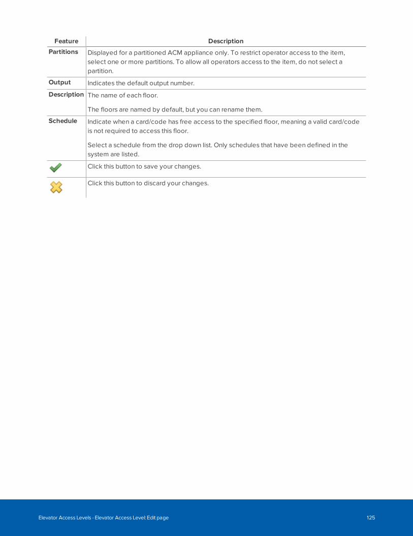
Feature Description
Partitions Displayed for a partitioned ACM appliance only. To restrict operator access to the item,select one or more partitions. To allow all operators access to the item, do not select apartition.
Output Indicates the default output number.
Description The name of each floor.
The floors are named by default, but you can rename them.
Schedule Indicate when a card/code has free access to the specified floor, meaning a valid card/codeis not required to access this floor.
Select a schedule from the drop down list. Only schedules that have been defined in thesystem are listed.
Click this button to save your changes.
Click this button to discard your changes.
Elevator Access Levels - Elevator Access Level: Edit page 125
Reports
The Reports screen allows you to create, edit, preview, and generate reports. Reports are used to gatherinformation from the system in either a PDF or Spreadsheet. Reports can be saved on your local computerand referred to offline. For example, the Identity/Doors with Access Report can be used to view which doorseach identity has access to. You have the option of using the default system reports or customizing thereports to fit your needs.
Note: If you do not have the correct delegations, you may not be able to access some of thefollowing pages. See your System Administrator for details.
Reports - Generating Reports
Anytime you see PDF or Spreadsheet, you can generate and save a copy of the current report.
You can generate a copy of reports from the Reports list, the Report Edit page or from the Report Previewpage.
Generated reports will only show the filtered information that is displayed. To edit the report before yougenerate it, see Reports - Editing on the next page.
l Click to save the current report as a PDF file.
l Click to save the current report as a CSV format spreadsheet.
Most generated reports saved as PDF files contain a maximum of 2,000 records, except the Audit LogReport, which contains a maximum of 1,000 records. Reports saved as CSV format spreadsheet files containa maximum of 2,000 records.
Depending on your web browser, the file may be auto-downloaded or you will be prompted to save the fileto your local computer.
Reports - Report Preview
When you click the name of a report from the Reports list and select , a preview of the selected reportis displayed.
In the preview, you can check the report to see if the report gives you the information you need, search thereport, or generate the report. For example, if you wanted to know the role of an identity, you can previewthe Identity Summary report and search for the specific identity.
You can use the following options to control what is displayed:
Reports 126
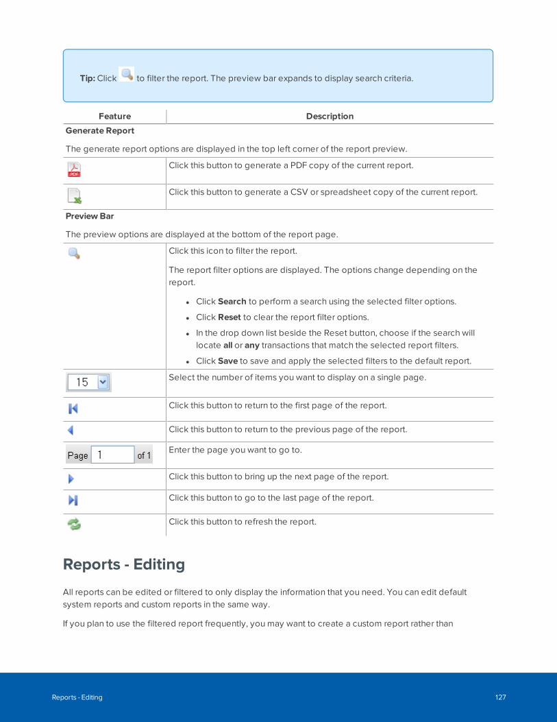
Tip: Click to filter the report. The preview bar expands to display search criteria.
Feature Description
Generate Report
The generate report options are displayed in the top left corner of the report preview.
Click this button to generate a PDF copy of the current report.
Click this button to generate a CSV or spreadsheet copy of the current report.
Preview Bar
The preview options are displayed at the bottom of the report page.
Click this icon to filter the report.
The report filter options are displayed. The options change depending on thereport.
l Click Search to perform a search using the selected filter options.
l Click Reset to clear the report filter options.
l In the drop down list beside the Reset button, choose if the search willlocate all or any transactions that match the selected report filters.
l Click Save to save and apply the selected filters to the default report.
Select the number of items you want to display on a single page.
Click this button to return to the first page of the report.
Click this button to return to the previous page of the report.
Enter the page you want to go to.
Click this button to bring up the next page of the report.
Click this button to go to the last page of the report.
Click this button to refresh the report.
Reports - Editing
All reports can be edited or filtered to only display the information that you need. You can edit defaultsystem reports and custom reports in the same way.
If you plan to use the filtered report frequently, you may want to create a custom report rather than
Reports - Editing 127
modifying the default system report every time. For more information see Reports - Creating CustomReports on the next page.
Most generated reports saved as PDF files contain a maximum of 2,000 records, except the Audit LogReport, which contains a maximum of 1,000 records. Reports saved as CSV format spreadsheet files containa maximum of 2,000 records.
Reports requiring more than 2,000 rows must be scheduled as a batch job for system performance. Formore information, see Generating a Batch Report on page 448.
1. Display the Reports list.
l To display the system reports page, click Reports.
l To display the custom reports page, select Reports > CustomReports.
2. Click for the report that you want to edit.
Note: The Audit Log Report and Transaction Report do not have available. To edit, click
on the report name and follow the steps in the related procedure - Reports - Editing AuditLog and Transaction Reports below.
3. On the following page, select your preferences for the report.
4. Click to save your changes.
Now you can generate or preview the report with your changes.
Reports - Editing Audit Log and Transaction Reports
The Audit Log and Transaction Reports are edited differently from other reports. There is no edit functiondirectly available from the Reports list.
Follow the steps below to edit these reports.
1. Display the Reports list.
l To display the system reports page, click Reports.
l To display the custom reports page, select Reports > CustomReports.
2. Click on the name of the report
3. Click in the bottom left-hand corner on the following page (either the Grid: Transaction Report orGrid: Audit Log page).
The Find section opens.
Reports - Editing Audit Log and Transaction Reports 128
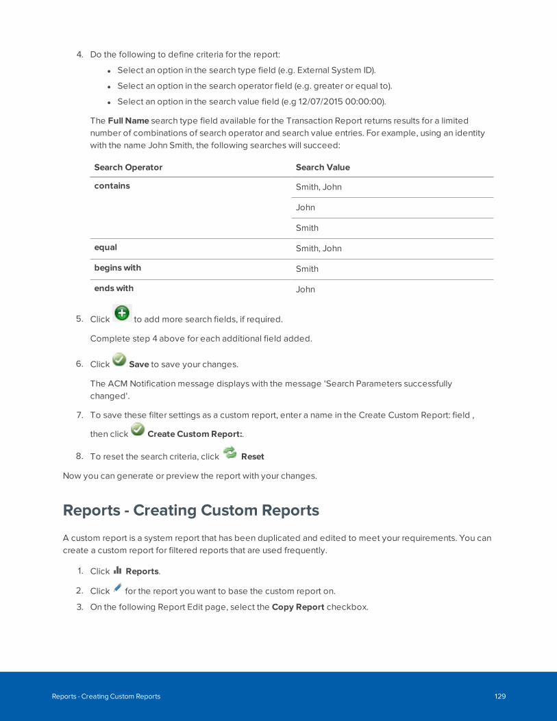
4. Do the following to define criteria for the report:
l Select an option in the search type field (e.g. External System ID).
l Select an option in the search operator field (e.g. greater or equal to).
l Select an option in the search value field (e.g 12/07/2015 00:00:00).
The Full Name search type field available for the Transaction Report returns results for a limitednumber of combinations of search operator and search value entries. For example, using an identitywith the name John Smith, the following searches will succeed:
Search Operator Search Value
contains Smith, John
John
Smith
equal Smith, John
begins with Smith
ends with John
5. Click to add more search fields, if required.
Complete step 4 above for each additional field added.
6. Click Save to save your changes.
The ACM Notification message displays with the message 'Search Parameters successfullychanged'.
7. To save these filter settings as a custom report, enter a name in the Create Custom Report: field ,
then click Create CustomReport:.
8. To reset the search criteria, click Reset
Now you can generate or preview the report with your changes.
Reports - Creating Custom Reports
A custom report is a system report that has been duplicated and edited to meet your requirements. You cancreate a custom report for filtered reports that are used frequently.
1. Click Reports.
2. Click for the report you want to base the custom report on.
3. On the following Report Edit page, select the Copy Report checkbox.
Reports - Creating Custom Reports 129
4. Give the new report a name.
5. Edit the report options to meet your requirements.
6. Click to save the new custom report.
Reports - Creating Custom Audit Log and TransactionReports
A custom audit log report lists all the selected recorded system logs. You can create a custom audit logreport to report only a selection of required audit logs. A custom transaction report lists all the selectedrecorded system transactions. You can create a custom transaction report to report only a selection ofrequired system transactions.
1. Click Reports.
2. Click Transaction Report in the Report Name column.
3. Click at the bottom of the page. The preview bar expands to display search criteria.
4. Enter the details you want to include in the report in the Find section. (Click to add more fields.)
5. Click Search.
The system transactions are filtered into a report.
6. In the Create CustomReport field, enter a name for the report.
7. Click Create CustomReport to save the new report.
Reports - Creating Custom Audit Log and Transaction Reports 130
Physical Access
The Physical Access pages allow you to access all connected panels, doors, inputs, outputs and associatedsecurity devices. These devices can be added, modified, and deleted. The status of the hardware can alsobe monitored from these pages.
Panels are controllers that connect one or more door controllers (subpanels) and their associated readers tothe appliance. Doors are logical units incorporating one or more components that are connected to a panel.The configuration of a door allows users to access certain areas.
Inputs are devices associated to panels and doors. For example, motion sensors or smoke detectors.Outputs are devices that perform tasks in response to input data. For example, unlocking a door or settingoff a fire alarm.
Note: If you do not have the correct delegations, you may not be able to access some of thefollowing pages. See your System Administrator for details.
Templates OverviewFor Avigilon and Mercury Security doors.
You can speed up the process of defining panels, subpanels and doors in the ACM system by creatingtemplates for bulk creation. For example, door templates create doors that automatically populate fieldvalues on the Parameters and Operations tabs.
l Door templates.
Standardize door configurations that set the basic parameters and operational settings for each typeof door at your site. Door templates are used when adding individual doors, modifying or updatingcommon door settings for groups of doors, or when batch creating subpanels for doors when addinga new Mercury panel.
Tip: Although you can create multiple door templates with the same name, it isrecommended that you give each the indoor template a unique name.
l Reader templates
Standardize reader settings. Reader templates are referenced from a wiring template when batchcreating subpanels for doors on a new panel.
l Output templates
Standardize output settings. Output templates are referenced from a wiring template when batch
Physical Access 131
creating subpanels for doors on a new panel, or used when batch creating output or input/outputsubpanels.
l Input templates
Standardize input settings. Input templates are referenced from a wiring template when batchcreating input subpanels for doors on a new panel, or used when batch creating output orinput/output subpanels.
l Wiring templates
Standardize Mercury subpanels with wiring templates that link subpanel addresses to door, reader,input, and output templates. Wiring templates are used to batch add the connections to functioningsubpanels and doors wired to a new Mercury panel when the panel is added to the ACM appliance.
Door TemplatesA door template contains a predefined set of common parameter values and operational settings that canbe applied to doors. Use a door template to populate the values assigned in the template to doors:
l When adding a new Mercury panel to the ACM system, new doors can be created in bulk by batchcreating the subpanels on the new panel. Door templates are used together with wiring templates tocreate access-controlled doors with preset configurations ready for use after the new panel andsubpanels are fully connected and communicating with the ACM system. To bulk create doors usinga wiring template when adding a new panel, see Batch Creating Subpanels on a New Mercury Panelon page 160.
l When adding a new door, you still need to configure many attributes such as operations, hardware,cameras, and interlocks specifically for individual doors. To create a door using a template, seeAdding Doors on page 215.
l When standardizing settings or updating settings supported by a door template for a group of doors.
l When you have many doors defined with non-standard settings, create a group containingthese doors and a new door template containing the standard settings. Then apply the newtemplate to the group of doors.
l When you have to change a setting common to all doors that use the same template, modifythe door template. Then apply the modified template to the group of doors.
You can apply a template to a group of doors:
l Immediately from the Templates page, using the Batch Update option.
l Alternatively, at any time after the template is created or modified, from the Groups using theBatch Update option.
l At a future time, or on a schedule, from the Batch Jobs Specifications page.
Note: When you use the Batch Update option and there are more than 10 doors in thegroup, a batch job is launched, which runs in the background.
To create a new template, see Door Templates - Add page on page 134.
Door Templates 132
When you select Physical Access > Templates, the Door Templates tab is selected, and the DoorTemplates list page is displayed. This page lists all door templates that have been defined in the system.
Door Templates - Batch Update
The Batch Update feature on the Templates page allows you to assign a door template to a group of doorsfrom the same manufacturer. This is useful for applying new settings or modifying current settings to a groupof doors.
WARNING — There is a risk of losing a door template batch update report due to blocked pop-ups in yourweb browser. When a door template batch update is performed on a group of doors, a report is generatedthat you can save to your local system. If pop-ups from the ACM client are blocked by your web browser,the report cannot be saved. Your web browser will notify you that the pop-up is blocked, and offer you theoption to unblock the pop-up. To save the report (and all future reports), you must enable pop-ups in yourweb browser from your ACM client. For instructions on how to enable pop-ups, refer to the Help files foryour web browser.
1. Select Physical Access > Templates.
The Templates panel opens with the Door Template tab selected and the Door Templates listdisplayed.
2. On the Door Templates list, click from the Batch Update column beside the template you wantto apply to a group.
The Batch Update dialog box appears.
3. From the Group drop down list, select a group of doors.
Only the groups that have been previously defined appear in this list.
4. Click OK.
All members of the specified group are updated with this template's settings.
Note: If you are doing a door template batch update on a group of doors, you will either beprompted to save the report generated by the system (if pop-ups from the ACM client areunblocked) or your web browser will notify you that the pop-up has been blocked.
If there are more than 10 doors, the update will be automatically scheduled as a batch job that starts two
minutes after you select the group and click OK. This can be checked at > My Account > Batch Jobs.
Door Templates list page
When you select Physical Access > Templates, the Door Templates tab is selected, and the DoorTemplates list page is displayed. This page lists all door templates that have been defined in the system.
Door Templates - Batch Update 133
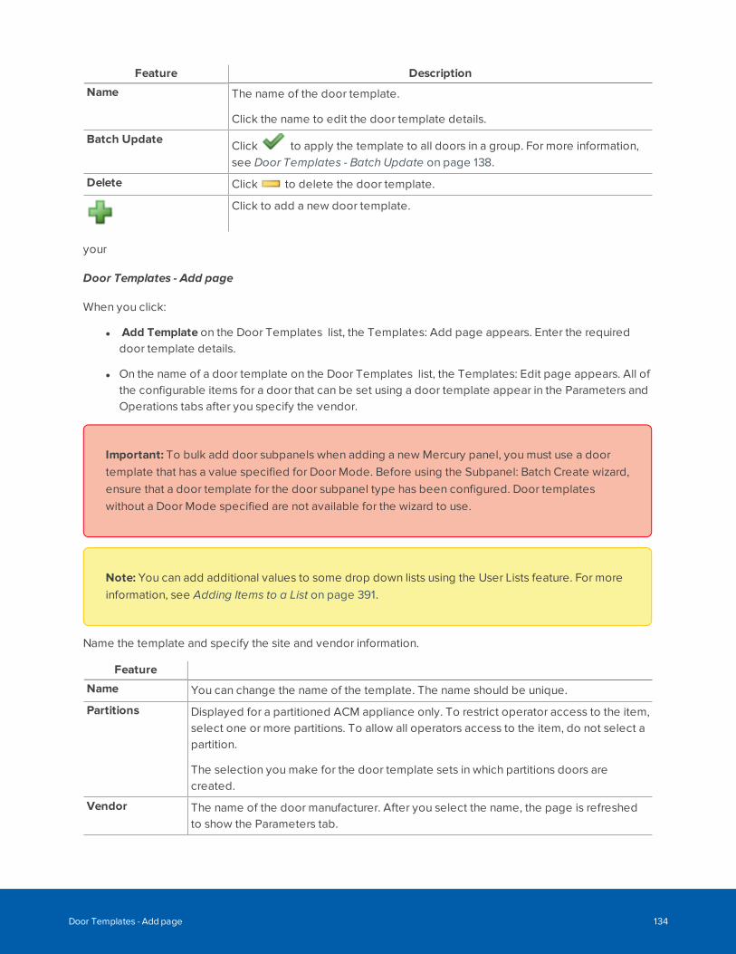
Feature Description
Name The name of the door template.
Click the name to edit the door template details.
Batch Update Click to apply the template to all doors in a group. For more information,see Door Templates - Batch Update on page 138.
Delete Click to delete the door template.
Click to add a new door template.
your
Door Templates - Add page
When you click:
l Add Template on the Door Templates list, the Templates: Add page appears. Enter the requireddoor template details.
l On the name of a door template on the Door Templates list, the Templates: Edit page appears. All ofthe configurable items for a door that can be set using a door template appear in the Parameters andOperations tabs after you specify the vendor.
Important: To bulk add door subpanels when adding a new Mercury panel, you must use a doortemplate that has a value specified for Door Mode. Before using the Subpanel: Batch Create wizard,ensure that a door template for the door subpanel type has been configured. Door templateswithout a Door Mode specified are not available for the wizard to use.
Note: You can add additional values to some drop down lists using the User Lists feature. For moreinformation, see Adding Items to a List on page 391.
Name the template and specify the site and vendor information.
Feature
Name You can change the name of the template. The name should be unique.
Partitions Displayed for a partitioned ACM appliance only. To restrict operator access to the item,select one or more partitions. To allow all operators access to the item, do not select apartition.
The selection you make for the door template sets in which partitions doors arecreated.
Vendor The name of the door manufacturer. After you select the name, the page is refreshedto show the Parameters tab.
Door Templates - Add page 134
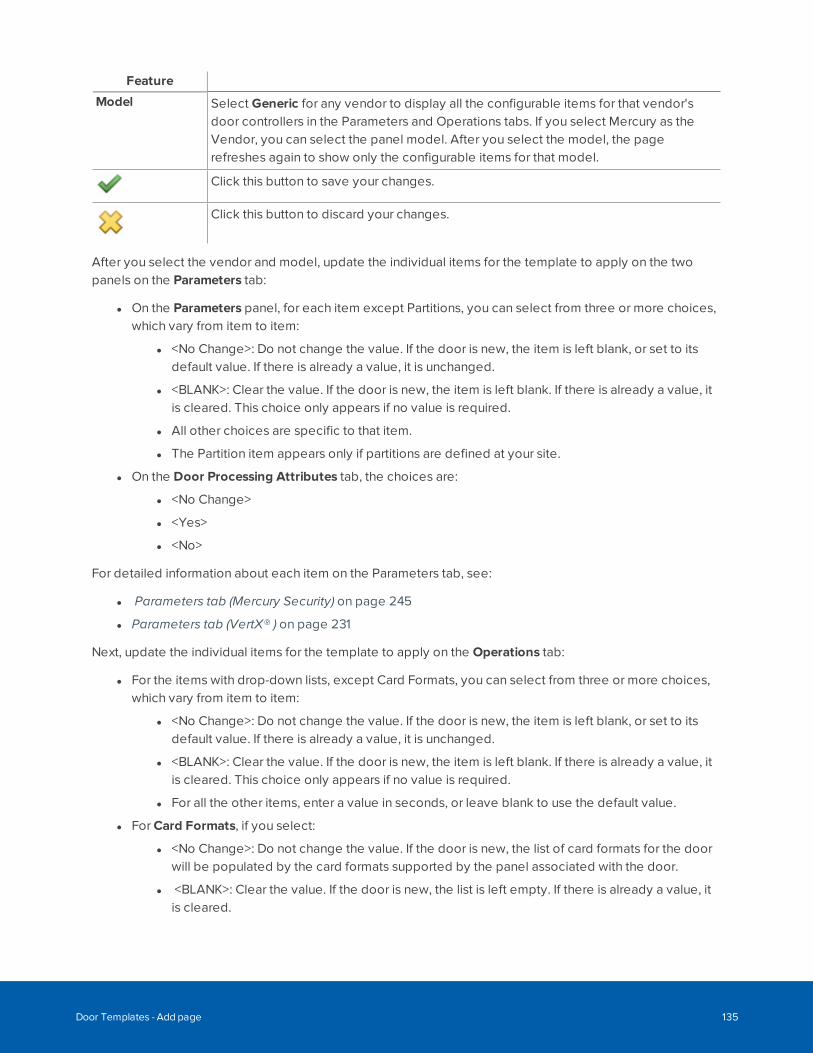
Feature
Model Select Generic for any vendor to display all the configurable items for that vendor'sdoor controllers in the Parameters and Operations tabs. If you select Mercury as theVendor, you can select the panel model. After you select the model, the pagerefreshes again to show only the configurable items for that model.
Click this button to save your changes.
Click this button to discard your changes.
After you select the vendor and model, update the individual items for the template to apply on the twopanels on the Parameters tab:
l On the Parameters panel, for each item except Partitions, you can select from three or more choices,which vary from item to item:
l <No Change>: Do not change the value. If the door is new, the item is left blank, or set to itsdefault value. If there is already a value, it is unchanged.
l <BLANK>: Clear the value. If the door is new, the item is left blank. If there is already a value, itis cleared. This choice only appears if no value is required.
l All other choices are specific to that item.
l The Partition item appears only if partitions are defined at your site.
l On the Door Processing Attributes tab, the choices are:
l <No Change>
l <Yes>
l <No>
For detailed information about each item on the Parameters tab, see:
l Parameters tab (Mercury Security) on page 245
l Parameters tab (VertX® ) on page 231
Next, update the individual items for the template to apply on the Operations tab:
l For the items with drop-down lists, except Card Formats, you can select from three or more choices,which vary from item to item:
l <No Change>: Do not change the value. If the door is new, the item is left blank, or set to itsdefault value. If there is already a value, it is unchanged.
l <BLANK>: Clear the value. If the door is new, the item is left blank. If there is already a value, itis cleared. This choice only appears if no value is required.
l For all the other items, enter a value in seconds, or leave blank to use the default value.
l For Card Formats, if you select:
l <No Change>: Do not change the value. If the door is new, the list of card formats for the doorwill be populated by the card formats supported by the panel associated with the door.
l <BLANK>: Clear the value. If the door is new, the list is left empty. If there is already a value, itis cleared.
Door Templates - Add page 135
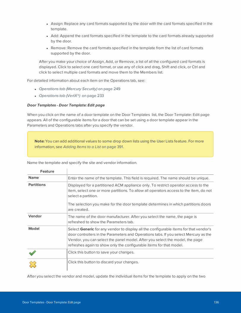
l Assign: Replace any card formats supported by the door with the card formats specified in thetemplate.
l Add: Append the card formats specified in the template to the card formats already supportedby the door.
l Remove: Remove the card formats specified in the template from the list of card formatssupported by the door.
After you make your choice of Assign, Add, or Remove, a list of all the configured card formats isdisplayed. Click to select one card format, or use any of click and drag, Shift and click, or Ctrl andclick to select multiple card formats and move them to the Members list.
For detailed information about each item on the Operations tab, see:
l Operations tab (Mercury Security) on page 249
l Operations tab (VertX®) on page 233
Door Templates - Door Template: Edit page
When you click on the name of a door template on the Door Templates list, the Door Template: Edit pageappears. All of the configurable items for a door that can be set using a door template appear in theParameters and Operations tabs after you specify the vendor.
Note: You can add additional values to some drop down lists using the User Lists feature. For moreinformation, see Adding Items to a List on page 391.
Name the template and specify the site and vendor information.
Feature
Name Enter the name of the template. This field is required. The name should be unique.
Partitions Displayed for a partitioned ACM appliance only. To restrict operator access to theitem, select one or more partitions. To allow all operators access to the item, do notselect a partition.
The selection you make for the door template determines in which partitions doorsare created.
Vendor The name of the door manufacturer. After you select the name, the page isrefreshed to show the Parameters tab.
Model Select Generic for any vendor to display all the configurable items for that vendor'sdoor controllers in the Parameters and Operations tabs. If you select Mercury as theVendor, you can select the panel model. After you select the model, the pagerefreshes again to show only the configurable items for that model.
Click this button to save your changes.
Click this button to discard your changes.
After you select the vendor and model, update the individual items for the template to apply on the two
Door Templates - Door Template: Edit page 136
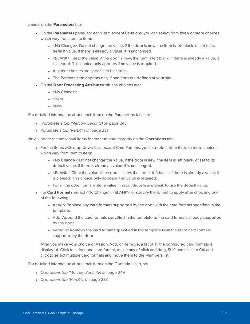
panels on the Parameters tab:
l On the Parameters panel, for each item except Partitions, you can select from three or more choices,which vary from item to item:
l <No Change>: Do not change the value. If the door is new, the item is left blank, or set to itsdefault value. If there is already a value, it is unchanged.
l <BLANK>: Clear the value. If the door is new, the item is left blank. If there is already a value, itis cleared. This choice only appears if no value is required.
l All other choices are specific to that item.
l The Partition item appears only if partitions are defined at your site.
l On the Door Processing Attributes tab, the choices are:
l <No Change>
l <Yes>
l <No>
For detailed information about each item on the Parameters tab, see:
l Parameters tab (Mercury Security) on page 245
l Parameters tab (VertX® ) on page 231
Next, update the individual items for the template to apply on the Operations tab:
l For the items with drop-down lists, except Card Formats, you can select from three or more choices,which vary from item to item:
l <No Change>: Do not change the value. If the door is new, the item is left blank, or set to itsdefault value. If there is already a value, it is unchanged.
l <BLANK>: Clear the value. If the door is new, the item is left blank. If there is already a value, itis cleared. This choice only appears if no value is required.
l For all the other items, enter a value in seconds, or leave blank to use the default value.
l For Card Formats, select <No Change>, <BLANK>, or specify the format to apply after choosing oneof the following:
l Assign: Replace any card formats supported by the door with the card formats specified in thetemplate.
l Add: Append the card formats specified in the template to the card formats already supportedby the door.
l Remove: Remove the card formats specified in the template from the list of card formatssupported by the door.
After you make your choice of Assign, Add, or Remove, a list of all the configured card formats isdisplayed. Click to select one card format, or use any of click and drag, Shift and click, or Ctrl andclick to select multiple card formats and move them to the Members list.
For detailed information about each item on the Operations tab, see:
l Operations tab (Mercury Security) on page 249
l Operations tab (VertX®) on page 233
Door Templates - Door Template: Edit page 137
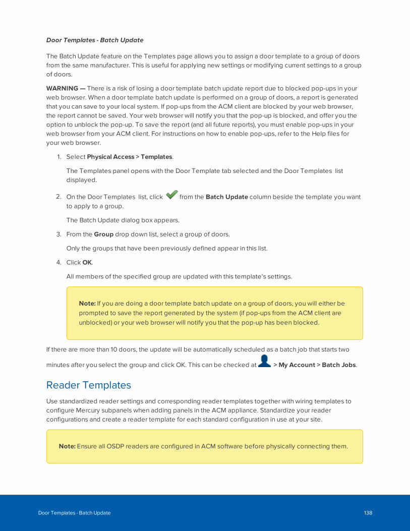
Door Templates - Batch Update
The Batch Update feature on the Templates page allows you to assign a door template to a group of doorsfrom the same manufacturer. This is useful for applying new settings or modifying current settings to a groupof doors.
WARNING — There is a risk of losing a door template batch update report due to blocked pop-ups in yourweb browser. When a door template batch update is performed on a group of doors, a report is generatedthat you can save to your local system. If pop-ups from the ACM client are blocked by your web browser,the report cannot be saved. Your web browser will notify you that the pop-up is blocked, and offer you theoption to unblock the pop-up. To save the report (and all future reports), you must enable pop-ups in yourweb browser from your ACM client. For instructions on how to enable pop-ups, refer to the Help files foryour web browser.
1. Select Physical Access > Templates.
The Templates panel opens with the Door Template tab selected and the Door Templates listdisplayed.
2. On the Door Templates list, click from the Batch Update column beside the template you wantto apply to a group.
The Batch Update dialog box appears.
3. From the Group drop down list, select a group of doors.
Only the groups that have been previously defined appear in this list.
4. Click OK.
All members of the specified group are updated with this template's settings.
Note: If you are doing a door template batch update on a group of doors, you will either beprompted to save the report generated by the system (if pop-ups from the ACM client areunblocked) or your web browser will notify you that the pop-up has been blocked.
If there are more than 10 doors, the update will be automatically scheduled as a batch job that starts two
minutes after you select the group and click OK. This can be checked at > My Account > Batch Jobs.
Reader TemplatesUse standardized reader settings and corresponding reader templates together with wiring templates toconfigure Mercury subpanels when adding panels in the ACM appliance. Standardize your readerconfigurations and create a reader template for each standard configuration in use at your site.
Note: Ensure all OSDP readers are configured in ACM software before physically connecting them.
Door Templates - Batch Update 138
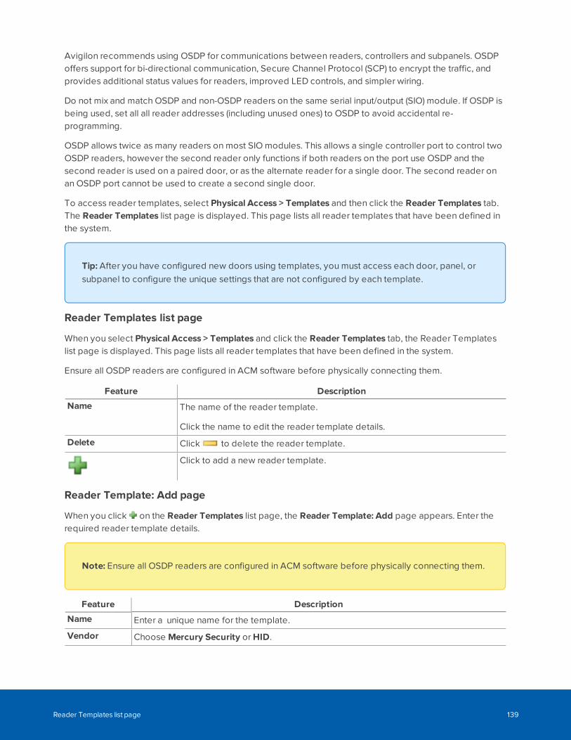
Avigilon recommends using OSDP for communications between readers, controllers and subpanels. OSDPoffers support for bi-directional communication, Secure Channel Protocol (SCP) to encrypt the traffic, andprovides additional status values for readers, improved LED controls, and simpler wiring.
Do not mix and match OSDP and non-OSDP readers on the same serial input/output (SIO) module. If OSDP isbeing used, set all all reader addresses (including unused ones) to OSDP to avoid accidental re-programming.
OSDP allows twice as many readers on most SIO modules. This allows a single controller port to control twoOSDP readers, however the second reader only functions if both readers on the port use OSDP and thesecond reader is used on a paired door, or as the alternate reader for a single door. The second reader onan OSDP port cannot be used to create a second single door.
To access reader templates, select Physical Access > Templates and then click the Reader Templates tab.The Reader Templates list page is displayed. This page lists all reader templates that have been defined inthe system.
Tip: After you have configured new doors using templates, you must access each door, panel, orsubpanel to configure the unique settings that are not configured by each template.
Reader Templates list page
When you select Physical Access > Templates and click the Reader Templates tab, the Reader Templateslist page is displayed. This page lists all reader templates that have been defined in the system.
Ensure all OSDP readers are configured in ACM software before physically connecting them.
Feature Description
Name The name of the reader template.
Click the name to edit the reader template details.
Delete Click to delete the reader template.
Click to add a new reader template.
Reader Template: Add page
When you click on the Reader Templates list page, the Reader Template: Add page appears. Enter therequired reader template details.
Note: Ensure all OSDP readers are configured in ACM software before physically connecting them.
Feature Description
Name Enter a unique name for the template.
Vendor Choose Mercury Security or HID.
Reader Templates list page 139
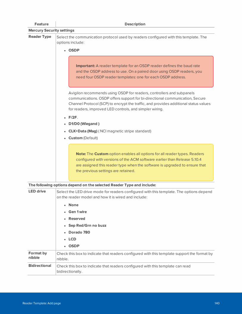
Feature Description
Mercury Security settings
Reader Type Select the communication protocol used by readers configured with this template. Theoptions include:
l OSDP
Important: A reader template for an OSDP reader defines the baud rateand the OSDP address to use. On a paired door using OSDP readers, youneed four OSDP reader templates: one for each OSDP address.
Avigilon recommends using OSDP for readers, controllers and subpanelscommunications. OSDP offers support for bi-directional communication, SecureChannel Protocol (SCP) to encrypt the traffic, and provides additional status valuesfor readers, improved LED controls, and simpler wiring.
l F/2F.
l D1/D0 (Wiegand )
l CLK+Data (Mag) ( NCI magnetic stripe standard)
l Custom (Default)
Note: The Custom option enables all options for all reader types. Readersconfigured with versions of the ACM software earlier than Release 5.10.4are assigned this reader type when the software is upgraded to ensure thatthe previous settings are retained.
The following options depend on the selected Reader Type and include:
LED drive Select the LED drive mode for readers configured with this template. The options dependon the reader model and how it is wired and include:
l None
l Gen 1wire
l Reserved
l Sep Red/Grn no buzz
l Dorado 780
l LCD
l OSDP
Format bynibble
Check this box to indicate that readers configured with this template support the format bynibble.
Bidirectional Check this box to indicate that readers configured with this template can readbidirectionally.
Reader Template: Add page 140

Feature Description
F/2FDecoding
Check this box to indicate that readers configured with this template use F or 2F decoding.
Inputs onreader
Check this box to indicate that readers configured with this template provide one or moreinput ports for serial input arrays.
Keypaddecode
Select the keypad decode/encryption method that is used by readers configured with thistemplate. The options include:
l MR20 8-bit tamper
l Hughes ID 4-bit
l Indala
l MR20 8-bit no tamper
Wiegand Check this box to indicate that readers configured with this template support the Wiegandstandard.
Trim Zero Bit Check this box to indicate that readers configured with this template support the trim zerobit standard.
NCI magstripe Check this box to indicate that readers configured with this template supports the NCIstandard for magnetic stripes.
Supervised Check this box to indicate that readers configured with this template are supervised(outfitted with detection devices)
SecureChannelProtocol
Check this box to enable secure OSDP communication between the reader and thecontroller. The reader must support SCP and must be in installation mode. The reader willremain offline if a secure connection cannot be established.
CAUTION — Do not enable SCP on readers that support OSDPv1, such as the ViRDIbiometric reader, as this will make the reader inoperable. Secure channel is onlysupported in by OSDPv2.
Baud Rate Set the OSDP baud rate. This must be the same for all readers on a single port. Validvalues are 9600 (default), 19200, 38000 or 115200. If blank is selected, the system will usedefault settings.
Note: Mercury controllers may auto-detect the OSDP baud rate. For moreinformation, refer to Mercury documentation.
See Appendix: pivCLASS Configuration on page 490.
Reader Template: Add page 141
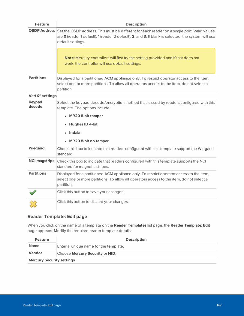
Feature Description
OSDP Address Set the OSDP address. This must be different for each reader on a single port. Valid valuesare 0 (reader 1 default), 1 (reader 2 default), 2, and 3. If blank is selected, the system will usedefault settings.
Note: Mercury controllers will first try the setting provided and if that does notwork, the controller will use default settings.
Partitions Displayed for a partitioned ACM appliance only. To restrict operator access to the item,select one or more partitions. To allow all operators access to the item, do not select apartition.
VertX® settings
Keypaddecode
Select the keypad decode/encryption method that is used by readers configured with thistemplate. The options include:
l MR20 8-bit tamper
l Hughes ID 4-bit
l Indala
l MR20 8-bit no tamper
Wiegand Check this box to indicate that readers configured with this template support the Wiegandstandard.
NCI magstripe Check this box to indicate that readers configured with this template supports the NCIstandard for magnetic stripes.
Partitions Displayed for a partitioned ACM appliance only. To restrict operator access to the item,select one or more partitions. To allow all operators access to the item, do not select apartition.
Click this button to save your changes.
Click this button to discard your changes.
Reader Template: Edit page
When you click on the name of a template on the Reader Templates list page, the Reader Template: Editpage appears. Modify the required reader template details.
Feature Description
Name Enter a unique name for the template.
Vendor Choose Mercury Security or HID.
Mercury Security settings
Reader Template: Edit page 142
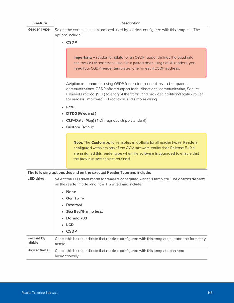
Feature Description
Reader Type Select the communication protocol used by readers configured with this template. Theoptions include:
l OSDP
Important: A reader template for an OSDP reader defines the baud rateand the OSDP address to use. On a paired door using OSDP readers, youneed four OSDP reader templates: one for each OSDP address.
Avigilon recommends using OSDP for readers, controllers and subpanelscommunications. OSDP offers support for bi-directional communication, SecureChannel Protocol (SCP) to encrypt the traffic, and provides additional status valuesfor readers, improved LED controls, and simpler wiring.
l F/2F.
l D1/D0 (Wiegand )
l CLK+Data (Mag) ( NCI magnetic stripe standard)
l Custom (Default)
Note: The Custom option enables all options for all reader types. Readersconfigured with versions of the ACM software earlier than Release 5.10.4are assigned this reader type when the software is upgraded to ensure thatthe previous settings are retained.
The following options depend on the selected Reader Type and include:
LED drive Select the LED drive mode for readers configured with this template. The options dependon the reader model and how it is wired and include:
l None
l Gen 1wire
l Reserved
l Sep Red/Grn no buzz
l Dorado 780
l LCD
l OSDP
Format bynibble
Check this box to indicate that readers configured with this template support the format bynibble.
Bidirectional Check this box to indicate that readers configured with this template can readbidirectionally.
Reader Template: Edit page 143
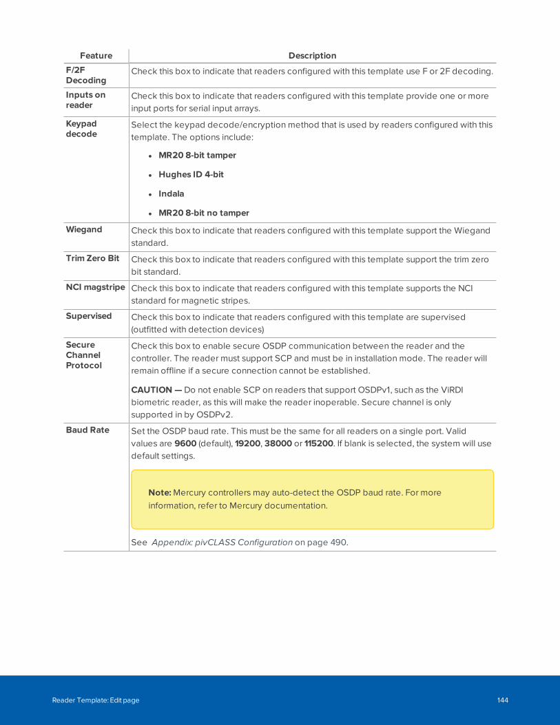
Feature Description
F/2FDecoding
Check this box to indicate that readers configured with this template use F or 2F decoding.
Inputs onreader
Check this box to indicate that readers configured with this template provide one or moreinput ports for serial input arrays.
Keypaddecode
Select the keypad decode/encryption method that is used by readers configured with thistemplate. The options include:
l MR20 8-bit tamper
l Hughes ID 4-bit
l Indala
l MR20 8-bit no tamper
Wiegand Check this box to indicate that readers configured with this template support the Wiegandstandard.
Trim Zero Bit Check this box to indicate that readers configured with this template support the trim zerobit standard.
NCI magstripe Check this box to indicate that readers configured with this template supports the NCIstandard for magnetic stripes.
Supervised Check this box to indicate that readers configured with this template are supervised(outfitted with detection devices)
SecureChannelProtocol
Check this box to enable secure OSDP communication between the reader and thecontroller. The reader must support SCP and must be in installation mode. The reader willremain offline if a secure connection cannot be established.
CAUTION — Do not enable SCP on readers that support OSDPv1, such as the ViRDIbiometric reader, as this will make the reader inoperable. Secure channel is onlysupported in by OSDPv2.
Baud Rate Set the OSDP baud rate. This must be the same for all readers on a single port. Validvalues are 9600 (default), 19200, 38000 or 115200. If blank is selected, the system will usedefault settings.
Note: Mercury controllers may auto-detect the OSDP baud rate. For moreinformation, refer to Mercury documentation.
See Appendix: pivCLASS Configuration on page 490.
Reader Template: Edit page 144
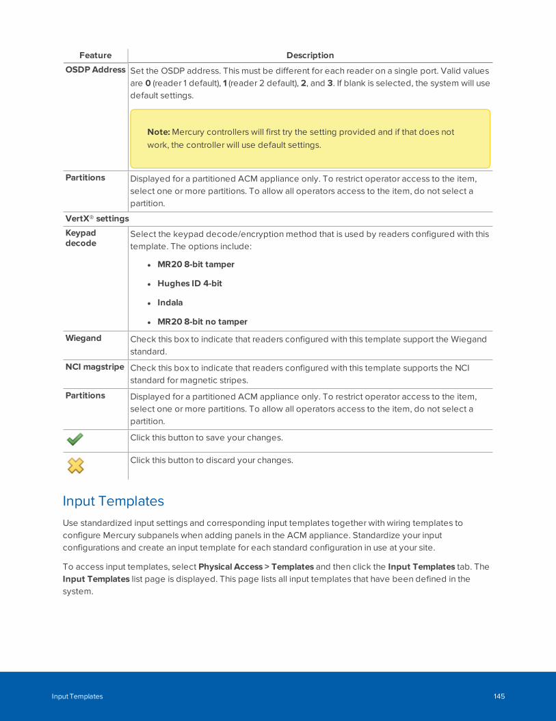
Feature Description
OSDP Address Set the OSDP address. This must be different for each reader on a single port. Valid valuesare 0 (reader 1 default), 1 (reader 2 default), 2, and 3. If blank is selected, the system will usedefault settings.
Note: Mercury controllers will first try the setting provided and if that does notwork, the controller will use default settings.
Partitions Displayed for a partitioned ACM appliance only. To restrict operator access to the item,select one or more partitions. To allow all operators access to the item, do not select apartition.
VertX® settings
Keypaddecode
Select the keypad decode/encryption method that is used by readers configured with thistemplate. The options include:
l MR20 8-bit tamper
l Hughes ID 4-bit
l Indala
l MR20 8-bit no tamper
Wiegand Check this box to indicate that readers configured with this template support the Wiegandstandard.
NCI magstripe Check this box to indicate that readers configured with this template supports the NCIstandard for magnetic stripes.
Partitions Displayed for a partitioned ACM appliance only. To restrict operator access to the item,select one or more partitions. To allow all operators access to the item, do not select apartition.
Click this button to save your changes.
Click this button to discard your changes.
Input TemplatesUse standardized input settings and corresponding input templates together with wiring templates toconfigure Mercury subpanels when adding panels in the ACM appliance. Standardize your inputconfigurations and create an input template for each standard configuration in use at your site.
To access input templates, select Physical Access > Templates and then click the Input Templates tab. TheInput Templates list page is displayed. This page lists all input templates that have been defined in thesystem.
Input Templates 145
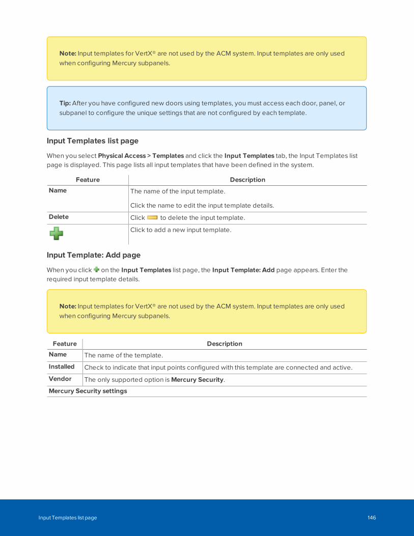
Note: Input templates for VertX® are not used by the ACM system. Input templates are only usedwhen configuring Mercury subpanels.
Tip: After you have configured new doors using templates, you must access each door, panel, orsubpanel to configure the unique settings that are not configured by each template.
Input Templates list page
When you select Physical Access > Templates and click the Input Templates tab, the Input Templates listpage is displayed. This page lists all input templates that have been defined in the system.
Feature Description
Name The name of the input template.
Click the name to edit the input template details.
Delete Click to delete the input template.
Click to add a new input template.
Input Template: Add page
When you click on the Input Templates list page, the Input Template: Add page appears. Enter therequired input template details.
Note: Input templates for VertX® are not used by the ACM system. Input templates are only usedwhen configuring Mercury subpanels.
Feature Description
Name The name of the template.
Installed Check to indicate that input points configured with this template are connected and active.
Vendor The only supported option is Mercury Security.
Mercury Security settings
Input Templates list page 146
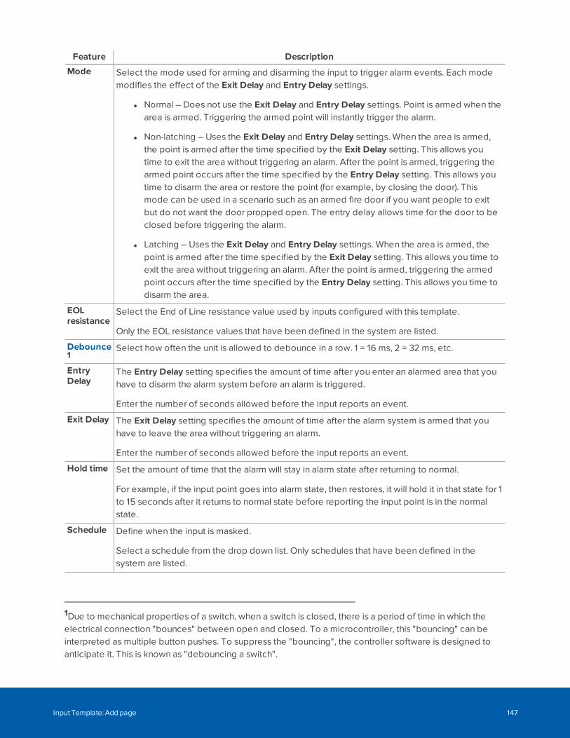
Feature Description
Mode Select the mode used for arming and disarming the input to trigger alarm events. Each modemodifies the effect of the Exit Delay and Entry Delay settings.
l Normal – Does not use the Exit Delay and Entry Delay settings. Point is armed when thearea is armed. Triggering the armed point will instantly trigger the alarm.
l Non-latching – Uses the Exit Delay and Entry Delay settings. When the area is armed,the point is armed after the time specified by the Exit Delay setting. This allows youtime to exit the area without triggering an alarm. After the point is armed, triggering thearmed point occurs after the time specified by the Entry Delay setting. This allows youtime to disarm the area or restore the point (for example, by closing the door). Thismode can be used in a scenario such as an armed fire door if you want people to exitbut do not want the door propped open. The entry delay allows time for the door to beclosed before triggering the alarm.
l Latching – Uses the Exit Delay and Entry Delay settings. When the area is armed, thepoint is armed after the time specified by the Exit Delay setting. This allows you time toexit the area without triggering an alarm. After the point is armed, triggering the armedpoint occurs after the time specified by the Entry Delay setting. This allows you time todisarm the area.
EOLresistance
Select the End of Line resistance value used by inputs configured with this template.
Only the EOL resistance values that have been defined in the system are listed.
Debounce1
Select how often the unit is allowed to debounce in a row. 1 = 16 ms, 2 = 32 ms, etc.
EntryDelay
The Entry Delay setting specifies the amount of time after you enter an alarmed area that youhave to disarm the alarm system before an alarm is triggered.
Enter the number of seconds allowed before the input reports an event.
Exit Delay The Exit Delay setting specifies the amount of time after the alarm system is armed that youhave to leave the area without triggering an alarm.
Enter the number of seconds allowed before the input reports an event.
Hold time Set the amount of time that the alarm will stay in alarm state after returning to normal.
For example, if the input point goes into alarm state, then restores, it will hold it in that state for 1to 15 seconds after it returns to normal state before reporting the input point is in the normalstate.
Schedule Define when the input is masked.
Select a schedule from the drop down list. Only schedules that have been defined in thesystem are listed.
1Due to mechanical properties of a switch, when a switch is closed, there is a period of time in which theelectrical connection "bounces" between open and closed. To a microcontroller, this "bouncing" can beinterpreted as multiple button pushes. To suppress the "bouncing", the controller software is designed toanticipate it. This is known as "debouncing a switch".
Input Template: Add page 147
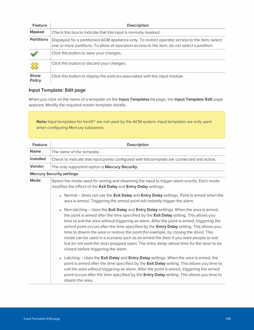
Feature Description
Masked Check this box to indicate that this input is normally masked.
Partitions Displayed for a partitioned ACM appliance only. To restrict operator access to the item, selectone or more partitions. To allow all operators access to the item, do not select a partition.
Click this button to save your changes.
Click this button to discard your changes.
ShowPolicy
Click this button to display the policies associated with this input module.
Input Template: Edit page
When you click on the name of a template on the Input Templates list page, the Input Template: Edit pageappears. Modify the required reader template details.
Note: Input templates for VertX® are not used by the ACM system. Input templates are only usedwhen configuring Mercury subpanels.
Feature Description
Name The name of the template.
Installed Check to indicate that input points configured with this template are connected and active.
Vendor The only supported option is Mercury Security.
Mercury Security settings
Mode Select the mode used for arming and disarming the input to trigger alarm events. Each modemodifies the effect of the Exit Delay and Entry Delay settings.
l Normal – Does not use the Exit Delay and Entry Delay settings. Point is armed when thearea is armed. Triggering the armed point will instantly trigger the alarm.
l Non-latching – Uses the Exit Delay and Entry Delay settings. When the area is armed,the point is armed after the time specified by the Exit Delay setting. This allows youtime to exit the area without triggering an alarm. After the point is armed, triggering thearmed point occurs after the time specified by the Entry Delay setting. This allows youtime to disarm the area or restore the point (for example, by closing the door). Thismode can be used in a scenario such as an armed fire door if you want people to exitbut do not want the door propped open. The entry delay allows time for the door to beclosed before triggering the alarm.
l Latching – Uses the Exit Delay and Entry Delay settings. When the area is armed, thepoint is armed after the time specified by the Exit Delay setting. This allows you time toexit the area without triggering an alarm. After the point is armed, triggering the armedpoint occurs after the time specified by the Entry Delay setting. This allows you time todisarm the area.
Input Template: Edit page 148
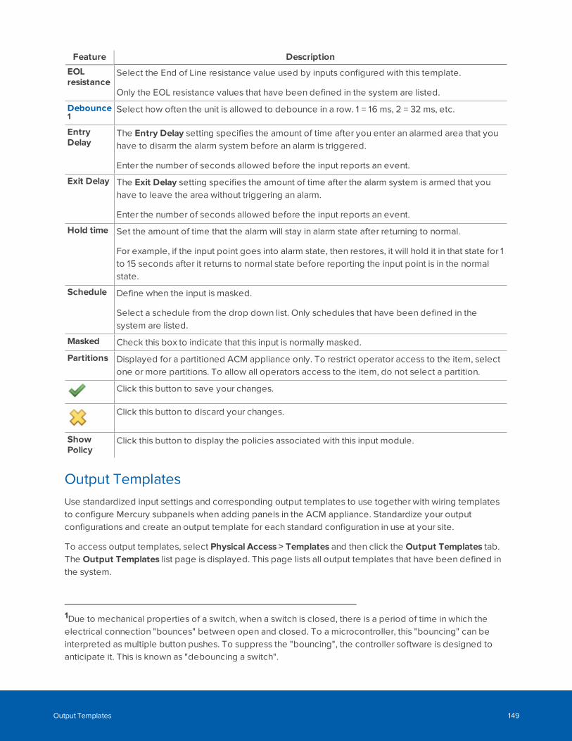
Feature Description
EOLresistance
Select the End of Line resistance value used by inputs configured with this template.
Only the EOL resistance values that have been defined in the system are listed.
Debounce1
Select how often the unit is allowed to debounce in a row. 1 = 16 ms, 2 = 32 ms, etc.
EntryDelay
The Entry Delay setting specifies the amount of time after you enter an alarmed area that youhave to disarm the alarm system before an alarm is triggered.
Enter the number of seconds allowed before the input reports an event.
Exit Delay The Exit Delay setting specifies the amount of time after the alarm system is armed that youhave to leave the area without triggering an alarm.
Enter the number of seconds allowed before the input reports an event.
Hold time Set the amount of time that the alarm will stay in alarm state after returning to normal.
For example, if the input point goes into alarm state, then restores, it will hold it in that state for 1to 15 seconds after it returns to normal state before reporting the input point is in the normalstate.
Schedule Define when the input is masked.
Select a schedule from the drop down list. Only schedules that have been defined in thesystem are listed.
Masked Check this box to indicate that this input is normally masked.
Partitions Displayed for a partitioned ACM appliance only. To restrict operator access to the item, selectone or more partitions. To allow all operators access to the item, do not select a partition.
Click this button to save your changes.
Click this button to discard your changes.
ShowPolicy
Click this button to display the policies associated with this input module.
Output TemplatesUse standardized input settings and corresponding output templates to use together with wiring templatesto configure Mercury subpanels when adding panels in the ACM appliance. Standardize your outputconfigurations and create an output template for each standard configuration in use at your site.
To access output templates, select Physical Access > Templates and then click the Output Templates tab.The Output Templates list page is displayed. This page lists all output templates that have been defined inthe system.
1Due to mechanical properties of a switch, when a switch is closed, there is a period of time in which theelectrical connection "bounces" between open and closed. To a microcontroller, this "bouncing" can beinterpreted as multiple button pushes. To suppress the "bouncing", the controller software is designed toanticipate it. This is known as "debouncing a switch".
Output Templates 149
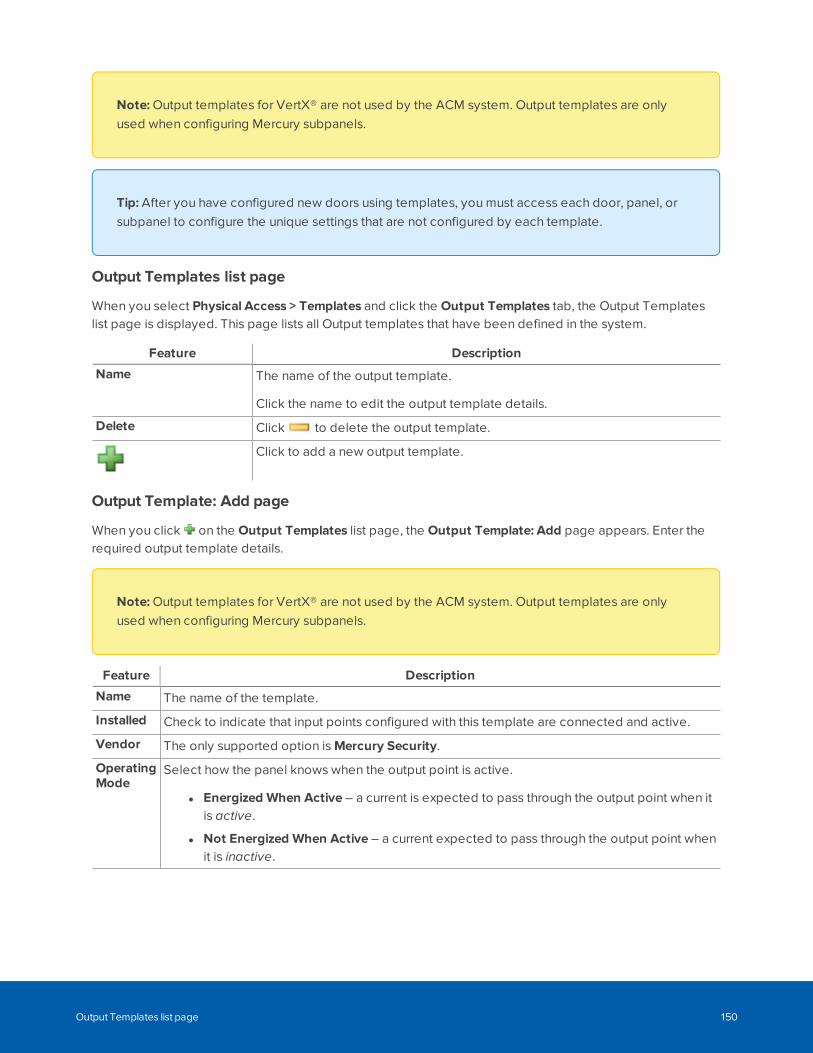
Note: Output templates for VertX® are not used by the ACM system. Output templates are onlyused when configuring Mercury subpanels.
Tip: After you have configured new doors using templates, you must access each door, panel, orsubpanel to configure the unique settings that are not configured by each template.
Output Templates list page
When you select Physical Access > Templates and click the Output Templates tab, the Output Templateslist page is displayed. This page lists all Output templates that have been defined in the system.
Feature Description
Name The name of the output template.
Click the name to edit the output template details.
Delete Click to delete the output template.
Click to add a new output template.
Output Template: Add page
When you click on the Output Templates list page, the Output Template: Add page appears. Enter therequired output template details.
Note: Output templates for VertX® are not used by the ACM system. Output templates are onlyused when configuring Mercury subpanels.
Feature Description
Name The name of the template.
Installed Check to indicate that input points configured with this template are connected and active.
Vendor The only supported option is Mercury Security.
OperatingMode
Select how the panel knows when the output point is active.
l Energized When Active – a current is expected to pass through the output point when itis active.
l Not Energized When Active – a current expected to pass through the output point whenit is inactive.
Output Templates list page 150
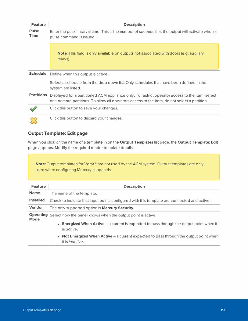
Feature Description
PulseTime
Enter the pulse interval time. This is the number of seconds that the output will activate when apulse command is issued.
Note: This field is only available on outputs not associated with doors (e.g. auxiliaryrelays).
Schedule Define when this output is active.
Select a schedule from the drop down list. Only schedules that have been defined in thesystem are listed.
Partitions Displayed for a partitioned ACM appliance only. To restrict operator access to the item, selectone or more partitions. To allow all operators access to the item, do not select a partition.
Click this button to save your changes.
Click this button to discard your changes.
Output Template: Edit page
When you click on the name of a template in on the Output Templates list page, the Output Template: Editpage appears. Modify the required reader template details.
Note: Output templates for VertX® are not used by the ACM system. Output templates are onlyused when configuring Mercury subpanels.
Feature Description
Name The name of the template.
Installed Check to indicate that input points configured with this template are connected and active.
Vendor The only supported option is Mercury Security.
OperatingMode
Select how the panel knows when the output point is active.
l Energized When Active – a current is expected to pass through the output point when itis active.
l Not Energized When Active – a current expected to pass through the output point whenit is inactive.
Output Template: Edit page 151
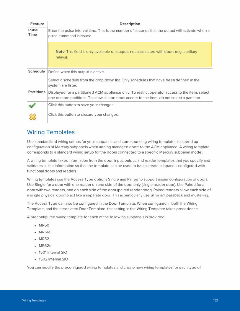
Feature Description
PulseTime
Enter the pulse interval time. This is the number of seconds that the output will activate when apulse command is issued.
Note: This field is only available on outputs not associated with doors (e.g. auxiliaryrelays).
Schedule Define when this output is active.
Select a schedule from the drop down list. Only schedules that have been defined in thesystem are listed.
Partitions Displayed for a partitioned ACM appliance only. To restrict operator access to the item, selectone or more partitions. To allow all operators access to the item, do not select a partition.
Click this button to save your changes.
Click this button to discard your changes.
Wiring TemplatesUse standardized wiring setups for your subpanels and corresponding wiring templates to speed upconfiguration of Mercury subpanels when adding managed doors to the ACM appliance. A wiring templatecorresponds to a standard wiring setup for the doors connected to a specific Mercury subpanel model.
A wiring template takes information from the door, input, output, and reader templates that you specify andvalidates all the information so that the template can be used to batch create subpanels configured withfunctional doors and readers.
Wiring templates use the Access Type options Single and Paired to support easier configuration of doors.Use Single for a door with one reader on one side of the door only (single reader door). Use Paired for adoor with two readers, one on each side of the door (paired reader door). Paired readers allow each side ofa single physical door to act like a separate door. This is particularly useful for antipassback and mustering.
The Access Type can also be configured in the Door Template. When configured in both the WiringTemplate, and the associated Door Template, the setting in the Wiring Template takes precedence.
A preconfigured wiring template for each of the following subpanels is provided:
l MR50
l MR51e
l MR52
l MR62e
l 1501 Internal SIO
l 1502 Internal SIO
You can modify the preconfigured wiring templates and create new wiring templates for each type of
Wiring Templates 152
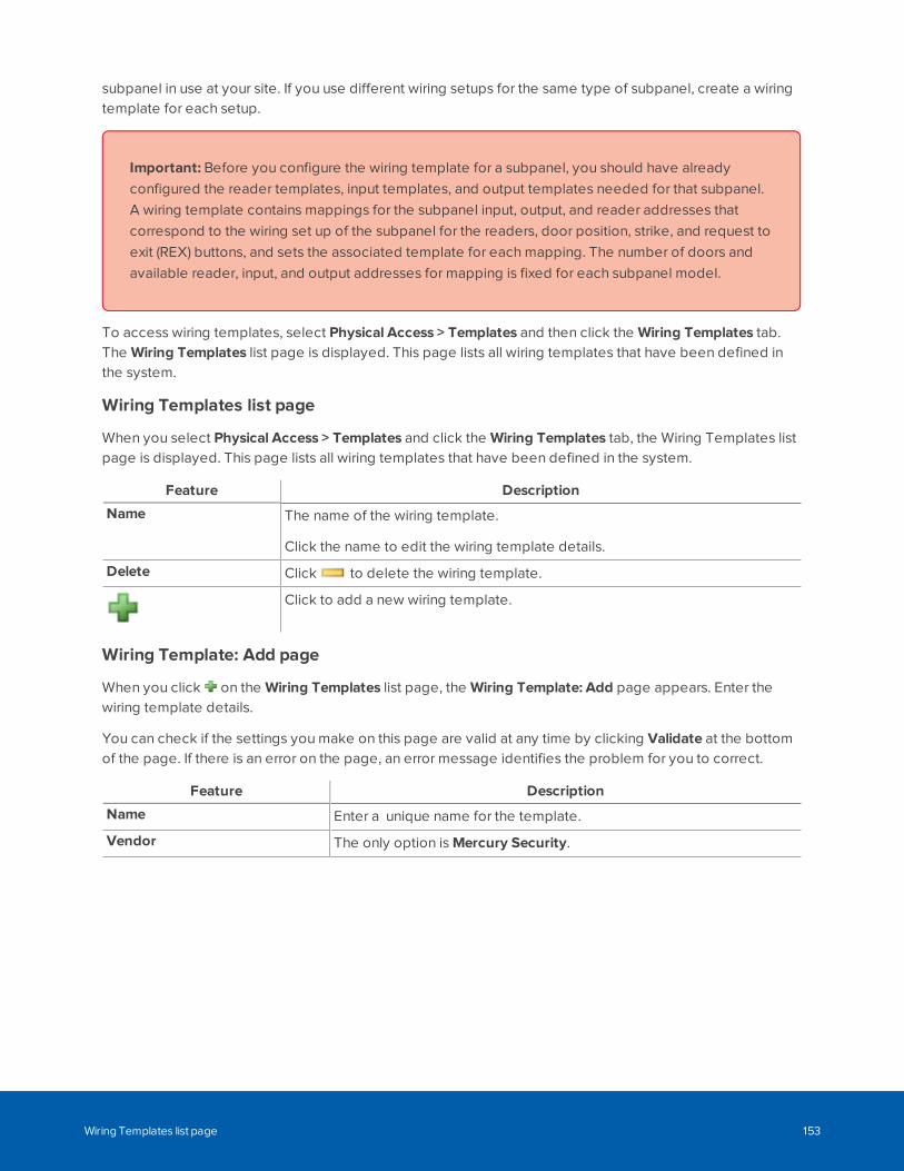
subpanel in use at your site. If you use different wiring setups for the same type of subpanel, create a wiringtemplate for each setup.
Important: Before you configure the wiring template for a subpanel, you should have alreadyconfigured the reader templates, input templates, and output templates needed for that subpanel.A wiring template contains mappings for the subpanel input, output, and reader addresses thatcorrespond to the wiring set up of the subpanel for the readers, door position, strike, and request toexit (REX) buttons, and sets the associated template for each mapping. The number of doors andavailable reader, input, and output addresses for mapping is fixed for each subpanel model.
To access wiring templates, select Physical Access > Templates and then click the Wiring Templates tab.The Wiring Templates list page is displayed. This page lists all wiring templates that have been defined inthe system.
Wiring Templates list page
When you select Physical Access > Templates and click the Wiring Templates tab, the Wiring Templates listpage is displayed. This page lists all wiring templates that have been defined in the system.
Feature Description
Name The name of the wiring template.
Click the name to edit the wiring template details.
Delete Click to delete the wiring template.
Click to add a new wiring template.
Wiring Template: Add page
When you click on the Wiring Templates list page, the Wiring Template: Add page appears. Enter thewiring template details.
You can check if the settings you make on this page are valid at any time by clicking Validate at the bottomof the page. If there is an error on the page, an error message identifies the problem for you to correct.
Feature Description
Name Enter a unique name for the template.
Vendor The only option is Mercury Security.
Wiring Templates list page 153
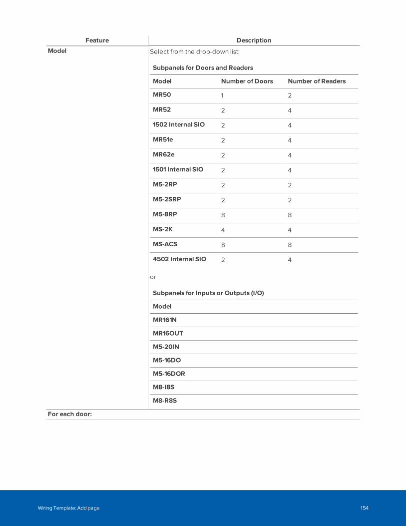
Feature Description
Model Select from the drop-down list:
Subpanels for Doors and Readers
Model Number of Doors Number of Readers
MR50 1 2
MR52 2 4
1502 Internal SIO 2 4
MR51e 2 4
MR62e 2 4
1501 Internal SIO 2 4
M5-2RP 2 2
M5-2SRP 2 2
M5-8RP 8 8
MS-2K 4 4
MS-ACS 8 8
4502 Internal SIO 2 4
or
Subpanels for Inputs or Outputs (I/O)
Model
MR161N
MR16OUT
M5-20IN
M5-16DO
M5-16DOR
M8-I8S
M8-R8S
For each door:
Wiring Template: Add page 154
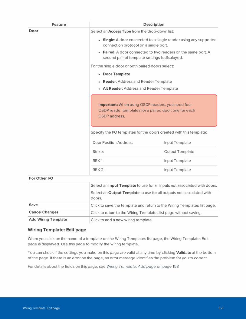
Feature Description
Door Select an Access Type from the drop-down list:
l Single: A door connected to a single reader using any supportedconnection protocol on a single port.
l Paired: A door connected to two readers on the same port. Asecond pair of template settings is displayed.
For the single door or both paired doors select:
l Door Template
l Reader: Address and Reader Template
l Alt Reader: Address and Reader Template
Important: When using OSDP readers, you need fourOSDP reader templates for a paired door: one for eachOSDP address.
Specify the I/O templates for the doors created with this template:
Door Position Address: Input Template
Strike: Output Template
REX 1: Input Template
REX 2: Input Template
For Other I/O
Select an Input Template to use for all inputs not associated with doors.
Select an Output Template to use for all outputs not associated withdoors.
Save Click to save the template and return to the Wiring Templates list page.
Cancel Changes Click to return to the Wiring Templates list page without saving.
Add Wiring Template Click to add a new wiring template.
Wiring Template: Edit page
When you click on the name of a template on the Wiring Templates list page, the Wiring Template: Editpage is displayed. Use this page to modify the wiring template.
You can check if the settings you make on this page are valid at any time by clicking Validate at the bottomof the page. If there is an error on the page, an error message identifies the problem for you to correct.
For details about the fields on this page, see Wiring Template: Add page on page 153
Wiring Template: Edit page 155
Configuring Panels
Panels are controllers that connect one or more door controllers (subpanels) and their associated readers tothe ACM appliance. Through an Ethernet cable or encrypted wireless connection, panels send informationabout the state of the doors back to the appliance. Panels are added one at a time.
When a new Mercury panel is created you can use the Subpanel: Batch Create wizard to add subpanels tothe panel. The wizard adds connection information for the subpanels and doors that are wired to the panelso that the ACM appliance can start managing door access. You must configure door templates, inputtemplates, output templates, reader templates, and wiring templates before you can use the wizard.Together, these templates can provide enough information to ensure basic functioning of doors as soon asthe new panel and subpanels are fully connected and communicating with the ACM system. For moreinformation, see Templates Overview on page 131.
Tip: To add a gateway to manage Schlage IP wireless locks, see Step 2: Configuring Gateways forIP Wireless Locks on page 279. To add a SALTO server and the SALTO panel, see Step 1:Connecting to a SALTO Server on page 296.
Searching for PanelsMany facilities require the control and monitoring of dozens, even hundreds, of panels simultaneously. Thiscan result in a crowded listing page. You can search for specific panels to narrow the list of panels appearingon the Panels list page.
1. Use any (or all) of the following to define your search:
l Enter your search term in the Search... field. Use any series of letters and numbers to searchfor the panels you want to see.
l If known, select the Device Status.
l If known, select the Appliance the panel is connected to.
l If known, select the Group the panel is included in.
2. Click OK.
Adding PanelsPanels connect door controllers and their readers to the ACM appliance. Adding a panel to the ACM systemallows the appliance to gather information on the connected doors.
Tip: To add a gateway to manage Schlage IP wireless locks, see Step 2: Configuring Gateways forIP Wireless Locks on page 279. To add a SALTO server and the SALTO panel, see Step 1:Connecting to a SALTO Server on page 296.
To add a panel to the system:
Configuring Panels 156
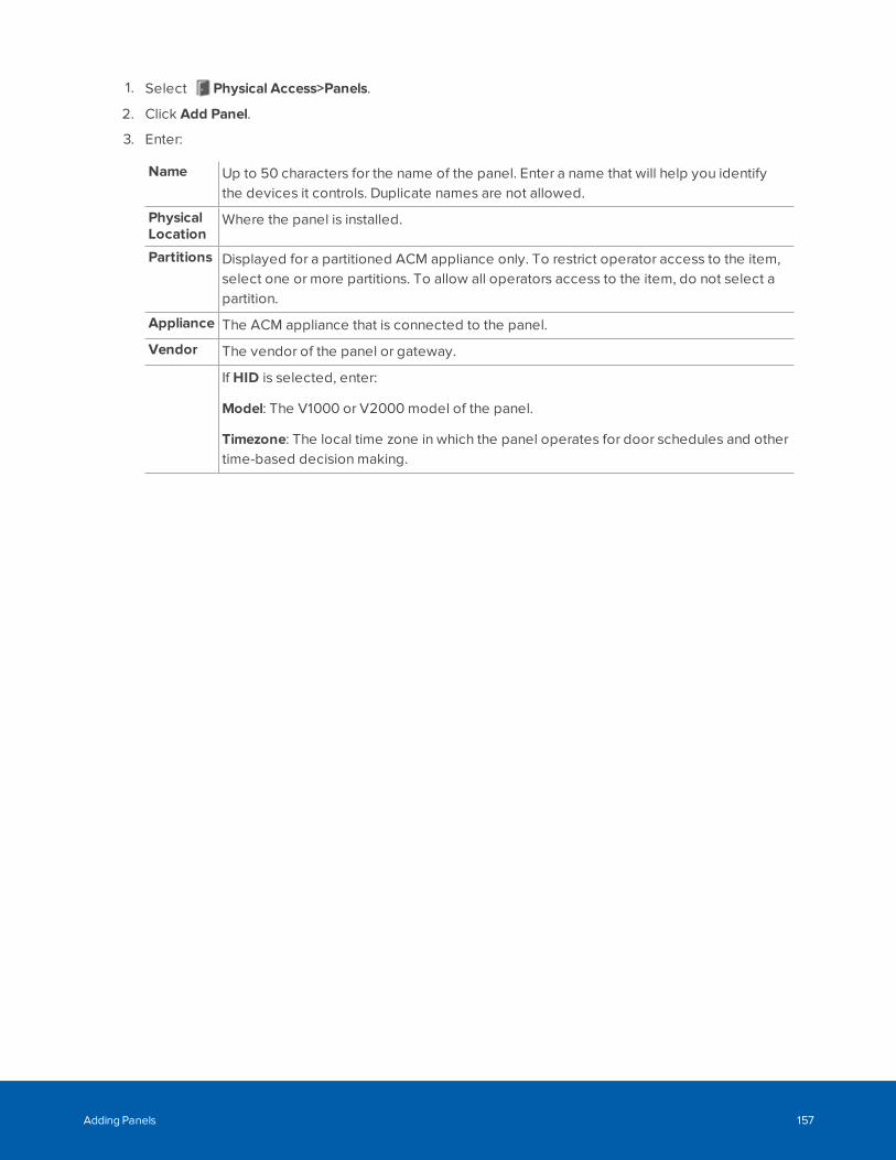
1. Select Physical Access>Panels.
2. Click Add Panel.
3. Enter:
Name Up to 50 characters for the name of the panel. Enter a name that will help you identifythe devices it controls. Duplicate names are not allowed.
PhysicalLocation
Where the panel is installed.
Partitions Displayed for a partitioned ACM appliance only. To restrict operator access to the item,select one or more partitions. To allow all operators access to the item, do not select apartition.
Appliance The ACM appliance that is connected to the panel.
Vendor The vendor of the panel or gateway.
If HID is selected, enter:
Model: The V1000 or V2000 model of the panel.
Timezone: The local time zone in which the panel operates for door schedules and othertime-based decision making.
Adding Panels 157
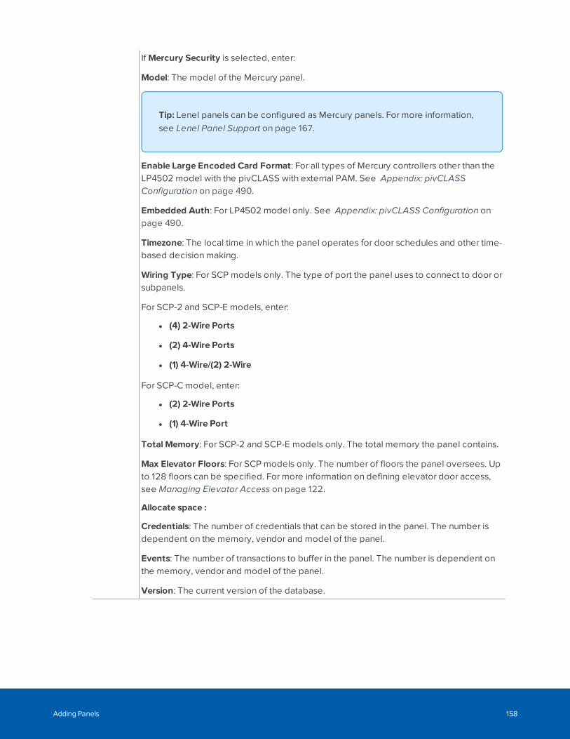
If Mercury Security is selected, enter:
Model: The model of the Mercury panel.
Tip: Lenel panels can be configured as Mercury panels. For more information,see Lenel Panel Support on page 167.
Enable Large Encoded Card Format: For all types of Mercury controllers other than theLP4502 model with the pivCLASS with external PAM. See Appendix: pivCLASSConfiguration on page 490.
Embedded Auth: For LP4502 model only. See Appendix: pivCLASS Configuration onpage 490.
Timezone: The local time in which the panel operates for door schedules and other time-based decision making.
Wiring Type: For SCP models only. The type of port the panel uses to connect to door orsubpanels.
For SCP-2 and SCP-E models, enter:
l (4) 2-Wire Ports
l (2) 4-Wire Ports
l (1) 4-Wire/(2) 2-Wire
For SCP-C model, enter:
l (2) 2-Wire Ports
l (1) 4-Wire Port
Total Memory: For SCP-2 and SCP-E models only. The total memory the panel contains.
Max Elevator Floors: For SCP models only. The number of floors the panel oversees. Upto 128 floors can be specified. For more information on defining elevator door access,see Managing Elevator Access on page 122.
Allocate space :
Credentials: The number of credentials that can be stored in the panel. The number isdependent on the memory, vendor and model of the panel.
Events: The number of transactions to buffer in the panel. The number is dependent onthe memory, vendor and model of the panel.
Version: The current version of the database.
Adding Panels 158
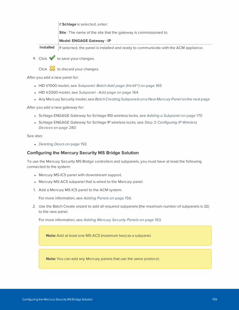
If Schlage is selected, enter:
Site : The name of the site that the gateway is commissioned to.
Model: ENGAGE Gateway - IP
Installed If selected, the panel is installed and ready to communicate with the ACM appliance.
4. Click to save your changes.
Click to discard your changes.
After you add a new panel for:
l HID V1000 model, see Subpanel: Batch Add page (VertX®) on page 165
l HID V2000 model, see Subpanel - Add page on page 164
l Any Mercury Security model, see BatchCreating SubpanelsonaNewMercury Panelonthe next page
After you add a new gateway for:
l Schlage ENGAGE Gateway for Schlage RSI wireless locks, see Adding a Subpanel on page 170
l Schlage ENGAGE Gateway for Schlage IP wireless locks, see Step 3: Configuring IP WirelessDevices on page 280
See also:
l Deleting Doors on page 192
Configuring the Mercury Security MS Bridge Solution
To use the Mercury Security MS Bridge controllers and subpanels, you must have at least the followingconnected to the system:
l Mercury MS-ICS panel with downstream support.
l Mercury MS-ACS subpanel that is wired to the Mercury panel.
1. Add a Mercury MS-ICS panel to the ACM system.
For more information, see Adding Panels on page 156.
2. Use the Batch Create wizard to add all required subpanels (the maximum number of subpanels is 32)to the new panel.
For more information, see Adding Mercury Security Panels on page 163.
Note: Add at least one MS-ACS (maximum two) as a subpanel.
Note: You can add any Mercury panels that use the same protocol.
Configuring the Mercury Security MS Bridge Solution 159
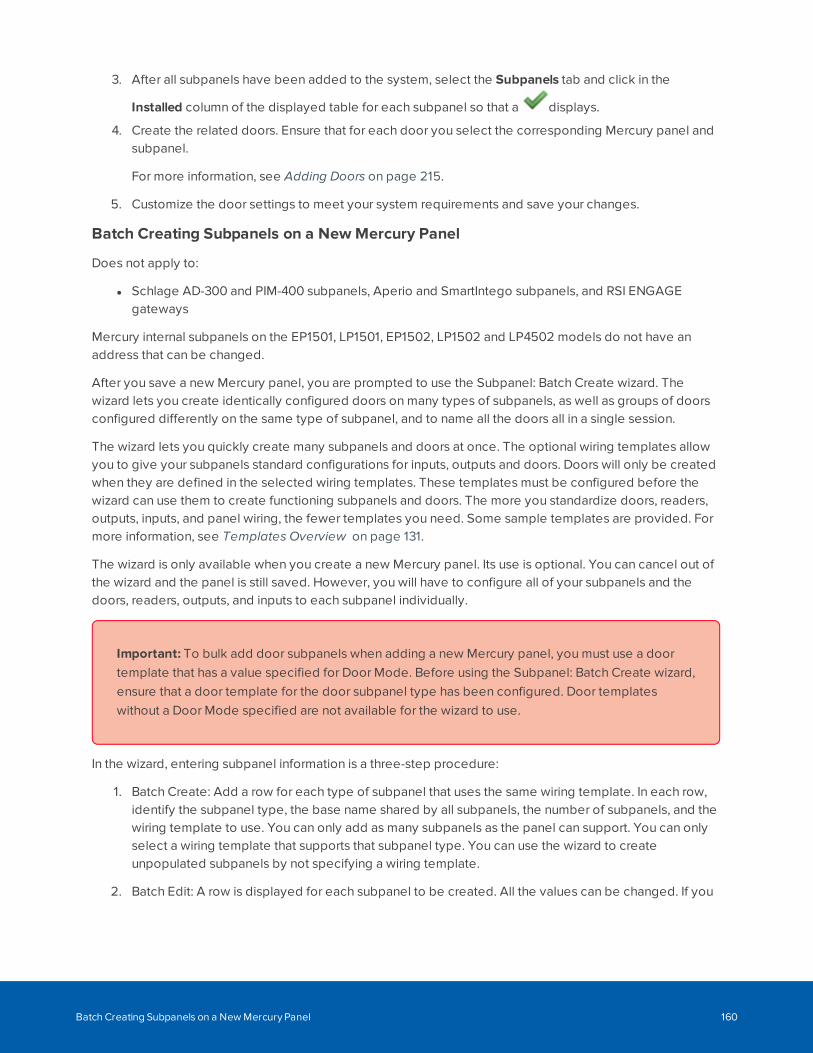
3. After all subpanels have been added to the system, select the Subpanels tab and click in the
Installed column of the displayed table for each subpanel so that a displays.
4. Create the related doors. Ensure that for each door you select the corresponding Mercury panel andsubpanel.
For more information, see Adding Doors on page 215.
5. Customize the door settings to meet your system requirements and save your changes.
Batch Creating Subpanels on a New Mercury Panel
Does not apply to:
l Schlage AD-300 and PIM-400 subpanels, Aperio and SmartIntego subpanels, and RSI ENGAGEgateways
Mercury internal subpanels on the EP1501, LP1501, EP1502, LP1502 and LP4502 models do not have anaddress that can be changed.
After you save a new Mercury panel, you are prompted to use the Subpanel: Batch Create wizard. Thewizard lets you create identically configured doors on many types of subpanels, as well as groups of doorsconfigured differently on the same type of subpanel, and to name all the doors all in a single session.
The wizard lets you quickly create many subpanels and doors at once. The optional wiring templates allowyou to give your subpanels standard configurations for inputs, outputs and doors. Doors will only be createdwhen they are defined in the selected wiring templates. These templates must be configured before thewizard can use them to create functioning subpanels and doors. The more you standardize doors, readers,outputs, inputs, and panel wiring, the fewer templates you need. Some sample templates are provided. Formore information, see Templates Overview on page 131.
The wizard is only available when you create a new Mercury panel. Its use is optional. You can cancel out ofthe wizard and the panel is still saved. However, you will have to configure all of your subpanels and thedoors, readers, outputs, and inputs to each subpanel individually.
Important: To bulk add door subpanels when adding a new Mercury panel, you must use a doortemplate that has a value specified for Door Mode. Before using the Subpanel: Batch Create wizard,ensure that a door template for the door subpanel type has been configured. Door templateswithout a Door Mode specified are not available for the wizard to use.
In the wizard, entering subpanel information is a three-step procedure:
1. Batch Create: Add a row for each type of subpanel that uses the same wiring template. In each row,identify the subpanel type, the base name shared by all subpanels, the number of subpanels, and thewiring template to use. You can only add as many subpanels as the panel can support. You can onlyselect a wiring template that supports that subpanel type. You can use the wizard to createunpopulated subpanels by not specifying a wiring template.
2. Batch Edit: A row is displayed for each subpanel to be created. All the values can be changed. If you
Batch Creating Subpanels on a New Mercury Panel 160
change the subpanel type, you also have to change the wiring template. You can also add moresubpanels, up to the maximum supported by the panel.
3. Batch Name Doors: Edit the default door names for any door to conform to your site's standardmethod for identifying doors (such as room numbers or names).
or
Batch Create Summary: If no doors are configured for the subpanel, review the details.
Each step is completed on its own page. Checks are made as you enter data to ensure that you enter onlyvalid data for the panel and subpanels, and do not overpopulate the panel. The subpanels are created whenyou click Save after completing the third step.
You can move between these three pages using Next and Previous buttons. If you press Previous, theGoing back will erase all progress from this page, are you sure? message isdisplayed and you have to choose to proceed. You can click Cancel Changes in any step to exit the wizardwithout creating any subpanels, although the panel has already been created.
Tip: After you have configured new doors using templates, you must access each door, panel, orsubpanel to configure the unique settings that are not configured by each template.
Subpanel: Batch Create page
To add a subpanel: Click
To remove a subpanel: Click
Add a row for each differently configured subpanel connected to the new panel, up to the maximumsupported for that type of panel. Typically, this would be one row for each type of subpanel. In each row,specify the type of subpanel, its base name, the number of subpanels to create, and the templates to use tocreate them.
Note: An exception to this is the MS-ISC panel, which only supports two MS-ACS subpanels, withaddresses 0 and 2. You can add more than two MS-ACS subpanels to an MS-ISC panel on the firstpage, but you must correct this on the Subpanel: Batch Edit Details page before you can proceedto the Subpanel: Batch Name Doors.
Most controllers have a built-in subpanel. That subpanel will be automatically created as part of the batchadd process. You cannot delete it or change its type, name, quantity or address.
Column Description
Subpanel Type Select the subpanel model from the Select Model drop-down list. The selectionis determined by the panel model.
Subpanel: Batch Create page 161
Column Description
Subpanel Base Name The prefix used in the name of each subpanel. The default format is<panelName>-<panelModel>. For example EastEntrance-LP2500. You canchange this name.
Quantity Select the number of identically configured subpanels you want to add. Thenumber of available subpanels is updated as new rows are added.
Wiring Template Select the template from the Select Wiring Template drop-down list. Theselection is determined by the subpanel type.
Important for users of templates created in releases prior to ACMRelease 6.0:If you select a template that supports doors that has no doors associated with it,the Selected template has no door profiles warning message isdisplayed. This warning usually occurs for wiring templates created prior to ACMRelease 6.0 that have not been modified to associate them with doors. You canchoose to continue (and no doors will be created by the wizard) or edit thetemplate. To edit the template, click the Edit Template button that is nowdisplayed .
Click Next and the Subpanel: Batch Edit Details page is displayed.
Subpanel: Batch Edit Details page
To add a subpanel: Click
To remove a subpanel: Click
Edit the details for all of the subpanels you added for the new panel. You can also continue to add andremove subpanels up to the maximum supported by the panel.
Column Description
Address The port address on the panel to which the subpanel is connected. If thereare addresses available, you can add and reorder the addresses. Newsubpanels are always added to the first available address.
Note: The MS-ISC panel only supports two MS-ACS subpanels, withaddresses two 0 and 2. If you added more than two MS-ACS subpanels to an MS-ISC panel on the first page, you mustcorrect this here before you can proceed to the Subpanel: BatchName Doors.
Subpanel Type You can change the subpanel type. After you make your selection, the row isupdated to prompt you for the information needed to create the subpanel.
Subpanel: Batch Edit Details page 162
Column Description
Subpanel Name The name of each subpanel. The default name is the subpanel addressappended to the Subpanel Base Name: <panelName>-<panelModel>-<subpanelAddress>. For example EastEntrance-LP2500-0. You can changethis name.
Wiring Template Select the template from the Select Wiring Template drop-down list. Theselection is determined by the subpanel type.
Click Next.
Subpanel: Batch NameDoors or Subpanel: Batch Create Summary page
If there are any doors to configure (because wiring templates with door configurations were selected), theycan be named on the Subpanel: Batch Name Doors page that is displayed. Otherwise the Subpanel: BatchCreate Summary page is presented. On both pages the settings you have configured on the previous pagesare displayed for your review before the subpanels are created.
On the Subpanel: Batch Name Doors, default names for each door are displayed for each door subpanelbeing added to the panel. You can edit the door names to match the door-naming standard for your sitebefore the subpanels are created.
Click Save to create the subpanels and doors and return to the Panel: Edit page. To access the subpanelsyou created, click the Subpanels tab.
Adding HID VertX® Subpanels
If you selected VertX® as the panel vendor in the Panel Add page, complete the following procedure:
1. After you save the new panel, the Subpanel: Batch Add page is displayed.
2. Select the number of each subpanel model that is installed at each port then click .
The HID Panel Configure page is displayed.
3. Select the Host tab.
4. Enter the IP address for this panel.
5. Click to save your changes.
Adding Mercury Security Panels
If you selected Mercury Security as the panel vendor in the Panel Add page, complete the followingprocedure:
1. After you save the new panel, the Subpanels: Batch Create page is displayed.
Note: The listed subpanel models will be different depending on the Mercury panel modelthat was selected on initial Panel Add page.
2. Select the number of subpanel models that are installed.
Subpanel: Batch Name Doors or Subpanel: Batch Create Summary page 163
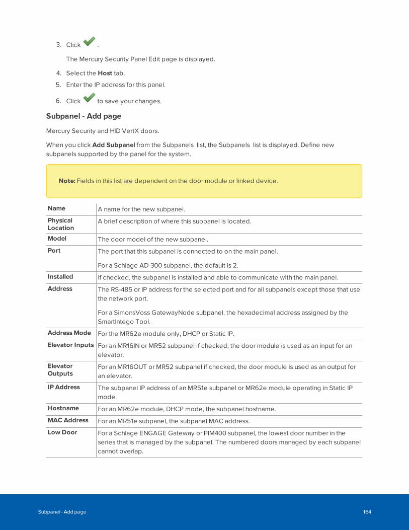
3. Click .
The Mercury Security Panel Edit page is displayed.
4. Select the Host tab.
5. Enter the IP address for this panel.
6. Click to save your changes.
Subpanel - Add page
Mercury Security and HID VertX doors.
When you click Add Subpanel from the Subpanels list, the Subpanels list is displayed. Define newsubpanels supported by the panel for the system.
Note: Fields in this list are dependent on the door module or linked device.
Name A name for the new subpanel.
PhysicalLocation
A brief description of where this subpanel is located.
Model The door model of the new subpanel.
Port The port that this subpanel is connected to on the main panel.
For a Schlage AD-300 subpanel, the default is 2.
Installed If checked, the subpanel is installed and able to communicate with the main panel.
Address The RS-485 or IP address for the selected port and for all subpanels except those that usethe network port.
For a SimonsVoss GatewayNode subpanel, the hexadecimal address assigned by theSmartIntego Tool.
AddressMode For the MR62e module only, DHCP or Static IP.
Elevator Inputs For an MR16IN or MR52 subpanel if checked, the door module is used as an input for anelevator.
ElevatorOutputs
For an MR16OUT or MR52 subpanel if checked, the door module is used as an output foran elevator.
IP Address The subpanel IP address of an MR51e subpanel or MR62e module operating in Static IPmode.
Hostname For an MR62e module, DHCP mode, the subpanel hostname.
MAC Address For an MR51e subpanel, the subpanel MAC address.
LowDoor For a Schlage ENGAGE Gateway or PIM400 subpanel, the lowest door number in theseries that is managed by the subpanel. The numbered doors managed by each subpanelcannot overlap.
Subpanel - Add page 164
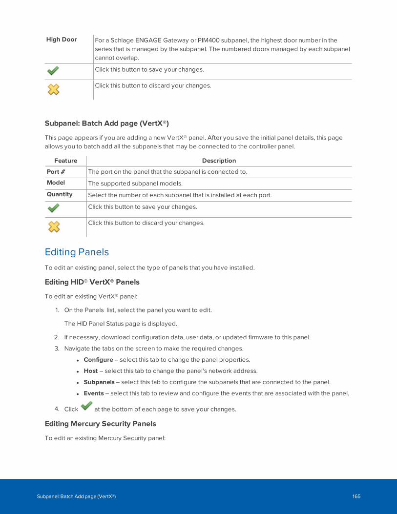
High Door For a Schlage ENGAGE Gateway or PIM400 subpanel, the highest door number in theseries that is managed by the subpanel. The numbered doors managed by each subpanelcannot overlap.
Click this button to save your changes.
Click this button to discard your changes.
Subpanel: Batch Add page (VertX®)
This page appears if you are adding a new VertX® panel. After you save the initial panel details, this pageallows you to batch add all the subpanels that may be connected to the controller panel.
Feature Description
Port # The port on the panel that the subpanel is connected to.
Model The supported subpanel models.
Quantity Select the number of each subpanel that is installed at each port.
Click this button to save your changes.
Click this button to discard your changes.
Editing PanelsTo edit an existing panel, select the type of panels that you have installed.
Editing HID® VertX® Panels
To edit an existing VertX® panel:
1. On the Panels list, select the panel you want to edit.
The HID Panel Status page is displayed.
2. If necessary, download configuration data, user data, or updated firmware to this panel.
3. Navigate the tabs on the screen to make the required changes.
l Configure – select this tab to change the panel properties.
l Host – select this tab to change the panel's network address.
l Subpanels – select this tab to configure the subpanels that are connected to the panel.
l Events – select this tab to review and configure the events that are associated with the panel.
4. Click at the bottom of each page to save your changes.
Editing Mercury Security Panels
To edit an existing Mercury Security panel:
Subpanel: Batch Add page (VertX®) 165
1. On the Panels list, select the panel you want to edit.
The Mercury Security Panel Status page is displayed.
2. If necessary, download configuration data, user data, or updated firmware to this panel.
3. Select the any tabs on the screen to make the required changes.
l Configure – select this tab to change the panel properties.
l Host – select this tab to configure authentication of the panel, encryption of traffic to and fromthe panel, and to change the panel's network address.
l Subpanels – select this tab to configure the subpanels that are connected to the panel.
l Macros – select this tab to add or configure the macros used to perform system actions.
l Triggers – select this tab to define what must occur before a macro is called into action.
l Access Levels – select this tab to review the access levels that have been defined for thepanel.
l Schedules – select this tab to review the schedules that have been defined for the panel.
l Card Formats – select this tab to view the card formats for all doors connected to the panel.
l Events – select this tab to review and configure the events that are associated with the panel.
4. Click at the bottom of each page to save your changes.
Panel Card Formats
When you click the Card Formats tab from the Panel: Edit page the Panel Card Formats page is displayed.
This read-only page displays a table that lists the card formats used on all the doors connected to that panel.Although the ACM system allows you to define up to 128 card formats system-wide, only 16 card formatscan be used within a single panel.
You can use this table to identify the doors that use each card format. Each row displays a card format in theCard Formats column, and displays a drop-down menu that displays the number of doors that recognize this.Click on the drop-down menu bar to see the list of doors.
Resetting Anti-Passback from the PanelIn the event of an emergency, all the people in a building may leave an area at once and arrive at amustering area together without using their access card at each door they encounter. This may cause thesystem to detect multiple anti-passback conditions.
To avoid granting each individual a free pass, you can reset the anti-passback condition for the panel.
1. On the Panels list, select the panel you want to update.
2. On the Panel Status page, click APB Reset.
A confirmation message is displayed when APB is reset. Badge holders can return to their regular stationsand the system will resume normal operations.
Downloading ParametersAny changes you make to the panel configuration or related events are automatically downloaded to the
Panel Card Formats 166
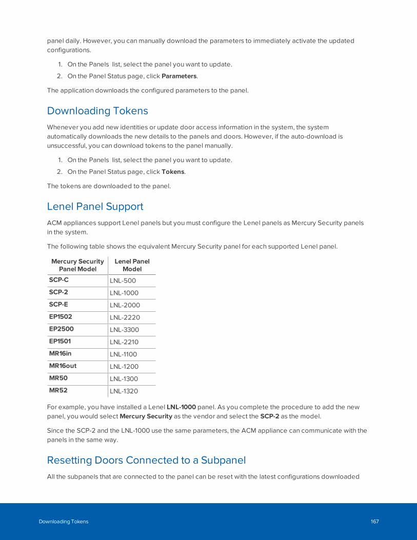
panel daily. However, you can manually download the parameters to immediately activate the updatedconfigurations.
1. On the Panels list, select the panel you want to update.
2. On the Panel Status page, click Parameters.
The application downloads the configured parameters to the panel.
Downloading TokensWhenever you add new identities or update door access information in the system, the systemautomatically downloads the new details to the panels and doors. However, if the auto-download isunsuccessful, you can download tokens to the panel manually.
1. On the Panels list, select the panel you want to update.
2. On the Panel Status page, click Tokens.
The tokens are downloaded to the panel.
Lenel Panel SupportACM appliances support Lenel panels but you must configure the Lenel panels as Mercury Security panelsin the system.
The following table shows the equivalent Mercury Security panel for each supported Lenel panel.
Mercury SecurityPanel Model
Lenel PanelModel
SCP-C LNL-500
SCP-2 LNL-1000
SCP-E LNL-2000
EP1502 LNL-2220
EP2500 LNL-3300
EP1501 LNL-2210
MR16in LNL-1100
MR16out LNL-1200
MR50 LNL-1300
MR52 LNL-1320
For example, you have installed a Lenel LNL-1000 panel. As you complete the procedure to add the newpanel, you would select Mercury Security as the vendor and select the SCP-2 as the model.
Since the SCP-2 and the LNL-1000 use the same parameters, the ACM appliance can communicate with thepanels in the same way.
Resetting Doors Connected to a SubpanelAll the subpanels that are connected to the panel can be reset with the latest configurations downloaded
Downloading Tokens 167
from the ACM system.
To reset all the doors that are connected to a specific panel:
1. Click Physical Access > Panels.
2. Click the panel you want to reset.
3. Click the Reset/Download button on the Panel: Status page.
Doors connected to the panel are now updated with the most recent configuration.
Updating Panel FirmwareYou can upload firmware updates to the panel, activate the new firmware and apply the latest ACM systemconfiguration parameters.
CAUTION — Risk of loss of functionality. It is possible to downgrade to an earlier firmware version bychoosing an earlier firmware file. If you do downgrade to an earlier firmware release, functionality providedin later releases will no longer be available, resulting in unexpected behavior. For example, overridefunctionality available for Mercury panels in the ACM software 5.12.2 and later, requires the Mercuryfirmware version 1.27.1 or later.
1. On the Panels list, select the panel.
2. On the Panel: Status page, click Firmware.
Note: For IP wireless locks, a firmware update is applied to all locks of the same typemanaged by the gateway (for example, NDE locks but not LE locks). For offline Wi-Fi locks, afirmware update is applied to the single selected lock.
3. Do any of the following:
l Apply a firmware update that is available in the system, click next to the firmware file.
l Upload a new firmware update provided by the manufacturer:
a. Download the firmware file from the manufacturer.
b. Click Add Firmware.
See Appendix: pivCLASS Configuration on page 490.
c. Click Choose File and select the firmware file.
d. Click to upload the firmware file.
Note: If you click , the Identity Import Type: will be set to Auto and any
attached CSV files will be deleted.
Updating Panel Firmware 168
e. On the Firmware list, click next to the firmware file to apply it to the panel.
l Delete an existing firmware update, click next to the firmware file. Click OK to confirm theoperation.
Updating Panel TimeEach panel tells time by synchronizing with a time server that is accessible on the network. For example, anetwork time protocol (NTP) server may be used. In the event of unexpected power or network failure, thepanel may run independently for a while and need to be re-synchronized when everything is back online.
1. On the Panels list, select the panel.
2. On the Panel: Status page, click Clock. The button is not displayed if clock synchronization is notsupported.
The panel connects and synchronizes with the time server.
SALTO Panel StatusOn the Panel: Status tab, see:
The communications status between the SALTO server and ACM appliance.The current status of the device is indicated by the background color. For moreinformation, see Status Colors on page 46.
Server Time/Date The date and time of the last import from the SALTO server to the ACMappliance.
Language Code The language code used.
Protocol Version The SALTO Host Interface Protocol version.
See also:
l Step 3: Syncing Doors with the SALTO Server on page 297
l Downloading All Tokens on page 302
SALTO Panel ConfigurationOn the Panel: Edit Configure tab, see:
Name Read-only. Up to 50 characters for the name of the server.
PhysicalLocation
A description of where the device is installed.
Partitions Displayed for a partitioned ACM appliance only. To restrict operator access to the item, selectone or more partitions. To allow all operators access to the item, do not select a partition.
Appliance Read-only. The ACM appliance the device is connected to.
Vendor Read-only. SALTO.
Installed Enables communication between the ACM appliance and SALTO server after saving.
See also:
Updating Panel Time 169
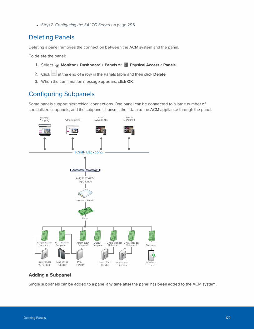
l Step 2: Configuring the SALTO Server on page 296
Deleting PanelsDeleting a panel removes the connection between the ACM system and the panel.
To delete the panel:
1. Select Monitor > Dashboard > Panels or Physical Access > Panels.
2. Click at the end of a row in the Panels table and then click Delete.
3. When the confirmation message appears, click OK.
Configuring SubpanelsSome panels support hierarchical connections. One panel can be connected to a large number ofspecialized subpanels, and the subpanels transmit their data to the ACM appliance through the panel.
Adding a Subpanel
Single subpanels can be added to a panel any time after the panel has been added to the ACM system.
Deleting Panels 170
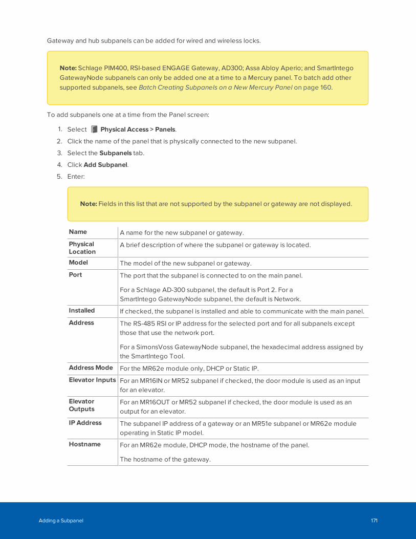
Gateway and hub subpanels can be added for wired and wireless locks.
Note: Schlage PIM400, RSI-based ENGAGE Gateway, AD300; Assa Abloy Aperio; and SmartIntegoGatewayNode subpanels can only be added one at a time to a Mercury panel. To batch add othersupported subpanels, see Batch Creating Subpanels on a New Mercury Panel on page 160.
To add subpanels one at a time from the Panel screen:
1. Select Physical Access > Panels.
2. Click the name of the panel that is physically connected to the new subpanel.
3. Select the Subpanels tab.
4. Click Add Subpanel.
5. Enter:
Note: Fields in this list that are not supported by the subpanel or gateway are not displayed.
Name A name for the new subpanel or gateway.
PhysicalLocation
A brief description of where the subpanel or gateway is located.
Model The model of the new subpanel or gateway.
Port The port that the subpanel is connected to on the main panel.
For a Schlage AD-300 subpanel, the default is Port 2. For aSmartIntego GatewayNode subpanel, the default is Network.
Installed If checked, the subpanel is installed and able to communicate with the main panel.
Address The RS-485 RSI or IP address for the selected port and for all subpanels exceptthose that use the network port.
For a SimonsVoss GatewayNode subpanel, the hexadecimal address assigned bythe SmartIntego Tool.
AddressMode For the MR62e module only, DHCP or Static IP.
Elevator Inputs For an MR16IN or MR52 subpanel if checked, the door module is used as an inputfor an elevator.
ElevatorOutputs
For an MR16OUT or MR52 subpanel if checked, the door module is used as anoutput for an elevator.
IP Address The subpanel IP address of a gateway or an MR51e subpanel or MR62e moduleoperating in Static IP model.
Hostname For an MR62e module, DHCP mode, the hostname of the panel.
The hostname of the gateway.
Adding a Subpanel 171
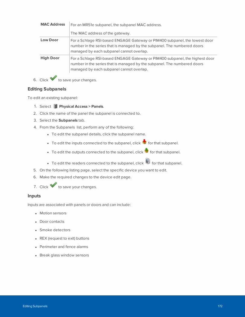
MAC Address For an MR51e subpanel, the subpanel MAC address.
The MAC address of the gateway.
LowDoor For a Schlage RSI-based ENGAGE Gateway or PIM400 subpanel, the lowest doornumber in the series that is managed by the subpanel. The numbered doorsmanaged by each subpanel cannot overlap.
High Door For a Schlage RSI-based ENGAGE Gateway or PIM400 subpanel, the highest doornumber in the series that is managed by the subpanel. The numbered doorsmanaged by each subpanel cannot overlap.
6. Click to save your changes.
Editing Subpanels
To edit an existing subpanel:
1. Select Physical Access > Panels.
2. Click the name of the panel the subpanel is connected to.
3. Select the Subpanels tab.
4. From the Subpanels list, perform any of the following:
l To edit the subpanel details, click the subpanel name.
l To edit the inputs connected to the subpanel, click for that subpanel.
l To edit the outputs connected to the subpanel, click for that subpanel.
l To edit the readers connected to the subpanel, click for that subpanel.
5. On the following listing page, select the specific device you want to edit.
6. Make the required changes to the device edit page.
7. Click to save your changes.
Inputs
Inputs are associated with panels or doors and can include:
l Motion sensors
l Door contacts
l Smoke detectors
l REX (request to exit) buttons
l Perimeter and fence alarms
l Break glass window sensors
Editing Subpanels 172
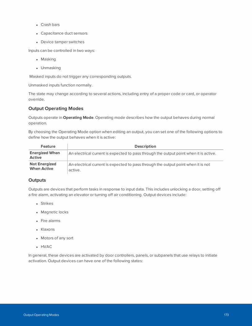
l Crash bars
l Capacitance duct sensors
l Device tamper switches
Inputs can be controlled in two ways:
l Masking
l Unmasking
Masked inputs do not trigger any corresponding outputs.
Unmasked inputs function normally.
The state may change according to several actions, including entry of a proper code or card, or operatoroverride.
Output Operating Modes
Outputs operate in Operating Mode. Operating mode describes how the output behaves during normaloperation.
By choosing the Operating Mode option when editing an output, you can set one of the following options todefine how the output behaves when it is active:
Feature Description
Energized WhenActive
An electrical current is expected to pass through the output point when it is active.
Not EnergizedWhen Active
An electrical current is expected to pass through the output point when it is notactive.
Outputs
Outputs are devices that perform tasks in response to input data. This includes unlocking a door, setting offa fire alarm, activating an elevator or turning off air conditioning. Output devices include:
l Strikes
l Magnetic locks
l Fire alarms
l Klaxons
l Motors of any sort
l HVAC
In general, these devices are activated by door controllers, panels, or subpanels that use relays to initiateactivation. Output devices can have one of the following states:
Output Operating Modes 173
l On (energized)
l Off (de-energized)
l Pulse (intermittently on and off)
Locks (in general) and strikes (specifically) come in several varieties that support a locked state that is eitherenergized or de-energized, with a default state that is either locked or unlocked. This is for safety reasons. Inthe case of power outages and emergency shutdowns, many doors must 'fail open', meaning that theyunlock whenever the power goes off, allowing people to exit an area. Other doors, such as bank vaults andsecured areas, must 'fail close', meaning that a de-energized state requires the bolt to remain in place. Formore on this, refer to Configuring Doors on page 178 and Configuring Panels on page 156.
Many outputs, such as sliding doors, alarms or warning lights need to be turned on and off. In order to dothis, relays on many panels also provide a pulse feature that energizes the output for a specified amount oftime then de-energizes the output for a specified amount of time.
Doors and other outputs can be activated by the user following a successful card or code entry.Alternatively, the operator can override normal operation or control the output on the Subpanel Status page.
Deleting Subpanels
To disable communication between a panel and external subpanel, you can delete the subpanel from thesystem.
1. Select Physical Access > Panels.
2. Click the name of the panel that is connected to the external subpanel.
3. Select the Subpanels tab.
4. Click next to the subpanel name This button is not displayed for an internal subpanel.
5. When the confirmation message is displayed, click OK.
Macros
Note: Only Mercury Security panels support macros.
Macros are commands, or sequences of commands, that can control the activity of devices connected to adoor, panel, or group of panels.
Macros can be extremely simple, such as turning out lights or masking an input. Or, they can besophisticated multi-step procedures. For example, you can define a macro that closes down the airconditioning system, unmasks the alarms, locks all the doors connected to a panel, turns out the lights, thenemails the operator for more instructions.
In the Avigilon ACM application, macros can be activated by:
l Triggers
l Interlocks
All doors (not limited to Mercury Security) support simple macros. Simple macros are triggered by a single
Deleting Subpanels 174
door event and activate one output in response. For more information, see Adding Simple Macros onpage 190.
Adding Macros
1. Select Physical Access > Panels.
2. Click the name of the panel that you want to add a macro to.
3. On the Macros page, click Add NewMacro.
4. On the following Macro Command list, click the Macro link to change the macro name. In the newtext field, enter a new name for the macro then click OK.
5. Click Add NewMacro Command.
6. Give the macro command a name.
7. From the Command drop down list, select a macro command.
8. If extra options are displayed after you select a macro command, choose the options you need.
9. From the Group drop down list, select the group you want to assign this macro to.
10. Click to save your changes.
11. Back at the Macro Command page, repeat the previous steps until you've added all the commandsthat are required for this macro.
To apply this macro to a specific situation, see Assigning Macros on the next page.
To create quick macros that are specific to a particular door (simple macros), see Adding Simple Macros onpage 190.
Editing Macros
1. Select Physical Access > Panels.
2. Click the name of the panel with the macro you want to edit.
3. On the Macros page, click the name of the macro you want to edit
4. On the following Macro Command list, perform any of the following:
l To change the macro name, click the Macro name link. Enter a new name then click OK.
l To add a new macro command, click Add NewMacro Command.
l To edit a macro command, click the command type name.
l To delete a macro command, click for the command.
l To change the order of the macro commands, click Sort.
Deleting Macros
1. Select Physical Access > Panels.
2. Click the name of the panel with the macro you want to delete.
3. On the Macros page, click for the macro you want to delete.
4. When the confirmation message appears, click OK.
Adding Macros 175
Assigning Macros
Note: Only Mercury Security doors and panels support macros.
Once you have created a macro, you can assign them to specific triggers or other macros so that they canautomatically perform a series of actions under the right conditions.
Assigning a Macro to a Trigger
When you add a trigger to a panel, assigning a macro is part of the process. Triggers and macros worktogether as a cause and effect pair. When the all the triggering conditions are met, the macro isautomatically initiated.
To assign a macro to a trigger:
1. Add a macro. For more information, see Adding Macros on the previous page.
2. Add a trigger. For more information, see Adding Triggers on the next page.
3. In the Trigger Add page, assign the new macro to the trigger.
4. Click .
Assigning a Macro to a Macro
You can activate a macro as part of a macro command to generate a complex series of actions.
To assign a macro to a macro command:
1. Add a macro. For more information, see Adding Macros on the previous page.
2. When you add a new macro command, select Macro Control from the Command drop down list.
3. When the related options are displayed, select the macro you want from the Macro drop down listand select a specific Command for the macro to perform.
4. When you're finished, click .
Assigning a Macro to a Door
You can also assign a macro to a specific door by using the Simple Macro feature on the Door Operationspage. For more information, see Adding Simple Macros on page 190 and Operations tab (Mercury Security)on page 249.
Sorting Macros
By default, when you add macro commands, the command actions are activated in the order they areadded. If you need to change the sequence of the macro commands, you can sort it into the order you want.
Assigning Macros 176
1. From the panel's Macros page, select the macro you want to sort.
2. On the following Macro Command list, click Sort. This button only appears if you have two or moremacro commands.
Each of the macro commands are highlighted in gray.
3. Click and drag the macro commands into the order you want.
4. Click Return when you are done.
Triggers
Note: Only Mercury Security panels support triggers.
Triggers work with macros to generate a set of cause and effect events. Triggers are the specific sequenceof events that must occur before a macro will be activated.
For example, you might define a trigger to be a tamper alarm issued by a specific subpanel. The macrolinked to that trigger will then automatically lock the door associated with that panel and sound the alarm.
Triggers are usually defined through the Triggers page on a specific panel or subpanel properties sheet.
Adding Triggers
1. Select Physical Access > Panels.
2. Click the name of the panel that you want to add a trigger to.
3. On the Triggers page, click Add New Trigger.
4. Enter all the parameters that are required of the trigger.
5. Click to save the new trigger.
Editing Triggers
1. Select Physical Access > Panels.
2. Click the name of the panel that your trigger is on.
3. On the Triggers page, click the name of the trigger you want to edit.
4. On the following page, make the required changes.
5. Click to save your changes.
Deleting Triggers
1. Select Physical Access > Panels.
2. Click the name of the panel that your trigger is on.
3. On the Triggers page, click for the trigger you want to delete.
4. When you see the confirmation message, click OK.
Triggers 177
Configuring Doors
Doors in the ACM system are logical units incorporating one or more components that are connected to apanel.
These components could include:
l Door, gate, elevator, escalator, etc.
l Lock (such as magnetic or strike) or relay
l Reader
l Keypad
l Contact
l Panic bar
l ACM Verify
These items do not need to be physically installed on a door, but should be included if they affect how thedoor locks or opens.
The usual components for a door are a reader, a lock (usually a strike), and a contact (usually a door positionor DPOS) that reports the door state. Additionally you can have an exit button (request-to-exit or REX) on theopposite side of the door from the reader, or a second reader if you want to control access in bothdirections.
You can add doors:
l One at a time, configuring all settings manually.
l One at a time, configuring common or standardized door parameters and operational settings using adoor template. You still need to configure many attributes such as operations, hardware, cameras,and interlocks specifically for individual doors. You must configure a door template before addingdoors using that template.
l In bulk, when you add a new Mercury panel and use the Subpanel: Batch Create wizard to create thesubpanels. At a minimum, you must have defined door templates with a Door Mode: option specified,to create doors with this wizard. You can use this wizard to create:
l Subpanels with functioning doors. This requires door templates (to specify at least the DoorMode: option) and wiring templates (to assign addresses and input, output and readertemplates to the doors).
l Subpanels with non-functioning doors. This requires door templates (to specify at least theDoor Mode:). You then need to complete the configuration for each door to make them allfunction.
l Subpanels only. These can then be configured for doors or for inputs and outputs only, asneeded.
For more information about the templates you can use to create doors and subpanels, seeTemplates Overview on page 131. For more information about the Subpanel: Batch Create wizard,see Batch Creating Subpanels on a New Mercury Panel on page 160.
See Appendix: pivCLASS Configuration on page 490.
Configuring Doors 178
Searching for DoorsMany facilities require the control and monitoring of dozens, even hundreds, of doors simultaneously. Thiscan result in a crowded listing page. You can search for specific doors to narrow the list of doors appearingon the Doors list page.
1. Use any (or all) of the following to define your search:
l Enter your search term in the Search... field. Use any series of letters and numbers to searchfor the doors you want to see.
l If known, select the Device Status.
l If known, select the Appliance the door is connected to.
l If known, select the Group the door is included in.
2. Click OK.
Advanced Filtering on the Doors ListIn addition to searching you can also use advanced filters to select multiple filters on the Door list.
1. Click Advanced Filters.
The Advanced Filters dialog box displays.
2. Select any required filters:
l Alarms—Select the alarms to include from the list of alarms.
l Masked—Select to include the masks to include from the list of masks.
l Normal—Select to include all properly functioning doors.
l Door Mode— Select the door modes to include from the list of door modes.
Note: To unselect all selected filters, click Unselect All. All selections will be removed.
3. If you want to save the selected filters, select Remember Filters.
4. Click OK.
The Door list refreshes to show the doors that meet your filters.
Controlling DoorsFrom a Doors listing page, you can use the options on the Door Action, Door Mode, Forced, Held, andInstalled drop-down menus to control doors. For example, you can choose a door and unlock it to allowunrestricted access to an area.
Doors can also be controlled from a map monitoring page. For more information, see Using a Map onpage 426.
Searching for Doors 179
Note: Only the Installed options are available for virtual doors installed for use with ACM Verifyreaders.
1. Select the checkbox beside the door you want to control.
If you want to affect all the doors in your system, click All at the top of the left column to select all thedoors.
2. Select any of the following Door Actions if required:
l Grant — Click this button to grant temporary access to the specified door. The door will bemomentarily unlocked to permit entry through the door.
l Restore — Click this button to restore the door to its default configuration values.
Schlage locks with activated lock functions only. Restoring a Door that has an activated LockFunction (Classroom, Office, Privacy, or Apartment), will remove the Lock Function and thedoor will be reset to its default configuration.
l Unlock — Click this button to unlock the specified door. This door will remain unlocked untilthe Locked No Access command is issued or until another change of state is directed (eithervia operator override or scheduled action).
l Locked No Access — Click this button to lock the specified door. This door will remain lockeduntil the Restore command is issued or until another change of state is directed (either viaoperator override or scheduled action).
l Disable — Click this button to disable the specified door. This door will stop operating andallow no access.
3. Select any of the following Door Mode options to change the door mode.
For more information, see Door Modes on page 192.
4. Select either of the following Forced options if required:
l Mask Forced — Click this button to mask the Forced Door Alarm for this door.
l Unmask Forced — Click this button to unmask the Forced Door Alarm for this door.
5. Select either of the following Held options if required:
l Mask Held — Click this button to mask the Door Held Open Alarm for this door.
l Unmask Held — Click this button to unmask the Door Held Open Alarm for this door.
6. Select either of the following Installed options if required:
l Install — Click this button to install a door.
l Uninstall — Click this button to uninstall a door.
Adding DoorsTo add a new door:
Adding Doors 180
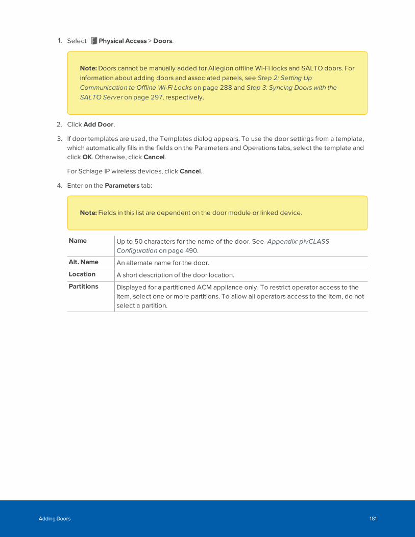
1. Select Physical Access > Doors.
Note: Doors cannot be manually added for Allegion offline Wi-Fi locks and SALTO doors. Forinformation about adding doors and associated panels, see Step 2: Setting UpCommunication to Offline Wi-Fi Locks on page 288 and Step 3: Syncing Doors with theSALTO Server on page 297, respectively.
2. Click Add Door.
3. If door templates are used, the Templates dialog appears. To use the door settings from a template,which automatically fills in the fields on the Parameters and Operations tabs, select the template andclick OK. Otherwise, click Cancel.
For Schlage IP wireless devices, click Cancel.
4. Enter on the Parameters tab:
Note: Fields in this list are dependent on the door module or linked device.
Name Up to 50 characters for the name of the door. See Appendix: pivCLASSConfiguration on page 490.
Alt. Name An alternate name for the door.
Location A short description of the door location.
Partitions Displayed for a partitioned ACM appliance only. To restrict operator access to theitem, select one or more partitions. To allow all operators access to the item, do notselect a partition.
Adding Doors 181
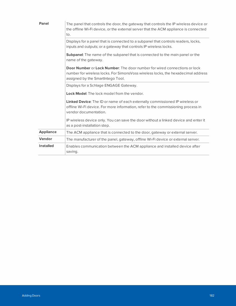
Panel The panel that controls the door, the gateway that controls the IP wireless device orthe offline Wi-Fi device, or the external server that the ACM appliance is connectedto.
Displays for a panel that is connected to a subpanel that controls readers, locks,inputs and outputs; or a gateway that controls IP wireless locks.
Subpanel: The name of the subpanel that is connected to the main panel or thename of the gateway.
Door Number or Lock Number: The door number for wired connections or locknumber for wireless locks. For SimonsVoss wireless locks, the hexadecimal addressassigned by the SmartIntego Tool.
Displays for a Schlage ENGAGE Gateway.
Lock Model: The lock model from the vendor.
Linked Device: The ID or name of each externally commissioned IP wireless oroffline Wi-Fi device. For more information, refer to the commissioning process invendor documentation.
IP wireless device only. You can save the door without a linked device and enter itas a post-installation step.
Appliance The ACM appliance that is connected to the door, gateway or external server.
Vendor The manufacturer of the panel, gateway, offline Wi-Fi device or external server.
Installed Enables communication between the ACM appliance and installed device aftersaving.
Adding Doors 182
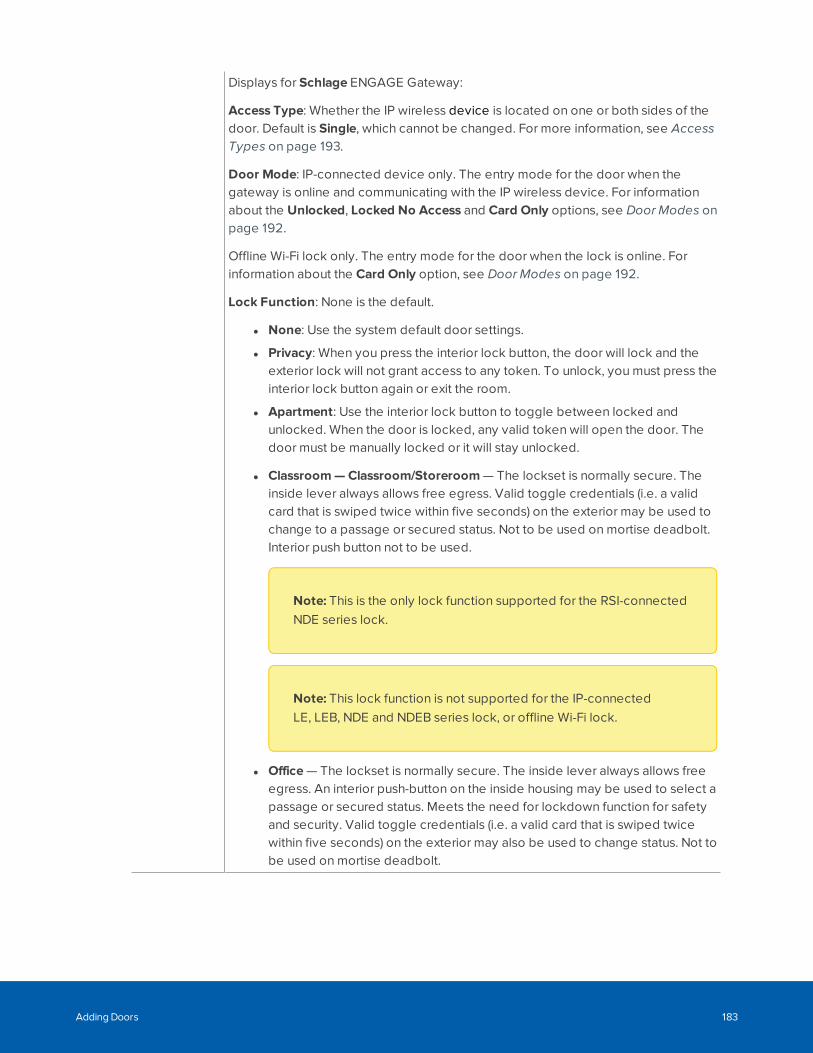
Displays for Schlage ENGAGE Gateway:
Access Type: Whether the IP wireless device is located on one or both sides of thedoor. Default is Single, which cannot be changed. For more information, see AccessTypes on page 193.
Door Mode: IP-connected device only. The entry mode for the door when thegateway is online and communicating with the IP wireless device. For informationabout the Unlocked, Locked No Access and Card Only options, see Door Modes onpage 192.
Offline Wi-Fi lock only. The entry mode for the door when the lock is online. Forinformation about the Card Only option, see Door Modes on page 192.
Lock Function: None is the default.
l None: Use the system default door settings.
l Privacy: When you press the interior lock button, the door will lock and theexterior lock will not grant access to any token. To unlock, you must press theinterior lock button again or exit the room.
l Apartment: Use the interior lock button to toggle between locked andunlocked. When the door is locked, any valid token will open the door. Thedoor must be manually locked or it will stay unlocked.
l Classroom—Classroom/Storeroom — The lockset is normally secure. Theinside lever always allows free egress. Valid toggle credentials (i.e. a validcard that is swiped twice within five seconds) on the exterior may be used tochange to a passage or secured status. Not to be used on mortise deadbolt.Interior push button not to be used.
Note: This is the only lock function supported for the RSI-connectedNDE series lock.
Note: This lock function is not supported for the IP-connectedLE, LEB, NDE and NDEB series lock, or offline Wi-Fi lock.
l Office — The lockset is normally secure. The inside lever always allows freeegress. An interior push-button on the inside housing may be used to select apassage or secured status. Meets the need for lockdown function for safetyand security. Valid toggle credentials (i.e. a valid card that is swiped twicewithin five seconds) on the exterior may also be used to change status. Not tobe used on mortise deadbolt.
Adding Doors 183
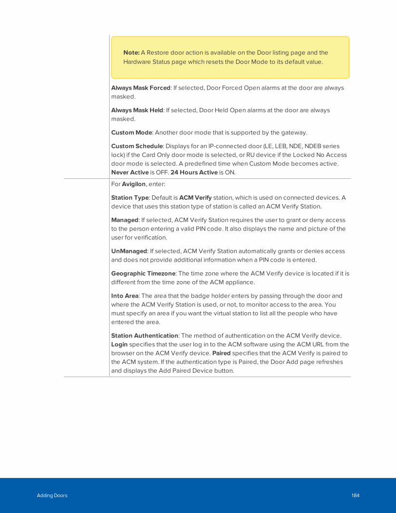
Note: A Restore door action is available on the Door listing page and theHardware Status page which resets the Door Mode to its default value.
AlwaysMask Forced: If selected, Door Forced Open alarms at the door are alwaysmasked.
AlwaysMask Held: If selected, Door Held Open alarms at the door are alwaysmasked.
CustomMode: Another door mode that is supported by the gateway.
Custom Schedule: Displays for an IP-connected door (LE, LEB, NDE, NDEB serieslock) if the Card Only door mode is selected, or RU device if the Locked No Accessdoor mode is selected. A predefined time when Custom Mode becomes active.Never Active is OFF. 24 Hours Active is ON.
For Avigilon, enter:
Station Type: Default is ACM Verify station, which is used on connected devices. Adevice that uses this station type of station is called an ACM Verify Station.
Managed: If selected, ACM Verify Station requires the user to grant or deny accessto the person entering a valid PIN code. It also displays the name and picture of theuser for verification.
UnManaged: If selected, ACM Verify Station automatically grants or denies accessand does not provide additional information when a PIN code is entered.
Geographic Timezone: The time zone where the ACM Verify device is located if it isdifferent from the time zone of the ACM appliance.
Into Area: The area that the badge holder enters by passing through the door andwhere the ACM Verify Station is used, or not, to monitor access to the area. Youmust specify an area if you want the virtual station to list all the people who haveentered the area.
Station Authentication: The method of authentication on the ACM Verify device.Login specifies that the user log in to the ACM software using the ACM URL from thebrowser on the ACM Verify device. Paired specifies that the ACM Verify is paired tothe ACM system. If the authentication type is Paired, the Door Add page refreshesand displays the Add Paired Device button.
Adding Doors 184
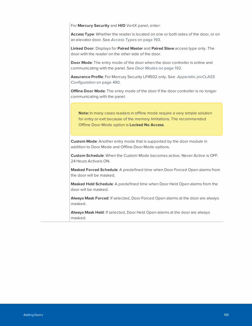
For Mercury Security and HID VertX panel, enter:
Access Type: Whether the reader is located on one or both sides of the door, or onan elevator door. See Access Types on page 193.
Linked Door: Displays for Paired Master and Paired Slave access type only. Thedoor with the reader on the other side of the door.
Door Mode: The entry mode of the door when the door controller is online andcommunicating with the panel. See Door Modes on page 192.
Assurance Profile: For Mercury Security LP4502 only. See Appendix: pivCLASSConfiguration on page 490.
Offline Door Mode: The entry mode of the door if the door controller is no longercommunicating with the panel.
Note: In many cases readers in offline mode require a very simple solutionfor entry or exit because of the memory limitations. The recommendedOffline Door Mode option is Locked No Access.
CustomMode: Another entry mode that is supported by the door module inaddition to Door Mode and Offline Door Mode options.
Custom Schedule: When the Custom Mode becomes active. Never Active is OFF.24 Hours Activeis ON.
Masked Forced Schedule: A predefined time when Door Forced Open alarms fromthe door will be masked.
Masked Held Schedule: A predefined time when Door Held Open alarms from thedoor will be masked.
AlwaysMask Forced: If selected, Door Forced Open alarms at the door are alwaysmasked.
AlwaysMask Held: If selected, Door Held Open alarms at the door are alwaysmasked.
Adding Doors 185
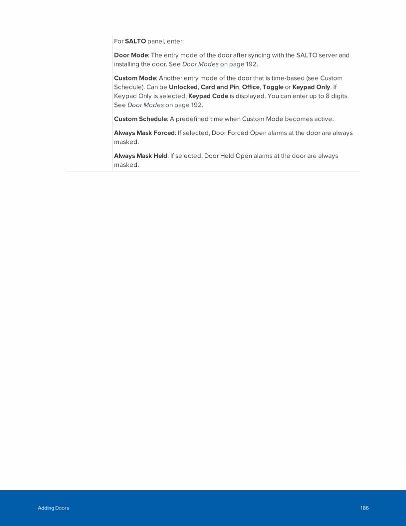
For SALTO panel, enter:
Door Mode: The entry mode of the door after syncing with the SALTO server andinstalling the door. See Door Modes on page 192.
CustomMode: Another entry mode of the door that is time-based (see CustomSchedule). Can be Unlocked, Card and Pin, Office, Toggle or Keypad Only. IfKeypad Only is selected, Keypad Code is displayed. You can enter up to 8 digits.See Door Modes on page 192.
Custom Schedule: A predefined time when Custom Mode becomes active.
AlwaysMask Forced: If selected, Door Forced Open alarms at the door are alwaysmasked.
AlwaysMask Held: If selected, Door Held Open alarms at the door are alwaysmasked.
Adding Doors 186

DoorProcessingAttributes
For Schlage door, select:
Note: The following three attributes are not applicable to Control locks oroffline Wi-Fi locks.
Log Grants Right Away: Initiates local I/O in the panel using the panel triggers. Thesystem logs an extra event as soon as a grant occurs (that is, before entry / no entryis determined). This event is not turned into an Access Control Manager event.
Certain customers may have a trigger they want to fire (to execute a macro) as soonas there is a grant but before entry / no entry is determined.
Log All Access as Used: Logs all access grant transactions as if the person used thedoor. If this field is not selected, the door determines if it was opened anddistinguishes if the door was used or not used for grant.
Detailed Events: Displays the current position of the door position switch (DPOS) inthe Door State column of the door listing screen. When enabled the column displays“Open” when the DPOS is in an open state and “Closed” when the DPOS is in aclosed state.
Note: To properly report the Door State from the Door Position Switch,Detailed Events must be enabled.
Typically, five to ten detailed transactions are generated for each grant transactions.During the normal course of operation, most guards don't need to see extensivereports on events; however, after hours, it is often useful to see every detail.
Do Not Log Rex Transactions: Indicates that request-to-exit transactions do not getlogged to the database.
Note: This is the only attribute supported for offline Wi-Fi locks.
Adding Doors 187

For Mercury Security panel, select:
Log Grants Right Away: Initiates local I/O in the panel using the panel triggers. Thesystem logs an extra event as soon as a grant ocurs (that is, before entry / no entry isdetermined). This event is not turned into an Access Control Manager event.
Certain customers may have a trigger they want to fire (to execute a macro) as soonas there is a grant but before entry / no entry is determined.
Deny Duress : Denies access to a user that indicates duress at a door.
Don't Pulse Door Strike on REX: Disables the pulse of the door strike output whenthe request-to-exit button is pressed and can be used for a 'quiet' exit. If notselected, the output is pulsed.
Note: This field must not be checked for the SimonsVoss wireless lock,such as cylinders, on a door that does not support a door position switch(DPOS).
Require Two Card Control: Two tokens are required to open this door. Thisenforces the two-person rule at a specified door.
Door Forced Filter: : Filters door-forced alarms. Sometimes a door is either slow toclose or is slammed shut and bounces open for a few seconds. With this filter, themonitor allows three seconds for a door to close before issuing an alarm.
Log All Access as Used: Logs all access grant transactions as if the person used thedoor. If this field is not selected, the door determines if it was opened anddistinguishes if the door was used or not used for grant.
Detailed Events: Displays the current position of the door position switch (DPOS) inthe Door State column of the door listing screen. When enabled the column displays“Open” when the DPOS is in an open state and “Closed” when the DPOS is in aclosed state.
Note: To properly report the Door State from the Door Position Switch,Detailed Events must be enabled.
Typically, five to ten detailed transactions are generated for each grant transactions.During the normal course of operation, most guards don't need to see extensivereports on events; however, after hours, it is often useful to see every detail.
Enable Cipher Mode: Enables the operator to enter card number digits at the door’skeypad.
Adding Doors 188
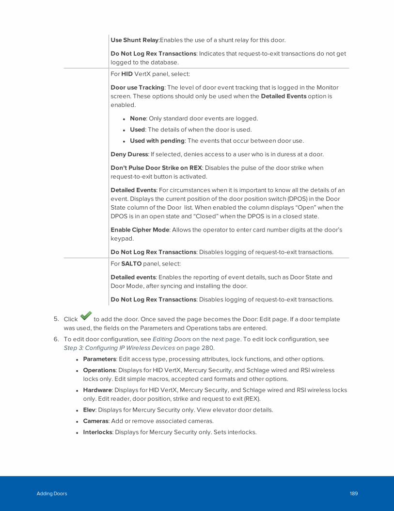
Use Shunt Relay:Enables the use of a shunt relay for this door.
Do Not Log Rex Transactions: Indicates that request-to-exit transactions do not getlogged to the database.
For HID VertX panel, select:
Door use Tracking: The level of door event tracking that is logged in the Monitorscreen. These options should only be used when the Detailed Events option isenabled.
l None: Only standard door events are logged.
l Used: The details of when the door is used.
l Used with pending: The events that occur between door use.
Deny Duress: If selected, denies access to a user who is in duress at a door.
Don't Pulse Door Strike on REX: Disables the pulse of the door strike whenrequest-to-exit button is activated.
Detailed Events: For circumstances when it is important to know all the details of anevent. Displays the current position of the door position switch (DPOS) in the DoorState column of the Door list. When enabled the column displays “Open” when theDPOS is in an open state and “Closed” when the DPOS is in a closed state.
Enable Cipher Mode: Allows the operator to enter card number digits at the door’skeypad.
Do Not Log Rex Transactions: Disables logging of request-to-exit transactions.
For SALTO panel, select:
Detailed events: Enables the reporting of event details, such as Door State andDoor Mode, after syncing and installing the door.
Do Not Log Rex Transactions: Disables logging of request-to-exit transactions.
5. Click to add the door. Once saved the page becomes the Door: Edit page. If a door templatewas used, the fields on the Parameters and Operations tabs are entered.
6. To edit door configuration, see Editing Doors on the next page. To edit lock configuration, seeStep 3: Configuring IP Wireless Devices on page 280.
l Parameters: Edit access type, processing attributes, lock functions, and other options.
l Operations: Displays for HID VertX, Mercury Security, and Schlage wired and RSI wirelesslocks only. Edit simple macros, accepted card formats and other options.
l Hardware: Displays for HID VertX, Mercury Security, and Schlage wired and RSI wireless locksonly. Edit reader, door position, strike and request to exit (REX).
l Elev: Displays for Mercury Security only. View elevator door details.
l Cameras: Add or remove associated cameras.
l Interlocks: Displays for Mercury Security only. Sets interlocks.
Adding Doors 189
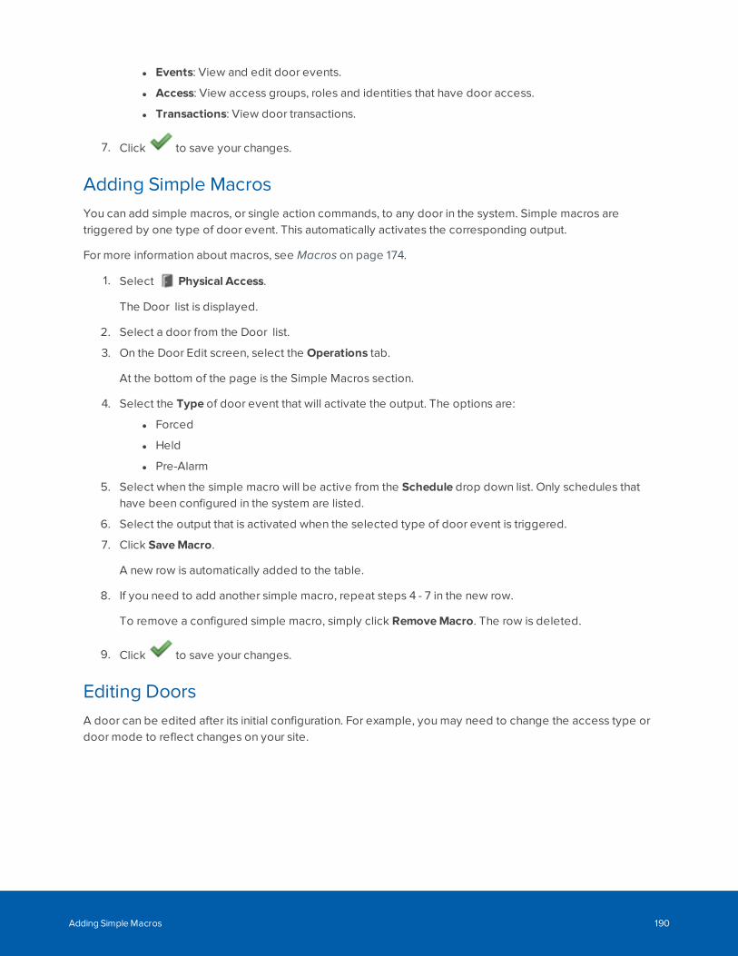
l Events: View and edit door events.
l Access: View access groups, roles and identities that have door access.
l Transactions: View door transactions.
7. Click to save your changes.
Adding Simple MacrosYou can add simple macros, or single action commands, to any door in the system. Simple macros aretriggered by one type of door event. This automatically activates the corresponding output.
For more information about macros, see Macros on page 174.
1. Select Physical Access.
The Door list is displayed.
2. Select a door from the Door list.
3. On the Door Edit screen, select the Operations tab.
At the bottom of the page is the Simple Macros section.
4. Select the Type of door event that will activate the output. The options are:
l Forced
l Held
l Pre-Alarm
5. Select when the simple macro will be active from the Schedule drop down list. Only schedules thathave been configured in the system are listed.
6. Select the output that is activated when the selected type of door event is triggered.
7. Click SaveMacro.
A new row is automatically added to the table.
8. If you need to add another simple macro, repeat steps 4 - 7 in the new row.
To remove a configured simple macro, simply click RemoveMacro. The row is deleted.
9. Click to save your changes.
Editing DoorsA door can be edited after its initial configuration. For example, you may need to change the access type ordoor mode to reflect changes on your site.
Adding Simple Macros 190
1. Select Physical Access > Doors.
2. Select the name of the door.
3. Edit the details on each tab as required:
l Parameters: Edit access type, processing attributes, lock functions, and other options.
l Operations: Displays for HID VertX, Mercury Security, and Schlage wired and RSI wirelesslocks only. Edit simple macros, accepted card formats and other options.
l Hardware: Displays for HID VertX, Mercury Security, and Schlage wired and RSI wireless locksonly. Edit reader, door position, strike and request to exit (REX).
l Elev: Displays for Mercury Security only. View elevator door details.
l Cameras: Add or remove associated cameras.
l Interlocks: Displays for Mercury Security only. Sets interlocks.
l Events: View and edit door events.
l Access: View access groups, roles and identities that have door access.
l Transactions: View door transactions.
For field descriptions, see:
l Door: Edit page (VertX® ) on page 231
l Door: Edit page (Mercury Security) on page 245
l Step 4: Configuring Locking Operation on page 281
l Step 4: Installing and Configuring Doors on page 297
4. After editing each tab, click to save your changes.
Doors - Editing VertX® Doors
1. Select Physical Access.
The Doors list is displayed.
2. From the Doors list, click the VertX® door name you want to edit.
The Door: Edit screen for that specific door type is displayed.
3. Edit the door by changing values on each of the door option tabs.
4. When you're finished, click .
You are returned to the list with all changes saved.
Doors - Editing Mercury Security Doors
To edit an existing Mercury Security door:
Doors - Editing VertX® Doors 191
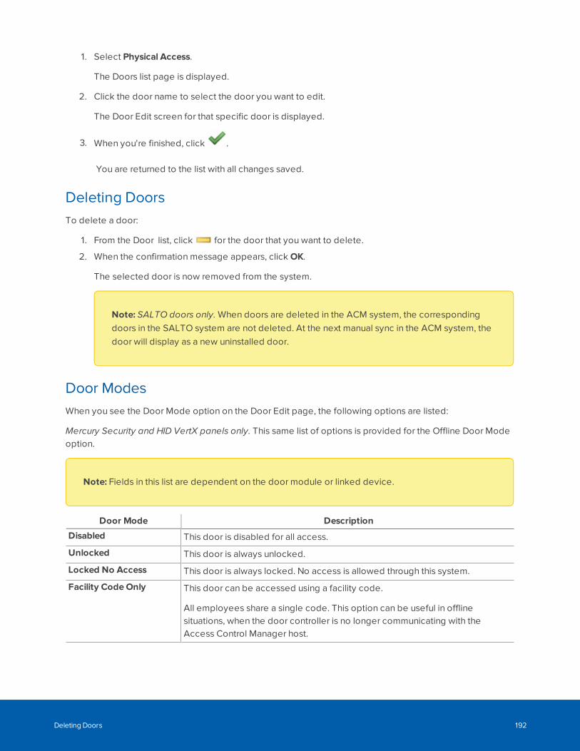
1. Select Physical Access.
The Doors list page is displayed.
2. Click the door name to select the door you want to edit.
The Door Edit screen for that specific door is displayed.
3. When you're finished, click .
You are returned to the list with all changes saved.
Deleting DoorsTo delete a door:
1. From the Door list, click for the door that you want to delete.
2. When the confirmation message appears, click OK.
The selected door is now removed from the system.
Note: SALTO doors only. When doors are deleted in the ACM system, the correspondingdoors in the SALTO system are not deleted. At the next manual sync in the ACM system, thedoor will display as a new uninstalled door.
Door ModesWhen you see the Door Mode option on the Door Edit page, the following options are listed:
Mercury Security and HID VertX panels only. This same list of options is provided for the Offline Door Modeoption.
Note: Fields in this list are dependent on the door module or linked device.
Door Mode Description
Disabled This door is disabled for all access.
Unlocked This door is always unlocked.
Locked No Access This door is always locked. No access is allowed through this system.
Facility CodeOnly This door can be accessed using a facility code.
All employees share a single code. This option can be useful in offlinesituations, when the door controller is no longer communicating with theAccess Control Manager host.
Deleting Doors 192
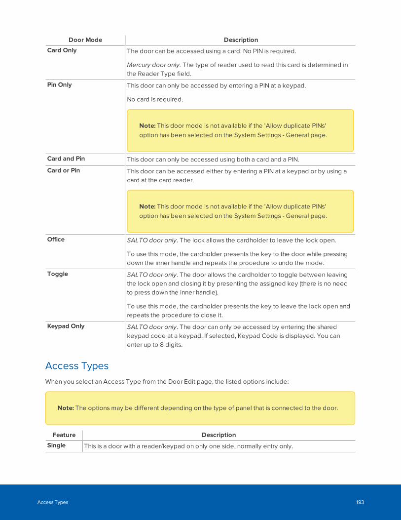
Door Mode Description
Card Only The door can be accessed using a card. No PIN is required.
Mercury door only. The type of reader used to read this card is determined inthe Reader Type field.
Pin Only This door can only be accessed by entering a PIN at a keypad.
No card is required.
Note: This door mode is not available if the 'Allow duplicate PINs'option has been selected on the System Settings - General page.
Card and Pin This door can only be accessed using both a card and a PIN.
Card or Pin This door can be accessed either by entering a PIN at a keypad or by using acard at the card reader.
Note: This door mode is not available if the 'Allow duplicate PINs'option has been selected on the System Settings - General page.
Office SALTO door only. The lock allows the cardholder to leave the lock open.
To use this mode, the cardholder presents the key to the door while pressingdown the inner handle and repeats the procedure to undo the mode.
Toggle SALTO door only. The door allows the cardholder to toggle between leavingthe lock open and closing it by presenting the assigned key (there is no needto press down the inner handle).
To use this mode, the cardholder presents the key to leave the lock open andrepeats the procedure to close it.
Keypad Only SALTO door only. The door can only be accessed by entering the sharedkeypad code at a keypad. If selected, Keypad Code is displayed. You canenter up to 8 digits.
Access TypesWhen you select an Access Type from the Door Edit page, the listed options include:
Note: The options may be different depending on the type of panel that is connected to the door.
Feature Description
Single This is a door with a reader/keypad on only one side, normally entry only.
Access Types 193
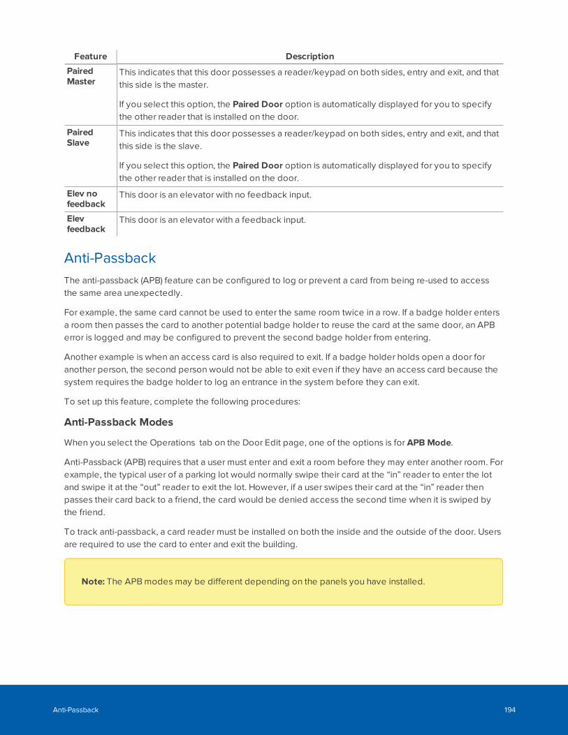
Feature Description
PairedMaster
This indicates that this door possesses a reader/keypad on both sides, entry and exit, and thatthis side is the master.
If you select this option, the Paired Door option is automatically displayed for you to specifythe other reader that is installed on the door.
PairedSlave
This indicates that this door possesses a reader/keypad on both sides, entry and exit, and thatthis side is the slave.
If you select this option, the Paired Door option is automatically displayed for you to specifythe other reader that is installed on the door.
Elev nofeedback
This door is an elevator with no feedback input.
Elevfeedback
This door is an elevator with a feedback input.
Anti-PassbackThe anti-passback (APB) feature can be configured to log or prevent a card from being re-used to accessthe same area unexpectedly.
For example, the same card cannot be used to enter the same room twice in a row. If a badge holder entersa room then passes the card to another potential badge holder to reuse the card at the same door, an APBerror is logged and may be configured to prevent the second badge holder from entering.
Another example is when an access card is also required to exit. If a badge holder holds open a door foranother person, the second person would not be able to exit even if they have an access card because thesystem requires the badge holder to log an entrance in the system before they can exit.
To set up this feature, complete the following procedures:
Anti-Passback Modes
When you select the Operations tab on the Door Edit page, one of the options is for APB Mode.
Anti-Passback (APB) requires that a user must enter and exit a room before they may enter another room. Forexample, the typical user of a parking lot would normally swipe their card at the “in” reader to enter the lotand swipe it at the “out” reader to exit the lot. However, if a user swipes their card at the “in” reader thenpasses their card back to a friend, the card would be denied access the second time when it is swiped bythe friend.
To track anti-passback, a card reader must be installed on both the inside and the outside of the door. Usersare required to use the card to enter and exit the building.
Note: The APB modes may be different depending on the panels you have installed.
Anti-Passback 194
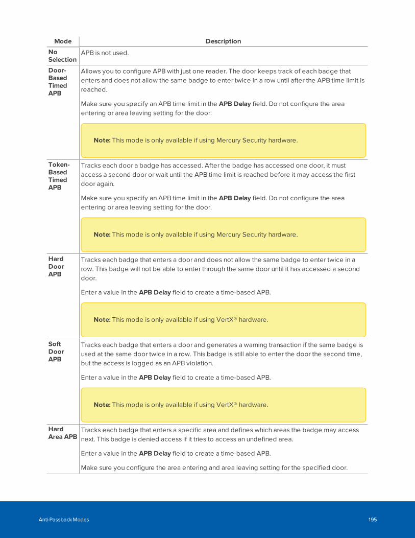
Mode Description
NoSelection
APB is not used.
Door-BasedTimedAPB
Allows you to configure APB with just one reader. The door keeps track of each badge thatenters and does not allow the same badge to enter twice in a row until after the APB time limit isreached.
Make sure you specify an APB time limit in the APB Delay field. Do not configure the areaentering or area leaving setting for the door.
Note: This mode is only available if using Mercury Security hardware.
Token-BasedTimedAPB
Tracks each door a badge has accessed. After the badge has accessed one door, it mustaccess a second door or wait until the APB time limit is reached before it may access the firstdoor again.
Make sure you specify an APB time limit in the APB Delay field. Do not configure the areaentering or area leaving setting for the door.
Note: This mode is only available if using Mercury Security hardware.
HardDoorAPB
Tracks each badge that enters a door and does not allow the same badge to enter twice in arow. This badge will not be able to enter through the same door until it has accessed a seconddoor.
Enter a value in the APB Delay field to create a time-based APB.
Note: This mode is only available if using VertX® hardware.
SoftDoorAPB
Tracks each badge that enters a door and generates a warning transaction if the same badge isused at the same door twice in a row. This badge is still able to enter the door the second time,but the access is logged as an APB violation.
Enter a value in the APB Delay field to create a time-based APB.
Note: This mode is only available if using VertX® hardware.
HardArea APB
Tracks each badge that enters a specific area and defines which areas the badge may accessnext. This badge is denied access if it tries to access an undefined area.
Enter a value in the APB Delay field to create a time-based APB.
Make sure you configure the area entering and area leaving setting for the specified door.
Anti-Passback Modes 195
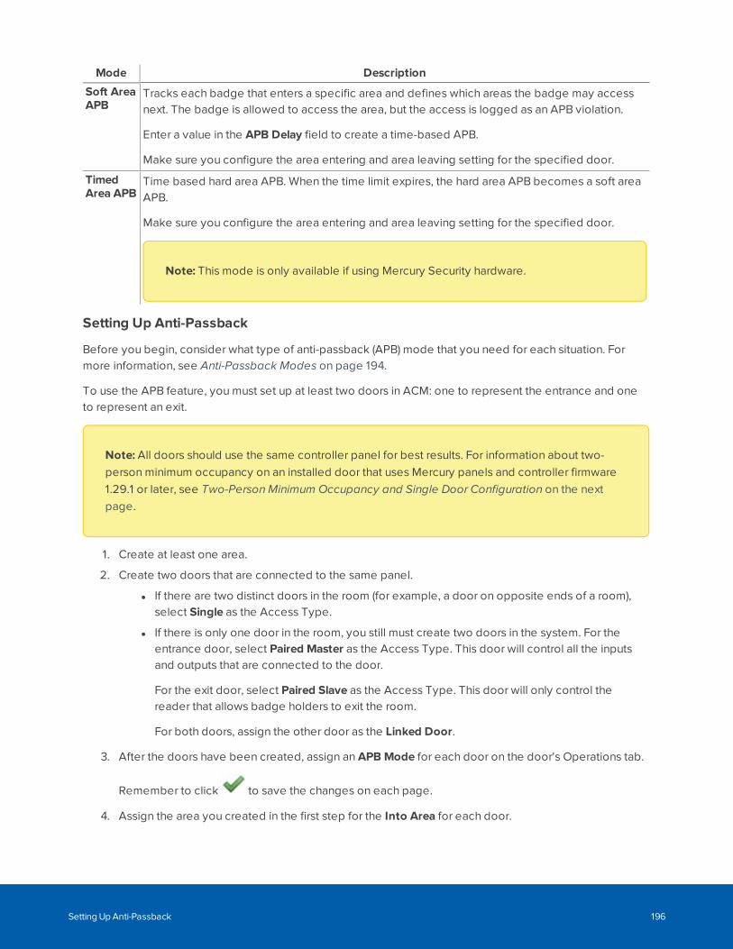
Mode Description
Soft AreaAPB
Tracks each badge that enters a specific area and defines which areas the badge may accessnext. The badge is allowed to access the area, but the access is logged as an APB violation.
Enter a value in the APB Delay field to create a time-based APB.
Make sure you configure the area entering and area leaving setting for the specified door.
TimedArea APB
Time based hard area APB. When the time limit expires, the hard area APB becomes a soft areaAPB.
Make sure you configure the area entering and area leaving setting for the specified door.
Note: This mode is only available if using Mercury Security hardware.
Setting Up Anti-Passback
Before you begin, consider what type of anti-passback (APB) mode that you need for each situation. Formore information, see Anti-Passback Modes on page 194.
To use the APB feature, you must set up at least two doors in ACM: one to represent the entrance and oneto represent an exit.
Note: All doors should use the same controller panel for best results. For information about two-person minimum occupancy on an installed door that uses Mercury panels and controller firmware1.29.1 or later, see Two-Person Minimum Occupancy and Single Door Configuration on the nextpage.
1. Create at least one area.
2. Create two doors that are connected to the same panel.
l If there are two distinct doors in the room (for example, a door on opposite ends of a room),select Single as the Access Type.
l If there is only one door in the room, you still must create two doors in the system. For theentrance door, select Paired Master as the Access Type. This door will control all the inputsand outputs that are connected to the door.
For the exit door, select Paired Slave as the Access Type. This door will only control thereader that allows badge holders to exit the room.
For both doors, assign the other door as the Linked Door.
3. After the doors have been created, assign an APB Mode for each door on the door's Operations tab.
Remember to click to save the changes on each page.
4. Assign the area you created in the first step for the Into Area for each door.
Setting Up Anti-Passback 196
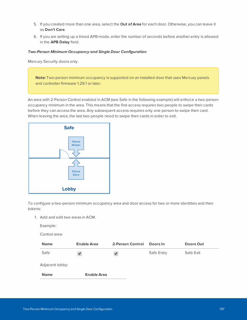
5. If you created more than one area, select the Out of Area for each door. Otherwise, you can leave itas Don't Care.
6. If you are setting up a timed APB mode, enter the number of seconds before another entry is allowedin the APB Delay field.
Two-Person Minimum Occupancy and Single Door Configuration
Mercury Security doors only.
Note: Two-person minimum occupancy is supported on an installed door that uses Mercury panelsand controller firmware 1.29.1 or later.
An area with 2-Person Control enabled in ACM (see Safe in the following example) will enforce a two-personoccupancy minimum in the area. This means that the first access requires two people to swipe their cardsbefore they can access the area. Any subsequent access requires only one person to swipe their card.When leaving the area, the last two people need to swipe their cards in order to exit.
To configure a two-person minimum occupancy area and door access for two or more identities and theirtokens:
1. Add and edit two areas in ACM.
Example:
Control area:
Name Enable Area 2-Person Control Doors In Doors Out
Safe Safe Entry Safe Exit
Adjacent lobby:
Name Enable Area
Two-Person Minimum Occupancy and Single Door Configuration 197
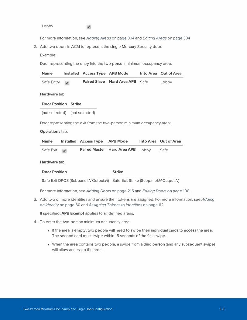
Lobby
For more information, see Adding Areas on page 304 and Editing Areas on page 304
2. Add two doors in ACM to represent the single Mercury Security door.
Example:
Door representing the entry into the two-person minimum occupancy area:
Name Installed Access Type APB Mode Into Area Out of Area
Safe Entry Paired Slave Hard Area APB Safe Lobby
Hardware tab:
Door Position Strike
(not selected) (not selected)
Door representing the exit from the two-person minimum occupancy area:
Operations tab:
Name Installed Access Type APB Mode Into Area Out of Area
Safe Exit Paired Master Hard Area APB Lobby Safe
Hardware tab:
Door Position Strike
Safe Exit DPOS (Subpanel:N Output:N) Safe Exit Strike (Subpanel:N Output:N)
For more information, see Adding Doors on page 215 and Editing Doors on page 190.
3. Add two or more identities and ensure their tokens are assigned. For more information, see Addingan Identity on page 60 and Assigning Tokens to Identities on page 62.
If specified, APB Exempt applies to all defined areas.
4. To enter the two-person minimum occupancy area:
l If the area is empty, two people will need to swipe their individual cards to access the area.The second card must swipe within 15 seconds of the first swipe.
l When the area contains two people, a swipe from a third person (and any subsequent swipe)will allow access to the area.
Two-Person Minimum Occupancy and Single Door Configuration 198
5. To leave the two-person minimum occupancy area:
l If the area contains more than two people, a single swipe will allow them to exit the area untilonly two people are left in the area.
l When the area contains only two people, both of them will need to swipe to exit the area. Thesecond card must swipe within 15 seconds of the first swipe.
Granting a Free Pass
You can grant a user one free pass to enter a door without generating an anti-passback error. This feature isuseful if a badge holder swiped their card at a card reader but did not actually enter the area.
For example, an employee uses his access card to unlock the office entrance but is distracted by anotheremployee before he opens the door. The two employees speak for several minutes, and the doorautomatically locks after a set amount of time. When the first employee attempts to unlock the office dooragain, this triggers an APB alarm and the employee is locked out. The employee contacts the securityofficer and explains the situation, the security officer can grant one free pass to allow the employee backinto the office area.
To grant a free pass:
1. Click Identities.
The Identities list is displayed.
2. From the Identities list, click on the name of the identity.
The Identities: Edit screen is displayed.
3. Select the Tokens tab.
4. Beside the 1 free pass button, select a door.
5. Click 1 free pass.
The badge holder can now enter the door without generating an new anti-passback alarm.
Global Anti-Passback
The anti-passback (APB) feature is used when you want to identify every badge holder that enters a room orarea. This feature can be configured to log or prevent a badge holder from re-entering the same areaunexpectedly.
For example, the same access badge cannot be used to enter the same room twice in a row. If a badgeholder enters a room then passes the badge to another potential badge holder to reuse the badge at thesame door, an APB error is logged and may be configured to prevent the second badge holder fromentering.
Another example is when an access badge is also required to exit. If a badge holder holds open a door foranother person, the second person would not be able to exit even if they have an access card because thesystem requires the badge holder to log an entrance in the system before they can exit.
Global anti-passback defines an area for which two or more readers are used to access the area, but arephysically wired to different controllers. If any one reader in that same area receives an APB violation, it willprevent that badge holder from entering through other doors in same area.
Granting a Free Pass 199
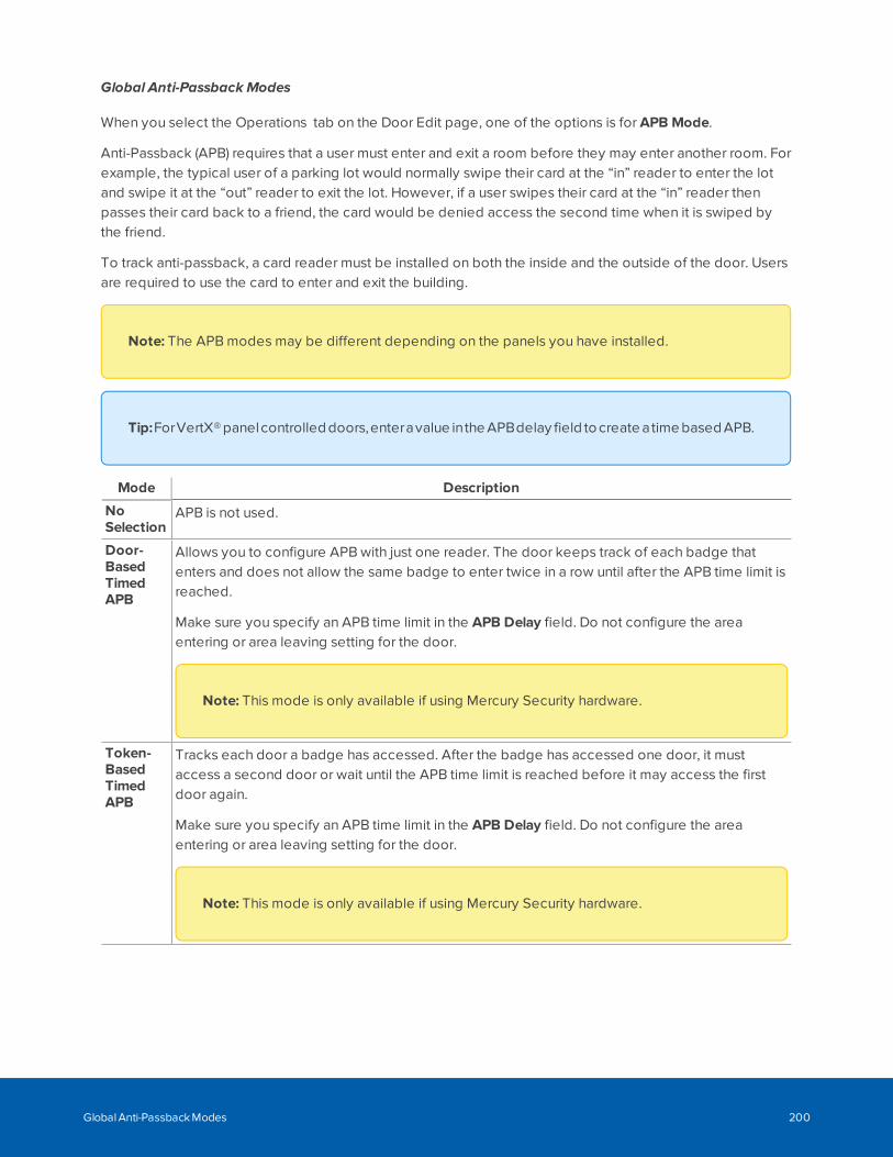
Global Anti-Passback Modes
When you select the Operations tab on the Door Edit page, one of the options is for APB Mode.
Anti-Passback (APB) requires that a user must enter and exit a room before they may enter another room. Forexample, the typical user of a parking lot would normally swipe their card at the “in” reader to enter the lotand swipe it at the “out” reader to exit the lot. However, if a user swipes their card at the “in” reader thenpasses their card back to a friend, the card would be denied access the second time when it is swiped bythe friend.
To track anti-passback, a card reader must be installed on both the inside and the outside of the door. Usersare required to use the card to enter and exit the building.
Note: The APB modes may be different depending on the panels you have installed.
Tip:ForVertX® panelcontrolled doors,enteravalue inthe APBdelay field to create atime based APB.
Mode Description
NoSelection
APB is not used.
Door-BasedTimedAPB
Allows you to configure APB with just one reader. The door keeps track of each badge thatenters and does not allow the same badge to enter twice in a row until after the APB time limit isreached.
Make sure you specify an APB time limit in the APB Delay field. Do not configure the areaentering or area leaving setting for the door.
Note: This mode is only available if using Mercury Security hardware.
Token-BasedTimedAPB
Tracks each door a badge has accessed. After the badge has accessed one door, it mustaccess a second door or wait until the APB time limit is reached before it may access the firstdoor again.
Make sure you specify an APB time limit in the APB Delay field. Do not configure the areaentering or area leaving setting for the door.
Note: This mode is only available if using Mercury Security hardware.
Global Anti-Passback Modes 200
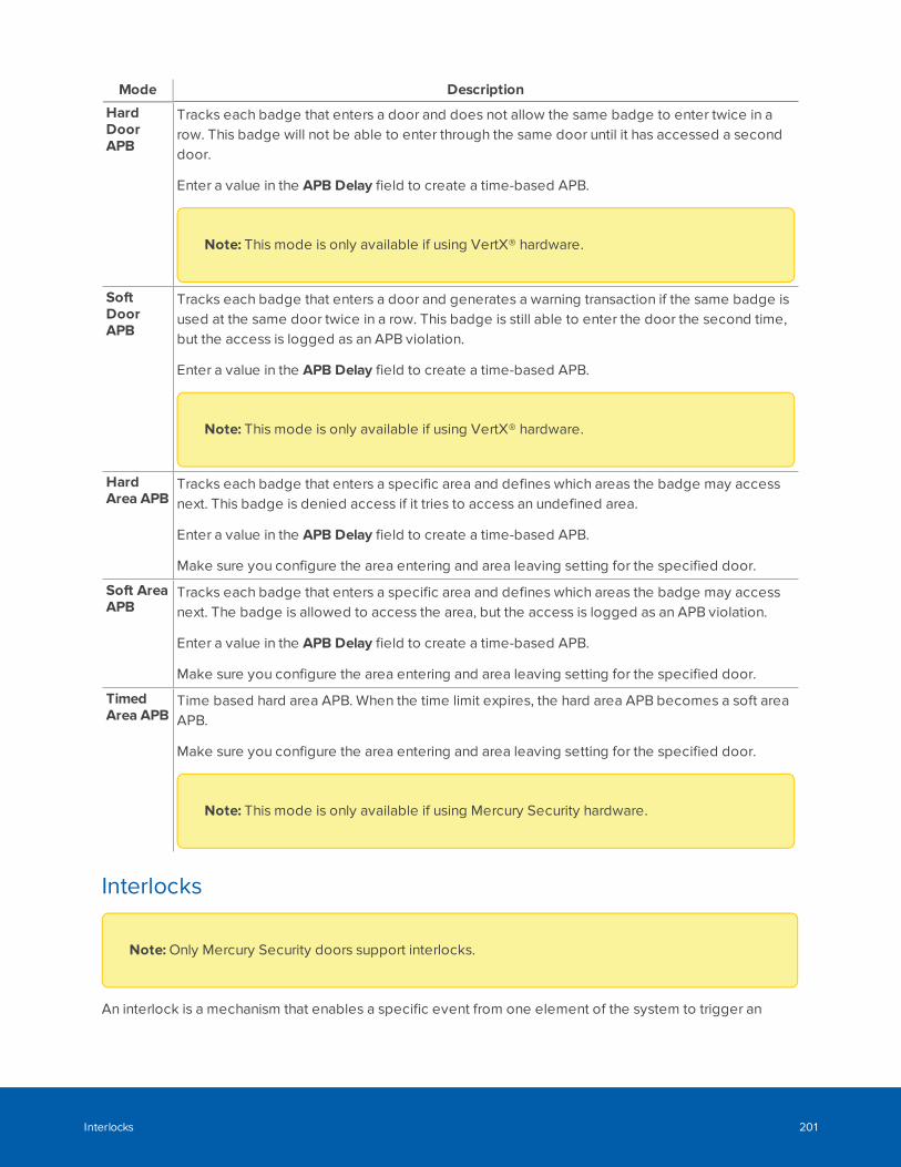
Mode Description
HardDoorAPB
Tracks each badge that enters a door and does not allow the same badge to enter twice in arow. This badge will not be able to enter through the same door until it has accessed a seconddoor.
Enter a value in the APB Delay field to create a time-based APB.
Note: This mode is only available if using VertX® hardware.
SoftDoorAPB
Tracks each badge that enters a door and generates a warning transaction if the same badge isused at the same door twice in a row. This badge is still able to enter the door the second time,but the access is logged as an APB violation.
Enter a value in the APB Delay field to create a time-based APB.
Note: This mode is only available if using VertX® hardware.
HardArea APB
Tracks each badge that enters a specific area and defines which areas the badge may accessnext. This badge is denied access if it tries to access an undefined area.
Enter a value in the APB Delay field to create a time-based APB.
Make sure you configure the area entering and area leaving setting for the specified door.
Soft AreaAPB
Tracks each badge that enters a specific area and defines which areas the badge may accessnext. The badge is allowed to access the area, but the access is logged as an APB violation.
Enter a value in the APB Delay field to create a time-based APB.
Make sure you configure the area entering and area leaving setting for the specified door.
TimedArea APB
Time based hard area APB. When the time limit expires, the hard area APB becomes a soft areaAPB.
Make sure you configure the area entering and area leaving setting for the specified door.
Note: This mode is only available if using Mercury Security hardware.
Interlocks
Note: Only Mercury Security doors support interlocks.
An interlock is a mechanism that enables a specific event from one element of the system to trigger an
Interlocks 201
action at another element. Interlocks allow you to set up security routines like man-traps, prison entry points,and automated building functions.
The interlock feature can be accessed from one of three ways:
Accessing Interlocks through Doors
1. Select Physical Access.
The Doors list is displayed.
2. Select the Mercury Security door that you want to interlock.
The Door Edit screen is displayed.
3. Click the Interlocks tab.
The Door Interlocks list is displayed.
Accessing Interlocks from Subpanel Inputs
1. Select Physical Access>Panels.
The Panels list is displayed.
2. Select the panel you want to interlock.
The Panel Status screen is displayed.
3. Click the Subpanels tab.
The Subpanels list is displayed.
4. Click for the subpanel that is connected to the input you want to interlock.
The Inputs list is displayed.
5. Click the Interlocks link beside the required input.
The Input Interlock list is displayed.
Accessing Interlocks from Subpanel Outputs
1. Select Physical Access>Panels.
The Panels list is displayed.
2. Select the panel you want to interlock.
The Panel Status screen is displayed.
3. Click the Subpanels tab.
The Subpanels list is displayed.
4. Click for the subpanel that is connected to the output you want to interlock.
The Outputs list is displayed.
Interlocks 202
5. Click the Interlocks link beside the required output.
The Output Interlock list is displayed.
Adding Interlocks
1. From the Interlock list, click Add New Interlock. For more information about how to access thedifferent Interlock Listing pages, see Interlocks on page 201.
2. On the following Interlock Add page, add the required information.
Notice that as you select options, new fields are displayed to help you further define yourrequirements.
3. When you're finished, click to save the new interlock.
Editing Interlocks
1. From the Interlock list, click the name of an interlock. For more information about how to access thedifferent Interlock Listing pages, see Interlocks on page 201.
2. On the following Interlock Edit page, make the required changes.
3. Click to save your changes.
Configuring LocksTo use locks with built-in card or PIN readers, add the related wireless lock subpanel to the system then addthe lock hardware as part of a door. The readers can be either wired or wireless, depending on the lock.
Tip: For information about configuring Schlage IP wireless locks and the Allegion ENGAGEGateway that supports IP/PoE mode of operation, see IP/PoE Mode Installation on page 277.
Configuring Assa Abloy Aperio® Wireless Lock Technology
To use the Assa Abloy Aperio wireless locks, you must have the following panels connected to the system:
l Mercury EP1501, EP1501 with downstream support, EP1502 or EP2500
l Assa Abloy Aperio 1 to 8 Hub or 1 to 1 Hub
The wireless lock assembly is installed directly to the door and communicate with the Aperio Hub subpanelwirelessly.
1. Add a Mercury EP1501 or EP2500 panel to the ACM system.
For more information, see Adding Panels on page 156.
2. Add the Aperio 1 to 8 Hub or Aperio 1 to 1 Hub as a subpanel to the panel added in the previousstep.
For more information, see Adding Mercury Security Panels on page 163.
Adding Interlocks 203
For more information, see Adding Mercury Security Panels on page 163.
3. Create a door for each wireless lock assembly.
For more information, see Adding Doors on page 215.
4. For each door, select the corresponding Mercury Security panel, Aperio Hub subpanel and LockNumber that is assigned to the wireless lock assembly.
5. Customize all other door settings to meet your system requirements and save your changes.
Configuring Allegion Schlage AD400 Series Locks
To use Allegion Schlage AD400 series locks, you must have the following panels connected to the system:
l Mercury EP1501 or EP2500 panel with downstream support
l PIM400 subpanel that is wired to the Mercury panel
The wireless lock assembly is installed directly to the door and communicates with the PIM400 subpanelwirelessly.
Note: Ensure that the wireless locks have been installed in line with Schlage's installationinstructions.
1. Add a Mercury EP1501 or EP2500 panel to the ACM system.
For more information, see Adding Panels on page 156.
2. Add the PIM400 as a subpanel to the panel in the previous step.
For more information, see Adding Mercury Security Panels on page 163.
3. After the panels have been added to the system, select the Subpanels tab.
4. For each PIM400 subpanel, enter the LowDoor and High Door number that is assigned to thesubpanel.
Each PIM400 subpanel manages up to 16 wireless doors in a series. You must identify the lowestnumbered door and the highest numbered door managed by each subpanel. The numbered doorsmanaged by each subpanel cannot overlap.
5. Create a door for each wireless lock assembly.
For more information, see Adding Doors on page 215.
6. For each door, select the corresponding Mercury Security panel, PIM400 subpanel and door numberthat is assigned to the wireless lock assembly.
7. On the door Parameters tab, you can set the Lock Function for the wireless locks. The options are:
l None: Use the system default door settings.
l Privacy: When you press the interior lock button, the door will lock and the exterior lock willnot grant access to any token. To unlock, you must press the interior lock button again or exitthe room.
Configuring Allegion Schlage AD400 Series Locks 204
l Apartment: Use the interior lock button to toggle between locked and unlocked. When thedoor is locked, any valid token will open the door. The door must be manually locked or it willstay unlocked.
l Classroom—Classroom/Storeroom — The lockset is normally secure. The inside lever alwaysallows free egress. Valid toggle credentials (i.e. a valid card that is swiped twice within fiveseconds) on the exterior may be used to change to a passage or secured status. Not to beused on mortise deadbolt. Interior push button not to be used.
Note: This is the only lock function supported for the RSI-connected NDE series lock.
Note: This lock function is not supported for the IP-connected LE, LEB, NDE and NDEBseries lock, or offline Wi-Fi lock.
l Office — The lockset is normally secure. The inside lever always allows free egress. An interiorpush-button on the inside housing may be used to select a passage or secured status. Meetsthe need for lockdown function for safety and security. Valid toggle credentials (i.e. a validcard that is swiped twice within five seconds) on the exterior may also be used to changestatus. Not to be used on mortise deadbolt.
Note: A Restore door action is available on the Door listing page and the Hardware Statuspage which resets the Door Mode to its default value.
8. Customize all other door settings to meet your system requirements and save your changes.
Configuring Allegion Schlage LE Series Locks
To use Allegion Schlage LE series locks, you must have one of the following panels connected to thesystem:
l Mercury EP1501 or EP2500 panel with downstream support.
l ENGAGE™ Gateway subpanel that is wired to the Mercury panel.
Note: Ensure that the wireless locks have been installed in line with Schlage's installationinstructions.
Configuring Allegion Schlage LE Series Locks 205
1. Add a Mercury EP2500 or EP1501 (with downstream) panel to the ACM system following the stepsbelow:
l Select Physical Access > Panels to open the Panels page.
l Click to add a new panel on the Panel: Add New page.
l Enter the Name, Vendor (Mercury Security), Model (2500 or 1501 with Downstream) and select
Installed, then click to save the new panel.
2. If you are adding:
l just ENGAGE Gateway subpanels, then add all required subpanels to the panel created in the
previous step using the Batch Add option and click .
Note: You will still need to manually make sure that the ENGAGE Gateway hasmatching configuration as the physical gateway.
l both Gateway and non-Gateway subpanels, then enter the correct number of Gatewaysubpanels and/or PIM400s on the Subpanel: Batch Add page (do not select any other panels
at this stage) and click . For each other subpanel to be added:
o Click on the Subpanels tab to open the Subpanel page. If you are adding non-Gatewaysubpanels ensure that the subpanels are set to the correct port.
o Add the subpanel. You can mix and match any subpanels using the same MercurySecurity protocol on the same port (i.e. ENGAGE Gateway and PIM400). For moreinformation, see Adding Mercury Security Panels on page 163.
For each ENGAGE Gateway subpanel, enter the following and select Installed:
o Port
o Address
o LowDoor and High Door number that is assigned to the subpanel.
Each ENGAGE Gateway subpanel manages up to 10 LE wireless doors. You must identify thelowest numbered door and the highest numbered door managed by each subpanel. Thenumbered doors managed by each subpanel cannot overlap.
3. Create a door for each wireless lock assembly.
For more information, see Adding Doors on page 215.
4. For each door, select the corresponding Mercury Security panel, ENGAGE Gateway subpanel anddoor number that is assigned to the wireless lock assembly.
Configuring Allegion Schlage LE Series Locks 206
5. On the door Parameters tab, you can set the Lock Function for the wireless locks. The options are:.
l None: Use the system default door settings.
l Privacy: When you press the interior lock button, the door will lock and the exterior lock willnot grant access to any token. To unlock, you must press the interior lock button again or exitthe room.
l Apartment: Use the interior lock button to toggle between locked and unlocked. When thedoor is locked, any valid token will open the door. The door must be manually locked or it willstay unlocked.
l Classroom—Classroom/Storeroom — The lockset is normally secure. The inside lever alwaysallows free egress. Valid toggle credentials (i.e. a valid card that is swiped twice within fiveseconds) on the exterior may be used to change to a passage or secured status. Not to beused on mortise deadbolt. Interior push button not to be used.
Note: This is the only lock function supported for the RSI-connected NDE series lock.
Note: This lock function is not supported for the IP-connected LE, LEB, NDE and NDEBseries lock, or offline Wi-Fi lock.
l Office — The lockset is normally secure. The inside lever always allows free egress. An interiorpush-button on the inside housing may be used to select a passage or secured status. Meetsthe need for lockdown function for safety and security. Valid toggle credentials (i.e. a validcard that is swiped twice within five seconds) on the exterior may also be used to changestatus. Not to be used on mortise deadbolt.
Note: A Restore door action is available on the Door listing page and the Hardware Statuspage which resets the Door Mode to its default value.
6. Customize all other door settings to meet your system requirements and save your changes.
Configuring Allegion Schlage NDE Series Locks
To use Allegion Schlage NDE series locks, you must have one of the following panels connected to thesystem:
l Mercury EP1501 or EP2500 panel with downstream support.
l ENGAGE Gateway subpanel that is wired to the Mercury Security panel.
Note: Ensure that the wireless locks have been installed in line with Schlage's installation
Configuring Allegion Schlage NDE Series Locks 207
instructions.
1. Add a Mercury EP2500 or EP1501 (with downstream) panel to the ACM system following the stepsbelow:
l Select Physical Access > Panels to open the Panels page.
l Click to add a new panel on the Panel: Add New page.
l Enter the Name, Vendor (Mercury Security), Model (2500 or 1501 with Downstream) and select
Installed, then click to save the new panel.
2. If you are adding:
l just ENGAGE Gateway subpanels, then add all required subpanels to the panel created in the
previous step using the Batch Add option and click .
Note: You will still need to manually make sure that the ENGAGE Gateway hasmatching configuration as the physical gateway.
l both Gateway and non-Gateway subpanels, then enter the correct number of Gatewaysubpanels and/or PIM400s on the Subpanel: Batch Add page (do not select any other panels
at this stage) and click . For each other subpanel to be added:
o Click on the Subpanels tab to open the Subpanel page. If you are adding non-Gatewaysubpanels ensure that the subpanels are set to the correct port.
o Add the subpanel. You can mix and match any subpanels using the same MercurySecurity protocol on the same port (i.e. ENGAGE Gateway and PIM400). For moreinformation, see Adding Mercury Security Panels on page 163.
For each ENGAGE Gateway subpanel, enter the following and select Installed:
o Port
o Address
o LowDoor and High Door number that is assigned to the subpanel.
Each ENGAGE Gateway subpanel manages up to 10 NDE wireless doors. You must identifythe lowest numbered door and the highest numbered door managed by each subpanel. Thenumbered doors managed by each subpanel cannot overlap.
3. Create a door for each wireless lock assembly.
For more information, see Adding Doors on page 215.
4. For each door, select the corresponding Mercury Security panel, ENGAGE Gateway subpanel anddoor number that is assigned to the wireless lock assembly.
Configuring Allegion Schlage NDE Series Locks 208
5. On the door Parameters tab, you can set the Lock Function for the wireless locks. For the NDE seriesthere is only one lock function: Classroom—Classroom/Storeroom.
Note: There is a Restore door action available on the Door listing page and the HardwareStatus page which resets the Door Mode to its default value.
6. Customize all other door settings to meet your system requirements and save your changes.
Configuring SimonsVoss Wireless Locks
To use SimonsVoss series locks, you must have the following panels connected to the ACM system:
l Mercury EP1501 (with downstream support), EP1502, EP2500, or MS-ICS panel .
l SmartIntego GatewayNode subpanel that is connected over an Ethernet networkusing TCP. This connection is established after setting up the subpanel in the ACM software.
Ensure that the wireless locks have been installed and configured according to the SimonsVoss installationinstructions. You must have:
l Configured the hostname, and optionally the IP address, or the MAC address in the SmartIntegoGatewayNode software. For more information, refer to the SimonsVoss documentation for theSmartIntego GatewayNode software.
Note: To use the MAC address of the wireless lock, the hostname must be configures in theformat MAC<nnnnnnnnnnnn>, where nnnnnnnnnnnn is the MAC address without any colons.For example, the hostname for a lock with MAC address 12:34:56:78:9A:BC is enteredMAC123456789ABC.
l Identified the hexadecimal address for each SmartIntego GatewayNode and each wireless lockbefore you can connect them to the ACM software. This information is available from the SmartIntegoTool as shown in the figures below. In these examples:
l 0X0011 is the hex address for the SimonsVoss GatewayNode. Enter this value in the Addressfield for each SmartIntego GatewayNode in the ACM software (Physical Access > Panel >Subpanel).
0X0016 is the hex address for the SimonsVoss wireless lock. This is the value entered in theDoor Number field for each SImonsVoss lock in the ACM software (Physical Access > Doors> Add Door).
Configuring SimonsVoss Wireless Locks 209
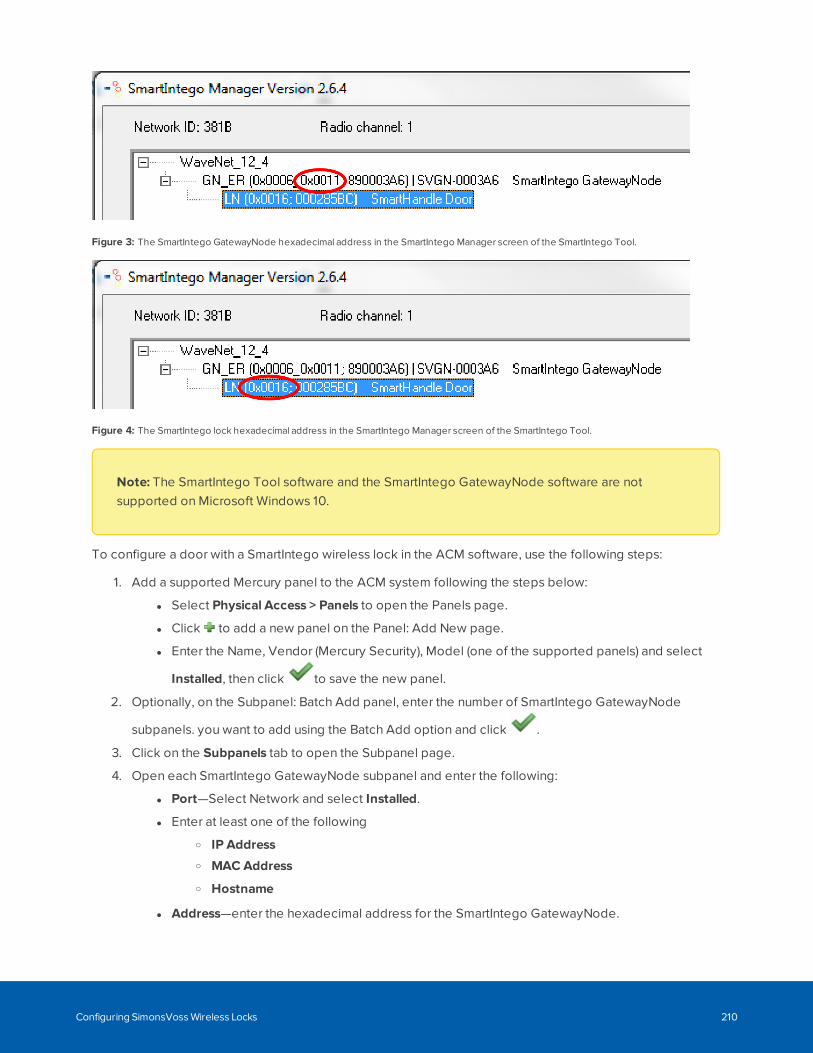
Figure 3: The SmartIntego GatewayNode hexadecimal address in the SmartIntego Manager screen of the SmartIntego Tool.
Figure 4: The SmartIntego lock hexadecimal address in the SmartIntego Manager screen of the SmartIntego Tool.
Note: The SmartIntego Tool software and the SmartIntego GatewayNode software are notsupported on Microsoft Windows 10.
To configure a door with a SmartIntego wireless lock in the ACM software, use the following steps:
1. Add a supported Mercury panel to the ACM system following the steps below:
l Select Physical Access > Panels to open the Panels page.
l Click to add a new panel on the Panel: Add New page.
l Enter the Name, Vendor (Mercury Security), Model (one of the supported panels) and select
Installed, then click to save the new panel.
2. Optionally, on the Subpanel: Batch Add panel, enter the number of SmartIntego GatewayNode
subpanels. you want to add using the Batch Add option and click .
3. Click on the Subpanels tab to open the Subpanel page.
4. Open each SmartIntego GatewayNode subpanel and enter the following:
l Port—Select Network and select Installed.
l Enter at least one of the following
o IP Addresso MAC Address
o Hostname
l Address—enter the hexadecimal address for the SmartIntego GatewayNode.
Configuring SimonsVoss Wireless Locks 210
Each SmartIntego GatewayNode subpanel manages up to 16 wireless doors.
Note: You will still need to manually make sure that the subpanel configuration matches thephysical gateway
5. Create a door for each wireless lock assembly. Ensure you specify Mercury Security as the vendor.
For more information, see Adding Doors on page 215.
6. On the Parameters panel for each door, ensure that you do the following:
l Vendor — Select Mercury Security
l Panel — Select the panel that is connected to the SmartIntego GatewayNode for the door.
l Subpanel — Select the subpanel for the SmartIntego GatewayNode that is connected to thedoor.
l Door Number — Enter the hexadecimal address for the SmartIntego wireless lock assembly.
l Installed — Click the checkbox.
l Don't pulse door strike on REX — For SimonsVoss wireless locks, such as cylinders, that donot support a door position switch (DPOS) , this box must not be checked.
7. If the SimonsVoss lock on the door does not support a DPOS, the settings in the following fields haveno effect:
l On the parameters tab:
o Mask Forced Schedule
o Mask held Schedule
o Always Mask Forced
o Always Mask Held
o Offline Mode
o Deny Duress
o Door Forced Filter
o Enable cipher Mode
o Use Shunt Relay
o Detailed Events
o do Not Log Rex Transactions
o Log all grants right away
Configuring SimonsVoss Wireless Locks 211
l On the Operations tab:
l APB Mode
l APB Delay
l Into Area
l Out of Area
l PIN Timeout
l PIN Attempts
l LED Mode
l Held Open Time
l Held Pre Alarm Access Time
l Extended Access
l Extended Held Open Time
l Simple Macros
l Strike Mode
l Access time when open
l Card Format
l The Door status will default to Normal Status
8. Customize the other door settings to meet your system requirements and click .
The ACM system and the SmartIntego GatewayNode subpanel should now connect and the door should beonline. If the door is not online:
l Wait a few minutes: The GatewayNode polls the SimonsVoss wireless lock three times in threeminutes, then polls every three hours, until the door responds. Normally, the door should come onlinewithin three minutes.
l If the door is not online within a few minutes: Check all the connections between the ACM systemand the SmartIntego GatewayNode subpanel, including the power.
After the door is operational, certain conditions of the SimonsVoss wireless lock that change the door statusare not always immediately reported to the ACM system. As a result, the door status reported in the ACMclient may not always accurately reflect the actual status of the of the door.
l If you uninstall the door and then reinstall it in the ACM system, the connection between theSmartIntego GatewayNode subpanel and the SimonsVoss lock is not interrupted. However, thereinstalled door will appear offline to the ACM system until the SmartIntego GatewayNode subpanelpolls the SimonsVoss lock. This poll happens once every 12 hours, so you may have to wait as longas 12 hours. During this period, the door will function normally but the ACM system will not receiveany events from the door.
Configuring SimonsVoss Wireless Locks 212
l After a power outage to the SmartIntego GatewayNode subpanel, an accurate door status will not beseen in the ACM system until after the SmartIntego GatewayNode subpanel is online and polling ofall the SimonsVoss doors connected to that subpanel has completed. The time it takes for thesubpanel to come online and start polling can be variable.
l If the batteries in the SimonsVoss lock are depleted or removed, an accurate door status will not beseen in the ACM system until after 24 hours have elapsed since the last battery status report wasreceived from the wireless lock. It could take up to 24 hours after battery power has been lost beforethe status is correctly reported. Meanwhile, commands can be sent to the door, but nothing happens.
Note: The ACM lockdown priority operation is superseded by the Escape and Return state of theSimonsVoss wireless lock when it becomes engaged in a lockdown situation.
Doors listThe Doors page lists of all the doors you are authorized to see and control. From this list you can controldoors, as well as add and delete doors, edit doors and their associated controller panels, and createoverrides to temporarily change the normal status of selected doors.
Note: Overrides can only be applied to installed doors on Mercury panels using controller firmware1.27.1 or later.
Select Physical Access>Doors to access the Doors list.
Searching, sorting, and filtering
Many facilities require the control and monitoring of dozens, even hundreds, of doors simultaneously. Thiscan result in a crowded listing page. You can search for specific doors to narrow the list of doors, filter thecolumns for specific values, and create and save custom filters. You can then sort the results using any onecolumn.
Searching the list:
1. Use any (or all) of the following to define your search:
l Enter your search term in the Search... field. Use any series of letters and numbers to searchfor the doors you want to see.
l If known, select the Device Status.
l If known, select the Appliance the door is connected to.
l If known, select the Group the door is included in.
2. Click OK.
Creating a filter to select multiple filters:
1. Click Advanced Filters to open the Advanced Filters dialog box.
Doors list 213
2. Select filters:
l Alarms—Select the alarms to include from the list of alarms.
l Masked—Select to include the masks to include from the list of masks.
l Normal—Select to include all properly functioning doors.
l Door Mode— Select the door modes to include from the list of door modes.
To unselect all selected filters, click Unselect All.
3. If you want to save the selected filters, select Remember Filters.
4. Click OK.
Sorting the list:
1. Click in a column heading:
l Click to sort in ascending order.
l Click to sort in descending order.
To see the legend for all the device statuses:
l Click Legend to see the list of statuses and the related icons.
There are three groupings which are color-coded — Normal , Alarms , Masked :
Adding and deleting doors
l Click the Add Door button to define a new door. For more information, see Adding Doors on the nextpage and Adding Doors on the next page
l Select doors in the list and click the Deletecontrol button.
Editing doors and panels:
l Click the link to the door in the Name column. For more information, see Editing Doors on page 190.
l Click the link to the panel in the Panel column.
Controlling doors:
Select doors in the list and then use the drop-down options from the control buttons at the top of the pageto control them:
l Door Action
l Door Mode
l Forced
l Held
l Installed
For more information, see Controlling Doors on page 179.
Creating a Door Configuration report
l Click Create New Report to generate a Door Configuration report on the doors in this list.
The following information is displayed for each door in the list:
Doors list 214
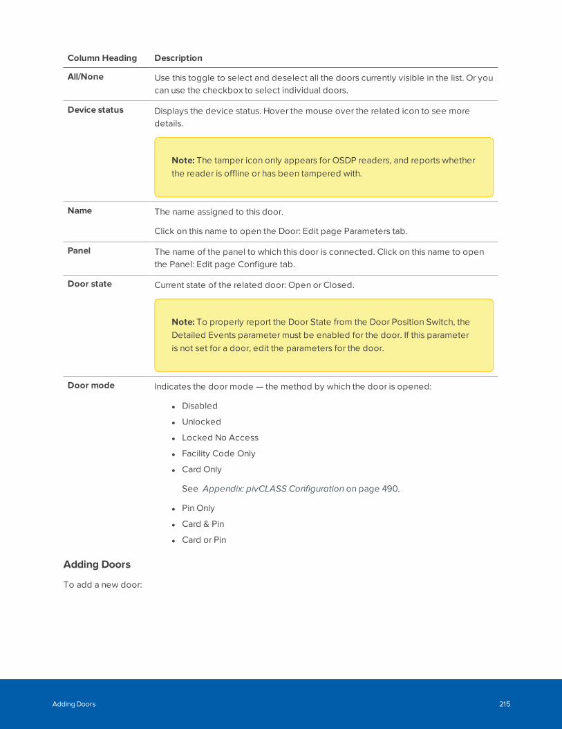
Column Heading Description
All/None Use this toggle to select and deselect all the doors currently visible in the list. Or youcan use the checkbox to select individual doors.
Device status Displays the device status. Hover the mouse over the related icon to see moredetails.
Note: The tamper icon only appears for OSDP readers, and reports whetherthe reader is offline or has been tampered with.
Name The name assigned to this door.
Click on this name to open the Door: Edit page Parameters tab.
Panel The name of the panel to which this door is connected. Click on this name to openthe Panel: Edit page Configure tab.
Door state Current state of the related door: Open or Closed.
Note: To properly report the Door State from the Door Position Switch, theDetailed Events parameter must be enabled for the door. If this parameteris not set for a door, edit the parameters for the door.
Door mode Indicates the door mode — the method by which the door is opened:
l Disabled
l Unlocked
l Locked No Access
l Facility Code Only
l Card Only
See Appendix: pivCLASS Configuration on page 490.
l Pin Only
l Card & Pin
l Card or Pin
Adding Doors
To add a new door:
Adding Doors 215

1. Select Physical Access > Doors.
Note: Doors cannot be manually added for Allegion offline Wi-Fi locks and SALTO doors. Forinformation about adding doors and associated panels, see Step 2: Setting UpCommunication to Offline Wi-Fi Locks on page 288 and Step 3: Syncing Doors with theSALTO Server on page 297, respectively.
2. Click Add Door.
3. If door templates are used, the Templates dialog appears. To use the door settings from a template,which automatically fills in the fields on the Parameters and Operations tabs, select the template andclick OK. Otherwise, click Cancel.
For Schlage IP wireless devices, click Cancel.
4. Enter on the Parameters tab:
Note: Fields in this list are dependent on the door module or linked device.
Name Up to 50 characters for the name of the door. See Appendix: pivCLASSConfiguration on page 490.
Alt. Name An alternate name for the door.
Location A short description of the door location.
Partitions Displayed for a partitioned ACM appliance only. To restrict operator access to theitem, select one or more partitions. To allow all operators access to the item, do notselect a partition.
Adding Doors 216
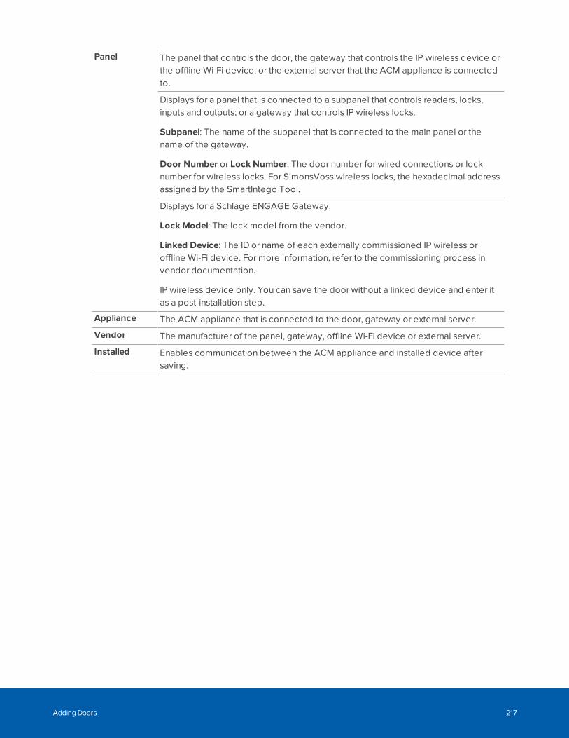
Panel The panel that controls the door, the gateway that controls the IP wireless device orthe offline Wi-Fi device, or the external server that the ACM appliance is connectedto.
Displays for a panel that is connected to a subpanel that controls readers, locks,inputs and outputs; or a gateway that controls IP wireless locks.
Subpanel: The name of the subpanel that is connected to the main panel or thename of the gateway.
Door Number or Lock Number: The door number for wired connections or locknumber for wireless locks. For SimonsVoss wireless locks, the hexadecimal addressassigned by the SmartIntego Tool.
Displays for a Schlage ENGAGE Gateway.
Lock Model: The lock model from the vendor.
Linked Device: The ID or name of each externally commissioned IP wireless oroffline Wi-Fi device. For more information, refer to the commissioning process invendor documentation.
IP wireless device only. You can save the door without a linked device and enter itas a post-installation step.
Appliance The ACM appliance that is connected to the door, gateway or external server.
Vendor The manufacturer of the panel, gateway, offline Wi-Fi device or external server.
Installed Enables communication between the ACM appliance and installed device aftersaving.
Adding Doors 217

Displays for Schlage ENGAGE Gateway:
Access Type: Whether the IP wireless device is located on one or both sides of thedoor. Default is Single, which cannot be changed. For more information, see AccessTypes on page 193.
Door Mode: IP-connected device only. The entry mode for the door when thegateway is online and communicating with the IP wireless device. For informationabout the Unlocked, Locked No Access and Card Only options, see Door Modes onpage 192.
Offline Wi-Fi lock only. The entry mode for the door when the lock is online. Forinformation about the Card Only option, see Door Modes on page 192.
Lock Function: None is the default.
l None: Use the system default door settings.
l Privacy: When you press the interior lock button, the door will lock and theexterior lock will not grant access to any token. To unlock, you must press theinterior lock button again or exit the room.
l Apartment: Use the interior lock button to toggle between locked andunlocked. When the door is locked, any valid token will open the door. Thedoor must be manually locked or it will stay unlocked.
l Classroom—Classroom/Storeroom — The lockset is normally secure. Theinside lever always allows free egress. Valid toggle credentials (i.e. a validcard that is swiped twice within five seconds) on the exterior may be used tochange to a passage or secured status. Not to be used on mortise deadbolt.Interior push button not to be used.
Note: This is the only lock function supported for the RSI-connectedNDE series lock.
Note: This lock function is not supported for the IP-connectedLE, LEB, NDE and NDEB series lock, or offline Wi-Fi lock.
l Office — The lockset is normally secure. The inside lever always allows freeegress. An interior push-button on the inside housing may be used to select apassage or secured status. Meets the need for lockdown function for safetyand security. Valid toggle credentials (i.e. a valid card that is swiped twicewithin five seconds) on the exterior may also be used to change status. Not tobe used on mortise deadbolt.
Adding Doors 218

Note: A Restore door action is available on the Door listing page and theHardware Status page which resets the Door Mode to its default value.
AlwaysMask Forced: If selected, Door Forced Open alarms at the door are alwaysmasked.
AlwaysMask Held: If selected, Door Held Open alarms at the door are alwaysmasked.
CustomMode: Another door mode that is supported by the gateway.
Custom Schedule: Displays for an IP-connected door (LE, LEB, NDE, NDEB serieslock) if the Card Only door mode is selected, or RU device if the Locked No Accessdoor mode is selected. A predefined time when Custom Mode becomes active.Never Active is OFF. 24 Hours Active is ON.
For Avigilon, enter:
Station Type: Default is ACM Verify station, which is used on connected devices. Adevice that uses this station type of station is called an ACM Verify Station.
Managed: If selected, ACM Verify Station requires the user to grant or deny accessto the person entering a valid PIN code. It also displays the name and picture of theuser for verification.
UnManaged: If selected, ACM Verify Station automatically grants or denies accessand does not provide additional information when a PIN code is entered.
Geographic Timezone: The time zone where the ACM Verify device is located if it isdifferent from the time zone of the ACM appliance.
Into Area: The area that the badge holder enters by passing through the door andwhere the ACM Verify Station is used, or not, to monitor access to the area. Youmust specify an area if you want the virtual station to list all the people who haveentered the area.
Station Authentication: The method of authentication on the ACM Verify device.Login specifies that the user log in to the ACM software using the ACM URL from thebrowser on the ACM Verify device. Paired specifies that the ACM Verify is paired tothe ACM system. If the authentication type is Paired, the Door Add page refreshesand displays the Add Paired Device button.
Adding Doors 219

For Mercury Security and HID VertX panel, enter:
Access Type: Whether the reader is located on one or both sides of the door, or onan elevator door. See Access Types on page 193.
Linked Door: Displays for Paired Master and Paired Slave access type only. Thedoor with the reader on the other side of the door.
Door Mode: The entry mode of the door when the door controller is online andcommunicating with the panel. See Door Modes on page 192.
Assurance Profile: For Mercury Security LP4502 only. See Appendix: pivCLASSConfiguration on page 490.
Offline Door Mode: The entry mode of the door if the door controller is no longercommunicating with the panel.
Note: In many cases readers in offline mode require a very simple solutionfor entry or exit because of the memory limitations. The recommendedOffline Door Mode option is Locked No Access.
CustomMode: Another entry mode that is supported by the door module inaddition to Door Mode and Offline Door Mode options.
Custom Schedule: When the Custom Mode becomes active. Never Active is OFF.24 Hours Activeis ON.
Masked Forced Schedule: A predefined time when Door Forced Open alarms fromthe door will be masked.
Masked Held Schedule: A predefined time when Door Held Open alarms from thedoor will be masked.
AlwaysMask Forced: If selected, Door Forced Open alarms at the door are alwaysmasked.
AlwaysMask Held: If selected, Door Held Open alarms at the door are alwaysmasked.
Adding Doors 220
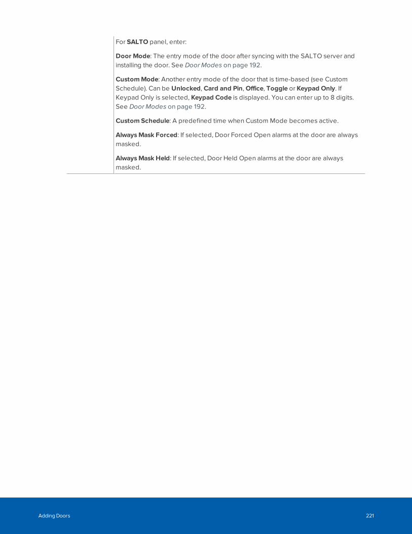
For SALTO panel, enter:
Door Mode: The entry mode of the door after syncing with the SALTO server andinstalling the door. See Door Modes on page 192.
CustomMode: Another entry mode of the door that is time-based (see CustomSchedule). Can be Unlocked, Card and Pin, Office, Toggle or Keypad Only. IfKeypad Only is selected, Keypad Code is displayed. You can enter up to 8 digits.See Door Modes on page 192.
Custom Schedule: A predefined time when Custom Mode becomes active.
AlwaysMask Forced: If selected, Door Forced Open alarms at the door are alwaysmasked.
AlwaysMask Held: If selected, Door Held Open alarms at the door are alwaysmasked.
Adding Doors 221
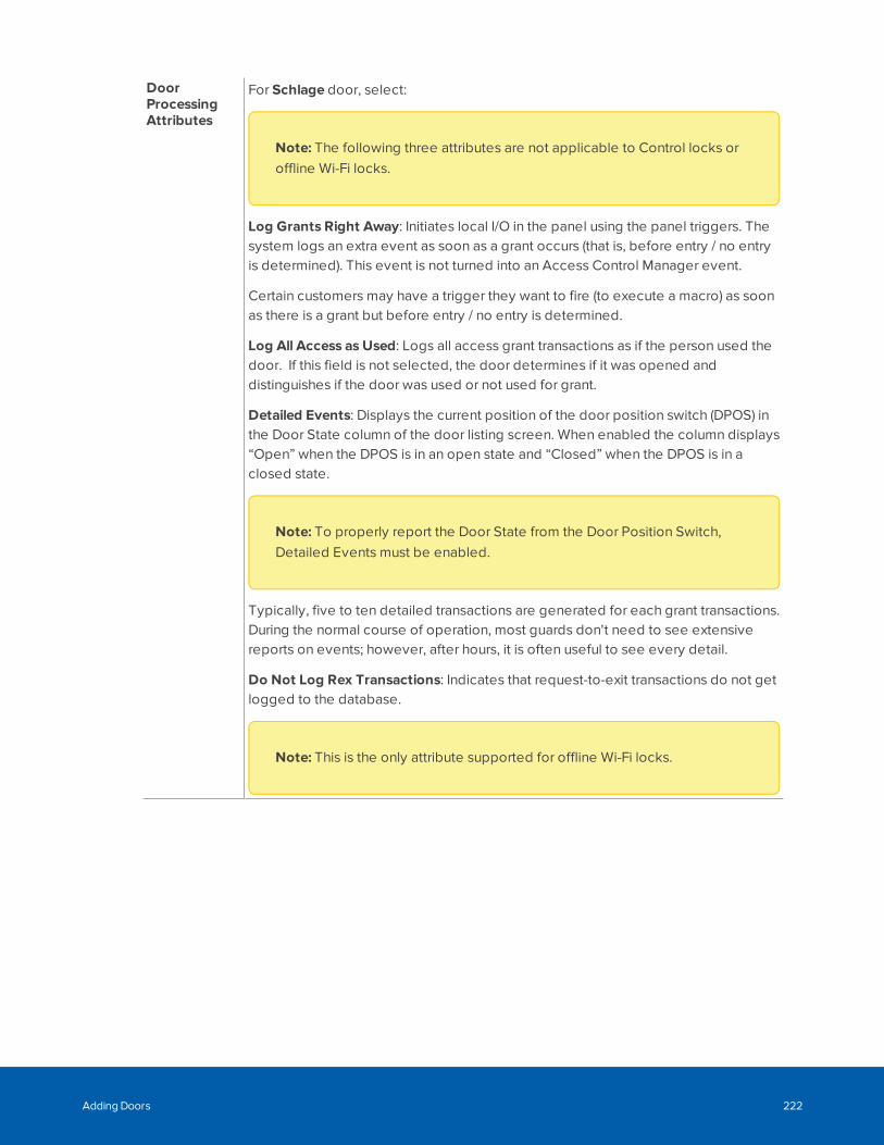
DoorProcessingAttributes
For Schlage door, select:
Note: The following three attributes are not applicable to Control locks oroffline Wi-Fi locks.
Log Grants Right Away: Initiates local I/O in the panel using the panel triggers. Thesystem logs an extra event as soon as a grant occurs (that is, before entry / no entryis determined). This event is not turned into an Access Control Manager event.
Certain customers may have a trigger they want to fire (to execute a macro) as soonas there is a grant but before entry / no entry is determined.
Log All Access as Used: Logs all access grant transactions as if the person used thedoor. If this field is not selected, the door determines if it was opened anddistinguishes if the door was used or not used for grant.
Detailed Events: Displays the current position of the door position switch (DPOS) inthe Door State column of the door listing screen. When enabled the column displays“Open” when the DPOS is in an open state and “Closed” when the DPOS is in aclosed state.
Note: To properly report the Door State from the Door Position Switch,Detailed Events must be enabled.
Typically, five to ten detailed transactions are generated for each grant transactions.During the normal course of operation, most guards don't need to see extensivereports on events; however, after hours, it is often useful to see every detail.
Do Not Log Rex Transactions: Indicates that request-to-exit transactions do not getlogged to the database.
Note: This is the only attribute supported for offline Wi-Fi locks.
Adding Doors 222
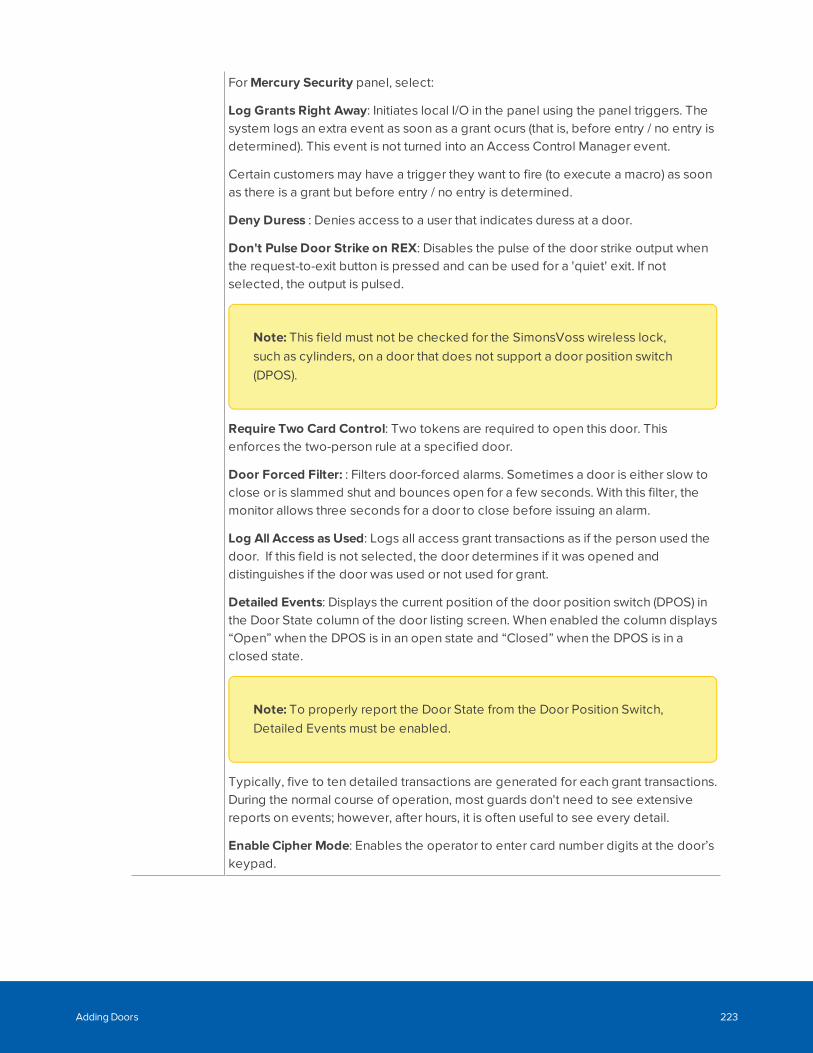
For Mercury Security panel, select:
Log Grants Right Away: Initiates local I/O in the panel using the panel triggers. Thesystem logs an extra event as soon as a grant ocurs (that is, before entry / no entry isdetermined). This event is not turned into an Access Control Manager event.
Certain customers may have a trigger they want to fire (to execute a macro) as soonas there is a grant but before entry / no entry is determined.
Deny Duress : Denies access to a user that indicates duress at a door.
Don't Pulse Door Strike on REX: Disables the pulse of the door strike output whenthe request-to-exit button is pressed and can be used for a 'quiet' exit. If notselected, the output is pulsed.
Note: This field must not be checked for the SimonsVoss wireless lock,such as cylinders, on a door that does not support a door position switch(DPOS).
Require Two Card Control: Two tokens are required to open this door. Thisenforces the two-person rule at a specified door.
Door Forced Filter: : Filters door-forced alarms. Sometimes a door is either slow toclose or is slammed shut and bounces open for a few seconds. With this filter, themonitor allows three seconds for a door to close before issuing an alarm.
Log All Access as Used: Logs all access grant transactions as if the person used thedoor. If this field is not selected, the door determines if it was opened anddistinguishes if the door was used or not used for grant.
Detailed Events: Displays the current position of the door position switch (DPOS) inthe Door State column of the door listing screen. When enabled the column displays“Open” when the DPOS is in an open state and “Closed” when the DPOS is in aclosed state.
Note: To properly report the Door State from the Door Position Switch,Detailed Events must be enabled.
Typically, five to ten detailed transactions are generated for each grant transactions.During the normal course of operation, most guards don't need to see extensivereports on events; however, after hours, it is often useful to see every detail.
Enable Cipher Mode: Enables the operator to enter card number digits at the door’skeypad.
Adding Doors 223

Use Shunt Relay:Enables the use of a shunt relay for this door.
Do Not Log Rex Transactions: Indicates that request-to-exit transactions do not getlogged to the database.
For HID VertX panel, select:
Door use Tracking: The level of door event tracking that is logged in the Monitorscreen. These options should only be used when the Detailed Events option isenabled.
l None: Only standard door events are logged.
l Used: The details of when the door is used.
l Used with pending: The events that occur between door use.
Deny Duress: If selected, denies access to a user who is in duress at a door.
Don't Pulse Door Strike on REX: Disables the pulse of the door strike whenrequest-to-exit button is activated.
Detailed Events: For circumstances when it is important to know all the details of anevent. Displays the current position of the door position switch (DPOS) in the DoorState column of the Door list. When enabled the column displays “Open” when theDPOS is in an open state and “Closed” when the DPOS is in a closed state.
Enable Cipher Mode: Allows the operator to enter card number digits at the door’skeypad.
Do Not Log Rex Transactions: Disables logging of request-to-exit transactions.
For SALTO panel, select:
Detailed events: Enables the reporting of event details, such as Door State andDoor Mode, after syncing and installing the door.
Do Not Log Rex Transactions: Disables logging of request-to-exit transactions.
5. Click to add the door. Once saved the page becomes the Door: Edit page. If a door templatewas used, the fields on the Parameters and Operations tabs are entered.
6. To edit door configuration, see Editing Doors on page 190. To edit lock configuration, seeStep 3: Configuring IP Wireless Devices on page 280.
l Parameters: Edit access type, processing attributes, lock functions, and other options.
l Operations: Displays for HID VertX, Mercury Security, and Schlage wired and RSI wirelesslocks only. Edit simple macros, accepted card formats and other options.
l Hardware: Displays for HID VertX, Mercury Security, and Schlage wired and RSI wireless locksonly. Edit reader, door position, strike and request to exit (REX).
l Elev: Displays for Mercury Security only. View elevator door details.
l Cameras: Add or remove associated cameras.
l Interlocks: Displays for Mercury Security only. Sets interlocks.
Adding Doors 224
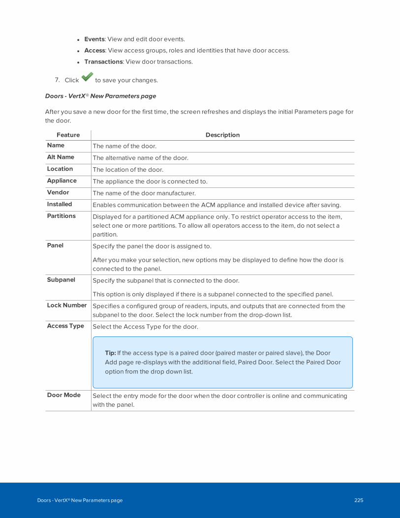
l Events: View and edit door events.
l Access: View access groups, roles and identities that have door access.
l Transactions: View door transactions.
7. Click to save your changes.
Doors - VertX® New Parameters page
After you save a new door for the first time, the screen refreshes and displays the initial Parameters page forthe door.
Feature Description
Name The name of the door.
Alt Name The alternative name of the door.
Location The location of the door.
Appliance The appliance the door is connected to.
Vendor The name of the door manufacturer.
Installed Enables communication between the ACM appliance and installed device after saving.
Partitions Displayed for a partitioned ACM appliance only. To restrict operator access to the item,select one or more partitions. To allow all operators access to the item, do not select apartition.
Panel Specify the panel the door is assigned to.
After you make your selection, new options may be displayed to define how the door isconnected to the panel.
Subpanel Specify the subpanel that is connected to the door.
This option is only displayed if there is a subpanel connected to the specified panel.
Lock Number Specifies a configured group of readers, inputs, and outputs that are connected from thesubpanel to the door. Select the lock number from the drop-down list.
Access Type Select the Access Type for the door.
Tip: If the access type is a paired door (paired master or paired slave), the DoorAdd page re-displays with the additional field, Paired Door. Select the Paired Dooroption from the drop down list.
Door Mode Select the entry mode for the door when the door controller is online and communicatingwith the panel.
Doors - VertX® New Parameters page 225
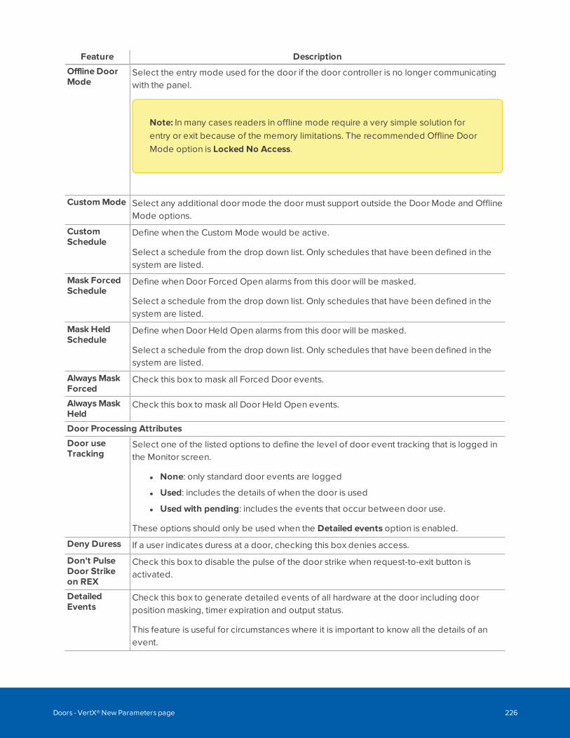
Feature Description
Offline DoorMode
Select the entry mode used for the door if the door controller is no longer communicatingwith the panel.
Note: In many cases readers in offline mode require a very simple solution forentry or exit because of the memory limitations. The recommended Offline DoorMode option is Locked No Access.
CustomMode Select any additional door mode the door must support outside the Door Mode and OfflineMode options.
CustomSchedule
Define when the Custom Mode would be active.
Select a schedule from the drop down list. Only schedules that have been defined in thesystem are listed.
Mask ForcedSchedule
Define when Door Forced Open alarms from this door will be masked.
Select a schedule from the drop down list. Only schedules that have been defined in thesystem are listed.
Mask HeldSchedule
Define when Door Held Open alarms from this door will be masked.
Select a schedule from the drop down list. Only schedules that have been defined in thesystem are listed.
AlwaysMaskForced
Check this box to mask all Forced Door events.
AlwaysMaskHeld
Check this box to mask all Door Held Open events.
Door Processing Attributes
Door useTracking
Select one of the listed options to define the level of door event tracking that is logged inthe Monitor screen.
l None: only standard door events are logged
l Used: includes the details of when the door is used
l Used with pending: includes the events that occur between door use.
These options should only be used when the Detailed events option is enabled.
Deny Duress If a user indicates duress at a door, checking this box denies access.
Don't PulseDoor Strikeon REX
Check this box to disable the pulse of the door strike when request-to-exit button isactivated.
DetailedEvents
Check this box to generate detailed events of all hardware at the door including doorposition masking, timer expiration and output status.
This feature is useful for circumstances where it is important to know all the details of anevent.
Doors - VertX® New Parameters page 226
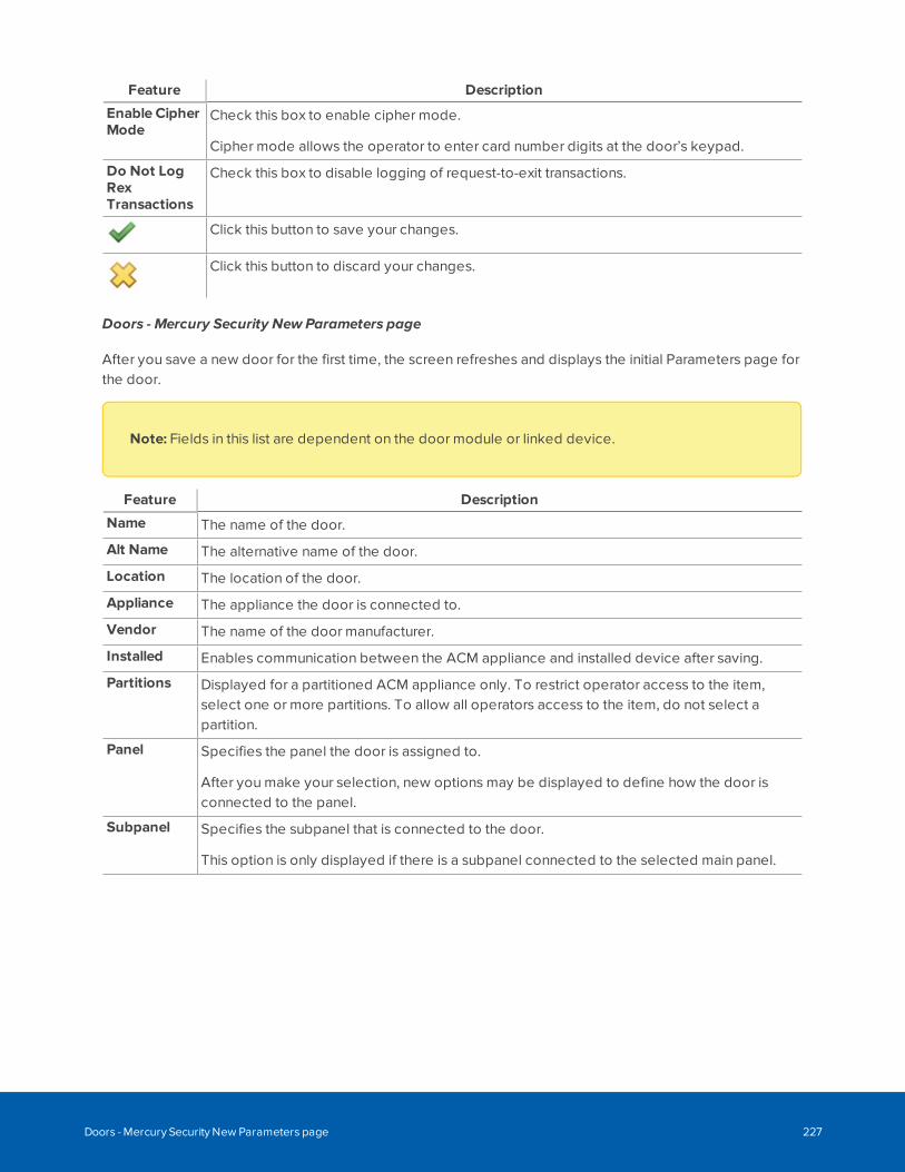
Feature Description
Enable CipherMode
Check this box to enable cipher mode.
Cipher mode allows the operator to enter card number digits at the door’s keypad.
Do Not LogRexTransactions
Check this box to disable logging of request-to-exit transactions.
Click this button to save your changes.
Click this button to discard your changes.
Doors - Mercury Security New Parameters page
After you save a new door for the first time, the screen refreshes and displays the initial Parameters page forthe door.
Note: Fields in this list are dependent on the door module or linked device.
Feature Description
Name The name of the door.
Alt Name The alternative name of the door.
Location The location of the door.
Appliance The appliance the door is connected to.
Vendor The name of the door manufacturer.
Installed Enables communication between the ACM appliance and installed device after saving.
Partitions Displayed for a partitioned ACM appliance only. To restrict operator access to the item,select one or more partitions. To allow all operators access to the item, do not select apartition.
Panel Specifies the panel the door is assigned to.
After you make your selection, new options may be displayed to define how the door isconnected to the panel.
Subpanel Specifies the subpanel that is connected to the door.
This option is only displayed if there is a subpanel connected to the selected main panel.
Doors - Mercury Security New Parameters page 227
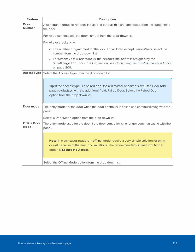
Feature Description
DoorNumber
A configured group of readers, inputs, and outputs that are connected from the subpanel tothe door.
For wired connections, the door number from the drop-down list.
For wireless locks only:
l The number programmed for the lock. For all locks except SimonsVoss, select thenumber from the drop-down list.
l For SimonsVoss wireless locks, the hexadecimal address assigned by theSmartIntego Tool. For more information, see Configuring SimonsVoss Wireless Lockson page 209.
Access Type Select the Access Type from the drop down list.
Tip: If the access type is a paired door (paired master or paired slave), the Door Addpage re-displays with the additional field, Paired Door. Select the Paired Dooroption from the drop down list.
Door mode The entry mode for the door when the door controller is online and communicating with thepanel.
Select a Door Mode option from the drop down list.
Offline DoorMode
The entry mode used for the door if the door controller is no longer communicating with thepanel.
Note: In many cases readers in offline mode require a very simple solution for entryor exit because of the memory limitations. The recommended Offline Door Modeoption is Locked No Access.
Select the Offline Mode option from the drop down list.
Doors - Mercury Security New Parameters page 228
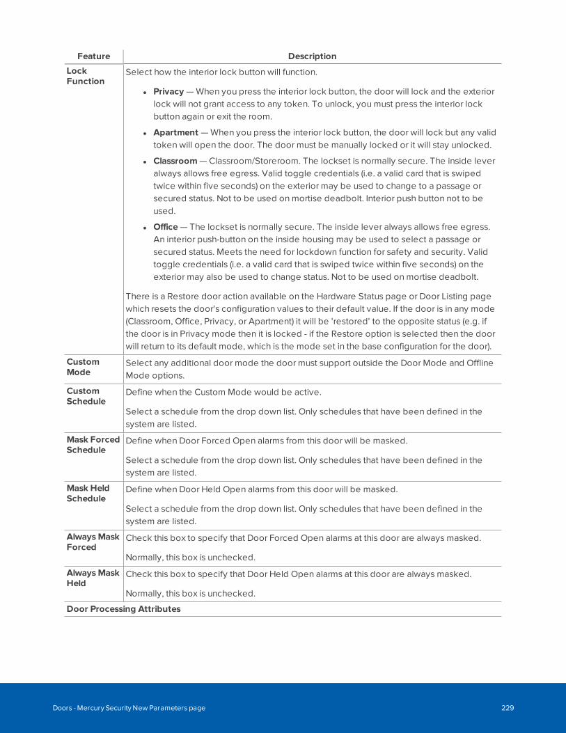
Feature Description
LockFunction
Select how the interior lock button will function.
l Privacy — When you press the interior lock button, the door will lock and the exteriorlock will not grant access to any token. To unlock, you must press the interior lockbutton again or exit the room.
l Apartment — When you press the interior lock button, the door will lock but any validtoken will open the door. The door must be manually locked or it will stay unlocked.
l Classroom — Classroom/Storeroom. The lockset is normally secure. The inside leveralways allows free egress. Valid toggle credentials (i.e. a valid card that is swipedtwice within five seconds) on the exterior may be used to change to a passage orsecured status. Not to be used on mortise deadbolt. Interior push button not to beused.
l Office — The lockset is normally secure. The inside lever always allows free egress.An interior push-button on the inside housing may be used to select a passage orsecured status. Meets the need for lockdown function for safety and security. Validtoggle credentials (i.e. a valid card that is swiped twice within five seconds) on theexterior may also be used to change status. Not to be used on mortise deadbolt.
There is a Restore door action available on the Hardware Status page or Door Listing pagewhich resets the door's configuration values to their default value. If the door is in any mode(Classroom, Office, Privacy, or Apartment) it will be 'restored' to the opposite status (e.g. ifthe door is in Privacy mode then it is locked - if the Restore option is selected then the doorwill return to its default mode, which is the mode set in the base configuration for the door).
CustomMode
Select any additional door mode the door must support outside the Door Mode and OfflineMode options.
CustomSchedule
Define when the Custom Mode would be active.
Select a schedule from the drop down list. Only schedules that have been defined in thesystem are listed.
Mask ForcedSchedule
Define when Door Forced Open alarms from this door will be masked.
Select a schedule from the drop down list. Only schedules that have been defined in thesystem are listed.
Mask HeldSchedule
Define when Door Held Open alarms from this door will be masked.
Select a schedule from the drop down list. Only schedules that have been defined in thesystem are listed.
AlwaysMaskForced
Check this box to specify that Door Forced Open alarms at this door are always masked.
Normally, this box is unchecked.
AlwaysMaskHeld
Check this box to specify that Door Held Open alarms at this door are always masked.
Normally, this box is unchecked.
Door Processing Attributes
Doors - Mercury Security New Parameters page 229
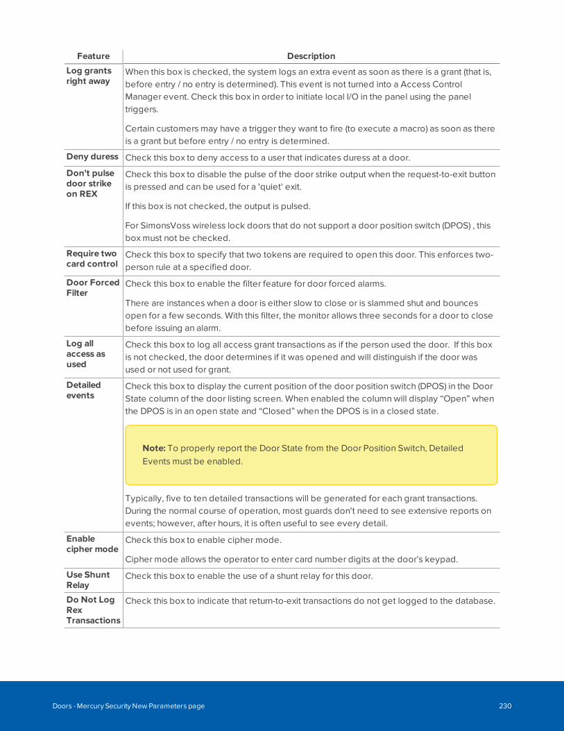
Feature Description
Log grantsright away
When this box is checked, the system logs an extra event as soon as there is a grant (that is,before entry / no entry is determined). This event is not turned into a Access ControlManager event. Check this box in order to initiate local I/O in the panel using the paneltriggers.
Certain customers may have a trigger they want to fire (to execute a macro) as soon as thereis a grant but before entry / no entry is determined.
Deny duress Check this box to deny access to a user that indicates duress at a door.
Don't pulsedoor strikeon REX
Check this box to disable the pulse of the door strike output when the request-to-exit buttonis pressed and can be used for a 'quiet' exit.
If this box is not checked, the output is pulsed.
For SimonsVoss wireless lock doors that do not support a door position switch (DPOS) , thisbox must not be checked.
Require twocard control
Check this box to specify that two tokens are required to open this door. This enforces two-person rule at a specified door.
Door ForcedFilter
Check this box to enable the filter feature for door forced alarms.
There are instances when a door is either slow to close or is slammed shut and bouncesopen for a few seconds. With this filter, the monitor allows three seconds for a door to closebefore issuing an alarm.
Log allaccess asused
Check this box to log all access grant transactions as if the person used the door. If this boxis not checked, the door determines if it was opened and will distinguish if the door wasused or not used for grant.
Detailedevents
Check this box to display the current position of the door position switch (DPOS) in the DoorState column of the door listing screen. When enabled the column will display “Open” whenthe DPOS is in an open state and “Closed” when the DPOS is in a closed state.
Note: To properly report the Door State from the Door Position Switch, DetailedEvents must be enabled.
Typically, five to ten detailed transactions will be generated for each grant transactions.During the normal course of operation, most guards don't need to see extensive reports onevents; however, after hours, it is often useful to see every detail.
Enablecipher mode
Check this box to enable cipher mode.
Cipher mode allows the operator to enter card number digits at the door’s keypad.
Use ShuntRelay
Check this box to enable the use of a shunt relay for this door.
Do Not LogRexTransactions
Check this box to indicate that return-to-exit transactions do not get logged to the database.
Doors - Mercury Security New Parameters page 230
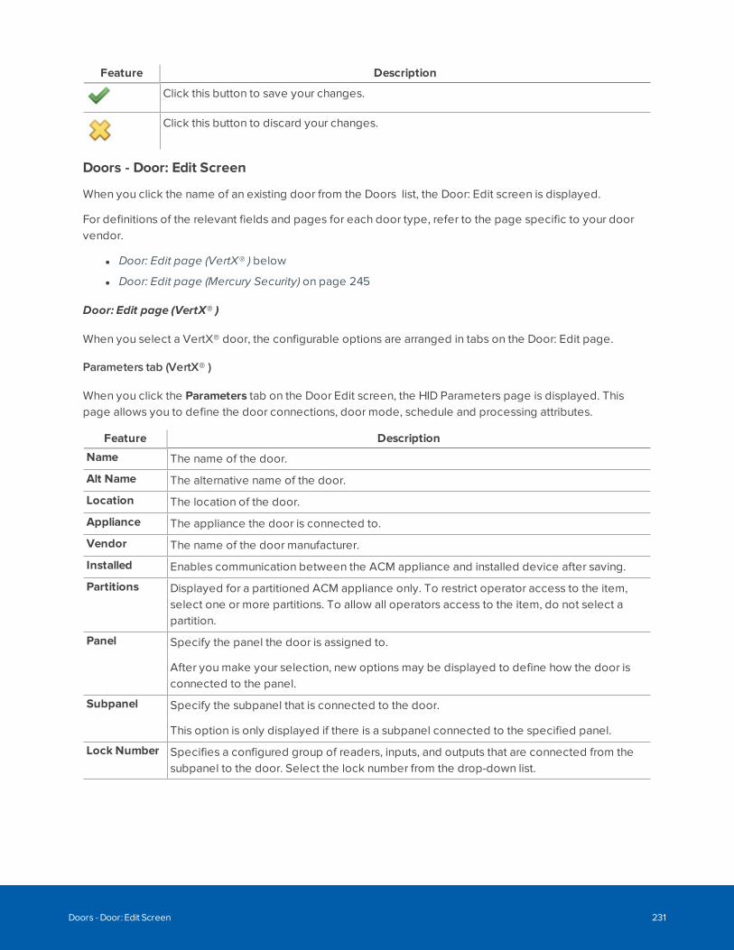
Feature Description
Click this button to save your changes.
Click this button to discard your changes.
Doors - Door: Edit Screen
When you click the name of an existing door from the Doors list, the Door: Edit screen is displayed.
For definitions of the relevant fields and pages for each door type, refer to the page specific to your doorvendor.
l Door: Edit page (VertX® ) below
l Door: Edit page (Mercury Security) on page 245
Door: Edit page (VertX® )
When you select a VertX® door, the configurable options are arranged in tabs on the Door: Edit page.
Parameters tab (VertX® )
When you click the Parameters tab on the Door Edit screen, the HID Parameters page is displayed. Thispage allows you to define the door connections, door mode, schedule and processing attributes.
Feature Description
Name The name of the door.
Alt Name The alternative name of the door.
Location The location of the door.
Appliance The appliance the door is connected to.
Vendor The name of the door manufacturer.
Installed Enables communication between the ACM appliance and installed device after saving.
Partitions Displayed for a partitioned ACM appliance only. To restrict operator access to the item,select one or more partitions. To allow all operators access to the item, do not select apartition.
Panel Specify the panel the door is assigned to.
After you make your selection, new options may be displayed to define how the door isconnected to the panel.
Subpanel Specify the subpanel that is connected to the door.
This option is only displayed if there is a subpanel connected to the specified panel.
Lock Number Specifies a configured group of readers, inputs, and outputs that are connected from thesubpanel to the door. Select the lock number from the drop-down list.
Doors - Door: Edit Screen 231
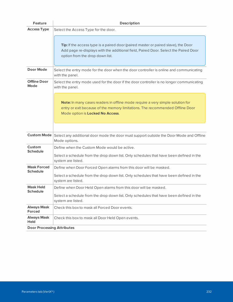
Feature Description
Access Type Select the Access Type for the door.
Tip: If the access type is a paired door (paired master or paired slave), the DoorAdd page re-displays with the additional field, Paired Door. Select the Paired Dooroption from the drop down list.
Door Mode Select the entry mode for the door when the door controller is online and communicatingwith the panel.
Offline DoorMode
Select the entry mode used for the door if the door controller is no longer communicatingwith the panel.
Note: In many cases readers in offline mode require a very simple solution forentry or exit because of the memory limitations. The recommended Offline DoorMode option is Locked No Access.
CustomMode Select any additional door mode the door must support outside the Door Mode and OfflineMode options.
CustomSchedule
Define when the Custom Mode would be active.
Select a schedule from the drop down list. Only schedules that have been defined in thesystem are listed.
Mask ForcedSchedule
Define when Door Forced Open alarms from this door will be masked.
Select a schedule from the drop down list. Only schedules that have been defined in thesystem are listed.
Mask HeldSchedule
Define when Door Held Open alarms from this door will be masked.
Select a schedule from the drop down list. Only schedules that have been defined in thesystem are listed.
AlwaysMaskForced
Check this box to mask all Forced Door events.
AlwaysMaskHeld
Check this box to mask all Door Held Open events.
Door Processing Attributes
Parameters tab (VertX® ) 232
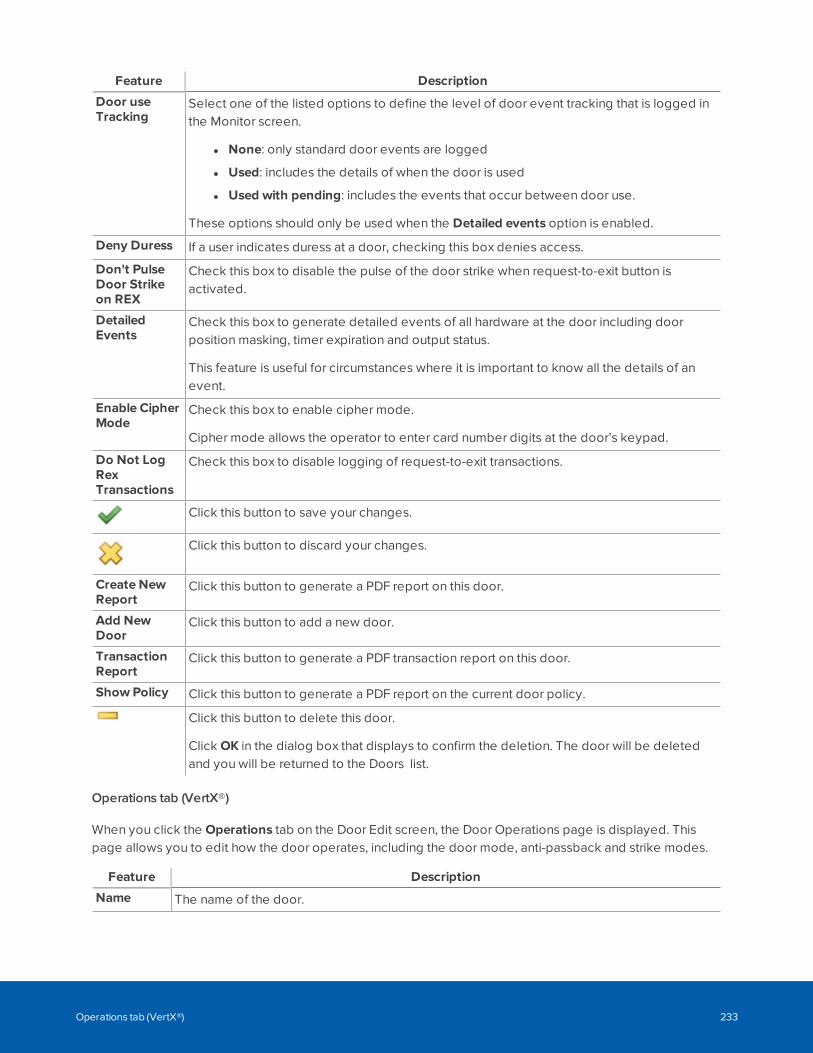
Feature Description
Door useTracking
Select one of the listed options to define the level of door event tracking that is logged inthe Monitor screen.
l None: only standard door events are logged
l Used: includes the details of when the door is used
l Used with pending: includes the events that occur between door use.
These options should only be used when the Detailed events option is enabled.
Deny Duress If a user indicates duress at a door, checking this box denies access.
Don't PulseDoor Strikeon REX
Check this box to disable the pulse of the door strike when request-to-exit button isactivated.
DetailedEvents
Check this box to generate detailed events of all hardware at the door including doorposition masking, timer expiration and output status.
This feature is useful for circumstances where it is important to know all the details of anevent.
Enable CipherMode
Check this box to enable cipher mode.
Cipher mode allows the operator to enter card number digits at the door’s keypad.
Do Not LogRexTransactions
Check this box to disable logging of request-to-exit transactions.
Click this button to save your changes.
Click this button to discard your changes.
Create NewReport
Click this button to generate a PDF report on this door.
Add NewDoor
Click this button to add a new door.
TransactionReport
Click this button to generate a PDF transaction report on this door.
Show Policy Click this button to generate a PDF report on the current door policy.
Click this button to delete this door.
Click OK in the dialog box that displays to confirm the deletion. The door will be deletedand you will be returned to the Doors list.
Operations tab (VertX®)
When you click the Operations tab on the Door Edit screen, the Door Operations page is displayed. Thispage allows you to edit how the door operates, including the door mode, anti-passback and strike modes.
Feature Description
Name The name of the door.
Operations tab (VertX®) 233
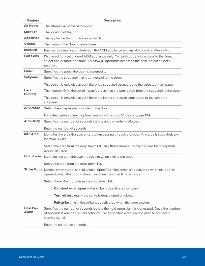
Feature Description
Alt Name The alternative name of the door.
Location The location of the door.
Appliance The appliance the door is connected to.
Vendor The name of the door manufacturer.
Installed Enables communication between the ACM appliance and installed device after saving.
Partitions Displayed for a partitioned ACM appliance only. To restrict operator access to the item,select one or more partitions. To allow all operators access to the item, do not select apartition.
Panel Specifies the panel the door is assigned to.
Subpanel Specifies the subpanel that is connected to the door.
This option is only displayed if there is a subpanel connected to the selected main panel.
LockNumber
The number ID for the set of inputs/outputs that are connected from the subpanel to the door.
This option is only displayed if there are inputs or outputs connected to the selectedsubpanel.
APB Mode Select the anti-passback mode for the door.
For a description of each option, see Anti-Passback Modes on page 194.
APB Delay Specifies the number of seconds before another entry is allowed.
Enter the number of seconds.
Into Area Identifies the area the user enters when passing through the door. If no area is specified, anylocation is valid.
Select the area from the drop down list. Only those areas currently defined for this systemappear in this list.
Out of area Identifies the area the user moves into when exiting the door.
Select the area from the drop down list.
StrikeMode Defines when a door should unlock. Specifies if the strike is deactivated when the door isopened, when the door is closed, or when the strike timer expires.
Select the strike mode from the drop down list.
l Cut short when open — the strike is deactivated on open
l Turn off on close — the strike is deactivated on close.
l Full strike time — the strike is deactivated when the timer expires.
Held Pre-Alarm
Specifies the number of seconds before the held open alarm is generated. Once the numberof seconds is reached, a transaction will be generated which can be used to activate awarning signal.
Enter the number of seconds.
Operations tab (VertX®) 234
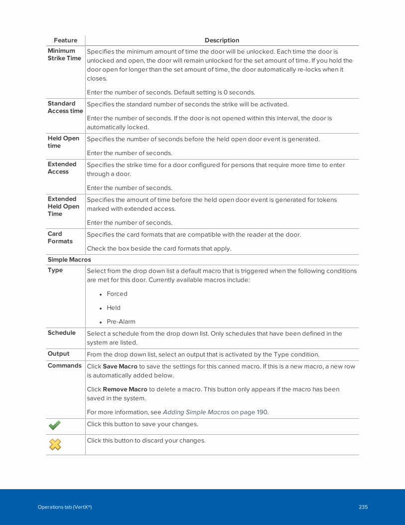
Feature Description
MinimumStrike Time
Specifies the minimum amount of time the door will be unlocked. Each time the door isunlocked and open, the door will remain unlocked for the set amount of time. If you hold thedoor open for longer than the set amount of time, the door automatically re-locks when itcloses.
Enter the number of seconds. Default setting is 0 seconds.
StandardAccess time
Specifies the standard number of seconds the strike will be activated.
Enter the number of seconds. If the door is not opened within this interval, the door isautomatically locked.
Held Opentime
Specifies the number of seconds before the held open door event is generated.
Enter the number of seconds.
ExtendedAccess
Specifies the strike time for a door configured for persons that require more time to enterthrough a door.
Enter the number of seconds.
ExtendedHeld OpenTime
Specifies the amount of time before the held open door event is generated for tokensmarked with extended access.
Enter the number of seconds.
CardFormats
Specifies the card formats that are compatible with the reader at the door.
Check the box beside the card formats that apply.
SimpleMacros
Type Select from the drop down list a default macro that is triggered when the following conditionsare met for this door. Currently available macros include:
l Forced
l Held
l Pre-Alarm
Schedule Select a schedule from the drop down list. Only schedules that have been defined in thesystem are listed.
Output From the drop down list, select an output that is activated by the Type condition.
Commands Click SaveMacro to save the settings for this canned macro. If this is a new macro, a new rowis automatically added below.
Click RemoveMacro to delete a macro. This button only appears if the macro has beensaved in the system.
For more information, see Adding Simple Macros on page 190.
Click this button to save your changes.
Click this button to discard your changes.
Operations tab (VertX®) 235
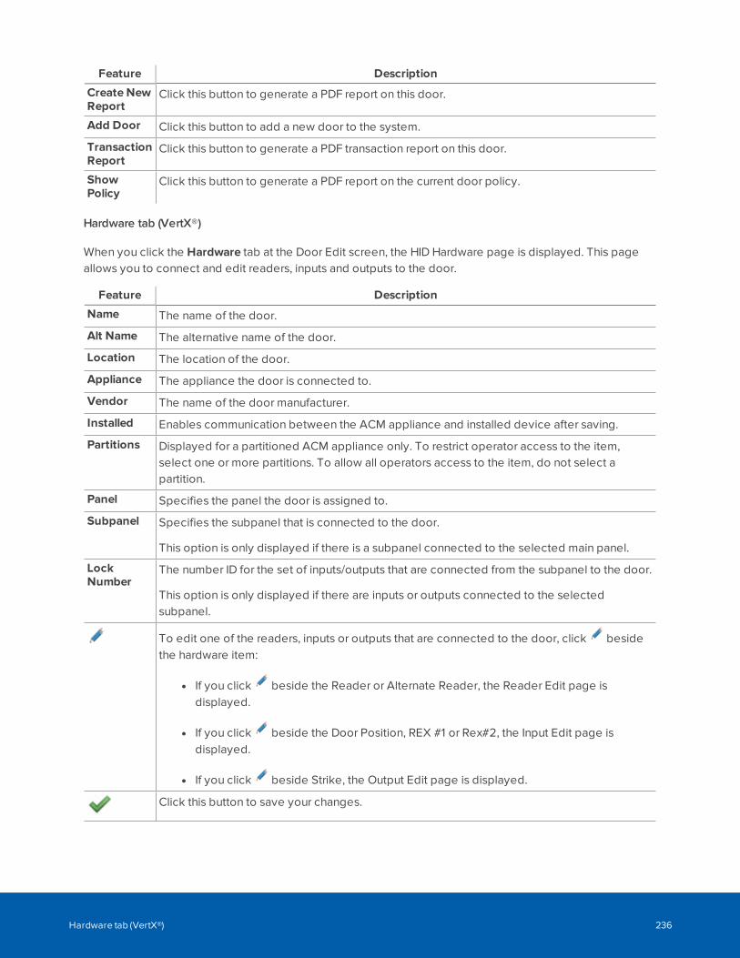
Feature Description
Create NewReport
Click this button to generate a PDF report on this door.
Add Door Click this button to add a new door to the system.
TransactionReport
Click this button to generate a PDF transaction report on this door.
ShowPolicy
Click this button to generate a PDF report on the current door policy.
Hardware tab (VertX®)
When you click the Hardware tab at the Door Edit screen, the HID Hardware page is displayed. This pageallows you to connect and edit readers, inputs and outputs to the door.
Feature Description
Name The name of the door.
Alt Name The alternative name of the door.
Location The location of the door.
Appliance The appliance the door is connected to.
Vendor The name of the door manufacturer.
Installed Enables communication between the ACM appliance and installed device after saving.
Partitions Displayed for a partitioned ACM appliance only. To restrict operator access to the item,select one or more partitions. To allow all operators access to the item, do not select apartition.
Panel Specifies the panel the door is assigned to.
Subpanel Specifies the subpanel that is connected to the door.
This option is only displayed if there is a subpanel connected to the selected main panel.
LockNumber
The number ID for the set of inputs/outputs that are connected from the subpanel to the door.
This option is only displayed if there are inputs or outputs connected to the selectedsubpanel.
To edit one of the readers, inputs or outputs that are connected to the door, click besidethe hardware item:
l If you click beside the Reader or Alternate Reader, the Reader Edit page isdisplayed.
l If you click beside the Door Position, REX #1 or Rex#2, the Input Edit page isdisplayed.
l If you click beside Strike, the Output Edit page is displayed.
Click this button to save your changes.
Hardware tab (VertX®) 236
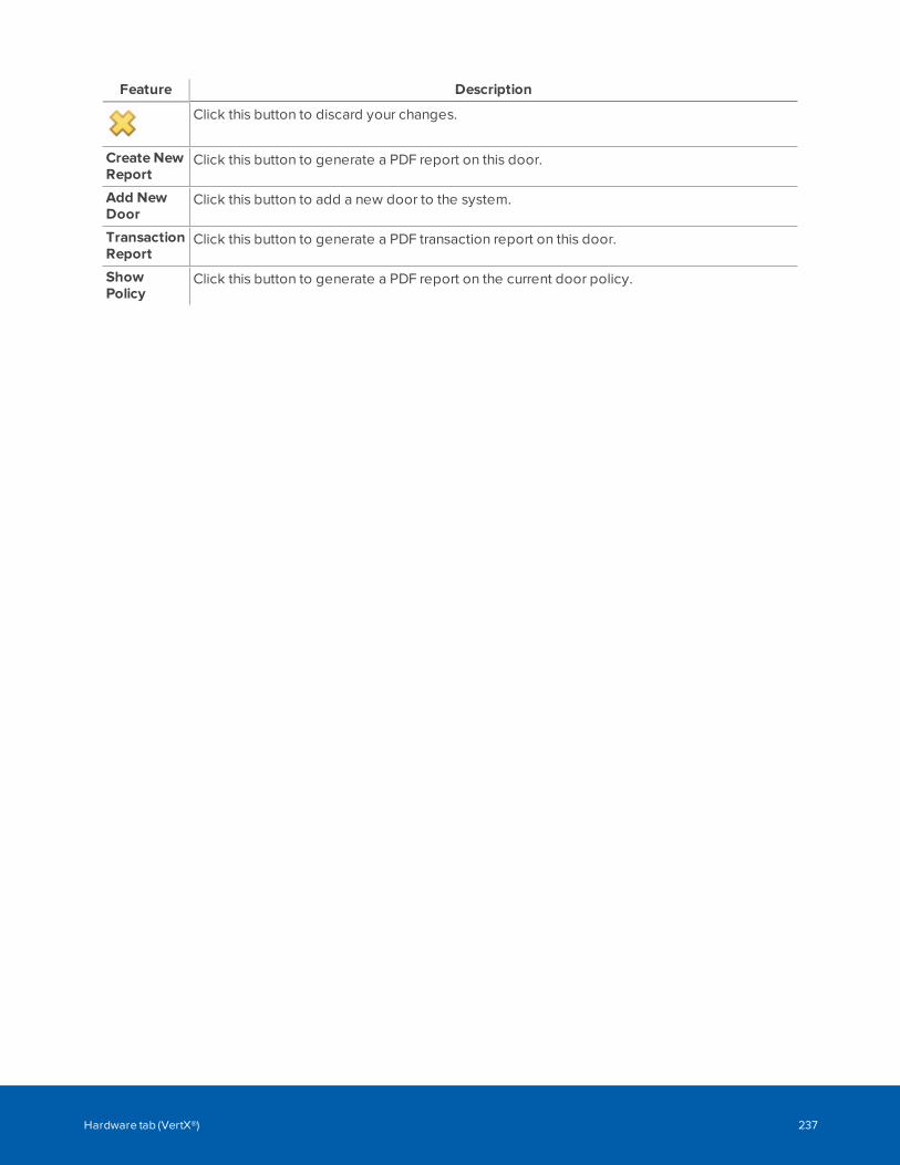
Feature Description
Click this button to discard your changes.
Create NewReport
Click this button to generate a PDF report on this door.
Add NewDoor
Click this button to add a new door to the system.
TransactionReport
Click this button to generate a PDF transaction report on this door.
ShowPolicy
Click this button to generate a PDF report on the current door policy.
Hardware tab (VertX®) 237
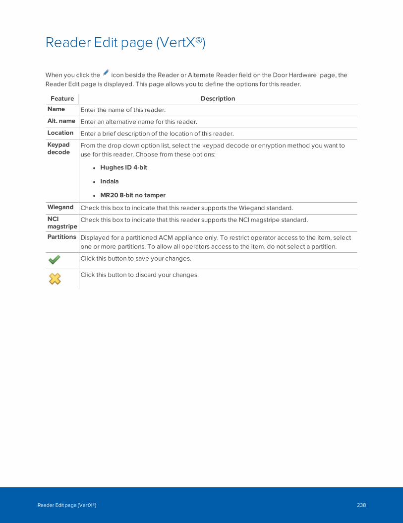
Reader Edit page (VertX®)
When you click the icon beside the Reader or Alternate Reader field on the Door Hardware page, theReader Edit page is displayed. This page allows you to define the options for this reader.
Feature Description
Name Enter the name of this reader.
Alt. name Enter an alternative name for this reader.
Location Enter a brief description of the location of this reader.
Keypaddecode
From the drop down option list, select the keypad decode or enryption method you want touse for this reader. Choose from these options:
l Hughes ID 4-bit
l Indala
l MR20 8-bit no tamper
Wiegand Check this box to indicate that this reader supports the Wiegand standard.
NCImagstripe
Check this box to indicate that this reader supports the NCI magstripe standard.
Partitions Displayed for a partitioned ACM appliance only. To restrict operator access to the item, selectone or more partitions. To allow all operators access to the item, do not select a partition.
Click this button to save your changes.
Click this button to discard your changes.
Reader Edit page (VertX®) 238
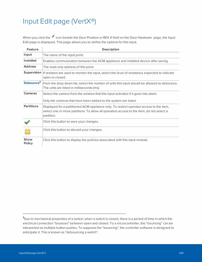
Input Edit page (VertX®)
When you click the icon beside the Door Position or REX # field on the Door Hardware page, the InputEdit page is displayed. This page allows you to define the options for this input.
Feature Description
Input The name of the input point.
Installed Enables communication between the ACM appliance and installed device after saving.
Address The read-only address of this point.
Supervision If resistors are used to monitor the input, select the level of resistance expected to indicateopen or closed.
Debounce1 From the drop down list, select the number of units this input should be allowed to debounce.The units are listed in milliseconds (ms).
Cameras Select the camera from the window that this input activates if it goes into alarm.
Only the cameras that have been added to the system are listed.
Partitions Displayed for a partitioned ACM appliance only. To restrict operator access to the item,select one or more partitions. To allow all operators access to the item, do not select apartition.
Click this button to save your changes.
Click this button to discard your changes.
ShowPolicy
Click this button to display the policies associated with this input module.
1Due to mechanical properties of a switch, when a switch is closed, there is a period of time in which theelectrical connection "bounces" between open and closed. To a microcontroller, this "bouncing" can beinterpreted as multiple button pushes. To suppress the "bouncing", the controller software is designed toanticipate it. This is known as "debouncing a switch".
Input Edit page (VertX®) 239
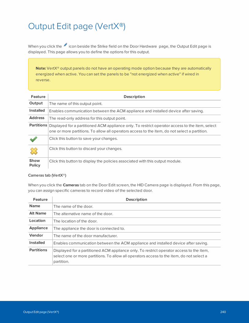
Output Edit page (VertX®)
When you click the icon beside the Strike field on the Door Hardware page, the Output Edit page isdisplayed. This page allows you to define the options for this output.
Note: VertX® output panels do not have an operating mode option because they are automaticallyenergized when active. You can set the panels to be "not energized when active" if wired inreverse.
Feature Description
Output The name of this output point.
Installed Enables communication between the ACM appliance and installed device after saving.
Address The read-only address for this output point.
Partitions Displayed for a partitioned ACM appliance only. To restrict operator access to the item, selectone or more partitions. To allow all operators access to the item, do not select a partition.
Click this button to save your changes.
Click this button to discard your changes.
ShowPolicy
Click this button to display the policies associated with this output module.
Cameras tab (VertX®)
When you click the Cameras tab on the Door Edit screen, the HID Camera page is displayed. From this page,you can assign specific cameras to record video of the selected door.
Feature Description
Name The name of the door.
Alt Name The alternative name of the door.
Location The location of the door.
Appliance The appliance the door is connected to.
Vendor The name of the door manufacturer.
Installed Enables communication between the ACM appliance and installed device after saving.
Partitions Displayed for a partitioned ACM appliance only. To restrict operator access to the item,select one or more partitions. To allow all operators access to the item, do not select apartition.
Output Edit page (VertX®) 240
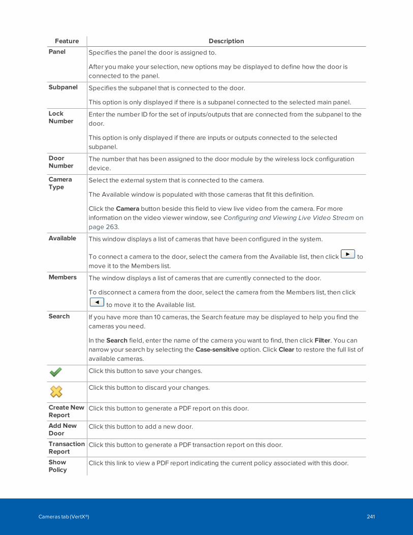
Feature Description
Panel Specifies the panel the door is assigned to.
After you make your selection, new options may be displayed to define how the door isconnected to the panel.
Subpanel Specifies the subpanel that is connected to the door.
This option is only displayed if there is a subpanel connected to the selected main panel.
LockNumber
Enter the number ID for the set of inputs/outputs that are connected from the subpanel to thedoor.
This option is only displayed if there are inputs or outputs connected to the selectedsubpanel.
DoorNumber
The number that has been assigned to the door module by the wireless lock configurationdevice.
CameraType
Select the external system that is connected to the camera.
The Available window is populated with those cameras that fit this definition.
Click the Camera button beside this field to view live video from the camera. For moreinformation on the video viewer window, see Configuring and Viewing Live Video Stream onpage 263.
Available This window displays a list of cameras that have been configured in the system.
To connect a camera to the door, select the camera from the Available list, then click tomove it to the Members list.
Members The window displays a list of cameras that are currently connected to the door.
To disconnect a camera from the door, select the camera from the Members list, then click
to move it to the Available list.
Search If you have more than 10 cameras, the Search feature may be displayed to help you find thecameras you need.
In the Search field, enter the name of the camera you want to find, then click Filter. You cannarrow your search by selecting the Case-sensitive option. Click Clear to restore the full list ofavailable cameras.
Click this button to save your changes.
Click this button to discard your changes.
Create NewReport
Click this button to generate a PDF report on this door.
Add NewDoor
Click this button to add a new door.
TransactionReport
Click this button to generate a PDF transaction report on this door.
ShowPolicy
Click this link to view a PDF report indicating the current policy associated with this door.
Cameras tab (VertX®) 241
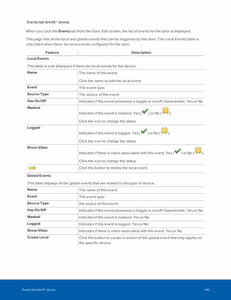
Events tab (VertX® doors)
When you click the Events tab from the Door: Edit screen, the list of events for the door is displayed.
This page lists all the local and global events that can be triggered by this door. The Local Events table isonly listed when there are local events configured for the door.
Feature Description
Local Events
This table is only displayed if there are local events for the device.
Name The name of this event.
Click the name to edit the local event.
Event The event type.
Source Type The source of this event.
Has On/Off Indicates if this event possesses a toggle or on/off characteristic. Yes or No.
MaskedIndicates if this event is masked. Yes ( ) or No ( ).
Click the icon to change the status.
LoggedIndicates if this event is logged. Yes ( ) or No ( ).
Click the icon to change the status.
Show VideoIndicates if there is video associated with this event. Yes ( ) or No ( ).
Click the icon to change the status.
Click this button to delete the local event.
Global Events
This table displays all the global events that are related to this type of device.
Name The name of this event.
Event The event type.
Source Type the source of this event.
Has On/Off Indicates if this event possesses a toggle or on/off characteristic. Yes or No.
Masked Indicates if this event is masked. Yes or No.
Logged Indicates if this event is logged. Yes or No.
Show Video Indicates if there is video associated with this event. Yes or No.
Create Local Click this button to create a version of this global event that only applies tothe specific device.
Events tab (VertX® doors) 242
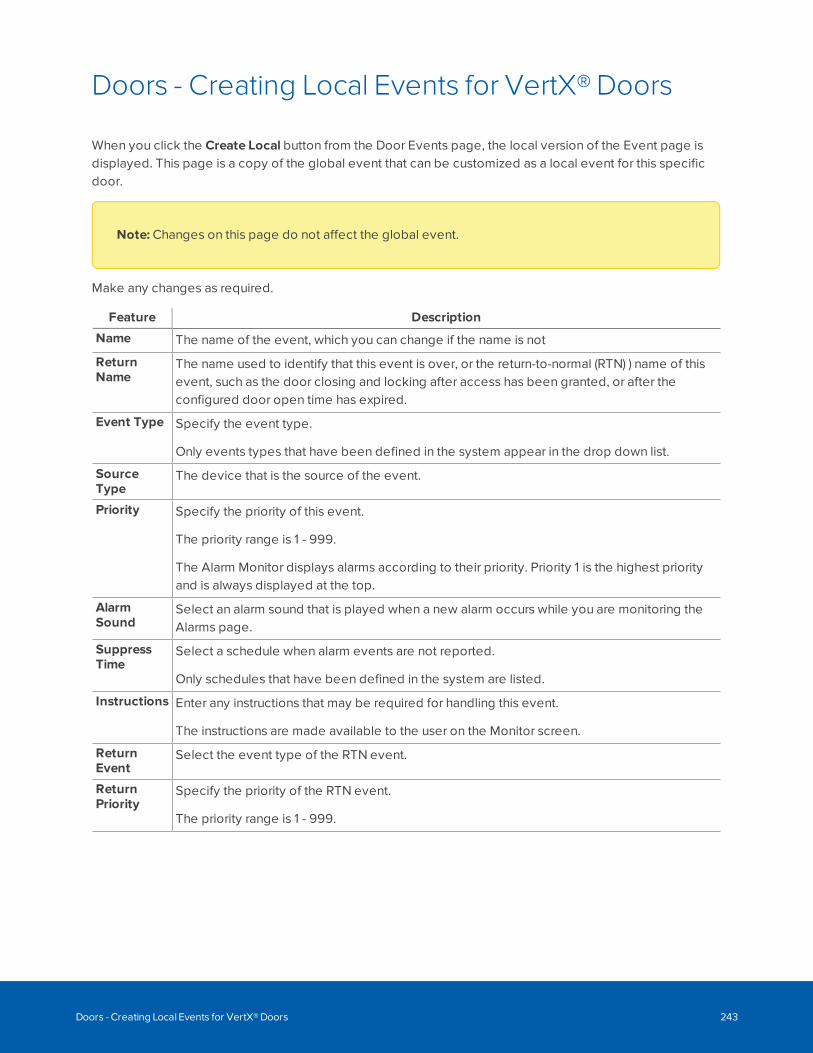
Doors - Creating Local Events for VertX® Doors
When you click the Create Local button from the Door Events page, the local version of the Event page isdisplayed. This page is a copy of the global event that can be customized as a local event for this specificdoor.
Note: Changes on this page do not affect the global event.
Make any changes as required.
Feature Description
Name The name of the event, which you can change if the name is not
ReturnName
The name used to identify that this event is over, or the return-to-normal (RTN) ) name of thisevent, such as the door closing and locking after access has been granted, or after theconfigured door open time has expired.
Event Type Specify the event type.
Only events types that have been defined in the system appear in the drop down list.
SourceType
The device that is the source of the event.
Priority Specify the priority of this event.
The priority range is 1 - 999.
The Alarm Monitor displays alarms according to their priority. Priority 1 is the highest priorityand is always displayed at the top.
AlarmSound
Select an alarm sound that is played when a new alarm occurs while you are monitoring theAlarms page.
SuppressTime
Select a schedule when alarm events are not reported.
Only schedules that have been defined in the system are listed.
Instructions Enter any instructions that may be required for handling this event.
The instructions are made available to the user on the Monitor screen.
ReturnEvent
Select the event type of the RTN event.
ReturnPriority
Specify the priority of the RTN event.
The priority range is 1 - 999.
Doors - Creating Local Events for VertX® Doors 243
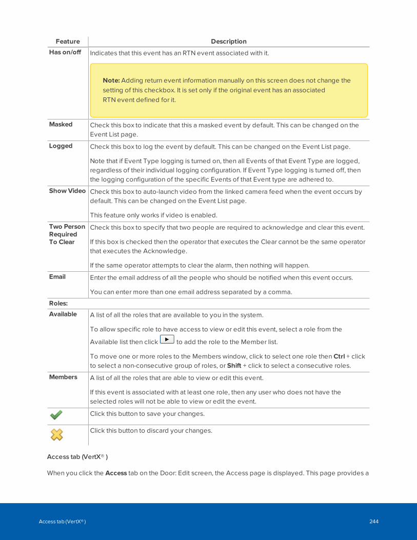
Feature Description
Has on/off Indicates that this event has an RTN event associated with it.
Note: Adding return event information manually on this screen does not change thesetting of this checkbox. It is set only if the original event has an associatedRTN event defined for it.
Masked Check this box to indicate that this a masked event by default. This can be changed on theEvent List page.
Logged Check this box to log the event by default. This can be changed on the Event List page.
Note that if Event Type logging is turned on, then all Events of that Event Type are logged,regardless of their individual logging configuration. If Event Type logging is turned off, thenthe logging configuration of the specific Events of that Event type are adhered to.
Show Video Check this box to auto-launch video from the linked camera feed when the event occurs bydefault. This can be changed on the Event List page.
This feature only works if video is enabled.
Two PersonRequiredTo Clear
Check this box to specify that two people are required to acknowledge and clear this event.
If this box is checked then the operator that executes the Clear cannot be the same operatorthat executes the Acknowledge.
If the same operator attempts to clear the alarm, then nothing will happen.
Email Enter the email address of all the people who should be notified when this event occurs.
You can enter more than one email address separated by a comma.
Roles:
Available A list of all the roles that are available to you in the system.
To allow specific role to have access to view or edit this event, select a role from the
Available list then click to add the role to the Member list.
To move one or more roles to the Members window, click to select one role then Ctrl + clickto select a non-consecutive group of roles, or Shift + click to select a consecutive roles.
Members A list of all the roles that are able to view or edit this event.
If this event is associated with at least one role, then any user who does not have theselected roles will not be able to view or edit the event.
Click this button to save your changes.
Click this button to discard your changes.
Access tab (VertX® )
When you click the Access tab on the Door: Edit screen, the Access page is displayed. This page provides a
Access tab (VertX® ) 244
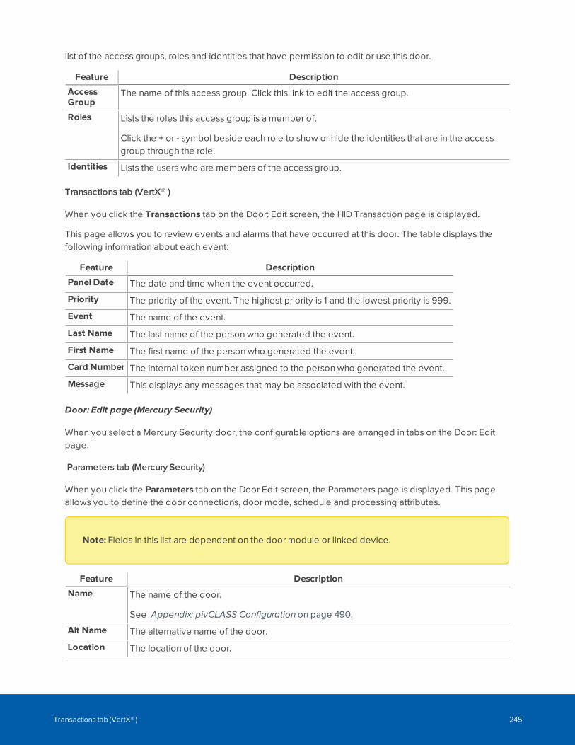
list of the access groups, roles and identities that have permission to edit or use this door.
Feature Description
AccessGroup
The name of this access group. Click this link to edit the access group.
Roles Lists the roles this access group is a member of.
Click the + or - symbol beside each role to show or hide the identities that are in the accessgroup through the role.
Identities Lists the users who are members of the access group.
Transactions tab (VertX® )
When you click the Transactions tab on the Door: Edit screen, the HID Transaction page is displayed.
This page allows you to review events and alarms that have occurred at this door. The table displays thefollowing information about each event:
Feature Description
Panel Date The date and time when the event occurred.
Priority The priority of the event. The highest priority is 1 and the lowest priority is 999.
Event The name of the event.
Last Name The last name of the person who generated the event.
First Name The first name of the person who generated the event.
Card Number The internal token number assigned to the person who generated the event.
Message This displays any messages that may be associated with the event.
Door: Edit page (Mercury Security)
When you select a Mercury Security door, the configurable options are arranged in tabs on the Door: Editpage.
Parameters tab (Mercury Security)
When you click the Parameters tab on the Door Edit screen, the Parameters page is displayed. This pageallows you to define the door connections, door mode, schedule and processing attributes.
Note: Fields in this list are dependent on the door module or linked device.
Feature Description
Name The name of the door.
See Appendix: pivCLASS Configuration on page 490.
Alt Name The alternative name of the door.
Location The location of the door.
Transactions tab (VertX® ) 245
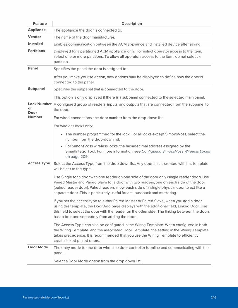
Feature Description
Appliance The appliance the door is connected to.
Vendor The name of the door manufacturer.
Installed Enables communication between the ACM appliance and installed device after saving.
Partitions Displayed for a partitioned ACM appliance only. To restrict operator access to the item,select one or more partitions. To allow all operators access to the item, do not select apartition.
Panel Specifies the panel the door is assigned to.
After you make your selection, new options may be displayed to define how the door isconnected to the panel.
Subpanel Specifies the subpanel that is connected to the door.
This option is only displayed if there is a subpanel connected to the selected main panel.
Lock NumberorDoorNumber
A configured group of readers, inputs, and outputs that are connected from the subpanel tothe door.
For wired connections, the door number from the drop-down list.
For wireless locks only:
l The number programmed for the lock. For all locks except SimonsVoss, select thenumber from the drop-down list.
l For SimonsVoss wireless locks, the hexadecimal address assigned by theSmartIntego Tool. For more information, see Configuring SimonsVoss Wireless Lockson page 209.
Access Type Select the Access Type from the drop down list. Any door that is created with this templatewill be set to this type.
Use Single for a door with one reader on one side of the door only (single reader door). UsePaired Master and Paired Slave for a door with two readers, one on each side of the door(paired reader door). Paired readers allow each side of a single physical door to act like aseparate door. This is particularly useful for anti-passback and mustering.
If you set the access type to either Paired Master or Paired Slave, when you add a doorusing this template, the Door Add page displays with the additional field, Linked Door. Usethis field to select the door with the reader on the other side. The linking between the doorshas to be done separately from adding the door.
The Access Type can also be configured in the Wiring Template. When configured in boththe Wiring Template, and the associated Door Template, the setting in the Wiring Templatetakes precedence. It is recommended that you use the Wiring Template to efficientlycreate linked paired doors.
Door Mode The entry mode for the door when the door controller is online and communicating with thepanel.
Select a Door Mode option from the drop down list.
Parameters tab (Mercury Security) 246
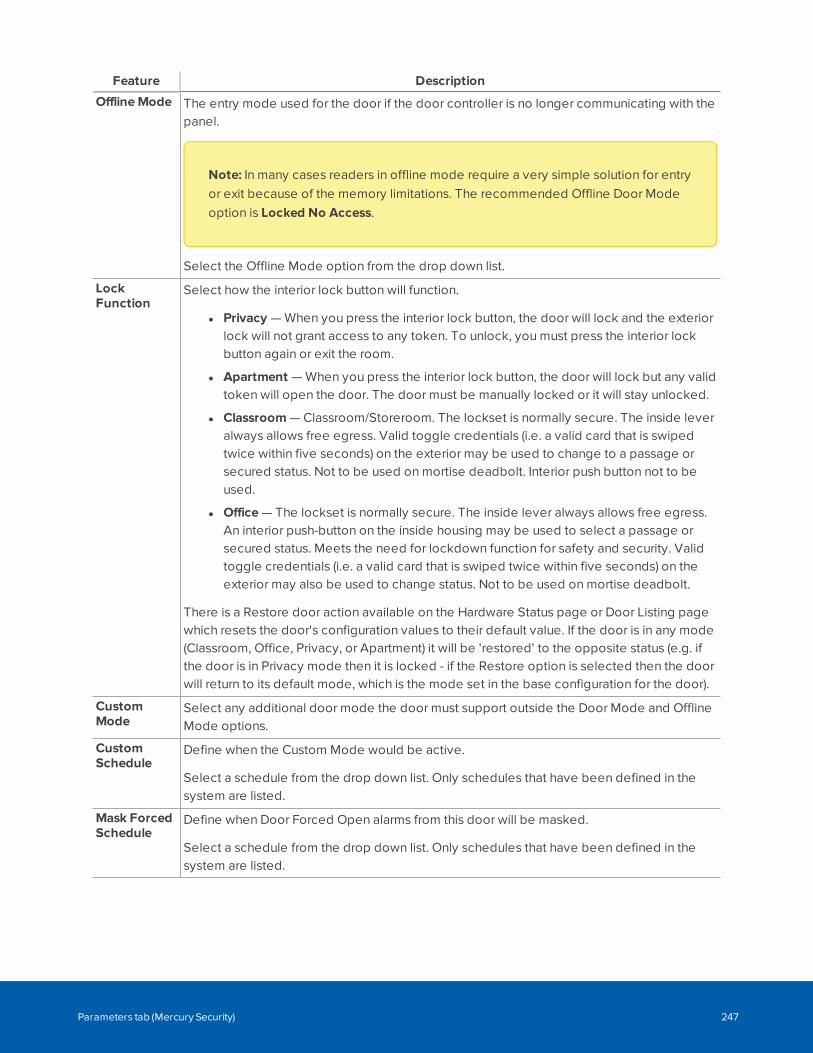
Feature Description
OfflineMode The entry mode used for the door if the door controller is no longer communicating with thepanel.
Note: In many cases readers in offline mode require a very simple solution for entryor exit because of the memory limitations. The recommended Offline Door Modeoption is Locked No Access.
Select the Offline Mode option from the drop down list.
LockFunction
Select how the interior lock button will function.
l Privacy — When you press the interior lock button, the door will lock and the exteriorlock will not grant access to any token. To unlock, you must press the interior lockbutton again or exit the room.
l Apartment — When you press the interior lock button, the door will lock but any validtoken will open the door. The door must be manually locked or it will stay unlocked.
l Classroom — Classroom/Storeroom. The lockset is normally secure. The inside leveralways allows free egress. Valid toggle credentials (i.e. a valid card that is swipedtwice within five seconds) on the exterior may be used to change to a passage orsecured status. Not to be used on mortise deadbolt. Interior push button not to beused.
l Office — The lockset is normally secure. The inside lever always allows free egress.An interior push-button on the inside housing may be used to select a passage orsecured status. Meets the need for lockdown function for safety and security. Validtoggle credentials (i.e. a valid card that is swiped twice within five seconds) on theexterior may also be used to change status. Not to be used on mortise deadbolt.
There is a Restore door action available on the Hardware Status page or Door Listing pagewhich resets the door's configuration values to their default value. If the door is in any mode(Classroom, Office, Privacy, or Apartment) it will be 'restored' to the opposite status (e.g. ifthe door is in Privacy mode then it is locked - if the Restore option is selected then the doorwill return to its default mode, which is the mode set in the base configuration for the door).
CustomMode
Select any additional door mode the door must support outside the Door Mode and OfflineMode options.
CustomSchedule
Define when the Custom Mode would be active.
Select a schedule from the drop down list. Only schedules that have been defined in thesystem are listed.
Mask ForcedSchedule
Define when Door Forced Open alarms from this door will be masked.
Select a schedule from the drop down list. Only schedules that have been defined in thesystem are listed.
Parameters tab (Mercury Security) 247
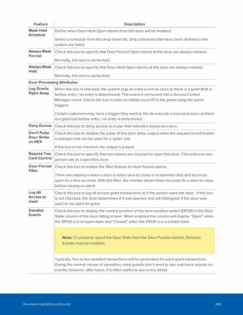
Feature Description
Mask HeldSchedule
Define when Door Held Open alarms from this door will be masked.
Select a schedule from the drop down list. Only schedules that have been defined in thesystem are listed.
AlwaysMaskForced
Check this box to specify that Door Forced Open alarms at this door are always masked.
Normally, this box is unchecked.
AlwaysMaskHeld
Check this box to specify that Door Held Open alarms at this door are always masked.
Normally, this box is unchecked.
Door Processing Attributes
Log GrantsRight Away
When this box is checked, the system logs an extra event as soon as there is a grant (that is,before entry / no entry is determined). This event is not turned into a Access ControlManager event. Check this box in order to initiate local I/O in the panel using the paneltriggers.
Certain customers may have a trigger they want to fire (to execute a macro) as soon as thereis a grant but before entry / no entry is determined.
Deny Duress Check this box to deny access to a user that indicates duress at a door.
Don't PulseDoor Strikeon REX
Check this box to disable the pulse of the door strike output when the request-to-exit buttonis pressed and can be used for a 'quiet' exit.
If this box is not checked, the output is pulsed.
Require TwoCard Control
Check this box to specify that two tokens are required to open this door. This enforces two-person rule at a specified door.
Door ForcedFilter
Check this box to enable the filter feature for door forced alarms.
There are instances when a door is either slow to close or is slammed shut and bouncesopen for a few seconds. With this filter, the monitor allows three seconds for a door to closebefore issuing an alarm.
Log AllAccess asUsed
Check this box to log all access grant transactions as if the person used the door. If this boxis not checked, the door determines if it was opened and will distinguish if the door wasused or not used for grant.
DetailedEvents
Check this box to display the current position of the door position switch (DPOS) in the DoorState column of the door listing screen. When enabled the column will display “Open” whenthe DPOS is in an open state and “Closed” when the DPOS is in a closed state.
Note: To properly report the Door State from the Door Position Switch, DetailedEvents must be enabled.
Typically, five to ten detailed transactions will be generated for each grant transactions.During the normal course of operation, most guards don't need to see extensive reports onevents; however, after hours, it is often useful to see every detail.
Parameters tab (Mercury Security) 248
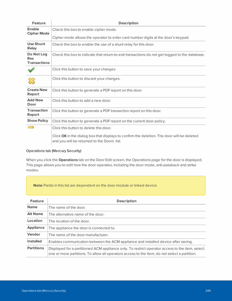
Feature Description
EnableCipher Mode
Check this box to enable cipher mode.
Cipher mode allows the operator to enter card number digits at the door’s keypad.
Use ShuntRelay
Check this box to enable the use of a shunt relay for this door.
Do Not LogRexTransactions
Check this box to indicate that return-to-exit transactions do not get logged to the database.
Click this button to save your changes.
Click this button to discard your changes.
Create NewReport
Click this button to generate a PDF report on this door.
Add NewDoor
Click this button to add a new door.
TransactionReport
Click this button to generate a PDF transaction report on this door.
Show Policy Click this button to generate a PDF report on the current door policy.
Click this button to delete this door.
Click OK in the dialog box that displays to confirm the deletion. The door will be deletedand you will be returned to the Doors list.
Operations tab (Mercury Security)
When you click the Operations tab on the Door Edit screen, the Operations page for the door is displayed.This page allows you to edit how the door operates, including the door mode, anti-passback and strikemodes.
Note: Fields in this list are dependent on the door module or linked device.
Feature Description
Name The name of the door.
Alt Name The alternative name of the door.
Location The location of the door.
Appliance The appliance the door is connected to.
Vendor The name of the door manufacturer.
Installed Enables communication between the ACM appliance and installed device after saving.
Partitions Displayed for a partitioned ACM appliance only. To restrict operator access to the item, selectone or more partitions. To allow all operators access to the item, do not select a partition.
Operations tab (Mercury Security) 249
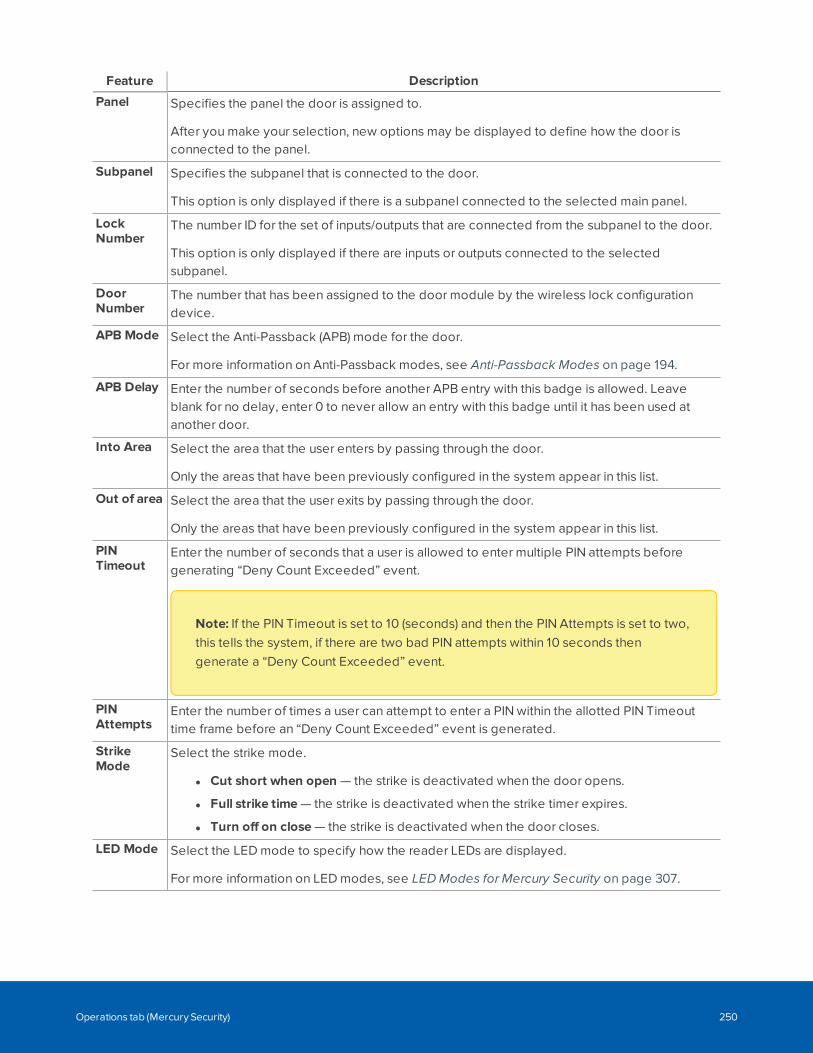
Feature Description
Panel Specifies the panel the door is assigned to.
After you make your selection, new options may be displayed to define how the door isconnected to the panel.
Subpanel Specifies the subpanel that is connected to the door.
This option is only displayed if there is a subpanel connected to the selected main panel.
LockNumber
The number ID for the set of inputs/outputs that are connected from the subpanel to the door.
This option is only displayed if there are inputs or outputs connected to the selectedsubpanel.
DoorNumber
The number that has been assigned to the door module by the wireless lock configurationdevice.
APB Mode Select the Anti-Passback (APB) mode for the door.
For more information on Anti-Passback modes, see Anti-Passback Modes on page 194.
APB Delay Enter the number of seconds before another APB entry with this badge is allowed. Leaveblank for no delay, enter 0 to never allow an entry with this badge until it has been used atanother door.
Into Area Select the area that the user enters by passing through the door.
Only the areas that have been previously configured in the system appear in this list.
Out of area Select the area that the user exits by passing through the door.
Only the areas that have been previously configured in the system appear in this list.
PINTimeout
Enter the number of seconds that a user is allowed to enter multiple PIN attempts beforegenerating “Deny Count Exceeded” event.
Note: If the PIN Timeout is set to 10 (seconds) and then the PIN Attempts is set to two,this tells the system, if there are two bad PIN attempts within 10 seconds thengenerate a “Deny Count Exceeded” event.
PINAttempts
Enter the number of times a user can attempt to enter a PIN within the allotted PIN Timeouttime frame before an “Deny Count Exceeded” event is generated.
StrikeMode
Select the strike mode.
l Cut short when open — the strike is deactivated when the door opens.
l Full strike time — the strike is deactivated when the strike timer expires.
l Turn off on close — the strike is deactivated when the door closes.
LED Mode Select the LED mode to specify how the reader LEDs are displayed.
For more information on LED modes, see LED Modes for Mercury Security on page 307.
Operations tab (Mercury Security) 250
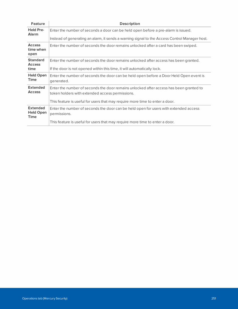
Feature Description
Held Pre-Alarm
Enter the number of seconds a door can be held open before a pre-alarm is issued.
Instead of generating an alarm, it sends a warning signal to the Access Control Manager host.
Accesstimewhenopen
Enter the number of seconds the door remains unlocked after a card has been swiped.
StandardAccesstime
Enter the number of seconds the door remains unlocked after access has been granted.
If the door is not opened within this time, it will automatically lock.
Held OpenTime
Enter the number of seconds the door can be held open before a Door Held Open event isgenerated.
ExtendedAccess
Enter the number of seconds the door remains unlocked after access has been granted totoken holders with extended access permissions.
This feature is useful for users that may require more time to enter a door.
ExtendedHeld OpenTime
Enter the number of seconds the door can be held open for users with extended accesspermissions.
This feature is useful for users that may require more time to enter a door.
Operations tab (Mercury Security) 251
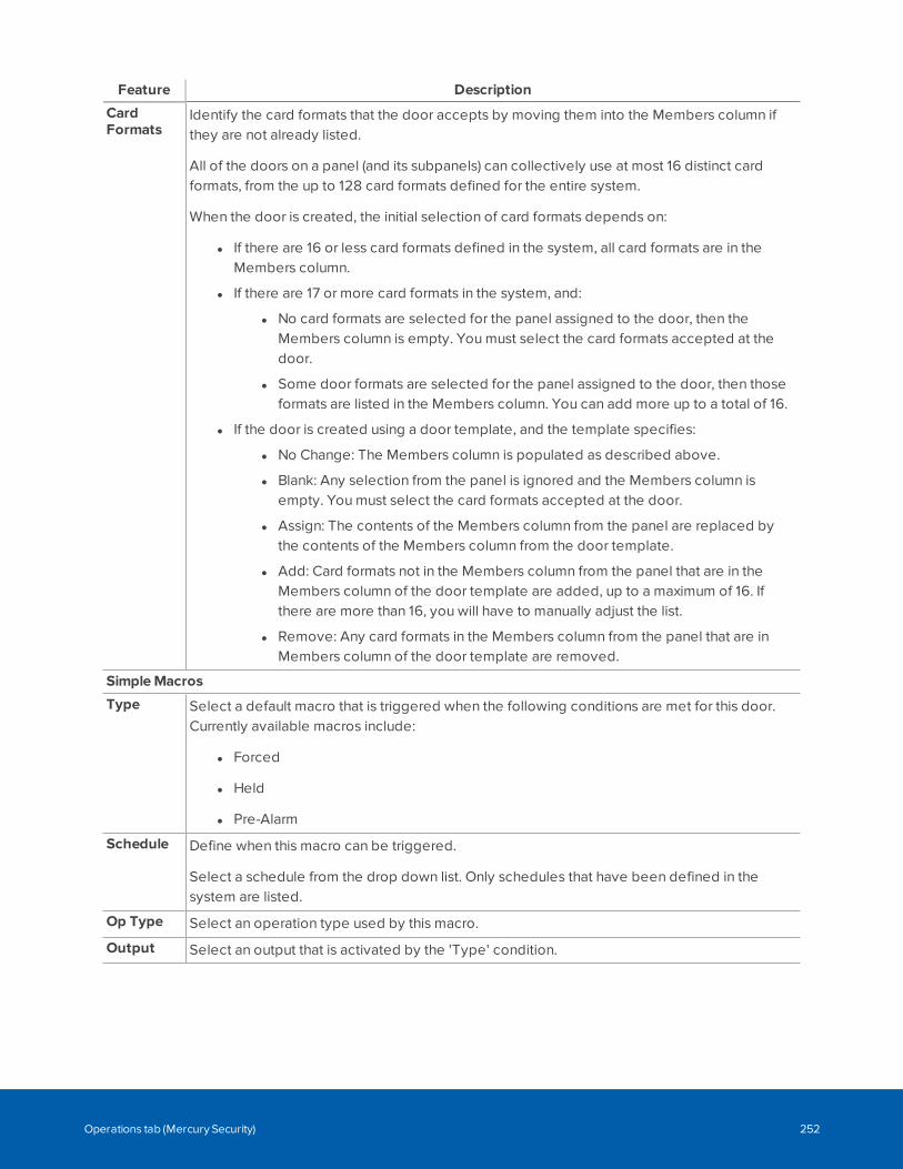
Feature Description
CardFormats
Identify the card formats that the door accepts by moving them into the Members column ifthey are not already listed.
All of the doors on a panel (and its subpanels) can collectively use at most 16 distinct cardformats, from the up to 128 card formats defined for the entire system.
When the door is created, the initial selection of card formats depends on:
l If there are 16 or less card formats defined in the system, all card formats are in theMembers column.
l If there are 17 or more card formats in the system, and:
l No card formats are selected for the panel assigned to the door, then theMembers column is empty. You must select the card formats accepted at thedoor.
l Some door formats are selected for the panel assigned to the door, then thoseformats are listed in the Members column. You can add more up to a total of 16.
l If the door is created using a door template, and the template specifies:
l No Change: The Members column is populated as described above.
l Blank: Any selection from the panel is ignored and the Members column isempty. You must select the card formats accepted at the door.
l Assign: The contents of the Members column from the panel are replaced bythe contents of the Members column from the door template.
l Add: Card formats not in the Members column from the panel that are in theMembers column of the door template are added, up to a maximum of 16. Ifthere are more than 16, you will have to manually adjust the list.
l Remove: Any card formats in the Members column from the panel that are inMembers column of the door template are removed.
SimpleMacros
Type Select a default macro that is triggered when the following conditions are met for this door.Currently available macros include:
l Forced
l Held
l Pre-Alarm
Schedule Define when this macro can be triggered.
Select a schedule from the drop down list. Only schedules that have been defined in thesystem are listed.
Op Type Select an operation type used by this macro.
Output Select an output that is activated by the 'Type' condition.
Operations tab (Mercury Security) 252
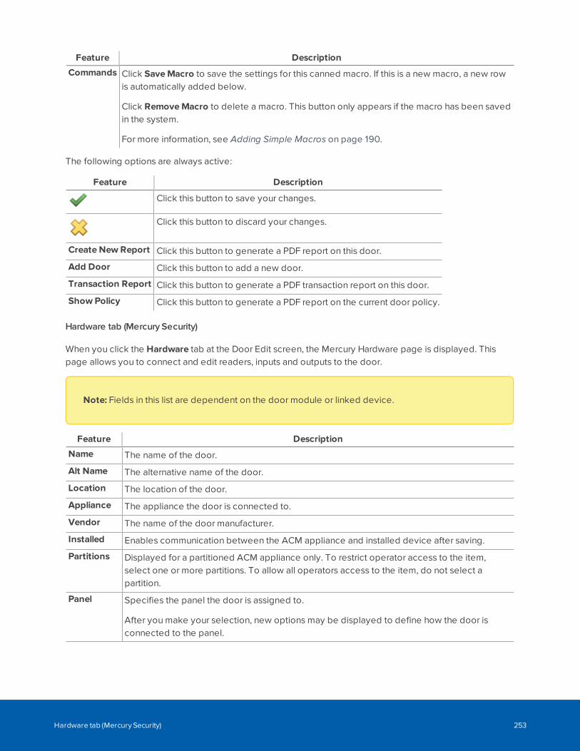
Feature Description
Commands Click SaveMacro to save the settings for this canned macro. If this is a new macro, a new rowis automatically added below.
Click RemoveMacro to delete a macro. This button only appears if the macro has been savedin the system.
For more information, see Adding Simple Macros on page 190.
The following options are always active:
Feature Description
Click this button to save your changes.
Click this button to discard your changes.
Create New Report Click this button to generate a PDF report on this door.
Add Door Click this button to add a new door.
Transaction Report Click this button to generate a PDF transaction report on this door.
Show Policy Click this button to generate a PDF report on the current door policy.
Hardware tab (Mercury Security)
When you click the Hardware tab at the Door Edit screen, the Mercury Hardware page is displayed. Thispage allows you to connect and edit readers, inputs and outputs to the door.
Note: Fields in this list are dependent on the door module or linked device.
Feature Description
Name The name of the door.
Alt Name The alternative name of the door.
Location The location of the door.
Appliance The appliance the door is connected to.
Vendor The name of the door manufacturer.
Installed Enables communication between the ACM appliance and installed device after saving.
Partitions Displayed for a partitioned ACM appliance only. To restrict operator access to the item,select one or more partitions. To allow all operators access to the item, do not select apartition.
Panel Specifies the panel the door is assigned to.
After you make your selection, new options may be displayed to define how the door isconnected to the panel.
Hardware tab (Mercury Security) 253
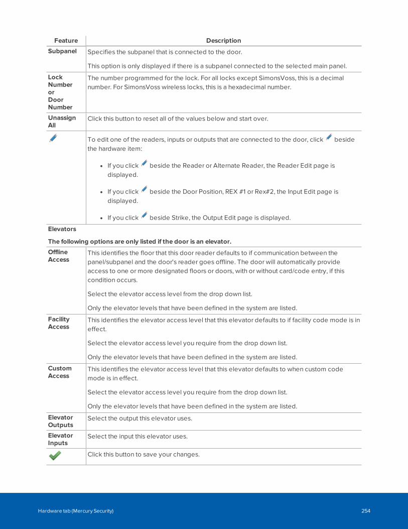
Feature Description
Subpanel Specifies the subpanel that is connected to the door.
This option is only displayed if there is a subpanel connected to the selected main panel.
LockNumberorDoorNumber
The number programmed for the lock. For all locks except SimonsVoss, this is a decimalnumber. For SimonsVoss wireless locks, this is a hexadecimal number.
UnassignAll
Click this button to reset all of the values below and start over.
To edit one of the readers, inputs or outputs that are connected to the door, click besidethe hardware item:
l If you click beside the Reader or Alternate Reader, the Reader Edit page isdisplayed.
l If you click beside the Door Position, REX #1 or Rex#2, the Input Edit page isdisplayed.
l If you click beside Strike, the Output Edit page is displayed.
Elevators
The following options are only listed if the door is an elevator.
OfflineAccess
This identifies the floor that this door reader defaults to if communication between thepanel/subpanel and the door's reader goes offline. The door will automatically provideaccess to one or more designated floors or doors, with or without card/code entry, if thiscondition occurs.
Select the elevator access level from the drop down list.
Only the elevator levels that have been defined in the system are listed.
FacilityAccess
This identifies the elevator access level that this elevator defaults to if facility code mode is ineffect.
Select the elevator access level you require from the drop down list.
Only the elevator levels that have been defined in the system are listed.
CustomAccess
This identifies the elevator access level that this elevator defaults to when custom codemode is in effect.
Select the elevator access level you require from the drop down list.
Only the elevator levels that have been defined in the system are listed.
ElevatorOutputs
Select the output this elevator uses.
ElevatorInputs
Select the input this elevator uses.
Click this button to save your changes.
Hardware tab (Mercury Security) 254
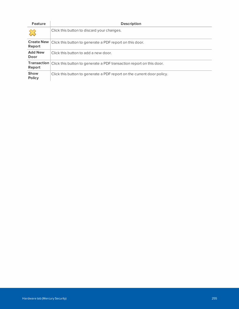
Feature Description
Click this button to discard your changes.
Create NewReport
Click this button to generate a PDF report on this door.
Add NewDoor
Click this button to add a new door.
TransactionReport
Click this button to generate a PDF transaction report on this door.
ShowPolicy
Click this button to generate a PDF report on the current door policy.
Hardware tab (Mercury Security) 255
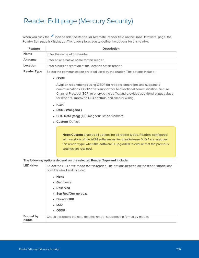
Reader Edit page (Mercury Security)
When you click the icon beside the Reader or Alternate Reader field on the Door Hardware page, theReader Edit page is displayed. This page allows you to define the options for this reader.
Feature Description
Name Enter the name of this reader.
Alt.name Enter an alternative name for this reader.
Location Enter a brief description of the location of this reader.
Reader Type Select the communication protocol used by the reader. The options include:
l OSDP
Avigilon recommends using OSDP for readers, controllers and subpanelscommunications. OSDP offers support for bi-directional communication, SecureChannel Protocol (SCP) to encrypt the traffic, and provides additional status valuesfor readers, improved LED controls, and simpler wiring.
l F/2F.
l D1/D0 (Wiegand )
l CLK+Data (Mag) ( NCI magnetic stripe standard)
l Custom (Default)
Note: Custom enables all options for all reader types. Readers configuredwith versions of the ACM software earlier than Release 5.10.4 are assignedthis reader type when the software is upgraded to ensure that the previoussettings are retained.
The following options depend on the selected Reader Type and include:
LED drive Select the LED drive mode for this reader. The options depend on the reader model andhow it is wired and include:
l None
l Gen 1wire
l Reserved
l Sep Red/Grn no buzz
l Dorado 780
l LCD
l OSDP
Format bynibble
Check this box to indicate that this reader supports the format by nibble.
Reader Edit page (Mercury Security) 256
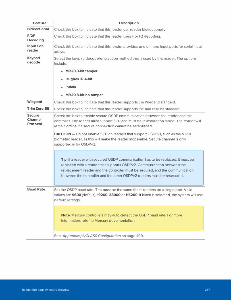
Feature Description
Bidirectional Check this box to indicate that this reader can reader bidirectionally.
F/2FDecoding
Check this box to indicate that this reader uses F or F2 decoding.
Inputs onreader
Check this box to indicate that this reader provides one or more input ports for serial inputarrays.
Keypaddecode
Select the keypad decode/encryption method that is used by this reader. The optionsinclude:
l MR20 8-bit tamper
l Hughes ID 4-bit
l Indala
l MR20 8-bit no tamper
Wiegand Check this box to indicate that this reader supports the Wiegand standard.
Trim Zero Bit Check this box to indicate that this reader supports the trim zero bit standard.
SecureChannelProtocol
Check this box to enable secure OSDP communication between the reader and thecontroller. The reader must support SCP and must be in installation mode. The reader willremain offline if a secure connection cannot be established.
CAUTION — Do not enable SCP on readers that support OSDPv1, such as the ViRDIbiometric reader, as this will make the reader inoperable. Secure channel is onlysupported in by OSDPv2.
Tip: If a reader with secured OSDP communication has to be replaced, it must bereplaced with a reader that supports OSDPv2. Communication between thereplacement reader and the controller must be secured, and the communicationbetween the controller and the other OSDPv2 readers must be resecured.
Baud Rate Set the OSDP baud rate. This must be the same for all readers on a single port. Validvalues are 9600 (default), 19200, 38000 or 115200. If blank is selected, the system will usedefault settings.
Note: Mercury controllers may auto-detect the OSDP baud rate. For moreinformation, refer to Mercury documentation.
See Appendix: pivCLASS Configuration on page 490.
Reader Edit page (Mercury Security) 257
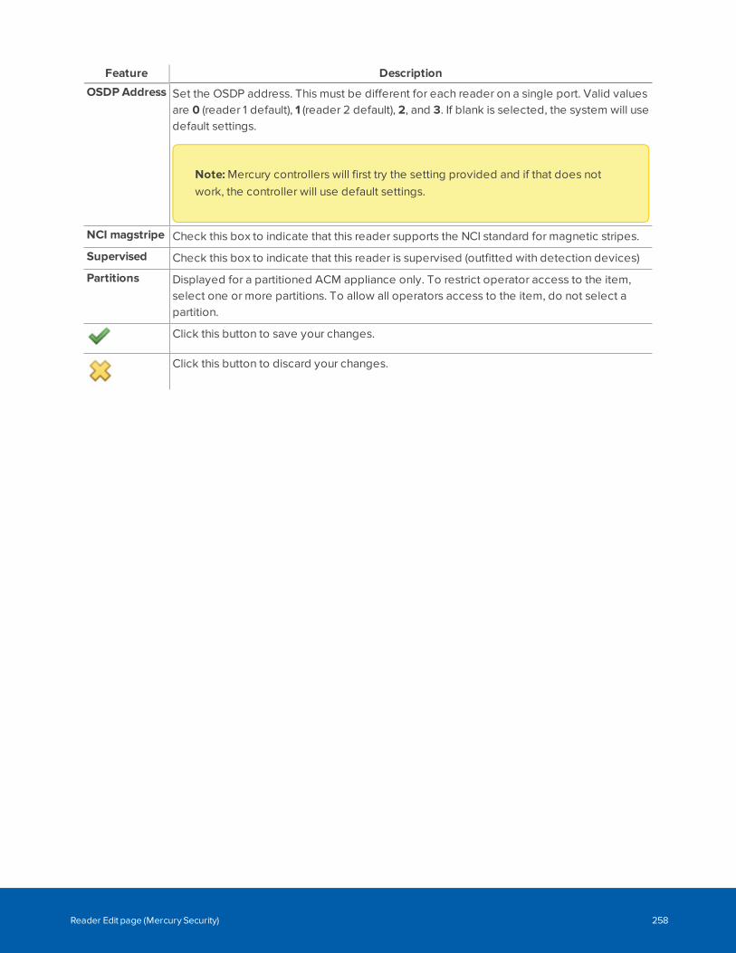
Feature Description
OSDP Address Set the OSDP address. This must be different for each reader on a single port. Valid valuesare 0 (reader 1 default), 1 (reader 2 default), 2, and 3. If blank is selected, the system will usedefault settings.
Note: Mercury controllers will first try the setting provided and if that does notwork, the controller will use default settings.
NCI magstripe Check this box to indicate that this reader supports the NCI standard for magnetic stripes.
Supervised Check this box to indicate that this reader is supervised (outfitted with detection devices)
Partitions Displayed for a partitioned ACM appliance only. To restrict operator access to the item,select one or more partitions. To allow all operators access to the item, do not select apartition.
Click this button to save your changes.
Click this button to discard your changes.
Reader Edit page (Mercury Security) 258
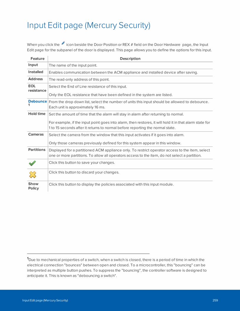
Input Edit page (Mercury Security)
When you click the icon beside the Door Position or REX # field on the Door Hardware page, the InputEdit page for the subpanel of the door is displayed. This page allows you to define the options for this input.
Feature Description
Input The name of the input point.
Installed Enables communication between the ACM appliance and installed device after saving.
Address The read-only address of this point.
EOLresistance
Select the End of Line resistance of this input.
Only the EOL resistance that have been defined in the system are listed.
Debounce1
From the drop down list, select the number of units this input should be allowed to debounce.Each unit is approximately 16 ms.
Hold time Set the amount of time that the alarm will stay in alarm after returning to normal.
For example, if the input point goes into alarm, then restores, it will hold it in that alarm state for1 to 15 seconds after it returns to normal before reporting the normal state.
Cameras Select the camera from the window that this input activates if it goes into alarm.
Only those cameras previously defined for this system appear in this window.
Partitions Displayed for a partitioned ACM appliance only. To restrict operator access to the item, selectone or more partitions. To allow all operators access to the item, do not select a partition.
Click this button to save your changes.
Click this button to discard your changes.
ShowPolicy
Click this button to display the policies associated with this input module.
1Due to mechanical properties of a switch, when a switch is closed, there is a period of time in which theelectrical connection "bounces" between open and closed. To a microcontroller, this "bouncing" can beinterpreted as multiple button pushes. To suppress the "bouncing", the controller software is designed toanticipate it. This is known as "debouncing a switch".
Input Edit page (Mercury Security) 259
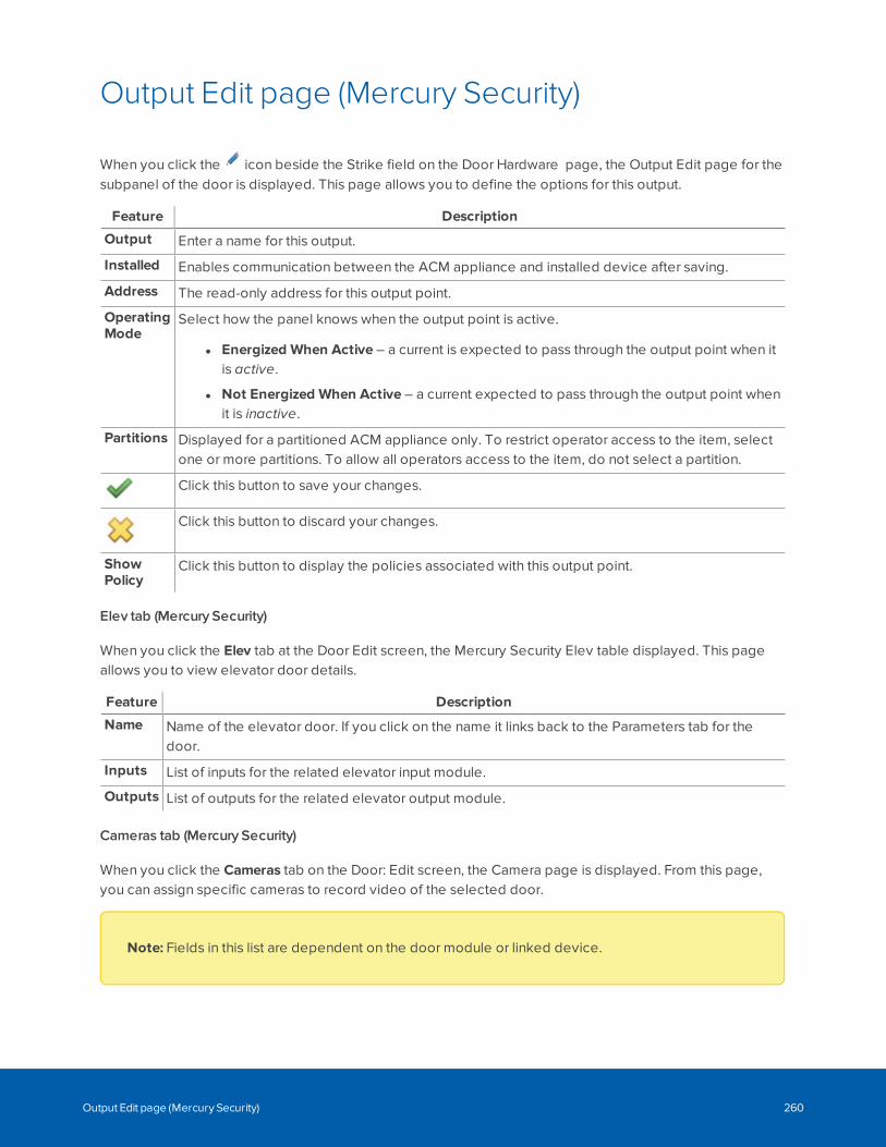
Output Edit page (Mercury Security)
When you click the icon beside the Strike field on the Door Hardware page, the Output Edit page for thesubpanel of the door is displayed. This page allows you to define the options for this output.
Feature Description
Output Enter a name for this output.
Installed Enables communication between the ACM appliance and installed device after saving.
Address The read-only address for this output point.
OperatingMode
Select how the panel knows when the output point is active.
l Energized When Active – a current is expected to pass through the output point when itis active.
l Not Energized When Active – a current expected to pass through the output point whenit is inactive.
Partitions Displayed for a partitioned ACM appliance only. To restrict operator access to the item, selectone or more partitions. To allow all operators access to the item, do not select a partition.
Click this button to save your changes.
Click this button to discard your changes.
ShowPolicy
Click this button to display the policies associated with this output point.
Elev tab (Mercury Security)
When you click the Elev tab at the Door Edit screen, the Mercury Security Elev table displayed. This pageallows you to view elevator door details.
Feature Description
Name Name of the elevator door. If you click on the name it links back to the Parameters tab for thedoor.
Inputs List of inputs for the related elevator input module.
Outputs List of outputs for the related elevator output module.
Cameras tab (Mercury Security)
When you click the Cameras tab on the Door: Edit screen, the Camera page is displayed. From this page,you can assign specific cameras to record video of the selected door.
Note: Fields in this list are dependent on the door module or linked device.
Output Edit page (Mercury Security) 260
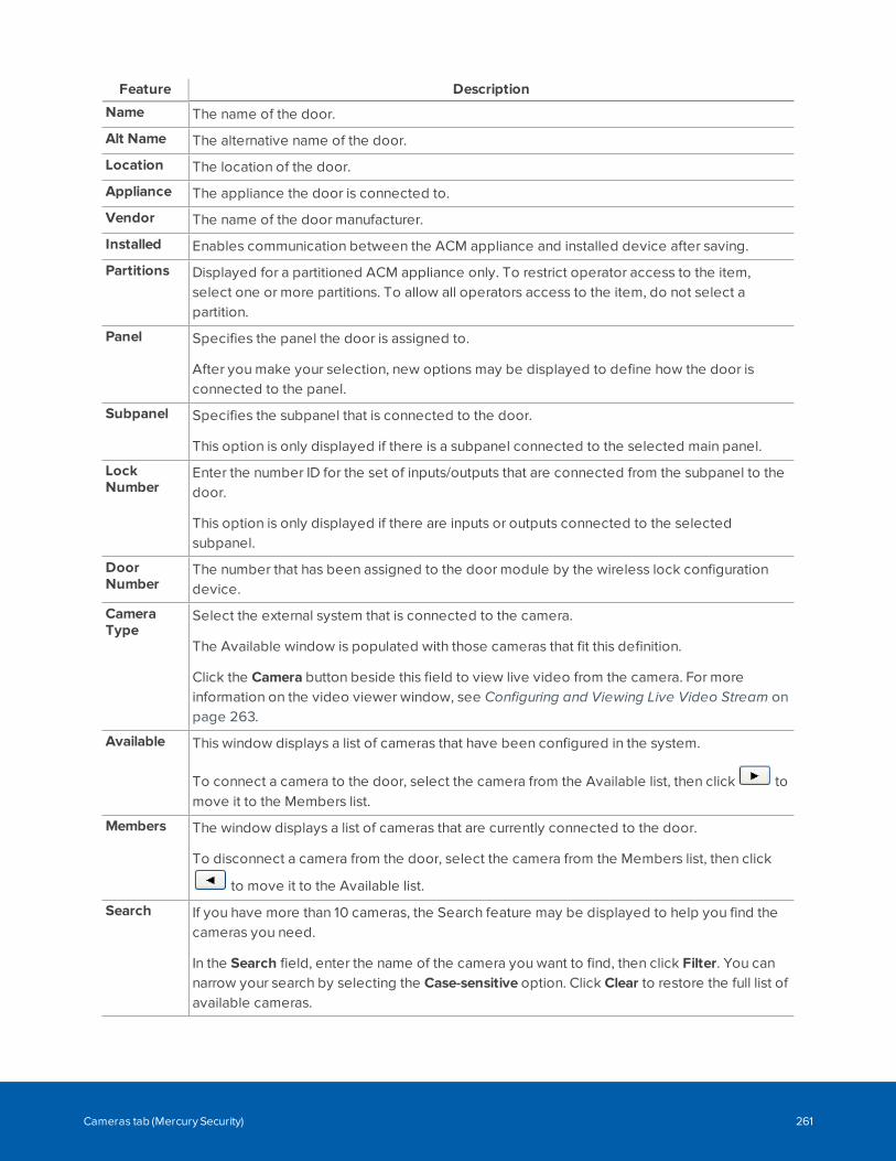
Feature Description
Name The name of the door.
Alt Name The alternative name of the door.
Location The location of the door.
Appliance The appliance the door is connected to.
Vendor The name of the door manufacturer.
Installed Enables communication between the ACM appliance and installed device after saving.
Partitions Displayed for a partitioned ACM appliance only. To restrict operator access to the item,select one or more partitions. To allow all operators access to the item, do not select apartition.
Panel Specifies the panel the door is assigned to.
After you make your selection, new options may be displayed to define how the door isconnected to the panel.
Subpanel Specifies the subpanel that is connected to the door.
This option is only displayed if there is a subpanel connected to the selected main panel.
LockNumber
Enter the number ID for the set of inputs/outputs that are connected from the subpanel to thedoor.
This option is only displayed if there are inputs or outputs connected to the selectedsubpanel.
DoorNumber
The number that has been assigned to the door module by the wireless lock configurationdevice.
CameraType
Select the external system that is connected to the camera.
The Available window is populated with those cameras that fit this definition.
Click the Camera button beside this field to view live video from the camera. For moreinformation on the video viewer window, see Configuring and Viewing Live Video Stream onpage 263.
Available This window displays a list of cameras that have been configured in the system.
To connect a camera to the door, select the camera from the Available list, then click tomove it to the Members list.
Members The window displays a list of cameras that are currently connected to the door.
To disconnect a camera from the door, select the camera from the Members list, then click
to move it to the Available list.
Search If you have more than 10 cameras, the Search feature may be displayed to help you find thecameras you need.
In the Search field, enter the name of the camera you want to find, then click Filter. You cannarrow your search by selecting the Case-sensitive option. Click Clear to restore the full list ofavailable cameras.
Cameras tab (Mercury Security) 261
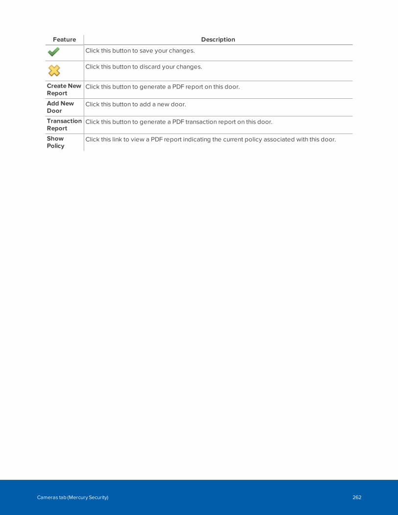
Feature Description
Click this button to save your changes.
Click this button to discard your changes.
Create NewReport
Click this button to generate a PDF report on this door.
Add NewDoor
Click this button to add a new door.
TransactionReport
Click this button to generate a PDF transaction report on this door.
ShowPolicy
Click this link to view a PDF report indicating the current policy associated with this door.
Cameras tab (Mercury Security) 262
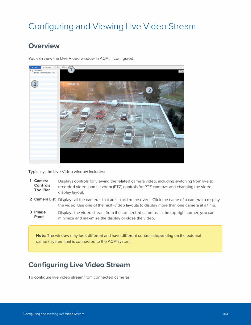
Configuring and Viewing Live Video Stream
Overview
You can view the LIve Video window in ACM, if configured.
Typically, the Live Video window includes:
1 CameraControlsTool Bar
Displays controls for viewing the related camera video, including switching from live torecorded video, pan-tilt-zoom (PTZ) controls for PTZ cameras and changing the videodisplay layout.
2 Camera List Displays all the cameras that are linked to the event. Click the name of a camera to displaythe video. Use one of the multi-video layouts to display more than one camera at a time.
3 ImagePanel
Displays the video stream from the connected cameras. In the top-right corner, you canminimize and maximize the display or close the video.
Note: The window may look different and have different controls depending on the externalcamera system that is connected to the ACM system.
Configuring Live Video Stream
To configure live video stream from connected cameras:
Configuring and Viewing Live Video Stream 263
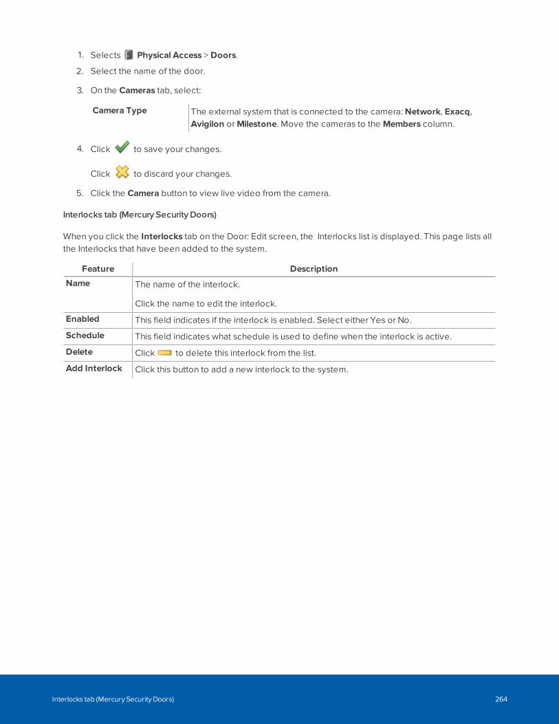
1. Selects Physical Access > Doors.
2. Select the name of the door.
3. On the Cameras tab, select:
Camera Type The external system that is connected to the camera: Network, Exacq,Avigilon or Milestone. Move the cameras to the Members column.
4. Click to save your changes.
Click to discard your changes.
5. Click the Camera button to view live video from the camera.
Interlocks tab (Mercury Security Doors)
When you click the Interlocks tab on the Door: Edit screen, the Interlocks list is displayed. This page lists allthe Interlocks that have been added to the system.
Feature Description
Name The name of the interlock.
Click the name to edit the interlock.
Enabled This field indicates if the interlock is enabled. Select either Yes or No.
Schedule This field indicates what schedule is used to define when the interlock is active.
Delete Click to delete this interlock from the list.
Add Interlock Click this button to add a new interlock to the system.
Interlocks tab (Mercury Security Doors) 264
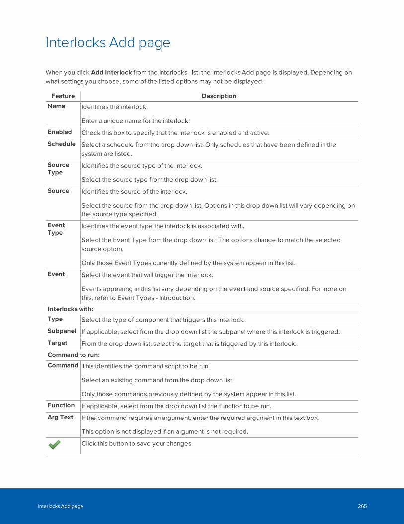
Interlocks Add page
When you click Add Interlock from the Interlocks list, the Interlocks Add page is displayed. Depending onwhat settings you choose, some of the listed options may not be displayed.
Feature Description
Name Identifies the interlock.
Enter a unique name for the interlock.
Enabled Check this box to specify that the interlock is enabled and active.
Schedule Select a schedule from the drop down list. Only schedules that have been defined in thesystem are listed.
SourceType
Identifies the source type of the interlock.
Select the source type from the drop down list.
Source Identifies the source of the interlock.
Select the source from the drop down list. Options in this drop down list will vary depending onthe source type specified.
EventType
Identifies the event type the interlock is associated with.
Select the Event Type from the drop down list. The options change to match the selectedsource option.
Only those Event Types currently defined by the system appear in this list.
Event Select the event that will trigger the interlock.
Events appearing in this list vary depending on the event and source specified. For more onthis, refer to Event Types - Introduction.
Interlocks with:
Type Select the type of component that triggers this interlock.
Subpanel If applicable, select from the drop down list the subpanel where this interlock is triggered.
Target From the drop down list, select the target that is triggered by this interlock.
Command to run:
Command This identifies the command script to be run.
Select an existing command from the drop down list.
Only those commands previously defined by the system appear in this list.
Function If applicable, select from the drop down list the function to be run.
Arg Text If the command requires an argument, enter the required argument in this text box.
This option is not displayed if an argument is not required.
Click this button to save your changes.
Interlocks Add page 265

Feature Description
Click this button to discard your changes.
Interlocks Add page 266
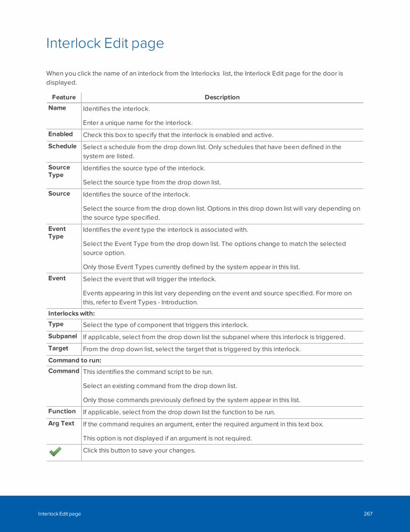
Interlock Edit page
When you click the name of an interlock from the Interlocks list, the Interlock Edit page for the door isdisplayed.
Feature Description
Name Identifies the interlock.
Enter a unique name for the interlock.
Enabled Check this box to specify that the interlock is enabled and active.
Schedule Select a schedule from the drop down list. Only schedules that have been defined in thesystem are listed.
SourceType
Identifies the source type of the interlock.
Select the source type from the drop down list.
Source Identifies the source of the interlock.
Select the source from the drop down list. Options in this drop down list will vary depending onthe source type specified.
EventType
Identifies the event type the interlock is associated with.
Select the Event Type from the drop down list. The options change to match the selectedsource option.
Only those Event Types currently defined by the system appear in this list.
Event Select the event that will trigger the interlock.
Events appearing in this list vary depending on the event and source specified. For more onthis, refer to Event Types - Introduction.
Interlocks with:
Type Select the type of component that triggers this interlock.
Subpanel If applicable, select from the drop down list the subpanel where this interlock is triggered.
Target From the drop down list, select the target that is triggered by this interlock.
Command to run:
Command This identifies the command script to be run.
Select an existing command from the drop down list.
Only those commands previously defined by the system appear in this list.
Function If applicable, select from the drop down list the function to be run.
Arg Text If the command requires an argument, enter the required argument in this text box.
This option is not displayed if an argument is not required.
Click this button to save your changes.
Interlock Edit page 267
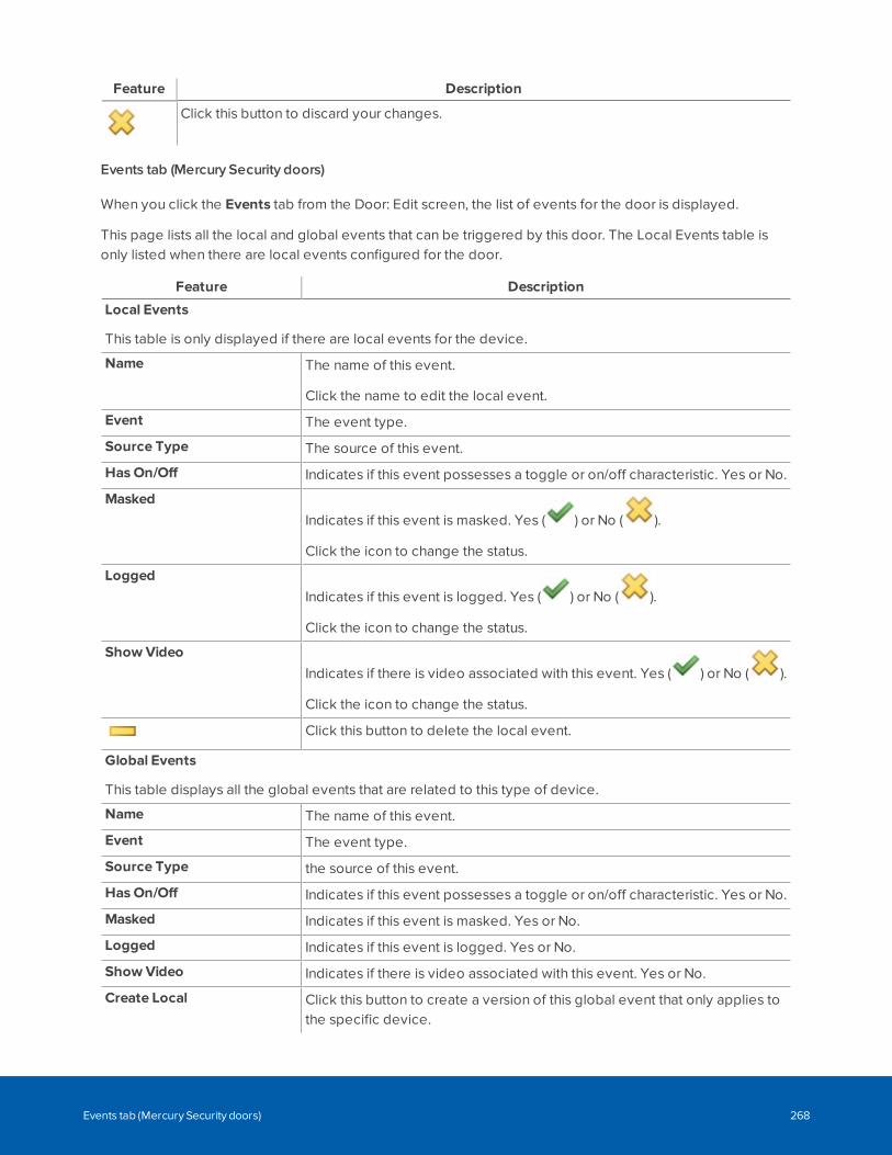
Feature Description
Click this button to discard your changes.
Events tab (Mercury Security doors)
When you click the Events tab from the Door: Edit screen, the list of events for the door is displayed.
This page lists all the local and global events that can be triggered by this door. The Local Events table isonly listed when there are local events configured for the door.
Feature Description
Local Events
This table is only displayed if there are local events for the device.
Name The name of this event.
Click the name to edit the local event.
Event The event type.
Source Type The source of this event.
Has On/Off Indicates if this event possesses a toggle or on/off characteristic. Yes or No.
MaskedIndicates if this event is masked. Yes ( ) or No ( ).
Click the icon to change the status.
LoggedIndicates if this event is logged. Yes ( ) or No ( ).
Click the icon to change the status.
Show VideoIndicates if there is video associated with this event. Yes ( ) or No ( ).
Click the icon to change the status.
Click this button to delete the local event.
Global Events
This table displays all the global events that are related to this type of device.
Name The name of this event.
Event The event type.
Source Type the source of this event.
Has On/Off Indicates if this event possesses a toggle or on/off characteristic. Yes or No.
Masked Indicates if this event is masked. Yes or No.
Logged Indicates if this event is logged. Yes or No.
Show Video Indicates if there is video associated with this event. Yes or No.
Create Local Click this button to create a version of this global event that only applies tothe specific device.
Events tab (Mercury Security doors) 268
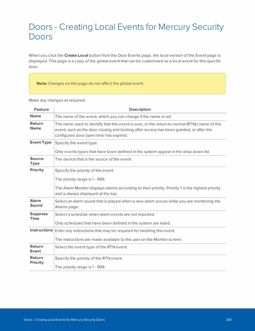
Doors - Creating Local Events for Mercury SecurityDoors
When you click the Create Local button from the Door Events page, the local version of the Event page isdisplayed. This page is a copy of the global event that can be customized as a local event for this specificdoor.
Note: Changes on this page do not affect the global event.
Make any changes as required.
Feature Description
Name The name of the event, which you can change if the name is not
ReturnName
The name used to identify that this event is over, or the return-to-normal (RTN) ) name of thisevent, such as the door closing and locking after access has been granted, or after theconfigured door open time has expired.
Event Type Specify the event type.
Only events types that have been defined in the system appear in the drop down list.
SourceType
The device that is the source of the event.
Priority Specify the priority of this event.
The priority range is 1 - 999.
The Alarm Monitor displays alarms according to their priority. Priority 1 is the highest priorityand is always displayed at the top.
AlarmSound
Select an alarm sound that is played when a new alarm occurs while you are monitoring theAlarms page.
SuppressTime
Select a schedule when alarm events are not reported.
Only schedules that have been defined in the system are listed.
Instructions Enter any instructions that may be required for handling this event.
The instructions are made available to the user on the Monitor screen.
ReturnEvent
Select the event type of the RTN event.
ReturnPriority
Specify the priority of the RTN event.
The priority range is 1 - 999.
Doors - Creating Local Events for Mercury Security Doors 269
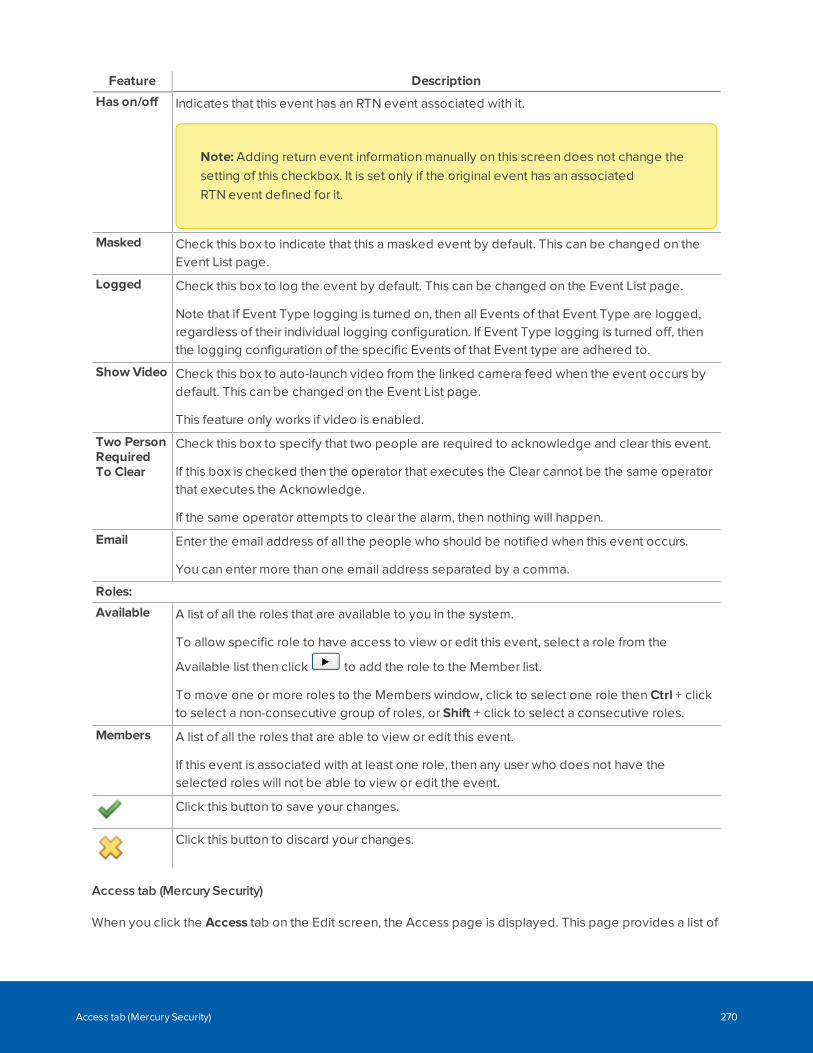
Feature Description
Has on/off Indicates that this event has an RTN event associated with it.
Note: Adding return event information manually on this screen does not change thesetting of this checkbox. It is set only if the original event has an associatedRTN event defined for it.
Masked Check this box to indicate that this a masked event by default. This can be changed on theEvent List page.
Logged Check this box to log the event by default. This can be changed on the Event List page.
Note that if Event Type logging is turned on, then all Events of that Event Type are logged,regardless of their individual logging configuration. If Event Type logging is turned off, thenthe logging configuration of the specific Events of that Event type are adhered to.
Show Video Check this box to auto-launch video from the linked camera feed when the event occurs bydefault. This can be changed on the Event List page.
This feature only works if video is enabled.
Two PersonRequiredTo Clear
Check this box to specify that two people are required to acknowledge and clear this event.
If this box is checked then the operator that executes the Clear cannot be the same operatorthat executes the Acknowledge.
If the same operator attempts to clear the alarm, then nothing will happen.
Email Enter the email address of all the people who should be notified when this event occurs.
You can enter more than one email address separated by a comma.
Roles:
Available A list of all the roles that are available to you in the system.
To allow specific role to have access to view or edit this event, select a role from the
Available list then click to add the role to the Member list.
To move one or more roles to the Members window, click to select one role then Ctrl + clickto select a non-consecutive group of roles, or Shift + click to select a consecutive roles.
Members A list of all the roles that are able to view or edit this event.
If this event is associated with at least one role, then any user who does not have theselected roles will not be able to view or edit the event.
Click this button to save your changes.
Click this button to discard your changes.
Access tab (Mercury Security)
When you click the Access tab on the Edit screen, the Access page is displayed. This page provides a list of
Access tab (Mercury Security) 270
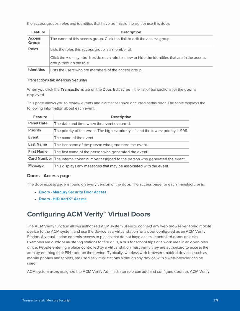
the access groups, roles and identities that have permission to edit or use this door.
Feature Description
AccessGroup
The name of this access group. Click this link to edit the access group.
Roles Lists the roles this access group is a member of.
Click the + or - symbol beside each role to show or hide the identities that are in the accessgroup through the role.
Identities Lists the users who are members of the access group.
Transactions tab (Mercury Security)
When you click the Transactions tab on the Door: Edit screen, the list of transactions for the door isdisplayed.
This page allows you to review events and alarms that have occurred at this door. The table displays thefollowing information about each event:
Feature Description
Panel Date The date and time when the event occurred.
Priority The priority of the event. The highest priority is 1 and the lowest priority is 999.
Event The name of the event.
Last Name The last name of the person who generated the event.
First Name The first name of the person who generated the event.
Card Number The internal token number assigned to the person who generated the event.
Message This displays any messages that may be associated with the event.
Doors - Access page
The door access page is found on every version of the door. The access page for each manufacturer is:
l Doors - Mercury Security Door Access
l Doors - HID VertX® Access
Configuring ACM Verify™ Virtual Doors
The ACM Verify function allows authorized ACM system users to connect any web browser-enabled mobiledevice to the ACM system and use the device as a virtual station for a door configured as an ACM VerifyStation. A virtual station controls access to places that do not have access-controlled doors or locks.Examples are outdoor mustering stations for fire drills, a bus for school trips or a work area in an open-planoffice. People entering a place controlled by a virtual station must verify they are authorized to access thearea by entering their PIN code on the device. Typically, wireless web browser-enabled devices, such asmobile phones and tablets, are used as virtual stations although any device with a web-browser can beused.
ACM system users assigned the ACM Verify Administrator role can add and configure doors as ACM Verify
Transactions tab (Mercury Security) 271
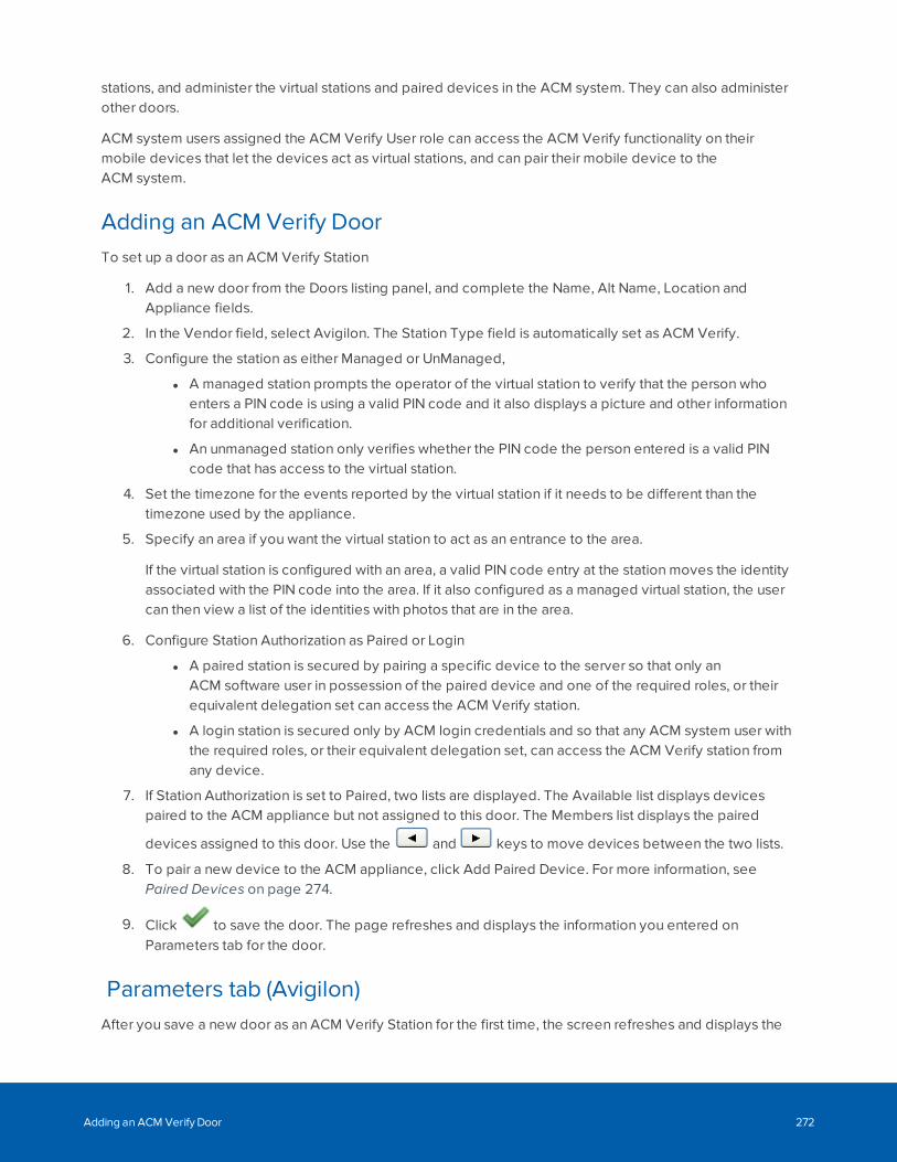
stations, and administer the virtual stations and paired devices in the ACM system. They can also administerother doors.
ACM system users assigned the ACM Verify User role can access the ACM Verify functionality on theirmobile devices that let the devices act as virtual stations, and can pair their mobile device to theACM system.
Adding an ACM Verify DoorTo set up a door as an ACM Verify Station
1. Add a new door from the Doors listing panel, and complete the Name, Alt Name, Location andAppliance fields.
2. In the Vendor field, select Avigilon. The Station Type field is automatically set as ACM Verify.
3. Configure the station as either Managed or UnManaged,
l A managed station prompts the operator of the virtual station to verify that the person whoenters a PIN code is using a valid PIN code and it also displays a picture and other informationfor additional verification.
l An unmanaged station only verifies whether the PIN code the person entered is a valid PINcode that has access to the virtual station.
4. Set the timezone for the events reported by the virtual station if it needs to be different than thetimezone used by the appliance.
5. Specify an area if you want the virtual station to act as an entrance to the area.
If the virtual station is configured with an area, a valid PIN code entry at the station moves the identityassociated with the PIN code into the area. If it also configured as a managed virtual station, the usercan then view a list of the identities with photos that are in the area.
6. Configure Station Authorization as Paired or Login
l A paired station is secured by pairing a specific device to the server so that only anACM software user in possession of the paired device and one of the required roles, or theirequivalent delegation set can access the ACM Verify station.
l A login station is secured only by ACM login credentials and so that any ACM system user withthe required roles, or their equivalent delegation set, can access the ACM Verify station fromany device.
7. If Station Authorization is set to Paired, two lists are displayed. The Available list displays devicespaired to the ACM appliance but not assigned to this door. The Members list displays the paired
devices assigned to this door. Use the and keys to move devices between the two lists.
8. To pair a new device to the ACM appliance, click Add Paired Device. For more information, seePaired Devices on page 274.
9. Click to save the door. The page refreshes and displays the information you entered onParameters tab for the door.
Parameters tab (Avigilon)After you save a new door as an ACM Verify Station for the first time, the screen refreshes and displays the
Adding an ACM Verify Door 272
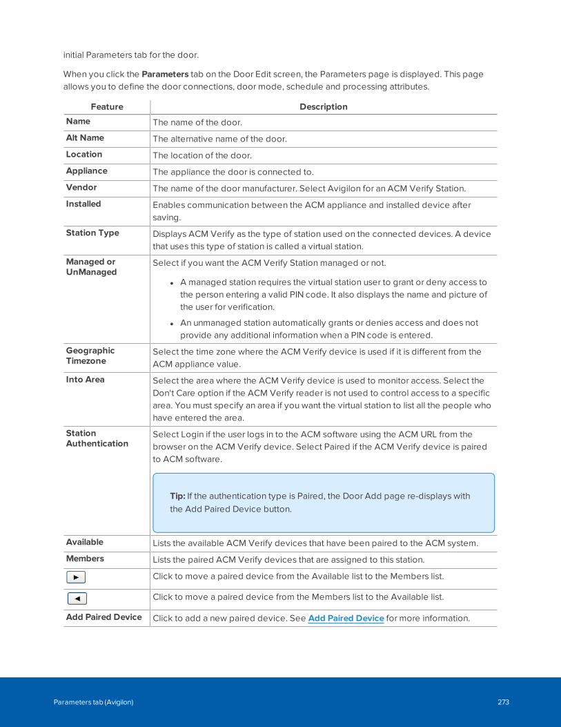
initial Parameters tab for the door.
When you click the Parameters tab on the Door Edit screen, the Parameters page is displayed. This pageallows you to define the door connections, door mode, schedule and processing attributes.
Feature Description
Name The name of the door.
Alt Name The alternative name of the door.
Location The location of the door.
Appliance The appliance the door is connected to.
Vendor The name of the door manufacturer. Select Avigilon for an ACM Verify Station.
Installed Enables communication between the ACM appliance and installed device aftersaving.
Station Type Displays ACM Verify as the type of station used on the connected devices. A devicethat uses this type of station is called a virtual station.
Managed orUnManaged
Select if you want the ACM Verify Station managed or not.
l A managed station requires the virtual station user to grant or deny access tothe person entering a valid PIN code. It also displays the name and picture ofthe user for verification.
l An unmanaged station automatically grants or denies access and does notprovide any additional information when a PIN code is entered.
GeographicTimezone
Select the time zone where the ACM Verify device is used if it is different from theACM appliance value.
Into Area Select the area where the ACM Verify device is used to monitor access. Select theDon't Care option if the ACM Verify reader is not used to control access to a specificarea. You must specify an area if you want the virtual station to list all the people whohave entered the area.
StationAuthentication
Select Login if the user logs in to the ACM software using the ACM URL from thebrowser on the ACM Verify device. Select Paired if the ACM Verify device is pairedto ACM software.
Tip: If the authentication type is Paired, the Door Add page re-displays withthe Add Paired Device button.
Available Lists the available ACM Verify devices that have been paired to the ACM system.
Members Lists the paired ACM Verify devices that are assigned to this station.
Click to move a paired device from the Available list to the Members list.
Click to move a paired device from the Members list to the Available list.
Add Paired Device Click to add a new paired device. See Add Paired Device for more information.
Parameters tab (Avigilon) 273
Feature Description
Click this button to save your changes.
Click this button to discard your changes.
Paired DevicesPairing devices to the ACM appliance ensures that access to ACM Verify Stations is restricted to authorizeddevices.
Pairing must be completed by both the ACM administrator and the user of the connected device. Thedevice user must be an authorized ACM user with the ACM Verify User role or equivalent at a minimum. Thepairing persists as long as the cookie used for the pairing exists. See Precautions for Paired ACM VerifyStations below
CAUTION — In a failover deployment of the ACM system, pair the device to both the main server and thefailover server. When a failover occurs, the ACM operator must restore the pairings for all ACM Verifydevices to the failover server, and repeat the process when the main server is back in service.
Prerequisites for Pairing Devices
Before pairing a device:
1. The ACM operator provides the user with the IP address or hostname of the ACM appliance. Do notprovide both. Use one format for the address of the ACM appliance for all pairings.
The ACM appliance IP address or hostname is visible in the web browser's navigation bar from anyACM client window.
2. The device user must have the web browser open on their device.
The pairing must be completed within ten minutes of the ACM operator generating the PIN for pairing.
Although the user's device is paired to the ACM appliance, the virtual stations configured for pairedauthentication are only active for a device when installed and the user's device is in the Members columnfor that station.
A device can be paired to only one active ACM appliance. If a failover ACM appliance is configured, pair allACM Verify devices to both servers. If a fail-over occurs, you must reassign devices to the ACM Verifystations on the fail-over server while it is active, and reassign them back to the main server after it is returnedto service. Pairing devices in advance will make this task much more efficient.
To pair a device, see Pairing a Device on the next page.
Precautions for Paired ACM Verify Stations
A paired device uses cookies to connect to ACM. Take the following precautions:
Paired Devices 274
l Always use the same device and browser to connect. Cookies are not shared between differentdevices or browsers.
l Do not pair the device while in private mode on your browser. Cookies are not saved when you are inprivate mode.
l Cookies are lost if you:
l Clean up history and cookies in your browser
l Pair the device using an IP address and then use the host name to access ACM.
If a device browser loses the cookie, it cannot access ACM Verify and you must pair the device again.Before the device can be paired again, the previous pairing must be deleted from the ACM appliance.
Pairing a Device
A device needs to be paired to the ACM appliance to access the ACM Verify function. A device can bepaired to the ACM appliance at any time, or when adding a door as an ACM Verify Station.
To pair a device:
1. The ACM operator and the device user agree on the name to use for the device.
2. The ACM operator provides the ACM URL or hostname to the device user.
The ACM appliance IP address or hostname is visible in the web browser's navigation bar from anyACM client window.
3. The ACM operator navigates to the Add Paired Device panel.
a. If the operator is:
l Pairing a device only, click > Paired Devices.
l Adding a new door as an ACM Verify Station, click on Add Paired Device in theDoor: Add New screen. For more information, see Parameters tab (Avigilon) onpage 272.
b. Enterthe name to identify the device,suchas"UserName'sSmartphone" and clickGeneratePIN.
Provide the 4-digit PIN to the device user. The PIN is valid for 10 minutes.
4. The device user:
a. Enters the URL to the ACM appliance in the web browser on their device in the format:<ipAddress>/doors/virtualThe ACM client log in screen is displayed.For example, if the ACM URL is 192.168.0.125, the device user enters://192.168.0.125/doors/virtual
b. Logs in to the ACM Verify client using their username and password.
c. Clicks on the and then clicks >Paired device.The user is prompted to enter the name of their device and the 4-digit PIN provided by theACM operator.
5. The ACM operator waits until the device is paired and then clicks .
To remove a pairing from the ACM appliance, click for the device.
Pairing a Device 275
Using ACM VerifyYou can use a web browser-enabled device, such as a smartphone or tablet, to connect to ACM, access theACM Verify Station functionality and use the device as a virtual station. Virtual stations control access toplaces that do not have access-controlled doors or locks. Examples are outdoor mustering stations for firedrills, a bus for school trips or a work area in an open-plan office. People entering a place controlled by avirtual station must verify they are authorized to access the area by entering their PIN code on the device.
You must be an ACM user to use ACM Verify on your device. To set up a device for ACM Verify, seeConfiguring ACM Verify™ Virtual Doors on page 271.
To use ACM Verify:
1. Use the URL or web link in your web browser provided when your device was set up to launchACM Verify from your web browser.
Note: If your device is paired to the ACM user, always use the same browser.
2. If the Access Control Manager login page is displayed, enter your ACM Login and Password.
ACM Verify is displayed and the Virtual Stations you can use are listed.
3. Tap to open a virtual station.
A prompt to enter PIN codes appears.
4. Anyone wanting to access the location you are controlling must enter a PIN code on your device andtap Submit.
l If the virtual station is managed, the user's picture and name displays, and you are prompted togrant or deny access.
l If the virtual station is unmanaged, access is granted if the code is valid.
l If the PIN code is incorrect or invalid, a message that access is not granted displays.
5. If an area is specified for the virtual station, the number of identities verified is also displayed, and youcan display a list of all the identities who have entered the area by clicking on the Identities Verified:link.
6. To switch to a different virtual station, tap the back button and tap another virtual station.
For example, if you want to have identities enter and exit an area using their PIN codes you need twovirtual stations. One station is configured for the area you want identities to enter into, and the secondstation is configured for the area you want identities to exit into. Both virtual stations are accessible onthe same device.
To log out of ACM Verify, tap and tap Log Out.
Using ACM Verify 276
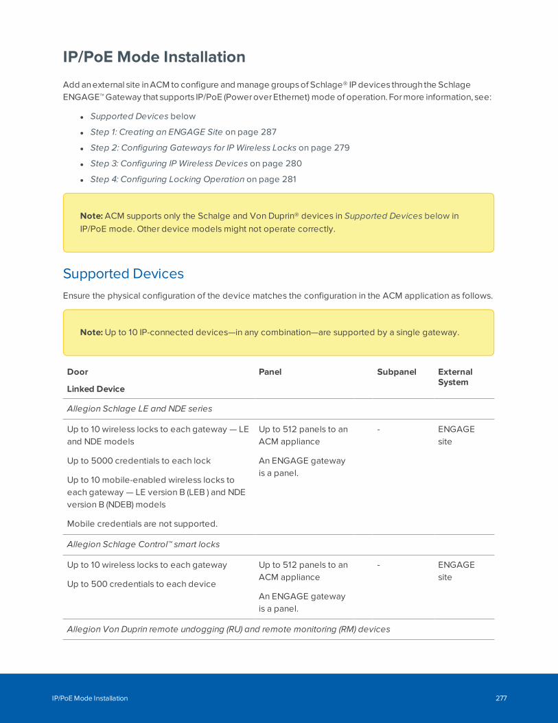
IP/PoE Mode Installation
Add anexternal site inACM to configure and manage groups of Schlage® IP devices throughthe SchlageENGAGE™ Gateway that supports IP/PoE (PoweroverEthernet) mode of operation. Formore information, see:
l Supported Devices below
l Step 1: Creating an ENGAGE Site on page 287
l Step 2: Configuring Gateways for IP Wireless Locks on page 279
l Step 3: Configuring IP Wireless Devices on page 280
l Step 4: Configuring Locking Operation on page 281
Note: ACM supports only the Schalge and Von Duprin® devices in Supported Devices below inIP/PoE mode. Other device models might not operate correctly.
Supported DevicesEnsure the physical configuration of the device matches the configuration in the ACM application as follows.
Note: Up to 10 IP-connected devices—in any combination—are supported by a single gateway.
Door
Linked Device
Panel Subpanel ExternalSystem
Allegion Schlage LE and NDE series
Up to 10 wireless locks to each gateway — LEand NDE models
Up to 5000 credentials to each lock
Up to 10 mobile-enabled wireless locks toeach gateway — LE version B (LEB ) and NDEversion B (NDEB) models
Mobile credentials are not supported.
Up to 512 panels to anACM appliance
An ENGAGE gatewayis a panel.
- ENGAGEsite
Allegion Schlage Control™ smart locks
Up to 10 wireless locks to each gateway
Up to 500 credentials to each device
Up to 512 panels to anACM appliance
An ENGAGE gatewayis a panel.
- ENGAGEsite
Allegion Von Duprin remote undogging (RU) and remote monitoring (RM) devices
IP/PoE Mode Installation 277
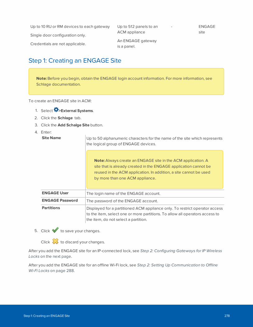
Up to 10 RU or RM devices to each gateway
Single door configuration only.
Credentials are not applicable.
Up to 512 panels to anACM appliance
An ENGAGE gatewayis a panel.
- ENGAGEsite
Step 1: Creating an ENGAGE Site
Note: Before you begin, obtain the ENGAGE login account information. For more information, seeSchlage documentation.
To create an ENGAGE site in ACM:
1. Select >External Systems.
2. Click the Schlage tab.
3. Click the Add Schalge Site button.
4. Enter:Site Name Up to 50 alphanumeric characters for the name of the site which represents
the logical group of ENGAGE devices.
Note: Always create an ENGAGE site in the ACM application. Asite that is already created in the ENGAGE application cannot bereused in the ACM application. In addition, a site cannot be usedby more than one ACM appliance.
ENGAGE User The login name of the ENGAGE account.
ENGAGE Password The password of the ENGAGE account.
Partitions Displayed for a partitioned ACM appliance only. To restrict operator accessto the item, select one or more partitions. To allow all operators access tothe item, do not select a partition.
5. Click to save your changes.
Click to discard your changes.
After you add the ENGAGE site for an IP-connected lock, see Step 2: Configuring Gateways for IP WirelessLocks on the next page.
After you add the ENGAGE site for an offline Wi-Fi lock, see Step 2: Setting Up Communication to OfflineWi-Fi Locks on page 288.
Step 1: Creating an ENGAGE Site 278
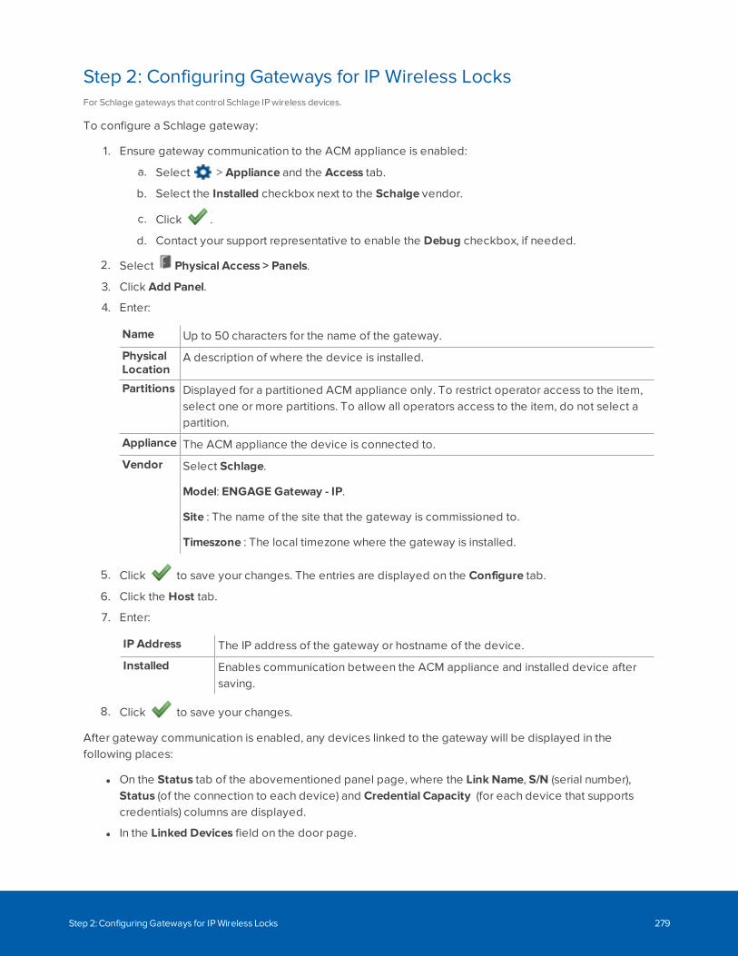
Step 2: Configuring Gateways for IP Wireless LocksFor Schlage gateways that control Schlage IP wireless devices.
To configure a Schlage gateway:
1. Ensure gateway communication to the ACM appliance is enabled:
a. Select > Appliance and the Access tab.
b. Select the Installed checkbox next to the Schalge vendor.
c. Click .
d. Contact your support representative to enable the Debug checkbox, if needed.
2. Select Physical Access > Panels.
3. Click Add Panel.
4. Enter:
Name Up to 50 characters for the name of the gateway.
PhysicalLocation
A description of where the device is installed.
Partitions Displayed for a partitioned ACM appliance only. To restrict operator access to the item,select one or more partitions. To allow all operators access to the item, do not select apartition.
Appliance The ACM appliance the device is connected to.
Vendor Select Schlage.
Model: ENGAGE Gateway - IP.
Site : The name of the site that the gateway is commissioned to.
Timeszone : The local timezone where the gateway is installed.
5. Click to save your changes. The entries are displayed on the Configure tab.
6. Click the Host tab.
7. Enter:
IP Address The IP address of the gateway or hostname of the device.
Installed Enables communication between the ACM appliance and installed device aftersaving.
8. Click to save your changes.
After gateway communication is enabled, any devices linked to the gateway will be displayed in thefollowing places:
l On the Status tab of the abovementioned panel page, where the Link Name, S/N (serial number),Status (of the connection to each device) and Credential Capacity (for each device that supportscredentials) columns are displayed.
l In the Linked Devices field on the door page.
Step 2: Configuring Gateways for IP Wireless Locks 279
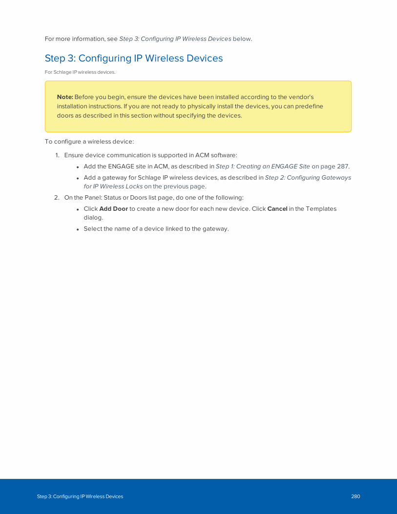
For more information, see Step 3: Configuring IP Wireless Devices below.
Step 3: Configuring IP Wireless DevicesFor Schlage IP wireless devices.
Note: Before you begin, ensure the devices have been installed according to the vendor'sinstallation instructions. If you are not ready to physically install the devices, you can predefinedoors as described in this section without specifying the devices.
To configure a wireless device:
1. Ensure device communication is supported in ACM software:
l Add the ENGAGE site in ACM, as described in Step 1: Creating an ENGAGE Site on page 287.
l Add a gateway for Schlage IP wireless devices, as described in Step 2: Configuring Gatewaysfor IP Wireless Locks on the previous page.
2. On the Panel: Status or Doors list page, do one of the following:
l Click Add Door to create a new door for each new device. Click Cancel in the Templatesdialog.
l Select the name of a device linked to the gateway.
Step 3: Configuring IP Wireless Devices 280
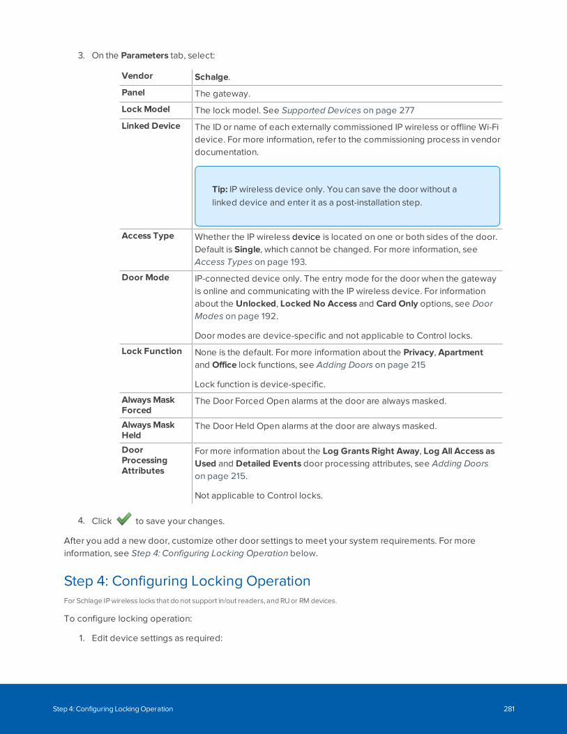
3. On the Parameters tab, select:
Vendor Schalge.
Panel The gateway.
Lock Model The lock model. See Supported Devices on page 277
Linked Device The ID or name of each externally commissioned IP wireless or offline Wi-Fidevice. For more information, refer to the commissioning process in vendordocumentation.
Tip: IP wireless device only. You can save the door without alinked device and enter it as a post-installation step.
Access Type Whether the IP wireless device is located on one or both sides of the door.Default is Single, which cannot be changed. For more information, seeAccess Types on page 193.
Door Mode IP-connected device only. The entry mode for the door when the gatewayis online and communicating with the IP wireless device. For informationabout the Unlocked, Locked No Access and Card Only options, see DoorModes on page 192.
Door modes are device-specific and not applicable to Control locks.
Lock Function None is the default. For more information about the Privacy, Apartmentand Office lock functions, see Adding Doors on page 215
Lock function is device-specific.
AlwaysMaskForced
The Door Forced Open alarms at the door are always masked.
AlwaysMaskHeld
The Door Held Open alarms at the door are always masked.
DoorProcessingAttributes
For more information about the Log Grants Right Away, Log All Access asUsed and Detailed Events door processing attributes, see Adding Doorson page 215.
Not applicable to Control locks.
4. Click to save your changes.
After you add a new door, customize other door settings to meet your system requirements. For moreinformation, see Step 4: Configuring Locking Operation below.
Step 4: Configuring Locking OperationFor Schlage IP wireless locks that do not support in/out readers, and RU or RM devices.
To configure locking operation:
1. Edit device settings as required:
Step 4: Configuring Locking Operation 281
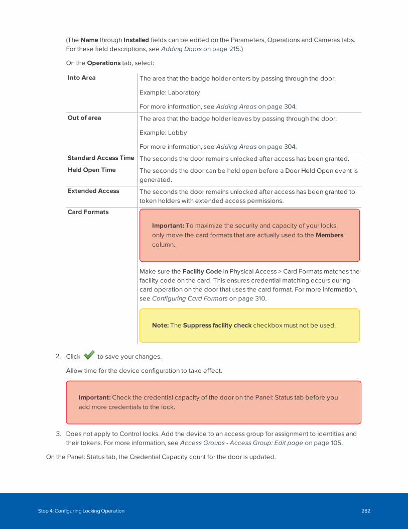
(The Name through Installed fields can be edited on the Parameters, Operations and Cameras tabs.For these field descriptions, see Adding Doors on page 215.)
On the Operations tab, select:
Into Area The area that the badge holder enters by passing through the door.
Example: Laboratory
For more information, see Adding Areas on page 304.
Out of area The area that the badge holder leaves by passing through the door.
Example: Lobby
For more information, see Adding Areas on page 304.
Standard Access Time The seconds the door remains unlocked after access has been granted.
Held Open Time The seconds the door can be held open before a Door Held Open event isgenerated.
Extended Access The seconds the door remains unlocked after access has been granted totoken holders with extended access permissions.
Card Formats
Important: To maximize the security and capacity of your locks,only move the card formats that are actually used to the Memberscolumn.
Make sure the Facility Code in Physical Access > Card Formats matches thefacility code on the card. This ensures credential matching occurs duringcard operation on the door that uses the card format. For more information,see Configuring Card Formats on page 310.
Note: The Suppress facility check checkbox must not be used.
2. Click to save your changes.
Allow time for the device configuration to take effect.
Important: Check the credential capacity of the door on the Panel: Status tab before youadd more credentials to the lock.
3. Does not apply to Control locks. Add the device to an access group for assignment to identities andtheir tokens. For more information, see Access Groups - Access Group: Edit page on page 105.
On the Panel: Status tab, the Credential Capacity count for the door is updated.
Step 4: Configuring Locking Operation 282
Applying Door CommandsFor Schlage IP wireless devices.
To control your device, apply the following door commands:
1. Select Physical Access > Doors.
2. Enter a checkmark in the All column next to the device.
3. For the Control lock:
l To grant access to the deadbolt on the Control lock, select Door Action > Grant (only thisdoor action is supported). Momentarily grants access to the door to permit a single-time entry.Ignore the Unknown door state and door mode.
The deadbolt is enabled for you to lock it (extend the bolt) or unlock it (retract the bolt) on theoutside.
4. For the RU device:
l To unlock the RU device in Closed door state and Locked No Access door mode, selectDoor Action > Unlock (only this door action and the Locked No Access door action aresupported).
The door mode changes to Locked No Access (Unlocked on Next Exit). The door is locked
on the outside and the inside. The remains displayed.
When a person presses the push bar, the door is Unlocked. While the door is unlocked,you will see the Open and Closed states as the door is opened and closed.
l To lock the RU device in Closed door state and Unlocked door mode, select DoorAction > Locked No Access.
The door is instantly locked.
You can also apply door commands to RU devices in maps. For more information, see Maps -Introduction on page 424.
Door Scheduling By Batch Job (Specification)For Schlage IP wireless devices.
To create a schedule for locking and unlocking doors, use a batch job specification. For more information,see Scheduling Batch Jobs on page 448 and Setting Batch Door Modes on page 455.
Viewing Gateway or Offline Wi-Fi Lock StatusFor IP/PoE mode and offline Wi-Fi mode ENGAGE gateways.
1. Select Physical Access > Panels to view gateways or offline Wi-Fi locks.
2. View the Device Status in the first column. For more information, see Device Status on page 47.Ignore the Cards in Use column.
Applying Door Commands 283
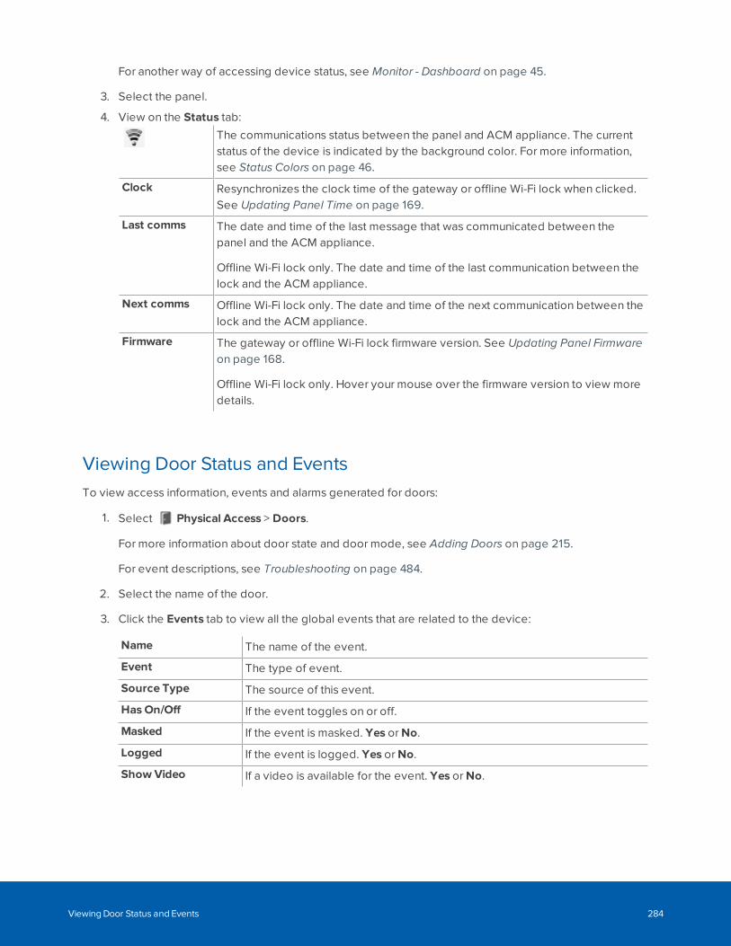
For another way of accessing device status, see Monitor - Dashboard on page 45.
3. Select the panel.
4. View on the Status tab:
The communications status between the panel and ACM appliance. The currentstatus of the device is indicated by the background color. For more information,see Status Colors on page 46.
Clock Resynchronizes the clock time of the gateway or offline Wi-Fi lock when clicked.See Updating Panel Time on page 169.
Last comms The date and time of the last message that was communicated between thepanel and the ACM appliance.
Offline Wi-Fi lock only. The date and time of the last communication between thelock and the ACM appliance.
Next comms Offline Wi-Fi lock only. The date and time of the next communication between thelock and the ACM appliance.
Firmware The gateway or offline Wi-Fi lock firmware version. See Updating Panel Firmwareon page 168.
Offline Wi-Fi lock only. Hover your mouse over the firmware version to view moredetails.
Viewing Door Status and EventsTo view access information, events and alarms generated for doors:
1. Select Physical Access > Doors.
For more information about door state and door mode, see Adding Doors on page 215.
For event descriptions, see Troubleshooting on page 484.
2. Select the name of the door.
3. Click the Events tab to view all the global events that are related to the device:
Name The name of the event.
Event The type of event.
Source Type The source of this event.
Has On/Off If the event toggles on or off.
Masked If the event is masked. Yes or No.
Logged If the event is logged. Yes or No.
Show Video If a video is available for the event. Yes or No.
Viewing Door Status and Events 284
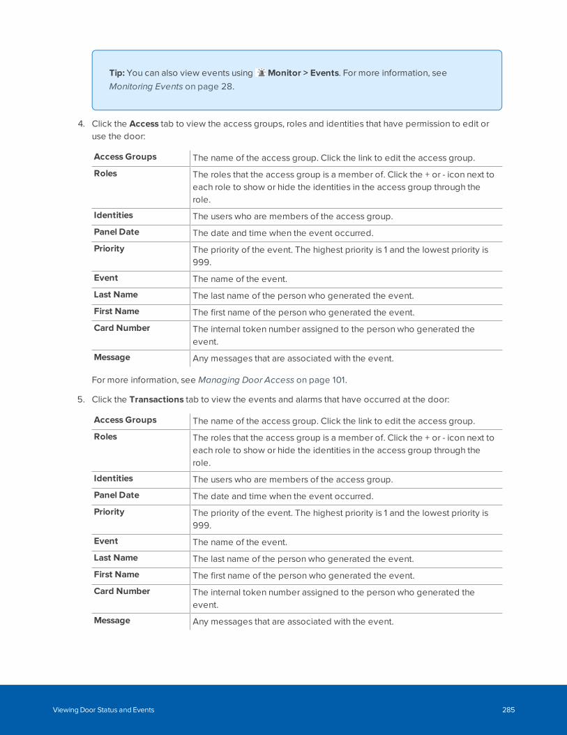
Tip: You can also view events using Monitor > Events. For more information, seeMonitoring Events on page 28.
4. Click the Access tab to view the access groups, roles and identities that have permission to edit oruse the door:
Access Groups The name of the access group. Click the link to edit the access group.
Roles The roles that the access group is a member of. Click the + or - icon next toeach role to show or hide the identities in the access group through therole.
Identities The users who are members of the access group.
Panel Date The date and time when the event occurred.
Priority The priority of the event. The highest priority is 1 and the lowest priority is999.
Event The name of the event.
Last Name The last name of the person who generated the event.
First Name The first name of the person who generated the event.
Card Number The internal token number assigned to the person who generated theevent.
Message Any messages that are associated with the event.
For more information, see Managing Door Access on page 101.
5. Click the Transactions tab to view the events and alarms that have occurred at the door:
Access Groups The name of the access group. Click the link to edit the access group.
Roles The roles that the access group is a member of. Click the + or - icon next toeach role to show or hide the identities in the access group through therole.
Identities The users who are members of the access group.
Panel Date The date and time when the event occurred.
Priority The priority of the event. The highest priority is 1 and the lowest priority is999.
Event The name of the event.
Last Name The last name of the person who generated the event.
First Name The first name of the person who generated the event.
Card Number The internal token number assigned to the person who generated theevent.
Message Any messages that are associated with the event.
Viewing Door Status and Events 285
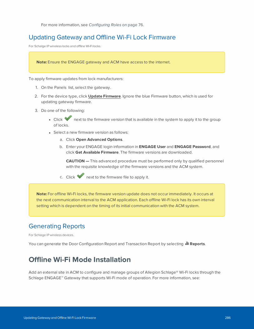
For more information, see Configuring Roles on page 76.
Updating Gateway and Offline Wi-Fi Lock FirmwareFor Schalge IP wireless locks and offline Wi-Fi locks.
Note: Ensure the ENGAGE gateway and ACM have access to the internet.
To apply firmware updates from lock manufacturers:
1. On the Panels list, select the gateway.
2. For the device type, click Update Firmware. Ignore the blue Firmware button, which is used forupdating gateway firmware.
3. Do one of the following:
l Click next to the firmware version that is available in the system to apply it to the groupof locks.
l Select a new firmware version as follows:
a. Click Open Advanced Options.
b. Enter your ENGAGE login information in ENGAGE User and ENGAGE Password, andclick Get Available Firmware. The firmware versions are downloaded.
CAUTION — This advanced procedure must be performed only by qualified personnelwith the requisite knowledge of the firmware versions and the ACM system.
c. Click next to the firmware file to apply it.
Note: For offline Wi-Fi locks, the firmware version update does not occur immediately. It occurs atthe next communication interval to the ACM application. Each offline Wi-Fi lock has its own intervalsetting which is dependent on the timing of its initial communication with the ACM system.
Generating ReportsFor Schlage IP wireless devices.
You can generate the Door Configuration Report and Transaction Report by selecting Reports.
Offline Wi-Fi Mode Installation
Add an external site in ACM to configure and manage groups of Allegion Schlage® Wi-Fi locks through theSchlage ENGAGE™ Gateway that supports Wi-Fi mode of operation. For more information, see:
Updating Gateway and Offline Wi-Fi Lock Firmware 286
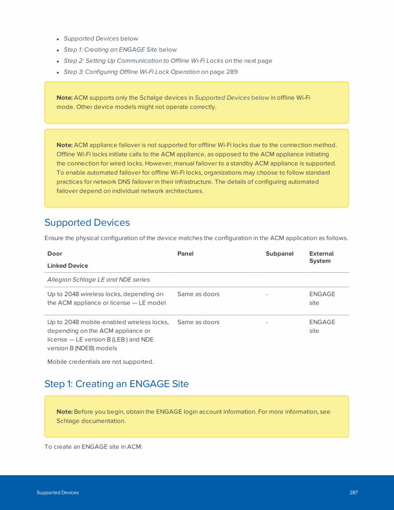
l Supported Devices below
l Step 1: Creating an ENGAGE Site below
l Step 2: Setting Up Communication to Offline Wi-Fi Locks on the next page
l Step 3: Configuring Offline Wi-Fi Lock Operation on page 289
Note: ACM supports only the Schalge devices in Supported Devices below in offline Wi-Fimode. Other device models might not operate correctly.
Note: ACM appliance failover is not supported for offline Wi-Fi locks due to the connection method.Offline Wi-Fi locks initiate calls to the ACM appliance, as opposed to the ACM appliance initiatingthe connection for wired locks. However, manual failover to a standby ACM appliance is supported.To enable automated failover for offline Wi-Fi locks, organizations may choose to follow standardpractices for network DNS failover in their infrastructure. The details of configuring automatedfailover depend on individual network architectures.
Supported DevicesEnsure the physical configuration of the device matches the configuration in the ACM application as follows.
Door
Linked Device
Panel Subpanel ExternalSystem
Allegion Schlage LE and NDE series
Up to 2048 wireless locks, depending onthe ACM appliance or license — LE model
Same as doors - ENGAGEsite
Up to 2048 mobile-enabled wireless locks,depending on the ACM appliance orlicense — LE version B (LEB ) and NDEversion B (NDEB) models
Mobile credentials are not supported.
Same as doors - ENGAGEsite
Step 1: Creating an ENGAGE Site
Note: Before you begin, obtain the ENGAGE login account information. For more information, seeSchlage documentation.
To create an ENGAGE site in ACM:
Supported Devices 287
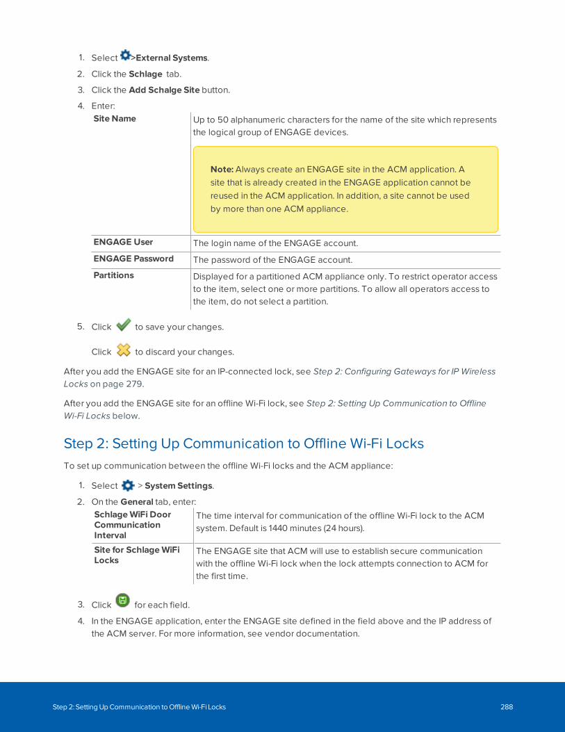
1. Select >External Systems.
2. Click the Schlage tab.
3. Click the Add Schalge Site button.
4. Enter:Site Name Up to 50 alphanumeric characters for the name of the site which represents
the logical group of ENGAGE devices.
Note: Always create an ENGAGE site in the ACM application. Asite that is already created in the ENGAGE application cannot bereused in the ACM application. In addition, a site cannot be usedby more than one ACM appliance.
ENGAGE User The login name of the ENGAGE account.
ENGAGE Password The password of the ENGAGE account.
Partitions Displayed for a partitioned ACM appliance only. To restrict operator accessto the item, select one or more partitions. To allow all operators access tothe item, do not select a partition.
5. Click to save your changes.
Click to discard your changes.
After you add the ENGAGE site for an IP-connected lock, see Step 2: Configuring Gateways for IP WirelessLocks on page 279.
After you add the ENGAGE site for an offline Wi-Fi lock, see Step 2: Setting Up Communication to OfflineWi-Fi Locks below.
Step 2: Setting Up Communication to Offline Wi-Fi LocksTo set up communication between the offline Wi-Fi locks and the ACM appliance:
1. Select > System Settings.
2. On the General tab, enter:SchlageWiFi DoorCommunicationInterval
The time interval for communication of the offline Wi-Fi lock to the ACMsystem. Default is 1440 minutes (24 hours).
Site for SchlageWiFiLocks
The ENGAGE site that ACM will use to establish secure communicationwith the offline Wi-Fi lock when the lock attempts connection to ACM forthe first time.
3. Click for each field.
4. In the ENGAGE application, enter the ENGAGE site defined in the field above and the IP address ofthe ACM server. For more information, see vendor documentation.
Step 2: Setting Up Communication to Offline Wi-Fi Locks 288
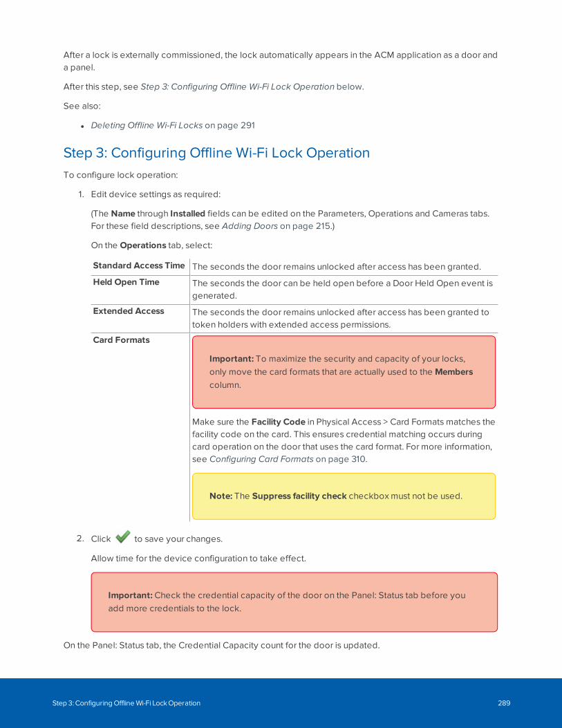
After a lock is externally commissioned, the lock automatically appears in the ACM application as a door anda panel.
After this step, see Step 3: Configuring Offline Wi-Fi Lock Operation below.
See also:
l Deleting Offline Wi-Fi Locks on page 291
Step 3: Configuring Offline Wi-Fi Lock OperationTo configure lock operation:
1. Edit device settings as required:
(The Name through Installed fields can be edited on the Parameters, Operations and Cameras tabs.For these field descriptions, see Adding Doors on page 215.)
On the Operations tab, select:
Standard Access Time The seconds the door remains unlocked after access has been granted.
Held Open Time The seconds the door can be held open before a Door Held Open event isgenerated.
Extended Access The seconds the door remains unlocked after access has been granted totoken holders with extended access permissions.
Card Formats
Important: To maximize the security and capacity of your locks,only move the card formats that are actually used to the Memberscolumn.
Make sure the Facility Code in Physical Access > Card Formats matches thefacility code on the card. This ensures credential matching occurs duringcard operation on the door that uses the card format. For more information,see Configuring Card Formats on page 310.
Note: The Suppress facility check checkbox must not be used.
2. Click to save your changes.
Allow time for the device configuration to take effect.
Important: Check the credential capacity of the door on the Panel: Status tab before youadd more credentials to the lock.
On the Panel: Status tab, the Credential Capacity count for the door is updated.
Step 3: Configuring Offline Wi-Fi Lock Operation 289
Viewing Gateway or Offline Wi-Fi Lock StatusFor IP/PoE mode and offline Wi-Fi mode ENGAGE gateways.
1. Select Physical Access > Panels to view gateways or offline Wi-Fi locks.
2. View the Device Status in the first column. For more information, see Device Status on page 47.Ignore the Cards in Use column.
For another way of accessing device status, see Monitor - Dashboard on page 45.
3. Select the panel.
4. View on the Status tab:
The communications status between the panel and ACM appliance. The currentstatus of the device is indicated by the background color. For more information,see Status Colors on page 46.
Clock Resynchronizes the clock time of the gateway or offline Wi-Fi lock when clicked.See Updating Panel Time on page 169.
Last comms The date and time of the last message that was communicated between thepanel and the ACM appliance.
Offline Wi-Fi lock only. The date and time of the last communication between thelock and the ACM appliance.
Next comms Offline Wi-Fi lock only. The date and time of the next communication between thelock and the ACM appliance.
Firmware The gateway or offline Wi-Fi lock firmware version. See Updating Panel Firmwareon page 168.
Offline Wi-Fi lock only. Hover your mouse over the firmware version to view moredetails.
Updating Lock FirmwareFor Schalge IP wireless locks and offline Wi-Fi locks.
Note: Ensure the ENGAGE gateway and ACM have access to the internet.
To apply firmware updates from lock manufacturers:
Viewing Gateway or Offline Wi-Fi Lock Status 290
1. On the Panels list, select the gateway.
2. For the device type, click Update Firmware. Ignore the blue Firmware button, which is used forupdating gateway firmware.
3. Do one of the following:
l Click next to the firmware version that is available in the system to apply it to the groupof locks.
l Select a new firmware version as follows:
a. Click Open Advanced Options.
b. Enter your ENGAGE login information in ENGAGE User and ENGAGE Password, andclick Get Available Firmware. The firmware versions are downloaded.
CAUTION — This advanced procedure must be performed only by qualified personnelwith the requisite knowledge of the firmware versions and the ACM system.
c. Click next to the firmware file to apply it.
Note: For offline Wi-Fi locks, the firmware version update does not occur immediately. It occurs atthe next communication interval to the ACM application. Each offline Wi-Fi lock has its own intervalsetting which is dependent on the timing of its initial communication with the ACM system.
Deleting Offline Wi-Fi LocksTo delete an offline Wi-Fi lock from the ACM application:
1. Uninstall the physical lock hardware.
2. Delete the door in the ACM application. For more information, see Deleting Doors on page 192.
Deleting the door automatically deletes the associated panel.
If a lock is deleted in the ACM application, it will reappear as a new door at the next communication intervalto the ACM application. A lock that is not deleted in the ACM application, but deleted in the ENGAGEapplication, will appear as an offline lock in the ACM application. Changing the site must be done in theENGAGE application.
Deleting Offline Wi-Fi Locks 291
SALTO Door Installation
Add a SALTO ProAccess SPACE server (referred to as SALTO server) in the ACM application to manageusers and physical access to installed doors that are configured in the SALTO network. For moreinformation, see:
l Prerequisites below
l Supported Devices on page 295
l Step 1: Connecting to a SALTO Server on page 296
l Step 2: Configuring the SALTO Server on page 296
l Step 3: Syncing Doors with the SALTO Server on page 297
l Step 4: Installing and Configuring Doors on page 297
l Step 5: Creating Identities and Tokens on page 299
Note: Doors must be created in the SALTO system before you use the ACM system. Every time youadd or delete doors in the SALTO system, remember to manually sync them with ACM asdescribed in Step 3. In addition, identities and their tokens must be managed in the ACM systemand requires using encoder hardware for some door modes, as described in Step 5.
PrerequisitesContact your integrator to install and configure the SALTO ProAccess SPACE server.
Note: Operators need to understand how to use SALTO security configuration, such as keyrevalidation, door open mode and timed-based configuration, before using the ACM system. SeeUnderstanding SALTO and ACM Door Configuration on page 294.
For general, new or updated instructions about registration, installation and configuration of SALTOsystems software and hardware, refer to SALTO systems documentation. The following instructionsare based on using SALTO ProAccess SPACE software version 6.2.3.1.
1. In the SALTO ProAccess SPACE Configurator application, set up the encrypted connection:
a. If the ProAccess SPACE service is running, select the SERVICE PROPERTIES panel and stop it.
b. Select the SERVICE PORTS panel.
c. Select SALTO authentication and enter the port used for communication betweenSALTO and ACM systems. Default is 8100.
This is the same port used in the URL to access the SALTO ProAccess SPACE web interface.
SALTO Door Installation 292
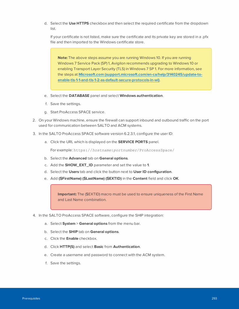
d. Select the Use HTTPS checkbox and then select the required certificate from the dropdownlist.
If your certificate is not listed, make sure the certificate and its private key are stored in a .pfxfile and then imported to the Windows certificate store.
Note: The above steps assume you are running Windows 10. If you are runningWindows 7 Service Pack (SP) 1, Avigilon recommends upgrading to Windows 10 orenabling Transport Layer Security (TLS) in Windows 7 SP 1. For more information, seethe steps at Microsoft.com (support.microsoft.com/en-ca/help/3140245/update-to-enable-tls-1-1-and-tls-1-2-as-default-secure-protocols-in-wi).
e. Select the DATABASE panel and select Windows authentication.
f. Save the settings.
g. Start ProAccess SPACE service.
2. On your Windows machine, ensure the firewall can support inbound and outbound traffic on the portused for communication between SALTO and ACM systems.
3. In the SALTO ProAccess SPACE software version 6.2.3.1, configure the user ID:
a. Click the URL which is displayed on the SERVICE PORTS panel.
For example: https://hostname:portnumber/ProAccessSpace/
b. Select the Advanced tab on General options.
c. Add the SHOW_EXT_ID parameter and set the value to 1.
d. Select the Users tab and click the button next to User ID configuration.
e. Add ($FirstName) ($LastName) ($EXTID) in the Content field and click OK.
Important: The ($EXTID) macro must be used to ensure uniqueness of the First Nameand Last Name combination.
4. In the SALTO ProAccess SPACE software, configure the SHIP integration:
a. Select System > General options from the menu bar.
b. Select the SHIP tab on General options.
c. Click the Enable checkbox.
d. Click HTTP(S) and select Basic from Authentication.
e. Create a username and password to connect with the ACM system.
f. Save the settings.
Prerequisites 293
Understanding SALTO and ACM Door Configuration
When you install doors in the SALTO system, consider the following:
l SALTO door open mode configuration is mapped to the ACM Door mode and Custom Mode fields.
Creating, updating or removing an open door mode in the SALTO system will add, update or remove(respectively) the mapped field values in the ACM system after a manual sync in ACM. See thefollowing table for the field values. When doors are deleted in the ACM system, the correspondingdoors in the SALTO system are not deleted. At the next manual sync in the ACM system, the door willdisplay as a new uninstalled door.
l SALTO Timed period field is mapped to the ACM Custom Schedule field.
Creating, updating or removing a schedule that is assigned to a door in the ACM system will create,update or remove (respectively) the Timed period value in the SALTO system.
l SALTO calendar group configuration is mapped to ACM holiday configuration.
Creating, updating or removing a holiday in the ACM system will add, update or remove(respectively) the calendar and any holidays in the SALTO system.
For information about ACM door configuration, see Door Modes on page 192, Step 3: Syncing Doors withthe SALTO Server on page 297 and Step 4: Installing and Configuring Doors on page 297
For information about SALTO door configuration, refer to SALTO systems documentation.
Understanding SALTO and ACM Door Configuration 294
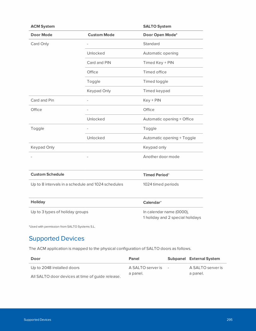
ACMSystem SALTO System
Door Mode CustomMode Door Open Mode*
Card Only - Standard
Unlocked Automatic opening
Card and PIN Timed Key + PIN
Office Timed office
Toggle Timed toggle
Keypad Only Timed keypad
Card and Pin - Key + PIN
Office - Office
Unlocked Automatic opening + Office
Toggle - Toggle
Unlocked Automatic opening + Toggle
Keypad Only Keypad only
- - Another door mode
Custom Schedule Timed Period*
Up to 8 intervals in a schedule and 1024 schedules 1024 timed periods
Holiday Calendar*
Up to 3 types of holiday groups In calendar name (0000),1 holiday and 2 special holidays
*Used with permission from SALTO Systems S.L.
Supported DevicesThe ACM application is mapped to the physical configuration of SALTO doors as follows.
Door Panel Subpanel External System
Up to 2048 installed doors
All SALTO door devices at time of guide release.
A SALTO server isa panel.
- A SALTO server isa panel.
Supported Devices 295
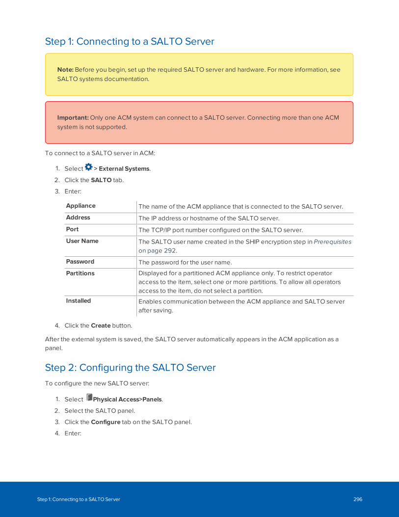
Step 1: Connecting to a SALTO Server
Note: Before you begin, set up the required SALTO server and hardware. For more information, seeSALTO systems documentation.
Important: Only one ACM system can connect to a SALTO server. Connecting more than one ACMsystem is not supported.
To connect to a SALTO server in ACM:
1. Select > External Systems.
2. Click the SALTO tab.
3. Enter:
Appliance The name of the ACM appliance that is connected to the SALTO server.
Address The IP address or hostname of the SALTO server.
Port The TCP/IP port number configured on the SALTO server.
User Name The SALTO user name created in the SHIP encryption step in Prerequisiteson page 292.
Password The password for the user name.
Partitions Displayed for a partitioned ACM appliance only. To restrict operatoraccess to the item, select one or more partitions. To allow all operatorsaccess to the item, do not select a partition.
Installed Enables communication between the ACM appliance and SALTO serverafter saving.
4. Click the Create button.
After the external system is saved, the SALTO server automatically appears in the ACM application as apanel.
Step 2: Configuring the SALTO ServerTo configure the new SALTO server:
1. Select Physical Access>Panels.
2. Select the SALTO panel.
3. Click the Configure tab on the SALTO panel.
4. Enter:
Step 1: Connecting to a SALTO Server 296
PhysicalLocation
A description of where the device is installed.
Partitions Displayed for a partitioned ACM appliance only. To restrict operator access to the item,select one or more partitions. To allow all operators access to the item, do not select apartition.
The other fields are read-only and cannot be changed. For more information, see SALTO PanelConfiguration on page 169.
5. Click to save your changes.
After saving the panel, see Step 3: Syncing Doors with the SALTO Server below.
Step 3: Syncing Doors with the SALTO ServerTo import SALTO doors to the ACM appliance:
l On the Status tab of the SALTO panel, click Sync Doors.
Doors are imported uninstalled. Sync Status displays the sync results. Doors in a zone in the SALTOsystem are displayed as doors in the ACM system.
Note: Every time you add or delete doors in the SALTO system, remember to sync themwith the ACM system.
The other fields are read-only and cannot be changed. For more information, see SALTO PanelStatus on page 169.
After doors are imported, see Step 4: Installing and Configuring Doors below.
Step 4: Installing and Configuring Doors
Note: Doors must be created in the SALTO system before you use Door mode, Custom Mode andCustom Schedule in the ACM system.
To enable communication to the SALTO door after syncing with the SALTO server:
1. Select Physical Access > Doors.
2. Install the door to enable communication with ACM, if not already done:
a. Select the door displaying the device status.
b. Select Installed > Install.
c. Click OK.
Step 3: Syncing Doors with the SALTO Server 297
Note: If a message (red text) is displayed indicating the need to update the door mode,make sure the Door Mode, CustomMode and Custom Schedule fields are selected. Youneed to set supported door modes in the ACM appliance.
If you add a door to a zone or remove a door from a zone in the SALTO system, allow up tofive minutes for the door to be added or deleted (respectively) in the ACM system.
3. Display the event details for each door in the list, if not already done:
a. Select the door name.
b. On the Parameters tab, enter a checkmark in Detailed events.
c. Click to save.
4. Return to Physical Access > Doors.
l In the Device Status column, you will see:
Online door only. Normal, Uninstalled, Communication, Unlocked, Battery, Tamper, Forced,Held or Synchronization.
Standalone door only. Normal, Uninstalled, Battery or Synchronization.
For more information, see Device Status on page 47.
l In the Door State column, you will see Unknown change to:
Online door. Open, Closed, Emergency Open or Emergency Closed.
Standalone door. Offline.
For more information, see Controlling Doors on page 179 and Maps - Introduction onpage 424.
l In the Door Mode column, you will see:
Online and standalone doors. Card Only, Card and Pin, Toggle, Office or Keypad Only.
For more information, see Door Modes on page 192.
5. Select and edit door configuration as required:
(The Alt Name through Installed fields can be edited on the Parameters and Cameras tabs. For thesefield descriptions, see Adding Doors on page 215.)
Door Mode: The entry mode of the door after syncing with the SALTO server and installing the door.For more information, see Door Modes on page 192.
CustomMode: Another entry mode of the door that is time-based (see Custom Schedule), which canbe Unlocked, Card and Pin, Office, Toggle or Keypad Only (same as Door Mode). If Keypad Only isselected, Keypad Code is displayed. You can enter up to 8 digits.
Step 4: Installing and Configuring Doors 298
Custom Schedule: A predefined time when Custom Mode becomes active. If you need to add a newschedule, see Adding Schedules (Intervals in Schedules) on page 378.
AlwaysMask Forced: If selected, Door Forced Open alarms at the door are always masked.
AlwaysMask Held: If selected, Door Held Open alarms at the door are always masked.
Detailed events: Enables the reporting of event details, such as Door Mode, after syncing andinstalling the door.
Do Not Log Rex Transactions: Disables logging of request-to-exit transactions.
6. Click to save your changes.
See Step 5: Creating Identities and Tokens below.
Step 5: Creating Identities and Tokens
Note: Before you start, make sure that you have access to encoder hardware before you create theidentity and token in the ACM system. In addition, make sure an access group and identity arecreated in the ACM system. For more information, see Adding an Access Group on page 101 andAssigning an Access Group to a Role on page 103.
To create an identity and token for a SALTO door:
1. Select Identities > Identities and click Search to select an identity already created.
If you need to add an identity, see Adding an Identity on page 60.
2. Click the Tokens tab and enter:
Token Type SALTO
Note: Only one SALTO token is allowed for an identity.
3. Click to save.
The Download and Assign Key buttons appear.
4. Edit the token and click Assign Key to assign a key, such as a keycard, to the token as follows:
a. Select the SALTO encoder in the dialog box and click Next.
b. SALTO encoder step. Place the physical key on the encoder hardware.
c. Click the Encode Key button in ACM.
ACM displays the status of the key update.
5. Click OK.
Step 5: Creating Identities and Tokens 299
Editing Tokens — Update Required and Re-edition RequiredIf the Update Required or Re-edition Required status (red box) appears on the Tokens tab, edit tokenconfiguration as follows:
Note: Updating some of the token configuration requires you to re-encode (referred to as re-edition or re-edit) the key. Therefore, make sure you have access to encoder hardware before youstart.
1. Select the token configuration:
PIN When a PIN is required, the PIN number that the user will be requiredto enter at a keypad card reader.
Token Status The status of the token is set manually and then updated by thesystem as follows:
l Active: The Not Yet Active token is set to Active when thecurrent date is past the Activate Date.
l Expired: The Active token is set to Expired when the currentdate is past the Deactivate Date.
l Inactive: The Active token is set manually to Inactive withoutfurther update.
l Not Yet Active: The token is not active yet.
Issue Level A number from 0 to 999999999, representing the issue level of thetoken.
Example: If a 3-digit length was configured on the Card Format: Editpage, you can enter 123 for the issue level of the card.
For more information, see Issue Level Numbering on page 310.
Never Expire A checkbox to prevent the token from expiring at a future date andtime.
Extended Door Times A checkbox to give the token extended access time.
Once enabled, the door remains unlocked for a longer period of timethan the standard access time to accommodate users that mayrequire more time to enter a door.
Standard and extended access times are specified on the Door Editpage.
Editing Tokens — Update Required and Re-edition Required 300
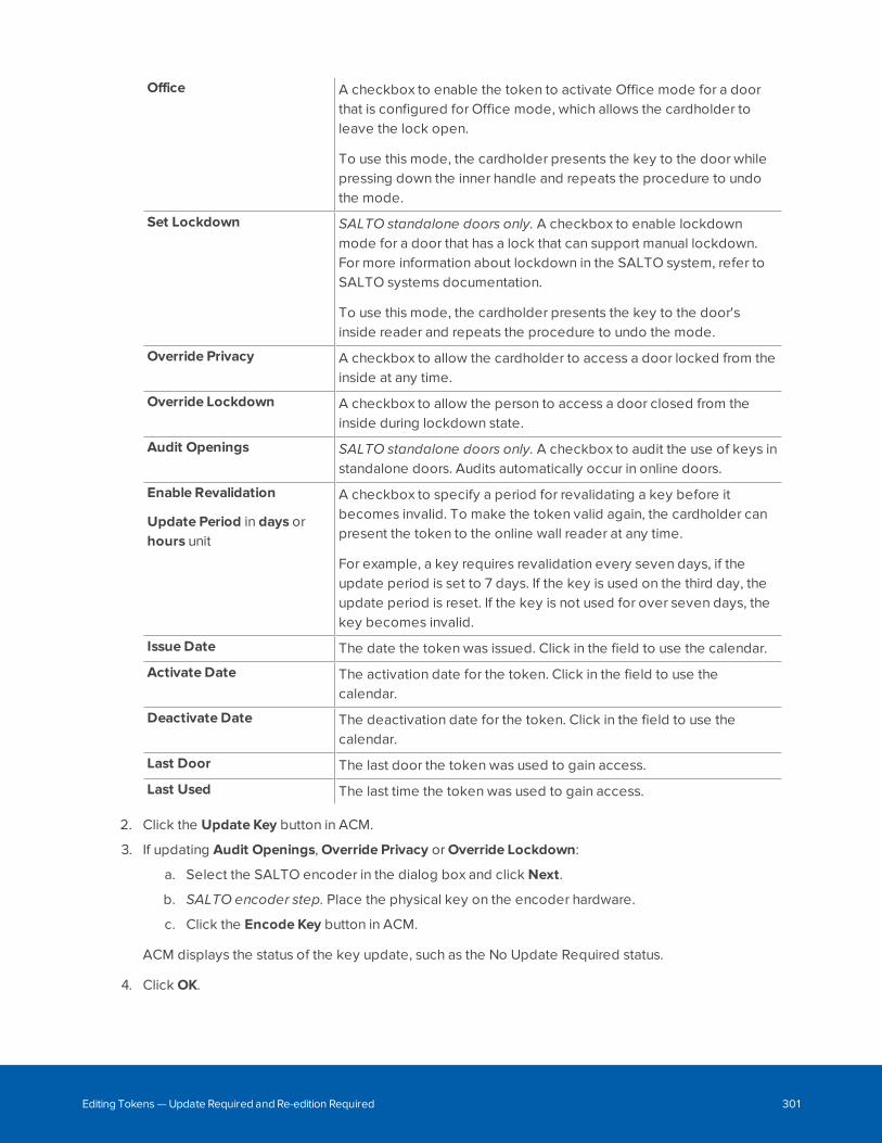
Office A checkbox to enable the token to activate Office mode for a doorthat is configured for Office mode, which allows the cardholder toleave the lock open.
To use this mode, the cardholder presents the key to the door whilepressing down the inner handle and repeats the procedure to undothe mode.
Set Lockdown SALTO standalone doors only. A checkbox to enable lockdownmode for a door that has a lock that can support manual lockdown.For more information about lockdown in the SALTO system, refer toSALTO systems documentation.
To use this mode, the cardholder presents the key to the door'sinside reader and repeats the procedure to undo the mode.
Override Privacy A checkbox to allow the cardholder to access a door locked from theinside at any time.
Override Lockdown A checkbox to allow the person to access a door closed from theinside during lockdown state.
Audit Openings SALTO standalone doors only. A checkbox to audit the use of keys instandalone doors. Audits automatically occur in online doors.
Enable Revalidation
Update Period in days orhours unit
A checkbox to specify a period for revalidating a key before itbecomes invalid. To make the token valid again, the cardholder canpresent the token to the online wall reader at any time.
For example, a key requires revalidation every seven days, if theupdate period is set to 7 days. If the key is used on the third day, theupdate period is reset. If the key is not used for over seven days, thekey becomes invalid.
Issue Date The date the token was issued. Click in the field to use the calendar.
Activate Date The activation date for the token. Click in the field to use thecalendar.
Deactivate Date The deactivation date for the token. Click in the field to use thecalendar.
Last Door The last door the token was used to gain access.
Last Used The last time the token was used to gain access.
2. Click the Update Key button in ACM.
3. If updating Audit Openings, Override Privacy or Override Lockdown:
a. Select the SALTO encoder in the dialog box and click Next.
b. SALTO encoder step. Place the physical key on the encoder hardware.
c. Click the Encode Key button in ACM.
ACM displays the status of the key update, such as the No Update Required status.
4. Click OK.
Editing Tokens — Update Required and Re-edition Required 301
Canceling KeysTo cancel a key that was assigned to a token:
1. On the Tokens tab, click the Cancel Key button.
ACM displays the status of key update.
2. Click OK .
Note: A canceled key cannot be used throughout the SALTO system. For more information, refer toSALTO system documentation.
Downloading All TokensTo download or restore all tokens to the SALTO server:
l On the Status tab of the SALTO panel, click Tokens.
Typically, this action is done after system restore. For more information, see also Restoring Backups onpage 351.
Configuring Areas
An area in the ACM system defines a physical location within a secured site that requires additional accesscontrol. This area can be relatively small, like a lab or a store room; or large, like a collection of buildings.Areas often incorporate one or more doors with their attached inputs and outputs. You can define areas totrack badge holder location, for example in a mustering scenario, or to control access to specific areas, forexample in an anti-passback configuration to limit user access within a building or facility.
Note: Do not confuse areas with partitions. A partition is a separate administrative access zonewithin the ACM system. An area is a physical location that requires additional access control.Therefore, in a partitioned system, an area is configured within a partition.
For example, an anti-passback configuration can be used in a laboratory facility to restrict access to aspecific room.
Canceling Keys 302
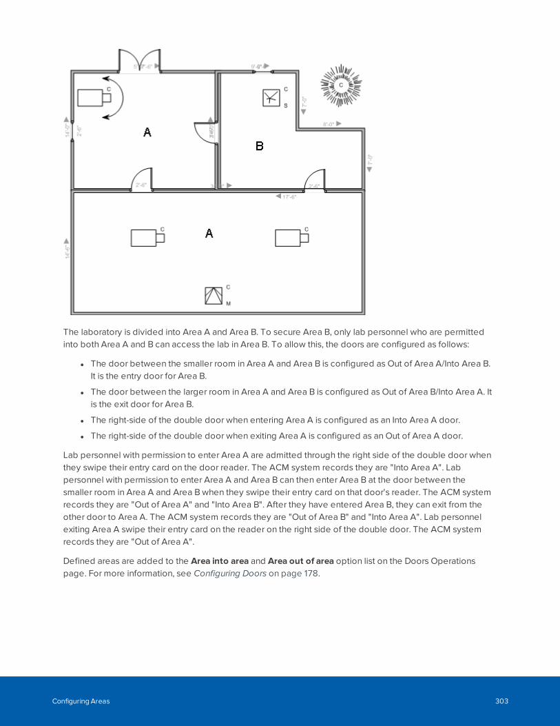
The laboratory is divided into Area A and Area B. To secure Area B, only lab personnel who are permittedinto both Area A and B can access the lab in Area B. To allow this, the doors are configured as follows:
l The door between the smaller room in Area A and Area B is configured as Out of Area A/Into Area B.It is the entry door for Area B.
l The door between the larger room in Area A and Area B is configured as Out of Area B/Into Area A. Itis the exit door for Area B.
l The right-side of the double door when entering Area A is configured as an Into Area A door.
l The right-side of the double door when exiting Area A is configured as an Out of Area A door.
Lab personnel with permission to enter Area A are admitted through the right side of the double door whenthey swipe their entry card on the door reader. The ACM system records they are "Into Area A". Labpersonnel with permission to enter Area A and Area B can then enter Area B at the door between thesmaller room in Area A and Area B when they swipe their entry card on that door's reader. The ACM systemrecords they are "Out of Area A" and "Into Area B". After they have entered Area B, they can exit from theother door to Area A. The ACM system records they are "Out of Area B" and "Into Area A". Lab personnelexiting Area A swipe their entry card on the reader on the right side of the double door. The ACM systemrecords they are "Out of Area A".
Defined areas are added to the Area into area and Area out of area option list on the Doors Operationspage. For more information, see Configuring Doors on page 178.
Configuring Areas 303
Adding Areas1. Select Physical Access > Areas.
2. From the Areas list, click Add Area.
3. Enter a name for the area.
4. Select the appliance that will maintain the area details.
5. Select the Enable Area checkbox to activate the new area.
6. Fill in the other options as required.
7. Click .
The new area is added to the Area Listings page.
Editing Areas1. Select Physical Access > Areas.
2. Click the name of the area you want to edit.
3. On the following page, make the required changes.
If you want to change the doors that are connected to the area, you must do so from the door'sOperations page.
4. Click .
Deleting Areas1. Select Physical Access > Areas.
2. From the Areas list, click for the area you want to delete.
3. When the browser displays a pop-up message to ask Are you sure?, click OK.
EOL Resistance
End-of-line (EOL) resistance refers to the resistance levels that must be maintained for input points. Inputdevices used with doors often measure circuit resistance in ohms. This measurement is used to determinethe normal resistance level. If the resistance drops across the circuit, an alarm is sent back to the ACMapplication.
For example, if resistance for a particular device has been set at 2000 ohms and the circuit's resistancesuddenly drops to 1000 ohm, an alarm is issued by the application.
Adding EOL Resistance for Mercury Input PointsTo add an EOL Resistance definition for a Mercury input device:
Adding Areas 304
1. Select Physical Access > EOL Resistance. Make sure the Mercury tab is selected.
2. From the Mercury EOL Resistance list, click Add-Normal or Add-Advanced.
3. On the following EOL Resistance Add page, enter the required details.
4. Click to save your changes.
Adding EOL Resistance for VertX® Input PointsTo add an EOL Resistance definition for an VertX® input point:
1. Select Physical Access > EOL Resistance > HID.
2. From the HID list, click Add.
3. Enter the required details.
4. Click to save your changes.
Editing EOL Resistance for Mercury Input PointsTo edit an EOL Resistance definition for a Mercury input device:
1. Select Physical Access > EOL Resistance. Make sure the Mercury tab is selected.
2. Select the EOL Resistance definition that you want to edit.
3. On the following page, make the required changes.
4. Click to save your changes.
Editing EOL Resistance for VertX® Input PointsTo edit an EOL Resistance definition for a VertX® input point:
1. Select Physical Access > EOL Resistance > HID.
2. On the HID list, select the EOL Resistance definition that you want to edit.
3. On the following page, make the required changes.
4. Click to save your changes.
Mercury LED Modes - List page
The Mercury LED Modes list lists the available Mercury Security LED modes.
Select a mode from the list of custom LED modes to modify its settings. The Mercury LED Mode Table<number> page is displayed. For more detail, see Editing LED Modes (Mercury Security) on the next page.
Before making any changes ensure that the related doors and subpanels are correctly configured andwired, including:
Adding EOL Resistance for VertX® Input Points 305
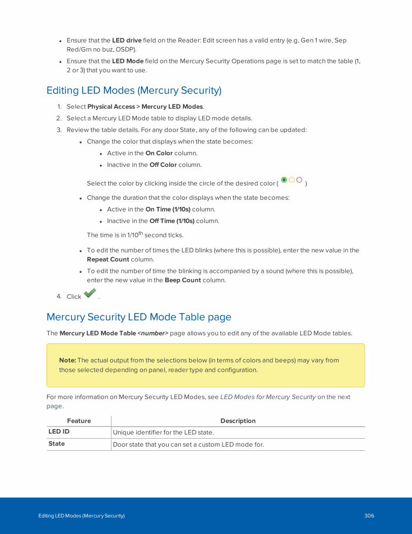
l Ensure that the LED drive field on the Reader: Edit screen has a valid entry (e.g. Gen 1 wire, SepRed/Grn no buz, OSDP).
l Ensure that the LED Mode field on the Mercury Security Operations page is set to match the table (1,2 or 3) that you want to use.
Editing LED Modes (Mercury Security)1. Select Physical Access > Mercury LED Modes.
2. Select a Mercury LED Mode table to display LED mode details.
3. Review the table details. For any door State, any of the following can be updated:
l Change the color that displays when the state becomes:
l Active in the On Color column.
l Inactive in the Off Color column.
Select the color by clicking inside the circle of the desired color ( )
l Change the duration that the color displays when the state becomes:
l Active in the On Time (1/10s) column.
l Inactive in the Off Time (1/10s) column.
The time is in 1/10th second ticks.
l To edit the number of times the LED blinks (where this is possible), enter the new value in theRepeat Count column.
l To edit the number of time the blinking is accompanied by a sound (where this is possible),enter the new value in the Beep Count column.
4. Click .
Mercury Security LED Mode Table pageThe Mercury LED Mode Table <number> page allows you to edit any of the available LED Mode tables.
Note: The actual output from the selections below (in terms of colors and beeps) may vary fromthose selected depending on panel, reader type and configuration.
For more information on Mercury Security LED Modes, see LED Modes for Mercury Security on the nextpage.
Feature Description
LED ID Unique identifier for the LED state.
State Door state that you can set a custom LED mode for.
Editing LED Modes (Mercury Security) 306
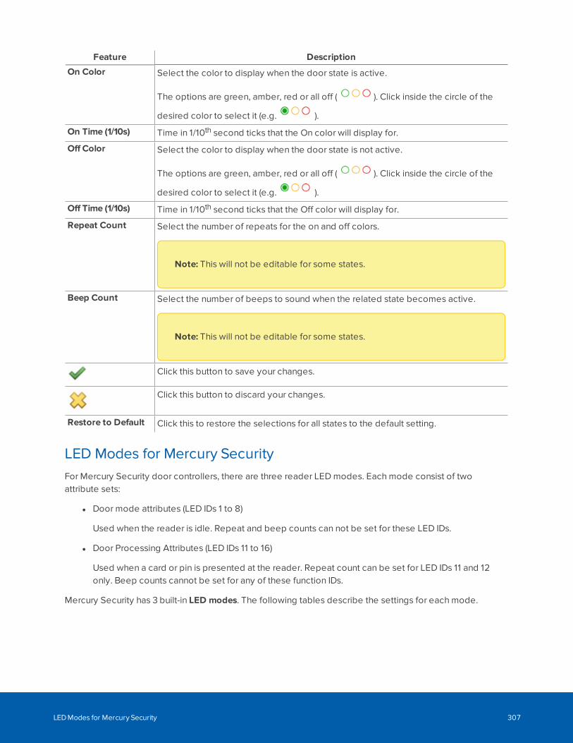
Feature Description
On Color Select the color to display when the door state is active.
The options are green, amber, red or all off ( ). Click inside the circle of the
desired color to select it (e.g. ).
On Time (1/10s) Time in 1/10th second ticks that the On color will display for.
Off Color Select the color to display when the door state is not active.
The options are green, amber, red or all off ( ). Click inside the circle of the
desired color to select it (e.g. ).
Off Time (1/10s) Time in 1/10th second ticks that the Off color will display for.
Repeat Count Select the number of repeats for the on and off colors.
Note: This will not be editable for some states.
Beep Count Select the number of beeps to sound when the related state becomes active.
Note: This will not be editable for some states.
Click this button to save your changes.
Click this button to discard your changes.
Restore to Default Click this to restore the selections for all states to the default setting.
LED Modes for Mercury SecurityFor Mercury Security door controllers, there are three reader LED modes. Each mode consist of twoattribute sets:
l Door mode attributes (LED IDs 1 to 8)
Used when the reader is idle. Repeat and beep counts can not be set for these LED IDs.
l Door Processing Attributes (LED IDs 11 to 16)
Used when a card or pin is presented at the reader. Repeat count can be set for LED IDs 11 and 12only. Beep counts cannot be set for any of these function IDs.
Mercury Security has 3 built-in LED modes. The following tables describe the settings for each mode.
LED Modes for Mercury Security 307
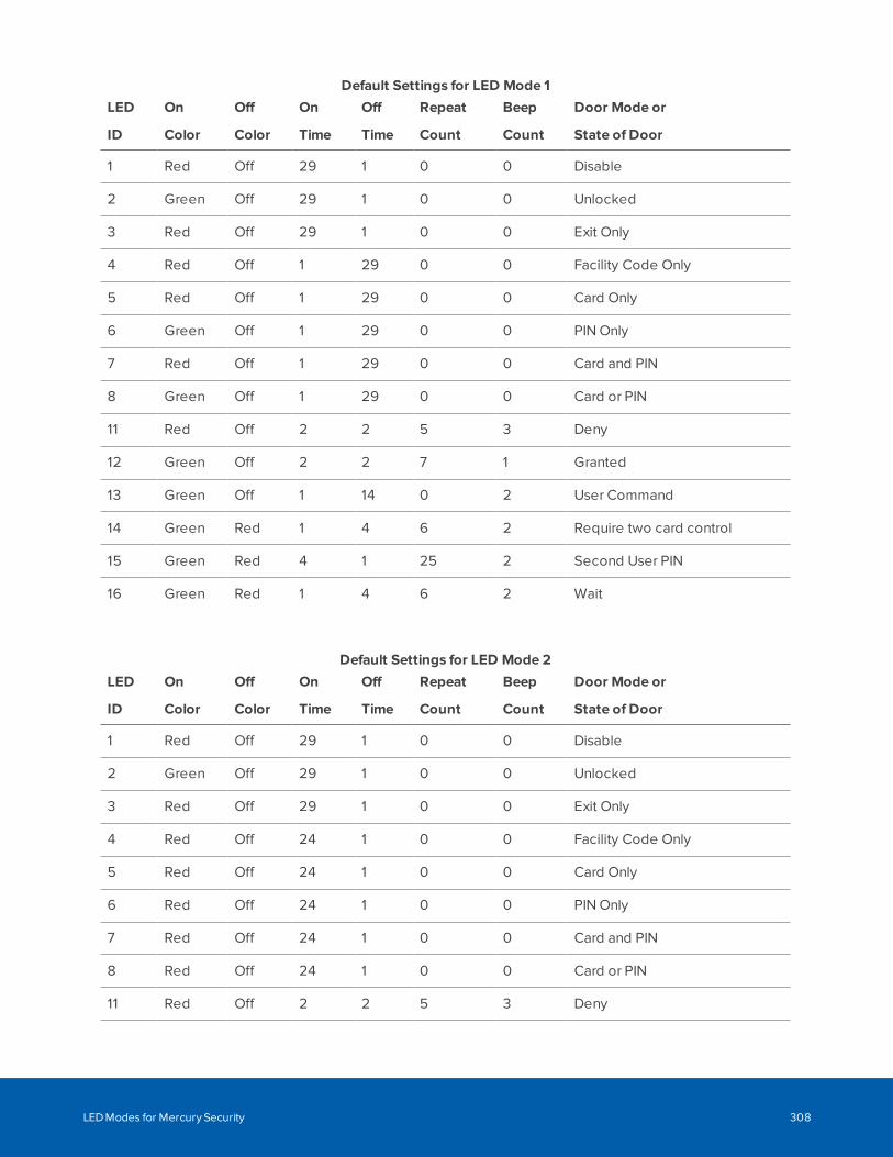
LED
ID
On
Color
Off
Color
On
Time
Off
Time
Repeat
Count
Beep
Count
Door Mode or
State of Door
1 Red Off 29 1 0 0 Disable
2 Green Off 29 1 0 0 Unlocked
3 Red Off 29 1 0 0 Exit Only
4 Red Off 1 29 0 0 Facility Code Only
5 Red Off 1 29 0 0 Card Only
6 Green Off 1 29 0 0 PIN Only
7 Red Off 1 29 0 0 Card and PIN
8 Green Off 1 29 0 0 Card or PIN
11 Red Off 2 2 5 3 Deny
12 Green Off 2 2 7 1 Granted
13 Green Off 1 14 0 2 User Command
14 Green Red 1 4 6 2 Require two card control
15 Green Red 4 1 25 2 Second User PIN
16 Green Red 1 4 6 2 Wait
Default Settings for LED Mode 1
LED
ID
On
Color
Off
Color
On
Time
Off
Time
Repeat
Count
Beep
Count
Door Mode or
State of Door
1 Red Off 29 1 0 0 Disable
2 Green Off 29 1 0 0 Unlocked
3 Red Off 29 1 0 0 Exit Only
4 Red Off 24 1 0 0 Facility Code Only
5 Red Off 24 1 0 0 Card Only
6 Red Off 24 1 0 0 PIN Only
7 Red Off 24 1 0 0 Card and PIN
8 Red Off 24 1 0 0 Card or PIN
11 Red Off 2 2 5 3 Deny
Default Settings for LED Mode 2
LED Modes for Mercury Security 308
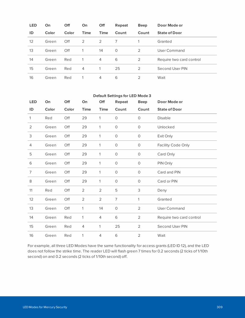
LED
ID
On
Color
Off
Color
On
Time
Off
Time
Repeat
Count
Beep
Count
Door Mode or
State of Door
12 Green Off 2 2 7 1 Granted
13 Green Off 1 14 0 2 User Command
14 Green Red 1 4 6 2 Require two card control
15 Green Red 4 1 25 2 Second User PIN
16 Green Red 1 4 6 2 Wait
LED
ID
On
Color
Off
Color
On
Time
Off
Time
Repeat
Count
Beep
Count
Door Mode or
State of Door
1 Red Off 29 1 0 0 Disable
2 Green Off 29 1 0 0 Unlocked
3 Green Off 29 1 0 0 Exit Only
4 Green Off 29 1 0 0 Facility Code Only
5 Green Off 29 1 0 0 Card Only
6 Green Off 29 1 0 0 PIN Only
7 Green Off 29 1 0 0 Card and PIN
8 Green Off 29 1 0 0 Card or PIN
11 Red Off 2 2 5 3 Deny
12 Green Off 2 2 7 1 Granted
13 Green Off 1 14 0 2 User Command
14 Green Red 1 4 6 2 Require two card control
15 Green Red 4 1 25 2 Second User PIN
16 Green Red 1 4 6 2 Wait
Default Settings for LED Mode 3
For example, all three LED Modes have the same functionality for access grants (LED ID 12), and the LEDdoes not follow the strike time. The reader LED will flash green 7 times for 0.2 seconds (2 ticks of 1/10thsecond) on and 0.2 seconds (2 ticks of 1/10th second) off.
LED Modes for Mercury Security 309
Configuring Card Formats
Readers that control access to doors come in many varieties and use many different card types. The ACMsystem supports the most commonly used card types using the following card formats:
l ABA Mag: for magnetic stripe cards.
l Wiegand: for other card types, including proximity cards and smart cards. These include most newercards that use embedded chips and proprietary formats, which are now widely used due toincreasingly stringent security requirements.
l Large Encoded: for internal numbers that are larger than 64 bits. For example, 128-bit and 200-bitcards need the 32-character Federal Agency Smart Credential Number (FASC-N) or Card HolderUnique Identifier (CHUID) for PIV-I cards. Large Encoded card formats are used with FIPS 201compliant pivCLASS readers.
This variety enables the qualified operator to define custom card formats, allowing a panel to control accessfor a variety of readers.
When you configure a door, you specify the card formats accepted at that door. A door can support up to 16card formats from a system-wide total of 128 card formats. All of the doors on a single panel can collectivelyuse at most 16 distinct card formats.
Important: A panel that is configured to accept the Large Encoded card format can not acceptABA Mag or Wiegand formats. However, the panel can only accept up to 16 distinct Large Encodedcard formats. Conversely, a panel that can accept any combination up to 16 of both ABA Mag orWiegand formats cannot accept any Large Encoded card formats.
Issue Level NumberingAn issue level enables a card number to be reused by creating the token for a card number with an updatedissue level. Only one token for a given card number can be active at a time. If your ACM deployment usesthe Issue Level numbering option in a custom card format, complete the following:
Configuring Card Formats 310
1. On the Card Format: Edit page, enter:
Issue Level Length The length of the issue level number in the card number string. Usedwith the Issue Location and Issue Level options.
Example: 3-digit number for the 56 bit card format type.
Issue Location The starting location of the issue level number in the card numberstring.
Example: 0 for the 56 bit card format type.
To enter other card format options, see Card Formats - Add page on the next page.
2. On the Token: Edit page, enter:
Issue Level A number from 0 to 999999999, representing the issue level of thetoken.
Example: If a 3-digit length was configured on the Card Format: Editpage, you can enter 123 for the issue level of the card.
3. When a cardholder swipes the token that is configured with an issue level, the cardholder is grantedaccess to the door. If an issue level that is not configured is swiped (for example, any issue level thatis not 123), the following door event is generated in the log: "Valid card with an incorrect issue level."
4. If the card number needs to be reused, repeat step 2 and increment the issue level number.
5. When the cardholder swipes the token that is configured with the updated issue level, the cardholderis granted access to the door.
Adding Card Formats1. Select Physical Access > Card Formats.
2. Click Add Card Format.
3. In the Card Format Add page, enter the details for the new card format.
4. Click to save the new card format.
The new card format is displayed in the Card Formats list and can be assigned to doors in the system.
Editing Card Formats1. Select Physical Access > Card Formats.
2. On the Card Formats list, click the name of the card format that you want to edit.
3. On the Card Format Edit page, make the required changes.
4. Click to save the changes and download the updated card format information to all panels anddoor subpanels that are assigned the format.
The updated card format is available on all affected doors as soon as the updated card format information isdownloaded.
Adding Card Formats 311
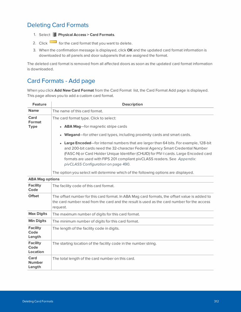
Deleting Card Formats1. Select Physical Access > Card Formats.
2. Click for the card format that you want to delete.
3. When the confirmation message is displayed, click OK and the updated card format information isdownloaded to all panels and door subpanels that are assigned the format.
The deleted card format is removed from all affected doors as soon as the updated card format informationis downloaded.
Card Formats - Add pageWhen you click Add NewCard Format from the Card Format list, the Card Format Add page is displayed.This page allows you to add a custom card format.
Feature Description
Name The name of this card format.
CardFormatType
The card format type. Click to select:
l ABAMag—for magnetic stripe cards
l Wiegand—for other card types, including proximity cards and smart cards.
l Large Encoded—for internal numbers that are larger than 64 bits. For example, 128-bitand 200-bit cards need the 32-character Federal Agency Smart Credential Number(FASC-N) or Card Holder Unique Identifier (CHUID) for PIV-I cards. Large Encoded cardformats are used with FIPS 201 compliant pivCLASS readers. See Appendix:pivCLASS Configuration on page 490.
The option you select will determine which of the following options are displayed.
ABAMag options
FacilityCode
The facility code of this card format.
Offset The offset number for this card format. In ABA Mag card formats, the offset value is added tothe card number read from the card and the result is used as the card number for the accessrequest.
Max Digits The maximum number of digits for this card format.
Min Digits The minimum number of digits for this card format.
FacilityCodeLength
The length of the facility code in digits.
FacilityCodeLocation
The starting location of the facility code in the number string.
CardNumberLength
The total length of the card number on this card.
Deleting Card Formats 312
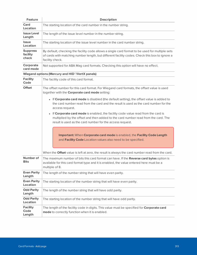
Feature Description
CardLocation
The starting location of the card number in the number string.
Issue LevelLength
The length of the issue level number in the number string.
IssueLocation
The starting location of the issue level number in the card number string.
Suppressfacilitycheck
By default, checking the facility code allows a single card format to be used for multiple setsof cards with matching number length, but different facility codes. Check this box to ignore afacility check.
Corporatecard mode
Not supported for ABA Mag card formats. Checking this option will have no effect.
Wiegand options (Mercury and HID™/VertX panels)
FacilityCode
The facility code of this card format.
Offset The offset number for this card format. For Wiegand card formats, the offset value is usedtogether with the Corporate card mode setting:
l If Corporate card mode is disabled (the default setting), the offset value is added tothe card number read from the card and the result is used as the card number for theaccess request.
l If Corporate card mode is enabled, the facility code value read from the card ismultiplied by the offset and then added to the card number read from the card. Theresult is used as the card number for the access request.
Important: When Corporate card mode is enabled, the Facility Code Lengthand Facility Code Location values also need to be specified.
When the Offset value is left at zero, the result is always the card number read from the card.
Number ofBits
The maximum number of bits this card format can have. If the Reverse card bytes option isavailable for this card format type and it is enabled, the value entered here must be amultiple of 8.
Even ParityLength
The length of the number string that will have even parity.
Even ParityLocation
The starting location of the number string that will have even parity.
Odd ParityLength
The length of the number string that will have odd parity.
Odd ParityLocation
The starting location of the number string that will have odd parity.
FacilityCodeLength
The length of the facility code in digits. This value must be specified for Corporate cardmode to correctly function when it is enabled.
Card Formats - Add page 313
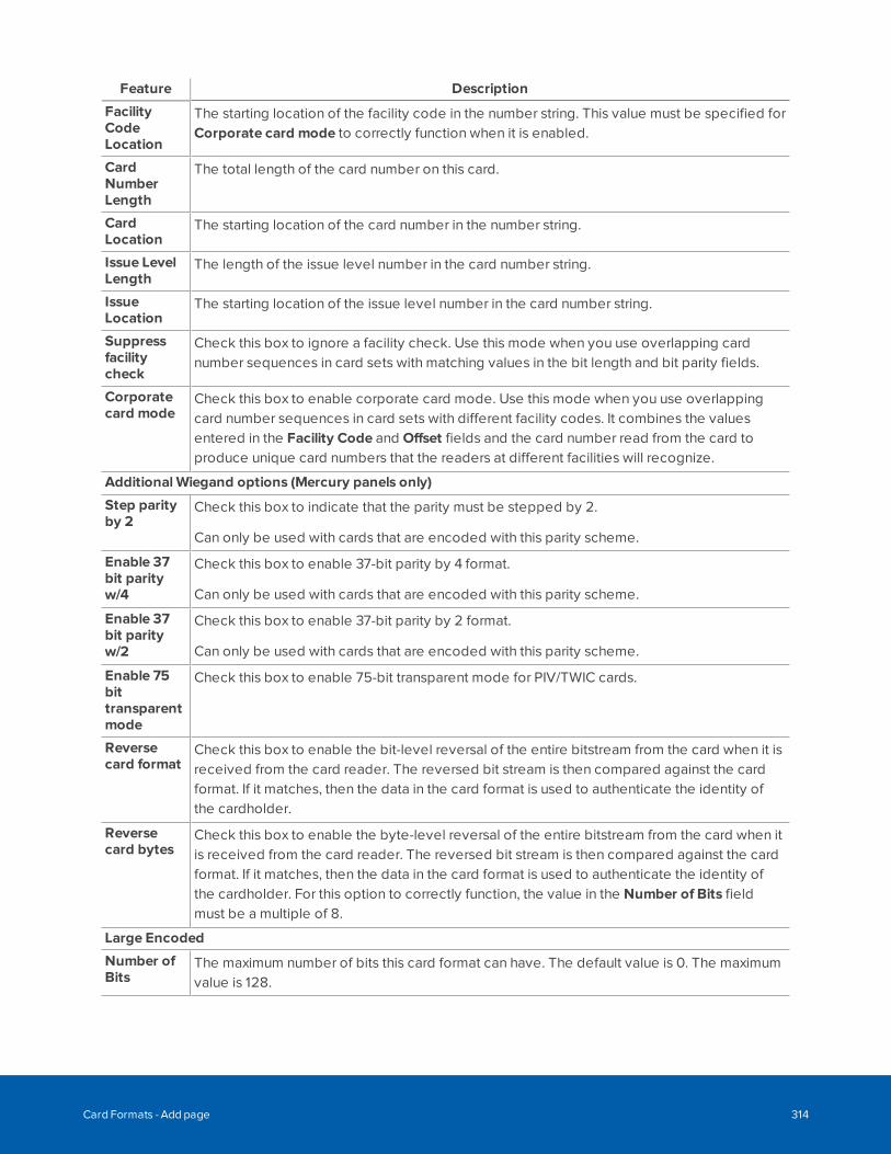
Feature Description
FacilityCodeLocation
The starting location of the facility code in the number string. This value must be specified forCorporate card mode to correctly function when it is enabled.
CardNumberLength
The total length of the card number on this card.
CardLocation
The starting location of the card number in the number string.
Issue LevelLength
The length of the issue level number in the card number string.
IssueLocation
The starting location of the issue level number in the card number string.
Suppressfacilitycheck
Check this box to ignore a facility check. Use this mode when you use overlapping cardnumber sequences in card sets with matching values in the bit length and bit parity fields.
Corporatecard mode
Check this box to enable corporate card mode. Use this mode when you use overlappingcard number sequences in card sets with different facility codes. It combines the valuesentered in the Facility Code and Offset fields and the card number read from the card toproduce unique card numbers that the readers at different facilities will recognize.
Additional Wiegand options (Mercury panels only)
Step parityby 2
Check this box to indicate that the parity must be stepped by 2.
Can only be used with cards that are encoded with this parity scheme.
Enable 37bit parityw/4
Check this box to enable 37-bit parity by 4 format.
Can only be used with cards that are encoded with this parity scheme.
Enable 37bit parityw/2
Check this box to enable 37-bit parity by 2 format.
Can only be used with cards that are encoded with this parity scheme.
Enable 75bittransparentmode
Check this box to enable 75-bit transparent mode for PIV/TWIC cards.
Reversecard format
Check this box to enable the bit-level reversal of the entire bitstream from the card when it isreceived from the card reader. The reversed bit stream is then compared against the cardformat. If it matches, then the data in the card format is used to authenticate the identity ofthe cardholder.
Reversecard bytes
Check this box to enable the byte-level reversal of the entire bitstream from the card when itis received from the card reader. The reversed bit stream is then compared against the cardformat. If it matches, then the data in the card format is used to authenticate the identity ofthe cardholder. For this option to correctly function, the value in the Number of Bits fieldmust be a multiple of 8.
Large Encoded
Number ofBits
The maximum number of bits this card format can have. The default value is 0. The maximumvalue is 128.
Card Formats - Add page 314
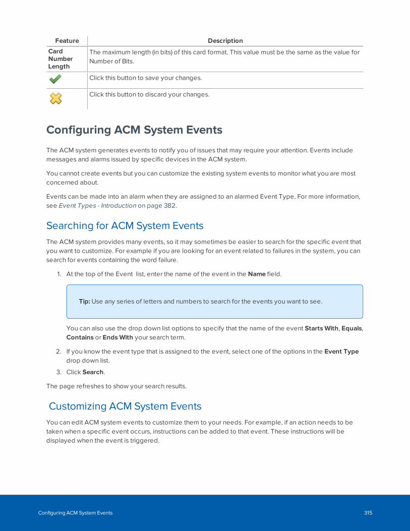
Feature Description
CardNumberLength
The maximum length (in bits) of this card format. This value must be the same as the value forNumber of Bits.
Click this button to save your changes.
Click this button to discard your changes.
Configuring ACM System Events
The ACM system generates events to notify you of issues that may require your attention. Events includemessages and alarms issued by specific devices in the ACM system.
You cannot create events but you can customize the existing system events to monitor what you are mostconcerned about.
Events can be made into an alarm when they are assigned to an alarmed Event Type. For more information,see Event Types - Introduction on page 382.
Searching for ACM System EventsThe ACM system provides many events, so it may sometimes be easier to search for the specific event thatyou want to customize. For example if you are looking for an event related to failures in the system, you cansearch for events containing the word failure.
1. At the top of the Event list, enter the name of the event in the Name field.
Tip: Use any series of letters and numbers to search for the events you want to see.
You can also use the drop down list options to specify that the name of the event StartsWith, Equals,Contains or EndsWith your search term.
2. If you know the event type that is assigned to the event, select one of the options in the Event Typedrop down list.
3. Click Search.
The page refreshes to show your search results.
Customizing ACM System EventsYou can edit ACM system events to customize them to your needs. For example, if an action needs to betaken when a specific event occurs, instructions can be added to that event. These instructions will bedisplayed when the event is triggered.
Configuring ACM System Events 315
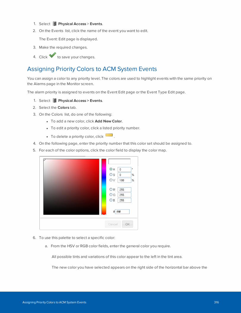
1. Select Physical Access > Events.
2. On the Events list, click the name of the event you want to edit.
The Event: Edit page is displayed.
3. Make the required changes.
4. Click to save your changes.
Assigning Priority Colors to ACM System EventsYou can assign a color to any priority level. The colors are used to highlight events with the same priority onthe Alarms page in the Monitor screen.
The alarm priority is assigned to events on the Event Edit page or the Event Type Edit page.
1. Select Physical Access > Events.
2. Select the Colors tab.
3. On the Colors list, do one of the following:
l To add a new color, click Add NewColor.
l To edit a priority color, click a listed priority number.
l To delete a priority color, click .
4. On the following page, enter the priority number that this color set should be assigned to.
5. For each of the color options, click the color field to display the color map.
6. To use this palette to select a specific color:
a. From the HSV or RGB color fields, enter the general color you require.
All possible tints and variations of this color appear to the left in the tint area.
The new color you have selected appears on the right side of the horizontal bar above the
Assigning Priority Colors to ACM System Events 316
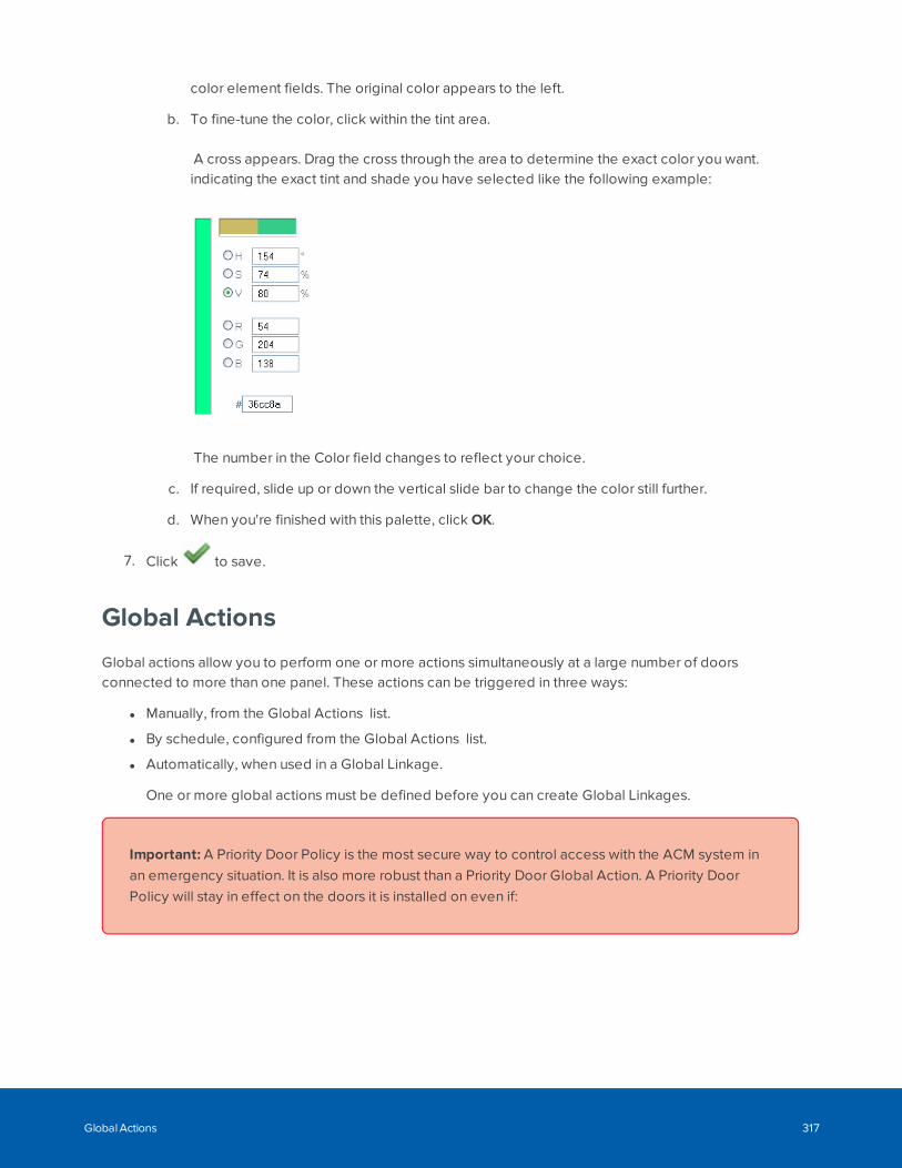
color element fields. The original color appears to the left.
b. To fine-tune the color, click within the tint area.
A cross appears. Drag the cross through the area to determine the exact color you want.indicating the exact tint and shade you have selected like the following example:
The number in the Color field changes to reflect your choice.
c. If required, slide up or down the vertical slide bar to change the color still further.
d. When you're finished with this palette, click OK.
7. Click to save.
Global Actions
Global actions allow you to perform one or more actions simultaneously at a large number of doorsconnected to more than one panel. These actions can be triggered in three ways:
l Manually, from the Global Actions list.
l By schedule, configured from the Global Actions list.
l Automatically, when used in a Global Linkage.
One or more global actions must be defined before you can create Global Linkages.
Important: A Priority Door Policy is the most secure way to control access with the ACM system inan emergency situation. It is also more robust than a Priority Door Global Action. A Priority DoorPolicy will stay in effect on the doors it is installed on even if:
Global Actions 317
l The ACM appliance:
l Is restarted
l Is disconnected from power
l Fails over to a backup appliance
l The door or door panel:
l Goes offline
l Is rebooted
l Is disconnected from power
l Is disconnected from the access control network.
Adding Global Actions1. Select Physical Access > Global Actions.
2. On the Global Action list, click Add Global Action.
3. Enter the required details for this new global action.
4. Click to save.
Once you've defined all the global actions that you need, proceed to the Global Linkages feature to createa chain of actions together.
Editing Global Actions1. Select Physical Access > Global Actions.
2. Click the name of the global action you need to modify.
3. Make the required changes.
4. Click to save your changes.
Global Actions - Action TypesFeature Description
Access GroupInstall/Uninstall
Specifies that one or more designated access groups are installed/uninstalled.
Action Group Specifies action groups that are executed.
Door Install/Uninstall Specifies that a designated door will be either installed or uninstalled.
Door Mode Specifies the mode one or more designated doors will enter.
Door Grant Specifies that entry is granted at one or more designated doors.
Door Mask Specifies that alarms are forced to a masked/unmasked state at one or moredesignated doors.
Adding Global Actions 318
Feature Description
Email Specifies email addresses and sends a predefined to those recipients.
Exacq Soft Trigger Specifies a soft trigger that is executed on the Exacq camera system by theglobal action.
Input Specifies that one or more designated inputs are masked/unmasked.
Intrusion Areas Specifies all available commands for intrusion areas.
Intrusion Outputs Specifies all available commands for intrusion outputs.
Intrusion Points Specifies all available commands for intrusion points.
Output Specifies that one or more designated outputs are activated/inactivated.
Panel Install/Uninstall Specifies that one or more designated panels are installed/uninstalled.
Panel Macro Specifies a macro routine to be run on a designated execute group.
Policy Install/Uninstall Specifies that one or more designated policies are installed or uninstalled.
Schedule Set Mode Specifies that one or more schedules are activated, inactivated or scanned.
Deleting Global Actions1. Select Physical Access > Global Actions.
2. From the Global Actions list, click for the global action that you want to delete.
3. When the browser displays a pop-up message to ask Are you sure?, click OK.
Global Actions - Intrusion Linkages and ActionsBosch doors only.
Noted below are some examples of setting up intrusion linkages and actions.
Intrusion panel alarm due to an event in the System
An ACM system event can trigger an intrusion alarm point. To set up an alarm condition that is generated atthe intrusion panel notifying the monitoring center) due to an ACM system event (for example, a forceddoor), ensure that the intrusion panel has a point with source "output" and select an index that is unused bothas a point and as an output. Follow the steps below:
1. Create global actions to activate and deactivate the output.
2. Create a global linkage to the Forced Door event, to activate the output.
3. Create a global linkage to a NORMAL Forced Door event to deactivate the output.
When the related event occurs in the ACM system, the corresponding point will be triggered at the intrusionpanel, and control over the event (for example,. silencing an alarm) can be made by intrusion panels.
Disable and enable doors from keypad
Arming an alarm at the intrusion keypad can also lock a door within the ACM system.
Deleting Global Actions 319
1. Create global actions to lock and restore the door.
2. Create a global linkage to the area arming events, to lock the door.
3. Create a global linkage to the area disarming events, to unlock the door.
It is best to set this action up with a single area as different combinations of arming and disarming couldleave the door unexpectedly locked or unlocked.
Alarms and access will be accessible from the keypad and from the Monitor > Intrusion Status > Areassection of the ACM system.
Note: Keypad access will be limited by the tokens assigned to the identity.
Disarm Alarm on Access Grant with restricted authorities
Accessing an area by a valid the ACM system card access can automatically disarm an area.
To allow a scenario where entry to an area by a valid card access disarms an intrusion area based on thebadge holder's intrusion authorities, follow the steps below:
1. Create a global action to disarm an area. Action type of 'Intrusion Area', Subtype 'Master Disarm' andthe relevant areas as the Members.
2. Create a global linkage to door access events.
l Devices tab: Door as the Type and the target doors as Members.
l Events tab: Local Grant.
l Actions tab: Disarm All.
Areas can be armed and disarmed from the keypad (depending on the tokens assigned to the identity) andfrom the Monitor > Intrusion Status > Areas section of the ACM system.
Global Linkages - Introduction
Global linkages are the final step in the process that defines specific actions for triggering events at specificdoors. What separates this procedure from the Macro or Trigger features available for specific doors orpanels, is that this feature is capable of connecting many doors and inputs spread across many panels.
For example, you could lock down an entire building simply by issuing a single trigger. At a moresophisticated level, you can use global linkages to plot a complex scenario, like a sally port or a man trap, inwhich a series of doors are opened in sequence, inputs associated with those doors are sequentiallymasked and unmasked, and cameras are turned on as each door is opened.
Global linkages allow you to plan a cascade of triggers and their resulting actions with only a single codeentry or command.
Disarm Alarm on Access Grant with restricted authorities 320
Adding Global Linkages1. Select Physical Access > Global Linkages.
2. On the Global Linkage list, click Add Global Linkage.
3. Enter the required details and click .
4. Edit each tab to add the required events, devices, identities and actions.
5. Click to save your changes on each page.
Editing Global Linkages1. Select Physical Access > Global Linkages.
2. On the Global Linkage list, click the name of the global linkage that you want to edit.
3. Edit each tab as required.
4. Click after editing each page to save your changes.
Mustering
In emergency situations, employees and other personnel in your building may be required to gather atspecific locations so emergency response teams can work quickly to ensure that everyone is safe. Forexample in a fire drill you may be asked to wait at a specific spot, or muster station, until the drill is over. Thiswould be the same spot you would gather in an actual fire.
To help track the location of users in emergency situations, Access Control Manager offers the Musteringfeature. Mustering allows you to create a dashboard to quickly monitor who has arrived at their musterstation and who is still in danger during emergency situations.
Mustering - RequirementsTo use the Mustering feature, you must configure each muster station and give users access to it in the ACMsystem.
1. Create an area for each muster station. For more information, see Adding Areas on page 304.
2. To organize related areas together, you can combine them into groups.
3. Identify all the doors that lead to the muster station area, then make sure the correct area is assignedto each door.
a. In the Access Control Manager software, select Physical Access > Doors.
b. Click the name of the door that should be in the area, then select the Operations tab.
c. From the Into Area drop down list, select the area the door enters into.
d. From the Out of area drop down list, select the area the door exits from.
e. Click .
Adding Global Linkages 321
4. Create an access group that includes all the doors in the muster station area.
5. Assign the access group to a role that would need access to the mustering area.
Tip: Create a role for each mustering area. If users physically move locations within anorganization, they can be easily assigned to new mustering stations without impacting theirprimary role in the system.
6. Assign the role to each identity that would need access to the muster station.
Next, create a dashboard to track identities as they arrive at the appropriate muster station in emergencysituations.
Mustering - Creating a DashboardA Mustering dashboard is a map that contains a quick view of who has entered each muster station area.
The dashboard can be a simple list of all the Mustering areas, or it can be configured into color codedshapes for quick identification.
You can add a dashboard to any map, or you can create a blank map to host the dashboard.
1. Select > Maps.
The Map Templates list is displayed.
2. Inthe Map Templates list,decide if youwant to add adashboard to anexisting map orcreate ablankmap.
l To add the dashboard to an existing map, click the name of the map you want to use.
l To create a blank map, click Add NewMap Template then check the Use Blank Canvas box.
Complete the other details and click .
3. On the Map Template Edit page, click Add beside Dashboard Elements.
4. Enter a title for the dashboard element. The map automatically updates with each change that youmake.
5. Click the Title Font Color field to change the text color.
6. In the Title Font Size drop down list, select the size. The options are Small, Medium and Large.
7. For the Opacity option, choose how transparent you want the dashboard element to be. You canenter a percent number, or move the slider to set the opacity. 100% is opaque and 0% is transparent.
8. In the Location field, enter where you want the dashboard element to appear on the map. You canalso move the dashboard element directly on the map.
9. In the Element Type drop down list, select if you want the dashboard element to appear as Text Onlyor Graphic & Text.
If you choose Graphic & Text, the following options are displayed:
Mustering - Creating a Dashboard 322
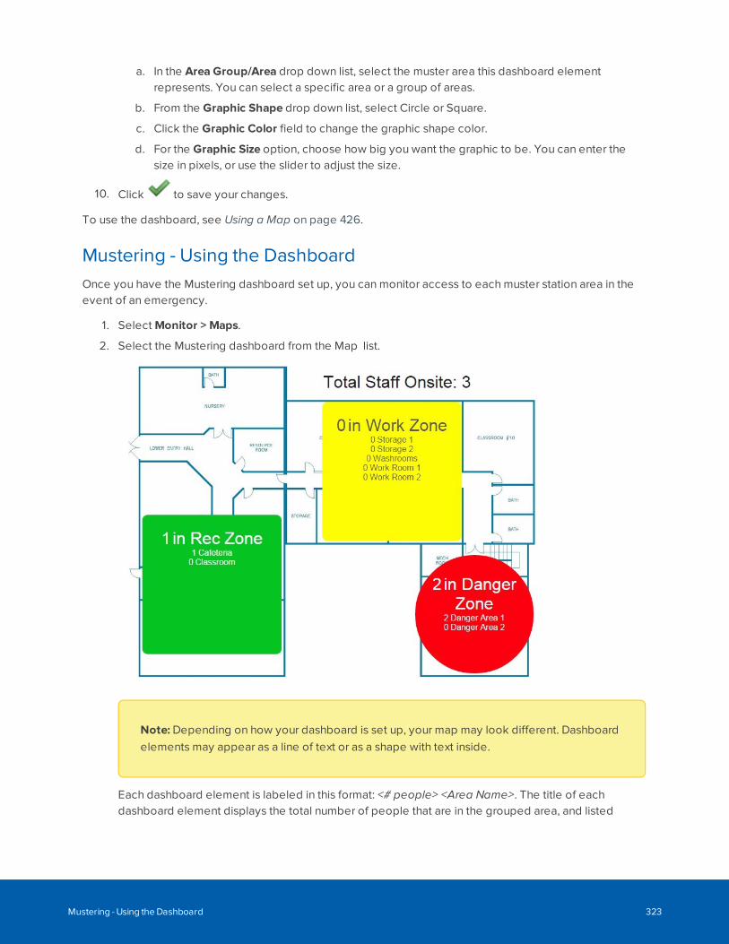
a. In the Area Group/Area drop down list, select the muster area this dashboard elementrepresents. You can select a specific area or a group of areas.
b. From the Graphic Shape drop down list, select Circle or Square.
c. Click the Graphic Color field to change the graphic shape color.
d. For the Graphic Size option, choose how big you want the graphic to be. You can enter thesize in pixels, or use the slider to adjust the size.
10. Click to save your changes.
To use the dashboard, see Using a Map on page 426.
Mustering - Using the DashboardOnce you have the Mustering dashboard set up, you can monitor access to each muster station area in theevent of an emergency.
1. Select Monitor > Maps.
2. Select the Mustering dashboard from the Map list.
Note: Depending on how your dashboard is set up, your map may look different. Dashboardelements may appear as a line of text or as a shape with text inside.
Each dashboard element is labeled in this format: <# people> <Area Name>. The title of eachdashboard element displays the total number of people that are in the grouped area, and listed
Mustering - Using the Dashboard 323
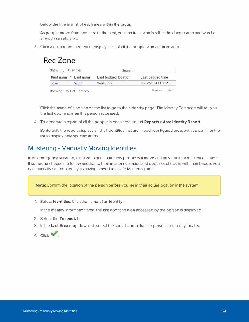
below the title is a list of each area within the group.
As people move from one area to the next, you can track who is still in the danger area and who hasarrived in a safe area.
3. Click a dashboard element to display a list of all the people who are in an area.
Click the name of a person on the list to go to their Identity page. The Identity Edit page will tell youthe last door and area this person accessed.
4. To generate a report of all the people in each area, select Reports > Area Identity Report.
By default, the report displays a list of identities that are in each configured area, but you can filter thelist to display only specific areas.
Mustering - Manually Moving IdentitiesIn an emergency situation, it is hard to anticipate how people will move and arrive at their mustering stations.If someone chooses to follow another to their mustering station and does not check-in with their badge, youcan manually set the identity as having arrived to a safe Mustering area.
Note: Confirm the location of the person before you reset their actual location in the system.
1. Select Identities. Click the name of an identity.
In the Identity Information area, the last door and area accessed by the person is displayed.
2. Select the Tokens tab.
3. In the Last Area drop down list, select the specific area that the person is currently located.
4. Click .
Mustering - Manually Moving Identities 324

Managing Appliances
When you log in to the ACM application, you are accessing an appliance that is set up in your network. Theappliance configures and directs communication between all the elements in the access control system.
After you have connected your appliance to the network, you can further customize and set up yourappliance to meet your system requirements.
Editing Appliance Settings
After initial setup, you can edit the ACM system settings and set up backup and redundancy for theappliance.
1. In the top-right, select > Appliance.
If only one appliance is managed by the system, the Appliance Edit page is displayed.
If more than one appliance is managed by the system, the Appliance list is displayed. Select theappliance you want to edit.
2. Navigate through the following tabs to configure the appliance:
l Appliance tab: Edit system, network and storage settings, as well as shut down or restart theappliance remotely.
l Access tab: Specify and enable the controller panel types.
l Ports tab: Specify how the Ethernet ports on the appliance are used to communicate withaccess control devices.
l Replication tab: Set up system replication and redundancy.
l Backups tab: Set up scheduled backups for the appliance.
l Logs tab: Access the system logs.
l Software Updates tab: Update the appliance software.
l SSL Certificate tab: Configure SSL certificates used in the authentication of ACM Client users.For more information, see Configuring Remote Authentication Using SSL Certificates onpage 393.
l About tab: View and manage licenses, and view the version numbers and End User LicenseTerms and Conditions.
3. Click to save your changes.
Deleting an Appliance
Appliances may need to be deleted in certain cases. If you want to disconnect an appliance that is nolonger needed, delete it from the system before physically removing it. If you want to take an appliance thatis being used for replication or redundancy and use it as a primary appliance, the appliance must be deleted
Managing Appliances 325
first.
Note: You can only delete an appliance if your system has more than one appliance.
1. In the top-right, select > Appliance.
2. From the Appliance list, click beside the appliance that you want to delete.
3. When the confirmation message is displayed, click OK.
The selected appliance is removed from the list.
Configuring Replication and Failover
The Replication tab on the Appliance: Edit page allows configuration and monitoring of LDAP datareplication and optionally redundancy/failover of the ACM application so that monitoring and hardwarecontrol is not lost even if an appliance fails. Only the default Admin identity can edit the applianceReplication settings.
Important: The ACM 6 license format is different from previous versions. You will need to upgradeyour license format if you upgraded from ACM 5.12.2 to ACM 6.0.0 or later in order to add newlicenses. Replication features, including failover, will not function if your license format is not thesame on both the primary and standby appliances.
The replication feature allows two or more appliances to be set up to share a single set of LDAPconfiguration data, so that the appliances can share identities and other system details. Any change made toconfiguration data on one appliance is automatically copied (“replicated”) to the other appliances. This isreferred to as a “Peer to Peer” configuration. In this configuration, each appliance “owns” the hardwareinstalled on it, and events and status information sent from that hardware can only be viewed on thehardware owner appliance. All panel hardware added in a replicated environment must be assigned uponcreation to one of the available Peer to Peer appliances. A panel and its subpanels cannot be split acrossmultiple appliances, but is installed on one of the Peer appliances.
Tip: It is recommended that replication be set up on all appliances before adding panels, otherhardware or user details to the system. After replication is configured, it is possible to configuresystem hardware and identity information from one of the replicated appliances on the networkrather than having to connect directly to each individual appliance to make changes to its installedhardware. However, it may be necessary to perform a download of the hardware configuration fromthe appliance where the hardware is installed in order to update the hardware with the latestconfiguration data changes made from another appliance.
Configuring Replication and Failover 326
Failover/Redundancy FeatureThe failover, or redundancy, feature of replication allows a “Hot Standby” appliance to be set up to takeover control and event monitoring when the Primary appliance used in daily operations fails. Thisconfiguration is referred to as Primary/Hot Standby. To use the failover feature, both appliances areoriginally configured with Peer to Peer replication so that each appliance will share a common LDAPconfiguration database. The Hot Standby appliance is then configured as such, and then will not have itsown hardware or collaborations, and will not appear in the list of replicated appliances available forassignment when these items are created.
Each Primary appliance can only be assigned one Standby appliance, but the same Standby appliance canbe assigned to more than one Primary appliance. However, if two or more Primary appliances fail at the sametime, the Standby appliance will replace the first appliance that it knows is offline (if configured for automaticfailover), and will not be available for failover of the other Primary appliances while it is standing in.
The following types of failover and failback are supported:
l Automatic failover
l Manual failover
l Manual failback
Automatic failover
Automatic failover is controlled by the Standby appliance by monitoring the health of the Primary appliance.If a Primary appliance is found to be unresponsive by the Standby appliance within a set period of time, theStandby appliance will automatically initiate failover of the Primary appliance and will begin to control thehardware installed on that Primary appliance, and will begin to receive events and status from this hardware.
There are two settings that control automatic failover - Heartbeat count and Heartbeat time. The Heartbeatcount is the number of health checks the inactive hot standby appliance makes to see if the active primaryappliance is alive. If this number of failures occurs in a row, the hot standby will do an automatic failover. TheHeartbeat time is the time between health checks (regardless of if the previous check was successful orfailed).
It is not necessarily possible to calculate specifically how long it would take to failover. It is not simply amatter of multiplying the Heartbeat count by the Heartbeat time (for example Heartbeat count of two andHeartbeat time of 30 seconds does not necessarily mean failover in about one minute of the primary goingdown, however one minute would be the best/shortest case). This is because the time it takes each checkto fail may depend on a network time-out in the case of the hot stand by machine no longer having networkconnectivity to the primary machine. Typically, a worst case network time-out is approximately two minutes -however this may possibly vary. A health check may also fail immediately depending on networkconsiderations/status.
It is recommended to set the Heartbeat count to at least a value of two so that a short network glitch doesnot cause a premature failover. A Heartbeat count of two and a Heartbeat time of 30 seconds shouldtypically ensure that a failover is initiated within one to about five minutes of the primary going down.
Manual failover and failback
A manual failover can be initiated through from the Replication tab on the Appliance: Edit page on theStandby appliance. This is usually done to test functionality or if a Primary appliance is going to be down for
Failover/Redundancy Feature 327
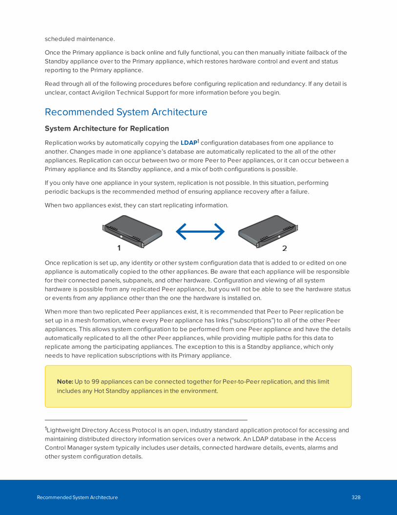
scheduled maintenance.
Once the Primary appliance is back online and fully functional, you can then manually initiate failback of theStandby appliance over to the Primary appliance, which restores hardware control and event and statusreporting to the Primary appliance.
Read through all of the following procedures before configuring replication and redundancy. If any detail isunclear, contact Avigilon Technical Support for more information before you begin.
Recommended System Architecture
System Architecture for Replication
Replication works by automatically copying the LDAP1 configuration databases from one appliance toanother. Changes made in one appliance’s database are automatically replicated to the all of the otherappliances. Replication can occur between two or more Peer to Peer appliances, or it can occur between aPrimary appliance and its Standby appliance, and a mix of both configurations is possible.
If you only have one appliance in your system, replication is not possible. In this situation, performingperiodic backups is the recommended method of ensuring appliance recovery after a failure.
When two appliances exist, they can start replicating information.
Once replication is set up, any identity or other system configuration data that is added to or edited on oneappliance is automatically copied to the other appliances. Be aware that each appliance will be responsiblefor their connected panels, subpanels, and other hardware. Configuration and viewing of all systemhardware is possible from any replicated Peer appliance, but you will not be able to see the hardware statusor events from any appliance other than the one the hardware is installed on.
When more than two replicated Peer appliances exist, it is recommended that Peer to Peer replication beset up in a mesh formation, where every Peer appliance has links (“subscriptions”) to all of the other Peerappliances. This allows system configuration to be performed from one Peer appliance and have the detailsautomatically replicated to all the other Peer appliances, while providing multiple paths for this data toreplicate among the participating appliances. The exception to this is a Standby appliance, which onlyneeds to have replication subscriptions with its Primary appliance.
Note: Up to 99 appliances can be connected together for Peer-to-Peer replication, and this limitincludes any Hot Standby appliances in the environment.
1Lightweight Directory Access Protocol is an open, industry standard application protocol for accessing andmaintaining distributed directory information services over a network. An LDAP database in the AccessControl Manager system typically includes user details, connected hardware details, events, alarms andother system configuration details.
Recommended System Architecture 328
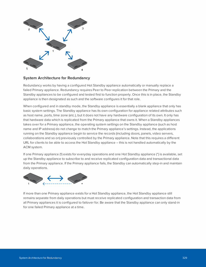
System Architecture for Redundancy
Redundancy works by having a configured Hot Standby appliance automatically or manually replace afailed Primary appliance. Redundancy requires Peer to Peer replication between the Primary and theStandby appliances to be configured and tested first to function properly. Once this is in place, the Standbyappliance is then designated as such and the software configures it for that role.
When configured and in standby mode, the Standby appliance is essentially a blank appliance that only hasbasic system settings. The Standby appliance has its own configuration for appliance related attributes suchas host name, ports, time zone (etc.), but it does not have any hardware configuration of its own. It only hasthat hardware data which is replicated from the Primary appliance that owns it. When a Standby appliancestakes over for a Primary appliance, the operating system settings on the Standby appliance (such as hostname and IP address) do not change to match the Primary appliance’s settings. Instead, the applicationsrunning on the Standby appliance begin to service the records (including doors, panels, video servers,collaborations and so on) previously controlled by the Primary appliance. Note that this requires a differentURL for clients to be able to access the Hot Standby appliance – this is not handled automatically by theACM system.
If one Primary appliance (1) exists for everyday operations and one Hot Standby appliance (*) is available, setup the Standby appliance to subscribe to and receive replicated configuration data and transactional datafrom the Primary appliance. If the Primary appliance fails, the Standby can automatically step-in and maintaindaily operations.
If more than one Primary appliance exists for a Hot Standby appliance, the Hot Standby appliance stillremains separate from daily operations but must receive replicated configuration and transaction data fromall Primary appliances it is configured to failover for. Be aware that the Standby appliance can only stand-infor one failed Primary appliance at a time.
System Architecture for Redundancy 329
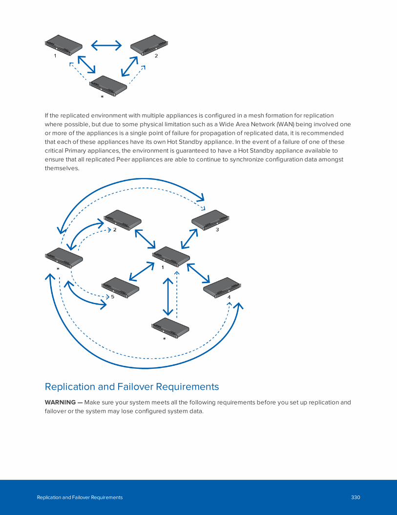
If the replicated environment with multiple appliances is configured in a mesh formation for replicationwhere possible, but due to some physical limitation such as a Wide Area Network (WAN) being involved oneor more of the appliances is a single point of failure for propagation of replicated data, it is recommendedthat each of these appliances have its own Hot Standby appliance. In the event of a failure of one of thesecritical Primary appliances, the environment is guaranteed to have a Hot Standby appliance available toensure that all replicated Peer appliances are able to continue to synchronize configuration data amongstthemselves.
Replication and Failover RequirementsWARNING — Make sure your system meets all the following requirements before you set up replication andfailover or the system may lose configured system data.
Replication and Failover Requirements 330
l License requirements:
l The application license agreement must be entered on all appliances. The license key is tiedto a specific machine. When using redundancy, a license and key must be separately installedon both the Primary and Standby appliances. The license features on a Standby applianceneeds to include all the features used by the Primary appliances it may replace.
l Network infrastructure:
l DNS registered host names for each appliance in the enterprise. Each appliance must be ableto connect to the other appliance by host name. There must be static or reserved IPaddresses, proper netmask, and network gateway for each appliance.
l Name server IP address for host name resolution. All appliances must be able to resolve all ofthe other appliances by host name.
l Time Server IP address or host name. All appliances must be synchronized for time and date.This is crucial for proper replication processing. Each must utilize a time server for thispurpose. The Open LDAP multi-master replication used by the ACM software synchronizes aLDAP directory tree across multiple appliances. Each appliance supports read/writeoperations across an enterprise system. Conflicts are handled using a timestamp to determinethe most recent record. All appliances must use a common clock base to synchronize theirclocks to ensure the conflict resolution works correctly.
Note: Time is based on UTC (Coordinated Universal Time) to ensure consistencyacross the ACM system. UTC time is transferred from the client to the server when thedate/time is set.
l Defined and open TCP ports:
l Web Server Port / Replication Subscriptions Web Port (default 443). Certain replication optionsrequire each appliance to contact each other through the web service port.
l LDAP Connect Port / Replication Subscription LDAP Port (should be a unique, open TCP portthat nothing else uses). This is a TCP port used for Open LDAP replication betweenappliances.
l Event Replication Port (default 6052). Once a Primary/Standby appliance relationship isestablished, the Primary appliance will automatically transfer event transactions to the Standbyappliance so event data will be available when a failover occurs. Connectivity is required forboth Primary and Standby appliances using the Event Replication Port (this is a TCP port usedfor open SSL socket communication).
l Replication Failover Port for heartbeat (default is NONE but should be a unique, open TCP portthat nothing else uses). This is a TCP port (used for open SSL socket communication) definedon the Primary appliance only. The Standby appliance uses it to communicate with the Primaryto check its health status in order to determine if an automatic failover is required, if monitoringis enabled on the Standby appliance.
l These ports must be open across the network between the two appliances.
Replication and Failover Requirements 331
l Appliance replication address. A unique numeric address number must be reserved and configuredfor each appliance, starting at 1 and extending to 99 (confirm max count). These addresses need notbe in sequence.
Note: You can have up to 99 appliances connected together for replication, including anyStandby appliances configured for failover.
l Software updates. When software updates are installed, they should be installed on all appliances ina timely manner (i.e. one after the other). Note that the appliance with address 1 should always be thefirst appliance in the environment to have software upgrades applied to it, as any LDAP schema anddata changes (adding deleting system records, massaging of data) involved are performed there andreplicated out to the other appliances. The other non-address 1 appliances will not have these LDAPschema changes applied by the upgrade, so it is essential to upgrade the address 1 appliance first.The remaining appliances can be upgraded in any order once the address 1 appliance is back onlineafter its upgrade completes.
l Recommended SMTP settings. The SMTP settings configure which mail server should be contactedto send out email and which account should be used. This is configured separately per appliance.When the Primary and Standby appliances are physically separated, sometimes by considerabledistances, it is recommended to assign local mail servers for each. A mail server must be set up onboth Primary and Standby appliances if you want to send email notifications for failover and failbackoccurrences.
1. Preparing Appliances for Replication and FailoverBefore you can set up replication and failover, you must set up the appliances to use the required networkinfrastructure and assigned ports. For more information, see Replication and Failover Requirements onpage 330.
Setting Up the Primary Appliance
Whether you are configuring two or more appliances to replicate to each other in a Peer to Peer system, orconfiguring a Primary/Hot Standby redundant failover system, designate one appliance as the replicationaddress 1 appliance. This appliance should not be used as a Standby appliance, and will be the firstappliance to have software updates applied to it.
1. Log in to the appliance that will use replication address 1.
2. On the Appliance Edit page, enter values for the following fields in the Appliance tab:
l Name – An appropriate name for the appliance so that you can identify it on sight.
l Host Name – The appliance's hostname on the network.
l Name Server – The IP address of the DNS server. If a DNS server is not available, this field canbe left blank.
1. Preparing Appliances for Replication and Failover 332
l Time Server – The name or IP address of a time server that is accessible on the network. Thetime on all connected appliances must be in sync. This setting is crucial for a replicatedappliance.
Note: Time is based on UTC (Coordinated Universal Time) to ensure consistencyacross the ACM system. UTC time is transferred from the client to the server whendate/time is set.
l Web Server Port – The port number for accessing the appliance web service.
l LDAP Connect Port – The port number for accessing the LDAP database on the appliance.This port will be used by replication to update LDAP data and will be used when otherappliances are added to the replicated environment.
3. Click to save your changes.
The appliance will automatically restart if changes are made to the above fields and saved.
Setting Up Additional Appliances
Complete this procedure for all the other appliances in your system. Besides the name and hostname, it isrecommended that if possible all other settings be the same as the primary appliance, as that will avoidconfusion on what ports are used and what network resources are used for time setting and nameresolution.
1. Log in to the appliance
2. On the Appliance Edit page, enter values for the following fields in the Appliance tab:
l Appliance Name – An appropriate name for the appliance so that you can identify it on sight.
l Host Name – The appliance's hostname on the network.
l Name Server – The IP address of the DNS server. If a DNS server is not available, this field canbe left blank.
l Time Server – The name or IP address of a time server that is accessible on the network. Usethe same value as the replication address 1 appliance if possible.
Note:Time is based on UTC (Coordinated Universal Time) to ensure consistencyacross ACM. UTC time is transferred from the client to the server when date/time is set.
l Web Server Port – The port number used for accessing the appliance web service.
l LDAP Connect Port – The port number used for accessing the LDAP database on theappliance. Use the same value as the replication address 1 appliance if possible.
Setting Up Additional Appliances 333
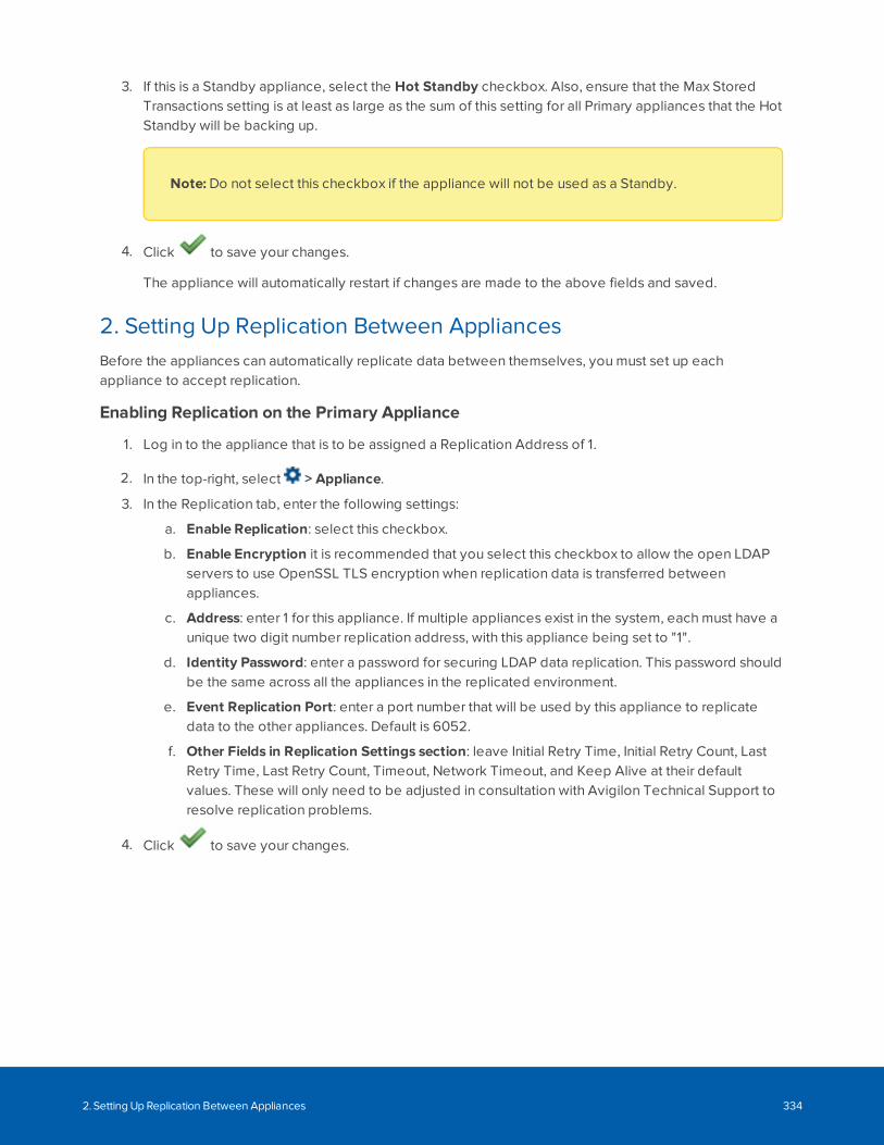
3. If this is a Standby appliance, select the Hot Standby checkbox. Also, ensure that the Max StoredTransactions setting is at least as large as the sum of this setting for all Primary appliances that the HotStandby will be backing up.
Note: Do not select this checkbox if the appliance will not be used as a Standby.
4. Click to save your changes.
The appliance will automatically restart if changes are made to the above fields and saved.
2. Setting Up Replication Between AppliancesBefore the appliances can automatically replicate data between themselves, you must set up eachappliance to accept replication.
Enabling Replication on the Primary Appliance
1. Log in to the appliance that is to be assigned a Replication Address of 1.
2. In the top-right, select > Appliance.
3. In the Replication tab, enter the following settings:
a. Enable Replication: select this checkbox.
b. Enable Encryption it is recommended that you select this checkbox to allow the open LDAPservers to use OpenSSL TLS encryption when replication data is transferred betweenappliances.
c. Address: enter 1 for this appliance. If multiple appliances exist in the system, each must have aunique two digit number replication address, with this appliance being set to "1".
d. Identity Password: enter a password for securing LDAP data replication. This password shouldbe the same across all the appliances in the replicated environment.
e. Event Replication Port: enter a port number that will be used by this appliance to replicatedata to the other appliances. Default is 6052.
f. Other Fields in Replication Settings section: leave Initial Retry Time, Initial Retry Count, LastRetry Time, Last Retry Count, Timeout, Network Timeout, and Keep Alive at their defaultvalues. These will only need to be adjusted in consultation with Avigilon Technical Support toresolve replication problems.
4. Click to save your changes.
2. Setting Up Replication Between Appliances 334
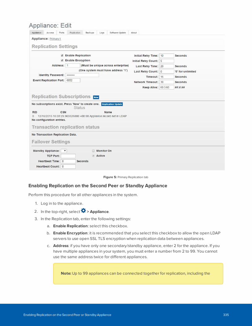
Figure 5: Primary Replication tab
Enabling Replication on the Second Peer or Standby Appliance
Perform this procedure for all other appliances in the system.
1. Log in to the appliance.
2. In the top-right, select > Appliance.
3. In the Replication tab, enter the following settings:
a. Enable Replication: select this checkbox.
b. Enable Encryption: it is recommended that you select this checkbox to allow the open LDAPservers to use open SSL TLS encryption when replication data between appliances.
c. Address: if you have only one secondary/standby appliance, enter 2 for the appliance. If youhave multiple appliances in your system, you must enter a number from 2 to 99. You cannotuse the same address twice for different appliances.
Note: Up to 99 appliances can be connected together for replication, including the
Enabling Replication on the Second Peer or Standby Appliance 335
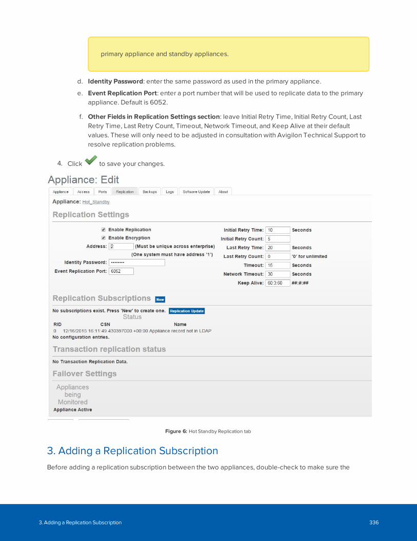
primary appliance and standby appliances.
d. Identity Password: enter the same password as used in the primary appliance.
e. Event Replication Port: enter a port number that will be used to replicate data to the primaryappliance. Default is 6052.
f. Other Fields in Replication Settings section: leave Initial Retry Time, Initial Retry Count, LastRetry Time, Last Retry Count, Timeout, Network Timeout, and Keep Alive at their defaultvalues. These will only need to be adjusted in consultation with Avigilon Technical Support toresolve replication problems.
4. Click to save your changes.
Figure 6: Hot Standby Replication tab
3. Adding a Replication SubscriptionBefore adding a replication subscription between the two appliances, double-check to make sure the
3. Adding a Replication Subscription 336
network requirements have been met:
l The appliances are on the same network and are able to communicate with each other. Make surethe appliances are able to ping each other by host name.
l Each appliance has a time server and a name server configured for them.
l A Web Server Port, LDAP Connect Port, and Event Replication Port are configured for the appliances.Make sure these ports are open between the appliances.
l Replication has been enabled on both appliances. Both appliances have a replication identitypassword configured for them.
l The clocks on both appliances are in sync. The current running time can be seen on the appliancepage for each appliance.
Always add the replication subscription to the first (replication address 1) appliance while logged into thesecond appliance and from the Hot Standby’s Replication tab. As the second and subsequent appliancesfirst subscribe to and receive replicated data from the first (replication address 1) appliance, the existingLDAP database on each subscribing appliance is overwritten by the replicated data from the first (replicationaddress 1) appliance, so that each subscriber appliance has its LDAP data properly initialized.
Note that this overwrite of the subscriber LDAP database only occurs when the first subscription is added ona subscribing appliance. Subsequent subscriptions created on this subscriber appliance do not perform theoverwrite of LDAP data that the first subscription, as the database is already initialized. This is why it isrecommended that replication (and redundancy if used) is set up for each subscriber before addinghardware, user identities or system configurations to avoid data being overwritten and lost.
Do not add the first replication subscription to the address 1 appliance, or all configured data on thatappliance will be overwritten as part of the initialization process described above.
1. Log in to the secondary or standby appliance. You must use the "admin" user name and password oryou will not be able to make changes to the Replication tab.
2. In the top-right, select > Appliance.
3. In the Replication tab, click New in the Replication Subscriptions area.
4. Complete the following fields:
a. Host – enter the replication address 1 appliance’s host name.
b. Web Port – enter the replication address 1 appliance’s web port number.
c. Ldap Port – enter the replication address 1 appliance LDAP Connect Port value. This is highlyrecommended to be the same as the LDAP Connect Port number on the current appliance.
d. Login – enter an account with the proper delegations for the default administrator identity.This can be the admin account, or a different identity, can be used, but it must be an identitywith the proper delegations available in its role. Delegation required for this login areAppliance Repl Subscription Add (remote), Appliance Repl Subscription Remove (remote),Appliance Replication Update and Appliances Show.
e. Password – enter the password for the Login identity.
5. Click to save your changes.
3. Adding a Replication Subscription 337
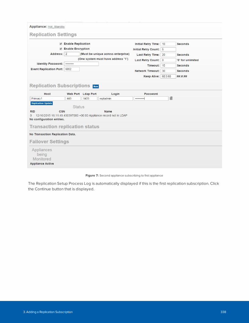
Figure 7: Second appliance subscribing to first appliance
The Replication Setup Process Log is automatically displayed if this is the first replication subscription. Clickthe Continue button that is displayed.
3. Adding a Replication Subscription 338
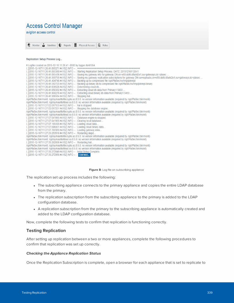
Figure 8: Log file on subscribing appliance
The replication set up process includes the following:
l The subscribing appliance connects to the primary appliance and copies the entire LDAP databasefrom the primary.
l The replication subscription from the subscribing appliance to the primary is added to the LDAPconfiguration database.
l A replication subscription from the primary to the subscribing appliance is automatically created andadded to the LDAP configuration database.
Now, complete the following tests to confirm that replication is functioning correctly.
Testing Replication
After setting up replication between a two or more appliances, complete the following procedures toconfirm that replication was set up correctly.
Checking the Appliance Replication Status
Once the Replication Subscription is complete, open a browser for each appliance that is set to replicate to
Testing Replication 339
each other.
After you have the browsers open, display the Appliance Replication page for the appliances. Confirm thatthe following settings are the same for all appliances:
Note: The Status and System Entries area are only displayed if the primary and subscribingappliance details are accessed together.
l Under the Status area, 1 and 2 are listed in the RID column. 1 should be the primary appliance and 2should be the secondary or standby appliance. There may be other numbers listed if you have moreappliance subscriptions.
l Confirm that the date and time listed in the CSN column is the same for all appliances.
l Under the System Entries area, there should be at least one entry to show that the primary appliancehas replicated data to the other appliances.
l When you click > Appliance, the Appliance list should be displayed and list all appliances.
Checking the Appliance Replication Status 340
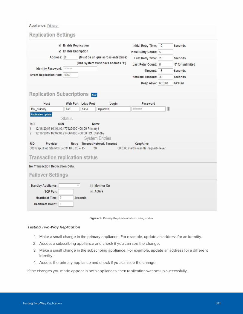
Figure 9: Primary Replication tab showing status
Testing Two-Way Replication
1. Make a small change in the primary appliance. For example, update an address for an identity.
2. Access a subscribing appliance and check if you can see the change.
3. Make a small change in the subscribing appliance. For example, update an address for a differentidentity.
4. Access the primary appliance and check if you can see the change.
If the changes you made appear in both appliances, then replication was set up successfully.
Testing Two-Way Replication 341
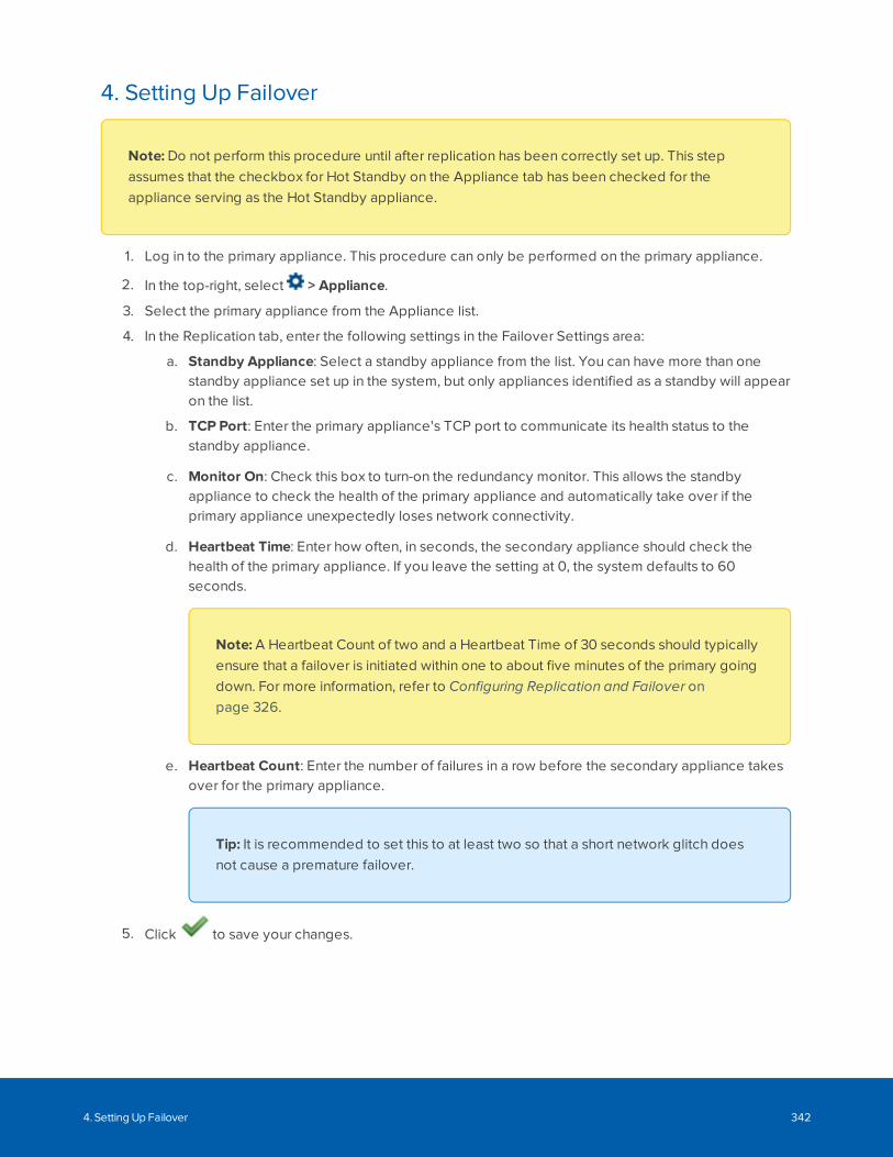
4. Setting Up Failover
Note: Do not perform this procedure until after replication has been correctly set up. This stepassumes that the checkbox for Hot Standby on the Appliance tab has been checked for theappliance serving as the Hot Standby appliance.
1. Log in to the primary appliance. This procedure can only be performed on the primary appliance.
2. In the top-right, select > Appliance.
3. Select the primary appliance from the Appliance list.
4. In the Replication tab, enter the following settings in the Failover Settings area:
a. Standby Appliance: Select a standby appliance from the list. You can have more than onestandby appliance set up in the system, but only appliances identified as a standby will appearon the list.
b. TCP Port: Enter the primary appliance's TCP port to communicate its health status to thestandby appliance.
c. Monitor On: Check this box to turn-on the redundancy monitor. This allows the standbyappliance to check the health of the primary appliance and automatically take over if theprimary appliance unexpectedly loses network connectivity.
d. Heartbeat Time: Enter how often, in seconds, the secondary appliance should check thehealth of the primary appliance. If you leave the setting at 0, the system defaults to 60seconds.
Note: A Heartbeat Count of two and a Heartbeat Time of 30 seconds should typicallyensure that a failover is initiated within one to about five minutes of the primary goingdown. For more information, refer to Configuring Replication and Failover onpage 326.
e. Heartbeat Count: Enter the number of failures in a row before the secondary appliance takesover for the primary appliance.
Tip: It is recommended to set this to at least two so that a short network glitch doesnot cause a premature failover.
5. Click to save your changes.
4. Setting Up Failover 342
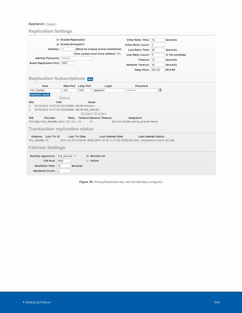
Figure 10: Primary Replication tab, with Hot Standby configured
4. Setting Up Failover 343
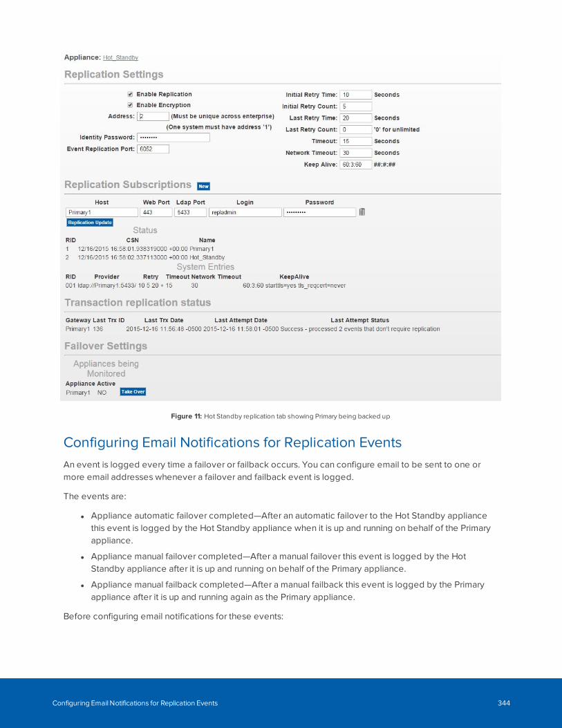
Figure 11: Hot Standby replication tab showing Primary being backed up
Configuring Email Notifications for Replication EventsAn event is logged every time a failover or failback occurs. You can configure email to be sent to one ormore email addresses whenever a failover and failback event is logged.
The events are:
l Appliance automatic failover completed—After an automatic failover to the Hot Standby appliancethis event is logged by the Hot Standby appliance when it is up and running on behalf of the Primaryappliance.
l Appliance manual failover completed—After a manual failover this event is logged by the HotStandby appliance after it is up and running on behalf of the Primary appliance.
l Appliance manual failback completed—After a manual failback this event is logged by the Primaryappliance after it is up and running again as the Primary appliance.
Before configuring email notifications for these events:
Configuring Email Notifications for Replication Events 344
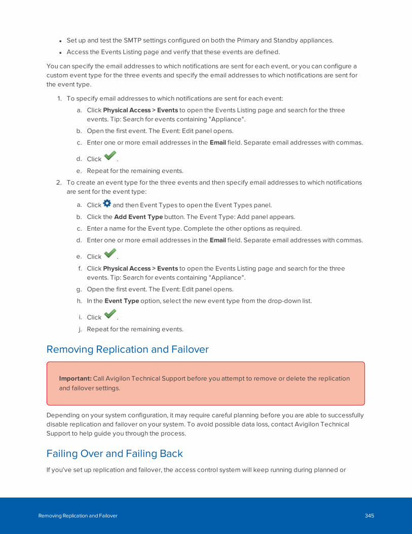
l Set up and test the SMTP settings configured on both the Primary and Standby appliances.
l Access the Events Listing page and verify that these events are defined.
You can specify the email addresses to which notifications are sent for each event, or you can configure acustom event type for the three events and specify the email addresses to which notifications are sent forthe event type.
1. To specify email addresses to which notifications are sent for each event:
a. Click Physical Access > Events to open the Events Listing page and search for the threeevents. Tip: Search for events containing "Appliance".
b. Open the first event. The Event: Edit panel opens.
c. Enter one or more email addresses in the Email field. Separate email addresses with commas.
d. Click .
e. Repeat for the remaining events.
2. To create an event type for the three events and then specify email addresses to which notificationsare sent for the event type:
a. Click and then Event Types to open the Event Types panel.
b. Click the Add Event Type button. The Event Type: Add panel appears.
c. Enter a name for the Event type. Complete the other options as required.
d. Enter one or more email addresses in the Email field. Separate email addresses with commas.
e. Click .
f. Click Physical Access > Events to open the Events Listing page and search for the threeevents. Tip: Search for events containing "Appliance".
g. Open the first event. The Event: Edit panel opens.
h. In the Event Type option, select the new event type from the drop-down list.
i. Click .
j. Repeat for the remaining events.
Removing Replication and Failover
Important: Call Avigilon Technical Support before you attempt to remove or delete the replicationand failover settings.
Depending on your system configuration, it may require careful planning before you are able to successfullydisable replication and failover on your system. To avoid possible data loss, contact Avigilon TechnicalSupport to help guide you through the process.
Failing Over and Failing BackIf you've set up replication and failover, the access control system will keep running during planned or
Removing Replication and Failover 345
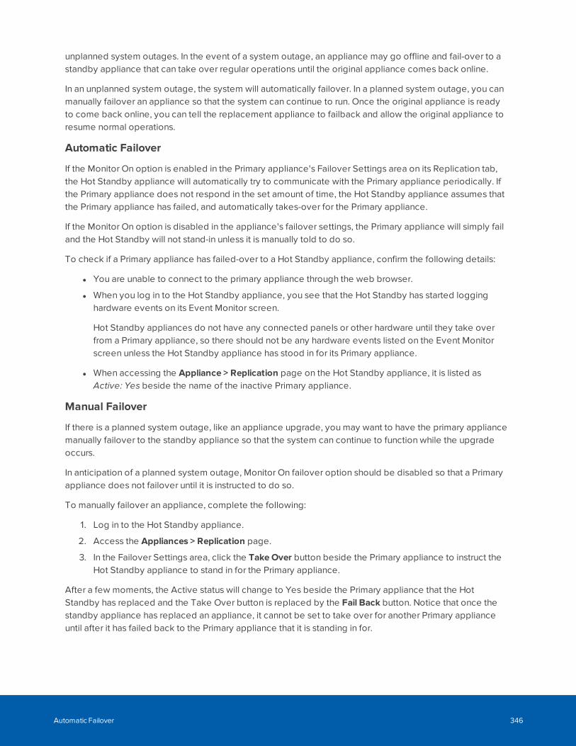
unplanned system outages. In the event of a system outage, an appliance may go offline and fail-over to astandby appliance that can take over regular operations until the original appliance comes back online.
In an unplanned system outage, the system will automatically failover. In a planned system outage, you canmanually failover an appliance so that the system can continue to run. Once the original appliance is readyto come back online, you can tell the replacement appliance to failback and allow the original appliance toresume normal operations.
Automatic Failover
If the Monitor On option is enabled in the Primary appliance's Failover Settings area on its Replication tab,the Hot Standby appliance will automatically try to communicate with the Primary appliance periodically. Ifthe Primary appliance does not respond in the set amount of time, the Hot Standby appliance assumes thatthe Primary appliance has failed, and automatically takes-over for the Primary appliance.
If the Monitor On option is disabled in the appliance's failover settings, the Primary appliance will simply failand the Hot Standby will not stand-in unless it is manually told to do so.
To check if a Primary appliance has failed-over to a Hot Standby appliance, confirm the following details:
l You are unable to connect to the primary appliance through the web browser.
l When you log in to the Hot Standby appliance, you see that the Hot Standby has started logginghardware events on its Event Monitor screen.
Hot Standby appliances do not have any connected panels or other hardware until they take overfrom a Primary appliance, so there should not be any hardware events listed on the Event Monitorscreen unless the Hot Standby appliance has stood in for its Primary appliance.
l When accessing the Appliance > Replication page on the Hot Standby appliance, it is listed asActive: Yes beside the name of the inactive Primary appliance.
Manual Failover
If there is a planned system outage, like an appliance upgrade, you may want to have the primary appliancemanually failover to the standby appliance so that the system can continue to function while the upgradeoccurs.
In anticipation of a planned system outage, Monitor On failover option should be disabled so that a Primaryappliance does not failover until it is instructed to do so.
To manually failover an appliance, complete the following:
1. Log in to the Hot Standby appliance.
2. Access the Appliances > Replication page.
3. In the Failover Settings area, click the Take Over button beside the Primary appliance to instruct theHot Standby appliance to stand in for the Primary appliance.
After a few moments, the Active status will change to Yes beside the Primary appliance that the HotStandby has replaced and the Take Over button is replaced by the Fail Back button. Notice that once thestandby appliance has replaced an appliance, it cannot be set to take over for another Primary applianceuntil after it has failed back to the Primary appliance that it is standing in for.
Automatic Failover 346
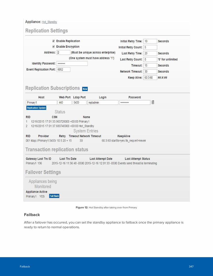
Figure 12: Hot Standby after taking over from Primary
Failback
After a failover has occurred, you can set the standby appliance to failback once the primary appliance isready to return to normal operations.
Failback 347
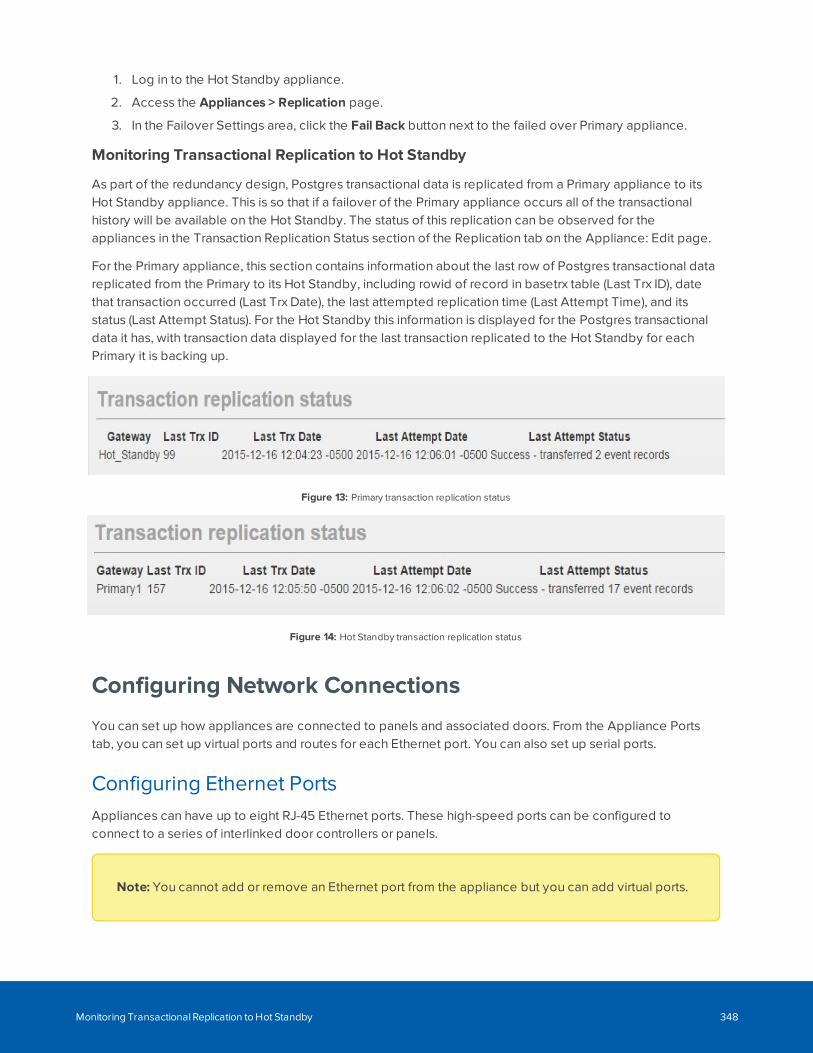
1. Log in to the Hot Standby appliance.
2. Access the Appliances > Replication page.
3. In the Failover Settings area, click the Fail Back button next to the failed over Primary appliance.
Monitoring Transactional Replication to Hot Standby
As part of the redundancy design, Postgres transactional data is replicated from a Primary appliance to itsHot Standby appliance. This is so that if a failover of the Primary appliance occurs all of the transactionalhistory will be available on the Hot Standby. The status of this replication can be observed for theappliances in the Transaction Replication Status section of the Replication tab on the Appliance: Edit page.
For the Primary appliance, this section contains information about the last row of Postgres transactional datareplicated from the Primary to its Hot Standby, including rowid of record in basetrx table (Last Trx ID), datethat transaction occurred (Last Trx Date), the last attempted replication time (Last Attempt Time), and itsstatus (Last Attempt Status). For the Hot Standby this information is displayed for the Postgres transactionaldata it has, with transaction data displayed for the last transaction replicated to the Hot Standby for eachPrimary it is backing up.
Figure 13: Primary transaction replication status
Figure 14: Hot Standby transaction replication status
Configuring Network Connections
You can set up how appliances are connected to panels and associated doors. From the Appliance Portstab, you can set up virtual ports and routes for each Ethernet port. You can also set up serial ports.
Configuring Ethernet PortsAppliances can have up to eight RJ-45 Ethernet ports. These high-speed ports can be configured toconnect to a series of interlinked door controllers or panels.
Note: You cannot add or remove an Ethernet port from the appliance but you can add virtual ports.
Monitoring Transactional Replication to Hot Standby 348
To enable and configure an Ethernet port:
1. From the Appliance Edit page, select the Ports tab.
The Port list is displayed.
2. Click the name or port number from the Ethernet Ports list.
The Port: Edit page is displayed.
3. Make the required changes.
4. Click .
Note: If you assign or change the IP address, make sure that any switches or routers connected tothe appliance recognize the changed address. To do this, perform one of the following:
l Reboot the appliance.
l Unplug the Ethernet cable that is connected to the appliance, wait a few seconds, then plug it back in.
If the switch or router is not able to detect the appliance's new IP address, you may need to manuallyupdate the switch or router. Refer to the switch or router documentation for more details.
Adding Ethernet RoutesIf you prefer not to use the default Ethernet route set by the appliance, you can add a new Ethernet route forappliance and controller panel communication.
1. From the Appliance Edit page, select the Ports tab.
The Port list is displayed.
2. In the right most column of the Ethernet Ports list, click Routes.
The Routes list is displayed.
3. From the Routes list, click Add New Route.
The Route Add page is displayed.
4. Complete the fields as required to define the new Ethernet route.
5. Click .
6. Repeat this procedure to add all the routes that are required.
Enabling Serial PortsEach appliance includes one or more serial ports for connecting devices via RS-232 or RS-485. Serial portscan be used to connect troubleshooting consoles or to connect panels that do not have Ethernetconnections.
To enable a serial port on an appliance:
Adding Ethernet Routes 349
1. Connect the appliance to one or more panels via the appropriate serial port.
Note the port number for each serial cable connection.
2. From the Appliance Edit page, select the Ports tab.
The Ports list is displayed.
3. At the bottom of the page, click the serial port you want to enable.
The Serial Port Edit page is displayed.
4. Select the Enable checkbox.
5. Complete the remaining fields as required to define the serial connection.
6. Click .
Backups
You can configure backup events to generate backup files of the configuration and transaction databases ofthe ACM system. The backup files can be used to restore information if an appliance's configuration ortransaction data ever becomes corrupted. They are used to retain data, especially transactional data, forregulatory purposes.
Configuration and transaction data are separately backed up. Backup events can either be scheduled on adaily or weekly frequency, or manually started. Backup files can also be encrypted, which may be requiredto protect data that is retained for regulatory purposes.
Configuration data, which includes identity information (including photographs, data, and tokens), cangenerate large backup files. Backups should be generated regularly, and at the very least, followingchanges. In the event of a catastrophic failure, an up-to-date configuration backup enables the ACM systemto be up and running again much faster.
Transactional data, which is generated while the ACM system is active, can be retained in backup form tomeet any applicable regulatory requirements, and can be generated to meet data retention policies.
Backing Up System DataYou can configure the appliance to back up system configuration settings and transaction event details.More than one backup event can be created, and each backup file can be stored in a different location. Youcan define a schedule for a backup event. Scheduled backups can occur at least once a week or at mostonce a day at a specific time. A backup event without a schedule must be manually started.
Note: Configuration data (including tokens) and transactions data must be backed up separately.
Backups 350
1. From the Appliance Edit page, select the Backups tab.
2. Click Add NewAppliance Backup.
The Appliance Backup: Add New page is displayed.
3. Enter a name for the back up.
4. Select the preferred Backup Type.
Some of the settings change to match the selected backup type.
5. From the Data Type drop down list, select Configuration or Transaction.
6. Click Browse to select where the back up files will be stored.
7. Optionally, in the Schedule area, select the days of the week when the back up will occur then enterthe preferred backup time in 24 hour format. Leave the schedule options blank for a backup that canonly be manually started.
8. Click .
Manually Backing Up DataAfter you've set up a backup event, you can manually start a backup at any time; for example, to create abackup of the current data before restoring an older backup.
1. From the Appliance Edit page, select the Backups tab.
The Appliance Backup list displays.
2. In the row for the backup you want to start, click Backup Now to start the backup.
The backup file name is generated in this format: <backup name>-<date: yyyyMMDDHHMMSS>.
Note: When you are using the Local Drive backup type, the previous backup file isoverwritten. For all other backup types, the file is added to the configured Location.
Restoring BackupsIf the appliance's configuration or transaction data ever becomes corrupted, you can restore the data from abackup.
Start with the most recent backup prior to the data being corrupted. The restored data will overwrite all theconfiguration or transaction data.
Restored configuration data won't be downloaded to the panels immediately. After the backup is restored,verify that the restored data for panels is correct. For example, identities (or door schedules, or overridesand so on) that you deleted after the backup was created may have to be deleted again, and identities thatyou added after the backup was created may have to be added again. Then, manually download therestored verified configuration data to each panel in your system. For more information about downloadingpanels, see Resetting Doors Connected to a Subpanel on page 167.
Manually Backing Up Data 351
As well as restoring backups from your ACM appliance, you can restore backup files:
l From other ACM systems, or that were created using backup events that are no longer on yoursystem. For more information, see Restoring Backups From Other Backup Events below.
Backups created in versions prior to the ACM software release 5.12.2 may not be compatible withlater ACM releases. Contact Customer Support if you need to restore a backup from an earlierrelease.
l Stored on your local workstation.
To restore a backup file created on your ACM appliance (other than one created by a Local Drive backupevent that has been downloaded to the default Downloads folder of your local workstation):
1. From the Appliance Edit page, select the Backups tab.
The Appliance Backup list displays.
2. Click File List beside the backup that you want to restore.
3. In the far right column, click Restore beside the copy of the backup that you want to restore.
The selected file is copied to the appliance and replaces the existing configuration or transactioninformation on the appliance.
Note: See Downloading All Tokens on page 302 if you have restored an ACM appliance that isconnected to a SALTO server.
Restoring Backups From Other Backup EventsYou can use a backup event to restore a file created by another backup event, as long as the backup type isthe same. This can be useful if you have to restore a backup created with a backup event no longer on yoursystem, or from another ACM system.
Note: It is also possible to restore backups from earlier releases of ACM systems. However,backups created in versions prior to the ACM software release 5.12.2 may not be compatible withlater ACM versions.
To restore a backup created by another backup event, you must:
1. Identify the name of the backup event used to create the backup:
a. Locate the backup file that you want to restore. The filename format is <backup event name>-<date: yyyyMMDDHHMMSS>.
b. Note the name of backup event that is embedded in the file name.
2. In the ACM Client software:
Restoring Backups From Other Backup Events 352
a. From the Appliance Edit page, select the Backups tab.
The Appliance Backup listing page displays.
b. Rename or create a backup event with the same name as the backup event used to createthe backup file:
l To rename an existing backup event:
1. Click on the name of the plan to open the Appliance Backup: Edit page.
2. Enter the new name for the backup event.
3. Leave the other fields as they are.
4. Click to save your changes.
Tip: After you have restored the backup file, rename the backup event to itsprevious name if you want to continue to use it as before.
l To create a new backup event:
1. Click to add a new backup event.
2. Enter all the details for the backup event, specifying the location of the backupfile to be restored.
3. Click to save your changes.
3. Copy the backup file to the location specified in the back up event you will use.
4. In the ACM Client software:
a. Click File List beside the backup that you want to restore.
The Backup File List is displayed.
b. In the far right column, click Restore beside the copy of the backup that you want to restore.
Important: The name of the backup event must match the backup event nameembedded in the filename of the backup file.
c. The selected file is copied to the appliance and replaces the existing configuration ortransaction information on the appliance.
Logs
Appliance logs are automatically generated to monitor communications between panels and devices.
Logs 353
Accessing Appliance LogsAppliance logs are automatically generated to monitor communications between panels and devices.
The appliance logs are automatically generated and monitor the communications between panels anddevices. They can be used to help diagnose appliance issues.
1. From the Appliance Edit screen, select the Logs tab.
The Logs list is displayed.
2. Click the log you want to view.
The Appliances Log page displays.
Log details are displayed in chronological order. The earliest log event is displayed at the top, and the mostrecent is displayed at the bottom. The full text of the log is displayed. Each log is different because of thedifferent activities that are tracked by the log. The name of the Appliance and the Log file are displayed atthe top of the screen for each log.
Software Updates
Software updates are available for download and installation.
Updating the Appliance SoftwareAvigilonAccess Control Manager software updates are available for download from the Avigilon website:avigilon.com.
Once you've downloaded the latest version of the software, you can install the update to the appliance fromany browser on the network.
Accessing Appliance Logs 354
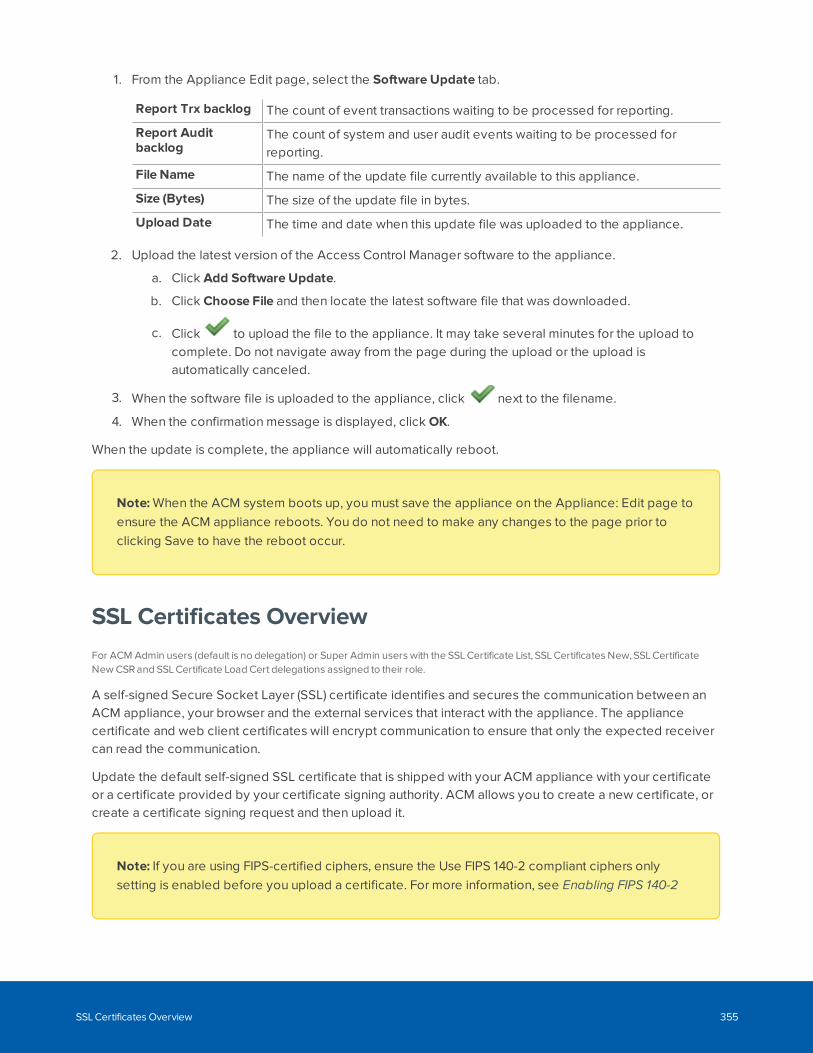
1. From the Appliance Edit page, select the Software Update tab.
Report Trx backlog The count of event transactions waiting to be processed for reporting.
Report Auditbacklog
The count of system and user audit events waiting to be processed forreporting.
File Name The name of the update file currently available to this appliance.
Size (Bytes) The size of the update file in bytes.
Upload Date The time and date when this update file was uploaded to the appliance.
2. Upload the latest version of the Access Control Manager software to the appliance.
a. Click Add Software Update.
b. Click Choose File and then locate the latest software file that was downloaded.
c. Click to upload the file to the appliance. It may take several minutes for the upload tocomplete. Do not navigate away from the page during the upload or the upload isautomatically canceled.
3. When the software file is uploaded to the appliance, click next to the filename.
4. When the confirmation message is displayed, click OK.
When the update is complete, the appliance will automatically reboot.
Note: When the ACM system boots up, you must save the appliance on the Appliance: Edit page toensure the ACM appliance reboots. You do not need to make any changes to the page prior toclicking Save to have the reboot occur.
SSL Certificates OverviewFor ACM Admin users (default is no delegation) or Super Admin users with the SSL Certificate List, SSL Certificates New, SSL CertificateNew CSR and SSL Certificate Load Cert delegations assigned to their role.
A self-signed Secure Socket Layer (SSL) certificate identifies and secures the communication between anACM appliance, your browser and the external services that interact with the appliance. The appliancecertificate and web client certificates will encrypt communication to ensure that only the expected receivercan read the communication.
Update the default self-signed SSL certificate that is shipped with your ACM appliance with your certificateor a certificate provided by your certificate signing authority. ACM allows you to create a new certificate, orcreate a certificate signing request and then upload it.
Note: If you are using FIPS-certified ciphers, ensure the Use FIPS 140-2 compliant ciphers onlysetting is enabled before you upload a certificate. For more information, see Enabling FIPS 140-2
SSL Certificates Overview 355
Encryption on ACM Appliances on page 490.
Supported StandardsThe ACM appliance certificate supports the secure hash algorithm, SHA-384 with elliptic curve digitalsignature algorithm (ECDSA). The SHA-256 with RSA algorithm is still supported for third-party certificates.
Note: To provide maximum security strength for your ACM system, ensure the certificate meets theU.S. government's National Institute of Standards and Technology (NIST) Special Publication800-131A (SP 800-131A) standard.
If your ACM appliance to ACC integration deployment is having trouble connecting, review thecertificate requirements for the two systems. You may need to update the certificate on the ACMappliance to resolve the connection issues between the two systems.
Viewing the SSL Certificate
1. In the top-right, select >Appliance.
2. Select the SSL Certificate tab.
The current SSL certificate is displayed.
Creating an SSL CertificateTo create a self-signed SSL certificate:
1. In the top-right, select >Appliance.
2. Select the SSL Certificate tab.
3. Click NewCertificate below the current certificate.
Supported Standards 356
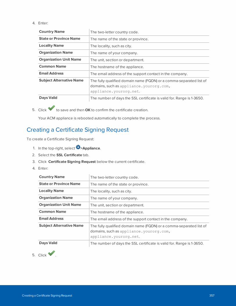
4. Enter:
Country Name The two-letter country code.
State or Province Name The name of the state or province.
Locality Name The locality, such as city.
Organization Name The name of your company.
Organization Unit Name The unit, section or department.
Common Name The hostname of the appliance.
Email Address The email address of the support contact in the company.
Subject Alternative Name The fully qualified domain name (FQDN) or a comma-separated list ofdomains, such as appliance.yourorg.com,appliance.yourorg.net.
Days Valid The number of days the SSL certificate is valid for. Range is 1-3650.
5. Click to save and then OK to confirm the certificate creation.
Your ACM appliance is rebooted automatically to complete the process.
Creating a Certificate Signing RequestTo create a Certificate Signing Request:
1. In the top-right, select >Appliance.
2. Select the SSL Certificate tab.
3. Click Certificate Signing Request below the current certificate.
4. Enter:
Country Name The two-letter country code.
State or Province Name The name of the state or province.
Locality Name The locality, such as city.
Organization Name The name of your company.
Organization Unit Name The unit, section or department.
Common Name The hostname of the appliance.
Email Address The email address of the support contact in the company.
Subject Alternative Name The fully qualified domain name (FQDN) or a comma-separated list ofdomains, such as appliance.yourorg.com,appliance.yourorg.net.
Days Valid The number of days the SSL certificate is valid for. Range is 1-3650.
5. Click .
Creating a Certificate Signing Request 357
6. When the Download CSR and Download Private Key links appear, click them to download both filesto your local drive.
7. Send the certificateRequest.csr file to your signing authority to obtain a signed certificate.
Note: Protect your csrPrivatekey.key file and make sure that it is accessible only totrusted administrators.
Next, see Uploading an SSL Certificate below.
Uploading an SSL CertificateTo upload self-signed certificate files:
1. In the top-right, select >Appliance.
2. Select the SSL Certificate tab.
3. Click Load new SSL Certificate.
4. Upload your new certificate and matching key files from your local drive in the Upload SSLCertificate and Upload Private Key fields.
5. Click to save and then OK to confirm the uploads.
Your ACM appliance is rebooted automatically to complete the process.
Appliances - About page
When you select the About tab from the Appliance Edit page, the appliance version and license details aredisplayed.
On this page, you can add or remove licenses on the appliance.
Adding a LicenseWhen you first install an ACM 6 system, you will need to license the system to use its features. Addadditional licenses to access new features as required.
If you do not already have a license, purchase one from Avigilon.
Online Licensing
If you have Internet access, use online activation. Otherwise, see Offline Licensing on the next page.
Uploading an SSL Certificate 358
1. In the top-right, select > Appliance.
2. In the About tab, click Add License.
3. In the Add Licenses dialog, enter your Activation IDs.
l Click Add ID to add additional Activation IDs.
l Click Remove Last ID to clear the last Activation ID entered.
4. Click Activate Licenses.
Offline Licensing
Offline licensing involves transferring files between a computer running the ACM system and a computerwith Internet access.
In the ACM system:
1. In the top-right, select >Appliance.
2. In the About tab, click Add License.
3. In the Add Licenses dialog, select the Manual tab.
4. Enter your Activation IDs.
l Click Add ID to add additional Activation IDs.
l Click Remove Last ID to clear the last Activation ID entered.
5. Click Save File... and select where you want to save the .key file. You can rename the file asrequired.
6. Copy the .key file to a computer with Internet access.
In a browser:
1. Go to activate.avigilon.com.
2. Click Choose File and select the .key file.
3. Click Upload. A capabilityResponse.bin file should download automatically.
If not, allow the download to occur when you are prompted.
4. Complete the product registration page to receive product updates from Avigilon.
5. Copy the .bin file to a computer running the ACC Client software.
In the ACM system:
1. In the Add Licenses dialog, click Choose File.
2. Select the .bin file and click Open.
3. Click Activate Licenses.
Removing a LicenseYou can deactivate individual licenses and activate them on a different system.
Online Licensing
If you have internet access, use the following procedure. Otherwise, see Offline Licensing on the next page.
Offline Licensing 359
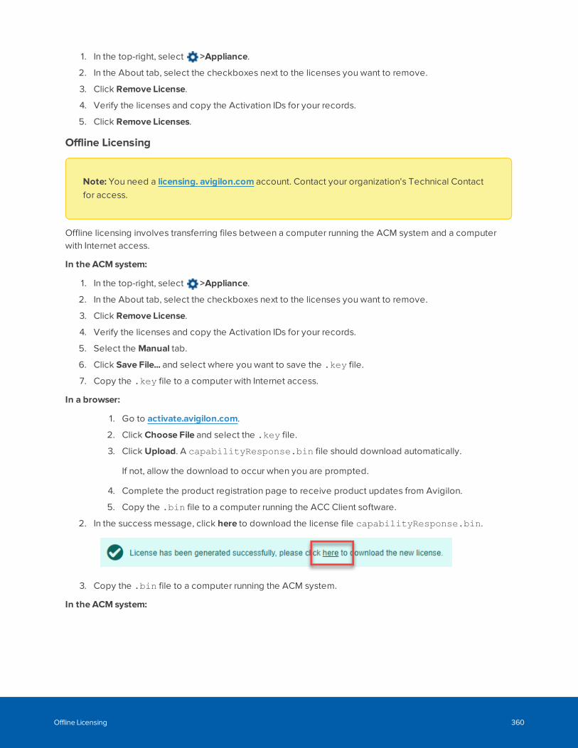
1. In the top-right, select >Appliance.
2. In the About tab, select the checkboxes next to the licenses you want to remove.
3. Click Remove License.
4. Verify the licenses and copy the Activation IDs for your records.
5. Click Remove Licenses.
Offline Licensing
Note: You need a licensing. avigilon.com account. Contact your organization's Technical Contactfor access.
Offline licensing involves transferring files between a computer running the ACM system and a computerwith Internet access.
In the ACM system:
1. In the top-right, select >Appliance.
2. In the About tab, select the checkboxes next to the licenses you want to remove.
3. Click Remove License.
4. Verify the licenses and copy the Activation IDs for your records.
5. Select the Manual tab.
6. Click Save File... and select where you want to save the .key file.
7. Copy the .key file to a computer with Internet access.
In a browser:
1. Go to activate.avigilon.com.
2. Click Choose File and select the .key file.
3. Click Upload. A capabilityResponse.bin file should download automatically.
If not, allow the download to occur when you are prompted.
4. Complete the product registration page to receive product updates from Avigilon.
5. Copy the .bin file to a computer running the ACC Client software.
2. In the success message, click here to download the license file capabilityResponse.bin.
3. Copy the .bin file to a computer running the ACM system.
In the ACM system:
Offline Licensing 360
1. In the Add Licenses dialog, click Choose File
2. Select the .bin file and click Open.
3. Click Remove Licenses.
Upgrading Your License FormatThe ACM 6 license format is different from previous versions. If you upgraded from ACM 5.12.2 to ACM6.0.0 or later, you will need to upgrade your license format in order to add new licenses.
Note: If your system is licensed for more than the maximum number of readers, you will not beeligible for an upgrade license. You can continue using your existing system, or contact sales to addmore features.
If you do not upgrade your license format, you can continue to use your existing features. However, you willnot be able to license new features.
Important: If you use the replication and failover features of the ACM system and you choose toupgrade the license format you must upgrade the license format on both the primary and standbyACM appliances. Replication features, including failover, will not function if the license format is notthe same on both appliances. Complete the following steps on both appliances.
1. In the top-right, select >Appliance.
2. In the About tab, click Download Upgrade File.
3. Email the .bin file to [email protected]. You will receive a response in 1-2 business dayswith an Activation ID for each feature you have. You can continue to use the ACM appliance duringthis time.
4. After you receive the Activation IDs, follow the procedure in Adding a License on page 358. You willonly need to enter one of the Activation IDs to automatically license the system for all features yourdevice is entitled to.
Viewing the End User License AgreementFollow the steps below to view the End User License Agreement:
1. In the top-right, select > Appliance.
2. In the About tab, click View End User License Agreement Terms and Conditions.
3. Click Back to return to the Appliance: Edit page.
Appliances - About pageWhen you select the About tab from the Appliance Edit page, the appliance version and license details aredisplayed.
Upgrading Your License Format 361
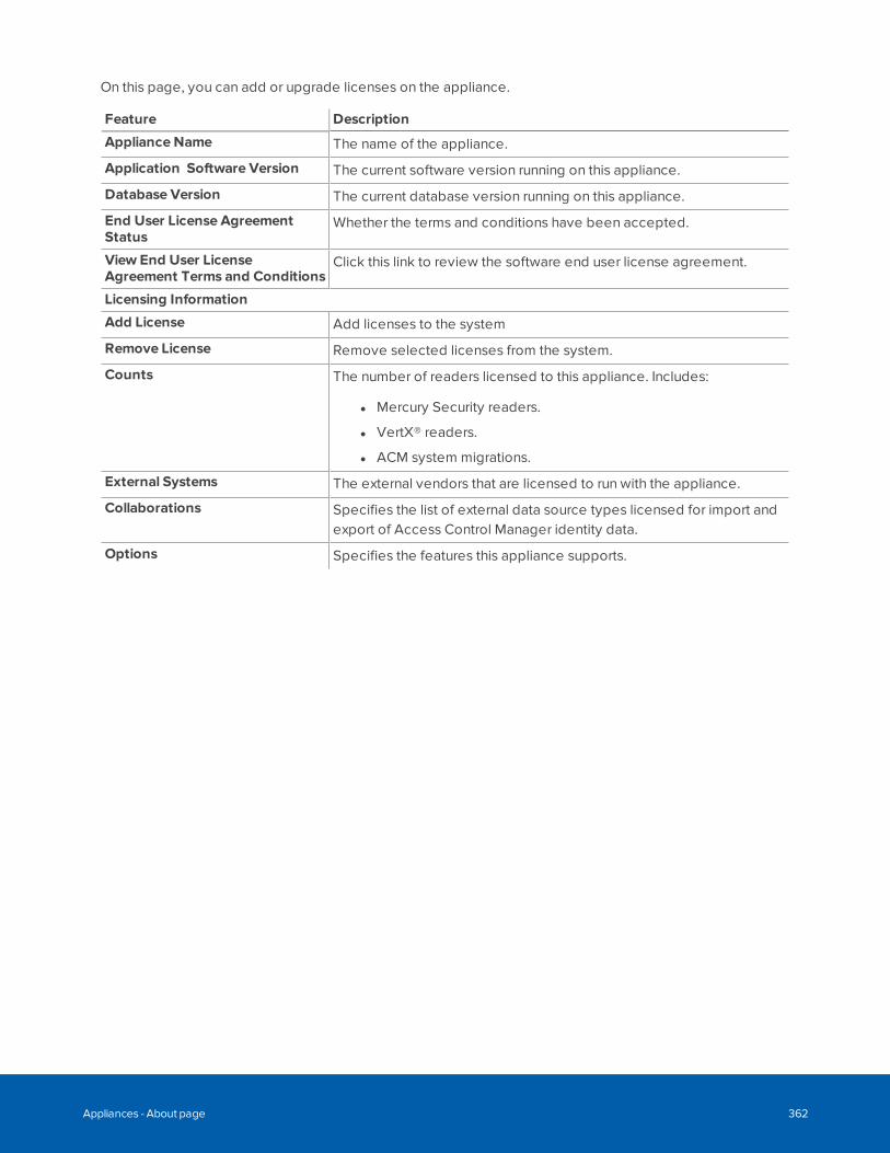
On this page, you can add or upgrade licenses on the appliance.
Feature Description
Appliance Name The name of the appliance.
Application Software Version The current software version running on this appliance.
Database Version The current database version running on this appliance.
End User License AgreementStatus
Whether the terms and conditions have been accepted.
View End User LicenseAgreement Terms and Conditions
Click this link to review the software end user license agreement.
Licensing Information
Add License Add licenses to the system
Remove License Remove selected licenses from the system.
Counts The number of readers licensed to this appliance. Includes:
l Mercury Security readers.
l VertX® readers.
l ACM system migrations.
External Systems The external vendors that are licensed to run with the appliance.
Collaborations Specifies the list of external data source types licensed for import andexport of Access Control Manager identity data.
Options Specifies the features this appliance supports.
Appliances - About page 362
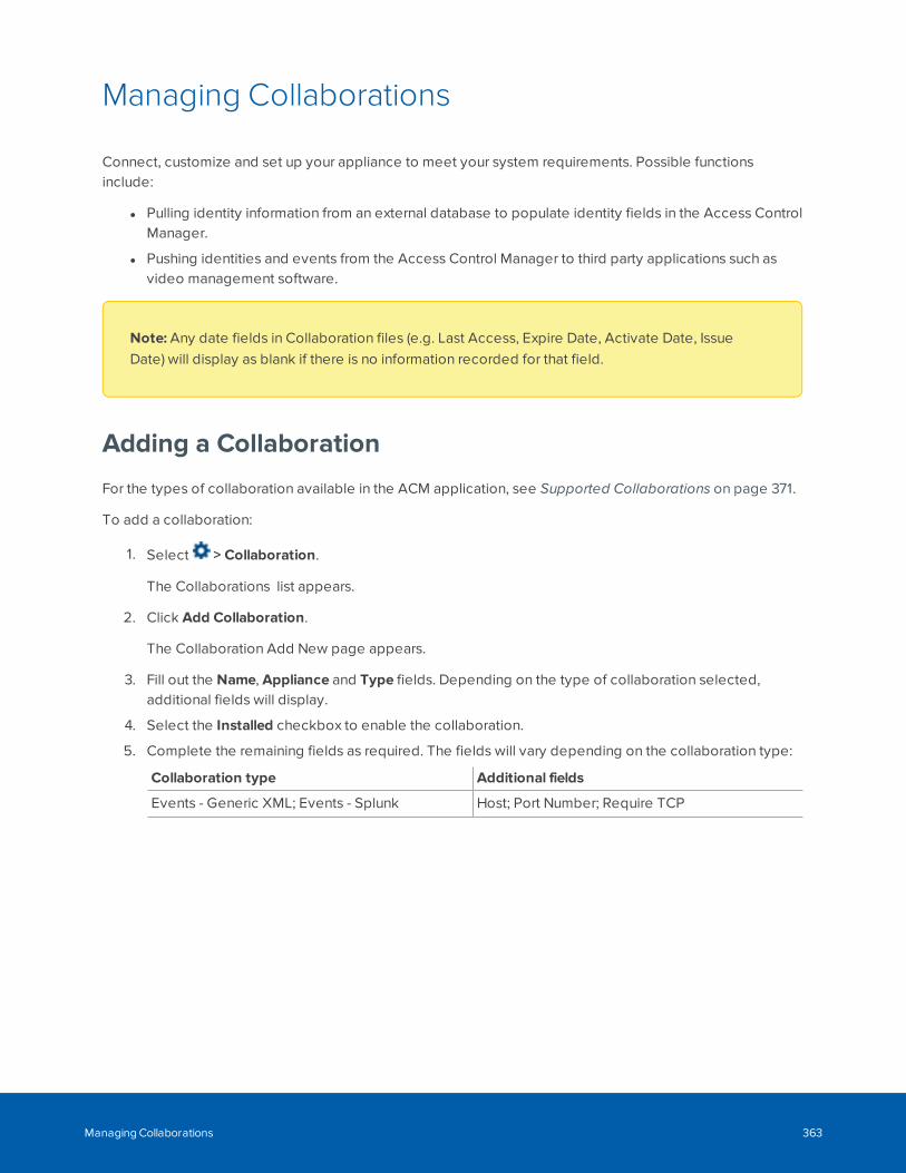
Managing Collaborations
Connect, customize and set up your appliance to meet your system requirements. Possible functionsinclude:
l Pulling identity information from an external database to populate identity fields in the Access ControlManager.
l Pushing identities and events from the Access Control Manager to third party applications such asvideo management software.
Note: Any date fields in Collaboration files (e.g. Last Access, Expire Date, Activate Date, IssueDate) will display as blank if there is no information recorded for that field.
Adding a Collaboration
For the types of collaboration available in the ACM application, see Supported Collaborations on page 371.
To add a collaboration:
1. Select > Collaboration.
The Collaborations list appears.
2. Click Add Collaboration.
The Collaboration Add New page appears.
3. Fill out the Name, Appliance and Type fields. Depending on the type of collaboration selected,additional fields will display.
4. Select the Installed checkbox to enable the collaboration.
5. Complete the remaining fields as required. The fields will vary depending on the collaboration type:
Collaboration type Additional fields
Events - Generic XML; Events - Splunk Host; Port Number; Require TCP
Managing Collaborations 363
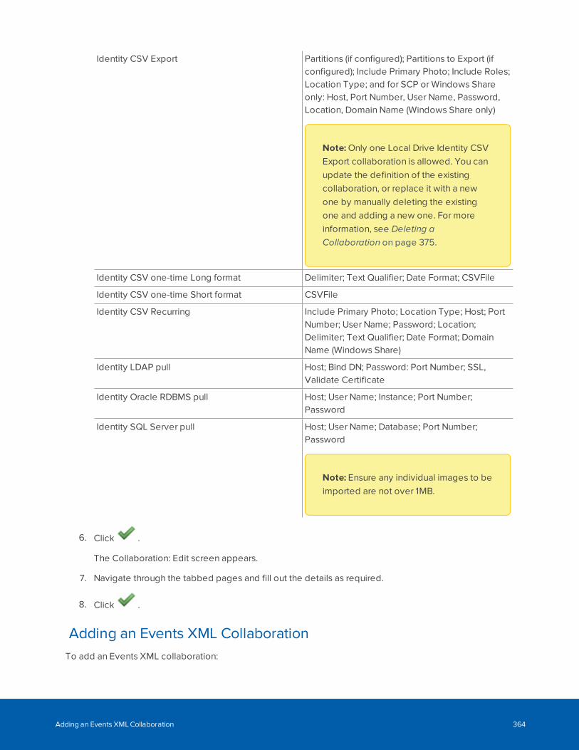
Identity CSV Export Partitions (if configured); Partitions to Export (ifconfigured); Include Primary Photo; Include Roles;Location Type; and for SCP or Windows Shareonly: Host, Port Number, User Name, Password,Location, Domain Name (Windows Share only)
Note: Only one Local Drive Identity CSVExport collaboration is allowed. You canupdate the definition of the existingcollaboration, or replace it with a newone by manually deleting the existingone and adding a new one. For moreinformation, see Deleting aCollaboration on page 375.
Identity CSV one-time Long format Delimiter; Text Qualifier; Date Format; CSVFile
Identity CSV one-time Short format CSVFile
Identity CSV Recurring Include Primary Photo; Location Type; Host; PortNumber; User Name; Password; Location;Delimiter; Text Qualifier; Date Format; DomainName (Windows Share)
Identity LDAP pull Host; Bind DN; Password: Port Number; SSL,Validate Certificate
Identity Oracle RDBMS pull Host; User Name; Instance; Port Number;Password
Identity SQL Server pull Host; User Name; Database; Port Number;Password
Note: Ensure any individual images to beimported are not over 1MB.
6. Click .
The Collaboration: Edit screen appears.
7. Navigate through the tabbed pages and fill out the details as required.
8. Click .
Adding an Events XML CollaborationTo add an Events XML collaboration:
Adding an Events XML Collaboration 364
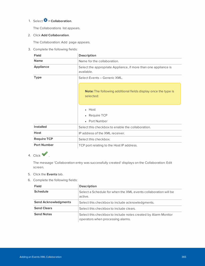
1. Select > Collaboration.
The Collaborations list appears.
2. Click Add Collaboration.
The Collaboration: Add page appears.
3. Complete the following fields:
Field Description
Name Name for the collaboration.
Appliance Select the appropriate Appliance, if more than one appliance isavailable.
Type Select Events – Generic XML.
Note: The following additional fields display once the type isselected:
l Host
l Require TCP
l Port Number
Installed Select this checkbox to enable the collaboration.
Host IP address of the XML receiver.
Require TCP Select this checkbox.
Port Number TCP port relating to the Host IP address.
4. Click .
The message 'Collaboration entry was successfully created' displays on the Collaboration: Editscreen.
5. Click the Events tab.
6. Complete the following fields:
Field Description
Schedule Select a Schedule for when the XML events collaboration will beactive.
Send Acknowledgments Select this checkbox to include acknowledgments.
Send Clears Select this checkbox to include clears.
Send Notes Select this checkbox to include notes created by Alarm Monitoroperators when processing alarms.
Adding an Events XML Collaboration 365
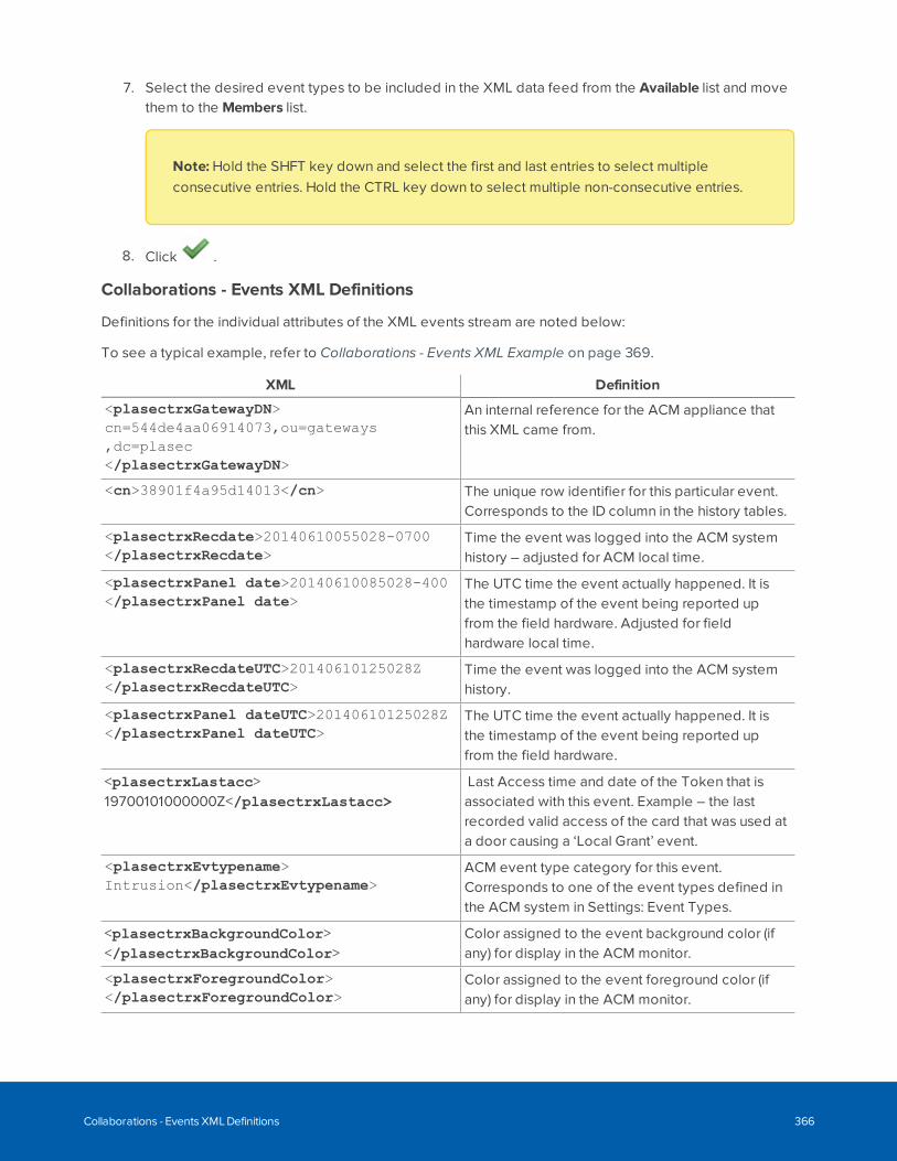
7. Select the desired event types to be included in the XML data feed from the Available list and movethem to the Members list.
Note: Hold the SHFT key down and select the first and last entries to select multipleconsecutive entries. Hold the CTRL key down to select multiple non-consecutive entries.
8. Click .
Collaborations - Events XML Definitions
Definitions for the individual attributes of the XML events stream are noted below:
To see a typical example, refer to Collaborations - Events XML Example on page 369.
XML Definition
<plasectrxGatewayDN>cn=544de4aa06914073,ou=gateways,dc=plasec</plasectrxGatewayDN>
An internal reference for the ACM appliance thatthis XML came from.
<cn>38901f4a95d14013</cn> The unique row identifier for this particular event.Corresponds to the ID column in the history tables.
<plasectrxRecdate>20140610055028-0700</plasectrxRecdate>
Time the event was logged into the ACM systemhistory – adjusted for ACM local time.
<plasectrxPanel date>20140610085028-400</plasectrxPanel date>
The UTC time the event actually happened. It isthe timestamp of the event being reported upfrom the field hardware. Adjusted for fieldhardware local time.
<plasectrxRecdateUTC>20140610125028Z</plasectrxRecdateUTC>
Time the event was logged into the ACM systemhistory.
<plasectrxPanel dateUTC>20140610125028Z</plasectrxPanel dateUTC>
The UTC time the event actually happened. It isthe timestamp of the event being reported upfrom the field hardware.
<plasectrxLastacc>19700101000000Z</plasectrxLastacc>
Last Access time and date of the Token that isassociated with this event. Example – the lastrecorded valid access of the card that was used ata door causing a ‘Local Grant’ event.
<plasectrxEvtypename>Intrusion</plasectrxEvtypename>
ACM event type category for this event.Corresponds to one of the event types defined inthe ACM system in Settings: Event Types.
<plasectrxBackgroundColor></plasectrxBackgroundColor>
Color assigned to the event background color (ifany) for display in the ACM monitor.
<plasectrxForegroundColor></plasectrxForegroundColor>
Color assigned to the event foreground color (ifany) for display in the ACM monitor.
Collaborations - Events XML Definitions 366
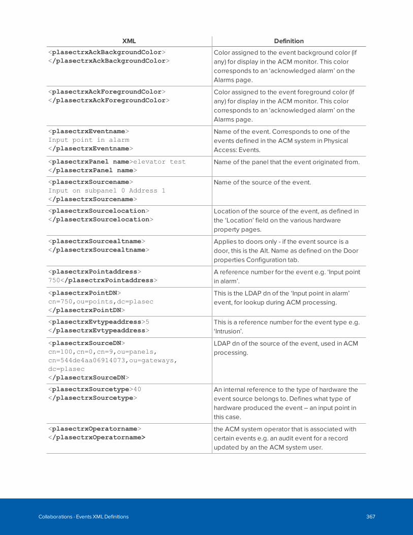
XML Definition
<plasectrxAckBackgroundColor></plasectrxAckBackgroundColor>
Color assigned to the event background color (ifany) for display in the ACM monitor. This colorcorresponds to an ‘acknowledged alarm’ on theAlarms page.
<plasectrxAckForegroundColor></plasectrxAckForegroundColor>
Color assigned to the event foreground color (ifany) for display in the ACM monitor. This colorcorresponds to an ‘acknowledged alarm’ on theAlarms page.
<plasectrxEventname>Input point in alarm</plasectrxEventname>
Name of the event. Corresponds to one of theevents defined in the ACM system in PhysicalAccess: Events.
<plasectrxPanel name>elevator test</plasectrxPanel name>
Name of the panel that the event originated from.
<plasectrxSourcename>Input on subpanel 0 Address 1</plasectrxSourcename>
Name of the source of the event.
<plasectrxSourcelocation></plasectrxSourcelocation>
Location of the source of the event, as defined inthe ‘Location’ field on the various hardwareproperty pages.
<plasectrxSourcealtname></plasectrxSourcealtname>
Applies to doors only - if the event source is adoor, this is the Alt. Name as defined on the Doorproperties Configuration tab.
<plasectrxPointaddress>750</plasectrxPointaddress>
A reference number for the event e.g. ‘Input pointin alarm’.
<plasectrxPointDN>cn=750,ou=points,dc=plasec</plasectrxPointDN>
This is the LDAP dn of the ‘Input point in alarm’event, for lookup during ACM processing.
<plasectrxEvtypeaddress>5</plasectrxEvtypeaddress>
This is a reference number for the event type e.g.‘Intrusion’.
<plasectrxSourceDN>cn=100,cn=0,cn=9,ou=panels,cn=544de4aa06914073,ou=gateways,dc=plasec</plasectrxSourceDN>
LDAP dn of the source of the event, used in ACMprocessing.
<plasectrxSourcetype>40</plasectrxSourcetype>
An internal reference to the type of hardware theevent source belongs to. Defines what type ofhardware produced the event – an input point inthis case.
<plasectrxOperatorname></plasectrxOperatorname>
the ACM system operator that is associated withcertain events e.g. an audit event for a recordupdated by an the ACM system user.
Collaborations - Events XML Definitions 367
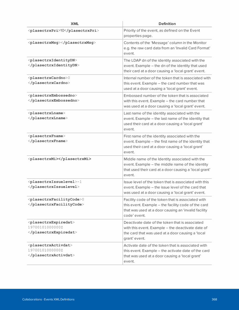
XML Definition
<plasectrxPri>10</plasectrxPri> Priority of the event, as defined on the Eventproperties page.
<plasectrxMsg></plasectrxMsg> Contents of the ‘Message’ column in the Monitore.g. the raw card data from an ‘Invalid Card Format’event.
<plasectrxIdentityDN></plasectrxIdentityDN>
The LDAP dn of the identity associated with theevent. Example – the dn of the identity that usedtheir card at a door causing a ‘local grant’ event.
<plasectrxCardno>0</plasectrxCardno>
Internal number of the token that is associated withthis event. Example – the card number that wasused at a door causing a ‘local grant’ event.
<plasectrxEmbossedno></plasectrxEmbossedno>
Embossed number of the token that is associatedwith this event. Example – the card number thatwas used at a door causing a ‘local grant’ event.
<plasectrxLname></plasectrxLname>
Last name of the identity associated with theevent. Example – the last name of the identity thatused their card at a door causing a ‘local grant’event.
<plasectrxFname></plasectrxFname>
First name of the identity associated with theevent. Example – the first name of the identity thatused their card at a door causing a ‘local grant’event.
<plasectrxMi></plasectrxMi> Middle name of the Identity associated with theevent. Example – the middle name of the identitythat used their card at a door causing a ‘local grant’event.
<plasectrxIssuelevel>-1</plasectrxIssuelevel>
Issue level of the token that is associated with thisevent. Example – the issue level of the card thatwas used at a door causing a ‘local grant’ event.
<plasectrxFacilityCode>0</plasectrxFacilityCode>
Facility code of the token that is associated withthis event. Example – the facility code of the cardthat was used at a door causing an ‘invalid facilitycode’ event.
<plasectrxExpiredat>19700101000000Z</plasectrxExpiredat>
Deactivate date of the token that is associatedwith this event. Example – the deactivate date ofthe card that was used at a door causing a ‘localgrant’ event.
<plasectrxActivdat>19700101000000Z</plasectrxActivdat>
Activate date of the token that is associated withthis event. Example – the activate date of the cardthat was used at a door causing a ‘local grant’event.
Collaborations - Events XML Definitions 368
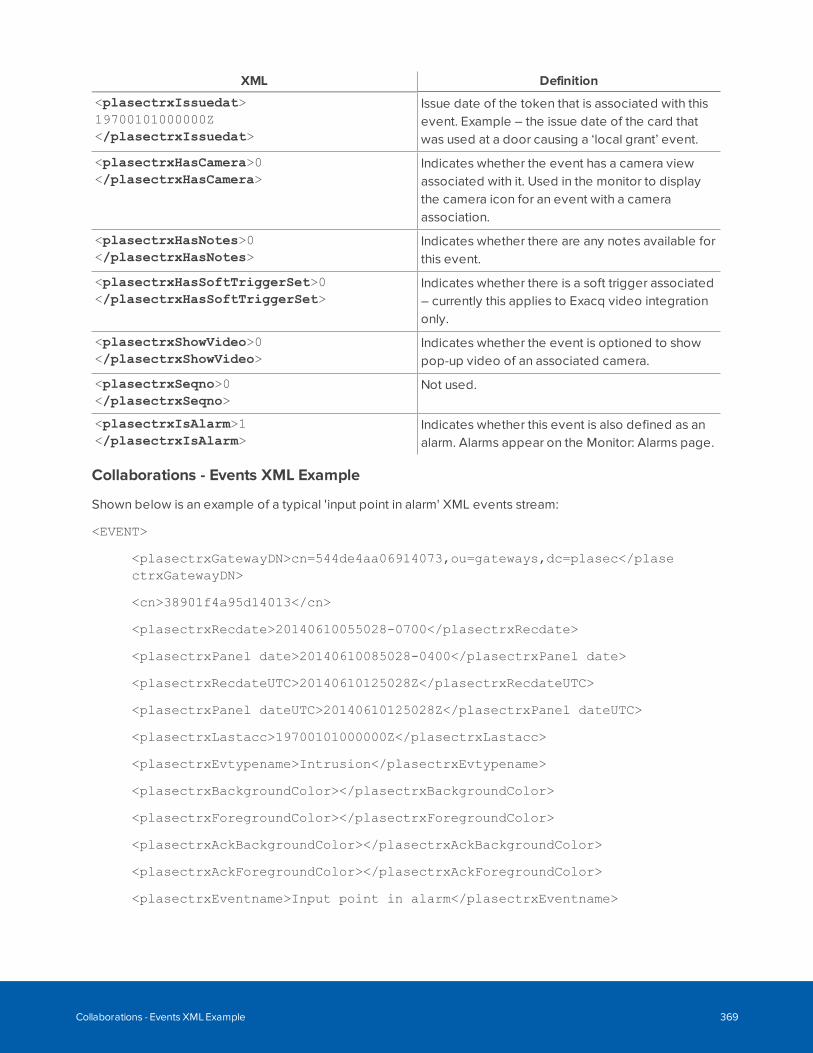
XML Definition
<plasectrxIssuedat>19700101000000Z</plasectrxIssuedat>
Issue date of the token that is associated with thisevent. Example – the issue date of the card thatwas used at a door causing a ‘local grant’ event.
<plasectrxHasCamera>0</plasectrxHasCamera>
Indicates whether the event has a camera viewassociated with it. Used in the monitor to displaythe camera icon for an event with a cameraassociation.
<plasectrxHasNotes>0</plasectrxHasNotes>
Indicates whether there are any notes available forthis event.
<plasectrxHasSoftTriggerSet>0</plasectrxHasSoftTriggerSet>
Indicates whether there is a soft trigger associated– currently this applies to Exacq video integrationonly.
<plasectrxShowVideo>0</plasectrxShowVideo>
Indicates whether the event is optioned to showpop-up video of an associated camera.
<plasectrxSeqno>0</plasectrxSeqno>
Not used.
<plasectrxIsAlarm>1</plasectrxIsAlarm>
Indicates whether this event is also defined as analarm. Alarms appear on the Monitor: Alarms page.
Collaborations - Events XML Example
Shown below is an example of a typical 'input point in alarm' XML events stream:
<EVENT>
<plasectrxGatewayDN>cn=544de4aa06914073,ou=gateways,dc=plasec</plasectrxGatewayDN>
<cn>38901f4a95d14013</cn>
<plasectrxRecdate>20140610055028-0700</plasectrxRecdate>
<plasectrxPanel date>20140610085028-0400</plasectrxPanel date>
<plasectrxRecdateUTC>20140610125028Z</plasectrxRecdateUTC>
<plasectrxPanel dateUTC>20140610125028Z</plasectrxPanel dateUTC>
<plasectrxLastacc>19700101000000Z</plasectrxLastacc>
<plasectrxEvtypename>Intrusion</plasectrxEvtypename>
<plasectrxBackgroundColor></plasectrxBackgroundColor>
<plasectrxForegroundColor></plasectrxForegroundColor>
<plasectrxAckBackgroundColor></plasectrxAckBackgroundColor>
<plasectrxAckForegroundColor></plasectrxAckForegroundColor>
<plasectrxEventname>Input point in alarm</plasectrxEventname>
Collaborations - Events XML Example 369
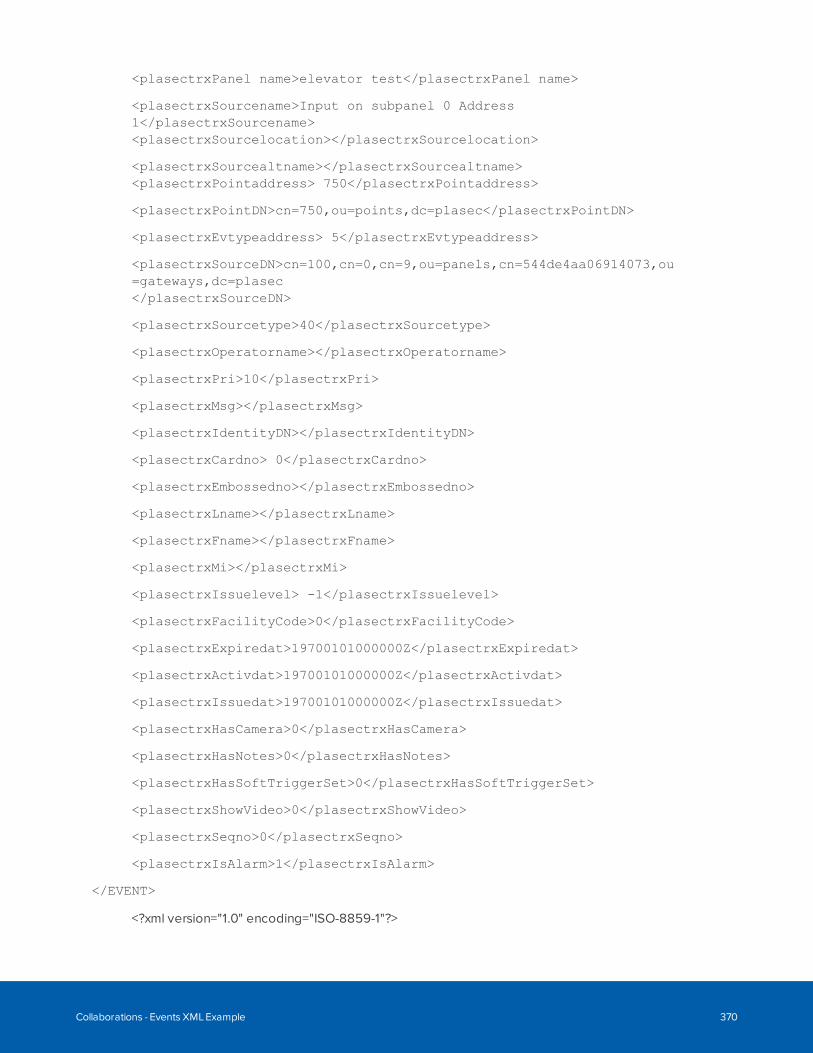
<plasectrxPanel name>elevator test</plasectrxPanel name>
<plasectrxSourcename>Input on subpanel 0 Address1</plasectrxSourcename><plasectrxSourcelocation></plasectrxSourcelocation>
<plasectrxSourcealtname></plasectrxSourcealtname><plasectrxPointaddress> 750</plasectrxPointaddress>
<plasectrxPointDN>cn=750,ou=points,dc=plasec</plasectrxPointDN>
<plasectrxEvtypeaddress> 5</plasectrxEvtypeaddress>
<plasectrxSourceDN>cn=100,cn=0,cn=9,ou=panels,cn=544de4aa06914073,ou=gateways,dc=plasec</plasectrxSourceDN>
<plasectrxSourcetype>40</plasectrxSourcetype>
<plasectrxOperatorname></plasectrxOperatorname>
<plasectrxPri>10</plasectrxPri>
<plasectrxMsg></plasectrxMsg>
<plasectrxIdentityDN></plasectrxIdentityDN>
<plasectrxCardno> 0</plasectrxCardno>
<plasectrxEmbossedno></plasectrxEmbossedno>
<plasectrxLname></plasectrxLname>
<plasectrxFname></plasectrxFname>
<plasectrxMi></plasectrxMi>
<plasectrxIssuelevel> -1</plasectrxIssuelevel>
<plasectrxFacilityCode>0</plasectrxFacilityCode>
<plasectrxExpiredat>19700101000000Z</plasectrxExpiredat>
<plasectrxActivdat>19700101000000Z</plasectrxActivdat>
<plasectrxIssuedat>19700101000000Z</plasectrxIssuedat>
<plasectrxHasCamera>0</plasectrxHasCamera>
<plasectrxHasNotes>0</plasectrxHasNotes>
<plasectrxHasSoftTriggerSet>0</plasectrxHasSoftTriggerSet>
<plasectrxShowVideo>0</plasectrxShowVideo>
<plasectrxSeqno>0</plasectrxSeqno>
<plasectrxIsAlarm>1</plasectrxIsAlarm>
</EVENT>
<?xml version="1.0" encoding="ISO-8859-1"?>
Collaborations - Events XML Example 370
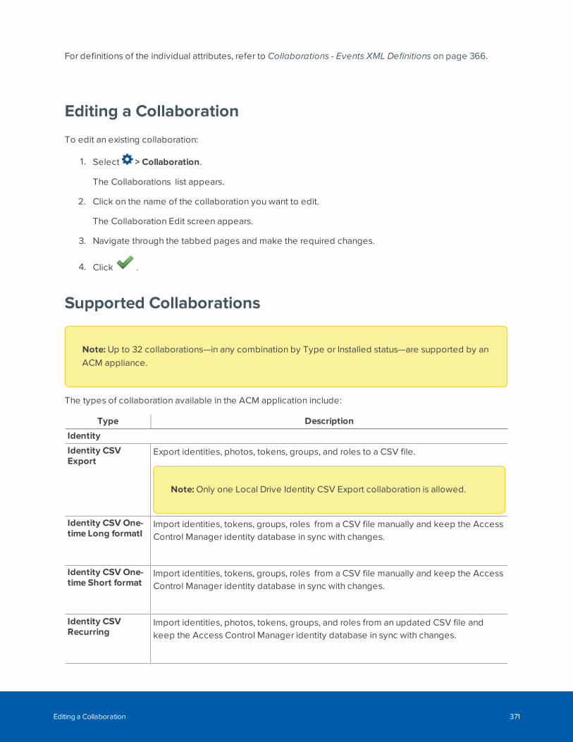
For definitions of the individual attributes, refer to Collaborations - Events XML Definitions on page 366.
Editing a Collaboration
To edit an existing collaboration:
1. Select > Collaboration.
The Collaborations list appears.
2. Click on the name of the collaboration you want to edit.
The Collaboration Edit screen appears.
3. Navigate through the tabbed pages and make the required changes.
4. Click .
Supported Collaborations
Note: Up to 32 collaborations—in any combination by Type or Installed status—are supported by anACM appliance.
The types of collaboration available in the ACM application include:
Type Description
Identity
Identity CSVExport
Export identities, photos, tokens, groups, and roles to a CSV file.
Note: Only one Local Drive Identity CSV Export collaboration is allowed.
Identity CSV One-time Long formatI
Import identities, tokens, groups, roles from a CSV file manually and keep the AccessControl Manager identity database in sync with changes.
Identity CSV One-time Short format
Import identities, tokens, groups, roles from a CSV file manually and keep the AccessControl Manager identity database in sync with changes.
Identity CSVRecurring
Import identities, photos, tokens, groups, and roles from an updated CSV file andkeep the Access Control Manager identity database in sync with changes.
Editing a Collaboration 371
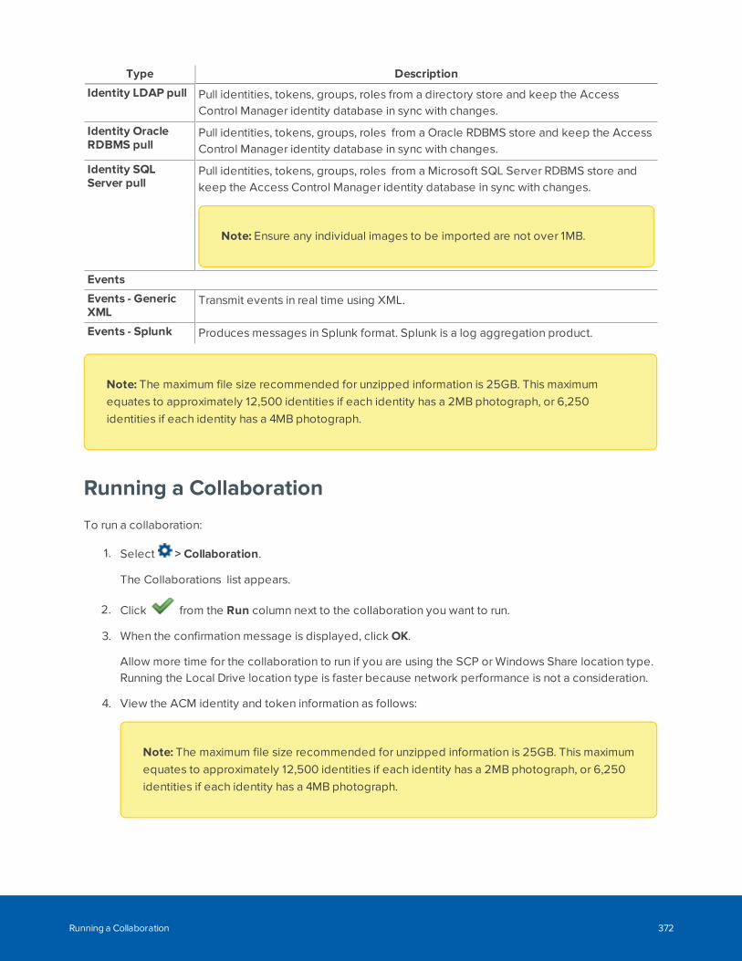
Type Description
Identity LDAP pull Pull identities, tokens, groups, roles from a directory store and keep the AccessControl Manager identity database in sync with changes.
Identity OracleRDBMS pull
Pull identities, tokens, groups, roles from a Oracle RDBMS store and keep the AccessControl Manager identity database in sync with changes.
Identity SQLServer pull
Pull identities, tokens, groups, roles from a Microsoft SQL Server RDBMS store andkeep the Access Control Manager identity database in sync with changes.
Note: Ensure any individual images to be imported are not over 1MB.
Events
Events - GenericXML
Transmit events in real time using XML.
Events - Splunk Produces messages in Splunk format. Splunk is a log aggregation product.
Note: The maximum file size recommended for unzipped information is 25GB. This maximumequates to approximately 12,500 identities if each identity has a 2MB photograph, or 6,250identities if each identity has a 4MB photograph.
Running a Collaboration
To run a collaboration:
1. Select > Collaboration.
The Collaborations list appears.
2. Click from the Run column next to the collaboration you want to run.
3. When the confirmation message is displayed, click OK.
Allow more time for the collaboration to run if you are using the SCP or Windows Share location type.Running the Local Drive location type is faster because network performance is not a consideration.
4. View the ACM identity and token information as follows:
Note: The maximum file size recommended for unzipped information is 25GB. This maximumequates to approximately 12,500 identities if each identity has a 2MB photograph, or 6,250identities if each identity has a 4MB photograph.
Running a Collaboration 372
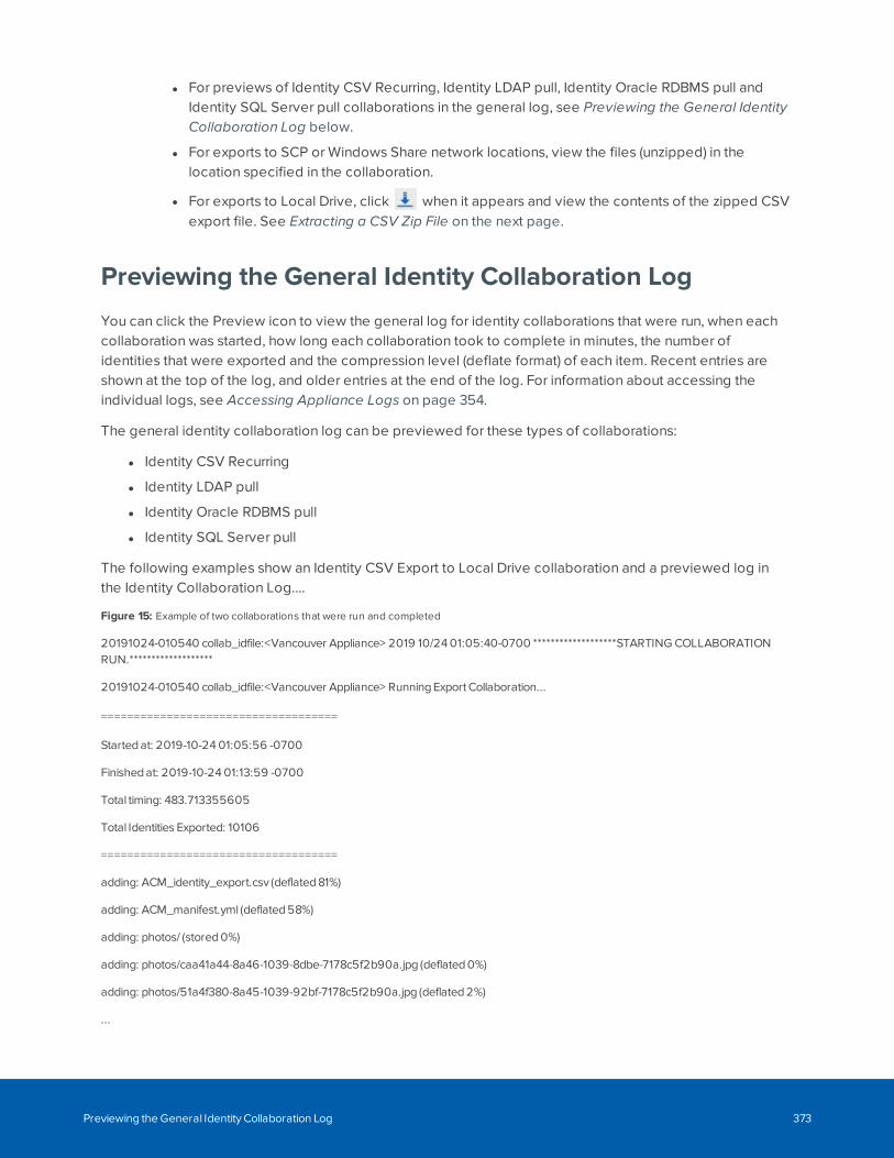
l For previews of Identity CSV Recurring, Identity LDAP pull, Identity Oracle RDBMS pull andIdentity SQL Server pull collaborations in the general log, see Previewing the General IdentityCollaboration Log below.
l For exports to SCP or Windows Share network locations, view the files (unzipped) in thelocation specified in the collaboration.
l For exports to Local Drive, click when it appears and view the contents of the zipped CSVexport file. See Extracting a CSV Zip File on the next page.
Previewing the General Identity Collaboration Log
You can click the Preview icon to view the general log for identity collaborations that were run, when eachcollaboration was started, how long each collaboration took to complete in minutes, the number ofidentities that were exported and the compression level (deflate format) of each item. Recent entries areshown at the top of the log, and older entries at the end of the log. For information about accessing theindividual logs, see Accessing Appliance Logs on page 354.
The general identity collaboration log can be previewed for these types of collaborations:
l Identity CSV Recurring
l Identity LDAP pull
l Identity Oracle RDBMS pull
l Identity SQL Server pull
The following examples show an Identity CSV Export to Local Drive collaboration and a previewed log inthe Identity Collaboration Log....
Figure 15: Example of two collaborations that were run and completed
20191024-010540 collab_idfile:<Vancouver Appliance> 2019 10/24 01:05:40-0700 *******************STARTING COLLABORATIONRUN.*******************
20191024-010540 collab_idfile:<Vancouver Appliance> Running Export Collaboration...
====================================
Started at: 2019-10-24 01:05:56 -0700
Finished at: 2019-10-24 01:13:59 -0700
Total timing: 483.713355605
Total Identities Exported: 10106
====================================
adding: ACM_identity_export.csv (deflated 81%)
adding: ACM_manifest.yml (deflated 58%)
adding: photos/ (stored 0%)
adding: photos/caa41a44-8a46-1039-8dbe-7178c5f2b90a.jpg (deflated 0%)
adding: photos/51a4f380-8a45-1039-92bf-7178c5f2b90a.jpg (deflated 2%)
...
Previewing the General Identity Collaboration Log 373
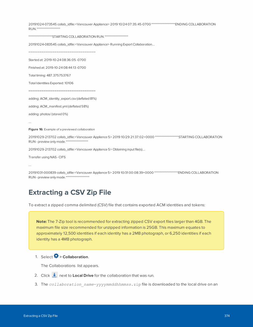
20191024-073545 collab_idfile:<Vancouver Appliance> 2019 10/24 07:35:45-0700 *******************ENDING COLLABORATIONRUN.*******************
*******************STARTING COLLABORATION RUN.*******************
20191024-083545 collab_idfile:<Vancouver Appliance> Running Export Collaboration...
====================================
Started at: 2019-10-24 08:36:05 -0700
Finished at: 2019-10-24 08:44:13 -0700
Total timing: 487.375753767
Total Identities Exported: 10106
====================================
adding: ACM_identity_export.csv (deflated 81%)
adding: ACM_manifest.yml (deflated 58%)
adding: photos/ (stored 0%)
...
Figure 16: Example of a previewed collaboration
20191029-213702 collab_idfile:<Vancouver Appliance 5> 2019 10/29 21:37:02+0000 *******************STARTING COLLABORATIONRUN - preview only mode.******************
20191029-213702 collab_idfile:<Vancouver Appliance 5> Obtaining input file(s)...
Transfer using NAS - CIFS
...
20191031-000839 collab_idfile:<Vancouver Appliance 5> 2019 10/31 00:08:39+0000 *******************ENDING COLLABORATIONRUN - preview only mode.*******************
Extracting a CSV Zip File
To extract a zipped comma delimited (CSV) file that contains exported ACM identities and tokens:
Note: The 7-Zip tool is recommended for extracting zipped CSV export files larger than 4GB. Themaximum file size recommended for unzipped information is 25GB. This maximum equates toapproximately 12,500 identities if each identity has a 2MB photograph, or 6,250 identities if eachidentity has a 4MB photograph.
1. Select > Collaboration.
The Collaborations list appears.
2. Click next to Local Drive for the collaboration that was run.
3. The collaboration_name-yyyymmddhhmmss.zip file is downloaded to the local drive on an
Extracting a CSV Zip File 374
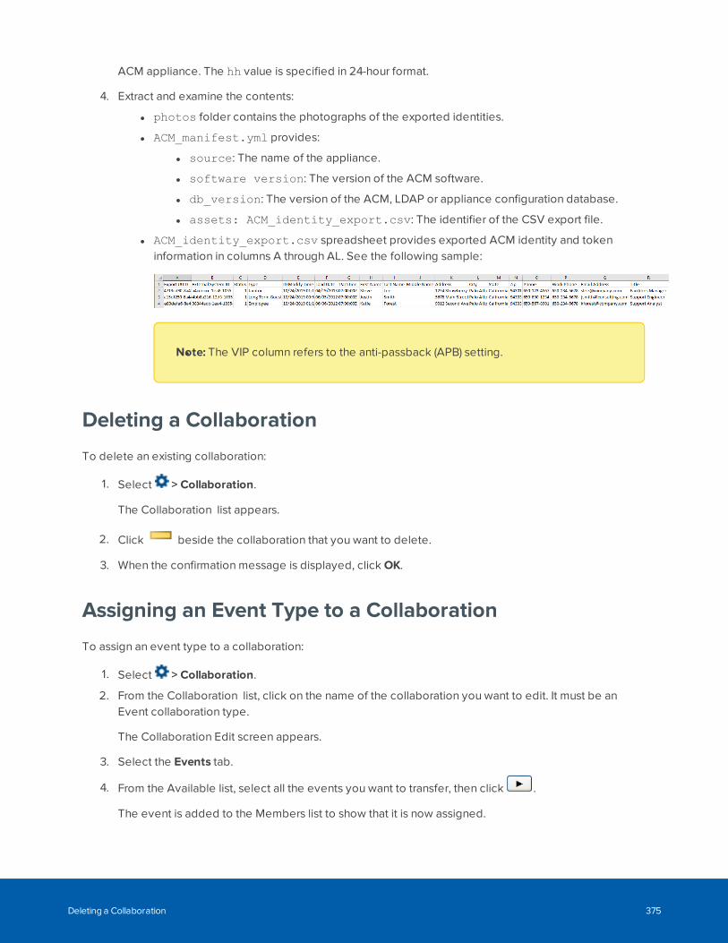
ACM appliance. The hh value is specified in 24-hour format.
4. Extract and examine the contents:
l photos folder contains the photographs of the exported identities.
l ACM_manifest.yml provides:
l source: The name of the appliance.
l software version: The version of the ACM software.
l db_version: The version of the ACM, LDAP or appliance configuration database.
l assets: ACM_identity_export.csv: The identifier of the CSV export file.
l ACM_identity_export.csv spreadsheet provides exported ACM identity and tokeninformation in columns A through AL. See the following sample:
lNote: The VIP column refers to the anti-passback (APB) setting.
Deleting a Collaboration
To delete an existing collaboration:
1. Select > Collaboration.
The Collaboration list appears.
2. Click beside the collaboration that you want to delete.
3. When the confirmation message is displayed, click OK.
Assigning an Event Type to a Collaboration
To assign an event type to a collaboration:
1. Select > Collaboration.
2. From the Collaboration list, click on the name of the collaboration you want to edit. It must be anEvent collaboration type.
The Collaboration Edit screen appears.
3. Select the Events tab.
4. From the Available list, select all the events you want to transfer, then click .
The event is added to the Members list to show that it is now assigned.
Deleting a Collaboration 375
To remove an event from the collaboration, select the event from the Members list, then click .
Note: You can select multiple events by using the Ctrl or Shift key.
5. Click .
Assigning an Event Type to a Collaboration 376
Setup & Settings
Click or hover over in the upper-right corner to:
l Appliance — Connect, customize and set up your appliance to meet your system requirements. Formore information, see Managing Appliances on page 325.
l Collaboration — Set up and manage collaborations which exchange data with third-party databasesand applications. For more information, see Managing Collaborations on page 363.
l Schedules — Configure when a door is accessible, when a card is valid, or when a device isactivated. For more information, see Schedules and Holidays Overview below.
l Holidays — Configure dates when normal rules are suspended in schedules. For more information,see Schedules and Holidays Overview below.
l Event Types — Configure event types and instructions on how to handle the event generated in theACM system. For more information, see Event Types - Introduction on page 382.
l User Forms — Customize the identity and tokens tabs or create additional ones, and then assignthem to ACM operators. For more information, see User Forms Overview on page 385.
l User Fields — Add additional fields for enrolling identities. For more information, see User DefinedFields - Introduction on page 388.
l User Lists — Add additional drop-down option lists for enrolling identities. For more information, seeUser Lists - Introduction on page 391.
l System Settings — Configure system settings such as language, token expiration time, requiredpassword strength and more. For more information, see System Settings - Introduction on page 392.
l Paired Devices — Generate a one-time key to connect a browser-enabled device, such as asmartphone, to a door configured as an ACM ACM Verify station so that it can function as a VirtualStation. For more information, see Paired Devices on page 274.
l Certificates — Mercury controllers only. Add custom certificates for panel and ACM authentication.
l Badge Designer — Customize a badge template for badge holders. For more information, see BadgeTemplates and the Badge Designer on page 403
l External Systems — Set up integration to cameras, sites and other third-party external systems. Formore information, see External Systems Overview on page 410.
l Maps — Import maps of your facility and populate them with door, panel, subpanel, input, output,camera and global action alarm points that can be monitored. For more information, see Maps -Introduction on page 424.
Schedules and Holidays Overview
SchedulesA schedule controls when a door setting is active. For example, you can apply a schedule to a group ofusers and secured doors to grant and deny access to the days and times specified in the schedule.
A door can be assigned an 'unlock schedule', which specifies a period of time when no credential is
Setup & Settings 377
required to access the door. All users have free access during the 'unlock schedule' period. Likewise, adevice may be assigned an 'active schedule', a period during which the device is in operation.
You can also create a holiday list to manage access during holidays or special days when the building isclosed. Before you can create a schedule to handle special occasions, you must set up the holiday list.
When a panel is not operating as expected, see Panel and Schedule Events on page 488 fortroubleshooting instructions.
HolidaysHolidays are special days in the year when the standard schedule does not apply or a different entry andexit pattern is observed. New Year's Day and National Day are examples of holidays. The Access ControlManager is designed to accommodate a large number of diverse holidays.
Note: Holidays are set for a specific day in the year. You will need to update the system holidayseach year.
Adding Schedules (Intervals in Schedules)
1. Select > Schedules.
The default 24 Hours Active (ON) and Never Active (OFF) default schedule modes cannot be deleted.
2. Click Add Schedule.
3. Enter a name for the schedule in Name.
4. Select the schedule mode:
l ON – The schedule is constantly on. You do not need to set specific dates or times. Clickto save the new schedule.
l OFF – The schedule is off. Click to save the new schedule.
l SCAN – The schedule follows a weekly, monthly or shift rotation and includes any holidays.One interval is represented by one row of checkboxes.
For SCAN mode:
a. Click the days of the week (Sun - Sat) and any applicable holiday ( 1 - 8).
b. Enter the start (Active is inclusive) and end (Inactive is exclusive) time in 24-hour clockformat and avoid overlapping times.
Example: A day shift from 08:00 - 19:59 and a night shift from 20:00 - 07:59.
No conflict occurs when the actual start time is 08:00:00 and the actual end time is19:59:59 for the day shift; and the actual start time is 20:00:00 and the actual end time is07:59:59 for the night shift.
Holidays 378
For more examples, see Adding Holidays on the next page and Examples on page 381.
Note: For Mercury Security doors, do not exceed 12 intervals in a schedule and255 schedules. For IP/PoE mode doors, do not exceed 16 intervals in allschedules combined. For SALTO doors, do not exceed 8 intervals in aschedule and 1024 schedules.
c. Click to save the new schedule.
5. Select Roles > Access Groups and click Add Access Group to select the schedule and the doors.
Note: SALTO doors only. If a door is linked to a zone in the SALTO system, do not assign theaccess group a schedule that is less than five minutes in duration in the Active and Inactivefields.
6. For more information, see Adding an Access Group on page 101.
7. Select Roles > Roles and select the role. Click the Access Groups tab and assign the access groupto a role.
For more information, see Assigning an Access Group to a Role on page 77.
Editing Schedules
1. Select > Schedules.
2. Click the name of the schedule you want to edit.
3. Edit the schedule as required.
4. Click to save your changes.
Deleting Schedules
Note: When you delete a schedule that is currently used (such as by a door, panel or interlock), allreferences to the deleted schedule are replaced by the Never Active schedule.
1. Select > Schedules.
2. Click beside the schedule you want to delete.
3. When the browser displays a pop-up message to ask Are you sure?, click OK.
Editing Schedules 379
Adding Holidays
1. Select > Holidays.
2. Click Add Holiday.
3. Enter a name for the holiday in Name.
4. Enter the specific date of the holiday.
Note: For a recurring holiday, create a holiday for each future year.
5. If the holiday spans more than one day, fill out the Additional Days field.
Default setting is 0 for a one-day holiday.
Example: If 01/01/2021 is the date of the holiday and 2 additional days are specified, the holidayperiod is January 1, 2 and 3.
6. Select the number corresponding to the Type of holiday. (The holiday type number allows you togroup specific types of holidays together.)
Note: SALTO doors only. Up to 3 types of holiday groups are supported.
7. Click the Preserve schedule days checkbox to specify that only the holiday schedule be activated onthe date of the holiday. Leave unchecked if all other schedules are to be activated on the same date.The holiday must be assigned to a schedule to control any door settings.
Note: Not applicable to SALTO doors.
8. Click to save the new holiday.
Editing Holidays
1. Select > Holidays.
2. Click the name of the holiday you want to edit.
3. Edit the information about the holiday as required.
4. Click to save your changes.
Adding Holidays 380
Deleting Holidays
1. Select > Holidays.
2. On the Holiday list, click for the holiday you want to delete.
3. When the browser displays a pop-up message to ask Are you sure?, click OK.
ExamplesNoted below are two examples of setting up holidays and schedules.
Example 1: Part-Day Holiday
All staff are attending an afternoon team function on 18 December, with work finishing at noon. On the 18thwe want the doors to unlock from 8 am to PM, with access by card only mode after PM. The normalschedule for Monday to Friday is for the doors to open from 8 am to 5 pm. Steps to take are:
1. Select > Holidays.
2. On the Holiday list, click to add a new holiday.
3. On the Holiday: Add New screen, enter the following then click to save:
l Name (e.g. Company Half Day).
l Date (e.g. 12/18/2016).
l Type (e.g. 8).
4. Select > Schedules.
5. Select the normal schedule on the Schedules list.
6. On the first available free line:
l Click in the checkbox for the Type selected in step 3 above (e.g. 8), so that a checkmarkdisplays.
l On the same line enter 08:00 as the Active time, and 11:59 as the Inactive time.
7. Click to save.
Example 2: Additional Access Time
A special delivery in scheduled for December 20, requiring additional access time from 8 pm to Amen. Inorder to create the additional access time without impacting the normal daily schedule, the Preserveschedule days option can be used. This option allows you to set separate access schedules for the sameday. Steps to take are:
Deleting Holidays 381
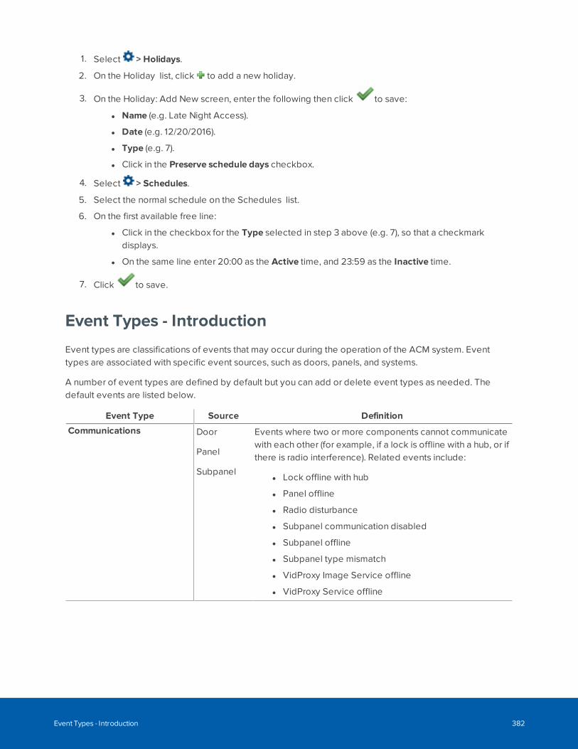
1. Select > Holidays.
2. On the Holiday list, click to add a new holiday.
3. On the Holiday: Add New screen, enter the following then click to save:
l Name (e.g. Late Night Access).
l Date (e.g. 12/20/2016).
l Type (e.g. 7).
l Click in the Preserve schedule days checkbox.
4. Select > Schedules.
5. Select the normal schedule on the Schedules list.
6. On the first available free line:
l Click in the checkbox for the Type selected in step 3 above (e.g. 7), so that a checkmarkdisplays.
l On the same line enter 20:00 as the Active time, and 23:59 as the Inactive time.
7. Click to save.
Event Types - Introduction
Event types are classifications of events that may occur during the operation of the ACM system. Eventtypes are associated with specific event sources, such as doors, panels, and systems.
A number of event types are defined by default but you can add or delete event types as needed. Thedefault events are listed below.
Event Type Source Definition
Communications Door
Panel
Subpanel
Events where two or more components cannot communicatewith each other (for example, if a lock is offline with a hub, or ifthere is radio interference). Related events include:
l Lock offline with hub
l Panel offline
l Radio disturbance
l Subpanel communication disabled
l Subpanel offline
l Subpanel type mismatch
l VidProxy Image Service offline
l VidProxy Service offline
Event Types - Introduction 382
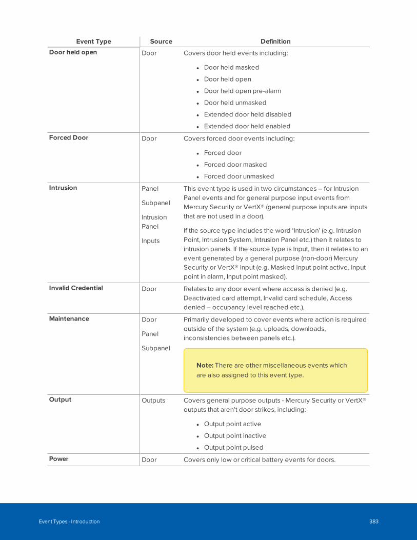
Event Type Source Definition
Door held open Door Covers door held events including:
l Door held masked
l Door held open
l Door held open pre-alarm
l Door held unmasked
l Extended door held disabled
l Extended door held enabled
Forced Door Door Covers forced door events including:
l Forced door
l Forced door masked
l Forced door unmasked
Intrusion Panel
Subpanel
IntrusionPanel
Inputs
This event type is used in two circumstances – for IntrusionPanel events and for general purpose input events fromMercury Security or VertX® (general purpose inputs are inputsthat are not used in a door).
If the source type includes the word ‘Intrusion’ (e.g. IntrusionPoint, Intrusion System, Intrusion Panel etc.) then it relates tointrusion panels. If the source type is Input, then it relates to anevent generated by a general purpose (non-door) MercurySecurity or VertX® input (e.g. Masked input point active, Inputpoint in alarm, Input point masked).
Invalid Credential Door Relates to any door event where access is denied (e.g.Deactivated card attempt, Invalid card schedule, Accessdenied – occupancy level reached etc.).
Maintenance Door
Panel
Subpanel
Primarily developed to cover events where action is requiredoutside of the system (e.g. uploads, downloads,inconsistencies between panels etc.).
Note: There are other miscellaneous events whichare also assigned to this event type.
Output Outputs Covers general purpose outputs - Mercury Security or VertX®outputs that aren't door strikes, including:
l Output point active
l Output point inactive
l Output point pulsed
Power Door Covers only low or critical battery events for doors.
Event Types - Introduction 383
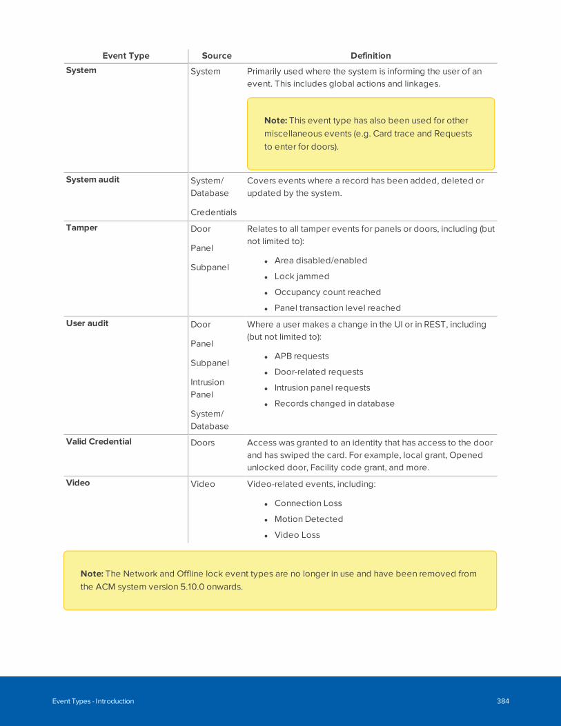
Event Type Source Definition
System System Primarily used where the system is informing the user of anevent. This includes global actions and linkages.
Note: This event type has also been used for othermiscellaneous events (e.g. Card trace and Requeststo enter for doors).
System audit System/Database
Credentials
Covers events where a record has been added, deleted orupdated by the system.
Tamper Door
Panel
Subpanel
Relates to all tamper events for panels or doors, including (butnot limited to):
l Area disabled/enabled
l Lock jammed
l Occupancy count reached
l Panel transaction level reached
User audit Door
Panel
Subpanel
IntrusionPanel
System/Database
Where a user makes a change in the UI or in REST, including(but not limited to):
l APB requests
l Door-related requests
l Intrusion panel requests
l Records changed in database
Valid Credential Doors Access was granted to an identity that has access to the doorand has swiped the card. For example, local grant, Openedunlocked door, Facility code grant, and more.
Video Video Video-related events, including:
l Connection Loss
l Motion Detected
l Video Loss
Note: The Network and Offline lock event types are no longer in use and have been removed fromthe ACM system version 5.10.0 onwards.
Event Types - Introduction 384
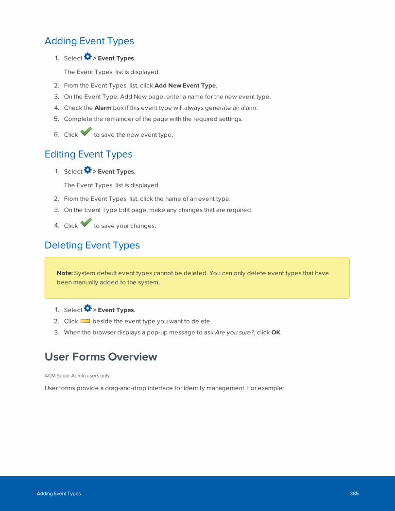
Adding Event Types
1. Select > Event Types.
The Event Types list is displayed.
2. From the Event Types list, click Add New Event Type.
3. On the Event Type: Add New page, enter a name for the new event type.
4. Check the Alarm box if this event type will always generate an alarm.
5. Complete the remainder of the page with the required settings.
6. Click to save the new event type.
Editing Event Types
1. Select > Event Types.
The Event Types list is displayed.
2. From the Event Types list, click the name of an event type.
3. On the Event Type Edit page, make any changes that are required.
4. Click to save your changes.
Deleting Event Types
Note: System default event types cannot be deleted. You can only delete event types that havebeen manually added to the system.
1. Select > Event Types.
2. Click beside the event type you want to delete.
3. When the browser displays a pop-up message to ask Are you sure?, click OK.
User Forms OverviewACM Super Admin users only
User forms provide a drag-and-drop interface for identity management. For example:
Adding Event Types 385
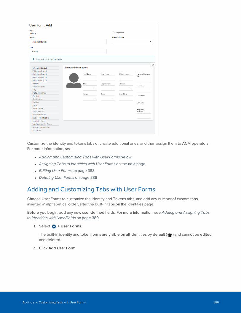
Customize the identity and tokens tabs or create additional ones, and then assign them to ACM operators.For more information, see:
l Adding and Customizing Tabs with User Forms below
l Assigning Tabs to Identities with User Forms on the next page
l Editing User Forms on page 388
l Deleting User Forms on page 388
Adding and Customizing Tabs with User FormsChoose User Forms to customize the Identity and Tokens tabs, and add any number of custom tabs,inserted in alphabetical order, after the built-in tabs on the Identities page.
Before you begin, add any new user-defined fields. For more information, see Adding and Assigning Tabsto Identities with User Fields on page 389.
1. Select > User Forms.
The built-in identity and token forms are visible on all identities by default ( ) and cannot be editedand deleted.
2. Click Add User Form.
Adding and Customizing Tabs with User Forms 386
3. Select a form type for customization:
l Identity — A form with pre-populated fields, which can be displayed instead of the defaultIdentity tab.
l Token — A form with pre-populated fields, which can be displayed instead of the defaultTokens tab.
l Custom — A blank form, which can be displayed as an additional tab that is customized tomeet your requirements.
4. Click Next and optionally assign the form to one or more identity profiles. Enter:
l Name — A name for the form.
l Title — A label for the tab on the identity page.
l All Profiles checkbox — All identity profiles, current and future, to be assigned to the form.
l Identity Profile — If All Profiles is not selected, select one or more identity profiles.
5. To customize the form, do any of the following:
l Drag and drop a layout from the list of layouts. This is required for a blank custom form andoptional for a pre-populated form.
l Drag and drop Header to enter a label for the items.
l Drag and drop a field from the list of built-in and user-defined fields.
l Last Name and Status are required for an identity record.
l Click the Advanced Edit icon in the upper-right corner.
l To make a field read-only which means it is grayed out and not editable by theoperator, click it and select Properties. Click the Read-only checkbox and click Save.
l To delete a field, hover your mouse over it and select Remove.
l To delete a layout and its items, hover your mouse over it and click on the bottomedge.
6. Click Save to save the new form.
After you add a new form, see Assigning Tabs to Identities with User Forms below.
Assigning Tabs to Identities with User FormsAfter one or more identity or token forms are created, display them to all ACM operator identities or onlyspecific identities.
After one or more custom forms are created, display them to all ACM operator identities or only specificidentities.
Note: Delegations can restrict operators from editing and viewing the list of assignments.
On the User Forms list, do any of the following:
Assigning Tabs to Identities with User Forms 387
l For an identity or token form:
l To display an identity or token form, click the default icon next to the form to make it the
default. The default icon changes to .
The identity or token tab will be displayed to all operator identities. To reverse this change,
click .
l For a custom form:
l To display one or more custom forms to all identities, click the public icon next to each
custom form. The public icon changes to .
The custom tab will be displayed to all operator identities. To reverse this change, click .
l For any form type:
l To define the operator identities who can view the form, click Assign and select the identities.
Click to move them from the Available list to the Members list. To reverse these changes,
click to move them back to the Available list. Click Save.
The identity, token or custom tab will not be displayed to all operator identities. Only theselected operator identities can view it.
Editing User FormsTo edit an identity, token or custom form:
1. On the User Forms list, click the name of the form.
2. Do any of the following:
l Add, edit or delete fields.
l Add, edit or delete a layout.
3. Click Save.
Deleting User FormsYou can delete an identity, token or custom form that is not set to default or not assigned to any identities. Inaddition, the built-in forms cannot be deleted.
1. Select >User Forms.
2. Click next to the name of the form. The button is not displayed if any identities are assigned tothe form.
3. When the confirmation message is displayed, click OK.
User Defined Fields - Introduction
User defined fields are custom fields that you can add to the Identities page to capture organization specificinformation for each identity.
Editing User Forms 388

To add user defined fields to the Identities page, you must also add a user defined tab to host the fields.
Information captured by user defined fields can be used on badges to display important details about eachidentity.
User defined fields can also be used for advanced searching for identities. For more information, seeSearching for an Identity on page 59.
Adding a Field for User Forms, Tabs and ListsUser-defined fields are used to collect additional details about users on the Identities screen. After you addall the fields, add at least one tab to display the new fields. For more information, see Adding andCustomizing Tabs with User Forms on page 386 and Adding and Assigning Tabs to Identities with UserFields below.
1. Select >User Fields.
2. Click Add User Defined Field.
3. Enter a name for the new field in the Name field.
4. Select the field Type:
l String — The field supports words and numbers.
l Integer — The field supports numbers only.
l Boolean — The field is a checkbox that works like a Yes or No question. Check the box toindicate 'yes' and clear the box to indicate 'no.
l Date — The field supports a date only. Click the field to display a calendar and select a date.
5. Click to save the new field.
Note: User-defined fields cannot be edited, only deleted.
Adding and Assigning Tabs to Identities with User FieldsYou must add a new tab to host user-defined fields before using them on the Identities page. Add tabs afteryou've added all the fields that you need.
Tip: It is recommended to add a tab and user-defined fields on the Identities page using identity,tokens and custom forms in a drag-and-drop interface. For more information, see Adding andCustomizing Tabs with User Forms on page 386.
Adding a Field for User Forms, Tabs and Lists 389
1. Select > User Fields.
2. Click the Tabs tab.
3. Click Add User Defined Tab.
4. Enter a name for the new tab in Name and click .
5. From the Available list, select all the user-defined fields that should be displayed on the tab and click
to add them to the Members list.
To remove a field from the tab, select the field from the Members list and click .
6. Click to save your changes.
Adding User Defined Fields to Tabs
1. Select > User Fields.
The User Fields list is displayed.
2. From the User Fields list, click the Tabs tab.
3. Click the name of the tab that you want to edit.
4. Edit the tab details as required.
5. Click to save your changes.
User Defined Fields - Deleting FieldsNOTE: You cannot delete user defined fields if they are used in a tab. To delete a field, you must remove itfrom all tabs first.
1. Select > User Fields.
2. If the symbol displays for the field you want to delete:
a. Click to delete the field.
b. When the browser displays a pop-up message to ask Are you sure?, click OK.
3. If the symbol does not display for the field you want to delete, this is because the field iscurrently used by a tab. To remove a field from a tab:
a. Select the Tabs tab then click the name of the tab that the field appears in.
b. On the following page, select the field from the Members list then click .
The field is removed from the tab and returned to the Members list.
c. Click .
User Defined Tabs - DeletingUser defined tabs can be deleted as required. However, you cannot delete user defined fields if they are
Adding User Defined Fields to Tabs 390
used in a tab.
1. Select > User Fields.
2. Select the Tabs tab.
3. Click for the tab you want to delete.
4. When the browser displays a pop-up message to ask Are you sure?, click OK.
User Lists - Introduction
Many fields on the Identity page involve selecting a value from a drop down list. While there are severaldefault values for these fields, you can add more options using the User Lists feature.
For example, if you want to add departments that are specific to your organization, you would use thisfeature to add those options to the Departments drop down list.
Adding Items to a List
Note: Any changes you make to the lists are automatically included in identity-relatedcollaborations.
1. Select > User Lists.
2. Click the name of the list you want to add items to.
3. On the User List Edit screen, enter a new list option in the NewValue field and click .
4. Repeat the previous step until all the new values you want are listed in Current Values.
5. Click to save your changes.
User Lists - Editing ItemsAny changes you make to the lists are automatically included in identity related collaborations.
1. Select > User Lists.
The User Defined Lists list is displayed.
2. On the User Defined Lists list, click the name of the list you want to edit.
3. To add a new option, enter the new option in the NewValue field then click .
The new value is added to the Current Values list.
4. To delete a value, select the option from the Current Values list and click .
5. Click to save your changes.
User Lists - Introduction 391
User Lists - Deleting Items
1. Select > User Lists.
The User Defined Lists list is displayed.
2. On the User Defined Lists list, click the name of the list you want to edit.
3. Select the option you want to delete from the Current Values list then click .
4. Click to save your changes.
The option you deleted is no longer listed on the Identities page.
System Settings - Introduction
Use > System Settings to:
l Customize default values for system-wide settings in the ACM system configure. For moreinformation, see System Settings - General page on page 396.
l Configure remote authentication of ACM users with an external domain server. For more information,see Remote Authentication - Introduction below.
l Identify the external domain servers used for remote authentication. For more information seeSystem Settings - External Domains list on page 400.
Remote Authentication - IntroductionWith remote authentication, ACM Client users can use their local domain username and passwords to accessthe ACM system. Remote authentication uses an external domain server to authenticate users that needaccess to the system, or to secure an LDAP Identity pull collaboration type. A separate password configuredin the ACM appliance is not needed. However, user access permissions are still based on the roles they areassigned within the ACM appliance.
Before remote authentication can be configured on the ACM appliance, a system administrator withprivileges on all the servers required to support remote authentication needs to:
l Add one or more external domains
l Add one or more AD or LDAP servers to each domain to the system
l Issue root certificates for each domain
l Enable each remote host to present its SSL certificate on connection to the ACM server software
Configuration of the external domain servers and the creation of their root certificates is outside the scopeof this document.
To allow remote authentication, you must:
User Lists - Deleting Items 392
1. Connect to the external domain servers hosting the AD or LDAP servers you want used forauthentication and validate the SSL certificates they present. System Settings - External Domains liston page 400.
2. Specify the default domain and server that hosts the AD database to use for authenticating ACMsoftware users, and enforce certificate authentication. For more information see System Settings -Remote Authentication page on page 399.
Secure Socket Layer (SSL) certificates are used to verify the remote hosts and to encrypt all the log in trafficbetween connected hosts. Only ACM system operators with administrative privilege and the followingdelegations assigned to their role can validate SSL certificates:
l External Domains Validate Certificates—delegation required to validate an SSL certificate from aWindows AD host
l Collaboration Validate Certificates—delegation required to validate an SSL certificate from an LDAPdatabase host in a Collaboration using the Identity Pull LDAP server collaboration type
You can set up different identities to be authenticated by different domains. Each identity must beconfigured to use one of these domains for authentication. This is done in the Account Information: sectionon either the Identity: Add or Identity: Edit panel of the given Identity. For more information, see
Configuring Remote Authentication Using SSL CertificatesRemote or external domains only. For Super Admin users with the External Domains Create Certificate, External Domains DestroyCertificate, External Domains List Certificates, External Domains Load Certificate and External Domains Validate Certificates delegationsassigned to their role.
Certificates can be recognized by the ACM appliance in two ways:
l Pinned SSL certificates—Certificates from remote hosts in external domains that are acceptedmanually by an ACM system administrator so that the remote host can connect automatically. Thesecertificates are trusted as long as they are not revoked manually by an ACM system administrator.
l Trusted SSL certificates—Certificates from remote hosts in external domains that are imported intothe ACM server software so that the remote host can connect automatically. They are valid until thecertificate expires.
Note: To provide maximum security strength for your ACM system, ensure the certificate meets theU.S. government's National Institute of Standards and Technology (NIST) Special Publication800-131A (SP 800-131A) standard.
If your ACM appliance to ACC integration deployment is having trouble connecting, review thecertificate requirements for the two systems. You may need to update the certificate on the ACMappliance to resolve the connection issues between the two systems.
About Certificate Pinning
When SSL certificates from a server in an external domain have not been exported from that server anduploaded to the ACM server they cannot be automatically trusted.
However, a remote server can present its SSL certificate to the ACM server so that an administrator can
Configuring Remote Authentication Using SSL Certificates 393
choose to trust it based on the administrator's certainty that the certificate is valid. In the ACM server, afteran SSL certificate is accepted manually, it will be trusted as long as the unique fingerprint embedded in thecertificate presented by the remote server each time it is connected to the ACM software is the same as thecertificate originally accepted by the ACM system administrator. A certificate that is trusted in this way isknown as a pinned certificate.
Pinning a certificate allows you to trust a certificate that has not been uploaded from a remote server,however the responsibility for ensuring that the certificate can be trusted is assumed by the ACM systemadministrator who pins the certificate. To ensure that an SSL certificate is valid before it is pinned, the ACMsystem administrator should compare the SSL certificate at the remote host to the certificate received fromthe remote host to confirm the SHA-256 fingerprints are identical.
Requirements for Using Pinned Certificates
On the remote Windows server (for example, an Active Directory (AD) server, if you are enabling remoteauthentication using the AD of your company), the following tasks must be completed :
1. Configure a Windows domain controller. For an LDAP collaboration, TLS encryption must beactivated.
2. Obtain the fully-qualified domain name of the DNS server for remote server's domain.
3. Enable AD Certificate Services.
4. Create a root certificate and a Domain Controller Authentication certificate.
These tasks are outside the scope of this document.
Requirements for Using Trusted Certificates
On the remote Windows server (for example, an Active Directory (AD) server, if you are enabling remoteauthentication using the AD of your company), the following tasks must be completed:
1. Configure a Windows domain controller. For an LDAP collaboration, TLS encryption must beactivated.
2. Obtain the fully-qualified domain name of the DNS server for remote server's domain.
3. Enable AD Certificate Services.
4. Create a root certificate and a Domain Controller Authentication certificate.
5. Export the Domain Controller's root CA certificate in Base-64 encoded X.509 (.CER) format. (Do notexport the private key.)
6.
Important: Use OpenSSL to convert the file from .cer format to .pem format before youupload the file to the appliance.
7. Upload the certificate to the ACM appliance. For more information, see Certificate Upload page onpage 403.
These tasks are outside the scope of this document.
Requirements for Using Pinned Certificates 394
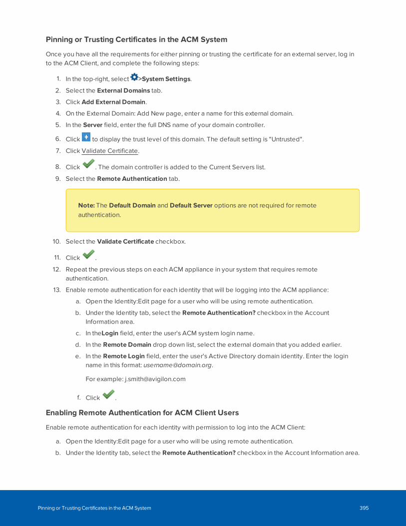
Pinning or Trusting Certificates in the ACM System
Once you have all the requirements for either pinning or trusting the certificate for an external server, log into the ACM Client, and complete the following steps:
1. In the top-right, select >System Settings.
2. Select the External Domains tab.
3. Click Add External Domain.
4. On the External Domain: Add New page, enter a name for this external domain.
5. In the Server field, enter the full DNS name of your domain controller.
6. Click to display the trust level of this domain. The default setting is "Untrusted".
7. Click Validate Certificate.
8. Click . The domain controller is added to the Current Servers list.
9. Select the Remote Authentication tab.
Note: The Default Domain and Default Server options are not required for remoteauthentication.
10. Select the Validate Certificate checkbox.
11. Click .
12. Repeat the previous steps on each ACM appliance in your system that requires remoteauthentication.
13. Enable remote authentication for each identity that will be logging into the ACM appliance:
a. Open the Identity:Edit page for a user who will be using remote authentication.
b. Under the Identity tab, select the Remote Authentication? checkbox in the AccountInformation area.
c. In theLogin field, enter the user's ACM system login name.
d. In the Remote Domain drop down list, select the external domain that you added earlier.
e. In the Remote Login field, enter the user's Active Directory domain identity. Enter the loginname in this format: [email protected].
For example: [email protected]
f. Click .
Enabling Remote Authentication for ACM Client Users
Enable remote authentication for each identity with permission to log into the ACM Client:
a. Open the Identity:Edit page for a user who will be using remote authentication.
b. Under the Identity tab, select the Remote Authentication? checkbox in the Account Information area.
Pinning or Trusting Certificates in the ACM System 395
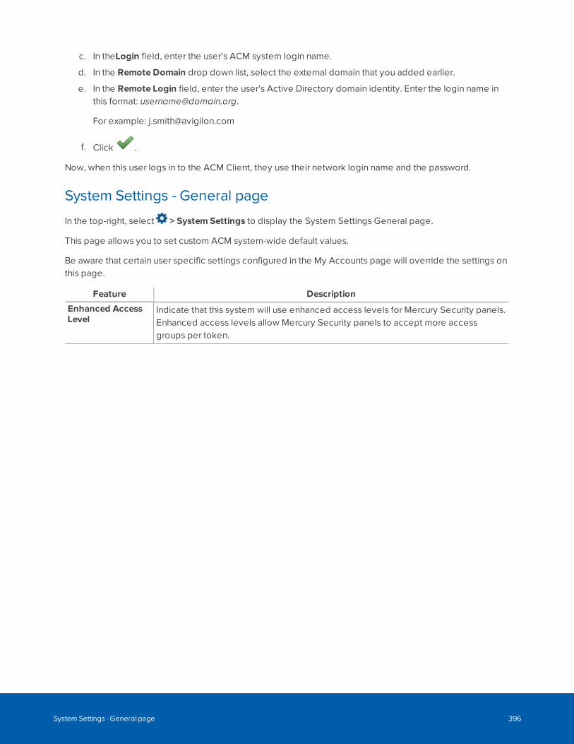
c. In theLogin field, enter the user's ACM system login name.
d. In the Remote Domain drop down list, select the external domain that you added earlier.
e. In the Remote Login field, enter the user's Active Directory domain identity. Enter the login name inthis format: [email protected].
For example: [email protected]
f. Click .
Now, when this user logs in to the ACM Client, they use their network login name and the password.
System Settings - General page
In the top-right, select > System Settings to display the System Settings General page.
This page allows you to set custom ACM system-wide default values.
Be aware that certain user specific settings configured in the My Accounts page will override the settings onthis page.
Feature Description
Enhanced AccessLevel
Indicate that this system will use enhanced access levels for Mercury Security panels.Enhanced access levels allow Mercury Security panels to accept more accessgroups per token.
System Settings - General page 396
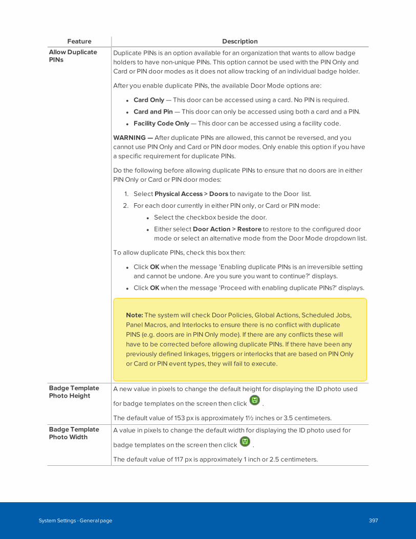
Feature Description
Allow DuplicatePINs
Duplicate PINs is an option available for an organization that wants to allow badgeholders to have non-unique PINs. This option cannot be used with the PIN Only andCard or PIN door modes as it does not allow tracking of an individual badge holder.
After you enable duplicate PINs, the available Door Mode options are:
l Card Only — This door can be accessed using a card. No PIN is required.
l Card and Pin — This door can only be accessed using both a card and a PIN.
l Facility CodeOnly — This door can be accessed using a facility code.
WARNING — After duplicate PINs are allowed, this cannot be reversed, and youcannot use PIN Only and Card or PIN door modes. Only enable this option if you havea specific requirement for duplicate PINs.
Do the following before allowing duplicate PINs to ensure that no doors are in eitherPIN Only or Card or PIN door modes:
1. Select Physical Access > Doors to navigate to the Door list.
2. For each door currently in either PIN only, or Card or PIN mode:
l Select the checkbox beside the door.
l Either select Door Action > Restore to restore to the configured doormode or select an alternative mode from the Door Mode dropdown list.
To allow duplicate PINs, check this box then:
l Click OK when the message 'Enabling duplicate PINs is an irreversible settingand cannot be undone. Are you sure you want to continue?' displays.
l Click OK when the message 'Proceed with enabling duplicate PINs?' displays.
Note: The system will check Door Policies, Global Actions, Scheduled Jobs,Panel Macros, and Interlocks to ensure there is no conflict with duplicatePINS (e.g. doors are in PIN Only mode). If there are any conflicts these willhave to be corrected before allowing duplicate PINs. If there have been anypreviously defined linkages, triggers or interlocks that are based on PIN Onlyor Card or PIN event types, they will fail to execute.
Badge TemplatePhoto Height
A new value in pixels to change the default height for displaying the ID photo used
for badge templates on the screen then click .
The default value of 153 px is approximately 1½ inches or 3.5 centimeters.
Badge TemplatePhoto Width
A value in pixels to change the default width for displaying the ID photo used for
badge templates on the screen then click .
The default value of 117 px is approximately 1 inch or 2.5 centimeters.
System Settings - General page 397
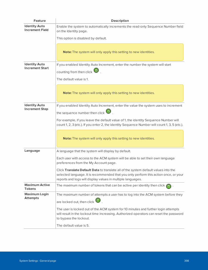
Feature Description
Identity AutoIncrement Field
Enable the system to automatically increments the read-only Sequence Number fieldon the Identity page.
This option is disabled by default.
Note: The system will only apply this setting to new identities.
Identity AutoIncrement Start
If you enabled Identity Auto Increment, enter the number the system will start
counting from then click .
The default value is 1.
Note: The system will only apply this setting to new identities.
Identity AutoIncrement Step
If you enabled Identity Auto Increment, enter the value the system uses to increment
the sequence number then click .
For example, if you leave the default value of 1, the identity Sequence Number willcount 1, 2, 3 (etc.). If you enter 2, the identity Sequence Number will count 1, 3, 5 (etc.).
Note: The system will only apply this setting to new identities.
Language A language that the system will display by default.
Each user with access to the ACM system will be able to set their own languagepreferences from the My Account page.
Click Translate Default Data to translate all of the system default values into theselected language. It is recommended that you only perform this action once, or yourreports and logs will display values in multiple languages.
MaximumActiveTokens
The maximum number of tokens that can be active per identity then click .
Maximum LoginAttempts
The maximum number of attempts a user has to log into the ACM system before they
are locked out, then click .
The user is locked out of the ACM system for 10 minutes and further login attemptswill result in the lockout time increasing. Authorized operators can reset the passwordto bypass the lockout.
The default value is 5.
System Settings - General page 398
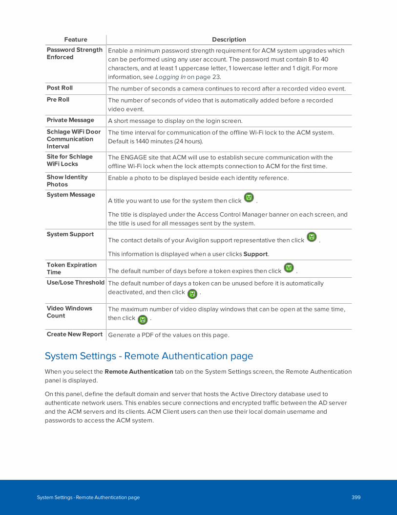
Feature Description
Password StrengthEnforced
Enable a minimum password strength requirement for ACM system upgrades whichcan be performed using any user account. The password must contain 8 to 40characters, and at least 1 uppercase letter, 1 lowercase letter and 1 digit. For moreinformation, see Logging In on page 23.
Post Roll The number of seconds a camera continues to record after a recorded video event.
Pre Roll The number of seconds of video that is automatically added before a recordedvideo event.
PrivateMessage A short message to display on the login screen.
SchlageWiFi DoorCommunicationInterval
The time interval for communication of the offline Wi-Fi lock to the ACM system.Default is 1440 minutes (24 hours).
Site for SchlageWiFi Locks
The ENGAGE site that ACM will use to establish secure communication with theoffline Wi-Fi lock when the lock attempts connection to ACM for the first time.
Show IdentityPhotos
Enable a photo to be displayed beside each identity reference.
SystemMessageA title you want to use for the system then click .
The title is displayed under the Access Control Manager banner on each screen, andthe title is used for all messages sent by the system.
System SupportThe contact details of your Avigilon support representative then click .
This information is displayed when a user clicks Support.
Token ExpirationTime The default number of days before a token expires then click .
Use/Lose Threshold The default number of days a token can be unused before it is automaticallydeactivated, and then click .
Video WindowsCount
The maximum number of video display windows that can be open at the same time,then click .
Create New Report Generate a PDF of the values on this page.
System Settings - Remote Authentication pageWhen you select the Remote Authentication tab on the System Settings screen, the Remote Authenticationpanel is displayed.
On this panel, define the default domain and server that hosts the Active Directory database used toauthenticate network users. This enables secure connections and encrypted traffic between the AD serverand the ACM servers and its clients. ACM Client users can then use their local domain username andpasswords to access the ACM system.
System Settings - Remote Authentication page 399
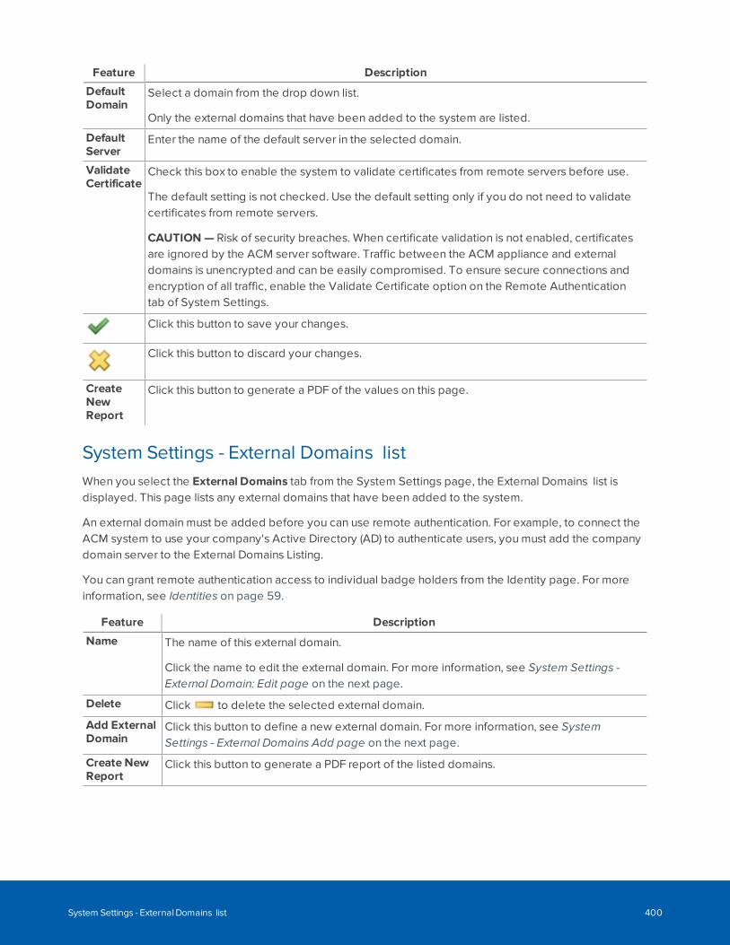
Feature Description
DefaultDomain
Select a domain from the drop down list.
Only the external domains that have been added to the system are listed.
DefaultServer
Enter the name of the default server in the selected domain.
ValidateCertificate
Check this box to enable the system to validate certificates from remote servers before use.
The default setting is not checked. Use the default setting only if you do not need to validatecertificates from remote servers.
CAUTION — Risk of security breaches. When certificate validation is not enabled, certificatesare ignored by the ACM server software. Traffic between the ACM appliance and externaldomains is unencrypted and can be easily compromised. To ensure secure connections andencryption of all traffic, enable the Validate Certificate option on the Remote Authenticationtab of System Settings.
Click this button to save your changes.
Click this button to discard your changes.
CreateNewReport
Click this button to generate a PDF of the values on this page.
System Settings - External Domains listWhen you select the External Domains tab from the System Settings page, the External Domains list isdisplayed. This page lists any external domains that have been added to the system.
An external domain must be added before you can use remote authentication. For example, to connect theACM system to use your company's Active Directory (AD) to authenticate users, you must add the companydomain server to the External Domains Listing.
You can grant remote authentication access to individual badge holders from the Identity page. For moreinformation, see Identities on page 59.
Feature Description
Name The name of this external domain.
Click the name to edit the external domain. For more information, see System Settings -External Domain: Edit page on the next page.
Delete Click to delete the selected external domain.
Add ExternalDomain
Click this button to define a new external domain. For more information, see SystemSettings - External Domains Add page on the next page.
Create NewReport
Click this button to generate a PDF report of the listed domains.
System Settings - External Domains list 400
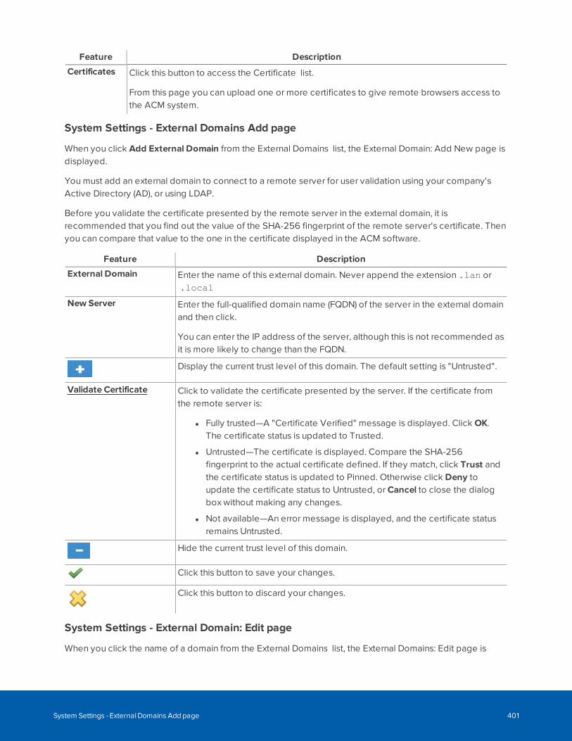
Feature Description
Certificates Click this button to access the Certificate list.
From this page you can upload one or more certificates to give remote browsers access tothe ACM system.
System Settings - External Domains Add page
When you click Add External Domain from the External Domains list, the External Domain: Add New page isdisplayed.
You must add an external domain to connect to a remote server for user validation using your company'sActive Directory (AD), or using LDAP.
Before you validate the certificate presented by the remote server in the external domain, it isrecommended that you find out the value of the SHA-256 fingerprint of the remote server's certificate. Thenyou can compare that value to the one in the certificate displayed in the ACM software.
Feature Description
External Domain Enter the name of this external domain. Never append the extension .lan or.local
New Server Enter the full-qualified domain name (FQDN) of the server in the external domainand then click.
You can enter the IP address of the server, although this is not recommended asit is more likely to change than the FQDN.
Display the current trust level of this domain. The default setting is "Untrusted".
Validate Certificate Click to validate the certificate presented by the server. If the certificate fromthe remote server is:
l Fully trusted—A "Certificate Verified" message is displayed. Click OK.The certificate status is updated to Trusted.
l Untrusted—The certificate is displayed. Compare the SHA-256fingerprint to the actual certificate defined. If they match, click Trust andthe certificate status is updated to Pinned. Otherwise click Deny toupdate the certificate status to Untrusted, or Cancel to close the dialogbox without making any changes.
l Not available—An error message is displayed, and the certificate statusremains Untrusted.
Hide the current trust level of this domain.
Click this button to save your changes.
Click this button to discard your changes.
System Settings - External Domain: Edit page
When you click the name of a domain from the External Domains list, the External Domains: Edit page is
System Settings - External Domains Add page 401
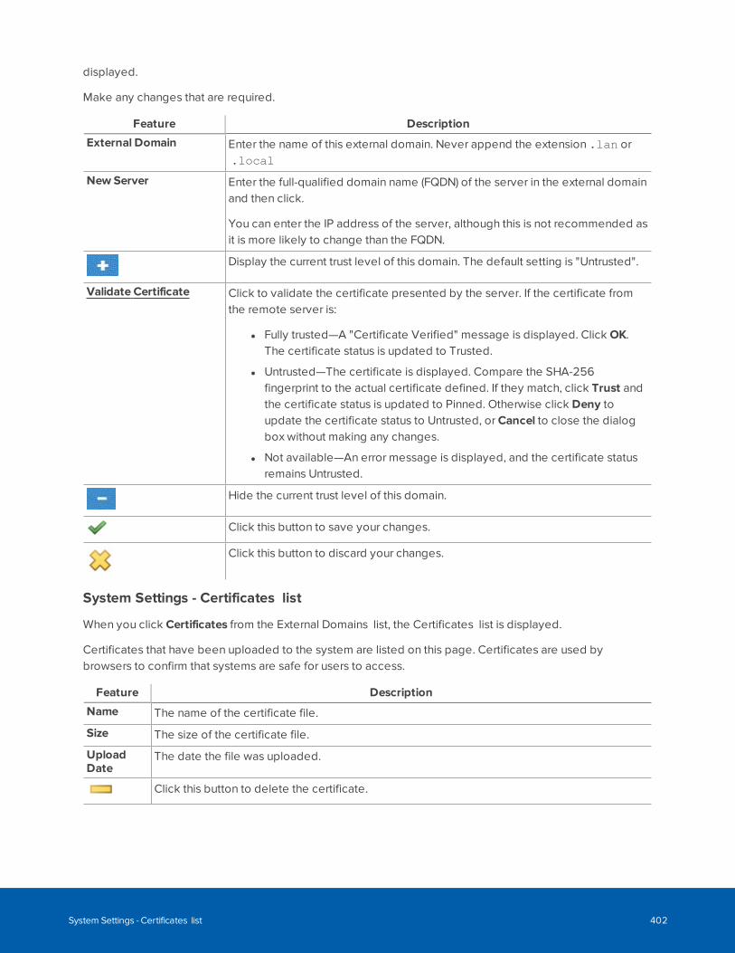
displayed.
Make any changes that are required.
Feature Description
External Domain Enter the name of this external domain. Never append the extension .lan or.local
New Server Enter the full-qualified domain name (FQDN) of the server in the external domainand then click.
You can enter the IP address of the server, although this is not recommended asit is more likely to change than the FQDN.
Display the current trust level of this domain. The default setting is "Untrusted".
Validate Certificate Click to validate the certificate presented by the server. If the certificate fromthe remote server is:
l Fully trusted—A "Certificate Verified" message is displayed. Click OK.The certificate status is updated to Trusted.
l Untrusted—The certificate is displayed. Compare the SHA-256fingerprint to the actual certificate defined. If they match, click Trust andthe certificate status is updated to Pinned. Otherwise click Deny toupdate the certificate status to Untrusted, or Cancel to close the dialogbox without making any changes.
l Not available—An error message is displayed, and the certificate statusremains Untrusted.
Hide the current trust level of this domain.
Click this button to save your changes.
Click this button to discard your changes.
System Settings - Certificates list
When you click Certificates from the External Domains list, the Certificates list is displayed.
Certificates that have been uploaded to the system are listed on this page. Certificates are used bybrowsers to confirm that systems are safe for users to access.
Feature Description
Name The name of the certificate file.
Size The size of the certificate file.
UploadDate
The date the file was uploaded.
Click this button to delete the certificate.
System Settings - Certificates list 402
Feature Description
Add NewCertificatesListing
Click this button to upload a new certificate for this external domain.
Note: To provide maximum security strength for your ACM system, ensure thecertificate meets the U.S. government's National Institute of Standards andTechnology (NIST) Special Publication 800-131A (SP 800-131A) standard.
If your ACM appliance to ACC integration deployment is having trouble connecting,review the certificate requirements for the two systems. You may need to update thecertificate on the ACM appliance to resolve the connection issues between the twosystems.
Certificate Upload page
Use this page to upload an external domain server certificate in .pem format to the ACM application. Thisallows ACM Client users to log in using their network user ID and password through a fully trusted ActiveDirectory (AD) server on an external domain.
Tip: The exported certificate must be converted from .cer format to .pem format by a systemadministrator on the AD server before it is uploaded to the ACM server.
There must be a certificate for every server that has been added to the system as part of the externaldomain.
Feature Description
Upload Certificatefile:
Click Browse to locate and select the certificate in the Choose File to Upload dialogbox.
Click this button to save your changes.
Click this button to discard your changes.
Badge Templates and the Badge Designer
This feature requires a license. Contact your Avigilon support representative for more information.
Badge templates define the layout of badges or cards that are used to access doors within your accesscontrol system. They are created by a qualified operator using the Badge Designer. Multiple badgetemplates can be defined in the ACM system.
Select > Badge Designer to access the Badge Templates page. From this page, you can add a newbadge template, or select a badge template to edit, with the Badge Designer.
The Badge Designer is used to design the appearance and content on a badge template. You can add
Certificate Upload page 403
photos, logos, text, and database fields to a badge template and position these elements on the layout. Abadge template can specify colors and fonts depending on the values provided.
For example, if an employee is specified as part-time, the color used for the employee's name can bechanged from black to orange, making it easier for guards to differentiate between full-time and part-timeemployees. You can differentiate identities with different access privileges, such as access to certainbuildings on a campus, or specific floors in a multi-tenant office building, using graphics such as companylogos and insignias, or text.
A badge template is used when a badge is generated for a badge-holder to both format the badge andpopulate it with data from the Identities database. At least one badge template to assign to identities mustbe created before badges can be printed using Identities > Badge. Badges are usually printed when aperson who requires a badge is enrolled into the ACM system using the Identities feature. When printing thebadge, an enrollment officer or administrator specifies a badge template and then generates (prints) abadge. The badge has all relevant information automatically placed on the badge.
Note: Badge templates can be designed as either one- or two-sided. A two-sided badge must beprinted by a badge printer possessing duplex capability.
Using the Badge DesignerUse the Badge Designer to create templates that define the layout and appearance of access badges.
A badge template defines the basic attributes of a badge that are used when a new badge is generated foran identity: size and background color, plus a variety of dynamic and static fields and images. Dynamic fieldsand images pull the unique information about the badge holder from the Identities database for eachindividual badge and static objects are the text strings and graphics printed on every badge. For eachobject, you can specify its location and appearance.
Field Image
Dynamic DBField: A data field objectspecifies the information about theidentity that you want on the badge,such as first and last name, IDnumber, title, position, rank and soon.
Picture:: A picture object specifies thesize and location of the photo of theidentity on a badge.
The actual photo used for an identitywhen a badge is generated is a photosaved in the Identities database thatwas either captured with a badgecamera, or uploaded, and saved.
Static Text: A text object specifies the textthat appears on every badgegenerated with this template.
Graphic: A graphic object specifiesthe name of an uploaded graphic fileimage file that appears on everybadge generated with this template.
You must create at least one badge template before you can print a badge at Identities > Badge.Depending on the requirements of your site, you may need one or more badge templates.
Using the Badge Designer 404
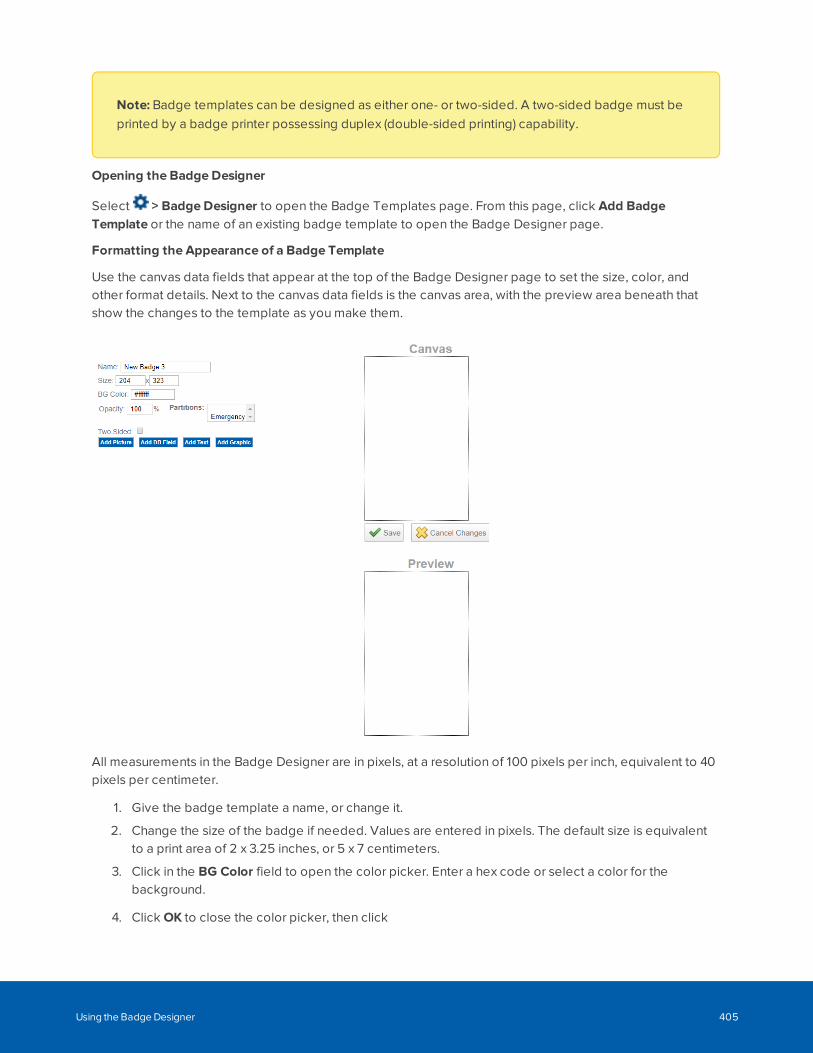
Note: Badge templates can be designed as either one- or two-sided. A two-sided badge must beprinted by a badge printer possessing duplex (double-sided printing) capability.
Opening the Badge Designer
Select > Badge Designer to open the Badge Templates page. From this page, click Add BadgeTemplate or the name of an existing badge template to open the Badge Designer page.
Formatting the Appearance of a Badge Template
Use the canvas data fields that appear at the top of the Badge Designer page to set the size, color, andother format details. Next to the canvas data fields is the canvas area, with the preview area beneath thatshow the changes to the template as you make them.
All measurements in the Badge Designer are in pixels, at a resolution of 100 pixels per inch, equivalent to 40pixels per centimeter.
1. Give the badge template a name, or change it.
2. Change the size of the badge if needed. Values are entered in pixels. The default size is equivalentto a print area of 2 x 3.25 inches, or 5 x 7 centimeters.
3. Click in the BG Color field to open the color picker. Enter a hex code or select a color for thebackground.
4. Click OK to close the color picker, then click
Using the Badge Designer 405
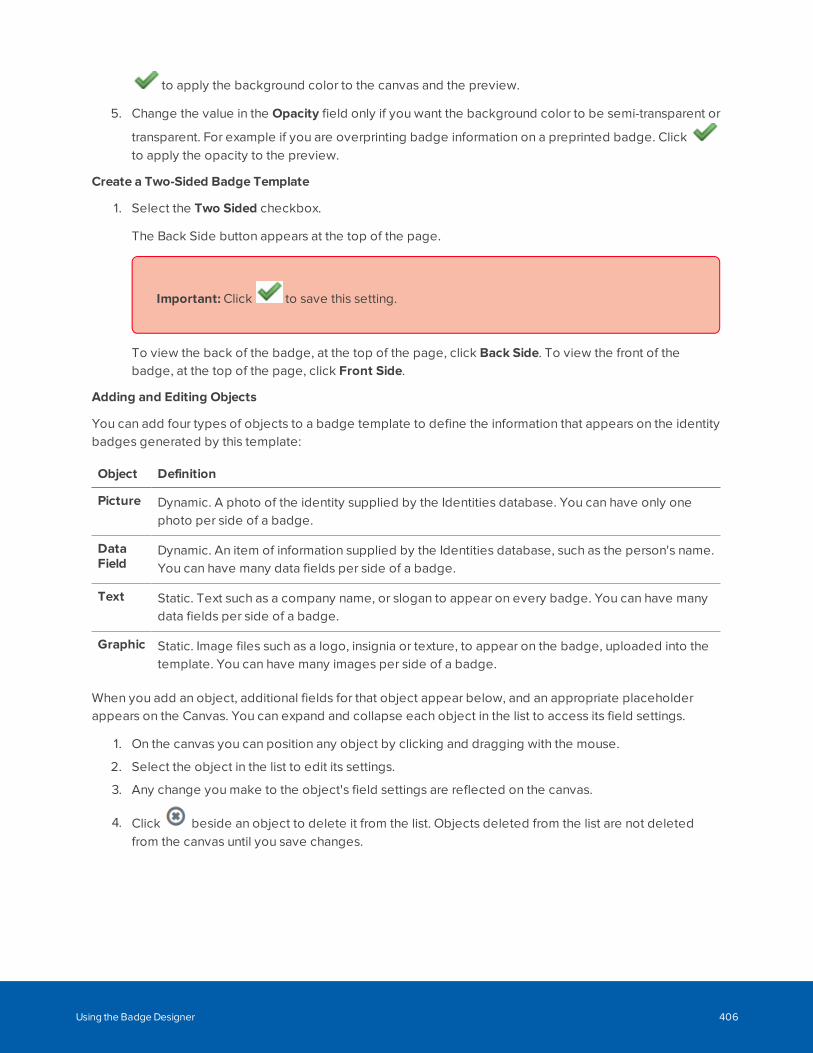
to apply the background color to the canvas and the preview.
5. Change the value in the Opacity field only if you want the background color to be semi-transparent or
transparent. For example if you are overprinting badge information on a preprinted badge. Clickto apply the opacity to the preview.
Create a Two-Sided Badge Template
1. Select the Two Sided checkbox.
The Back Side button appears at the top of the page.
2.
Important: Click to save this setting.
To view the back of the badge, at the top of the page, click Back Side. To view the front of thebadge, at the top of the page, click Front Side.
Adding and Editing Objects
You can add four types of objects to a badge template to define the information that appears on the identitybadges generated by this template:
Object Definition
Picture Dynamic. A photo of the identity supplied by the Identities database. You can have only onephoto per side of a badge.
DataField
Dynamic. An item of information supplied by the Identities database, such as the person's name.You can have many data fields per side of a badge.
Text Static. Text such as a company name, or slogan to appear on every badge. You can have manydata fields per side of a badge.
Graphic Static. Image files such as a logo, insignia or texture, to appear on the badge, uploaded into thetemplate. You can have many images per side of a badge.
When you add an object, additional fields for that object appear below, and an appropriate placeholderappears on the Canvas. You can expand and collapse each object in the list to access its field settings.
1. On the canvas you can position any object by clicking and dragging with the mouse.
2. Select the object in the list to edit its settings.
3. Any change you make to the object's field settings are reflected on the canvas.
4. Click beside an object to delete it from the list. Objects deleted from the list are not deletedfrom the canvas until you save changes.
Using the Badge Designer 406
5. Click frequently to save changes and show the result in the Preview.
Tip: Add objects to the Canvas from largest to smallest in size. The Canvas displays objectsin the order they are added not by the Layer Order setting, so large objects can obscuresmaller ones. Save the template to refresh the Preview and see the actual result.
Adding and Editing a Picture Object
1. Click the Add Picture button to add a photo object to the canvas.
2. Click Photo to hide or show the photo object settings.
3. Adjust the appearance of the photo.
Tip: The default dimensions of the photo on the badge displayed on the screen are definedby the values set on the System Settings page for Badge Template Photo Height andBadge Template Photo Width and should not normally be altered here. These two settingsensure that the size of the photo on all badges printed by this badge template are uniformlysized and have the same aspect ratio.
To accommodate minor variations in the aspect ratio of individual photos without distortion, enablethe Maintain Aspect Ratio option.
See Fields Common to All Objects on the next page and Fields Common to Picture and GraphicObjects on page 409.
Adding and Editing a Data Field Object
1. Click Add DB Field to add a data field object to the canvas.
2. Click Data Field to hide or show the data field object settings.
3. In the Data Field drop-down list select a data field. For example, to have a badge include a person'sname when it is generated, select one of the name fields listed, such as Full Name.
4. Adjust the appearance of the data field object. You can resize the object to ensure all text is visibleas well as change the font, size, and color. Additionally, select the Auto Resize checkbox to make thetext shrink to fit inside a fixed size box if the text in the specified font size does not fit. See FieldsCommon to All Objects on the next page and Fields Common to Data Field and Text Objects on thenext page.
Adding and Editing a Text Object
1. Click Add Text to add a text object to the canvas.
2. Click Text to hide or show the text object settings.
3. In the Text field, enter the text you want to appear on all badges generated with this template.
Using the Badge Designer 407
4. Adjust the appearance of the database field object. You can resize the object to ensure all text isvisible as well as change the font, size, and color. Additionally, select the Auto Resize checkbox tomake the text shrink to fit inside a fixed size box if the text in the specified font size does not fit. SeeFields Common to All Objects below and Fields Common to Data Field and Text Objects below.
Adding and Editing a Graphic Object
1. Click Add Graphic to add an image object to the canvas.
2. Click # or Image File Name item to show or hide the graphic object settings.
3. In the Image field, click Choose File to upload a file to the ACM system and add to the badgetemplate.
4. Adjust the appearance of the photo object in various ways. See Fields Common to All Objects belowand Fields Common to Picture and Graphic Objects on the next page.
Fields Common to All ObjectsField Description
LayerOrder
A number indicating the order an object appears when objects are stacked in front of eachother. The initial layer order is the order the objects were added to the template.
1 is the lowest layer, 2 is in front of 1 and so on. You can reorder the layers by typing over thevalue for each object.
Location Click and drag the object on the canvas, or enter the horizontal and vertical coordinates of thetop left corner.
The default setting of 0 x 0 would place the object in the top left corner, while 80 x 160 wouldplace the object lower and to the right.
Dimensions Modify the default size of the object (in pixels) if needed.
Tip: Do not modify the size of an identity photo object here. It is better to change thedefault values on the System Settings page, as this ensures the same aspect ratio isused for the dropping overlay when photos are taken with a badge camera andsaved in the Identities database.
The first field is the width and the second field is the height.
Rotation Select the number of degrees to rotate this object clockwise from the dropdown list.
The default is 0 degrees.
Fields Common to Data Field and Text ObjectsField Description
BG Color Click this field to choose a background color for the object. By default, it is set to be the samecolor as the badge template.
Use the color picker to either select a color from the palette or manually enter the color in RGB,HSV or hex code format.
Using the Badge Designer 408
Field Description
Opacity Enter how opaque you want the background color to be, in conjunction with the layer order.
0% is fully transparent and the default setting of 100% is fully opaque.
Font Select the font you want for the text.
The font list includes text fonts and barcode fonts. Text fonts are listed first, then barcode fonts.
Font Size Enter the font size in points. If Auto Resize is selected, this is the maximum font size.
AutoResize
Select this checkbox to have the system automatically shrink the font size to fit the dimensionsof the object.
Alignment Select how you want the text to align inside the object.
TextColor
Click this field to choose a font color.
Use the color picker to either select a color from the palette or manually enter the color in RGB,HSV or hex code format.
Opacity Enter how opaque you want the font color to be, in conjunction with the layer order.
0% is fully transparent and the default setting of 100% is fully opaque.
Fields Common to Picture and Graphic ObjectsField Description
Image (Applies to graphic objects only) Specifies the image to upload to the ACM system andplace on the badge template. After the graphic is uploaded, the file name replaces # in thelist of objects on the badge template.
MaintainAspect
Check this box to always maintain the aspect ratio of the photo. When the aspect ratio ismaintained, the photo is scaled to fit within the object space. If this option is disabled, thephoto is automatically stretched to fill the object space.
Border Width Select the border thickness (in pixels) for the picture or image from the drop-down list. Thephoto or graphic will be offset by the width of the border.
Border Color Use the color picker to either select a color from the palette or manually enter the color inRGB, HSV or hex code format.
Adding a Barcode Using Static and Dynamic Objects
1. When you create a badge template, you can add a barcode by using either of the following options:
l Click Add Text to place a static barcode that will be the same for every badge that isgenerated from the template.
l Click Add DB Field to place a dynamic barcode that changes to match the detail listed in theidentity record.
2. After you add the badge object, select a barcode font. The available barcode fonts include Barcode3 of 9, Barcode 3 of 9 Extended, Aztec Code, CodeOne and more. The font option lists the text fontsfirst and then the barcode fonts.
3. Click to save your changes and display the barcode in the preview area.
Using the Badge Designer 409
Note: Many of these barcodes require a specific format or do not accept certain characters. If thedata given to the barcode generator from the Identities database is invalid, the barcode will not bedisplayed on the badge.
Badge Templates list
When you select > Badge Designer, the Badge Templates list is displayed. From this page, you can addand edit badge templates with the Badge Designer.
Badge templates are used to define the layout of badges or cards that are used to access doors within youraccess control system. They are created by a qualified operator using the Badge Designer. Multiple badgetemplates can be defined in the ACM system.
This page lists all the badge templates that have been added to the system.
Feature Description
Name The name of the badge template.
Click the name to edit the badge template. For more information, see Using the BadgeDesigner on page 404.
Commands Click to delete the badge template.
Click to copy the badge template.
The copy of the badge template is automatically added to the top of the list.
Add BadgeTemplate
Click this button to add a new badge template. For more information, see Using theBadge Designer on page 404.
External Systems Overview
Set up integration to cameras, sites and other third-party external systems.
Note: Some external systems may not be available if your system does not have the requiredlicense.
Before you can connect and use the external systems, the external system must be installed and accessibleto the appliance over the local network.
Supported External SystemsListed below are all the external systems that are supported by the ACM system. Some systems may not beavailable to you if your system does not have the required license.
Badge Templates list 410
l IP cameras and network video management systems (VMSs), including AvigilonControl Center.
You can add individual cameras to add photos to the Identities database, or you can add wholenetwork video systems that can be configured to work with doors and events in the ACM system, andrecord video triggered by events for surveillance.
l LifeSafety Power Supplies
l ViRDI Biometric Access scanners and readers
l Virtual Stations — ACMVerify™ Virtual Doors
For example, the ViRDI external system requires a separate license. Before a ViRDI system can becreated on your ACM server appliance, the system administrator for the ACM application must:
l Add the ViRDI license to the ACM application. See Adding a License on page 358.
l Add the four ViRDI-specific delegations to the role assigned to operators. These delegationsare all prefixed with "ViRDI". See Assigning Delegations to a Role on page 78 and Roles -Delegate page on page 83.
l Bosch intrusion panels
l Allegion ENGAGE gateways
For more information, see IP/PoE Mode Installation on page 277 and Step 1: Creating an ENGAGESite on page 287.
l SALTO servers
For more information, see Step 1: Connecting to a SALTO Server on page 296.
Adding External SystemsYou can add several types of external systems to the ACM system.
Important: Before you can add any external system, you must first connect a supported device toyour network or server, and then configure the device as described in device documentation. Writedown the device's IP address and onboard URL. For some external systems, refer to an ACM-specific integration guide that provides installation, connection and configuration instructions.
1. Select > External Systems.
2. Select the tab for the external system you want to add.
3. From the External Systems listing page, click .
4. In the following page, complete the required fields to add the new external system.
5. Click to save the new external system.
See also:
l Step 1: Creating an ENGAGE Site on page 287
l Step 1: Connecting to a SALTO Server on page 296
Adding External Systems 411
Editing External Systems
1. Select > External Systems.
2. Select the tab for the type of external system you want to edit.
3. From the External Systems listing page, click the name or address of the specific system you want toedit.
4. In the following page, make the required changes.
5. Click to save your changes.
See also:
l Editing an ENGAGE Site below
l Step 1: Connecting to a SALTO Server on page 296
Editing an ENGAGE Site
To edit an ENGAGE site in ACM:
1. Select >External Systems.
2. Click the Schlage tab.
3. Click the site name.
4. Edit:Site Name Up to 50 alphanumeric characters for the name of the site which represents
the logical group of ENGAGE devices. Always create an ENGAGE site inthe ACM application. A site that is already created in the ENGAGEapplication cannot be reused in the ACM application. In addition, a sitecannot be used by more than one ACM appliance.
Partitions Displayed for a partitioned ACM appliance only. To restrict operator accessto the item, select one or more partitions. To allow all operators access tothe item, do not select a partition.
5. Click to save your changes.
Click to discard your changes.
Deleting External SystemsDeleting an external system does not remove it from your system. Deleting it will simply preventcommunication with the ACM appliance. You may need to uninstall the external system as required.
1. Select > External Systems.
2. Select the tab for the type of external system.
3. Click next to the name of the external system.
For Bosch intrusion panels, click
Editing External Systems 412
. Associated items such as linkages and actions, and intrusion users will also be deleted.
4. When the confirmation message is displayed, click OK.
External Systems - Integrating an ACM Appliance into an ACC™ SiteAn ACM appliance can be integrated into an ACC site so that events occurring in the ACM software cantrigger rules in the ACC software to initiate actions. For example, door events in the ACM software cantrigger a rule that allows an ACC operator to grant door access, or an input event from a panic button ormotion sensor in the ACM software can trigger a live camera feed, or video recording.
To integrate an ACM appliance, a special identity to interact with the ACC software must be created by anACM administrator. This identity must be assigned a special role and delegation with specific rights, and arouting group that specifies the events that the ACC software receives. Only one identity must be createdfor this purpose.
As of ACM 5.10.10.2, a preconfigured role and delegation with the necessary rights are available for thisspecial identity that is suitable for most integration scenarios. The role and delegation are both calledACC Administrator. However, if this special identity needs additional rights, you will have to modify therights associated with the delegation, or configure a new role and delegation. The routing group has to beconfigured, and optionally if you plan to import Active Directory identities through ACM, you will have toconfigure remote authentication.
If you are using an earlier version of the ACM appliance, you will need to create your own ACC Administratorrole and delegation with the appropriate rights.
Use the following steps to configure an identity to interact with the ACC software:
1. Examine the rights assigned to the preconfigured ACC Administrator delegation:
l Appliance Listing
l Delegations Listing
l Doors Grant
l Doors Listing
l Identities Listing
l Identities Login - Remote
l Identities Photo Render
l Inputs Listing
l Panels Listing
l Partitions List
l Roles Listing
l Subpanels Listing
l System Summary Listing
2. If additional rights are required, such as the Partitions right because your ACM installation ispartitioned and you want the ACC operator to access doors within the partitions, you must add these
External Systems - Integrating an ACM Appliance into an ACC™ Site 413
rights to this delegation, or create a new delegation with the rights assigned to the preconfiguredACC Administrator delegation.
3. Create a routing group to define events sent from the ACM appliance to the ACC software.
a. Specify the following for the group:
l Schedule: 24 Hours Active
l Schedule Qualifier: Appliance
l The Installed box must be checked
b. Add the following event types to the routing group:
l Door held open
l Forced Door
l Intrusion
l Invalid Credential
l Maintenance
l System
l Tamper
l Valid Credential
4. If you created a new delegation to use instead of the preconfigured ACC Administrator delegation,you also need to modify the preconfigured ACC Administrator role, or create a new role that allowsthe ACC software to communicate with the ACM system.
a. If you modify the preconfigured ACC Administrator role, under the role's Delegate tab, assignonly the new delegation that was created to replace the preconfigured ACC Administratordelegation.
b. If you create a new role:
a. Keep the default Parent value (none).
b. Keep the default Start Date value (the current date).
c. In the Stop Date box, enter an appropriate date for this role to expire. By default, therole will stop working 1 year from its creation date.
d. Select the Installed checkbox and click Save.
Additional tabs will appear.
e. In the role's Delegate tab, assign only the delegation that was created in the precedingsteps.
f. In the Routing tab, assign only the routing group that was created in the precedingsteps.
5. If you plan to import Active Directory identities to the ACM appliance or the ACC software, configurea Lightweight Directory Access Protocol (LDAP) Collaboration. For Active Directory RemoteAuthentication, configure remote authentication from external domains.
6. Create a dedicated identity for interacting with the ACC software.
External Systems - Integrating an ACM Appliance into an ACC™ Site 414
Note: To protect the security of the connection between the ACM appliance and the ACCsoftware, the dedicated identity should have only the permissions outlined in this procedure.Operators should not have access to this account.
l Assign a Last Name, Login, and Password for the identity.
l The password should meet the minimum password strength requirements for your ACC site.
The password strength is defined by how easy it is for an unauthorized user to guess. It ishighly recommended that you select a password that uses a series of words that is easy foryou to remember but difficult for others to guess.
l Under the identity's Roles tab, assign only the role that was created in the preceding step.
7. If your ACM appliance uses partitions, add the identity as a member of the partitions they will need toaccess from the ACC Client.
Once these settings are applied, an ACC Client can connect to the ACM appliance.
External Systems - Defining the Badge Camera for the SystemOnce all cameras or other imaging devices have been added as part of an external system, you can setwhich camera to use when creating badges for identities.
1. Select > My Account.
2. Under the Profile tab, select a camera from the Badge Camera drop down list:
l Local Camera — Any camera connected directly to your computer or built into your computeror monitor.
l IP-based camera — Any IP-based camera previously connected to your network and added toyour ACM system.
3. When you're finished, click .
Next time you create a badge, the selected camera is used to take the identity photo.
Bosch Intrusion PanelsThe following procedures relate to Bosch intrusion panels.
Adding a Bosch Intrusion Panel
To add a new Bosch intrusion panel:
External Systems - Defining the Badge Camera for the System 415
1. Select > External Systems.
2. Click the Bosch Intrusion tab.
3. Click to add a new panel.
4. Complete the following fields:
l Panel Name
l Appliance
l Address
l Port
l Automation Passcode
l Application Passcode
l Installed
5. Click Create.
Note: The Areas, Points, Outputs and Users are created from the panel, as configured inBosch's Remote Programming Software (RPS).
6. Click beside the Panel name.
7. Select Areas. View the Area details.
8. Select Points. View the Point details.
9. Select Outputs. View the Output details.
10. Select Users. View the User details.
11. Click .
Editing a Bosch Intrusion Panel
To edit and view a Bosch intrusion panel:
1. Select > External Systems.
2. Click the Bosch Intrusion tab.
3. Review the panel status indicator to identify the current status of the panel.
4. Edit or view the following fields:
l Panel Name
l Appliance
l Address
l Port
Editing a Bosch Intrusion Panel 416
l Automation Passcode
l Application Passcode
l Installed
5. To view Area details, select Areas.
6. To view Point details, select Points.
7. To view Output details, select Outputs.
8. To view User details, select Users.
Synchronizing Bosch Intrusion Panels
If intrusion panel information is updated externally to the ACM system (e.g. new identities being added inBosch's Remote Programming Software - RPS), then the panel will need to be re-synchronized to the ACMsystem. When the panel is out of synch then a warning message (Warning, ACM and the Intrusion Panel arenot synchronized, go to Settings ->External Systems->Bosch Intrusion and resync) will display on the screensavailable under the Monitor > Intrusion Status menu path.
To synchronize a Bosch intrusion panel:
1. Select > External Systems.
2. Click the Bosch Intrusion tab.
3. Either:
l Click at the top level to synchronize all panels that are currently out of synch.
l Click beside the panel name to synchronize an individual panel.
Deleting a Bosch Intrusion Panel
To delete a Bosch intrusion panel:
1. Select > External Systems.
2. Click the Bosch Intrusion tab.
3. Select the panel to be deleted.
4. Click to delete the panel.
Note: The panel will be deleted and will disappear from this view.
Viewing Bosch Intrusion Panel Areas
To view Bosch intrusion panel areas:
Synchronizing Bosch Intrusion Panels 417
1. Select > External Systems.
2. Click the Bosch Intrusion tab.
3. Select a panel and click .
4. View the areas details that display.
Note: Areas are not edited in the ACM system. All editing is done in Remote ProgrammingSoftware (RPS) and updated through the panel.
Viewing Bosch Intrusion Panel Points
To view Bosch intrusion panel points:
1. Select > External Systems.
2. Click the Bosch Intrusion tab.
3. Select a panel and click .
4. Select Points.
5. View the point details that display.
Note: Points are not edited in the ACM system. All editing is done in Remote ProgrammingSoftware (RPS) and updated through the panel.
Viewing Bosch Intrusion Panel Outputs
To view Bosch intrusion panel outputs:
1. Select > External Systems.
2. Click the Bosch Intrusion tab.
3. Select a panel and click .
4. Select Outputs.
5. View the output details that display.
Note: Outputs are not edited in the ACM system. All editing is done in Remote ProgrammingSoftware (RPS) and updated through the panel.
Viewing Bosch Intrusion Panel Users
To view Bosch intrusion panel users:
Viewing Bosch Intrusion Panel Points 418
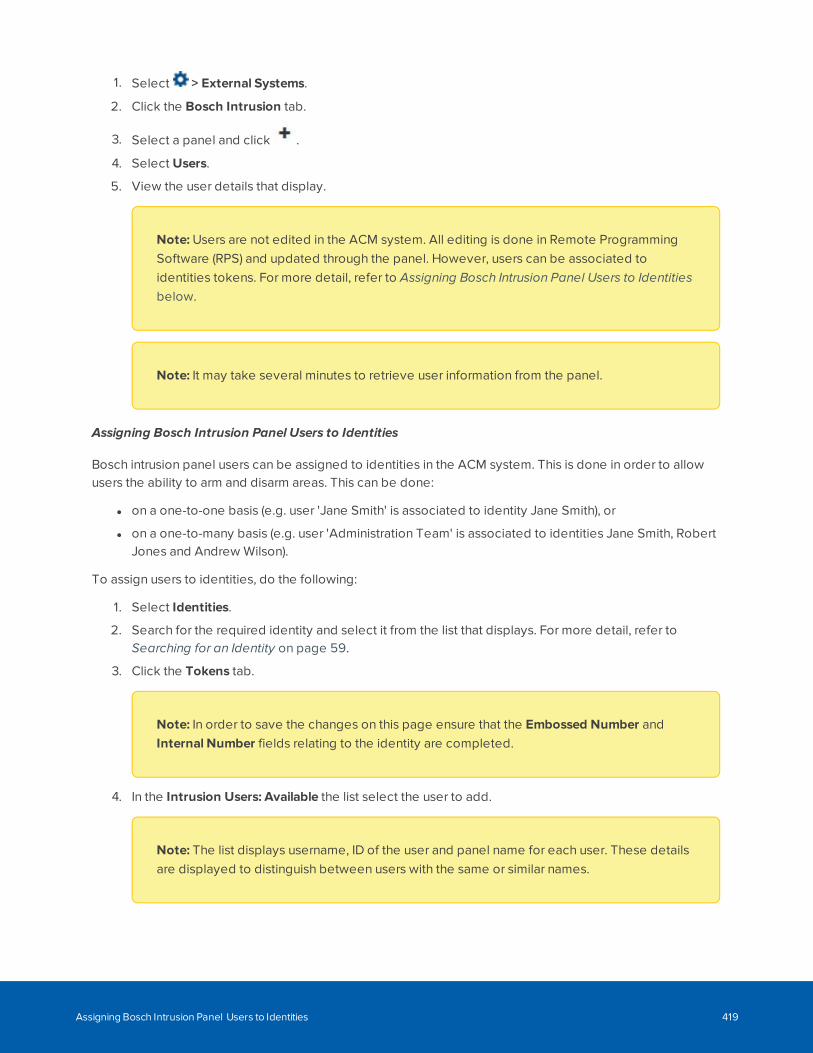
1. Select > External Systems.
2. Click the Bosch Intrusion tab.
3. Select a panel and click .
4. Select Users.
5. View the user details that display.
Note: Users are not edited in the ACM system. All editing is done in Remote ProgrammingSoftware (RPS) and updated through the panel. However, users can be associated toidentities tokens. For more detail, refer to Assigning Bosch Intrusion Panel Users to Identitiesbelow.
Note: It may take several minutes to retrieve user information from the panel.
Assigning Bosch Intrusion Panel Users to Identities
Bosch intrusion panel users can be assigned to identities in the ACM system. This is done in order to allowusers the ability to arm and disarm areas. This can be done:
l on a one-to-one basis (e.g. user 'Jane Smith' is associated to identity Jane Smith), or
l on a one-to-many basis (e.g. user 'Administration Team' is associated to identities Jane Smith, RobertJones and Andrew Wilson).
To assign users to identities, do the following:
1. Select Identities.
2. Search for the required identity and select it from the list that displays. For more detail, refer toSearching for an Identity on page 59.
3. Click the Tokens tab.
Note: In order to save the changes on this page ensure that the Embossed Number andInternal Number fields relating to the identity are completed.
4. In the Intrusion Users: Available the list select the user to add.
Note: The list displays username, ID of the user and panel name for each user. These detailsare displayed to distinguish between users with the same or similar names.
Assigning Bosch Intrusion Panel Users to Identities 419
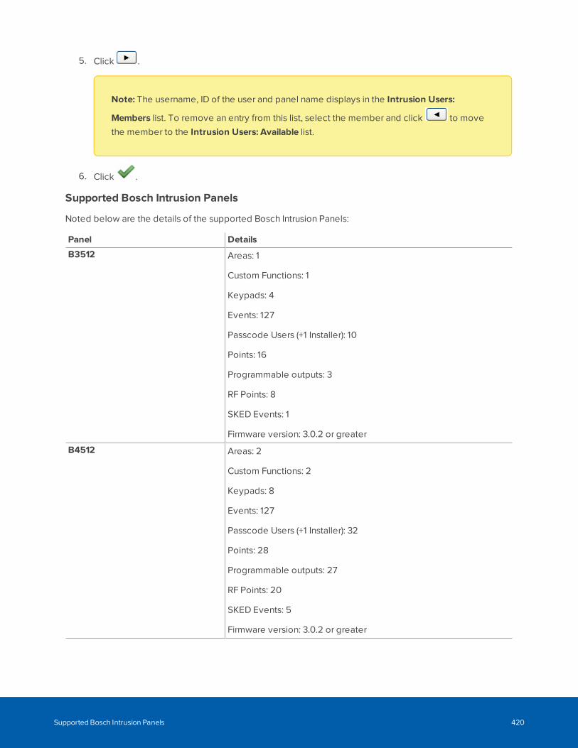
5. Click .
Note: The username, ID of the user and panel name displays in the Intrusion Users:
Members list. To remove an entry from this list, select the member and click to move
the member to the Intrusion Users: Available list.
6. Click .
Supported Bosch Intrusion Panels
Noted below are the details of the supported Bosch Intrusion Panels:
Panel Details
B3512 Areas: 1
Custom Functions: 1
Keypads: 4
Events: 127
Passcode Users (+1 Installer): 10
Points: 16
Programmable outputs: 3
RF Points: 8
SKED Events: 1
Firmware version: 3.0.2 or greater
B4512 Areas: 2
Custom Functions: 2
Keypads: 8
Events: 127
Passcode Users (+1 Installer): 32
Points: 28
Programmable outputs: 27
RF Points: 20
SKED Events: 5
Firmware version: 3.0.2 or greater
Supported Bosch Intrusion Panels 420
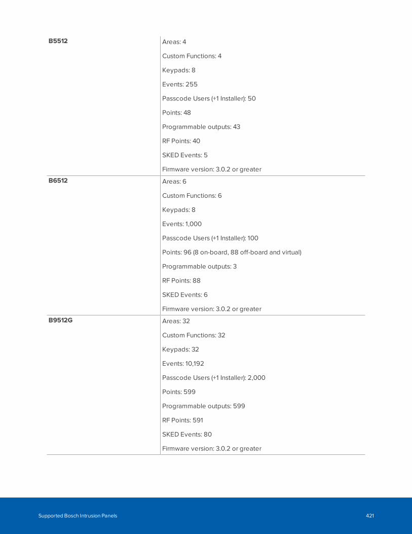
B5512 Areas: 4
Custom Functions: 4
Keypads: 8
Events: 255
Passcode Users (+1 Installer): 50
Points: 48
Programmable outputs: 43
RF Points: 40
SKED Events: 5
Firmware version: 3.0.2 or greater
B6512 Areas: 6
Custom Functions: 6
Keypads: 8
Events: 1,000
Passcode Users (+1 Installer): 100
Points: 96 (8 on-board, 88 off-board and virtual)
Programmable outputs: 3
RF Points: 88
SKED Events: 6
Firmware version: 3.0.2 or greater
B9512G Areas: 32
Custom Functions: 32
Keypads: 32
Events: 10,192
Passcode Users (+1 Installer): 2,000
Points: 599
Programmable outputs: 599
RF Points: 591
SKED Events: 80
Firmware version: 3.0.2 or greater
Supported Bosch Intrusion Panels 421
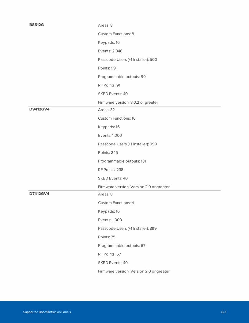
B8512G Areas: 8
Custom Functions: 8
Keypads: 16
Events: 2,048
Passcode Users (+1 Installer): 500
Points: 99
Programmable outputs: 99
RF Points: 91
SKED Events: 40
Firmware version: 3.0.2 or greater
D9412GV4 Areas: 32
Custom Functions: 16
Keypads: 16
Events: 1,000
Passcode Users (+1 Installer): 999
Points: 246
Programmable outputs: 131
RF Points: 238
SKED Events: 40
Firmware version: Version 2.0 or greater
D7412GV4 Areas: 8
Custom Functions: 4
Keypads: 16
Events: 1,000
Passcode Users (+1 Installer): 399
Points: 75
Programmable outputs: 67
RF Points: 67
SKED Events: 40
Firmware version: Version 2.0 or greater
Supported Bosch Intrusion Panels 422
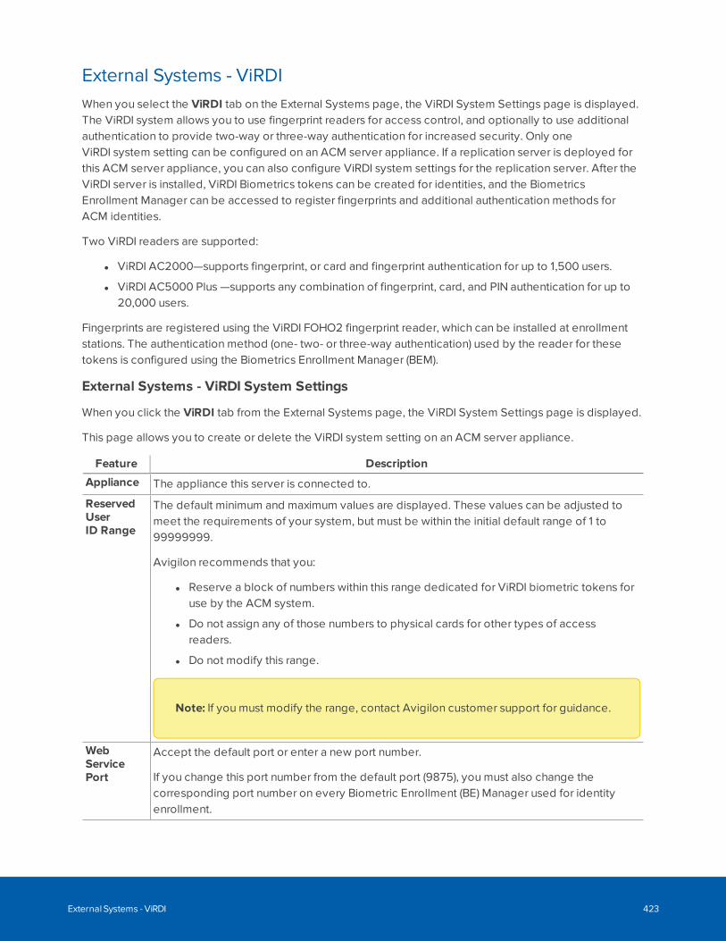
External Systems - ViRDIWhen you select the ViRDI tab on the External Systems page, the ViRDI System Settings page is displayed.The ViRDI system allows you to use fingerprint readers for access control, and optionally to use additionalauthentication to provide two-way or three-way authentication for increased security. Only oneViRDI system setting can be configured on an ACM server appliance. If a replication server is deployed forthis ACM server appliance, you can also configure ViRDI system settings for the replication server. After theViRDI server is installed, ViRDI Biometrics tokens can be created for identities, and the BiometricsEnrollment Manager can be accessed to register fingerprints and additional authentication methods forACM identities.
Two ViRDI readers are supported:
l ViRDI AC2000—supports fingerprint, or card and fingerprint authentication for up to 1,500 users.
l ViRDI AC5000 Plus —supports any combination of fingerprint, card, and PIN authentication for up to20,000 users.
Fingerprints are registered using the ViRDI FOHO2 fingerprint reader, which can be installed at enrollmentstations. The authentication method (one- two- or three-way authentication) used by the reader for thesetokens is configured using the Biometrics Enrollment Manager (BEM).
External Systems - ViRDI System Settings
When you click the ViRDI tab from the External Systems page, the ViRDI System Settings page is displayed.
This page allows you to create or delete the ViRDI system setting on an ACM server appliance.
Feature Description
Appliance The appliance this server is connected to.
ReservedUserID Range
The default minimum and maximum values are displayed. These values can be adjusted tomeet the requirements of your system, but must be within the initial default range of 1 to99999999.
Avigilon recommends that you:
l Reserve a block of numbers within this range dedicated for ViRDI biometric tokens foruse by the ACM system.
l Do not assign any of those numbers to physical cards for other types of accessreaders.
l Do not modify this range.
Note: If you must modify the range, contact Avigilon customer support for guidance.
WebServicePort
Accept the default port or enter a new port number.
If you change this port number from the default port (9875), you must also change thecorresponding port number on every Biometric Enrollment (BE) Manager used for identityenrollment.
External Systems - ViRDI 423
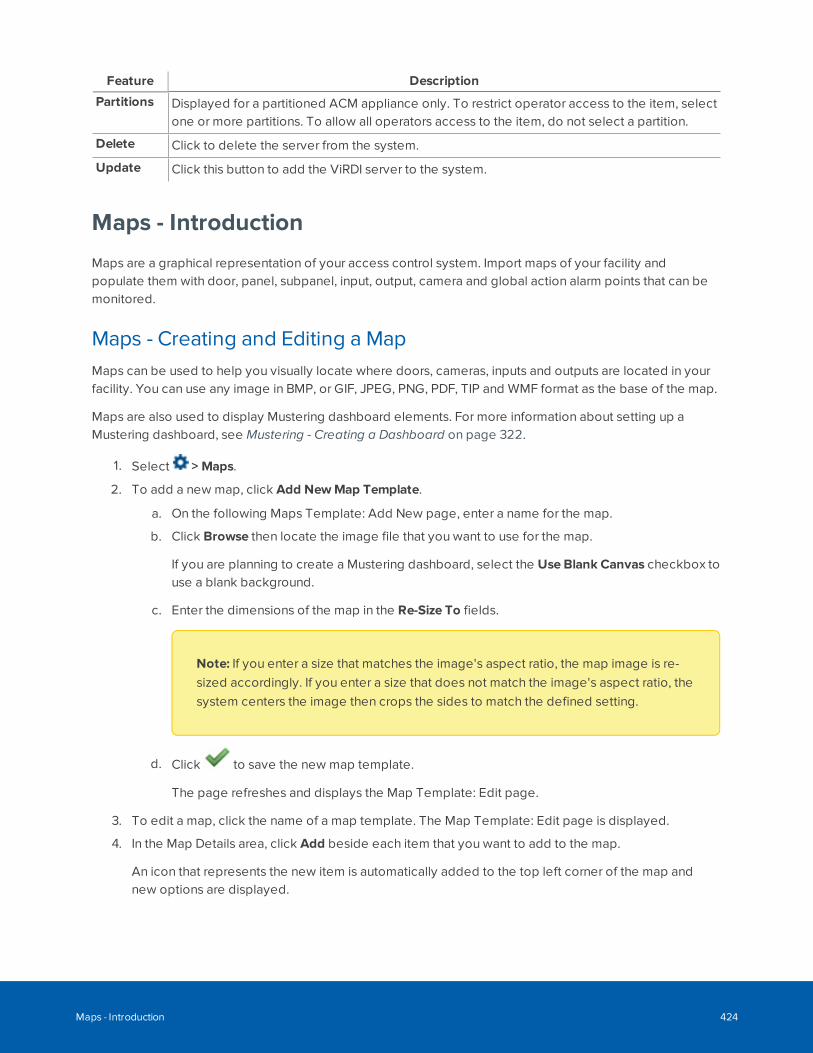
Feature Description
Partitions Displayed for a partitioned ACM appliance only. To restrict operator access to the item, selectone or more partitions. To allow all operators access to the item, do not select a partition.
Delete Click to delete the server from the system.
Update Click this button to add the ViRDI server to the system.
Maps - Introduction
Maps are a graphical representation of your access control system. Import maps of your facility andpopulate them with door, panel, subpanel, input, output, camera and global action alarm points that can bemonitored.
Maps - Creating and Editing a MapMaps can be used to help you visually locate where doors, cameras, inputs and outputs are located in yourfacility. You can use any image in BMP, or GIF, JPEG, PNG, PDF, TIP and WMF format as the base of the map.
Maps are also used to display Mustering dashboard elements. For more information about setting up aMustering dashboard, see Mustering - Creating a Dashboard on page 322.
1. Select > Maps.
2. To add a new map, click Add NewMap Template.
a. On the following Maps Template: Add New page, enter a name for the map.
b. Click Browse then locate the image file that you want to use for the map.
If you are planning to create a Mustering dashboard, select the Use Blank Canvas checkbox touse a blank background.
c. Enter the dimensions of the map in the Re-Size To fields.
Note: If you enter a size that matches the image's aspect ratio, the map image is re-sized accordingly. If you enter a size that does not match the image's aspect ratio, thesystem centers the image then crops the sides to match the defined setting.
d. Click to save the new map template.
The page refreshes and displays the Map Template: Edit page.
3. To edit a map, click the name of a map template. The Map Template: Edit page is displayed.
4. In the Map Details area, click Add beside each item that you want to add to the map.
An icon that represents the new item is automatically added to the top left corner of the map andnew options are displayed.
Maps - Introduction 424
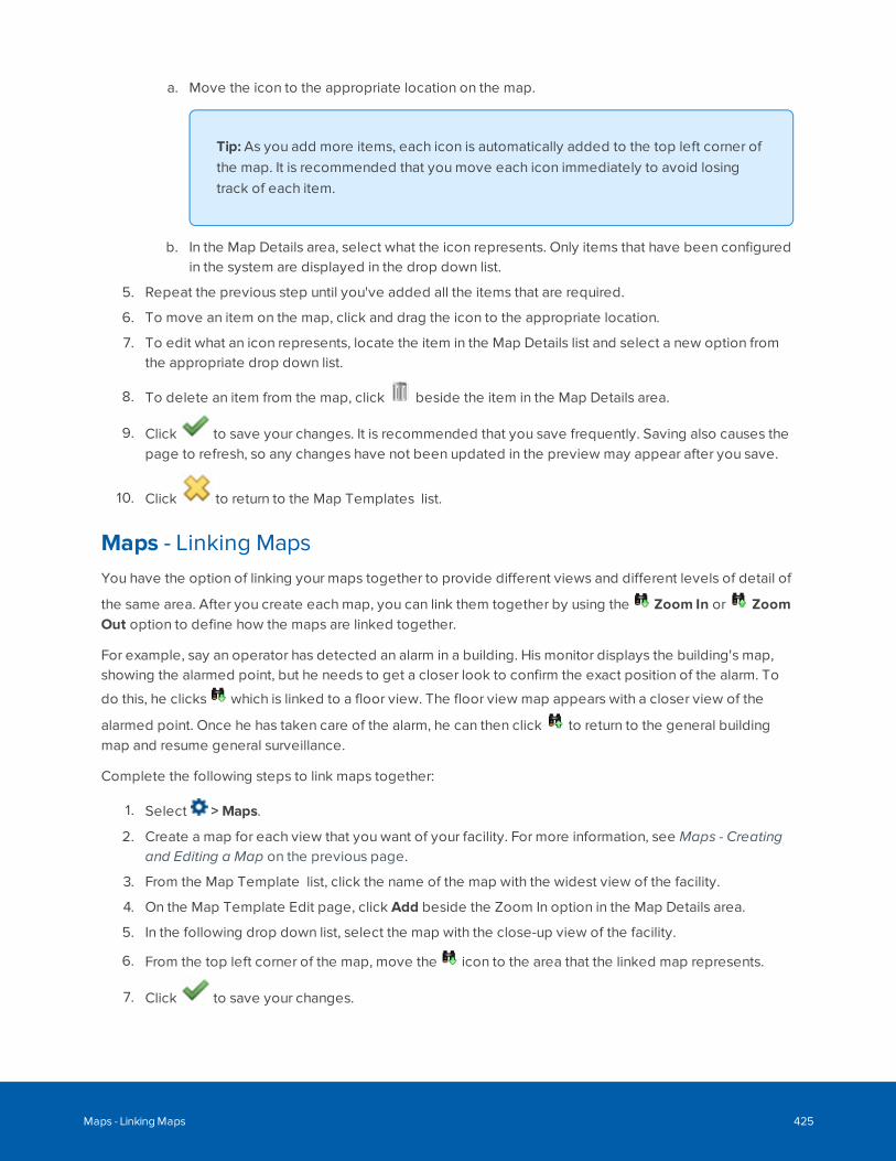
a. Move the icon to the appropriate location on the map.
Tip: As you add more items, each icon is automatically added to the top left corner ofthe map. It is recommended that you move each icon immediately to avoid losingtrack of each item.
b. In the Map Details area, select what the icon represents. Only items that have been configuredin the system are displayed in the drop down list.
5. Repeat the previous step until you've added all the items that are required.
6. To move an item on the map, click and drag the icon to the appropriate location.
7. To edit what an icon represents, locate the item in the Map Details list and select a new option fromthe appropriate drop down list.
8. To delete an item from the map, click beside the item in the Map Details area.
9. Click to save your changes. It is recommended that you save frequently. Saving also causes thepage to refresh, so any changes have not been updated in the preview may appear after you save.
10. Click to return to the Map Templates list.
Maps - Linking MapsYou have the option of linking your maps together to provide different views and different levels of detail of
the same area. After you create each map, you can link them together by using the Zoom In or ZoomOut option to define how the maps are linked together.
For example, say an operator has detected an alarm in a building. His monitor displays the building's map,showing the alarmed point, but he needs to get a closer look to confirm the exact position of the alarm. To
do this, he clicks which is linked to a floor view. The floor view map appears with a closer view of the
alarmed point. Once he has taken care of the alarm, he can then click to return to the general buildingmap and resume general surveillance.
Complete the following steps to link maps together:
1. Select > Maps.
2. Create a map for each view that you want of your facility. For more information, see Maps - Creatingand Editing a Map on the previous page.
3. From the Map Template list, click the name of the map with the widest view of the facility.
4. On the Map Template Edit page, click Add beside the Zoom In option in the Map Details area.
5. In the following drop down list, select the map with the close-up view of the facility.
6. From the top left corner of the map, move the icon to the area that the linked map represents.
7. Click to save your changes.
Maps - Linking Maps 425
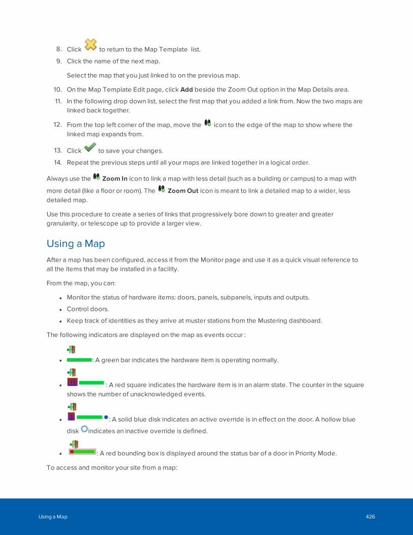
8. Click to return to the Map Template list.
9. Click the name of the next map.
Select the map that you just linked to on the previous map.
10. On the Map Template Edit page, click Add beside the Zoom Out option in the Map Details area.
11. In the following drop down list, select the first map that you added a link from. Now the two maps arelinked back together.
12. From the top left corner of the map, move the icon to the edge of the map to show where thelinked map expands from.
13. Click to save your changes.
14. Repeat the previous steps until all your maps are linked together in a logical order.
Always use the Zoom In icon to link a map with less detail (such as a building or campus) to a map with
more detail (like a floor or room). The ZoomOut icon is meant to link a detailed map to a wider, lessdetailed map.
Use this procedure to create a series of links that progressively bore down to greater and greatergranularity, or telescope up to provide a larger view.
Using a MapAfter a map has been configured, access it from the Monitor page and use it as a quick visual reference toall the items that may be installed in a facility.
From the map, you can:
l Monitor the status of hardware items: doors, panels, subpanels, inputs and outputs.
l Control doors.
l Keep track of identities as they arrive at muster stations from the Mustering dashboard.
The following indicators are displayed on the map as events occur :
l : A green bar indicates the hardware item is operating normally.
l : A red square indicates the hardware item is in an alarm state. The counter in the squareshows the number of unacknowledged events.
l : A solid blue disk indicates an active override is in effect on the door. A hollow blue
disk indicates an inactive override is defined.
l : A red bounding box is displayed around the status bar of a door in Priority Mode.
To access and monitor your site from a map:
Using a Map 426
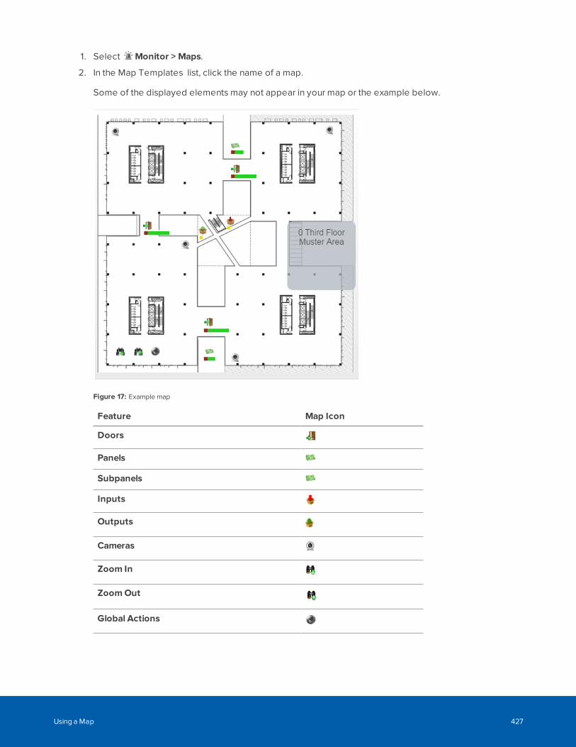
1. Select Monitor > Maps.
2. In the Map Templates list, click the name of a map.
Some of the displayed elements may not appear in your map or the example below.
Figure 17: Example map
Feature Map Icon
Doors
Panels
Subpanels
Inputs
Outputs
Cameras
Zoom In
ZoomOut
Global Actions
Using a Map 427
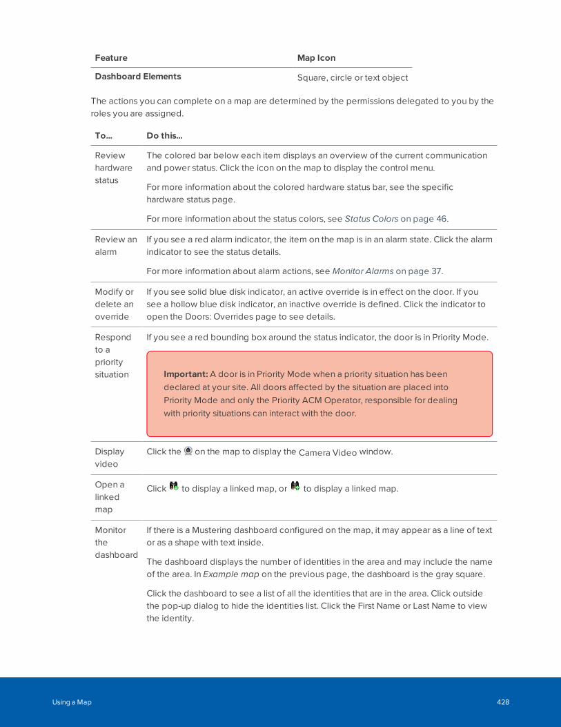
Feature Map Icon
Dashboard Elements Square, circle or text object
The actions you can complete on a map are determined by the permissions delegated to you by theroles you are assigned.
To... Do this...
Reviewhardwarestatus
The colored bar below each item displays an overview of the current communicationand power status. Click the icon on the map to display the control menu.
For more information about the colored hardware status bar, see the specifichardware status page.
For more information about the status colors, see Status Colors on page 46.
Review analarm
If you see a red alarm indicator, the item on the map is in an alarm state. Click the alarmindicator to see the status details.
For more information about alarm actions, see Monitor Alarms on page 37.
Modify ordelete anoverride
If you see solid blue disk indicator, an active override is in effect on the door. If yousee a hollow blue disk indicator, an inactive override is defined. Click the indicator toopen the Doors: Overrides page to see details.
Respondto aprioritysituation
If you see a red bounding box around the status indicator, the door is in Priority Mode.
Important: A door is in Priority Mode when a priority situation has beendeclared at your site. All doors affected by the situation are placed intoPriority Mode and only the Priority ACM Operator, responsible for dealingwith priority situations can interact with the door.
Displayvideo
Click the on the map to display the Camera Video window.
Open alinkedmap
Click to display a linked map, or to display a linked map.
Monitorthedashboard
If there is a Mustering dashboard configured on the map, it may appear as a line of textor as a shape with text inside.
The dashboard displays the number of identities in the area and may include the nameof the area. In Example map on the previous page, the dashboard is the gray square.
Click the dashboard to see a list of all the identities that are in the area. Click outsidethe pop-up dialog to hide the identities list. Click the First Name or Last Name to viewthe identity.
Using a Map 428
Priority Situations
Your site may have requirements for your ACM system to support your organization's emergencyprocedures. Typical emergency procedures might be for potentially life-threatening situations (such as fires,tornadoes, earthquakes, physical attacks), and hazardous situations (such as chemical spills, gas leaks,explosions). Your ACM appliance can provide automated access control of doors connected to Mercurypanels in unpredictable emergency and high-priority situations, including lockdowns and evacuations, tosupport your organization's existing operating procedures.
Important: The functionality to respond to high-priority situations is not supported by HID® VertX®panels. If you only have HID VertX doors at your site, the procedures provided for high-prioritysituations using the ACM system do not apply. If you have a mix of HID VertX and Mercury Securitydoors, do not include HID VertX doors in any group of doors that are associated to your PriorityDoor Policies or Priority Door Global Actions.
If you have Mercury Security doors operating with SimonsVoss SmartIntego wireless locks, refer toSimonsVoss SmartIntego documentation. The ACM lockdown priority operation is superseded bythe Escape and Return state of the SimonsVoss wireless lock when it becomes engaged in alockdown situation.
To respond to a priority situation a Priority ACMOperator activates a Priority Door Policy, which is aspecialized Door Policy that is configured to immediately apply a Priority Mode to a group of doors uponactivation. Optionally, the policy can also set the Door Mode of all the doors to a single value, such as DoorLocked No Access for an emergency lockdown.
While a door is in Priority Mode, it is highlighted in red wherever it appears in the ACM client, such as theDoors listing page and on maps or dashboards. These doors can be controlled only by Priority ACMOperator, who have a Priority Role that allows them this control. A Priority ACM Operator can issuecommands to individual doors in Priority Mode to allow safe exit of trapped people, to allow emergencyresponders in, or to isolate persons of interest, and so on.
Risk of loss of functionality. While a priority situation is active, any configuration change made to theACM system may have unintended consequences. To avoid this risk during an active prioritysituation, do not allow any ACM operator other than the Priority ACM Operator to make (or approve)any configuration changes, including changes in unaffected partitions. For more information, see onpage 436
Upon deactivation of the policy, the Priority Mode is removed and the doors return to the door mode theyare configured to be in at the time. To secure this functionality from unauthorized access, it can all beisolated in a secure Priority Partition.
Priority Situations 429
Planning Priority Door Policies
Analyze all existing door policies at your site before designing and configuring any Priority Door Policies.You must be familiar with all the door policies that are configured at your site. The settings in all of your non-priority and priority door policies must be designed, configured, and tested to ensure that there are nounexpected results after these polices are applied over each other in all possible combinations.
For example, a Priority Door Policy is configured that overwrites only a subset of the door settings. Some ofthose settings are set in the base configuration of a door, and some are reset by the non-priority door policythat is normally in effect at the time the Priority Door Policy is activated. After the priority situation is over andthe Priority Door Policy is deactivated, the currently scheduled non-priority policy is re-activated and appliesits settings.
The priority door policies or other related priority items you configure to support them in the ACM systemmust be:
l Aligned with the emergency procedures in effect at your site.
l Securely isolated so that they cannot be interrupted by lower priority activities.
l Regularly tested and rehearsed to ensure they function as expected, and corrected if they do not.
Note: You can configure Priority Door Global Action pairs. However, Priority Door Global Actionsare not recommended; see Limitations of Priority Global Actions on page 438. Priority Door GlobalActions are specialized Global Actions for doors (the first Priority Global Action applies a PriorityMode, and optionally sets the door mode to a single known value, to a group of doors uponactivation, and the second Priority Global Action restores those doors to the mode they areconfigured to be in at the time).
If you have previously used a pair of Global Actions to respond to a priority situation, consider replacingthem with a single Priority Door Policy, as recommended.
Important: A Priority Door Policy is the most secure way to control access with the ACM system inan emergency situation. It is also more robust than a Priority Door Global Action. A Priority DoorPolicy will stay in effect on the doors it is installed on even if:
l The ACM appliance:
l Is restarted
l Is disconnected from power
l Fails over to a backup appliance
Planning Priority Door Policies 430
l The door or door panel:
l Goes offline
l Is rebooted
l Is disconnected from power
l Is disconnected from the access control network.
Priority Door Policies, Global Actions, and Modes
When activated, a Priority Door Policy or Priority Door Global Action sets all doors in an associated group ofdoors into Priority Mode. Additionally, it can set all these doors to a single configurable door mode (forexample, Locked - No Access) regardless of their current mode when activated.
While a Priority Door Policy or Priority Door Global Action active, only Priority ACM Operator is authorized toissue commands to doors in Priority Mode can change the door mode on specific doors (for example toallow safe exit of trapped people, to allow emergency responders in, or to isolate persons of interest). Afterthe situation is resolved, you can remove the Priority Door Policy or Priority Door Global Action and all thedoors will return to the mode they normally are in at the current time.
Priority Door Policies and Priority Door Global Actions and the associated door Priority Mode are at the topof the ACM system's priority hierarchy. For information about the priority hierarchy, see Priority Hierarchy onpage 439.
A Priority Door Policy is created in the same way as any other door policy, with specific settings that define itas a Priority Door Policy. A Priority Global Action is created in the same way as any other global action,except that it can only be configured for the Door Mode.
Priority Door Policies and Emergencies
Use Priority Door Policies to support your organization's critical emergency response procedures, whichmight include lockdowns and evacuations.
To ensure the security of Priority Door Policies, isolate everything required to manage the Priority DoorPolicy in a Priority Partition, accessible only to the Priority ACM Operator responsible for managing the ACMsystem during an emergency.
The operators, roles and groups associated with Priority Door Policies must be configured to conform toyour organization’s operating procedures:
l Roles to trigger a Priority Door Policy, and the assignment of those roles to operators, must bedefined so that the policy can be activated only in conformance with those operating procedures.
l Door groups that are affected by a Priority Door Policy must be defined so that they cannot beinadvertently altered.
Priority Door Policies, Global Actions, and Modes 431
Secured priority situation response functionality is configured in the following order:
1. Priority Partition: A specialized partition that isolates all the functionality required for a securedresponse to a priority situation.
2. Priority Role: A specialized role for authorized ACM operators responsible for operating the ACMsystem during priority situations. The Priority Role must be assigned the following delegations:
l Policies Set Priority to configure a Priority Door Policy.
l Global Action Set Priority to configure a Priority Global Action.
l Doors Commands During Priority to allow manual control of doors in Priority Mode during apriority situation
3. Priority ACMOperator: An ACM operator authorized to operate the ACM system duringemergencies. This operator is assigned membership of the:
l Priority Role
l Priority Partition
4. Priority Group: A Group that is a member of the Priority Partition that is reserved to associate doorswith Priority Door Policies.
5. Priority Door Policy: A specialized Door Policy that enables the Priority Mode and, optionally, asingle known value for the Door Mode, to be assigned to a group of doors upon activation. A door inPriority Mode is highlighted in red wherever it appears in the ACM client, such as the Doors listingpage and on maps, while a Priority Door Policy is in effect.
For the procedure on securely isolating a Priority Door Policy, see Configuring a Secure High-PriorityEmergency Response below.
Configuring a Secure High-Priority Emergency Response
You can maximize the security of your high-priority emergency response procedure by isolating everythingit requires the ACM system to manage in a dedicated partition, referred to as a Priority Partition. If your site:
l Does not use partitions, you only need to create one Priority Partition.
l Does use partitions, you should determine how many Priority Partitions you require. Whether youneed more than one Priority Partition depends on the complexity and requirements of yourorganization. Consider:
l One Priority Partition for your entire site.
l Several Priority Partitions that do not correspond to the existing ones.
l A matching set of one Priority Partition for each existing partition.
It is recommended that you define as few Priority Partitions and Priority Door Policies as possible. Forexample, do not configure multiple Priority Door Policies with the same settings in the same Priority Partition.
To secure your high-priority emergency response using a Priority Partition, complete the following steps:
Configuring a Secure High-Priority Emergency Response 432
1. Create a partition, and give it a name that identifies it clearly as the Priority Partition.
2. Add all the doors at your site that you want to control in any emergency or high-priority situation asmembers of the Priority Partition. Typically this would be all the doors managed by the ACM system.
3. Create a Priority Role for the Priority ACM Operator and add the following delegations as members:
l Policies Set Priority: Allows the identity to configure a Priority Door Policy.
l Global Action Set Priority: Allows the identity to configure a Priority Global Action.
l Doors Commands During Priority: Allows the identity to use commands to change theattributes of a door in priority mode.
WARNING — Assign these three delegations only to the Priority Role reserved for Priority ACMOperator.
4. Add a new identity, and give it a name that identifies it clearly as the Priority ACM Operator. Assignthe high-priority identity as a member of the:
l Priority Role
l Priority Partition
Alternatively, you can add an existing administrator identity as a member of the Priority Role and thePriority Partition, although this will be less secure.
WARNING — Risk that users other than the Priority ACM Operator can change door modes when aPriority Door Policy is in effect. Users with the Doors Commands During Priority delegation can usecommands to change the door mode. To avoid this risk, assign the Doors Commands During Prioritydelegation only to the Priority Role and assign the Priority Role only to the high-priority ACM systemadministrator.
5. Create a group, and give it a name that identifies it clearly as the Priority Group. Assign the PriorityGroup to the Priority Partition.
6. Create a Priority Door Policy. Assign the Priority Door Policy to the Priority Partition.
7. A Priority Door Policy is created in the same way as any other door policy, with the following fivespecific settings on the Mercury tab:
a. Set the Lock Function to None.
b. Set Custom Schedule to 24 Hours Active.
The Priority checkbox is enabled.
You can use a custom schedule other then the recommended 24 Hours Active. However, theintent of a Priority Door Policy is that it should be used on demand, not on a schedule. Whenyou set the Custom Schedule option for a Priority Door Policy, be aware of the following:
l Holiday and custom schedules must be configured with matching values for the Typeoption so that they can interact.
l Do not set Custom Schedule to Never Active. With this setting, the doors affected gointo Priority Mode when the policy is activated, but their door mode is not updated with
Configuring a Secure High-Priority Emergency Response 433
the value in the policy.
l Do not associate a Priority Door Policy with a schedule that has fixed start and endtimes. The purpose of a Priority Door Policy is to respond to an unanticipated situationwhen it occurs and to stay in effect until the situation is resolved. A Priority Door Policyis intended to be activated on demand only.
l The maximum number of custom schedules is 255 if you use a custom schedule otherthan 24 Hours Active.
c. Click the Priority checkbox.
d. Use the Door mode option to set the mode for all doors to have when this policy is active. Forexample Locked No Access for a policy tor a lockdown, or Unlocked for a policy for anevacuation. Leave this option blank if you want to individually reset each door's mode from itsnormal mode after the policy is activated.
e. Set the Offline Door Mode to the same value as the Door Mode. This ensures that, if the dooris disconnected from network or power during the emergency, the door mode will remain inthe same as the mode set by the Priority Mode while the door is disconnected, or after poweris restored.
CAUTION — Set the offline door mode to match the priority mode. This ensures that the doorstays in the same mode in the event of a subpanel going offline or the subpanel is uninstalledwhile the Priority Door Policy is in effect.
f. Optionally, if there are additional settings that must be retained on all the doors affected bythis policy, ensure they are correctly configured. For example, if there is a door policy thatcontains settings for other options that must be retained through an emergency, and thatpolicy might be installed on these doors at the time of the emergency.
8. Create two Global Actions: to activate the Priority Door Policy, and to deactivate the Priority DoorPolicy. Assign the Global Actions to the Priority Partition.
Create the Global Actions with the following specific settings:
a. Assign each global action to the Priority Partition.
b. Set Type to Policy Install/Un-install.
c. Set the Sub-Type to:
l Install for the global action to activate the Priority Door Policy
l Un-install for the global action to deactivate the Priority Door Policy
d. In each global action, add the Global Door Policy as the only member.
9. Create a new map template. Place the door icons and global actions created in the previous steps onthe map. Assign the map to the Priority Partition.
10. In the Priority Group, associate the Priority Door Policy with all the doors in the Priority Partition.
Configuring a Secure High-Priority Emergency Response 434
Testing a Secure Priority Emergency Response in the ACMSystem
To test that all of your emergency-related configurations and activities are securely isolated:
1. Log out of the ACM client.
2. Log in as the Priority ACM Operator.
3. Activate the Priority Door Policy:
1. Navigate to the priority map.
2. Click on the icon for the global action to activate the Priority Door Policy.
4. Verify that the doors enter into Priority Mode:
l On the priority map, a red bounding box appears over the status bar under each door icon.Hover the mouse over the status bar to see the Door in Priority mode tooltip.
l On the Doors listing page, all users will see a red bounding box over each door in Prioritymode. Commands to change the door made are enabled for the Priority ACM Operator.
5. Log out as the Priority ACM Operator and log in as an ACM client user who is not a member of thePriority Partition, and verify that the user:
l Can see:
l On any map other than the priority map, a red bounding box over the status bar underthe door icon for any door in Priority Mode on that map. Hover the mouse over thestatus bar to see the Door in Priority mode tooltip.
l On the Doors listing page, a red bounding box over each door in Priority mode. Allcommands that affect doors are disabled for the user.
l Cannot see any of the members of the Priority Partition:
l The Priority Door Policy on the Policy list
l The two policy install/uninstall global actions for the Priority Door Policy on theGlobal Actions list.
l The priority group on the Groups list.
l The map template on the Maps list or the Monitor > Maps page.
l Cannot initiate any door commands on any door in priority from the Doors list.
6. Log in as the Priority ACM Operator.
7. Deactivate the Priority Door Policy:
1. Navigate to the priority map.
2. Click on the icon for the global action to deactivate the Priority Door Policy.
8. Log out as the Priority ACM Operator and log in as an ACM client user who is not a member of thePriority Partition, and verify that the user:
Testing a Secure Priority Emergency Response in the ACM System 435
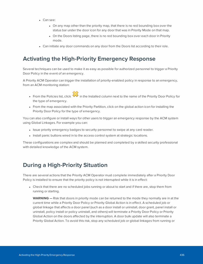
l Can see:
l On any map other than the priority map, that there is no red bounding box over thestatus bar under the door icon for any door that was in Priority Mode on that map.
l On the Doors listing page, there is no red bounding box over each door in Prioritymode.
l Can initiate any door commands on any door from the Doors list according to their role.
Activating the High-Priority Emergency Response
Several techniques can be used to make it as easy as possible for authorized personnel to trigger a PriorityDoor Policy in the event of an emergency.
A Priority ACM Operator can trigger the installation of priority-enabled policy in response to an emergency,from an ACM monitoring station:
l From the Policies list, click in the Installed column next to the name of the Priority Door Policy forthe type of emergency.
l From the map associated with the Priority Partition, click on the global action icon for installing thePriority Door Policy for the type of emergency.
You can also configure or install ways for other users to trigger an emergency response by the ACM systemusing Global Linkages. For example you can:
l Issue priority emergency badges to security personnel to swipe at any card reader.
l Install panic buttons wired in to the access control system at strategic locations.
These configurations are complex and should be planned and completed by a skilled security professionalwith detailed knowledge of the ACM system.
During a High-Priority Situation
There are several actions that the Priority ACM Operator must complete immediately after a Priority DoorPolicy is installed to ensure that the priority policy is not interrupted while it is in effect:
l Check that there are no scheduled jobs running or about to start and if there are, stop them fromrunning or starting.
WARNING — Risk that doors in priority mode can be returned to the mode they normally are in at thecurrent time while a Priority Door Policy or Priority Global Action is in effect. A scheduled job orglobal linkage that affects a door panel (such as a door install or uninstall, door grant, panel install oruninstall, policy install or policy uninstall, and others) will terminate a Priority Door Policy or PriorityGlobal Action on the doors affected by the interruption. A door bulk update will also terminate aPriority Global Action. To avoid this risk, stop any scheduled job or global linkages from running or
Activating the High-Priority Emergency Response 436
starting, during the emergency.
l Verify that there are no global actions or global linkages about to be initiated.
l Verify that there are no other users with any of the high-priority delegations active during theemergency situation. The only exception might be if your organization requires the deployment ofmore than one Priority ACM Operator working in coordination.
WARNING — Risk that users other than the high-priority ACM system administrator can change doormodes when a Priority Door Policy is in effect. Users with the Doors Commands Set Prioritydelegation can use commands to change the door mode. To avoid this risk, assign the DoorsCommands Set Priority delegation only to the Priority Role and assign the Priority Role only to thehigh-priority ACM system administrator.
l Secure the ACM appliance to ensure that it does not accidentally reboot.
l If you are using peer-to-peer or hot standby replication , issue all commands from the same appliancefrom which the Priority Door Policy or Priority Door Global Action was issued.
During the emergency, the Priority ACM Operator can use the ACM client to issue commands to individualdoors in Priority Mode. This allows the Priority ACM Operator to grant access to emergency responders,provide safe exits for trapped people, or isolate persons of interest.
If there are ACM system partitions not affected by the active Priority Door Policy, normal operations cancontinue in those partitions.
While a Priority Door Policy is active, the Priority ACM Operator must ensure that the Priority Partition isisolated and all activities affecting the ACM system are under strict control. In the Priority Partition:
l Do not allow anyone other than the Priority ACM Operator to use the ACM client in the PriorityPartition, and limit the number of people using the ACM client in any other partitions (if any).
l Do not activate additional Priority Door Policies.
WARNING — Risk of unpredictable results installing multiple Priority Door Policies. If you install asecond Priority Door Policy while one is already in effect, the latest created policy takesprecedence, which may not be the most recently installed policy. To avoid this risk, never activate asecond Priority Door Policy until after the first policy is deactivated.
l Do not allow any configuration, maintenance, or scheduled maintenance operations.
l Do not activate any Priority Door Global Actions.
The Priority Door Policy is active until it is deactivated. Deactivation restores doors to their normal doormode for the current time.
Deactivating a Priority Door Policy
The ability to end a Priority Door Policy must be restricted to ensure that your site is fully secured beforenormal access is restored. The Priority ACM Operator is responsible for deactivating the Priority Door Policyafter it is determined that the emergency situation has been resolved and it is safe to return the ACM systemto its normal operating state.
The deactivation of an active Priority Door Policy can only be completed from an ACM monitoring station,
Deactivating a Priority Door Policy 437
regardless of how the policy was triggered:
l From the Policies list, click in the Installed column next to the name of the active Priority DoorPolicy.
l From the map associated with the Priority Partition, click on the global action icon for uninstalling theactive Priority Door Policy.
Limitations of Priority Global Actions
Priority Global Actions are not recommended for emergency situations. A Priority Door Global Action ismuch less robust than a Priority Door Policy. Never use a Priority Door Global Action while a Priority DoorPolicy is activated.
WARNING — There is a risk that, while a Priority Global Action is in effect, doors in priority mode can bereturned to the mode they normally are in at the current time. Any action that interrupts the functioning of theACM appliance or the door panels will terminate a Priority Global Action on the doors affected by theinterruption. Some examples of actions that can cause this are:
l Failover of the ACM appliance
l Reboot of the ACM appliance or a door panel.
l Network disconnection, or a site-wide power recycling or outage.
l Change to any door attribute on the Doors editing page while a door is in priority mode.
l Reset/Download from the Panel Status page.
l Scheduled job or global linkage for a door bulk update.
WARNING — There is a risk that not all doors in a large number of doors set to Priority Mode will correctlyreturn to their normal operating state when a Priority Global Action is used to restore a large number ofdoors. To avoid this risk, when you define a Priority Global Action for doors, also define a group of doorscontaining all the doors associated with that Priority Global Action, and then to restore the doors to theirnormal operating state:
l Navigate to the Doors listing page.
l Filter the list of doors by the group associated with the Priority Global Action.
l Select all the doors in the group.
l Click the Door Action button and select Restore from the drop-down list.
WARNING — Risk of unpredictable results using Priority Global Actions in either a peer-to-peer replicationor hot-standby environment:
l Priority Global Actions executed on one appliance are not mirrored on the other appliance. When aglobal action is executed on one appliance, it only affects the doors that are connected to thatappliance.
l While a Priority Global Action is in effect, and there is a failover to the hot-standby appliance,affected doors can be returned to the mode they normally are in at the current time.
To avoid these risks, use a Priority Door Policy. Priority Door Policies installed on one appliance in either a
Limitations of Priority Global Actions 438
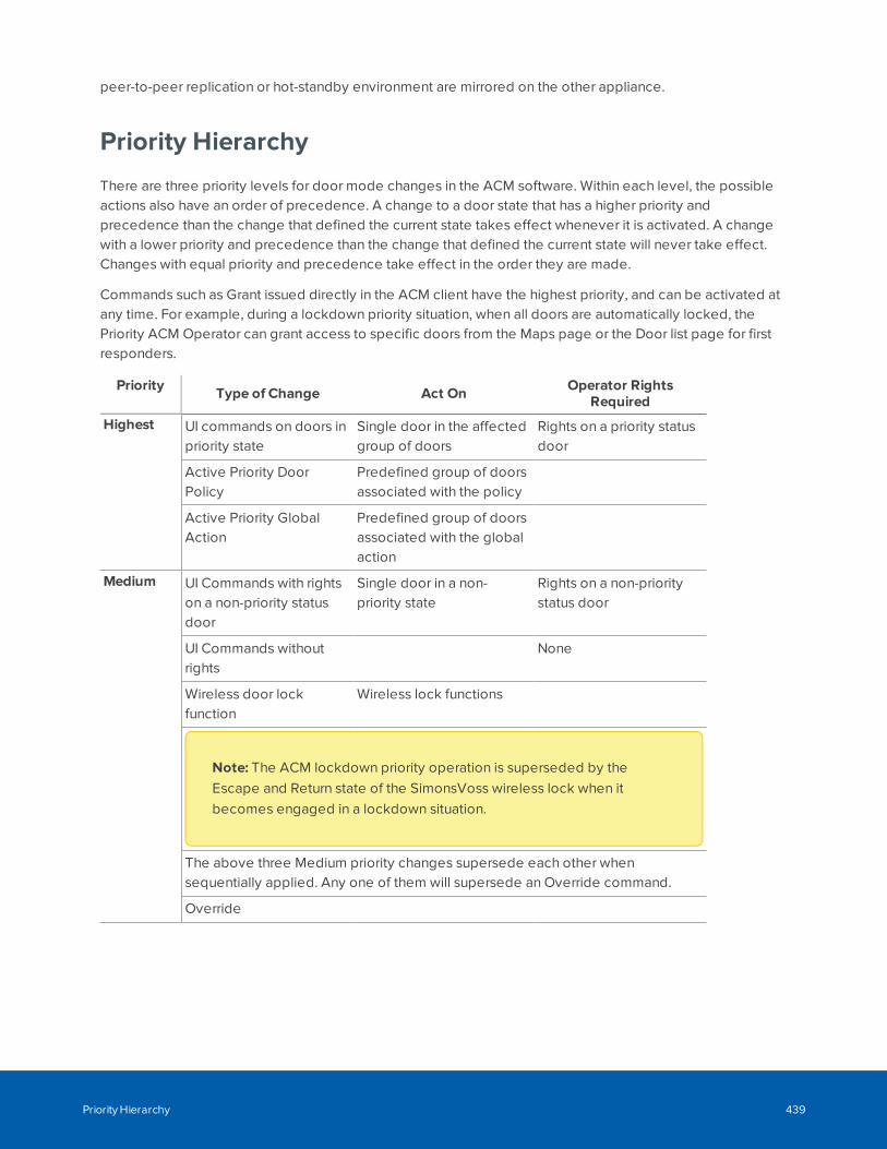
peer-to-peer replication or hot-standby environment are mirrored on the other appliance.
Priority Hierarchy
There are three priority levels for door mode changes in the ACM software. Within each level, the possibleactions also have an order of precedence. A change to a door state that has a higher priority andprecedence than the change that defined the current state takes effect whenever it is activated. A changewith a lower priority and precedence than the change that defined the current state will never take effect.Changes with equal priority and precedence take effect in the order they are made.
Commands such as Grant issued directly in the ACM client have the highest priority, and can be activated atany time. For example, during a lockdown priority situation, when all doors are automatically locked, thePriority ACM Operator can grant access to specific doors from the Maps page or the Door list page for firstresponders.
Priority Type of Change Act On Operator RightsRequired
Highest UI commands on doors inpriority state
Single door in the affectedgroup of doors
Rights on a priority statusdoor
Active Priority DoorPolicy
Predefined group of doorsassociated with the policy
Active Priority GlobalAction
Predefined group of doorsassociated with the globalaction
Medium UI Commands with rightson a non-priority statusdoor
Single door in a non-priority state
Rights on a non-prioritystatus door
UI Commands withoutrights
None
Wireless door lockfunction
Wireless lock functions
Note: The ACM lockdown priority operation is superseded by theEscape and Return state of the SimonsVoss wireless lock when itbecomes engaged in a lockdown situation.
The above three Medium priority changes supersede each other whensequentially applied. Any one of them will supersede an Override command.
Override
Priority Hierarchy 439
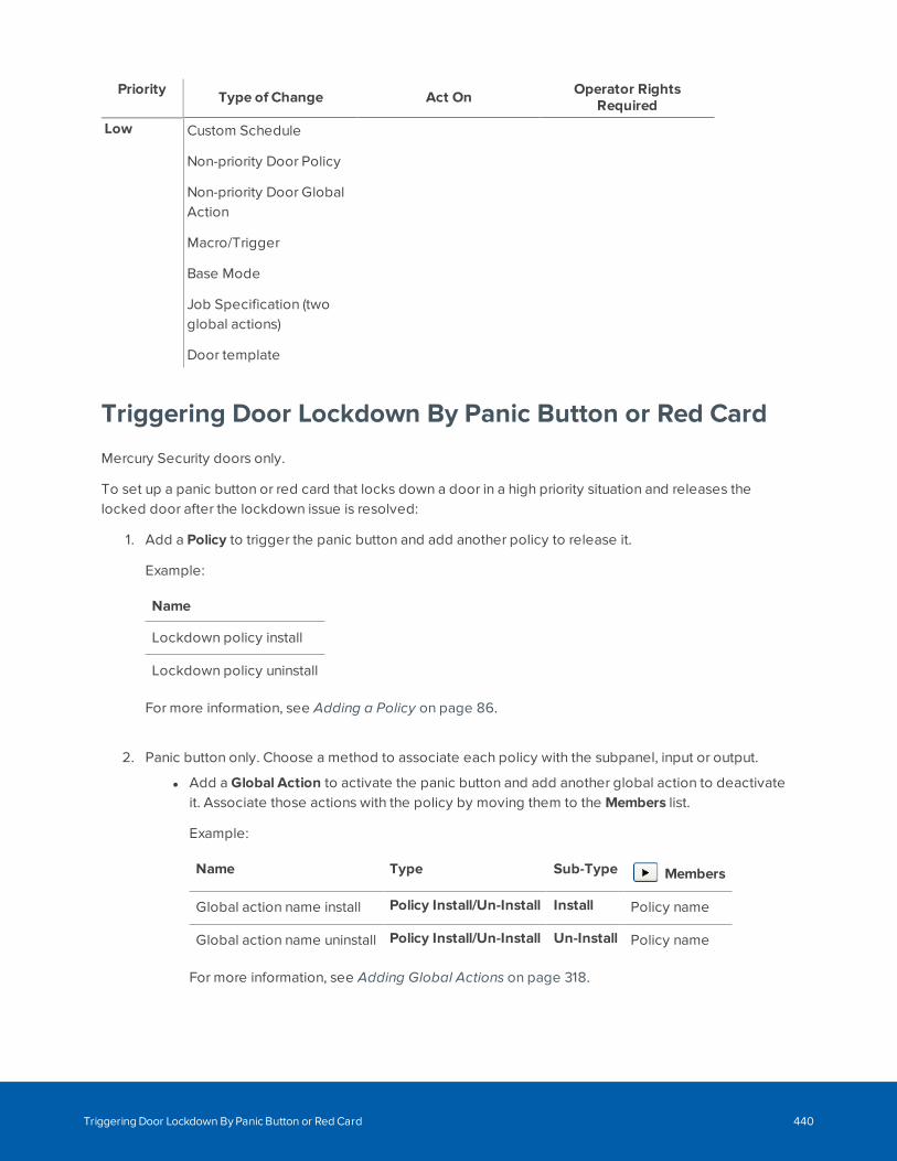
Priority Type of Change Act On Operator RightsRequired
Low Custom Schedule
Non-priority Door Policy
Non-priority Door GlobalAction
Macro/Trigger
Base Mode
Job Specification (twoglobal actions)
Door template
Triggering Door Lockdown By Panic Button or Red Card
Mercury Security doors only.
To set up a panic button or red card that locks down a door in a high priority situation and releases thelocked door after the lockdown issue is resolved:
1. Add a Policy to trigger the panic button and add another policy to release it.
Example:
Name
Lockdown policy install
Lockdown policy uninstall
For more information, see Adding a Policy on page 86.
2. Panic button only. Choose a method to associate each policy with the subpanel, input or output.
l Add a Global Action to activate the panic button and add another global action to deactivateit. Associate those actions with the policy by moving them to the Members list.
Example:
Name Type Sub-Type Members
Global action name install Policy Install/Un-Install Install Policy name
Global action name uninstall Policy Install/Un-Install Un-Install Policy name
For more information, see Adding Global Actions on page 318.
Triggering Door Lockdown By Panic Button or Red Card 440
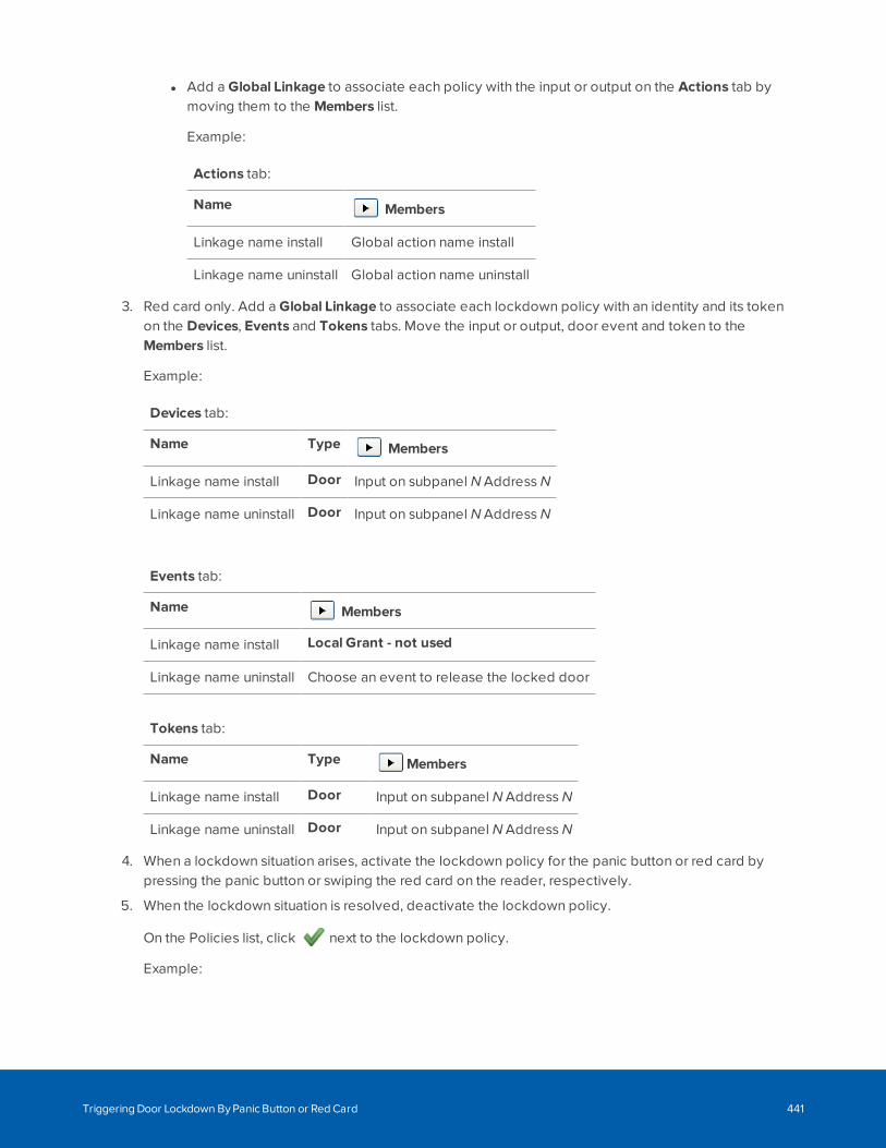
l Add a Global Linkage to associate each policy with the input or output on the Actions tab bymoving them to the Members list.
Example:
Actions tab:
Name Members
Linkage name install Global action name install
Linkage name uninstall Global action name uninstall
3. Red card only. Add a Global Linkage to associate each lockdown policy with an identity and its tokenon the Devices, Events and Tokens tabs. Move the input or output, door event and token to theMembers list.
Example:
Devices tab:
Name Type Members
Linkage name install Door Input on subpanel N Address N
Linkage name uninstall Door Input on subpanel N Address N
Events tab:
Name Members
Linkage name install Local Grant - not used
Linkage name uninstall Choose an event to release the locked door
Tokens tab:
Name Type Members
Linkage name install Door Input on subpanel N Address N
Linkage name uninstall Door Input on subpanel N Address N
4. When a lockdown situation arises, activate the lockdown policy for the panic button or red card bypressing the panic button or swiping the red card on the reader, respectively.
5. When the lockdown situation is resolved, deactivate the lockdown policy.
On the Policies list, click next to the lockdown policy.
Example:
Triggering Door Lockdown By Panic Button or Red Card 441
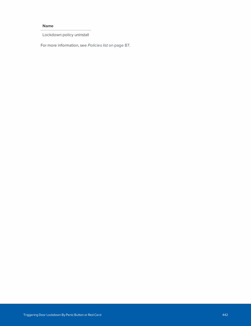
Name
Lockdown policy uninstall
For more information, see Policies list on page 87.
Triggering Door Lockdown By Panic Button or Red Card 442
Overriding Door Modes and Schedules
Note: Overrides are only supported on Mercury panels using firmware 1.27.1 or later. Your currentversion of the ACM software includes compatible firmware you can download to your panels. Youcan create up to 100 overrides on a single panel.
Use overrides to apply a temporary one-time change to the normal door mode of a selected set of doors.For example, to extend or delay opening or closing hours, or for closing on a snow day. Overrides can bescheduled to take effect immediately, or in advance (for example, for a one-time occurrence such as an all-access event next week in a normally locked room). When an override ends, the door or doors each returnto the mode they are supposed to be in according to their schedule at that time. Overrides are not recurring.For almost all purposes, an override should be deleted as soon as it has ended as there is a maximumnumber of overrides per panel.
Override functionality is designed to work best with your regular door schedules. Overrides have a mediumpriority-level in the ACM priority hierarchy and many higher-priority actions take precedence. For moreinformation about this hierarchy see Priority Hierarchy on page 439. For example a manual command to aspecific door, or a priority lockdown command to a set of doors, takes precedence. If a priority lockdownoccurs while an override is in effect, the priority lockdown becomes active. After the priority lockdown hasbeen cleared by the Priority ACM Operator, the override becomes active on the doors if it is still in effect,otherwise each door returns to its regular schedule for that time.
On Mercury panels using firmware earlier than 1.29, an override starts and ends at the beginning of theminute of its scheduled time. On Mercury panels using firmware 1.29 or later, an override starts at thebeginning of the minute and ends at the end of the minute of its specified time. Time overlaps are notsupported. For example, you can specify 1:00 - 1:30 and 1:31 - 1:59 overrides.
Important: You can only add an override to doors you are authorized to access that are on thesame ACM server. However, you can modify or delete any override, and your changes will apply toall the doors in the override, including doors you are not normally authorized to access. Ifpartitioning is used in your ACM system and you expect users authorized for specific partitions tomodify an override, define individual overrides for each partition rather than a single override thatspans multiple partitions. Otherwise, users can modify overrides that affect doors they cannot seeand be unaware of any changes.
Adding an OverrideYou add an override by selecting a set of doors on the Door list, clicking the Override control button,specifying the door mode, and the start and end times of the override.
To add an override:
Overriding Door Modes and Schedules 443
1. Select Physical Access.
2. Click the checkbox for each door you want to add to the override.
If you want to override all the doors you can see in your system, click All at the top of the left columnto select all the doors.
3. Click Override.
4. Select the door action or door mode you want applied to all the doors in the override:
l Disabled — Stops the doors from operating and allows no access.
l Unlocked — Unlocks the doors.
l Locked No Access — Locks the doors.
l Facility CodeOnly — This door can be accessed using a facility code.
l Card Only — This door can be accessed using a card. No PIN is required. See Appendix:pivCLASS Configuration on page 490.
l Pin Only — This door can only be accessed by entering a PIN at a keypad. No card is required.
l Card and Pin — This door can only be accessed using both a card and a PIN.
l Card or Pin — This door can be accessed either by entering a PIN at a keypad or by using acard at the card reader.
Note: The Pin Only and Card or Pin door modes are not available if the Allow duplicate PINsoption has been selected on the System Settings - General page.
5. Specify the date and time settings for Start Day/Time and End Day/Time. Both are required. Time isspecified to the minute. On Mercury panels using firmware earlier than 1.29, the override begins andends at the beginning of the minute you specify. On Mercury panels using firmware 1.29 or later, anoverride starts at the beginning of the minute and ends at the end of the minute of its specified time.Time overlaps are not supported. For example, you can specify 1:00 - 1:30 and 1:31 - 1:59 overrides.
Tip: To start an override immediately, click Now in the Start Day/Time pop-up window.
Important: The date and time the override is active is based on the settings at the controllerpanel for the doors, not the ACM server. If your ACM server is in a time zone ahead of thetime zone of your ACM client and the doors and panels you control, you may see an errormessage that the override occurs in the past. You can ignore this error message if yoursettings in the local time zone are correct.
6. Add an optional note to provide relevant information for future use.
Adding an Override 444
7. If partitions are used, you can restrict the override to only those doors in the Doors Selected list thatare in a specific partition.
8. Click Add.
Accessing the List of OverridesYou can access a list of all overrides from the Doors page:
l Click Overrides: (above the list of doors) to open the Doors: Overrides page for all defined overrides.
Tip: The total number of defined overrides is displayed next to Overrides:.
You can access a list of all overrides for a specific door from the Doors page.
l A blue disk in the Override column for a door indicates overrides are defined for the door. The diskhas two states:
l : An override is currently active.
l : An override is defined, but not active. An inactive override can be an override that hasbeen completed but not deleted, or an override that has not yet started.
l Click the disk to open the Doors: Overrides page listing all the overrides for that door.
Tip: Completed overrides must be manually deleted. Overrides are intended to be temporaryactions for use on an as-needed basis. Most overrides should be deleted as soon as they arecompleted and no longer needed. Keep only override definitions that are highly likely to be re-used as defined, with only the start and end time and date settings modified.
For more information, see Modifying and Deleting Overrides on the next page.
Monitoring OverridesUse the Maps feature to monitor overrides on doors. When a door that is displayed on a map is included inan override, the status indicator for the door is updated to display a blue disk. The disk indicates overridesare defined for the door. The disk has two states:
l : An override is currently active.
l : An override is defined, but not active. An inactive override can be an override that has beencompleted but not deleted, or an override that has not yet started.
For example, if an override is active on a door, a solid blue disk is displayed next to the green bar:
For more information, see Using a Map on page 426.
Accessing the List of Overrides 445
Modifying and Deleting Overrides
On the Doors: Override page you can select an override to modify or delete overrides.
To modify the override:
1. Click on the override name in the Name column to open the Override: Edit page.
If partitions are used, and doors you cannot see are included in the override "One or more doors inthis override are in partitions you cannot see. These doors will be affected by your changes if youcontinue." is displayed. You can modify all the override settings, but only add or remove doors thatyou are authorized to see.
2. Make the modifications you need.
l All settings can be modified if partitions are not used in your ACM system.
l In the Doors Selected section, you can add doors to the override by highlighting them in theAvailable list and moving them to the Members list.
3. Click .
To edit the base settings of any door in the override:
l Click on the door name in the Selected column.
Changes made to the base settings do not take effect until the override expires.
To delete an override:
l Click .
The time the override is deleted is logged by the system. When an active override is deleted, thedoor or doors each return to the mode they are supposed to be in according to their schedule at thattime.
Modifying an Override
To modify the override:
1. Select the door action or door mode you want applied to all the doors in the override:
l Disabled — Stops the doors from operating and allows no access.
l Unlocked — Unlocks the doors.
l Locked No Access — Locks the doors.
l Facility CodeOnly — This door can be accessed using a facility code.
l Card Only — This door can be accessed using a card. No PIN is required. See Appendix:pivCLASS Configuration on page 490.
l Pin Only — This door can only be accessed by entering a PIN at a keypad. No card is required.
Modifying and Deleting Overrides 446
l Card and Pin — This door can only be accessed using both a card and a PIN.
l Card or Pin — This door can be accessed either by entering a PIN at a keypad or by using acard at the card reader.
Note: The Pin Only and Card or Pin door modes are not available if the Allow duplicate PINsoption has been selected on the System Settings - General page.
2. In the Doors Selected section, add doors to the override by highlighting them in the Available list andmoving them to the Members list.
Important: If partitions are used, only doors that are not in any partition or are in the partitionsyou are authorized to see are displayed in the Doors Selected list.
3. Specify the date and time settings for Start Day/Time and End Day/Time. Both are required. Time isspecified to the minute. On Mercury panels using firmware earlier than 1.29, the override begins andends at the beginning of the minute you specify. On Mercury panels using firmware 1.29 or later, anoverride starts at the beginning of the minute and ends at the end of the minute of its specified time.Time overlaps are not supported. For example, you can specify 1:00 - 1:30 and 1:31 - 1:59 overrides.
Tip: To start an override immediately, click Now in the Start Day/Time pop-up window.
Important: The date and time the override is active is based on the settings at the controllerpanel for the doors, not the ACM server. If your ACM server is in a time zone ahead of thetime zone of your ACM client and the doors and panels you control, you may see an errormessage that the override occurs in the past. You can ignore this error message if yoursettings in the local time zone are correct.
4. Add an optional note to provide relevant information for future use.
5. If partitions are used, you can restrict the override to only those doors in the Doors Selected list thatare in a specific partition.
6. Click .
Modifying an Override 447
Setting Personal Preferences
To set up your personal preferences, select > My Account from the top-right. Navigate through thetabbed pages and edit the details as required. The tabbed pages include:
l Profile: use this page to edit your account details and preferences.
l Batch Jobs: use this page to view the batch jobs that have been run from your account.
l Job Specification: use this page to add, edit, activate/ deactivate, or delete batch jobs.
Changing the Password in My Account
While you are logged in to the ACM system, you can choose to change your password any time from the MyAccount page.
1. In the top-right, select > My Account.
2. On the following Profile page, enter your current password in the Old Password field.
3. In the Password field, enter your new password.
As you enter your new password, the status bar underneath will tell you the strength of yourpassword. Red is weak, while green is very strong. Use a combination of numbers, letters, andsymbols to increase the password strength. The password must be at least 4 characters long.
4. Click to save your new password.
A system message tells you that you will be logged out.
5. When the login screen appears, log in with your new password.
Scheduling Batch Jobs
Batch jobs are processes, such as generating reports, that are performed automatically, according to aschedule.
From the Job Specification page, you can create the following batch jobs:
Generating a Batch ReportBatch reports are custom reports generated on a schedule and which can contain more data than reportsgenerated from the Reports list, the Report Edit page or from the Report Preview page.
There are no length limits on any batch reports generated in the CSV spreadsheet format. In PDF format, theAudit Log report is limited to 13,000 records, the Identity Summary Report is limited to 100,000 records, andthe Transaction Report is limited to 50,000 records.
WARNING — Risk of system becoming unusable. Scheduling large reports on separate but overlapping
Setting Personal Preferences 448
schedules, may cause memory problems that can result in the ACM system being unusable. To avoid thisrisk, schedule the start times for large reports, such as audit logs in any format, to allow for each report tofinish before the next starts.
Perform this procedure to generate a custom report on a schedule.
1. Select >My Account and click the Job Specification tab.
The Job Specification page is displayed.
2. Click the Add button.
The Job Specification - General dialog box is displayed.
3. In the Appliance drop down list, select the appliance on which this job will run.
Only those appliances previously defined for this system appear in this option list.
If only one appliance is used for this system (the default), this field is automatically populated.
4. In the Name field, enter a name for this batch job.
5. From the Type drop down list, select Report.
After you select the job type, additional options are displayed.
l From the Report drop down list, select the report you want to batch.
Only custom reports appear in this list.
l From the Output Format drop down list, select the format in which you want this jobgenerated.
6. Click Next.
The following screen shows the select report definition. Click Back to select a different report.
7. Click Next to continue.
8. On the following page, select how often the batch report is generated. From the Repeat drop downlist, select one of the following options:
l Once —- The report will be generated once. Click the On field to display the calendar andselect a specific date and time.
l Hourly — The report will be generated at the same minute of every hour. Enter the minutewhen the report is generated at each hour. For example, if you want the report generated at1:30, 2:30, etc. then you would enter 30.
l Daily — The report will be generated every day at the same time. Enter the specific time whenthe report is generated in 24 hour time format.
l Weekly — The report will be generated each week on the same day and time. Select thecheckbox for each day the report will be generated, and enter the specific time in 24 hourformat.
Generating a Batch Report 449
l Monthly — The report will be generated each month on the same day and time. Select thedays when the report is generated and enter the specific time in 24 hour format. Shift + clickto select a series of days, or Ctrl + click to select separate days.
9. Click Next.
A summary is displayed.
Select the Send Email checkbox if you want to receive an email copy of the report after it has beengenerated. In the following field, enter your email address.
10. Click Submit to create this job.
11. To activate or deactivate this job, select the job and click Activate/Deactivate
Applying an Identity Profile to a Group Using a Job SpecificationCreate and schedule an Identity Updatebatch job to apply a new, updated or temporary identity profile toall of the identities in a predefined group.
After you make changes to an identity profile, the identities previously created from the identity profile arenot automatically updated. Using a job specification and scheduling the job is one of the ways that thesechanges can be applied.
Scenarios to apply an identity profile to a group of identities include:
l To apply a set of standard settings. When you have many identities defined with non-standardsettings, create a group containing these users and a new profile containing the standard settings.Then apply the new profile to the group of identities.
l To apply modified settings in a commonly used identity profile. After you make changes to anidentity profile, the identities created from the identity profile are not automatically updated. Youneed to create a batch job to apply these changes. Create a group of all the users that were createdusing this profile, and then apply the modified profile to that group. If the profile is frequentlymodified, you can create a repeating schedule.
l To apply a profile temporarily to a group. When you have identities that require a different profile fora short time that cannot be cannot be satisfied using a policy, you can use an Identity Update batchjob to "turn on" a temporary profile for a specified duration, and then "turn off" that profile byreplacing it with a permanent profile. If the temporary profile is used repeatedly in a predictablemanner, you can create a repeating schedule.
Note: A group containing all of the identities previously created from the identity profile must becreated before the changes can be applied to the group. If the required groups have not beencreated, contact your System Administrator.
When you choose to create an Identity Update job, you have the option to apply a new, updated ortemporary identity profile to the group.
A temporary door template is one that is applied for a specific period of time (either once or repeating) Youcan apply a temporary door template to a group by using the Off Identity Profile option. Once the new
Applying an Identity Profile to a Group Using a Job Specification 450
identity profile expires, the original identity profile is applied.
To create an Identity Update job specification:
1. Select > My Account and click the Job Specification tab.
The Job Specification page is displayed.
2. Click the Add button.
The Job Specification dialog box is displayed.
3. In the Appliance drop down list, select the appliance on which this job will run.
Only those appliances previously defined for this system appear in this option list.
If only one appliance is used for this system (the default), this field is automatically populated.
4. In the Name field, enter a name for this batch job.
5. From the Type drop down list, select Identity Update.
After you select the job type, more options are displayed.
l From the Group drop down list, select the group of identities that you want to change.
l From the Identity Profile drop down list, select the identity profile that you want to apply to thegroup. If you are applying a temporary profile, this is the "on" profile.
l From the Off Identity Profile drop down list, select the identity profile to be applied if you wantan identity profile applied temporarily (that is, you want the identity profile to expire).
l From the Output Format drop down list, select the format for the report that is generatedwhen the job is complete.
6. Click Next to continue.
The Job Specification - Schedule dialog box is displayed.
7. From the Repeat drop down list, select how often this batch job is run. Then specify the time youwant the profile to be applied. If you selected an Off Identity Profile, you also specify when the Offprofile is applied.
l Once —- The batch job is run once. Click the On and Off fields to display the calendar andselect a specific date and time.
l Hourly — The batch job is run at the same minute of every hour. Enter the minute when thebatch job is run at each hour. For example, if you want the job to run at 1:30, 2:30, etc. then youwould enter 30.
l Daily — The batch job is run every day at the same time. Enter the specific time when the jobis run in 24 hour time format.
l Weekly — The batch job is run each week on the same day and time. Select the checkbox foreach day the job will run, and enter the specific time in 24 hour format.
l Monthly — The batch job is run each month on the same day and time. Select the days whenthe job will run and enter the specific time in 24 hour format. Shift + click to select a series ofdays, or Ctrl + click to select separate days.
Applying an Identity Profile to a Group Using a Job Specification 451
8. Click Next.
A summary is displayed.
9. Click Submit to create this job.
10. To activate or deactivate this job, select the job and click Activate/Deactivate.
Applying a Door Template to a Group Using a Job SpecificationCreate and schedule a Door Update batch job to apply a new, updated or temporary door template to all ofthe doors in a predefined group.
After you make changes to a door template, the doors previously created from the door template are notautomatically updated. Using a job specification and scheduling the job is one of the ways that thesechanges can be applied.
Scenarios to apply a door template to a group of doors include:
l To apply a set of standard settings. When you have many doors defined with non-standard settings,create a group containing doors and a new template containing the standard settings. Then apply thenew template to the group of doors.
l To apply modified settings in a commonly used door template. After you make changes to a doortemplate, the identities created from the door template are not automatically updated. You need tocreate a batch job to apply these changes. Create a group of all the doors that were created usingthis template, and then apply the modified template to that group. If the template is frequentlymodified, you can create a repeating schedule.
l To apply a template temporarily to a group. When you have doors that require a different templatefor a short time that cannot be cannot be satisfied using a policy, you can use an Identity Updatebatch job to "turn on" a temporary template for a specified duration, and then "turn off" that templateby replacing it with a permanent template. If the temporary template is used repeatedly in apredictable manner, you can create a repeating schedule.
Note: A group containing all of the doors previously created from the door template must becreated before the changes can be applied to the group. If the required groups have not beencreated, contact your System Administrator.
When you choose to create a Door Update job, you have the option to apply a new, updated or temporarydoor template to the group.
A temporary door template is one that is applied for a specific period of time (either once or repeating). Youcan apply a temporary door template to a group by using the Off Door Template option. Once the new doortemplate expires, the original door template is applied.
To create a Door Update job specification:
Applying a Door Template to a Group Using a Job Specification 452
1. Select > My Account and click the Job Specification tab.
The Job Specification page is displayed.
2. Click the Add button.
The Job Specification - General dialog box is displayed. All options marked with * are required.
3. In the Appliance drop down list, select the appliance on which this job will run.
Only those appliances previously defined for this system appear in this option list.
If only one appliance is used for this system (the default), this field is automatically populated.
4. In the Name field, enter a name for this batch job.
5. From the Type drop down list, select Door Update.
After you select the job type, additional options are displayed.
l From the Group drop down list, select the group of doors that you want to change.
l From the Door Template drop down list, select the door template that you want to apply tothe group.
l From the Off Door Template drop down list, you have the option to select to an alternativedoor template when the first door template expires.
l From the Output Format drop down list, select the format for the report that is generatedwhen the job is complete.
6. Click Next to continue.
The Job Specification - Schedule dialog box is displayed.
7. Select how often this batch job is run. From the Repeat drop down list, select one of the followingoptions:
If you selected an Off Door Template, you will have the option to enter when the Off template isapplied. Otherwise, only the On field is displayed.
l Once —- The batch job is run once. Click the On field to display the calendar and select aspecific date and time.
l Hourly — The batch job is run at the same minute of every hour. Enter the minute when thebatch job is run at each hour. For example, if you want the job to run at 1:30, 2:30, etc. then youwould enter 30.
l Daily — The batch job is run every day at the same time. Enter the specific time when the jobis run in 24 hour time format.
l Weekly — The batch job is run each week on the same day and time. Select the checkbox foreach day the job will run, and enter the specific time in 24 hour format.
l Monthly — The batch job is run each month on the same day and time. Select the days whenthe job will run and enter the specific time in 24 hour format. Shift + click to select a series ofdays, or Ctrl + click to select separate days.
Applying a Door Template to a Group Using a Job Specification 453
8. Click Next.
A summary is displayed.
9. Click Submit to create this job.
10. To activate or deactivate this job, select the job from the list in the Batch Job Specifications window
and click Activate/Deactivate.
Scheduling a Global ActionPerform this procedure to schedule global actions.
Note: The global actions must be created before they can be scheduled. If the required globalactions have not been created, contact your System Administrator.
1. Select >My Account and click the Job Specification tab.
The Job Specification page appears.
2. Click the Add button.
The Job Specification dialog box is displayed.
3. In the Appliance drop down list, select the appliance on which this job will run.
Only those appliances previously defined for this system appear in this option list.
If only one appliance is used for this system (the default), this field is automatically populated.
4. In the Name field, enter a name for this batch job.
5. From the Type drop down list, select Global Action.
After you select the job type, additional options are displayed.
l From the Global Action drop down list, select global action to perform. Only configured globalactions will appear on the list.
l From the Off Global Action drop down list, you have the option to select to a global action thatis performed after the first global action expires.
l From the Output Format drop down list, select the format for the report that is generatedwhen the job is complete.
6. Click Next to continue.
Scheduling a Global Action 454
7. On the following page, select how often this batch job is run. From the Repeat drop down list, selectone of the following options:
l Once —- The batch job is run once. Click the On field to display the calendar and select aspecific date and time.
l Hourly — The batch job is run at the same minute of every hour. Enter the minute when thebatch job is run at each hour. For example, if you want the job to run at 1:30, 2:30, etc. then youwould enter 30.
l Daily — The batch job is run every day at the same time. Enter the specific time when the jobis run in 24 hour time format.
l Weekly — The batch job is run each week on the same day and time. Select the checkbox foreach day the job will run, and enter the specific time in 24 hour format.
l Monthly — The batch job is run each month on the same day and time. Select the days whenthe job will run and enter the specific time in 24 hour format. Shift + click to select a series ofdays, or Ctrl + click to select separate days.
Note: If you selected an Off Global Action, you will have the option to enter when the Offaction occurs. Otherwise, only the On field is displayed.
8. Click Next.
A summary is displayed.
9. Click Submit to create this job.
10. To activate or deactivate this job, select the job and click Activate/Deactivate.
Setting Batch Door ModesPerform this procedure to change the door mode for a set of doors.
1. Select >My Account and click the Job Specification tab.
2. Click the Add button.
The Job Specification dialog box is displayed.
3. In the Appliance drop down list, select the appliance on which this job will run.
Only those appliances previously defined for this system appear in this option list.
If only one appliance is used for this system (the default), this field is automatically populated.
4. In the Name field, enter a name for this batch job.
5. From the Type drop down list, select Door Mode.
After you select the job type, additional options are displayed.
Setting Batch Door Modes 455
l From the Available list, select the required doors then click to add it to the Members list.
l From the On Door mode drop down list, select the door mode that you want to apply to theselected doors.
l From the Off Door mode drop down list, select the door mode that you want to apply to thedoors when the On action is complete.
l From the Output Format drop down list, select the format for the report that is generatedwhen the job is complete.
l Select the Activate checkbox to make the door modes active.
6. Click Next to continue.
7. On the following page, select how often this batch job is run. From the Repeat drop down list, selectone of the following options:
l Once —- The batch job is run once. Click the On field to display the calendar and select aspecific date and time.
l Hourly — The batch job is run at the same minute of every hour. Enter the minute when thebatch job is run at each hour. For example, if you want the job to run at 1:30, 2:30, etc. then youwould enter 30.
l Daily — The batch job is run every day at the same time. Enter the specific time when the jobis run in 24 hour time format.
l Weekly — The batch job is run each week on the same day and time. Select the checkbox foreach day the job will run, and enter the specific time in 24 hour format.
l Monthly — The batch job is run each month on the same day and time. Select the days whenthe job will run and enter the specific time in 24 hour format. Shift + click to select a series ofdays, or Ctrl + click to select separate days.
Note: If you selected an Off Door Mode, you will have the option to enter when the Offaction occurs. Otherwise, only the On field is displayed.
8. Click Next.
A summary is displayed.
9. Click Submit to create this job.
Setting Batch Door Modes 456
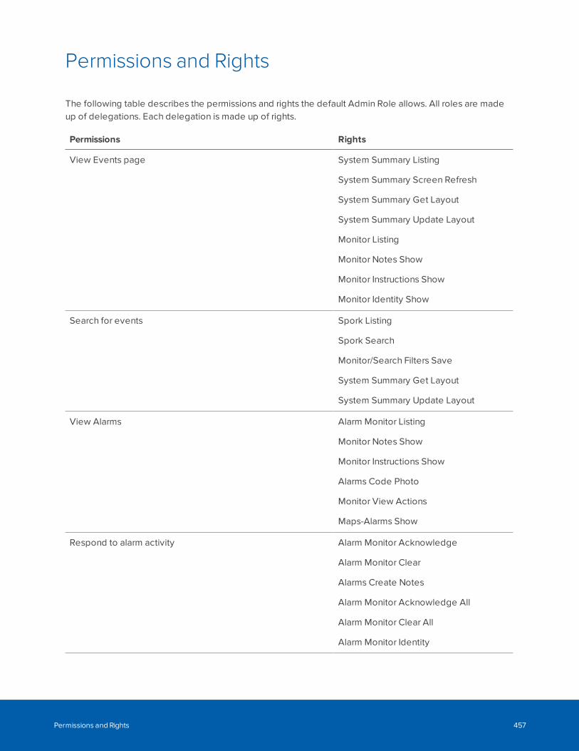
Permissions and Rights
The following table describes the permissions and rights the default Admin Role allows. All roles are madeup of delegations. Each delegation is made up of rights.
Permissions Rights
View Events page System Summary Listing
System Summary Screen Refresh
System Summary Get Layout
System Summary Update Layout
Monitor Listing
Monitor Notes Show
Monitor Instructions Show
Monitor Identity Show
Search for events Spork Listing
Spork Search
Monitor/Search Filters Save
System Summary Get Layout
System Summary Update Layout
View Alarms Alarm Monitor Listing
Monitor Notes Show
Monitor Instructions Show
Alarms Code Photo
Monitor View Actions
Maps-Alarms Show
Respond to alarm activity Alarm Monitor Acknowledge
Alarm Monitor Clear
Alarms Create Notes
Alarm Monitor Acknowledge All
Alarm Monitor Clear All
Alarm Monitor Identity
Permissions and Rights 457
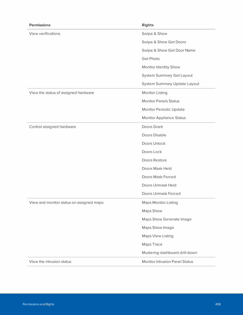
Permissions Rights
View verifications Swipe & Show
Swipe & Show Get Doors
Swipe & Show Get Door Name
Get Photo
Monitor Identity Show
System Summary Get Layout
System Summary Update Layout
View the status of assigned hardware Monitor Listing
Monitor Panels Status
Monitor Periodic Update
Monitor Appliance Status
Control assigned hardware Doors Grant
Doors Disable
Doors Unlock
Doors Lock
Doors Restore
Doors Mask Held
Doors Mask Forced
Doors Unmask Held
Doors Unmask Forced
View and monitor status on assigned maps Maps Monitor Listing
Maps Show
Maps Show Generate Image
Maps Show Image
Maps View Listing
Maps Trace
Mustering dashboard drill-down
View the intrusion status Monitor Intrusion Panel Status
Permissions and Rights 458
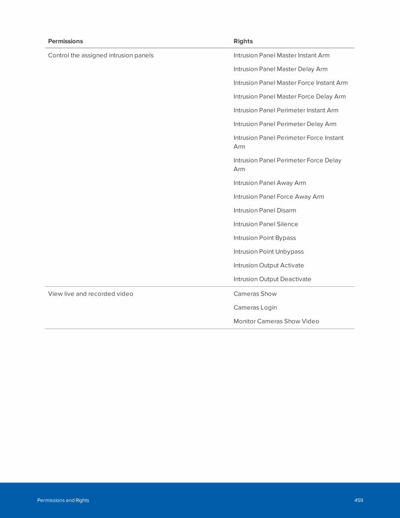
Permissions Rights
Control the assigned intrusion panels Intrusion Panel Master Instant Arm
Intrusion Panel Master Delay Arm
Intrusion Panel Master Force Instant Arm
Intrusion Panel Master Force Delay Arm
Intrusion Panel Perimeter Instant Arm
Intrusion Panel Perimeter Delay Arm
Intrusion Panel Perimeter Force InstantArm
Intrusion Panel Perimeter Force DelayArm
Intrusion Panel Away Arm
Intrusion Panel Force Away Arm
Intrusion Panel Disarm
Intrusion Panel Silence
Intrusion Point Bypass
Intrusion Point Unbypass
Intrusion Output Activate
Intrusion Output Deactivate
View live and recorded video Cameras Show
Cameras Login
Monitor Cameras Show Video
Permissions and Rights 459
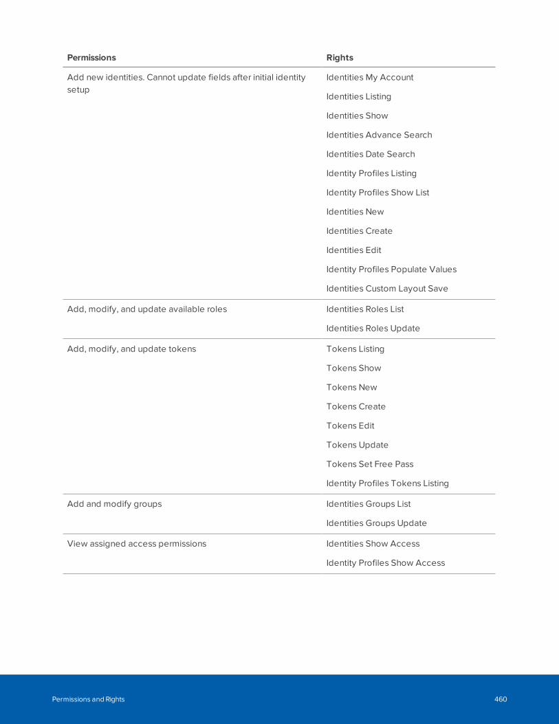
Permissions Rights
Add new identities. Cannot update fields after initial identitysetup
Identities My Account
Identities Listing
Identities Show
Identities Advance Search
Identities Date Search
Identity Profiles Listing
Identity Profiles Show List
Identities New
Identities Create
Identities Edit
Identity Profiles Populate Values
Identities Custom Layout Save
Add, modify, and update available roles Identities Roles List
Identities Roles Update
Add, modify, and update tokens Tokens Listing
Tokens Show
Tokens New
Tokens Create
Tokens Edit
Tokens Update
Tokens Set Free Pass
Identity Profiles Tokens Listing
Add and modify groups Identities Groups List
Identities Groups Update
View assigned access permissions Identities Show Access
Identity Profiles Show Access
Permissions and Rights 460
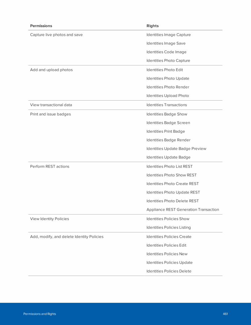
Permissions Rights
Capture live photos and save Identities Image Capture
Identities Image Save
Identities Code Image
Identities Photo Capture
Add and upload photos Identities Photo Edit
Identities Photo Update
Identities Photo Render
Identities Upload Photo
View transactional data Identities Transactions
Print and issue badges Identities Badge Show
Identities Badge Screen
Identities Print Badge
Identities Badge Render
Identities Update Badge Preview
Identities Update Badge
Perform REST actions Identities Photo List REST
Identities Photo Show REST
Identities Photo Create REST
Identities Photo Update REST
Identities Photo Delete REST
Appliance REST Generation Transaction
View Identity Policies Identities Policies Show
Identities Policies Listing
Add, modify, and delete Identity Policies Identities Policies Create
Identities Policies Edit
Identities Policies New
Identities Policies Update
Identities Policies Delete
Permissions and Rights 461
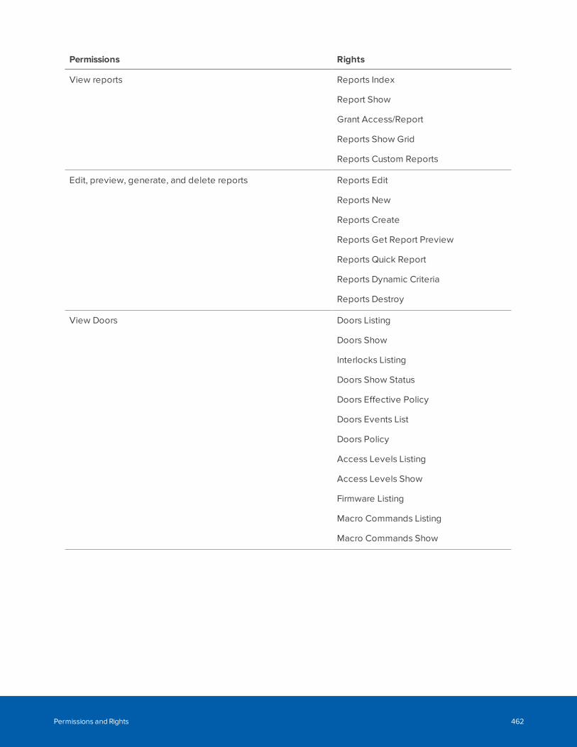
Permissions Rights
View reports Reports Index
Report Show
Grant Access/Report
Reports Show Grid
Reports Custom Reports
Edit, preview, generate, and delete reports Reports Edit
Reports New
Reports Create
Reports Get Report Preview
Reports Quick Report
Reports Dynamic Criteria
Reports Destroy
View Doors Doors Listing
Doors Show
Interlocks Listing
Doors Show Status
Doors Effective Policy
Doors Events List
Doors Policy
Access Levels Listing
Access Levels Show
Firmware Listing
Macro Commands Listing
Macro Commands Show
Permissions and Rights 462
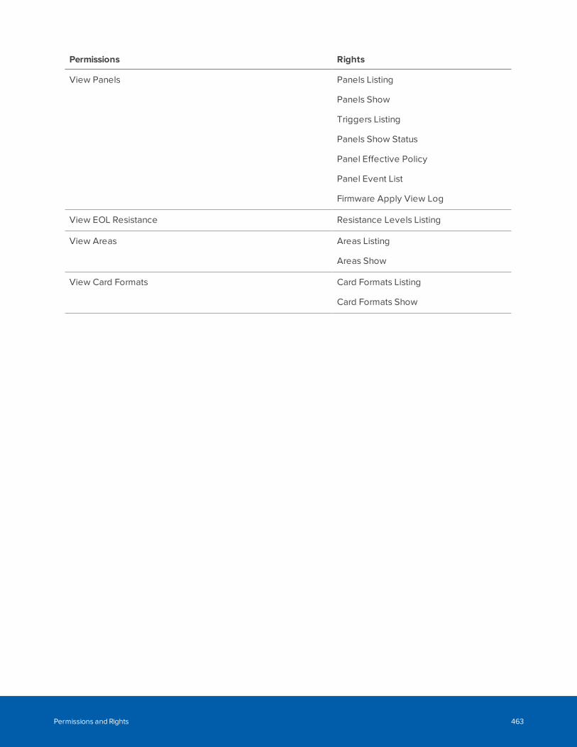
Permissions Rights
View Panels Panels Listing
Panels Show
Triggers Listing
Panels Show Status
Panel Effective Policy
Panel Event List
Firmware Apply View Log
View EOL Resistance Resistance Levels Listing
View Areas Areas Listing
Areas Show
View Card Formats Card Formats Listing
Card Formats Show
Permissions and Rights 463
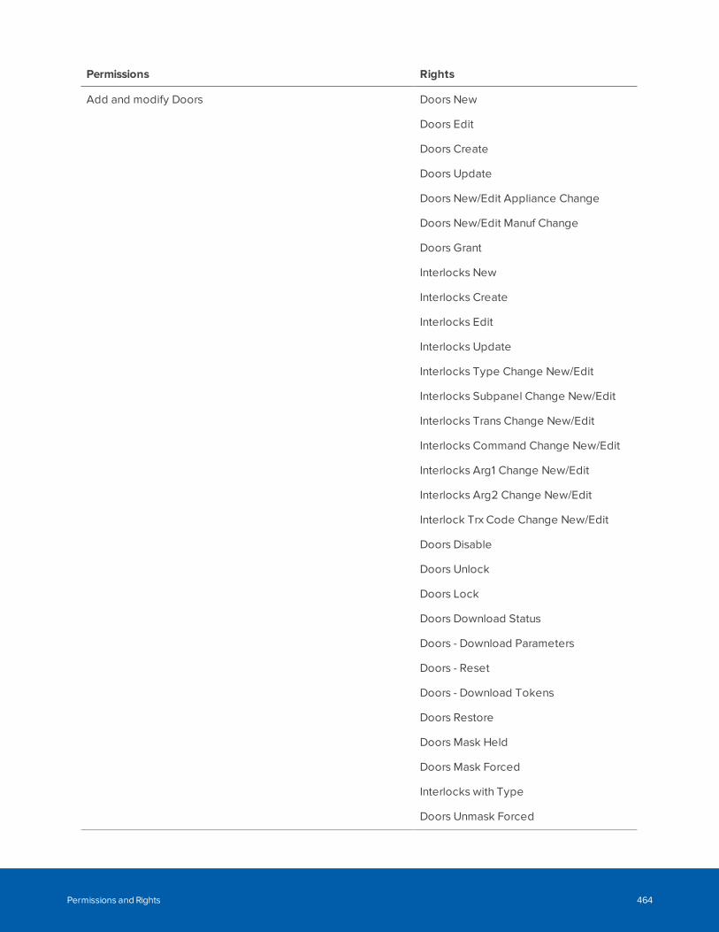
Permissions Rights
Add and modify Doors Doors New
Doors Edit
Doors Create
Doors Update
Doors New/Edit Appliance Change
Doors New/Edit Manuf Change
Doors Grant
Interlocks New
Interlocks Create
Interlocks Edit
Interlocks Update
Interlocks Type Change New/Edit
Interlocks Subpanel Change New/Edit
Interlocks Trans Change New/Edit
Interlocks Command Change New/Edit
Interlocks Arg1 Change New/Edit
Interlocks Arg2 Change New/Edit
Interlock Trx Code Change New/Edit
Doors Disable
Doors Unlock
Doors Lock
Doors Download Status
Doors - Download Parameters
Doors - Reset
Doors - Download Tokens
Doors Restore
Doors Mask Held
Doors Mask Forced
Interlocks with Type
Doors Unmask Forced
Permissions and Rights 464
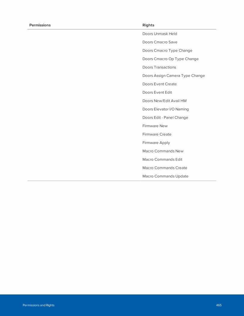
Permissions Rights
Doors Unmask Held
Doors Cmacro Save
Doors Cmacro Type Change
Doors Cmacro Op Type Change
Doors Transactions
Doors Assign Camera Type Change
Doors Event Create
Doors Event Edit
Doors New/Edit Avail HW
Doors Elevator I/O Naming
Doors Edit - Panel Change
Firmware New
Firmware Create
Firmware Apply
Macro Commands New
Macro Commands Edit
Macro Commands Create
Macro Commands Update
Permissions and Rights 465
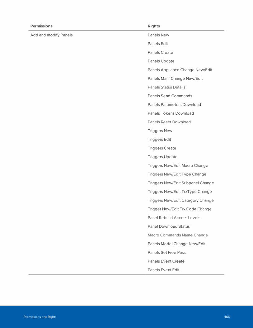
Permissions Rights
Add and modify Panels Panels New
Panels Edit
Panels Create
Panels Update
Panels Appliance Change New/Edit
Panels Manf Change New/Edit
Panels Status Details
Panels Send Commands
Panels Parameters Download
Panels Tokens Download
Panels Reset Download
Triggers New
Triggers Edit
Triggers Create
Triggers Update
Triggers New/Edit Macro Change
Triggers New/Edit Type Change
Triggers New/Edit Subpanel Change
Triggers New/Edit TrxType Change
Triggers New/Edit Category Change
Trigger New/Edit Trx Code Change
Panel Rebuild Access Levels
Panel Download Status
Macro Commands Name Change
Panels Model Change New/Edit
Panels Set Free Pass
Panels Event Create
Panels Event Edit
Permissions and Rights 466
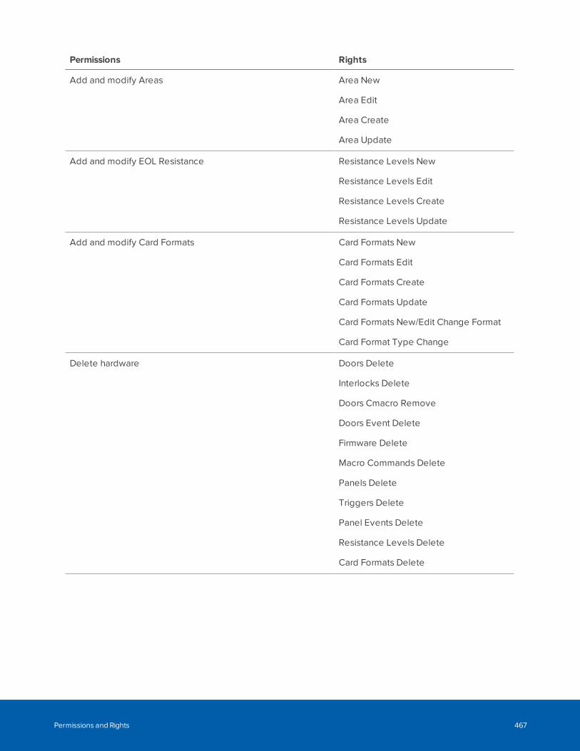
Permissions Rights
Add and modify Areas Area New
Area Edit
Area Create
Area Update
Add and modify EOL Resistance Resistance Levels New
Resistance Levels Edit
Resistance Levels Create
Resistance Levels Update
Add and modify Card Formats Card Formats New
Card Formats Edit
Card Formats Create
Card Formats Update
Card Formats New/Edit Change Format
Card Format Type Change
Delete hardware Doors Delete
Interlocks Delete
Doors Cmacro Remove
Doors Event Delete
Firmware Delete
Macro Commands Delete
Panels Delete
Triggers Delete
Panel Events Delete
Resistance Levels Delete
Card Formats Delete
Permissions and Rights 467
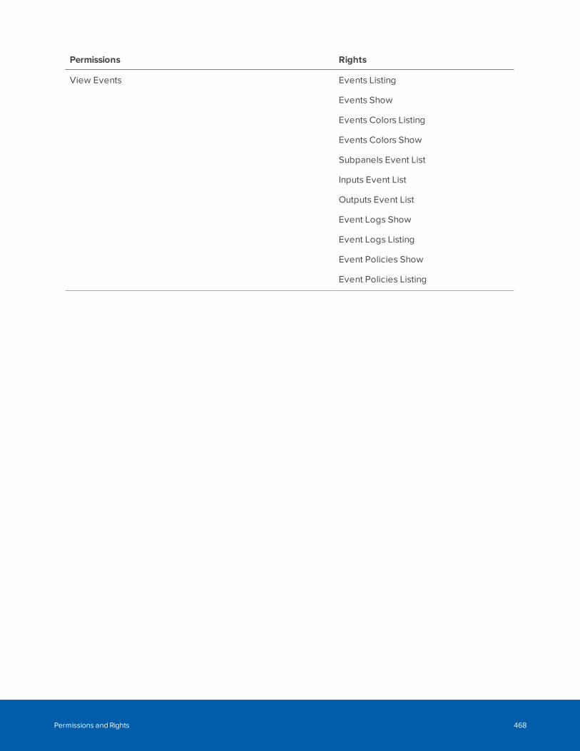
Permissions Rights
View Events Events Listing
Events Show
Events Colors Listing
Events Colors Show
Subpanels Event List
Inputs Event List
Outputs Event List
Event Logs Show
Event Logs Listing
Event Policies Show
Event Policies Listing
Permissions and Rights 468
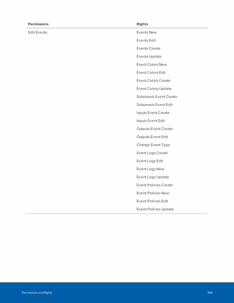
Permissions Rights
Edit Events Events New
Events Edit
Events Create
Events Update
Event Colors New
Event Colors Edit
Event Colors Create
Event Colors Update
Subpanels Event Create
Subpanels Event Edit
Inputs Event Create
Inputs Event Edit
Outputs Event Create
Outputs Event Edit
Change Event Type
Event Logs Create
Event Logs Edit
Event Logs New
Event Logs Update
Event Policies Create
Event Policies New
Event Policies Edit
Event Policies Update
Permissions and Rights 469
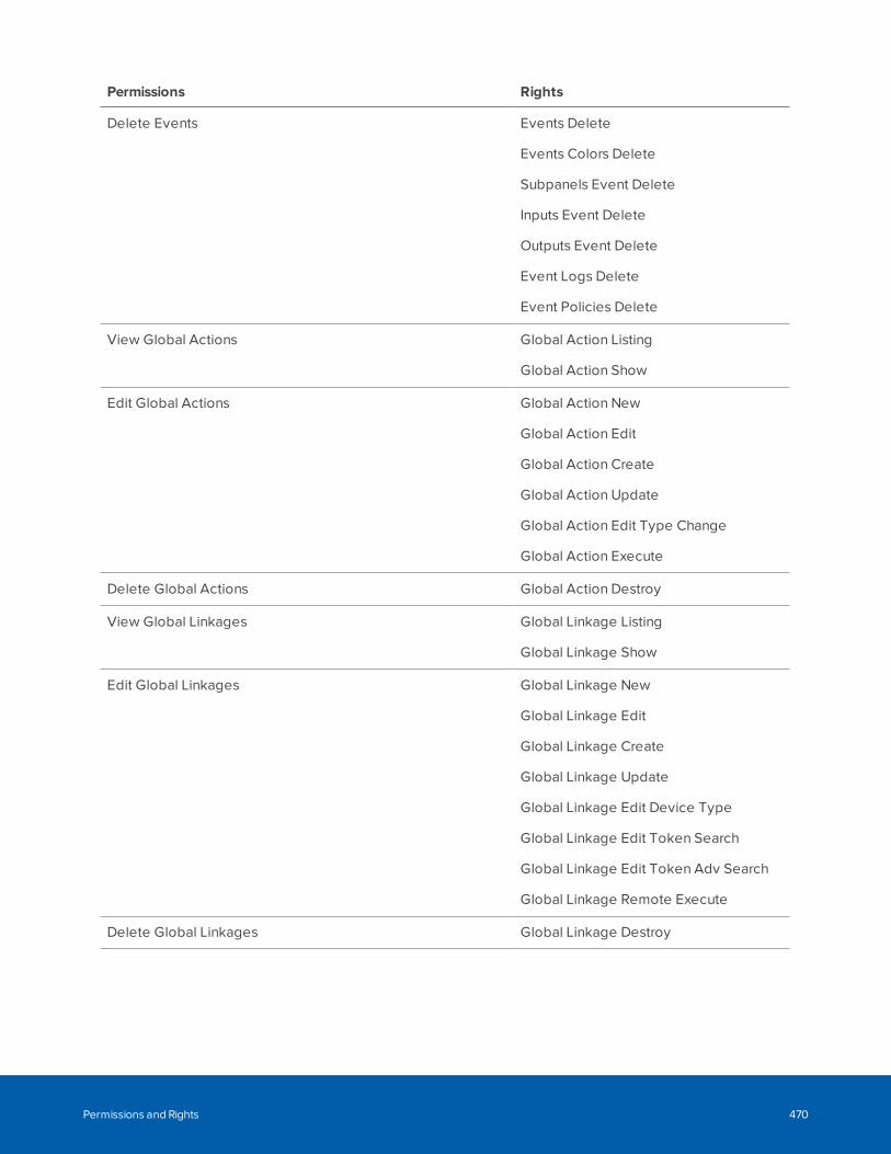
Permissions Rights
Delete Events Events Delete
Events Colors Delete
Subpanels Event Delete
Inputs Event Delete
Outputs Event Delete
Event Logs Delete
Event Policies Delete
View Global Actions Global Action Listing
Global Action Show
Edit Global Actions Global Action New
Global Action Edit
Global Action Create
Global Action Update
Global Action Edit Type Change
Global Action Execute
Delete Global Actions Global Action Destroy
View Global Linkages Global Linkage Listing
Global Linkage Show
Edit Global Linkages Global Linkage New
Global Linkage Edit
Global Linkage Create
Global Linkage Update
Global Linkage Edit Device Type
Global Linkage Edit Token Search
Global Linkage Edit Token Adv Search
Global Linkage Remote Execute
Delete Global Linkages Global Linkage Destroy
Permissions and Rights 470
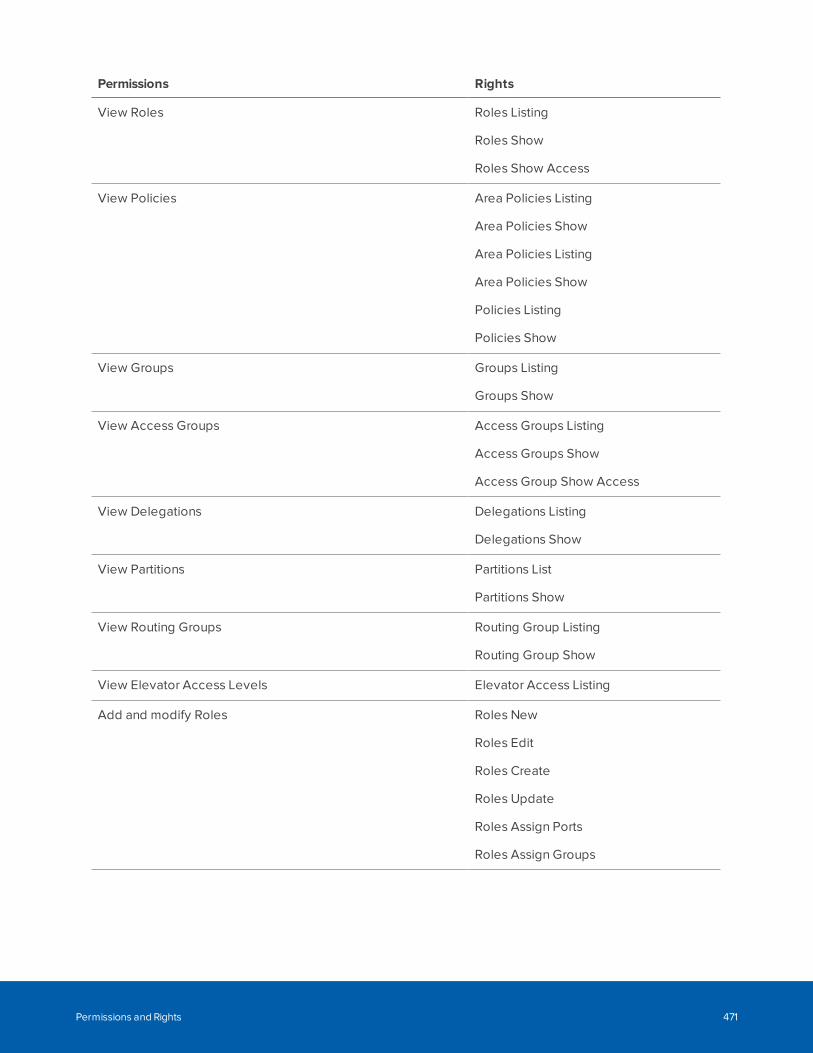
Permissions Rights
View Roles Roles Listing
Roles Show
Roles Show Access
View Policies Area Policies Listing
Area Policies Show
Area Policies Listing
Area Policies Show
Policies Listing
Policies Show
View Groups Groups Listing
Groups Show
View Access Groups Access Groups Listing
Access Groups Show
Access Group Show Access
View Delegations Delegations Listing
Delegations Show
View Partitions Partitions List
Partitions Show
View Routing Groups Routing Group Listing
Routing Group Show
View Elevator Access Levels Elevator Access Listing
Add and modify Roles Roles New
Roles Edit
Roles Create
Roles Update
Roles Assign Ports
Roles Assign Groups
Permissions and Rights 471
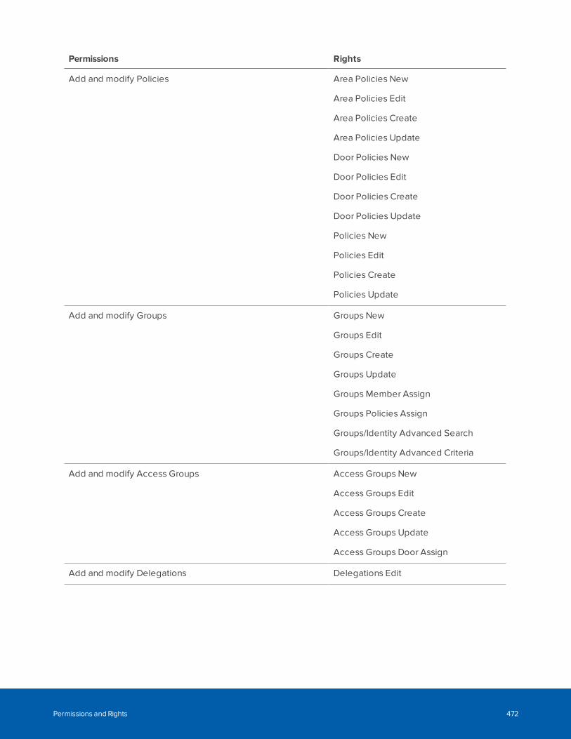
Permissions Rights
Add and modify Policies Area Policies New
Area Policies Edit
Area Policies Create
Area Policies Update
Door Policies New
Door Policies Edit
Door Policies Create
Door Policies Update
Policies New
Policies Edit
Policies Create
Policies Update
Add and modify Groups Groups New
Groups Edit
Groups Create
Groups Update
Groups Member Assign
Groups Policies Assign
Groups/Identity Advanced Search
Groups/Identity Advanced Criteria
Add and modify Access Groups Access Groups New
Access Groups Edit
Access Groups Create
Access Groups Update
Access Groups Door Assign
Add and modify Delegations Delegations Edit
Permissions and Rights 472
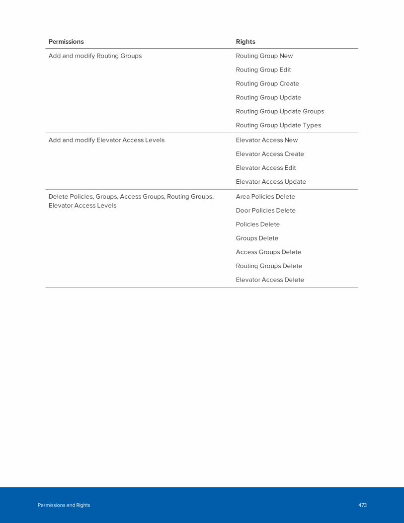
Permissions Rights
Add and modify Routing Groups Routing Group New
Routing Group Edit
Routing Group Create
Routing Group Update
Routing Group Update Groups
Routing Group Update Types
Add and modify Elevator Access Levels Elevator Access New
Elevator Access Create
Elevator Access Edit
Elevator Access Update
Delete Policies, Groups, Access Groups, Routing Groups,Elevator Access Levels
Area Policies Delete
Door Policies Delete
Policies Delete
Groups Delete
Access Groups Delete
Routing Groups Delete
Elevator Access Delete
Permissions and Rights 473
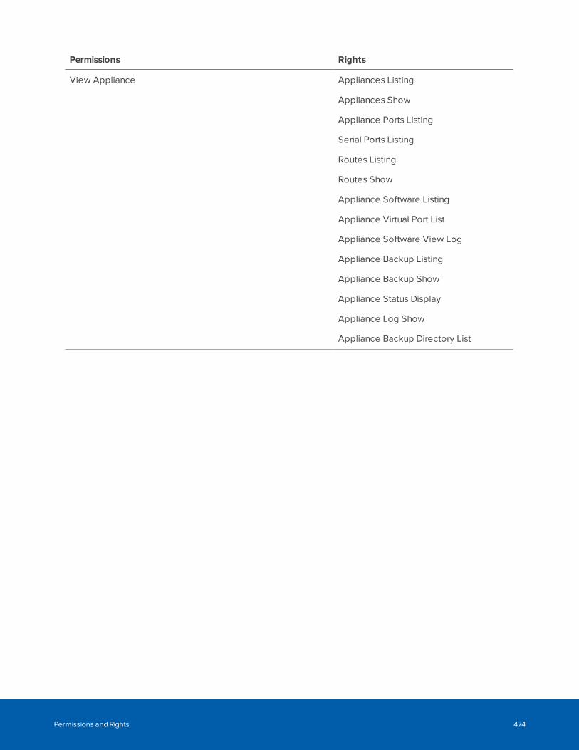
Permissions Rights
View Appliance Appliances Listing
Appliances Show
Appliance Ports Listing
Serial Ports Listing
Routes Listing
Routes Show
Appliance Software Listing
Appliance Virtual Port List
Appliance Software View Log
Appliance Backup Listing
Appliance Backup Show
Appliance Status Display
Appliance Log Show
Appliance Backup Directory List
Permissions and Rights 474
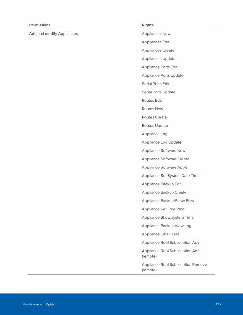
Permissions Rights
Add and modify Appliances Appliances New
Appliances Edit
Appliances Create
Appliances Update
Appliance Ports Edit
Appliance Ports Update
Serial Ports Edit
Serial Ports Update
Routes Edit
Routes New
Routes Create
Routes Update
Appliance Log
Appliance Log Update
Appliance Software New
Appliance Software Create
Appliance Software Apply
Appliance Set System Date Time
Appliance Backup Edit
Appliance Backup Create
Appliance Backup/Show Files
Appliance Set Free Pass
Appliance Show system Time
Appliance Backup View Log
Appliance Email Test
Appliance Repl Subscription Add
Appliance Repl Subscription Add(remote)
Appliance Repl Subscription Remove(remote)
Permissions and Rights 475
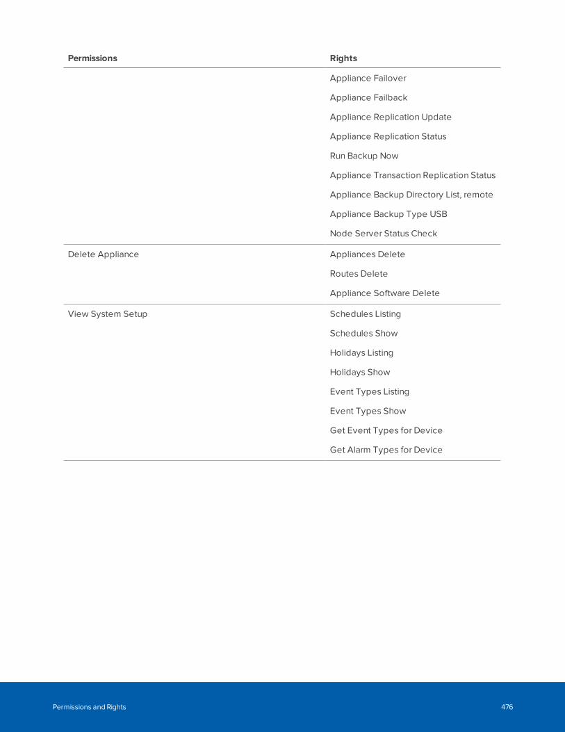
Permissions Rights
Appliance Failover
Appliance Failback
Appliance Replication Update
Appliance Replication Status
Run Backup Now
Appliance Transaction Replication Status
Appliance Backup Directory List, remote
Appliance Backup Type USB
Node Server Status Check
Delete Appliance Appliances Delete
Routes Delete
Appliance Software Delete
View System Setup Schedules Listing
Schedules Show
Holidays Listing
Holidays Show
Event Types Listing
Event Types Show
Get Event Types for Device
Get Alarm Types for Device
Permissions and Rights 476
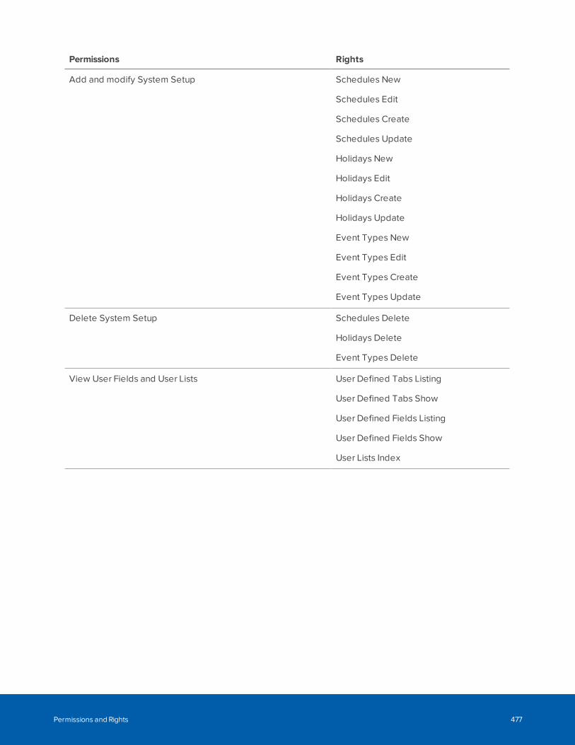
Permissions Rights
Add and modify System Setup Schedules New
Schedules Edit
Schedules Create
Schedules Update
Holidays New
Holidays Edit
Holidays Create
Holidays Update
Event Types New
Event Types Edit
Event Types Create
Event Types Update
Delete System Setup Schedules Delete
Holidays Delete
Event Types Delete
View User Fields and User Lists User Defined Tabs Listing
User Defined Tabs Show
User Defined Fields Listing
User Defined Fields Show
User Lists Index
Permissions and Rights 477
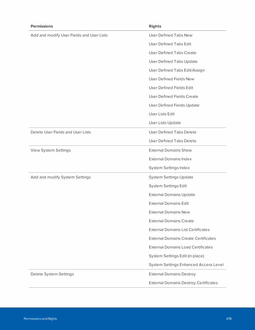
Permissions Rights
Add and modify User Fields and User Lists User Defined Tabs New
User Defined Tabs Edit
User Defined Tabs Create
User Defined Tabs Update
User Defined Tabs Edit/Assign
User Defined Fields New
User Defined Fields Edit
User Defined Fields Create
User Defined Fields Update
User Lists Edit
User Lists Update
Delete User Fields and User Lists User Defined Tabs Delete
User Defined Tabs Delete
View System Settings External Domains Show
External Domains Index
System Settings Index
Add and modify System Settings System Settings Update
System Settings Edit
External Domains Update
External Domains Edit
External Domains New
External Domains Create
External Domains List Certificates
External Domains Create Certificates
External Domains Load Certificates
System Settings Edit (in place)
System Settings Enhanced Access Level
Delete System Settings External Domains Destroy
External Domains Destroy Certificates
Permissions and Rights 478
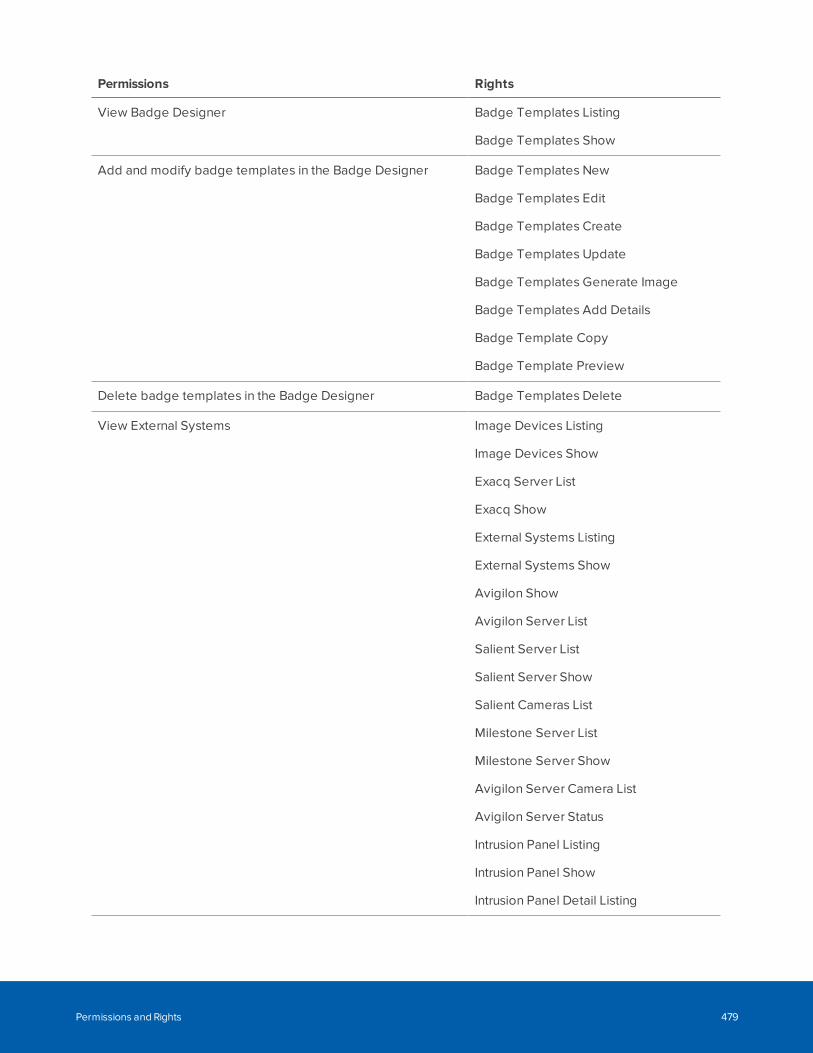
Permissions Rights
View Badge Designer Badge Templates Listing
Badge Templates Show
Add and modify badge templates in the Badge Designer Badge Templates New
Badge Templates Edit
Badge Templates Create
Badge Templates Update
Badge Templates Generate Image
Badge Templates Add Details
Badge Template Copy
Badge Template Preview
Delete badge templates in the Badge Designer Badge Templates Delete
View External Systems Image Devices Listing
Image Devices Show
Exacq Server List
Exacq Show
External Systems Listing
External Systems Show
Avigilon Show
Avigilon Server List
Salient Server List
Salient Server Show
Salient Cameras List
Milestone Server List
Milestone Server Show
Avigilon Server Camera List
Avigilon Server Status
Intrusion Panel Listing
Intrusion Panel Show
Intrusion Panel Detail Listing
Permissions and Rights 479
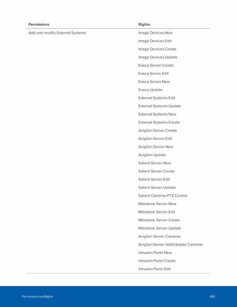
Permissions Rights
Add and modify External Systems Image Devices New
Image Devices Edit
Image Devices Create
Image Devices Update
Exacq Server Create
Exacq Server Edit
Exacq Server New
Exacq Update
External Systems Edit
External Systems Update
External Systems New
External Systems Create
Avigilon Server Create
Avigilon Server Edit
Avigilon Server New
Avigilon Update
Salient Server New
Salient Server Create
Salient Server Edit
Salient Server Update
Salient Cameras PTZ Control
Milestone Server New
Milestone Server Edit
Milestone Server Create
Milestone Server Update
Avigilon Server Cameras
Avigilon Server Add/Update Cameras
Intrusion Panel New
Intrusion Panel Create
Intrusion Panel Edit
Permissions and Rights 480
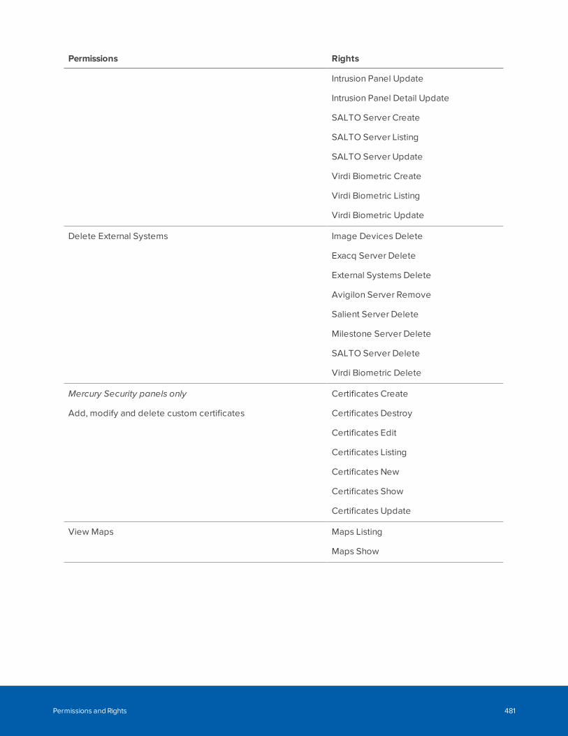
Permissions Rights
Intrusion Panel Update
Intrusion Panel Detail Update
SALTO Server Create
SALTO Server Listing
SALTO Server Update
Virdi Biometric Create
Virdi Biometric Listing
Virdi Biometric Update
Delete External Systems Image Devices Delete
Exacq Server Delete
External Systems Delete
Avigilon Server Remove
Salient Server Delete
Milestone Server Delete
SALTO Server Delete
Virdi Biometric Delete
Mercury Security panels only
Add, modify and delete custom certificates
Certificates Create
Certificates Destroy
Certificates Edit
Certificates Listing
Certificates New
Certificates Show
Certificates Update
View Maps Maps Listing
Maps Show
Permissions and Rights 481
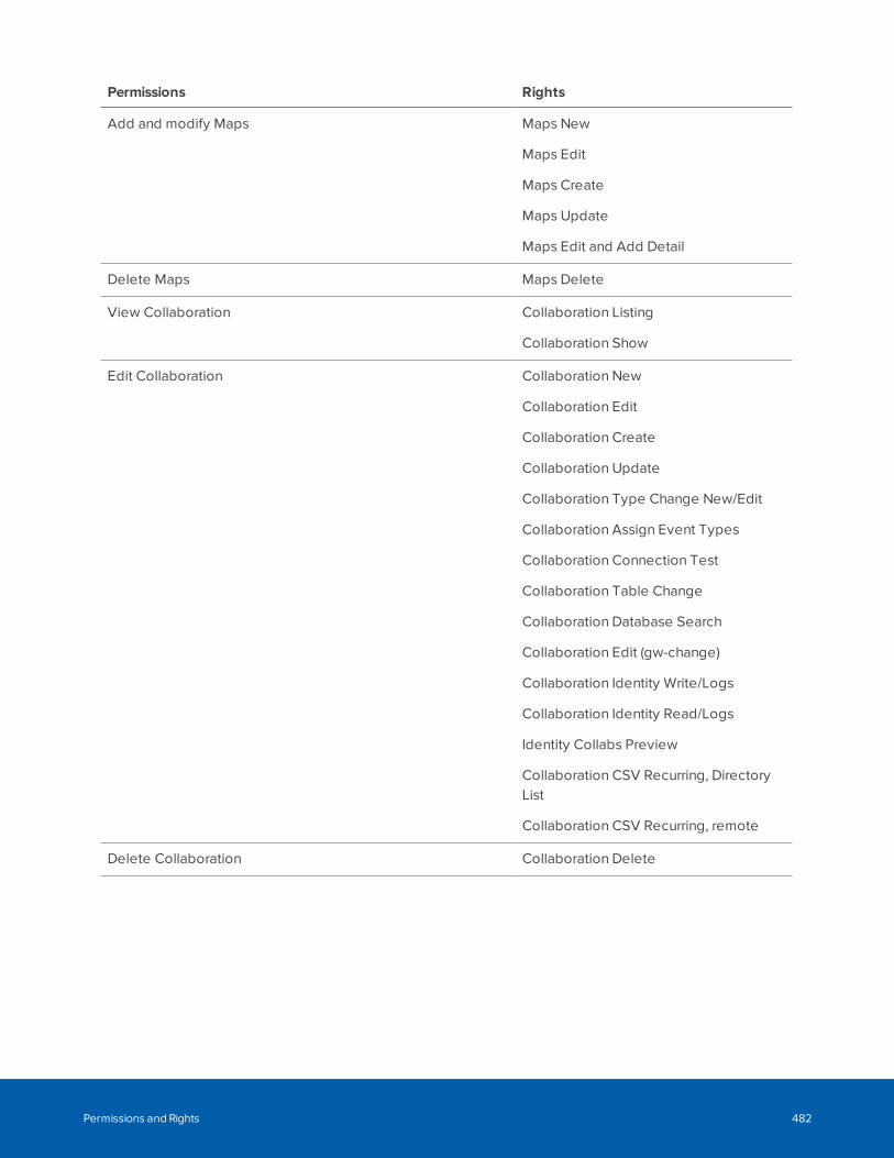
Permissions Rights
Add and modify Maps Maps New
Maps Edit
Maps Create
Maps Update
Maps Edit and Add Detail
Delete Maps Maps Delete
View Collaboration Collaboration Listing
Collaboration Show
Edit Collaboration Collaboration New
Collaboration Edit
Collaboration Create
Collaboration Update
Collaboration Type Change New/Edit
Collaboration Assign Event Types
Collaboration Connection Test
Collaboration Table Change
Collaboration Database Search
Collaboration Edit (gw-change)
Collaboration Identity Write/Logs
Collaboration Identity Read/Logs
Identity Collabs Preview
Collaboration CSV Recurring, DirectoryList
Collaboration CSV Recurring, remote
Delete Collaboration Collaboration Delete
Permissions and Rights 482
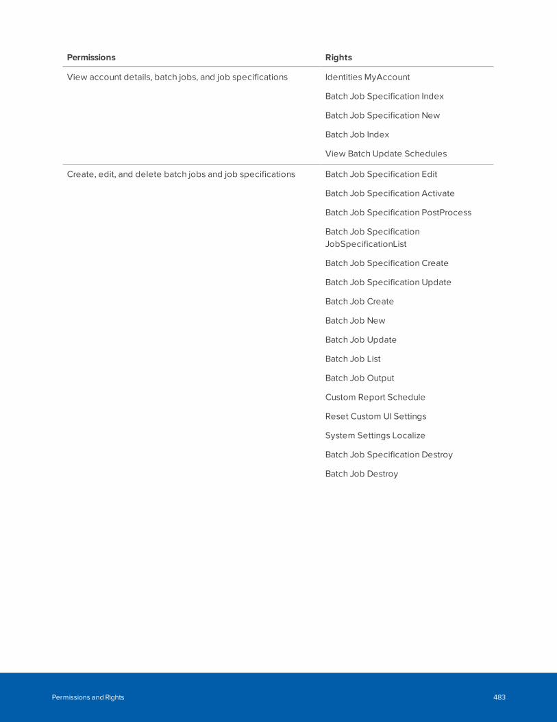
Permissions Rights
View account details, batch jobs, and job specifications Identities MyAccount
Batch Job Specification Index
Batch Job Specification New
Batch Job Index
View Batch Update Schedules
Create, edit, and delete batch jobs and job specifications Batch Job Specification Edit
Batch Job Specification Activate
Batch Job Specification PostProcess
Batch Job SpecificationJobSpecificationList
Batch Job Specification Create
Batch Job Specification Update
Batch Job Create
Batch Job New
Batch Job Update
Batch Job List
Batch Job Output
Custom Report Schedule
Reset Custom UI Settings
System Settings Localize
Batch Job Specification Destroy
Batch Job Destroy
Permissions and Rights 483
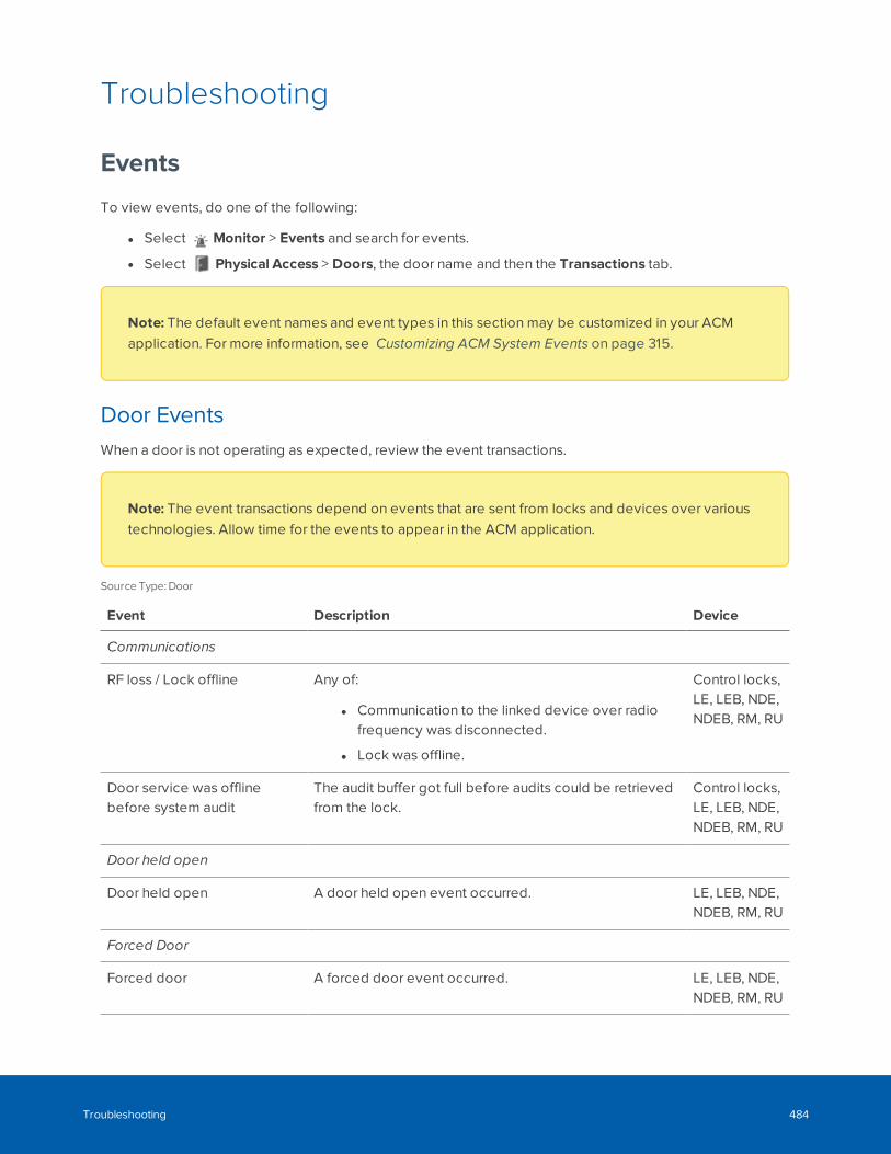
Troubleshooting
Events
To view events, do one of the following:
l Select Monitor > Events and search for events.
l Select Physical Access > Doors, the door name and then the Transactions tab.
Note: The default event names and event types in this section may be customized in your ACMapplication. For more information, see Customizing ACM System Events on page 315.
Door EventsWhen a door is not operating as expected, review the event transactions.
Note: The event transactions depend on events that are sent from locks and devices over varioustechnologies. Allow time for the events to appear in the ACM application.
Source Type: Door
Event Description Device
Communications
RF loss / Lock offline Any of:
l Communication to the linked device over radiofrequency was disconnected.
l Lock was offline.
Control locks,LE, LEB, NDE,NDEB, RM, RU
Door service was offlinebefore system audit
The audit buffer got full before audits could be retrievedfrom the lock.
Control locks,LE, LEB, NDE,NDEB, RM, RU
Door held open
Door held open A door held open event occurred. LE, LEB, NDE,NDEB, RM, RU
Forced Door
Forced door A forced door event occurred. LE, LEB, NDE,NDEB, RM, RU
Troubleshooting 484
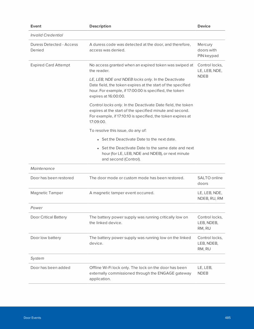
Event Description Device
Invalid Credential
Duress Detected - AccessDenied
A duress code was detected at the door, and therefore,access was denied.
Mercurydoors withPIN keypad
Expired Card Attempt No access granted when an expired token was swiped atthe reader.
LE, LEB, NDE and NDEB locks only. In the DeactivateDate field, the token expires at the start of the specifiedhour. For example, if 17:00:00 is specified, the tokenexpires at 16:00:00.
Control locks only. In the Deactivate Date field, the tokenexpires at the start of the specified minute and second.For example, if 17:10:10 is specified, the token expires at17:09:00.
To resolve this issue, do any of:
l Set the Deactivate Date to the next date.
l Set the Deactivate Date to the same date and nexthour (for LE, LEB, NDE and NDEB), or next minuteand second (Control).
Control locks,LE, LEB, NDE,NDEB
Maintenance
Door has been restored The door mode or custom mode has been restored. SALTO onlinedoors
Magnetic Tamper A magnetic tamper event occurred. LE, LEB, NDE,NDEB, RU, RM
Power
Door Critical Battery The battery power supply was running critically low onthe linked device.
Control locks,LEB, NDEB,RM, RU
Door low battery The battery power supply was running low on the linkeddevice.
Control locks,LEB, NDEB,RM, RU
System
Door has been added Offline Wi-Fi lock only. The lock on the door has beenexternally commissioned through the ENGAGE gatewayapplication.
LE, LEB,NDEB
Door Events 485
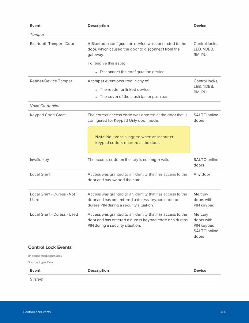
Event Description Device
Tamper
Bluetooth Tamper - Door A Bluetooth configuration device was connected to thedoor, which caused the door to disconnect from thegateway.
To resolve this issue:
l Disconnect the configuration device.
Control locks,LEB, NDEB,RM, RU
Reader/Device Tamper A tamper event occurred in any of:
l The reader or linked device.
l The cover of the crash bar or push bar.
Control locks,LEB, NDEB,RM, RU
Valid Credential
Keypad Code Grant The correct access code was entered at the door that isconfigured for Keypad Only door mode.
Note: No event is logged when an incorrectkeypad code is entered at the door.
SALTO onlinedoors
Invalid key The access code on the key is no longer valid. SALTO onlinedoors
Local Grant Access was granted to an identity that has access to thedoor and has swiped the card.
Any door
Local Grant - Duress - NotUsed
Access was granted to an identity that has access to thedoor and has not entered a duress keypad code orduress PIN during a security situation.
Mercurydoors withPIN keypad
Local Grant - Duress - Used Access was granted to an identity that has access to thedoor and has entered a duress keypad code or a duressPIN during a security situation.
Mercurydoors withPIN keypad,SALTO onlinedoors
Control Lock Events
IP-connected doors only
Source Type: Door
Event Description Device
System
Control Lock Events 486
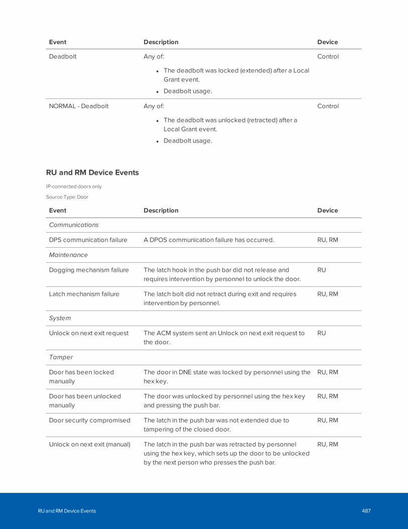
Event Description Device
Deadbolt Any of:
l The deadbolt was locked (extended) after a LocalGrant event.
l Deadbolt usage.
Control
NORMAL - Deadbolt Any of:
l The deadbolt was unlocked (retracted) after aLocal Grant event.
l Deadbolt usage.
Control
RU and RM Device Events
IP-connected doors only
Source Type: Door
Event Description Device
Communications
DPS communication failure A DPOS communication failure has occurred. RU, RM
Maintenance
Dogging mechanism failure The latch hook in the push bar did not release andrequires intervention by personnel to unlock the door.
RU
Latch mechanism failure The latch bolt did not retract during exit and requiresintervention by personnel.
RU, RM
System
Unlock on next exit request The ACM system sent an Unlock on next exit request tothe door.
RU
Tamper
Door has been lockedmanually
The door in DNE state was locked by personnel using thehex key.
RU, RM
Door has been unlockedmanually
The door was unlocked by personnel using the hex keyand pressing the push bar.
RU, RM
Door security compromised The latch in the push bar was not extended due totampering of the closed door.
RU, RM
Unlock on next exit (manual) The latch in the push bar was retracted by personnelusing the hex key, which sets up the door to be unlockedby the next person who presses the push bar.
RU, RM
RU and RM Device Events 487
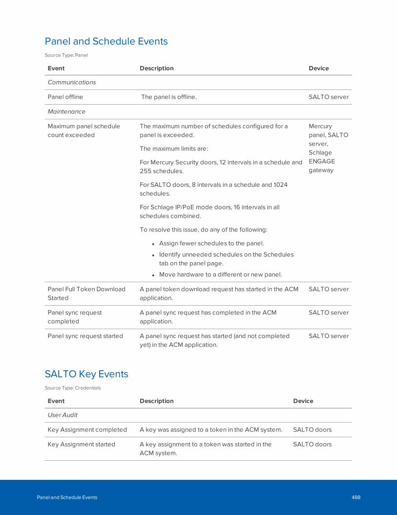
Panel and Schedule EventsSource Type: Panel
Event Description Device
Communications
Panel offline The panel is offline. SALTO server
Maintenance
Maximum panel schedulecount exceeded
The maximum number of schedules configured for apanel is exceeded.
The maximum limits are:
For Mercury Security doors, 12 intervals in a schedule and255 schedules.
For SALTO doors, 8 intervals in a schedule and 1024schedules.
For Schlage IP/PoE mode doors, 16 intervals in allschedules combined.
To resolve this issue, do any of the following:
l Assign fewer schedules to the panel.
l Identify unneeded schedules on the Schedulestab on the panel page.
l Move hardware to a different or new panel.
Mercurypanel, SALTOserver,SchlageENGAGEgateway
Panel Full Token DownloadStarted
A panel token download request has started in the ACMapplication.
SALTO server
Panel sync requestcompleted
A panel sync request has completed in the ACMapplication.
SALTO server
Panel sync request started A panel sync request has started (and not completedyet) in the ACM application.
SALTO server
SALTO Key EventsSource Type: Credentials
Event Description Device
User Audit
Key Assignment completed A key was assigned to a token in the ACM system. SALTO doors
Key Assignment started A key assignment to a token was started in theACM system.
SALTO doors
Panel and Schedule Events 488
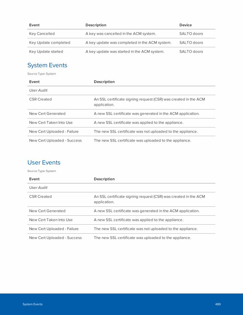
Event Description Device
Key Cancelled A key was cancelled in the ACM system. SALTO doors
Key Update completed A key update was completed in the ACM system. SALTO doors
Key Update started A key update was started in the ACM system. SALTO doors
System EventsSource Type: System
Event Description
User Audit
CSR Created An SSL certificate signing request (CSR) was created in the ACMapplication.
New Cert Generated A new SSL certificate was generated in the ACM application.
New Cert Taken Into Use A new SSL certificate was applied to the appliance.
New Cert Uploaded - Failure The new SSL certificate was not uploaded to the appliance.
New Cert Uploaded - Success The new SSL certificate was uploaded to the appliance.
User EventsSource Type: System
Event Description
User Audit
CSR Created An SSL certificate signing request (CSR) was created in the ACMapplication.
New Cert Generated A new SSL certificate was generated in the ACM application.
New Cert Taken Into Use A new SSL certificate was applied to the appliance.
New Cert Uploaded - Failure The new SSL certificate was not uploaded to the appliance.
New Cert Uploaded - Success The new SSL certificate was uploaded to the appliance.
System Events 489
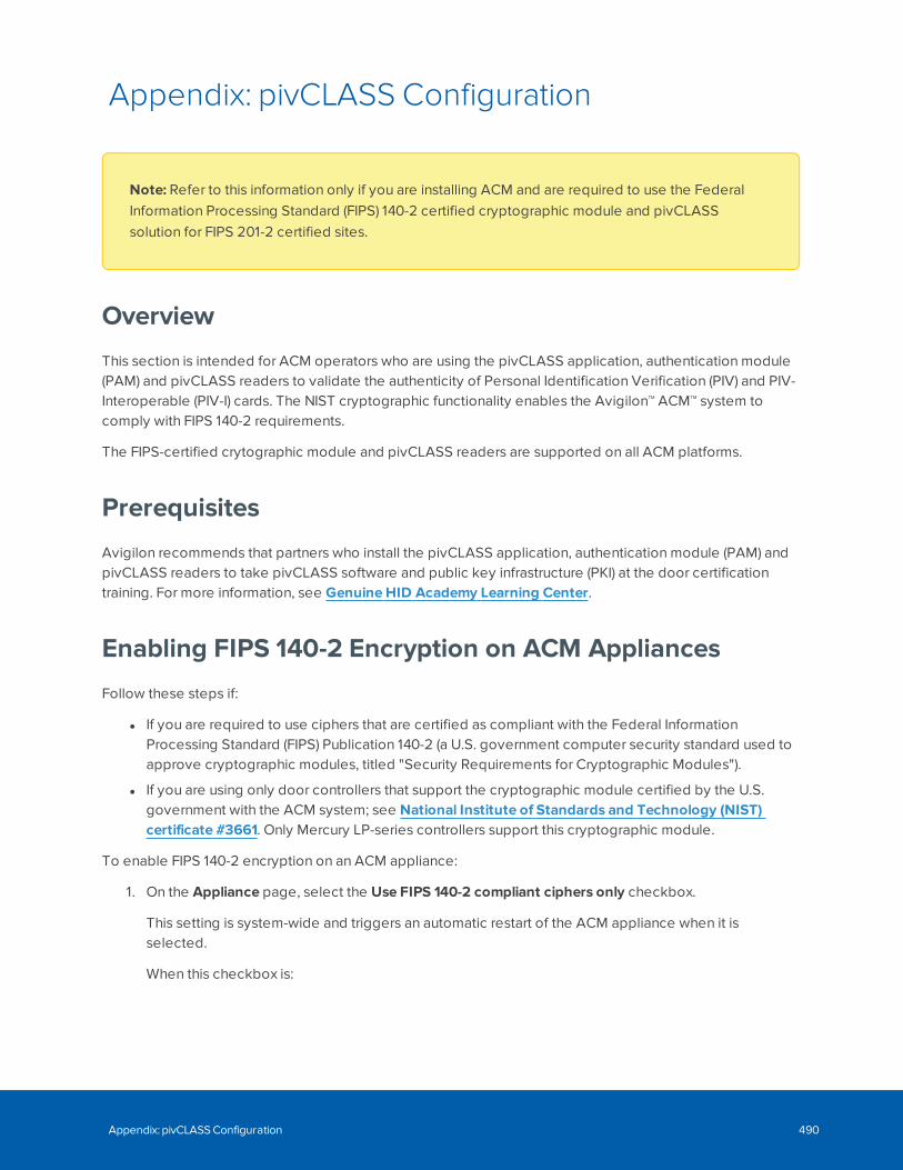
Appendix: pivCLASS Configuration
Note: Refer to this information only if you are installing ACM and are required to use the FederalInformation Processing Standard (FIPS) 140-2 certified cryptographic module and pivCLASSsolution for FIPS 201-2 certified sites.
Overview
This section is intended for ACM operators who are using the pivCLASS application, authentication module(PAM) and pivCLASS readers to validate the authenticity of Personal Identification Verification (PIV) and PIV-Interoperable (PIV-I) cards. The NIST cryptographic functionality enables the Avigilon™ ACM™ system tocomply with FIPS 140-2 requirements.
The FIPS-certified crytographic module and pivCLASS readers are supported on all ACM platforms.
Prerequisites
Avigilon recommends that partners who install the pivCLASS application, authentication module (PAM) andpivCLASS readers to take pivCLASS software and public key infrastructure (PKI) at the door certificationtraining. For more information, see Genuine HID Academy Learning Center.
Enabling FIPS 140-2 Encryption on ACM Appliances
Follow these steps if:
l If you are required to use ciphers that are certified as compliant with the Federal InformationProcessing Standard (FIPS) Publication 140-2 (a U.S. government computer security standard used toapprove cryptographic modules, titled "Security Requirements for Cryptographic Modules").
l If you are using only door controllers that support the cryptographic module certified by the U.S.government with the ACM system; see National Institute of Standards and Technology (NIST)certificate #3661. Only Mercury LP-series controllers support this cryptographic module.
To enable FIPS 140-2 encryption on an ACM appliance:
1. On the Appliance page, select the Use FIPS 140-2 compliant ciphers only checkbox.
This setting is system-wide and triggers an automatic restart of the ACM appliance when it isselected.
When this checkbox is:
Appendix: pivCLASS Configuration 490
l Not Enabled (the default) — A cipher that is not FIPS compliant is used to encrypt traffic in theACM system.
l Enabled — The ACM system uses the ciphers supported by the NIST #3661 cryptographicmodule. Only the ciphers covered by this certificate are used.
A warning message is displayed.
2. Click OK to confirm.
The ACM appliance is restarted, and now the ACM system is using the FIPS 140-2 encryption. Noadditional steps are required to configure Mercury panels.
Enabling Large Encoded Card Format and EmbeddedAuthorization on Panels
Use the following fields when you add a panel to the ACM system, depending on the type of authenticationin use at your site.
Authentication Subsystem Enable Large Encoded Card Format Embedded Auth
None (uncheck) None
pivCLASS with external PAM (check) None
pivCLASS embedded AAM forMercury LP4502 only
(check) pivCLASS
On the Panel: Add page:
l For Mercury LP4502 model only. In the Embedded Auth field, select pivCLASS. The Enable LargeEncoded Card Format field is automatically selected.
l For all other types of Mercury controllers. Select the Enable Large Encoded Card Format field (non-reversible; see Note below):
l Used for internal numbers that are larger than 64 bits. For example, 128-bit and 200-bit cardsneed the 32-character Federal Agency Smart Credential Number (FASC-N) or Card HolderUnique Identifier (CHUID) for PIV-I cards. Large Encoded card formats are used with FIPS 201certified pivCLASS readers; see Approved Product List (APL) #10122.
l Used typically to enable authentication by pivCLASS readers at FIPS 201-2 certified sites.
Note: The panel cannot be reconfigured after this setting is selected. To accept any other cardformat other than large formats, delete it and re-add it to the ACM system.
Updating Firmware
To update the firmware of the Mercury LP4502 panel:
Enabling Large Encoded Card Format and Embedded Authorization on Panels 491
1. On the Panels list, select the panel and then on the Status tab, click Firmware.
2. To add support for the authentication module on the panel, install the pivCLASS-Embedded-Auth_Pkg_05_10_27_#145.crc firmware version.
To remove the authentication module from the panel, install the pivCLASS-Embedded-Auth-Removal_Pkg_01_00_00_#14.crc firmware version.
3. To verify the installation of the firmware, review the panel status page which shows the name andversion of the pivCLASS package along with the authentication module and firmware versions.
4. For pivCLASS embedded AAM for Mercury LP4502 only. After the firmware is installed, you mustconfigure communication between the panel and pivCLASS service. For more information aboutconfiguring the pivCLASS-Embedded-Auth fields on the Configuration Manager for the panel, refer toMercury documentation.
Adding Doors
When adding a door with pivCLASS embedded AAM for the Mercury LP4502 model, do the following:
l Ensure the Name field is updated as follows. If your site uses pivCLASS-compliant credentials toauthenticate credentials, the Name of the door that you enter in the ACM system must match thereader name entered in the Description field of the reader in the pivCLASS registration system.Before adding doors, ensure you that you know the reader name entered in the pivCLASSregistration system, as they must be identical. For more information about pivCLASS-compliantregistration software, refer to pivCLASS documentation.
l Select the LP4502 panel name in the Panel field.
l Ensure the Assurance Profile field is updated as follows.
For LP4502 with AAM only; does not appear for external PAM. Select a pivCLASS security levelappropriate for the pivCLASS compliant door at the site; for example, CAK (PIV).
Each profile refers to a protected area that is defined by NIST SP 800-116, titled "A Recommendationfor the Use of PIV Credentials in PACS," and is secured by an identification method in accordancewith the FIPS 201 standard, titled "Personal Identity Verification (PIV) of Federal Employees andContractors."
For more information about each authentication method, refer to pivCLASS Service documentation.
l To support the selected Assurance Profile for a pivCLASS configured door, it is recommended to setthe Door Mode to Card Only. Note also, the Disabled, Unlocked and Locked No Access door actionssupercede the Assurance Profile.
Adding Reader Templates
When adding a reader template, do the following:
l Ensure the Baud Rate for the pivCLASS reader is updated as follows:
Adding Doors 492
Note: It recommended to specify a Baud Rate that is higher than the default 9600 (default) rateand to lower the baud rate, if reader issues occur. In addition, end users should hold the pivCLASScard on the pivCLASS reader for more than 5 seconds for smooth operation.
Assigning Large Encoded Formats to Panels
If the Enable Large Encoded Card Format checkbox is enabled, the 128 bit Large Encoded and 200 bitLarge Encoded card formats are automatically generated for the panel:
l On the Door: Edit page, select the Operations tab and ensure a large encoded card format isassigned to the panel in the Members box under Card Formats.
Viewing Identities and Tokens
When adding an identity, do the following:
Note: ACM identity management is not used to create pivCLASS users. However, you can viewidentities and their tokens. You must use the pivCLASS registration system to add these identities inthe ACM system. For more information about using pivCLASS-compliant registration software toadd identities to the ACM system, refer to pivCLASS documentation. After these identities havebeen added, they can be searched, edited and modified to provide physical and logical access. Ifnecessary, you can produce and print badges, assign to groups, roles, delegations, and so on, asyou can for any other identity.
When viewing a token for an identity the following fields are read-only:
l The Token Type field displays PIV for a Personal Identification Verification (PIV) card for governmentemployees or PIV-I for a PIV-Interoperable (PIV-I) card for government contractors.
l For PIV-I card only. The CHUID field displays the Card Holder Unique Identifier of the PIV-I card.
Monitoring Events
You can monitor pivCLASS events on the Monitor Events page.
Note: pivCLASS events may be configured from Physical Access > Events and searching on Name:contains pivCLASS.
Assigning Large Encoded Formats to Panels 493
Glossary
2
2-person control
Under this rule, all access and actions requires the presence of two authorizedpeople at all times. Two people are necessary to either enter or exit a door.
A
ACM
Access Control Manager. A PACS from Avigilon. Available in Enterprise, EnterprisePlus, Professional and Virtual Appliance platforms.
B
Badge template
The format designed for a user badge on which information from the Identitiesfeature is placed. Templates are designed using the Badge Designer.
BLE
Bluetooth Low Energy, a wireless communication protocol.
C
CHUID
Card Holder Unique Identifier. Used in PIV-I cards.
CoS
Change of State
D
Debounce
Due to mechanical properties of a switch, when a switch is closed, there is aperiod of time in which the electrical connection "bounces" between open andclosed. To a microcontroller, this "bouncing" can be interpreted as multiple button
Glossary 494
pushes. To suppress the "bouncing", the controller software is designed toanticipate it. This is known as "debouncing a switch".
dogging
The action of turning the hex key and pressing the push bar to retract thelatchbolt, which unlocks the perimeter door on the outside and allows a person toenter the building. Can be done remotely or manually.
Door contacts
Input devices that detect changes in door position. This is generally done bymeasuring resistance across a circuit connecting part of the door jamb to the dooritself. If the door is opened, the resistance drops.
DPOS
Door position switch. These input devices are more commonly called doorcontacts.
E
EOL
End-Of-Line (EOL) are resistors that supervise the wiring between the alarm paneland the switch. Preset resistance levels must be maintained at input points or analarm event is triggered.
F
Failover
When an appliance fails, a configured standby appliance is able to automatically,or manually, take its place so that the system can continue to run.
FAS-N
Federal Agency Smart Credential Number. A 32-character number generated forFASC-N or CHUID for PIV-I cards.
FIPS
Federal Information Processing Standard. The U.S. government's securitystandards for approving cryptographic modules and personnel identification
Glossary 495
methods. Only Mercury LP-series controllers with NIST certificate #2389 supportthe cryptographic module. Compliance requirements include: FIPS Publication140-2 — a U.S. government computer security standard for approvingcryptographic modules, titled "Security Requirements for Cryptographic Modules";FIPS Publication 201-2 — a U.S. government standard for identifying federalgovernment personnel, titled "Personal Identity Verification (PIV) of FederalEmployees and Contractors."
Flow control
The process of managing the rate of data transmission between two nodesto prevent a fast sender from over running a slow receiver.
I
Interlock
A defined action that occurs within a panel at a destination device whenever anevent occurs at the source device. For example, a REX input device (source);receives a request to exit and passes the order to the door strike device(destination); to open the door latch. For each interlock, a source and a destinationdevice (or group of devices) is defined.
L
LDAP
Lightweight Directory Access Protocol is an open, industry standard applicationprotocol for accessing and maintaining distributed directory information servicesover a network. An LDAP database in the Access Control Manager system typicallyincludes user details, connected hardware details, events, alarms and other systemconfiguration details.
M
Mag Lock
Magnetic locks work only with DC current, usually 12 to 24 volts. Never connect amagnetic lock to AC current of any voltage. All magnetic locks are fail safe. Thismeans that they need a constant source of current to remained locked. If power isremoved the lock will open. If this is a concern use a back-up power supply. Allmagnetic locks are silent even when powered and locked. 300 pound pullmagnetic locks work well in light duty installations such as cabinetry.
Glossary 496
N
Netmask
In administering Internet sites, a netmask is a string of 0's and 1's that mask orscreen out the network part of an IP address(IP) so that only the host computer partof the address remains. The binary 1's at the beginning of the mask turn thenetwork ID part of the IP address into 0's. The binary 0's that follow allow the hostID to remain. A frequently-used netmask is 255.255.255.0. (255 is the decimalequivalent of a binary string of eight ones.) Used for a Class C subnet (one with upto 255 host computers), the \".0\" in the \"255.255.255.0\" netmask allows thespecific host computer address to be visible.
NIST
National Institute of Standards and Technology. The U.S. government's standardsbody for approving software cryptographic modules in door controllers andpersonnel identification methods. Standards include: NIST SP 800-116, "UsingPersonal Identity Verification (PIV) Credentials In Physical Access Control Systems(PACS)"; NIST SP 800-131A, "Transitioning the Use of Cryptographic Algorithms andKey Lengths."
P
PACS
Physical Access Control System. An access control solution for securing people,property and assets. ACM is a PACS.
Panel
Panels are controllers that connect to one or more doors (door controllers) andtheir associated readers, inputs, and outputs.
PIV
Personal Identification Verification. A card issued to U.S. government employeesand includes FASC-N information.
PIV-I
PIV - Interoperable. A card issued to U.S. government contractors and includesCHUID and FASC-N information.
Glossary 497
Postgres
An object-relational database management system (ORDBMS) available for manyplatforms including Linux, FreeBSD, Solaris, Microsoft Windows and Mac OS X.Also callsed PostgreSQL.
R
redundancy
see Failover
Replication
The process of copying and synchronizing the LDAP database between two ormore appliances so that they share the same configuration information.
REX
Request to exit. REX devices include crash bars and exit buttons.
RQE
Request to exit. Normally these are crash bars or buttons.
RTN
Return to normal. This is normally associated with an event that effectively cancelsan original event. For example, a door open too long event is canceled by a doorclosed RTN.
S
SCP
Secure Copy Protocol is the most basic backup protocol and does not requiremuch adjustment before it can work properly. It can work effectively on Linux andother Unix-like systems. To start work, its enough to install the SCP program on theserver and establish the connection.
SFTP
Secure File Transfer Protocol is a network protocol that provides file managementfunctionality over any reliable data stream. This protocol assumes that it is run overa secure channel, such as Secure Shell Protocol (SSH), that the server has already
Glossary 498
authenticated the client, and that the identity of the client user is available to theprotocol.
SMTP
Simple Mail Transfer Protocol (SMTP) is an Internet standard for electronic mail (e-mail) transmission across Internet Protocol (IP) networks.
SNMP
A UDP-based network protocol used mostly in network management systems tomonitor network-attached devices for conditions that warrant administrativeattention.
Strike
Electric strikes are often used for "buzz in" types of systems. Electric strikes comein many varieties. They can be 12 or 24 volts or even higher voltage and they maytake AC or DC current and some even take both. They may be fail safe or failsecure. A fail safe electric strike needs power to keep it locked. A fail secureelectric strike stays locked even without power. The most common by far is a failsecure.
Subpanels
If your system supports a hierarchical structure, subpanels are specialty panels thatare controlled by a master panel. One master panel can be connected to a largenumber of specialty subpanels, incorporating an array of devices such as singleand multiple door modules, keypads, input modules and output modules.
T
TLS
Transport Layer Security (TLS) and its predecessor, Secure Sockets Layer (SSL), arecryptographic protocols which are designed to provide communication securityover the Internet.
Token
The entry data required to enable an employee or visitor to access a location. Thistypically includes a PIN number and, if a physical badge or keycard is required, anumber on the card.
Glossary 499

U
undogging
The action of turning the hex key and releasing the push bar to extend thelatchbolt, which locks the perimeter door on the outside and prevents a personfrom entering the building. Can be done remotely or manually.
Glossary 500