a wearable skin stretch device for haptic feedback
TRANSCRIPT
A Wearable Skin Stretch Device for Haptic FeedbackKarlin Bark∗
Stanford UniversityJason Wheeler†
Stanford UniversityGayle Lee‡
Stanford UniversityJoan Savall§
CEIT and Tecun, University of Navarra
Mark Cutkosky¶
Stanford University
ABSTRACT
We describe a wearable haptic feedback device that imparts rota-tional skin stretch to provide feedback regarding movement of avirtual object. Applications for this device include feedback of mo-tion for physical therapy or rehabilitation exercises or propriocep-tive feedback for amputees. The device uses a small piezoelectricmotor for a combination of low weight, moderate torques and ro-tation without vibrations that could interfere with the sensation ofstretch. We present the results of experiments to determine the ac-curacy with which subjects can use feedback from the device tocontrol the orientation of a virtual object. Most subjects were ableto position the device within several degrees. In a second test, sub-jects were asked to identify randomly applied levels of skin stretchwhile they remained passive. In this case, the accuracy was poorerand subjects occasionally confused positive and negative rotations.Tests were also conducted to evaluate the effect of rotational com-pliance at the end effector, added to improve comfort at large dis-placements.
Index Terms: H.1.2 [Models and Principles]: User/MachineSystems—Human information processing; H.5.2 [Information In-terfaces and Presentation]: User Interfaces—Haptic I/O
1 INTRODUCTION
There is an increasing interest in small, wireless haptic displaysthat are portable or wearable. Possible applications of these dis-plays include physical therapy, motion training and human inter-action within virtual reality environments. One example is motionrehabilitation after orthopedic surgery. Patients must re-learn howto walk and it has been noted that in some patients, their gait pre-surgery and post-surgery are different. Physical therapists can ob-serve the patient and provide oral feedback, giving instructions suchas ”Lift your foot a little higher.” However, such statements do notclearly specify to patients how much they should move their joints.A wearable device that is programmed to detect and track the mo-tion of a patient can be used at home to provide cues to guide theexercise. Another potential application for wearable haptics is tac-tile feedback of the motions or forces of a prosthetic arm. A devicecould be strapped to a users body to indicate the movement of theprosthetic arm, reducing the dependence on vision.
When considering the different methods of providing hapticfeedback, the easiest and by far the most widely used technologyfor portable haptics is vibration, as found in cell phones, pagersetc. and incorporated into haptic vests, sleeves, and other accou-trements [3, 9]. However, vibration is best suited for transientevent cues and is less effective when used for sustained stimuli. It
∗[email protected]†[email protected]‡[email protected]§[email protected]¶[email protected]
can lead to desensitization and it can become annoying when pro-longed. In addition, sensitivity to vibrations can be reduced whenpeople are in rapid motion because the background levels of accel-eration mask the vibration signals [12, 16].
In this paper we describe a wearable feedback device that workson the principle of imparting localized skin stretch. The device isdesigned to be mounted on a patient’s arms or legs, typically neara joint, and provides feedback consisting of positive or negative ro-tation angles. Part of the motivation is that skin stretch is knownto be part of the normal apparatus for proprioception, particularlyfor the distal joints but also at the elbow and knee [5], indicatingthat it may provide a more intuitive means of providing propriocep-tive feedback associated with physical therapy, motion training, etc.Skin stretch display has the potential advantage of imparting moreaccurate information about the required magnitudes and directionsof motion, beyond simply alerting the user as to whether a motionis correct or incorrect. Previous work has indicated skin stretchcan be particularly effective at providing motion feedback [1] andthat mechanoreceptors respond quickly and accurately to skin strainchanges [6, 7]. In other work, skin stretch has been used for finger-tip displays [4, 8, 13], however little has been done on devices thatapply large strains to the hairy skin on patients’ limbs.
In the following sections we present the design of the deviceand then describe experiments conducted to determine how wellsubjects can use it actively and passively. In the former case, sub-jects used the device to provide feedback for desired motions; inthe latter case they were asked to assess the magnitudes of arbitraryamounts of skin stretch imposed on them. Previous research indi-cates differences in perception resulting from the different modesof touch [10], in which subjects have better accuracy with activetouch. The results of these studies provide a preliminary indica-tion of how accurately users can interpret the feedback to positionan external object or interpret the position of an object passively,providing insight into which practical applications and interactionmethods this feedback is best suited for.
2 DEVICE DESIGN
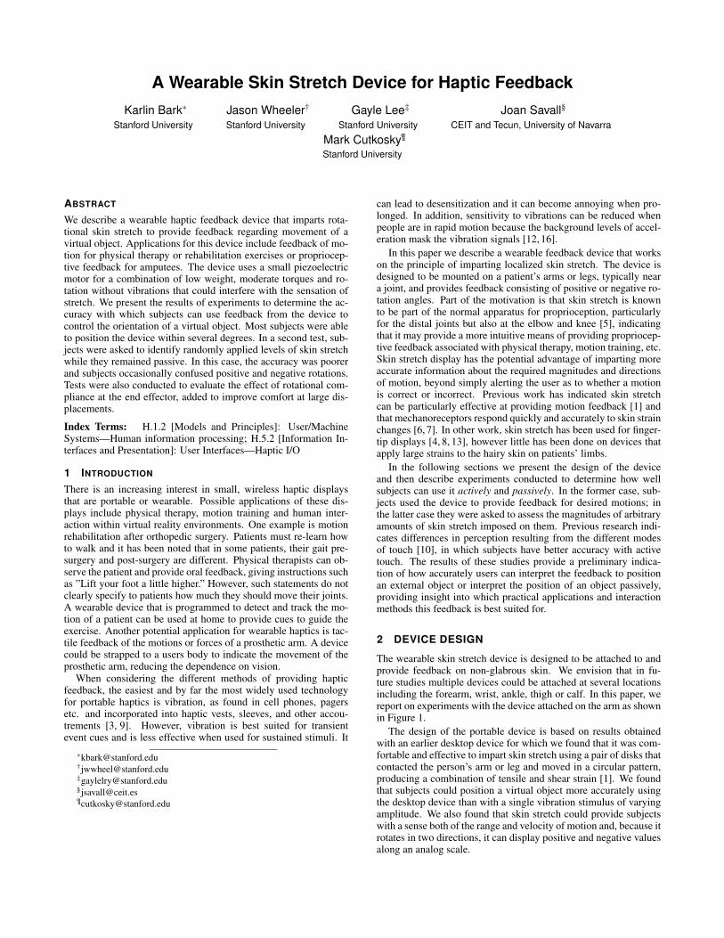
The wearable skin stretch device is designed to be attached to andprovide feedback on non-glabrous skin. We envision that in fu-ture studies multiple devices could be attached at several locationsincluding the forearm, wrist, ankle, thigh or calf. In this paper, wereport on experiments with the device attached on the arm as shownin Figure 1.
The design of the portable device is based on results obtainedwith an earlier desktop device for which we found that it was com-fortable and effective to impart skin stretch using a pair of disks thatcontacted the person’s arm or leg and moved in a circular pattern,producing a combination of tensile and shear strain [1]. We foundthat subjects could position a virtual object more accurately usingthe desktop device than with a single vibration stimulus of varyingamplitude. We also found that skin stretch could provide subjectswith a sense both of the range and velocity of motion and, because itrotates in two directions, it can display positive and negative valuesalong an analog scale.
skin stretchdevice rotational
knob
Figure 1: Wearable skin stretch device and knob used to control ro-tation of the device or input perceived positions.
Based on results obtained with the desktop device, initial re-quirements for the portable device were as follows:• end effector positioning resolution within 1 degree (the mini-
mum distinguishable motion for some subjects)• operating range of ±60 degrees.• range of speeds of 5-200 degrees per second• maximum torque of 0.2 Nm at maximum rotations• very smooth motion (humans are extremely sensitive to vibra-
tions).
2.1 ActuationAn ultrasonic piezoelectric motor (Shinsei Motors, USR30-B3) issuited to the requirements of a wearable skin stretch device. Thesemotors use a piezoelectric ceramic element to produce small, highfrequency deflections in a stator structure. The displacements areconverted into unlimited rotary motion of the rotor through inter-mittent frictional coupling [14] . Ultrasonic piezoelectric motorsproduce comparatively high torques at low speeds and are not back-driveable, which reduces power consumption when holding a posi-tion against an external torque. The motors are also small, flat, andlightweight, simplifying packaging. The vibration frequencies at50 kHz are well above the frequencies perceivable by humans, sothe motion feels smooth.
The motor is coupled to the end effector through a capstan andcable drive system, which provides a 6:1 speed reduction and keepsvibrations low. The range of speeds produced at the end effector is15–150 deg/s with a maximum torque output of 0.6 Nm. A smalltensioning block is adjusted with a screw to prevent slippage be-tween the braided steel cable and capstan.
Table 1: Wearable Skin Stretch Device CharacteristicsDesign Requirements Device Specifications
Size small 29 x 45 x 126 mmMax Torque 0.2 Nm 0.6 NmSpeed Range ≤ 200 deg/s 15–150 deg/sWeight ≤ 200 g 115 gSensor 1 deg 1 deg (Hall Effect)
resolution 0.05 deg (Encoder)
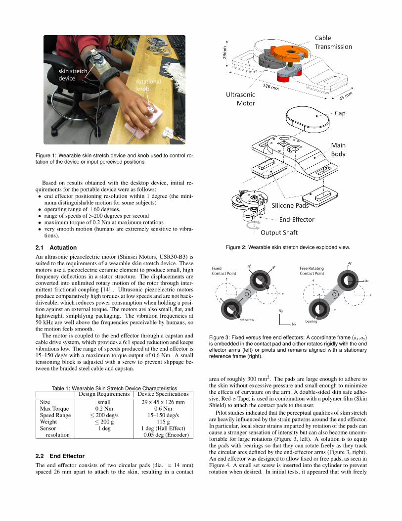
2.2 End EffectorThe end effector consists of two circular pads (dia. = 14 mm)spaced 26 mm apart to attach to the skin, resulting in a contact
Figure 2: Wearable skin stretch device exploded view.
Fixed Contact Point
Free RotatingContact Point
set screw bearing
Ny
Nx
ayax
ay
ax
Figure 3: Fixed versus free end effectors: A coordinate frame (ax,ay)is embedded in the contact pad and either rotates rigidly with the endeffector arms (left) or pivots and remains aligned with a stationaryreference frame (right).
area of roughly 300 mm2. The pads are large enough to adhere tothe skin without excessive pressure and small enough to minimizethe effects of curvature on the arm. A double-sided skin safe adhe-sive, Red-e-Tape, is used in combination with a polymer film (SkinShield) to attach the contact pads to the user.
Pilot studies indicated that the perceptual qualities of skin stretchare heavily influenced by the strain patterns around the end effector.In particular, local shear strains imparted by rotation of the pads cancause a stronger sensation of intensity but can also become uncom-fortable for large rotations (Figure 3, left). A solution is to equipthe pads with bearings so that they can rotate freely as they trackthe circular arcs defined by the end-effector arms (Figure 3, right).An end effector was designed to allow fixed or free pads, as seen inFigure 4. A small set screw is inserted into the cylinder to preventrotation when desired. In initial tests, it appeared that with freely
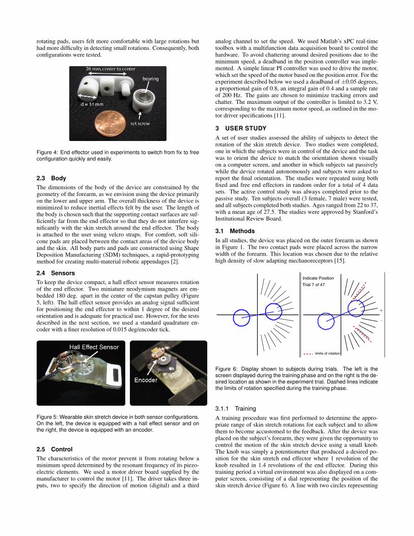
rotating pads, users felt more comfortable with large rotations buthad more difficulty in detecting small rotations. Consequently, bothconfigurations were tested.
Figure 4: End effector used in experiments to switch from fix to freeconfiguration quickly and easily.
2.3 BodyThe dimensions of the body of the device are constrained by thegeometry of the forearm, as we envision using the device primarilyon the lower and upper arm. The overall thickness of the device isminimized to reduce inertial effects felt by the user. The length ofthe body is chosen such that the supporting contact surfaces are suf-ficiently far from the end effector so that they do not interfere sig-nificantly with the skin stretch around the end effector. The bodyis attached to the user using velcro straps. For comfort, soft sili-cone pads are placed between the contact areas of the device bodyand the skin. All body parts and pads are constructed using ShapeDeposition Manufacturing (SDM) techniques, a rapid-prototypingmethod for creating multi-material robotic appendages [2].
2.4 SensorsTo keep the device compact, a hall effect sensor measures rotationof the end effector. Two miniature neodymium magnets are em-bedded 180 deg. apart in the center of the capstan pulley (Figure5, left). The hall effect sensor provides an analog signal sufficientfor positioning the end effector to within 1 degree of the desiredorientation and is adequate for practical use. However, for the testsdescribed in the next section, we used a standard quadrature en-coder with a finer resolution of 0.015 deg/encoder tick.
Figure 5: Wearable skin stretch device in both sensor configurations.On the left, the device is equipped with a hall effect sensor and onthe right, the device is equipped with an encoder.
2.5 ControlThe characteristics of the motor prevent it from rotating below aminimum speed determined by the resonant frequency of its piezo-electric elements. We used a motor driver board supplied by themanufacturer to control the motor [11]. The driver takes three in-puts, two to specify the direction of motion (digital) and a third
analog channel to set the speed. We used Matlab’s xPC real-timetoolbox with a multifunction data acquisition board to control thehardware. To avoid chattering around desired positions due to theminimum speed, a deadband in the position controller was imple-mented. A simple linear PI controller was used to drive the motor,which set the speed of the motor based on the position error. For theexperiment described below we used a deadband of±0.05 degrees,a proportional gain of 0.8, an integral gain of 0.4 and a sample rateof 200 Hz. The gains are chosen to minimize tracking errors andchatter. The maximum output of the controller is limited to 3.2 V,corresponding to the maximum motor speed, as outlined in the mo-tor driver specifications [11].
3 USER STUDYA set of user studies assessed the ability of subjects to detect therotation of the skin stretch device. Two studies were completed,one in which the subjects were in control of the device and the taskwas to orient the device to match the orientation shown visuallyon a computer screen, and another in which subjects sat passivelywhile the device rotated autonomously and subjects were asked toreport the final orientation. The studies were repeated using bothfixed and free end effectors in random order for a total of 4 datasets. The active control study was always completed prior to thepassive study. Ten subjects overall (3 female, 7 male) were tested,and all subjects completed both studies. Ages ranged from 22 to 37,with a mean age of 27.5. The studies were approved by Stanford’sInstitutional Review Board.
3.1 MethodsIn all studies, the device was placed on the outer forearm as shownin Figure 1. The two contact pads were placed across the narrowwidth of the forearm. This location was chosen due to the relativehigh density of slow adapting mechanoreceptors [15].
Indicate PositionTrial 7 of 47
limits of rotation
+
-
Figure 6: Display shown to subjects during trials. The left is thescreen displayed during the training phase and on the right is the de-sired location as shown in the experiment trial. Dashed lines indicatethe limits of rotation specified during the training phase.
3.1.1 TrainingA training procedure was first performed to determine the appro-priate range of skin stretch rotations for each subject and to allowthem to become accustomed to the feedback. After the device wasplaced on the subject’s forearm, they were given the opportunity tocontrol the motion of the skin stretch device using a small knob.The knob was simply a potentiometer that produced a desired po-sition for the skin stretch end effector where 1 revolution of theknob resulted in 1.4 revolutions of the end effector. During thistraining period a virtual environment was also displayed on a com-puter screen, consisting of a dial representing the position of theskin stretch device (Figure 6). A line with two circles representing
−60 −40 −20 0 20 40 60
−60
−40
−20
0
20
40
60
80R2 = 0.86slope = 1.03
Desired Position (deg)
Mea
sure
d Sk
in S
tretc
h Po
sitio
n (d
eg)
Fixed Contact
−60 −40 −20 0 20 40 60
−60
−40
−20
0
20
40
60
80R2 = 0.88slope = 1.03
Desired Position (deg)
Active Positioning Study Results- All Subjects
Free Rotating ContactM
easu
red
Skin
Stre
tch
Posi
tion
(deg
)−60 −40 −20 0 20 40 60
−60
−40
−20
0
20
40
60
80
Stimulus Position (deg)
Perc
eive
d Po
sitio
n (d
eg)
−60 −40 −20 0 20 40 60
−60
−40
−20
0
20
40
60
80
Stimulus Position (deg)
Perc
eive
d Po
sitio
n (d
eg)
Passive Perception Study Results - All Subjects
Fixed Contact Free Rotating Contact
(a) Data from all ten subjects in the active positioning task. (b) Data from all ten subjects in the passive perception study.Fixed contact pad data on the left, free rotating on the right. Fixed contact pad data on the left, free rotating on the right.
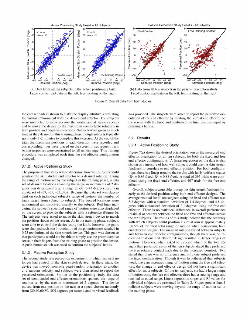
Figure 7: Overall data from both studies.
the contact pads is shown to make the display intuitive, correlatingthe virtual environment with the device end effector. The subjectswere instructed to move accross the workspace at various speedsand to move the device to the maximum comfortable rotations inboth positive and negative directions. Subjects were given as muchtime as they desired in this training phase though subjects typicallyspent only 1-2 minutes to complete this exercise. At the end of thetrial, the maximum positions in each direction were recorded andcorresponding lines were placed on the screen in subsequent trialsso that responses were constrained to fall in this range. This trainingprocedure was completed each time the end effector configurationchanged.
3.1.2 Active Positioning Study
The purpose of this study was to determine how well subjects couldposition the skin stretch end effector to a desired rotation. Usingthe range of motion set by the subject in the training phase, a dataset of desired locations spanning the range in increments of 2 de-grees was determined (e.g. a range of -37 to 43 degrees results ina data set of -37, -35, -33...43). Because the data set was depen-dent on each individual subject’s range of motion, the number oftrials varied from subject to subject. The desired locations wererandomized and displayed visually to the subject. Red lines indi-cating the subject’s specified range of motion were also displayedon the screen to provide the subjects with a reference (Figure 6).The subjects were asked to move the skin stretch device to matchthe position shown on the screen. As in the training phase, subjectswere able to control the device using the knob, however the gainswere changed such that 1 revolution of the potentiometer resulted in0.23 revolutions of the skin stretch device. This gain was chosen sothat participants would not be able to simply use the proprioceptivesense in their fingers from the training phase to position the device.A push-button switch was used to confirm the subjects’ inputs.
3.1.3 Passive Perception Study
The second study is a perception experiment in which subjects nolonger had control of the skin stretch device. In these trials, thedevice was moved from one quasi-random orientation to anotherat a random velocity and subjects were then asked to report theperceived orientation. Similar to the positioning study, the dataset of commanded end effector orientations spanned the range ofrotation set by the user in increments of 2 degrees. The devicemoved from one position to the next at a speed chosen randomlyfrom [20,40,60,80,100] degrees per second and no visual feedback
was provided. The subjects were asked to report the perceived ori-entation of the end effector by rotating the virtual end effector onthe screen with the knob and confirmed the final position input bypressing a button.
3.2 Results
3.2.1 Active Positioning Study
Figure 7(a) shows the desired orientation versus the measured endeffector orientation for all ten subjects, for both the fixed and freeend effector configurations. A linear regression on the data is alsoshown as a measure of how well subjects could use the skin stretchfeedback to correlate to end effector position. For both configura-tions, there is a linear trend to the results with fairly uniform scatter(R2 = 0.86 fixed, R2 = 0.88 free). A total of 393 trials were com-pleted using the fixed end effector, and 407 trials for the free endeffector.
Overall, subjects were able to map the skin stretch feedback lin-early to the desired position using both end effector designs. Theaverage residual for all ten subjects using the fixed end effector was5.2 degrees with a standard deviation of 1.4 degrees, and 4.8 de-grees with a standard deviation of 2.1 degrees using the free endeffector. There is no statistical difference in overall performance(residual or scatter) between the fixed and free end effectors acrossthe ten subjects. The results of this study indicate that the accuracywith which subjects could position a virtual arm is approximately±6.5% of the their total range of motion when considering bothend effector designs. The range of rotation varied between subjectsand between end effector configurations, though there was no in-dication that one end effector design resulted in larger ranges ofmotion. However, when asked to indicate which of the two de-signs they preferred, seven of the ten subjects stated they preferredthe free rotating contact pads due to the increased comfort. Twostated that there was no difference and only one subject preferredthe fixed configuration. Though it was hypothesized that subjectswould have an increased range of motion using the free end effec-tors, the change in end effector design did not have a significanteffect for most subjects. Of the ten subjects, six had a larger rangeof motion using the free end effector, three had a smaller range andone had an equal range. Linear regression slopes and R2 values forindividual subjects are presented in Table 2. Slopes greater than 1indicate subjects were moving beyond the range of motion set inthe training phase.
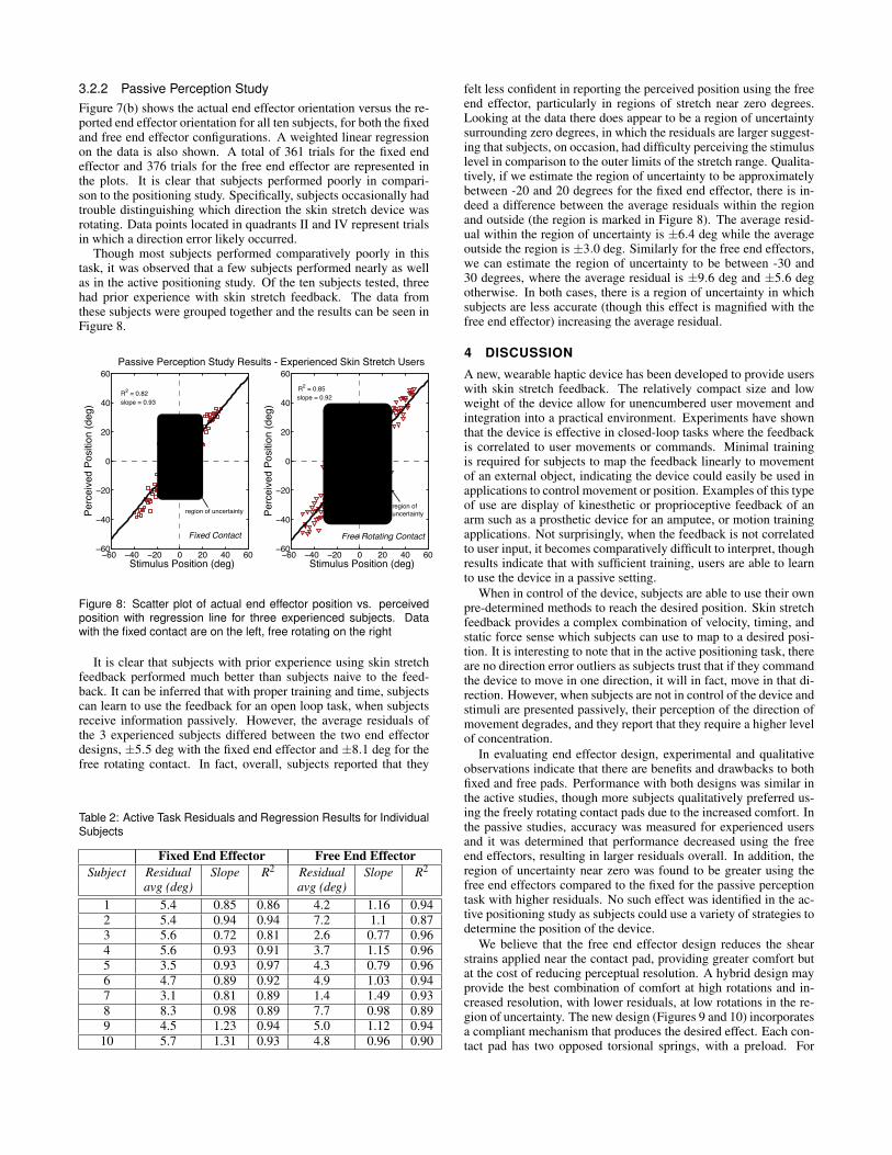
3.2.2 Passive Perception StudyFigure 7(b) shows the actual end effector orientation versus the re-ported end effector orientation for all ten subjects, for both the fixedand free end effector configurations. A weighted linear regressionon the data is also shown. A total of 361 trials for the fixed endeffector and 376 trials for the free end effector are represented inthe plots. It is clear that subjects performed poorly in compari-son to the positioning study. Specifically, subjects occasionally hadtrouble distinguishing which direction the skin stretch device wasrotating. Data points located in quadrants II and IV represent trialsin which a direction error likely occurred.
Though most subjects performed comparatively poorly in thistask, it was observed that a few subjects performed nearly as wellas in the active positioning study. Of the ten subjects tested, threehad prior experience with skin stretch feedback. The data fromthese subjects were grouped together and the results can be seen inFigure 8.
−60 −40 −20 0 20 40 60−60
−40
−20
0
20
40
60
R2 = 0.82slope = 0.93
Stimulus Position (deg)
Perc
eive
d Po
sitio
n (d
eg)
Fixed Contact
−60 −40 −20 0 20 40 60−60
−40
−20
0
20
40
60R2 = 0.85slope = 0.92
Stimulus Position (deg)
Perc
eive
d Po
sitio
n (d
eg)
Passive Perception Study Results - Experienced Skin Stretch Users
Free Rotating Contact
region of uncertaintyregion of uncertainty
Figure 8: Scatter plot of actual end effector position vs. perceivedposition with regression line for three experienced subjects. Datawith the fixed contact are on the left, free rotating on the right
It is clear that subjects with prior experience using skin stretchfeedback performed much better than subjects naive to the feed-back. It can be inferred that with proper training and time, subjectscan learn to use the feedback for an open loop task, when subjectsreceive information passively. However, the average residuals ofthe 3 experienced subjects differed between the two end effectordesigns, ±5.5 deg with the fixed end effector and ±8.1 deg for thefree rotating contact. In fact, overall, subjects reported that they
Table 2: Active Task Residuals and Regression Results for IndividualSubjects
Fixed End Effector Free End EffectorSubject Residual Slope R2 Residual Slope R2
avg (deg) avg (deg)1 5.4 0.85 0.86 4.2 1.16 0.942 5.4 0.94 0.94 7.2 1.1 0.873 5.6 0.72 0.81 2.6 0.77 0.964 5.6 0.93 0.91 3.7 1.15 0.965 3.5 0.93 0.97 4.3 0.79 0.966 4.7 0.89 0.92 4.9 1.03 0.947 3.1 0.81 0.89 1.4 1.49 0.938 8.3 0.98 0.89 7.7 0.98 0.899 4.5 1.23 0.94 5.0 1.12 0.94
10 5.7 1.31 0.93 4.8 0.96 0.90
felt less confident in reporting the perceived position using the freeend effector, particularly in regions of stretch near zero degrees.Looking at the data there does appear to be a region of uncertaintysurrounding zero degrees, in which the residuals are larger suggest-ing that subjects, on occasion, had difficulty perceiving the stimuluslevel in comparison to the outer limits of the stretch range. Qualita-tively, if we estimate the region of uncertainty to be approximatelybetween -20 and 20 degrees for the fixed end effector, there is in-deed a difference between the average residuals within the regionand outside (the region is marked in Figure 8). The average resid-ual within the region of uncertainty is ±6.4 deg while the averageoutside the region is ±3.0 deg. Similarly for the free end effectors,we can estimate the region of uncertainty to be between -30 and30 degrees, where the average residual is ±9.6 deg and ±5.6 degotherwise. In both cases, there is a region of uncertainty in whichsubjects are less accurate (though this effect is magnified with thefree end effector) increasing the average residual.
4 DISCUSSION
A new, wearable haptic device has been developed to provide userswith skin stretch feedback. The relatively compact size and lowweight of the device allow for unencumbered user movement andintegration into a practical environment. Experiments have shownthat the device is effective in closed-loop tasks where the feedbackis correlated to user movements or commands. Minimal trainingis required for subjects to map the feedback linearly to movementof an external object, indicating the device could easily be used inapplications to control movement or position. Examples of this typeof use are display of kinesthetic or proprioceptive feedback of anarm such as a prosthetic device for an amputee, or motion trainingapplications. Not surprisingly, when the feedback is not correlatedto user input, it becomes comparatively difficult to interpret, thoughresults indicate that with sufficient training, users are able to learnto use the device in a passive setting.
When in control of the device, subjects are able to use their ownpre-determined methods to reach the desired position. Skin stretchfeedback provides a complex combination of velocity, timing, andstatic force sense which subjects can use to map to a desired posi-tion. It is interesting to note that in the active positioning task, thereare no direction error outliers as subjects trust that if they commandthe device to move in one direction, it will in fact, move in that di-rection. However, when subjects are not in control of the device andstimuli are presented passively, their perception of the direction ofmovement degrades, and they report that they require a higher levelof concentration.
In evaluating end effector design, experimental and qualitativeobservations indicate that there are benefits and drawbacks to bothfixed and free pads. Performance with both designs was similar inthe active studies, though more subjects qualitatively preferred us-ing the freely rotating contact pads due to the increased comfort. Inthe passive studies, accuracy was measured for experienced usersand it was determined that performance decreased using the freeend effectors, resulting in larger residuals overall. In addition, theregion of uncertainty near zero was found to be greater using thefree end effectors compared to the fixed for the passive perceptiontask with higher residuals. No such effect was identified in the ac-tive positioning study as subjects could use a variety of strategies todetermine the position of the device.
We believe that the free end effector design reduces the shearstrains applied near the contact pad, providing greater comfort butat the cost of reducing perceptual resolution. A hybrid design mayprovide the best combination of comfort at high rotations and in-creased resolution, with lower residuals, at low rotations in the re-gion of uncertainty. The new design (Figures 9 and 10) incorporatesa compliant mechanism that produces the desired effect. Each con-tact pad has two opposed torsional springs, with a preload. For
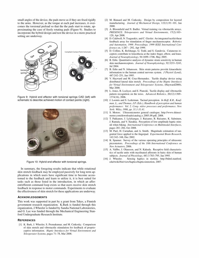
small angles of the device, the pads move as if they are fixed rigidlyto the arms. However, as the torque at each pad increases, it over-comes the torsional preload so that the the pads start to rotate, ap-proximating the case of freely rotating pads (Figure 9). Studies toincorporate the hybrid design and test the device in a more practicalsetting are underway.
main body
bearingstorsionalspring
caps
pin
Compliant Contact Point Schematic
Figure 9: Hybrid end effector with torsional springs CAD (left) withschematic to describe achieved motion of contact points (right).
Figure 10: Hybrid end effector with torsional springs.
In summary, the foregoing results indicate that while rotationalskin stretch feedback may be employed passively for long term ap-plications in which users have significant time to become accus-tomed to the feedback and learn to utilize it, it is best suited fortasks such as those listed in the introduction, in which an affer-ent/efferent command loop exists so that users receive skin stretchfeedback in response to motor commands. Experiments to evaluatethe effectiveness of skin stretch for these applications are underway.
ACKNOWLEDGEMENTS
This work was supported in part by a grant from Tekes, a Finnishgovernment research organization. K.Bark is funded through thisorganization, J.Wheeler is funded by Sandia National Laboratories,and G. Lee was funded through the Mechanical Engineering Stan-ford Undergraduate Research Institute.
REFERENCES
[1] K. Bark, J. Wheeler, S. Premakumar, and M. Cutkosky. Comparisonof skin stretch and vibrotactile stimulation for feedback of proprio-ceptive information. Haptic Interfaces for Virtual Environment andTeleoperator Systems, pages 71–78, Mar 2008.
[2] M. Binnard and M. Cutkosky. Design by composition for layeredmanufacturing. Journal of Mechanical Design, 122(1):91–101, Jan2000.
[3] A. Bloomfield and N. Badler. Virtual training via vibrotactile arrays.PRESENCE: Teleoperators and Virtual Environments, 17(2):103–120, Apr 2008.
[4] D. Caldwell, N. Tsagarakis, and C. Giesler. An integrated tactile/shearfeedback array for stimulation of finger mechanoreceptor. Roboticsand Automation, 1999. Proceedings. 1999 IEEE International Con-ference on, 1:287 – 292, Apr 1999.
[5] D. Collins, K. Refshauge, G. Todd, and S. Gandevia. Cutaneous re-ceptors contribute to kinesthesia at the index finger, elbow, and knee.Journal of Neurophysiology, 94:1699–1706, May 2005.
[6] B. Edin. Quantitative analyses of dynamic strain sensitivity in humanskin mechanoreceptors. Journal of Neurophysiology, 92:3233–3243,Jul 2004.
[7] B. Edin and N. Johansson. Skin strain patterns provide kinaestheticinformation to the human central nervous system. J Physiol (Lond),487:242–251, Jan 1995.
[8] V. Hayward and M. Cruz-Hernandez. Tactile display device usingdistributed lateral skin stretch. Proceedings of the Haptic Interfacesfor Virtual Environment and Teleoperator Systems, (Hayward2000),Mar 2000.
[9] L. Jones, B. Lockyer, and E. Piateski. Tactile display and vibrotactilepattern recognition on the torso. Advanced Robotics, 20(12):1369–1374(16), 2006.
[10] J. Loomis and S. Lederman. Tactual perception. In Boff, K.R., Kauf-man, L., and Thomas, J.P. (Eds.), Handbook of perception and humanperformance: Vol. 2. Cong- nitive processes and performance. NewYork: Wiley, 1986, pp. 31.1-31.41.
[11] S. Motors. Ultrasonicmotor general catalogue, http://www.shinsei-motor.com/downloads/catalog e 2005 09.pdf, 2008.
[12] T. Pakkanen, J. Lylykangas, J. Raisamo, R. Raisamo, K. Salminen,J. Rantala, and V. Surakka. Perception of low-amplitude haptic stim-uli when biking. International Conference on Multimodal Interfaces,pages 281–284, Oct 2008.
[13] M. Pare, H. Carnahan, and A. Smith. Magnitude estimation of tan-gential force applied to the fingerpad. Experimental Brain Research,142:342–348, Dec 2002.
[14] K. Spanner. Survey of the various operating principles of ultrasonicpiezomotors. Proceedings of the 10th International Conference onNew Actuators, 2006.
[15] A. Vallbo, J. Olausson, and N. Kakuda. Receptive field characteris-tics of tactile units with myelinated afferents in hairy skin of humansubjects. Journal of Physiology, 483.3:783–795, Jan 1995.
[16] J. Wheeler. Sensing haptics in motion, http://bdml.stanford.edu/twiki/bin/view/haptics/hapticsinmotion, 2007.