a virtual testbed for tactile industrial internet of things services
TRANSCRIPT
sensors
Article
IoTactileSim: A Virtual Testbed for Tactile Industrial Internet ofThings Services
Muhammad Zubair Islam , Shahzad , Rashid Ali , Amir Haider * and Hyungseok Kim *
�����������������
Citation: Zubair Islam, M.; Shahzad;
Ali, R.; Hadier, A.; Kim, H.S.
IoTactileSim: A Virtual Testbed for
Tactile Industrial Internet of Things
Services. Sensors 2021, 21, 8363.
https://doi.org/10.3390/s21248363
Academic Editors: Zihuai Lin and
Wei Xiang
Received: 10 November 2021
Accepted: 13 December 2021
Published: 15 December 2021
Publisher’s Note: MDPI stays neutral
with regard to jurisdictional claims in
published maps and institutional affil-
iations.
Copyright: © 2021 by the authors.
Licensee MDPI, Basel, Switzerland.
This article is an open access article
distributed under the terms and
conditions of the Creative Commons
Attribution (CC BY) license (https://
creativecommons.org/licenses/by/
4.0/).
School of Intelligent Mechatronics Engineering, Sejong University, Seoul 05006, Korea;[email protected] (M.Z.I.); [email protected] (S.); [email protected] (R.A.)* Correspondence: [email protected] (A.H.); [email protected] (H.K.)
Abstract: With the inclusion of tactile Internet (TI) in the industrial sector, we are at the doorstepof the tactile Industrial Internet of Things (IIoT). This provides the ability for the human operatorto control and manipulate remote industrial environments in real-time. The TI use cases in IIoTdemand a communication network, including ultra-low latency, ultra-high reliability, availability,and security. Additionally, the lack of the tactile IIoT testbed has made it more severe to investigateand improve the quality of services (QoS) for tactile IIoT applications. In this work, we proposea virtual testbed called IoTactileSim, that offers implementation, investigation, and managementfor QoS provisioning in tactile IIoT services. IoTactileSim utilizes a network emulator Mininet androbotic simulator CoppeliaSim to perform real-time haptic teleoperations in virtual and physicalenvironments. It provides the real-time monitoring of the implemented technology parametric values,network impairments (delay, packet loss), and data flow between operator (master domain) andteleoperator (slave domain). Finally, we investigate the results of two tactile IIoT environments toprove the potential of the proposed IoTactileSim testbed.
Keywords: 5G/6G; URLLC; tactile Internet; industrial IoT; network emulator; robotic simulator;virtual testbed
1. Introduction
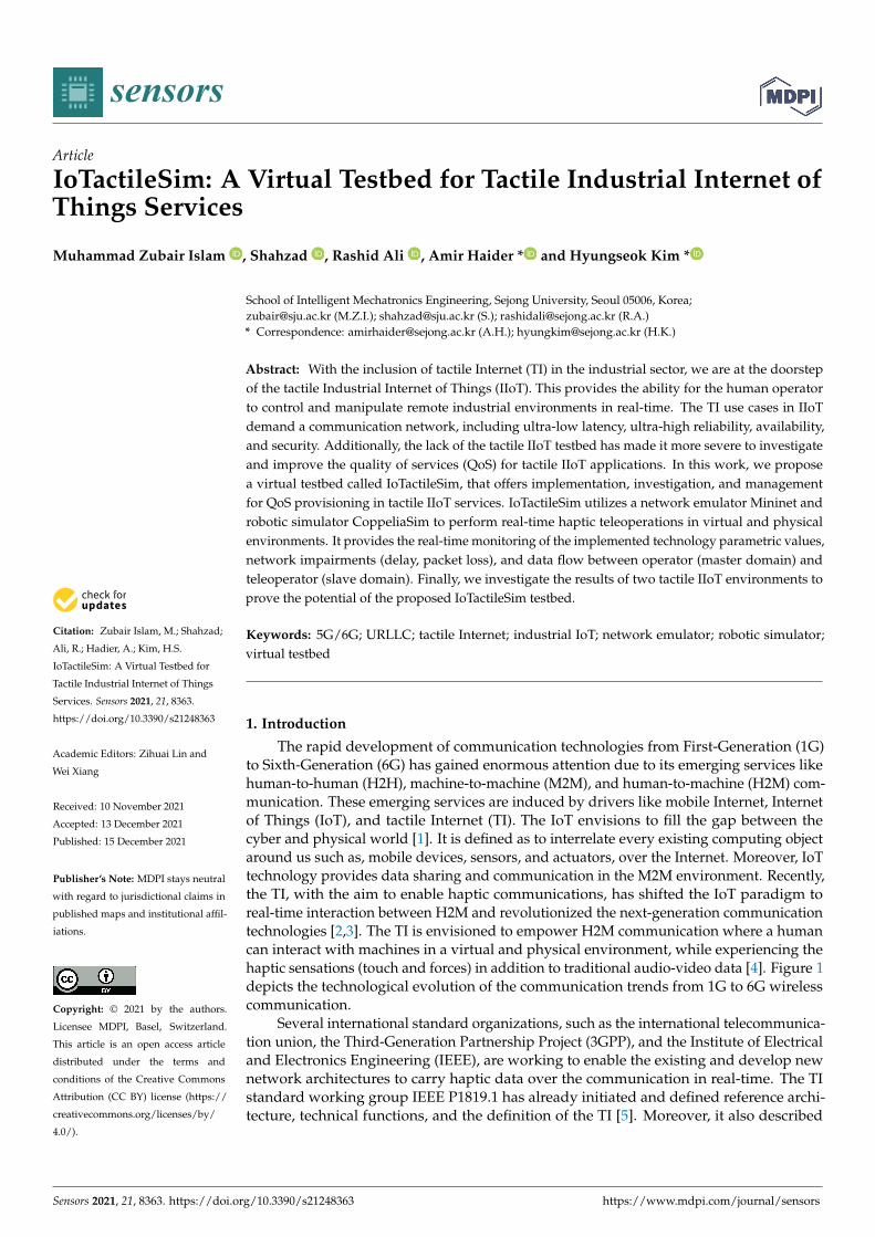
The rapid development of communication technologies from First-Generation (1G)to Sixth-Generation (6G) has gained enormous attention due to its emerging services likehuman-to-human (H2H), machine-to-machine (M2M), and human-to-machine (H2M) com-munication. These emerging services are induced by drivers like mobile Internet, Internetof Things (IoT), and tactile Internet (TI). The IoT envisions to fill the gap between thecyber and physical world [1]. It is defined as to interrelate every existing computing objectaround us such as, mobile devices, sensors, and actuators, over the Internet. Moreover, IoTtechnology provides data sharing and communication in the M2M environment. Recently,the TI, with the aim to enable haptic communications, has shifted the IoT paradigm toreal-time interaction between H2M and revolutionized the next-generation communicationtechnologies [2,3]. The TI is envisioned to empower H2M communication where a humancan interact with machines in a virtual and physical environment, while experiencing thehaptic sensations (touch and forces) in addition to traditional audio-video data [4]. Figure 1depicts the technological evolution of the communication trends from 1G to 6G wirelesscommunication.
Several international standard organizations, such as the international telecommunica-tion union, the Third-Generation Partnership Project (3GPP), and the Institute of Electricaland Electronics Engineering (IEEE), are working to enable the existing and develop newnetwork architectures to carry haptic data over the communication in real-time. The TIstandard working group IEEE P1819.1 has already initiated and defined reference archi-tecture, technical functions, and the definition of the TI [5]. Moreover, it also described
Sensors 2021, 21, 8363. https://doi.org/10.3390/s21248363 https://www.mdpi.com/journal/sensors
Sensors 2021, 21, 8363 2 of 20
standard use cases of the TI and corresponding strict requirements, including teleopera-tion, automotive, immersive virtual/augmented reality, internet of drones, interpersonalcommunication, live haptic broadcast, and cooperative automated driving. However, theseuse cases demand near real-time connectivity (ultra-reliable and ultra-responsive) for M2Mand H2M communication. This type of real-time connectivity is termed as ultra-reliableand low latency communication (URLLC). The URLLC is one of the key services of theFifth-Generation (5G) networks, along with enhanced mobile broadband and massivemachine-type communication. Moreover, 3GPP has introduced the 5G new radio to in-crease reliability and minimize end-to-end (E2E) communication latency for the URLLCservices. In Release 15, 3GPP describes the URLLC requirement with the reliability of 99.9%for a single 32-byte packet under 1ms latency [6]. Conclusively, 5G URLLC services are oneof the potential enablers for the extreme requirements of the TI.
1G
2G
3G
4G
5G
6G
Voice
Text
Text + Voice
Multimedia + Voice
Mobile Internet
IoT
TI /Internet of Skills
M2M
H2M
H2H
Fixed Internet
Mobile TV Mobile Pay
Multimedia
AR/VR/360
Videos
Wearable
Devices
HD Videos
Inte rnet of
Applica tions
Smart City Smart Factory
HealthCare 4.0
Smart Home
Smart
Health
Industry 4.0
Autonomous
Driving
Smart Grid
Tele-Medicine
Framing 4.0
Smart Eduaction
Figure 1. A taxonomy of the different emerging communication trends.
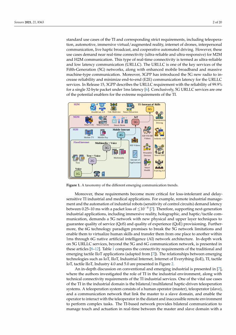
Moreover, these requirements become more critical for loss-intolerant and delay-sensitive TI industrial and medical applications. For example, remote industrial manage-ment and the automation of industrial robots (sensitivity of control circuits) demand latencybetween 0.25–10 ms with a packet loss of ≤10−9 [7]. Therefore, supporting next-generationindustrial applications, including immersive reality, holographic, and haptic/tactile com-munication, demands a 5G network with new physical and upper layer techniques toguarantee quality of service (QoS) and quality of experience (QoE) provisioning. Further-more, the 6G technology paradigm promises to break the 5G network limitations andenable them to virtualize human skills and transfer them from one place to another within1ms through 6G native artificial intelligence (AI) network architecture. In-depth workon 5G URLLC services, beyond the 5G and 6G communication network, is presented inthese articles [8–12]. Table 1 compares the connectivity requirements of the traditional andemerging tactile IIoT applications (adapted from [7]). The relationships between emergingtechnologies such as IoT, IIoT, Industrial Internet, Internet of Everything (IoE), TI, tactileIoT, tactile IIoT, Industry 4.0 and 5.0 are presented in Figure 2.
An in-depth discussion on conventional and emerging industrial is presented in [7],where the authors investigated the role of TI in the industrial environment, along withtechnical connectivity requirements of the TI industrial services. One of the vital use casesof the TI in the industrial domain is the bilateral/multilateral haptic-driven teleoperationsystems. A teleoperation system consists of a human operator (master), teleoperator (slave),and a communication network that link the master to a slave domain, and enable theoperator to interact with the teleoperator in the distant and inaccessible remote environmentto perform complex tasks. The TI-based network provides bilateral communication tomanage touch and actuation in real-time between the master and slave domain with a
Sensors 2021, 21, 8363 3 of 20
focus to ensure QoS and QoE requirements. Haptic-enabled teleoperation systems havenumerous applications in Industry 4.0, such as robotic automation, smart manufacturing,smart logistic, the mining industry, food industry, healthcare industry, and industrialmanagement (controlling and monitoring). Contrary to the traditional application, Haptic-enabled industrial applications demand high QoS and QoE, and depend on the nature ofthe application.
Table 1. Summary of the connectivity requirements for traditional IIoT and emerging tactile IIoT services.
Applications/Requirements Latency (ms) Reliability (%) Scalability Data Rate (Mbps)
Con
vent
iona
l Monitoring 50–100 99.9–99.99 100–1000 0.1–0.5
Safety control 10 99.99–99.999 10–20 0.1–1
Motion control 0.5–2 99.9999–99.99999 10–50 1–5
Closed-loop control 100–150 99.99–99.999 100–150 1–5
Emer
ging
Remote monitoring and maintenance 20–50 99.99–99.999 500–1000 1–2
Remote operation (teleoperations) 2–10 99.999–99.99999 1–5 100–200
Mobile workforce 5–10 99.999–99.9999 50–100 10–50
Augmented reality 10 99.99–99.999 10–20 500–1000
TI
Industry
4.0
IIoT
IoTIndustrial
Internet
IoE
Industry 5.0
Figure 2. An overview of the relation between IoT, IIoT, tactial IoT, tactile IIoT, Industry 4.0, andIndustry 5.0.
One of the effective ways to investigate the tactile IIoT application requirements,performance, and testing the new solutions to ensure QoS and QoE, is to set up a virtualtestbed similar to the real network. The testbed must allow us to utilize and maintainhardware and software virtually on a standard computer without purchasing them. In theliterature, several recent articles have proposed testbeds to overcome the above-mentionedchallenges. The work in [13] proposed a haptic system testbed to characterize and validateE2E haptic communication of different use cases of TI. The authors introduce a frameworkcomprised of multiple sub-blocks that can be re-configured based on the nature of usecases, with a focus on minimizing cost and evaluation time. It also provides an option tointegrate the testbed with the simulation platform through a connector interface to performtesting. Commonly, it is intended to offer an extensive range of haptic hardware, includingsensors, actuators, and tactile interface boards. A testbed for tactile and kinesthetic datacoding was proposed in [14] aligned with IEEE P1918.1 TI standard working group toimprove and standardize haptic codec. The proposed haptic coding testbed is considered asa reference testbed with the aim to develop optimal data compression schemes to exchangetactile and kinesthetic information and enable human-in-the-loop TI services. The authors
Sensors 2021, 21, 8363 4 of 20
also provide some reference tactile data traces, software, and hardware to evaluate newlydeveloped kinesthetic and tactile codecs.
In [15], a framework for tactile cyber physical systems was proposed, which is specifi-cally for physical remote environments and based on network simulator NS3. It providesan interface for robotic experiments, along with haptic communication modules. However,the authors ignored the extensibility of the proposed testbed for other haptic-driven appli-cations. Similarly, the authors in [16,17] proposed a generic testbed framework for differentTI use cases. A data-driven experiment setup was proposed in [16] to provide a commonplayground for testing haptic applications. The proposed haptic communication testbedat the Otto-von-Guericke University of Magdeburg (OVGU-HC) focused on providingexperiment testbed for long-distance haptic-enabled teleoperation systems, in additionto small scale wireless haptic-driven applications. The OVGU-HC presents experimentautomation and data collection utilizing experiment description language (DES-Cript).The proposed OVGU-HC did not work standalone, is a part of the MIoT-Lab, and is justused to gather hepatic experiment information. Moreover, it utilized domain-specificlanguage DES-Cript [18], and did not provide an open-source facility to the research anddevelopment community.
The study in [17] presents a two-level classification of the TI applications basedon controlled environment and master-slave integrations to develop a generic testbed,with a focus to ensure compatibility for all these classified applications, which is namedas TI- eXtensible Testbed (XT). To demonstrate the potential of the TIXT, they discussH2M haptic communication in the virtual and physical environment. However, theyignored the explanation on how to characterize the network impairments (delay, jitter,and packet losses) and investigate the performance of the haptic-driven IIoT application.Therefore, there is a strong need for a testbed that offers flexibility, scalability, open-sourceavailability, tailored to examine network impairments, communication flow, and extensiblefor TI IIoT use cases. In this regard, we proposed a virtual testbed called IoTactileSimto investigate tactile IIoT services from QoS and QoE perspectives. The IoTactileSimemploys Software Define Network (SDN) and edge computing at the core network totactile industrial application. The following section presents the main contribution of theproposed IoTactileSim testbed.
1.1. Research Contributions
The primary contributions of this work are summarized below as:
• We presented the details of TI in the context of various industrial environments anddiscussed some emerging applications of the tactile IIoT.
• A hybrid virtual testbed, IoTactileSim, is proposed by combining a network emulatorand an industrial robotic simulator to simulate tactile IIoT applications and investigatetheir performance.
• We designed the IoTactileSim by adopting a hierarchical approach, where the networkis divided into two parts; a core and an edge layer. The core layer consists of SDNrouters to perform intelligent routing, while the edge layer performs as an intelligentsupport engine for tactile IIoT services.
• The proposed IoTactileSim identifies the challenges imposed by the tactile IIoT andtheir strict QoS/QoE requirements. Moreover, it focuses on investigating the com-munication network parameters (latency, reliability) and other configurations corre-sponding to the identified requirements.
• We conduct two different experiments in the tactile IIoT environment to evaluate theperformance and present the potential of the proposed IoTactileSim testbed.
1.2. Paper Organization
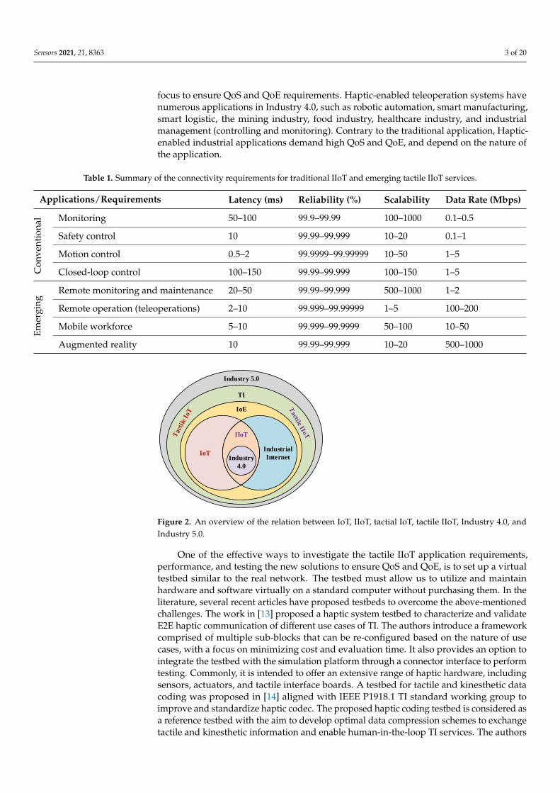
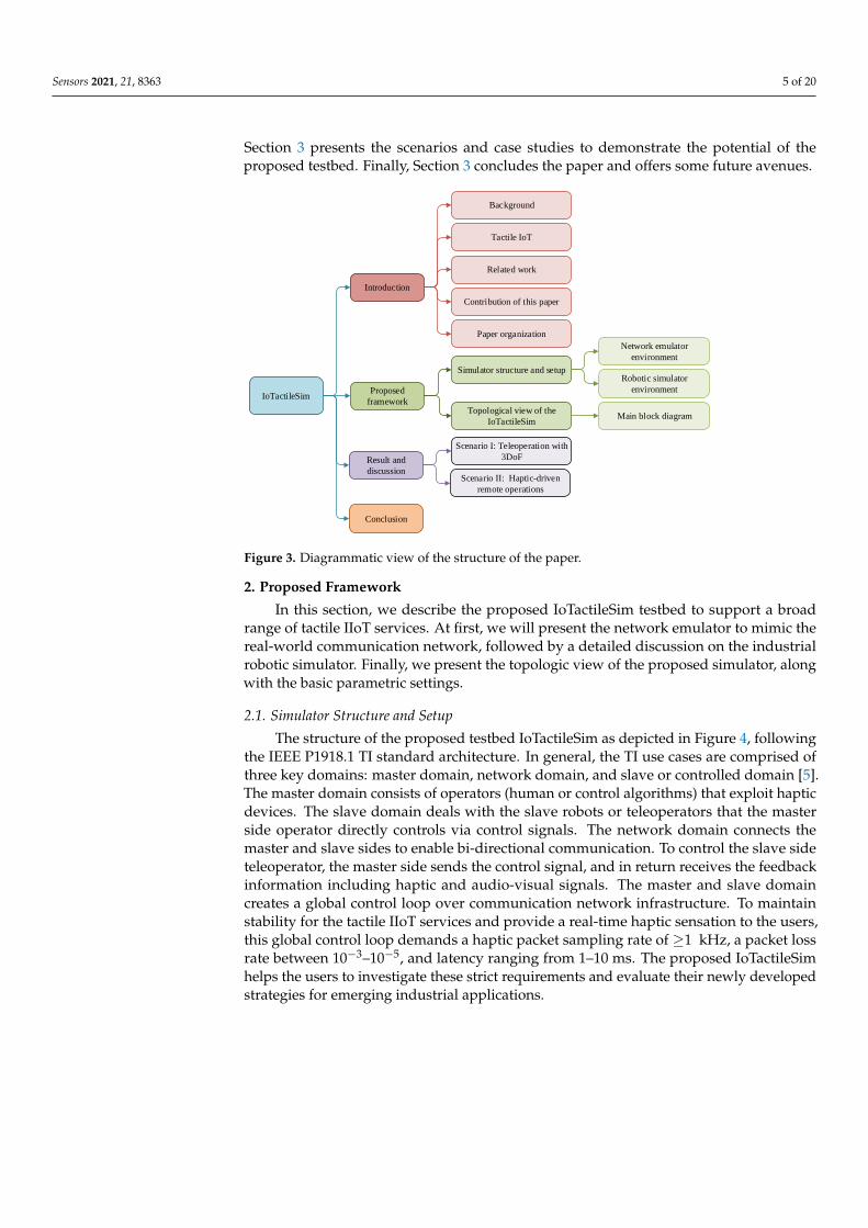
As illustrated in Figure 3, the rest of this paper is organized as follows. Section 2discusses the proposed IoTactileSim structure and setup, along with the topological view.
Sensors 2021, 21, 8363 5 of 20
Section 3 presents the scenarios and case studies to demonstrate the potential of theproposed testbed. Finally, Section 3 concludes the paper and offers some future avenues.
IoTactileSim
Introduction
Proposed
framework
Result and
discussion
Conclusion
Tactile IoT
Background
Related work
Paper organization
Network emulator
environment
Main block diagramTopological view of the
IoTactileSim
Scenario I: Teleoperation with
3DoF
Scenario II: Haptic-driven
remote operations
Contribution of this paper
Simulator structure and setupRobotic simulator
environment
Figure 3. Diagrammatic view of the structure of the paper.
2. Proposed Framework
In this section, we describe the proposed IoTactileSim testbed to support a broadrange of tactile IIoT services. At first, we will present the network emulator to mimic thereal-world communication network, followed by a detailed discussion on the industrialrobotic simulator. Finally, we present the topologic view of the proposed simulator, alongwith the basic parametric settings.
2.1. Simulator Structure and Setup
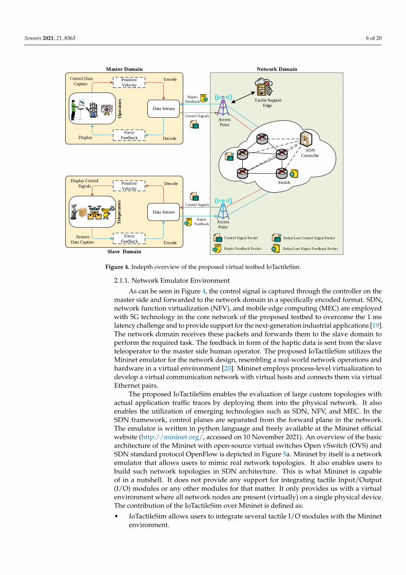
The structure of the proposed testbed IoTactileSim as depicted in Figure 4, followingthe IEEE P1918.1 TI standard architecture. In general, the TI use cases are comprised ofthree key domains: master domain, network domain, and slave or controlled domain [5].The master domain consists of operators (human or control algorithms) that exploit hapticdevices. The slave domain deals with the slave robots or teleoperators that the masterside operator directly controls via control signals. The network domain connects themaster and slave sides to enable bi-directional communication. To control the slave sideteleoperator, the master side sends the control signal, and in return receives the feedbackinformation including haptic and audio-visual signals. The master and slave domaincreates a global control loop over communication network infrastructure. To maintainstability for the tactile IIoT services and provide a real-time haptic sensation to the users,this global control loop demands a haptic packet sampling rate of ≥1 kHz, a packet lossrate between 10−3–10−5, and latency ranging from 1–10 ms. The proposed IoTactileSimhelps the users to investigate these strict requirements and evaluate their newly developedstrategies for emerging industrial applications.
Sensors 2021, 21, 8363 6 of 20
Master Domain
Op
erato
rs
Data Stream
Decode
Encode Control Data
Capture
DisplayForce
Feedback
Position/
Velocity
Network Domain
Data Stream
Slave Domain
Tele
perato
rs
Display Control
SignalsDecode
Encode
Sensors
Data Capture
Force
Feedback
Position/
Velocity
Control Signals
Control Signals
Haptic
Feedback
Access
Point
Tactile Support
Edge
Haptic
FeedbackAccess
Point
Delay/Lost Haptic Feedback PacketHaptic Feedback Packe t
Switch
SDN
Controller
Control Signal Packet Delay/Lost Control Signal Packet
Figure 4. Indepth overview of the proposed virtual testbed IoTactileSim.
2.1.1. Network Emulator Environment
As can be seen in Figure 4, the control signal is captured through the controller on themaster side and forwarded to the network domain in a specifically encoded format. SDN,network function virtualization (NFV), and mobile edge computing (MEC) are employedwith 5G technology in the core network of the proposed testbed to overcome the 1 mslatency challenge and to provide support for the next-generation industrial applications [19].The network domain receives these packets and forwards them to the slave domain toperform the required task. The feedback in form of the haptic data is sent from the slaveteleoperator to the master side human operator. The proposed IoTactileSim utilizes theMininet emulator for the network design, resembling a real-world network operations andhardware in a virtual environment [20]. Mininet employs process-level virtualization todevelop a virtual communication network with virtual hosts and connects them via virtualEthernet pairs.
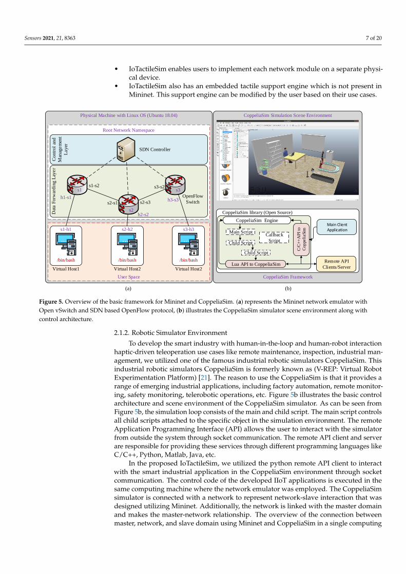
The proposed IoTactileSim enables the evaluation of large custom topologies withactual application traffic traces by deploying them into the physical network. It alsoenables the utilization of emerging technologies such as SDN, NFV, and MEC. In theSDN framework, control planes are separated from the forward plane in the network.The emulator is written in python language and freely available at the Mininet officialwebsite (http://mininet.org/, accessed on 10 November 2021). An overview of the basicarchitecture of the Mininet with open-source virtual switches Open vSwitch (OVS) andSDN standard protocol OpenFlow is depicted in Figure 5a. Mininet by itself is a networkemulator that allows users to mimic real network topologies. It also enables users tobuild such network topologies in SDN architecture. This is what Mininet is capableof in a nutshell. It does not provide any support for integrating tactile Input/Output(I/O) modules or any other modules for that matter. It only provides us with a virtualenvironment where all network nodes are present (virtually) on a single physical device.The contribution of the IoTactileSim over Mininet is defined as:
• IoTactileSim allows users to integrate several tactile I/O modules with the Mininetenvironment.
Sensors 2021, 21, 8363 7 of 20
• IoTactileSim enables users to implement each network module on a separate physi-cal device.
• IoTactileSim also has an embedded tactile support engine which is not present inMininet. This support engine can be modified by the user based on their use cases.
Physical Machine with Linux OS (Ubuntu 18.04)
Dat
a F
orw
ard
ing
Lay
er
Con
tro
l an
d
Man
agem
ent
La
yer
OpenFlow
Switch
SDN Controller
Virtual Host1
/bin/bash
s1-h1
Virtual Host2
/bin/bash
s2-h2
Virtual Host2
/bin/bash
s3-h3
h1-s1
h2-s2
h3-s3
s1-s2
s2-s1 s2-s3
s3-s2s1
s2
s3
Root Network Namespace
User Space
CoppeliaSim library (Open Source)
Callback
Script
Main Client Application
C/C
++
AP
I to
Cop
peli
aSim
Child Script
Main Script
CoppeliaSim Engine
Child Script
Remote API
Clients/Server Lua API to CoppeliaSim
CoppeliaSim Framework
CoppeliaSim Simulation Scene Environment
(a) (b)
Figure 5. Overview of the basic framework for Mininet and CoppeliaSim. (a) represents the Mininet network emulator withOpen vSwitch and SDN based OpenFlow protocol, (b) illustrates the CoppeliaSim simulator scene environment along withcontrol architecture.
2.1.2. Robotic Simulator Environment
To develop the smart industry with human-in-the-loop and human-robot interactionhaptic-driven teleoperation use cases like remote maintenance, inspection, industrial man-agement, we utilized one of the famous industrial robotic simulators CoppeliaSim. Thisindustrial robotic simulators CoppeliaSim is formerly known as (V-REP: Virtual RobotExperimentation Platform) [21]. The reason to use the CoppeliaSim is that it provides arange of emerging industrial applications, including factory automation, remote monitor-ing, safety monitoring, telerobotic operations, etc. Figure 5b illustrates the basic controlarchitecture and scene environment of the CoppeliaSim simulator. As can be seen fromFigure 5b, the simulation loop consists of the main and child script. The main script controlsall child scripts attached to the specific object in the simulation environment. The remoteApplication Programming Interface (API) allows the user to interact with the simulatorfrom outside the system through socket communication. The remote API client and serverare responsible for providing these services through different programming languages likeC/C++, Python, Matlab, Java, etc.
In the proposed IoTactileSim, we utilized the python remote API client to interactwith the smart industrial application in the CoppeliaSim environment through socketcommunication. The control code of the developed IIoT applications is executed in thesame computing machine where the network emulator was employed. The CoppeliaSimsimulator is connected with a network to represent network-slave interaction that wasdesigned utilizing Mininet. Additionally, the network is linked with the master domainand makes the master-network relationship. The overview of the connection betweenmaster, network, and slave domain using Mininet and CoppeliaSim in a single computing
Sensors 2021, 21, 8363 8 of 20
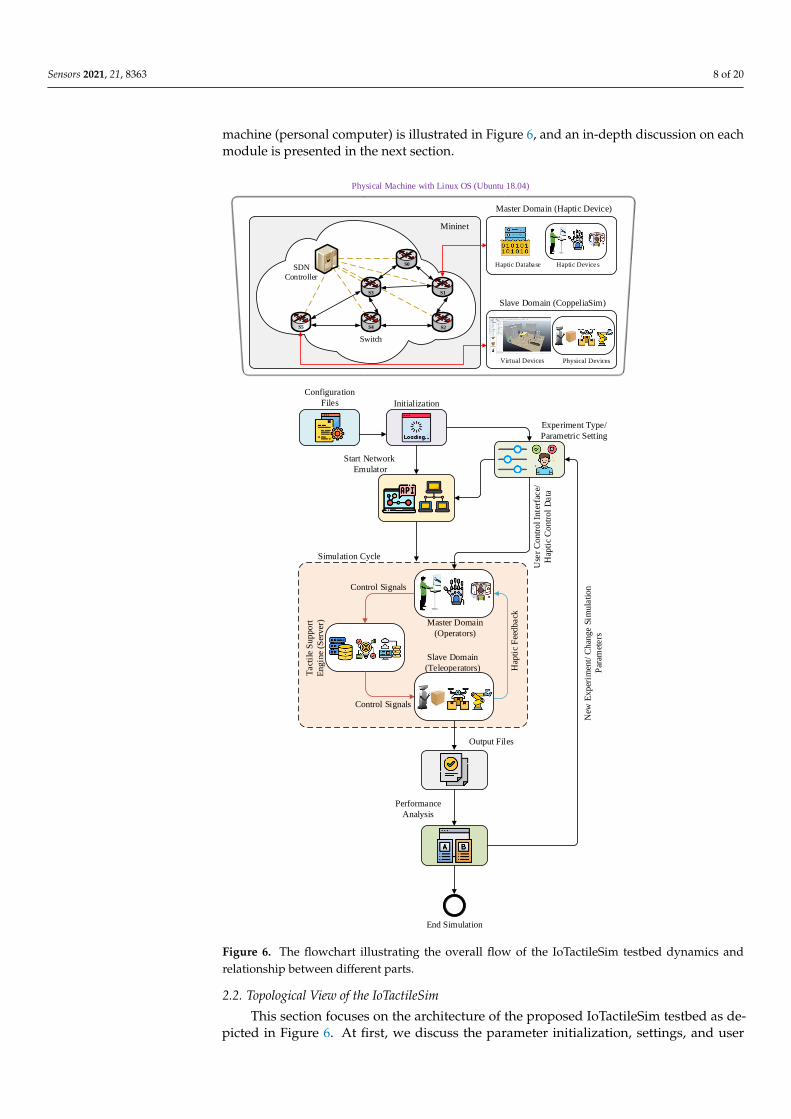
machine (personal computer) is illustrated in Figure 6, and an in-depth discussion on eachmodule is presented in the next section.
Configuration
Files Initialization
Experiment Type/
Parametric Setting
Use
r C
ontr
ol In
terf
ace/
Hap
tic
Con
tro
l D
ata
Start Network
Emulator
Simulation Cycle
Master Domain
(Operators)
Control Signals
Hap
tic
Fee
dback
Control Signals
Tact
ile
Su
ppo
rt
Engin
e (S
erver
)
Slave Domain
(Teleoperators)
Output Files
Performance
Analysis
End Simulation
New
Exp
erim
ent/
Chan
ge S
imula
tion
Par
amet
ers
Physical Machine with Linux OS (Ubuntu 18.04)
Switch
SDN
Controller
S3
S0
S2S4S5
S1
Mininet
Haptic Database
Master Domain (Haptic Device)
Haptic Devices
Slave Domain (CoppeliaSim)
Physical DevicesVirtual Devices
Figure 6. The flowchart illustrating the overall flow of the IoTactileSim testbed dynamics andrelationship between different parts.
2.2. Topological View of the IoTactileSim
This section focuses on the architecture of the proposed IoTactileSim testbed as de-picted in Figure 6. At first, we discuss the parameter initialization, settings, and user
Sensors 2021, 21, 8363 9 of 20
interface to interact with the proposed testbed. Second, the topological view of the corenetwork architecture is presented. Third, an in-depth discussion on application-agnosticdesign with the application and network connectivity is reported.
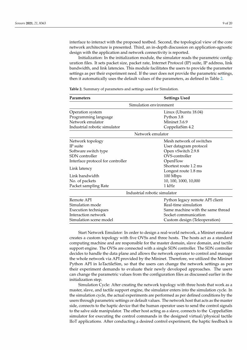
Initialization: In the initialization module, the simulator reads the parametric config-uration files. It sets packet size, packet rate, Internet Protocol (IP) suite, IP address, linkbandwidth, and link latencies. This module facilitates the users to provide the parametersettings as per their experiment need. If the user does not provide the parametric settings,then it automatically uses the default values of the parameters, as defined in Table 2.
Table 2. Summary of parameters and settings used for Simulation.
Parameters Settings Used
Simulation environment
Operation system Linux (Ubuntu 18.04)Programming language Python 3.8Network emulator Mininet 3.6.9Industrial robotic simulator CoppeliaSim 4.2
Network emulator
Network topology Mesh network of switchesIP suite User datagram protocolSoftware switch type Open vSwitch 2.9.8SDN controller OVS-controllerInterface protocol for controller OpenFlow
Link latency Shortest route 1.2 msLongest route 1.8 ms
Link bandwidth 100 MbpsNo. of packets 10, 100, 1000, 10,000Packet sampling Rate 1 kHz
Industrial robotic simulator
Remote API Python legacy remote API clientSimulation mode Real-time simulationExecution techniques Same machine with the same threadInteraction network Socket communicationSimulation scene model Custom design (Teleoperation)
Start Network Emulator: In order to design a real-world network, a Mininet emulatorcreates a custom topology with five OVSs and three hosts. The hosts act as a standardcomputing machine and are responsible for the master domain, slave domain, and tactilesupport engine. The OVSs are connected with a single SDN controller. The SDN controllerdecides to handle the data plane and allows the network operator to control and managethe whole network via API provided by the Mininet. Therefore, we utilized the MininetPython API in IoTactileSim, so that the users can change the network settings as pertheir experiment demands to evaluate their newly developed approaches. The userscan change the parametric values from the configuration files as discussed earlier in theinitialization step.
Simulation Cycle: After creating the network topology with three hosts that work as amaster, slave, and tactile support engine, the simulator enters into the simulation cycle. Inthe simulation cycle, the actual experiments are performed as per defined conditions by theusers through parametric settings or default values. The network host that acts as the masterside, connects to the haptic device that the human operator uses to send the control signalsto the salve side manipulator. The other host acting as a slave, connects to the CoppeliaSimsimulator for executing the control commands in the designed virtual/physical tactileIIoT applications. After conducting a desired control experiment, the haptic feedback is
Sensors 2021, 21, 8363 10 of 20
sent to the human teleoperator at the master domain. This loop runs until the simulatorreaches the defined threshold values like 1000 packets, etc. Finally, at the end of thesimulation cycle, the simulator stores the experimental results into a file to investigatevarious network impairments.
Performance Analysis: This module receives the stored experimental data file andcompiles result graphs to understand the strengths and weaknesses of the conductedexperiments from the QoE and QoS perspectives. After representing the experimentalresult in the visual form, it stores these results, and enables the users to perform newexperiments or to exit the simulator. The list of the default parameter values and settingsused in the proposed IoTactileSim are summarized in Table 2. The proposed IoTactileSim ispublicly available at Github (https://github.com/zubair1811/IoTactileSimV1.git, accessedon 30 November 2021) to the interested researchers to conduct extensive experiments toevaluate their suggested approaches.
3. Result and Discussion
In this section, we demonstrate the effectiveness of the proposed IoTactileSim withtwo different tactile industrial scenarios using the simulation environment and parameterssetting defined in Table 2. These two realistic applications belonging to tactile industrialuse cases define as follows
• Scenario I: Teleoperation with 3 Degree-of-Freedom (3DoF)• Scenario II: Haptic-driven remote operations
Moreover, these scenarios can be classified into two categories, like offline and real-time applications. On the one hand, offline (teleoperation with 3DoF) experimentationmeans that we already have a static dataset of some real-world teleoperation applicationsand utilize previously collected data for analytical analysis. On the other hand, real-timeor online (haptic-driven remote operations) experiments indicate that interaction databetween operator and teleoperator are collected in real-time to make a suitable decision toensure stability and transparency. The real-time scenario is complex compared to offlinebecause it deals with more data under time constraints. Most of the existing studies onindustrial testbeds just utilized the offline methodology, while the proposed IoTactileSimconsidered both scenarios. The discussion considering offline and real-time scenarios ispresented in detail in the following subsections.
3.1. Scenario I: Teleoperation with 3DoF
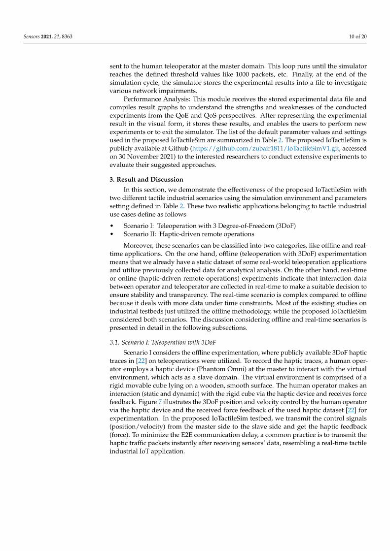
Scenario I considers the offline experimentation, where publicly available 3DoF haptictraces in [22] on teleoperations were utilized. To record the haptic traces, a human oper-ator employs a haptic device (Phantom Omni) at the master to interact with the virtualenvironment, which acts as a slave domain. The virtual environment is comprised of arigid movable cube lying on a wooden, smooth surface. The human operator makes aninteraction (static and dynamic) with the rigid cube via the haptic device and receives forcefeedback. Figure 7 illustrates the 3DoF position and velocity control by the human operatorvia the haptic device and the received force feedback of the used haptic dataset [22] forexperimentation. In the proposed IoTactileSim testbed, we transmit the control signals(position/velocity) from the master side to the slave side and get the haptic feedback(force). To minimize the E2E communication delay, a common practice is to transmit thehaptic traffic packets instantly after receiving sensors’ data, resembling a real-time tactileindustrial IoT application.
Sensors 2021, 21, 8363 11 of 20
0 5,000 10,000 15,000 20,000 25,000Time (ms)
1.5
1.0
0.5
0.0
0.5
1.0
Posi
tions
(cm
)
(a)
Position XPosition YPosition Z
0 5,000 10,000 15,000 20,000 25,000Time (ms)
6
4
2
0
2
4
Vel
ocity
(cm
/s)
(b)
Velocity XVelocity YVelocity Z
0 5,000 10,000 15,000 20,000 25,000Time (ms)
5
0
5
10
15
20
Forc
e (N
)
(c)
Force ZForce YForce Z
Figure 7. Dynamic interaction of the human operator with virtual application via haptic device. ( a) positions of the humanoperator’s hand at master side device, (b) velocity traces of the operator (c) force data traces of the teleopertor x, y andz-axis.
We adopt the same method in our experiments; after reading the sensors data, thesystem makes packets of the haptic traces as following:
PacketSize = Ethernet/UDP/IP/8 × NDoF (1)
where Ethernet/UDP/IP indicates the header of the ethernet, user datagram protocol, andinternet protocol layer, respectively. NDoF is the number of DoF in the experimental data.We are using 3DoF, so the formulation can be evaluated as:
Packet Size = 14/8/20/8 × 3
Packet Size = 14 + 8 + 20 + 24 = 78
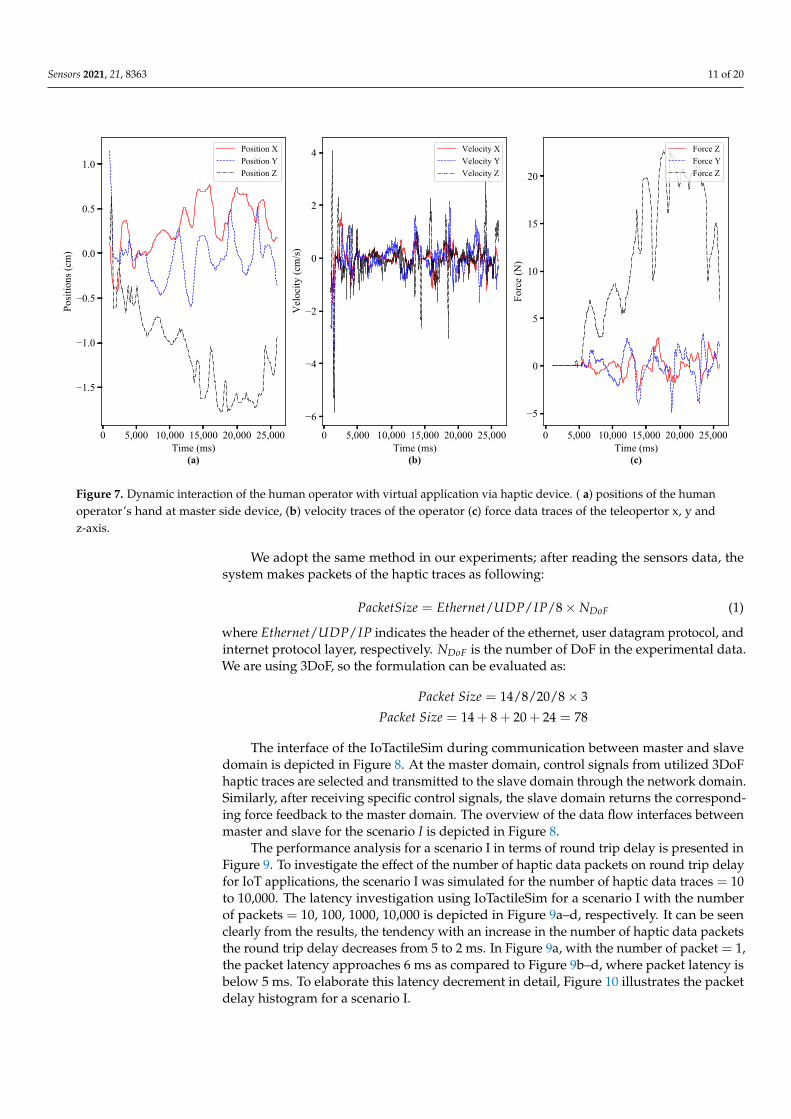
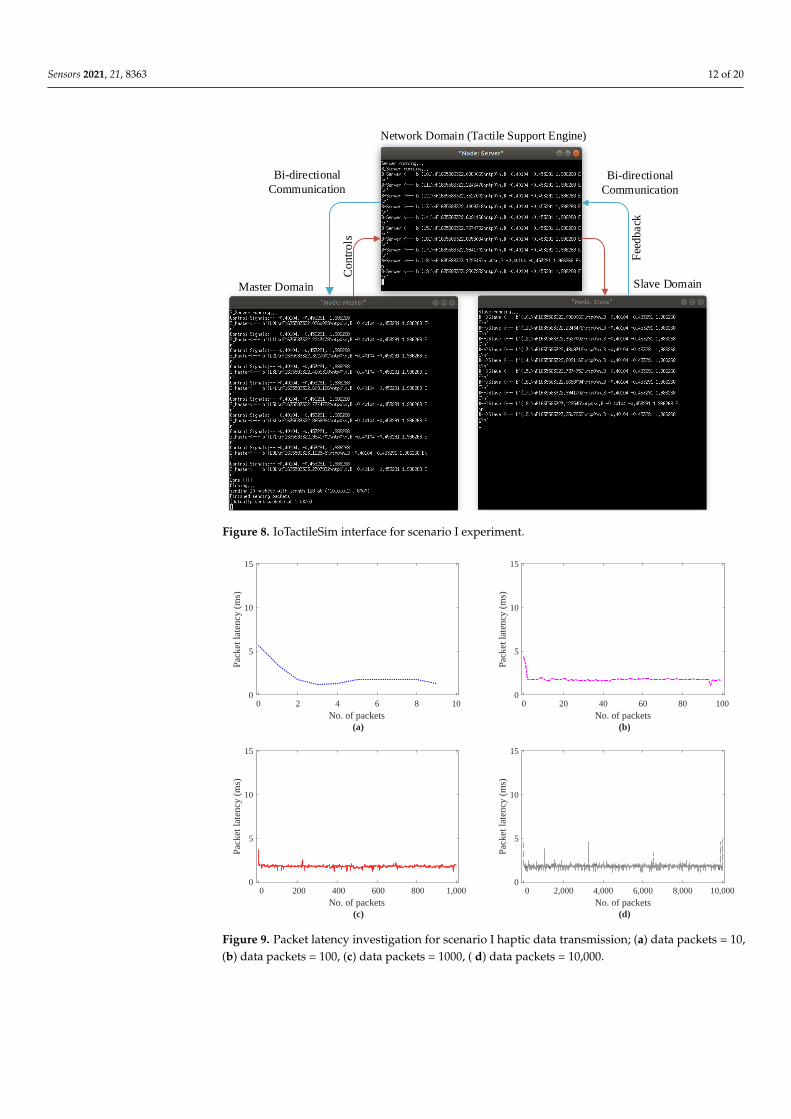
The interface of the IoTactileSim during communication between master and slavedomain is depicted in Figure 8. At the master domain, control signals from utilized 3DoFhaptic traces are selected and transmitted to the slave domain through the network domain.Similarly, after receiving specific control signals, the slave domain returns the correspond-ing force feedback to the master domain. The overview of the data flow interfaces betweenmaster and slave for the scenario I is depicted in Figure 8.
The performance analysis for a scenario I in terms of round trip delay is presented inFigure 9. To investigate the effect of the number of haptic data packets on round trip delayfor IoT applications, the scenario I was simulated for the number of haptic data traces = 10to 10,000. The latency investigation using IoTactileSim for a scenario I with the numberof packets = 10, 100, 1000, 10,000 is depicted in Figure 9a–d, respectively. It can be seenclearly from the results, the tendency with an increase in the number of haptic data packetsthe round trip delay decreases from 5 to 2 ms. In Figure 9a, with the number of packet = 1,the packet latency approaches 6 ms as compared to Figure 9b–d, where packet latency isbelow 5 ms. To elaborate this latency decrement in detail, Figure 10 illustrates the packetdelay histogram for a scenario I.
Sensors 2021, 21, 8363 12 of 20
Bi-directional
Communication
Bi-directional
Communication
Master Domain Slave Domain
Network Domain (Tactile Support Engine)
Con
trols
Fee
dback
Figure 8. IoTactileSim interface for scenario I experiment.
0 2 4 6 8 10No. of packets
(a)
0
5
10
15
Pack
et la
tenc
y (m
s)
0 20 40 60 80 100No. of packets
(b)
0
5
10
15
Pack
et la
tenc
y (m
s)
0 200 400 600 800 1,000No. of packets
(c)
0
5
10
15
Pack
et la
tenc
y (m
s)
0 2,000 4,000 6,000 8,000 10,000No. of packets
(d)
0
5
10
15
Pack
et la
tenc
y (m
s)
Figure 9. Packet latency investigation for scenario I haptic data transmission; (a) data packets = 10,(b) data packets = 100, (c) data packets = 1000, ( d) data packets = 10,000.
Sensors 2021, 21, 8363 13 of 20
0 2 4 6Packet latency (ms)
(a)
0
2
4
6
8
10
Freq
uenc
y
0 2 4 6Packet latency (ms)
(b)
0
2
4
6
8
10
Freq
uenc
y
101
0 2 4 6Packet latency (ms)
(c)
0
2
4
6
8
10
Freq
uenc
y
102
0 2 4 6Packet latency (ms)
(d)
0
2
4
6
8
10
Freq
uenc
y
103
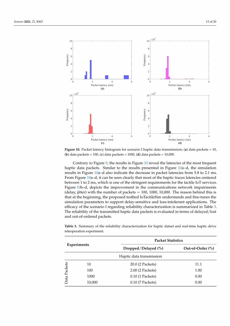
Figure 10. Packet latency histogram for scenario I haptic data transmission; (a) data packets = 10,(b) data packets = 100, (c) data packets = 1000, (d) data packets = 10,000.
Contrary to Figure 9, the results in Figure 10 reveal the latencies of the most frequenthaptic data packets. Similar to the results presented in Figure 10a–d, the simulationresults in Figure 10a–d also indicate the decrease in packet latencies from 5.8 to 2.1 ms.From Figure 10a–d, it can be seen clearly that most of the haptic traces latencies centeredbetween 1 to 2 ms, which is one of the stringent requirements for the tactile IoT services.Figure 10b–d, depicts the improvement in the communications network impairments(delay, jitter) with the number of packets = 100, 1000, 10,000. The reason behind this isthat at the beginning, the proposed testbed IoTactileSim understands and fine-tunes thesimulation parameters to support delay-sensitive and loss-intolerant applications. Theefficacy of the scenario I regarding reliability characterization is summarized in Table 3.The reliability of the transmitted haptic data packets is evaluated in terms of delayed/lostand out-of-ordered packets.
Table 3. Summary of the reliability characterization for haptic datset and real-time haptic driveteleoperation experiment.
ExperimentsPacket Statistics
Dropped/Delayed (%) Out-of-Order (%)
Haptic data transmission
Dat
aPa
cket
s 10 20.0 (2 Packets) 11.1
100 2.00 (2 Packets) 1.00
1000 0.10 (1 Packets) 0.00
10,000 0.10 (7 Packets) 0.00
Sensors 2021, 21, 8363 14 of 20
Table 3. Cont.
ExperimentsPacket Statistics
Dropped/Delayed (%) Out-of-Order (%)
Haptic-driven remote operationsD
ata
Pack
ets 10 100 (10 Packets) 100
100 44.0 (44 Packets) 44.4
1000 3.10 (31 Packets) 3.00
10,000 0.40 (39 Packets) 0.30
3.2. Scenario II: Haptic-Driven Remote Operations
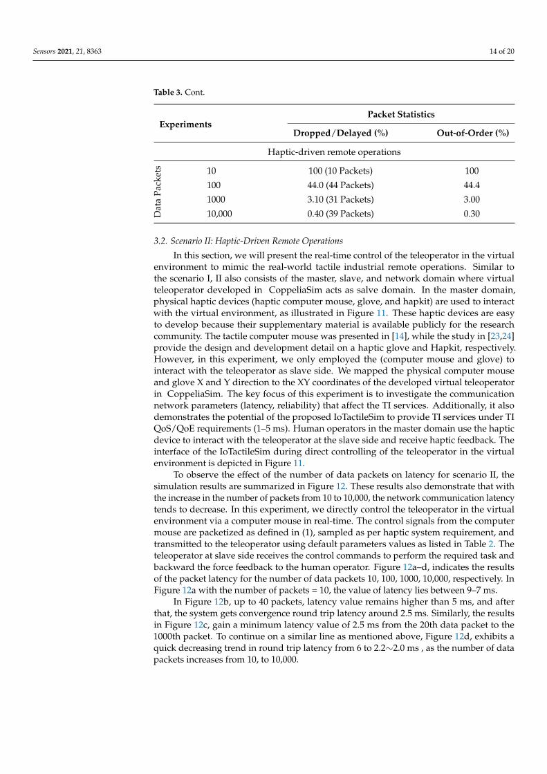
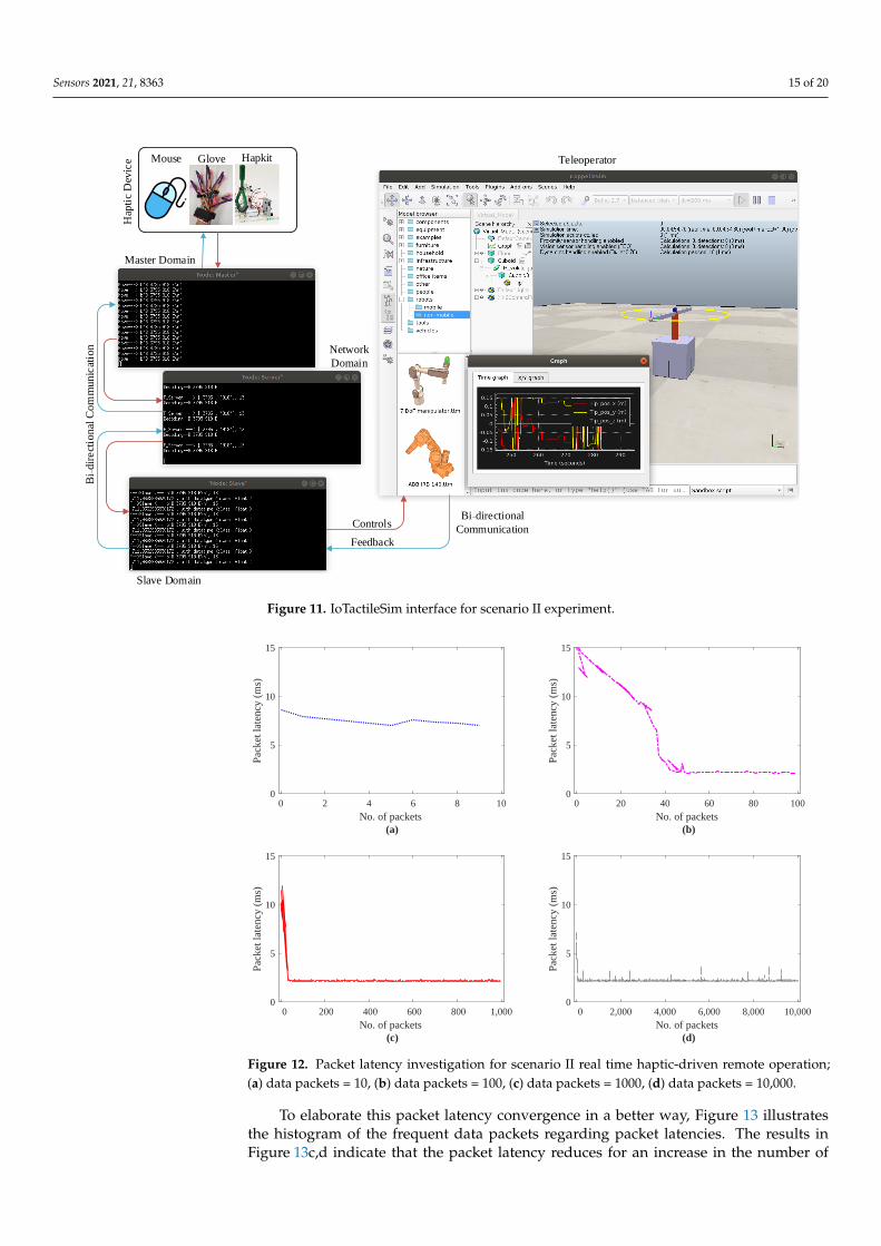
In this section, we will present the real-time control of the teleoperator in the virtualenvironment to mimic the real-world tactile industrial remote operations. Similar tothe scenario I, II also consists of the master, slave, and network domain where virtualteleoperator developed in CoppeliaSim acts as salve domain. In the master domain,physical haptic devices (haptic computer mouse, glove, and hapkit) are used to interactwith the virtual environment, as illustrated in Figure 11. These haptic devices are easyto develop because their supplementary material is available publicly for the researchcommunity. The tactile computer mouse was presented in [14], while the study in [23,24]provide the design and development detail on a haptic glove and Hapkit, respectively.However, in this experiment, we only employed the (computer mouse and glove) tointeract with the teleoperator as slave side. We mapped the physical computer mouseand glove X and Y direction to the XY coordinates of the developed virtual teleoperatorin CoppeliaSim. The key focus of this experiment is to investigate the communicationnetwork parameters (latency, reliability) that affect the TI services. Additionally, it alsodemonstrates the potential of the proposed IoTactileSim to provide TI services under TIQoS/QoE requirements (1–5 ms). Human operators in the master domain use the hapticdevice to interact with the teleoperator at the slave side and receive haptic feedback. Theinterface of the IoTactileSim during direct controlling of the teleoperator in the virtualenvironment is depicted in Figure 11.
To observe the effect of the number of data packets on latency for scenario II, thesimulation results are summarized in Figure 12. These results also demonstrate that withthe increase in the number of packets from 10 to 10,000, the network communication latencytends to decrease. In this experiment, we directly control the teleoperator in the virtualenvironment via a computer mouse in real-time. The control signals from the computermouse are packetized as defined in (1), sampled as per haptic system requirement, andtransmitted to the teleoperator using default parameters values as listed in Table 2. Theteleoperator at slave side receives the control commands to perform the required task andbackward the force feedback to the human operator. Figure 12a–d, indicates the resultsof the packet latency for the number of data packets 10, 100, 1000, 10,000, respectively. InFigure 12a with the number of packets = 10, the value of latency lies between 9–7 ms.
In Figure 12b, up to 40 packets, latency value remains higher than 5 ms, and afterthat, the system gets convergence round trip latency around 2.5 ms. Similarly, the resultsin Figure 12c, gain a minimum latency value of 2.5 ms from the 20th data packet to the1000th packet. To continue on a similar line as mentioned above, Figure 12d, exhibits aquick decreasing trend in round trip latency from 6 to 2.2∼2.0 ms , as the number of datapackets increases from 10, to 10,000.
Sensors 2021, 21, 8363 15 of 20
Mouse Glove Hapkit
Bi₋directional
Communication
Bi₋
dir
ect
ional
Co
mm
unic
atio
n
Hap
tic
Dev
ice Teleoperator
Controls
Feedback
Master Domain
Slave Domain
Network
Domain
Figure 11. IoTactileSim interface for scenario II experiment.
0 2 4 6 8 10No. of packets
(a)
0
5
10
15
Pack
et la
tenc
y (m
s)
0 20 40 60 80 100No. of packets
(b)
0
5
10
15
Pack
et la
tenc
y (m
s)
0 200 400 600 800 1,000No. of packets
(c)
0
5
10
15
Pack
et la
tenc
y (m
s)
0 2,000 4,000 6,000 8,000 10,000No. of packets
(d)
0
5
10
15
Pack
et la
tenc
y (m
s)
Figure 12. Packet latency investigation for scenario II real time haptic-driven remote operation;(a) data packets = 10, (b) data packets = 100, (c) data packets = 1000, (d) data packets = 10,000.
To elaborate this packet latency convergence in a better way, Figure 13 illustratesthe histogram of the frequent data packets regarding packet latencies. The results inFigure 13c,d indicate that the packet latency reduces for an increase in the number of
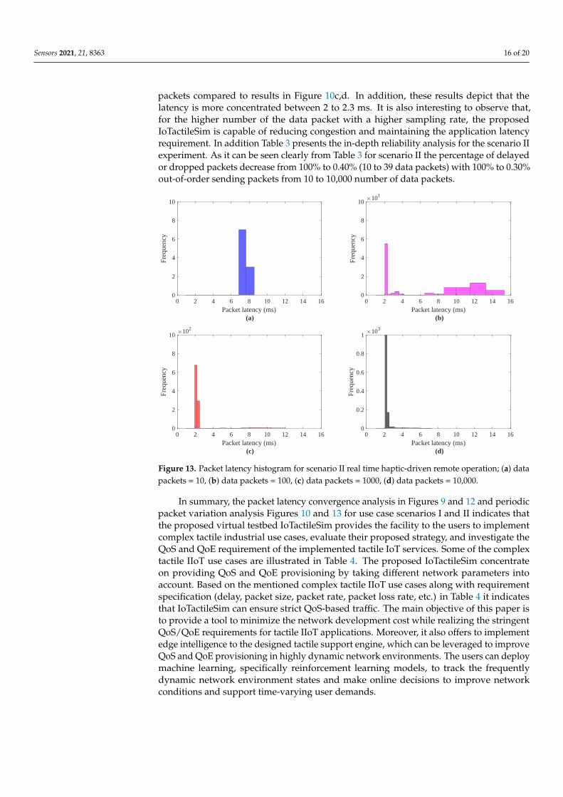
Sensors 2021, 21, 8363 16 of 20
packets compared to results in Figure 10c,d. In addition, these results depict that thelatency is more concentrated between 2 to 2.3 ms. It is also interesting to observe that,for the higher number of the data packet with a higher sampling rate, the proposedIoTactileSim is capable of reducing congestion and maintaining the application latencyrequirement. In addition Table 3 presents the in-depth reliability analysis for the scenario IIexperiment. As it can be seen clearly from Table 3 for scenario II the percentage of delayedor dropped packets decrease from 100% to 0.40% (10 to 39 data packets) with 100% to 0.30%out-of-order sending packets from 10 to 10,000 number of data packets.
0 2 4 6 8 10 12 14 16Packet latency (ms)
(a)
0
2
4
6
8
10
Freq
uenc
y
0 2 4 6 8 10 12 14 16Packet latency (ms)
(b)
0
2
4
6
8
10
Freq
uenc
y
101
0 2 4 6 8 10 12 14 16Packet latency (ms)
(c)
0
2
4
6
8
10
Freq
uenc
y
102
0 2 4 6 8 10 12 14 16Packet latency (ms)
(d)
0
0.2
0.4
0.6
0.8
1
Freq
uenc
y
103
Figure 13. Packet latency histogram for scenario II real time haptic-driven remote operation; (a) datapackets = 10, (b) data packets = 100, (c) data packets = 1000, (d) data packets = 10,000.
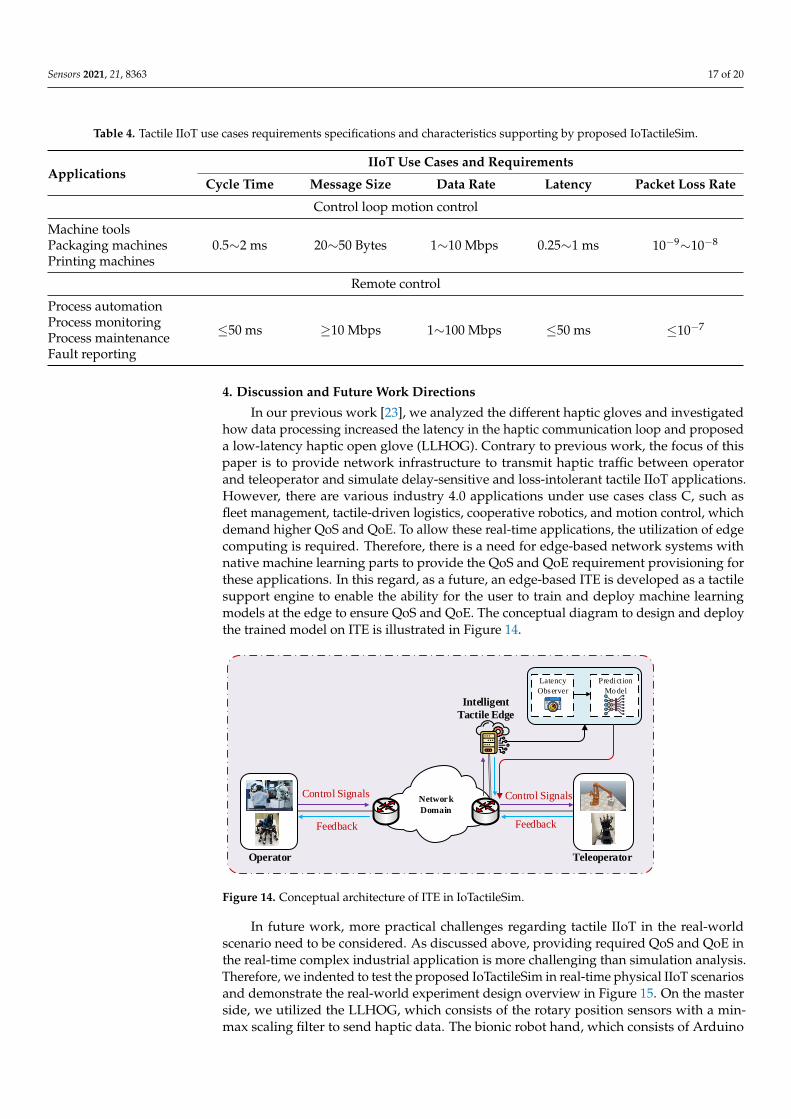
In summary, the packet latency convergence analysis in Figures 9 and 12 and periodicpacket variation analysis Figures 10 and 13 for use case scenarios I and II indicates thatthe proposed virtual testbed IoTactileSim provides the facility to the users to implementcomplex tactile industrial use cases, evaluate their proposed strategy, and investigate theQoS and QoE requirement of the implemented tactile IoT services. Some of the complextactile IIoT use cases are illustrated in Table 4. The proposed IoTactileSim concentrateon providing QoS and QoE provisioning by taking different network parameters intoaccount. Based on the mentioned complex tactile IIoT use cases along with requirementspecification (delay, packet size, packet rate, packet loss rate, etc.) in Table 4 it indicatesthat IoTactileSim can ensure strict QoS-based traffic. The main objective of this paper isto provide a tool to minimize the network development cost while realizing the stringentQoS/QoE requirements for tactile IIoT applications. Moreover, it also offers to implementedge intelligence to the designed tactile support engine, which can be leveraged to improveQoS and QoE provisioning in highly dynamic network environments. The users can deploymachine learning, specifically reinforcement learning models, to track the frequentlydynamic network environment states and make online decisions to improve networkconditions and support time-varying user demands.
Sensors 2021, 21, 8363 17 of 20
Table 4. Tactile IIoT use cases requirements specifications and characteristics supporting by proposed IoTactileSim.
ApplicationsIIoT Use Cases and Requirements
Cycle Time Message Size Data Rate Latency Packet Loss Rate
Control loop motion control
Machine tools0.5∼2 ms 20∼50 Bytes 1∼10 Mbps 0.25∼1 ms 10−9∼10−8Packaging machines
Printing machines
Remote control
Process automation
≤50 ms ≥10 Mbps 1∼100 Mbps ≤50 ms ≤10−7Process monitoringProcess maintenanceFault reporting
4. Discussion and Future Work Directions
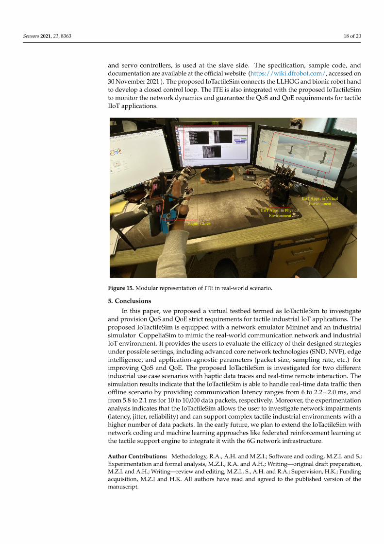
In our previous work [23], we analyzed the different haptic gloves and investigatedhow data processing increased the latency in the haptic communication loop and proposeda low-latency haptic open glove (LLHOG). Contrary to previous work, the focus of thispaper is to provide network infrastructure to transmit haptic traffic between operatorand teleoperator and simulate delay-sensitive and loss-intolerant tactile IIoT applications.However, there are various industry 4.0 applications under use cases class C, such asfleet management, tactile-driven logistics, cooperative robotics, and motion control, whichdemand higher QoS and QoE. To allow these real-time applications, the utilization of edgecomputing is required. Therefore, there is a need for edge-based network systems withnative machine learning parts to provide the QoS and QoE requirement provisioning forthese applications. In this regard, as a future, an edge-based ITE is developed as a tactilesupport engine to enable the ability for the user to train and deploy machine learningmodels at the edge to ensure QoS and QoE. The conceptual diagram to design and deploythe trained model on ITE is illustrated in Figure 14.
Intelligent
Tactile Edge
Control Signals
Operator Teleoperator
Latency
Observer
Predict ion
Model
Feedback Feedback
Network
Domain
Control Signals
Figure 14. Conceptual architecture of ITE in IoTactileSim.
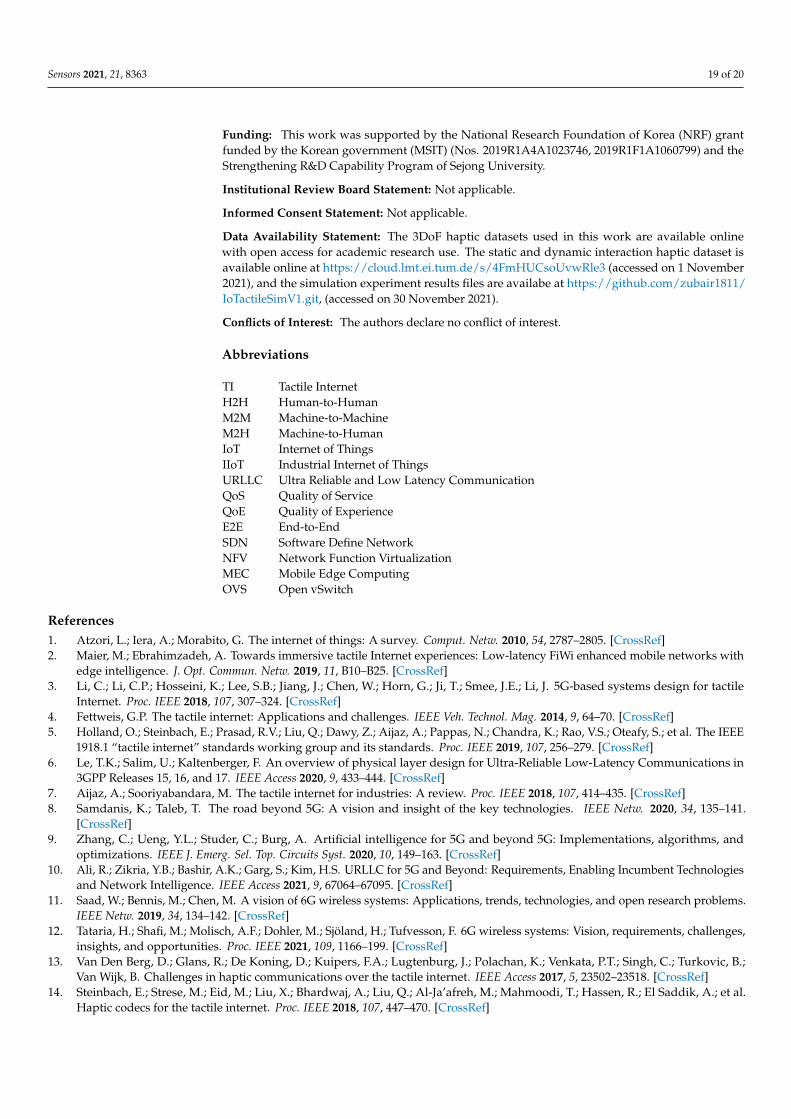
In future work, more practical challenges regarding tactile IIoT in the real-worldscenario need to be considered. As discussed above, providing required QoS and QoE inthe real-time complex industrial application is more challenging than simulation analysis.Therefore, we indented to test the proposed IoTactileSim in real-time physical IIoT scenariosand demonstrate the real-world experiment design overview in Figure 15. On the masterside, we utilized the LLHOG, which consists of the rotary position sensors with a min-max scaling filter to send haptic data. The bionic robot hand, which consists of Arduino
Sensors 2021, 21, 8363 18 of 20
and servo controllers, is used at the slave side. The specification, sample code, anddocumentation are available at the official website (https://wiki.dfrobot.com/, accessed on30 November 2021 ). The proposed IoTactileSim connects the LLHOG and bionic robot handto develop a closed control loop. The ITE is also integrated with the proposed IoTactileSimto monitor the network dynamics and guarantee the QoS and QoE requirements for tactileIIoT applications.
Haptic Glove
ITE
IIoT Apps. in Virtual
Environment
IIoT Apps. in Physical
Environment
Figure 15. Modular representation of ITE in real-world scenario.
5. Conclusions
In this paper, we proposed a virtual testbed termed as IoTactileSim to investigateand provision QoS and QoE strict requirements for tactile industrial IoT applications. Theproposed IoTactileSim is equipped with a network emulator Mininet and an industrialsimulator CoppeliaSim to mimic the real-world communication network and industrialIoT environment. It provides the users to evaluate the efficacy of their designed strategiesunder possible settings, including advanced core network technologies (SND, NVF), edgeintelligence, and application-agnostic parameters (packet size, sampling rate, etc.) forimproving QoS and QoE. The proposed IoTactileSim is investigated for two differentindustrial use case scenarios with haptic data traces and real-time remote interaction. Thesimulation results indicate that the IoTactileSim is able to handle real-time data traffic thenoffline scenario by providing communication latency ranges from 6 to 2.2∼2.0 ms, andfrom 5.8 to 2.1 ms for 10 to 10,000 data packets, respectively. Moreover, the experimentationanalysis indicates that the IoTactileSim allows the user to investigate network impairments(latency, jitter, reliability) and can support complex tactile industrial environments with ahigher number of data packets. In the early future, we plan to extend the IoTactileSim withnetwork coding and machine learning approaches like federated reinforcement learning atthe tactile support engine to integrate it with the 6G network infrastructure.
Author Contributions: Methodology, R.A., A.H. and M.Z.I.; Software and coding, M.Z.I. and S.;Experimentation and formal analysis, M.Z.I., R.A. and A.H.; Writing—original draft preparation,M.Z.I. and A.H.; Writing—review and editing, M.Z.I., S., A.H. and R.A.; Supervision, H.K.; Fundingacquisition, M.Z.I and H.K. All authors have read and agreed to the published version of themanuscript.
Sensors 2021, 21, 8363 19 of 20
Funding: This work was supported by the National Research Foundation of Korea (NRF) grantfunded by the Korean government (MSIT) (Nos. 2019R1A4A1023746, 2019R1F1A1060799) and theStrengthening R&D Capability Program of Sejong University.
Institutional Review Board Statement: Not applicable.
Informed Consent Statement: Not applicable.
Data Availability Statement: The 3DoF haptic datasets used in this work are available onlinewith open access for academic research use. The static and dynamic interaction haptic dataset isavailable online at https://cloud.lmt.ei.tum.de/s/4FmHUCsoUvwRle3 (accessed on 1 November2021), and the simulation experiment results files are availabe at https://github.com/zubair1811/IoTactileSimV1.git, (accessed on 30 November 2021).
Conflicts of Interest: The authors declare no conflict of interest.
Abbreviations
TI Tactile InternetH2H Human-to-HumanM2M Machine-to-MachineM2H Machine-to-HumanIoT Internet of ThingsIIoT Industrial Internet of ThingsURLLC Ultra Reliable and Low Latency CommunicationQoS Quality of ServiceQoE Quality of ExperienceE2E End-to-EndSDN Software Define NetworkNFV Network Function VirtualizationMEC Mobile Edge ComputingOVS Open vSwitch
References1. Atzori, L.; Iera, A.; Morabito, G. The internet of things: A survey. Comput. Netw. 2010, 54, 2787–2805. [CrossRef]2. Maier, M.; Ebrahimzadeh, A. Towards immersive tactile Internet experiences: Low-latency FiWi enhanced mobile networks with
edge intelligence. J. Opt. Commun. Netw. 2019, 11, B10–B25. [CrossRef]3. Li, C.; Li, C.P.; Hosseini, K.; Lee, S.B.; Jiang, J.; Chen, W.; Horn, G.; Ji, T.; Smee, J.E.; Li, J. 5G-based systems design for tactile
Internet. Proc. IEEE 2018, 107, 307–324. [CrossRef]4. Fettweis, G.P. The tactile internet: Applications and challenges. IEEE Veh. Technol. Mag. 2014, 9, 64–70. [CrossRef]5. Holland, O.; Steinbach, E.; Prasad, R.V.; Liu, Q.; Dawy, Z.; Aijaz, A.; Pappas, N.; Chandra, K.; Rao, V.S.; Oteafy, S.; et al. The IEEE
1918.1 “tactile internet” standards working group and its standards. Proc. IEEE 2019, 107, 256–279. [CrossRef]6. Le, T.K.; Salim, U.; Kaltenberger, F. An overview of physical layer design for Ultra-Reliable Low-Latency Communications in
3GPP Releases 15, 16, and 17. IEEE Access 2020, 9, 433–444. [CrossRef]7. Aijaz, A.; Sooriyabandara, M. The tactile internet for industries: A review. Proc. IEEE 2018, 107, 414–435. [CrossRef]8. Samdanis, K.; Taleb, T. The road beyond 5G: A vision and insight of the key technologies. IEEE Netw. 2020, 34, 135–141.
[CrossRef]9. Zhang, C.; Ueng, Y.L.; Studer, C.; Burg, A. Artificial intelligence for 5G and beyond 5G: Implementations, algorithms, and
optimizations. IEEE J. Emerg. Sel. Top. Circuits Syst. 2020, 10, 149–163. [CrossRef]10. Ali, R.; Zikria, Y.B.; Bashir, A.K.; Garg, S.; Kim, H.S. URLLC for 5G and Beyond: Requirements, Enabling Incumbent Technologies
and Network Intelligence. IEEE Access 2021, 9, 67064–67095. [CrossRef]11. Saad, W.; Bennis, M.; Chen, M. A vision of 6G wireless systems: Applications, trends, technologies, and open research problems.
IEEE Netw. 2019, 34, 134–142. [CrossRef]12. Tataria, H.; Shafi, M.; Molisch, A.F.; Dohler, M.; Sjöland, H.; Tufvesson, F. 6G wireless systems: Vision, requirements, challenges,
insights, and opportunities. Proc. IEEE 2021, 109, 1166–199. [CrossRef]13. Van Den Berg, D.; Glans, R.; De Koning, D.; Kuipers, F.A.; Lugtenburg, J.; Polachan, K.; Venkata, P.T.; Singh, C.; Turkovic, B.;
Van Wijk, B. Challenges in haptic communications over the tactile internet. IEEE Access 2017, 5, 23502–23518. [CrossRef]14. Steinbach, E.; Strese, M.; Eid, M.; Liu, X.; Bhardwaj, A.; Liu, Q.; Al-Ja’afreh, M.; Mahmoodi, T.; Hassen, R.; El Saddik, A.; et al.
Haptic codecs for the tactile internet. Proc. IEEE 2018, 107, 447–470. [CrossRef]
Sensors 2021, 21, 8363 20 of 20
15. Polachan, K.; Prabhakar, T.; Singh, C.; Kuipers, F.A. Towards an Open Testbed for Tactile Cyber Physical Systems. In Proceedingsof the 2019 11th International Conference on Communication Systems & Networks (COMSNETS), Bengaluru, India, 7–11 January2019; pp. 375–382.
16. Engelhardt, F.; Behrens, J.; Günes, M. The OVGU Haptic Communication Testbed (OVGU-HC). In Proceedings of the 2020IEEE 31st Annual International Symposium on Personal, Indoor and Mobile Radio Communications, London, UK, 31 August–3September 2020; pp. 1–6.
17. Gokhale, V.; Kroep, K.; Rao, V.S.; Verburg, J.; Yechangunja, R. TIXT: An Extensible Testbed for Tactile Internet Communication.IEEE Internet Things Mag. 2020, 3, 32–37. [CrossRef]
18. Günes, M.; Juraschek, F.; Blywis, B. An experiment description language for wireless network research. J. Internet Technol. 2010,11, 465–471.
19. Parvez, I.; Rahmati, A.; Guvenc, I.; Sarwat, A.I.; Dai, H. A survey on low latency towards 5G: RAN, core network and cachingsolutions. IEEE Commun. Surv. Tutor. 2018, 20, 3098–3130. [CrossRef]
20. Lantz, B.; Heller, B.; McKeown, N. A network in a laptop: Rapid prototyping for software-defined networks. In Proceedings ofthe 9th ACM SIGCOMM Workshop on Hot Topics in Networks, Monterey, CA, USA, 20–21 October 2010; pp. 1–6.
21. Rohmer, E.; Singh, S.P.; Freese, M. V-REP: A versatile and scalable robot simulation framework. In Proceedings of the 2013IEEE/RSJ International Conference on Intelligent Robots and Systems, Tokyo, Japan, 3–7 November 2013; pp. 1321–1326.
22. Bhardwaj, A.; Cizmeci, B.; Steinbach, E.; Liu, Q.; Eid, M.; AraUjo, J.; El Saddik, A.; Kundu, R.; Liu, X.; Holland, O.; et al.A candidate hardware and software reference setup for kinesthetic codec standardization. In Proceedings of the 2017 IEEEInternational Symposium on Haptic, Audio and Visual Environments and Games (HAVE), Abu Dhabi, United Arab Emirates,22–23 October 2017; pp. 1–6.
23. Sim, D.; Baek, Y.; Cho, M.; Park, S.; Sagar, A.; Kim, H.S. Low-Latency Haptic Open Glove for Immersive Virtual Reality Interaction.Sensors 2021, 21, 3682. [CrossRef] [PubMed]
24. Stanford-University. Hapkit. Available online: https://hapkit.stanford.edu/ ( accessed on 30 November 2021).