a single synchronous frame hybrid (ssfh) multifrequency controller for power active filters
TRANSCRIPT

1640 IEEE TRANSACTIONS ON INDUSTRIAL ELECTRONICS, VOL. 53, NO. 5, OCTOBER 2006
A Single Synchronous Frame Hybrid (SSFH)Multifrequency Controller for
Power Active FiltersIon Etxeberria-Otadui, Member, IEEE, Amaia López de Heredia, Haizea Gaztañaga,
Seddik Bacha, and M. Raúl Reyero, Member, IEEE
Abstract—Conventional integration-based controllers, such asthe multisynchronous PI and the multiresonant controllers, arewell adapted for multifrequency-current-control applications. Thefirst controller involves multiple reference frames, while the sec-ond one operates in a static frame using multiple resonant regula-tors. This paper presents a hybrid type of controller, called a singlesynchronous frame hybrid (SSFH) controller, which combinesboth features: It operates in an SSF mixing conventional PI andresonant controllers. A detailed design criterion for the SSFHcontroller is presented based on a frequency-response approach.Digital-implementation aspects (such as computation delays) andthe phase margin of the system are taken into consideration duringthe design process. The SSFH and the multiresonant controllersare compared considering various criteria such as the compu-tational load and the performances in terms of transient andsteady-state response. It is concluded that the SSFH controller isa very interesting and execution time-saving structure for heavilydistorted multifrequency applications, which is especially adaptedfor balanced or slightly unbalanced cases.
Index Terms—AC current control, active filters, inverters.
I. INTRODUCTION
CURRENT CONTROL of pulsewidth modulation (PWM)converters is one of the most important subjects of mod-
ern power electronics. A short general review of the availablecurrent-control techniques for three-phase PWM systems ispresented in [1], classifying them in two main groups: linearand nonlinear controllers. Described linear controllers includethe stationary and synchronous PI, the resonant controller, thestate feedback, and the deadbeat controller, while nonlinearcontrollers comprise basically the hysteresis controller andartificial intelligence and online optimization techniques.
These controllers are generally suitable for single-frequency-current-control applications but they are not always appropriate
Manuscript received February 17, 2005; revised January 27, 2006. Abstractpublished on the Internet July 14, 2006.
I. Etxeberria-Otadui and M. R. Reyero are with the IKERLAN Techno-logical Center, E-20.500 Mondragón, Spain (e-mail: [email protected];[email protected]).
A. López de Heredia and S. Bacha are with the Electrotechnical Laboratoryof Grenoble (LEG), 38402 Saint-Martin-d’Hères, France (e-mail: [email protected]; [email protected]).
H. Gaztañaga is with the Research Center on Distributed Generationand Electrotechnologies (CIDAE), E-20.500 Mondragón, Spain (e-mail:[email protected]).
Digital Object Identifier 10.1109/TIE.2006.881994
for multifrequency applications, such as active filtering. Manytechniques have been proposed for current control in multifre-quency applications, such as the hysteresis [2] and the deadbeatcontrollers [3]. On one hand, the hysteresis controller is simpleand robust, and even if the basic technique is affected by thedrawbacks of a variable switching frequency and of a heavyinterference among phases, effective methods to eliminate theseinconveniences have been successfully introduced in previousworks [4], [5]. On the other hand, the performance of the dead-beat controller is constrained to the accuracy of the plant modelas well as the accuracy of the reference current prediction [6].
Other contributions propose the use of integrator-based reg-ulators for multifrequency applications in any of its mostcommon forms: multisynchronous PI [7], [8] and stationary-frame multiresonant controllers [9], [10]. These controllers areparticularly well adapted for multifrequency applications suchas active filters. Their main advantages are their robustnessand the fact that they guarantee zero steady-state error for theconsidered harmonics. The first controller, which is derivedfrom single-frequency applications, requires a particular framefor each harmonic and sequence to be controlled. Typically,the harmonics considered in active filter applications are de-termined by the dominating harmonics of three phase diodeor thyristor rectifiers [8] (the main polluting loads connectedto the grid). Therefore, some simplifications may be adopted,considering only some harmonics and sequences to be com-pensated: harmonics +1, −5, +7, −11, +13 etc. Nevertheless,the computational load required by the multisynchronous PIcontrol structure is nonnegligible due to the need of multiplereference frame transformations.
The multiresonant controller has been widely proposed asan alternative to the multisynchronous PI controller. As thiscontroller operates in a static frame, its implementation permitsa considerable economy of operations (all calculations relatedto multiple frame transformations). Nevertheless, as the con-trollers themselves are more complex (second order), the gainin terms of operational load is restrained, especially in the caseof a four-wire topology. Concerning the design criteria of thiskind of controllers or their implementation and tuning methods,there is not much work that has been done. The design criterionfor a single-frequency resonant controller [11] has been moredeep analyzed than for the multifrequency resonant controller[12], [13], but most of the analyses do not consider the maineffect of a digital implementation, the delay, which can becrucial in multifrequency applications.
0278-0046/$20.00 © 2006 IEEE
ETXEBERRIA-OTADUI et al.: SSFH MULTIFREQUENCY CONTROLLER FOR POWER ACTIVE FILTERS 1641
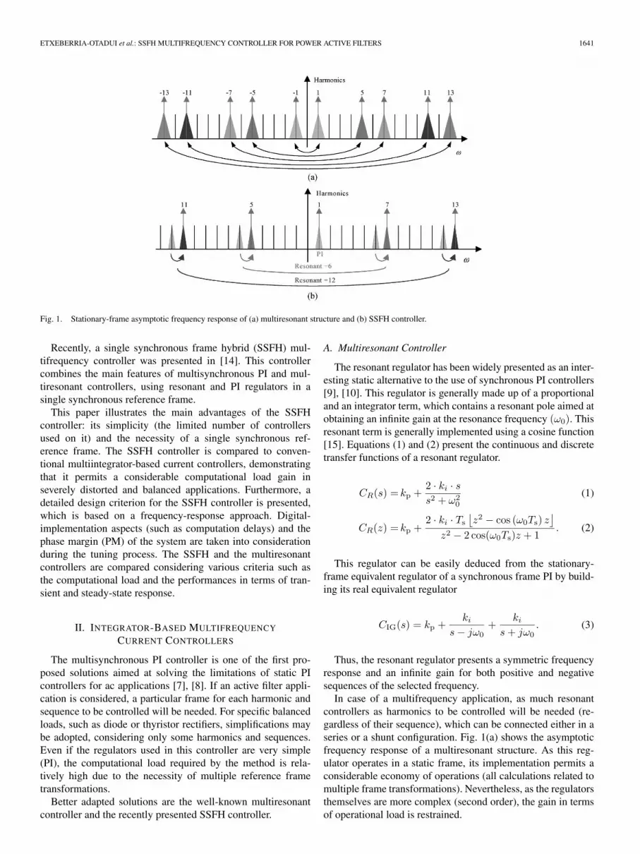
Fig. 1. Stationary-frame asymptotic frequency response of (a) multiresonant structure and (b) SSFH controller.
Recently, a single synchronous frame hybrid (SSFH) mul-tifrequency controller was presented in [14]. This controllercombines the main features of multisynchronous PI and mul-tiresonant controllers, using resonant and PI regulators in asingle synchronous reference frame.
This paper illustrates the main advantages of the SSFHcontroller: its simplicity (the limited number of controllersused on it) and the necessity of a single synchronous ref-erence frame. The SSFH controller is compared to conven-tional multiintegrator-based current controllers, demonstratingthat it permits a considerable computational load gain inseverely distorted and balanced applications. Furthermore, adetailed design criterion for the SSFH controller is presented,which is based on a frequency-response approach. Digital-implementation aspects (such as computation delays) and thephase margin (PM) of the system are taken into considerationduring the tuning process. The SSFH and the multiresonantcontrollers are compared considering various criteria such asthe computational load and the performances in terms of tran-sient and steady-state response.
II. INTEGRATOR-BASED MULTIFREQUENCY
CURRENT CONTROLLERS
The multisynchronous PI controller is one of the first pro-posed solutions aimed at solving the limitations of static PIcontrollers for ac applications [7], [8]. If an active filter appli-cation is considered, a particular frame for each harmonic andsequence to be controlled will be needed. For specific balancedloads, such as diode or thyristor rectifiers, simplifications maybe adopted, considering only some harmonics and sequences.Even if the regulators used in this controller are very simple(PI), the computational load required by the method is rela-tively high due to the necessity of multiple reference frametransformations.
Better adapted solutions are the well-known multiresonantcontroller and the recently presented SSFH controller.
A. Multiresonant Controller
The resonant regulator has been widely presented as an inter-esting static alternative to the use of synchronous PI controllers[9], [10]. This regulator is generally made up of a proportionaland an integrator term, which contains a resonant pole aimed atobtaining an infinite gain at the resonance frequency (ω0). Thisresonant term is generally implemented using a cosine function[15]. Equations (1) and (2) present the continuous and discretetransfer functions of a resonant regulator.
CR(s) = kp +2 · ki · ss2 + ω2
0
(1)
CR(z) = kp +2 · ki · Ts
⌊z2 − cos (ω0Ts) z
⌋z2 − 2 cos(ω0Ts)z + 1
. (2)
This regulator can be easily deduced from the stationary-frame equivalent regulator of a synchronous frame PI by build-ing its real equivalent regulator
CIG(s) = kp +ki
s − jω0+
ki
s + jω0. (3)
Thus, the resonant regulator presents a symmetric frequencyresponse and an infinite gain for both positive and negativesequences of the selected frequency.
In case of a multifrequency application, as much resonantcontrollers as harmonics to be controlled will be needed (re-gardless of their sequence), which can be connected either in aseries or a shunt configuration. Fig. 1(a) shows the asymptoticfrequency response of a multiresonant structure. As this reg-ulator operates in a static frame, its implementation permits aconsiderable economy of operations (all calculations related tomultiple frame transformations). Nevertheless, as the regulatorsthemselves are more complex (second order), the gain in termsof operational load is restrained.
1642 IEEE TRANSACTIONS ON INDUSTRIAL ELECTRONICS, VOL. 53, NO. 5, OCTOBER 2006
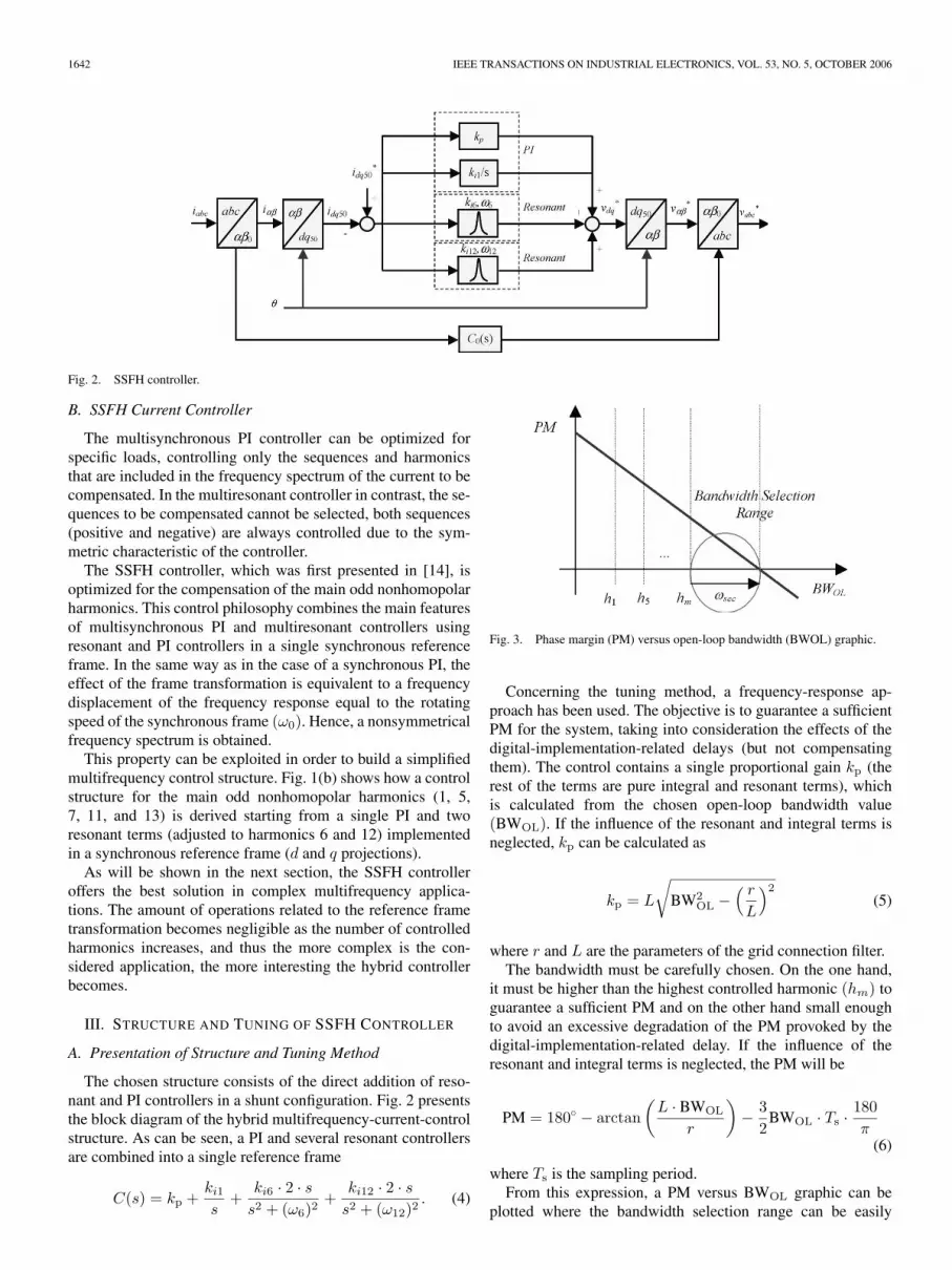
Fig. 2. SSFH controller.
B. SSFH Current Controller
The multisynchronous PI controller can be optimized forspecific loads, controlling only the sequences and harmonicsthat are included in the frequency spectrum of the current to becompensated. In the multiresonant controller in contrast, the se-quences to be compensated cannot be selected, both sequences(positive and negative) are always controlled due to the sym-metric characteristic of the controller.
The SSFH controller, which was first presented in [14], isoptimized for the compensation of the main odd nonhomopolarharmonics. This control philosophy combines the main featuresof multisynchronous PI and multiresonant controllers usingresonant and PI controllers in a single synchronous referenceframe. In the same way as in the case of a synchronous PI, theeffect of the frame transformation is equivalent to a frequencydisplacement of the frequency response equal to the rotatingspeed of the synchronous frame (ω0). Hence, a nonsymmetricalfrequency spectrum is obtained.
This property can be exploited in order to build a simplifiedmultifrequency control structure. Fig. 1(b) shows how a controlstructure for the main odd nonhomopolar harmonics (1, 5,7, 11, and 13) is derived starting from a single PI and tworesonant terms (adjusted to harmonics 6 and 12) implementedin a synchronous reference frame (d and q projections).
As will be shown in the next section, the SSFH controlleroffers the best solution in complex multifrequency applica-tions. The amount of operations related to the reference frametransformation becomes negligible as the number of controlledharmonics increases, and thus the more complex is the con-sidered application, the more interesting the hybrid controllerbecomes.
III. STRUCTURE AND TUNING OF SSFH CONTROLLER
A. Presentation of Structure and Tuning Method
The chosen structure consists of the direct addition of reso-nant and PI controllers in a shunt configuration. Fig. 2 presentsthe block diagram of the hybrid multifrequency-current-controlstructure. As can be seen, a PI and several resonant controllersare combined into a single reference frame
C(s) = kp +ki1
s+
ki6 · 2 · ss2 + (ω6)2
+ki12 · 2 · s
s2 + (ω12)2. (4)
Fig. 3. Phase margin (PM) versus open-loop bandwidth (BWOL) graphic.
Concerning the tuning method, a frequency-response ap-proach has been used. The objective is to guarantee a sufficientPM for the system, taking into consideration the effects of thedigital-implementation-related delays (but not compensatingthem). The control contains a single proportional gain kp (therest of the terms are pure integral and resonant terms), whichis calculated from the chosen open-loop bandwidth value(BWOL). If the influence of the resonant and integral terms isneglected, kp can be calculated as
kp = L
√BW2
OL −( r
L
)2
(5)
where r and L are the parameters of the grid connection filter.The bandwidth must be carefully chosen. On the one hand,
it must be higher than the highest controlled harmonic (hm) toguarantee a sufficient PM and on the other hand small enoughto avoid an excessive degradation of the PM provoked by thedigital-implementation-related delay. If the influence of theresonant and integral terms is neglected, the PM will be
PM = 180 − arctan(
L · BWOL
r
)− 3
2BWOL · Ts · 180
π(6)
where Ts is the sampling period.From this expression, a PM versus BWOL graphic can be
plotted where the bandwidth selection range can be easily

ETXEBERRIA-OTADUI et al.: SSFH MULTIFREQUENCY CONTROLLER FOR POWER ACTIVE FILTERS 1643
identified (see Fig. 3). From this plot, it can be deduced thata suitable value for the bandwidth is given by
BWOL = hm + ωsec (7)
where ωsec is a security margin of approximately 1000 rad/sthat is used to keep away from the influence zone of thehighest harmonic and to increase robustness against parametricvariations.
Regarding the calculation of resonant and integral gains(kin), the objective is to minimize their influence on the PMof the system. For instance, the phase addition (∆Φ) of theseterms at BWOL can be limited to 5, as shown in (8), whichis shown at the bottom of the page, where BW′
OL = BWOL +100π, and ki1 is the integral gain.
In order to solve this equation, a relationship between res-onant and integral coefficients must be established. Variouspossibilities have been explored: linearly or exponentially dis-tributed according to their distance to BWOL, identical value forall harmonics, etc. It has been observed that this choice has nota significant effect on the performances of the system. Thus, thesimplest one has been used: identical value for all coefficients.Then, ki is shown in (9), which is also shown at the bottom ofthe page.
B. Implementation
The presented control structure and the chosen tuning ap-proach have been tested in an active filter application. Theobjective is to design a control structure that is able to handlewith harmonics 5, 7, 11, and 13 (in addition to the fundamental).The system, sampling, and controller parameters deduced from(5) to (9) are presented in Table I. With these parameters, thecharacteristics of the system have been validated by meansof the open-loop and closed-loop frequency responses of theglobal system (controller + delay + physical system).
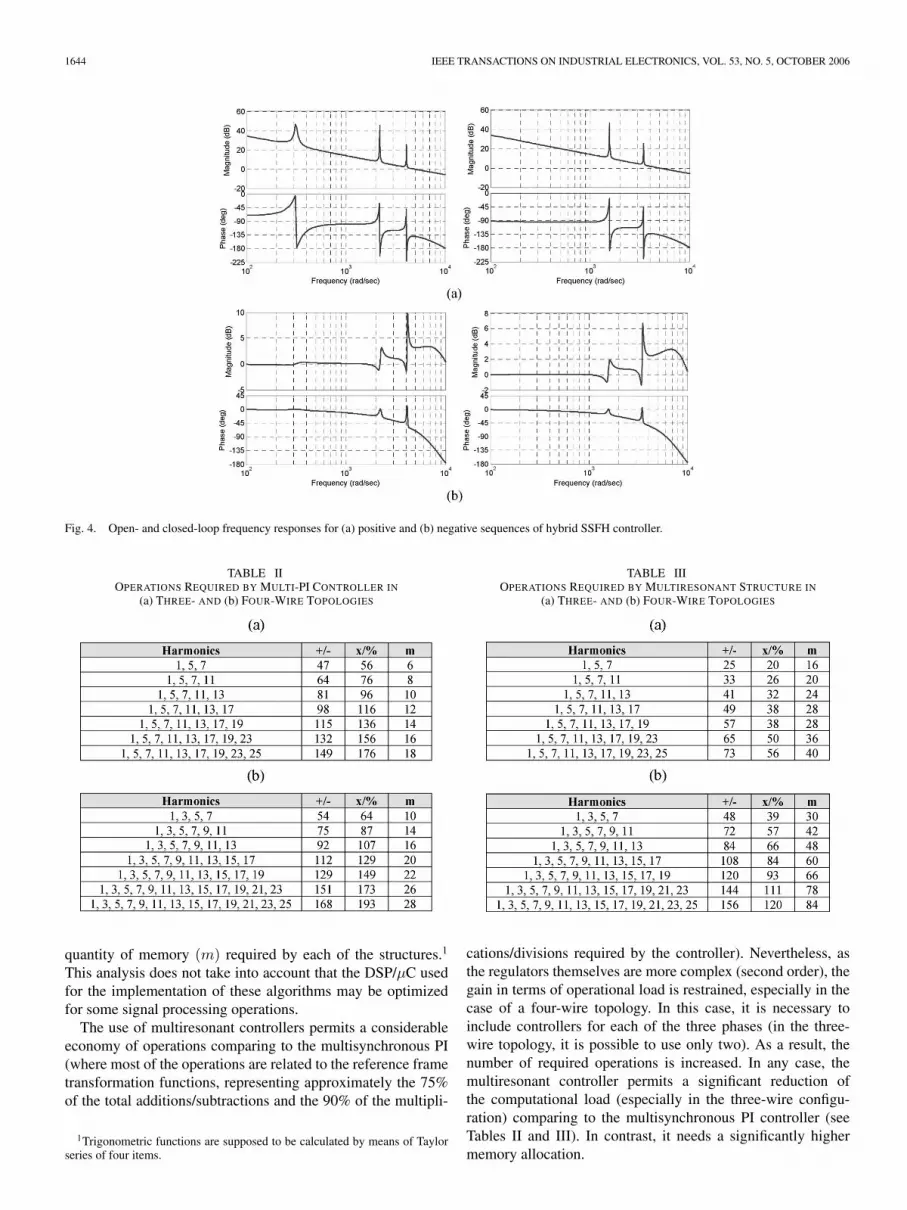
Fig. 4 shows the open- and closed-loop frequency responsesof the designed system for frequencies corresponding to thepositive and negative sequences. Note that as the frequency re-sponse is not symmetrical, harmonics 1, 7, and 13 are included
TABLE IPHYSICAL, CONTROL, AND SAMPLING PARAMETERS
in the positive sequence response, and harmonics 5 and 11 inthe negative one. As can be seen in these figures, the open-loop bandwidth of the system is approximately 5000 rad/s; thefrequency crossover is located in the desired region, and the PMis relatively high (40). Concerning the closed-loop frequencyresponse, it can be observed that the system assures a null errorat steady state for the concerned harmonics and sequences, evenif it contains a slight resonance at high frequencies.
IV. COMPARISON BETWEEN MULTIRESONANT AND
HYBRID CONTROLLERS
The comparison between the multiresonant and the SSFHcontrollers has been carried out based on various criteria, suchas the computational load, and the experimental transient, andsteady-state performances of the considered systems. Identicalstructure (a shunt configuration) and tuning approach (seeSection III-A) have been used for both controllers.
A. Computational Load
The computational load of the control system depends on thenumber of harmonics to be compensated and on the topologyof the system: three or four wires. The comparison has beencarried out computing the number of operations (+/−: addi-tions and subtractions, and x/%: products or divisions) and the
∆Φ = 90 + tan−1
−kpBW′OL
N∏y=1
(yω2
0 − BW′2OL
)
ki1
N∏y=1
(yω2
0 − BW′2OL
) − 2BW′2OL
N∑n=1
kin
N∏y=1y =n
(yω2
0 − BW′2OL
)
≤ 5 (8)
ki =−kpBW′
OL
N∏y=1
(yω2
0 − BW′2OL
)
tan(∆Φ − 90)
N∏
y=1
(yω2
0 − BW′2OL
) − 2BW′2OL
N∑n=1
N∏y=1y =n
(yω2
0 − BW′2OL
)(9)
1644 IEEE TRANSACTIONS ON INDUSTRIAL ELECTRONICS, VOL. 53, NO. 5, OCTOBER 2006
Fig. 4. Open- and closed-loop frequency responses for (a) positive and (b) negative sequences of hybrid SSFH controller.
TABLE IIOPERATIONS REQUIRED BY MULTI-PI CONTROLLER IN
(a) THREE- AND (b) FOUR-WIRE TOPOLOGIES
quantity of memory (m) required by each of the structures.1
This analysis does not take into account that the DSP/µC usedfor the implementation of these algorithms may be optimizedfor some signal processing operations.
The use of multiresonant controllers permits a considerableeconomy of operations comparing to the multisynchronous PI(where most of the operations are related to the reference frametransformation functions, representing approximately the 75%of the total additions/subtractions and the 90% of the multipli-
1Trigonometric functions are supposed to be calculated by means of Taylorseries of four items.
TABLE IIIOPERATIONS REQUIRED BY MULTIRESONANT STRUCTURE IN
(a) THREE- AND (b) FOUR-WIRE TOPOLOGIES
cations/divisions required by the controller). Nevertheless, asthe regulators themselves are more complex (second order), thegain in terms of operational load is restrained, especially in thecase of a four-wire topology. In this case, it is necessary toinclude controllers for each of the three phases (in the three-wire topology, it is possible to use only two). As a result, thenumber of required operations is increased. In any case, themultiresonant controller permits a significant reduction ofthe computational load (especially in the three-wire configu-ration) comparing to the multisynchronous PI controller (seeTables II and III). In contrast, it needs a significantly highermemory allocation.
ETXEBERRIA-OTADUI et al.: SSFH MULTIFREQUENCY CONTROLLER FOR POWER ACTIVE FILTERS 1645
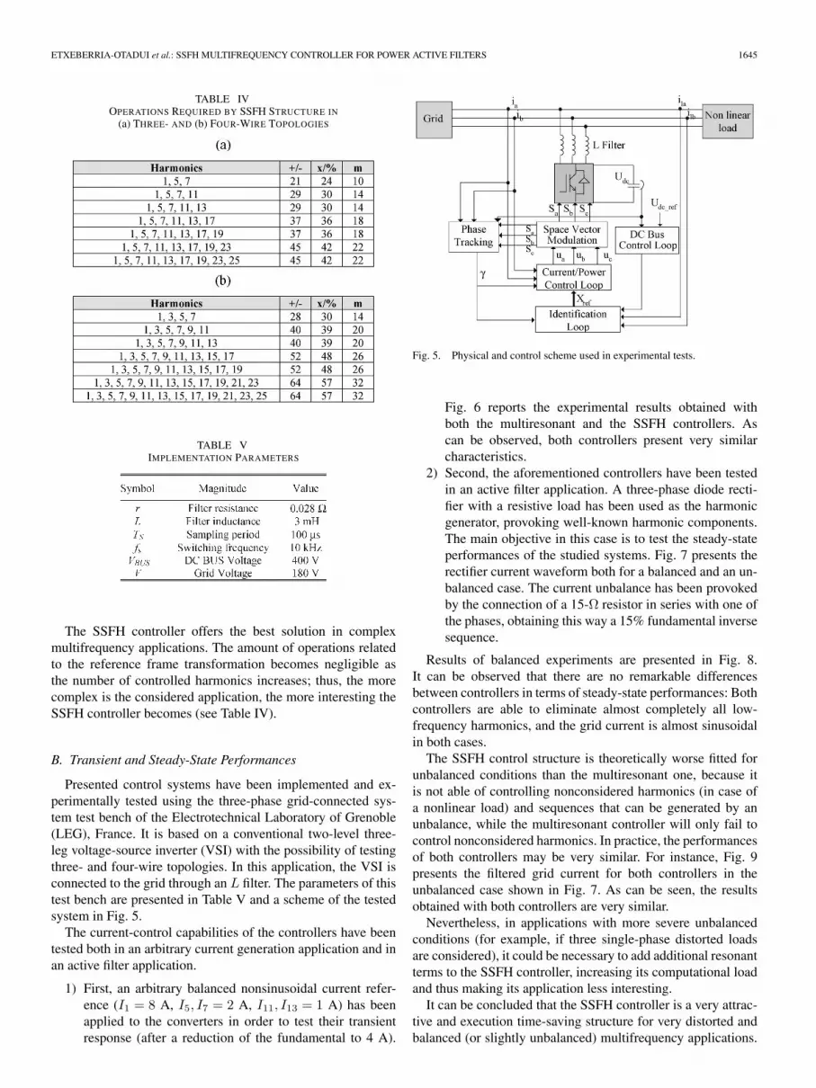
TABLE IVOPERATIONS REQUIRED BY SSFH STRUCTURE IN
(a) THREE- AND (b) FOUR-WIRE TOPOLOGIES
TABLE VIMPLEMENTATION PARAMETERS
The SSFH controller offers the best solution in complexmultifrequency applications. The amount of operations relatedto the reference frame transformation becomes negligible asthe number of controlled harmonics increases; thus, the morecomplex is the considered application, the more interesting theSSFH controller becomes (see Table IV).
B. Transient and Steady-State Performances
Presented control systems have been implemented and ex-perimentally tested using the three-phase grid-connected sys-tem test bench of the Electrotechnical Laboratory of Grenoble(LEG), France. It is based on a conventional two-level three-leg voltage-source inverter (VSI) with the possibility of testingthree- and four-wire topologies. In this application, the VSI isconnected to the grid through an L filter. The parameters of thistest bench are presented in Table V and a scheme of the testedsystem in Fig. 5.
The current-control capabilities of the controllers have beentested both in an arbitrary current generation application and inan active filter application.
1) First, an arbitrary balanced nonsinusoidal current refer-ence (I1 = 8 A, I5, I7 = 2 A, I11, I13 = 1 A) has beenapplied to the converters in order to test their transientresponse (after a reduction of the fundamental to 4 A).
Fig. 5. Physical and control scheme used in experimental tests.
Fig. 6 reports the experimental results obtained withboth the multiresonant and the SSFH controllers. Ascan be observed, both controllers present very similarcharacteristics.
2) Second, the aforementioned controllers have been testedin an active filter application. A three-phase diode recti-fier with a resistive load has been used as the harmonicgenerator, provoking well-known harmonic components.The main objective in this case is to test the steady-stateperformances of the studied systems. Fig. 7 presents therectifier current waveform both for a balanced and an un-balanced case. The current unbalance has been provokedby the connection of a 15-Ω resistor in series with one ofthe phases, obtaining this way a 15% fundamental inversesequence.
Results of balanced experiments are presented in Fig. 8.It can be observed that there are no remarkable differencesbetween controllers in terms of steady-state performances: Bothcontrollers are able to eliminate almost completely all low-frequency harmonics, and the grid current is almost sinusoidalin both cases.
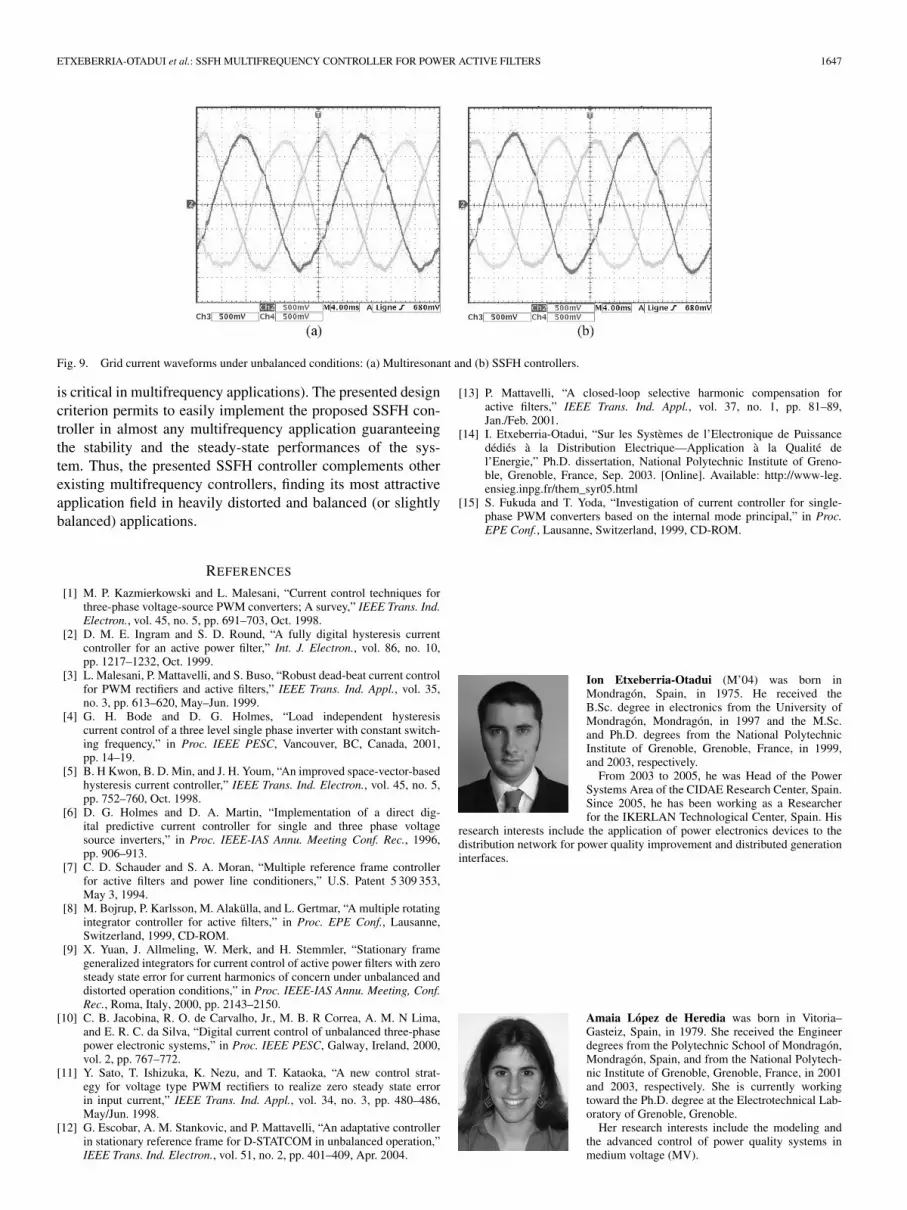
The SSFH control structure is theoretically worse fitted forunbalanced conditions than the multiresonant one, because itis not able of controlling nonconsidered harmonics (in case ofa nonlinear load) and sequences that can be generated by anunbalance, while the multiresonant controller will only fail tocontrol nonconsidered harmonics. In practice, the performancesof both controllers may be very similar. For instance, Fig. 9presents the filtered grid current for both controllers in theunbalanced case shown in Fig. 7. As can be seen, the resultsobtained with both controllers are very similar.
Nevertheless, in applications with more severe unbalancedconditions (for example, if three single-phase distorted loadsare considered), it could be necessary to add additional resonantterms to the SSFH controller, increasing its computational loadand thus making its application less interesting.
It can be concluded that the SSFH controller is a very attrac-tive and execution time-saving structure for very distorted andbalanced (or slightly unbalanced) multifrequency applications.

1646 IEEE TRANSACTIONS ON INDUSTRIAL ELECTRONICS, VOL. 53, NO. 5, OCTOBER 2006
Fig. 6. Current reference and injected current after reference change: (a) Multiresonant and (b) SSFH controllers.
Fig. 7. Load current waveforms under (a) balanced and (b) unbalanced conditions.
Fig. 8. Grid current waveforms under balanced conditions: (a) Multiresonant and (b) SSFH controllers.
However, if the current is slightly distorted or severely unbal-anced, the conventional multiresonant controller could be moreinteresting from the point of view of the computational load.
V. CONCLUSION
This paper presents an alternative for conventional multifre-quency current controllers: the hybrid SSFH controller. Themain advantages of the SSFH controller are illustrated: itssimplicity (the limited number of controllers used on it) and thenecessity of a single synchronous reference frame. The SSFH
controller is especially well fitted for severely distorted andbalanced applications, where it permits a considerable com-putational economy compared to other multifrequency con-trollers. It has been shown through experimental tests thatthe SSFH controller offers very good transient and steady-state performances almost identical to those obtained with themultiresonant controller in balanced or slightly unbalanced ap-plications. In addition, a detailed design criterion for the SSFHcontroller has been proposed, which is based on a frequency-response approach and takes into consideration (but not com-pensated) the effects of the digital-implementation delay (which
ETXEBERRIA-OTADUI et al.: SSFH MULTIFREQUENCY CONTROLLER FOR POWER ACTIVE FILTERS 1647
Fig. 9. Grid current waveforms under unbalanced conditions: (a) Multiresonant and (b) SSFH controllers.
is critical in multifrequency applications). The presented designcriterion permits to easily implement the proposed SSFH con-troller in almost any multifrequency application guaranteeingthe stability and the steady-state performances of the sys-tem. Thus, the presented SSFH controller complements otherexisting multifrequency controllers, finding its most attractiveapplication field in heavily distorted and balanced (or slightlybalanced) applications.
REFERENCES
[1] M. P. Kazmierkowski and L. Malesani, “Current control techniques forthree-phase voltage-source PWM converters; A survey,” IEEE Trans. Ind.Electron., vol. 45, no. 5, pp. 691–703, Oct. 1998.
[2] D. M. E. Ingram and S. D. Round, “A fully digital hysteresis currentcontroller for an active power filter,” Int. J. Electron., vol. 86, no. 10,pp. 1217–1232, Oct. 1999.
[3] L. Malesani, P. Mattavelli, and S. Buso, “Robust dead-beat current controlfor PWM rectifiers and active filters,” IEEE Trans. Ind. Appl., vol. 35,no. 3, pp. 613–620, May–Jun. 1999.
[4] G. H. Bode and D. G. Holmes, “Load independent hysteresiscurrent control of a three level single phase inverter with constant switch-ing frequency,” in Proc. IEEE PESC, Vancouver, BC, Canada, 2001,pp. 14–19.
[5] B. H Kwon, B. D. Min, and J. H. Youm, “An improved space-vector-basedhysteresis current controller,” IEEE Trans. Ind. Electron., vol. 45, no. 5,pp. 752–760, Oct. 1998.
[6] D. G. Holmes and D. A. Martin, “Implementation of a direct dig-ital predictive current controller for single and three phase voltagesource inverters,” in Proc. IEEE-IAS Annu. Meeting Conf. Rec., 1996,pp. 906–913.
[7] C. D. Schauder and S. A. Moran, “Multiple reference frame controllerfor active filters and power line conditioners,” U.S. Patent 5 309 353,May 3, 1994.
[8] M. Bojrup, P. Karlsson, M. Alakülla, and L. Gertmar, “A multiple rotatingintegrator controller for active filters,” in Proc. EPE Conf., Lausanne,Switzerland, 1999, CD-ROM.
[9] X. Yuan, J. Allmeling, W. Merk, and H. Stemmler, “Stationary framegeneralized integrators for current control of active power filters with zerosteady state error for current harmonics of concern under unbalanced anddistorted operation conditions,” in Proc. IEEE-IAS Annu. Meeting, Conf.Rec., Roma, Italy, 2000, pp. 2143–2150.
[10] C. B. Jacobina, R. O. de Carvalho, Jr., M. B. R Correa, A. M. N Lima,and E. R. C. da Silva, “Digital current control of unbalanced three-phasepower electronic systems,” in Proc. IEEE PESC, Galway, Ireland, 2000,vol. 2, pp. 767–772.
[11] Y. Sato, T. Ishizuka, K. Nezu, and T. Kataoka, “A new control strat-egy for voltage type PWM rectifiers to realize zero steady state errorin input current,” IEEE Trans. Ind. Appl., vol. 34, no. 3, pp. 480–486,May/Jun. 1998.
[12] G. Escobar, A. M. Stankovic, and P. Mattavelli, “An adaptative controllerin stationary reference frame for D-STATCOM in unbalanced operation,”IEEE Trans. Ind. Electron., vol. 51, no. 2, pp. 401–409, Apr. 2004.
[13] P. Mattavelli, “A closed-loop selective harmonic compensation foractive filters,” IEEE Trans. Ind. Appl., vol. 37, no. 1, pp. 81–89,Jan./Feb. 2001.
[14] I. Etxeberria-Otadui, “Sur les Systèmes de l’Electronique de Puissancedédiés à la Distribution Electrique—Application à la Qualité del’Energie,” Ph.D. dissertation, National Polytechnic Institute of Greno-ble, Grenoble, France, Sep. 2003. [Online]. Available: http://www-leg.ensieg.inpg.fr/them_syr05.html
[15] S. Fukuda and T. Yoda, “Investigation of current controller for single-phase PWM converters based on the internal mode principal,” in Proc.EPE Conf., Lausanne, Switzerland, 1999, CD-ROM.
Ion Etxeberria-Otadui (M’04) was born inMondragón, Spain, in 1975. He received theB.Sc. degree in electronics from the University ofMondragón, Mondragón, in 1997 and the M.Sc.and Ph.D. degrees from the National PolytechnicInstitute of Grenoble, Grenoble, France, in 1999,and 2003, respectively.
From 2003 to 2005, he was Head of the PowerSystems Area of the CIDAE Research Center, Spain.Since 2005, he has been working as a Researcherfor the IKERLAN Technological Center, Spain. His
research interests include the application of power electronics devices to thedistribution network for power quality improvement and distributed generationinterfaces.
Amaia López de Heredia was born in Vitoria–Gasteiz, Spain, in 1979. She received the Engineerdegrees from the Polytechnic School of Mondragón,Mondragón, Spain, and from the National Polytech-nic Institute of Grenoble, Grenoble, France, in 2001and 2003, respectively. She is currently workingtoward the Ph.D. degree at the Electrotechnical Lab-oratory of Grenoble, Grenoble.
Her research interests include the modeling andthe advanced control of power quality systems inmedium voltage (MV).
1648 IEEE TRANSACTIONS ON INDUSTRIAL ELECTRONICS, VOL. 53, NO. 5, OCTOBER 2006
Haizea Gaztañaga was born in Elorrio, Spain,in 1979. She received the Engineer degrees fromthe Polytechnic School of Mondragón, Mondragón,Spain, and from the National Polytechnic Instituteof Grenoble, Grenoble, France, in 2001 and 2003,respectively. She is currently working toward thePh.D. degree at the CIDAE Research Center, Spain.
Her research interests include the analysis of con-trol structures and design of microgrids.
Seddik Bacha received the Engineer and Magis-ter degrees from Ecole Nationale Polytechnique ofAlgiers, Algeria, in 1982 and 1990, respectively,and the Ph.D. degree and HDR from Laboratoired’Electrotechnique de Grenoble (LEG), Grenoble,France, in 1993 and 1998, respectively.
He joined the Laboratoire d’Electrotechnique deGrenoble (LEG) in 1990. He is currently Managerof the Power System Group of LEG, France, anda Professor with the University Joseph Fourier ofGrenoble, Grenoble. His research interests include
power electronics system modeling and control, power quality, and renewable-energy integration.
M. Raúl Reyero (M’81) received the Ph.D. de-gree in control engineering from the University ofValladolid, Valladolid, Spain, in 1984.
From 1977 to 1980, he was Assistant Professorwith the Universities of Valladolid and the BasqueCountry, Spain. From 1982 to 1985, he worked forseveral companies of the National Institute of Indus-try of Spain. From 1986 to 2002, he worked for theIKERLAN Research Centre as the Head of the Con-trol Engineering Department. From 2002 to 2005,he promoted and Managed the CIDAE Research
Center on Distributed Generation and Electrotechnologies. He is currentlythe Coordinator of the Basque Regional Strategic RTD Plan of DistributedEnergy, Spain.