a simplified constitutive model for dowel action across rc
TRANSCRIPT

A Simplified Constitutive Model for Dowel Action across RCCracksAli Reza Moradi, Masoud Soltani Abbas Ali Tasnimi,Journal of Advanced Concrete Technology, volume ( ), pp.10 2012 264-277
Local Stress Filed Approach for Shear Failure Assessment of Reinforced Concrete MembersMasoud Soltani, Bahman GhiassiJournal of Advanced Concrete Technology, volume ( ), pp.8 2010 223-238
Modeling and Analysis of Shear-Critical ECC Members with Anisotropic Stress and Strain FieldsBenny Suryanto , Kohei Nagai Koichi Maekawa,Journal of Advanced Concrete Technology, volume ( ), pp.8 2010 239-258
Smeared-Crack Modeling of R/ECC Membranes Incorporating an Explicit Shear Transfer ModelBenny Suryanto, Kohei Nagai Koichi Maekawa,Journal of Advanced Concrete Technology, volume ( ), pp.8 2010 315-326
Numerical Simulation on Shear Capacity and Post-Peak Ductility of Reinforced High-Strength ConcreteCoupled with Autogenous ShrinkageEsayas Gebreyouhannes, Koichi MaekawaJournal of Advanced Concrete Technology, volume ( ), pp.9 2011 73-88
Journal of Advanced Concrete Technology Vol. 10, 264-277, August 2012 / Copyright © 2012 Japan Concrete Institute 264
Scientific paper
A Simplified Constitutive Model for Dowel Action across RC Cracks
Ali Reza Moradi1, Masoud Soltani2, Abbas Ali Tasnimi3
Received 15 February 2012, accepted 29 July 2012 doi:10.3151/jact.10.264
Abstract Cracks and interfaces have been recognized as important planes in global behavior of RC structures. In fact, the response of structures, failure modes and even capacity of RC elements can be affected by the stress transfer mechanism across cracks and interfaces. On the other hand, understanding and expressing different kinds of stress transfer mechanisms has a major role in finite element-based analyses. In this paper, dowel action mechanism has been examined analytically and experimentally. In order to simulate the shear transfer by the dowel bar under different loading conditions, the beam on elastic foundation analogy has been extended by proposing a simple elasto-plastic formulation for subgrade springs. Available experimental results and the data obtained from the experimental program have been used to calibrate and develop the model. Verification of the proposed model is carried out by comparing with the corresponding experimental results.
1. Introduction
Joints and interfaces are basic components of many re-inforced concrete (RC) structures. The behavior of RC cracks and interfaces is complex due to different types of stress transfer mechanism such as aggregate interlock and dowel action. Earthquake excitations will form lo-calized damages at connections (e.g. beam-column) and increase crack opening during load reversals. Aggregate interlock deteriorates fast with crack widening. This makes dowel action as the main resisting mechanism at RC connections. On the other hand the dowel action is the only resisting mechanism at pre-formed joints, con-traction connections and precast structures. These inter-faces may turn out to be critical planes in the operation of the load-resisting mechanism and govern the ultimate strength, ductility and energy absorption capacity of an entire structure (Soltani and Maekawa 2008).
During the past years, extensive experimental and analytical investigations have been carried out to inves-tigate the shear transfer behavior of dowel bars across cracks and interfaces. Most investigators reported Beam on Elastic Foundation analogy (BEF) as a suitable tool to simulate the behavior of crossing bars. It seems that
Timoshenko and Lessels (El-Ariss 2007) presented the first analytical model to predict the behavior of a dowel bar embedded in concrete. The first studies on the dowel action of the reinforcement were conducted on contrac-tion joints in concrete highway pavement. The results from the contraction joint investigations, however, can-not be directly applied to other structural problems where significant nonlinear response as induced by concrete cracking and material nonlinearities, is observed. Other investigations designed to study the dowel stiffness re-lationships and its ultimate load capacity have employed direct dowel test setups, divided beam tests, and beam end tests (ASCE 1982). Dulacska (1972) planed a test program in order to establish theoretical load-deforma-tion relation. Soroushian et al. (1986, 1987b) designed an experimental study to reproduce the dowel behavior of common beam longitudinal bars against the concrete core and cover at the cracked beam-column interface. They presented an empirical formulation for the consti-tutive behavior and the strength of dowel bars acting against the concrete core and cover from the experi-mental results. Vintzeleou and Tassios (1986, 1987) experimentally and analytically studied the behavior of dowel bars under monotonic and reversed cyclic loadings. They concluded that the response under reversed cyclic loading is highly nonlinear and showed that stiffness degradation is pronounced, especially in case of fully reversed deformations. The capacity of reinforcing bars was predicted by considering the bar as a long, free-headed pile in cohesive soil. It was assumed that the soil reaches its strength and the plastic hinge is formed in the pile, simultaneously. Dei Poli et al. (1992) exten-sively studied the load-carrying behavior of dowel bars by preparing block-type specimens and investigated the subgrade stiffness under pure shear. Soroushian et al. (1987a) experimentally examined the bearing strength
1PhD. Candidate, Structural Engineering, Faculty of Civil and Environmental Engineering, Tarbiat Modares University, Tehran, Iran 2Associate Professor, Earthquake Engineering, Faculty of Civil and Environmental Engineering, Tarbiat Modares University, Tehran, Iran E-mail: [email protected] 3Professor, Structural Engineering, Faculty of Civil and Environmental Engineering, Tarbiat Modares University, Tehran, Iran
A. R. Moradi, M. Soltani and A. A. Tasnimi / Journal of Advanced Concrete Technology Vol. 10, 264-277, 2012 265
and stiffness of concrete under dowel bars and based on the results, some empirical equations were proposed.
Maekawa and Qureshi (1996b) proposed a micro scale model for prediction of reinforcing bar behavior under the generic condition of axial pullout and transverse displacement. The formulation established by consider-ing the combined axial pullout and transverse dowel action. Maekawa and Qureshi (1996a) showed that cou-pling of pullout and transverse shear of steel at a crack cannot be ignored in structural analysis. Then, Maekawa and Qureshi (1997) presented a unified model to simulate the behavior of interface transfer mechanism. Soltani and Maekawa (2008) extended the model proposed by Maekawa and Qureshi (1996b) to path-dependent cyclic loading case. The model determines the deformational behavior of deformed bars by solving the nonlinear equilibrium and compatibility equations numerically with respect to the loading path and history. Since they considered the crossing bar as a three-dimensional member capable of developing coupled shears and mo-ment in addition to axial force, the model is time con-suming.
Most of existing models have been developed by using BEF to express embedded reinforcement and surround-ing concrete under shear displacement. Some researchers proposed empirical formulations from the experimental observations (Dei Poli et al. 1992; Soroushian et al. 1988, 1987b) and also some others have evaluated the load carrying capacity of a dowel within a limit analysis ap-proach based on the simultaneous formation of a plastic hinge in the bar and a plasticized (crushed) zone in the concrete (Vintzeleou and Tassios 1986; Soroushian et al. 1986). In the modelization based on limit analysis and empirical formulation, the deformational behavior of dowel bars during load reversals and also at post-peak range cannot be captured properly. Since the most rele-vant parameter in the BEF is the subgrade stiffness of concrete embedment ( sk ), calibration of the model can be simply performed. On the other hand, explicit for-mulations of the BEF make it possible to increase the scale of modeling. Also, the interaction of surrounding concrete and dowel bar can be determined in a consistent manner.
This paper aims at simulating the behavior of dowel bars across cracks and interfaces under different loading paths. Some experiments have been carried out in order to have a better insight into the behavior of dowel action mechanism under cyclic and repeating loading. The proposed model is established based on the experimental program and the available experimental results. The model formulation is based on the BEF theory and ex-tended to the beam on inelastic foundation (BIF) by proposing a consistent formula for subgrade springs. The stiffness deformation relation ( sk δ− ) for springs is suggested based on studies conducted by Soltani and Maekawa (2008) and Maekawa and Qureshi (1996b), since, to the authors’ knowledge, they are the most comprehensive models. It is shown that the gradual
change in springs stiffness is a convenient and proper method to simulate the damages and fractures within the subgrade at the vicinity of shear plane. Effect of concrete cover splitting as well as the effect of axial stress of deformed bars are considered. The extensive verification is carried out to show the reliability of the proposed model by comparing the computational predictions with the available experimental results and the experimental program.
2. Experimental program
Some investigations designed to study the dowel stiff-ness relationships and its ultimate load capacity have employed direct dowel test setups, divided beam test, and beam end test. The first two groups study the dowel action mechanism with little or no tension in the rein-forcement. The beam end tests enable researches to study the effect of the interaction between tensile and dowel forces on the stiffness relations and ultimate dowel strength (ASCE 1982).
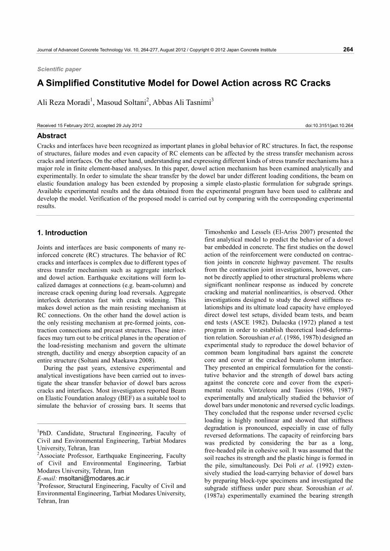
As a part of an extensive experimental research, five beam-type specimens under pure shear have been de-signed in order to investigate the behavior of dowel ac-tion under cyclic and repeating loading and to calibrate the required parameters for the proposed model. The specimens used for investigation consisted of two con-crete blocks connected by one crossing bar, each 300mm long, 250mm and 200mm high for large and small specimens, respectively (Fig. 1). Plexiglass sheets 5mm thick were placed between adjacent concrete blocks and were removed before testing. The specimens were sub-jected to cyclic and repeating loading conditions and are summarized in Table 1. The length of each block was limited to 300 mm to reduce the deflection due to the weight of each block. The cross sectional dimensions of the specimens were considered such that the response is
600mm
5mm notch
200mm, 250mm
A-A 200mm,
250mm
14mm,
16mm,
20mm
A-A
Square section
10mm steel plate(a) (b)
5mm notch
Crossing dowel bar
5mm plexiglass sheets
B-B
B-B
(c)
Fig. 1 Specimens for experimental investigation, a) specimen dimension, b) cross section and bar arrange-ment of the specimens, c) plexiglass sheet arrangement
A. R. Moradi, M. Soltani and A. A. Tasnimi / Journal of Advanced Concrete Technology Vol. 10, 264-277, 2012 266
mainly governed by action against core. where ,bd ρ are bar diameter and reinforcement ratio, respectively.
Maekawa and Qureshi (1996a) used beam-type specimens to investigate the behavior of stress transfer across RC cracks. Maekawa et al. (2006) experimentally and analytically investigated the shear transfer fatigue behavior of cracked concrete interface. The experimental loading setup is similar to Maekawa and Qureshi (1996b) and designed in such a way that the crack interface is under pure shear. The test setup used herein is designed according to the aforementioned investigations in order to calibrate the model.
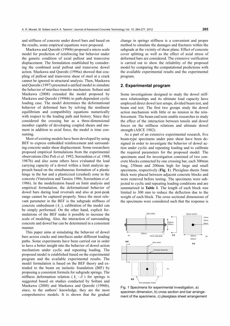
Test setup is shown schematically in Fig. 2. The tests were carried out by controlling the displacement which imposed pure shear with respect to the supports ar-rangement. As indicated in Fig. 2, the specimens were supported on the roller bearings. Shear displacements and shear forces were continuously recorded during loading, unloading and reloading. The shear displace-ments of each block were recorded by means of two linear voltage displacement transducers (LVDT), at-tached to the both side of the blocks and the shear load was measured by means of load cell.
Arrangement of roller supports makes it possible to apply cyclic and repeating loading by using a compres-sive jack (Fig. 3). In order to simulate a half cycle, the supports are placed according to Fig. 3(a). Loading and unloading are applied by means of compressive jack and the first half cycle is simulated (Fig. 3(a)). Then, the other half cycle is obtained by changing the arrangement of supports according to Fig. 3(b). Therefore, the fully reversed cyclic response of the specimens can be re-corded.
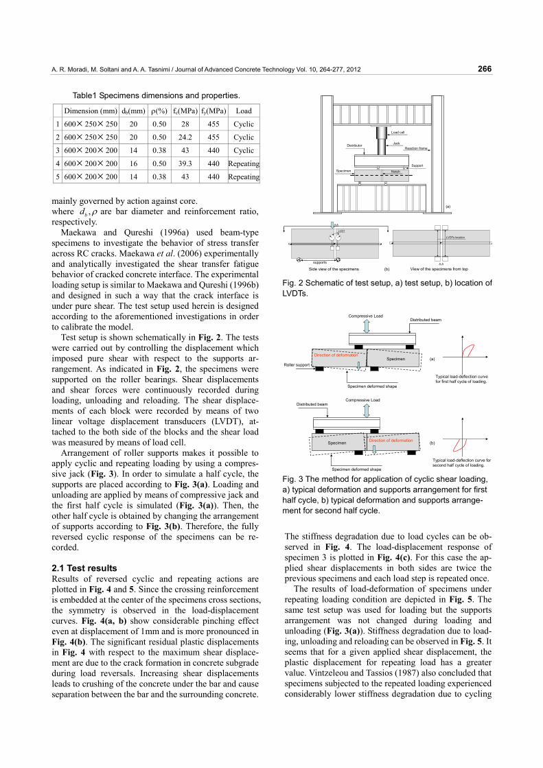
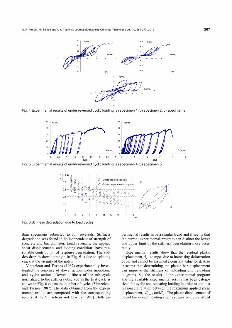
2.1 Test results Results of reversed cyclic and repeating actions are plotted in Fig. 4 and 5. Since the crossing reinforcement is embedded at the center of the specimens cross sections, the symmetry is observed in the load-displacement curves. Fig. 4(a, b) show considerable pinching effect even at displacement of 1mm and is more pronounced in Fig. 4(b). The significant residual plastic displacements in Fig. 4 with respect to the maximum shear displace-ment are due to the crack formation in concrete subgrade during load reversals. Increasing shear displacements leads to crushing of the concrete under the bar and cause separation between the bar and the surrounding concrete.
The stiffness degradation due to load cycles can be ob-served in Fig. 4. The load-displacement response of specimen 3 is plotted in Fig. 4(c). For this case the ap-plied shear displacements in both sides are twice the previous specimens and each load step is repeated once.
The results of load-deformation of specimens under repeating loading condition are depicted in Fig. 5. The same test setup was used for loading but the supports arrangement was not changed during loading and unloading (Fig. 3(a)). Stiffness degradation due to load-ing, unloading and reloading can be observed in Fig. 5. It seems that for a given applied shear displacement, the plastic displacement for repeating load has a greater value. Vintzeleou and Tassios (1987) also concluded that specimens subjected to the repeated loading experienced considerably lower stiffness degradation due to cycling
Table1 Specimens dimensions and properties.
Dimension (mm) db(mm) ρ(%) fc(MPa) fy(MPa) Load
1 600× 250× 250 20 0.50 28 455 Cyclic
2 600× 250× 250 20 0.50 24.2 455 Cyclic
3 600× 200× 200 14 0.38 43 440 Cyclic
4 600× 200× 200 16 0.50 39.3 440 Repeating
5 600× 200× 200 14 0.38 43 440 Repeating
Reaction frame
Load cell
JackDistributor
SpecimenSupport
Notch
(a)
LVDT
A-A
LVDTs location
A-A
(b)Side view of the specimenssupports
View of the specimens from top
Fig. 2 Schematic of test setup, a) test setup, b) location of LVDTs.
SpecimenRoller support
Compressive Load Distributed beam
(a)
Specimen
Compressive Load Distributed beam
(b)
Direction of deformation
Direction of deformation
Specimen deformed shape
Specimen deformed shape
Typical load-deflection curve for first half cycle of loading.
Typical load-deflection curve for second half cycle of loading.
Fig. 3 The method for application of cyclic shear loading, a) typical deformation and supports arrangement for first half cycle, b) typical deformation and supports arrange-ment for second half cycle.
A. R. Moradi, M. Soltani and A. A. Tasnimi / Journal of Advanced Concrete Technology Vol. 10, 264-277, 2012 267
than specimens subjected to full reversals. Stiffness degradation was found to be independent of strength of concrete and bar diameter. Load reversals, the applied shear displacements and loading conditions have rea-sonable contribution of response degradation. The sud-den drop in dowel strength in Fig. 5 is due to splitting crack at the vicinity of the notch.
Vintzeleou and Tassios (1987) experimentally inves-tigated the response of dowel action under monotonic and cyclic actions. Dowel stiffness of the nth cycle normalized to the stiffness observed in the first cycle is shown in Fig. 6 versus the number of cycles (Vintzeleou and Tassios 1987). The data obtained from the experi-mental results are compared with the corresponding results of the Vintzeleou and Tassios (1987). Both ex-
perimental results have a similar trend and it seems that the current experimental program can distinct the lower and upper limit of the stiffness degradation more accu-rately.
Experimental results show that the residual plastic displacement, pδ changes due to increasing deformation of bar and cannot be assumed a constant value for it. Also it seems that determining the plastic bar displacement can improve the stiffness of unloading and reloading diagrams. So, the results of the experimental program and the available experimental results has been catego-rized for cyclic and repeating loading in order to obtain a reasonable relation between the maximum applied shear displacement, maxδ , and pδ . The plastic displacement of dowel bar in each loading step is suggested by statistical
(a) (b)
(c)
V(kN)
δ (mm)
V(kN)
δ (mm)
V(kN)
δ (mm)
Fig. 4 Experimental results of under reversed cyclic loading, a) specimen 1, b) specimen 2, c) specimen 3.
0
10
20
30
40
50
0 1 2 3 4 50
10
20
30
40
50
0 0.5 1 1.5 2 2.5 3 3.5 4(a)
V(kN)
δ (mm)
(b)
V(kN)
δ (mm)
Fig. 5 Experimental results of under reversed cyclic loading, a) specimen 4, b) specimen 5.
0
0.2
0.4
0.6
0.8
1
1 3 5 7 9 11 13 15 17 19
1d
nd
KK
n
Vintzeleou and Tassios
Current experimental program
n1
1dK
ndK δ
dV
Fig. 6 Stiffness degradation due to load cycles.
A. R. Moradi, M. Soltani and A. A. Tasnimi / Journal of Advanced Concrete Technology Vol. 10, 264-277, 2012 268
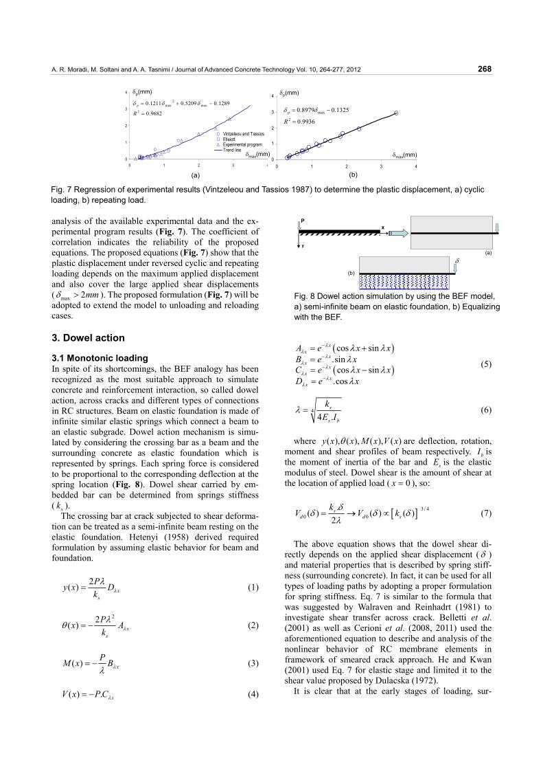
analysis of the available experimental data and the ex-perimental program results (Fig. 7). The coefficient of correlation indicates the reliability of the proposed equations. The proposed equations (Fig. 7) show that the plastic displacement under reversed cyclic and repeating loading depends on the maximum applied displacement and also cover the large applied shear displacements ( max 2mmδ > ). The proposed formulation (Fig. 7) will be adopted to extend the model to unloading and reloading cases.
3. Dowel action
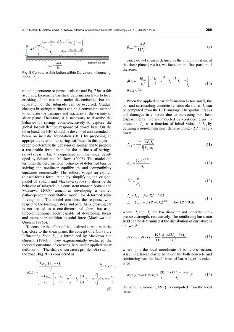
3.1 Monotonic loading In spite of its shortcomings, the BEF analogy has been recognized as the most suitable approach to simulate concrete and reinforcement interaction, so called dowel action, across cracks and different types of connections in RC structures. Beam on elastic foundation is made of infinite similar elastic springs which connect a beam to an elastic subgrade. Dowel action mechanism is simu-lated by considering the crossing bar as a beam and the surrounding concrete as elastic foundation which is represented by springs. Each spring force is considered to be proportional to the corresponding deflection at the spring location (Fig. 8). Dowel shear carried by em-bedded bar can be determined from springs stiffness ( sk ).
The crossing bar at crack subjected to shear deforma-tion can be treated as a semi-infinite beam resting on the elastic foundation. Hetenyi (1958) derived required formulation by assuming elastic behavior for beam and foundation.
2( ) xs
Py x Dk λλ
= (1)
22( ) xs
Px Ak λλθ = − (2)
( ) xPM x Bλλ
= − (3)
( ) . xV x P Cλ= − (4)
( )
( )
cos sin.sin
cos sin.cos
xx
xx
xx
xx
A e x xB e xC e x xD e x
λλ
λλ
λλ
λλ
λ λλλ λλ
−
−
−
−
= +== −=
(5)
44 .
s
s b
kE I
λ = (6)
where ( ), ( ), ( ), ( )y x x M x V xθ are deflection, rotation, moment and shear profiles of beam respectively. bI is the moment of inertia of the bar and sE is the elastic modulus of steel. Dowel shear is the amount of shear at the location of applied load ( 0x = ), so:
[ ] 3 / 40 0
.( ) ( ) ( )
2s
d d sk
V V kδ
δ δ δλ
= → ∝ (7)
The above equation shows that the dowel shear di-rectly depends on the applied shear displacement (δ ) and material properties that is described by spring stiff-ness (surrounding concrete). In fact, it can be used for all types of loading paths by adopting a proper formulation for spring stiffness. Eq. 7 is similar to the formula that was suggested by Walraven and Reinhadrt (1981) to investigate shear transfer across crack. Belletti et al. (2001) as well as Cerioni et al. (2008, 2011) used the aforementioned equation to describe and analysis of the nonlinear behavior of RC membrane elements in framework of smeared crack approach. He and Kwan (2001) used Eq. 7 for elastic stage and limited it to the shear value proposed by Dulacska (1972).
It is clear that at the early stages of loading, sur-
0
1
2
3
4
0 1 2 3 4
Vintzeleou and TassiosElleiottExperimental programTrend line
0
1
2
3
4
0 1 2 3 4
9936.0
1325.08979.02
max
=
−=
Rp δδ
(a)
9682.0
1289.05209.01211.02
max2
max
=
−+=
Rp δδδ
(b)
δp(mm)
δmax(mm)
δp(mm)
δmax(mm)
Fig. 7 Regression of experimental results (Vintzeleou and Tassios 1987) to determine the plastic displacement, a) cyclic loading, b) repeating load.
P
y
x
δ(a)
(b)
Fig. 8 Dowel action simulation by using the BEF model, a) semi-infinite beam on elastic foundation, b) Equalizing with the BEF.
A. R. Moradi, M. Soltani and A. A. Tasnimi / Journal of Advanced Concrete Technology Vol. 10, 264-277, 2012 269
rounding concrete response is elastic and Eq. 7 has a fair accuracy. Increasing bar shear deformation leads to local crushing of the concrete under the embedded bar and separation of the subgrade can be occurred. Gradual changes in springs stiffness can be a convenient method to simulate the damages and fractures at the vicinity of shear plane. Therefore, it is necessary to describe the behavior of springs comprehensively to capture the global load-deflection response of dowel bars. On the other hand, the BEF should be developed and extended to beam on inelastic foundation (BIF) by proposing an appropriate relation for springs stiffness. In this paper in order to determine the behavior of springs and to propose a reasonable formulation for the stiffness of springs, dowel shear in Eq. 7 is equalized with the model devel-oped by Soltani and Maekawa (2008). The model de-termines the deformational behavior of deformed bars by solving the nonlinear equilibrium and compatibility equations numerically. The authors sought an explicit (closed-form) formulation by simplifying the original model of Soltani and Maekawa (2008) to describe the behavior of subgrade in a consistent manner. Soltani and Maekawa (2008) aimed at developing a unified path-dependent constitutive model for deformed rein-forcing bars. The model considers the response with respect to the loading history and path. Also, crossing bar is not treated as a one-dimensional chord but as a three-dimensional body capable of developing shears and moment in addition to axial force (Maekawa and Qureshi 1996b).
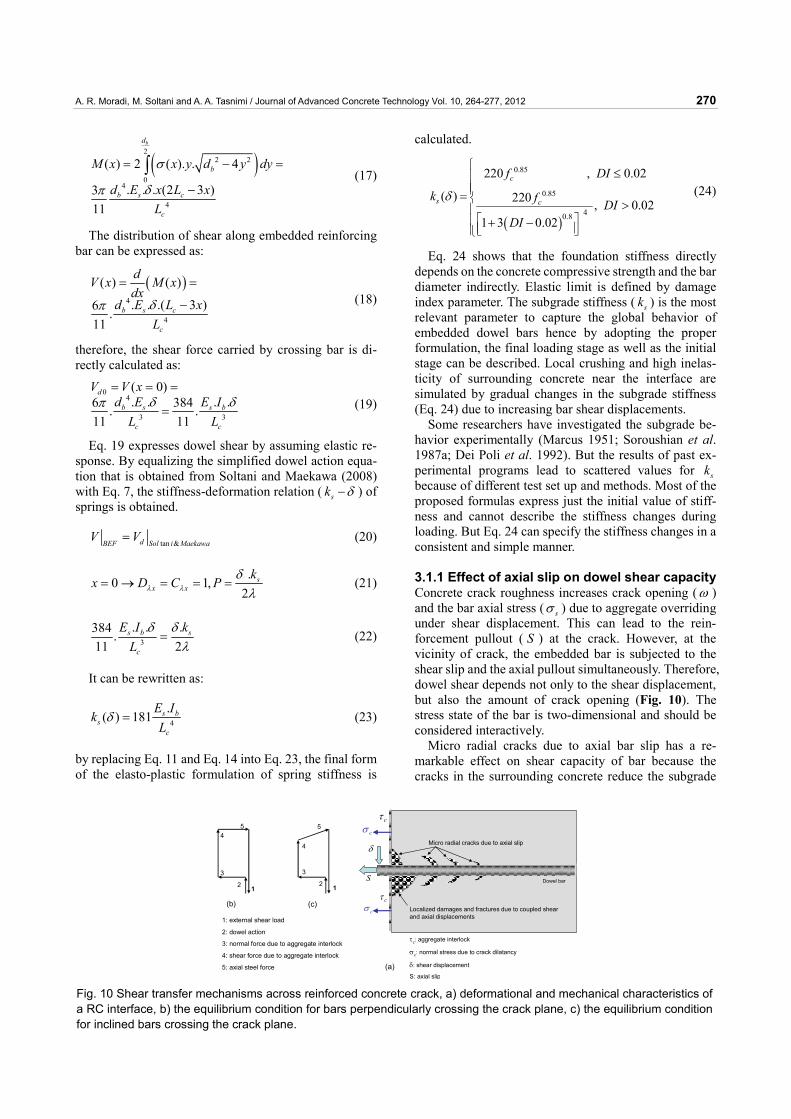
To consider the effect of the localized curvature in the bar, close to the shear plane, the concept of a Curvature Influencing Zone, cL , is introduced by Maekawa and Qureshi (1996b). They experimentally evaluated the induced curvature of crossing bars under applied shear deformation. The shape of curvature profile, ( )xφ within the zone (Fig. 9) is considered as:
( )2
max2
2
max2
3. .,
2( )
3. 3. 3. . . , 0
2 4 2
c cc
c
c cc c
c
L x Lx L
Lx
L Lx L L x x
L
φ
φφ
−≤ <
=−
− − − ≤ <
⎧⎪⎪⎨
⎡ ⎤⎛ ⎞ ⎛ ⎞⎪⎢ ⎥⎜ ⎟⎜ ⎟⎪ ⎝ ⎠⎝ ⎠⎣ ⎦⎩
(8)
max 2
64.11 cL
δφ = (9)
Since dowel shear is defined as the amount of shear at the shear plane ( 0x = ), we focus on the first portion of the zone.
2max
2
3 3( ) . 3 . .2 4
02
cc c
c
c
Lx x L L x
LL
x
φφ
⎡ ⎤⎛ ⎞ ⎛ ⎞= − − − −⎢ ⎥⎜ ⎟⎜ ⎟ ⎝ ⎠⎝ ⎠⎢ ⎥⎣ ⎦≤ <
(10)
When the applied shear deformation is too small, the bar and surrounding concrete remains elastic so cL can be computed from the BEF analogy. The gradual cracks and damages in concrete due to increasing bar shear displacements (δ ) are modeled by considering an in-crease in cL as a function of initial value of 0cL by defining a non-dimensional damage index ( DI ) as fol-lows:
4043
4 .s b
cfc b
E IL
k dπ
= (11)
'0.85150 cfc
b
fk
d= (12)
b
DIdδ
= (13)
00.8
0
0.02
1 3( 0.02) 0.02c c
c c
L L for DI
L L DI for DI⎡ ⎤⎣ ⎦
= ≤
= + − > (14)
where bd and cf are bar diameter and concrete com-pressive strength, respectively. The reinforcing bar strain field can be determined if the distribution of curvature is known. So:
4
. .(2 3 )192( , ) ( ). .11
c
c
x L x yx y x y
Lδ
ε φ−
= = (15)
where y is the local coordinate of bar cross section. Assuming linear elastic behavior for both concrete and reinforcing bar, the local stress of bar, ( , )x yσ is calcu-lated.
4
. .(2 3 )192( , ) ( , ). . .
11c
s s
c
x L x yx y x y E E
Lδ
σ ε−
= = (16)
the bending moment, ( )M x is computed from the local stress.
δ
Reinforcing bar2max 11
64
cLδφ =
2
2max ).(3)(
c
c
LxLx −
=φφ
⎥⎥⎦
⎤
⎢⎢⎣
⎡⎟⎠⎞
⎜⎝⎛ −−⎟
⎠⎞
⎜⎝⎛ −
−= xLLxL
Lx cc
c
c 43.
2.3.3)(
2
2maxφφ
Fig. 9 Curvature distribution within Curvature Influencing Zone ( cL ).
A. R. Moradi, M. Soltani and A. A. Tasnimi / Journal of Advanced Concrete Technology Vol. 10, 264-277, 2012 270
( )2
2 2
04
4
( ) 2 ( ). . 4
. . . (2 3 )311
bd
b
b s c
c
M x x y d y dy
d E x L xL
σ
δπ
= − =
−
∫ (17)
The distribution of shear along embedded reinforcing bar can be expressed as:
( )4
4
( ) ( )
. . .( 3 )6 .11
b s c
c
dV x M xdx
d E L xLδπ
= =
− (18)
therefore, the shear force carried by crossing bar is di-rectly calculated as:
04
3 3
( 0). . . .6 384. .
11 11
d
b s s b
c c
V V xd E E I
L Lδ δπ
= = =
= (19)
Eq. 19 expresses dowel shear by assuming elastic re-sponse. By equalizing the simplified dowel action equa-tion that is obtained from Soltani and Maekawa (2008) with Eq. 7, the stiffness-deformation relation ( sk δ− ) of springs is obtained.
tan &dBEF Sol i MaekawaV V= (20)
.0 1,
2s
x xk
x D C Pλ λδλ
= → = = = (21)
3
. . .384 .11 2
s b s
c
E I kL
δ δλ
= (22)
It can be rewritten as:
4
.( ) 181 s b
sc
E Ik
Lδ = (23)
by replacing Eq. 11 and Eq. 14 into Eq. 23, the final form of the elasto-plastic formulation of spring stiffness is
calculated.
( )
0.85
0.85
40.8
220 , 0.02
( ) 220 , 0.021 3 0.02
c
s c
f DI
k f DIDI
δ
⎧⎪⎪⎪⎨⎪⎡ ⎤⎪⎢ ⎥⎪ ⎣ ⎦⎩
≤
=>
+ −
(24)
Eq. 24 shows that the foundation stiffness directly depends on the concrete compressive strength and the bar diameter indirectly. Elastic limit is defined by damage index parameter. The subgrade stiffness ( sk ) is the most relevant parameter to capture the global behavior of embedded dowel bars hence by adopting the proper formulation, the final loading stage as well as the initial stage can be described. Local crushing and high inelas-ticity of surrounding concrete near the interface are simulated by gradual changes in the subgrade stiffness (Eq. 24) due to increasing bar shear displacements.
Some researchers have investigated the subgrade be-havior experimentally (Marcus 1951; Soroushian et al. 1987a; Dei Poli et al. 1992). But the results of past ex-perimental programs lead to scattered values for sk because of different test set up and methods. Most of the proposed formulas express just the initial value of stiff-ness and cannot describe the stiffness changes during loading. But Eq. 24 can specify the stiffness changes in a consistent and simple manner.
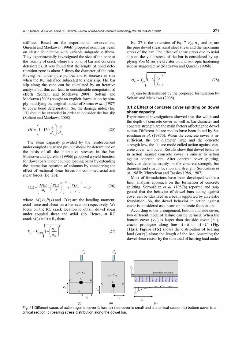
3.1.1 Effect of axial slip on dowel shear capacity Concrete crack roughness increases crack opening (ω ) and the bar axial stress ( sσ ) due to aggregate overriding under shear displacement. This can lead to the rein-forcement pullout ( S ) at the crack. However, at the vicinity of crack, the embedded bar is subjected to the shear slip and the axial pullout simultaneously. Therefore, dowel shear depends not only to the shear displacement, but also the amount of crack opening (Fig. 10). The stress state of the bar is two-dimensional and should be considered interactively.
Micro radial cracks due to axial bar slip has a re-markable effect on shear capacity of bar because the cracks in the surrounding concrete reduce the subgrade
cτcσ
δ
S
cτcσ Localized damages and fractures due to coupled shear
and axial displacements
Micro radial cracks due to axial slip
Dowel bar
τc: aggregate interlock
σc: normal stress due to crack dilatancy
δ: shear displacement
S: axial slip
12
3
4
5
12
3
45
(b) (c)
1: external shear load
2: dowel action
3: normal force due to aggregate interlock
4: shear force due to aggregate interlock
5: axial steel force (a)
Fig. 10 Shear transfer mechanisms across reinforced concrete crack, a) deformational and mechanical characteristics of a RC interface, b) the equilibrium condition for bars perpendicularly crossing the crack plane, c) the equilibrium condition for inclined bars crossing the crack plane.
A. R. Moradi, M. Soltani and A. A. Tasnimi / Journal of Advanced Concrete Technology Vol. 10, 264-277, 2012 271
stiffness. Based on the experimental observations, Qureshi and Maekawa (1996b) proposed nonlinear beam on elastic foundation with variable subgrade stiffness. They experimentally investigated the size of the zone at the vicinity of crack where the bond of bar and concrete deteriorates. It was found that the length of bond dete-rioration zone is about 5 times the diameter of the rein-forcing bar under pure pullout and to increase in size when the RC interface subjected to shear slip. The bar slip along the zone can be calculated by an iterative analysis but this can lead to considerable computational efforts (Soltani and Maekawa 2008). Soltani and Maekawa (2008) sought an explicit formulation by sim-ply modifying the original model of Shima et al. (1987) to cover bond deterioration. So, the damage index (Eq. 13) should be extended in order to consider the bar slip (Soltani and Maekawa 2008):
1 150 .b b
SDId d
δ⎛ ⎞= +⎜ ⎟⎝ ⎠
(25)
The shear capacity provided by the reinforcement under coupled shear and pullout should be determined on the basis of all the interactive stresses in the bar. Maekawa and Qureshi (1996b) proposed a yield function for dowel bars under coupled loading paths by extending the interaction equation of columns by considering the effect of sectional shear forces for combined axial and shear forces (Eq. 26):
22 2
0 0 0
( ) ( ) ( )( ) 1.0M x P x V xxM P V
λ⎡ ⎤⎛ ⎞ ⎡ ⎤⎢ ⎥⎜ ⎟ ⎢ ⎥⎜ ⎟⎢ ⎥ ⎢ ⎥⎝ ⎠ ⎣ ⎦⎣ ⎦
= + + = (26)
where ( ), ( )M x P x and ( )V x are the bending moment, axial force and shear on a bar section respectively. We focus on the RC crack location to obtain dowel shear under coupled shear and axial slip. Hence, at RC crack ( 0) 0M x = = , then:
4
00
. 1 sd dV V
σσ⎛ ⎞
= − ⎜ ⎟⎝ ⎠
(27)
Eq. 27 is the extension of Eq. 7 0 0,dV σ and sσ are the pure dowel shear, axial steel stress and the maximum stress of the bar. The effect of shear stress due to axial slip on the yield stress of the bar is considered by ap-plying Von Mises yield criterion and isotropic hardening rule as suggested by (Maekawa and Qureshi 1996b):
2
0 1 3 dy
y
Vf
fσ
⎛ ⎞= − ⎜ ⎟⎜ ⎟
⎝ ⎠ (28)
sσ can be determined by the proposed formulation by Soltani and Maekawa (2008).
3.1.2 Effect of concrete cover splitting on dowel shear capacity Experimental investigations showed that the width and the depth of concrete cover as well as bar diameter and concrete strength are the main factors affecting the dowel action. Different failure modes have been found by So-roushian et al. (1987b). When the concrete cover is in-sufficient, the bar diameter large and the concrete strength low, the failure mode called action against con-crete cover, will occur. Results show that dowel behavior in action against concrete cover is similar to action against concrete core. After concrete cover splitting, behavior depends mainly on the concrete strength, bar diameter and stirrup location and strength (Soroushian et al. 1987b; Vintzeleou and Tassios 1986, 1987).
Most of formulations have been developed within a limit analysis approach on the formation of concrete splitting. Soroushian et al. (1987b) reported and sug-gested that the behavior of dowel bars acting against cover can be idealized as a beam supported by an elastic foundation. So, the dowel behavior in action against cover is considered as a beam on inelastic foundation.
According to bar arrangement, bottom and side cover, two different mode of failure can be defined. When the bottom cover ( bc ) is larger than the side cover ( sc ), cracks propagate along line A B− or A C− (Fig. 11(a)). Figure 11(c) shows the distribution of bearing load ( ( )xω ) along the length of the bar. Assuming the dowel shear resists by the sum total of bearing load under
sc
bc
bs cc <
dVdV
ABC
bs cc >
D
sc
bc
A BC
D
iL
dV
Embedded dowel bar
(a) (b) (c) Fig. 11 Different cases of action against cover failure, a) side cover is small and is a critical section, b) bottom cover is a critical section, c) bearing stress distribution along the dowel bar.
A. R. Moradi, M. Soltani and A. A. Tasnimi / Journal of Advanced Concrete Technology Vol. 10, 264-277, 2012 272
the dowel bar from the shear plane up to the inflection point, as follows:
( ) ( ) 2 . . .cos( )xdx V x P e xdx
λω λ λ−= = (29)
( ) 02ix L πωλ
= → = (30)
2
0
. 1.21dV dx P
πλ
ω= =∫ (31)
where
.2sk
Pδλ
= (32)
where ( ), ix Lω are the distribution of bearing stress along length of the bar and the length of inflection point, respectively. Eq. 31 determines the dowel shear when the side cover is insufficient in comparison to the bottom cover. Reduction in spring stiffness ( sk ) increases the length of inflection point and causes reduction in corre-sponding shear.
When the bottom cover is small enough in comparison with the side cover, crack propagation starts under the dowel bar. The normal stress at point A is smaller than in the side cover splitting case. In this case, the sum of total of bearing loads overestimates the dowel shear and is reduced by the ratio of the bottom cover to the side cover.
1.21. .vd
s
cV P
c⎛ ⎞
= ⎜ ⎟⎝ ⎠
(33)
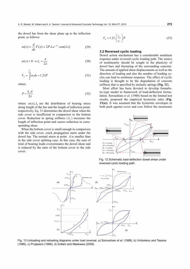
3.2 Reversed cyclic loading Dowel action mechanism has a considerable nonlinear response under reversed cyclic loading path. The source of nonlinearity should be sought in the plasticity of dowel bars and fracturing of the surrounding concrete. The amount of applied shear displacements as well as the direction of loading and also the number of loading cy-cles can lead to nonlinear response. The effect of cyclic loading is thought to be the degradation of concrete stiffness that is specified by inelastic springs (Fig. 12).
Most effort has been devoted to develop formalis-tic-type model in framework of load-deflection formu-lation. Soroushian et al. (1988) based on the limited test results, proposed the empirical hysteretic rules (Fig. 13(a)). It was assumed that the hysteretic envelopes in both push against cover and core follow the monotonic
loadingDEUnloadingCDLoadingBCUnloadingABLoadingOA
Re→→→→→
Vd
δ
A
B
C
D
maxδ
maxdV
pδpδminδ
mindV
δ
δ
δ
δ E
O
Fig. 12 Schematic load-deflection dowel shear under reversed cyclic loading path.
δ
dV
max25.0 V
max75.0 V
maxV
min75.0 V
min25.0 V
Monotonic curve
1K
2K
1K
δ
dV
minδ min8.0 δ min25.0 δ
max25.0 δ max7.0 δ maxδ
max1.0 V
max).1711( VnV −−=+
min70.0 V
Monotonic curve
n=no. of cycles
δ
dV
maxδmax25.0 δ
1K
2K
3K
3K
2K
yb fd ..1.0 2
dV75.0
maxVdV
δ
max4.0 δδ =p
min4.0 δδ =p
maxδ
maxV
minδ
minV
(a) (b)
(c) (d)
Fig. 13 Unloading and reloading diagrams under load reversal, a) Soroushian et al. (1988), b) Vintzeleou and Tassios (1986), c) Pruijssers (1988), d) Soltani and Maekawa (2008).
A. R. Moradi, M. Soltani and A. A. Tasnimi / Journal of Advanced Concrete Technology Vol. 10, 264-277, 2012 273
load-deflection diagrams. The stiffness of unloading and reloading curves is constant regardless of load cycles. Pruijssers (1988) approximated the unloading and the reloading diagrams with some pre-defined constant lines. Soltani and Maekawa (2008) as well as Vintzeleou and Tassios (1986), assumed a direct proportionality between the residual plastic and the maximum (or minimum) shear displacements and expressed the unloading and reloading curves (Fig. 13(c) and (d)).
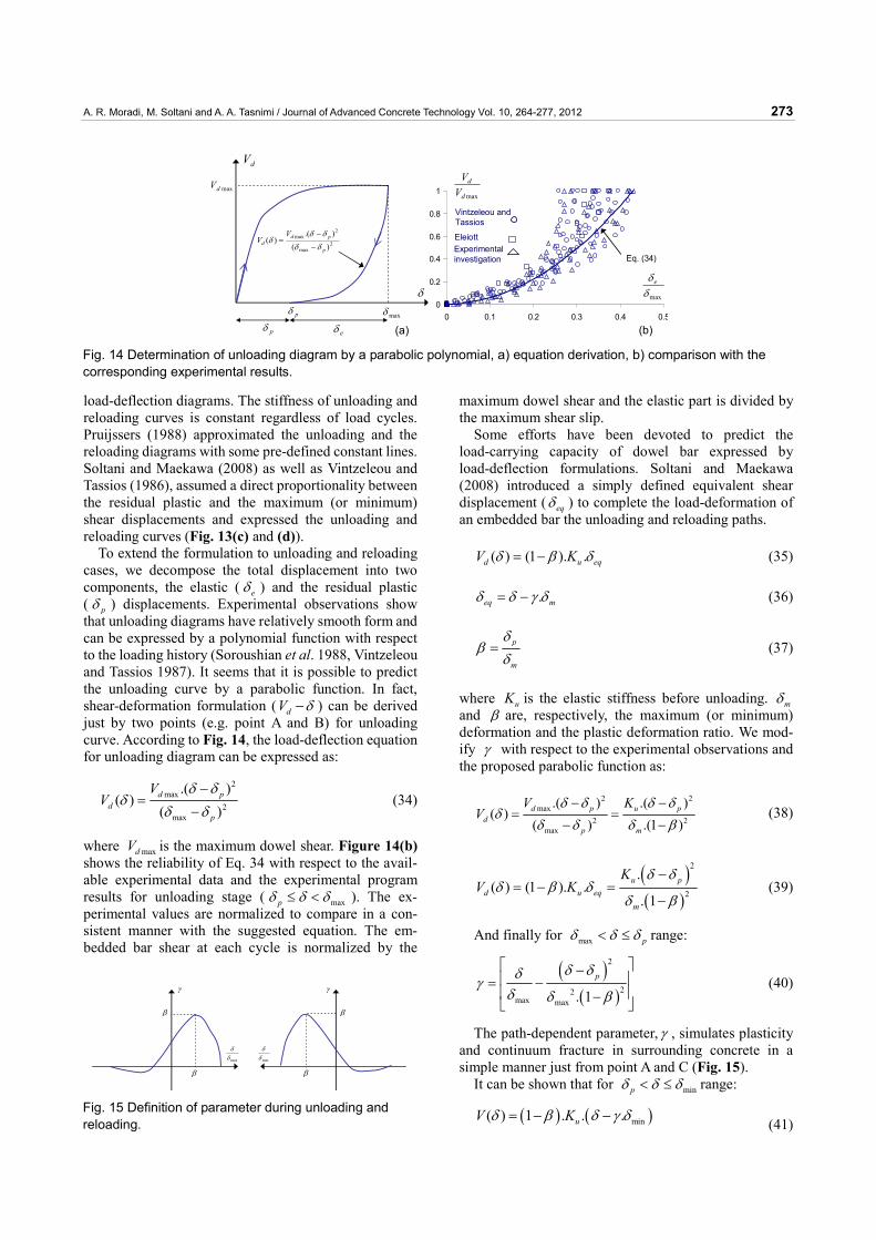
To extend the formulation to unloading and reloading cases, we decompose the total displacement into two components, the elastic ( eδ ) and the residual plastic ( pδ ) displacements. Experimental observations show that unloading diagrams have relatively smooth form and can be expressed by a polynomial function with respect to the loading history (Soroushian et al. 1988, Vintzeleou and Tassios 1987). It seems that it is possible to predict the unloading curve by a parabolic function. In fact, shear-deformation formulation ( dV δ− ) can be derived just by two points (e.g. point A and B) for unloading curve. According to Fig. 14, the load-deflection equation for unloading diagram can be expressed as:
2max
2max
.( )( )
( )d p
dp
VV
δ δδ
δ δ−
=−
(34)
where maxdV is the maximum dowel shear. Figure 14(b) shows the reliability of Eq. 34 with respect to the avail-able experimental data and the experimental program results for unloading stage ( maxpδ δ δ≤ < ). The ex-perimental values are normalized to compare in a con-sistent manner with the suggested equation. The em-bedded bar shear at each cycle is normalized by the
maximum dowel shear and the elastic part is divided by the maximum shear slip.
Some efforts have been devoted to predict the load-carrying capacity of dowel bar expressed by load-deflection formulations. Soltani and Maekawa (2008) introduced a simply defined equivalent shear displacement ( eqδ ) to complete the load-deformation of an embedded bar the unloading and reloading paths.
( ) (1 ). .d u eqV Kδ β δ= − (35)
.eq mδ δ γ δ= − (36)
p
m
δβ
δ= (37)
where uK is the elastic stiffness before unloading. mδ and β are, respectively, the maximum (or minimum) deformation and the plastic deformation ratio. We mod-ify γ with respect to the experimental observations and the proposed parabolic function as:
2 2max
2 2max
.( ) .( )( )
( ) .(1 )d p u p
dp m
V KV
δ δ δ δδ
δ δ δ β− −
= =− −
(38)
( )( )
2
2
.( ) (1 ). .
. 1u p
d u eqm
KV K
δ δδ β δ
δ β
−= − =
− (39)
And finally for max pδ δ δ< ≤ range:
( )( )
2
22max max . 1
pδ δδγδ δ β
⎡ ⎤−⎢ ⎥= −⎢ ⎥−⎣ ⎦
(40)
The path-dependent parameter, γ , simulates plasticity and continuum fracture in surrounding concrete in a simple manner just from point A and C (Fig. 15).
It can be shown that for minpδ δ δ< ≤ range:
( ) ( )min( ) 1 . . .uV Kδ β δ γ δ= − − (41)
dV
δ
maxδ
maxdV
pδ
eδpδ
2max
2max
)().(
)(p
pdd
VV
δδδδ
δ−
−=
0
0.2
0.4
0.6
0.8
1
0 0.1 0.2 0.3 0.4 0.5
maxδδe
maxd
d
VV
(a)
Eq. (34)
Vintzeleou and Tassios
EleiottExperimental investigation
(b) Fig. 14 Determination of unloading diagram by a parabolic polynomial, a) equation derivation, b) comparison with the corresponding experimental results.
β
β
maxδδ
γ
β
β
minδδ
γ
Fig. 15 Definition of parameter during unloading and reloading.
A. R. Moradi, M. Soltani and A. A. Tasnimi / Journal of Advanced Concrete Technology Vol. 10, 264-277, 2012 274
and also we have (according to Eq. 34)
( )( )
( )( )
2 2
min min2 22
minmin
( ). 1
p p
p
V VV
δ δ δ δδ
δ βδ δ
− −= =
−− (42)
we can write :
( ) ( )min min min. . . 1u p uV K Kδ δ δ β= − = − (43)
from Eq. (42) and (43):
( ) ( )( )
( )( )
2
min22
min
min
. . 1 .( )
1.
. 1
u p
u p
KV
K
δ β δ δδ
δ βδ δ
δ β
− −= =
−−
−
(44)
from Eq. (44) and (41):
( )( ) ( ) ( )
2
minmin
.1 . . .
. 1u p
u
KK
δ δβ δ γ δ
δ β
−= − −
− (45)
and finally we have
( )( )22
min min . 1pδ δδγ
δ δ β
⎡ ⎤−⎢ ⎥= −⎢ ⎥−⎣ ⎦
(46)
The value of γ for unloading and reloading conditions with a simple parabolic formulation is shown in Fig. 15. On the other hand, the proposed formulation for γ is an engineering approximation based on the experimental program and the available experimental results.
4. Calculation procedure
The calculation procedure is simple and can be summa-rized as follows:
1. Axial steel slip ( S ) and shear displacement (δ ) are considered as input.
2. From ( ,S δ ), loading condition (loading, unloading and reloading) is determined.
3. By using the path-dependent slip-strain and stress-strain relationships proposed by Shima et al (1987) and Soltani and Maekawa (2008), the steel strain and stress can be computed.
4. From the loading path, spring stiffness is computed by using (Eq. 24) during loading.
5. By using the BEF analogy, the pure dowel shear is calculated from (Eq. 7) and (Eq. 27). Also, the dowel shear can be computed from (Eq. 35-46) and (Eq. 27) during unloading and reloading. The dowel shear should be determined from (Eq. 29-33) and (Eq. 27), if the concrete cover is not sufficient.
5. Experimental verification
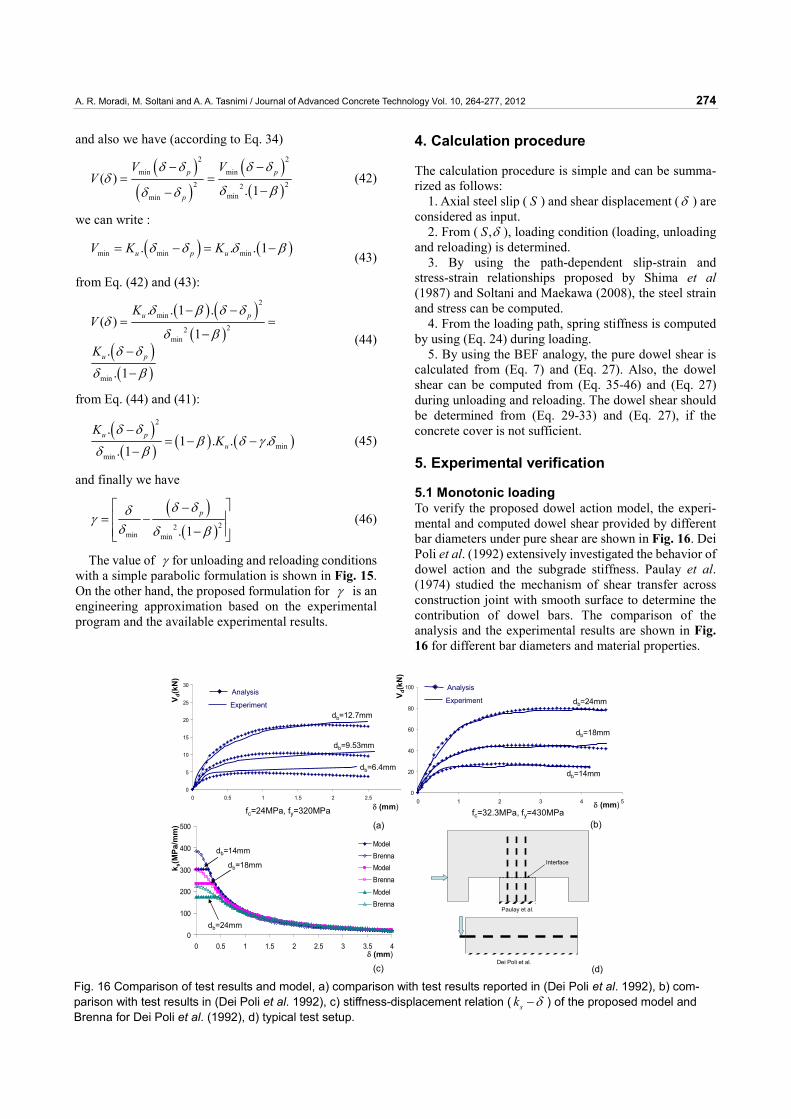
5.1 Monotonic loading To verify the proposed dowel action model, the experi-mental and computed dowel shear provided by different bar diameters under pure shear are shown in Fig. 16. Dei Poli et al. (1992) extensively investigated the behavior of dowel action and the subgrade stiffness. Paulay et al. (1974) studied the mechanism of shear transfer across construction joint with smooth surface to determine the contribution of dowel bars. The comparison of the analysis and the experimental results are shown in Fig. 16 for different bar diameters and material properties.
0
5
10
15
20
25
30
0 0.5 1 1.5 2 2.5 30
20
40
60
80
100
0 1 2 3 4 5
0
100
200
300
400
500
0 0.5 1 1.5 2 2.5 3 3.5 4
ModelBrennaModelBrenna
ModelBrenna
(b)
δ (mm)
V d(k
N)
V d(k
N)
(a)
δ (mm)
δ (mm)
k s(M
Pa/m
m)
(c)
Interface
Paulay et al.
Dei Poli et al.(d)
db=14mm
db=18mm
db=24mmAnalysis
Experiment
Analysis
Experiment
db=6.4mm
db=9.53mm
db=12.7mm
db=14mm
db=18mm
db=24mm
fc=24MPa, fy=320MPa fc=32.3MPa, fy=430MPa
Fig. 16 Comparison of test results and model, a) comparison with test results reported in (Dei Poli et al. 1992), b) com-parison with test results in (Dei Poli et al. 1992), c) stiffness-displacement relation ( sk δ− ) of the proposed model and Brenna for Dei Poli et al. (1992), d) typical test setup.
A. R. Moradi, M. Soltani and A. A. Tasnimi / Journal of Advanced Concrete Technology Vol. 10, 264-277, 2012 275
Dei Poli et al. (1992) suggested a formulation of sub-grade stiffness ( sk ) based on Brenna, Dei Poli and Di Prisco. A comparison between the proposed formulation for spring stiffness (Eq. 24) and the case described is also shown in Fig. 16(c). Satisfactory correlation can be ob-served for different specimens.
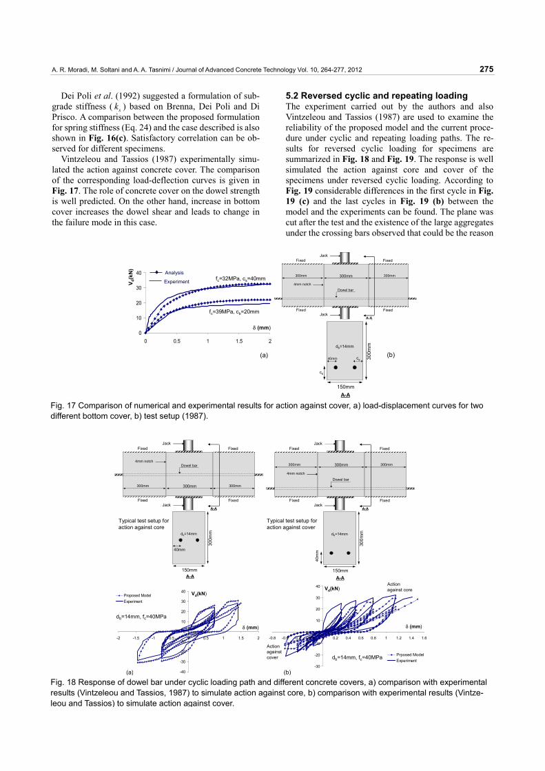
Vintzeleou and Tassios (1987) experimentally simu-lated the action against concrete cover. The comparison of the corresponding load-deflection curves is given in Fig. 17. The role of concrete cover on the dowel strength is well predicted. On the other hand, increase in bottom cover increases the dowel shear and leads to change in the failure mode in this case.
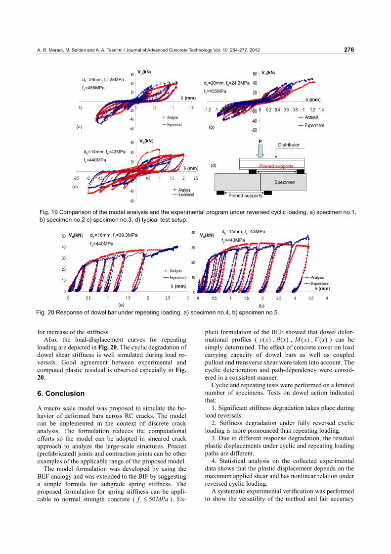
5.2 Reversed cyclic and repeating loading The experiment carried out by the authors and also Vintzeleou and Tassios (1987) are used to examine the reliability of the proposed model and the current proce-dure under cyclic and repeating loading paths. The re-sults for reversed cyclic loading for specimens are summarized in Fig. 18 and Fig. 19. The response is well simulated the action against core and cover of the specimens under reversed cyclic loading. According to Fig. 19 considerable differences in the first cycle in Fig. 19 (c) and the last cycles in Fig. 19 (b) between the model and the experiments can be found. The plane was cut after the test and the existence of the large aggregates under the crossing bars observed that could be the reason
0
10
20
30
40
0 0.5 1 1.5 2
V d(k
N)
δ (mm)
(a)
4mm notch
FixedJack
300mm 300mm 300mm
Dowel bar
A-A
Fixed
Fixed FixedJack
(b)
fc=39MPa, cb=20mm
fc=32MPa, cs=40mmAnalysis
Experiment
150mm
300m
m
A-A
db=14mm
40mm
cb
cs
Fig. 17 Comparison of numerical and experimental results for action against cover, a) load-displacement curves for two different bottom cover, b) test setup (1987).
-30
-20
-10
0
10
20
30
40
-0.8 -0.6 -0.4 -0.2 0 0.2 0.4 0.6 0.8 1 1.2 1.4 1.6
Prposed ModelExperiment
4mm notch
FixedJack
300mm 300mm 300mm
Dowel bar
A-A
Fixed
Fixed FixedJack
-40
-30
-20
-10
0
10
20
30
40
-2 -1.5 -1 -0.5 0 0.5 1 1.5 2
Proposed ModelExperiment
db=14mm, fc=40MPa
Vd(kN)
(a)
δ (mm)
db=14mm, fc=40MPa
(b)
Vd(kN)
δ (mm)
4mm notch
FixedJack
300mm 300mm 300mm
Dowel bar
A-A
Fixed
Fixed FixedJack
Typical test setup for action against core
Action against cover
Action against core
150mm
300m
m
A-A
40m
m
db=14mm
150mm
300m
m
40mm
A-A
db=14mm
Typical test setup for action against cover
Fig. 18 Response of dowel bar under cyclic loading path and different concrete covers, a) comparison with experimental results (Vintzeleou and Tassios, 1987) to simulate action against core, b) comparison with experimental results (Vintze-leou and Tassios) to simulate action against cover.
A. R. Moradi, M. Soltani and A. A. Tasnimi / Journal of Advanced Concrete Technology Vol. 10, 264-277, 2012 276
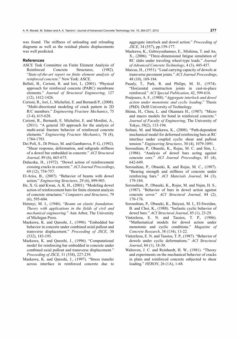
for increase of the stiffness. Also, the load-displacement curves for repeating
loading are depicted in Fig. 20. The cyclic degradation of dowel shear stiffness is well simulated during load re-versals. Good agreement between experimental and computed plastic residual is observed especially in Fig. 20.
6. Conclusion
A macro scale model was proposed to simulate the be-havior of deformed bars across RC cracks. The model can be implemented in the context of discrete crack analysis. The formulation reduces the computational efforts so the model can be adopted in smeared crack approach to analyze the large-scale structures. Precast (prefabricated) joints and contraction joints can be other examples of the applicable range of the proposed model.
The model formulation was developed by using the BEF analogy and was extended to the BIF by suggesting a simple formula for subgrade spring stiffness. The proposed formulation for spring stiffness can be appli-cable to normal strength concrete ( 50cf MPa≤ ). Ex-
plicit formulation of the BEF showed that dowel defor-mational profiles ( ( )y x , ( )xθ , ( )M x , ( )V x ) can be simply determined. The effect of concrete cover on load carrying capacity of dowel bars as well as coupled pullout and transverse shear were taken into account. The cyclic deterioration and path-dependency were consid-ered in a consistent manner.
Cyclic and repeating tests were performed on a limited number of specimens. Tests on dowel action indicated that:
1. Significant stiffness degradation takes place during load reversals.
2. Stiffness degradation under fully reversed cyclic loading is more pronounced than repeating loading.
3. Due to different response degradation, the residual plastic displacements under cyclic and repeating loading paths are different.
4. Statistical analysis on the collected experimental data shows that the plastic displacement depends on the maximum applied shear and has nonlinear relation under reversed cyclic loading.
A systematic experimental verification was performed to show the versatility of the method and fair accuracy
-60
-40
-20
0
20
40
60
-2.5 -2 -1.5 -1 -0.5 0 0.5 1 1.5 2 2.5
AnalysisExperiment
-60
-40
-20
0
20
40
60
-1.2 -1 -0.8 -0.6 -0.4 -0.2 0 0.2 0.4 0.6 0.8 1 1.2 1.4AnalysisExperiment
Vd(kN)
(b)
δ (mm)
-60
-40
-20
0
20
40
60
-1.5 -1 -0.5 0 0.5 1 1.5
AnalysisExperiment
Vd(kN)
(a)
δ (mm)
Vd(kN)
(c)
δ (mm)
Specimen
Pinned supports
PDistributor
Pinned supports(d)
db=20mm, fc=28MPa
fy=455MPadb=20mm, fc=24.2MPa
fy=455MPa
db=14mm, fc=43MPa
fy=440MPa
Fig. 19 Comparison of the model analysis and the experimental program under reversed cyclic loading, a) specimen no.1,b) specimen no.2 c) specimen no.3, d) typical test setup.
0
10
20
30
40
0 0.5 1 1.5 2 2.5 3 3.5 4
AnalysisExperiment
0
10
20
30
40
50
0 0.5 1 1.5 2 2.5 3
AnalysisExperiment
Vd(kN)
(a)
δ (mm)
Vd(kN)
δ (mm)
(b)
db=16mm, fc=39.3MPa
fy=440MPa
db=14mm, fc=43MPa
fy=440MPa
Fig. 20 Response of dowel bar under repeating loading, a) specimen no.4, b) specimen no.5.
A. R. Moradi, M. Soltani and A. A. Tasnimi / Journal of Advanced Concrete Technology Vol. 10, 264-277, 2012 277
was found. The stiffness of unloading and reloading diagrams as well as the residual plastic displacements was well predicted.
References ASCE Task Committee on Finite Element Analysis of
Reinforced Concrete Structures, (1982). “State-of-the-art report on finite element analysis of reinforced concrete.” New York: ASCE.
Belleti, B., Cerioni, R. and Iori, I., (2001). “Physical approach for reinforced concrete (PARC) membrane elements.” Journal of Structural Engineering, 127 (12), 1412-1426.
Cerioni, R., Iori, I., Michelini, E. and Bernardi P., (2008). “Multi-directional modeling of crack pattern in 2D R/C members.” Engineering Fracture Mechanics, 75 (3-4), 615-628.
Cerioni, R., Bernardi, E. Michelini, E. and Mordini, A., (2011). “A general 3D approach for the analysis of multi-axial fracture behavior of reinforced concrete elements.” Engineering Fracture Mechanics, 78 (8), 1784-1793.
Dei Poli, S., Di Prisco, M. and Gambarova, P. G., (1992). “Shear response, deformation, and subgrade stiffness of a dowel bar embedded in concrete.” ACI Structural Journal, 89 (6), 665-675.
Dulacska, H., (1972). “Dowel action of reinforcement crossing cracks in concrete.” ACI Journal Proceedings, 69 (12), 754-757.
El-Ariss, B., (2007). “Behavior of beams with dowel action.” Engineering Structures, 29 (6), 899-903.
He, X. G. and Kwan, A. K. H., (2001). “Modeling dowel action of reinforcement bars for finite element analysis of concrete structures.” Computers and Structures, 79 (6), 595-604.
Hetenyi, M. I., (1946). “Beams on elastic foundation: Theory with applications in the fields of civil and mechanical engineering.” Ann Arbor, The University of Michigan Press.
Maekawa, K. and Qureshi, J., (1996). “Embedded bar behavior in concrete under combined axial pullout and transverse displacement.” Proceeding of JSCE, 30 (532), 183-195.
Maekawa, K. and Qureshi, J., (1996). “Computational model for reinforcing bar embedded in concrete under combined axial pullout and transverse displacement.” Proceeding of JSCE, 31 (538), 227-239.
Maekawa, K. and Qureshi, J., (1997). “Stress transfer across interface in reinforced concrete due to
aggregate interlock and dowel action.” Proceeding of JSCE, 34 (557), pp.159-177.
Maekawa, K., Gebreyouhannes, E., Mishima, T. and An, X., (2006). “Three-dimensional fatigue simulation of RC slabs under traveling wheel-type loads.” Journal of Advanced Concrete Technology, 4 (3), 445-457.
Marcus, H., (1951). “Load carrying capacity of dowels at transverse pavement joints.” ACI Journal Proceedings, 48 (10), 169-184.
Paualy, T., Park, R. and Philips, M. H., (1974). “Horizontal construction joints in cast-in-place reinforced.” ACI Special Publication, 42, 599-616.
Pruijssers, A. F., (1988). “Aggregate interlock and dowel action under monotonic and cyclic loading.” Thesis (PhD). Delft University of Technology.
Shima, H., Chou, L. and Okamura H., (1987). “Micro and macro models for bond in reinforced concrete.” Journal of Faculty of Engineering, The University of Tokyo, 39(2), 133-194.
Soltani, M. and Maekawa, K., (2008). “Path-dependent mechanical model for deformed reinforcing bars at RC interface under coupled cyclic shear and pullout tension.” Engineering Structures, 30 (4), 1079-1091.
Soroushian, P., Obaseki, K., Rojas, M. C. and Sim, J., (1986). “Analysis of dowel bars acting against concrete core.” ACI Journal Proceedings, 83 (4), 642-649.
Soroushian, P., Obaseki, K. and Rojas, M. C., (1987). “Bearing strength and stiffness of concrete under reinforcing bars.” ACI Materials Journal, 84 (3), 179-184.
Soroushian, P., Obaseki, K., Rojas, M. and Najm, H. S., (1987). “Behavior of bars in dowel action against concrete cover.” ACI Structural Journal, 84 (2), 170-176.
Soroushian, P., Obaseki, K., Baiyasi, M. I., El-Sweidan, B. and Choi, K., (1988). “Inelastic cyclic behavior of dowel bars.” ACI Structural Journal, 85 (1), 23-29.
Vintzeleou, E. N. and Tassios, T. P., (1986). “Mathematical models for dowel action under monotonic and cyclic conditions.” Magazine of Concrete Research, 38 (134), 13-22.
Vintzeleou, E. N. and Tassios, T. P., (1987). “Behavior of dowels under cyclic deformations.” ACI Structural Journal, 84 (1), 18-30.
Walraven, J. C. and Reinhardt, H. W., (1981). “Theory and experiments on the mechanical behavior of cracks in plain and reinforced concrete subjected to shear loading.” HERON, 26 (1A), 1-68.