a project report on \" intelligent robotic arm \" submitted to innovation cell iit, bombay
TRANSCRIPT

Intelligent Robotic Arm 1
A PROJECT REPORT ON
“Intelligent Robotic Arm”
Submitted to
Innovation Cell
IIT, Bombay
By
Nikhil Sawake
Electronics and Communication Engineering
Visvesvaraya National Institute of Technology, Nagpur
JULY, 2013

Intelligent Robotic Arm 2
ACKNOWLEDGEMENT
I hereby express my sincere thanks to respected Dr. Abhishek Gupta Sir
for giving me the chance to be the part of this project.
I also take an opportunity to express my deep sense gratitude to
Innovation Cell, IIT Bombay for providing all the required facilities and
inspiration in bringing out this project work.
I am indebted to my mentor Ms. Kriti Gupta who always guided and
helped me whenever needed.
And last but not the least, I express my thanks to my friends Mr. Nilesh
and Ugale Mr. Ashish Ghatge for their keen advice and valuable cooperation
during completion of this project.

Intelligent Robotic Arm 3
INDEX
SR.NO. TOPIC
1. Abstract
2. Introduction
3. Experimental Setup
4. Hardware Implementation
5. Kinematics
6. Catching Area Estimation in MATLAB
7. Servo Motor (Actuators)
8. Control Unit
9. RS232 Standard
10. Image Processing Algorithm
11. Possible Improvements

Intelligent Robotic Arm 4
ABSTRACT:
This report presents a ball catching robotic arm system with 2 DOF
assembled from the commercially available parts. Other than the previous
research works where a complex systems were designed, I have designed a
very simple arm which is able to catch the ball which is thrown in a specified
2-diamentional region in a horizontal plane. The given robotic arm system is
low cost implementation compared to the previous ones. In this system, a
single camera system is used as a sensor to perceive the trajectory of the ball.
The environment is first captured as an image using a webcam which is
mounted above the whole region. Image processing methods are then
performed to identify the location of the ball within the environment.
Program is written in C language using openCV library functions which runs
in Microsoft Visual Studio on a computer. It calculates the centroid of the
identified color intensity and according to that it sends the control
commands over the serial port to the controller of robotic arm via RS-232
port. The basic objective is to catch the specific colored ball in the specified
region. The proposed method does not make use of any other type of sensor
other than the webcam.

Intelligent Robotic Arm 5
INTRODUCTION:
Image processing is a form of signal processing where the input signals
are images such as photographs or video frames. The output could be a
transformed version of the input image or a set of characteristics or
parameters related to the image. The computer revolution that has taken
place over the last 20 years has led to great advancements in the field of
digital image processing. This has in turn, opened up a multitude of
applications in various fields, in which the technology could be utilized.
The aim of this project is to present a method for visual servo control
using only visual images from a webcam. Visual servo is the use of image
data in closed loop control of a robot. Without doubt, today, the use of
vision in robotic applications is rapidly increasing. This is due to the fact
that vision based sensors such as webcams are falling in price more rapidly
than any other sensor. It is also a richer sensor than traditional ranging
devices, particularly since a camera captures much more data
simultaneously.
Images can be captured by camera, and subsequently, processed using
some particular software or directly using standard OpenCV library
functions. OpenCV (open source computer vision library) is a library of
programming functions mainly aimed at real time computer vision which
focuses mainly on real time image processing. Information obtained from the
image processing exercise can then be used to generate motion commands to
be sent to the robotic system.
Catching a moving object with a hand is one of the most difficult tasks
for humans as well as for robot systems. In order for a robot to catch a
moving object, the pose of the object must be determined. When the
trajectory of the object is known, the object motion can be calculated.
Common approaches to utilizing vision information for controlling robotic
manipulators are the (i) position (velocity) control and the (ii) image feature
control (color).
The goal of my work is to visually track a ball thrown in a region and
send the data to the robotic arm to move for catching the ball at expected

Intelligent Robotic Arm 6
location. The most important problem that had to be addressed is that of
selecting the feature to use for segmenting the ball. Using approach where to
detect the ball by its shape is not an efficient approach, in this approach we
have require to set our background static or stable because here tracking of
moving object is obtained by computing the difference between the actual
image (new frame) and some reference image i.e. background image which is
static. This is very difficult when we used our system in real time constraints.
Instead we using color of the object in which we just take care about the
lightning conditions we never bother about setting the threshold value of
background with the original object.
In this report I present a ball catching robotic arm setup, which
significantly differs in two aspects from previous research. First, I develop a
robotic arm with commercially available parts with a low cost. This is
challenging for me to build an arm with such a low cost because the
hardware and motors of the arm has to be able to reach to the ball fast
enough and in addition it has to be light weight, so that the impact of the
weight doesn’t effects the motors. Moreover, this is also challenging for me to
implement the algorithms for the arm movements, because all the work here
is to be carried out for the real time results so we need such algorithms which
are more efficient than the previous work and also which are able to work on
my robotic arm setup.
The second new aspect is, that, instead of using dual or stereo vision
cameras (300 fps) I used a 60 fps camera to determine the ball and to
calculate its trajectory. The image processing algorithm is used here
responsible for tracking ball and determines location of ball in real time. A
TSOP based obstacle sensor is also used which is mounted at the end
effector, which actually tells whether the end effector is reached to the ball or
not. At the end effector a simple hoop is used to catch the ball. So using these
simple steps I am here able to calculate the trajectory of ball and the joint
angles of the arm which then allows the arm to move up to the ball.
Intelligent Robotic Arm 7
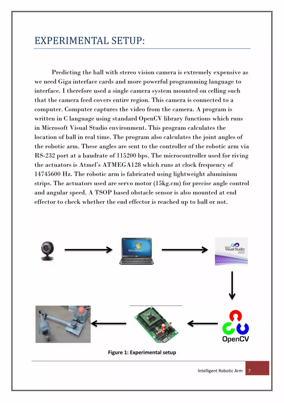
EXPERIMENTAL SETUP:
Predicting the ball with stereo vision camera is extremely expensive as
we need Giga interface cards and more powerful programming language to
interface. I therefore used a single camera system mounted on celling such
that the camera feed covers entire region. This camera is connected to a
computer. Computer captures the video from the camera. A program is
written in C language using standard OpenCV library functions which runs
in Microsoft Visual Studio environment. This program calculates the
location of ball in real time. The program also calculates the joint angles of
the robotic arm. These angles are sent to the controller of the robotic arm via
RS-232 port at a baudrate of 115200 bps. The microcontroller used for riving
the actuators is Atmel’s ATMEGA128 which runs at clock frequency of
14745600 Hz. The robotic arm is fabricated using lightweight aluminium
strips. The actuators used are servo motor (15kg.cm) for precise angle control
and angular speed. A TSOP based obstacle sensor is also mounted at end
effector to check whether the end effector is reached up to ball or not.
Figure 1: Experimental setup

Intelligent Robotic Arm 8
HARDWARE IMPLEMENTATION:
As mentioned earlier the links are fabricated using lightweight
aluminium strips. Aluminium was chosen as the appropriate material
because of its low density and reasonable strength. The main challenge was
to keep the weight as minimum as possible as weight of links is directly
proportional to the torque required. Standard caster wheels are used to give
the support to the whole mechanical assembly. To actuate this assembly, a
servo motor is used at each joint. The torque required was calculated and
servo motor of 15kg.cm torque rating chosen. These servo motors are driven
to the angles which are received from computer to the microcontroller. The
maximum angle of rotation of these servo motors is 130 degrees. The actual
length of both kinks is equal to 40cm, hence accordingly reachable area for
the end effector was estimated. The design of end effector is very simple. I
have used a hoop which is dropped on the ball when end effector reaches the
ball. To drop this hoop a servo motor 6kg.cm torque rating is used. To check
whether the end effector is reached the ball or not, a TSOP based obstacle
sensor is used. The range of this sensor can calibrated according to expected
distance of ball from end effector. This sensor gives high voltage level at its
output when there is no obstacle in front of it, and it gives low voltage level
when ball comes in front of it. Hence when the low voltage level is detected
at the output, the hoop is dropped on the ball.
(a) (b) (c)
Figure 2: (a)Base, (b)First link, (c)Second link

Intelligent Robotic Arm 9
End effector TSOP sensor Servo motor
Figure 3: Complete mechanical arm assembly
Robotic arm specifications:
o Length:
- First link (L1) = 40cm
- Second link (L2) = 40cm
o Maximum angular rotation:
- First link (Theta1) = 130degrees
- Second link (Theta2) = 130 degrees
o Torque rating:
- First servo motor (S1) = 15kg.cm
- Second servo motor (S2) = 15kg.cm
- Third servo motor (S3) = 6kg.cm

Intelligent Robotic Arm 10
KINEMATICS:
Kinematics is the science of motion. In a two-joint robotic arm, given
the angles of the joints, the kinematics equations give the location of the tip
of the arm. Inverse kinematics refers to the reverse process, given a desired
location for the tip of the robotic arm, what should the angles of the joints be
so as to locate the tip of the arm at the desired location. There is usually
more than one solution and can at times be a difficult problem to solve.
This is a typical problem in robotics that needs to be solved to control
a robotic arm to perform tasks it is designated to do. In a 2-dimensional
input space, with a two-joint robotic arm and given the desired co-ordinate,
the problem reduces to finding the two angles involved. The first angle is
between the first arm and the ground (or whatever it is attached to). The
second angle is between the first arm and the second arm.
Figure 4: Illustration showing the two-joint robotic arm with the two angles

Intelligent Robotic Arm 11
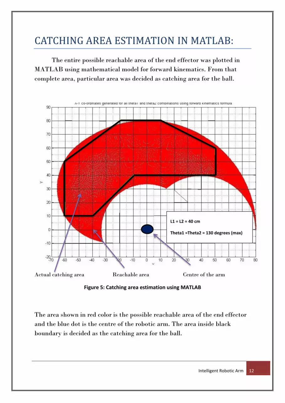
In this case the lengths of both the links are known which equal to
40cm. Therefore using forward kinematics, we can calculate the whole
reachable area of the end effector. This helps in estimating the catching area
of the ball. First the reachable area of end effector was calculated in
MATLAB. Then from that reachable area, a particular area was decided was
as catching area for ball. The inverse kinematics model is implemented in
code running in computer to calculate the joint angles for servo motor using
the co-ordinates of ball which are obtained from image processing algorithm.
Mathematical model for forward kinematics:
X = l1 * cos (THETA1) + l2 * cos (THETA1 + THETA2); % x coordinates
Y = l1 * sin (THETA1) + l2 * sin (THETA1 + THETA2); % y coordinates
Mathematical model for inverse kinematics:
c = (X*X + Y*Y – l1*l1 - l2*l2) / (2*l1*l2);
s = sqrt (1 – c*c);
k1 = l1 + l2*c;
k2 = l2*s;
THETA1 = atan2 (Y, X) – atan2 (k2, k1); % theta1 is deduced
THETA2 = atan2(s, c); % theta2 is deduced
Intelligent Robotic Arm 12
CATCHING AREA ESTIMATION IN MATLAB:
The entire possible reachable area of the end effector was plotted in
MATLAB using mathematical model for forward kinematics. From that
complete area, particular area was decided as catching area for the ball.
Actual catching area Reachable area Centre of the arm
Figure 5: Catching area estimation using MATLAB
The area shown in red color is the possible reachable area of the end effector
and the blue dot is the centre of the robotic arm. The area inside black
boundary is decided as the catching area for the ball.
L1 = L2 = 40 cm
Theta1 =Theta2 = 130 degrees (max)

Intelligent Robotic Arm 13
SERVO MOTOR (ACTUATORS):
Servo refers to an error sensing feedback control which is used to
correct the performance of a system. Servo or RC Servo Motors are DC
motors equipped with a servo mechanism for precise control of angular
position. The RC servo motors usually have a rotation limit from 90° to
180°. But servos do not rotate continually. Their rotation is restricted in
between the fixed angles. The Servos are used for precision positioning. They
are used in robotic arms and legs, sensor
scanners and in RC toys like RC helicopter,
airplanes and cars.
The Servo Motors come with three wires
or leads. Two of these wires are to provide
ground and positive supply to the servo DC
motor. The third wire is for the control signal.
These wires of a servo motor are colour coded.
The red wire is the DC supply lead and must be
connected to a DC voltage supply in the range of 4.8 V to 6V. The black wire
is to provide ground. The color for the third wire (to provide control signal)
varies for different manufacturers. It can be yellow (in case of Hitec), white
(in case of Futaba), brown etc. Unlike DC motors, reversing the ground and
positive supply connections does not change the direction (of rotation) of a
servo. This may, in fact, damage the servo motor. That is why it is
important to properly account for the order of wires in a servo motor.
Figure 7: Working of servo motor system
Figure 6: Servo motor

Intelligent Robotic Arm 14
A servo motor mainly consists of a DC motor, gear system, a position
sensor which is mostly a potentiometer, and control electronics. The DC
motor is connected with a gear mechanism which provides feedback to a
position sensor which is mostly a potentiometer. From the gear box, the
output of the motor is delivered via servo spline to the servo arm. The
potentiometer changes position corresponding to the current position of the
motor. So the change in resistance produces an equivalent change in voltage
from the potentiometer. A pulse width modulated signal is fed through the
control wire. The pulse width is converted into an equivalent voltage that is
compared with that of signal from the potentiometer in an error amplifier.
The servo motor can be moved to a desired angular position by sending
PWM (pulse width modulated) signals on the control wire. The servo
understands the language of pulse position modulation. A pulse of width
varying from 1 millisecond to 2 milliseconds in a repeated time frame is sent
to the servo for around 50 times in a second. The width of the pulse
determines the angular position.
Figure 8: PWM signal vs. angular rotation of servo motor
For example, a pulse of 1 millisecond moves the servo towards 0°,
while a 2 milliseconds wide pulse would take it to 180°. The pulse width for

Intelligent Robotic Arm 15
in between angular positions can be interpolated accordingly. Thus a pulse of
width 1.5 milliseconds will shift the servo to 90°.
It must be noted that these values are only the approximations. The
actual behavior of the servos differs based on their manufacturer.
A sequence of such pulses (50 in one second) is required to be passed to
the servo to sustain a particular angular position. When the servo receives a
pulse, it can retain the corresponding angular position for next 20
milliseconds. So a pulse in every 20 millisecond time frame must be fed to the
servo. The required pulse train for controlling the servo motor can be
generated by a timer IC such as IC 555 or a microcontroller can be
programmed to generate the required waveform.

Intelligent Robotic Arm 16
CONTROL UNIT:
Control unit refers to an electronic system which takes inputs from the
various sensors which collect data from the environment and can drive the
output devices according to the conditions which are applied due to various
constraints. The control unit consists of a programmable logic device called
microcontroller. The microcontroller is a type of electronic device which can
be pre-programmed according to our requirements. Every microcontroller
has various input and output pins where different I/O devices can be
connected. The microcontroller also has other peripherals like ADC, USART,
PWM, etc. embedded inside the same chip. Therefore microcontroller is
nothing but a microprocessor with all other peripherals embedded inside the
same chip. Whenever we have to control the systems dynamically according
to the conditions of system environment, we use a microcontroller as the
control unit.
Figure 9: Functional block diagram of microcontroller
Microcontrolle
r
Microprocessoror
Peripherals
Output
devices:
like actuators
Input
devices:
Like sensors

Intelligent Robotic Arm 17
For this project I have used the Atmel’s ATMEGA128 microcontroller.
The Atmel AVR ATmega128 is a low-power CMOS 8-bit microcontroller
based on the AVR enhanced RISC architecture. By executing powerful
instructions in a single clock cycle, the ATmega128 achieves throughputs
approaching 1MIPS per MHz allowing the system designer to optimize
power consumption versus processing speed. The ATmega128 provides the
following features: 128Kbytes of In-System Programmable Flash with Read-
While-Write capabilities, 4Kbytes EEPROM, 4Kbytes SRAM, 53 general
purpose I/O lines, 32 general purpose working registers, Real Time Counter
(RTC), four flexible Timer/Counters with compare modes and PWM, 2
USARTs, a byte oriented Two-wire Serial Interface, an 8-channel, 10-bit
ADC with optional differential input stage with programmable gain,
programmable Watchdog Timer with Internal Oscillator, an SPI serial port,
IEEE std. 1149.1 compliant JTAG test interface, also used for accessing the
On-chip Debug system and programming and six software selectable power
saving modes.
Figure 10: ATMEGA128 pin out diagram

Intelligent Robotic Arm 18
In this project ATMEGA128 microcontroller is used to drive
the actuators or the servo motors. The required PWM signals are generated
using this microcontroller. Also the TSOP sensor is interfaced with this
microcontroller, the voltage level is checked at its output by this
microcontroller. Apart from this, the microcontroller receives the angles of
the joint servo motors from computer via RS-232 port, for this USART
(Universal synchronous asynchronous receive and transmission) module of
ATMEGA128 is used. The code is written in the microcontroller to
continuously receive the angles of servo motors and to generate the required
PWM signals. The code also checks the status of TSOP sensor to check
whether the end effector is reached to ball or not.
Figure 11: ATMEGA128 development board

Intelligent Robotic Arm 19
RS-232 STANDARD:
In telecommunications, RS-232 (Recommended Standard 232) is the
traditional name for a series of standards for serial binary single-ended data
and control signals connecting between a DTE (Data Terminal Equipment)
and a DCE (Data Circuit-terminating Equipment). It is commonly used in
computer serial ports. The standard defines the electrical characteristics and
timing of signals, the meaning of signals, and the physical size and pin out of
connectors.
In RS-232, user data is sent as a time-series of bits. Both synchronous
and asynchronous transmissions are supported by the standard. In addition
to the data circuits, the standard defines a number of control circuits used to
manage the connection between the DTE and DCE. Each data or control
circuit only operates in one direction that is signaling from a DTE to the
attached DCE or the reverse. Since transmit data and receive data are
separate circuits.
Figure 12: Block diagram of RS-232
RS232 data is bi-polar.... +3 to +12 volts indicate an “ON or
0-state condition’s while A -3 to -12 volts indicates an “OFF” 1-state
condition.... Modern computer equipment ignores the negative level and
accepts a zero voltage level as the “OFF” state. In fact, the “ON” state may
be achieved with lesser positive potential. The output signal level usually
swings between +12V and -12V. The “dead area” between +3v and -3v is
designed to absorb line noise. In the various RS-232-like definitions this dead
area may vary.

Intelligent Robotic Arm 20
To allow compatibility among data communication
equipment made by various Manufacturers, an interfacing standard called
RS232 was set by the Electronics and Industries Association in 1960.Today,
RS232 is the most widely used serial I/O interfacing standard. RS232
standard is not TTL compatible; therefore it requires a line driver such as
MAX232 chip to convert RS232 voltage levels to TTL levels and vice versa.
One advantage of the MAX 232 chip is that it uses +5V power source that
has same source voltage as that of ATMEGA128.
The MAX232 is a dual
driver/receiver that includes a capacitive voltage
generator to supply EIA-232 voltage levels from a
single 5-V supply. The RS 232 is not compatible with
micro controllers, so a line driver converts the RS
232's signals to TTL voltage levels. It is a 16 pin DIP
package. The MAX232 is a dual driver/receiver that
includes a capacitive voltage generator to supply
voltage level from a single 5-V supply. Each receiver
converts to 5-V TTL/CMOS levels. These receivers
have a typical threshold of 1.3 V, a typical hysteresis
of 0.5 V, and can accept ±30-V inputs.
Figure 13: MAX232
In this project, the computer sends the angle of servo motors
to the microcontroller serially via RS232 port. The IC MAX232 is used for
the purpose of level convertor. In this way, serial communication between
computer and microcontroller is set up.

Intelligent Robotic Arm 21
IMAGE PROCESSING ALGORITHM:
The project uses a single camera system for the purpose of image
processing. A camera is mounted on celling such that the camera feed covers
whole region. This video feed is captured in the computer. A program is
written in C language to detect the location of ball in real time and predict
the trajectory of the ball. The program also calculates the angle required to
send to servo motors using mathematical model for inverse kinematics.
The program is written in C language using standard OpenCV
functions. OpenCV (Open Computer Vision) is a library that implements
many algorithms commonly used in the field of computer vision. Computer
vision is the area of computer science that focuses on extracting structured
information from images. Images as they are stored on computers are large,
unstructured, two dimensional arrays of pixels. Computer vision techniques
can also be applied to videos, which are stored as sequences of images.
OpenCV provides algorithms that can be used for tasks such as locating faces
in an image, recognizing predefined objects and shapes and detecting
movement in a video. OpenCV also provides the infrastructure necessary for
working with images and videos.
The steps involved in the image processing algorithm are:
Video capture:
The very first task in image processing algorithm is to get the actual vide
feed from camera. The starts to capture the video frame by frame,
afterwards these frames are used in order to do apply further image
processing algorithm.
Setting region of interest:
It is not always necessary to process the whole image which we get from
camera. It advisable to process the required part of image only as it reduces
the processing time. So for that I have used some trackbars to define the
region of interest which we have to set before further processing.

Intelligent Robotic Arm 22
ROI
Figure 14: Camera video feed Figure 15: Trackbars for ROI
Calibration for color detection:
After setting the ROI, the next task is to do the calibration for detecting the
color. The BGR image is first converted to HSV colorspace. Every fixel is
checked for its value of hue, saturation and intensity. A lower and and upper
limit is set for these three during calibration. After calibration if value of
pixel lies in that range then that pixel is set white, otherwise black. In this
way color detection is done and a BGR image is converted in a binary image
which is further processing after calibration.
Figure 16: Binary image(Color detection) Figure 17: Trackbars for HSV

Intelligent Robotic Arm 23
Object tracking:
Now after calibration, the binary image is directly accessed. The white patch
in binary image indicates the colored ball. The centroid of ball is computed in
each frame using OpenCV functions. In this way trajectory of ball is
determined.
Inverse kinematics model:
As the centroid of the ball is computed, we have the x and y co-ordinates of
ball in the plane. Now using mathematical model for inverse kinematics, the
joint angles for servo motors are calculated.
Serial communication:
Once we get the joint angles, the only job remained is to send these angles to
microcontroller. These angle are sent to microcontroller by accessing the
serial port of computer via RS232 port at a baudrate of 115200 bps.

Intelligent Robotic Arm 24
POSSIBLE IMPROVEMENTS:
o Current prototype is not sufficiently big to cover larger area, so this
can be rectified by using longer links provided we have good actuators
to drive them.
o Using better actuators other than servo motor as servo motors have
limited angular rotation and it very difficult to find a high torque
servo motor with good performance and speed.
o Links can be fabricated using some other material which is sturdy
enough and light in weight.
o The current prototype shows some performance issues while the ball is
continuously moving. Actually the end effector many times lags
behind the ball, some good solution to rectify this.
o The current image processing algorithm can modified to predict the
future trajectory of ball.
o Same methodology can be implemented on the basis of shape detection
algorithm. The robot can be used as an object sorting robot on basis of
color and shape. Also the degrees of freedom can be increased for
utilizing this concept in 3-D region.