a modular multilevel converter with integrated shared
TRANSCRIPT
978-1-5386-5541-2/18/$31.00 ©2018 IEEE
A Modular Multilevel Converter with Integrated Shared Capacitor Sub-Module for MV Motor Drives
Incorporating Symmetrical Six-Phase Machines
Mohamed S. Diab, Barry W. Williams Electronic and Electrical Engineering Dept.
University of Strathclyde Glasgow, U.K.
Ahmed M. Massoud Electrical Engineering Dept.
Qatar University Doha, Qatar
Shehab Ahmed ECEN Dept.
Texas A&M University at Qatar Doha, Qatar
Abstract—This paper proposes a new modular multilevel converter (MMC) configuration as a medium-voltage drive for variable-speed applications incorporating symmetrical six-phase machines. The proposed topology employs six MMC phase-legs feeding two isolated groups of three-phase machine windings, each with 60° spatial phase-displacement. A novel concept of sharing one capacitor between each pair of adjacent-arm sub-modules (SMs) of MMC phase-legs, while feeding machine windings in a spatial phase-opposition, is realized through a new integrated SM arrangement. The integrated SM allows the shared capacitor to absorb and release the same energy amount in a consecutive switching scheme, where the capacitor is experiencing both charging and discharging arm currents, one after another. This results in a limited voltage variation across the SM shared capacitor, independent of the operating frequency. Also, the proposed approach allows the MMC to utilize half the number of the SM capacitors, compared to a traditional MMC topology, while further diminishes the SM capacitance requirement, reducing the volume of the MMC system and its stored energy. The proposed configuration can efficiently operate at near zero frequency, therefore a machine speed-range from zero speed to the rated speed is possible under rated torque operating condition. The proposed MMC topology is elucidated in detail, and its effective performance is verified using simulation. Index Terms—Medium-voltage drives, modular multilevel converter (MMC), shared capacitor, six-phase machines, sub-module (SM) capacitor voltage ripple.
I. INTRODUCTION
Over the past decades, adjustable speed drives have gained research attention due to their key role in industrial, commercial, and military applications. With the wide deployment of high power applications in various sectors, such as ship propulsion, milling rolls, and oil and gas applications, the power level requirement of the adjustable speed drives is invariably increasing, reaching the megawatt level, where MV grids are inevitably utilized as the main power source [1]. As a result, the MV high-power drives have triggered the development of MV converter topologies, while fostering multiphase machine rejuvenation based on its salient feature of reducing the rated current of the semiconductor devices, compared to three-phase machines at the same power level.
Multiphase drives incorporating six-phase machines have garnered most of the interests among the numerous multiphase possibilities due to their modular three-phase structure which allows adaptation of existing three-phase technology. Compared to conventional three-phase machines, six-phase machines provide lower ripple in both developed torque and dc-link current harmonics, higher efficiency, and improved system reliability [2], [3]. In the recent literature, six-phase machines have been addressed from different perspectives, considering their design [4], control [5], [6], and applications [7], [8]. Depending on the spatial phase-shift between the two three-phase windings, six-phase machines can be categorized into symmetrical and asymmetrical configurations with a spatial phase-angle of 60° and 30° respectively. Numerous MV converter topologies for high-power industrial drives have been proposed and investigated since the mid-1980s [9]-[11]. In MV applications, multilevel inverter topologies are much preferred as they generate a stepped output voltage waveform that reduces dv/dt stresses and provides a better output current waveform, which positively reflects on the machine developed torque and the overall drive performance. Among the different multilevel inverter topologies, the MMC has shown promise in the high-voltage direct-current transmission field, offering new possibilities and options regarding its utilization as an MV machine drive based on its outstanding features [12]. Recently, different MMC configurations have been adopted as MV drives for both three-phase and six-phase machines [13]-[17]. One major drawback of the MMC topology is the wide energy variation at the sub-module (SM) capacitor, which increases with reduced operating frequency and determines the sizing requirement of SM capacitance. This inherent constraint precludes the MMC from many MV drives applications where startup from stand-still and continuous low-speed operation are required. With the SM capacitance being the dominant factor for both cost and volume of the MMC, feeding an MV six-phase machine through a traditional six-phase MMC, while Volt/Hertz control is a prime requirement, will not be technically attractive nor cost effective. In this context, this paper presents a new MMC configuration for symmetrical six-phase machines, regarded as a reliable solution to overcome
the mentioned limitations of MMC-fed variable-speed drives. The configuration applies a novel concept of sharing capacitors between adjacent-arm SMs that operate with out-of-phase modulation. That is, it employs a new SM arrangement that allows its attached capacitor be accessed from two ports, however, in a complementary manner. Although the new SM configuration employs extra switching devices than the common half-bridge (HB) and full-bridge (FB) SMs, it achieves outstanding merits as summarized in the following bullets.
• Employing half the number of the SM capacitors, compared to conventional MMC topologies.
• Utilizing a diminished SM capacitance. • Achieving a limited SM capacitor voltage-ripple,
independent of the operating frequency. • Driving MV machines with scores of megawatt from
stand-still condition, at rated torque.
II. LIMITATIONS OF TRADITIONAL MMC TOPOLOGY
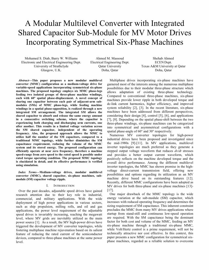
Symmetrical six-phase machines can be supplied by a dual three-phase MMC to generate two sets of three-phase voltages with 60° electrical-degrees phase-shift. Then each three-phase MMC is controlled independently to generate a multi-level-based three-phase voltage-set which can be applied across either three-phase group of machine windings. Each MMC is composed of three-phase legs, each formed by two arms connected in series through arm inductors . Each arm consists of N series-connected SMs, while the SM consists of an HB cell with a dc capacitor of an equivalent capacitance and voltage rating , as shown in Fig. 1. A general form for symmetrical six-phase voltages generated by a six-phase MMC is: = cos − , = 0, 2, 4for = , ,
and = 1, 3, 5for = , , (1)
where is the output angular frequency, while is the magnitude of the output phase-voltage which is bounded by the modulation index and the voltage of the input source
, as shown in (2).
= (2)
Similarly, a general form for the six-phase currents passing through the symmetrical machine windings is: = cos − − , = 0, 2, 4for = , ,
and = 1, 3, 5for = , , (3)
where is the magnitude of the machine current and is the power-factor angle of the machine. The modulation of both the upper and lower arms is out-of-phase, where the developed voltages across the SM capacitors inserted in the conduction path are complementary for both the upper and lower arms, to achieve balance with the dc-link voltage. This results in the load current being equally split out-of-phase between the upper and lower arms.
Fig. 1 Circuit diagram of an MMC phase-leg using HB-SMs.
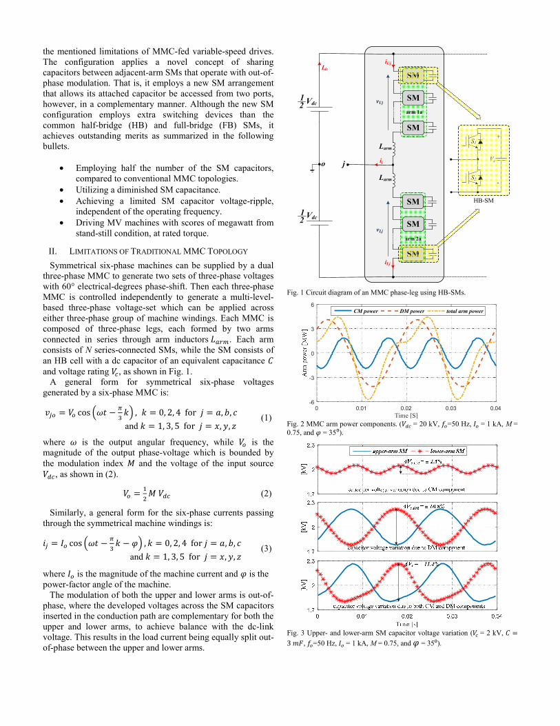
Fig. 2 MMC arm power components. ( = 20 kV, =50 Hz, = 1 kA, M = 0.75, and = 35⁰).
Fig. 3 Upper- and lower-arm SM capacitor voltage variation ( = 2 kV, =3 , =50 Hz, = 1 kA, M = 0.75, and = 35⁰).
arm 1a
arm 2a
SM
SM
SM
SM
SM
SM
Vdc
Vdc
Larm
Larm
j
12
12
o
vUj
vLj
Idc
ij
iUj
iLj
Vc
S1
S2
+
-
HB-SM
0 0.01 0.02 0.03 0.04Time [S]
-6
-3
0
3
6CM power DM power total arm power
Performing power analysis, the MMC arm power pulsates as a consequence of two components, namely the common-mode (CM) and the differential-mode (DM) components [18]. The CM component alternates in phase in both the upper and lower arms at the second-frequency harmonic as a direct result of the active power at the dc-side being constant, while the power at the ac-side pulsates at twice the fundamental frequency. Whereas, the DM component alternates anti-phase in both arms at the first-frequency harmonic, representing the power which is circulated back and forth internally between the upper and lower arms of the same phase-leg. Both the CM and DM power components are graphically demonstrated in Fig. 2 along with the total arm power, where it can be noticed that the DM power is the dominant component. The predominance of the out-of-phase DM component results in a complemented action of the energy stored in both the upper and lower arms, which is eventually manifested in the SM capacitor voltage ripple. That is, when the upper-arm SMs are absorbing a certain amount of energy, the lower-arm SMs are releasing almost the same energy amount. The resulting SM capacitor voltage fluctuations due to both CM and DM components are shown in Fig. 3, for a 2 kV nominal SM capacitor voltage, where the CM component has the least influence on the SM capacitor voltage ripple.
III. PROPOSED MMC CONFIGURATION FOR SYMMETRICAL
SIX-PHASE MACHINES
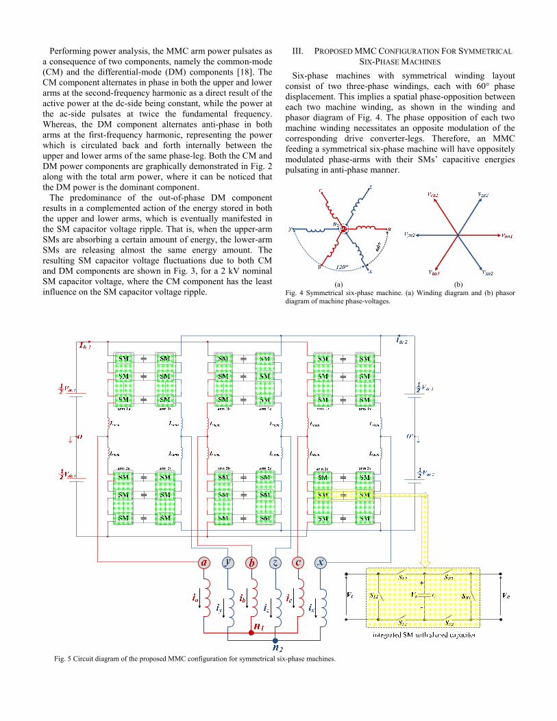
Six-phase machines with symmetrical winding layout consist of two three-phase windings, each with 60° phase displacement. This implies a spatial phase-opposition between each two machine winding, as shown in the winding and phasor diagram of Fig. 4. The phase opposition of each two machine winding necessitates an opposite modulation of the corresponding drive converter-legs. Therefore, an MMC feeding a symmetrical six-phase machine will have oppositely modulated phase-arms with their SMs’ capacitive energies pulsating in anti-phase manner.
(a) (b)
Fig. 4 Symmetrical six-phase machine. (a) Winding diagram and (b) phasor diagram of machine phase-voltages.
Fig. 5 Circuit diagram of the proposed MMC configuration for symmetrical six-phase machines.
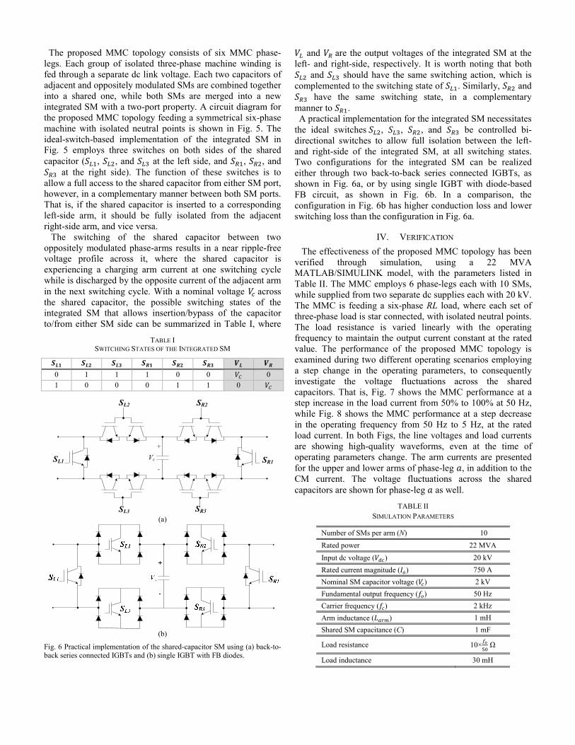
The proposed MMC topology consists of six MMC phase-legs. Each group of isolated three-phase machine winding is fed through a separate dc link voltage. Each two capacitors of adjacent and oppositely modulated SMs are combined together into a shared one, while both SMs are merged into a new integrated SM with a two-port property. A circuit diagram for the proposed MMC topology feeding a symmetrical six-phase machine with isolated neutral points is shown in Fig. 5. The ideal-switch-based implementation of the integrated SM in Fig. 5 employs three switches on both sides of the shared capacitor ( , , and at the left side, and , , and
at the right side). The function of these switches is to allow a full access to the shared capacitor from either SM port, however, in a complementary manner between both SM ports. That is, if the shared capacitor is inserted to a corresponding left-side arm, it should be fully isolated from the adjacent right-side arm, and vice versa. The switching of the shared capacitor between two oppositely modulated phase-arms results in a near ripple-free voltage profile across it, where the shared capacitor is experiencing a charging arm current at one switching cycle while is discharged by the opposite current of the adjacent arm in the next switching cycle. With a nominal voltage across the shared capacitor, the possible switching states of the integrated SM that allows insertion/bypass of the capacitor to/from either SM side can be summarized in Table I, where
TABLE I SWITCHING STATES OF THE INTEGRATED SM
0 1 1 1 0 0 0
1 0 0 0 1 1 0
(a)
(b)
Fig. 6 Practical implementation of the shared-capacitor SM using (a) back-to-back series connected IGBTs and (b) single IGBT with FB diodes.
and are the output voltages of the integrated SM at the left- and right-side, respectively. It is worth noting that both
and should have the same switching action, which is complemented to the switching state of . Similarly, and
have the same switching state, in a complementary manner to . A practical implementation for the integrated SM necessitates the ideal switches , , , and be controlled bi-directional switches to allow full isolation between the left- and right-side of the integrated SM, at all switching states. Two configurations for the integrated SM can be realized either through two back-to-back series connected IGBTs, as shown in Fig. 6a, or by using single IGBT with diode-based FB circuit, as shown in Fig. 6b. In a comparison, the configuration in Fig. 6b has higher conduction loss and lower switching loss than the configuration in Fig. 6a.
IV. VERIFICATION
The effectiveness of the proposed MMC topology has been verified through simulation, using a 22 MVA MATLAB/SIMULINK model, with the parameters listed in Table II. The MMC employs 6 phase-legs each with 10 SMs, while supplied from two separate dc supplies each with 20 kV. The MMC is feeding a six-phase RL load, where each set of three-phase load is star connected, with isolated neutral points. The load resistance is varied linearly with the operating frequency to maintain the output current constant at the rated value. The performance of the proposed MMC topology is examined during two different operating scenarios employing a step change in the operating parameters, to consequently investigate the voltage fluctuations across the shared capacitors. That is, Fig. 7 shows the MMC performance at a step increase in the load current from 50% to 100% at 50 Hz, while Fig. 8 shows the MMC performance at a step decrease in the operating frequency from 50 Hz to 5 Hz, at the rated load current. In both Figs, the line voltages and load currents are showing high-quality waveforms, even at the time of operating parameters change. The arm currents are presented for the upper and lower arms of phase-leg , in addition to the CM current. The voltage fluctuations across the shared capacitors are shown for phase-leg as well.
TABLE II SIMULATION PARAMETERS
Number of SMs per arm (N) 10
Rated power 22 MVA
Input dc voltage ( ) 20 kV
Rated current magnitude ( ) 750 A
Nominal SM capacitor voltage ( ) 2 kV
Fundamental output frequency ( ) 50 Hz
Carrier frequency ( ) 2 kHz
Arm inductance ( ) 1 mH
Shared SM capacitance (C) 1 mF
Load resistance 10× Ω
Load inductance 30 mH
Vc
+
-
SL1
SL2
SL3 SR3
SR2
SR1

Fig. 7 Performance of proposed MMC topology during a step-increase in the load current from 50% to 100%, at 50 Hz. The consecutive switching of the shared capacitors between two complemented arms cancels out the effect of the DM ripple component, resulting in a limited voltage-ripple pulsating with the second-frequency harmonic due to only the CM ripple component. Also, the capacitor voltage ripple is slightly affected by either the load current increase or operating frequency reduction. Since the maximum capacitor voltage ripple is recorded as ±2.5% (less than the ±10% tolerance), the integrated SM capacitance can be reduced to hundreds of micro Farads rather than the utilized 1 mF.
V. CONCLUSION
This paper presented an MMC configuration for symmetrical six-phase machines, with a novel concept of integrating the capacitors of each two oppositely modulated SMs into a shared one based on the spatial phase displacement in the symmetrical machine windings. The proposed
Fig. 8 Performance of proposed MMC topology during a step-decrease in the operating frequency from 50 Hz to 5 Hz, at the same load current. configuration reduces the number of employed capacitors, and hence the voltage sensors, by 50% compared to a traditional six-phase MMC topology, which reduces the drive system volume and its stored capacitive energy. With the switching of the shared capacitor between two oppositely modulated phase-arms, the capacitor is exposed to a near equal amount of consecutive charging and discharging currents. This results in limited voltage fluctuations across the shared capacitor, with a diminished capacitance requirement. The proposed configuration is very suitable for variable-speed applications since it guarantees the continuous operation at any speed/torque condition with the ability of driving multi-megawatt machines from stand-still at full-load torque. Since the proposed topology utilises extra switching devices in the integrated SM, an efficiency assessment will be considered in future research.
[kV]
[kA]
[kA]
[kV]
REFERENCES [1] R. D. Klug, N. Klaassen, “High Power Medium Voltage Drives–
Innovations, Portfolio, Trends,” 2005 European Conference on Power Electronics and Applications, 11-14 September 2005.
[2] E. Levi, "Multiphase Electric Machines for Variable-Speed Applications," Industrial Electronics, IEEE Transactions on, vol.55, no.5, pp.1893-1909, May 2008.
[3] E. Levi, R. Bojoi, F. Profumo, H. A. Toliyat and S. Williamson, "Multiphase induction motor drives—A technology status", IET Elect. Power Appl., vol. 1, no. 4, pp.489 -516 2007.
[4] C. Lin and C. Hwang, “Multi objective optimization design for a six-phase copper rotor induction motor mounted with a scroll compressor,” IEEE Trans. Magnetics, vol. 52, no. 7, Article # 9401604, Jul. 2016.
[5] M. Duran and F. Barrero, “Recent advances in the design, modeling and control of multiphase machines—Part II,” IEEE Trans. Ind. Electron., vol. 63, no. 1, pp. 459–468, Jan. 2016
[6] D. Glose and R. Kennel, “Continuous space vector modulation for symmetrical six-phase drives,” IEEE Trans. Power. Electron., vol. 31, no. 5, pp. 3837-3848, May. 2016.
[7] M. S. Diab, A. A. Elserougi, A. S. Abdel-Khalik, A. M. Massoud and S. Ahmed, "A Nine-Switch-Converter-Based Integrated Motor Drive and Battery Charger System for EVs Using Symmetrical Six-Phase Machines," IEEE Trans. Ind. Electron., vol. 63, no. 9, pp. 5326-5335, Sept. 2016.
[8] E. Levi, “Advances in converter control and innovative exploitation of additional degrees of freedom for multiphase machines,” IEEE Trans. Ind. Electron., vol. 63, no. 1, pp. 433-448, Jan. 2016.
[9] K. H. J. Chong, R. D. Klug, "High power medium voltage drives", Proc. Power Syst. Technol. PowerCon'04, pp. 658-664, 2004-Nov.-21-24.
[10] S. Bernet, “Recent developments of high power converters for industry and traction applications,” IEEE Trans. Power Electron., vol. 15, no. 6, pp. 1102–1117, Nov. 2000.
[11] S. Rizzo and N. Zargari, "Medium voltage drives: what does the future hold?," The 4th International Power Electronics and Motion Control Conference, 2004. IPEMC 2004., Xi'an, 2004, pp. 82-89 Vol.1.
[12] Maryam Saeedifard and Reza Iravani, “Dynamic performance of a modular multilevel back-to-back HVDC system,” IEEE Trans. Power Del., vol. 25, no. 4, pp. 2903-2912, Oct. 2010.
[13] B. Tai; C. Gao; X. Liu; Z. Chen, “A Novel Flexible Capacitor Voltage Control Strategy for Variable-Speed Drives with Modular Multilevel Converters,” IEEE Trans. Power Electron., vol. 32, no. 1, pp. 128-141, Jan. 2017.
[14] A. Antonopoulos, L. Ängquist, H. P. Nee, “Optimal Selection of the Average Capacitor Voltage for Variable-Speed Drives with Modular Multilevel Converters,” IEEE Trans. Power Electron., vol. 30, no. 1, pp. 227-234, Jan. 2015.
[15] M. S. Diab, B. W. Williams, D. Holliday, A. M. Massoud and S. Ahmed, "A modular multilevel converter with isolated energy-balancing modules for MV drives incorporating symmetrical six-phase machines," 2017 IEEE Energy Conversion Congress and Exposition (ECCE), Cincinnati, OH, 2017, pp. 2715-2722.
[16] M. S. Diab, G. P. Adam, B. W. Williams, A. M. Massoud and S. Ahmed, "Quasi two-level PWM operation of a nine-arm modular multilevel converter for six-phase medium-voltage motor drives," 2018 IEEE Applied Power Electronics Conference and Exposition (APEC), San Antonio, TX, 2018, pp. 1641-1648.
[17] M. S. Diab, A. A. Elserougi, A. M. Massoud, S. Ahmed and B. W. Williams, "A Hybrid Nine-Arm Modular Multilevel Converter for Medium-Voltage Six-Phase Machine Drives," in IEEE Trans. Ind. Electron., vol. PP, no.99, pp.1-1.
[18] M. S. Diab, A. M. Massoud, S. Ahmed and B. W. Williams, "A Dual Modular Multilevel Converter with High-Frequency Magnetic Links Between Submodules for MV Open-End Stator Winding Machine Drives," in IEEE Transactions on Power Electronics, vol. 33, no. 6, pp. 5142-5159, June 2018.